
Challenge of mechanical properties of an acicular ferrite pipeline steel
12
Materials Science and Engineering A 431 (2006) 41–52 Challenge of mechanical properties of an acicular ferrite pipeline steel Fu-Ren Xiao a,b , Bo Liao a,∗ , Yi-Yin Shan b , Gui-Ying Qiao a , Yong Zhong b , Chunling Zhang a , Ke Yang b a Key Laboratory of Metastable Materials Science and Technology, College of Materials Science and Engineering, Yanshan University, Qinhuangdao 066004, PR China b Institute of Metal Research, Chinese Academy of Science, Shenyang 110016, PR China Received 1 May 2006; received in revised form 5 May 2006; accepted 5 May 2006 Abstract In modern industry, the developing tendency and prospect for productions of the oil and gas pipeline steels is to further improve the strength and toughness by advanced manufacture process of the thermo-mechanical control process (TMCP) to refine microstructure. In this work, the hot deformation behavior as well as its effect on the phase transformation of the clean acicular ferrite pipeline steel with simple chemical composition has been investigated. According to the result, the optimum TMCP parameters were designed. Furthermore, the rolling test was carried out on the experimental rolling mill. The results show that, the high strength and excellent toughness of the clean acicular ferrite pipeline steel can be obtained by controlling the TMCP parameters of the production process appropriately. © 2006 Elsevier B.V. All rights reserved. Keywords: Pipeline steels; Acicular ferrite; TMCP; Process parameters; Mechanical properties 1. Introduction In modern industry, the developing tendency and prospect for productions of the low-carbon micro-alloyed steels is to refine microstructure, so as to further improve its strength and tough- ness. In order to realize this aim, the thermo-mechanical control process (TMCP) has been applied as an important method. In recent years, great attention has been taken to attain ultra-fine ferrite grain structure by using strain-induced ferritic transfor- mation and/or dynamic recrystallization of ferrite [1,2] during deformation. The microstructure with the finer ferrite grain has been achieved by strain-induced transformation in plain carbon and micro-alloyed steels [3,4]. However, for pipeline steel, if the acicular ferrite microstruc- ture can be achieved, it will with better properties, such as high tensile strength, good toughness, excellent corrosion resistance and superior weldability [5–8], than ultrofine grain ferrite struc- ture [8]. The combination of properties has led to the application of this steel in the manufacturing of large dimension pipes for gas and oil transportation in the low temperature area [9–11]. ∗ Corresponding author. Tel.: +86 335 8057047; fax: +86 335 8074545. E-mail addresses: [email protected] (F.-R. Xiao), [email protected] (B. Liao). Although the term of acicular ferrite steel was firstly described by Smith et al. in the early 1970s [5,6] and has been widely accepted in pipeline engineering [9–11], there are still controver- sies and uncertainties on the metallographical identification and classification of the phases. Sometimes, the structure of acicular ferrite is also contested as bainite [12] and quasi-polygonal fer- rite (or massive ferrite) [13]. However, from our previous work, the structure of acicular ferrite is considered as the mixture of massive ferrite with bainite ferrite [14]. These results show that the transformation mechanism of the acicular ferrite is different from that of the polygonal ferrite. Meanwhile, when the polyg- onal ferrite is appeared in the acicular ferrite microstructure, the final mechanical properties of this steel are decreased [8,15], which indicates that the way to refine acicular ferrite structure is different from that with heavy deformation at lower tempera- ture. Recently, the studies on acicular ferrite pipeline steels are focus on the effect of element on the phase transformation and the mechanical properties of acicular ferrite [16,17], however, little systematic work has been carried out in the refinement its microstructure. The acicular ferrite microstructure can be obtained without special alloy elements, and the high tensile strength and good toughness can be obtained too [8,18]. However, the change of the microstructure during hot deformation, and the effect of the hot deformation on phase transformation, as well as the 0921-5093/$ – see front matter © 2006 Elsevier B.V. All rights reserved. doi:10.1016/j.msea.2006.05.029
-
Upload
independent -
Category
Documents
-
view
1 -
download
0
Transcript of Challenge of mechanical properties of an acicular ferrite pipeline steel

A
adhto©
K
1
pmnprfmdba
ttatog
(
0d
Materials Science and Engineering A 431 (2006) 41–52
Challenge of mechanical properties of an acicular ferrite pipeline steel
Fu-Ren Xiao a,b, Bo Liao a,∗, Yi-Yin Shan b, Gui-Ying Qiao a, Yong Zhong b,Chunling Zhang a, Ke Yang b
a Key Laboratory of Metastable Materials Science and Technology, College of Materials Science and Engineering,Yanshan University, Qinhuangdao 066004, PR China
b Institute of Metal Research, Chinese Academy of Science, Shenyang 110016, PR China
Received 1 May 2006; received in revised form 5 May 2006; accepted 5 May 2006
bstract
In modern industry, the developing tendency and prospect for productions of the oil and gas pipeline steels is to further improve the strengthnd toughness by advanced manufacture process of the thermo-mechanical control process (TMCP) to refine microstructure. In this work, the hot
eformation behavior as well as its effect on the phase transformation of the clean acicular ferrite pipeline steel with simple chemical compositionas been investigated. According to the result, the optimum TMCP parameters were designed. Furthermore, the rolling test was carried out onhe experimental rolling mill. The results show that, the high strength and excellent toughness of the clean acicular ferrite pipeline steel can bebtained by controlling the TMCP parameters of the production process appropriately.2006 Elsevier B.V. All rights reserved.
nical
Abascfrtmtfofiwitf
eywords: Pipeline steels; Acicular ferrite; TMCP; Process parameters; Mecha
. Introduction
In modern industry, the developing tendency and prospect forroductions of the low-carbon micro-alloyed steels is to refineicrostructure, so as to further improve its strength and tough-
ess. In order to realize this aim, the thermo-mechanical controlrocess (TMCP) has been applied as an important method. Inecent years, great attention has been taken to attain ultra-fineerrite grain structure by using strain-induced ferritic transfor-ation and/or dynamic recrystallization of ferrite [1,2] during
eformation. The microstructure with the finer ferrite grain haseen achieved by strain-induced transformation in plain carbonnd micro-alloyed steels [3,4].
However, for pipeline steel, if the acicular ferrite microstruc-ure can be achieved, it will with better properties, such as highensile strength, good toughness, excellent corrosion resistancend superior weldability [5–8], than ultrofine grain ferrite struc-
ure [8]. The combination of properties has led to the applicationf this steel in the manufacturing of large dimension pipes foras and oil transportation in the low temperature area [9–11].∗ Corresponding author. Tel.: +86 335 8057047; fax: +86 335 8074545.E-mail addresses: [email protected] (F.-R. Xiao), [email protected]
B. Liao).
tlm
sttt
921-5093/$ – see front matter © 2006 Elsevier B.V. All rights reserved.oi:10.1016/j.msea.2006.05.029
properties
lthough the term of acicular ferrite steel was firstly describedy Smith et al. in the early 1970s [5,6] and has been widelyccepted in pipeline engineering [9–11], there are still controver-ies and uncertainties on the metallographical identification andlassification of the phases. Sometimes, the structure of acicularerrite is also contested as bainite [12] and quasi-polygonal fer-ite (or massive ferrite) [13]. However, from our previous work,he structure of acicular ferrite is considered as the mixture of
assive ferrite with bainite ferrite [14]. These results show thathe transformation mechanism of the acicular ferrite is differentrom that of the polygonal ferrite. Meanwhile, when the polyg-nal ferrite is appeared in the acicular ferrite microstructure, thenal mechanical properties of this steel are decreased [8,15],hich indicates that the way to refine acicular ferrite structure
s different from that with heavy deformation at lower tempera-ure. Recently, the studies on acicular ferrite pipeline steels areocus on the effect of element on the phase transformation andhe mechanical properties of acicular ferrite [16,17], however,ittle systematic work has been carried out in the refinement its
icrostructure.The acicular ferrite microstructure can be obtained without
pecial alloy elements, and the high tensile strength and goodoughness can be obtained too [8,18]. However, the change ofhe microstructure during hot deformation, and the effect ofhe hot deformation on phase transformation, as well as the

4 e and
rntncTt
sc(bprret
2
pt7si
chØtior0mtwt1pmo
TC
E
CSMPSMNVNO
foc
st3dhttuhtpfiaacfi1c1oc
ydfeomppw
3
2 F.-R. Xiao et al. / Materials Scienc
efinement of the acicular ferrite of the final production haveot been studied extensively. Therefore, in order to achievehe refined acicular ferrite microstructure and to make a tech-ological foundation for this pipeline steel, it is necessary tolarify the changing principle of the microstructure during theMCP procedures and the effect of the TMCP parameters on
he microstructure and mechanical property [19].In this work, the effect of the hot deformation on
tatic/dynamic recrystallization, strain induced precipitation ofarbinitride and phase transformation of the clean pipeline steelcommercial grade X60) with simple chemical composition haseen studied. And according to the results, the optimum TMCParameters were designed. Furthermore, the experimental hotolling plate of the clean pipeline steel with refined acicular fer-ite microstructure was manufactured and its mechanical prop-rty was measured by controlling all the design parameters ofhe production process.
. Experimental procedure
The clean acicular pipeline steel used in this work wasrepared in a 25 kg vacuum induction melted furnace, andhe cast ingots were forged to bars of Ø25 mm and slabs of0 mm × 78 mm × 80 mm. The chemical composition of thisteel designed by a commercial grade X60 pipeline steel is listedn Table 1.
Two types of compressive tests (single-pass and interruptedompressive test) were carried out by means of Gleeble-3500ot simulator. The hot compressive specimen was machined into10 mm × 15 mm cylinder. For a single-pass compressive test,
he specimens were reheated to 1200 ◦C, then cooled to the test-ng temperature. The continuous compressive tests were carriedut to determine the critical strain in experimental temperatureange from 900 to 1100 ◦C and the strain rate was in range from.01 to 10 s−1. For an interrupted compressive test, the speci-ens were reheated to 1200 ◦C and/or 1130 ◦C, and then cooled
o the testing temperature. The interrupted compressive testsere carried out. The experimental technologies were that, the
emperature rang was from 900 to 1000 ◦C, the stain rate was−1
0 s , the inter-pass time rang was from 1 to 1000 s, and there-strain was about 40%. By using the “back extrapolation”ethod [20,21], the recrystallized fraction (Xa) after an interval
f hot working was calculated. With this method, the softened
able 1hemical composition of the experimental steel (wt.%)
lement Content
0.025i 0.24n 1.56
0.00200.0006
o 0.32b 0.039
0.0190.00620.0043
3
F9Utcor(cnmwt
t
Engineering A 431 (2006) 41–52
raction is approximately equal to the recrystallized fraction, inther words, the effect of recovery is excluded from the doubleompression data [20,21].
The continuous cooling transformation (CCT) curve of thisteel with and without hot deformation has been obtained fromhe experiments by using Formastor-F dilatometer and Gleeble-500 hot simulator. The dimension of the specimen used for theilatation test was Ø3 mm × 10 mm. The specimens were firsteated at 1100 ◦C for 5 min, subsequently held at 950 ◦C for 30 s,hen cooled to room temperature at linear cooling rates from 0.1o 100 ◦C s−1. The dimension of the specimen used for hot sim-lative test was Ø10 mm × 15 mm. The specimens were firsteated at 1130 ◦C for 5 min, and then two types of hot deforma-ion processes, the single and two-pass compressive tests, wereerformed. For the single-pass compression, the specimens wererst cooled to 850 ◦C at a cooling rate of 10 ◦C s−1 immediatelynd 40% compressive deformation was carried out at 850 ◦C,nd then the deformed specimens were cooled directly at linearooling rates from 0.5 to 40 ◦C s−1. For two-passes compression,rstly, the specimens were cooled to 980 ◦C at cooling rate of0 ◦C s−1 immediately and 40% compressive deformation wasarried out, and then cooled 850 and/or 750 ◦C at cooling rate of0 ◦C s−1. Secondly, 40% compressive deformation was carriedut at same temperature, and then the deformed specimens wereooled directly at linear cooling rates from 0.5 to 40 ◦C s−1.
A combination of the optical microscopy, dilatometric anal-sis and transmission electron microscopy (TEM) were used toetermine the microstructures of the specimens. The specimensor metallographic examination were mechanically polished andtched with a 3% Nital solution, and then observed by usingptical microscopy. For TEM observation, the thin foils wereechanically thinned from 300 to 50 �m, and then electro-
olished by a twin-jet electropolisher in a solution of 10%erchloric acid and 90% acetic acid. The thin foil specimensere observed by using H-800 TEM with 200 kV.
. Hot deformation behavior of this steel
.1. Stress–strain curves
The typical stress–strain curves of this steel are shown inig. 1, which were determined at the temperature range from00 to 1100 ◦C and the strain rate range from 0.01 to 10 s−1.nder the lower temperature or higher strain rate conditions,
he stress is increased with the increasing of the strain, whoseurve is a typical one of the work hardening. With the increasingf the deformed temperature, or the decreasing of the strainate, a maximum characterized by peak strain (εp) and stressσp) is appeared in the curve, followed by a gradual fall to aonstant stress value (σss). Furthermore, the peak is changed toarrows and its stress and strain value is decreased. This is typicalaterials that the recrystallization can be initiated dynamically
hen the specimen is deformed at temperature above half ofheir melting point.This is confirmed by an analysis of the effect of the deforma-
ion conditions on the peak stress (σp) by using the hyperbolic

F.-R. Xiao et al. / Materials Science and Engineering A 431 (2006) 41–52 43
d stra
s
ε
wrlJat4apuwohTbrmm
3p
t9a4ctsttpsotthrecrystallization during unloading process [22]. However, it
Fig. 1. The effect of temperature (a) an
ine function [22]:
˙ = A(sinh ασ)n′exp
(−Qdef
RT
)(1)
here A, α and n′ are constants, R is the gas constant, ε the strainate, Qdef the activation energy, σ the stress and T is the abso-ute temperature. A method similar to that used by Unira andonas [23] was adopted to determine the parameters of the α, n′nd Qdef at peak stress of dynamic recrystallization. In this case,he activation energy (Qdef) for deformation was found to be07 kJ/mol for the tested steel. The results of the fit are presenteds a plot of ln(sinh ασ) versus ln Z (Z is the Zener–Hollomonarameter, Z = ε exp(−Qdef/RT )) as shown in Fig. 2. The val-es of n′ = 5.9 is in agreement with the observation of otherorkers [22,24]. Because the strain rates are higher than 10 s−1
r the deformed temperature is below 1000 ◦C, the Qdef is veryigh, so that the dynamic recrystallization occurs difficultly.hese results indicate that it is difficult to refine austenite grainy utilized dynamic recrystallization during practical industrial
olling process because the strain rate is higher 10 s−1 on rollingill. Therefore, the static recrystallization will be an effectiveethod to refine initial austenite grain.Fig. 2. Relationship of ln(sinh(ασp)) vs. ln Z.
cfc
in rates (b) on the stress–strain curves.
.2. Static recrystallization and strain induced carbonitriderecipitation
The typical interrupted compressive stress–strain curve ofhe specimens after reheating at 1130 ◦C are determined at of50 ◦C, which are shown in Fig. 3. The experimental conditionsre that the constant true strain rate is 10 s−1, the pre-strain is0% and the inter-pass times are 1–1000 s. Several interruptedompressive tests with inter-pass time are plotted togethero demonstrate the effect of unloading time on the flowingtress–strain curves. It can be seen that, when the inter-passime is short, the flow curve resulting from second twist followshe continuous one closely because little softening is takenlace. With the increasing of the inter-pass time, the initial flowtress of second loading is decreased because static recoveryccurs gently. When the inter-pass time is increased to 1000 s,he work hardens of the second curve are similar to that ofhe first curve so as to rebuild the dislocation structure, whichas been recovered because of the static and/or meta-dynamic
an be found from Fig. 3, when unloading time is in the rangerom 10 to 120 s, little change can be found from the secondurve. It indicates that another factor affects the recovery
Fig. 3. Double twist stress–strain curves of this steel.
44 F.-R. Xiao et al. / Materials Science and Engineering A 431 (2006) 41–52
e: (a)
pdc
raaTishicusb
iotcct
tt
o[
X
widw[
t
wa
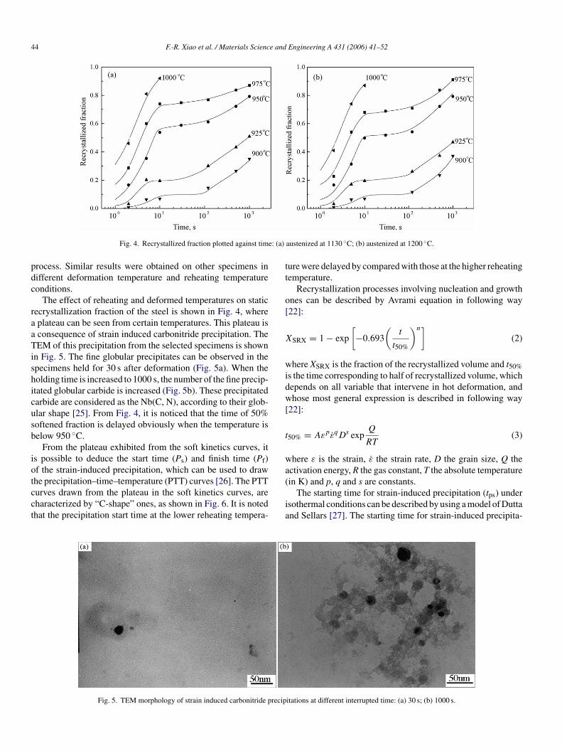
Fig. 4. Recrystallized fraction plotted against tim
rocess. Similar results were obtained on other specimens inifferent deformation temperature and reheating temperatureonditions.
The effect of reheating and deformed temperatures on staticecrystallization fraction of the steel is shown in Fig. 4, whereplateau can be seen from certain temperatures. This plateau isconsequence of strain induced carbonitride precipitation. TheEM of this precipitation from the selected specimens is shown
n Fig. 5. The fine globular precipitates can be observed in thepecimens held for 30 s after deformation (Fig. 5a). When theolding time is increased to 1000 s, the number of the fine precip-tated globular carbide is increased (Fig. 5b). These precipitatedarbide are considered as the Nb(C, N), according to their glob-lar shape [25]. From Fig. 4, it is noticed that the time of 50%oftened fraction is delayed obviously when the temperature iselow 950 ◦C.
From the plateau exhibited from the soft kinetics curves, its possible to deduce the start time (Ps) and finish time (Pf)f the strain-induced precipitation, which can be used to draw
he precipitation–time–temperature (PTT) curves [26]. The PTTurves drawn from the plateau in the soft kinetics curves, areharacterized by “C-shape” ones, as shown in Fig. 6. It is notedhat the precipitation start time at the lower reheating tempera-(
ia
Fig. 5. TEM morphology of strain induced carbonitride precip
austenized at 1130 ◦C; (b) austenized at 1200 ◦C.
ure were delayed by compared with those at the higher reheatingemperature.
Recrystallization processes involving nucleation and growthnes can be described by Avrami equation in following way22]:
SRX = 1 − exp
[−0.693
(t
t50%
)n](2)
here XSRX is the fraction of the recrystallized volume and t50%s the time corresponding to half of recrystallized volume, whichepends on all variable that intervene in hot deformation, andhose most general expression is described in following way
22]:
50% = AεpεqDs expQ
RT(3)
here ε is the strain, ε the strain rate, D the grain size, Q thectivation energy, R the gas constant, T the absolute temperature
in K) and p, q and s are constants.The starting time for strain-induced precipitation (tps) undersothermal conditions can be described by using a model of Duttand Sellars [27]. The starting time for strain-induced precipita-
itations at different interrupted time: (a) 30 s; (b) 1000 s.

F.-R. Xiao et al. / Materials Science and
t
t
wHcde
ir
esa
eetdtittipo
asru
Fd
Fig. 6. The PTT curves of this steel.
ion is given for Nb-steels by the following equation [26]:
ps = A[Nb]−1ε−1Z−0.5 exp170000
RTexp
B
T 3(ln Ks)2 (4)
here Ks = ([Nb][C + 12N/14])/102.26 − 6770/T, Z is the Zener–
ollomon parameter, [Nb], [C] and [N] are the weight per-entages of Nb, C and N, respectively, ε is the strain applieduring hot rolling and T is the rolling temperature (in K). Theffect of strain rate on precipitation times is accounted for
tnsf
ig. 7. Effect of hot deformation on CCT diagrams: (a) without hot deformation;eformation (40% reduction at 980 ◦C and 40% reduction at 850 ◦C); (d) with two-pa
Engineering A 431 (2006) 41–52 45
n the Zener–Hollomon parameter that is a function of strainate.
From Eqs. (2)–(4), during the same deformation process, theffect of the Nb content in solid solution and the austenite grainize on the starting time for strain-induced precipitation and thectivation energy (Q) of static recrystallization is obvious.
According to the equation given by Irvine et al. [28], thequilibrium solution temperature of Nb(C, N) carbonitrite isstimated to about 1028 ◦C. Therefore, it is believed that whenhe reheating temperature is above 1130 ◦C, it is enough toissolve all the Nb(C, N) carbonitrites in austenite. However,he static recrystallization is also affected by primary austen-te grain size. With the increasing of the reheating tempera-ure, the size of the primary austenite grain is increased, sohat the static recrystallization is restrained. Meanwhile, it alsondicates that, by compared with the higher reheating tem-erature, the precipitation start time is delayed at the lowerne.
As mentioned above, the effects of the reheating temper-ture on the static recrystallization and the precipitation fortrain-induced Nb carbonitrites, as well as the microstructureefinement and the mechanical properties of final hot rolled prod-cts can be found. For the tested steel, the non-recrystallization
emperature is 950 ◦C. Therefore, the reheating temperature,on-recrystallization temperature and carbinitride precipitationhould be considerable factors for the production of high per-ormance hot rolled products.(b) with one-pass deformation (40% reduction at 850 ◦C); (c) with two-passss deformation (40% reduction at 980 ◦C and 40% reduction at 750 ◦C).

46 F.-R. Xiao et al. / Materials Science and Engineering A 431 (2006) 41–52
cooli
4
ttbwmst
twfnl
Fig. 8. The optical micrographs of the steel without deformation at
. Effect of hot deformation on phase transformation
The effect of the hot deformation on the phase transforma-ion kinetics and microstructures is obvious [29–31]. Therefore,he effect of hot deformation parameters on CCT curve haseen investigated in this work. The CCT curves of this steel
ith and without hot deformation are shown in Fig. 7, and theicrostructures of the specimens at different cooling rates arehown in Figs. 8 and 9, which reveal a pronounced evolution ofhe microstructures in different cooling conditions.
pamd
Fig. 9. Effect of hot deformation on microstructures of cooling rate at 10
ng rate: (a) 100 ◦C s−1; (b) 10 ◦C s−1; (c) 2 ◦C s−1; (d) 0.2 ◦C s−1.
In CCT curves, the phase transformation microstructures ofhis steel are complex during the continuous cooling processes,hich are bainite ferrite (BF), acicular ferrite (AF), polygonal
errite (PF), and pearlite (P). The acicular ferrite in this work iseither the titanium oxide one nor welding metals with needle-ike grain [32,12]. This nomenclature of the acicular ferrite, first
roposed by Smith et al. in the early 1970s [6,7], is readilyccepted by the researchers of pipeline steels as an independenticrostructure [5,9–11]. This acicular ferrite microstructure isefined as a highly substructured non-equiaxed phase, which is
◦C/s: (a) one-pass; (b) two-pass at 850 ◦C; (c) two-pass at 750 ◦C.

F.-R. Xiao et al. / Materials Science andTa
ble
2T
MC
Ppa
ram
eter
sde
sign
edan
dm
easu
red
duri
ngho
trol
ling
Spec
imen
no.
Con
ditio
nsR
ough
rolli
ngR
ollin
gdu
ring
non-
recr
ysta
lliza
tion
Coo
ling
rate
(◦C
/s)
Fini
shco
olin
gte
mpe
ratu
re(◦
C)
Coo
ling
tem
pera
ture
(◦C
)
Beg
inro
lling
tem
pera
ture
(◦C
)Fi
nish
rolli
ngte
mpe
ratu
re(◦
C)
Red
uctio
n(%
)B
egin
rolli
ngte
mpe
ratu
re(◦
C)
Fini
shro
lling
tem
pera
ture
(◦C
)R
educ
tion
(%)
21D
esig
ned
1100
970
5790
080
076
2050
050
0M
easu
red
1070
976
896
800
18
22D
esig
ned
1100
970
5790
075
076
2054
050
0M
easu
red
1080
969
900
783
20
23D
esig
ned
1050
950
5792
080
076
2052
050
0M
easu
red
1047
955
922
804
17.8
24D
esig
ned
1050
950
5790
075
076
2050
950
0M
easu
red
1054
946
905
750
16.1
25D
esig
ned
1050
950
5792
080
076
2057
060
0M
easu
red
1050
954
920
799
22.5
26D
esig
ned
1050
950
5790
075
076
2057
560
0M
easu
red
1052
957
899
750
22.7
ffsobp
apfF1cWuaTc
(hrctmftroFbpiaeafmtspitba
isittamddtt
Engineering A 431 (2006) 41–52 47
ormed during the continuous cooling process by a mixed dif-usion and shear transformation mode at a temperature rangelightly higher than upper bainite [6,7]. And the characteristicf the acicular ferrite microstructure with bainite in the low car-on Mn–Mo–Nb steels is different from that formed from therimary austenite grain boundary.
In the CCT curve without hot deformation, the intermedi-te transformation such as bainite and acicular ferrite can beromoted by Mn, Mo, Nb elements greatly and the polygonalerrite and pearlite transformation can be restrained (shown inig. 7a). For example, when the cooling rate is changed from0 to 100 ◦C s−1, the microstructure is the classical bainite withlear primary austenite grain boundary (shown in Fig. 8a and b).hen the cooling rate is changed from 0.2 to 5 ◦C s−1, the acic-
lar ferrite microstructure can be obtained, in which the primaryustenite grain boundary is eliminated (shown in Fig. 8c and d).he polygonal ferrite transformation can only be achieved at theooling rate lower than 0.2 ◦C s−1.
The effect of hot deformation on CCT curve is very largeshown in Fig. 7b–d). Comparing with the CCT curve withoutot deformation (shown in Fig. 7a–d), the bainite transformationegion is disappeared with the tested cooling rate, and the aci-ular and polygonal ferrite transformation curves are moved tohe left top corner in the dynamic CCT diagram. Meanwhile, the
icrostructure shape in the deformed conditions is markedly dif-erent from that in the un-deformed ones because of hot deforma-ion. In the transformed microstructure (Fig. 9), whose coolingate is larger than 10 ◦C s−1, the island microstructure is obvi-usly deduced, and the grains are distributed un-homogeneously.urthermore, the grain and the island are refined. Moreover, theainite microstructure characteristics with sheaf-like ferrite orrimary austenite grain boundary cannot be found at any exper-mental cooling rates. The characteristics of this microstructurere that of the classical acicular ferrite. It indicates that theffect of the different hot deformed processes on CCT curvend the transformed microstructure is different. The polygonalerrite/pearlite transformation and acicular ferrite can be pro-oted by two-pass deformation and the transformed microstruc-
ure can be refined remarkably. However, the effect of theecond deformed temperature on the beginning formed tem-erature of the acicular ferrite and transformed microstructuren the experimental condition is small. With the decreasing ofhe second deformation temperature from 850 to 750 ◦C, theeginning formed temperature of acicular ferrite is decreasedppreciably.
When the specimens with one-pass deformation is deformedn the non-recrystallized austenite region, the high densityubstructure and dislocation are formed in austenite, whichncreases the nucleation site for the acicular ferrite and promoteshe acicular ferrite transformation. However, the specimens withwo-pass deformation are first deformed in the recrystallizedustenite region and then in the non-recrystallized one. The pri-ary austenitic grain size can be refined by recrystallization
uring cooling process after first deformation, and then higherensity substructure and dislocation are formed in austenite dueo finer primary austenitic grain. Therefore, both of refine ini-ial austenitic grain size and deformed austenite can increase the

48 F.-R. Xiao et al. / Materials Science and Engineering A 431 (2006) 41–52
Table 3Mechanical properties of hot rolled plates
Specimen no. Yield strength, σs (MPa) Tensile strength, σb (MPa) σs/σb Elongation, δ5 (%) Impact toughness (J, −40 ◦C)
21 555 656 0.85 25 14322 571 630 0.91 23 13323 588 650 0.90 24 14924 594 651 0.91 23 14822
N
nt
5p
5
tmbthacTttb9apTctrfrtdfim
5p
osobydt
sa
hestic(fwicebdpwdi
5
spatpmsesw
tuhtmo
5 616 6796 626 716
ote: the impact specimen size is 55 mm × 10 mm × 5 mm.
ucleation site of acicular ferrite and promote the acicular ferriteransformation.
. TMCP schedules design and microstructure androperties of this steel
.1. Design of hot rolling process
As mentioned above, the effect of all the hot rolling parame-ers on the final transformed microstructure as well as the final
echanical properties is obvious. Therefore, in order to attainest mechanical properties for the final hot rolling production,he TMCP parameters should be chosen to be optimized. Theot rolling process schedules designed by the results mentionedbove were shown in Table 2. The hot rolling experiment wasarried out on a pilot rolling mill with Ø370 mm twin rolls.he forged slabs of 70 mm × 78 mm × 80 mm were reheated
o 1150 ◦C for 90 min and rolled to 7 mm by seven passes,hen, they were cooled to 500–600 ◦C at various cooling ratesy spraying water on them, and annealed at 500–600 ◦C for0 min and cooled in furnace to simulate the coiling process inctual production of pipeline steel plates. The main hot rollingarameters measured from hot rolling experiment are listed inable 2 too. The higher reheating temperature of 1150 ◦C ishosen to assure all the alloy element dissolve in austenite ando obtain homogeneous austenite microstructure. The differentough rolling conditions are chosen to obtain the refined and uni-ormed austenite grain. In order to determine the effect of finisholling and coiling temperature on the mechanical properties ofhis steel, they are chosen differently. Considering the effect ofeformed reduction on the phase transformation of the acicularerrite according to the results of CCT curve, the cooling rates chosen at 20 ◦C s−1 for ensuring to obtain the acicular ferriteicrostructure.
.2. Mechanical properties and microstructures of rolledlates
The mechanical properties of the hot rolling plates by meansf various TMCP schedules are shown in Table 3. It can beeen that both extreme high strength and toughness have beenbtained. However, the effect of the TMCP parameters on
oth strength and toughness can be found. The tensile andield strength of the rolled steel plate are increased with theecreasing of the rough and finish rolling temperature. Whenhe coiling temperature is increased from 500 to 600 ◦C, theprpc
0.91 20 1320.87 23 133
trength is increased, and the impact toughness and elongationre decreased appreciably.
The effect of the TMCP parameters on microstructures ofot rolled plates is shown in Fig. 10. It can be seen that the vari-ty of microstructure is depended upon the TMCP parameterseverely. With the decreasing of the rough and the finish rollingemperatures, the microstructure of rolled plate is refined (shownn Fig. 10a–d). With the increasing of finish cooling and/oroiling temperatures, the final average grain size is increasedFig. 10c–f). However, the acicular ferrite microstructure is con-used from the optical metallograph, so the typical specimensere selected to observe by TEM in detailed, which is shown
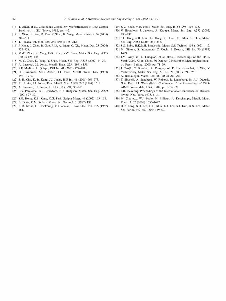
n Fig. 11. From Fig. 11, the microstructure is finer and moreomplicated, in which the different shape ferrites, such as none-quiaxial and lathy ferrite with dense density dislocations, cane observed. Meanwhile, some martensite/austenite islands areistributed in the microstructure, and a few fine carbonitridearticles are distributed in ferrite matrix. This microstructureith fine ferrite grain, martensite/austenite islands, high-densityislocations and fine carbonitride particles is the reason formproving the strength and toughness of this steel.
.3. Discussion
The acicular ferrite microstructure consists of non-equiaxialhape and lathy ferrites with dense dislocations and widely dis-ersed fine second phases islands in the matrix, because thecicular ferrite transformations consist of two independent phaseransformation mode [14,33]. The reason for acicular ferriteipeline steels with higher properties by the advanced thermo-echanical control process is that all the strengthening methods,
uch as grain refining strengthening, second phase strength-ning (both precipitation and M/A island hardening), solutiontrengthening and dislocation strengthening are utilized in thisork [15,34–36].The advanced thermo-mechanical control process is an effec-
ive method to obtain high property by controlling the final acic-lar ferrite microstructure for micro-alloyed pipeline steels. Theot deformation affects the microstructure refinement by effec-ive nucleation and growth of acicular ferrite, so that, the final
icrostructure and mechanical properties are depended stronglyn controlled rolling parameters and cooling conditions of the
late [37]. Therefore, the controlled rolling parameters (such aseheating temperature, reduction, deforming temperature, inter-ass time) and cooling conditions (such as cooling rate and finishooling temperature) play a particularly important role, because
F.-R. Xiao et al. / Materials Science and Engineering A 431 (2006) 41–52 49
. 21;
tathoaGngte
tir
wsi
Fig. 10. Microstructures of rolled plate samples: (a) no
he nucleation sites of acicular ferrite can be increased and thecicular ferrite transformation can be promoted effectively byhe fine austenite grain and substructure and dislocation withigh density formed in austenite [14]. The grain refinement isbtained by control of the rolling conditions—time, temper-ture and deformations during the whole production process.rain refinement in the steel is enhanced through a combi-
ation of controlled rolling and microalloying. The primaryrain refinement mechanism in controlled rolling is the recrys-allization of austenite during hot deformation. Small alloyinglements like Nb and V can result in the formation of carboni-fcaF
(b) no. 22; (c) no. 23; (d) no. 24; (e) no. 25; (f) no. 26.
rides in the microstructure. These fine precipitates are effectiven preventing grain growth. By the use of controlled rolling,ecrystallization is retarded during the last pass [38].
From the results of mechanical properties of rolled plates,ith the increasing of the rough rolling temperature, both
trengths (yield and tensile strengths) and impact toughnesss decreased (shown in Table 3). The reason is explained as
ollow. During rough rolling process, the main effect of pro-essing parameters is on austenite grain size by recrystallizationnd carbonitrite precipitation. As mentioned above (shown inigs. 4–6), when the rough rolling temperature is decreased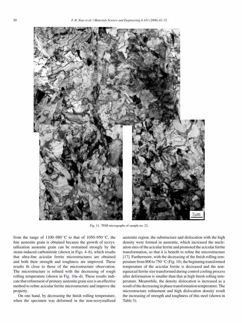
50 F.-R. Xiao et al. / Materials Science and Engineering A 431 (2006) 41–52
graph
ffitstarTrcmp
w
adat[pteap
Fig. 11. TEM micro
rom the range of 1100–980 ◦C to that of 1050–950 ◦C, thene austenite grain is obtained because the growth of recrys-
allization austenite grain can be restrained strongly by thetrain-induced carbonitride (shown in Figs. 4–6), which resultshat ultra-fine acicular ferrite microstructures are obtainednd both their strength and toughness are improved. Theseesults fit close to those of the microstructure observation.he microstructure is refined with the decreasing of rough
olling temperature (shown in Fig. 10a–d). These results indi-ate that refinement of primary austenite grain size is an effective
ethod to refine acicular ferrite microstructure and improve theroperty.On one hand, by decreasing the finish rolling temperature,
hen the specimen was deformed in the non-recrystallized
rmtT
s of sample no. 23.
ustenite region, the substructure and dislocation with the highensity were formed in austenite, which increased the nucle-tion sites of the acicular ferrite and promoted the acicular ferriteransformation, so that it is benefit to refine the microstructure17]. Furthermore, with the decreasing of the finish rolling tem-erature from 800 to 750 ◦C (Fig. 10), the beginning transformedemperature of the acicular ferrite is decreased and the non-quiaxial ferrite size transformed during control cooling processfter deformation is smaller than that at high finish rolling tem-erature. Meanwhile, the density dislocation is increased as a
esult of the decreasing in phase transformation temperature. Theicrostructure refinement and high dislocation density resulthe increasing of strength and toughness of this steel (shown inable 3).

F.-R. Xiao et al. / Materials Science and
F
iitcftFhiip6actsttit
mlptgaccroT
6
(
(
(
(
A
2((P
R
[
[Productions, West-/East Natural Gas Transportation Project Management
ig. 12. The different sizes of the precipitated carbonitride of sample no. 26.
From Fig. 10c–f, it can be seen that the coarse microstructures obtained with the increasing of the finish cooling and coil-ng temperature. However, its strength is increased, while theoughness is deceased (listed in Table 3 nos. 22–26), which indi-ates that the properties of this steel will be influenced by otheractors besides refinement and dislocation. Two typical carboni-rides with different size distributed in ferrite matrix is shown inig. 12. One is larger than 40 nm, which maybe formed duringot rolling process and another is smaller than 10 nm, whichs distributed in dislocation and maybe forming during coilingsothermal process. For this steel with Nb and V elements, theeak temperature for carbonitrides of Nb and V precipitation is00 ◦C [39,40], so the finish cooling and coiling temperaturesre increased from 500 to 600 ◦C, the amount of precipitatedarbonitride is increased. Furthermore, the precipitated carboni-rides are finer because of the high-density dislocation and sub-tructure by hot deformation. The finer carbonitride results inhe increasing of the strength and the decreasing of the impactoughness [39]. Therefore, an appropriate coiling temperatures important for precipitation strengthening, which can increasehe yield strength and decrease toughness appreciably.
As mentioned results above, in order to obtain the opti-um mechanical properties with the high strength and excel-
ent toughness for the acicular ferrite pipeline steel, the TMCParameters during the whole production process must be con-rolled. All factors of strengthening and toughening, such as therain refining, second phase strengthening (both precipitationnd M/A island hardening), solution strengthening and dislo-ation strengthening, must be taken into account and utilizedomprehensively by controlling the TMCP parameters accu-ately. In this work, the high strength and excellent toughnessf the clean acicular ferrite steel are obtained by controlling theMCP parameters of the whole production process.
. Conclusions
1) The activation energy of dynamic recrystallization inMn–Mo–Nb pipeline steel has been determined. The
dynamic and static recrystallization can be restrained greatlyand the non-recrystallization temperature can be increasedby added Mo and Nb elements into the steel. The effect ofthe reheating temperature on the behavior of static recrys-[
Engineering A 431 (2006) 41–52 51
tallization and the strain-induced carbonitride precipitationis obvious.
2) The acicular ferrite transformation can be promoted by hotdeformation, which makes the CCT curve move toward thetop left corner. In addition, the island structures in acicularferrites become finer, and the grains of the final microstruc-tures are distributed un-homogeneously.
3) The excellent properties of the clean pipeline steel witha simple chemical composition of commercial grade X60pipeline steel have been achieved grade X80 by control-ling all thermo-mechanical control process parameters ofthe whole production process, which include 580 MPa yieldstrength, 130 J impact toughness (−40 ◦C, half size ofCharpy impact sample).
4) In order to obtain the good combination of the high strengthand toughness for acicular ferrite pipeline steel, it is neces-sary to control thermo-mechanical control process param-eters of the whole production process accurately, whichincludes the reheating of slabs, controlled rolling, controlledcooling, coiling temperature by comprehensive utilizationall strengthening and toughening factors, such as the grainrefining strengthening, precipitation hardening, M/A islandssecond phase strengthening, solution strengthening and dis-location strengthening.
cknowledgments
This work is financially supported by “863” project (No.005AA412020), the National Natural Sciences FoundationNo. 50471106), Natural Science Foundation of Hebei ProvinceNo. 501205), and Natural Science Foundation of Liaoningrovince (no. 20022013).
eferences
[1] H. Beladi, G.L. Kelly, A. Shokouhi, P.D. Hodgson, Mater. Sci. Eng. A371 (2004) 343–352.
[2] M. Jahazi, B. Egbal, J. Mater. Process. Technol. 103 (2000) 276–279.[3] S.Y. Ok, J.K. Park, Scripta Mater. 52 (2005) 1111–1116.[4] N.S.V.S. Murty, S. Torizuka, K. Nagai, T. Kitai, Y. Kogo, Scripta Mater.
53 (2005) 763–768.[5] Y.M. Kim, S.K. Kim, Y.J. Lim, N.J. Kim, ISIJ Int. 42 (2002) 1571–1577.[6] Y.E. Smith, A.P. Coldren, R.L. Cryderman, Toward Improved Ductility
and Toughness, Climax Molybdenum Company (Japan) Ltd., Tokyo,1972, pp. 119–142.
[7] Y. Smith, A. Coldren, R. Cryderman, Met. Sci. Heat Treat. 18 (1976)59–65 (English translation of Metallovedenie i Termicheskaya ObrabotkaMetallov).
[8] M.-C. Zhao, Y.-Y. Shan, F.-R. Xiao, K. Yang, Y.-H. Li, Mater. Lett. 57(2002) 141–145.
[9] Y. Wang, K. Yang, Y. Shan, M. Zhao, B. Qian, Proceedings of theInternational Pipe Dreamer’s Conference, Yokohama, Japan, November7–8, 2002, pp. 53–84.
10] T. Janzen, W.N. Horner, Proceedings of the International Pipeline Con-ference, ASME, New York, 1998, p. 83.
11] Workshops on the Summarization of X70 Grade Pipeline Steel Trial
Organization of Petrochina Co. Ltd., Langfang, China, December 18–21,2000, p. 3.
12] J.M. Gregg, H.K.D.H. Bhadeshia, Metall. Mater. Trans. 25A (1994)1603–1612.
5 e and
[
[
[[
[
[[[[
[[[[
[[[
[[
[
[[
[
[
[[
[
2 F.-R. Xiao et al. / Materials Scienc
13] T. Araki, et al., Continuous-Cooled Zw Microstructures of Low-CarbonSteel, vol. 1, ISIJ, Tokyo, 1992, pp. 4–5.
14] F. Xiao, B. Liao, D. Ren, Y. Shan, K. Ynag, Mater. Charact. 54 (2005)305–314.
15] T. Tanaka, Int. Met. Rev. 264 (1981) 185–212.16] J. Kong, L. Zhen, B. Guo, P. Li, A. Wang, C. Xie, Mater. Des. 25 (2004)
723–728.17] M.-C. Zhao, K. Yang, F.-R. Xiao, Y.-Y. Shan, Mater. Sci. Eng. A355
(2003) 126–136.18] M.-C. Zhao, K. Yang, Y. Shan, Mater. Sci. Eng. A335 (2002) 14–20.19] A. Laasroui, J.J. Jonas, Metall. Trans. 22A (1991) 151.20] S.F. Medina, A. Quispe, ISIJ Int. 41 (2001) 774–781.21] H.L. Andrade, M.G. Akben, J.J. Jonas, Metall. Trans. 14A (1983)
1967–1977.22] S.-H. Cho, K.-B. Kang, J.J. Jonas, ISIJ Int. 41 (2001) 766–773.23] J.L. Uvira, J.J. Jonas, Tans. Metall. Soc. AIME 242 (1968) 1619.24] A. Laasroui, J.J. Jonas, ISIJ Int. 32 (1991) 95–105.25] E.V. Pereloma, B.R. Crawford, P.D. Hodgson, Mater. Sci. Eng. A299
(2001) 27–37.26] S.G. Hong, K.B. Kang, C.G. Park, Scripta Mater. 46 (2002) 163–168.27] B. Dutta, C.M. Sellars, Mater. Sci. Technol. 3 (1987) 197.28] K.M. Irvine, F.B. Pickering, T. Gladman, J. Iron Steel Inst. 205 (1967)
161.
[
[
Engineering A 431 (2006) 41–52
29] J.-C. Zhao, M.R. Notis, Mater. Sci. Eng. R15 (1995) 108–135.30] V. Homolova, J. Janovec, A. Kroupa, Mater. Sci. Eng. A335 (2002)
290–297.31] S.C. Hong, S.H. Lim, H.S. Hong, K.J. Lee, D.H. Shin, K.S. Lee, Mater.
Sci. Eng. A355 (2003) 241–248.32] S.S. Babu, H.K.D.H. Bhadeshia, Mater. Sci. Technol. 156 (1992) 1–12.33] M. Niikura, S. Yamamoto, C. Ouchi, I. Kozasu, ISIJ Int. 70 (1984)
1429.34] J.M. Gray, in: L. Guoquan, et al. (Eds.), Proceedings of the HSLS
Steels’2000, Xi’an, China, 30 October–2 November, Metallurgical Indus-try Press, Beijing, 2000, pp. 71–79.
35] J. Zrnyk, T. Kvackaj, A. Pongpaybul, P. Sricharoenchai, J. Vilk, V.Vrchovinsky, Mater. Sci. Eng. A 319–321 (2001) 321–325.
36] A. Bakkaloglu, Mater. Lett. 56 (2002) 200–209.37] T. Siwecki, A. Sandberg, W. Roberts, R. Lagneborg, in: A.J. DeArdo,
G.A. Ratz, P.J. Wray (Eds.), Conference of the Proceedings of TMS-AIME, Warrendale, USA, 1982, pp. 163–169.
38] F.B. Pickering, Proceedings of the International Conference on Microal-
loying, New York, 1975, p. 3.39] M. Charleux, W.J. Poole, M. Militzer, A. Deschamps, Metall. Mater.Trans. A 32 (2001) 1635–1647.
40] H.C. Kang, S.H. Lee, D.H. Shin, K.J. Lee, S.J. Kim, K.S. Lee, Mater.Sci. Forum 449–452 (2004) 49–52.