COMPARATIVE STUDY OF MICROWAVE AND CONVENTIONAL SINTERING OF GLASS METAL COMPOSITES
83
COMPARATIVE STUDY OF MICROWAVE AND CONVENTIONAL SINTERING OF GLASS METAL COMPOSITES _______________ A Thesis Presented to the Faculty of San Diego State University _______________ In Partial Fulfillment of the Requirements for the Degree Master of Science in Mechanical Engineering _______________ by Gajendra Pendse Spring 2011
-
Upload
independent -
Category
Documents
-
view
1 -
download
0
Transcript of COMPARATIVE STUDY OF MICROWAVE AND CONVENTIONAL SINTERING OF GLASS METAL COMPOSITES

COMPARATIVE STUDY OF MICROWAVE AND CONVENTIONAL
SINTERING OF GLASS METAL COMPOSITES
_______________
A Thesis
Presented to the
Faculty of
San Diego State University
_______________
In Partial Fulfillment
of the Requirements for the Degree
Master of Science
in
Mechanical Engineering
_______________
by
Gajendra Pendse
Spring 2011

iii
Copyright © 2011
by
Gajendra Pendse
All Rights Reserved

iv
DEDICATION
This thesis is dedicated to my father, who taught me that the best kind of knowledge
is that which is learned for its own sake. This work is dedicated to my mother, who taught me
that even the largest task can be accomplished if it is done one step at a time. It is also
dedicated to my sister who taught me that belief comes first.

v
ABSTRACT OF THE THESIS
Comparative Study of Microwave and Conventional Sintering of Glass Metal Composites
by Gajendra Pendse
Master of Science in Mechanical Engineering San Diego State University, 2011
Sintering is a useful technology in the present world. The applications of the sintered products range from automotive and aerospace parts to the basic household parts. An attempt has been made to study the science of sintering through its practical application. This thesis aims to clarify some of the important issues related to two sintering processes namely conventional and microwave sintering processes. There have been few studies which have included comparative analysis of conventional and microwave sintering process.
The present study includes the study of microwave and conventional sintering of a composite made from glass and copper powders. The differences in the two processes are an object of study. Most of the sintering process parameters are discussed as wells as the properties of the sintered products.

vi
TABLE OF CONTENTS
PAGE
ABSTRACT ...............................................................................................................................v
LIST OF TABLES ................................................................................................................. viii
LIST OF FIGURES ................................................................................................................. ix
ACKNOWLEDGEMENTS ..................................................................................................... xi
CHAPTER
1 INTRODUCTION .........................................................................................................1
1.1 Sintering .............................................................................................................1
1.2 Fundamentals of Sintering .................................................................................2
1.3 Conventional Sintering Process .........................................................................6
1.4 Microwave Sintering Process ............................................................................7
1.5 Composites .........................................................................................................8
1.6 Sintering of Composites .....................................................................................9
1.7 Sintering of Glass ...............................................................................................9
1.8 Conventional Sintering of Glass-Metal Composites........................................11
1.9 Microwave Sintering of Glass .........................................................................13
1.10 Limitations of Existing Research Activities ..................................................15
1.11 Research Objectives .......................................................................................17
2 EXPERIMENTAL PROCEDURE ..............................................................................21
2.1 Materials Used .................................................................................................21
2.2 Equipment Used ...............................................................................................23
2.3 Conventional Sintering Procedure ...................................................................29

vii
2.4 Microwave Sintering Experimental Procedure ................................................34
2.5 Density Measurement Technique ....................................................................40
2.6 Characterization Process ..................................................................................40
3 RESULTS ....................................................................................................................41
4 COMPARATIVE ANALYSIS ....................................................................................51
4.1 Density Comparison.........................................................................................56
4.2 Microstructure Comparison .............................................................................58
4.3 Process Duration Comparison ..........................................................................61
5 CONCLUSIONS..........................................................................................................63
6 SCIENTIFIC AND ENGINEERING NOVELTY OF THE CONDUCTED RESEARCH .................................................................................................................66
7 FUTURE SCOPE.........................................................................................................67
REFERENCES ........................................................................................................................68

viii
LIST OF TABLES
PAGE
Table 2.1. Physical Properties of BSG Powder .......................................................................22
Table 2.2. Electrical Properties of BSG Powder ......................................................................22
Table 2.3 Chemical Durability of BSG Powder ......................................................................22
Table 2.4. Particle Size Data ....................................................................................................23
Table 2.5. Temperature Results Using Thermocouple ............................................................40
Table 3.1. Results of Conventional Sintering Process (Sample 1) ..........................................42
Table 3.2. Results of Conventional Sintering Process (Sample 2) ..........................................43
Table 3.3. Results of Conventional Sintering Process (Sample 3) ..........................................44
Table 3.4. Results of Microwave Sintering Process (Sample 1)..............................................45
Table 3.5. Results of Microwave Sintering Process (Sample 2)..............................................46
Table 3.6 Results of Microwave Sintering Process (Sample 3)...............................................47
Table 4.1. Density Comparison ...............................................................................................52
Table 4.2 Microstructure Comparison .....................................................................................53
Table 4.3. Process Duration Comparison ................................................................................56

ix
LIST OF FIGURES
PAGE
Figure 1.1. Sintering process. ....................................................................................................4
Figure 1.2. Flowchart showing research objectives and research tasks. ..................................20
Figure 2.1. Vacuum baking oven. ............................................................................................24
Figure 2.2. Magneto stirrer equipment. ...................................................................................25
Figure 2.3. Carver Hydraulic Press. .........................................................................................26
Figure 2.4. Microwave sintering oven. ....................................................................................26
Figure 2.5. NEY series 2 furnace. ............................................................................................27
Figure 2.6. Theta dilatometer. ..................................................................................................28
Figure 2.7. Infrared pyrometer. ................................................................................................29
Figure 2.8. Scanning electron microscope. ..............................................................................30
Figure 2.9. Microwave sintering setup with aluminosilicate refractory lining. .......................37
Figure 2.10. Microwave oven and pyrometer alignment. ........................................................38
Figure 2.11. Microwave oven and thermocouple setup. ..........................................................39
Figure 3.1. Temperature profile for sample 1 (5 vol % of Copper). ........................................48
Figure 3.2. Temperature profile for sample 2 (10 vol % of Copper). ......................................48
Figure 3.3. Temperature profile for sample 3 (20 vol % of Copper). ......................................49
Figure 3.4 Dilatometer shrinkage curve for sample 1 (5 vol % of Copper). ...........................49
Figure 3.5. Shrinkage curve for sample 2 (10 vol % of Copper.) ............................................50
Figure 3.6. Shrinkage curve for sample 3(20 vol % of Copper). .............................................50
Figure 4.1. Microwave and conventional sintered chart comparison. .....................................58
Figure 4.2. Relative density vs. composite concentration of Cu by volume (%). ...................59

x
Figure 4.3. Temperature vs. time for microwave and conventional sintering processes. ........62

xi
ACKNOWLEDGEMENTS
I wish to thank my advisor Dr. Eugene Olevsky for the support and direction that he
has given me. I would also like to acknowledge his guidance and support throughout the
duration of this research. I want to thank my fellow lab members for all their help and
support. I would also like to thank Dr. Sam Kassegne and Dr. Ege Engin for serving on this
graduate committee.

1
CHAPTER 1
INTRODUCTION
The current research in the field of sintering is an important part of the research
activities aimed at the development of new materials. The main objective of this thesis can be
understood more clearly if the process of Sintering is known in its most basic and general
form. So let us start from the question what is sintering? Sintering is the technique of
applying thermal energy to metal and ceramic powders to produce high density products.
It involves the formation of the coherent bond between the particles of the material
powder as heat is supplied to the material powders. An important thing to note is that in solid
state sintering this bond is formed without the melting of the material involved in the process.
The ISO defines Sintering as “The thermal treatment of a powder or compact at a
temperature below the melting point of the main constituent, for the purpose of increasing its
strength by bonding together of the particles.” [1].
Sintering is a process in powder metallurgy which renders consolidated products.
There is still some debate over the fundamental governing factors of sintering process. This
process however does not always result in a fully dense finished product. Some secondary
treatment processes can be further applied to the end product.
1.1 SINTERING
The science of sintering process is accompanied by two major phenomena’s at any
given time and they are strengthening and densification. A powder compact after undergoing
sintering process has a better densified microstructure as well as good strength. Another

2
question which might arise with respect to the importance of the uses of the sintered product
compared to other process products are the mechanical properties. The sintered product
increases mechanical and chemical qualities as well as durability due to which it can be used
for many purposes.
There are many ways to carry out the sintering process, different type of furnaces
give different type of heating. The amount of thermal energy supplied is usually below the
melting point of the powder which is to be processed. The thermal energy supplied can be
monitored and varied to give control over the sintered product. This independence to vary the
input conditions such as temperature as well as pressure benefits the overall sintering process
in turn increasing the quality of the product.
Sintering helps in reducing the porosity of the material powder used. Porosity is
defined as the ratio of the volume of all void spaces to the total volume of the compact. It is
highly desired that porosity remain as close to zero as possible. This helps to strengthen the
compact as the pores can reduce the strength of the compact. Another criteria to be
considered is the particle size. The total elimination of porosity with high inter particle bond
strength is the prime purpose and result of any sintering process.
1.2 FUNDAMENTALS OF SINTERING
The fundamentals that govern what really happens to the green compact undergoing
the sintering process has been a topic of research for many years. Green compact is the state
of the powder before it undergoes sintering process. Thus the particle behavior at and before
the sintering temperature is a cause of curiosity for the scientists. There have been many
theories developed over the years after the very first one developed by Ya. I. Frenkel [2].

3
Ya. I. Frenkel established the first physical theory of sintering. His study concludes
that due to surface tension the powder particles adhere to each other resulting in decrease of
pores as well as consolidation of the powder particles. Other researchers such as B. Ya. Pines
[3]and G. C. Kucyunski [4] used the basic concept of Frenkel to explain diffusion driven
sintering. The atomic movements give rise to different mechanisms such as surface diffusion,
grain boundary diffusion, evaporation and condensation, plastic deformation.
Over the years the science of sintering has developed rapidly. The Sintering process
can be mainly characterized by the phase involved in the process. It can be liquid phase
sintering, solid state sintering, viscous flow sintering or transient liquid phase sintering. Also
when parameter such as pressure is varied during the sintering process the process is termed
pressure assisted sintering. Both the pressure assisted as well as pressure less sintering
processes have been used for the production of a large number of products.
Other process parameters include time, temperature and furnace atmosphere as shown
by Suk Joong L Kang [5]. Each have their own effect on the sintering process. Also the
overall output of the sintering process can be controlled by varying the material variables
such as particle size, particle shape, particle structure and particle composition and most
importantly green density. All these variables affect the sinter quality as well as the rate of
sintering.
Another important aspect affecting the strength of the processed powder product is
the size of the grains as shown in the study of M N Rahaman [6]. The grain size should not
be above a desired level to give better strength to the product. Further the physics of sintering
process has to be studied carefully to understand the science of sintering. The basic concepts
behind the sintering science are explained as we go further.

4
The physics of sintering gives us a good understanding about what really drives the sintering
process. There are some driving forces which govern the sintering process for nearly any
system. They include particle surface curvature and applied pressure in case of pressure –
assisted sintering. The reduction in surface area causes a reduction in surface energy. This
results in the lowering of the free energy system thus causing the particles to adhere to each
other.
Neck growth is another important phenomenon in sintering. It is caused due to the
transfer of mass between two particles. The neck size at various stages affects the physics of
sintering process to a large extent. It can either expedite or slower the process. The grain
boundary and powder defects also affect the sintering process as well as sintered product.
Figure 1.1 shows the process of sintering in three stages. Particles are joined together by the
forces. In the second stage the neck growth is evident Substech [7]. We can see how the
porosity is eliminated in successive stages of sintering as shown in the Figure 1.1.
Figure 1.1. Sintering process.
Grain growth in the sintered product is highly undesirable. Grain growth negatively
changes the properties of the sintered material. Thus the essence of sintering is the increase

5
of density but decrease of grain growth. Grain growth occurs due to the atomic motion across
grain boundaries. The nature of grain growth depends upon the nature of the curved surface,
whether it is a convex or a concave surface. Grain boundaries move towards the center of
curvature in convex surfaces. There are two ways to control the grain growth in a sintering
process. The grain growth can be reduced by addition of a dopant. Also it can be reduced by
reducing temperature.
Sintering is an irreversible process. The mechanisms of mass transport in sintering are
surface diffusion, lattice diffusion from the surface; lattice diffusion from grain boundary,
vapor transport, grain boundary diffusion and plastic flow. Some mechanisms such as
volume diffusion, grain boundary diffusion, plastic flow and viscous flow induce shrinkage
on the compact while others such as surface diffusion, evaporation condensation do not
induce shrinkage in the compact. During the sintering process different mechanisms are
involved at different point of time. The size of the particles involved also affects the
mechanism of sintering process.
Modeling of the existing sintering processes is extremely important. There have been
well established models for all the sintering processes. The models developed till now have
been 2 stage or 3 stage explaining the initial stage, intermediate stage and final stage of
sintering. Only some models include more than 3 stages. Some basic criteria for the modeling
of the sintering processes include the particle to particle interaction, grain growth,
microstructural development, pore sizes.
Sintering in the modern day can be carried out in many ways. Some of the ways to
achieve this process is by using a commercially available furnace, a microwave, spark
plasma sintering machine, selective laser sintering machine. Microwave sintering process is a

6
very useful process; the microwaves used can range in frequency and power. Another way is
by conventional sintering method in which any commercially available furnace can be used.
Again the furnaces can vary in the temperature range. One of the most advanced sintering
machines is the spark plasma sintering machine. It makes use of a pulsed DC current which
is directly passed through a graphite die and the powder compact to be sintered
simultaneously. This is a very fast and a powerful approach. Another way of carrying out the
sintering process is with the help of a selective laser sintering machine. In this process a very
powerful laser is used to sinter the powder compact. Similar to selective laser sintering is the
direct metal laser sintering. Also rapid prototyping makes use of laser sintering.
1.3 CONVENTIONAL SINTERING PROCESS
As mentioned earlier, the sintering of a powder compact is only possible by applying
some thermal energy. When the source of this thermal energy is any type of commercially
available furnace, the process is termed as conventional sintering. Usually in conventional
sintering the temperature can be controlled as well as the shrinkage can be monitored. All
these controls help in achieving the maximum density, obtaining the required grain size of
the material powder is frequently a challenge.
In case of conventional sintering the heating of the powders causes the thermal
energy transfer via conduction. This process has been used to sinter almost all ceramic and
metal powders. In conventional sintering the heating of the material is only external and not
internal. The atmosphere used for the sintering process can also be controlled in the
experiments inside the conventional furnaces. Besides Air the different types of atmospheres
used can be Argon, Nitrogen, and Hydrogen etc.

7
The conventional sintering process can be controlled by modifying various factors.
The controlling factors of the conventional sintering process are the material composition,
particle size distribution, temperature and time.
1.4 MICROWAVE SINTERING PROCESS
When the microwave energy is the source of the thermal energy needed to processing
of a powder, the technique is termed as microwave sintering. Microwave sintering is now
widely applied. The fundamental properties that drive the microwave sintering process are
still under research. However the basic common understanding is that the electromagnetic
energy of the microwaves is converted into thermal energy resulting in the internal heating of
the powder. It can be said that the heating of the powders is volumetric.
Usually a 2.45 Ghz microwave furnace is sufficient to sinter most of the material
powders available. The frequency of these microwave electromagnetic waves range from
400MHz to 60 GHz. Microwave susceptors are used as they rapidly couple with microwaves
and heat fast, thereby heating the powder to be sintered. These susceptors are often made
using silicon carbide material as it readily couples with microwaves and increases the initial
rate of heating. The atmosphere can also be controlled in the case of microwave sintering
process. The rate of sintering increases to a great extent because of the microwave effect.
Also densification can occur in a short period of time.
A proven capability of the microwave sintering process is the sintering of metal
powders. As we all know the metal powders are used in the aerospace, transport, defense and
other related areas. In the study of K Saitou [8] single mode microwave radiation has been
used for the sintering of iron, cobalt, nickel, copper and stainless steel powders. The purpose
of study was to observe the densification behavior of these materials.

8
The need for the better, faster densified as well as high toughness materials
incentivizes the usage of microwave sintered products. However till now there have not been
many efforts to model the microwave sintering process. As the relationship between the
metals and the electromagnetic waves are complex there have not been established any basic
principles as well as models of this process, hence the analysis of the process becomes
difficult.
As mentioned above, there have been few efforts in this area. David Clark and Diane
C Folz have studied the microwave processing of materials [9]. The study also includes the
microwave processing of glasses. Fundamentals of microwave processing technology have
also been discussed. Also modeling of the microwave sintering has been performed as shown
by a study by Buchelnikov, Luzgin, Anzulevich, Bychkov, Yoshikawa, Sato and Inoue [10].
There have been many findings with supported evidence that sintering in the metals
and ceramics is carried out by solid state diffusion process. Microwave Sintering of all
metals such as nickel, tin, titanium, aluminum, copper, steel, iron have been studied
individually. For instance the study of Kristen H. Brosnan, Gary L. Messing and Dinesh K.
Agrawal [11] describes the microwave sintering of pure alumina at 2. 45 GHz. In the study
sintering kinetics and microstructure evolution have been analyzed.
1.5 COMPOSITES
This study concerns the sintering of composites. Composites are combinations of two
or more materials with different physical and distinct chemical properties. Composites are
usually man-made materials. The logic behind using composites is simple and that is the
combination of the better qualities of different materials. The sintering of composites will
give a very densified, hard and chemically durable final product which can be used in many

9
different areas. Also composites are prepared to diminish poor qualities or the disadvantages
one or more material can have in the specific area of use. The next section describes research
work done in sintering composite powders.
1.6 SINTERING OF COMPOSITES
Sintering of composites has fascinated researchers for years as composites give a
mixture of the advantages of the both the component materials involved and a better final
product is achieved. Again the sintering of different metal combinations have been studied in
this area. The study of Agarwal, Cheng and Roy [12] involves the analysis of the sintering of
cermet’s. Cermet’s are combinations of ceramic and metal materials. There are many such
detailed analysis of the composite sintering according to their specific use in various areas.
1.7 SINTERING OF GLASS
Because of the great practical importance of the use of sintered glass, the research
study of the kinetics of the sintering of glass has been performed over the years. The
sintering of glass has been a subject of study on a few but consistent occasions in this field.
Sintered Glass materials are used for a variety of purposes individually as well as in the
composite form. The physics of sintering of glass has been studied for a long period of time.
G C Kuczynski first established the model for the process of sintering of glass [13]. The
study shows that the sintering of glass alone is possible by viscous flow mechanism. This
observation was made in the study for glass spheres. Kingery and Berg [14] showed that the
initial rate of sintering of glass powders is directly proportional to the surface tension and
inversely proportional to the particle size and the viscosity of glass. Mackenzie and
Shuttleworth [15] arrived at a similar result in their research involving the study of the
sintering of glass.

10
Cutler and Heinrichsen [16] showed that glass particles having high specific surface
densify five times faster than the spherical glass particles. In another study [17] Czarwinski
showed that during the sintering of glass, the grains adhere to one another due to heat
treatment. The study shows that the process is carried out in two stages. In the first stage the
glass powders transform into a low strength porous materials. In the second stage density
becomes same as that of monolithic glass.
From the study of Shelyubskii and T. M Moiseeva [18], it is again very obvious that
the analysis of viscosity of glass is of very high importance. For the use in the electrovacuum
industry the study of sintering of glass shows that the viscosity analysis has been an
important criteria for the manufacturing of products in this industry .There have been few
studies of sintering of glass metal composites with shrinkage being one of the objectives of
the study. The study of Bocaccini and Olevsky [19] gives an account of the anisotropic
shrinkage of glass particles during the sintering process.
From the study of A. E. Shilo, E. K. Bondarev, and S. A. Kukharenko, [20], it has
been shown in their investigative research of low melting glass powders for the abrasive
industry that glass material can be used as a binder for these abrasive tools which are made of
superhard materials. There are few other areas in which the sintered glass products can be
applied but due to its brittle nature the usage remains limited. For this reason it is important
to carry research on composites involving glass.
Sintered glass usually lacks strength. Another limited property of glass is its low
ductility. This limits the use of the sintered glass in many industries and hence glass is used
in combination with many metals and ceramics to increase their use to a large extent. Glass
metal composites have their applications in many areas such as. The sintering of glass has

11
been improved as well as hindered the densification process by adding metal to glass. The
cause of failure is that densification is hard to achieve even in some metal-glass mixtures.
The chapter ahead gives good understanding of the research conducted till now in case of
microwave and conventional processes involving glass metal composites.
1.8 CONVENTIONAL SINTERING OF GLASS-METAL
COMPOSITES
Study of sintering behavior of glass along with Zirconia fibres has been performed by
M. J. Pascual, A. Dura´ n and L. Pascual [21]. The zirconia fibres have been added to
increase the mechanical properties of the glass composites. The corrosion resistance of the
composite is effectively increased making it a good sealing material. The equipment used for
the experimental process was a conventional electric furnace. Viscosity of sintered material
was another important aspect which was studied. The viscosity was high enough to avoid the
flow of the material. These are the perfect conditions for the sealing material. The use of
these composites in general involve joining and packaging of electronic devices, film
resistors etc.
The study of fracture characteristics of glass metal composites is done by DLouhy,
Boccaccini and Rheinish [22]. Using conventional sintering techniques the study shows the
sample preparation procedure as well as the study of the sintered microstructure and
mechanical properties of the metal –glass composites, the metal used was vanadium. Also
fracture behavior analysis was conducted in this study.
The study of compaction and sintering of glass alumina composites by Ray and
Tiwari [23] shows the investigation of the sintering of lead borosilicate glass after addition of
alumina. Conventional furnace was used for the sintering process to be carried out. The study
describes the rearrangement of particles due to the heating effect. Also the sintering

12
parameters such as relative sintered density and percentage of diametrical shrinkage have
been analyzed. Also the effect of sintering temperature and thermal expansion coefficient
have been studied. The microstructure of the sintered composites has been also the subject of
study.
In another study by Eberstein, Reinsch, Müller, Deubener and Schiller [24] sintering
of glass matrix composites with small rigid inclusions has been the subject of research. These
composites find their applications as co-fired ceramics. The study incudes the particle size
distribution. The sintering process was carried out in a conventional furnace. The effects of
the small rigid inclusions on the shrinkage of the sintered sample have been studied.
Another study by F. Beloivan, G. V. Isakhanov, I. D. Radomyselskii and N. I.
Shcherban [25] shows the analysis of the ductility of glass-metal materials. The study
concludes that glass activates the sintering process for the metal.
Research carried out by I. D Radomyselskii and N I Scherban [26] describes the
sintering process in glass metal composites. The study involves liquid phase sintering as the
glass softens and reacts with the metallic part triggering a sintering reaction. It has been
concluded that Glass activates the shrinkage process during the sintering process.
Relationship between sintering temperature and shrinkage has also been developed. Acid
content in the glass affects the sintering process. More acid content causes more shrinkage.
Vlasyuk, R.Z. along with I.D Radomysel’skii [27] also describes the behavior of glass
in the study of sintering of glass metal materials. The study was conducted with many
different type of glasses. The investigative analysis concluded that shrinkage occurs in two
stages. During the first stage shrinkage is brought about by the surface tension forces at the
metal and glass interface and glass promotes shrinkage. However during the second stage the
13
glass hinders the shrinkage process by internal pressure. This internal pressure can be
decreased by the increase in the porosity. Another conclusion has been made that oxygen
enhances the shrinkage of the glass-metal composites.
Our literature survey indicates numerous studies made in the area of the sintering of
glass- metal composites. The foci of these studies have been viscosity of the glass, the
behavior of glass, the overall shrinkage of the metal glass composites. Porosity has been also
a subject of study as it does affect the sintering process to a large extent. For most of the
studies the experiments have been carried out in a conventional furnace. So a significant
understanding of the kinetics of the sintering of glass metal composites has been achieved.
The next section describes the research carried out in the microwave sintering of glass metal
composites.
1.9 MICROWAVE SINTERING OF GLASS
The microwave sintering of metal powders has been introduced more than a decade
ago. For instance the research carried out by Roy, Agarwal, Cheng and Gedevanishvili [28]
included the microwave sintering of full metal powders. Microstructure analysis of the
sintered composites has been conducted by P. Veronesi, C. Leonelli, G. C. Pellacani and A.
R. Boccaccini [29]. This study was based on a unique microstructure obtained from glass
metal composites by microwave- assisted heat treatments. Gas evolution formation in the
glass metals has been thoroughly studied. Also the causes of the entrapment of the pores have
been analyzed and concluded that the pore shape was mostly spherical. All these factors give
rise to a unique microstructure evolution in the sintered composite.
The research of E. J. Minaya, A. R. Boccaccini, P. Veronesi c, V. Cannillo, C.
Leonelli [30] involved the conventional and microwave sintering of various glass-metal

14
composites. The glass used was borosilicate glass. The metals used in the research were
tungsten, molybdenum, tin, nickel, iron and aluminum. The powders were pre-pressed and
pellets were prepared for the sintering process experiments. The goal was to determine the
microwave heating parameters for the composites when they reach maximum densification.
Some composites such as those containing Iron densified extremely well. Others such as
Nickel and Tin could not be densified by microwave sintering. Also conventional sintering
was performed for similar composites.
In another study by E. J. Minaya, P. Veronesi, V. Cannillob, C. Leonellib, A. R.
Boccaccini, “ [31] microwave sintering of glass metal composites has been studied. Pore
analysis has been the main aim of this study. As the pores have a direct relation with the
density, the control of the pore size has been the subject of research in this study. The glass
used has been soda borosilicate glass. The results of the study show that high shock
resistance composites can be produced which are usable for thermal protection systems. The
fracture toughness is increased by the addition of the metallic fibers to the glass matrix. The
metals used in this case were Molybdenum and tungsten.
Another study by D. V. Louzguine-Luzgin, G. Q. Xie, S. Li, A. Inoue, N. Yoshikawa,
K. Mashiko S. Taniguchi M. Sato [32] on the sintering of metallic glasses, showed that
microwave heating considerably promoted crystallization and at the same time reduced the
crystallization temperature of these composites. The metal used was Iron, also in this case it
was seen that the sintering was carried out due to the softening of the metallic glasses. The
particles attached to each other at a very low temperature.
The research study in the area of metal fibre reinforced glass matrix using microwave
radiation by E. J. Minay, A. R. Boccaccini, P. Veronesi, V. Cannillo and C. Leonelli [33]

15
showed the usage of metal for raising the temperature of the glass. Similarly to earlier
remarks, metals helped in coupling with the microwaves and intensified the initial stage of
sintering. Another goal achieved was that the susceptors were not required in the microwave
heating of the composite material. Another study by L. Chen, C. Leonelli, T. Manfredini, C.
Siligardi, [34] shows the sintering of glass – ceramic composite by microwave heating.
1.10 LIMITATIONS OF EXISTING RESEARCH ACTIVITIES
The previous sections describe the research conducted in the area of conventional and
microwave sintering of glass metal composites. The following is an account of the
shortcomings of the research study in this area. These limitations serve as an incentive for
our research study in this area. There have been almost no comparative studies for both the
conventional and microwave sintering of glass-metal composites.
Some previous studies have analyzed the conventional sintering of glass metal
composites, while others have independently concentrated on microwave sintering of glass
metal composites. Very few have concentrated their research on both conventional and
microwave sintering of composites such as a study by E. Brevala, J. P. Chenga, D. K.
Agrawal, P. Gigla, M. Dennis, R. Roy, A. J. Papworth [35], which shows the comparison
between microwave and conventional sintering of W/Co composites. Different sintering
mechanisms have been compared in the research. The study of the kinetics of sintering can
be completed only by analyzing the process for the same composite material in both the
conventional and the microwave furnaces. The other limitation includes the scarcity of the
studies comparing densities of the final compacts by both processes. There have been very
few studies which have addressed this issue

16
The other important issue for comparison is the microstructure comparison. Again
very few studies have addressed this matter. The microstructure examination of two similar
compacts sintered by conventional and microwave process is essential. It gives a good
understanding into the qualitative analysis of the sintered properties of the glass metal
composites. After density and microstructure the next important parameter is the duration of
each of the processes, conventional and microwave. It is common knowledge that the
microwave sintering process takes less time than the conventional sintering process. It is
therefore obvious that microwave sintering is time saving but is needed to show whether this
present comparative study benefits. Further limitations in terms of the final product
properties include pore comparative analysis of the sintered powder compacts obtained by
conventional and microwave process.
Almost all the research has been concentrated on the sintering of various glass metal
combinations for one chosen concentration of the metal in the glass metal composites. Does
the metal concentration variation in the glass mixture exhibit any different sintered qualities
have not been thoroughly examined. The investigations of glass metal only by microwave
sintering cannot give us a conclusion as to whether the microwave sintering process is a
better option than conventional for the particular powder compact. Microwave heating
provides for rapid means of heating as compared to conventional sintering but the method in
which it heats the powder compact is still not very clear. There has been almost no defining
model of the microwave sintering process.
Two completely different thermal energy sources drive the microwave and
conventional sintering process so there has to be some final product difference. Also the
material heating itself is different due to the application of different heating sources. This

17
difference in heating can cause shape changes for one process and not for the other. This can
only be observed when the composite is sintered by both the microwave and conventional
furnaces and the results are compared. This has not been the topic of research in many
studies involving sintering of glass-metal composites.
The limitations of the previously conducted studies in this area show that there has
been a shortage of research involving comparative analyses of microwave and conventional
process of sintering with respect to the microstructure and density of the powder sample. The
other shortcoming in the previously conducted research is that the constitutive behavior of
the material could not be identified for microwave sintering. Taking into consideration all the
limitations of the conducted studies in this area we identify the purpose of the present
research project as comparative analysis of the Sintering of glass and copper composite in the
microwave and conventional furnaces.
1.11 RESEARCH OBJECTIVES
The main aim of this thesis is the comparative study of the sintering of the glass
copper composite with different copper concentrations processed in both microwave and
conventional furnace. The research objective of this study includes the analysis of the
specimen’s density evolution for the two different processes which can give a fair idea as to
which process is better in terms of sintering outcomes.
It is known that conventional heating takes longer time than microwave heating to
sinter the product completely. The quality of the sintered products however, should be
compared to determine the more efficient sintering process.
Another research objective is the microstructure examination. In depth microstructure
analysis of the sintered compact specimen obtained from both microwave and conventional

18
process has to be done. In a conventional furnace the added metals may somewhat increase
the heating rate of glass powders. In microwave furnace metals will help in generating a lot
of internal volumetric heating of the glass metal composite. The microstructure
characterization should be carried out by a Scanning Electron Microscopy. Also a
comparative analysis should be conducted in terms of the compact shape distortion and the
strength of the compact at the end of the process. To check for any defects in the final
sintered compact is of prime importance too.
The sample preparation for both microwave and conventional sintering process
should be the same in order to keep the green density as similar as possible. The glass used
for the research purpose is borosilicate glass as the sintering properties are well known for
this particular type of glass. Also a lot of research has been concentrated on borosilicate
glasses by Boccaccini and Co workers [23] where the characteristics of borosilicate glass
with reinforced metal particles have been studied. In this study the glass used is
commercially available Borosilicate glass. Usually the glass used for the study of sintering of
glass metal composites has been borosilicate glass due to its low melting point as well as a
low coefficient of expansion. Also it provides greater chemical durability. It is also thermal
shock resistant.
An additional reason behind using borosilicate glass for research purposes is that
there are very low material stresses induced due to small temperature changes. Hence it is
rather resistant to thermal fracture. The metal used in the present study is copper as it has not
been investigated before in glass-metal composite sintering.
The experimental procedure and the related practical considerations are described in
the further chapters. The composite composition used is by volume 5%, 10% and 20 % of

19
copper in the content of glass copper composites. As mentioned before very few studies have
taken a variation of concentration of the same metal in the metal glass composition into
consideration. This is the reason to conduct a thorough study of the effect of the
concentration of metal in the glass based composites. The particle size used for the
borosilicate glass is 22 microns, the particle size has been kept as small as possible as finer
grain size helps in better densification and effectively a better sintering process for both the
conventional as well as the microwave sintering.
All other material considerations have been kept the same for both the processes,
conventional as well as microwave. It is necessary for a comparative study to have same
usage of input, otherwise it becomes difficult to compare the process. The green compact was
prepared by uniaxial pressing for both the microwave as well as the conventional sintering
proceses.
The common applications found for these composites are the systems where high
corrosion resistance is required. They are also used for commercial thermal and electronic
applications. These composites are good materials for the electronic circuit boards. The
chapters further shall give a full and comprehensive data of the research carried out. The flow
chart in Figure 1.2 shows the research objectives and corresponding research tasks.

20
Figure 1.2. Flowchart showing research objectives and research tasks.
Comparative Analysis of
Sintered Density.
Process Duration effects on
the sintered glass‐metal
composites.
Micro‐structural analysis of
the sintered glass‐metal
composites.
Performance of
Microwave and
Conventional Sintering
Procedure.
Density Measurement
Using Archimedes
Technique.
Study the effect of
Variation of
Concentration on
density of the glass‐Cu
specimens.
Measurement of
process duration.
Study the Impact of
high and slow heating
rates on the mass
transport mechanisms
of the sintered glass‐Cu
composite.
Study of the effect of
time on the grain‐pore
relationship.
Characterization of the
sintered specimens
obtained from
conventional and
microwave sintering
processes using an SEM
Microscope.
Comparative Analysis of
the characterized
specimens.
RESEARCH OBJECTIVES RESEARCH TASKS

21
CHAPTER 2
EXPERIMENTAL PROCEDURE
2.1 MATERIALS USED
The materials used for the sintering experiments are the commercially available
borosilicate glass powder and copper powder.
Borosilicate Glass Powder
German glassmaker Otto Schott was the first to develop borosilicate glass. Today
borosilicate glass is known as Pyrex as introduced by Corning Glass Works. The main
constituents of borosilicate glass powder are silica and boron oxide. The important property
of this glass powder is its resistance to thermal shock. It is known to have a very low thermal
expansion coefficient. The usage of borosilicate glass includes kitchen glassware, laboratory
test tubes and beakers. Glassblowing form of lampworking is another important usage of this
glass. Jewelry and telescope mirrors are also manufactured using this glass. In the
semiconductor industry the glass is used for the development of the micro-electrical
mechanical systems.
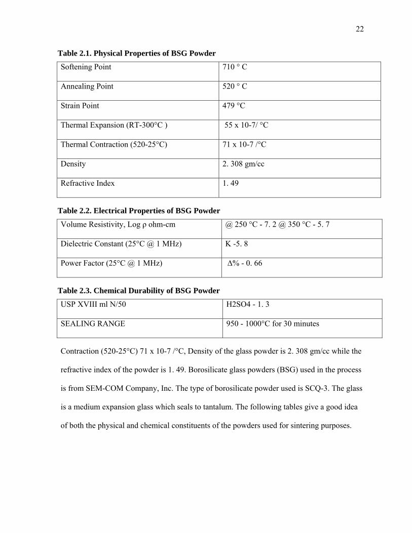
The type of borosilicate powder used is SCQ-3 and Table 2.1 shows the physical
properties The chemical composition of the used borosilicate glass powder was 70% silica,
10% boron oxide, 8% sodium oxide 8% potassium oxide, and 1% calcium oxide. The
electrical properties of the BSG powder used is shown in Table 2.2. The chemical Durability
of BSG powder is shown in Table 2.3. The mean particle size of the glass powder is about 20
microns as shown in the Table 2. 4. The mean particle size of the glass powder is about 20
microns as shown in the Table 2. 4. The thermal expansion is 55 x 10-7/ °C while Thermal
22
Table 2.1. Physical Properties of BSG Powder
Softening Point 710 ° C
Annealing Point 520 ° C
Strain Point 479 °C
Thermal Expansion (RT-300°C ) 55 x 10-7/ °C
Thermal Contraction (520-25°C) 71 x 10-7 /°C
Density 2. 308 gm/cc
Refractive Index 1. 49
Table 2.2. Electrical Properties of BSG Powder
Volume Resistivity, Log ρ ohm-cm @ 250 °C - 7. 2 @ 350 °C - 5. 7
Dielectric Constant (25°C @ 1 MHz) K -5. 8
Power Factor (25°C @ 1 MHz) Δ% - 0. 66
Table 2.3. Chemical Durability of BSG Powder
USP XVIII ml N/50 H2SO4 - 1. 3
SEALING RANGE 950 - 1000°C for 30 minutes
Contraction (520-25°C) 71 x 10-7 /°C, Density of the glass powder is 2. 308 gm/cc while the
refractive index of the powder is 1. 49. Borosilicate glass powders (BSG) used in the process
is from SEM-COM Company, Inc. The type of borosilicate powder used is SCQ-3. The glass
is a medium expansion glass which seals to tantalum. The following tables give a good idea
of both the physical and chemical constituents of the powders used for sintering purposes.

23
Table 2.4. Particle Size Data
% Tile Size (µm)
10. 00 3. 14
20. 00 6. 03
30. 00 9. 91
40. 00 14. 90
50. 00 20. 95
60. 00 27. 15
70. 00 33. 48
80. 00 40. 90
90. 00 52. 60
95. 00 66. 25
Copper Powder
The copper powder has been manufactured by Cerac Speciality Inorganics. It is
typically 99% pure. The particles of the powder are copper metal. The copper powder used to
make the composite compact has an average particle size of – 325 mesh.
2.2 EQUIPMENT USED
The process of sintering involves the use of various equipment including microwave
furnace, conventional furnace as well as the dilatometer. The other equipment’s used in the
process are the baking oven used to de-humidify the powders, the Carver hydraulic pressing
machine to prepare the green compacts. Magnetic stirrer used for preparing the mixture of

24
the powders. Also the scanning electron microscope (SEM) is used for characterization
purposes. All the equipment is briefly described below.
Vacuum Baking Oven
For baking the powders a commercially available vacuum baking oven is used. It is
utilized to reduce the moisture from the powder. The oven manufacturer is Precision
Scientific. The model used is 19. The temperature range is from 35 degree Celsius to 200
degree Celsius. Vacuum range of the model is from 1 atm. to 30 in. Hg (762 mm Hg). The
Figure 2.1 shows the vacuum baking oven used.
Figure 2.1. Vacuum baking oven.
Magnetic-Stirring Equipment
For the powder mixing process, magnetic stirring equipment from Econostir
Laboratory Craftsmen as shown in Figure 2.2 has been used. The magnets used are 30 gram
Alnico V Bar magnet. The power consumption of the equipment is 45 W, 120 volts, 60Hz.

25
Figure 2.2. Magneto stirrer equipment.
Hydraulic Press
For making a green compact of the composite material the Carver Hydraulic Press as
shown in Figure 2.3 has been used. The press model no is 3925. The Carver uniaxial pressing
uses the hydraulic force of a fluid for applying pressure to make a compact. The Press
consists of a 25 ton hydraulic unit and maximum Ram strike of six and a half inches.
Microwave Oven
For microwave sintering purposes a commercially available microwave oven as
shown in Figure 2.4 has been used. The microwave version is Panasonic Genius Sensor. The
oven uses inverter technology. This oven operates at a power of 1300 W. The oven is a
consistent source of microwave energy.
Conventional Furnace
For initial tests on the samples before the use of dilatometry a conventional furnace as
shown in Figure 2.5 has been used. The furnace is NEY SERIES 2 - 1350 single door
industrial oven. The furnace can go up to high temperatures of approximately 1600 degree
Celsius. It includes digital control.

26
Figure 2.3. Carver Hydraulic Press.
Figure 2.4. Microwave sintering oven.

27
Figure 2.5. NEY series 2 furnace.
Dilatometer
For conventional sintering experiments a dilatometer as shown in Figure 2.6 has been
used. The dilatometer has been manufactured by theta industries, Inc. It is a horizontal
dilatometer with temperatures up to 1600 degree Celsius. The dilatometer consists of the
following parts and accessories
1. Measuring Head
2. Specimen Holder
3. Furnace
4. Temperature Control
5. Signal Conditioner
6. Computer
7. Software
Thermocouple
For temperature measurement a K type thermocouple has been used. The
thermocouple is a rugged thermocouple from Omega Co. The model number and version of

28
Figure 2.6. Theta dilatometer.
the thermocouple is omega clad TJ36-CAXL-14U-24. The thermocouple can approximately
go upto a temperature of 1300 degree Celsius.
Infrared Pyrometer
Infrared pyrometer also has been used for temperature measurement. The infrared
pyrometer used is manufactured by Impac in collaboration with Mikron Infrared Inc is
shown in Figure 2.7. The pyrometer version used is MI-P 140. This pyrometer is a non-
contact infrared pyrometer.
Weight Measurement
The weight measurement for the entire project has been done using the weight
balance manufactured by OHAUS Corporation.
Scanning Electron Microscope
29
Figure 2.7. Infrared pyrometer.
For characterization Scanning Electron Microscope (SEM) as shown in Figure 2.8 has
been used. The Scanning Electron Microscope is manufactured by HITACHI co. The model
number is S 2700.
The other equipment used for the sample characterization preparation were the saw to
cut the sample, polisher and the mounting Press.
2.3 CONVENTIONAL SINTERING PROCEDURE
The conventional sintering experiments have been performed using the theta
dilatometer. The whole experimental process first involves trial tests and then the final
experiments. A commercially available NEY furnace has been used for the conventional
sintering trial tests. For performing conventional sintering experiments, the first step is to
bake the glass and copper powders separately in a baking oven. The baking oven is
essentially an oven which can create vacuum inside it with simultaneous heating the

30
Figure 2.8. Scanning electron microscope.
powders. The purpose is to remove any moisture out of the powders so it does not affect the
sintering process. The baking was carried out for around 2 hours at a temperature of about
200 degree Celsius and the powders were kept in the vacuum till their removal for the actual
experimental process before sample preparation. Also the powders cannot be mixed before
the baking process in the vacuum oven as they might reactively interact inside the oven due
to the substantial amount of heat supplied which is around 200 degree Celsius.
Once the glass and copper powders are baked individually inside the vacuum baking
oven, the next step of the experimental procedure to be performed is to prepare the green
sample pellets from the mixture of the two powders. To achieve this first both the powders
have to be mixed. For the mixture of finely distributed copper particles in the glass powder,
the copper and glass powder are first mixed together in volumetric ratio. The mixture
prepared for some trial tests and some final experiments contained 5 vol % copper, 10 vol %
copper as well as 20 vol % copper. The mixing of the powders was done in a glass beaker.

31
To ensure that the two powders will thoroughly mix, they were first mixed in a glass beaker
by hand with the help of a stirrer. Stirring by hand was done for about 5-7 minutes.
After stirring by hand the mixture of the two powders was subjected to the magnetic
stirring mechanism as shown in Figure 2.4. The mixing of powders is an integral part for the
proper sintering of any composite powder compact. Also to maintain a good quality of
sintering the mixing should be taken care of properly. In the magneto stirrer mixing
procedure, the two powders to be mixed together are put in a small plastic bottle which can
be closed with a cap on it. Two small cylindrical magnets are placed inside this plastic case.
The whole assembly is then placed on the top of a mounting which has access to electric
supply. As soon as the switch is turned on, the magnetic stirrers start to vibrate and rotate in a
clockwise direction mixing the powders. This process is carried on for duration of 30 minutes
to ensure thorough mixing of the powders.
The next step of the experimental procedure is the preparation of the pellet which is
going to be sintered. The compacts used in the conventional sintering process are prepared in
the Carver hydraulic uniaxial press machine as shown in Figure 2.3.
The usage of the Carver press is as follows. The mixture of the two powders which is
already prepared in a desired ratio is now poured into a die having a diameter of
approximately 12. 5 mm. After pouring the powder into the die, the punch is slowly pushed
inside the die while the outer sleeve is slid over the assembly of die and the punch. The
whole assembly is put in the press. Pressure of about ten thousand pounds is exerted by the
use of a handle. The action is performed till the desired level of pressure is achieved to
prepare a sufficiently solid compact. The pressure is applied for around five minutes. Then
slowly the pressure is released. Any sudden pressure changes would create irregularities in

32
the compact thereby increasing probability of cracking of the compact. The green density
obtained for the samples was around forty percent. The diameter of the pellets produced was
fixed and was same as the diameter of the die (12. 5 mm). The green density can be
calculated using the dimensions and the weight of the pellets. The pellets are of cylindrical
shape.
After releasing the pressure the compact is removed carefully from the die. Carefully
pressure is applied on the inner punch so that it pushes the compact out on to a soft surface.
In case of glass, due to its brittle nature care has to be taken as in some cases the compacts
produced are difficult to handle.
Conventional Sintering Experiments
In case of conventional sintering, first step was to perform tests in the conventional
furnace to know the melting temperature as well as to assess the sintering temperature. The
samples were then placed in a conventional furnace as shown in the figure below. This
furnace is a high temperature furnace from NEY.
The samples produced were put through trial tests in the NEY Series 2 furnace. The
furnace was programmed to heat the samples at the rate of 25 degrees Celsius per 5 min, so it
took more than 2 hours for the sample to reach high temperatures.
The samples were kept inside the furnace and the rate of heating was set at 25 degree
Celsius per 5 min. The next step was to hold the temperature at a temperature range of 600 to
735 individually for about 5 minutes. The samples were then allowed to cool. Inside the
furnace the sample was kept on an alumina base as shown in the figure. The alumina base
was kept on two refractory bricks for the maintenance of adequate thermal energy inside the
furnace. The alumina base is kept for the protection of the inner parts of the conventional
furnace in case of the melting of the compact. The density of these test samples was

33
measured using the Archimedes technique. The final sintering process of these samples was
carried out in the theta horizontal dilatometer.
The purpose of the pre sintering tests is to find a close range of temperature to the
melting point. It was observed that the glass from the composite starts to soften at a very high
rate at and above 700 degree Celsius. Softening point is not the melting point but close to the
melting point. So the closest temperature which could be achieved in solid state sintering was
650 degree Celsius. Similar samples were now ready to be sintered in the dilatometer.
A dilatometer is a scientific instrument for measuring thermal expansion or
contraction. In this device the samples to be sintered are placed in a horizontal or vertical
direction. Then as heat is supplied, the dilatometer measures the change in the volume of the
sample.
The actual experimental procedure to carry out the sintering process in the
dilatometer is discussed below. The specimen tube holder is the place where the sample is
located during sintering. The dilatometer which is used for the experiments is a horizontal
dilatometer as seen in the Figure 2.6. The specimen holder can slide inside the outer tube.
Now the sample is placed in the specimen holder at the end of the tube inside the cylindrical
casing. The push rod’s movement is corresponds to the linear shrinkage recorded by the
measuring head.
The push rod is arranged in such a way that it barely touches the sample. At one end
of the push rod a measuring head is located. This head has to be zero calibrated before
starting the experiment as it can give wrong shrinkage results if not properly checked. Then
the whole assembly is inserted inside the tube furnace. The joint of the two tubes is tightened
with a C clamp. The whole assembly is connected to a computer interface. The computer can
34
control the input temperature as well as get the output shrinkage from the dilatometer
equipment. The temperature controller takes care of the temperature management of the
entire process.
The whole temperature profile to be set as well as the experimental conditions can be
monitored using the program known as DILASOFT which is controlling this dilatometer. For
the experimental purpose the temperature profile was set to heat at a rate of 20 degree Celsius
for every five minutes upto 650 degree celsius, then holding the temperature at 650 degree
celsius for about 90 minutes and then cooling at a rate of 20 degree celsisus per five minutes.
For selecting the temperature profile, the heat increment, the holding time and temperature
and the cooling time are specified. The whole process was performed for different
concentrations of copper powder in the composite. As stated before firstly 5 vol % copper
was used in the composite mixture, then 10 vol % copper was used while finally 20 vol %
copper was made use of in the composite sintering.
After cooling the sample is carefully removed from the specimen holder. The density
measurements are conducted. The density determination is made with the help of
Archimedes technique which proves very beneficial. Further the sample is cut and
characterized with a scanning electron microscope.
2.4 MICROWAVE SINTERING EXPERIMENTAL
PROCEDURE
The experimental work for the microwave sintering process was performed in a 1300
Watt Panasonic microwave machine. Similar mixing technique has been used for the
microwave sintering experiments as the one previously explained regarding the baking and
mixing technique for the preparation of the powder compact in the conventional sintering
experiments. The glass and copper powders were first separately baked in a baking oven for

35
about 2 hours. The powders were then mixed by hand in a glass beaker. Further the powders
were subjected to the magnetic stirring. Finally after the mixing process was finished, the
powders were transformed into pellets of same size and diameter as prepared for the
conventional sintering experiments with the help of the Carver uniaxial hydraulic Pressing.
The pressure applied has been kept the same as before (ten thousand pounds.)
Before the experiments were performed in the microwave, it was necessary to carry
out tests in the microwave furnace to determine the point at which the sample melts. Test
runs were performed for the glass copper composites to determine approximately the heating
rate of these two materials in the microwave to be used. Also it was important to know at
which maximum temperature to sinter the composite. It was a challenge to measure the
temperature of the composite during sintering process in the microwave as the microwave
door obstructs the pyrometer measurement of temperature. It was important to maintain the
similar conditions which will are present during the actual sintering experiments, during
microwave sintering.
In the microwave sintering it was observed that the glass in the composite starts to
soften after 25 minutes. However the thermal energy produced inside the microwave furnace
depends largely on the placement of the silicon carbide susceptors as well as the use of
aluminosilicate refractory lining. Now comes the most important part of the procedure which
is the actual sintering experiments to be carried out inside the microwave oven. The
microwave oven used is a commercially available 1300 Watt with a frequency of 2. 45 Ghz .
The prepared compact is kept in the microwave at the center of the plate which is located
inside the microwave. The compact is now covered with a cylindrical aluminosilicate
refractory lining which helps to prevent the thermal energy from escaping outside. This

36
cylindrical lining has a hole on its side for the pyrometer to measure the temperature. It also
has a hole on the top of it for the thermocouple to measure the temperature of the compact
during pyrometer calibration.
As mentioned before the sample is placed inside the microwave oven on the plate as
shown in the Figure 2.9. It is surrounded by the aluminosilicate refractory lining. Two silicon
carbide susceptors are closely placed without touching the composite sample. The task of the
susceptors is to increase the initial rate of heating as they couple with the microwave readily.
These susceptors supply heat to the compact quickly to increase the thermal energy needed to
sinter the compact. Thus with an enclosed refractory lining and silicon carbide susceptors a
substantial amount of thermal energy is created inside the microwave for sintering the
compact. The sample is heated for about 20 minutes. The sample is sintered after a period of
twenty minutes as shown by the microstructure analysis. The sample is allowed to cool for
some time.
After cooling the sample is removed and further subjected to density measurement
and characterization process. The refractory lining helps in conserving the energy inside the
microwave. It functions as a heat energy leakage protector. Thus the maximum thermal
energy is concentrated on the compact. This is necessary for the rapid sintering of the
material compact. A number of compacts were processed and characterized to understand the
sintering process as well as the effect of heating time on the compacts. After sintering is
finished the sintered compact is then allowed to cool. First the compacts containing 5 vol %
copper were experimented with. Then the compacts containing 10 vol % copper were used.
Finally compacts containing 20 vol % copper were used.

37
Figure 2.9. Microwave sintering setup with aluminosilicate refractory lining.
Temperature Measurement For Microwave Sintering Processing
There are limitations for using a thermocouple during the actual sintering process as it
affects the sintering process. Hence an Infrared non contact pyrometer has been used to
record the temperature during the actual sintering process. But due to the limitations of the
pyrometer to record temperature through the tinted microwave door, the pyrometer has been
calibrated using a thermocouple. Therefore the temperature measurement for the microwave
sintering process has been carried out in 2 steps. In the first step pyrometer records
temperature of the compact during the actual sintering process. In the next step the pyrometer
is further calibrated with the help of a thermocouple.
Temperature Measurement Using a Pyrometer
The Pyrometer temperature recording process is briefly described as follows. The
pyrometer microwave assembly can be seen in the Figure 2.10 which helps to understand the

38
Figure 2.10. Microwave oven and pyrometer alignment.
actual temperature measurement process. As the microwave oven is turned on, heat starts to
build up inside the oven. Simultaneously the pyrometer starts reading the temperature of the
compact. Also before starting the experimental process, the lens of the pyrometer is focused
on the compact. The refractory lining has a small hole in it for the infrared pyrometer to
record the temperature of the heated surface of the compact. The hole on the refractory
lining is in alignment with the pyrometer lens spot and the compact as shown below in the
Figure 2.10. The pyrometer is connected to the computer to record the temperature. The
temperature profile is recorded by the computer for the samples sintered in the microwave
oven and can be captured from the computer using the pyrometer software.
Pyrometer Calibration using a thermocouple
The pyrometer does not give an accurate reading due to the microwave furnace door.
The pyrometer was further calibrated by using a thermocouple. For the purpose of
temperature measurement and pyrometer calibration an omega thermocouple was used. The

39
microwave oven consists of a small opening at the top of its body for thermocouple to be
inserted through it to measure temperature of the heated composite. But there is also a fixture
for the hole to be covered when the microwave sintering process is in progress.
The thermocouple was inserted from the top of the microwave furnace down to the
specimen through the hole in the aluminosilicate refractory lining. Also a part of the opening
was covered to reduce thermal losses. The whole assembly was first set up as shown in
Figure 2.11 before the sintering experiment was started. By simulating the conditions of the
actual sintering process, the temperature measurement by the thermocouple was recorded.
Figure 2.11. Microwave oven and thermocouple setup.
When the microwave was turned on and the specimen starts heating up, the
thermocouple also starts reading temperature of this heated specimen. At the same time the
pyrometer also records the temperature. The temperature measurement for the compact was
done under similar conditions which were used for actual sintering experiments. The heating
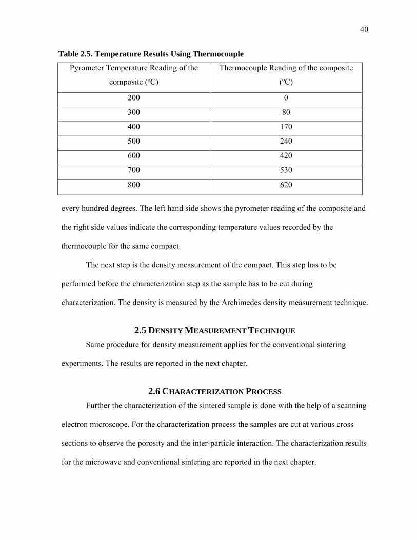
profiles are the ones created by the pyrometer. Table 2.5 has been plotted at an interval of
40
Table 2.5. Temperature Results Using Thermocouple
Pyrometer Temperature Reading of the
composite (ºC)
Thermocouple Reading of the composite
(ºC)
200 0
300 80
400 170
500 240
600 420
700 530
800 620
every hundred degrees. The left hand side shows the pyrometer reading of the composite and
the right side values indicate the corresponding temperature values recorded by the
thermocouple for the same compact.
The next step is the density measurement of the compact. This step has to be
performed before the characterization step as the sample has to be cut during
characterization. The density is measured by the Archimedes density measurement technique.
2.5 DENSITY MEASUREMENT TECHNIQUE
Same procedure for density measurement applies for the conventional sintering
experiments. The results are reported in the next chapter.
2.6 CHARACTERIZATION PROCESS
Further the characterization of the sintered sample is done with the help of a scanning
electron microscope. For the characterization process the samples are cut at various cross
sections to observe the porosity and the inter-particle interaction. The characterization results
for the microwave and conventional sintering are reported in the next chapter.

41
CHAPTER 3
RESULTS
Tables 3.1 to 3.6 show the relative density as calculated by Archimedes Technique
for the sintered samples obtained from both the processes. Also the table includes the
duration of the sintering process for each individual sample. The left hand side shows the
microstructure images of the sintered samples. The magnification used for the SEM images
in all cases was the same. The main aim was to look at the inter particle interaction of the
samples. Also porosity can be assessed from the SEM images
Pyrometer Temperature Profiles for Microwave Sintering Experiments
Figures 3.1 to 3.3 show the pyrometer temperature profile for the three samples
sintered in the microwave oven. The temperature profile for sample 1 (5 vol % of Cu) is
shown in Figure 3.1. The temperature profile for sample 2 (10 vol % of Cu) is shown in
Figure 3.2. The temperature profile for sample 3 (20 vol % of Cu) is shown in Figure 3.3.
The shrinkage curves have been plotted for each specimen sintered in the dilatometer.
Figure 3.4 corresponds to the specimen consisting of 5% of copper by volume. Figure 3.5
corresponds to the specimen consisting of 10% of copper by volume. Figure 3.6 corresponds
to the specimen consisting of 20% of copper by volume. The graphs have been plotted for the
push rod position vs. Time at specific interval.

42
Tab
le 3
.1. R
esu
lts
of C
onve
nti
onal
Sin
teri
ng
Pro
cess
(S
amp
le 1
)
S
EM
imag
e
Tim
e (m
inut
es)
Init
ial G
rain
Siz
e (µ
m)
Rel
ativ
e D
ensi
ty
(%)
Bor
osil
icat
e
Gla
ss
Cop
per
(5 %
) In
itia
l F
inal
1
00 µ
m
150
21
1-44
40
87
Por
esC
u
Incl
usio
ns
Gla
ss

43
Tab
le 3
.2. R
esu
lts
of C
onve
nti
onal
Sin
teri
ng
Pro
cess
(S
amp
le 2
)
SE
M im
age
Tim
e (m
inut
es)
Init
ial G
rain
Siz
e (µ
m)
Rel
ativ
e D
ensi
ty
(%)
Bor
osil
icat
e
Gla
ss
Cop
per
(10
%)
Init
ial
Fin
al
10
0 µ
m
150
20
1-44
39
83
Cu
Incl
usio
ns
Gla
ss
Mat
rix
P
ores

44
Tab
le 3
.3. R
esu
lts
of C
onve
nti
onal
Sin
teri
ng
Pro
cess
(S
amp
le 3
)
SE
M im
age
Tim
e (m
inut
es)
Init
ial G
rain
Siz
e (µ
m)
Rel
ativ
e D
ensi
ty
(%)
Bor
osil
icat
e
Gla
ss
Cop
per
(20
%)
Init
ial
Fin
al
10
0 µ
m
100
2
1
1-4
4
41
83
Cu
Incl
usio
ns
Gla
ss
Mat
rx
Por
es

45
Tab
le 3
.4. R
esu
lts
of M
icro
wav
e S
inte
rin
g P
roce
ss (
Sam
ple
1)
SE
M im
age
Tim
e (m
inut
es)
Init
ial G
rain
Siz
e (µ
m)
Rel
ativ
e D
ensi
ty
(%)
Bor
osil
icat
e G
lass
C
oppe
r(5
%)
Init
ial
Fin
al
100
µm
20
21
1-44
40
85
Cu
Incl
usio
ns
Por
es
Gla
ss
Mat
rix

46
Tab
le 3
.5. R
esu
lts
of M
icro
wav
e S
inte
rin
g P
roce
ss (
Sam
ple
2)
SE
M im
age
T
ime
(min
utes
)In
itia
l Gra
in S
ize
(µm
) R
elat
ive
Den
sity
(%
) B
oros
ilic
ate
Gla
ss
Cop
per
(10%
) In
itia
lF
inal
700
µm
20
21
1-44
40
93
Gla
ss
Mat
rix
Por
es
Cu
Incl
usio
n

47
Tab
le 3
.6 R
esu
lts
of M
icro
wav
e S
inte
rin
g P
roce
ss (
Sam
ple
3)
SE
M im
age
T
ime
(min
utes
) In
itia
l Gra
in S
ize
(µm
) R
elat
ive
Den
sity
(%
) B
oros
ilic
ate
G
lass
C
oppe
r (2
0%)
Init
ial
Fin
al
100
µm
19
2
1
1-4
4
39
82
Cu
Incl
usio
nP
ores
Gla
ss
Mat
rix

48
Figure 3.1. Temperature profile for sample 1 (5 vol % of Copper).
Figure 3.2. Temperature profile for sample 2 (10 vol % of Copper).
0
100
200
300
400
500
600
700
800
900
0 5 10 15 20 25
Tem
per
atu
re (
°C
)
Time (mins)
0
100
200
300
400
500
600
700
800
900
0 5 10 15 20 25
Temperature (°C)
Time (mins)

49
Figure 3.3. Temperature profile for sample 3 (20 vol % of Copper).
Figure 3.4. Dilatometer shrinkage curve for sample 1 (5 vol % of Copper).
0
100
200
300
400
500
600
700
800
900
0 5 10 15 20 25
Tem
per
atu
re (
°C)
Time (mins)
‐0.5
‐0.45
‐0.4
‐0.35
‐0.3
‐0.25
‐0.2
‐0.15
‐0.1
‐0.05
0
0 10 20 30 40 50 60 70 80 90
Pu
sh R
od
Po
siti
on
(m
m)
Time (mins)

50
Figure 3.5. Shrinkage curve for sample 2 (10 vol % of Copper.)
Figure 3.6. Shrinkage curve for sample 3(20 vol % of Copper).
‐0.6
‐0.5
‐0.4
‐0.3
‐0.2
‐0.1
0
0 10 20 30 40 50 60 70 80
Pu
sh R
od
Po
siti
on
(m
m)
Time (mins)
‐0.5
‐0.45
‐0.4
‐0.35
‐0.3
‐0.25
‐0.2
‐0.15
‐0.1
‐0.05
0
0 10 20 30 40 50 60 70 80 90
Po
siti
on
Ro
d P
osi
tio
n (
mm
)
Time (mins)

51
CHAPTER 4
COMPARATIVE ANALYSIS
The purpose of sintering the glass copper composites by conventional and microwave
sintering machines is to compare the results obtained from both the procedures. The
comparison of results consists of 3 steps namely, the comparison of microstructure, the
comparison of the duration of each procedure as well as the comparison of the densities of
the final sintered products. The comparison of the two processes (conventional and
microwave) is done on the same platform. It means that the same methods have been applied
to create the samples used for both processes. The height and the metal phase concentrations
have been maintained the same for a better and a fair comparative analysis.
As stated earlier the conventional and microwave sintering processes have not been
compared for the chosen glass copper. Previously conducted works have tried either one of
the process, and even if they have tried both processes, they have not done used a
comparative approach. The conventional sintering approach has been studied over the years
and the fundamental mechanisms that govern the conventional sintering process have been
formulated. Same is not the case with microwave sintering process. Even though the
microwave sintering process has been studied a number of works, the actual fundamental
mechanisms that govern the microwave sintering process are still a matter of research. The
comparative analysis carried out in this research project should be helpful in bringing more
understanding of the microwave sintering physical basis.
The results of the conventional and microwave sintering process with respect to time
are given in the Tables 4.1, 4.2 and 4.3 respectively.

52
Table 4.1. Density Comparison
Sample
Number
Microwave Sintering
Conventional Sintering
(Relative
Density (% )
Time
(mins)
Temp
( °C )
(Relative
Density (% )
Time
(mins)
Temp
(°C )
Sample 1
(5 % Copper)
85
19
650 87
150
650
Sample 2
(10 %
Copper)
93 20
650
83
150
650
Sample 3
(20
%Copper)
83
20
650
82
100
650

53
Tab
le 4
.2 M
icro
stru
ctu
re C
omp
aris
on
Sam
ple
Num
ber
Mic
row
ave
Sin
teri
ng P
roce
ss
(Mic
rost
ruct
ure
imag
e us
ing
SE
M)
Con
vent
iona
l Sin
teri
ng P
roce
ss
(Mic
rost
ruct
ure
imag
e us
ing
SE
M)
Sam
ple
1
Tim
e ta
ken
to s
inte
r –
19 m
ins
Tem
pera
ture
– 6
50 °
C
Tim
e ta
ken
to s
inte
r –
150
min
s
Tem
pera
ture
– 6
50 °
C
(tab
le c
onti
nu
es)
Cop
per
incl
usio
ns e
mbe
dded
in
gla
ss m
atri
x
Cop
per
incl
usio
ns
surr
ound
ed b
y po
res.

54
Tab
le 4
.2. (
con
tin
ued
) S
ampl
e N
umbe
r M
icro
wav
e S
inte
ring
Pro
cess
(M
icro
stru
ctur
e im
age
usin
g S
EM
) C
onve
ntio
nal S
inte
ring
Pro
cess
(M
icro
stru
ctur
e im
age
usin
g S
EM
)
Sam
ple
2
Tim
e ta
ken
to s
inte
r –
20
Tem
pera
ture
– 6
50 °
C
Tim
e ta
ken
to s
inte
r –
150
Tem
pera
ture
- 6
50 °
C
(tab
le c
onti
nu
es)
Cop
per
incl
usio
ns e
mbe
dded
in g
lass
mat
rix
Cop
per
incl
usio
ns
surr
ound
ed b
y po
res.

55
Tab
le 4
.2. (
con
tin
ued
) S
ampl
e
No
Mic
row
ave
Sin
tere
d S
peci
men
C
onve
ntio
nall
y S
inte
red
Spe
cim
en
Sam
ple
3
Tim
e ta
ken
to s
inte
r –
20
Tem
pera
ture
– 6
50 °
C
Tim
e ta
ken
to s
inte
r –
100
Tem
pera
ture
- 6
50 °
C
Cop
per
incl
usio
ns e
mbe
dded
in g
lass
mat
rix
Cop
per
incl
usio
ns
surr
ound
ed b
y po
res.

56
Table 4.3. Process Duration Comparison
Sample Number Microwave Sintering Process
Conventional Sintering
Process
Time
(mins)
Density Time
(minutes)
Density
Sample 1
(5 % Copper)
19
85
150
87
Sample 2
(10 % Copper)
20
93
150
83
Sample 3
(20 % copper)
20
83
100
82
4.1 DENSITY COMPARISON
The microstructure pictures show that there are no crack formations in any of the
sintered samples. There were no other shape defects found in the sintered samples. For both
processes i. e conventional and microwave sintering processes the samples showed some
oxidation. But this was not the case for all samples But rather only for a few in the test
experiments. This also shows that oxidation was not affected by time. Indeed, both the
samples were sintered in air and conventional sintering process takes more time than the

57
microwave process. Nevertheless, the oxide formation was seen for both the processes in
extremely few cases.
For the comparison of the porosity, it is necessary to find the density of the samples
which have been sintered through both the processes. The density calculation was done by
the Archimedes technique.
Table 4.2 shows the difference in the densities. All the 3 samples varied in density for
both the processes. In the case of the first specimen, the density of the specimen obtained by
the conventional sintering process is more than the microwave sintering-processed sample. In
case of the second specimen, the density of microwave sintered process is much higher than
the conventionally sintered process. In case of third specimen, the density of specimens
sintered by both the processes is almost the same with microwave sintered specimen having
higher density than conventional sintered specimen.
The bar graph in Figure 4.1 shows the relative densities plotted for microwave and
conventional sintered specimens for their respective composite concentrations. The blue bar
indicates the microwave sintered density and the red bar indicates conventional sintered
density. As seen from the graphs the sintered density of the first specimen containing 5 vol %
of copper obtained from conventional sintering process is higher than the specimen obtained
from microwave sintering process. However in case of the second (Cu 10%vol) and third
samples (Cu 20% vol) the microwave sintered density is higher than the conventional
sintered density. The graph in Figure 4.2 has been plotted for the relative density of the
sintered specimen vs. Copper concentration by volume (%) in each sintered sample. As it can
be seen from the graph the conventional sintered density decreases as copper concentration in
the composite increases. In case of microwave sintering process, the relative density of the

58
Figure 4.1. Microwave and conventional sintered chart comparison.
sintered sample is highest for the second specimen consisting of 10 vol % of copper and
lowest for the third specimen consisting of 20 vol % of copper. It can be seen from the
microwave sintering process graph that there is a competition between the localized heating
which causes densification of glass and the rigid inclusions which act as an obstacle for this
densification process. As the amount of rigid inclusions increases in the composite, they
provide resistance to the bonding of glass.
4.2 MICROSTRUCTURE COMPARISON
Table 4.2 shows the difference in microstructures of both microwave and
conventional sintered samples. The sample 1 contains 5 vol % copper. As it is seen there is
76
78
80
82
84
86
88
90
92
94
1 2 3
85
93
83
87
8382
Rel
ativ
e D
ensi
ty (
%)
Glass-Cu Composite Specimens
Microwave Sintered Density
Conventionally Sintered Density

59
F
igu
re 4
.2. R
elat
ive
den
sity
vs.
com
pos
ite
con
cen
trat
ion
of
Cu
by
volu
me
(%).
80
82
84
86
88
90
92
94
05
10
15
20
25
Relative Density (%)
Co
mp
osi
te C
on
cen
trat
ion
o
f C
u b
y V
olu
me
(%)
Mic
row
ave
Sin
tere
d
Con
vent
iona
lly
Sin
tere
d

60
more porosity in the microwave sintered samples than in the conventionally sintered sample.
The conventionally sintered sample is to the right while the microwave sintered sample is to
the left. In this case it is seen that the conventionally sintered sample has less porosity and the
particle size is bigger. That is not the case in the sample which has been sintered by the
microwave process. In this case the particles have combined less with each other resulting in
a large amount of small pores. The pore sizes although small are in a greater quantity. Also it
can be seen that the microwave sintered sample has a superior appearance as against the
conventionally sintered sample.
The next sample contains 10 vol % of copper. The Table 4.2 shows microwave
sintered sample on the left hand side while the conventionally sintered sample is on the right
hand side. Again we find the same pattern in this case too. In the case of conventional
sintering the porosity is very low. So we can see that the conventional sintering process has
again given a better sample. The next sample contains 20 % of copper in it. This time we find
that the microwave sintered sample matches with the conventionally sintered sample. The
porosity in both the cases is low and the particles have combined with one another to a large
extent.
From the microstructure images it can be seen that in case of microwave sintered specimens the copper inclusions are completely embedded inside the glass matrix.
In case of conventionally sintered specimens the copper inclusions are surrounded by pores in all the specimen microstructures.
This can be explained with the formation of hot and cold spots inside the compact. In
case of microwave sintering due to the electromagnetic radiations, the copper particles gets
heated up faster than the glass particles thus creating a hot spot in those regions of the
powder compact. Comparatively the glass particles are cooler in the compact during the
microwave sintering process. This makes energy transfer possible from high temperature

61
regions to low temperature region. Essentially the densification might rise due to these
particular hot spots. This can result in more intense heating and early activation of viscous
flow sintering in the glass matrix.
4.3 PROCESS DURATION COMPARISON
The Table 4.3 shows the time taken in minutes for the composite to sinter by
conventional and microwave sintering process. As seen the time taken to sinter the composite
samples in the microwave was around 20 minutes for each of the three specimens. But in the
case of conventional sintering process the time taken to sinter the composite samples was
around 180 minutes. This shows the differences in duration of sintering. The difference is
160 minutes which is a huge difference. Microwave sinters the composite more rapidly than
conventional sintering. This shows how powerful microwave sintering is. Also throws a light
on the potential of microwave sintering in the product manufacturing industries in the present
world.
It should be noted that, the process duration for conventional sintering was defined by
us. However the conventional sintering technique could not consolidate the specimen and the
density was lower. Hence to solve this issue the holding time was increased. This shows a
limitation in the heating method of conventional sintering. Even though it provides heating to
the specimen in a consistent manner, it cannot match the rapid heating as provided by
microwave oven. Meanwhile the microwave sintering process could consolidate the
specimen to a great extent. Even if the idea behind conventional sintering is to provide heat
for a longer duration for high quality of sintering, it looks like the nature of the heat produced
in the specimen is less effective in comparison with the microwave heating of the specimen.

62
Another explanation for the better densification in microwave sintering is the Impact of High
and Slow Heating Rates as shown in Figure 4.3 on mass transport mechanism.
Figure 4.3. Temperature vs. time for microwave and conventional sintering processes.
Sintering of glass takes place by viscous flow mechanism. In a sintering process the
first mechanism to be activated is surface diffusion. After surface diffusion the sintering
takes place by viscous flow and grain boundary diffusion processes respectively. The impact
of heating a composite at a very high rate for a short period of time can change the sequence
of operation of the mass transport mechanisms as seen from the study of Eugene A Olevsky
et al [36]. In microwave sintering this can lead to the simultaneous activities of surface
diffusion, viscous flow and grain boundary diffusion thus intensifying the heating process.
However for conventional sintering the mass transport mechanisms will have more time
leading to less intensity of the densification process.
Microwave
Sintering
Conventional Sintering
Process
63
CHAPTER 5
CONCLUSIONS
The comparative analysis of the microwave and conventional sintering has been the
main objective of this thesis. The focus of research was on the three parameters namely
density of the sintered product, the duration of the sintering process and the microstructure of
the sintered material. The results of comparison as seen in the previous chapters give a good
idea as to which sintering process is more effective.
The questions which are to be answered are as follows
Which process is more reliable with respect to time consumption?
Which process gives higher density products?
How is the surface appearance of the final sintered product?
What observations can be made from microstructure analysis?
Which process has higher probability of giving defective products?
At microstructure level what is nature of porosity and grain growth?
Which process is more suitable for a manufacturing environment?
The first criterion to be studied was duration of the sintering process. As the results
show for each sample the conventional sintering process has taken much more time than the
microwave sintering process. The process has taken around 3 hours to give a sintered
product. While the microwave sintering process took around 20 minutes to give a 93 % dense
sintered product. In most cases due to unconsolidated final product, the holding time was
increased. This is one of the drawbacks concerning the heating method of conventional
sintering process.

64
The duration of conventional sintering process is a very formidable hindrance in the
industrial work culture where production has to be fast. This makes microwave sintering
much effective as the time taken to sinter the same composite samples was found to be less
than the time taken to sinter the composite via conventional route. This is a substantial
difference giving microwave sintering an edge over conventional sintering.
The next criterion to be studied was the density of the sintered product. This is the
most important criterion as the industry demands high density high strength products. The
quality of the product is of prime importance. High density products have huge demand in
the manufacturing of automobile and other such mechanical parts. It was seen that for
majority of the samples the density achieved was higher in case of microwave sintering
process. The highest density of 93 % was obtained in a specimen sintered by the microwave
process. Thus it can be concluded that the microwave sintering process was much more
effective than the conventional sintering process.
The sintered samples showed some differences in the surface appearance. The
microwave sintered sample showed smoother surface than the conventional sintered sample.
The microwave sintered sample had a superior appearance than the conventionally sintered
sample. This might be due to the copper particles on the surface of the specimen might get
highly heated than the rest of the composite as they are continuously and consistently heated
at a very high rate in case of microwave sintering.
The microstructure analysis of the sintered sample was another important criterion
which was studied in this thesis. As seen from the images conventionally sintered samples
have shown more porosity than the microwave sintered samples. We can conclude that

65
microwave sintering process has been a more effective process in comparison with the
conventionally sintered process for the sintering of glass metal composites.
There were no other surface defects in the products obtained from microwave as well
as conventionally sintered specimens. There were no crack formations in both the cases as
well. The appearance of the microwave sintered sample is better than the conventionally
sintered sample. The conclusions of this study can be listed in the following manner:
The comparative analysis concludes that densification in microwave sintered glass-copper composites was better and much higher for two specimens than the conventionally sintered composites.
It is also seen that the duration of the process affects the densification process as density in conventional sintering is dependent on time. The grain growth and porosity can only increase with increased time. However in microwave sintering the density has been found to be independent of time.
Metals do have a positive effect in sintering glass in a microwave oven as against sintering glass in conventional furnace. The internal volumetric heating of the composite in the microwave oven can trigger high quality sintering of glass.
The microstructure images give some evidences of metals hindering the conventional sintering process. The study thus concludes that variation of concentration affected the densification of composite in conventional sintering. The density decreased with increase in volume fraction of Cu inclusions. However Microwave sintering densification was not affected negatively by different volume percent of Cu.
The surface appearance of the microwave sintered specimens was better than the conventionally sintered specimens.
The study concludes that microwave sintering process can be used for manufacturing glass-metal composite components more effectively than conventional sintering process.

66
CHAPTER 6
SCIENTIFIC AND ENGINEERING NOVELTY OF
THE CONDUCTED RESEARCH
The research carried out has been novel from scientific and engineering point of view.
The achievement of these tasks has been listed below.
Sintering study of Glass and Copper composites has not been carried out extensively. In fact this study is one of the first research activities in this area.
The comparative study between the conventional and microwave sintering of glass copper composites has not been performed previously.
The study provides some conclusive evidence with respect to the microwave and conventional sintering processes used to sinter glass copper composite specimens.
The study also shows micro structural analysis of the conventional and microwave sintered specimens.
Also copper is a highly conductive metal. Very few studies have concentrated on the microwave sintering of glass and a highly conductive metal like copper.
Most importantly this study has been thorough and comprehensive as sintering analysis is based upon different concentrations of copper inclusions in the glass matrix

67
CHAPTER 7
FUTURE SCOPE
There are some important areas in which the work on this thesis can be expanded.
The following list outlines some of these areas
Comparing Microwave and Conventional Sintering processes having the same heating rates.
Finite element modeling of thermal stresses occurring due to the mismatch of the coefficient of thermal expansion and shrinkage rates of glass copper composite sintering.
Comparing Microwave and Conventional Sintering mass flow mechanisms especially diffusional and viscous flow mechanisms
Comparative Studies of neck growth in glass copper composites.
Even though the comparative study has been attempted in this thesis, it can be made
more substantial by in depth microstructure analysis. The main shortcoming of the present
approach is that the conventional and microwave sintering processes with different heating
rates have been compared. Therefore such a comparison is not very complete. In future one
should design a process comparison when both sintering approaches will have same
temperature history (heating rates).
Subsequent study of the sintering mechanism which operates in both the process can
give better knowledge and understanding of sintering science. This detailed analysis can give
more information regarding the material properties of the sintered products. Also it can give
large amount of information with respect to the strength of the inter-particle contacts in the
final sintered sample. It can also help in improving the process control parameters. This is
why the fundamentals of any process should be absolutely clear.

68
REFERENCES
[1] Boccaccini, A. R., and G. Ondracek. “Viscous Sintering of Non-Spherical Borosilicate Glass Powder.” Glastechnische Berichte - Glass Science and Technology 65 (1992): 73-78.
[2] Frenkel, J. “Viscous Flow of Crystalline Bodies under the Action of Surface Tension.” Journal of Physics 9 (1945): 385–391.
[3] Pines, B. Ya. “Mechanics of Sintering.” Journal of Technical Physics 16 (1946): 137.
[4] Kuczynski, G. “Self-Diffusion in Sintering of Metallic Particles.” Transactions of the American Institute of Mining, Metallurgical and Petroleum Engineers 185 (1949): 169–178.
[5] Kang, Suk-Joong L. Densification, Grain Growth and Microstructure. Oxford: Elsevier Butterworth-Heinemann, 2005.
[6] Rahaman, M. N. Ceramic Processing and Sintering. New York: Marcel Dekker, Inc., 2003.
[7] Substech. “Sintering of Ceramics.” Last modified March 13, 2010. http://www.Substech.com.
[8] Saitou, K. “Microwave Sintering of Iron, Cobalt, Nickel, Copper and Stainless Steel Powders.” Scripta Materialia 54, no. 5 (2006): 875-879.
[9] Clark, David E., Diane C. Folz, and Jon K. West. “Processing Materials with Microwave Energy.” Materials Science and Engineering, 287, no. 2 (2000): 153-158.
[10] Buchelnikov, V. D., D. V. Louzguine-Luzgin, A. P. Anzulevich, I. V. Bychkov, N. Yoshikawa, M. Sato, and A. Inoue “Modeling of Microwave Heating of Metallic Powders.” Physica B: Condensed Matter 403, no. 21-22 (2008): 4053-4058.
[11] Brosnan, Kristen H., Gary. L Messing, and Dinesh K. Agrawal. “Microwave Sintering of Alumina at 2.45 GHz.” Journal of the European Ceramic Society 24, no. 2 (2004): 387-391.
[12] Agarwal, Dinesh, Jiping Cheng, and Rustum Roy. “Microwave Sintering of Ceramics, Composites and Metal Powders.” Current Opinion in Solid State and Materials Science 3, no. 5 (1998): 480-485.
[13] Kuczyunski, G. “Study of Sintering of Glass.” Journal of Applied Physics, 20, no. 12 (1949):1160-1163.

69
[14] Kingery, W.D., and M. Berg. “Studies of Initial Stages of Sintering Solid by Viscous Flow, Evaporation, Condensation Self-Diffusion.” Journal of Applied Physics 26, no. 10 (1955): 1205-1212.
[15] Mackenzie, J., and R. Shuttleworth. “A Phenomenological Theory of Sintering.” Proceedings of the Physical Society 62, no. 12 (1949): 833-852.
[16] Cutler, J., and R. Henrichsen. “Effects of Particle Shape on the Kinetics of Sintering of Glass.” Journal of the American Ceramic Society 51, no. 10 (1968): 604–605.
[17] Scherer, G. W. “Sintering of Low-Density Glass. I. Theory.” Journal of the American Ceramic Society 60 (1977): 236–239.
[18] Shelyubskii, V. L., and T. M Moiseeva. “Investigation of the Sintering of Glass,” Steklo i Keramika 23, no. 8 (1966): 8–10.
[19] Boccaccini, A. R., and E. A. Olevsky. “Anisotropic Shrinkage During Sintering of Glass Powder Compacts Under Uniaxial Stresses.” Metallurgical and Materials Transactions A 28, no. 11 (1995) 2397-2404. doi:10.1007/s11661-997-0196-1.
[20] Shilo, A. E, E. K Bondarev, and S. A Kukharenko. “Sintering of Low Melting Glass Powders and Glass-Abrasive Composites.” Science of Sintering 35 (2003): 117-124.
[21] Diouhy, I., and A. R. Boccaccini “Preparation, Microstructure and Mechanical Properties of Metal-Particulate/Glass-Matrix Composites.” Composites Science and Technology 56, no. 12 (1996): 1415-1424.
[22] Diouhy, I., M. Rheinish, A. R. Boccaccini, and J. F. Knott. “Fracture Characteristics of Borosilicate Glasses Reinforced by Ductile Metallic Particles.” Fatigue and Fracture of Engineering Materials and Structures 20 (1997): 1235–1253.
[23] Ray, Amlan, and A. N. Tiwari. “Compaction and Sintering Behaviour of Glass–Alumina Composites.” Materials Chemistry and Physics 67, no. 1-3 (2001): 220-225.
[24] Eberstein, Markus, Stefan Reinsch, Ralf Muller, Joachim Deubener, and Wolfgang A. Schiller. “Sintering of Glass Matrix Composites with Small Rigid Inclusions.” Journal of the European Ceramic Society 29, no. 12 (2009): 2469-2479.
[25] Beloivan, F., G. V. Isakhanov, I. D. Radomyselskii, and N. I. Scherban. “Ductility of Sintered- Metal Glass Materials.” Powder Metallurgy and Metal Ceramics 6, no. 6 (1967): 486-489. doi:10.1007/BF00780139.4.
[26] Radomysel’skii, I. D., and N. I. Scherban. “Sintering Processes in Metal Glass Materials.” Powder Metallurgy and Metal Ceramics 5, no. 11 (1966): 860-863. doi:10.1007/BF00775493.

70
[27] Vlasyuk, R. Z., and I. D. Radomysel’skii. “Behaviour of Glass in the Sintering of Metal -Glass Materials.” Poroshkovaya Metallurgiya 83, no. 11, (1969): 31-39.
[28] Roy, R., D. Agrawal, J. Cheng, and S. Gedevanishvilli. “Full Sintering of Powdered Metal Bodies in a Microwave Field.” Nature 399 (1999): 668-670.
[29] Veronesi, P., C. Leonelli, G. C. Pellacani, and A. R. Boccaccini. “Unique Microstructures of Glass Metal Composites Obtained by Microwave Assisted Heat Treatments.” Journal of Thermal Analysis and Calorimetry 72, no. 3 (2003): 1141-1149.
[30] Minaya, E. J., A. R. Boccaccini, P. Veronesi, V. Canrillo, and C. Leonelli. “Processing of Novel Glass Matrix Composites by Microwave Heating.” Journal of Materials Processing Technology 155-156 (2004): 1749-1755.
[31] Minaya, E. J., P. Veronesi, V. Cannillob, C. Leonelli, and A. R. Boccaccini. “Control of Pore Size by Metallic Fibres in Glass Matrix Composite Foams Produced by Microwave Heating.” Journal of the European Ceramic Society 24, no. 10-11 (2004): 3203-3208.
[32] Louzguine-Luzgin, D. V., G. Q. Xie, S. Li, A. Inoue, N. Yoshikawa, K. Mashiko, S. Taniguchi, and M. Sato. “Microwave-Induced Heating and Sintering of Metallic Glasses.” Journal of Alloys and Compounds 483, no. 1-2 (2009): 78-81.
[33] Minay, E. J, A. R. Boccaccini, P. Veronesi, V. Cannillo, and C. Leonelli. “Sintering of Metal Fibre Reinforced Glass Matrix Composites Using Microwave Radiation.” Advances in Applied Ceramics 104, no. 2 (2005): 49-54.
[34] Chen, L., C. Leonelli, T. Manfredini, and C. Siligardi. “Processing of a Silicon Carbide-Whisker-Reinforced Glass-Ceramic Composite by Microwave Heating.” Journal of the American Ceramic Society 80 (1997): 3245–3249.
[35] Brevala, E., J. P. Chenga, D. K. Agrawal, P. Gigla, M. Dennis, R. Roy, and A. J. Papworth. “Comparison Between Microwave and Conventional Sintering of WC/Co Composites.” Materials Research Innovations 1, no. 1 (2005): 44-52.
[36] Olevsky, Eugene A., Sastry Kandukuri, and Ludo Froyen, “Consolidation Enhancement in Spark-Plasma Sintering: Impact of High Heating Rates.” Journal of Applied Sciences 102, no. 11 (2007): 114913-1 - 114913-12
WORKS CONSULTED
Baran, G., M. Degrange, C. Roques-Carmes, and D. Wehbi. “Fracture Toughness of Metal Reinforced Glass Composites.” Journal of Materials Science 25 (1990): 4211-4215.
Biswas, Dipak R. “Strength and Fracture Toughness of Indented Glass-Nickel Compacts.” Journal of Materials Science 15 (1980): 1696-1700.

71
Boccaccini, A. R., G. Ondracek, and C. Syhre. “Borosilicate Glass Matrix Composites Reinforced with Short Metal Fibres.” Glastech 67 (1994): 16-20.
Boccaccini, A. R., and K. Pfeiffer. “Preparation and Characterization of a Glass Matrix Composite Containing Aluminium Titanate Particles with Improved Thermal Shock Resistance.” Glastechnische Berichte – Glass Science and Technology 72 (1999): 352–357.
Boccaccini, A. R., and P. A. Trusty. “Toughening and Strengthening of Glass by Al2O3, Platelets.” Journal of Materials Science Letters 15 (1996): 60-63.
Bordia, R. K., and R. Raj. “Analysis of Sintering of Composite with a Glass or Ceramic Matrix.” Journal of the American Ceramic Society 69 (1986): C–55-C-57.
Cannillo, Valeria , Cristina Leonelli, and Aldo R. Boccaccini. “Numerical Models for Thermal Residual Stresses in Al2O3 Platelets/Borosilicate Glass Matrix Composites.” Materials Science and Engineering: A 323 (2002): 246–250.
Clark, D. E, and W. H. Sutton. “Microwave Processing of Ceramic Materials.’’ American Ceramic Society Bulletin 68, no. 2 (1989): 376–86.
D'arrigo, M. C., C. Siligardi, C. Leonelli, J. Y. So, and H.S. Kim. “Evolution of Macropores in a Glass-Ceramic Under Microwave and Conventional Sintering.” Journal of Porous Materials 9 (2002): 299–305.
Diouhy, I., and A. R. Boccaccini. “Preparation, Microstructure and Mechanical Properties of Metal – Particulate/Glass-Matrix Composites.” Composites Science and Technology 56, no. 12 (1996): 1415-1424.
El-Kheshen, A. A., and M. F. Zawrah. “Sinterability, Microstructure and Properties of Glass/Ceramic Composites.” Ceramics International 29, no. 3 (2003): 251-257.
German, Randall M. Liquid Phase Sintering. New York: Plenum Publishing Corporation, 1985.
German, Randall M., Gary L. Messing, and Robert G. Cornwall. Sintering Technology. New York: Marcel Dekker Inc., 1996.
Jagota, A., E. D. Boyes, and R. K. Bordia, “Sintering of Glass Powder Packings with Metal Inclusions.” Materials Research Society Symposium Proceedings 249, (2007): 475-480.
Jessen, Todd L., and John J. Mecholsky Jr. “Viscoelastic Effect of Heat Treatment on the Fracture Toughness of Metalparticulate/Glass-Matrix Composites,” Journal of the American Ceramic Society 72 (1989): 2094-2097.

72
Katz, J. D. “Microwave Sintering of Ceramics.” Annual Review of Materials Research 22, (1992): 153–70.
Knox, M. P., and G. J. Copley. “Use of Microwave Radiation for the Processing of Glass.” Society of Glass Technology 38 (1997): 91–96.
Krstic, V., P. Nicholson, and R.G. Hoagland. “Toughening Glasses by Metallic Particles.” Journal of the American Ceramic Society 64 (1981): 499-504.
Lopes, M. A., F. J. Monteiro, and J. D. Santos. “Glass Reinforced Hydroxyapatite Composites: Fracture Toughness and Hardness Dependence on Microstructural Characteristics.” Biomaterials 21 (1999): 2085-90.
Majling, J., P. Znasik, D. Agrawal, J. Cheng, and R. Roy. “Conventional and Microwave Sintering of Condensed Silica Fume.” Journal of Materials Research 10, (1995): 2411–2414.
Richerson, David W. Modern Ceramic Engineering: Properties, Processing, and Use in Design. New York: Marcel Dekker Inc., 1992.
Ristić, M. M., and S. D. Milošević. “Frenkel’s Theory of Sintering.” Science of Sintering 38, no. 1 (2006): 7-11.
Scherer, G. W. “Sintering of Low-Density Glass. I. Theory.” Journal of the American Ceramic Society 60 (1977): 236–239.
Scherer, G. W. “Sintering of Low-Density Glasses: III: Effect of a Distribution of Pore Sizes.” Journal of the American Ceramic Society 60, no. 5-6 (1977): 243-247.
Scherer, G. W. “Sintering with Rigid Inclusions.” Journal of the American Ceramic Society 70 (1987): 719–725.
Scherer, G. W., and D. J. Bachman. “Sintering of Low-Density Glasses: II. Experimental Study.” Journal of the American Ceramic Society 60, no. 5-6 (1977): 239-243.
Siligardi, C., C. Leonelli, F. Bondioli, A. Corradi, and Gian Carlo Pellacani. “Densification of Glass Powders Belonging to the CaO-ZrO2-SiO2 System by Microwave Heating.” Journal of the European Ceramic Society 20 (2000): 177–183.
Yu P., K. B. Kim, J. Das, F. Baier, W. Xu, and J. Eckert. “Fabrication and Mechanical Properties of Ni-Nb Metallic Glass Particle-Reinforced Al Based Metal Matrix Composite.” Scripta Materialia 54, no. 8 (2006): 1445-1450.
Zhou, Y., and O. Van der Biest. “Microwave Processed Glass Composite Materials.” Silicates Industriels 61, no. 7-8 (1996): 163-169.