
Surgical Critical Care Residency Program - Baylor College of ...
Upload
khangminh22Category
view
1download
0
M
IEEECOMMUNICATIONSAGAZINE
A Publication of the IEEE Communications Societywww.comsoc.org
•Critical Communications and Public Safety Networks•Integrated Circuits for Communications
April 2016, Vol. 54, No. 4

THANKS OUR CORPORATE SUPPORTERS
M
IEEECOMMUNICATIONSAGAZINE

M
IEEECOMMUNICATIONSAGAZINE
A Publication of the IEEE Communications Societywww.comsoc.org
•Critical Communications and Public Safety Networks•Integrated Circuits for Communications
April 2016, Vol. 54, No. 4

it will work here.
Soon it will be reality. A world connected as never before. Always available. Low latency. Ultra reliable. That’s the promise of 5G. New spectrum. New waveforms. Millimeter- waves. More. Keysight offers the world’s rst 5G simulation, design and test environment able to emulate your real-world 5G wireless thesis. With deep expertise to help you navigate 5G risk and complexity. So you can go from 5G ideas to 5G reality faster.
Autonomous vehicles navigating through traf c. Hands free.
HARDWARE + SOFTWARE + PEOPLE = 5G INSIGHTS
If your 5G idea works here...
© Keysight Technologies, Inc. 2016
US A: 800 829 4444 CAN: 877 894 4414
5G Get the latest app notes,white papers and tutorials www.keysight.com/find/5G-Insight
IENYCM3512.indd 1IENYCM3512.indd 1 19/03/16 5:56 PM19/03/16 5:56 PM

1
Director of MagazinesRaouf Boutaba, University of Waterloo (Canada)
Editor-in-ChiefOsman S. Gebizlioglu, Huawei Tech. Co., Ltd. (USA)
Associate Editor-in-ChiefZoran Zvonar, MediaTek (USA)
Senior Technical EditorsNim Cheung, ASTRI (China)
Nelson Fonseca, State Univ. of Campinas (Brazil)Steve Gorshe, PMC-Sierra, Inc (USA)
Sean Moore, Centripetal Networks (USA)Peter T. S. Yum, The Chinese U. Hong Kong (China)
Technical EditorsMohammed Atiquzzaman, Univ. of Oklahoma (USA)Guillermo Atkin, Illinois Institute of Technology (USA)
Mischa Dohler, King’s College London (UK)Frank Effenberger, Huawei Technologies Co.,Ltd. (USA)
Tarek El-Bawab, Jackson State University (USA)Xiaoming Fu, Univ. of Goettingen (Germany)
Stefano Galli, ASSIA, Inc. (USA)Admela Jukan, Tech. Univ. Carolo-Wilhelmina zu
Braunschweig (Germany)Vimal Kumar Khanna, mCalibre Technologies (India)
Yoichi Maeda, Telecommun. Tech. Committee (Japan)Nader F. Mir, San Jose State Univ. (USA)
Seshradi Mohan, University of Arkansas (USA)Mohamed Moustafa, Egyptian Russian Univ. (Egypt)
Tom Oh, Rochester Institute of Tech. (USA)Glenn Parsons, Ericsson Canada (Canada)
Joel Rodrigues, Univ. of Beira Interior (Portugal)Jungwoo Ryoo, The Penn. State Univ.-Altoona (USA)
Antonio Sánchez Esguevillas, Telefonica (Spain)Mostafa Hashem Sherif, AT&T (USA)
Tom Starr, AT&T (USA)Ravi Subrahmanyan, InVisage (USA)
Danny Tsang, Hong Kong U. of Sci. & Tech. (China)Hsiao-Chun Wu, Louisiana State University (USA)
Alexander M. Wyglinski, Worcester Poly. Institute (USA)Jun Zheng, Nat’l. Mobile Commun. Research Lab (China)
Series EditorsAd Hoc and Sensor Networks
Edoardo Biagioni, U. of Hawaii, Manoa (USA)Silvia Giordano, Univ. of App. Sci. (Switzerland)
Automotive Networking and ApplicationsWai Chen, Telcordia Technologies, Inc (USA)
Luca Delgrossi, Mercedes-Benz R&D N.A. (USA)Timo Kosch, BMW Group (Germany)
Tadao Saito, University of Tokyo (Japan)Consumer Communicatons and Networking
Ali Begen, Cisco (Canada)Mario Kolberg, University of Sterling (UK)
Madjid Merabti, Liverpool John Moores U. (UK)Design & Implementation
Vijay K. Gurbani, Bell Labs/Alcatel Lucent (USA)Salvatore Loreto, Ericsson Research (Finland)
Ravi Subrahmanyan, Invisage (USA)Green Communicatons and Computing Networks
Song Guo, University of Aizu (Japan)John Thompson, Univ. of Edinburgh (UK)
RangaRao V. Prasad, Delft Univ. of Tech. (The Netherlands)Jinsong Wu, Alcatel-Lucent (China)
Honggang Zhang, Zhejiang Univ. (China)Integrated Circuits for CommunicationsCharles Chien, CreoNex Systems (USA)
Zhiwei Xu, SST Communication Inc. (USA)Network and Service Management
George Pavlou, U. College London (UK)Juergen Schoenwaelder, Jacobs University (Germany)
Networking Testing and AnalyticsYing-Dar Lin, National Chiao Tung University (Taiwan)
Erica Johnson, University of New Hampshire (USA)Irena Atov, InCluesive Technologies (USA)
Optical CommunicationsAdmela Jukan, Tech. Univ. Braunschweig, Germany (USA)
Xiang Lu, Futurewei Technologies, Inc. (USA)Radio Communications
Thomas Alexander, Ixia Inc. (USA)Amitabh Mishra, Johns Hopkins Univ. (USA)
ColumnsBook Reviews
Piotr Cholda, AGH U. of Sci. & Tech. (Poland)History of Communications
Steve Weinsten (USA)Regulatory and Policy Issues
J. Scott Marcus, WIK (Germany)Jon M. Peha, Carnegie Mellon U. (USA)
Technology Leaders’ ForumSteve Weinstein (USA)Very Large Projects
Ken Young, Telcordia Technologies (USA)
Publications StaffJoseph Milizzo, Assistant Publisher
Susan Lange, Online Prod uction ManagerJennifer Porcello, Production Specialist
Catherine Kemelmacher, Associate Editor
IEEE Communications Magazine • April 2016
April 2016, vol. 54, no. 4www.comsoc.org/commag
CritiCal CommuniCations and PubliC safety networks, Part 2: teChniCal issues, seCurity, and aPPliCations
Guest editors: MehMet uleMa, alan Kaplan, Kevin lu, niranth aMoGh, and Barcin KozBe
Guest editoriAl
Group CommuniCAtion over lte : A rAdio ACCess perspeCtive
Juyeop Kim, Sang Won Choi, Won-Yong Shin, Yong-Soo Song, and Yong-Kyu Kim
publiC sAfety networks evolution towArd broAdbAnd: shArinG infrAstruCtures And speCtrum with CommerCiAl systems
Romano Fantacci, Francesco Gei, Dania Marabissi, and Luigia Micciullo
AeriAl bAse stAtions with opportunistiC links for next GenerAtion emerGenCy CommuniCAtions
Karina Gomez, Sithamparanathan Kandeepan, Macià Mut Vidal, Vincent Boussemart, Raquel Ramos, Romain Hermenier, Tinku Rasheed, Leonardi Goratti, Laurent Reynaud, David Grace, Qiyang Zhao, Yunbo Han, Salahedin Rehan, Nils Morozs, Isabelle Bucaille, Thomas Wirth, Roberta Campo, and Tomaž Javornik
enhAnCed interworkinG of lte And wi-fi direCt for publiC sAfety
Rajavelsamy Rajadurai, Karthik Srinivasa Gopalan, Mayuresh Patil, and Suresh Chitturi
Cloud-CentriC multi-level AuthentiCAtion As A serviCe for seCure publiC sAfety deviCe networks
Ismail Butun, Melike Erol-Kantarci, Burak Kantarci, and Houbing Song
lte/lte-A JAmminG, spoofinG, And sniffinG: threAt Assessment And mitiGAtion
Marc Lichtman, Roger Piqueras Jover, Mina Labib, Raghunandan Rao, Vuk Marojevic, and Jeffrey H. Reed
mission-CritiCAl mobile broAdbAnd CommuniCAtions in open-pit mines
Luis G. Uzeda Garcia, Erika P. L. Almeida, Viviane S. B. Barbosa, George Caldwell, Ignacio Rodriguez, Hernani Lima, Troels B. Sørensen, and Preben Mogensen
integrated CirCuits for CommuniCationsseries editors: charles chien and zhiwei Xu
series editoriAl
hiGh-speed time interleAved AdCs
Aaron Buchwald
the suCCessive ApproximAtion reGister AdC: A versAtile buildinG bloCk for ultrA-low-power to ultrA-hiGh-speed AppliCAtions
Boris Murmann
the president’s pAGe
GlobAl CommuniCAtions newsletter
ConferenCe CAlendAr
soCiety news/ soCiety members nAmed to ieee fellow GrAde
Advertisers’ index
14
M
IEEECOMMUNICATIONSAGAZINE
3
5
9
10
160
16
24
31
40
47
62
70
78
54
71
IEEE Communications Magazine • April 20162
2016 IEEE Communications Society Elected OfficersHarvey A. Freeman, President
Luigi Fratta, VP–Technical ActivitiesGuoliang Xue, VP–Conferences
Stefano Bregni, VP–Member RelationsNelson Fonseca, VP–PublicationsRob Fish, VP-Standards ActivitiesSergio Benedetto, Past President
Members-at-Large
Class of 2016Sonia Aissa, Hsiao Hwa Chen
Nei Kato, Xuemin Shen
Class of 2017Gerhard Fettweis, Araceli Garciá Gómez
Steve Gorshe, James Hong
Class of 2018Leonard J. Cimini, Tom HouRobert Schober, Qian Zhang
2016 IEEE OfficersBarry L. Shoop, President
Karen Bartleson, President-ElectParviz Famouri, SecretaryJerry L. Hudgins, Treasurer
Howard E. Michel, Past-PresidentE. James Prendergast, Executive Director
Celia Desmond, Director, Division III
IEEE COMMUNICATIONS MAGAZINE (ISSN 0163-6804) is published monthly by The Institute of Electrical and Electronics Engineers, Inc. Headquarters address: IEEE, 3 Park Avenue, 17th Floor, New York, NY 10016-5997, USA; tel: +1 (212) 705-8900; http://www.comsoc.org/commag. Responsibility for the contents rests upon authors of signed articles and not the IEEE or its members. Unless otherwise specified, the IEEE neither endorses nor sanctions any positions or actions espoused in IEEE Communications Magazine.
ANNUAL SUBSCRIPTION: $27 per year print subscrip-tion. $16 per year digital subscription. Non-member print subscription: $400. Single copy price is $25.
EDITORIAL CORRESPONDENCE: Address to: Editor-in-Chief, Osman S. Gebizlioglu, Huawei Technologies, 400 Crossing Blvd., 2nd Floor, Bridgewater, NJ 08807, USA; tel: +1 (908) 541-3591, e-mail: [email protected].
COPYRIGHT AND REPRINT PERMISSIONS: Abstracting is permitted with credit to the source. Libraries are permitted to photocopy beyond the limits of U.S. Copyright law for private use of patrons: those post-1977 articles that carry a code on the bottom of the first page provided the per copy fee indicated in the code is paid through the Copyright Clearance Center, 222 Rosewood Drive, Danvers, MA 01923. For other copying, reprint, or republication permission, write to Director, Publishing Services, at IEEE Headquarters. All rights reserved. Copyright © 2016 by The Institute of Electrical and Electronics Engineers, Inc.
POSTMASTER: Send address changes to IEEE Communications Magazine, IEEE, 445 Hoes Lane, Piscataway, NJ 08855-1331. GST Registration No. 125634188. Printed in USA. Periodicals postage paid at New York, NY and at additional mailing offic-es. Canadian Post International Publications Mail (Canadian Distribution) Sales Agreement No. 40030962. Return undeliv-erable Canadian addresses to: Frontier, PO Box 1051, 1031 Helena Street, Fort Eire, ON L2A 6C7.
SUBSCRIPTIONS: Orders, address changes — IEEE Service Center, 445 Hoes Lane, Piscataway, NJ 08855-1331, USA; tel: +1 (732) 981-0060; e-mail: [email protected].
ADVERTISING: Advertising is accepted at the discretion of the publisher. Address correspondence to: Advertising Manager, IEEE Communications Magazine, 3 Park Avenue, 17th Floor, New York, NY 10016.
SUBMISSIONS: The magazine welcomes tutorial or survey articles that span the breadth of communications. Submissions will normally be approximately 4500 words, with few mathematical formulas, accompanied by up to six figures and/or tables, with up to 10 carefully selected references. Electronic submissions are preferred, and should be sumitted through Manuscript Central: http://mc.manuscriptcentral.com/commag-ieee. Submission instructions can be found at the following: http://www.comsoc.org/commag/paper-submis-sion-guidelines. For further information contact Zoran Zvonar, Associate Editor-in-Chief ([email protected]). All submissions will be peer reviewed.
aCCePted from oPen Callnetwork funCtion virtuAlizAtion in 5GSherif Abdelwahab, Bechir Hamdaoui, Mohsen Guizani, and Taieb Znati
AdAptive And CoGnitive CommuniCAtion ArChiteCture for next-GenerAtion ppdr systems
Ozgur Ergul, Ghalib A. Shah, Berk Canberk, and Ozgur B. Akan
sCAlAble And mobile Context dAtA retrievAl And distribution for Community response heteroGeneous wireless networks
Luca Foschini, Rebecca Montanari, Azzedine Boukerche, and Antonio Corradi
A unifyinG perspeCtive on proximity-bAsed CellulAr-Assisted mobile soCiAl networkinG
Sergey Andreev, Jiri Hosek, Thomas Olsson, Kerstin Johnsson, Alexander Pyattaev, Aleksandr Ometov, Ekaterina Olshannikova, Mikhail Gerasimenko, Pavel Masek, Yevgeni Koucheryavy, and Tommi Mikkonen
A survey on rApidly deployAble solutions for post-disAster networks
Karen Miranda, Antonella Molinaro, and Tahiry Razafindralambo
multi-Comm-Core ArChiteCture for terAbit-per-seCond wireless
Farooq Khan
buffer sizinG in wireless networks: ChAllenGes, solutions, And opportunities
Ahmad Showail, Kamran Jamshaid, and Basem Shihada
millimeter-wAve GiGAbit broAdbAnd evolution towArd 5G: fixed ACCess And bACkhAul
Zhouyue Pi, Junil Choi, and Robert Heath Jr.
A sCAlAble ArChiteCture for hAndlinG Control plAne fAilures in heteroGeneous networks
Joseph Stalin Thainesh, Ning Wang, and Rahim Tafazolli
reduCinG the Complexity of virtuAl mAChine networkinG
Sander Vrijders, Vincenzo Maffione, Dimitri Staessens, Francesco Salvestrini, Matteo Biancani, Eduard Grasa, Didier Colle, Mario Pickavet, Jason Barron, John Day, and Lou Chitkushev
84
92
101
108
Currently sCheduled topiCs
topiC issue dAte mAnusCript due dAte
iMpact of neXt-Generation MoBile technoloGies on iot-cloud January 2017 april 15, 2016 converGence
research to standards: neXt Generation iot/M2M applications, deceMBer 2016 april 30, 2016 networKs and architectures
practical perspectives on iot in 5G networKs: froM theory to feBruary 2017 May 1, 2016 industrial challenGes and Business opportunities
internet of thinGs (iot) deceMBer 2016 May 15, 2016
sustainaBle incentive MechanisMs for MoBile crowdsensinG March 2017 July 15, 2016
foG coMputinG and networKinG april 2017 septeMBer 1, 2016
www.comsoc.org/commag/call-for-papers
topiCs plAnned for the mAy issue wireless CommuniCAtions, networkinG, And positioninG with uAvs
lte evolution
Green CommuniCAtions
from the open CAll Queue
CellulAr CommuniCAtions on liCense-exempt speCtrum
sdn@home: A method for ControllinG future wireless home networks
deviCe-to-deviCe (d2d) meets lte-unliCensed
the tACtile internet: vision, reCent proGress, And open ChAllenGes
index modulAted ofdm for underwAter ACoustiC CommuniCAtions
117
124
130
138
145
152

IEEE Communications Magazine • April 2016 3
The PresidenT’s Page
This month we are starting a series of columns on new technology areas and how we, in the Communications Soci-
ety, plan to become involved. Our first focus is in the area of the “Internet of Things” (IoT). This will be followed by articles on 5G and Fog Computing. The work required for IoT involves much more than communications, so we plan to partner with our colleagues in the Computer Society and Consumer Electronics Society, as well as the Sensors Council and others as appropriate. To lead the IoT effort, the Communications Society has selected Dr. Adam Drobot.
Dr. Adam T. Drobot is a technologist with management expertise and more than 40 years of experience with business, government, and academia. Today his activities include strate-gic consulting, start-ups, and participation in industry associations and government advisory bodies. Previously he was the President of the Applied Research and Government Business Units at Telcordia Technologies, and the com-pany’s CTO from 2002 to 2010. Prior to that, Adam managed the Advanced Technology Group at Science Applications International Corporation (SAIC). He also served as Senior Vice President for Science and Technology as part of his 27 years of service at SAIC from 1975 to 2002. He has published more than 100 journal articles, and is a frequent contributor to industry literature. He currently holds 21 patents. Adam is the 2007 recipient of IEEE’s Managerial Excellence Award. He holds a B.S. in Engineering Physics from Cornell University and a Ph.D. in Plasma Physics from the Uni-versity of Texas. He is currently a member of several corporate boards and the FCC Technology Advisory Council, and he chairs the TIA’s Board Technology Committee.
Rarely does one have the privilege to participate in an activ-ity that will have as profound an impact on the world we live in as the Internet of Things. We use IoT as the short label for the “Connected World” which extends the emphasis in com-munications from the connections between people to the con-nections between devices, the generation and analysis of data from diverse sources, and the actions that drive decisions and autonomous processes. The accelerating deployment of IoT will likely impact almost every aspect of life on the planet and is important to the world’s population across all levels of economic development. For the wealthier nations it promises better use of resources, improvement in the quality of life, and the next pro-gression in the standard of living. For the emerging economies it is a chance to rapidly advance and develop their economies in ways that bypass many deleterious effects of the industrial revo-lution. For the developing world it is the ability to provide public and commercial services that accelerate their growth by deliver-ing advanced goods and essential services at dramatically lower costs, and making them full participants in the world’s economy. The IoT is a key opportunity for the IEEE to meet its goal of “Advancing Technology for Humanity.”
The underlying technology of IoT is likely to touch almost every vertical. It is also likely to dramatically transform the way
goods and services are designed, manufac-tured, or developed, how they are deployed, and how they are delivered through the move-ment of goods and operation of services. Just as important is the impact of how the use of goods and services is managed, how they are maintained and improved over time, and finally retired. Perhaps most important are the new capabilities that will emerge and the options the world will have to solve the prob-lems of general welfare, literacy and educa-tion, the environment, sustainability, mobility, and a secure, healthy, and more involved life for much of the world’s population. A few areas in which we already have an inkling that IoT is “real” and having an impact include: manufacturing; transportation and logistics; health care, public health, and personal well-ness; utility services such as power, water, and gas; management of natural resources; human habitation and human lifestyles; agri-culture; education and collaboration; and scientific research and discovery. While we won’t go into the specifics here, each of the areas mentioned has well developed use cases, early experimentation and deployment, and commercial offerings that are rapidly filling the market space. While we can imagine the course of IoT evolution, it is only through the continued investment in new technologies, the nurturing of new inventions, experimentation, and experience in use, that the future of IoT innovation will unfold.
The seminal events that have led to mak-ing IoT possible include many precursors. We can think of them as coming in intertwined pathways: seminal inventions that spawn new
technologies; and recognition of the utility of technology at a profound level that leads to the creation of new businesses and new industries. The first path includes the invention of comput-ers, the transistor, the integrated circuit, fiber optic communi-cations, the Internet, high bandwidth wireless communications, databases, the World Wide Web, and many more. The second stream is about individuals who recognized important trends, and championed their importance, or leaders who harnessed new technologies and launched important enterprises. Exam-ples of thinkers who had deep influence include: Thomas S. Kuhn, Paul A Strassmann, Champy and Hammer, and Clayton Christiansen. On the commercial and government front there are many leaders who drove the creation of dominant com-panies that make up the “digital economy.” This includes the early stalwarts who either pioneered or embraced digital tech-nologies and their adoption such as IBM, HP, Texas Instru-ments, TMSC, Oracle, and Cisco. It also includes leaders in the new digital economy such as Alibaba, Apple, Amazon, and Google. Many of the service providers in telecommunications who followed the trends and transformed their businesses have emerged as champions of IoT services in the new ecosystem, as have totally new operators created by the revolution in wireless communications. Many old-line companies, such as GE, almost all of the oil and gas companies, power utilities, and agricul-tural companies, are extending IoT to the world of industri-
Harvey Freeman
The InTerneT of ThIngs and The ConneCTed World
Adam Drobot

4 IEEE Communications Magazine • April 2016
The PresidenT’s Page
al infrastructure and manufacturing. There is a considerable investment around the world in initiatives such as: “smart cit-ies,” “smart grid,” “precision agriculture,” “connected cars and telematics,” “focused logistics,” “eCommerce,” “eHealth and telemedicine,” “big data,” and many more that are in part man-ifestations of IoT.
One can ask the question: What is it at this point in time that makes the opportunity for IoT so compelling? What thresholds have we crossed that makes the IoT possible? There appear to be two drivers. The first are underlying technologies where continued investment by business and governments are advancing multiple aspects of performance at an exponen-tial rate. The investments in turn are made possible because they create or maintain the competitive edge of enterprises or deliver important capabilities to meet societal goals for gov-ernments. This is an area in which attracting and educating the brightest and engaging them in research and innovation is essential, as is the presence of agile startups with access to capital, talent, expertise, and a path to viability, and finally the large multi-nationals who deliver goods and services glob-ally. The second is the deployment and adoption of “digital” infrastructure and capabilities on a global scale, increasingly engaging a much greater segment of the world’s population in access to and the benefits from digitization. This includes the formation of larger markets, and it also includes the ability of technologically proficient individuals to contribute, participate, and benefit from involvement. The high-level outcome from these two drivers is economic, and the ability to provide value by either dramatically lowering costs or providing dramatically better capabilities and functionality.
The important technologies that are the building blocks for IoT and are advancing most rapidly are: communications, com-puting, storage, sensors, actuators, interfaces (by this we mean how humans interact with IoT systems and devices), and for a category that binds the others, software and algorithms. Other indispensible areas of technology are power and the evolution of powerful design and integration methods. Again, it is not the purpose of this article to go into detail, but it is still useful to give some concrete examples. Each of the technology areas enumerated above represents a broad front. For example, in Communications there is a hierarchy that includes: i) global communications characterized by trans-oceanic cables and sat-ellites; ii) national networks that are continental in extent and augmented by MEO and LEO satellites and perhaps airborne platforms; iii) regional wide area networks; iv) metropolitan and rural networks; v) access networks; vi) local campus or building scale local networks; vii) in dwelling connectivity; viii) device connectivity; all the way down to ix) on chip communica-tions. The same would be true of storage, where the hierarchy would include: i) archival storage; ii) near line; iii) online stor-age, i.e. cloud mist or fog storage; iv) local storage; v) device storage; vi) embedded storage; vii) all the way to chip memo-ries and buffers in semiconductor products. A good example of performance and the many aspects involved can be taken from communications and computing. In communications, if we look at the progression in optical transport, the throughput has continued to improve exponentially, at decreasing cost per bit, and at the same time latency and jitter have been reduced significantly. Similarly, the progress in wireless technologies has been nothing short of revolutionary, with the latest implemen-tations delivering >100 Megabits/sec to hand held devices. For computing, despite the feeling of some that Moore’s Law is reaching its end, the consumption of energy per computation have fallen almost 14 orders of magnitude since the introduc-tion of modern computers. The form factor has shrunk, the number of circuits on a computing chip continues to increase, and the number of operations per second continues to climb. In
the area of software and algorithms, the dimension of progress has been the ability of software to deal with greater and greater complexity, leading to significant progress in artificial intelli-gence and autonomy. At the same time the improvement in speed from algorithms to perform specific functions has made possible many breakthroughs. Perhaps the greatest advances have come from the introduction of stable long-lived protocols such as TCP/IP that now dominate how we build and design networks and create services.
The enablers on the infrastructure front include: the Inter-net; mobility; cloud, mist and fog computing and storage; and the rise of consumer and industrial digitization, virtualization, and software defined functionality. The penetration of these capabilities is global and rapidly approaching ubiquity. The infrastructure is making the flow of knowledge across borders and the access to information almost anywhere and at any-time a reality. With this infrastructure in place, the thresh-old cost to instrument devices and processes using sensors has dropped significantly and will continue to drop for the foresee-able future. The infrastructure as it evolves can store the data from instrumentation, and that data can be processed through computation. It can further be merged with data from other relevant sources or historical data and then used to analyze and optimize the systems we use. The results from the analysis can then be used to either autonomously control or engage actuators, or manage the configurations of our systems auto-matically, and finally aid us in making decisions by presenting information and status on interfaces and allow us to collaborate with others in exercising our decisions from almost anywhere and at any time. This is how IoT allows us to operate systems, maintain them, or improve them. It is the typical IoT loop for creating value.
For the IEEE and the Communications Society, IoT cre-ates an opportunity to contribute and to be at the forefront in exploiting IoT to improve the quality and course of life on the planet. These opportunities lie in leading research to harness new technologies and create new applications, for drawing the best minds to build careers in our disciplines, for contributing to education in our respective professions, for improving the knowl-edge base and best practices for engineers involved in designing products or creating services, and for being the drivers of IoT innovations yet to come. The activities we normally undertake such as sharing knowledge through publication, holding confer-ences, spreading practices in workshops, creating standards, and encouraging entrepreneurs, all have an important role.
Several of the larger IEEE societies are natural players. For IoT the communications between “things” is an necessity, and the requirements from use cases pose many new challenges that are in line with what the membership of the Communication Society excels at. Similarly, embedding sensors in “things” and generating the data that creates much of the value from IoT is a great fit with the Sensors Council and is rife with opportuni-ties for new invention and innovation. The participation from the Computer Society is essential as much of IoT is composed of software frameworks and platforms, storage and computing, and the creation of a whole new generation of middleware to deal with the scale and complexity that IoT introduces. A whole branch of the IoT world, from wearables, to virtual reality, to in-home appliances, to entertainment products, emphasizes the value to individuals, and the Consumer Electronics Society has much to offer. There is probably no Society or Council in IEEE that does not have an interest in IoT, and we hope that all will be involved in collective IoT activities. The necessity for multi-disciplinary approaches and critical mass are what make the IEEE a formidable player. This is a call for participation and involvement, and it includes all of our IEEE Societies and Councils and interested individuals.

April 2016 Global Communications Newsletter 1
GLOBALCOMMUNICATIONSNEWSLETTER
In 2015, IEEE ComSoc Chapters in Eastern Canada had an active and dynamic year. We brought some of the best technical speakers across the world from Australia, Asia, Europe, and North America, to IEEE members that are interested in telecom-related technologies and research. Over-all, we had the pleasure of inviting 15 outstanding telecommunication experts from government, academia and industry. The speakers are lead-ers in the field, and a number of them are IEEE Fellows.
The IEEE Montréal Section was a champion in initiating many of these events. Then, based on the availability and interest of the invited speakers, we coordinated visits to IEEE Sections and research insti-tutes in neighboring cities. Indeed, one of the advantages of IEEE Sec-tions and ComSoc Chapters in Eastern Canada is the close cooperation among volunteers. Specifically, the IEEE Sections in Montréal, Ottawa, Kingston, Québec City, and St-Maurice demonstrated an example of teamwork in adequately managing these technical events.
Logistically, we had exceptional speakers that were invited as IEEE ComSoc Distinguished Lecturers (DL). With this privilege, ComSoc covers airfare expenses for these high-profile speakers. Local expenses were nat-urally covered by the particular Section and Chapter. Of course, aiming for a Distinguished Lecturer Tour (DLT) to a certain city and its neighboring IEEE Sections is more impactful while remaining economical to the Soci-ety. We are proud to report that this is exactly what we achieved in East-ern Canada during 2015. In addition to DL/DLTs, we also had speakers who were invited through sponsorship via the IEEE ComSoc Distinguished Speaker Program (DSP). This program has a fixed financial support that is practical for local expenses and generally excludes travel costs. Yet, even for DSP lecturers, we were able to organize tours to nearby cities. Furthermore, we had speakers who were in the region under research visits. Through networking relations, we were privileged to have them visit
our Sections and present their most recent findings to IEEE Members in Canada. Some memorable pictures from throughout the year with DL/DLT/DSP speakers are included with this article.
As expected, despite the different angles of research, the common theme among the majority of these technical seminars focused on the definition, expectation, and the eventual realization of the much anticipat-ed 5G wireless network. Of course, the subject matter of optical commu-nications was also treated. An overview of the seminars is listed below:
IEEE ComSoc Distinguished Lecturer Tours (DL/DLT):•Prof. Koichi Asatani (Nankai U., China and Japan), “Trends and
Issues of FTTH and G-PON,” Feb. 18, 2015 (https://meetings.vtools.ieee.org/m/31847).
•Prof. Ekram Hossain (U. Manitoba, Canada), “Self-Organizing Small Cell Networks,” Mar. 31, 2015 (https://meetings.vtools.ieee.org/m/31201).
•Prof. Halim Yanikomeroglu (Carleton U., Canada), “Emerging Con-cepts and Technologies towards 5G+ Wireless Networks,” Jun. 03, 2015 (https://meetings.vtools.ieee.org/m/34802).
IEEE ComSoc Distinguished Speaker Tours (DSP):•Prof. Abbas Jamlipour (U. Sydney, Australia), “Software Defined
Networking for Future Dense Wireless Communications,” Jan. 07, 2015 (https://meetings.vtools.ieee.org/m/31091).
•Mr. Fawzi Behmann (TelNet Consulting, USA), “The Future of Col-
April 2016ISSN 2374-1082
(Continued on Newsletter page 4)
A Busy 2015 for IEEE ComSoc in Eastern CanadaBy Mouhamed Abdulla, Vice-Chair, IEEE Montréal Communications and IT Chapter; Anader Benyamin-Seeyar, Chair, IEEE Montréal Communications and IT Chapter; and Fabrice Labeau, IEEE Montréal Section Chair, Canada
Left to right (Jun. 2015): Dr. Anader Benyamin-Seeyar (Concordia U.), Dr. François Gagnon (ÉTS), Dr. Halim Yanikomeroglu (Carleton U., IEEE ComSoc DL & VTS DL), Dr. Fabrice Labeau (McGill U., IEEE Montréal Section Chair & IEEE Vehicular Technology Society President) and Dr. Mouhamed Abdulla (U. Québec).
Left to right (Jan. 2015): Dr. Mouhamed Abdulla (U. Québec), Dr. Fabrice Labeau (McGill U.), Dr. Reza Soleymani (Concordia U.), Dr. Abbas Jamlipour (U. Sydney, IEEE ComSoc DSP and VTS DL) and Dr. Anader Benyamin-Seeyar (Concordia U.).
Left to right (Dec. 2015): Some attendees along with Dr. Mouhamed Abdulla (Chalmers U. Technology), Mr. Fawzi Behmann (TelNet, IEEE ComSoc DSP), Dr. Anader Benyamin-Seeyar (Concordia U.), Mr. Baris Demir (National Research Council of Canada) and Mr. Christopher Faust (research consultant).
CHAPTER REPORT

2 Global Communications Newsletter April 2016
In New Zealand (NZ), we have a Communications Society (Com-Soc) Chapter that is a joint chapter of the IEEE NZ North, South, and Central Sections. We believe that both ComSoc members and the wider community would benefit from a single joint Chapter. However, last year (2015) was very productive for us in the areas of professional activities and community development programs.
Being a ComSoc chapter chair, Associate Professor Nurul I Sarkar had nominated Professor Ying-Dar Lin (National Chiao Tung University, Hsin-chu, Taiwan), for an IEEE ComSoc Distinguished Lecturer (DL) tour to NZ. Professor Lin gave three public lectures in three main cities of NZ, Christ-church, Wellington, and Auckland, on 17, 20, 25 August, respectively. All three lectures went very well as far as professional development of the members of the society and the wider community is concerned. A brief description of each of the talks is highlighted below.
Professor Lin gave his first DL talk, “Software Defined Networking: The 2nd Wave of Cloud Computing,” at the University of Canterbury, Christchurch on Monday, 17 August. This talk was organized by Profes-sor Harsha Sirisena. Next, Professor Lin gave his lecture “Research Road-map Driven by Network Benchmarking Lab” in Wellington on Thursday, 20 August. This talk was organized by Dr. Terence Betlehem. The third lecture was held in Auckland on Tuesday, 25 August (see below for more details). The DL talks on some aspects of “Software Defined Networking” are relevant because the NZ Government is encouraging academia-industry collaboration. Most hi-tech companies are small to medium enterprises in NZ; therefore, government initiative and seed funding are important incentives to foster such cooperation.
IEEE DL-NSRG WorkshopIn Auckland, the DL lecture was held at the Auckland University of
Technology (AUT), Auckland CBD. AUT’s School of Computer and Math-ematical Sciences hosted a day-long Network and Security Research Group (NSRG) workshop in conjunction with the IEEE DL program on Tuesday 25 August 2015.
Associate Professor Jairo Gutierrez (Head of Computer Sciences) gave an opening talk and outlined the program for the day. The work-shop had three keynote speakers: Professor Ying-Dar Lin (ComSoc DL from National Chiao Tung University, Taiwan), Professor Adnan Al-An-buky (School of Engineering), and Dr. Alastair Nisbet (School of Com-puter and Mathematical Sciences). In addition to the keynote session,
two regular sessions were chaired by Dr. Sayan Ray (Manukau Institute of Technology) and Dr. Bobby Yang (AUT).
In addition, there was a series of presentations given by DLs, invited speakers, and research students. First, Professor Lin gave his DL talk, “Research Roadmap Benchmarking Lab: Deep Packet Inspection, Traffic Forensics, WLAN/LTE, Embedded Benchmarking, SDN, and Beyond”. The talk focused on aspects of research activities, including product development and testing, third-party testbed, network benchmarking lab (www.nbl.org.tw), and a research roadmap for traffic forensics, WLAN/LTE, embedded benchmarking, and SDN at the research plane. Some issues and open research areas were discussed.
Professor Al-Anbuky gave his keynote, “Federated Physical Sensor Clouds and Related Cloud Services,” which focused on aspects of the management of physical sensor clouds through the remote cloud com-puting environment, and research activities at the Sensor Network and Smart Environment lab (http://sense.aut.ac.nz/SeNSe_Lab/). Finally, Dr. Alastair Nisbet gave his keynote talk on “Challenges of Implement-ing Security in MANETs,” which focused on issues and challenges of implementing security mechanisms in MANETs. The tutorial style pre-sentations helped the audiences understand the technical subjects very well. There was ample opportunity for question and answer and further discussion after the each keynote talk.
Among the other 11 presenters, Shariful Islam (research assistant) talked about “Base Station Congestion Management for Post-Disaster Scenarios”. The remaining 10 Ph.D. students from NSRG gave mini presentations during the day. Despite the busy time of year, approxi-mately 40 people from both within and outside the University attended the event. Having ample opportunity for discussion, people enjoyed networking during lunch breaks. The event was co-sponsored by IEEE and AUT. The organizing chair A/Professor Nurul Sarkar received positive feedback from the participants, indicating that the event was successful.
Dr. Chiaraviglio Gives Invited TalkDr. Luca Chiaraviglio (Universi-
ty of Rome Sapienza, Italy) visited Auckland and gave an invited talk at Auckland University of Technolo-gy (School of Computer and Math-ematical Sciences)) on Thursday, 13 August, 2015. The talk, entitled “From Energy-Aware Networking to (Continued on Newsletter page 4)
April 2016 Global Communications Newsletter 3
Professional Development and Networking through the IEEE DL Program and Workshops in New ZealandBy Nurul I Sarkar, IEEE Joint NZ North, South and Central ComSoc Chair
2015 IEEE DL-NSRG workshop attendees in Auckland.
Professor Adnan Al-Anbuky addressing his keynote speech.
A/Prof. Nurul Sarkar introduces Dr. Nisbet for his keynote talk.
2015 IEEE NZ Wireless workshop participants.
CHAPTER REPORT

2 Global Communications Newsletter April 2016
The 7th edition of RNDM (International Workshop on Reliable Networks Design and Modeling) was held in Munich, Germany in Novotel Munich City on 5–7 October, 2015. The event was technically co-sponsored by the IEEE Communications Society and endorsed by its Technical Committees on Computer Communications (TCCC), Com-munications Systems Integration and Modeling (CSIM), and Commu-nications Quality and Reliability (CQR). Other technical co-sponsors of RNDM 2015 included the IEEE Germany Section, IFIP TC6, and the V.A. Trapeznikov Institute of Control Sciences of RAS.
RNDM 2015 was organized by Gdansk University of Technology, PL, Technical University of Munich, DE, and the University of Electro-Com-munications, Tokyo, JP, in conjunction with two other meetings: WMNC 2015 (8th IFIP Wireless and Mobile Networking Conference) and Nets-4Cars 2015 Fall (9th International Workshop on Communication Tech-nologies for Vehicles).
RNDM 2015 also offered two co-located half-day workshops, the 2nd International Workshop on Survivable Content-Oriented and Cloud-Ready Networking (S2CN), and the 3rd International Workshop on Understanding the Inter-play between Sustainability, Resilience, and Robustness in Networks (USRR).
The aim of the S2CN workshop was to bring together researchers and to provide an international forum for sharing, exchange, presenta-tion, and discussion of original research results related to survivability aspects of content-oriented networks and cloud computing services. S2CN 2015 was supported by ENGINE, the European research center of Network intelliGence for INnovation Enhancement, the European Commission under the 7th Framework Programme, Coordination and Support Action, Grant Agreement Number 316097 (http://engine.pwr.edu.pl/).
The main purpose of the third edition of the USRR workshop (Under-standing the Inter-play between Sustainability, Resilience, and Robust-ness in Networks) was to introduce rigorous methods for science-based communication networks and systems design which capture all sources of uncertainty and its propagation (including probabilistic approaches) to determine probable outputs when specific factors are unknown, e.g. input parameters and model (structural, behavioral). In this respect, the main topics covered the identification and characterization of all sources of uncertainties in the design model and its parameters together with the related methods, e.g. parametric/non-parametric statistical inference methods from observable data, Bayesian inference, estimation methods (Kernel Density Estimation), and regression analysis.
With the increasing level of uncertainty resulting from unpredict-able disturbance/perturbations, unexpected changes/variations, (un)voluntary disruptions, malfunctions, and changes in usage patterns due to socio-economic or technological evolution, current network design, as well as verification and validation methods, are confronted to the fundamental challenge of meeting inter-dependent properties involving resilience, robustness, and sustainability.
On the other hand, this event also aimed at exploiting operational data to develop data-driven techniques for the design of uncertainty sets using statistical hypothesis tests which significantly outperform tra-ditional robust optimization techniques that rely on “a priori” reasoning and domain-knowledge. Indeed the formulation of robust counterparts of optimization problems is intrinsically related to the specification of the uncertainty set by means of data-driven statistical or distributional methods.
RNDM, the annual single-track event established in 2009, has quickly become one of the leading workshops on network resilience and dependability. Despite being located near the European research community, every year it gathers world-class academic and industrial researchers from non-European countries, including, for example, the USA, Canada, Japan, China, or Uruguay.
A total of 55 regular submissions submitted to RNDM 2015 authored by researchers from more than 30 countries were reviewed by 67 TPC members and 57 external reviewers. Each submitted paper received at least four reviews. The 32 accepted manuscripts were finally orga-nized as full and short papers into the following technical sessions:•Network Resilience Evaluation
Highlights from RNDM 2015: The 7th International Workshop on Reliable Networks Design and ModelingBy Jacek Rak, Poland; Carmen Mas Machuca, Germany; Eiji Oki, Japan; Dimitri Papadimitriou, Belgium; and Krzysztof Walkowiak, Poland
April 2016 Global Communications Newsletter 3
Participants of RNDM 2015. (Continued on Newsletter page 4)
Left to right: Prof. Jacek Rak (RNDM 2015 General Chair), Prof. Mario Gerla, Prof. Jozef Wozniak, and Prof. James P.G. Sterbenz (RNDM Steering Committee member).
Dr. Roland Wessaely (left) and Prof. Bjarne Helvik (middle) delivering their keynote talks, and Dr. Carmen Mas Machuca (right), Co-chair of RNDM 2015.
Presentation of the Best Paper Award (left to right: Prof. Jacek Rak, RNDM 2015 General Chair and Prof. Krzysztof Walkowiak, recipient of the award for a joint paper with Róza Goscien).
CONFERENCE REPORT

4 Global Communications Newsletter April 2016
GLOBALCOMMUNICATIONSNEWSLETTER
Stefano BregniEditor
Politecnico di Milano — Dept. of Electronics and InformationPiazza Leonardo da Vinci 32, 20133 MILANO MI, ItalyTel: +39-02-2399.3503 — Fax: +39-02-2399.3413
Email: [email protected], [email protected]
ieee CommuniCationS SoCiety
Stefano Bregni, Vice-PreSident for MeMBer and gloBal actiVitieScarloS andreS lozano garzon, director of la region
Scott atkinSon, director of na regionandrzej jajSzczyk, director of eMea region
takaya yaMazato, director of aP regioncurtiS Siller, director of SiSter and related SocietieS
www.comsoc.org/gcnISSN 2374-1082
Sustainable Networking,” generated much interest among the participants, and was followed by a good discussion. Approximately 16 people attend-ed the talk (mostly staff and students from AUT). Dr. Chiaraviglio also gave another talk, entitled “How to Apply Sustainability in the ICT Sector: The University Role,” at the University level. These events were jointly supported by the AUT Sustainability Taskforce and IEEE NZ North Section. Thanks to Dr. William Liu (AUT) for organizing Dr Chiaraviglio’s trip to NZ.
Professor Kevin Sowerby Organizes IEEE NZ Wireless WorkshopThe IEEE NZ ComSoc chapter organized a day-long IEEE NZ Wireless
Workshop on Friday, 4 September, 2015 at the University of Auckland, Auckland. This annual event brought together more than 90 engineers, researchers, industrialists, and policy makers working in the field of wireless communications and network technologies. There was a series of talks by speakers from industry, wireless research centers, and aca-demia, with ample opportunity for informal discussion and networking. The presentations covered various topics and provided a forum for experts in the wireless industry and academia to discuss innovative technologies and research currently in progress. This event provided an excellent opportunity for professional development and networking for the members of the community. Thanks to Professor Sowerby (Universi-ty of Auckland) for organizing this fruitful event.
ConclusionThe IEEE NZ ComSoc DL program and workshops were very useful
for the professional development of the members of the wider univer-sity community in 2015. We had four good speakers including ComSoc DL Professor Ying-Dar Lin (from Taiwan) who gave public lectures in three main cities of New Zealand. We had ample opportunities for net-working and international links/collaboration. The workshops were effec-tive in promoting networking, academia-industry links, and sharing ideas. The DL program was supported by IEEE ComSoc and AUT.
new Zealand/Continued from page 2eaStern Canada/Continued from page 1
laborative Internet of Things,” Dec. 16, 2015 (https://meetings.vtools.ieee.org/m/37439).
IEEE ComSoc Invited Speakers:•Prof. Matthew Valenti (West Virginia U., USA), “Coverage and Rate
in Finite-Sized Device-to-Device Millimeter Wave Networks,” Mar. 23, 2015 (https://meetings.vtools.ieee.org/m/33209).
•Prof. Pierre Duhamel (Supélec, France), “Robust Reception of Mul-timedia: Joint Source, Protocol, and Channel Decoding,” Jun. 04, 2015 (https://meetings.vtools.ieee.org/m/34684).
•Dr. Pierre Siohan (Orange Labs, France), “Multi-Carrier Waveforms: State of the Art and Challenges in a 5G Perspective,” Jun. 08, 2015 (https://meetings.vtools.ieee.org/m/31935).
•Drs. Sergey Andreev/Olga Galinina (Tampere U. Technology, Fin-land), “Intelligent Connectivity Enablers for Converged Heterogeneous 5G-IoT” and “Analytical Performance Evaluation of Cooperative and Multi-Radio Concepts,” Jun. 09, 2015 (https://meetings.vtools.ieee.org/m/34875).
•Prof. Pablo Piantanida (Supélec, France), “The Wiretap Channel with Generalized Feedback: Secure Communication and Key Generation,” Sep. 10, 2015 (https://meetings.vtools.ieee.org/m/35839).
•Prof. Bharat K. Bhargava (Purdue U., USA), “A Mobile-Cloud Pedes-trian Crossing Guide for the Blind,” Sep. 29, 2015 (https://meetings.vtools.ieee.org/m/35864).
•Mr. Charles Rousseau (Radio-Canada, Canada), “Spectrum Issues for North American Broadcasters” and Mr. Guy Bouchard (CBC, Canada), “Potential Interference from IMT Devices to C-Band Satellite Broadcast Services,” Oct. 05, 2015 (https://meetings.vtools.ieee.org/m/36153).
•Dr. Marco Breiling (IEEE BTS DL, Fraunhofer Institute for Integrated Circuits, Germany), “Terrestrial Broadcast vs. LTE-eMBMS: Competi-tion and Cooperation,” Nov. 19, 2015 (https://meetings.vtools.ieee.org/m/36603).
Overall, we would like to acknowledge the wonderful volunteers that assisted in any capacity to make these events possible. Special thanks to IEEE Societies that were co-sponsors of these seminars, in particular: IEEE Information Theory Society (ITSoc), IEEE Vehicular Technology Society (VTS), IEEE Signal Processing Society (SPS), and IEEE Broadcast Technol-ogy Society (BTS). Moreover, Concordia U., McGill U., U. Québec, ÉTS, and INRS were all gracious to provide facilities for these seminars.
The momentum of our successes will hopefully continue. We already have exciting plans for outstanding speakers in 2016. One such planned event is our first DSP Invitee, Prof. Martin Haenggi (U. Notre Dame, Indiana, USA), who will visit and offer a Distinguished Lecture on “Stochastic Geometry for 5G Cellular Network Modeling and Analysis” for Montréal and Québec City February 18–20, 2016. Stay tuned!
•Survivability of Content-oriented and Cloud-ready Networking•Design of Resilient Optical Networks•Theory of Network Resilience•Resilience of Wireless Networks•Fault Management and Monitoring•Fault Localization and Control•Inter-play between Sustainability, Resilience, and Robustness in Networks–Parts I-II.
The technical program of RNDM 2015 was extended by two keynote talks by Prof. Bjarne Helvik (Norwegian University of Science and Tech-nology, NO) entitled “Dependability of Non-Engineered and Unmanaged System of Systems,” and by Dr. Roland Wessäly (atesio GmbH, DE), entitled “DISCUS: Towards Nation-wide, Scalable, Highly Survivable Fiber Networks.” The technical program also included eight invited talks.
The last part of RNDM 2015 was a panel discussion session entitled “Reliability in Information-Centric Networks: Research Challenges and Perspectives,” with four panelists: Dr. Achim Autenrieth (ADVA Optical Net-working, DE), Prof. Tibor Cinkler (Budapest University of Technology and Economics, HU), Dr. Heiko Niedermayer (Technical University of Munich, DE), and Dr. Dimitri Papadimitriou (Alcatel Lucent Bell Labs, BE).
Considering the Best Paper Award, four papers were nominated (all receiving equal highest overall reviewers’ score). The final decision was thus based on presentation quality (scored by chairs of RNDM 2015 technical sessions). This year, the award was given to Roza Goscien and Prof. Krzysztof Walkowiak for their paper entitled “Comparison of Differ-ent Data Center Location Policies in Survivable Elastic Optical Networks.”
Similar to previous editions of RNDM, in addition to IEEE Xplore publication, participants were provided with printed as well as electronic proceedings. Authors of the top RNDM 2015 papers were invited to submit the extended versions of their contributions to the special issue of Optical Switching and Networking journal (Elsevier).
RNDM 2016 will be held in Halmstad, Sweden, on 12–15 Septem-ber, 2016. More information can be found at http://www.rndm.pl.
rndm 2015/Continued from page 3

IEEE Communications Magazine • April 2016 9
ConferenCe Calendar
–Communications Society portfolio events appear in bold colored print. –Communications Society technically co-sponsored conferences appear in black italic print. –Individuals with information about upcoming conferences, Calls for Papers, meeting announcements, and meeting reports should send this information to: IEEE Communications Society, 3 Park Avenue, 17th Floor, New York, NY 10016; e-mail: [email protected]; fax: + (212) 705-8996. Items submitted for publication will be included on a space-available basis.
2016
A P R I L
IEEE WCNC 2016 — IEEE Wireless Com-munications and Networking Confer-ence, 3–6 Apr.Doha, Qatarhttp://wcnc2016.ieee-wcnc.org/
IEEE INFOCOM 2016 — IEEE Int’l. Con-ference on Computer Communications, 10–15 AprilSan Francisco, CAhttp://infocom2016.ieee-infocom.org/
WTS 2016 — Wireless Telecommunica-tions Symposium, 18–20 Apr.London, U.K.http://www.cpp.edu/~wtsi/
FRUCT18 2016 — 18th Conference of Open Innovations Association FRUCT and Seminar on Information Security and Protection of Information Technology, 18–22 Apr.St. Petersburg, Russiahttp://fruct.org/cfp
IEEE/IFIP NOMS 2016 — IEEE/IFIP Net-work Operations and Management Sym-posium, 25–29 Apr.Istanbul, Turkeyhttp://noms2016.ieee-noms.org/
M A Y
IEEE CQR 2016 — IEEE Int’l. Commu-nications Quality and Reliability Work-shop, 9–12 MayStevenson, WAhttp://www.ieee-cqr.org/
ONDM 2016 — Int’l. Conference on Optical Network Design and Modeling, 9–12 MayCartagena, Spainhttp://ondm2016.upct.es/index.php
IEEE CTW 2016 — IEEE Communication Theory Workshop, 15–18 MayNafplio, Greecehttp://www.ieee-ctw.org/
ICT 2016 — Int’l. Conference on Tele-communications, 16–18 MayThessaloniki, Greecehttp://ict-2016.org/
IEEE ICC 2016 — IEEE International Conference on Communications, 23–27 MayKuala Lampur, Malaysiahttp://icc2016.ieee-icc.org/
J U N E
IEEE BlackSeaCom 2016 — 4th Int’l. Black Sea Conference on Communica-tions and Networking, 6–9 JuneVarna, Bulgariahttp://www.ieee-blackseacom.org/
IEEE NETSOFT — IEEE Conference on Network Softwarization, 6–10 JuneSeoul, Koreahttp://sites.ieee.org/netsoft/
IEEE LANMAN 2016 — 22nd IEEE Work-shop on Local & Metropolitan Area Net-works, 13–15 JuneRome, Italyhttp://www.ieee-lanman.org/
IEEE HPSR 2016 — IEEE 17th Int’l. Con-ference on High Performance Switching and Routing, 14–17 JuneYokohama, Japanhttp://www.ieee-hpsr.org/
IEEE IWQOS — IEEE Int’l. Symposium on Quality and Service, 20–21 JuneBeijing, Chinahttp://www.dongliangxie.com/
MED-HOC-NET — Mediterranean Ad Hoc Networking Workshop, 20–22 JuneVilanova I la Geltru, Spainhttp://craax.upc.edu/medhocnet2016/
EUCNC 2016 — European Conference on Networks and Communications, 27–30 JuneAthens, Greecehttp://eucnc.eu/
IEEE ISCC — Int’l. Symposium on Com-puters and Communications, 26–30 JuneMessina, Italyhttp://iscc2016.unime.it/
IEEE SECON — 2016 IEEE Int’l. Confer-ence on Sensing, Communication and Networking, 27–30 JuneLondon, U.K.http://secon2016.ieee-secon.org/
J U L Y
ICUFN 2016 — Int’l. Conference on Ubiquitous and Future Networks, 5–8 JulyVienna, Austriahttp://www.icufn.org/main/
CITS 2016 — Int’l. Conference on Com-puter, Information and Telecommunica-tion Systems, 6–8 JulyKunming, Chinahttp://atc.udg.edu/CITS2016/
IEEE ICME 2016 — IEEE Int’l. Confer-ence on Multimedia and Expo, 11–15 JulySeattle, WAhttp://www.icme2016.org/
SPLITECH 2016 — Int’l. Multidisciplinary Conference on Computer and Energy Sci-ence, 13–15 JulySplit, Croatiahttp://splitech2016.fesb.hr/
SPECTS 2016 — Int’l Symposium on Performance Evolution of Computer and Telecommunications Systems, 24–27 JulyMontreal, Canadahttp://atc.udg.edu/SPECTS2016/
TEMU 2016 — Int’l. Conference on Tele-communications and Multimedia, 25–27 JulyHeraklion, Greecehttp://www.temu.gr/
IEEE/CIC ICCC 2016 — Int’l. Confer-ence on Communications in ChinaChengdu, Chinahttp://www.ieee-iccc.org/
ICCE 2016 — IEEE Int’l. Conference on Communications and Electronics, 27–29 JulyHa Long, Vietnamhttp://www.icce-2016.org/
–Communications Society portfolio events appear in bold colored print. –Communications Society technically co-sponsored conferences appear in black italic print. –Individuals with information about upcoming conferences, Calls for Papers, meeting announcements, and meeting reports should send this information to: IEEE Communications Society, 3 Park Avenue, 17th Floor, New York, NY 10016; e-mail: [email protected]; fax: + (212) 705-8996. Items submitted for publication will be included on a space-available basis.
Updated on the CommUniCations soCiety’s Web sitewww.comsoc.org/conferences
IEEE Communications Magazine • April 201610
Society NewS
Society MeMberS NaMed to ieee Fellow Grade
For contributions to wireless sensor networks.
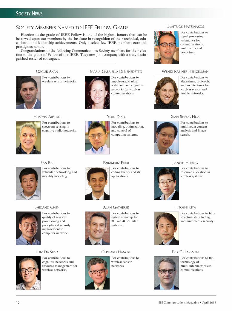
Election to the grade of IEEE Fellow is one of the highest honors that can be bestowed upon our members by the Institute in recognition of their technical, edu-cational, and leadership achievements. Only a select few IEEE members earn this prestigious honor.
Congratulations to the following Communications Society members for their elec-tion to the grade of Fellow of the IEEE. They now join company with a truly distin-guished roster of colleagues.
ozGur akaN Maria-Gabriella di beNedetto weNdi rabiNer HeiNzelMaN
For contributions to impulse-radio ultra wideband and cognitive networks for wireless communications.
For contributions to algorithms, protocols, and architectures for wireless sensor and mobile networks.
For contributions to spectrum sensing in cognitive radio networks.
HuSeyiN arSlaN yixiN diao xiaN-SHeNG Hua
For contributions to modeling, optimization, and control of computing systems.
For contributions to multimedia content analysis and image search.
For contributions to vehicular networking and mobility modeling.
FaN bai FaraMarz Fekri JiaNwei HuaNG
For contributions to coding theory and its applications.
For contributions to resource allocation in wireless systems.
For contributions to quality of service provisioning and policy-based security management in computer networks.
SHiGaNG cHeN alaN GatHerer HitoSHi kiya
For contributions to systems-on-chip for 3G and 4G cellular systems.
For contributions to filter structure, data hiding, and multimedia security.
For contributions to cognitive networks and resource management for wireless networks.
luiz da Silva GerHard HaNcke erik G. larSSoN
For contributions to wireless sensor networks.
For contributions to the technology of multi-antenna wireless communications.
For contributions to signal processing techniques for communications, multimedia and biometrics.
diMitrioS HatziNakoS

IEEE Communications Magazine • April 2016 11
Society NewS
For contributions to multiple antenna systems for wireless communications.
iNkyu lee
SHiNJi MatSuo zHouyue Pi
For contributions to heterogeneous integration of semiconductor lasers.
For leadership in millimeter wave communication technology.
For leadership and contributions in communication systems and signal processing.
ta SuNG lee
SudiP MazuMder Petar PoPovSki
For contributions to analysis and control of power electronics systems.
For contributions to network coding and multiple access methods in wireless communications.
For leadership in development of broadband wireless networks.
SHaoqiaN li
HlaiNG MiNN SuNdeeP raNGaN
For contributions to synchronization and channel estimation in communication systems.
For contributions to orthogonal frequency division multiple access cellular communication systems.
For contributions to adaptive real-time computing systems.
cHeNyaNG lu
viSHal MiSra kui reN
For contributions to network traffic modeling, congestion control and Internet economics.
For contributions to security and privacy in cloud computing and wireless networks.
tHyaGaraJaN NaNdaGoPal Pablo rodriGuez
For contributions to wireless network optimization, RFID systems, and network architectures.
For contributions to the design and development of content distribution architectures in the Internet.
For leadership in design and standardization of cable modems.
Mark laubacH
xiaoli Ma claude oeStGeS
For contributions to block transmissions over wireless fading channels.
For contributions to channel characterization and modeling for multiple-input multiple-output wireless communications.
For contributions to analysis of cross-layer interactions in cellular networks.
SubHabrata SeN

12 IEEE Communications Magazine • April 2016
Society NewS
For contributions to network design, routing and applications to Internet backbone, data centers, and peer-to-peer systems.
SudiPta SeNGuPta JoHN tHoMPSoN kaikit woNG
For contributions to multiple antenna and multi-hop wireless communications.
For contributions to multiuser communication systems.
For contributions to cooperative cellular systems and cognitive radio networks.
oSvaldo SiMeoNe SeNNur ulukuS viNceNt woNG
For contributions to characterizing performance limits of wireless networks.
For contributions to mobility management in wireless networks and demand side management in smart grid.
For leadership in wireless communications technology.
tHeodore Sizer berNHard walke SHuGoNG xu
For contributions to packet switching and relaying in cellular mobile system.
For contributions to the improvement of wireless networks efficiency.
For contributions to digital television broadcasting.
JiaN SoNG PeNGJuN waN lie liaNG yaNG
For contributions to scheduling and resource allocation in wireless networks.
For contributions to multicarrier communications and wireless communications.
For contributions to the design of high-frequency integrated circuits for clocking and communications.
MeHMet Soyuer Jia waNG JiNHoNG yuaN
For contributions to measurement and management of large operational networks.
For contributions to multi-antenna wireless communication technologies.
SuN SuMei zHeNGdao waNG
For leadership in design and standardization of wireless communication systems.
For contributions to multicarrier communications and performance analysis of wireless systems.
For contributions to image and video coding.
biNG zeNG

IEEE Communications Magazine • April 2016 13
Society NewS
For leadership in standardization of cellular systems.
JiaNzHoNG (cHarlie) zHaNG
For contributions to quality of service in mobile wireless networks.
xi zHaNG
For contributions to wireless and mobile net-working and network security.
SoNGwu lu
OMBUDSMAN
ComSoc Bylaws Article 3.8.10
“The Ombudsman shall be the first point of contact for
reporting a dispute or complaint related to
Society activities and/or volunteers. The Ombudsman
will investigate, provide direction to the appropriate
IEEE resources if necessary, and/or otherwise help
settle these disputes at an appropriate level within
the Society.”
IEEE Communications Society Ombudsman
c/o Executive Director
3 Park Avenue, 17 Floor
New York, NY 10017, USA
[email protected] “About Us” (bottom of page)
Call for Papers The IEEE ComSoc technically co-sponsored 24th International Conference on Software, Telecommunications and Computer Networks (SoftCOM 2016) will be held in attractive ambience of the Radisson Blu Resort hotel in Split, Croatia, September 22 to 24. Authors are invited to submit their high-quality papers representing original results in all areas of communications software, services and applications, telecommunications and computer networks. Accepted and presented papers will be published in the conference proceedings, and submitted to IEEE Xplore as well as other Abstracting and Indexing (A&I) databases. General Co-Chairs Sinisa Krajnovic ,Ericsson AB and Dinko Begusic, University of Split Technical Program co-Chair: Nikola Rozic, University of Split, FESB, Croatia Financial Chair: Josko Radic, University of Split, FESB, CroatiaConf. Secretary: Petar Solic, University of Split, FESB, Croatia ([email protected])More information about the Conference Program and information for authors are available on the conference website: www.fesb.hr/softcom.
Complete manuscript due 01 June, 2016Notification of acceptance 15 July, 2016
September 22-24, 2016 Split, Croatia
SYMPOSIA & SPECIAL SESSIONS QoS in Wired and Wireless Networks Ad Hoc and Sensor Networks RFID Technologies & the Internet of Things Green Networking and Computing Cloud Communications and Computing Smart Environment Technologies Electromagnetic Compatibility: Environmental and Safety Aspects Security and Digital ForensicsPhD Students Sessions WORKSHOPS • 6thRegulatory Challenges in the Electonic Communications Market
5th Workshop on Software Eng. in Practice
IENYCM3514.indd 1 19/03/16 6:14 PM
IEEE Communications Magazine • April 201614
Guest editorial
As we mentioned in the Guest Editorial of Part 1 of this Feature Topic, which was published in March 2016, due to a high number of high quality submis-
sions, we divided the accepted papers into two parts. While the articles in Part 1 focused on general topics such as overview, spectrum policies, and economics, the articles of Part 2 in this issue of the magazine focus on more technical issues and solutions.
Technologies used in public safety networks and crit-ical communications networks today are going through a transformation from narrowband technologies to broad-band-communications-based technologies (mainly Long Term Evolution, LTE) due to its superior support for high-er bandwidth multimedia applications, and the ubiquitous, standardized, and cost-effective availability of equipment. To realize the promises of broadband technologies for criti-cal communications and public safety networks, many obsta-cles in designing, deploying, and operating these kinds of systems need to be overcome. The Feature Topic articles in this issue are intended to provide an in-depth overview of the technical issues and solutions related to evolution, crit-ical communications, performance, security, and reliability aspects as well as application challenges in environments other than public safety agencies.
The first article in this series is “Group Communication over LTE : A Radio Access Perspective,” co-authored by Juyeop Kim, Sang Won Choi, Won-Yong Shin, Yong-Soo Song, and Yong-Kyu Kim. This article provides an anal-ysis of how the current LTE system can support group communication and demonstrates how each LTE-en-abled radio access method can efficiently support group communication. In addition, they propose a new multi-cast transmission scheme, which shows more scalable and resource-efficient support of group communication by the LTE system.
The second article, “Public Safety Networks Evolution towardNew Technologies: Sharing Infrastructures and Spec-trum with Commercial Systems” co-authored by Romano Fantacci, Francesco Gei, Dania Marabissi, Luigia Micciullo,
focuses on critical issues that impact migration toward new technologies and describes possible evolution steps, includ-ing advanced solutions.
The third article, “Aerial Base Stations with Opportu-nistic Links for Next Generation Emergency Communica-tions,” co-authored by Karina Gomez, Sithamparanathan Kandeepan, Macià Mut Vidal, Vincent Boussemart, Raquel Ramos Ramos, Romain Hermenier, Tinku Rasheed, Leon-ardi Goratti, Laurent Reynaud, David Grace, Qiyang Zhao, Yunbo Han, Salahedin Rehan, Nils Morozs, Tao Jiang, Isa-belle Bucaille, Philippe Charpentier, Tom Wirth, Roberta Campo, and Tomaž Javornik, describes the main outcomes of the ABSOLUTE project, which focuses on designing, prototyping, and demonstrating a high-capacity IP mobile data network with low latency and large coverage suitable for many forms of multimedia delivery including public safety scenarios.
The fourth article, “Enhanced Interworking of LTE and Wi-Fi Direct for Public Safety,” co-authored by Rajavel-samy Rajadurai, Karthik Srinivsa Gopalan, Mayuresh Patil, and Suresh Chitturi, provides an overview of the PS related efforts in the Third Generation Partnership Project (3GPP), interworking aspects of LTE and Wi-Fi, and their applica-tion to public safety, and provides a mechanism to enhance the interworking between the two technologies to deliver an effective solution for mission-critical communication and applications.
The fifth article, “Cloud-Centric Multi-Llevel Authen-tication as a Service for Secure Public Safety Device Networks,” co-authored by Ismail Butun, Melike Erol-Kantarci, Burak Kantarci, and Houbing Song, also focuses on the security aspects of public safety networks with an emphasis on cloud-centric multi-level authentica-tion as a service approach that addresses scalability and time constraints.
The sixth article, “LTE/LTE-A Jamming, Spoofing, and Sniffing: Threat Assessment and Mitigation,” co-authored by Marc Lichtman, Roger Piqueras Jover, Mina Labib, Raghunandan Rao, Vuk Marojevic, and Jeffrey H. Reed,
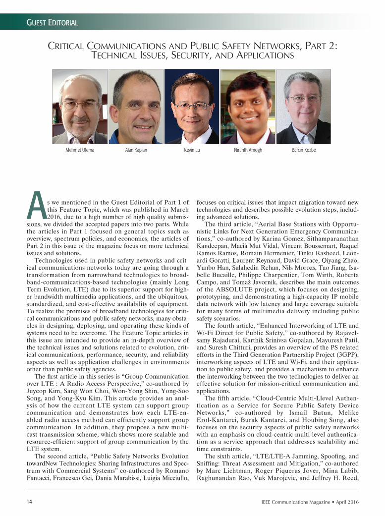
CritiCal CommuniCations and PubliC safety networks, Part 2: teChniCal issues, seCurity, and aPPliCations
Mehmet Ulema Alan Kaplan Kevin Lu Niranth Amogh Barcin Kozbe

IEEE Communications Magazine • April 2016 15
Guest editorial
investigates the extent to which LTE is vulnerable to RF jamming, spoofing, and sniffing, and assesses different phys-ical layer threats that could affect next-generation critical communication networks. In addition, the authors examine how sniffing the LTE broadcast messages can aid an adver-sary in an attack and establish an overall threat assessment of LTE to jamming and spoofing.
The final article in this Feature Topic, “Mission-Critical Mobile Broadband Communications in Open-Pit Mines,” by Luis G. Uzeda Garcia, Erika P. L. Almeida, Viviane S. B. Barbosa, George Caldwell, Ignacio Rodriguez, Hernani Lima, Troels B. Sorensen, and Preben Mogensen, intro-duces fundamental concepts behind open-pit mining, which poses unique challenges to traditional network planning and optimization techniques. The authors also present an integrated framework to support continuous environmental awareness and autonomous adaptation of the network infra-structure.
We hope that you find these articles interesting, infor-mative, and challenging, and that they encourage further research and development, leading to more advanced solutions. Again, we would like to thank all the authors who submitted their articles to this Feature Topic and the reviewers, who have given their time generously to provide valuable feedback and comments on the articles and thus make this Feature Topic a reality.
BiographiesMehMet UleMa ([email protected]) is a professor with Computer Information Systems at Manhattan College, New York. Previously, he was with AT&T Bell Laboratories, Bellcore, Daewoo Telecom, and Hazeltine. He also serves as the Director of Standards Development in ComSoc. He was the TPC Chair of GLOBECOM 2009 and General Co-Chair of NOMS 2016. He is on the Editorial Boards of IEEE Journal of IoT and Springer Journal of Network and Services Management. He received his Ph.D. from Polytechnic University, Brooklyn, and his B.S. and M.S. from Istanbul Technical University.
alan Kaplan ([email protected]) is CTO of Drakontas, developing software for public safety agen-cies. He was formerly with Panasonic Princeton Research Lab, Clemson University, and Flinders Uni-versity of South Australia. He holds Ph.D. and M.S. degrees in computer science from the University of Massachusetts Amherst and a B.S. in computer science from Duke University. He is also currently a lecturer in the Department of Computer Science at Princeton University.
Kevin lU ([email protected]) is an adjunct professor of electrical and computer engineering at Stevens Institute of Technology. He is a member of the IEEE Standards Association (IEEE-SA) Standards Board and is the IEEE-SA contact for the Global Standards Collaboration task force on emergency communications. He was a chief scientist and executive director at Telcordia applied research until 2012. He received his D.Sc. in systems science and mathematics from Washington University in St. Louis.
niranth aMogh ([email protected]) is a principal researcher at the Huawei India R&D Center at Bangalore. He is responsible for the wireless networks research within the organization. His research areas include broadband critical communications, M2M/IoT, SDN/NFV, and NGSON. He has filed several patents in his research areas and holds leadership positions in several SDOs in India and globally. In critical communications standardization, he is actively contributing to the 3GPP SA6 (Mission-Critical Applications) WG. Barcin KozBe ([email protected]) is currently a senior consultant at NGen Solutions. Prior to join-ing NGen Solutions, he was a technical solutions manager at Ericsson Inc. He has been working in the field of computer science, specializing in information technology for telecommunications, for 20 years. He received his M.Sc. degree in computer engineering from Chalmers Technology University in Sweden. His research interests include public safety networks, network management systems, software defined networks, and cloud computing.

IEEE Communications Magazine • April 201616 0163-6804/16/$25.00 © 2016 IEEE
AbstrAct
Long Term Evolution, which has its roots in commercial mobile communications, has recently become an influential solution to future public safety communications. To verify the feasibility of LTE for public safety, it is essential to investi-gate whether an LTE system optimized for one-to-one communications is capable of providing group communication, which is one of the most important service concepts in public safety. In general, a number of first responders for public safety need to form a group for communicating with each other or sharing common data for col-laboration on their mission. In this article, we analyze how the current LTE system can sup-port group communication from the aspect of radio access. Based on the requirements for group communication, we validate whether each LTE-enabled radio access method can efficiently support group communication. In addition, we propose a new multicast transmission scheme, called index-coded HARQ. By applying the index coding concept to HARQ operations, we show that the LTE system can provide group communication that is more sophisticated in terms of radio resource efficiency and scalability. We finally evaluate the performance of LTE-en-abled group communication using several radio access methods and show how the proposed transmission scheme enhances performance via system-level simulations.
IntroductIonMany operators of commercial mobile commu-nications nowadays provide personal data ser-vices along with a Long Term Evolution (LTE) system. Under this circumstance, many opera-tors in other fields such as railways and public safety have begun to take into account the LTE system for special-purpose data communications dedicated to accomplish a specific task in a spe-cific field. Many railway research works, includ-ing the Future Railway Mobile Communication System (FRMCS) project triggered by the Inter-national Union of Railways (UIC), estimate that LTE can meet the needs for transferring railway data in the long term [1]. Governments in many countries, including the United States and the Republic of Korea, have also been sur-veying how to utilize the LTE system for public safety communications [2, 3]. In particular, the
South Korean government has recently opened a request for proposals of a demo business in July 2015 so that the public safety communi-cations system based on LTE can be deployed. The main motive of this trend is that LTE net-work devices and terminals are ubiquitous and continuously upgraded according to the demand from vitalized commercial markets. From these facts, operators can reduce the burden of both operational expenditure (OPEX) and capital expenditure (CAPEX) in fulfilling their needs for data communications.
To utilize the LTE system for special-purpose data communications, it is essential to investigate whether it is capable of providing group commu-nication. Group communication is to disseminate the common voice or data context to multiple terminal users in a group and is a common form of special-purpose data services. In many spe-cial-purpose scenarios, multiple groups aim to accomplish a common mission and want to share various related information for collaboration. The representative application in the form of group communication is push-to-talk (PTT), where a user in a group sends a talk burst to the other listening users in half-duplex mode. Police officers or firefighters form a group for each mis-sion and communicate with each other through PTT for commanding and reporting. Locomotive engineers on a train, maintenance staff on the track side, and station staff also share the opera-tional status of trains and negotiate train opera-tions through PTT [4].
For this reason, many researchers and engi-neers have recently discussed the requirements of a mobile communications system for support-ing the group communication feature. Accord-ing to the conclusion of the Third Generation Partnership Project (3GPP), the key perfor-mance measures for group communication are latency and scalability [5, 6]. In a latency per-spective, the setup time for a group call and the end-to-end delay of a group data dissemination are required to be within an allowable range regardless of the group size so that every user in a group can experience a qualified group service. Based on the criteria in the require-ment of terrestrial trunked radio (TETRA) mis-sion-critical voice systems, it is recommended to take less than 300 ms from the moment that a user requests to join a group to the moment that the user receives the first packet of group
Group Communication over LTE: A Radio Access Perspective
Juyeop Kim, Sang Won Choi, Won-Yong Shin, Yong-Soo Song, and Yong-Kyu Kim
crItIcAl communIcAtIons And PublIc sAfety networks
The authors analyze how the current LTE system can support group communication from the aspect of radio access. Based on the requirements for group communication, they validate whether each LTE-enabled radio access method can effi-ciently support group communication.
Juyeop Kim, Sang Won Choi, Yong-Soo Song, and Yong-Kyu Kim are with the Korea Railroad Research Institute; Won-Yong Shin is with Dankook University.

IEEE Communications Magazine • April 2016 17
data. It is also recommended that the end-to-end data transfer should be terminated within 150 ms. From a scalability perspective, it is rec-ommended to support a case in which the num-ber of users in a group is unlimited, because massive members of staff may belong to one group under public safety scenarios. In practice, a total of at least 2000 users can participate, and at most 500 users can be included in the same group [5].
It is obvious that the typical way of transmit-ting data over LTE within the framework of uni-cast is limited in its ability to satisfy the above requirements. This motivates us to introduce a new system architecture and advanced data transmission schemes suitable for group commu-nication. From a specification perspective, 3GPP has recently been handling various specifica-tion items to support the group communication feature in LTE. Especially due to the needs of several governments for public safety communi-cations, most of the technical specification groups in 3GPP have focused on the group communica-tion items in Release 12 and 13 specifications, which include Group Communication System Enabler (GCSE), Single Cell Point-to-Multipoint (SC-PTM), and Mission-Critical Push-To-Talk (MCPTT). From a research perspective, vari-ous studies have been conducted in the literature for providing efficient data communications to a group of terminals efficiently in mobile commu-nications systems [7–10]. Most of their research is with respect to machine-to-machine commu-nications, where massive machine nodes exist in a cell’s coverage and communicate with a base station.
The aim of this article is to introduce strong candidate methods for LTE-enabled group com-munication from a radio aspect. From the per-spectives of scalability and latency, we provide an analysis of how LTE-enabled radio access meth-ods will perform in a group communication sce-nario. Furthermore, we propose a new multicast transmission scheme that contributes to accom-plish group communication in an efficient way. To design our scheme, we modify hybrid auto-matic retransmission request (HARQ) operation based on a recent concept studied in the field of information theory, called index coding. Through numerical evaluation, we validate that the pro-posed index-coded HARQ scheme can further enhance the performance of LTE-enabled group communication.
rAdIo Access methods for lte-enAbled GrouP communIcAtIon
We start by investigating how group communi-cation can be realized through the air interface in the current LTE system. The most critical issue at the radio access level is how the com-mon group data is disseminated to the wireless section between an eNodeB and a group of user equipments (UEs) while fulfilling the require-ments of latency and scalability. To understand the behavior of radio access in LTE, it is worth examining the structure and related procedures of LTE physical channels. Detailed descriptions of the physical channels are provided in Release 12 and 13 specifications.
releAse 12: utIlIzInG conventIonAl lte PhysIcAl chAnnels
The core specification item of Release 12 in terms of group communication is GCSE. The conventional physical channels in LTE can be good media for providing group communication in some basic scenarios [11]. GCSE defines the requirements for group communication and pro-poses a system architecture on top of the existing physical channels. The LTE system of Release 12 has two fundamental physical channels for trans-ferring the data; the physical downlink shared channel (PDSCH), which is commonly used for normal unicast data, and the physical multicast channel (PMCH), which is designed for evolved multimedia broadcasting and multicasting ser-vice (eMBMS). Figure 1 describes an example of the frame structure in which the two physi-cal channels coexist. In a radio frame consisting of 10 subframes, the two physical channels are switched on a basis of the subframe boundary. Based on an operational rule, a radio access network decides both portion and position of the subframes for the two physical channels, and broadcasts the related control information to UEs through system information block type 2 (SIB2). It is worth noting that the two physical channels are multiplexed only across the time domain, but not across the frequency domain.
In a PDSCH subframe, each data is trans-ferred only to a specific UE. Each UE commu-nicating with its eNodeB has a cell radio network temporary identifier (C-RNTI), which is unique in the cell to which it belongs. During the physi-cal layer encoding, each data is scrambled based on the C-RNTI of the receiving UE so that only the UE can decode the data successfully. In fact, a UE cannot usually notice whether the data for other UEs passes through the PDSCH. A region of the orthogonal frequency-division multiple access (OFDMA) radio resource allocated for the specific data in the PDSCH is indicated by
Figure 1. An example of group communication through the PDSCH and PMCH.
0 1 2 3 4 5 6 7 8 9
SIB2RadioframeAllocationPeriod n4RadioframeAllocationOffset 3SubframeAllocation 0x16
Unicast through PDSCH
C-RNTI 1C RNTI 1 C-RNTI 2 C-RNTI 3 MBSFN Area IDFN Area I
Multicast through PMCH
TMGI 10
MBSFN Area
configur-ationDCI
C-RNTI 1 (implicitly included in CRC)Resource block assignmentMCSHARQ information
sf-AllocEnd 15dataMCSTMGI 3
sf-AllocEnd 12dataMCSTMGI 1
sf-AllocEnd 7dataMCS TMGI 10
MCCHPDCCH

IEEE Communications Magazine • April 201618
downlink control information (DCI), which is transmitted through the physical downlink con-trol channel (PDCCH). For every subframe, the UE initially attempts to decode the data in the PDCCH, and if it succeeds in decoding its own DCI, it decodes the data in the PDSCH based on the DCI. Importantly, the UE cannot decode the DCI for other UEs. This is because the cyclic redundancy check (CRC) part of the DCI is scrambled based on the C-RNTI of the receiving UE, and those who do not own the C-RNTI will experience CRC failure for the DCI. Thus, for group communication through the PDSCH, the group data should be individually transmitted to each UE in a group. As shown in Fig. 1, each of the three UEs receives the group data from the separate radio resource region within subframes 0 and 1.
The advantage of group communication through the PDSCH is that the system can apply advanced link adaptation schemes utilized in LTE, such as adaptive modulation and coding (AMC), HARQ, and various multiple-input mul-tiple-output (MIMO) schemes. Applying these technologies will defi nitely lead to high spectral effi ciency and improved scalability. In addition, the end-to-end delay of the group data will be rather short when the PDSCH is used since the group data goes through the system architecture evolution (SAE) core network, which has a flat all-IP architecture and is optimized in terms of minimizing latency. However, group commu-nication through the PDSCH has a fundamen-tal and critical problem in that the group data should be duplicated as much as the number of UEs per group. The eNodeB should then allo-cate the radio resource separately for each UE in a group. This can be a bottleneck to satisfy the requirements of scalability and latency simulta-neously, since the radio resource shortage and additional queuing delay at the eNodeB side may be beyond a certain critical level when there are many UEs in a group.
On the other hand, PMCH is optimized to broadcast the common data to multiple UEs. In the eMBMS system, the group data is carried through an eMBMS session identifi ed by a tem-porary mobile group identity (TMGI) and is ini-tially forwarded to an MBMS coordination entity (MCE). The MCE then multicasts the data to multiple eNodeBs, which are grouped as a service area and configured to serve the eMBMS ses-sion. In a PMCH subframe, the eNodeBs simul-taneously transmit the same physically encoded signals according to the scheduling by the MCE. At the same time, UEs interested in the eMBMS session attempt to combine the signals from the eNodeBs to decode the group data. Unlike the PDSCH, any UE willing to access the eMBMS session can receive the group data in the PMCH, because the data can easily be decoded based on the broadcast information. The group data in the PMCH is scrambled with a multimedia broadcast single-frequency network (MBSFN) area ID that can be found in SIB13. An MBSFN area confi g-uration message carrying the scheduling infor-mation for all the eMBMS sessions served in the cell is also available from the multicast control channel (MCCH), which can easily be decoded with the information in SIB13. This allows the
eNodeBs to disseminate the group data to mul-tiple UEs with a single radio resource allocation.
It is advantageous that the amount of the radio resource consumed for group communi-cation through the PMCH is independent of the number of UEs per group. No matter how many UEs exist in a group, the group data can be transferred to the UEs with a certain amount of radio resource through the PMCH. Group com-munication through the PMCH also enables the UEs in the cell edge region to achieve improved performance via signal combining. However, the PMCH has a limitation in making a syner-gistic effect along with various link adaptation schemes due to the lack of the uplink feedback channel. The eNodeB is then forced to utilize a robust MCS for the PMCH transmission, which results in degraded spectral efficiency and has a bad influence on scalability. In addition, the granularity of the radio resource allocation in the PMCH is rather huge and thus is not suitable for multiplexing small-sized data such as voice packets. Only the data from eMBMS sessions is allowed to be multiplexed in a PMCH subframe. Thus, there is no way to utilize the rest of the radio resource in the PMCH subframe when the amount of the group data to be sent is instanta-neously small.1
From a latency perspective, group commu-nication through the PMCH performs properly while mostly satisfying the requirements, as in the PDSCH case. In practice, the setup time for an eMBMS data bearer is generally similar to that for a normal unicast data bearer in the com-mercial mobile communications system. How-ever, group communication through the PMCH may cause an additional queueing delay at the MCE/eNodeB sides when the subframe sched-uled for transmitting the specific eMBMS ses-sion is far away from the current moment. The context of the MCCH cannot be modifi ed during the MCCH modification period, referred to as SIB13. Thus, the scheduling for the PMCH can-not be changed during the MCCH modifi cation period. This implies that the queueing time of group data will reach the MCCH modification period for the worst case.
releAse 13:sInGle cell PoInt-to-multIPoInt
As reviewed above, both physical channels in Release 12 have their own problems with satisfy-ing the requirements for group communication. To provide a fundamental solution for group com-munication, 3GPP has recently started a specifi ca-tion item, so-called single-cell point-to-multipoint (SC-PTM), in Release 13 [12]. The SC-PTM is a new type of radio access method dedicated to multicast through the PDSCH in a single cell. It can be regarded as a fusion of PDSCH and eMBMS. For SC-PTM transmission, UEs in a group receive the group data through a common radio resource region in the PDSCH. This con-cept naturally allows the group data to be mul-tiplexed with the normal unicast data within a PDSCH subframe and thus does not cause the problem of radio resource granularity.
Figure 2 depicts the details of SC-PTM trans-mission. Instead of the C-RNTI, SC-PTM trans-mission utilizes a common RNTI, the so-called
1 It is hard to change the portion of PDSCH and PMCH subframes in a short term, which requires to modify SIB2 frequently, thereby resulting in a burden to both UE and eNodeB sides.
Only the data from
eMBMS sessions is
allowed to be multi-
plexed in a PMCH sub-
frame. Thus, there is no
way to utilize the rest
of the radio resource
in the PMCH subframe
when the amount of the
group data to be sent is
instantaneously small.

IEEE Communications Magazine • April 2016 19
group RNTI, which is allocated to each TMGI. According to the cell list from the core network, the MCE disseminates the group data to the cor-responding eNodeBs. Each eNodeB then trans-mits the group data through the PDSCH based on its own scheduling and sends the correspond-ing DCI through the PDCCH simultaneous-ly with the group RNTI. UEs can decode both the DCI and the group data successfully based on the pre-acquired group RNTI. The UEs in a group can acquire their group RNTI from an SC-PTM configuration message, which is peri-odically broadcast through the single-cell MCCH (SC-MCCH), and provides the mapping between TMGIs and group RNTIs. Since the SC-PTM allows any UE to receive the group data as in the PMCH case, it only requires a single radio resource allocation for disseminating the group data without multiple data transmissions.
The eNodeBs can utilize various link adap-tation schemes for SC-PTM because the uplink feedback channel corresponding to the PDSCH is available. Performance evaluation in [12] showed that SC-PTM transmission outperforms the transmission through the PMCH in terms of spectral efficiency. Although defining the uplink feedback channel for SC-PTM is out of the scope of the Release 13 specification, the numerical results in [12] reveal that the uplink feedback channel still has potential to bring a significant performance gain over SC-PTM. Since SC-PTM does not perform multiple data transmissions for group communication, it consumes less radio resource even when there are relatively many UEs per group. In addition, SC-PTM is attrac-tive from an operator’s perspective, because it enables managing the radio frame more flexibly by multiplexing the group data with the normal unicast data in any PDSCH subframe.
From the latency point of view, group com-munication through the SC-PTM takes a small-er delay since the significant queueing delay, which may take place for both the PDSCH and PMCH cases, will not occur. Since duplicated transmission is not needed for the SC-PTM case, data queueing due to radio resource shortage will rarely occur even when there are sufficient-ly many UEs per group. The group data is also transmitted through the PDSCH, in which the eNodeB performs scheduling per subframe, and thus the queueing delay due to the scheduling of the MCE will not take place.
Figure 3 summarizes the characteristics of radio access methods. From the comparison, it is seen that the SC-PTM is a compromise solution between the existing physical channels. Unicast through the PDSCH and multicast through the PMCH are optimized to serve small and very large groups, respectively, while the SC-PTM is dominant for mid-sized groups. Thus, it is essen-tial to utilize SC-PTM to fulfill the requirements for group communication in every use scenario.
new PArAdIGm: Index-coded hArQ for sc-Ptm
HARQ is one of the important link adaptation schemes, and plays a significant role in achiev-ing high spectral efficiency in SC-PTM transmis-sions. The key HARQ operation is physical-layer
retransmission, which enables a transmitter to utilize MCS at a higher data rate while suppress-ing the block error rate (BLER) under 1 percent. When HARQ is applied to SC-PTM, its enti-ty needs to perform retransmission according to multiple feedbacks from the UEs in a group. However, this HARQ retransmission can matter in terms of radio resource efficiency. Since the HARQ retransmission should take place when at least one negative acknowledgment (NACK) is sent from the UEs in the group, it may occur more frequently as the number of UEs per group increases. It would also be redundant for the UEs with ACK for the HARQ retransmission to be performed through SC-PTM due to the inher-ent nature of this retransmission method.
To overcome this inefficiency, the issue of the retransmission to multiple receivers can be combined with a new coding scheme, index cod-ing, studied in the field of information theory. The transmitter sends data through a noiseless broadcasting network to multiple receivers, each knowing some data a priori, referred to as side information. Then one can exploit this side infor-mation to reduce the number of coded data to be sent by the transmitter for all receivers to decode their requested data. This concept is known as the index coding problem and was originally introduced by Birk and Kol [13], motivated by a satellite broadcasting application. Interest in index coding has further increased due to two more recent developments [14, 15].
Based on the sophisticated philosophy of index coding, we can enhance the HARQ retransmission for multiple UEs in the sense of diminishing the number of retransmissions. In LTE, the HARQ entity at the eNodeB side operates based on several HARQ processes in parallel, and each HARQ process is responsible for transferring a transport block (TB), which is
Figure 2. The concept of SC-PTM.
UEUE
0 1 2 3 4 5 6 7 8 9
Group-RNTI 1
TMGI 10
oup R NT
Multicasting through PDSCHDCI
Group RNTI (implicitly included in CRC)Resource block assignmentMCSHARQ information
PDCCH
SC-MCCH
SC-PTM configuration
tmgi 10,Group-RNTI 1,Scheduling subframe 3
UE
Session StartRequest (cell list)
Session StartResponse
Decide to use SC-PTM
eNodeB
MBMS Session Start Request (cell list)
MBMS Session Start Response SC-PTM
ConfigurationGroup Data
Bearer Setup Procedure
Core network MCE

IEEE Communications Magazine • April 201620
the minimal unit of data in HARQ operations. The eNodeB is aware of the group’s reception status (ACK/NACK) for each HARQ process from the received HARQ feedbacks. Based on the ACK/NACK information, the eNodeB can select proper HARQ processes with TBs that can be index coded for retransmission. According to the principle of index coding, a UE can retrieve a TB from m index-coded TBs assuming that the UE already has the m – 1 TBs. In other words, each NACK UE can retrieve the TB that it wants to receive from the index-coded TBs only if there is no common NACK UE among the selected HARQ processes. Thus, index coding enables simultaneous retransmissions for several HARQ processes by carefully selecting the HARQ pro-cesses with disjoint sets of NACK UEs.
Figure 4 shows an example of the index-cod-ed HARQ, where there are three UEs receiving the group data through SC-PTM. In subframe n + 4, UE 3 sends the NACK for HARQ process 1. In subframe n + 7, UE 2 sends the NACK for HARQ process 4. After collecting a cer-tain amount of HARQ feedback from the UEs, the eNodeB checks whether there is a possible combination of the HARQ processes for the index-coded retransmission. In this case, HARQ processes 1 and 4 can be index-coded, because UEs 2 and 3 have successfully decoded the TBs of HARQ processes 1 and 4, respectively. The eNodeB combines the TBs of HARQ process-es 1 and 4 by applying an exclusive OR (XOR) operation and transmits the index-coded TBs. After completing the receiving procedure in the PDSCH, UE 2 applies an XOR operation to the
Figure 3. The characteristics of various methods of group communication.
Method Radio Resource Efficiency Scalability Latency
Unicast through PDSCH
Multicast through PMCH
SC-PTM
Various link adaptation schemes improving spectral efficiency can be applied.Can be transmitted per cell, and easily multiplexed with normal unicast data.
Requires a radio resource allocation for each UE in a group.Amount of radio resource is proportional to the number of UEs in a group.
Will be minimized in both control and data plane due to the SAE core network.Queueing delay may occur if the group size is large and the group data transmission requires too much amount of radio resource.
No link adaptation due to the lack of the uplink feedback channel.Involves multi-cells for a group data transmission, which improves the spectral efficiency of cell edge UEs.Allows to multiplex only eMBMS data in a subframe.
Requires one radio resource allocation for the group UEs.Amount of radio resource is independent of the number of UEs in a group.
Bearer setup time is basically similar to the unicast case.Queuing delay may occur at MCE/eNB when scheduled subframe is far from the current time.
Basic link adaptation schemes improving spectral efficiency can be applied.Can be transmitted per cell and easily multiplexed with normal unicast data.
Requires one radio resource allocation for the group UEs.Amount of radio resource is not basically proportional to the number of UEs, but may be increased due to link adaptation.
Bearer setup time is basically similar to the unicast case.Queuing delay rarely occur at MCE/eNB.
Table 1. System parameters for simulation.
System parameters Values
Channel model ITU, rural macrocell
eNodeB layout 19 hexagonal cells
Distance between eNodeBs 1732 m
Subcarrier spacing 15 kHz
Carrier frequency and bandwidth 800 MHz, 10 MHz BW
UE speed 3 km/h
Duplex FDD
eNodeB antenna gain 15 dBi
eNodeB output power 46 dBm
UE distribution Uniform drop in the cell coverage region
Traffic model Voice
Downlink transmission scheme TxD
Antenna configuration 2 2
HARQ type Chase combining up to three retransmissions
Rate adaptationFeedback from group in the worst radio condition will be ignored, with 1 percent BLER
Number of OFDM symbols reserved for PDCCH
2

IEEE Communications Magazine • April 2016 21
decoded data with the TB of HARQ process 1 and retrieves the TB of HARQ process 4. Sim-ilarly, UE 3 retrieves the TB of HARQ process 1 from the index-coded TBs. Consequently, the index-coded HARQ can conduct the two HARQ retransmissions with a single radio resource allo-cation, whereas two radio resource allocations are needed to perform the two HARQ retrans-missions through the conventional HARQ opera-tion with no index coding.
The key point of using the index coding to SC-PTM is to reduce the amount of the radio resource consumed for HARQ retransmissions. More specifi cally, this leads to a reduced amount of the radio resource for disseminating the group data, thus resulting in improved scalability for group communication. The index-coded HARQ also reduces the frequency of duplicated recep-tion and disuse by UEs with ACK. In addition, applying the index-coded HARQ requires a minor change of the conventional LTE system from the protocol aspect by adding the informa-tion for index-coded TBs that can be natural-ly sent through the PDCCH. Specifi cally, either multiple sets of HARQ information can belong to a DCI, or multiple DCIs can be sent to indi-cate which TBs are index-coded.
PerformAnce of GrouP communIcAtIonWe evaluate the performance of group commu-nication from the aspect of scalability. Our aim is to show:• How scalable each radio access method is
for group communication• How to improve scalability using the pro-
posed schemeTo evaluate the scalability of the PMCH, we con-duct a numerical analysis based on the frame-work in [12]. For both the PDSCH and SC-PTM,
we evaluate the scalability in LTE-based simula-tion environments.
system AssumPtIons
For numerical evaluation, we basically use the LTE system along with the system parameters in [12], which are indeed commonly used for eval-uating public safety scenarios. In addition, we assume that voice traffi c is used, since voice PTT is the main application in public safety. The sys-tem parameters for simulation are summarized in detail in Table 1.
For quantitative analysis of scalability, we define a performance measure, called group capacity, which is the maximal number of groups that a cell can support with a given group size. The group capacity can be calculated as the total amount of radio resource within the inter-arrival time of the group data traffi c normalized by the average amount of the radio resource needed to disseminate a piece of group data to the group. Through simulations, we evaluate the amount of the radio resource that a HARQ process con-sumes for transmitting/retransmitting a terabyte while satisfying the 1 percent BLER criterion.
PerformAnce evAluAtIon
Figure 5 shows the performance of each radio access method in terms of scalability and radio resource effi ciency. Unicast through the PDSCH outperforms the other methods for most cases with respect to cell capacity. However, unicast through the PDSCH has the worst performance in group capacity even when the group size is very small. This is because this unicast method wastes a substantial amount of radio resource for duplicated data transmissions. Multicast through the PMCH has the worst performance in cell capacity, but has higher group capacity
Figure 4. An example of index-coded HARQ retransmission for the SC-PTM.
=+
+
=+
n+10
fn+6
n+7
fn+3
n+6
fn+2
...
n n+4
fn
n+5
fn+1
n+8
fn+4
n+9
fn+5
eNB
UEs
e
U
4+1
nn+8 n+9
44 =
21+ 11 = 4
3 = 144+
Index coding
Index-coded HARQ retransmission
Indication method
DCIGroup RNTIResource block assignmentMCSHARQ information list
DCIGroup RNTIResource block assignmentMCSHARQ information
DCIGroup RNTIResource block assignmentMCSHARQ information
DCIGroup RNTIResource block assignmentMCSHARQ information
OR
PDCCH
For numerical evalu-
ation, we use the LTE
system along with the
system parameters in
[12], which are indeed
commonly used for
evaluating public safety
scenarios. In addition,
we assume that the
voice traffi c is used,
since the voice PTT is
the main application in
public safety.

IEEE Communications Magazine • April 201622
than unicast through the PDSCH for most cases (even higher group capacity than the SC-PTM when there are relatively many UEs per group). This implies that the best method for maximizing group capacity is dependent on the group size. The LTE system would prefer to serve either a small group size through SC-PTM or a large group size, which can be up to 500 users, through the PMCH. It is also worth noting that all the subframes are configured for the PMCH, and there is no subframe configured for the PDSCH. Since the radio frame is generally composed of both PMCH and PDSCH subframes in practice, the group capacity for the multicast case through the PMCH will be lessened as much as the por-tion of the PMCH subframes. Therefore, a cross-point of the group capacity curves between the PMCH and SC-PTM will vary depending on the frame configuration.
Figure 5 also shows how SC-PTM with index-coded HARQ performs. It turns out that the group capacity can be improved up to 17.5 percent using the proposed scheme. The performance gain gets larger as the number
of UEs per group increases. This is because the large group size leads to more NACKs, resulting in more frequent HARQ retrans-missions, and thus index-coded transmission occurs more frequently. We remark that the index-coded HARQ compensates a vulnerable point of SC-PTM, which enables the availabil-ity of SC-PTM to be significantly extended. It is shown that SC-PTM without index-coded HARQ is applicable when there are fewer than 6 UEs per group, whereas the SC-PTM with index-coded HARQ can be applied when there are 12 UEs per group.
Moreover, index-coded HARQ can improve the performance over SC-PTM in terms of radio resource efficiency. The result indicates that SC-PTM with index-coded HARQ consumes the radio resource for retransmission more effi-ciently than does SC-PTM without index-coded HARQ, even than unicast through the PDSCH. In addition, the cell capacity of SC-PTM, depending heavily on spectral efficiency, is high-er than that of unicast through the PDSCH when the group size is relatively small. This reveals
Figure 5. Performance comparison of the various radio access methods.
0 5 10 15 200
100
200
300
400
500
600
700
800
nac llec a taht spuorg fo rebmu
Ntroppus ylsuoenatlu
mis
Number of UEs in a group
Unicast through PDSCH Multicast through PMCH SC-PTM SC-PTM with index coded HARQ
Group capacity itScalability
0 5 10 15 200.0
0.5
1.0
1.5
2.0
2.5
3.0
3.5Nu
mbe
r of P
RBs a
lloca
ted
for
a gr
oup
data
pac
ket (
160
bits)
Number of UEs in a group
Multicast through PMCH SC-PTM SC-PTM with index coded HARQ
Radio resource consumption
Radio resource efficency
0 5 10 15 200
2
4
6
8
10
12)s/b
M( tuphguorht lleC
Number of UEs in a group
Unicast through PDSCH Multicast through PMCH SC-PTM SC-PTM with index coded HARQ
Cell capacity
0 5 10 15 200.0
0.5
1.0
1.5
Spec
tral e
fficie
ncy
(b/s
/Hz)
Number of UEs in a group
Unicast through PDSCH SC-PTM SC-PTM with index coded HARQ
Spectral efficiency for Retransmissions
e x xx coc-
e x cc o-
e x c o-e x cocc

IEEE Communications Magazine • April 2016 23
that the enhancement of the group capacity by the index-coded HARQ comes mainly from the improved radio resource effi ciency.
concludInG remArksIt has been comprehensively verifi ed that group communication is one of the most important and widely used applications for public safety, as one-to-one voice communication is for commercial mobile communications. As the applicable range of LTE has recently been extended to various fields, including public safety, it is essential to account for whether the LTE system can fulfill the requirements for group communication in an efficient way. In this circumstance, this arti-cle sheds light on the technical aspect of LTE in terms of providing group communication. From the scalability and latency perspectives, the Release 12 LTE system is shown to support group communication to some extent by using both unicast (PDSCH) and multicast (PMCH) channels. Furthermore, SC-PTM, defined in Release 13, has turned out to be a compromise solution of the existing physical channels and to fulfill the requirements for group communica-tion more smoothly. The proposed index-coded HARQ has led to a new paradigm of retransmis-sion to multiple receivers, where it can further enhance the scalability of SC-PTM, and has been validated via numerical evaluation.
AcknowledGment
This work was supported by ICT R\&D program of MSIP/IITP. [B0101-15-1361, Development of PS-LTE System and Terminal for National Pub-lic Safety Service].
references
[1] J. Kim et al., “Automatic Train Control over LTE: Design and Performance Evaluation,” IEEE Commun. Mag., vol. 53, no. 10, Oct. 2015, pp. 102—09.
[2] T. Doumi et al., “LTE for Public Safety Networks,” IEEE Commun. Mag., vol. 51, no. 2, Feb. 2013, pp. 106—12.
[3] R. Ferrus et al., “LTE: The Technology Driver for Future Public Safety Com-munications,” IEEE Commun. Mag., vol. 51, no. 10, Oct. 2013, pp. 154–61.
[4] K. Balachandran et al., “Mobile Responder Communication Networks for Public Safety,” IEEE Commun. Mag., vol. 44, no. 1, Jan. 2006, pp. 56—64.
[5] 3GPP TS 22.468 v12.1.0, “Technical Specification Group Services and System Aspects; Group Communication System Enablers for LTE (GCSE_LTE),” 2014.
[6] 3GPP TS 22.179 v13.2.0, “Technical Specification Group Services and System Aspects; Mission Critical Push to Talk (MCPTT) over LTE; Stage 1,” 2015.
[7] T. Kwon and J. W. Choi, “Multi-Group Random Access Resource Allocation for M2M Devices in Multicell Systems,” IEEE Commun. Letters, vol. 16, no. 6, June 2012, pp. 834—37.
[8] C. H. Wei, R. G. Cheng, and S. L. Tsao, “Performance Analysis of Group Paging for Machine-Type Communications in LTE Networks,” IEEE Trans. Vehic. Tech., vol. 62, no. 7, Sept. 2013, pp. 3371—82.
[9] K. Zheng et al., “Radio Resource Allocation in LTE-Advanced Cellular Net-works with M2M Communications,” IEEE Commun. Mag., vol. 50, no. 7, July 2012, pp. 184—92.
[10] R. Sivaraj et al., “QoS-Enabled Group Communication in Integrated VANET-LTE Heterogeneous Wireless Networks,” 2011 IEEE 7th Int’l. Conf. Wireless Mobile Computing, Networks and Commun., Oct. 2011, pp. 17—24.
[11] 3GPP TS 23.468 v12.5.0, “Technical Specification Group Services and System Aspects; Group Communication System Enablers for LTE (GCSE_LTE); Stage 2,” 2015.
[12] 3GPP TR 36.890 v13.0.0, “Technical Specifi cation Group Radio Network; Evolved Universal Terrestrial Radio Access (E-UTRA); Study on Single-Cell Point-to-Multipoint Transmission for E-UTRA,” 2015.
[13] Y. Birk and T. Kol, “Coding-On-Demand by an Informed Source (ISCOD) for Efficient Broadcast of Different Supplemental Data to Caching Cli-ents,” IEEE Trans. Info. Theory, vol. 52, no. 6, June 2006, pp. 2825—30.
[14] Z. Bar-Yossef et al., “Index Coding with Side Information,” IEEE Trans. Info. Theory, vol. 57, no. 3, Mar. 2011, pp. 1479—94.
[15] S. El Rouayheb, A. Sprintson, and C. Georghiades, “On the Index Coding Problem and Its Relation to Network Coding and Matroid Theory,” IEEE Trans. Info. Theory, vol. 56, no. 7, July 2010, pp. 3187—95.
bIoGrAPhIes
JUYEOP KIM ([email protected]) is an senior researcher in the ICT Conver-gence Team at Korea Railroad Research Institute. He received his M.S. and Ph.D. in electrical engineering and computer science from Korea Advanced Institute of Science and Technology (KAIST) in 2010. His current research interests are railway communications systems, group communications, and mission-critical communications.
SANG WON CHOI ([email protected]) received his M.S. and Ph.D. in electrical engineering and computer science from KAIST in 2004 and 2010, respec-tively. He is currently a senior researcher in the ICT Convergence Research Team. His research interests include mission-critical communications, mobile communication, communication signal processing, and multi-user information theory. He was the recipient of a Silver Prize at the Samsung Humantech Paper Contest in 2010.
WON-YONG SHIN [S’02, M’08] received his B.S. degree in electrical engineering from Yonsei University, Seoul, Korea, in 2002. He received his M.S. and Ph.D. degrees in electrical engineering and computer science from KAIST in 2004 and 2008, respectively. From February 2008 to April 2008, he was a visiting scholar in the School of Engineering and Applied Sciences, Harvard University, Cambridge, Massachusetts. From September 2008 to April 2009, he was with the Brain Korea Institute and CHiPS at KAIST as a postdoctoral Fellow. From August 2008 to April 2009, he was with Lumicomm, Inc., Daejeon, Korea, as a visiting researcher. In May 2009, he joined Harvard University as a postdoc-toral fellow and was promoted to research associate in October 2011. Since March 2012, he has been with the Division of Mobile Systems Engineering, College of International Studies, and the Department of Computer Science and Engineering, Dankook University, Yongin, Korea, where he is currently an assistant professor. His research interests are in the areas of information the-ory, communications, signal processing, mobile computing, big data analytics, and online social networks analysis. He has served as an Associate Editor for IEICE Transactions on Fundamentals of Electronics, Communications, Computer Sciences, IEICE Transactions on Smart Processing and Computing, and the Journal of Korea Information and Communications Society. He also served as an Organizing Committee member for the 2015 IEEE Information Theory Workshop.
YONG-SOO SONG ([email protected]) received his Master’s degree in electrical engineering from Yonsei University in 2004. He has been with the Korea Rail-raod Research Institute since 2004. He is working toward his Ph.D in electrical engineering from Yonsei University. His current research interests are in cell planning and handover in LTE-Railway.
YONG-KYU KIM ([email protected]) received his M.S. in electronic engineering from Dankook University in 1987, and his D.E.A. and Ph.D. in automatic and digital signal processing from Institute National Polytechnique de Lorraine, France, in 1993 and 1997, respectively. He is currently an executive research-er in the ICT Convergence Research Team at the Korea Railroad Research Institute. His research interests are in automatic train control, communica-tion-based train control, and driverless train operation.
The cell capacity of the
SC-PTM, depending
heavily on the spectral
effi ciency, is higher than
that of unicast through
the PDSCH when the
group size is relatively
small. This reveals that
the enhancement of
the group capacity by
the index-coded HARQ
comes mainly from
the improved radio
resource effi ciency.

IEEE Communications Magazine • April 201624 0163-6804/16/$25.00 © 2016 IEEE
AbstrAct
Nowadays, efficient communication technol-ogies are of paramount importance to provide effective and reliable emergency management systems. New wireless communications engineer-ing approaches and value-added services could lead to great benefits, improving situational awareness and enhancing life-saving capabili-ties. For these reasons, governments and orga-nizations involved in public safety and security (PSS) are devoting great interest in the transi-tion from existing narrowband wireless systems toward broadband. For this purpose, a viable solution is to adapt the new LTE-A technology in order to provide IP-based broadband services with security and reliability characteristics typ-ical of PSS networks. However, the migration of these systems to LTE-A is currently a critical issue. Costs, timing, and spectrum availability for the deployment of a PSS-dedicated network are demanding. In addition, providing mission-criti-cal services on an LTE-based PSS system needs a proper network architecture solution in order to achieve and maintain required performance and reliability levels. To fully accomplish this task, research efforts can result in significant improve-ments and adjustments of future releases of the LTE-A standard. This article focuses on critical issues that impact PSS communications evolu-tion toward new technologies and describes the related possible steps, starting from the exploita-tion of the already deployed LTE-A commercial networks up to a fully PSS-dedicated network infrastructure. Finally, advanced solutions are described and critically discussed.
IntroductIonWireless communications play a fundamental role in public safety and security (PSS) operations, since appropriate communications have a strong impact on efficiency and responsiveness of emer-gency services. However, current PSS networks are not able to support advanced applications enabled by broadband data distribution, because they are mostly based on narrowband systems such as terrestrial trunked radio (TETRA), TETRA for police (TETRAPOL), and Project 25 (P25). The capabilities of these technologies focus on advanced security features and specif-
ic functionalities, but the support of high data rate services is still lagging behind that provid-ed by broadband commercial mobile networks, which are constantly evolving in response to data traffic demand increase, changes in the habits of customers, and continuous mobile equipment improvements. PSS operators, governments, and research communities are working to amend this gap; in particular, the Long Term Evolution-Ad-vanced (LTE-A) mobile radio technology has widely been envisaged as a basic technology for the evolution of PSS communication systems [1, 2]. However, PSS and commercial communica-tion networks are designed for different needs, and the challenge is to provide optimized and reliable services for professional use, by exploiting facilities proper for new broadband fourth/fifth generation (4G/5G) commercial systems. Toward this end, since Release 12, the Third Generation Partnership Project (3GPP) is working to incor-porate specific functionalities of the PSS world in the LTE standard, including group and direct-mode communications (referred to as proximity service, ProSe, in LTE) [3], which are two of the most characteristic PSS applications.
Today, it is a widely accepted opinion that a unique standard for commercial and PSS envi-ronments can create new synergies, offering advantages to both worlds. A common tech-nology leads to new opportunities, as network sharing reduces the time and costs of deploying and maintaining infrastructures. In addition, PSS operators can always benefit from an up-to-date communication system, under specific agree-ments with commercial operators, thus avoiding new technological gaps. On the other hand, the use of commercial systems for providing PSS ser-vices raises several critical issues that must be carefully addressed.
This article provides an analysis of different factors influencing the migration of narrowband PSS communications toward broadband, in rela-tion to different solutions:• PSS-dedicated network infrastructure• PSS services over commercial networks• Hybrid solutionsThis allows the presentation of an evolutionary deployment scenario for PSS communication networks and advanced solutions to overcome some critical problems.
Public Safety Networks Evolution toward Broadband: Sharing Infrastructures and
Spectrum with Commercial SystemsRomano Fantacci, Francesco Gei, Dania Marabissi, and Luigia Micciullo
crItIcAl communIcAtIons And PublIc sAfety networks
This article focuses on critical issues that impact PSS commu-nications evolution toward new technol-ogies and describes the related possible steps, starting from the exploitation of the already deployed LTE-A commercial networks up to a fully PSS-ded-icated network infra-structure. Advanced solutions are described and critically discussed.
The authors are with the University of Florence. The corresponding author is Dania Marabissi ([email protected]).

IEEE Communications Magazine • April 2016 25
network dePloyment Issues
The main issues and requirements that must be carefully considered in the evolution process from current narrowband PSS networks toward new broadband technologies are: deployment costs and times, spectrum availability, network coverage and resilience capabilities, quality of service (QoS) and security requirements satisfac-tion, and support of advanced PSS services.
This section provides details on the time and costs needed to deploy a PSS-dedicated network infrastructure, and discusses the other issues in relation to criticalities that can arise if PSS ser-vices are provided over commercial networks. Finally, some considerations on hybrid solutions are provided. Discussion of spectrum availability occurs later in the article.
Pss-dedIcAted network dePloyment tIme And costs
The full deployment of a completely new PSS-dedicated network infrastructure requires a long time and huge investments, in particular to satisfy the requirement of having effective and fl exible coverage. Moreover, almost no elements of previous PSS narrowband networks can be reused; due to the great technological gap, just some physical infrastructures (e.g., masts) and installation sites can be shared. Until deep and uniform radio coverage is available through the new broadband network, PSS communications will be dependent on current narrowband sys-tems, such as TETRA, TETRAPOL, and P25. This will temporary lead to overlapped use of the two technologies, requiring specifi c solutions for interconnecting the two networks and for the interoperability of devices, thus leading to additional costs. The total expenditures for the deployment of a wireless mobile network can be classified as capital expenditures (CapEx) and operational expenditures (OpEx). CapEx are the funds needed to purchase major physical goods or services for realizing the fi xed infrastructures. They assume a particularly relevant role during initial network deployment (or in network update operations) and cover the equipment value, which will depreciate over time. OpEx represent the costs of keeping the network operational and fail-safe; they do not contribute to the infra-structure deployment and consequently are not subject to depreciation. Techno-economic mod-els for both CapEx and OpEx are available to simulate the expenditures of deploying ex novo a new commercial LTE network [4], but additional costs have to be considered for PSS infrastruc-tures, taking into account stringent requirements of resilience and full territory coverage. Hence, time and costs can slow down the deployment of national PSS-dedicated networks, postponing the diffusion of broadband services for PSS.
In this context, the availability of spectrum resources is also a fundamental issue. Indeed, terri-tory coverage, and consequently deployment costs, also depend on the operational frequency band. Low frequencies (usually allocated to PSS services) allow better territory coverage, thus requiring fewer base stations (BSs) and better network planning, while working at higher frequencies leads to worst propagation conditions and hence to a higher num-ber of BSs. Moreover, reserving suitable frequency
bands means higher cost since governments cannot earn from commercial licenses.
For all these reasons, the alternative solution of providing PSS services over already deployed commercial networks represents a quick and rel-atively low-cost solution. Moreover, commer-cial systems could allow PSS operators to always benefi t from an up-to-date communication infra-structure.
crItIcAl reAsons to ProvIde Pss servIces over commercIAl networks
Even if the provision of PSS services over com-mercial networks is the quicker and cheaper solu-tion, some drawbacks arise when critical services and QoS requirements are considered. Indeed, mission-critical communications are character-ized by different and more severe QoS (especial-ly in terms of latency) and security requirements in respect to commercial communications. More-over, PSS operators need some essential applica-tions and functionalities — in particular, group and direct communications — that in general are not supported by commercial systems. These are the main reasons that until now have moti-vated the development of technologies and net-works strictly dedicated to PSS communications, and make the solution of having a broadband PSS-dedicated network the preferable approach for PSS users. Indeed, in the case of provisioning PSS services over broadband commercial net-works, all the sensitive features of PSS services are demanded in the negotiation of appropriate service level agreements (SLAs) with the mobile network operator (MNO). Moreover, particular-ly in critical situations, commercial networks are usually congested, overloaded, and exposed to downtime, with unpredictable effects on high-pri-ority emergency communications. Furthermore, there is always the risk that commercial oper-ators will not completely fulfill the contract, especially if penalties are lower than the costs of respecting SLAs. Also, in terms of security, the provisioning of PSS services over commercial networks can introduce more risks, because they are open to unsecured terminals, and guarantee-ing end-to-end security can be more diffi cult.
Similar to services and requirements, network coverage policies are also different in the com-mercial and PSS worlds. While the former pre-fers to have high resources in densely populated regions, accepting the presence of uncovered areas, the latter requires full territory coverage and a base of granted services always available without the risk of jeopardized coverage. More-over, PSS networks must be characterized by high reliability and resilience, also allowing com-munications in disaster or critical situations (e.g., earthquake, fl ooding, loss of power supply) when commercial networks are often seriously dam-aged or out of order, since in general these are not suitably designed according to the principle of redundancy typical of PSS networks.
Specific consideration has to be paid to the current situation. At the moment, LTE-A is not fully compliant with the PSS requirements and services for critical communications. Indeed, 3GPP is working to include these in the new standard releases, but they are not completely defined and frozen.1 This means that no LTE-
The main issues and
requirements that must
be carefully consid-
ered in the evolution
process from current
narrowband PSS net-
works toward new
broadband technologies
are: deployment costs
and times, spectrum
availability, network
coverage and resilience
capabilities, quality of
service and security
requirements satisfac-
tion, and support of
advanced PSS services.

IEEE Communications Magazine • April 201626
based solution (i.e., neither PSS-dedicated network nor PSS services over commercial net-works) is able to fully support PSS operations. As a consequence, at the moment, we can expect that public administrations will not invest large capital to deploy expensive new PSS-dedicated networks that are not completely suitable for their goals when they could select cheaper solu-tions based on provisioning non-critical high data rate PSS services over broadband commercial networks and maintain current narrowband sys-tems to support critical services.
HybrId solutIon oPPortunItIes
From the previous analysis we can conclude that providing PSS services using a commercial net-work is risky for PSS operators in terms of critical service requirements, security, network cover-age, and resilience. On the other hand, time and cost limits — at least at first — the deployment of completely PSS-dedicated networks. To find a trade-off between these two trends, it is conve-nient to evaluate different solutions for providing advanced PSS services (Fig. 1), not necessarily by means of dedicated resources, but also through hybrid solutions based on partial infrastructure sharing, as detailed in the next section. In fact, the experience in network sharing of commer-cial operators shows strong savings in CapEx and OpEx, on the order of roughly 20–30 percent [5].
Moreover, hybrid solutions could allow a high degree of flexibility in terms of spectrum usage, service management, radio access policies, and territory coverage. This will allow achievement of the desired trade-off among the multiple factors described above.
evolutIon stePs
While LTE-A is not fully compliant with PSS requirements, the simplest way for the initial quick distribution of high data rate services to a wide number of PSS operators can be, as men-tioned, the use of already deployed broadband commercial networks. In this case, from a tech-nical point of view, the PSS network manager acts as an enhanced service provider — mobile virtual network operator (ESP-MVNO), using the broadband network only for the distribution of added-value non-critical applications, besides the voice services still provided by narrowband PSS networks.
When the LTE-A standard includes all the specific services and requirements of PSS com-munications, different solutions can be envisaged. In particular, the full-IP nature of LTE networks benefits and eases the success of shared network architectures. 3GPP provides recommendations and technical specifications for infrastructure sharing [6], commonly used in the commercial market. MVNOs offer mobile services to their customers without directly owning the licenses for the radio spectrum but having agreements with mobile host operators (MHOs) for using its resources; this approach can easily be extended to PSS networks as well.
LTE networks are composed of several logical domains:• The services domain, injecting the traffic in
the network through a service delivery plat-form
• The Evolved Packet Core (EPC) network, mainly responsible for control functions
• The Evolved-Universal Terrestrial Radio Access Network (E-UTRAN), composed of eNodeBs
• The mobile backhaul, interconnecting RAN cell sites with the EPC through access, aggregation, and transport infrastructures
• The user equipment (UE) domainThe services domain shall be dedicated to
PSS communications and the specific services to be provided, while others can be partially or completely shared between PSS and commer-cial networks in several hybrid configurations. A hybrid approach may represent a final or transi-tional solution toward the step-by-step deploy-ment of a PSS-dedicated network infrastructure for professional services, as in Fig. 2.
After the initial configuration, where the PSS network owner acts as an ESP-MVNO, the first step toward increasing control of the network is represented by full RAN sharing configurations (i.e., RAN and part of the EPC in common). 3GPP [6] describes the gateway core network (GWCN) sharing approach, which also considers the mobility management entities (MMEs) as shared elements. The MME represents one of the most critical entities for the control of the network, in particular for professional use, since they manage the authentication and authoriza-tion for the UE. As a consequence, the lack of control over these activities represents a strong limit on PSS networks. A further step forward is represented by the multiple-operator core network (MOCN) approach, described in [6], which allows the virtualization of two (or more)
1 Release 13 was frozen in March 2016.
Figure 1. Comparison of possible network solutions.
• Low costs• Rapid development (solutions for non-critical services already available)• Constantly up-to-date technology
PSS services overcommercial networks
PSS dedicatednetwork infrastructure
Hybrid solutions
• Quality of services demanded from SLA• Exposure to traffic congestion and network downtime• Possible coverage holes and lack of redundancy
• Resilience, security, availability• Guaranteed QoS• Full support of mission-critical applications• Flexible coverage, on-demand resources for critical areas/situations
• Contained deployment and maintenance costs• Quick deployment• Different possible sharing levels, depending on needs and resources• Flexible and optimized spectrum sharing• Possible use of dedicated infrastructures where a commercial network is insufficient or unavailable
• High costs• Time for network deployment
• Need for suitable differentiated services and QoS management• Need for suitable resource sharing policies• Possible coverage lack or additional costs for dedicated infrastructure deployment where needed

IEEE Communications Magazine • April 2016 27
networks on the same RAN. The PSS network owner autonomously provides specific services and manages users through its EPC, but using some eNodeBs in common with a commercial MHO, over shared or dedicated spectrum (multi-ple-operator RAN, MORAN) [6]. This approach facilitates the diffusion of broadband PSS-ded-icated network initially only covering sensible areas while sharing infrastructures in less critical ones, to be covered afterward.
Some forms of network sharing can be recom-mended not only in the initial coverage-driven rollouts of the network, but also as permanent solutions for the distribution of PSS services in areas where they are seldom or temporari-ly needed (as in low population density or rural areas), and hence where network sharing results are more benefi cial in both CapEx and OpEx [5].
sPectrum oPPortunItIesCurrently, narrowband PSS communications take place in reserved portions of spectrum, located in the 380–400 MHz or 150–174 and 412–521 MHz bands, which are insufficient to also host new broadband services. Indeed, it is globally recog-nized that additional resources shall be locat-ed under the concept of harmonization, that is, identifying a range of frequencies where each administration can select the spectrum portion to be used locally. In fact, not all frequencies can be available in every country, but terminals are intended to operate over the whole range. This solution presents numerous advantages: it improves interoperability and cooperation between different organizations and countries, and increases the volume of business and equip-ment availability, with wider economies of scale for terminals and infrastructures.
In July 2007, the U.S. Federal Communica-tions Commission assigned a portion of the 700 MHz band, released by analog TV, to safety communications, with the aim of establishing a nationwide interoperable communication net-
work. Later, in 2012, the reserved radio spectrum was extended to 2 10 MHz in bands 758–768 and 788–798 MHz.
In Europe, the PSS community expressed the need to identify a portion of spectrum below 1 GHz to be harmonized, and a study conducted by the European Conference of Postal and Tele-communications Administrations — Electronic Communications Committee (CEPT-ECC) cal-culated the minimum spectrum needed for PSS broadband data services as 2 10 MHz,2 while voice communications require additional 2 3.2 MHz.
Studies currently ongoing identify two bands as possible candidates for spectrum harmoniza-tion: 700 MHz (international mobile telecom-munications, IMT, band 694–791 MHz) and 400 MHz (sub-ranges 410–430 and 450–470 MHz) [7]. In particular, the World Radio Conference 2012 (WRC-12) decided to allocate in Region 1 the 694–790 MHz frequency band to mobile ser-vices, while CEPT proposed a possible channel arrangement with the following options for PSS networks:A. 2 10 MHz (703–713/758–768 MHz),B. Combining of option C and D,C. 2 5 MHz (768–703/753–758 MHz),D. 2 3 MHz (733–736/788–791 MHz),E. 2 2 5 MHz (698–703/753–758 MHz and
703–708/ 758–763 MHz).Option A is relative to the arrangement of PSS communications in spectrum harmonized for mobile/fi xed communications networks (MFCN); options B, C, and D are relative to PSS commu-nications arranged in dedicated spectrum; and option E is for PSS communications placed in a combination of MFCN and dedicated spectrum.
The use of 700 MHz band has the advantage of being in common with commercial networks, making network sharing easy and enabling econ-omies of scale and interoperability. On the other hand, 400 MHz band presents better propagation and coverage characteristics, with the drawback
2 In line with the decision made in the United States.
Figure 2. Evolutionary approach to dedicated broadband PSS network deployment.
PMR operatorinfrastructure
PMR operatorinfrastructure
PSS services overcommercial networks
Deployment timeControl of the network
Pote
ntial
cost
savin
gDe
ploy
men
t spe
edServicesdomain
Servicesdomain
PMR evolvedpacket core
network
Servicesdomain
PMR evolvedpacket core
network
Evolvedpacket core
network
Hybrid solutions
PSS dedicated networkinfrastructure
LTE radioaccess
network
PMR operatorinfrastructure
Public operatorinfrastructure
LTE radioaccess
network
Public operatorinfrastructure
Evolvedpacket core
network
LTE radioaccess
network
Public operatorinfrastructure LTE access
network
PMR operatorinfrastructure
Servicesdomain
PMR evolvedpacket core
network
LTE radioaccess
network
Some forms of network
sharing can be recom-
mended not only in the
initial coverage-driven
roll-outs of the network,
but also as permanent
solution for the distri-
bution of PSS services
in areas where they are
seldom or temporarily
needed, and hence
where network sharing
results more convenient
for both CapEx and
OpEx.

IEEE Communications Magazine • April 201628
of more difficult harmonization, since these fre-quencies are currently reserved to narrowband PSS communications and regulated with differ-ent policies at the national level; in particular, in some countries only 2 5 MHz bands may be available. Hence, this portion of the spectrum could just be used as an addition.
Particular attention also needs to be direct-ed at other applications requiring additional resources, such as temporary networks to be used in case of network fault or in areas usually not covered by the service. This requires installing additional BSs working in the 4940–4990 MHz band, used by PSS in International Telecommu-nication Union (ITU) Regions 2 and 3. Another supplementary application is air-ground-air com-munications, mainly used for monitoring video streaming from cameras mounted on helicopters or unmanned aerial vehicles (UAVs). In this case the use of an external frequency band is demand-ed due to national decisions subject to specif-ic regulatory and technical conditions. Finally, ProSe — allowing terminals to communicate in direct mode without the intervention of the net-work infrastructure — can be allocated in the same frequency band of the network or in unli-censed IMT bands.
The arrangement of broadband PSS sys-tems in 700 and 400 MHz bands, as described in ITU Radiocommunication Standardization Sector (ITU-R) Recommendation M2015 and confirmed in ITU-R Resolution 646 of WRC-15, can cause compatibility and coexistence issues with systems already allocated to these bands. For this reason, compatibility studies have been conducted by ECC [8, 9].
A particularly critical situation derives from the coexistence of future LTE-based PSS net-works and current TETRA networks in 410–430 MHz and 450–470 MHz, due to the jeopardized use of these bands in different countries. To give evidence of that, we performed a compatibility study analyzing the interference level generated by a PSS-LTE system allocated in a portion of spectrum adjacent to bands used by current sys-tems, varying the guard band. In particular, we have evaluated the interference produced by the LTE system on a victim receiver (i.e., TETRA) and compared it with a tolerable interference level deduced by an appropriate protection cri-terion. Our analysis followed the minimum cou-pling loss (MCL) and Monte Carlo simulation methodologies. Given that the use of small LTE bandwidths3 facilitates the introduction of the new LTE system in crowded frequency bands, we present here the results of our compatibility study for an LTE system with 1.4 MHz band-width. We must also note that filters used for
1.4 MHz bandwidth have the lowest interference attenuation in the useful band; hence, this corre-sponds to the worst case. In the analysis we con-sidered several scenarios where mobile stations are randomly distributed in the area, while the BSs are placed at fixes distances, and a modified Hata path loss model for rural environments has been used. The main parameters for path loss calculations and simulations are summarized in Table 1.
As an example, Fig. 3 shows the probability P of having disruptive interference as a function of the distance between BSs obtained by simula-tions. Even if a unique value of P that allows the coexistence does not exist, because it depends on network design choices, we can note that even with a high frequency separation (Δf) the values of P are high if the distance between the BSs is limited to a few kilometers. This could make a joint deployment of LTE and TETRA difficult.
This conclusion is particularly evident when evaluating the separation between the two sys-tems needed to guarantee complete isolation (i.e., the interference signal level lower than the receiver sensitivity) by means of MCL analysis. In this case, we have verified that, taking into account unwanted emissions and receiver block-ing characteristics, the BSs of the two systems should be placed hundreds of kilometers apart even with Δf = 200 kHz.
AdvAnced solutIonsAs described above, the deployment of a new dedicated broadband professional network that is secure, reliable, and flexible enough to support exceptional traffic in emergency scenarios [10]requires high cost, time, and spectrum resources. In this regard, techniques for improving the spec-trum utilization efficiency, as advanced spectrum sharing solutions and dynamic resource manage-ment emerge in future 5G communications, can help in finding a good trade-off between benefits and needed resources.
In particular, the solutions here envisaged are based on:• Partial RAN sharing between PSS and com-
mercial networks, with the core network management in charge of the PSS operator
• A limited amount of resources exclusively dedicated to the PSS network for providing at least basic services (i.e., critical services)
The shortage of dedicated spectrum is solved by using additional resources that can be achieved opportunistically from the commercial network in order to improve the range and the quality of offered services. This will reduce costs and guar-antee service reliability and continuity, particu-larly in dense areas or in emergency situations where peaks of data traffic occur.
Hetnet
Heterogeneous networks (HetNets) are consid-ered a promising methodology for responding to the demand for pervasive wireless access and high data rates, also expected for future 5G networks [11]. This novel networking paradigm is based on the idea of deploying short-range, low-power, and low-cost BSs that operate in con-junction with the main 5G macrocellular network infrastructure. HetNets can be a key element for
Table 1. LTE-TETRA simulation parameters.
Transmission power 40 dBm (BS)/30 dBm (MS) 43 dBm (BS)/23 dBm (MS)
Antenna gain 9 dBi (BS)/0 dBi (MS) 18 dBi (BS)/0 dBi (MS)
Cable loss 1 dB (BS)/0 dB (MS) 3 dB (BS)/0 dB (MS)
Receiver sensitivity –106 dBm (BS)/-103 dBm (MS) –106.8 dBm (BS)/–102.2 dBm (MS)
C/I 19 dB —
3 Due to the extension of such frequency bands, the required 10 MHz bandwidth cannot be allocated, and smaller channel bandwidths (1.4, 3, 5 MHz) shall be considered.
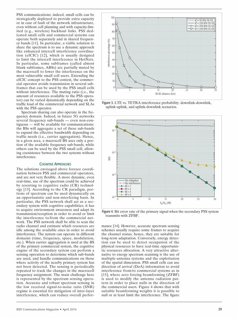
IEEE Communications Magazine • April 2016 29
PSS communications; indeed, small cells can be strategically deployed to provide extra capacity or in case of fault of the network infrastructure, even without cell planning and with capacity-lim-ited (e.g., wireless) backhaul links. PSS ded-icated small cells and commercial systems can operate both separately and in shared frequen-cy bands [11]. In particular, a viable solution to share the spectrum is to use a dynamic approach like enhanced intercell interference coordina-tion (eICIC) [12], which is usually designed to limit the intercell interference in HetNets. In particular, some subframes (called almost blank subframes, ABSs) are partially muted by the macrocell to lower the interference on the most vulnerable small cell users. Extending the eICIC concept to the PSS context, the commer-cial operator avoids transmission in several sub-frames that can be used by the PSS small cells without interference. The muting ratio (i.e., the amount of resources available to the PSS opera-tor) can be varied dynamically depending on the traffic load of the commercial network and SLAs with the PSS operator.
Spectrum sharing can also operate in the fre-quency domain. Indeed, in future 5G networks several frequency sub-bands — even non-con-tiguous — will be available for communications: the BSs will aggregate a set of these sub-bands to expand the effective bandwidth depending on traffic needs (i.e., carrier aggregation). Hence, in a given area, a macrocell BS uses only a por-tion of the available frequency sub-bands, while others can be used by the PSS small cell, allow-ing coexistence between the two systems without interference.
cognItIve APProAcHes
The solutions envisaged above foresee coordi-nation between PSS and commercial operators, and are not very flexible. A more dynamic, even real-time, use of the spectrum could be achieved by resorting to cognitive radio (CR) technol-ogy [13]. According to the CR paradigm, por-tions of spectrum can be used dynamically on an opportunistic and non-interfering basis. In particular, the PSS network shall act as a sec-ondary system with cognitive capabilities; it has to acquire environment awareness and adapt its transmission/reception in order to avoid or limit the interference to/from the commercial net-work. The PSS network shall be able to scan the radio channel and estimate which resources are idle among the available ones in order to avoid interference. The system can operate in different domains (time, frequency, space, modulation, etc.). When carrier aggregation is used at the BS of the primary commercial system, the cognitive engine of the secondary system can perform a sensing operation to determine which sub-bands are used, and handle communications on those where activity of the nearby primary system has not been detected. The sensing is periodically repeated to track the changes in the macrocell frequency assignment. The main challenge here is represented by the spectrum sensing opera-tion. Accurate and robust spectrum sensing in the low received signal-to-noise ratio (SNR) regime is essential for mitigation of inter-layer interference, which can reduce overall perfor-
mance [14]. However, accurate spectrum sensing schemes usually require some frames to acquire the channel status; hence, they are suitable for long-term adaptation. Conversely, energy detec-tion can be used to detect occupation of the physical resources to have real-time opportunis-tic resources allocation. A very attractive alter-native to energy spectrum scanning is the use of multiple-antenna systems and the exploitation of the spatial dimension. PSS small cells can use direction of arrival (DoA) information to avoid interference from/to commercial systems as in [15], where zero forcing beamforming (ZFBF) is used to modify the antenna radiation pat-tern in order to place nulls in the direction of the commercial users. Figure 4 shows that with suitable beamforming weights it is possible to null or at least limit the interference. The figure
Figure 3. LTE vs. TETRA interference probability: downlink-downlink, uplink-uplink, and uplink-downlink scenarios.
BS-BS distance (km)50
10
0
Inte
rfere
nce
perc
enta
ge (%
)
20
30
40
50
60
70
80
90
100
10 15 20 25 30 35
f = 50 kHz DL-DLf = 250 kHz DL-DLf = 250 kHz UL-ULf = 250 kHz UL-DL
Figure 4. Bit error rate of the primary signal when the secondary PSS system transmits with ZFBF.
Eb/N0 (dB)50
10-3
10-4
BER
10-2
10-1
10 15 20 25 30
No mitigationNo interferenceM = 1M = 2M = 3M = 4

IEEE Communications Magazine • April 201630
refers to a system with only L = 4 antennas and M incident multipath signals. If M > L – 1, for inherent characteristics of a DoA estimator and a beamformer, residual interference due to the 4th path is present, even if the performance gain is always signifi cant in respect to the case without interference mitigation. This problem can be overcome by increasing the number of antennas — which is the trend for future 5G communications — thus allowing the motion of individual UEs to be followed through very narrow beams.
conclusIonsThe migration of current narrowband PSS com-munication systems toward new technologies will face several factors concerning new network deployment: a broadband PSS-dedicated network yields benefi ts in terms of security, reliability, and service continuity, but requires a high amount of resources (i.e., time, costs, and spectrum) that are not always available. In order to fi nd a trade-off between these two trends, it is convenient to identify different approaches for providing high data rate PSS services, not necessarily by means of a PSS-dedicated network, but also through hybrid solutions based on partial infrastructure sharing. This article presents an analysis of the deployment issues and possible hybrid solutions for the gradual deployment of PSS broadband networks. Finally, some advanced solutions to allow efficient use of resources are introduced, focusing on partial RAN sharing between PSS and commercial networks, and leaving the PSS operator to provide critical services over harmo-nized spectrum.
references
[1] T. Doumi et al., “LTE for Public Safety Networks,” IEEE Commun. Mag., vol. 51, no. 2, 2013, pp. 106–12.
[2] G. Baldini et al., “Survey of Wireless Communication Technologies for Public Safety,” IEEE Commun. Surveys & Tutorials, vol. 16, no. 2, 2014, pp. 619–41.
[3] L. Carlá et al., “LTE Enhancements for Public Safety and Security Commu-nications to Support Group Multimedia Communications,” IEEE Network, vol. 30, no. 1, Feb. 2016, pp. 80–85.
[4] T. Knoll, “A Combined CapEx and OpEx Cost Model for LTE Networks,” 16th Int’l. Telecommun. Network Strategy and Planning Symp., Sept. 2014, pp. 1–6.
[5] D.-E. Meddour, T. Rasheed, and Y. Gourhant, “On the Role of Infrastruc-ture Sharing for Mobile Network Operators in Emerging Markets,” Comp. Networks, vol. 55, no. 7, 2011, pp. 1576–91.
[6] 3GPP, “TS 23.251 Technical Specification Group Services and System Aspects; Network Sharing; Architecture and Functional Description (Release 10),” tech. rep. V10.6.0, June 2013.
[7] CEPT-ECC, “Harmonised Conditions and Spectrum Bands for the Imple-mentation of Future European Broadband Public Protection and Disaster Relief (BB-PPDR) Systems,” tech. rep. 218, Oct. 2015.
[8] CEPT-ECC, “Compatibility and Sharing Studies for BB PPDR Systems Oper-ating in the 700 MHz Range,” tech. rep. 239, Sept. 2015.
[9] CEPT-ECC, “Compatibility Studies Regarding Broadband PPDR and Other Radio Applications in 410–430 and 450–470 MHz and Adjacent Bands,” tech. rep. 240, Sept. 2015.
[10] R. Fantacci, D. Marabissi, and D. Tarchi, “A Novel Communication Infra-structure for Emergency Management: The In.Sy.Eme. Vision,” Wireless Commun. Mobile Comp. (Wiley), Special Issue on Innovative Commun. for a Better Future, vol. 10, no. 12, Dec. 2010, pp. 1672–81.
[11] G. Bartoli et al., “Beamforming for Small Cell Deployment in LTE-Ad-vanced and Beyond,” IEEE Wireless Commun., vol. 21, no. 2, Apr. 2014, pp. 50–56.
[12] D. Lopez-Perez et al., “Enhanced Intercell Interference Coordination Challenges in Heterogeneous Networks,” IEEE Wireless Commun., vol. 18, no. 3, June 2011, pp. 22–30.
[13] R. Ferrus et al., “Public Safety Communications: Enhancement through Cognitive Radio and Spectrum Sharing Principles,” IEEE Vehic. Tech. Mag., vol. 7, no. 2, June 2012, pp. 54–61.
[14] T. Yucek and H. Arslan, “A Survey of Spectrum Sensing Algorithms for Cognitive Radio Applications,” IEEE Commun. Surveys & Tutorials, vol. 11, no. 1, 2009, pp. 116–30.
[15] G. Bartoli et al., “LTE-A Femto-Cell Interference Mitigation with MuSiC DOA Estimation and Null Steering in an Actual Indoor Environment,” IEEE ICC, Budapest, Hungary, 2013, pp. 2707–11.
bIogrAPHIes
ROMANO FANTACCI [F’05] is a full professor at the University of Florence, Italy. His current research interests are digital communication, computer communi-cation, queueing theory, and wireless broadband communication networks. He received the IEE IERE Benefactor premium in 1990, the IEEE ComSoc Award for Distinguished Contributions to Satellite Communications in 2002, and the IEEE ComSoc Award for Distinguished Contributions to Wireless Communications in 2015. He is currently serving as an Associate Editor for IEEE Network and the International Journal of Communications Systems. and as a Regional Editor for IET Commununications.
FRANCESCO GEI received his Master’s degree in telecommunications engineer-ing in 2008 from the University of Florence, where he currently collaborates as a researcher. In recent years, he has focused his activity on professional mobile radio evolution toward 4G mobile networks. He also collaborates in the scientific activities of the Technologies for Information and Communi-cation Consortium (TICom) , in cooperation with Finmeccanica S.p.A., for an industrial research project on SDR and mesh networks for military and professional purposes.
DANIA MARABISSI [SM’13] (dania.marabissi@unifi .it) received her Ph.D. degree in informatics and telecommunications engineering in 2004 from the Uni-versity of Florence, where she works as an assistant professor. She was the winner of the FIR-2013 contest funded by the Italian Ministry of Education. She is an Associate Editor of IEEE Transactions on Vehicular Technology, IET Communications, and the Scientifi c World Journal (Hindawi), and has been involved in the organization of several international conferences. Her current research interests are physical and access layers issues.
LUIGIA MICCIULLO received her degree in telecommunication engineering and Ph.D. from the University of Florence. Her research interests include aeronautical and professional communications and their evolution toward 4G technologies, intra-systems coexistence, interference management, and LTE multicast transmission. She also collaborates in the scientifi c activities of TICom, a consortium in cooperation between the University of Florence and Finmeccanica S.p.A.
The migration of cur-
rent narrowband PSS
communication systems
toward new technol-
ogies will face several
factors concerning new
network deployment:
a broadband PSS-ded-
icated network yields
benefi ts in terms of
security, reliability, and
service continuity, but
requires a high amount
of resources that are
not always available.

IEEE Communications Magazine • April 2016 310163-6804/16/$25.00 © 2016 IEEE
AbstrAct
Rapidly deployable and reliable mission-crit-ical communication networks are fundamental requirements to guarantee the successful oper-ations of public safety officers during disaster recovery and crisis management preparedness. The ABSOLUTE project focused on designing, prototyping, and demonstrating a high-capacity IP mobile data network with low latency and large coverage suitable for many forms of multi-media delivery including public safety scenarios. The ABSOLUTE project combines aerial, ter-restrial, and satellites communication networks for providing a robust standalone system able to deliver resilience communication systems. This article focuses on describing the main out-comes of the ABSOLUTE project in terms of network and system architecture, regulations, and implementation of aerial base stations, por-table land mobile units, satellite backhauling, S-MIM satellite messaging, and multimode user equipments.
IntroductIonTerrestrial communication infrastructures can be annihilated or partially damaged during disas-ter scenarios or temporary events [1]. In such scenarios, the necessity of re-establishing the communication system or deploying temporal infrastructures is a crucial requirement of public safety and disaster relief (PSDR) officers to pro-vision essential services, aid, and reconciliation for communities in affected areas. Therefore, the ABSOLUTE project [2] designed and demon-strated an innovative rapidly deployable net-work architecture, which is capable of providing broadband multimedia services and dependable connectivity for large areas affected by unexpect-ed disasters or temporary events.
Aerial and terrestrial rapidly deployable plat-forms are the key components of the ABSO-LUTE system. They are required to deliver
wide-area radio coverage with many applica-tions, embedded in easily and rapidly deploy-able equipment, suitable for inhospitable areas (e.g., after a disaster). In addition, innovative concepts such as standalone Evolved Packet Core (EPC), cognitive mechanisms for dynamic spectrum management, network reconfigura-tion, as well as opportunistic and cooperative networking mechanisms maximizing ABSO-LUTE system availability and dependability were developed.
This article focuses on explaining and describ-ing the main outcomes of the ABSOLUTE project in terms of innovative research and real implementation. In order to achieve a represen-tative overall validation of the proposed solution, a system demonstrator integrates major function-alities of system components such as:• Long Term Evolution-Advanced (LTE-A)
base stations embedded in low-altitude plat-forms (LAPs) enabling wide coverage for broadband services
• Portable land mobile base stations interop-erable with conventional public safety net-works
• Advanced multi-service professional termi-nals for first responders
• Satellite communications for both broad-band backhauling as well as narrowband ubiquitous messaging servicesAs design guidelines, the demonstrator takes
into account to a great extent the PSDR user requirements, and more precisely the 101 indi-vidual requirements detailed in [1] on the basis of technical perimeters identified after the sys-tem engineering phase.
The rest of this article is organized as follows. The PSDR communications requirements are explained. The proposed network and system architecture are presented, respectively. Then we concentrate on implementation details while also dealing with regulation aspects. Finally, we conclude this article.
Aerial Base Stations with Opportunistic Links for Next Generation
Emergency CommunicationsKarina Gomez, Sithamparanathan Kandeepan, Macià Mut Vidal, Vincent Boussemart, Raquel Ramos, Romain Hermenier, Tinku Rasheed,
Leonardi Goratti, Laurent Reynaud, David Grace, Qiyang Zhao, Yunbo Han, Salahedin Rehan, Nils Morozs, Isabelle Bucaille, Thomas Wirth, Roberta Campo, and Tomaž Javornik
crItIcAl communIcAtIons And PublIc sAfety networks
The authors focus on describing the main
outcomes of the ABSOLUTE project in terms of network and
system architecture, regulations, and imple-
mentation of aerial base stations, portable
land mobile units, satellite backhauling, S-MIM satellite mes-
saging, and multimode user equipments.
Karina Gomez and Sithamparanathan Kandeepan are with RMIT University; Macià Mut Vidal, Vincent Boussemart, Raquel Ramos, and Romain Hermenier are with TriaGnoSys GmbH; Tinku Rasheed and Leonardi Goratti are with Create-Net; Laurent Reynaud is with Orange; David Grace, Qiyang Zhao, Yunbo Han, Sala-hedin Rehan, Nils Morozs, and Tao Jiang are with the University of York; Isabelle Bucaille is with Philippe Charpentier Thales Communications & Security; Thomas
Wirth is with Heinrich Hertz Institute; Roberta Campo is with Eutelsat; Tomaž Javornik is with Jozef Stefan Institute.

IEEE Communications Magazine • April 201632
PublIc sAfety scenArIoMajor PSDR network services encompass first responder intercommunication support, emer-gency medical and critical infrastructure commu-nication facilities, surveillance and security, and so on. Such services rely on advanced devices, fully equipped to support demanding applica-tions, notably in terms of bandwidth and delay, including the transmission of real-time video flows and high-resolution images and group con-versations, and the support of remote sensing and monitoring. However, in post-disaster situations, the reliability and performance of such services may be seriously affected since regular networks can be exposed to significant impairments. For instance, terrestrial network infrastructure may be structurally damaged or subjected to power outages caused by multiple factors, including earthquakes and tsunamis.
Psdr requIrements
As a result, the nature and extent of a PSDR network is largely governed by the magni-tude of the considered disaster. This leads to a series of requirements to address, including the size of the area to be covered, the number of users to support, the subsequent minimum network capacity, and the choice of adequate deployment sites for the required equipment. In addition, this network must operate robustly in potentially adverse conditions met in post-disas-ter situations (e.g., harsh weather, unfavorable radio propagation conditions, limited avail-ability of electrical power, communication link disruptions, and unexpected user traffic surge). Moreover, it must be able to meet all of these constraints as autonomously as possible with-out compromising the expected performance. In this context, self-configuration and spectrum awareness techniques are particularly required to adapt to the existence, in the deployment area, of dynamic conditions (in terms of allowed or more appropriate frequency bands and radio frequency power bounds, power availability, varying opportunities to interconnect with sur-viving terrestrial infrastructure being restored, etc.) [1]. Furthermore, PSDR communication systems need to dynamically adapt to the envi-ronmental conditions of the deployment scenar-ios and, in particular, to the successive stages of
post-disaster operations. In this regard, flexibil-ity and modularity both represent key enablers to ensure adequate scalability of the PSDR network. Consequently, there is an increasing demand from the PSDR community for a reli-able and scalable multi-purpose communication system, adapted to the provision of dynamic network coverage with low-delay and large-ca-pacity transmissions, and able to interoperate with legacy PSDR networks.
ABSOLUTE network ArchItectureScalable network coverage and capacity as well as a resilient, flexible, and secure infrastructure are essential features of the ABSOLUTE system. The network has been derived starting from the general user needs, and identifies the main sub-systems and their interactions in terms of com-munication links in different scenarios [1]. The overall architecture is shown in Fig. 1.
Low-altitude platforms (LAPs), also referred to as aerial eNodeBs (AeNBs), are standalone aerial platforms that can rapidly be deployed by means of tethered balloons equipped with the LTE payload and capable of acting as base sta-tions. LTE cell coverage can be controlled by properly setting the altitude of the helikite and transmission power.
Portable land mobile units (PLMUs) are standalone ground platforms that can be rap-idly deployed in areas where terrestrial access for PSDR officers is available. The PLMU is characterized by a payload that can host several communication technologies. The PLMUs also extend the AeNB coverage and capacity by act-ing as eNBs, and providing terrestrial trunked radio (TETRA) and Wi-Fi connectivity.
Wireless sensor networks (WSNs) are spread over the disaster area or carried by PSDR teams. WSNs acquire different ambient information regarding temperature, humidity, or other met-rics. PLMUs act as gateways for information gathered by WSNs.
Satellite backhauling functionalities for the AeNB and PLMU subsystems are achieved by means of a broadband link in the Ka-band with a geostationary satellite. This offers the sys-tem users a reliable and resilient connection to headquarters and the Internet. Notice that inter-eNB communication is also implemented by the adoption of a wireless backhaul link, using, for example, longer-range Wi-Fi tech-nology [13].
S-MIM bidirectional messaging is implement-ed using the S-MIM satellite protocol. It provides PSDR officers an immediate narrowband commu-nication with the headquarters [4].
Multimode user equipments (MM-UEs) are powerful terminals capable of supporting mul-tiple radio links and additional services. Such devices allow PSDR officers to associate with the AeNB or PLMU to communicate with each other via LTE, Wi-Fi, or TETRA, or with their remote headquarters via the satellite link.
Device-to-device communications (D2D) links are established in an ad hoc fashion among MM-UEs, via either LTE D2D mode orvia other interfaces (Wi-Fi or TETRA). D2D communica-tions are used out of coverage, in coverage, and in partial coverage.
Figure 1. Overall ABSOLUTE architecture suitable for public safety scenar-ios. The main components of the ABSOLUTE network are aerial base stations (AeNBs), portable land mobile units (PLMUs), Ka-band satellite backhauling, S-MIM satellite messaging, and multimode user equipment (which are able to operate in direct mode).
SurvivalLTE eNB
AeNB
MM-UE
MM-UEMM-UE
PLMU
MM-UEMM-UE
MM-UEMM-UE
MM-UE
MM-UE
ConsumerUE
ConsumerUE
MM-UE
Tetra or WiFi linkLTE terrestrial linkLTE aerial linkDirect UE-UE link (D2D)Inter eNB communication linkWSN linkSatellite link
AeNB
Ka-band
Ka-band
Ka-band
S-band
Satellite accessnetwork
LTE backbone
Datastorage
Headquarter 1
Headquarter 2
Internet
WSN

IEEE Communications Magazine • April 2016 33
ABSOLUTE system ArchItecture
In order to enable good connectivity over the variety of technologies available in network archi-tecture, a coordinated mechanism such as dynam-ic spectrum sharing (DSS), improved handover, energy management, relay and clustering tech-niques, optimal base station placement, and oth-ers have been designed [4–13].
flexIble mAnAgement entIty
The LTE cells of ABSOLUTE-eNBs (AeNBs or PLMUs) are designed to work totally iso-lated from the physical EPC using the flexible management entity (FME) [7]. A standalone EPC is the architectural concept introduced by the FME in the ABSOLUTE architecture. The main objective of the FME is embedding the most fundamental EPC operations at the ABSOLUTE-eNB side (Fig. 2). The main dif-ference between the FME and conventional EPC is the change of residency of core network elements, which leads to multiple advantages toward system optimization, especially scalabil-ity, and easy and fast deployment. The main advantage of placing the EPC functionalities at the ABSOLUTE-eNB side is plug-and-play capability, allowing it to operate without the necessity of third party equipment, which is highly beneficial in disaster system deployments. Thus, the virtual-EPC (vEPC in Fig. 2) supports specific EPC functionalities that give the AeNB the freedom to operate autonomously providing connectivity and other services to users. It is composed of the following parts: • The gateway agent (GW-A) manages all the
mechanisms implemented for supporting serving gateway and packet data network gateway functionalities.
• The mobility management entity agent (MME-A) supports the mechanisms imple-mented for supporting the MME stack and non-access stratum (NAS) functionalities.
• The home subscriber server (HSS) is a data-base that contains public safety user and subscription-related information.
• The device-to-device agent (D2D-A) is respon-sible for managing D2D communications.To support the networking requirements of
operating an EPC, the FME implements addi-tional units and agents:• A routing management unit (RMU) is
responsible for the routing mechanism in the network.
• A topology management unit (TMU) is responsible for topology optimization and load balancing techniques.
• A link management unit (LMU) manages the backhauling connectivity.
• A cognitive dynamic spectrum access agent (CDSA-A) implements cognitive dynamic spectrum access techniques.
• A disruption management agent (DMA) implements techniques for disruption-toler-ant operations.These units and agents perform tasks based
on information collected at the cell or network level. These allow distributed radio and net-work resources management among the multiple access technologies and subsystems.
mobIlIty And toPology mAnAgement
Since the ABSOLUTE network is characterized by flexible and dynamic deployment of subsys-tems in order to provide coverage and sufficient capacity, the network is rolled out and rolled back in multiple phases. Therefore, several algo-rithms and techniques have been proposed in the ABSOLUTE project in order to optimize capacity in the dynamic network architecture using topology management protocols. Mobil-ity management techniques that allow efficient mobility management of connected users across the subsystems have also been studied, includ-ing handover techniques and mobility robustness optimization schemes. The proposed techniques include:• Geographical placement and re-placement
of ABSOLUTE-eNBs such that coverage and capacity of the network are maximized and interference is minimized
• Clustering of MM-UEs mapped onto a limited number of ABSOLUTE-eNBs to improve energy efficiency
• Activation and deactivation of ABSO-LUTE-eNBs and MM-UEs distribution to trade off traffic load, capacity, energy con-sumption, and so on
• Handover parameters optimization for reducing radio link failures
Figure 2. High-level view of the units and agents of the flexible manage-ment entity (FME), which is part of the system-level protocol of ABSO-LUTE-eNB.
MM-UEMM-UE
MM-UE
MM-UEMM-UE
MM-UE
MM-UE
ConsumerUE
AeNB
LAPcomm
RRHSatcom
Additional radiointerfaces
LAPcomm
S-ban
d Ka-band
PLMU
eNB FMEeNB FME
ABSOLUTE-eNBQAM
RRC
PDCPHeader
compression
S1-APS1-MME
FMERouting management unit
WLAN or satellite interface
Topology management unit
Link management unit
Virtual EPC
PHY
CRPIGbE
Modulation
MACMultiplexing and
hybrid ARQ process
RLCMac addressclassifier and
bearer selection
LTE radioand antenna(LAP-RHH)
CDSA-C
CDSA-A
Reso
urce
man
ager
S1-U
GTP-U
DMA
MME-A
GW-A
Gi
D2D-A
NAS HSS

IEEE Communications Magazine • April 201634
• Detection and minimization occurrences of too-early and too-late handovers, wrong handovers, and unnecessary handovers (to avoid the ping-pong effect)
dynAmIc sPectrum shArIng mechAnIsms The ABSOLUTE project focused on investigat-ing, proposing, and implementing techniques for sharing portions of spectrum with primary users, since it is likely that dedicated spectrum will not be available in all cases for PSDR. Sharing needs to be achieved on a dynamic basis and is imple-mented in a distributed way at each eNB, using a CDSA-A. Dynamic spectrum sharing (DSS) is enabled using spectrum awareness to dynamical-ly determine which resources are available for use, on either whole LTE channels or resource block groups within an LTE channel.
Spectrum awareness comprises a radio envi-ronment map (REM), which is an intelligent database that stores, processes, and delivers information about the status of the radio envi-ronment needed to support DSS. The REM is initially based on knowledge retrieved from mobile operators and telecommunications reg-ulatory agencies about the locations of existing base stations and their basic parameters. This is supplemented by spectrum sensing, which is based on spectrum sensing information supplied
by the ABSOLUTE-eNBs and MM-UEs. This allows the list of radio channels available for transmission, the maximum transmit power for a specified location, and configuration of each base station to be determined in real time in a distributed fashion. The REM, via a web inter-face, can also be used to calculate the cover-age achieved with radio signals [13], exclusion zones, different LTE parameters, and expected throughput in the region.
This list of available resources is then used by the cognitive dynamic spectrum access to priori-tize the resources to be used. This is an extended version of LTE-A, which creates the flexibility to achieve DSS within the PSDR context. Sever-al cognitive techniques have been developed to prioritize the resources. These exploit different forms of machine learning, allowing historical information to be used to improve performance. These include [8–10]: • An adaptive call admission control scheme
for distributed reinforcement learning based dynamic spectrum access
• Heuristically accelerated Q-learning, which significantly speeds up the learning process
• Case-based reasoning reinforcement learn-ing to cope with asymmetric traffic loads
• Transfer learning for dynamic spectrum and topology management in flexible architec-tures to assist with the rollout and rollback of the ABSOLUTE infrastructure in PSDR scenarios
d2d communIcAtIons
The advantage offered by the D2D feature is to enable proximity services and quick data exchange among MM-UEs without resorting to the intervention of the AeNB or PLMU. D2D communications over LTE require a number of challenges to be solved that include the definition of a D2D protocol for communication, potential D2D pair discovery, and security. In order to solve these challeng-es, a suitable protocol was proposed within the project [8], in which a selected MM-UE becomes the enabler, coordinator, and manag-er of the D2D network. Thus, when MM-UEs lose connectivity with the ABSOLUTE-eNBs, or the LTE coverage does not exist for at least a specific amount of time, the selected MM-UE is responsible for establishing and managing the D2D network. The proposed protocol includes the mechanisms for network discovery, D2D communication session setup, and association/disassociation in the differ-ent scenarios of radio coverage. In addition, a security mechanism for D2D that is based on exchanging shared encryption keys was also proposed [12]. The key strength of such a mechanism consists of its simplicity, and a number of security parameters have been studied in order to adapt to the peculiarities of D2D communications. It is worth empha-sizing that devices involved in D2D commu-nications are battery operated and therefore sensitive to energy waste. Furthermore, the length of the security keys must be limited to avoid having too high a requirement on the computational power and memory storage at the MM-UE side.
Figure 3. Aerial-eNodeB implementation: aerial segment (RRH and antenna) and terrestrial segment (EPC, LTE baseband Ka-band equipment) during validation phase.
Aerial segment
Terrestrial segment
Antenna
RF cable
RRH
Rack mounted screen and keyboard
Deployable Ka-band terminal
LTE baseband rack
Boards (PHY + MAC)Router plus miscellaneous
Rack mounted server(EPC plus SIP server)

IEEE Communications Magazine • April 2016 35
demonstrAtor
The project consortium successfully demonstrat-ed the use of several implemented subsystems of the ABSOLUTE system to the European Com-mission reviewers and end users (the event took place in France in September 2015).
Aenb ImPlementAtIon
The AeNB is composed of aerial and terrestrial segments. The aerial segment consists of a Helik-ite platform with its radio remote head (RRH) (plus antenna and battery power payload) oper-ating at varying altitudes on the air, while the terrestrial segment consists of an eNB baseband (plus EPC and satellite equipment) operating stationary on the ground.
Aerial Segment: An important component of the aerial segment is the Helikite, which is a helium inflatable kite that relies on lighter-than-air principles to achieve buoyancy, with increased lift and stability thanks to its kite pro-file and the use of a tether (which is moored to the terrestrial segment). Helikite aerostats are reliable in high winds, heavy rainfall, or very dusty conditions. The ABSOLUTE system uses moderate sized helikites of 34 m3, which are highly mobile, simple/fast to set up, and only require a few days of training for operators. This helikite is 6.5 m long and 5 m wide, and has a net helium lift in no wind, in dry condi-tions, of 14 kg. Note that rainfall, snow, sleet, and so on will reduce the lift by 3 kg or so. Therefore, this leaves about 10 kg for maximum payload, including RRH, fiber optic, batteries, waterproof cases, and so on.
Since the helikite payload is limited, sig-nificant effort has been made in designing and choosing efficient but very lightweight and cost-efficient RRH, waterproof suitcase, batteries, and antennas that integrate easily into the AeNB environment. To achieve this, metalized foam has been used to realize the antenna. The total weight of the helix antenna including radoma, cable, and N connector is 240 grams. The helikite also provides a sys-tem suitable to fix the RRH in the kite and the antenna shapes onto the balloon, which consists of two vertical bars fixed at the back of the balloon, as shown in the aerial segment of Fig. 3.
Another key component of the aerial segment is the RRH, which supports a wide frequency range from 70 MHz up to 6 GHz. The RRH design allows a power reduction to 1 A, without power amplifiers (PAs), while with external PAs, the power consumption totals 1.7–1.8 A. Flex-ible software defined radio (SDR) runs on the RRH. SDR consists of a stacked digital interface card and a radio frequency front-end fiber opti-cal baseband interface. The most relevant SDR-RRH characteristics are:• 2 radio frequency transceivers with 2-anten-
na duplex operation with up to 56 MHz analog bandwidth
• 70 MHz–6 GHz carrier frequency range and different reference clocks
• Duplex components (filters, diplexers and/or TDD switches) on extra plug-on modules
• Cognitive extension with key sensing func-tionalities for obtaining occupancy thresh-olds of spectrum and collecting data measurement (e.g., signal strength indica-tors)Finally, an industry-standard common public
radio interface (CPRI) is used for the optical link that connects the aerial (RRH) and terres-trial segment (eNB baseband). Notice that the fiber optic is moored with the helikite tender.
Terrestrial Segment: In the terrestrial segment, the eNB baseband boards are integrated in a 19 in AMC rack fitted in a deployable cabinet (here-after called “baseband cabinet” and shown in Fig. 3) so that they can easily be used in outdoor conditions. In complement to the eNB baseband boards, the baseband cabinet comprises all the necessary functions of the AeNB subsystem. To this purpose, it is equipped with following ele-ments:• A MicroTCA rack aimed at receiving the
eNB baseband boards for the PHY and MAC layers
• A server where the EPC software and SIP server software run
• A foldable keyboard and screen to have easy access to the server (e.g., to perform regis-tration of new MM-UEs)
• A rack dedicated to routing, cabling, and powering functions of the terrestrial seg-ment
The baseband cabinet is linked by Ethernet to the deployable Ka-band satellite terminal on one hand and to the RRH via optical fiber on the other.
Plmu ImPlementAtIon
The PLMU corresponds to the terrestrial com-munication segment of the ABSOLUTE archi-tecture. This unit is deployed on the ground and therefore offers smaller coverage compared to that reached with the AeNB. However, it pro-vides additional wireless communication technol-ogies and is also highly modular for answering different users’ needs. The PLMU has been implemented as a complete communication sys-tem embedded in a rugged suitcase, as shown in Fig. 4. It is composed of several components,
Table 1. List of components integrated within the PLMU.
Device Functionality
Energino Measures the voltage, current, and power consumption
4G eNodeB Provides an LTE network
WLAN router Provides a Wi-Fi network
3G+ femtocell Provides an HSPA network
Wireless sensor gateway
Provides environmental measurements and connectivity to the sensor nodes
Single-board computer Constitutes the main processing platform
Relay blocks moduleAllows switching on/off of the communication technologies for saving battery and increasing PLMU autonomy
Tablet Offers an interface to the main user

IEEE Communications Magazine • April 201636
listed in Table 1. The entire system can be pow-ered by either a regular power outlet or a battery pack providing up to several days of autonomy, depending on the battery capacity and the com-ponents in use. The PLMU is modular and easily adaptable to the requirements of each specific emergency situation by using only the required communication technologies, which are switched on/off using the relay blocks module. External devices can be plugged to the PLMU for extend-ing its capabilities (e.g., a satellite system for enabling satellite backhauling).
The components and applications integrated in the PLMU provide the following services and functionalities:• System management: PSDR officers can
remotely control the PLMU subsystems and see their power consumption.
• Voice calls and SMS: PSDR officers can call and send SMS to any other first responder, using either the same communication tech-nology or any other one (interoperability), and to any public switched telephone net-work (PSTN) subscriber.
• Internet access: PSDR officers can access the Internet using any of the available commu-nications technologies.
• Messages and location: Victims can send geo-located distress messages to the PSDR network using the ABSOLUTE application. PSDR officers can grade distress messages, see their location on a map, and exchange other PSDR messages.
• Area monitoring: PSDR officers can see environmental measurements (temperature, pressure, light intensity, humidity, etc.) pro-vided by the deployed WSN and geo-locat-ed on a map.Note that voice calls and messages services
are supported and managed by a standalone Ses-sion Initiation Protocol (SIP) server running in the PLMU. Therefore, those services are avail-able without an external Internet connection. SMS are enabled by the standalone EPC; addi-tionally, the SIP server allows interoperability between the different communication technol-ogies. Apart from local services, access to the PLMN and PSTN is also possible thanks to the SIP server communicating with an external SIP provider.
Performance Evaluation: The performance of the PLMU has been evaluated in both the lab-oratory and the field during the demonstration of the project. Different metrics have been mea-sured, ranging from the services and application performance to the efficiency of the wireless communication networks. The results shown in Table 2 are obtained without any optimization of the radio frequency frontend (i.e., no dedicated power amplifiers and specific antennas).
kA-bAnd bAckhAulIng ImPlementAtIon
Satellite is a critical component of ABSOLUTE system where infrastructure may be damaged or not fully functional. It allows for connectivity in almost any weather condition and any location. The Ka-band antenna subsystem is the element that connects the ABSOLUTE-eNB with the sat-ellite segment, and thus enables the backhauling functionalities. The Ka-band antenna subsystem is auto-pointing and easy to deploy and set up with a minimal amount of training, as shown in Fig. 5. The Ka-band subsystem is composed of the following:• The antenna is a portable and motorized sat-
ellite dish with auto-pointing functionalities. Less than 10 min is required for deployment and connection setup.
• The suitcase unit is a ruggedized 19 inch-es flight case hosting a modem, a router, and an antenna control unit. The modem is based on the ViaSat SurfBeam2 technology, granting high speed and performance.The Ka-band backhauling makes use of the
Tooway system of Eutelsat, which provides satel-lite broadband services all over Europe via the 82 spots of the high-throughput geostationary satel-lite KA-SAT, positioned at 9° East. The ground segment is composed of eight terrestrial gate-ways, plus two for backup, deployed in differ-ent regions and interconnected in a fiber ring for maximum reliability. This backhauling solution provides a tried and tested, stable, and reliable platform able to perform any IP communication, from voice to data, from any location in Europe as long as there is line of sight (LOS) from the terminal to the satellite.
s-mIm messAgIng ImPlementAtIon Third party applications for messaging, includ-ing WhatsApp, Hangouts, Skype, and simi-lar, installed on MM-UE can be used with the
Figure 4. Portable land mobile unit equipment (PLMU, on the right) and its battery (on the left) during the validation phase.
Table 2. Performance measurements of the PLMU.
Communication Technology Cell radius (m)Data rates (Mb/s)
Uplink Downlink
SatCom DVB-like NA 8.4 18.5
Wi-Fi IEEE 802.11n 450 29.8 31.9
3G HSPA 600 3.9 17.9
4G LTE Rel. 8 650 19.5 61.6

IEEE Communications Magazine • April 2016 37
S-band terminal. The S-band terminal acts as an IP satellite gateway for PSDR users connected to the S-band terminal via its embedded Wi-Fi access point. The transmission of data packets over the satellite link takes place according to the S-MIM standard.
The S-band terminal prototype, shown in Fig. 5, is integrated inside a polycarbonate rug-gedized suitcase with a weight of 24 kg, and an embedded battery pack granting an auton-omy of 3 h (it also works with 230 V AC). The S-band terminal uses two satellite antennas: one for transmission and one for reception. Although two omnidirectional antennas are embedded in the suitcase, it is recommended that two external directive antennas are used that ensure a higher gain. Communication in S-band was provided through the geostation-ary satellite Eutelsat 10A (E10A), positioned at 10°, East and the antennas have to be posi-tioned in LOS with the satellite. The S-band terminal implements the S-MIM protocol with a spread spectrum on a channel of 5 MHz and operates at 2005 GHz in transmission and 2193 GHz in reception. It is optimized for bursts of messages, with a maximum transmitted power of 5 W. It provides a maximum data rate in transmission (terminal to satellite) of 80 kb/s and a maximum data rate in reception (satel-lite to terminal) of 2.1 Mb/s [4].
mm-ue ImPlementAtIon
Nowadays smartphones and tablets are a real breakthrough compared to previous genera-tions of terminals. Indeed, they can run many applications downloaded from app stores on the Internet and embed many interfaces and communication standards: 2G/3G, 4G (LTE-A), Wi-Fi, Bluetooth, and GPS. Adding some dedicated ABSOLUTE applications on a smart-phone is a smart and cheap solution for the MM-UE. However, while having some appeal-ing functions, the smartphone cannot answer all PSDR officers’ needs as such, especially in disaster scenarios.
The MM-UE needs to be fully secure and reliable in adverse situations, with huge auton-omy and extended radio range. Besides, for PSDR officers performing specific operations in harsh environments (high temperature, shocks, possible water immersion, etc.) with extended autonomy expectations and extended radio cov-erage, dedicated rugged devices are an imposi-tion. To this end, two rugged MM-UE designs are defined:• An autonomous small MM-UE for personal
use• A rugged Ethernet UE in aluminum casingMM-UEs also include multi-band operations comprising PSDR bands, as well as commercial-ly operated bands to allow users to roam from PSDR networks to public networks when need-ed.
regulAtory AsPectsAs a radio system, the used frequencies in the ABSOLUTE system must be coordinated with those of other nearby networks in order to minimize interference. In the temporary event scenario, the deployment of LAPs is coordi-
nated by a PLMN operator (PLMNO), which uses the ABSOLUTE network to strengthen its ground network. It is therefore the responsi-bility of the PLMNO to obtain the appropriate licenses for the deployment of the ABSO-LUTE network. On the other hand, in the disaster relief scenario, the system is deployed by the PSDR agencies, which must hold the appropriate frequency license in order not to disturb surviving network infrastructure. The European Union and NATO have agreed on allocating frequencies in the 300 MHz band for PSDR usage. In addition, countries in South America and the Asia-Pacific region will also use the 800 MHz band.
The radio spectrum for broadband PSDR (BB-PSDR) in Europe is still under study by Conference of European Posts and Telecom-munications (CEPT)-ECC in Working Group FM49 [15]. This group provides a BB-PSDR regulatory framework, with 3GPP LTE Release 12 as the reference technology. The main direc-tions followed in this regard are to consider the provision of broadband PSDR services with-in the paired frequency arrangement (703–733
Figure 5. Ka-band Backhauling (Antenna and Suitcase Unit) and S-band Mes-saging (Modem, Wi-Fi and Antennas) Satellite Equipment.
Ka-band
S-bandS-band
omnidirectionalantennas
S-banddirectiveantennas Wi-Fi
access pointwith Web Gui

IEEE Communications Magazine • April 201638
MHz and 758–788 MHz), provided that the implementation is in line with the assumptions made by the mobile telcos. Furthermore, there is consideration of a harmonized solution for ad hoc PSDR network usage above 1 GHz, and other solutions outside the 700 MHz band (e.g., 400 MHz) and/or the possible use of guard band and duplex gap of 700 MHz with a conventional duplex: for example, the following options are under consideration: 2 x 5 MHz (698–703/753–758 MHz) and 2 × 3 MHz (733–736/788–791 MHz). Nevertheless, the United States and Australia have already regulated the 700 MHz and 800 MHz bands, respectively, for LTE BB-PSDR usage.
conclusIonsThe ABSOLUTE project designed and demon-strated the high capacity and coverage capa-bilities of technical solutions adapted to the fi eld of broadband emergency communications in which LTE technology is predominantly adopted. In PSDR scenarios the key solution is to adopt flexible base stations embedded onboard aerial platforms and terrestrial land mobile stations. The ABSOLUTE project also provides a reference implementation for an interoperable and backward-compatible net-work solution, including relevant regulatory and standardization efforts, which enable quick adoption of 4G communication technologies to remarkably improve disaster recovery and cri-sis management preparedness. This is based on the ability to operate with existing LTE spec-trum by exploiting energy-efficient cognitive mechanisms, which provide agile reconfigu-ration. Since technical and business cases for ABSOLUTE system exploitation are also been studied for industrial partners, it is expected that the ABSOLUTE system can rapidly be produced and marketed.
AcknowledgmentThe research leading to these results received partial funding from the EC Seventh Framework Programme (FP7-2011-8) under Grant Agree-ment FP7-ICT-318632.
references
[1] M. Kobayashi, “Experience of Infrastructure Damage Caused by the Great East Japan Earthquake and Countermeasures against Future Disasters,” IEEE Commun. Mag., vol. 52, no. 3, Mar. 2014, pp. 23–29.
[2] A. Valcarce et al., “Airborne Base Stations for Emergency and Temporary Events,” Proc. PSATS, Toulouse, France, June 2013.
[3] I. Bucaille et al., “Rapidly Deployable Network for Tactical Applications: Aerial Base Station with Opportunistic Links for Unattended and Tem-porary Events ABSOLUTE Example.” Proc. IEEE MILCOM., Nov. 2013, pp. 1116–20.
[4] A. Recchia, F. Collard, and N. Antip, “Performance Analysis of the S-MIM Messaging Protocol over Satellite,” Proc. Advanced Satellite Multimedia Sys. Conf. and Signal Processing for Space Commun. Wksp., Sept. 2012, pp. 7–12.
[5] A. Hourani. S. Kandeepan and S. Lardner, “Optimal LAP Altitude for Maximum Coverage,” IEEE Wireless Commun., vol.3, no.6, Dec. 2014, pp. 569–72.
[6] S.Chandrasekharan et al., “Clustering Approach for Aerial Base-Station Access with Terrestrial Cooperation,” Proc. Wi-UAV Wksp., IEEE GLOBE-COM, Atlanta, GA, Dec. 2013, pp. 1397–1402.
[7] K. Gomez et al., “Enabling Disaster-Resilient 4G Mobile Communication Networks,” IEEE Commun. Mag., vol. 52, no. 12, Dec. 2014, pp. 66–73.
[8] Q. Zhao, D. Grace, and T. Clarke, “Transfer Learning and Cooperation Management: Balancing the Quality of Service and Information Exchange Overhead in Cognitive Radio Networks,” Trans. Emerging Telecommun. Technologies, vol. 26, no 2, Feb. 2015, pp. 290–301.
[9] N. Morozs, T. Clarke, and D. Grace, “Distributed Heuristically Accelerated Q-Learning for Robust Cognitive Spectrum Management in LTE Cellular
Systems,” IEEE Trans. Mobile Computing, published online 17 June 2015.[10] N. Morozs, T. Clarke, and D. Grace, “Heuristically Accelerated Reinforce-
ment Learning for Dynamic Secondary Spectrum Sharing,” IEEE Access, Dec. 2015.
[11] L. Goratti et al., “A Novel Device-to-Device Communication Protocol for Public Safety Applications,” Proc. D2D Wksp., IEEE GLOBECOM, Atlanta, GA, Dec. 2013, pp. 629–34.
[12] L. Goratti et al., “Connectivity and Security in a D2D Communication Protocol for Public Safety Applications,” Proc. IEEE Wireless Commun. Sys., 26–29 Aug. 2014, pp. 548–52.
[13] D. Sekuljica et al., “Mobile Networks Optimization Using Open-Source GRASS-RaPlaT Tool and Evolutionary Algorithm,” Proc. Euro. Conf. Antennas and Propagation, Apr. 2015, pp. 1–5.
[14] T. R. Rasheed et al., “On the Feasibility of Handover over WiFi Backhaul in LTE-based Aerial-Terrestrial Networks,” Proc. IEEE Wireless Commun. and Networking Conf., Apr. 2014, pp. 2196–2201.
[15] R. Ferrus et al., “Public Safety Mobile Broadband: A Techno-Economic Perspective,” IEEE Vehic. Tech. Mag., vol. 8, no. 2, June 2013, pp. 28–36.
bIogrAPhIes
karina GomeZ chaveZ ([email protected]) received her Mas-ter’s degree in wireless systems and related technologies from Turin Polytech-nic, Italy. In 2007, she joined the Communication and Location Technologies Area at FIAT Research Centre. In 2008, she joined the Future Networks Area at Create-Net, Italy. In 2013, she obtained her Ph.D. degree in telecommuni-cations from the University of Trento, Italy. Since July 2015, she has been a lecturer at the School of Electrical and Computer Engineering of RMIT Univer-sity, Melbourne, Australia.
sithamparanathan kandeepan [SM] has a Ph.D. from the University of Technolo-gy, Sydney, Australia, and is currently with the School of Electrical and Computer Engineering at RMIT University. Previously he worked with the NICTA Research Laboratory, Canberra, and CREATE-NET Research Centre. He served as Vice Chair of the IEEE Technical Committee on Cognitive Networks, and currently serves as Chair of the IEEE VIC Region Communications Society Chapter.
maciÀ mut vidaL ([email protected]) received a Master’s degree in telecommunications at Universitat Politècnica de Barcelona in 2012. Since 2012, he has been with TriaGnoSys GmbH as an R&D engineer working on many different topics with the main focus on mobile, aeronauti-cal, and emergency communications, and system design and integration. His project expertise includes various FP7, ARTES/ESA, and LuFo Projects such as ABSOLUTE, SPARTACUS, 3InSat, and SO4A as a team member, work package leader, and technical manager.
vincent boussemart ([email protected]) received his Technological Research diploma from ENSIAME, France, in 2006. In 2013 he received a Ph.D. from the Institut Supérieur de l’Aéronautique et de l’Espace, France, and the German Aerospace Centre. He worked at the Deutsches Zen-trum für Luft- und Raumfahrt (DLR) between 2006 and 2013 as a technical engineer/scientific researcher. He joined TriaGnoSys in 2014, and is now involved in European and internal projects.
raQueL ramos ([email protected]) received a Bachelor’s degree in 2011 in industrial engineering specialized in electronics from the Polytechnic University of Catalonia. In 2014 she obtained a Master’s diplo-ma in electrical engineering from the Polytechnic University of Catalonia with focus on design and optimization of satellite communication. From 2011 to 2013 whe worked in the R&D Department for Sony Europe Ltd, Barcelona. She has been working for TriaGnoSys since 2014 as a research engineer.
romain hermenier ([email protected]) received his Mas-ter of Engineering from Telecom SudParis in 2008. In the same year he joined DLR in the Institute of Communications and Navigation. He has been involved in European FP7 research projects (SANDRA, SafeTRIP, ABSOLUTE) related to aeronautics and space communications. Since autumn 2014 he has been working as a program manager at Zodiac Aerospace (TriaGnoSys GmbH) for in-flight entertainment products. He is an author/co-author of several papers.
tinku rasheed ([email protected]) is a senior research staff mem-ber at Create-Net. Since May 2013, he has headed the Future Networks R&D Area (FuN) within Create-Net. He has extensive industrial and academic research experience in the areas of mobile wireless communication and data technologies, and end-to-end network architectures and services. He has several granted patents, and has published his research in major journals and conferences.
Leonardo Goratti ([email protected]) received his Ph.D. degree in wireless communications in 2011 from the University of Oulu, Finland, and his M.Sc. in telecommunications engineering in 2002 from the University of Firenze, Italy. From 2003 until 2010, he worked at the Centre for Wireless Communications Oulu. From 2010 until early 2013 he worked at the European funded Joint Research Centre (JRC), Ispra, Italy. In 2013, he joined CREATE-NET.
The ABSOLUTE proj-
ect designed and
demonstrated the high
capacity and coverage
capabilities of technical
solutions adapted to
the fi eld of broadband
emergency communica-
tions in which LTE tech-
nology is predominantly
adopted.

IEEE Communications Magazine • April 2016 39
Laurent reynaud ([email protected]) is a senior research engi-neer for the Future Networks research community at Orange. After receiving his engineering degree from ESIGETEL at Fontainebleau in 1996, he acquired experience in the development and deployment of distributed software in the context of telecommunications through successive positions at the French Home Department in 1997, Alcatel-Lucent from 1998 to 2000, and Orange since 2000. He participated to many French, European, and international research projects.
david Grace ([email protected]) received his Ph.D. from the University of York in 1999. Since 1994 he has been in the Department of Electronics at York, where he is now a professor (research) and head of the Communica-tions and Signal Processing Group. Current research interests include aerial platform based communications, cognitive dynamic spectrum access, and interference management. He is currently a non-executive director of a tech-nology startup company, and a former Chair of the IEEE Technical Committee on Cognitive Networks.
isabeLLe bucaiLLe ([email protected]) received her engineer-ing degree from ISEP in France in 1994. Then she joined the CNI Division of TH-CSF for digital processing studies. In 1997 she participlated in the ETSI group in charge of HiperLAN2 normalization. In 1998 she was in charge of system definition concerning stratospheric platforms (HAPS). Since September 2001 she has been in the Secured Wireless Products Activity of THALES Communications. In 2011, She was appointed TCS Representative in 3GPP.
thomas Wirth ([email protected]) received a Dipl.-Inform. degree in computer science from Universität Würzburg, Germany, in 2004. In 2004, he joined Universität Bremen working in the field of robotics. In 2006 he joined HHI working as a senior researcher on resource allocation algorithms for LTE/LTE-Advanced systems. Since 2011, he has been head of the Software Defined Radio (SDR) group in the Wireless Communciations and Networks Department, working in various projects on PHY and MAC design for 5G.
roberta campo ([email protected]) holds a Master’s degree in computer science from the University of Catania, Italy. In 2002 she joined Eutelsat. Working in the Eutelsat Innovation Team, she has been involved in several R&D projects related to the provision of broadband and mobile satellite services (Mowgly, UNIC, J-ORTIGIA, SafeTRIP), and in the provision of satellite communication to authorities and first responders involved in emergency and crisis management (Alert4All, PHAROS, ABSOLUTE).
tomaž Javornik ([email protected]) is a senior researcher in the Com-munication Systems Department at the Jozef Stefan Institute, and an assis-tant professor in the Jozef Stefan International Postgraduate School. He received B.Sc., M.Sc., and Ph.D. degrees in electrical engineering from the University of Ljubljana, Slovenia, in 1987, 1990, and 1993, respectively. He has co-authored many conference and journal articles, holds two inter-national patents, and serves as TPC member or reviewer for several IEEE conferences and journals.

IEEE Communications Magazine • April 201640 0163-6804/16/$25.00 © 2016 IEEE
AbstrAct
Mission-critical communications for public safety (PS) is of significant interest and a very high priority item for various organizations such as national regulatory agencies, telecom service providers, network vendors, device manufactur-ers, and third party public safety service provid-ers. LTE has been selected as the next-generation platform to support new mission-critical real-time broadband services to the PS community [1]. To address high performance and seamless user experience, LTE networks interwork with Wi-Fi for direct communication. Wi-Fi Direct provides the ability to create groups for efficient dissemination of information needed for critical communication directly between devices. In real-izing LTE for PS, it is also necessary to provide enhanced interworking between LTE and Wi-Fi for adequate emergency group communication. This article provides an overview of the PS-re-lated efforts in 3GPP, interworking aspects of LTE, Wi-Fi and its application to PS, as well as a mechanism to enhance the interworking between the two technologies to deliver an effective solu-tion for mission-critical communication and applications.
IntroductIonCommercial networks, such as third generation (3G), Long Term Evolution (LTE), and Wi-Fi, and dedicated land mobile radio (LMR) for pub-lic safety (PS) systems, such as Project 25 (P25) [2] and terrestrial trunked radio (TETRA) [3], are two distinct systems currently offering wire-less communication services. Push-to-talk (PTT) is ideal for group communication in a coopera-tive work environment, and PS agencies use PTT for mission-critical communications. Commercial wireless networks offer high data rates and good interoperability for voice and data, but lack ade-quate support to meet the needs of PS services. Current LMR systems utilize proprietary radio networks. Due to bandwidth limitations of LMR systems, PS agencies are keen to leverage com-mercial networks to support their application needs.
LTE-Advanced (LTE-A) standards provide multi-megabit-per-second data rates and multi-media capabilities in addition to traditional voice and messaging services. LTE is an evolutionary mobile broadband technology based on 3GPP
standards that has been selected as the baseline technology for a next generation broadband PS network for mission-critical communication. The existing PS standards (P25, TETRA) address a set of features that are not supported in com-mercial cellular systems. The PS requirement from commercial networks is to enhance the sys-tems to ensure high robustness and to address specific communication needs of emergency ser-vices. Establishing common technical standards for commercial cellular and PS networks offers advantages to both communities.
Third Generation Partnership Project (3GPP) expertise is being applied to the development of LTE enhancements related to PS. In emergency services, real-time group multimedia communica-tion including live videos or photos is often desir-able. There is a need for instant reliable mobile broadband service for communication between the various PS departments. 3GPP’s objective is to preserve the considerable strengths of LTE while also adding features needed for PS. A further goal is to maximize the technical com-monality between commercial and PS aspects to provide the best and most cost-effective solution for both communities.
WLAN systems, through the use of Wi-Fi Direct technology, enable the formation of groups on the fly for dissemination of informa-tion. They provide the robustness needed for critical communication and support offloading of communication from cellular networks. Efficient interworking of Wi-Fi and LTE enables opera-tors to harness their WLAN access networks to disseminate critical communication to a larger set of users. Figure 1 depicts the use of LTE and Wi-Fi as a single managed system for PS direct communication. The following sections of the article describe PS initiatives in 3GPP, as well as the application of interworking aspects of LTE and Wi-Fi Direct, and provide detailed mech-anisms for optimized provisioning and setup of Wi-Fi Direct groups for critical communication.
Ps requIrementsIn the event of an emergency situation, instant
intra- and inter-PS agency communication and collaboration is critical for crisis management. PS communication in an emergency situation may range from a minor incident (e.g., road accident) to a major incident such as a natural disaster. In
Enhanced Interworking of LTE and Wi-Fi Direct for Public Safety
Rajavelsamy Rajadurai, Karthik Srinivasa Gopalan, Mayuresh Patil, and Suresh Chitturi
crItIcAl communIcAtIons And PublIc sAfety networks
The authors provide an overview of the PS related efforts in 3GPP, interworking aspects of LTE and Wi-Fi and its application to PS, as well as a mechanism to enhance the interwork-ing between the two technologies to deliver an effective solution for mission-critical communication and applications.
The authors are with Samsung R&D Institute Bangalore.

IEEE Communications Magazine • April 2016 41
these scenarios it is critical for PS personnel to have efficient means for group communication with high reliability, including cases when there is loss of connectivity in affected regions.
A PS solution requires a standards-based holistic communications infrastructure to deliver interoperable mobile broadband mission-criti-cal communications (e.g., voice, video, media-rich applications). PS agencies place a strong emphasis on a user’s ability to trust their com-munications tools and network; therefore, special consideration of security is an important aspect when designing a PS LTE solution. Further requirements include reliability, accessibility, and allocation of network resources to ensure a sta-ble network connection in LTE for PS. An access priority mechanism among PS users and reduced access time are critical to ensure that PS users who need the network resources for announce-ments and monitoring will gain instant access.
PS users frequently need to communicate in dynamic groups that might involve both mobile users on the field and dispatchers from a con-trol center. Often these groups operate in PTT mode. Therefore, improved support for group communication in wireless networks expands the opportunity for commercial networks. PS requirements, however, are more rigorous, espe-cially for direct discovery and communication between the devices even when macro radio net-work coverage is unavailable.
Standardization of group call communication systems and related PTT features (e.g., floor control, group management) across multiple networks and radio technologies is critical for a strong ecosystem and reliable service offering. Work is still ongoing to identify and prioritize enhancements necessary for commercial net-works to support PS features.
3GPP stAndArds for Ps Ps over lte
The National Public Safety Telecommunications Council (NPSTC) [1] decided to use LTE as the platform for their national PS network [4]. Subsequently, after reviewing the PS require-ments, the TETRA and Critical Communications Association (TCCA) also endorsed the decision to use LTE for delivering mission-critical com-munications. Following these developments, the PS community of various regions is now closely working with the 3GPP community to develop a harmonized global LTE-based mission-critical standard.
3GPP has established a new working group (SA6) [5] and a corresponding work item, Mis-sion-Critical Push-to-Talk (MCPTT), for Release 13. The main objective of this work in 3GPP is to create a single common standard that meets the needs of the entire global PS commu-nity. While PS over LTE (PS-LTE) standards are already in development within 3GPP with initiatives such as LTE Device-to-Device Prox-imity Services (ProSe) and Group Communica-tion System Enablers for LTE (GCSE_LTE ) since 3GPP Release 12, MCPTT is responsible for developing the overall application and ser-vice layer aspects of mission-critical applications. However, it is expected that MCPTT will utilize the underlying technologies such as IMS, ProSe,
Wi-Fi interworking, and GCSE_LTE as neces-sary to realize the MCPTT requirements. Over the coming years, 3GPP intends to work with both the commercial cellular and PS communi-ties to evolve the PS-LTE platform.
MCPTT systems utilized by PS agencies enable their personnel to selectively and sequen-tially transmit messages to one another, on either a one-to-one or one-to-many basis over LTE. Using the LTE-based solution will enable broad-band PS networks to easily incorporate the core features including ProSe and group call enablers. This will provide PS operators with economic benefits from increased use of commercial net-works, decreased cost, technical benefits from improved data rates, and a robust group commu-nication solution. Similarly, commercial cellular operators will gain access to new capabilities that can enable new types of consumer and business services as well as being able to play an import-ant role in delivering PS communications. Ulti-mately, the most important benefit will be the delivery of an enhanced PS system that can meet the mission-critical needs of the global society.
3GPP system feAtures for PsThe following are the two main areas of LTE enhancements to address PS applications: • ProSe, which identify mobiles in physical
proximity and enable optimized communi-cations between them
• Group call system enablers, which support core requirements for efficient and dynamic group communications operations such as one-to-many communicationIn this article, our main focus is on the prox-
imity services that provide direct group commu-nication.
Figure 1. LTE managed PS system.
Wi-Fi Direct
Wi-Fi Direct
LTE Direct
LTE cell
UE#9
UE#10UE#11UE#12
UE#8
UE#6
UE#8
UE#7
UE#1UE#4
UE#3UE#5
UE#2

IEEE Communications Magazine • April 201642
ProXImIty servIces for Ps
ProSe consists of two main elements: network assisted discovery of users and the facilitation of direct communication between users. Direct communication means a radio connection is established between the user equipment (UE) without transiting via the network. ProSe meet the need for communication among PS users even if they are out of coverage.
The ProSe defi nition includes some features that are dedicated exclusively to PS applications. The ProSe features of signifi cance for PS consid-ered in 3GPP are: • Discovery within network coverage • Discovery out of network coverage • One-to-one communication • ProSe group communication (one-to-many)• ProSe broadcast • Coexistence of direct communication and
cellular communication Two potential mechanisms that aid PS appli-
cations include: • Discovery over LTE and communication via
Wi-Fi Direct• Discovery over LTE and communication
over LTE Direct
lte suPPort for wI-fI dIrect communIcAtIon
An LTE system supporting ProSe can enable Wi-Fi Direct-capable UEs to directly communi-cate using Wi-Fi Direct technology. When the LTE network supports discovery over LTE and identifies that Wi-Fi Direct-capable UEs are in proximity, the LTE network enables Wi-Fi Direct communication between the UEs. This is accomplished by triggering the two UEs to estab-lish a Wi-Fi Direct group and providing them with assistance information that enables the LTE network to control and expedite the establish-ment of the Wi-Fi Direct group. By providing the assistance information, the LTE network can control when a Wi-Fi Direct group can be established, authorize the UEs that can become members of a group, and control the operating parameters of the Wi-Fi Direct group (e.g., secu-rity keys, operating frequency).
wI-fI InterworkInG wIth lte for AdvAnced servIces
overvIew
The Wi-Fi Alliance (WFA) [6] is a non-prof-it organization that certifies interoperability of WLAN products based on IEEE standards. Over the years, considerable improvements have been achieved with respect to throughput of WLAN systems. IEEE 802.11ad (WiGig) sup-ports data rates up to 7 Gb/s in the 60 GHz industrial, scientific, and medical (ISM) band. IEEE 802.11ac supports data rates up to 1300 Mb/s with improvements expected to push data rates up to 3.47 Gb/s. This increase in through-put has enabled support of advanced services over WLAN (e.g., PS). Adoption of WLAN tech-nology in devices has increased considerably over the years, which has led to problems, especially in dense deployments, and resulted in coexis-tence issues with other technologies. With the intent of supporting new and advanced services
while also addressing the problems related to dense environments and coexistence, the Wi-Fi Alliance has initiated new task groups to address these issues.
relAvAnt InterworkInG GrouPs In the wI-fI AllIAnce
Mobile network operators are seeking to improve network capacity by utilizing the license exempt 5 GHz band as a supplement. 802.11n and 802.11ac WLAN systems function in the 5 GHz band, leading to the possibility for interfer-ence and the need for coexistence between LTE (LTE Assisted Access, LAA) and Wi-Fi. The Wi-Fi Coexistence Task Group (WCTG) and Optimized Connectivity Experience (OCE) Task Group were created to study these issues. The groups aim to investigate the fairness aspects of medium sharing between LTE and Wi-Fi. Sim-ulation and testing in real-world scenarios will be done to assess current W-Fi performance and evaluate how this will be impacted by LAA. WCTG will also study existing precedents for coexistence, identify mechanisms that enable coexistence with other technologies, and defi ne key aspects of coexistence in terms of specific parameters that need to be met for quality of ser-vice and performance. OCE will study the prob-lems that exist during offl oad scenarios between LTE and Wi-Fi, and formulate requirements to ensure better user experience
The Spectrum and Regulatory Task Group (SRTG) is looking into the regulatory implica-tions of LTE in 5 GHz band. Differences exist in certain regions of the world w.r.t listen-be-fore-talk, with some regions requiring this and others not. A globally acceptable solution for coexistence is the optimal solution envisioned by the Alliance, and the SRTG is working toward achieving this goal. The Operator Marketing Task Group (OMTG) has the mandate to resolve issues faced in the extensive Wi-Fi deployments of operators. OMTG is providing recommenda-tions on carrier grade Wi-Fi that will reflect in the certifi cation programs.
The Wi-Fi Hotspot Group launched Wi-Fi certified Passpoint in 2012 as an industry-wide solution to streamline network access in hotspots and eliminate the need for users to find and authenticate a network each time they connect. Passpoint automates the entire process, enabling a seamless connection between hotspot networks and mobile devices. Passpoint supports WPA2 security while providing a cellular-like experience when connecting to Wi-Fi networks. The pro-gram supports data offl oad with instant network selection and authentication that will enable clos-er interworking between Wi-Fi and LTE. The OCE Task Group will also look at provisioning from other technologies .
wI-fI dIrect
To enable creation of WLAN groups on the go and peer-to-peer (P2P) operation between WLAN devices, the Wi-Fi Alliance has devel-oped the Wi-Fi Direct mode of operation. This enables mobile and handheld devices to operate as access points (AP) and form their own groups for communication with other Wi-Fi Direct enabled devices. Two network roles are defi ned for the devices in Wi-Fi Direct: the group owner
Mobile network
operators are seeking
to improve network
capacity by utilizing the
license exempt 5 GHz
band as a supplement.
802.11n and 802.11ac
WLAN systems function
in the 5 GHz band,
leading to the possibility
for interference and the
need for coexistence
between LTE (LTE
Assisted Access, LAA)
and Wi-Fi.

IEEE Communications Magazine • April 2016 43
(GO) role, which is similar to an AP, and the group client (GC) role of a participating device in the group. The essential steps involved in the formation of a Wi-Fi Direct group are illustrat-ed in Fig. 2. Devices that need to connect to each other perform device discovery on certain prespecified channels called social channels. Once the devices discover each other and per-form service discovery to identify the service provided, they enter into a GO negotiation pro-cess to determine the GO and GC roles. Alter-natively, the GO initiates the creation of the group and is discoverable on the social channel. Devices that need to connect to the GO initiate the provisioning process. This includes Wi-Fi protected setup followed by a four-way hand-shake for security key generation. Once this is done the GO acts as a Dynamic Host Configu-ration Protocol (DHCP) server and provides the IP address assignment for communication. The Wi-Fi Direct group is now ready for informa-tion exchange. The formation of Wi-Fi Direct groups is extremely useful in PS scenarios where robustness and quick dissemination of informa-tion is required.
lte-enAbled wI-fI dIrect communIcAtIon enhAncements
rAtIonAle
Essentially, the efforts in the Wi-Fi Alliance w.r.t interworking of Wi-Fi and LTE revolve around solving interference issues, improving the robustness of Wi-Fi for offload use cases. In 3GPP we see similar efforts at interworking between the two technologies. The PS group in 3GPP, while addressing this critical issue, has not looked at interworking with Wi-Fi for this purpose. While there have been efforts in the Wi-Fi hotspot group to improve ease of access and network selection, more needs to be done for the two technologies to function in a seamless manner, perhaps as a more coalesced entity rather than as disjoint interworking com-ponents. This is all the more true in scenarios of PS and critical communication, where response time, robustness to failures, and quick dissemi-nation of information is imperative. In scenar-ios where the PS UEs supports Wi-Fi Direct, there is a need for optimized provisioning of Wi-Fi Direct access information from the LTE network. There is also a need for an optimized connection establishment that enables the quick setup and utilization of the Wi-Fi Direct data path for critical communication. PTT commu-nication can happen over Wi-Fi Direct. Later sections of this article describe mechanisms for very fast and optimized provisioning and data path setup of Wi-Fi devices from the LTE net-work, which is very much needed for critical communication in PS use cases.
One of the objectives of 3GPP Release 12 ProSe is Evolved Packet Core (EPC) support of ProSe communication over WLAN. 3GPP Release 12 TS 23.303 specified the provision for the EPC to support Wi-Fi Direct discovery and communication. The motivation is that during PS scenarios, it may be required for the EPC, after discovery, to offload the direct communi-cation between the UEs in proximity to Wi-Fi
Direct. During PS scenarios, UEs are required to join the group immediately and start securely listening and/or transmitting without signaling overhead. For example, PS broadcast on a criti-cal situation by a PS device need to be received by other PS devices (smartphones) in proximity to know the details of the situation. Such criti-cal services require far fewer connection setup timings. However, current Wi-Fi Direct out-of-band provisioning mechanisms require the UEs to exchange control signaling before exchanging user plane data. This signaling exchange for PS communication before user data exchange intro-duces signaling overhead, and increased battery power consumption and processing load in Wi-Fi Direct devices.
mAnAGed ProvIsIonInG And connectIon setuP for In-coverAGe scenArIos
We illustrate a method that allows the ProSe function to trigger Wi-Fi Direct connection between two UEs. Our proposed method offers quick and fast connection setup without any user interaction and no or minimal signaling exchanges. This method utilizes the close prox-imity of authenticated and authorized UEs (enabled for ProSe) that are within the range of Wi-Fi Direct to initiate Wi-Fi Direct commu-nication between them. The ProSe function is a logical function defined by 3GPP and is used to provision the UEs with necessary parame-ters for enabling ProSe direct discovery and communication. During service authorization, the ProSe function discovers the location infor-mation of the UEs and may decide to enable two or more ProSe-enabled Wi-Fi Direct-capa-ble UEs to directly communicate using Wi-Fi technology. Whether the ProSe-enabled UE is Wi-Fi Direct-capable or not is identified by the ProSe function using UE capability exchange procedures. Figure 3 illustrates the proposed mechanism for secure provisioning and setup for in-coverage scenarios.
Figure 2. Wi-Fi Direct group creation process.
Social channel hoppingdiscovery process(device and service)
Device discovery1
Service discovery2
GO negotiation3
DHCP
IP data
5
Four-way handshake and association4
Group formationprocess
Secure association
Network assignments

IEEE Communications Magazine • April 201644
Once the ProSe function decides to enable two or more UEs for Wi-Fi Direct communi-cation, it initiates the Wi-Fi Direct connection authorization request, which allows UEs to accept or reject the authorization request for a particular ProSe service. The decision of the UE will be indicated in the response. If the UE accepts the request, the UE includes Wi-Fi inter-face information, which includes its P2P interface address (medium access control, MAC, address) and its GO intent preference. Upon receiving responses from the UEs, the ProSe function per-forms the Wi-Fi group formation process, which includes the steps of determining the GO among the UEs, service roles, and behavior, determin-ing the security level, and generating the securi-ty keys for secure communication. The security
level being determined includes the granularity of the security key generation and validity period of the keys. Alternatively, the ProSe function can perform the Wi-Fi group formation irrespective of the UE response and enforce the formation of the group when receiving responses from the UEs.
Wi-Fi Direct security key generation can be performed at multiple levels of granularity. The ProSe function can generate an independent pairwise master key (PMK) for the Wi-Fi Direct group that it is creating. The ProSe function can enforce the usage of the group master key assigned to the proximity service as the PMK for the Wi-Fi Direct group. The ProSe function can also directly generate the group temporal key (GTK) and pairwise temporal key (PTK) needed for broadcast and unicast communication within the Wi-Fi Direct group. The security keys can be valid for a single session or more than one ses-sion, which is configured by the ProSe function.
Upon generating the security keys, the ProSe function initiates the Wi-Fi Direct Group Setup Request, which includes the fol-lowing information, which defines the Managed Wi-Fi Group: the security keys (GTK/PTK and/or PMK), GO bit indicating a UE’s role, and network information (e.g., IP address and group operating frequency). This information allows the UE to bootstrap the Wi-Fi Direct connectivity. Figure 4 shows the high-level net-work entity and UE operation for triggering the Wi-Fi Direct group setup.
Figure 5 illustrates the detailed sequence of events involved in the secure bootstrapping of a Wi-Fi Direct group using a ProSe function, with the provisioning of the GTK and PTK direct-ly. This is the most optimized version for secure provisioning, where steps 1 to 5 from discovery to IP address assignment in Fig. 2 are completely avoided, and a Wi-Fi data path is directly setup for communication. Once the ProSe function chooses to set up a Wi-Fi Direct group between UE-A and UE-B, which are in proximity, the following steps are performed. The ProSe func-tion transmits a Wi-Fi Direct Service Authori-zation request to UE-A. The message includes all parameters needed for establishing a service session between UE-A and UE-B. If UE-A accepts the Wi-Fi Direct Service Authorization request, it responds with the WLAN Direct Ser-vice Authorization response ACCEPT. This mes-sage includes the Wi-Fi interface MAC address and the GO intent of UE-A. Along similar lines, the ProSe function communicates with UE-B. The MAC addresses of UEs can be the physical MAC address of the Wi-Fi interface or the virtu-al MAC Wi-Fi interface allocated for the ProSe service communication.
On receiving the service authorization responses from the two devices, the ProSe func-tion proceeds to identify the GO of the Wi-Fi Direct group and generate the Wi-Fi keys. The device with the higher GO intent is identified as the Wi-Fi Direct GO. When the GO intent of the devices is the same or not set, the ProSe function chooses one of the devices to be the GO. The GTK is generated as per (1) using the pseudorandom function (PRF) and the men-tioned inputs:
Figure 3. Proposed mechanism for secure provisioning and setup for in-cover-age scenarios.
Directconnectionprovisioning
ProSe function
UE B
UE ALTE attachment
LTE attachment
Register proximity services
Register proximity servicesBootstrapping wireless
direct connection Bootstrapping wirelessdirect connection
Directconnectionprovisioning
Wi-Fi Direct connection setup
PS communication
• Detect proximity of UEs• Create group for proximity service
Figure 4. ProSe function and UE operation for secure provisioning and con-nection setup.
Stop
Application requireimmediate join?
Determine what type of application,device capability/intention and
generate/issue the security contextalong with the assisted information
Stop
Start
Yes No
Yes No
ProSe function operation
Issue the assistedinformation includinggroup information, the
PMK (UE join the WLANdirect communication by
performing 4-wayhandshake).
Stop
Join the WLAN directcommunication byperforming 4-way
handshake (using thereceived PMK), IP address
assignment by GO.
Issue the assistedinformation includinggroup information, IP
address, the derived PTKand GTK of the authorizedgroup created (so that theUE join the group without
4-way handshake).
Stop
Join the WLAN directcommunication (without4-way handshake, DHCP)
using PTK and GTK.
Assisted informationis to join the
direct communicationimmediately?
Obtain the assisted informationsecurely from the trusted network
entity
StartUE operation

IEEE Communications Magazine • April 2016 45
GTK ← PRF-256(GMK, Random Number, “Group key expansion,” UE-A-MAC-AD-DRESS) (1)
The PTK is generated as per (2)
PTK ← PRF-512(PMK, Random Number, Init Counter, UE-A-MAC-ADDRESS|UE-B-MAC-ADDRESS) (2)
where PMK is as per (3)
PMK ← PRF-256(MK, random) where MK is the master key of the LTE-Direct group (3)
The ProSe function sends the Wi-Fi Direct Group setup request, with the parameters GO = 1, and the GTK, PTK, and key validity time for the Wi-Fi Direct group that is to be formed to UE-A. GO = 1 identifies UE-A as a Wi-Fi Direct GO. This message also carries addition-al parameters like group SSID and operating frequency needed to set up the Wi-Fi Direct group and network information such as IP address. UE-A configures the received keys in the Wi-Fi interface, and responds with a Wi-Fi Direct Group Setup response to the ProSe function, initiates the creation of the auton-omous group as GO, and starts beaconing on the specified frequency. The ProSe function sends the Wi-Fi Direct Group setup request, with the parameters GO = 0, and the GTK, PTK, and key validity for the Wi-Fi Direct group that is to be formed to UE-B. GO = 0 identifies UE-B as a Wi-Fi Direct client. This message also carries additional parameters (group SSID, operating frequency, etc.) need-ed to join the Wi-Fi Direct group and network information like IP address. UE-B configures the received keys in the Wi-Fi interface, hops to the specified frequency, and initiates provi-sioning to join the group of UE-A.
As a part of provisioning, only steps M1 and M2 of the Wi-Fi protected setup are performed. These steps can also be skipped as the two devic-es have already been authenticated by the ProSe function. As the GTK and PTK are already con-figured, the devices skip the four-way handshake and behave like a Wi-Fi Direct persistent group with UE-B directly joining the group of UE-A. Once UE-B has successfully joined the Wi-Fi Direct group of UE-A, it sends a Wi-Fi Direct group setup response to the ProSe function. The ProSe function can then trigger the data stream for UE-B. For ongoing critical communication, the UE-B can send the Wi-Fi Direct group setup response to the ProSe function on receiving the group setup request, and then proceed to join the Wi-Fi Direct group and listen to the ongoing data stream from UE-A. Wi-Fi Direct commu-nication is now established between UE-A and UE-B.
While provisioning with a PMK, the steps are similar to the provisioning with the PTK and GTK, except that in this case, upon receiving the configuration parameters, including the roles GO and GC in the Wi-Fi Direct group, the two UEs need to use the provided PMK and perform the four-way handshake to establish the GTK and PTK and proceed to set up the group.
mAnAGed ProvIsIonInG And connectIon setuP for out-of-coverAGe scenArIos
In PS scenarios and emergencies, it is often possible for network outages to occur. There is a possibility for the devices to lose connection to the centralized entities. There is a need in such scenarios for devices to continue to per-form certain critical functions like being able to form communication groups in an ad hoc man-ner and issue preconfigured procedures that the responders need to follow in out-of-coverage scenarios. Figure 6 illustrates the steps involved in out-of-coverage communication setup. When the UEs attach themselves to the LTE network for ProSe, the ProSe function preconfigures cer-tain procedures and group creation information including security keys, operating frequency, and network roles for out-of-coverage scenarios. In the event of devices losing connection to the net-work, the devices will execute the preconfigured
Figure 5. Provisioning and Wi-Fi Direct group setup with GTK and PTK.
Managedgroup for
Wi-Fi Direct
WLAN direct group setup request (GO=1, network info)
WLAN direct group setup responseWLAN direct group setup
request (GO=0), network_info
WLAN direct groupsetup request response
Trigger deviceprovisioning
Trigger deviceprovisioning
Message 1 (start P2P)
Message 1 (start P2P)
M1M2
Message 1 response(MAC, GO intent)
UE B
LTE
UE A
Wi-Fi LTEWi-Fi ProSe function
• Select GO based on intent preference• Generate GTK/PTK
• Auto GO trigger• Go beacons• Network info
Provision completed
PS communication
Message 1 response (MAC, GO intent)
Figure 6. Proposed mechanism for secure provisioning and setup for out-of-coverage scenarios.
ProSe function
UE B
UE A
LTE attachment
LTE attachment
Register proximity services
Register proximity services
Bootstrapping wirelessdirect connection
Bootstrapping wirelessdirect connection
Wi-Fi Direct connection setup
PS communication
• Emergency triggers• Create predefined group for proximity service
• Emergency triggers• Create predefined group for proximity service
Predefine group infofor emergency case Predefine group info
for emergency case

IEEE Communications Magazine • April 201646
procedures for creation of the predefi ned Wi-Fi Direct group for critical communication.
conclusIonIt is evident that LTE will remain the core enabler for PS applications that require secure high-speed communication, robustness, and high reliability. While LTE provides the backbone for critical communication networks, Wi-Fi Direct-based group communication complements LTE by enhancing capacity, enabling effi cient reuse of unlicensed spectrum, with higher bandwidth and the robustness to continue functioning even in out-of-coverage scenarios. Hence, the close inter-working of these two technologies is imperative and extremely benefi cial for effective PS commu-nications. This article has illustrated an enhanced method of provisioning and setup of Wi-Fi Direct communication from an LTE ProSe function. The enhanced method overcomes the signaling over-head involved in setup of Wi-Fi Direct groups in in-coverage scenarios. Furthermore, the article has shown how these provisioned Wi-Fi Direct groups can continue to function in out-of-cover-age scenarios for the information dissemination essential for critical communication.
references[1] NPSTC, “700 MHz Public Safety Broadband Task Force Report and Recom-
mendations,” Sept. 4, 2009 [2] TIA, “APCO Project 25 System and Standards Defi nition,” TIA/EIA Telecom-
mun. Sys. Bull., TSB102-A, Nov. 1995[3] ETSI, “Terrestrial Trunked Radio (TETRA); Voice plus Data (V+D); Part 1:
General Network Design,” EN 300 392-1 v1.2.0, Sept. 2002.[4] Public Safety Broadband, “Push-to-Talk over Long Term Evolution Require-
ments,” NPSTC Public Safety Communications Report, July 18, 2013. [5] 3GPP, SP-140645, “Draft Terms of Reference for TSG SA WG6,” SA Meet-
ing #66, Dec. 10–12, 2014.[6] W. Sun et al., “Wi-Fi Could Be Much More,” IEEE Commun. Mag., vol. 52,
no. 11, Nov. 2014, pp. 22–29.
bIoGrAPhIesRAJAVELSAMY RAJADURAI ([email protected]) is a group engineering man-ager (principal engineer) in the Advanced Research and Standards Division of Samsung Research Institute Bangalore, focusing on research and standard-
ization activities for next generation mobile communication security aspects (LTE, LTE-A, LTE-WLAN interworking, HeNB, MTC, small cell enhancements, ProSe, MCPTT) and has publications in these areas. He received his B.E. degree in electronics and communication engineering from Bharathiar Uni-versity, India, in 1999. He worked as a project engineer at the Indian Institute of Science from 1999 to 2003. His area of work is wireless networks, security, and IP technologies. He joined Samsung Electronics at its Bangalore offi ce in 2003. Since 2004, he has been actively participating and contributing to 3GPP SA3 — Security Working Group, where he served as Vice Chairman (2007–2009) and Rapporteur of Machine Type Communication (TS 33.187, TR 33.868, TR 33.889) work items.
KARTHIK SRINIVASA GOPALAN [M’97, SM’13] ([email protected]) is a senior chief engineer in the Advanced Research and Standards Division of Samsung Research Institute Bangalore. Before joining Samsung he was with Qualcomm USA. He received his B.E. degree in computer science and engi-neering from Bangalore University and his M.S degree in computer science from the University of Southern California. He has worked extensively in the areas of research, development, and standardization in P2P systems, content recommendations systems, UMTS, ultra-wideband, and Wi-Fi systems, and has publications in these areas. He has served as Vice-Chairman of the Wi-Fi Docking Marketing Task Group and the Wi-Fi Docking Technical Task Group of the Wi-Fi Alliance standards body. He is actively involved in the standard-ization of Miracast 2.0, Neighbor Awareness Networking (NAN), and Device Provisioning Protocol (DPP) in the Wi-Fi Alliance, and has research interests in the area of LTE W-Fi interworking and intelligent transportation systems
MAYURESH MADHUKAR PATIL ([email protected]) is a senior chief engi-neer in the Advanced Research and Standards Division of Samsung Research Institute Bangalore. He received his Master’s degree in communications and signal processing from the Indian Institute of Technology Bombay. He has worked extensively in the areas of research, development, and standardiza-tion of P2P systems, mobile services, and Wi-Fi systems, and has publications in these areas. He is serving as the Chairman of the Wi-Fi Serial Bus Technical Task Group in the Wi-Fi Alliance standards body. He is actively involved in the standardization of Wi-Fi Direct services, NAN, and DPP in the Wi-Fi Alliance, and has research interests in the area of Wi-Fi Direct and Wi-Fi services.
SURESH CHITTURI ([email protected]) is the leader of the Standards team in the Advanced Research Division of Samsung Research Institute Ban-galore. The team focus areas include research and standardization of emerg-ing technologies in the areas of mobile services, security, and convergence standards. He received his Bachelor’s degree in electronics and communi-cations, from University B.D.T. College of Engineering, India, followed by an M.Sc. degree in computer science from the University of North Texas. He has over 15 years total experience in the mobile industry, including over 12 years of experience in defi ning emerging technology standards. He is currently the Vice-Chairman of the 3GPP SA6 Working Group on Mission-Critical Applica-tions, and has played an instrumental role in steering SA6 to completion of the MCPTT functional architecture in Release 13. Prior to Samsung, he worked at BlackBerry USA (2006–2013) and Nokia Research Centre, Dallas, Texas (2000–2006), responsible for mobile web and services standards. His current interests include public safety, IoT, and vehicular communications.
While LTE provides
the backbone for
critical communication
networks, Wi-Fi Direct
based group commu-
nication complements
LTE, by enhancing
capacity, enabling
effi cient reuse of
unlicensed spectrum,
with higher bandwidth,
and the robustness to
continue functioning
even in out-of-coverage
scenarios.

IEEE Communications Magazine • April 2016 470163-6804/16/$25.00 © 2016 IEEE
AbstrAct
With the advances in IoT, future public safe-ty responders will be well armed with devic-es that pump data between on-site responders and command centers, carrying useful informa-tion about the event scene, the status of a mis-sion, and helping critical decisions to be made in real time. In addition, wearable and on-body sensors will monitor the vital signals and well being of the responders. These connected devic-es or the so-called IoT surrounding public safe-ty responders generate highly vulnerable data, where security breaches may have life threaten-ing consequences. Authentication of respond-er devices is essential in order to control access to public safety networks. Most of the existing authentication schemes do not scale well with the large number of devices of IoT, and are not fast enough to work during time-critical public safe-ty missions. On the other hand, for general IoT services, cloud-based solutions provide unlimit-ed resources for storing and accessing IoT data. However, the cloud may have some implications for sensitive data that are collected for public safety. Therefore, authentication solutions are desired to integrate well into the cloud environ-ment. In this article, we propose cloud-centric, multi-level authentication as a service approach that addresses scalability and time constraints, and demonstrate its effectiveness. We draw future research directions for secure public safety networks in the presence of IoT devices and the cloud.
IntroductIonFor many years, in the United States, public safety communications relied on two-way radio communications over Federal Communications Commission (FCC)-designated bands. In the past decades, recurring inefficiencies in public safety communications in the face of gigantic terror-ist attacks and massive natural disasters, such as 9/11 and Hurricane Katrina, have reduced the response capabilities of public safety personnel in such missions. Those inefficiencies may risk the lives of response teams as well as civilians. For instance, investigations into the 9/11 attack revealed that some responders and workers in the towers did not receive evacuation orders
properly due to malfunctioning communication systems.
The fast paced advances in information and communication technologies (ICT) were slow to penetrate public safety communications due to reasonable concerns regarding security as well as standardization and interoperability issues. Pub-lic safety communications are being modernized with new regulations, and public safety networks are finally becoming a part of the hyper-connect-ed world. As a part of the changing landscape, wearables, on-body sensors, and tracking devic-es carried by the police, firefighters, and rescue teams will become interconnected, eventually forming the Internet of Things (IoT) around public safety responders.
IoT can be best defined as the next gener-ation of the Internet, where physical things or objects are connected, accessed, and uniquely identified through the Internet [1]. To date, a number of technologies are involved in IoT, such as wireless sensor networks (WSNs), intelligent sensing, remote sensing, radio frequency iden-tification (RFID), near field communications (NFC), low-energy wireless communications, and cloud computing. All of these technologies can find unique applications in public safety as well as other domains such as health systems, smart homes and environments, smart grid, smart cit-ies, and almost all pervasive systems [2].
IoT in public safety will connect a wide range and variety of network devices irrespective of their resource capabilities, local network, or manufacturers. This will undoubtedly increase the requirement to build dynamic and secure end-to-end communications between heteroge-nous network devices that do not possess a priori knowledge about each other. In addition, public safety networks are potential targets for terror-ists while security breaches to those networks pose a high risk to the public and responders.
Offloading the immense data collected by IoT devices to the cloud is a preferred method to handle the large volume, variety, velocity, verac-ity, and value of the big data produced by IoT devices. However, for public safety, offloading data to public clouds raises security-related con-cerns. For this reason, several cloud solutions have emerged such as the Criminal Justice Infor-mation Services-(CJIS) compliant cloud com-
Cloud-Centric Multi-Level Authentication as a Service for
Secure Public Safety Device NetworksIsmail Butun, Melike Erol-Kantarci, Burak Kantarci, and Houbing Song
crItIcAl communIcAtIons And PublIc sAfety networks
Authentication solu-tions are desired to
integrate with the cloud environment well.
The authors propose cloud-centric, multi-lev-
el authentication as a service approach that addresses scalability
and time constraints, and demonstrate its effectiveness. They
draw future research directions for secure
public safety networks in the presence of IoT devices and the cloud.
Ismail Butun is with Bursa Technical University; Melike Erol-Kantarci and Burak Kantarci are with Clarkson University; Houbing Song is with West Virginia University.

IEEE Communications Magazine • April 201648
puting solution implemented by Intrado Inc. [3]. General security concerns such as intrusion, malware spread, and data leakage persist in public safety device networks as well [4]. How-ever, the fundamental security challenges in the cloud-centric IoT for public safety are authorized data sharing in near real time and secure stor-age. The former can be addressed by authenti-cation and the latter by traditional cloud security approaches. Authentication prevents access by illegitimate users or devices, and it can prevent legitimate devices from accessing resources in an unauthorized way. Authentication has been widely studied for traditional computer networks as well as WSNs. There are robust and well defi ned authentication schemes that can scale to several tens or hundreds of devices. Cloud-cen-tric authentication as a service solution has also been considered to minimize task overhead on user devices. In [5], the authors proposed PIN-based authentication as a service for terminal devices in order to avoid credit card fraud. In [6], continuous authentication of users on mobile devices through combination of biometric and behaviometric identifiers has been proposed by aiming at computational offloading of mobile devices and cloud-based context analysis to con-tinuously authenticate an IoT device. Besides authentication of individuals on personal devices, public safety responders and their devices are also expected to accumulate to large numbers in correlation with the severity of the response mission. Therefore, scalability of existing authen-tication schemes is a signifi cant concern.
In this article, we propose authentication as a service for public safety networks, which is a lightweight, cloud-centric, multi-level frame-work that addresses scalability for IoT devices surrounding public safety responders. The hier-archical structure of our proposed authentica-tion scheme scales well with a large number of devices. We also discuss the challenges of public safety networks and lay out a roadmap for secure public safety networks.
The rest of the article is organized as follows. We provide background on the history of public safety communications and our vision on what public safety networks will look like in the future. We present our cloud-centric, multi-level authen-tication as a service (CMULA) scheme. We eval-uated the performance of our CMULA scheme analytically. We briefly discuss general security challenges of connected public safety devices and provide future directions.
PublIc sAfetycommunIcAtIons And networks
The Public Safety and Homeland Security Bureau (PSHSB) includes police and fi re depart-ments, emergency medical services, forestry con-servation, and highway maintenance as potential users of emergency communications. In the Unit-ed States, emergency communications such as emergency telephone calls (911 and Enhanced 9111), disaster response, alerts, and interopera-bility of public safety communications are gov-erned by the FCC. The FCC allows several bands to be used for public safety communications. These bands are at 136–174 MHz, 380–520 MHz,
700 MHz, 800 MHz, and 4.9 GHz. The Associ-ation of Public Safety Communications Offi cials (APCO) 25 project defines standard bands for public safety communications over digital radios.
A brIef flAshbAck on PublIc sAfety communIcAtIons
In terms of using wireless communications in public safety, emergency communications go back to the electric telegraph and the fi rst use of SOS from the American steamship Arapahoe [7]. Later on, walkie-talkies along with vehicle radios became available in the 1930s. Walkie-talkies were used in World War II, while vehicle radios found use in military and civilian applications. It was not until 1968 that President Johnson first sent a message to Congress to make more use of public phones for emergencies, which led to 911 service. 911 became the national emergen-cy service in 1999. Today, 911 still covers most emergency calls; however, emergency response, that is, the action of public safety personnel to a crime or disaster, can make better use of data communications rather than only voice commu-nications. For this reason, the FCC allocated sev-eral broadband channels to public safety. Along with wider bandwidths, advanced camera mount-ed devices, high computational power, and mesh networked smart devices, the landscape of public safety is anticipated to change signifi cantly in the near future.
fAst forwArd to the future of PublIc sAfety
Future public safety networks are desired to use broadband to support mission-critical voice and video, and as a result improve responders’ operational capabilities. Commercial broad-band networks are utilized even today for various applications including CJIS queries, computer-aided dispatch (CAD) information, location-based information, picture and image transmission, and so on. LTE network operators are working to advance existing capabilities and add the ability to access data to and from first responders during patrol, provide fl oor plans to rescue teams, and deliver incident commands in real time, while the unique needs of public safety have yet to be fulfi lled. It is reasonable to envision that public safety will be one of the core areas in fifth generation (5G) communications. In addition, IoT and wearable devices open up new directions in public safety where the vital signals of responders, the well being of public safety teams, localization and tracking of person-nel, and sharing high resolution video between peers will enhance the response capabilities of public safety crews. On the other hand, device-to-device (D2D) communications will be critical as infrastructures may also fail in massive disas-ters. Hence, devices should be able to form an ad hoc network, allow sharing information between peers, and provide real-time access to necessary information. The future landscape of public safe-ty with IoT devices is illustrated in Fig. 1. In this landscape, security is of fundamental importance. A public safety network should be secure enough that anybody with an IoT device who walks into a crime scene would not be allowed to access or manipulate sensitive information. Although any available strong authentication mechanism would be able to control access, running authentication
The FCC allocated
several broadband
channels to public
safety. Along with wider
bandwidths, advanced
camera mounted devic-
es, high computational
power, and mesh net-
worked smart devices,
the landscape of public
safety is anticipated to
change signifi cantly in
the near future.
1 E911 is a service that enables mobile user locations to be detect-ed. Calls to 911 through landline phones are associated with phones’ primary addresses; however, calls from mobile users have brought up the need for E911 to determine their locations.

IEEE Communications Magazine • April 2016 49
for large number of devices in near real time is a challenge. In this article, we propose a light-weight, cloud-centric, multi-level authentication as a service approach to support public safety applications.
cloud-centrIc multI-level AuthentIcAtIon for
PublIc sAfetyThe CMULA scheme uses hierarchical authenti-cation of the IoT devices carried or worn by public safety responders in order to increase scalability. CMULA also offloads continuous authentication to the cloud, allowing a lightweight implementa-tion. CMULA is an enhanced version of a two-lev-el authentication approach that was proposed for WSNs [8]. The two-level authentication scheme was devised for a WSN, which consists of a sin-gle base station (working as a certificate server), users, cluster heads, and finally, sensor nodes. Authentication was done locally in the two-lev-el approach; however, CMULA takes advantage of the cloud. In the proposed CMULA scheme, responders and devices are authenticated through the cloud service provider. This approach enables easier mobility management.
Our proposed CMULA network consists of four entities:• User (U): The chief officers who are regis-
tered with the emergency system and are responsible for managing the responders on site.
• Wearable node (w): Attached to the respond-er’s body and responsible for collecting vital information such as heart rate, blood pres-sure (BP), and GPS position data.
• Wearable network coordinator (WNC): Responsible for managing all sensors attached to the responder’s body.
• Cloud service provider (CSP): Responsible for managing all member WNCs associated with it. It provides an intermediate layer in between users and WNCs.CMULA adopts:
1. A variant of Elliptic Curve Cryptography (ECC) — a public key cryptography algo-rithm — called Elliptic Curve Digital Signa-ture Algorithm (ECDSA)
2. Another variant of ECC, the Elliptic Curve Diffie Hellman (ECDH) key exchange algo-rithmECDSA is only used for digital signature
generation and verification between users and the CSP in the registration phase, while ECDH is only used to exchange the secret message authentication code (MAC) keys in the initial-ization phase.
MAC is a kind of hashing function (keyed-hashing function) that uses a secret key to secure the hashing result by making it unique and known only to both participating parties [9].
The CMULA scheme takes advantage of high processing power at the CSP side to reduce the processing load on the wearable nodes, and runs power-hungry public key cryptography (PKC) algorithms in the cloud [10]. Therefore, between a CSP and users, a PKC algorithm (ECDSA) is used. Once a user is authenticated to a CSP, wearable devices can be accessed through a
WNC. Since keyed-hashing algorithms are less power demanding, between a CSP and WNCs, and also between WNCs and wearable IoT devic-es, a MAC algorithm is used.
CMULA requires time synchronization between all parties. This is used as an input in authentica-tion steps and a useful tool to prevent replay attack, which is also known as playback attack, a form of network attack in which a valid data transmission is maliciously or fraudulently repeated.
In our proposed CMULA scheme, the chief officer is allowed to register to the cloud (CSP) once and authenticate to the network many times. The CSP is the point of central control, which serves as a trusted key management facil-ity, besides providing computing and storage resources.
CMULA is composed of three phases: ini-tialization, registration, and authentication. The operational functionality (handshake messag-es) of all these phases are summarized and illus-trated in Fig. 2. The details of each phase are described in the following sections.
InItIAlIzAtIon: key Agreement And key dIstrIbutIon
In our CMULA scheme, we consider a public key infrastructure (PKI) issuing ECC through-out the cloud-centric IoT. The CSP serves as the certification authority for the IoT-based public safety network. ECDSA is used for digital cer-tificate generation and verification. The ECDH key agreement protocol is used for key agreement between the CSP and WNC(s), to be used as pair-
Figure 1. An illustration of future secure public safety networks.
Wearablenetwork
coordinatorWNC
CSPCloud serviceprovider
Users (command center officers) Responders (firefighters)
Wearable nodes (w)

IEEE Communications Magazine • April 201650
wise MAC keys (i.e., KCSP,WNC), and also between WNCs and their member wearable nodes (w), to be used as pair-wise MAC keys (i.e., KWNC,w). Ini-tially, the cloud platform (i.e., the CSP) generates elliptic curve parameters for ECDSA operations to be used by the CSP and users, and for ECDH operations to be used by the CSP, WNCs, and wearable nodes. These parameters are base point P, private key pri_keyCSP, and the corresponding public key pub_keyCSP = pri_keyCSP × P (where × stands for elliptic curve point multiplication) itself. The CSP also generates private-public key pairs for each wearable node (pri_keyw, pub_keyw = pri_keyw × P) and for each WNC (pri_keyWNC, pub_keyWNC = pri_keyWNC × P). Each wearable device is pre-loaded with its private–public key pair and also the public key of the WNCs. Each WNC is pre-loaded with its private-public key pair and also the public keys of the wearable devices and the CSP. The CSP is pre-loaded with its pri-vate-public key pair and also the public keys of the WNCs.
In our CMULA scheme, in order to let both parties agree on a shared secret key between the CSP and WNCs, and also between WNCs and wearable devices, the ECDH key agreement protocol is used similar to [11]. ECDH allows two parties to agree on the secret key of the MAC algorithm to be used. In order to reduce
energy consumption, all public keys needed for ECDH are pre-loaded to WNCs and also to wearable nodes. Hence, we assume that the key distribution between the CSP and WNCs and also between WNCs and wearable devices is established in a manner such that all the WNCs have the public key of the CSP, pub_keyCSP, and also that all wearable devices have the public key of the WNC (i.e., pub_keyWNC). Thus, after deployment, no further communication is need-ed to exchange public keys. Public keys will be renewed, whenever the network administrator requires, through the lifetime of the network.
After deployment, each wearable node (w) computes a shared secret key (KWNC,w) with its WNC for authentication purposes as follows:
w computes the elliptic point Rw:Rw = (xw, yw) = pri_keyw × pub_keyWNC
WNC also computes another elliptic point RWNC:RWNC =(xWNC, yWNC) = pri_keyWNC × pub_keyw
Sincepri_keyw × pub_keyWNC = = pri_keyw × pri_keyWNC × P = pri_keyWNC × pri_keyw × P = pri_keyWNC × pub_keyw
Figure 2. Communication handshake messages that are passed between different entities of the IoT for the initialization, registration, and authentication phases of the CMULA scheme.
Reg_request, CL: decryptpri_keyCL(IDU)
CL: verify (IDU)
CL: certU = signpri_keyCL (IDU)
certU, TU,CSP: verify (certU) = IDU
WNC: verify
w: verify
CSP: verify (H(certU || TU || IDU))
IDCSP, TCSP,
MAC(KCSP,WNC, IDCSP || TCSP)(MAC(KCSP,WNC, IDCSP || TCSP))
(MAC(KWNC, w, IDWNC || TWNC))MAC(KWNC,w, IDWNC || TWNC)
IDWNC, TWNC,
Msg(Auth_Result)Msg(Auth_Result) Msg(Auth_Result)
H(certU || TU || IDU)
encryptpub_keyCSP(IDU)
certU
wWNCCSP
ECDH: KCSP,WNC
wWNCCSP
CSP
CSP:
Initi
aliza
tion
Regi
strat
ion
Auth
entic
atio
n
User: ({IDU1,...IDUN},
{pub_keyU1,... pub_keyUN},
pri_keyCSP,
pub_keyCSP)
pri_keyU,
(IDU,
pub_keyU,
pub_keyCSP)
User
User
ECDH: KWNC,w
CMULA requires time
synchronization in
between all parties. This
is used as an input in
authentication steps and
a useful tool to prevent
replay attack, which is
also known as playback
attack, a form of net-
work attack in which a
valid data transmission
is maliciously or fraudu-
lently repeated.

IEEE Communications Magazine • April 2016 51
Therefore, Rw = RWNC, and so does xw = xWNC. As a result KWNC,w = xw is assigned as the shared secret key between w and WNC.
In the same manner, after deployment, each WNC computes a shared secret key (KCSP,WNC) with the CSP for authentication purposes as fol-lows:
WNC computes the elliptic point RWNC: RWNC = (xWNC, yWNC) = pri_keyWNC × pub_keyCSP
CSP also computes another elliptic point RCSP: RCSP = (xCSP, yCSP) = pri_keyCSP × pub_keyWNC
Since pri_keyWNC × pub_keyCSP = pri_keyWNC × pri_keyCSP × P = pri_keyCSP × pri_keyWNC × P = pri_keyCSP × pub_keyWNC
Therefore, RWNC = RCSP, and so does xWNC = xCSP. As a result KCSP,WNC = xWNC is assigned as the shared secret key between the WNC and CSP.
user regIstrAtIon
In the registration phase, users send a request to the CSP for registration to the IoT along with their ID encrypted with the public key of the CSP:
User → CSP : Registration_requestUser → CSP : encryptpub_key_CSP(IDU)
The CSP provides each legitimate user with a certifi cate. The CSP has the private and public key pair (pri_keyCSP, pub_keyCSP), and the certifi -cate is the user’s ID signed by the CSP, using the private key (pri_keyCSP). As a fi nal step, the CSP sends back the certifi cate to the user.
CSP: certU = signpri_keyCSP(IDU)CSP → User : certU
In the authentication phase, by using its own public key (pub_keyCSP), the CSP verifies the certifi cate of the user and extracts the ID of the user, IDU.
AuthentIcAtIon
All the communications within the secure public safety network are routed through a network of access points, which receives authentication as a service from the CSP. Let us consider the sce-nario where a chief offi cer (user) wants to access data aggregated at a responder’s wearable device w. The authentication process includes the fol-lowing steps, as shown in Fig. 2:Step 1. The user sends her own certificate
certU and timestamp TU along with the hash value of those concatenated by her own ID, IDU, to the CSP:
User → CSP : certU, TU, H(certU⎜⎜TU⎜⎜IDU)
where ⎜⎜ means concatenation and H stands for a hashing algorithm such as SHA-1. In this representation, the hash value rep-resents the variable password of the user (changes with time, protected by time-stamp).
Upon receiving an authentication request from the user, the CSP fi rst checks whether
TU of the user is valid. If it is valid, the CSP can verify the certifi cate of the user by using its own public key (pub_keyCSP) and extracts the ID of the user, IDU, as follows:
CSP : verify(certU) = IDU
Finally, the CSP verifies the hash value of the user by using the ID of the user:
CSP : verify(H(certU⎜⎜TU⎜⎜IDU))
Step 2. If the verifi cation process of step 1 is successful, the CSP sends to the coordinator node, WNC, its identification (IDCSP) and timestamp (TCSP) along with a MAC using its shared pair-wise key (KCSP,WNC) with the WNC, MAC(KCSP,WNC, IDCSP⎜⎜TCSP), as fol-lows:
CSP → WNC: IDCSP, TCSP, MAC(KCSP,WNC, IDCSP⎜⎜TCSP)
Upon receiving the message, the WNC of the emergency site fi rst checks if TCSP of the CSP is valid. If it is valid, it verifi es IDCSP by generating a MAC with the shared pair-wise key with CSP (KCSP,WNC) and comparing it to the received MAC as follows:
WNC : verify(MAC(KCSP,WNC, IDCSP⎜⎜TCSP))
Step 3. If the verifi cation is successful in step 2 (meaning that the CSP is authenticat-ed), the WNC sends to wearable node w its identification (IDWNC) and timestamp (TWNC) along with a MAC using its shared pair-wise key (KWNC,w) with the wearable node w, MAC(KWNC,w, IDWNC⎜⎜TWNC) as follows:
WNC → w:IDWNC, TWNC, MAC(KWNC,w, IDWNC⎜⎜TWNC)
Upon receiving the message, the wear-able body sensor of the responder at the emergency site, w, fi rst checks if TWNC of the WNC is valid. If it is valid, it verifi es IDWNC by generating a MAC with the shared pair-wise key with WNC (KWNC,w) and comparing it to the received MAC as follows:
w : verify(MAC(KWNC,w, IDWNC⎜⎜TWNC))
If all of these steps (1, 2, and 3) are success-ful, the user (command center offi cer) and all intermediate participants are authen-ticated and are granted access to the vital information stored in the wearable nodes of the responders in the emergency site.
numerIc AnAlysIsIn this section, we analytically evaluate (by using theoretical calculations and also practical results from the literature) the performance of our proposed CMULA scheme for the following criteria: storage requirement (memory), scal-ability, computation cost, and communication overhead.
Since CMULA issues
PKC, the total number
of users does not effect
the memory storage
for the keying materi-
als. This advantage is
brought by the PKC,
which is used through
authentication steps of
our CMULA scheme.

IEEE Communications Magazine • April 201652
storAge
CSP: Since CMULA issues PKC, the total number of users does not effect the memory storage for the keying materials. This advantage is brought by the PKC, which is used throughout the authentication steps of our CMULA scheme. In the user registration phase of CMULA, each user registers to the cloud server to obtain a cer-tificate (certU). In this way, users do not need to possess passwords and/or keys to be authenticat-ed by CMULA.
In our CMULA scheme, since we use 160-bit (20-byte) elliptic curves, the public key size is 40 bytes (for a 160-bit elliptic curve, the certificate is 40 bytes long, the public key is 40 bytes long, and a private key is 20 bytes long).
To authenticate users, the CSP needs to store its own public key (pub_keyCSP) and also shared secret keys with the member WNCs (KCSP,WNC). In our scheme, secret key KCSP,WNC size is 20 bytes long. Assuming that 1000 responders are registered in the emer-gency system (1000 responders means that there will be 1000 member WNCs of the CSP) in the service area of the CSP; the memory required to store keys on the CSP is calculat-ed as follows:
Memory_required_CSP = size_of(pub_keyCSP) + 1000 * size_of(KCSP,WNC) = 40 bytes + 1000 * 20 bytes = 20,040 bytesWNCs: Each WNC needs to store the shared
secret key (KCSP,WNC) with its associated CSP and also needs to store all shared keys with the member wearable nodes of the responders (KWNC,w). Let us assume that on average there are 10 wearable devices, w, on each respond-er; then the memory required to store keys on WNCs is calculated as follows:
Memory_required_WNC = size_of(KCSP,WNC) + 10 * size_of(KWNC,w) = 20 bytes + 10 * 20 bytes = 220 bytes
Wearable device: Each wearable device stores the shared secret key (KWNC,w) with their associ-ated WNC, which is 20 bytes long. The memory
required to store keys on each wearable node is calculated as follows:
Memory_required_w = size_of(KWNC,w) = 20 bytesThe memory storage required by each partic-
ipant in CMULA for the scenario of 100 users (CMULA can support thousands of users); 1000 responders at the emergency site and 10 body sensors attached to each responder are shown in the first column in Table 1. In the second col-umn, we provide the memory utilization percent-age for each entity presented. Here, we adopted the following configuration: For the CSP, the memory size is 16 GB; for the WNC, the mem-ory size is 1 GB; and finally, for the wearable node, memory size is 128 kB (a generic wearable wireless sensor node [12]).
scAlAbIlIty
As mentioned in the previous section, due to the PKC approach, the CMULA scheme does not introduce any memory overhead (only 20 bytes of memory is required to store the keys for authentication) to wearable devices. The memory load is mostly carried by the CSP, as shown in Table 1. Since CSP storage is extremely large, CMULA scales well with a huge number of wear-able responder devices and also large numbers of responders. Besides, CMULA can support thou-sands of users without any memory storage load to the CSP, WCP, and wearable nodes.
comPutAtIon
To compare the computational cost we have two comparison criteria: time cost and energy cost.
Time Cost: We define TMAC, TSHA1, TRC5, TXOR, and TVER as computational time cost of performing hash-based message authen-tication code (CBC-MAC), hash function (SHA-1), symmetric encryption (RC5), XOR operation, and digital signature verification with ECDSA, respectively. Following this con-vention, the computational time costs of each entity in the CMULA scheme are presented in Table 2.
Energy Cost: As in the case of time cost cal-culations, we define EMAC, ESHA1, ERC5, EXOR, and EVER as the computational energy cost of performing hash-based message authenti-cation code (HMAC), hash function (SHA-1), symmetric encryption (RC5), XOR operation, and digital signature verification with ECDSA, respectively. Following this convention, the computational energy costs of each entity in the CMULA scheme are presented in Table 2, sim-ilar to [13].
communIcAtIon cost
For communication cost, we are interested in the communications involving the CSP, WNCs, and wearable nodes. To calculate communications cost, we define a number of notations as follows (all of these are in number of hops):• CU-CSP: Communication cost between the
user and the CSP• CCSP-WNC: Communication cost between the
CSP and the WNC• CWNC-w: Communication cost between the
WNC and the wearable node
Table 1. Memory required by each participant of the CMULA scheme.
Memory required in bytes
Memory utilization (%)
CSP 20,040 0.125 × 10⁻³
WNC 220 0.22 × 10⁻⁴
Wearable node 20 0.156 × 10⁻¹
Table 2. Analytical comparison of computational time and energy cost of each entity in the CMULA scheme.
Phase CSP WNC Wearable node
Registration 0 0 0
Time cost for authentication 1TVER + 1TSHA1 + 1TMAC 2TMAC 1TMAC
Energy cost for authentication 1EVER + 1ESHA1 +1 EMAC 2EMAC 1EMAC

IEEE Communications Magazine • April 2016 53
In the registration phase, CMULA does not introduce any overhead on the CSP, WNCs, or wearable nodes. For the authentication phase, two messages are sent between the user and the CSP, two messages are sent between the CSP and the WNC, and two messages sent between the WNC and the wearable node: 2CU-CSP + 2CCSP-WNC + 2CWNC-w.
CMULA can provide energy effi ciency more effectively than most of the proposed authenti-cation schemes in the literature (e.g., [14–16]), since those require a costly network-wide broad-cast message in the registration phase, where-as CMULA requires none as it employs PKC. Nevertheless, CMULA relies on the availability of cloud services. In the event of a simultaneous intentional attack on the CSP, authentication may be incapacitated. However, cloud servers are distributed, and securing these cloud services against such major attacks can be possible by replicating critical data in multiple secure serv-ers.
conclusIon And future dIrectIonsThe advances in ICT are foreseen to dramat-ically change public safety networks with the penetration of IoT devices and utilization of the cloud. Meanwhile, security stands as a signifi-cant challenge in fi eld missions where hundreds of devices are connected, sending sensitive data to and from responders, and potentially allow-ing some data to be offloaded to the cloud. In this article, we have proposed cloud-centric multi-level authentication as a service approach for responder devices.
The ultimate goal is to design a cloud-centric public safety network that is not only resilient but also reliable. Such a network is a cyber-phys-ical system that requires seamless integration of the cyber and physical elements (i.e., computing, control, sensing, and networking). Security and privacy have to be built by design when we devel-op a reliable public safety network.
As for future directions, real-time big data analytics, which enables the move from IoT to real-time control and all-the-time security of public safety networks, requires efficient meth-ods for storage, filtering, transformation, and retrieval. There is a clear need for privacy pres-ervation in cloud-centric IoT due to the fact that IoT generates a vast amount of data, and con-nects billions of devices that pervasively persist in our surroundings, while cloud platforms allow these data to be processed and stored remotely. Future work should address the privacy-utility trade-off in secure public safety networks.
references
[1] S. Li, L. Da Xu, and S. Zhao, “The Internet of Things: A Survey,” Springer Information Systems Frontiers, 2014, pp. 1--17.
[2] M.Ulema, M. Waldman, and B. Kozbe, “A Framework for Personal Mobile Agents in Wireless Pervasive Computing Environment,” Proc. Int’l. Symp. Wireless Pervasive Computing 2006, Phuket, Thailand, 16–18 Jan. 2006.
[3] Intrado Inc., “CJIS Compliant Cloud Computing Solution,” 2015, online material; http://www.intrado.com/cloudservices.
[4] I. Butun, B. Kantarci, and M. Erol-Kantarci, “Anomaly Detection and Privacy Preservation in Cloud-Centric Internet of Things,” IEEE ICC 2015 — 1st Wksp. Security and Privacy for Internet of Things and Cyber-Physical Systems, London, U.K., 2015.
[5] R. Khan, R. Hasan, and J. Xu, “SEPIA: Secure-PIN-Authentication-as-a-Ser-vice for ATM Using Mobile and Wearable Devices,” 2015 3rd IEEE Int’l. Conf. Mobile Cloud Computing, Services, and Engineering, Mar. 2015, pp. 41–50.
[6] B. Kantarci, M. Erol-Kantarci, and S. Schuckers, “Towards Secure Cloud-Centric Internet of Biometric Things,” IEEE Intl. Conf. Cloud Net-working, Oct. 2015, pp. 182–84.
[7] “Steamer Arapahoe Breaks Shaft at Sea,” New York Times, 1909; http://query.nytimes.com/gst/abstract.html?res=9401E2D71731E733A-25751C1A96E9C946897D6CF.
[8] I. Butun et al., “Intrusion Prevention with Two-Level User Authentication in Heterogeneous Wireless Sensor Networks,” Int’l. J. Security and Net-works, vol. 7, no. 2, 2012, pp. 107–21.
[9] P. Rogaway, and T. Shrimpton, “Cryptographic Hash-Function Basics: Defi nitions, Implications, and Separations for Preimage Resistance, Sec-ond-Preimage Resistance, and Collision Resistance,” Springer Fast Soft-ware Encryption, 2004, pp. 371--88.
[10] G. Gaubatz, J. P. Kaps, and B. Sunar, “Public Key Cryptography in Sensor Networks — Revisited,” Springer J. Security in Ad Hoc and Sensor Net-works, 2005, pp. 2–18.
[11] X. H. Le et al., “An Energy-Effi cient Access Control Scheme for Wireless Sensor Networks Based on Elliptic Curve Cryptography,” J. Commun. and Networks, vol. 5, no. 3, 2009.
[12] Libelium Inc., “Libelium Wasp Mote,” 2016; http://www.libelium.com/products/waspmote/.
[13] N. R. Potlapally et al., “A Study of the Energy Consumption Character-istics of Cryptographic Algorithms and Security Protocols,” IEEE Trans. Mobile Computing, vol. 5, no. 2, 2006, pp. 128–43.
[14] X. H. Le, S. Lee, and Y. K. Lee, “Two-Tier User Authentication Scheme for Heterogeneous Sensor Networks,” Proc. 5th IEEE Int’l. Conf. Distributed Computing in Sensor Systems,, 2009.
[15] Z. Benenson, N. Gedicke, and O. Raivio, “Realizing Robust User Authen-tication in Sensor Networks,” Proc. Wksp. Real-World Wireless Sensor Networks, 2005.
[16] H. R. Tseng, R. H. Jan, and W. Yang, “An Improved Dynamic User Authentica-tion Scheme for Wireless Sensor Networks,” Proc. IEEE GLOBECOM, 2007.
bIogrAPhIes
ISMAIL BUTUN ([email protected]) received B.Sc. and M.Sc. degrees in electrical and electronics engineering from Hacettepe University in 2003 and 2006, respectively. He received another M.Sc. and a Ph.D. degree in electrical engineering from the University of South Florida in 2009 and 2013, respec-tively. Since December 2014, he has been affiliated with the Department of Mechatronics Engineering at Bursa Technical University as an assistant professor. His research interests include computer networks, wireless commu-nications, cryptography, and network security.
MELIKE EROL-KANTARCI [M’08‚ SM’15] ([email protected]) is an assistant professor and the founding director of the Networked Systems and Commu-nications Research (NETCORE) laboratory at the Department of Electrical and Computer Engineering, Clarkson University, Potsdam, New York. She received her Ph.D. and M.Sc. degrees in computer engineering from Istanbul Technical University in 2009 and 2004, respectively. She received her B.Sc. degree from the Department of Control and Computer Engineering, Istanbul Technical University in 2001. Her main research interests are wireless sensor networks, wireless communications, smart grid, and the Internet of Things.
BURAK KANTARCI [M’08‚ SM’14] ([email protected]) is an assistant pro-fessor in the Department of Electrical and Computer Engineering at Clarkson University and the founding director of the next generation communications and computing networks (NEXTCON) research lab at Clarkson. He was a postdoctoral researcher at the University of Ottawa from 2009 to 2014. He received his M.Sc, and Ph.D. degrees in computer engineering from Istanbul Technical University in 2005 and 2009, respectively. He is Secretary of the IEEE ComSoc Communication Systems Integration and Modeling Technical Committee.
HOUBING SONG [M’12‚ SM’14] ([email protected]) received his Ph.D. degree in electrical engineering from the University of Virginia, Charlot-tesville, in 2012. In 2012, he joined the Department of Electrical and Comput-er Engineering, West Virginia University, Montgomery, where he is currently an assistant professor and the founding director of the Security and Optimi-zation for Networked Globe Laboratory (SONG Lab). His research interests lie in the areas of communications and networking, cyber-physical systems, the Internet of Things, and big data analytics.
There is a clear need
for privacy preservation
in cloud-centric IoT due
to the fact that IoT gen-
erates a vast amount
of data, and connects
billions of devices that
pervasively persist
in our surroundings
while cloud platforms
allow these data to be
processed and stored
remotely.

IEEE Communications Magazine • April 201654 0163-6804/16/$25.00 © 2016 IEEE
AbstrActLTE is currently being proposed for use in
a nationwide wireless broadband public safety network in the United States as well as for other critical applications where reliable communica-tion is essential for safety. Unfortunately, like any wireless technology, disruption of these net-works is possible through radio jamming. This article investigates the extent to which LTE is vulnerable to RF jamming, spoofing, and sniff-ing, and assesses different physical layer threats that could affect next-generation critical com-munication networks. In addition, we examine how sniffing the LTE broadcast messages can aid an adversary in an attack. The weakest links of LTE are identified and used to establish an overall threat assessment. Lastly, we provide a survey of LTE jamming and spoofing mitigation techniques that have been proposed in the open literature.
IntroductIonLong Term Evolution (LTE) was standard-ized by the Third Generation Partnership Proj-ect (3GPP) to meet the growing demand in cellular data traffic. LTE offers better coverage, enhanced system capacity, higher spectral effi-ciency, lower latency, and higher data rates than its predecessors in a cost-effective manner. True to its namesake, LTE has been able to keep pace with the rapid evolution of technology by intro-ducing LTE-Advanced (LTE-A) for even higher data rates and capacity, more reliable coverage, and higher spectral efficiency.
At the time of writing, there are 422 com-mercially launched LTE networks in 147 coun-tries, of which 95 operators have commercially launched LTE-A carrier aggregation systems. LTE/LTE-A is unarguably the primary standard for 4G cellular technology and is well on its way to becoming the primary global cellular standard. In addition to providing commercial communi-cations services, cellular networks are used to broadcast emergency information, announcing natural disasters and other crises. Over the next decade we will likely become further dependent on commercial cellular networks based on LTE, which is why we must ensure that it is secure and available when and where it is needed. Unfortu-
nately, like any wireless technology, disruption through deliberate radio frequency (RF) inter-ference, or jamming, is possible.
In the United States, LTE is being used as a framework for the nationwide public safe-ty network known as FirstNet. The objective of FirstNet is to provide a nationwide wireless broadband interoperable public safety network that provides reliable communications among first responders. Of greatest concern are emer-gencies caused by an adversary, such as a terror-ist organization, whose attack may involve radio jamming against cellular networks (including FirstNet) to ensure disarray and cause further panic. As such, anti-jamming countermeasures need to be considered.
The U.S. military has considered using ad hoc LTE-based networks to keep soldiers on the battlefield connected, as well as for shipborne communication with naval aircraft. Unlike mil-itary standards, cellular standards are publicly available, meaning that adversaries may lever-age this knowledge and target weak points in the protocol to enhance the efficacy of their attacks. Radio jamming attacks are a serious threat to any military or battlefield communications link and must be accounted for.
Attacks on LTE can be grouped into two broad categories: denial of service (DoS) and information extraction. Jamming attacks are typ-ically used to cause service disruption or DoS; attacks that extract information or cause DoS by targeting the higher layers fall under the cate-gory of cyber-attacks. Radio jamming is broadly defined as an attack in which a jammer transmits energy to disrupt reliable data communication. Jamming is performed through an RF attack vec-tor, while cyber-attacks use network attack vec-tors. In this article we are only concerned with jamming. An important property of jamming is that it always targets the receiver (as opposed to the transmitter), regardless of how close the jammer is to the transmitting node. Thus, jam-ming the LTE downlink, the signal transmitted by a base station and received by mobile devic-es, targets the mobile devices, whereas jamming the uplink targets the base station. RF spoofing refers to transmitting a fake signal meant to mas-querade as an actual signal [1].
LTE/LTE-A Jamming, Spoofing, and Sniffing: Threat Assessment and Mitigation
Marc Lichtman, Roger Piqueras Jover, Mina Labib, Raghunandan Rao, Vuk Marojevic, and Jeffrey H. Reed
crItIcAl communIcAtIons And PublIc sAfety networks
The authors investigate the extent to which LTE is vulnerable to RF jamming, spoofing, and sniffing, and assess different physical layer threats that could affect next-generation critical communication net-works. In addition, they examine how sniffing LTE broadcast messag-es can aid an adversary in an attack.
Marc Lichtman, Mina Labib, Raghunandan Rao, Vuk Marojevic, and Jeffrey H. Reed are with Virginia Tech; Piqueras Jover is with Bloomberg LP.

IEEE Communications Magazine • April 2016 55
Protocol-aware jamming attacks against LTE networks are primarily enabled by the openness of the protocol. Moreover, the broadcast messag-es transmitted by LTE base stations do not use any means of encryption. As a result, all sorts of essential network configuration details can easily be eavesdropped with low-cost software radios, a process we refer to as sniffing. This informa-tion can aid attackers in optimizing and crafting attacks against LTE-based networks.
The objectives of this article are to outline and motivate the need for high-availability LTE networks, provide insight into physical layer vul-nerabilities of LTE, and survey mitigation tech-niques that can harden the physical layer of next generation LTE and LTE-A deployments. The remainder of this article is organized as follows. We provide a brief background on the physical layer of LTE. We investigate the individual chan-nels and signals of LTE, and analyze their vul-nerabilities to jamming and spoofing. We offer a comparison of attacks in terms of efficiency and complexity, survey mitigation techniques found in literature, and conclude.
bAckground of lteOrthogonal frequency-division multiple access (OFDMA) is the channel access scheme used in the LTE downlink. OFDMA uses orthogo-nal frequency-division multiplexing (OFDM) as the underlying modulation scheme and transmits a large number of parallel subcarriers with dif-ferent blocks designated to different users. For example, when LTE is configured for a 10 MHz bandwidth (the most common configuration in the United States), there are 600 subcarriers in the downlink signal. Within one symbol, each subcarrier carries separate bits of information, resulting in information being mapped in both the time and frequency domains. This leads to the OFDM time-frequency lattice, which is a two-dimensional grid used to represent how information is mapped to physical resources. In LTE, one subcarrier over one OFDM symbol interval is called a resource element, as shown in Fig. 1. The entire frame is 10 ms long, and frames repeat continuously.
Single-carrier frequency-division multiple access (SC-FDMA) is the multiple access scheme used for the LTE uplink. However, unlike in OFDMA, information is spread across several subcarriers. Uplink and downlink transmission happen in either different bands (frequency-divi-sion duplex mode) or the same band (time-divi-sion duplex mode).
LTE user devices — cellphones, tablets, and dongles, among others — are known as user equipment (UE). The UE accesses the LTE network by connecting to an LTE base station, called an evolved NodeB or eNodeB. A UE typ-ically attaches to only one eNodeB at a time, but constantly monitors the surrounding cells for the purpose of assisting the network in the handover process. In addition, UEs can sometimes roam (depending on the network’s policy) in other fourth generation (4G), 3G, or 2G networks when their home LTE network is unavailable.
The LTE downlink and uplink signals are made up of “physical channels” and “physical signals.” These physical channels and signals are
multiplexed together in time and frequency, and mapped onto the time-frequency frame lattice. The mapping of physical channels within the LTE frame is defined in the broadcast messages sent by each base station. This method of infor-mation mapping allows a jammer to selectively jam information contained in specific resource elements (REs) or interfere with specific physical downlink channels or signals. Figures 2 and 3 show the mapping of downlink and uplink LTE frames, respectively, when using frequency-divi-sion duplex mode. Each color represents a dif-ferent physical control channel or signal, whereas the white spaces represent data.
LTE-A networks are an evolution of LTE. They use the same resource structure as LTE (shown in Figs. 2 and 3) and add addition-al signaling and resources to support carrier aggregation, coordinated multipoint (CoMP) transmission and reception, and other LTE-A features that are beyond the scope of this article.
VulnerAbIlIty of PhysIcAl chAnnels And sIgnAls
The following subsections investigate the various LTE physical channels and signals and also dis-cuss potential threats that could cause communi-cations denial. All threats analyzed in this article are fundamental to the protocol, and thus apply to LTE and LTE-A networks. Table 1 highlights the parameters associated with each physical channel and signal, and is referenced throughout the remainder of this article.
synchronIzAtIon sIgnAls
The primary synchronization signal (PSS) is a downlink synchronization signal, received by the UE in order to find and synchronize to a cell (macrocell base stations typically have three cells, also known as sectors, each). By detecting the PSS, the UE determines the cell’s physical layer identity and acquires time and frequency syn-chronization. The secondary synchronization sig-nal (SSS) provides the UE with the physical cell identity group. The physical cell identity group together with the physical layer identity provides the full physical cell identity (PCI). Through the SSS, the UE also learns about the cyclic prefix (CP) type and duplexing mode used by the cell.
Figure 1. Depiction of the OFDM time-frequency lattice.
Time
Resourceelement
Frequ
ency
Sym
bol 5
Sym
bol 4
Sym
bol 3
Sym
bol 2
Subcarrier 5Subcarrier 4
Subcarrier 3Subcarrier 2
Subcarrier 1
OFDM sy
mbo
l 1

IEEE Communications Magazine • April 201656
Jamming the PSS or SSS requires fairly high power, because they are designed to be detect-able at a low SNR. A more effi cient method of denying access to the PSS and SSS is to use RF spoofing, which means transmitting a fake sig-nal meant to mas querade as an actual signal [2]. PSS spoofi ng essentially means that the attacker transmits a fake PSS, asynchronous to the LTE frame (i.e., not overlapping in time with the real PSS) and at higher power.
In order to understand the effect of PSS spoof-ing, we point out that the 3GPP LTE specifica-tion states that “the UE needs to search only for the strongest cell” at any given frequency [3]. The LTE specifications do not specify the behavior of the UE when it detects a valid PSS with no associated SSS. Hence, this will be implementa-tion-specific. However, if the PSS and SSS are both spoofed, the 3GPP specifi cation for the radio resource control (RRC) layer [4] states that if the UE is in the idle mode and does not receive the master information block (MIB) message after receiving the PSS and SSS, the UE shall treat this cell as “barred” and is allowed to select the second strongest cell within the same frequency. Since the 3GPP specifications do not allow the UE to select the second strongest cell in most cases, as mentioned before, UE baseband chips may overlook the importance of choosing the sec-ond strongest cell in this particular case for the sake of simplifying the interface between the phys-ical layer (PHY) and the RRC layer.
downlInk reference sIgnAl
An OFDM receiver needs to estimate the chan-nel and perform equalization prior to decoding information. In OFDM systems, pilots or refer-ence symbols are therefore transmitted on spe-cific subcarriers in parallel with the data. These reference symbols are generated at the PHY layer and collectively called the cell-specifi c reference signal (CRS) in the LTE downlink (Fig. 2). The CRS occupies roughly 14 percent of the resource elements in a frame. The symbols are modulated
with quadrature phase shift keying (QPSK) and are generated from a length-31 Gold sequence, which is initialized with a value based on the cell ID. The cell ID also determines the location of the CRS in the LTE resource lattice.
It has been shown that jamming a subcarri-er that carries pilots leads to a higher error rate than jamming one that contains only data [5, 6]. This is so because the adjacent subcarriers are also affected, due to the nature of channel esti-mation. For a jammer to surgically transmit noise on top of the CRS, it must detect the target eNodeB’s PSS and SSS first to retrieve the cell ID. The jammer must also synchronize its trans-missions with the target cell, using the PSS and SSS. However, it does not need to be perfectly synchronized, due to LTE’s long symbol duration of 66.7 s. Even if the difference in the signal path lengths to the UE were 5 mi, the propaga-tion delay difference would only be 27 s, which could easily be compensated for, if needed, by the jammer transmitting a fraction of a symbol longer each time. This applies to all synchronous jamming attacks discussed in this article.
Asynchronous multi-tone jamming of CRS is also possible for a jammer with a low-complexity transceiver, where there is no need for synchro-nization of the jammer with the eNodeB. This strategy involves transmitting noise on all CRS subcarriers (one third of all subcarriers) at a 100 percent duty cycle. However, this would come at the cost of about seven times more power than the synchronous case and would lead to a threat that is only slightly more effective than jamming the entire downlink frame.
downlInk broAdcAst chAnnel
After synchronizing with the cell and with the help of the CRS, the UE receives more informa-tion about the cell by decoding the MIB, which is transmitted over the physical broadcast channel (PBCH). The MIB contains information essen-tial for initial access to a cell. It consists of 14 bits that contain the downlink system bandwidth,
Table 1. Physical channel and signal modulation scheme, coding type and rate, sparsity, synchronization requirement, and minimum J/S to cause DoS.
Channel/signal Modulation Coding Coding rate % of REsSynch.
requiredJ/SCH J/SF
PDSCH {4, 16, 64}-QAM Turbo Adaptive 85% No 0 dB –1 dB
PBCH QPSK Convolutional 1/48 0.3% Yes 0 dB –25 dB
PCFICH QPSK Block 1/16 0.2% Yes 0 dB –27 dB
PDCCH QPSK Convolutional 1/3 7% Yes –5 dB –16.5 dB
PHICH BPSK Repetition 1/3 1.5% Yes 3 dB –15 dB
PUSCH {4, 16, 64}-QAM Turbo Adaptive ~ 75% No 0 dB –1 dB
PUCCH BPSK, QPSK Convolutional 1/3 ~ 25% No –5 dB –11 dB
PRACH Zadoff-Chu sequence N/A N/A ~ 2% Yes 10 dB –7 dB
PSS (spoofi ng) Zadoff-Chu sequence N/A N/A 0.45% No 3 dB –20.5 dB
SSS M-sequences N/A N/A 0.2% Yes 15 dB –12 dB
CRS QPSK N/A N/A 5% Yes 5 dB –8 dB
Jamming the PSS or
SSS requires fairly high
power, because they
are designed to be
detectable at a low SNR.
A more effi cient method
of denying access to
the PSS and SSS is to
use RF spoofi ng, which
means transmitting a
fake signal meant to
mas querade as an actu-
al signal.

IEEE Communications Magazine • April 2016 57
information allowing frame synchronization, and other control information [7]. It is mapped to the central 72 subcarriers, on the first 1 ms sub-frame of every frame. The PBCH is transmitted using QPSK, and uses a 16-bit cyclic redundancy check (CRC) as a form of error detection. Against a 10 MHz signal, PBCH jamming only requires jam-ming about 10 percent of the downlink subcarri-ers with a 3 percent duty cycle, making it a very efficient synchronous jamming attack.
While jamming the PBCH is of concern, simply sniffing it may give the adversary infor-mation useful to more efficient attacks. Infor-mation carried over the PBCH allows the UE to determine the location of the system information block (SIB) messages, which are carried over the physical downlink control channel (PDCCH). These messages indicate the complete configu-ration of the cell and other critical information of the mobile network, including the eNodeB’s idle timer [4], the configuration of the physical random access channel (PRACH), and the con-figuration of the paging channel (PCH).
As illustrated in Fig. 4, which was obtained with the Sanjole LTE sniffing tool, the entirety of the information broadcast by all eNodeBs in the MIB and SIB messages is sent in the clear. This allows an adversary to sniff this traffic and extract all details about cell and network config-urations. For example, sniffing the SIB1 message allows the mobile operator running the eNodeB to be identified. In the case of a public safety LTE deployment, a passive sniffer could iden-tify the specific cells that are deployed for criti-cal communications and distinguish them from mobile operator eNodeBs.
Having complete knowledge of the MIB and SIB messages could also be leveraged by an attacker to determine the location of the PRACH in order to efficiently jam it, as dis-cussed later. Other types of higher-layer network attacks are enabled as well, such as the control plane “signaling overload” threat [8].
downlInk control chAnnels
The physical control format indicator channel (PCFICH) is used to send the UE information regarding where the PDCCH is located in the
time-frequency lattice. Without successful decod-ing of this information, the UE will not be able to decode the PDCCH. The PDCCH contains infor-mation about the UE uplink and downlink resource allocation, which is vital for receiving LTE service. Although it is possible to jam the PDCCH directly, we first discuss jamming the PCFICH.
The PCFICH appears only in the first OFDM symbol in each subframe and occupies a total of 16 REs. In other words, it is an extremely sparse channel, making it vulnerable to efficient jam-ming. Jamming the PCFICH consists of transmit-ting on top of the 16 REs that carry the PCFICH. The REs used for the PCFICH are shown in blue in Fig. 2. The resource mapping is not static, but rather determined by the eNodeB’s PCI [9], which the jammer can acquire through the PSS and SSS. This also limits a PCFICH jamming attack to a single cell, although multiple attacks could be launched by a single jammer.
Jamming the PDCCH also requires synchro-nization with the cell, but it is much less sparse than the PCFICH, making it a less effective jam-ming attack. In addition, since the PDCCH size varies between one and three OFDM symbols, the jammer needs to decode the PCFICH first in order to launch an effective attack with the least amount of power.
Figure 2. The LTE downlink signal, showing one full 10 millisecond frame (left) and the central 1.4 MHz of the same frame (right)
Time
Freq
uenc
y
Control format indicator channel (PCFICH)Hybrid ARQ indicator channel (PHICH)Downlink control channel (PDCCH)Downlink shared channel (a.k.a. data)Primary synchronization signal (PSS)Secondary synchronization signal (SSS)Broadcast channel (PBCH)Cell-specific reference signal (CRS a.k.a. pilots)Unused
Figure 3. The LTE uplink signal.
PRACHPRACH
Time
Freq
uenc
yPUCCH
PUSCH (data)
PUCCH

IEEE Communications Magazine • April 201658
hybrId ArQ IndIcAtor chAnnel
Positive and negative acknowledgments (ACKs/NACKs) for uplink packets are sent on the downlink channel called the physical hybrid auto-matic repeat request (ARQ) indicator channel (PHICH). The PHICH uses binary phase shift keying (BPSK) with repetition-3 coding [9]. This physical channel is fairly sparse, and thus PHICH Jamming is a threat worth considering.
downlInk And uPlInk user dAtA
The physical downlink shared channel (PDSCH) and physical uplink shared channel (PUSCH) are used to transmit user data from the eNodeB to the UE and vice versa. While surgically jam-ming these channels is possible, the adversary might as well jam the entire LTE signal. Thus, PDSCH and PUSCH jamming are two of the least important threats to consider.
However, it is possible to jam a specific user’s uplink transmissions. Doing so would require extensive decoding of control information and knowledge of the user’s temporary mobile iden-tity number. This makes it an extremely complex attack that might be considered a combination of jamming and cyber-attack. Therefore, we do not include it in the vulnerability assessment.
uPlInk control chAnnel
The UE uses the physical uplink control chan-nel (PUCCH) to send a variety of uplink con-trol information (UCI) to the eNodeB, including scheduling requests, HARQ acknowledgments, and channel quality indicators. The UCI is
mapped to the resource blocks on the edges of the system bandwidth, as shown in Fig. 3. This allows PUCCH jamming to be possible when the jammer only knows the LTE system bandwidth and center frequency. For an uplink bandwidth of 10 MHz, roughly 16 resource blocks (or 192 subcarriers) are allocated to the PUCCH [9]. Therefore, PUCCH jamming requires jamming about 25–30 percent of the uplink system band-width. The PUCCH is modulated with a com-bination of BPSK and QPSK, and uses 1/3 rate convolutional coding. Because of its low com-plexity, PUCCH jamming is an important threat to consider. Also note that uplink jamming has an impact on the entire cell as opposed to locally around the jammer.
rAndom Access chAnnel
After the initial cell search, the UE initiates the random access procedure with the objective to establish an RRC connection with the network. By transmitting the random access preamble on the PRACH, a UE lets the eNodeB know of its presence and that it wants to connect to the cell. The specific location of the PRACH is conveyed to the UE in the SIB2 message, which is carried over the PDCCH. Therefore, to effectively jam the PRACH, the jammer must decode the SIB2 message fields. It is important to note that a suc-cessful jamming attack against the PRACH will prevent new UEs from accessing a base station, but will not cause immediate DoS for active UEs. However, any active UE transitioning between idle and connected RRC states will be blocked, resulting in all devices within a cell being blocked within a rather short period of time.
VulnerAbIlIty AssessmentWe have discussed several jamming and spoofing attacks against LTE. This section compares these attacks in terms of efficiency and complexity to quantify the vulnerability of LTE and determine its weakest links. First, we need to introduce two different ways of measuring the received jam-mer-to-signal ratio (J/S), that is, the ratio of the received jamming signal power to the received LTE signal power. Two different J/S metrics are required because there are two different ways to observe J/S.
We define J/SCH as the J/S that only takes into account the specific subcarriers and OFDM symbols (a.k.a. REs) of the channel or signal being jammed. For example, when jamming the broadcast channel (the light blue region in Fig. 2), it is assumed the jammer will place its energy on top of the broadcast channel in time and frequency, and not transmit on any other REs. Thus, J/SCH corresponds to the received power from the jammer divided by the received power of only the broadcast channel, not the entire downlink signal.
J/S averaged over an entire frame is referred to as J/SF. Using the previous example of jam-ming the broadcast channel, J/SF corresponds to the received power from the jammer divid-ed by the received power of the accumulated signal power over the entire 10 ms LTE uplink or downlink frame. The J/SF metric provides a convenient way to compare each jamming attack against the baseline attack, which is jamming the entire downlink or uplink signal.Figure 4. Real MIB and SIB1 messages captured from a production network.
Bit length00000000
24 Head
MIB at 00:00:55.453865 since connect
SIB1 at 00:01:18.368866 since connect
A82800⋅⋅ ( _
10101000A8 28 00
00000000Tail Hex
--
-
BCCH-BCH-Messagemessage
dl-Bandwidth n100phich-Config
systemFrameNumber {8bits|0x0A}spare {10bits|0x0000|Right Aligned}
phich-Duration normalphich-Resource one
--
-
BCCH-DL-SCH-Messagemessage
MIB message
c1- systemInformationBlockType1
- cellAccessRelatedInfo- plmn-IdentityList
trackingAreaCode {16bits|0x0701}
- plmn-Identity
cellReservedForOperatorUse notReserved
- mccMCC-MNC-DigitMCC-MNC-DigitMCC-MNC-Digit
- mncMCC-MNC-DigitMCC-MNC-DigitMCC-MNC-Digit
- PLMN-IdentityInfo
SIB1 message
Bit length0000000000000010
169 Head 080988D2020E0295F08192530C642062115842C2D10000000 10000000Tail Hex

IEEE Communications Magazine • April 2016 59
Note that J/S alone does not give enough information to determine how large an area around the jammer is jammed (i.e., the radius of effect). Link budgets, which take into account factors like the jammer’s transmit power and channel attenuation, are needed to determine such information.
The vulnerability of each channel or signal is based primarily on three factors:• The sparsity of the channel with respect to
the entire downlink or uplink frame (i.e., the percent of REs used for the channel)
• The jamming power needed to significant-ly corrupt the channel or signal, which we measure using the metric J/SCH
• The complexity of the jammer required to perform such an attack, mostly based on whether synchronization to the cell is need-ed or notThis information for each channel and signal is
summarized in Table 1. The sparsity can be com-bined with the minimum J/SCH needed to cause immediate denial of the channel or signal to find an approximation for the corresponding J/SF. This is an approximation because it assumes a uniform power spectral density across the LTE downlink or uplink signal, which is not the case in real-world deployments. From the perspective of a jammer trying to minimize its power consump-tion and be more difficult to detect, a lower J/SF is better.
The jamming portion of the vulnerabili-ty assessment involved a series of experiments using both simulation and tests with commer-cial LTE equipment [10]. These experiments were meant to determine the approximate J/SCH needed for each attack to cause DoS. First, we developed each of the downlink jam-ming attacks using a system bandwidth of 10 MHz and one UE. We used the open source 3GPP-compliant LTE emulation library known as srsLTE, a library that provides a full physical layer software radio implementation for both the LTE downlink and uplink. It allows full operation of a software-radio-based eNodeB, with ability to transmit and receive on all phys-ical channels. We define the minimum J/SCH needed for a successful attack as causing either an error rate of 10 percent or a failed detection rate of 90 percent. At these failure rates, DoS is achieved in most cases, making them fairly conservative figures. In addition to using open source software, we used commercial LTE (test) equipment for certain experiments. The specific eNodeB will not be disclosed due to the sensi-tive nature of jamming. Throughput was mea-sured for each experiment, and the minimum J/SCH was measured when throughput reached 10 percent relative to the baseline (no jammer) scenario. Results of these experiments are sum-marized in the J/SCH column of Table 1.
To analyze the effect of RF spoofing, we built a testbed using Rohde & Schwarz’s CMW-500 as the legitimate eNodeB. To emulate PSS and SSS spoofing we used srsLTE, along with commer-cial-off-the shelf software-defined radio hardware. A commercial LTE dongle was connected to a second laptop, which monitored the UE state. For both cases of spoofing, through either PSS or PSS and SSS, we observed that the UE was not able to
camp (i.e., maintain a connection on) the legiti-mate eNodeB while the spoofing attack occurred at a higher power level. This resulted in the UE being denied LTE service. Even though this cor-responds with a J/SCH of 0 dB, a 3 dB “safety margin” from the perspective of the jammer was added, as seen in Table 1. Note that in the com-parison we only include PSS spoofing. Performing PSS and SSS spoofing combined requires 3 dB more power in terms of J/SF. PSS and SSS jam-ming are not included in the comparison because they require considerably more power and are not efficient attacks.
Based on the information gathered in Table 1, we can form an initial threat assessment of the vulnerability of LTE to jamming and RF spoof-ing. We compare the attacks against a baseline attack, which we define as barrage jamming over the entire LTE system bandwidth on either the downlink or uplink frame. Barrage jamming sim-ply involves transmitting noise (typically Gauss-ian) over the entire LTE frame. Because there is an efficiency and complexity aspect to each attack, instead of simply ranking them, we have assembled the attacks into a two-dimensional map, shown in Fig. 5. From the perspective of a jammer, the most effective attacks are toward the bottom right. Specifically, we believe that efforts toward hardening LTE for critical communica-tions should focus on addressing possible PSS spoofing, PUCCH jamming, PCFICH jamming, and PBCH jamming attacks.
It is also important to note that even the most complex attacks can easily be implemented with widely available open source libraries, low-cost software radio hardware with a budget under $1500, and basic Linux programming skills.
surVey of mItIgAtIon technIQuesBefore we discuss methods for mitigating jam-ming and RF spoofing attacks on LTE, it is important to understand the implications of the changes needed to harden LTE. The cellular technology inside of modern cell phones and other UEs resides in an application-specific inte-
Figure 5. Ranking of attacks based on efficiency and complexity.
Low
Com
plex
ity
Attack efficiency (based on J/SF)
0 dBLow
PRACH
PUSCH
PDSCH
PDCCH PBCH
PSS
PCFICH
Least e
ffective
attack
s
Most effec
tive att
acks
PHICH
SSSRS
PUCCH
$
$ $
$$$
Medium
High
Very high
–10 dBMedium
–20 dBHigh
–30 dBVery high

IEEE Communications Magazine • April 201660
grated circuit (ASIC), sometimes referred to as a system-on-chip or chipset. On the other side of the link, the eNodeBs typically use a baseband unit that does most of the processing in software, and an RF module handles the RF chain. Thus, changes to the behavior in the eNodeB likely only require a fi rmware update, whereas changes to the UE require a new chipset to be designed and manufactured.
There is little openly available literature related to LTE jamming attacks, and even less on mitigation of attacks. The authors of [11] propose various methods of enhancing the secu-rity of LTE networks against jamming attacks. This includes spread-spectrum modulation of the downlink broadcast channels. This strategy is meant to mitigate a jammer that targets the cen-ter 1 MHz of the downlink signal, where many important signals and channels are located. By using direct-sequence spread spectrum (DSSS), the important signals and channels can be spread across the entire available downlink bandwidth, which in most cases is 10 MHz. The authors also propose scrambling the radio resource allocation for the PUCCH with an encrypted sequence, whereby the allocation of the PUCCH is no longer on the band edges of the uplink band, but instead can appear anywhere in the uplink frame. Only legitimate users connected to the cell would know how to decrypt the scrambled sequence. Lastly, the authors of [11] propose a system in which the MIB and SIBs would be encrypted so that essential network config-uration parameters are not transmitted in the clear. All three of these anti-jamming strategies require changes to the UE chipset as well as changes to the eNodeB because of the extensive modifi cations to the LTE protocol and signaling.
PSS spoofing can be mitigated by creating a timer for receiving the SSS. If this timer expires, the UE should blacklist the PSS and choose the second strongest cell within the same frequency. PSS and SSS spoofing attacks can be mitigated by having the UE create a list of all available cells in the given frequency channel along with their received power levels. The UE could then search for the PBCH of the strongest cell and have another timer for decoding the MIB. If this timer expires, the UE would look for the PBCH of the next strongest cell, and so forth [12].
A simple way of mitigating PUCCH jamming would be to provide periodic PUSCH resources to UEs, even if not requested [13]. This way, the UE will send its uplink control information on the PUSCH instead of the PUCCH. Since the down-link resources are typically the bottleneck, the over-head associated with such periodic assignment of PUSCH resources might not be as critical.
The authors of [14] investigate the PCFICH jamming attack and propose a mitigation strat-egy called “extra-blind PDCCH decoding.” This strategy suggests that the UE decodes each PDCCH block with all three possible CFI val-ues, instead of extracting it directly from the PCFICH. Another option is using a fixed CFI for mission-critical LTE networks or operational modes. Unfortunately, both of these strategies require modifi cations to the UE chipset, making them unlikely to be implemented unless they are added to the 3GPP specifi cations.
These mitigation strategies only address a few of the attacks discussed in this article. Further research on mitigation techniques that require minimal changes to the UE, and the LTE stan-dard itself, is needed.
conclusIonIn this article we analyze the vulnerability of LTE to jamming, spoofi ng, and sniffi ng by look-ing at each of the physical channels and signals of LTE. Using barrage jamming as a baseline, we have shown that more effective jamming methods can be realized by exploiting the spe-cifi c protocol features of LTE. We derive met-rics related to the effi ciency and complexity of each method to compare them, and conclude that the PSS, PUCCH, PCFICH, and PBCH are the weakest subsystems and should there-fore be addressed fi rst. When considering how many forms of jamming are more effi cient than barrage jamming (e.g., PCFICH jamming pro-vides a 27 dB jamming advantage), it is clear that LTE is highly vulnerable to adversarial jamming. This high level of vulnerability is not surprising given that LTE was not designed to become a mission-critical communications tech-nology. However, with the rapid adoption of mobile devices and networks, LTE is going to be highly relied upon during the next decade. We therefore recommend that the identified vulnerabilities be seriously considered, and mit-igation techniques integrated into future 3GPP releases and LTE network deployments, espe-cially for critical communication systems. Back-ward compatible solutions, such as [1], would ensure a gradual evolution to more robust LTE/LTE-A networks.
Acknowledgment
We would like to thank Vencore, Inc. for fund-ing parts of this research. This work was also supported by the Defense University Research Instrumentation Program (DURIP) contract number W911NF-14-1-0553 through the Army Research Offi ce. Lastly, we would like to thank Sanjole, Inc. for providing the LTE network cap-tures and software to analyze them.
references
[1] M. Labib, V. Marojevic, and J. Reed, “Analyzing and Enhancing the Resil-ience of LTE/LTE-A Systems to RF Spoofi ng,” IEEE Conf. Standards for Commun. and Net. Proc., Oct. 2015, pp. 160–65.
[2] M. Lichtman et al., “Vulnerability of LTE to Hostile Interference,” IEEE Global Conf. Signal and Info. Processing, Dec 2013, pp. 285–88.
[3] 3GPP, “Evolved Universal Terrestrial Radio Access (E-UTRA); User Equip-ment (UE) Procedures in Idle Mode (Release 12),” TS 36.304, Mar. 2015; http://www.3gpp.org/dynareport/36304.htm
[4] —, “Evolved Universal Terrestrial Radio Access (E-UTRA); Radio Resource Control (RRC) (Release 12),” TS 36.331, Mar. 2015; http://www.3gpp.org/dynareport/36331.htm.
[5] C. S. Patel, G. L. Stüber, and T. G. Pratt, “Analysis of OFDM/MC-CDMA under Channel Estimation and Jamming,” IEEE Wireless Commun. and Networking Conf., vol. 2, 2004, pp. 954–58.
[6] T. Clancy, “Effi cient OFDM Denial: Pilot Jamming and Pilot Nulling,” IEEE ICC, June 2011.
[7] M. Baker and T. Moulsley, “Downlink Physical Data and Control Channels,” LTE, The UMTS Long Term Evolution: From Theory to Practice, 2nd ed., S. Sesia, I. Toufi k, and M. Baker, Eds., Wiley, 2011, ch. 9.
[8] G. Gorbil, O. H. Abdelrahman, and E. Gelenbe, “Storms in Mobile Net-works,” Proc. 10th ACM Symp. QoS and Security for Wireless and Mobile Networks, 2014, pp. 119–126.
[9] 3GPP, “Evolved Universal Terrestrial Radio Access (E-UTRA); Physical Channels and Modulation (Release 8),” TS 36.211, Dec. 2009; http://www.3gpp.org/dynareport/36211.htm.
With the rapid adoption
of mobile devices and
networks, LTE is going
to be highly relied-upon
during the next decade.
We therefore recom-
mend that the identifi ed
vulnerabilities be seri-
ously considered and
mitigation techniques
integrated into future
3GPP releases and LTE
network deployments,
especially for critical
communication systems.

IEEE Communications Magazine • April 2016 61
[10] T. Newman et al., “Virginia Tech Cognitive Radio Network Testbed and Open Source Cognitive Radio Framework,” Int’l. Conf. Testbeds and Research Infrastructures for the Development of Networks Communities and Wksps., Apr. 2009, pp. 1–3.
[11] R. P. Jover, J. Lackey, and A. Raghavan, “Enhancing the Security of LTE Networks against Jamming Attacks,” EURASIP J. Info. Security, 2014.
[12] M. Labib et al., “How to Enhance the Immunity of LTE Systems Against RF Spoofing,” Int’l. Conf. Computing, Networking and Communications, Feb. 2016, to be published.
[13] M. Lichtman et al., “Detection and Mitigation of Uplink Control Channel Jamming in LTE,” IEEE MILCOM, 2014, pp. 1187–94.
[14] J. Kakar et al., “Analysis and Mitigation of Interference to the LTE Physical Control Format Indicator Channel,” IEEE MILCOM, 2014, pp. 228–34.
bIogrAPhIes
Marc LichtMan ([email protected]) received his B.S. and M.S. degrees in electri-cal engineering from Virginia Polytechnic Institute and State University, Blacks-burg,, in 2011 and 2012, respectively, where he is currently working toward his Ph.D. degree under the advisement of Dr. Jeffrey H. Reed. His Ph.D. research is focused on introducing and developing the concept of antifragile electronic warfare. His research interests include electronic warfare, machine learning, cognitive radio, and wireless communication system design.
roger Piqueras Jover ([email protected]) is a wireless security research scientist in the Security Architecture team of Bloomberg LP. Previ-ously, he spent five years as a principal member of technical staff at the AT&T Security Research Center. He graduated in 2006 with a Dipl.-Ing. in telecom-munications engineering from the Universitat Politécnica de Catalunya (UPC). He also graduated with an M.Sc. in electrical and computer engineering from the University of California Irvine and an M.Phil. in electrical engineering from Columbia University in 2008 and 2010, respectively. His work and research interests focus on wireless network security, LTE security and proto-col exploits, IoT and embedded device security, and new 5G mobile network architectures for control plane scalability.
Mina Labib ([email protected]) received his B.S. degree from Ain Shams University, Cairo, Egypt, in electronics and communications engineering, and his M.Sc. degree from Carleton University, Ottawa, Ontario, Canada, in systems and computer engineering. He is currently working toward his Ph.D. degree at the Bradley Department of Electrical and Computer Engineering at Virginia Tech within the Wireless@VirginiaTech research group. His current research interests are in the broad areas of wireless communications, with a particular emphasis on LTE systems, enhancing the security of wireless communication systems, LTE-Unlicensed, spectrum sharing, and game theory.
raghunandan M rao ([email protected]) received his Bachelor’s degree in telecommunication engineering from R. V. College of Engineering, Bangalore, India, in 2011, and his Master’s degree in laser technology from the Indian Institute of Technology Kanpur in 2013. He is currently a graduate student at the Bradley Department of Electrical and Computer Engineering at Virginia Tech. His areas of interest include anti-jamming of LTE networks, mmWave communications, and software radios.
vuk MaroJevic ([email protected]) graduated from the University of Hannover (M.S.), Germany, and UPC (Ph.D.), both in electrical engineering. He joined Wireless@Virginia Tech in 2013. His research interests are in software-defined radio, spectrum sharing, 4G/5G cellular technology, and resource manage-ment with application to public safety and mission-critical networks and unmanned aircraft systems.
Jeffrey h. reed [F’05] ([email protected]) is the founder of Wireless @ Virginia Tech, and served as its director until 2014. He is the founding faculty member of the Ted and Karyn Hume Center for National Security and Technology and served as its interim director when founded in 2010. In 2005, he became a Fellow of the IEEE for contributions to software radio and communications signal processing and for leadership in engineering education. In 2012 he served on the President’s Council of Advisors of Science and Technology Working Group who examine ways to transition federal spectrum to allow commercial use and improve economic activity.

IEEE Communications Magazine • April 201662 0163-6804/16/$25.00 © 2016 IEEE
AbstrAct
The need for continuous safety improvements and increased operational efficiency is driving the mining industry through a transition toward automated operations. From a communications perspective, this transition introduces a new set of high-bandwidth business-critical and mis-sion-critical applications that need to be met by the wireless network. This article introduces fundamental concepts behind open-pit mining and discusses why this ever-changing environ-ment and strict industrial reliability requirements pose unique challenges to traditional broadband network planning and optimization techniques. On the other hand, unlike unpredictable disaster scenarios, mining is a carefully planned activity. Taking advantage of this predictability element, we propose a framework that integrates mine and radio network planning so that continuous and automated adaptation of the radio network becomes possible. The potential benefits of this framework are evaluated by means of an illustra-tive example.
IntroductIonExtraction of minerals stretches back to pre-his-toric times and remains one of the most essential industrial activities bringing forth the conve-niences of modern lifestyle. As a maxim, if it can-not be grown, it needs to be mined. However, mining frequently involves people working in distant areas under potentially dangerous con-ditions. With the end of the so-called mining boom, (iron) ore prices have now fallen nearly 80 percent since 2011, forcing mining companies to do more with much less.
In this challenging economic scenario, mining giants such as Vale (Brazil) and others have sev-eral ongoing large-scale automation initiatives. Known by different names, e.g. “Autonomous Mine,” these initiatives involve the proliferation of large unmanned machines doing the harsh and risky work in remote locations connected via fiber and broadband radios to conveniently placed information and control centers where humans and computers plan, supervise, and/or
control their operation. One can think of this mine-wide network of interacting yet physical-ly distributed machines as a large-scale mobile cyber-physical system (MCPS) [1], where oper-ational and information technologies come together, the so-called “IT/OT convergence” [2]. Amid the countless challenges related to the development, implementation, and management of a MCPS, securing highly reliable tether-free broadband connectivity is paramount. Consid-er that endless streams of mission-critical data from all sorts of sensors, actuators, and supervi-sory systems will be traversing the network with stringent latency and packet error rate (PER) requirements.
This automation revolution is taking place gradually, and connectivity is shifting from existing narrowband professional mobile radio (PMR) systems to broadband systems due to the unabating demand to transfer large volumes of information to feed decision-support systems in real time. However, open-pit mines are not exactly the kind of environment radio frequency (RF) engineers are accustomed to. For example, the topography of a typical pit consists of bench-es and slopes with mineral-rich reflective surfaces that are always changing, thus altering the propa-gation conditions used to plan the radio network. Conversely, a deep understanding of wireless connectivity is not part of the traditional skill set of mining engineers, which hampers conversa-tions and might lead to false expectations from both sides. Finally and similarly to public safety networks, wireless connectivity is not a source of revenue for mining companies, but rather a key enabler of automated operations, whose own feasibility hinges on a cost-effectiveness analysis. Therefore, the ability to predict the associated investment, years in advance, is critical.
In what follows, the role that broadband wire-less networks (will) play in mine automation is discussed. We examine some of the environmen-tal and operational characteristics that make the deployment of broadband mission-critical wire-less networks in open-pit mines particularly chal-lenging. We describe an integrated framework devised to address the difficulties in deploying
Mission-Critical Mobile Broadband Communications in Open-Pit Mines
Luis G. Uzeda Garcia, Erika P. L. Almeida, Viviane S. B. Barbosa, George Caldwell, Ignacio Rodriguez, Hernani Lima, Troels B. Sørensen, and Preben Mogensen
crItIcAl communIcAtIons And PublIc sAfety networks
The authors propose a framework that inte-grates mine and radio network planning so that continuous and automated adaptation of the radio network becomes possible. The potential benefits of this framework are evaluated by means of an illustrative example.
Luis G. U. Garcia is with Vale Institute of Technology (ITV) and Massachusetts Institute of Technology (MIT); Erika P. L. Almeida is with Institute of Technological Development (INDT) and Aalborg University (AAU); Viviane S. B. Barbosa is with Vale Institute of Technology (ITV) and Universidade Federal de Ouro Preto
(UFOP); George Caldwell is with Institute of Technological Development (INDT); Hernani Lima is with Universidade Federal de Ouro Preto (UFOP); Ignacio Rodriguez, Troels B. Sørensen, and Preben Mogensen are with Aalborg University (AAU).

IEEE Communications Magazine • April 2016 63
and maintaining a wireless network that supports current and future automation initiatives. Then we discuss a series of correlated topics suggested for future investigation. Finally, we wrap up the discussion.
wIreless conectIvIty In oPen-PIt mInesWireless networks have been widely used by the mining industry for their mobility support, rapid deployment, and scalability within dynamic environments. However, mining comprises a set of industrial domains with different needs and expectations about radio solutions. For example, the automation of processing plants is conceptu-ally closer to Industrial Internet of Things (IoT) [2] scenarios, while automation of heavy machin-ery employed in open pits, discussed in this article, is closer to traditional LTE-Advanced (LTE-A) use cases.
Despite those differences, communication is already essential and considered determinant. Miners work in day-to-day situations that may cost lives because the environment naturally presents a number of risks, requiring constant safety precautions and staff training. Critical business, safety, and production systems also rely on wireless connectivity.
oPerAtIonAl context
Mining for Non-Miners: Mining includes the processes and activities whose purpose is the extraction of minerals from unevenly dis-tributed natural deposits. Such activities can be roughly divided into four large groups: prospect-ing and exploration, extraction, processing, and mine reclamation [3]. In this work we pay spe-cial attention to the extraction activity, the part that is generally taken for the whole by laymen. Extraction usually follows rock blasting and is carried out by heavy machinery that is able to load and haul tons of material at once.
Open-pit mines are characterized by the transit of gargantuan machinery, uneven roads, potentially unstable terrain, taxing weather, and environmental conditions. And akin to wireless networks, where each deployment is unique due to the propagation conditions, each mine is a
unique case due to the geological disposition of ore bodies.
Deployment Scenarios: Mines are typically located in remote areas, where little to no pre-vious communication infrastructure exists. The provision of ubiquitous and reliable wireless con-nectivity in mines resembles disaster scenarios where communication is vital, but very little can be taken for granted. In contrast to communications in underground mines, which has been subject of extensive research [5, 6], wireless communications in open-pit mines is relatively unexplored.
Dependable wireless networks must be planned and optimized according to the specif-ic scenarios where they operate. In this respect, open-pit mines bring a few interesting ele-ments to the table that set them apart from well researched environments, such as cities, rural areas, and even hilly terrains.
First, an open-pit mine differs from natural surfaces and most man-made structures. The ter-rain is sprinkled with deep troughs whose sides are cut into benches, resulting in jagged discon-tinuities [3]. In addition, electromagnetic proper-ties of the mineral-rich surfaces also play a role. High concentrations of minerals such as hema-tite (Fe2O3) and magnetite (Fe3O4) can lead to very high reflectiveness [7] and severe multipath propagation. This could make radio interference containment and hence system-level planning a much more challenging task.
Another unique factor is the very nature of mining. For example, a large iron ore mine can move a total of one million tons of material per day. An ever changing topography leads to unpre-dictable coverage if the system is left unchecked. Consider the examples shown in Figs. 1(a) and 1(b), which give a sense of the scale change over the course of one year. A typical narrowband network deployment in open-pit mines consists of a single macrocell, providing coverage from an elevated position. However, as pits become deeper, line-of-sight (LOS) conditions may be lost. Areas initially covered by forest and later by waste rock or ore would present different RF propagation conditions. In addition, the location of the rock faces being mined also vary during
Figure 1. Carajas iron ore mine in Brazil in: a) August, 2011 and b) July, 2012 ©2016 Google.
(a) (b)

IEEE Communications Magazine • April 201664
the mine life-cycle. When combined, these fac-tors imply that initial radio measurement data, calibrated models, and deployment plans will not be able to characterize wireless performance at later stages, thus requiring expensive and time-consuming planning processes to be con-tinuously repeated over time, requiring frequent re-positioning of nomadic access nodes. As long as broadband connectivity provided on a best-ef-fort basis is sufficient, mining teams can grap-ple with network outages. This certainly is not the case for mission-critical and business-critical automated systems. Finally, in the operational technology (OT) world, Ethernet rather than IP is the prevailing connectivity mode. Hence, tunneling solutions may be required if LTE-A is employed.
essentIAl APPlIcAtIons
Although strongly regulated by international authorities, mines are still very hazardous envi-ronments that need constant safety monitoring and reliable communications. Not surprisingly, the first and foremost driver behind the intro-duction of wireless communication in mines was safety. Professional voice services such as group and individual calls, dynamic grouping, fast call set-up, and ambiance listening are nec-essary to ensure that fi rst responders will be able to exchange information reliably and quickly in case of emergency. Typically, these features are delivered by self-owned networks operating on the low-band UHF range of frequencies. As a result, systems like Terrestrial Trunked Radio (TETRA) and Project 25 (P25), usually designed for public safety applications [4], are still very common in mining sites.
In addition to mission-critical voice services, other important mining systems rely on narrow-band data services, e.g. fl eet management, real-time telemetry, and GPS-augmentation systems. Particularly, dispatch systems play a fundamental operational role, scheduling haul trucks and opti-mizing routes to increase productivity and reduce running expenses (fuel is one of the major OPEX components).
InItIAl broAdbAnd dePloyments
With the gradual introduction of new applica-tions in mines, such as video surveillance, real-time data acquisition, and analytics, broadband technologies are being deployed to complement narrowband systems. A wide range of IEEE 802.11 based solutions are in widespread use. Ini-tial offerings consisted of ruggedized WiFi access points and repeaters. Lately, multi-hopping and self-organizing mesh networks led to overall per-formance improvements without investments in wired infrastructure.
However, some well known technical issues can impact the performance of contention based wireless networks, such as the use of industrial, scientifi c and medical (ISM) bands that eliminates licensing fees but impose severe limitations on emission levels. The reduced coverage radius leads to denser networks to cover the same area, increasing the total cost of ownership (TCO). Additionally, towns and cities may spring up around mines due to the economic activity, and the presence of addi-
tional users inevitably increases channel utili-zation; therefore, service quality become less predictable.
To overcome most of these problems, ven-dors provide multi-band radios and implement proprietary radio resource management (RRM) and layer-2 routing algorithms. Unfortunately, these radios are more expensive, and proprietary solutions tend to be incompatible, leading to cus-tomer lock-in.
technology evolutIon And regulAtory fActors
The recent evolution of commercial cellular net-works is turning these systems into viable options for critical communications [11]. For example, the Federal Communications Commission (FCC) explicitly recommended leveraging the advantag-es of LTE-A technologies and standards for the radio access network. Additionally, the 3rd Gen-eration Partnership Project (3GPP) and TETRA and Critical Communications Association (TCCA) joined efforts to include critical mission functionalities into LTE-A standards after TCCA adopted LTE-A as the technology for mission crit-ical mobile broadband communications.
However, the deployment of an LTE-A net-work presupposes the availability of at least 1.4 MHz per carrier, in contrast to the 12.5–25 kHz required by legacy systems [11]. Understanding that bidding in an auction and competing with carriers was not an option for certain strategic sectors of the state and economy, Anatel, the spectrum regulator in Brazil, approved a resolu-tion dedicating a 2 5 MHz slice of the evolved universal terrestrial radio access (E-UTRA) operating band, for public safety, national defense, and infrastructure LTE networks. In Australia, Rio Tinto and BHP Billiton have both filed submissions with the Australian Commu-nications and Media Authority (ACMA), which proposed to issue apparatus licenses in the 1800 MHz band.
Involving carriers, two other paths are possi-ble: using services provided by carriers, and sub-leasing the spectrum from current incumbents. The first is unlikely because of little interest, from a business perspective, in providing mobile services in remote areas. The second, however more probable, is not trivial from business and regulatory perspectives.
Finally, regarding standardization efforts, the features being introduced in LTE-A that are relevant for public safety networks are equal-ly important to the mining sector. Group com-munications and mission critical push to talk (MCPTT) over LTE-A would eliminate the need for separate voice and data networks. High-pow-er user equipment, isolated LTE-A radio access network (RAN), and proximity-based services (ProSe) are all important to make the network more resilient against backhaul connectivity loss-es and cell coverage dead zones. ProSe could also fi nd application in collision awareness and avoid-ance solutions. Finally, RAN sharing enhance-ments (RSEs) might facilitate the adoption of sharing practices among critical users. In that respect, LTE-A in unlicensed spectrum (LTE-U), and the deployment of heterogeneous net-works (HetNets), combining macrocells already deployed in open-pit mines and small cells, might
To overcome most of
these problems, ven-
dors provide multi-band
radios and implement
proprietary radio
resource management
(RRM) and layer-2 rout-
ing algorithms. Unfor-
tunately, these radios
are more expensive and
proprietary solutions
tend to be incompatible
leading to customer
lock-in.

IEEE Communications Magazine • April 2016 65
also play an important role in circumventing the relatively small capacity offered by 5 MHz LTE-A deployments.
broAdbAnd crItIcAl communIcAtIons And IntellIgent mInIng
The combination of robotics and information systems, in the form of autonomous and auto-mated equipment, has emerged as a viable strat-egy to remove humans from hazardous areas and increase productivity in mines [8].
Automated equipment can be broadly clas-sified into three categories [9]: remotely con-trolled, teleoperated, and fully automated. In the first two, the human operator is still in control of the machines; the main difference relies on the need of a line-of-sight between the operator and the machine, while the teleoperator can be, in theory, anywhere in the world. In turn, fully automated machines rely on onboard intelligence and communications capabilities. In all cases, wireless connectivity is the common denomina-tor bringing together robotic equipment, infor-mation systems, and humans. A fully connected robotic mine simply cannot be bought off-the-shelf and implemented even though some com-ponents are commercially available today. From available quality-of-service (QoS) requirements, the common characteristics seem to be:• Small payload sizes.• High-packet rates.• High-delay and jitter sensitivity.• Modest bandwidth requirements.• Uplink (UL) dominated traffic.
Another absolutely critical requirement for teleoperated systems is the transmission of live video and (ideally) audio feeds so that the oper-ator has sufficient and timely information about the environment and the equipment being con-trolled. Assuming use of the H.264 codec [10], high-definition (HD), at 15 frames per second (fps), and full-HD transmissions at 30 fps would require approximately 2.35 Mb/s and 7.75 Mb/s per equipment, respectively, in contrast to the 32 kb/s required by basic telemetry. Clearly, the high data rate video requirements are beyond what is achievable with narrowband PMR, which is in the order of a few hundreds of kb/s. Therefore, a single highly dependable converged broadband wireless network providing voice and data ser-vices would be simpler to manage and potentially more cost-effective.
InItIAl coverAge And cAPAcIty evAluAtIon
To gain further insight into the issues related to the deployment of a cellular infrastructure in a mine site, a simple uplink analysis of a single mac-rocell, single user LTE-A deployment, with 5 MHz bandwidth, serving an area of approximately 11 km2 was performed, considering a single user in three bands: 700 MHz, 1.5 GHz and 2.6 GHz. A 1 meter/pixel resolution digital terrain model (DTM) obtained from Vale’s geographic infor-mation system (GIS) database was used as input to a commercial planning tool software (Atoll). The macrocell antenna was placed at 60 m above ground level, in an elevated area, and the stan-dard propagation model (SPM) was calibrated with drive-test measurements. Open-loop power control is assumed and the scheduler selects
proper modulation and coding scheme (MCS), according to the UL received power, to calculate the achievable throughput for each location. The percentage of locations that would achieve the minimum data rate for basic telemetry applica-tions, HD, and Full-HD video for the different bands is shown in Fig. 2.
In all bands, the required 99 percent cover-age probability for basic telemetry applications is achieved. However, if we consider a single full-HD or HD transmission, covered locations would drop. In fact, the results show that even HD transmission can be challenging for a single macrocell LTE-A deployment, depending on the available spectrum.
To evaluate the results in a more realis-tic scenario, the simulation was repeated for a 99 percent grade of service (GoS) at 700 MHz, considering 10 users and 30 users. The UL data rate per user would drop to 1 Mb/s and 32 kb/s, respectively; therefore, despite LTE-A, broad-band services would not be supported.
This simplified planning exercise illustrates one important difference between narrowband and broadband deployments. Coverage zones for each service level are sensitive to the bands and amount of spectrum allocated to the system. This simple observation is not a surprise for RF engineers, but goes against conventional wisdom in the mining industry. Since spectrum is a scarce resource and mines impose practical restrictions on the installation of network infrastructure, cov-erage, capacity, and above all, network resilience must be the object of careful considerations during network planning and continuous optimi-zation in mines.
An IntegrAted PlAnnIng And oPtImIzAtIon frAmework
Constant terrain profile and clutter variations coupled with stringent OT requirements entail continuous efforts to achieve stable and high-ly predictable connectivity in open-pit mines. Although stand-alone RF planning tools can still be used, repeating the process is laborious, error-prone, and likely to use outdated information, leading to unsatisfactory results. Furthermore, there are key pieces of information that the mining industry may offer to network planners, which make the proposition of delivering high-
Figure 2. Percentage of locations where the throughput is sufficient to meet the requirements of telemetry applications, HD video and Full-HD video, with LTE-A deployments in 700 MHz, 1.5 GHz and 2.6 GHz, considering a single user.
100 100 10094
74
52
99
84
67
0
20
40
60
80
100
700 MHz
Covered area - uplink [%]
Full - HD HD Telemetry1.5 GHz 2.6 GHz

IEEE Communications Magazine • April 201666
ly dependable wireless broadband connectivity more credible and sustainable.
PlAnnIng AheAd
While the landscapes of mine sites are truly mutant, such changes are not fortuitous. Although several decades elapse between the ini-tial exploration and land reclamation, stakehold-ers expect returns on investment as quickly as possible. This gulf between short-term pressures and long operational timeframes mandates a careful exercise in economics, constrained by cer-tain geological and mining engineering aspects, namely mine planning. At this stage, using data acquired during the exploration phase, engi-neers select appropriate physical (geometric) design parameters and define the short, medi-um, and long term schedules for the extraction of marketable material (ore) and waste rocks that need removal to expose the ore. The goal is to optimize the costs of mineral exploitation, respecting the constraints imposed by topogra-phy, safety, equipment capacity, and operating costs [3]. Mine planning essentially determines where, when, and to what extent the terrain pro-file will be modified, also providing estimates of fleet sizes and their communications require-ments, translating into quasi-determinist traffic dimensioning information in the wireless world. Acknowledging the value of this data coming from the mining domain, we present an integrat-ed framework inspired by the concepts of radio environment maps (REMs) [12] and self-orga-nizing networks (SONs) [13]. The framework is shown in Fig. 3 and aims at simplifying the task of delivering and maintaining broadband connec-tivity in open-pit mines.
Awareness Module: This is the sensing (input) interface between the real-world mine environ-ment and the integrated framework. It fetches and combines data from several mine informa-tion systems (dispatch, mine planning, GIS, etc.) as well as other sources of relevant information on the radio access interface obtained from monitoring the network and gathering key per-formance indicators (KPIs). Coverage informa-tion can be provided by drive-tests, which can be automatized using the minimization of drive tests (MDT) LTE-A feature. The framework also takes advantage of periodic aerial topograph-
ic surveys carried out in order to update mine maps. In this respect, drones are a cost-effective solution to update these maps and could, at least in theory, be used to perform drive tests.
Unified Database: This can be understood as a REM, dynamically storing the environmen-tal information extracted and post-processed by the awareness module from mine systems, i.e. current and future topographic data, location of users with augmented GPS (DGPS or RTK) precision, as well as network conditions, param-eters, and requirements. The unified database constantly exchanges data with the processing module, providing information gathered by the awareness module and receiving information about physical and logical parameters to be opti-mized in the network.
Processing Module: This module analyzes the information received from the unified database, and makes decisions about network re-planning, RRM optimization, and physical parameters, such as optimal antenna elevation and azimuth. It can perform short-term and long-term infor-mation analysis, combining network require-ments and current infrastructure to check the need for local optimization, or considering long-term mine planning to predict when network infrastructure updates will be needed. It can also trigger the collection of new sensor data, such as a new drive tests motivated by mine expansion.
Delivery Module: This module is the output interface. In its simplest form, it might provide a report and/or actionable information to humans, who will then carry out a task. Alternatively, it may interface with other software and hardware to achieve a certain goal. For example, it may reconfigure an antenna azimuth position con-trol system, deliver a flight plan to an unmanned aerial vehicle (UAV), or provide mine staff with a set of new coordinates for a mobile small cell, a cell-on-wheels (COW). In a more visionary sce-nario, such a COW would be able to reposition itself autonomously.
In short, the goal of the proposed framework is to move away from reactive network planning and optimization by turning these tasks into a continuous and proactive procedure that should lead to a broadband wireless network that will safely accommodate the needs of automat-ed mines. As an example of the framework in action, the next subsection will tackle the uplink capacity limitation of the deployment of a single 700 MHz LTE-A macrocell with 5 MHz band-width.
Proof-of-concePt
To illustrate the operation of the proposed framework, we consider a simplified static opti-mization case, for the example shown earlier. From the awareness module, the terrain profile, the location, number, and requirements of the active users are known, as well as the deployed network infrastructure, a single 700 MHz LTE-A macrocell. It is identified that the UL require-ments for 30 users are not met, due to insuffi-cient cell capacity. This information is sent to the processing module, and the optimization begins considering coverage predictions and restrictions.
Besides the previous simulations, the process-ing module also takes into account new updated
Figure 3. Self-organizing Wireless Infrastructure for the Next Generation (SWING) mines.
Awareness module
Mine informationsystems
Processing module
Propagation prediction
Network planning
Delivery module
Number and nodes parameters
Technology roadmap
Unified database
TCO
RF KPIs & optimization

IEEE Communications Magazine • April 2016 67
propagation information, such as that presented in Fig. 4, the direct received signal strength indi-cator (RSSI) from new drive-tests.
The transmitters were a macrocell located in an elevated position, and a small cell with anten-na closer to the ground level. Macrocells favor the LOS conditions over a larger area of the mine, and combined with the reflective behav-ior of the scenario, lead to a very high RSSI in most of the area covered, as shown in Fig. 4(a). On the other hand, the RSSI measured from the small cell is in the order of 30–40 dB lower. By placing the antennas closer to the ground, NLOS conditions are more likely to occur, increasing the probability of blockage and reducing the potential area covered. Reduced coverage may be beneficial in co-channel small cell deploy-ments, providing good signal levels in their LOS vicinity and taking advantage of the terrain pro-file for creating physical isolation between cells.
These observations are inputs to the process-ing module, motivating the desired solution: to provide reliable HD transmission to 30 users dis-tributed across the entire mine. The output of the optimization framework considers a combined deployment of a macrocell at 700 MHz and six small cells operating at 2600 MHz placed where most of the traffic is expected to be located. This band is chosen because it favors interference con-tainment among small cells. Figure 5(a) shows the percentage of satisfied HD users, according to the percentage of users offloaded to small cells. Depending on the position of the small cells, more or less users are offloaded from the macro layer. The requirements are only met when 80 percent of the users are offloaded to small cells, resulting in four users per small cell and six users remaining in the macro layer. The throughput map is shown in Fig. 5(b); the UL data rate per user increas-es up to 2.35 Mb/s, sufficient to meet the HD requirements, but still insufficient for full-HD.
While a significant amount of effort remains until the integrated framework is fully developed, the preliminary results illustrate the potential gains of this platform.
reseArch dIrectIons
We summarize some of the topics addressed throughout the preceding discussions, and hint at related topics that fellow researchers might find worth investigating further.
Radio Propagation: The quality of radio net-work planning depends on the accuracy of RF propagation models, and there is very little mate-rial available in the literature dealing with prop-agation in open-pit mines. More data is needed, in terms of measurement campaigns, in order to develop and validate large-scale and small-scale wideband channel characterization considering macrocell and small cell deployments, as well as mobile backhaul (MBH) links. Furthermore, ray-tracing techniques could also play an import-ant role in characterization and optimization of smaller areas, taking advantage of the mineralo-gy information contained in databases.
Integrated Mine and RF Planning Systems: Development of a GIS platform would provide tight integration of RF and mine planning tools that could act as a common ground where mining and RF experts would come together and discuss the implications of their design decisions, thus facilitating the exchange of ideas and observa-tions leading to new problem formulations, algo-rithms, and technical solutions. Since waste rock needs to be moved anyway, it might be used to create physical isolation between cells, providing favorable low interference conditions.
Field Robotics: Mobile infrastructure deliver-ing wireless connectivity that is able to navigate through the mine site either autonomously or teleoperated would make the repositioning of nomadic nodes much more rapid and safer as humans would hardly ever be physically pres-ent. Similarly, drones could be used as drive-test tools that are able to access hard to reach areas in the mines and detect potential connectivity issues before mobile mining equipment becomes affected.
Cyber-Physical Security: An autonomous mine is a layered construct where physical and
Figure 4. Drive-test RSSI values at 1500 MHz: a) macrocell deployment; b) small cell deployment.
RSSI macro cell
dBm
−120
−110
−100
−90
−80
−70
−60
−50
−40
−30 RSSI small cel l
dBm
−120
−110
−100
−90
−80
−70
−60
−50
−40
−30
(a) (b)

IEEE Communications Magazine • April 201668
computational components interact in order to make mining activities safer, more sustainable, and more productive. A large share of the inter-actions will rely upon the industrial broadband wireless network. As such, this network becomes equivalent to an invisible utility that must be protected from threats and attacks in order to ensure the integrity of the entire cyber-physi-cal system. The emerging field of ultra-reliable communications (URC) [14] is expected to play an important role in the area of cyber-physical security.
Return on Information: Developing a frame-work that accurately quantifies the total eco-nomic value of an investment in information and communication technologies upon which upper management can make decisions is just as critical as delivering a reliable network. Tight cross-disciplinary collaboration between mining and wireless networking and automation experts is needed to develop models that will allow perti-nent sensitivity analyses to be performed in order to provide a clear-cut picture of the TCO and the estimated benefits in terms of mining pro-ductivity.
conclusIonsThis article has addressed the delivery of broad-band critical communications in open-pit mines. Although such an environment is alien to the vast majority of RF engineers and wireless sys-
tem designers, wireless connectivity plays a vital role in current and future large-scale mine auto-mation plans. Therefore, it is not an overstate-ment to claim that the future of both industries is intertwined as the wireless world turns its attention to industrial automation, and intelli-gent, connected mines loom on the horizon as a path toward a safer, more productive and sus-tainable mining industry. This article attempt-ed to bring these two dissimilar industries a bit closer by highlighting the specific challenges, e.g. high-reflectivity of mineral rich surfaces and mutant topographic profiles, and by proposing a network planning and optimization frame-work that makes use of the important informa-tion pieces offered by mine planning systems. As a final contribution, the article also outlined a few complementary research directions that may lead to a self-planning and self-deployable communications infrastructure, a key enabler of future unmanned mining activities in remote and extreme environments.
AcknowledgmentThe authors would like to thank the automation, telecommunications, mineral exploration cartog-raphy, and IT teams from Vale for their valuable inputs, and acknowledge the support granted by MCTI/CTInfo/CNPq, process 440880/2013-0.
references
[1] R. R. Rajkumar et al., “Cyber-Physical Systems: The Next Computing Rev-olution,” Proc. 47th Design Automation Conf., ACM 2010, pp. 731–31.
[2] D. Dujovne et al., “6TiSCH: Deterministic IP-Enabled Industrial Internet (of Things),” IEEE Commun. Mag., vol. 52, no. 12, 2014, pp. 36–41.
[3] W. A. Hustrulid, M. Kuchta, and R. K. Martin, Open Pit Mine Planning and Design, Two Volume Set & CD-ROM Pack, CRC Press, 2013.
[4] G. Baldini et al., “Survey of Wireless Communication Technologies for Public Safety,” IEEE Commun. Surveys & Tutorials, vol. 16, no. 2, 2014, pp. 619–41.
[5] A. E. Forooshani et al., “A Survey of Wireless Communications and Prop-agation Modeling in Underground Mines,” IEEE Commun. Surveys & Tutorials, vol. 15, no. 4, 2013, pp. 1524–45.
[6] L. Bandyopadhyay, S. Chaulya, and P. Mishra, Wireless Communication in Underground Mines, Springer, 2010.
[7] J. Garvin, J. Head, and S. Zisk, “On the Origin of High Radar Reflectivity Surfaces on Venus,” Lunar and Planetary Science Conf., vol. 16, 1985, pp. 266–67.
[8] D. Kumar, “Emerging Tools and Techniques for Mine Safety and Disas-ter Management,” Natural and Anthropogenic Disasters: Vulnerability Preparedness and Mitigation, Springer Netherlands, 2010, pp. 332–65.
[9] D. Lynas and T. Horberry, “Exploring the Human Factors Challenges of Automated Mining Equipment,” 46th Annual Human Factors and Ergo-nomics Society of Australia Conf. 2010, HFESA 2010, 2010, pp. 115–22.
[10] J. Ostermann et al., “Video Coding with H.264/AVC: Tools, Performance, and Complexity,” IEEE Circuits and Systems Mag., vol. 4, no. 1, 2004, pp. 7–28.
[11] R. Ferrus and O. Sallent, “Extending the LTE/LTE-A Business Case: Mis-sion- and Business-Critical Mobile Broadband Communications,” IEEE Vehic. Tech. Mag., vol. 9, no. 3, 2014, pp. 47–55.
[12] Y. Zhao et al., “Applying Radio Environment Maps to Cognitive Wireless Regional Area Networks,” 2nd IEEE Int’l. Symp. New Frontiers in Dynam-ic Spectrum Access Networks, 2007, pp. 115–18.
[13] L. Jorguseski et al., “Self-Organizing Networks in 3GPP: Standardization and Future Trends,” IEEE Commun. Mag., vol. 52, no. 12, 2014, pp. 28–34.
[14] P. Popovski, “Ultra-Reliable Communication in 5G Wireless Systems,” 2014 1st Int’l. Conf. 5G for Ubiquitous Connectivity (5GU), 2014, pp. 146–51.
bIogrAPhIes
Luis GuiLherme uzeda Garcia is currently an International Faculty Fellow at the Massachusetts Institute of Technology (MIT) and has been working at the Vale Institute of Technology (ITV) since 2013. He holds a Ph.D. degree in wireless communications from Aalborg University (AAU), and M.Sc. E.E. and B.Sc. degrees in electronics and computer engineering from the Federal University of Rio de Janeiro (UFRJ/COPPE). Besides wireless systems and industrial automation, his current research interests include through-the-earth communications, cyberphysical security, and machine learning.
Figure 5. Example of an Heterogeneous Network deployment in open-pit mines: a) percentage of satisfied HD users as a function of the share of users served by small cells; and b) throughput plot in the scenario where 80% of the users are served by small cells. The yellow crosses represent the location of small cells at the final setup.
(a)
(b)
00 20 40 60 80
102030405060708090
100Sa
tisfie
d HD
use
rs [%
]
Share of users served by small cells [%]
Small cell Macro cell

IEEE Communications Magazine • April 2016 69
erika PorteLa LoPes de aLmeida ([email protected]) received her B.Sc. in telecommunications engineering and M.Sc. E.E. degrees from the Univer-sity of Brasília (UnB), Brazil, in 2007 and 2010, respectively. Since 2011 she has been a researcher at the Institute of Technology Development (INdT), where she has worked on Wi-Fi evolution and coexistence in TV white spaces. She is currently a Ph.D. student at Aalborg University, Denmark. Her research interests include Wi-Fi, radio propagation, future radio access technologies, and coexistence.
ViViane da siLVa BorGes BarBosa graduated in mathematics and mining engi-neering from the Federal University of Minas Gerais (UFMG). Since April 2014 she has been working in the research of exploration, mine planning, and wireless communications for surface mines at the Vale Institute of Technol-ogy. She is a CNPq researcher in information and communication technolo-gies, and she is conducting a master of science at the School of Mines at the Federal University of Ouro Preto (UFOP).
GeorGe caLdweLL received a B.Sc. in electrical engineering from the University of Brasília, Brazil, in 2004. From 2003 to 2006 he worked at Brazilian telecom operators. Since 2006 he has been a researcher at the Institute of Technology Development (INdT), Brazil. From 2006 to 2015 he worked on GERAN, UMTS/HSPA+, LTE/LTE-A system performance evaluation. His research inter-ests include IoT, LTE, critical communications, and 5G.
iGnacio rodriGuez received his M.Sc. in mobile communications from Aalborg University, Denmark in 2011. He is currently working toward the Ph.D. degree in wireless communications. also at Aalborg University, Denmark. His research
interests are mainly related to radio propagation, measurements and field trials, channel modeling, and radio network planning and optimization of heterogeneous networks.
hernani mota de Lima graduated in mining engineering from the Federal Uni-versity of Ouro Preto (UFOP). He received an M.Sc. in metallurgical and mining from the Federal University of Minas Gerais (UFMG), and Ph.D. in environment management from the University of Wales, Aberstwyth. He is an associated professor in the Mining Engineering Department of the School of Mines at UFOP. He conducts studies in mining engineering, with an emphasis on mine development, mine closure, and environment management in mining.
troeLs B. sørensen received his Ph.D. degree in wireless communications from Aalborg University in 2002. Upon completing his M.Sc. E.E. degree in 1990, he worked with a Danish telecom operator developing type approval test methods. Since 1997 he has been at Aalborg University, where he is now an associate professor in the Wireless Communication Networks Section. His current research and teaching activities include cellular network perfor-mance and evolution, radio resource management, and related experimental activities.
PreBen eLGaard moGensen received his M.Sc. E.E. and Ph.D. degrees in 1988 and 1996, respectively, from Aalborg University, Denmark. He is currently a professor at Aalborg University, leading the Wireless Communication Net-works (WCN) Section. He is also associated on a part-time basis with Nokia Networks as principal engineer. His current research interests include 5G and MTC/IoT.

IEEE Communications Magazine • April 201670
SerieS editorial
In this issue of Integrated Circuits for Communications, we have selected two articles that mark recent progress in the communications semiconductor industry which is enabling
digital implementation of communication systems on chip (SoCs).
Prior to the late 1980s, communications circuits were mainly analog, and so were the corresponding systems that used them. These systems include the National Television System Com-mittee (NTSC) analog television, the analog cellular Advanced Mobile Phone System (AMPS), and of course old analog radio broadcasting. However, ever since the introduction of the com-plementary metal oxide semiconductor (CMOS) in the early 1970s, the communications circuit landscape began to evolve. Advances in CMOS enabled at the outset the integration of thousands of logic gates per square millimeter to at present tens of million per square millimeter in deep sub-micron tech-nology nodes. This level of integration follows the well-known Moore’s Law, which has successfully predicted in the past 40 years that the number of transistors in an integrated circuit doubles approximately every two years.
Today, we are at the height of the digital revolution, which has enabled complex communications SoCs covering diverse areas touching nearly every aspect of our daily activities. Digital technology can be found everywhere ranging from mobile cel-lular devices implementing fourth generation (4G) Long Term Evolution (LTE) to transportable connectivity devices designed for Bluetooth, Wi-Fi, and near-field communications (NFC), and to fixed infrastructure devices enabling carrier bandwidths in excess of 100 Gb/s. One common circuit component that has often been overlooked in these large communications SoCs is the analog-to-digital converter (ADC), which typically occupies less than one percent of the overall chip area. While tiny, these circuits are essential to interface powerful digital processing units to the analog channel carrying the received signal. ADCs achieve this by digitizing the received signal at sufficiently high sampling rate and resolution for subsequent digital processing.
Often, the capability of the ADC also determines to a large extent the architecture of the overall receiver. For instance, in the holy grail of an ideal digital receiver, the ADC is pushed all the way up to the antenna to process the received signal completely in the digital domain, thereby eliminating all RF circuits. Such a receiver is known as a software defined radio (SDR). Unfortunately, the performance of an ADC scales at a much slower rate in comparison to advances in fabrication technology as predicted by Moore’s Law. Therefore, an ADC suitable for an ideal SDR is an illusive milestone yet to be reached in the future. In the meantime, it is instructive for us
to examine state-of-the-art ADC circuit architecture and design challenges for current communications SoCs.
The first article, “High-Speed Time Interleaved ADCs,” drills deep into the time-interleaving architecture which has become the key design technique for nearly all high-sample-rate ADC implementations. Time-interleaving architecture serves as an efficient means to push the speed envelope of an ADC by exploiting arrays of sub-ADCs operating at reduced speed. However, mismatches in the sub-ADC result in sig-nal-dependent errors and limit the performance of the time-in-terleaved architecture. This article offers design guidelines to reduce such signal-dependent errors and illustrates these prin-ciples on circuit examples that achieve performance ranging from 12 bits at 2.5 GS/s to 8-bits at 64 GS/s.
The second article in our series is “The Successive Approx-imation Register ADC: A Versatile Building Block for Ultra-Low-Power to Ultra-High-Speed Applications.” This article focuses on the successive approximation register (SAR) ADC architecture, which has found favor recently because it effec-tively exploits the large-scale integration offered by deep-sub-micron CMOS for ultra-low-power applications (e.g., 1 nW, kilohertz), as well as, high sample rate applications (e.g. tens of gigasamples per second). Nevertheless, many challenges must be overcome. The article in particular describes key design challenges and offers insights on potential solutions that will allow SAR-based designs to break through 100 GS/s perfor-mance in the near future.
We would like to take this opportunity to thank all the authors as well as the reviewers for their contributions to this Series. Future issues will continue to cover circuit technolo-gies that are enabling new emerging communication systems. If readers are interested in submitting a paper to this Series, please send your paper title and an abstract to either of the Series Editors for consideration.
Biographies
Charles Chien ([email protected]) is the president and CTO of CreoNex Systems which focuses on technology development for next generation communication systems. Previously, he held key roles at Conexant Systems, SST Communications, and Rockwell. He was also an assis-tant adjunct professor at the University of California, Los Angeles. His interests focus mainly on the design of system-on-chip solutions for communication systems. He has published in various journals and conferences, and has authored a book, Digital Radio Systems on a Chip.
Zhiwei Xu ([email protected]) is currently with Zhejiang University, working on cognitive radios, high-speed ADC, and mmWave ICs. He has held industry positions with SST Communications, Con-exant Systems, NXP, and HRL Laboratories, where he developed wireless LAN and SoC solutions for proprietary wireless multimedia systems, a CMOS cellular transceiver, multimedia over cable (MoCA) systems, TV tuners, software defined radios, and analog VLSI. He has published in various journals and conferences, three book chapters, and 12 granted patents.
Integrated CIrCuIts for CommunICatIons
Charles Chien Zhiwei Xu

IEEE Communications Magazine • April 2016 710163-6804/16/$25.00 © 2016 IEEE
AbstrAct
Software-defined multi-gigahertz receiv-ers require high-speed ADCs at the front-end. Time interleaving has emerged as the most common method of achieving ultra-fast quantization at reasonably high resolution. However, this multi-path solution introduces systematic errors due to mismatches in signal paths, whereas in non-interleaved versions these were mixed to DC, where they appeared as a harmless offset. Mitigating all possible time-in-terleaved errors comes at a heavy cost in com-plexity, risk, and power. Knowing which errors are most important and which can be neglected in any given application is essential for pick-ing an appropriate architecture and calibration scheme. Guidelines for reducing errors lead to potentially different architecture choices. When the goal is to use the fewest slices, an iner-leaved pipelined ADC results, whereas when the overriding objective is to use the simplest slice possible, a large array of SAR slices is usu-ally adopted. Both approaches have merit. This article addresses when and where to use each approach by discussing specification require-ments and showing that different types of error sources should not be merged into one single metric like ENOB, but should be treated sepa-rately to determine their impact on overall sys-tem performance. An example of an eight-way interleaved pipelined ADC is presented, which illustrates these principles in the context of a real circuit.
IntroductIonResolution and speed of analog-to-digital con-verters (ADCs) continue to improve to the point where digitally-based transceivers are now com-mon in many broadband systems above a few gigasamples. Cable TV, satellite TV, backplanes for network routers, and optical communication links are notable applications. Quantifying the improvement in ADCs can be a subjective mat-ter as multi-dimensional metrics may have one component that is vital for some applications but virtually irrelevant for others. Nevertheless, general trends in circuit quality can be mapped using a few key metrics, such as signal-to-noise-and-distortion ratio (SNDR) and power dissi-pation. Thankfully, such data has been carefully collected and made publicly available by Boris Murmann for published works at the industry’s two premier conferences, the International Sol-id-State Circuits Conference (ISSCC) and Sym-
posia on VLSI Technology and Circuits (VLSI Symposia), since 1997.
Often this data is graphically represent-ed as two separate plots: resolution vs. speed or power vs. speed. It is difficult to determine the benefits of a given design using only one of these two-dimensional plots: both resolution and power should be considered simultaneously to adequately evaluate quality. Figure 1 pro-vides one means of visualizing four items of data in a two dimensional plot. Resolution vs. speed is represented by the position on the x and y axes. The power dissipation of the ADC is visualized by the size of the circle, which is proportional to the log of the power dissipation. Finally, the color of the marker is used to show the year of publication. Designers aim to move toward the upper right corner, achieving the highest resolution at the highest speeds while having the smallest dot possible (meaning low power). A few trends stand out in this plot: The speed-resolution frontier is constantly expand-ing over time toward the upper right corner as most of the “best” performing ADCs have been published in recent years. Also, the power required to obtain better performance at higher speed remains as low or lower than was needed for slower, less precise ADCs in years past.
To aid the reader in becoming better equipped to make optimal architectural and design decisions about time-interleaved ADCs, primary error sources are categorized as addi-tive and multiplicative and considered for their impact on system performance in both time- and frequency-domain applications. Putting these ideas into practice, an example implementation of a time-interleaved pipelined ADC is presented to illustrate design choices.
Adc Error sourcEsTime-interleaving is a widely used option to push ADC performance boundaries to even high-er throughputs by exploiting arrays of reduced speed quantizers operating on subsections of the signal. The technique is not without challenges. The very nature of interleaving forces the signal to traverse multiple paths on its way to the out-put. Physically distinct circuits process different subsections of the signal, thereby causing any mismatch to result in pattern-dependent errors. Sources of errors and their impact on the com-bined output of parallel ADCs were analyzed and described as early as the 1980s [1, 2], further into the 1990s [3, 4], and later by several authors [5–7].
High-Speed Time Interleaved ADCsAaron Buchwald
IntEgrAtEd cIrcuIts for communIcAtIons
Software-defined multi-gigahertz receiv-ers require high-speed ADCs at the front-end. Time interleaving has emerged as the most common method of
achieving ultra-fast quantization at reason-
ably high resolution. However, this multi-
path solution introduc-es systematic errors
due to mismatches in signal paths, whereas
in non-interleaved versions these were mixed to DC where they appeared as a
harmless offset.
The author is with Inphi Corporation. He was previously with Möbius Semiconductor.
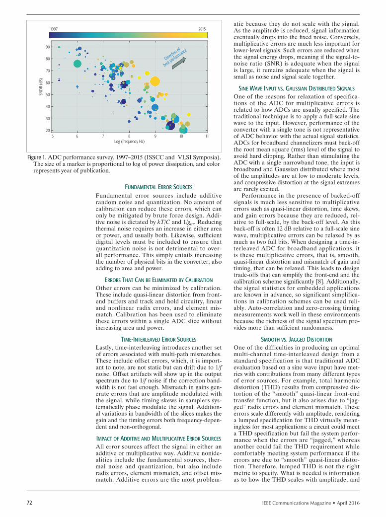
IEEE Communications Magazine • April 201672
fundAmEntAl Error sourcEs
Fundamental error sources include additive random noise and quantization. No amount of calibration can reduce these errors, which can only be mitigated by brute force design. Addi-tive noise is dictated by kT/C and 1/gm. Reducing thermal noise requires an increase in either area or power, and usually both. Likewise, suffi cient digital levels must be included to ensure that quantization noise is not detrimental to over-all performance. This simply entails increasing the number of physical bits in the converter, also adding to area and power.
Errors thAt cAn bE ElImInAtEd bY cAlIbrAtIon
Other errors can be minimized by calibration. These include quasi-linear distortion from front-end buffers and track and hold circuitry, linear and nonlinear radix errors, and element mis-match. Calibration has been used to eliminate these errors within a single ADC slice without increasing area and power.
tImE-IntErlEAvEd Error sourcEs
Lastly, time-interleaving introduces another set of errors associated with multi-path mismatches. These include offset errors, which, it is import-ant to note, are not static but can drift due to 1/f noise. Offset artifacts will show up in the output spectrum due to 1/f noise if the correction band-width is not fast enough. Mismatch in gains gen-erate errors that are amplitude modulated with the signal, while timing skews in samplers sys-tematically phase modulate the signal. Addition-al variations in bandwidth of the slices makes the gain and the timing errors both frequency-depen-dent and non-orthogonal.
ImPAct of AddItIvE And multIPlIcAtIvE Error sourcEs
All error sources affect the signal in either an additive or multiplicative way. Additive nonide-alities include the fundamental sources, ther-mal noise and quantization, but also include radix errors, element mismatch, and offset mis-match. Additive errors are the most problem-
atic because they do not scale with the signal. As the amplitude is reduced, signal information eventually drops into the fi xed noise. Conversely, multiplicative errors are much less important for lower-level signals. Such errors are reduced when the signal energy drops, meaning if the signal-to-noise ratio (SNR) is adequate when the signal is large, it remains adequate when the signal is small as noise and signal scale together.
sInE WAvE InPut vs. gAussIAn dIstrIbutEd sIgnAls
One of the reasons for relaxation of specifica-tions of the ADC for multiplicative errors is related to how ADCs are usually specifi ed. The traditional technique is to apply a full-scale sine wave to the input. However, performance of the converter with a single tone is not representative of ADC behavior with the actual signal statistics. ADCs for broadband channelizers must back-off the root mean square (rms) level of the signal to avoid hard clipping. Rather than stimulating the ADC with a single narrowband tone, the input is broadband and Gaussian distributed where most of the amplitudes are at low to moderate levels, and compressive distortion at the signal extremes are rarely excited.
Performance in the presence of backed-off signals is much less sensitive to multiplicative errors such as quasi-linear distortion, time skews, and gain errors because they are reduced, rel-ative to full-scale, by the back-off level. As this back-off is often 12 dB relative to a full-scale sine wave, multiplicative errors can be relaxed by as much as two full bits. When designing a time-in-terleaved ADC for broadband applications, it is these multiplicative errors, that is, smooth, quasi-linear distortion and mismatch of gain and timing, that can be relaxed. This leads to design trade-offs that can simplify the front-end and the calibration scheme signifi cantly [8]. Additionally, the signal statistics for embedded applications are known in advance, so significant simplifica-tions in calibration schemes can be used reli-ably. Auto-correlation and zero-crossing timing measurements work well in these environments because the richness of the signal spectrum pro-vides more than suffi cient randomness.
smooth vs. JAggEd dIstortIon
One of the difficulties in producing an optimal multi-channel time-interleaved design from a standard specification is that traditional ADC evaluation based on a sine wave input have met-rics with contributions from many different types of error sources. For example, total harmonic distortion (THD) results from compressive dis-tortion of the “smooth” quasi-linear front-end transfer function, but it also arises due to “jag-ged” radix errors and element mismatch. These errors scale differently with amplitude, rendering a lumped specifi cation for THD virtually mean-ingless for most applications: a circuit could meet a THD specification but fail the system perfor-mance when the errors are “jagged,” whereas another could fail the THD requirement while comfortably meeting system performance if the errors are due to “smooth” quasi-linear distor-tion. Therefore, lumped THD is not the right metric to specify. What is needed is information as to how the THD scales with amplitude, and
Figure 1. ADC performance survey, 1997–2015 (ISSCC and VLSI Symposia). The size of a marker is proportional to log of power dissipation, and color represents year of publication.
Log (frequency Hz)65
30
SND
R (d
B)
20
40
50
60
70
80
90
7 8 9 10
20151997
11
Direction of
best perfo
rmance

IEEE Communications Magazine • April 2016 73
a separate specification for “smooth” multipli-cative distortion and abrupt, additive “jagged” distortion; otherwise, the ADC is likely to be over-designed in one area and under-designed in another.
ArchItEcturE consIdErAtIonsBefore giving advice on architectural choices, the reader should be aware of the author’s biases and limited experience in time-interleaved ADCs, which have primarily been restricted to fi ve sep-arate designs ranging from 12 bits at 2.5 GS/s to 8 bits at 64 GS/s. Layouts for all five chips are shown in Fig. 2 and illustrated using the same resolution vs. speed format as Fig. 1.
tImE domAIn vs. frEQuEncY domAIn modulAtIon
Choosing an appropriate architecture greatly depends on the intended application of an ADC as errors impact various systems quite differ-ently. Often the goals of proposed calibration techniques are ambitious with aims to provide workable solutions for virtually all classes of input signals. This is usually not necessary, as most high-speed ADCs are embedded and there-fore only used for one purpose. Calibrating only what is important for this one and only applica-tion leads to more effi cient and smaller designs. The two most common embedded applications are:• Multi-channel frequency-division multi-
plexed signals, such as in cable and satellite TV
• Baseband applications for optical and back-plane transceivers
The first is best understood by viewing signals and errors in the frequency domain, while the second is easiest to understand in the time domain.
In time-domain applications such as for radar, backplanes, and optical networks, spectral purity is not as important, so there can be some relax-ation of offsets. Most channels with sufficient inter-symbol interference also have a Gaussian distribution of the baseband signal, so the sensi-tivity to multiplicative errors is also less import-ant than additive errors by the back-off level. As gain and time-skew errors are multiplicative, they often do not need to be calibrated to the same accuracy level of additive errors like ther-mal noise and offsets. Background calibration of time skews may not be necessary, which further simplifi es the overal system.
rulEs of thumb for tImE-IntErlEAvEd Adcs
After painstaking effort in the laboratory to track down as many sources of errors as possible and determine ultimate limitations of the calibration algorithms, a general consensus emerged about what constitutes good design practice. This expe-rience can be summarized as “rules of thumb” for time-interleaved ADC design. The least con-troversial rules are listed here.
Never interleave if you do not have to: There are many error sources in multi-path design that are not present in a single-slice ADC. If you can keep the signal path from branching, you save a lot of headaches. If speed or metastability are not at issue the ADC can and should be designed without interleaving.
Avoid interleaving by two: This might not be obvious at first, but is essentially a corollary to the above rule. If it is possible to design the ADC with only two slices, it should be nearly possible, given a little more power, area, time, and risk, to design it with one. Removing all time interleav-ing is highly advantageous as it eliminates many error sources, most of which require calibration to mitigate. In the special case where there is no signal energy above fs/4 and interleaving is only used as a means to 2 oversample the sig-nal, thereby gaining 3dB in noise performance, this is an exception where interleaving by two might be useful. Otherwise, avoid it. Obviously, if you exhaust all options and still cannot meet the speed requirements, interleaving by two might be the only viable option left. Just make it your last option and not your fi rst.
Use as few slices as possible: Increasing com-plications arrise as the number of independent slices in an ADC increases. Crosstalk from mul-tiple sources is hard to control as the array gets larger, and as the input signal and clock distri-bution networks become more complicated. In addition, the difference in the integral nonlinear-ity (INL) profi le of each quantizer generates pat-tern-dependent errors, which for high-resolution ADCs requires many lookup tables and dither to eliminate, quickly becoming prohibitive in a large array. Keeping the number of quantizers small, but still more than two, is a good idea. Four slic-es is usually a good place to start.
PIPElInEd slIcEs vs. sArAdhering to the third rule leads to the strate-gy of making the ADC slices as fast as possible without compromising power and dynamic set-tling behavior. This approach was adopted for all ADCs shown in Fig. 2. Each used a pipelined architecture for the slices as itemized in Table 1.
Pipelining allows a high sample rate as throughput is limited only by the speed of a single multiplying digital-to-analog conversion (MDAC) stage. Primary MDAC error sources are highlighted in Fig. 3. These include linear and nonlinear errors in the residue amplifier, and dynamic effects of incomplete settling and
Figure 2. Five time-interleaved ADCs ranging from 12 bits at 2.5 GS/s to 8 bits at 64 GS/s.
Sample rate1 GS/s
6
Bits
8
10
12
3 GS/s 10 GS/s 30 GS/s 100 GS/s
Opticaltest and measure
Satellitelaser radar
Cablephased-array radar

IEEE Communications Magazine • April 201674
memory effects due to incomplete reset. All can be corrected digitally as well as mismatched ele-ments in the DAC, which are usually compensat-ed with a lookup table.
Design guidelines, although based on data and experience, are nevertheless subjective. Dif-ferent designers may arrive at different “rules of thumb” which in turn lead to different design choices. There is a competing school of thought with regard to time-interleaved ADC design to make each slice as simple as possible. This guiding principle results in large arrays of inter-leaved successive approximation register (SAR) ADCs as each SAR slice is simple, compact, and energy-efficient. Since SARs require no resam-pling of a residue as in a pipelined ADC, there is no gain element needed and therefore no radix error to calibrate. This is indeed an advantage. Calibration of capacitor mismatch is still needed for higher resolution applications, and there are more slices to calibrate, but this can be static and done once at startup or even at factory test and is not required to run in the background.
The drawback with SAR arrays is simply that there are a lot of slices. Assuming roughly the same settling time plus comparator decision delays for both implementations, the number of SARs required in an n-bit ADC is about n times more than for a pipelined implementation as the SAR requires n clock cycles per sample, whereas the pipelined converter requires one. For instance, an ADC constituting a 10-bit, pipe-lined, four-slice, interleaved approach would require approximately 40 SAR slices for the same resolution and throughput. The complexity of input distribution and clocking networks also
increases with the number of slices. Although the quantizer itself is simple, getting the signals and clocks routed to each slice often becomes more complicated than the quantizer itself and can eventually dominate the power dissipation. To counteract this, asynchronous design heavi-ly reduces clock distribution issues to the point where in some cases it is not relevant to the total power budget [9].
To avoid routing a high-speed input to many samplers in a large array, a multi-rank sampling scheme is needed whereby the input is resampled and demultiplexed without gain before quanti-zation. This is an important point to remember when considering a large array. Although some ADCs use a large number of SAR quantizers, they generally adhere to the third rule, which can be amended here to read: Use as few front-end samplers as possible. Once the critical first sample is taken, the held signal can be resampled without suffering further errors due to timing skew provided the signal is settled.
WhIch ArchItEcturE Is bEst
Although a SAR slice is simpler and more pow-er-efficient than a pipelined ADC, when consid-ering signal and clock distribution as part of the slice design, the SAR slice becomes less efficient, and the two approaches become more compara-ble. Likewise, a pipelined architecture requires far fewer slices, but a two-rank sampling system makes a large array hierarchically look the same as small arrays from a front-end perspective pro-vided kT/C noise is not compromised by dou-ble-sampling.
Both time interleaving of high-count SAR arrays or the use of fewer pipelined slices have merit. Pipelined-based designs are most appro-priate for high-resolution signal analysis applica-tions where spectral purity is important such as in spectrum analyzers. Minimizing the number of slices keeps interleaving artifacts to a minimum so that calibration can reduce all residual errors to achieve 80 dB spurious-free dynamic range (SFDR) at 2.5 GS/s [10]. It is difficult to achieve the same level of spectral purity when there are so many SARs that all need to be calibrated to the same level of accuracy. Therefore, SAR arrays are suitable for lower-resolution appli-cations where spectral purity is not as import-ant and kT/C noise requirements are easily met. They have been widely used in high-speed appli-cations, such as in optical networks, backplanes, and real-time oscilloscopes where eight physical bits and about five or six effective bits are com-mon.
8 tImE-IntErlEAvEd Adc WIth sloW rEfErEncE
As each of the ADCs of Fig. 2 and Table 1 are interleaved pipelined architectures, one design is highlighted here that is representative of all five. This circuit is a 2.5 GS/s 12-bit ADC, imple-mented as an eight-way time interleaved pipe-lined architecture and shown in Fig. 4. When presented with the requirements, we primari-ly considered the first rule, but found it would be nearly impossible to achieve the throughput without interleaving, so the guiding principle in
Figure 3. Block diagram of a single 12-bit pipelined ADC slice. Background calibration adjusts the radix and populates a lookup table to remove any errors due to capacitor mismatch.
Offset, linear gain errorsNonlinear transfer functionMemory effects
Comparator offsets Capacitor mismatches
VI
V3
D3
V2
Vrefφ
VI V2 V3 Vn-2TH
A
Stage1
Stage2
CoarseADC DAC
Stage3
Stagen – 1
Stagen
Vn-1
DnDn-1D3D2D1
�
Table 1. Table of ADC architecture details.
ADC
Sample rate Resolution Slice architecture Bits per stage Nominal radix
2.5 GS/s 12 bits Pipelined 3.5 7.95
6.0 GS/s 10 bits Pipelined 2.5 3.8
6.0 GS/s 8 bits Pipelined 0.7 1.6
40.0 GS/s 6 bits Pipelined 0.7 1.6
64.0 GS/s 8 bits Pipelined 2.5 3.8

IEEE Communications Magazine • April 2016 75
the design became the third rule: to use as few slices as possible. The initial plan was to use four slices as previously recommended. Each slice would run at approximately 625 MS/s. Initial sim-ulations showed this to be an appropriate choice. As often happens, circuit model and extraction parameters changed during the course of the design to where it became difficult to meet the speed and performance requirements simultane-ously. Therefore, eight interleaved slices at 312 MS/s were chosen for the final design.
A slow (1 MS/s) recirculating ADC with dynamic capacitor shuffling is used to provide a reference sample: the error between the actu-al sample and the reference is used to drive all background calibration. Some drawbacks of the impact of the slow ADC on performance are dis-cussed more fully later.
A single least mean squared (LMS) loop converges all error sources simultaneously [11]. Within each ADC slice the radix is corrected: a lookup table is populated to mitigate errors due to capacitive mismatch in the MDAC. The gain, offset, and time-skew errors of each slice are corrected by forcing them to match the ref-erence ADC. System identification (SI) methods are used for calibration in this design. Since LMS updates are driven by observations from a known reference, this approach, which is common in control systems and adaptive equalizers, is known to be robust and have good convergence prop-erties. Performance is virtually independent of signal statistics, although degenerate cases always exist (e.g., fs/8 tones). Convergence is quick with-out requiring long decorrelation filters to extract the signal from a randomly applied dither.
To align each of the eight slices to the ref-erence ADC, a full-speed 2.5 GS/s clock is run through a delay line ranging from one- to eight-unit samples. The delay position is randomly selected, multiplexed, and then retimed with the full-speed clock before being divided and then retimed again after the divide-by-eight. There-fore, the reference ADC will align with any of the eight slices with the exact precision of one unit-interval step, but in a user-selectable ran-dom order. In this manner calibration of the entire time-interleaved array is accomplished one slice at a time: the reference aligns to each slice, calibrates the errors, then moves to the next randomly selected slice until the complete array is corrected. All calibration is autonomous and operates in the background. Calibration updates can also be frozen by user control depending on the application. No pilot tones or dither are nec-essary. However, sufficient signal activity at the input is required in order to have something to compare to and correct. In the absence of a sig-nal, a power detector circuit holds the calibra-tion registers frozen until a signal with sufficient amplitude is present.
The layout of the ADC is shown in Fig. 5, which illustrates that all calibration circuitry resides on chip as does an 8 kS memory for use in test. All error correction is performed exclu-sively in the digital domain, directed only by the magnitude of the sub-sampled error between the main ADC slices and the reference ADC, with the exception of the sample phase. Time-skew correction is similar to clock recovery in that
information about both magnitude and direction are necessary. Here, a hybrid approach is used to determine direction, which is a combination of a small additional analog block with the digital cir-cuitry [12]. The LMS engine then drives a digital code, which in turn adjusts the edge position of eight capacitive clock-delay DACs, thus closing time-skew correction in the analog domain.
A measured 8 kS spectrum of the ADC with a 2.525 GHz external sample clock and an input near fs/5 is shown in Fig. 6. An SFDR of 75 dBc is achieved, and is limited by the third harmon-ic of the input buffer and track and hold. The SFDR drops to 62 dBc for a 3.225 GHz input in the third Nyquist zone. The SNR of the ADC is 62 dB at low frequencies. At intermediate fre-quencies the SNDR is solely a function of the
Figure 4. Block diagram of an eight-slice time-interleaved pipelined ADC using a system identification (SI) slow ADC for a reference for full back-ground calibration. The gain, time skew, and offsets are also corrected so that all slices appear identical and uniformly spaced in time.
Radix and cap mismatchcorrection
Measure and compare
-+
VIStage#4
Stage#2
Stage#1TH
TH
D4D3D2D1
x̂ = G ⋅ y(D1, D2, D3, D4) + Voff
LMS calibration
SlowADC
Stage#3
Figure 5. Layout of a 2.5 GS/s 12-bit ADC with 75 dB SFDR through the first Nyquist zone and 62 dB through the third Nyquist zone. All digital circuit-ry is included to perform background calibration. An 8 kS memory is used to aid in data capture for benchtesting. The chip measures 4.5 mm 4.7 mm and is fabricated in IBM’s 8HP 130 nm BiCMOS process.
4.7283 mm
5.5133 mm
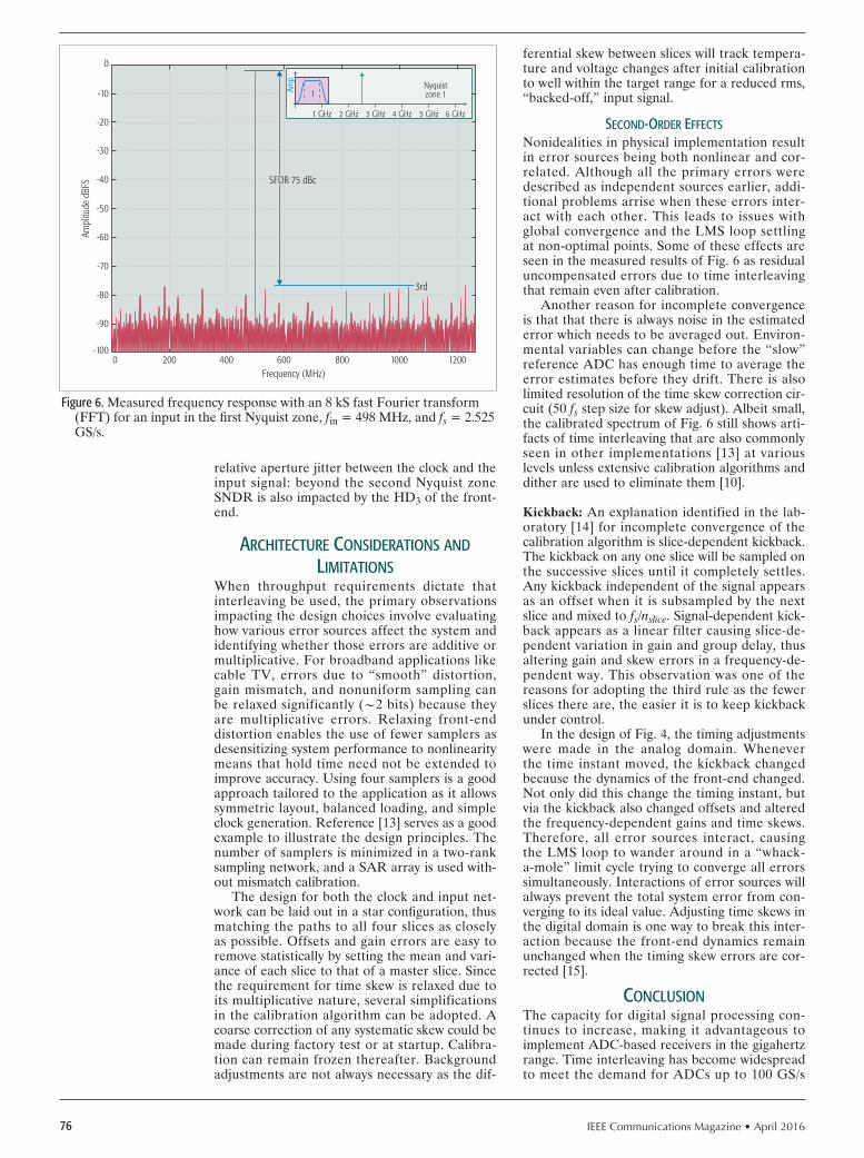
IEEE Communications Magazine • April 201676
relative aperture jitter between the clock and the input signal: beyond the second Nyquist zone SNDR is also impacted by the HD3 of the front-end.
ArchItEcturE consIdErAtIons And lImItAtIons
When throughput requirements dictate that interleaving be used, the primary observations impacting the design choices involve evaluating how various error sources affect the system and identifying whether those errors are additive or multiplicative. For broadband applications like cable TV, errors due to “smooth” distortion, gain mismatch, and nonuniform sampling can be relaxed significantly (~2 bits) because they are multiplicative errors. Relaxing front-end distortion enables the use of fewer samplers as desensitizing system performance to nonlinearity means that hold time need not be extended to improve accuracy. Using four samplers is a good approach tailored to the application as it allows symmetric layout, balanced loading, and simple clock generation. Reference [13] serves as a good example to illustrate the design principles. The number of samplers is minimized in a two-rank sampling network, and a SAR array is used with-out mismatch calibration.
The design for both the clock and input net-work can be laid out in a star configuration, thus matching the paths to all four slices as closely as possible. Offsets and gain errors are easy to remove statistically by setting the mean and vari-ance of each slice to that of a master slice. Since the requirement for time skew is relaxed due to its multiplicative nature, several simplifications in the calibration algorithm can be adopted. A coarse correction of any systematic skew could be made during factory test or at startup. Calibra-tion can remain frozen thereafter. Background adjustments are not always necessary as the dif-
ferential skew between slices will track tempera-ture and voltage changes after initial calibration to well within the target range for a reduced rms, “backed-off,” input signal.
sEcond-ordEr EffEcts
Nonidealities in physical implementation result in error sources being both nonlinear and cor-related. Although all the primary errors were described as independent sources earlier, addi-tional problems arrise when these errors inter-act with each other. This leads to issues with global convergence and the LMS loop settling at non-optimal points. Some of these effects are seen in the measured results of Fig. 6 as residual uncompensated errors due to time interleaving that remain even after calibration.
Another reason for incomplete convergence is that that there is always noise in the estimated error which needs to be averaged out. Environ-mental variables can change before the “slow” reference ADC has enough time to average the error estimates before they drift. There is also limited resolution of the time skew correction cir-cuit (50 fs step size for skew adjust). Albeit small, the calibrated spectrum of Fig. 6 still shows arti-facts of time interleaving that are also commonly seen in other implementations [13] at various levels unless extensive calibration algorithms and dither are used to eliminate them [10].
Kickback: An explanation identified in the lab-oratory [14] for incomplete convergence of the calibration algorithm is slice-dependent kickback. The kickback on any one slice will be sampled on the successive slices until it completely settles. Any kickback independent of the signal appears as an offset when it is subsampled by the next slice and mixed to fs/nslice. Signal-dependent kick-back appears as a linear filter causing slice-de-pendent variation in gain and group delay, thus altering gain and skew errors in a frequency-de-pendent way. This observation was one of the reasons for adopting the third rule as the fewer slices there are, the easier it is to keep kickback under control.
In the design of Fig. 4, the timing adjustments were made in the analog domain. Whenever the time instant moved, the kickback changed because the dynamics of the front-end changed. Not only did this change the timing instant, but via the kickback also changed offsets and altered the frequency-dependent gains and time skews. Therefore, all error sources interact, causing the LMS loop to wander around in a “whack-a-mole” limit cycle trying to converge all errors simultaneously. Interactions of error sources will always prevent the total system error from con-verging to its ideal value. Adjusting time skews in the digital domain is one way to break this inter-action because the front-end dynamics remain unchanged when the timing skew errors are cor-rected [15].
conclusIonThe capacity for digital signal processing con-tinues to increase, making it advantageous to implement ADC-based receivers in the gigahertz range. Time interleaving has become widespread to meet the demand for ADCs up to 100 GS/s
Figure 6. Measured frequency response with an 8 kS fast Fourier transform (FFT) for an input in the first Nyquist zone, fin = 498 MHz, and fs = 2.525 GS/s.
Frequency (MHz)2000
-90
-100
Ampl
itude
dBF
S
-80
-70
-60
-50
-40
-30
-20
-10
0
400 600 800
1 GHz
1000 1200
SFDR 75 dBc
2 GHz 3 GHz 4 GHz 5 GHz 6 GHz
Nyquistzone 11Am
p3rd

IEEE Communications Magazine • April 2016 77
and beyond. Multiple error sources exist that can be adressed to varying degrees of success using calibration. However, different applications are sensitive to different error sources, so calibration is not always required. Knowing how sensitive each system requirement is to individual noni-dealities is critical for choosing the appropriate architecture and optimizing the design.
Pipelined architectures result in fewer slices, which simplifies many issues but likely requires radix calibration to compensate for incorrect gains in the MDAC stages. SAR arrays do not require gain stages or radix calibration, but make clocking and signal distribution more difficult. They also require two-rank sampling, which can result in a noise penalty that is problematic for higher resolutions. As each sampler needs to meet kT/C requirements, the capacitor area increases as the square of the resolution, and SAR arrays grow exponentially after turning the noise-limited corner at about the 10–11-bit level. Additionally, each slice needs an independent lookup table to mitigate mismatch issues when spectral purity is needed, which makes a large array less attractive for high-resolution applica-tions.
Based on experience and observations, pipelined ADCs with few slices are best for frequency-domain applications and high res-olution (7–14 bits). SAR arrays are best for low resolution (5–10 bits). For resolutions of 5 bits and below, simple flash converters are an option. The designer’s dilemma is at the level of 7–10 bits, where both SAR and pipe-lined ADCs have merit and drawbacks with-out a clear separation between one approach over the other. Designer experience, prefer-ence, and available process options, along with other factors such as metastability and cross-talk mitigation, may tip the balance toward one approach over the other.
AcKnoWlEdgmEntThe author would like to thank the team former-ly at Möbius Semiconductor for all their original ideas, enthusiasm, and hard work on multiple time-interleaved ADCs with various architec-tures spanning a wide range of sample rates in many processing nodes: primarily, Dr. Avi
Madisetti, Dr. Ralph Duncan, Dr. Jurgen van Engelen, Espen Olsen, Dr. Sasidhar Lingham, Jatan Shah, Howard Baumer, John Sin, Dr. Hai-rong Yu, Dr. Tommy Yu, Rajesh Radhamohan, and Ted Buchwald.
rEfErEncEs
[1] W. Black and D. Hodges, “Time Interleaved Converter Arrays,” IEEE J. Solid-State Circuits, Dec. 1980, pp. 1022–29.
[2] K. Poulton, J. J. Corcoran, and T. Hornak, “A 1-GHz 6-bit ADC System,” IEEE J. Solid-State Circuits, vol. 22, no. 6, Dec. 1987, pp. 962–70.
[3] C. S. G. Conroy, D. W. Cline, and P. R. Gray, “An 8-b 85-MS/s Parallel Pipeline A/D Converter in 1-m CMOS,” IEEE J. Solid-State Circuits, vol. 28, no. 4, Apr. 1993, pp. 447–54.
[4] A. Petraglia and S. K. Mitra, “Analysis of Mismatch Effects Among A/D Converters in a Time-Interleaved Waveform Digitizer,” IEEE Trans. Instru-mentation and Measurement, vol. 49, no. 5, May 1991, pp. 831–35.
[5] M. El-Chammas and B. Murmann, Background Calibration of Time-Inter-leaved Data Converters, Springer, 2012.
[6] R. Payne, “A 12b 1GS/s SiGe BiCMOS Two-Way Time-Interleaved Pipeline adc,” IEEE ISSCC Dig. Tech. Papers, San Francisco, CA, Feb. 2011, pp. 182–84.
[7] B. Razavi, “Design Considerations for Interleaved ADCs,” IEEE J. Solid-State Circuits, vol. 48, no. 8, Aug. 2013, pp. 1806–17.
[8] S. Gupta and J. Wang, “A 1-gs/s 11-bit ADC with 55-db SNDR, 250-mw Power Realized by a High Bandwidth Scalable Time-Interleaved Architec-ture,” IEEE J. Solid-State Circuits, vol. 41, no. 12, Dec. 2006, pp. 2650–57.
[9] L. Kull et al., “A 90GS/s 8b 667mw 64x Interleaved SAR ADC in 32nm Digital SOI CMOS,” IEEE ISSCC Dig. Tech. Papers, San Francisco, CA, Feb. 2014, pp. 89–92.
[10] B. Setterberg et al., “A 14b 2.5GS/s 8-Way-Interleaved Pipelined {ADC} with Background Calibration and Digital Dynamic Linearity Correction,” IEEE ISSCC Dig. Tech. Papers, San Francisco, CA, Feb. 2013, pp. 466–67.
[11] A. Madisetti, T. D. Kwon, and A. Buchwald, “Nonlinear Compensation in Analog to Digital Converters,” U.S. Patent 7,800,521, 10, 2010; http://www.patentlens.net/patentlens/patent/US_7800521/.
[12] —, “Minimizing Adverse Effects of Skew Between Two Analog-to-Digital Converters,” Patent US 7,808,408, 09, 2010; http://www.patentlens.net/patentlens/patent/US_7808408/.
[13] K. Doris et al., “A 480 mW 2.6 GS/s 10b Time-Interleaved ADC with 48.5 dB SNDR Up to Nyquist in 65 nm CMOS,” IEEE J. Solid-State Circuits, vol. 46, no. 12, Dec. 2011, pp. 2821–33.
[14] J. van Engelen, private communication, “Kickback Effects in Time-Inter-leaved ADCs and the Impact on Non-Orthogonality of Time-Skew, Offset, Gain and Distortion,” Apr. 2012.
[15] D. Stepanovic’ and B. Nikolic’, “A 2.8gs/s 44.6mw Time-Interleaved adc Achieving 50.9db sndr and 3db Effective Resolution Bandwidth of 1.5ghz in 65nm cmos,” IEEE VLSI Symp. Dig. Tech. Papers, Honolulu, HI, June 2012, pp. 84–85.
bIogrAPhIEs
AARON BUCHWALD ([email protected]) is a senior technical director at Inphi Corp and an adjunct professor at the Hong Kong University of Science and Technology. He received his Ph.D. in electrical engineering from the Uni-versity of California, Los Angeles in 1993. He research interests are in data converters and mixed signal circuits for communication. He currently serves as an Associate Editor for IEEE Journal of Solid State Circuits and previously served on the Data Converters Subcommittee for the International Solid-State Circuits Conference.
The designer’s dilemma
is at the level of 7–10-
bits, where both SAR
and Pipelined ADCs
have merit and draw-
backs without a clear
separation between
one approach over
the other. Designer
experience, preference,
and available process
options, along with
other factors such as
metastability and cross-
talk mitigation, may tip
the balance towards
one approach over
the other.

IEEE Communications Magazine • April 201678 0163-6804/16/$25.00 © 2016 IEEE
AbstrAct
Over the past decade, the successive approxi-mation register (SAR) architecture has played a significant role in advancing the state of the art in analog-to-digital conversion. One of the pri-mary reasons for this is that modern SAR ADCs thrive on MOS switches and latches, which strongly benefit from technology scaling. Build-ing on this observation, this article compares the strengths and limitations of SAR ADCs against those of competing topologies and projects and related performance bounds. In this context, we also discuss application-specific considerations, specifically for ultra-low power and ultra-high speed (time-interleaved) application scenarios.
IntroductIonThe successive approximation register (SAR) analog-to-digital converter (ADC) architecture dates back to the 1950s and saw its debut in sil-icon complementary metal oxide semiconductor (CMOS) in the 1970s. The main application driv-ers back then were in telephony and relatively low-speed instrumentation and measurement. By 2000, this situation had not changed significant-ly, and a number of alternative ADC topologies emerged to address high-end audio requirements (oversampling ADCs) as well as video and high-speed communication throughputs (folding and pipelined ADCs). However, as we entered the age of sub-100-nm CMOS, the SAR topology began to rebound, cashing in on its compatibility with aggressively scaled “digital” process tech-nology.
After a significant rise in R&D activities on SAR ADCs over the past 10 years, this build-ing block now stands as an attractive solution for a much wider performance range than ever anticipated. This is further illustrated in Fig. 1, which plots the so-called Schreier figure of merit (FoMS) against the sampling rate (fs) for ADCs published at IEEE flagship conferences between 1997 and 2015. FoMS measures the conversion efficiency by enumerating how well the invest-ed power is translated into speed and resolution (signal-to-noise-and-distortion ratio, SNDR). The result is a number in decibels, the larger the better (see [1] for more information on this fig-ure of merit).
From Fig. 1, we see that SAR-based designs (in orange) deliver leading-edge performance for sampling rates from tens of kilohertz to tens of gigahertz. On the lower end, we find designs such as [2, 3], targeting biomedical instrumentations or sensor platforms for the Internet of Every-thing (IoE). In the moderate speed regime, we see SAR-assisted pipeline ADCs such as [4], run-ning at tens of megahertz with very low levels of power (~1 mW) and overall performance num-bers that are compatible with a number of imag-ing applications. Finally, in the ultra-high-speed regime, the groundbreaking 90 GS/s design of [5] demonstrated that a sea of 64 SAR ADCs run-ning in parallel can be an attractive solution for emerging optical and electrical data links.
The purpose of this article is to convey fur-ther insight on the recent success of SAR-based ADCs to the system designer. For brevity, we focus on the extreme ends of the frequency axis in Fig. 1 and explain why SAR-based topologies can shine for low-bandwidth IoE-type applica-tions as well as for high-speed communication platforms. In this context, we also highlight the weaknesses of SAR ADCs and explain why they cannot fully displace all other competing Nyquist architectures. Finally, we explore the limits on how much further we can expect to push SAR-based converters in terms of power efficiency and speed. For this exercise, we again consider typical constraints seen for low-speed IoE and high-speed communications applications. A com-parison between SAR, SAR-assisted pipelines, and delta-sigma topologies providing moderately high bandwidths (tens of megahertz) would make another interesting case study, but is outside the scope of the present article.
the bAsIcsFigure 2a shows a conceptual schematic of the most basic SAR ADC variant. It consists of switches, capacitors, a voltage comparator, and digital logic. As mentioned above, this compo-sition aligns the converter particularly well with the strengths of modern nano-CMOS, which is first and foremost optimized for digital logic (and switch) performance. As a byproduct, digital CMOS processes provide a tall metal stack with high-end lithography in the lower layers. SAR designers have leveraged this to create the shown
The Successive Approximation Register ADC: A Versatile Building Block for Ultra-Low-Power to Ultra-High-Speed Applications
Boris Murmann
IntegrAted cIrcuIts for communIcAtIons
Over the past decade, the successive approx-imation register (SAR) architecture has played a significant role in advancing the state of the art in analog-to-dig-ital conversion. One of the primary reasons for this is that modern SAR ADCs thrive on MOS switches and latches, which strongly ben-efit from technology scaling.
The author is with Stanford University.

IEEE Communications Magazine • April 2016 79
binary weighted capacitor array using metal fringe capacitors. The unit capacitance (labeled 1 in Fig. 2a) is nowadays made as small as 100 atto-farads (to save area and switching energy), and this still yields a very accurate binary weighting in mass production. Finally, the voltage comparator (or “slicer”) is often nothing but a regenerative dynamic latch, which is also a core ingredient of digital flip-flops.
The ADC operates as indicated in Fig. 2b, and essentially forces the input to zero via a bina-ry search (or “successive approximation”). At the start of the conversion, the input voltage is sampled on the capacitive array. From the polar-ity of the sample, the comparator makes its first decision, which represents the most significant output bit (MSB). Based on the outcome of this decision, the largest capacitance (on the proper side of the circuit) is switched to drive the com-parator input toward zero. This process repeats with progressively smaller steps (according to the binary weights), and all bits are resolved as the voltage is nulled to within a small residual quan-tization error over time.
It is relatively straightforward to argue why this architecture has been popular for low-speed sen-sor applications, even in older technologies (e.g., the 0.25 m design of [6]). First, it can be designed to operate in a fully dynamic manner, which means that it does not consume static currents that would be required to operate opamps or sim-ilar “classical” analog components. This facil-itates aggressive power management that puts the converter into a near-zero power sleep state when it is idle. Second, the sequential nature of the conversion process is no showstopper at kilo-hertz frequencies, since any reasonably advanced CMOS process provides switching speeds that are many orders of magnitude faster than each sub-cycle.
The above-described advantages become only more pronounced as CMOS technology is scaled and the circuit improves, much like digital logic. At 1 kS/s, the 10-bit 65-nm design of [3] dissi-pates only 1.1 nW from a 0.6 V supply. These numbers are possible due to aggressive unit capacitor scaling (250 aF), scaled digital logic with low leakage (high threshold voltages) and subthreshold operation of the latch comparator. Even then, the comparisons occur so fast that they take up only 0.5 percent of the 1 mS conver-sion cycle. During the rest of the time, most of the ADC’s circuitry is asleep. Remarkably, such a 1-nW converter can (theoretically) be pow-ered from a 1 mm3 thin-film battery for about 40 years.
Once we start thinking about high-speed applications that demand the highest possi-ble sampling rate, it becomes less obvious why SAR-based ADCs can be attractive. To see this, consider Fig. 3, which compares the SAR ADC with traditional high-speed flash and pipelined ADC topologies. A B-bit flash ADC uses 2B – 1 comparators in a parallel configuration, so only one clock cycle is needed to digitize the input. A pipelined ADC is essentially an unrolled ver-sion of a SAR ADC, trading latency for speed. Each stage performs a coarse digitization and passes an amplified residue to the next stage. Since all stages run concurrently, the pipeline
produces new output in each clock cycle. Based on its sequential operation, the SAR topology thus comes with a relative speed penalty factor proportional to the number of bits that it must resolve. With clock speeds in modern technology going as high as 5–10 GHz, it is thus difficult to go much beyond 1 GS/s for a SAR ADC, even at moderate resolutions of B = 6–8. So, how does one build a converter running at tens of gigasam-ples per second, and why would a SAR ADC be an attractive ingredient?
The answer lies in the fact that most ultra-high-speed ADCs use a time-interleaved archi-tecture, leveraging parallelism much like a multi-core processor. Figure 4 shows an exam-ple where 64 SAR ADCs run in parallel, using a hierarchical 4-4-4 interleaving approach as proposed in [5]. Here, the first rank switches are clocked in quadrature (90˚ phase shift between each clock), and the second rank performs a multiplexing operation that fans out the signal by another factor of four (see [5] for more details on the exact timing). At the last layer, the signal terminates in banks of four SAR ADCs. Within each bank, the ADC slices process the incoming samples in a round-robin fashion. The aggregate throughput of this example is thus 64 times the sampling rate of each ADC slice (e.g., 64 GS/s when 1 GS/s SAR slices are employed). But why should we use SAR ADCs when faster topolo-gies, such as flash, can be interleaved in the same way, but with fewer slices and a less complex interleaving network?
Answering the above question in full detail is nontrivial, but we can consider a few basic argu-ments that explain the recent success of time-in-terleaved SAR ADCs. The first important point is that flash architectures are limited to about 6 bits of resolution. The reason for this is that the complexity grows exponentially with the bit resolution (Fig. 3) and in addition, achieving the required component matching for B > 6 leads to large and power-hungry circuits. While match-ing issues can be addressed via calibration tech-
Figure 1. ADC power efficiency (quantified via the Schreier figure of merit, FOMS) vs. sampling frequency (fs). Time-interleaved designs are marked with a bold outline (for SAR) or gray shading (for all other architectures). The raw data is available at http://web.stanford.edu/~murmann/adcsur-vey.html.
fs (Hz)104
135
130
FoM
S =
SNDR
(dB)
+ lo
g(f s/
2/P)
(dB)
140
145
150
155
160
165
170
[2]
[3][4]
[5]
175
180
105 106 107 108 109 1010 1011
FlashPipelineSARΣOther

IEEE Communications Magazine • April 201680
niques, they only help contain the problem (in terms of power dissipation), but do not lead to quantum leaps. Unfortunately, many evolving communications applications require an effec-tive number of bits (ENOB = (SNDR[dB] – 1.76)/6.02) greater than 6, which eliminates the flash topology as a potential solution.
While pipelined ADCs can easily achieve 6 ENOB, they can be inferior to SAR ADCs for a different reason. As shown in Fig. 3, each pipe-line stage contains a digital-to-analog convert-er (DAC), a sample and hold (S/H), a summing node, and a residue amplifier (G). The construc-tion of these blocks typically involves an opamp or a similar circuit that is relatively slow and does not benefit as much from technology scaling as the components used in a SAR ADC. Therefore, even though a pipeline needs only one clock cycle per conversion, that clock cycle is longer than the sub-cycles in a SAR ADC. Over time, and with aggressive technology scaling, this disadvan-tage has grown in significance, as we see in the next section. Lastly, SAR ADCs are much more compact than traditional pipelined ADCs, again because they do not contain any opamp-like cir-cuits. This leads to a much denser layout in a large interleaved design, which can also translate into speed and power improvements.
PerformAnce trAjectorIesGiven the qualitative insight from the previous section, it is now interesting to evaluate actual performance trajectories of the recent past. For brevity, we focus here on speed performance and return to the low-speed, low-power space in the next section. Figure 5a plots the state of the art in single-channel ADC sampling rates over time. The first thing to note is that SAR ADCs used to be substantially slower than pipelined ADCs, but have now caught up. This trend is well explained by the reasoning of the previous section. Sec-
ond, note that flash ADC speed plateaued more than five years ago (at ~7.5 GS/s). The reason for this is similar to what we have seen in sin-gle-core microprocessors. Pushing single-compo-nent speed beyond a certain threshold leads to diminishing returns, and it becomes more effi-cient to explore parallelism. In ADCs, this means time interleaving.
Figure 5b plots the conversion speed multi-plied by the effective number of quantization levels (i.e., the speed-resolution product). Inter-estingly, we see from this plot that SAR ADCs have recently surpassed the speed-resolution product of flash ADCs. The reason for this is clear: flash ADCs have stopped improving in speed, and their resolution is upper-bounded. This made it possible for SAR ADCs to catch up from behind, strongly exploiting the benefits from aggressive CMOS technology scaling.
On the downside, SAR ADCs are still lag-ging far behind pipelined ADCs in the achievable speed-resolution product. With a (single-channel) pipelined ADC, it is nowadays possible to deliver ~11 ENOB at 1 GS/s [7]. The push toward this performance level began around 2008, seen as a sharp rise in the pipeline ADC speed-resolution product. These advancements were mainly due to substantial R&D investments in high-resolu-tion converters for wireless base stations. Tech-nology scaling payed a minor role in this trend, as the designs defining the uptick in the curve use 0.18 m technology and have only recently been migrated to the (relatively old) 65 nm node [7].
The speed-resolution product offered by tra-ditional pipelined ADCs is presently out of reach for SAR ADCs, and there is no obvious path for getting there. One step in the right direction is to explore hybrid topologies that combine SAR con-version and pipelining [4]. However, so far this has only led to more power-efficient ADCs, and has not (yet) helped push the speed-resolution prod-uct. Consequently, traditional pipelined ADC will (for the time being) continue to dominate appli-cations such as wireless base stations, where both high speed and high dynamic range are important.
Figure 6 shows the speed and speed-reso-lution product trajectories for time interleaved designs. Again, several interesting observations can be made. In Fig. 6a, we see that time inter-leaved pipelines plateaued more than a decade ago, with the introduction of the groundbreaking 20 GS/s design by Poulton et al. [8]. Time inter-leaved flash ADCs have seen a significant push since 2008, mostly fueled by the introduction of digital equalization techniques in high-speed wire-line communication. For time interleaved SAR ADCs, a quantum jump occurred with the intro-duction of the 24 GS/s design by Schvan et al. in 2008 [9]. With the recent contribution by Kull et al. [5], time-interleaved SAR ADCs have become the fastest available ADCs. Interestingly, with the introduction of [5], time-interleaved SAR ADCs have also claimed the peak performance in terms of speed-resolution product (Fig. 6b). This is mostly explained by the achieved ultra-high speed, extracted via massive interleaving of a relatively slow but densely tileable topology.
As a final remark, it is interesting to note that the peak speed-resolution product of the time interleaved converters in Fig. 6b is only insig-
Figure 2. a) Most basic incarnation of a SAR ADC (with “top plate sam-pling”); b) Corresponding conversion waveform.
Logic
2B-2 8 4 2 1
2B-2 8
•••
•••
•••
•••
4 2 1
++- -
+
-Vxd Dout
VREFP
VREFP
VREFN
VREFN
Vid
Vid
Vxd
0 Time
(a)
(b)

IEEE Communications Magazine • April 2016 81
nificantly larger than that of the single-channel pipeline ADCs in Fig. 6a. What this means is that time interleaving is effective mainly for aggregat-ing speed, but the gained speed tends to force us to sacrifice resolution. For the plotted data set, this is mainly due to the effect of clock jitter, which imposes a hard bound on the achievable speed-resolution product (see [1] for an extended discussion). However, system designers must be careful with this conclusion, since the jitter sensi-tivity can be somewhat relaxed in practical appli-cations. For example, in a wireline communication system, the input signal is wideband and low-pass shaped, with much of its power concentrated in the lower part of the spectrum. Compared to an input sinusoid near fs/2 (which is typically the basis for the above-plotted data), the jitter sensitivity of such signals can be reduced by as much as 12 dB lower for a typical wireline channel [10].
In addition to jitter, time-interleaving artifacts such as timing skew (in the first-rank sampling clocks) and inter-channel gain and offset mis-matches put another damper on the achievable ENOB. Subtler effects such as channel-to-channel interaction via kick-back and reference voltage bounce can also cost performance (or power).
LookIng AheAdAs evident from the above discussion, SAR ADCs have come a long way and will certainly continue to improve. In this section, we discuss critical design aspects going forward, as well as some of the showstoppers that may ultimately affect and limit future progress.
Let us first consider the ultra-low-power appli-cation scenario, using the 1.1 nW, 1 kHz design of [3] as a concrete example. The Schreier FoM of this and other leading-edge designs is about 175 dB (Fig. 1). As explained in [1], there is a bound on ADC conversion efficiency somewhere near FoMS = 186 dB, which would get us to the 0.1 nW level. However, in the design of [3], leak-age current alone amounts to 0.15 nW. To get to such a low value in total power, we would have to reduce the transistor count substantially or find an effective way to gate the leakage. Alternative-ly, a technology with a steep subthreshold slope (< 60 mV/decade) could come to the rescue, but the odds of this are low. Even if this were to hap-pen, there are other power overheads, such as the analog front-end circuitry, the supply regu-lator, and the reference voltage generator (sup-plying VREFN,P in Fig. 2a), which are difficult to design with nearly “zero” power.
Given the above analysis, it seems unlikely that we will be able to improve kilohertz-speed ADCs significantly below 1 nW. But should this worry us? Thinking about it in another way, the energy dissi-pated per sample in such an ADC is 1 nW/1 kHz = 1 pJ. In the context of a larger chip in a mod-ern process (28 nm or below), 1 pJ is the typical energy cost for flipping 1000 logic gates (NAND2) or driving 10 bits along 1 mm of on-chip wire. In light of these numbers, it is difficult to imagine that there will be applications where the ADC will dominate the power or energy, since processing and distributing the digitized data should come at a significant energy cost. Instead of improving the ADC, it can be argued that there is more to gain from a proper system design that minimizes the
amount of data that is being acquired and pushed around on the chip. Ideas along these lines have appeared in the context of analog-to-information conversion, a topic that was reviewed in [11].
For high-speed time-interleaved SAR ADCs, the situation is not quite as bleak, and there are many open problems that must be (and likely will be) resolved in the coming years. The first import-ant problem lies in the signal distribution network, as shown in Fig. 4. In a hierarchically interleaved design, the signal buffers that drive the succeed-ing sampling capacitors can appear as speed bottlenecks and typically consume a significant amount of power. In [5], which uses hierarchical 4-4-4 interleaving, one set of buffers was elimi-nated by running two switches in series without signal restoration (demultiplexing approach). This was effective mainly because of the employed sili-con-on-insulator (SOI) process with low parasitics. Many such ideas, in combination with rigorous joint optimization of the distribution network and the interleaving structure, are still being explored and will feed into the next generation of designs.
There are further challenges related to sig-nal distribution at the package level, where unavoidable parasitics from/to fringe fields and electrostatic discharge (ESD) protection limit the converter’s input bandwidth, typically below 20–30 GHz today. Further innovation is needed to make significant leaps on this front. This is perhaps an opportunity for optical signaling.
Figure 3. Comparison between SAR and other Nyquist ADC architectures. B is the number of ADC bits.
Flash
Cycles perconversion
~1
~1
~B
Complexity
High ~2B
Moderate ~B
Low ~1
Opamps
No
Yes
No
Pipelined ADC
Flash ADC
Enco
der
•••
•••
G+S/HG+-
S/H
D/A
DLSB
Dout
DMSB DLSB+1
Vin
VREFP Vin
VREFN
-D/A
Pipeline
SAR
Figure 4. a) 4-4-4 hierarchical time interleaving used in [5]; b) die photo of [5]. This ADC contains a total of 4 × 4 × 4 = 64 SAR ADC slices.
56-100 GS/s 8 b ADC
96 kb [email protected] Tb/s
960 �m
470 �m
Sampler/interleaverClock
divider
SAR
ADC
ADC111
ADC112
ADC113
ADC114
(a) (b)
Timing skewcontrolQuadrature
clockgen
•••
•••
•••vin
φ1
φ2
φ3
φ4
φ11
φ12
φ13
φ14•••
•••
•••
φ111
φ112
φ113
φ114

IEEE Communications Magazine • April 201682
Another fundamental issue lies in managing metastable events in the SAR slices. Even though time interleaving can generally help with metasta-bility issues (see, e.g., [12]), the designer of a large SAR array is typically pressured into minimizing the slice count and running each sub-converter at the highest possible speed, typically around 1 GS/s today. This means that within less than 1 ns, the comparator has to make B decisions. For some of these decisions, the input signal will be very small (Fig. 2b), which lengthens the decision time of the latch comparator. With some finite probability, the comparator will see a voltage level that it can-not resolve within the available time.
A fi rst order remedy for this problem is to use asynchronous timing [13], which allocates more time for “hard” decisions. However, even then it is difficult to meet the metastability require-ments needed for systems without feed-forward error correction (FEC), which can demand error rates on the order of 10–18. To combat this issue, a number of unproven “metastability detectors” and “timeout” schemes have appeared in the lit-erature and, and most of them have not been val-idated experimentally. An exception is the work of [14], which provides extra regeneration in the converter backend to improve the converter’s metastability, proven through measurements. As we continue to move to higher speeds, this issue needs much more attention and new ideas, along with their experimental validation.
Another area for further investigation is the sampling clock generation at the converter front-end. As shown in Fig. 4, a typical solution is to work with four phases that can be directly gener-ated from an on-chip quadrature oscillator (being part of a phase locked loop, PLL). There are two important design aspects: jitter and static phase skew. As already mentioned, jitter tends to bound the speed-resolution product. And even though the requirements are somewhat relaxed for typical
communication signals, the growing bandwidth requirements will force us to improve the jitter below 100 fsrms, which is the number seen in the best designs today. However, as explained in [1], it is not immediately clear how to make signifi cant progress, since much of the jitter does not come from the clock source itself, but from distributing it to the fi rst rank of sampling switches. Perhaps there will be exotic new technologies that bring us optically controlled samplers.
Similar to jitter, any phase skew in the sam-pling clocks can cause loss in performance. Today, the skew is typically trimmed using a dig-itally controlled delay line to within a few hun-dred fsrms. However, such delay lines introduce a penalty in jitter performance, leading to an undesired trade-off. Again, as we move toward higher speeds, it is not clear how we can achieve signifi cant improvements at the circuit level. The answer may lie in system solutions (e.g. skew absorption in backend equalizers [15]), or via a fully digital skew correction in the digital back-end. The latter is diffi cult to justify from a power perspective, even in the latest technologies.
The fi nal and most fundamental impairment to watch is thermal noise. Not long ago, ADC designers would take it for granted that thermal noise was a non-issue in high-speed converters with resolutions around 6 ENOB. However, when designing with aggressively scaled transis-tors, this is no longer the case. The main impair-ment in the design of [5] is thermal noise from the comparators inside the SAR ADC slices. To make further progress in power dissipation and/or speed, this issue must be addressed with a cre-ative circuit-level solution.
Viewing the above challenges as opportunities that will fuel innovation, it is foreseeable that time-interleaved SAR ADCs will at some point break the 100 GS/s barrier. In addition, given further circuit innovation and optimization, the
Figure 5. Trends in a) sampling frequency; b) speed-resolution product for single-channel CMOS ADCs. (SAR-assisted pipeline ADCs were considered to be in the “pipeline” category for this plot. However, none of the plotted landmarks are set by this topology.)
Year(a)
20052000
106
105
Sam
plin
g fre
quen
cy f s
(Hz)
107
108
109
1010
2010 2015Year(b)
20052000
109
108
f s x2
ENO
B (H
z-ste
ps)
1010
1011
1012
1013
2010 2015
FlashPipelineSAR
The fi nal and most fun-
damental impairment to
watch is thermal noise.
Not long ago, ADC
designers would take it
for granted that thermal
noise was a non-issue
in high-speed convert-
ers with resolutions
around 6 ENOB. How-
ever, when designing
with aggressively scaled
transistors, this is no
longer the case.

IEEE Communications Magazine • April 2016 83
power dissipation of today’s high-speed designs should continue to decrease. The 90 GS/s design of [5] dissipates 667 mW. For the application of this ADC in densely packed networking modules, power levels of 100–200 mW are more desirable, and the industry will work hard to converge to these targets by leveraging SAR-friendly technol-ogy scaling.
concLusIonsUp until about 10 years ago, the widely preva-lent view was that the SAR topology is only suit-able for low-speed ADC design. However, due this architecture’s compatibility with nano-scale CMOS, it has recently made remarkable per-formance leaps. With single-channel speeds of around 1 GS/s at 8 bits and below, it has become a highly attractive block for time interleaving and aggregating speeds in excess of 10 GS/s. At the same time, the SAR ADC persists as the de facto standard for low-speed and ultra-low-power con-version for IoE-type applications.
Despite the recent rise of the SAR topol-ogy, it is clear that it cannot displace its competing architectures in all performance regimes. For example, traditional pipelined ADCs will (for the time being) be superior in applications with high demands in both speed and resolution. As a natural consequence, hybrid architectures combining the best fea-tures of pipelining and SAR conversion are being actively researched.
As we design the next generation of SAR-based ADCs, it is clear that the majority of chal-lenges and opportunities lie in high-speed design, including fundamental issues such as metastabil-ity and thermal noise mitigation. In their appli-cation at lower speed and ultra-low power levels, SAR designs are already approaching optimum performance, and further gains are likely to come from optimizing the system around the converter.
references[1] B. Murmann, “The Race for the Extra Decibel: A Brief Review of Current
ADC Performance Trajectories,” IEEE Solid-State Circuits Mag., vol. 7, no. 3, 2015, pp. 58–66.
[2] P. Harpe, E. Cantatore, and A. van Roermund, “A 10b/12b 40 kS/s SAR ADC with Data-Driven Noise Reduction Achieving up to 10.1b ENOB at 2.2 fJ/Conversion-Step,” IEEE Solid-State Circuits Mag., vol. 48, no. 12, Dec. 2013, pp. 3011–18.
[3] P. Harpe et al., “A 3nW Signal-Acquisition IC Integrating an Amplifi er with 2.1 NEF and a 1.5fJ/conv-step ADC,” ISSCC Dig. Tech. Papers, 2015, pp. 382–83.
[4] Y. Lim and M. P. Flynn, “A 1mW 71.5dB SNDR 50MS/S 13b Fully Differ-ential Ring-Amplifi er-Based SAR-Assisted Pipeline ADC,” ISSCC Dig. Tech. Papers, 2015, pp. 458–59.
[5] L. Kull et al., “A 90GS/s 8b 667mW 64x Interleaved SAR ADC in 32nm Digital SOI CMOS,” ISSCC Dig. Tech. Papers, 2014.
[6] M. D. Scott, B. E. Boser, and K. S. J. Pister, “An Ultralow-Energy ADC for Smart Dust,” IEEE J. Solid-State Circuits, vol. 38, no. 7, July 2003, pp. 1123–29.
[7] A. M. A. Ali et al., “A 14 Bit 1 GS/s RF Sampling Pipelined ADC with Back-ground Calibration,” IEEE J. Solid-State Circuits, vol. 49, no. 12, Dec. 2014, pp. 2857–67.
[8] K. Poulton et al., “A 20 GS/s 8 b ADC with a 1 MB Memory in 0.18 ?m CMOS,” ISSCC Dig. Tech. Papers, Papers, 2003, pp. 318–496.
[9] P. Schvan et al., “A 24GS/s 6b ADC in 90nm CMOS,” 2008 IEEE Int’l. Sol-id-State Circuits Conf. — Dig. Tech. Papers, 2008, pp. 544–634.
[10] B. Murmann, “A/D Converter Circuit and Architecture Design for High-Speed Data Communication,” IEEE Custom Integrated Circuits Conf., Tutorial Session, 2013.
[11] M. Verhelst and A. Bahai, “Where Analog Meets Digital: Analog-to-Infor-mation Conversion and Beyond,” IEEE Solid-State Circuits Mag., vol. 7, no. 3, Jan. 2015, pp. 67–80.
[12] B. Setterberg et al., “A 14b 2.5GS/s 8-Way-Interleaved Pipelined ADC with Background Calibration and Digital Dynamic Linearity Correction,” ISSCC Dig. Tech. Papers, 2013, pp. 466–67.
[13] S.-W. M. Chen and R. W. Brodersen, “A 6-bit 600-MS/s 5.3-mW Asyn-chronous ADC in 0.13-um CMOS,” IEEE J. Solid-State Circuits, vol. 41, no. 12, Dec. 2006, pp. 2669–80.
[14] Y. Duan and E. Alon, “A 6b 46GS/s ADC with >23GHz BW and Spar-kle-Code Error Correction,” Symp. VLSI Circuits Dig., 2015, pp. 162–63.
[15] T.-H. Tsai, P. J. Hurst, and S. H. Lewis, “Correction of Mismatches in a Time-Interleaved Analog-to-Digital Converter in an Adaptively Equalized Digital Communication Receiver,” IEEE Trans. Circuits and Sys. I, vol. 56, no. 2, Feb. 2009, pp. 307–19.
bIogrAPhYBORIS MURMANN [F] ([email protected]) received his Ph.D. degree in electrical engineering from the University of California at Berkeley in 2003. He is currently a professor in the Department of Electrical Engineering at Stanford University. His research interests are in the area of mixed-signal integrated-cir-cuit design, with special emphasis on data converters, sensor interfaces, and machine learning circuits.
Figure 6. Trends in a) sampling frequency; b) speed-resolution product for time-interleaved CMOS ADCs. (SAR-assisted pipeline ADCs were considered to be in the “pipeline” category for this plot. However, none of the plotted landmarks are set by this topology.)
Year
(a)
20052000
109
Sam
plin
g fre
quen
cy f s
(Hz)
1010
1011
2010 2015Year
(a)
20052000
1012
1011
1010
1013
2010 2015
TI flashTI pipelineTI SAR
f s x2
ENO
B (H
z-ste
ps)
The In their application
at lower speed and
ultra-low power levels,
SAR designs are already
approaching optimum
performance, and fur-
ther gains are likely to
come from optimizing
the system around the
converter.

IEEE Communications Magazine • April 201684 0163-6804/16/$25.00 © 2016 IEEE
AbstrAct
5G wireless technology is paving the way to revolutionize future ubiquitous and pervasive networking, wireless applications, and user quali-ty of experience. To realize its potential, 5G must provide considerably higher network capacity, enable massive device connectivity with reduced latency and cost, and achieve considerable ener-gy savings compared to existing wireless tech-nologies. The main objective of this article is to explore the potential of NFV in enhancing 5G radio access networks’ functional, architectur-al, and commercial viability, including increased automation, operational agility, and reduced capital expenditure. The ETSI NFV Indus-try Specification Group has recently published drafts focused on standardization and implemen-tation of NFV. Harnessing the potential of 5G and network functions virtualization, we discuss how NFV can address critical 5G design chal-lenges through service abstraction and virtual-ized computing, storage, and network resources. We describe NFV implementation with network overlay and SDN technologies. In our discussion, we cover the first steps in understanding the role of NFV in implementing CoMP, D2D communi-cation, and ultra densified networks.
IntroductIonIn the last decade, wireless technology has emerged as one of the most significant trends in networking. Recent statistics show that mobile wireless broadband penetration has exceeded that of fixed wireline broadband networks. In addition to general broadband access, recent advances in wireless communications and node processing capabilities have made it possible for communication networks to provide support for a wide variety of new multimedia applications and compelling wireless services, which are rap-idly and steadily becoming national priorities. This trend is expected to continue in the future at much faster growth rates. By 2018, the glob-al mobile traffic will increase from 2.6 to 15.8 exabytes. Addressing the expected exponential growth of rich media underscores the need to evolve cellular networks. To this end, the fifth generation (5G) will support 1000 times the cur-rent aggregate data rate and 100 times the user data rate, while enabling a 100 times increase in the number of currently connected devices, 5 times decrease of end-to-end latency, and 10 times increase of battery lifetime [1].
To meet the expected three-orders-of-magni-tude capacity improvement and massive device connectivity, 5G centers its design objectives around efficiency, scalability, and versatility. To sustain its commercial viability, 5G networks must be significantly efficient in terms of energy, resource management, and cost per bit. Connect-ing a massive number of terminals and battery operated devices necessitates the development of scalable and versatile network functions that cope with a wider range of service requirements including: low power, low-data-rate machine-type communication, high data rate multimedia, and delay-sensitive applications, among many other services. The efficiency, scalability, and versatility objectives of 5G direct the 5G community toward finding innovative but simple implementations of 5G network functions.
5G network functions face critical function-al and architectural challenges in spite of their performance superiority. Coordinated multi-point (CoMP), for instance, can improve the cell edge user experience by using coordinated and combined transmission of signals from multiple antennas, cells, terminals, and sites to improve the downlink (DL) and uplink (UL) performance (e.g., by coordinated scheduling, coordinated beam-forming, and interference alignment). However, CoMP achieves this gain with increased computa-tion, increased signaling overhead, and increased backhauling and equipment cost. Moreover, the massive number of devices requires ultra densified networks, specialized hardware, and device-centric architecture that are not well defined yet. Finally, 5G must coexist with legacy technologies like 2G, 3G, and 4G. This requirement alone increases cost and complexity indefinitely. These challenges can be effectively addressed by implementing the 5G network functions as software components using the network functions virtualization (NFV) paradigm.
A growing group of companies and standard-ization bodies are pushing research and devel-opment of the NFV paradigm to improve cost efficiency, flexibility, and performance guarantees of cellular networks in general.1 In NFV, vendors implement network functions in software compo-nents called virtual network functions (VNFs). VNFs are deployed on high-volume servers or cloud infrastructure instead of specialized hard-ware. For example, NFV pools the signal pro-cessing resources in cloud infrastructure rather than using dedicated baseband processing units (BBUs) at every site. Such resource pooling
Network Function Virtualization in 5GSherif Abdelwahab, Bechir Hamdaoui, Mohsen Guizani, and Taieb Znati
Accepted from open cAll
5G wireless technology is paving the way to revolutionize future ubiquitous and per-vasive networking, wireless applications, and user quality of experience. To realize its potential, 5G must provide considerably higher network capac-ity, enable massive device connectivity, with reduced latency and cost, and achieve considerable energy savings compared to existing wireless technologies.
Sherif Abdelwahab and Bechir Hamdaoui are with Oregon State University; Taieb Znati is with the University of Pittsburth/ Mohsen Guizani is the University of Idaho.
1 https://portal.etsi.org/TBSiteMap/NFV/NFVMembership.aspx

IEEE Communications Magazine • April 2016 85
reduces computational and signaling overhead, optimizes cost, and improves fl exibility so that a service provider activates a particular signal pro-cessing resource for only specifi c terminals in the whole network instead of activating all process-ing resources unnecessarily at each site.
Generally, NFV can overcome some challeng-es of 5G by:• Optimizing resource provisioning of the
VNFs for cost and energy effi ciency• Mobilizing and scaling VNFs from one
hardware resource to the other• Ensuring performance guarantees of VNFs
operations, including maximum failure rate, maximum latency, and tolerable unplanned packet loss
• Ensuring coexistence of VNFs with non-vir-tualized network functions [2]
Unlike other work on application of NFV and software defi ned networking (SDN) technologies in generic 5G networking, virtualized Long Term Evolution (LTE) evolved packet core, and soft-ware defi ned radio (SDR)-based sites [3–6], this work focuses on the implementation of an NFV framework that meets 5G radio access network (RAN) technology requirements and enables several complex 5G functions while smoothing its coexistence with other technologies. We also demonstrate the effectiveness of NFV in reduc-ing the capital expenditures (CAPEX) and oper-ational expenditures (OPEX) of the 5G RAN.
In this article, we fi rst survey service abstrac-tion, architecture of NFV, and network virtual-ization via the network overlay model. As NFV enabling technologies, we describe how to use SDN and OpenFlow to virtualize and intercon-nect VNFs. Second, we focus on 5G virtualizable radio functions and describe CoMP, inter-cell device-to-device (D2D), and ultra densifi ed net-
work implementation using NFV. Finally, we dis-cuss open research problems specifi c to NFV in 5G RAN.
nfV And network oVerlAy
With NFV, services are described as a forward-ing graph of connected network functions. A forwarding graph defines the sequence of net-work functions that process different end-to-end fl ows in the network. For example, Fig. 1 shows a simplifi ed forwarding graph of a mobile Inter-net service where data flows traverse network functions from the evolved NodeB (eNodeb) to the service gateway (seGW) to the IP backbone until it reaches the application server. Mobili-ty management and non-access stratum (NAS) protocols flow through different network func-tions for mobility management, authentication, and policy enforcement. Unlike current cellular networks, where a particular feature is activat-ed network-wide, forwarding graphs enable 5G operators to activate features per service (e.g., CoMP becomes active only for predefined ser-vice classes). The network functions are virtu-alized using a separate virtualization layer that decouples service design from service implemen-tation while improving effi ciency, resiliency, agil-ity, and fl exibility. Network functions that can be virtualized in general include: • Evolved packet core functions such as the
mobility management entity, serving gate-way, and packet data network gateway
• Baseband processing units functions, includ-ing medium access control (MAC), radio link control (RLC), and radio resource con-trol (RRC) procedures [7]
• Switching function• Traffi c load balancing• Operation service centers
Mobility management
and NAS protocols
fl ow through different
network functions for
mobility management,
authentication, and
policy enforcement.
Unlike the current cel-
lular networks where a
particular feature is acti-
vated network wide, for-
warding graphs enable
5G operators to activate
features per service.
Figure 1. Virtualization of a forwarding graph implementing mobile Internet service.
VNFeNodeB
VNFS-GW
VNFP-GW
IP services forwarding graph
VRouter FW
Loadbalance
VNFMME
VNFHSS
VNFPCRF
Uu S5/S8SGi
S1-MME
S6a
S11 GxRx
VNFeNodeB
X2
Uu
UE
Internet
App server
Cloud RANInfrastructure networkBase station
radio
Subscriber data flow
NAS protocols flow
IP flow (policy control)
Compute, storage, and network resources in physical locations
Virtualizes
Virtualization layer
Network function forwarding graph of an end-to-end mobile Internet servicePhysical hardwareLogical linkPhysical linkPacket flow
Virtualization
S1-UApplication data flow

IEEE Communications Magazine • April 201686
The NFV reference architecture (Fig. 2) supports a wide range of services described as forwarding graphs by orchestrating the VNF deployment and operation across diverse com-puting, storage, and networking resources [2]. As shown in Fig. 2, the computing and storage hardware resources are commonly pooled and interconnected by networking resources. Other network resources interconnect the VNFs with external networks and non-virtualized func-tions, enabling the integration of existing tech-nologies with virtualized 5G network functions. NFV management and orchestration comprises resource provisioning modules that achieve the promised benefits of NFV.
The VNF managers(s) (Fig. 2) perform two main functions: operation and resource provi-sioning. VNF operation consists of infrastructure management, fault management, performance management, and capacity planning and opti-mization. Resource provisioning ensures opti-mal resource allocation (e.g., allocate virtual machines, VMs, to servers), optimal connec-tivity between VNFs, energy conservation, and resource reclamation. Moreover, resource man-agers discover computing, storage, and network resources in the infrastructure. Efficient design of a VNF manager leverages the peak benefits of NFV to reduce CAPEX and OPEX in 5G by means of dynamic resource allocation, traffic load balancing, and easier operation and main-tenance [8].
In the rest of this section, we detail the NFV design trade-offs and the main networking prob-lems associated with them. Then we introduce the network overlay concept as a solution to these problems.
networkIng problems In nfVNFV faces several networking problems; some are inherited from multi-tenant data center networking, while others are specific to NFV. Designing NFV platforms for carrier-grade avail-ability that exceeds five nines requires fail-over times between redundant 5G VNFs of less than
a second. Also, almost all cellular services are dynamic in nature, and the physical resourc-es must expand and shrink as service demand changes (elasticity). Cellular traffic has regu-lar daily and weekly patterns, but also changes spatially in case of special events (e.g., football matches), so resources must be assigned opti-mally to cope with these changes. VM mobility is one technology that can support these rapid traf-fic changes, but it comes with networking design challenges. First, migrating VMs from one serv-er to another must retain VMs’ network states, including at least physical location, and IP and MAC addresses. Second, as a VM implements 5G radio functions, it must have access to devic-es’ data, radio states, and channel information, and it becomes critical that VM migration solu-tions provide real-time capabilities of distributed state management through localized caching and acceleration agents. Third, from an operational efficiency viewpoint, resource utilization must be kept as high as possible to ensure profitabil-ity. An optimal NFV system design incorporates efficient and flexible allocation of resources and optimal forwarding of traffic by which an oper-ator can realize and mobilize virtual networks of VNFs on any hardware across the infrastructure.
The flexibility of NFV is also associated with overhead. If we place multiple VNFs on the same physical server, the server will not have a single address but many. The switching network will have to learn addresses of individual VMs, and we can witness an uncontrolled increase in forwarding table sizes. Additionally, if an infra-structure is shared between multiple service providers, VNFs address separation becomes a must as we need to perceive the address use flexibility of a single provider, while the address space may overlap between providers. Specif-ically, as traffic from different providers share the same networking resources, not only securi-ty becomes challenging, but also flexibility and optimal forwarding of traffic from one virtual network (network of VNFs) to the other without compromising security and address separation. Additionally, NFV shall maintain the scalability characteristics of the current highly distributed cellular networks while exploiting the discussed benefits of NFV; hence, features such as load balancing and VM placement in the cloud envi-ronment shall become real-time aware and support thousands of back-end cellular virtual functions. We discuss the network overlay con-cept as a typical solution to the networking prob-lems in such a virtualized environment.
network oVerlAy
Network overlay is an approach to address NFV networking problems by implementing virtual networks of VNFs as overlays. The first-hop net-work device connected to a VNF, called the net-work virtualization edge (NVE), encapsulates the original packets from the VNF and identifies the destination NVE that will decapsulate the packet before delivering it to the next VNF. The network forwards the packet based on the encap-sulation header oblivious of the packet payload. The NVE is basically a physical switch, router, or a virtual switch in a network hypervisor.
Network overlay enjoys several appealing
Figure 2. The network function virtualization reference architecture.
OSS/BSS
NFVI
Service, NVF, andinfrastructuredescription
Orchestrator
VNF manager
Virtualizedinfrastructure
manager
VNFEMS 1
VNF 1
EMS 1
VNF 1
EMS 1
VNF 1
Virtualization layer
Virtualcompute
Virtualstorage
Virtualnetwork
Hardware resources
Computinghardware
Storagehardware
Networkhardware
NFV managementand orchestration

IEEE Communications Magazine • April 2016 87
characteristics. A key feature of network over-lay is the decoupling of the VNF addresses from the physical network addresses, and isolation of traffi c from multiple virtual networks. The traffi c isolation is achieved by the fact that forwarding traffi c between virtual networks requires a gate-way entity to forward such traffi c. If this gateway is missing, forwarding traffi c between virtual net-works is not possible. With such a feature, the overlay provides both traffi c isolation and fl exi-bility to forward traffi c between virtual networks (with adequate gateways).
Moreover, overlay works well in environments that are highly distributed, which involves thou-sands of VNFs. The expected number of NVEs required to implement a virtual network is gen-erally low, which is important for scalability, while these NVEs provide the needed fl exibility to mobilize VNFs with highly dynamic traffi c. In principle, migrating a VNF implies quick recon-figuration of a single NVE to maintain routing fl ows from that VNF.
Looking at its drawbacks, network overlay generally requires changes, possibly using exist-ing encapsulation or tunneling protocols in order to support packet (en/de)capsulation. For exam-ple, the Generic Routing Encapsulation proto-col (RFC 2784) can be used to encapsulate — in principle — any arbitrary protocol over IP and to create any virtual layer 2 network on top of a physical layer 3 network.
SDN is another approach that simplifi es net-work overlay implementation. The idea is to program switches at the NVE to modify packet headers from different NFV flows according to a global mapping of virtual network addresses (e.g. MAC and IP addresses) to physical network addresses. This can be done without changes to the data plane protocols. A central SDN control-ler maintains global mapping of virtual/physical network addresses and install rules in switches to implement this mapping. We overview SDN via OpenFlow fi rst and give more details on network virtualization using SDN in the next section. After that, we provide specifi c use cases of SDN in virtualization of 5G RAN functions.
VIrtuAl network functIons oVerlAy VIA sdn
SDN adopts two main ideas: logically central-ized control of the data plane, and network state management across distributed controllers. Sepa-rating the control and data planes accommodates increasing traffi c volumes and improves network reliability, predictability, and performance. Such separation allows a controller to deploy forward-ing table entries in data plane programmable switches (or routers) and frees switches from performing control functions.
The controlling function does not need to be centralized in principle, but logically centralized. How distributed controllers manage their states to improve performance, reliability, and scalabil-ity is a challenging problem. Support from an underlying SDN platform is required from one side to achieve distributed state management. This platform incorporates sophisticated algo-rithmic and protocol solutions for optimized net-work control and state management [9].
OpenFlow [10] is a standardized protocol for programming the data plane using control plane application programming interfaces (APIs). Openflow programs the forwarding behavior of the traffic flows in switches based on differ-ent packet header fields, which are specified in fl ow table rows, matching. An OpenFlow switch matches protocol header fields (e.g., ports, MAC, and IP) in an incoming packet, and per-forms actions against matched packets. A router matches the specified header fields and either fl oods, forwards the packet on a predefi ned port, or drops the packet. The router is also capable of rewriting header fi elds before forwarding the packet.
OpenFlow made the idea of a network oper-ating system possible. A network operating sys-tem is software that controls the behavior and state of the network through:• Data plane forwarding rules programming• Network state management• Network behavior controlNetwork state management is challenging in dis-tributed SDN controllers to maintain network state at different controllers. The open network operating system (ONOS) is an example of a dis-tributed controller [11] that maintains consis-tent shared network state information across all controllers represented by a graph database. For fast read/write of network states, it maintains the network data in low-latency, distributed key-val-ue storage along with in-memory topology infor-mation cache. The question now is why SDN and OpenFlow are particularly important for NFV.
openflow And nfVNFV does not necessarily require SDN and OpenFlow. However, NFV and SDN are relat-ed in many ways. First, SDN is an enabling technology to NFV, where it can simplify the implementation of the network overlay model. Second, virtualizing network functions like rout-ers and switches is complicated with conventional networking technologies, while SDN provides a natural solution. Imagine the complexity of a router that is running several virtual routers, each implementing its own control plane. Third, SDN flexibly allocates pooled computing resources to a particular VNF, elastically manag-es these resource allocations according to traffi c demands, and easily mobilizes VNFs with quick modification to NVE rules. In this subsection, we discuss the fi rst two possibilities and leave the third one to the next section.
Unlike adding an encapsulation layer to implement network overlay, an SDN controller just rewrites packets’ addresses to implement overlays.2 This idea does not require changing the data plane at all and still leverages the same benefits of separating virtual networks’ address spaces. A controller maintains mapping between virtual networks and physical networks includ-ing routes through which traffi c of a virtual net-work traverse. The controller installs a flow in the OpenFlow switch’s (NVE switch at the edge) flow table with an action to rewrite a matched source and destination IP/MAC address of a packet from a VNF to addresses in the physical network. The controller also installs rules in the OpenFlow switches in the network to implement
Unlike adding an
encapsulation layer to
implement network
overlay, an SDN control-
ler just rewrites packets’
addresses to implement
overlays. This idea does
not require changing
the data plane at all and
still leverages the same
benefi ts of separating
virtual networks’
address spaces.
2 http://ovx.onlab.us/

IEEE Communications Magazine • April 201688
a particular route between two chained VNFs. In this process, the controller is not aware of every single packet rewriting event, but just installs the flows in the switches that optimally implement a particular network overlay.
A rigorous method of traffic isolation between virtual networks with SDN-based virtualization is to define multiple physical IP addresses ranges for the same physical network. Packet addresses from one virtual network are translated to a par-ticular physical IP addresses range, while pack-et addresses from another virtual network are translated to another physical IP address range. This separation allows flexible isolation of traffic between virtual networks as flows from one virtu-al network can be controlled to follow a disjoint route from another virtual network’s flows. The main drawback of this approach is the increased IP address space that is needed in the physical network, which is not necessarily required in the encapsulation approach. Nevertheless, rigid traf-fic separation is of paramount importance when the infrastructure is shared between multiple ser-vice providers.
The second flexibility of the SDN approach is the independent networking behavior design of different virtual networks of VNFs. Even if network virtualization is not implemented via SDN, a separate SDN controller can control each virtual network behavior independent from other virtual networks. The network behavior not only includes how traffic flows are routed, but also how individual VNFs process traffic (control plane) flows (e.g., firewall, load balancing, deep packet inspection). This discussion reveals that SDN is a natural choice for implementing 5G VNFs. Using OpenFlow for SDN or not is anoth-er arguable choice due to some limitations in the OpenFlow standard that we discuss later.
NFV and its implementation using SDN can be applied to legacy cellular network functions, virtualization of data centers networks, infra-structure as a service in cloud computing, and so on. What are the network functions that shall be virtualized in 5G RAN?, How does the third advantage of SDN mentioned at the beginning of this section benefit 5G related technologies? How do NFV and SDN meet 5G architectur-
al and functional challenges? We try to give an answer to these questions by discussing current and forthcoming research activities that lever-age the benefits of NFV and SDN towards an advanced but yet simpler 5G network.
VIrtuAlIzAtIon of 5g rAnSeveral control and user plane network functions in 3GPP RANs are candidates for virtualization. Figure 3 shows typical 3GPP network functions, which will also be in 5G, that are virtualizable in principle. Virtualizing these functions low-ers footprint and energy consumption through dynamic infrastructure resource allocation and traffic balancing. It also eases network manage-ment and operations, and enables innovative ser-vice offerings. We study potential CAPEX and OPEX savings to be incurred from virtualizing BBUs in a typical cellular network.
cApeX And opeX In nfVConsider a scenario in which a VNF imple-ments baseband processing in virtual BBUs, as illustrated in Fig. 3. This scenario is known as Cloud-RAN [7], where NFV provides the needed orchestration layer for Cloud-RAN to virtual-ize layers 2 and 3 of the radio interface. and the necessary framework to incorporate specialized hardware and accelerators for baseband pro-cessing. The virtualized infrastructure manager deploys a pool of virtual BBUs near the network edge infrastructure. The cell site in this scenar-io simplifies to antennas, remote radio units (RRUs), and switching functions. The switch-ing functions interconnect the virtual BBU pool to the RRUs via optical links and a high-speed OpenFlow switch to meet strict latency require-ments [7, 12]. Every virtual BBU has exactly the same processing capability as the non-virtual BBUs being deployed in every site. According to traffic demand, the VNF Manager allocates par-ticular slices of BBUs’ VNFs to active cell sites. For this allocation, the VNF Manager programs an overlay virtual network to switch physical layer flows to/from the RRUs connected to the site and from/to the RRUs to the allocated VM hosting the BBU VNF for processing. We study the impact of VNF on CAPEX by comparing the total number of needed BBUs in virtualized and non-virtualized deployments given the same maximum traffic. We also study the impact of NFV on OPEX by showing the average number of active BBUs in both cases.
We consider the real traffic mixture of a cel-lular network.3 The network consists of 85 cells, and the traffic traces were collected for a peri-od of six hours. A speech call in these traces requires one processing unit per second, and a packet session requires two processing units per second. This assumption is quite realistic and follows dimensioning rules of major hardware vendors. A single BBU capacity, whether virtu-alized or not, ranges from 64 to 256 processing units. We assume that a BBU is active if at least one processing unit is active, and when the BBU is idle it consumes no energy.
Figure 4 shows the total number of required BBUs in virtualized and non-virtualized scenar-ios. As the maximum capacity of a single BBU increases, the total number of the required BBUs
Figure 3. Common RAN network functions in 3GPP control and user planes.
Switchingnetwork
Inter-cell RMM
RRU + antennas
Radio bearer control
Connection control
Measurement configuration
Resource allocation
Channelestimation,
FFT,decoder
(MIMO/turbo)
IFFT,encoder
(MIMO/turbo)
Control plane virtualresource pool
Virtual BBU resource pool
3 The data source is anonymized as per the providing operator request.

IEEE Communications Magazine • April 2016 89
decreases significantly with VNFs to reach 25 percent if a single BBU supports 256 processing units (typically found in major vendors). The sav-ing is attributed to two facts. First, with NFV a single virtual BBU can serve traffic from multiple cell sites by ideal traffic allocation to pooled vir-tual BBUs instead of a specific BBU. Second, the total number of required virtual BBUs depends on the maximum of the aggregate traffic of the network, unlike the non-virtualized case where it depends on the maximum traffic of each indi-vidual cell. Since the maximum traffic of each cell occurs at a time interval that varies from one cell to the other, the maximum aggregate traffic of the network becomes significantly less than the sum of maximum traffic of all cells. The sav-ings in total number of required BBUs translates directly to CAPEX savings.
OPEX saving in this study can be observed from the average number of active BBUs shown in Fig. 5. The fewer the active BBUs, the lower the aggregate energy consumption of the whole system (contributed only by BBUs). In the pro-posed NFV architecture, we allocate traffic from any cell site to an already active virtual BBU first with sufficient utilization before activating another virtual BBU. At any point in time, a virtual BBU becomes active only if the current aggregate network traffic cannot be served by the already active BBUs. By this approach, we can observe around 30 percent savings comparing current non-virtualized architecture and VNF. The saving reaches up to 55 percent with increas-ing the maximum BBU capacity to 256. The saving in CAPEX and OPEX is clear from this study on a small-sized network. We can antici-pate more significant impact on networks with thousands of cells and heavier traffic. But the benefit of NFV is not only expenditures savings, but also flexibility in implementing 5G functions.
nfV for comp And d2dNFV and SDN can be viewed as enabling imple-mentations of advanced 5G technologies such as CoMP and D2D communication. Figure 6 illustrates this architecture. The VNF Manager, embodying the OpenFlow controller, easily and effectively realizes DL CoMP, UL CoMP, and high-speed inter-cell D2D connectivity by install-ing the flows shown in the flow table in Fig. 6 in the switch.
DL CoMP requires all BBUs from multiple 5G cell sites to communicate while delivering parallel terminal data from one to all involved cell sites. Similar communication is required in UL CoMP in the reverse direction from multiple cell sites to a single BBU. Additionally, two ter-minals communicating in inter-cell D2D require BBUs of the cells to communicate directly and to handle high-speed low-latency traffic. That type of D2D communication required exploiting the mobile backhaul network in legacy architectures to route traffic through the core network.
The NFV/SDN approach in Fig. 6 instantiates DL CoMP in which terminal data from BBU-1 are forwarded to two different sites. A flow mod-ification message installs an OpenFlow flow that matches traffic from input port 1, and takes two parallel actions to output flow packets to output ports a and c. This realizes both DL CoMP from
two cell sites to a single terminal at aggregate rate and forwards the same aggregate message to multiple terminals at user data rate. A two-match single-action flow entry realizes UL CoMP similarly. Input flow matched on ports b and d are forwarded in a single action to output port 4.
The OpenFlow controller implements D2D communication in the inter-cell scenario by establishing high-speed low-latency connection of different BBUs. At the same time, another high-speed low-latency connection is established between the correspondent cells. This is illus-trated by the two multiple-match multiple-action flows in Fig. 6. Multiple matches and multiple
Figure 4. Up to 25 percent saving in total required BBUs, comparing current (non-virtualized) architecture and VNF.
100 64 128 192 256
200
300
400
500
600
700
Tota
l req
uire
d (p
hysic
al/vir
tual)
BBU
s
Single (physical/virtual) BBU capacity
Current architectureVNF
Figure 5. Up to 55 percent saving in active BBUs, comparing current (non-vir-tualized) architecture and VNF.
20
40
60
80
100
120
140
160
180
200
Aver
age
activ
e (p
hysic
al/vir
tual)
BBU
s
Single (physical/virtual) BBU capacity
Current architectureVNF
64 128 192 256

IEEE Communications Magazine • April 201690
actions are needed in this case as both UL and DL traffic are involved in the connection. We could also use four parallel single-match sin-gle-action rules in a less optimized flow table size. In all these scenarios, the NFV manager keeps track of active flows’ rules and BBU allo-cation.
eVolVIng densIfIcAtIon wIth nfVAnother 5G technology where NFV and SDN are of great benefit is ultra densified networks. 4G network design was based on the assump-tion of sparse deployments where cell sites make nearly autonomous radio resource management decisions. This is not the case in ultra densified networks. The terminal connects to the network through a cluster of closest cells, which cooper-atively minimize the impact of interference from neighbor clusters to which the terminal is not connected [13]. The terminal will also exhibit rapid handover decisions, adding and removing cells from its cluster. The solution to this is to logically centralize the radio resource manage-ment decision like legacy 3G and 2G networks. However, unlike 2G and 3G, we are challenged by scalability problems, which prevents providing a commercially viable centralized controller that manages resources in chaotically deployed mas-sive numbers of cell sites.
NFV can provide a solution to scalability issues by deploying all control decisions that mainly require cooperation of a large number of cells in VNFs near the network core and rapid deci-sions in NFVs near the network edge. Handovers, transmit power allocation, and cluster selection are control decisions that must be made coop-eratively as they impact inter-cell interference. Alternatively, control decisions as radio resource allocation are done near the network edge as a decision must be available as frequent as every transmission time interval (TTI) [14].
In addition to the optimized deployment of VNFs, the logical centralization enables advanced algorithms to have access to an accu-rate and updated view of network status, inter-ference maps, flow parameters, and operator
preferences. Mobility management functions can base their decisions on network statuses beyond local radio quality at the cell site (e.g., energy, traffic, and interference awareness), while still providing minimal service interruptions during handovers. For example, operators can imple-ment efficient VNFs that offload user traffic at the network edge, and load balance traffic at the core. And small cells clustering can be done more efficiently with network-supported deci-sions rather than terminal-based decisions.
open problemsThe previous discussion envisioned several research problems to efficiently employ NFV in 5G RANs. RANs rely heavily on digital signal processors in the base station hardware to meet strict real time requirements. Virtualized SDR technology can virtualize BBUs, and generally requires support of real-time constraint process-ing in both VMs and the interconnecting net-works. The CoMP example presented earlier [12] uses fiber communication to ensure meeting time constraints of the BBUs. However, OpenFlow does not provide native support of time-critical packet switching and leaves this task to con-trollers. Performance of virtualized SDR-based BBUs interconnected to RRUs through Open-Flow switches is unexplored.
OpenFlow is currently limited by the lack of programmable data plane support across differ-ent network stacks, by which packet payload can be inspected, modified, or reassembled. The work of Bansal et al. in [15] is an example approach that addresses data plane programmability across the wireless stack by decomposing the data plane into two main components, processing and deci-sion. The processing plane includes data stream processing operation (e.g., signal processing), and the decision plane includes rules that define the sequence of processing operations required to process the data stream.
Moreover, the programmable control plane is currently limited in available solutions (e.g., OpenFlow) as it supports limited protocol spec-trum to suit all needs of 5G protocols. Non-access stratum protocols, RRC protocols, and packet data conversion protocols are examples of proto-cols above layer 3 that require OpenFlow modi-fications to match their header fields and specify relevant actions to interconnect VNFs in RANs.
Computing resource allocation is also chal-lenging with strict real-time requirements and dynamic allocation according to network traffic demands, service descriptions, and operator cost constraints. One particular challenge previously discussed is where to place the VNF pool initial-ly; that is, near the edge or near the core of the network. Although this split is somewhat intui-tive — deploy VNFs with real-time constraints near the edge and those with coordination requirements near the core — the deployment scenario where both requirements are present is still unstudied.
Support of deployability and interoperabili-ty with legacy and non-virtualized network func-tions is not investigated yet as the NFV is far from maturity. Possible solutions include integration of special-purpose hardware in data centers such as digital signal processing and graphics processing
Figure 6. NFV/SDN enabling implementation of DL/UL CoMP and inter-cell D2D communication [7].
OpenFlow controllerFeature Match ActionDL CoMP Inport: 1 Output: a,c
Output: 4Output: 8Output: 6Output: gOutput: e
Inport: 5Inport: 7Inport: fInport: h
UL CoMP Inport: b, Inport: d
Inter-BBU
Inter-Cell
Virtual BBUresource pool
OpenFlowswitch

IEEE Communications Magazine • April 2016 91
units, optimized placement of VNFs in proximity to non-virtualized functions to avoid performance degradation during interworking procedures, and extension of I/O virtualization beyond Eth-ernet network interfaces to include other lega-cy interfaces such as time-division multiplexing transport interfaces, specialized acceleration units (e.g., crypto hardware accelerators), and SoCs. Performance evaluation of early proof-of-concept deployments along with legacy technologies shall enforce policy and research directions in devel-oping open and standardized protocols, program-ming interfaces, infrastructure federation, and orchestration algorithms. The orchestration algo-rithms in particular shall not orchestrate virtual-ized resources only but also manage dependencies and information flows between virtualized and non-virtualized functions.
conclusIonsAs mobile computing continues to evolve and access to computing clouds becomes ubiquitous, mobile users expect highly reliable, anywhere and anytime wireless connectivity and services. The need to evolve future wireless networks toward supporting, reliably and effi ciently, a wider range of networking and multimedia services and appli-cations becomes a critical design requirement of next-generation wireless networks. Cognizant of emerging trends in wireless services and applica-tions, the article focuses on exploring the poten-tial of NFV to address the daunting challenges and design requirements of 5G RANs. The arti-cle underscores that NFV approaches to enable advanced, cooperative, rapidly changing base-band processing and radio resource management in 5G must be fl exible, cost effective, and elastic. NFV naturally inherits these benefi ts from virtu-alization, cloud computing, and SDN paradigms. New challenges related to carrier-grade network functions must be addressed. To this end, the article discusses critical open problems, including the need to adhere to strict real-time process-ing, support a programmable data plane, achieve effi cient local and global resource management and orchestration, and explore NFV placement trade-offs.
Acknowledgment
This work was supported by National Science Foundation (NSF): grant CNS-1162296.
references[1] J. G. Andrews et al., “What Will 5G Be?” IEEE JSAC, vol. 32, no. 6, 2014,
pp. 1065–82. [2] ETSI GS NFV, “Network Functions Virtualisation (NFV): Architectural
Framework,” 2:V1.1.1, 2013.
[3] I. Giannoulakis et al., “On the Applications of Effi cient NFV Management Towards 5G Networking,” Proc. 1014 1st IEEE Int’l. Conf. 5G for Ubiqui-tous Connectivity, 2014, pp. 1–5.
[4] R. Guerzoni, R. Trivisonno, and D. Soldani, “SDN-Based Architecture and Procedures for 5G Networks,” Proc. 1st IEEE Int’l. Conf. 5G for Ubiqui-tous Connectivity, 2014, 2014, pp. 209–14.
[5] H.-H. Cho et al., “Integration of SDR and SDN for 5G,” IEEE Access, vol. 2, 2014, pp. 1196–1204.
[6] A. Basta et al., “Applying NFV and SDN to LTE Mobile Core Gateways, the Functions Placement Problem, Proc. 4th Wksp. All Things Cellular: Oper-ations, Applications, & Challenges, ACM, 2014, pp. 33–38.
[7] A. Checko et al., “Cloud RAN for Mobile Networks, A Technology Overview,” IEEE Commun. Surveys & Tutorials, vol. 17, no. 1, 2014, pp. 405–26.
[8] E. Hernandez-Valencia, S. Izzo, and B. Polonsky, “How Will NFV/SDN Transform Service Provider OPEX?” IEEE Network, vol. 29, no. 3, 2015, pp. 60–67.
[9] N. Feamster, J. Rexford, and E. Zegura, “The Road to SDN: An Intellectual History of Programmable Networks,” ACM SIGCOMM Comp. Commun. Rev., vol. 44, no. 2, 2014, pp. 87–98.
[10] N. McKeown et al., “Openflow: Enabling Innovation in Campus Net-works.” ACM SIGCOMM Comp. Commun. Rev., vol. 38, no. 2, 2008, pp. 69–74.
[11] P. Berde et al., “Onos: Towards an Open, Distributed SDN OS, Proc. Third Wksp. Hot Topics in Software Defined Networking, ACM, 2014, pp. 1–6.
[12] N. Cvijetic et al., “SDN-Controlled Topology-Reconfigurable Optical Mobile Fronthaul Architecture for Bidirectional Comp and Low Latency Inter-Cell D2D in the 5G Mobile Era,” Optics Express, vol. 22, no. 17, 2014, pp. 20809–15.
[13] N. Lee et al., “Base Station Cooperation with Dynamic ClusTering in Super-Dense Cloud-Ran,” Proc. 2013 IEEE GLOBECOM Wksps., 2013, pp. 784–88.
[14] A. Gudipati et al., “Softran: Software Defined Radio Access Network,” Proc. 2nd ACM SIGCOMM Wksp. Hot Topics in Software Defi ned Net-working, ACM, 2013, pp. 25–30.
[15] M. Bansal et al., “Openradio: A Programmable Wireless Dataplane,” Proc. 1st Wksp. Hot Topics in Software Defi ned Networks, ACM, 2012, pp. 109–14.
bIogrAphIesSHERIF ABDELWAHAB [S’07, M’11, S’14] received his B.S. and M.S. degrees in electrical and communications engineering from Cairo University in 2004 and 2010, respectively, and is currently working toward a Ph.D. degree at the School of Electrical Engineering and Computer Science (EECS), Oregon State University, Corvallis. Before pursuing his Ph.D. degree, he was in the mobile networks industry with Alcatel-Lucent from 2004 to 2007 and with Etisalat from 2008 to 2013. His research interests include distributed networking, networked systems and services, and mobile and wireless networks.
BECHIR HAMDAOUI [S’02, M’05, SM’12] is an associate professor in the School of EECS at Oregon State University. He received his Ph.D. in electrical and computer engineering from University of Wisconsin at Madison (2005). His research interests span various topics in computer networking and commu-nication. He won an NSF CAREER Award (2009), and currently serves on the Editorial Boards of several journals. He has served as Program Chair/Co-Chair and TPC member for many conferences..
MOHSEN GUIZANI [S’85, M’89, SM’99, F’09] is currently a professor and chair of the Electrical and Communications Engineering Department at the Uni-versity of Idaho. He received his Ph.D. in computer engineering in1990 from Syracuse University. His research interests include computer networks and wireless communications. He currently serves on the Editorial Boards of six journals. He is a Senior Member of ACM.
TAIEB ZNATI is a computer science professor at the University of Pittsburgh, Pennsylvania. He served as senior program director of Advanced Networking Research at NSF (1999–2005) and later as the director of the NSF-CNS Divi-sion. He served as General Chair of INFOCOM 2005 and SECON 2004. He is a member of the Editorial Board of IEEE Security and Privacy, Wireless Sensor Networks, and the International Journal of Sensor Networks.
NFV can provide a solu-
tion to scalability issues
by deploying all control
decisions that mainly
require cooperation of a
large number of cells in
VNFs near the network
core and rapid decisions
in NFVs near the net-
work edge.

IEEE Communications Magazine • April 201692 0163-6804/16/$25.00 © 2016 IEEE
AbstrAct
In light of recent natural catastrophes and ter-rorist activities, it has become evident that new architectural approaches are needed for next gen-eration public protection and disaster relief net-works. These architectures should be adaptable to the conditions at the event site and resilient enough to operate under adverse conditions in an emergency. Furthermore, they should enable rapid gathering of crucial event data and its deliv-ery to the responder units at the site as well as the command and control center that is off-site. In this article, we first examine the state of the art in areas related to communication in PPDR systems, and discuss the open research issues for each topic. Then we propose a novel architecture that meets the aforementioned requirements and relies on a novel device called an ICG. An ICG enables flexible use of the spectrum and facil-itates data gathering from all lower-tier devic-es and relays this data to relevant units through the higher-tier public or commercial backhaul networks. Finally, we provide some results that justify the need for these devices in emergency scenarios.
IntroductIonWhen responding to emergency situations, the quality and sustainability of communication have a great impact on the performance of first responders. Recent natural catastrophes (e.g., Hurricane Katrina) and terrorist activities (e.g., the London metro bombings) revealed that even the most recent TETRA/TERAPOL systems have inadequacies.
The current public protection and disaster relief (PPDR) networks provide feature-rich voice-centric services, but they offer a very lim-ited range of data services for imaging, video, and data files. Recently, Tetra Release 2, Tetra Enhanced Data Services (TEDS), was intro-duced. Although some efforts have been devoted to upgrading the existing standards with wide-band data capabilities, the development toward an enhanced mobile broadband solution for public safety lags far behind commercial mobile broadband wireless networks [1]. Moreover,
today’s urgently missing requirement is interop-erability, not only between different services, but also within the same service if different systems are in operation between regions [2]. Further-more, TETRA/TETRAPOL networks have a cell-based central structure, and failure in a base station (BS) leads to large coverage loss and pos-sibly network partitioning.
To address these inadequacies, there has been an increasing amount of work in the literature on network resilience and PPDR networks. Our aim in this article is two-fold. We first classify and examine the previous work in the literature, dis-cussing open research venues for each sub-topic. Then we focus on research related to data retriev-al during and after an emergency, and introduce a novel multi-tier cognitive communication architec-ture for adaptive and sustainable wireless commu-nication required in PPDR operations.
So far, the existing works on communication in PPDR systems have only partially addressed the problem of providing uninterrupted/sus-tainable communication. Some propose a ded-icated network for public safety operation such as TETRA/TETRAPOL, while others rely on the existing commercial networks [3]. Although some cognitive radio (CR) architectures [4] are also proposed to counteract the failure of the existing networks, all these efforts are made in a non-collaborative manner, and there is a need to intelligently integrate them and address different issues in a focused way.
PrevIous WorkOne of the greatest problems in current networks is the lack of resilience. The research on network resilience can broadly be divided into two, as research aiming pre- and post-emergency.
reseArch on Pre-dIsAster ImProvements
Most of the research in the literature on network resilience, specifically in PPDR networks, may be included among improvements that can be made before an emergency. These mainly include:• Resilience analysis• Resilient network design – Resilient backhaul network design – Resilient access network design
Adaptive and Cognitive Communication Architecture for Next-Generation PPDR Systems
Ozgur Ergul, Ghalib A. Shah, Berk Canberk, and Ozgur B. Akan
AccePted from oPen cAll
The authors examine the state of the art in areas related to com-munication in PPDR systems, and discuss the open research issues for each topic. Then they propose a novel architecture that meets the aforemen-tioned requirements and relies on a novel device called an ICG.
Ozgur Ergul and Ozgur B. Akan are with Koc University; Ghalib A. Shah is with Al-Khawarizmi Institute of Computer Science, University of Engineering and Technology; Berk Canberk is with Istanbul Technical University.

IEEE Communications Magazine • April 2016 93
• Developing resilient network layers or mod-ifying existing network layers to introduce resilienceResilience Analysis: Resilience analysis
research includes finding meaningful metrics to analyze networks in terms of failure types, and developing algorithms that can generate resil-ient network topologies. Moreover, conven-tional performance metrics are not suitable for mission-critical networks [5]. With these metrics, high-probability events dominate their effect on the performance measures. However, in mis-sion-critical networks, certain events with rare occurrences may have dramatic importance. For example, if link sustainability is taken as an important metric, the resulting design may prior-itize fi nding channels that retain desirable condi-tions. However, in the case of a terrorist attack, an adaptive jammer that looks for good channels to jam may render these solutions highly ineffective.
The European Network and Information Security Agency (ENISA) issued a report on resilience metrics [6]. The report does not pro-pose new metrics but rather lays out an overview of previous work on the subject. It is pointed out that measuring the effectiveness of current resil-ience policies is challenging, and the discipline is still in its early stages.
No consensus is developed on the identifi-cation of metrics and standards for measuring resilience. The United Nations Development Program (UNDP) recently conducted a sur-vey of the resilience measures taken across the world [7]. The report indicates that resilience has various elements (well being, vulnerability, etc.), levels (e.g., inputs, impacts), and dimen-sions (technical, economic, etc.). Furthermore, measurements may be tailored to context (e.g., the Country Disaster Resilience Index for coastal communities). The conclusion of the report is that the resilience metrics and measurements should cover as many of these elements, dimen-sions, and so on as possible.
Resilient Network Design: Resilient network design research has mostly been on backhaul networks. Standards such as IEEE 802.17 on resilient packet ring (RPR) address resilience directly. Amendments to existing standards, such as IEEE 802.3ah (Ethernet passive optical networks) and recommendations, such as Inter-national Telecommunication Union Telecommu-nication Standardization Sector (ITU-T) G.984 (gigabit passive optical networks) help in devel-oping backhaul networks that remain operational in case of power shortages. These approaches take advantage of the ability to function without electrically powered switching components.
Research on this front mostly focuses on ring or mesh topologies that introduce redundancy to obtain fault tolerance [8]. New approaches that use recently emerging network types are needed. For example, vehicle-to-roadside (V2R) com-munication is a recent hot topic. In the case of backhaul network failures, these networks may be utilized. However, they are generally designed in a linear fashion and lack redundancy, and thus fault tolerance. Also, handover algorithms for V2R are straightforward due to the simple net-work structure. Introducing resilience to such recently developing networks through either net-
work design (e.g., mesh V2R networks) or algo-rithm design (e.g., resilient handover algorithms) to exploit them in an emergency scenario is an open research area.
Software defi ned networking (SDN) is a new paradigm that simplifi es network management by decoupling the decision making system on traf-fic forwarding (control plane) from the actual underlying system that does the forwarding (data plane). Due to this abstraction, SDN provides a very convenient means for traffi c management in case of a disaster [9]. There is a minimal amount of work in the literature on using SDN to design disaster-resilient backhaul networks. Algorithms that can rapidly adapt to new conditions in the case of component failures and configuration changes, which may occur frequently after a disaster, are needed. Analysis and effi cient meth-ods that consider mapping of virtual resources to physical components are also among the open research issues.
When a disaster strikes, wired backhaul net-works may fail due to wire cuts. Wireless back-haul networks provide a promising alternative. Generally, directional antennas are used in wire-less backhaul networks to meet the high perfor-mance required. Since the number of directional antennas per unit is limited, node degree is lim-ited. However, to increase resilience and intro-duce fault tolerance, high node degree is desired. New research efforts that address the trade-off between node degree, network performance, and cost are needed. Another open issue is designing resilient wireless backhaul networks based on the results of these trade-off analyses.
Compared to the research on resilience of backhaul networks, the effort on designing resil-ient access networks is limited. Access networks may provide invaluable data for first responder units after a disaster. Consider an example case where an operational wireless access point (AP) in a collapsed building can communicate with a wearable health monitoring device in the wireless personal area network (WPAN) of a patient. By accessing the AP, fi rst responder units may gath-er vital data for their rescue operations.
There are many open research venues on this topic. To name a couple, methods that make use of power line communications (PLC) are need-ed. Recently, PLC is being considered as part of home digital networks [10]. With proper design, a PLC network with components that have back-up batteries may still be partly operational after a disaster, even with occasional power line cuts. Another important alternative is designing resil-ient femto/picocell home area networks (HANs). Resilient network designs that make use of these new and emerging access networks are needed.
Resilient Network Layers: Algorithms that are developed for various network levels, such as routing algorithms, congestion control algo-rithms, and network coding algorithms, must be reconsidered to increase traffi c fl ow resilience in case of component failures. Most of the research on this topic is on developing countermeasures for malicious attacks [11]. However, outages due to disaster cases are different. There is a limited amount of work in the literature, such as [12], where a cognitive routing protocol that takes quality of service (QoS) into account is proposed.
Algorithms that can
rapidly adapt to new
conditions in the case of
component failures and
confi guration changes,
which may occur fre-
quently after a disaster,
are needed. Analysis
and effi cient methods
that consider mapping
of virtual resources to
physical components
are also among the
open research issues.

IEEE Communications Magazine • April 201694
Opportunistic spectrum access (OSA) provided by CR may prove to be of great value for estab-lishing communications in case of a disaster. Research on this front is very limited. Routing algorithms that consider spectrum availability, sensing algorithms that can search, identify, and communicate with operational access network devices, and algorithms that consider directional transmission with spectrum availability are some of the open research areas on this topic.
reseArch on Post-dIsAster ImProvements
Research on work that must be performed after a disaster mainly consist of means of data retriev-al from the emergency area, and forwarding this data to first responder units and their command and control centers. These can be broadly cate-gorized as:• Through-the-wall inspection• Operational device identification• Resilient data fusion and routing
Through-the-Wall Detection: Firefighters and first responders use through-the-wall detection technologies to locate people in collapsed or burning buildings. The most dominant research area is ultra wideband (UWB) [13]. Howev-er, since UWB uses a very large bandwidth, its
impact on wireless communication in the event area must be analyzed. It has been reported that even though interference from a single UWB device has a negligible effect on narrowband (NB) devices, if the NB receiver is closer to the UWB transmitter than to the NB transmitter, this may cause very low signal-to-interference ratio (SIR) and performance degradation in the NB link [14].
Operational Device Identification: Another important issue is to identify operational devices inside the event area. These devices can provide invaluable information to first responder units. They may be under collapsed concrete or in dis-tant locations that first responders cannot move into due to the nature of the disaster (radiation, fire, etc.). To increase the chance of identifying and communicating with operational access net-work devices, intelligent means of using direc-tional antennas and fast sensing algorithms that can scan the spectrum bands of these devices are essential. There has been some work on direction of arrival (DoA) estimation to increase the per-formance of directional antennas [15]. However, algorithms that coordinate scanning of bands in conjunction with DoA to discover operational devices are needed, considering that these oper-ational devices may use a variety of access tech-nologies (IEEE 802.15, GSM, 3G, etc.).
The radiation patterns of directional anten-nas differ with frequency. Methods that use CR capabilities with directional wireless communi-cation can increase performance. These methods should also consider fading since fading varies with the communication frequency. Therefore, more resilient and efficient communication may be possible with novel algorithms that take into account all of the aforementioned factors.
Resilient Data Fusion and Routing: When operational wireless devices are found using the means mentioned above, algorithms to retrieve data efficiently and rapidly is essential. Cog-nitive radio sensor networks are a relatively recent paradigm [16] and can be very useful in a PPDR network architecture. A CR network can also be used to restore functionality to par-tially destroyed networks by providing connec-tivity through alternative bands as proposed in [17]. Such novel resilient data delivery and data aggregation algorithms, and restorative routing algorithms that consider spectrum availability must be developed.
We present a summary of the open issues in Table 1 for each research area. One of the over-looked capabilities in PPDR architecture is the capability to extract data from the event area, from either still functional devices in the area or devices deployed by the first responder units after the event. In the following section, we pres-ent a new adaptive and cognitive PPDR architec-ture that has the features and structure to cover this shortcoming.
AdAPtIve And cognItIve communIcAtIon ArchItecture for PPdr
Post-disaster improvements have attracted less interest from the research community compared to pre-disaster improvements. The limited exist-ing effort is generally focused on one aspect such
Table 1. Categorization of studies on PPDR.
Category Research area Open issue
Pre-disaster improvements
Resilience analysisMetrics suitable for mission-critical networks
Resilience analysis for mission-critical networks
Resilient network design
Resilient network architectures for both backhaul and access networks
Introducing resilience to emerging networks (e.g., V2R, CPL, HAN)
Resilient traffic forwarding algorithms (SDN)
Resilient network and source coding
Resilience when mapping virtual resources to physical components
Resilient network structures for wireless backhaul net-works
Resilient network layers
Spectrum awareness and OSA capability for existing devices
Modifications to network layers for traffic flow resilience
Post-disaster Iimprove-ments
Through-the-wall inspection
UWB for through-the-wall vision
Inspection of interference of UWB on NB devices
Operational device ID Detection algorithms for operational wireless devices in event areas
Resilient data fusion and routing
Combined use of directional antennas and OSA
Resilient data fusion
Spectrum as an additional dimension in routing via OSA

IEEE Communications Magazine • April 2016 95
as the information and communication technol-ogy (ICT) infrastructure for PPDR vehicles and satellite communication. In this section, we lay out a broader proposal for a new PPDR network architecture that aims to gather data from the event area in case of an emergency and forward this crucial information to command units. First, we list the challenges that must be overcome by such architecture.
chAllenges
Spectrum Usage: The fundamental challenge in PPDR systems is to specify the part of spec-trum for exclusive use of PPDR communication. However, with new applications such as real-time video from drones and through-the-wall imag-ing, the demand for bandwidth in future first responder networks will be exceptionally high, and exclusive access to the spectrum may not be sufficient since only a limited amount of band-width can be spared for any one service
Interoperability: In disaster scenarios, various national and international organizations perform rescue operations to cover the large incident region. This requires interoperability of devices and equipment.
Self-Organization: In order to help emergen-cy personnel concentrate on their tasks, an inci-dent area network should be deployed quickly with little human maintenance. Therefore, devic-es must be capable of self-organizing into a net-work.
Reliability: Reliability is required for data to be consistently and continuously transported to the central command station or data collection points. Also, fi rst responders’ connections among themselves and the command center should be reliable.
Scalability: This refers to the ability of a sys-tem to support a large number of parameters without impacting performance. These param-eters include number of nodes, traffi c load, and mobility aspects. Limited processing and storage capacities of radio devices are also a concern.
the netWork ArchItecture
We propose a novel multi-tier cognitive commu-nication architecture that can overcome these challenges. The required resilience and adap-tation are provided with the concept of intel-ligent cognitive gateways (ICGs). An ICG is a gateway with multiple interfaces to interact with both various low-level devices, including sensor nodes, RFID readers, WiFi routers, and so on, and high-level devices, such as commercial and backbone network devices. ICGs provide means for OSA through their cognitive radio interface. They can be manufactured in various forms such as mobile ICGs and ICGs with the capability of passive communications. The details of the three-tiered architecture are as follows.
Low-Tier Application Network: The low tier consists of wireless sensor network (WSN) nodes composed of any kind of sensing devices, remote health monitoring, telemetry, and voice phones. The low-tier elements are usually low-power devices with short-range communication capa-bilities.
The potential applications commonly real-ized in PPDR systems deploy a variety of low-tier
devices used for day-to-day operations, as well as on-scene mobile devices. For example, a remote healthcare monitoring application can deploy ECG, asthma (nanotube asthma sensor), swine fl u, and diabetes sensors (glucose sensor, etc.) in the low tier. Several of these low-tier elements are organized in one unit and can form a net-work nucleus interfacing to the middle tier by one gateway/port only.
An example of the network nucleus could be an RFID reader fetching information from a large number of tags. Thus, a low-tier net-work is analogous to a WSN that builds ad hoc auto-configuring architecture based on a short-range transmission network. Data collected by these devices are sent to a nearby ICG directly or via multihop routing through neighboring nodes. Therefore, ICG integrates the most widely used low-power wireless interfaces such as IEEE 802.15.4. Additionally, battery-less devices may also be used. These devices do not communi-cate actively. They have a passive radio interface that can modulate refl ected waves. This enables mobile ICGs to move into the event area and fetch information from these passive sensing devices by sending radio waves to them.
Middle-Tier PPDR Infrastructure: ICGs form the middle tier of the architecture and enhance the existing PPDR infrastructure. They pro-vide close-up connectivity to lower-tier devic-es in order to access a backhaul network. These ICG nodes are not only deployed for day-to-day routine operations of the evolving PPDR appli-cations, but also allow self-configured ad hoc extension to the infrastructure in incident areas. ICGs are equipped with intelligent CR capabili-ty that can tune into any of the communication bands of the lower-tier devices, recognize and authenticate nodes, and provide communication interface to/from application networks. Each ICG forms a cluster with its lower-tier surround-ing devices.
Established standards for CR, such as IEEE 802.22 and IEEE 802.11af, have certain problems when used in a fi rst responder network. 802.22 is a centralized approach that relies on a BS. Bas-ing the whole architecture on a BS that may not be operational is a problem. On the other hand, 802.11af requires connection to a geolocation database (GDB) to query available bands. Such connection may not be available in an event area. However, first responders may keep copies of these databases and bring them along to be used in the emergency area. Therefore, IEEE 802.11af is better suited for our architecture.
High-Tier Access Network: The third tier is formed by the existing radio networks used for surveillance or monitoring such as TETRA and TETRAPOL or commercial GSM/LTE net-works, satellite networks, or even WiFi hotspots, as shown in Fig. 1. For backhaul access, ICGs forward data through other ICGs until contact with one of these backhaul networks can be established and then exploit these existing infra-structures.
The deployment of ICGs mainly includes the establishment of static ICG sites to provide cov-erage in all the possible regions where the PPDR organizations may operate.
According to the capacity requirements, the
Reliability is required for
data to be consistently
and continuously trans-
ported to the central
command station or the
data collection points.
Also, fi rst responders’
connections amongst
themselves and the
command center should
be reliable.

IEEE Communications Magazine • April 201696
deployment also ensures that the ICG network has sufficient connectivity with the backhaul networks connecting to PPDR remote stations. Moreover, the self-configuration property of the communication protocols developed for ICG networks allow mobile ICGs to join the network spontaneously to overcome the possible failures of existing nodes or extend the coverage area in no time. Thus, the ICG network aims to enhance the existing infrastructure of public (TETRA), commercial (LTE), and satellite networks. More-over, ICGs also facilitate PPDR applications by supporting multiple fixed spectrum interfaces in addition to OSA for ubiquitous communication. Furthermore, the ability to self-configure and adaptively change communication parameters provides robustness and sustainability, which are much needed in disaster relief scenarios.
PPdr communIcAtIon frAmeWork
Figure 2 demonstrates the system-level approach to designing communication protocols at differ-ent tiers of the proposed PPDR architecture.
Data from different applications running on a PPDR network is classified using a traffic classi-fier layer according to the priority of the applica-tion or a particular scenario to achieve minimum time of delivery of an event from the network layer, where the event has been detected, to the decision point. An early warning system is based on micro-fusion of data supplied by local sensing element and traffic classifier output. A QoS framework based on the communication requirements of PPDR data maps the classified traffic to different traffic queues for transmission and ensures that the required QoS is provided to each traffic class.
The network layer and other lower layers of the International Standards Organization Open-Systems Internconnection (ISO/OSI) provide an addressing mechanism, and error correction and link layer functionality, and are responsi-ble for routing data to a BS using appropriate ICGs. SDN can be used here. However, SDN has a centralized approach [18], whereas an ICG network has an ad hoc structure. Moreover, such centralized approaches have single points of fail-ure. Therefore, SDN is more suitable for a high-er layer, and may especially prove valuable for interoperability by controlling and coordinating the flows of different first responder units.
A middle-tier-forming PPDR infrastructure is built by the deployment of a number of ICGs in pre-disaster arrangement as well as on-scene deployment of ICGs. These ICGs implement self-configuration protocol to enable flexible and resilient PPDR architecture. They also imple-ment ad hoc routing protocol to dynamically determine the route according to the availability of the infrastructure. Essentially, they are relay nodes that forward application data from lower tiers to the application BS. Since the proposed
Figure 1. Proposed architecture for future PPDR Infrastructure.
Low-tier networks
Middle-tier ICG network Higher-tier TETRA/
TETRAPOL, GSM/LTE etc
Local gateway
Sensor
RFID Tag
ISO-18000-4
Passive radio
Base stationTETRA/TETRAPOL
GSM/LTE
LP-PAN
ICG
ICG
Mobile ICG
RFID reader
Figure 2. Communication protocol stack of the architecture.
LP-P
ANW
i-Fi
IEEE
802
.22/
cu
stom
co
gniti
ve ra
dio
GSM
/WCD
MA
VSAT
Tetra
/Tet
ra P
OL
Pass
ive ra
dio
Interface managerIntelligent network layer
QoS framework
Relay UDP/IP
Lower layersOSI/ISO
QoS framework
Traffic classifier
Applications
Lower-tier device
Middle-tier ICG node
UDP/IP
GSM
/WCD
MA
VSAT
Tetra
/Tet
ra P
OL
Backhaul node
Cogn
itive
spec
trum
man
agem
ent
Data fusionengine
Physical layer Mob
ility/
powe
r man
agem
ent
LTE/
LTE
-A
LTE /
LTE-
A

IEEE Communications Magazine • April 2016 97
architecture is an enhancement to the existing PPDR infrastructure, it integrates existing com-mercial and public wireless networks into our architecture by adding an interface to the ICG. Therefore, it enables the pre-installed communi-cation infrastructure to be exploited using UDP or TCP/IP to access the application BS. While communication between the ICGs is performed over a CR interface, this makes the ICG middle tier network spectrum efficient and resilient. Its functions are divided into the following layers:• The relay layer acts as a relay and builds the
data to an IP packet for transmission to a higher tier.
• The QoS framework implements the ser-vices that include mapping the lower-tier QoS functions to higher-tier QoS functions, prioritizing interfaces, and so on.
• The intelligent network layer performs the task of finding a route and an appropriate interface to send data to the BS. This may involve coordination with other ICGs.
• The interface manager maintains and moni-tors the status of each interface and acts as a single access point to higher layer. It also shields all the underlying interfaces’ com-plexity to simplify the design of higher lay-ers.
comPArIson of ArchItecturesIn this section, we aim to present a comparison of the proposed architecture with other PPDR architectures in the literature. We investigate six criteria that we believe are important for future PPDR networks:• Interoperability indicates that the architec-
ture supports multiple network interfaces of various first responder units.
• Expansion is the ability to increase coverage on demand.
• Anti-jamming is required for terrorist attacks.
• Recovery is the ability to cover for failed units in the architecture.
• Deployment indicates whether the architec-ture is infrastructure-based or ad hoc.
• Broadband capability is the final criterion in which we are interested.We present comparison of our architecture
with four other architectures, TETRA Enhanced Data Services (TEDS), the LTE-based solution proposed in [1], the satellite-based architecture in [3], and the CR-capable solution in [4].
As summarized in Table 2, our solution covers the widest range of features. The new TETRA network architecture has problems mainly due to its strict infrastructure-based architecture. It lacks important capabilities such as data forward-ing and dynamic spectrum access. Furthermore, despite the improvements, it still has insufficient bandwidth for future PPDR networks, which have high bandwidth demands (e.g., for real-time video). The LTE-based approach suffers from similar inadequacies except for bandwidth. The architecture proposed in [3] offers some flexibil-
Table 2. Comparison of existing work with our architecture.
Architecture Proposed architecture TEDS LTE-based Satellite-based [3] CR-based [4]
Interoperability Yes (multi-interface) No (only TETRA R2) Only LTE devices WiFi and satellite
(L, S, Ku, Ka Bands) No
Expansion Yes (due to mobile ad hoc ICG nodes) Limited Not possible
Yes (due to vehicle communication gateway nodes)
Yes
Anti-jammingCognitive spectrum provides more resilience against jamming or attack
Fixed spectrum, jammed bands cannot be restored
Fixed spectrum, jammed bands cannot be restored
Fixed spectrum, jammed bands can-not be restored
Yes
RecoveryEasy recovery in disaster (multihop and mesh connectivity)
Might be unavailable in a disaster
Might be unavailable in a disaster
Limited (no multihop)
Might be unavailable in a disaster
Deployment Infrastructure/ad hoc Infrastructure Infrastructure Infrastructure/ad hoc
Infrastructure/ad hoc
Broadband Yes Wideband (up to 450 kb/s) Yes Yes No (only voice)
Figure 3. Power required to transmit to 5 m for various material percentages.
2030
4050
60
1015
2025
3035
40−20
0
20
40
60
80
100
120
140
160
Percentage of bricksPercentage of concrete
Requ
ired
P t to
acc
ess 5
m (d
Bm)

IEEE Communications Magazine • April 201698
ity by use of mobile access points. However, it cannot offer anti-jamming since it does not have CR capability, and only offers limited recovery since it does not support multihop communica-tion. The CR-based solution does not support data links and, like the others, does not have interoperability support.
To highlight the capabilities of ICG, we ana-lyze a hypothetical case. ICGs are deployed in a building before a disaster. We present a simple analysis of the communication area inside the rubble that can be covered by ICGs. We take the path loss as 7 dB and 4 dB for concrete and brick, respectively, for a thickness of 0.1 m.
We have evaluated path loss of these mate-rials and found it to be linear in the log scale. These results are in line with those in the literature (e.g., [19]). We assume a receiver sensitivity of –110 dBm, and transmitter and receiver antenna gains of 30 dBi. Transmis-sion power of 50 dBm is assumed to be used in an emergency situation. This allows for a total attenuation of 190 dB. We realize that this power value is much higher than the allowed 2 W effective isotropic radiated power (EIRP) in Europe and 4 W EIRP in the United States. However, ICGs will only use this high trans-mission power mode for emergency rescue operations for a very short time to collect data from the event area. Therefore, we think this is a reasonable assumption.
In Fig. 3, we show the amount of power need-ed to transmit successfully over a 5 m distance for various percentages of concrete and brick in the rubble. For a high number of cases, ICGs can transmit data when they are 5 m deep in rubble.
sImulAtIon resultsIn this section, we provide the results of the
simulations we performed to demonstrate the effectiveness of our architecture. We assume a disaster scenario where a certain emergency sit-uation (fire, bombing, etc.) occurs in the middle of the simulation area, which is taken to be 500 m 500 m. People, sensors, ICGs, and primary users (PUs) are located randomly according to a Poisson point process within the area. Since we are only interested in the sensors located in the event area, we focus on sensors within 100 m of the event.
To compare the effectiveness of ICG, we also place an equal number of non-mobile WiFi access points (APs) inside the area. We believe five APs inside a 500 m 500 m area is a reasonable assumption. We choose WiFi for comparison, because centralized systems such as cellular have the problem of single points of failure, which is critical in disaster scenarios. We assume a channel bandwidth of 20 MHz for APs, as supported by most IEEE 802.11 variants. Assuming ICGs use TV white space, we take 6 MHz as the channel bandwidth for ICGs. Since nowadays most TV users are cable subscribers, the number of TV users that use over-the-air antennas is small. Therefore, we assume three PUs.
After the event, some of the devices are destroyed with probabilities inversely proportion-al to their distance to the event. Furthermore, people and ICGs start to move. We assume the “gravitational” mobility model proposed in [20], that is, people move away from the event area with velocities inversely proportional to their distance to the event, and ICGs move toward the event area with velocities proportional to the square of the distance to the event.
We compare the throughput of data gathered Figure 4. Sample positions for simulation elements.
−500 −400 −300 −200 −100 0
(a)
(b)
(c)
100 200 300 400 500−500
−400
−300
−200
−100
0
100
200
300
400
500
−500 −400 −300 −200 −100 0 100 200 300 400 500−500
−400
−300
−200
−100
0
100
200
300
400
500
−500 −400 −300 −200 −100 0 100 200 300 400 500−500
−400
−300
−200
−100
0
100
200
300
400
500

IEEE Communications Magazine • April 2016 99
from the sensors by ICGs and APs by repeating the same scenario for both cases. We run the simulation 1000 times with different random placements. For each placement, we assume PU existence probabilities (probability of a PU being active) from 0.1 to 0.9.
In Fig. 4, we show sample random location distributions before the event, right after the event and at simulation end (i.e., 200 s after the event), respectively. By comparing these figures, we see that some of the equipment is destroyed in the event. Also, people have moved away from the event area and ICGs have moved closer by the end of 200 s.
We present the throughput obtained by both ICGs and APs as time passes in Fig. 5. ICGs provide higher throughput even though their channel bandwidth is considerably lower (6 MHz vs. 20 MHz). As time progresses, people move away from the area, reducing both the number of users served by APs and the interference on APs. Therefore, AP throughput increases with time. However, ICG throughput increases more rapidly, since ICGs can get closer to the sen-sors and further increase their signal-to-inter-ference-plus-noise ratio. The wider deviation in ICG throughput is due to different PU existence probabilities.
The effect of PU existence probability is pre-sented in Fig. 6. We see that ICGs perform bet-ter up to PU existence probability of 0.85. This shows that our proposed architecture enables higher throughput for the majority of cases due to its CR and mobility capabilities.
conclusIonsIn this article, we introduce an adaptable and resilient architecture that enables sustainable communication and rapid gathering of crucial event data and its delivery to responder units at the site as well as command and control cen-ters that are off-site. We lay out communica-tion requirements and challenges that should be addressed by the next-generation PPDR network architecture and explain how the proposed solu-tion fulfills these requirements.
references
[1] R. Ferrus et al., “LTE: The Technology Driver for Future Public Safety Communications,” IEEE Commun. Mag., vol. 51, no. 10, Oct. 2013, pp. 154–61.
[2] J. Rajamaki, “Redundant Multichannel Public Safety Communication Net-work for Public Protection and Disaster Relief (PPDR) Organizations,” Proc. Mathematical Modelling and Simulation in Applied Sciences, 2012, pp. 56–61.
[3] G. Iapichino et al., “A Mobile Ad Hoc Satellite and Wireless Mesh Net-working Approach for Public Safety Communications,” Proc. SPSC ’08, 2008, pp. 1–6.
[4] W. Wang et al., “A Framework of Wireless Emergency Communications Based on Relaying and Cognitive Radio,” Proc. IEEE PIMRC ’07, Sept. 2007, pp. 1–5.
[5] M. T. Gardner, C. Beard, and D. Medhi, “Using Network Measure to Reduce State Space Enumeration in Resilient Networks,” Proc. 2013 9th Int’l. Conf. Design Reliable Communication Networks, 4–7 Mar. 2013, pp. 250–57.
[6] ENISA, “Measurement Frameworks and Metrics for Resilient Networks and Services: Technical Report,” https://www.enisa.europa.eu/activities/Resilience-and-CIIP/Incidents-reporting/metrics/reports/metrics-tech-report, last accessed Mar. 2016.
[7] T. Winderl, “Disaster Resilience Measurements,” UNDP Report, Feb. 2014; http://www.ieee802.org/3/ah/index.html, last accessed Mar. 2016.
[8] L. Sadeghioon, P. Gravey, and A. Gravey, “Resilience in Transparent OPS Multi-Rings,” Proc. 2012 Int’l. Conf. Photonics in Switching, 11–14 Sept. 2012, pp. 1–3.
[9] P. Smith et al., “Management Patterns: SDN-Enabled Network Resilience Management,” Proc. IEEE NOMS’14, 5-9 May 2014, pp. 1–9.
[10] J-P. Javaudin and M. Bellec, “OMEGA Project: On Convergent Digital Home Networks,” Proc. 2011 Third Int’l Workshop Cross Layer Design, 30 Nov.–1 Dec. 2011, pp. 1–5.
[11] Y-J. Luo, X. Yang, and X. Zhang, “An Effective Resilient Data Aggregation Algorithm in Wireless Sensor Networks,” Proc. 2007 Int’l Conf. Wireless Commun., Networking and Mobile Computing, 21-25 Sept. 2007, pp. 2642–45.
[12] E. Onem et al., “QoS-Enabled Spectrum-Aware Routing for Disaster Relief and Tactical Operations over Cognitive Radio Ad Hoc Networks,” Proc. MILCOM ’13, 18-20 Nov. 2013, pp. 1109–15.
[13] X. Li et al., “A Novel Through-Wall Respiration Detection Algorithm Using UWB Radar,” Proc. 35th Annual IEEE Int’l. Conf. Engineering in Medicine and Biology Society, 3-7 July 2013, pp.1013–16.
[14] M. Chiani and A. Giorgetti, “Coexistence between UWB and Narrow-Band Wireless Communication Systems,” Proc. IEEE, Feb. 2009, pp. 231–54.
[15] E. T. Northardt, I. Bilik, and Y. I. Abramovich, “Spatial Compressive Sens-ing for Direction-of-Arrival Estimation with Bias Mitigation via Expected Likelihood,” IEEE Trans. Signal Processing, vol. 61, no. 5, 1 Mar. 2013, pp. 1183–95.
[16] O. B. Akan, O. B. Karli, and O. Ergul, “Cognitive Radio Sensor Networks,” IEEE Network, vol. 23, no. 4, July 2009, pp. 34-40.
Figure 5. Throughput vs. time.
0 50 100 150 2000
0.5
1
1.5
2
2.5
3
3.5x 10 7
Time (s)
Thro
ughp
ut (b
/s)
ICGNon−ICG
Figure 6. Throughput vs. PU existence probability.
0.1 0.2 0.3 0.4 0.5 0.6 0.7 0.8 0.90
0.5
1
1.5
2
2.5
3
3.5
4x 10 7
PU existence probability
Thro
ughp
ut (b
/s)
ICGNon−ICG

IEEE Communications Magazine • April 2016100
[17] M. H. Rehmani et al., “A Cognitive Radio Based Internet Access Frame-work for Disaster Response Network Deployment,” Proc. 2010 3rd Int’l. Symp. Applied Sciences in Biomedical and Commun. Technologies, 7–10 Nov. 2010, pp. 1–5.
[18] P. Fonseca et al., “A Replication Component for Resilient Openflow-Based Networking,” Proc. IEEE NOMS ’12, 16-20 Apr. 2012, pp. 933–39.
[19] D. Pena et al., “Measurement and Modeling of Propagation Losses in Brick and Concrete Walls for the 900-MHz Band,” IEEE Trans. Antennas and Propagation, vol. 51, no. 1, Jan 2003, pp. 31–39.
[20] S. C. Nelson, A. F. Harris, and R. Kravets, “Event-Driven, Role-Based Mobility in Disaster Recovery Networks,” ACM Wksp. Challenged Net-works, 2007, pp. 27–34.
bIogrAPhIes
Ozgur Ergul [S’11, M’16] received his Ph.D. degree in electrical and elec-tronics engineering from Koc University, Turkey, in 2015. He is currently a post-doctoral research fellow in the Next-Generation and Wireless Commu-nication Laboratory, Koc University. His research interests include nanoscale communications, cognitive radio networks, next-generation wireless commu-nications, sensor networks, and the Internet of things.
ghalib a. Shah [M’09] received his Ph.D. degree in computer engineering from Middle East Technical University, Turkey, in 2007. He is currently an associate professor at Al-Khawarizmi Institute of Computer Science, UET Lahore. His research interests include the design and analysis of communi-
cation protocols from MAC to transport layer for cognitive radio networks, wireless multimedia networks, Internet of Things, and software defined networks.
bErk CanbErk [M’11, SM’16] received his M.Sc degree in communications engineering from Chalmers University of Technology, Sweden and his Ph.D. degree in computer engineering from Istanbul Technical University, Turkey, in 2005 and 2011, respectively. He was a postdoctoral researcher with the Broadband Wireless Networking Laboratory at the Georgia Institute of Tech-nology, Atlanta, 2011–2013. Currently, he is an associate professor at the Department of Computer Engineering at Istanbul Technical University. He is also a visiting professor at Queen’s University Belfast, United Kingdom. He serves as an Editor for IEEE Transactions in Vehicular Technology, an Area Editor for the Computer Networks Journal (Elsevier), and an Associate Editor for the International Journal of Communication Systems (Wiley). His current research areas include software-defined networking, 5G networks, sensor networks, and cognitive radio vehicular networks.
Ozgur b. akan [M’00, SM’07, F’16] received his Ph.D. degree in electrical and computer engineering from the Broadband and Wireless Networking Laboratory, School of Electrical and Computer Engineering, Georgia Institute of Technology in 2004. He is currently a full professor with the Department of Electrical and Electronics Engineering, Koc University, and the director of the Next-Generation and Wireless Communications Laboratory. His current research interests are in wireless communications, nanoscale and molecular communications, and information theory.

IEEE Communications Magazine • April 2016 1010163-6804/16/$25.00 © 2016 IEEE
AbstrAct
Recent studies have indicated that community response networks, locally grouping both profes-sional emergency responders and residents by using mobile and social networking technologies, can significantly improve disaster response. In particular, community response networks formed by mobile users/devices communicating by using only heterogeneous wireless ad hoc links, called herein CRHWNs, can exploit context awareness, defined as the capability of providing applica-tions with full awareness of execution context. In fact, the correct and timely distribution of the current situation, such as health state and posi-tion of injured people, can substantially improve community coordination, thus increasing the possibility of saving human lives. Unfortunately, real-world context-aware services in disaster area scenarios require efficient, reliable, and scalable context data distribution and retrieval, and these properties clash with the limited resources usual-ly supported by mobile devices and wireless com-munications. Along that direction, this article presents our context data distribution infrastruc-ture for CRHWNs, which achieves data distribu-tion efficiency and reliability by also exploiting useful quality indicators, such as data retriev-al time and trustworthiness. We also show how our solution increases context data distribution/retrieval scalability by dynamically self-adapt-ing (a limited number of) data distribution paths and optimizing context data pushing to inter-ested consumers. Experimental results validate our main assumptions and demonstrate how our solution introduces a limited runtime overhead.
IntroductIonNatural disaster calamities around the world, such as the 2005 Hurricane Katrina in the Unit-ed States, the 2010 earthquake in Haiti, and the 2013 Hurricane Haiyan in the Philippines, have highlighted the complexity of properly and effectively responding and recovering from a disaster. In particular, promoting collaboration/information sharing among professional emer-gency responders and local community mem-bers, that is, residents, and exploiting the local information provided by the crowd involved in a disaster have been shown to have a crucial role
in leveraging disaster relief [1, 2]. The concept of community response networks (CRNs) aggregat-ing responders and residents (in physical proxim-ity) is emerging as a crucial design principle for disaster management platforms [1].
However, the creation/management of CRNs for disaster scenarios involves many technical chal-lenges, ranging from providing CRN members full awareness of a timely and correct characterization of a current disaster (via dynamically harvested context data, e.g., responder/resident locations and conditions) to designing appropriate context data analysis/fusion and distribution tools and com-munity-based crowdsensing platforms [2, 3]. This article focuses on the still challenging issues of context data retrieval/distribution among CRN members, especially when exchanging information from mobile devices over heterogeneous wire-less ad hoc links, because it is realistic to assume the unavailability of fully connected infrastruc-tures. Disaster response operations typically occur in a highly heterogeneous ecosystem consisting of mobile devices that can be opportunistically connected via ad hoc IEEE 802.11 (WiFi) and Bluetooth links and are able to exploit all avail-able wireless infrastructure trunks still in place. In addition, intermittent connectivity and network partitions are expected and frequent; consequent-ly, mobile devices have to take over all context management responsibilities, spanning from stor-age to delivery. Context data distribution/retrieval is also particularly demanding due to the large number of data producers/consumers involved (responders and residents), context data time sensitivity, and the heterogeneity of context data sources. Another shortcoming is that context data do not always provide the right information at the needed level of quality and trustworthiness [4].
This article proposes a novel context data distribution infrastructure (CDDI), called Reli-able, Efficient, and Trustworthy Context-Aware Data Dissemination Middleware for Emergency Response (RETCOWER),1 which supports data retrieval/distribution for community response heterogeneous wireless networks (CRHWNs) with different dissemination strategies includ-ing subscription/data flooding and gossip-based dissemination to leverage scalability. In the fol-lowing, we use the term CRHWNs to indicate groups of co-located responders and residents
Scalable and Mobile Context Data Retrieval and Distribution for Community Response
Heterogeneous Wireless NetworksLuca Foschini, Rebecca Montanari, Azzedine Boukerche, and Antonio Corradi
Accepted from open cAll
The authors present their context data
distribution infrastruc-ture for CRHWNs,
which achieves data distribution efficiency and reliability by also
exploiting useful qual-ity indicators, such as
data retrieval time and trustworthiness. They also show how their
solution increases con-text data distribution/retrieval scalability by
dynamically self-adapt-ing (a limited number
of) data distribution paths and optimizing
context data pushing to interested consumers.
Luca Foschini, Rebecca Montanari, and Antonio Corradi are with the University of Bologna; Azzedine Boukerche is with the University of Ottawa.
1 Additional information, experi-mental results, and the prototype code of RETCOWER are available at http://lia.deis.unibo.it/Research/RETCOWER/.
IEEE Communications Magazine • April 2016102
equipped with mobile devices that communicate over ad hoc heterogeneous wireless links (WiFi, BT, third generation [3G] cellular, etc.) and via the wireless and fi xed infrastructure when avail-able. As a key feature, RETCOWER automat-ically and continuously re-organizes CRHWN topologies that typically change at provisioning time due to CRHWN member mobility, specifi c responder/resident needs/profiles, and current disaster area conditions, and exploits context data quality indicators (e.g., time and trustwor-thiness) to optimize access to context data.
conteXt AWAreness fordIsAster dAtA retrIeVAl/dIstrIbutIon In communItY response heterogeneous
WIreless netWorKsA clAssIfIcAtIon of communItY response netWorKs
Several studies have recognized the crucial role of social attitudes to effectively support CRNs for disaster management [1–5]. Traditional online social networks (OSNs), such as Facebook and Twitter, became crucial platforms for disaster data collection, sharing, and notifi cation in several disas-ters. For example, after the devastating Haiti earth-quake in January 2010, users used their mobile phones to post disaster-related texts and photos on OSNs. Not only OSNs, but also crowdsourcing systems merging OSNs with geospatial technolo-gies and geographic information have shown great potential for disaster management [2–4].
Based on user locations in case of disaster, it is possible to classify CRNs into two main cate-gories [2]: a) those formed by on-site responders located at the disaster site; b) those formed by off-site volunteers located elsewhere but willing to provide on-site responders with specifically tailored remote assistance, such as data analysis, navigation, translation, and remote mental health counseling. CRHWNs complement these two CRN categories by enabling communications not only between on-site co-located responders and residents communicating in an ad hoc mode via their mobile devices, but also between responders and off-site volunteers with direct or indirect con-nectivity to wireless infrastructure trunks (also via other users connected to the same CRHWN).
CRHWNs require several technical issues to be addressed, from community detection/cre-ation to content distribution, from mobility to security management. Recent surveys addressed the network architectures, protocols, and avail-able middleware solutions required to support mobile social communities (CRHWNs can be considered a mobile social community category) [6]. In the article we limit our investigation to CDDI requirements and systems for CRHWNs.
crhWns scenArIos And cddI desIgn guIdelInes
A disaster area and its surroundings are usual-ly divided into four principal areas: an incident site where the disaster has happened; a casualties treatment area that is a safe area where people obtain the first extended medical aid; a trans-port zone where all transport units stop, such as ambulances and helicopters used to transport injured people; and a hospital zone where people are fi nally moved if necessary. Various CRHWNs
can be envisioned from ones centered around a specifi c responder/resident users’ group in phys-ical proximity to CRHWNs centered around a physical area, such as a hospital or a block.
For instance, Fig. 1 shows two CRHWNs dynamically created at a damaged and partial-ly collapsed stadium where people communicate over heterogeneous impromptu formed WiFi and BT mobile ad hoc networks (MANETs). Mem-bers of the CRHWN centered around the chief fi refi ghter, Bob, can periodically collect presence advertisements of the injured people belonging to the CRHWN centered around the resident Tim, and forward presence and medical data to the hospital zone whenever in visibility of a wire-less infrastructure. CRHWNs can include wireless trunks and overlap to extend the coverage and allow off-site responders to access data of interest generated in the incident site. For instance, the red CRHWN interacts with the green CRHWNs (Fig. 1), thus allowing off-site doctors at the hos-pital to collect medical records locally managed by other on-site doctors, fi refi ghters, and residents.
The above CRHWN examples show our guidelines for CDDIs in disaster management. First, the CDDI should jointly exploit all the most widespread ad hoc wireless technologies available onboard injured people’s devices (i.e., WiFi and BT) in order to enlarge the total avail-able bandwidth, thus improving scalability, and employ all available wireless ad hoc links, thus reducing network partitions. Second, to foster the space/time decoupling between context pro-duction and consumption, the CDDI should adopt a pub/sub model: sinks declare their inter-est in specific context data to the CDDI; the CDDI delivers data from sources to all connect-ed sinks. In particular, since nodes can fail and move, the CDDI should exploit multiple data distribution paths. Third, a CDDI should imple-ment a fully distributed context data reposito-ry to avoid excessive memory load on a single mobile device. On one hand, context data must be spread over the entire MANET; on the other hand, the CDDI should adopt distribution strat-egies toward effi cient usage of all available mem-orization resources: data replication should be extensively employed to improve availability and reliability, and caching techniques too. Final-ly, the high number of context queries typical in a disaster scenario requires optimizing query results by adopting appropriate aggregation tech-niques that avoid useless repetition of both que-ries and results over the network.
Moreover, the CDDI should be quality-based and context-aware. In terms of data retrieval time and trustworthiness, the CDDI can control data distribution by quality, for instance, suppressing distribution of data that do not respect them. In the above CHRWN, medical data require strict time delivery constraints, and firefighters must acquire correct context data that do not compro-mise decision processes; CDDI should make use of a trustworthiness quality indicator to deliver trustful context data [4].
Context awareness allows distribution paths rep-lication to be reduced depending on nearby avail-able resources. At the same time, if profi le diversity is distributed among local data repositories, the CDDI can achieve higher repository diversity and
Based on user locations
in case of disaster, it
is possible to classify
CRNs into two main
categories: those
formed by the on-site
responders located at
the disaster site; and
those formed by off-
site volunteers located
elsewhere but willing to
provide on-site respond-
ers with specifi cally tai-
lored remote assistance.

IEEE Communications Magazine • April 2016 103
thus improve context data replication. Finally, the CDDI must self-adapt to very time-dependent neighborhood and available resources.
To the best of our knowledge, design of CDDIs with all these characteristics for disas-ter scenarios is still an open research area. The research efforts toward the design of CDDIs for delay/disruption-tolerant networks, MANETs, and ubiquitous computing can provide useful insights and guidelines [7–12]. However, some of these CDDI solutions are not specifi cally tai-lored to disaster areas, do not scale for the huge amount of data in disaster areas, or do not deal with message quality (e.g., trustworthiness).
retcoWer dAtA retrIeVAl/dIstrIbutIon WIth tIme And trustWorthIness guArAntees
RETCOWER CRHWNs are built over a distribut-ed network environment consisting of mobile nodes (MNs) that represent residents’/responders’/volun-teers’ mobile devices, wireless access network ele-ments (typically WiFi access points [APs], 3G/4G cellular base stations), and peer-to-peer fi xed nodes (FNs) (Fig. 1). When no wireless infrastructure is available, MNs organize themselves as distributed peer-to-peer MANETs, where nodes know only one-hop peers. When MNs obtain connectivity to an access network element of the wireless infra-structure, they can act as bridges to connect other MNs to locally available FNs.
RETCOWER aims to provide context data routing protocols for data retrieval with time and trustworthiness guarantees; in addition, to foster further scalability, it supports two differ-ent infrastructure-to-MN data push distribution strategies. The fi rst one is geographically bound-ed distribution to advertise a context data to all
possible nodes; for instance, the response coor-dinator center uses it to update all CRHWNs working at the incident site about the availability of a new transport unit waiting at the transport zone. The second is profi le bounded distribution, focused on the logical proximity of nodes with similar profi les; for instance, it allows advertising to all available fi refi ghters a new incident site.
conteXt dAtA retrIeVAl WIth tIme And trustWorthIness guArAntees
Data Retrieval Protocol: Before describing the RETCOWER context data retrieval protocol when either completely disconnected from any infrastructure or connected to some available fi xed infrastructure, we anticipate that both MNs and FNs exploit the same protocol.
Our data retrieval protocol is based on context queries and data. Context queries can build light-weight temporary distribution paths to move data from remote repositories toward a query creator node. Consequently, if a (sink) node needs some specifi c context data, it emits queries for that.
Delving into finer detail, every node (MNs and FNs) can produce context data. Produced data are always stored in the local data repos-itory at the producer node, while further data distributions happen only when matching context queries: if no one requires that content, it sits on the producer node. RETCOWER grants reliable data retrieval through adaptive query flooding, which distributes and replicates queries via hop-by-hop broadcasts until a maximum number of hops, that is, time to live (TTL), has been tra-versed. Our adaptive query fl ooding implements query replication to increase data retrieval reli-ability, but also avoids useless retransmissions
Figure 1. Examples of CRHWNs for impromptu collaboration at different disaster areas in a city.
Stadiumincident site
Hospital zone
Block incident site andcasualties treatment area
Fixednode
Fixednode
Residents undertreatment
John John
Jeff
Alan
Sam
Bob
Tim
Mobilenode
MANETWireless
access element
Firefighter-residentCRHWN centered
around Tim
Doctor-Resident-Firefighter CRHWN
centered around Sam
Firefighter-Resident-Doctor
CRHWN centered around
Alan
Resident’sCRHWN centered
around Jeff
Firefighter’s CRHWN entered around
Bob
Doctor’s CRHWN atthe hospital
Our data retrieval proto-
col is based on context
queries and data. Con-
text queries can build
lightweight temporary
distribution paths to
move data from remote
repositories towards
query creator node.
Consequently, if a (sink)
node needs some
specifi c context data, it
emits queries for that.

IEEE Communications Magazine • April 2016104
through the awareness of node neighbors and already seen queries [10]. For data distribution, instead, RETCOWER uses a unicast-based approach to reduce the number of total trans-missions. In fact, almost all nodes in the same physical area are (potentially) allowed to store a particular query, and, if any node broadcasts the
data, it could produce an intolerable number of data retransmissions.
Data Retrieval with Time and Trustworthiness: To address data retrieval times and trustworthi-ness requirements both, RETCOWER queries and context data contain parameters toward a distributed decision.
To ensure data retrieval time, any RETCOW-ER query carries some fundamental parameters: query lifetime (QLT) to express the time peri-od (in seconds) after which the query is expired and removed by the system; query routing delay (QRD) and data routing delay (DRD) to repre-sent the two maximum delays a node can apply while distributing a query and data, respectively; and TTL to physically bound query distribution. To grant timely data retrieval, the RETCOW-ER routing process maps data retrieval time and query parameters. While TTL is decided depend-ing on the required data retrieval scope, QLT is exactly equal to the expected retrieval time: in fact, since data with more delay than data retrieval time are useless, we remove associated queries to avoid unneeded data distributions. QRD and DRD directly depend on QLT, and each node can introduce a maximum delay of DRD during data distribution and a maximum delay of QRD during query distribution: since each node can introduce a maximum delay of (DRD+QRD), the ratio between QLT and the query TTL is the maximum delay each node along the path can introduce. For the rest of this article, this delay is considered equally split between DRD and QRD.
Regarding trusted data retrieval, RETCOWER uses trustworthiness as the probability of correct-ness of context data coming from a source. If all nodes in the distribution path of the context data transitively trust each other, the source is consid-ered legitimate and context data correct. We state that one node trusts another if, from the observa-tions of data distribution actions, the other node performed correctly, and we build trust relations over the trust evidence in previous interactions as in [13]. It is out of the scope of RETCOWER to compute the level of trust for MNs, but RETCOW-ER can integrate and exploit different significant trust evaluation metrics in the literature [14].
To assign a trust level to the whole distri-bution path, both RETCOWER queries and context data include trust parameters. Each RETCOWER query contains two parameters: a NeededTrust (NTr) Boolean field and a Path-Trust (PTr) parameter of variable length. The NTr specifies whether the sender MN expects context data with trustworthiness guarantees. This field prevents MNs along a distribution path from performing unneeded trust-related com-putation when prompt data availability is more crucial than correctness. For instance, members of closed groups, such as firefighters and doctors, tend to require trustworthy context data, being responsible for crucial rescue decisions, where-as members of open groups, such as those com-posed of responders and residents, can tolerate untrusted data, especially at incident sites when collecting information about a disaster situation. The PTr parameter takes into account the level of trust (distrust, unknown, and trust) each node assigns to the next hop node in the transmission Figure 2. Comparison between Naïve and Adaptive Query Flooding.
TTL
(a)
1
500
Aver
age
retri
eval
time
(ms)
02 3
1000
1500NF - 0.5 reqs/sAF - 1 req/s
AF - 0.5 reqs/sNF - 2 req/s
NF - 1 reqs/sAF - 2 req/s
TTL
(b)
1 2 3
20%
Perc
enta
ge o
f sat
isfie
d qu
erie
s (%
)
0%
40%
60%
100%
80%
NF - 0.5 reqs/sAF - 1 req/s
AF - 0.5 reqs/sNF - 2 req/s
NF - 1 reqs/sAF - 2 req/s
TTL
(c)
1 2 3
5%Perc
enta
ge o
f dro
pped
pac
kets
(%)
0%
10%
20%
15%
NF - 0.5 reqs/sAF - 1 req/s
AF - 0.5 reqs/sNF - 2 req/s
NF - 1 reqs/sAF - 2 req/s

IEEE Communications Magazine • April 2016 105
range. At any hop, any MN adds to the previous PTr fi eld its name along with the next-hop node name and its level of trust to embody the transi-tivity property of trust. When a node matches a query against local data, it copies the PTr param-eter from the context query into the Calculat-edTrust (CTr) parameter fi eld in the context data format. Upon context data reception, the sink that created the query evaluates the CTr field to assign the overall level of trustworthiness to the context data source (which depends on the trust route followed to reach that source). RET-COWER adopts a pretty good privacy (PGP)-like trust level assignment approach: a source is trusted only if all nodes along the path are trusted. Otherwise, the source is considered dis-trusted if there is at least one distrust in the CTr parameter, and unknown if there is at least one unknown in the CTr parameter and no distrust. Based on the level of trustworthiness, each sink can decide how to deal with incoming context data and which data to consider when multiple matching data return along different paths.
Let us note that disaster scenarios can make us assume that the trust management system itself is not subverted, attacked, or compromised [14]; in addition, more security mechanisms for data integ-rity and authenticity in MANETs and MANET survivability are out of the scope of our work [15].
conteXt dAtA geo-floodIng And profIle-bAsed-gossIpIng for InfrAstructure-enAbled crhWns
RETCOWER tailors context data distribution by exploiting awareness of MN positions and inter-est profiles, and enforces strong physical locality principles by leveraging MNs equipped with both ad hoc and wireless connectivity and visible to the wireless infrastructure as bridges nodes between MNs and FNs (in the following bridge MNs, BMNs). In particular, RETCOWER splits disaster areas into smaller subareas and assumes that FNs:• Store all the context data to distribute by
logically linking them to specifi c subareas• Have a map with the shapes of all subareas• Cooperate with BMNs to monitor MNs
moving (in the BMN vicinity) in these sub-areas to gather their positions and profi les
The MN position and profi le are piggy-backed in the mobility beacon exchanged by MNs to signal their presence to one-hop neighbors, and saved by BMNs that upload this context information to FNs as they connect to a wireless access network element.
The geo-flooding strategy, given a set of geo-localized context data to periodically dis-tribute, aims to select the set of subareas, and the BMNs therein, to grant the widest data dis-semination. Each FN ranks subareas under its responsibility with a weighted linear combination of two main parameters: number of nodes (densi-ty of nodes might be considered as well, but we use a grid with subareas of the same dimension) and distance of the subarea from the geolocation of context data to distribute. Hence, for each dis-tribution round, an FN chooses the subarea with
the best rank by avoiding hitting again the subar-eas most recently chosen. Then it batches in the data distribution message all data of the subarea and sets a TTL to limit message storms during message rebroadcasts. For selection of the BMN to address, the FN uses a weighted linear com-bination of centrality, that is, BMN position with respect to the center of the subarea, and mobili-ty, the ratio of time of the BMN in the area. The goal is to choose the BMN able to hit as many MNs as possible with a single broadcast and grant longer availability of the data in the subarea.
Profile-based gossiping works similarly to geo-flooding, but with the goal of distributing context data of interest to specific profiles to reach all MNs sharing the same profile. After grouping and batching data for that profi le, the FN selects the subarea with the highest number of those MNs. Then the FN chooses, within that subarea, the BMN with the highest mobility, eval-uated according to this simple formula:
number_of_traversed_subareas ∑× =
n
t
T.ii
n1
n and number_of_traversed_subareas count, respec-tively, for the total number of subareas in the FN’s scope and those traversed by the BMN, ti is time passed by the BMN in each of those i subareas, and T the total time the BMN has been in systems (also outside the FN’s responsibility). The goal is to choose BMNs that are highly mobile, but main-ly between subareas in the FN’s scope. Another important part of profile-based gossiping is data distribution by the BMN; for the selection of MNs to gossip, each MN maintains a contact table that continuously updates at the reception of mobility beacons from other MNs. For each profile p, the BMN calculates the score as shown in Eq. 1, where np is the number of contacts (in the contact table) that share the same profi le; UpdatedTimeContacti is the last time of contact with the ith MN node decay-ing for nodes no longer seen; number_of_beaconsi is the total number of beacons received by the ith MN; and total_number_of_expected_beaconsi is the total number of beacons expected by the ith MN since the last contact, evaluated as time_of_real_last_con-tacti/beacon_period. These ScoreContactsp, includ-ed and exchanged in mobility beacons, represent a measure of the capability of the BMN to reach other MNs with similar interest in the same profi le. For each periodic gossip round, the BMN selects the MN with the highest score; in addition, it uses a gossip TTL (GTTL) to limit the number of gossip rounds by also avoiding sending the same message multiple times to the same recipient.
ImplementAtIon AndeXperImentAl results
We have thoroughly evaluated RETCOWER protocols via extensive ns-2.34 simulations.2 We consider a simulation area of 500 500 m where 50 MNs roam according to the Reference Point Group Mobility (RPGM) model,3 to simulate
∑= × +=
n UpdatedTimeContactScoreContacts (1)p ii
in
p 1p number_of_beacons
total_number_of_expected_beaconsi If all nodes in the
distribution path of the
context data transitively
trust each other, the
source is considered
legitimate and context
data correct. We state
that one node trusts
another if, from the
observations of data
distribution actions, the
other node performed
correctly, and we build
trust relations over the
trust evidence in previ-
ous interactions.

IEEE Communications Magazine • April 2016106
a realistic scenario where CRHWN team mem-bers move together in an area that spans a 350 350 m region (Xmin = 0, Xmax = 350, Ymin = 0, Ymax = 350). If not stated otherwise, we gen-erate nomadic mobility scenarios with the follow-ing parameters: average group size of 6, standard deviation of group size equal to 0.1, group change probability of 0.2, maximum distance of 30 m from the group leader, node pause time at 10 s to simulate a highly dynamic environment, and node velocity in [0.5; 1] m/s. Each MN hosts two wireless interfaces based on IEEE 802.11g tech-nology (bandwidth of 54 Mb/s) and with a trans-mission range of 70 m. Every 10 s, each MN emits a mobility beacon; if we employ geo-flooding and profile-based gossiping, this beacon message also carries all needed context information detailed above to dynamically discover and associate with available FNs. The simulation area is covered by 5 APs, each one connected to FNs, placed in [100; 100], [100; 400], [400; 100], [400; 400], and [250; 250]. For geo-flooding, we evenly divide the area into 4 regions (250 250 m) and consider as a geo-flooding sensible area the bottom left quadrant, which contains two APs that generate context data uniformly localized in the following regions (Xmin = 0, Xmax = 200, Ymin = 0, Ymax = 200) and (Xmin = 150, Xmax = 250, Ymin = 150, Ymax = 250). Similarly, for profile-based gossiping, we consider the same two FNs in the sensible area as data generators for three main types of profiles (profile1, profile2, profile3), and MNs are evenly distributed across the three profiles (1/3 for each profile). Finally, simulations last 60 min (3600 s), and reported results are averaged over 33 runs with different RPGM instances.
The first set of experiments evaluates reliabili-ty, in terms of percentage of satisfied queries, and timeliness, measured as average retrieval time in RETCOWER data retrieval time protocol. We compare our Adaptive Query Flooding (AF) algo-rithm with Naïve Flooding (NF). In NF, each node simply broadcasts a query depending on the associ-ated TTL, while always introducing proper random query/data routing delays. Of course, in both NF and AF, if the received query is already known, the node does not broadcast it again. We consider 20 different context data sources: with a QLT of 2 s, each MN periodically emits a new query by using a
uniform distribution to select the source. In addition, we consider a realistic scenario where the number of queries that can be stored on each mobile device is limited by a QMAX parameter of 50.
By exploiting these parameters, Fig. 2 shows average retrieval times, percentage of satisfied requests, and percentage of dropped packets with request rate in {0.5, 1, 2} requests/s and different flooding algorithms. When the final network load is limited due to low TTL and/or request rate val-ues, NF and AF perform very similarly, and the percentage of satisfied queries is lower due to too few replications of queries (which hinders overall reliability). For higher TTL and request rates, the network load increases as well as the reliability, and then AF performs significantly better than NF: in fact, it ensures lower retrieval times, always com-patible with required QLT, higher percentages of satisfied queries, thus confirming the reliability of the proposed approach even under 2 requests/s heavy load conditions, and lower dropped packet rates. All these positive effects are mainly connect-ed to the reduced number of distributed queries, which in turn reduces the probability of message collision and network congestion. Moreover, although Figs. 2a and 2b suggest that NF and AF significantly differ only with TTL equal to 3 and request rates in {1, 2} requests/s, Fig. 2c shows that AF always ensures reduced dropped packets start-ing with TTL equal to 2, although for TTL equal to 3 several collisions hinder reliability.
In the second set of experiments, we focus on geographically bounded data distribution with 72 different context data resources (72 in the best case is the number of different context data retrievable by all peers in one CRHWN), evenly distributed in a grid and distant about 30 m from each other. In addition, subareas are 70 70 m squares within the bottom left 250 250 quad-rant, flooding period is equal to 40 s, TTL is 1 to limit network saturation effects, and the query research radius is equal to 50 m.
We compare a solution with the usual non-op-timized data retrieval protocol (selection in Fig. 3) and our context data geo-flooding (Flooding) for different request rates coming from MNs in [0.05;0.2] requests/s. Figure 3 shows (in logarith-mic scale for the sake of better results readabil-ity) the average data traffic exchanged between FNs and BMNs, and data traffic reduction in the MANET; vertical bars confirm the very limit-ed result variance. Our RETCOWER approach significantly reduces the traffic at the boundar-ies between FNs and BMNs, with a reduction increasing with the request rate up to 22.5 per-cent. The situation is even better considering the total data traffic in the MANET that, for high request rates, reduces even by one third.
For the profile-bounded strategy, we consid-er 84 different context data resources (24 for each profile, and equal to the number of dif-ferent context data retrievable by all peers in one CRHWN, as for the geographically bound-ed strategy) and GTTL set to 5. As in previous experiments, we compare the non-optimized data retrieval protocol (selection) with our context data profile-based gossiping (gossip). Figure 4 (also in logarithmic scale) shows the average data traffic between FNs and BMNs, and data traffic reduction in the MANET. Even for relatively
2 Network Simulator ns-2: http://www.isi.edu/nsnam/ns/.
3 Institute of CS 4 Communication and Networked Systems: http://net.cs.uni-bonn.de/wg/cs/applications/bonnmotion/.
Figure 3. Optimized geographically-bounded context data distribution.
Reqs/s
MB
0,05
10
1
100
1000
Selection - Data traffic from FNs to MNsSelection - Data traffic in the MANET
Flooding - Data traffic from FNs to MNsFlooding - Data traffic in the MANET
0,1 0,2
22.5%14%
29%30%
32%
2.9%

IEEE Communications Magazine • April 2016 107
low request rates (in [0.025;0.033] requests/s), our RETCOWER approach can significantly lower the traffic between FNs and BMNs, with an improvement up to 24.69 percent; the same situation also occurs in the MANET, confirming the validity of our scoring function to select good target MNs for the gossiping operation.
With regard to trustworthiness, RETCOWER trust support introduces two different overhead factors: the first is the processing for the evalua-tion of node trust levels; the second is bandwidth occupation due to increased query and context data packet length. The value of both these factors, measured on the field, is very limited and negligi-ble. In particular, because the current RETCOW-ER implementation relies on the model described in [13], we refer to [13] for trust performance eval-uation discussion. While in the model proposed in [13] trust is measured as a value between 0 and 1, in RETCOWER we adopt a threshold trust sche-ma where all trust values within the range 0.5 and 1 are considered as corresponding to the trust label in the PTr parameter, and all values between 0 and 0.5 as corresponding to the distrust label.
conclusIonsCRHWNs are crucial to enable new classes of context-aware collaborative services in emergen-cy response scenarios. Heterogeneous CRHWNs involving social relationships through mobile technologies have great potential, but require advanced CDDIs still missing. This article paves the way to a new generation of CDDI platforms able not only to grant timely and reliable retriev-al of queried context data, but also to guarantee needed scalability and trustworthiness.
Encouraged by initial results, we are currently working in two principal directions. First, while we have already developed a real RETCOWER Java-based implementation that supports and integrates heterogeneous wireless technologies, we are integrating it within large-scale distrib-uted emergency response simulations to enable realistic training of professional CRHWN teams. Second, while RETCOWER already supports a basic trust mechanism, we are working on an advanced trust management infrastructure able to integrate several reputation models not only for associating context data with more precise levels of trust, but also for selecting only secure distribution paths with minimal overhead.
references
[1] P. T. Jaeger et al., “Community Response Grids: E-Government, Social Networks, and Effective Emergency Management,” Telecommun. Policy, Elsevier, vol. 31, no. 10-11, Nov.-Dec. 2007, pp. 592–604.
[2] D. Yang et al., “Providing Real-Time Assistance in Disaster Relief by Lever-aging Crowdsourcing Power,” Springer/ACM J. Personal and Ubiquitous Computing, vol. 18, no.8, 2014, pp. 2025–34.
[3] Z. Yu et al., “Selecting the Best Solvers: Toward Community Based Crowd-Sourcing for Disaster Management,” Proc. 2012 Asia Pacific Conf. Services Computing, 2012, pp. 271–77.
[4] M. F. Goodchild and J. Alan Glennon, “Crowdsourcing Geographic Infor-mation for Disaster Response: A Research Frontier,” Int’l. J. Digital Earth, Taylor & Francis, vol. 3, no. 3, 2010, pp. 231–41.
[5] L. Li and M. F. Goodchild, “The Role of Social Networks in Emergency Management: A Research Agenda,” Int’l. J. Info. Sys. for Crisis Response and Mgmt., IGI Global, vol. 2, no. 4, Oct.–Dec. 2010, pp. 49–59.
[6] P. Bellavista, R. Montanari, and S. K. Das, “Mobile Social Networking Middleware: A Survey,” Pervasive and Mobile Computing, Elsevier, vol. 9, no. 4, 2013, pp. 437–53.
[7] N. Chand, R.C. Joshi, and M. Misra, “Efficient Cooperative Caching in Ad Hoc Networks,” Proc. First Int’l. Conf. Commun. Sys. Software and Middleware, 2006, pp. 1–8.
[8] L. Vu and K. Nahrstedt, “Adaptive Mobility-Assisted Data Dissemination InMo-bile Disaster/Recovery Environments,” Proc. IEEE MILCOM, 2007, pp. 1–7.
[9] R. Neisse, M. Wegdam, and M. van Sinderen, “Trustworthiness and Quality of Context Information,” Proc. 9th ICYCS, 2008, pp. 1925–31.
[10] P. Bellavista et al., “A Survey of Context Data Distribution for Mobile Ubiquitous Systems,” ACM Computing Surveys, vol. 44, no. 4, Aug. 2012, pp. 1–45.
[11] A. Ranganathan et al., “MiddleWhere: A Middleware for Location Aware-ness in Ubiquitous Computing Applications,” Proc. 5th ACM Middleware, 2004, pp. 397–416.
[12] G. Chen, M. Li, and D. Kotz, “Data-Centric Middleware for Context-Aware Pervasive Computing,” Elsevier Pervasive and Mobile Computing, vol. 4, no. 2, Apr. 2008, pp. 216–53.
[13] A. Boukerche and Y. Ren, “A Security Management Scheme Using a Novel Computational Reputation Model for Wireless and Mobile Ad hoc Networks,” Proc. 5th ACM Int’l Symp. Perf. Eval. of Wireless Ad Hoc, Sensor, and Ubiquitous Networks, 2008, pp. 88–95.
[14] J. Cho, A. Swami, and I. Chen, “A Survey on Trust Management for Mobile Ad Hoc Networks,” IEEE Commun. Surveys & Tutorials, vol. 13, no. 4, 2011, pp. 562–83.
[15] M. Nogueira Lima, A. L. dos Santos, and G. Pujolle, “A Survey of Surviv-ability in Mobile Ad Hoc Networks,” IEEE Commun. Surveys & Tutorials, vol. 11, no. 1, 2009, pp. 66–77.
bIogrAphIes
Luca Foschini [M] ([email protected]) graduated from the University of Bologna, Italy, where he received a Ph.D. degree in computer engineering in 2007. He is now an assistant professor of computer engineering at the University of Bologna, and has been a visiting researcher at the PARADISE Research Laboratory at the University of Ottawa. His interests include distrib-uted systems and solutions for system and service management, manage-ment of cloud computing, context data distribution platforms for smart city scenarios, context-aware session control and adaptive mobile services, and mobile crowdsensing and crowdsourcing.
Rebecca MontanaRi [M] ([email protected]) graduated from the University of Bologna, where she received a Ph.D. degree in computer sci-ence engineering in 2001. She is now an associate professor at the Univer-sity of Bologna. Her research interests include policy-based networking and systems/service management, context-aware service management, security management mechanisms, and tools in both traditional and mobile systems.
azzedine boukeRche [F] is a full professor and holds a Senior Canada Research Chair Tier 1 position at the University of Ottawa. He is the founding director of the PARADISE Research Laboratory and the scientific director of the DIVA Strategic Research Network at the University of Ottawa. He was a recipient of the IEEE Canada K. Gotlieb Computer Gold Medal Award, IEEE-CS Golden Core Award, and Ontario Distinguished Research Award. He serves on the Editorial Boards of several IEEE/ACM international journals. His current research interests include context-interpre-tation-based systems for emergency class applications, sensor networks, vehicular networks, wireless multimedia, distributed and mobile computing, and mobile cloud networking. He is a Fellow of the Canadian Academy of Engineering.
antonio coRRadi [M] ([email protected]) graduated from the Univer-sity of Bologna and received an M.S. in electrical engineering from Cornell University, Ithaca, New York. He is a full professor of computer engineering at the University of Bologna. His research interests include distributed and parallel systems and solutions, middleware for pervasive and heterogeneous computing, infrastructure support for context-aware multimodal services, network management, and mobile agent platforms. He is a member of the Italian Association for Computing.
Figure 4. Optimized profile-bounded context data distribution.
Reqs/s
MB
0.025
14.29%
20.9%
100
1
10
1000
10,000
Selection - Data traffic from FNs to MNsSelection - Data traffic in the MANET
Gossip - Data traffic from FNs to MNsGossip - Data traffic in the MANET
0.033
24.69%
25.5%

IEEE Communications Magazine • April 2016108 0163-6804/16/$25.00 © 2016 IEEE
AbstrActToday, the rapid adoption of mobile social
networking is changing how and where humans communicate. As a result, in recent years we have been increasingly moving from physical (e.g., face-to-face) to virtual interaction. Howev-er, there is also a new emerging category of social applications that take advantage of both worlds, that is, using virtual interaction to enhance phys-ical interaction. This novel form of networking is enabled by D2D communication between/among the laptops, smartphones, and wearables of per-sons in proximity of each other. Unfortunately, it has remained limited by the fact that most peo-ple are simply not aware of the many potential virtual opportunities in their proximity at any given time. This is a result of the very real digital privacy and security concerns surrounding direct communication between “stranger” devices. For-tunately, these concerns can be mitigated with the help of a centralized trusted entity, such as a cellular service provider, which can not only authenticate and protect the privacy of devices involved into D2D communication, but also facil-itate the discovery of device capabilities and their available content. This article offers an exten-sive research summary behind this type of “cel-lular-assisted” D2D communication, detailing the enabling technology and its implementation, relevant usage scenarios, security challenges, and user experience observations from large-scale deployments.
IntroductIon And MotIvAtIonThe use of personal mobile devices has already become inseparable from our daily lives due to the ubiquitous availability of cost-efficient wireless connectivity. Consequently, mobile communication is rapidly evolving into a truly global commodity, with over 80 percent of Inter-net users owning a smartphone as of early 2015. Today, the average person tasks a device more than 1500 times weekly, starting from early morning to check personal e-mails and Facebook profile while still in bed or commuting to work. According to modern statistics, a mobile phone is utilized over three hours throughout the day, which adds up to almost one full day a week [1]. In addition to contemporary smartphones that allow for producing, sharing, and upload-
ing diverse digital content, people also actively employ other gadgets in their digital device eco-systems, including laptops, tablets, smart watch-es, and fitness wristbands [2].
Not surprisingly, the resulting avalanche in mobile data traffic, with almost 70 percent growth over 2014 and another 10-fold increase projected within the following 5 years [3], is straining contemporary broadband wireless sys-tems. In particular, much of today’s traffic con-sists of large user-created videos and images shared across many social media services [4]. To effectively meet this unprecedented acceleration, current cellular technology is aggressively devel-oping toward its fifth generation (5G), embracing higher carrier frequencies, massive multi-anten-na techniques, and ultra-dense heterogeneous deployments. All these and other technological advancements are altogether expected to dramat-ically increase the available network capacity by a factor of 1000 and more toward 2020 [5]. On the other hand, the parallel progress in mobile devic-es with increasingly powerful computation and communication capabilities brings to life novel device-centric architectures, where intelligent user equipment is becoming involved in decision mak-ing on par with the network infrastructure.
Smarter mobile devices equipped with more intelligence, enhanced connectivity, and advanced caching and interference rejec-tion capabilities are therefore expected to take a larger role in managing future 5G networks. Particularly, direct device-to-device (D2D) con-nectivity is envisioned to ultimately aid in trans-mitting user information more efficiently. The resulting fundamental change from axiomatic network-centric to emerging device-centric sys-tem design, where the center of gravity shifts from the network core to the periphery, is in turn facilitating the revolution in how mobile commu-nication systems are used. Indeed, while in the legacy voice-centric networks all user traffic trav-eled solely through the network infrastructure, in the modern era of data-centric communication it is common for users to wirelessly share their content in close proximity.
However, user-aware mobile interaction is very different from centralized networking in that it is inherently intertwined with human social behavior as well as driven by the respective user
A Unifying Perspective on Proximity-Based Cellular-Assisted Mobile Social Networking
Sergey Andreev, Jiri Hosek, Thomas Olsson, Kerstin Johnsson, Alexander Pyattaev, Aleksandr Ometov, Ekaterina Olshannikova, Mikhail Gerasimenko, Pavel Masek, Yevgeni Koucheryavy, and Tommi Mikkonen
Accepted froM open cAll
Today, the rapid adop-tion of mobile social networking is chang-ing how and where humans communicate. As a result, in recent years we have been increasingly moving from physical (e.g., face-to-face) to virtual interaction. However, there is also a new emerging category of social applications that take advantage of both worlds, that is, using virtual interaction to enhance physical interaction.
Sergey Andreev, Thomas Olsson, Alexander Pyattaev, Aleksandr Ometov, Ekaterina Olshannikova, Mikhail Gerasimenko, Yevgeni Koucheryavy, and Tommi Mik-konen are with Tampere University of Technology; Jiri Hosek and Pavel Masek are with Brno University of Technology; Kerstin Johnsson is with Intel Corporation.

IEEE Communications Magazine • April 2016 109
needs. Historically, Internet fora and chat rooms became the fi rst forms of web-based social net-works driven by people’s desire to communicate freely. Later, these were augmented with a mul-titude of fi le sharing networks, supported further by dedicated social websites [6]. More recently, novel device-centric technology capabilities — improved localization (via GPS and cellular posi-tioning), higher context awareness (via sensors), diverse short-range radios, and ubiquitous Inter-net connectivity — have all become instrumental in liberating the user from “face-to-monitor” life. Presently, billions of people access a rich vari-ety of online social networks, such as Facebook, LinkedIn, Twitter, Instagram, and Google+, by utilizing their capable handheld gadgets.
It is known from sociology that human con-tacts are naturally very clustered, as the life of an individual typically follows a certain social structure: people’s interactions and social rela-tions remain highly local, being organized around shared physical space. As a result of the above transformation, however, mobile social networks promise a decisive paradigm shift by pushing their users from physical to virtual communities (i.e., groups of individuals sharing experience vir-tually). These are essentially composed of people who are organized according to certain stable social structures, with their specific interaction patterns, exhibiting meaningful social relation-ships.
While remote connectivity through central-ized networking has indeed had an immense effect on the productivity and connectivity of people, it also has limitations and induces chal-lenges to the naturalness of social interactions. A major impediment to such virtual communities and online social contacts is that people are not aware of the rich social opportunities available to them in the surrounding environment (e.g., new possibilities for acquaintance, business, and entertainment, collective gaming, contextual media data). Furthermore, recent research has shown that remote connectivity has hampered face-to-face social interactions — the most tradi-tional and natural activity for humans.
Therefore, future 5G technology has to pro-vide efficient means to bridge physical and vir-tual communities, allowing its users to interact with matching people (e.g., those with similar interests) and objects in physical proximity, as well as to virtually engage in joint social activities according to personal preferences. This can not only advance the general interactivity between people, but also practically enhance collabora-tion through identification of meaningful com-binations of people and their skills, or create a better sense of community in urban environ-ments, where the sense of loneliness has become an increasing concern.
In light of the above, we envision that togeth-er with its undisputed benefi ts, proximity-based mobile social networking brings the unique chal-lenges of socially aware autonomous discovery and real-time identification, trusted content management in public environments, as well as adequate quality of service (QoS) and user experience administration. In this article, our mission is to provide a unifying perspective on this emerging form of communication, with the
primary emphasis on network-assisted proximal connectivity employing a certain degree of cel-lular network coordination and control of other-wise distributed direct connections. To this end, we begin with surveying the respective technol-ogy background, then summarize our latest real-world implementation and deployment efforts, discuss the key enablers behind the technology adoption, concluding with a user experience eval-uation campaign.
toWArd proxIMIty-bAsedsocIAl netWorKIng
prospectIve ApplIcAtIons of dIrect connectIvIty
The structure of mobile demand in today’s wire-less networks reveals that the majority of traffi c consumption comes from the download of pop-ular content, such as videos and mobile applica-tions [7]. Therefore, whenever feasible, proximal users may prefer acquiring such locally popular data directly from their neighbors to relieve cel-lular congestion, thus benefi ting network opera-tors [8]. Doing so should also reward the users themselves due to shorter and lower-to-the-ground (thus more power-effi cient) direct radio links [9]. However, the D2D communication paradigm, while started more as a solution to mitigate the imminent wireless capacity crunch via traffic offloading, is turning into one of the most promising innovations on the way to 5G mobile networks by enabling a rich palette of novel 5G-grade applications and services (Fig. 1).
Proximal Device and Service Discovery: In these scenarios, D2D connectivity helps dissem-inate user identifi cation data to facilitate further direct interaction. It can also assist in retrieving “lost connections” or locating “familiar strang-ers” who share similar interests, especially when supplied with relevant social recommendations. This category mainly focuses on improving the subsequent user experience in various contexts, and features the means for locating nearby suit-able D2D partners.
Collaborative Content Creation and Sharing: As the name implies, these use cases empower proximal users to opportunistically download and share their desired content. The respective con-tent could, for example, be user-created (photos, videos, etc.) and may relate to a particular event or activity common to all the communicating par-ties (from exchanging multimedia information to collectively conducting enterprise tasks).
Professional Community Networks: In this category, there are applications related to profes-sional use or the needs of local businesses. These may generally demand faster connection estab-lishment as well as more stringent security, pri-vacy, and trust guarantees. This is due to the fact that the corresponding D2D links are required to have industry-grade security mechanisms, as specifi ed by the respective regulatory authorities and effective legislative base. For example, in the case of disaster recovery when the cellular infra-structure becomes (partially) unavailable, the crisis response and disaster management units may continue communication by employing such proximal connectivity.
Proactive and Serendipitous Interaction: Interestingly, D2D communication can also be
The structure of mobile
demand in today’s wire-
less networks reveals
that the majority of traf-
fi c consumption comes
from the download of
popular content, such
as videos or mobile
applications. Therefore,
whenever feasible, prox-
imal users may prefer
acquiring such locally
popular data directly
from their neighbors.

IEEE Communications Magazine • April 2016110
made to proactively notify the user of certain events and locations (nearby commercial offers in shopping malls, location-based advertising, etc.), or even act on a user’s behalf (e.g., auto-mated opportunistic invitations, trading, and data exchange). These mechanisms can be flexibly tai-lored to the specific needs of an individual per-son.
Localized Social Media: In addition, D2D-based interaction can assist masses of people in physical proximity to engage jointly in collective activities and contact each other with the empha-sis on socialization and leisure. This category also includes many location-based services and is primarily targeted at content distribution during social events. For example, instant replays at a sports event could be transmitted to all the inter-ested users in proximity.
Proximal Gaming and Other Indirect Inter-actions: Finally, D2D connectivity has the poten-tial to advance a plethora of proximity-based gaming scenarios, featuring both nearby people and identifiable objects. Gaming is an attractive activity for people to engage in, without the need for explicit social interactions or identification of other users, and it is likely that this kind of play-ful interaction will become even more common with the new D2D connectivity enablers. Indeed, with today’s powerful technologies for proximal communication, the user may receive better gam-ing experiences.
AdvAnceMent of cellulAr-AssIsted d2d technology
As maintained above, D2D communication opens the door to unprecedented opportuni-ties for people in proximity. All of that, how-ever, requires the development of simple and reliable technology enablers, pushing proximal
interactions into the mainstream of socio-tech-nical 5G systems. To fully leverage the prom-ised D2D benefits, such as higher transmission rates, lower transfer delays, and better ener-gy efficiency, future wireless technology has to natively incorporate direct connectivity. In the past, though, only rudimentary support has been available in the form of delay- and dis-ruption-tolerant networks (DTNs), mobile ad hoc networks (MANETs), as well as sensor and mesh networks, offering close to no system-wide control of distributed peer-to-peer (P2P) con-nectivity.
Going beyond these inefficient legacy topol-ogies, the ubiquitous availability of cellular con-nectivity promises to augment the distributed direct links with a certain degree of management, coordination, and assistance coming from the operator’s network, as envisioned by the Third Generation Partnership Project (3GPP), for example, in their TS 33.303 specification. Such cellular-assisted D2D connectivity may generally exist in two forms [10]:• As a 4G add-on in licensed (e.g., cellular)
spectrum, known as in-band• As an alternative non-cellular technology
available in unlicensed (e.g., industrial sci-entific, and medical, ISM) bands, called out-of-bandThe former option can in turn be imple-
mented as underlay (when D2D transmitters opportunistically access time-frequency resourc-es occupied by cellular users) or overlay (when cellular and D2D transmitters use orthogonal time-frequency resources). Both these variations have been subject to much recent research and subsequent consideration as part of the 3GPP’s Long Term Evolution (LTE) cellular technology (in Release 12). However, the directions of the respective specification work have been focused primarily on a proximity detection 4G feature for public safety [11], with very limited performance potential.
As a result, the standardization efforts behind cellular-only D2D, also referred to as LTE-Direct, are developing slowly, such that the related products may not be the first to enter the market. In contrast to the cumber-some in-band operation, there is a possibility to deploy cellular-assisted D2D systems today, by freely employing one of many unlicensed-band technologies, such as IEEE 802.11 (WiFi). Indeed, most contemporary handheld devices can already establish concurrent LTE and WiFi connections: if the devices are continually asso-ciated with the cellular network, they may thus use this connectivity to control their WiFi-based D2D communication. In other words, the cellu-lar network can quickly and without much over-head determine if/when users are potentially within the D2D range, notify them accordingly, and automate the subsequent connection estab-lishment. With the advent of emerging IEEE 802.11 protocols, including WiFi-Direct (for infrastructureless communication in ISM bands) and IEEE 802.11ad (for data transmission in millimeter-wave, mmWave, frequencies at extremely high rates), the consideration of out-of-band D2D connectivity is becoming increas-ingly attractive.
Figure 1. Scenarios employing social direct connectivity.
Operator network
1
1
2
3
EventSale
Hi!
Hi!
6
Objectto play
5
4
Direct link Cellular assistance
AB
C 2
3
Done
Hello

IEEE Communications Magazine • April 2016 111
reAl-World d2d deployMent experIence
pArAdIgM shIft of dIrect connectIvIty
Today’s mobile users inherently rely on the premise that wireless connectivity is nearly ubiquitous and omnipresent. In fact, this judgment is implicitly sup-ported by the primary Internet protocol, IP, which assumes that communicating devices have static topology-bound addresses. In sharp contrast to such thinking, D2D connections cannot be made to work in a similar way — they are opportunistic by nature. Therefore, direct communication calls for redefining the very foundations of network design philosophy by employing the principle alternative to “always-on” connectivity. To this end, proximal interaction requires that a network dynamically adapts its topology to reflect the current applica-tion-layer requirements in a manner not impeding the everyday social routines of human users. Our proposed D2D communication framework detailed in the rest of this section appears to be the first attempt to address this issue.
Unlike previous network architectures, which lend themselves as a static “service” to their over-the-top applications, the envisioned net-work-assisted D2D system attempts to follow the actual structure of the social group of users that intends to utilize it. As demonstrated in Fig. 2, the social plane corresponds to the real-world interactions between proximal people in a shared physical space , which motivates the use of D2D communication in the first place. However, these interactions are somewhat “hidden” from the underlying network, since it is not generally aware of such aspects due to limitations of the state-of-the-art technology. On the other hand, social networking (SN) websites have much bet-ter understanding of current relations between their users, thus producing the SN “reflection” of the corresponding contacts .
Our proposed D2D framework then enables its users to selectively share this reflection with the Proximity Services (ProSe) 3GPP infrastruc-ture, thus empowering it to “see” far beyond its default capabilities. Indeed, in our system each mobile device is not only a SIM card, but also a set of social networking identifiers, potentially coupling together multiple communicating enti-ties, as shown by the physical topology layer . Finally, by leveraging the knowledge of physical topology, we entrust the applications running on the mobile devices to address the desired prox-imal social contacts with the assistance coming from the cellular ProSe function .
The resulting communication is then conduct-ed directly via the necessary D2D connections, which can be initiated for this purpose as neces-sary. Therefore, the logical topology of the net-work can be constructed on demand, such that the capabilities of the involved devices are utilized in the best way. As a result, the proposed framework allows the social interactions to be reflected by the logical network topology, thus enhancing — not obstructing — them with technology. Below we continue with our implementation of these ideas.
IMpleMentIng lte-AssIsted WIfI-dIrect
Driven by a need for a reliable D2D communi-cation architecture that allows the SN proper-ties to be exploited, we employed a full-featured
3GPP LTE network deployment and augmented it with all the necessary support to provide D2D connectivity over the contemporary WiFi-Direct technology [12]. To this end, our LTE-assisted D2D implementation aimed at demonstrating how direct connectivity could be seamlessly inte-grated into a real-world operator-grade cellular network with minimal modifications and over-head.
For this purpose, we have utilized the exper-imental LTE deployment in Brno University of Technology (BUT), Czech Republic, which supports most of the functionality expected of the LTE Release 10 communication system. The employed LTE testbed consists of:• The radio access network (RAN), including
one outdoor and four indoor cells operating in the bands 700, 1800, and 2600 MHz
• The Evolved Packet Core (EPC)• The IP multimedia subsystem (IMS) sup-
porting voice over LTE (VoLTE) technol-ogy as well as rich communication services (RCS)
A more detailed description of the considered network topology and the corresponding proto-type implementation can be found in [8].
In particular, we have upgraded the experi-mental BUT deployment with our own realiza-tion of the ProSe functionality (Fig. 3, left) as envisioned by the current 3GPP specifications. To this end, we have constructed a unique net-work-assisted D2D architecture, which includes the evolved serving mobile location center (e-SMLC) module, called the D2D server. The functionality of the D2D server has been imple-mented as a virtualized entity located outside of the system core (in our network, the D2D
Figure 2. Principles and structure of proximal direct connectivity.
Devices of user BDevices of user C
Social plane
Local link range
Friendship
Friendship
Infrastructurelink
Direct link
Interest
1
1
Physical topology3
Social network “reflection”2
Logical topology4
23
4
??
?B
B
C
A
B
SN
A
A
A
B
C
C
C

IEEE Communications Magazine • April 2016112
server has been positioned as part of the IMS), as a conventional IP service with the capability to access the core network functions. Further important design choices and lessons learned are explained below.
The Impact of the Radio Access Network on D2D: The RAN is crucial for any kind of ser-vice in a mobile network as it is responsible for signaling and data transfer. Fortunately, direct connectivity is not particularly demanding with respect to the RAN capacity as the messages are only several bytes in size, whereas D2D commu-nication itself is actually meant to reduce the RAN load. D2D signaling should, however, be prioritized to decrease service response times. In addition, positioning services residing within a RAN are crucial to enable proximal interaction, and are based on the collaboration between base stations and other EPC elements.
Providing Unrestricted IP Connectivity: Any direct connectivity requires the ability to commu-nicate packets between the target devices without any intermediary nodes at the transport layer or above. Typically, cellular networks employ reserved IP ranges for their associated devices, which theoretically does not impose any con-straints as long as communicating devices reside within the same operator’s network. However, in practice effective firewall policies may deny direct communication between user devices, thus causing difficulties for D2D operation. Hence, the impact of a firewall needs to be circumvent-ed, thus enabling the D2D server to maintain direct paths for selected connections whenever necessary.
Communication between the D2D Server and Users: By design, a cellular-assisted D2D system inherently relies on the ability of the network to communicate with the user devices engaged in direct connectivity. This ability must be aug-mented with efficient means of initiating such connections. For instance, either Session Initi-ation Protocol (SIP) may be employed for this purpose, which requires an active radio bearer, or more economical non-access stratum (NAS) signaling may be utilized, which is commonly used to set up the bearers themselves.
Integrating Location Services: For their efficient operation, D2D systems need regular updates on current user locations. In LTE, such information is conventionally managed by the e-SMLC entity, which can then be made avail-able to the devices securely. However, the exact means to obtain such information may vary from relying on GPS-based positioning mechanisms to inserting dedicated reference symbols inside the LTE frame and subsequent triangulation. For the purposes of our implementation [8], we have utilized an additional interface between the D2D server and the mobile management entity (MME) to obtain device location information. Either way, the current coordinates may readily be accessible by most modern user equipment.
D2D Connection Control: Finally, D2D communication requires effective connectivity control, which embraces both signaling and exe-cution components. The signaling may be han-dled by a service running as an application on the user’s mobile device, whereas the execution part is essentially integrated into the kernel drivers of the mobile operating system (OS). In prac-tice, for most platforms (Android, the majority of Linux-based systems, etc.) this means employ-ing custom-built firmware for the phone, or obtaining administrative privileges by alterna-tive means. For other platforms, such as iOS and Windows Mobile, similar solutions are close to impossible without support from the platform vendors.
lIve trIAl of lte-bAsed d2d technology
The above experimental D2D implementation is a complete deployment of an LTE mobile communication system augmented with cellular assistance (i.e., ProSe) functionality. Our trial setup is configured to provide all conventional services: packet data, VoIP communication over converged LTE-WiFi radio access, and so on. Full-featured IMS functionality is also included.
In our implementation, we have been relying on the 3GPP specifications as much as possible within the limitations of the target deployment platform. Therefore, in this work, as opposed to numerous past publications, we can study
Figure 3. Trial of LTE-assisted WiFi-Direct technology.
Physical (fiber)connection
LTE core network
Proximity services,home subscriber server,
mobility management entity
Cellular picocell
Infrastructure link
Cellular picocell
Local link rangeDirect link(WiFi-Direct)
Directional MIMO antennas
BUT deployment: floor plan
Internet
Network (LTE + WiFi) loadIdle (10%) 50% 90% 99%
500
D2D
conn
ectio
n se
tup
time
(ms)
1000
1500

IEEE Communications Magazine • April 2016 113
the performance of signaling and network assis-tance logic, as the latter can be reliably assessed in our controlled trial environment, but cannot be adequately simulated. To this end, we aim to investigate the connection setup time as the key measurable parameter of network-assisted D2D procedures.
To provide the best available accuracy, we have additionally decomposed the considered D2D protocol [9] into individual messages and performed our measurements on a statistically large sample set. The cellular link latency has been analyzed between the client device and the D2D server under various network loads, as it has a major impact on the D2D link setup pro-cedure. In addition, the WiFi-Direct D2D link setup times have been assessed between two Sony Xperia ZL phones, running custom Cyano-genmod 10.2 aftermarket fi rmware.
The D2D link setup, in turn, has been man-aged by the known-channel pre-shared key (PSK) authentication procedure (employing the WiFi Protected Access II, WPA2, protocol). The measurement of the WiFi-Direct D2D connec-tion setup time (Fig. 3, right) has been made with the wpa_cli interface, by monitoring the time between when a new network has been enabled and when a new connection has been completed. The connection was considered com-pleted once the first IP packet was successfully acknowledged.
Our results indicate that if the overall load-ing on the LTE network does not exceed 90 per-cent, the round-trip times (RTTs) between the client and the D2D server are generally below 30 ms. Hence, cell loads of up to 90 percent do not have any evident effect on the D2D signal-ing procedure when compared to the WiFi link setup time. Under higher cell loads, LTE laten-cies become comparable to the WiFi connection time, thus making LTE signaling optimization a growing concern. This is especially critical since, for example, offloading is most needed under high loads.
In the case of a scenario marked as cell load 99 percent, the network queues have been over-filled, as would happen under congestion. The resulting LTE RTT values are on the order of half a second, and without the appropriate QoS support in LTE, the signaling delay might dra-matically impact the overall performance of the considered D2D technology.
Based on the performance numbers obtained above as well as on our trial experience, we can conclude the following on the current bottlenecks of the network-assisted WiFi-Direct technology:• The WiFi-Direct link setup time could be
dramatically shortened by removing the OS-introduced delays. While this does not significantly affect user experience (as we demonstrate below), it does delay the actual start of offl oading. Under most conditions, this overhead is nearly constant [13].
• The D2D connection negotiation stage is the primary bottleneck in an idle LTE system, as it involves up to four LTE RTT cycles in order to complete, and can thus grow exceptionally quickly when RTT increases.
• In a loaded network, any communication with the D2D server may take considerable
time since the signaling traffic shares the same channel with the data traffic due to the absence of dedicated bearer support in the application programming interface (API) of the mobile OS.
• If the users are highly mobile, their location tracking may become inaccurate (especial-ly inside buildings), thus resulting in false proximity notifi cations or late link establish-ments due to relatively short durations of effective proximity.
user AdoptIon ofproxIMAl coMMunIcAtIon
understAndIng Key chAllenges
behInd technology AdoptIon
While the technology behind network-assisted D2D communication is already taking shape as the respective standardization and implemen-tation efforts gain momentum [9], the entire user perspective on this new type of environ-ment is nowhere near well understood. Natural-ly, it should incorporate such technology-driven aspects of proximal communication as energy consumption and power management, data deliv-ery latency, as well as achievable throughput lev-els. Even more importantly, future research on D2D communication should concentrate on con-structing incentive-aware applications and ser-vices, and may incorporate the following major steps:• Proposing feasible D2D-aware scenarios• Developing D2D-centric system architec-
tures• Designing efficient D2D operation mecha-
nisms• Conducting performance evaluation of pro-
spective D2D solutions• Leveraging available D2D benefi ts for oper-
ators and for clientsIn light of the above, a major hurdle to ulti-
mate user adoption remains the question of how D2D service providers can earn their customers’ trust and deliver security, privacy, and reliability when accessing, processing, and transferring sen-sitive user data. Presently, the crucial aspects of security, privacy, and trust in the context of assist-ed D2D communication have not been suffi cient-ly explored. Hence, they constitute an emerging research area riddled with numerous challenges connected with how a human user would utilize, and feel about utilizing, this new technology. We believe that the cornerstone security-related problems in the context of assisted D2D (with a central entity facilitating system operation) might be drastically different from similar problems in both conventional client-server and P2P architec-tures. Indeed, enabling D2D communication is an attractive way of alleviating potential vulner-ability of centralized systems with a single point of failure.
In order to provide the desired reliabili-ty, future D2D communication systems would require new effi cient means to handle intermit-tent connections [14]. In real-world situations, the hierarchical security framework would need to operate without access to the application serv-er due to the unreliable nature of wireless links.
While the technology
behind network-assisted
D2D communication is
already taking shape as
the respective standard-
ization and implementa-
tion efforts are gaining
momentum, the entire
user perspective on this
new type of environ-
ment is not nearly well
understood.

IEEE Communications Magazine • April 2016114
Due to the larger scale of today’s networks, dis-ruptive overloads can easily occur naturally, or could be caused by a cyber-attack, but in neither case should they impact the connectivity and user experience. As a consequence of this reasoning, our main target in what follows is to explore the resulting hybrid centralized-distributed D2D architectures.
The underlying goal of the related research is to allow secure data delivery for already com-municating proximal users even in cases of unre-liable cellular connection, which may become temporarily unavailable due to a variety of differ-ent factors (Fig. 4), such as user mobility, natural obstacles, tunnels, and lifts. When connected to the centralized infrastructure, a group of D2D users can straightforwardly establish their own information security rules with convention-al methods. In particular, the trusted authority on the side of the cellular service provider can authenticate and protect the privacy of the asso-ciated devices. However, whenever infrastructure link becomes unavailable (unreliable), we need to empower a certain number of user devices in this group to admit a new (previously unasso-ciated) device or to exclude one of the existing members from the group.
Today, such group admission/exclusion can only be managed by the cellular network employ-ing the public key infrastructure (PKI), and new methods are required to extend this functionality for cases of partially unavailable infrastructure links. In fact, this topic is currently under heavy investigation,1 for example, by 3GPP in their TS 33.303 specification. Correspondingly, novel information security protocols for network-assist-ed D2D connectivity are urgently needed, which would remain operational even when cellular connection becomes temporarily unavailable. To this end, we argue that the mobile network cov-erage may be imperfect, and some users can face situations of intermittent cellular connectivity. However, when utilizing proximity services such as games, file sharing, and social networking, users need to rely on having continuous support for these applications over a secure channel.
The resulting D2D-aware information securi-ty frameworks should efficiently handle situations when the connection to the cellular infrastruc-
ture is partially unavailable (Fig. 4). The corre-sponding practical solutions hence bring such opportunities as “trustworthy” coverage exten-sion and QoS improvement by taking advantage of secure group establishment as well as uninter-rupted inclusion and exclusion of users in/from the secure and trusted groups.
user experIence AssessMent And evAluAtIon
In parallel with the above research on securi-ty-centric framework and enablers, we also recognized that in order to deliver assisted prox-imity-based services with the adequate customer adoption levels, the complete D2D system needs to be designed and evaluated from the user expe-rience (UX) perspective. Indeed, it has been confirmed by numerous quality of experience (QoE) studies that a much broader UX-centric vision has to be considered when developing a new technology, including subjectively defined aspects including perceived benefits, enjoyability and fun, trust, sense of user control, feeling of community, societal impacts, and so on. To this end, QoE incorporates many factors related to conventional and objective technology perfor-mance and usability measures, and also embraces the subjective UX aspects.
The emerging D2D-empowered mobile mul-timedia streaming and social networking services are highly interactive by nature. Therefore, any disturbances in their expected operation may not only become sources of disappointment and thus negatively impact the end user satisfaction, but also hamper the very social fabric between inter-acting people. With this in mind, as well as rely-ing on the state-of-the-art research and standards behind QoE assessment, we decided to conduct a full-fledged evaluation campaign aimed to unveil the key UX hurdles on the way to user adoption of the D2D paradigm. Utilizing our extensive practical experience in this field [15], we devel-oped our own subjective assessment methodolo-gy for mobile social networking applications, with a particular emphasis on the very popular You-Tube service. Based on the latest QoE studies, our proposed methodology takes into account the most significant factors that contribute to and affect the resulting subjective user opinion (Fig. 5, left).
Around 200 participants were featured in our conducted QoE trial, who submitted their quality assessment scores on the two de facto quality rating scales:• The absolute category rating (ACR) with
the five-grade mean opinion score (MOS)• The acceptability score in the form of a
binary answer for the marketing analysisThe discussed subjective QoE evaluation
conducted on the Samsung Galaxy Nexus smart-phone and the Samsung Galaxy Tab 10.1 tab-let was performed in laboratory conditions with a viewing setup typical for home environments as defined by International Telecommunication Union Telecommunication Standardization Sec-tor (ITU-T) Recommendations P.911 and P.910. The main goal of this study was to identify the impact of initial service delay and possible service interruptions on the resulting QoE. In addition, it was crucial to analyze the “demography” of our test subjects (age, gender, level of education,
Figure 4. D2D interaction over unreliable cellular connections.
Direct link Infrastructure link
Network operator
Obstacle
Cellular coverage
Existing coalitionNew coalition
No coverage
1 See also https://www.google.com/patents/US7512796 for a prior method of authenticating a mobile node to a packet data network.

IEEE Communications Magazine • April 2016 115
type of mobile device, etc.). For QoE assessment, we employed our sophisticated evaluation tool, which allows for automated modification of input parameters and convenient remote collection of test results.
The most interesting of our obtained results (Fig. 5, right) is evidence that the overall mobile video quality is clearly insufficient under the res-olution of 640 360 pixels, while the QoE sat-uration point is achieved at around 854 480 pixels (for the 5-in screen size). Furthermore, we observe a relative decrease in QoE between the optimal streaming conditions (no initial delay) and 5–10 s of initial delay. However, the test sub-jects are surprisingly tolerant to an initial delay of up to 10 s. Finally, in identical scenarios but on various devices, very different results have been obtained. Based on that, we conclude that people generally have higher QoE expectations of their tablet than of their smartphone, which may be due to larger screen size and higher res-olution of the former, allowing for a more com-fortable viewing experience.
Our above finding that people seem to be less sensitive to initial delay (up to several seconds without any significant QoE degradation in our tests) — the time when they are waiting for their desired service to start on a handheld device — is highly valuable in the context of the discussed proximity-based D2D technology. Combined with the results of our measurement campaign report-ed in Fig. 3 (right), we can conclude that even in the overload network (the load of 99 percent in case of, e.g., D2D-based traffic offloading), the D2D connection setup time takes less than 1.5 s, which should not become a significant barrier to user adoption of this technology according to our evaluations.
In contrast, the most irritating QoE factor appears to be the lack of subsequent service continuity, which translates to, for example, the stalling of streamed video. Indeed, even a slight interruption in smooth video playback with a duration of 2 s can decrease the resulting MOS by one point, whereas repeated stalling produces even higher degradation of one additional MOS point. Therefore, any further improvement of
the proximity-based mobile multimedia system should primarily concentrate on stability and reli-ability of direct connections.
Given that user expectations are constant-ly evolving driven by the respective technology enablers, the ultimate user adoption evaluation should be implemented in several iterations (Fig. 5), where the UX testing methodology is updat-ed based on the results obtained at each itera-tion. Moreover, as human demands are steadily growing and the consequent network overload is imminent, we should not solely rely on network performance optimization, but also enforce QoE provisioning already at the design phase when developing novel mobile services.
suMMAry And conclusIonsOur extensive research on assisted proximi-ty-based mobile communication reported sys-tematically throughout this article confirms that the enabling wireless technology is already mature enough to accommodate spontaneously and opportunistically connected users. With our proposed prototype implementation, cur-rent 3GPP LTE networks may supply mobile devices with effective means to discover, con-nect, and communicate with their desired proximal partners over high-rate WiFi-Direct channels. What is even more important, such connectivity can be made seamless and auto-matic, taking advantage of reliable, secure, and optimized direct links.
Moreover, the broad research knowledge of human behavior and social interactions could also be utilized to further improve on any sig-nificant limitations of present technology, pref-erably at the early stages of platform design and connectivity optimization. For instance, within the considered proximity-based SN eco-system, it might be possible to achieve better link reliability by lengthening initial connec-tion setup times — should the user know that there is another person at the other end of a communication chain — as people tend to be more forgiving of other humans, rather than technology, when it comes to response times and operational efficiency.
Figure 5. User adoption study of mobile social networking.
Resolution (lines)240180
1.5
1
MO
S (-)
2
2.5
3
3.5
4
4.5
5
300 360 420 480 540 600 660 720
Iteration
Testing
Analyzing dataCollecting data
DesigningQoE Results
QoE factors
User,context,content,system
Smartphone, initial delay = 0 sSmartphone, initial delay = 5 sSmartphone, initial delay = 10 sTablet, initial delay = 0 sTablet, initial delay = 5 sTablet, initial delay = 10 s

IEEE Communications Magazine • April 2016116
AcKnoWledgMent
This work is supported by Intel Corporation and the Academy of Finland (project “Empowering Secure, Private, and Trusted Network-Assisted Device-to-Device Communication”). Research described in this article was financed in part by the National Sustainability Program under grant LO1401. For the research, infrastructure of the SIX Center was used. The work of the fi rst author is supported with a Postdoctoral Researcher grant by the Academy of Finland as well as with a Jorma Ollila grant by Nokia Foundation.
references
[1] MailOnline, ”How Often Do YOU Look at Your Phone?” http://www.daily-mail.co.uk/sciencetech/article-2783677.
[2] T. Jokela, J. Ojala, and T. Olsson, “A Diary Study on Combining Multiple Information Devices in Everyday Activities and Tasks,” Proc. ACM Conf. Human Factors in Computing Systems, 2015, pp. 3903–12.
[3] Cisco Visual Networking Index: Global Mobile Data Traffi c Forecast Update, 2014–2019, Feb. 2015.
[4] A. Pyattaev et al., “Understanding Practical Limitations of Network Coding for Assisted Proximate Communication,” IEEE JSAC, vol. 33, no. 2, 2015, pp. 156–70.
[5] B. Bangerter et al., “Networks and Devices for the 5G Era,” IEEE Commun. Mag., vol. 52, no. 2, Feb. 2014, pp. 90–96.
[6] N. Vastardis and K. Yang, “Mobile Social Networks: Architectures, Social Properties, and Key Research Challenges,” IEEE Commun. Surveys & Tutorials, vol. 15, no. 3, 2013, pp. 1355–71.
[7] Y. Zhang et al., “Social Network Aware Device-to-Device Communication in Wireless Networks,” IEEE Trans. Wireless Commun., vol. 14, no. 1, 2015, pp. 177–90.
[8] A. Pyattaev et al., “3GPP LTE-Assisted Wi-Fi- Direct: Trial Implementation of Live D2D Technology,” ETRI J., vol. 37, no. 5, 2015, pp. 877–87.
[9] S. Andreev et al., “Cellular Traffic Offloading onto Network-Assisted Device-to-Device Connections,” IEEE Commun. Mag., vol. 52, no. 4, Apr. 2014, pp. 20–31.
[10] A. Asadi, Q. Wang, and V. Mancuso, “A Survey on Device-to-Device Com-munication in Cellular Networks,” IEEE Commun. Surveys & Tutorials, vol. 16, no. 4, 2014, pp. 1801–19.
[11] A. Prasad et al., “Energy-Effi cient D2D Discovery for Proximity Services in 3GPP LTE-Advanced Networks: ProSe Discovery Mechanisms,” IEEE Vehic. Tech. Mag., vol. 9, no. 4, 2014, pp. 40–50.
[12] S. Andreev et al., “LTE-Assisted WiFi Direct Trial,” Global Commun. Newsletter, IEEE Commun. Mag., Apr. 2015, p. 3.
[13] X. Liang et al., “Security and Privacy in Mobile Social Networks: Chal-lenges and Solutions,” IEEE Wireless Commun., vol. 21, no. 1, 2014, pp. 33–41.
[14] G. Fodor et al., “Device-to-Device Communications for National Security and Public Safety,” IEEE Access, vol. 2, 2015, pp. 1510–20.
[15] J. Hosek et al., “Predicting user QoE Satisfaction in Current Mobile Net-works,” Proc. IEEE ICC, 2014, pp. 1088–93.
bIogrAphIesSERGEY ANDREEV ([email protected] ) is a senior research scientist in the Department of Electronics and Communications Engineering at Tampere University of Technology (TUT), Finland. He received his Specialist degree (2006) and Cand.Sc. degree (2009), both from St. Petersburg State University of Aerospace Instrumentation, Russia, as well as his Ph.D. degree (2012) from TUT. He has (co-)authored more than 100 published research works on wireless communications, energy effi ciency, heterogeneous networking, coop-erative communications, and machine-to-machine applications.
JIRI HOSEK ([email protected]) received his M.S. and Ph.D. degrees in electrical engineering from the Faculty of Electrical Engineering and Com-munication at Brno University of Technology (BUT), Czech Republic, in 2007 and 2011, respectively. He is currently a senior researcher at the Department of Telecommunications, BUT. His research work has concentrated on the design of new communication mechanisms and services for mobile networks. Recently, his research scope also includes the measurement and prediction of end-user satisfaction with mobile data services (QoE).
THOMAS OLSSON ([email protected] ) is an adjunct professor and post-doc-toral researcher at the Department of Pervasive Computing at TUT. He received his Dr.Tech. degree from TUT in 2012 with a thesis addressing user experience and user expectations of future mobile augmented reality systems. Currently, he leads a research team focusing on the user experience aspects of social proximity-based systems that aim to enhance social interaction between co-located people. He has (co-)authored over 60 research papers on user experience, augmented reality, ubiquitous computing systems, multi-de-vice interaction, smart environments, haptic interfaces, and user expectations of new interactive technology.
KERSTIN JOHNSSON ([email protected]) is a senior research scientist in the Wireless Communications Laboratory at Intel, California, where she conducts research on MAC, network, and application layer optimizations that improve the mobile client experience while reducing wireless operator costs. She received her Ph.D. in electrical engineering from Stanford University, California, in 2004 and has more than 10 years’ experience in the wireless industry. She is the author of numerous publications and patents in the fi eld of wireless communications.
ALEXANDER PYATTAEV ([email protected]) is a Ph.D. candidate in the Department of Electronics and Communications Engineering at TUT. He received his B.Sc. degree from St. Petersburg State University of Telecom-munications and his M.Sc. degree from TUT. He has published on a variety of networking-related topics in internationally recognized venues, as well as several technology patents. His primary research interest lies in the area of future wireless networks: shared spectrum access, smart RAT selection, and fl exible, adaptive topologies.
ALEKSANDR OMETOV ([email protected] ) received his specialist degree in information security from the St. Petersburg State University of Aerospace Instrumentation, Russia, in 2013. He has been a research assistant at the Department of Electronics and Communications Engineering of TUT since 2013. Currently, his major research interests are wireless communications, information security, heterogeneous networking, cooperative communica-tions, and machine-to-machine applications.
EKATERINA OLSHANNIKOVA ([email protected] ) is a project research-er at the Department of Pervasive Computing, TUT. She received her Art Critic specialist degree in history and theory of fi ne art at St. Petersburg State Uni-versity of Technology and Design in 2013. Her major research interests are in big data, augmented and virtual reality, proximity-based and location-based services, human-computer interaction, and user experience design.
MIKHAIL GERASIMENKO ([email protected]) is a researcher at the Department of Electronics and Communications Engineering, TUT. He received his B.S. degree from St. Petersburg State University of Telecommu-nications in 2011. In 2013, he obtained his M.S. degree in communications engineering from TUT. He started his academic career in 2011. Since then, he has appeared as a coauthor on multiple scientifi c journal and conference publications, as well as several patents. His main subjects of interest are wireless communications, machine-type communications, and heterogeneous networks.
PAVEL MASEK ([email protected]) received his B.S. and M.S. degrees from the Department of Telecommunication, BUT, in 2011 and 2014, respec-tively. He is currently pursuing his Ph.D. degree in teleinformatics at the same university. He has publications on a variety of networking-related topics in internationally recognized venues, as well as several technology products. His primary research interest lies in the area of wireless networks: M2M/H2H communication, cellular networks, heterogeneous networking, and data offl oading techniques.
YEVGENI KOUCHERYAVY ([email protected] ) is a full professor and lab director at the Department of Electronics and Communications Engineering of TUT. He received his Ph.D. degree (2004) from TUT. He is the author of numerous publications in the field of advanced wired and wireless networking and communications. His current research interests include various aspects of heterogeneous wireless communication networks and systems, the Internet of Things and its standardization, as well as nanocommunications. He is an Associate Technical Editor of IEEE Communications Magazine and an Editor of IEEE Communications Surveys & Tutorials.
TOMMI MIKKONEN ([email protected]) is a professor of software sys-tems at TUT. His research interests include software architectures, distributed systems, and mobile and web software. He has a Ph.D. in computer science from TUT.
With our proposed
prototype implemen-
tation, current 3GPP
LTE networks may
supply mobile devices
with effective means
to discover, connect,
and communicate with
their desired proximal
partners over high-rate
WiFi-Direct channels.

IEEE Communications Magazine • April 2016 1170163-6804/16/$25.00 © 2016 IEEE
AbstrAct
In post-disaster scenarios, for example, after earthquakes or floods, the traditional commu-nication infrastructure may be unavailable or seriously disrupted and overloaded. Therefore, rapidly deployable network solutions are needed to restore connectivity and provide assistance to users and first responders in the incident area. This work surveys the solutions proposed to address the deployment of a network without any a priori knowledge about the communication environment for critical communications. The design of such a network should also allow for quick, flexible, scalable, and resilient deployment with minimal human intervention.
IntroductIonIn September 2014, Hurricane Odile hit Mex-ico’s Baja California coasts. The category four hurricane devastated several towns, where trees and electricity poles collapsed, causing a general blackout. Following this event, most of the cities hit by the hurricane lost communication services with the outside world. This is just one of many possible examples of natural or man-made disas-ters whose occurrence and consequential dam-age are difficult to predict. As a result of such a disaster, the communication infrastructure may very often be totally or partially destroyed, trans-forming the affected zone into an isolated infor-mation island. In addition to the infrastructure destruction, the remaining communication net-works, e.g. mobile networks, may be insufficient because of the large number of people attempt-ing to call emergency services or communicate with their relatives [1].
After a disaster, providing connectivity among the rescue teams, e.g. firemen, policemen, or paramedics, becomes a crucial task to allow the first responders to report their findings and coor-dinate their rescue tactics. Therefore, from the networking point of view, the goal is to restore connectivity at least temporarily to provide such communication services. One approach to over-coming such problems is to organize and execute the dissemination of network components, such as routers, access points, or relays, to replace those that were destroyed or to create a network on demand [2].
However, deploying a network under critical conditions presents an important set of challeng-es. First, the proposed network must be deployed without any a priori knowledge about the envi-ronment. Therefore, its deployment must be performed on the fly and as rapidly as possible, meaning the network must be set up quickly, almost in real time, to replace the damaged por-tion of the infrastructure or to alleviate traffic congestion. Second, the network must be adap-tive, self-reconfigurable, flexible, scalable, and energy efficient to cope with unknown dynam-ic environments and battery-powered wireless devices, meaning the network must be set up on demand in accordance with the location and cur-rent needs. Problems of this type have motivated a long-term research effort on an approach to network component deployment called rapidly deployable networks (RDN). A rapidly deploy-able network, also known as an impromptu net-work or spontaneous network, is an adaptive, mobile communications system that can be easily extended [3]. The purpose of an RDN is to tem-porarily replace the infrastructure damaged after a disaster to guarantee emergency communica-tions among the rescue command center, the first responders and, if possible, the victims inside the disaster zone. Restoring permanent communica-tions for the affected population is beyond the scope of this work.
In parallel, considerable effort has been directed toward improving the capabilities of various professional mobile radio (PMR) tech-nologies, such as the ETSI TETRA enhanced data service (TEDS), which still has major lim-itations with regard to the requirements of new emergency applications. In the U.S., the FCC has identified Long-Term Evolution (LTE) as the technology to be used for public safety net-works in the future, and this trend is receiving worldwide consensus. However, key features must still be implemented in LTE before it can satisfy the requirements of public safety systems. Meanwhile, traditional PMRs will be used for mission-critical voice communications, whereas novel technologies will be used for data transfer.
This article summarizes the main require-ments for the rapid deployment of network solutions in disaster scenarios, and presents a classification of the existing proposals. We
A Survey on Rapidly Deployable Solutions for Post-Disaster Networks
Karen Miranda, Antonella Molinaro, and Tahiry Razafindralambo
Accepted from open cAll
The authors survey the solutions pro-posed to address
the deployment of a network without any a
priori knowledge about the communication
environment for crit-ical communications.
The design of such a network should
also allow for quick, flexible, scalable, and resilient deployment with minimal human
intervention.
Karen Miranda is with Metropolitan Autonomous University - Cuajimalpa; Antonella Molinaro is with University Mediterranea of Reggio Calabria; Tahiry Razafindralambo is with Inria Lille — Nord Europe.

IEEE Communications Magazine • April 2016118
describe the main features of such proposals and provide an analysis of the advantages and weak-nesses of several approaches.
reQuIrementsImpromptu networks use wireless technology, which enables flexible, scalable, and mobile deployment with little or no planning in advance. Even if RDNs are a temporary solution, their design must satisfy certain minimal requirements to provide and maintain sustainable communica-tion for fi rst responders.
In general, the most representative require-ments for RDN design cited in the literature are as follows.
Resilience: Resilience is the ability to provide and maintain an acceptable level of service in the face of faults and challenges to normal operation. Hence, the network must provide and maintain essential services under adverse conditions as well as allow for rapid and full service recovery.
Basic service set: Carrying voice communi-cation is traditionally the main task of a PMR network. However, first responders may need to exchange up-to-date position information, maps, images, and other locally monitored data to coordinate operations. Furthermore, depend-ing on the capabilities of the deployed network, it might be advisable to support video streaming restricted to specifi c cases for rescue purposes.
Self-*: Self-capabilities, such as self-organiza-tion, self-optimization, and self-healing, help to reduce the need for human intervention in net-work management, improve process automation, and improve the network’s reliability.
Mobility: Mobile nodes facilitate the deploy-ment and redeployment of the network, making it possible to tailor the network topology to the incident zone conditions. Moreover, the posi-tions of the nodes can be modified to improve network performance.
Interoperability: To the greatest extent possi-ble, the deployed network should be able to work compatibly with other heterogeneous undamaged network systems to extend the coverage area and the offered services. This requirement is a very desirable feature of an RDN, although its accom-plishment depends on the impromptu conditions under which the network is deployed.
The next section introduces the main wireless technologies that satisfy the requirements just described.
WIreless technoloGIesWireless networks (WNs) have achieved great success because they are, in general, flexible, low cost, easily deployable, and scalable, and can dynamically self-organize. These charac-teristics make wireless networks well suited for military, emergency, disaster, and community applications. In particular, ad hoc networks are an interesting solution for disaster relief scenari-os because they are composed of wireless mobile and/or static nodes capable of self-organizing and creating temporary and arbitrary topologies without any pre-existing infrastructure providing interconnections between nodes [4]. At present, by virtue of protocols such as Bluetooth, ZigBee, HiperLAN, and IEEE 802.11x, mobile ad hoc networks (MANETs) are easy to assemble.
Similarly, wireless mesh networks (WMNs) are also a viable solution for rapid network deployment, and are typically based on the IEEE 802.11s amendment. A WMN is a multi-hop wireless network in which participant nodes con-nect via redundant interconnections and cooper-ate with one another to route packets. In a mesh network, a particular set of nodes is dedicated to forwarding the traffi c of the other nodes, form-ing a wireless backhaul that may be considered “infrastructure.” As such, WMNs have certain specifi c features:• Multi-hop capability to provide greater cov-
erage and non-line-of-sight (NLOS) com-munications.
• Self-forming, self-healing, and self-organiz-ing capabilities to provide gradual growth and enhanced performance.
• Distributed management.WMNs have been used to extend the coverage of public access points and to provide low-cost connectivity to mobile users, a useful property in the context of RDNs. The main advantage of using WMNs for spontaneous networking is the inherent resilience achieved through multi-hop communication, in which nodes are connected by several links and transmit data from source to destination by relaying the necessary packets among themselves. Hence, in the case of fail-ure, it is possible to choose alternative paths by exploiting the self-healing and reconfi gurability of the mesh to avoid disconnection [5].
Recently, cognitive radio networks (CRNs) have gained popularity and become promis-ing candidates for exploiting opportunistically available radio interfaces and frequencies in the deployment field. Cognitive radio techniques offer the capability of using or sharing the spec-trum in an opportunistic manner, thus allowing them to operate on the best available channel. More specifically, cognitive radio technology enables spectrum sensing (i.e. the determination of which portions of the spectrum are available and the detection of the presence of prima-ry users when a user is operating in a licensed band), and spectrum management (i.e. the selec-tion of the best available channel). Because CRNs have adjustable transmission frequencies, they offer interesting features that are useful in post-disaster scenarios, including self-organiza-tion, heterogeneity management, adaptability, reconfi gurability, and robustness [6].
In the literature, several proposals have been presented for the rapid deployment of a network as a response to emergency circumstances. These solutions aim to restore connectivity where the existing network infrastructure has been destroyed or never existed. These proposals are mostly based on WMN, ad hoc, and cellular technologies, and they adopt various approaches to determining how, where, and when the devices composing the RDN must be deployed.
rApIdlY deploYAble netWorksEvans et al. introduced the concept of RDNs in 1998 to maintain connectivity among military troops constantly moving through unknown ter-ritories [3]. The fundamental idea was to deploy a network infrastructure in an impromptu man-ner to provide communication services for mili-
Impromptu networks
use wireless technology,
which enables fl exible,
scalable, and mobile
deployment with little or
no planning in advance.
Even if RDNs are a
temporary solution,
their design must satisfy
certain minimal require-
ments to provide and
maintain sustainable
communication for fi rst
responders.

IEEE Communications Magazine • April 2016 119
tary applications based on asynchronous transfer mode (ATM) technology.
After this pioneering work, several deploy-ment schemes were investigated, focusing pri-marily on emergency communications to connect first responders to incident command centers and, if possible, to victims. Hence, we identify two major categories of such schemes: a) met-ropolitan area approaches and b) local area approaches. The former aims to cover a wide area, and in most cases the RDN is part of a larger emergency system. Meanwhile, the latter aims to tailor the network topology to each par-ticular scenario and to any eventual changes in the environment. We will discuss each category separately.
metropolItAn AreA ApproAchThe metropolitan area approach is oriented toward deploying network nodes and devices to cover a large incident area. This approach adopts a layered composition in which the first respond-ers are connected to base stations (BSs) or access points (APs) that are mostly carried by vehicles such as ambulances, police cars, or fire trucks. Each of these BSs is connected to an aerial or aerospace node, e.g. an airplane or a satellite, which in turn connects the incident zone to the command center [7]. This architecture is depict-ed in Fig. 1, which illustrates police cars provided with APs such that each AP covers a given area for first-responder communication.
Because the assets of the rescue forces are used directly, solutions of the type just described are often implemented in broader systems that may include:• A monitoring tool for zone surveillance
before, during, and after a disaster.• A public alarm system to warn the popula-
tion of possible natural disasters.• Communication infrastructure for disaster
recovery scenarios, such as RDNs.• Communication infrastructure for informa-
tion dissemination and exchange between the disaster zone and elsewhere.
• A system for processing and analyzing infor-mation about the disaster.Several examples of such systems are the
Communications for enHanced envirOnmental RISk management and citizens safeTy (CHO-RIST) system [8], the Wireless Deployable Net-work System (WIDENS) project [9], and the virtual cell layout (VCL) scheme [10]. Of these, the latter was proposed for military communi-cations. Such systems are based on cluster-based organization in a layered architecture, in which there is a cluster head for each group of first responders. Every cluster head acts as a bridge between the first responders and the access points carried by the vehicles (Fig. 1). Likewise, at the AP level, there is at least one cluster head connecting the remainder of the nodes to an upper layer, such as a satellite acting as a gate-way.
CHORIST proposes to form a mesh network using wireless routers carried by emergency vehi-cles [8]. The vehicles are automatically connected in a peer-to-peer fashion and form a self-con-figuring inter-vehicular core. At the edges, the mobile radios carried by the first responders are
connected to the closest router via WiFi and create local cells. The remote connection to the command center is established through an IP backbone.
Similarly, WIDENS proposes a cross-layer approach coupled with a cluster-based architec-ture to provide high-bit-rate service using ad hoc hot spots. This approach includes PHY, MAC, and network levels. The physical layer relies on reconfigurable Orthogonal Frequency-Division Multiple Access (OFDMA) with multi-anten-na capability (Multiple Input, Multiple Output; MIMO) to provide data transport services. In addition, this approach includes a MAC layer organized in clusters, where in a given set of nodes, the cluster head is the best located node. Relay nodes are used to ensure interconnectivity between clusters, and gateway nodes are used to connect the created network to other networks. The cornerstone of this proposal is the terminode concept, which means that each node in the net-work is able to perform the functions of a cluster head, relay, router, or gateway, depending on its location and service requirements. The ter-minodes may dynamically change their roles to take advantage of the cross-layer approach and improve network performance.
Finally, the virtual cell layout scheme for tacti-cal communications divides a given coverage area into fixed virtual cells, similarly to cellular net-works (3G). The access points use VCL resourc-es to create an overlaid real cell that moves over the virtual cells. Manpack radios (MPRs) form small cells, and each cell has a node that plays the role of an MPR cluster head. These MPR cells are grouped into a larger cell through radio access points (RAPs). Finally, all cells are con-nected through a satellite or an unmanned aeri-al vehicle (UAV). The VCL approach focuses on adapting 3G technologies to tactical systems. Accordingly, the authors propose procedures for managing overlaid cells, handoff, and MPR orga-nization.
Recently, the SALICE (Satellite-Assisted LocalIzation and Communication system for Emergency services) Project [11] has been focus-ing on an integrated navigation (NAV)/communi-cation (COM) reconfigurable system architecture for emergency scenarios. In this architecture, rescuers within the incident area network are organized in teams or clusters. Localization tech-niques, software-defined radio (SDR), and cog-
Figure 1. A metropolitan area approach deployment scheme based on cluster-ing networks.
Incident command center
Access point
First responder
Cluster head

IEEE Communications Magazine • April 2016120
nitive radio NAV/COM devices, the integration of satellites and high-altitude platforms (HAPs) into rescue services, and the adoption of hetero-geneous solutions in the intervention area, are the main research topics of the project.
In summary, the metropolitan area approach provides broadband connectivity to rescue teams in large-scale scenarios. Nevertheless, this approach offers limited opportunities for rede-ployment or improvement on demand because the vehicles carrying the nodes have constrained mobility. Therefore, their locations may not be optimal for covering all mobile fi rst responders operating inside the incident zone.
locAl AreA ApproAchIn contrast to the metropolitan area approach, the local area approach aims to provide services in situ; that is, its intent is to create a dedicat-ed network in a target zone through distributed, inexpensive, on-demand adaptive, and on-the-fl y solutions. Hence, the deployment algorithms must be capable of operating without any pre-vious information about the environment. Although all of the various approaches described thus far in this article must consider the so-called SWaP (size, weight, and power) requirements, the functionality of local area approaches depends on these factors particularly strongly. Thus, low SWaP features are highly desirable when implementing an RDN. We introduce two types of mechanisms classified based on their deployment strategies: breadcrumb-based and mobile-backbone-based approaches, which are described in the following sections.
breAdcrumb-bAsed ApproAches
The term “breadcrumbs” is a reference to the well-known fairy tale “Hansel and Gretel,” in which Hansel uses breadcrumbs to trace the way back home. In the context of RDNs, bread-crumbs are small and inexpensive devices that act as relays; that is, their only goal is to forward packets between edge nodes. Thus, in a given emergency, first responders are provided with several breadcrumb devices and a mobile radio. Following Hansel’s example, the mobile users must drop these devices at regular intervals while exploring the emergency zone to main-tain connectivity with the command center. The relays are dropped on demand to create a static ad hoc backbone adapted to the environmen-
tal dynamics. Figure 2 depicts an example of a breadcrumb-based network; the command center maintains communication with the mobile users through relays dropped by the first responders, thus enlarging the coverage area.
Among the advantages offered by the bread-crumb-based approach, we fi nd that it:1. Enables the on-demand creation of a multi-
hop network.2. Allows for communication among the
first responders as soon as the relays are deployed.
3. Allows for communication with isolated relays.
4. Guarantees reliable communications.5. Offers an increased coverage area.6. Reduces the probability of network parti-
tioning. Here, “reliability,” as cited in (4), refers to the probability that a message transmitted on a link will be successfully received, just as this term is defined in [12]. Because the deployment deci-sions are made in real time without any knowl-edge about the fi nal network topology, the main concern to be addressed is when and/or where to place the relays to establish and maintain connec-tivity for the fi rst responders. A naive approach is to establish simple, static rules for dropping relays, e.g. at any given distance, one relay per fl oor, or every three doors. However, such rules guarantee only that the relays will lie within each other’s communication ranges and do not con-sider physical phenomena such as interference, channel fading, background noise, or the hidden terminal problem [12, 13]. Thus, the goal is to develop a deployment decision process that max-imizes network performance.
Extensive research has been conducted to address the deployment decision problem. The various proposals each describe their own deployment algorithms; nevertheless, they share several common characteristics. The algorithms monitor the link quality through measurements of the received signal strength indicator (RSSI) [14], signal-to-noise ratio (SNR) [12], or band-width [13]. Such measurements may be obtained by means of probe packets artificially injected into the network or based on control messag-es obtained directly from the routing protocol. A threshold for triggering a deployment event is set. Once the link quality drops below this threshold, the user must drop a new relay. For instance, the algorithms presented in [12] and [14] use a pre-defined threshold for all appli-cations, whereas that in [13] sets the threshold based on the bandwidth required for each appli-cation. Recall that deployment is performed manually by the fi rst responder; thus, to notify the user, a warning signal such as a light or a sound is also implemented. Therefore, an effi -cient deployment algorithm must be capable of monitoring changes in the network to satisfy the relays’ needs.
Bao and Lee proposed a collaborative algo-rithm that introduces two types of control infor-mation, one to request and one to announce the deployment of a relay [14]. Such control messag-es are added to the control packet header from the routing protocol. Thus, relay deployment is triggered either because the mobile user detects
Figure 2. A conceptual schema of a bread-crumb-based network.
Incident command centerRelayFirst responder
The metropolitan area
approach provides
broadband connectiv-
ity to rescue teams in
large-scale scenarios.
Nevertheless, this
approach offers limited
opportunities for rede-
ployment or improve-
ment on demand
because the vehicles
carrying the nodes have
constrained mobility;
therefore, their locations
may not be optimal for
covering all mobile fi rst
responders operating
inside the incident zone.

IEEE Communications Magazine • April 2016 121
link quality degradation, or because it receives an explicit deployment request from its neigh-bors. The latter case occurs when a mobile user runs out of relays; hence, the mobile user sends a request message to its neighbors for another user to drop a relay. Once the deployment decision is made, the candidates to be deployed broadcast announcement messages.
Similarly, Souryal et al. proposed an algo-rithm based on a rapid evaluation of the phys-ical layer performed by the mobile relay [12]. The relay constantly broadcasts probe packets to the previously dropped relays. When a relay is within communication range, it responds with an acknowledgment packet. Then, the relay mea-sures the SNR through ACK reception; if the maximum ACK value falls below the threshold level, a new relay must be dropped.
The breadcrumb approach is well suited to extending communication coverage for first responders in indoor scenarios. Moreover, the breadcrumb backbone may be easily deployed by following the dropping rules. Therefore, it is possible to adapt the network topology to the sizes and configurations of different scenari-os as well as to create a resilient network by adding a few redundant relays. However, this approach does not offer any possibility of rede-ployment because the relays have no mobility of their own. Indeed, in the proposals men-tioned above, the deployment action depends on the users; that is, the users must take direct action by dropping the devices. However, this is not necessarily the ideal case. When the first responders enter an emergency zone, their first priority is not relay deployment, and there-fore, they may bypass dropping a relay or may simply miss the deployment signal. To over-come this problem, an automatic breadcrumb dispenser is proposed in [15]. Along with the dispenser, an algorithm based on a utility func-tion is proposed. This algorithm attempts to optimize the trade-off between the improve-ment to the communication link accomplished by deploying a new relay and the number of remaining relays.
Finally, given that the nodes are static, low SWaP values may be achieved at the expense of sacrificing mobility and weight. Thus, the design of such an impromptu deployed network should take this trade-off into account.
mobIle robotIc bAckbone ApproAch
The breadcrumb approach has achieved great success by virtue of its flexibility and cost effi-ciency; however, the relays remain static once deployed, which is the primary disadvantage of this strategy. That is, if the environmental condi-tions eventually change, the breadcrumb network may not be able to adapt to the new condi-tions. In recent years, a mechanism similar to the breadcrumb approach has been developed. In this approach, the relays are provided with autonomous mobility for self-deployment. This capability allows the mobile relays to adjust their own locations on demand. This mobile robotic approach was enabled by advances in robotics and automation.
Similar to the breadcrumb approach, the pur-pose of a robotic backbone network is to provide
communication connectivity to mobile users with minimal human intervention during deployment. The fleet of mobile relays must be able to orga-nize and deploy on their own and, if possible, to optimize network performance. Hereafter, we use the terms “robotic backbone network” and “robot-based wireless relay network” inter-changeably. In Fig. 3, we illustrate the concept of a mobile-robot-based network. In brief, the mobile relay devices are placed in an initial con-figuration, either clustered together or not. By following a deployment algorithm, they will self-spread across the target zone, creating a wireless backbone.
We identify two types of schemes in this cat-egory. Schemes of the first type are based on strategies related to chain formation, that is, the robots follow each other along a chain (Fig. 3). Among these, Pezeshkian et al. proposed an ini-tial convoy arrangement in which the relays fol-low a robot leader one after the other, forming a line [16]. When the degradation in the RSSI reaches a certain threshold, the farthest relay in the line will stop and convert into a static relay. This process is repeated until all relays have become static nodes.
Similarly, Nguyen et al. investigated the case of two APs outside each other’s transmission range in a wireless mesh network [17]. A chain of relays is deployed to restore the connectiv-ity between such APs. The authors’ proposed algorithm considers three types of relays, lead-er, follower, and tail, each moving as specified depending on its type. All relays are initial-ly placed close to the first AP. Then, the relay leader moves forward until it finds the second AP. Each time the RSSI value falls below a given threshold, a follower relay will move to maintain the connectivity between the first AP and the leader; this follower will pursue the node ahead of it, creating a chain. Once the leader reaches the second AP, it will stop when it finds the best RSSI value, and the remaining relays will stop iteratively based on the same rule.
In the two aforementioned algorithms [16, 17], a differentiation among the mobile robots is assumed, that is, there are leader robots and follower robots. Such a differentiation may be regarded as a weakness because the followers’ motion depends on the leader’s motion; thus, if the leader fails for any reason, it will lead to a failure in the remainder of the chain. The mobile
Figure 3. Chain-like deployment of a mobile robotic backbone-based network.
Initial configuration
Deployment
Final configuration
Mobile relay
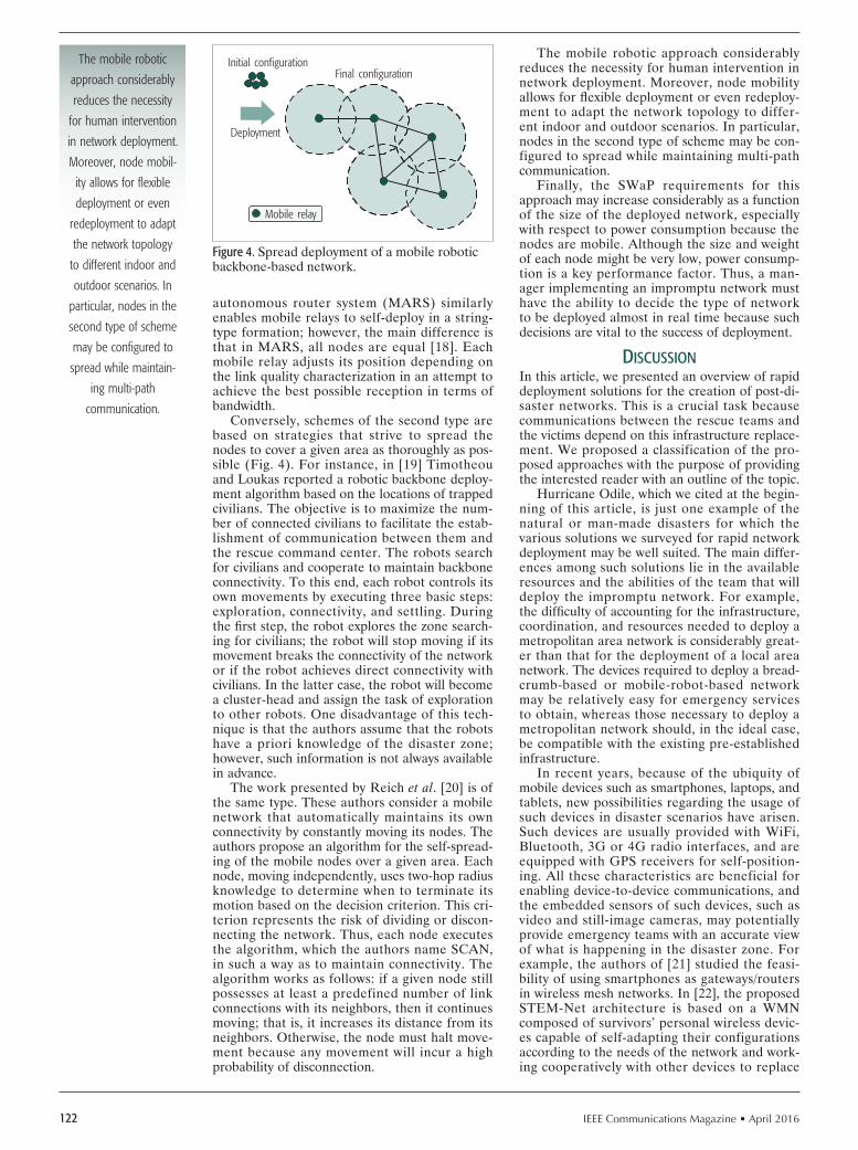
IEEE Communications Magazine • April 2016122
autonomous router system (MARS) similarly enables mobile relays to self-deploy in a string-type formation; however, the main difference is that in MARS, all nodes are equal [18]. Each mobile relay adjusts its position depending on the link quality characterization in an attempt to achieve the best possible reception in terms of bandwidth.
Conversely, schemes of the second type are based on strategies that strive to spread the nodes to cover a given area as thoroughly as pos-sible (Fig. 4). For instance, in [19] Timotheou and Loukas reported a robotic backbone deploy-ment algorithm based on the locations of trapped civilians. The objective is to maximize the num-ber of connected civilians to facilitate the estab-lishment of communication between them and the rescue command center. The robots search for civilians and cooperate to maintain backbone connectivity. To this end, each robot controls its own movements by executing three basic steps: exploration, connectivity, and settling. During the fi rst step, the robot explores the zone search-ing for civilians; the robot will stop moving if its movement breaks the connectivity of the network or if the robot achieves direct connectivity with civilians. In the latter case, the robot will become a cluster-head and assign the task of exploration to other robots. One disadvantage of this tech-nique is that the authors assume that the robots have a priori knowledge of the disaster zone; however, such information is not always available in advance.
The work presented by Reich et al. [20] is of the same type. These authors consider a mobile network that automatically maintains its own connectivity by constantly moving its nodes. The authors propose an algorithm for the self-spread-ing of the mobile nodes over a given area. Each node, moving independently, uses two-hop radius knowledge to determine when to terminate its motion based on the decision criterion. This cri-terion represents the risk of dividing or discon-necting the network. Thus, each node executes the algorithm, which the authors name SCAN, in such a way as to maintain connectivity. The algorithm works as follows: if a given node still possesses at least a predefined number of link connections with its neighbors, then it continues moving; that is, it increases its distance from its neighbors. Otherwise, the node must halt move-ment because any movement will incur a high probability of disconnection.
The mobile robotic approach considerably reduces the necessity for human intervention in network deployment. Moreover, node mobility allows for fl exible deployment or even redeploy-ment to adapt the network topology to differ-ent indoor and outdoor scenarios. In particular, nodes in the second type of scheme may be con-figured to spread while maintaining multi-path communication.
Finally, the SWaP requirements for this approach may increase considerably as a function of the size of the deployed network, especially with respect to power consumption because the nodes are mobile. Although the size and weight of each node might be very low, power consump-tion is a key performance factor. Thus, a man-ager implementing an impromptu network must have the ability to decide the type of network to be deployed almost in real time because such decisions are vital to the success of deployment.
dIscussIonIn this article, we presented an overview of rapid deployment solutions for the creation of post-di-saster networks. This is a crucial task because communications between the rescue teams and the victims depend on this infrastructure replace-ment. We proposed a classification of the pro-posed approaches with the purpose of providing the interested reader with an outline of the topic.
Hurricane Odile, which we cited at the begin-ning of this article, is just one example of the natural or man-made disasters for which the various solutions we surveyed for rapid network deployment may be well suited. The main differ-ences among such solutions lie in the available resources and the abilities of the team that will deploy the impromptu network. For example, the diffi culty of accounting for the infrastructure, coordination, and resources needed to deploy a metropolitan area network is considerably great-er than that for the deployment of a local area network. The devices required to deploy a bread-crumb-based or mobile-robot-based network may be relatively easy for emergency services to obtain, whereas those necessary to deploy a metropolitan network should, in the ideal case, be compatible with the existing pre-established infrastructure.
In recent years, because of the ubiquity of mobile devices such as smartphones, laptops, and tablets, new possibilities regarding the usage of such devices in disaster scenarios have arisen. Such devices are usually provided with WiFi, Bluetooth, 3G or 4G radio interfaces, and are equipped with GPS receivers for self-position-ing. All these characteristics are beneficial for enabling device-to-device communications, and the embedded sensors of such devices, such as video and still-image cameras, may potentially provide emergency teams with an accurate view of what is happening in the disaster zone. For example, the authors of [21] studied the feasi-bility of using smartphones as gateways/routers in wireless mesh networks. In [22], the proposed STEM-Net architecture is based on a WMN composed of survivors’ personal wireless devic-es capable of self-adapting their configurations according to the needs of the network and work-ing cooperatively with other devices to replace
Figure 4. Spread deployment of a mobile robotic backbone-based network.
Initial configuration
Deployment
Final configuration
Mobile relay
The mobile robotic
approach considerably
reduces the necessity
for human intervention
in network deployment.
Moreover, node mobil-
ity allows for fl exible
deployment or even
redeployment to adapt
the network topology
to different indoor and
outdoor scenarios. In
particular, nodes in the
second type of scheme
may be confi gured to
spread while maintain-
ing multi-path
communication.

IEEE Communications Magazine • April 2016 123
the portion of the infrastructure damaged by a disaster.
We believe that the development of a truly effective post-disaster network still requires fur-ther effort, and future proposed solutions must allow for fl exible deployment or redeployment to adapt to the conditions of each scenario. In addi-tion, such solutions should function with minimal human intervention over the incident area, and should be compatible with current technologies to cooperate with the already-existing infrastruc-ture without neglecting the issue of energy con-servation, which is extremely critical in the case of battery-powered wireless devices.
AcknoWledGment
This work was partially supported by a grant from CPER Nord-Pas-de-Calais/FEDER Cam-pus Intelligence Ambiante, the French Nation-al Research Agency (ANR) under the VERSO RESCUE project (ANR-10-VERS-003), and from the Italian government within the Cooper-link initiative under the international research project “PALMARES: an Internet of Smart Objects.” Part of this work was performed when Karen Miranda was with the FUN project team at Inria Lille–Nord Europe.
references
[1] Y. Ran, “Considerations and Suggestions on Improvement of Communi-cation Network Disaster Countermeasures after the Wenchuan Earth-quake,” IEEE Commun. Mag., vol. 49, no. 1, Jan. 2011, pp. 44–47.
[2] K. Mase, “How to Deliver Your Message from/to a Disaster Area,” IEEE Commun. Mag., vol. 49, no. 1, Jan. 2011, pp. 52–57.
[3] J. Evans, et al., “The Rapidly Deployable Radio Network,” IEEE JSAC, vol. 17, no. 4, Apr. 1999, pp. 689–703.
[4] F. Legendre et al., “30 Years of Wireless Ad Hoc Networking Research: What about Humanitarian and Disaster Relief Solutions? What are We Still Missing?” Proc. 1st Int’l. Conf. Wireless Technologies for Humanitar-ian Relief (ACWR), Amritapuri, Kollam, Kerala, India, Dec. 2011, p. 217.
[5] R. Bruno, M. Conti, and E. Gregori, “Mesh Networks: Commodity Multihop Ad Hoc Networks,” IEEE Commun. Mag., vol. 43, no. 3, Mar. 2005, pp. 123–31.
[6] S. Ghafoor et al., “Cognitive Radio for Disaster Response Networks: Sur-vey, Potential, and Challenges,” IEEE Wireless Commun., vol. 21, no. 5, Oct. 2014, pp. 70–80.
[7] M. Berioli et al., “Aerospace Communications for Emergency Applications,” Proc. IEEE, vol. 99, no. 11, Nov. 2011, pp. 1922–38.
[8] H. Aïache et al., “Increasing Public Safety Communications Interoperability: The CHORIST Broadband and Wideband Rapidly Deployable Systems,” Proc. Next Generation Public Safety Communication Networks and Technologies (NGenSafe), Dresden, Germany, Jun. 2009.
[9] H. Aïache et al., “WIDENS: Advanced Wireless Ad-Hoc Networks for Public Safety,” Proc. IST Mobile & Wireless Communications Summit, Dresden, Germany, Jun. 2005.
[10] E. Cayirci and C. Ersoy, “Application of 3G PCS Technologies to Rapidly Deployable Mobile Networks,” IEEE Network, vol. 16, 2002, pp. 20–27.
[11] E. Del Re et al., “SALICE Project: Satellite-Assisted Localization and Com-munication Systems for Emergency Services,” IEEE Aerospace and Elec-tronic Systems Mag., vol. 28, no. 9, Sep. 2013, pp. 4–15.
[12] M. R. Souryal et al., “Real-Time Deployment of Multihop Relays for Range Extension,” Proc. 5th Int’l. Conf. Mobile Systems, Applications, and Ser-vices (MobiSys), San Juan, Puerto Rico, Jun. 2007, pp. 85–98.
[13] A. Wolff, S. Subik, and C. Wietfeld, “Performance Analysis of Highly Available Ad Hoc Surveillance Networks Based on Dropped Units,” Proc. IEEE Conf. Technologies for Homeland Security, Waltham, MA, USA, May 2008, pp. 123–28.
[14] J. Q. Bao and W. C. Lee, “Rapid Deployment of Wireless Ad Hoc Back-bone Networks for Public Safety Incident Management,” Proc. Global Communications Conference (GLOBECOM), Nov. 2007, pp. 1217–21.
[15] H. Liu et al., “An Automatic, Robust, and Effi cient Multi-User Breadcrumb System for Emergency Response Applications,” IEEE Trans. Mobile Com-puting, vol. 13, no. 4, April 2014, pp. 723–36.
[16] N. Pezeshkian, H. G. Nguyen, and A. Burmeister, “Unmanned Ground Vehicle Radio Relay Deployment System for Non-Line-of-Sight Opera-tions,” Proc. 13th IASTED Int’l. Conf. Robotics and Applications, Würz-burg, Germany, 2007, pp. 501–06.
[17] C. Q. Nguyen et al., “Using Mobile Robots to Establish Mobile Wireless Mesh Networks and Increase Network Throughput,” Int’l. J. Distributed Sensor Networks (IJDSN), vol. 2012, 2012, pp. 1–13.
[18] K.-H. Kim, K. G. Shin, and D. Niculescu, “Mobile Autonomous Router Sys-tem for Dynamic (Re)formation of Wireless Relay Networks,” IEEE Trans. Mobile Computing, vol. 12, no. 9, 2013, pp. 1828–41.
[19] S. Timotheou and G. Loukas, “Autonomous Networked Robots for the Establishment of Wireless Communication In Uncertain Emergency Response Scenarios,” Proc. 2009 ACM Symposium on Applied Comput-ing (SAC), Honolulu, Hawaii, USA, Mar. 2009, pp. 1171–75.
[20] J. Reich, V. Misra, D. Rubenstein, and G. Zussman, “Connectivity Mainte-nance in Mobile Wireless Networks via Constrained Mobility,” IEEE JSAC, vol. 30, no. 5, Jun. 2012, pp. 935–50.
[21] A. Iera et al., “Making a Mesh Router/Gateway from a Smartphone: Is that a Practical Solution?” Ad Hoc Networks, vol. 9, no. 8, Nov. 2011, pp. 1414–29.
[22] G. Aloi et al., “STEM-Net: An Evolutionary Network Architecture for Smart and Sustainable Cities,” Trans. Emerging Telecommunications Technolo-gies, vol. 25, no. 1, Jan. 2014, pp. 21–40.
bIoGrAphIes
KAREN MIRANDA ([email protected]) received the Ph.D. degree in computer science from the University of Lille 1, France in 2013, and the M.Sc. degree in information sciences and technologies from the Metropolitan Autonomous University (UAM), Mexico in 2009. From January 2011 to April 2014 she worked within the FUN research team at Inria Lille–Nord Europe, France. Currently she is a visiting scholar with the Department of Applied Mathematics and Systems at the Metropolitan Autonomous University (UAM) in Mexico City. Her major research interests are performance evaluation of computer protocols, robot-based wireless relay networks, and wireless sensor networks.
ANTONELLA MOLINARO has been an associate professor of telecommunications at the University Mediterranea of Reggio Calabria, Italy, since 2005. Previously she was an assistant professor at the University of Messina (1998-2001), with the University of Calabria (2001-2004), and a research fellow at the Polytech-nic of Milan (1997-1998). She was with Telesoft, Rome (1992-1993), and with Siemens, Munich (1994-1995) as a CEC Fellow in the RACE-II program. Her current research focuses on wireless and mobile networking, vehicular networks, and future Internet.
TAHIRY RAZAFINDRALAMBO received his M.Sc. in applied statistics and computer science from the University of Antananarivo in 2001, and his Ph.D. degree in computer science from the INSA de Lyon in 2007. He is currently an Inria full researcher. His research interests are mainly focused on distributed algo-rithms and protocol design for wireless networks and performance evaluation. He is involved in many organization and program committees of national and international conferences such as DCOSS, MASS, PE-WASUN, MSWIM, PIMRC, and ICC, and he is the principal investigator of many national and international projects.
All these characteris-
tics are benefi cial for
enabling device-to-de-
vice communications,
and the embedded
sensors of such devic-
es, such as video and
still-image cameras,
may potentially provide
emergency teams with
an accurate view of
what is happening in
the disaster zone.

IEEE Communications Magazine • April 2016124 0163-6804/16/$25.00 © 2016 IEEE
AbstrActWireless communications along with the
Internet has been the most transformative tech-nology in the past 50 years. We expect that wireless data growth, driven by new mobile applications and the need to connect all human-kind (not just one third of the world’s popula-tion) as well as billions of things to the Internet, will require terabit-per-second shared links for ground-based local area and wide area wireless access, for wireless backhaul as well as access via unmanned aerial vehicles and satellites. We present a new scalable radio architecture that we refer to as multi-comm-core to enable low-cost ultra-high-speed wireless communications using both traditional and millimeter-wave spectrum.
IntroductIonMobile connectivity has transformed daily life across the globe, becoming one of the most dra-matic game-changing technologies the world has ever seen. As more people connect to the Inter-net, increasingly chat to friends and family, watch videos on the move, and listen to streamed music on their mobile devices, mobile data traffic con-tinues to grow at unprecedented rates. Actually, this surge in demand is following what we can informally call an omnify principle. Here, omnify stands for order of magnitude increase every five years. This means that demand for data increas-es 10 times every 5 years and will continue to increase at this pace with an expected 1000 times increase in the next 15 years. This increase in demand is similar to the memory and comput-ing power growth following Moore’s law, which offered a million-fold more memory capacity and processing power in the last 30 years. For wireless communications, it is more appropriate to mea-sure advances in 5-year and 10-year timeframes as a new generation wireless technology is intro-duced every 10 years, and a major upgrade on each generation follows 5 years after, as shown in Fig. 1. The total global mobile traffic already surpassed the 1 exabyte/mo mark in 2013 and is projected to grow 10-fold, exceeding 10 exabytes/mo within 5 years in 2018 [1]. With this trend, in 2028 global mobile traffic will exceed 1 zettabyte/mo, which is equivalent to 200 GB/month for 5 billion users worldwide. WiFi offload accounts for almost as much traffic as is carried on mobile networks and also follows a similar growth trend
with expected 1 zettabyte/mo WiFi offload traffic in 2028. We also expect peak wireless data rates to follow the omnify principle, increasing from 1 Mb/s in 2000 with the third generation (3G) to around 10 Gb/s with 5G in 2020, and finally 1 Tb/s with 6G in 2030, offering a million times increase in 30 years, as depicted in Fig. 1. Others have also highlighted the need and drivers for terabit-per-second data rates [2]. The peak data rates for WiFi follow a similar trend with a few years’ lead. This means wireless data is catch-ing up with the memory, storage, and computing capabilities that are already available to deal with these massive amounts of data.
Traditionally, all wireless communications, with the exception of point-to-point microwave backhaul links and satellite communications, used a relatively narrow band of the spectrum below 3 GHz. This sub-3 GHz spectrum has been attractive for non-line-of-sight (NLOS) point-to-multipoint wireless communications due to its favorable propagation characteristics. The large antenna aperture size at these frequencies enables broadcasting large amounts of power, which allows signals to travel longer distances as well as bend around and penetrate through obstacles more easily. This way, the sub-3 GHz spectrum allowed wide area coverage to be pro-vided with a small number of base stations or wireless access points (WAPs). However, with the mobile data traffic explosion, modern wireless systems face capacity (not coverage) challenges requiring deployment of more and more base stations with smaller coverage areas. However, the number of small cells that can be deployed in a geographic area is limited due to the costs involved in acquiring a new site, installing the equipment, provisioning backhaul, and so on. In theory, to achieve 1000-fold increase in capacity, the number of cells also needs to be increased by the same factor. Therefore, small cells alone are not expected to meet the capacity required to accommodate orders of magnitude increase in mobile data traffic demand in a cost-effective manner.
In order to address the continuously growing wireless capacity challenge, the author and his colleagues pioneered use of higher frequencies above 3 GHz, referred to as millimeter waves (mmWaves), with a potential availability of over 250 GHz spectrum for mobile communications
Multi-Comm-Core Architecture for Terabit-per-Second Wireless
Farooq Khan
Accepted from open cAll
Wireless communica-tions along with the Internet has been the most transformative technology in the past 50 years. We expect that wireless data growth will require terabit-per-second shared links for ground-based local area and wide area wireless access, wire-less backhaul, and access via unmanned aerial vehicles and satellites.
The author is with PHAZR. The work was done when the author was with Samsung Research America.

IEEE Communications Magazine • April 2016 125
[3–5]. At mmWave frequencies, radio spectrum use is lighter, and very wide bandwidths along with a large number of smaller antennas can be used to provide the orders of magnitude increase in capacity needed in the next 15 to 20 years. The smaller size of antennas is enabled by car-rier waves that are millimeters long compared to centimeter-long waves at currently used lower frequencies. A drawback of mmWaves, howev-er, is that they tend to lose more energy than do lower frequencies over long distances because they are readily absorbed or scattered by gases, rain, and foliage.
Adaptive beamforming technology can over-come these challenges by using an array of smaller antennas to concentrate radio energy in a narrow directional beam, thereby increas-ing gain without increasing transmission power. A prototype of adaptive beamforming using a matchbook-size array of 64 antenna elements connected to custom-built signal processing com-ponents was demonstrated in [6]. By dynamically varying the signal phase at each antenna, this prototype transceiver generates a beam just 10˚ wide that it can switch rapidly in the desired direction. The base station and mobile radio continually sweep their beams to search for the strongest connection, getting around obstructions by taking advantage of reflections thereby pro-viding NLOS communications.
terAbIt WIrelessAs of 2015, almost two-thirds of humankind did not have access to the Internet. A major barrier to expanding access to these communities is the cost of providing mobile services. Therefore, our foremost goal is to reduce cost per bit by devel-oping a new wireless architecture and integrated solution that can scale to terabits per second for ground-based local area and wide area wireless access, for wireless backhaul as well as access via unmanned aerial vehicles (UAVs) and satellites, as depicted in Fig. 2. In many parts of the world where high-speed data communications infra-structure is not available, it is considered more economical to provide high-speed access via sat-ellites, UAVs, or other non-traditional systems. The satellite communications and wireless back-haul markets have been highly fragmented. With the vision of providing wireless mobile access in the mmWave spectrum, a single wireless technol-ogy can be developed for access, backhaul, aerial, and space systems eliminating fragmentation and thereby reducing costs of providing wireless ser-vices across these diverse platforms. With the use of higher mmWave frequencies, backhaul links and access can also share the same spectrum due to the highly directional nature of beamformed mmWave transmissions. However, for satellite and /or UAV-based communications with very wide coverage areas, methods to avoid or can-cel interference need to be considered when the same spectrum is shared.
We note that battery-powered handheld mobile devices may not be able to transmit (or even receive) terabit-per-second data rates due to the high energy required to process these data rates. Therefore, terabit-per-second access links would need to be shared among multiple such devices with each device capable of transmitting
or receiving at peak data rates say on the order of tens of gigabits per second. However, back-haul links between WAPs, between a ground station and a satellite, between a ground station and a UAV, or a link between a satellite and an airplane or a base station and a car, for example, can transmit and receive at peak data rates of terabits per second or higher. We also note that in some of these cases the distinction between access link and backhaul link becomes blurred. For example, an airplane can provide access ser-vice for its passengers who are using battery-pow-ered handheld devices while connected to the satellite using so-called sky-haul. A UAV can use either a sky-haul link to the satellites or connect to the ground system via a backhaul link.
Figure 1. Wireless data follows an omnify principle.
Year20001995
105
100
Peak
rate
(b/s
), da
ta tr
affic
(byt
es/m
onth
)
1010
1015
1020
1025
2005 2010 2015 2020 2025 2030 2035
TrafficWi-FiMobile
1 zettabyte/month
1 exabyte/month
802.11ac1 Gb/s
802.11ad7 Gb/s
802.11ay100 Gb/s
Terabit/sWi-Fi
6G1 Tb/s5.5G
100 Gb/s5G10 Gb/sLTE-A
1 Gb/sLTE100 Mb/s
3G2 Mb/s
Figure 2. Terabit-per-second for ground-based, UAV, and satellite wireless links.
Groundcoverage
layer
HumansHumans
UAVUAV
WAP
WAP
WAP
Internet
Tb/ssky-haul
Tb/swired
backhaul Tb/swirelessbackhaul
Tb/suplink Tb/s
shared
Tb/ssharedaccess
Tb/s
Tb/s
Tb/s
Satellite
Antennaarray
Datacenter
Humans
HumansHumans
UAVcoverage
layer
Satellitecoverage
layer

IEEE Communications Magazine • April 2016126
We expect that future mobile and WiFi systems will continue to rely on below 6 GHz frequencies for important control information transmission and data communications when higher frequencies signals are not available [5]. This is because radio waves below 6 GHz fre-quencies can better penetrate obstacles, and are less sensitive to NLOS communications or other impairments such as absorption by foliage, rain, and other particles in the air.
A key benefit of using higher frequencies is wider available bandwidths providing higher data rates and capacity, thereby lowering cost per bit. In order to fully utilize the lower and higher frequencies spectrum, we provide a three-layer system design framework as shown in Fig. 3. The lower-band group utilizes spectrum below 6 GHz providing a maximum peak data rate of around 10 Gb/s using arrays consisting of tens of antennas. The mid-band group covers spectrum between 6–56GHz providing peak data rate of 100Gb/s using arrays consisting of hundreds of antennas. In the high-band group, peak data rates approach terabits per second with the pos-sibility of using thousands of antennas.
A single system design approach can be used for the three layers with each layer potentially having different physical layer parameters to optimize performance. This is because the chan-nel propagation characteristics are expected to be different in the three band groups due to dependence on frequency. At the same time, we expect that the differences in channel character-istics within a band group are small enough to justify a single set of physical layer parameters. For example, from Fig. 3, we can see that a high-band system needs to account for higher attenua-tions due to water vapor (H2O) and oxygen (O2) absorption [7].
mId-bAnd spectrum
The use of lower-band-group spectrum below 6 GHz is well understood; therefore, we start by exploring the mid-band spectrum that covers the 6–56 GHz frequency range. In October 2004, the FCC issued a Notice of Inquiry (NOI) to examine use of bands above 24 GHz for mobile radio services [8]. The FCC’s U.K. counterpart, Ofcom, also released a Call for Input on “Spec-trum above 6 GHz for future mobile communica-tions” [9]. The bands identified below 60 GHz in the FCC NOI providing a total bandwidth of 5.2 GHz are summarized in Table 1 and Fig. 3. The regulators in other countries are also current-ly working on identifying millimeter spectrum for wireless communications. We defined mid-band spectrum in the range of 6–56 GHz cov-ering a total 50 GHz spectrum. Therefore, the FCC NOI only identifies about 10 percent of the total mid-band spectrum. We expect that in the future, more spectrum in the mid-band can be identified for wireless communications not only in the United States but also globally. Separate spectrum allocations are provided for satellite communications [11].
HIgH-bAnd spectrum
Terabit-per-second wireless may require many gigahertz of spectrum, which is practically impossible in the low band below 6 GHz and unlikely in the mid-band due to the presence of other services. However, much larger spectrum bandwidths can be made available in the high band, which covers frequencies above 56 GHz. In Fig. 3 and Table 1, we also summarize the 60/70/80 GHz bands identified in the FCC NOI. We also list 90 GHz and higher bands that are currently designated as mobile in the FCC fre-quency allocation chart [10] in addition to other services such as passive Earth exploration sat-ellite, radio astronomy, passive space research, fixed/mobile satellite, radio navigation, amateur radio, non-communication industrial, scientific, and medical (ISM) Part 18 equipment, and so on. We note that a total of 66.6 GHz bandwidth can potentially be available in the high band to enable terabit-per-second wireless communica-tions. However, the use of wireless and mobile communications in these bands needs to be care-fully studied to evaluate the impact on other ser-vices present in these bands. We further remark that with continuous advances in technology, bands above 164 GHz can also become candi-dates for future wireless communications in the future.Figure 3. Mid-band and high-band mmWave spectrum.
Frequency (GHz)Low-band
High-band
High-bandgroup
Mid-bandgroup
Low-bandgroup
Peak
data
rate
1 Tb/s
100 Gb/s
10 Gb/s
f < 6 GHz
High-band(cont’d)Mid-band
0.4GHz 1.6GHz
1.4 GHz1.3 GHz
7 GHzBW 7 GHz 5 GHz
0.5GHz
6 GHz 56 GHz 300 GHz
LB
20
0.1
Atten
tion
(dB/
km)
0.01
1
10
100
30 50 70 10010 200
High-band
Mid-band
300
6 GHz > f ≤ 56 GHz f > 56 GHzf
28
37
39
42 GHz24 GHz
60GHzlower
60GHz
upper
70GHz
5 GHz
80GHz
5 GHz
95GHz
7.5GHz
105GHz
4 GHz
130GHz
7.5 GHz
140GHz
12.5 GHz
150/160GHz
2.9GHz
90
2.45GHz
112
0.75GHz
122

IEEE Communications Magazine • April 2016 127
multI-comm core ArcHItecture
Multiple computational cores, or multi-core, has become the norm ever since IBM introduced the first general-purpose processor, called POWER4, in 2001, which featured multiple processing cores on the same complementary metal oxide semi-conductor (CMOS) die. The transition to multi-core architecture was driven by an unsustainable level of power consumption implied by clock rates in excess of a few gigahertz. The heat losses and dynamic power of integrated circuits (the power that is consumed when the transistor is switching from an on-state to an off-state) both increase faster as frequencies rise. The switching or dynamic power dissipated by a CMOS chip increases quadratically with voltage,
P CV2f + Pstatic,
where C is the capacitance being switched per clock cycle, V is the supply voltage, f is the switch-ing frequency, and Pstatic is the power due to stat-ic leakage current, which has become more and more accentuated as feature sizes have become smaller and threshold levels lower. The voltage required for stable operation is determined by the frequency at which the circuit is clocked, and can be reduced if the frequency is also reduced. This can yield a significant reduction in power consumption because of the quadratic relation-ship above. Currently, the only practical way to improve the processing performance is to keep clock rates around 1–2 GHz while adding support for more threads, either in the number of cores or through multithreading on cores. We expect a similar transition to happen in wireless com-munications when data rates in the hundreds of gigabits per second to terabit-per-second range would require many gigahertz of bandwidth.
We present a scalable radio system architecture called Multi-Comm-Core (MCC), shown in Fig. 4, to achieve ultra-high-speed data transmission with reasonable cost, complexity, and power con-sumption. As we go to such high data rates while using very large bandwidth (BW), it is more ener-gy-efficient to work in smaller blocks operating at lower clock frequencies and using multiples of them to achieve the high data rate. We already see this trend in current multi-core CPU designs for microprocessors, graphic cards, and mobile phones where exploiting parallelism is key to attaining per-formance at limited power consumption. With mul-tiple-input multiple-output (MIMO) and carrier aggregation support in current wireless systems, we are already in the era where we have multiple simi-lar blocks of hardware in the system, and are seeing it pervade all aspects of the design at the micro and macro levels such as antenna arrays (with multiple identical elements), analog-to-digital converters (with time-interleaved sub-ADCs), low-density par-ity code (LDPC) decoders (multiple decoders with multiple identical processing elements within each decoder), and so on. The proposed radio archi-tecture also complements the multi-core proces-sor architecture, which can implement the medium access control (MAC), security and higher-layer functions.
We can also consider the evolution of HW accelerators used in multi-core application pro-
cessors to align with the proposed MCC radio architecture. Moreover, in the case of cloud radio access network (C-RAN) implementations, we can centralize and aggregate the baseband processing part of the MCC architecture for a large number of distributed radio nodes.
In practice, the bandwidths required to sup-port ultra-high-speed data transmissions may not be available in a contiguous manner (Table 1) even in the higher mmWaves or the RF front-end, and the antennas may not support such high bandwidths with the required efficiency. Therefore, we expect the system to use a set of RF front-end and antenna arrays covering each spectrum group of frequencies, as shown in Fig. 4. Within each spectrum group, multiple BW cores, each supporting 1–2 GHz bandwidth, will be stacked together. The RF front-end and BW core stacking blocks within each spectrum group are replicated to provide spatial cores (to support multi-beam and/or MIMO capability). Each BW core has its own set of data converters (ADC/DACs), fast Fourier transform (FFT)/inverse FFT (IFFT), channel coding, and other baseband functions, and these blocks/functions are repli-cated across spatial cores. The MIMO/beam pro-cessing may need to be performed jointly across the spatial cores for the same BW core.
The proposed radio architecture provides a high degree of flexibility to achieve a given data
Table 1. Mid-band and high-band spectrum candidates.
Bands (GHz) Frequency (GHz) Bandwidth (GHz)
24 GHz bands 24.25–24.45 25.05-25.25
0.2000.200
Mid-band spectrum = 5.2 GHz
LMDS band27.5–28.35 29.1–29.25 31–31.3
0.850 0.150 0.300
39 GHz band 38.6-40 1.400
37/42 GHz bands 37.0–38.6 42.0–42.5
1.600 0.500
60 GHz 57–64 64–71
7.000 7.000
High-band spectrum = 66.6 GHz
70/80 GHz 71–76 81–86
5.000 5.000
90 GHz 92–94 94.1–95.0 2.900
95 GHz 95–100 5.000
105 GHz 102–105 105–109.5 7.500
112 GHz 111.8–114.25 2.450
122 GHz 122.25–123 0.750
130 GHz 130–134 4.000
140 GHz 141–148.5 7.500
150/160 GHz151.5–155.5 155.5–158.5 158.5–164
12.50
> 164 GHz High-band future extensions Over 100 GHz spectrum

IEEE Communications Magazine • April 2016128
rate through use of various combinations of BW cores, spatial cores, and spectrum groups based on hardware and spectrum availability. More-over, it allows scaling down the hardware to meet given cost, form factor, power consumption, or complexity requirements.
An example of a key block that will ben-efit from MCC architecture are data convert-ers. A commonly used figure of merit (FOM) for ADCs, referred to as the Walden FOM [12], defi nes energy required per conversion step as
FOM = P2ENOB × fs
J conv⎡⎣ ⎤⎦
where P is the power dissipation, fs is the Nyquist sampling rate, and ENOB is the effective num-ber of bits defi ned by the signal-to-noise-plus-dis-tortion ratio (SNDR).
Figure 4 shows this FOM as a function of speed or the Nyquist sampling rate for many ADCs published in the literature. We note that energy required per conversion step increases by orders of magnitudes when going above gigahertz sampling rates. This makes a case for limiting the sampling rates to around 1 GHz and using many ADCs, with a pair of ADCs for I and Q sampling per comm-core. We note that with the semiconductor process technology scaling, the cut-off point for transition-ing to MCCs may move to higher sampling rates and hence higher bandwidths.
The energy of the clock distribution network of integrated circuits scales with the clock fre-quency and consumes a signifi cant portion of the energy as well [14]. The MCC architecture allows the clock frequencies to be kept low, thereby providing not only savings in power consumption
but also reduction in heat that needs to be dissi-pated. By limiting the core bandwidth to around 1 GHz, MCC architecture also avoids or min-imizes beam squint (i.e., changes in the beam steering angle with frequency) issues when true-time delay (TTD) cannot be implemented, as may be the case for baseband beamforming.
The MCC architecture presents several other advantages from the system capacity and hard-ware perspectives. For example, the number of BW MCCs allocated for uplink and downlink can be dynamically varied to meet the varying traffi c needs while fully utilizing the air interface and hardware resources. Also, not all MCCs need to be homogeneous, meaning supporting the same bandwidth or number of antennas and so on. A set of heterogeneous MCCs can take into account different requirements of standards specifi cations, hardware and spectrum allocation, as well as the needs of low-power control signal transmission or low-rate data transmission. Moreover, similar to multi-core CPU architecture, we can turn on only the required number of MCCs to support a given data rate and capacity at a given time, turning off the other MCCs to save power.
lInk budget AnAlysIsIn order to assess the feasibility of tera-bit-per-second using MCC architecture, we carry out the link budget analysis of the system in Table 2. We first calculate the data rate per comm-core for a reference system with 1 GHz core BW at 100 GHz frequency and a 200 m range. We note that with a total of 256 comm-cores, we can reach 1.5 Tb/s data rate. This can, for example, be achieved with 32 BW cores with total 32 GHz bandwidth and 8 spatial cores or other combinations of BW cores and spatial cores. This means that very large BW and large numbers of spatial cores (multiple beams) will be required to achieve terabit-per-second data rates. With the proposed MCC architecture, the total bandwidth (32 GHz in this example) can also be aggregated across low-band, mid-band, and high-band spectrum. Another observation is the large amount of total transmit power, which will be 25.6 W for 256 cores just for the power amplifiers with the assumption of 100 mW of power per core. Accounting for power amplifi er efficiency and consumption in other RF com-ponents and the baseband, we expect the total power consumption at least an order of magni-tude higher in the hundreds of Watts range or higher. As discussed earlier, this will limit the feasibility of terabit-per-second access data rates in the downlink from a WAP, UAV, or satel-lite to mobile devices. In the case of backhaul links between base stations or a link between a satellite and a ground-based gateway, both ends of the link can possibly transmit and receive at terabit-per-second data rates. Moreover, these aggregate data rates would need to be shared among multiple mobile devices as just receiving terabit-per-second data rates will be way above the power budget available in mobile devices. This can be achieved by sharing the resources in frequency, time, and space (multi-user MIMO) among multiple users. With the assumption that a mobile device can transmit over a few cores within its power budget, a reasonable assump-
Figure 4. Multi-Comm-Core architecture and Walden FOM vs. speed for ADCs [13].
fs[Hz]1.E+05
5.E+00
5.E-01
FOM
[fJ/c
onv-s
tep]
5.E+01
5.E+02
5.E+03
5.E+04
1.E+04 1.E+06 1.E+07 1.E+08
A communication core Many cores
MIMOprecoding/detecting
LDPCenc/dec
BW cores Spatial cores RFFE replication for spatial cores
1.E+09 1.E+10 1.E+11
ISSCC 2015VLSI 2014ISSCC 1997-2014VLSI 1997-2013Envelope
IFFT/FFT
DAC/ADC
BWcore
stacking
RFfront-end
Spec
trum
grou
p 1
MIMOprecoding/detecting
LDPCenc/dec
IFFT/FFT
DAC/ADC
BWcore
stacking
RFfront-end
Spec
trum
grou
p 2
MIMOprecoding/detecting
LDPCenc/dec
IFFT/FFT
DAC/ADC
BWcore
stacking
RFfront-end
PLL, mixer, phase shiftersPA/LNA etc.
Antenna array
Spec
trum
grou
p K
Map
ping o
f com
m-co
res t
o BW
/spati
al co
res a
nd sp
ectru
m gr
oups
MAC
+ h
igher
laye
rs (m
ulti-c
ore p
roce
ssor
s)

IEEE Communications Magazine • April 2016 129
tion for the data rates from a mobile device then probably is in the range of tens of gigabits per second.
The transmit antenna total gain of 32 dB is achieved using an array of size 512 and anten-na element gain of 5 dB. We assume a receive antenna array size of 64 elements providing a total gain of 23 dB after accounting for anten-na element gain of 5 dB. When antenna arrays are used at both the transmitter and the receiv-er, higher frequencies will benefit from higher array gain for the same total antenna area due to smaller wavelengths [1, 4]. This will help com-pensate for other losses that tend to increase with increasing frequency. In the link budget cal-culations, we accounted for total losses of 18 dB, which includes 10 dB for NLOS reflection, 3 dB RF front-end loss, and 5 dB baseband implemen-tation loss. In practice, these losses may be high-er, and there may be other losses that will reduce achievable data rate, range, or both. For satel-lite-based access requiring very large distance links, achieving terabit-per-second data rates would require the transmit power and antennas’ gain to increase to compensate for the higher propagation loss as discussed in [11].
conclusIonWe outline a vision to connect the remaining two thirds of humankind as well as billions of things to the Internet via low-cost terabit-per-second wireless access. We present a scalable radio architecture referred to as multi-comm-core, which can scale to higher-frequency millime-ter-wave spectrum in addition to using traditional frequencies below 6 GHz. With the MCC archi-tecture, the number of communication cores and hence the bandwidth and hardware can be scaled naturally to provide terabit-per-second wireless for ground-based local area access (WiFi), wide area wireless (mobile) access, wireless backhaul, as well as access via unmanned aerial vehicles (UAVs) and satellites. A single radio technology operating at both traditional and millimeter-wave spectrum can be developed, eliminating fragmen-tation and thereby reducing costs of providing wireless services through these diverse platforms.
AcknoWledgment
The author would like to thank his colleagues at Samsung for valuable discussions and feedback.
references[1] Cisco Visual Networking Index (VNI): Global Mobile Data Traffic Forecast
Update, 2014–2019.[2] G. Fettweis, F. Guderian, and S. Krone, “Entering the Path towards Tera-
bit/s Wireless Links,” Design, Automation & Test in Europe Conf. Exhibi-tion 14–18 Mar., 2011.
[3] F. Khan and Z. Pi, “Millimeter Wave Mobile Broadband (MMB): Unleashing 3 300 GHz spectrum,” Proc. IEEE WCNC, March 2011; http://wcnc2011.ieee-wcnc.org/tut/t1.pdf.
[4] F. Khan and Z. Pi, “mmWave Mobile Broadband (MMB): Unleashing the 3–300 GHz spectrum,” Proc. 34th IEEE Sarnoff Symp., 3–4 May 2011, Princeton, NJ.
[5] Z. Pi and F. Khan, “An Introduction to Millimeter-Wave Mobile Broadband Systems,” IEEE Commun. Mag., July 2011.
[6] W. Roh et al., “Millimeter-Wave Beamforming as an Enabling Technology for 5G Cellular Communications: Theoretical Feasibility and Prototype Results,” IEEE Commun. Mag., Feb. 2014.
[7] FCC OET Bulletin #70, “illimeter Wave Propagation, Spectrum Manage-ment Implications,” July 1997.
[8] FCC 14-154, “NOI to Examine Use of Bands above 24 GHz for Mobile Broadband.”
[9] Ofcom COI, “Spectrum above 6 GHz for Future Mobile Communications.”[10] FCC Online Table of Frequency Allocations, July 2014.[11] F. Khan, “Mobile Internet from the Heavens”; http://arxiv.org/
abs/1508.02383[12] R. H. Walden, “Analog-to-Digital Converter Survey and Analysis,” IEEE
JSAC, vol. 17, Apr. 1999, pp. 539–50.[13] B. Murmann, “ADC Performance Survey 1997–2015”; http://web.stan-
ford.edu/~murmann/adcsurvey.html.[14] V. Kursun and E. G. Friedman, Multi-Voltage CMOS Circuit Design,
Wiley, 2006.
bIogrApHyFarooq Khan is currently CEO of PHAZR, a startup focused on developping 5G mobile ommunications systems. Prior to PHAZR, he was president of Samsung Research America, Dallas, Texas, where he led high-impact collab-orative research programs in mobile technology. He received his Ph.D. in wireless communications from the University of Versailles, France. He holds over 200 U.S. patents, and has written 50 research articles and a best-selling book on 4G LTE.
Table 2. Terabit-per-second link budget analysis.
Parameter Value Comments
Transmit power 20 dBm Possibly multiple PAs
Transmit antenna gain 32 dBi Element + array gain
Carrier frequency 100 GHz Ref. for calculations
Distance 200 meters
Propagation loss 118.42 dB
Other path losses 10 dB Some NLOS
Tx front-end loss 3 dB Non-ideal RF
Receive antenna gain 23 dB Element + array gain
Received power –56.42 dBm
Bandwidth 1 GHz BW / comm-core
Thermal noise PSD –174 dBm/Hz
Receiver noise figure 5.00 dB
Thermal noise –79 dBm
SNR 22.58 dB
Implementation loss 5 dB Non-ideal baseband
Spectral efficiency 5.86 b/s/Hz
Data rate/comm-core 5.86 Gb/s SE BW
Number of comm-cores 256 BW and spatial cores
Aggregate data rate 1.5 Tb/s 256 5.86 Gb/s
IEEE Communications Magazine • April 2016130 0163-6804/16/$25.00 © 2016 IEEE
AbstrActBuffer sizing is an important network con-
figuration parameter that impacts the quality of service characteristics of data traffic. With falling memory costs and the fallacy that “more is bet-ter,” network devices are being overprovisioned with large buffers. This may increase queueing delays experienced by a packet and subsequent-ly impact stability of core protocols such as TCP. The problem has been studied extensive-ly for wired networks. However, there is little work addressing the unique challenges of wire-less environments such as time-varying channel capacity, variable packet inter-service time, and packet aggregation, among others. In this article we discuss these challenges, classify the current state-of-the-art solutions, discuss their limita-tions, and provide directions for future research in the area.
IntroductIonBuffers are designed to absorb transient traffic bursts. However, arbitrarily sized buffers can degrade network performance. Large buffers lead to long queueing delays, while very small buffers may result in network underutilization. Ideally, the buffers need to be sized just large enough to keep the link saturated at close to full utilization while minimizing queueing delays.
With declining memory prices and the fal-lacy that “more is better,” network devices are increasingly being overprovisioned with large buffers that aim to improve throughput by lim-iting packet drops. While throughput is the dominant performance metric, packet forward-ing latency also impacts user experience. This includes not only real-time traffic such as voice over IP (VoIP), video conferencing, and net-worked games, but also web browsing, which is sensitive to latencies on the order of hundreds of milliseconds. Studies have indicated that a 1 s delay in page load times of e-commerce websites can significantly impact customer conversion. Furthermore, large queueing delays also impact the stability of core Internet protocols such as TCP, which rely on timely notification of conges-tion information to respond effectively.
Buffer sizing for wired networks has been extensively studied (e.g., [1, 2], among others). A well-known rule of thumb is to have buffers slightly larger than the bandwidth-delay prod-
uct (BDP) [3] of the network. However, there is limited work on understanding the impact of buffer sizing on wireless networks. Wireless net-works have significantly different characteristics from wired networks. For example, the wireless link capacity is not constant and may vary over time due to interference. Moreover, the pack-et inter-service time may vary due to the ran-dom access medium access control (MAC) and frame retransmissions following automatic repeat request (ARQ). Also, recent MAC enhance-ments such as frame aggregation allow transmis-sion of large frame aggregates, creating further challenges in efficient management of buffer siz-ing techniques in wireless networks.
To illustrate the impact of buffer size on wireless network performance, we performed a number of experiments on a Linux-based WiFi testbed by transferring a large file between two hosts connected via 802.11n radios. We vary the link rate every 50 s: we start at 144.4 Mb/s, then drop it to 65 Mb/s, 6.5 Mb/s, and finally 13 Mb/s. We monitor the growth of the TCP con-gestion window as well as the round-trip time (RTT) between the two hosts. We also measure the queue utilization of the FTP server and the amount of dropped packets by the sender. Our results are shown in Fig. 1. We observe that the TCP congestion window peaks at 1.6 million bytes (window scaling is enabled by default on Linux hosts), with RTT peaking at around 2.6 s. Most of these “in-flight” TCP segments are queued up at the Linux transmit queue (txqueue) interface (default size of 1000 packets), contrib-uting to large queueing delays that lead to high RTT delays. Most operating systems use some variant of loss-based TCP congestion control algorithms. Having large buffers prevents a time-ly dropping of a packet that is required for con-veying network congestion to the TCP sender, leading the TCP congestion window to shoot up to the high values observed in our experiment. We note that with these large buffers, the queue utilization never drops to 0, despite the TCP sender reducing its congestion window multiple times during the experiment. Slower links lead to the longest queueing delays. The variations in RTT clearly suggest that a uniform static buffer size cannot be used for wireless networks that are fundamentally dynamic in nature. Similar performance degradation due to bloated buf-
Buffer Sizing in Wireless Networks: Challenges, Solutions, and Opportunities
Ahmad Showail, Kamran Jamshaid, and Basem Shihada
Accepted from open cAll
There is little work addressing the unique challenges of wireless environments such as time-varying channel capacity, variable packet inter-service time, and packet aggregation, among others. The authors discuss these chal-lenges, classify the current state-of-the-art solutions, discuss their limitations, and provide directions for future research in the area.
The authors are with King Abdullah University of Science and Technology and Taibah University.

IEEE Communications Magazine • April 2016 131
fers has also been reported for cellular networks [4]. Figure 1 shows that packet dropping increas-es with network load. This is in agreement with what Fu et al. found earlier [5].
In this article, we describe the challenges of buffer sizing in wireless data networks. We then present a summary of buffer sizing solu-tions available in the literature. We classify these solutions for single-hop and multihop wireless networks. This delineation is necessary because multihop wireless networks introduce a new set of challenges that require rethinking the packet delay paradigm. We also discuss recent active queue management (AQM) techniques. Since these operate at a different control point, they may be used to complement direct manipulation of buffer sizes. To ground our discussion, we also present some performance measurements from our wireless network testbed. We conclude the article by presenting our view on future direc-tions to address the buffer sizing problem in the wireless domain.
buffer sIzIng chAllengesBuffer sizing techniques and their impact on the performance of wired networks is well under-stood [1–3]. However, these techniques can-not be directly applied to the wireless domain because of several unique challenges, described below.
lInk schedulIng
The wireless spectrum is a shared resource between a set of neighboring nodes. Interference considerations may require that only one of these nodes transmit at a time. The number of transmit opportunities available to a node is partly depen-dent on the number of neighboring nodes that are also actively contending for channel access. Thus, unlike a wired link, a wireless link cannot be scheduled independent of its neighboring nodes. This limits the available, usable capacity of a wireless link, as it now varies depending on the network topology and the number of compet-ing flows. Therefore, while the physical wireless link rates may connect at 300 Mb/s, the actual rate achievable by a flow may be significantly less and would further vary over time based on the link scheduling constraints.
AdAptIve lInk rAtes
Wired link rates are constant and often known a priori. In contrast, link rate adaptation algo-rithms dynamically set the wireless link rate in response to changing network conditions. These link rates may exhibit significant variations over time; for example, the link rate for a 802.11n radio may vary from 6.5 to 600 Mb/s. Depend-ing on the link rate adaptation algorithm, these link rates may vary on timescales ranging from milliseconds to minutes. This has implications on the network BDP and the resulting buffer size required for saturating the link.
We have performed various experiments to study the impact of variable link rates on wire-less network dynamics. Our testbed uses Ath-eros 802.11n wireless cards on Linux machines with ath9k drivers. The default txqueue size on current Linux kernels is 1000 packets. We use a radio channel that does not interfere with our
campus production network. We transfer a large file between two wireless nodes and simultane-ously monitor the goodput as well as other TCP statistics. We repeated this experiment at mul-tiple link rates and txqueue buffer sizes while enabling and disabling wireless frame aggre-gation. Figure 2 shows the end-to-end delay and network goodput over a single-hop wire-less network. We observe that there is no opti-mal buffer size that works across the four link rates used in our experiments. Large buffers work well with fast links where they can satu-rate the link capacity while maintaining accept-able delays. Small buffers are better suited for slow links, where they limit the queueing delays while giving similar goodput as large buffers at the price of packet drop. For example, in Figs. 2b and 2d we observe that changing the buffer size from 10 to 50 packets shows only a minor goodput improvement for a 13–144.4 Mb/s link, but shows a 30 percent increase in goodput for the 300 Mb/s link. However, this buffer size can-not be used across all link rates as the RTT with 13 Mb/s link already exceeds 250 ms over a sin-gle wireless hop. Such delays are unacceptable when these queues are shared with real-time traffic. Figure 2f shows the packet drop per-centage for each buffer size. We observe that shrinking the buffer size increases the number of dropped packets. This is in agreement with the results of Dhamdhere and Dovrolis [2], who show that extremely small buffers lead to high loss rates.
Figure 1. TCP congestion window, RTT, egress queue utilization, and the number of dropped packets for a TCP flow in a 802.11n wireless testbed with varying link rates over time. Buffer size values correspond to values in the stock Linux kernel.}
Time (s)144 Mb/s 65 Mb/s 6.5 Mb/s 13 Mb/s
500
200,0000
Cong
estio
n wi
ndow
(byt
es)
RTT
(ms)
400,000600,000800,000
1e+061.2e+061.4e+06
2500
30001.6e+061.8e+06
2000
1500
1000
500
0100 150 200
Time (s)500
200,0000
Buffe
r occ
upan
cy (b
ytes
)
400,000600,000800,000
1e+061.2e+061.4e+061.6e+061.8e+06
100 150 200
Time (s)500
30
0
Cum
ulat
ive p
acke
t dro
ppin
g25
20
15
10
5
35
100 150 200
Congestion windowRound-trip time
Dropped packets
Queue [B]

IEEE Communications Magazine • April 2016132
frAme AggregAtIon
While these challenges are common across wire-less networks in general, standard-specific enhance-ments introduce additional complexity. For example, IEEE 802.11n standard specifications include various enhancements to improve channel capacity utilization, including frame aggregation. An aggregate MAC protocol data unit (A-MPDU) aggregates multiple IP packets back to back into a single frame. An A-MPDU is limited in size to 65,535 B (bound by the 16-bit length field in the HT-SIG headers) and can carry a maximum of 64 subframes (limited by the Block Acknowl-edgment frame). Figure 2 shows that A-MPDU aggregation increases the network goodput by 5 for 300 Mb/s link with large buffers, and up to 3 with small buffers. It also shows that big buf-fers lead to slightly higher packet drop rate when
A-MPDU frame aggregation is enabled. Both of these observations are attributed to the fact that big buffers allow large aggregates, as shown in Fig. 3. The only exception is at the 6.5 Mb/s link rate as frame aggregation is disabled at this rate in our hardware (transmitting a large A-MPDU frame at this link rate violates the 4 ms frame transmit duration regulatory requirement).
UDP flows are used in real-time communi-cation, such as online games, IPTV, and VoIP. Hence, it is important to compare such flows to other flows that favor reliable delivery over timely delivery. We repeated the same exper-iments with UDP instead of TCP to evaluate the interaction of frame aggregation with UDP flows. The only difference in the experiment setup is enabling the default rate control algo-rithm in Linux (Minstrel) instead of fixed link rates. Latency, goodput, and packet drop results
Figure 2. Latency, goodput, and packet drop of a TCP large file transfer over various link rates and buffer sizes: a) latency with-out A-MPDU aggregation; b) latency with A-MPDU aggregation; c) goodput without A-MPDU aggregation; d) goodput with A-MPDU aggregation; e) drop without A-MPDU aggregation; f) drop with A-MPDU aggregation.
Buffer size (packets)10 50 100 500 1000 2000
500
0
RTT
(ms)
1000
1500
2000
2500
3000
3500
Buffer size (packets)10 50 100 500 1000 2000
500
0
RTT
(ms)
1000
1500
2000
2500
Buffer size (packets)10 50 100 500 1000 2000
5
0
Good
put (
Mb/
s)
10
15
20
25
Buffer size (packets)10 50 100 500 1000 2000
10
0
Good
put (
Mb/
s)
20
30
40
50
60
70
80
90
100
Buffer size (packets)10 50 100 500 1000 2000
0.005
0
Pack
et d
rop
(%)
0.01
0.015
0.02
0.025
0.03
Buffer size (packets)
(a) (b)
(c) (d)
(e) (f)
10 50 100 500 1000 2000
0.005
0
Pack
et d
rop
(%)
0.01
0.015
0.02
0.025
0.03
0.035
0.04
13 Mb/s65 Mb/s144 Mb/s300 Mb/s
13 Mb/s65 Mb/s144 Mb/s300 Mb/s
13 Mb/s65 Mb/s144 Mb/s300 Mb/s
13 Mb/s65 Mb/s144 Mb/s300 Mb/s
13 Mb/s65 Mb/s144 Mb/s300 Mb/s
13 Mb/s65 Mb/s144 Mb/s300 Mb/s

IEEE Communications Magazine • April 2016 133
are shown in Fig. 4. UDP consistently achieves higher goodput compared to TCP. This is due to multiple factors:• UDP does not incur the overhead of trans-
mitting TCP ACK segments, and thus the capacity spared can be used to send addi-tional data packets.
• TCP employs congestion control algorithms, while UDP can saturate the medium with a sustained traffic rate. In our experiments, the only case when TCP
goodput outperforms UDP is with the 10-pack-et buffer; we attribute this to the high UDP drop rate (around 9 percent), which limits the performance of A-MPDU frame aggregation. Figure 4b shows that UDP goodput stabilizes when the aggregation is disabled, although we observe variations in results with aggregation for buffers larger than 10 packets. This is because large buffers allow longer aggregates. For exam-ple, the average number of frames per aggregate increases from 16.1 for the 50-packet buffer to 17.6 for a 2000-packet buffer. Figure 4a shows that UDP delays are always smaller than TCP; this is because UDP does not incur extra delays for connection management and reliability.
vArIAble pAcket Inter-servIce tIme
The packet inter-service rate for any wired link is deterministic for a given packet size. In contrast, the packet inter-service rate for a wireless link is variable due to several factors. First, MAC proto-cols such as carrier sense multiple access with col-lision avoidance (CSMA/CA) use random backoffs to reduce the probability of a collision. Second, the wireless link bit error rate (BER) is typically orders of magnitude higher than that of a wired link (BER of 10–5 to 10–3 for a wireless link vs. 10–15 to 10–12 for a wired link). Wireless MAC protocols use ARQ to provide reliability. As a result, a pack-et may be transmitted multiple times (e.g., up to seven retries per IEEE 802.11 standard specifica-tions) before it is successfully received, contributing to variations in inter-service delays.
multIhop chAllenges
Multihop wireless networks further exacer-bate the challenges described above. Due to the shared nature of wireless spectrum, a flow not only competes for transmission opportuni-ties with other flows (inter-flow contention), but also contends with its own packet transmissions along the hops to the destination (intra-flow con-tention). This adds to the link scheduling and variable packet inter-service time challenges described above. Further, the abstraction of a “bottleneck” in a shared wireless medium trans-lates to a set of nodes in a part of the network that experiences high channel contention. A flow may traverse multiple hops in this part of the network, and hence the bottleneck spans multi-ple nodes. It is unclear how to size buffers in this distributed environment. Moreover, a multihop node may also relay traffic for other nodes in the network, so it needs additional measures to pro-vide isolation and fairness between flows.
To illustrate the effects of mulithop topologies on network dynamics, we performed a large file transfer between two hosts in our testbed while varying the number of intermediate hops from one
to four. We observe from Fig. 5 that the maximum RTT increases by 3 (from 2.69 to 7.95 s) when the hop count changes from one to two, while the network goodput decreases by half (from 4.87 to only 2.41 Mb/s). Similar behavior (i.e., longer delays and lower goodput) is experienced when we increase the hop count between the sender and the receiver. These persistently full buffers also affect the network fairness characteristics. To study this, we repeated these experiments with a bidirectional file transfer. Table 1 lists per flow goodput over various hops. We observe severe unfairness between the two flows, with the flow starting first starving out the flow starting later in the experiment. This is because the flow starting first quickly saturates the buffers at the intermedi-ate hosts, resulting in dropped packets and time-outs for the flow starting later.
ImplementAtIon chAllenges
Implementing buffer sizing mechanisms on modern operating systems represents another challenge as buffers exist on multiple layers in the software stack. It is unclear as to which of these buffers should be tuned. For example, the Linux network stack uses txqueue to buffer packets between the kernel network subsystem and the device driver. txqueue may be scheduled using a variety of queueing disciplines. In addi-tion to txqueue, packets may also be queued at the device driver ring buffers (also called Tx/Rx descriptors). These buffers are used to hide the latency of the interrupt processing overhead. One of the main issues with device driver ring buffers is the fact that they are sized by the num-ber of descriptors, which vary in size. As a result, the actual time to empty the buffer cannot be estimated precisely.
buffer sIzIng solutIonsWe categorize the current research on buffer sizing methods for wireless networks based on network architecture to single-hop solutions and multihop solutions. These are discussed below.
Figure 3. Average A-MPDU length of a TCP large file transfer for various link rates and buffer sizes.
Buffer (packets)10
5
0
Aver
age
AMPD
U le
ngth
(fra
mes
)
10
15
20
25
30
35
50 100 500 1000 2000
6.5 Mb/s13 Mb/s65 Mb/s144.4 Mb/s300 Mb/s
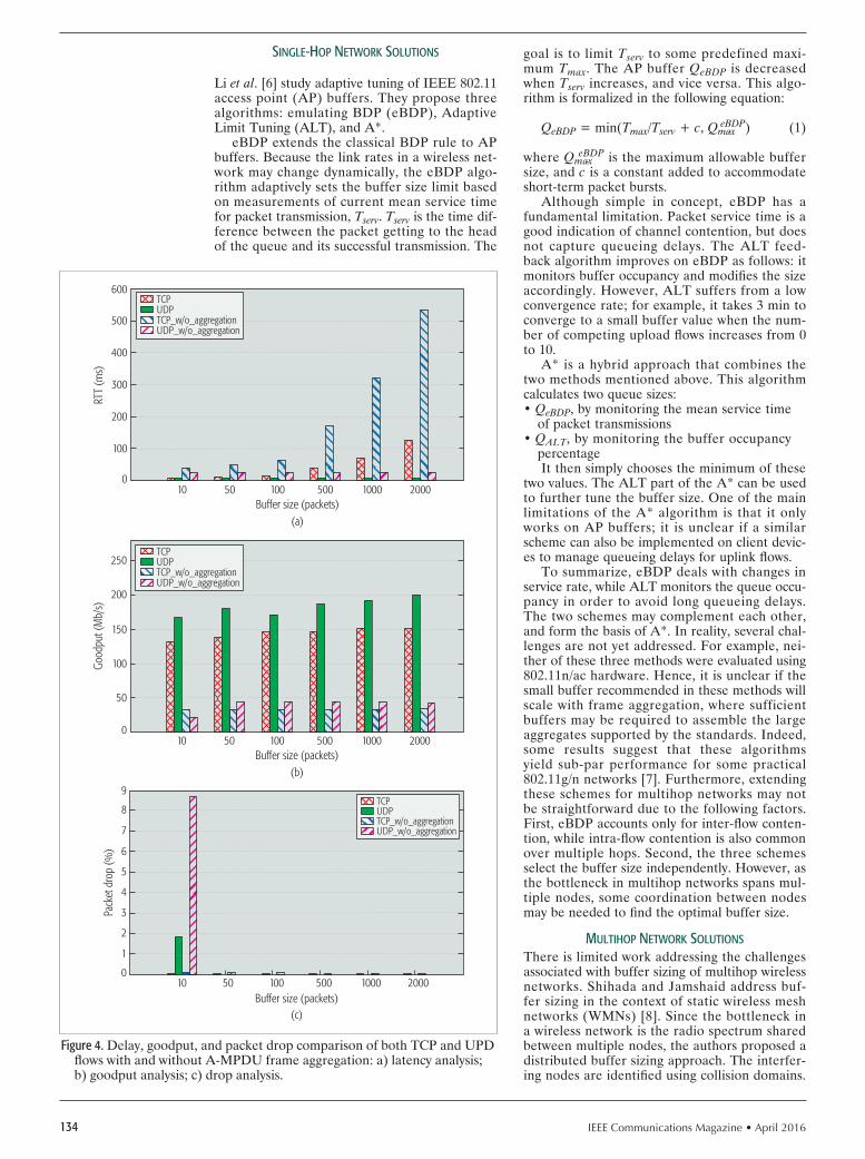
IEEE Communications Magazine • April 2016134
sIngle-hop network solutIons
Li et al. [6] study adaptive tuning of IEEE 802.11 access point (AP) buffers. They propose three algorithms: emulating BDP (eBDP), Adaptive Limit Tuning (ALT), and A*.
eBDP extends the classical BDP rule to AP buffers. Because the link rates in a wireless net-work may change dynamically, the eBDP algo-rithm adaptively sets the buffer size limit based on measurements of current mean service time for packet transmission, Tserv. Tserv is the time dif-ference between the packet getting to the head of the queue and its successful transmission. The
goal is to limit Tserv to some predefined maxi-mum Tmax. The AP buffer QeBDP is decreased when Tserv increases, and vice versa. This algo-rithm is formalized in the following equation:
QeBDP = min(Tmax/Tserv + c, Qmax - eBDP) (1)
where Qmax - eBDP is the maximum allowable buffer
size, and c is a constant added to accommodate short-term packet bursts.
Although simple in concept, eBDP has a fundamental limitation. Packet service time is a good indication of channel contention, but does not capture queueing delays. The ALT feed-back algorithm improves on eBDP as follows: it monitors buffer occupancy and modifies the size accordingly. However, ALT suffers from a low convergence rate; for example, it takes 3 min to converge to a small buffer value when the num-ber of competing upload flows increases from 0 to 10.
A* is a hybrid approach that combines the two methods mentioned above. This algorithm calculates two queue sizes: • QeBDP, by monitoring the mean service time
of packet transmissions• QALT, by monitoring the buffer occupancy
percentageIt then simply chooses the minimum of these
two values. The ALT part of the A* can be used to further tune the buffer size. One of the main limitations of the A* algorithm is that it only works on AP buffers; it is unclear if a similar scheme can also be implemented on client devic-es to manage queueing delays for uplink flows.
To summarize, eBDP deals with changes in service rate, while ALT monitors the queue occu-pancy in order to avoid long queueing delays. The two schemes may complement each other, and form the basis of A*. In reality, several chal-lenges are not yet addressed. For example, nei-ther of these three methods were evaluated using 802.11n/ac hardware. Hence, it is unclear if the small buffer recommended in these methods will scale with frame aggregation, where sufficient buffers may be required to assemble the large aggregates supported by the standards. Indeed, some results suggest that these algorithms yield sub-par performance for some practical 802.11g/n networks [7]. Furthermore, extending these schemes for multihop networks may not be straightforward due to the following factors. First, eBDP accounts only for inter-flow conten-tion, while intra-flow contention is also common over multiple hops. Second, the three schemes select the buffer size independently. However, as the bottleneck in multihop networks spans mul-tiple nodes, some coordination between nodes may be needed to find the optimal buffer size.
multIhop network solutIons
There is limited work addressing the challenges associated with buffer sizing of multihop wireless networks. Shihada and Jamshaid address buf-fer sizing in the context of static wireless mesh networks (WMNs) [8]. Since the bottleneck in a wireless network is the radio spectrum shared between multiple nodes, the authors proposed a distributed buffer sizing approach. The interfer-ing nodes are identified using collision domains.
Figure 4. Delay, goodput, and packet drop comparison of both TCP and UPD flows with and without A-MPDU frame aggregation: a) latency analysis; b) goodput analysis; c) drop analysis.
Buffer size (packets)(a)
10 50 100 500 1000 2000
100
0
RTT
(ms)
200
300
400
500
600
Buffer size (packets)(c)
10 50 100 500 1000 2000
2
0
Pack
et d
rop
(%)
1
3
4
5
6
7
8
9
Buffer size (packets)(b)
10 50 100 500 1000 2000
50
0
Good
put (
Mb/
s)
100
150
200
250TCPUDPTCP_w/o_aggregationUDP_w/o_aggregation
TCPUDPTCP_w/o_aggregationUDP_w/o_aggregation
TCPUDPTCP_w/o_aggregationUDP_w/o_aggregation

IEEE Communications Magazine • April 2016 135
The collision domain for a link l is a set of links that interfere with l. For a multihop flow, the end-to-end rate is bottlenecked by a collision domain that experiences full channel utilization. This is the bottleneck collision domain.
The authors consider the buffer sizing prob-lem in two parts. First, they determine the cumu-lative buffer required to saturate the bottleneck collision domain. This is the BDP of the network, which factors in various overheads associated with frame transmissions in a wireless network. Second, this cumulative buffer is distributed among the nodes that constitute the bottleneck. Various distribution criteria can be used: the authors propose a cost function where buffers are assigned in a way such that packets are more likely to be dropped closer to the source nodes than to the destination. The authors show that using this approach results in small buffer sizes for each node. This minimizes queueing delays, while allowing a node to achieve close to full link utilization.
This approach was evaluated under two sce-narios: large file transfer with TCP, and simul-taneous TCP and UDP fl ows. In both cases, this scheme reduces the end-to-end delay to accept-able values when compared to the default buf-fer size while incurring a slight drop in network goodput.
This work has several limitations. First, accu-rate detection of collision domains using a low overhead mechanisms is a challenge. Second, the analysis of cumulative buffer sizing is optimized for a single TCP fl ow. It is unclear if similar small-sized buffers would work well with multiple fl ows. Moreover, these small buffers result in suboptimal performance when using A-MPDU aggregation with 802.11n radios. Our testbed measurements show a goodput drop of up to 20 percent com-pared to results with 1000 packet buffers. We found that these small buffers prevent a node from transmitting large A-MPDUs. In our mea-surements, average A-MPDU length dropped from 13.5 to 7.5 frames per aggregate with small buffers, resulting in goodput drop.
To overcome these limitations, Showail et al. recently proposed WQM [9], an aggrega-tion-aware queue management scheme that sizes buffers for WiFi-based networks. WQM relies on passive channel measurements to determine the buffer size at each node. It operates in two phases: in the fi rst phase, the buffer size is initial-ized based on a variant of the BDP rule of thumb while accounting for frame aggregation. In the second phase, the queue drain time is monitored and the buffer size is adjusted accordingly. The queue drain time reflects the transmission rate and the contention from other active nodes shar-ing the radio spectrum. One important feature in WQM is enforcing a lower bound on the buf-
fer size so that it is not allowed to be less than the average A-MPDU length for any node. This allows a node to transmit multiple packets back to back in a single channel access, which quick-ly deflates the buffer and reduces the queue-ing delays. WQM was evaluated using multiple topologies over both single-flow and multi-flow scenarios. Results show that WQM reduced the end-to-end delay by up to 8 compared to Linux default buffers.
Routing protocols play a significant role in the performance of multihop wireless networks. Both [8, 9] use static routing. In contrast, adap-tive load-aware routing protocols that route around the congested parts of the network may yield better performance. Multi-path routing protocols can also be used, where a data stream is distributed as multiple data flows that can take link-disjoint or even node-disjoint paths. However, the performance gains of these pro-tocols may be limited by the network topology. For example, in infrastructure WMNs where the bulk of traffic is routed either toward or away from a single gateway router providing Internet connectivity, load-aware or multi-path routing has limited leeway. Routing protocols can also be used to address channel contention issues such as the hidden terminal and exposed terminal problems. To address some of these issues, Dousse [10] proposes a hole routing scheme. The main idea behind this scheme is to reduce the queue size on relay nodes to only one packet to mitigate the problem of low goodput in multihop networks. Hence, every node has either a packet or a hole. This rout-ing scheme helps solve the bandwidth alloca-tion problem. Similarly, Xue and Ekici [11] use adaptive routing, among other techniques, to
Figure 5. End-to-end delay CDF of a large fi le transfer over topologies with increasing num-ber of hops.
RTT(ms)20000
0.2
0CD
F
0.4
0.6
0.8
1
4000 6000 8000 10,000 12,000
1 hop2 hops3 hops4 hops
Table 1. Per fl ow goodput for a bidirectional fi le transfer over a multihop wireless network.
Flow # 1 hop 2 hops 3 hops
Flow 1 18.53 Mb/s 16.98 Mb/s 9.85 Mb/s
Flow 2 18.45 Mb/s 0.10 Mb/s 0.77 Mb/s
WQM relies on passive
channel measurements
to determine the buffer
size at each node. It
operates in two phases:
the buffer size is initial-
ized based on a variant
of the BDP rule-of-
thumb while accounting
for frame aggregation;
and the queue drain
time is monitored and
the buffer size is adjust-
ed accordingly.

IEEE Communications Magazine • April 2016136
increase energy effi ciency in multihop networks. Finally, Draves et al. [12] tackle the problem of routing multi-radio devices. They come up with a routing protocol that takes into consideration loss rate and channel bandwidth to be able to choose a high-throughput path.
AQm-bAsed solutIonsActive queue management (AQM) techniques address the problem of persistently full buffers from an aspect other than direct buffer sizing and, as such, are complementary to these efforts. They attempt to prevent large queue buildup at intermediary network hosts through proactive probabilistic packet drop. However, these algo-rithms failed to gain traction because of the com-plexity of setting the configuration parameter knobs effectively. Recently, a no-knobs AQM technique called CoDel [13] has been proposed. Unlike traditional AQM techniques, CoDel does not monitor queue size or queue occupan-cy directly. Instead, it keeps track of the pack-et sojourn time through the queue. Once the queueing delay exceeds a predefined value for a fi xed amount of time, the algorithm goes into the dropping phase. Packet dropping will stop only if the queueing delay goes below the pre-defi ned value again or if the queue has less than one MTU worth of bytes.
Another no-knobs AQM variant, called PIE [14], has also been proposed recently. PIE deter-mines the level of network congestion based on latency moving trends. Upon packet arrival, the packet may be dropped according to a dropping probability that is determined by the dequeue rate and the length of the queue.
Neither CoDel nor PIE was specifi cally designed for wireless networks. Hence, it is unclear how they can be effectively used in multihop wireless net-works where the bottleneck spans multiple dis-tributed nodes. Furthermore, these schemes may not be able to support fast mobility in wireless devices (e.g., vehicular speed mobility). Finally, CoDel allows the buffer to be as small as one frame, which will restrict aggregate formation, resulting in lower utilization.
future dIrectIonsWe believe that fi xing bufferbloat at the wireless edge requires work along multiple lines, creating complementary solutions that, taken together, may address the myriad challenges described in this article.
frAme AggregAtIon schedulers IEEE 802.11 standard specifi cations have left the design of A-MPDU aggregation schedulers open to vendor implementation, creating the space for well designed schedulers that can balance the various performance trade-offs in a wireless net-work. Our prior work shows that effi cient design of A-MPDU aggregation schedulers can boost goodput while simultaneously reducing end-to-end delays [15]. This can be attributed to two factors:• Each A-MPDU includes a single PHY pre-
amble and header, significantly reducing this overhead as these headers are usually transmitted at base rate for backward com-patibility with 802.11 a/b/g nodes.
• A single channel access can transmit as many as 64 subframes, and in response receive a single block ACK. However, even with aggregation enabled, RTT
values can still exceed approximately 100 ms over a single wireless hop. We anticipate that the per-formance will deteriorate further in a noisy radio environment as well as in multihop networks. These delays may potentially be further exacer-bated with the emerging 802.11ac standard, which supports aggregates as large as 1 MB.
wIreless-compAtIble Queue mAnAgement Buffer sizing and AQM algorithms may be con-sidered complementary solutions that can be used in conjunction. As such, the combined effect of the two schemes needs to be studied through both analyses and experimentation. Traditional AQM algorithms may fail in a wire-less environment where the queue size may not always be the best indicator of network conges-tion. Newer algorithms such as CoDel address this challenge by using the packet sojourn time to interpret congestion. Thus, the optimal queue backlog is a function of the buffer drain time, and this varies in response to changing channel conditions. Analyzing and adapting the behavior of AQM algorithms with dynamic buffer sizing under this environment needs to be studied in more detail.
vIrtuAl QueueIng
The AP or BS transmits data to multiple client devices, each experiencing different channel conditions. As a result, the buffer size suitable for one client device may deteriorate the per-formance of another. One solution is to imple-ment a per station virtual queue to segregate the traffi c for different nodes. We believe that some variant of fair queueing is necessary to isolate the impact of one wireless device from the other. This can also help improve fairness between flows with different congestion win-dow sizes.
fIne-tunIng tcpEnd-to-end solutions may be easier to deploy in controlled networks such as cellular networks. This is particularly benefi cial when the operator cannot access/confi gure bottleneck router buffers along the traffi c route. The TCP stack on client devices can be modifi ed through updates pushed out to smartphones locked by the operator. It is more beneficial to implement these changes at the client side (than at the BS) as the client has more accurate information about the last-hop wireless link.
conclusIonWireless networks usually have smaller BDP than wired networks. Hence, they need small-er buffers. On the other hand, extremely small buffers may limit the overall network goodput. In this article, we identify the challenges of opti-mally sizing buffers in various types of wireless networks. We show that optimally sizing buffers is not only important for real-time traffic, but also for TCP fl ows sharing the bottleneck buffer as well. We classify wireless buffer sizing schemes into two categories based on network topolo-
IEEE 802.11 standard
specifi cations have left
the design of A-MPDU
aggregation schedulers
open to vendor imple-
mentation, creating the
space for well designed
schedulers that can
balance the various per-
formance trade-offs in a
wireless network.

IEEE Communications Magazine • April 2016 137
gy: single-hop and multihop solutions. As shown in this survey, it is very diffi cult to have a single optimal buffer that suits all types of wireless net-works. The new advancements in wireless tech-nology, such as 802.11n/ac frame aggregation, make choosing the optimal buffer size even more challenging.
references
[1] G. Appenzeller, I. Keslassy, and N. McKeown, “Sizing Router Buffers,” Proc. 2004 Conf. Applications, Technologies, Architectures, and Protocols for Comp. Commun., 2004, pp. 281–92.
[2] A. Dhamdhere and C. Dovrolis, “Open Issues in Router Buffer Sizing,” SIGCOMM Comp. Commun. Rev., vol. 36, no.1, , Jan. 2006, pp. 87–92.
[3] C. Villamizar and C. Song, “High Performance TCP in ANSNET,” SIGCOMM Comp. Commun. Rev., vol. 24, no. 5, Oct. 1994, pp. 45–60.
[4] H. Jiang et al., “Tackling Bufferbloat in 3G/4G Networks,” Proc. 2012 ACM Conf. Internet Measurement, 2012, pp. 329–42.
[5] Z. Fu et al., “The Impact of Multihop Wireless Channel on TCP Throughput and Loss,” Proc. INFOCOM 2003, vol. 3, Mar. 2003, pp. 1744–53.
[6] T. Li, D. Leith, and D. Malone, “Buffer Sizing for 802.11-Based Networks,” IEEE/ACM Trans. Networking, vol. 19, no. 1, Feb. 2011, pp. 156–69.
[7] D. Taht, “What I Think Is Wrong with eBDP in Debloat-Testing,” https://lists.bufferbloat.net/pipermail/ bloat-devel/2011-November/000280.html.
[8] B. Shihada and K. Jamshaid. “Buffer Sizing for Multi-Hop Networks,” Jan. 28, 2014, U.S. Patent 8,638,686.
[9] A. Showail, K. Jamshaid, and B. Shihada, “WQM: An Aggregation-Aware Queue Management Scheme for IEEE 802.11n Based Networks,” Proc. 2014 ACM SIGCOMM Workshop on Capacity Sharing Workshop, 2014, pp. 15–20.
[10] O. Dousse, “Revising Buffering in CSMA/CA Wireless Multihop Networks,” Proc. IEEE SECON ‘07, June 2007.
[11] D. Xue and E. Ekici, “Optimal Power Allocation in Multi-Hop Wireless Networks With Finite Buffers,” Proc. 2011 IEEE ICC, June 2011, pp. 1–5.
[12] R. Draves, J. Padhye, and B. Zill, “Routing in Multi-Radio, Multi-Hop Wire-less Mesh Networks,” Proc. 10th Annual Int’l. Conf. Mobile Computing and Networking, 2004, pp. 114–28.
[13] K. Nichols and V. Jacobson, “Controlling Queue Delay,” Queue, vol. 10, no. 5, May 2012, pp. 20:20–20:34.
[14] R. Pan et al., “Pie: A Lightweight Control Scheme to Address the Buffer-bloat Problem,” Proc. 2013 IEEE 14th Int’l. Conf. High Performance Switching and Routing, 2013.
[15] A. Showail, K. Jamshaid, and B. Shihada, “An Empirical Evaluation of Bufferbloat in IEEE 802.11n Wireless Networks,” Proc. IEEE Wireless Commun. and Networking Conf., 2014, pp. 1–6.
bIogrAphY
AHMAD SHOWAIL is a faculty member of computer engineering at Taibah Uni-versity. He received M.S. and Ph.D. degrees in computer science from King Abdullah University of Science and Technology (KAUST) in 2010 and 2016, respectively. He received B.Sc. in computer engineering from King Fahd Uni-versity of Petroleum and Minerals (KFUPM). His research focuses on queue management for various kinds of wireless networks.
KAMRAN JAMSHAID received a Ph.D. in electrical and computer engineering from the University of Waterloo, an M.S. in computer science from Wayne State University, and a B.S. in electronic engineering from GIK Institute, Pakistan. His research interests include computer networks, network secu-rity, pervasive and mobile computing, distributed systems, and big data analytics.
BASEM SHIHADA [SM’12] is in the CEMSE division at KAUST. He obtained a Ph.D. degree from thre University of Waterloo in 2007. His current research covers a range of topics in energy and resource allocation in wired and wire-less communication networks. He is also interested in network security and cloud computing.
As shown in this survey,
it is very diffi cult to
have a single optimal
buffer that suits all types
of wireless networks.
The new advancements
in wireless technolo-
gy, such as 802.11n/
ac frame aggregation,
make choosing the
optimal buffer size even
more challenging.

IEEE Communications Magazine • April 2016138 0163-6804/16/$25.00 © 2016 IEEE
AbstrActAs wireless communication evolves toward
5G, both fixed broadband and mobile broad-band will play a crucial part in providing the gigabit-per-second infrastructure for a connected society. This article proposes an MGB system as the solution to two critical problems in this evo-lution: last-mile access for fixed broadband and small cell backhaul for mobile broadband. The key idea is to use spectrum that is already avail-able in the millimeter-wave bands for fixed wire-less access with optimized dynamic beamforming and massive MIMO infrastructure to achieve high capacity with wide area coverage. This arti-cle explains the MGB concept and describes potential array architectures for realizing the sys-tem. Simulations demonstrate that with 500 MHz of bandwidth (at 39 GHz band) and 28 dBm transmission power (55 dBm EIRP), it is possible to provide more than 11 Gb/s backhaul capacity for 96 small cells within a 1 km radius.
IntroductIonMobile computing is one of the greatest inno-vations in the history of technology. The rapid adoption of smartphones and the explosive growth of data traffic due to these devices have been phenomenal. As the world anticipates more connected devices — the Internet of Things (IoT), vehicle-to-vehicle (V2V) communications, and wearable devices — and more value added applications and services (ultra high definition video, 360° video, virtual reality, smart cars, etc.), leading industry experts are calling for the fifth generation (5G) networks to provide 1000 capacity increase over 4G. Among many possible technologies, such as cloud radio access network (C-RAN), full duplex, and non-orthogonal multi-ple access (NOMA), three key technologies have been identified to achieve this goal: millime-ter-wave (mmWave) mobile broadband [1], mas-sive multiple-input multiple-output (MIMO) [2], and small cells [3]. These technologies need to be used in combination; no one technology can provide the expected 1000 capacity increase.
Each technology option comes with its own specific challenges. MmWave carrier frequencies need new spectrum allocations. Both mmWave and massive MIMO require new hardware at the base station and global standardization before commercialization. Small cells can be applied
even with today’s technology, but site acquisition and backhaul become increasingly challenging, especially when small cells need to support giga-bit-per-second physical layer technologies.
Applying mmWave and massive MIMO to 5G mobile broadband involves new system designs. The challenge faced by small cell backhaul, how-ever, is similar to the last mile problem of fixed broadband access. As society moves toward the gigabit-per-second era, broadband service provid-ers face the demanding task of upgrading their entire twisted-pair or coaxial-cable-based infra-structure to fiber. While it may be manageable to upgrade the backbone network, it may take years — if not decades — to upgrade all the wires to millions of homes or enterprises, with the caveat that this approach may not be economically viable at all. A scalable way of deploying a network with a large number of small cells and fixed broadband access points is crucial for the success of 5G.
In this article, we propose an mmWave giga-bit broadband (MGB) solution that provides gigabit-per-second links to small cells and fixed broadband access points. For simplicity, we refer to both mobile broadband small cells (e.g., Long Term Evolution, LTE, small cells) and fixed broadband access points (e.g., WiFi access points) as small cells. The MGB system provides area cov-erage of gigabit-per-second connections, allowing small cells to be deployed anywhere within the coverage without being limited by access to wired infrastructure. This will significantly increases the gigabit-per-second coverage for mobile devices and connected vehicles with minimal latency. In addition, the fixed nature of the small cells in the MGB system provides favorable channel con-ditions that allow sophisticated transmission to achieve much higher spectral efficiency than that attainable in a mobile environment.
Spectrum is readily available for MGB sys-tems. For example, in the United States, a total of 2.7 GHz of bandwidth is available for MGB in the local multipoint distribution system (LMDS) band (27.5–28.35, 29.1–29.25, and 31.0–31.3 GHz) and the 39 GHz band (38.6–40.0 GHz) as these bands are already licensed for fixed PtMP services on a geographic basis. This means that unlike the mmWave mobile technologies, which need global standards and 5G spectrum before commercialization, the MGB system proposed in this article can be developed and deployed today.
Millimeter-Wave Gigabit Broadband Evolution toward 5G: Fixed Access and Backhaul
Zhouyue Pi, Junil Choi, and Robert Heath Jr.
Accepted from open cAll
The authors explain the MGB concept and describe potential array architectures for realizing the system. Simulations demon-strate that with 500 MHz of bandwidth (at 39 GHz band) and 28 dBm transmission power (55 dBm EIRP), it is possible to provide more than 11 Gb/s backhaul capacity for 96 small cells within a 1 km radius.
Zhouyue Pi is with Straight Path Communications Inc.; Junil Choi and Robert Heath Jr. are with the University of Texas at Austin.

IEEE Communications Magazine • April 2016 139
In applications as both small cell backhaul and gigabit-per-second broadband access, the MGB system is more attractive than fiber or point-to-point microwave solutions. Its flexibility, scalabil-ity, and potential for lower capital expenditure and much lower operating costs make it much easier to deploy and reconfigure networks. This provides cellular operators and broadband ser-vice providers a higher return on investment in upgrading their network. The area coverage of gigabit-per-second connectivity of an MGB sys-tem makes it possible for cellular operators or broadband service providers to deploy large num-bers of WiFi access points to meet data traffic demands before 5G arrives. With a scalable giga-bit-per-second infrastructure already in place by the time 5G becomes available, cellular operators and broadband service providers can smoothly ramp up the deployment of 5G by adding onto or upgrading some of the existing small cells. The MGB system can even be used for other appli-cations that may require high data rates. For example, it seems ideal to power the infrastruc-ture of vehicle-to-infrastructure networks that will empower cars with gigabit connections, enabling connected and autonomous driving.
There has been previous work that also studied PtMP mmWave backhaul [4–8]. A general over-view of mmWave backhaul was discussed in [4], where the benefit of using mmWave for backhaul over low frequency band was shown. Hierarchi-cal codebook designs were proposed to establish reliable links between the hub and small cells with reduced overhead in [5]. It was shown in [6] that the energy efficiency of mmWave backhaul increas-es as the hub supports more small cells. A frame structure and a multihop protocol that are back-ward-compatible with LTE were proposed in [7], and time domain scheduling to support PtMP in-band mmWave backhaul was proposed in [8]. In this article, we discuss in detail practical hub and small cell antenna array design and transceiver architecture of an MGB system. We also analyze the required backhaul capacity headroom for the MGB system to support bursty traffic. In addition, we provide the link budget for an MGB system to achieve more than 10 Gb/s backhaul capacity and demonstrate by simulations that the MGB system can successfully fulfill this requirement.
In summary, MGB provides a solution to the important backhaul problem in current and future cellular systems. In the rest of this article, we explain the MGB system concept. Then we describe antenna array and transceiver designs for the MGB system. Based on the proposed sys-tem, we provide simulation results to validate the capacity of an MGB system with reasonable system configuration and practical antenna array and transceiver design.
the mIllImeter-WAve GIGAbIt broAdbAnd system
In this section we first explain the concept of an MGB system at a high level and discuss the principal building blocks of the system, that is, multiplexing techniques, link budget analy-sis, orthogonal frequency-division multiplexing (OFDM) numerology, and adaptive modulation and coding techniques. Then we describe possi-
ble deployment scenarios of MGB systems and discuss the benefit of statistical multiplexing of small cell traffic in supporting bursty traffic.
Operators deploy cells with different sizes such as macrocells, microcells, picocells, and femtocells, which are generally connected to the core network via wired or wireless links. Interme-diate nodes such as in-band relay stations have also been added, but the deployment is limited because relay links compete with access links for the expensive licensed spectrum. PtMP systems have also been used for backhaul, mostly using unlicensed spectrum in 5 GHz band, and licensed spectrum in 28 GHz. To deliver area coverage, however, the hub station typically employs anten-nas with wide azimuth beamwidth, resulting in limited antenna gain and range.
Recent developments in phased antenna arrays make it possible to use antenna arrays with elec-tronically steerable beams in commercial systems. For example, 16 phased array RF channels have been integrated into a single integrated circuit (IC) [9]. With phased array antennas, beams with high antenna gain can be formed and pointed in virtually any direction within a wide solid angle defined by the antenna pattern of the individual antenna elements. This not only can extend the range and coverage, but also reduce interference with other nearby transmissions.
The proposed MGB system is illustrated in Fig. 1. The system consists of a hub and a number of small cells. Communication between the hub and the small cells is established in mmWave spectrum (“MGB backhaul” in the figure). Both the trans-mitter and the receiver use analog beamforming [5] or a hybrid of analog beamforming and digital MIMO processing [10] to adapt to channel con-ditions and balance analog power consumption and digital processing complexity. A typical MGB hub has three sectors. Each sector uses a planar phased antenna array and dynamically forms beams to transmit to and receive from small cells. The small cells also use planar phased antenna arrays to point in the best directions to transmit to and receive from the MGB hub. On the access link, small cells can use either LTE, WiFi, or 5G, or the combination of these access technologies to communicate with a variety of devices including smartphones, tablets, laptops, TVs, home appli-
Figure 1. An MGB system with LTE small cells, Wi-Fi access points, and 5G.
Hub
LTE LTE+WiFiWiFi 5G
Fiber backhaul
Small cells
MGB backhaul
Terminals
Access link

IEEE Communications Magazine • April 2016140
ances, wearable devices, and future connected devices such as robots and self-driving vehicles.
With multiple small cells under its coverage, the MGB hub can use multi-user MIMO to com-municate with multiple small cells simultaneously when needed. Beamforming with large antenna arrays at both the hub and the small cells provides strong suppression of interference among small cells and thus achieves high spectral efficiency in spatial multiplexing of traffic from multiple small cells. In addition, time-division multiple access (TDMA) and orthogonal frequency-division mul-tiple access (OFDMA) are also supported in multiplexing traffic to and from small cells. For its primary purpose of boosting mobile or fixed broadband throughput, time-division duplex (TDD) is the preferred duplex scheme because of its flexibility to adapt to the asymmetry of uplink and downlink data traffic, and the possibility to exploit channel reciprocity to adapt transmission schemes to maximize throughput.
The link budget for an exemplary MGB sys-tem at 39 GHz with 500 MHz system bandwidth and cell radius of 1 km is shown in Table 1.
The MGB hub uses a 256-element antenna array and 64 power amplifiers (PAs) with 10 dBm output power each. The small cell uses a 64-element antenna array and 16 PAs with 10 dBm output power each. Effective isotropic radi-ation power (EIRP) of 55 dBm and 43 dBm can be achieved for downlink and uplink, respective-ly. The link budget analysis in Table 1 assumes a path loss model of free space path loss plus an additional loss of 15 dB/km to account for other factors including rain, reflection, foliage, and so on. With 500 MHz system bandwidth, more than 1 Gb/s can be achieved in both the downlink and uplink at the cell edge (1 km from the hub).
With 4-stream multi-user MIMO to 4 small cells with median path loss (707 m from the hub), 7.7 Gb/s system throughput can be achieved per sec-tor in both the downlink and uplink.
Note that in the 39 GHz band 15 dB/km addi-tional path loss corresponds to 60 mm/h rainfall, which occurs less than 0.01 percent of the time (<1 h/year) for most parts of the world [11]. The MGB transceivers at small cells should preferably be placed in locations where a good link (e.g., line-of-sight or near-line-of-sight) can be established. In the worst case scenario, when a small cell placed at the cell edge in a non-line-of-sight condition encounters heavy rainfall, the backhaul throughput of that small cell needs to be reduced. For exam-ple, reducing the throughput to 100 Mb/s would provide another 20 dB margin beyond the 15 dB/km already included in the link budget calculation.
The OFDM numerology of a wide-area mmWave system needs to be carefully chosen, with consideration of coherence time, coherent bandwidth, and clock accuracy (frequency off-set, phase noise, etc.), among others (see more detailed discussion in [1]). Fortunately, the rel-atively stable channel conditions in MGB sys-tems mean large coherent bandwidth and ample time for synchronization, channel estimation, and beam tracking. This allows a wide range of OFDM numerology, providing flexibility to accommodate other implementation consider-ations. As a rule of thumb, we recommend the subcarrier spacing to be in the range of 100 kHz~1 MHz, and the cyclic prefix to be in the range of 100 ns~1 s. Alternatively, single-carri-er waveform with similar cyclic prefix can be con-sidered, but this makes it harder to more flexibly allocate resources as in OFDMA.
Adaptive modulation and coding are support-ed with modulation from quadrature phase shift keying (QPSK) to 64-quadrature amplitude mod-ulation (QAM) and a variable code rate to allow rate adaptation based on channel conditions. We refrain from supporting 256-QAM due to the strin-gent requirement on transceiver linearity (error vector magnitude < –30 dB), which could sig-nificantly increase the cost of the transceiver but only have limited usage in practice. We use low density parity check (LDPC) codes as the forward error correction (FEC) coding scheme to achieve gigabit-per-second decoding throughput with low power. LDPC codes have already been used in other mmWave standards like IEEE 802.11ad [12]. Practical design of LDPC decoders today can achieve multi-gigabit-per-second throughput with less than 100 mW power consumption [13].
deployment of mGb systems
By providing area coverage of gigabit-per-second connections, MGB systems significantly increase the site availability for small cells. This in turn lowers the site acquisition and site development cost, making dense deployment of small cells practical. In addition, the improved availabili-ty of gigabit-per-second backhaul also benefits the access network as small cells can be set up in locations that provide the best access link cover-age without the limitation of wired backhaul.
The radius of an MGB system needs to be large enough to provide sufficient coverage, but small enough to provide gigabit-per-second con-
Table 1. Link budget for an MGB system at 39 GHz.
39 GHz MGB link budget Downlink cell edge
Uplink cell edge
Downlink 4-stream
Uplink 4-stream
PA output (dBm) 10 10 10 10
Number of PAs 64 16 64 16
Total power (dBm) 28 22 28 22
EIRP (dBm) 55.14 43.10 55.14 43.10
Distance (m) 1000 1000 707 707
Total path loss (dB) 139.26 139.26 131.86 131.86
Received power (dBm) –84.12 –96.16 –76.71 –88.75
Bandwidth (MHz) 500 500 500 500
Noise figure (dB) 5.00 5.00 5.00 5.00
Number of MIMO streams 1 1 4 4
Receiver loss (dB) 3.00 3.00 3.00 3.00
Spectral efficiency 5.34 3.44 15.45 15.45
Throughput (Mb/s) 2668 1720 7725 7725

IEEE Communications Magazine • April 2016 141
nectivity with great availability. We recommend the MGB cell radius to be in the range of 300 m–3 km, achieving excellent economics in giga-bit-per-second network deployment. A cell radius greater than 3 km leads to significant degradation of performance at the cell edge from the perfor-mance predicted by the link budget analysis in Table 1. A cell radius smaller than 300 m pro-vides little footprint for gigabit-per-second back-haul for small cells, making it difficult to justify the cost of the system. Note that this cell radius range leads to deployment density comparable to the typical micro base station deployment density in urban and suburban areas, allowing poten-tial site sharing with existing mobile broadband infrastructure, which can further lower the cost of the network. For example, for an MGB cell radius of 1 km, less than 500 hubs are needed to cover all of New York City (a total area of 1214 km2 with a population of 8.4 million).
The MGB hub should preferably be installed in towers and rooftops with similar requirements as base station sites (10–30 m antenna height, fiber access, power, etc.) The MGB transceiv-er of small cells preferably should be installed at sufficient height (e.g., wall-mounted on the outside of a building or house). Although not required, it would be advantageous to choose a good location and general pointing direction for the MGB transceiver of a small cell so that a line-of-sight or near-line-of-sight link with the hub can be established. In the case where non-line-of-sight links have to be used, the MGB system can use beamforming to align the trans-mitter and receiver with the strongest paths and maximize the link quality.
One of the main challenges in point-to-point microwave/mmWave links is the installation of bulky dish antennas. Due to the required high gain to close the link, the antennas are typi-cally large and heavy, requiring heavy mount-ing equipment and skilled technicians onsite to complete the installation and calibration. More-over, with large numbers of small cells deployed, maintenance cost also increases. With the MGB backhaul solution, both the hubs and the small cells have the ability to electronically steer the beams in the most favorable direction, making it possible to automate a significant portion of the configuration and management of the system.
stAtIstIcAl multIplexInG of smAll cell trAffIc
The small footprint of small cells means fewer users per cell, and increases the traffic variation among small cells and over time. For example, the traffic going through a small cell in a popu-lar restaurant can be high during lunch or din-ner while falling drastically in other hours. In addition, new data applications (e.g., Snapchat, Instagram) also tend to generate more bursty traffic. With 4G delivering hundreds of megabits per second peak rate over the access link, it is expected that 5G will provide gigabit-per-second access. The backhaul for each small cell there-fore needs to provision for gigabit-per-second peak rate. However, the average throughput from each small cell is likely much smaller.
It is a tremendous challenge and huge waste
to use wired or point-to-point wireless solutions to provide backhaul for a large network of small cells. These solutions are not only very cost-ly because operators need to deploy millions of small cells to provide meaningful upgrades to their networks, but also highly inefficient because significant capacity headroom must be provi-sioned to handle the gigabit-per-second peak rate, even though it may only be utilized for a small fraction of time. The PtMP nature of the MGB system provides inherent statistical multiplexing of traffic from multiple small cells within its cov-erage, thus providing the ability to handle giga-bit-per-second peak rate from each small cell and the aggregated multi-gigabit-per-second through-put within the coverage of an MGB system in the most scalable and cost-efficient manner.
For example, assuming traffic of small cells is independent and follows the same exponential dis-tribution, the complementary cumulative distribu-tion function (CCDF) of the aggregated traffic is plotted for N = 1, 2, 4, 8, 16, and 32 in Fig. 2. The backhaul capacity headroom is the ratio between the backhaul capacity needed to accommodate the bursty traffic and the average throughput is then obtained for different numbers of small cells. In order to meet traffic demand 99 percent of the time for a single cell, the backhaul capacity needs to be 4.6 times the average throughput. However, in order to meet traffic demand 99 percent of the time for 32 cells served by a single MGB hub, the MGB hub only needs to provide 1.46 times of the aggregated average throughput from these cells, exemplifying the significant savings achieved by statistical multiplexing. In other words, to provide the same quality of service as described above to 32 small cells (100 Mb/s average throughput and 460 Mb/s peak rate), a network operator can either use 32 460-Mb/s point-to-point backhaul links with total capacity of 14.72 Gb/s or a sin-gle MGB sector with backhaul capacity of 4.67 Gb/s. With multiple sectors, an MGB hub can support even more small cells. Even when con-gested, the MGB system has a lot of flexibility to dynamically schedule and multiplex packets from
Figure 2. Statistical multiplexing of small cell traffic reduces backhaul throughput fluctuation and the backhaul capacity headroom needed.
Backhaul capacity provision over average throughput
Probability of traffic demand exceeding capacity
10
10-2
CCD
F
10-1
100
10-32 3 4 5 6 7
1 cell2 cells4 cells8 cells16 cells32 cells
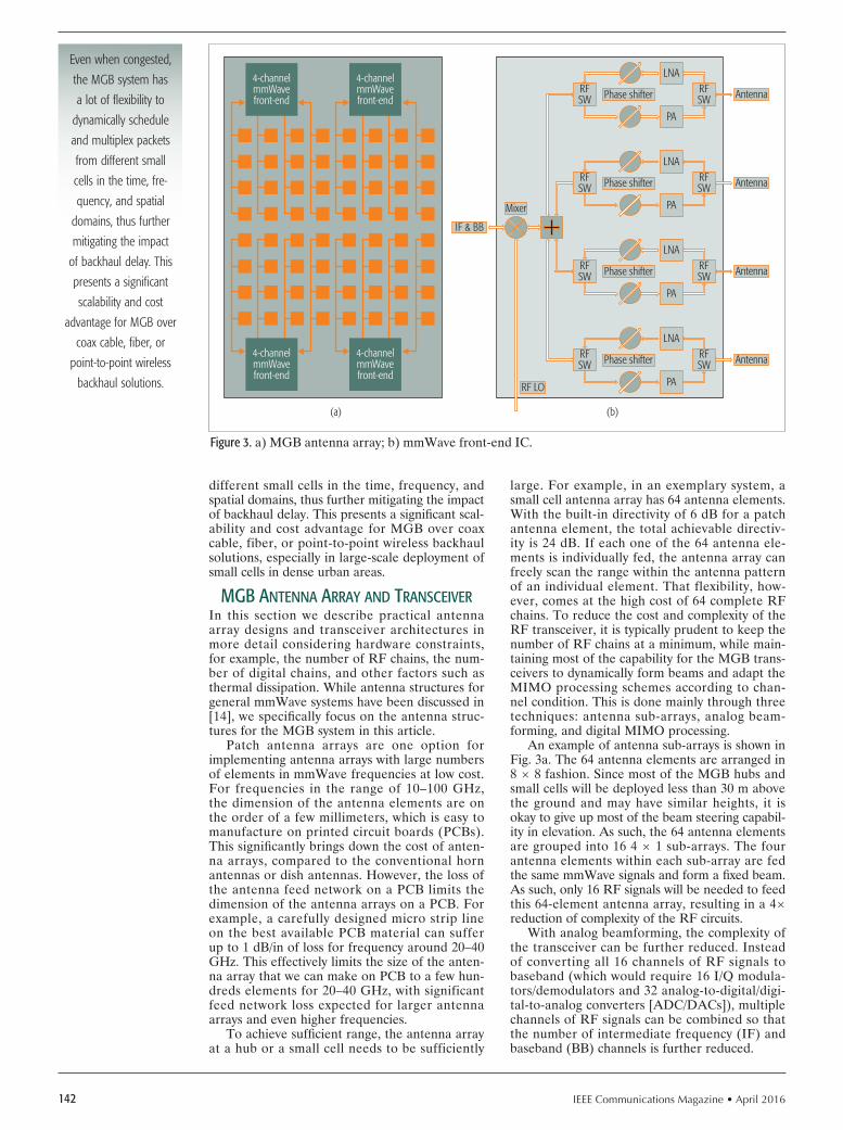
IEEE Communications Magazine • April 2016142
different small cells in the time, frequency, and spatial domains, thus further mitigating the impact of backhaul delay. This presents a signifi cant scal-ability and cost advantage for MGB over coax cable, fiber, or point-to-point wireless backhaul solutions, especially in large-scale deployment of small cells in dense urban areas.
mGb AntennA ArrAy And trAnsceIverIn this section we describe practical antenna array designs and transceiver architectures in more detail considering hardware constraints, for example, the number of RF chains, the num-ber of digital chains, and other factors such as thermal dissipation. While antenna structures for general mmWave systems have been discussed in [14], we specifi cally focus on the antenna struc-tures for the MGB system in this article.
Patch antenna arrays are one option for implementing antenna arrays with large numbers of elements in mmWave frequencies at low cost. For frequencies in the range of 10–100 GHz, the dimension of the antenna elements are on the order of a few millimeters, which is easy to manufacture on printed circuit boards (PCBs). This signifi cantly brings down the cost of anten-na arrays, compared to the conventional horn antennas or dish antennas. However, the loss of the antenna feed network on a PCB limits the dimension of the antenna arrays on a PCB. For example, a carefully designed micro strip line on the best available PCB material can suffer up to 1 dB/in of loss for frequency around 20–40 GHz. This effectively limits the size of the anten-na array that we can make on PCB to a few hun-dreds elements for 20–40 GHz, with significant feed network loss expected for larger antenna arrays and even higher frequencies.
To achieve suffi cient range, the antenna array at a hub or a small cell needs to be sufficiently
large. For example, in an exemplary system, a small cell antenna array has 64 antenna elements. With the built-in directivity of 6 dB for a patch antenna element, the total achievable directiv-ity is 24 dB. If each one of the 64 antenna ele-ments is individually fed, the antenna array can freely scan the range within the antenna pattern of an individual element. That flexibility, how-ever, comes at the high cost of 64 complete RF chains. To reduce the cost and complexity of the RF transceiver, it is typically prudent to keep the number of RF chains at a minimum, while main-taining most of the capability for the MGB trans-ceivers to dynamically form beams and adapt the MIMO processing schemes according to chan-nel condition. This is done mainly through three techniques: antenna sub-arrays, analog beam-forming, and digital MIMO processing.
An example of antenna sub-arrays is shown in Fig. 3a. The 64 antenna elements are arranged in 8 8 fashion. Since most of the MGB hubs and small cells will be deployed less than 30 m above the ground and may have similar heights, it is okay to give up most of the beam steering capabil-ity in elevation. As such, the 64 antenna elements are grouped into 16 4 1 sub-arrays. The four antenna elements within each sub-array are fed the same mmWave signals and form a fi xed beam. As such, only 16 RF signals will be needed to feed this 64-element antenna array, resulting in a 4 reduction of complexity of the RF circuits.
With analog beamforming, the complexity of the transceiver can be further reduced. Instead of converting all 16 channels of RF signals to baseband (which would require 16 I/Q modula-tors/demodulators and 32 analog-to-digital/digi-tal-to-analog converters [ADC/DACs]), multiple channels of RF signals can be combined so that the number of intermediate frequency (IF) and baseband (BB) channels is further reduced.
Figure 3. a) MGB antenna array; b) mmWave front-end IC.
AntennaRFSW
LNA
(a) (b)
4-channelmmWavefront-end
4-channelmmWavefront-end
4-channelmmWavefront-end
4-channelmmWavefront-end
RFSW
PA
Phase shifter
AntennaRFSW
LNARFSW
PA
Phase shifter
Antenna
IF & BB
Mixer
RF LO
RFSW
LNARFSW
PA
Phase shifter
AntennaRFSW
LNARFSW
PA
Phase shifter
Even when congested,
the MGB system has
a lot of fl exibility to
dynamically schedule
and multiplex packets
from different small
cells in the time, fre-
quency, and spatial
domains, thus further
mitigating the impact
of backhaul delay. This
presents a signifi cant
scalability and cost
advantage for MGB over
coax cable, fi ber, or
point-to-point wireless
backhaul solutions.
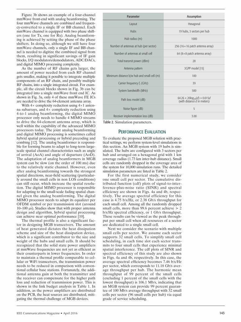
IEEE Communications Magazine • April 2016 143
Figure 3b shows an example of a four-channel mmWave front-end with analog beamforming. The four mmWave channels are combined and frequen-cy-converted to a single IF or BB channel. Each mmWave channel is equipped with two phase shift-ers (one for Tx, one for Rx). Analog beamform-ing is achieved by setting the phase of the phase shifters. In doing so, although we still have four mmWave channels, only a single IF and BB chan-nel is needed to digitize the combined signal from them, resulting in significant savings of IF gain blocks, I/Q modulators/demodulators, ADC/DACs, and digital MIMO processing complexity.
As the number of RF chains gets larger, the amount of power needed from each RF channel gets smaller, making it possible to integrate multiple components of an RF chain, and possibly multiple RF chains, into a single integrated circuit. For exam-ple, all the circuit blocks shown in Fig. 3b can be integrated into a single mmWave front end IC. As shown in Fig. 3a, only 4 of these mmWave FE ICs are needed to drive the 64-element antenna array.
With 4 complexity reduction using 41 anten-na subarrays, and 4 complexity reduction using 4-to-1 analog beamforming, the digital MIMO processor only needs to handle 4 MIMO streams to drive the 64-element antenna array, which is well within the capability of the advanced MIMO processors today. The joint analog beamforming and digital MIMO processing is sometimes called hybrid spatial processing or hybrid precoding and combing [12]. The analog beamformer is responsi-ble for forming beams to adapt to long-term large-scale spatial channel characteristics such as angle of arrival (AoA) and angle of departure (AoD). The adaptation of analog beamformers in MGB system can be slow (on the order of 100 ms) due to the relatively static channel. However, even after analog beamforming towards the strongest spatial directions, near-field scattering (particular-ly around the small cells in non LOS conditions) can still occur, which increase the spatial resolu-tion. The digital MIMO processor is responsible for adapting to the small-scale fading spatial chan-nel given the analog beamforming. The digital MIMO processor needs to adapt its equalizer per OFDM symbol or per transmission slot (around 10–100 s). Studies show that with proper antenna design and algorithm, hybrid spatial processing can achieve near optimal performance [10].
The thermal profile is also a significant fac-tor in designing MGB transceivers. The amount of heat generated dictates the heat dissipation scheme and size of the heat dissipation device, which is a significant contributor to the size and weight of the hubs and small cells. It should be recognized that the solid state power amplifiers at mmWave frequencies are not yet as efficient as their counterparts in lower frequencies. In order to maintain a thermal profile comparable to cel-lular or WiFi transceivers, the transmission power needs to be reduced in comparison with conven-tional cellular base stations. Fortunately, the addi-tional antenna gain at both the transmitter and the receiver can compensate for the higher path loss and reduction of transmission power. This is shown in the link budget analysis in Table 1. In addition, as the power amplifiers are distributed on the PCB, the heat sources are distributed, miti-gating the thermal challenge of MGB devices.
performAnce evAluAtIonTo evaluate the proposed MGB solution with prac-tical settings, we perform system-level simulations in this section. An MGB system with 19 hubs is sim-ulated. The hubs are configured with 3 sectors per hub and arranged on a hexagonal grid with 1 km coverage radius (1.73 km inter-hub distance). Small cells are randomly dropped in the coverage area of the system for 10,000 simulation runs. The detailed simulation parameters are listed in Table 2.
For the first numerical study, we consider one small cell per sector. The cumulative dis-tributed function (cdf) plots of signal-to-inter-ference-plus-noise ratio (SINR) and spectral efficiency are shown in Figs. 4a and 4b, respec-tively. The average spectral efficiency for this case is 4.75 b/s/Hz, or 2.38 Gb/s throughput for each small cell. Among all the randomly dropped small cells, more than 99.6 percent achieve > 2 b/s/Hz spectral efficiency, or 1 Gb/s throughput. These results can be viewed as the peak through-put per small cell when all resources of a sector are dedicated to a single small cell.
Next we consider the scenario with multiple small cells per sector. We assume each sector supports 32 small cells. To simplify small cell scheduling, in each time slot each sector trans-mits to four small cells that experience minimal spatial interference. The cdf plots of SINR and spectral efficiency of this study are also shown in Figs. 4a and 4b, respectively. In this case, the average spectral efficiency becomes 7.46 b/s/Hz per sector, which corresponds to 11.18 Gb/s aver-age throughput per hub. The harmonic mean throughput of 99 percent of the small cells (excluding 1 percent of the small cells with the lowest throughput) is 106.1 Mb/s, indicating that an MGB system can provide 99 percent guaran-tee of 100 Mb/s average throughput with 32 small cells per sector (96 small cells per hub) via equal grade of service scheduling.
Table 2. Simulation parameters.
Parameter Assumption
Layout Hexagonal
Hubs 19 hubs, 3 sectors per hub
Hub radius (m) 1000
Number of antennas at hub (per sector) 256 (1616 patch antenna array)
Number of antennas at small cell 64 (88 patch antenna array)
Total transmit power (dBm) 28
Antenna pattern 3GPP model [15]
Minimum distance b/w hub and small cell (m) 100
Carrier frequency fc (GHz) 39
System bandwidth (MHz) 500
Path loss model (dB) 64.26 + 20log10(d) + 0.015d (with distance d in meters)
Noise figure (dB) 5
Receiver implementation loss (dB) 3.00

IEEE Communications Magazine • April 2016144
conclusIonIn this article, we propose a millimeter-wave giga-bit broadband (MGB) system for both fixed access and backhaul evolution toward 5G. Due to its dis-tinctive ability to provide wide-area gigabit-per-sec-ond coverage, the MGB system is flexible, scalable, and cost effective as the last mile solution for gigabit-per-second fixed broadband and as the small cell backhaul solution for gigabit-per-second mobile broadband. In an exemplary MGB system with 500 MHz bandwidth at 39 GHz band, our simulation shows that a single MGB hub with 3 sectors can guarantee 1 Gb/s peak rate and 100 Mb/s average throughput to 96 small cells within 1 km radius with 99 percent probability.
In future research, we plan to study the architec-ture, configuration, and performance of hierarchical systems with MGB backhaul links and 5G access links. We are also interested in designing frequen-cy reuse and interference management schemes that can take advantage of the directional nature of mmWave backhaul and access links. Last but not least, we plan to continue to research novel antenna array and transceiver design to make MGB backhaul and fixed access units more compact, power effi-cient, and amenable to small cell deployment scenar-ios such as wall-mount and lamppost deployments.
AcknoWledGment
Junil Choi and Robert Heath Jr. were spon-sored by the Texas Department of Transporta-tion under Project 0-6877, “Communications and Radar-Supported Transportation Operations and Planning (CAR-STOP).”
references
[1] Z. Pi and F. Khan, “An Introduction to Millimeter-Wave Mobile Broadband Systems,” IEEE Commun. Mag., vol. 9, no. 6, June 2011, pp. 101–07.
[2] T. L. Marzetta, “Noncooperative Cellular Wireless with Unlimited Numbers of Base Station Antennas,” IEEE Trans. Wireless Commun., vol. 9, no. 11, Nov. 2010, pp. 3590–3600.
[3] Bhushan et al., “Network Densification: The Dominant Theme for Wireless Evolution into 5G,” IEEE Commun. Mag., vol. 52, no. 2, Feb. 2014, pp. 82–89.
[4] Cedric Dehos et al., “Millimeter-Wave Access and Backhauling: The Solution to the Exponential Data Traffic Increase in 5G Mobile Communications Systems?” IEEE Commun. Mag., vol. 52, no. 9, Sept. 2014, pp. 88–95.
[5] S. Hur et al., “Millimeter Wave Beamforming for Wireless Backhaul and Access in Small Cell Networks,” IEEE Trans. Commun., vol. 61, no. 10, Oct. 2013, pp. 4391–4403.
[6] X. Ge et al., “5G Wireless Backhaul Networks: Challenges and Research Advances,” IEEE Network, vol. 28, no. 6, Nov./Dec., 2014, pp. 6–11.
[7] K. Zheng et al., “10 Gb/s HetSNets with Millimeter-Wave Communications: Access and Networking Challenges and Protocols,” IEEE Commun. Mag., vol. 53, no. 1, Jan. 2015, pp. 222–31.
[8] R. Taori and A. Sridharan, “Point-to-Multipoint In-Band mmWave Backhaul for 5G Networks,” IEEE Commun. Mag., vol. 53, no. 1, Jan. 2015, pp. 195–201.
[9] K.-J. Koh, J. W. May, and G. M. Rebeiz, “A Millimeter-Wave (4045 GHz) 16-Element Phased-Array Transmitter in 0.18- m SiGe BiCMOS Technol-ogy,” IEEE J. Solid-State Circuits, vol.44, no.5, May 2009, pp. 1498–1509.
[10] El Ayach et al., “Spatially Sparse Precoding in Millimeter Wave MIMO Systems,” IEEE Trans. Wireless Commun., vol.13, no.3, Mar. 2014, pp. 1499–1513.
[11] ITU-R Rec. P.837-1, “Characteristics of Precipitation for Propagation Mod-elling,” Geneva, Switzerland, 2013.
[12] T. Rappapport et al., Millimeter Wave Wireless Communications, Pearson Education, Inc., 2014.
[13] Meng Li et al., “An Area and Energy Efficient Half-Row-Paralleled Layer LDPC Decoder for the 802.11ad Standard,” Proc. 2013 IEEE Wksp. Signal Processing Systems (SiPS), 16–18 Oct. 2013, pp.112–17.
[14] A. L. Swindlehurst et al., “Millimeter-Wave Massive MIMO: The Next Wireless Revolution?” IEEE Commun. Mag., vol. 52, no. 9, Sept. 2014, pp. 56–62.
[15] 3GPP TR 25.996 v12.0.0, “Spatial Channel Model for Multiple Input Mul-tiple Output (MIMO) Simulations,” Technical Report 3GPP, Sept. 2014.
bIoGrAphIes
Zhouyue Pi [F] is the chief technology officer of Straight Path Communi-cations Inc., where he leads the strategy and R&D in 5G, gigabit broad-band access, and backhaul solutions. Prior to joining Straight Path, he was a senior director at Samsung Research America, where he led system research, standardization, and prototyping in 4G and 5G. He pioneered the development of millimeter-wave technologies for 5G with the world’s first invention and first journal article on millimeter-wave mobile broadband. He also led the development of the world’s first 5G baseband and RF system prototype that successfully demonstrated the feasibility of 5G mobile com-munication at 28 GHz. Before joining Samsung in 2006, he was with Nokia Research Center doing research, standardization, and modem development for 3G. He received a B.E. degree from Tsinghua University (with honors), an M.S. degree from Ohio State University, and an M.B.A. degree from Cornell University (with distinction). Junil Choi received his B.S. (with honors) and M.S. degrees in electrical engi-neering from Seoul National University in 2005 and 2007, respectively, and received his Ph.D. degree in electrical and computer engineering from Pur-due University in 2015. He is now a postdoctoral fellow at the University of Texas at Austin. From 2007 to 2011, he was a member of technical staff at Samsung Electronics in Korea, where he contributed to advanced codebook and feedback framework designs for the 3GPP LTE/LTE-Advanced and IEEE 802.16m standards. Along with his co-authors, he was awarded the 2015 IEEE Signal Processing Society Best Paper Award and the 2013 GLOBECOM Signal Processing for Communications Symposium Best Paper Award. Robert W. Heath Jr. is a Cullen Trust Endowed Professor in the Department of Electrical and Computer Engineering at the University of Texas at Austin and a member of the Wireless Networking and Communications Group. He received his Ph.D. in electrical engineering from Stanford University. He is a co-author of the book Millimeter Wave Wireless. His current research interests include millimeter-wave for 5G, cellular system analysis, communication with low-resolution ADCs, and vehicle-to-X systems.
Figure 4. a) SINR; b) spectral efficiency of the MGB system.
SINR (dB)
(a)
0-10
0.2
0
CDF
0.4
0.6
0.8
1
10 20 30 40
1 small cell per sector32 small cells per sector
Spectral efficiency (b/s/Hz/sector)
(b)
20
0.2
0
CDF
0.4
0.6
0.8
1
4 6 8 1610 12 14
1 small cell per sector32 small cells per sector

IEEE Communications Magazine • April 2016 1450163-6804/16/$25.00 © 2016 IEEE
AbstrActThe separation between the control plane and
the user plane is a key property of the newly pro-posed heterogeneous networks that will be wide-ly deployed in 5G. In contrast to the failure of a small cell base station in the user plane which can be directly handled by the associated macro-cell base station, the solution to handling a mac-rocell base station failure in the control plane is less investigated, in particular with regard to the signaling scalability issues of having all the affect-ed small cell base stations directly communicate with the core network. In this article, we propose a small cell controller scheme for controlling and managing affected small cell base stations in a clustered fashion during the corresponding mac-rocell base station fail-over period. The advantage is to achieve substantial reduction of signaling overhead caused by user device handovers across small cell base station boundaries as compared to the existing solution, while maintaining compa-rable system performance. The proposed scheme is evaluated through realistic simulation studies and compared against the legacy scheme. The results clearly indicate that the proposed scheme can significantly reduce the signaling latency and processing load on the core network during the macrocell base station fail-over period.
IntroductIonA small cell is a low-range base station mainly designed to provide cellular coverage in enter-prise, residential, and hotspot outdoor environ-ments [1]. It can be mounted on street facilities such as bus stops and traffic lights, as well as in public transportation vehicles including buses and cars. In the envisaged fifth generation (5G) envi-ronment, small cells can be used to enhance sys-tem capacity in hotspot areas by offloading traffic from macrocells, but the deployment of small cells is likely to become a major challenge in dense urban areas. One of the major challenges is that a large number of small cells causes heavy signaling load on the core network (CN) due to frequent handover events [2]. Such a challenge has been considered, and a new architecture with the sep-aration of control and user plane was proposed in Third Generation Partnership Project (3GPP) Release 12. In this architecture, the control and user planes are not necessarily covered by the same type of base station; the control plane will be handled by a macrocell base station, and the
user plane will be handled by small cell base sta-tions [3]. Such an architecture is called a hetero-geneous network with dual connectivity. Besides, dual connectivity allows for the maintenance of a connection to the macrocell base station, and hence frequent mobility handover of user equip-ment (UE) can be avoided.
In heterogeneous network areas a low-cost small cell base station enables the operator to pro-vide additional capacity where needed. With the increasing reliance on mobile applications, het-erogeneous networks with a mixture of macrocell base station and small cell base stations are con-sidered to be a possible deployment option for 5G networks [4]. With the advent of 5G technologies, where subscribers may demand a high degree of reliability, infrastructure failures may have severe impact on operators. Various evolved packet core (EPC) network elements failure scenarios have been studied by the 3GPP technical group [5]. This study mainly covers the mobility manage-ment entity (MME), serving gateway (SGW), and packet data network gateway (PGW) failures with possible recovery solutions.
Since small cell base stations are deployed within the radio coverage of an existing macro-cell network, necessary techniques should be in place in order to enable small cell base stations to work autonomously upon the failure of the corresponding macrocell base station [6]. This situation may be handled by the new 3GPP architecture in the proposal, in which case the affected UEs that are originally attached to the macrocell base station will be connected to the small cell base stations in the user plane to which they are attached [6]. According to the require-ments in the Next Generation Mobile Network (NGMN) initiative, each small cell base station will need to autonomously take over the control plane functions upon failure of its umbrella mac-rocell base station [7]. In this article, we refer to this mechanism as the legacy scheme. In this case, using small cell base stations for covering control plane operations (in particular, mobili-ty handover) introduces high overhead in han-dover signaling on the core network during the fail-over period. This situation can be mitigated by applying our proposed small cell controller (SCC) scheme, which takes control of small cell base stations in a clustered fashion. By default, a cluster is a set of small cell base stations covered under a common macrocell base station. Specifi-
A Scalable Architecture for Handling Control Plane Failures in Heterogeneous Networks
Joseph Stalin Thainesh, Ning Wang, and Rahim Tafazolli
Accepted from open cAll
The authors propose a small cell controller
scheme for controlling and managing affected small cell base stations
in a clustered fashion during the correspond-
ing macrocell base station fail-over period.
The advantage is to achieve substantial
reduction of signaling overhead caused by
user device handovers across small cell base station boundaries as
compared to the existing solution,
while maintaining comparable system
performance.
The authors are with the University of Surrey.

IEEE Communications Magazine • April 2016146
cally, upon failure of the umbrella macrocell base station, a predetermined small cell base station in each cluster can become an autonomous local SCC for handling control plane functions (in particular, UE mobility handover signaling) as a bridge between the rest of the affected small cell base stations and the CN. In that way, unnec-essary handover signaling to the CN incurred by UEs’ frequent mobility can still be avoided, and similar behavior as before in heterogeneous networks is still maintained. Moreover, the SCC maintains a cluster of small cell base stations and associated forwarding information for UEs with-in a localized mobility management domain.
tHe scc scHeme overvIewIn this section, we first introduce the protection scenario upon macrocell failures according to the legacy architecture. Then we present our pro-posed SCC architecture for tackling the loss of control plane functions due to macrocell failures, in order to avoid heavy UE handover signaling from which the legacy scheme suffers. In the fol-lowing sections, we use 3GPP terminology for description purposes, for example, master evolved NodeB (MeNB) for a macrocell base station, sec-ondary evolved NodeB (SeNB) for a small cell base station, and UE for a mobile station. Also, in this article SGW refers to both SGW and PGW network elements. The detailed descriptions of each functional entity can be found in [6].
tHe legAcy scHeme
In this section, we discuss the MeNB failure handling scenario, which is impacted by equip-ment failure, power outage, and so on in hetero-geneous network [7], and necessary techniques should be in place in order to enable SeNBs to work autonomously upon failure of the MeNB, as shown in Fig. 1. It can be seen from Figs. 1a and 1b that the UE connectivity procedure steps are numbered in the following order: 1. A UE sends an attach request message to
the MeNB/SeNB4 in the control plane.2. The MeNB/SeNB4 forwards an attach
request message to the MME.3. After successful connection establishment
with the CN, the SGW forwards the user plane data to SeNB4.
4. The UE connects to SeNB4 in the user plane; SeNB4 forwards the user plane data to the UE.Since the SeNBs’ radio coverage will reside within
an existing MeNB’s coverage, a UE attaches to the MeNB in the control plane and to SeNB4 in the user plane, as shown in Fig. 1a. The support for control plane signaling with the CN is covered by the MeNB, and the data transmission from/to the SGW in the user plane is fulfi lled by SeNB4. In such a scenario, when an MeNB goes down, all its MeNB contexts are deleted. All neighbor SeNBs (SeNB1, SeNB2, SeNB3, and SeNB4) detect the failure of the MeNB over an X2 interface, where they delete the forwarding tunnel contexts. When the MME detects the unavailabili-ty of the MeNB, it locally deletes the MeNB related contexts and initiates release of all S1 bearers toward the SGW by sending a Release Access Bearer Request message [8]. Furthermore, the MME initiates a Ded-icated Bearer Deactivation procedure in the packet core [9]. Upon receiving the Release Access Bearer
Request message, the SGW releases all MeNB relat-ed information [8]. Besides, the affected UEs that were originally attached to the MeNB are connected to SeNB4 in the control plane and the user plane, as shown in Fig. 1b.
tHe proposed scHeme
In the legacy scheme, the affected UEs are attached to the SeNBs in the control plane, which can introduce high mobility signaling load on the CN during the MeNB fail-over period. This situation will be mitigated by applying our proposed SCC scheme on SeNB1, which takes local control of the SeNBs (SeNB2, SeNB3, and SeNB4) in a clustered fashion, as shown in Fig. 1c. It can be seen from Fig. 1c that the UE con-nectivity procedure steps are numbered in the following order: 1. A UE sends an attach request message to
SeNB4 in the control plane.2. SeNB4 forwards an attach request message
to the SCC (SeNB1).3. The SCC (SeNB1) forwards an attach
request message to the MME4. After successful connection establishment
with the CN, the SGW forwards the user plane data to the SCC (SeNB1).
5. The SCC (SeNB1) forwards the user plane data to SeNB4.
6. The UE connects to SeNB4 in the user plane; SeNB4 forwards the user plane data to the UE.Figure 1c illustrates that the designated SCC
function on SeNB1 becomes active when the MeNB goes down in the network; then the UE connectivity procedure operates in the same way as in the legacy scheme except for the hando-ver procedure and user plane data transmission. Moreover, when an MeNB becomes live in the network, the MeNB takes the control back from the designated SCC (i.e., SeNB1) and behaves in the same way as before. By comparing with the legacy scheme, the affected UEs re-establish the context and resume the data transfer, a new data path is created between the SGW and the desig-nated SCC, and the user plane data is forwarded from the SGW to SeNB4 via the designated SCC, as shown in Fig. 1c. Also, a direct backhaul S1 connection to the CN is required for every SeNB in the legacy scheme, as shown in Figs. 1a and 1b. While the direct backhaul S1 connection to every SeNB is still necessary for the user plane data transmission when the MeNB works normally, these S1 connections (except the one connecting to the SCC) are not involved in the user/control plane during the MeNB fail-over period, as shown in Fig. 1c. Moreover, the legacy scheme uses the secondary cell group bearer for transmission of the user plane data, and this bearer is re-created on the CN for every UE handover. This bearer re-creation is avoided by applying the proposed SCC scheme, which uses the split bearer for the user plane data transmission; this bearer could not be re-created on the CN for every UE hando-ver within an SCC cluster. Therefore, for better scalability (reducing a number of secondary cell group bearers) and the MeNB resilient case, the proposed SCC is a viable and preferable option. Given that the heterogeneous network is still at an early stage of deployment, only a small upgrade is
Since the SeNBs’ radio
coverage will reside
within existing MeNB
coverage, a UE attaches
to the MeNB in the
control plane and to
SeNB4 in the user
plane. The support for
control plane signalling
with the CN is covered
by the MeNB, and the
data transmission from/
to the SGW in the user
plane is fulfi lled by
SeNB4.

IEEE Communications Magazine • April 2016 147
required in the radio access network (RAN) side, which means a small upgrade is required in the MeNB and the SeNBs, and technically it can be fitted into the current 3GPP scope without intro-ducing any radical changes.
scc cluster-bAsed Heterogeneous network
In this section, we present the proposed SCC cluster-based heterogeneous network, as shown in Fig. 1c. Figure 1c illustrates that the MeNB is connected to the MME by means of the S1-C interface, and to the SGW by means of the S1-U interface. The MeNB with SCC is directly con-nected to a group of SeNBs via X2 interfaces. The MME is connected to the SGW with the S11 interface. Neighbor SeNBs are also interconnect-ed via the X2 interface; this interface between SeNBs is a physical link [10]. It can be seen from Fig. 1c that a group of SeNBs form an SCC clus-ter. The SCC cluster contains a group of SeNBs and one SCC, which also serves as a base station but with additional control functions. Further-more, Fig. 1c illustrates that all SeNBs (SeNB1, SeNB2, and SeNB3) are controlled by the SCC in a clustered fashion within an MeNB’s cov-erage, where the transport of user plane data is based on the split bearer. Also, the SCC will maintain UEs’ information, which associates UEs with the SeNBs to which they are attached. In fact, the SCC is preconfigured by the mobile network operator rather than nominated by the MeNB. Concerning bandwidth provisioning for the SCC backhaul capacity, it should match the capacity of the MeNB’s S1 interface, as this is used to carry all the affected user plane data under the common MeNB upon its failure. The main functions of the SCC are as follows:• Tracking UE management (for connected
mode active UEs) • Forwarding the user plane data
In the 3GPP protocol stack, only the radio
resource control (RRC) protocol is modified, and the major procedures are as follows: • X2 configuration setup: During the X2 setup
procedure, the MeNB sends the identity of the designated SCC to all the SeNBs so that all the SeNBs are aware of the SCC prior to any possible failure of the MeNB.
• X2-based handover: The SCC tracks the UE mobility within a cluster and forwards the ongoing user plane data to the UE.
• Post-MeNB-failure: Upon the failure of the MeNB, all the affected SeNBs select the designated SCC to be reconnected in both the control plane and the user plane.
• Post-MeNB-recovery: Upon recovery of the MeNB, the MeNB takes the control back from the designated SCC and behaves in the same way as the legacy scheme in the 3GPP standard [6].
A HybrId confIgurAtIon scenArIo
Up to now we mainly focus on a special scenario where one single SCC is responsible for covering all the affected SeNBs upon failure of the MeNB. The proposed scheme can be configured flexibly into a hybrid scenario where the SCC only cov-ers a subset of its nearby SeNBs, while leaving the remaining remote SeNBs to continue using their own backhaul links upon failure of the com-mon MeNB. This is a typical trade-off between the signaling overhead reduction and bandwidth capacity required for the SCC S1 backhaul. Spe-cifically, depending on the preconfigured con-trol coverage by the SCC, the SCC’s backhaul is not required to match the bandwidth capacity of MeNB’s S1 interface, as those remote SeNBs not covered by the SCC use their own S1 interfaces for the user plane data transmission upon fail-ure of the MeNB. For instance, Fig. 2 illustrates that some of the SeNBs are not controlled by the SCC within an MeNB’s coverage. The SCC on
Figure 1. An MeNB goes down in the heterogeneous network: a) normal operation without failure (legacy scheme); b) post-failure operation (legecy scheme); c) post-failure operation (SCC scheme).
MeNB
SeNB 2
SeNB 3SeNB 4
MeNB
A UE connects to the SeNB inthe control plane and the user plane
MeNBgoesdown
SCCbecomes
active
(5)(2)
(3)
(6)
(4)
No control/user plane transmission
Step (1)
EPC
S5/S11
S1-C/S1-USeNB 1
SeNB 2
SeNB 3SeNB 4
N
A UE connects to the SeNB in the control planeand the user plane
MeNBgoesdown
(2)
(4)
(3)
Step (1)
EPC
S5/S11
S1-C/S1-U
MeNB
A UE connects to the MeNB in the control planeand to the SeNB in the user plane
SeNB 1
SeNB 2
SeNB 3
SeNB 4
Control plane User plane
N
Step (1)
(2)(3)
(4)
EPC
S5/S11
S1-C/S1-U
X2X2 X2
(a)
MME
Control plane User plane(b)
Control plane User plane
(c)
MME SGW/PGWSGW/PGW MME SGW/PGW
SeNB 1with SCC

IEEE Communications Magazine • April 2016148
SeNB1 takes local control of SeNB2 and SeNB3 in a clustered fashion during the MeNB fail-over period, as shown in Fig. 2. It illustrates that UE1 is attached to SeNB2 in the control plane and the user plane, in which case SeNB2 and SeNB3 use the split bearer for user plane data transmission. Furthermore, Fig. 2 shows that only SeNB4 is not controlled by the SCC within the MeNB’s cov-erage; UE2 is attached to SeNB4 in the control plane and the user plane, in which case SeNB4 uses the secondary cell group bearer for trans-mission of the user plane data. Moreover, path switch signaling messages are used to modify the bearer for the user plane data transmission, and these path switch signaling messages are forward-ed to the CN for every UE handover in the legacy scheme [6]. These path switch signaling messag-es are not forwarded to the CN according to our proposed SCC scheme, as shown in Fig. 3. There-fore, the UE mobility is not visible to the CN in the proposed SCC scheme.
An example in Fig. 4 illustrates that the desig-nated SCC forms a group of nearby SeNBs that can be arranged in a hexagonal ring structure in the hybrid scenario. The hexagonal ring struc-ture represents the SCC’s control coverage, and each hexagonal ring is composed of a number of SeNBs. The designated SCC is deployed in the center cell, which is the innermost ring 0, and it is surrounded by a number of rings of SeNBs. It can be seen from Fig. 4 that the SeNBs (SeNB 2 to 19) of rings 1 and 2 are controlled by the SCC (SeNB1), and SeNB20 to 37 of ring 3 are not controlled by the SCC (SeNB1). Further-more, SeNB2 to 19 are inside the SCC control coverage and follow the proposed SCC handover procedure, as shown in Fig. 3, and SeNB20 to 37 are outside of the SCC control coverage and fol-low the legacy handover procedure in the 3GPP standard [6]. Specifically, the number of rings
(the number of SeNBs within each successive ring increases) increases with the enlargement of the SCC control coverage size, which has two simultaneous effects on handover performance. Larger control coverage size indicates more SCC handovers and thus fewer legacy handovers.
post-menb-fAIlure mobIlIty mAnAgement
In this section, we present the proposed SCC handover scheme during the MeNB post-failure phase. If a UE moves across the area covered by the SCC cluster during the MeNB fail-over period, it invokes the X2-based SCC handover scheme, as shown in Fig. 3. Moreover, three types of X2-based SCC procedures have been identified. These are as follows: • SeNB-to-SeNB handover procedure • SeNB-to-SCC handover procedure • SCC-to-SeNB handover procedure
The handover procedure is described below: 1. Once the Handover decision is completed by
the source SeNB, the source SeNB sends an HO Request message to the target SeNB over the X2 interface. If the target SeNB admits this handover request, the target SeNB sends an HO Request ACK message with configuration information to the source SeNB over the X2 interface.
2. As soon as a UE receives the RRC Connec-tion Reconfiguration message with config-uration information, it detaches from the source SeNB and synchronizes with the tar-get SeNB.
3. The source SeNB starts to buffer the down-link data received from the SCC. It sends out an SN Status Transfer message and for-wards the data to the target SeNB. At this point all downlink data is being buffered at the target SeNB as the UE has yet to con-nect to the target SeNB.
4. After the synchronization has been complet-ed, the UE sends an RRC Connection Recon-figuration Complete message to the target SeNB over the air interface. Upon receiving a successful RRC Connection Reconfiguration Complete message, the target SeNB starts to send the buffered data to the UE.
5. The target SeNB sends a Path Switch Request message to the SCC over the X2 interface to switch the data path, and as soon as the SCC receives the Path Switch Request mes-sage, it will not forward the message toward the MME, because the UE is still attached to the SeNB that belongs to the SCC clus-ter. The SCC responds with a Path Switch Request ACK message to the target SeNB over the X2 interface.
6. Upon receiving the successful Path Switch Request ACK message, the target SeNB sends a UE Context Release message to the source SeNB.
7. Upon receiving the UE Context Release mes-sage, the source SeNB removes any context related to the UE. The data forwarding resource has been released at the source SeNB; then it reports by sending an End marker message to the target SeNB. In all three cases, if a UE moves from the
Figure 2. A hybrid configuration, in which some of the SeNBs are controlled by the SCC.
S1-C/S1-U
SeNB 2 SeNB 4
X2
SeNB 3
UE 1
SeNB 1with SCC
SeNB1 SCC Cluster:SeNB 2 and SeNB 3
UE 2
SS(3)
Step (1)
(2)
(2)
(4)
(5)
(3)
(4)
(6) Step (1)
Control plane User plane
No control/user plane transmission
EPC
MME SGW/PGWS5/S11

IEEE Communications Magazine • April 2016 149
source SeNB to the target SeNB, the SCC updates the target SeNB identity, and this is used to forward the ongoing user data to the UE. In the legacy scheme, the handover decision and inter-node UE context procedures behave in the same way as in the proposed SCC scheme except for the path switch signaling messages and user plane data transmission. These path switch sig-naling messages are forwarded to the CN by the target SeNB in the legacy scheme, but these mes-sages are not forwarded to the CN by the SCC. In this way, the proposed SCC scheme reduces path switch signaling messages on the CN during handover. In all other respects, the handover behaves in the same way as in the legacy scheme in the 3GPP standard [6].
performAnce AnAlysIsIn this section, we evaluate the performance of the proposed scheme and compare it against the legacy scheme through system-level simu-lation. The network modeling framework has been implemented in Network Simulator ver-sion 3 (NS3). We consider that each hexagonal cell area is served by an SeNB, and the SeNBs can be arranged in a ring structure, as shown in Fig 4. It is worth noting that such a ring-based topology is effectively able to cover the consid-eration of different hybrid scenarios, depending on how many rings are under the control of the SCC upon failure of the umbrella MeNB. For the network model, the system is configured to follow the 3GPP evolved packet system topology and build up a network scenario that consists of one MME, one SGW, and up to 100 SeNBs. All the nodes are distributed within an MeNB cover-age area of 1 km2. Note that we do not explicitly model the MeNB failure in the network, but we assume that the MeNB failure has happened; hereafter, we evaluate the performance of the mobility management in the network during the fail-over period only. Neighboring SeNBs are interconnected via a physical interface. The sim-ulation was performed at a number of average constant velocities 2–10 km/h, and their move-ments were based on the ns3 built-in random walk mobility model [11]. For instance, in the random walk model, the UEs select a direction in which to move between 0 and 2p, a speed from a given distribution, and then move in that direc-tion at that speed for a given time period. The UEs were uniformly distributed, and the user density in the given area varies from 100–300 users/km2. In the network model we assumed all UEs are always in ECM_CONNECTED state, and that all handovers were X2-based. There are three parameters identified in order to analyze the effects of mobility management in the net-work: cell size, user velocity, and user density.
sIgnAlIng And dAtA delIvery lAtency per ueWe first evaluate the signaling latency during han-dover and the data delivery latency. The latency is calculated based on the transmission latency and processing latency of the messages, and the calculation is similar to previous work [10]. The transmission latency and processing latency related parameter values are based on [10, 12]. Figure 5 shows the signaling and data delivery latency as a function of user velocity under various ring sizes.
In terms of signaling latency, as shown in Fig. 5a, we make the following observations. First, more signaling savings can be achieved when the user velocity increases. Second, the signaling latency of the proposed scheme has less impact when the ring size increases. This is because the UE move-ment within a cluster area is more likely to perform path switch operation procedures. However, the signaling latency savings come at the expense of the data delivery latency, as shown in Fig. 5b. With the increase of user velocity, the proposed scheme incurs more data delivery latency than the legacy scheme, because the local X2 traffic forwarding between the designated SCC and the SeNB incurs additional latency. However, since it is common practice that backhaul latency is higher than the local X2 forwarding latency [10], our proposed scheme only introduces marginal extra latency in the user plane data transmission. Therefore, the SCC scheme can be selected based on the signaling and data delivery latency requirements.
sIgnAlIng loAd At tHe cnThe impact of the signaling load on the CN is evaluated in this section in terms of the number of messages processed at the MME, as described in the handover procedure in Fig. 3. We consider that different cell sizes, ranging from 100 m to 600 m, are distributed under the coverage area of an MME and SGW. In this network, 300 UEs are randomly distributed, they randomly move within the given geographical area of 1 km2, and their average velocity is 10 km/h. Figure 6a shows the number of signaling messages processed at the MME per minute as a function of the cell size. It can be directly inferred that the number of
Figure 3. Example of hexagonal ring structure in the hybrid scenario.
UE SourceSeNB
TargetSeNB
SCCSeNB
MME SGW
Handover request
Admissioncontrol
Handover request ACK
RRC connection reconfiguration
SN status transfer
RRC connection reconfiguration complete
Path switch request
Path switch request ACK
UE context release command
End marker
Synchronize tonew cell
Handoverdecision
Releaseresources
Data forwardingData forwarding
Data forwarding
Data forwarding
Data forwardingData forwarding
Data buffering
Inter-node UEcontexttransfer
Signallingtoward CN
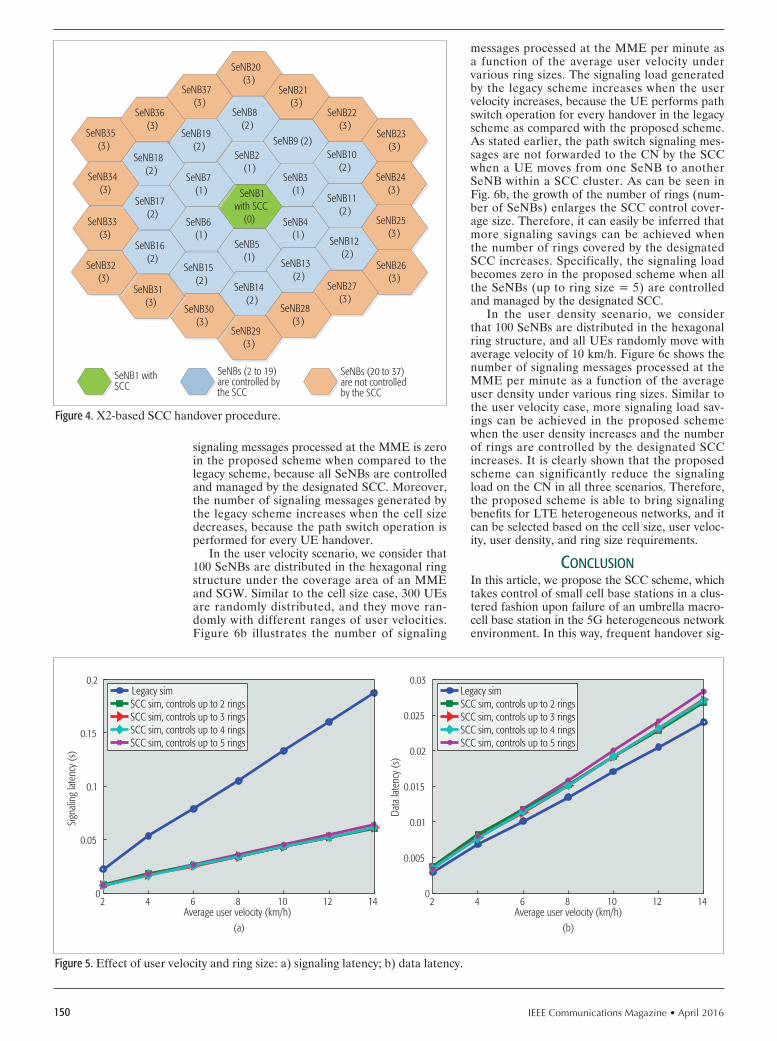
IEEE Communications Magazine • April 2016150
signaling messages processed at the MME is zero in the proposed scheme when compared to the legacy scheme, because all SeNBs are controlled and managed by the designated SCC. Moreover, the number of signaling messages generated by the legacy scheme increases when the cell size decreases, because the path switch operation is performed for every UE handover.
In the user velocity scenario, we consider that 100 SeNBs are distributed in the hexagonal ring structure under the coverage area of an MME and SGW. Similar to the cell size case, 300 UEs are randomly distributed, and they move ran-domly with different ranges of user velocities. Figure 6b illustrates the number of signaling
messages processed at the MME per minute as a function of the average user velocity under various ring sizes. The signaling load generated by the legacy scheme increases when the user velocity increases, because the UE performs path switch operation for every handover in the legacy scheme as compared with the proposed scheme. As stated earlier, the path switch signaling mes-sages are not forwarded to the CN by the SCC when a UE moves from one SeNB to another SeNB within a SCC cluster. As can be seen in Fig. 6b, the growth of the number of rings (num-ber of SeNBs) enlarges the SCC control cover-age size. Therefore, it can easily be inferred that more signaling savings can be achieved when the number of rings covered by the designated SCC increases. Specifically, the signaling load becomes zero in the proposed scheme when all the SeNBs (up to ring size = 5) are controlled and managed by the designated SCC.
In the user density scenario, we consider that 100 SeNBs are distributed in the hexagonal ring structure, and all UEs randomly move with average velocity of 10 km/h. Figure 6c shows the number of signaling messages processed at the MME per minute as a function of the average user density under various ring sizes. Similar to the user velocity case, more signaling load sav-ings can be achieved in the proposed scheme when the user density increases and the number of rings are controlled by the designated SCC increases. It is clearly shown that the proposed scheme can significantly reduce the signaling load on the CN in all three scenarios. Therefore, the proposed scheme is able to bring signaling benefits for LTE heterogeneous networks, and it can be selected based on the cell size, user veloc-ity, user density, and ring size requirements.
conclusIonIn this article, we propose the SCC scheme, which takes control of small cell base stations in a clus-tered fashion upon failure of an umbrella macro-cell base station in the 5G heterogeneous network environment. In this way, frequent handover sig-
Figure 4. X2-based SCC handover procedure.
SeNB2 (1)
SeNB1 with SCC
(0)
SeNB3 (1)
SeNB6 (1)
SeNB5 (1)
SeNB4 (1)
SeNB7 (1)
SeNB8 (2)
SeNB18 (2)
SeNB19 (2)
SeNB17 (2)
SeNB16 (2)
SeNB15 (2)
SeNB14 (2)
SeNB12 (2)
SeNB13 (2)
SeNB11 (2)
SeNB10 (2)
SeNB9 (2)
SeNB1 withSCC
SeNBs (2 to 19)are controlled bythe SCC
SeNBs (20 to 37)are not controlledby the SCC
SeNB20 (3)
SeNB21 (3)
SeNB22 (3)
SeNB23 (3)
SeNB24 (3)
SeNB25 (3)
SeNB26 (3)
SeNB27 (3)
SeNB28 (3)
SeNB29 (3)
SeNB30 (3)
SeNB31 (3)
SeNB32 (3)
SeNB33 (3)
SeNB34 (3)
SeNB35 (3)
SeNB36 (3)
SeNB37 (3)
Figure 5. Effect of user velocity and ring size: a) signaling latency; b) data latency.
2 4 6 8 10 12 140
0.005
0.01
0.015
0.02
0.025
0.03
Average user velocity (km/h)
Data
late
ncy
(s)
Legacy simSCC sim, controls up to 2 ringsSCC sim, controls up to 3 ringsSCC sim, controls up to 4 ringsSCC sim, controls up to 5 rings
2 4 6 8 10 12 140
0.05
0.1
0.15
0.2
Average user velocity (km/h)
Sign
aling
late
ncy
(s)
Legacy simSCC sim, controls up to 2 ringsSCC sim, controls up to 3 ringsSCC sim, controls up to 4 ringsSCC sim, controls up to 5 rings
(a) (b)

IEEE Communications Magazine • April 2016 151
naling can be avoided during the fail-over period of the macrocell base station. In order to achieve such a feature, we also introduce the correspond-ing local signaling mechanism for the X2-based handover procedure. As such, recreation of the secondary cell group bearer is avoided on the CN for every UE handover as compared to the legacy scheme in 3GPP. Without loss of generality, the proposed scheme can be flexibly configured into a ring-based hybrid scenario where nearby small cell base stations can be controlled directly by the SCC itself, while remote small cell base stations can remain independent with their own backhaul links to the CN for signaling and data transmis-sion. Compared to the legacy scheme, our simula-tion results show that significant signaling latency savings can be achieved per UE; also, the signal processing load can be reduced at the CN. As a final remark, the proposed scheme to be applied is not visible to the CN or UEs, and an incremen-tal upgrade is necessary only at the RAN side.
Acknowledgment
We would like to acknowledge the support of the University of Surrey 5GIC (http://www.surrey.ac.uk/5gic) members for this work.
references[1] J. Andrews et al., “Femtocells: Past, Present, and Future,” IEEE JSAC, vol.
30, no. 3, Apr. 2012, pp. 497–508. [2] X. Ge et al., “5G Wireless Backhaul Networks: Challenges and Research
Advances,” IEEE Network, vol. 28, no. 6, Nov 2014, pp. 6–11. [3] S. Jha et al., “Dual Connectivity In LTE Small Cell Networks,” Proc. IEEE
GLOBECOM Wksps., Dec 2014, pp. 1205–10. [4] B. Bangerter et al., “Networks and Devices for the 5G era,” IEEE Commun.
Mag., vol. 52, no. 2, Feb. 2014, pp. 90–96. [5] 3GPP TR 23.857 V11.0.0, “Study of Evolved Packet Core (EPC) Nodes
Restoration,” Dec. 2012. [6] 3GPP TS 36.300 V13.1.0, “Evolved Universal Terrestrial Radio Access
(E-UTRA) and Evolved Universal Terrestrial Radio Access Network (E-UTRAN); Overall Description,” Sept. 2015.
[7] J. Robson, “Small Cell Backhaul Requirements,” NGMN White Paper, June 2012.
[8] 3GPP TS 23.401 V13.4., “General Packet Radio Service (GPRS) Enhance-ments for Evolved Universal Terrestrial Radio Access Network (E-UTRAN) Access,” Sept. 2015.
[9] 3GPP TS 23.007 V13.2.0, “Restoration Procedures,” Sept. 2015. [10] T. Guo et al., “Local Mobility Management for Networked Femtocells
Based on X2 Traffic Forwarding,” IEEE Trans. Vehic. Tech., vol. 62, no. 1, Jan. 2013, pp. 326–40.
[11] K.-H. Chiang and N. Shenoy, “A 2-D Random-Walk Mobility Model for Location-Management Studies in Wireless Networks,” IEEE Trans. Vehic. Tech., vol. 53, no. 2, Mar. 2004, pp. 413–24.
[12] 3GPP TR 25.912 V12.0.0, “Feasibility Study for Evolved Universal Terres-trial Radio Access (UTRA) and Universal Terrestrial Radio Access Network (UTRAN),” Oct. 2014.
bIogrApHIes
Joseph stalin thainesh ([email protected]) is a consultant at TEOCO, and currently also a part-time research student at the Institute for Communication Systems (ICS), University of Surrey, United Kingdom. He has many years of experience in the telecom domain. He has been working with many customers in various areas including data communication, IMS, 2G, 3G, and 4G.
ning Wang ([email protected]) is a reader at ICS, University of Surrey. He received his B.Eng (honors) from Changchun University of Science and Tech-nology, P.R. China, in 1996, his M.Eng. from Nanyang Technological University, Singapore, in 2000, and his Ph.D. from the University of Surrey in 2004. He currently leads the work area on content, user, and network context at the 5G Innovation Centre (5GIC), University of Surrey. His research interests include mobile content delivery, context-aware networking, and network management.
Rahim tafazolli ([email protected]) is a professor and the director of ICS and the 5G Innovation Centre (5GIC), University of Surrey. He has published more than 500 research papers in refereed journals, international conferences, and as an invited speaker. He is the Editor of two book vol-umes published by Wiley in 2004 and 2006, titled Technologies for the Wireless Future. In April 2011 he was appointed a Fellow of the Wireless World Research Forum (WWRF), in recognition of his personal contribution to the wireless world.
Figure 6. Signaling load at the MME: a) cell size; b) average user velocity; c) average user density.
100 150 200 250 3000
500
1000
1500
2000
Average user density (users/km2 )
Num
ber o
f pro
cess
ed m
essa
ges/
min
Legacy simSCC sim, controls up to 2 ringsSCC sim, controls up to 3 ringsSCC sim, controls up to 4 ringsSCC sim, controls up to 5 rings
2 4 6 8 10 12 140
500
1000
1500
2000
2500
3000
Average user velocity (km/h)
Num
ber o
f pro
cess
ed m
essa
ges/
min
Legacy simSCC sim, controls up to 2 ringsSCC sim, controls up to 3 ringsSCC sim, controls up to 4 ringsSCC sim, controls up to 5 rings
100 200 300 400 500 6000
500
1000
1500
2000
Cell size (m)
Num
ber o
f pro
cess
ed m
essa
ges/
min
Legacy simSCC sim
(a)
(b)
(c)

IEEE Communications Magazine • April 2016152 0163-6804/16/$25.00 © 2016 IEEE
AbstrAct
Virtualization is an enabling technology that improves scalability, reliability, and flexibility. Virtualized networking is tackled by emulat-ing or paravirtualizing network interface cards. This approach, however, leads to complex-ities (implementation and management) and has to conform to some limitations imposed by the Ethernet standard. RINA turns the cur-rent approach to virtualized networking on its head: instead of emulating networks to perform inter-process communication on a single pro-cessing system, it sees networking as an exten-sion to local inter-process communication. In this article, we show how RINA can leverage a paravirtualization approach to achieve a more manageable solution for virtualized networking. We also present experimental results performed on IRATI, the reference open source imple-mentation of RINA, which shows the potential performance that can be achieved by deploying our solution.
IntroductIonVirtualization technologies provide a cost-effective way of increasing the scalability, reliability, and flex-ibility of services deployed over the internet. Virtual machine (VM) networking, that is, the way a VM connects to the physical network, is an aspect of high importance in the virtualization world, with network performance being paramount [1]. The traditional way that hypervisors implement VM net-working is based on network interface card (NIC) emulation; for example, QEMU [2], VirtualBox [3], VMWare [4] are able to emulate Intel e1000, Realtek r8169, and other NICs. This is also referred to as full NIC emulation, where the hypervisor implements a NIC hardware model in software, including the transmit and receive memory mapped rings and the peripheral component interconnect (PCI) registers.
The paravirtualization approach initial-ly proposed by Xen [5], with the netfront/net-back paravitualized NIC, gained popularity over traditional emulation, leading to the advent of VMware vmxnet [6] and the VirtIO [7] standard for I/O paravirtualization. NIC paravirtualization
(and I/O paravirtualization in general) is a soft-ware technique that greatly improves VM net-working performance and eases implementation of VM I/O support in hypervisors. Paravirtual-ization removes the need to implement the emu-lation of hardware-related details and features, thereby exposing a simple and efficient interface for shared-memory communication between VM and hypervisor. The main advantage of the para-virtualization approach is a gain in performance. However, it is still necessary to present a NIC device in the VM, which makes it a solution that is hard to manage.
In this article we try to reduce the complexity associated with managing VM communication by applying the paravirtualization paradigm, a cleaner and simpler interface for VM I/O, in the recursive internetwork architecture (RINA) [8]. This results in a simple and clean solution for the communication between VMs and their hypervi-sor, without the need for the VM to even imple-ment a (paravirtualized) NIC.
In the next section we give a brief description of RINA. After that we, we introduce IRATI, the open source implementation of RINA in Linux/OS. Then we introduce our main contri-bution, a new component, called the shim dis-tributed inter-process communication (IPC) facility (DIF) for hypervisors, that leverages the paravir-tualization approach. Some experimental results with this new component are then presented. Finally, we explore future works and we con-clude the article.
recursIve Internetwork ArchItectureRINA is a network architecture ab initio, aiming to provide an alternative to the current TCP/IP Internet architecture. RINA extends IPC, the way processes communicate on a single process-ing system, from a local concept to the scope of an (inter)network [9].
The endpoints of all communications are processes, AND the means of communication between them is called the IPC service. By definition, if processes can communicate local-ly using shared memory (test-and-set), they reside on the same processing system. In this case, an operating system provides and manages
Reducing the Complexity of Virtual Machine Networking
Sander Vrijders, Vincenzo Maffione, Dimitri Staessens, Francesco Salvestrini, Matteo Biancani, Eduard Grasa, Didier Colle, Mario Pickavet, Jason Barron, John Day, and Lou Chitkushev
Accepted from open cAll
The authors show how RINA can leverage a paravirtualization approach to achieve a more manageable solution for virtualized networking. They also present experimental results performed on IRATI, the reference open source imple-mentation of RINA, which shows the potential performance that can be achieved by deploying their solution.
Sander Vrijders, Dimitri Staessens, Didier Colle, and Mario Pickavet are with Ghent University — iMinds; Vincenzo Maffione and Francesco Salvestrini are with Nextworks s.r.l.; Matteo Biancani is with Interoute S.p.A.; Eduard Grasa is with i2CAT Foundation; Jason Barron is with Waterford Institute of Technology;
John Day and Lou Chitkushev are with Boston University.

IEEE Communications Magazine • April 2016 153
the IPC service between processes. If processes cannot communicate using test-and-set, they are on different processing systems. In RINA, an operating system process that provides IPC services is called an IPC process (IPCP). To provide the IPC service to processes residing on multiple processing systems, IPCP instanc-es on each system work together to form a DIF, which is the core organizing structure in RINA and corresponds to what typically is referred to as a “network layer.” As many DIFs as needed by the network designer can be stacked on top of each other. Most of the time at least two levels of DIFs are needed, at the link level and the network level, inter-connecting nodes over multiple hops. DIFs of higher order can be internetworks, virtual pri-vate networks (VPNs), or application-specifi c virtual networks. A DIF offers a fixed set of functionalities and services (the mechanism), but is fully confi gurable with suitable policies in order to adapt to the environment in which it operates and to fulfi ll the requirements of the applications (or other DIFs) it serves. DIFs are bootstrapped from a single IPCP instance, and the process of an IPCP instance joining a DIF is called enrollment.
All IPC processes provide the same applica-tion programming interface (API) to their users, which can be regular applications or other IPC processes. Through this API — referred to as the IPC API — an application can:• Register with a DIF so that it can be reached
by other applications that are clients of this DIF
• Allocate a fl ow to a registered application• Read and write from/to an allocated fl ow• Deallocate the fl ow when desired
IPCPs that both provide the IPC API north-bound and make use of the IPC API southbound are called normal IPCPs and form a normal DIF. Some internal components of the IPCP are ded-icated to layer management, while others are devoted to data transfer or data transfer control. RINA has special IPCPs that are tailored to a transmission medium (possibly incorporating a medium access control , MAC, protocol) or wrap around an existing legacy network technology such as Ethernet and provide the IPC API north-bound only. Such IPCPs are called shim IPCPs and form shim DIFs.
An example scenario is shown in Fig. 1. Two
physical machines are interconnected over an Ethernet LAN, wrapped by a shim DIF over Ethernet with virtual LANs (VLANs) (IEEE 802.1Q) [10]. Each physical machine is run-ning a VM. Between each VM and the physical machine on which it runs, there is a shim DIF for hypervisors, which provides communication directly using shared memory. On top of these shim DIFs lies a normal DIF, which uses the (basic) IPC services provided by the shim DIFs, and itself provides IPC services to applications running on top. The line denotes the path that service data units (SDUs) sent by the applica-tions would follow through the network in this specifi c scenario.
Due to space restrictions, a complete discus-sion of RINA is not possible here. We kindly refer the reader to [8, 9] for further details.
the IrAtI prototypeIRATI [11] is an open source Linux/OS imple-mentation of RINA, written in C/C++. In IRATI, the data transfer and data transfer con-trol functionalities (the fast path) run in kernel space, whereas layer management functionalities (the slow path) run in userspace in the context of system daemons; that is, the IPC Manager dae-mon and the IPC Process daemons.
The current implementation provides the fol-lowing features:• Enrollment, which allows IPCP instances to
join an existing DIF• Allocation of fl ows with different QoS char-
acteristics• Data unit protection functionalities like
checksumming, encryption, and time to live mechanisms
• A simple link-state routing protocol that works on a fl at (not hierarchical) addressing space
• Extended programmability, by allowing pol-icies to be plugged into components in both user and kernel space
•Two shim IPCPs: the shim IPCP over TCP/UDP and the shim IPCP over IEEE 802.1Q [10]We extended the IRATI prototype with a new
component: the shim DIF for hypervisors. This new component provides a point-to-point shim DIF over shared memory between a VM and its hypervisor, which is achieved by leveraging the paravirtualization approach.
We extended the IRATI
prototype with a new
component: the shim
DIF for hypervisors. This
new component pro-
vides a point-to-point
shim DIF over shared
memory between a
virtual machine and
its hypervisor, which is
achieved by leveraging
the paravirtualization
approach.
Figure 1. An example of the recursive internetwork architecture.
Physical machine
IPCprocess
Shim IPCprocess
Shim IPCprocess
IPCprocess
Normal DIF
Shim IPCprocess
Shim IPCprocess
IPCprocess
Shim IPCprocess
Virtual machine
Application
IPCprocess
Shim IPCprocess
Virtual machine
Application
Shim DIF over IEEE 802.1Q
Shim DIF over hypervisorsShim DIF over hypervisors
Physical machine

IEEE Communications Magazine • April 2016154
shIm dIf for hypervIsors
Virtual machine networking is commonly imple-mented by providing VMs with NICs that are emulated by the hypervisor, which also creates and manages the VMs. The emulated NIC for-wards the VM’s packets to/from the hypervisor’s TCP/IP stack. The hypervisor usually connects to the emulated NIC through a special (soft-ware) network interface. As an example, Xen [5] Domain 0 uses a so-called vif interface (a xen-netback device), while QEMU [2] uses a tap interface.
In order to connect the emulated NIC with other VMs hosted by the same hypervisor or with the external network, the hypervisor’s software interfaces are bridged to other host interfaces (physical interfaces and/or software interfaces associated with other emulated NICs) using soft-ware switches (e.g., OpenVSwitch [12] or the standard Linux in-kernel bridge). Each hyper-visor may host many bridges in order to build arbitrary network topologies for VMs.
In TCP/IP, applications require an IP address, which must be assigned to an interface. In RINA this is not the case. Applications request IPC services through the IPC API to any DIF that can provide connectivity to the destination appli-cation. Because of this strong API, the physi-cal layer is abstracted away and not visible to applications. In short, the DIF abstraction is at a higher level than the NIC abstraction. As a con-sequence, there is no need to emulate a NIC to connect the VM stack to the hypervisor’s stack. Instead, VM-to-hypervisor point-to-point con-nectivity is provided directly using shared mem-ory or message passing mechanisms provided by the hypervisor itself. This method is imple-mented in the shim DIF for hypervisors. While a physical machine will typically have one or more shim DIFs over Ethernet or TCP/UDP as the lowest-level network access, a VM will have one or more shim DIFs for hypervisors.
Exploring the possibilities of using hypervisor internal mechanisms other than the tradition-al networking subsystem for VM-to-hypervisor communication provides a more easily managed solution and may also allow for better perfor-mance. Of course, it is necessary to configure the DIFs in the network, but management is sim-
plified since it is always the same architectural component that has to be configured; there is no need for a different ad hoc component. Since the shim DIF for hypervisors provides VM-to-hyper-visor point-to-point connectivity directly using shared memory or message passing mechanisms provided by the hypervisor, it is not restricted by some limitations of Ethernet technology (unlike traditional VM networking).
The shim DIF for hypervisors is built on top of a new device we implemented: the virtual mes-sage passing interface (VMPI) VM-to-hypervisor shared-memory communication mechanism. The high-level architecture of the VMPI is depicted in Fig. 2. A VMPI device is used to implement the point-to-point link, and is seen as a special device on both the VM and hypervisor. It requires only a very small driver on the guest and hypervisor. The VMPI device implementation is almost entire-ly data path since it focuses on message passing only. There is no need for all the details of Eth-ernet NICs, like tens of configuration registers, autonegotiation, TCP/IP offloading, checksum-ming, MAC addresses, maximum transmission unit (MTU) limitations, VLAN support, con-figuration of the internal modem (e.g., PHY), internal buffering, direct memory access (DMA) configuration, and EEPROM configuration.
As a concrete example of the simplicity, the e1000 driver in Linux is implemented in about 17 kilo lines of code (KLoC), the ixgbe driver in 37 KLoC. An emulated NIC such as e1000 is implemented in 3 KLoC on QEMU and 8 KLoC on VirtualBox. The differences in KLoC are due to different degrees of emulation accura-cy. For paravirtualized devices, on the guest, the virtio-net driver is 2 KLoC, whereas the VMPI driver is only 1 KLoC. Similarly, on the host, vir-tio-net support is about 2 KLoC, while VMPI support is implemented in about 1 KLoC. Most of the complexities of NIC drivers are due to the configuration routines as opposed to the data path (i.e., the TX and RX rings). This explains the differences in code size among traditional NIC drivers/emulators and paravirtualized solu-tions. All the configuration-related complexities of an emulated NIC are overhead only when deployed in VM environments, since there is no real hardware to drive.
The VMPI consists of two blocks: the VMPI
Figure 2. Shim DIF over hypervisors in depth.
Tx
VMPI
VMPIVMPI-HL
VMPI-IMPLAPI
VMPI-ILL
QEMU virtqueues orXen I/O rings
Tx ring
VMPIAPI
Rx queues
Rx
Sharedmemory
Sharedmemory
VMPI APIShim IPCP for HV
Application orIPCP
IPC API
Main environment (QEMU host or Xen Dom 0)
Virtual machine
VMPIVMPI APIShim IPCP for
HVApplication or
IPCPIPC API

IEEE Communications Magazine • April 2016 155
high level (VMPI-HL) and the VMPI low level (VMPI-LL). The VMPI-LL block is hypervi-sor-dependent, and is used to access Xen [5] I/O rings or QEMU/KVM [7, 13] Virtqueues [2] with a common (internal) interface, referred to as VMPI-IMPL. Therefore, the VMPI-LL acts as a wrapper for the shared memory communication mechanism made available by the hypervisor, effectively making use of the paravirtualization mechanisms Xen and QEMU/KVM offer. The VMPI-IMPL interface is used by the VMPI-HL block, which is hypervisor-independent, to implement the VMPI device abstraction. VMPI-HL offers the VMPI API to its users, allowing data to be exchanged between the VM and the hypervisor. Each VMPI device is assigned two identifiers, one on the VM OS and the other on the hypervisor OS. The first identifier is neces-sary to distinguish multiple VMPI devices in the same VM, while the second one is required to distinguish between the multiple VMPI devices (assigned to possibly different VMs) on the same hypervisor. Nevertheless, the scope of those identifiers is confined to a single OS, so the man-agement is far easier than MAC management. The scope of MACs needs to be unique on the layer 2 (L2) domain in which the NICs exist (or can exist), which may be a large segment of a data center (DC) infrastructure, involving mul-tiple hypervisors. A shim DIF for hypervisors makes use of the VMPI API offered by a VMPI device, which is a much simpler API than the one between the kernel and the NIC driver, to offer the IPC API to its users. The VMPI iden-tifier serves as an address within the shim DIF for hypervisors. Addresses are contained within a layer in RINA, and the shim DIF for hypervisors is a layer inside the OS.
The shim DIF for hypervisors has several advantages when compared to traditional NIC emulation:• No need to implement complex and expen-
sive NIC emulation.• No need to generate and assign MAC
addresses, which can become an issue at scale, especially for large DCs. Generation of VMPI-ids is needed, but is confined to a single OS; thus, they need to be unique only per hypervisor, not network-wide. The length of a VMPI-id is quite small because of this.
• No need to create and configure software L2 bridges to connect VMs and hypervisor physical NICs together.
• Users of the shim DIF are not restricted to the Ethernet MTU (maximum payload of 1500 bytes or 9000 bytes if jumbo frames are used). This restriction is common-ly bypassed in traditional VM networking by using the TCP segmentation offloading (TSO) features offered by emulated NICs. However, this is a workaround that adds complexity and dependencies between lay-ers, since L4-specific operations are needed in the driver, which is situated at L2. It is not needed by the shim DIF over hypervisors.
• No need to perform TCP/UDP check-summing in the emulated NIC (checksum offloading), since shared memory commu-nication is protected from corruption by
other means. Checksumming is not actually performed by modern paravirtualized NICs (e.g., virtio-net [7], xen-netfront [5]), but this is again a complex workaround that is not needed by the shim DIF over hypervisors.
experImentAtIon resultsIn order to assess the possible gains from deploy-ing the shim DIF for hypervisors in the DC, we measured the performance of the IRATI stack against the performance of the TCP/IP stack in Linux when deployed to support VM networking.
Note up front, however, that the IRATI stack is currently not optimized for performance. In particular, kernel-space components have several bottlenecks such as high per-packet locking over-head (too many locks taken for each PDU to be processed) and several unnecessary per-packet deep copies. These bottlenecks have been iden-tified, but their implementation is out of scope for a research prototype. Therefore, we expect our prototype to underperform by possibly an order of magnitude compared to its theoretical performance.
The tests reported in this section involve one or two physical machines (hosts) that act as a hypervisor for one or two VMs. We performed three different test scenarios:• Host-to-VM tests, where a benchmarking
tool (rina-tgen [14] for IRATI tests and net-perf for TCP/IP tests) is used to measure the goodput between a client running in the host and a server running on a VM.
• Intra-host VM-to-VM tests, where a bench-marking tool is used to measure the good-put between a client running on a VM and a server running on a different VM in the same host.
• Inter host VM-to-VM tests, where a bench-marking tool is used to measure the good-put between a client running on a VM and a server running on a different VM in differ-ent hosts. The hosts are connected through a 10 Gb/s Ethernet link.The measurements were taken on a process-
ing system with two 8-core Intel E5-2650v2 (2.6 GHz) CPUs and 48 GB RAM. QEMU/KVM was chosen as the hypervisor, since it is one of the two hypervisors supported by the shim DIF for hypervisors.
For the host-to-VM scenario, three test ses-sions were executed. The first two tests assess UDP goodput performance at variable packet size, thereby assessing the performance of tra-ditional VM networking. The tap device corre-sponding to emulated NIC in the VM is bridged to the host stack through a Linux in-kernel soft-
Figure 3. Setup of traditional networking in VMs.
VM 1
10.0.0.1eth0
VM 2
10.0.0.2eth0tap1 tap2
br010.0.0.200
HOST
Linuxbridge

IEEE Communications Magazine • April 2016156
ware bridge. This setup is also depicted in Fig. 3, where the setup of traditional networking in VMs is shown. The Linux bridge is accessible in the host stack through a bridge interface (e.g., br0). Once the bridge interface and VM NIC have been given an IP address on the same IP subnet, as they are on the same L2 domain, the netperf benchmarking tool is used to measure UDP performance between the host and the VM. In particular, the netperf server (netserver) listens on the VM’s interface, while the netperf client runs in the host and uses the bridge inter-face.
In the first session, a NIC belonging to the Intel e1000 family is used, which is implement-ed in QEMU by emulating the hardware behav-ior (full virtualization); for example, NIC PCI registers, DMA, packet rings, and offloadings. The second test session makes use of a paravir-tualized NIC model, the virtio-net device. Para-virtualized devices do not correspond to real hardware; instead, they are explicitly designed to be used by VMs in order to save the hypervi-sor from the burden of emulating real hardware. Paravirtualized devices allow for better perfor-mance and code reusability. The virtio standard also provides a paravirtualized disk, serial con-sole, number generator, and so on. The only dif-ference between the first and second test sessions is the model of the emulated NIC. Despite being more virtualization-friendly than e1000 (or other emulated NICs like r8169 or pcnet2000), the guest OS still sees the virtio-net adapter as a nor-mal Ethernet interface, with all the complexities and details involved (MAC, MTU, TSO, check-sum offloading, etc.).
The third test session shows the performance of the shim DIF for hypervisors. A scenario comparable to the one deployed in the first and second test sessions involves a shim IPC process for hypervisors on the host and a corresponding one on the guest. No normal IPC processes are used; the applications can run directly over the shim DIF. This is a consequence of the flexibil-ity of RINA, since the application can use the lowest-level DIF with sufficient scope to support the intended communication (guest-to-host in this case) and that provides the required quality of service (QoS). This also drastically reduces the header size. In TCP/IP the minimum header size is 84; the Ethernet header is 38 bytes and requires a payload of at least 46 bytes. With the shim DIF for hypervisors, the minimum head-er length is 4; the actual data is only prepend-ed by an identifier of the VMPI channel. Zero is the control channel; other channels can be used to send data on. The host runs our rina-tgen application in server mode, while the guest runs rina-tgen in client mode. Rina-tgen is a traf-fic generator for RINA that also functions as a benchmarking application; it uses the IPC API to measure goodput. Each test run consists of the client sending a unidirectional stream of SDUs of a specified size to the server. Measurements have been taken varying the SDU size, ranging from 0 to 4000 (the page size of the processing systems), with a step size of 250. We repeated every measurement 20 times. The result of these goodput measurements for a host-to-VM com-munication scenario are shown in Fig. 4a. 95 per-cent confidence levels are also depicted, as well as a first degree polynomial regression line.
As shown in Fig. 4a, the shim DIF for hyper-visors outperforms both e1000 and virtio-net NIC setups, which validates that a simpler and clean-er architecture allows for better performance, even with an unoptimized prototype. Note that while the Ethernet MTU is set to 1500 in the first two sessions, it is possible to go beyond the limit because of the UDP segmentation offloading (UFO) feature, which is supported by both the e1000 and virtio-net models. This feature allows the NIC (real hardware or emulated) to accept
Figure 4. Goodput of different network virtualization technologies: a) host-to-VM communication; b) VM-to-VM communication intra-host; c) VM-to-VM communication inter-host.
SDU size (bytes)(a)
5000
2000
0
Good
put (
Mb/
s)
4000
6000
8000
10000
12000
1000 1500 2000 2500 3000 3500 4000
SDU size (bytes)(b)
5000
1000
0
Good
put (
Mb/
s)
2000
3000
4000
5000
6000
7000
1000 1500 2000 2500 3000 3500 4000
SDU size (bytes)(c)
5000
1000
0
Good
put (
Mb/
s)
2000
3000
4000
5000
6000
7000
1000 1500 2000 2500 3000 3500 4000
e1000 network adapterVirtIO network adapterShim DIF for hypervisors
e1000 network adapterVirtIO network adapterNormal DIF over shim DIF for hypervisors
e1000 network adapterVirtIO network adapterNormal DIF over shim DIF for hypervisors

IEEE Communications Magazine • April 2016 157
UDP packets that do not fit into a single 1500-byte Ethernet frame. A real NIC performs the necessary segmentation in hardware, while an emulated one (e.g., e1000) emulates the segmen-tation in software. It is interesting to note that in the virtio-net case, this segmentation is not really carried out, since there is no real Ethernet cable to deal with, but the oversized packet is directly forwarded to the host stack, which is able to pro-cess and deliver to the receiving application (net-server) without further segmentations. This is clearly an optimization made possible by paravir-tualization, but can also be seen as a workaround that is not necessary in our solution.
Next, similar goodput performance measure-ments were taken on the intra-host VM-to-VM scenario. Again, three test sessions were per-formed, the first two for traditional VM network-ing and the third one for the IRATI stack. The setup of the first two sessions is very similar to the corresponding one in the host-to-VM sce-nario. The VMs are given an emulated NIC, the corresponding tap device of which is bridged to the host stack through a Linux in-kernel soft-ware bridge (Fig. 3). Both VMs and the bridge interface are given an IP address on the same subnet. Measurements are again performed with the netperf utlity, with the netperf server running on a VM and the netperf client running on the other VM.
In the case of the IRATI tests, point-to-point connectivity between host and VM is provided by the shim DIF for hypervisors. A normal DIF is overlaid on these shim DIFs to provide connec-tivity between the two VMs. Tests are performed again with the rina-tgen application, using a flow that provides flow control without retransmission control. Flow control is used so that the receiv-er’s resources are not abused. Retransmission control is not needed because no SDUs can be lost along the data path, since in these very spe-cific tests we are sure the SDU never leaves the host or is dropped in some intermediate queue. In TCP/IP, this kind of functionality, flow control without retransmission control, is not available. Hence, we again chose UDP to perform the tests for the traditional networking solution, since its functionality is most similar. The result of these test sessions are depicted in Fig. 4b, again with their respective 95 percent confidence intervals and a first degree polynomial regression line. Full virtualization again performs poorly. The paravirtualized solution currently outperforms the unoptimized IRATI stack, because a normal DIF is used to provide the connectivity between the VMs. This part of the IRATI stack is the least optimized for performance, which explains why the IRATI prototype performs worse than TCP/IP in this case.
Finally, inter-host VM-to-VM tests were per-formed. The hosts are connected through a 10 Gb/s link. The setup of the first two sessions now differs in the fact that both hosts have to set up a Linux bridge. Each VM is given an emulated NIC, the tap device of which is bridged to the host stack through a Linux in-kernel software bridge. On both hosts, the interface connecting the host to the other host is also added as an interface to the bridge. In this way, the VMs are connected to each other. The VMs are assigned
an IP address in the same subnet, and all NICs are enabled to use jumbo frames. Once more, we used netperf to test the goodput between the VMs.
For the IRATI prototype, the setup is identical to that depicted in Fig. 1. Point-to-point connec-tivity between host and VM is provided by the shim DIF for hypervisors. Point-to-point connec-tivity between the hosts is provided by the shim DIF for IEEE 802.1Q. The NICs on the hosts have jumbo frames enabled. On top of these shim DIFs, a normal DIF is overlaid. Tests are per-formed using the rina-tgen application. These test sessions’ results are shown in Fig. 4c, with their respective 95 percent confidence intervals and a first degree polynomial regression line. Full vir-tualization performs similar to the previous test sessions. Both the paravirtualized solution and the IRATI prototype solution achieve performance similar to that in the previous test session. The paravirtualized solution again outperforms the unoptimized IRATI stack, since the IRATI pro-totype also uses a normal DIF in this test session, which is the bottleneck for performance.
future worksWe plan to optimize the IRATI stack to achieve better performance by reducing buffer copies and allocations to the bare minimum to improve the performance when communicating between VMs.
conclusIonIn this article, we illustrate how paravirtualiza-tion can be leveraged by RINA, a network archi-tecture ab initio. We present the shim DIF for hypervisors as an alternative to traditional net-working solutions in virtual machines, which has been implemented in the IRATI prototype.
We explain how the shim DIF for hypervisors is a more manageable solution for VM network-ing. A summary of the main differences between VM networking in TCP/IP and VM network-ing in RINA can be found in Table 1. We also show how it already allows for good performance in some reference scenarios, host-to-VM and VM-to-VM, despite being unoptimized.
Table 1. Comparison between VM networking in TCP/IP and RINA.
VM networking in TCP/IP VM networking in RINA
Checksumming is always performed Only checksumming if needed
Header length 84 Header length 4
Hardware offloading required for performance No hardware offloading needed
MAC address to be unique in whole data center VMPI-id to be unique per OS
SDU size restricted by Ethernet standard No restrictions on SDU size
Complete NIC to be implemented Device simple to implement
Hard to configure Easy to configure
Ad hoc components are needed VM networking is part of the architecture
Code size increased due to configuration Most code is related to the data path

IEEE Communications Magazine • April 2016158
AcknowledGment
This work is partly funded by the European Commission’s Seventh Framework Programme (FP7/2007-2013) through the projects IRATI (Grant 317814), part of the Future Internet Research and Experimentation (FIRE) objective, and IRINA, part of the GN3plus Open Calls.
references
[1] L. Rizzo, G. Lettieri, and V. Maffi one, “Speeding Up Packet I/O in Virtual Machines,” Proc. Ninth ACM/IEEE Symp. Architectures for Networking and Commun Sys., 2013, pp. 47–58.
[2] F. Bellard, “Qemu, a Fast and Portable Dynamic Translator,” Proc. USENIX Annual Tech. Conf., FREENIX Track, 2005, pp. 41–46.
[3] VirtualBox; https://www.virtualbox.org/ (Nov. 2015).[4] VMware; http://www.vmware.com/ (Nov. 2015).[5] P. Barham et al., “Xen and the Art of Virtualization,” ACM SIGOPS Op. Sys.
Rev., vol. 37, no. 5, 2003, pp. 164–77. [6] “Performance Evaluation of VMXNET3 Virtual Network Device,” VMware,
Inc., tech. rep., 2009. [7] R. Russell, “Virtio: Towards a De-Facto Standard for Virtual I/O Devices,”
ACM SIGOPS Op. Sys. Rev., vol. 42, no. 5, 2008, pp. 95–103. [8] J. Day, Patterns in Network Architecture: A Return to Fundamentals, Pren-
tice Hall, 2008. [9] J. Day, I. Matta, and K. Mattar, “Networking Is IPC: A Guiding Principle to a
Better Internet,” Proc. 2008 ACM CoNEXT Conf., 2008, p. 67. [10] S. Vrijders et al., “Unreliable Inter Process Communication in Ethernet:
Migrating to RINA with the Shim DIF,” Proc. 5th Int’l. Wksp. Reliable Networks Design and Modeling, 2013, pp. 97–102.
[11] S. Vrijders et al., “Prototyping the Recursive Internet Architecture: The IRATI Project Approach,” IEEE Network, vol. 28, no. 2, 2014, pp. 20–25.
[12] B. Pfaff et al., “Extending Networking into the Virtualization Layer,” Hot-nets, 2009.
[13] A. Kivity et al., “KVM: The Linux Virtual Machine Monitor,” Proc. Linux Symp., vol. 1, 2007, pp. 225–30.
[14] RINA Traffic Generator; http://www.github.com/IRATI/traffic-generator (Nov. 2015).
bIoGrAphIes
SANDER VRIJDERS received his M.Sc. degree in applied engineering: computer science in 2012 from University College Ghent, Belgium. Since then he has been working at the Internet Based Communications Networks and Services group at Ghent University, where he is a Ph.D. candidate. His current interests are in RINA, funded through FP7 IRATI, FP7 PRISTINE, and H2020 ARCFIRE.
VINCENZO MAFFIONE received his Italian Laurea degree in computer engineer-ing from the University of Pisa in 2013. In 2013–2014 he worked as a tem-porary research fellow at the University of Pisa, focusing on high-performance virtual machine networking and high-performance userspace networking. Currently he is an R&D software engineer at Nextworks. His research interests include SDN, virtualization, and RINA. He is currently active in the FP7 T2 and PRISTINE projects, and has worked in the FP7 IRATI project.
DIMITRI STAESSENS received his M.Sc. degree in numerical computer science in 2004 from Ghent University and fi nished a Ph.D. on survivability of optical networks in 2012. This was performed in European projects such as NOBEL, DICONET, and NoE’s e-photon/One and BONE. His current interests are in the control and management of networks, and future network architectures such as RINA, funded through FP7 PRISTINE and H2020 ARCFIRE.
FRANCESCO SALVESTRINI received his Italian Laurea degree in computer engi-neering from the University of Pisa in 2001. He is currently technical leader at Nextworks. He has a strong hands-on background in architecture principles, design practices, and trade-offs related to software modularity, integration, and performance. He participated in several FP5, FP6, and FP7 projects, and his current research activities cover software defi ned networking (SDN), net-work functions virtualization (NFV), and clean-slate internetwork architectures.
MATTEO BIANCANI has a degree in telecommunications engineering (Università degli Studi di Pisa). Currently he is responsible for Interoute’s Enterprise Busi-ness in Italy as sales director. In addition to customer/market related activities, he is deeply involved in Interoute’s R&D initiatives on SDN, cloud, data cen-ters, and RINA. He is coordinator for the FP7 DOLFIN and H2020 CYCLONE projects. Previously, he was coordinator of the FP7 projects GEYSERS and LIGHTNESS in which he worked on cloud and network integration. Previous job experiences were at Telecom Italia/IT Department and Netesi SpA (appli-cation service provider).
EDUARD GRASA is a graduate in telecommunication engineering of the Tech-nical University of Catalonia (2004) and Ph.D. (2009). He has participated in several national and international research projects, including UCLP, HULP, FP6 PHOSPHORUS, FP7 FEDERICA, FP7 OFELIA, DREAMS, HPDMnet, and IaaS Framework. His current interests are in RINA, an internetwork architecture proposed by John Day. He was and is the technical lead of the FP7 IRATI project and its follow-up, FP7 PRISTINE.
DIDIER COLLE received M. Sc. and Ph.D. degrees in electrotechnical engineer-ing (option: communications) from Ghent University in 1997 and 2002, respectively, and became an associate professor at the same university in 2011. He is a group leader in the Future Internet Department of iMinds. His research has been published in 300 articles in international journals and con-ference proceedings. He has been very active in FIRE projects, with a focus on OpenFlow and software defi ned networks.
MARIO PICKAVET is a full professor at Ghent University — iMinds. His research activities and interests are optical networking, energy-effi cient networking, and design of network algorithms. He is and has been involved in several Europe-an and national research projects. He has published about 300 international publications, in both journals and the proceedings of renowned conferences (e.g., Journal of Lightwave Technology, Proceedings of the IEEE, JOCN).
JASON BARRON received his Bachelor’s degree in computing from Water-ford Institute of Technology (WIT) in 2008 and his Ph.D. in the area of pol-icy-based network management in 2013. He has been a lecturing assistant at WIT since 2008 and currently lectures on several undergraduate degree courses. Previously, he worked on the Science Foundation Ireland (SFI) funded Federated Autonomic Management of End-to-End Communications Services (FAME) project. He is currently involved in the FP7 funded projects IRINA and PRISTINE investigating RINA.
JOHN DAY has been involved in research and development of computer net-works since 1970, when his group at the University of Illinois was the 12th node on ARPANet. He managed the development of the OSI reference model, naming and addressing, and the upper layer architecture. He was a major con-tributor to the development of network management architecture. He published Patterns in Network Architecture: A Return to Fundamentals, which analyzes the fundamental fl aws in the Internet and proposes RINA as the path forward.
LOU CHITKUSHEV has served on several IEEE conference committees and as an NSF review panelist. He is cofounder and associate director of Boston Univer-sity’s Center for Reliable Information Systems and Cyber Security, and played a role in initiatives that led to Boston University’s designation as a Center of Academic Excellence in Information Assurance by the National Security Agen-cy. He teaches data communications, computer networks, advanced Internet technologies, medical informatics, and network security.
Both the paravirtualized
solution and the IRATI
prototype solution
achieve a performance
that is similar to the one
in the previous test ses-
sion. The paravirtualized
solution again outper-
forms the unoptimized
IRATI stack, since the
IRATI prototype also
uses a normal DIF in
this test session, which
is the bottleneck for
performance.

Call for PaPers
Ieee CommunICatIons magazIne
CommunICatIons standards suPPlement
BaCkground
Communications Standards enable the global marketplace to offer interoperable products and services at affordable cost. Standards Development Organizations (SDOs) bring together stake holders to develop consensus standards for use by a global industry. The importance of standards to the work and careers of communications practitioners has motivated the creation of a new publication on standards that meets the needs of a broad range of individuals including: industrial researchers, industry practitioners, business entrepre-neurs, marketing managers, compliance/interoperability specialists, social scientists, regulators, intellectual property managers, and end users. This new publication will be incubated as a Communications Standards Supplement in IEEE Communications Magazine, which, if successful, will transition into a full-fledged new magazine. It is a platform for presenting and discussing standards-related topics in the areas of communications, networking and related disciplines. Contributions are also encouraged from relevant disciplines of computer science, information systems, management, business studies, social sciences, economics, engineering, political science, public policy, sociology, and human factors/usability.
sCoPe of ContrIButIons
Submissions are solicited on topics related to the areas of communications and networking standards and standardization research, in at least the following topical areas:
Analysis of new topic areas for standardization, either enhancements to existing standards, or of a new area. The standards activity may be just starting or nearing completion. For example, current topics of interest include:
•5G radio access•Wireless LAN•SDN •Ethernet •Media codecs•Cloud computing
Tutorials on, analysis of, and comparisons of IEEE and non-IEEE standards. For example, possible topics of interest include:
•Optical transport•Radio access•Power line carrier
The relationship between innovation and standardization, including, but not limited to:•Patent policies, intellectual property rights, and antitrust law•Examples and case studies of different kinds of innovation processes, analytical models of innovation, and new innovation methods
Technology governance aspects of standards focusing on both the socio-economic impact as well as the policies that guide it. This would include, but are not limited to:
•The national, regional, and global impacts of standards on industry, society, and economies •The processes and organizations for creation and diffusion of standards, including the roles of organizations such as IEEE and IEEE-SA •National and international policies and regulation for standards•Standards and developing countries
The history of standardization, including, but not limited to:•The cultures of different SDOs•Standards education and its impact•Corporate standards strategies•The impact of Open Source on standards•The impact of technology development and convergence on standards•Research-to-Standards, including standards-oriented research, standards-related research, research on standards•Compatibility and interoperability, including testing methodologies and certification to standards•Tools and services related to any or all aspects of the standardization lifecycle
Proposals are also solicited for Feature Topic issues of the Communications Standards Supplement.
Articles should be submitted to the IEEE Communications Magazine submissions site at
http://mc.manuscriptcentral.com/commag-ieee
Select “Standards Supplement” from the drop down menu of submission options.

IEEE Communications Magazine • February 2016160
Advertisers’ index
NATIONAL SALES OFFICEJames A. Vick
Sr. Director Advertising Business, IEEE MediaEmAIL: [email protected]
Marion DelaneySales Director, IEEE Media
EmAIL: [email protected]
Mark DavidSr. Manager Advertising & Business Development
EmAIL: [email protected]
Mindy BelferAdvertising Sales Coordinator
EmAIL: [email protected]
NORTHERN CALIFORNIAGeorge Roman
TEL: (702) 515-7247FAx: (702) 515-7248
EmAIL: [email protected]
SOUTHERN CALIFORNIAMarshall Rubin
TEL: (818) 888 2407FAx: (818) 888-4907
EmAIL: [email protected]
mID-ATLANTICDawn Becker
TEL: (732) 772-0160FAx: (732) 772-0164
EmAIL: [email protected]
NORTHEASTMerrie Lynch
TEL: (617) 357-8190FAx: (617) 357-8194
EmAIL: [email protected]
Jody EstabrookTEL: (77) 283-4528
FAx:: (774) 283-4527EmAIL: [email protected]
SOUTHEASTScott Rickles
TEL: (770) 664-4567FAx: (770) 740-1399
EmAIL: [email protected]
MIDWEST/CENTRAL CANADADave Jones
TEL: (708) 442-5633FAx: (708) 442-7620
EmAIL: [email protected]
MIDWEST/ONTARIO, CANADAWill Hamilton
TEL: (269) 381-2156FAx: (269) 381-2556
EmAIL: [email protected]
TEXASBen Skidmore
TEL: (972) 587-9064FAx: (972) 692-8138
EmAIL: [email protected]
EUROPEChristian Hoelscher
TEL: +49 (0) 89 95002778FAx: +49 (0) 89 95002779
EmAIL: [email protected]
ADVERTISING SALES OFFICESClosing date for space reservation: 15th of the month
prior to date of issue
COMPANY ............................................................................................PAGE
Keysight ............................................................................................ Cover 2
National Instruments ........................................................................ Cover 4
Softcom .....................................................................................................13
Tutorial ............................................................................................. Cover 3
CURRENTLY SCHEDULED TOPICS
TOPIC ISSUE DaTE MaNUSCRIPT DUE DaTE
Impact of Next-GeNeratIoN mobIle techNoloGIes oN Iot-cloud JaNuary 2017 aprIl 15, 2016 coNverGeNce
research to staNdards: Next GeNeratIoN Iot/m2m applIcatIoNs, december 2016 aprIl 30, 2016 Networks aNd archItectures
practIcal perspectIves oN Iot IN 5G Networks: from theory to february 2017 may 1, 2016 INdustrIal challeNGes aNd busINess opportuNItIes
INterNet of thINGs (Iot) december 2016 may 15, 2016
sustaINable INceNtIve mechaNIsms for mobIle crowdseNsING march 2017 July 15, 2016
foG computING aNd NetworkING aprIl 2017 september 1, 2016
www.comsoc.org/commag/call-for-papers
TOPICS PLaNNED FOR THE MaY ISSUE
WIRELESS COMMUNICaTIONS, NETWORkINg, aND POSITIONINg WITH UaVS
LTE EVOLUTION
gREEN COMMUNICaTIONS
FROM THE OPEN CaLL QUEUE
CELLULaR COMMUNICaTIONS ON LICENSE-ExEMPT SPECTRUM
SDN@HOME: a METHOD FOR CONTROLLINg FUTURE WIRELESS HOME NETWORkS
DEVICE-TO-DEVICE (D2D) MEETS LTE-UNLICENSED
THE TaCTILE INTERNET: VISION, RECENT PROgRESS, aND OPEN CHaLLENgES
INDEx MODULaTED OFDM FOR UNDERWaTER aCOUSTIC COMMUNICaTIONS

For this and other sponsor opportunities contact Mark David // 732-465-6473 // [email protected]
apri
l 201
6
Sponsor content provided by:
Theory to Practice: Experimental Testbeds and Prototyping of Next-generation Wireless Networks
5G includes many ideas and technologies touted as the next big revolution in wireless. Numerous network configuration and deployment options are available such as small cells, eICIC, LTE/WiFi interworking, carrier aggregation, dual connectivity, MIMO as well as CoMP. O ther new concepts include C-RAN, D-RAN, mmWave, Massive MIMO as well as ultra-low latency. While many of the concepts mainly affect the complexity of the physical layer and RF, the higher protocol layers including MAC will have to cope with a tremendous range of requirements e.g. throughput, latency and traffic scheduling to optimize capacity.
To separate the hype from reality , this tutorial will present experimental setups, early results, and ideas for future experiments to take us a step closer to a truly revolution-ary next-generation wireless network.
IEEE ComSoc content sponsored by:
Limited Time Only at >> ww.comsoc.org
Create it – Bring it Closer with Mobile Edge Computing
The wireless industry is working towards the fastest, smartest network to date – 5G. The demand for low latency and high availability required for 5G networks and services is driving the emergence of new technologies, such as Mobile Edge Computing (MEC). MEC provides access to cloud-like computing and storage resources at the Mobile Edge.
Join experts from InterDigital, Nokia and XCellAir during this 60-minute webinar to explore the challenges and benefits of Mobile Edge Computing, with an emphasis on the Small Cell Environment.
InterDigital’s Creating the Living Network ™ Webinar Series
Future mobile networks will change everything about how we live, work, and interact. This webinar series will focus on experiencing the Living Network – how to create it through emerging 5G technologies and standards, how to connect it through IoT interoperability and applications, and how to live it through IoT and 5G use-cases.
Now available on-demand!
For this and other sponsor opportunities contact Mark David // 732-465-6473 // [email protected]
Limited Time Only at >> ww.comsoc.org
IENYCM3513.indd 1IENYCM3513.indd 1 19/03/16 6:08 PM19/03/16 6:08 PM

800 891 8841
>> See how at ni.com/5g
.stnemurtsnI lanoitaN fo skramedart era moc.in dna ,IN ,stnemurtsnI lanoitaN ,WEIVbaL .devreser sthgir llA .stnemurtsnI lanoitaN 5102© Other product and company names listed are trademarks or trade names of their respective companies. 24296
It starts with an integrated design approach for rapid prototyping.
In the race to 5G, researchers need to accelerate design cycles. With the LabVIEW Communications System Design Suite and NI software defined radio hardware, they can build 5G prototypes fast to decrease the time between an idea and a real-world application.
IENYCM3499.indd 1IENYCM3499.indd 1 21/12/15 5:19 PM21/12/15 5:19 PM
Copyright © 2022 FDOKUMEN