ECS Toronto'13-Talk 2
30
Low Cost TCO Less Counter Electrodes for Dye Sensitized Solar Cell Application Neil Vyas , David Wragg, Cecile Charbonneau, Matthew Carnie, David Worsley and Trystan Watson SPECIFIC, College of Engineering Swansea University, United Kingdom email: [email protected]
-
Upload
independent -
Category
Documents
-
view
3 -
download
0
Transcript of ECS Toronto'13-Talk 2
Low Cost TCO Less Counter Electrodes for Dye Sensitized Solar Cell Application
Neil Vyas, David Wragg, Cecile Charbonneau, Matthew Carnie, David Worsley and Trystan Watson
SPECIFIC, College of Engineering Swansea University, United Kingdom
email: [email protected]
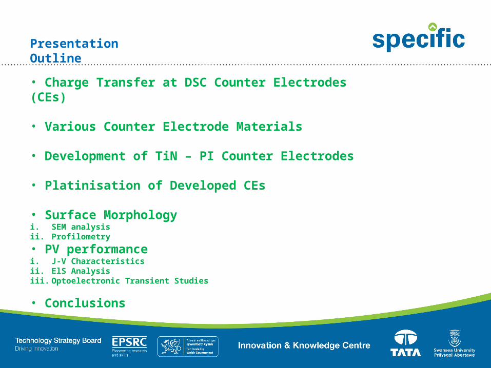
Presentation Outline• Charge Transfer at DSC Counter Electrodes (CEs)
• Various Counter Electrode Materials
• Development of TiN – PI Counter Electrodes
• Platinisation of Developed CEs
• Surface Morphologyi. SEM analysisii. Profilometry• PV performancei. J-V Characteristicsii. ElS Analysisiii. Optoelectronic Transient Studies
• Conclusions
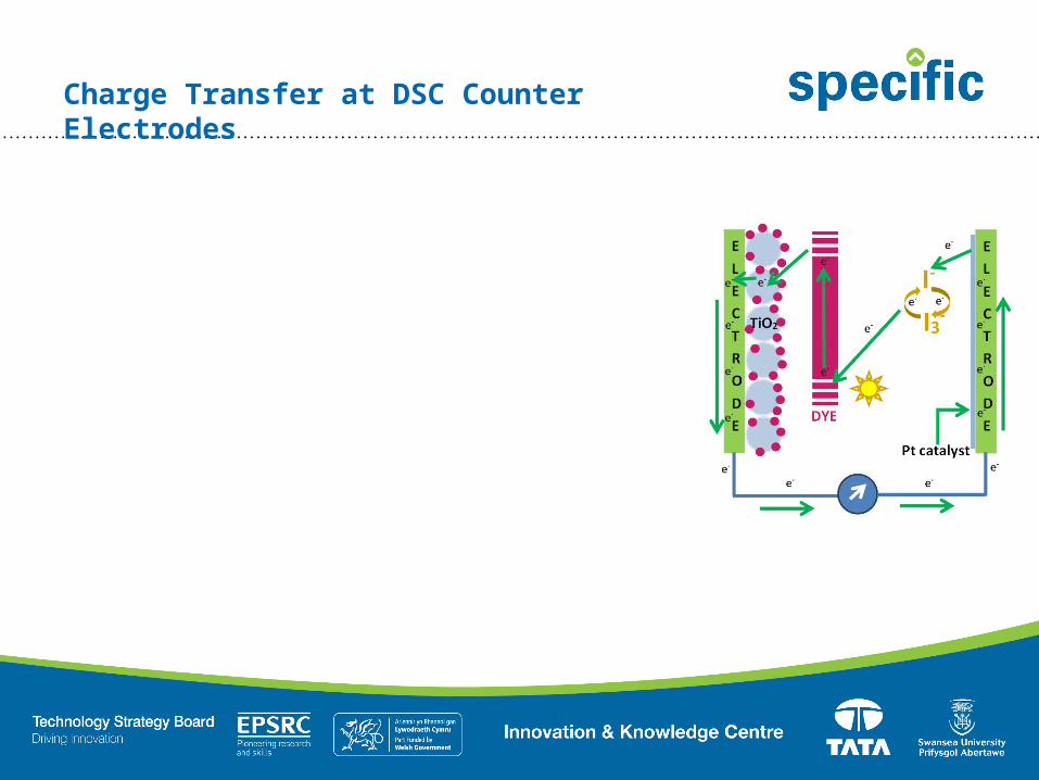
Charge Transfer at DSC Counter Electrodes
Charge Transfer at DSC Counter Electrodes
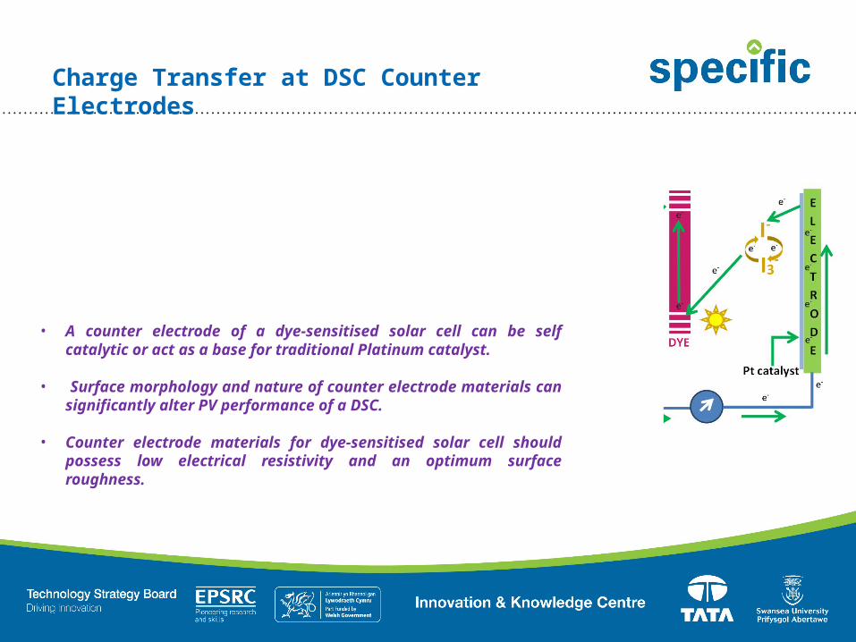
• A counter electrode of a dye-sensitised solar cell can be self catalytic or act as a base for traditional Platinum catalyst.
• Surface morphology and nature of counter electrode materials can significantly alter PV performance of a DSC.
• Counter electrode materials for dye-sensitised solar cell should possess low electrical resistivity and an optimum surface roughness.

Charge Transfer at DSC Counter Electrodes
15.00 25.00 35.00 45.000.00
2.00
4.00
6.00
8.00
Zreal, Ω
Zima
ginary
, Ω
Rrec= Recombination resistance at the TiO2/electrolyte interface of a DSC
Rce = Charge transfer resistance at the counter electrode of a DSC
Electrochemical Impedance within a Platinised FTO based DSC
• A counter electrode of a dye-sensitised solar cell can be self catalytic or act as a base for traditional Platinum catalyst.
• Surface morphology and nature of counter electrode materials can significantly alter PV performance of a DSC.
• Counter electrode materials for dye-sensitised solar cell should possess low electrical resistivity and an optimum surface roughness.
• Charge transfer resistance at the counter electrode of a DSC also depends on materials used for counter electrode application.

Charge Transfer at DSC Counter Electrodes
15.00 25.00 35.00 45.000.00
2.00
4.00
6.00
8.00
Zreal, Ω
Zima
ginary
, Ω
Rrec= Recombination resistance at the TiO2/electrolyte interface of a DSC
Rce = Charge transfer resistance at the counter electrode of a DSC
Electrochemical Impedance within a Platinised FTO based DSC
• Lower Rce = Higher Catalytic activity at the CE = Improved PV performance
• Higher Rce = Lower Catalytic activity at the CE = Poor PV performance

Various Counter Electrode Materials
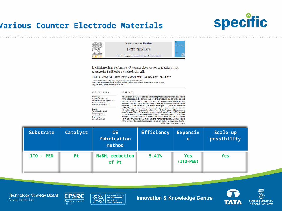
Various Counter Electrode Materials
Substrate Catalyst CE fabrication
method
Efficiency Expensive
Scale-up possibility
ITO - PEN Pt NaBH4 reduction of Pt
5.41% Yes(ITO-PEN)
Yes

Various Counter Electrode Materials

Substrate Catalyst CE fabrication
method
Efficiency Expensive
Scale-up possibility
PEDOT:PSS PEDOT Electrodeposited
PEDOT
8.33% Yes(PEDOT:PSS)
NO
Various Counter Electrode Materials

Various Counter Electrode Materials
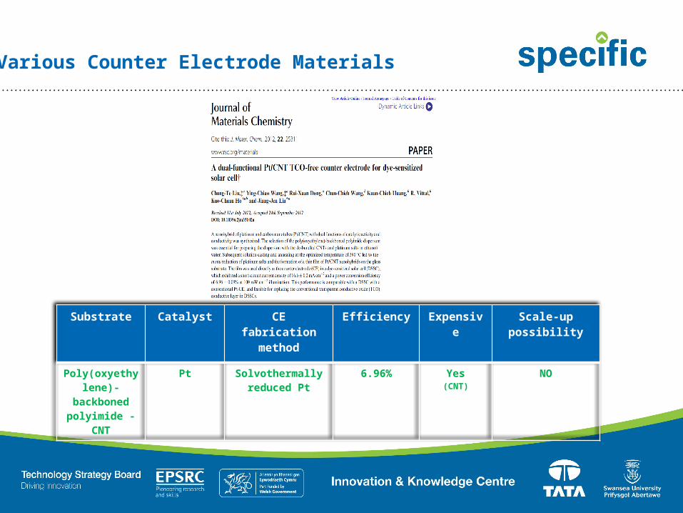
Substrate Catalyst CE fabrication
method
Efficiency Expensive
Scale-up possibility
Poly(oxyethylene)-
backboned polyimide -
CNT
Pt Solvothermally reduced Pt
6.96% Yes(CNT)
NO
Various Counter Electrode Materials

Various Counter Electrode Materials (Comparison)
Substrate Catalyst CE fabrication
method
Efficiency Expensive
Scale-up possibility
ITO - PEN Pt NaBH4 reduction of Pt
5.41% Yes(ITO-PEN)
Yes
PEDOT:PSS PEDOT Electrodeposited
PEDOT
8.33% Yes(PEDOT:PSS)
NO
Poly(oxyethylene)-
backboned polyimide -
CNT
Pt Solvothermally reduced Pt
6.96% Yes(CNT)
NO

Substrate Catalyst CE fabrication
method
Efficiency Expensive
Scale-up possibility
ITO - PEN Pt NaBH4 reduction of Pt
5.41% Yes(ITO-PEN)
Yes
PEDOT:PSS PEDOT Electrodeposited
PEDOT
8.33% Yes(PEDOT:PSS)
NO
Poly(oxyethylene)-
backboned polyimide -
CNT
Pt Solvothermally reduced Pt
6.96% Yes(CNT)
NO
TiN - Polyimide
Pt Sputtered/Thermal - Pt
3.41% – 1.92% ? ?
Various Counter Electrode Materials (Comparison)

Substrate Catalyst CE fabrication
method
Efficiency Expensive
Scale-up possibility
ITO - PEN Pt NaBH4 reduction of Pt
5.41% Yes(ITO-PEN)
Yes
PEDOT:PSS PEDOT Electrodeposited
PEDOT
8.33% Yes(PEDOT:PSS)
NO
Poly(oxyethylene)-
backboned polyimide -
CNT
Pt Solvothermally reduced Pt
6.96% Yes(CNT)
NO
TiN - Polyimide
Pt Sputtered/Thermal - Pt
3.41% – 1.92% NO Yes
Various Counter Electrode Materials (Comparison)

Development of TiN – PI Counter Electrodes
Polyimide
X% of TiN
PI /TiN composite
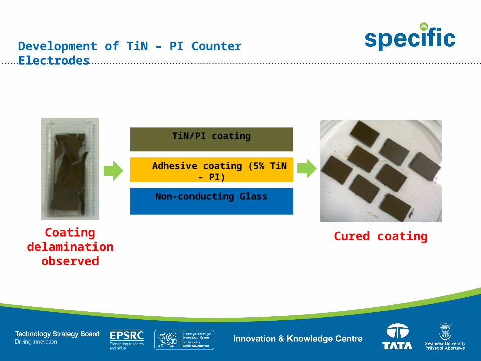
• TiN (particle size = < 3 µ) at a specific wt% (x = 90%) was blended with a Polyimide precursor (Poly (pyromellitic dianhydride-co-4, 4′-oxydianiline), amic acid) to develop the PI/TiN composite coatings for DSC counter electrode application.
• Developed coatings were initially applied onto non-conducting glass substrates using doctor blade technique and cured at 350oC.

Development of TiN – PI Counter Electrodes
Coating delamination observed

Development of TiN – PI Counter Electrodes
Non-conducting Glass
Adhesive coating (5% TiN – PI)
TiN/PI coating
Coating delamination observed
Development of TiN – PI Counter Electrodes
Coating delamination observed
Non-conducting Glass
Adhesive coating (5% TiN – PI)
TiN/PI coating
Cured coating
Platinisation of Developed CEs
• Developed TiN-PI coatings were platinised using “Thermal” and “Sputter” platinisation techniques.
• H2PtCl6.6H20 precursor was used in thermal platinisation technique which upon heat treatment (at 385oC for 20 minutes) reduces to Pt catalyst.
• A platinum target was used in sputtering technique to deposit 2 nm thick platinum film onto the TiN-PI coating.

Thermally deposited Pt on TiN-PI coating
Sputtered Pt on TiN-PI coating
Surface Morphology (SEM Analysis)
Pt particle
0 1000 2000 3000 4000 5000 6000 70000
200000
400000
600000
800000
1000000
1200000Cured TiN-PISintered TiN-PI
Micrometer, µ
Nano
meter, n
m
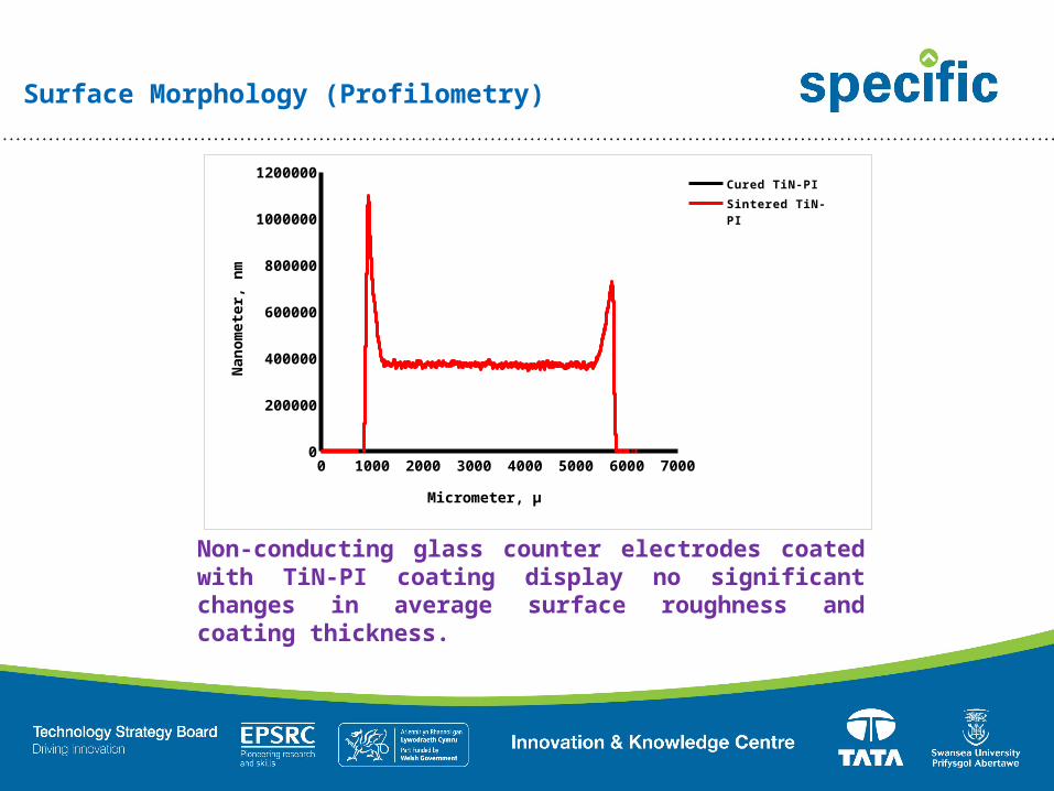
Surface Morphology (Profilometry)
Non-conducting glass counter electrodes coated with TiN-PI coating display no significant changes in average surface roughness and coating thickness.

Cells Voc (V) Jsc
(mA/cm2)FF % η %
Glass-TH 0.73 8.39 72.23 4.44Glass -
SP 0.73 7.88 73.13 4.23TiN-TH 0.72 8.52 31.04 1.92
TiN - SP 0.73 8.12 57.46 3.41
-0.2 0 0.2 0.4 0.6 0.8 1 1.2
-4
-2
0
2
4
6
8
10 TiN-THTiN-TH-DTiN-SPTiN-SP-DGlass - THG-TH-DGlass-SPGlass-SP-D
Voltage, V
Curren
t density,
mA/cm2
TiN-PI coating with thermally deposited Pt displayed lowest efficiency but highest short-circuit current density. On the other hand TiN coating with sputtered Pt exhibited decent efficiency and current density values comparable to the glass cells.
Photovoltaic Performance (J-V Characteristics)
Photovoltaic Performance (EIS Studies)
0.600000000000001 0.8 11
10
100
1000TiN-TH-RceGlass-TH-RceGlass-SP-Rce
Voltage, V
Char
ge trans
fer
resistan
ce
(Rce), Ohm
s
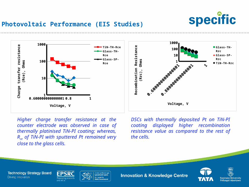
Higher charge transfer resistance at the counter electrode was observed in case of thermally platinised TiN-PI coating; whereas, Rce of TiN-PI with sputtered Pt remained very close to the glass cells.
DSCs with thermally deposited Pt on TiN-PI coating displayed higher recombination resistance value as compared to the rest of the cells.
110
1001000
Glass-TH-RrcGlass-SP-RrcTiN-TH-Rrc
Voltage, V
Reco
mbin
atio
n Re
sist
ance
(R
rc),
Ohm
s

0 0.002 0.004 0.006 0.008 0.01
Glass-SPGlass-THTiN-SPTiN-TH
Current density, Jsc
Lifetime
0 10 20 30 40 50 60 700
0.1
0.2
0.3
0.4
0.5
0.6
0.7
0.8Glass-SPGlass-THTiN-TH
Time, S
Volt
age, V
As the working electrodes were FTO based glass therefore no significant deviation has been noticed in short circuit current transient measurements. This confirms that TiN-PI counter electrodes have no influence on Jsc values of the fabricated devices.
Same applies in case of PV decay measurements where the photovoltage decay rate was found to be same in all cases due to FTO glass working electrodes without any pre-applied blocking layer.
Photovoltaic Performance (Optoelectronic Transient Studies)

Conclusions
• TiN-PI coatings can be used as counter electrodes for dye-sensitised solar cell application.

Conclusions
• TiN-PI coatings can be used as counter electrodes for dye-sensitised solar cell application.
•This technique does not require FTO deposited glass counter electrodes hence has the potential to replace them.

Conclusions
• TiN-PI coatings can be used as counter electrodes for dye-sensitised solar cell application.
•This technique does not require FTO deposited glass counter electrodes hence has the potential to replace them.
• TiN-PI counter electrodes with thermally deposited platinum demonstrated very poor catalytic as well as photovoltaic performance.
•TiN- PI counter electrodes with sputtered platinum however, performs significantly better than the thermally deposited Pt ones and its photovoltaic performance is comparable to the glass cells.