COMFLTFORCOMINST 4790.3 REV A CH-6 i JOINT FLEET ...
650
COMFLTFORCOMINST 4790.3 REV A CH-6 i JOINT FLEET MAINTENANCE MANUAL VOLUME VI MAINTENANCE PROGRAMS LIST OF EFFECTIVE PAGES Page Numbers Change in Effect Page Numbers Change in Effect i thru xxx Change 6 VI-FWD-1 Change 4 VI-FWD-2 Change 2 VI-FWD-A-1 Change 6 VI-FWD-A-2 thru VI-FWD-A-3 Change 4 VI-FWD-A-4 thru VI-FWD-A-7 Change 6 VI-FWD-A-8 Change 2 VI-1-1 thru VI-1-2 Change 6 VI-2-1 thru VI-2-5 Change 3 VI-2-6 Change 4 VI-2-7 thru VI-2-10 Change 3 VI-2A-1 Change 3 VI-2A-2 Change 4 VI-2A-3 Change 3 VI-2A-4 Change 2 VI-2B-1 thru VI-2B-2 Change 3 VI-3-1 thru VI-3-8 Change 2 VI-3-9 thru VI-3-10 REV A VI-3A-1 thru VI-3A-2 Change 2 VI-3B-1 thru VI-3B-2 Change 3 VI-3C-1 thru VI-3C-4 Change 3 VI-3D-1 Change 3 VI-3D-2 REV A VI-3E-1 Change 3 VI-3E-2 REV A VI-3F-1 Change 3 VI-3F-2 REV A VI-3G-1 thru VI-3G-4 Change 2 VI-4-1 thru VI-4-7 Change 4 VI-4-8 REV A VI-5-1 Change 1 VI-5-2 REV A VI-5-3 Change 1 VI-5-4 REV A VI-6-1 thru VI-6-4 REV A VI-6A-1 thru VI-6A-6 REV A VI-7-1 Change 4 VI-7-2 thru VI-7-8 REV A VI-7A-1 thru VI-7A-4 Change 4 VI-8-1 Change 4 VI-8-2 thru VI-8-3 Change 2 VI-8-4 thru VI-8-5 Change 4 VI-8-6 thru VI-8-8 REV A VI-8A-1 thru VI-8A-2 REV A VI-8B-1 thru VI-8B-2 REV A VI-8C-1 Change 2 VI-8C-2 REV A VI-8D-1 thru VI-8D-2 Change 3 VI-8E-1 Change 3 VI-8E-2 REV A VI-8F-1 Change 3 VI-8F-2 REV A
-
Upload
khangminh22 -
Category
Documents
-
view
0 -
download
0
Transcript of COMFLTFORCOMINST 4790.3 REV A CH-6 i JOINT FLEET ...

COMFLTFORCOMINST 4790.3 REV A CH-6
i
JOINT FLEET MAINTENANCE MANUAL
VOLUME VI
MAINTENANCE PROGRAMS
LIST OF EFFECTIVE PAGES
Page Numbers Change in Effect Page Numbers Change in Effect
i thru xxx Change 6
VI-FWD-1 Change 4
VI-FWD-2 Change 2
VI-FWD-A-1 Change 6
VI-FWD-A-2 thru VI-FWD-A-3 Change 4
VI-FWD-A-4 thru VI-FWD-A-7 Change 6
VI-FWD-A-8 Change 2
VI-1-1 thru VI-1-2 Change 6
VI-2-1 thru VI-2-5 Change 3
VI-2-6 Change 4
VI-2-7 thru VI-2-10 Change 3
VI-2A-1 Change 3
VI-2A-2 Change 4
VI-2A-3 Change 3
VI-2A-4 Change 2
VI-2B-1 thru VI-2B-2 Change 3
VI-3-1 thru VI-3-8 Change 2
VI-3-9 thru VI-3-10 REV A
VI-3A-1 thru VI-3A-2 Change 2
VI-3B-1 thru VI-3B-2 Change 3
VI-3C-1 thru VI-3C-4 Change 3
VI-3D-1 Change 3
VI-3D-2 REV A
VI-3E-1 Change 3
VI-3E-2 REV A
VI-3F-1 Change 3
VI-3F-2 REV A
VI-3G-1 thru VI-3G-4 Change 2
VI-4-1 thru VI-4-7 Change 4
VI-4-8 REV A
VI-5-1 Change 1
VI-5-2 REV A
VI-5-3 Change 1
VI-5-4 REV A
VI-6-1 thru VI-6-4 REV A
VI-6A-1 thru VI-6A-6 REV A
VI-7-1 Change 4
VI-7-2 thru VI-7-8 REV A
VI-7A-1 thru VI-7A-4 Change 4
VI-8-1 Change 4
VI-8-2 thru VI-8-3 Change 2
VI-8-4 thru VI-8-5 Change 4
VI-8-6 thru VI-8-8 REV A
VI-8A-1 thru VI-8A-2 REV A
VI-8B-1 thru VI-8B-2 REV A
VI-8C-1 Change 2
VI-8C-2 REV A
VI-8D-1 thru VI-8D-2 Change 3
VI-8E-1 Change 3
VI-8E-2 REV A
VI-8F-1 Change 3
VI-8F-2 REV A

COMFLTFORCOMINST 4790.3 REV A CH-6
ii
Page Numbers Change in Effect Page Numbers Change in Effect
VI-8G-1 Change 2
VI-8G-2 REV A
VI-9-1 Change 5
VI-9-2 thru VI-9-9 Change 3
VI-9-10 thru VI-9-14 Change 4
VI-10-1 thru VI-10-4 REV A
VI-11-1 Change 4
VI-11-2 Change 2
VI-11-3 REV A
VI-11-4 thru VI-11-5 Change 2
VI-11-6 Change 1
VI-12-1 thru VI-12-2 Change 2
VI-12-3 thru VI-12-4 REV A
VI-13-1 Change 3
VI-13-2 REV A
VI-14-1 thru VI-14-3 REV A
VI-14-4 Change 2
VI-14A-1 Change 3
VI-14A-2 REV A
VI-15-1 thru VI-15-2 REV A
VI-16-1 REV A
VI-16-2 Change 2
VI-16-3 Change 1
VI-16-4 thru VI-16-8 REV A
VI-16A-1 Change 3
VI-16A-2 REV A
VI-16B-1 Change 1
VI-16B-2 REV A
VI-17-1 thru VI-17-2 REV A
VI-18-1 thru VI-18-5 Change 2
VI-18-6 REV A
VI-19-1 thru VI-19-10 Change 6
VI-19A-1 thru VI-19A-3 Change 2
VI-19A-4 REV A
VI-19A-5 Change 6
VI-19A-6 REV A
VI-19A-7 thru VI-19A-8 Change 3
VI-19A-9 thru VI-19A-12 REV A
VI-19A-13 Change 2
VI-19A-14 thru VI-19A-22 REV A
VI-19A-23 Change 4
VI-19A-24 thru VI-19A-40 REV A
VI-19A-41 Change 2
VI-19A-42 thru VI-19A-46 REV A
VI-19B-1 thru VI-19B-7 REV A
VI-19B-8 thru VI-19B-9 Change 1
VI-19B-10 thru VI-19B-12 REV A
VI-19C-1 thru VI-19C-2 Change 6
VI-19C-3 REV A
VI-19C-4 Change 6
VI-19C-5 thru VI-19C-6 REV A
VI-19D-1 Change 3
VI-19D-2 Change 2
VI-19D-3 Change 3
VI-19D-4 Change 2
VI-19D-5 Change 3
VI-19D-6 Change 2
VI-19D-7 Change 6
VI-19D-8 Change 2
VI-19D-9 Change 3

COMFLTFORCOMINST 4790.3 REV A CH-6
iii
Page Numbers Change in Effect Page Numbers Change in Effect
VI-19D-10 Change 2
VI-19D-11 Change 6
VI-19D-12 thru VI-19D-14 Change 2
VI-19E-1 Change 6
VI-19E-2 Change 2
VI-19F-1 thru VI-19F-2 Change 2
VI-19G-1 thru VI-19G-2 Change 2
VI-19H-1 thru VI-19H-2 Change 2
VI-19I-1 thru VI-19I-2 Change 2
VI-19J-1 thru VI-19J-2 Change 2
VI-20-1 thru VI-20-2 REV A
VI-21-1 Change 3
VI-21-2 thru VI-21-3 Change 4
VI-21-4 Change 3
VI-21A-1 thru VI-21A-2 Change 3
VI-21B-1 thru VI-21B-2 Change 3
VI-21C-1 thru VI-21C-2 Change 3
VI-21D-1 thru VI-21D-2 Change 3
VI-21E-1 thru VI-21E-5 Change 3
VI-21E-6 Change 4
VI-21E-7 thru VI-21E-8 Change 3
VI-21F-1 Change 4
VI-21F-2 thru VI-21F-6 Change 3
VI-21G-1 thru VI-21G-6 Change 3
VI-22-1 thru VI-22-2 Change 4
VI-23-1 thru VI-23-3 REV A
VI-23-4 Change 5
VI-23-5 thru VI-23-6 REV A
VI-23A-1 thru VI-23A-2 REV A
VI-23B-1 thru VI-23B-2 REV A
VI-23C-1 thru VI-23C-11 REV A
VI-23C-12 Change 6
VI-23C-13 thru VI-23C-16 REV A
VI-23C-17 Change 3
VI-23C-18 thru VI-23C-30 REV A
VI-23C-31 Change 6
VI-23C-32 REV A
VI-23D-1 thru VI-23D-2 REV A
VI-23E-1 thru VI-23E-3 Change 4
VI-23E-4 REV A
VI-23F-1 Change 3
VI-23F-2 REV A
VI-24-1 Change 4
VI-24-2 Change 6
VI-24-3 Change 4
VI-24-4 REV A
VI-24-5 Change 3
VI-24-6 Change 1
VI-24-7 thru VI-24-8 Change 3
VI-24-9 thru VI-24-10 Change 2
VI-24-11 thru VI-24-12 REV A
VI-24A-1 thru VI-24A-2 REV A
VI-24B-1 thru VI-24B-2 REV A
VI-24C-1 thru VI-24C-4 REV A
VI-24D-1 Change 3
VI-24D-2 REV A
VI-24E-1 thru VI-24E-2 REV A
VI-24F-1 thru VI-24F-2 REV A
VI-25-1 REV A
VI-25-2 Change 6
COMFLTFORCOMINST 4790.3 REV A CH-6
iv
Page Numbers Change in Effect Page Numbers Change in Effect
VI-25-3 thru VI-25-4 Change 2
VI-25-5 Change 1
VI-25-6 Change 2
VI-25-7 Change 5
VI-25-8 thru VI-25-10 Change 2
VI-25A-1 Change 2
VI-25A-2 REV A
VI-25B-1 Change 2
VI-25B-2 REV A
VI-25C-1 thru VI-25C-2 REV A
VI-25D-1 thru VI-25D-2 REV A
VI-25E-1 Change 3
VI-25E-2 REV A
VI-25F-1 thru VI-25F-2 REV A
VI-26-1 REV A
VI-26-2 Change 5
VI-27-1 thru VI-27-2 Change 3
VI-27-3 thru VI-27-4 REV A
VI-27A-1 Change 3
VI-27A-2 REV A
VI-27B-1 thru VI-27B-2 REV A
VI-27C-1 Change 3
VI-27C-2 REV A
VI-28-1 REV A
VI-28-2 thru VI-28-3 Change 2
VI-28-4 REV A
VI-28A-1 thru VI-28A-2 Change 3
VI-29-1 thru VI-29-4 REV A
VI-29A-1 thru VI-29A-2 REV A
VI-30-1 Change 1
VI-30-2 REV A
VI-31-1 thru VI-31-12 Change 5
VI-31A-1 thru VI-31A-8 Change 5
VI-32-1 Change 4
VI-32-2 thru VI-32-9 Change 1
VI-32-10 Change 2
VI-32-11 thru VI-32-16 Change 1
VI-32A-1 thru VI-32A-2 Change 1
VI-33-1 thru VI-33-2 Change 3
VI-34-1 thru VI-34-4 Change 1
VI-35-1 thru VI-35-2 Change 1
VI-35-3 Change 4
VI-35-4 thru VI-35-6 Change 1
VI-35A-1 thru VI-35A-2 Change 1
VI-35B-1 thru VI-35B-22 Change 4
VI-36-1 Change 2
VI-36-2 thru VI-36-4 Change 3
VI-36-5 thru VI-36-7 Change 2
VI-36-8 thru VI-36-9 Change 3
VI-36-10 Change 2
VI-36-11 thru VI-36-14 Change 4
VI-36A-1 thru VI-36A-4 Change 2
VI-36B-1 thru VI-36B-22 Change 2
VI-36C-1 thru VI-36C-6 Change 2
VI-36D-1 thru VI-36D-4 Change 2
VI-36E-1 thru VI-36E-4 Change 2
VI-36F-1 thru VI-36F-4 Change 2
VI-36G-1 thru VI-36G-2 Change 5
VI-37-1 Change 3
VI-37-2 thru VI-37-4 Change 2
COMFLTFORCOMINST 4790.3 REV A CH-6
v
Page Numbers Change in Effect Page Numbers Change in Effect
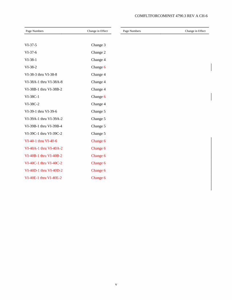
VI-37-5 Change 3
VI-37-6 Change 2
VI-38-1 Change 4
VI-38-2 Change 6
VI-38-3 thru VI-38-8 Change 4
VI-38A-1 thru VI-38A-8 Change 4
VI-38B-1 thru VI-38B-2 Change 4
VI-38C-1 Change 6
VI-38C-2 Change 4
VI-39-1 thru VI-39-6 Change 5
VI-39A-1 thru VI-39A-2 Change 5
VI-39B-1 thru VI-39B-4 Change 5
VI-39C-1 thru VI-39C-2 Change 5
VI-40-1 thru VI-40-6 Change 6
VI-40A-1 thru VI-40A-2 Change 6
VI-40B-1 thru VI-40B-2 Change 6
VI-40C-1 thru VI-40C-2 Change 6
VI-40D-1 thru VI-40D-2 Change 6
VI-40E-1 thru VI-40E-2 Change 6

COMFLTFORCOMINST 4790.3 REV A CH-6
vi
(This Page Intentionally Left Blank)

COMFLTFORCOMINST 4790.3 REV A CH-6
vii
JOINT FLEET MAINTENANCE MANUAL
VOLUME VI
MAINTENANCE PROGRAMS
RECORD OF CHANGES
CHANGE NO. DATE TITLE OR BRIEF DESCRIPTION ENTERED BY
(INITIALS)

COMFLTFORCOMINST 4790.3 REV A CH-6
viii
(This Page Intentionally Left Blank)
COMFLTFORCOMINST 4790.3 REV A CH-6
ix
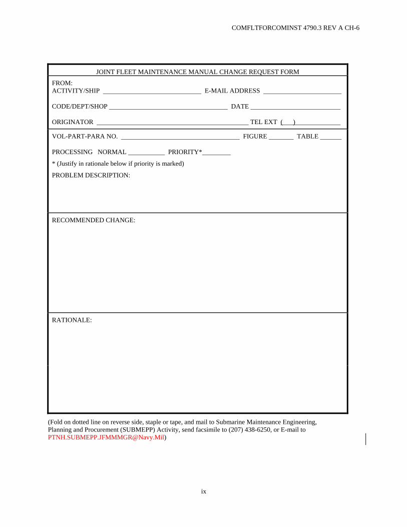
JOINT FLEET MAINTENANCE MANUAL CHANGE REQUEST FORM
FROM: ACTIVITY/SHIP E-MAIL ADDRESS
CODE/DEPT/SHOP DATE
ORIGINATOR TEL EXT ( )
VOL-PART-PARA NO. FIGURE TABLE
PROCESSING NORMAL PRIORITY*
* (Justify in rationale below if priority is marked)
PROBLEM DESCRIPTION:
RECOMMENDED CHANGE:
RATIONALE:
(Fold on dotted line on reverse side, staple or tape, and mail to Submarine Maintenance Engineering, Planning and Procurement (SUBMEPP) Activity, send facsimile to (207) 438-6250, or E-mail to [email protected])

COMFLTFORCOMINST 4790.3 REV A CH-6
x
FOLD
-----------------------------------------------------------------------------------------------------------------------------------------------
Commanding Officer
___________________ OFFICIAL BUSINESS
Commanding Officer Submarine Maintenance Engineering, Planning and Procurement (SUBMEPP) Activity Attn: Code 1832 P.O. Box 2500 Portsmouth Naval Shipyard Portsmouth, NH 03804-2500
-----------------------------------------------------------------------------------------------------------------------------------------------
FOLD
COMFLTFORCOMINST 4790.3 REV A CH-6
xi
JOINT FLEET MAINTENANCE MANUAL
VOLUME VI
MAINTENANCE PROGRAMS
TABLE OF CONTENTS
Page No.
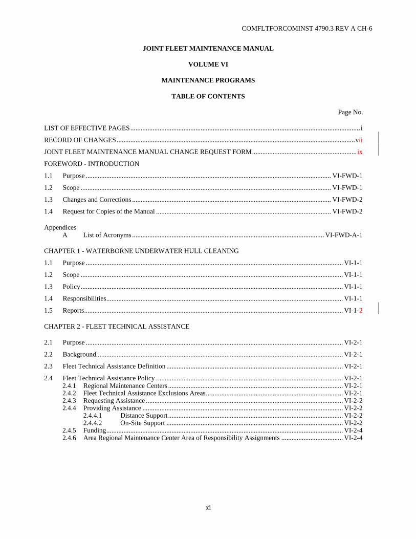
LIST OF EFFECTIVE PAGES...................................................................................................................................... i
RECORD OF CHANGES...........................................................................................................................................vii
JOINT FLEET MAINTENANCE MANUAL CHANGE REQUEST FORM............................................................. ix
FOREWORD - INTRODUCTION
1.1 Purpose ............................................................................................................................................... VI-FWD-1
1.2 Scope .................................................................................................................................................. VI-FWD-1
1.3 Changes and Corrections .................................................................................................................... VI-FWD-2
1.4 Request for Copies of the Manual ...................................................................................................... VI-FWD-2
Appendices A List of Acronyms ................................................................................................................ VI-FWD-A-1
CHAPTER 1 - WATERBORNE UNDERWATER HULL CLEANING
1.1 Purpose ...................................................................................................................................................... VI-1-1
1.2 Scope ......................................................................................................................................................... VI-1-1
1.3 Policy......................................................................................................................................................... VI-1-1
1.4 Responsibilities.......................................................................................................................................... VI-1-1
1.5 Reports....................................................................................................................................................... VI-1-2
CHAPTER 2 - FLEET TECHNICAL ASSISTANCE
2.1 Purpose ...................................................................................................................................................... VI-2-1
2.2 Background................................................................................................................................................ VI-2-1
2.3 Fleet Technical Assistance Definition ....................................................................................................... VI-2-1
2.4 Fleet Technical Assistance Policy ............................................................................................................. VI-2-1 2.4.1 Regional Maintenance Centers ...................................................................................................... VI-2-1 2.4.2 Fleet Technical Assistance Exclusions Areas................................................................................ VI-2-1 2.4.3 Requesting Assistance ................................................................................................................... VI-2-2 2.4.4 Providing Assistance ..................................................................................................................... VI-2-2 2.4.4.1 Distance Support...................................................................................................... VI-2-2 2.4.4.2 On-Site Support ....................................................................................................... VI-2-2 2.4.5 Funding.......................................................................................................................................... VI-2-4 2.4.6 Area Regional Maintenance Center Area of Responsibility Assignments .................................... VI-2-4

COMFLTFORCOMINST 4790.3 REV A CH-6
xii
2.4.7 Fleet Technical Assistance Support Transfer and Acceptance ...................................................... VI-2-5 2.4.7.1 Transferring Regional Maintenance Center ............................................................. VI-2-5 2.4.7.2 Accepting Regional Maintenance Center................................................................. VI-2-5
2.5 Responsibilities.......................................................................................................................................... VI-2-5 2.5.1 Ship's Commanding Officer .......................................................................................................... VI-2-5 2.5.2 Regional Maintenance Center Commanders ................................................................................. VI-2-6 2.5.3 Other Source of Support Providers................................................................................................ VI-2-7
2.6 Fleet Technical Assistance Procedures...................................................................................................... VI-2-7 2.6.1 Requesting Fleet Technical Assistance.......................................................................................... VI-2-7 2.6.2 Cognizant Area Regional Maintenance Center Fleet Technical Assistance Request
Processing Procedures ................................................................................................................... VI-2-8 2.6.3 Navy Global Distance Support Center Fleet Technical Assistance Request
Processing Procedure..................................................................................................................... VI-2-9 2.6.4 Homeport Regional Maintenance Center Fleet Technical Assistance Processing Procedures
(for ships in another Area Regional Maintenance Center's Area of Responsibility) ..................... VI-2-9 2.6.5 Required Fleet Technical Assistance Request Information ........................................................... VI-2-9 2.6.6 Chief of Naval Operations Availability Fleet Technical Assistance Procedures......................... VI-2-10
2.7 Post-Fleet Technical Assistance Administrative Requirements............................................................... VI-2-10
Appendices A Area Regional Maintenance Center Fleet Technical Assistance Contact Information ............... VI-2A-1 B Sample Technical Assistance Visit Report (TAVR) Message.................................................... VI-2B-1
CHAPTER 3 - SUBMARINE FLEET MODERNIZATION PROGRAM
3.1 Purpose ...................................................................................................................................................... VI-3-1 3.1.1 Scope ............................................................................................................................................. VI-3-1 3.1.2 Definition....................................................................................................................................... VI-3-2
3.2 Responsibilities.......................................................................................................................................... VI-3-2 3.2.1 Immediate Superior In Command ................................................................................................ VI-3-2 3.2.2 Fleet Maintenance Activity............................................................................................................ VI-3-4 3.2.3 Ship's Alteration Coordinator ........................................................................................................ VI-3-5
3.3 Alteration Programs................................................................................................................................... VI-3-6 3.3.1 Reactor Plant Ship Alteration Package Program (Nuclear Powered Ships only) .......................... VI-3-6 3.3.2 Alteration Installation Team Program ........................................................................................... VI-3-6 3.3.3 Type Commander Alteration Kit Program .................................................................................... VI-3-7
3.4 Monitoring of Alteration Status................................................................................................................. VI-3-7 3.4.1 Type Commander Alteration Management System....................................................................... VI-3-7 3.4.2 Navy Data Environment - Navy Modernization............................................................................ VI-3-7 3.4.3 Nuclear Alteration Technical Documentation Compact Disk ...................................................... VI-3-7
3.5 Reporting Change in Alteration Status ...................................................................................................... VI-3-8 3.5.1 Reactor Plant Alterations............................................................................................................... VI-3-8 3.5.2 All Other Alterations ..................................................................................................................... VI-3-8
3.6 Alteration Requests.................................................................................................................................... VI-3-8
3.7 Alteration Feedbacks ................................................................................................................................. VI-3-8
3.8 Permanent Modifications to Tenders With Nuclear Support Facilities ..................................................... VI-3-8 3.8.1 Modification .................................................................................................................................. VI-3-8 3.8.2 Improvements ................................................................................................................................ VI-3-8 3.8.3 Changes ......................................................................................................................................... VI-3-8 3.8.4 Internal Space Rearrangements ..................................................................................................... VI-3-8

COMFLTFORCOMINST 4790.3 REV A CH-6
xiii
Appendices A Major Ship Alteration Types Executive Summary..................................................................... VI-3A-1 B Submarine Alteration Request Format ....................................................................................... VI-3B-1 C RPCCR Forwarding Letter Format............................................................................................. VI-3C-1 D Sample TEMPALT/OPALT Reporting Message ....................................................................... VI-3D-1 E TYKIT Requisition Form ............................................................................................................VI-3E-1 F Sample Alteration Feedback Message.........................................................................................VI-3F-1 G TYCOM Alteration Management System Interpretation Guide................................................. VI-3G-1
CHAPTER 4 - SHIPBOARD ELECTROMAGNETIC COMPATIBILITY
4.1 Purpose ...................................................................................................................................................... VI-4-1 4.1.1 Background.................................................................................................................................... VI-4-1
4.2 Electromagnetic Compatibility Assessments or Surveys........................................................................... VI-4-1 4.2.1 Shipboard Electromagnetic Compatibility Assessments ............................................................... VI-4-1 4.2.1.1 Surface Ships ........................................................................................................... VI-4-2 4.2.1.2 Submarines............................................................................................................... VI-4-2
4.3 Fleet Electromagnetic Compatibility Support Tools ................................................................................. VI-4-3
4.4 Engineer Electromagnetic Interference Fixes............................................................................................ VI-4-3 4.4.1 Shipboard Full-scale Electromagnetic Compatibility Evaluations ................................................ VI-4-3
4.5 Electromagnetic Compatibility Certification............................................................................................. VI-4-3 4.5.1 System Electromagnetic Compatibility Certification .................................................................... VI-4-4 4.5.1.1 System Electromagnetic Compatibility Certification Requirements........................ VI-4-4 4.5.2 Ship Electromagnetic Compatibility Certification......................................................................... VI-4-4 4.5.2.1 Ship Electromagnetic Compatibility Certification Requirements ............................ VI-4-4
4.6 Electromagnetic Compatibility Certification Maintenance........................................................................ VI-4-5 4.6.1 Fleet Maintenance Activity............................................................................................................ VI-4-5
4.7 Shipboard Electromagnetic Compatibility Improvement Program Technical Assistance Network ................................................................................................................................... VI-4-5
4.8 Responsibilities.......................................................................................................................................... VI-4-6
CHAPTER 5 - COMMON ASSESSMENT PROGRAM
5.1 Purpose ...................................................................................................................................................... VI-5-1 5.1.1 Applicability .................................................................................................................................. VI-5-1
5.2 Common Assessment Program.................................................................................................................. VI-5-1
5.3 Objectives .................................................................................................................................................. VI-5-1
5.4 Principles ................................................................................................................................................... VI-5-1
5.5 Ship Common Assessment Program Visits ............................................................................................... VI-5-2 5.5.1 Technical Common Assessment and Repair Program Assist Visits .............................................. VI-5-2
5.6 Responsibilities.......................................................................................................................................... VI-5-2 5.6.1 Type Commander .......................................................................................................................... VI-5-2 5.6.2 Immediate Superior In Command (Commander, Naval Surface Force Atlantic/Pacific Only)..... VI-5-2 5.6.3 Regional Maintenance Center........................................................................................................ VI-5-3 5.6.4 Fleet Maintenance Activity............................................................................................................ VI-5-3 5.6.5 Ship Commanding Officer............................................................................................................. VI-5-3

COMFLTFORCOMINST 4790.3 REV A CH-6
xiv
CHAPTER 6 - INDUSTRIAL PLANT EQUIPMENT
6.1 Purpose ...................................................................................................................................................... VI-6-1 6.1.1 Scope ............................................................................................................................................. VI-6-1 6.1.2 Background.................................................................................................................................... VI-6-2
6.2 Definitions ................................................................................................................................................. VI-6-2 6.2.1 Plant Equipment - Classes Three and Four Plant Property............................................................ VI-6-2 6.2.2 Class Three Plant Property - Other Plant Equipment .................................................................... VI-6-2 6.2.3 Class Four Plant Property - Industrial Plant Equipment ................................................................ VI-6-2
6.3 Procurement Requirements........................................................................................................................ VI-6-2 6.3.1 Requesting Activities..................................................................................................................... VI-6-2 6.3.1.1 New Procurement..................................................................................................... VI-6-2 6.3.1.2 Urgent Replacement................................................................................................. VI-6-3 6.3.1.3 Receipt of Plant Property ......................................................................................... VI-6-3
6.4 Responsibilities.......................................................................................................................................... VI-6-4 6.4.1 Fleet Commander .......................................................................................................................... VI-6-4 6.4.2 Type Commander .......................................................................................................................... VI-6-4
6.5 Reports....................................................................................................................................................... VI-6-4
Appendices A Plant Equipment Project Form.................................................................................................... VI-6A-1
CHAPTER 7 - BOARD OF INSPECTION AND SURVEY MATERIAL INSPECTIONS POLICY
7.1 Purpose ...................................................................................................................................................... VI-7-1 7.1.1 Scope ............................................................................................................................................. VI-7-1 7.1.2 Policy............................................................................................................................................. VI-7-1 7.1.3 Background.................................................................................................................................... VI-7-2 7.1.4 Discussion...................................................................................................................................... VI-7-2
7.2 Responsibilities.......................................................................................................................................... VI-7-2 7.2.1 Type Commander .......................................................................................................................... VI-7-2 7.2.2 Immediate Superior In Command ................................................................................................. VI-7-2 7.2.3 Ship Commanding Officer............................................................................................................. VI-7-3 7.2.4 Board of Inspection and Survey Coordinator ................................................................................ VI-7-3
7.3 Inspection Scheduling................................................................................................................................ VI-7-4 7.3.1 Combined Trial/Acceptance Trial Inspections .............................................................................. VI-7-4 7.3.2 Guarantee Material Inspection/Final Contract Trials..................................................................... VI-7-4 7.3.3 Underway Material Inspections..................................................................................................... VI-7-4
7.4 Preparation for the Board of Inspection and Survey Material Inspection.................................................. VI-7-5 7.4.1 Active Preparation ......................................................................................................................... VI-7-5 7.4.2 Ship's Internal Organization .......................................................................................................... VI-7-5 7.4.3 Updating the Current Ship's Maintenance Project......................................................................... VI-7-5
7.5 Board of Inspection and Survey Trial Conduct and Documentation ......................................................... VI-7-6 7.5.1 Trial Conduct................................................................................................................................. VI-7-6 7.5.2 Deficiency Documentation ............................................................................................................ VI-7-6
7.6 Post Board of Inspection and Survey Trial Actions................................................................................... VI-7-6 7.6.1 Deficiency Processing and Resolution .......................................................................................... VI-7-6 7.6.2 Post Board of Inspection and Survey Inspection Reports.............................................................. VI-7-7
Appendices A INSURV Plan of Action and Milestones (POAM)........................................................................ VI-7A-1

COMFLTFORCOMINST 4790.3 REV A CH-6
xv
CHAPTER 8 - MINIATURE/MICROMINIATURE ELECTRONIC REPAIR PROGRAM
8.1 Purpose ...................................................................................................................................................... VI-8-2 8.1.1 Scope ............................................................................................................................................. VI-8-2 8.1.2 Policy............................................................................................................................................. VI-8-2 8.1.3 Background.................................................................................................................................... VI-8-2
8.2 Responsibilities.......................................................................................................................................... VI-8-2 8.2.1 Fleet Commander .......................................................................................................................... VI-8-2 8.2.2 Type Commander/Immediate Superior In Command.................................................................... VI-8-2 8.2.3 Commanding Officer/Officer In Charge........................................................................................ VI-8-3 8.2.4 Miniature/Microminiature Repair Program Coordinator/Module Test and Repair
Facility Coordinator....................................................................................................................... VI-8-3 8.2.5 Regional Maintenance Center........................................................................................................ VI-8-4
8.3 Authorized Miniature/Microminiature Outfitting...................................................................................... VI-8-4
8.4 Miniature/Microminiature Personnel and Station Requirements............................................................... VI-8-4
8.5 Progressive Repair Process........................................................................................................................ VI-8-4 8.5.1 Repair Process ............................................................................................................................... VI-8-4 8.5.2 Ship's Force Process ...................................................................................................................... VI-8-4 8.5.3 Fleet Maintenance Activity Process .............................................................................................. VI-8-5 8.5.4 Certification of Miniature/Microminiature Repaired Assets as Ready for Issue ........................... VI-8-5 8.5.5 Miniature/Microminiature Module Test and Repair Piece Parts ................................................... VI-8-5
8.6 Unique Miniature/Microminiature Guidance (Naval Air Force Only) ...................................................... VI-8-6 8.6.1 Aviation Intermediate Maintenance Department........................................................................... VI-8-6 8.6.2 Aircraft Carrier Fleet Maintenance Activity Module Test and Repair Facility ............................. VI-8-6
8.7 Unique Miniature/Microminiature Guidance (Submarine Force Only)..................................................... VI-8-7 8.7.1 Module Screening and Repair Activity ......................................................................................... VI-8-7 8.7.2 Fleet Maintenance Activity/Submarine Base................................................................................. VI-8-7 8.7.3 Reports........................................................................................................................................... VI-8-7
Appendices A Emergency 2M Repair Process................................................................................................... VI-8A-1 B Normal 2M Repair Process......................................................................................................... VI-8B-1 C MTRF 3-M Reporting (Aircraft Carriers Only).......................................................................... VI-8C-1 D Sample MTRF Amplifying Procedures Message ....................................................................... VI-8D-1 E Sample CV/CVN MTRF Repair Request Message .....................................................................VI-8E-1 F Sample MTRF Quarterly Report Message (Aircraft Carriers Only)............................................VI-8F-1 G MTRF Equipment Configuration ............................................................................................... VI-8G-1
CHAPTER 9 - METROLOGY AND CALIBRATION PROGRAM
9.1 Purpose ...................................................................................................................................................... VI-9-1 9.1.1 Scope ............................................................................................................................................. VI-9-1 9.1.2 Policy............................................................................................................................................. VI-9-1
9.2 Responsibilities.......................................................................................................................................... VI-9-1 9.2.1 Fleet Commanders......................................................................................................................... VI-9-1 9.2.2 Type Commander .......................................................................................................................... VI-9-2 9.2.3 NAVSEA Technical Authority...................................................................................................... VI-9-2 9.2.4 Immediate Superior in Command.................................................................................................. VI-9-3 9.2.5 Commanding Officers All Forces.................................................................................................. VI-9-3 9.2.6 Commanding Officers Surface Force ............................................................................................ VI-9-4 9.2.7 Commanding Officers Naval Air Force......................................................................................... VI-9-4 9.2.8 Regional Maintenance Center Metrology and Calibration Coordinators....................................... VI-9-4 9.2.9 Regional Maintenance Center/Regional Calibration Center.......................................................... VI-9-5

COMFLTFORCOMINST 4790.3 REV A CH-6
xvi
9.3 Calibration Management ........................................................................................................................... VI-9-5 9.3.1 Shipboard Gage Calibration Program Field Calibration Activity (Surface Force only) ................ VI-9-5 9.3.2 Calibration Accounting.................................................................................................................. VI-9-6 9.3.3 Submarine Forces Management Policy ......................................................................................... VI-9-6
9.4 Regional Loan Pools.................................................................................................................................. VI-9-7
9.5 Replacement of General Purpose Electronic Test Equipment/Calibration Standards ............................... VI-9-7 9.5.1 Depot Level Repairables ............................................................................................................... VI-9-7 9.5.2 Navy Stock Funded ....................................................................................................................... VI-9-7
9.6 Test Measurement Diagnostic Equipment Management ........................................................................... VI-9-8 9.6.1 Ship's Portable Electronic Test Equipment Requirements List ..................................................... VI-9-8 9.6.2 Test Measurement Diagnostic Equipment Index........................................................................... VI-9-8 9.6.3 Sub-Category Code........................................................................................................................ VI-9-8 9.6.4 Ship's Configuration and Logistics Support Information System Index........................................ VI-9-8 9.6.5 Consolidated Test, Measurement and Diagnostic Equipment Readiness Assessment .................. VI-9-8 9.6.5.1 Consolidated Test, Measurement and Diagnostic Equipment Readiness
Assessment Program.................................................................................................. VI-9-8 9.6.5.2 Type Commander Metrology and Calibration Program Managers............................ VI-9-8 9.6.5.2.1 Consolidated Test, Measurement and Diagnostic Equipment
Readiness Assessment Review Process............................................ VI-9-8 9.6.5.2.2 Consolidated TMDE Readiness Assessment Test, Measurement
and Diagnostic Equipment Redistribution........................................ VI-9-9
9.7 Shipboard Instrumentation and System Calibration .................................................................................. VI-9-9 9.7.1 Calibration Requirements List ....................................................................................................... VI-9-9 9.7.2 Calibration Interval...................................................................................................................... VI-9-10 9.7.3 Markings for Installed Instrumentation ....................................................................................... VI-9-10
9.8 LHA and LHD Class Ship Metrology and Calibration Program ............................................................. VI-9-10 9.8.1 Purpose ........................................................................................................................................ VI-9-10 9.8.2 Background.................................................................................................................................. VI-9-10 9.8.3 Discussion.................................................................................................................................... VI-9-11 9.8.4 Scope ........................................................................................................................................... VI-9-11 9.8.5 Applicability ................................................................................................................................ VI-9-11 9.8.6 Action .......................................................................................................................................... VI-9-11
9.9 Nuclear Propulsion Calibration Requirements ........................................................................................ VI-9-14
CHAPTER 10 - MOTOR GASOLINE HANDLING AND STORAGE
10.1 Purpose .................................................................................................................................................... VI-10-1 10.1.1 Discussion.................................................................................................................................... VI-10-1
10.2 Characteristics ......................................................................................................................................... VI-10-1
10.3 Personnel Hazards ................................................................................................................................... VI-10-1
10.4 Storage and Handling .............................................................................................................................. VI-10-2 10.4.1 Tank Conditions .......................................................................................................................... VI-10-2 10.4.2 Loading and Off-loading ............................................................................................................. VI-10-2 10.4.3 Identification and Sampling Requirements.................................................................................. VI-10-3 10.4.4 Safe Handling of Motor Gasoline................................................................................................ VI-10-3 10.4.5 Containerized Motor Gasoline..................................................................................................... VI-10-4
10.5 Motor Gasoline Assessment Program...................................................................................................... VI-10-4
COMFLTFORCOMINST 4790.3 REV A CH-6
xvii
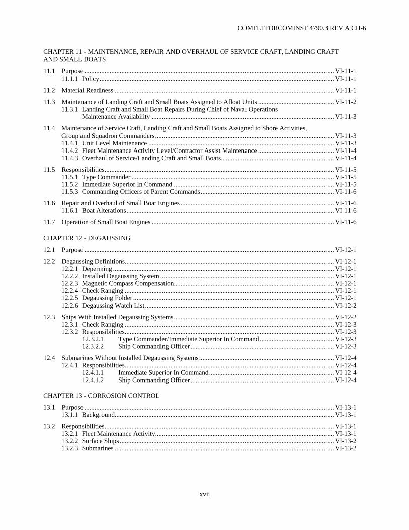
CHAPTER 11 - MAINTENANCE, REPAIR AND OVERHAUL OF SERVICE CRAFT, LANDING CRAFT AND SMALL BOATS
11.1 Purpose .................................................................................................................................................... VI-11-1 11.1.1 Policy........................................................................................................................................... VI-11-1
11.2 Material Readiness .................................................................................................................................. VI-11-1
11.3 Maintenance of Landing Craft and Small Boats Assigned to Afloat Units ............................................. VI-11-2 11.3.1 Landing Craft and Small Boat Repairs During Chief of Naval Operations Maintenance Availability ............................................................................................................ VI-11-3
11.4 Maintenance of Service Craft, Landing Craft and Small Boats Assigned to Shore Activities, Group and Squadron Commanders.......................................................................................................... VI-11-3
11.4.1 Unit Level Maintenance .............................................................................................................. VI-11-3 11.4.2 Fleet Maintenance Activity Level/Contractor Assist Maintenance ............................................. VI-11-4 11.4.3 Overhaul of Service/Landing Craft and Small Boats................................................................... VI-11-4
11.5 Responsibilities........................................................................................................................................ VI-11-5 11.5.1 Type Commander ........................................................................................................................ VI-11-5 11.5.2 Immediate Superior In Command ............................................................................................... VI-11-5 11.5.3 Commanding Officers of Parent Commands............................................................................... VI-11-6
11.6 Repair and Overhaul of Small Boat Engines ........................................................................................... VI-11-6 11.6.1 Boat Alterations........................................................................................................................... VI-11-6
11.7 Operation of Small Boat Engines ............................................................................................................ VI-11-6
CHAPTER 12 - DEGAUSSING
12.1 Purpose .................................................................................................................................................... VI-12-1
12.2 Degaussing Definitions............................................................................................................................ VI-12-1 12.2.1 Deperming ................................................................................................................................... VI-12-1 12.2.2 Installed Degaussing System ....................................................................................................... VI-12-1 12.2.3 Magnetic Compass Compensation............................................................................................... VI-12-1 12.2.4 Check Ranging ............................................................................................................................ VI-12-1 12.2.5 Degaussing Folder ....................................................................................................................... VI-12-1 12.2.6 Degaussing Watch List ................................................................................................................ VI-12-2
12.3 Ships With Installed Degaussing Systems............................................................................................... VI-12-2 12.3.1 Check Ranging ............................................................................................................................ VI-12-3 12.3.2 Responsibilities............................................................................................................................ VI-12-3 12.3.2.1 Type Commander/Immediate Superior In Command ............................................ VI-12-3 12.3.2.2 Ship Commanding Officer ..................................................................................... VI-12-3
12.4 Submarines Without Installed Degaussing Systems................................................................................ VI-12-4 12.4.1 Responsibilities............................................................................................................................ VI-12-4 12.4.1.1 Immediate Superior In Command.......................................................................... VI-12-4 12.4.1.2 Ship Commanding Officer ..................................................................................... VI-12-4
CHAPTER 13 - CORROSION CONTROL
13.1 Purpose .................................................................................................................................................... VI-13-1 13.1.1 Background.................................................................................................................................. VI-13-1
13.2 Responsibilities........................................................................................................................................ VI-13-1 13.2.1 Fleet Maintenance Activity.......................................................................................................... VI-13-1 13.2.2 Surface Ships ............................................................................................................................... VI-13-2 13.2.3 Submarines .................................................................................................................................. VI-13-2

COMFLTFORCOMINST 4790.3 REV A CH-6
xviii
CHAPTER 14 - CANNIBALIZATION
14.1 Purpose .................................................................................................................................................... VI-14-1 14.1.1 Policy........................................................................................................................................... VI-14-1
14.2 Definitions ............................................................................................................................................... VI-14-1 14.2.1 Self-Cannibalization .................................................................................................................... VI-14-1 14.2.2 System Cannibalization ............................................................................................................... VI-14-1 14.2.3 Active Ship Cannibalization ........................................................................................................ VI-14-1
14.3 Authorization (Active Ship) .................................................................................................................... VI-14-2 14.3.1 Commander Naval Surface Force Pacific Ships.......................................................................... VI-14-2 14.3.2 Commander Naval Surface Force Atlantic Ships ........................................................................ VI-14-3 14.3.3 Naval Air Force Ships ................................................................................................................. VI-14-3 14.3.4 Submarine Force Ships................................................................................................................ VI-14-3
14.4 Request and Authorization ...................................................................................................................... VI-14-3 14.4.1 Requesting Ship........................................................................................................................... VI-14-3 14.4.2 Immediate Superior In Command ............................................................................................... VI-14-3 14.4.3 Type Commander ........................................................................................................................ VI-14-3
14.5 Procedures ............................................................................................................................................... VI-14-4 14.5.1 Type Commander ........................................................................................................................ VI-14-4 14.5.2 Immediate Superior In Command ............................................................................................... VI-14-4 14.5.3 Requesting Ship........................................................................................................................... VI-14-4 14.5.4 Cannibalized Ship........................................................................................................................ VI-14-4
Appendices A Sample Cannibalization Request Message ............................................................................... VI-14A-1
CHAPTER 15 - AMMUNITION OFF-LOAD
15.1 Purpose .................................................................................................................................................... VI-15-1 15.1.1 Policy........................................................................................................................................... VI-15-1
15.2 Action ...................................................................................................................................................... VI-15-1
15.3 Notification.............................................................................................................................................. VI-15-2
CHAPTER 16 - HABITABILITY
16.1 Purpose .................................................................................................................................................... VI-16-1 16.1.1 Policy........................................................................................................................................... VI-16-1 16.1.2 Discussion.................................................................................................................................... VI-16-1
16.2 Habitability Improvement Programs ....................................................................................................... VI-16-2 16.2.1 Ship's Force Habitability Improvement Projects ......................................................................... VI-16-2 16.2.2 Naval Sea Systems Command Habitability Self-Help Program.................................................. VI-16-3 16.2.2.1 Self-Help Program Responsibilities ....................................................................... VI-16-3 16.2.2.1.1 Chief of Naval Operations .............................................................. VI-16-3 16.2.2.1.2 Naval Sea Systems Command ........................................................ VI-16-4 16.2.2.1.3 Type Commander ........................................................................... VI-16-4 16.2.2.1.4 Supply Activity............................................................................... VI-16-4 16.2.2.1.5 Ship Commanding Officer.............................................................. VI-16-4 16.2.2.2 Self-Help Project Milestones ................................................................................. VI-16-5 16.2.2.3 Self-Help Project Completion Report .................................................................... VI-16-5 16.2.2.4 Integrated Logistics Support Reporting ................................................................. VI-16-5
16.3 New Construction Ships .......................................................................................................................... VI-16-5

COMFLTFORCOMINST 4790.3 REV A CH-6
xix
16.4 Naval Air Force Specific Habitability Improvement Programs............................................................... VI-16-6 16.4.1 Aircraft Carrier Climate Control Investigating Team.................................................................. VI-16-6 16.4.2 Enhanced Quality Of Life Program............................................................................................. VI-16-6
Appendices A Sample Habitability OPTAR Augment Funding Request ........................................................ VI-16A-1 B Advance Planning Milestones .................................................................................................. VI-16B-1
CHAPTER 17 - IMPRESSED CURRENT CATHODIC PROTECTION
17.1 Purpose .................................................................................................................................................... VI-17-1 17.1.1 Applicability ................................................................................................................................ VI-17-1
17.2 Cathodic Protection Logs ........................................................................................................................ VI-17-1 17.2.1 Surface Force Ships ..................................................................................................................... VI-17-1 17.2.2 Naval Air Force Ships ................................................................................................................. VI-17-1
17.3 Post Drydocking Activation .................................................................................................................... VI-17-1
CHAPTER 18 - INFLATABLE LIFE RAFTS
18.1 Purpose .................................................................................................................................................... VI-18-1 18.1.1 Discussion.................................................................................................................................... VI-18-1
18.2 Fleet Life Raft Program........................................................................................................................... VI-18-1 18.2.1 Types of Inflatable Life Rafts...................................................................................................... VI-18-1 18.2.2 Commercial Life Rafts ................................................................................................................ VI-18-1
18.3 Recertification ......................................................................................................................................... VI-18-2
18.4 Contingency Pools................................................................................................................................... VI-18-2
18.5 Automated Tracking System ................................................................................................................... VI-18-2
18.6 Responsibilities........................................................................................................................................ VI-18-3 18.6.1 Commanding Officer/Officer In Charge...................................................................................... VI-18-3 18.6.2 Regional Maintenance Center/Regional Repair Center ............................................................... VI-18-3 18.6.3 Regional Maintenance Activity ................................................................................................... VI-18-4
18.7 Unserviceable/Rejected Life Rafts .......................................................................................................... VI-18-5
18.8 Records .................................................................................................................................................... VI-18-5
CHAPTER 19 - MAINTENANCE AND MATERIAL MANAGEMENT
19.1 Purpose .................................................................................................................................................... VI-19-1 19.1.1 Policy........................................................................................................................................... VI-19-1 19.1.2 Scope ........................................................................................................................................... VI-19-1
19.2 Ship Maintenance and Material Management ......................................................................................... VI-19-2 19.2.1 Responsibilities............................................................................................................................ VI-19-2 19.2.1.1 Type Commander................................................................................................... VI-19-2 19.2.1.2 Type Commander 3-M Regional Representatives (Submarines only)................... VI-19-2 19.2.1.3 Immediate Superior In Command.......................................................................... VI-19-3 19.2.1.4 In-Service Engineering Activity ............................................................................ VI-19-3 19.2.1.5 Naval Sea Logistics Center Detachments .............................................................. VI-19-3 19.2.1.6 Submarine Maintenance Engineering, Planning and Procurement Activity .......... VI-19-4 19.2.1.7 Ship's Maintenance and Material Management Coordinator ................................. VI-19-4 19.2.1.8 Ship's Fleet Maintenance Activity Availability Coordinator ................................. VI-19-4 19.2.1.9 Afloat Training Group (Surface Force only).......................................................... VI-19-5 19.2.2 Qualifications .............................................................................................................................. VI-19-5 19.2.3 Maintenance and Material Management Operation and Administration ..................................... VI-19-5 19.2.3.1 Standard Force Work Center Numbering System.................................................. VI-19-5 19.2.3.2 Scheduling ............................................................................................................. VI-19-6 19.2.3.3 Accountability........................................................................................................ VI-19-6

COMFLTFORCOMINST 4790.3 REV A CH-6
xx
19.2.4 Technical Feedback Report Reporting ........................................................................................ VI-19-7 19.2.4.1 Technical Feedback Report History Tracking Program
(Submarine Force only) ......................................................................................... VI-19-7 19.2.4.2 Type Commander Screening of Technical Feedback Reports
(Submarine Force only) ......................................................................................... VI-19-7 19.2.5 Submarine Safety Scope of Certification/Survivability and Escape
(Submarine Force only)............................................................................................................... VI-19-8 19.2.6 Evaluation.................................................................................................................................... VI-19-8 19.2.6.1 Assessments........................................................................................................... VI-19-8 19.2.6.2 Assessment Reporting............................................................................................ VI-19-9
Appendices A 3-M System Assessment/Evaluation Procedures...................................................................... VI-19A-1 B Listing of Standard Work Center Codes for Aircraft Carriers...................................................VI-19B-1 C Listing of Standard Work Center Codes for Submarine Force Ships ........................................VI-19C-1 D1 Listing of Standard Work Center Codes for LPD Class Ships ................................................. VI-19D-1 D2 Listing of Standard Work Center Codes for ARS Class Ships................................................. VI-19D-3 D3 Listing of Standard Work Center Codes for PC Class Ships.................................................... VI-19D-5 D4 Listing of Standard Work Center Codes for MCM/MHC Class Ships..................................... VI-19D-7 D5 Listing of Standard Work Center Codes for LSD Class Ships ................................................. VI-19D-9 D6 Listing of Standard Work Center Codes for LHA/LHD Class Ships ..................................... VI-19D-11 E Listing of Standard Work Center Codes for Small Boat and Service Craft Managers (Submarine Force Only) ...........................................................................................VI-19E-1 F Listing of Standard Work Center Codes for Tugs and Retrievers (Submarine Force Only) ..... VI-19F-1 G Listing of Standard Work Center Codes for Master Job Catalog Items Contained in Ship's CSMP (Surface and Submarine Forces Only) ........................................................... VI-19G-1 H Sample Situational Requirement Reference Sheet ................................................................... VI-19H-1 I Sample Accountability Log........................................................................................................VI-19I-1 J Format for Reporting 3-M Assessments.....................................................................................VI-19J-1
CHAPTER 20 - WEIGHT AND MOMENT CONTROL
20.1 Purpose .................................................................................................................................................... VI-20-1 20.1.1 Discussion ................................................................................................................................... VI-20-1
20.2 Ballast Changes ....................................................................................................................................... VI-20-2 20.2.1 Naval Sea Systems Command Notification................................................................................. VI-20-2 20.2.2 Changes in Ballast ....................................................................................................................... VI-20-2
20.3 Unusual Conditions ................................................................................................................................. VI-20-2
CHAPTER 21 - SUBMARINE STORAGE BATTERIES
21.1 Purpose .................................................................................................................................................... VI-21-1 21.1.1 Background ................................................................................................................................. VI-21-1 21.1.2 Discussion ................................................................................................................................... VI-21-2
21.2 Action ...................................................................................................................................................... VI-21-2
21.3 Casualty Reporting ................................................................................................................................. VI-21-3 21.3.1 Purpose ....................................................................................................................................... VI-21-3 21.3.2 Background ................................................................................................................................ VI-21-4 21.3.3 SSN/SSGN Class Submarine Main Storage Battery .................................................................. VI-21-4 21.3.4 SSBN Class Submarine Main Storage Battery ............................................................................ VI-21-4
Appendices A Temperature Versus TVG Table .............................................................................................. VI-21A-1 B Temperature Versus MCV Table ..............................................................................................VI-21B-1 C TCV Calculation Table..............................................................................................................VI-21C-1 D Capacity Test Discharge Data Sheet ........................................................................................ VI-21D-1
COMFLTFORCOMINST 4790.3 REV A CH-6
xxi
E Main Storage Battery Inspection Check-Off .............................................................................VI-21E-1 F Instructions for Completing Submarine Battery Quarterly Reports -
NAVSEA 9320/3....................................................................................................................... VI-21F-1 G Instructions for Maintaining the Submarine Battery Record Book -
NAVSEA 9320/1 (3-92)........................................................................................................... VI-21G-1
CHAPTER 22 - TRIDENT SYSTEM AND EQUIPMENT MAINTENANCE PLANS
22.1 Purpose .................................................................................................................................................... VI-22-1
22.2 TRIDENT System and Equipment Maintenance Plans ........................................................................... VI-22-1 22.2.1 TRIDENT Planned Equipment Replacement .............................................................................. VI-22-1 22.2.2 Major Shore Spares ..................................................................................................................... VI-22-2 22.2.3 Fleet Logistics Agent................................................................................................................... VI-22-2 22.2.4 Updating of Submarine Logistics Technical Data....................................................................... VI-22-2 22.2.5 Planned Refit Work Lists ............................................................................................................ VI-22-2
CHAPTER 23 - SUBMARINE NOISE REDUCTION
23.1 Purpose .................................................................................................................................................... VI-23-1 23.1.1 Scope ........................................................................................................................................... VI-23-1 23.1.2 Background ................................................................................................................................. VI-23-2
23.2 Noise Reduction Program Elements........................................................................................................ VI-23-2 23.2.1 Radiated Noise Surveys............................................................................................................... VI-23-2 23.2.1.1 Naval Sea Systems Command Acoustic Trials...................................................... VI-23-2 23.2.1.2 Coordinated Submarine Radiated Noise Analysis Exercise................................... VI-23-2 23.2.1.3 Coordinated Submarine Exercises (KILOEX/JTFEX/INT-2/TRACKEX/
GUNSLINGER) .................................................................................................... VI-23-2 23.2.1.4 Beartrap Acoustic Radiated Trials ......................................................................... VI-23-3 23.2.2 Onboard Noise Surveys............................................................................................................... VI-23-3 23.2.2.1 Platform Noise Survey........................................................................................... VI-23-3 23.2.2.2 Topside and Housekeeping Survey........................................................................ VI-23-3 23.2.2.2.1 Topside Survey............................................................................... VI-23-3 23.2.2.2.2 Housekeeping Survey..................................................................... VI-23-3 23.2.2.3 Machinery Vibration Survey.................................................................................. VI-23-3 23.2.2.4 Hull Vibration Survey............................................................................................ VI-23-4 23.2.2.5 Isolation System Survey ........................................................................................ VI-23-4 23.2.2.6 Damping Material Survey...................................................................................... VI-23-4 23.2.2.7 Predeployment Noise Inspections.......................................................................... VI-23-4 23.2.2.8 Technical Onboard Monitoring Assist ................................................................... VI-23-4 23.2.2.9 Sound Absorption Material Survey........................................................................ VI-23-4 23.2.2.10 Airborne Noise Survey .......................................................................................... VI-23-4 23.2.3 Shipboard Noise Reduction Program .......................................................................................... VI-23-4 23.2.3.1 Noise Reduction Officer ........................................................................................ VI-23-4 23.2.3.2 Noise Deficiency Log ............................................................................................ VI-23-5 23.2.3.3 Noise Related Maintenance Records ..................................................................... VI-23-5 23.2.4 Training ....................................................................................................................................... VI-23-5
23.3 Responsibilities ....................................................................................................................................... VI-23-5 23.3.1 Immediate Superior In Command ............................................................................................... VI-23-5 23.3.2 Industrial Activity........................................................................................................................ VI-23-6 23.3.3 Submarine Commanding Officer................................................................................................. VI-23-6
Appendices A Supplemental Noise Measurements.......................................................................................... VI-23A-1 B Beartrap Acoustic Radiated Trials (BART) ..............................................................................VI-23B-1 C Shipboard Noise Reduction Instruction.....................................................................................VI-23C-1 D Predeployment Noise Inspection .............................................................................................. VI-23D-1 E Submarine Silencing Publications .............................................................................................VI-23E-1 F Sample Propeller Changeout Message ...................................................................................... VI-23F-1

COMFLTFORCOMINST 4790.3 REV A CH-6
xxii
CHAPTER 24 - PERIODIC MAINTENANCE REQUIREMENT PROGRAM
24.1 Purpose .................................................................................................................................................... VI-24-1
24.2 Type Commander Scheduling System..................................................................................................... VI-24-2 24.2.1 Periodic Maintenance Requirements Schedule............................................................................ VI-24-2 24.2.2 Scheduling Periodic Maintenance Requirements Work .............................................................. VI-24-2 24.2.3 Periodic Maintenance Requirements Calldown/Brokering ......................................................... VI-24-2 24.2.4 Calculating Adjusted Last Maintenance Action Date.................................................................. VI-24-2 24.2.5 Calculating Due Dates................................................................................................................. VI-24-3
24.3 Periodic Maintenance Requirements Accomplishment ........................................................................... VI-24-3
24.4 Material Support for Fleet Maintenance Activity Accomplished Periodic Maintenance Requirements........................................................................................................................................... VI-24-3 24.4.1 Mandatory Parts .......................................................................................................................... VI-24-3 24.4.2 Contingency Parts........................................................................................................................ VI-24-3 24.4.3 Requisitioning Procedures........................................................................................................... VI-24-3 24.4.4 Material Support Provided by the Advance Equipment Repair Program.................................... VI-24-3 24.4.5 Material Support Provided by the TRIDENT Planned Equipment Replacement Program ......... VI-24-4
24.5 Corrective Maintenance of Equipment Using Periodic Maintenance Requirements............................... VI-24-4
24.6 Periodic Maintenance Requirements Accomplishment During Chief of Naval Operations Maintenance Availabilities ...................................................................................................................... VI-24-5
24.6.1 Operating Cycle/Interval Extension ............................................................................................ VI-24-6
24.7 Responsibilities ....................................................................................................................................... VI-24-6 24.7.1 Type Commander ........................................................................................................................ VI-24-6 24.7.2 Submarine Maintenance Engineering Planning and Procurement Activity................................. VI-24-6 24.7.3 Immediate Superior In Command ............................................................................................... VI-24-7 24.7.4 Fleet Maintenance Activity ....................................................................................................... VI-24-10 24.7.5 Submarine Commanding Officer............................................................................................... VI-24-11
Appendices A SUBMEPP Maintenance and Shipwork Planning (MSWP) Periodic Maintenance
Schedule - I Level..................................................................................................................... VI-24A-1 B SUBMEPP Maintenance and Shipwork Planning (MSWP) Inventory of Periodic Maintenance
Requirements - I Level ..............................................................................................................VI-24B-1 C SUBMEPP Maintenance and Shipwork Planning (MSWP) Inventory of Periodic Maintenance
Requirements - I/D Level ..........................................................................................................VI-24C-1 D Submarine Periodic Maintenance Requirement (PMR) Management Process......................... VI-24D-1 E Work Package Supplement - Shipyard Planning and Feedback Report ....................................VI-24E-1 F Work Package - Ship's System Work Description Part 4.13 ..................................................... VI-24F-1
CHAPTER 25 - UNRESTRICTED OPERATIONS
25.1 Purpose .................................................................................................................................................... VI-25-1
25.2 Unrestricted Operation Maintenance Scheduling, Planning and Reporting ............................................ VI-25-1 25.2.1 Maintenance Requirements for Continued Unrestricted Operation to Design Test Depth.......... VI-25-1 25.2.2 Scheduling and Reporting ........................................................................................................... VI-25-1 25.2.2.1 Non-SSBN/SSGN 726 Class Ships ....................................................................... VI-25-2 25.2.2.2 SSBN/SSGN 726 Class Ships................................................................................ VI-25-2 25.2.2.3 Submarine Maintenance Engineering Planning and Procurement Activity Inventories, and Schedules..................................................................................... VI-25-2 25.2.3 Baseline and Due Dates............................................................................................................... VI-25-2 25.2.3.1 Last Maintenance Action Date............................................................................... VI-25-2 25.2.3.2 Calculating Due Dates ........................................................................................... VI-25-3

COMFLTFORCOMINST 4790.3 REV A CH-6
xxiii
25.2.4 Periodicity Extensions ................................................................................................................. VI-25-3 25.2.5 Scheduling, Planning and Reporting Unrestricted Operation Accomplishment at
Ship/Fleet Maintenance Activity Level ....................................................................................... VI-25-3 25.2.5.1 Scheduling ............................................................................................................. VI-25-3 25.2.5.2 Planning ................................................................................................................. VI-25-3 25.2.5.3 Reporting to the Maintenance and Material Management (3-M) System .............. VI-25-3 25.2.6 Unrestricted Operation Maintenance Requirement Card Accomplishment During
Chief of Naval Operations Maintenance Availabilities ............................................................... VI-25-4 25.2.7 Unrestricted Operation Maintenance Requirement Card Completion Reporting ........................ VI-25-4 25.2.8 Operating Cycle/Interval Extensions ........................................................................................... VI-25-5
25.3 Responsibilities........................................................................................................................................ VI-25-5 25.3.1 Type Commander ........................................................................................................................ VI-25-5 25.3.2 Submarine Maintenance Engineering, Planning and Procurement Activity................................ VI-25-5 25.3.3 Immediate Superior In Command ............................................................................................... VI-25-6 25.3.4 Submarine Commanding Officer................................................................................................. VI-25-9
Appendices A URO MRC Automated Work Request for Ship's Force Accomplishment ............................... VI-25A-1 B URO MRC Automated Work Request for FMA Accomplishment .......................................... VI-25B-1 C SUBMEPP URO MRC Inventory ............................................................................................ VI-25C-1 D SUBMEPP URO MRC Schedule ............................................................................................. VI-25D-1 E Request for URO MRC Periodicity Extension Format..............................................................VI-25E-1 F Sample Work Package Supplement...........................................................................................VI-25F-1
CHAPTER 26 - OPERATING DEPTH POLICY
26.1 Purpose .................................................................................................................................................... VI-26-1 26.1.1 Background.................................................................................................................................. VI-26-1
26.2 Initial Tightness Dive .............................................................................................................................. VI-26-1
26.3 Deep Dive/Controlled Dive ..................................................................................................................... VI-26-2 26.3.1 Depth Limitations ........................................................................................................................ VI-26-2 26.3.2 Conduct of Deep Dives/Controlled Dives ................................................................................... VI-26-2 26.3.3 Deep Submergence Bill ............................................................................................................... VI-26-2 26.3.4 Valve Operation........................................................................................................................... VI-26-2
CHAPTER 27 - SCHEDULED PRESERVATION UPKEEP COORDINATED EFFORT
27.1 Purpose .................................................................................................................................................... VI-27-1
27.2 Scheduling ............................................................................................................................................... VI-27-1
27.3 Responsibilities........................................................................................................................................ VI-27-2 27.3.1 Type Commander ........................................................................................................................ VI-27-2 27.3.2 Immediate Superior In Command ............................................................................................... VI-27-2 27.3.3 Fleet Maintenance Activity.......................................................................................................... VI-27-2 27.3.4 Submarine Commanding Officer................................................................................................. VI-27-2
Appendices A SPRUCE Key Event Schedule.................................................................................................. VI-27A-1 B SPRUCE Report Form.............................................................................................................. VI-27B-1 C SPRUCE Check List................................................................................................................. VI-27C-1
COMFLTFORCOMINST 4790.3 REV A CH-6
xxiv
CHAPTER 28 - CABLEWAY ASSESSMENT
28.1 Purpose .................................................................................................................................................... VI-28-1
28.2 Hazard Categories.................................................................................................................................... VI-28-1
28.3 Deficiency Correction.............................................................................................................................. VI-28-1
28.4 Assessment Scheduling ........................................................................................................................... VI-28-1 28.4.1 Initial Assessment........................................................................................................................ VI-28-1 28.4.2 Follow-up Assessments ............................................................................................................... VI-28-2 28.4.3 Partial Assessments ..................................................................................................................... VI-28-2
28.5 Cableway Assessment/Assist Team Composition and Procedures.......................................................... VI-28-2
28.6 Responsibilities........................................................................................................................................ VI-28-2 28.6.1 Immediate Superior In Command ............................................................................................... VI-28-2 28.6.2 Regional Support Group/Regional Maintenance Center ............................................................. VI-28-2 28.6.3 Fleet Maintenance Activity.......................................................................................................... VI-28-2 28.6.4 Cableway Assessment Team ....................................................................................................... VI-28-3 28.6.5 Ship Commanding Officer........................................................................................................... VI-28-3
28.7 Reports..................................................................................................................................................... VI-28-3
Appendices A Sample Cableway Assessment Message................................................................................... VI-28A-1
CHAPTER 29 - HEAT STRESS CONTROL AND REPAIR OF THERMAL INSULATION
29.1 Purpose .................................................................................................................................................... VI-29-1
29.2 Heat Stress ............................................................................................................................................... VI-29-1 29.2.1 Measurement of Insulation Surface Temperatures ...................................................................... VI-29-2 29.2.2 Heat Stress Area Stay Times ....................................................................................................... VI-29-2
29.3 Industrial Availability Lagging Plan........................................................................................................ VI-29-2
29.4 Asbestos Lagging/Insulation ................................................................................................................... VI-29-2 29.4.1 Repairs to Asbestos Lagging/Insulation ...................................................................................... VI-29-2 29.4.2 Removal of Asbestos Lagging/Insulation.................................................................................... VI-29-3
Appendices A Inspection Guide for Excessive Heat........................................................................................ VI-29A-1
CHAPTER 30 - PORTABLE TOOL ASSISTANCE PROGRAM
30.1 Purpose .................................................................................................................................................... VI-30-1
30.2 Portable Tool Inventory Policy................................................................................................................ VI-30-1 30.2.1 Distribution Priorities .................................................................................................................. VI-30-1 30.2.2 Borrowing Procedures ................................................................................................................. VI-30-1 30.2.3 Borrowing Ship's Responsibilities ............................................................................................... VI-30-1
CHAPTER 31 - SURFACE SHIP MAINTENANCE PLACEMENT AND OVERSIGHT BUSINESS RULES
31.1 Purpose .................................................................................................................................................... VI-31-1
31.2 Background.............................................................................................................................................. VI-31-1
31.3 Ship Maintenance Funding Management Business Rules ....................................................................... VI-31-1 31.3.1 Scope ........................................................................................................................................... VI-31-1 31.3.2 Maintenance Team Business Responsibilities ............................................................................. VI-31-1

COMFLTFORCOMINST 4790.3 REV A CH-6
xxv
31.3.3 Regional Maintenance Center Business Responsibilities ............................................................ VI-31-5 31.3.4 Type Commander Responsibilities.............................................................................................. VI-31-6
31.4 Maintenance Proposal Review ................................................................................................................ VI-31-7 31.4.1 Concept........................................................................................................................................ VI-31-7 31.4.2 Business Rules............................................................................................................................. VI-31-7 31.4.3 Continuous Technical Analysis Reports...................................................................................... VI-31-8 31.4.3.1 Concept .................................................................................................................. VI-31-8 31.4.3.2 Business Rules ....................................................................................................... VI-31-8
31.5 Guidance for Firm Fixed Price Contracts .............................................................................................. VI-31-10 31.5.1 Overall Process .......................................................................................................................... VI-31-10 31.5.2 Firm Fixed Price Planning......................................................................................................... VI-31-10 31.5.3 Firm Fixed Price Placement....................................................................................................... VI-31-11
Appendices A RMC Spotlight Reports ............................................................................................................ VI-31A-1
CHAPTER 32 - TOP MANAGEMENT ATTENTION TOP MANAGEMENT ISSUES
32.1 Purpose .................................................................................................................................................... VI-32-1
32.2 Background.............................................................................................................................................. VI-32-1
32.3 Applicability and Scope........................................................................................................................... VI-32-1
32.4 Responsibilities........................................................................................................................................ VI-32-2 32.4.1 Commander, Fleet Forces Command .......................................................................................... VI-32-2 32.4.1.1 Duties ..................................................................................................................... VI-32-2 32.4.2 Naval Sea Systems Command ..................................................................................................... VI-32-2 32.4.2.1 Duties ..................................................................................................................... VI-32-2 32.4.2.1.1 Commander, Naval Sea Systems Command (05) and Commander, Naval Sea Systems Command (07)........................... VI-32-2 32.4.2.1.2 Commander, Naval Sea Systems Command Program Offices ....... VI-32-3 32.4.2.1.3 Program Executive Officers and Direct Reporting Program Managers.......................................................................... VI-32-3 32.4.2.1.4 Top Management Attention/Top Management Issues Panels......... VI-32-3 32.4.2.1.4.1 Top Management Attention Panels........................ VI-32-3 32.4.2.1.5 Top Management Attention/Top Management Issues Working Groups ............................................................................. VI-32-5 32.4.2.1.6 Review............................................................................................ VI-32-5 32.4.3 Top Management Attention/Top Management Issues Analysis Center....................................... VI-32-5 32.4.3.1 Candidate Identification......................................................................................... VI-32-5 32.4.3.2 Candidate Expanded Metrics ................................................................................. VI-32-5 32.4.4 Type Commanders....................................................................................................................... VI-32-5
32.5 Metrics..................................................................................................................................................... VI-32-6 32.5.1 Top Management Attention/Top Management Issues Candidate Selection Metrics ................... VI-32-6 32.5.1.1 Top Management Attention/Top Management Issues Ranking Matrix ................. VI-32-6 32.5.1.1.1 Ranking Matrix Calculation ........................................................... VI-32-6 32.5.1.2 Impact Chart .......................................................................................................... VI-32-9 32.5.1.3 Balanced Score Card.............................................................................................. VI-32-9 32.5.1.4 Time (problem free) ............................................................................................. VI-32-10 32.5.1.4.1 Time (problem free) Assessment.................................................. VI-32-11 32.5.1.5 Failure Trend........................................................................................................ VI-32-12 32.5.1.6 Parts Ranking....................................................................................................... VI-32-13 32.5.1.7 Ship's Logistics Indicator Computerized Report.................................................. VI-32-13 32.5.1.8 Ranking Matrix .................................................................................................... VI-32-14 32.5.1.9 Summary.............................................................................................................. VI-32-16
Appendices A Top Management Attention and Top Management Issues Flowchart ...................................... VI-32A-1

COMFLTFORCOMINST 4790.3 REV A CH-6
xxvi
CHAPTER 33 - CONTRACT ADMINISTRATION QUALITY ASSURANCE PROGRAM
33.1 Location................................................................................................................................................... VI-33-1
CHAPTER 34 - SUBMARINE FLY-BY-WIRE SHIP CONTROL SYSTEM MAINTENANCE AND CERTIFICATION
34.1 Purpose .................................................................................................................................................... VI-34-1 34.1.1 Applicability ................................................................................................................................ VI-34-1
34.2 Submarine Fly-By-Wire Maintenance and Certification ......................................................................... VI-34-1 34.2.1 General ........................................................................................................................................ VI-34-1 34.2.2 Objective...................................................................................................................................... VI-34-1 34.2.3 Maintenance and Repair Requirements ....................................................................................... VI-34-1 34.2.4 Upgrades/Alteration Requirements.............................................................................................. VI-34-2 34.2.5 Material Control Requirements ................................................................................................... VI-34-3
CHAPTER 35 - REGIONAL MAINTENANCE CENTERS
35.1 Purpose .................................................................................................................................................... VI-35-1
35.2 Background.............................................................................................................................................. VI-35-1
35.3 Reporting Relationships .......................................................................................................................... VI-35-1
35.4 Organizational Structure.......................................................................................................................... VI-35-2 35.4.1 Hawaii Regional Maintenance Center and Northwest Regional Maintenance Center ................ VI-35-2
35.5 Responsibilities........................................................................................................................................ VI-35-2 35.5.1 Fleet Maintenance Officers.......................................................................................................... VI-35-2 35.5.2 Regional Maintenance Center Commander ................................................................................. VI-35-2 35.5.2.1 Engineering Department ........................................................................................ VI-35-3 35.5.2.2 Waterfront Operations Department........................................................................ VI-35-3 35.5.2.3 Contracts Department ............................................................................................ VI-35-3 35.5.2.4 Logistics Department ............................................................................................. VI-35-4 35.5.2.5 Financial Department............................................................................................. VI-35-4 35.5.2.6 Production Department .......................................................................................... VI-35-4 35.5.2.7 Command Support Services Department ............................................................... VI-35-5 35.5.2.8 Business Office ...................................................................................................... VI-35-5 35.5.2.9 Information Technology Department..................................................................... VI-35-6
Appendices A Regional Maintenance Center Standard Departments .............................................................. VI-35A-1 B Regional Maintenance Center Departmental Numbering Table............................................... VI-35B-1
CHAPTER 36 - SURFACE SHIP/AIRCRAFT CARRIER MODERNIZATION PROGRAM (SHIPMAIN)
36.1 Scope ....................................................................................................................................................... VI-36-1
36.2 Purpose .................................................................................................................................................... VI-36-1
36.3 Background.............................................................................................................................................. VI-36-2
36.4 Process..................................................................................................................................................... VI-36-2 36.4.1 Key Elements............................................................................................................................... VI-36-2 36.4.2 Decision Points ............................................................................................................................ VI-36-3 36.4.3 Ship Change Document ............................................................................................................... VI-36-3 36.4.3.1 Phase I.................................................................................................................... VI-36-4 36.4.3.2 Phase II .................................................................................................................. VI-36-5 36.4.3.3 Phase III ................................................................................................................. VI-36-5 36.4.4 Technical Assessment Teams ...................................................................................................... VI-36-5 36.4.4.1 Technical Assessments .......................................................................................... VI-36-5 36.4.4.2 Technical Assessment Business Rules................................................................... VI-36-5

COMFLTFORCOMINST 4790.3 REV A CH-6
xxvii
36.4.4.3 Phase I Technical Assessment Rules ..................................................................... VI-36-5 36.4.4.4 Technical Assessment Teams ................................................................................ VI-36-5 36.4.4.5 Changes.................................................................................................................. VI-36-5 36.4.4.6 Phase II Technical Assessment Rules .................................................................... VI-36-5 36.4.4.7 Phase II(a) Update Technical Assessment ............................................................. VI-36-5 36.4.4.8 Phase III Technical Assessment Rules................................................................... VI-36-6 36.4.5 Cost Benefit Analysis .................................................................................................................. VI-36-6 36.4.5.1 Phase I Preliminary Analysis Business Rules ........................................................ VI-36-6 36.4.5.2 Phase II Concept Design Cost Benefit Analysis Update........................................ VI-36-6 36.4.5.3 Phase III Design Development Cost Benefit Analysis Update .............................. VI-36-6 36.4.6 Alteration Figure of Merit ........................................................................................................... VI-36-7 36.4.7 Annual Assignment of Weights................................................................................................... VI-36-7 36.4.8 Combining of Phases ................................................................................................................... VI-36-8
36.5 Voting Rules............................................................................................................................................ VI-36-9 36.5.1 Voting Database Rules ................................................................................................................ VI-36-9 36.5.2 Initiate Ship Change Document Business Rules.......................................................................... VI-36-9
36.6 Decision Boards....................................................................................................................................... VI-36-9 36.6.1 Board Specific Rules ................................................................................................................. VI-36-10
36.7 Approval for Fleet Alterations............................................................................................................... VI-36-11
36.8 Execution Year Changes to Modernization Plans ................................................................................. VI-36-11
36.9 Metrics................................................................................................................................................... VI-36-11 36.9.1 Evaluation.................................................................................................................................. VI-36-11 36.9.1.1 Process Effectiveness........................................................................................... VI-36-11 36.9.1.2 Process Efficiency................................................................................................ VI-36-12 36.9.1.3 First Pass Yield .................................................................................................... VI-36-13 36.9.1.4 Productivity.......................................................................................................... VI-36-13 36.9.1.5 Sunk Cost............................................................................................................. VI-36-14
36.10 Milestones.............................................................................................................................................. VI-36-14
Appendices A Modernization Plan Flowchart ................................................................................................. VI-36A-1 B Ship Change Document Template ............................................................................................ VI-36B-1 C Technical Assessment Flowchart ............................................................................................. VI-36C-1 D Cost Benefit Analysis Flowchart .............................................................................................. VI-36D-1 E Alteration Figure of Merit Flowchart ........................................................................................VI-36E-1 F Voting Database Flowchart .......................................................................................................VI-36F-1 G Entitled Process Milestones...................................................................................................... VI-36G-1
CHAPTER 37 - REGIONAL MAINTENANCE CENTER PASSIVE COUNTERMEASURE SYSTEM SUPPORT REQUIREMENTS
37.1 Purpose .................................................................................................................................................... VI-37-1 37.1.1 Background.................................................................................................................................. VI-37-1
37.2 Passive Countermeasure System Event Description................................................................................ VI-37-1
37.3 Passive Countermeasure System Personnel Certification........................................................................ VI-37-2 37.3.1 Passive Countermeasure System In-Service Engineering Activity ............................................. VI-37-2 37.3.2 Training Requirements ................................................................................................................ VI-37-2 37.3.3 Support Personnel........................................................................................................................ VI-37-2 37.3.4 Japan Regional Maintenance Center............................................................................................ VI-37-2 37.3.5 Ship's Force Personnel................................................................................................................. VI-37-2
37.4 Passive Countermeasure System Technical Assistance........................................................................... VI-37-2 37.4.1 Technical Assistance ................................................................................................................... VI-37-2
37.5 Responsibilities........................................................................................................................................ VI-37-2

COMFLTFORCOMINST 4790.3 REV A CH-6
xxviii
CHAPTER 38 - DEEP SUBMERGENCE SYSTEMS HULL INTEGRITY PROCEDURES
38.1 Purpose .................................................................................................................................................... VI-38-1
38.2 Hull Integrity Procedures Maintenance Scheduling, Planning and Reporting ........................................ VI-38-1 38.2.1 Maintenance Requirements for Continued Certification ............................................................. VI-38-1 38.2.2 Scheduling and Reporting ........................................................................................................... VI-38-1 38.2.2.1 Dry Deck Shelter and Advanced SEAL Delivery System ..................................... VI-38-1 38.2.2.2 Submarine Maintenance Engineering, Planning and Procurement Activity
Inventories and Schedules...................................................................................... VI-38-1 38.2.3 Baseline and Due Dates............................................................................................................... VI-38-2 38.2.3.1 Last Maintenance Action Date............................................................................... VI-38-2 38.2.3.2 Calculating Due Dates ........................................................................................... VI-38-2 38.2.4 Periodicity Extensions ................................................................................................................. VI-38-2 38.2.5 Scheduling, Planning and Reporting Hull Integrity Procedure Accomplishment at
Ship/Fleet Maintenance Activity Level ....................................................................................... VI-38-2 38.2.5.1 Scheduling ............................................................................................................. VI-38-2 38.2.5.2 Planning ................................................................................................................. VI-38-2 38.2.5.3 Reporting to the Maintenance and Material Management (3-M) System.............. VI-38-3 38.2.6 Deep Submergence System Hull Integrity Procedures Accomplishment During
Chief of Naval Operations Maintenance Availabilities ............................................................... VI-38-3 38.2.7 Deep Submergence System Hull Integrity Procedures Completion Reporting ........................... VI-38-3 38.2.8 Operating Cycle/Interval Extensions........................................................................................... VI-38-4
38.3 Responsibilities ....................................................................................................................................... VI-38-4 38.3.1 Type Commander ........................................................................................................................ VI-38-4 38.3.2 Submarine Maintenance Engineering, Planning and Procurement Activity................................ VI-38-4 38.3.3 Immediate Superior In Command ............................................................................................... VI-38-4 38.3.4 Deep Submergence System Commanding Officer ...................................................................... VI-38-7
Appendices A SUBMEPP DSS HIP Inventory................................................................................................... VI-38A-1 B SUBMEPP DSS HIP Schedule ....................................................................................................VI-38B-1 C Request for DSS HIP Periodicity Extension Format....................................................................VI-38C-1
CHAPTER 39 -HOT WASH PROCESS BUSINESS RULES
39.1 Purpose .................................................................................................................................................... VI-39-1
39.2 Interaction Among Feedback Processes .................................................................................................. VI-39-1
39.3 Hot Wash Meeting Overview .................................................................................................................. VI-39-1 39.3.1 Hot Wash Meeting Concept ........................................................................................................ VI-39-1 39.3.2 Timing ......................................................................................................................................... VI-39-1 39.3.3 Responsibilities ........................................................................................................................... VI-39-1 39.3.4 Hot Wash Process Meeting Objective ......................................................................................... VI-39-2
39.4 Preparing for the Hot Wash Meeting....................................................................................................... VI-39-2 39.4.1 Feedback Sources ........................................................................................................................ VI-39-2 39.4.2 Metrics......................................................................................................................................... VI-39-2 39.4.3 Invitees ........................................................................................................................................ VI-39-2 39.4.4 Announcement............................................................................................................................. VI-39-2 39.4.5 Feedback Submission .................................................................................................................. VI-39-3 39.4.6 Feedback Analysis and Categorization........................................................................................ VI-39-3 39.4.7 Metrics Analysis.......................................................................................................................... VI-39-3 39.4.8 Issue Categorization .................................................................................................................... VI-39-3
39.5 Conducting a Hot Wash Meeting ............................................................................................................ VI-39-3 39.5.1 Agenda ........................................................................................................................................ VI-39-3 39.5.2 Identification of Time Critical Items ........................................................................................... VI-39-4 39.5.3 Breakout Sessions........................................................................................................................ VI-39-4
39.6 Post Hot Wash Process Meeting Activity................................................................................................ VI-39-4 39.6.1 Hot Wash Livelink Web Site....................................................................................................... VI-39-4
COMFLTFORCOMINST 4790.3 REV A CH-6
xxix
39.6.2 Hot Wash Minutes....................................................................................................................... VI-39-5 39.6.3 Action Item Routing .................................................................................................................... VI-39-5 39.6.4 Coordinated Resolution Effort..................................................................................................... VI-39-5
39.7 Super Hot Wash Meetings ....................................................................................................................... VI-39-5 39.7.1 Mission ........................................................................................................................................ VI-39-5 39.7.2 Scope ........................................................................................................................................... VI-39-5 39.7.3 Action Items ................................................................................................................................ VI-39-5
Appendices A Submitting and Processing Feedback ....................................................................................... VI-39A-1 B Availability Feedback Form/Availability Feedback Form Instructions.....................................VI-39B-1 C Feedback Issue Filter Process....................................................................................................VI-39C-1
CHAPTER 40 - SUBMARINE MESSAGE REPORTING
40.1 Purpose .................................................................................................................................................... VI-40-1
40.2 Background.............................................................................................................................................. VI-40-1
40.3 Scope ..................................................................................................................................................... VI-40-1
40.4 Policy ..................................................................................................................................................... VI-40-1
40.5 Responsibilities........................................................................................................................................ VI-40-2 40.5.1 Type Commanders ...................................................................................................................... VI-40-2 40.5.2 Immediate Superior In Command ............................................................................................... VI-40-3 40.5.3 Ship's Commanding Officer ........................................................................................................ VI-40-3
40.6 Message Requirements ............................................................................................................................ VI-40-3
Appendices
A Sample (SUBS) Initial Message ............................................................................................... VI-40A-1 B Sample (SUBS) Update Message ..............................................................................................VI-40B-1 C Sample (SUBS) Final/Closeout Message ..................................................................................VI-40C-1 D Sample (SUBS) Shipalt/Tempalt Installation Messsage........................................................... VI-40D-1 E Sample (SUBS) Shipalt/Tempalt Removal Message.................................................................VI-40E-1

COMFLTFORCOMINST 4790.3 REV A CH-6
xxx
(This Page Intentionally Left Blank)

COMFLTFORCOMINST 4790.3 REV A CH-4
VI-FWD-1
VOLUME VI
FOREWORD
INTRODUCTION
REFERENCES.
(a) OPNAVINST 3120.32 - Standard Organization and Regulations of the U.S. Navy (b) OPNAVINST 4700.7 - Maintenance Policy for U.S. Naval Ships (c) COMLANTFLTINST 5400.2 - U.S. Atlantic Fleet Regulations (d) COMPACFLTINST 5400.3 - U.S. Pacific Fleet Regulations (e) NAVSEAINST 4790.8/OPNAVINST 4790.4 - Ships' Maintenance and Material Management (3-M)
Manual (f) SSPINST 4720.1 - Policies and Procedures for Alteration of Strategic Weapon System Equipment
LISTING OF APPENDICES.
A List of Acronyms
1.1 PURPOSE. To provide guidance in the execution and management for maintenance programs applicable to units of the Navy.
a. Volume I of this manual contains a master listing of all references used throughout the Joint Fleet Maintenance Manual. These references are arranged in alphanumeric order to facilitate their procurement for use with this manual. References used in specific chapters of this volume are listed at the beginning of each chapter in the order in which they appear in the chapter text.
b. Acronyms are identified when they are initially used in each chapter of this volume. Appendix A of this chapter contains a master listing of acronyms used throughout all chapters of this volume.
c. References (a) through (e) shall be used in conjunction with this manual, however, the requirements of this manual shall not take precedence over these higher authority directives, or technical directives from applicable Systems Commands (SYSCOM). Where conflicts exist with previously issued Fleet Commander, Commander, Naval Reserve Force (COMNAVRESFOR), Type Commander (TYCOM) letters, transmittals and instructions, other than references (c) and (d), this manual shall take precedence. Conflicts shall be reported to the cognizant TYCOM for resolution.
1.2 SCOPE. This volume applies to all ships and shore activities under the cognizance of Commander, Atlantic Fleet (COMLANTFLT), Commander, Pacific Fleet (COMPACFLT) and COMNAVRESFOR. This volume is not intended to be all encompassing, since the guidance for many elements of the maintenance programs and their execution are promulgated by higher/technical authority (e.g., Naval Ships' Technical Manuals (NSTM), Office of the Chief of Naval Operations Instruction (OPNAVINST)).

COMFLTFORCOMINST 4790.3 REV A CH-2
VI-FWD-2
a. This volume contains general programs applicable to all ships and units under the cognizance of COMLANTFLT or COMPACFLT. In those cases where chapters, sections and/or paragraphs of chapters are not applicable to certain Forces, an applicability statement has been used for clarification.
b. Equipment under the cognizance of Naval Sea Systems Command Nuclear Propulsion Directorate (NAVSEA 08) is maintained in accordance with NAVSEA 08 directives.
c. Nuclear-Powered Ballistic Missile Submarine (SSBN) Strategic Weapon System (SWS) and Nuclear-Powered Guided Missile Submarine (SSGN) Attack Weapons Systems (AWS) equipment under the cognizance of Strategic Systems Programs (SSP) is operated, maintained, modified and/or modernized in accordance with approved SSP directives/instructions.
(1) Reference (f) defines policies, controls, processes and procedures for the accomplishment of all SSP Alterations (SPALT) issued by the Director, Strategic Systems Programs for all SSP cognizant equipment on both SSBNs and SSGNs. Reference (f) further defines the methodology and processes to plan, document, coordinate, install, and test SWS/AWS hardware, software and/or modernization SPALTs.
(2) Adherence to reference (f) ensures that all related or affected Equipment, Fleet Documentation, Training, Logistic and Maintenance functions under the cognizance of SSP are fully integrated as part of the SPALT. Only SSP authorized SWS/AWS SPALTs are installed on SSBNs and SSGNs.
(3) Applicable and required local support services such as Crane, Riggers, Power Isolation/Tag-Out, Hazardous Material, Quality Assurance/Critical Skill requirements, etc., for the conduct of a SPALT shall be identified within the Director, Strategic Systems Programs SPALT document, related Ordnance Document, and/or SPALT installation pre-brief. This information shall be communicated/provided to all involved and affected local activities in accordance with the SPALT process no later than forty-five (45) days prior to the conduct of a SPALT, as outlined and defined within reference (f).
(4) As SSP Contractor/Government Team shall provide the required operational and engineering support for all SPALT, Maintenance and Repair Activities to SWS/AWS equipment under the cognizance of SSP. The respective responsibilities of SSP Contractor/Government Teams, the Fleet Maintenance Activity and other local Commands for the execution of the SSP SPALT program shall be documented in an overarching Memorandum of Agreement in order to define areas of responsibility for all activities involved in the accomplishment of authorized alterations in a timely, efficient, and coordinated manner.
1.3 CHANGES AND CORRECTIONS. Changes and corrections will be issued as required. Comments and suggestions for improving or changing this volume are invited. Address comments, recommendations, and requested changes to Submarine Maintenance Engineering, Planning and Procurement (SUBMEPP) Activity utilizing the change request form located in the front of this manual. If changes are submitted in electronic format, facsimile or E-mail, each change request shall contain the information required on the change request form.
1.4 REQUEST FOR COPIES OF THE MANUAL. Activities on distribution for the Joint Fleet Maintenance Manual (JFMM) that require additional copies or activities wanting to be added to distribution should submit a letter to their applicable TYCOM, identifying CD-ROM/paper requirements along with justification for the request. To the maximum extent possible, technical publications libraries at each activity will receive all copies of the manual for that activity and coordinate local distribution and updates.

COMFLTFORCOMINST 4790.3 REV A CH-6
VI-FWD-A-1
APPENDIX A
LIST OF ACRONYMS
2-Kilo 3-M Maintenance Action Form 2M Miniature/Microminiature 3-M Maintenance and Material Management 3-MPR 3-M Performance Rate
A&I Alteration and Improvement ACAT Acquisition Category ACCCIT Aircraft Carrier Climate Control Investigating Team ACF Accomplishment Confidence Factor ACN Advance Change Notice ACO Administering Contracting Officer ADP Automated Data Processing AEL Allowance Equipage List AER Alteration Equivalent to Repair AERP Advanced Equipment Repair Program AFOM Alteration Figure of Merit AIMD Aviation Intermediate Maintenance Department AIS Automated Information Systems AIT Alteration Installation Team Ao Operational Availability AOR Area of Responsibility APL Allowance Parts List APPN/PE Appropriation/Preliminary Engineering ARRS Analysis, Records and Reports Section ASDS Advanced SEAL Delivery System ASI Automated Shore Interface ATE Automated Test Equipment AWP Availability Work Package AWR Automated Work Request AWS Attack Weapons Systems
BART Beartrap Acoustic Radiated Trials BCE Battery Charging Electrician BCEF Battery Charging Electrician Forward BER Beyond Economical Repair BRB Battery Record Book BSC Balanced Score Card
C5RA Combat Systems, Command, Control, Communications and Computer Readiness Review
CAL STD Calibration Standard CAQAP Contract Administration Quality Assurance Program CAR Corrective Action Request CAS Contract Administration Services CASREP Casualty Report CBA Cost Benefit Analysis CD-ROM Compact Disk - Read Only Memory CFFC Commander, Fleet Forces Command CFOSS Cargo Fuel Operational Sequencing System CFT Cross Functional Team

COMFLTFORCOMINST 4790.3 REV A CH-4
VI-FWD-A-2
CM Continuous Maintenance CMF Confidence Management Factor CMO Contract Management Office CMP Class Maintenance Plan CNO Chief of Naval Operations COMFLTFORCOM Commander Fleet Forces Command COMLANTFLT Commander, Atlantic Fleet COMLOGWESTPAC Commander Logistics Western Pacific COMNAVAIRFOR Commander Naval Air Forces COMNAVAIRLANT Commander Naval Air Force Atlantic COMNAVAIRPAC Commander Naval Air Force Pacific COMNAVAIRSYSCOM Commander, Naval Air Systems Command COMNAVRESFOR Commander Naval Reserve Force COMNAVSEASYSCOM Commander, Naval Sea Systems Command COMNAVSURFGRUMIDPAC Commander Naval Surface Group Middle Pacific COMNAVSURFGRUPACNORWEST Commander Naval Surface Group Pacific North West COMNAVSURFLANT Commander Naval Surface Force Atlantic COMNAVSURFOR Commander Naval Surface Forces COMNAVSURFPAC Commander Naval Surface Force Pacific COMPACFLT Commander, Pacific Fleet COMPATRECONFORLANT Commander Patrol Reconnaissance Forces Atlantic COMPATRECONFORPAC Commander Patrol Reconnaissance Forces Pacific COMSPAWARSYSCOM Commander, Space and Naval Warfare Systems Command COMSUBGRU Commander Submarine Group COMSUBLANT Commander Submarine Force Atlantic COMSUBPAC Commander Submarine Force Pacific COMSUBRON Commander Submarine Squadron COSAL Coordinated Shipboard Allowance List CPO Chief Petty Officer CPR Calibration Problem Report CQA Contract Quality Assurance CREI Cost Reduction and Effectiveness Improvement CRL Calibration Requirements List CS Combat Systems CS/CCS Command and Control Systems CSMP Current Ship's Maintenance Project CSRR Combat Systems Readiness Review CTRA Consolidated TMDE Readiness Assessment CVF CSMP Validity Factor CWP Controlled Work Package
DCMA Defense Contract Management Agency DDS Dry Deck Shelter Det/DET Detachment DFS Departure From Specification DLR Depot Level Repairable DMP Depot Modernization Period DO Duty Officer DPP Deployment Preparation Period DSN Defense Switched Network DSRV Deep Submergence Rescue Vehicle DSS Deep Submergence System
EDO Engineering Duty Officer EGL Equipment Guide List

COMFLTFORCOMINST 4790.3 REV A CH-4
VI-FWD-A-3
EIC Equipment Identification Code EM Electronic Module EMC Electromagnetic Compatibility EMI Electromagnetic Interference EMO Electronics Material Officer EPCP Electric Plant Control Panel EQOL Enhanced Quality Of Life ERR Engineering Readiness Review ESD Electrostatic Discharge ESL Equipment Status Log
FC Field Change FCA Field Calibration Activity FCFBR Fleet COSAL Feedback Report FFP Firm Fixed Price FLR Field Level Repairable FMA Fleet Maintenance Activity FMAV Fleet Maintenance Activity Availability FMP Fleet Modernization Program FMPMIS Fleet Modernization Program Management Information System FPY First Pass Yield FTA Fleet Technical Assistance FTSCLANT Fleet Technical Support Center Atlantic FTSCPAC Fleet Technical Support Center Pacific FY Fiscal Year
GPETE General Purpose Electronic Test Equipment GSI Government Source Inspection
HIP Hull Integrity Procedure HM&E Hull, Mechanical and Electrical HRMC Hawaii Regional Maintenance Center
ICCP Impressed Current Cathodic Protection ICR Independent Cost Review ICV Individual Cell Voltage ILRRR Inflatable Life Raft Recertification Record ILS Integrated Logistics Support IMA Intermediate Maintenance Activity IMF Intermediate Maintenance Facility IMI Intermodulation Interference IMMP Integrated Maintenance and Modernization Planning INSURV Board of Inspection and Survey IPE Industrial Plant Equipment ISEA In-Service Engineering Activity ISIC Immediate Superior In Command IT Information Technology
JCN Job Control Number JFMM Joint Fleet Maintenance Manual JRMC Japan Regional Maintenance Center JSN Job Sequence Number
LDS Logistics Data System LMA Last Maintenance Action LOEP List Of Effective Pages LOD Letter of Delegation
COMFLTFORCOMINST 4790.3 REV A CH-6
VI-FWD-A-4
LSD Logistics Support Data LTD Logistics Technical Data LWC Lead Work Center
MACHALT Machinery Alteration MARMC Mid-Atlantic Regional Maintenance Center MCF MDS Confidence Factor MCV Maximum Corrected Voltage MDCO Maintenance Document Control Office MDS Maintenance Data System MDT Mean Down Time MEASURE Metrology Automated System for Uniform Recall and Reporting METCAL Metrology and Calibration MFOM Maintenance Figure of Merit MI Material Inspection MILCON Military Construction MILSPEC Military Specification MIP Maintenance Index Page MJC Master Job Catalog MMBP Maintenance and Modernization Business Plan MOA Memorandum of Agreement MOGAS Motor Gasoline MP Modernization Plan MPR MDS Performance Rate MR Maintenance Requirement MRC Maintenance Requirement Card MRMS Maintenance Resource Management System MS Maintenance Standard MSF Magnetic Silencing Facility MS/MO Multi-Ship/Multi-Option MSRA Module Screening and Repair Activity MSS Major Shore Spares MTBF Mean Time Between Failures MTR Module Test and Repair MTRF Module Test and Repair Facility
NAVAIR Naval Air Systems Command NAVICP Naval Inventory Control Point NAVSEA Naval Sea Systems Command NAVSEA 08 Naval Sea Systems Command Nuclear Propulsion Directorate NAVSEALOGCEN Naval Sea Logistics Center NAVSUP Naval Supply Systems Command NC Critical Noise Deficiency NCR No Calibration Required NDE Navy Data Environment NDE-NM Navy Data Environment-Navy Modernization NDT Nondestructive Testing NEC Navy Enlisted Classification NFE No Fault Evident NGDSC Navy Global Distance Support Center NIIN National Item Identification Number NMD Navy Maintenance Database NP Potential Noise Deficiency NPV Net Present Value NRPO Noise Reduction Petty Officer NSA Naval Supervising Authority

COMFLTFORCOMINST 4790.3 REV A CH-6
VI-FWD-A-5
NSN National Stock Number NSTM Naval Ship's Technical Manual NSWC Naval Surface Warfare Center NSWCCD Naval Surface Warfare Center, Carderock Division NUCALT Nuclear Alteration NWRMC Northwest Regional Maintenance Center
OARS Open Architecture Retrieval System OJT On the Job Training OMMS Organizational Maintenance Management System OOD Officer Of the Deck OPALT Operational Alteration OPNAV Office of the Chief of Naval Operations OPNAVINST Office of the Chief of Naval Operations Instruction OPTAR Operating Target ORDALT Ordnance Alteration
PARM Participating Managers PCMS Passive Countermeasure System PEO Program Executive Officer PEP Plant Equipment Project PFR Periodic Force Revision PHD Port Hueneme Detachment PHNSY Pearl Harbor Naval Shipyard PLAD Plain Language Address Directory PM Program Manager PMR Periodic Maintenance Requirement PMS Planned Maintenance System PMT Performance Monitoring Team POAM Plan of Action and Milestones POC Point of Contact POM Pre-Overseas Movement PPR PMS Performance Rate PQS Personnel Qualification Standard PRWL Planned Refit Work List PSNS Puget Sound Naval Shipyard PVI Product Verification Inspection PY Planning Yard
QA Quality Assurance QAR Quality Assurance Representative QBR Quarterly Battery Report QC Quality Control QOS/QOL Quality of Service/Quality of Life
RAB Registrar Accreditation Board RAF Reporting and Automated Shore Interface Processing
Confidence Factor RAR Recorded Accomplishment Rate RCC Regional Calibration Center RCP Recommended Change Package REC Re-Entry Control RFI Ready For Issue RIP Readiness Improvement Program RLP Regional Loan Pool RMAIS Regional Maintenance Automated Information System RMC Regional Maintenance Center

COMFLTFORCOMINST 4790.3 REV A CH-6
VI-FWD-A-6
ROI Return On Investment ROV Repair Other Vessel RPCCR Reactor Plant Configuration Change Report RPPO Repair Parts Petty Officer RPSM Reactor Plant Ship Modification RSG Regional Support Group
SC Ship Change SCAT Sub-Category SCD Ship Change Document SCLSIS Ship's Configuration and Logistics Support Information System SCP System Calibration Procedures SCRMC South Central Regional Maintenance Center SDI Ship's Drawing Index SEF Ship's Equipment File SEMAT Systems and Equipment Material Assessment Team SEMCIP Shipboard Electromagnetic Compatibility Improvement Program SEOC Submarine Engineered Operating Cycle SERMC Southeast Regional Maintenance Center SF Ship's Force SFWL Ship's Force Work List SG Specific Gravity SGCP Shipboard Gage Calibration Program SHIPALT Ship Alteration SHIPMAIN Ship Maintenance SISCAL Shipboard Instrumentation System Calibration SKED Scheduling Software SLICR Ship's Logistics Indicator Computerized Report SME Subject Matter Expert SNAP Ship's Non-Tactical Automated Data Processing System SOC Scope of Certification SOVT System Operation Verification Testing SPALT Strategic Systems Programs Alteration SPAWAR Space and Naval Warfare Systems Command SPETE Special Purpose Electronic Test Equipment SPETERL Ship's Portable Electronic Test Equipment Requirements List SPM Ship's Program Manager SPRUCE Scheduled Preservation Upkeep Coordinated Effort SRA Selected Restricted Availability SRF Ship Repair Facility SSBN Nuclear-Powered Ballistic Missile Submarine SSES Ship Systems Engineering Station SSGN Nuclear-Powered Guided Missile Submarine SSM Ship Systems Manual SSP Strategic Systems Programs SSPINST Strategic Systems Programs Instruction SSR Ship's Selected Records STAN Shipboard Electromagnetic Compatibility Improvement
Program Technical Assistance Network SUBMEPP Submarine Maintenance Engineering, Planning and
Procurement Activity SUBSAFE Submarine Safety SUPSHIP Supervisor of Shipbuilding SUPSHIP NN Supervisor of Shipbuilding Newport News SWE Surface Warfare Enterprise SWLIN Ship Work List Item Number

COMFLTFORCOMINST 4790.3 REV A CH-6
VI-FWD-A-7
SWRMC Southwest Regional Maintenance Center SWS Strategic Weapon System SYSCOM Systems Command
TA Technical Analyst TAMS TYCOM Alteration Management System TAMS Test and Monitoring System TAR Technical Analysis Report TAT Technical Assessment Team TAVR Technical Assistance Visit Report TCV Total Corrected Voltage TDMIS Technical Document Management Information System TEMPALT Temporary Alteration TFBR Technical Feedback Report TFBR H/T Technical Feedback Report History Tracking TMA Top Management Attention TMDE Test, Measurement and Diagnostic Equipment TMDER Technical Manual Deficiency/Evaluation Report TMI Top Management Issues TOMA Technical Onboard Monitoring Assist T(pf) Time (problem free) TPS Test Program Set TRIPER TRIDENT Planned Equipment Replacement TRIREFFAC TRIDENT Refit Facility TRS Technical Repair Standard TVG Temperature Voltage Gassing TYCOM Type Commander TYKIT TYCOM Alteration Kit TZ Type Zero
UIC Unit Identification Code UMAT Underway Material Assessment Team UMI Underway Material Inspection URO Unrestricted Operation
VIDS/MAF Visual Information Display/Maintenance Action Form
WC Work Center WCS Work Center Supervisor WCWL Work Center Work List WP Work Package WPS Work Package Supplement

COMFLTFORCOMINST 4790.3 REV A CH-2
VI-FWD-A-8
(This Page Intentionally Left Blank)

COMFLTFORCOMINST 4790.3 REV A CH-6
VI-1-1
VOLUME VI
CHAPTER 1
WATERBORNE UNDERWATER HULL CLEANING
REFERENCES.
(a) NAVSEA S9086-CQ-STM-010 - NSTM Chapter 081 R4 (Waterborne Underwater Hull Cleaning of Navy Ships)
(b) NAVSEA 389-0288 - Radiological Controls (c) NAVSEA S0600-AA-PRO-280 - Underwater Ship Husbandry Manual, Chapter 28: Pollution
Prevention
1.1 PURPOSE. To implement the program requirements delineated in references (a) and (b) and to provide guidance for waterborne hull cleaning of naval ships. This process applies to surface ships and submarines, both conventionally powered and nuclear powered.
1.2 SCOPE. As stated in reference (a), commercial and Naval experience has demonstrated that appreciable savings in energy are obtainable by maintaining smooth underwater hull and propeller surfaces through periodic waterborne hull cleaning. Additionally, a hull cleaning program provides a means in which hull damage can be detected in early stages and corrective action can be taken. The hull cleaning and propeller polishing requirements of this instruction apply to all ships. It is intended to conserve fuel, restore effectiveness of sonar systems, and reduce ship self-noise, which increases anti-submarine warfare effectiveness. Reference (a) provides necessary criteria, methodology, and guidelines for waterborne underwater ship inspection and cleaning. Reference (a) provides a rating scale for inspecting and reporting fouling, fouling thresholds to initiate cleaning, approved cleaning equipment for various underwater ship systems (i.e., hull sections, appendages, dome, masker/prairie air), cleaning requirements, safety precautions and procedures for cleaning, guidelines for establishing cleaning intervals and documentation and reporting requirements. To meet the objectives of reference (a), special attention will be given to ensure that appropriate action will be taken to clean ships within 30 days of deployment.
1.3 POLICY.
a. Scheduling of periodic cleaning will be the responsibility of the Type Commander (TYCOM) and accomplished in accordance with reference (a). Full, partial and interim cleaning shall be accomplished by diving activities (military and civilian) certified by Naval Sea Systems Command (NAVSEA) code 00C.
b. Full hull cleaning will only be accomplished by NAVSEA divers contracted for world wide waterborne underwater hull cleaning services. Interim or partial hull cleaning will be done by a certified navy activity or NAVSEA contracted service.
c. The execution of waterborne underwater hull cleaning operations shall follow best management practices delineated in reference (c) to maximize hull cleaning effectiveness and to minimize the release of hull cleaning by-products into surrounding waters.
1.4 RESPONSIBILITIES. An effective hull cleaning program that ensures the delivery of reliable, environmentally sound, and quality services to the Fleet requires the well-coordinated effort of several organizations. Together, these groups must manage the planning, execution, quality assurance, inspection and condition-reporting functions necessary to ensure the work is performed efficiently and in accordance with technical specifications. Reference (c), Appendix A, Section II specifies the responsibilities for each organization (NAVSEA code 00C, Commander United States Fleet Forces Command, TYCOMs, On-Scene Navy Representative, and the Ship's Chief Engineer) involved in the hull cleaning program.

COMFLTFORCOMINST 4790.3 REV A CH-6
VI-1-2
1.5 REPORTS. All waterborne underwater hull cleaning and inspection shall be documented and submitted to the respective TYCOM and NAVSEA 00C for review. Documentation for cleaning submarines shall also be transmitted to SUBMEPP Code 1844. Inspection results shall be recorded on the standard Diver Hull Inspection Data form (NAVSEA 4730 available on-line at http://www.supsalv.org). The inspection documentation may be mailed or electronically stored and transmitted to the appropriate organizations.
Mailing addresses are as follows:
COMNAVSEASYSCOM Attn: NAVSEA 00C5 1333 Isaac Hull Avenue S.E. Stop 1075 Washington Navy Yard, DC 20376-1075
Commanding Officer SUBMEPP Activity PO Box 2500 Portsmouth Naval Shipyard Portsmouth, NH 03804-2500

COMFLTFORCOMINST 4790.3 REV A CH-3
VOLUME VI
CHAPTER 2
FLEET TECHNICAL ASSISTANCE
REFERENCES.
(a) COMLANTFLTINST 4700.10 - Policies and Procedures for Fleet Technical Support (b) COMPACFLTINST 4341.1 - Fleet Technical Assistance (FTA) Program (c) COMFLTFORCOM R291336Z DEC 03 - Fleet Technical Assistance Policy
LISTING OF APPENDICES. A Area Regional Maintenance Center Fleet Technical Assistance Contact Information B Sample Technical Assistance Visit Report (TAVR) Message
2.1 PURPOSE. This chapter provides policy, procedures and guidance regarding utilization of Fleet Technical Assistance (FTA) program resources in support of all surface ships, aircraft carriers, submarines and craft. Commander, U. S. Fleet Forces Command and Commander, U.S. Pacific Fleet (COMPACFLT) Fleet Maintenance Officers (N43) will ensure that appropriate Fleet resources are available to provide technical assistance to the Naval operating forces under their cognizance.
2.2 BACKGROUND. Fleet Technical Support Center Atlantic (FTSCLANT)/Fleet Technical Support Center Pacific (FTSCPAC) commands and detachments have been disestablished and consolidated into the Regional Maintenance Centers (RMC). Policy, procedures and guidance promulgated by references (a) through (c) are superseded by this instruction.
2.3 FLEET TECHNICAL ASSISTANCE DEFINITION. FTA is the help that surface ships, aircraft carriers, submarines and craft request when they are unable to resolve equipment or software deficiencies using their own ships resources or other means available within their Strike Group. Paragraph 2.4.2 of this chapter lists FTA program exclusion items. Use of RMC or RMC-obtained resources for other purposes, such as assessments, Board of Inspection and Survey inspections, etc., is not considered FTA but is addressed elsewhere in this manual or other policy guidance. All FTA requests will be responded to by the RMCs as defined in paragraph 2.4.1 of this chapter.
2.4 FLEET TECHNICAL ASSISTANCE POLICY.
2.4.1 Regional Maintenance Centers. RMCs will serve as the primary source of maintenance support and will be the first point of contact when ships need technical assistance for shipboard systems and equipment. For purposes of this specific FTA policy, use of the term "RMC" includes Regional Support Group New London and TRIDENT Refit Facility Kings Bay since these two activities will be serving as "Area RMCs" in providing FTA as noted in paragraph 2.4.6 of this chapter.
2.4.2 Fleet Technical Assistance Exclusions Areas. RMCs are not responsible for technical assistance in the following areas:
a. Naval Sea Systems Command (NAVSEA) 08 cognizant equipment.
b. TRIDENT missile weapons systems.
c. Aircraft.
d. Catapults and arresting gear - Aircraft Launch and Recovery Equipment.
e. Ordnance and munitions.
VI-2-1

COMFLTFORCOMINST 4790.3 REV A CH-3
VI-2-2
f. Submarine Safety systems/components.
g. Nuclear weapons.
h. Special clearance equipment.
i. Undersea and land-based surveillance equipment.
j. Flight deck certification related systems and equipment.
k. Diver life support systems.
l. Non-Program of Record (pre-prototype) programs.
2.4.3 Requesting Assistance. It is important that ships develop and exercise self-sufficiency for shipboard system maintenance to the fullest extent possible. If unable to resolve a technical problem internally, the ship should contact the cognizant Area RMC, as listed in paragraph 2.4.6 of this chapter, using information listed in Appendix A of this chapter. If the ship is uncertain about which Area RMC to contact for assistance or, if more expedient, the ship may contact the Navy Global Distance Support Center (NGDSC), who will route their request to the cognizant Area RMC.
2.4.4 Providing Assistance. Upon receipt of an FTA request, the cognizant Area RMC's initial response will always be via Distance Support. If Distance Support is unable to resolve the issue and use of on-site support is warranted, the cognizant Area RMC will provide or obtain personnel to effect on-site assistance. In support of the Chief of Naval Operation's guidance to shift away from a risk averse culture in the Navy, not all FTA requests will be responded to with on-site support. The cognizant Area RMC will take into account the ship's operational schedule, as well as ship, Immediate Superior In Command (ISIC), Operational Commander and Type Commander (TYCOM) requirements, when determining if and at what point to shift from Distance Support to on-site support. Paragraph 2.4.4.2 of this chapter provides additional specific guidance regarding when on-site support will be provided and the prioritization of such responses should there be multiple requirements for the same FTA support personnel.
2.4.4.1 Distance Support. The initial response to all FTA requests will be via Distance Support. Distance Support may include various forms of two-way communication such as telephone, email, web "chat", streaming video, etc. Costs to provide FTA have been dramatically reduced using Distance Support. Additionally, its use has facilitated more effective use of limited technical resources to service a larger number of customers more efficiently. Normally, the cognizant Area RMC will have a subject matter expert available to respond to FTA requests via Distance Support, but in the event that such an expert is not readily available, the cognizant Area RMC is encouraged to contact another Area RMC to enlist their assistance in providing such Distance Support. In this instance, close coordination should be maintained between the Area RMC providing such assistance and the cognizant Area RMC to ensure the highest level of responsiveness is being provided to the supported unit. Assistance from another Area RMC does not abrogate the cognizant Area RMC's responsibility to ensure completion of the FTA request and the cognizant Area RMC retains full responsibilities as outlined in this manual if Distance Support fails to resolve the problem.
2.4.4.2 On-Site Support. If Distance Support is unsuccessful or if the nature of the FTA request warrants immediate transition to on-site support, the cognizant Area RMC will coordinate and provide such on-site support as prioritized below:
Priority 1 - Casualties requiring clear and immediate action to offset personnel safety hazards and/or catastrophic equipment damage.

COMFLTFORCOMINST 4790.3 REV A CH-3
VI-2-3
Priority 2 - Services to deployed ships. If resource constrained when there are multiple requirements to provide on-site support to deployed ships, prioritization of response will be: (1) SSBN FTAs; (2) FTAs associated with a C4 Casualty Report (CASREP); (3) FTAs associated with a C3 CASREP; (4) other FTA requirements as determined by the ship and cognizant Area RMC and concurred on by the appropriate ISIC, Operational Commander or TYCOM.
Priority 3 - Services to ships that are classified as "surge capable" in the Fleet Readiness Program. If resource constrained when there are multiple requirements to provide on-site support to surge capable ships, prioritization of response will be: (1) SSBN FTAs; (2) FTAs associated with a C4 CASREP; (3) FTAs associated with a C3 CASREP; (4) other FTA requirements as determined by the ship and cognizant Area RMC and concurred on by the appropriate ISIC, Operational Commander or TYCOM.
Priority 4 - Services to ships that are classified as "emergency surge capable" in the Fleet Readiness Program. If resource constrained when there are multiple requirements to provide on-site support to emergency surge capable ships, prioritization of response will be: (1) SSBN FTAs; (2) FTAs associated with a C4 CASREP; (3) FTAs associated with a C3 CASREP; (4) other FTA requirements as determined by the ship and cognizant Area RMC and concurred on by the appropriate ISIC, Operational Commander or TYCOM.
Priority 5 - Other U.S. Navy FTA requests not addressed in one of the above priorities (e.g., FTA support during Chief of Naval Operations availabilities addressed in paragraph 2.6.6 of this chapter).
Priority 6 - Technical assistance requests from non-Navy organizations (e.g., Coast Guard, U.S. Army, U.S. Air Force, Foreign Military Sales, etc.).
NOTE: THERE WILL BE OCCASIONS WHEN AN UNDERWAY SHIP MAY NOT REQUIRE ALL SYSTEMS TO BE FULLY OPERATIONAL. SUCH SYSTEM DEFICIENCIES MAY BE THE SUBJECT OF A CASREP OR THEY MAY ONLY BE DOCUMENTED IN THE SHIP'S CURRENT SHIP'S MAINTENANCE PROJECT. IF THE SHIP, ISIC, OPERATIONAL COMMANDER OR TYCOM DETERMINES THAT THE EXPENSE OF PROVIDING ON-SITE ASSISTANCE IS NOT WARRANTED, IT IS INCUMBENT ON THEM TO INFORM THE COGNIZANT AREA RMC THAT ON-SITE SUPPORT IS NOT REQUIRED IF DISTANCE SUPPORT IS UNABLE TO RESOLVE THE ISSUE. IN THIS INSTANCE, WHEN ALL DISTANCE SUPPORT OPTIONS HAVE BEEN EXHAUSTED, THE FTA MAINTENANCE AND MATERIAL MANAGEMENT (3-M) MAINTENANCE ACTION FORM (2-KILO) WILL BE ADDRESSED AFTER THE SHIP HAS RETURNED TO HOME PORT, UNLESS THE COGNIZANT AREA RMC IS SUBSEQUENTLY NOTIFIED THAT ON-SITE SUPPORT IS REQUIRED TO SUPPORT A CHANGE IN OPERATIONAL REQUIREMENTS.
NOTE: IF U.S. COAST GUARD OR FOREIGN NAVY VESSELS ARE PART OF A CARRIER STRIKE GROUP OR EXPEDITIONARY STRIKE GROUP, EITHER IN WORK-UP PHASE OR DEPLOYMENT, THEY WILL RECEIVE FTA SUPPORT PRIORITIZATION AS THOUGH THEY WERE UNITED STATES NAVY SHIPS (PRIORITIES 1-5 ABOVE APPLY). REIMBURSEMENT FOR ALL COSTS TO PROVIDE SUCH FTA SERVICES WILL BE IN ACCORDANCE WITH THE MEMORANDUM OF AGREEMENT/MEMORANDUM OF UNDERSTANDING THAT IS NORMALLY SIGNED BETWEEN THE SERVICES/GOVERNMENTS WHEN SUCH JOINT OPERATIONAL ARRANGEMENTS EXIST.

COMFLTFORCOMINST 4790.3 REV A CH-3
VI-2-4
2.4.5 Funding. Expenditure of funds for on-site FTAs has been significantly reduced by increased use of Distance Support. The source selection to provide on-site FTA must consider overall resource availability balanced against criticality of need, but in order to minimize cost, resources to meet on-site FTA needs should be considered in the following priority order: (1) cognizant Area RMC personnel; (2) other Area RMC personnel; (3) other government resources; and (4) private sector. If personnel from another Area RMC are used to support the FTA requirement, the Area RMC providing the personnel will pay all costs for those personnel including base salary, overtime, travel and per diem. For all other sources of support, the cognizant Area RMC will pay all costs for providing the on-site support. Area RMCs will notify the Fleets if their total FTA-related expenditures in support of ships home ported in other RMC locations become significant. The Fleets will review these submissions and determine if funds transfer(s) are required to ensure RMC mission completion.
2.4.6 Area Regional Maintenance Center Area of Responsibility Assignments. Area RMC Area of Responsibility (AOR) assignments are listed in the table below. The AOR in which a ship is operating at the time an FTA request is initiated will dictate which Area RMC is responsible for coordinating/providing that FTA (becomes the "cognizant Area RMC"). If a ship is located in an AOR other than their homeport AOR, and the ship initiates a routine FTA request (one that does not require the cognizant Area RMC to expend travel or overtime funds for on site support in the event Distance Support is unsuccessful) in accordance with paragraph 2.6.1.c of this chapter, the homeport Area RMC will assume cognizance of that FTA request and accomplish it as a routine priority via Distance Support or, if necessary, via on-site FTA when the ship returns to homeport. For FTA requests under the cognizance of Mid-Atlantic Regional Maintenance Center (MARMC) Detachment (Det) Bahrain, the Detachment will normally first contact MARMC Det Naples for assistance when MARMC Det Bahrain cannot provide support from internal resources. If MARMC Det Naples is unable to assist, MARMC Det Bahrain will then refer to MARMC for assistance before seeking other sources of support. Similarly, Southeast Regional Maintenance Center (SERMC) Det Pascagoula will seek assistance first from SERMC.
AREA RMC AREA OF RESPONSIBILITY (AOR)
Southwest RMC (SWRMC), San Diego, CA
Ships, SSNs, aircraft carriers and craft in port or operating off the U.S. West Coast from the San Francisco Bay area south to the southern point of South America.
Puget Sound Naval Shipyard & Intermediate Maintenance Facility (IMF), Bremerton, WA
Ships, SSNs, aircraft carriers and craft in port or operating in the PACNORWEST area from North of San Francisco, CA, to northern Pacific/Alaska area and all SSBN/SSGN units in PACFLT.
Pearl Harbor Naval Shipyard & IMF, Pearl Harbor, HI
Ships, aircraft carriers, craft and submarines (less SSBN/SSGN assets) in port or operating in the MIDPAC area and all non-SSBN/SSGN submarines operating in the Seventh Fleet AOR.
Ship Repair Facility (SRF) and Japan Regional Maintenance Center (JRMC), Yokosuka, Japan
Ships, aircraft carriers and craft in port or operating in the Seventh Fleet AOR.
MARMC, Norfolk, VA Ships, aircraft carriers and craft in port or operating in the Atlantic Ocean from Charleston, SC, latitude northward. Submarines in port and all non-SSBN/SSGN submarines operating in the Atlantic Ocean to the southern tip of South America excluding those in port or operating in New London/Groton, CT regional waters.

COMFLTFORCOMINST 4790.3 REV A CH-3
AREA RMC AREA OF RESPONSIBILITY (AOR)
MARMC Det., Naples, Italy Ships, aircraft carriers, craft and submarines (less SSBN/SSGN assets) in port or operating in the Sixth Fleet AOR.
MARMC Det. Bahrain Ships, aircraft carriers, craft and submarines (less SSBN/SSGN assets) in port or operating in the Fifth Fleet AOR.
Regional Support Group New London Submarines in port or operating in the Groton/New London, CT regional waters.
TRIDENT Refit Facility, Kings Bay, GA All Atlantic Fleet SSBN/SSGN units.
SERMC, Mayport, FL Ships, aircraft carriers and craft (not including mine warfare craft in port or operating along the Texas Gulf Coast) in port or operating south of the Charleston, SC latitude in the Atlantic Ocean to the southern tip of South America.
South Central RMC (SCRMC) Ingleside, TX
Mine Warfare craft in port or operating along the Texas Gulf Coast plus selected mine warfare systems world-wide.
2.4.7 Fleet Technical Assistance Support Transfer and Acceptance. The cognizant Area RMC is responsible for providing or obtaining FTA support and is responsible for its completion. If the cognizant area RMC has neither the capability nor capacity to provide the FTA support required, the cognizant RMC will request FTA support from another RMC. Specific guidance for requesting FTA support from another RMC is provided below.
2.4.7.1 Transferring Regional Maintenance Center. The RMC transferring the FTA will transmit a Technical Assistance Visit Report (TAVR) via appropriately classified email or Naval message, using the sample provided as Appendix B of this chapter for Naval message, synopsizing actions taken to date on the FTA after reaching agreement with another RMC to accept responsibility for the FTA. The accepting RMC and new Point of Contact information will be identified in the TAVR. The transferring RMC will document all time and actions taken, clone and broker the 2-Kilo to the accepting RMC and close out the initial 2-Kilo.
2.4.7.2 Accepting Regional Maintenance Center. The RMC accepting the FTA is now the Cognizant "Area RMC" and assumes responsibility to provide or obtain the support necessary to resolve the 2-Kilo. The accepting RMC will induct the brokered 2-Kilo for the FTA being accepted and contact the ship via Distance Support.
2.5 RESPONSIBILITIES.
2.5.1 Ship's Commanding Officer. Ship's Commanding Officer will:
a. Ensure all FTA requests are accurate, complete and timely.
b. Ensure all FTA requests reference a Job Control Number (JCN) and contain a detailed problem description in accordance with paragraph 2.6.5 of this chapter to enable technical assistance personnel to adequately research the problem and provide timely and accurate technical assistance.
c. For FTA requests associated with systems that are not required to meet current/projected mission tasking, ensure associated CASREP and/or 2-Kilo address whether or not on-site assistance will be required if Distance Support is unable to resolve the issue.
VI-2-5
COMFLTFORCOMINST 4790.3 REV A CH-4
VI-2-6
d. Ensure that TYCOM, ISIC and Operational Commander are kept informed of technical issues and technical assistance requests in accordance with existing guidance.
e. Ensure Distance Support alternatives are exhausted before on-site technical assistance is requested. This applies to assistance requested while a ship is in an RMC's or RMC Detachment's port, as well as when a ship is underway or in another port. This policy is in place to ensure satisfactory crew and technical assistance personnel Distance Support procedure training and proficiency so they are able to efficiently use Distance Support when the ship is deployed. If the Commanding Officer feels Distance Support will not meet his/her operational needs, this fact should be transmitted to the cognizant Area RMC to facilitate the RMC's decision about providing on-site FTA.
f. Ensure Ship's Force technicians who are qualified on the systems/equipment in question are available to support technical assistance personnel.
g. Immediately upon completion of an on-site visit, the Fleet unit will release the FTA personnel. When redirection of the same personnel to other problems is desired, the Fleet unit will coordinate with the cognizant Area RMC.
h. Ships will establish a central, secure E-mail account that will be available to all appropriately cleared technical assistance personnel who visit the ship. The account will be used by visiting technical representatives to communicate with their home office or detachment for technical support/information. The account will be [email protected] where "Ship" is the name of the vessel.
i. Ship will issue arrival/departure message keeping all apprised of technical representative movement.
2.5.2 Regional Maintenance Center Commanders. RMC Commanders will ensure:
a. Sufficient capability exists to provide timely response to all requests for technical assistance.
b. RMC mission funds are used to fund all FTA efforts in accordance with paragraph 2.4.5 of this chapter.
c. Technical support is provided to Fleet units in accordance with this directive. In the event there is a work priority conflict, the Area RMC will coordinate resolution with the appropriate TYCOM, Operational Commander or Fleet Maintenance Officer Staff, as necessary.
d. The initial response to every FTA request is via Distance Support and that the Distance Support alternative is exhausted/unsuitable before on-site technical assistance is considered. If Distance Support is unsuccessful, the cognizant Area RMC will determine if on-site assistance is appropriate, based on guidance in paragraph 2.4.4.2 of this chapter. If appropriate, the Area RMC will provide on-site FTA from RMC resources or coordinate provision of on-site support from other government/contractor organizations as discussed in paragraph 2.5.3 of this chapter.
e. Personnel responding to a request for technical assistance are thorough in their review of the specific technical problem, including system trouble shooting, fault isolation, root cause analysis, failed parts identification, logistic support and system restoration assistance while imparting the maximum amount of onboard maintenance training to Ship's Force personnel. Troubleshooting shall be conducted in accordance with Volume V, Part I, Chapter 2, paragraph 2.4 of this manual.
f. Acknowledgment and response to all FTA requests within 24 hours, via phone conversation, e-mail or Naval Message.
g. Personnel providing on-site technical assistance keep the cognizant ship's department head or designated representative informed of the scope of the problem and the recommended corrective action.

COMFLTFORCOMINST 4790.3 REV A CH-3
VI-2-7
h. A TAVR, in the format provided in Appendix B, is submitted at the completion of an on-site FTA action or in the event responsibility for an FTA is transferred to another Area RMC. Ensure that any other Source of Support Provider who responds to an on-site technical assistance tasking, coordinated by his/her RMC, submits a TAVR as required by paragraph 2.5.3.e of this chapter and in the format provided in Appendix B.
i. Submission of a message report if an on-site assist visit is terminated. Technicians who are not supported by Ship's Force personnel are authorized to depart the ship and terminate the visit. Termination of the ship's visit under these circumstances will be detailed in a follow-up message to the appropriate ISIC/TYCOM with information to the appropriate Fleet Maintenance Officer (N43).
2.5.3 Other Source of Support Providers. Other Source of Support Providers include any non-Area RMC activity that responds to a technical assistance request. Examples of other Source of Support Providers include: Naval Warfare Center, Original Equipment Manufacturer, commercial repair firms, Systems Command, non-RMC Naval Shipyard, Propulsion Plant Engineering Activity, etc. Other Source of Support Providers will:
a. Acknowledge receipt of FTA assignment to the tasking Area RMC and the requesting unit.
b. First, use Distance Support to resolve the problem. Provide the tasking Area RMC with timely Distance Support status and results.
c. Coordinate with the tasking Area RMC and execute an on-site technical assist if Distance Support is unable to resolve the problem. Ensure personnel providing on-site technical assistance are thorough in their review of the specific technical problem, including system trouble shooting, fault isolation, root cause analysis, failed parts identification, logistic support and system restoration assistance, while imparting the maximum amount of onboard maintenance training to Ship's Force personnel.
d. Ensure that personnel providing on-site technical assistance keep the cognizant ship's department head or designated representative informed of the scope of the problem and the recommended corrective action.
e. At the completion of on-site technical assistance, comply with administrative requirements addressed in paragraph 2.7 of this chapter within 5 working days of the visit completion.
2.6 FLEET TECHNICAL ASSISTANCE PROCEDURES.
NOTE: WHEN CONTACTING AN AREA RMC OR NGDSC, UTILIZE SECURE COMMUNICATIONS AS APPROPRIATE TO MAINTAIN SECURITY OF CLASSIFIED EQUIPMENT AND OPERATIONAL PARAMETERS.
2.6.1 Requesting Fleet Technical Assistance. Ships will use the following specific procedures when requesting FTA:
a. When a technical assistance requirement is identified, determine the cognizant area RMC by referring to paragraph 2.4.6 of this chapter and contact that RMC directly, using the contact information in Appendix A. If unsure of which Area RMC to contact, or based on ship's desires, the NGDSC may be contacted as described in paragraph 2.6.1.b of this chapter. Provide pertinent information listed in paragraph 2.6.5 of this chapter.
b. Contact the NGDSC when there is uncertainty regarding which activity to contact for technical assistance or when it is more expedient to do so. Provide pertinent information listed in paragraph 2.6.5 of this chapter. A JCN is required. The NGDSC can be contacted 24-hours a day via the worldwide web, by E-mail, via Naval message or via toll-free numbers as follows:

COMFLTFORCOMINST 4790.3 REV A CH-3
VI-2-8
(1) SIPR Web site: WWW.ANCHORDESK.NAVY.SMIL.MIL
(2) NIPR Web site: WWW.ANCHORDESK.NAVY.MIL
(3) SIPR E-mail: [email protected]
(4) NIPR E-mail: [email protected]
(5) Message Plad: ANCHOR DESK NORFOLK VA//JJJ//
(6) Telephone: Comm 1-877-418-6824, DSN 510-428-6824
c. If an FTA requirement is routine (does not require the cognizant Area RMC to expend travel or overtime funds for on site support in the event Distance Support is unsuccessful), it should be entered in the Current Ship's Maintenance Project with Type Availability 3 for routine up-lining to Regional Maintenance Automated Information Systems (RMAIS) and processing by the homeport RMC.
2.6.2 Cognizant Area Regional Maintenance Center Fleet Technical Assistance Request Processing Procedures. Cognizant Area RMCs will normally receive FTA requests directly from the requesting activity, via the NGDSC, from a unit's homeport RMC or, in unusual instances, via another non-RMC/NGDSC support provider. Cognizant Area RMCs will process FTA requests as follows:
a. If an FTA request is received via direct ship-to-cognizant Area RMC contact, or if an activity other than another Area RMC or NGDSC notifies the cognizant Area RMC of a direct ship FTA request (e.g., notification from a Naval Surface Warfare Center that a ship contacted them directly for FTA support), the cognizant Area RMC should contact the ship's homeport RMC Maintenance Team and request Maintenance Team validate the requirement and establish a 2-Kilo in RMAIS. Following establishment of the 2-Kilo in RMAIS and induction into Navy Enterprise Maintenance Automated Information System (NEMAIS), the cognizant Area RMC may execute actions beginning with paragraph 2.6.2.d of this chapter. Det Naples/Bahrain do not have RMAIS capability. The alternative would be for Naples to contact the appropriate MARMC Norfolk Maintenance Team Port Engineer to establish the RMAIS/NEMAIS approval/notification via phone conversation/e-mail.
b. For FTA 2-Kilos received in RMAIS from the NGDSC, validate the requirement and execute actions beginning with paragraph 2.6.2.d of this chapter. Det Naples/Bahrain cannot receive RMAIS 2-Kilos from NGDSC.
c. Upon receipt of an FTA 2-Kilo in RMAIS from a ship's homeport RMC, execute actions beginning with paragraph 2.6.2.d of this chapter.
d. Utilize RMAIS E-mail generation capability to the maximum extent possible to acknowledge receipt of the FTA request to the ship and, as applicable, to the ship's homeport RMC, NGDSC and other non-Area RMC/NGDSC activity that was involved in receipt/processing of the original FTA request.
e. Conduct Distance Support to completion or exhaustion. Upon successful completion of Distance Support, close out the FTA 2-Kilo and, if the NGDSC was involved in the FTA request, provide completion notification to the NGDSC via email.
f. If Distance Support is unsuccessful, the cognizant Area RMC will refer to guidance and procedures contained in paragraph 2.4.4.2 of this chapter to determine if and how to provide on-site assistance.

COMFLTFORCOMINST 4790.3 REV A CH-3
VI-2-9
g. At the completion of an on-site FTA, the cognizant Area RMC will ensure the on-site personnel providing the assistance comply with administrative requirements addressed in paragraph 2.7 of this chapter and close out the FTA 2-Kilo. Det Naples/Bahrain do not yet have RMAIS/NEMAIS connectivity.
h. RMAIS will provide FTA feedback to the NGDSC to support maintenance of the NGDSC trouble ticket database. Automated feedback to the NGDSC will include new Trouble Tickets (2-Kilos) established as a result of direct ship contact with the RMC, FTA requests (2-Kilos) entered in RMAIS by the NGDSC, and 2-Kilos status/completions posted to RMAIS by the RMC providing the technical assistance.
2.6.3 Navy Global Distance Support Center Fleet Technical Assistance Request Processing Procedure. Initial FTA requests received by the NGDSC will be recorded as a 2-Kilo in RMAIS by a Customer Service Representative. RMAIS automatically sends the 2-Kilo to the FTA-requesting ship's homeport RMC, but the Customer Service Representative must also ensure the 2-Kilo is sent to the cognizant Area RMC (if different from the homeport RMC) in RMAIS and then notify the cognizant Area RMC, preferably by phone, of the incoming FTA 2-Kilo. This will enable the cognizant Area RMC to commence immediate action on the FTA request. Det Naples/Bahrain cannot receive 2-Kilos via RMAIS. Notify Det Naples/Bahrain via e-mail.
2.6.4 Homeport Regional Maintenance Center Fleet Technical Assistance Processing Procedures (for ships in another Area Regional Maintenance Center's Area of Responsibility). Homeport RMCs will ensure timely execution of the following:
a. For FTA requests received via direct ship-to-homeport RMC contact, establish a 2-Kilo in RMAIS and immediately validate, screen and broker it to the cognizant Area RMC. Notify the cognizant Area RMC, preferably by phone, of the incoming FTA 2-Kilo to facilitate timely response.
b. Upon receipt of a NGDSC-originated FTA 2-Kilo in RMAIS, immediately validate, screen and broker the 2-Kilo to the cognizant Area RMC.
2.6.5 Required Fleet Technical Assistance Request Information. When requesting Technical Assistance, the following information is necessary to assist in a timely and accurate response:
a. JCN (required) and Casualty Report (if applicable) numbers.
b. Equipment identification: (Noun name, nomenclature, model, MK/MOD, etc.).
c. Equipment failure mode: Detailed description of the nature of failure or casualty, including symptoms and operational condition at time of casualty, current symptoms and indications, and any other relevant information available to assist in diagnosing the problem.
d. Repair actions taken to date: [Include any extra-unit assistance (e.g., Ship Repair Facility, Tender, etc.)].
e. Parts status: (Indicate spare parts required, document numbers, document status, etc., if known).
f. Technical manual: (NAVSEA/NAVSHIPS/NAVORD Technical manual number or Commercial Off-The-Shelf manufacturer's publication identification, if available).
g. Dates: (Include earliest through latest possible dates assist is required. Provide alternate dates if possible).
h. Location: (Country, port, Naval Base, pier, berth, etc.).

COMFLTFORCOMINST 4790.3 REV A CH-3
i. Contact information: (Ship/staff Point of Contact name(s) and rate/rank, DSN/INMARSAT/commercial phone numbers, FAX number, SIPRNET/NIPRNET E-mail addresses).
j. Manufacturer of equipment for which assistance is required.
k. Equipment Allowance Parts List/Record Identification Number.
l. Whether or not on-site support requiring the expenditure of travel or overtime funds is needed to meet current/projected mission tasking in the event Distance Support is unsuccessful.
2.6.6 Chief of Naval Operations Availability Fleet Technical Assistance Procedures. Fleet units may request technical assistance while in a Chief of Naval Operations scheduled maintenance availability. The request must be submitted to the cognizant Area RMC, which will coordinate with the appropriate Naval Supervising Authority (NSA) (if not the same as the cognizant Area RMC) for technical assistance related to systems/equipment that are under the NSA's cognizance or are part of an availability work package. When the cognizant Area RMC is the NSA, the RMC will provide technical support (quality assurance, overhaul guidance, acceptance testing oversight, etc.) to industrial overhaul/repair activities. If not the NSA, the cognizant Area RMC may also do so, as necessary/coordinated with the NSA.
2.7 POST-FLEET TECHNICAL ASSISTANCE ADMINISTRATIVE REQUIREMENTS.
a. At the conclusion of an on-site technical assistance visit, the cognizant Area RMC representative(s) will assist the ship in completing block 35 of the 2-Kilo and provide a final debrief to the ship's cognizant Department Head, or his/her designated representative, prior to departing the ship. For those cognizant Area RMCs using the NEMAIS, add maintenance action completion information into NEMAIS for upload back through RMAIS for 3M history.
b. A TAVR is required at the completion of any on-site technical assistance visit. The TAVR will normally be submitted via Naval message for quick dissemination of information. Letter TAVRs are acceptable when attachments are required. TAVRs should be submitted within 5 working days of visit completion. A sample TAVR message is provided in Appendix B. Letter TAVRs should provide the same information as outlined in the sample TAVR message.
VI-2-10

COMFLTFORCOMINST 4790.3 REV A CH-3
APPENDIX A
AREA REGIONAL MAINTENANCE CENTER FLEET TECHNICAL ASSISTANCE CONTACT INFORMATION
AREA RMC COVERAGE HOURS PHONE E-mail/Message PLADs
Mid-Atlantic Regional Maintenance Center
(MARMC) Norfolk, VA
24/7/365 Comm: 1-877-387-2526 DSN: 646-3663
STU III: 757-443-3872, ext 2451
CDO: 757-443-3663
NIPRNET: [email protected] or [email protected]
SIPRNET: [email protected] or [email protected]
MSG PLAD: MIDLANT RMC NORFOLK VA
Mid-Atlantic Regional Maintenance Center Detachment Naples, Italy
(MARMC DET NAPLES)
0600-1800 WEEKDAYS
0700-1200 WEEKENDS & HOLIDAYS
CDO after hours
Comm: 011-39-081-568-7849
DSN: 314-626-7849
Fax: 011-39-081-568-7866
CDO: 39-335-725-1657
NIPRNET: [email protected]
SIPRNET: [email protected]
MSG PLAD: MIDLANT RMC DET NAPLES IT//00NA//
Regional Support Group Groton/Submarine Technical Support Center
(STSC) Groton, CT
0730-1630 WEEKDAYS
CDO after hours
Comm: 860-694-4714
DSN: 694-4714
STU III: 860-694-2821
CDO: 860-625-3230
NIPRNET: [email protected]
SIPRNET: www.ftsclant.navy.smil.mil
MSG PLAD: COMREGSUPPGRU STSC GROTON CT
Mid-Atlantic Regional Maintenance Center Detachment Bahrain
(MARMC Det. Bahrain)
TBD Comm: 011-973-17-853-583
DSN: 318-439-3583
Fax: 011-973-17-854-447
NIPRNET:
SIPRNET: [email protected]
MSG PLAD: MARMC DET BAHRAIN
VI-2A-1
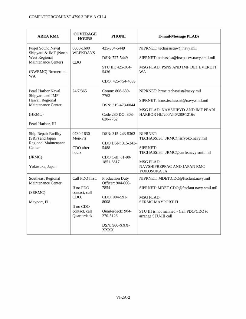
COMFLTFORCOMINST 4790.3 REV A CH-4
AREA RMC COVERAGE HOURS PHONE E-mail/Message PLADs
Puget Sound Naval Shipyard & IMF (North West Regional Maintenance Center)
(NWRMC) Bremerton, WA
0600-1600 WEEKDAYS
CDO
425-304-5449
DSN: 727-5449
STU III: 425-304-5436
CDO: 425-754-4083
NIPRNET: [email protected]
SIPRNET: [email protected]
MSG PLAD: PSNS AND IMF DET EVERETT WA
Pearl Harbor Naval Shipyard and IMF Hawaii Regional Maintenance Center
(HRMC)
Pearl Harbor, HI
24/7/365 Comm: 808-630-7762
DSN: 315-473-0044
Code 280 DO: 808-630-7762
NIPRNET: [email protected]
SIPRNET: [email protected]
MSG PLAD: NAVSHIPYD AND IMF PEARL HARBOR HI//200/240/280/1216//
Ship Repair Facility (SRF) and Japan Regional Maintenance Center
(JRMC)
Yokosuka, Japan
0730-1630 Mon-Fri
CDO after hours
DSN: 315-243-5362
CDO DSN: 315-243-5488
CDO Cell: 81-90-1851-8817
NIPRNET: [email protected]
SIPRNET: [email protected]
MSG PLAD: NAVSHIPREPFAC AND JAPAN RMC YOKOSUKA JA
Southeast Regional Maintenance Center
(SERMC)
Mayport, FL
Call PDO first.
If no PDO contact, call CDO.
If no CDO contact, call Quarterdeck.
Production Duty Officer: 904-866-7854
CDO: 904-591-8008
Quarterdeck: 904-270-5126
DSN: 960-XXX-XXXX
NIPRNET: [email protected]
SIPRNET: [email protected]
MSG PLAD: SERMC MAYPORT FL
STU III is not manned - Call PDO/CDO to arrange STU-III call
VI-2A-2
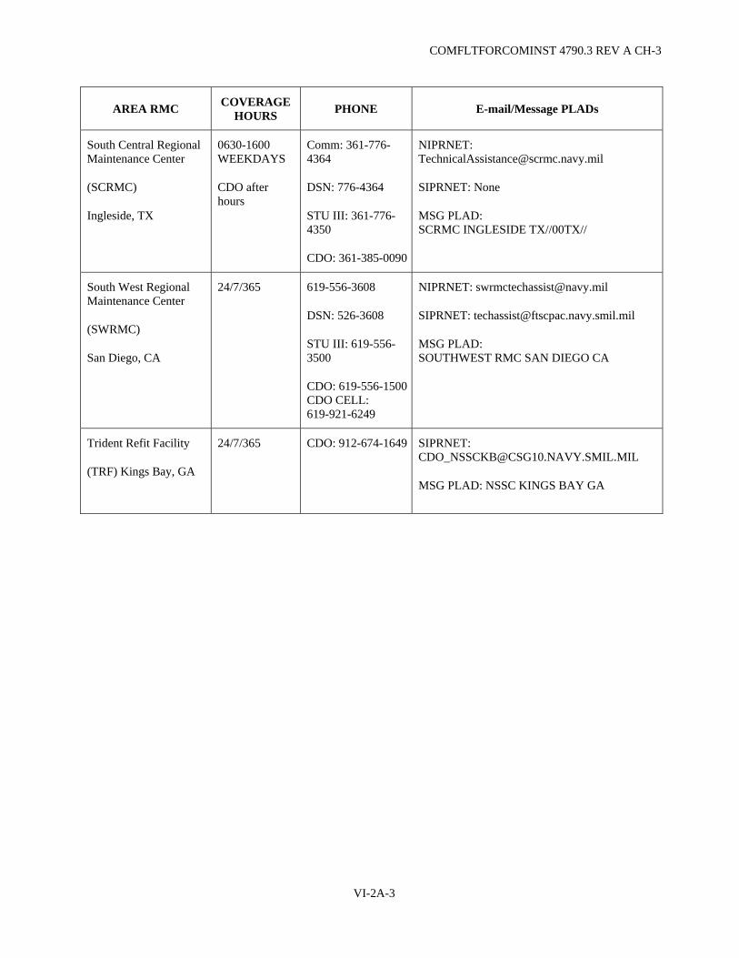
COMFLTFORCOMINST 4790.3 REV A CH-3
COVERAGE HOURS AREA RMC PHONE E-mail/Message PLADs
South Central Regional Maintenance Center
(SCRMC)
Ingleside, TX
0630-1600 WEEKDAYS
CDO after hours
Comm: 361-776-4364
DSN: 776-4364
STU III: 361-776-4350
CDO: 361-385-0090
NIPRNET: [email protected]
SIPRNET: None
MSG PLAD: SCRMC INGLESIDE TX//00TX//
South West Regional Maintenance Center
(SWRMC)
San Diego, CA
24/7/365 619-556-3608
DSN: 526-3608
STU III: 619-556-3500
CDO: 619-556-1500CDO CELL: 619-921-6249
NIPRNET: [email protected]
SIPRNET: [email protected]
MSG PLAD: SOUTHWEST RMC SAN DIEGO CA
Trident Refit Facility
(TRF) Kings Bay, GA
24/7/365
CDO: 912-674-1649
SIPRNET: [email protected]
MSG PLAD: NSSC KINGS BAY GA
VI-2A-3

COMFLTFORCOMINST 4790.3 REV A CH-2
(This Page Intentionally Left Blank)
VI-2A-4

COMFLTFORCOMINST 4790.3 REV A CH-3
APPENDIX B
SAMPLE TECHNICAL ASSISTANCE VISIT REPORT (TAVR) MESSAGE
FROM ON-SITE FTA PERFORMING ACTIVITY//JJJ// (Could be RMC, NSY, NWC, etc.) TO: SHIP REQUESTING ASSISTANCE ADDITIONAL ACTION ADDRESSEES (AS APPROPRIATE, TO INCLUDE ACCEPTING RMC FOR FTA TRANSFERS) INFO: COMFLTFORCOM NORFOLK VA//N43// (AS APPROPRIATE) COMPACFLT PEARL HARBOR HI//N43// (AS APPROPRIATE) NUMBERED FLEET COMMANDER TYCOM GROUP SQUADRON COMNAVSEASYSCOM WASHINGTON DC//(PROGRAM MANAGER)// ISEA/PROGRAM MANAGER//XXXX// OTHER REGIONAL MAINTENANCE CENTER (AS APPROPRIATE) RMC DET (AS APPROPRIATE) NSWC CORONA CA//QA33// (FOR ASSISTS ON C4I/COMBAT SYSTEM) COMNAVSAFECEN NORFOLK VA//XXX// (SAFETY RELATED ITEMS ONLY) NETC PENSACOLA FL//ETE5// (TRAINING ISSUES ONLY) SERVSCOLCOM GREAT LAKES IL//00// (TRAINING ISSUES ONLY) FLEASWTRACEN SAN DIEGO CA//00// (ASW TRAINING ISSUES ONLY) FCTCLANT DAM NECK VA//00// (FOR ASSISTS ON C4I/COMBAT SYSTEM) SWRMC//3B00/SSMD// (FOR PACFLT SSN ONLY) NAVSUBSCOL GROTON CT//00// (FOR SUBMARINES ONLY) TRITRAFAC KINGS BAY GA//00// (FOR SSBN/SSGN SUBMARINES) NWRMC//00// (FOR SSBN/SSGN SUBMARINES) OTHERS (AS APPROPRIATE) BT UNCLAS //N0XXXX// MSGID/GENADMIN/RMC XXXX// SUBJ/USS XXXX (HULL) EQUIPMENT NAME-NOMENCLATURE TECH ASSIST VISIT REPORT// REF/A/CASREP/MSG/TELCON REQUESTING TECH ASSIST// REF/B/DOC/APPLICABLE TECH MANUAL/(OPTIONAL)// REF/C/OTHER REFS AS NECESSARY// NARR/REF A IS SHIP MESSAGE OR TELCON BETWEEN XXXX/X AND XXXX/X.// POC/NAME/CIV/CODE/-/TEL:DSN XXX-XXXX/TEL:XXX XXX-XXXX// RMKS/1. BACKGROUND: REF A REPORTED (PROBLEM). AS REQ REF A, RMCXXXX REP, (NAME) PROVIDED TECH ASSIST (DATE) AT (LOCATION) TO ASSIST WITH CORRECTION OF THE PROBLEM. REF B IS THE APPLICABLE TECHNICAL MANUAL. 2. FINDINGS: A. BRIEF PROBLEM DESCRIPTION: B. SUMMARIZE FINDINGS & CORRECTIVE ACTION ON HARDWARE. (STATE WHY
DISTANCE SUPPORT WAS UNABLE TO RESOLVE THIS ISSUE. IF THIS TAVR IS TO DOCUMENT AN FTA TRANSFER, SO STATE AND INCLUDE FTA ACCEPTING RMC COMMAND TITLE AND SPECIFIC POC INFO.).
C. SUMMARIZE FINDINGS & CORRECTIVE ACTION ON LOGISTICS (IF ANY). 3. CONCLUSION: A. STATEMENT ON CAUSE OF PROBLEM (IF NOT OBVIOUS). B. SOMETIMES CONVENIENT TO COMBINE WITH FINDINGS. 4. LEVEL OF SHIP'S FORCE SUPPORT: A. ABOVE AVERAGE/AVERAGE/BELOW AVERAGE. B. NUMBER OF SHIP'S FORCE PERSONNEL TRAINED DURING VISIT.
VI-2B-1

COMFLTFORCOMINST 4790.3 REV A CH-3
5. RECOMMENDATIONS: A. FOR USS XXXXX: (1) IDENTIFY FOLLOW-ON ACTION. (2) ABOVE DISCUSSED WITH (NAME) PRIOR TO DEPARTING SHIP. B. FOR TYCOM/RMC: (1) IDENTIFY FOLLOW-ON ACTION. (2) ABOVE DISCUSSED WITH (NAME) ON (DATE). C. FOR NAVSEA/ISEA: (1) IDENTIFY FOLLOW-ON ACTION. (2) ABOVE DISCUSSED WITH (NAME) ON (DATE). 6. INFORMATION FOR BLOCK 35 OF 2-KILO PROVIDED TO SHIP DURING DEBRIEF. JCN APPLIES. 7. A. MAN HOURS EXPENDED FOR TECHNICAL ASSISTANCE. B. MAN HOURS EXPENDED FOR TRAINING. C. MATERIAL COSTS. 8. EVALUATION OF NECESSITY FOR TECHNICAL ASSISTANCE: A. WAS ADEQUATE TECHNICAL DOCUMENTATION AVAILABLE TO SHIP'S FORCE TO
CORRECT PROBLEM? B. WERE ADEQUATE TOOLS AVAILABLE TO SHIP'S FORCE TO CORRECT THE PROBLEM? C. WERE ADEQUATE MATERIALS/SPARE PARTS AVAILABLE TO SHIP'S FORCE TO
CORRECT THE PROBLEM? D. WAS SHIP'S FORCE LEVEL OF KNOWLEDGE ADEQUATE TO CORRECT THE PROBLEM? BT
NOTE: ENSURE MESSAGES ARE IN ACCORDANCE WITH NTP-3 FORMAT AND CURRENT PLAIN LANGUAGE ADDRESS DIRECTORY (PLAD) IS UTILIZED.
VI-2B-2

COMFLTFORCOMINST 4790.3 REV A CH-2
VI-3-1
VOLUME VI
CHAPTER 3
SUBMARINE FLEET MODERNIZATION PROGRAM
REFERENCES.
(a) NAVSEA SL720-AA-MAN-010 - Fleet Modernization Program (FMP) Management and Operations Manual
(b) OPNAVINST 4720.2 - Fleet Modernization Program (FMP); Policy for (c) NAVSEAINST 9210.14 - Changes to Submarine Tenders and Destroyer Tenders with Nuclear Support
Facilities, Requirements Concerning (d) NAVSEAINST C9210.4 - Changes, Repairs and Maintenance to Nuclear Powered Ships (e) NAVSEAINST 4720.14 - Temporary Alterations to Active Fleet Submarines; Control of (f) NAVSEA Technical Specification 9090-310 - Ship Alteration Accomplishment by Installation Teams (g) NAVSEA T9044-AD-MAN-010 - Requirements Manual for Submarine Fly-By-Wire Ship Control
Systems (h) NAVSEAINST 4790.8/OPNAVINST 4790.4 - Ships' Maintenance and Material Management (3-M)
Manual (i) NAVSEA 0989-LP-037-2000 - Commissioned Submarine General Reactor Plant Overhaul and Repair
Specification (j) NAVSEA 0989-LP-058-1000 - Destroyer Tender and Submarine Tender Nuclear Support Facilities
Overhaul and Repair Specification (k) COMLANTFLT/COMPACFLTINST 4720.3A - Management of Afloat Combat Systems and C41
Installations and Improvements (l) NAVSEAINST 4720.11 - Shipboard Installation and Modifications Performed by Alteration Installation
Teams
LISTING OF APPENDICES.
A Major Ship Alteration Types Executive Summary B Submarine Alteration Request Format C RPCCR Forwarding Letter Format D Sample TEMPALT/OPALT Reporting Message E TYKIT Requisition Form F Sample Alteration Feedback Message G TYCOM Alteration Management System Interpretation Guide
3.1 PURPOSE. To establish procedures, policy and responsibilities for the management and execution of the Submarine Fleet Modernization Program (FMP). Amplifying information is contained in references (a) and (b).
3.1.1 Scope. The scope of this chapter is limited to Ship Alterations (SHIPALT), Naval Sea Systems Command Nuclear Propulsion Directorate (NAVSEA 08) Alterations, Alteration and Improvement (A&I) items, Machinery Alterations (MACHALT), Type Zero (TZ) Improvements, Engineering Changes, Field Changes (FC), Ordnance Alterations (ORDALT), Temporary Alterations (TEMPALT), Operational Alterations (OPALT), TRIDENT Command and Control System Modifications, Temporary Engineering Changes and Type Commander (TYCOM) Discretionary Changes. Appendix A of this chapter provides an executive summary of these major alteration types.
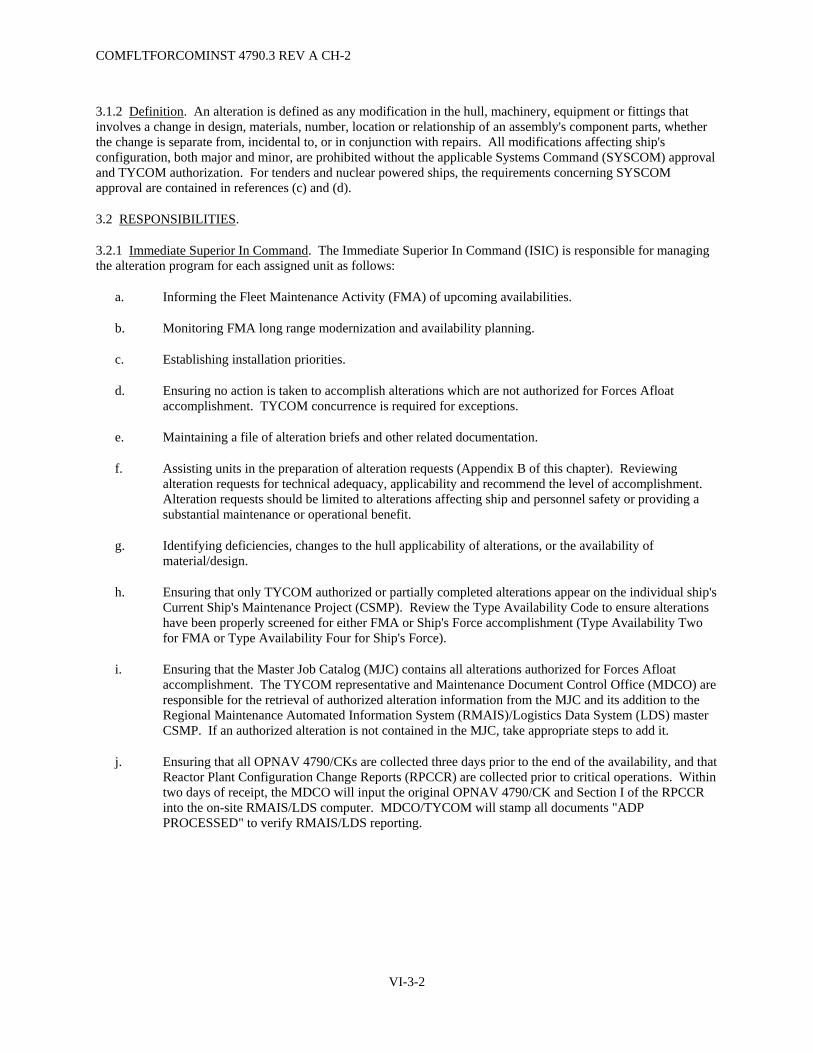
COMFLTFORCOMINST 4790.3 REV A CH-2
VI-3-2
3.1.2 Definition. An alteration is defined as any modification in the hull, machinery, equipment or fittings that involves a change in design, materials, number, location or relationship of an assembly's component parts, whether the change is separate from, incidental to, or in conjunction with repairs. All modifications affecting ship's configuration, both major and minor, are prohibited without the applicable Systems Command (SYSCOM) approval and TYCOM authorization. For tenders and nuclear powered ships, the requirements concerning SYSCOM approval are contained in references (c) and (d).
3.2 RESPONSIBILITIES.
3.2.1 Immediate Superior In Command. The Immediate Superior In Command (ISIC) is responsible for managing the alteration program for each assigned unit as follows:
a. Informing the Fleet Maintenance Activity (FMA) of upcoming availabilities.
b. Monitoring FMA long range modernization and availability planning.
c. Establishing installation priorities.
d. Ensuring no action is taken to accomplish alterations which are not authorized for Forces Afloat accomplishment. TYCOM concurrence is required for exceptions.
e. Maintaining a file of alteration briefs and other related documentation.
f. Assisting units in the preparation of alteration requests (Appendix B of this chapter). Reviewing alteration requests for technical adequacy, applicability and recommend the level of accomplishment. Alteration requests should be limited to alterations affecting ship and personnel safety or providing a substantial maintenance or operational benefit.
g. Identifying deficiencies, changes to the hull applicability of alterations, or the availability of material/design.
h. Ensuring that only TYCOM authorized or partially completed alterations appear on the individual ship's Current Ship's Maintenance Project (CSMP). Review the Type Availability Code to ensure alterations have been properly screened for either FMA or Ship's Force accomplishment (Type Availability Two for FMA or Type Availability Four for Ship's Force).
i. Ensuring that the Master Job Catalog (MJC) contains all alterations authorized for Forces Afloat accomplishment. The TYCOM representative and Maintenance Document Control Office (MDCO) are responsible for the retrieval of authorized alteration information from the MJC and its addition to the Regional Maintenance Automated Information System (RMAIS)/Logistics Data System (LDS) master CSMP. If an authorized alteration is not contained in the MJC, take appropriate steps to add it.
j. Ensuring that all OPNAV 4790/CKs are collected three days prior to the end of the availability, and that Reactor Plant Configuration Change Reports (RPCCR) are collected prior to critical operations. Within two days of receipt, the MDCO will input the original OPNAV 4790/CK and Section I of the RPCCR into the on-site RMAIS/LDS computer. MDCO/TYCOM will stamp all documents "ADP PROCESSED" to verify RMAIS/LDS reporting.

COMFLTFORCOMINST 4790.3 REV A CH-2
VI-3-3
k. (Nuclear Powered Vessels only) Ensuring RPCCRs are distributed by the ship's Commanding Officer within seven days of receipt in accordance with Appendix C of this chapter and that they identify all applicable FCs and Reactor Plant Ship Modifications (RPSM) to the correct revision level.
l. Scheduling required ship checks prior to accomplishment of the alteration.
m. Ensuring situational alterations are accomplished when conditions warrant.
n. Informing ships of alterations planned during an availability in the pre-arrival message. Include alterations being accomplished by outside activities (industrial activity, vendor, Alteration Installation Team (AIT), etc.).
o. Reviewing reports of alteration completions provided by the industrial activity during Chief of Naval Operations (CNO) Maintenance Availabilities.
p. Ensuring that alterations authorized for Forces Afloat accomplishment are completed to the maximum extent possible prior to ship entry into a CNO Maintenance Availability.
q. For deploying units, provide to the receiving FMA a listing of alterations desired for accomplishment during the deployment upkeep in the Material Transfer message and on the ship's CSMP.
r. Allocating a portion of the FMA Repair Other Vessel (ROV) funding for use in procuring alteration material for installation by Forces Afloat.
s. Before installation begins onboard assigned units, ensure a Memorandum of Agreement (MOA) is in place for any alteration or TEMPALT/OPALT accomplished by an industrial activity. Ensure the MOA provides the duration of installation and scheduled removal date for TEMPALTs/OPALTs. (See Volume II, Part I, Chapter 4 of this manual).
t. Ensuring installation of TEMPALTs/OPALTs are in accordance with reference (e) and installation/removal is reported in the format provided in Appendix D of this chapter.
u. Ensuring installation of alterations by the AIT is in accordance with reference (f).
v. Ensuring that the FMA obtains TYCOM Alteration Kits (TYKIT), which are Ready For Issue (RFI), using a TYKIT Requisition Form shown in Appendix E of this chapter.
w. Ensuring no action is taken to procure material for alterations designated as TYKITs or other type packages. In the event that material procurement was started prior to the time the alteration was designated as a package, initiate immediate action to preclude duplicating material procurement.
x. Ensuring that Category "A" A&I's are completed within 12 months of the date of authorization. Category "A" items affect the structural or operational capability of the ship such that non-accomplishment would result in unsafe ship conditions. Failure to complete a Category "A" A&I within 12 months will require the ISIC to submit a major Departure From Specifications (DFS) in accordance with Volume V, Part I, Chapter 8 of this manual. Category "A" A&I items will be assigned to the parent FMA for management.

COMFLTFORCOMINST 4790.3 REV A CH-2
VI-3-4
y. Maintaining a current status of alterations, a TYCOM Alteration Management (TAMS) Report, a Non-Nuclear Title "K" SHIPALT Report (available from TYCOM), and a Nuclear Alteration (NUCALT) Technical Documentation Compact Disk (CD).
z. Preparing and forwarding TAMS/Fleet Modernization Program Management Information System reports to individual units a minimum of once per quarter.
aa. Ensuring all Fly-By-Wire Ship Control System alterations are in accordance with reference (g).
3.2.2 Fleet Maintenance Activity. The FMA will establish and maintain an Alteration Management Group. This group will be responsible for:
a. Using the priorities set by the TYCOM/ISIC, commence alteration planning in time to permit accomplishment of alterations on designated units by the end of the fiscal year designated by the TYCOM Fiscal Year Program in TAMS.
b. Ensuring required ship checks are conducted by the installing activity in a timely manner. Request Ship's Force verify an alteration's status. In cases where Ship's Force cannot conclusively verify an alteration's status, provide necessary assistance.
c. Ensuring no action is taken to accomplish alterations which are not authorized for Forces Afloat.
d. Notifying the ISIC that an alteration is ready to work when all procedures have been prepared and all material is on hand.
e. Upon completion of each non-reactor plant alteration, ensure that the OPNAV 4790/CK is completely filled in by the Lead Work Center in accordance with reference (h) and returned with the signed off Automated Work Request (AWR) to the Analysis, Records and Reports Section (ARRS). The OPNAV 4790/CK will be forwarded by the ARRS to MDCO for entry into RMAIS/LDS and then forwarded to the ship for follow-up.
f. (Nuclear Powered Vessels only) Upon completion of each reactor plant alteration, prepare an RPCCR using the procedures outlined in references (i) and (j). Prior to forwarding the RPCCR to Ship's Force, forward it to MDCO for entry into RMAIS/LDS. Forward the MDCO processed RPCCRs to the ship in a timely manner, using the format in Appendix C of this chapter to facilitate their final processing and return to the ISIC/TYCOM three days prior to the end of the availability.
g. Maintaining a file consisting of a TAMS Report, a Non-Nuclear Title "K" SHIPALT Report (available from TYCOM), and a NUCALT Technical Documentation CD report, alteration briefs, alteration software and related documentation.
h. Maintaining a current status of alterations.
i. For deploying units, the assembly and provisioning of all material (other than standard FMA stock items) for alterations specified on the material transfer message for accomplishment during the deployment upkeep.
COMFLTFORCOMINST 4790.3 REV A CH-2
VI-3-5
j. Maintaining the status of alteration planning for all alterations authorized for Forces Afloat accomplishment.
k. Preparing an Alteration Feedback (Appendix F of this chapter) when problems are encountered during the planning for or installation of an alteration. Forward the Alteration Feedback to the TYCOM.
l. Requisitioning authorized and RFI TYKITs using Appendix E of this chapter.
m. Ensuring material necessary for the installation of alterations not designated as TYKITs is procured in sufficient time to ensure availability during scheduled upkeeps using ROV funding. This includes obtaining all hardware and software required for Ship's Force responsible alterations.
n. Providing for proper stowage of TYKITs and other alteration material.
o. Upon completion of a Category "A" A&I item, ensure the Re-Entry Control (REC) Number (if required) is specified on the OPNAV 4790/CK or RPCCR reporting completion.
3.2.3 Ship's Alteration Coordinator. Ships will designate, in writing, the Ship's Maintenance Manager, the Maintenance and Material Management (3-M) Coordinator, or a designated assistant as the Alteration Coordinator. Responsibilities will include:
a. Acting as the central point of contact for all matters relating to alterations.
b. Responding to specific requests for ship checks made by the TYCOM/ISIC or FMA.
c. Maintaining a copy of all outstanding alteration briefs applicable to the ship.
d. Ensuring no alteration is attempted by Ship's Force until the alteration appears in the unit's CSMP as planned for accomplishment by Work Center 991.
e. Ensuring that all OPNAV 4790/CK forms provided by the installing activity are expeditiously completed and submitted to MDCO in accordance with reference (h) three days prior to end of upkeep.
f. Ensuring that all RPCCRs provided by the installing activity are expeditiously completed in accordance with references (i) and (j) and forwarded in accordance with Appendix C of this chapter three days prior to end of upkeep.
g. Monitoring the accomplishment of alterations during CNO Maintenance Availabilities by both the industrial activity and Ship's Force and reviewing alteration completion reports provided by the industrial activity. Report any discrepancies to the ISIC/TYCOM.
h. Ensuring proper 3-M reporting by monitoring the submission of OPNAV 4790/CK forms or RPCCRs regardless of the installing activity or availability. If an OPNAV 4790/CK form or RPCCR has not been submitted for a completed alteration, obtain one. The certification letter of alterations accomplished by industrial activities will be processed as an OPNAV 4790/CK as shown in reference (h).
COMFLTFORCOMINST 4790.3 REV A CH-2
VI-3-6
i. Ensuring an MOA is in place before installation of an alteration or TEMPALT/OPALT by any industrial activity. Ensure the MOA provides the duration of installation and scheduled removal date for TEMPALTs/OPALTs. (See Volume II, Part I, Chapter 4 of this manual).
j. Ensuring installation of TEMPALTs/OPALTs is in accordance with reference (e) and installation/removal is reported in the format provided in Appendix D of this chapter.
k. Ensuring TEMPALTs are removed by the scheduled removal date.
l. Ensuring all TEMPALTs are removed prior to an industrial availability.
m. Ensuring installation of alterations by an AIT is in accordance with reference (f).
n. Verifying the accuracy of the TAMS Report, a Non-Nuclear Title "K" SHIPALT Report (available from TYCOM), and a NUCALT Technical Documentation CD report and reporting any discrepancies to the ISIC/TYCOM.
o. When reporting a Category "A" A&I item as complete, ensure the REC number (if required) is specified on the OPNAV 4790/CK or RPCCR reporting completion.
p. (Nuclear Powered Ships only) Ensuring onboard repair parts are ordered in sufficient time to ensure availability prior to a reactor plant SHIPALT installation.
q. Ensuring all Fly-By-Wire Ship Control System alterations are in accordance with reference (g).
3.3 ALTERATION PROGRAMS.
3.3.1 Reactor Plant Ship Alteration Package Program (Nuclear Powered Ships only). A NAVSEA 08 program to package and position reactor plant alteration material at the Naval Inventory Control Point (NAVICP) Mechanicsburg for requisition and installation by Forces Afloat. RFI reactor plant alteration packages should be requisitioned via official correspondence to the following address:
Department of the Navy Naval Inventory Control Point Code 009F, Building 07 5450 Carlisle Pike P.O. Box 2020 Mechanicsburg, PA 17055-1788
3.3.2 Alteration Installation Team Program. A program to support installation of alterations by an industrial team outside of an industrial availability. Specific guidelines governing AITs are contained in references (f), (k) and (l). The AIT is responsible for providing the ship with:
a. All Integrated Logistics Support (ILS), equipment (including on-board spares) and documentation.
b. Ship's Selected Records (SSR) documentation.
c. A complete set of installation drawings red-lined to indicate all variances.
d. For Ship's Non-Tactical Automated Data Processing System II/III ships, appropriately formatted media for updating databases to properly reflect any configuration changes, new repair parts, and support requirements.
COMFLTFORCOMINST 4790.3 REV A CH-2
VI-3-7
e. For Non-Ship's Non-Tactical Automated Data Processing ships, hard copy Coordinated Shipboard Allowance List (COSAL) pages.
f. A copy of the completion message.
NOTE: IF ANY OF THE ITEMS IN PARAGRAPH 3.3.2 OF THIS CHAPTER ARE NOT PROVIDED BY THE AIT, REPORT THE MISSING ITEMS IN THE COMPLETION REPORT, WITH A COPY TO THE TYCOM FMP MANAGER.
3.3.3 Type Commander Alteration Kit Program. A TYCOM program which packages all hardware and software required to plan, install and report completion of the alteration. No action should be taken by Forces Afloat to obtain material to accomplish an alteration designated as a TYKIT. Accomplishment will be authorized in TAMS when the TYKIT becomes available. The installing activity should request shipment of RFI TYKITs from the TYCOM using Appendix E of this chapter.
3.4 MONITORING OF ALTERATION STATUS.
3.4.1 Type Commander Alteration Management System. An automated system operated by COMSUBLANT/COMSUBPAC containing information relating to an alteration's completion status, authorization, scheduling and designated accomplishing activity for all A&I items, TZ Improvements, TEMPALTs/OPALTs and all SHIPALTs with the exception of Title K non-reactor plant SHIPALTs. TAMS is the instrument by which the TYCOM authorizes the accomplishment and maintains a completion status. Appendix G of this chapter provides a TAMS Interpretation Guide.
3.4.2 Navy Data Environment - Navy Modernization. The official automated system supporting the information and decision support requirements of FMP managers Navy wide. The Navy Data Environment - Navy Modernization database contains data related to: ships and their availability schedules; alteration applicability; alteration material requirements and procurement status; and material, installation and outfitting costs for non-nuclear alterations. The Navy Data Environment - Navy Modernization database is the authoritative planning baseline for FMP operation throughout the Navy FMP community.
NOTE: SUBMARINE MODERNIZATION WILL BE INCORPORATED INTO NDE DURING CY 2005.
3.4.3 Nuclear Alteration Technical Documentation Compact Disk. The NUCALT Technical Documentation CD provides information required to accomplish nuclear SHIPALTs and A&I items. It is issued to applicable ships, ISICs and FMAs quarterly. It provides information on all outstanding nuclear alterations applicable to each individual ship.

COMFLTFORCOMINST 4790.3 REV A CH-2
VI-3-8
3.5 REPORTING CHANGE IN ALTERATION STATUS.
3.5.1 Reactor Plant Alterations. The RPCCR provides the format for reporting reactor plant configuration changes to the TYCOM, SYSCOMs, appropriate planning yards, reactor plant prime contractors, and NAVICP. Further guidance on its completion is contained in references (i) and (j). Appendix C of this chapter provides formats for distribution of RPCCRs.
3.5.2 All Other Alterations. The OPNAV 4790/CK provides the format for reporting non-reactor plant configuration changes. Further guidance on its completion and submission is contained in reference (h).
3.6 ALTERATION REQUESTS. Requests for new alterations should be made using the format provided in Appendix B. Alteration requests should be limited to alterations affecting safety or those providing a substantial warfighting or maintenance benefit.
3.7 ALTERATION FEEDBACKS. An Alteration Feedback Message (Appendix F of this chapter) is to be submitted to the TYCOM when a problem is encountered during the planning for or installation of a non-reactor plant alteration. Liaison Action Requests should be used to report problems encountered during the planning for or installation of a reactor plant alteration in accordance with reference (i).
3.8 PERMANENT MODIFICATIONS TO TENDERS WITH NUCLEAR SUPPORT FACILITIES.
3.8.1 Modification. Rearrangement or modification to spaces within or adjacent to the Nuclear Support Facility shall be accomplished in accordance with reference (j).
3.8.2 Improvements. Improvements designated for Ship's Force action (less space relocations or major equipment reorientations or rearrangements of spaces covered by paragraph 3.8.1 of this chapter) as specified in a Naval Sea Systems Command (NAVSEA) Upgrade Program Book or in a NAVSEA conducted Industrial Plant Equipment (IPE) Survey (subject to the stipulations of paragraph 3.8.3 and 3.8.4 of this chapter) for a unit or a unit of the same class may be used as authority to accomplish the improvement without further correspondence.
3.8.3 Changes. Changes prescribed by applicable and authorized Title D/F FMA Upgrade SHIPALTs may be accomplished by Forces Afloat when authorized by the TYCOM. Changes prescribed by applicable authorized Title K FMA Upgrade SHIPALTs must be authorized by NAVSEA.
3.8.4 Internal Space Rearrangements.
a. Internal space rearrangements other than those addressed in paragraph 3.8.2 and 3.8.3 of this chapter are authorized provided prior TYCOM approval is obtained and in each case, none of the following are involved:
(1) Changes in structural bulkheads.
(2) Changes or modifications to ship systems such as ventilation, lighting (other than fixture relocation), potable water, etc.
(3) Relocation or reorientation of major equipments. A major equipment is defined as any piece of IPE or ship machinery permanently mounted to the hull structure.
(4) Rearrangement or modification to spaces within or adjacent to the Nuclear Support Facility as defined and further discussed in reference (c).

COMFLTFORCOMINST 4790.3 REV A
VI-3-9
(5) Modification to weapon stowage spaces.
b. Changes outside the scope of paragraphs 3.8.2, 3.8.3 or 3.8.4 of this chapter shall be submitted in accordance with reference (a).
c. Changes made by Forces Afloat under the authorization provided in paragraphs 3.8.2, 3.8.3, and 3.8.4 of this chapter must be documented. If not covered by an approved alteration, they must be submitted to the appropriate planning yard via the TYCOM.
d. FMA Upgrade Program Book or IPE Survey recommendations which specify "NAVSEA action is required" should not be accomplished until specifically authorized.

COMFLTFORCOMINST 4790.3 REV A
VI-3-10
(This Page Intentionally Left Blank)

COMFLTFORCOMINST 4790.3 REV A CH-2
VI-3A-1
APPENDIX A
MAJOR SHIP ALTERATION TYPES EXECUTIVE SUMMARY
TYPE ALTERATION BRIEF WHO FUNDS FMP INSTALLATION
Title K SHIPALT Most complex military characteristic change; requires Industrial Activity expertise; usually requires CPM or HCPM.
FMP (SHIPALT Installation Funds)
Title K-P SHIPALT Approved package alteration. FMP (Package Alterations) Title D SHIPALT Requires Industrial Activity/FMA, or Ship's Force
expertise. Can require CPM (3). Fleet Commander/TYCOM
Title F SHIPALT Less complex; requires FMA/Ship's Force expertise. Cannot require CPM.
Fleet Commander/TYCOM
ORDALT Changes to Naval Ordnance Equipment. FMP (ORDALTs) MACHALT Hull, Mechanical and Electrical (HM&E) changes
within strict equipment/system boundaries and with limited system ramifications.
FMP (MACHALTs)
NAVSEA Field Changes (FC) Approved minor changes to NAVSEA 06 combat systems equipment.
FMP (ORDALTs)
NAVSEA Command and Control Systems (CS/CCS) Engineering Change (EC)
Approved minor changes to selected NAVSEA CS/CCS equipment.
FMP (ORDALTs)
Space and Naval Warfare Systems Command (SPAWAR) Field Changes (FC)
Approved minor changes to SPAWAR electronic equipment.
FMP (SPAWAR FCs)
Alteration & Improvement (A&I)
Tests, inspections and minor alterations to submarines and submarine tenders; no significant ILS impact.
Fleet Commander/TYCOM
TZ Improvements Minor alterations to SSBN/SSGN 726 Class submarines; no significant ILS impact.
Fleet Commander/TYCOM
TYCOM Discretionary Changes (TDC)
Minor alteration to SSBN/SSGN 726 Class submarines at the discretion of the TYCOM/ISIC; no significant ILS impact.
Fleet Commander/TYCOM
TRIDENT Command and Control System Modification (TCMOD)
Alterations on the TRIDENT Command and Control System.
NAVSEA
Temporary Engineering Changes (TEC)
Emergent temporary modification to the TRIDENT Command and Control System.
NAVSEA

COMFLTFORCOMINST 4790.3 REV A CH-2
VI-3A-2
TYPE ALTERATION BRIEF WHO FUNDS FMP INSTALLATION
TEMPALT Emergent temporary modification to submarines; installed for short, predetermined time frame.
Technical Sponsor
OPALT Emergent temporary modifications to submarines requiring ILS support; interim to SHIPALT development.
Technical Sponsor

COMFLTFORCOMINST 4790.3 REV A CH-3
VI-3B-1
APPENDIX B
SUBMARINE ALTERATION REQUEST FORMAT
4720 Ser
Date From: Commanding Officer, USS (Ship's Name and Hull No.) To: Commander, Naval Sea Systems Command Via: ISIC (as appropriate) TYCOM (as appropriate)
Subj: USS (Ship's Name and Hull No.) ARN (Hull No.-CY-Ser No.)REQUEST FOR ALTERATION TO (PROVIDE/REMOVE/REPLACE/RELOCATE/INSTALL/CORRECT/etc.) IN (Ship Type/Class)
Ref: (a) COMFLTFORCOMINST 4790.3; Joint Fleet Maintenance Manual
Encl: (1) (Photographs, sketches, etc. to fully describe the proposed alteration) (2) Recommended Changes to Technical Documentation
1. Existing Deficiency/Condition. Statement of circumstances which warrant initiation of alteration request.
2. Alteration Request. In accordance with Volume VI, Chapter 3 of reference (a), request that the following alteration be approved for (Ship Type/Class) ships and be authorized for accomplishment on USS (Ships Name and Hull No.).
Group Name Group Number
a. Brief: Description of alteration desired.
b. Justification: Statements that the alteration meets one or more of the following criteria:
(1) Significant improvement in ship/equipment safety.
(2) Significant improvement in equipment/system reliability and/or reduction in maintenance requirements.
(3) Significant benefits to health/safety of personnel.
(4) Significant improvement in mission capability.
c. Applicable Plans/Publications: List applicable technical manuals, drawings, correspondence, maintenance documentation, etc.
d. Priority: Defined by TYCOM instructions.
e. Relationship to other issued alterations:
f. Manual Changes: Recommended manual changes (attached as enclosure (2)).
g. Affect on Habitability.
h. Materials.
i. Work to be accomplished by:
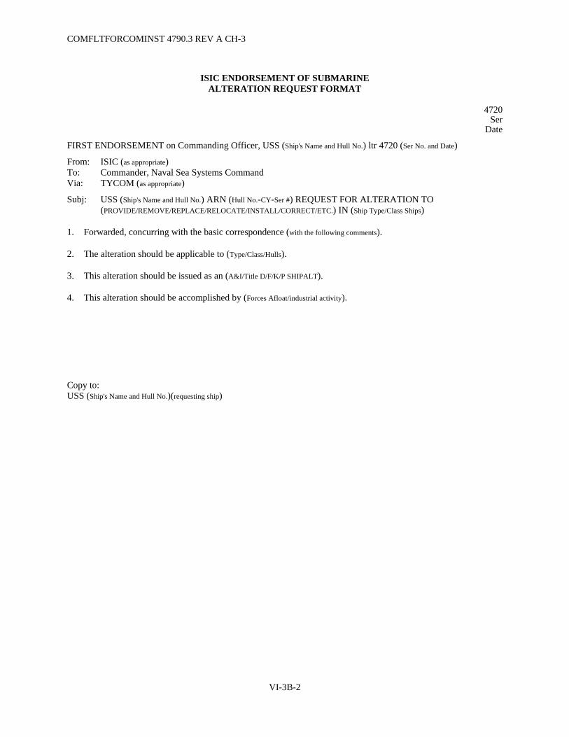
COMFLTFORCOMINST 4790.3 REV A CH-3
VI-3B-2
ISIC ENDORSEMENT OF SUBMARINE ALTERATION REQUEST FORMAT
4720 Ser
Date
FIRST ENDORSEMENT on Commanding Officer, USS (Ship's Name and Hull No.) ltr 4720 (Ser No. and Date)
From: ISIC (as appropriate) To: Commander, Naval Sea Systems Command Via: TYCOM (as appropriate)
Subj: USS (Ship's Name and Hull No.) ARN (Hull No.-CY-Ser #) REQUEST FOR ALTERATION TO (PROVIDE/REMOVE/REPLACE/RELOCATE/INSTALL/CORRECT/ETC.) IN (Ship Type/Class Ships)
1. Forwarded, concurring with the basic correspondence (with the following comments).
2. The alteration should be applicable to (Type/Class/Hulls).
3. This alteration should be issued as an (A&I/Title D/F/K/P SHIPALT).
4. This alteration should be accomplished by (Forces Afloat/industrial activity).
Copy to: USS (Ship's Name and Hull No.)(requesting ship)

COMFLTFORCOMINST 4790.3 REV A CH-3
VI-3C-1
APPENDIX C
RPCCR FORWARDING LETTER FORMAT
Installing Activity Format for End of Availability
RPCCR Status Letter
9210 Ser
Date
NOFORN (When filled in)
From: Commanding Officer, (Installing Activity) To: Commanding Officer, USS (Ship's Name and Hull No.)
Subj: END OF AVAILABILITY REACTOR PLANT ALTERATION STATUS
Ref: (a) COMFLTFORCOMINST 4790.3; Joint Fleet Maintenance Manual
Encl: (1) RPCCR Job Control Number (JCN)
1. Per the requirements of Volume VI, Chapter 3 of reference (a), enclosures (1) through ( ) forward an RPCCR for each change in reactor plant configuration accomplished by (Installing Activity) on (Ship's Name and Hull No.) during the period (Date) to (Date).
2. The following changes to the reactor plant alteration status are reported:
Alteration Identification/Rev
Previous Status
Current Status
Installing Activity
Remarks
a. Reactor Plant SHIPALTs:
b. Reactor Plant A&Is:
3. The following other reactor plant configuration changes, including component replacements in accordance with the applicable NAVSEA reactor plant component replacement and modification technical manual, were accomplished during the availability:
a.
b.
Copy to: ISIC TYCOM (N4) EBDIV/NNS (as applicable)

COMFLTFORCOMINST 4790.3 REV A CH-3
VI-3C-2
Ship's Force Format for Endorsing Installing Activity Letter
RPCCRs
9210 Ser
Date
NOFORN (When filled in)
FIRST ENDORSEMENT on (Installing Activity) ltr 9210, Ser of (Date)
From: Commanding Officer, USS (Ship's Name and Hull No.) To: TYCOM Via: ISIC
Subj: END OF AVAILABILITY REACTOR PLANT ALTERATION STATUS
Ref: (a) NAVSEAINST 4720.16; Logistics Management Procedures for Configuration Changes Installed Outside of Depot Level Availabilities
(b) NAVSEAINST 9210.37; Naval Reactor Plant Material History
1. Readdressed and forwarded/forwarded with the following changes:
2. The ship's master copy of the Ship's Drawing Index (SDI) has been marked up to reflect these actions in accordance with reference (a). Ship's Material History Records have been revised in accordance with reference (b) to reflect these modifications and changes to onboard repair part support have been initiated.
Copy to: (Installing Activity)

COMFLTFORCOMINST 4790.3 REV A CH-3
VI-3C-3
Ship's Force Format for Forwarding RPCCRs
in the Absence of Installing Activity Letter
9210 Ser
Date
NOFORN (When filled in)
From: Commanding Officer, USS (Ship's Name and Hull No.) To: TYCOM Via: ISIC
Subj: CHANGES TO REACTOR PLANT ALTERATION STATUS
Ref: (a) COMFLTFORCOMINST 4790.3; Joint Fleet Maintenance Manual (b) NAVSEAINST 4720.16; Logistics Management Procedures for Configuration Changes
Installed Outside of Depot Level Availabilities (c) NAVSEAINST 9210.37; Naval Reactor Plant Material History
Encl: (1) RPCCR JCN
1. Per the requirements of Volume VI, Chapter 3 of reference (a), enclosures (1) through ( ) forward an RPCCR for each change in reactor plant configuration accomplished by (Installing Activity) on USS (Ship's Name and Hull No.) during the period (Date) to (Date).
2. The following changes to the reactor plant alteration status are reported:
Alteration Identification/Rev
Previous Status
Current Status
Installing Activity
Remarks
a. Reactor Plant SHIPALTs:
b. Reactor Plant A&Is:
3. The ship's master copy of the Ship's Drawing Index (SDI) has been marked up to reflect these actions in accordance with reference (b). Ship's Material History Records have been revised in accordance with reference (c) to reflect these modifications and changes to onboard repair part support have been initiated.
Copy to: (Installing Activity)
COMFLTFORCOMINST 4790.3 REV A CH-3
VI-3C-4
ISIC Format for Endorsement of Letter Forwarding RPCCRs
9210 Ser
Date
FIRST/SECOND ENDORSEMENT on (Ship/Installing Activity) ltr 9210 Ser of (Date)
From: ISIC Subj: END OF AVAILABILITY REACTOR PLANT ALTERATION STATUS
1. Forwarded.
2. Data from Section I of each attached RPCCR has been entered into the CSMP.
Distribution: TYCOM (N4) NAVSEA (08H) ANSTR Pittsburgh ANSTR Schenectady EBDIV/NNS (as applicable) NAVICP Mechanicsburg (Code 87)
Copy to: (Ship) (Installing Activity)

COMFLTFORCOMINST 4790.3 REV A CH-3
VI-3D-1
APPENDIX D
SAMPLE TEMPALT/OPALT REPORTING MESSAGE
FM (INSTALLING ACTIVITY)// TO COMNAVSEASYSCOM WASHINGTON DC//PMS392 (SSN/SSBN/SSGN)// TYCOM//N4072// (AS APPROPRIATE) INFO COMSUBRON (SQUADRON NO.)// USS (SHIP'S NAME AND HULL NO.)// BT UNCLAS //N04720// MSGID/GENADMIN/(INSTALLING ACTIVITY)// SUBJ/(SUBS) INSTALLATION/REMOVAL OF TEMPALT (TEMPALT NO.) (ON/FROM) USS (SHIP'S NAME AND HULL NO.)// REF/A/LTR/(ORIGINATOR, SERIAL NO.)/(DATE)// REF/B/LTR/(ORIGINATOR, SERIAL NO.)/(DATE)// NARR/REF A APPROVED DESIGN OF TEMPALT (TEMPALT NO.). REF B APPROVED INSTLN OF TEMPALT (TEMPALT NO.)// POC/(NAME)/(RANK/RATE/TITLE)/(LOCATION)/(DSN/COMM TELEPHONE)// RMKS/1. TEMPALT (TEMPALT NO. AND NARRATIVE DESCRIPTION), DESIGN APPROVED BY REF A, INSTALLATION APPROVED BY REF B, WAS (INSTALLED/REMOVED)(ON/FROM) USS (SHIP'S NAME AND HULL NO.) ON (DATE). INSTALLATION WAS IAW NAVSEA APPROVED TECHNICAL DATA PACKAGE (TDP). DEVIATIONS WERE APPROVED BY ________. THIS TEMPALT IS SCHEDULED FOR REMOVAL ON (DATE)// BT
NOTE: ENSURE MESSAGES ARE IN ACCORDANCE WITH NTP-3 FORMAT AND CURRENT PLAIN LANGUAGE ADDRESS DIRECTORY (PLAD) IS UTILIZED.

COMFLTFORCOMINST 4790.3 REV A
VI-3D-2
(This Page Intentionally Left Blank)

COMFLTFORCOMINST 4790.3 REV A CH-3
VI-3E-1
APPENDIX E
TYKIT REQUISITION FORM
DATE:
FROM:
TO: TYCOM (as appropriate)
1. REQUEST SHIPMENT OF BELOW LISTED TYKIT(S):
TYKIT# HULL#
2. COMPLETE SHIPPING ADDRESS:
3. POINT OF CONTACT:
4. TELEPHONE (VOICE/FAX):
5. DATE REQUIRED:
6. SPECIAL INSTRUCTIONS:

COMFLTFORCOMINST 4790.3 REV A
VI-3E-2
(This Page Intentionally Left Blank)

COMFLTFORCOMINST 4790.3 REV A CH-3
VI-3F-1
APPENDIX F
SAMPLE ALTERATION FEEDBACK MESSAGE
FM USS (SHIP'S NAME AND HULL NO.)// TO TYCOM//(AS APPROPRIATE) INFO ISIC//(AS APPROPRIATE) NAVSEA (APPROPRIATE CODE)// PLANNING YARD//(AS APPROPRIATE) BT UNCLAS //N04720// MSGID/GENADMIN/(SHIP'S NAME AND HULL NO.)// SUBJ/ALT FEEDBACK// REF/A/(ALTERATION NUMBER)// AMPN/REF A IS (DESCRIPTION OF ALTERATION)// RMKS/1. DURING (PLANNING/ACCOMPLISHMENT) OF REF A THE FOLLOWING AREAS WERE EVALUATED: A. (INSTALLATION ACCOMPLISHES INTENT OF ALTERATION) B. (ADEQUACY AND AVAILABILITY OF MATERIAL) C. (APPLICABILITY OF ALTERATION TO ASSIGNED SHIP) D. (THE RECOMMEND CATEGORY/CAPABILITY IN TAMS/FMPMIS AS APPROPRIATE) 2. (DETAILS OF PROBLEM AREAS NOTED IN PARAGRAPH 1 OR OTHER PROBLEMS ENCOUNTERED) 3. (RECOMMEND CORRECTIVE ACTIONS/IMPROVEMENTS/COMMENTS) 4. (RECOMMEND SCHEDULING/PROGRAMMING CHANGES)// BT
NOTE: ENSURE MESSAGES ARE IN ACCORDANCE WITH NTP-3 FORMAT AND CURRENT PLAD IS UTILIZED.

COMFLTFORCOMINST 4790.3 REV A
VI-3F-2
(This Page Intentionally Left Blank)
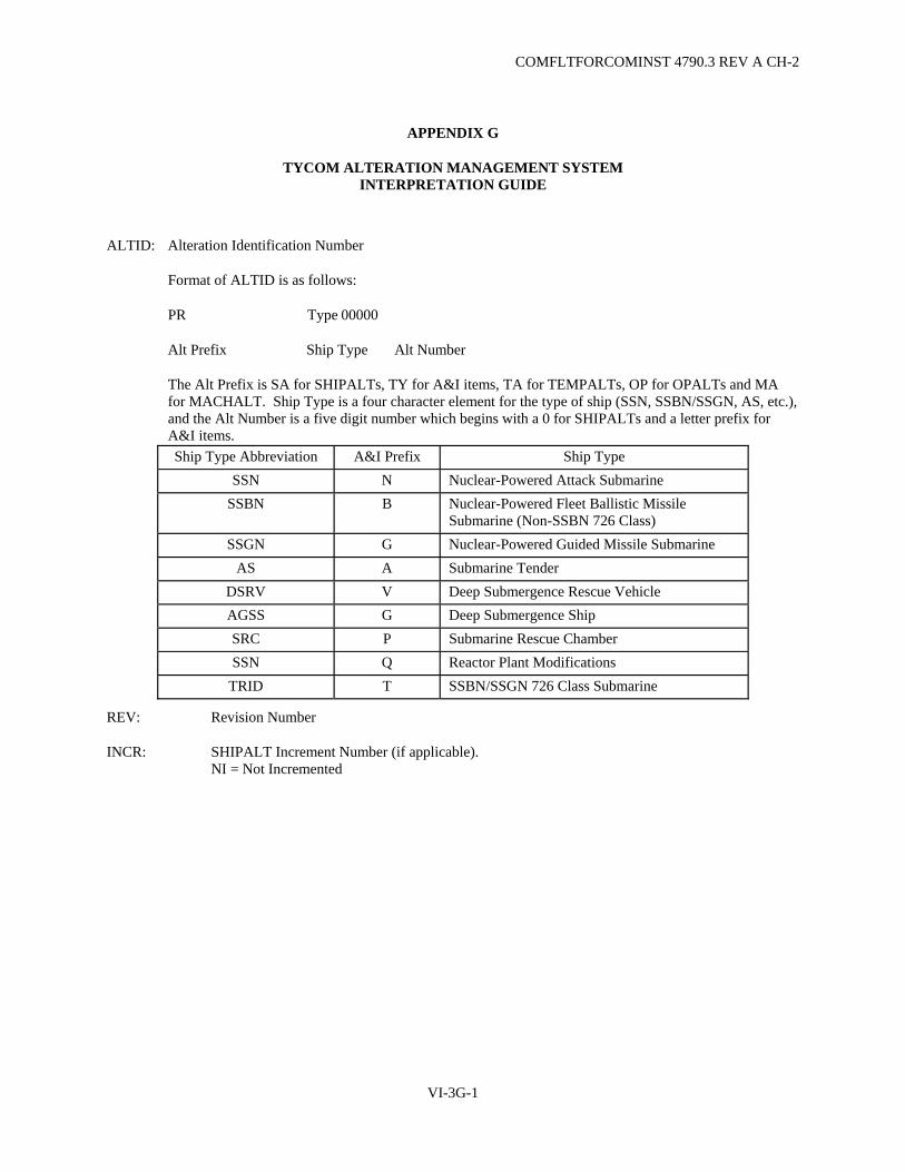
COMFLTFORCOMINST 4790.3 REV A CH-2
VI-3G-1
APPENDIX G
TYCOM ALTERATION MANAGEMENT SYSTEM INTERPRETATION GUIDE
ALTID: Alteration Identification Number
Format of ALTID is as follows:
PR Type 00000
Alt Prefix Ship Type Alt Number
The Alt Prefix is SA for SHIPALTs, TY for A&I items, TA for TEMPALTs, OP for OPALTs and MA for MACHALT. Ship Type is a four character element for the type of ship (SSN, SSBN/SSGN, AS, etc.), and the Alt Number is a five digit number which begins with a 0 for SHIPALTs and a letter prefix for A&I items. Ship Type Abbreviation A&I Prefix Ship Type
SSN N Nuclear-Powered Attack Submarine SSBN B Nuclear-Powered Fleet Ballistic Missile
Submarine (Non-SSBN 726 Class) SSGN G Nuclear-Powered Guided Missile Submarine
AS A Submarine Tender DSRV V Deep Submergence Rescue Vehicle AGSS G Deep Submergence Ship SRC P Submarine Rescue Chamber SSN Q Reactor Plant Modifications
TRID T SSBN/SSGN 726 Class Submarine
REV: Revision Number
INCR: SHIPALT Increment Number (if applicable). NI = Not Incremented

COMFLTFORCOMINST 4790.3 REV A CH-2
VI-3G-2
TITLE: SHIPALT Title K = Funded & scheduled by NAVSEA P = Funded by NAVSEA and scheduled by TYCOM/NAVSEA F = Funded & scheduled by TYCOM D = Funded & scheduled by TYCOM
NOUN NAME: Noun Name of Alteration
EIC: Equipment Identification Code (Z0ZZ = Reactor Plant Equipment)
SWAB: Ship Work Authorization Boundary
ICNC: Alteration Cancellation Indicator 0 = Active 1 = Canceled 2 = Superseded 3 = Never Issued 4 = Completed 5 = Not Used 6 = Low Priority/Obsolete/Deferred
08: Nuclear Indicator (*denotes reactor plant alteration)
CAP: Capability Code/Recommended Level of Accomplishment S/F = Ship's Force FMA = Fleet Maintenance Activity SY = Shipyard (Industrial Activity) AIT = Alteration Installation Team FA = Forces Afloat
CAT: Category Code/(non-reactor plant A&I items only) A = Mandatory/Safety of Ship - Accomplish within one year of authorization or
submit major DFS in accordance with Volume V, Part I, Chapter 8 of this manual. Invoke SUBSAFE/Submarine Flight Critical Component Boundary work requirements and document SUBSAFE/REC or Submarine Flight Critical Component CWP numbers on the associated OPNAV 4790/CK or RPCCR (NAVSEA ltr 92L23/197 of 1 Jan 95).
B = Mandatory/Safety - Accomplish within two years of authorization. C = Mandatory/Maintenance Improvement - Accomplish within three years of
authorization and all applicable FCs/RPSMs have been completed. D = Optional (Habitability). E = Optional (Minor Improvement). F = Situational - Accomplish when specific situation occurs.
ALT NARR: Narrative description of the alteration.
TYST: TYCOM Status A = Applicable but not yet authorized. No action should be taken to accomplish this
alteration without TYCOM concurrence.

COMFLTFORCOMINST 4790.3 REV A CH-2
VI-3G-3
B = Applicable and Authorized. C = Alteration has been fully completed in accordance with the alteration document.
For non-reactor plant alterations, "C" is assigned only after the completion report has been upline reported in the 3-M System. For reactor plant alteration, "C" is assigned only after the RPCCR has been distributed in accordance with reference (c) and all applicable FCs/RPSMs have been completed.
D = Deferred. No action should be taken to accomplish without TYCOM concurrence.
E = Intent of the alteration has been equivalently accomplished via a method other than the alteration document.
H = May or may not have been accomplished during new construction/Post Shakedown Availability via Headquarters or Field Modification Request. A shipcheck is required to determine status.
I = Incomplete Reactor Plant Alteration (all applicable FCs/RPSMs have not been completed).
J = Title P SHIPALT package scheduled for installation by the FMA. K = Title P SHIPALT package scheduled for installation by an industrial activity
during CNO Maintenance Availabilities. L = Title P SHIPALT package scheduled for AIT installation. N = Not Applicable. P = Partial. Q = A reactor plant alteration reported complete via an improperly distributed
RPCCR. R = Removed TEMPALT/OPALT. T = Technically applicable, however, requirement to accomplish has been negated by
another alteration. X = Canceled. Z = Interim completion. For non-reactor plant alterations, awaiting feedback from the
3-M system that the completion has been upline reported. For reactor plant alterations, awaiting distribution of an endorsed RPCCR.
FYPR: Fiscal Year Programmed - Fiscal year in which alteration is to be accomplished (**denotes situational alteration).

COMFLTFORCOMINST 4790.3 REV A CH-2
VI-3G-4
PRRMK: Programming Remarks - Assigned Accomplished Level
AIT = Alteration Installation Team ARP = Advance Equipment Repair Program CNX = Canceled CON = New Construction DCA = Depot Conversion Availability DEF = Deferred DMA = Docking Maintenance Availability DMP = Depot Modernization Program DPM = Docking Phased Maintenance Availability DRA = Docking Restricted Availability EOG = EOGASP Program ERO = Engineered Refueling Overhaul FA = Forces Afloat FMA = Fleet Maintenance Activity IDD = Interim Dry-docking MAC = MACHALT MTS = Moored Training Ship PKG = Title P Package SHIPALT PMA = Phased Maintenance Availability POU = Post Overhaul Upkeep Period PSA = Post Shakedown Availability PSC = Status Confirmed by Shipcheck RAV = Restricted Availability ROH = Regular Overhaul SAV = Special Availability SCA = Surface Craft Availability S/F = Ship's Force SIT = Submarine Installation Team SMP = Submarine Extended Operating Cycle Modernization Program SRA = Selected Restricted Availability TAV = Technical Availability TKT = TYCOM Alteration Kit TSY = TYKIT for Depot Level Installation TYC = No Installing Activity Assigned
SHPCK: Shipcheck Indicator
REQD = Shipcheck is required COMP = Status has been confirmed by Shipcheck
AUTH/COMP: If alteration is outstanding, this date is the authorization date. If the alteration is complete, this date is the completion date.
LAST UPDATE: Date the record was the last updated by TYCOM.
REMARKS: Used to record information relating to hull status or situational requirements.

COMFLTFORCOMINST 4790.3 REV A CH-4
VOLUME VI
CHAPTER 4
SHIPBOARD ELECTROMAGNETIC COMPATIBILITY
REFERENCES.
(a) NAVSEA STD DWG 407-5291780 - Standard Electromagnetic Interference (EMI) Survey Procedures (b) SUBMEPP Test Procedure 441-5-7001 - SSN 688 Class Submarine, Systems EMI Measurements,
Dockside (c) Maintenance Plan 4100-02-01 - Command and Control System (CCS) Electromagnetic Interference
(EMI) Testing (d) NAVSEA STD DWG 407-5287556 - Electronics Material Officer's Guide to Shipboard
Electromagnetic Interference Control (e) NWP 1-03.1 - Naval Warfare Publication Operational Report (f) NAVSEA S9040-AA-GTP-010 - Shipboard Systems Certification Requirements for Surface Ship
Industrial Periods (Non-Nuclear) (g) COMNAVSEASYSCOM WASHINGTON DC 031440Z MAR 03 - Submarine Industrial EMC and
EMI Control Interim Guidance (h) N6-NTSP-S-70-8003H - Navy Training System Plan (NTSP) for Electromagnetic Interference (EMI)
Control (i) NAVSEA STD DWG 407-5287561 - Industrial Electromagnetic Compatibility (IEMC) Work Process
Instructions
4.1 PURPOSE. To provide guidance in the execution of a shipboard Electromagnetic Compatibility (EMC) program in the U.S. surface and submarine fleets.
4.1.1 Background. The Shipboard Electromagnetic Compatibility Improvement Program (SEMCIP) was established by Naval Sea Systems Command (NAVSEA) under the sponsorship of the Chief of Naval Operations (CNO). The goals of SEMCIP are to rectify mission degrading Electromagnetic Interference (EMI) problems, support fleet EMC training, and maintain shipboard EMC. SEMCIP is divided into five major elements; Up-front Systems Engineering, Fleet Response and EMI Problem Quantification, Spectrum Management/EMC in the D30 Process, Engineer EMI Fixes and Fleet EMC Support Tools. One of the Fleet tools is the SEMCIP Technical Assistance Network (STAN), a database containing current and historical information on all known shipboard submarine and battle force EMI problems. Since some SEMCIP elements are normally associated with the development of new systems, all elements will not be discussed here.
4.2 ELECTROMAGNETIC COMPATIBILITY ASSESSMENTS OR SURVEYS. EMC assessments are an important line of defense against shipboard EMI problems and are performed by NAVSEA or NAVSEA qualified activities for the purpose of testing various ship's systems for EMI degradation. During an EMC assessment or Survey, EMI problems are investigated and evaluated, applicable EMI fixes are installed and effects of EMI on each system tested is ascertained.
4.2.1 Shipboard Electromagnetic Compatibility Assessments. Deploying surface ships will receive an EMC assessment from Regional Maintenance Center (RMC) as part of a Combat Systems, Command, Control, Communications and Computers Readiness Review (C5RA) approximately 4 to 6 months prior to deployment. Non-deploying ships may submit requests for an EMC assessment to the RMC or by submitting an OPNAV 4790/2K to their Regional Support Group (RSG)/RMC. Submarines will receive an EMI survey or EMI groom within two months prior to deployment during Pre-Overseas Movement 2 portion of the submarine deployment cycle. The surface ship EMC assessment and the submarine EMI survey address different types of ship's systems and therefore will be discussed separately.
VI-4-1

COMFLTFORCOMINST 4790.3 REV A CH-4
4.2.1.1 Surface Ships. EMC assessments should not be scheduled coincidental with evolutions that restrict either antenna radiation or personnel movement about the ship. EMC assessments must be performed per the requirements of reference (a), and include, but are not limited to:
a. Using STAN to verify that all available EMI fixes have been installed, or if not installed, documented in ship's Current Ship's Maintenance Project.
b. Performing topside visual surveys to ensure the ship conforms to the applicable topside electromagnetic control drawing as specified in STAN for that ship.
c. Performing Intermodulation Interference (IMI) test.
d. Performing instrumented IMI source location when IMI level exceeds the 19th order.
e. Performing broadband noise test.
f. Identifying source location when broadband noise is detected.
g. Performing Time-Domain Reflectometer measurements on all high frequency, very high frequency, and ultra high frequency transmission lines.
h. Conducting Voltage Standing-Wave Ratio tests on all high frequency, very high frequency, and ultra high frequency transmit antennas.
i. Performing insulation resistance tests on high frequency antennas, where required by the Planned Maintenance System (PMS).
j. Documenting all discrepancies noted on OPNAV 4790/2Ks.
k. Assisting Ship's Force with hands-on training and technical guidance in correcting discrepancies as appropriate.
4.2.1.2 Submarines. EMI surveys require up to four working days depending on the ship class being evaluated. EMI surveys can be accomplished concurrently with most submarine work but must not be scheduled coincidental with evolutions that would impede access to the forward sonar and communications system units or cause power-down of systems during the EMI survey without prior notification of the EMC technician conducting the survey. If equipment must be powered down, the EMC technician will determine if further EMI testing can be accomplished. For an accurate assessment of the submarine EMI posture, the ship's forward electronics must be energized as close as possible to the ship's at sea lineup. The electronics and hydraulics for both multifunction mast antennas must be operational. In addition, crane service is required to lift two antenna shields (approximate weight 130 lbs. each) to cover both partially raised multifunction mast antennas for testing. Major sonar, communications, fire control or navigation system casualties will cause test data to be invalid. EMI surveys must be performed per references (b) and (c) by qualified NAVSEA or NAVSEA designated activities and include but not limited to:
a. Using STAN to verify all available EMI fixes have been installed.
b. Briefing Ship's Force on the details of the EMI survey and discussing testing time-lines and potential impacts to the EMI survey.
c. Coordinating antenna shield installation and removal with the ship, RSG/RMC and port services.
VI-4-2
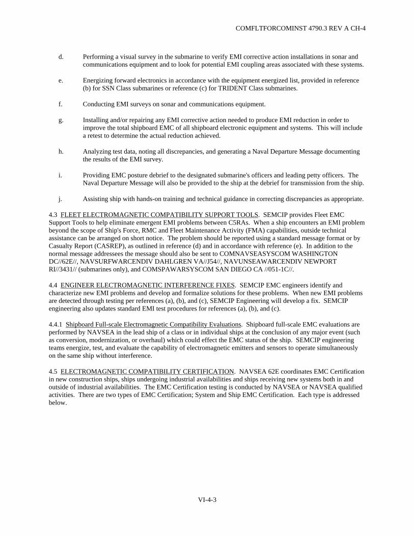
COMFLTFORCOMINST 4790.3 REV A CH-4
d. Performing a visual survey in the submarine to verify EMI corrective action installations in sonar and communications equipment and to look for potential EMI coupling areas associated with these systems.
e. Energizing forward electronics in accordance with the equipment energized list, provided in reference (b) for SSN Class submarines or reference (c) for TRIDENT Class submarines.
f. Conducting EMI surveys on sonar and communications equipment.
g. Installing and/or repairing any EMI corrective action needed to produce EMI reduction in order to improve the total shipboard EMC of all shipboard electronic equipment and systems. This will include a retest to determine the actual reduction achieved.
h. Analyzing test data, noting all discrepancies, and generating a Naval Departure Message documenting the results of the EMI survey.
i. Providing EMC posture debrief to the designated submarine's officers and leading petty officers. The Naval Departure Message will also be provided to the ship at the debrief for transmission from the ship.
j. Assisting ship with hands-on training and technical guidance in correcting discrepancies as appropriate.
4.3 FLEET ELECTROMAGNETIC COMPATIBILITY SUPPORT TOOLS. SEMCIP provides Fleet EMC Support Tools to help eliminate emergent EMI problems between C5RAs. When a ship encounters an EMI problem beyond the scope of Ship's Force, RMC and Fleet Maintenance Activity (FMA) capabilities, outside technical assistance can be arranged on short notice. The problem should be reported using a standard message format or by Casualty Report (CASREP), as outlined in reference (d) and in accordance with reference (e). In addition to the normal message addressees the message should also be sent to COMNAVSEASYSCOM WASHINGTON DC//62E//, NAVSURFWARCENDIV DAHLGREN VA//J54//, NAVUNSEAWARCENDIV NEWPORT RI//3431// (submarines only), and COMSPAWARSYSCOM SAN DIEGO CA //051-1C//.
4.4 ENGINEER ELECTROMAGNETIC INTERFERENCE FIXES. SEMCIP EMC engineers identify and characterize new EMI problems and develop and formalize solutions for these problems. When new EMI problems are detected through testing per references (a), (b), and (c), SEMCIP Engineering will develop a fix. SEMCIP engineering also updates standard EMI test procedures for references (a), (b), and (c).
4.4.1 Shipboard Full-scale Electromagnetic Compatibility Evaluations. Shipboard full-scale EMC evaluations are performed by NAVSEA in the lead ship of a class or in individual ships at the conclusion of any major event (such as conversion, modernization, or overhaul) which could effect the EMC status of the ship. SEMCIP engineering teams energize, test, and evaluate the capability of electromagnetic emitters and sensors to operate simultaneously on the same ship without interference.
4.5 ELECTROMAGNETIC COMPATIBILITY CERTIFICATION. NAVSEA 62E coordinates EMC Certification in new construction ships, ships undergoing industrial availabilities and ships receiving new systems both in and outside of industrial availabilities. The EMC Certification testing is conducted by NAVSEA or NAVSEA qualified activities. There are two types of EMC Certification; System and Ship EMC Certification. Each type is addressed below.
VI-4-3

COMFLTFORCOMINST 4790.3 REV A CH-4
4.5.1 System Electromagnetic Compatibility Certification. System EMC Certification ensures all newly installed electrical/electronic systems are compatible with previously installed systems. System EMC Certification will be accomplished in accordance with references (f) for surface ships and (g) for submarines:
a. For electrical/electronic systems installed by Ship Alteration, Alteration Equivalent to Repair, Type Commander Issued Alteration or other alteration.
b. Following the System Operation Verification Test or other operation test for the newly installed system.
c. By NAVSEA 62E test team for the first two ships of a class, flight or baseline.
d. By Program Acquisition Resource Manager, Ship Program Manager, Naval Supervising Authority, RMC, FMA or a contractor witnessed by a government activity for the subsequent System EMC Certifications using test procedures provided in references (a) and (b).
4.5.1.1 System Electromagnetic Compatibility Certification Requirements. System EMC Certification mandates:
a. The system has an approved (Stage 4) Application for Frequency Allocation (JF-12).
b. No mission-degrading EMI has been introduced by installation of the system.
c. EMI fixes have been installed to correct mission-degrading EMI caused by the installation of the system.
4.5.2 Ship Electromagnetic Compatibility Certification. Ship EMC Certification ensures all shipboard systems are compatible with each other and topside EMI mitigation treatments are in place. Ship EMC Certifications will be accomplished in accordance with references (f) and (g):
a. For all Ship Construction Navy ships to establish an initial EMC Baseline.
b. For deployers after Target Configuration Date, typically 6 months prior to deployment for surface ships and within two months prior to deployment for submarines (during Pre-Overseas Movement 2).
c. Following industrial availabilities greater than 120 days.
d. Every three years for non-deployers.
4.5.2.1 Ship Electromagnetic Compatibility Certification Requirements. Ship EMC Certification mandates that:
a. All "available EMI fixes" that correct mission degrading EMI problems are installed. Available EMI fixes are fixes that have been developed and listed in the STAN database. An "available EMI fix" is required for certification even if the kit/parts are not in stock. In that case, priority would be given for procurement and installation of the fix required for certification.
b. All mission degrading EMI problems that remain uncorrected due to non-availability of EMI fixes, must be identified and reported to the ship's Commanding Officer.
c. All discrepancies causing IMI above the 19th order must be corrected. IMI levels are defined in reference (a).
VI-4-4

COMFLTFORCOMINST 4790.3 REV A CH-4
4.6 ELECTROMAGNETIC COMPATIBILTY CERTIFICATION MAINTENANCE. System Commands provide support during ship construction and CNO Maintenance Availabilities at industrial activities to achieve EMC certification. It is the responsibility of the Type Commander, the FMA and Ship's Force to maintain EMC at the highest level practical.
4.6.1 Fleet Maintenance Activity. EMC technical billets (NEC ET-1419 surface) have been established in reference (h) for FMAs, Aircraft Carriers and selected larger ships to provide technical assistance to Ship's Force in maintaining EMC. These technicians conduct EMI inspections, install known fixes, test for problems and investigate new problems.
4.7 SHIPBOARD ELECTROMAGNETIC COMPATIBILITY IMPROVEMENT PROGRAM TECHNICAL ASSISTANCE NETWORK. STAN is NAVSEA's computer-based EMC information network that resides on the World Wide Web at https://www.semcip.com. Each user is required to obtain a User ID and password.
a. STAN contains information required to help a ship maintain EMC. This includes but is not limited to:
(1) A listing of all EMI problems for an individual ship.
(2) A listing of Category 1 and 2 problems for an individual ship.
(3) A listing of Category 1 and 2 fixable problems, where a fix has been identified for an individual ship.
(4) Brief sheet listings for an individual ship, containing a description of each problem and the solution and/or status.
(5) Topside electromagnetic control drawings for all surface ship classes.
(6) Reference (a), Standard EMI Survey Procedures.
(7) Individual Shipboard EMI Assessment Reports.
(8) EMC certification data and EMI/EMC reports.
(9) Hazards of Electromagnetic Radiation to Personnel and Fuel certifications and reports.
b. EMC technicians at the RMCs, FMAs, Aircraft Carriers, and various other maintenance commands have access to STAN and will provide applicable information upon request.
c. Requests for access to STAN may be obtained by contacting the STAN Manager, NAVSEA 62E at (202) 781-3554, Defense Switched Network (DSN) 326-3554.
d. Assistance can also be obtained by contacting Navy Distance Support at 1-877-418-6824 or by e-mail at [email protected].
VI-4-5

COMFLTFORCOMINST 4790.3 REV A CH-4
4.8 RESPONSIBILITIES.
a. Type Commander shall:
(1) Coordinate with the System Commands in identifying, solving and correcting operational EMI deficiencies.
(2) Arrange for SEMCIP services when required and schedule SEMCIP EMC technician training/qualification visits for FMA and RMC technicians.
(3) Prior to promulgation, review and authorize all documents prepared by technical agencies that contain procedures relative to EMI reduction and the fleet EMC process.
(4) Evaluate comments and recommendations regarding EMI reduction and the fleet EMC process. If necessary, promulgate changes to existing policy and procedures.
(5) Ensure that FMA and RMC have adequate EMC technicians to support EMI surveys. If qualified EMC Technicians are not available at local FMA and RMC, NAVSEA personnel will be contacted to perform the EMC assessment or survey.
b. Group/Squadron/RSG/RMC/SSSU Commanders shall:
(1) Schedule FMA/RMC EMC assessments or EMI surveys prior to deployment for each unit. For submarines the EMI survey should be within two months of deployment during Pre-Overseas Movement 2, take up to four days to perform and can be scheduled concurrently with most shipboard evolutions provided power is not secured to a major system. NAVSEA personnel will be contacted to perform the EMI survey.
(2) Review and take the appropriate action to correct EMI discrepancies on EMC reports for subordinate units.
(3) Request SEMCIP engineering assistance when determined necessary.
c. FMAs and RMCs shall:
(1) Maintain qualified EMC personnel (NEC-1419/Surface Ships) in coordination with NAVSEA 62E and ensure that test equipment assets are available to perform EMC assessments and surveys.
(2) Assist surface ships/submarines in conducting EMC related PMS procedures when requested.
(3) Conduct EMC assessments and surveys in accordance with applicable references (a) through (g) and (i).
(4) Install authorized limited corrective actions when required in STAN.
(5) Write a departure message describing the results of the EMI survey using the latest message formats. Message is submitted to the surface ship/submarine during the EMI survey departure briefing.
VI-4-6
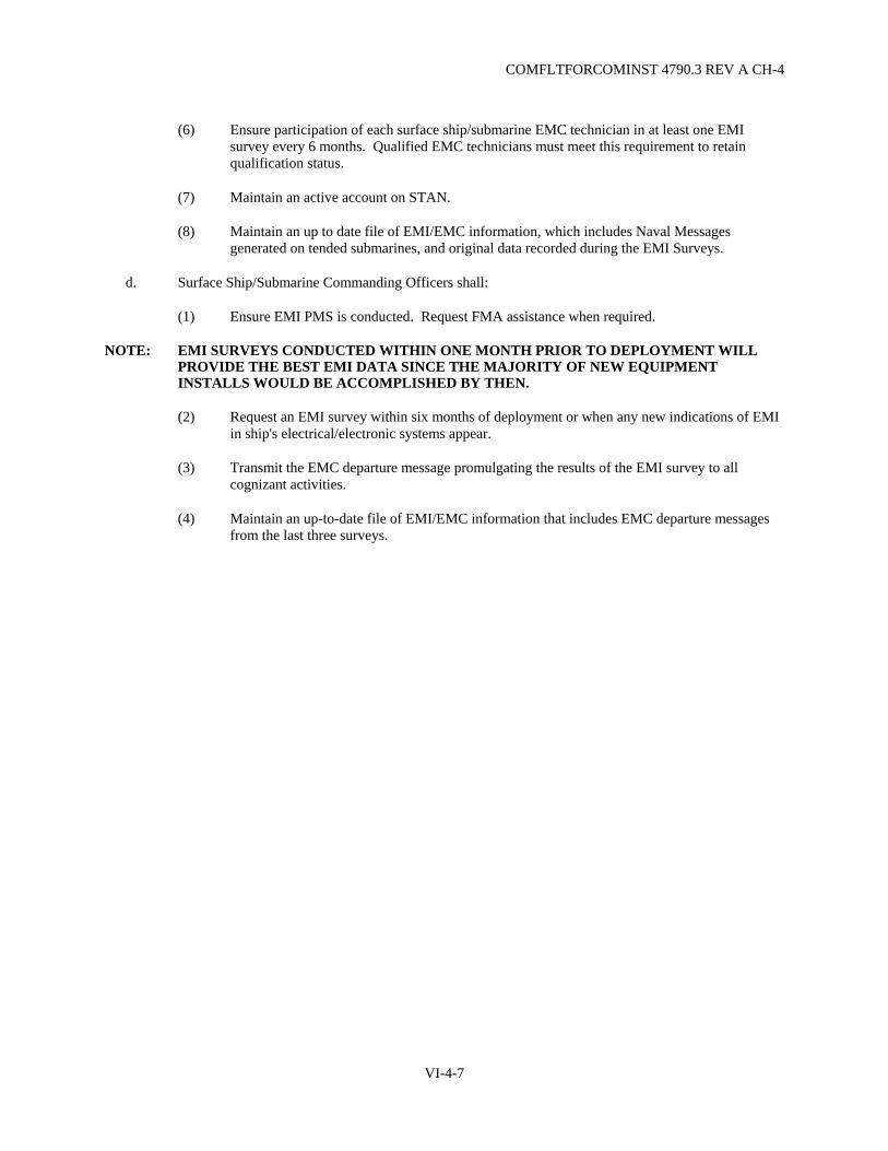
COMFLTFORCOMINST 4790.3 REV A CH-4
(6) Ensure participation of each surface ship/submarine EMC technician in at least one EMI survey every 6 months. Qualified EMC technicians must meet this requirement to retain qualification status.
(7) Maintain an active account on STAN.
(8) Maintain an up to date file of EMI/EMC information, which includes Naval Messages generated on tended submarines, and original data recorded during the EMI Surveys.
d. Surface Ship/Submarine Commanding Officers shall:
(1) Ensure EMI PMS is conducted. Request FMA assistance when required.
NOTE: EMI SURVEYS CONDUCTED WITHIN ONE MONTH PRIOR TO DEPLOYMENT WILL PROVIDE THE BEST EMI DATA SINCE THE MAJORITY OF NEW EQUIPMENT INSTALLS WOULD BE ACCOMPLISHED BY THEN.
(2) Request an EMI survey within six months of deployment or when any new indications of EMI in ship's electrical/electronic systems appear.
(3) Transmit the EMC departure message promulgating the results of the EMI survey to all cognizant activities.
(4) Maintain an up-to-date file of EMI/EMC information that includes EMC departure messages from the last three surveys.
VI-4-7

COMFLTFORCOMINST 4790.3 REV A
(This Page Intentionally Left Blank)
VI-4-8
COMFLTFORCOMINST 4790.3 REV A CH-1
VOLUME VI
CHAPTER 5
COMMON ASSESSMENT PROGRAM
5.1 PURPOSE. To maintain ships in a material condition that ensures the highest degree of operational readiness and the ability to accomplish assigned missions.
5.1.1 Applicability. Implementation will be as directed by the applicable Type Commander (TYCOM).
5.2 COMMON ASSESSMENT PROGRAM. Ship assessments, grooms and evaluations encompass many current and former stand-alone programs, such as Underway Material Assessment Team, Engineering Readiness Review, Carrier Engineering Maintenance Assist Team, Systems and Equipment Material Assessment Team, Systems and Equipment Material Assessment Team II, Enhanced Quality of Life, and Aviation Safety Readiness Review. Such efforts typically include technical personnel from the Naval Surface Warfare Center, Regional Maintenance Centers, TYCOM Staffs, Naval Sea Systems Command and civilian contractors. These people are experienced in the operation, repair and testing of a select list of shipboard equipment and systems.
5.3 OBJECTIVES. The principle objectives are:
a. Assist Ship's Force in identifying and performing system/equipment repairs.
b. Assist Ship's Force in improving material readiness.
c. Assist Ship's Force in defining work for their upcoming maintenance availabilities.
d. Conduct training in maintenance and supply support procedures.
e. Conduct periodic material assessments of selected equipment and systems and document the results.
5.4 PRINCIPLES. Assessments will employ standard test (i.e., Planned Maintenance Systems) procedures for Ship's Force material assessment. Specifically, the scheduling of assessments and correction of discrepancies are integrated into the continuous maintenance process, as directed by the TYCOM, who will:
a. Develop and use standard test (i.e., Planned Maintenance Systems) procedures for Ship's Force self-assessment.
b. Document discrepancies on OPNAV 4790/2K forms and configuration discrepancies on OPNAV 4790/CK forms. Discrepancies will be reviewed and screened by Ship's Force and the Maintenance Manager.
c. Use the Navy and Federal Supply System, to the maximum extent possible.
d. Schedule ship visits on a quarterly employment schedule.
VI-5-1

COMFLTFORCOMINST 4790.3 REV A
5.5 SHIP COMMON ASSESSMENT PROGRAM VISITS.
5.5.1 Technical Common Assessment and Repair Program Assist Visits. Ships will undergo assessments as scheduled by the TYCOM and promulgated in the Quarterly Employment Schedule. Systems and equipment are selected for assessment based upon review of the Current Ship's Maintenance Project, ship class trends, and Ship's Force and Maintenance Manager inputs. No grades or performance evaluations are assigned as a result of this visit. The visit will include, as directed by the TYCOM:
a. Conduct Ship's Force pre-visit brief in order to effect maximum support for the visit.
b. Determine system material condition and a review of documented system deficiencies, using established test procedures and Ship's Force/Maintenance Manager input. Ship's Force personnel shall be included in this process as a training effort.
c. Provide daily progress review by the team leader for Ship's Force and the Maintenance Manager.
d. Determine preliminary level-of-effort required to correct deficiencies, in conjunction with ship Maintenance Managers. This will include the numbers of personnel, their ratings, and who will receive training from the technical instructors.
e. Produce Automated Work Requests (OPNAV 4790/2Ks) or configuration change requests (OPNAV 4790/CKs) for direct input into the ship's Maintenance Support Center/Technical Library.
f. Establish configuration baseline (sight validation) of selected systems to upgrade logistics support documentation.
g. Repair and groom as required and as dictated by time constraints and operational necessity.
h. Prepare list of the material requirements to effect repairs during follow-on visits.
i. Provide a preliminary report to the ship's Commanding Officer, describing significant findings and determining the requirements and schedule for follow-on repair visits.
5.6 RESPONSIBILITIES.
5.6.1 Type Commander. TYCOMs shall:
a. Schedule visits.
b. Direct participants in how and when to assist in visit execution.
c. Provide funding for execution and support, when required.
d. Conduct periodic program reviews.
e. Establish standards of effectiveness to ensure continuous program improvement.
5.6.2 Immediate Superior In Command (Commander, Naval Surface Force Atlantic/Pacific only). Submit schedule recommendations to the TYCOM in sufficient time to support scheduling.
VI-5-2
COMFLTFORCOMINST 4790.3 REV A CH-1
5.6.3 Regional Maintenance Center. Regional Maintenance Centers shall:
a. Support assessments as requested by the TYCOM.
b. Initiate change recommendations for program improvement.
5.6.4 Fleet Maintenance Activity. Fleet Maintenance Activities shall:
a. Assist Ship's Force with authorized repairs, as directed by the TYCOM.
b. When requested by the TYCOM, provide a representative to attend briefings and deficiency screening. Participate in the adjudication of deficiencies which may become Fleet Maintenance Activities work items.
5.6.5 Ship Commanding Officer. Commanding Officers, as directed by the TYCOM, should:
a. Ensure ship Maintenance Managers and appropriate personnel attend the pre-visit, arrival and exit briefings.
b. Ensure the necessary Work Center personnel are present during the assessment/repairs of ship's systems/equipment.
c. Submit OPNAV 4790/2K work requests for outside assistance on visit related repair items.
VI-5-3

COMFLTFORCOMINST 4790.3 REV A
(This Page Intentionally Left Blank)
VI-5-4

COMFLTFORCOMINST 4790.3 REV A
VOLUME VI
CHAPTER 6
INDUSTRIAL PLANT EQUIPMENT
REFERENCES.
(a) NAVSO P 1000 - Navy Comptroller Manual (b) NAVCOMPTINST 7000.38 - Productivity Enhancing Incentive Fund (PEIF)/The Productivity
Enhancement Capital Investment Fast Payback Program (c) NAVSUP 5009 (DLAM 4215.1) - Management of Defense-Owned Industrial Plant Equipment (d) NAVSO P 3635 - Federal Acquisition Regulation, Section 13, Chapter 312 (e) SECNAVINST 4855.3A - Product Data Reporting and Evaluation Program (PDREP)
LISTING OF APPENDICES.
A Plant Equipment Project Form
6.1 PURPOSE. To define the responsibilities and procedures for the acquisition and management of Class Three and Class Four Plant Property.
6.1.1 Scope. This instruction applies to Class Three and Class Four Plant Property as defined in reference (a) with the following exclusions:
a. Alterations. Develop and submit requests for alterations in accordance with Volume VI, Chapter 3 of this manual. Requests for additional shipboard equipment that will be permanently installed require an approved alteration.
b. Productivity enhancement/fast paybacks. Develop and submit requirements in accordance with reference (b). Due to payback documentation requirements the Productivity Enhancement Incentive Fund is most often used in requesting new technology equipment for the establishment of major new capabilities. This fund is also used for the implementation of radical procedural, productivity or efficiency improvements to current maintenance capabilities.
c. Plant property assigned an active National Stock Number (NSN). Forward requirements by requisition through the supply system to the cognizant Inventory Control Point. Acquisition of new equipment discussed in this chapter pertains only to items that are not assigned an active NSN.
d. Operating Forces Support Equipment. Submit requirements to the cognizant Type Commander (TYCOM) for funding consideration and local procurement by the requesting activity. Operating Forces Support Equipment refers to equipment such as test equipment, fixtures, hand tools, etc., required for the maintenance, assembly, disassembly, overhaul, repair, and test of the end item. Equipment included in the definition of Class Four Plant Property in paragraph 6.2.3 of this chapter does not qualify as Operating Forces Support Equipment.
VI-6-1
COMFLTFORCOMINST 4790.3 REV A
e. Materials Handling Equipment is under the single manager control of the Naval Supply Systems Command (NAVSUP) (see Volume IV, Chapter 13 of this manual). Civil engineering support equipment is under the single manager control of the Naval Facilities Engineering Command. General Purpose Electronic Test Equipment (GPETE) is under the single manager control of Naval Sea Systems Command (NAVSEA) 04DS (see Volume VI, Chapter 9 of this manual).
6.1.2 Background. The program for acquisition of Class Three and Class Four Plant Property (as defined in section 6.2 of this chapter) is managed and funded by NAVSEA PMS 335. References (a) and (c) provide instructions to facilitate procurement and management of Class Three and Class Four Plant Property within the Department of the Navy.
6.2 DEFINITIONS.
6.2.1 Plant Equipment - Classes Three and Four Plant Property. Navy owned plant property of a capital nature (consisting of equipment, machine tools, test equipment, furniture, vehicles, accessories and auxiliary items, but excluding special tooling and special test equipment) used or capable of use in the manufacture of supplies or in the performance of services or for any administrative or general purpose.
6.2.2 Class Three Plant Property - Other Plant Equipment. That part of plant equipment, with an acquisition cost of $100,000 or more, used in or in conjunction with the manufacture of components or end items relative to maintenance, supply processing, assembly or research and development operations, but excluding items categorized as Industrial Plant Equipment (IPE).
6.2.3 Class Four Plant Property - Industrial Plant Equipment. That part of plant equipment with an acquisition cost of $100,000 or more, used for the purpose of cutting, abrading, grinding, shaping, forming, joining, testing, measuring, heating, treating or otherwise altering the physical, electrical or chemical properties of materials, components, or end items entailed in manufacturing, maintenance, supply processing, assembly or research and development operations as identified by noun name in references (a) and (d).
6.3 PROCUREMENT REQUIREMENTS.
6.3.1 Requesting Activities. All requesting activities shall submit requests for plant property as follows:
6.3.1.1 New Procurement. Submit all replacement (new equipment) requirements, with an acquisition cost of $100,000 or more, to the cognizant TYCOM. Use the Plant Equipment Project (PEP) form, Appendix A of this chapter, to submit requirements one calendar year prior to the start of the fiscal year in which equipment is actually required (e.g., 1 October 1995 for Fiscal Year 1997).
a. Identify each different requirement by individual project format. Instructions for completing the PEP form are included in Appendix A of this chapter.
b. Provide a priority listing of all projects with each annual submission.
c. Activities, such as Fleet Maintenance Activities, having an IPE Management System or IPE Maintenance Module Program shall submit PEPs on computer disk accompanied by a hard copy.
d. New procurement requirements, with an acquisition cost of less than $100,000 and Other Plant Equipment/IPE Maintenance Requirements (e.g., major repairs or overhaul) shall be forwarded to the cognizant TYCOM for funding consideration.
VI-6-2

COMFLTFORCOMINST 4790.3 REV A
6.3.1.2 Urgent Replacement. Submit previously unidentified requirements to the cognizant TYCOM. Use the PEP form of Appendix A of this chapter, or message format if the replacement is associated with correcting a Casualty Report. Assign an integrated priority position for each requirement. If message format is used, justification and all relevant data for equipment acquisition must be provided.
a. All PEPs shall be prioritized and evaluated to ensure compatibility with maintenance capability requirements/configuration.
b. PEPs for replacement of currently installed equipment shall be screened to ensure there is no conflict with other maintenance actions.
c. Cancel any project which is no longer required. Notify the TYCOM by letter of any canceled requirements.
6.3.1.3 Receipt of Plant Property. Upon receipt of plant property, comply with the procedures described below:
a. Receive the equipment from the staging area.
b. Notify the procurement activity immediately if deficient conditions are found after receipt. Notifications will be made via a Product Quality Deficiency Report with an information copy to the cognizant TYCOM. Product Quality Deficiency Report preparation and processing instructions are available in reference (e).
(1) When timing is critical, such as near the end of the warranty period, or when an urgent need to correct the problem exists, notify the procurement activity by the most expedient method (i.e., telephone or message).
(2) Provide the contract number, model and serial number of the plant property, date accepted, date problem developed, nature of the problem and local point of contact (name and telephone numbers).
c. Notify the TYCOM of actual equipment delivery date.
d. Notify the TYCOM when installation is satisfactorily completed.
e. Submit an OPNAV 4790/CK and/or Allowance Change Request as required to initiate Coordinated Shipboard Allowance List support for new equipment and, if appropriate, to stop Coordinated Shipboard Allowance List support for IPE replaced by new equipment.
f. Submit requests for excess IPE/Other Plant Equipment disposition instructions to the cognizant TYCOM.
VI-6-3
COMFLTFORCOMINST 4790.3 REV A
6.4 RESPONSIBILITIES.
6.4.1 Fleet Commander. Fleet Commanders shall:
a. Review all PEPs submitted by the TYCOMs.
b. Prioritize and assign a Project Number to PEPs and forward the approved requests to NAVSEA PMS 335. Return the unapproved requests to the TYCOM.
c. Upon notification from NAVSEA PMS 335, forward the information regarding disposition (approval/disapproval), acquisition status and delivery dates for PEPs to the submitting activities with an information copy to the cognizant TYCOM.
6.4.2 Type Commander. TYCOMs shall:
a. Review all PEPs submitted by cognizant afloat and shore activities for technical accuracy and completeness.
b. Review each PEP that requests replacement of currently installed equipment to ensure there is no conflict with other maintenance actions (e.g., separate repair, rebuild or replacement action).
c. Prioritize all PEPs and evaluate each project to ensure compatibility with the requesting activity's maintenance capability requirements and site configuration.
d. Forward the approved requests to the Fleet Commander for consolidation. Return unapproved requests to the submitting activity.
e. Schedule an annual assessment of IPE and coordinate repairs.
6.5 REPORTS. Information forwarded on forms pertaining to the requirements of PEP, as required in this chapter, are exempt from the report controls required by reference (e).
VI-6-4

COMFLTFORCOMINST 4790.3 REV A
APPENDIX A
PLANT EQUIPMENT PROJECT FORM
PLANT EQUIPMENT PROJECT 1. Activity, UIC & Location 2. Activity Priority 3. Type Commander Priority 4. MILCON Proj Number
5. Project Number 6. Fiscal Year 7. Date
8. Description 9. Plant Equipment Code (12 Digits)
10. Number of Equip Items/Systems Requested
11. DD Form 1419 (List Req Numbers for each)
12. ESTIMATED COST - PROJECT 13. JUSTIFICATION CATEGORY
(Check Approp. Block) (1) Total Cost (2) Equipment (3) Transportation (4) Installation
A. Additional B. Replacement
C. Economic D. Mandatory E. Safety/OSHA F. Pollution Abatement 14. SPECIAL PROGRAM
A. FORCES AFLOAT B. SHIPALT C. PRODUCTIVITY ENHANCEMENT/FAST PAYBACK
D. NUCLEAR SUPPORT E. COLLATERAL EQUIP. 15. PROCUREMENT 16. LOCATION OF EQUIPMENT
A. Shop/Code B. WC C. Bldg. A. Procured by NAVSEA B. Procured Locally by Activity
17. Purpose, Description and Justification of Project (Identify other special projects here) 18. Typed Name of Project Preparer 19. Signature of Preparer 20. Date Signed 21. APL No. PAGE of
VI-6A-1

COMFLTFORCOMINST 4790.3 REV A
(This Page Intentionally Left Blank)
VI-6A-2

COMFLTFORCOMINST 4790.3 REV A
INSTRUCTIONS FOR COMPLETION OF PLANT EQUIPMENT PROJECT FORM
1. (Block 1). Activity, Unit Identification Code (UIC) and Location.
a. Activity. The name of the military facility (and hull number if applicable) where the proposed equipment is to be used. (mandatory)
b. UIC. (mandatory)
c. Location. For shore activities: building number, street, city, state and zip code. (mandatory) For ships: homeport and building number (if applicable), street, city, state and zip code. (mandatory)
2. (Block 2) Activity Priority. Priority of requested equipment. (Example: 001-94) (mandatory)
3. (Block 3) Type Commander Priority. Priority order for TYCOM. (mandatory)
4. (Block 4) Military Construction (MILCON) Project Number. MILCON Project Number if equipment requested is to be installed as part of a MILCON project.
5. (Block 5) Project Number. Assigned by the cognizant Fleet Commander.
6. (Block 6) Fiscal Year. The fiscal year in which the equipment is requested to be purchased. (mandatory)
7. (Block 7) Date. Record the month, day and year the PEP is developed. (mandatory)
8. (Block 8) Description. Description title of the proposed equipment or system. Include capacity or size. (mandatory)
9. (Block 9) Plant Equipment Code. Use Plant Equipment Code number and include all 12 digits, if possible. Plant Equipment Code numbers are assigned in accordance with reference (e). For Class Three, use NSN (preferred), or Federal Supply Class.
10. (Block 10) Number of Equipment Items or Systems Requested. The total number of items or systems in Block 8 required by this project. (mandatory)
11. (Block 11) DD Form 1419. Required only for surplus Class Four equipment acquisition.
12. (Block 12) Estimated Costs - Project.
(1) The total estimated cost including equipment, transportation and installation. (mandatory)
(2) The estimated cost of the equipment includes all desired accessories. (mandatory)
(3) The estimated cost of transportation shipping from the supplier to the activity. (mandatory)
(4) The estimated installation cost. (mandatory)
VI-6A-3

COMFLTFORCOMINST 4790.3 REV A
13. (Block 13) Justification Category. Check Appropriate Block. (mandatory)
A. Indicate if equipment is an additional requirement (additional shipboard requirements to be permanently installed require an approved alteration).
B. Indicate if equipment is a replacement requirement. For shipboard activities this requires entering the Allowance Parts List (APL) number (if assigned) in Block 21 when replacing existing equipment. A copy of the APL page shall be attached with the PEP submission.
NOTE: CHECK ONLY ONE OF THE ABOVE TWO CHOICES.
C. Indicate if equipment is being replaced or added for economic reasons. Economic reasons may include frequent and costly maintenance or an advanced equipment design that makes the installed version obsolete.
D. Indicate if equipment replacement or addition is mandatory. This block should be checked if new or additional equipment is required to meet significant increases in, or new, tasking.
E. Indicate if equipment is being replaced or added to meet safety or Occupational Safety and Health Administration requirements. Reasons for checking this block could include replacement of equipment that has become unsafe to operate or is required to meet new safety/Occupational Safety and Health Administration regulations.
F. Indicate if equipment is being replaced or added to meet pollution abatement standards. This block should be checked if the replacement or addition of equipment will facilitate significant reduction in the generation of hazardous waste or is required to satisfy newly levied pollution abatement criteria.
NOTE: MORE THAN ONE BLOCK (C THROUGH F) MAY BE CHECKED.
14. (Block 14) Special Program.
A. Indicate if equipment is for Forces Afloat Program.
B. Indicate if equipment is for Ship Alteration Program.
C. Indicate if equipment is for Productivity Enhancement/Fast Payback Program.
D. Indicate if equipment is for Nuclear Support.
E. Indicate if equipment is Collateral Equipment for MILCON.
15. (Block 15) Procurement. (mandatory)
A. Indicate if project is recommended for procurement by NAVSEA.
B. Indicate if project is recommended for procurement locally by requesting activity.
VI-6A-4

COMFLTFORCOMINST 4790.3 REV A
16. (Block 16) Location of Equipment.
A. Shop/Code. The shop number, activity code, cost center or organizational segment, as applicable, where the proposed equipment or system is to be used. (mandatory if applicable)
B. Work Center. Work Centers where the equipment will be assigned. (mandatory if applicable)
C. Building. The building number where the proposed equipment or system is to be used. (mandatory if applicable)
17. (Block 17) Purpose, Description and Justification of Project.
NOTE: BLOCK 17 MAY BE CONTINUED ON THE BACK OF THE FORM OR ON ADDITIONAL PAGES. IF BLOCK 17 IS CONTINUED ON ADDITIONAL PAGE(S), REPEAT BLOCKS 1 AND 8 ON EACH PAGE. ENSURE ADDITIONAL PAGE(S) ARE ANNOTATED IN THE SPACE PROVIDED BELOW BLOCK 21.
a. Purpose. Purpose for which the new equipment or system is to be used. In addition, state increased capacities and/or capabilities (increased power, speeds, feeds, safety, state of the art improvements, pollution abatement features, etc.). An alteration may be required for shipboard applications if other than a "one-for-one" replacement (mandatory).
b. Description. Include a complete technical description and specifications in sufficient detail to ensure procurement of the exact equipment required (include necessary accessories and attachments). If any of the description is restrictive or proprietary to one manufacturer, underline this portion and give adequate justification for the proprietary requirement. State the manufacturer, model number(s), size, weight, or utility restrictions (mandatory).
c. Justification. Information and data concerning the following items will constitute the basis of the requirements. Each item should be addressed as fully as possible and in the same sequence in which they are listed below: (A positive or negative statement should be used in lieu of yes or no answers) (mandatory).
(1) Reason for the replacement of the equipment. Identify item being replaced (include manufacturer, model number, serial number, plant account number (where applicable), size and capacity).
(2) Is additional space required for the installation? If so, where will the installation be made? Submit sketches, complete with size restrictions, including hatch sizes to be considered if equipment must pass through them.
(3) Is military or minor construction required? If MILCON, give the title of the MILCON project and beneficial occupancy date, if available. If MILCON, ensure the project number is in Block 4.
(4) Indicate the particular electrical characteristics from which the equipment is to be powered (voltage, frequency, phase, number or wires, and if power source is grounded or ungrounded). Also state whether or not sufficient power is available.
VI-6A-5

COMFLTFORCOMINST 4790.3 REV A
(5) Is the need for the requested equipment generated wholly or partially by the assignment of new tasks or by new or tightened specifications for existing task(s)? If so, give details.
(6) Will the new equipment produce products of better usable quality (products which will last longer, perform better, ensure ready interchangeability, etc.)? If so, give details.
(7) What would happen if the present equipment failed? Also, answer the following:
(a) What is the remaining life expectancy of present equipment?
(b) Is the present equipment worn? To what extent?
(c) Is the present equipment unsafe? To what extent?
(d) Does the present equipment have an adequate capacity and/or capability?
(8) Is the proposed equipment a mandatory requirement (capability increase)? If so, give reason.
(9) Is the proposed equipment recommended for local procurement? Block 15B must be checked. If so, give justification.
(10) Does the requested equipment require an hour meter?
(11) Will this equipment or system be installed in a secure area thus requiring the prime contractor to provide the installer(s) with current security clearance requirements to enable the timely accomplishment of installation services, training, or warranty repairs.
18. (Block 18) Typed Name of Project Preparer. (mandatory)
19. (Block 19) Signature of Preparer. (mandatory)
20. (Block 20) Date Signed. (mandatory)
21. (Block 21) APL Number.
VI-6A-6

COMFLTFORCOMINST 4790.3 REV A CH-4
VOLUME VI
CHAPTER 7
BOARD OF INSPECTION AND SURVEY MATERIAL INSPECTIONS POLICY
REFERENCES.
(a) OPNAVINST 4730.5 - Material Inspection of Ships Conducted by the Board of Inspection and Survey (b) NWP 1-03.1 - Naval Warfare Publication Operational Report (c) NAVSEAINST 4790.8/OPNAVINST 4790.4 - Ships' Maintenance and Material Management (3-M)
Manual (d) OPNAVINST 4700.8 - Trials, Acceptance, Commissioning, Fitting Out, Shakedown, and Post
Shakedown Availability of U.S. Naval Ships Undergoing Construction or Conversion (e) OPNAVINST 4730.7 - Material Inspection of Submarines Conducted by the Board of Inspection and
Survey (f) INSURVINST 4730.1 - Trials and Inspections of Surface Ships (g) INSURVINST 4730.2 - Trials and Material Inspections of Submarines (h) INSURVINST 4730.11 - Preparation of Deficiency Forms (i) INSURVINST 4730.8 - Reports of Trials, Material Inspections and Survey Conducted by INSURV
LISTING OF APPENDICES.
A INSURV Plan of Action and Milestones (POAM)
7.1 PURPOSE. To define the responsibilities and provide guidance for the preparation and conduct of a Board of Inspection and Survey (INSURV) Underway Material Inspection (UMI).
7.1.1 Scope. The policies and actions required by this chapter are applicable to all ships of the U.S. Navy.
7.1.2 Policy.
a. As designated in reference (a), Material Inspections (MI) are to provide assurance to Commanding Officers and higher authority that mechanisms to identify, document and resolve material deficiencies are adequate. To this end the ship will establish a program to complete administrative and organizational preparations for the INSURV inspection commencing approximately 12 months prior to the scheduled inspection. Ships assigned to Commander Naval Surface Forces shall utilize the guidance shown in Appendix A of this chapter.
b. Adequate preparation for an INSURV inspection does not imply that all deficiencies must be corrected. The goal is to present a ship that is fully aware of all existing deficiencies. All deficiencies must be properly documented and those which are considered to be mission degrading must be reported by Casualty Report (CASREP) in accordance with reference (b). Administrative preparations, in addition to deficiency documentation, must be complete and comprehensive.
VI-7-1
COMFLTFORCOMINST 4790.3 REV A
7.1.3 Background. INSURV was established by Title 10, U.S. Code, Section 7304, as a board of Naval Officers to make recommendations to the Secretary of the Navy as to which vessels, if any, should be stricken from the Naval register. Additionally, per reference (a), the Board has been tasked with providing assurance to the Chief of Naval Operations regarding the ship's material readiness and command's self-assessment effectiveness.
7.1.4 Discussion.
a. The INSURV Board is charged with conducting three basic types of inspections.
NOTE: COMBINED TRIALS AND GUARANTEE MATERIAL INSPECTIONS ARE CONDUCTED ON SUBMARINES ONLY. ACCEPTANCE TRIALS AND FINAL CONTRACT TRIALS ARE CONDUCTED ON ALL OTHER SHIPS.
(1) Combined Trials/Acceptance Trials for new construction or conversion ships. Details are discussed in Volume I, Chapter 4 of this manual.
(2) Guarantee Material Inspection/Final Contract Trials for new construction or conversion ships. Details are discussed in Volume I, Chapter 4 of this manual.
(3) UMI for commissioned ships.
b. Detailed procedures for reporting UMI deficiencies in the Maintenance and Material Management (3-M) system are contained in reference (c).
c. Typical milestones for UMIs are shown in Appendix A of this chapter.
7.2 RESPONSIBILITIES.
7.2.1 Type Commander. The Type Commander (TYCOM) shall:
a. Act as the cognizant authority for the conduct of INSURV inspections for all ships of the force (including new construction ships) and maintain a schedule of inspections due.
b. Nominate active ships (including ships scheduled for inactivation, if appropriate) for UMIs by the INSURV Board. Promulgate schedules of inspections to be conducted by INSURV on ships of the force.
c. Schedule Hull, Mechanical and Readiness Assessment and Command, Control, Communication, Computers, Combat Systems Readiness Assessment inspections/assessments within 60 days of the scheduled UMI (see reference (a)).
7.2.2 Immediate Superior In Command. The Immediate Superior In Command (ISIC) shall (TYCOM responsible if ISIC is not assigned):
a. Schedule a Navy Safety Center Safety Survey. This survey is to be conducted at some point during the 12 months preceding the UMI.
b. Monitor Ship's Force preparation for the UMI.
c. Ensure post inspection reporting procedures are followed.
VI-7-2

COMFLTFORCOMINST 4790.3 REV A
d. Attend post-INSURV inspection critiques.
e. Ensure supporting subordinate commands are prepared for the scheduled INSURV.
f. Ensure that the ship is prepared to discuss those deficiencies which have not been corrected, and those items which have been removed from the Current Ship's Maintenance Project (CSMP) and passed to history.
g. Approximately two weeks prior to the inspection, provide the ship an original and three copies of the Automated Work Request (AWR) package and CSMP printouts. Routines, Integrated Maintenance and Modernization Planning Procedures, Unrestricted Operation MRCs, and alterations should be omitted.
h. Monitor the reporting and correction of UMI deficiencies through the CSMP.
7.2.3 Ship Commanding Officer. The Commanding Officer shall:
a. Ensure that the ship is prepared for the UMI.
b. Be prepared to discuss with the senior member of the board any item from the previous INSURV Inspection which is still on the CSMP, all items which were determined to be not correctable and designated "pass to history", or those for which reporting had been deferred by the TYCOM, including supporting rationale and reference material.
c. Designate an officer as INSURV Coordinator and a Chief Petty Officer, preferably the 3-M Coordinator, as his assistant.
d. Assign a senior coordinator for each INSURV departmental category.
7.2.4 Board of Inspection and Survey Coordinator. The INSURV Coordinator shall:
a. Brief all Department Heads on the review of the CSMP, confirm existing Job Control Numbers as valid, and report any existing deficiencies which are not in the CSMP.
b. Review the AWR/CSMP package with the TYCOM/ISIC Maintenance Document Control Office to ensure quality (e.g., readability, proper printing and page-break by Work Center).
c. Segregate the AWR originals by INSURV departmental designations for turnover to the INSURV team.
d. Provide the original of the complete CSMP Report to the INSURV team.
e. Retain a copy of the AWRs and the CSMP for use during the UMI.
f. Distribute copies of the AWRs to Department Heads and Work Centers.
g. Collect and track all INSURV deficiencies identified during the UMI.
h. Coordinate Work Center updating of the CSMP and the processing of updated OPNAV 4790/2Ks or AWRs.
i. Coordinate production of the Post INSURV Report.
VI-7-3
COMFLTFORCOMINST 4790.3 REV A
7.3 INSPECTION SCHEDULING.
7.3.1 Combined Trial/Acceptance Trial Inspections. The scheduling of these trials for new construction or conversion ships will be coordinated by the TYCOM in accordance with Volume I, Chapter 4 of this manual and reference (d).
7.3.2 Guarantee Material Inspection/Final Contract Trials. The scheduling of the Guarantee Material Inspection or Final Contract Trials will be coordinated by the TYCOM in accordance with Volume I, Chapter 4 of this manual and reference (d).
7.3.3 Underway Material Inspections. An INSURV MI will be included in a unit's five-year plan. The desired outcome is for INSURV's MIs to be conducted at the maximum interval at a consistent time within the Inter-Deployment Training Cycle, and in a manner not to interfere with battle group operations. In achieving this end state, TYCOMs will avoid scheduling INSURV MIs in the time frame between the Composite Training Unit Exercise and the end of post-deployment stand down. INSURV MIs forced into the post-deployment time frame should be conducted no earlier than ten weeks following deployment. Conduct of INSURV MIs during these time frames requires approval from the Fleet Commander.
a. Surface Ships. The MI will optimally be conducted after the Basic Phase Assessment and prior to Composite Training Unit Exercise. These MIs should make maximum use of the TYCOM assessment visits integral to the surface ship continuous maintenance process. With these scheduling considerations, the overall average time between examinations for surface ships will be about 56-60 months, not to exceed 60 months.
b. Aircraft Carriers/Nuclear-Powered Aircraft Carriers. The optimal time to conduct MIs is 60 to 90 days following the completion of the Chief of Naval Operations maintenance availability. INSURV MIs conducted during this time frame should make maximum use of shipyard and TYCOM testing and assessment programs. Avoid conducting MIs after the air wing is embarked for carrier qualification, Composite Training Unit Exercise and Fleet Exercise. With these scheduling considerations, the overall average time between examinations for carriers will be about 56-60 months, not to exceed 60 months.
c. Submarines. INSURV MIs are integrated into the submarine engineered operating cycle per reference (e). MIs should be scheduled post Depot Modernization Period/Engineered Refueling Overhaul and at mid-cycle. With these scheduling considerations, the overall average time between examinations for submarines will be about 78-84 months, not to exceed 84 months.
Scheduling the INSURV MI at a consistent time in the Inter-Deployment Training Cycle will provide invaluable independent assessments of how well our maintenance processes perform. Coordinating these inspections with TYCOM assessment events reduces the burden placed on our sailors and saves money.
VI-7-4

COMFLTFORCOMINST 4790.3 REV A
7.4 PREPARATION FOR THE BOARD OF INSPECTION AND SURVEY MATERIAL INSPECTION.
7.4.1 Active Preparation. Ships routinely must maintain their CSMP in accurate condition and continuously monitor and accurately report their own material readiness posture per reference (b). However, due to outside agency assessments/audits/inspections the scheduling of a UMI should occur at an optimum time when full material condition awareness is maximized. Active preparation for the INSURV inspection will commence upon receipt of the TYCOM approved proposed INSURV inspection schedule. The TYCOM will notify the Commanding Officer (via the ISIC if applicable) of the proposed dates with specific guidance for the preparation and execution of the inspection. Direct and early liaison with the INSURV Board is essential to ensure agenda approval, facilitate travel arrangements, berthing and other similar items. Ships shall make use of the information and data available at the INSURV website to better understand and prepare for a UMI. Ships are strongly encouraged to liaison with INSURV regarding current material problem areas that may exist within the fleet and to actively resolve them as appropriate within their own command.
7.4.2 Ship's Internal Organization. The ship will establish an internal organization for the INSURV. While the details of such an organization will vary from ship to ship, two key elements must be addressed:
a. Specific personnel assignments shall be made to ensure that all necessary logistic and support arrangements for the INSURV Board are adequately covered (e.g., transportation, berthing, laundry, clerical assistance).
b. The Board inspects by INSURV departmental category, which may not exactly correspond to the standard ship's organization. For purposes of the inspection, the ship will provide one-to-one correspondence for each inspector, with a senior coordinator for each INSURV departmental category. Assigned individuals should be thoroughly familiar with each deficiency, show the inspector exactly where the deficiency is, be able to explain why it has not been corrected and answer questions about related items in the same category, etc. Knowledgeable ship's representatives are essential for a successful inspection.
7.4.3 Updating the Current Ship's Maintenance Project.
a. The CSMP must be reviewed, updated and purged of all deferrals which have been completed. All outstanding corrective maintenance should be documented as a deferral. This evolution is important since the CSMP is the primary source of deficiencies that will be presented to the INSURV. A vital part of the review is to ensure that deficiencies are properly assessed and documented.
b. Results of the CSMP review and pre-INSURV audit will be entered in the CSMP and reissued for final INSURV documentation.
c. Upon receipt of the automated AWR/CSMP listing, the following steps will be taken:
(1) Verify all pre-printed forms for accuracy and separate those that are not applicable to the INSURV inspection. If there is any doubt as to whether or not a deferral should be submitted to the INSURV Board, the deferral should be submitted.
(2) Complete the applicable blocks identifying the location of the deficiency including Compartment, Deck, Frames and Side.
(3) Prepare an OPNAV 4790/2K for each ship discovered deficiency not included in the pre-printed package. This type of documentation should be limited to significant items as denoted within reference (c).
VI-7-5

COMFLTFORCOMINST 4790.3 REV A
7.5 BOARD OF INSPECTION AND SURVEY TRIAL CONDUCT AND DOCUMENTATION.
7.5.1 Trial Conduct. The INSURV Trial will be conducted as specified in reference (f) for surface ships and reference (g) for submarines.
a. All scheduled events, demonstrations, and schedule changes will be announced over the General Announcing System.
b. Flight operations (if applicable) and other ship evolutions will not be scheduled during the conduct of the trial, except when scheduled in direct support of the trial or when specifically requested by the INSURV Board.
c. A proposed "open and inspect" list will be submitted to the ship's assigned senior coordinator for each INSURV department category no later than the start of the underway portion of the trial. The senior INSURV Board member may modify the "open and inspect" list at any time.
d. Correct minor deficiencies as they occur with priority given to safety and mission critical items.
7.5.2 Deficiency Documentation.
a. Preparation of INSURV deficiency forms will be in accordance with reference (h).
b. The INSURV Board will provide the ship with a printout of new deficiencies found during the inspection.
c. The final forms generated by the INSURV Board will be screened by the TYCOM following the trial. Whenever an item is considered not cost-effective to correct or is inconsistent with reference (c), the TYCOM will authorize passing the item to the history file.
7.6 POST BOARD OF INSPECTION AND SURVEY TRIAL ACTIONS.
7.6.1 Deficiency Processing and Resolution.
a. Immediately after the INSURV inspection, representatives of the ship will meet with the TYCOM Representative to determine the disposition of INSURV deficiencies per the requirements of reference (c).
b. INSURV inspection deficiencies will be reported by entering them into the ship's CSMP within 30 days following completion of the inspection.
c. Upon completion of the INSURV inspection, Ship's Force shall take the following actions:
(1) With TYCOM assistance, screen all INSURV deficiencies. Identify those which are mission degrading or safety items.
(2) Initiate prompt action on all mission degrading and safety items. All Part I "Mission Degrading" items and any additional items that are deemed to significantly degrade the ability of the ship to carry out its assigned mission shall be documented by an appropriate CASREP in accordance with reference (a).
VI-7-6

COMFLTFORCOMINST 4790.3 REV A
(3) Correct all deficiencies within the capability of Ship's Force as soon as possible. Deficiencies corrected within seven days shall be documented as completed maintenance actions. All other outstanding deficiencies originated by INSURV shall be incorporated into the CSMP as soon as possible but no later than 30 days following the inspection.
(4) Modify deficiencies previously identified and processed to include the assigned INSURV number and any modifications, in accordance with the requirements of reference (c).
(5) Comply with the requirements of reference (c) if instances occur where INSURV enters multiple deficiencies under a single INSURV number.
7.6.2 Post Board of Inspection and Survey Inspection Reports. The INSURV Board will issue a final report in accordance with reference (i).
VI-7-7

COMFLTFORCOMINST 4790.3 REV A
(This Page Intentionally Left Blank)
VI-7-8

COMFLTFORCOMINST 4790.3 REV A CH-4
APPENDIX A
INSURV PLAN OF ACTION AND MILESTONES (POAM)
MILESTONE DUE RESPONSIBLE ACTIVITY
Notify Ship of Scheduled INSURV I-365 days TYCOM
Schedule Safety Survey I-365 days TYCOM/ISIC
Maintenance Team define and schedule assessments desired prior to INSURV
I-365 days Ship/Regional Maintenance Center (RMC)
Develop Departmental/Ship's Plan of Action and Milestones (POAM) for INSURV Preparation
I-330 days Ship
Begin Review and Update of CSMP
I-180 days Ship
Review Previous Inspection Reports (INSURV, Initial Assessment/Underway Demonstration, etc.)
I-180 to I-90 days ISIC/Ship
Update Ship's POAM verify on track
I-180 days Ship
Identify Ship's INSURV Coordinator to INSURV Board
I-180 days Ship
Develop program to conduct/practice INSURV material checks and identify/correct training deficiencies
I-180 days Ship
Schedule INSURV pre-brief I-120 days Ship
Download applicable INSURV instructions and check sheets and distribute to Ship's Force
I-120 days Ship
INSURV Package delivered to Ship I-90 days INSURV Board
Update Ship's POAM verify on track
I-90 days Ship
Conduct INSURV pre-brief I-90 to I-60 days INSURV/Ship
Conduct Pre-Trial Self Audit I-60 days (TYCOM/ISIC)/Ship
Update CSMP following Self Audit I-60 to I-45 days Ship
VI-7A-1

COMFLTFORCOMINST 4790.3 REV A CH-4
VI-7A-2
MILESTONE DUE RESPONSIBLE ACTIVITY
Send 45-DAY INSURV readiness status message to TYCOM. Message should describe the ship's level of preparedness for INSURV, significant issues and CASREPs, significant preparations and grooms, and the ISIC's determination of the ship's readiness for the inspection
I-45 days ISIC/Ship
Utilizing INSURV proposed trial/inspection Summary of Events agenda listed in references (f) and (g), submit trial/inspection Summary of Events agenda to INSURV
I-45 days Ship
Send update 14-DAY INSURV readiness status message to TYCOM N43. Message should describe the ship's level of preparedness for INSURV, significant issues and CASREPs, significant preparations and grooms, and the ISIC's determination of the ship's readiness for the inspection
I-14 days ISIC
Attend day one debrief and report to TYCOM N43 (phone/email) status of underway restrictives and major safety items
I+1 day ISIC
Screen Deficiencies; Identify those which are Mission Degrading or Safety Items
I+1 day Ship
Update status of all underway restrictives and major safety items by 1000 to TYCOM N43 (phone/email)
I+2 days ISIC

COMFLTFORCOMINST 4790.3 REV A CH-4
MILESTONE DUE RESPONSIBLE ACTIVITY
Attend day two debrief and report to TYCOM N43 (phone/email) status of underway restrictives and major safety items
I+2 days ISIC
Submit CASREPs as appropriate; Enter all Mission Degrading and Safety Deficiencies into CSMP
I+2 days Ship
Report the time ship cleared for underway to TYCOM N43
I+2 days ISIC
Report the ship's return to port and any significant results to TYCOM N43 (phone/email)
I+3 days ISIC
Enter all Deficiencies into CSMP I+30 days Ship
Report status of INSURV part 1 and part 1 safeties to RMCs and TYCOM
I+30 days Ship/ISIC
Screen Remaining Deficiencies and assign Responsible Actions
I+45 days ISIC/Ship
Submit Pass to History Items I+120 days Ship
Report status of all of part 1 and part 1 safeties to RMCs and TYCOM until all deficiencies are completed
15 Jun and 15 Dec Ship/ISIC
VI-7A-3
COMFLTFORCOMINST 4790.3 REV A CH-4
(This Page Intentionally Left Blank)
VI-7A-4

COMFLTFORCOMINST 4790.3 REV A CH-4
VOLUME VI
CHAPTER 8
MINIATURE/MICROMINIATURE ELECTRONIC REPAIR PROGRAM
REFERENCES.
(a) NAVSUP Publication 485 - Afloat Supply Procedures (b) NAVSEAINST 4790.17 - Fleet Test and Repair of Shipboard Electronic Equipment (c) NAVSEA SE004-AK-TRS-010/2M Marine Corps TM 5895-45/1B - Standard Maintenance Practices
2M Electronic Assembly Repair (d) NAVSEAINST 4790.8/OPNAVINST 4790.4 - Ships' Maintenance and Material Management (3-M)
Manual (e) COMNAVAIRLANTINST 4790.42/COMNAVAIRPACINST 4790.54 - CV/CVN Intermediate
Maintenance Activity (IMA) Module Test and Repair Facility (MTRF) (f) NAVSEA TE000-AA-MAN-010/2M - Certification Manual for Miniature/Microminiature
(2M)/Module Test and Repair (MTR) Program (g) MIL-HDBK-263 - Electrostatic Discharge Control Handbook for Protection of Electrical and Electronic
Parts, Assemblies and Equipment (h) COMNAVAIRLANTINST 4790.34 - Electrostatic Discharge (ESD) Control Program (i) NAVSUP 484 - Supply Afloat Fleet and Field Packaging Procedures (j) OPNAVINST 5100.19 - Navy Occupational Safety and Health (NAVOSH) Program Manual for Forces
Afloat (k) NAVPERS 18068 - Manual of Navy Enlisted Manpower and Personnel Classification and Occupational
Standards (l) OPNAVINST 4700.7 - Maintenance Policy for U.S. Naval Ships (m) COMNAVSURFLANT/COMNAVSURFPACINST 4400.1 - Surface Force Supply Procedures (n) MIL-STD 1686 - Electrostatic Discharge Control Program for Protection of Electrical and Electronic
Parts, Assemblies and Equipment (o) MIL-HDBK-773 - Electrostatic Discharge Protective Packaging (p) SPCCINST 4441.170 - COSAL Use and Maintenance Manual (q) NAVAIR 01-1A-23 - Electronic Assembly Repair Standard Maintenance Practice (r) NAVAIR 17-1-124 - Microminiature Component Repair Set (s) NAVAIR 17-600-141-6-1 - Microminiature Repair Status Pre-operational Check List (t) NAVAIR 17-600-141-6-2 - Microminiature Repair Station (u) COMNAVAIRLANTINST 13650.1 - Individual Material Readiness List (IMRL) Program (v) COMSUBPACINST 4419.1 - Submarine Tender Supply Management Procedures for AN/BSY-1
Repairables (w) COMSUBLANTINST 4419.1 - Module Screening and Repair Activity (MSRA) Repairables
Management Procedure
LISTING OF APPENDICES.
A Emergency 2M Repair Process B Normal 2M Repair Process C MTRF 3-M Reporting (Aircraft Carriers Only) D Sample MTRF Amplifying Procedures Message E Sample CV/CVN MTRF Repair Request Message F Sample MTRF Quarterly Report Message (Aircraft Carriers Only) G MTRF Equipment Configuration
VI-8-1

COMFLTFORCOMINST 4790.3 REV A CH-2
8.1 PURPOSE. To promulgate policy, guidelines and procedures for the management of the Miniature/ Microminiature (2M) Electronic Repair Program.
8.1.1 Scope. This chapter applies to all activities engaged in the repair of electronic equipment, assemblies, subassemblies, and modules. This chapter does not apply to electronic equipment under the cognizance of Naval Sea Systems Command Nuclear Propulsion Directorate (NAVSEA 08) or the Strategic Systems Project Office.
8.1.2 Policy. All failed Circuit Card Assemblies (CCA)/Electronic Modules (EM) are candidates for 2M screening and repair using Automated Test Equipment (ATE), General Purpose Electronic Test Equipment (GPETE) (including AN/USM-674(V)(2) and the Huntron 2000), and test bed installations. CCAs/EMs may be certified Ready For Issue (RFI) per reference (a).
8.1.3 Background. The 2M Electronic Repair Program, established by reference (b), supports the test and repair of electronic equipment at the Fleet level. Reference (c) describes 2M capabilities which include the performance of high quality repairs on CCAs and EMs. This 2M repair capability includes training, tools, techniques, technical documentation and certification.
8.2 RESPONSIBILITIES.
8.2.1 Fleet Commander. Fleet Commanders shall:
a. Operationally administer the 2M Electronic Repair and the Module Test and Repair Programs.
b. Inspect and certify 2M repair facilities and technicians in accordance with reference (b) in conjunction with the Combat Systems Readiness Review (CSRR).
c. Ensure all 2M maintenance actions are documented in accordance with reference (d).
8.2.2 Type Commander/Immediate Superior In Command. Type Commanders (TYCOM)/Immediate Superiors in Command shall:
a. Coordinate and manage the 2M program.
b. Monitor the effectiveness of the 2M program and provide recommendations concerning 2M equipment, tools, and training.
c. Implement progressive repair procedures.
d. Coordinate logistic support, outfitting requirements, and deployment priorities for 2M repair stations and associated test equipment.
e. Monitor 2M certification status and direct corrective actions as required.
f. Schedule 2M certifications in conjunction with the CSRR prior to deployment, or as required.
g. (Aircraft Carriers only) Conduct Module Test and Repair Facility (MTRF) inspections in accordance with reference (e) during the CSRR, as required, or prior to deployment.
VI-8-2
COMFLTFORCOMINST 4790.3 REV A CH-2
8.2.3 Commanding Officer/Officer In Charge. Commanding Officers/Officers In Charge shall:
a. Establish a 2M program under the cognizance of the Electronics Material Officer (EMO) and the Combat Systems Officer. For Fleet Maintenance Activities (FMA), utilize the Electronics Repair Officer as the overall coordinator.
b. Maintain certified 2M stations and technicians.
c. Screen and repair all CCAs/EMs using the progressive repair process. Submit CCAs/EMs beyond Ship's Force repair capability to the FMA.
d. (Aircraft Carriers only) Establish a MTRF with the EMO, Combat Systems Officer, or, for FMAs, the Electronics Repair Officer as the overall coordinator.
e. (Aircraft Carriers only) Maintain an active MTRF. Use the Module Test and Repair (MTR) Tracking System to maintain the ship's MTR performance and production database. Ensure quarterly production/performance reports are submitted in accordance with reference (e).
8.2.4 Miniature/Microminiature Repair Program Coordinator/Module Test and Repair Facility Coordinator. The 2M/MTRF Coordinator shall:
a. Coordinate and monitor the effectiveness of the 2M Work Center (WC) and the repair program.
b. Provide adequate space with environmental controls to support the 2M WC using the guidance of references (c) and (f).
c. Submit additional/new 2M and test equipment requirements to the TYCOM Representative, providing complete justification (e.g., workload, documented manhours, added capabilities with addition of new equipment).
d. Ensure adequate numbers of 2M trained and technically qualified personnel support the WC.
e. Ensure 2M personnel and station requirements are met per the criteria of Section 8.4 of this chapter.
f. Ensure 2M WC personnel are formally trained in the operation and maintenance of all ATE and MTRF equipment.
g. Maintain an up to date library inventory of Gold Disks for the AN/USM-674(V)(2) and test documentation for other installed ATE, in accordance with TYCOM outfitting requirements. Develop and submit Silver Disks to Naval Undersea Warfare Center, Fleet Engineering Office for CCAs/EMs which are not supported by Gold Disks.
h. Ensure all 2M repair actions are documented per reference (d).
i. Ensure the Electrostatic Discharge (ESD) procedures of references (g) and (h) are implemented within the 2M WC to provide adequate protection for ESD sensitive CCAs/EMs.
j. Coordinate with supply to ensure all CCAs/EMs meet the packaging requirements of per reference (i).
VI-8-3
COMFLTFORCOMINST 4790.3 REV A CH-4
k. Ensure all CCAs/EMs certified RFI are processed as discussed in Section 8.5 of this chapter.
l. Maintain a complete inventory of 2M, ATE, AN/USM-674(V)(2), materials and consumables.
m. Ensure compliance with all applicable safety procedures in accordance with reference (j).
n. Ensure that the MTR Tracking System is used to record all maintenance actions and produces required production reports.
8.2.5 Regional Maintenance Center. The Regional Maintenance Center (RMC) 2M/MTR Inspection and Certification Branch shall:
a. Maintain qualified 2M/MTR Fleet Coordinators (Mid-Atlantic RMC/Southwest RMC) as per reference (f), who are responsible for management of the 2M/MTR efforts for their respective geographical areas (i.e., Mid-Atlantic RMC is responsible for Southeast RMC, South Central RMC, Regional Support Group New London, etc. Southwest RMC is responsible for Pearl Harbor, Sasebo, Yokosuka, Everett).
b. Maintain a certified laboratory for the purposes of recertifying technicians, where Field Service Engineers are assigned.
c. Maintain certification of assigned 2M Field Service Engineers.
d. Inventory, test operate and certify all 2M/MTR related equipment and report inspection results to the appropriate TYCOM.
e. Conduct technician recertifications and issue operator proficiency cards to qualified 2M technicians.
8.3 AUTHORIZED MINIATURE/MICROMINIATURE OUTFITTING. Authorized 2M outfitting is identified in reference (b).
8.4 MINIATURE/MICROMINIATURE PERSONNEL AND STATION REQUIREMENTS. References (f) and (k) provide certification criteria for all 2M stations and technicians. Reference (f) contains information on 2M repair stations and the Quality Assurance (QA) standards for workmanship.
8.5 PROGRESSIVE REPAIR PROCESS. The progressive repair process is the sequential attempt to test and repair CCAs/EMs. Reference (l) requires repairs at the lowest possible level. Reference (a) describes Repairables Management for Depot Level Repairables (DLR) and Field Level Repairables (FLR). 2M repair technicians will screen and attempt to repair all CCAs/EMs within their training and capability, regardless of cognizance or the Source Maintenance and Recoverability code.
8.5.1 Repair Process. The two principal categories of 2M repair are normal and emergency as defined in reference (l). Appendices A and B of this chapter define the emergency and normal processes respectively.
8.5.2 Ship's Force Process. An activity's repair capability and the type of 2M station may differ depending upon TYCOM outfitting. Such differences include the type of 2M station (MN or MC) and outfitting of test capability (AN/USM-674(V)(2), Huntron 2000, GPETE, etc.). These factors plus 2M technicians' training/certification dictate Ship's Force ability to screen and repair CCAs/EMs. Regardless of these differences, an attempt should be made to repair all CCAs/EMs prior to their forwarding to the FMA.
a. The 2M WC shall be designated as CSE3 (OE15 for Aircraft Carriers). All 2M work will be documented using these WCs. Final action codes will use "7 series" in accordance with reference (d).
VI-8-4
COMFLTFORCOMINST 4790.3 REV A CH-4
b. Submit Beyond Capability Maintenance to the FMA using an OPNAV 4790/2K or MJC-OXCA-C028. The WC responsible for the system will forward the CCA/EM to the FMA if the CCA/EM repair is beyond the capability of the 2M WC.
c. Supply Officers have different responsibilities for DLRs or FLRs, per references (a) and (m).
(1) DLRs. Carcass tracking procedures are delineated in local command instructions and will identify supply/maintenance personnel responsibilities for tracking CCAs/EMs either at the Ship's Force 2M WC or the FMA WC. Supply Officers are authorized to delay stock issue, replenishment, and non-RFI turn-in for up to 72 hours pending testing and repair. Aircraft Carrier WC OE15 MTRF will use the Progressive Repair Program with the MTR Tracking System to support Supply/MTRF interaction.
(2) FLRs. Disposal of FLRs can be accomplished by either Ship's Force or the FMA.
8.5.3 Fleet Maintenance Activity Process. FMAs have additional 2M repair and ATE capabilities exceeding the Ship's Force level. The FMA will conduct repairs to CCAs/EMs if it is within their capability.
a. An OPNAV 4790/2K or Master Job Catalog item will be submitted to the local Regional Support Group/Regional Maintenance Center for brokering. The organizational WC/MTRF will advise the Regional Support Group/Regional Maintenance Center if the CCA/EM is time sensitive (i.e., Casualty Report (CASREP)) to prioritize for immediate scheduling.
b. CASREP driven OPNAV 4790/2Ks will be accepted by the FMA on the same day the job is submitted and worked to support a 24 hour turn-around.
c. Non-CASREP driven OPNAV 4790/2Ks will be screened to support activities and worked to support a 72-hour time limit or deadline date.
d. If the FMA is unable to repair the CCA/EM, it is condemned according to Repairables Management procedures in accordance with the requirements of reference (a).
8.5.4 Certification of Miniature/Microminiature Repaired Assets as Ready for Issue. Reference (a) describes the definition and certification criteria for RFI items. Repaired CCAs/EMs will meet the following basic RFI requirements:
a. Packaging and preservation.
(1) Repaired items from the 2M WC/MTRF will be packaged to meet the minimum standards of reference (a).
(2) A repair unit identification label shall be affixed to the body of each repaired unit in accordance with reference (a). The label must specify the command/activity performing the repair, the date repaired and the name of the 2M technician.
b. ESD protection. ESD sensitive CCAs/EMs will be handled, prepared, and packaged in accordance with references (g) and (n). Ensure all CCAs/EMs are packaged for shipment per reference (o).
8.5.5 Miniature/Microminiature Module Test and Repair Piece Parts. Piece parts required for 2M repairs have been formalized into Allowance Parts Lists (APL) for each ship class having 2M/MTR repair capability. These APLs contain unique high usage piece parts such as resistors, diodes, capacitors, transistors, and integrated circuit chips determined from Fleet wide demand data, TYCOM recommendations and from the latest Gold Disk release which support, and are part of, the equipment and/or systems installed on a specific ship class. 2M/MTR piece part APLs are divided into two distinct groups, Baseline and Augmented APLs.
VI-8-5
COMFLTFORCOMINST 4790.3 REV A
a. Intermediate-Level Baseline APL. The Intermediate-Level Baseline APL is supply coded Operating Space Item. 2M/MTR piece parts listed in this APL are ordered, staged in three VIDMAR-type cabinets and delivered onboard selective intermediate level ships to the 2M work center. These 2M/MTR piece parts have been identified as maintenance critical. Operating Space Item parts consumed during 2M repairs must be reordered on a one-for-one basis as usage is reported and are eligible for demand base stocking by the supply department.
b. Organizational-Level Baseline APL. The Organizational-Level Baseline APL is supply coded Storeroom Item and contains an Allowance Note Code to ensure that 100% of the listed 2M piece parts are stocked on board regardless of stocks presently on hand and/or past usage.
c. Augmented APL. To ensure that sufficient piece parts are authorized to support increases in 2M/MTR repairs, additional APLs have been developed to support both I- and O-Level 2M/MTR ships and shore facilities. These APLs, labeled "Augmented APLs" list all 2M/MTR piece parts appearing in the latest Gold Disk release and are applicable to a ship's class and/or maintenance capability. These APLs are supply coded Storeroom Item and allowances will be computed using normal Fleet Logistics Support Improvement Program computations. Augmented APLs will continue to be updated as the number of Gold Disks continues to increase. Parts needed for a 2M/MTR repair but not listed in 2M/MTR APLs should be reported by Fleet Coordinated Shipboard Allowance List Feedback Report in accordance with reference (p).
8.6 UNIQUE MINIATURE/MICROMINIATURE GUIDANCE (NAVAL AIR FORCE ONLY).
8.6.1 Aviation Intermediate Maintenance Department.
a. Use reference (q) as the standard maintenance instruction when repairing aircraft or aircraft support equipment CCAs/EMs. Copies of references (q), (r), (s), and (t) shall be maintained in each 2M WC.
b. Ensure all 2M Collateral Duty Inspectors demonstrate in-depth knowledge of 2M repairs. All micro repair should be inspected by Collateral Duty Inspectors familiar with micro repair standards.
c. Initial support equipment outfitting for 2M stations is accomplished under the Individual Material Readiness List Program in accordance with reference (u).
8.6.2 Aircraft Carrier Fleet Maintenance Activity Module Test and Repair Facility.
a. The mission of the MTRF WC OE15 shall be to enhance the parent Aircraft Carrier and Battle Group units' Combat Systems readiness through onboard I-level electronics repair of CCAs/EMs.
b. MTRF evaluations will be conducted by the Naval Underwater Warfare Center, Fleet Engineering Office during the CSRR or prior to deployment in accordance with reference (e).
c. Ensure all MTRF WC repair actions are documented under the Maintenance and Material Management (3-M) system per reference (d) and the procedures delineated in Appendix C of this chapter, using a pre-formatted OPNAV 4790/2K. Maintain a file copy of the OPNAV 4790/2K with the completed QA Form 17 for a period of 12 months or until the next CSRR or QA audit, whichever is the longer period.
d. Ensure the ESD control procedures of references (g), (h), and (i) are instituted at the MTRF WC and all departments (less Aviation Intermediate Maintenance Department) to provide for the adequate protection of ESD sensitive CCAs/EMs.
e. Ensure that the MTR Tracking System is used to record all repairs, maintain the production database and to produce required reports.
VI-8-6
COMFLTFORCOMINST 4790.3 REV A
f. Aircraft Carrier Combat Systems Material Officers will promulgate amplifying procedures by message for Battle Group units to request MTRF WC assistance. A sample format is provided in Appendix D of this chapter.
g. Units requesting CV/CVN MTRF repairs submit "IMMEDIATE" message in the format of Appendix E of this chapter. MTRFs will not accept CCAs/EMs for repair without prior notification.
h. Each MTRF shall provide Commander, Naval Air Force Atlantic (COMNAVAIRLANT)/Commander, Naval Air Force Pacific (COMNAVAIRPAC) a quarterly summary report of MTRF accomplishments, by message or Naval Telegram, due by the 15th day of the month following the end of each quarter. A sample format is provided in Appendix F of this chapter.
i. Employ the Progressive Repair Program to establish and support the interface between the Supply Department and Combat Systems MTRF in repair of all ship systems CCAs/EMs.
8.7 UNIQUE MINIATURE/MICROMINIATURE GUIDANCE (SUBMARINE FORCE ONLY).
8.7.1 Module Screening and Repair Activity. The Module Screening and Repair Activity (MSRA) has been developed to support the AN/BSY-1(V), AN/BQQ-15D/E, and CCS MK1/2 programs (WC 84). Parts supported by the MSRA Module Support List are managed in accordance with references (v) and (w), as appropriate.
a. MSRAs are located at the Naval Submarine Support Facility New London, CT, Submarine Base Pearl Harbor, HI, and Engineering Development Model, Norfolk, VA.
b. The MSRA suite of test equipment includes a Teradyne tester for digital CCAs/EMs, an LTX for analog CCAs/EMs, a UTS-625 for power supplies, an Amplifier Test Set for Modular Power Amplifiers, and the Display Assembly Test for displays.
c. (Submarine Base & Naval Submarine Support Facility only) FMAs shall establish and maintain an MTRF consisting of the combined capabilities of WCs 67L, 67M, and 84A.
8.7.2 Fleet Maintenance Activity/Submarine Base.
a. Designate the R-4 Division Officer through the Production Officer to be the overall coordinator for the MTRF.
b. FMAs are to maintain 2M/ATE/GPETE repair capability. The minimum acceptable capability is two 2M repair stations, one of which will be microminiature capable.
c. Promulgate amplifying procedures for out-of-area or inter-service customers to request MTRF assistance using the guidance of Appendix D of this chapter.
d. Maintain a complete inventory of MTRF using Appendix G of this chapter.
8.7.3 Reports. FMAs shall utilize the Mandatory Turn-in Repairable Tracking System to generate a quarterly Mandatory Turn-in Repairable Summary Package, with option (1) of the MTRF accomplishments, forwarded to the TYCOM (N42). This summary package is due by the 15th day of the month following the end of each quarter.
VI-8-7

COMFLTFORCOMINST 4790.3 REV A
(This Page Intentionally Left Blank)
VI-8-8

COMFLTFORCOMINST 4790.3 REV A
APPENDIX A
EMERGENCY 2M REPAIR PROCESS
VI-8A-1

COMFLTFORCOMINST 4790.3 REV A
(This Page Intentionally Left Blank)
VI-8A-2
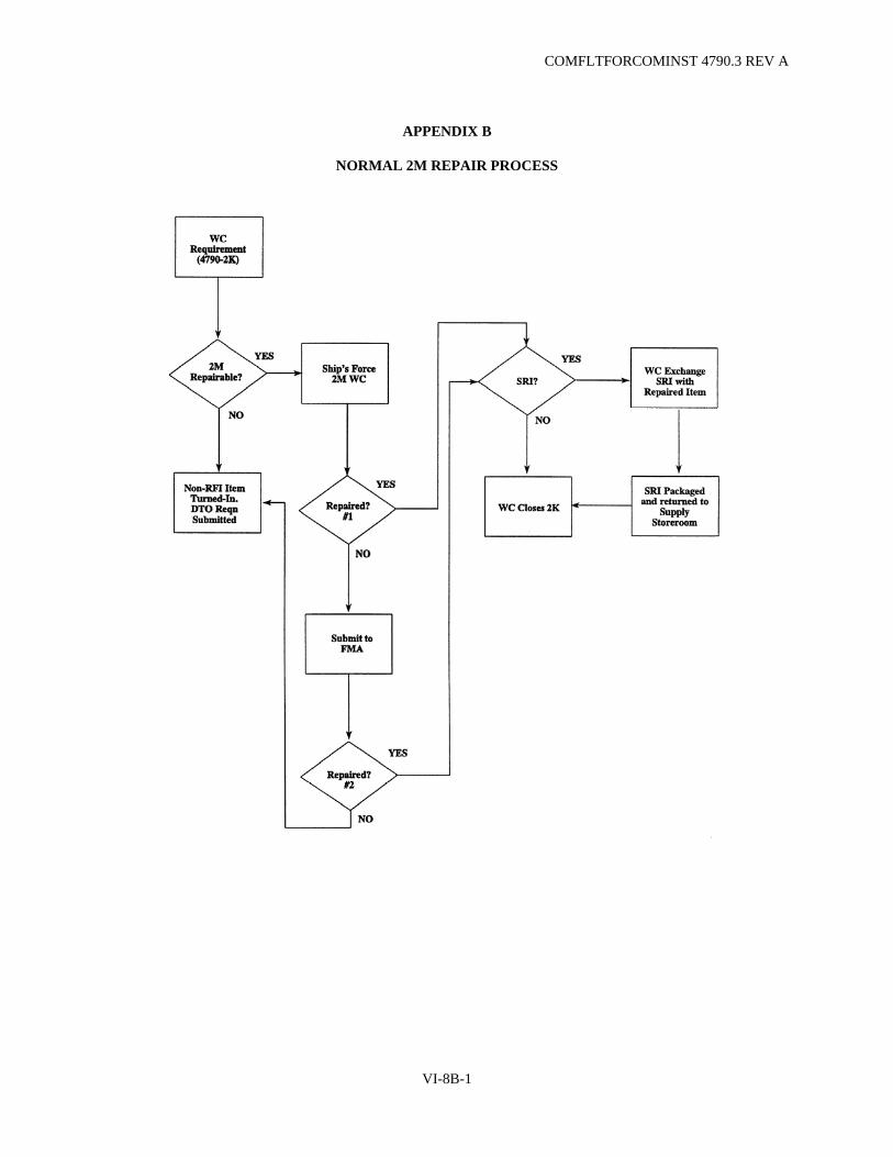
COMFLTFORCOMINST 4790.3 REV A
APPENDIX B
NORMAL 2M REPAIR PROCESS
VI-8B-1

COMFLTFORCOMINST 4790.3 REV A
(This Page Intentionally Left Blank)
VI-8B-2
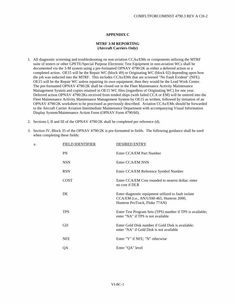
COMFLTFORCOMINST 4790.3 REV A CH-2
APPENDIX C
MTRF 3-M REPORTING (Aircraft Carriers Only)
1. All diagnostic screening and troubleshooting on non-aviation CCAs/EMs or components utilizing the MTRF suite of testers or other GPETE/Special Purpose Electronic Test Equipment in non-aviation WCs shall be documented via the 3-M system using a pre-formatted OPNAV 4790/2K as either a deferred action or a completed action. OE15 will be the Repair WC (block 49) or Originating WC (block 02) depending upon how the job was inducted into the MTRF. This includes CCAs/EMs that are screened "No Fault Evident" (NFE). OE15 will be the Repair WC unless repairing its own equipment; then they would be the Lead Work Center. The pre-formatted OPNAV 4790/2K shall be closed out in the Fleet Maintenance Activity Maintenance Management System and copies retained in OE15 WC files (regardless of Originating WC) for one year. Deferred action OPNAV 4790/2Ks received from tended ships (with failed CCA or EM) will be entered into the Fleet Maintenance Activity Maintenance Management System by OE15 as written, followed by initiation of an OPNAV 4790/2K worksheet to be processed as previously described. Aviation CCAs/EMs should be forwarded to the Aircraft Carrier Aviation Intermediate Maintenance Department with accompanying Visual Information Display System/Maintenance Action Form (OPNAV Form 4790/60).
2. Sections I, II and III of the OPNAV 4790/2K shall be completed per reference (d).
3. Section IV, Block 35 of the OPNAV 4790/2K is pre-formatted in fields. The following guidance shall be used when completing these fields:
a. FIELD IDENTIFIER DESIRED ENTRY
PN Enter CCA/EM Part Number
NSN Enter CCA/EM NSN
RSN Enter CCA/EM Reference Symbol Number
COST Enter CCA/EM Cost rounded to nearest dollar; enter no cost if DLR
DE Enter diagnostic equipment utilized to fault isolate CCA/EM (i.e., AN/USM-465, Huntron 2000, Huntron ProTrack, Fluke 77AN)
TPS Enter Test Program Sets (TPS) number if TPS is available;enter "NA" if TPS is not available
GD Enter Gold Disk number if Gold Disk is available; enter "NA" if Gold Disk is not available
NFE Enter "Y" if NFE; "N" otherwise
QA Enter "QA" level
VI-8C-1

COMFLTFORCOMINST 4790.3 REV A
FIELD IDENTIFIER DESIRED ENTRY
CA Enter "Y" if CASREP averted; "N" otherwise (see Note)
CC Enter "Y" if CASREP corrected; "N" otherwise
TST Enter troubleshooting time in hours and tenths of hours (i.e., 0.3, 1.6)
2MT Enter 2M repair time in hours and tenths of hours (i.e., 0.3, 1.6)
AWPT Enter delay of CCA/EM repair, in days, due to awaiting parts status
b. COMPONENTS REPLACED DESIRED ENTRY
RSN Enter reference symbol number of component replaced
NSN/PN Enter NSN or component replaced; if no NSN, enter part number
COST Enter cost of component replaced
AEL Enter "Y" if component replaced is included in piece parts Allowance Equipage List; "N" otherwise
COMMENTS Comment on effectiveness of TPS and Gold Disk if applicable; if "Y" entered in CC field, include CASREP number and the Date Time Group of the message
NOTE: A CASREP HAS BEEN AVERTED WHEN A CCA/EM HAS BEEN:
A. REPAIRED OR FOUND NFE.
B. REPLACEMENT CCA/EM IS NOT CARRIED IN ONBOARD STOCK.
C. INSTALLED IN ANY COMBAT, ENGINEERING, AVIATION OR NON-TACTICAL SYSTEM RESTORING THE SYSTEM TO OPERATION.
VI-8C-2

COMFLTFORCOMINST 4790.3 REV A CH-3
APPENDIX D
SAMPLE MTRF AMPLIFYING PROCEDURES MESSAGE
FM USS (SHIP'S NAME AND HULL NO.)// TO BATTLE GROUP// INFO TYCOM//(AS APPROPRIATE) CTF//(AS APPROPRIATE) CTG//(AS APPROPRIATE) BT UNCLAS //N04790// MSGID/GENADMIN/USS (SHIP'S NAME AND HULL NO.) EMO// SUBJ/MTRF ADVISORY// REF/A/DOC/NWP 1-03.1// REF/B/DOC/NAVSUP P-485// REF/C/DOC/CNALINST 4790.42/CNAPINST 4790.54//(AS APPROPRIATE) NARR/REF A SPECIFIES REPORTING PROCEDURES TO BE USED WHEN REPORTING SIGNIFICANT EQUIPMENT CASUALTIES. REF B DETAILS MATERIAL REQUISITION AND HANDLING PROCEDURES. REF C PROVIDES INST FOR OBTAINING MTRF ASSIST// POC/(NAME)/(RANK/RATE)/(LOCATION)/(DSN/COMM TELEPHONE NO.)// RMKS/1. MTRF CONTINUES TO BE FULLY OPERATIONAL ONBOARD USS (SHIP'S NAME AND HULL NO.). MTRF ENHANCES BATTLE GROUPS COMBAT SYSTEM READINESS THROUGH ONBOARD FMA ELECTRONICS REPAIR. USS (SHIP'S NAME AND HULL NO.) HAS THE CAPABILITY TO FAULT ISOLATE AND REPAIR MAJORITY OF SUSPECT FAILED CCA/EM FOR THE BATTLE GROUP. MTRF ASSETS INCLUDE: (TAILOR LIST TO MTRF CONFIGURATION) A. HUNTRON TRACKER MODELS 2000 AND AN/USM-674(V)(2) (ProTrack) B. AN/USM-465 ATE C. 2M ELECTRONICS REPAIR D. 2M PIECE PARTS ELECTRONICS SUPPORT E. RIPLE CROWN 700 MICRO-COMPUTER BASED DRAM AND EPROM IC TEST SETS F. SENCORE LC-77 CAPACITANCE/INDUCTANCE TESTER 2. BRIEF DESCRIPTION OF (CARRIER/FMA) REPAIR CAPABILITIES (TAILOR LIST TO MTRF CONFIGURATION) A. AN/USM-674(V)(2) (ProTrack) INTERFACES WITH A DEDICATED DESKTOP PC TO ASCERTAIN AND STORE CHARACTERISTICS OF KNOWN GOOD CCAS/EMS ON MAGNETIC DISK OR CD-ROM FOR FUTURE USE AS A COMPARISON STANDARD FOR SUSPECT CCAS/EMS B. USS (SHIP'S NAME AND HULL NO.) HOLDS MOST CURRENT AN/USM-674(V)(2) TPS. MAINTENANCE SUPPORT GUIDES ARE AVAILABLE TO FULLY SUPPORT TEST AND PIECE PART REPAIR FOR THE BATTLE GROUP C. LIMITED CRYPTO REPAIR D. XEROX COPIER REPAIRS FOR MODELS 2830/1048/1090 AND SAVIN MODEL 7020S E. FULL MICRO COMPUTER TEST AND REPAIR FOR DESKTOP PC PRINTERS AND ASSOCIATED PERIPHERALS JOTS POST TIMS AND VARIOUS OTHER RAPID PROTOTYPE PC BASED SYSTEMS 3. AN/USM-674(V)(2) (ProTrack) GOLD DISK LIBRARY OF LEARNED CCAS/EMS IS AVAILABLE TO ENHANCE BATTLE GROUP COMBAT SYSTEMS AND OTHER ELECTRONIC SYSTEMS SELF SUFFICIENCY
VI-8D-1
COMFLTFORCOMINST 4790.3 REV A CH-3
4. MTRF WILL ATTEMPT TO REPAIR ANY AND ALL CCAS/EMS WITH FOLLOWING EXCEPTIONS A. CCA/EM UNIDENTIFIABLE DUE TO: (1) LACK OF TECHNICAL DOCUMENTATION (2) LACK OF COMPONENT OR CIRCUIT IDENTIFICATION (3) UNAVAILABILITY OF KNOWN GOOD CCA/EM B. CCA/EM GREATER THAN FIFTY PERCENT DESTROYED C. COMPLEX RADIO FREQUENCY CCAS/EMS D. EPROM CCA/EM WITHOUT DOCUMENTATION OR DUPLICATE CCA/EM E. UNIQUE EXPERIMENTAL CIRCUITRY 5. MTRF IS GUIDED BY THE FOLLOWING RULES: A. UPON RECEIPT OF NON-RFI CCA/EM MTRF WILL EVALUATE PROGNOSIS FOR COMPLETING REPAIRS AND PROVIDE ECD TO ALCON BY IMMED MSG WITHIN 48 HOURS. MTRF CANNOT ACCEPT CCAS/EMS OR OTHER MATERIALS REQUIRING REPAIR WITHOUT PRIOR MTRF NOTIFICATION AND DIRECTIONS PROVIDED FOR SHIPMENT BY MATCONOFF B. REPAIRED ITEMS WILL BE TAGGED RFI AND RETURNED TO THE REQUESTING UNIT C. CASREPS WILL BE SUBMITTED IAW REF A CONCURRENT WITH MTRF REPAIR REQUEST. CASREP WILL IDENTIFY MTRF REQUIREMENTS IN THE ASSIST AND AMPN BLOCKS WHEN APPLICABLE. WHEN MTRF REPAIR IS SUCCESSFUL CASREP REQUISITION WILL BE CANX IAW REF B AND CASCOR SUBMITTED IAW REF A. IF MTRF IS UNSUCCESSFUL NON-RFI ASSET WILL BE RETURNED TO REQUESTING UNIT D. ITEMS SUBMITTED TO MTRF WILL NOT BE HELD IN AWAITING PARTS STATUS. IF PARTS ARE UNAVAILABLE FROM MTRF PRE-EX BINS CV SUPPLY OR MATCONOFF SCREEN NON-RFI ASSET WILL BE RETURNED TO ORIG AS NOT REPAIRABLE BY MTRF 6. UNITS REQUESTING MTRF ASSIST SEND IMMED MSG IAW ENCL 7 OF REF C 7. ADDITIONAL INFORMATION A. PACKAGE AND MARK ALL ELECTROSTATIC DEVICES PROPERLY FOR SHIPMENT B. INCLUDE COPY OF MTRF REPAIR REQUEST MSG WITH 4790/2K AND ORIG DD 1348-1 IN SHIPPING CONTAINER. SHIP TO USS (SHIP'S NAME AND HULL NO.) MARKED ATTN EMO FOR MTRF REPAIR. USS (SHIP'S NAME AND HULL NO.) WILL PROVIDE RED STRIPE MTRF REPAIR STICKERS TO ALCON VIA SEPCOR C. ALL NON-RFI AND RFI ASSETS WILL BE COORDINATED BY MATCONOFF// BT
NOTE: ENSURE MESSAGES ARE IN ACCORDANCE WITH NTP-3 FORMAT AND CURRENT PLAIN LANGUAGE ADDRESS DIRECTORY (PLAD) IS UTILIZED.
VI-8D-2

COMFLTFORCOMINST 4790.3 REV A CH-3
APPENDIX E
SAMPLE CV/CVN MTRF REPAIR REQUEST MESSAGE
FM USS (SHIP'S NAME AND HULL NO.)//(TENDED SHIP) TO USS (SHIP'S NAME AND HULL NO.)// INFO CTF//(AS APPROPRIATE) CTG//(AS APPROPRIATE) MATCONOFF// BT UNCLAS //N04790// MSGID/GENADMIN/USS (SHIP'S NAME AND HULL NO.)//(TENDED SHIP) SUBJ/MTRF REPAIR REQUEST// REF/A/DOC/CNALINST 4790.42/CNAPINST 4790.54//(AS APPROPRIATE) AMPN/REF A SPECIFIES PROCEDURES FOR REQUESTING CV/CVN MTRF ASSIST// RMKS/1. IAW REF A, REQ MTRF ASSIST AS FOLLOWS: A. PRIME EQUIPMENT/(AN/SPS-49, MK-86, AN/UYQ-21(V) ETC.) B. CIRCUIT SYMBOL AND PN OF CCA/EM/ITEM TO BE TESTED C. NSN OF CCA/EM/ITEM TO BE TESTED D. DOCUMENT NUMBER/JSN/APL E. PRIORITY
PRI ONE - CASREP/(ITEM REQUIRED TO CORRECT CASUALTY (A, C-4 B, C-3 C, C-2 D, ANORS)) PRI TWO - SYSTEM/EQUIPMENT IS OPERABLE FROM ONBOARD OR BATTLE GROUP STOCK. FWD NON-RFI CCA/EM TO MTRF FOR REPAIR PRI THREE - REPAIR TO SPARE CCA/EM
F. BRIEF DESCRIPTION OF EQUIPMENT FAILURE G. AVAILABLE TECH DOCUMENTATION H. DISPOSITION OF NON-RFI IF NOT REPAIRABLE// BT
NOTE: ENSURE MESSAGES ARE IN ACCORDANCE WITH NTP-3 FORMAT AND CURRENT PLAD IS UTILIZED.
VI-8E-1

COMFLTFORCOMINST 4790.3 REV A
(This Page Intentionally Left Blank)
VI-8E-2

COMFLTFORCOMINST 4790.3 REV A CH-3
APPENDIX F
SAMPLE MTRF QUARTERLY REPORT MESSAGE (Aircraft Carriers Only)
FM USS (SHIP'S NAME AND HULL NO.)// TO TYCOM//(COMNAVAIRLANT OR COMNAVAIRPAC AS APPROPRIATE) INFO CNO WASHINGTON DC//N86B/N77/N88/N61/N62/N63/94// COMLANTFLT NORFOLK VA//N435// COMPACFLT PEARL HARBOR HI//N4315// COMNAVSEASYSCOM WASHINGTON DC//06Q//06QM/04DS/56Y/PMS312/PMS331/ PMS400/PMS411/PMS412// NUWC DET NORFOLK VA//2431/24311// NAVSURFWPNCEN CRANE IN//PM6/607/6073// COMSPAWARSYSCOM WASHINGTON DC//003A/003-22/003-222D/PD-50/PD-60/PMW151/PMW152/PMW156/PMW162// COMNAVSUPSYSCOM WASHINGTON DC//031/03113/03114// BT UNCLAS //N04790// SUBJ/CV/CVN MTRF (OE15) WORK CENTER QUARTERLY SUMMARY REPORT// MSGID/GENADMIN/USS (SHIP'S NAME AND HULL NO.)// REF/A/DOC/CNALINST 4790.42/CNAPINST 4790.54//(AS APPROPRIATE) AMPN/REF A CONTAINS REQ FOR MTRF QUARTERLY REPORT// RMKS/1. IAW REF A FOL DATA PROVIDED FOR O1JAN - 31MAR/ CV EQUIP BG EQUIP A. MTRF REPAIRS REQUESTED (QTY) (QTY) B. MTRF REPAIRS INDUCTED (QTY) (QTY) C. MTRF REPAIRS COMPLETED (QTY) (QTY) D. CASREPS AVERTED/CORRECTED (QTY) (QTY) E. CCAS/EMS TESTED WITH NO FAULT EVIDENT (QTY) (QTY) F. OE15 WORK CENTER REPAIRS DOCUMENTED (QTY) VIA 3-M SYSTEM G. TOTAL ESTIMATED MONETARY SAVINGS (AMOUNT) H. SURFACE MOUNT TECHNOLOGY STATION
UTILIZATION (QTY) I. PRIMARY DIAGNOSTIC EQUIPMENT USED FOR REPAIR
(1) AN/USM-465 (QTY) (2) AN/USM-674(V)(2) (ProTrack) (QTY) (3) HUNTRON TRACKER 2000/1000 (QTY) (4) OTHER (SPECIFY EQUIPMENT) (QTY) J. RETURNED TO SUPPLY RFI (PART NO.) (NSN) (EQUIP/SYSTEM) K. CV/CVN DEPARTMENT/DIVISION/WORKCENTER/SUPPORT DEPT (DEPT) (DIV) (WC/SD) (EQUIP/SYSTEM) L. RECOMMENDATIONS/COMMENTS// BT
NOTE: ENSURE MESSAGES ARE IN ACCORDANCE WITH NTP-3 FORMAT AND CURRENT PLAD IS UTILIZED.
VI-8F-1

COMFLTFORCOMINST 4790.3 REV A
(This Page Intentionally Left Blank)
VI-8F-2

COMFLTFORCOMINST 4790.3 REV A CH-2
APPENDIX G
MTRF EQUIPMENT CONFIGURATION
1. The following list comprises the minimum MTRF WC equipment and accessory configuration.
a. Digital and Analog Testing Capability:
GPETE. Huntron Tracker AN/USM-674(V)(2) (ProTrack) Huntron Tracker 2000 Huntron Switcher 410 Huntron Shortracker Model 90
b. Personal Computer:
386 microprocessor with math co-processor 4MB RAM 3.5 or 5.25 inch floppy disk drive 80MB hard drive Compact Disk - Read Only Memory (CD-ROM) VGA monitor Mouse 2 serial ports 1 parallel port
c. 2M Repair Station.
d. Modular Transfer Kits.
e. ESD Protection (Mat, Support Accessories).
f. Piece Parts Support:
Allowance Equipage List configured to site requirements. VIDMAR parts cabinet.
g. Gold Disks for Huntron ProTrack.
VI-8G-1

COMFLTFORCOMINST 4790.3 REV A
(This Page Intentionally Left Blank)
VI-8G-2

COMFLTFORCOMINST 4790.3 REV A CH-5
VOLUME VI
CHAPTER 9
METROLOGY AND CALIBRATION PROGRAM
REFERENCES. (a) OPNAVINST 3960.16 - Navy Test, Measurement and Diagnostic Equipment (TMDE), Automatic Test
Systems (ATS), and Metrology and Calibration (METCAL) (b) OPNAVINST 4790.2 - The Naval Aviation Maintenance Program (NAMP) (c) OPNAVINST 4700.7 - Maintenance Policy for U.S. Naval Ships (d) OPNAVINST 4000.57 - Logistic Support of the TRIDENT and POSEIDON Fleet Ballistic Missile
(FBM) Systems (e) NAVSEAINST 4734.1 - NAVSEA Test, Measurement, and Diagnostic Equipment (TMDE) and
Calibration Programs (f) NAVSEA ST700-AA-LST-010/NAVAIR 17-35NCA-1 - Navy Calibration Activity (NCA) List (g) NAVSEA OD 45845/NAVAIR 17-35MTL-1 - Metrology Requirements List (METRL) (h) NAVSEA ST000-AG-IDX-010 - Test, Measurement and Diagnostic Equipment Index (TMDEI) (i) NAVAIR 17-35QAL-15 - Naval Aircraft Carrier (METCAL) Program Manual (j) OPNAV 43P6 - MEASURE Users Manual (k) NAVSEAINST 4790.8/OPNAVINST 4790.4 - Ships' Maintenance and Material Management (3-M)
Manual (l) NAVSUP Publication 485 - Afloat Supply Procedures (m) NAVSEAINST C9210.4 - Changes, Repairs and Maintenance to Nuclear Powered Ships
9.1 PURPOSE. To promulgate policy and assign responsibility for the management of the Navy Test, Measurement and Diagnostic Equipment (TMDE) which includes the associated Metrology and Calibration (METCAL) program, in accordance with reference (a).
9.1.1 Scope. This instruction applies to all Navy commands whose maintenance policy and practices fall under the cognizance of references (b), (c) and (d) and Fleet shore activities such as Ground Electronic Maintenance Divisions and Fleet Area Control and Surveillance Facilities. Excluded are calibration activities and equipment under the technical cognizance of the Radiation Detection, Indication and Computation program.
9.1.2 Policy. The Chief of Naval Operations (CNO), Office of the Chief of Naval Operations (OPNAV) N4, sets policy to ensure all TMDE used for quantitative measurements are maintained and calibrated at the lowest practical level. Specific CNO policy is stated in reference (a).
9.2 RESPONSIBILITIES.
9.2.1 Fleet Commanders.
a. Operationally administer the TMDE and METCAL programs in accordance with reference (a).
b. Ensure that TMDE calibration and repair is performed at the lowest level practical using certified laboratories and trained technicians.
c. Calibrate all TMDE within the capability of the Regional Calibration Centers (RCC), TYCOM and shipboard calibration activities.
d. Assign a Fleet Representative to the TAMS Executive Board.
e. Chair Fleet TMDE - METCAL Working Groups. Commander, Atlantic Fleet chair Test and Monitoring Systems (TAMS) Executive Board Fleet Support Standing Committee.
VI-9-1

COMFLTFORCOMINST 4790.3 REV A CH-3
f. Establish the Shipboard Instrumentation System Calibration (SISCAL) program in accordance with reference (e) as required.
g. Provide funding for calibration and repair of TMDE including calibration standards, except as follows:
(1) Naval Air Systems Command (NAVAIR) will fund for fleet aviation TMDE calibration and repair.
(2) Strategic Systems Programs (SSP) will fund for TRIDENT TMDE calibration and repair.
h. Evaluate Regional Maintenance Center (RMC)/RCC and coordinate with Naval Sea Systems Command (NAVSEA) for standards to support new capabilities.
9.2.2 Type Commander.
a. Assign a METCAL Manager to administer TMDE and METCAL program requirements in accordance with references (a) and (b). Serve as a voting member to the Fleet TMDE - METCAL Working Group.
b. Review Fleet Forces Allowance Change Requests and forward to the TMDE Allowance Manager. TMDE Allowance Managers are: Type Commander (TYCOM) for aviation activities, SSP for TRIDENT activities and NAVSEA 04 for all remaining activities.
c. Redistribute excess TMDE. Aviation activities and TRIDENT activities will follow the guidance of NAVAIR and SSP respectively in redistributing TMDE. The Atlantic and Pacific Fleets will use the Consolidated TMDE Readiness Assessment (CTRA) Program.
d. Provide properly trained personnel to authorized calibration activities for the repair and calibration of assigned TMDE. Manage assigned calibration standards and calibration laboratories and Field Calibration Activities (FCA) in accordance with reference (a) and the guidance provided by the appropriate Systems Command (SYSCOM).
e. Perform Quality Assurance reviews of laboratories and ensure compliance with this instruction and appropriate SYSCOM instructions.
f. Budget and manage funds to support calibration overflow for calibration support beyond the capability of RMC/RCC, TYCOM and shipboard calibration activities.
g. Ensure that Regional Loan Pools (RLP) are established in RMC/RCC.
h. Coordinate with Naval Surface Warfare Center Earle, NJ for Sub-Category (SCAT) assignments and Ship's Portable Electronic Test Equipment Requirements List (SPETERL) revisions.
i. Assist Fleet Commander representatives in managing the Fleet TMDE and METCAL programs.
9.2.3 NAVSEA Technical Authority.
a. Naval Surface Warfare Center (NSWC) Corona Division is the Engineering Activity for metrology and acts as NAVSEA technical authority. NSWC Corona performs acceptance tests for new equipment for induction into the METCAL program, sets and modifies calibration intervals, and publishes metrology associated documents such as the Naval Calibration Activity List and the Metrology Requirements List (references (f) and (g)) in accordance with SYSCOM directives. NSWC Corona may be contacted by telephone or message for resolution of urgent technical problems related to calibration standards or Instrument Calibration Procedures.
VI-9-2

COMFLTFORCOMINST 4790.3 REV A CH-3
b. Naval Surface Warfare Center, Carderock Division, Ship Systems Engineering Station (NSWCCD-SSES) is the Engineering Activity for SISCAL and acts as NAVSEA technical authority for all shipboard installed instrumentation. NSWCCD-SSES determines shipboard instrumentation calibration workload (cal "YES" or "NO") by applying the principles of Reliability-Centered Maintenance, sets and modifies calibration intervals for shipboard instrumentation/systems, develops and validates associated calibration procedures and publishes related calibration documentation such as ship-specific Calibration Requirements Lists (CRL), calibration Planned Maintenance System (PMS) (Maintenance Requirement Cards (MRC)), and System Calibration Procedures (SCP) in accordance with NAVSEA directives (see paragraph 9.7 of this chapter). NSWCCD-SSES may be contacted by telephone or message for resolution of urgent technical problems related to calibration of shipboard instrumentation, calibration PMS and/or SCPs. (SSES).
c. NSWC Indian Head Division, Seal Beach Detachment is the In-Service Engineering Activity for Test Measurement Diagnostic Equipment/General Purpose Electronic Test Equipment (TMDE/GPETE) and acts as NAVSEA technical authority. Seal Beach Detachment prepares specifications for new TMDE/GPETE and makes technical decision on what instruments are listed in the TMDE Index. Seal Beach Detachment may be contacted by telephone or message for resolution of urgent technical problems related to all Navy GPETE. (NSWC SEAL BEACH).
9.2.4 Immediate Superior in Command.
a. Monitor calibration readiness status within their respective organizations, especially ships in a pre-deployment status. Forward requests for assistance to the TYCOM METCAL Manager.
b. Monitor the effectiveness of Shipboard Gage Calibration Program (SGCP) FCAs.
c. Ensure that ships with FCAs extend their service to other ships in company, as appropriate, to reduce cost and turn-around time of calibration.
d. Ensure that each ship with an FCA has all the necessary standards, documentation and trained personnel to maintain current certification.
e. Coordinate resolution of calibration problems found by the TYCOM designated support activity for assigned ships.
f. (Submarine Force only) Ensure each activity actively supports the Periodic Maintenance Requirement (PMR)/Maintenance Resource Management System scheduling program by maintaining at least 95% accomplishment rate for all calibration equipment in its inventory. The PMR reports or equivalent will be used to monitor the program.
9.2.5 Commanding Officers All Forces.
a. Maintain a high degree of TMDE calibration readiness.
b. Appoint in writing, a calibration coordinator/test equipment manager responsible for all matters related to the calibration of ship's TMDE. Separate coordinators may be appointed for electronic and mechanical equipment.
c. Maintain TMDE allowances in the SPETERL. Advise the TYCOM METCAL Manager and contact the CTRA to fill deficiencies prior to submitting requisitions for replacement test equipment through the supply system. Deliver excess test equipment to the CTRA facility.
d. Use only standard test equipment listed in reference (h). Inform the TYCOM METCAL Manager of system maintenance requirements that are not supported by standard test equipment.
VI-9-3
COMFLTFORCOMINST 4790.3 REV A CH-3
e. Ensure TMDE is submitted for calibration prior to the calibration due date, with all accessories, power cords and technical manuals required to complete calibration.
f. Submit pre-deployment calibration requirements to the RMC METCAL Coordinator at least 60 days before deployment. Conduct an inventory of all Special Purpose Electronic Test Equipment (SPETE) to confirm material condition and calibration due dates.
g. Calibration Readiness Goal: Submarine Force - 95% Air Force and Surface Force - 85%
9.2.6 Commanding Officers Surface Force.
a. Ensure the CRL is used to determine calibration requirements.
b. Use a TYCOM approved formal recall system for scheduling, planning and monitoring the ship's calibration status.
c. Ensure the FCA is currently certified and properly staffed with trained personnel, documentation and calibration standards (allowance quantities listed in the SPETERL).
d. Ensure all TMDE within the calibration capability of the FCA are calibrated onboard.
e. Ensure FCA equipped ships offer support to other ships in company on a not-to-interfere basis with own ship's work schedules.
f. Request calibration services, beyond the capability of the onboard FCA, from the RMC METCAL Coordinator.
g. Maintain liaison with the RMC METCAL Coordinator to make sure TMDE scheduled for off-ship calibration are delivered and returned according to the agreed upon schedule.
h. Use the RLP for maintenance requirements while the ship's test equipment is being calibrated or as indicated in the SPETERL (borrow from Regional Loan Pool).
i. Ensure all critical instruments are clearly labeled with current calibration stickers.
j. Ensure all calibration is conducted at the lowest level of calibration feasible.
k. Ensure all ship's instrumentation appears in a formal calibration accounting and recall system. This data should reflect CRL information such as system, nomenclature, periodicity, etc. The CRL should also be validated annually and these updates (adds/deletes) should be forwarded via Technical Manual Deficiency/Evaluation Report (TMDER) to correct the hull specific CRL.
l. SGCP FCA calibration procedures are listed in Maintenance Index Page (MIP) 9802 series and should be listed under PMS work center FCA1.
9.2.7 Commanding Officers Naval Air Force. Naval Air Force activities shall also follow the detailed procedures outlined in reference (i) for TMDE management and for operation of the consolidated FCA.
9.2.8 Regional Maintenance Center Metrology and Calibration Coordinators.
a. Coordinate and schedule off-ship calibration or repair services for ships within their geographic area of responsibility. Specific lack of capability is the only justification for off-ship calibration.
VI-9-4

COMFLTFORCOMINST 4790.3 REV A CH-3
b. Maintain close liaison with the RMC/RCC shipboard calibration coordinators and the Immediate Superior In Command (ISIC) to prevent or resolve calibration scheduling and readiness problems.
c. Review ship's calibration work requests to ensure that TMDE within the calibration capability of the ship's FCA are not sent to a higher-level calibration laboratory.
d. Contact all deploying ships that have not delivered a pre-deployment calibration work package at least 45 days before deployment to determine ship's requirements.
e. Notify TYCOM METCAL Managers, as applicable, of all changes in RMC/RCC calibration capability.
f. Assist RMC/RCC calibration laboratories in obtaining calibration or repair services for laboratory standards.
g. Identify TMDE calibration requirements beyond the technical capability of the RMC/RCC. Coordinate the scheduling of those TMDE to an approved calibration laboratory. Notify by message, the overflow laboratory selected to receive the calibration assignment.
h. Coordinate with ISIC to confirm SISCAL dates and promulgate in SISCAL scheduling messages.
9.2.9 Regional Maintenance Center/Regional Calibration Center.
a. In the absence of an approved Instrument Calibration Procedure for TMDE within the general range of the laboratory capability, develop a Local Calibration Procedure in accordance with reference (e), and then calibrate the instrument. Technical manuals, manufacturers' guides or other equipment technical documentation may be used to develop the interim procedure. Forward the locally developed procedure to NSWC Corona for review and approval.
b. Calibrate and/or repair TMDE including calibration standards assigned by the RMC METCAL Coordinators. Document all calibration actions using the Metrology Automated System for Uniform Recall and Reporting (MEASURE) or the TYCOM directed data collection method.
c. Ensure that electronic TMDE submitted by the Fleet is standard test equipment listed in reference (h). Contact the submitting activity and the TYCOM METCAL Manager when non-standard TMDE is submitted for calibration. Non-standard TMDE will not be calibrated or repaired unless approved by the TYCOM.
d. Ensure all laboratory standards are properly calibrated at the lowest appropriate level. Notify the TYCOM METCAL Manager of any lost or reduced laboratory capability.
e. Ensure all TMDE repaired by the RMC/RCC are completely recalibrated before being returned to service. Calibration of a repaired instrument will serve as Quality Assurance of an accomplished repair.
f. Prepare and submit Calibration Problem Reports to NSWC Corona for assistance or guidance concerning calibration problems encountered during operation of the calibration laboratory.
g. Refer to Section 9.5 of this chapter for replacing malfunctioning calibration standards certified by a repair facility to be Beyond Economical Repair (BER), (i.e., having a repair cost in excess of 50% of the replacement cost).
9.3 CALIBRATION MANAGEMENT.
9.3.1 Shipboard Gage Calibration Program Field Calibration Activity (Surface Force only). The SGCP provides onboard calibration capability for TAMS in the following measurement areas: temperature (high and low), pressure, vacuum and torque (selected ship classes only).
VI-9-5

COMFLTFORCOMINST 4790.3 REV A CH-3
a. Only certified SGCP FCAs are authorized to calibrate installed instrumentation within their capability. Beyond capability calibration is submitted to the RMC Calibration Coordinator for scheduling and accomplishment.
b. The SGCP technicians are responsible for placing the appropriate METCAL label on the calibrated instruments. The SGCP Calibration Coordinator is responsible for adding the calibration data into the TYCOM directed recall program.
c. SGCP FCAs shall establish PMS work center FCA1. PMS MIP 9802 series are the calibration procedures for SGCP FCAs.
d. Non-critical instrumentation will have a No Calibration Required (NCR) METCAL label attached. When a NCR instrument's reliability is suspect, it will be sight compared with a critical instrument or a SGCP standard. When a NCR instrument is repaired or replaced, it will be installed and sight compared with a critical instrument or SGCP standard. If a primary instrument is out of commission, a NCR instrument may be calibrated at the discretion of the inspection team to validate system parameters.
e. The SGCP Calibration Coordinator is responsible for validating the CRL data and ensuring that instrumentation identified in the METCAL Automated Information Systems (AIS) inventory matches CRL data: system, nomenclature, periodicity, etc. Updates are forwarded via TMDERs.
9.3.2 Calibration Accounting.
a. METCAL AIS is a recognized Navy data processing system supporting the Navy METCAL Program. METCAL AIS must be used for TMDE calibration recall scheduling and to report calibration accomplishment.
b. Complete guidance for implementation and operation of METCAL AIS shall be in accordance with reference (j).
9.3.3 Submarine Forces Management Policy.
a. Personnel certified as submarine FCA technicians will use PMS MIPs/MRCs to accomplish shipboard calibrations. Any A-64 series MIPs currently held on board are to be destroyed as the calibration MIPs are received. PMS MIPs are currently developed for SSBN/SSGN 726 and SSN 21 Class Submarines and are in the validation phase of development for SSN 688 Class.
b. Personnel certified as FCA Technicians for surface platforms assigned to COMSUBLANT/COMSUBPAC are to utilize PMS MIP 9802 series for the performance of shipboard calibration.
c. The scheduling and reporting of calibration actions will be accomplished via Maintenance Data System using the PMR Scheduling Module and its associated Micro-Calibration and Scheduling Management program. All assigned MIPs/MRCs are to be maintained in accordance with the requirements of reference (k).
d. All components being "tested" or "calibrated" using a calibrator (i.e., 3666, 3461, 1127, 3604, 3605, etc.) will have a calibration sticker affixed. System calibrations will utilize the miniature yellow, Special Calibration, sticker annotated to reflect system calibration and the components tested. This Special Calibration sticker is to be located on the "readout component." The system calibration periodicity will be governed by the applicable Class Maintenance Plan and the most restrictive component within that system except where MRC periodicities have been established for the system.
e. A certified FCA technician is required for the operation of calibration equipment called out for use in the performance of any PMS requirement.
VI-9-6

COMFLTFORCOMINST 4790.3 REV A CH-3
9.4 REGIONAL LOAN POOLS. RLPs are established at the RMC/RCC to alleviate shipboard maintenance support shortfalls caused by a lack of shipboard GPETE due to calibration or repair requirements.
a. RLPs include a wide variety of calibrated, Ready For Issue items stocked in sufficient quantity to ensure continuous availability.
b. GPETE from the RLPs may be checked out for a specific purpose (i.e., repair of the AN/SPS-73 Radar, PMS of the AN/WSC-3, etc.) or to satisfy a temporary requirement for special purpose items not normally included in the ship's allowance. Pool items are intended as short-term substitutes for unavailable shipboard items. Pool items may be checked out for ten working days; however, the RMC METCAL Coordinator may authorize an extension of the ten day limit on a case basis.
c. All GPETE returned to the RLP shall be inspected by representatives of the lending RMC/RCC and the borrowing command. The original inventory receipt is checked to see if the GPETE has been damaged or is missing accessories provided at the time of the loan. GPETE lost, damaged beyond repair or destroyed must be surveyed by the borrowing command using procedures established in reference (l). A copy of the completed survey report shall be forwarded to the appropriate TYCOM METCAL Manager.
9.5 REPLACEMENT OF GENERAL PURPOSE ELECTRONIC TEST EQUIPMENT/CALIBRATION STANDARDS.
9.5.1 Depot Level Repairables. GPETE/Calibration Standards (CAL STD) (7Z Cog), certified by a RMC/RCC or a higher-level activity as BER will be turned into the Naval Supply System. (Note: NAVAIR CAL STDs will not fall under these instructions.) For BER NAVAIR CALSTDs, RMC/RCC and Customer activities are required to contact TYCOM METCAL manager.
a. The RMC/RCC certifying the GPETE/CAL STD as BER may turn the defective unit in to the Navy Supply System for the customer activity, provided the customer has given the RMC/RCC a requisition number under which a replacement will be ordered. If the RMC/RCC turns the defective GPETE/CAL STD in to the Naval Supply System, all turn-in data must be given to the customer to assist in any future carcass tracking follow-up investigations by the Naval Supply System.
b. The customer activity may accept return of the defective GPETE/CAL STD from the RMC/RCC and initiate turn-in and replacement procedures through the normal Navy Supply System process.
c. Depot Level Repairable GPETE/CAL STD will not be processed for survey by a RMC/RCC.
9.5.2 Navy Stock Funded. GPETE (1H or 9N Cog), certified by an RMC/RCC or a higher-level authority as BER will be processed for survey.
a. The RMC/RCC certifying the GPETE/CAL STD that are BER must notify the customer of a requirement to survey the defective GPETE/CAL STD. The customer is responsible for initiating a survey action and requisitioning a replacement item through normal Operating Target funded supply channels.
b. The RMC/RCC certifying the GPETE/CAL STD as BER may retain the carcass for cannibalization of repair parts provided the customer has acknowledged that the survey process has been initiated and has provided a copy of the survey document to the RMC/RCC.
VI-9-7
COMFLTFORCOMINST 4790.3 REV A CH-3
9.6 TEST MEASUREMENT DIAGNOSTIC EQUIPMENT MANAGEMENT.
9.6.1 Ship's Portable Electronic Test Equipment Requirements List. The SPETERL is the allowance document for all GPETE, SPETE and FCA calibration standards. Test equipment and FCA calibration standards allowance requirements (quantity and type) are computed on an individual ship's entire configuration of installed electrical and electronic equipment, with due consideration for function, quantity, usage and location of prime equipment. The Allowance Change Request form, NAVSUP 1220-2, is used to request an increase or decrease in the SPETERL allowance.
9.6.2 Test Measurement Diagnostic Equipment Index. Reference (h) is the primary source for determining test equipment uses and requirements. Consult reference (h) to determine the preferred model of test equipment needed to fill a specific deficiency. Test equipment deficiencies fall into two categories, initial outfitting and replacement.
9.6.3 Sub-Category Code. Defines a family of test and measurements parameters. Test equipment within the SCAT code is prioritized in accordance with reference (l), with the lowest priority number assigned to the TMDE currently being procured to fill outstanding deficiencies. SCAT codes are the basis for identifying TMDE on MRCs.
9.6.4 Ship's Configuration and Logistics Support Information System Index. The primary test equipment inventory document for ships. The Ship's Configuration and Logistics Support Information System (SCLSIS) Index must be kept current by the submission of completed OPNAV 4790/CK forms.
9.6.5 Consolidated Test, Measurement and Diagnostic Equipment Readiness Assessment.
9.6.5.1 Consolidated Test, Measurement and Diagnostic Equipment Readiness Assessment Program. The CTRA Program is a joint fleet program that improves fleet and shore command non-Aviation TMDE readiness. The CTRA Program also includes the receipt, staging and redistribution of Fleet excess electronic test equipment, mechanical test equipment and calibration standards used to replace equipment that is missing or BER.
9.6.5.2 Type Commander Metrology and Calibration Program Managers. TYCOM METCAL Program Managers are responsible for the following:
a. Scheduling a CTRA during ship Inter-Deployment Training Cycle or Integrated Logistics Overhaul and every 18 to 24 months for shore commands.
b. Budget for the CTRA program as necessary.
c. Develop and promulgate CTRA schedule as required.
d. Maintain excess test equipment and calibration standards at CTRA staging area for redistribution to fleet activities.
9.6.5.2.1 Consolidated Test, Measurement and Diagnostic Equipment Readiness Assessment Review Process.
a. Brief ship's department heads, division officers and technicians.
b. Conduct training for TMDE management and the calibration recall software.
c. Review SPETERL and electronic (E) TMDE inventory with the ship's Combat Systems Test Equipment manager. Review will include: Configuration verification of prime systems and Fleet Supplemental Test Equipment Requirements, verification of shipboard TMDE inventory and revision to the "E" inventory, prime system updates to Navy configuration database (if during Integrated Logistics Overhaul availability), identification of SPETERL allowance changes based on actual configuration, listing of inoperable items and coordination of repair of items that fill deficiencies, removal of excess equipment from the ship and filling of deficient equipment from CTRA staging assets. Deficient initial outfitting items will be coordinated through NAVSEA.
VI-9-8
COMFLTFORCOMINST 4790.3 REV A CH-3
d. Review Mechanical "S" inventory with the SGCP Coordinator using the CRL to determine calibration requirements. Mechanical test equipment will be listed on this mechanical inventory. Use the CRL to validate the recall inventory.
e. Provide the results of the assessment to the ship (results will be provided by Integrated Logistic Overhaul for those ships in availability).
9.6.5.2.2 Consolidated TMDE Readiness Assessment Test, Measurement and Diagnostic Equipment Redistribution. The CTRA Center manages the redistribution of Fleet TMDE to fill allowance deficiencies or replace equipment that is missing or BER. Excess TMDE and decommissioned ships' assets are received and made available for redistribution to FLEET activities. Fleet activities are required to forward all excess TMDE to the CTRA Center.
9.7 SHIPBOARD INSTRUMENTATION AND SYSTEM CALIBRATION. The SISCAL Program, which includes SGCP, is responsible for the calibration and maintenance support for shipboard installed instrumentation and machinery control system calibration requirements. The source document for calibration requirements is the CRL and includes data pertinent to each instrument (e.g., nomenclature, system, periodicity, calibration activity, etc.). CRLs are hull specific and require shipboard personnel to validate. RMC SISCAL teams, SGCP and Aviation Intermediate Maintenance Departments (AIMD) provide SISCAL calibration support. Approved calibration procedures include MIP 9802, SCP and Instrument Calibration Procedures. Only SISCAL Teams are authorized to use SCPs.
a. SISCAL teams are established at RMCs and assigned responsibility for performing calibration using SCPs and MIP 9802 series, in addition to calibration of instrumentation beyond the capability of the AIMD/SGCPs. SISCAL team responsibilities also include:
(1) Provide a SISCAL report to each ship after completion of scheduled SISCAL. Report format is promulgated by the TYCOM. Submit calibration data to MEASURE Operation Control Center for updating METCAL AIS.
(2) Ensure SISCAL team manning is in accordance with SISCAL certification requirements.
(3) The SISCAL SPETERL is the allowance document for all standards and test equipment.
b. RMC METCAL Coordinator schedules SISCALs with ISICs. Requests for SISCAL extensions will be processed by submission of a minor Departure from Specification to the TYCOM (Volume V, Part I, Chapter 8 of this manual) and will be granted on a case-by-case basis.
c. SISCAL workload may only be contracted out if certified as a Navy lab and approved by NAVSEA 04 to use SCPs (system calibration). Commercial activity must calibrate using periodicities listed in the CRL. The commercial activity must provide calibration data to Ship's Force in format to accommodate entry into METCAL AIS.
9.7.1 Calibration Requirements List. The CRL is distributed to the Engineer Officer and AIMD Officer (LHA/LHDs).
a. The CRL is the primary technical reference for shipboard installed instrumentation.
b. CRL Validation.
(1) Ship's Force validates CRL to make ship specific. Validate SGCP responsible instrumentation and confirm nomenclature, function, range, location and calibration requirement. The SISCAL team is responsible for validating SISCAL instruments.
(2) Ship's Force submit NAVSEA TMDER, via mail or email, to document changes to shipboard configuration (adds/deletes).
VI-9-9
COMFLTFORCOMINST 4790.3 REV A CH-4
(3) Ship's Force match CRL data to the METCAL AIS or Calibration Recall and Inventory System inventory and submit changes to the MEASURE Operational Control Center East or West. The CRL and METCAL AIS do not have matching data elements as MEASURE and Calibration Recall and Inventory System; refer to the CRL CD-ROM Users Guide.
c. The CRL is the technical authority document for all shipboard instrumentation calibration requirements. To preclude continuous and duplicative review of TMDERs, inspecting activities are to coordinate directly with NAVSEA METCAL MANAGER, 04RM, regarding any instrument believed to be critical but indicates No Calibration Required in the CRL. Ship's Force is not required to calibrate these instruments unless specifically approved by NAVSEA 04RM.
d. Calibration intervals in the CRL take precedence over the intervals in technical manuals and the Metrology Requirements List.
9.7.2 Calibration Interval. Since calibration intervals are identified in different technical documents, use the following order of precedence for determining and assigning the proper calibration interval:
a. Reactor Plant Manual.
b. PMS documentation.
c. CRL.
d. Reference (g) of this chapter. Unless superseded by PMS, the generic calibration intervals for all other instruments found in Section 2 of reference (g) will be used.
e. System or equipment technical manuals.
9.7.3 Markings for Installed Instrumentation. All installed instrumentation will be clearly labeled with current calibration stickers and have easily read serial numbers. If the instrument does not have a serial number inscribed by the manufacturer, Ship's Force must inscribe a ship-generated serial number in a clearly visible location. Attached tags are acceptable for instruments without space for inscribing a serial number. Limit the serial number to 15 characters due to the MEASURE serial number field size. Serial number should include: Unit Identification Code + CRL reference number + Alpha letter (i.e., DDG5100025A). Alpha number is used when an instrument is replaced. The new instrument should be given the same ship generated serial number to allow for history to be maintained (i.e., serial number and A, B, C, etc.).
9.8 LHA AND LHD CLASS SHIP METROLOGY AND CALIBRATION PROGRAM.
9.8.1 Purpose. To establish the consolidated METCAL program for LHA and LHD class ships. This guidance implements policy and responsibility for the management of TMDE onboard these ship classes. The CNO METCAL policy is promulgated in reference (a).
9.8.2 Background. LHA and LHD class ships have formerly operated three distinct calibration programs: AIMD FCA for aviation Support Equipment; Combat Systems Electronic FCA supporting GPETE and SPETE for the ship's non-aviation electronic/electrical and weapons systems; and the Engineering SGCP for installed instrumentation associated with Hull, Mechanical and Electrical (HM&E) systems. This guidance establishes and describes a consolidation of the three programs into a single program for shipboard calibration support. For the purpose of this section, TMDE are considered to be all shipboard GPETE, SPETE, Support Equipment, calibration standards and the installed instrumentation that support HM&E systems.
VI-9-10
COMFLTFORCOMINST 4790.3 REV A CH-4
9.8.3 Discussion. The forces afloat METCAL program for LHA and LHD class ships is intended to improve force readiness and self-sustainability through the consolidation of the three existing, separate calibration programs laboratories into a single management entity under the management of the AIMD Officer. This guidance preserves the positive aspects of all previous calibration programs and results in a more efficient use of personnel, a conservation of physical space and a reduction of expenditures for calibration standards.
9.8.4 Scope. This guidance is directive in nature and may be cited as authority for actions as the need dictates. Reference (i) is a parallel effort onboard aircraft carriers, and may be used as an authoritative reference for overlapping procedures and responsibilities. Reference (j) provides MEASURE documentation procedures. Reference (g) remains the authoritative reference document for all general procedural issues relating to calibration. Reference (b) addresses CNO concepts, policies, organizations, maintenance support procedures and organizational/intermediate maintenance. In the event the contents of this guidance or reference (i) conflict with any directive issued by higher authority, the latter shall prevail.
9.8.5 Applicability. This guidance is applicable for all calibration performed by LHA and LHD class Ship's Force personnel, with the exception of technical matters pertaining to Radiation Detection, Indication and Computation equipment, which are the responsibility of Commander, Naval Sea Systems Deputy for Logistics (SEA 04). Nothing in this directive detracts from these responsibilities.
9.8.6 Action.
a. Commanding Officers shall have the overall responsibility for maintaining a high degree of calibration readiness for all TMDE.
b. AIMD Officers shall:
(1) Be the shipboard METCAL program manager.
(2) Be the consolidated FCA manager.
(3) Provide calibration, per the intervals and procedures of reference (g), except as noted in paragraph 9.7 of this chapter, where the CRL takes precedence for SISCAL instrumentation calibration intervals and procedures. Provide repair services for all qualifying shipboard TMDE per reference (i).
(4) Maintain custody of, and be accountable for, all shipboard standards for calibration of TMDE.
(5) Use MEASURE to plan, schedule, monitor and document the calibration of all TMDE per reference (j).
(6) Staff the shipboard FCA with qualified calibration technicians and provide training to maintain their proficiency.
(7) Ensure all approved calibration standards are available to support the authorized workload.
(8) Ensure all documentation required to support calibration is current and available to personnel operating the FCA.
(9) Produce appropriate documentation or document the repair requirement and record repair accomplishment into MEASURE and the aviation Maintenance and Material Management system.
(10) Calibrate all TMDE within the capability of the onboard FCA. Calibration standards have first priority for calibration, with all other priorities based on mission requirements determined in coordination with affected department heads.
VI-9-11

COMFLTFORCOMINST 4790.3 REV A CH-4
VI-9-12
(11) Schedule required calibration and repair requirements beyond the capability of the shipboard FCA to another calibration laboratory. Calibration of NAVAIR Standards and Support Equipment beyond the capability of the FCA shall be authorized and scheduled in accordance with reference (b).
(12) Coordinate the calibration of TMDE that is beyond FCA capability with external resources based on accessibility and cost effectiveness. Five general categories of external resources are available to the FCA. The resources, in order of precedence to be used, are:
(a) Ashore AIMDs and RCCs.
(b) System Command sponsored Navy Calibration Laboratories.
(c) Navy depot level activities.
(d) Other Department of Defense calibration laboratories approved for use by TYCOM.
(e) Navy Certified commercial calibration laboratories.
(13) Coordinate all TMDE repairs with outside resources. The precedence (based on cost effectiveness) for selecting the outside resource for repairs is:
(a) AIMD and RCC.
(b) COMNAVAIRSYSCOM Depot Level Rework Program for Support Equipment and Items (Individual Material Readiness List).
(c) Naval shipyards and ship repair facilities.
(d) Designated Overhaul Points listed in the Master Repairable Item List.
(e) Naval Systems Command field activities.
(f) Navy Certified commercial repair facilities.
NOTE: REPAIR OF NAVAIR STANDARDS AND SUPPORT EQUIPMENT BEYOND THE CAPABILITY OF THE FCA SHALL BE AUTHORIZED AND SCHEDULED IN ACCORDANCE WITH REFERENCE (b).
(14) Submit only operational TMDE for off-ship calibration. All functions and ranges to be calibrated must be operating and usable unless special calibration is requested. Verify all necessary accessories, power cords, and technical manuals, as required to complete the calibration, are included with the instruments at the time of calibration.
(15) Request TYCOM authorization (COMNAVAIRFORCE) for repair of NAVAIR assigned calibration standards per the NAVAIR METCAL Scheduling Letter, NAVAIR Ltr 13640 Ser 3.9.2/series. Contact information for COMNAVAIRFORCE:
Phone - Commercial (757) 445-4434, DSN 565-4434 Fax - Commercial (757) 444-1690, DSN 564-1690 Message - COMNAVAIRFORCE SAN DIEGO CA//N421Q/N421QC//

COMFLTFORCOMINST 4790.3 REV A CH-4
(16) Coordinate with Commander, Regional Support Center METCAL manager for SISCAL scheduling. AIMD is authorized to calibrate all instrumentation within the capability of the FCA except instruments requiring SCPs per the CRL. SCPs will be performed by SISCAL teams. Ensure SISCAL instrumentation is calibrated at the periodicity with the procedure listed in the CRL.
(17) Ensure the FCA provides support under the Battle Force Intermediate Maintenance Activity concept.
c. Engineer Officers shall:
(1) Report all TMDE which require calibration to the AIMD Officer for inclusion in the ship's calibration recall schedule upon request.
(2) Deliver portable TMDE for calibration to the FCA per the AIMD managed calibration recall schedule.
(3) Coordinate in-place calibration requirements for non-portable TMDE with the AIMD Officer.
(4) Ensure only operational TMDE are submitted for calibration. All functions and ranges to be calibrated must be operating and usable unless special calibration is requested. Verify all necessary accessories, power cords, and technical manuals, as required to complete the calibration, are included with the instruments at the time of submission.
(5) Notify the AIMD Officer and, when applicable, the Combat Systems Officer, of any TMDE inventory changes, TMDE configuration changes, CRL changes that may affect the calibration recall schedule or require additional calibration procedures or standards.
(6) Maintain the allowance quantities of authorized TMDE.
(7) Report the inventory and configuration of all TMDE supporting HM&E systems and combat support systems using the SCLSIS.
(8) Maintain a ship specific CRL or Critical Instruments List for ship HM&E systems and combat support systems.
(9) Submit all TMDE repair requirements to the AIMD Officer. A formal repair request, such as a Visual Information Display System/Maintenance Action Form (VIDS/MAF) or an OPNAV 4790/2K, is not required for repair by the shipboard FCA. MEASURE METER cards will be provided by the ship's calibration laboratory.
d. Air Officers shall:
(1) Report all TMDE eligible for calibration to the AIMD Officer for inclusion in the ship's calibration recall schedule.
(2) Deliver portable TMDE for calibration to the FCA per the AIMD managed calibration recall schedule.
(3) Ensure only operational TMDE are submitted for calibration. All functions and ranges to be calibrated must be operating and usable unless special calibration is requested. Verify all necessary accessories, power cords, and technical manuals, as required to complete the calibration, are included with the instruments at the time of submission.
(4) Coordinate in-place calibration requirements for non-portable TMDE with the AIMD Officer.
VI-9-13
COMFLTFORCOMINST 4790.3 REV A CH-4
(5) Notify the AIMD Officer and, when applicable, the Combat Systems Officer, of any TMDE inventory changes, TMDE configuration changes that may affect the calibration recall schedule, in-place calibration requirements or require additional calibration procedures or calibration standards.
(6) Maintain the allowance quantities of authorized TMDE.
(7) Submit all TMDE repair requirements to the AIMD Officer. A formal repair request, such as a VIDS/MAF or an OPNAV 4790/2K, is not required for repair by the shipboard FCA. MEASURE meter cards will be provided by the ship's calibration laboratory.
e. Combat Systems Officers shall:
(1) Report all portable and installed GPETE or SPETE eligible for calibration to the AIMD Officer for inclusion in the ship's calibration recall schedule.
(2) Deliver portable TMDE for calibration to the FCA per the AIMD managed calibration recall schedule.
(3) Ensure only operational TMDE are submitted for calibration. All functions and ranges to be calibrated must be operating and usable unless special calibration is requested. Verify all necessary accessories, power cords, and technical manuals, as required to complete the calibration, are included with the instruments at the time of submission.
(4) Notify the AIMD Officer of any TMDE inventory changes, TMDE configuration changes that may affect the calibration recall schedule or require for additional calibration procedures or calibration standards.
(5) Maintain GPETE/SPETE inventories in quantities allowed in the SPETERL. Include funding procurement of TMDE when assets are not available through CTRA programs.
(6) Report the inventory and configuration of all TMDE supporting combat systems using SCLSIS.
(7) Submit all TMDE repair requirements to the AIMD Officer. A formal repair request, such as VIDS/MAF or an OPNAV 4790/2K, is not required for repair by the shipboard FCA.
9.9 NUCLEAR PROPULSION CALIBRATION REQUIREMENTS. Nuclear propulsion plant gages, meters, thermometers and other instruments in those reactor plant systems specified by reference (m) must be calibrated in accordance with the requirements of the applicable Reactor Plant Manual. Other nuclear-powered ship's system calibration must be performed per the requirements of reference (a).
VI-9-14
COMFLTFORCOMINST 4790.3 REV A
VOLUME VI
CHAPTER 10
MOTOR GASOLINE HANDLING AND STORAGE
REFERENCES.
(a) NAVSEA S9086-SP-STM-010 - NSTM Chapter 542 (Gasoline and JP-5 Fuel Systems) (b) COMNAVAIRLANT/COMNAVAIRPACINST 3400.4 - Air Department Standard Operating
Procedures
10.1 PURPOSE. To provide guidance and safety requirements for the storage, handling and loading of Motor Gasoline (MOGAS) aboard ship.
10.1.1 Discussion. In view of the special hazards involved in the handling of MOGAS, Commanding Officers must ensure strict compliance with all MOGAS handling safety instructions, Cargo Fuel Operational Sequencing System (CFOSS) (as applicable), references (a) or (b) and this chapter. The Commanding Officer's approval shall be obtained prior to any MOGAS operation. The Aviation Fuels Officer, or other officer as may be directed by the Commanding Officer, shall be directly responsible for the planning of all MOGAS operations (i.e., loading, off-loading or transfer of gasoline, etc.), and the operation of the MOGAS system, including the training of all MOGAS operation and handling personnel. Any deviation from the safety precautions and procedures of reference (a) or this chapter shall have the approval of the appropriate Type Commander. Additionally, the Commanding Officer may specify any additional safety precautions to be taken as the situation dictates.
10.2 CHARACTERISTICS.
a. Gasoline is a highly volatile liquid that gives off vapors under all environmental conditions. This vapor, when combined with air in the proper proportion (approximately 1.4 to 7.6 percent by volume), forms an explosive mixture that can be set off by any ignition source such as a slight spark or flame. If liquid gasoline is present, the violent explosion will be followed by fire.
b. Air, at ordinary atmospheric temperature, can absorb as much as 28 percent gasoline vapor. Gasoline vapors are three to five times heavier than air, and when released, will tend to sink to the lowest level of a compartment. Liquid gasoline will expand 0.7 percent for each ten degree increase in temperature.
10.3 PERSONNEL HAZARDS. Gasoline and gasoline vapors are extremely toxic; breathing air that is rich in gasoline vapor can and has caused unconsciousness and in some cases death. Gasoline vapors, even in concentrations of less than 1.0 percent, may cause nausea and headaches if inhaled for any length of time. Strong concentrations of gasoline vapors produce an excited state leading to unconsciousness. Gasoline saturated clothing will cause irritation and severe burns to the skin and will ignite if exposed to a source of ignition. Gasoline splashed in the eyes can cause blindness. Severe physical and mental complications may result from inhalation or body absorption. Ship's personnel shall be instructed in the characteristics of MOGAS and the necessary precautions to prevent personnel injury by exposure to MOGAS or its vapor.
VI-10-1

COMFLTFORCOMINST 4790.3 REV A
10.4 STORAGE AND HANDLING.
10.4.1 Tank Conditions. Ships with installed MOGAS tanks/systems will maintain them in one of the following conditions at all times.
a. Tank is empty and gas free certified.
b. Tank is filled with water (Cofferdam may or may not be inert).
c. Tank is filled with gasoline and water (Cofferdam must be inert).
d. Gasoline has been pumped off and the tank is full of water with trace amounts of gasoline. The Cofferdam will remain inert until the tank has been flushed three times in accordance with the CFOSS and has been turned over to an industrial activity or contractor. In no case will the tank be emptied until the industrial activity or contractor is ready to gas free the tank.
10.4.2 Loading and Off-loading.
a. Before transferring MOGAS, the planning phase must include:
(1) Time the operation will start and its expected duration.
(2) CFOSS training of all involved personnel for their respective watch stations. All involved personnel must be Personnel Qualification Standard qualified for their assigned operating stations. A CFOSS talk-through and walk-through must be completed prior to commencing any MOGAS evolution.
(3) Stationing of special fire fighting personnel and their equipment, as required by the CFOSS, plus any additional requirements mandated by the Commanding Officer.
(4) Control of the smoking lamp.
(5) Setting of material condition "YOKE".
(6) Use of non-ferrous (spark-proof) tools.
b. Loading and off-loading of MOGAS to or from the installed ship's system shall be conducted pier-side. Since the MOGAS tanks overflow directly overboard, any single tank shall normally never be filled above 80 percent capacity. Operational necessity, as dictated by the appropriate Type Commander, may require the tank to be filled to 95 percent. During this time, additional precautions must be taken as follows:
(1) MOGAS pumping shall be reduced to the minimum rate.
(2) Posting of additional overboard discharge watches.
(3) Loading only that amount of gasoline that has been calculated to fill the tank to 95 percent.
VI-10-2
COMFLTFORCOMINST 4790.3 REV A
c. Most MOGAS inventory requirements are controlled by the Fleet Marine Force. They will make necessary arrangements for the delivery and/or pickup of the MOGAS. The ship will be responsible for requesting, by message, an on-load/off-load date and time, and an alternate date and time, for the evolution to commence. This message information will be provided to the local Naval Base Commander and Base Fire Marshal.
d. The Base Fire Marshal shall ensure that all fire fighting equipment is in position, rigged and properly manned. Additionally, the Base Fire Marshal shall ensure that all MOGAS connections are tight, and that no leaks are apparent when the pumps are started.
e. Constant communication shall be maintained between all operating stations throughout the evolution.
f. The Ship's Fire Marshal will ensure that fire fighting equipment is rigged and manned in accordance with the CFOSS and ship's regulations.
g. Sample MOGAS per the requirements identified in paragraph 10.4.3.b below.
10.4.3 Identification and Sampling Requirements.
a. Only unleaded gasoline is used aboard naval ships with installed gasoline tanks. MOGAS color can range from light red to a straw color.
b. MOGAS samples shall be taken for laboratory analysis during on-load evolutions at the following times; just prior to starting the evolution, at approximately the mid point, and just prior to completion. During off-load, laboratory samples need only be taken just prior to commencing the off-load evolution. Gasoline samples must be clearly marked and handled with extreme care.
10.4.4 Safe Handling of Motor Gasoline.
a. Maintain all portable and installed fire fighting equipment and alarm systems in proper operational condition.
b. Maintain all grounding cables in proper operational condition.
c. Conduct frequent inspections to ensure system integrity and tightness.
d. Hold frequent fire fighting drills, with particular emphasis on the MOGAS system and storage tanks.
e. Immediately clean up any spilled or leaked gasoline and dispose of any rags or other cleanup material in accordance with ship's instructions.
f. Gasoline shall not to be used for cleaning purposes under any circumstances.
g. When the MOGAS system is in use, maintain a security watch in accordance with the requirements of the CFOSS. When the system is secured, the aviation fuels watch shall inspect the MOGAS system to ensure that there are no leaks, and that the inert readings and pressures are satisfactory.
VI-10-3
COMFLTFORCOMINST 4790.3 REV A
10.4.5 Containerized Motor Gasoline. Gasoline in drums, bladders or cans shall be located on the weather deck only, and stored so that the containers can be readily jettisoned as described in reference (a).
10.5 MOTOR GASOLINE ASSESSMENT PROGRAM.
a. The MOGAS Assessment Program has been established to assist Ship's Force personnel in the operation and maintenance of the installed MOGAS systems. This program requires an assessment to be conducted on each MOGAS equipped ship; annually, prior to on-load or off-load of MOGAS evolutions, and prior to an industrial or Fleet Maintenance Activity Availability.
b. The MOGAS Assessment Program shall be conducted by the ISIC, and will consist of the following elements:
(1) Conducting required assessments, and providing assessment reports to the appropriate Type Commander and Fleet Commander.
(2) Taking corrective action on minor discrepancies and providing guidance for repairs of major discrepancies.
(3) Providing On the Job Training for operators and maintenance personnel, as requested.
(4) Reviewing and validating the Coordinated Shipboard Allowance List, CFOSS, Planned Maintenance System, Personnel Qualification Standard and the associated technical manuals.
(5) Providing assistance during MOGAS on-load or off-load evolutions, as requested.
(6) Performing assist visits when requested by the ship.
VI-10-4

COMFLTFORCOMINST 4790.3 REV A CH-4
VOLUME VI
CHAPTER 11
MAINTENANCE, REPAIR AND OVERHAUL OF SERVICE CRAFT, LANDING CRAFT AND SMALL BOATS
REFERENCES.
(a) OPNAVINST 4780.6 - Policy for Administering Service Craft and Boats in the U.S. Navy (b) OPNAVNOTE 4780 - Service Craft and Boats Accounting Report (SABAR) (c) NAVSEA S9086-TX-STM-010 - NSTM Chapter 583 (Boats and Small Craft) (d) NWP 1-03.1 - Naval Warfare Publications Operational Report (e) NAVSEA S9086-HB-STM-010 - NSTM Chapter 233 (Diesel Engines)
11.1 PURPOSE. To provide guidance and assign responsibilities for the maintenance and repair of service craft, landing craft and small boats.
11.1.1 Policy.
a. Personnel assigned to individual ships, service craft or responsible shore based activities shall perform all landing craft, service craft and boat maintenance within their capabilities.
b. Landing craft, small boats and service craft shall be maintained with the same care that naval ships receive. This is particularly true for boats which also serve as ready lifeboats.
c. (Submarine Force only) If there is no Unit Identification Code (UIC) assigned to the craft, the parent command's UIC and a unique Work Center will be used for Current Ship's Maintenance Project control and any related OPNAV 4790/2K (see Chapter 19, Appendix E of this volume).
11.2 MATERIAL READINESS.
a. Regular periodic inspections of landing craft, small boats and service craft shall be conducted by the command to which the craft is assigned (referred to hereafter as the "parent command"). Use Fleet Maintenance Activity (FMA) facilities to conduct the required periodic inspections, whenever possible. The results of these inspections will determine the need for repairing a craft or boat. Submit overhaul and major maintenance items (i.e., engine overhauls and hull repairs beyond the ability of the parent command) to the appropriate Type Commander (TYCOM), no later than 15 January for the current and following two years. The requests for maintenance must cite the boat or craft hull number and the fiscal year quarter in which the overhaul or major maintenance availability is desired. Any significant changes to previously submitted maintenance requests must be discussed in detail (i.e., material condition of the craft affected by the change, operational commitments requiring changes, etc.).
VI-11-1

COMFLTFORCOMINST 4790.3 REV A CH-2
b. To conserve repair funds and assets, and to maintain craft and boats in a satisfactory state of material readiness, Commanding Officers of ships and shore activities shall set up a training program for all personnel connected with the operation and maintenance of craft and boats. Pride of ownership should be instilled in boat crews and assigned unit personnel. Use available personnel and funds to the fullest extent possible before requesting help from the FMA to perform routine or emergent repairs.
c. Active service craft are inspected by the Service Craft Material Inspection Board, per reference (a), to support industrial availability planning. Deficiencies identified by the Service Craft Material Inspection Board must be entered in the Current Ship's Maintenance Project prior to the Work Definition Conference. Service craft parent commands shall ensure reference (b) accurately reflects the current status of requested availabilities.
d. TYCOMs will aid parent commands with landing craft, small boat and service craft industrial availabilities by:
(1) Scheduling Restricted Availabilities or Technical Availabilities.
(2) Establishing overhaul cycles including, budgeting, scheduling, and funding per the requirements of reference (b).
11.3 MAINTENANCE OF LANDING CRAFT AND SMALL BOATS ASSIGNED TO AFLOAT UNITS.
a. Commanding Officers are urged to take full advantage of the FMA facilities for Ship's Force upkeep and repair of their landing craft and boats. A limited quantity of hand and power tools and air compressors are available at the FMA for Ship's Force use. Ships may borrow these tools by sending a properly prepared work request (OPNAV 4790/2K) directly to the FMA/Regional Support Group (RSG)/Regional Maintenance Center (RMC). Depending on the workload, assist teams from the FMA/RSG/RMC may be available to assist with the inspection of boats and craft. COMNAVSURFLANT and COMNAVSURFPAC ships and units shall obtain tools from the FMA per the requirements of Chapter 30 of this volume.
b. Ship personnel desiring to make use of FMA/RSG/RMC facilities should send a work request (OPNAV 4790/2K) to the FMA/RSG/RMC requesting crane services to handle the craft or boat and stowage space for accomplishing the work. Limited repair material not normally available on board ship, may be obtained from the FMA/RSG/RMC by including required items in the work request.
c. If long usage or extensive damage to any boat or landing craft is such that repairs by Ship's Force cannot keep a boat or craft in a proper state of readiness, a work request (OPNAV 4790/2K) must be submitted to the FMA/RSG/RMC via the TYCOM or Immediate Superior In Command (if assigned). The work request must show the following additional information in Section IV of the OPNAV 4790/2K:
(1) Boat or landing craft registry number.
(2) Complete description of the work requested.
d. The FMA/RSG/RMC will accept such requests, provided that:
(1) The ship is not scheduled for a routine Chief of Naval Operations (CNO) Maintenance Availability in the immediate future.
VI-11-2

COMFLTFORCOMINST 4790.3 REV A
(2) The repairs are beyond the capacity and/or capability of Ship's Force to accomplish.
(3) Enough time in advance of the ship's next scheduled operation is allowed for the FMA to perform the repairs and return the boat or landing craft to the ship before departure.
e. When a boat or landing craft is badly damaged, a statement of the circumstances surrounding the damage must be submitted with the request for repairs.
f. Before delivery of a boat or landing craft to the FMA for repairs, Ship's Force must accomplish the following:
(1) Remove all items of outfitting and all portable parts invoiced with the hull, including compass, tools, batteries, and portable lights.
(2) Drain and clean the bilges of dirt, diesel fuel, and oil. When it is not possible to deliver the boat or landing craft in the above condition, the repair activity will be notified in advance so that arrangements can be made for gas free inspections.
g. Reference (c) provides details for transfer, receipt, disposal and survey of boats and landing craft. Replacement boats or landing craft are normally available from Naval Sea Systems Command (NAVSEA), via the TYCOM, upon receipt of a valid Boat Inspection Report per reference (c).
h. If the FMA cannot accomplish the requested boat or landing craft repairs, the Commanding Officer of the FMA will advise the ship to request a Technical Availability from the TYCOM.
11.3.1 Landing Craft and Small Boat Repairs During Chief Of Naval Operations Maintenance Availability.
a. Hull repairs affecting strength and watertight integrity beyond the capability of Ship's Force are considered urgent items. Ship's Force shall ensure that the required repairs are included in the work package for screening at the Work Definition Conference.
b. Boats and landing craft which do not require work by an industrial activity should normally accompany the ship during the availability. Stowage areas can usually be made available at the industrial facility for accomplishment of Ship's Force work. Commanding Officers should not overlook the facilities available at FMAs for accomplishment of this work while the ship is undergoing a CNO Maintenance Availability.
c. Tests of landing craft and boat lifting gear shall be accomplished during the ship's CNO Maintenance Availability in accordance with reference (c) and Volume IV, Chapter 13 of this manual.
11.4 MAINTENANCE OF SERVICE CRAFT, LANDING CRAFT AND SMALL BOATS ASSIGNED TO SHORE ACTIVITIES, GROUP AND SQUADRON COMMANDERS.
11.4.1 Unit Level Maintenance.
a. Maintenance and repair of craft and boats within the capability of the parent command should be budgeted, scheduled, and accomplished to maintain a high state of material readiness. Commands and activities shall appoint a Maintenance Officer as a sole point of contact for all matters relating
VI-11-3

COMFLTFORCOMINST 4790.3 REV A CH-2
to boat and craft maintenance. The Maintenance Officer shall be capable of making maintenance decisions based on engineering and operational parameters and should actively participate in the planning and execution of all maintenance actions affecting the parent command.
b. Annual budget proposals submitted by the parent commands to their TYCOM shall address anticipated funding requirements to maintain the material condition of all assigned boats and craft, the accomplishment of approved modifications and modernization work (within the parent command's capability), and must discuss in detail how these funds will be applied to specific craft or boats.
c. Request for changes to boat or craft inventories, resulting from mission requirement changes, must be assessed in terms of maintenance capabilities and budget constraints. Approval of such changes may require the TYCOM to adjust the units Operating Target allocation for maintenance. The impact on maintenance support for changes in inventory must be assessed for each unit by the TYCOM before instituting changes.
11.4.2 Fleet Maintenance Activity Level/Contractor Assist Maintenance.
a. Repairs to craft and boats which are beyond the capabilities of the parent command, shall be documented on work requests (OPNAV 4790/2K) and submitted to the cognizant FMA/RSG/RMC for accomplishment. Repair funds for craft and boats are budgeted for FMA activities, on a quarterly basis, by the TYCOM. Individual craft and boat work packages will be screened by the TYCOM to ensure accomplishment within allocated funding.
b. Work requests which are screened as beyond the capability of the FMA will be submitted to the TYCOM for screening to an industrial activity. Industrial repairs are normally programmed for accomplishment during scheduled craft or boat overhauls or Restricted/Technical Availabilities, unless the repairs are of an emergent nature and have been documented with a Casualty Report in accordance with reference (d). FMAs/RSGs/RMCs will accept emergent work requests, to clear Casualty Reports, on a case basis with TYCOM approval.
c. Shore based commands which have craft or boat repairs being accomplished by industrial activities retain the responsibility for these repairs. The parent command is responsible for maintaining liaison with the industrial activity and keeping the TYCOM informed, via the RSG/RMC/Immediate Superior In Command, of problems or potential problems.
11.4.3 Overhaul of Service/Landing Craft and Small Boats.
a. A four to five year overhaul cycle has been established by the CNO for self-propelled service craft, high value boats and landing craft (e.g., SLWTs, service craft and LCUs). For other craft and boats, the necessity for overhaul is determined by usage and material condition and will generally be conducted every four to five years or as required by reference (a).
b. Service/landing craft and boats undergo CNO Maintenance Availabilities to accomplish major maintenance and modernization items which, in the judgment of the TYCOM, are beyond the unit or FMA capability. All high value boats, landing craft and service craft receive complete and thorough availabilities within the available funding. The primary goal is to accomplish all outstanding repairs and major maintenance items to ensure reliable operations during the craft's projected operational cycle.
VI-11-4

COMFLTFORCOMINST 4790.3 REV A CH-2
c. There are basically two distinct types of availabilities applicable to boats and service/landing craft:
(1) Supervisor of Shipbuilding administered industrial availabilities using a work package consisting of OPNAV 4790/2Ks.
(2) CNO Maintenance Availabilities administered through the Naval Supply Center (contracting agency) by the FMA/RSG/RMC for smaller craft/boats with less extensive maintenance and repair packages.
d. After the Work Definition Conference, and before the contracting authority (Supervisor of Shipbuilding/Naval Supply Center) issues the Invitation for Bids to potential bidders, the TYCOM and parent command will review the copies of the bid specifications for accuracy and completeness. The parent command must complete the review quickly and report any discrepancies to the TYCOM. The TYCOM will resolve any discrepancies in the bid specifications with the contracting authority before the Invitation for Bids is released.
e. Post-repair trials for craft and boats are conducted, as applicable, per Volume II, Part I, Chapter 3 of this manual.
11.5 RESPONSIBILITIES. For both types of industrial availabilities identified in paragraph 11.4.3.c of this chapter the following responsibilities are assigned:
11.5.1 Type Commander.
a. Coordinate all aspects of the advance planning.
b. Authorize all new industrial work items.
c. Authorize all growth in an existing industrial work item.
d. Provide funding to accomplish all authorized work.
e. Monitor and approve all changes in established milestones (internal milestones, used by the industrial activity to monitor schedule progress, are not subject to TYCOM approval).
f. Direct appropriate action when the quality or completeness of the industrial activity work is in question.
11.5.2 Immediate Superior In Command. (if not assigned, these functions will revert to the TYCOM)
a. Review overhaul progress reports.
b. Review Ship's Force and FMA concurrent work.
c. Ensure pertinent directives are followed concerning the safety of personnel and equipment.
d. Attend sea trial and overhaul completion review conferences.
e. Assist in all aspects of the planning and monitoring of industrial availabilities.
VI-11-5

COMFLTFORCOMINST 4790.3 REV A CH-1
11.5.3 Commanding Officers of Parent Commands.
a. Coordinate all planning aspects of craft and/or boat overhauls with the TYCOM and Immediate Superior In Command (where assigned).
b. Prepare and submit overhaul progress reports in accordance with Volume II, Part I, Chapter 3 of this manual.
c. Ensure enough trained personnel are assigned to on-site monitoring of craft or boats while in an industrial availability.
d. Fulfill all responsibilities for safety of craft and personnel.
11.6 REPAIR AND OVERHAUL OF SMALL BOAT ENGINES.
a. Boat and craft custodians shall repair and maintain engines on a continuing basis, using their Operating Target. Replacement parts shall be obtained through the Navy Stock system, when available, to prevent the potential for using erroneous parts and to simplify stocking of parts.
b. Craft and boat engine overhaul intervals are determined by engine operating hours as specified in reference (e) and/or, for engines over 400 Brake Horsepower, by trend analysis.
c. Boat Alterations are issued for the replacement of engines no longer supported by the supply system. Direct questions concerning the status of obsolete engines to NAVSEA (PMS 325) or the TYCOM.
d. All spare boat engines, or engines being turned in for replacement, must be preserved in accordance with reference (e) and stored in an enclosed protective compartment.
11.6.1 Boat Alterations.
a. Submit Boat Alteration requests to NAVSEA, (PMS 325) via the chain of command.
b. The accomplishment and funding of approved Boat Alteration shall be managed by the TYCOM.
11.7 OPERATION OF SMALL BOAT ENGINES. The operation and maintenance of all diesel engines on boats and craft shall be in accordance with reference (e).
VI-11-6

COMFLTFORCOMINST 4790.3 REV A CH-2
VOLUME VI
CHAPTER 12
DEGAUSSING
REFERENCES.
(a) OPNAVINST C8950.2 - Magnetic Silencing (b) NAVSEA S9086-QN-STM-010 - NSTM Chapter 475 (Magnetic Silencing) (c) NAVSEA S9475-AC-PRO-010 - Degaussing Forms, Records and Reporting Procedures (d) NAVSEA S5475-AL-PRO-010 - Principles and Procedures for Magnetic Treatment of Ships (e) SSPINST 8950.2 - Procedure for Fleet Ballistic Missile (FBM)/Strategic Weapons System (SWS)
Components During Flash-Deperm Treatment of an SSBN
12.1 PURPOSE. To provide magnetic silencing and deperming requirements, and the check ranging and reporting procedures defined by reference (a). Reference (b) provides the basic principles and background of degaussing.
12.2 DEGAUSSING DEFINITIONS.
12.2.1 Deperming. Deperming is the magnetic treatment of a ship's hull to minimize permanent magnetism. All newly constructed ships require deperming. The deperming needs of operational ships are established by check ranging.
12.2.2 Installed Degaussing System. A shipboard system which reduces the residual permanent and induced magnetic signature of the ship, and is the ship's primary passive mine countermeasure system. Different combinations of degaussing coils, type of controls and power supplies help to identify a degaussing system.
12.2.3 Magnetic Compass Compensation. Magnetic field from a ship's degaussing system can interfere with a ship's magnetic compass heading and make the system useless for navigation. Per reference (b), a compensating coil is set up around the magnetic compass to neutralize the effect of degaussing coil field in the vicinity of the compass.
12.2.4 Check Ranging. The action of a ship making reciprocal range runs over an instrumented range, at a Magnetic Silencing Facility (MSF), for purposes of measuring the ship's degaussed magnetic signature. Check ranging is the principle method of determining the effectiveness and reliability of installed degaussing systems. A satisfactory check range is two range runs on reciprocal headings within a six week period which are determined to be magnetically satisfactory while ship's degaussing equipment is operating properly. Degaussing range services are available at the following locations:
San Diego, CA Norfolk, VA Pearl Harbor, HI Mayport, FL Yokosuka, Japan Bangor, WA Kings Bay, GA
12.2.5 Degaussing Folder. The Degaussing Folder (NAVSEA 8950/1) is an official ship log. It contains instructions for operation of the degaussing system, degaussing charts, values for current and turn settings, installation forms, compass compensation forms, and a log section showing all pertinent details of magnetic treatment and of action taken on the ship's degaussing system for the information of degaussing authorities. The degaussing folder is issued to a ship by the MSF that renders the initial magnetic treatment and system calibration. Reference (c) provides the detailed requirements for maintaining the degaussing folder.
VI-12-1
COMFLTFORCOMINST 4790.3 REV A CH-2
12.2.6 Degaussing Watch List.
a. The Degaussing Watch List is a list of all degaussing actions required on U.S. Navy ships with installed degaussing systems. The watch list is compiled and distributed by Naval Sea Systems Command based on recommended degaussing actions submitted by the MSF, industrial activities, and other official sources.
b. Each item on the Degaussing Watch List will show the name of the deficient ship and a brief explanation of the circumstances on which the required degaussing action is based (e.g., unsatisfactory magnetic condition, faulty degaussing system, lack of trained degaussing personnel, etc.), and the nature of the required actions to be taken. Degaussing Watch List items are indexed by number and urgency codes for future reference.
c. Afloat units are provided copies of the Degaussing Watch List by Naval Sea Systems Command for those items that apply to their configuration. Type Commanders are provided copies of all Degaussing Watch List items and periodic summaries issued by the MSF.
12.3 SHIPS WITH INSTALLED DEGAUSSING SYSTEMS.
a. Reference (a) mandates check ranging for ships. To meet minimum requirements, a satisfactory check range is required every six months. Requirements for the check ranging of ships are as follows:
(1) After new construction.
(2) Before and after a major dry-docking availability.
(3) After a major shock to the hull from a nearby explosion.
(4) After grounding or collision.
(5) As feasible, before entering mined waters.
(6) Before issuing a Casualty Corrected of any Casualty Report degaussing equipment.
(7) At every opportunity, when entering or leaving a port with ranging facilities. Declining use of range facilities is not an option.
(8) After a major alteration to the hull and superstructure.
b. When ranging facilities are not available in the home port, ships will satisfactorily check range annually.
(1) Ships forward deployed to areas without ranging facilities are exempted from check range requirements by reference (a).
(2) Ships not equipped with an installed degaussing system are not required to check range.
VI-12-2

COMFLTFORCOMINST 4790.3 REV A
c. A ship which becomes the subject of a Degaussing Watch List item should send an OPNAV 4790/2K deferred action for Current Ship's Maintenance Project (CSMP) documentation. When the item has been corrected, and upon completion of satisfactory check ranging, the ship must submit a completed action document to update the CSMP.
d. Installed degaussing systems will be operated at all times while underway.
12.3.1 Check Ranging.
a. Before check ranging, contact the range facility by voice radio or by flashing light. For best results, ensure the range is clear of other shipping (including tugboats) before crossing.
b. Ranging facility requires the following information:
(1) Coil Settings. Once the ship is on course, and before the ship crosses the range, inform the facility of actual ammeter currents and polarities. Ensure the meter readings are correct for both zone and polarity.
(2) Ship's Draft. Forward and aft drafts. Provide actual keel drafts, vice navigational drafts.
(3) Ship's heading. If more than five degrees off channel course, provide the range with the actual ship's heading. Once the course is established, maintain a steady course and constant speed between 8 to 10 knots, or as the range operator directs.
12.3.2 Responsibilities.
12.3.2.1 Type Commander/Immediate Superior In Command.
a. Monitor the degaussing readiness of assigned ships.
b. Ensure that ships "check range" as required.
12.3.2.2 Ship Commanding Officer.
a. Maintain ship's installed degaussing system. Ensure ship's magnetic signature is minimized by periodic check ranging.
(1) Ships unable to check range or unable to establish communications with the MSF shall make comments as appropriate in the remarks section of the daily Operational Reports.
(2) Ships with installed systems may not decline check ranging.
b. Maintain ship's Degaussing Folder.
VI-12-3

COMFLTFORCOMINST 4790.3 REV A
12.4 SUBMARINES WITHOUT INSTALLED DEGAUSSING SYSTEMS. The submarine force shall maintain all units in the best degaussed condition within expected areas of operation. Expected areas of operation include zones .22, .33, .44, and .55 as shown in reference (d). Operations in zone .55 will necessitate additional treatment, since presently used flashing procedures are designed to provide protection only in zones .22, .33, and .44. Normally, ships are automatically ranged by degaussing facilities as they transit channels between the hours of 0800-1600 weekdays only. Weekend ranging can be arranged with the MSF on a case basis. Reference (a) mandates check ranging for ships. To meet minimum requirements, a satisfactory check range is required annually during peacetime or semi-annually during war time. Other requirements for check ranging of ships are as follows:
a. Before and after Post Shakedown Availability (following new construction).
b. After a CNO Maintenance Availability.
c. After a major shock to the hull from a nearby explosion.
d. After grounding or collision.
NOTE: THE ABOVE ARE THE MINIMUM RANGING REQUIREMENTS. EVERY OPPORTUNITY FOR RANGING SHOULD BE USED TO ENSURE EARLY IDENTIFICATION AND CORRECTION OF MAGNETIC SILENCING DEFICIENCIES.
12.4.1 Responsibilities.
12.4.1.1 Immediate Superior In Command.
a. Ensure that ships check range as required.
b. Schedule ships with unsatisfactory magnetic signatures for flash deperming at the earliest opportunity.
12.4.1.2 Ship Commanding Officer.
a. Ensure ship's magnetic signature is minimized by periodic check ranging.
b. Inform the ISIC upon receipt of an unsatisfactory ranging.
c. Maintain the ship's Degaussing Folder.
d. Undergo flash deperming as directed by the ISIC or TYCOM.
e. Before flash deperming prepare ship's equipment and off-load/protect material in accordance with references (b) and (e). Additional guidance can be obtained from the MSF.
VI-12-4

COMFLTFORCOMINST 4790.3 REV A CH-3
VOLUME VI
CHAPTER 13
CORROSION CONTROL
REFERENCES.
(a) NAVSEA S9086-VD-STM-010/020/030 - NSTM Chapter 631 Volumes 1, 2 and 3 (Preservation of Ships In-Service)
(b) NAVSEA MS 6310-081-015 - Submarine Preservation
13.1 PURPOSE. To provide basic guidelines necessary to maintain an effective Corrosion Prevention and Control Program. Guidance for prevention and repair of corrosion on ships is contained in reference (a), which supersedes all previous class specific Corrosion Control Manuals distributed by Naval Sea Systems Command, and reference (b), as applicable.
13.1.1 Background. Protective coatings are the most widely used method of corrosion control. These protective coatings have specific applications, therefore, the physical location and operating environment should be taken into consideration when choosing a coating system. Through the application of improved corrosion prevention and control techniques, procedures, and materials, longer lasting and more effective results can be obtained with a reduction in man-hours spent on preservation.
13.2 RESPONSIBILITIES.
13.2.1 Fleet Maintenance Activity.
a. Maintain facilities and sufficient qualified personnel to apply protective coatings.
b. Conduct Technical Assist Visits upon request from a ship during a Fleet Maintenance Activity Availability, or at other times as the workload permits, to include:
(1) Identification of shipboard topside corrosion problem areas.
(2) Recommendations for methods and means of corrosion problem correction.
(3) Informing Ship's Force of local industrial assets, including local Fleet Maintenance Activity, other industrial facilities (i.e., industrial activities) or Commercial Industrial Services assets.
(4) Self-help information for Ship's Force.
(5) Technical assistance on setting up and updating a ship's Corrosion Prevention and Control Program.
VI-13-1

COMFLTFORCOMINST 4790.3 REV A
13.2.2 Surface Ships.
a. Set up an ongoing corrosion prevention and control program, including all topside structure, equipment, machinery, fixtures, combat and weapons systems, and components, using reference (a) for guidance.
b. Take planned and/or corrective action on all potential discrepancies, and enter all significant discrepancies into the Current Ship's Maintenance Project.
c. Include requests for Corrosion Control Technical Assist Visits in the Fleet Maintenance Activity Availability work packages at least annually, and as necessary.
13.2.3 Submarines. Corrosion control for submarines is covered in Chapter 27 of this volume.
VI-13-2
COMFLTFORCOMINST 4790.3 REV A
VOLUME VI
CHAPTER 14
CANNIBALIZATION
REFERENCES.
(a) COMSUBLANT/COMSUBPACINST 4406.1 - Submarine Supply Procedures Manual (b) NWP 1-03.1 - Naval Warfare Publication Operational Report
LISTING OF APPENDICES.
A Sample Cannibalization Request Message
14.1 PURPOSE. To provide guidance for active ship cannibalization and the resultant payback process between ships.
14.1.1 Policy. Cannibalization between active Fleet units is not a normal peacetime practice and will not occur unless:
a. A significant degraded readiness condition has been reported.
b. All possible actions have been taken to satisfy the material requirement through other means.
c. The impact on maintenance personnel has been considered.
14.2 DEFINITIONS.
14.2.1 Self-Cannibalization. When a component is available on board the ship, but in a less essential or already inoperative piece of equipment, it may be desirable for the ship to disable the equipment/system to correct a casualty to a more critical piece of equipment or system. Such self-cannibalization is the prerogative of the Commanding Officer. Self-cannibalization is a temporary measure to return a more critical piece of equipment to an operational status. Replacement of the cannibalized component may or may not be required.
14.2.2 System Cannibalization. System cannibalization is cannibalization of system assets beyond the Type Commander's (TYCOM) purview, including other TYCOM end-use material and inactive ship equipment and components. System cannibalizations are a supply system action whereas active cannibalizations are a maintenance action. TYCOM expediters will initiate all system cannibalizations.
14.2.3 Active Ship Cannibalization. Active ship cannibalization is removal of component(s)/equipment installed in an active ship (or component(s)/equipment removed for overhaul from an active ship) for installation in another active ship. Because of the adverse effects of active ship cannibalization, such action will be taken as a last resort and only in exceptional cases when all other sources have been exhausted. When active ship cannibalization is authorized, the primary source for cannibalization are ships in Chief of Naval Operations Maintenance Availabilities, with recourse to operational ships only as a last resort.
VI-14-1

COMFLTFORCOMINST 4790.3 REV A
14.3 AUTHORIZATION (Active Ship). Conditions upon which authorization decisions are based, include the following criteria.
a. There is an urgent operational requirement for the equipment and the existing degradation to the equipment/system is considered to be unacceptable to meet the specific operational commitments.
b. A Casualty Report (CASREP) and a Not Operationally Ready Supply requisition for the material or component to be cannibalized have been issued. The scheduled or estimated delivery date must be such that the parts will not be available from the designated supply stocking point in time to achieve satisfactory material readiness at least seven days prior to an underway date or operational commitment. The required part must not be available from other equipment on board the ship, where such equipment is not essential for the ship to accomplish its mission.
c. All other sources, including screening of all ashore supply support sources, afloat inventory assets, local fabrication and system cannibalization have been exhausted.
d. Operational alternatives such as delays in deployment and gaping requirements have been considered. Routine operations may not, at the TYCOMs discretion, be sufficient cause to justify active ship cannibalization.
e. TYCOMs will normally initiate the cannibalization when the Immediate Superior In Command (ISIC) has recommended the action under special circumstances or to meet urgent operational commitments.
14.3.1 Commander Naval Surface Force Pacific Ships.
a. Cannibalization Not Involving Ships in Overhaul. When a system asset is not available and if the degree of readiness degradation (normally C3/C4 CASREP) warrants such action, the only remaining alternative is to cannibalize from an active ship. Approval of active ship cannibalization actions (not involving ships in overhaul) required to satisfy C3/C4 CASREP requirements will be at the lowest appropriate command level. If transferring and receiving ships are in the same squadron, the squadron commander is authorized to approve; if in different squadrons but the same group, the group commander is authorized to approve. If ships are in different groups, the group commander of the transferring ship is authorized to approve the cannibalization upon request from the receiving ship's group commander. Approval by the applicable group exercising operational or administrative control is required in all cases involving cannibalization for C2 CASREPs and non-CASREP requirements.
b. Cannibalization Involving Ships in Availabilities. Cannibalization from ships in availabilities will be minimized since such actions often affect maintenance/operational schedules for several ships. Cannibalization may be initiated only after non-availability of C3/C4 CASREP materials through the supply system or alternate sources has been ascertained. Cannibalization from ships in overhaul/ availability must be approved by the applicable availability manager (i.e., Commander Naval Surface Force Pacific (COMNAVSURFPAC), Commander Naval Surface Group Pacific North West (COMNAVSURFGRUPACNORWEST), Commander Logistics Western Pacific (COMLOGWESTPAC) or Commander Naval Surface Group Middle Pacific (COMNAVSURFGRUMIDPAC). Requests must be submitted via the chain of command.
c. COMNAVSURFPAC (N43) and (N4111) will be included as information addressees for tracking purposes on all cannibalization request and approval messages.
VI-14-2
COMFLTFORCOMINST 4790.3 REV A
14.3.2 Commander Naval Surface Force Atlantic Ships. All cannibalization shall be authorized by the TYCOM based upon the recommendation of the ISIC.
14.3.3 Naval Air Force Ships. All cannibalization shall be requested from and authorized by the TYCOM. The request and authorizations will be via message. The requesting message will specify the source of replacement parts, and will reference communications indicating the cannibalized ship's Commanding Officer's concurrence with the cannibalization action. The message shall further specify the method of replacement.
14.3.4 Submarine Force Ships. Cannibalization actions shall be requested from and authorized by the TYCOM. In some unique circumstances, intra-squadron cannibalization to resolve CASREPs may be authorized by the Squadron Commander. In all cases cannibalization shall be in strict compliance with Appendix J of reference (a).
14.4 REQUEST AND AUTHORIZATION. The following procedures apply when requesting authorization for active ship cannibalization:
14.4.1 Requesting Ship.
a. Submit a CASREP in accordance with reference (b) on equipment involved.
b. Submit a Not Operational Ready Supply requisition for the parts.
c. Specify the required delivery date. Verify, through the supply system, the part will not be available in time to correct the casualty.
d. Determine that the required parts are not available from on board stock, other ships of the force in the same port, or other non-essential equipment on board the requesting ship.
e. Initiate an active ship cannibalization request via naval message. Appendix A of this chapter contains a sample cannibalization message.
14.4.2 Immediate Superior In Command. When assigned, the ISIC will perform the actions listed below. Where not assigned these functions revert to the responsible TYCOM.
a. Ensure the criteria for active ship cannibalization has been met. This may require TYCOM expediter assistance.
b. Nominate possible sources of cannibalization from ships within the force.
c. When required, request authorization from the TYCOM to cannibalize from a ship within the force.
14.4.3 Type Commander.
a. Confirm that cannibalization is necessary and that all prerequisites for active ship cannibalization, including attempts to supply the components from afloat storeroom spares and system cannibalization, have been met.
b. Determine whether cannibalization is feasible from a ship within the force.
VI-14-3

COMFLTFORCOMINST 4790.3 REV A CH-2
c. If cannibalization is not feasible from a ship within the force request assistance from other TYCOMs.
14.5 PROCEDURES. The following procedures apply when cannibalization is authorized:
14.5.1 Type Commander.
a. Authorize the ISIC (where assigned) to cannibalize from a ship within the Force and provide direction concerning the method of payback to the cannibalized ship. Normally this is done by having the outstanding parts ordered by the receiving ship diverted to the cannibalized ship.
b. When the ship to be cannibalized is undergoing a Chief of Naval Operations Maintenance Availability in an industrial activity, request the industrial activity or Supervisor of Shipbuilding, as appropriate, to perform the cannibalization and to issue replacement parts.
c. Track the payback. The cannibalized ship will monitor/expedite the item(s) requisitioned for payback.
14.5.2 Immediate Superior In Command. When assigned, the ISIC will perform the actions listed below. Where not assigned these functions revert to the responsible TYCOM.
a. Monitor the delivery of cannibalized part(s) to the ship to ensure the parts are received as soon as possible.
b. Request the appropriate FMA/Regional Support Group/Regional Maintenance Center to assist in performing the cannibalization, to include the removal of the cannibalized parts and providing rigging services, as appropriate.
14.5.3 Requesting Ship. When directed the ship requesting the cannibalized part will:
a. Assist the cannibalized ship, as requested, with the removal of the parts from the equipment.
b. Ensure the outstanding requisition for the cannibalized parts remains active unless otherwise directed by the TYCOM or the supply inventory control point. This requisition is the payback and will be diverted to the cannibalized ship.
14.5.4 Cannibalized Ship. When directed, the cannibalized ship will:
a. Remove the requested parts, prepare shipping documents, package the parts for shipment and deliver the items to the shipping activity, or deliver directly to the requesting ship, as appropriate.
b. Keep the chain of command advised of the supply status of the required parts. The cannibalized ship should follow-up the outstanding requisition(s), and acknowledge receipt of payback material.
VI-14-4

COMFLTFORCOMINST 4790.3 REV A CH-3
APPENDIX A
SAMPLE CANNIBALIZATION REQUEST MESSAGE
FM USS (SHIP'S NAME AND HULL NO.)//(CANNIBALIZING SHIP) TO TYCOM/ISIC//(AS APPROPRIATE) INFO TYCOM/ISIC//(AS APPROPRIATE) NAVICP MECHANICSBURG PA//03113// USS (SHIP'S NAME AND HULL NO.)//(CANNIBALIZED SHIP) BT UNCLAS //N04400// SUBJ/ACTIVE SHIP CANNIBALIZATION REQUEST// MSGID/GENADMIN/USS (ORIGINATING SHIP'S NAME AND HULL NO.)// REF/A/MSG/USS (SHIP'S NAME AND HULL NO.)/(DTG)// REF/B/DOC/COMFLTFORCOMINST 4790.3// NARR/REF A IS PROCEDURE FOR INITIAL CASREP/REF B IS FLEET MAINT MAN VOL VI CHAP 14 PROVIDING TYCOM POLICY ON ACTIVE CANNIBALIZATION.// RMKS/1. TO CORRECT CASREP IAW REF A ON BOARD USS (SHIP'S NAME AND HULL NO.) REQ ACTIVE SHIP CANNIBALIZATION PER REF B. FOLLOWING MATL REQMNT APPLIES: A. (EQUIPMENT)/(EIC) B. (CASREP SERIAL NO.)/(C-RATING) C. (SHIP'S STATUS - D-DEPLOYED; N-NON-DEPLOYED; P-PRE-DEPLOYED; RR-ROH; S-SPECIAL OPS) D. (COG SYM-NSN/FSCM-PART NUMBER/NOMENCLATURE) E. (APL NO.) F. (CIRCUIT SYMBOL, IF APPLICABLE) G. (QTY REQUIRED)/(QTY ALLOWED)/(QTY ON HAND). 2. SUGGESTED SOURCE IS USS (SHIP'S NAME AND HULL NO.) (CANNIBALIZED SHIP) IF REQUIRED PAYBACK BY DIVERSION. RECONSIGNMENT OF REQN USS (SHIP'S NAME AND HULL NO.) (CANNIBALIZING SHIP) OUTSTANDING REQN (REQUIRED INFORMATION). STATUS AB1/EST AVAIL DATE (DAY, MONTH, YEAR). 3. CANNIBALIZATION ACTION NECESSARY FOR USS (SHIP'S NAME AND HULL NO.) (CANNIBALIZING SHIP) TO MEET (DEPLOYMENT SCHEDULE), (OTHER JUSTIFICATION AS APPROPRIATE)// BT
NOTE: ENSURE MESSAGES ARE IN ACCORDANCE WITH NTP-3 FORMAT AND CURRENT PLAIN LANGUAGE ADDRESS DIRECTORY (PLAD) IS UTILIZED.
VI-14A-1

COMFLTFORCOMINST 4790.3 REV A
(This Page Intentionally Left Blank)
VI-14A-2

COMFLTFORCOMINST 4790.3 REV A
VOLUME VI
CHAPTER 15
AMMUNITION OFF-LOAD
REFERENCES.
(a) NAVSEA OP-4 - Ammunition Afloat (b) NAVSEA S9086-CH-STM-030 - NSTM Chapter 074 V3 (Gas Free Engineering)
15.1 PURPOSE. This chapter provides guidance and actions to be taken concerning the status of shipboard ammunition and explosives for ships and craft entering an availability whose duration will be in excess of 6 weeks.
15.1.1 Policy. Except for those instances where operational requirements dictate the exception, the policies of reference (a) must be adhered to. Operational requirements dictating non-compliance with reference (a) will be addressed in a Type Commander (TYCOM) request for waiver.
15.2 ACTION. Pyrotechnics (except those within life raft containers) and any ammunition which cannot be stowed in sprinkler-protected magazine spaces will be off loaded. Such magazine spaces need not be located below the main deck or waterline of the ship. All ammunition and pyrotechnics must be removed from ready service locations, launchers, and boats. Retention of other ammunition on board may be authorized on a case basis by the Naval Base Commander, Shipyard Commander or Supervisor of Shipbuilding (SUPSHIP), as applicable, provided the following mandatory requirements are met:
NOTE: TYCOM CONCURRENCE IS REQUIRED BEFORE AMMUNITION OFF-LOAD FOR A RESTRICTED AVAILABILITY.
a. If an overriding operational requirement exists, precluding the off-load of all ammunition, the TYCOM will certify that requirement to the cognizant Shipyard Commander/SUPSHIP and/or Naval Base Commander, as applicable.
b. Concurrence of the cognizant Shipyard Commander/SUPSHIP and/or Naval Base Commander must be obtained. This concurrence is based on an evaluation of the work to be done, the spaces involved, the security and damage control capabilities to be maintained on board during the availability, as well as other environmental factors.
c. Within the ship, hot work of any type will not be performed in a space or compartment containing ammunition, or adjacent to a compartment or space containing ammunition. If either condition is expected to exist during the availability, the ammunition in the affected compartment must be off-loaded before starting the availability. For hot work required on external parts of the ship, the requirement for one intervening compartment may be waived by the Shipyard Commander/ SUPSHIP, as applicable, if satisfied with the safety precautions to be taken. For all hot work in the ship, observe the safety and fire precautions in reference (b).
VI-15-1

COMFLTFORCOMINST 4790.3 REV A
d. Notification shall be made to the base and/or industrial activities emergency services, including fire, security, safety and medical organizations, that ammunition remains on board.
e. There shall be no handling, re-stowage, test sampling or on/off-loading of ammunition while the ship is within an industrial activity.
f. The ship's fire prevention and damage control organizations must remain in effect at all times throughout the availability.
g. Placards and warning signs shall be properly posted per reference (a) for specific spaces containing ammunition.
15.3 NOTIFICATION. When a ship or craft is scheduled to enter a commercial industrial activity, and approval has been granted to allow ammunition to remain on board, the United States Coast Guard Captain of the Port, within whose jurisdiction the industrial activity is located, shall be informed as to name and hull number of the ship, and the types and quantities of ammunition remaining on board. Should there be no cognizant Captain of the Port office, notify the cognizant Coast Guard District Commandant.
VI-15-2

COMFLTFORCOMINST 4790.3 REV A
VOLUME VI
CHAPTER 16
HABITABILITY
REFERENCES.
(a) OPNAVINST 9640.1 - Shipboard Habitability Program (b) NAVSEA S9600-AD-GTP-010 - U.S. Navy Shipboard Furniture Catalog (c) NAVSUP S6161-Q5-CAT-010 - Ship Food Service Equipment Catalog (d) NAVSEAINST C9210.4 - Changes, Repairs and Maintenance to Nuclear Powered Ships (e) NAVSEAINST 9210.14 - Changes to Submarine Tenders and Destroyer Tenders with Nuclear Support
Facilities, Requirements Concerning
LISTING OF APPENDICES.
A Sample Habitability OPTAR Augment Funding Request B Advance Planning Milestones
16.1 PURPOSE. To provide guidance in the requirements for implementing various self-help habitability programs, and to identify the sources of assistance available for these programs.
16.1.1 Policy. The Chief of Naval Operation's (CNO) shipboard habitability policy, as set forth in reference (a), sets specific minimum standards for new construction and commissioned naval ships, establishes procedures for attainment, and assigns responsibility for implementation.
a. Expenditure of ship's Operating Target (OPTAR) on habitability improvements, tools, and shipboard furniture and fixtures is considered a part of this program. Funds allocated to habitability must be obligated wisely to ensure the maximum, positive impact on shipboard quality of life.
b. Procurement of furnishings and food service equipment shall conform to references (b) and (c).
c. Unauthorized alterations and rearrangements are prohibited.
d. Changes to spaces or systems covered by references (d) and (e) shall be approved by Naval Sea Systems Command (NAVSEA) and conform to the requirements of Chapter 3 section 3.8 of this volume.
16.1.2 Discussion. Shipboard habitability encompasses ship's systems and facilities which satisfy the basic human needs of the crew. Included are facilities and systems for eating, sleeping, personal hygiene, ventilation, climate control, and recuperative or leisure activity. Since funds are severely limited, a well managed habitability program is essential to ensure ships conform to the minimum standards of shipboard habitability.
VI-16-1

COMFLTFORCOMINST 4790.3 REV A CH-2
16.2 HABITABILITY IMPROVEMENT PROGRAMS.
16.2.1 Ship's Force Habitability Improvement Projects. A short range program, initiated, planned and scheduled by the ship. This program uses ship's OPTAR funds, with the majority of the work being accomplished by Ship's Force.
a. These projects are intended to be practical, workable, short-range projects representing the individual Commanding Officer's strategy for the enhancement of living quarters and personnel services areas on board ship.
b. The emphasis of this program is to improve existing living conditions and the quality of life to meet the standards of reference (a) using Ship's Force labor and, when approved, special habitability fund augmentation. Allocation of these limited funds will be on a "fair share" basis in relation to Force requirements.
c. Not all livability items fall within the purview of ship's habitability improvement projects or qualify for special habitability fund augmentation. Items of the following nature are not within the scope of this program.
(1) Replacement of consumable items such as mattresses, pillows, or utensils. These items should be programmed for regular OPTAR funding on an incremental basis.
(2) Improvements such as furnishings and lighting in working spaces and passageways which are more properly categorized as improvements in safety and/or operations.
(3) Unauthorized modifications or alterations. This includes alterations which affect compartment size or location, or add false bulkheads, overheads, or new equipment not previously installed.
(4) Normal ship maintenance and organizational repair responsibilities.
(5) The deck coverings such as tile, terrazzo, PRC, etc. which are available via the Regional Support Group/Regional Maintenance Center/ISIC Commercial Industrial Services contracts.
d. Ship's OPTAR funds may be used to renew existing bulkhead sheathing and false overheads in food preparation, medical, dental, flag, Commanding Officer, Executive Officer, chapel, wardroom, and Chief Petty Officer (CPO) messing and lounge areas. Existing sheathing and false overheads in crew messing areas may be replaced when unserviceable. Sheathing and false overheads in all other areas will be removed when unserviceable and will not be replaced. There will be no new installations of bulkhead sheathing or false overheads.
e. Due to the fiscal and physical limitations on this program, individual ships should develop a sensible, realistic and continuing plan for improving overall living conditions, with most of the work to be accomplished by Ship's Force.
f. Commanding Officers may request funds to support an emergent Habitability Improvement Project through the chain of command at any time. The request should contain an itemized listing, in prioritized order, with location, nomenclature, National Stock Number (NSN), cost estimate, and other clarifying information.
VI-16-2

COMFLTFORCOMINST 4790.3 REV A CH-1
g. When requesting funds to replace food service equipment, comply with Type Commander (TYCOM) supply procedures. All requests must have clear and concise justification. Appendix A of this chapter provides a sample request letter.
16.2.2 Naval Sea Systems Command Habitability Self-Help Program. A formalized long range program, using fleet maintenance funds and Ship's Force labor for the accomplishment of NAVSEA approved habitability upgrade alterations during CNO Maintenance Availabilities.
a. This program uses Ship's Force to accomplish TYCOM authorized and funded habitability upgrade projects. This program assigns contractor services for design and engineering support, procurement development and monitoring, overall management, and on board technical assistance during installation. The major advantage of this program is the professional technical advisor who shows untrained and inexperienced Ship's Force personnel how to do the work.
b. A five year NAVSEA Habitability Self-Help Program Plan is developed by the TYCOM to aid in advance planning and budgeting. Ships are selected for induction into the Self-Help Program based on years in-service, non-compliance with the Category II standards of reference (a), and the general scope of habitability deficiencies as noted by the Board of Inspection and Survey inspection and other available documentation. Ship's Force input to the Five-Year Plan is encouraged.
c. NAVSEA Habitability Self-Help Program Projects should be prioritized in the following order.
(1) Crew/CPO Berthing.
(2) Crew/CPO Sanitary Spaces.
(3) Troop Spaces.
(4) Food Preparation and Service Spaces.
d. Per the authority of reference (a), the TYCOM may task and fund Regional Maintenance Center (RMC) to perform the following:
(1) Design habitability alterations for Forces Afloat accomplishment.
(2) Prepare and monitor requisitions for materials.
(3) Perform engineering services and offer installation technical assistance.
16.2.2.1 Self-Help Program Responsibilities.
16.2.2.1.1 Chief of Naval Operations.
a. Authorize the Self-Help Program.
b. Establish shipboard habitability standards based on recommendations of the CNO shipboard habitability steering group.
VI-16-3
COMFLTFORCOMINST 4790.3 REV A
16.2.2.1.2 Naval Sea Systems Command.
a. Establish technical policy and administer the NAVSEA Habitability Self-Help Program.
b. Prepare feasibility studies.
c. Approve furnishings, fixtures, and materials.
d. Develop installation procedures.
e Prepare Alteration records.
f. Perform ship surveys incident to the development of plans.
g. Prepare and approve drawings for space arrangements, ventilation, piping, and electrical modifications.
h. Identify all required equipment, manpower requirements, and necessary tools, working stock, and safety devices.
i. Prepare procurement documents and coordinate procurement with the supply activity.
j. Establish preliminary schedule.
k. Assign technical advisors to guide Ship's Force during installation.
l. Aid Ship's Force in developing training requirements for specific projects.
16.2.2.1.3 Type Commander.
a. Develop the Five Year Plan and establish priorities for attainment of standards.
b. Plan, schedule, coordinate, and monitor projects.
c. Authorize, budget, and fund the NAVSEA Habitability Self-Help Program.
16.2.2.1.4 Supply Activity.
a. Prepare, contract, and procure materials.
b. Administer other associated contracts.
16.2.2.1.5 Ship Commanding Officer.
a. Report habitability deficiencies to TYCOM.
b. Assign project manager and petty officer supervision for projects.
c. Assign the labor force for removal, space preparation, and installation under technical advisor supervision.
VI-16-4

COMFLTFORCOMINST 4790.3 REV A
d. Conduct training programs.
e. Accept delivery, store, and account for materials.
f. Maintain custody of tools for removal and installation.
g. Report changes affecting repair parts support to Naval Inventory Control Point.
h. Report completion to the TYCOM with summary of lessons learned.
i. Ensure Ship's Selected Records are updated, as appropriate.
16.2.2.2 Self-Help Project Milestones.
a. Advance Planning Letter. This TYCOM generated letter identifies Self-Help Projects proposed for accomplishment, and provides work scope details including Ship's Force manpower requirements. This letter also requests Commanding Officer's comments, concurrence, and commitment of resources to the proposed projects. Advanced Planning milestones for scheduled projects are listed in Appendix B of this chapter.
b. Project Confirmation Letter. Following receipt of the Commanding Officer's concurrence with the proposed work scope and commitment of resources, the TYCOM confirms the projects. Thereafter, any modification or change to the scope of the projects will adversely affect scheduled milestones and could result in project deferral or cancellation.
c. Project Authorization. Upon receipt of the Commanding Officer's project start request, normally about two weeks before the start of the maintenance availability, the TYCOM evaluates readiness to begin the project and authorizes the project to be started. Rip-out shall not proceed until receipt of this authorization.
16.2.2.3 Self-Help Project Completion Report. Following completion of the project, the Commanding Officer shall prepare a letter describing the project experience, which will be used by the TYCOM to update planning and installation practices. The letter should include the name and designation of the project, funds expended, certification that Integrated Logistics Support procedures have been followed, and any significant problems encountered, improvement recommendations, or lessons learned. Forward completion letters on all authorized projects via the chain of command to the TYCOM.
16.2.2.4 Integrated Logistics Support Reporting. Ship's Force is responsible for submitting any necessary OPNAV 4790/CK forms for Coordinated Shipboard Allowance List (COSAL) support. The TYCOM will send as-built data and configuration drawings, as well as weight and moment effects, if any, to the NAVSEA Program Manager, Supervisor of Shipbuilding Newport News (SUPSHIP NN), Code 1800 and the designated Planning Yard, as applicable.
16.3 NEW CONSTRUCTION SHIPS. U.S. Navy ships are built to meet habitability standards of reference (a). Prior to certifying the ship's readiness for In-Service, the ISIC will conduct a Habitability Inspection to determine that the ship is materially ready for the crew to move aboard. The results of the Habitability Inspection shall be reported to the TYCOM by message per Volume I, Chapter 3 of this manual.
VI-16-5

COMFLTFORCOMINST 4790.3 REV A
16.4 NAVAL AIR FORCE SPECIFIC HABITABILITY IMPROVEMENT PROGRAMS.
16.4.1 Aircraft Carrier Climate Control Investigating Team.
a. The Aircraft Carrier Climate Control Investigating Team (ACCCIT) provides technical assistance to improve aircraft carrier habitability through specific improvements to air conditioning, heating, and ventilation systems serving manned spaces. The TYCOM schedules an ACCCIT visit once per interdeployment training cycle but no greater than 24 months.
b. 30 days prior to the visit, the ship will provide a list of 25 spaces the ship requests to be inspected to SUPSHIP NN, Code 1800 (Nuclear Powered Aircraft Carriers)/TYCOM (other Aircraft Carriers) with an information copy to the TYCOM. Criteria for the spaces to be nominated are as follows:
(1) Normally manned.
(2) Spaces are being utilized as designated. Voids/storerooms that have been converted to offices/workshops by Ship's Force without alteration authorization will not be investigated.
(3) Space has not been investigated during a previous ACCCIT unless all discrepancies were corrected and a problem still exists.
(4) Main Propulsion and Auxiliary equipment spaces.
c. During the visit, the team will provide On the Job Training (OJT) for the ship's ventilation team, validate alteration requirements, validate Planned Maintenance System coverage and assist in the preparation of Current Ship's Maintenance Project (CSMP) deferrals to document discrepancies found. Additionally, with Ship's Force assistance, the team will correct deficiencies as they are discovered if within their capability. Upon completion of the visit, a formal report will be issued listing discrepancies discovered, status of each, correction responsibility and recommended alterations. The TYCOM will utilize this report to conduct follow-up shipchecks to track completion of discrepancies.
16.4.2 Enhanced Quality Of Life Program.
a. The Enhanced Quality Of Life (EQOL) Program was developed to achieve and maintain high standards of material and operational readiness of food and hotel services equipment through intensified work definition, configuration analysis, corrective maintenance, and programmed and emergent equipment replacements.
b. The EQOL program is a cooperative effort involving the Aircraft Carrier TYCOMs, Ship's Material and Supply Divisions, and SUPSHIP NN, Code 1800 (Nuclear Powered Aircraft Carriers only). TYCOM Ship Material Officers and Supply Officers provide overall program direction and funding. Ship's Force is instrumental in determining the requirements and opportunity for correction of material deficiencies. SUPSHIP NN, Code 1800 (Nuclear Powered Aircraft Carriers)/TYCOM (other Aircraft Carriers) provide program management and administers material procurement.
c. The EQOL program key objectives are:
(1) Advance planning.
VI-16-6
COMFLTFORCOMINST 4790.3 REV A
(2) Technical expertise and continuity.
(3) Standardization of approved shipboard food/hotel service equipment.
(4) Achievement of full Allowance Parts List supportability.
(5) Maintenance and grooming support planning.
d. All desired habitability improvements which require a permanent change to the basic characteristics of a ship require approval from higher authority. The general method of obtaining approval is through the submission of an alteration request, as outlined in Chapter 3 of this volume. The EQOL program is not intended to supplant alteration requests or to accomplish any configuration changes. Repair, general refurbishment and maintenance, or replacement, that is within Ship's Force capability, normally does not require approval from higher authority.
VI-16-7

COMFLTFORCOMINST 4790.3 REV A
(This Page Intentionally Left Blank)
VI-16-8
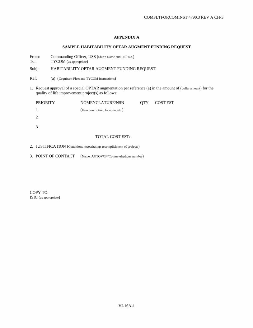
COMFLTFORCOMINST 4790.3 REV A CH-3
APPENDIX A
SAMPLE HABITABILITY OPTAR AUGMENT FUNDING REQUEST
From: Commanding Officer, USS (Ship's Name and Hull No.) To: TYCOM (as appropriate)
Subj: HABITABILITY OPTAR AUGMENT FUNDING REQUEST
Ref: (a) (Cognizant Fleet and TYCOM Instructions)
1. Request approval of a special OPTAR augmentation per reference (a) in the amount of (dollar amount) for the quality of life improvement project(s) as follows:
PRIORITY NOMENCLATURE/NSN QTY COST EST
1 (Item description, location, etc.)
2
3
TOTAL COST EST:
2. JUSTIFICATION (Conditions necessitating accomplishment of projects)
3. POINT OF CONTACT (Name, AUTOVON/Comm telephone number)
COPY TO: ISIC (as appropriate)
VI-16A-1

COMFLTFORCOMINST 4790.3 REV A
(This Page Intentionally Left Blank)
VI-16A-2

COMFLTFORCOMINST 4790.3 REV A CH-1
APPENDIX B
ADVANCE PLANNING MILESTONES
MILESTONE (A-MO) ACTION EVENT
A - 23 TYCOM ESTABLISH PLANNING ESTIMATE. TASK RMC WITH DESIGN SHIPCHECK
A - 22 TYCOM SEND HABITABILITY SELF-HELP PROJECT ADVANCE PLANNING LETTER
A - 21 SHIP INDICATE CONCURRENCE/ COMMITMENT TO PROJECT(S) TO TYCOM. ENTER PROJECT(S) IN CSMP
A - 21 TYCOM CONFIRM PROJECT
A - 21 RMC SHIP VALIDATION AND COMMENCE DESIGN
A - 18 RMC PREPARE MATERIAL REQUISITIONS
A - 16 RMC SEND REQUISITIONS TO FLEET INDUSTRIAL SUPPORT CENTER
A - 10 SUPSHIP NN, Code 1800 (CVNs)/TYCOM (other Aircraft Carriers)/SHIP
PRELIMINARY SCREENING CONFERENCE
A - 9 SUPSHIP NN, Code 1800 (CVNs)/TYCOM (other Aircraft Carriers)
ENTER PROJECTS IN WORK PACKAGE
A - 8 SUPSHIP NN, Code 1800 (CVNs)/SHIP/TYCOM
WORK DEFINITION CONFERENCE
A - 2 RMC/SHIP PROJECT KICK-OFF BRIEFING
A SHIP START AVAILABILITY/PROJECTS
COMP SHIP SEND COMPLETION REPORT
VI-16B-1

COMFLTFORCOMINST 4790.3 REV A
(This Page Intentionally Left Blank)
VI-16B-2
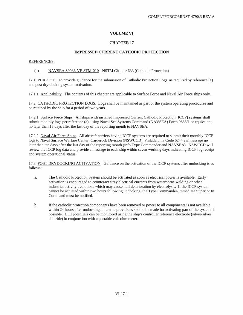
COMFLTFORCOMINST 4790.3 REV A
VOLUME VI
CHAPTER 17
IMPRESSED CURRENT CATHODIC PROTECTION
REFERENCES.
(a) NAVSEA S9086-VF-STM-010 - NSTM Chapter 633 (Cathodic Protection)
17.1 PURPOSE. To provide guidance for the submission of Cathodic Protection Logs, as required by reference (a) and post dry-docking system activation.
17.1.1 Applicability. The contents of this chapter are applicable to Surface Force and Naval Air Force ships only.
17.2 CATHODIC PROTECTION LOGS. Logs shall be maintained as part of the system operating procedures and be retained by the ship for a period of two years.
17.2.1 Surface Force Ships. All ships with installed Impressed Current Cathodic Protection (ICCP) systems shall submit monthly logs per reference (a), using Naval Sea Systems Command (NAVSEA) Form 9633/1 or equivalent, no later than 15 days after the last day of the reporting month to NAVSEA.
17.2.2 Naval Air Force Ships. All aircraft carriers having ICCP systems are required to submit their monthly ICCP logs to Naval Surface Warfare Center, Carderock Division (NSWCCD), Philadelphia Code 6244 via message no later than ten days after the last day of the reporting month (info Type Commander and NAVSEA). NSWCCD will review the ICCP log data and provide a message to each ship within seven working days indicating ICCP log receipt and system operational status.
17.3 POST DRYDOCKING ACTIVATION. Guidance on the activation of the ICCP systems after undocking is as follows:
a. The Cathodic Protection System should be activated as soon as electrical power is available. Early activation is encouraged to counteract stray electrical currents from waterborne welding or other industrial activity evolutions which may cause hull deterioration by electrolysis. If the ICCP system cannot be actuated within two hours following undocking; the Type Commander/Immediate Superior In Command must be notified.
b. If the cathodic protection components have been removed or power to all components is not available within 24 hours after undocking, alternate provisions should be made for activating part of the system if possible. Hull potentials can be monitored using the ship's controller reference electrode (silver-silver chloride) in conjunction with a portable volt-ohm meter.
VI-17-1
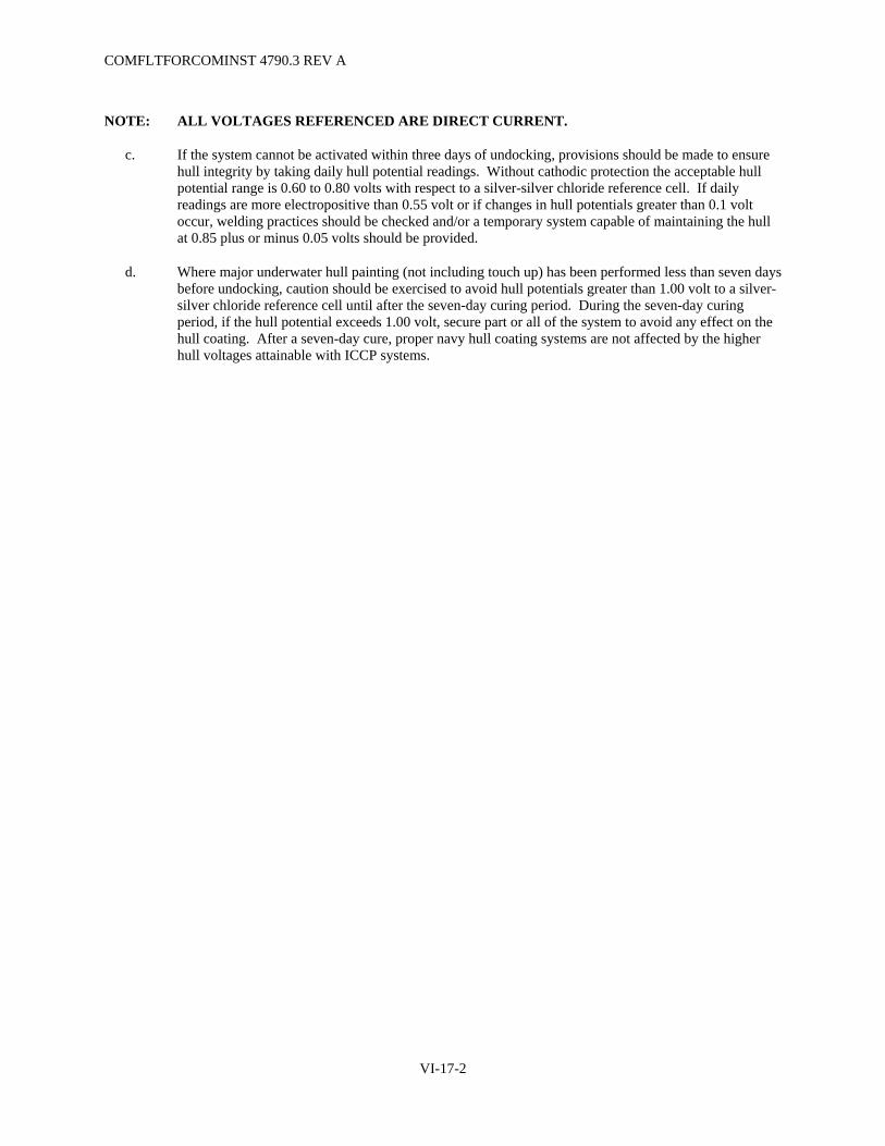
COMFLTFORCOMINST 4790.3 REV A
NOTE: ALL VOLTAGES REFERENCED ARE DIRECT CURRENT.
c. If the system cannot be activated within three days of undocking, provisions should be made to ensure hull integrity by taking daily hull potential readings. Without cathodic protection the acceptable hull potential range is 0.60 to 0.80 volts with respect to a silver-silver chloride reference cell. If daily readings are more electropositive than 0.55 volt or if changes in hull potentials greater than 0.1 volt occur, welding practices should be checked and/or a temporary system capable of maintaining the hull at 0.85 plus or minus 0.05 volts should be provided.
d. Where major underwater hull painting (not including touch up) has been performed less than seven days before undocking, caution should be exercised to avoid hull potentials greater than 1.00 volt to a silver-silver chloride reference cell until after the seven-day curing period. During the seven-day curing period, if the hull potential exceeds 1.00 volt, secure part or all of the system to avoid any effect on the hull coating. After a seven-day cure, proper navy hull coating systems are not affected by the higher hull voltages attainable with ICCP systems.
VI-17-2

COMFLTFORCOMINST 4790.3 REV A CH-2
VOLUME VI
CHAPTER 18
INFLATABLE LIFE RAFTS
REFERENCES.
(a) NAVSEA S9086-TX-STM-010 - NSTM Chapter 583 (Boats and Small Craft) (b) NAVSEA S9008-AA-PRO-010 - Lifeboat, Inflatable, MK6, MK7 and MK8 Inspection, Test and Repair
Procedures (c) NAVAIR 13-1-6.1 - Aviation Crew Systems, Chapter 7 (LRU 13/A) (d) NAVSEA TW024-AA-ORD-010 - Unserviceable, Suspended, and Limited Use Ammunition (e) NAVSUP Publication 485 - Afloat Supply Procedures
18.1 PURPOSE. To provide guidance for the maintenance, repair, certification and procurement of life rafts used onboard naval ships and craft.
18.1.1 Discussion. An inflatable life raft is one constructed of a coated fabric and inflated to its design shape by air or other gas. The raft is stowed aboard ship for use only as a life raft, when and as directed by the Commanding Officer/Officer In Charge.
18.2 FLEET LIFE RAFT PROGRAM. The Fleet Life Raft Program Manager designated by the Fleet Forces Command Maintenance Officer is responsible for establishing policy guidelines for the program. Policy will be disseminated to the Fleet and Naval Sea Systems Command (NAVSEA) certified Regional Maintenance Centers (RMC) for scheduling, planning, conducting Planned Maintenance System (PMS) recertification of fleet assets and management of life raft contingency pools. Commander Naval Surface Force Atlantic (Code N434) and Commander Naval Surface Force Pacific (code N4344) are designated Fleet Life Raft Program Managers.
18.2.1 Types of Inflatable Life Rafts. There are 5 basic Navy type inflatable life rafts for use throughout the fleet (ships and aircraft):
a. MK-6 Mod 3, 25 person, air inflated - currently carried by surface ships, encapsulated in a fiberglass container.
b. MK-7 Mod 0, 25 person, air inflated - currently carried by surface ships, encapsulated in a fiberglass container.
c. MK-8 Mod 0, 50 person, air inflated - currently carried by aircraft carriers and other air-capable ships, encapsulated in a fiberglass container.
d. LRU 13/A (former MK-2), 7 person, CO2 inflated - used on aircraft, certified to Naval Air Systems Command (NAVAIR) requirements.
e. LRU 12/A (former MK-4), 4 person, CO2 inflated - used on submarines only.
18.2.2 Commercial Life Rafts. Various commercial Coast Guard approved life rafts are installed on board certain boats and/or Navy ships for service and in-service evaluation testing. The cognizant command is responsible for PMS recertification requirements.
VI-18-1
COMFLTFORCOMINST 4790.3 REV A CH-2
18.3 RECERTIFICATION. The periodicity of recertification will be as designated by PMS requirements.
a. Recertification is based on PMS periodicity requirements starting from the recertification date stenciled on the outside of the life raft container.
b. If the certification date is not stenciled or tagged on the outside of the life raft container or verified from the ship's life raft log inspection, recertification records, or unavailable by scanning and electronic remote identification, life raft certification will be considered expired.
c. Submit an OPNAV 4790/2K to the Fleet RMC for recertification.
18.4 CONTINGENCY POOLS. Designated Regional Maintenance Activities in the Atlantic Fleet and select maintenance activities in the Pacific Fleet are responsible for coordinating the disposition of assets and maintaining contingency pools within authorized limits. Contingency pools will consist of the MK-6, MK-7, MK-8 and LRU 12/A life rafts (ships/boats/craft). The cognizant NAVAIR command will coordinate the disposition of LRU 13/A life rafts (aircraft) from a separate pool of assets. Contingency pools are authorized a limit not to exceed 100 rafts unless approved by the Fleet Life Raft Program Manager.
a. If the contingency pool should fall below the authorized limit, restock the pool from decommissioning assets (as available). Purchase a new raft from the stock system, using Repair Other Vessel funds, only as a last option to facilitate scheduling.
b. Commands are not authorized to maintain and operate a life raft contingency pool other than those designated as fleet approved contingency pools. Contact the life raft contingency pool manager for disposition and turn-in instructions for all rafts that are removed from decommissioning ships and/or aircraft.
c. Contact the designated Fleet Life Raft Program Manager for disposition instructions if the inclusion of additional rafts into the pool will exceed authorized pool limits.
d. Location of Fleet Life Raft Repair Facilities and Contingency Pools:
Mid-Atlantic Regional Maintenance Center(MARMC) Regional Repair Center (RRC) - Norfolk Naval Shipyard, Portsmouth, VA
Southeast Regional Maintenance Center (SERMC) - Mayport, FL Southwest Regional Maintenance Center(SWRMC) - San Diego, CA Naval Ship Repair Facility Yokosuka, Japan
18.5 AUTOMATED TRACKING SYSTEM. A data base is maintained by Naval Surface Warfare Center, Carderock Division (NSWCCD) Detachment, Norfolk VA, for tracking the Navy MK-6, MK-7 and MK-8 life raft population (www.boats.dt.navy.mil). Inputs on each life raft are provided by all certified life raft repair facilities. Access is restricted; therefore, for reports or data retrieval, contact the respective Fleet Life Raft Repair Facility (e.g., Fleet Maintenance Activity, Fleet Life Raft Program Manager or Data Base Manager).
VI-18-2

COMFLTFORCOMINST 4790.3 REV A CH-2
18.6 RESPONSIBILITIES.
18.6.1 Commanding Officer/Officer In Charge.
a. Submitting an OPNAV 4790/2K to the RMC for any life raft requiring replacement or recertification. For recertification, the OPNAV 4790/2K should be submitted no sooner than 6-months prior to the expiration date stenciled on the outside of the life raft container (or date verified by the ship's life raft log). Arrange with the RMC/RRC/Fleet Maintenance Activity for transfer and shipping of rafts to facilitate schedules.
b. Maintaining a log or data base of all life rafts on board, to include the following:
(1) The Inflatable Life Raft Recertification Record (ILRRR) for each raft. ILRRRs are issued with each life raft at recertification. Ships should not accept any life raft from a recertification/repair facility without the ILRRR provided. If the ship does not have the required ILRRR, contact NSWCCD Detachment Norfolk VA.
(2) Record the station location and serial number of each life raft. Annotate this information on the top of each ILRRR in the log.
c. Send a report to NSWCCD Detachment Norfolk VA, the Type Commander (TYCOM) (N43) and the respective recertification/repair facility if any life raft is lost or transferred to another ship. Reports should include the life raft serial number, manufacturer's name, recertification facility and a description of the circumstances.
d. Ensure life raft fiberglass containers are handled with care using appropriate slings. Life rafts are not to be rolled or stood on-end. Life rafts will be placed with the top up, in racks, with the container seal or canister joint in the horizontal position.
e. Upon notification of decommissioning from the TYCOM, contact the designated Life Raft Regional Maintenance Activity for disposition instructions concerning the unit's life raft inventory whenever the unit is scheduled for decommissioning and not designated for foreign military sales.
f. Requisition a replacement raft whenever a life raft is lost or determined to be unserviceable and beyond economical repair by the Life Raft Repair Facility, using the ship's Operating Target (OPTAR) funds only when contingency pool assets can not support the replacement.
18.6.2 Regional Maintenance Center/Regional Repair Center.
a. RMC/RRC Designated Regional Maintenance Activities are responsible for establishing priority of work, scheduling, coordinating PMS recertification and any repair service to support fleet life rafts unless otherwise directed by the Fleet Life Raft Program Manager.
b. RMC/RRC/Designated Regional Maintenance Activity will function as follows:
(1) Management and disposition of all life raft contingency pool assets.
(2) Upon receipt of an OPNAV 4790/2K, screen the request as follows:
VI-18-3

COMFLTFORCOMINST 4790.3 REV A CH-2
(a) For replacement of lost life rafts or rafts considered to be beyond economical repair, replace with contingency pool asset. If contingency pool assets are unavailable, notify the ship to requisition replacement raft(s) using the ship's OPTAR funds.
(b) For repair and recertification, screen OPNAV 4790/2Ks to the respective Life Raft Regional Maintenance Activity for action. Issue an immediate replacement from contingency pool assets, if available, and/or recertify within the defined schedule.
(c) If the Life Raft Regional Maintenance Activity is temporarily overloaded and contingency assets cannot fulfill the requirements, screen the repair or recertification to a NAVSEA certified industrial activity.
(d) When contingency pool assets cannot support requirements, notify the Fleet Life Raft Program Manager. In cases where requirements cannot be supported due to the non-availability of materials, notify NSWCCD Detachment, Norfolk VA, for assistance. As a last option for non-deployers, notify the ship to submit a Departure From Specification per Volume V, Part I, Chapter 8 of this manual. Request the cognizant TYCOM grant a six-month extension of PMS periodicity. Subject Life raft must be recertified or replaced prior to expiration of the PMS periodicity extension.
NOTE: ASSETS MAY BE AVAILABLE AT ANOTHER FLEET CONTINGENCY POOL.
c. Inform the Fleet Life Raft Program Manager and cognizant TYCOM (N43) of any problems encountered.
18.6.3 Regional Maintenance Activity.
a. Upon receipt of screened OPNAV 4790/2K, repair or recertify life rafts to a Level "C" Plan in accordance with references (a), (b), (c), PMS and/or Volume V of this manual, as applicable.
b. Maintain an equipped life raft facility with qualified repair personnel to conduct repairs and/or recertification of life rafts as indicated below:
NOTE: FACILITY CAPABILITIES AND PERSONNEL QUALIFICATIONS WILL BE AUDITED BY NSWCCD AND TYCOM REPRESENTATIVES ON AN ANNUAL BASIS OR AS A SITUATION DICTATES.
(1) A minimum of 75 percent of all personnel assigned to the life raft shop shall have received formal NSWCCD training and certification in Level "C" repair.
(2) Conduct and document annual training and/or the level of On-the-Job Training in Level "C" repair of all shop personnel.
(3) Appoint in writing, two life raft repair coordinators, E-6 or above, who have received formal NSWCCD training in Level "C" repair.
(4) Appoint in writing, a signal flare coordinator, E-4 or above, who is trained in handling ordnance and is responsible for the coordination and installation of signal flares in all life rafts.
(5) Maintain copies of all technical manuals, maintenance bulletins, correspondence and messages pertaining to life raft maintenance and repair.
(6) Maintain accountability of signal flare kits in accordance with reference (d).
VI-18-4

COMFLTFORCOMINST 4790.3 REV A CH-2
18.7 UNSERVICEABLE/REJECTED LIFE RAFTS. Fleet Maintenance Activities shall process unserviceable/rejected life rafts as follows:
a. The Quality Assurance Officer shall verify the condition of the rejected life raft.
b. Survey the rejected life raft in accordance with reference (a). Upon completion of the survey, turn in the carcass to the Defense Re-utilization Marketing Office in accordance with reference (e).
c. Report survey results to NSWCCD, Detachment, Norfolk VA.
d. Issue a replacement life raft to the customer ship/boat/craft from the contingency pool. If none are available, the ship will requisition a new life raft using OPTAR funds.
18.8 RECORDS. Activities with the responsibilities defined in section 18.6 of this chapter shall maintain an auditable record for 5 years of all life raft transactions, including repairs, replacements, and recertification. These records must include:
a. Copies of all ILRRRs issued for recertified life rafts.
b. Job Sequence Numbers, serial numbers, and the manufacturer's name of each rejected life raft.
c. The condition of the rejected life rafts.
d. The disposition of the rejected life rafts and components salvaged.
VI-18-5

COMFLTFORCOMINST 4790.3 REV A
(This Page Intentionally Left Blank)
VI-18-6

COMFLTFORCOMINST 4790.3 REV A CH-6
VI-19-1
VOLUME VI
CHAPTER 19
MAINTENANCE AND MATERIAL MANAGEMENT
REFERENCES.
(a) NAVSEAINST 4790.8/OPNAVINST 4790.4 - Ships' Maintenance and Material Management (3-M) Manual
(b) NAVEDTRA 43241 - Personnel Qualification Standard for Ship's Maintenance and Material Management (3-M) System
(c) NAVSEA S9810-AA-GTP-010 - Intermediate Maintenance Activity Work Center Requirements Manual
LISTING OF APPENDICES.
A 3-M System Assessment/Evaluation Procedures B Listing of Standard Work Center Codes for Aircraft Carriers C Listing of Standard Work Center Codes for Submarine Force Ships D1 Listing of Standard Work Center Codes for LPD Class Ships D2 Listing of Standard Work Center Codes for ARS Class Ships D3 Listing of Standard Work Center Codes for PC Class Ships D4 Listing of Standard Work Center Codes for MCM MHC Class Ships D5 Listing of Standard Work Center Codes for LSD Class Ships D6 Listing of Standard Work Center Codes for LHA LHD Class Ships E Listing of Standard Work Center Codes for Small Boat and Service Craft Managers (Submarine Force
Only) F Listing of Standard Work Center Codes for Tugs and Retrievers (Submarine Force Only) G Listing of Standard Work Center Codes for Master Job Catalog Items Contained in Ship's CSMP
(Surface and Submarine Forces Only) H Sample Situational Requirement Reference Sheet I Sample Accountability Log J Format for Reporting 3-M Assessments
19.1 PURPOSE. To provide guidance for the implementation of policies for the Maintenance and Material Management (3-M) system, set forth in reference (a).
19.1.1 Policy. To maintain high levels of Operational Readiness by ensuring that Material Readiness, which is a key component of Operational Readiness, is supported throughout the chain of command with clear and concise directives, maintenance requirements and maintenance procedures.
19.1.2 Scope. This chapter applies to all ships, service craft, small boats, Type Commander (TYCOM) cognizant shore activities, and non-aviation fleet test and support equipment, except as exempted in paragraph 19.1.2.b below. This includes, but is not limited to, Navy Meteorological Equipment, equipment of the Naval Air Traffic Control, Air Navigation and Landing Systems, Aviation Launch and Recovery Equipment, Commander Naval Reserve Force, and Chief of Naval Education and Training activities.
COMFLTFORCOMINST 4790.3 REV A CH-6
VI-19-2
a. If conflicts exist between this chapter and reference (a), reference (a) shall take precedence. Any departure from the policies, procedures or responsibilities delineated in reference (a) are not authorized without prior Naval Sea Systems Command (NAVSEA) approval and Chief of Naval Operations (CNO) concurrence.
b. This chapter does not apply to Fleet Ballistic Missile systems under the cognizance of Strategic Systems Programs, nuclear power plants and associated test equipment under the cognizance of Naval Sea Systems Command Nuclear Propulsion Directorate (NAVSEA 08) or aeronautical equipment used in support of the aviation maintenance mission. Also excluded are civilian operated and maintained ships, small boats, and service craft, unless specifically included in a Base Operating Contract or other similar document.
19.2 SHIP MAINTENANCE AND MATERIAL MANAGEMENT.
19.2.1 Responsibilities.
19.2.1.1 Type Commander. Exercises primary responsibility for the effective operation and support of the 3-M System. The areas of responsibility include but are not limited to the following:
a. Maintenance Data System (MDS).
b. Planned Maintenance System (PMS).
c. Alteration Management System.
d. (Submarines only) Technical Feedback Report History/Tracking (TFBR H/T) Program.
e. Maintenance Resource Management System (MRMS).
f. Periodic Maintenance Requirement (PMR) Scheduling System.
g. Current Ship's Maintenance Project (CSMP).
h. Ship's Non-Tactical Automated Data Processing System (SNAP) I/II/III Organizational Maintenance Management System (OMMS).
i. TRIDENT Logistical Data System/MRMS Interface.
j. Master Job Catalog (MJC).
k. (Submarines only) TYCOM TFBR Screening.
19.2.1.2 Type Commander 3-M Regional Representatives (Submarines only). Regional 3-M Representatives have been established at all submarine homeports. These positions provide for continuous monitoring at Submarine Force concentration areas and provide assistance to Submarine Squadron Commanders in the administration of the 3-M Program. Their areas of responsibility include but are not limited to the following:
a. Act as team "lead" for all 3-M Assessments of activities under their cognizance and provide the results of the assessment to the ship via the Immediate Superior In Command (ISIC).
b. Originate all correspondence relating to 3-M Assessments, Periodic Monitoring, and reports of non-compliance with CNO WASHINGTON DC/YMS: 941107/4790.4C and COMFLTFORCOMINST 4790.3.
COMFLTFORCOMINST 4790.3 REV A CH-6
VI-19-3
c. Carry out the duties and responsibilities of the TYCOM during PMS Installations.
d. Monitor MDS documents and report deficiencies to the ISIC for corrective action.
e. Provide the following services to the ISIC:
(1) 3-M System monitoring.
(2) TYCOM 3-M Assist Visits as described by reference (a).
(3) PMS MDS technical assistance.
(4) On site training in PMS, MDS and PMS Scheduling (SKED software).
(5) Assistance with the preparation and submission of TFBRs.
(6) Assistance in obtaining prompt correction to faulty PMS documentation (liaison with In-Service Engineering Activity (ISEA)).
(7) On a case basis, provide the authorization to use modified (red lined) PMS documentation.
19.2.1.3 Immediate Superior In Command.
a. The ISIC will designate a 3-M Officer. The 3-M Officer is responsible for the satisfactory administration of 3-M programs for subordinate units. Specific responsibilities include supervision of maintenance management programs resident at the Maintenance Document Control Office (MDCO), if applicable.
b. The ISIC organization will centralize maintenance management programs in the MDCO, if applicable. The MDCO will report to the ISIC 3-M Officer and be manned with trained personnel to accurately and expeditiously process data in support of maintenance management.
19.2.1.4 In-Service Engineering Activity. ISEAs are those activities designated by NAVSEA as the technical expert for specific systems and/or equipments. Naval Surface Warfare Center, Carderock Division (NSWCCD), for example, is the ISEA for the majority of Hull, Mechanical and Electrical equipment installed on most ships. ISEA responsibilities include but are not limited to the following:
a. Development of PMS documentation.
b. Maintenance of PMS documentation.
c. Providing timely responses to TFBRs.
d. Providing copies of critical TFBR resolutions to all holders of the affected Maintenance Index Page (MIP)/Maintenance Requirement Card (MRC). All other resolutions will be integrated into the next available Force Revision.
19.2.1.5 Naval Sea Logistics Center Detachments. Responsibilities associated with this chapter are as follows:
a. Receive, screen and process TFBRs.
b. Resolve TFBRs within their technical capability.

COMFLTFORCOMINST 4790.3 REV A CH-6
VI-19-4
c. Provide periodic updates (Force Revisions).
d. Maintain the Navy PMS Database.
19.2.1.6 Submarine Maintenance Engineering, Planning and Procurement Activity. Submarine Maintenance Engineering, Planning and Procurement Activity (SUBMEPP) is a NAVSEA engineering activity chartered to support NAVSEA and the submarine TYCOMs in their effort to maintain a high degree of Submarine Force Material and Operational Readiness. In support of 3-M, SUBMEPP is tasked by NAVSEA and the TYCOMs with the following:
a. Establish, maintain, update and distribute all requirements as MJC Items in support of TYCOM Alteration Management System, PMR, Baseline Overhaul Work Packages/Selected Restricted Availability (SRA) Routines and Standard Availability Routines.
b. Provide semi-annual analysis of Naval Sea Logistics Center (NAVSEALOGCEN) historical MJC originated data and distribute updated planning and estimating data to include changes in estimated MJC manhours.
c. Provide semi-annual analysis of NAVSEALOGCEN historical PMR originated data and distribute updated manhour and material requirements to the PMR scheduling and Technical Repair Standards.
d. Maintain the Submarine TFBR H/T Program.
e. Liaison with ISEAs and NAVSEALOGCEN detachments to ensure submarine TFBRs receive accurate and timely responses.
f. Assist with PMS installation on all new construction submarines.
g. Act as the TYCOM's agent in the screening of all submarine and submarine support facility generated TFBRs.
19.2.1.7 Ship's Maintenance and Material Management Coordinator. The duties and responsibilities of the ship's 3-M Coordinator are well defined in reference (a). Specifically the 3-M Coordinator is the functional manager of the 3-M System and is responsible to the Executive Officer for the administrative facets of the ship's 3-M program. In addition to the requirements of reference (a) the following applies:
a. Develop and administer the Ship's PMS Spot Check Program. Section I-E of Appendix A of this chapter may be used as a spot check evaluation sheet.
b. Monitor the Ship's 3-M Personnel Qualification Standard (PQS) Program and maintain an auditable record of personnel qualified in 3-M PQS.
c. Ensure that all Equipment Status Log/Ship's Force Work List (SFWL) items outstanding for more than 30 calendar days are converted to 3-M deferrals.
19.2.1.8 Ship's Fleet Maintenance Activity Availability Coordinator. The Ship's Fleet Maintenance Activity Availability Coordinator will be responsible for the coordination of all Fleet Maintenance Activity (FMA) repairs and coordinate closely with the 3-M Coordinator. The Fleet Maintenance Activity Availability Coordinator will also provide a single working level point of contact and coordinate the command's requirements with the requirements of the FMA. These duties include:
a. Technical review of work requests submitted for FMA accomplishment.

COMFLTFORCOMINST 4790.3 REV A CH-6
VI-19-5
(1) Ensure readability and technical correctness.
(2) Prevent duplication of work requests for Ship Alterations/Unrestricted Operation/Integrated Maintenance and Modernization Planning and other MJC originated deferrals.
(3) Ensure corrective maintenance described in Block 35 (Remarks) of the Ship's Maintenance Action Form OPNAV 4790/2K includes reference to the associated Integrated Maintenance and Modernization Planning procedure(s) when applicable.
(4) Collect supplemental form OPNAV 4790/2L requests for routine work (i.e., lagging, painting, label plates, tiling, etc.) from all Work Centers (WC) and prepare an integrated priority list for each type of routine work to maximize the FMA's effectiveness.
b. (Non-SNAP ships only) Ensure all FMA level work included on the Equipment Status Log is documented on OPNAV 4790/2K deferrals.
c. Ensure ship's preparations for an FMA availability are conducted in accordance with Volume II, Part I, Chapter 4 of this manual.
d. Meet daily, during an availability, with the assigned Ship Superintendent to discuss the status of all active jobs and to tour the ship.
e. Attend all FMA production, night work, and management meetings.
f. Provide a daily FMA job status to each Department Head, Division Officer, and Leading Petty Officer.
19.2.1.9 Afloat Training Group (Surface Force only). Afloat Training Groups are under the technical administration of the Fleet Training Commands. They provide TYCOM designated platforms with the following:
a. Technical and personnel support for 3-M training.
b. 3-M training services as needed.
19.2.2 Qualifications. All personnel assigned to billets associated with the 3-M system, must be 3-M PQS qualified for the assigned billet in accordance with reference (b).
19.2.3 Maintenance and Material Management Operation and Administration.
19.2.3.1 Standard Force Work Center Numbering System. The production of automated products in support of the 3-M system such as automated List of Effective Pages (LOEP) and list of Library Issue Documents, as well as applications of the MRMS, dictate that a standard force WC organization be maintained. Commanding Officers will designate their shipboard organization and applicable WC codes as listed in Appendices B, C and D of this chapter, for Aircraft Carriers and Submarine Force (except for units addressed in paragraph 19.2.3.1.c and e. below) respectively. FMAs will designate their organization and applicable WC codes as listed in reference (c). Additionally:
a. Ship's 3-M Coordinator, ISIC, and Area Maintenance Document Control Office/MDCOs must not allow the use of any WC codes not authorized by reference (a) or this manual.
b. Requests to change WC designation codes will not be approved unless they are applicable to all ships of a class and supported by detailed justification. Standardization is required to support the developing interfaces between the Weapons System File, Planning Yards, PMS, SNAP systems, Supervisor of Shipbuilding Newport News, Code 1800 and SUBMEPP. This does not affect the re-assignment of a MIP to another WC (shift of maintenance responsibility). Reference (a) provides guidance for the shift of maintenance responsibility.

COMFLTFORCOMINST 4790.3 REV A CH-6
VI-19-6
c. (Submarine Force only) Small boat and service craft managers will use the specific WCs identified in Appendix E of this chapter for MDS documentation, however, for PMS management they may assign a "**00" WC to consolidate PFRs, MIPs, scheduling, etc., (e.g., PY30 through PY84 may consolidate PMS under WC PY00, or PY01-Mechanical, PY02-Electrical, etc.). The Unit Identification Code will be that of the parent command.
d. (Submarine Force only) WC designations for tugs and retrievers are reflected in Appendix F of this chapter.
e. (Surface and Submarine Forces only) Standard MJC assigned WC codes are reflected in Appendix G of this chapter.
19.2.3.2 Scheduling. PMS is a portion of the ship's 3-M system and provides, in one authoritative system, the scheduling information and technical procedures governing planned maintenance for Ship's Force accomplishment. PMS provides a simple method for scheduling, and documenting the execution of planned maintenance procedures. TYCOM policy is as follows:
NOTE: WHERE THE GOAL OF 100% ACCOMPLISHMENT CANNOT BE REACHED, THE UNIT'S CHAIN OF COMMAND SHALL BE KEPT INFORMED OF THE CIRCUMSTANCES WHICH PREVENT ACCOMPLISHMENT OF SCHEDULED MAINTENANCE.
a. (Submarine Force only) An asterisk (*) will be inserted in SKED against any Maintenance Requirement (MR) which is a "Safety of Ship" item. A "Safety of Ship Item" is defined as any maintenance action vital to the maintenance of a submarine's watertight integrity or its ability to return safely to the surface. "Safety of Ship" MRs, so designated by the cognizant technical authority, are annotated on the MIP with a single asterisk (*) in the periodicity code column. Commanding Officer notification is required for non-accomplishment of any "Safety of Ship" designated MR.
b. A CNO Maintenance Availability of 12 months or greater restarts the Cycle PMS schedule. Cycle schedules are not restarted following industrial availabilities of shorter duration, such as an SRA.
c. Equipment Guide Lists (EGL) are not required for Ship's Force PMS PMR Scheduling system or similar authorized automated system which provides each WC with reports of components due for inspection, testing, or calibration.
d. Situational reference sheets will be maintained/posted in the WC PMS Manual (formerly known as 43P1). These sheets will contain a brief description of the situation and the maintenance action for all situational requirements listed in the right hand column of the weekly schedule. Appendix H of this chapter provides a typical situational reference sheet.
19.2.3.3 Accountability. The credibility of the Navy PMS program relies heavily on the individual accomplishing the maintenance. The required dedication and integrity of that individual cannot be overstressed. With shrinking budgets, Maintenance Effectiveness Reviews, Reliability Centered Maintenance and "fewer individuals to do more" the complete "step-by-step" performance of assigned maintenance is of paramount importance. To maintain accountability, personnel are required to sign for the completion of assigned maintenance in an Accountability Log (Appendix I of this chapter refers). The Work Center Supervisor (WCS) is required to review the Accountability Log weekly to verify the accuracy and completeness of entries. Accountability sheets will be maintained in the WC PMS Manual for a period of not less than 13 weeks.

COMFLTFORCOMINST 4790.3 REV A CH-6
VI-19-7
19.2.4 Technical Feedback Report Reporting. The PMS TFBR is used to notify the NAVSEALOGCEN detachments, ISEAs, and/or the TYCOM of administrative/technical issues related to PMS. The "hardcopy" TFBR form is composed of an original and four copies. Instructions for preparation and submission of the form are printed on the back of the last copy. TFBRs may also be submitted electronically either via SKED or the NAVSEALOGCEN web site. Submarine submission via SKED is currently not functioning as the SKED software is loaded to the classified server. Deployed submarine units not able to process their TFBRs through a TYCOM 3-M Regional Representative, go to: http://www.nslc.navsea.navy.mil/pms/pms.nsf, select "Electronic Feedback Report Form OPNAV 4790.7B", scroll down on the next page and select "YES". This will open up a TFBR. Simply fill in the blanks and submit.
19.2.4.1 Technical Feedback Report History Tracking Program (Submarine Force only). The TFBR H/T Program is a Personal Computer based database containing summary information taken from TFBRs initiated by COMSUBLANT/COMSUBPAC units and support activities. Each TFBR is presented with a header identifying the feedback report serial number, a summary of the action request and the resolution. The TFBR H/T Program is supported with Compact Disk - Read Only Memory (CD-ROM) disks containing copies of the original TFBRs and supporting documents.
a. The system provides a centrally controlled, comprehensive TFBR/MIP/MRC history, intended to improve response time, problem resolution and reduce redundant TFBRs.
b. Monthly updates of the computer files are provided to TYCOMs, Submarine Squadrons and appropriate ISEAs involved in resolving TFBRs.
19.2.4.2 Type Commander Screening of Technical Feedback Reports (Submarine Force only). COMSUBLANT and COMSUBPAC have reinstated TYCOM screening of TFBRs. SUBMEPP has been designated as the screening activity. All submarine and submarine support activity TFBRs are provided to SUBMEPP electronically via the PMS Management Information System prior to delivery to the NAVSEALOGCEN. SUBMEPP reviews the proposed TFBR and will:
a. Return the TFBR to the originator under any one or all of the following circumstances:
(1) An answer currently recorded in the TFBR H/T Program satisfies the proposed TFBR. The TFBR will be returned with authorization to implement the previously received response or rationale for non-concurrence.
(2) A similar request has already been submitted and submission of another duplicative request will add no value to the process.
(3) The TFBR requests actions contrary to the direction of this manual or reference (a).
(4) The request does not adequately address or identify the problem. In cases of this nature, return of the TFBR to the originator will be a last resort, as SUBMEPP will attempt to contact the originator to better define the issue.
b. Forward the TFBR for further processing taking any one or all of the following actions:
(1) Provide amplifying information.
(2) Correct erroneous data.
(3) Provide TYCOM concurrence of the requested change.
(4) Provide a Do Not Concur recommendation to NAVSEALOGCEN/ISEA.

COMFLTFORCOMINST 4790.3 REV A CH-6
VI-19-8
19.2.5 Submarine Safety Scope of Certification/Survivability and Escape (Submarine Force only).
a. MRCs which direct work/entry within the Submarine Safety (SUBSAFE) Certification Boundary, require Re-Entry controls to be invoked. In order to ensure that these controls are initiated, Ship's Force personnel shall over stamp MRCs requiring such work/entry with the word "SUBSAFE" in red ink.
b. MRCs which direct work/entry within the Scope of Certification (SOC) Certification Boundary, also require Re-Entry controls to be invoked. SOC documentation is applicable and governing to Dry Deck Shelter (DDS)/Advanced SEAL Delivery System (ASDS) host platforms and must be loaded to Work Center WK02 for those platforms. SOC MRCs are annotated on the MIP with either an "X" or an "R" in the "OTHER" column. Non-DDS/ASDS platforms need not establish WK02 nor are they governed by SOC directives.
c. Survivability and Escape Equipment and supporting maintenance has come under increased scrutiny since the loss of the Russian submarine KURSK. All MIPs and associated MRCs dealing with Survivability and Escape equipment are to be loaded into WC EA01. WC EA01 is now responsible for the accomplishment of this maintenance.
19.2.6 Evaluation.
19.2.6.1 Assessments.
a. Goal/Intent. To ensure that the ship's 3-M program is functioning at maximum efficiency and per the requirements of reference (a). All departments on each unit shall be evaluated within a 24 month period and the determination of the Recorded Accomplishment Rate and PMS Performance Rate for a given department will be conducted during the same evaluation. Time in major CNO Maintenance Availabilities should be counted in determining when these inspections are to be done. Assessments will be conducted more frequently when determined to be necessary by either the TYCOM, ISIC or unit's Commanding Officer. 3-M assessments for each unit will be scheduled on a limited or no advance notice basis and shall be conducted in accordance with the criteria and format established in Appendix A of this chapter.
b. Method for Assignment of Numerical Evaluations. Planned maintenance is the foundation of a well executed, effective maintenance program. Therefore PMS must be vigorously prosecuted and thoroughly monitored. The standards of PMS performance must remain high. The minimum performance requirements are identified below. TYCOMs may authorize the utilization of specific check sheets to reflect current directives and system operation modernization provided that attributes provided by Appendix A of this chapter are properly evaluated when applicable.
(1) 3-M Performance Rate (3-MPR) shall be 80% or better.
(2) PMS Performance Rate (PPR) shall be 80% or better.
(3) MDS Performance Rate (MPR) shall be 80% or better.
(4) The Accomplishment Confidence Factor (ACF) shall be 90% or better.
(5) The Recorded Accomplishment Rate (RAR) shall be 80% or better.

COMFLTFORCOMINST 4790.3 REV A CH-6
VI-19-9
19.2.6.2 Assessment Reporting. Significant deficiencies and numerical assessments are reported to the assessed unit's Commanding Officer, ISIC and TYCOM using the format shown in Appendix J of this chapter. Reporting may be accomplished on the entire unit or on a departmental basis.
a. Significant deficiencies require a report of corrective actions taken by the unit to be forwarded to the ISIC within 30 days following the assessment.
b. Any department receiving an overall evaluation of unsatisfactory in either PMS or MDS should be re-evaluated within a reasonable period of time to ensure unsatisfactory areas have been corrected.
COMFLTFORCOMINST 4790.3 REV A CH-6
VI-19-10
(This Page Intentionally Left Blank)
COMFLTFORCOMINST 4790.3 REV A CH-2
VI-19A-1
APPENDIX A
3-M SYSTEM ASSESSMENT/EVALUATION PROCEDURES
1. The purpose of this Appendix is to provide a means for evaluating the 3-M programs aboard each ship and shore command. These procedures are used to conduct 3-M assessments.
2. These procedures are written in such a manner as to permit PMS and MDS assessments to be conducted independently on an individual department basis. The only requirements are that all departments on each unit be evaluated within a 24 month period and that the determination of the Recorded Accomplishment Rate and PMS Performance Rate for a given department be conducted during the same evaluation. This method permits a continuing assessment of each unit throughout the period and reduces crew disruption during a given availability. These procedures are divided into three sections:
a. Section I - Assessment of PMS
b. Section II - Assessment of MDS
c. Section III - Overall 3-M Assessment
3. 3-M Assessments for each unit will be scheduled on a limited or no advance notice basis. Time in major CNO Maintenance Availabilities should be counted in determining when these inspections are to be done. A PMS and MDS Evaluation Summary Sheet will be maintained for each unit. As each department is evaluated, the individual evaluations (Sat/Unsat and calculated values) will be recorded on the appropriate Evaluation Summary Sheet and a copy of the rough administrative evaluation sheet will be provided to the unit. Sections I, II, and III of this Appendix provide the specific criteria to be used in the assessment of each unit and its departments.
4. The following criteria will be used in determining PMS and MDS Administration assessments:
a. PMS or MDS WC Administration for a department will be evaluated as unsatisfactory if more than 25% of the WCs in the department are evaluated as UNSAT.
b. A department will be evaluated as unsatisfactory overall in PMS if more than 25% of assigned WCs are assessed UNSAT, or if Departmental RAR is less than 80%, or ACF is less than 90%, or PPR is less than 80%. A department will be evaluated as unsatisfactory in MDS if more than 25% of assigned WCs are assessed UNSAT.
c. The ship will be evaluated as unsatisfactory overall in PMS if two or more major departments (as defined by Section II - A) are UNSAT overall; or if ship wide RAR is less than 80%, or ACF is less than 90%, or PPR is less than 80%. The ship will be evaluated as UNSAT overall in MDS if two or more major departments are UNSAT in MDS.
5. All calculations shall be rounded to two decimal places.

COMFLTFORCOMINST 4790.3 REV A CH-2
VI-19A-2
SECTION I
ASSESSMENT OF PMS
1. Complete the administrative checks for Executive level and each WC per Sections I-A and I-B of this Appendix respectively. Enter a narrative evaluation of overall effectiveness (e.g., above average, average, below average) and evaluate PMS Administration in each area as Sat or Unsat.
2. Using the basic definitions and guidelines described below, determine PMS RAR for each department.
a. Using each WC quarterly schedule for the quarter immediately preceding the period of inspection:
(1) Count the number of MRs scheduled for accomplishment (monthly and above, but not including situational MRs).
(2) Then count the number of MRs marked as accomplished (monthly and above, but not including situational MRs or MRs rescheduled from the previous quarter).
(3) From the back of the schedule, determine the number of MRs considered to have had significant maintenance accomplished, but the MR was not marked as fully accomplished.
b. Calculate for all WCs the total number of MRs scheduled, recorded as accomplished, and considered as partially accomplished. Calculate each work center RAR. Calculate the Departmental RAR by using the total number of checks for the department (cumulative total of all work centers evaluated). Enter the values determined in Section I-C.
3. Enter significant comments from Sections I-B in Section I-C of this Appendix.
4. Enter the overall Departmental PMS Administration assessment on the PMS Assessment Summary Sheet, Section I-H of this Appendix. Departmental WC Administration will be evaluated as Unsat if more than 25% of WCs in the department are evaluated as Unsat.
5. Using the basic definitions and guidelines described below, determine the PMS ACF for each department. Enter the values determined on a Department ACF Summary Sheet, Section I-D of this Appendix.
a. Using current WC quarterly schedules for the department, randomly select MRCs that have been recorded as accomplished until at least 2% of the total number of MRCs scheduled have been selected. Surface Forces shall ensure that half of the required spot checks are Damage Control spot checks.
b. Complete an MRC Evaluation/Spot Check Sheet, Section I-E of this Appendix, for each MRC selected. Based on the results, evaluate the overall effectiveness of the accomplishment of each MR selected. Enter significant comments from the MRC Evaluation Sheets on the Departmental ACF Summary Sheet, Section I-D. Summarize spot check results of each department and ship on the Spot check Summary Sheet, Section I-F.
c. Calculate for all WCs the total number of MRs evaluated, total MRs evaluated as partially accomplished, and total MRs evaluated as not accomplished. Calculate each work center ACF. Calculate the Departmental ACF by using the total number of evaluated checks for the Department (cumulative total of all work centers evaluated). Enter the values determined in Section I-D.

COMFLTFORCOMINST 4790.3 REV A CH-2
VI-19A-3
6. Calculate the WC and Departmental PPR, Section I-G, by use of the following formula:
a. WC PPR = RAR x ACF
b. Departmental PPR = Departmental RAR x Departmental ACF
7. Enter the values calculated for Departmental RAR (Section I-C), ACF (Section I-D), and PPR (Section I-G) on the PMS Assessment Summary Sheet (Section I-H).
COMFLTFORCOMINST 4790.3 REV A
VI-19A-4
(This Page Intentionally Left Blank)

COMFLTFORCOMINST 4790.3 REV A CH-6
VI-19A-5
SECTION I-A
EXECUTIVE LEVEL PMS ADMINISTRATION
Ship Date
Department Work Center
1. Does the 3-M Coordinator maintain an updated: Sat/Unsat
a. Record of MIP changes (ALID-1)?
b. MIP to WC File (PMS-4)?
c. Master LOEP (PMS-5)?
d. Change Accountability Log?
e. TFBR Accountability Log? (Note 1)
f. File of unanswered TFBRs.
g. File of PMS Service Briefs?
h. PMR Inventory/Schedule of Test Equipment/Weight Handling Equipment? (As applicable)
2. Does the 3-M Coordinator have an effective system for routing and explaining PMS documentation changes (Force Revisions, Document Input Transmittals, Advance Change Notices, TFBR answers) to all concerned?
3. Is an effective system in use whereby supervisory personnel periodically and routinely monitor PMS performance in accordance with the requirements of reference (a)?
4. Does the 3-M Coordinator have a file of Master EGLs, confidential MRCs and the current PMS CD-ROM?
Overall effectiveness of Executive level PMS is evaluated as:
PMS Administration: Sat Unsat
Remarks: (Required for UNSAT findings)
(Inspector/Activity)
Note 1: May be combined with Change Accountability Log.

COMFLTFORCOMINST 4790.3 REV A
VI-19A-6
(This Page Intentionally Left Blank)

COMFLTFORCOMINST 4790.3 REV A CH-3
VI-19A-7
SECTION I-B
WORK CENTER PMS ADMINISTRATION
Ship Date
Department Work Center
1. Does the WC PMS file contain: Yes/No
a. Correction Sheet?
b. Supplementary information (if applicable)?
c. Current LOEP (check PFR Number)?
d. All current MIPs (check MIP Control Numbers against LOEP)?
e. Current Service Brief?
f. 13 weeks of Accountability Sheets?
2. Does the correction sheet indicate that all changes (SFRs/Advance Change Notices/Document Input Transmittals) applicable to the WC are being properly entered?
3. Are all pen-and-ink changes on the LOEP and MIPs (except as allowed by management aids) annotated with the reference for the change (TFBR serial, Document Input Transmittal serial, etc.) and properly noted by the Department Head?
4. Are all Accountability Sheets properly filled out and reviewed weekly by the WCS?
5. Is the WC deck of MRCs complete and current, including EGLs (check Systems Command MRC Control Number against MIPs and EGLs)?
6. Is a WC file of unresolved TFBRs maintained?
a. Are all unresolved Category B TFBRs listed on the latest PMS 22 Report?
b. Has the ship submitted a Follow-up TFBR to resolve Category B TFBRs older than one year?
7. From the cycle schedule:
a. Is the heading complete?
b. Are all applicable MIPs listed?
c. Are all MRs listed with proper periodicities?
d. Are all monthly, quarterly, and situational MRs listed in EACH QUARTER column?
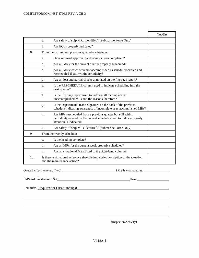
COMFLTFORCOMINST 4790.3 REV A CH-3
VI-19A-8
Yes/No
e. Are safety of ship MRs identified? (Submarine Force Only)
f. Are EGLs properly indicated?
8. From the current and previous quarterly schedules:
a. Have required approvals and reviews been completed?
b. Are all MRs for the current quarter properly scheduled?
c. Are all MRs which were not accomplished as scheduled circled and rescheduled if still within periodicity?
d. Are all lost and partial checks annotated on the flip page report?
e. Is the RESCHEDULE column used to indicate scheduling into the next quarter?
f. Is the flip page report used to indicate all incomplete or unaccomplished MRs and the reasons therefore?
g. Is the Department Head's signature on the back of the previous schedule indicating awareness of incomplete or unaccomplished MRs?
h. Are MRs rescheduled from a previous quarter but still within periodicity entered on the current schedule in red to indicate priority attention is indicated?
i. Are safety of ship MRs identified? (Submarine Force Only)
9. From the weekly schedule:
a. Is the heading complete?
b. Are all MRs for the current week properly scheduled?
c. Are all situational MRs listed in the right-hand column?
10. Is there a situational reference sheet listing a brief description of the situation and the maintenance action?
Overall effectiveness of WC PMS is evaluated as:
PMS Administration: Sat Unsat
Remarks: (Required for Unsat Findings)
(Inspector/Activity)

COMFLTFORCOMINST 4790.3 REV A
VI-19A-9
SECTION I-C
SAMPLE DEPARTMENTAL RAR SUMMARY
Ship Department Date
Work Center Total MRs Scheduled
(S)
Total MRs Accomplished
(A)
Total MRs Partially
Accomplished (P)
RAR (Note 1)
RAR Evaluation (Sat/Unsat)
(Note 2)
Total Department
Notes:
1. RAR = (A + (P /2)) / (S)
2. Sat RAR = 80% or better
3. Comments:

COMFLTFORCOMINST 4790.3 REV A
VI-19A-10
(This Page Intentionally Left Blank)

COMFLTFORCOMINST 4790.3 REV A
VI-19A-11
SECTION I-D
SAMPLE DEPARTMENTAL ACF SUMMARY
Ship Department Date
Work Center Total MRs Evaluated
(E)
Total MRs Evaluated as
Partially Accomplished
(P)
Total MRs Evaluated as
Not Accomplished
(N)
ACF (Note 1)
ACF Evaluation (Sat/Unsat)
(Note 2)
Total Department
Notes:
1. ACF = (E - (P/2) - N)/(E)
2. Sat ACF = 90% or better
3. Comments:

COMFLTFORCOMINST 4790.3 REV A
VI-19A-12
(This Page Intentionally Left Blank)

COMFLTFORCOMINST 4790.3 REV A CH-2
VI-19A-13
SECTION I-E
MRC EVALUATION AND PMS SPOT CHECK SHEET
Ship Date of Spot Check
WC MIP MRC
Equipment Date PMS performed
1. Contact the maintenance person assigned responsibility for the accomplishment of the MRC, have the individual deliver MRC (and EGL if applicable), and determine the following by questions and/or personal observation.
(Circle One)
a. Is the maintenance person PQS qualified to perform the MR. YES/NO*
b. Presenter validated MRC using the WC PMS record. (Change page to LOEP to MIP to MRC).
YES/NO
c. Maintenance person reviewed the MRC before accomplishment of the MR. YES/NO
d. Discussed the appropriate safety precautions including hazardous material, Personal Protective Equipment, Tagout etc.
YES/NO
e. Presented the correct tools, parts (NSN), material (Military Specification (MILSPEC)) and test equipment (Calibrated).
YES/NO*
f. Properly identified the equipment by using location block, Location Guide List, or EGL.
YES/NO
g. Demonstrated all steps of MR including all notes, warnings and cautions according to the MRC.
YES/NO
1) Followed all steps of the MRC. YES/NO
2) Can the procedure be followed exactly as written? YES/NO
3) Correctly demonstrated use and disposal of Hazardous Material. YES/NO/NA
4) Correctly performed equipment Tagout. YES/NO/NA*
5) Followed all safety precautions. YES/NO*
6) Are the safety precautions complete as listed? YES/NO
7) Is the manhour estimate correct?
If not, what is the correct estimate?
YES/NO
8) Is the tool/material list complete as written?
If not, what should be changed?
YES/NO
9) Was the MRC within the capability of the assigned individual to perform as written?
YES/NO
10) If an EGL is used, was the MRC performed on all equipments? YES/NO/NA
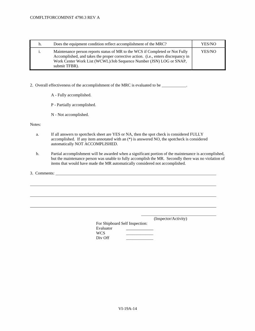
COMFLTFORCOMINST 4790.3 REV A
VI-19A-14
h. Does the equipment condition reflect accomplishment of the MRC? YES/NO
i. Maintenance person reports status of MR to the WCS if Completed or Not Fully Accomplished, and takes the proper corrective action. (i.e., enters discrepancy in Work Center Work List (WCWL)/Job Sequence Number (JSN) LOG or SNAP, submit TFBR).
YES/NO
2. Overall effectiveness of the accomplishment of the MRC is evaluated to be .
A - Fully accomplished.
P - Partially accomplished.
N - Not accomplished.
Notes:
a. If all answers to spotcheck sheet are YES or NA, then the spot check is considered FULLY accomplished. If any item annotated with an (*) is answered NO, the spotcheck is considered automatically NOT ACCOMPLISHED.
b. Partial accomplishment will be awarded when a significant portion of the maintenance is accomplished, but the maintenance person was unable to fully accomplish the MR. Secondly there was no violation of items that would have made the MR automatically considered not accomplished.
3. Comments:
(Inspector/Activity) For Shipboard Self Inspection: Evaluator _____________ WCS _____________ Div Off _____________
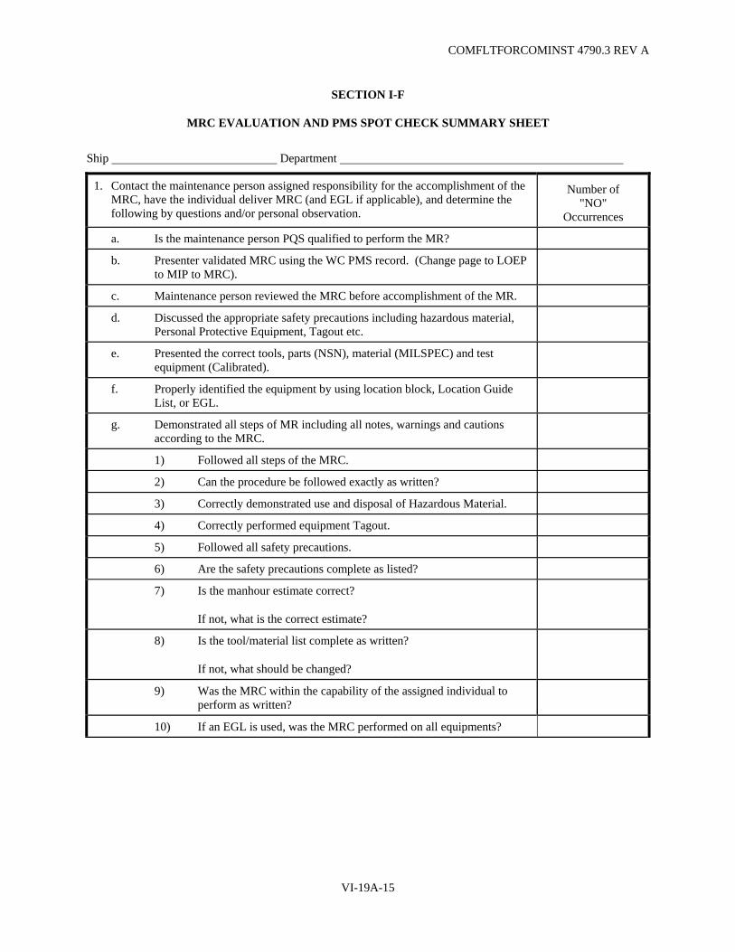
COMFLTFORCOMINST 4790.3 REV A
VI-19A-15
SECTION I-F
MRC EVALUATION AND PMS SPOT CHECK SUMMARY SHEET
Ship Department
1. Contact the maintenance person assigned responsibility for the accomplishment of the MRC, have the individual deliver MRC (and EGL if applicable), and determine the following by questions and/or personal observation.
Number of "NO"
Occurrences
a. Is the maintenance person PQS qualified to perform the MR?
b. Presenter validated MRC using the WC PMS record. (Change page to LOEP to MIP to MRC).
c. Maintenance person reviewed the MRC before accomplishment of the MR.
d. Discussed the appropriate safety precautions including hazardous material, Personal Protective Equipment, Tagout etc.
e. Presented the correct tools, parts (NSN), material (MILSPEC) and test equipment (Calibrated).
f. Properly identified the equipment by using location block, Location Guide List, or EGL.
g. Demonstrated all steps of MR including all notes, warnings and cautions according to the MRC.
1) Followed all steps of the MRC.
2) Can the procedure be followed exactly as written?
3) Correctly demonstrated use and disposal of Hazardous Material.
4) Correctly performed equipment Tagout.
5) Followed all safety precautions.
6) Are the safety precautions complete as listed?
7) Is the manhour estimate correct?
If not, what is the correct estimate?
8) Is the tool/material list complete as written?
If not, what should be changed?
9) Was the MRC within the capability of the assigned individual to perform as written?
10) If an EGL is used, was the MRC performed on all equipments?

COMFLTFORCOMINST 4790.3 REV A
VI-19A-16
h. Does the equipment condition reflect accomplishment of the MRC?
i. Maintenance person reports status of MR to the WCS if Completed or Not Fully Accomplished, and takes the proper corrective action. (i.e., enters discrepancy in WCWL/JSN LOG or SNAP, submit TFBR).
2. Total MRs Sampled:
Total MRs Fully Accomplished:
Total MRs Partially Accomplished:
3. Comments:

COMFLTFORCOMINST 4790.3 REV A
VI-19A-17
SECTION I-G
SAMPLE DEPARTMENTAL PPR SUMMARY
Ship Department Date
Work Center RAR ACF PPR (Note 1)
PPR Evaluation (Sat/Unsat)
(Note 2)
Total Department
Notes:
1. PPR = RAR x ACF
2. Sat PPR = 80% or better
3. Comments:

COMFLTFORCOMINST 4790.3 REV A
VI-19A-18
(This Page Intentionally Left Blank)
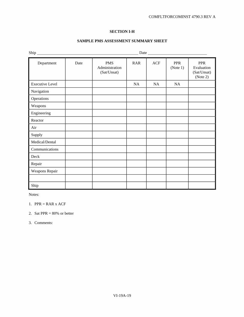
COMFLTFORCOMINST 4790.3 REV A
VI-19A-19
SECTION I-H
SAMPLE PMS ASSESSMENT SUMMARY SHEET
Ship Date
Department Date PMS Administration
(Sat/Unsat)
RAR ACF PPR (Note 1)
PPR Evaluation (Sat/Unsat)
(Note 2)
Executive Level NA NA NA
Navigation
Operations
Weapons
Engineering
Reactor
Air
Supply
Medical/Dental
Communications
Deck
Repair
Weapons Repair
Ship
Notes:
1. PPR = RAR x ACF
2. Sat PPR = 80% or better
3. Comments:

COMFLTFORCOMINST 4790.3 REV A
VI-19A-20
(This Page Intentionally Left Blank)
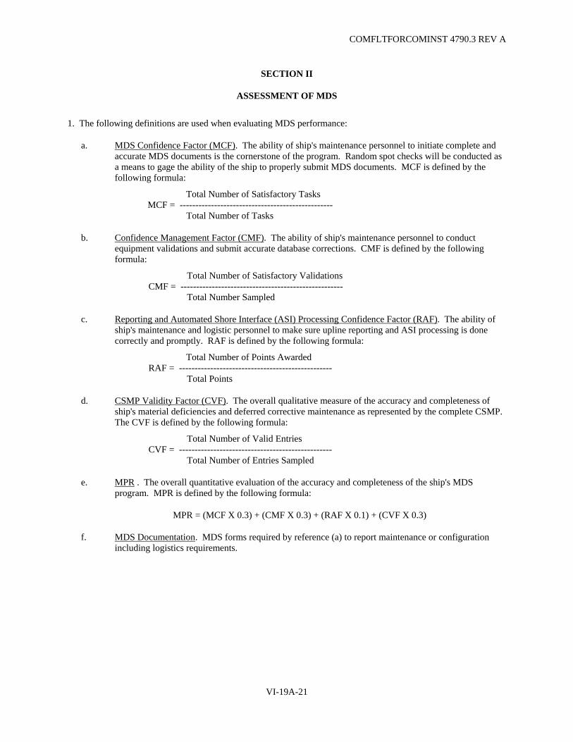
COMFLTFORCOMINST 4790.3 REV A
VI-19A-21
SECTION II
ASSESSMENT OF MDS
1. The following definitions are used when evaluating MDS performance:
a. MDS Confidence Factor (MCF). The ability of ship's maintenance personnel to initiate complete and accurate MDS documents is the cornerstone of the program. Random spot checks will be conducted as a means to gage the ability of the ship to properly submit MDS documents. MCF is defined by the following formula:
Total Number of Satisfactory Tasks MCF = -------------------------------------------------
Total Number of Tasks
b. Confidence Management Factor (CMF). The ability of ship's maintenance personnel to conduct equipment validations and submit accurate database corrections. CMF is defined by the following formula:
Total Number of Satisfactory Validations CMF = ---------------------------------------------------- Total Number Sampled
c. Reporting and Automated Shore Interface (ASI) Processing Confidence Factor (RAF). The ability of ship's maintenance and logistic personnel to make sure upline reporting and ASI processing is done correctly and promptly. RAF is defined by the following formula:
Total Number of Points Awarded RAF = ------------------------------------------------- Total Points
d. CSMP Validity Factor (CVF). The overall qualitative measure of the accuracy and completeness of ship's material deficiencies and deferred corrective maintenance as represented by the complete CSMP. The CVF is defined by the following formula:
Total Number of Valid Entries CVF = ------------------------------------------------- Total Number of Entries Sampled
e. MPR . The overall quantitative evaluation of the accuracy and completeness of the ship's MDS program. MPR is defined by the following formula:
MPR = (MCF X 0.3) + (CMF X 0.3) + (RAF X 0.1) + (CVF X 0.3)
f. MDS Documentation. MDS forms required by reference (a) to report maintenance or configuration including logistics requirements.

COMFLTFORCOMINST 4790.3 REV A
VI-19A-22
g. Equipment Validation. Process of comparing installed equipment to the Coordinated Shipboard Allowance List (COSAL) for non-automated ships or the Ship's Equipment File (SEF) for automated ships. The equipment record, whether found in a COSAL, Shipboard Navy Identification Technical Configuration Handbook, or in an OMMS data base, is the sole source for the Ship's Configuration and Logistics Support Information System (SCLSIS) information used to accurately describe a piece of installed equipment. This data record has both configuration and logistics data elements used to functionally describe a piece of equipment. This record is also used to complete the identification section (Section I) of the OPNAV 4790/2K.
h. CSMP. The CSMP is the sole source of work to be accomplished by industrial activities, FMAs, and organizational level activities. The complete CSMP consists of:
(1) A computer-produced list of deferred repairs, alterations and INSURV deficiencies.
(2) Copies of MDS documents submitted, but not yet reflected in the computer produced list. (Non-automated ship).
(3) WCWL/JSN Log (Non-automated ship) or SFWL (OMMS ship).
2. Determining the MCF.
a. Select ten percent (Surface and Submarine Forces) or two percent (Air Forces) of the crew who have access to MDS functions for functional MDS evaluation. The sample will include maintenance personnel, WCS, group supervisor, Repair Parts Petty Officer (RPPO), Division Officers, and Department Heads.
b. Selected personnel will demonstrate their ability to accomplish selected MDS tasks. These tasks are based on PQS qualifications of each person selected. The tasks will be evaluated using Section II-A (Automated) or II-B (Manual) of this Appendix for each person evaluated.
c. Section II-C (Automated) or Section II-D (Manual) of this Appendix are used to compute and summarize the final MCF for the ship and each department.
NOTE: WCWL/SFWL ITEMS MUST BE CONVERTED TO CSMP DEFERRALS AFTER 30 CALENDAR DAYS.
3. Determining the CMF.
a. Select two completed equipment validation forms per WC for validation.
b. Verify validation forms to the ship's equipment record and to the installed equipment, verifying the data collected is accurate and complete and that the SEF record is updated.
c. Record the results of the validation on Section II-E of this Appendix. Both the equipment validation form and SEF update must be graded Satisfactory for an overall grade of SAT.
4. Determining the RAF. Section II-F (Automated) or Section II-G (Manual) of this Appendix will be used to evaluate the RAF and record the results.
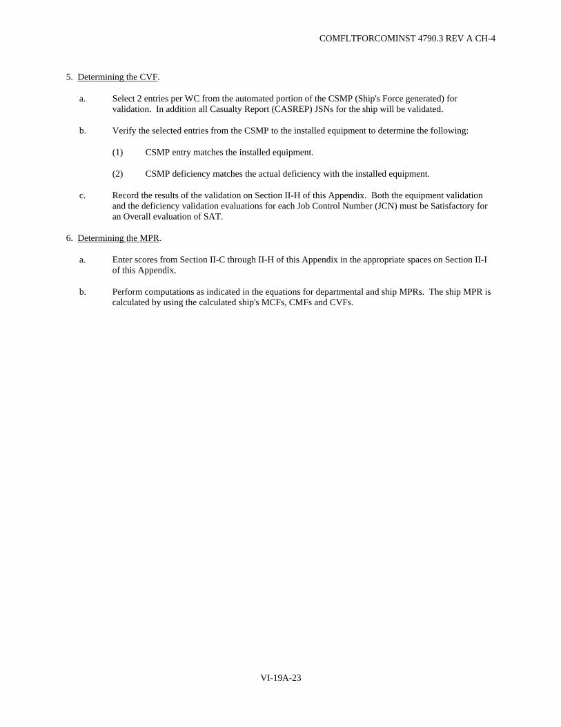
COMFLTFORCOMINST 4790.3 REV A CH-4
VI-19A-23
5. Determining the CVF.
a. Select 2 entries per WC from the automated portion of the CSMP (Ship's Force generated) for validation. In addition all Casualty Report (CASREP) JSNs for the ship will be validated.
b. Verify the selected entries from the CSMP to the installed equipment to determine the following:
(1) CSMP entry matches the installed equipment.
(2) CSMP deficiency matches the actual deficiency with the installed equipment.
c. Record the results of the validation on Section II-H of this Appendix. Both the equipment validation and the deficiency validation evaluations for each Job Control Number (JCN) must be Satisfactory for an Overall evaluation of SAT.
6. Determining the MPR.
a. Enter scores from Section II-C through II-H of this Appendix in the appropriate spaces on Section II-I of this Appendix.
b. Perform computations as indicated in the equations for departmental and ship MPRs. The ship MPR is calculated by using the calculated ship's MCFs, CMFs and CVFs.

COMFLTFORCOMINST 4790.3 REV A
VI-19A-24
(This Page Intentionally Left Blank)

COMFLTFORCOMINST 4790.3 REV A
VI-19A-25
SECTION II-A
MDS CONFIDENCE FACTOR WORKSHEET (AUTOMATED)
Name: PQS Qualification Level:
Department: Work Center:
POSITIONS:
M R W D D
P P C O H
P G
O S
X X X X X 3-M PQS Qualification completed. YES NO
X X X X X Able to Log-on. YES NO
CSMP ACTIONS:
X
X
X
X
Add Maintenance Action: 4790/2K
YES
NO
X X X SFWL/WCWL
YES NO
X
X
X
X
Close Maintenance Action: 4790/2K
YES
NO
X X X SFWL/WCWL
YES NO
X
X
X
X
Change Maintenance Action: 4790/2K
YES
NO
X X X SFWL/WCWL
YES NO
X
X
X
X
X
Display Maintenance Action: 4790/2K
YES
NO
X X X X X SFWL/WCWL YES NO
CONFIGURATION MAINTENANCE ACTION:
X X X Report installation of equipment: YES NO
X X X Report modification of equipment: YES NO
X X X Report removal of equipment: YES NO

COMFLTFORCOMINST 4790.3 REV A
VI-19A-26
POSITIONS:
M R W D D
P P C O H
P G
O S
UPDATE SEF:
X X X X X Review on-line equipment records: YES NO
X Add equipment records: YES NO
X Modify equipment records: YES NO
X Delete equipment records: YES NO
UPDATE LOGISTICS SUPPORT DATA (LSD) FILE:
X X X X X Review on-line LSD records: YES NO
X Add LSD data elements: YES NO
X Change LSD data elements: YES NO
X Delete LSD data elements: YES NO
SUPPLY REQUISITIONING:
X X Order maintenance parts: YES NO
X X Order non-maintenance related items: YES NO
X X Create Fleet COSAL Feedback Reports (FCFBR): YES NO
PRINT REPORTS:
X X SEF summary reports: YES NO
X X X X CSMP reports: YES NO
PRE-TRANSMITTAL REVIEW:
X X X Review CSMP transactions: YES NO
X X X Review SEF transactions: YES NO
X X X Review FCFBR transactions: YES NO

COMFLTFORCOMINST 4790.3 REV A
VI-19A-27
SECTION II-B
MDS CONFIDENCE FACTOR WORKSHEET (MANUAL)
Name: PQS Qualification Level:
Department: Work Center: POSITIONS: M R W D D P P C O H P G O S
X X X X X 3-M PQS Qualification completed. YES NO X X X X X Use SFWL/JSN Log. YES NO CSMP ACTIONS:
X
X
X
X
Add Maintenance Action: 4790/2K
YES
NO
X X X SFWL/WCWL YES NO
X
X
X
X
Close Maintenance Action: 4790/2K
YES
NO
X X X SFWL/WCWL YES NO
X
X
X
X
Change Maintenance Action: 4790/2K
YES
NO
X X X SFWL/WCWL YES NO CONFIGURATION MAINTENANCE ACTION:
X X X Report installation of equipment: YES NO X X X Report modification of equipment: YES NO X X X Report removal of equipment: YES NO SUPPLY REQUISITIONING: X X Order maintenance parts: YES NO X X Order non-maintenance related items: YES NO X X Create FCFBRs: YES NO MDS DOCUMENT REVIEW: X X X Review CSMP transactions: YES NO X X X Review configuration transactions: YES NO X X X Review FCFBR transactions: YES NO

COMFLTFORCOMINST 4790.3 REV A
VI-19A-28
(This Page Intentionally Left Blank)

COMFLTFORCOMINST 4790.3 REV A
VI-19A-29
SECTION II-C
SAMPLE MCF SUMMARY (AUTOMATED)
Ship Department Date
Work Center or Department
MP
(#pts/15)
RPPO
(#pts/20)
WC/GS
(#pts/29)
DO
(#pts/13)
DH
(#pts/10)
Total Department or
Ship
(average of above)
(average of above)
(average of above)
(average of above)
(average of above)
MP Confidence Factor = (Average from MP column above) RPPO Confidence Factor = (Average from RPPO column above) WC/GS Confidence Factor = (Average from WC/GS column above) DO Confidence Factor = (Average from DO column above) DH Confidence Factor = (Average from DH column above) Dept Confidence Factor = (Average of above Confidence Factors)

COMFLTFORCOMINST 4790.3 REV A
VI-19A-30
(This Page Intentionally Left Blank)

COMFLTFORCOMINST 4790.3 REV A
VI-19A-31
SECTION II-D
SAMPLE MCF SUMMARY (MANUAL)
Ship Department Date
Work Center or Department
MP (#pts/11)
RPPO (#pts/14)
WC/GS (#pts/17)
DO (#pts/8)
DH (#pts/5)
Total Department or
Ship
(average of above)
(average of above)
(average of above)
(average of above)
(average of above)
MP Confidence Factor = (Average from MP column above) RPPO Confidence Factor = (Average from RPPO column above) WC/GS Confidence Factor = (Average from WC/GS column above) DO Confidence Factor = (Average from DO column above) DH Confidence Factor = (Average from DH column above)
Dept Confidence Factor = (Average of above Confidence Factors)

COMFLTFORCOMINST 4790.3 REV A
VI-19A-32
(This Page Intentionally Left Blank)

COMFLTFORCOMINST 4790.3 REV A
VI-19A-33
SECTION II-E
SAMPLE CMF SUMMARY SHEET
Ship Department Date
Work Center Equipment Equipment Validation (Sat/Unsat)
Equipment File Updated (Sat/Unsat)
CMF Evaluation (Sat/Unsat)
(Note 1)
Total number of SAT equipment validations:______________________
Total number of updated SNAP files (if applicable):______________
CMF = (Total Number of SAT Validations)/(Total Sampled) =__________________________ (Sat = 80% or better)
Note:
1. CMF Evaluation = SAT, if both Equipment Validation and Equipment File Updated receives a score of Satisfactory.
Comments:

COMFLTFORCOMINST 4790.3 REV A
VI-19A-34
(This Page Intentionally Left Blank)
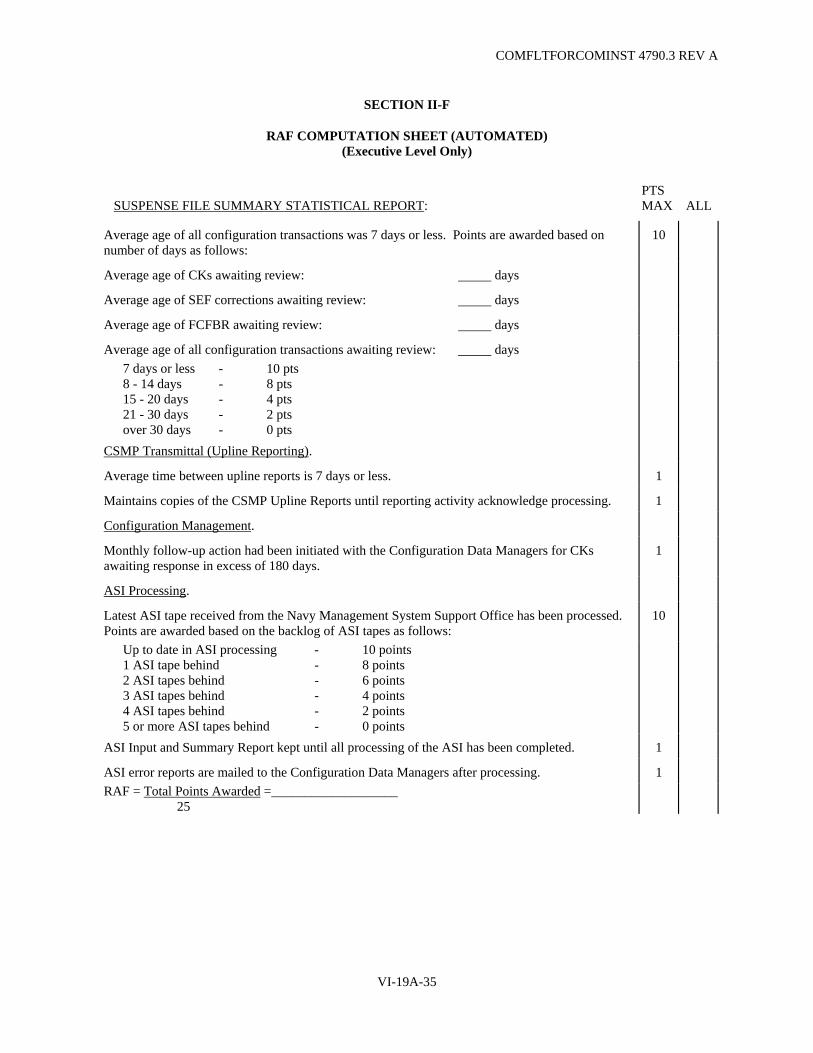
COMFLTFORCOMINST 4790.3 REV A
VI-19A-35
SECTION II-F
RAF COMPUTATION SHEET (AUTOMATED) (Executive Level Only)
PTS SUSPENSE FILE SUMMARY STATISTICAL REPORT: MAX ALL
Average age of all configuration transactions was 7 days or less. Points are awarded based on number of days as follows:
10
Average age of CKs awaiting review: days
Average age of SEF corrections awaiting review: days
Average age of FCFBR awaiting review: days
Average age of all configuration transactions awaiting review: days 7 days or less - 10 pts 8 - 14 days - 8 pts 15 - 20 days - 4 pts 21 - 30 days - 2 pts over 30 days - 0 pts
CSMP Transmittal (Upline Reporting).
Average time between upline reports is 7 days or less. 1
Maintains copies of the CSMP Upline Reports until reporting activity acknowledge processing. 1
Configuration Management.
Monthly follow-up action had been initiated with the Configuration Data Managers for CKs awaiting response in excess of 180 days.
1
ASI Processing.
Latest ASI tape received from the Navy Management System Support Office has been processed. Points are awarded based on the backlog of ASI tapes as follows:
10
Up to date in ASI processing - 10 points 1 ASI tape behind - 8 points 2 ASI tapes behind - 6 points 3 ASI tapes behind - 4 points 4 ASI tapes behind - 2 points 5 or more ASI tapes behind - 0 points
ASI Input and Summary Report kept until all processing of the ASI has been completed. 1
ASI error reports are mailed to the Configuration Data Managers after processing. 1 RAF = Total Points Awarded =___________________ 25

COMFLTFORCOMINST 4790.3 REV A
VI-19A-36
(This Page Intentionally Left Blank)

COMFLTFORCOMINST 4790.3 REV A
VI-19A-37
SECTION II-G
RAF COMPUTATION SHEET (MANUAL) (Executive Level Only)
PTS MAX ALL
3-M COORDINATOR.
3-M Coordinator properly maintains the ship's master WCWL/JCN Log. 1
3-M Coordinator properly maintains MDS transmittal file of all MDS maintenance actions awaiting processing by Automated Data Processing (ADP) facility.
1
Average age of MDS documents awaiting transmittal is 7 days or less. Points are awarded based on backlog of MDS documents as follows:
10
7 days or less - 10 points 8 - 14 days - 8 points 15 - 20 days - 6 points 21 - 30 days - 4 points over 30 days - 2 points
3-M Coordinator properly processes the error reports received from the ADP facility. 1 RAF = Total Points Awarded = 13

COMFLTFORCOMINST 4790.3 REV A
VI-19A-38
(This Page Intentionally Left Blank)
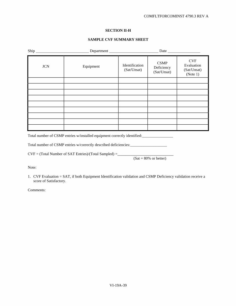
COMFLTFORCOMINST 4790.3 REV A
VI-19A-39
SECTION II-H
SAMPLE CVF SUMMARY SHEET
Ship Department Date
JCN Equipment Identification (Sat/Unsat)
CSMP Deficiency (Sat/Unsat)
CVF Evaluation (Sat/Unsat)
(Note 1)
Total number of CSMP entries w/installed equipment correctly identified:________________
Total number of CSMP entries w/correctly described deficiencies:___________________
CVF = (Total Number of SAT Entries)/(Total Sampled) =_____________________________ (Sat = 80% or better)
Note:
1. CVF Evaluation = SAT, if both Equipment Identification validation and CSMP Deficiency validation receive a score of Satisfactory.
Comments:

COMFLTFORCOMINST 4790.3 REV A
VI-19A-40
(This Page Intentionally Left Blank)
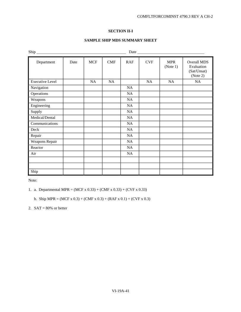
COMFLTFORCOMINST 4790.3 REV A CH-2
VI-19A-41
SECTION II-I
SAMPLE SHIP MDS SUMMARY SHEET
Ship Date
Department Date MCF CMF RAF CVF MPR (Note 1)
Overall MDS Evaluation (Sat/Unsat)
(Note 2) Executive Level NA NA NA NA NA Navigation NA Operations NA Weapons NA Engineering NA Supply NA Medical/Dental NA Communications NA Deck NA Repair NA Weapons Repair NA Reactor NA Air NA Ship
Note:
1. a. Departmental MPR = (MCF x 0.33) + (CMF x 0.33) + (CVF x 0.33)
b. Ship MPR = (MCF x 0.3) + (CMF x 0.3) + (RAF x 0.1) + (CVF x 0.3)
2. SAT = 80% or better

COMFLTFORCOMINST 4790.3 REV A
VI-19A-42
(This Page Intentionally Left Blank)
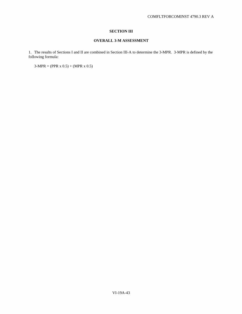
COMFLTFORCOMINST 4790.3 REV A
VI-19A-43
SECTION III
OVERALL 3-M ASSESSMENT
1. The results of Sections I and II are combined in Section III-A to determine the 3-MPR. 3-MPR is defined by the following formula:
3-MPR = (PPR x 0.5) + (MPR x 0.5)

COMFLTFORCOMINST 4790.3 REV A
VI-19A-44
(This Page Intentionally Left Blank)
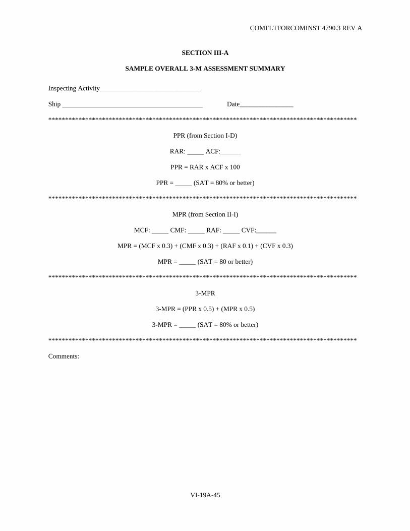
COMFLTFORCOMINST 4790.3 REV A
VI-19A-45
SECTION III-A
SAMPLE OVERALL 3-M ASSESSMENT SUMMARY
Inspecting Activity______________________________
Ship Date________________
********************************************************************************************
PPR (from Section I-D)
RAR: ACF:______
PPR = RAR x ACF x 100
PPR = (SAT = 80% or better)
********************************************************************************************
MPR (from Section II-I)
MCF: CMF: RAF: CVF:______
MPR = (MCF x 0.3) + (CMF x 0.3) + (RAF x 0.1) + (CVF x 0.3)
MPR = (SAT = 80 or better)
********************************************************************************************
3-MPR
3-MPR = (PPR x 0.5) + (MPR x 0.5)
3-MPR = (SAT = 80% or better)
********************************************************************************************
Comments:

COMFLTFORCOMINST 4790.3 REV A
VI-19A-46
(This Page Intentionally Left Blank)

COMFLTFORCOMINST 4790.3 REV A
VI-19B-1
APPENDIX B
LISTING OF STANDARD WORK CENTER CODES FOR AIRCRAFT CARRIERS
1. Afloat Departmental Codes.
WC CODE SHIP TYPE*
Safety A Chaplain B Communication C Deck D Engineering E Flag/Embarked Staff F Aviation Intermediate Maintenance Department (AIMD) I Legal L Medical and Dental M Navigation N Operations O Maintenance P Reactor R Supply S Air V Weapons W Executive X Administrative Y Embarked Airwing Z
2. Afloat Professional WC Codes
a. Safety Department. AS01
b. Chaplain Department. BC01
c. Communication.
Message Processing CR01 Copier/Teletype Repair CR02 Signal Communication CV01
d. Deck Department.
1st Division DA01 2nd Division DB02 3rd Division DC03 Boat Division DD01 Sail Loft DE01
* Ship type CV/CVN unless otherwise noted.

COMFLTFORCOMINST 4790.3 REV A
VI-19B-2
WC CODE SHIP TYPE*
e. Engineering Department.
(1) Auxiliaries.
Hydraulics EA01 Steam Heat/Galley/Laundry EA02 Air Conditioning & Refrigeration EA03 Diesels EA04 Machine Shop EA05 Oxygen & Nitrogen EA06 Boats EA07 Outside Repair EA08
(2) Boiler Division.
1 Group Boilers EB01 2 Group Boilers EB02 3 Group Boilers EB03 4 Group Boilers EB04 Oil and Water Lab EB14 Catapult Shop EB15 ACC Shop EB16 Boiler Repair Shop EB17
(3) Damage Control Division.
Damage Control Training ED01 Prof. Fire Party (0-3 Level and above)
ED11
Prof. Fire Party (Main Deck to 0-2 Lev)
ED12
Prof. Fire Party (DC Deck)
ED13
(4) Electrical Division.
Lighting/General EE01 Rewind EE02 Power (Non-nuclear) EE03 Distribution EE04 Forward Interior Communications & Sound Power Phones
EE05
After Interior Communications EE06 Announcing Systems EE07 Alarms EE08
* Ship type is CV/CVN unless otherwise noted.

COMFLTFORCOMINST 4790.3 REV A
VI-19B-3
WC CODE SHIP TYPE*
Flight Deck Electrical EE09 Movie/Copy Machine EE10 Battery Locker EE11 Electrical Safety EE12 Fwd Plant (Nuclear (E-1)) EE31 Aft Plant (Nuclear (E-1)) EE32 400 HZ Nuclear EE33
(5) Machinery Division.
#1 Engine Room EM01 #2 Engine Room EM02 #3 Engine Room EM03 #4 Engine Room EM04 #1 Auxiliary Machinery Room EM05 #2 Auxiliary Machinery Room EM06 #1 Turbo Gen/Pump Room EM21 #2 Turbo Gen/Pump Room EM22 #3 Turbo Gen/Pump Room EM23 #4 Turbo Gen Pump Room EM24
(6) Repair Division.
Sheet Metal ER01 Carpenter ER02 Pipe ER03 Damage Control ER04 Collection, Holding and Transfer ER06 Compressed Gas ER07 Locksmith ER08 AFFF ER10 Firemain ER12
f. AIMD Department.
PC/QA division IM01 Mechanical Repairs IM02 Avionics IM03 Ground Support IM04
g. Legal Department.
Legal LN01
* Ship type is CV/CVN unless otherwise noted.
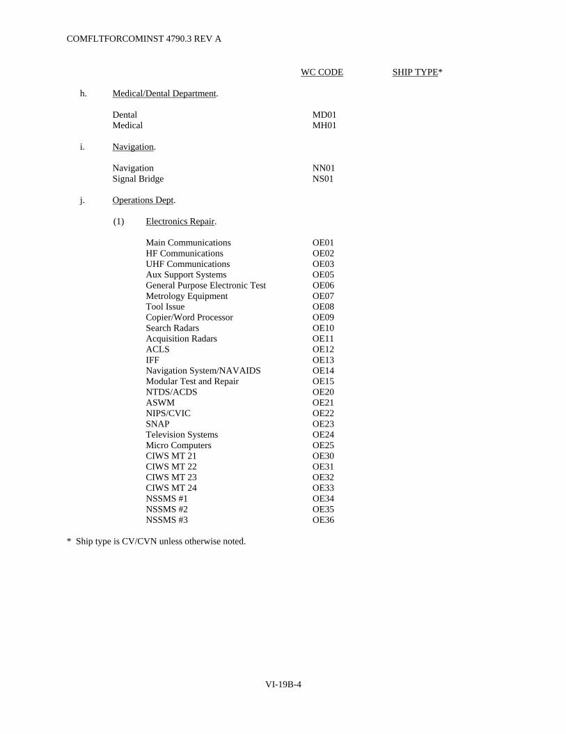
COMFLTFORCOMINST 4790.3 REV A
VI-19B-4
WC CODE SHIP TYPE*
h. Medical/Dental Department.
Dental MD01 Medical MH01
i. Navigation.
Navigation NN01 Signal Bridge NS01
j. Operations Dept.
(1) Electronics Repair.
Main Communications OE01 HF Communications OE02 UHF Communications OE03 Aux Support Systems OE05 General Purpose Electronic Test OE06 Metrology Equipment OE07 Tool Issue OE08 Copier/Word Processor OE09 Search Radars OE10 Acquisition Radars OE11 ACLS OE12 IFF OE13 Navigation System/NAVAIDS OE14 Modular Test and Repair OE15 NTDS/ACDS OE20 ASWM OE21 NIPS/CVIC OE22 SNAP OE23 Television Systems OE24 Micro Computers OE25 CIWS MT 21 OE30 CIWS MT 22 OE31 CIWS MT 23 OE32 CIWS MT 24 OE33 NSSMS #1 OE34 NSSMS #2 OE35 NSSMS #3 OE36 * Ship type is CV/CVN unless otherwise noted.
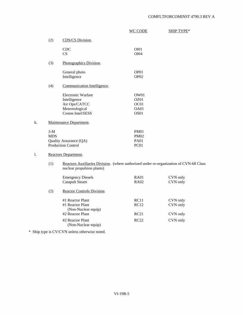
COMFLTFORCOMINST 4790.3 REV A
VI-19B-5
WC CODE SHIP TYPE*
(2) CDS/CS Division.
CDC OI01 CS OI04
(3) Photographics Division.
General photo OP01 Intelligence OP02
(4) Communication Intelligence.
Electronic Warfare OW01 Intelligence OZ01 Air Ops/CATCC OC01 Meteorological OA01 Comm Intel/SESS OS01
k. Maintenance Department.
3-M PM01 MDS PM02 Quality Assurance (QA) PA01 Production Control PC01
l. Reactors Department.
(1) Reactors Auxiliaries Division. (where authorized under re-organization of CVN-68 Class nuclear propulsion plants)
Emergency Diesels RA01 CVN only Catapult Steam RA02 CVN only
(2) Reactor Controls Division.
#1 Reactor Plant RC11 CVN only #1 Reactor Plant (Non-Nuclear equip)
RC12 CVN only
#2 Reactor Plant RC21 CVN only #2 Reactor Plant (Non-Nuclear equip)
RC22 CVN only
* Ship type is CV/CVN unless otherwise noted.

COMFLTFORCOMINST 4790.3 REV A
VI-19B-6
WC CODE SHIP TYPE*
(3) Reactor Electrical Division.
#1 Reactor Plant RE11 CVN only #1 Reactor Plant (Non-Nuclear equip)
RE12 CVN only
#2 Reactor Plant RE21 CVN only #2 Reactor Plant (Non-Nuclear equip)
RE22 CVN only
(4) Reactor Laboratory Division.
#1 Reactor Plant RL11 CVN only #1 Reactor (Non-Nuclear equip)
RL12 CVN only
#2 Reactor Plant RL21 CVN only #2 Reactor (Non-Nuclear equip)
RL22 CVN only
Dosimetry RL30 CVN only
(5) Reactor Mechanical Division.
Reactor Room #1 RM11 CVN only Reactor Room #1 (Non-Nuclear equip)
RM12 CVN only
Reactor Room #2 RM21 CVN only Reactor Room #2 (Non-Nuclear equip)
RM22 CVN only
Technical Support RM30 CVN only Turbine Test/QA RM31 CVN only
(6) Reactor Propulsion Division. (where authorized under re-organization of CVN-68 Class
nuclear propulsion plants) #1 Main Machinery Room RP01 CVN only #2 Main Machinery Room RP02 CVN only Oil/Water/Auxiliary Boiler RP05 CVN only #1 Reactor Auxiliary Room RP21 CVN only #2 Reactor Auxiliary Room RP22 CVN only Calibration RP31 CVN only
(7) Reactor Training/Admin Division.
Training/Admin RT01 CVN only
* Ship type is CV/CVN unless otherwise noted.

COMFLTFORCOMINST 4790.3 REV A
VI-19B-7
WC CODE SHIP TYPE*
m. Supply Department.
Stock Control S1 Division SS01 Food Service S2 Division SS02 Ship's Store S3 Division SS03 Disbursing S4 Division SS04 Wardroom S5 Division SS05 Aviation Support S6 Division SS06 ADP S7 Division SS07 Material S8 Division SS08 Supply QA S10 Division SS10 CPO Mess S11 Division SS11
n. Weapons Department.
Weapons Handling G1 Division WG01 Ship's Armory GZ Division WG02 Weapons Magazine G3 Division WG03 Weapons Elevator G4 Division WG04 Weapons Control G5 Division WG05 Marine Detachment/Security WM01 Forward SAS WW01 After SAS WW02
o. Air Department.
(1) V1 Division.
Flight Deck VA01 Crash and Salvage VA02
(2) V2 Division.
#1 Catapult VB01 #2 Catapult VB02 #3 Catapult VB03 #4 Catapult VB04 #1 Arresting Gear VB05 #2 Arresting Gear VB06 #3 Arresting Gear VB07 #4 Arresting Gear VB08 Barricade VB09 Fresnel Lens Optical System VB10 Pilot Landing Aid TV VB11
* Ship type is CV/CVN unless otherwise noted.
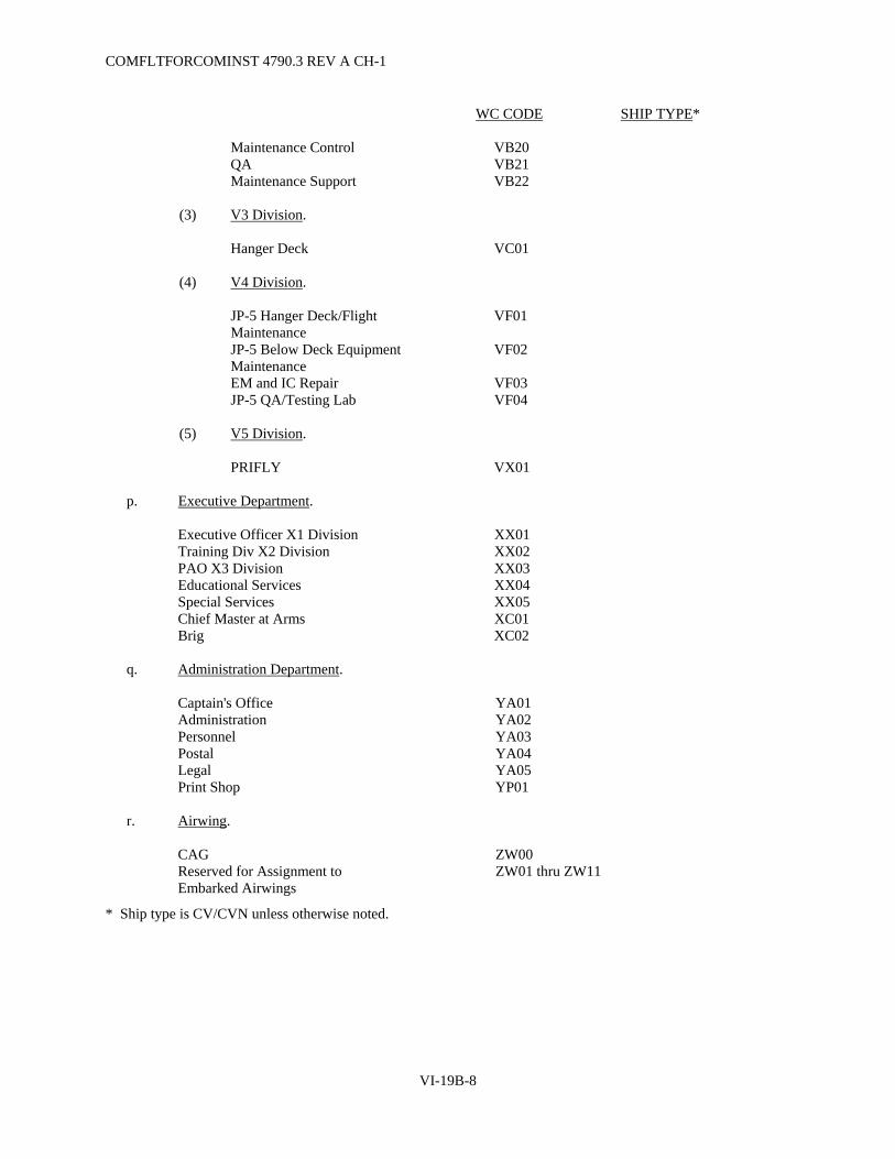
COMFLTFORCOMINST 4790.3 REV A CH-1
VI-19B-8
WC CODE SHIP TYPE*
Maintenance Control VB20 QA VB21 Maintenance Support VB22
(3) V3 Division.
Hanger Deck VC01
(4) V4 Division.
JP-5 Hanger Deck/Flight Maintenance
VF01
JP-5 Below Deck Equipment Maintenance
VF02
EM and IC Repair VF03 JP-5 QA/Testing Lab VF04
(5) V5 Division.
PRIFLY VX01
p. Executive Department.
Executive Officer X1 Division XX01 Training Div X2 Division XX02 PAO X3 Division XX03 Educational Services XX04 Special Services XX05 Chief Master at Arms XC01 Brig XC02
q. Administration Department.
Captain's Office YA01 Administration YA02 Personnel YA03 Postal YA04 Legal YA05 Print Shop YP01
r. Airwing.
CAG ZW00 Reserved for Assignment to Embarked Airwings
ZW01 thru ZW11
* Ship type is CV/CVN unless otherwise noted.
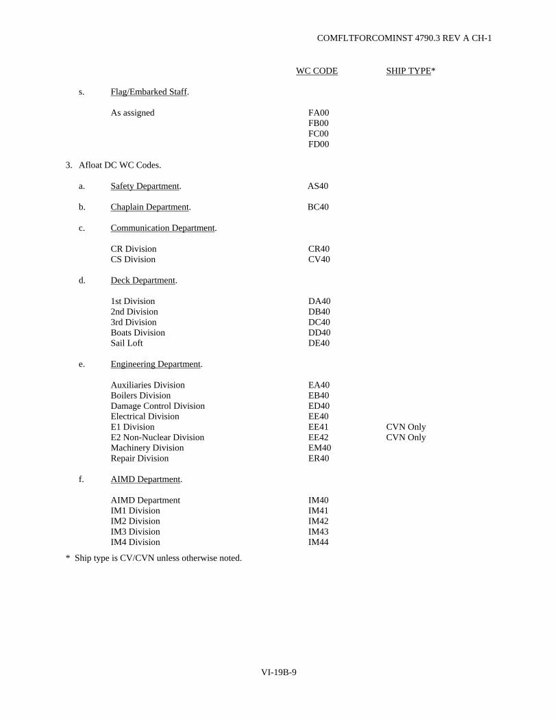
COMFLTFORCOMINST 4790.3 REV A CH-1
VI-19B-9
WC CODE SHIP TYPE*
s. Flag/Embarked Staff.
As assigned FA00 FB00 FC00 FD00
3. Afloat DC WC Codes.
a. Safety Department. AS40
b. Chaplain Department. BC40
c. Communication Department.
CR Division CR40 CS Division CV40
d. Deck Department.
1st Division DA40 2nd Division DB40 3rd Division DC40 Boats Division DD40 Sail Loft DE40
e. Engineering Department.
Auxiliaries Division EA40 Boilers Division EB40 Damage Control Division ED40 Electrical Division EE40 E1 Division EE41 CVN Only E2 Non-Nuclear Division EE42 CVN Only Machinery Division EM40 Repair Division ER40
f. AIMD Department.
AIMD Department IM40 IM1 Division IM41 IM2 Division IM42 IM3 Division IM43 IM4 Division IM44
* Ship type is CV/CVN unless otherwise noted.

COMFLTFORCOMINST 4790.3 REV A
VI-19B-10
WC CODE SHIP TYPE*
g. Legal Department.
Legal LN40
h. Medical/Dental Department.
Medical MD40 Dental MH40
i. Navigation Department.
Navigation Division MN40
j. Operations Department.
OA Division OA40 OC Division OC40 OE Communications Division OE41 OE Data Division OE42 OE Missile Division OE43 OE Repair Division OE44 OI Division OI40 OP Division OP40 OS Division OS40 OW Division OW40 OZ Division OZ40
k. Maintenance Department.
PM40
l. Reactors Department.
RA Division RA40 CVN Only RC Division RC40 CVN Only RE Division RE40 CVN Only RL Division RL40 CVN Only RM Division RM40 CVN Only RP Division RP40 CVN Only RT Division RT40 CVN Only
m. Supply Department.
S1 Division SS41 S2 Division SS42 S3 Division SS43 S4 Division SS44 * Ship type is CV/CVN unless otherwise noted.

COMFLTFORCOMINST 4790.3 REV A
VI-19B-11
WC CODE SHIP TYPE*
S5 Division SS45 S6 Division SS46 S7 Division SS47 S8 Division SS48 S9 Division SS49 S10 Division SS50 S11 Division SS51
n. Weapons Department.
G1 Division WG41 G2 Division WG42 G3 Division WG43 G4 Division WG44 G5 Division WG05 Marine Detachment WM40 W Division WW40
o. Air Department.
V1 Division VA40 V2 Division VB40 V3 Division VC40 V4 Division VF40 V5 Division VK40
p. Executive Department.
XX40
q. Administrative Department. YA40
r. Airwing. ZW40
s. Flag/Embarked Staff. FA40
4. Shore Station Departmental Codes. (Under Development)
5. Shore Station WC Codes. (Under Development)
* Ship type is CV/CVN unless otherwise noted.

COMFLTFORCOMINST 4790.3 REV A
VI-19B-12
(This Page Intentionally Left Blank)

COMFLTFORCOMINST 4790.3 REV A CH-6
VI-19C-1
APPENDIX C
LISTING OF STANDARD WORK CENTER CODES FOR SUBMARINE FORCE SHIPS Standard Submarine Work Center Codes
Description Used by Submarine Type Code
Executive
Executive/Administration (ADM – Functional Area Supervisor - SNAP)
All
XX00
Chief of the Boat All XX03 3-M Coordinator (SNAP OMMS Functional Area Supervisor)
All XM01
Safety Petty Officer All SP01
Engineering
Auxiliary
All
EA01 Damage Control Petty Officer (Note 1) All EDC1 Electrical (Main Power - SS) All EE01 Auxiliary Power AGSS EE02 Machinery All EM01 Aft Engine Room SS EM02 Engineering Administration All EX00 Engineering Log Room All EX02 Reactor Controls All Nuclear RC01 Engineering Laboratory All RL01
Medical
Medical
All
MH01
Navigation/Operations
Navigation/Electronics
All
NE01 Radio/Communications All OC01 Afloat Information Systems/Automated Data Processing Coordinator (AIS/ADP)
All OC02
Navigation/Operations Administration All OX00
Research and Development
Mission Auxiliary
SSN-23 Only
MA01 Mission Electronics SSN-23 Only ME01 Mission Navigation SSN-23 Only MN01 Mission Vehicle Support SSN-23 Only MV01
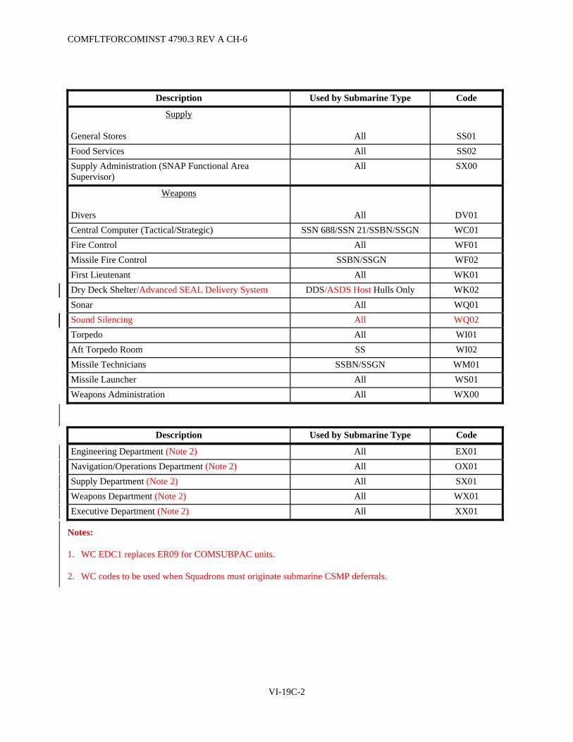
COMFLTFORCOMINST 4790.3 REV A CH-6
VI-19C-2
Description Used by Submarine Type Code
Supply
General Stores
All
SS01 Food Services All SS02 Supply Administration (SNAP Functional Area Supervisor)
All SX00
Weapons
Divers
All
DV01 Central Computer (Tactical/Strategic) SSN 688/SSN 21/SSBN/SSGN WC01 Fire Control All WF01 Missile Fire Control SSBN/SSGN WF02 First Lieutenant All WK01 Dry Deck Shelter/Advanced SEAL Delivery System DDS/ASDS Host Hulls Only WK02 Sonar All WQ01 Sound Silencing All WQ02 Torpedo All WI01 Aft Torpedo Room SS WI02 Missile Technicians SSBN/SSGN WM01 Missile Launcher All WS01 Weapons Administration All WX00
Description Used by Submarine Type Code
Engineering Department (Note 2) All EX01 Navigation/Operations Department (Note 2) All OX01 Supply Department (Note 2) All SX01 Weapons Department (Note 2) All WX01 Executive Department (Note 2) All XX01
Notes:
1. WC EDC1 replaces ER09 for COMSUBPAC units.
2. WC codes to be used when Squadrons must originate submarine CSMP deferrals.
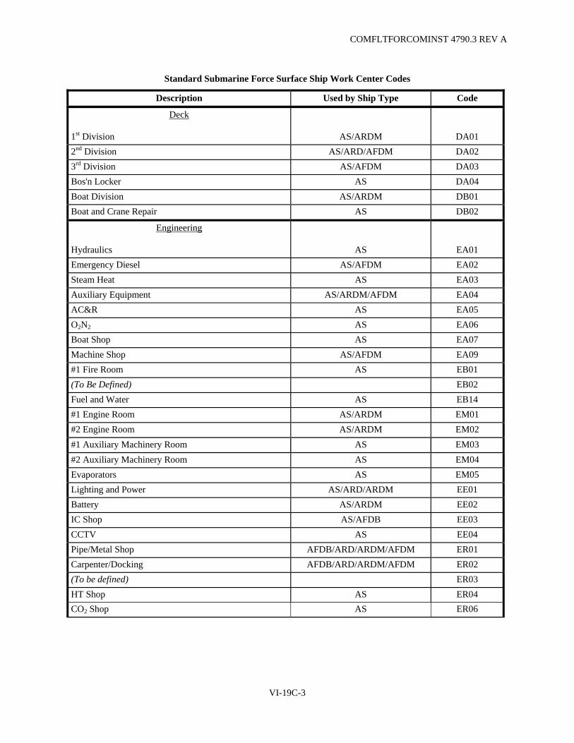
COMFLTFORCOMINST 4790.3 REV A
VI-19C-3
Standard Submarine Force Surface Ship Work Center Codes
Description Used by Ship Type Code
Deck
1st Division
AS/ARDM
DA01 2nd Division AS/ARD/AFDM DA02 3rd Division AS/AFDM DA03 Bos'n Locker AS DA04 Boat Division AS/ARDM DB01 Boat and Crane Repair AS DB02
Engineering
Hydraulics
AS
EA01 Emergency Diesel AS/AFDM EA02 Steam Heat AS EA03 Auxiliary Equipment AS/ARDM/AFDM EA04 AC&R AS EA05 O2N2 AS EA06 Boat Shop AS EA07 Machine Shop AS/AFDM EA09 #1 Fire Room AS EB01 (To Be Defined) EB02 Fuel and Water AS EB14 #1 Engine Room AS/ARDM EM01 #2 Engine Room AS/ARDM EM02 #1 Auxiliary Machinery Room AS EM03 #2 Auxiliary Machinery Room AS EM04 Evaporators AS EM05 Lighting and Power AS/ARD/ARDM EE01 Battery AS/ARDM EE02 IC Shop AS/AFDB EE03 CCTV AS EE04 Pipe/Metal Shop AFDB/ARD/ARDM/AFDM ER01 Carpenter/Docking AFDB/ARD/ARDM/AFDM ER02 (To be defined) ER03 HT Shop AS ER04 CO2 Shop AS ER06

COMFLTFORCOMINST 4790.3 REV A CH-6
VI-19C-4
Description Used by Ship Type Code
Ventilation (Filter Cleaning Shop) AS ER07 Damage Control Petty Officer All EDC1 Engineering Administration All EX00 Engineering Log Room All EX02
Medical
Medical
All
MH01 Dental AS MD01
Navigation/Operations
Navigation (QM)
AS
NN01 Sonar All OA01 Radio/Communications AS/ARDM OC01 Afloat Information Systems/Automated Data Processing Coordinator (AIS/ADP)
All OC02
Electronics AS OE01 Electronic Navigation AS OE02 Radar AS/ARD/AFDM OI01
Supply
Supply Administration
All
SX00 General Stores All SS01 Food Service All SS02 Ship's Store AS SS03 Disbursing AS SS04 Supply QA AS SS05 Inventory Control AS SS06 SUBSAT AS SS07 ROVSS AS SS09
Weapons
(To Be Defined)
ARD/ARDM
WA01 (To Be Defined) ARDB WA11 Armory/Magazine AS WK02 Weapons Cranes & Elevators AS WK04 Fire Control AS WI01 Gunnery AS/ARDM WI05 Weapons Administration All WX00

COMFLTFORCOMINST 4790.3 REV A
VI-19C-5
Description Used by Ship Type Code
Executive
Executive Administration
AS
XX00 3-M Coordinator AS XM01 Safety Petty Officer All SP01 Personnel Office AS XX02 Educational Services All XX03

COMFLTFORCOMINST 4790.3 REV A
VI-19C-6
(This Page Intentionally Left Blank)
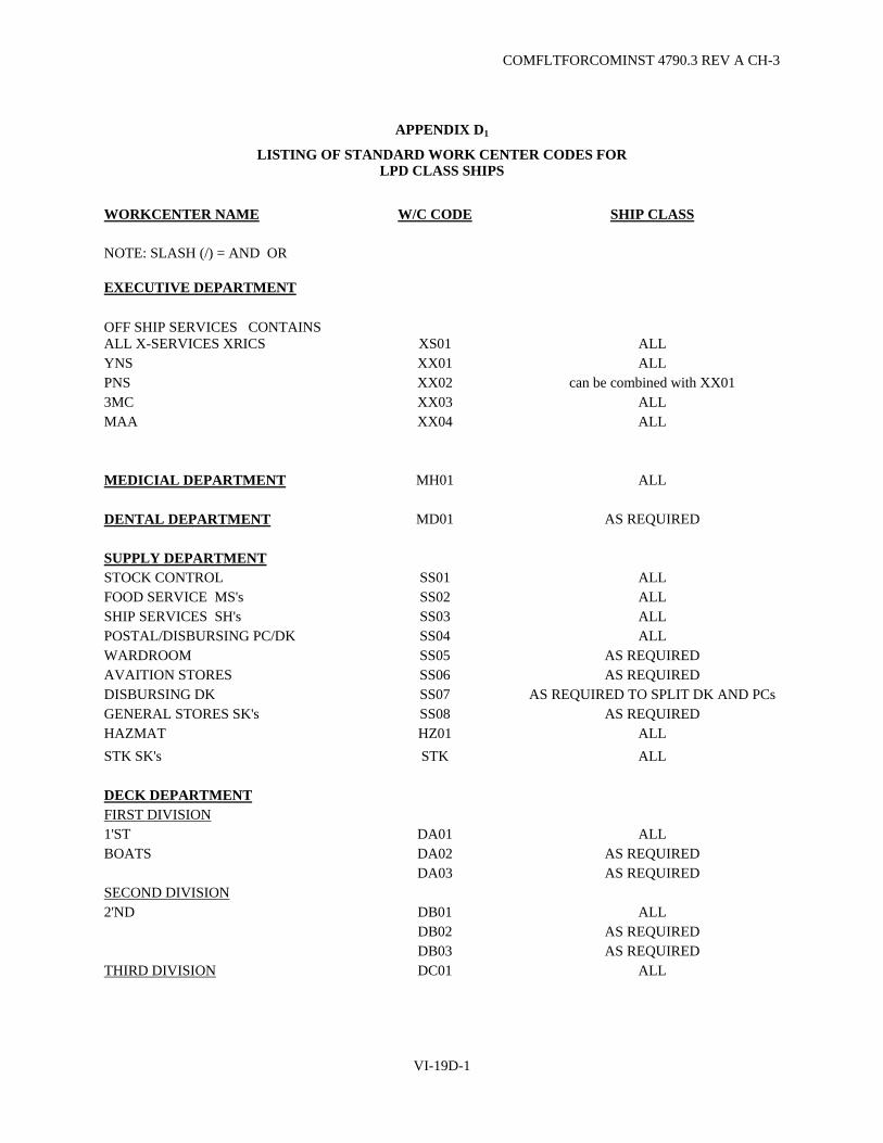
COMFLTFORCOMINST 4790.3 REV A CH-3
VI-19D-1
APPENDIX D1
LISTING OF STANDARD WORK CENTER CODES FOR LPD CLASS SHIPS
WORKCENTER NAME W/C CODE SHIP CLASS NOTE: SLASH (/) = AND OR EXECUTIVE DEPARTMENT
OFF SHIP SERVICES CONTAINS ALL X-SERVICES XRICS XS01 ALL YNS XX01 ALL PNS XX02 can be combined with XX01 3MC XX03 ALL MAA XX04 ALL MEDICIAL DEPARTMENT MH01 ALL DENTAL DEPARTMENT MD01 AS REQUIRED SUPPLY DEPARTMENT STOCK CONTROL SS01 ALL FOOD SERVICE MS's SS02 ALL SHIP SERVICES SH's SS03 ALL POSTAL/DISBURSING PC/DK SS04 ALL WARDROOM SS05 AS REQUIRED AVAITION STORES SS06 AS REQUIRED DISBURSING DK SS07 AS REQUIRED TO SPLIT DK AND PCsGENERAL STORES SK's SS08 AS REQUIRED HAZMAT HZ01 ALL STK SK's STK ALL DECK DEPARTMENT FIRST DIVISION 1'ST DA01 ALL BOATS DA02 AS REQUIRED DA03 AS REQUIRED SECOND DIVISION 2'ND DB01 ALL DB02 AS REQUIRED DB03 AS REQUIRED THIRD DIVISION DC01 ALL

COMFLTFORCOMINST 4790.3 REV A CH-2
VI-19D-2
WORKCENTER NAME W/C CODE SHIP CLASS ENGINEERING DEPARTMENT AUXILIARY EN's EA01 ALL ENGINE SHOP EA02 AS REQUIRED HYDRAULICS EA04 ALL AIR CONDITIONING & REPAIR EA05 ALL GAGE CAL FCA1 ALL ELEC TOOL ISSUE/SAFETY EE01 ALL ELECTRICAL SHOP EE02 ALL INTERIOR COMMUNICATIONS IC01 ALL SITE TELEVISION IC03 AS REQUIRED MAIN MACHINERY ROOM 1 EM01 ALL MAIN MACHINERY ROOM 2 EM02 ALL AUXILIARY MACHINERY ROOM 1 EM03 ALL AUXILIARY MACHINERY ROOM 2 EM04 ALL OIL LAB EB14 ALL HULL REPAIR HT's ER01 ALL CARPENTER SHOP ER02 AS REQUIRED MACHINERY REPAIR MR's ER03 ALL DAMAGE CONTROL REPAIR ER04 ALL SHEET METAL ER05 AS REQUIRED DCPO ER09 ALL ENGINEERING ADMIN EX00 AS REQUIRED AIR DEPARTMENT FLIGHT DECK (ABHs) VA01 ALL AVAITION FUELS VF01 ALL GROUND SUPPORT EQUIPMENT IM04 ALL OPERATIONS DEPARTMENT RADIO IS01 ALL LAN/ADP IS02 ALL ELECTRONICS CSE1 ALL 2M REPAIR CSE3 ALL RADARS OE02 ALL TEST EQUIPMANT ELEC CAL CE04 ALL CIC OI01 ALL ELECTRONIC WARFARE OT01 GUNNERY/ARMORY CG03 ALL CIWS CF04 ALL FORCE PROTECTION FP01 ALL NAVIGATION OSs OI02 ALL SIGNAL BRIDGE OI03 ALL

COMFLTFORCOMINST 4790.3 REV A CH-3
VI-19D-3
APPENDIX D2
LISTING OF STANDARD WORK CENTER CODES FOR ARS CLASS SHIPS
WORKCENTER NAME W/C CODE SHIP CLASS EXECUTIVE DEPARTMENT
OFF SHIP SERVICES CONTAINS ALL X-SERVICES XRICS XS01 ALL MEDICIAL MH01 ALL ADMIN XX01 ALL 3MC XX03 ALL SUPPLY DEPARTMENT GENERAL STORES SK's SS01 ALL FOOD SERVICE CS's SS02 ALL SHIP SERVICES SH's SS03 ALL POSTAL/DISBURSING PC/DK SS04 ALL
DISBURSING DK SS07 AS REQUIRED TO SPLIT DK
AND PCs HAZMAT HZ01 ALL STK SK's STK ALL ENGINEERING DEPARTMENT AUXILIARY EN's EA01 ALL INTERIOR COMMS IC IC01 ALL ELECTRICAL SHOP EE02 ALL MER EM01 ALL AMR EM02 ALL OIL LAB EB14 ALL FLEET CAL ACTIVITY FCA1 ALL HULL REPAIR HT's ER01 ALL DAMAGE CONTROL ER04 ALL DCPO ER09 ALL OPERATIONS DEPARTMENT RADIO IS01 ALL LAN/ADP IS02 ALL CIC OI01 ALL NAVIGATION OSs OI02 ALL
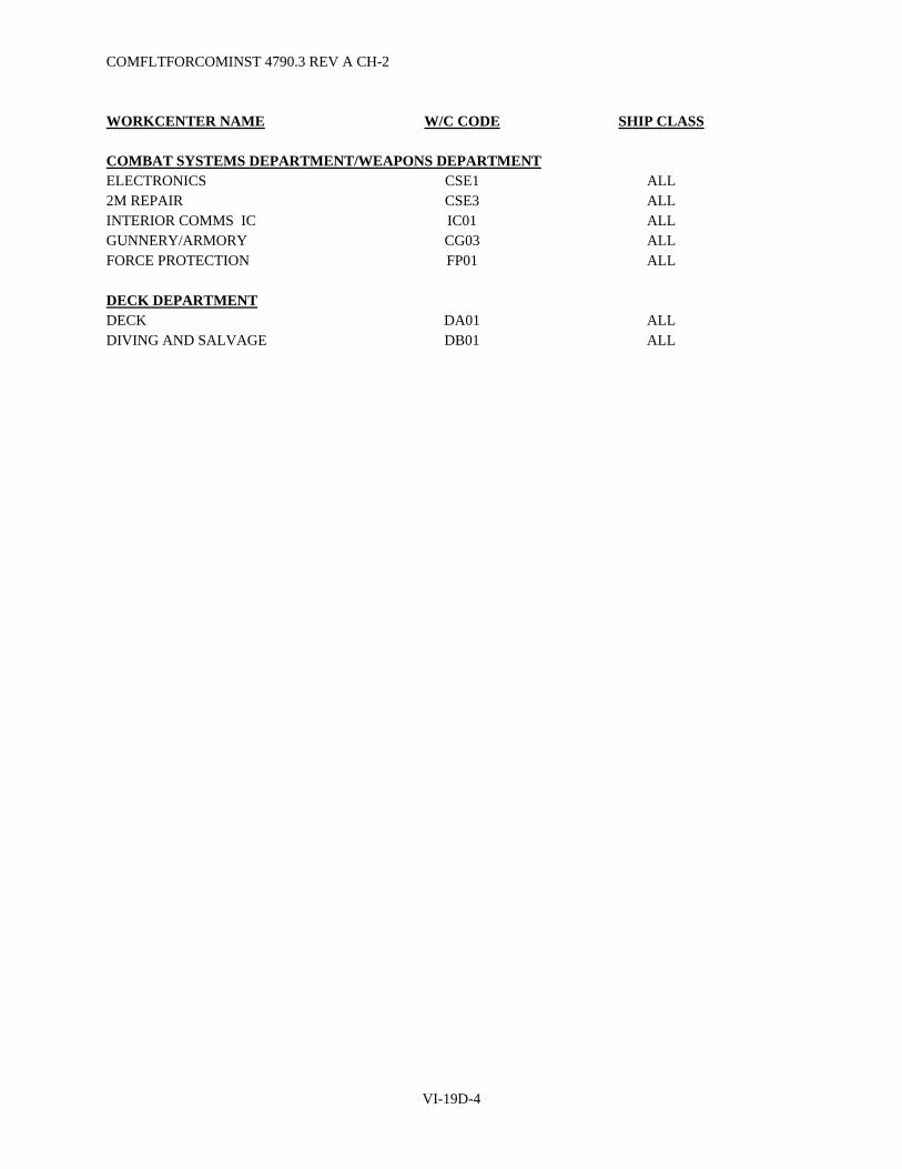
COMFLTFORCOMINST 4790.3 REV A CH-2
VI-19D-4
WORKCENTER NAME W/C CODE SHIP CLASS COMBAT SYSTEMS DEPARTMENT/WEAPONS DEPARTMENT ELECTRONICS CSE1 ALL 2M REPAIR CSE3 ALL INTERIOR COMMS IC IC01 ALL GUNNERY/ARMORY CG03 ALL FORCE PROTECTION FP01 ALL DECK DEPARTMENT DECK DA01 ALL DIVING AND SALVAGE DB01 ALL

COMFLTFORCOMINST 4790.3 REV A CH-3
VI-19D-5
APPENDIX D3
LISTING OF STANDARD WORK CENTER CODES FOR PC CLASS SHIPS
WORKCENTER NAME W/C CODE SHIP CLASS EXECUTIVE DEPARTMENT OFF SHIP SERVICES CONTAINS ALL X-SERVICES XRICS XS01 ALL MEDICIAL MH01 ALL ENGINEERING DEPARTMENT ELECTRICAL SHOP EE02 ALL MER FWD EM01 ALL MER AFT EM02 ALL DCPO ER09 ALL OPERATIONS DEPARTMENT RADIO IS01 ALL GUNNERY/ARMORY CG03 ALL FORCE PROTECTION FP01 ALL NAVIGATION OI02 ALL

COMFLTFORCOMINST 4790.3 REV A CH-2
VI-19D-6
(This Page Intentionally Left Blank)

COMFLTFORCOMINST 4790.3 REV A CH-6
VI-19D-7
APPENDIX D4
LISTING OF STANDARD WORK CENTER CODES FOR MCM/MHC CLASS SHIPS
WORKCENTER NAME W/C CODE SHIP CLASS EXECUTIVE DEPARTMENT OFF SHIP SERVICES CONTAINS ALL X-SERVICES XRICS XS01 ALL MEDICIAL MH01 ALL ADMIN XX01 ALL 3MC XX03 ALL SUPPLY DEPARTMENT GENERAL STORES SK's SS01 ALL FOOD SERVICE CS's SS02 ALL HAZMAT HZ01 ALL STK SK's STK ALL ENGINEERING DEPARTMENT AUXILIARY EN's EA01 ALL INTERIOR COMMS IC IC01 ALL ELECTRICAL SHOP EE02 ALL MER EM01 ALL AMR EM02 MCM OIL LAB EB14 ALL FLEET CAL ACTIVITY FCA1 ALL HULL REPAIR HT's ER01 ALL DAMAGE CONTROL ER04 ALL DCPO ER09 ALL OPERATIONS DEPARTMENT RADIO IS01 ALL ELECTRONICS CSE1 ALL GUNNERY/ARMORY CG03 ALL FORCE PROTECTION FP01 ALL NAVIGATION OSs OI02 ALL SIGNAL BRIDGE OI03 AS REQUIRED
COMFLTFORCOMINST 4790.3 REV A CH-2
VI-19D-8
(This Page Intentionally Left Blank)

COMFLTFORCOMINST 4790.3 REV A CH-3
VI-19D-9
APPENDIX D5
LISTING OF STANDARD WORK CENTER CODES FOR LSD CLASS SHIPS
WORKCENTER NAME W/C CODE SHIP CLASS EXECUTIVE DEPARTMENT
OFF SHIP SERVICES CONTAINS ALL X-SERVICES XRICS XS01 ALL YNS / PNS ADMIN XX01 ALL 3MC XX03 ALL MAA XX04 ALL MEDICAL/DENTAL DEPARTMENT MEDICAL MH01 ALL DENTAL MD01 ALL SUPPLY DEPARTMENT STOCK CONTROL SS01 ALL FOOD SERVICE CS's SS02 ALL SHIP SERVICES SH's SS03 ALL POSTAL/DISBURSING PC/DK SS04 ALL HAZMAT HZ01 ALL STK SK's STK ALL OPERATIONS DEPARTMENT RADIO IS01 ALL LAN/ADP IS02 ALL IC SHOP IC01 ALL ELECTRONICS CSE1 ALL 2M REPAIR CSE3 ALL RADARS OE02 ALL TEST EQUIPMANT ELEC CAL CE04 ALL CIC OI01 ALL ELECTRONIC WARFARE OT01 AS REQUIRED GWS FIRE CONTROL CG02 ALL GUNNERY/ARMORY CG03 ALL CIWS CF04 ALL FORCE PROTECTION FP01 ALL NAVIGATION OI02 ALL SIGNAL BRIDGE OI03 ALL

COMFLTFORCOMINST 4790.3 REV A CH-2
VI-19D-10
WORKCENTER NAME W/C CODE SHIP CLASS DECK DEPARTMENT FIRST DIVISION DA01 ALL DA02 AS REQUIRED DA03 AS REQUIRED SECOND DIVISION DB01 ALL DB02 AS REQUIRED DB03 AS REQUIRED ENGINEERING DEPARTMENT ENGINE/BOAT SHOP EA02 ALL HYDRAULICS EA04 ALL AIR CONDITIONING & REPAIR EA05 ALL ELEC TOOL ISSUE/SAFETY EE01 ALL ELECTRIC SHOP EE02 ALL MAIN MACHINERY ROOM 1 FWD EM01 ALL MAIN MACHINERY ROOM 2 AFT EM02 ALL AMR FWD EM03 ALL AMR AFT EM04 ALL OIL LAB EB14 ALL HULL REPAIR HT's ER01 ALL CARPENTER/SHIPFITTER SHOP ER02 AS REQUIRED MACHINE SHOP MR's ER03 ALL DAMAGE CONTROL REPAIR ER04 ALL DCPO ER09 ALL GAGE CAL FCA1 ALL

COMFLTFORCOMINST 4790.3 REV A CH-6
VI-19D-11
APPENDIX D6
LISTING OF STANDARD WORK CENTER CODES FOR LHA/LHD CLASS SHIPS
WORKCENTER NAME W/C CODE SHIP CLASS NOTE: SLASH (/) = AND OR EXECUTIVE DEPARTMENT OFF SHIP SERVICES CONTAINS ALL X-SERVICES XRICS XS01 ALL YNS XX01 ALL PNS XX02 ALL 3MC XX03 ALL MAA XX04 ALL MEDICIAL DEPARTMENT MH01 ALL DENTAL DEPARTMENT MD01 ALL SUPPLY DEPARTMENT STOCK CONTROL SS01 ALL FOOD SERVICE MS's SS02 ALL SHIP SERVICES SH's SS03 ALL POSTAL/DISBURSING PC/DK SS04 ALL WARDROOM SS05 ALL AVAITION STORES SS06 ALL
DISBURSING DK SS07 AS REQUIRED TO SPLIT DK
AND PCs GENERAL STORES SK's SS08 ALL HAZMAT HZ01 ALL STK SK's STK ALL COMBAT CARGO CC01 ALL AIMD DEPARTMENT AIR CRAFT REPAIR IM01 ALL MAINTENANCE IM02 AS REQUIRED ELECTRICAL/ELECTRONICS IM03 AS REQUIRED GROUND SUPPORT EQUIPMENT IM04 ALL AIR DEPARTMENT FLIGHT DECK (ABHs) VA01 ALL CRASH AND SALVAGE VA02 ALL

COMFLTFORCOMINST 4790.3 REV A CH-2
VI-19D-12
WORKCENTER NAME W/C CODE SHIP CLASS HANGER DECK VC01 ALL FLIGHT DECK FUELS (ABFs) VF01 ALL BELOW DECKS FUELS (ABFs) VF02 ALL COMBAT SYSTEMS DEPARTMENT AVIATION ARMS CSA1 ALL CARGO HANDLING MAGAZINE CSA2 ALL SHIPS ARMORY CG03 ALL RADAR REPAIR CSE1 ALL COMMUNICATION REPAIR CSE2 ALL 2M REPAIR CSE3 ALL TEST EQUIPMANT ELEC CAL CE04 ALL COMPUTER REPAIR CSE4 ALL ACDS CSF1 ALL RADARS CSF2 ALL CIWS CF04 ALL MISSLES (RAM, TAS) CSF4 ALL ELECTRONIC WARFARE OT01 ALL IC SHOP IC01 ALL INTERIOR COMMUNICATION IC02 AS REQUIRED CCTV IC03 ALL FORCE PROTECTION FP01 ALL DECK DEPARTMENT FIRST DIVISION DA01 ALL DA02 AS REQUIRED DA03 AS REQUIRED SECOND DIVISION DB01 ALL DB02 AS REQUIRED DB03 AS REQUIRED THIRD DIVISION DC01 ALL ENGINEERING DEPARTMENT AUXILIARY MACHINERY ROOM EA01 ALL ENGINE SHOP EA02 ALL STEAM SHOP (HOTEL SERVICES) EA03 ALL HYDRAULICS EA04 ALL AIR CONDITIONING & REPAIR EA05 ALL ASSAULT SHOP EA06 ALL GAGE CAL FCA1 ALL ELEC TOOL ISSUE/SAFETY EE01 ALL
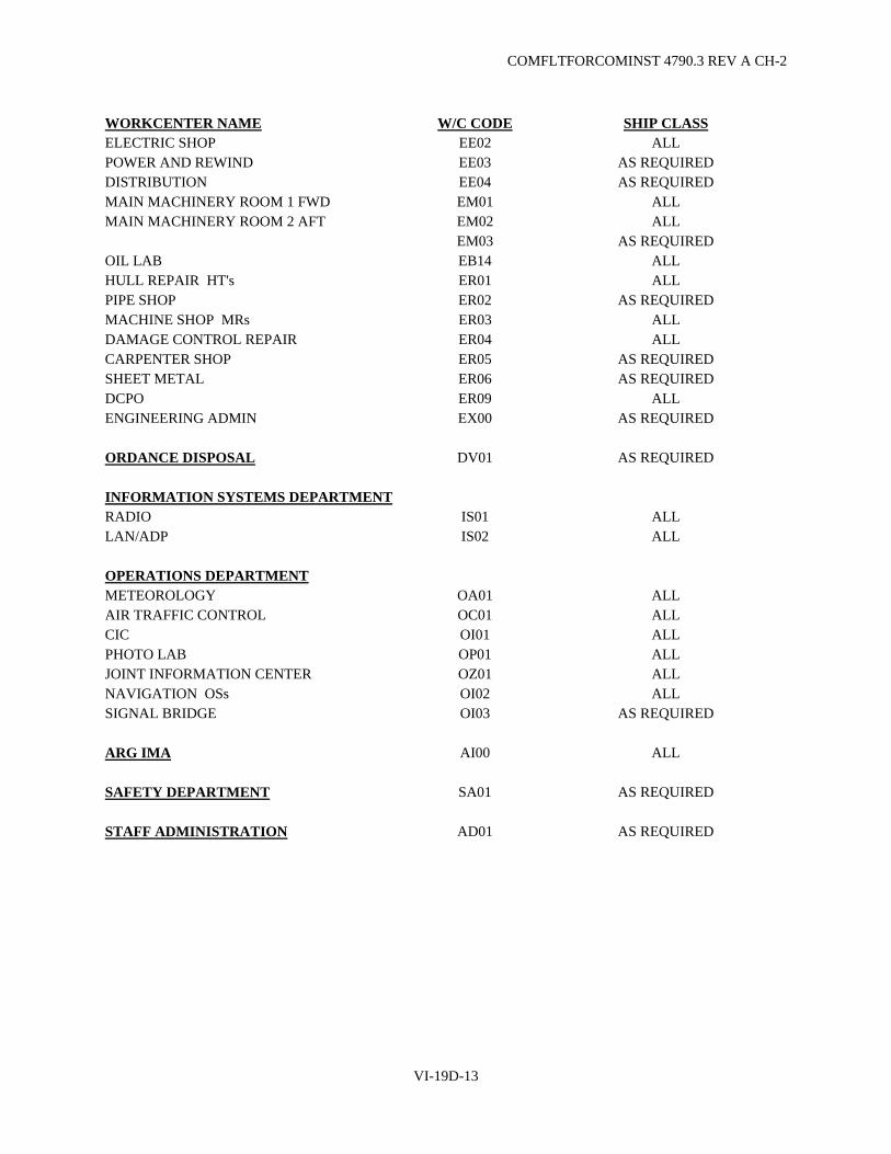
COMFLTFORCOMINST 4790.3 REV A CH-2
VI-19D-13
WORKCENTER NAME W/C CODE SHIP CLASS ELECTRIC SHOP EE02 ALL POWER AND REWIND EE03 AS REQUIRED DISTRIBUTION EE04 AS REQUIRED MAIN MACHINERY ROOM 1 FWD EM01 ALL MAIN MACHINERY ROOM 2 AFT EM02 ALL EM03 AS REQUIRED OIL LAB EB14 ALL HULL REPAIR HT's ER01 ALL PIPE SHOP ER02 AS REQUIRED MACHINE SHOP MRs ER03 ALL DAMAGE CONTROL REPAIR ER04 ALL CARPENTER SHOP ER05 AS REQUIRED SHEET METAL ER06 AS REQUIRED DCPO ER09 ALL ENGINEERING ADMIN EX00 AS REQUIRED ORDANCE DISPOSAL DV01 AS REQUIRED INFORMATION SYSTEMS DEPARTMENT RADIO IS01 ALL LAN/ADP IS02 ALL OPERATIONS DEPARTMENT METEOROLOGY OA01 ALL AIR TRAFFIC CONTROL OC01 ALL CIC OI01 ALL PHOTO LAB OP01 ALL JOINT INFORMATION CENTER OZ01 ALL NAVIGATION OSs OI02 ALL SIGNAL BRIDGE OI03 AS REQUIRED ARG IMA AI00 ALL SAFETY DEPARTMENT SA01 AS REQUIRED STAFF ADMINISTRATION AD01 AS REQUIRED

COMFLTFORCOMINST 4790.3 REV A CH-2
VI-19D-14
(This Page Intentionally Left Blank)

COMFLTFORCOMINST 4790.3 REV A CH-6
VI-19E-1
APPENDIX E
LISTING OF STANDARD WORK CENTER CODES FOR SMALL BOAT AND SERVICE CRAFT MANAGERS
(Submarine Force Only)
Name Code Name Code
COMSUBRON ONE PS SUBASE PEARL HARBOR (IMF) PK
COMSUBRON SIX TQ TRIDENT Refit Facility BANGOR PM
COMSUBRON SEVEN PW TRIDENT Refit Facility KINGS BAY TM
COMSUBRON EIGHT TW
COMSUBRON ELEVEN PQ
COMSUBRON SEVENTEEN PV USS EMORY S. LAND (AS-39) TJ
COMSUBRON TWENTY TX USS FRANK CABLE (AS-40) TA
COMSUBRON TWENTY-TWO TS
NAVSUBSUPPFAC NLON TK
SUBASE BANGOR PY
SUBASE KINGS BAY TY
SUBASE NLON TC

COMFLTFORCOMINST 4790.3 REV A CH-2
VI-19E-2
(This Page Intentionally Left Blank)
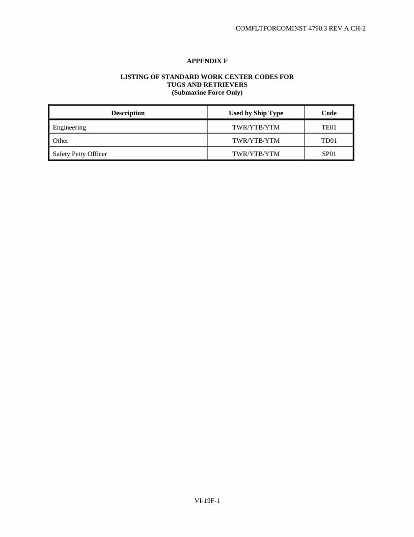
COMFLTFORCOMINST 4790.3 REV A CH-2
VI-19F-1
APPENDIX F
LISTING OF STANDARD WORK CENTER CODES FOR TUGS AND RETRIEVERS
(Submarine Force Only)
Description Used by Ship Type Code
Engineering TWR/YTB/YTM TE01
Other TWR/YTB/YTM TD01
Safety Petty Officer TWR/YTB/YTM SP01

COMFLTFORCOMINST 4790.3 REV A CH-2
VI-19F-2
(This Page Intentionally Left Blank)

COMFLTFORCOMINST 4790.3 REV A CH-2
VI-19G-1
APPENDIX G
LISTING OF STANDARD WORK CENTER CODES FOR MASTER JOB CATALOG ITEMS CONTAINED IN SHIP'S CSMP
(Surface and Submarine Forces Only)
Submarine Forces:
Description Code
Overhaul, SRA, Baseline routines EXSY
NAVSEA Issued Alterations *XSA
NSWCCD Machinery Alteration *XMA
TYCOM Issued Alterations *XTY
DIRSSP Issued Strategic Systems Program Alterations (SSBN/SSGN) **SP
Submarine Extended Operating Cycle PMRs **JC
Test and Measurement System Repair Routines **CR
MJC Service Routines **MC
*=Department **=Department/Division
Surface Forces:
Description Code
Overhaul, SRA, Baseline routines EXSY
Engineering Cycle **EC
First character identifies the requesting Department. Second character identifies the Administrative Procedure ("X"). Third character indicates catalog routine ("C"). Last character denotes the maintenance source code as follows: A - Planned Maintenance Subsystem B - Unassigned C - Corrective D - Upkeep E - Miscellaneous

COMFLTFORCOMINST 4790.3 REV A CH-2
VI-19G-2
(This Page Intentionally Left Blank)
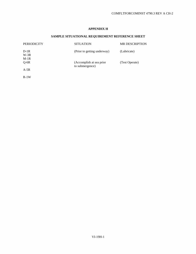
COMFLTFORCOMINST 4790.3 REV A CH-2
VI-19H-1
APPENDIX H
SAMPLE SITUATIONAL REQUIREMENT REFERENCE SHEET
PERIODICITY SITUATION MR DESCRIPTION
D-1R (Prior to getting underway) (Lubricate) W-3R M-1R Q-6R (Accomplish at sea prior
to submergence) (Test Operate)
A-5R
R-1W

COMFLTFORCOMINST 4790.3 REV A CH-2
VI-19H-2
(This Page Intentionally Left Blank)

COMFLTFORCOMINST 4790.3 REV A CH-2
VI-19I-1
APPENDIX I
SAMPLE ACCOUNTABILITY LOG Work Center Accountability Record Sheet
Work Center: [ ] Work Center Supervisor Week of: [ ] to [ ]
MIP MRC EGL/ID SERIAL #
EQUIP NOUN NAME
MAINT MAN(PRINT)
MAINT MAN (SIGNATURE)
DATE ACCOMPLISHED
A-083/904 8ZYU 1-A2 SNORKEL VENT VLV
Work Center Supervisor's Signature __________________________________________
Division Officer's Signature _________________________________________________
1. Record all partially accomplished/non-accomplished MRs on the reverse. All checks listed on the reverse will include the steps not done, requisition numbers or a complete explanation why the PMS could not be accomplished.
2. The WCS/Leading Petty Officer will maintain this log and shall ensure that the maintenance is logged the day the PMS was completed.
3. Retain in the WC PMS Manual for a period of 13 weeks.
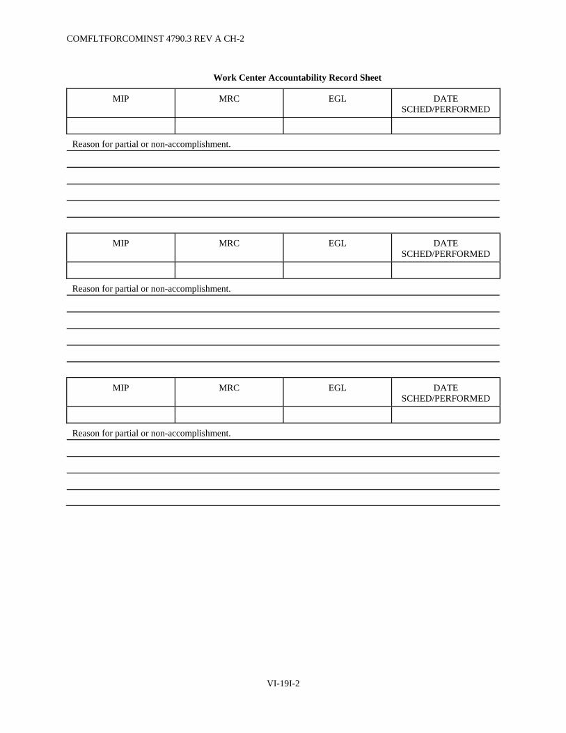
COMFLTFORCOMINST 4790.3 REV A CH-2
VI-19I-2
Work Center Accountability Record Sheet
MIP MRC EGL DATE SCHED/PERFORMED
Reason for partial or non-accomplishment.
MIP MRC EGL DATE SCHED/PERFORMED
Reason for partial or non-accomplishment.
MIP MRC EGL DATE SCHED/PERFORMED
Reason for partial or non-accomplishment.
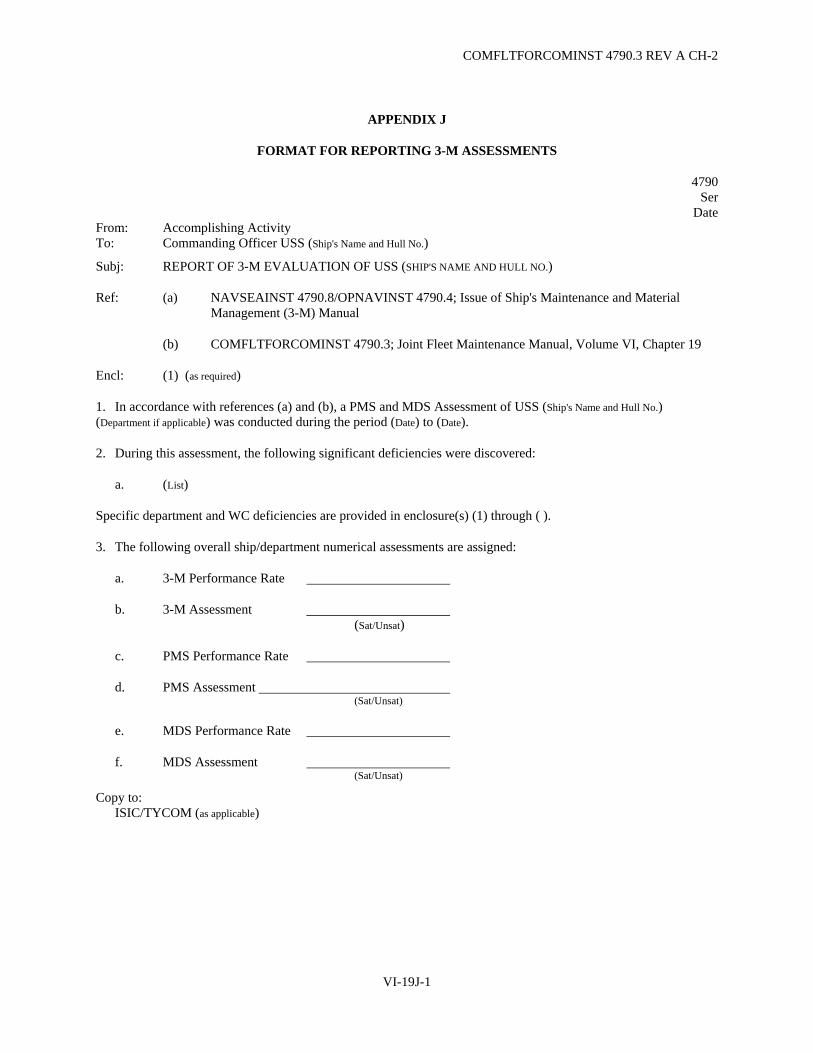
COMFLTFORCOMINST 4790.3 REV A CH-2
VI-19J-1
APPENDIX J
FORMAT FOR REPORTING 3-M ASSESSMENTS
4790 Ser
Date From: Accomplishing Activity To: Commanding Officer USS (Ship's Name and Hull No.)
Subj: REPORT OF 3-M EVALUATION OF USS (SHIP'S NAME AND HULL NO.)
Ref: (a) NAVSEAINST 4790.8/OPNAVINST 4790.4; Issue of Ship's Maintenance and Material Management (3-M) Manual
(b) COMFLTFORCOMINST 4790.3; Joint Fleet Maintenance Manual, Volume VI, Chapter 19
Encl: (1) (as required)
1. In accordance with references (a) and (b), a PMS and MDS Assessment of USS (Ship's Name and Hull No.) (Department if applicable) was conducted during the period (Date) to (Date).
2. During this assessment, the following significant deficiencies were discovered:
a. (List)
Specific department and WC deficiencies are provided in enclosure(s) (1) through ( ).
3. The following overall ship/department numerical assessments are assigned:
a. 3-M Performance Rate
b. 3-M Assessment (Sat/Unsat)
c. PMS Performance Rate
d. PMS Assessment (Sat/Unsat)
e. MDS Performance Rate
f. MDS Assessment (Sat/Unsat)
Copy to: ISIC/TYCOM (as applicable)

COMFLTFORCOMINST 4790.3 REV A CH-2
VI-19J-2
(This Page Intentionally Left Blank)

COMFLTFORCOMINST 4790.3 REV A
VOLUME VI
CHAPTER 20
WEIGHT AND MOMENT CONTROL
REFERENCES.
(a) NAVSEA S9086-C6-STM-000 - NSTM Chapter 096 (Weights and Stability) (b) NAVSEAINST C9096.2 - Weight and Stability Requirements for Active Submarines
20.1 PURPOSE. This chapter provides basic information and guidance concerning submarine ballast changes, including mandatory authorization and reporting requirements.
20.1.1 Discussion.
a. The use of ballast is important in maintaining a submarine's stability. Ballast, in most cases lead, is installed in submarines for the following purposes:
(1) To improve transverse stability.
(2) To adjust trim.
(3) To provide adequate immersion.
(4) To eliminate an inherent list.
(5) To permit submarines to submerge with neutral buoyancy and zero trim.
b. An inclining experiment is performed in accordance with the requirements of reference (a). This experiment provides the basic data concerning weight and center of gravity for use in all considerations of stability, reserve buoyancy, immersion, trim, and in determining compliance with the requirements of the weight control program. An inclining experiment is the only satisfactory method of accurately determining the location of the center of gravity of the submarine. Inclining experiments are conducted on each submarine in new construction, after conversion or overhaul and when authorized by Naval Sea Systems Command (NAVSEA) for some Selected Restricted Availabilities.
c. Initial ship design provides for adequate stability from a light load through full load condition. The design allows a margin for growth, but experience has shown that the margin is quickly used up for several reasons:
(1) The on-going process of modernization over the life of the ship.
(2) The accumulation of an assortment of personal gear and equipment.
(3) Weight removal for compensation being accorded a low priority.
VI-20-1

COMFLTFORCOMINST 4790.3 REV A
20.2 BALLAST CHANGES. NAVSEA maintains a record of the solid ballast installed in each submarine. These records are valuable in evaluating the ship's stability and seaworthiness, in determining the deadweight and space available for cargo, and in locating valuable material such as lead or iron in the ballast installation when a ship is scheduled for disposal. NAVSEA maintains a system of checks and balances on weight and moment changes when approving alterations. Accomplishment of an alteration involving a weight reduction does not make this saving available to the ship for use when requesting new alterations. NAVSEA expects to utilize this weight savings as compensation for future alterations. New and unexplored sources must be found when recommending weight and moment compensation.
20.2.1 Naval Sea Systems Command Notification. Occasionally, the permanent ballast on a ship may be increased, decreased, relocated, or replaced. Changes in ballast may result from alterations issued by NAVSEA or may become necessary in connection with other repairs or alterations. In order to maintain the accuracy of NAVSEA records, each activity installing or rearranging ballast shall furnish NAVSEA a report, with copies to the Type Commander (TYCOM), Immediate Superior In Command (ISIC) and the Commanding Officer of the ship involved, containing the following data pertaining to the ballast installed, removed or relocated.
a. Material and approximate density.
b. Weight installed at each location.
c. Vertical, longitudinal, and transverse position of center of gravity of ballast at each location.
d. Principal dimensions of each ballast location.
20.2.2 Changes in Ballast. Submarines of the active fleet shall be maintained within stability and buoyancy limits for a state of war readiness. Deviations from this principle are not authorized.
a. Changes in permanent or cargo (temporary) ballast, which includes adding, removing or relocating, shall not be accomplished by Ship's Force, Fleet Maintenance Activities or any industrial activity without prior TYCOM approval and NAVSEA written guidance.
b. Additional guidance and procedures concerning the installation or removal of cargo ballast is available in reference (b).
20.3 UNUSUAL CONDITIONS. NAVSEA requires reports to be submitted of any unusual conditions which are considered dangerous or seriously affect the operation of the ship. Report the following situations to NAVSEA, via the ISIC and TYCOM, in accordance with the requirements of reference (a).
a. Excessive rolling.
b. Heeling due to rudder action.
c. Excessive pounding.
d. Inadequate propeller immersion.
VI-20-2

COMFLTFORCOMINST 4790.3 REV A CH-3
VOLUME VI
CHAPTER 21
SUBMARINE STORAGE BATTERIES
REFERENCES.
(a) NAVSEA S9223-AF-MMO-010 - Submarine Main Storage Battery Technical Manual (b) NAVSEA S9086-G1-STM-010 - NSTM Chapter 223, V1 (Submarine Storage Batteries - Lead Acid
Batteries)
LISTING OF APPENDICES.
A Temperature Versus TVG Table B Temperature Versus MCV Table C TCV Calculation Table D Capacity Test Discharge Data Sheet E Main Storage Battery Inspection Check-Off F Instructions for Completing Submarine Battery Quarterly Reports - NAVSEA 9320/3 G Instructions for Maintaining the Submarine Battery Record Book - NAVSEA 9320/1 (3-92)
21.1 PURPOSE. To emphasize the necessity for proper operation and maintenance of flooded submarine main storage batteries and to provide instructions for:
a. Operation of submarine main storage batteries.
b. Completing Submarine Quarterly Battery Reports (QBR).
c. Maintaining the Submarine Battery Record Book – Naval Sea Systems Command (NAVSEA) 9320/1 (3-92).
21.1.1 Background. Records of prior submarine batteries indicate that with proper operation and maintenance, the batteries will provide relatively trouble free service throughout their expected life. The primary factors in obtaining reliable performance are:
a. Strict compliance with maintenance and charging instructions.
b. Accomplishment of periodic meter checks ensuring the accurate indication of parameters monitored.
c. Proper operation and maintenance of electrolyte agitation systems.
d. Proper operation of battery ventilation systems.
e. Strict adherence to the trickle discharge routine.
VI-21-1

COMFLTFORCOMINST 4790.3 REV A CH-4
21.1.2 Discussion. This chapter does not apply to Valve Regulated Lead-Acid batteries. Although there are a wide variety of problems that can develop in batteries, previous experience has shown that there are specific causes of problems that can be eliminated.
a. Improper electrolyte agitation is the most frequent cause of problems with flooded submarine batteries. Airlift pump failure can cause stratification, sulfation, internal shorts, low gravities and low Individual Cell Voltages (ICV). The end result is failed cells and decreased capacity. Improper maintenance of the agitation system can cause problems to exist for up to six months before becoming evident as capacity reductions below 90% during a test discharge.
b. Improper maintenance of the battery will shorten its service life and result in an unscheduled battery replacement or inability of the ship to perform its mission until the battery is replaced. For example, inaccurate voltmeters and ammeters can cause the battery to be overcharged or undercharged. Allowing this condition to go uncorrected can result in permanent damage to the cell plates with a subsequent decrease in service life.
c. Operating the main storage battery and support systems in accordance with established procedures is essential. The consequences of improper operation can range from a reduction in battery life with subsequent rescheduling of ship operations to a major ship's casualty.
21.2 ACTION.
a. All submarines with flooded lead acid cells installed shall comply with the procedures in this chapter for the operation, maintenance and inspection of main storage batteries.
b. Since the main storage battery can be operated safely and efficiently by using references (a) and (b) directly, individual ship main storage battery operating procedures, which may require changes because of changes to source documents, are not required except as specified in this chapter. Where conflicts exist, reference (a) takes precedence over reference (b).
c. Naval Surface Warfare Center Crane, through the battery manufacturer and with Type Commander (TYCOM) approval, will conduct on-site battery inspections between 9 and 15 months since the last submarine inspection and in situations warranting closer scrutiny. An inspection report will be prepared by the manufacturer and forwarded to the parent Immediate Superior In Command (ISIC) by Naval Surface Warfare Center Crane, copy to the ship. The ISIC will endorse the report and forward to the ship for retention and completion of any recommended corrective actions. Ships will report to TYCOM N4 via ISIC the root causes for and the satisfactory completion of all corrective actions for deficiencies noted in the inspection report within 30 days of receipt of the report.
d. ISIC shall ensure that attached units operate and maintain installed main storage batteries in accordance with established procedures. When deemed appropriate, promulgate lessons learned concerning battery operation and maintenance among units and provide feedback to the TYCOM.
e. Submarine Commanding Officers shall implement the provisions of this instruction as follows:
(1) Maintain a hard copy of references (a) and (b) in the Maneuvering Area (or normal controlling station for battery charges).
(2) SSN 688, SSN 21, SSBN/SSGN 726, SSN 774 and later Class submarines shall operate the main storage battery and support system in accordance with the Ship's Systems Manual. These submarines may insert copies of Appendices A through C of this chapter in the Battery Technical Manual if desired.
VI-21-2

COMFLTFORCOMINST 4790.3 REV A CH-4
(3) Require Battery Charging Electrician (BCE) and Battery Charging Electrician Forward (BCEF) qualifications to include familiarity with this chapter.
(4) Incorporate familiarity with reference (a), reference (b) and this chapter as part of the formal qualification procedures for Officer of the Deck/Duty Officer, Chief of the Watch/Inport Duty Chief, Engineering Officer of the Watch/Engineering Duty Officer and Engineering Watch Supervisor/Engineering Duty Petty Officer.
(5) Perform battery planned maintenance as specified by Planned Maintenance System (PMS) and reference (a). Where conflicts exist, PMS takes precedence over reference (a).
(6) Conduct battery charges at the frequency and in the manner specified in reference (a).
(7) Operate and maintain battery ventilation including minimum airflow requirements, as specified in reference (b).
(8) Maintain battery test discharge data using Appendix D of this chapter. A copy of Appendix D shall be included with the Submarine QBR when a test discharge is conducted during a reporting quarter.
(9) Maintain battery records in accordance with reference (a) and reference (b). The Battery Record Book (BRB) for SSBN/SSGNs is to be updated and certified by the Engineer Officer during each crew turnover.
(10) Submit a Submarine QBR as specified in reference (b).
(11) Pursue a battery well maintenance and cleaning program. With proper care and maintenance, a battery resistance to ground with the battery isolated (i.e., battery circuit breakers open) can easily be maintained greater than 500,000 ohms. DC bus grounds must be above 100,000 ohms to conduct a battery charge except in an emergency (see reference (b)).
(12) Ensure that electric plant logs show a minimum specification of 50,000 ohms for AC and DC bus grounds and battery charging logs show a minimum specification of 100,000 ohms for DC bus grounds.
(13) Upon battery replacement, prior to Fast Cruise at completion of a Depot Modernization Period, Engineered Refueling Overhaul or Engineered Overhaul and annually, use Appendix E of this chapter to evaluate the material condition of the battery and determine accuracy and completeness of battery records. Material deficiencies will be recorded in the Equipment Status Log for correction and the Job Sequence Number recorded in the margin of the inspection checklist next to the appropriate article. Record the completion date of the most recent Appendix E inspection and correction of deficiencies in the remarks section of the QBR. Only the most recent complete copy of Appendix E of this chapter need be retained with battery records.
(14) Request technical assistance from higher authority via ISIC or TYCOM for correction of abnormal conditions not within Ship's Force capability.
21.3 CASUALTY REPORTING.
21.3.1 Purpose. To provide guidance for Casualty Reporting (CASREP) requirements for the submarine main storage battery. CASREPs are in addition to, and do not replace the reporting requirements of other documents (e.g., Naval Reactors Technical Bulletins, Operational Orders, Mishap Reports, etc.).
VI-21-3

COMFLTFORCOMINST 4790.3 REV A CH-3
21.3.2 Background. The significance of a submarine's emergency and backup power supplies cannot be overstated. CASREP requirements of Out of Commission power generating or storage equipment require additional clarification.
21.3.3 SSN/SSGN Class Submarine Main Storage Battery. Battery CASREPs shall be submitted as follows:
a. C-2 when battery capacity falls below 80 percent of rated capacity.
b. C-3 when battery capacity falls below 65 percent of rated capacity.
c. C-4 when battery capacity falls below 50 percent of rated capacity.
21.3.4 SSBN Class Submarine Main Storage Battery. Report low battery capacity casualties by message as allowed by operational constraints.
VI-21-4
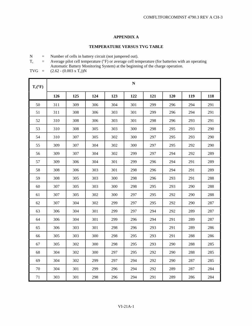
COMFLTFORCOMINST 4790.3 REV A CH-3
APPENDIX A
TEMPERATURE VERSUS TVG TABLE
N = Number of cells in battery circuit (not jumpered out). Tc = Average pilot cell temperature (°F) or average cell temperature (for batteries with an operating
Automatic Battery Monitoring System) at the beginning of the charge operation. TVG = (2.62 - (0.003 x Tc))N
Tc(°F) N
126 125 124 123 122 121 120 119 118
50 311 309 306 304 301 299 296 294 291
51 311 308 306 303 301 299 296 294 291
52 310 308 306 303 301 298 296 293 291
53 310 308 305 303 300 298 295 293 290
54 310 307 305 302 300 297 295 293 290
55 309 307 304 302 300 297 295 292 290
56 309 307 304 302 299 297 294 292 289
57 309 306 304 301 299 296 294 291 289
58 308 306 303 301 298 296 294 291 289
59 308 305 303 300 298 296 293 291 288
60 307 305 303 300 298 295 293 290 288
61 307 305 302 300 297 295 292 290 288
62 307 304 302 299 297 295 292 290 287
63 306 304 301 299 297 294 292 289 287
64 306 304 301 299 296 294 291 289 287
65 306 303 301 298 296 293 291 289 286
66 305 303 300 298 295 293 291 288 286
67 305 302 300 298 295 293 290 288 285
68 304 302 300 297 295 292 290 288 285
69 304 302 299 297 294 292 290 287 285
70 304 301 299 296 294 292 289 287 284
71 303 301 298 296 294 291 289 286 284
VI-21A-1

COMFLTFORCOMINST 4790.3 REV A CH-3
Tc(°F) N
126 125 124 123 122 121 120 119 118
72 303 301 298 296 293 291 288 286 284
73 303 300 298 295 293 291 288 286 283
74 302 300 297 295 293 290 288 285 283
75 302 299 297 295 292 290 287 285 283
76 301 299 297 294 292 289 287 285 282
77 301 299 296 294 291 289 287 284 282
78 301 298 296 293 291 289 286 284 282
79 300 298 295 293 291 288 286 284 281
80 300 298 295 293 290 288 286 283 281
81 300 297 295 292 290 288 285 283 280
82 299 297 294 292 290 287 285 283 280
83 299 296 294 292 289 287 285 282 280
84 298 296 294 291 289 287 284 282 279
85 298 296 293 291 289 286 284 281 279
86 298 295 293 291 288 286 283 281 279
87 297 295 293 290 288 285 283 281 278
88 297 295 292 290 287 285 283 280 278
89 296 294 292 289 287 285 282 280 278
90 296 294 291 289 287 284 282 280 277
91 296 293 291 289 286 284 282 279 277
92 295 293 291 288 286 284 281 279 277
93 295 293 290 288 286 283 281 279 276
94 295 292 290 288 285 283 281 278 276
95 294 292 290 287 285 283 280 278 276
96 294 292 289 287 285 282 280 278 275
97 293 291 289 286 284 282 279 277 275
98 293 291 288 286 284 281 279 277 274
99 293 290 288 286 283 281 279 276 274
100 292 290 288 285 283 281 278 276 274
VI-21A-2
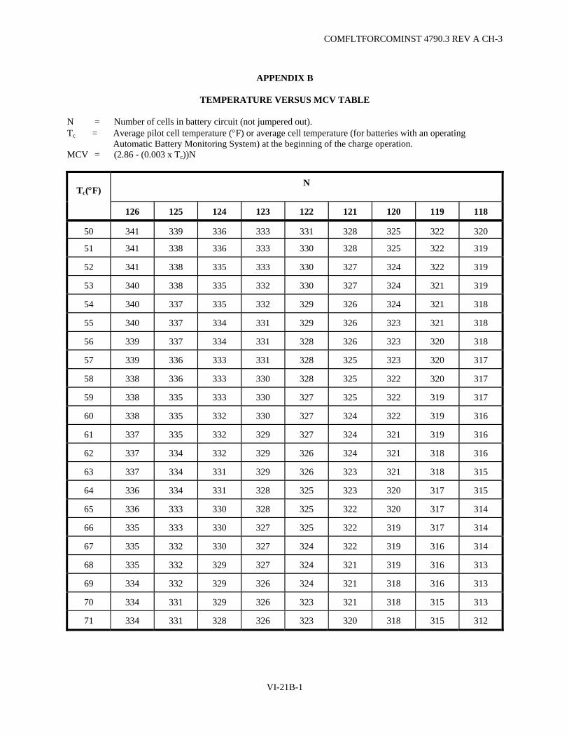
COMFLTFORCOMINST 4790.3 REV A CH-3
APPENDIX B
TEMPERATURE VERSUS MCV TABLE
N = Number of cells in battery circuit (not jumpered out). Tc = Average pilot cell temperature (°F) or average cell temperature (for batteries with an operating
Automatic Battery Monitoring System) at the beginning of the charge operation. MCV = (2.86 - (0.003 x Tc))N
Tc(°F) N
126 125 124 123 122 121 120 119 118
50 341 339 336 333 331 328 325 322 320
51 341 338 336 333 330 328 325 322 319
52 341 338 335 333 330 327 324 322 319
53 340 338 335 332 330 327 324 321 319
54 340 337 335 332 329 326 324 321 318
55 340 337 334 331 329 326 323 321 318
56 339 337 334 331 328 326 323 320 318
57 339 336 333 331 328 325 323 320 317
58 338 336 333 330 328 325 322 320 317
59 338 335 333 330 327 325 322 319 317
60 338 335 332 330 327 324 322 319 316
61 337 335 332 329 327 324 321 319 316
62 337 334 332 329 326 324 321 318 316
63 337 334 331 329 326 323 321 318 315
64 336 334 331 328 325 323 320 317 315
65 336 333 330 328 325 322 320 317 314
66 335 333 330 327 325 322 319 317 314
67 335 332 330 327 324 322 319 316 314
68 335 332 329 327 324 321 319 316 313
69 334 332 329 326 324 321 318 316 313
70 334 331 329 326 323 321 318 315 313
71 334 331 328 326 323 320 318 315 312
VI-21B-1

COMFLTFORCOMINST 4790.3 REV A CH-3
Tc(°F) N
126 125 124 123 122 121 120 119 118
72 333 331 328 325 323 320 317 315 312
73 333 330 327 325 322 320 317 314 312
74 332 330 327 324 322 319 317 314 311
75 332 329 327 324 321 319 316 314 311
76 332 329 326 324 321 318 316 313 311
77 331 329 326 323 321 318 315 313 310
78 331 328 326 323 320 318 315 312 310
79 330 328 325 323 320 317 315 312 310
80 330 328 325 322 320 317 314 312 309
81 330 327 325 322 319 317 314 311 309
82 329 327 324 322 319 316 314 311 308
83 329 326 324 321 319 316 313 311 308
84 329 326 323 321 318 316 313 310 308
85 328 326 323 320 318 315 313 310 307
86 328 325 323 320 317 315 312 310 307
87 327 325 322 320 317 314 312 309 307
88 327 325 322 319 317 314 312 309 306
89 327 324 322 319 316 314 311 309 306
90 326 324 321 319 316 313 311 308 306
91 326 323 321 318 316 313 310 308 305
92 326 323 320 318 315 313 310 307 305
93 325 323 320 317 315 312 310 307 305
94 325 322 320 317 315 312 309 307 304
95 324 322 319 317 314 312 309 306 304
96 324 322 319 316 314 311 309 306 303
97 324 321 319 316 313 311 308 306 303
98 323 321 318 316 313 310 308 305 303
99 323 320 318 315 313 310 308 305 302
100 323 320 317 315 312 310 307 305 302
VI-21B-2

COMFLTFORCOMINST 4790.3 REV A CH-3
APPENDIX C
TCV CALCULATION TABLE
N = Number of cells in battery circuit (not jumpered out). Tc = Average pilot cell temperature (°F) or average cell temperature (for batteries with an operating
Automatic Battery Monitoring System) at the end of the charge. V = Switchboard voltage just prior to end of charge. TCV = (0.003(N)) x (Tc-80) + (V) (Add or subtract as indicated to switchboard voltage)
Tc(°F) N
126 125 124 123 122 121 120 119 118
60 -7.6 -7.5 -7.4 -7.4 -7.3 -7.3 -7.2 -7.2 -7.1
61 -7.2 -7.1 -7.1 -7.0 -7.0 -6.9 -6.8 -6.8 -6.7
62 -6.8 -6.8 -6.7 -6.6 -6.6 -6.5 -6.5 -6.4 -6.4
63 -6.4 -6.4 -6.3 -6.3 -6.2 -6.2 -6.1 -6.1 -6.0
64 -6.0 -6.0 -6.0 -5.9 -5.9 -5.8 -5.8 -5.7 -5.7
65 -5.7 -5.6 -5.5 -5.5 -5.5 -5.4 -5.4 -5.4 -5.3
66 -5.3 -5.3 -5.2 -5.2 -5.1 -5.1 -5.0 -5.0 -5.0
67 -4.9 -4.9 -4.8 -4.8 -4.8 -4.7 -4.7 -4.6 -4.6
68 -4.5 -4.5 -4.5 -4.4 -4.4 -4.4 -4.3 -4.3 -4.2
69 -4.2 -4.1 -4.1 -4.1 -4.0 -4.0 -4.0 -3.9 -3.9
70 -3.8 -3.8 -3.7 -3.7 -3.7 -3.6 -3.6 -3.6 -3.5
71 -3.4 -3.4 -3.3 -3.3 -3.3 -3.3 -3.2 -3.2 -3.2
72 -3.0 -3.0 -3.0 -3.0 -2.9 -2.9 -2.9 -2.9 -2.8
73 -2.6 -2.6 -2.6 -2.6 -2.6 -2.5 -2.5 -2.5 -2.5
74 -2.3 -2.3 -2.2 -2.2 -2.2 -2.2 -2.2 -2.1 -2.1
75 -1.9 -1.9 -1.9 -1.8 -1.8 -1.8 -1.8 -1.8 -1.8
76 -1.5 -1.5 -1.5 -1.5 -1.5 -1.5 -1.4 -1.4 -1.4
77 -1.1 -1.1 -1.1 -1.1 -1.1 -1.1 -1.1 -1.1 -1.1
78 -0.8 -0.8 -0.7 -0.7 -0.7 -0.7 -0.7 -0.7 -0.7
VI-21C-1
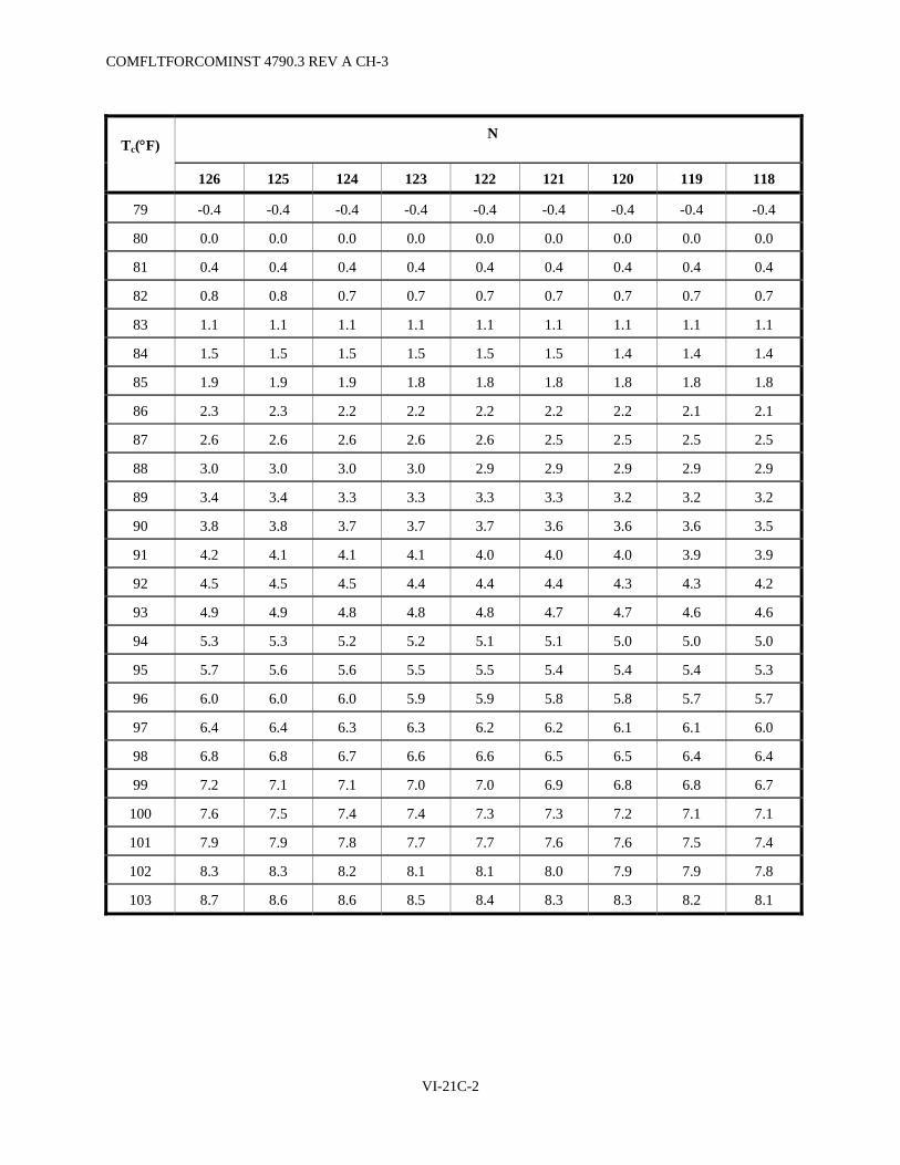
COMFLTFORCOMINST 4790.3 REV A CH-3
Tc(°F) N
126 125 124 123 122 121 120 119 118
79 -0.4 -0.4 -0.4 -0.4 -0.4 -0.4 -0.4 -0.4 -0.4
80 0.0 0.0 0.0 0.0 0.0 0.0 0.0 0.0 0.0
81 0.4 0.4 0.4 0.4 0.4 0.4 0.4 0.4 0.4
82 0.8 0.8 0.7 0.7 0.7 0.7 0.7 0.7 0.7
83 1.1 1.1 1.1 1.1 1.1 1.1 1.1 1.1 1.1
84 1.5 1.5 1.5 1.5 1.5 1.5 1.4 1.4 1.4
85 1.9 1.9 1.9 1.8 1.8 1.8 1.8 1.8 1.8
86 2.3 2.3 2.2 2.2 2.2 2.2 2.2 2.1 2.1
87 2.6 2.6 2.6 2.6 2.6 2.5 2.5 2.5 2.5
88 3.0 3.0 3.0 3.0 2.9 2.9 2.9 2.9 2.9
89 3.4 3.4 3.3 3.3 3.3 3.3 3.2 3.2 3.2
90 3.8 3.8 3.7 3.7 3.7 3.6 3.6 3.6 3.5
91 4.2 4.1 4.1 4.1 4.0 4.0 4.0 3.9 3.9
92 4.5 4.5 4.5 4.4 4.4 4.4 4.3 4.3 4.2
93 4.9 4.9 4.8 4.8 4.8 4.7 4.7 4.6 4.6
94 5.3 5.3 5.2 5.2 5.1 5.1 5.0 5.0 5.0
95 5.7 5.6 5.6 5.5 5.5 5.4 5.4 5.4 5.3
96 6.0 6.0 6.0 5.9 5.9 5.8 5.8 5.7 5.7
97 6.4 6.4 6.3 6.3 6.2 6.2 6.1 6.1 6.0
98 6.8 6.8 6.7 6.6 6.6 6.5 6.5 6.4 6.4
99 7.2 7.1 7.1 7.0 7.0 6.9 6.8 6.8 6.7
100 7.6 7.5 7.4 7.4 7.3 7.3 7.2 7.1 7.1
101 7.9 7.9 7.8 7.7 7.7 7.6 7.6 7.5 7.4
102 8.3 8.3 8.2 8.1 8.1 8.0 7.9 7.9 7.8
103 8.7 8.6 8.6 8.5 8.4 8.3 8.3 8.2 8.1
VI-21C-2

COMFLTFORCOMINST 4790.3 REV A CH-3
APPENDIX D
CAPACITY TEST DISCHARGE DATA SHEET
USS _______________________________________________ DATE:____________________________
TEMP SPECIFIC GRAVITY BEFORE/AFTER BEFORE/AFTER/PT DROP PILOT CELL # _______ ____/_____ ______ /______ / ______ PILOT CELL #_______ ____/_____ ______ /______ / ______
AVERAGE ____/_____ AVG PT DROP ________
TIME (ACTUAL)
TIME DIFFERENCE (MINUTES)
BATTERY DISCHARGE RATE
CALCULATED AMP-HOURS DISCHARGED
TOTAL BATTERY VOLTAGE
AMPERE-HOUR METER READING
START
FINISH
TIME DIFFERENCE (MINUTES) = ( ) X 100 = = % CAPACITY
NOTE (1) REQUIRED TIME (MINUTES CORRECTED) ( ) X NOTE (2) = THEORETICAL AMP-HRS
(AVG PT DROP) (AMP-HRS/PT)
(1) OBTAINED FROM DISCHARGE CHARACTERISTICS AND TEMPERATURE CORRECTION TABLE. (2) BASED ON ACTUAL LABORATORY TESTS USING 3 HOUR DISCHARGE RATE.
BATTERY TYPE DISCHARGE RATE AMP-HR/PT
MOD E (ASB-49) 2400 49 SEAWOLF (LLL-69) 2600 54 TRIDENT (PDX-57) 3450 91
NOTE: COMPARISON OF TOTAL AMP-HR VALUES (METER, CALCULATED AND THEORETICAL) WILL GIVE INDICATION OF CALCULATION ERRORS OR INACCURACIES/NEED FOR CALIBRATION OF BATTERY AMP-METER. (>10% BETWEEN METER AND CALCULATED OR >20% BETWEEN METER OR CALCULATED AND THEORETICAL INDICATES INACCURACIES OR ERRORS.) USE THE LOWEST VALUE (METER, CALCULATED OR THEORETICAL) TO DETERMINE THE 10% AND 20% VALUES.
NOTE: PILOT CELL AVG TEMPERATURES AND ACTUAL AND REQUIRED TIMES SHOULD BE ROUNDED TO THE NEAREST WHOLE NUMBER AND THE ROUNDED VALUES USED FOR ALL CALCULATIONS.
VI-21D-1

COMFLTFORCOMINST 4790.3 REV A CH-3
(This Page Intentionally Left Blank)
VI-21D-2

COMFLTFORCOMINST 4790.3 REV A CH-3
APPENDIX E
MAIN STORAGE BATTERY INSPECTION CHECK-OFF
Battery Inspection of USS Date______________
NOTE: UPON BATTERY REPLACEMENT, PRIOR TO FAST CRUISE AT COMPLETION OF A DEPOT MODERNIZATION PERIOD, ENGINEERED REFUELING OVERHAUL OR ENGINEERED OVERHAUL AND ANNUALLY, USE THE MAIN STORAGE BATTERY INSPECTION CHECK-OFF TO EVALUATE THE MATERIAL CONDITION OF THE BATTERY AND DETERMINE ACCURACY AND COMPLETENESS OF BATTERY RECORDS. MATERIAL DEFICIENCIES WILL BE RECORDED IN THE EQUIPMENT STATUS LOG FOR CORRECTION AND THE JOB SEQUENCE NUMBER RECORDED IN THE MARGIN OF THE INSPECTION CHECKLIST NEXT TO THE APPROPRIATE ARTICLE. RECORD THE COMPLETION DATE OF THE MOST RECENT APPENDIX E INSPECTION AND CORRECTION OF DEFICIENCIES IN THE REMARKS SECTION OF THE QUARTERLY BATTERY REPORT. ONLY THE MOST RECENT COMPLETE COPY OF THE INSPECTION NEED BE RETAINED WITH BATTERY RECORDS.
NOTE: IF ANY CONFLICT EXISTS BETWEEN THIS CHECK-OFF AND THE REFERENCE DOCUMENTS, THE REFERENCE DOCUMENTS TAKE PRECEDENCE.
1. Battery Records and Documentation:
a. Cycles __________
b. Age in months __________
c. Date battery installed __________
d. Date of last capacity test discharge __________
e. Capacity of battery at last test discharge __________
f. List cell which reached minimum final cell voltage during test discharge __________
g. Next four lowest cells at the end of test discharge Cell/Voltage Cell Voltage
_____ ____
_____ ____
_____ ____
_____ ____
h. Battery ground reading, (battery circuit breakers open) __________
i. Total battery voltage at the end of test discharge __________
j. Pilot cells are numbers ____ and ____.
k. List cells jumpered out ___ , ___ , ___ , ___ , ___ , ___.
Yes No 2. Does the ship use standard submarine battery log (NAVSEA 9320/6 (4-90), National
Stock Number 0116-LF-010-4100)? _____ ____
VI-21E-1

COMFLTFORCOMINST 4790.3 REV A CH-3
Yes No
3. Does a review of the completed battery logs indicate the following:
a. Does the first set of battery charge log readings indicate that the initial charging rate (amps) did not exceed the total number of ampere-hours discharged prior to the charge? _____ ____
b. Subsequent log readings indicate:
(1) When maximum charging rate was obtained? _____ ____
(2) When TVG was reached? _____ ____
NOTE: BOTH (1) AND (2) ABOVE MAY BE WRITTEN AS ONE LOG READING IF TVG IS REACHED FIRST.
c. Charge/discharge data completed correctly? _____ ____
d. Specific Gravity (SG) data completed correctly? _____ ____
e. Is data recorded in accordance with reference (b)? _____ ____
f. Did the Engineering Officer of the Watch/Engineering Duty Officer review and initial the battery charging log approximately hourly during the battery charge? _____ ____
g. Is there an effective system utilized to ensure that logs are reviewed and data entered in the BRB promptly? _____ ____
4. Does the BCE comply with reference (a) and reference (b)? (e.g., take ground readings at fifteen minute intervals during charge) _____ ____
5. Does a review of completed Individual Cell Record Sheets indicate the following:
a. ICV/SG section completed correctly? _____ ____
b. SG averages computed? _____ ____
c. Log reviewed and signed? _____ ____
6. At the completion of equalizing charges and prior to SG readings, does the ship check the hydrometers in use against reference hydrometers and record these readings to ensure accurate hydrometer readings? (N/A for digital thermometers) _____ ____
7. Does the ship use and forward QBR NAVSEA 9320/3? _____ ____
a. Is the QBR being maintained in accordance with Appendix F of this chapter? _____ ____
b. Is Appendix D of this chapter being sent with QBR as appropriate? _____ ____
c. Are the battery manufacturer's inspection recommendations reported as complete and status of non-completed recommendations addressed? _____ ____
d. Is the date of completion for the last Appendix E inspection being reported on each QBR? _____ ____
VI-21E-2

COMFLTFORCOMINST 4790.3 REV A CH-3
Yes No
8. Does the ship have an effective system to ensure that different cells are checked for agitation before each battery charge? _____ ____
9. Does the ship have a set of calibration curves for the venturi air-flow meter showing pressure (inches of water) versus airflow (Cubic Feet per Minute)? _____ ____
10. Capacity Test Discharges:
a. Was a two-ohm resistance check completed? (If applicable) _____ ____ (Applicable to SSGN 726, 727, 728 and SSBN 730 only until TZ-0253 Rev 0 Battery
Digital Voltmeter EN DE44753 Rev D is complete.)
b. Are ICVs being plotted at 30-minute intervals? _____ ____
c. When any cell drops to 1.75 volts are the ICVs being taken and plotted continuously? _____ ____
11. Are the ship's charging instructions available in Maneuvering to the BCE? _____ ____
a. Are they in accordance with reference (b)? _____ ____
12. Are BRB entries in accordance with the instructions contained in Appendix G of this chapter? _____ ____
a. Are BRB entries neat, legible and correct? _____ ____
b. Does the Engineer Officer review and sign the BRB at monthly intervals and at each crew turnover for SSBN/SSGNs? _____ ____
c. Are there monthly and grand totals at the end of each month's charges? _____ ____
d. Are battery electrolyte sample results being recorded? _____ ____
e. Is discharge data being recorded properly? _____ ____
13. Has corrective action been taken in any case where the battery capacity has dropped 10% or below 90%? _____ ____
14. PMS:
a. Could a BCEF/BCE demonstrate the ability to properly check battery air agitation? _____ ____
b. Could a BCEF/BCE properly inspect the air agitation system? _____ ____
c. Does the ship complete the proper agitation filter Maintenance Requirement Cards? _____ ____
d. Is the two-ohm resistance check done within 24 hours prior to each equalizer? (If applicable) (Applicable to SSGN 726, 727, 728 and SSBN 730 only until TZ-0253 Rev 0 Battery Digital Voltmeter EN DE44753 Rev D is complete.) _____ ____
e. Are all cells with ICV readings of 0.10 volts below battery average checked for loose, dirty or corroded connections and completion recorded on ICV Sheet? _____ ____
VI-21E-3
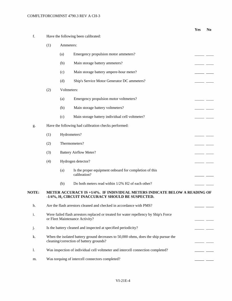
COMFLTFORCOMINST 4790.3 REV A CH-3
Yes No
f. Have the following been calibrated:
(1) Ammeters:
(a) Emergency propulsion motor ammeters? _____ ____
(b) Main storage battery ammeters? _____ ____
(c) Main storage battery ampere-hour meter? _____ ____
(d) Ship's Service Motor Generator DC ammeters? _____ ____
(2) Voltmeters:
(a) Emergency propulsion motor voltmeters? _____ ____
(b) Main storage battery voltmeters? _____ ____
(c) Main storage battery individual cell voltmeter? _____ ____
g. Have the following had calibration checks performed:
(1) Hydrometers? _____ ____
(2) Thermometers? _____ ____
(3) Battery Airflow Meter? _____ ____
(4) Hydrogen detector? _____ ____
(a) Is the proper equipment onboard for completion of this calibration? _____ ____
(b) Do both meters read within 1/2% H2 of each other? _____ ____
NOTE: METER ACCURACY IS +1/4%. IF INDIVIDUAL METERS INDICATE BELOW A READING OF -1/4%, H2 CIRCUIT INACCURACY SHOULD BE SUSPECTED.
h. Are the flash arrestors cleaned and checked in accordance with PMS? _____ ____
i. Were failed flash arrestors replaced or treated for water repellency by Ship's Force or Fleet Maintenance Activity? _____ ____
j. Is the battery cleaned and inspected at specified periodicity? _____ ____
k. When the isolated battery ground decreases to 50,000 ohms, does the ship pursue the cleaning/correction of battery grounds? _____ ____
l. Was inspection of individual cell voltmeter and intercell connection completed? _____ ____
m. Was torquing of intercell connectors completed? _____ ____
VI-21E-4

COMFLTFORCOMINST 4790.3 REV A CH-3
Yes No
15. Battery Well and Material Items:
a. During the last two equalizing charges, did all of the cells have a SG within 0.010 points of the average SG? _____ ____
(1) If no, list cells and gravities.
Date Chg # Cell SG Cell SG Date Chg # Cell SG Cell SG
(2) Were these cells inspected for proper agitation, SG verified and the results recorded on back of the individual cell record sheet in accordance with reference (a)? _____ ____
b. Does the location of the pilot cells meet the criteria defined in reference (b)? _____ ____
c. Does the ship have a "Charge in Progress" sign to install over the battery hatch during battery charges? _____ ____
d. During inspection of the battery well was it free of any loose or unauthorized gear? _____ ____
(1) Is the battery well hatch free, latch works and gasket not deteriorated? _____ ____
(2) Are the cell tops cleaned? _____ ____
(3) Are the flash arrestors free of electrolyte? _____ ____
(4) Are jumpered cells properly jumpered out? _____ ____
(5) Is agitation being maintained for isolated cells? _____ ____
(6) Is electrolyte level being maintained for isolated cells? (N/A for cells due to grounds) _____ ____
(7) Are jumpered cell terminals painted red? _____ ____
(8) Spot check several cells throughout the battery well. Is electrolyte height and air agitation proper? _____ ____
(9) Are the battery deck flats properly secured? (Note missing or damaged fastener hardware) _____ ____
(10) Is the battery well deck and area between cells clean, dry and free of foreign material? _____ ____
(11) Are meter leads on the shunt tight? _____ ____
VI-21E-5
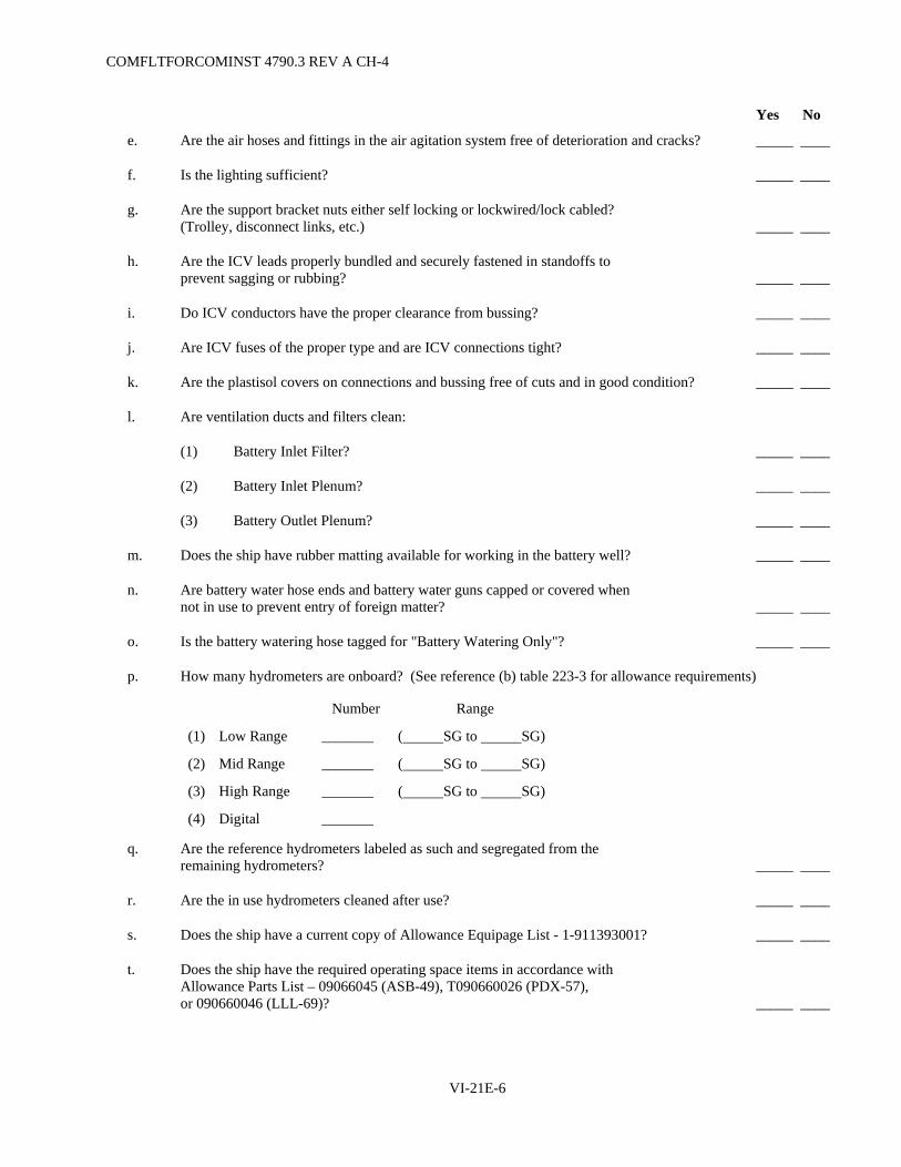
COMFLTFORCOMINST 4790.3 REV A CH-4
Yes No
e. Are the air hoses and fittings in the air agitation system free of deterioration and cracks? _____ ____
f. Is the lighting sufficient? _____ ____
g. Are the support bracket nuts either self locking or lockwired/lock cabled? (Trolley, disconnect links, etc.) _____ ____
h. Are the ICV leads properly bundled and securely fastened in standoffs to prevent sagging or rubbing? _____ ____
i. Do ICV conductors have the proper clearance from bussing? _____ ____
j. Are ICV fuses of the proper type and are ICV connections tight? _____ ____
k. Are the plastisol covers on connections and bussing free of cuts and in good condition? _____ ____
l. Are ventilation ducts and filters clean:
(1) Battery Inlet Filter? _____ ____
(2) Battery Inlet Plenum? _____ ____
(3) Battery Outlet Plenum? _____ ____
m. Does the ship have rubber matting available for working in the battery well? _____ ____
n. Are battery water hose ends and battery water guns capped or covered when not in use to prevent entry of foreign matter? _____ ____
o. Is the battery watering hose tagged for "Battery Watering Only"? _____ ____
p. How many hydrometers are onboard? (See reference (b) table 223-3 for allowance requirements)
Number Range
(1) Low Range _______ ( SG to SG)
(2) Mid Range _______ ( SG to SG)
(3) High Range _______ ( SG to SG)
(4) Digital _______
q. Are the reference hydrometers labeled as such and segregated from the remaining hydrometers? _____ ____
r. Are the in use hydrometers cleaned after use? _____ ____
s. Does the ship have a current copy of Allowance Equipage List - 1-911393001? _____ ____
t. Does the ship have the required operating space items in accordance with Allowance Parts List – 09066045 (ASB-49), T090660026 (PDX-57), or 090660046 (LLL-69)? _____ ____
VI-21E-6

COMFLTFORCOMINST 4790.3 REV A CH-3
VI-21E-7
Yes No
u. Does the ship have the required number of jumper cable assemblies available for use onboard?
(1) 60 inch cables (four) [72 inch cables on SSBN/SSGN-726 Class] _____ ____
(2) 30 inch cables (eight) [36 inch cables on SSBN/SSGN-726 Class] _____ ____
(3) 36 inch cable assemblies (six) on SSN-21 Class _____ ____
(4) 72 inch cable assemblies (three) on SSN-21 Class _____ ____
(5) Eighteen LLX terminal plates on SSN 21 Class ships _____ ____
(6) LLX hardware jumper assemblies on SSN 21 Class ships _____ ____
(7) Are these assemblies complete? _____ ____
(8) Are these assemblies stowed in a dry place? _____ ____
(9) Are these assemblies cleaned in accordance with applicable PMS? _____ ____
v. Are the leads for cell and battery testing in the ICV panel tight? _____ ____
w. Do they fit properly into the female connectors? _____ ____
x. Are eye wash facilities, with a minimum 2-quart capacity, available near the battery well hatch? _____ ____
y. Does the ship have the torque wrenches (two) required for intercell torquing? _____ ____
(1) Are they calibrated? _____ ____
(2) Are the sockets six point? _____ ____
z. Are the battery well heaters:
(1) Turned on when injection temperature is less than 55°F? _____ ____
(2) Turned off whenever the battery well hatch is open? _____ ____
Results and Recommendations:
Submitted: _______________________ Inspector Officer Title_________________
Noted:____________________________ Commanding Officer Date________

COMFLTFORCOMINST 4790.3 REV A CH-3
(This Page Intentionally Left Blank)
VI-21E-8
COMFLTFORCOMINST 4790.3 REV A CH-4
APPENDIX F
INSTRUCTIONS FOR COMPLETING SUBMARINE BATTERY QUARTERLY REPORTS - NAVSEA 9320/3
1. General. Accurate battery reports are an absolute requirement. These reports enable reviewing activities to recognize a specific problem or to change the scheduled battery replacement date based on the history and performance of a particular battery installation. These reports provide vital information for assessing submarine readiness, predicting future funding requirements and scheduling battery renewals. The NAVSEA form 9320/3 is designed to facilitate the automatic data processing of specific information reported. Therefore, all blocks must be completed correctly.
2. Frequency. This section is applicable to all submarines with installed storage batteries, including those in pre-commissioning status.
a. Submarine QBRs shall be submitted each calendar quarter that a battery is installed in the ship. The report shall be submitted within five working days of the quarter just ending, operations permitting.
b. When a battery is being replaced, submit a "final" report on the date the battery is removed. Submit a "first" report on the date a new battery is installed. If no battery is installed on the end of a reporting quarter (such as during overhaul) no report is required. First reports shall contain the date of initial filling, the date of installation and data on the installing activity acceptance test discharge. Ampere-hours and cycles of charge from the initial charge and developing cycle shall not be included as part of the total ampere-hours and cycles.
c. A "special" report shall be submitted whenever the battery capacity falls below 90%, whenever battery capacity decreases more than 10 percentage points from the previous capacity test discharge or anytime unusual or unexplained changes occur.
3. Distribution.
a. Original to Naval Surface Warfare Center Crane (Code 6095).
b. One copy to the applicable TYCOM. (Commander Submarine Force Atlantic Code N43213/Commander Submarine Force Pacific Code 43213).
c. One copy to the ISIC.
d. One copy to the GNB Industrial Power.
e. One copy for ship's file.
4. Instructions. (See Sample Report).
a. Submarine QBRs will be submitted on form NAVSEA 9320/3 (provided by TYCOM) as a word document.
b. Title Section. Insert ship's name and hull number on FROM line. Fill in the date of submission (must be 1 January, 1 April, 1 July, or 1 October, except Special Reports), and the date of installation (the battery completely bussed and fully ready for service). Place an "X" in the appropriate box to indicate individual meters/detectors are currently in calibration.
VI-21F-1

COMFLTFORCOMINST 4790.3 REV A CH-3
Block #(s) Required Format Remarks
1-5 Five digits, no blanks. Unit Identification Code (UIC).
6-11 Letters and numbers. Do not use hyphens. Block 11 may be blank.
Battery type (ASB-49, PDX-57, LLL-69).
12-13 Two digits, no blanks. Battery age in months to the nearest whole month computed from the date of initial filling (02, 05, 32, 55, etc.).
14 One digit. Fiscal Quarter (either 1, 2, 3, or 4) (Note: Oct, Nov, Dec is Fiscal Quarter 1).
15-16 Two digits. Fiscal Year (01, 02, etc.).
17 Either X or blank. Mark with an X if this is the first report after a new battery installation. Otherwise leave blank.
18 Either X or blank. Mark with an X if battery has been removed or inactivated. Otherwise leave blank.
19-20 Two digits, no blanks. Months (to nearest whole month) on open circuit since initial filling. Months on open circuit is defined as any calendar month in which an onboard charge is not conducted and the battery is only used intermittently for supplemental power or not used at all.
c. Battery Upkeep (Section A). Fill in data as indicated for battery charges, cycles and watering. Amount of water shall be to the nearest gallon. Ampere-hours shall be to the nearest ampere-hour. Under "Amp-Hours Charged (A-H Meter)" and "Amp-Hours Discharged (A-H Meter)" columns, "Last Report" and "Total" entries are not required (see Sample Report).
VI-21F-2
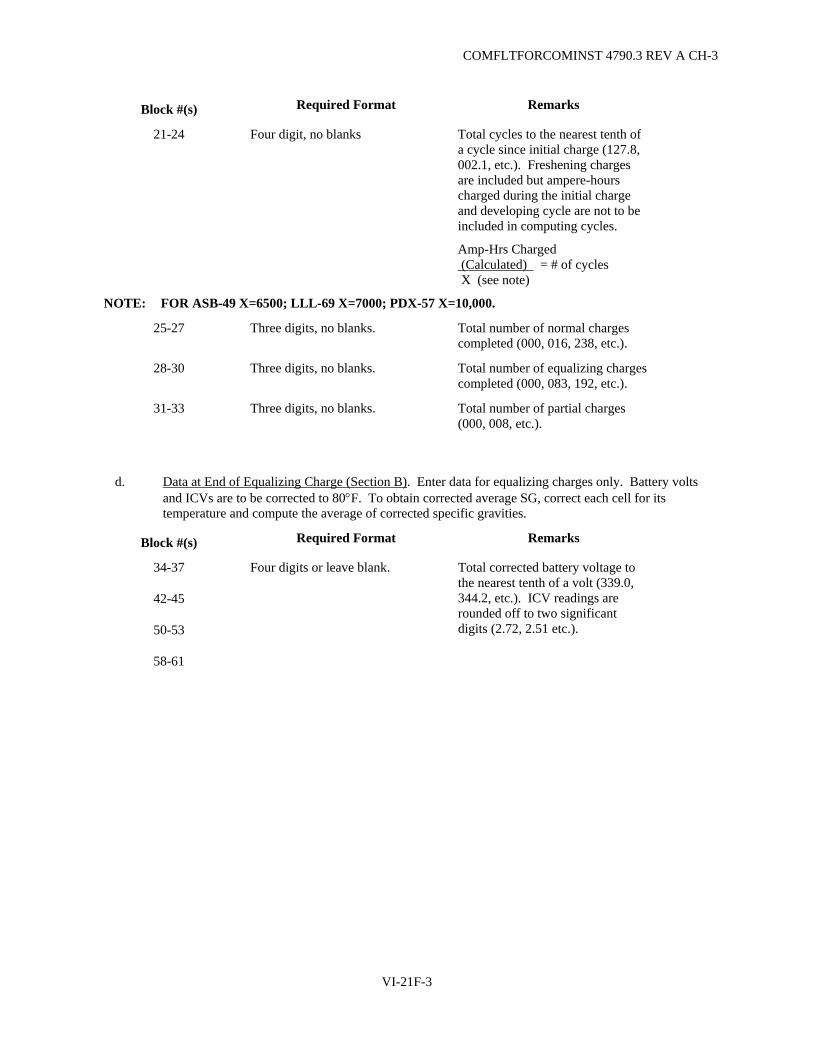
COMFLTFORCOMINST 4790.3 REV A CH-3
Block #(s) Required Format Remarks
21-24 Four digit, no blanks Total cycles to the nearest tenth of a cycle since initial charge (127.8, 002.1, etc.). Freshening charges are included but ampere-hours charged during the initial charge and developing cycle are not to be included in computing cycles.
Amp-Hrs Charged (Calculated) = # of cycles X (see note)
NOTE: FOR ASB-49 X=6500; LLL-69 X=7000; PDX-57 X=10,000.
25-27 Three digits, no blanks. Total number of normal charges completed (000, 016, 238, etc.).
28-30 Three digits, no blanks. Total number of equalizing charges completed (000, 083, 192, etc.).
31-33 Three digits, no blanks. Total number of partial charges (000, 008, etc.).
d. Data at End of Equalizing Charge (Section B). Enter data for equalizing charges only. Battery volts and ICVs are to be corrected to 80°F. To obtain corrected average SG, correct each cell for its temperature and compute the average of corrected specific gravities.
Block #(s) Required Format Remarks
34-37
42-45
50-53
58-61
Four digits or leave blank. Total corrected battery voltage to the nearest tenth of a volt (339.0, 344.2, etc.). ICV readings are rounded off to two significant digits (2.72, 2.51 etc.).
VI-21F-3

COMFLTFORCOMINST 4790.3 REV A CH-3
e. Battery Capacity Tests (Section C). If no test discharge was conducted during the reporting quarter, enter data from previous test discharge. A completed copy of Appendix D of this chapter will be included with this report when a test discharge was conducted during the reporting quarter.
Block #(s) Required Format Remarks
66-71 Six digits or the letters "INYARD" Month, day and year of the capacity test discharge (02/25/01, 11/03/02, etc.). For ships that are in CNO Maintenance Availabilities for more than six months, put the words "INYARD" in Blocks 66-71 and report the date and information of the last capacity test discharge on the line below Blocks 66-71.
72-75 Four digits, no blanks. Percent capacity to the nearest tenth (088.5, 101.2, etc.).
f. Other Data and Signature Lines (Section D). Use this section to include remarks such as (attach additional sheets if required to keep the information legible):
(1) Date of the most recent Appendix E Main Storage Battery Inspection Check-Off.
(2) Cells noted during PMS, inspection or battery charging lineups that had insufficient air agitation.
(3) Cell or cells jumpered this quarter and reason.
(4) Any other information that would affect the service life or performance of the battery.
(5) Report completion of manufacturer's battery inspection recommendations and plan for completion of any recommendations not yet accomplished.
(6) Meter calibration problems, battery open circuited and other pertinent information.
(7) Results of electrolyte analysis performed as a result of battery manufacturer's recommendation.
VI-21F-4

COMFLTFORCOMINST 4790.3 REV CH-3
SAMPLE REPORT
NAVSEA PRT 9320-1 SUBMARINE BATTERY QUARTERLY REPORT
NAVSEA 9320/3 (REV 1-78) 0116-LF-093-2016 From: Commanding Officer, USS (Ship’s Name and Hull No.)
DATE OF SUBMISSION 05 Oct 95 DATE OF INITIAL FILlNG 09 Dec 93
To: Commander, Code 6095 Bldg. 3287 NAVSURFWARCENDIV 300 Highway 361 Crane, IN 47522-5001
DATE OF INSTALLATION 12 Feb 94
Requiring Document:
Naval Ships Technical Manual Chapter 223, Vol. 1
DATE OF ELECTROLYTE ANALYSIS (SEMI-ANNUAL)
15 Apr 95
QUARTERLY CHECK (Check One)
PROP. MTR. & GEN. AMMETERS
BATTERY AMMETERS
BATTERY A-H METERS
PROP. MTR. & GEN. VOLTMETERS
BATTERY VOLTMETERS
INDIVIDUAL CELL VOLTMETERS
BATTERY AIRFLOW METERS
HYDROMETERS
HYDROGEN DETECTORS
YES
■
■
■
■
■
■
■
■
■
NO
□
□
□
□
□
□
□
□
□
0 5 5 5 5 T L X 3 9 8 2 2 4 9 5 0 4 1 2 3 4 5 6 7 8 9 10 11 12 13 14 15 16 17 18 19 20
UIC BATTERY TYPE AGE (MONTHS)
FY RPT QTR FISCAL YEAR FIRST
RPT FINAL RPT
MONTHS ON OPEN CIRCUIT
A- BATTERY UPKEEP
NUMBER OF CHARGES WATER USED
(GALLONS)
AMP HOURS CHARGED (CALCULATED)
CYCLES (1)
NORMAL EQUALIZING PARTIAL
AMP HOURS CHARGED
(A-H METER)
AMP HOURS DISCHARGED (A-
H METER) LAST REPORT 265 141989 028.4 080 018 005 NA NA FIRST MONTH 70 8773 001.8 005 001 000 8882 8067 SECOND MONTH 62 13959 002.8 007 001 001 14121 14690 THIRD MONTH 53 17808 003.6 010 001 000 16 17317
TOTAL 450 182529 0 21
3 22
6 23
6 24
1 25
0 26
2 27
0 28
2 29
1 30
0 31
0 32
6 33 NA NA
B-DATA AT END OF EQUALIZING CHARGE (2)
DATE
MO. DA. YR.
BATTERY VOLTS
CORRECTED TO 80°F
(3)
CORRECTED SP. GR.
(AVERAGE) (4)
CELLS 10 POINTS BELOW OR ABOVE AVERAGE SP. GR
(CONTINUE IN REMARKS SECTION)
FOUR LOWEST CORRECTED INDIVIDUAL CELL VOLTAGE
(5) 3 4 3 2 CELL NONE NONE NONE CELL 81 74 77 75 07 23 95 34 35 36 37 1.274 SP. GR. VOLTS 2.72 2.72 2.72 2.73 3 4 3 3 CELL 104 NONE NONE CELL 81 104 47 101 08 25 95 42 43 44 45 1.280 SP. GR. 1.270 VOLTS 2.69 2.71 2.72 2.72 3 4 2 1 CELL NONE NONE NONE CELL 81 41 104 58 09 28 95 50 51 52 53 1.280 SP. GR. VOLTS 2.69 2.70 2.71 2.71 CELL CELL
58 59 60 61
SP. GR. VOLTS
DATE
BATTERY DISCHARGE
RATE (6) (AMPERES)
ACTUAL TIME (MIN) (7)
AGE IN CYCLES
(6)
AVG. PILOT CELL TEMP AT
START AND END FINAL VOLTS MO. DA. YR. CELL NO.
RATEDTIME(MIN)
(9)
ACTUAL CAPACITY (PERCENT)
(10)
NO. OF CELLS
JUMPERED TOTAL THREE LOWEST CELLS
START END 1 0 3 9 CELL 91 102 47 0 8 8
6 6 7
1 8 8
2 6 9
9 7 0
5 7 1 1750 186 26.7 78 96 179 72 73 74 75 0 212 VOLTS 1.51 1.53 1.63
CELL
VOLTS
D-OTHER DATA AND SIGNATURE LINES REMARKS: (11)
COPY TO: FORCE COMMANDER (Self Explanatory) COMSUBRON (Self Explanatory)
ENGINEERING OFFICER
BATTERY MFGR (As appropriate) APPROVED BY FILE COMMANDING OFFICER
(Numerals in parentheses refer to instructions on reverse side)
VI-21F-5

COMFLTFORCOMINST 4790.3 REV A CH-3
(This Page Intentionally Left Blank)
VI-21F-6

COMFLTFORCOMINST 4790.3 REV A CH-3
APPENDIX G
INSTRUCTIONS FOR MAINTAINING THE SUBMARINE BATTERY RECORD BOOK NAVSEA 9320/1 (3-92)
1. GENERAL. Accurate battery records are an absolute requirement. These records enable reviewing activities to identify problem areas or to change the scheduled battery replacement based on the performance of a particular battery installation. These records provide the data necessary to complete NAVSEA form 9320/3, Submarine Battery Quarterly Report. Therefore, proper maintenance of the BRB is essential.
2. INSTRUCTIONS.
a. Remarks Section: This section should include information of a general nature. Information such as the following should be included: Date and manner of installation; lifting of a cell for examination and results thereof, electrolyte "spiking" to include reason for action, quantities involved, authority granted, etc.; initial pilot cells selected, as well as any change of pilot cells; any change, transfer or removal of cells; pertinent data concerning the isolation of cells; completion of battery manufacturers recommendations from battery inspection reports; other abnormal or unusual information that is pertinent to the battery. The following should not be included in the remarks section: waterings; two ohm load checks; PMS checks; water purity test results performed by Ship's Force; battery well inspections or other information of a repetitive nature unless different or unusual conditions exist.
b. Electrolyte Analysis Section:
(1) Laboratory - enter the name of the laboratory where the analysis was performed.
(2) Serial or file number of report - enter the number assigned to the report by the laboratory.
(3) Date - the date on which the sample was taken from the cell (vice the date the analysis was performed by the laboratory).
(4) Cells analyzed - enter the battery cell number from which the sample was drawn.
(5) Remarks - enter either satisfactory or unsatisfactory based on the analysis record. If unsatisfactory, enter the reference covering the action taken.
NOTE: THE "DATE" AND "CELLS ANALYZED" INFORMATION SHOULD BE ENTERED IMMEDIATELY AFTER THE SAMPLE IS DRAWN. ALL OTHER INFORMATION SHOULD BE ENTERED UPON RECEIPT OF THE LABORATORY REPORT.
c. Equalizing Charge Data Section:
(1) Date - enter the date on which the equalizing charge was commenced. (This should match the date on the Submarine Battery Log (NAVSEA 9320/6)).
(2) Charge number - enter the charge number for the equalizing charge being logged.
VI-21G-1
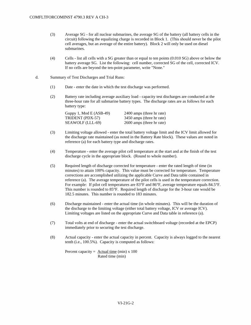
COMFLTFORCOMINST 4790.3 REV A CH-3
(3) Average SG - for all nuclear submarines, the average SG of the battery (all battery cells in the circuit) following the equalizing charge is recorded in Block 1. (This should never be the pilot cell averages, but an average of the entire battery). Block 2 will only be used on diesel submarines.
(4) Cells - list all cells with a SG greater than or equal to ten points (0.010 SG) above or below the battery average SG. List the following: cell number, corrected SG of the cell, corrected ICV. If no cells are beyond the ten-point parameter, write "None."
d. Summary of Test Discharges and Trial Runs:
(1) Date - enter the date in which the test discharge was performed.
(2) Battery rate including average auxiliary load - capacity test discharges are conducted at the three-hour rate for all submarine battery types. The discharge rates are as follows for each battery type:
Guppy 1, Mod E (ASB-49) 2400 amps (three hr rate) TRIDENT (PDX-57) 3450 amps (three hr rate) SEAWOLF (LLL-69) 2600 amps (three hr rate)
(3) Limiting voltage allowed - enter the total battery voltage limit and the ICV limit allowed for the discharge rate maintained (as noted in the Battery Rate block). These values are noted in reference (a) for each battery type and discharge rates.
(4) Temperature - enter the average pilot cell temperature at the start and at the finish of the test discharge cycle in the appropriate block. (Round to whole number).
(5) Required length of discharge corrected for temperature - enter the rated length of time (in minutes) to attain 100% capacity. This value must be corrected for temperature. Temperature corrections are accomplished utilizing the applicable Curve and Data table contained in reference (a). The average temperature of the pilot cells is used in the temperature correction. For example: If pilot cell temperatures are 83°F and 86°F, average temperature equals 84.5°F. This number is rounded to 85°F. Required length of discharge for the 3-hour rate would be 182.5 minutes. This number is rounded to 183 minutes.
(6) Discharge maintained - enter the actual time (in whole minutes). This will be the duration of the discharge to the limiting voltage (either total battery voltage, ICV or average ICV). Limiting voltages are listed on the appropriate Curve and Data table in reference (a).
(7) Total volts at end of discharge - enter the actual switchboard voltage (recorded at the EPCP) immediately prior to securing the test discharge.
(8) Actual capacity - enter the actual capacity in percent. Capacity is always logged to the nearest tenth (i.e., 100.5%). Capacity is computed as follows:
Percent capacity = Actual time (min) x 100 Rated time (min)
VI-21G-2
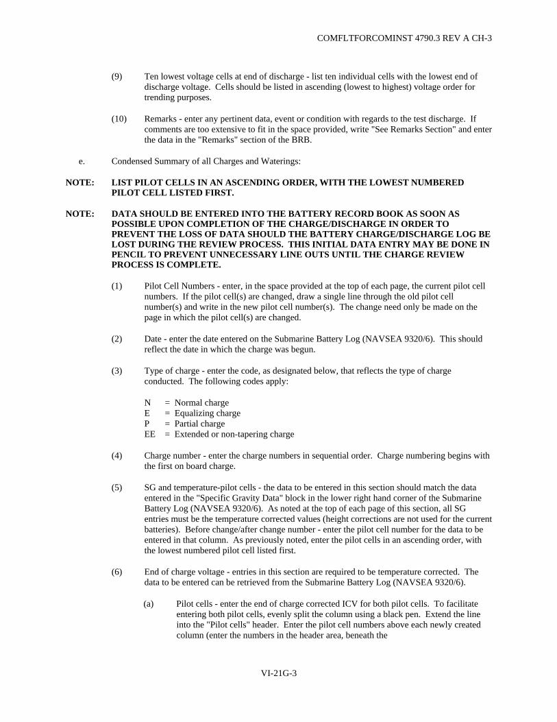
COMFLTFORCOMINST 4790.3 REV A CH-3
(9) Ten lowest voltage cells at end of discharge - list ten individual cells with the lowest end of discharge voltage. Cells should be listed in ascending (lowest to highest) voltage order for trending purposes.
(10) Remarks - enter any pertinent data, event or condition with regards to the test discharge. If comments are too extensive to fit in the space provided, write "See Remarks Section" and enter the data in the "Remarks" section of the BRB.
e. Condensed Summary of all Charges and Waterings:
NOTE: LIST PILOT CELLS IN AN ASCENDING ORDER, WITH THE LOWEST NUMBERED PILOT CELL LISTED FIRST.
NOTE: DATA SHOULD BE ENTERED INTO THE BATTERY RECORD BOOK AS SOON AS POSSIBLE UPON COMPLETION OF THE CHARGE/DISCHARGE IN ORDER TO PREVENT THE LOSS OF DATA SHOULD THE BATTERY CHARGE/DISCHARGE LOG BE LOST DURING THE REVIEW PROCESS. THIS INITIAL DATA ENTRY MAY BE DONE IN PENCIL TO PREVENT UNNECESSARY LINE OUTS UNTIL THE CHARGE REVIEW PROCESS IS COMPLETE.
(1) Pilot Cell Numbers - enter, in the space provided at the top of each page, the current pilot cell numbers. If the pilot cell(s) are changed, draw a single line through the old pilot cell number(s) and write in the new pilot cell number(s). The change need only be made on the page in which the pilot cell(s) are changed.
(2) Date - enter the date entered on the Submarine Battery Log (NAVSEA 9320/6). This should reflect the date in which the charge was begun.
(3) Type of charge - enter the code, as designated below, that reflects the type of charge conducted. The following codes apply:
N = Normal charge E = Equalizing charge P = Partial charge EE = Extended or non-tapering charge
(4) Charge number - enter the charge numbers in sequential order. Charge numbering begins with the first on board charge.
(5) SG and temperature-pilot cells - the data to be entered in this section should match the data entered in the "Specific Gravity Data" block in the lower right hand corner of the Submarine Battery Log (NAVSEA 9320/6). As noted at the top of each page of this section, all SG entries must be the temperature corrected values (height corrections are not used for the current batteries). Before change/after change number - enter the pilot cell number for the data to be entered in that column. As previously noted, enter the pilot cells in an ascending order, with the lowest numbered pilot cell listed first.
(6) End of charge voltage - entries in this section are required to be temperature corrected. The data to be entered can be retrieved from the Submarine Battery Log (NAVSEA 9320/6).
(a) Pilot cells - enter the end of charge corrected ICV for both pilot cells. To facilitate entering both pilot cells, evenly split the column using a black pen. Extend the line into the "Pilot cells" header. Enter the pilot cell numbers above each newly created column (enter the numbers in the header area, beneath the
VI-21G-3
COMFLTFORCOMINST 4790.3 REV A CH-3
words "Pilot cells"). (Pilot cell numbers should be entered in ascending order). Individual cell temperature corrections can be accomplished by using the TCV formula. Enter a value of "1" for the "N" (number of cells) value.
(b) Total voltage corrected to 80°F - enter the TCV value. TCV is calculated using the formula in reference (a). (The last on charge battery voltage reading entered on the Submarine Battery Log (NAVSEA 9320/6) must be used in this calculation). This value need only be entered for equalizing and non-tapering equalizing charges. This value is contained in Block 4 of the Submarine Battery Log (NAVSEA 9320/6).
(7) Minutes on charge after reaching TVG at finishing rate - enter the total time (in whole minutes) from the point at which the finishing rate is reached at TVG until the charge is completed. This value need only be entered for equalizing and non-tapering equalizing charges. This data is contained in Block 5 of the Submarine Battery Log (NAVSEA 9320/6).
(8) Hours of charge to nearest tenth (this charge) - enter the total number of hours (to the nearest tenth) to complete the charge (time from the first on charge log readings, until the last on charge log reading). This data is contained in Block 6 of the Submarine Battery Log (NAVSEA 9320/6).
(9) Amp-hours of charge per battery (this charge) - enter the calculated ampere hours of charge. (Calculate as indicated in reference (a)). This number should be rounded to the nearest whole number. This data is contained in Block 8 of the Submarine Battery Log (NAVSEA 9320/6).
(10) Total cycles of charge to nearest 0.1 - enter the value for total cycles to the nearest tenth. This data is contained in Block 9 of the Submarine Battery Log (NAVSEA 9320/6). Use the following formula to derive these values:
Cycles = Ampere-hours (calculated) Service cycle
A service cycle is defined as follows:
Guppy 1, Mod E (ASB-49) 6,500 ampere hours
TRIDENT (PDX-57) 10,000 ampere hours
SEAWOLF (LLL-69) 7,000 ampere hours
(11) Number of gallons of water used - enter the amount of water (in gallons) actually added to the cells. The amount used to flush out the watering hose and piping prior to sampling the filling water is not included in this figure. The value should be rounded to the nearest whole number. This data is contained in Block 13 of the Submarine Battery Log (NAVSEA 9320/6).
VI-21G-4
COMFLTFORCOMINST 4790.3 REV A CH-3
(12) Percent charge back - enter the percentage of ampere hours charged back. The data is contained in Block 12 of the Submarine Battery Log (NAVSEA 9320/6). This value is calculated using the following formula:
Percent charge back = Ampere hour meter charged x 100 Ampere hour meter discharged
(13) Ampere hours by meter - enter the values as read directly from the ampere hour meter. Discharged values are the ampere hours as read immediately prior to the start of charge. Charged values are the ampere hours from the beginning (following resetting (zeroing) the ampere hour meter) of the charge to the charge completion. The mode selector switch must be placed in the appropriate position (depending on ampere hour meter type used). The values for discharge and charge ampere hours are contained in blocks 10 and 11 respectively of the Submarine Battery Log (NAVSEA 9320/6).
(14) Totals - both monthly and grand totals must be calculated at the end of the calendar month. Quarterly totals need not be maintained, but may be calculated if desired. If quarterly totals are maintained, entries should coincide with the submission date of the QBR. The following values must be computed for monthly and grand totals (and quarterly, if maintained).
(a) Hours of charge to nearest tenth (this charge) - computed by adding the hours of charge values for each individual charge.
(b) Ampere hours of charge per battery (this charge) - computed by adding the ampere hours of charge values per battery for each individual charge.
(c) Total cycles for charge to nearest 0.1 - computed by dividing the appropriate (monthly, grand totals or quarterly) ampere hours of charge by the appropriate service cycle as listed below.
Cycles = Ampere-hours (calculated) Service cycle
A service cycle is defined as follows:
Guppy 1, Mod E (ASB-49) 6,500 ampere hours
TRIDENT (PDX-57) 10,000 ampere hours
SEAWOLF (LLL-69) 7,000 ampere hours
(d) Number of gallons of water used - computed by adding the water addition values for each individual charge.
(e) Ampere hours by meter - computed by adding the ampere hours of discharge/charge for each individual charge.
VI-21G-5
COMFLTFORCOMINST 4790.3 REV A CH-3
NOTE: ONLY MONTHLY TOTALS ARE REQUIRED FOR AMPERE HOURS BY METER. GRAND TOTALS NEED NOT BE MAINTAINED.
(15) BRB audits/records reviews - between 9 and 15 months since last inspection, through a NAVSEA contract, a battery manufacturer's representative will conduct an on-site battery inspection. The BRB will be signed and dated following the representative's review. Where possible, the dated signature will be placed after the last month of the inspection period in the "Condensed Summary of All Charges and Waterings" section. Battery records should be made available for overnight off-ship review by the battery manufacturer's representative.
f. Certification by Engineer Officer:
(1) This section certifies that the Engineer Officer has reviewed the battery records (including the BRB) for accuracy and legibility. The Engineer should review and sign the BRB on a monthly basis and at each crew turnover for SSBN/SSGNs.
(2) Period - from date/to date - enter the period/time frame of the records being reviewed.
(3) Signature - signature of the reviewing officer (Engineer Officer).
(4) Rank - rank of the reviewing officer (Engineer Officer).
VI-21G-6

COMFLTFORCOMINST 4790.3 REV A CH-4
VOLUME VI
CHAPTER 22
TRIDENT SYSTEM AND EQUIPMENT MAINTENANCE PLANS
REFERENCES.
(a) OPNAVINST 4700.7 - Maintenance Policy for U.S. Naval Ships
22.1 PURPOSE. To provide information and guidance concerning TRIDENT submarine system and equipment maintenance plans and associated programs.
22.2 TRIDENT SYSTEM AND EQUIPMENT MAINTENANCE PLANS. Maintenance plans have been prepared for all maintenance worthy configuration items onboard SSBN/SSGN 726 Class Submarines. These maintenance plans are written to the system, equipment and/or component and list all of the planned maintenance required by a configuration item during its life cycle. These Maintenance Requirements are derived through the conduct of a maintenance engineering and a logistics support analysis process. Maintenance plans list the job description, periodicity, maintenance level (organization, intermediate, or industrial) and the applicable maintenance procedures. Unrestricted Operation (URO), TRIDENT Planned Equipment Replacement (TRIPER), Major Shore Spares (MSS), Maintenance Standards (MS) and Performance Monitoring applications are included in maintenance plans as appropriate. Technical management of these plans is assigned to the Submarine Maintenance Engineering, Planning and Procurement Activity. An SSBN/SSGN 726 Class Submarine Maintenance Plan comprising all individual maintenance plans is issued periodically by NAVSEA. In accordance with reference (a), the Type Commander will identify and prioritize corrective maintenance actions for SSBN/SSGN Class Submarine emergent repairs. Programs and requirements supporting the SSBN/SSGN 726 Class operating cycle are discussed in the following paragraphs.
22.2.1 TRIDENT Planned Equipment Replacement. The purpose of the TRIPER program is to accomplish an incremental overhaul of a submarine over several refit periods. Shipboard equipment which requires significant maintenance during the planned operating cycle between overhauls, which is beyond the capability of Ship's Force, and which cannot be accomplished during the refit period (without unacceptable impact on other refit requirements), will be supported by this program. TRIPER equipment will be removed from the ship for refurbishment ashore, replaced with pre-tested, ready for issue units and the affected system restored to full operational condition prior to completion of the refit period. Replacement will be accomplished on a planned basis at intervals designed to preclude the failure of the equipment or significant degradation of its associated system. Deviations of greater or less than one refit from established TRIPER change-out periodicities shall require Type Commander concurrence. A planned change to shelf stock TRIPER equipment will be accomplished only when sufficient change kits are available to effect the change in all units of a given model of the equipment held in shelf stock. Shelf stock TRIPER equipment is represented in configuration status accounting databases maintained by Submarine Maintenance Engineering, Planning and Procurement Activity Hull, Mechanical, Electrical, Ordnance and Electronic and Naval Underwater Warfare Center Division Newport and transitions to the configuration database of the receiving ship upon installation. The Type Commander shall manage emergent repairs requiring use of TRIPER assets. In accordance with reference (a), the Type Commander will identify and prioritize corrective maintenance actions for SSBN/SSGN Class Submarine emergent repairs. Support of the Strategic Platform (SSBN) generally has the highest priority.
VI-22-1

COMFLTFORCOMINST 4790.3 REV A CH-4
22.2.2 Major Shore Spares. The purpose of the TRIDENT MSS Program is to maintain a supply of designated major equipment candidates in a certified, tested, ready-for-issue condition to effect replacement of equipment experiencing catastrophic failure, without jeopardizing refit completion. The employment of MSS assets shall require Type Commander authorization. Typically, MSS equipments include ship's propeller, Ship's Service Turbine Generators, towed arrays, towed buoys, Integrated Radio Room cabinets, etc. Like TRIPER, MSS equipment is managed by NAVSEA (PMS 392). Configuration tracking is under the cognizance of the applicable Participating Manager and is identified in the TRIDENT MSS Catalog published by NAVSEA (PMS 392). Equipment under the cognizance of the Strategic System Project Office and Naval Sea Systems Command Nuclear Propulsion Directorate (NAVSEA 08) is not included in the TRIPER or MSS programs.
22.2.3 Fleet Logistics Agent. The function of the fleet logistics agent for SSBN/SSGN 726 Class Submarines has been assigned to the TRIDENT Refit Facility (TRIREFFAC). TRIREFFAC provides refit and configuration management support. These functions involve:
a. Staging and delivering updated Logistics Technical Data (LTD) applicable to the ship's current configuration.
b. Providing available interim technical documentation and logistic support elements for emergent changes installed during refit.
c. Assessing the logistic impact and reporting of, configuration changes effected by all sources in SSBN/SSGN 726 Class Submarines.
22.2.4 Updating of Submarine Logistics Technical Data. TRIREFFAC will stage and deliver LTD Advance Change Notices and revisions to SSBN/SSGN 726 Class Submarines during refit and shall assist Ship's Force in the removal and disposal of LTD that is no longer applicable to the ship's current configuration. Upon request, TRIREFFAC will also provide training to Ship's Force in the proper techniques for identification, procurement and maintenance of TRIDENT LTD.
22.2.5 Planned Refit Work Lists. Planned Refit Work Lists (PRWL) define all the planned work required for each SSBN/SSGN 726 Class ship for a one year period or four refits. The PRWL includes scheduled TRIPER replacements, URO and Performance Monitoring requirements. In addition, alterations approved for accomplishment will be incorporated into the PRWL. The PRWL will be issued periodically, each for a one year period. Subsequent PRWLs will include rescheduling of requirements identified on previous work lists which were not reported complete. Each PRWL will allocate specific work items to a proposed refit based on the Class Maintenance Plan scheduled requirements and projected manpower requirements.
VI-22-2

COMFLTFORCOMINST 4790.3 REV A
VI-23-1
VOLUME VI
CHAPTER 23
SUBMARINE NOISE REDUCTION
REFERENCES.
(a) NAVSEA S9073-AW-SNC-010 - Ship Acoustical Surveys for Submarines (b) NAVSEA S9073-A4-SNC-010 - USS LOS ANGELES (SSN 688) Class Acoustic Stealth Manual (c) NSWCCD-71-TR-2001/020 - February 2001 USS SEAWOLF (SSN 21) Class Acoustic Stealth Manual (d) NAVSEAINST C9073.2 - Acoustical Survey of Submarines (e) COMSUBLANTINST C9460.3A - Coordinated Submarine Radiated Noise Analysis (f) COMSUBPACINST 9460.5 - Coordinated Submarine Radiated Noise Analysis (g) NAVSEA S9073-AF-SNC-010(C) - Ship Noise Control (h) NAVSEA S0600-AA-PRO-230 - Underwater Ship Husbandry Manual, Chapter 23: Submarine
Predeployment Noise Inspections (i) NAVEDTRA 10500 - Catalog of Navy Training Courses (j) COMSUBLANT/COMSUBPACINST C3500.1 - Submarine Force Training Manual
LISTING OF APPENDICES.
A Supplemental Noise Measurements B Beartrap Acoustic Radiated Trials (BART) C Shipboard Noise Reduction Instruction D Predeployment Noise Inspection E Submarine Silencing Publications F Sample Propeller Changeout Message
23.1 PURPOSE. This chapter provides the requirements for an effective onboard noise reduction program during the ship's operating cycle. It identifies the acoustic surveys required to assess the radiated noise signature of a ship and summarizes the responsibilities and requirements for the onboard surveys necessary to be performed on a regular basis to maintain the submarine in its most quiet configuration.
23.1.1 Scope. Reference (a) discusses the various acoustic surveys to be conducted on ships in order to establish their baseline noise signatures and to monitor those signatures throughout the operating cycle. Surveys discussed in reference (a) are briefly summarized, as well as several additional survey techniques available and essential to an effective noise reduction program. In addition, a discussion of the model shipboard noise reduction program and available training programs are presented. References (b) and (c) provide class specific and comprehensive documentation on submarine noise reductions, including discussion of acoustic surveys, shipboard noise reduction program, acquisition systems, and procedures, data analysis and trending, and detailed write-ups with photographs and audio clips of typical noise sources. In addition, the manual contains an extensive library of documents and training aids.

COMFLTFORCOMINST 4790.3 REV A
VI-23-2
23.1.2 Background. Reduction of the radiated noise signature of a submarine platform is a key element to the tactical employment of the ship. As a ship begins its operating cycle, a series of acoustic surveys are conducted to characterize the baseline noise signature. Then, throughout the remainder of its operating cycle, the ship requires the tools and procedures necessary to monitor its signature against the baseline. As deficiencies are identified, Ship's Force needs to have an understanding of the extent to which an identified deficiency can affect the ship's radiated noise signature and the procedures required to effect corrective action. It should be kept in mind that although the implications of a degraded noise signature are fundamentally tactical in nature, the primary method of preserving a ship's acoustic advantage is through an aggressive and effective planned and corrective noise reduction maintenance program. Because of an increased emphasis in recent years, a number of new initiatives are being pursued within the technical community to develop new and improved measurement procedures and equipment that will assist Ship's Force in more effectively assessing the effects of noise deficiencies on their radiated noise signature. These efforts should lead to improved survey procedures and will be incorporated into future changes to this chapter.
23.2 NOISE REDUCTION PROGRAM ELEMENTS.
23.2.1 Radiated Noise Surveys.
23.2.1.1 Naval Sea Systems Command Acoustic Trials. These trials are conducted at the beginning of and at various times throughout each ship's operating cycle in accordance with reference (d) and provide a broad range of baseline measurements for the ship. In particular, the radiated noise signature of the ship is measured under various operating conditions. A determination is made of the controlling radiated noise offenders including those which are speed and depth dependent. While the principal objective of these trials is to assess the radiated noise signature of the submarine, platform and machinery and hull vibration measurements are also made to provide baseline and supporting data in these areas for continued ship monitoring.
23.2.1.2 Coordinated Submarine Radiated Noise Analysis Exercise. This test shall be conducted in accordance with references (e) and (f), for Commander Submarine Force Atlantic (COMSUBLANT) units and Commander Submarine Force Pacific (COMSUBPAC) units, respectively. The primary objective of these submarine-versus-submarine exercises is to collect and analyze data to assess current acoustic vulnerabilities. These tests can be used during Pre-Overseas Movement (POM)/Deployment Preparation Period (DPP) work-ups to indicate that the deploying unit's acoustic signature is free of any unusual or highly detectable noise characteristics.
23.2.1.3 Coordinated Submarine Exercises (KILOEX/JTFEX/INT-2/TRACKEX/GUNSLINGER). While acoustic trials and surveys are the principal means to evaluate a submarine's acoustic profile, coordinated exercises provide another opportunity for the submarine force to monitor itself for noise deficiencies. Although the primary purpose of these exercises is generally tactically oriented, the noise signature obtained can and should also serve to monitor submarine radiated noise. It is incumbent upon exercise participants to note and record any unusual or excessive radiated noise being emitted by submarine exercise participants. Discrepancies noted should be reported to the cognizant Immediate Superior In Command (ISIC) for evaluation and corrective action. Initial message reports should be followed by supporting documentation including tape recordings, annotated lofargrams, and annotated frequency spectrum plots. The message report should contain the following information:
a. Description of noise signature problem.
b. Date and time of detection.
c. Range at detection.
d. Sensor/processor used for detection.
e. Own ship depth and speed.

COMFLTFORCOMINST 4790.3 REV A
VI-23-3
f. Acoustic sea state.
g. Water depth.
h. Water temperature.
i. Layer depth.
23.2.1.4 Beartrap Acoustic Radiated Trials. The primary objective of these trials is to provide a cost effective means to detect and identify radiated noise sources that have caused signature degradations. Coordinated trial events are conducted with Marine Patrol Aircraft. Detected narrowband tones in the radiated noise signature are provided by naval message. Parent ISICs are responsible for requesting these trials. Specific information, including message requests and scheduling requirements, as well as Ship's Force and Type Commander (TYCOM) responsibility is provided in Appendix B of this chapter.
23.2.2 Onboard Noise Surveys. The noise surveys discussed in this section do not provide conclusive information on the actual radiated noise signature of the ship. However, when these surveys are analyzed for developing trends, they can be effective tools for monitoring overall ship effectiveness in noise reduction.
23.2.2.1 Platform Noise Survey. This survey is conducted to define own ship's noise environment and is the best means available to Ship's Force to assess the radiated noise signature of the ship using only onboard equipment. Surveys are conducted by taking periodic measurements under various ship's operating conditions using the applicable Planned Maintenance System (PMS) Maintenance Requirement Cards (MRC). In addition, at-sea watch-to-watch aural monitoring is also conducted. Analysis of this data determines the platform noise signature and also identifies the noise offenders which affect this signature. When changes in the ship's signature occur, the diagnostic procedures of the class specific platform noise manual are used to isolate the noise source. Platform Noise Surveys should be conducted in accordance with enclosure (2a) of Appendix C of this chapter. Propeller cavitation surveys, a separate survey from the Platform Noise Survey but considered an important part of platform noise monitoring analysis, should be conducted in accordance with enclosure (2b) of Appendix C of this chapter.
23.2.2.2 Topside and Housekeeping Survey. The most common and preventable sources of submarine noise are rattles emanating from improperly secured topside equipment, discontinuities in the hull, and machinery noise sound shorted to the hull due to improper stowage.
23.2.2.2.1 Topside Survey. The topside survey consists of a thorough inspection to identify and eliminate potential noise sources external to the pressure hull. Particular attention should be given to ensure that rattles are not installed, built in, or created by repairs, alterations, or stowage. Topside Surveys should be conducted in accordance with enclosure (2c) of Appendix C of this chapter.
23.2.2.2.2 Housekeeping Survey. The housekeeping survey consists of a thorough visual inspection to identify and eliminate these potential noise sources internal to the pressure hull. Particular attention should be given to ensure that sound shorts are not installed, built in, or created by repairs, alterations, or stowage. Housekeeping Surveys should be conducted in accordance with enclosure (2d) of Appendix C of this chapter.
23.2.2.3 Machinery Vibration Survey. A vibration survey conducted quarterly for both machinery health assessment and noise reduction purposes. Performance of this survey alone does not provide reliable information on radiated noise. Machinery Vibration Surveys should be conducted in accordance with enclosure (2e) of Appendix C of this chapter.

COMFLTFORCOMINST 4790.3 REV A CH-5
VI-23-4
23.2.2.4 Hull Vibration Survey. A shipboard hull vibration survey is conducted quarterly or as required for the purpose of noise diagnostics by Ship's Force. The purpose is to assess acoustic deficiencies related to noise sources and transmission paths, and to estimate certain slow-speed, low frequency radiated noise levels. Hull Vibration Surveys should be conducted in accordance with enclosure (2e) of Appendix C of this chapter.
23.2.2.5 Isolation System Survey. This survey consists of a visual inspection of sound isolation components throughout the ship per applicable road maps and reference (g). These components include resilient mounts, pipe hangers, ground straps, and flexible piping. This visual inspection ensures that these devices are properly installed, undamaged, and not sound shorted. Improper installation or failure of any of these devices will contribute to increasing the radiated noise signature of the ship. Isolation System Surveys should be conducted in accordance with enclosure (2f) of Appendix C of this chapter.
23.2.2.6 Damping Material Survey. This is a visual inspection of sound damping material installed in the vicinity of sonar arrays, sail, free flood spaces, and on machinery foundations. Like the isolation system survey, this inspection is designed to detect deficiencies in materials installed to limit the radiated noise signature of the ship. Damping Material Surveys should be conducted in accordance with enclosure (2g) of Appendix C of this chapter.
23.2.2.7 Predeployment Noise Inspections. Requirements and forms are contained in reference (h) and Appendix D of this chapter.
23.2.2.8 Technical Onboard Monitoring Assist. This survey consists of at sea analysis by acoustic technical experts to evaluate the acoustic signature of the ship. The survey consists of a towed array, platform noise hydrophones and machinery and hull vibration measurements taken simultaneously to identify and localize major acoustic degradation. Emphasis is placed on training the submarine's crew on own ship noise data acquisition and analysis using their available sensors. Technical Onboard Monitoring Assists should be conducted in accordance with Appendix A of this chapter.
23.2.2.9 Sound Absorption Material Survey. This is a thorough visual inspection of interior sound absorption material and sound transmission loss material conducted in all spaces. These materials are installed to assist in habitability of the ship by absorbing vibration. Sound Absorption Material Surveys should be conducted in accordance with enclosure (2h) of Appendix C of this chapter.
23.2.2.10 Airborne Noise Survey. The airborne noise survey exists to identify shipboard areas whose airborne noise levels have increased or are possibly high enough to cause hearing damage. Airborne Noise Surveys should be conducted in accordance with paragraph 5.c.(6) of Appendix C of this chapter.
23.2.3 Shipboard Noise Reduction Program. The key to a successful shipboard noise reduction program will be the ability of the ship to identify potential noise deficiencies and to initiate prompt corrective action. References listed in Appendix E of this chapter should be a part of the ship's onboard library of submarine silencing publications. Several elements of the noise reduction program are discussed in the following paragraphs.
23.2.3.1 Noise Reduction Officer. To ensure a coordinated and aggressive approach to noise reduction, each ship will assign one of its senior Department Heads, as designated by the Commanding Officer, to serve as Noise Reduction Officer. The Noise Reduction Officer will coordinate the activities of all personnel assigned to support the ship's Noise Reduction Program. This officer will ensure that all required surveys are conducted, that identified deficiencies are documented, and that corrective action is initiated. A Noise Reduction Board, chaired by the Noise Reduction Officer, will convene at regular intervals to review the status of the Noise Reduction Program. Following each meeting, formal written reports will be made to the Commanding Officer.

COMFLTFORCOMINST 4790.3 REV A
VI-23-5
23.2.3.2 Noise Deficiency Log. The ship's Equipment Status Log (ESL) will be used to record and track all noise deficiencies. Deficiencies will be entered in the section for the Work Center (WC) responsible for the equipment concerned. The Critical Noise Deficiencies (NC)/Potential Noise Deficiencies (NP) code (per paragraph 23.2.3.3 below) in the deficiency description block will tag the entry as a noise deficiency. The Noise Reduction Officer will ensure the ESL is properly maintained and accurately reflects the latest status of all noise deficiencies. Items to be entered in the ESL include noise deficiencies reported during radiated noise acoustic trials as well as those discovered during onboard surveys. Ship's logs shall be maintained in a manner where all diagnostics, repairs or other evaluations performed are documented. The logs need to be maintained until noise issues are verified to be repaired by associated acoustic or vibration measurements. If Ship's Non-Tactical Automated Data Processing system is the primary means of maintaining equipment status, history and overall plan of action for repair needs to be maintained elsewhere.
23.2.3.3 Noise Related Maintenance Records. The OPNAV 4790/2K will be used to document all deferred and completed noise related maintenance actions. Block 46-G will be used to further classify noise deficiencies in one of two categories; NC and NP.
a. The NC code will be used to identify deficiencies of a critical nature identified during one of the following:
(1) Naval Sea Systems Command (NAVSEA) Acoustic Trials.
(2) Supplemental Radiated Noise Measurements.
(3) Technical Onboard Monitoring Assist.
(4) Platform Noise Monitoring Surveys.
b. The NP code will be used to identify deficiencies that could potentially be radiated noise problems identified during one of the following:
(1) Topside and Housekeeping Surveys.
(2) Machinery and Hull Vibration Surveys.
(3) Isolation System Surveys.
(4) Damping Material Surveys.
(5) Airborne Sound Absorption Material Surveys.
(6) Routine Ship Operations.
23.2.4 Training. Formal training course prerequisites and descriptions are listed in reference (i). Specific training requirements are contained in reference (j).
23.3 RESPONSIBILITIES.
23.3.1 Immediate Superior In Command.
a. Assign a Staff Noise Reduction Officer as a specific point of contact for all matters relating to noise reduction within the Squadron.
COMFLTFORCOMINST 4790.3 REV A
VI-23-6
b. Oversee and supervise the Noise Reduction Program within the Squadron, ensuring that assigned units aggressively identify and correct noise deficiencies.
c. Submit requests for Beartrap Acoustic Radiated Trials (BART) to COMSUBLANT/COMSUBPAC, N454, N42N, as appropriate.
d. Schedule acoustic surveys during the operating cycle of submarines in accordance with reference (d).
e. Recommend and/or authorize corrective actions based on the findings of the surveys conducted.
f. Review Noise Reduction Program records, survey results, procedures and monitoring equipment during material readiness inspections, Tactical Readiness Evaluations and POM/DPP certification.
g. Schedule divers to conduct underwater hull and propeller surveys for noise deficiencies prior to undocking, pre-deployment, post-deployment, and during upkeep.
h. Report propeller replacements using the message format of Appendix F of this chapter.
i. Ensure that personnel tasked to support assigned submarines are adequately trained in submarine noise reduction.
23.3.2 Industrial Activity.
a. Ensure proper handling and repair of noise critical machinery.
b. Conduct in-shop and in-place balancing of all rotating equipment, both motors and coupled units, repaired by the industrial activity.
c. Conduct in-place balancing as authorized by work requests.
d. Assist ships in identifying and correcting noise problems and in conducting noise surveys in accordance with approved work requests.
e. Establish new baseline machinery and hull vibration measurement data for repaired units.
f. Ensure that all applicable personnel are adequately trained in submarine noise reduction.
g. Conduct underwater hull and propeller surveys for noise deficiencies in accordance with reference (h).
23.3.3 Submarine Commanding Officer.
a. Establish and maintain a ship's Noise Reduction Program consistent with this chapter. Appendix C of this chapter provides the basis for a shipboard instruction to meet this requirement.
b. Appoint a senior Department Head as Noise Reduction Officer and establish a Ship's Noise Reduction Board.

COMFLTFORCOMINST 4790.3 REV A
VI-23A-1
APPENDIX A
SUPPLEMENTAL NOISE MEASUREMENTS
This Appendix provides a brief discussion of the TYCOM sponsored, noise measurements that may periodically be conducted on submarines during their operating cycle.
TECHNICAL ONBOARD MONITORING ASSIST (TOMA)
1. Purpose. TOMAs are conducted on submarines to maintain their acoustic signatures between scheduled radiated noise trials. Major acoustic degradations and their corrective actions are identified, and training is provided to Ship's Force.
2. Procedure. TOMA schedules are coordinated by the TYCOMs and the Squadrons. TOMAs are conducted by Naval Surface Warfare Center (NSWC), with assistance from on-site Performance Monitoring Team (PMT) and Ship's Force personnel. TOMAs need 18 to 30 hours of data acquisition time. Normally, TOMAs are conducted on three to seven day underways and can be scheduled concurrently with other operations. Tests consist of a series of runs in various machinery line ups to collect data required to assess the acoustic signature of the submarine. Data is collected using onboard sensors and compared to baseline signatures from previous acoustic trials. A TOMA will serve as the quarterly hull, machinery, and platform noise surveys.
3. Frequency. TOMAs are to be conducted prior to, or early in the POM/DPP cycle when no radiated noise trial is scheduled to occur within one year of the deployment date.
NOTE: A TOMA IS NOT A SUBSTITUTE FOR THE NAVAL SEA SYSTEMS COMMAND ACOUSTIC TRIAL. A TOMA MAY ALSO BE REQUESTED BY THE SUBMARINE'S ISIC.
4. Reports. NSWC will issue a "quick look" message from the submarine at the completion of the TOMA. This message will detail significant findings and recommended corrective actions, as well as the status of previous corrective actions. A separate message will be sent by NSWC detailing hull and machinery vibration data.
5. Action. Ship's Force and the submarine's ISIC should use the results and recommendations of the TOMA "quick look" message to schedule and implement corrective action. Ship's Force should use the 3-M Maintenance Data System to document deficiencies and corrective actions. For deferred items, the Noise Reduction Officer should develop and implement appropriate corrective action.

COMFLTFORCOMINST 4790.3 REV A
VI-23A-2
(This Page Intentionally Left Blank)

COMFLTFORCOMINST 4790.3 REV A
VI-23B-1
APPENDIX B
BEARTRAP ACOUSTIC RADIATED TRIALS (BART)
1. Purpose. BARTs provide submarines with the opportunity to measure and assess their narrowband radiated noise signatures, identify problems, and provide an opportunity to correct deficiencies and evaluate their acoustic health prior to certain deployments.
2. Procedure. BARTs are initially scheduled by TYCOM prior to major deployments or upon request by the submarine's ISIC. The ISIC is then responsible for updating the TYCOM on schedule changes. BARTs are a structured Beartrap in a designated quiet ocean area in accordance with the BART agenda. The objective is to collect sufficient data to determine the radiated noise signature and mission readiness of the ship. Data collection on station is accomplished by Commander Patrol Reconnaissance Forces Pacific (COMPATRECONFORPAC) or Commander Patrol Reconnaissance Forces Atlantic (COMPATRECONFORLANT) Anti Submarine Warfare patrol aircraft and is restricted to a single eight hour period during ship operations in a designated ocean area.
3. Frequency. For COMSUBPAC units, ISICs should coordinate BART scheduling for their submarines such that each ship will be tested prior, or early in the DPP. The schedule should allow sufficient time for corrective action on noise deficiencies detected during the BART to be planned and accomplished during a DPP upkeep period. For COMSUBLANT units, ISICs should coordinate BART scheduling for their submarines as required.
4. Reports. For Pacific Fleet submarines, COMPATRECONFORPAC will issue a message within 60 days of completion of a BART. For Atlantic Fleet submarines, "quick look" message will be issued in accordance with Local Operating Instructions.
5. Action. Ship's Force and the submarine's ISIC should use the results of the BART messages to schedule and implement corrective action for noise deficiencies detected during the trial. For deferred items the Noise Reduction Officer should develop and implement appropriate corrective action.

COMFLTFORCOMINST 4790.3 REV A
VI-23B-2
(This Page Intentionally Left Blank)
COMFLTFORCOMINST 4790.3 REV A
VI-23C-1
APPENDIX C
SHIPBOARD NOISE REDUCTION INSTRUCTION
USS (Ship's Name and Hull No.)
Subj: SHIP'S NOISE REDUCTION PROGRAM
Ref: (a) COMFLTFORCOMINST 4790.3; Joint Fleet Maintenance Manual, Volume VI, Chapter 23
Encl: (1) Quarterly Noise Reduction Program Status Report (2) Noise Reduction Surveys (3) Control Surface Noise Questionnaire
1. Purpose. To establish a ship's Noise Reduction Program to include: a Noise Reduction Board to advise the Commanding Officer concerning appropriate noise reduction procedures; a set of noise surveys to characterize the ship's noise signature; and procedures to ensure proper coordination of efforts in the ship's noise reduction program.
2. Discussion. A great deal of emphasis has been placed on upgrading noise reduction awareness within the submarine force. As required by reference (a), (Ship's Name) must devote continued attention to the detection, correction and prevention of increases in its radiated noise signature. Significant mission degrading radiated noise problems could not be tolerated in wartime. (Ship's Name) must minimize noise to maximize our detection range of threats/targets and to reduce the possibility of hostile ships detecting (Ship's Name). Quietness is absolutely essential to our primary mission and a continuous, aggressive effort must be made in acoustic housekeeping and noise reduction to ensure a quiet ship. The acoustic surveys considered mandatory for effectively maintaining a quiet ship and improving the ship's acoustic signature during the operating cycle are discussed in this instruction. While these surveys serve as a formal means of noise reduction, each crew member's actions play an equally important role in the noise reduction consciousness of the entire ship. A quiet ship requires involvement of the whole crew. THINK QUIET!
3. Program Organization.
a. A ship's Noise Reduction Board shall be established to assist the Commanding Officer in the development and execution of long and short range plans for maintaining and enhancing the acoustic posture of the ship. The board will recommend appropriate shipboard noise reduction procedures and monitor their execution. The board will consist of the following personnel:
(1) Executive Officer.
(2) Combat Systems Officer.
(3) Engineer Officer.
(4) Sonar Officer.
(5) Electrical Officer.
(6) First Lieutenant.

COMFLTFORCOMINST 4790.3 REV A
VI-23C-2
(7) Sonar Division Leading Petty Officer.
(8) Electrical Division Noise Reduction Petty Officer (NRPO).
(9) Chief of the Boat.
(10) Sail Coordinator.
b. To assist the board in carrying out their responsibilities, experienced Petty Officers and non-rated personnel who have completed qualification in submarines shall be assigned in the ship's collateral duties notice as NRPO. Each division will have at least one formally designated NRPO.
4. Program Management.
a. The Noise Reduction Officer will coordinate all noise reduction activities within the ship. The Noise Reduction Board will meet periodically (before and after each upkeep and at least monthly underway) and discuss actions completed and further action required to correct outstanding noise deficiencies. The Noise Reduction Officer will chair these meetings. The Noise Reduction Officer will ensure that the noise reduction portion of the ESL contains updated entries on all outstanding noise deficiencies. Each of the significant noise deficiencies will be discussed at every meeting. The Commanding Officer will be apprised of the results of the meeting and any unresolved problems shortly after the meeting. Formal written reports summarizing the status of the Noise Reduction Program will be submitted following each meeting to the Commanding Officer using the format of enclosure (1).
b. Onboard surveys will be conducted in accordance with this instruction. Noise deficiencies discovered during these surveys or detected during routine ship's operations will be reported to the Noise Reduction Officer. At sea, these reports will be made to the Officer Of the Deck (OOD) who will, in turn, inform both the Noise Reduction Officer and the Commanding Officer. The OOD will initiate corrective action for all significant noise deficiencies and ensure that these items are included in the watch turnover. All deficiencies that are not immediately correctable will be entered in the noise deficiency section of the ESL.
c. The Noise Reduction Officer shall ask the following questions during each Noise Reduction Board meeting.
(1) Have we effected all corrective action recommendations from our latest acoustic trials? Have on board measurement surveys conclusively proven that outstanding noise deficiencies were corrected? Report all unresolved items to the Commanding Officer using the format of enclosure (1).
(2) Have any noise sources, especially rattles or control surface transients, been aurally detected during the conduct of the platform noise survey of enclosure (2a)? If rattles or transients are present, have tape recordings or data packages been accomplished in accordance with platform noise or maintenance manual guidance for submission?
(3) Have we conducted a propeller tip cavitation survey in accordance with enclosure (2b)? Are the measured tip cavitation points acceptable? If cavitation is not acceptable, has a tape package been prepared in accordance with reference (a)?

COMFLTFORCOMINST 4790.3 REV A
VI-23C-3
(4) Have any signature degradations been identified from the latest set of towed array, platform noise hydrophone or machinery and hull vibration measurements? If so, have the noise sources been identified? Report unresolved items to the Commanding Officer using the format of enclosure (1).
5. Action.
a. The Executive Officer shall:
(1) Attend all Noise Reduction Board meetings.
(2) Implement a comprehensive, all hands training program to elevate the awareness of Ship's Force personnel to the importance of noise reduction.
b. The Noise Reduction Officer shall:
(1) Coordinate and administer the ship's Noise Reduction Program.
(2) Schedule Noise Reduction Board meetings and chair their meetings.
(3) Report the status of noise deficiencies to the Commanding Officer following meetings of the Noise Reduction Board. Submit written summary reports to the Commanding Officer using the format of enclosure (1).
(4) Ensure that cognizant divisions enter all noise reduction deficiencies in the ESL, that prompt corrective action is taken by responsible divisions and that work requests are submitted for deficiencies beyond the capability of Ship's Force.
(5) Ensure that acoustic trial deficiencies are entered in the ESL and that appropriate corrective action is initiated.
(6) Assess the tactical implications of noise deficiencies detected during underway operations and make recommendations to the Commanding Officer as to tactical limitations and required corrective action.
(7) Ensure that cognizant divisions have men properly trained in Ship's Force acoustic surveys, noise reduction equipment, proper bearing replacement, and in-place balancing of rotating equipment.
(8) Ensure that surveys are being conducted by cognizant divisions and that deficiencies are reported to the Commanding Officer.
(9) Conduct spot reviews of acoustic survey results.
(10) Be inventory manager of all publications required by reference (a), to support the Noise Reduction Program and ensure that divisions have applicable MRCs.
(11) Assist the Engineer Officer with the implementation and maintenance of the ship's quiet bills.
(12) Ensure action is taken, to the maximum extent possible, to complete enclosure (3) for all identified control surface noises.

COMFLTFORCOMINST 4790.3 REV A
VI-23C-4
c. The Sonar Officer shall:
(1) Ensure that the Platform Noise Survey is accomplished, recorded, and analyzed in accordance with enclosure (2a).
(2) Perform Propeller Cavitation Noise Surveys as required in accordance with enclosure (2b).
(3) Develop propeller cavitation curves in accordance with enclosure (2b) and forward results to the Commanding Officer via the Noise Reduction Officer.
(4) Direct the use of the installed sonar systems to assist in the identification and isolation of noise related material deficiencies detected in Topside, Housekeeping, Machinery and Hull Vibration, and Isolation System Surveys. (Enclosures 2c, 2d, 2e, and 2f respectively refer).
(5) Ensure that Damping Material Surveys are accomplished, recorded, and analyzed in accordance with enclosure (2g).
(6) Ensure the Airborne Noise Surveys are accomplished, recorded, and analyzed in accordance with the applicable Maintenance Index Page (MIP). The Sonar Officer shall ensure that airborne noise levels in all shipboard areas remain within permissible limits. An Airborne Noise survey shall be conducted when increased airborne noise levels are suspected of exceeding permissible limits. A written report in memorandum form shall be submitted for each watch station and shall include, as a minimum, the date of inspection, names of personnel conducting the survey, and the discrepancies noted in the ESL. Review the status of noise level measurements and any affected watch station and report this information to the Commanding Officer and the ship's corpsman.
(7) Report immediately any abnormal increase in own ship's noise to the OOD and the Noise Reduction Officer.
(8) Ensure that all survey deficiencies are entered in the noise reduction section of the ESL and reported to the Noise Reduction Officer. Ensure that prompt corrective action is taken and that work requests are submitted for deficiencies beyond the capability of Ship's Force.
(9) Ensure that personnel assigned to conduct noise reduction surveys under his cognizance are properly trained.
d. The Electrical Officer shall:
(1) Ensure that the Machinery and Hull Vibration Surveys are accomplished, recorded, and analyzed in accordance with enclosure (2e).
(2) Ensure that in-place balancing is conducted on an assembled unit at any time that repairs are made by Forces Afloat that would affect the balance of the equipment.
(3) Determine the cause of out of specification machinery and hull vibration readings and initiate corrective action.

COMFLTFORCOMINST 4790.3 REV A
VI-23C-5
(4) Ensure that prompt corrective action is taken and that work requests are submitted for deficiencies beyond the capability of Ship's Force.
(5) Ensure that personnel under his cognizance assigned to conduct noise reduction surveys are properly trained.
e. The First Lieutenant shall:
(1) Ensure that the Topside and Housekeeping Surveys are accomplished, recorded, and analyzed in accordance with enclosure (2c) and (2d).
(2) Ensure that the Sound Absorption Material Survey is accomplished, recorded, and analyzed in accordance with enclosure (2h).
(3) With the assistance of the Supply Officer, ensure that equipment, stores, personal effects, and consumables are stowed in a manner that will not produce noise or transmit noise to the ship's hull or structure.
(4) Ensure that all survey deficiencies are entered in the noise reduction section of the ESL and reported to the Noise Reduction Officer. Ensure that prompt corrective action is taken and that work requests are submitted for deficiencies beyond the capability of Ship's Force.
(5) Ensure that personnel under his cognizance assigned to conduct noise reduction surveys are properly trained.
f. The NRPO shall:
(1) Promote the Noise Reduction Program in their respective divisions.
(2) Perform or assist in the performance of noise reduction surveys under their respective division's cognizance in accordance with enclosure (2).
(3) Enter all survey deficiencies in the noise reduction section of the ESL and report deficiencies to the cognizant Division Officer.
g. The OOD shall:
(1) Remain aware of the status of critical noise deficiencies and operate the ship in a manner that will minimize its radiated noise signature.
(2) Report all new noise deficiencies and the correction of existing deficiencies to the Noise Reduction Officer and the Commanding Officer. Ensure new deficiencies are recorded in the noise reduction section of the ESL.
(3) Ensure sonar watchstanders conduct aural monitoring of own ship's noise signature upon initial dive and once per watch.

COMFLTFORCOMINST 4790.3 REV A
VI-23C-6
(This Page Intentionally Left Blank)

COMFLTFORCOMINST 4790.3 REV A
VI-23C-7
From: Noise Reduction Officer To: Commanding Officer Via: Executive Officer
Subj: QUARTERLY NOISE REDUCTION PROGRAM STATUS REPORT FOR PERIOD ENDING (DATE)
Encl: (1) Noise Reduction Section of ESL
1. The following MRCs associated with the Noise Reduction Program were not accomplished, partially accomplished, or deferred:
MRC No./Deficiency reason/Corrective Action
2. The following noise deficiencies were identified during the current period:
Deficiency/Source/ESL No./Plan of action for identification and repair
3. The following previously identified noise deficiencies were corrected during the current period:
Deficiency/Corrective Action
4. The following noise deficiencies from the previous period are outstanding:
Deficiency/Source/ESL No./Diagnostics and repairs performed/Plan of action for identification and repair
5. Enclosure (1) summarizes all currently outstanding deficiencies associated with the Noise Reduction Program.
Submitted:_____________________________
Noise Reduction Officer
Copy to: Engineer Officer
Enclosure (1)

COMFLTFORCOMINST 4790.3 REV A
VI-23C-8
(This Page Intentionally Left Blank)

COMFLTFORCOMINST 4790.3 REV A
VI-23C-9
NOISE REDUCTION SURVEYS
1. This enclosure contains a description of the onboard surveys conducted in support of the Noise Reduction Program. For each survey, applicable references are cited and a summary of procedures and reporting requirements are presented. Surveys included are:
Enclosure 2a Platform Noise Survey
2b Propeller Cavitation Noise Survey
2c Topside Survey
2d Housekeeping Survey
2e Machinery and Hull Vibration Survey
2f Isolation System Survey
2g Damping Material Survey
2h Sound Absorption Material Survey
Enclosure (2)

COMFLTFORCOMINST 4790.3 REV A
VI-23C-10
(This Page Intentionally Left Blank)

COMFLTFORCOMINST 4790.3 REV A
VI-23C-11
PLATFORM NOISE SURVEY
Reference: (a) Class Applicable Technical Manual for Platform Noise Monitoring Analysis for Noise Reduction
(b) Class Applicable SO-544 MIP/MRCs (c) OPNAVINST 5513.5A Department of the Navy (DON) Security Classification Guidance for
Undersea Warfare Programs
1. Responsibility. Sonar Officer.
2. Procedure.
a. Platform Noise Surveys shall be conducted as specified in references (a) and (b).
b. Sonar supervisors shall monitor each hydrophone for objectionable noises at least once each watch while underway and report results to the OOD. Problems detected shall also be recorded in the Noise Reduction section of the ESL. Problem investigation and corrective action shall be initiated as soon as possible within the current operations schedule.
c. As soon as feasible, after diving, following an inport period, accomplish the following:
(1) Monitor each platform hydrophone for objectionable noise while changing speed in five knot increments up to Flank speed (monitor all frequency bands/where applicable). At slow speed, monitor hydrophones nearest the rudder/stern planes and fairwater planes while each control surface is cycled. Monitor the hydrophone nearest the sail while each mast and antenna is cycled. If control surface deficiencies are found complete the applicable portions of the Control Surface Noise Questionnaire, enclosure (3), to report control surface noise. This questionnaire assists in troubleshooting.
(2) Check at least one point of the propeller cavitation curve. If results are significantly different from the previous data, establish a new cavitation curve at the earliest opportunity as discussed in enclosure (2b).
(3) If operations preclude complete accomplishment of (1) and (2) above, speeds/areas not monitored should be noted and carried forward in the sonar supervisor's log until they can be monitored.
(4) Results of this monitoring will be reported to the OOD and deficiencies recorded in the ESL.
Enclosure (2a)
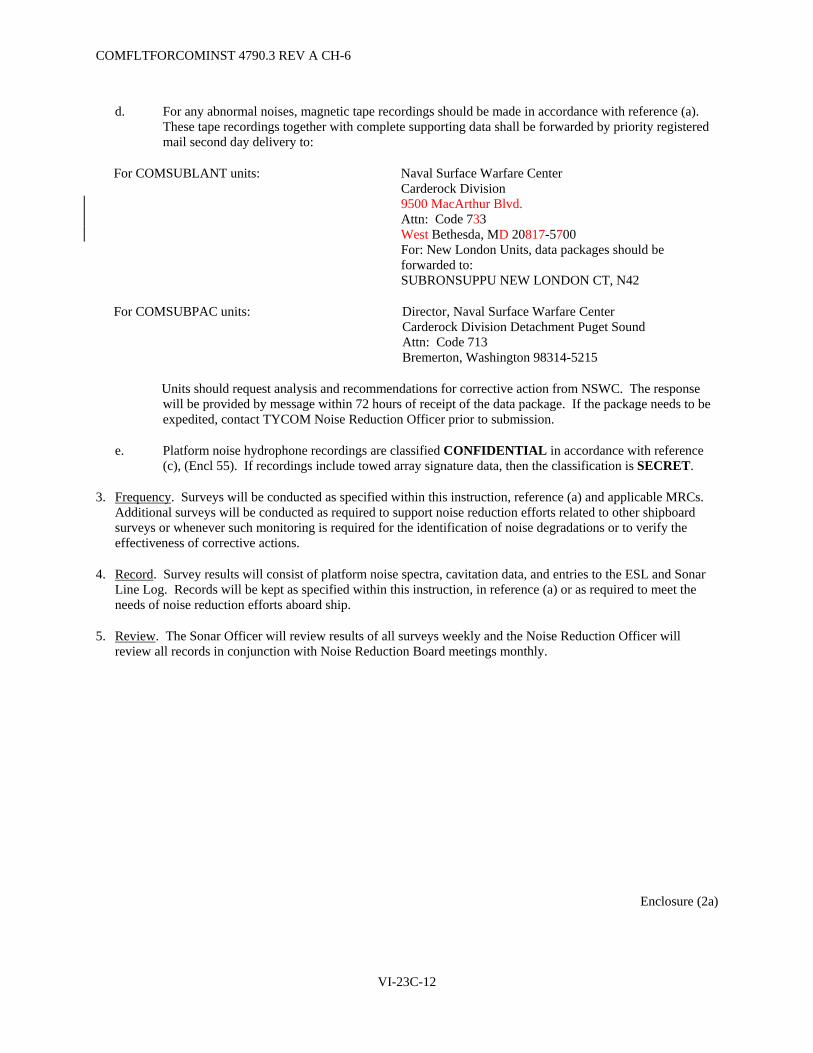
COMFLTFORCOMINST 4790.3 REV A CH-6
VI-23C-12
d. For any abnormal noises, magnetic tape recordings should be made in accordance with reference (a). These tape recordings together with complete supporting data shall be forwarded by priority registered mail second day delivery to:
For COMSUBLANT units: Naval Surface Warfare Center Carderock Division 9500 MacArthur Blvd. Attn: Code 733 West Bethesda, MD 20817-5700 For: New London Units, data packages should be forwarded to: SUBRONSUPPU NEW LONDON CT, N42
For COMSUBPAC units: Director, Naval Surface Warfare Center Carderock Division Detachment Puget Sound Attn: Code 713 Bremerton, Washington 98314-5215
Units should request analysis and recommendations for corrective action from NSWC. The response will be provided by message within 72 hours of receipt of the data package. If the package needs to be expedited, contact TYCOM Noise Reduction Officer prior to submission.
e. Platform noise hydrophone recordings are classified CONFIDENTIAL in accordance with reference (c), (Encl 55). If recordings include towed array signature data, then the classification is SECRET.
3. Frequency. Surveys will be conducted as specified within this instruction, reference (a) and applicable MRCs. Additional surveys will be conducted as required to support noise reduction efforts related to other shipboard surveys or whenever such monitoring is required for the identification of noise degradations or to verify the effectiveness of corrective actions.
4. Record. Survey results will consist of platform noise spectra, cavitation data, and entries to the ESL and Sonar Line Log. Records will be kept as specified within this instruction, in reference (a) or as required to meet the needs of noise reduction efforts aboard ship.
5. Review. The Sonar Officer will review results of all surveys weekly and the Noise Reduction Officer will review all records in conjunction with Noise Reduction Board meetings monthly.
Enclosure (2a)
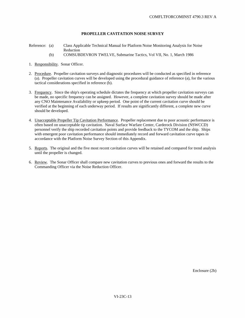
COMFLTFORCOMINST 4790.3 REV A
VI-23C-13
PROPELLER CAVITATION NOISE SURVEY
Reference: (a) Class Applicable Technical Manual for Platform Noise Monitoring Analysis for Noise Reduction
(b) COMSUBDEVRON TWELVE, Submarine Tactics, Vol VII, No. 1, March 1986
1. Responsibility. Sonar Officer.
2. Procedure. Propeller cavitation surveys and diagnostic procedures will be conducted as specified in reference (a). Propeller cavitation curves will be developed using the procedural guidance of reference (a), for the various tactical considerations specified in reference (b).
3. Frequency. Since the ship's operating schedule dictates the frequency at which propeller cavitation surveys can be made, no specific frequency can be assigned. However, a complete cavitation survey should be made after any CNO Maintenance Availability or upkeep period. One point of the current cavitation curve should be verified at the beginning of each underway period. If results are significantly different, a complete new curve should be developed.
4. Unacceptable Propeller Tip Cavitation Performance. Propeller replacement due to poor acoustic performance is often based on unacceptable tip cavitation. Naval Surface Warfare Center, Carderock Division (NSWCCD) personnel verify the ship recorded cavitation points and provide feedback to the TYCOM and the ship. Ships with emergent poor cavitation performance should immediately record and forward cavitation curve tapes in accordance with the Platform Noise Survey Section of this Appendix.
5. Reports. The original and the five most recent cavitation curves will be retained and compared for trend analysis until the propeller is changed.
6. Review. The Sonar Officer shall compare new cavitation curves to previous ones and forward the results to the Commanding Officer via the Noise Reduction Officer.
Enclosure (2b)

COMFLTFORCOMINST 4790.3 REV A
VI-23C-14
(This Page Intentionally Left Blank)

COMFLTFORCOMINST 4790.3 REV A
VI-23C-15
TOPSIDE SURVEY
Reference: (a) MRC SO-591-R1
1. Responsibility. First Lieutenant.
2. Procedure. The First Lieutenant shall ensure that the following items are accomplished in accordance with reference (a):
a. Open and inspect all line lockers and free flood areas for loose gear and other sources of noise, such as loose zincs, rattling pipes, loose grates, etc.
b. Check all deck hatches to ensure they shut properly and will not rattle.
c. Check that all towed array fairing plates are properly secured (if applicable).
d. Check all cleats for proper operation and ensure that they do not rattle when stowed.
e. Check stowage of all portable equipment topside to ensure that proper gasket material is installed, all bolts and wing nuts are present, and equipment is securely held in place when mounted.
f. When required, inspect sail area for loose gear and sources of rattles. Particular attention should be given to the mast bearings and operating equipment to ensure that masts will not be damaged or fouled. Before reinstalling sail plates, the sail should be inspected by the Noise Reduction Officer.
3. Frequency. A complete Topside Survey, including the sail, shall be conducted after any major upkeep or inport period, or whenever major topside work is completed. A sail closeout inspection shall be conducted by an officer prior to the reinstallation of any sail plate removed. Surveys should be completed as far in advance of underway as possible. Other inspections shall be conducted as directed by the First Lieutenant.
4. Reports. A written report in memorandum form shall be submitted to the Commanding Officer at the completion of each inspection. This report shall include, as a minimum, the date the inspection was made, names of personnel conducting the inspection and uncorrected discrepancies noted in the ESL. Reports shall be routed via the Noise Reduction Officer, with copies to cognizant Department Heads.
5. Review. The results of each inspection shall be reviewed by the First Lieutenant and retained until all discrepancies are corrected.
Enclosure (2c)

COMFLTFORCOMINST 4790.3 REV A
VI-23C-16
(This Page Intentionally Left Blank)

COMFLTFORCOMINST 4790.3 REV A CH-3
VI-23C-17
HOUSEKEEPING SURVEY
Reference: (a) MRC SO-591-R2
1. Responsibility. Noise Reduction Officer.
2. Procedure. It is the responsibility of the NRPO to inspect their division's spaces in accordance with reference (a) for sound shorts or other silencing discrepancies which may result from improper stowage of loose gear.
3. Frequency. Improper stowage is a continuous problem and should be monitored as such. It is the responsibility of all hands to monitor the stowage of all gear and to ensure that sound shorts are not created by improper stowage. OODs, Engineering Officers Of the Watch and all watchstanders are required by other instructions to inspect various spaces. These inspections should include monitoring for proper stowage and possible sound shorts. Prior to getting underway, all divisions must inspect their spaces for proper stowage at sea. Division Officers should acknowledge by signature on respective pre-underway check sheets that their spaces are stowed for sea.
4. Reports. Potential sound short discrepancies will be reported to the OOD who will inform the Commanding Officer and responsible Department Heads, to ensure that problems are corrected. Discrepancies not immediately corrected shall be noted in the ESL.
5. Review. The Noise Reduction Officer shall review all pre-underway check sheets and maintain a record of all noise discrepancy items until corrected.
Enclosure (2d)

COMFLTFORCOMINST 4790.3 REV A
VI-23C-18
(This Page Intentionally Left Blank)

COMFLTFORCOMINST 4790.3 REV A
VI-23C-19
MACHINERY AND HULL VIBRATION SURVEY
Reference: (a) Class Applicable Technical Manual for Machinery and Hull Vibration Testing and Monitoring of SSN/SSBN/SSGN Auxiliary Machinery
(b) MIP EL-035/903 Vibration Noise Monitoring
1. Responsibility. Electrical Officer.
2. Procedure. Machinery and hull vibration surveys shall be conducted as specified in reference (a) and in accordance with applicable PMS (reference (b)). Items found to be out-of-specification will be logged in the ESL as potential noise deficiencies. Machinery and hull vibration surveys are conducted on all submarines.
3. Frequency. A comprehensive machinery and hull vibration survey should be conducted quarterly by Ship's Force. Results are submitted to PMT, who in turn forwards the packages to the applicable NSWC Detachment. Specific machinery and hull vibration monitoring surveys shall be conducted by Ship's Force bi-weekly on selected equipment identified in the NSWC, machinery Vibration Deficiency Message and as required to support onboard noise reduction efforts.
4. Reports.
a. NSWC evaluates and maintains machinery and hull vibration data collected by Ship's Force. They report out-of-specification equipment or hull vibration levels via message.
b. During each machinery and hull vibration survey, a report is submitted to NSWC via the local PMT. This report shall include the sound cut data and a feedback package.
c. For the Hull Vibration Monitoring Program, a message should be sent from the submarine to NSWC within 45 days of receipt of the NSWC hull vibration deficiency message or when operationally feasible. This message should include the results of actions taken to identify and correct the sources of excessive hull vibration levels and to identify platform noise sources.
5. Noise Reduction Training. Crew training in noise awareness and noise reduction is absolutely essential to maintaining a quiet ship. The Submarine Force Training Manual discusses formal training courses and requirements pertaining to noise reduction as well as materials available for onboard training.
6. Review. The Electrical Officer shall review and forward the results of all machinery and hull vibration measurements to the Commanding Officer via the Noise Reduction Officer and Executive Officer. This report shall be submitted within five working days of the survey and shall include a listing of which noise measurements have been taken and any out-of-specification equipment.
Enclosure (2e)

COMFLTFORCOMINST 4790.3 REV A
VI-23C-20
(This Page Intentionally Left Blank)

COMFLTFORCOMINST 4790.3 REV A
VI-23C-21
ISOLATION SYSTEM SURVEY
Reference: (a) NAVSEA S9073-AW-SNC-010/(U) Ship Acoustical Surveys (b) NAVSEA S9073-AF-SNC-010/(C), Ship Noise Control (c) Appropriate Noise Control Guidelines, Road Maps, and Equipment Guide Lists (d) Appropriate MIP SO-593 MRCs
1. Responsibility. Noise Reduction Officer.
2. Procedure. The Noise Reduction Officer shall require Ship's Force to conduct a visual inspection of silencing equipment and components such as resilient mounts, flexible pipe, pipe hangers, ground straps, electrical connections, etc., to ensure they are properly installed, within periodicity, undamaged and not sound shorted. References (a), (b), (c) and (d) apply. When funded, these inspections will be conducted by a NAVSEA designated activity, however, the ship is still responsible for conducting the survey regardless of NAVSEA funding.
3. Frequency. An Isolation System Survey shall be conducted as specified by reference (d) in accordance with reference (a). Additionally, a localized isolation system survey shall be conducted in the area of sound isolated equipment changeouts and in the area of work accomplished on sound isolated systems. When requested and funded, a NAVSEA designated activity shall provide training and assist in the performance of an isolation system survey.
4. Reports. The Noise Reduction Officer shall ensure that all defects found are logged in the ESL and shall report survey results to the Commanding Officer within five working days of completion of the inspection.
5. Review. The Noise Reduction Officer shall maintain a record of all discrepancies noted until corrected.
Enclosure (2f)

COMFLTFORCOMINST 4790.3 REV A
VI-23C-22
(This Page Intentionally Left Blank)

COMFLTFORCOMINST 4790.3 REV A
VI-23C-23
DAMPING MATERIAL SURVEY
Reference: (a) NAVSEA S9073-AW-SNC-010/(U), Ship Acoustical Surveys (b) MIP SO-592/001 Damping Material Survey (c) NAVSEA S9073-AF-SNC-010/(C), Ship Noise Control
1. Responsibility. Sonar Officer.
2. Procedure. The Sonar Officer shall ensure that a thorough inspection is conducted of all damping material installed in sonar array areas, fairwater, main ballast tanks, and free flood areas, to ensure that no deterioration has taken place in accordance with the guidance provided in references (a) and (b). Reference (c) provides specific information relating to these materials.
3. Frequency. A Damping Material survey shall be conducted as specified with reference (b) or at each dry-docking, in accordance with reference (a).
4. Reports. A written report in memorandum form shall be submitted for each inspection and shall include, as a minimum, the date of inspection, names of personnel conducting the inspection, and the discrepancies noted in the ESL.
5. Review. The Sonar Officer shall review the results of each inspection and forward them to the Commanding Officer via the Noise Reduction Officer within five working days of the completion of the inspection. This report shall be retained by the Noise Reduction Officer until all discrepancies have been corrected.
Enclosure (2g)

COMFLTFORCOMINST 4790.3 REV A
VI-23C-24
(This Page Intentionally Left Blank)

COMFLTFORCOMINST 4790.3 REV A
VI-23C-25
SOUND ABSORPTION MATERIAL SURVEY
Reference: (a) NAVSEA S9073-AW-SNC-010/(U), Ship Acoustical Surveys (b) NAVSEA S9073-AF-SNC-010/(C), Ship Noise Control
1. Responsibility. First Lieutenant.
2. Procedure. The First Lieutenant will ensure that a thorough inspection of the interior sound absorption and sound transmission loss material is conducted in all spaces. This inspection ensures that no deterioration of these materials has taken place. This inspection is accomplished with guidance from reference (a), while reference (b) provides specific information relating to these materials.
3. Frequency. A Sound Absorption Material Survey shall be conducted prior to each major CNO Maintenance Availability. An inspection of any system affected by maintenance or other work shall be conducted following completion of the work.
4. Reports. A written report in memorandum form will be submitted to the Noise Reduction Officer for each inspection and will include, as a minimum, the date of the inspection, names of personnel conducting the inspection, and discrepancies noted in the ESL.
5. Review. The First Lieutenant will review the results of each inspection and forward them to the Commanding Officer via the Noise Reduction Officer within five working days of the completion of the inspection. This report will be retained by the Noise Reduction Officer until all discrepancies have been corrected.
Enclosure (2h)

COMFLTFORCOMINST 4790.3 REV A
VI-23C-26
(This Page Intentionally Left Blank)

COMFLTFORCOMINST 4790.3 REV A
VI-23C-27
CONTROL SURFACE NOISE QUESTIONNAIRE
1. The purpose of this questionnaire is to provide more accurate and definitive information than reports of "noise in the fairwater" or "noise in the mud tank". This information can reduce troubleshooting time, prevent unnecessary maintenance, and perhaps prevent an unnecessary and unscheduled dry-docking. It can also furnish vital data to assist in the resolution of a problem and prevent its recurrence. It is very important to monitor the audio during the greasing operations; the effects of greasing for worn bearings can be short.
2. Record audio of all platform noise evaluations in accordance with reference (a).
3. Perform all evaluations in all modes (Normal, Emergency and Automatic where applicable).
4. Note how long greasing effects the noise characteristics of the control surface (minutes, hours, days or months).
Hull Number: ____________ Date:_____________
Check the appropriate box or fill in the blanks in response to the questions below: 1. Give the date when the noise was first noticed: 2. Which control surface is suspected of causing the noise? a. Fairwater/Bow Planes Yes ∼ No ∼ b. Stern Planes Yes ∼ No ∼ c. Rudder Yes ∼ No ∼ 3. Was the noise observed upon leaving port? Yes ∼ No ∼ a. If not observed upon leaving port, after how many days at sea? ________________ 4. Was the noise first observed during the first high speed run? Yes ∼ No ∼ 5. Was any work performed on this system, associated systems, or in its
vicinity during the last refit/upkeep period (including welding or sandblasting)?
Yes ∼ No ∼
a. If yes, describe work
6. How was the noise first detected? a. Audible to crew Yes ∼ No ∼ b. Self noise monitoring system Yes ∼ No ∼ (1) If yes, which system? c. Other? (Describe)
(CONFIDENTIAL when filled in) Enclosure (3)
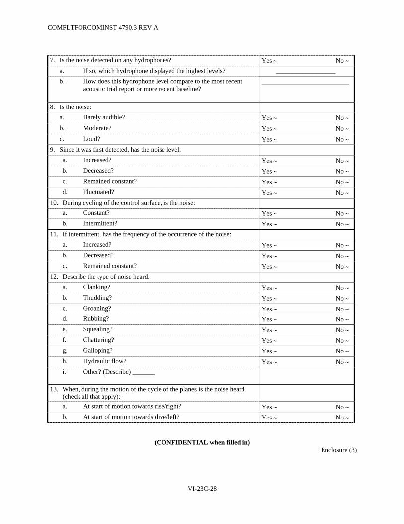
COMFLTFORCOMINST 4790.3 REV A
VI-23C-28
7. Is the noise detected on any hydrophones? Yes ∼ No ∼ a. If so, which hydrophone displayed the highest levels? __________________ b. How does this hydrophone level compare to the most recent
acoustic trial report or more recent baseline?
8. Is the noise: a. Barely audible? Yes ∼ No ∼ b. Moderate? Yes ∼ No ∼ c. Loud? Yes ∼ No ∼ 9. Since it was first detected, has the noise level: a. Increased? Yes ∼ No ∼ b. Decreased? Yes ∼ No ∼ c. Remained constant? Yes ∼ No ∼ d. Fluctuated? Yes ∼ No ∼ 10. During cycling of the control surface, is the noise: a. Constant? Yes ∼ No ∼ b. Intermittent? Yes ∼ No ∼ 11. If intermittent, has the frequency of the occurrence of the noise: a. Increased? Yes ∼ No ∼ b. Decreased? Yes ∼ No ∼ c. Remained constant? Yes ∼ No ∼ 12. Describe the type of noise heard. a. Clanking? Yes ∼ No ∼ b. Thudding? Yes ∼ No ∼ c. Groaning? Yes ∼ No ∼ d. Rubbing? Yes ∼ No ∼ e. Squealing? Yes ∼ No ∼ f. Chattering? Yes ∼ No ∼ g. Galloping? Yes ∼ No ∼ h. Hydraulic flow? Yes ∼ No ∼ i. Other? (Describe)
13. When, during the motion of the cycle of the planes is the noise heard (check all that apply):
a. At start of motion towards rise/right? Yes ∼ No ∼ b. At start of motion towards dive/left? Yes ∼ No ∼
(CONFIDENTIAL when filled in) Enclosure (3)

COMFLTFORCOMINST 4790.3 REV A
VI-23C-29
c. At the end of motion towards rise/right? Yes ∼ No ∼ d. At the end of motion towards dive/left? Yes ∼ No ∼ e. Entering the rise/right hardstop? Yes ∼ No ∼ f. Entering the dive/left hardstop? Yes ∼ No ∼ g. Leaving the rise/right hardstop? Yes ∼ No ∼ h. Leaving the dive/left hardstop? Yes ∼ No ∼ i. The entire length of travel towards rise/right? Yes ∼ No ∼ j. The entire length of travel towards dive/left? Yes ∼ No ∼ k. At some intermediate point(s) while moving towards rise/right? Yes ∼ No ∼ (Indicate degrees of rise/right when heard): _______________________ l. At some intermediate point(s) while moving towards dive/left? Yes ∼ No ∼ (Indicate degrees of dive/left when heard): _______________________ 14. Is there any unusual hesitancy or motion during operation of the planes: a. Leaving the rise/right hardstop? Yes ∼ No ∼ b. Leaving the dive/left hardstop? Yes ∼ No ∼ c. At any other point(s) in the motion cycle? Yes ∼ No ∼ (1) If yes, describe giving direction of movement and
degrees of rise, dive, left, or right when noise occurs:
15. Does ship's speed or depth have any effect on whether or not the noise is
generated? Yes ∼ No ∼
a. If yes, describe:
16. Does ship's speed or depth have any effect on when the noise is detected during the movement cycle as described in question 13?
Yes ∼ No ∼
a. If yes, describe:
17. Is the noise audible: a. Surfaced, underway? Yes ∼ No ∼ b. At periscope depth? Yes ∼ No ∼ c. Below periscope depth? Yes ∼ No ∼ 18. Does sea state effect the degree of noise? Yes ∼ No ∼ 19. Does simultaneous operation of the stern planes and rudder cause or
increase the degree of noise? Yes ∼ No ∼
20. Are any of the following components very warm to the touch while operating the control surface suspected of causing the noise?
a. Hydraulic tail rod (if installed)? Yes ∼ No ∼
(CONFIDENTIAL when filled in) Enclosure (3)

COMFLTFORCOMINST 4790.3 REV A
VI-23C-30
b. Hydraulic piston rod? Yes ∼ No ∼ c. Through hull connecting rod? Yes ∼ No ∼ 21. On the control surface suspected of causing the noise, perform the
appropriate quarterly greasing MRC for the components listed in question 22, below. Operate the control surface while greasing (except the guide cylinder). Listen to determine if greasing causes any change in the occurrence or loudness of the noise.
Greasing Performed? Yes ∼ No ∼
22. Did the noise diminish after greasing the following components? Fairwater/Bow Planes: a. Hull gland: Yes ∼ No ∼ b. Lower end of connecting rod: see Note 1 Yes ∼ No ∼ c. Upper end of connecting rod: see Note 1 Yes ∼ No ∼ d. Port stock bearing: Yes ∼ No ∼ e. Starboard stock bearing: Yes ∼ No ∼ Stern Planes: f. Hull gland: Yes ∼ No ∼ g. Forward end of connecting rod: see Note 1 Yes ∼ No ∼ h. Aft end of connecting rod: see Note 1 Yes ∼ No ∼ i. Port stock bearing: see Note 2 Yes ∼ No ∼ j. Starboard stock bearing: see Note 2 Yes ∼ No ∼ k. Port pintle bearing: Yes ∼ No ∼ l. Starboard pintle bearing: Yes ∼ No ∼ Rudder: m. Hull gland: Yes ∼ No ∼ n. Forward end of connecting rod: see Note 1 Yes ∼ No ∼ o. Aft end of connecting rod: see Note 1 Yes ∼ No ∼ p. Port stock bearing: see Note 2 Yes ∼ No ∼ q. Starboard stock bearing: see Note 2 Yes ∼ No ∼ r. Upper rudder stock bearing: see Note 2 Yes ∼ No ∼ s. Lower rudder stock bearing: see Note 2 Yes ∼ No ∼ t. Rudder carrier bearing (two fittings): see Note 2 Yes ∼ No ∼ 23. Pump one pound of grease into the guide cylinder grease fitting while the
control surface is in the neutral position. Then operate the control surface about five cycles from full rise to full dive or left to right, as appropriate, while listening for the noise. Repeat this procedure for the guide cylinder until the specified amount of grease has been applied.
Greasing Performed? Yes ∼ No ∼
(CONFIDENTIAL when filled in) Enclosure (3)

COMFLTFORCOMINST 4790.3 REV CH-6
VI-23C-31
Note 1: Grease underway if the appropriate alteration is installed to permit remote greasing of the stern planes and rudder connecting rods. The fairwater/bow planes connecting rod may be greased locally while underway on the surface even if remote greasing alteration is not installed.
Note 2: If the stern planes are suspected of causing the noise and the noise did not diminish after greasing the stern plane components, grease the rudder components. If the greasing did not help a suspected noisy rudder, grease the stern planes.
Deliver this questionnaire to:
For COMSUBLANT units: Naval Surface Warfare Center Carderock Division 9500 MacArthur Blvd. Attn: Code 733 West Bethesda, MD 20817-5700 For: New London Units, data packages should be forwarded to: SUBRONSUPPU NEW LONDON CT, N42
For COMSUBPAC units: Director, Naval Surface Warfare Center Carderock Division Detachment Puget Sound Attn: Code 713 Bremerton, Washington 98314-5215
The NSWC will provide appropriate distribution to NAVSEA PMS 350, SEA 07T, PMS 392, TYCOM, and ISIC.
(CONFIDENTIAL when filled in) Enclosure (3)

COMFLTFORCOMINST 4790.3 REV A
VI-23C-32
(This Page Intentionally Left Blank)

COMFLTFORCOMINST 4790.3 REV A
VI-23D-1
APPENDIX D
PREDEPLOYMENT NOISE INSPECTION
1. Purpose. To provide requirements for Predeployment Noise Inspections.
2. Policy. This Appendix establishes the requirements for the Under Hull Sound Silencing Survey of all submarines.
3. Under Hull Sound Silencing Surveys. Under Hull Sound Silencing Surveys of submarines (using reference (h)) will be done at the following times:
a. Prior to the ship leaving dry-dock.
b. Waterborne Under Hull Inspection during the first week of a scheduled upkeep, normally accomplished by the inspecting facilities divers.
c. Waterborne Under Hull Inspection prior to deployments of 30 days or greater, normally accomplished by the inspecting facilities divers.
4. Reports. The Senior Hull Inspector of the inspecting facility will conduct an inspection critique for the ship's Noise Reduction Officer and ISIC Material Officer. Copies of the final survey report (a format is provided on the following page) or reference (h) data sheets will be supplied by the inspecting facility to the submarine and cognizant ISIC Material Officer.

COMFLTFORCOMINST 4790.3 REV A
VI-23D-2
SOUND SILENCING SURVEY REPORT
1. Inspection performed by:
Senior Inspector:
Inspector #1
Inspector #2
Inspector #3
Inspector #4
2. The following deficiencies were noted:
3. Submitted by:
Senior Inspector

COMFLTFORCOMINST 4790.3 REV A CH-4
VI-23E-1
APPENDIX E
SUBMARINE SILENCING PUBLICATIONS
X-Applicability PUBLICATION Note 1 688 726 21 774 AS
PLATFORM NOISE S9073-A4-SNC-010/(C) USS LOS ANGELES (SSN 688) Class Acoustic Stealth Manual
X X
NSWCCD-71-TR-2001/020 February 2001 USS SEAWOLF (SSN 21) Class Acoustic Stealth Manual
X
S9073-AS-PNM-010/(C) Platform Noise Monitoring Analysis for Noise Reduction X
S9073-AT-PNM-010/(C) Platform Noise Monitoring Analysis for Noise Reduction X X
NAVSEA SE 394-NO-MMA-030/(C) AN/BSQ-7 Platform Noise Manual X
(TBD) Platform Noise Monitoring Analysis for Noise Reduction X(4) X(4)
MACHINERY AND HULL VIBRATION S9073-AL-SBV-010/(C) Structureborne Noise Criteria for Auxiliary Machinery (U) Operation and Maintenance Instructions
X X(4) X(4) X
S9073-AM-SBV-010/(U) Structureborne Noise Acceptance Tests and Monitoring Program for Submarine Auxiliary Machinery (U) Volume I, Procedure (U)
X X(4) X(4) X
S9073-AM-SBV-020/(C) Structureborne Noise Acceptance Tests and Monitoring Program for Submarine Auxiliary Machinery (U) Volume II, Criteria
X X(4) X(4) X
SUBMARINE SONAR DOMES S9165-AC-HBK-010/(U) Submarine Sonar Dome Handbook; Description and Maintenance
X
X
X(4)
X(4)
X
SE300-AY-MMA-010/(U) TRIDENT Glass Reinforced Plastic Bow Sonar Dome
X
X MISCELLANEOUS NAVSEA NOISE
REDUCTION MANUALS S6360-AD-HBK-010 Special Hull Treatment, Maintenance and Repair for Submarines
X
X
X(4)
X(4)
X
S9311-AM-MME-010/(U) Microbalancing of Ship Service Turbine Generator Sets on SSN/SSBN Submarines
X X X(4) X(4) X
S9561-AQ-MMA-010/(U) Low Noise Electrohydraulic Flow Control Servo Valve Model SV-438-10P; Service Instructions
X
S9073-AW-SNC-010/(U) Ship Acoustical Surveys for Submarines X X X X
S9073-AF-SNC-010/(C) Ship Noise Control X X X(4) X(4) X

COMFLTFORCOMINST 4790.3 REV A CH-4
VI-23E-2
X-Applicability PUBLICATION Note 1 688 726 21 774 AS
S9SSB-X9-SSM-09A/(U) SSBN 726 Class Ship System Manual, Volume II, Part IV, Monitoring Subsystem Note 2
X X
0900-LP-060-2010(U) Electrical Machinery Repair Manual, Volume I, Electric Motor Repairs (Rev 2)
X
0900-LP-060-2020(U) Electrical Machinery Repair Manual, Volume II, Vibration Analysis and Rotor Balance
X
S0600-AA-PRO-230(U) Underwater Ship Husbandry Manual, Chapter 23, Submarine Pre-Deployment Noise Inspection
X X X(4) X(4) X
MIPs FOR NOISE MONITORING Platform Noise Monitoring MIP SO-544/002 X Platform Noise Monitoring MIP SO-544/003 (AN/BSQ-7 data analysis vice AN/BQR-22) X
Platform Noise Monitoring (TBD) X X TRIDENT Monitoring Subsystem 4190/011-11 (contains platform monitoring) X
Topside and Housekeeping Surveys, reference (h) X X X(4) X(4)
Damping Material Survey, MIP SO-592/001 X X X(4) X(4) Isolation System Survey, MIP SO-593/004 Topside and Housekeeping Surveys MIP SO-591/901-A0 X X
Airborne Noise Survey, MIP SO-594/001 X X X(4) X(4) Vibration Noise Monitoring MIP EL-035/903, See Note 3 (Machinery and Hull) X X X(4) X(4)
NOISE CONTROL GUIDELINES 0900-LP-093-9010/(C) Noise Control Guide for SSBN 640 Class X
Specifically Applicable Noise Road Maps (Selected Record Drawings) X X X X X
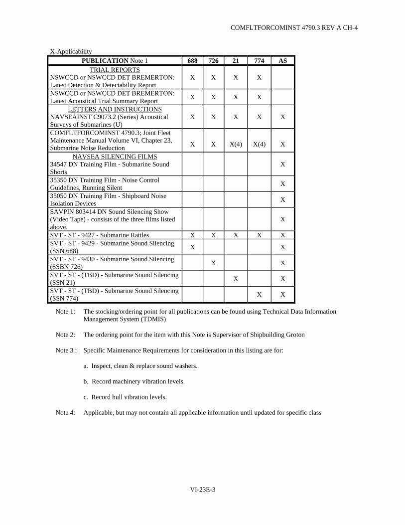
COMFLTFORCOMINST 4790.3 REV A CH-4
VI-23E-3
X-Applicability PUBLICATION Note 1 688 726 21 774 AS
TRIAL REPORTS NSWCCD or NSWCCD DET BREMERTON: Latest Detection & Detectability Report
X X X X
NSWCCD or NSWCCD DET BREMERTON: Latest Acoustical Trial Summary Report X X X X
LETTERS AND INSTRUCTIONS NAVSEAINST C9073.2 (Series) Acoustical Surveys of Submarines (U)
X X X X X
COMFLTFORCOMINST 4790.3; Joint Fleet Maintenance Manual Volume VI, Chapter 23, Submarine Noise Reduction
X
X
X(4)
X(4)
X
NAVSEA SILENCING FILMS 34547 DN Training Film - Submarine Sound Shorts
X
35350 DN Training Film - Noise Control Guidelines, Running Silent X
35050 DN Training Film - Shipboard Noise Isolation Devices X
SAVPIN 803414 DN Sound Silencing Show (Video Tape) - consists of the three films listed above.
X
SVT - ST - 9427 - Submarine Rattles X X X X X SVT - ST - 9429 - Submarine Sound Silencing (SSN 688) X X
SVT - ST - 9430 - Submarine Sound Silencing (SSBN 726) X X
SVT - ST - (TBD) - Submarine Sound Silencing (SSN 21) X X
SVT - ST - (TBD) - Submarine Sound Silencing (SSN 774) X X
Note 1: The stocking/ordering point for all publications can be found using Technical Data Information Management System (TDMIS)
Note 2: The ordering point for the item with this Note is Supervisor of Shipbuilding Groton
Note 3 : Specific Maintenance Requirements for consideration in this listing are for:
a. Inspect, clean & replace sound washers.
b. Record machinery vibration levels.
c. Record hull vibration levels.
Note 4: Applicable, but may not contain all applicable information until updated for specific class

COMFLTFORCOMINST 4790.3 REV A
VI-23E-4
(This Page Intentionally Left Blank)

COMFLTFORCOMINST 4790.3 REV A CH-3
VI-23F-1
APPENDIX F
SAMPLE PROPELLER CHANGEOUT MESSAGE
FM COMSUBRON (AS APPROPRIATE)// TO COMNAVSEASYSCOM WASHINGTON DC//05F3/393/396// INFO COMSUBPAC PEARL HARBOR HI//N42N/N402// COMSUBLANT NORFOLK VA//N42N/N402// USS (SHIP'S NAME AND HULL NO.)// BT UNCLAS //N09245// MSGID/GENADMIN/COMSUBRON (AS APPROPRIATE)// SUBJ/(SUBS) PROPELLER CHANGEOUT// REF/A/DOC/COMFLTFORCOMINST 4790.3// NARR/REF A IS JOINT FLEET MAINTENANCE MANUAL/VOL VI, CH 23 PROVIDES GUIDANCE FOR MONITORING PROPELLER VIBRATION DATA AND PROPELLER CHANGE OUT// RMKS/1. IAW REF A, FOL PROPELLER DATA REPORTED A. SERIAL NO. OF PROPELLER REMOVED B. SERIAL NO. OF PROPELLER INSTALLED C. REASON PROPELLER REPLACED (POOR PERFORMANCE, EXCESSIVE CAVITATION, GOUGED/NICKED, SINGING SCREW, ETC.) 2. REQUEST DISPOSITION INSTRUCTIONS FOR REMOVED PROPELLER// BT
NOTE: ENSURE MESSAGES ARE IN ACCORDANCE WITH NTP-3 FORMAT AND CURRENT PLAIN LANGUAGE ADDRESS DIRECTORY (PLAD) IS UTILIZED.

COMFLTFORCOMINST 4790.3 REV A
VI-23F-2
(This Page Intentionally Left Blank)

COMFLTFORCOMINST 4790.3 REV A CH-4
VI-24-1
VOLUME VI
CHAPTER 24
PERIODIC MAINTENANCE REQUIREMENT PROGRAM
REFERENCES.
(a) NAVSEAINST 4790.8/OPNAVINST 4790.4 - Ships' Maintenance and Material Management (3-M) Manual
(b) NAVSUP Publication 485 - Afloat Supply Procedures (c) NAVSEAINST 4790.19 - Submarine Engineered Operating Cycle (SEOC) Program (d) OPNAVINST 3120.33 - Submarine Extended Operating Cycle (SEOC) Program
LISTING OF APPENDICES.
A SUBMEPP Maintenance and Shipwork Planning (MSWP) Periodic Maintenance Schedule - I Level B SUBMEPP Maintenance and Shipwork Planning (MSWP) Inventory of Periodic Maintenance
Requirements - I Level C SUBMEPP Maintenance and Shipwork Planning (MSWP) Inventory of Periodic Maintenance Requirements - I/D Level D Submarine Periodic Maintenance Requirement (PMR) Management Process E Work Package Supplement - Shipyard Planning and Feedback Report F Work Package - Ship's System Work Description, Part 4.13
24.1 PURPOSE. This chapter defines the functions and responsibilities of the submarine Periodic Maintenance Requirements (PMR) Program, and applies to all submarines. Details of PMR documentation are described in Appendix C of reference (a). Unrestricted Operation (URO) PMR guidance is provided in Chapter 25 of this Volume. Accomplishment of all PMRs is mandatory.
a. The Integrated Maintenance and Modernization Planning (IMMP) Program defines the Maintenance Requirements (MR) to support the Submarine Engineered Operating Cycle (SEOC) for SSN 688 Class nuclear attack submarines' 120 month operating cycle. IMMP is a PMR Program which defines a series of planned periodic tests, inspections and component restorations using Fleet Maintenance Activity (FMA) and industrial activity resources. It is designed to ensure the execution of the Class Maintenance Plans (CMP) as well as safe, reliable and continued submarine operations.
b. The SSBN/SSGN 726 Class and SSN 21 Class CMPs form the basis of a PMR Program which takes the place of the IMMP Program for these classes and defines the planned, corrective and inactive equipment MRs for all levels of accomplishment.
c. PMR work requires detailed planning and long lead time material procurement; therefore, all PMR work has been assigned to the FMA. Ship's Force is not expected to be called upon for PMR work other than the normal responsibilities for approving, inspecting, monitoring, interference removal, delivery of ship to shop items, retesting and accepting work. Ship's Force 991 Work Center (WC) will not be assigned as Lead Work Center (LWC) for "I" level PMR work but may be assigned as an assist WC (991).

COMFLTFORCOMINST 4790.3 REV A CH-6
VI-24-2
24.2 TYPE COMMANDER SCHEDULING SYSTEM. PMR program management has been assigned to Submarine Maintenance Engineering, Planning and Procurement Activity (SUBMEPP) who develops CMPs, Maintenance Requirement Cards (MRC), Maintenance Repair Standards (IMMP MRCs, Technical Repair Standards (TRS) and Maintenance Standards (MS), URO MRCs, and provides PMR configuration and scheduling information to the Submarine Force. Appendices A and B of this chapter show examples of the SUBMEPP PMR Inventories and Schedules provided in support of the Type Commander (TYCOM) PMR Scheduling System. A description of the data elements utilized is provided in each issue of the PMR Inventories and Schedules, which is issued quarterly, or as requested by the Immediate Superior in Command (ISIC). These Inventories and Schedules aid in decisions concerning PMR scheduling and accomplishment during upkeep, provide visibility to problem areas and facilitate auditing and assessing the material condition of a ship.
a. For Non-SSBN/SSGN 726 Class submarines. The quarterly inventories and schedules include a section of "I"-Level PMRs coming due within the next xxx months (number of months as requested by ISIC). Additionally, they provide a combined inventory of "I" and "D"-Level PMRs shown in Appendix C of this chapter. This inventory identifies the availability for which the "D" level PMRs are planned for accomplishment.
b. For SSBN/SSGN 726 Class submarines. This inventory provides all "I" and "D" level requirements, with their due dates.
24.2.1 Periodic Maintenance Requirements Schedule. The PMR Inventories and Schedules, scheduling/configuration files (M79EII), and a Master Job Catalog (MJC) update file are distributed automatically by SUBMEPP to the parent ISIC every three months or as requested. SUBMEPP informs the ISIC of the latest update information. Appendix D of this chapter provides a flow chart of the Submarine PMR Management System.
24.2.2 Scheduling Periodic Maintenance Requirements Work. The PMR scheduling system is based on calendar periods starting with the month following the completion month of a scheduled Chief of Naval Operations (CNO) Availability, or starting with the month following PMR completion for TYCOM availabilities. It is designed to ensure reliable equipment operation during the unit's extended operating cycle. The ISIC, in conjunction with the FMA, will have to smooth the work load by spreading the work over several availabilities by re-planning the scheduled start and completion dates of individual Job Control Numbers (JCN) to ensure they are accomplished prior to the due dates. Once the actual completion dates are reported, subsequent scheduling for the future periods will retain the same relative time frames based on the periodicity of the requirement. The current PMR Inventories and Schedules provided by SUBMEPP shall be maintained by the parent ISIC.
24.2.3 Periodic Maintenance Requirements Calldown/Brokering. PMRs which are due for accomplishment are called down from the local scheduling systems, and brokered to the FMA. JCNs for PMRs consist of ship's Unit Identification Code (five characters) plus WC (Department/Division + �JC�) (four characters) plus Job Sequence Number (four characters, sequentially assigned, numeric).
24.2.4 Calculating Adjusted Last Maintenance Action Date.
a. TYCOM Availabilities. When a PMR is accomplished during a TYCOM availability (Fleet Maintenance Activity (FMA)/Refit, Voyage Repair, Planning), the adjusted Last Maintenance Action (LMA) date will be the first of the month following actual completion.
b. CNO Availabilities. When a PMR is accomplished during a CNO Availability (Selected Restricted Availability, Interim Drydocking, Extended Refit Period, Depot Modernization Period (DMP) or Engineered Refueling Overhaul), the adjusted LMA date will be the first of the month following the scheduled availability's actual completion date. ISICs operating with the on-site PMR Scheduling System must ensure that Availability Dates are accurately maintained so that completed Automated Work Request (AWR) reported data reflects the adjusted LMA and on-site PMR scheduling records calculate the proper next due date.

COMFLTFORCOMINST 4790.3 REV A CH-4
VI-24-3
24.2.5 Calculating Due Dates. Next Due Dates are calculated based on an Adjusted LMA date. Due dates are calculated, for scheduling purposes, by taking the adjusted LMA date month/year (number) and adding the periodicity months (number) to show the month/year due (i.e., an item with an adjusted LMA date of February 2003 (2/03) with a six month periodicity would be due in August 2003 (8/03). The PMR will be accomplished prior to midnight of the last calendar day of the month due.
24.3 PERIODIC MAINTENANCE REQUIREMENTS ACCOMPLISHMENT. PMR requirements are to be accomplished on or before the scheduled due date listed in the SUBMEPP TYCOM PMR Scheduling System Inventories and Schedules. Accomplishment of all PMRs is mandatory. Only by accomplishing PMR maintenance on schedule and in accordance with specifications can safe and reliable operation be ensured and the period between CNO Availabilities be extended.
24.4 MATERIAL SUPPORT FOR FLEET MAINTENANCE ACTIVITY ACCOMPLISHED PERIODIC MAINTENANCE REQUIREMENTS.
24.4.1 Mandatory Parts. Parent FMAs requisition mandatory parts as specified on TRS/MRC/MS documentation for PMRs that are scheduled to be accomplished by that FMA. Material requisitioning is accomplished by the FMA using standard supply procedures. Material is not normally stocked by the FMA and is requisitioned from the nearest stocking point.
24.4.2 Contingency Parts. Contingency parts will not be procured in advance for PMR requirements and will be ordered only upon determination that a contingency part is required based on observed equipment condition. Parent FMAs may have some high usage contingency material available in stock, as identified by the Tender Load List supplements, (not applicable to SSBN/SSGN 726 Class submarines) however, low usage contingency material is stocked only at designated stock points or not at all.
24.4.3 Requisitioning Procedures. SEOC PMR material requisitions shall be submitted through normal channels and shall use a Project Code of "732". Appendix 6 of Reference (b) refers. Contingency material requisitions shall be forwarded by message or telephone, and shall include appropriate "work stoppage" indicator/codes. Forward Contingency Material requisitions directly to, Fleet Industrial Support Center San Diego, Pearl Harbor or Submarine Base New London by message or telephone as appropriate; use the phrase "SEOC Requisition" as the subject line on message requisitions.
24.4.4 Material Support Provided by the Advance Equipment Repair Program. Shore based spares are available for replacing some critical equipment, such as seawater system pumps and motors, during CNO Maintenance Availabilities. The Advanced Equipment Repair Program (AERP) is managed by SUBMEPP under the direction of Naval Sea Systems Command (NAVSEA) and both TYCOMs. AERP equipment scheduled for change-out will be specifically authorized in the ship's Availability Work Package (AWP). Although originally intended to support CNO Availabilities, AERP assets, when available, are used to support Casualty Reports (CASREP). In these instances, a CASREP requisition must be submitted to Naval Inventory Control Point and the shipment of equipment is monitored and tracked until the condition "F" off-load has been returned to the refurbishment activity/vendor identified by Naval Inventory Control Point. The expedited return of an AERP off-load is essential to ensure adequate restoration turnaround time is afforded and to minimize AERP impact.

COMFLTFORCOMINST 4790.3 REV A
VI-24-4
24.4.5 Material Support Provided by the TRIDENT Planned Equipment Replacement Program.
a. TRIDENT Planned Equipment Replacement (TRIPER) is a rotatable pool program for SSBN/SSGN 726 Class submarines. TRIPER equipments are removed from the ship via pre-planned access routes and six-foot diameter Logistics and Escape Trunks, using specifically designed handling attachments and procedures. Removed equipments are replaced with fully interchangeable, tested, ready for issue units which can be rapidly installed and made fully operational within a refit period. Equipment replacement periodicity is determined by maintenance and reliability analysis and engineering judgments intended to preclude equipment failure or significant degradation during operational periods. Removed equipments are refurbished by approved Designated Overhaul Points, tested and returned to ready for issue condition for use on another SSBN/SSGN 726 Class submarine.
b. Safety spares are made available for CASREPs which are considered as unplanned change outs. The TRIPER Program rotatable pool is managed by NAVSEA (PMS 392) and supported by various agencies and activities. Hull, Mechanical, Electrical, Ordnance and Electronics and Command and Control System equipment comprise the TRIPER inventory pool. Items under the cognizance of the Director, Strategic Systems Project Office and the Deputy Commander, NAVSEA Nuclear Power Directorate are excluded.
24.5 CORRECTIVE MAINTENANCE OF EQUIPMENT USING PERIODIC MAINTENANCE REQUIREMENTS. Scheduled restoration of equipment by the FMA or industrial activity is done in accordance with specified Maintenance Standards (IMMP MRC, MS, TRS, Technical Manual, etc.). Whenever corrective maintenance is required on Hull, Mechanical and Electrical equipments, the SUBMEPP combined "I" and "D" Level PMR inventory shall be reviewed by the ISIC and FMA. The ISIC and FMA will determine whether to limit repairs to those described by the ship or to have the Maintenance Standard accomplished. If the corrective maintenance is to include the criteria of the IMMP MRC, MS or TRS, the work request shall be processed in accordance with paragraph 24.7.3 and 24.7.4 of this chapter.
NOTE: IN ORDER TO RECEIVE ACCOMPLISHMENT CREDIT, THE ISIC SHALL ENSURE PROMPT COMPLETION REPORTING OF THE PMR AS DESCRIBED ABOVE. THIS WILL ENSURE THE CORRECT SCHEDULING OF PMRs FOR FUTURE ACCOMPLISHMENT.
NOTE: EQUIPMENT IS CONSIDERED TO HAVE BEEN RESTORED IN ACCORDANCE WITH PMR CRITERIA WHEN THE FOLLOWING SOFTWARE (IMMP MRC, MS, TRS) REQUIREMENTS HAVE BEEN SATISFIED.
(1) THE EQUIPMENT IS RESTORED TO PLAN SPECIFICATIONS.
(2) THE COMPONENTS SATISFACTORILY PASS THE TEST REQUIREMENTS WITHIN THE IMMP MRC/MS/TRS.
(3) ALL MATERIAL LISTED ON THE IMMP MRC/MS/TRS AS MANDATORY HAS BEEN REPLACED.
(4) COMPONENTS AND EQUIPMENT ARE REPLACED WITH SUPPLY SYSTEM, AERP, OR TRIPER ASSETS.

COMFLTFORCOMINST 4790.3 REV A CH-3
VI-24-5
24.6 PERIODIC MAINTENANCE REQUIREMENTS ACCOMPLISHMENT DURING CHIEF OF NAVAL OPERATIONS MAINTENANCE AVAILABILITIES. PMRs to be accomplished by the industrial activity will be included in the SUBMEPP PMR Inventories and Schedules.
a. For SSN 688, SSN 774 and SSN 21 Class submarines:
(1) The AWP prepared by SUBMEPP will reflect all PMRs authorized for shipyard accomplishment during the CNO Availability period at the AWP Ship Work List Item Number (SWLIN) level. The Work Package Supplement (WPS) accompanying the AWP will identify a specific PMR to the applicable AWP SWLIN paragraph. Appendix E of this chapter provides an example of the WPS format. In addition, the DMP and overhaul AWPs will contain an "I"-Level PMR work package cross-index. This cross-index will enable maintenance planners to readily determine the "I"-Level PMRs accomplished incidental to accomplishing higher "D"-Level PMRs or other industrial activity authorized work. The cross-index will also identify "I"-Level PMRs which will become overdue by availability completion plus six months. These "I"-level PMRs should only be listed in the cross index as a reference and not listed in the body of the AWP. Appendix F of this chapter provides an example of the cross-index format. This ISIC will report any "I"-level PMRs from the cross-index that will not be completed prior to the arrival conference for adjudication.
(2) Upon receipt of Issue Two of a DMP or overhaul AWP the ISIC will review the AWP against the schedules and inventories and add those PMRs not covered by the Work Package (WP) coming due within 6 months after availability completion that aren't assigned to shipyard to a Fleet Maintenance Activity Availability prior to the CNO period, to a concurrent availability, or to a future availability with TYCOM concurrence.
(3) For I-Level PMRs assigned to the depot, or I-Level PMRs covered by higher level maintenance assigned to the depot, the ISIC will enter "Assigned to <depot name> by AWP <AWP number>" in the Remarks/Completion block of the PMR Schedule/Inventory, Part 2 Section III and in the local scheduling system.
(4) Completions and MCA data for PMRs accomplished by the industrial activity during CNO Availabilities will be retrieved from Advanced Industrial Management in conjunction with Historical Information Tool Kit and or the Technical Information Management module by SUBMEPP. The WPS, or comparable report, annotated by SUBMEPP to show PMR completions and material condition feedback categories, will be retained by SUBMEPP upon completion of the availability. The PMR Schedule/Inventory and local scheduling system will be updated by SUBMEPP.
b. For SSBN/SSGN 726 Class submarines:
(1) The Engineered Overhaul Work Package prepared by SUBMEPP will reflect all PMRs authorized for accomplishment during the CNO Maintenance Availability period at the SWLIN level. For each SWLIN, the specific PMRs will be identified to the applicable component level. The Engineered Overhaul Work Package preparation process ensures all PMRs due prior to the first availability following the subject availability period are included in the Engineered Overhaul Work Package. The preparation process also includes review and inclusion of appropriate items from the ship's Current Ship's Maintenance Project (CSMP), Ship's Force originated deficiencies, and alterations screened for industrial activity accomplishment.
COMFLTFORCOMINST 4790.3 REV A CH-1
VI-24-6
(2) Completions and Material Condition Assessment data for PMRs accomplished by the industrial activity during CNO Availabilities will be reported by the industrial activity, as a function of the Submarine Maintenance Programs Coordinator as established by reference (c), or equivalent. PMR completions and material condition feedback will be returned to SUBMEPP and the parent squadron upon completion of the availability. The PMR inventories and schedules and local scheduling system will be updated by SUBMEPP.
(3) Completions and MCA data for PMRs accomplished by TRIDENT Refit Facility Kings Bay/NAVIMFAC PACNORWEST during CNO availabilities will be called down and reported using their local scheduling system as identified in paragraph 24.2.3 of this chapter.
24.6.1 Operating Cycle/Interval Extension. An audit plan to assess the material condition of a ship prior to extending their operating cycles/intervals beyond IMMP PMR periodicity due to changing CNO Maintenance Availability dates is addressed in reference (d). Procedures and responsibilities are contained in Volume II, Part I, Chapter 3 of this manual.
24.7 RESPONSIBILITIES.
24.7.1 Type Commander.
a. The TYCOM is responsible for providing an overall scheduling system for the accomplishment of PMRs for assigned ships.
b. Perform periodic audits of ISICs and FMAs to verify full compliance with the provisions of this chapter.
c. Provide guidance to the ISICs, obtaining NAVSEA concurrence as appropriate, when deviations in scheduling or accomplishment of maintenance or repairs is required.
24.7.2 Submarine Maintenance Engineering Planning and Procurement Activity.
a. Receive reports of the completion of PMRs from industrial activities and extract Maintenance and Material Management (3-M) data from NAVSEA Logistics Center, Mechanicsburg PA of all Forces Afloat accomplished PMRs containing "JC" WC.
b. Review completion reports for any change in material condition status and analyze 3-M data for Material Condition Assessment to determine validity of requirements.
c. Update schedules to reflect new LMA and next due dates.
d. Provide updated PMR inventories and schedules to each ISIC and the SUBMEPP representative at TYCOM. Notify the SUBMEPP Representative at TYCOM and each ISIC when products will not be provided as scheduled.
e. Provide quarterly or more frequent (if requested) MJC and PMR update files to each parent ISIC/FMA and TYCOM.
f. Provide updated combined inventories of "I" and "D"-level PMRs on a quarterly basis or as requested by TYCOM/ISIC.

COMFLTFORCOMINST 4790.3 REV A CH-3
VI-24-7
g. (Except SSBN/SSGN 726 Class submarines) Adjust the due dates for any PMRs that are accomplished within ten months of the major CNO availability start date that will come due again during the availability by the number of months of the availability duration.
h. (SSBN/SSGN 726 Class submarines) Provide Refit Work Package electronic files which reflect PMR scheduling to the TRIDENT Refit Facility Kings Bay at the arrival minus 60 day milestone.
i. Prepare and issue AWPs in support of CNO availabilities.
j. Manage AERP/TRIPER programs.
k. Extract PMR completion verification and documentation for SEOC availabilities from Advanced Industrial Management/Technical Information Management and Historical Information Tool kit. Subsequently annotate WPS.
24.7.3 Immediate Superior In Command.
a. Although the responsibility for the accomplishment of PMRs must rest with the ship's Commanding Officer, the ISIC is responsible for scheduling and ensuring completion of all PMR work within the planned periodicity in the CMP. Normally, PMR work is accomplished by the FMA which maintains the unit's CSMP. However, when submarines are assigned availabilities to other than the parent FMA, and that FMA is authorized by the TYCOM to perform PMRs, an agreement between the parent ISIC and the accomplishing FMA will identify the PMRs to be accomplished and any associated logistics.
b. Calldown all PMRs planned for accomplishment into the CSMP by availability dates. For SSBN/SSGN 726 Class submarines this shall be 45 days prior to refit start. For non-726 Class submarines, 60 days prior to Fleet Maintenance Activity Availability. This ISIC Maintenance Document Control Officer (MDCO) must be proficient in these procedures to preclude erroneous or duplicate data from entering the CSMP. If the inventories and schedules contain errors/omissions, report the discrepancies to SUBMEPP.
c. Conduct periodic audits of assigned FMAs to verify full compliance with the provisions of this chapter.
d. Maintain auditable records of PMR accomplishment for each submarine. These records will include the current SUBMEPP Quarterly PMR Inventories and Schedules and the last completed AWR for PMRs completed by the parent FMA, whether or not reflected in the SUBMEPP Quarterly PMR Inventories and Schedules.
e. At Naval Intermediate Maintenance Facility Pacific Northwest, PMR and non-controlled URO inspection scheduling, completion, LMA date establishment and next due date scheduling shall be maintained in the automated database of the Logistic Data System, Planned/Refit Maintenance Management System for SSBN/SSGN 726 Class submarines. This database will contain the complete history for all occurrences (past), dates of completion, frequency of occurrence, next due dates and future scheduling data for each PMR/non-controlled URO inspection. Data will be entered from Objective Quality Evidence from refit close out processes and the selected job management report.
f. Notify the SUBMEPP representative at TYCOM of non-receipt of SUBMEPP Quarterly PMR Inventories and Schedules.

COMFLTFORCOMINST 4790.3 REV A CH-3
VI-24-8
g. Contact SUBMEPP if a PMR has been completed prior to receipt of the inventories and schedules with the date the PMR was completed and JCN under which completed. This JCN must be a "JC" series. Instruct MDCO to do the calldown of PMRs for the applicable ship and commence production of AWRs.
h. Keep the local scheduling system correct and accurate. This should be done by periodically doing a check of the data against the inventories and schedules, and the ship's CSMP.
i. Ensure PMRs which are not accomplished by the SUBMEPP scheduled due date are rescheduled.
j. Ensure that all "I"-level PMRs, which will become due during a scheduled CNO Availability (but not authorized for industrial activity accomplishment), are scheduled for accomplishment by the FMA prior to the end of the availability. The PMRs may be assigned to an FMA concurrent availability with an end date the same as the CNO availability. This will allow for a more appropriate Adjusted LMA Date.
(1) Any "I"-level PMR that is overdue by the availability start date minus 6 months and is identified in the AWP/WPS by SUBMEPP to be accomplished by the industrial activity does not have to be done prior to the availability start. This includes "I"-level PMRs for which the higher tier "D" level PMR is authorized in the AWP/WPs.
(2) Notify the TYCOM representative at the Pre-Arrival Conference of any "I"-level PMRs that will either not be accomplished prior to the availability start date or will become due during the availability.
(3) Any PMR accomplished within ten months prior to start of a scheduled CNO Availability that becomes due again during the availability, will have their scheduled due date adjusted by SUBMEPP by the number of months of the availability duration.
k. Review completed AWRs prior to close-out of the AWRs by Analysis, Records and Reports Section (ARRS) and resolve any discrepancies.
l. Transferring Periodic Maintenance Requirements to other Fleet Maintenance Activities for Accomplishment. When submarine availabilities are accomplished by other than the parent FMA (whether another FMA in the same geographic area or due to deployment), the parent ISIC will take the following action:
(1) Coordinate with the parent FMA to select only those PMRs for accomplishment for which all plans and materials will be available and ready for shipment prior to the availability or deployment of the submarine.
(2) Dispatch a message to the submarine, the recipient squadron and FMA identifying by JCN the PMRs to be accomplished, confirming that plans and materials are being shipped or will be carried by the deploying submarine and that the submarine's total CSMP tape will be either retained by the parent ISIC or transferred to the recipient squadron/Regional Support Group/Regional Maintenance Center as mutually agreed prior to the availability or deployment.
COMFLTFORCOMINST 4790.3 REV A CH-2
VI-24-9
(a) If the CSMP is retained by the parent ISIC, an AWP tape (MM6031) will be provided to the recipient FMA which will maintain it as "I"-level (only AWR completions for the tended submarine accomplished by the FMA will be passed upline). The submarine will forward all 3-M transactions to the parent ISIC.
(b) If the total CSMP is transferred, the recipient FMA will maintain it as level II (the submarine will pass all 3-M transactions to the availability FMA). In addition, the PMR configuration and scheduling file will be transferred to the recipient FMA for URO/PMR/Calibration scheduling purposes.
(c) When the submarine departs from the tending FMA, the CSMP and PMR data files will be updated and returned to the parent ISIC with the letter of transfer. FMAs receiving only the work package tape will create a CSMP transfer out tape and transmittal letter for return to the parent ISIC. The parent ISIC MDCO will reconcile the master CSMP with the returning submarine's 3-M coordinator.
(3) Ensure that the FMA properly packages by JCN all materials, plans, drawings, etc., for dispatch to the receiving FMA or for custodial turnover to the submarine's Engineer Officer for delivery to the deployed FMA.
(4) Ensure MDCO/ARRS takes coordinated action to provide a correct CSMP tape and letter of transmittal. The parent ISIC MDCO must retain copies of transfer-out and in letters for MJC Job Sequence Number control.
NOTE: ONCE A DEFERRAL HAS INITIALLY BEEN ENTERED IN THE COMPUTER AT THE ORIGINATING FMA, IT IS AUTOMATICALLY PASSED TO THE TYCOM MASTER CSMP. SUBSEQUENT TAPE TRANSFERS BETWEEN FMAs WILL NOT CAUSE THE DEFERRAL TO PASS AGAIN TO THE TYCOM PROVIDING THAT MDCO INPUTS THE TRANSFER TAPE (MM6031) TO MAINTENANCE RESOURCE MANAGEMENT SYSTEM (MRMS) PROGRAM 173 NOT 174.
m. Non-Scheduled Repairs of PMR components. The ISIC must add to the ship's CSMP those PMRs to be accomplished in conjunction with a repair action, in lieu of a repair action, or to be credited subsequent to a repair or replacement action. One of the following actions must be taken by the ISIC and MDCO:
(1) When a ship's submitted deferral references a PMR for concurrent accomplishment with the repair action, or if ISIC or FMA planners recommend a PMR, the ISIC must make the decision whether or not to invoke the PMR in conjunction with or in lieu of the requested repair. This will result in two AWRs being created. The planner will have work accomplished under one JCN (EA01) and use the second JCN (EAJC) for administrative completion crediting of the PMR.
(2) If the repair job has resulted in replacement of the PMR component or if the maintenance standard requirements were completely accomplished prior to retrieving the PMR from the MJC, calldown the item from the local scheduling system. The ISIC should instruct FMA to report its completion including the added narrative to identify the originally assigned ship's JCN. Though the materials used cannot be re-identified to the PMR JCN, it is recommended that the total man hours expended also be reported on the PMR AWR or subsequent analysis of required PMR support.

COMFLTFORCOMINST 4790.3 REV A CH-2
VI-24-10
n. Training. The parent ISIC is responsible to provide assigned ship's training in the TYCOM PMR Scheduling System. Such training should include an overview of the SEOC Program, PMR scheduling products. MS Library, and PMR program accomplishment and reporting systems. Emphasis should be placed on the ship's responsibilities to the PMR program as identified in paragraph 24.7.5 of this chapter.
24.7.4 Fleet Maintenance Activity.
a. The FMA is responsible for accomplishing all PMR work as scheduled to the required repair standards.
b. Commence the planning and material procurement function when the PMR is called down by the ISIC from the local scheduling system and brokered to the FMA.
c. Progress the job, ensuring that the LWC coordinates with ship superintendent and all Assist WCs and that production time and current status is reflected in the local scheduling system.
d. Complete the job, report its accomplishment and as found material condition feedback code on the AWR. Any significant findings should also be documented on the AWR. FMA LWCs completing AWRs are to ensure that all participating WCs document their man hours and provide action taken codes, that the Final Action Taken (the most appropriate overall action) and Date Completed have been recorded, and that the acceptance signatures from Ship's Force are obtained before returning the completed AWR to ARRS. The material condition feedback codes are described in Appendix B of reference (a) as part of the action taken code, and are as follows:
NOTE: THE BELOW MATERIAL CONDITION FEEDBACK CODES SHALL DESCRIBE THE "AS FOUND" CONDITION OF THE COMPONENTS AND NOT THE AFTER REFURBISHED CONDITION OF THE COMPONENTS.
(1) Code "A" means the material condition of the component being refurbished could have allowed the PMR to be deferred (extend the periodicity).
(2) Code "B" means the material condition of the component being refurbished justified the scheduled PMR.
(3) Code "C" means the material condition of the component being refurbished should have mandated an earlier completion of the PMR (shorten the periodicity).
NOTE: VARIATIONS TO THESE CODES MAY BE DESCRIBED IN INDIVIDUAL PMR MJC NARRATIVES.
e. ARRS will verify that all participating WCs have documented completion of assigned tasks, Ship's Force acceptance signature is on AWR and the final action taken code (2 character) is entered. Prior to close-out of the AWR, ARRS will pass the AWR to the ISIC for review. For MRMS FMA sites, it is essential that ARRS verify that the MRMS Availability file has the proper scheduled completion date and code to identify that it is a scheduled availability. This is done by showing a "Y" in answer to "Is this a CNO Availability" on the appropriate screen.
f. Adjustments of scheduled start and completion dates of the PMR and factual reporting of status codes.
g. Review corrective action request submitted by Ship's Force via an OPNAV 4790/2K to determine if the corrective action is to include the criteria of IMMP MRC, MS or TRS requirements.
COMFLTFORCOMINST 4790.3 REV A
VI-24-11
h. If the PMR maintenance procedure has a material condition feedback form, fill out the form and submit in accordance with the reporting requirements defined in the procedure.
i. Report to the ISIC when PMRs are met in accordance with paragraph 24.5 of this chapter, due to the expansion of work boundaries.
24.7.5 Submarine Commanding Officer.
a. The ship's Commanding Officer is responsible for the execution of PMR work on the ship.
b. All discovered maintenance deficiencies which affect the equipments and systems covered by the PMR program should be documented to reflect the possible PMR with which the deficiency is associated. This will provide the ISIC with the alternative of simultaneously imposing repairs to the criteria of the specified Maintenance Standard and credit PMR accomplishment.
c. All maintenance deficiencies will reflect in Block 46 (TYCOM SPECIAL PURPOSE), of the OPNAV 4790/2K whether or not quality control and Quality Assurance standards are required.
d. Review Depot Availability Work Packages and provide comments to the TYCOM and SUBMEPP representatives during the work package review.
e. Review the status of PMR maintenance in the SUBMEPP Quarterly PMR inventories and schedules and CSMP reports with parent ISICs prior to upkeep periods in order to assist in planning for accomplishment of required PMR maintenance.
f. All maintenance deficiencies which affect the equipments and systems covered by the PMR program should be documented to reflect the possible PMR with which the deficiency is associated. Review ship's submitted deferrals of corrective maintenance for FMA accomplishment against the PMR inventory and record any applicable Maintenance Standard numbers on the OPNAV 4790/2K. If a component or piece of equipment is listed in the inventory but a Maintenance Standard number is not identified, annotate the OPNAV 4790/2K with "PMR applies".
g. Ensure that the current SUBMEPP Quarterly PMR Inventories and Schedules CD, IMMP MRCs, MRs and TRSs applicable to the ship class are carried on board.
h. Ensure that IMMP MRCs, MSs and TRSs, which provide detailed information and repair guidance are referenced and used during equipment maintenance. Additionally, SUBMEPP PMR inventories provide useful guidance in preparing maintenance documents and planning work (i.e., component identification, Equipment Identification Codes, Allowance Parts Lists, Maintenance Standards, etc.).
i. If Ship's Force accomplishes a repair of a PMR component to an IMMP MRC, MS or TRS, report same to the ISIC Material Officer so that the SUBMEPP Inventory and Schedules may be updated and follow-up reporting action may be initiated.
j. Ensure all completed AWRs for PMRs are signed as accepted by Ship's Force.

COMFLTFORCOMINST 4790.3 REV A
VI-24-12
(This Page Intentionally Left Blank)

PERIODIC MAINTENANCE REQUIREMENTS REPORT DATE: 16 Jan 2003
SCHEDULED MPS REQUIREMENTS I-LEVEL CUTOFF DATE: 01 Oct 2003 SSSU NLON
NSSF NLON 68316
REMARKS/COMPLETION INFO
COMPID LINE ITEM
COMP SERIAL MJC NO
PROCTYPE
MAINTENANCE INSTRUCTION STAT
DD
LAST WRK CTR JSN
MC C
LMA DATE
DUE DATE PER ALT JSN DATE
HSC RIC EIC SYSTEM: 1110 SUPERSTRUCTURE AND FAIRWATER
DAVIT 001256 P10004 N002WKCC6132 MS 1510-081-006 IS WKJC1319 Jan 2001 Jul 2003 30M
1111X1000G X90613CM001 A600000
SAFE TRACKS 001259 P10003 N0000WXCN0012 NONE IS WXJC1320 X May 2001 May 2003 24M
1111X2090B X90613STRAK A000000 SUBMEPP HM&E TEST PROCEDURE 111-5387
SYSTEM: 2070 MAIN STEAM (NON-NUCLEAR)
GMS8A01 001489 P10267 N0002EMCC6141 MS 2530-081-017 IS EMJC1969 A Aug 2002 Aug 2003 12M
2071X1003A X90613PIP01 F704000
SMS8A01 001518 P10266 N0002EMCC6142 MS 2530-081-017 IS EMJC1970 A Aug 2002 Aug 2003 12M
2071X1005A X90613PIP01 F704000
SMS8A02 001519 P10265 N0002EMC06142 MS 2530-081-017 IS EMJC1971 A Aug 2002 Aug 2003 12M
2071X1007 X90613PIP01 F704000
SYSTEM: 2080 FEEDWATER (NON-NUCLEAR)
GCF8A01 001590 P10344 N0002EMCC6145 MS 2550-081-049 IS EMJC1972 A Jul 2002 Jul 2003 12M
2081X1001C X90613PIP01 F704000
SCF8A01 001598 P10343 N0002EMCC6146 MS 2550-081-049 IS EMJC1973 A Jul 2002 Jul 2003 12M
2081X1001E X90613PIP01 F704000
SCF8A02 001599 P10342 N0002EMCC6146 MS 2550-081-049 IS EMJC1974 A Jul 2002 Jul 2003 12M
2081X1001G X90613PIP01 F704000
SCF8A03 001600 P10341 N0002EMCC6146 MS 2550-081-049 IS EMJC1975 A Jul 2002 Jul 2003 12M
2081X1001J X90613PIP01 F704000
SCF8A04 001601 P10340 N0002EMCC6146 MS 2550-081-049 IS EMJC1976 A Jul 2002 Jul 2003 12M
2081X1001L X90613PIP01 F704000
SYSTEM: 2090 MAIN SEAWATER
VI-24A
-1
CO
MFLTFO
RC
OM
INST 4790.3 R
EV A
APPE
ND
IX A
SU
BM
EPP M
AIN
TE
NA
NC
E A
ND
SHIPW
OR
K PL
AN
NIN
G (M
SWP)
PER
IOD
IC M
AIN
TE
NA
NC
E SC
HE
DU
LE
-I LE
VE
L

COMFLTFORCOMINST 4790.3 REV A
VI-24A-2
(This Page Intentionally Left Blank)

PART 2, SECTION 3, PAGE 1 SSN
PERIODIC MAINTENANCE REQUIREMENTS REPORT DATE: 16 Jan 2003
I-LEVEL INVENTORY SORTED BY SYSTEM SSSU NLON
NSSF NLON 68316
REMARKS/COMPLETION INFO
COMPID LINE ITEM
COMP SERIAL MJC NO
PROCTYPE
MAINTENANCEINSTRUCTION DOC STAT
D D
LAST WRKCTR JSN
MC C
LMA DATE
DUE DATE PER ALT JSN DATE
HSC RIC EIC SYSTEM: 1110 SUPERSTRUCTURE AND FAIRWATER
DAVIT 001256 P10004 N0002WKCC6132 MS 1510-081-006 IS WKJC1319 Jan 2001 Jul 2003 30M
1111X1000G X90613CM001 A600000
SAFE TRACKS 001259 P10003 N0000WXCN0012 NONE IS WXJC1320 X May 2001 May 2003 24M
1111X2090B X90613STRAK A000000 SUBMEPP HM&E TEST PROCEDURE 111-5387
SYSTEM: 1310 PRESSURE HULL
CAT PROT DEV 001262 P10031 N0002EACC7703 MS 6330-081-007 IS D EAJC1321 Jan 2001 Jan 2005 48M
1311X1024A X90613CAT01 1106000
PRESERVATION 001279 P10033 N0002WKCC6140 MS 6310-081-015 IS D EAJC1322 Jan 2001 Jan 2005 48M/R
1311X1020A X90613P0001 UF03000 ATCH 5 R=W46IMA accomplish this job during drydock availability (SRA).
PRESERVATION 001279 P10033 N0002WKCC6143 MS 6310-081-015 IS D EAJC1323 Jan 2001 Jan 2005 48M
1311X1020A X90613P0001 UF03000 ATCH 3
SPHERE MHCOV 001282 P10032 N0002WQCC4238 MS 1200-081-001 IS WQJC1968 B Nov 2002 Nov 2005 36M
1311X1002Z X90613CM031 A600000
SYSTEM: 1320 NON-PRESSURE HULL
BATHTUB AREA 006709 P10003 N0002WKCC6141 MS 6310-081-015 IS WKJC1324 Jan 2001 Jan 2005 48M
1321X10B1C X90613CM216 A000000 ATCH 5
CAT PROT DEV 005613 P10001 N0002EACC7704 MS 6330-081-007 IS D EAJC1458 B Jan 2001 Jan 2005 48M
1321X10E1C X90613CAT01 1106000
PRESERVATION 001290 P10043 N0002WKCC6146 MS 6310-081-015 IS D WKJC1327 Jan 2001 Jan 2005 48M
1321X0001B X90613P0001 A000000 ATCH 3
PRESERVATION 001290 P10043 N0002WKCC6145 MS 6310-081-015 IS D WKJC1326 Jan 2001 Jan 2005 48M/R
1321X0001B X90613P0001 A000000 ATCH 5 R=W46IMA accomplish this job during drydock availability (SRA)
SYSTEM: 1780 PLATFORMS, WALKING FLATS AND NON-STRUCTURAL BULKHEADS
VI-24B
-1
CO
MFLTFO
RC
OM
INST 4790.3 R
EV A
APPE
ND
IX B
SU
BM
EPP M
AIN
TE
NA
NC
E A
ND
SHIPW
OR
K PL
AN
NIN
G (M
SWP)
INV
EN
TO
RY
OF PE
RIO
DIC
MA
INT
EN
AN
CE
RE
QU
IRE
ME
NT
S -I LE
VE
L

COMFLTFORCOMINST 4790.3 REV A
VI-24B-2
(This Page Intentionally Left Blank)

TOTAL PERIODIC MAINTENANCE REQUIREMENTS INVENTORY REPORT DATE: 04 Nov 2002
SORTED BY SYSTEM
CSMP LOCATION - SSSU NLON NSSF NLON 68316
COMPID
HSC
LINE ITEM
RIC COMP SERIAL MJC NO
PROC TYPE
MAINTENANCE INSTRUCTION DOC (STATUS)
MCC
LMA DATE
DUE DATE PER ALT
DD
UPK01
SRA11
SRA21
DMP01
SRA12
SRA22
EOH01
SRA13
S R A 2 3
SYSTEM: 0611 AUDITS AND CERTIFICATION
SOE DOCUMENT 005716 P10001 N0008EXCKS036 URO 036 (IS) A Sep 02 o o o o o o o o
0611X5000B X90613CM140 R=T34 Complete at the end of each depot availability but not to exceed 48 months.
VITAL EQUIP 001252 P10001 N0008EXCKS029 URO 029 (IS) X Jan 01 o o o o o o o o
0611X1000A X90613V0001 R=T34 Complete at the end of each depot availability but not to exceed 48 months.
SYSTEM: 111 SUPERSTRUCTURE AND FAIRWATAER
CAT PROT DEV 001254 P10009 N0002EACC7702 MS 6330-081-007 (IS) Z Feb 94 D D D
1111X1050A X90613CAT01
CAT PROT DEV 001254 P10009 N0002WKCC1054 NONE (IS) Z Feb 94 D
1111X1050A X90613CAT01 NSTM CHAPT 633 AND NAVSEA DWG 803-921865 R=003 This maintenance requirement will not be scheduled. The associated
maintenance standard is available for use.
COVERS 001255 P10007 N0002WKCC6241 MS 1510-081-004 (IS) Z Feb 94
1111X1000Q X90613CM004 R=003 This maintenance requirement will not be scheduled. The associated maintenance standard is available for use.
SRA99: Jan 1980 - Feb 1980 PSA01: Jun 1993 - Dec 1993 SRA11: Feb 1997 - Apr 1997 SRA21: Oct 2000 - Dec 2000 DMP01: Jan 2004- Feb 2005
SRA12: Feb 2009 - Apr 2009
Page: 1
VI-24C
-1
CO
MFLTFO
RC
OM
INST 4790.3 R
EV A
APPE
ND
IX C
SU
BM
EPP M
AIN
TE
NA
NC
E A
ND
SHIPW
OR
K PL
AN
NIN
G (M
SWP)
INV
EN
TO
RY
OF PE
RIO
DIC
MA
INT
EN
AN
CE
RE
QU
IRE
ME
NT
S - I/D L
EV
EL
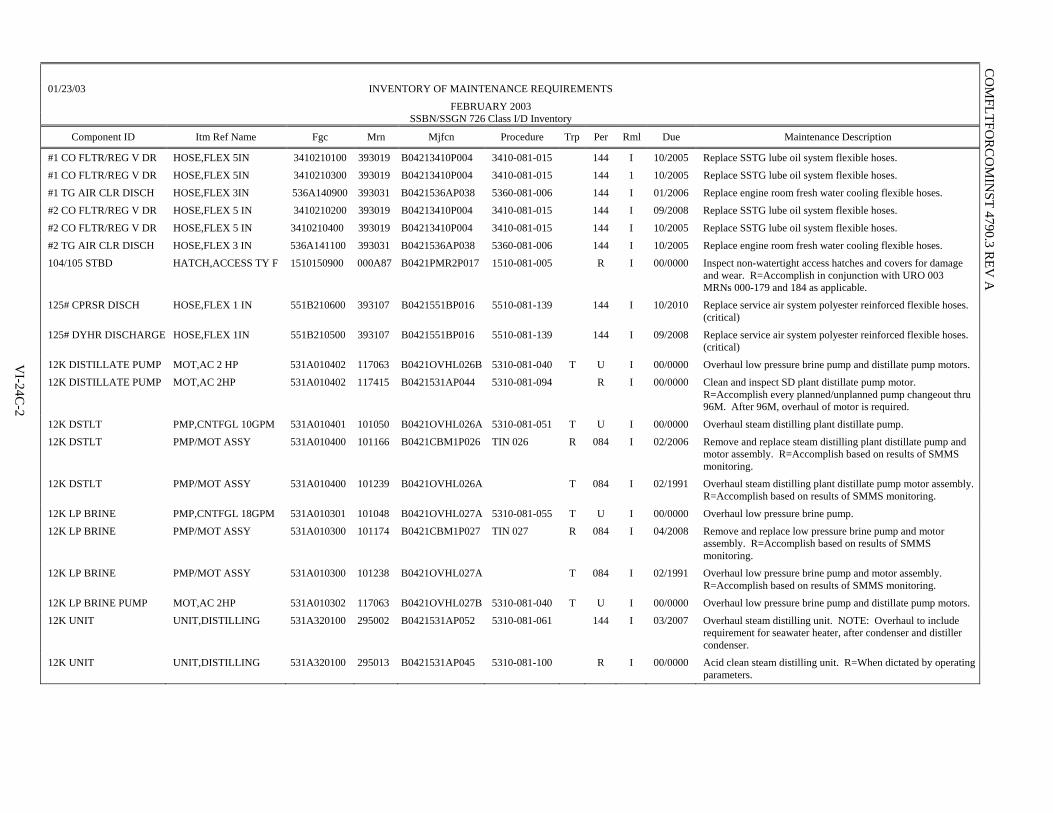
01/23/03 INVENTORY OF MAINTENANCE REQUIREMENTS
FEBRUARY 2003 SSBN/SSGN 726 Class I/D Inventory
Component ID Itm Ref Name Fgc Mrn Mjfcn Procedure Trp Per Rml Due Maintenance Description
#1 CO FLTR/REG V DR HOSE,FLEX 5IN 3410210100 393019 B04213410P004 3410-081-015 144 I 10/2005 Replace SSTG lube oil system flexible hoses.
#1 CO FLTR/REG V DR HOSE,FLEX 5IN 3410210300 393019 B04213410P004 3410-081-015 144 1 10/2005 Replace SSTG lube oil system flexible hoses.
#1 TG AIR CLR DISCH HOSE,FLEX 3IN 536A140900 393031 B0421536AP038 5360-081-006 144 I 01/2006 Replace engine room fresh water cooling flexible hoses.
#2 CO FLTR/REG V DR HOSE,FLEX 5 IN 3410210200 393019 B04213410P004 3410-081-015 144 I 09/2008 Replace SSTG lube oil system flexible hoses.
#2 CO FLTR/REG V DR HOSE,FLEX 5 IN 3410210400 393019 B04213410P004 3410-081-015 144 I 10/2005 Replace SSTG lube oil system flexible hoses.
#2 TG AIR CLR DISCH HOSE,FLEX 3 IN 536A141100 393031 B0421536AP038 5360-081-006 144 I 10/2005 Replace engine room fresh water cooling flexible hoses.
104/105 STBD HATCH,ACCESS TY F 1510150900 000A87 B0421PMR2P017 1510-081-005 R I 00/0000 Inspect non-watertight access hatches and covers for damage and wear. R=Accomplish in conjunction with URO 003 MRNs 000-179 and 184 as applicable.
125# CPRSR DISCH HOSE,FLEX 1 IN 551B210600 393107 B0421551BP016 5510-081-139 144 I 10/2010 Replace service air system polyester reinforced flexible hoses. (critical)
125# DYHR DISCHARGE HOSE,FLEX 1IN 551B210500 393107 B0421551BP016 5510-081-139 144 I 09/2008 Replace service air system polyester reinforced flexible hoses. (critical)
12K DISTILLATE PUMP MOT,AC 2 HP 531A010402 117063 B0421OVHL026B 5310-081-040 T U I 00/0000 Overhaul low pressure brine pump and distillate pump motors.
12K DISTILLATE PUMP MOT,AC 2HP 531A010402 117415 B0421531AP044 5310-081-094 R I 00/0000 Clean and inspect SD plant distillate pump motor. R=Accomplish every planned/unplanned pump changeout thru 96M. After 96M, overhaul of motor is required.
12K DSTLT PMP,CNTFGL 10GPM 531A010401 101050 B0421OVHL026A 5310-081-051 T U I 00/0000 Overhaul steam distilling plant distillate pump.
12K DSTLT PMP/MOT ASSY 531A010400 101166 B0421CBM1P026 TIN 026 R 084 I 02/2006 Remove and replace steam distilling plant distillate pump and motor assembly. R=Accomplish based on results of SMMS monitoring.
12K DSTLT PMP/MOT ASSY 531A010400 101239 B0421OVHL026A T 084 I 02/1991 Overhaul steam distilling plant distillate pump motor assembly. R=Accomplish based on results of SMMS monitoring.
12K LP BRINE PMP,CNTFGL 18GPM 531A010301 101048 B0421OVHL027A 5310-081-055 T U I 00/0000 Overhaul low pressure brine pump.
12K LP BRINE PMP/MOT ASSY 531A010300 101174 B0421CBM1P027 TIN 027 R 084 I 04/2008 Remove and replace low pressure brine pump and motor assembly. R=Accomplish based on results of SMMS monitoring.
12K LP BRINE PMP/MOT ASSY 531A010300 101238 B0421OVHL027A T 084 I 02/1991 Overhaul low pressure brine pump and motor assembly. R=Accomplish based on results of SMMS monitoring.
12K LP BRINE PUMP MOT,AC 2HP 531A010302 117063 B0421OVHL027B 5310-081-040 T U I 00/0000 Overhaul low pressure brine pump and distillate pump motors.
12K UNIT UNIT,DISTILLING 531A320100 295002 B0421531AP052 5310-081-061 144 I 03/2007 Overhaul steam distilling unit. NOTE: Overhaul to include requirement for seawater heater, after condenser and distiller condenser.
12K UNIT UNIT,DISTILLING 531A320100 295013 B0421531AP045 5310-081-100 R I 00/0000 Acid clean steam distilling unit. R=When dictated by operating parameters.
VI-24C
-2
CO
MFLTFO
RC
OM
INST 4790.3 R
EV A

01/23/03 INVENTORY OF MAINTENANCE REQUIREMENTS
FEBRUARY 2003 SSBN/SSGN 726 Class I/D Inventory
Component ID Itm Ref Name Fgc Mrn Mjfcn Procedure Trp Per Rml Due Maintenance Description
12K UNIT COND,DSTLT STEAM 531A320101 295017 B0421531AP013 5310-081-106 R I 00/0000 Conduct internal visual inspection of sea water side of steam distilling unit heat exchangers. R=Perform based on results of performance test.
1B SWBD,DC DISTR 320A010100 122099 R D 00/0000 Inspect DC switchboards. R=Accomplish during any depot availability lasting longer than 6 months. NOTE: Accomplish IAW NAVSEA INST 4730.1.
1S SWITCHBOARD,DISTR 320C020100 122101 R D 00/0000 Inspect AFT AC power distribution switchboards. R=Accomplish during any depot availability lasting longer than 6 months. NOTE: Accomplish IAW NAVSEA INST 4730.1.
1SA SWITCHBOARD,DISTR 320C020200 122100 R D 00/0000 Inspect AFT AC power distribution switchboards. R=Accomplish during any depot availability lasting longer than 6 months. NOTE: Accomplish IAW NAVSEA INST 4730.1.
1SF SWBD,CONT & DISTR 320B010100 122012 3240-081-024 180 I 10/2013 Overhaul 400 HZ S.S. switchboard 1SF and circuit breakers.
1SFA SWITCHBOARD,DISTR 320B010200 122034 B0421320BP001 3240-081-026 180 I 10/2013 Overhaul navigation switchboard (1SFA).
1ST DNSTR (LCTN Q) PIPE,BEND45(LCTN R) 2580051700 000483 B0421PMR2P023 2580-081-003 120 I 01/2004 Conduct ultrasonic inspection of high pressure steam drain system piping. (Monel portion)
1ST DNSTR (LCTN V) PIPE,BEND90(LCTN W) 2580052200 000483 B0421PMR2P023 2580-081-003 120 I 01/2004 Conduct ultrasonic inspection of high pressure steam drain system piping. (Monel portion)
1ST DNSTR CORD F13 45DEG LAT (LCTNCL) 5640349000 000787 B04215640P088 5640-081-056 120 I 10/2003 Inspect trim and aft drain system piping.
1ST DNSTR FLG CONN ELB,90 (LCTN G) 2580050700 000A85 B0421PMR2P027 2580-081-006 036 I 08/2003 Conduct ultrasonic inspection of high pressure steam drain system piping. (Carbon steel portion)
Page: 1
VI-24C
-3
CO
MFLTFO
RC
OM
INST 4790.3 R
EV A

COMFLTFORCOMINST 4790.3 REV A
VI-24C-4
(This Page Intentionally Left Blank)

COMFLTFORCOMINST 4790.3 REV A CH-3
VI-24D-1
APPENDIX D
SUBMARINE PERIODIC MAINTENANCE REQUIREMENT (PMR) MANAGEMENT PROCESS
SUBMEPP
CLASS MAINTENANCE PLAN
CMP PMR STATUS
ASI
NAVSEA TECHNICAL REQUIREMENTS
MRMS PMR
MASTER JOB CATALOG SCHED/CONFIG
PMR CALLDOWN MULTI-TASK AWR COMPLETION
MRMS FMA (NON-TRIDENT)
LDS (TRIDENT)
JOB PLANNING ORDER MATERIAL
JOB EXECUTION
MJC INFOR (MM6031) SCH INFO (M79EII)
See NOTE (1)
MRMS TRC
CSMP MANAGEMENT JOB SCREENING
WORK BROKERING MJC (NON-PMR SITES ONLY)
NAVSEA LOGCEN
3-M DATABASE MAINTAIN HISTORICAL FILE
OF ALL ACCOMPLISHED WORK
Configuration Data Managers/SCLSIS
MJC INFO (MM6001) SCH INFO (M79EH1)
See NOTE (2)
AWR COMP INFO
BROKERED WORK
AWR COMP
INFO & ROV
MTRLS
SHIP’S CSMP
SHIP’S DEFERRALS
(2K, CK)
PMR COMP INFO
CONFIG DATA
ALT COMP INFO
SHIP SHIP
NOTES: (1) For sites with MRMS Micro-PMR installed, process
is displayed with dotted lines. (2) For sites without MRMS Micro-PMR installed,
process is displayed with dashed lines. (1)
PMR CALL
DOWN (2R)
3-M UPLINE
REPORTING

COMFLTFORCOMINST 4790.3 REV A
VI-24D-2
(This Page Intentionally Left Blank)

CO
MFLTFO
RC
OM
INST 4790.3 R
EV A
A
PPEN
DIX
E
WO
RK
PAC
KA
GE
SUPPL
EM
EN
T – SH
IPYA
RD
PLA
NN
ING
A
ND
FEE
DB
AC
K R
EPO
RT
USS (SHIP’S NAME AND HULL NO.) PART 1 – SWLIN 204A01
OWP ISSUE: ISSUE 02 WORK PACKAGE SUPPLEMENT URO CHANGE NO. 074 SHIPYARD PLANNING & FEEDBACK REPORT 09DEC92SWLIN 204A01: SNORKEL WP ALIGN COMP IDENT APL/RIC HSC COMPONENT DESCRIPTION SS DD PMR NUMBER MAINTENANCE STANDARD R/D CONDITION REMARKS DRAIN VALVES WP (CONTINUED) WP WP SECTION 44.0200.2100 MAINT ACTION: RESTORE LVL: SY
APPLIES ONLY TO THOSE VALVES INSPECTED BY URO MRC 008
DE-005 884246532 2041X3K888VI VALVE GLB X AML COMBN 1.50IPS BT SS DD 204-C008-01 TRS 4820-086-113 A B C DE-007 884245532 2041X3K008VI VALVE GLB X AML COMBN 1.50IPS BT SS DD 204-C008-01 TRS 4820-086-113 A B C DE-008 884245532 2041X3K0FVBI VALVE GLB X AML COMBN 1.50IPS BT SS DD 204-C008-01 TRS 4820-086-113 A B C TD-032 884305400 2041X5K1TBVE VALVE B.150IPS 700PSI SWLDG X F SS 204-S017-01 TRS 4820-086-053 A B C TD-033 884305400 2041X5K1VBVE VALVE B.150IPS 700PSI SWLDG X F SS 204-S017-01 TRS 4820-086-053 A B C SNORKEL HEAD VALVE (INCLUDING HEAD VALVE ELECTRODES) WP WP SECTION 44.0300.2100 MAINT ACTION: RESTORE LVL: SY HEAD VALVE 071070010 A 2041X1K01BJ3 MAST SNKL INO 204-0006-81 TRS 0204-086-021 A B C TRANSITION PIECE & ACCESS COVER WP WP SECTION 70.0760.1325 MAINT ACTION: INSPECT: REPAIR/REPLACE LVL: SY TRAN PC/COVER NONE 2041X1010AXY 204-0026-01 TRS 0204-086-038 A B C SWLIN 204A01 PART 1 PAGE - 2
VI-24E-1

COMFLTFORCOMINST 4790.3 REV A
VI-24E-2
(This Page Intentionally Left Blank)

COMFLTFORCOMINST 4790.3 REV A
VI-24F-1
APPENDIX F
WORK PACKAGE – SHIP’S SYSTEM WORK DESCRIPTION PART 4.13
USS (SHIP’S NAME AND HULL NO.)
SHIP SYSTEM WORK DESCRIPTION – ISSUE TWO PART 4.13 FMA SCHEDULE PERIODIC MAINTENANCE REQUIREMENTS
WORK PACKAGE STATUS (AUTHORIZED BY)
CHG
WPS SWAB GCMA
MA DESCRIPTION WPS COMPID PER
LMA VIT
DUE DATE
MJC#
SWLIN SECT ASSN
059 5520 RESTORE JUL85 02EECC5309 552A01 SY
79.0280.2100 ACC IND LEAD 3 79.0280.2100 REMARKS: Restoration of contents indicator is required because lead accumulator maintenance is being replaced by AERP in Section
38.0078.2222.
059 5520 RESTORE JUL85 02EECC5309 SEE
REMARKS
79.0300.2100 ACC IND PORT 3 REMARKS: No fixed periodicity. Accomplish only if accumulator maintenance is performed.
059 5520 RESTORE JUL85 JUL93 02EECC5309 SEE REMARKS
79.0300.2100 ACC IND STBD 3 REMARKS: No fixed periodicity. Accomplish only if accumulator maintenance is performed.
059 5610 URO REQUIREMENT 096 JUL85 JUL93 08EMCKC741 561A01 SY 37.0320.U006 ASW PUMP-1 1 37.0320.U006 REMARKS: -
059 5610 URO REQUIREMENT 096 JUL85 JUL93 08EMCKC741 561A01 SY 37.0320.U006 ASW PUMP-2 1 37.0320.U006 REMARKS: -
059 5610 URO REQUIREMENT 096 JUL85 JUL93 08EMCKC741 561A01 SY 37.0320.U006 ASW PUMP-3 1 37.0320.U006 REMARKS: -
059 5610 URO REQUIREMENT 036 JAN91 JAN94 08EMCKC918 561A01 SY 44.0020.U009 ASW-030 1 44.0020.U009 REMARKS: -
059 5610 INSPECT 012 OCT90 OCT92 07EMCF0004 561A01 FMA 44.4285.1300 ASW-067 1 44.4285.1300 REMARKS: FMA accomplish prior to ship entering the shipyard for DMP. PART 4.13 FMA SCHDULED PERIODIC MAINTENANCE REQUIREMENTS PAGE 8 OF 13

COMFLTFORCOMINST 4790.3 REV A
VI-24F-2
(This Page Intentionally Left Blank)

COMFLTFORCOMINST 4790.3 REV A
VI-25-1
VOLUME VI
CHAPTER 25
UNRESTRICTED OPERATIONS
REFERENCES.
(a) NAVSEA 0924-LP-062-0010 - Submarine Safety (SUBSAFE) Requirements Manual (b) NAVSEAINST 4790.19 - Submarine Engineered Operating Cycle (SEOC) Program (c) OPNAVINST 3120.33 - Submarine Extended Operating Cycle (SEOC) Program (d) COMSUBLANT/COMSUBPAC NOTE C3120 - Submarine Operating Restrictions and Depth
Authorization
LISTING OF APPENDICES.
A URO MRC Automated Work Request for Ship's Force Accomplishment B URO MRC Automated Work Request for FMA Accomplishment C SUBMEPP URO MRC Inventory D SUBMEPP URO MRC Schedule E Request for URO MRC Periodicity Extension Format F Sample Work Package Supplement
25.1 PURPOSE. This chapter provides guidance and definition for the requirements, responsibilities and actions for continued submarine Unrestricted Operation (URO) to design test depth. The URO Maintenance Requirement Card (MRC) program is invoked on all Submarine Safety (SUBSAFE) certified submarines.
25.2 UNRESTRICTED OPERATION MAINTENANCE SCHEDULING, PLANNING AND REPORTING.
25.2.1 Maintenance Requirements for Continued Unrestricted Operation to Design Test Depth. Reference (a) establishes the Maintenance Requirements and identifies the responsibilities and actions required to support continued unrestricted submarine operations to design test depth. In conjunction with reference (a), Naval Sea Systems Command (NAVSEA) has issued individual manuals containing required, periodic SUBSAFE maintenance actions for each ship/class. The URO MRCs in these publications will identify degradation of the material condition of the hull integrity boundary and of those systems affecting ship's recoverability. The requirements set forth in these publications are, in addition, defect monitoring requirements, established on an individual ship basis, for submarines in which known uncorrected deficiencies exist. SUBSAFE certification indicates that a valid recommendation for URO to design test depth can be made. Maintenance of certification is dependent on both the positive control of all re-entries into the SUBSAFE boundaries per Volume V, Part I, Chapter 5 of this manual, the satisfactory and timely completion of applicable URO MRCs as required by reference (a) and any necessary repairs. Accomplishment of the URO MRCs specified with this program identify changes within the SUBSAFE boundary which result from inadvertent error and/or from degradation caused by the service environment.
25.2.2 Scheduling and Reporting. In order for the Type Commanders (TYCOM) to carry out their responsibilities in the material certification of submarines and to aid in decisions concerning operational restrictions, an auditable system of scheduling the performance and reporting of URO MRCs has been developed. This system provides visibility to problem areas, facilitates verification and provides a permanent record of URO MRC accomplishment in the ship's Maintenance and Material Management (3-M) machinery history maintained at the NAVSEA Logistics Center.

COMFLTFORCOMINST 4790.3 REV A CH-6
VI-25-2
25.2.2.1 Non-SSBN/SSGN 726 Class Ships. Submarine Maintenance Engineering, Planning and Procurement Activity (SUBMEPP) provided Periodic Maintenance Requirement (PMR) inventories and schedules and the 3-M Master Job Catalog (MJC) Programs are used for scheduling and reporting. The scheduled URO MRC requirements added to the Current Ship's Maintenance Project (CSMP) from the local scheduling system and the Automated Work Requests (AWR) produced will contain unique Job Control Numbers (JCN) consisting of ship's Unit Identification Code (five characters) plus WC (Department/Division + JC) (four characters) plus Job Sequence Number (four characters). Appendices A and B of this chapter show a URO AWR for Ship's Force and Fleet Maintenance Activity (FMA) accomplishment respectively. Appendices C and D of this chapter show examples of the SUBMEPP URO MRC inventories and schedules respectively.
25.2.2.2 SSBN/SSGN 726 Class Ships. SUBMEPP provided URO MRC inventories, schedules, Master Job File, as well as the Refit Work Planning System, are used for scheduling and reporting. The scheduled URO MRC requirements added to the CSMP from the local scheduling system and the AWRs produced will contain unique JCNs consisting of ship's Unit Identification Code (five characters) plus WC (Department/Division + JC) (four characters) plus Job Sequence Number (four characters). Appendices A and B of this chapter show a URO MRC AWR for Ship's Force and FMA accomplishment respectively. Appendices C and D of this chapter show examples of the SUBMEPP URO inventories and schedules respectively.
25.2.2.3 Submarine Maintenance Engineering Planning and Procurement Activity Inventories and Schedules. The SUBMEPP inventories and schedules are provided quarterly. The SUBMEPP schedules reflect all URO MRC requirements coming due within the next 12 months. A description of the data elements used in the inventories and schedules is provided with each issue.
25.2.3 Baseline and Due Dates. The baseline date for determining URO MRC due dates is the Last Maintenance Action (LMA) date. LMA dates for new requirements will be based on the Change Issue Date of the URO MRC invoking the new requirement unless otherwise directed from NAVSEA. Due dates are calculated based on LMA dates in accordance with paragraph 25.2.3.2 of this chapter. It is recognized that upkeep and docking schedules for ships which are well into the operating cycle may not permit full compliance with the scheduled due dates. In such cases, a Departure From Specification (DFS) for the URO MRC will be addressed on a case-by-case basis as specified in Volume V, Part I, Chapter 8 of this manual. LMA dates and URO MRC due dates are determined as follows:
25.2.3.1 Last Maintenance Action Date. For new construction ships, all URO MRCs have an initial LMA date established at delivery from new construction or from Post Shakedown Availability to start the operating cycle in accordance with the applicable URO MRC manual. During the operating period between commissioning and start of Post Shakedown Availability and during the operating cycle following Post Shakedown Availability, an adjusted LMA, as discussed below, is used for URO MRCs. Calculate the adjusted LMA date as follows:
a. If the PMR is accomplished during a period other than a scheduled Chief of Naval Operations (CNO) Availability (e.g., voyage repair periods, at sea, port calls, FMA Availability, refit, upkeep, Technical Availability, etc.) the adjusted LMA date will be the first of the month following the completion date listed on the PMR data form.
b. If the PMR is accomplished during a scheduled CNO Availability (e.g., Selected Restricted Availability, Extended Refit Period, Depot Modernization Period, Engineered Refueling Overhaul, Interim Dry Docking and other CNO Availabilities), the adjusted LMA date will be the first of the month following the scheduled availability's actual completion date.
NOTE: IMMEDIATE SUPERIORS IN COMMAND (ISIC) OPERATING WITH THE ON-SITE PMR SCHEDULING SYSTEM MUST ENSURE THAT AVAILABILITY DATES ARE ACCURATELY MAINTAINED SO THAT COMPLETED AWR UPLINE REPORTED DATA REFLECTS THE ADJUSTED LMA DATE AND ON-SITE PMR SCHEDULING RECORDS CALCULATE THE PROPER NEXT DUE DATE.

COMFLTFORCOMINST 4790.3 REV A CH-2
VI-25-3
25.2.3.2 Calculating Due Dates. Next due dates are calculated based on an adjusted LMA date. Due dates are calculated, for scheduling purposes, by taking the adjusted LMA date month (number) and adding the periodicity months (number) to show the month due (i.e., an item with an adjusted LMA date of February 2003 (2/03) with a six month periodicity would be due in August 2003 (8/03)). The PMR will be accomplished prior to midnight of the last calendar day of the month due.
25.2.4 Periodicity Extensions. When determining the due date for URO MRC inspections 001, 004, and 005 for an individual submarine, inactive time (defined as the number of days pierside plus the number of days in dry-dock) may be excluded from the time elapsed since the last inspection. When determining the due date for URO MRC 002, 003 (certain portions) and 035, only the time in dry-dock may be excluded from the elapsed time. The ship's deck log, engineering log or the ship's coolant discharge log will be used to determine the number of days pierside or the number of days in drydock. Ship's Force will perform this review and provide the applicable dry-dock and/or inactive time via official correspondence to the ISIC. Extensions of periodicity from the next due date identified in the SUBMEPP PMR inventory for these URO MRCs can be authorized by the TYCOM without further NAVSEA approval. However, they are not automatic and such requests shall be submitted by letter, in the format of Appendix E of this chapter, to SUBMEPP via the TYCOM. Upon receipt of TYCOM authorization, SUBMEPP will reflect the periodicity extension and the revised due date in the next issue of the ship's PMR inventories and schedules.
25.2.5 Scheduling, Planning and Reporting Unrestricted Operation Accomplishment at Ship/Fleet Maintenance Activity Level.
25.2.5.1 Scheduling. The TYCOM PMR Scheduling System Inventories and Schedules is distributed by SUBMEPP to the appropriate ISIC every quarter. Except at NAVIMFAC PACNORWEST, along with this PMR CD, electronic update files are provided to keep the local scheduling systems up to date with the Class Maintenance Plan (CMP). As a minimum, ISICs will schedule applicable URO MRCs 45 days (SSBN/SSGN 726 Class submarines) or 60 days (non-SSBN/SSGN 726 Class submarines), as applicable prior to Refit Fleet Maintenance Activity Availability. Those URO MRC AWRs requiring work packages or other planning are forwarded to the FMA Planning Section.
25.2.5.2 Planning. FMA Planners will requisition materials, obtain plans and drawings, prepare Formal Work Procedures and/or Controlled Work Packages and coordinate the scheduling with the Ship Superintendent, Production Officer and ISIC Material Office. Then the job will be turned over to the production WC for accomplishment. For Ship's Force accomplishment of URO MRCs, the ISIC will provide an AWR to the ship. The Maintenance Document Control Office (MDCO) will adjust the scheduled start and completion date within the local scheduling system.
25.2.5.3 Reporting to the Maintenance and Material Management (3-M) System. Each URO MRC AWR contains specific instructions on reporting the completed action and on use of a special feedback code to identify the material condition or that a change in inspection frequency is required. In order to ensure URO MRCs are correctly accomplished and reported to SUBMEPP, the following actions are to be taken prior to closeout of the AWR by Analysis, Records and Reports Section (ARRS):
a. Submarines completing URO MRC AWRs are to fill-in the AWR with action taken codes and suffix of A, B, or C for material condition assessment, if applicable. Ship will sign for completion, ISIC will sign for acceptance. Include a narrative statement, if required, and return the original AWR to the ISIC. The ISIC will review the AWR and forward to ARRS to close out the computer AWR and update SUBMEPP inventories and schedules. Note that because of the Auto-Close features, the completed AWR will automatically close the deferral in the CSMP.

COMFLTFORCOMINST 4790.3 REV A CH-2
VI-25-4
b. FMA Lead Work Centers (LWC) completing URO MRC AWRs must ensure that all assist WCs have completed their work. The LWC then completes the AWR by filling in action taken codes, signing for completion and obtains acceptance signature from Ship's Force. The AWR is then returned to ARRS. The ARRS will verify that all participating WCs have documented completion of their assigned tasks and then pass the AWR to the ISIC for review and updating of SUBMEPP inventories and schedules prior to close-out of the AWR by ARRS.
25.2.6 Unrestricted Operation Maintenance Requirement Card Accomplishment During Chief of Naval Operations Maintenance Availabilities.
a. The Availability Work Package (AWP) prepared by SUBMEPP will reflect all URO MRCs authorized for accomplishment during the availability at the AWP Ship Work List Item Number (SWLIN) level. The Work Package Supplement (WPS), accompanying the AWP, will identify a specific URO MRC requirement to the applicable AWP SWLIN paragraph. Appendix F of this chapter provides an example of the WPS format.
b. For URO MRCs assigned to the depot, the ISIC will enter "Assigned to <depot name> by AWP <AWP number>" in the Remarks/Completion block of the URO MRC Schedule/Inventory and in the local scheduling system.
c. URO MRC completions by an industrial activity during CNO Availabilities will be, for non-SSBN/SSGN 726 Class submarines, retrieved from AIM (shipyard information system) by SUBMEPP. For SSBN/SSGN 726 Class submarines, completions will be reported by the industrial activity as a function of the Submarine Maintenance Program Coordinator as established by reference (b). The WPS, annotated by the Submarine Maintenance Program Coordinator to show URO PMR completions and material condition feedback categories, will be returned to SUBMEPP and forwarded to parent ISIC upon completion of the availability. The ISIC will verify that all URO MRCs assigned to the shipyard were reported and subsequently updated by SUBMEPP.
25.2.7 Unrestricted Operation Maintenance Requirement Card Completion Reporting.
a. Within 30 days after the completion of an availability the activity accomplishing the URO MRC is required to provide a report of accomplishment to SUBMEPP and the ship's ISIC as well as other technical codes as designated in the URO MRC. Specific information to be included in the report is identified in the applicable URO MRC. The accomplishing activity shall retain a legible copy of the most current inspection report until the ship is disposed of or stricken from the Naval Register.
b. Prior to Fast Cruise for CNO Availabilities, the industrial activity is required to provide the ship and ISIC with a letter of certification (including final inspection categories A, B, or C when applicable) that certifies all required inspections have been satisfactorily completed. For items which must be accomplished in dry-dock, the industrial activity is required to provide such certification prior to undocking.
c. Upon identifying a material condition that would result in a reduced inspection periodicity if not restored to Category A condition during the availability in which the condition was found, a special report is required to be submitted by the accomplishing activity in accordance with the applicable URO MRC and, if applicable, the AWP. This special report shall be provided immediately to NAVSEA (SEA 07), TYCOM, ISIC, and SUBMEPP indicating:
(1) Applicable MRC.
(2) Equipment component identification.

COMFLTFORCOMINST 4790.3 REV A CH-1
VI-25-5
(3) Inspection category.
(4) The reduced or deferred periodicity of each equipment component that should be inspected at less than its normal periodicity. This reduced periodicity report requirement is in addition to the completion reporting requirements of paragraphs 25.2.7.a and b above.
25.2.8 Operating Cycle/Interval Extensions. An Audit Plan to assess the material condition of ships prior to extending their operating cycle/intervals beyond URO MRC periodicities due to changing CNO Availability dates or operational schedules, is addressed in reference (c). Additional guidance and responsibilities are contained in Volume II, Part I, Chapter 3 of this manual.
25.3 RESPONSIBILITIES.
25.3.1 Type Commander.
a. Perform periodic audits of the ISICs and FMAs to verify full compliance with the provisions of reference (a), Volume V, Part I, Chapter 9 of this manual and this chapter.
b. Provide guidance to the ISICs, obtaining NAVSEA concurrence as necessary, when deviations in the scheduling or accomplishment of maintenance or repairs are required by a DFS request and resolution per Volume V, Part I, Chapter 8 or this manual.
25.3.2 Submarine Maintenance Engineering, Planning and Procurement Activity.
a. Receive reports of completion of URO MRCs from all completing activities.
b. Review completion reports for compliance with the scheduled periodicity requirements and any change in the status category.
c. Establish an LMA date per paragraph 25.2.3.1 of this chapter.
d. Revise the periodicity and next due dates in ship URO MRC inventories and schedules to reflect any NAVSEA approved periodicity change, TYCOM approved periodicity extensions for URO MRCs 001 through 005, and 035 as allowed for in paragraph 25.2.4 of this chapter and NAVSEA approval of Major DFSs for extending URO MRC requirements.
e. Notify the TYCOM via the on-site SUBMEPP Representative of any URO MRC beyond periodicity for TYCOM resolution.
f. Provide updated:
(1) URO MRC inventories and schedules CD in accordance with the distribution.
(2) For SSBN/SSGN 726 Class ships, provide Refit Work Package electronic files which reflect URO MRC scheduling to the Trident Refit Facility at the arrival minus 60 day milestone.
(3) For those ISICs using Micro-PMR, provide scheduling and configuration files to process in the local scheduling system and FMA database quarterly.
(4) Provide MJC update files which reflect URO MRC changes to the ISIC/TYCOM at least quarterly or upon request.

COMFLTFORCOMINST 4790.3 REV A CH-2
VI-25-6
g. Provide, as enclosures to the quarterly inventories and schedules forwarding letter, a list of URO MRCs that appear overdue in the schedules and a list of URO MRCs that have been reported complete by the fleet but Objective Quality Evidence has not been received by SUBMEPP.
h. Receive and review URO MRC Objective Quality Evidence for technical accuracy and maintain URO MRC completion history.
25.3.3 Immediate Superior In Command.
a. Maintain auditable records of URO MRC accomplishment for each submarine. These records will include the current SUBMEPP Quarterly inventories and schedules, completed AWRs for URO MRCs completed, data report forms/reports submitted as a result of last accomplishment and all approved DFS.
b. Conduct periodic audits of assigned FMAs and units to verify full compliance with the provisions of reference (a), Volume V, Part I, Chapter 9 of this manual and this chapter.
c. In addition to the records of audits, maintain a file, by ship, of the current URO MRC inventories and schedules as provided by SUBMEPP. The schedules (Appendix D of this chapter) for each ship shall be annotated with the Job Sequence Number (JSN), the new adjusted LMA date and the next due dates for the completions and any periodicity extensions authorized.
d. Although the responsibility for the accomplishment of URO MRCs must rest with the ship's Commanding Officer, the nature and scope of the URO MRCs dictate that the ISIC coordinate the accomplishment of URO MRCs in accordance with the SUBMEPP provided PMR inventories and schedules. Accordingly, the ISIC shall assist in the preparation of, and approve each submarine's URO MRC performance schedule. In addition, the ISIC shall:
(1) Unless previously notified by SUBMEPP of delays, notify the SUBMEPP Representative at TYCOM of the non-receipt of schedules and reports.
(2) Upon receipt of the quarterly report from SUBMEPP, perform a line-by-line verification of each ship's new URO MRC Inventory and Schedule against the URO MRC Inventory and Schedule report held by the ISIC. At a minimum, this verification will include a review of each URO MRC LMA, Due Date, and Periodicity to ensure any recent completion data or rescheduling data that has been submitted to SUBMEPP has been accurately incorporated into the new Inventory and Schedule. PMRs accomplished during the month preceding the quarterly report may or may not be reflected in the issue received. Similarly, upon receipt of URO MRC changes, audit the individual URO MRC procedural and schedule information against each ship's PMR Inventory and Schedule held by the ISIC to verify that the component/equipment and periodicity has not changed and that provided changes do not impact current schedules. Resolve identified deficiencies through the SUBMEPP Representative at TYCOM.
(3) Review the enclosures to the PMR procedural inventories and the schedule forwarding letter and advise SUBMEPP of the completion dates and JSNs for URO MRCs listed. Forward copies of completed Data Report Forms for these and any other URO MRC completions identified by SUBMEPP as having missing Data Report Forms.
(4) Following receipt of the URO MRC Inventory and Schedule quarterly report from SUBMEPP the ISIC shall provide the following material to each applicable ship:
(a) A copy of each PMR Inventory and Schedule CD.

COMFLTFORCOMINST 4790.3 REV A CH-5
VI-25-7
(b) A copy of each organizational level URO AWR assigned to Ship's Force and scheduled for accomplishment during the next refit/availability.
(c) A copy of the individual ship's URO MRC Inventory and Schedule that has been customized by the ISIC to include information more current than the quarterly report provided by SUBMEPP and JSN scheduling information entered by the ISIC URO MRC coordinator.
e. Control input of the SUBMEPP scheduling file (M79EII) to the local scheduling system and resultant calldowns to the CSMP, which will produce the JCN and products for job completion.
f. Ensure that all URO MRC requirements with the appropriate screening (Ship's Force, FMA) are in the CSMP for subsequent development by SUBMEPP of forthcoming CNO Availability AWPs.
g. In the event that deviations from required periodicities or full requirements of the URO MRCs are required, request approval from the TYCOM by submitting a DFS request in accordance with Volume V, Part I, Chapter 8 of this manual. Such DFS requests will be a Major DFS for URO MRC program deviations. DFS requests are also to be submitted when repairs arising from the URO MRC inspections cannot be completely accomplished. Periodicity extension requests for URO MRC 001, 002, 003, 004, 005 and 035 shall be submitted in accordance with paragraph 25.2.4 of this chapter.
h. Establish procedures to affect routing of completed AWRs from the FMA ARRS or from the submarine (LWC 991) through the ISIC for all URO MRC transactions. The ISIC should ensure proper documentation has been completed as described in the special reporting procedures of the AWR. This must include the material condition feedback code as part of the final action, if required. A rejection series code (6A-6I) should not be accepted unless the FMA Repair Officer cannot accomplish the URO MRC at that site. Delays in accomplishment are to be reported as status changes so that the job remains in the production system and is visible as a "to-be-done" requirement. If the URO MRC requirement cannot be accomplished at the site, the ISIC must ensure update (re-screening) of the CSMP concurrently with DFS notification, if necessary. Each processed AWR is to be validated with the PMR Special Report described in the Maintenance Resource Management System section of Volume II, Part I, Chapter 2 of this manual and, if satisfactory, passed to the Automated Data Processing Center for computer input. Upon receipt of the report of maintenance action accomplishment from an assigned unit or the FMA, review the report for completeness, consistency, acceptability of conditions and material trends. Where unsatisfactory conditions are found, direct repairs. Where repairs cannot be made, submit a DFS in accordance with Volume V, Part I, Chapter 8 of this manual. Ensure SUBMEPP inventories and schedules are updated in accordance with paragraph 25.3.3(c) of this chapter. Clear URO MRC major DFS upon TYCOM or NAVSEA approval and upon receipt of the SUBMEPP Quarterly PMR inventories and schedules, and ensure they accurately reflect the new due date of the URO MRC as stated in the approved DFS.
i. Upon identifying a material condition that would result in a reduced inspection periodicity, ensure the accomplishing activity immediately reports the condition found via faxed letter to NAVSEA (SEA 07), the TYCOM and SUBMEPP in accordance with paragraph 25.2.7.c of this chapter.
j. Monitor the timely submission of URO MRC data report forms and the report of accomplishment for URO MRCs completed by the FMA and Ship's Force to ensure required documentation is submitted in accordance with paragraph 25.2.7 of this chapter. Ensure data report forms are submitted to report component replacement/repair/operation out of specification. Review all Ship's Force accomplished URO MRC data for compliance with the requirements of the URO MRC Program prior to submittal to SUBMEPP.
k. Prior to a ship's underway period, review the ship's certification continuity report, if submitted, to ensure the ISIC and ship's records (including the CSMP) accurately reflect URO MRC status.

COMFLTFORCOMINST 4790.3 REV A CH-2
VI-25-8
l. The Parent ISIC of deploying ships will:
(1) Ensure that any URO MRC due for accomplishment by the ship during its deployment period is identified in the CSMP transfer file and that the ship possesses the AWRs and URO MRC data report forms (if applicable) for reporting job completion.
(2) Provide a message to the applicable deployed FMA/Squadron identifying any URO MRC expected to be accomplished by the deployed FMA and the status of required materials for each submarine deploying to cover the period of the deployment.
m. Deployed Squadrons will review the URO MRC status of deployed submarines upon in-chop. Perform the function of the Parent ISIC in ensuring all URO MRCs are accomplished and reported within the required periodicity while the submarine is deployed.
NOTE: THIS IN NO WAY RELIEVES THE PARENT ISIC OF THE RESPONSIBILITY TO ENSURE THAT THE REQUIRED URO MRCs ARE ACCOMPLISHED WITHIN THE SPECIFIED PERIODICITIES.
n. Prior to the start of a CNO availability, ISIC URO coordinators will:
(1) Assign JCNs to URO MRC items assigned to Forces Afloat in the AWP and screen them to an availability prior to the start of the CNO availability or to the concurrent availability in accordance with the directions in the AWP. Forces Afloat items are accomplished by Ship's Force or Performance Monitoring Team. Care must be taken to appropriately assign URO MRC items to the correct accomplishing activity.
(2) ISIC URO coordinators will not assign JCNs to URO MRC items assigned to the shipyard in the AWP. In the URO MRC inventories and schedules, in the remarks/completion information area, enter "assigned to (name of shipyard) by AWP (name and number of availability)". The shipyard is responsible for performing, auditing and reporting all URO MRC items assigned by the AWP.
(3) URO MRCs assigned to Forces Afloat by the AWP for accomplishment prior to the start of the depot period, but for some reason were not completed, will be reassigned to a concurrent availability or formally reassigned to the shipyard via a supplemental work request.
o. During a CNO availability, URO MRCs assigned to the shipyard by the AWP which are not accomplished during the depot period will be placed on the guarantee list or reassigned to a fleet availability by the TYCOM following the depot period provided the URO MRC does not exceed its due date. The ISIC will be notified of this reassignment by formal correspondence which will include justification and reason why the scheduled and planned requirements were not met.
p. Prior to CNO availability completion, ISICs will audit URO MRCs assigned to Forces Afloat by the AWP and ensure all have been satisfactorily completed and documented within the required periodicity. The ISIC audit will also verify that all URO MRC items coming due within six months of availability completion are complete or assigned to a follow-on fleet availability. Under no circumstances are URO MRC due dates to be exceeded. ISIC Quality Assurance Officers will not be responsible for auditing URO MRCs assigned to the depot in the AWP.
q. Following CNO availability completion, the ISIC URO coordinator will ensure that all URO MRCs assigned to the shipyard were reported and subsequently updated by SUBMEPP. ISICs will only upline the closed JCNs for URO MRCs completed by Forces Afloat.
COMFLTFORCOMINST 4790.3 REV A CH-2
VI-25-9
25.3.4 Submarine Commanding Officer.
a. Ensure all URO MRCs are accomplished within the required periodicity as specified by reference (a), Volume V, Part I, Chapter 5 of this manual and this chapter.
b. For visual inspections in between URO MRC 003 inspections, see Volume V, Part I, Chapter 5, paragraph 5.8.3.d. of this manual for a description of requirements to inspect submarine hull structure in between the periodic URO MRC 003 inspections.
c. Maintain auditable records of the accomplishment of URO MRCs to permit verification of compliance with reference (a), Volume V, Part I, Chapter 10 of this manual and this chapter. These records shall consist of:
(1) A copy of the TYCOM and NAVSEA SUBSAFE Material Certification message from new construction, Depot Modernization Period or overhaul until the ship's current status is reflected in reference (d). When the ship's current status is reflected in reference (d) the messages may be destroyed and the current notice will be retained.
(2) Copies of letter of completion for all URO MRC work accomplishment by other activities.
(3) Copies of letters of completion and inspection reports for work accomplished by Ship's Force. The required report forms are located at the end of the individual URO MRCs. A copy of each completed report shall be submitted to the ISIC for review a minimum of 24 hours prior to underway.
(4) One copy each of the current Quarterly URO MRC inventories and schedules as printed from the CD provided by SUBMEPP via the ISIC. Annotate the URO MRC Inventory Report when accepting completed work requests from the FMA or Ship's Force (LWC 991). It is the ship's responsibility for ensuring that the reports reflect the actual configuration, especially with regards to the equipment identity and the Allowance Parts List.
(5) Copy of outstanding URO MRC AWRs to be accomplished by Ship's Force.
(6) One copy of each approved DFS from the requirements of reference (a), Volume V, Part I, Chapter 8 of this manual and this chapter. This authority is based on the following factors and considerations:
(a) The completion of all URO MRCs, or portions thereof, will be reported on AWRs provided by the ISIC in accordance with paragraph 25.2.5.3 of this chapter. Particular care must be exercised to ensure that existing conditions found at the time of inspection and/or need for repair or replacement of components is recorded in detail as prescribed by the URO MRC.
(b) Deviations from URO MRC requirements or periodicities may result in operational restrictions being placed on a unit. In order to determine whether such restrictions are necessary, the TYCOM must be fully apprised of the number and extent of deviations involved.

COMFLTFORCOMINST 4790.3 REV A CH-2
VI-25-10
(c) Allow no deviations in the scheduling or accomplishment of required URO MRC maintenance actions unless formal NAVSEA approval of such deviations has been granted by an approved DFS or as allowed in paragraph 25.2.4 of this chapter. All system disassembles, repairs, and reassemblies must be conducted in accordance with Volume V of this manual, including requests for a DFS, if necessary.
(d) Except in an emergency, refrain from submerged operations if all required URO MRC maintenance actions have not been completed within the specified periodicities unless formal authorization to deviate from these requirements has been granted by NAVSEA. NAVSEA recommendation and TYCOM authority to conduct URO MRC to design test depth are contingent upon the satisfactory completion of these maintenance actions.

COMFLTFORCOMINST 4790.3 REV A CH-2
VI-25A-1
IER622 *** AUTOMATED WORK REQUEST *** 03 DEC 92 (92338) OPNAV 4790/2R/Q DEFERRAL AVAIL: P106 (01JAN93-31MAR93) **********************SECTION I. IDENTIFICATION************************** 1. UIC: 05152 2. OWC: EAJC 3. JSN: 3171 4. APL: 520175132 AILSN: 5520 A. NAME: FINBACK 5. EQUIP: ACCUMULATOR-HYD 13. IDENT: ACCUM MNA FC B. HULL: SSN 670 14. EIC: TV01 16. LOCATION: 15. SAFE: NO 6. WHEN DISC: 0 7. EQ STAT: 0 8. CAUSE: 0 9. DEF REA: 6 10. : 11. : 12. : 18. CAT SHIP ALT # RN PC F$ 19. PI 20. INSURV # 21. SUF 22. MDG 23. SAF 24. P/F 18A. MJC: N0008EAEACKS026 ***********************SECTION II. DEFERRAL ACTION*********************** 26. DEF DATE: 23 NOV 92 27. OMA MHR REM: AUTO 28. DEALN DATE: 31 JAN 93 9. DEF REA: 6 *********************SECTION III COMPLETED ACTION************************ 29. A/T: 30. OMA MHR EXP: 0000 31. DATE COMP: SELECT EQUIPMENT 32. AMT: 33. TI: 0 34. METER READING: **********************SECTION IV. REMARKS/DESCRIPTION******************** 35. REMARKS: CHECK HYD SYS FLOOD CONTROL ACCUMULATORS IAW URO MRC 026 XXX LAST COMPLETED 90001 NEXT DUE DATE 93001 MDCO PASS TO SHIP'S FORCE. S/F COMPLY WITH URO 026, COMPLETE BLOCKS 102-104 AND RETURN THIS AWR TO MDCO FOR ADP PROCESS. CONSULT THE TYCOM PMR SCHEDULING SYSTEM FOR SHIP OR COMPONENT SPECIFIC INFO SUCH AS "DD", SPECIAL REQ-MTS, PERIODICITY OR LEVEL OF ACCOMPLISHMENT. 37. CSMP SUMMARY: ACCOMPLISH URO MRC 026 38. 1ST CON: 39. 2ND CON: 41. PRI: 2 42. T/A: 2 43. INT PRI: 44. IUC SCRN: 2 45. TYC SCRN: 46. SPECIAL PURPOSE: A- B- C- D- E- F- G- H- I- J- K- L- E. CO F. TYCOM *********************SECTION V. SUPPLEMENTARY INFORMATION**************** 48. REP TM: MRC URO MRC 026 ON BRD: NO 49. PREARV: 50. PLNRMK: MRC URO MRC 026 *** COMPLETE INSPECTION FINDINGS AND FORWARD IAW URO 026 *** 50A. IUCRMK: 50B. TYCRMK: 50C. IMARMK: ***************************SECTION VI. PLANNING************************** 51. PMR: URO MRC 026 52. PER: 000 53. ISS: 7512 54. SPEC DATA: HP JC008638 QLV: 55. QA S/S: YES NUC L/I: 1NUC WPR: SP CLN: SPECID: RADCON: L/I: NON DT: SAE DIV: SP TST: NOISE: OTHCON: 56. SR K E: 0091 SP INT: YES D/D REQ: PREOVH: AFTOVH: DEPART: K.E.: UROS DUE K.E. DATE: NORMALLY DONE BY: *********SECTION VII. REPAIR ACTIVITY PLANNING/SCHEDULING ACTION********* 57. L/A RWC 58. SKD STRT 59. SKD COMP 60. PMHR 61. K/O 62. TASK L 991 01 JAN 93 30 JAN 93 008 001 93. RAUIC: 05851 L Y SPEAR 94. WK RTN #: 99. JOB ORDER NO: 95. EST M/D: 96. EST M/D $: 97. EST MATL $: 98. EST TOT $: 100. LEAD P&E: 101. DATE OF ESTIMATE: 23 NOV 92 102. FAT: 103. ACT MHRS EXP: 104. DATE COMP: G. COMPLETED: H. ACCEPTED BY: ******************************SECTION VIII. SUPPLY DATA****************** PRI DOC NUM NIIN/PART# DESC QTY STATUS
APPENDIX A
URO MRC AUTOMATED WORK REQUEST FOR SHIP'S FORCE ACCOMPLISHMENT

COMFLTFORCOMINST 4790.3 REV A
VI-25A-2
(This Page Intentionally Left Blank)

COMFLTFORCOMINST 4790.3 REV A CH-2
VI-25B-1
IER622 *** AUTOMATED WORK REQUEST *** 03 DEC 92 (92338) OPNAV 4790/2R/Q DEFERRAL AVAIL: A015* (04JAN93-07FEB93) **********************SECTION I. IDENTIFICATION************************** 1. UIC: 05152 2. OWC: EMJC 3. JSN: 3170 4. APL: 884305120 AILSN: 2090 A. NAME: FINBACK 5. EQUIP: VALVE B 3.00 IPS 13. IDENT: MSW-108 B. HULL: SSN 670 14. EIC: FB08 16. LOCATION: 15. SAFE: NO 6. WHEN DISC: 0 7. EQ STAT: 0 8. CAUSE: 0 9. DEF REA: 6 10. : 11. : 12. : 18. CAT SHIP ALT # RN PC F$ 19. PI 20. INSURV # 21. SUF 22. MDG 23. SAF 24. P/F 18A. MJC: N0008EMCKC918 ***********************SECTION II. DEFERRAL ACTION*********************** 26. DEF DATE: 23 NOV 92 27. OMA MHR REM: AUTO 28. DEADLN DATE: 9. DEF REA: 6 *********************SECTION III COMPLETED ACTION************************ 29. A/T: 30. OMA MHR EXP: 0000 31. DATE COMP: SELECT EQUIPMENT 32. AMT: 33. TI: 0 34. METER READING: **********************SECTION IV. REMARKS/DESCRIPTION******************** 35. REMARKS: INSPECT BALL VALVE STEM IAW URO MRC 009 LAST COMPLETED 90001 NEXT DUE DATE 93001 CONSULT THE TYCOM PMR SCHEDULING SYSTEM FOR SHIP OR COMPONENT SPECIFIC INFO SUCH AS "DD", SPECIAL REQ-MTS, PERIODICTY, OR LEVEL OF ACCOMPLISHMENT 37. CSMP SUMMARY: ACCOMPLISH URO MRC 009 38. 1ST CON: LPO 39. 2ND CON: 41. PRI: 2 42. T/A: 2 43. INT PRI: 44. IUC SCRN: 2 45. TYC SCRN: 46. SPECIAL PURPOSE: A- B- C- D- E- F- G- H- I- J- K- L- E. CO F. TYCOM *********************SECTION V. SUPPLEMENTARY INFORMATION**************** 48. REP TM: MRC URO MRC 009 ON BRD: NO 49. PREARV: *** COMP INSP FINDINGS AND FORWARD IAW URO/LID MRC 009 *** 50. PLNRMK: THIS DEPOT JOB IS ASSIGNED TO IMA BY TYCOM *** REPORT INSPECTION FINDINGS AND FORWARD IAW URO 009 *** 50A. IUCRMK: 50B. TYCRMK: 50C. IMARMK: ***************************SECTION VI. PLANNING************************** 51. PMR: URO MRC 009 52. PER: 000 53. ISS: 7302 54. SPEC DATA: HP1JC006547 QLV: 55. QA S/S: YES NUC L/I: NUC WPR: SP CLN: SPECID: RADCON: L/I: NON DT: SAE DIV: SP TST: NOISE: OTHCON: 56. SR K E: 0091 SP INT: YES D/D REQ: PREOVH: AFTOVH: DEPART: K.E.: UROS DUE K.E. DATE: NORMALLY DONE BY: 1 DEP **********SECTION VII. REPAIR ACTIVITY PLANNING/SCHEDULING ACTION******** 57. L/A RWC 58. SKD STRT 59. SKD COMP 60. PMHR 61. K/O 62. TASK L 10C 04 JAN 93 18 JAN 93 0002 001 PACKAGE A 38A 04 JAN 93 18 JAN 93 0027 001 INSP A 93A 04 JAN 93 18 JAN 93 0008 001 INSP A 93B 04 JAN 93 18 JAN 93 0002 001 QA 93. RAUIC: 05851 L Y SPEAR 94. WK RTN #: 99. JOB ORDER NO: 95. EST M/D: 96. EST M/D $: 97. EST MATL $: 98. EST TOT $: 100. LEAD P&E: 101. DATE OF ESTIMATE: 23 NOV 92 102. FAT: 103. ACT MHRS EXP: 104. DATE COMP: G. COMPLETED: H. ACCEPTED BY: ******************************SECTION VIII. SUPPLY DATA****************** PRI DOC NUM NIIN/PART# DESC QTY STATUS
APPENDIX B
URO MRC AUTOMATED WORK REQUEST FOR FMA ACCOMPLISHMENT

COMFLTFORCOMINST 4790.3 REV A
VI-25B-2
(This Page Intentionally Left Blank)

PART 2: SECTION 1 SSN
PERIODIC MAINTENANCE REQUIREMENTS REPORT DATE: 10 APRIL 2003 URO CHANGE NO: 119 Mar 2003 INVENTORY URO/HIP SORTED BY SYSTEM
SSSU NLON NSSF NLON 68316
REMARKS/COMPLETION INFO
COMPID LINE ITEM
COMP SERIAL
R
MJC NO
M
PROCTYPE
MAINTENANCEINSTRUCTION DOC STAT
M DL D
LAST WRK CTR JSN
C C
LMA DATE
DUE DATE PER ALT JSN DATE
HSC RIC EIC SYSTEM: 0611 AUDITS AND CERTIFICATION
SOE DOCUMENT 005716 P10001 N0008EXCKS036 URO 036 IS O EXJC1967A Sep 2002 Sep 2006 48M/R 0611X5000B X90613CM140 UE0000 R=T34 Complete at the end of each depot availability but not to exceed 48 months. VITAL EQUIP 001252 P10001 N0008EXCKS029 URO 029 IS O X Jan 2001 Jan 2005 48M/R 0611X1000A X90613V0001 IC03000 R=T34 Complete at the end of each depot availability but not to exceed 48 months.
SYSTEM: 1110 SUPERSTRUCTURE AND FAIRWATER
FAIRWATER 001257 P1005 N0007WKCKC920 URO 003 IS D D Feb 1994 Feb 2004 120M 1111X1000J X90613V0001 A600000
SYSTEM: 1310 PRESSURE HULL
ASW1/2 007333 P10035 N0007WKCKC920 URO 003 IS D D X Jan 2001 Jan 2007 72M 1311XAB11C X90613CM027 1108000 ASW29/30 INS 007334 P10034 N0007WKCKC920 URO 003 IS D D X Jan 2001 Jan 2007 72M 1311XAB12C X90613CM027 1108000 ASW80/81 007335 P10033 N0007WKCKC920 URO 003 IS D D X Jan 2001 Jan 2007 72M 1311XAA73C X90613CM027 1108000 CD 35 INSR 007336 P10031 N0007WKCKC920 URO 003 IS D D X Jan 2001 Jan 2007 72M 1311XA781C X90613CM027 1108000 CD 4 INSR 007337 P10032 N0007WKCKC920 URO 003 IS D D X Jan 2001 Jan 2007 72M 1311XA711C X90613CM027 1108000 CD 1/2 INSR 007338 P10029 N0007WKCKC920 URO 003 IS D D X Jan 2001 Jan 2007 72M 1311X8980C X90613CM027 1108000
VI-25C
-1
CO
MFLTFO
RC
OM
INST 4790.3 R
EV A
APPE
ND
IX C
SU
BM
EPP UR
O M
RC
INV
ENTO
RY

COMFLTFORCOMINST 4790.3 REV A
VI-25C-2
(This Page Intentionally Left Blank)

PERIODIC MAINTENANCE REQUIREMENTS REPORT DATE: 10 APRIL 2003 URO CHANGE NO: 119 Mar 2003 INVENTORY URO/HIP SORTED BY SYSTEM CUTOFF DATE: 01 OCT 2003
SSSU NLON NSSF NLON 68316
REMARKS/COMPLETION INFO
COMPID LINE ITEM
COMP SERIAL
R
MJC NO
M
PROCTYPE
MAINTENANCEINSTRUCTION DOC STAT
M DL D
LAST WRK CTR JSN
C C
LMA DATE
DUE DATE PER ALT JSN DATE
HSC RIC EIC SYSTEM: 5182 STEERING AND DIVING (STRUCTURAL, MECHANICAL, AND ELECTRICAL CONTROL)
LKG STDIV DR 003361 P12140 N0008EACKS016 URO 016 IS O/ EAJC1962A Sep 2002 Sep 2003 9M/R 12M
5182X1811B X90613CM100 TL06000 R=260 Complete at the end of each depot availability but not to exceed 9 months from the last accomplishment
SYSTEM: 5400 NORMAL AND EMERGENCY BALLAST TANK BLOW (TITLE FOR 688 CLASS IS EMBT BLOW)
RISE BLOW 003813 P12548 N0008EACKS022 URO 022 IS O EAJC1963 X Jan 2002 Jan 2003 12M 5401X0101A X90613BL001 TF01000 STATBLOW LOC 003814 P12546 N0008EACKS022 URO 022 IS O EAJC1963 X Jan 2002 Jan 2003 12M
5401X0105A X90613BL001 TF01000 R=260 Complete at the end of each depot availability but not to exceed 12 months from the last accomplishment.
STATBLOW REM 003815 P12547 N0008EACKS022 URO 022 IS O EAJC1965 X Jan 2001 Jan 2007 72M
1311XAB11C X90613CM027 1108000 R=260 Complete at the end of each depot availability but not to exceed 12 months from the last accomplishment.
SYSTEM: 5520 MAIN AND VITAL HYDRAULIC (TITLE FOR 688 CLASS IS SHIP'S SERVICE HYDRAULICS)
HULL CLOSURE 004440 P13205 N0008EACKS025 URO 025 IS O EAJC2188 X Jan 2002 Jun 2003 72M
1311XAB12C X90613CM027 1108000 R=261 Complete at the end of each depot availability but not to exceed 7 months from the last accomplishment.
VI-25D
-1
CO
MFLTFO
RC
OM
INST 4790.3 R
EV A
APPE
ND
IX D
SU
BM
EPP UR
O M
RC
SCH
EDU
LE

COMFLTFORCOMINST 4790.3 REV A
VI-25D-2
(This Page Intentionally Left Blank)

COMFLTFORCOMINST 4790.3 REV A CH-3
VI-25E-1
APPENDIX E
REQUEST FOR URO MRC PERIODICITY EXTENSION FORMAT
4790 Ser
From: Commander, Submarine Squadron To: Commanding Officer, Submarine Maintenance Engineering, Planning and Procurement (SUBMEPP)
Activity Via: Commander Submarine Force, (Atlantic/Pacific Fleet)
Subj: REQUEST FOR EXTENSION OF PERIODICITY FOR URO MRC(S) ON USS (Ship's Name and Hull No.)
Ref: (a) Applicable URO MRC (b) COMFLTFORCOMINST 4790.3; Joint Fleet Maintenance Manual, Volume VI, Chapter 25 (c) COMSUB(LANT/PAC) ltr 4790 Ser of (previous letter granting extension of periodicity)
1. In accordance with references (a) and (b), request extension of URO MRC periodicity for USS (Ship's Name and Hull No.) to coincide with Selected Restricted Availability/Overhaul/Depot Modernization Period/Interim Dry-Docking as follows:
URO MRC
Equipment Guide List
Item Number or Component
Ident
LMA Date
Current Due Date
Inactive Time Extension Required
Required Next Due
Date
Pierside
Days *
Drydock
Days
001 All June 82 Apr 91 200 days 100 days 7 months Nov 91 002 All June 82 Aug 91 N/A 100 days 3 months Nov 91 003 4.b June 82 Aug 91 N/A 100 days 3 months Nov 91 004 INT Welds June 84 Apr 91 200 days 100 days 7 months Nov 91 005 INT Welds June 84 Apr 91 200 days 100 days 7 months Nov 91 035 All June 84 Aug 91 N/A 100 days 3 months Nov 91
* Credit for pierside days is awarded for days the ship is tied to the pier, no credit is given if the ship is underway anytime during the day.
2. Inactive time identified for the URO MRCs listed in paragraph 1 above is the actual allowable time accrued to date since URO MRC was last accomplished/previous extension of periodicity was granted by reference (c).
Copy to: COMNAVSEASYSCOM (SEA 07) (080) Commanding Officer, USS (Ship's Name and Hull No.)

COMFLTFORCOMINST 4790.3 REV A
VI-25E-2
(This Page Intentionally Left Blank)

COMFLTFORCOMINST 4790.3 REV A
VI-25F-1
APPENDIX F
SAMPLE WORK PACKAGE SUPPLEMENT

COMFLTFORCOMINST 4790.3 REV A
VI-25F-2
(This Page Intentionally Left Blank)

COMFLTFORCOMINST 4790.3 REV A
VOLUME VI
CHAPTER 26
OPERATING DEPTH POLICY
REFERENCES.
(a) NAVSEA S9086-DA-STM-000 - NSTM Chapter 100 (Hull Structures) (b) COMNAVSUBFOR OPORD 2000 (c) NAVSEAINST C9094.2 - Submarine Valve Operation Requirements for Builders and Post Overhaul
Sea Trial Test Dives
26.1 PURPOSE. To provide Type Commander (TYCOM) policy with respect to the maximum allowable operating depths during trials, evolutions to be performed at the various depths, and the prescribed maximum water depth applicable in each case.
26.1.1 Background. Some deep diving submarines are limited to depths less than designed test depth pending accomplishment of certain hull and system modifications prescribed by Naval Sea Systems Command (NAVSEA) as necessary to permit certification to design test depth. As these modifications are accomplished during the availability, the integrity of the ships will be certified and they will be permitted to operate down to their design test depth either periodically or without restriction.
a. The sequence of events leading to authorization for operations at the maximum operating depth during post industrial availability or new construction trials for SUBSAFE ships is as follows:
(1) Upon completion of the authorized industrial facility work, NAVSEA reviews the scope, degree and manner of accomplishment and recommends to the TYCOM that the submarine be authorized to test hull strength and integrity at an appropriate maximum keel depth during trials. This depth may be the designed test depth or a lesser depth.
(2) Based on this recommendation the TYCOM will normally authorize operation to the NAVSEA recommended keel depth by message to the ship, information to the applicable Immediate Superior In Command (ISIC), Supervising Authority/Industrial Activity (as applicable), NAVSEA, Fleet Commander and Chief of Naval Operations.
b. In every instance where the maximum authorized operating depth is exceeded, a report shall be made in accordance with reference (a). In addition to those addressees listed in reference (a), an information copy shall be provided to the applicable TYCOM and ISIC.
26.2 INITIAL TIGHTNESS DIVE. The initial tightness dive following an industrial availability or new construction will be conducted in accordance with carefully planned procedures.
VI-26-1

COMFLTFORCOMINST 4790.3 REV A CH-5
a. The initial tightness dive will be an especially deliberate, planned, step-by-step evolution using conservative angles and moderate speed, or slower, in accordance with the approved Sea Trial Agenda. Caution is required not only because the material condition of the ship is untested at any depth following major industrial facility work, but also because of the crew's lack of recent submerged operational experience. Reference (b) applies.
b. The maximum water depth allowable during the initial tightness dive will be as specified by reference (b). The approved Sea Trial Agenda and reference (c) describe those events to be conducted during the initial tightness dive and provide the requirements of the initial tightness dive. The approved Sea Trial Agenda also describes those events immediately following the initial tightness dive. The maximum operating keel depth will be 200 feet.
26.3 DEEP DIVE/CONTROLLED DIVE. After demonstrating satisfactory hull strength and integrity during the initial tightness dive, the requirement exists to test the hull at submerged depths down to the maximum operating depth. The first approach to these depths subsequent to the repair of major hull or sea connected systems work will be made in accordance with the following paragraphs.
26.3.1 Depth Limitations. The Deep Dive/Controlled Dive shall be made to the maximum operating depth in water specifically designated for such trials and under specific water depth restrictions in accordance with reference (b), and as promulgated in the appropriate TYCOM/ISIC Operation Order.
26.3.2 Conduct of Deep Dives/Controlled Dives. Deep Dive/Controlled Dive depth changes should be conducted in no greater than 200 foot increments when above one-half the maximum operating depth and in no greater than 100 foot increments when below one-half the maximum operating keel depth. Moderate speeds (within the limits of the submerged operating envelope) and angles must be used. Trim must be continually adjusted to provide neutral buoyancy.
26.3.3 Deep Submergence Bill. The Deep Submergence Bill shall be in effect with systems in the maximum secure condition and all unnecessary sea connected systems isolated. The main ballast tank blow system shall be lined up with all banks within 200 psi of full pressure. Cycling of the rudder and planes through full travel should be limited to the maximum authorized operating depth minus 100 feet at a moderate speed.
26.3.4 Valve Operation. Seawater system valve operations during post industrial availability and new construction Sea Trials will be in accordance with reference (c).
VI-26-2

COMFLTFORCOMINST 4790.3 REV A CH-3
VOLUME VI
CHAPTER 27
SCHEDULED PRESERVATION UPKEEP COORDINATED EFFORT
REFERENCES.
(a) NAVSEA S9510-AB-ATM-010 - Nuclear Powered Submarine Atmosphere Control Manual, Volume 1 (b) NAVSEA S9510-AB-ATM-020/(C) - Nuclear Powered Submarine Atmosphere Control Manual,
Volume 2 (c) NAVSEA S9086-VD-STM-010/020/030 - NSTM Chapter 631 Volumes 1, 2 and 3 (Preservation of
Ships In-Service) (d) NAVSEA MS 6310-081-015 - Submarine Preservation (e) OPNAVINST 5100.19 - Navy Occupational Safety and Health (NAVOSH) Program Manual for Forces
Afloat (f) SOBT Video SVT-GT-9336 - Submarine Preservation
LISTING OF APPENDICES.
A SPRUCE Key Event Schedule B SPRUCE Report Form C SPRUCE Check List
27.1 PURPOSE. The Scheduled Preservation Upkeep Coordinated Effort (SPRUCE) program has been established to ensure internal preservation is maintained at the highest possible level throughout the life of the ship. As a result of increased intervals between submarine Chief of Naval Operations Maintenance Availabilities, effective SPRUCE upkeeps are of prime importance. SSBN/SSGN 726 Class submarines are exempt from SPRUCE upkeeps. Under special circumstances, requests for SPRUCE upkeeps on SSBN/SSGN 726 Class submarines will be considered and shall be conducted in accordance with this chapter.
27.2 SCHEDULING.
a. Immediate Superiors In Command (ISIC) shall schedule a three week SPRUCE below decks every 48 months. The SPRUCE shall contain a 14 day production period which will not be scheduled to commence sooner than two days following an underway period. Per references (a) and (b), underway periods shall not be scheduled within five days of completion of the production period. In summary:
Ship returns to port 0 days Preparation period 2 days Production period 14 days Gas off period 5 days
TOTAL 21 days
VI-27-1
COMFLTFORCOMINST 4790.3 REV A CH-3
b. ISICs shall schedule a one week SPRUCE for the sail interior every 24 months. Sail SPRUCEs can be coincidental with routine availabilities.
c. A SPRUCE shall not be scheduled during other Ship's Force or Fleet Maintenance Activity (FMA) upkeeps with the exception of the five day gas off period which may be scheduled during a follow-on upkeep. A SPRUCE should not be scheduled within the six month period prior to a Chief of Naval Operations Maintenance Availability. A SPRUCE should not be scheduled within six months after a Depot Modernization Period (DMP), Engineered Refueling Overhaul, or Engineered Overhaul because of the industrial activity's preservation programs.
d. The initial base date for scheduling is the official completion date of the ship's last DMP, Engineered Refueling Overhaul, or Engineered Overhaul.
27.3 RESPONSIBILITIES.
27.3.1 Type Commander.
a. Administer the SPRUCE program.
b. Maintain a file of SPRUCE lessons learned and distribute to ensure that all commands concerned have the latest information available.
27.3.2 Immediate Superior In Command.
a. Schedule and coordinate SPRUCE upkeeps per the Key Event Schedule of Appendix A of this chapter.
b. Coordinate submarine crew training.
c. Monitor the effectiveness of the SPRUCE program.
d. Chair a SPRUCE debrief with Ship's Force and FMA to review the effectiveness of the SPRUCE and generate lessons learned. The results of this meeting will be included in the Ship's SPRUCE completion letter.
27.3.3 Fleet Maintenance Activity.
a. Provide training, tools, consumables, services, and required support personnel.
b. Provide technical guidance consisting of around the clock coverage by a coatings inspector trained to the requirements of reference (c) and reference (d), as applicable. The coatings inspector will perform all inspections necessary to ensure proper preservation is accomplished and will complete Appendix B of this chapter for each area preserved. All completed forms from Appendix B of this chapter will be submitted to the ship for inclusion into their SPRUCE completion letter.
27.3.4 Submarine Commanding Officer.
a. Ensure preservation is performed by Ship's Force using the procedures contained in references (c) and (d), as applicable, through (f).
VI-27-2

COMFLTFORCOMINST 4790.3 REV A
b. Ensure Ship's Force personnel are relieved of all requirements other than those necessary to maintain the safety and security of the ship during the SPRUCE.
c. Designate an officer or Chief Petty Officer (CPO) to serve as the SPRUCE Manager.
d. Ensure the ship is divided into preservation zones. Each zone will have an officer or CPO in charge during the SPRUCE. Conduct a thorough preservation inspection of each zone, assisted by an FMA coatings inspector (if possible) at least 90 days prior to the start of the SPRUCE to determine and prioritize the preservation to be accomplished. Appendix C of this chapter shall be reviewed as part of this inspection.
e. Submit completion letter to the Type Commander (TYCOM) via the chain of command. This letter shall report results of the SPRUCE, problems encountered, lessons learned, and shall contain completed forms from Appendix C of this chapter.
VI-27-3

COMFLTFORCOMINST 4790.3 REV A
(This Page Intentionally Left Blank)
VI-27-4

COMFLTFORCOMINST 4790.3 REV A CH-3
APPENDIX A
SPRUCE KEY EVENT SCHEDULE
1. The ISIC is responsible for ensuring adherence to the following schedule to assure the effective planning of a SPRUCE upkeep. The ISIC will act for the ship to complete items should an underway period preclude timely accomplishment. The ISIC will alert the ship's Commanding Officer and the TYCOM in the event that any of the following time frames will be exceeded.
DAY ACTION
-90 ISIC ensure SPRUCE is on the ship's operating schedule. Schedule the SPRUCE with the FMA. Notify TYCOM (N3/N4) of planned SPRUCE dates.
-90 Commanding Officer assign SPRUCE manager and zone supervisors. Ship/FMA conduct preservation inspection.
-90 Commanding Officer submit OPNAV 4790 2K/2L requests for powder coating services. Ships shall make effective use of these services to enhance the effectiveness of preservation for components located in hostile environments.
-90 ISIC/Commanding Officer arrange for respiratory protection physicals, initial respiratory training for the ship's Hospital Corpsman, and respirator fit-checks for crew by FMA Occupational Safety and Health personnel. The crew shall be trained in respirator use by the ship's Hospital Corpsman.
-90 ISIC/Commanding Officer make plans for crew technical training.
-30 Commanding Officer establish painting "Tiger Team" and ensure adequate number of personnel are assigned to accomplish the upkeep commensurate with ship checks. The Tiger Team should include personnel not necessary to maintain the safety and security of the ship. Promulgate a SPRUCE watchbill.
-30 Commanding Officer review and conduct training with assigned personnel and Work Center Supervisors. Establish a General Military Training program incorporating requirements of references (c) and (d), as applicable, (e), and (f) and the ship's paint schedule. Provide the SPRUCE Plan of Action and Milestone to the ISIC for review.
2. Conduct a 21 Day SPRUCE as follows:
DAY ACTION
-2 Tiger team make preparations for SPRUCE.
1-2 Ship's Force preparations for SPRUCE.
3-16 Ship's Force execute SPRUCE preservation work.
VI-27A-1

COMFLTFORCOMINST 4790.3 REV A
DAY ACTION
16 ISIC, Commanding Officer, FMA conduct SPRUCE debrief. Commanding Officer submit SPRUCE completion letter.
21 Ship's first available underway date.
VI-27A-2

COMFLTFORCOMINST 4790.3 REV A
VI-27B-1

COMFLTFORCOMINST 4790.3 REV A
(This Page Intentionally Left Blank)
VI-27B-2
COMFLTFORCOMINST 4790.3 REV A CH-3
APPENDIX C
SPRUCE CHECK LIST
1. Has a Navy Occupational Safety and Health/Environmental Protection Agency representative been onboard to ensure compliance with occupational health and environmental regulations?
2. Is the ship aware of all required training (Hazardous Material, Respirator, Technical)?
3. Assess level of effort required to accomplish SPRUCE. Assess type/quantity of tools and paint required. FMA informed for planning purposes.
4. FMA coatings inspector review SPRUCE report form (Appendix A of this chapter) of this chapter requirements with the ship. Discuss why, how, and when these inspections are required.
5. Does the ship have a copy of Submarine On Board Training Video SVT-GT-9336 (Submarine Preservation)?
6. Does the ship hold the most recent revisions to NSTM Chapter 631 (Preservation of Ships In-Service) and reference (d)?
7. Is the ship aware of the appropriate uses of powder coatings?
8. Does the ship hold the most recent "lessons learned" distribution from the TYCOM?
VI-27C-1

COMFLTFORCOMINST 4790.3 REV A
(This Page Intentionally Left Blank)
VI-27C-2

COMFLTFORCOMINST 4790.3 REV A
VOLUME VI
CHAPTER 28
CABLEWAY ASSESSMENT
REFERENCES.
(a) NAVSEAINST 9304.1C - Shipboard Electrical Cable and Cableway Inspection and Reporting Procedures
(b) DOD-STD-2003 - Military, Standard, Electric Plant Installation Standard Methods for Surface Ships and Submarines
LISTING OF APPENDICES.
A Sample Cableway Assessment Message
28.1 PURPOSE. The Cableway Assessment Program is a comprehensive inspection of shipboard electrical cables, conducted by Fleet Maintenance Activity (FMA) cableway assessment teams. The requirements for cableway assessments are contained in reference (a), which defines the training requirements, assessment criteria, and reporting procedures relevant to the assessments.
28.2 HAZARD CATEGORIES. The surface ship electrical cable and cableway assessment program is designed to identify and correct cable/cableway safety hazards in a prioritized, orderly manner, consistent with ship and personnel safety. The three categories of deficiencies are defined as follows:
a. Category I - IMMEDIATE HAZARD: Deficiencies which are, or have the immediate potential to be, personnel safety hazards, electrical fire hazards, or which negate firebreak integrity.
b. Category II - POTENTIAL HAZARD: Deficiencies which require corrective action to ensure continued reliable safe performance or to maintain watertight integrity, but are not an immediate danger to personnel or equipment.
c. Category III - NON-HAZARDOUS: Deficiencies which are not hazardous to personnel or equipment but are not in compliance with approved standard installation practices.
28.3 DEFICIENCY CORRECTION. The intent of this program is to ensure that deficiencies classified as Category I are corrected immediately. Deficiencies classified as Category II should be scheduled for repair during the ship's next regularly scheduled industrial availability as work priority permits. Category III deficiencies should be corrected whenever such repairs can be accomplished in conjunction with other scheduled repairs or alterations involving the cables or cableway in which the deficiencies exist.
28.4 ASSESSMENT SCHEDULING.
28.4.1 Initial Assessment. Initial cable/cableway assessments are conducted on each ship to establish a baseline configuration to ensure compliance with reference (b).
VI-28-1

COMFLTFORCOMINST 4790.3 REV A CH-2
28.4.2 Follow-up Assessments. Follow-up assessments shall be conducted within 12 months prior to an industrial availability of greater than six weeks scheduled duration. The purpose of this assessment is to validate the integrity of ship's cableways, identify discrepancies that require depot or commercial level work effort, and to train responsible Ship's Force personnel to meet requirements of paragraph 28.6.5 of this chapter. Both the initial and follow-up assessments will be comprehensive, complete ship assessments.
28.4.3 Partial Assessments. Following availabilities which modify shipboard cableways, ships may request partial assessments to validate the quality of the modified or newly installed cableways.
28.5 CABLEWAY ASSESSMENT/ASSIST TEAM COMPOSITION AND PROCEDURES.
a. FMA Electrical Cableway Assessment shops ideally consist of 12 FMA personnel. The recommended shop manning is six certified personnel and six personnel in training. Certified personnel must have satisfactorily completed a cableway assessment/repair training course and satisfactorily demonstrated their practical knowledge based on enclosure (1) of reference (a). Personnel in training may assist in cableway assessments after satisfactorily completing classroom training modules per reference (a) and satisfactorily demonstrating their practical knowledge to an FMA appointed certifying assessor. Assessors should be E5 or above, with shipboard experience, and from the following source ratings: AE, EM, ET, EW, FC, FT, GM, GSE, IC, IT, STG, and STS.
b. For assessment/assist visit purposes, the FMAs should establish sub-teams of one certified assessor, one trainee, and one Ship's Force member. Assign as many sub-teams as necessary to assess the entire ship. The assessed ship will assign a minimum of one Ship's Force person per FMA sub-team from the above source ratings, for the purpose of training, and to assist in shipboard assessment and repairs. Each FMA will assign one HT (qualified welder) to assist during shipboard cableway repairs.
c. In addition to technical training, all team members shall be trained to administer Cardio-Pulmonary Resuscitation.
d. Upon completing the assessment of the entire ship, assessment teams will assist in the correction of cableway deficiencies as time and schedules permit. Repair efforts will concentrate on removal of dead-ended cables, correction of watertight integrity items, and Category I discrepancies.
28.6 RESPONSIBILITIES.
28.6.1 Immediate Superior In Command. Ensure assigned ships are scheduled to receive required cableway assessments and training.
28.6.2 Regional Support Group/Regional Maintenance Center. Schedule assigned ships for cableway assessments/assist visits and coordinate the training effort of Ship's Force personnel by the FMA.
28.6.3 Fleet Maintenance Activity.
a. Establish the following to support the Electrical Cableway program:
(1) Electrical Cableway Assessment and Repair Teams for the accomplishment of scheduled cableway assessments.
(2) Training program to support FMA training needs.
VI-28-2

COMFLTFORCOMINST 4790.3 REV A CH-2
(3) Training program for ship's personnel. Training of Ship's Force personnel will include classroom training before the assessment and shipboard practical training during the assessment.
b. Give daily progress reports (briefing, if possible) to ship's Commanding Officer, identifying Category I findings and any other areas of concern.
c. Upon completion of the assessment, submit a final report per Appendix A of this chapter to the applicable Type Commander (TYCOM) (N434), info the Immediate Superior In Command (ISIC) and the Regional Support Group/Regional Maintenance Center. The final report should contain a list of Ship's Force personnel trained as cableway assessors/repairmen, including names, social security numbers, and rate/rank.
28.6.4 Cableway Assessment Team.
a. Locate, identify, and categorize electrical cableway discrepancies on ships.
b. Train Ship's Force to assess, repair, and maintain shipboard cableways.
c. Correct identified discrepancies which are beyond Ship's Force capability, and/or document discrepancies for future correction.
d. Provide guidance for the repair of deferred discrepancies.
28.6.5 Ship Commanding Officer.
a. Assign Ship's Force personnel (E4 or above) from source ratings listed in paragraph 28.5.a of this chapter for FMA cableway assessment repair training. After completing training, they will serve as quality assurance personnel to minimize future discrepancies by contractors and electrical installation teams. They should identify, track, and repair cableway discrepancies within their departments.
b. Correct outstanding discrepancies listed in the final cableway assessment report.
c. Within 30 days of completion of the assessment, enter all unrepaired Category I discrepancies in the Current Ship's Maintenance Project. Schedule these items for corrective action at the earliest opportunity.
28.7 REPORTS. Upon completion of the cableway assessment, the assessing agency must submit a final report using the format of Appendix A of this chapter.
VI-28-3

COMFLTFORCOMINST 4790.3 REV A
(This Page Intentionally Left Blank)
VI-28-4

COMFLTFORCOMINST 4790.3 REV A CH-3
APPENDIX A
SAMPLE CABLEWAY ASSESSMENT MESSAGE
FM (FMA)// TO USS (SHIP'S NAME AND HULL NO.)// INFO ISIC//(AS APPROPRIATE) RSG/RMC//(AS APPROPRIATE) BT UNCLAS //N04790// MSGID/GENADMIN/(ORIGINATING FMA)// SUBJ/ ELECTRICAL CABLEWAY ASSESSMENT REPORT FOR USS (SHIP'S NAME AND HULL NO.)// REF/A/DOC/COMFLTFORCOMINST 4790.3// AMPN/REF A IS JOINT FLEET MAINT MAN/VOL VI CH 28 PROVIDES GUIDANCE IN CABLEWAY INSPECTIONS// RMKS/1. CABLEWAY ASSESSMENT OF USS (SHIP'S NAME AND HULL NO.) WAS CONDUCTED IN ACCORDANCE WITH REF A FROM (START DATE) TO (COMPLETION DATE) BY (INSPECTING UNIT). RESULTS ARE AS FOLLOWS:
CAT I CAT II CAT III TOTAL
ITEMS IDENTIFIED _____ _____ _____ _____
ITEMS CORRECTED _____ _____ _____ _____
ITEMS REMAINING _____ _____ _____ _____
ITEMS DOWNGRADED _____ _____ _____ _____
2. CABLE/CABLEWAY DISCREPANCIES.
QUANTITY PERCENTAGE
DEAD-ENDED CABLES ________ ________
IMPROPER EQUIPMENT PENETRATIONS ________ ________
COLLARS/CHAFING RINGS WITHOUT FIRE STOP ________ ________
MISSING CABLE HANGERS ________ ________
TUBES NOT PACKED ________ ________
TUBES NOT BLANKED ________ ________
CHAFED CABLES ________ ________
EQUIPMENT IMPROPERLY MOUNTED ________ ________
CONNECTERS MISSING TEMPSEAL ________ ________
IMPROPER SPLICES ________ ________
EXCESSIVE SLACK IN CABLES ________ ________
INCORRECT BEND RADIUS ________ ________
MISSING COVERS ________ ________
VI-28A-1

COMFLTFORCOMINST 4790.3 REV A CH-3
IMPROPER BANDING ________ ________
IMPROPER CABLE RUNS ________ ________
FIRE BOUNDARIES MISSING FIRE PROTECTIVE COATING
________ ________
3. THE FOLLOWING ITEMS WERE CORRECTED:
QUANTITIES
DEAD ENDED CABLES ________
DEAD ENDED CABLES PROPERLY END SEALED ________
NEW CABLES INSTALLED ________
IMPROPER EQUIPMENT PENETRATIONS DOWNGRADED WITH APPROVED METHODS
________
FIRE BOUNDARIES TREATED WITH FIRE PROTECTIVE COATING ________
(LIST ANY OTHER TYPES OF DISCREPANCIES AND QUANTITIES CORRECTED)
4. FIRE PROTECTIVE COATING (TYPE) HAS BEEN APPLIED TO ALL ELECTRICAL PENETRATIONS THROUGH DESIGNATED FIRE ZONE BOUNDARIES (IF ALL DESIGNATED BOUNDARIES WERE NOT COATED, IDENTIFY REMAINING BOUNDARIES TO BE COATED).
5. ELECTRICAL CABLE/CABLEWAY INSPECTION IS COMPLETED (OR) ELECTRICAL CABLE/CABLEWAY INSPECTION IS COMPLETE WITH THE FOLLOWING EXCEPTIONS (LIST COMPARTMENTS OR IDENTIFY BOUNDARIES).
6. THE FOLLOWING SHIP'S FORCE PERSONNEL WERE TRAINED AND HAVE SATISFACTORILY DEMONSTRATED THEIR PRACTICAL KNOWLEDGE IN CABLEWAY INSPECTION AND REPAIR TECHNIQUE. PERSONNEL HAVE BEEN INFORMED OF THEIR RESPONSIBILITY FOR QUALITY ASSURANCE OF CABLEWAYS INCLUDING INSPECTION AND MAINTENANCE OF CABLEWAYS:
NAME RATE/RANK SSN
________________ ________ ________
________________ ________ ________
________________ ________ ________
________________ ________ ________
BT
NOTE: ENSURE MESSAGES ARE IN ACCORDANCE WITH NTP-3 FORMAT AND CURRENT PLAIN LANGUAGE ADDRESS DIRECTORY (PLAD) IS UTILIZED.
VI-28A-2

COMFLTFORCOMINST 4790.3 REV A
VOLUME VI
CHAPTER 29
HEAT STRESS CONTROL AND REPAIR OF THERMAL INSULATION
REFERENCES.
(a) NAVSEA S9086-VH-STM-010 - NSTM Chapter 635 (Thermal, Fire and Acoustic Insulation) (b) OPNAVINST 5100.20 - Shipboard Heat Stress Control and Personnel Protection (c) NAVSEA S9086-RQ-STM-010 - NSTM Chapter 510 (Heating, Ventilation, and Air Conditioning
Systems for Surface Ships)
LISTING OF APPENDICES.
A Inspection Guide for Excessive Heat
29.1 PURPOSE. To provide guidance for reducing excessive heat generation and the control of asbestos lagging and insulation material.
29.2 HEAT STRESS.
a. Excessive temperatures not only cause discomfort to personnel and the risk of burns from hot surfaces, but also lead to inattentive or inefficient watch standing, and the inability to perform maintenance. They also lead to jury-rigging of ventilation systems, often making the situation more severe. While the principal problems are centered in the engineering spaces, these conditions also exist in other heat producing spaces (i.e., laundries, sculleries, and auxiliary machinery spaces).
b. The causes of excessive temperatures in ship machinery spaces are:
(1) Radiant heat from steam piping valves and machinery which has missing, water soaked, or deteriorated insulation.
(2) Steam and water leaks.
(3) Boiler air casing leaks.
(4) Ventilation system deficiencies, such as, inadequate cleaning, improper maintenance/grooming, and design inadequacies.
c. Several steps have been taken toward correcting the problem of heat stress.
(1) Fleet Maintenance Activities (FMA) have increased their capability to accomplish lagging of piping and machinery.
(2) Special teams have been set up in some FMAs to aid ships in inspecting for insulation deficiencies.
VI-29-1
COMFLTFORCOMINST 4790.3 REV A
VI-29-2
(3) FMAs are outfitted with heat guns.
(4) Fire room lagging repairs are priority items during Chief of Naval Operations Maintenance Availability.
29.2.1 Measurement of Insulation Surface Temperatures.
a. Check and calibrate the heat gun per the instrument directions. Checking for the proper emissivity setting is particularly important. The following emissivities apply to this procedure:
(1) Navy white paint (clean) - 0.9
(2) Navy aluminum paint (clean) - 0.4
b. Sight the heat gun on the object to be inspected. Record heat gun readings for each location tested. Measure and record ambient dry bulb readings in proximity to the surface being inspected for each location being inspected. When inspecting piping systems, scan the pipe run with the heat gun. When a location with deteriorated insulation, producing a hot spot, is passed the readings will increase significantly. Record this location as requiring insulation replacement.
(1) Items or systems being inspected shall be at normal operating conditions and temperatures.
(2) If the heat gun acts erratically (i.e., zero not adjustable), place the instrument in a cool air stream until the instrument stabilizes and then proceed with the readings.
(3) When not in use, store the heat gun in an area having an ambient temperature of less than 100 degrees F.
c. Determine the maximum allowable surface temperature, as shown in reference (a). If the recorded temperature exceeds the maximum allowed per reference (a), corrective action must be taken.
d. Appendix A of this chapter is a checklist guide to be used in locating areas of excessive heat generations.
29.2.2 Heat Stress Area Stay Times. Heat stress is measured with a Wet Bulb Globe Thermometer in accordance with the instructions contained in reference (b). Using the Wet Bulb Thermometer readings, calculate stay times from the Stay Time Tables of reference (b).
29.3 INDUSTRIAL AVAILABILITY LAGGING PLAN. For any industrial availability period where major lagging work is expected, prepare an overall lagging plan, and schedule repairs that permit coordination with other planned work. The plan must show which areas to be repaired contain asbestos. Visual inspection and use of a heat gun, when underway, is normally sufficient to reveal areas needing repair or replacement. For each piping system inspected, mark up a copy of the system piping diagram to show specific repairs needed, and attach the marked up diagram to an OPNAV 4790/2K work request.
29.4 ASBESTOS LAGGING/INSULATION.
29.4.1 Repairs to Asbestos Lagging/Insulation. Exposed asbestos thermal insulation poses a danger to personnel who may breathe in the airborne fibers. Damaged asbestos insulation shall not be left unattended. Corrective measures include:

COMFLTFORCOMINST 4790.3 REV A
a. Application of ARABOL (MIL-A-3316) for minor insulation damage.
b. Use of aluminized fibrous glass to protect insulation in high traffic area.
c. Use of chafing gear and other protection to reduce damage.
d. Training work center or work party personnel who may be contributing to excessive insulation damage.
e. Alerting all shipboard personnel to report any insulation damage.
29.4.2 Removal of Asbestos Lagging/Insulation.
a. If removal of asbestos lagging is required to carry out equipment repairs, request that the Type Commander arrange for a special asbestos handling team. The team will be assigned from either an FMA or contractor, depending on the size of the job.
b. If the ship is away from its home port and damage occurs, remove minor areas of defective asbestos insulation using the methods specified in reference (a). Ship's Force must be made aware of the health hazards involved in removing asbestos, and know the measures required for personnel safety.
c. To simplify cleanup and reduce health hazards from dust, collect any debris from removed asbestos lagging in containers, in accordance with the requirements of reference (a).
VI-29-3

COMFLTFORCOMINST 4790.3 REV A
(This Page Intentionally Left Blank)
VI-29-4
COMFLTFORCOMINST 4790.3 REV A
APPENDIX A
INSPECTION GUIDE FOR EXCESSIVE HEAT
1. Insulation.
a. Visually check piping, lagging pads, and bulkhead insulation for:
(1) Deteriorated (crushed or frayed) lagging or pads.
(2) Wet or oil soaked lagging or pads.
(3) Missing pads. This is also a burn hazard!
(4) Surface temperature.
2. Valves.
a. Visually check valves for:
(1) Leaking bonnet or flexitallic gaskets.
(2) Proper packing adjustment.
(3) Damaged or worn valve stems.
(4) Proper lagging.
3. Boiler Casing Joints.
a. Visually check casing for leaks.
4. Drains.
a. Visually check steam drains for leakage and system misalignment.
b. Check funnel drains for overflow conditions or missing contamination covers.
c. Periodically check orifice plates for oversize conditions.
d. Inspect for leaking or bypassed steam traps.
5. Bilge Levels.
a. Dry bilges. Visual, no water present.
b. Wet bilge. Visual, minimize bilge levels to control humidity levels.
VI-29A-1

COMFLTFORCOMINST 4790.3 REV A
6. Deck Plates.
a. Ensure proper deck plate types (solid or open grate) are in place. Ensure proper airflow pattern.
7. Ventilation.
a. Visually inspect for system cleanliness in accordance with reference (c). Particular attention shall be paid to clogged exhaust screens, dirty ventilation ducting, missing or mutilated ductwork and misdirected terminals.
b. Check system for breaks or openings due to corrosion. The system must be intact to deliver the proper velocity (minimum 250 Cubic Feet per Minute at each station). Check for closed or partially closed "Circle William" dampers and inoperative fan motors and controllers.
c. Main spaces should have a negative air pressure differential of 1/4" to 1/2" (water) with supply and exhaust systems running at normal settings.
VI-29A-2

COMFLTFORCOMINST 4790.3 REV A CH-1
VOLUME VI
CHAPTER 30
PORTABLE TOOL ASSISTANCE PROGRAM
30.1 PURPOSE. To provide guidance in the acquisition of portable tools, not normally carried onboard ship, and the priorities for loaning these tools to a ship in an availability.
30.2 PORTABLE TOOL INVENTORY POLICY. Shipboard preservation conducted during a Chief of Naval Operations Maintenance Availability requires an inventory of power tools beyond a ship's daily needs or normal allowance. Ships in Naval industrial activities can borrow the necessary tools directly from the activity's tool inventory under the Fleet Support Program. Such service is not routinely available to ships undergoing availabilities in a private industrial activity, because the private activity cannot legally be funded to perform this function. For ships undergoing availabilities in private facilities, tools are available in varying degrees from most Fleet Maintenance Activities (FMA).
30.2.1 Distribution Priorities. The FMAs should maintain an adequate inventory to meet anticipated needs of assigned ships. When the demand exceeds the availability, the distribution of portable tools will be based on the following priority:
a. Priority I - Ships in availabilities in private industrial activities.
b. Priority II - Ships in Fleet Maintenance Activity Availabilities, or Technical Availabilities.
c. Priority III - Ships in availabilities in Naval industrial activities.
d. Priority IV - All other ships.
30.2.2 Borrowing Procedures.
a. The borrowing unit advises the lending FMA of the type, quantity, and date tools are required and the scheduled availability completion date.
b. FMA personnel assemble a tool package in the variety and quantity requested.
c. When the tools are picked up, an inventory receipt must be signed by an authorized representative from the borrowing command. The borrowing unit is financially responsible for the tools.
30.2.3 Borrowing Ship's Responsibilities.
a. The borrowing unit is financially responsible for the tools.
b. Routine maintenance (electrical safety check, fitting replacement, etc) must be accomplished by the borrowing command.
c. Tools and equipment must be returned promptly upon job completion or no later than the due date.
VI-30-1
COMFLTFORCOMINST 4790.3 REV A
d. Upon return and inspection of the tools, charges will be levied to the borrowing ship as follows:
(1) Lost Tools (to include tools not returned when due). Ships that fail to return tools when due will be reminded by letter or message that they have overdue tools. If no response is received within 30 days, the ship will be charged for the missing tools.
(2) Damaged tools (to include missing parts).
VI-30-2

COMFLTFORCOMINST 4790.3 REV A CH-5
VOLUME VI
CHAPTER 31
SURFACE SHIP MAINTENANCE PLACEMENT AND OVERSIGHT BUSINESS RULES
REFERENCE.
(a) NWP 1-03.1 - Naval Warfare Publication Operational Report
LISTING OF APPENDICES.
A RMC Spotlight Reports
31.1 PURPOSE. The purpose of this chapter is to provide procedures and guidance regarding ship maintenance placement and oversight business rules. These procedures and guidance affect Regional Maintenance Centers (RMC), Type Commanders (TYCOM) and Ship Maintenance Teams.
31.2 BACKGROUND. The processes for surface ship maintenance previously used varied by region and certain policies were overly restrictive. New directives promoting a culture of readiness and placing a significant percentage of the fleet under a ready surge requirement have driven the need for a fresh look at current maintenance processes. SHIPMAIN addresses the need for a flexible maintenance support system, that increases efficiency without compromising effectiveness, and defines a common planning process for ship maintenance and alterations. These processes need to be disciplined with objective measurements and institutionalized with a continuous improvement methodology.
31.3 SHIP MAINTENANCE FUNDING MANAGEMENT BUSINESS RULES.
31.3.1 Scope. The goals of the entitled funding process are to reduce premiums paid for maintenance while at the same time improving the ability to respond to maintenance and operational requirements. The funding business rules establish the central role of the Maintenance Team in managing the controls required to support all maintenance for a given ship. Starting with the submission of an overall Maintenance and Modernization Business Plan (MMBP), the team will establish the quarterly distribution of controls from the established annual maintenance target needed to accomplish the ship's maintenance in the most efficient manner. The process provides the Maintenance Team with a level of funding stability that will provide for the execution of an effective maintenance plan. The MMBP uses Maintenance Figure of Merit (MFOM) to create a class distribution pool intended to move money from ships with lesser maintenance priorities to ships that have higher maintenance requirements based on MFOM. All ships in the class, within the RMC's region, including the "donor ships" are eligible for distribution pool money subject to the RMC Commander's discretion in evaluation of the business cases presented. Distribution pool money shall be managed within each ship class, with an exception permitted for smaller ports.
31.3.2 Maintenance Team Business Responsibilities.
a. Each RMC Maintenance Team is led by the ship's Commanding Officer and works for the RMC Commander, who has the authority from the Fleet Maintenance Officer and TYCOM to execute Fleet and TYCOM maintenance policies and directives. The respective RMC and TYCOM shall ensure that each Maintenance Team's Business Plan is tailored to fit the unique geographic and business climate situations.
b. The Maintenance Team supports the Fleet Maintenance Officer and TYCOM in identifying budget needs based on well documented requirements in the Current Ship's Maintenance Project (CSMP), the Integrated Class Maintenance Plan and historical data. The Maintenance Team's MMBP identifies the
VI-31-1
COMFLTFORCOMINST 4790.3 REV A CH-5
total funding requirement to support the ship during the execution year, along with advance planning and funding requirements for availabilities to be executed in future years. It also establishes the allocation of the "controls", or "phasing" plan that the team will utilize to support the ship. The following guidelines are not all inclusive but should be considered when structuring the "phasing" plan:
(1) The Maintenance Team will receive their actual spending levels or controls from the RMC. While the RMC has the authority to adjust controls between maintenance teams as required during the course of the execution year, the goal is to establish controls before the execution year starts and then maintain these controls at a constant level throughout the execution year.
(2) The Maintenance Team divides the controls into quarterly spending or phasing plans. The plans should be consistent with the ship's operational cycle and predefined maintenance periods. For example, deployments and underway periods in a given quarter should cause the displacement of Continuous Maintenance (CM) controls to other quarters where the maintenance is likely to occur.
(3) Funds will be provided to Maintenance Teams early enough to avoid premiums associated with late contract award, definitization or assignment of work.
c. The Maintenance Team's performance shall in part be evaluated on conformance with the individual ship MMBP or in the larger scope, the ability of the maintenance team to execute required maintenance without exceeding funding controls. Significant deviations from the final negotiated MMBP or controls will be documented in a Summary of Events. It is recognized that the drivers for MMBP changes are often outside the direct control of the Maintenance Team and will be documented as such. The fundamental guidelines for executing at MMBP financial control levels are:
(1) Follow the guidance in Volume II, Part II, Chapter 1 of this manual regarding screening and brokering of work candidates.
(2) During the execution of an availability, growth and new work should be authorized only if the Business Case Analysis indicates that this is the best course of action, taking into consideration all applicable business and operational risks and factors.
d. The Maintenance Team has the authority to shift controls between the Chief of Naval Operations (CNO) availability and CM budget lines in order to most efficiently accomplish required maintenance and modernization.
e. The Maintenance Team shall schedule continuous maintenance availabilities per Volume II, Part II, Chapter 2 of this manual. Adjustment of Continuous Maintenance Availability dates shall be coordinated with the RMC and requested from the Immediate Superior In Command via naval message. Date changes shall be minimized in order to realize the maximum benefit from advance planning work. The Maintenance Team may not change CNO availability dates. The Maintenance Team shall resolve CNO availability scheduling issues with the TYCOM via the RMC. The TYCOM shall include Program Executive Office Ships in any discussions resulting in availability date changes when Program Alterations are scheduled for the availability.
f. The Maintenance Team shall review proposals for fair and reasonable costs, work scope and applicable technical aspects prior to the Technical Analysis Report (TAR) process.
g. The Maintenance Team has the authority to adjust the MMBP in response to changes in ship operations, planned maintenance periods, and other business case reasons provided the intended distributions do not exceed the total remaining annual budget requirement allocated for that ship. This redistribution will be documented via a revised quarterly phasing plan, a Summary of Events prompting the change, and a formal recovery plan, which will be submitted to the RMC for approval and adjustment of the Maintenance Team controls. Over the course of the fiscal year, some minor adjustments to the phased
VI-31-2
COMFLTFORCOMINST 4790.3 REV A CH-5
funding requirement can be expected. The cognizant RMC will establish funding redistribution limits below which a formal recovery plan would not be required, however, the revised quarterly phasing plan and Summary of Events would still be needed for approval. Ship's Commanding Officers shall ensure that their Immediate Superior In Command is advised of any proposed changes to their MMBP which may affect operational schedules or planned modernization.
h. The Maintenance Team may not unilaterally adjust the MMBP when the adjustments would exceed the total remaining funding controls allocated for the ship. Any requirement in excess of the total MMBP currently approved will require the submission of a revised quarterly phasing plan, a Summary of Events related to the change, and a formal recovery plan. The RMC will evaluate the increased requirement based on the ship's MFOM and other factors and will make their approval decision based on total controls available. The RMC shall inform the TYCOM if the requirement exceeds the current RMC funding controls.
i. The MFOM system sets a numerical weight for every job in the CSMP. This number is known as the Screening MFOM and will range in value from 0 to 100. The higher the Screening MFOM value, the less impact on mission readiness the work candidate has and the lower priority it should receive in the screening and brokering process. To achieve a capability-based level of readiness across the Force, the TYCOM will establish an MFOM threshold. It is mandatory that jobs with a Screening MFOM below the threshold be funded for execution. Once the work scope is set for a given maintenance availability, the Maintenance Team shall verify that controls are sufficient to fund all repairs below the MFOM threshold. If spending controls are not sufficient, the Maintenance Team shall notify the TYCOM.
(1) MFOM is generated in the shore file and is not readily visible to shipboard personnel. To make MFOM available to key shipboard maintenance personnel, an extract of the shore CSMP, in the form of an Excel workbook, is now e-mailed weekly to each ship's Executive Officer, Maintenance and Material Management Coordinator, Ship's Maintenance Management Officer, and Port Engineer. A separate CSMP summary e-mail comparing the ship's average MFOM to the average MFOM for the Ship Class, is e-mailed weekly to each ship's Commanding Officer.
(2) The CSMP summary and detailed Excel reports are e-mailed using the standard Commanding Officer, Executive Officer, Maintenance and Material Management Coordinator, and Ship's Maintenance Management Officer synonyms. To receive this report, ships must keep these synonyms current on their respective mail servers. Shipboard personnel are encouraged to further distribute this information to the work center level.
(3) The Excel version CSMP extract contains all of a ship's deferred work that is currently active on the shore file, including TA4 deferrals. There are three worksheets separating jobs into the following categories:
(a) Type Commander Code 1/2/3 jobs originated by the ship.
(b) Type Commander Code 1/2/3 jobs that were originated by other than the ship.
(c) TA4 deferrals that have been uplined to the shore file.
(4) Jobs originated by other than the ship include Ship Alterations (EXSA), Ordnance Alterations (EXOA), Machinery Alterations (EXMA), Boat Alterations (EXBA). Habitability Alterations (EXHI), Supervisor of Shipbuilding/Shipyard routines (EXSY), TYCOM routines (EXTY), Port Engineer (PE00), etc. It also includes any job with a letter prefix Job Sequence Number, such as Board of Inspection and Survey items, Hull, Mechanical, Electrical Readiness Assessments, etc.
VI-31-3

COMFLTFORCOMINST 4790.3 REV A CH-5
VI-31-4
(5) Data is provided in Excel format to enhance its value by providing the ability to sort and filter work. Some examples:
(a) Sort in descending MFOM order to identify high impact work.
(b) Sort by Ship Work List Item Number to group related work by system/sub-system/ component.
(c) Sort by work center to find work originated by off-ship activities.
(d) Sort by Availability Number to group work into scheduled accomplishment times.
(e) Filter work by Availability Number to create an Availability Work List.
(f) Filter work by the Unfunded Availability Number to list unfunded work not likely to be accomplished.
(6) The Excel workbook details information concerning each job's assignment to an availability, authorization for accomplishment, repair activity status, and Navy Enterprise Maintenance Automated Information System percent complete (actual/planned labor hours). It also provides Port Engineer comments from the shore file. This Excel report is not intended to be a replacement for reviewing/updating the ship's CSMP as required, but as a reference tool to assist in making maintenance decisions. Questions concerning any information on the report should be directed to the ship's Port Engineer.
j. If funding controls permit, the Maintenance Team is permitted to accomplish maintenance that falls below the MFOM threshold provided the maintenance is accomplished during the most cost effective maintenance period available. No premiums should be expended on below-MFOM-threshold maintenance.
k. Depot level maintenance will normally be screened to the Multi-Ship/Multi-Option (MS/MO) contractor. The Maintenance Team may go to other contracting vehicles when:
(1) The contractor and government cannot agree on cost and scope.
(2) The contractor does not have the capability or capacity.
(3) Indefinite Delivery, Indefinite Quantity/Commercial Industrial Services (or Simplified Acquisition Purchases and a qualified vendors list) is available.
(4) Other organic RMC assets are available and have the capability for the work.
(5) Work is to be accomplished outside of homeport area.
(6) Work is to be accomplished by an Alteration Installation Team.
l. During the execution of a maintenance availability, it is anticipated that deficiencies will be identified that could be accomplished as either growth or new work on the existing contract. The Maintenance Team shall perform a Business Case Analysis to decide whether or not to add the work to the current availability or schedule it during another maintenance opportunity.
m. When work deferral reduces the total cost of the job or maintenance completes with a cost under-run and funds can be recaptured, the funding controls will normally remain under the control of the respective Maintenance Team. If the funds are needed for critical work on another ship or to cover a funding shortfall at the TYCOM/Fleet level, the RMC has authority to redistribute or recapture controls

COMFLTFORCOMINST 4790.3 REV A CH-5
VI-31-5
from all or selected Maintenance Teams. The change will be documented in a revised quarterly phasing plan and the Maintenance Team(s) should provide to the RMC an impact statement and recommended plan to mitigate the effects of the plan change.
n. The RMC shall ensure that Maintenance Teams comply with their approved MMBPs.
o. Maintenance Teams will issue funds to the appropriate executing activity by submitting a planning estimate to the TYCOM (via the RMC) and the TYCOM will issue the actual funding document.
p. MS/MO contractors normally submit cost reports to Maintenance Teams on a bi-weekly basis. The Maintenance Team will utilize these reports to assess the cost performance of the MS/MO contractor and address items of concern to the RMC.
31.3.3 Regional Maintenance Center Business Responsibilities.
a. The RMC Commander has the authority from the Fleet Maintenance Officer and TYCOM to execute surface ship maintenance and shall do so in accordance with Fleet and TYCOM policies and directives. The RMC Commander shall enforce the minimum Figure of Merit threshold requirement to achieve the desired readiness goals in accordance with TYCOM policy.
b. Based on input from the Maintenance Teams and the TYCOM regarding modernization requirements, the RMC Commander will develop a consolidated spending plan for the execution year.
c. The Fleet Commander spending controls are issued to the TYCOM who then passes spending controls to the RMC and updates them on a quarterly basis. The RMC issues quarterly spending controls to all of the Maintenance Teams in accordance with the final approved MMBP for each ship.
d. The RMC Commander will evaluate MMBP adjustment requests based on the Summary of Events, recovery plan, and quarterly adjustment provided by the Maintenance Teams. If the RMC supports the request but lacks the spending controls required, the RMC will forward the issue to the TYCOM for consideration and resolution.
e. The RMC has authority to redistribute controls across the surface ship Maintenance Teams for which he is responsible. The RMC Commander shall inform the TYCOM whenever redistributions result in annual funding control changes in excess of ten (10) percent on any ship, and shall obtain prior approval from the TYCOM when controls require adjustment in excess of twenty (20) percent. When considering funding control redistributions among surface ship Maintenance Teams, the RMC Commander is not constrained to consider only those ships with a common Chief of Naval Operations Resource Sponsor. The RMC shall provide the TYCOM a record of all control changes for tracking purposes. The RMC may not redistribute funds between Active Fleet and Reserve Fleet funding lines or between different TYCOMs. The RMC shall provide the TYCOM a record of all control changes for tracking purposes.
f. In the event of significant program wide control changes the RMCs shall:
(1) Provide an impact statement to the TYCOM regarding the effect on the execution of maintenance.
(2) Provide a recommendation to minimize the impact on Force readiness.
g. The RMC shall evaluate the financial status of each of the Maintenance Teams on a monthly basis.

COMFLTFORCOMINST 4790.3 REV A CH-5
h. The RMC shall submit end of quarter financial summary reports to the respective surface TYCOM. This end of quarter report provides a comparison of actual versus planned funding execution. The last quarterly report for the execution year will include an annual summary showing how the funds were utilized, sorted by Naval Operations resource sponsor.
i. C3/C4 Casualty Reports (CASREP), or a C2 CASREP with reasonable potential to become a C3/C4 CASREP, are identified as emergent maintenance and will be funded with emergent dollars. Emergent work will be scheduled to minimize premiums in as much as the operational schedule will permit. C2 CASREPs will normally be corrected using the CM Process. Consideration will be given to schedule all maintenance, including emergent, at an opportune time to reduce premiums. The RMC Commander may, with the respective TYCOM's approval, convert Emergency Maintenance funds to execute CNO availability or CM maintenance.
j. Whenever possible, C2 CASREPs will be corrected during CM periods using CM funds. C2 CASREPs discovered during a CNO availability or Continuous Maintenance Availability will be addressed as new work. Emergent work will be scheduled to minimize premiums in as much as the operational schedule will permit. C2 CASREPs may be allowed to "age" until the appropriate repair opportunity. The RMC Commander has the authority and responsibility to determine when Emergency Maintenance funds should be used for the correction of C2 CASREPs or other non-CASREP related, but nonetheless urgent maintenance. The RMC is required to approve any planned delay of action on a CASREP. In the event that the delay effectively constitutes a CASREP deferral in accordance with reference (a), the RMC will forward the deferral recommendation to the TYCOM for approval. Measures of command efficiency used in the past, such as sailing "CASREP free" are no longer appropriate. The TYCOM staff will not use this metric. Surface Force Immediate Superiors In Command also need to modify their approach to pre-underway readiness assessments to ensure no mixed signals are being transmitted.
k. The RMC Commander will generate monthly reports for all assigned ships planning for a CNO availability, ships in a CNO availability and ships that have completed their Hot Wash following the completion of a CNO availability. These reports will be briefed at least monthly at SHIPMAIN Cross Functional Team meetings. The business rules for preparation of these forms are included in Appendix A.
31.3.4 Type Commander Responsibilities.
a. The TYCOM establishes Force maintenance policies and directives, consistent with Fleet Commander guidance, and authorizes the RMC to act as the principal agent to execute those policies and directives.
b. The TYCOM will provide a list of Fleet Alteration requirements for the execution year as input to the RMC business plan no later than 15 February in the year prior to execution. To assist with business plan development, the TYCOM will identify which alterations are scheduled for accomplishment and will provide the RMC with the cost estimates for accomplishment.
c. When the Fleet issues the spending controls to the TYCOM, the TYCOM will in turn issue spending controls to the RMC and update them on a quarterly basis. The TYCOM will establish a minimum Figure of Merit threshold based on the Force readiness requirements specified by the Fleet Commander.
d. The TYCOM has the authority to recapture spending controls previously issued to the RMCs in response to unforeseen Force budget requirements. This will be used as a last resort, as the goal is to maintain stable funding plans in support of the RMC business plans.
e. To achieve a capability-based level of readiness across the Force, the TYCOM will establish an MFOM threshold as described in paragraph 31.3.2.i of this Chapter.
VI-31-6
COMFLTFORCOMINST 4790.3 REV A CH-5
f. If it is determined that the best course of action is not to fund a CNO availability, the TYCOM must approve the removal of funds before the RMC initiates this action. The TYCOM shall ensure Program Executive Office Ships is included in the decision process to not fund any availability where Program Alterations are scheduled for accomplishment during that availability.
g. The TYCOM will evaluate Maintenance and Modernization Business Plan adjustment requests forwarded by the RMC based on the Summary of Events, recovery plan, and quarterly adjustment provided by the Maintenance Team. If the TYCOM supports the request but lacks spending "controls" required, the TYCOM will forward the issue to the Fleet for approval and additional controls.
h. The TYCOM will evaluate the RMC's end of quarter financial status report to assess the degree of conformance to the approved RMC consolidated spending plan.
31.4 MAINTENANCE PROPOSAL REVIEW. The current planning process for CNO availabilities will not support current operational requirements. The maintenance process must be flexible enough to be able to respond to changing operational requirements. The key to this flexibility is to reduce the cycle time involved prior to the actual execution of the maintenance. The Proposal Review guidelines will be utilized by the Maintenance Team to approve all proposed maintenance actions within time and budget constraints. The guidelines apply equally to Advance Planning, Long-Lead-Time Material, CNO, CM and Emergent Maintenance work proposals.
31.4.1 Concept. The entitled process concept enables the Maintenance Team to review proposals on a continuous basis as proposals are received. The Maintenance Team is empowered to shift work items from CNO to CM or vice versa to optimize work scheduling and reduce premium exposure and overall cost. As proposals are reviewed and accepted, they are passed to the Continuous TAR process.
31.4.2 Business Rules.
a. The Maintenance Team shall analyze the work package against the availability schedule and recommend availability length adjustments to the TYCOM to minimize premiums. In general, Maintenance Teams should consider scheduled availability lengths fixed and attempt to adjust the work package to ensure it can be completed within the scheduled dates.
b. The Maintenance Team shall analyze the work package against potential CM windows of opportunity to maintain the scheduled dates of the availability, to best level load the contractor, and to minimize premiums.
c. The Maintenance Team may not change CNO availability dates and shall resolve scheduling issues with the TYCOM via the RMC. The TYCOM shall include Program Executive Office Ships in any discussions resulting in availability date changes when Program Alterations are scheduled for the availability.
d. Work packages must currently be developed and "locked" at A-240 days in order to realize cost savings and avoid premiums associated with late identification of work. While the A-240 package lock date remains the current requirement, implementation of the business rules contained in Commander, Naval Surface Force Notice 4703 may, in the future, allow for work packages to be formulated as shown in the Entitled Placement "Concept" chart found in enclosure (4) of Notice 4703. This enclosure shows the build-up and approval of the work package as continuous processes vice step functions. The funding is shown as a three step function with a small amount of planning funds provided first, Long Lead Time Material and prefabrication funds added later, and finally, full funding for the availability provided early enough for the contractor to avoid situations where premium costs are incurred.
VI-31-7

COMFLTFORCOMINST 4790.3 REV A CH-5
e. Depot level maintenance will normally be screened to the MS/MO contractor. The Maintenance Team may go to other contracting vehicles when:
(1) The contractor and government cannot agree on cost and scope.
(2) The contractor does not have the capability or capacity.
(3) Indefinite Delivery, Indefinite Quantity/Commercial Industrial Services (or Simplified Acquisition Purchases and a qualified vendors list) is available.
(4) Other organic RMC assets are available and have the capability for the work.
(5) Work is to be accomplished outside of homeport area.
(6) Work is to be accomplished by an Alteration Installation Team.
f. The Maintenance Team shall review proposals for fair and reasonable costs, work scope and applicable technical aspects prior to the TAR process.
31.4.3 Continuous Technical Analysis Reports. A TAR is the examination and evaluation of the contractor's proposal to include labor, material, subcontractor and teaming members pricing which results in a documented determination of the reasonability of the proposal. The Continuous TAR process is not applicable to Firm Fixed Price (FFP) contracts where "batch" processing (not the entitled process) must be used for work package proposals. In situations where the Continuous TAR process cannot be implemented, "Parallel" TAR Processes should be developed and used. The "Parallel" TAR process involves establishing and agreeing to forward pricing rates with contractors for specific tasks (e.g.,establishing a price per square foot of decking installed, or a price for each linear foot of pipe installed). This process (done in "parallel" to the TAR) will greatly decrease the time required to complete the required TAR process.
31.4.3.1 Concept. Under the Continuous TAR process, each work item is submitted with a separate proposal and a TAR is prepared for each work item as it is submitted. The Technical Analyst (TA) will review and prepare a TAR on every work item screened by the Maintenance Team. The completed TAR serves as the documentation and rationale for the work scoping conference and subsequent work package cost definition.
31.4.3.2 Business Rules.
a. The criteria used to arrive at the acceptability or reasonableness of the contractor's proposal include: the requirements of the specifications; the manner in which the work is to be accomplished by the contractor taking into account his facilities, processes and manpower; and historical cost information. The TA shall make recommendations based upon analysis of the proposal, backup data prepared by the contractor in accordance with work specifications and, if necessary, a work scope discussion conducted with the contractor. When fully implemented, it is envisioned that the Continuous TAR Process will satisfy the requirement for Independent Government estimates in most cases.
b. The TA and the Maintenance Team must work together to ensure the contractor's proposal accurately reflects the actual scope of work, schedule and any associated premiums. Without close coordination between the TA and the Maintenance Team, the effectiveness of the TAR process will be greatly diminished.
c. The final TAR serves several essential purposes, including negotiation strategy for the Administering Contracting Officer (ACO) or Contract Negotiator and an auditable record.
d. The ACO or Contract Negotiator will use the completed TAR and scoping conference results as the essential elements for work package cost definition. Indirect rates and fees will be applied to the scoping results to reach a final agreement with the contractor.
VI-31-8

COMFLTFORCOMINST 4790.3 REV A CH-5
e. The TA receives the screened contractor's proposals from the Maintenance Team. The proposals are not held for "batch" processing. Proposals may consist of one or more work items and shall be processed using single piece flow. Every work item screened by the Maintenance Team will receive the TA's review and written comment.
f. Emergent Maintenance and CM work items screened to the TA with performance periods before the next scheduled CNO availability shall take priority in the Continuous TAR process.
g. The TA shall review each proposal for appropriate content before conducting the initial price analysis. The proposal shall include man hours, material, subcontracts, teaming agreement information, any associated premiums, and other information necessary to complete the TAR. If required, additional information will be requested from the Maintenance Team or contractor. If proposal packages or individual work items are greater than $550,000 the contractor is required to provide a certification of cost and pricing data.
h. Items that have been forward priced (subject to contract modifications) do not require price analysis, and will be automatically transferred to the TAR and noted in the written comment section.
i. The TA prepares standardized price and cost data for individual work items. The preferred method shall include electronic proposals submitted by the contractor in a format that facilitates merger into the Government's Navy Maintenance Database.
j. The TA shall conduct price analysis on remaining contractor proposals at the work item level. Price acceptability or reasonableness of the contractor's proposal include: the requirements of the specifications; and the manner in which the work is to be accomplished by the contractor taking into account his facilities, processes and manpower; and will rely upon historical cost information using a range of variation that recognizes a small degree of deviation in man hours, material, subcontractor and premium costs. The TA will focus on trend analysis and application of learning curve or best practices to drive cost savings and eliminate possible cost creep. If questions arise, the TA will contact the Maintenance Team or contractor for additional information to resolve any differences. Contractor proposals that fall out of the range of variation will be subject to Pareto or Parametric calculations and further cost analysis.
k. When price reasonableness cannot be determined, Pareto or Parametric calculations will be used to consider the individual contractor's facilities, work practices, skills, efficiencies, and any other conditions affecting the proposal. As applicable, the TA will meet with the Maintenance Team or contractor to justify differences and develop TAR rationale. Again, the TA will focus on trend analysis and application of learning curve or best practices to drive cost savings and eliminate possible cost creep.
l. If Pareto or Parametric analysis and Maintenance Team or contractor clarification do not produce an acceptable price reasonable determination, detailed cost analysis is required to develop TAR rationale. The TA shall identify the nature of variance including man hours, labor trade mixture, material, subcontractors, teaming partners, premiums, trend analysis, learning curve application and inclusion of industry best practices. The analysis shall consider individual contractor's facilities, work practices, skills, efficiencies, and any other conditions affecting the proposal. As applicable, the TA will meet with the Maintenance Team or contractor to justify differences and develop TAR rationale. To support the rationale, the TA will review the scope of work, previous proposals, other historical information and cost reports. Again, the TA will focus on development of a rationale that supports cost savings and eliminates possible cost creep.
m. The final TAR (total package) will include all necessary information to develop a negotiation strategy, pricing recommendation and rationale to support a scope conference, if necessary, and subsequent work
VI-31-9

COMFLTFORCOMINST 4790.3 REV A CH-5
package cost definition. It shall include background information, essential contractor proposal information, method of evaluation, scope of work, analysis of work items with rationale to support questionable costs and summary of pricing recommendations.
n. The scope conference shall include the appropriate members of the Maintenance Team, TA, ACO or Contract Negotiator and contractor. All work items with unsubstantiated differences identified in the TAR are discussed to reach agreement on the scope of work and contractor's proposal. When all differences have been resolved, the conference shall end with an agreement on labor hours, subcontracts and materials between the contractor and ACO or Contract Negotiator.
o. The ACO or Contract Negotiator will take the work scope conference results and ensure correct application of indirect rates, fees and prepare appropriate documentation for signature and cost definition.
p. New work will follow the Continuous TAR process.
q. The ACO representative will negotiate target costs for new work.
r. The Maintenance Team will minimize growth and overtime. Growth items that cannot be settled by the Maintenance Team shall be forwarded to the TA for induction into the Continuous TAR process.
31.5 GUIDANCE FOR FIRM FIXED PRICE CONTRACTS.
31.5.1 Overall Process. Unless specifically noted otherwise, the following are common practices in both the MS/MO and FFP contracting environments:
a. Validation, screening, and brokering process.
b. Maintenance Teams.
c. Planning Board for Maintenance.
d. MFOM.
e. MMBPs.
f. Movement of work between CNO and CM.
g. Maintenance Team metrics.
31.5.2 Firm Fixed Price Planning. Government activities shall accomplish FFP planning with the goal of compiling a complete, clear, concise and well-defined work package. The Maintenance Team shall work together to define the work scope and solicitation in a FFP environment. The following points shall be considered in the planning process for FFP contracts:
a. Assessments are an important part of the planning phase of any availability. The Maintenance Team shall ensure assessment results are considered for inclusion into the work package. The Maintenance Team shall also determine if additional assessments should be accomplished so that the material condition of critical systems and equipment can be determined prior to the work package lock date.
b. Proper work screening between CNO and CM availabilities is critical in order to reduce costs and premiums.
VI-31-10

COMFLTFORCOMINST 4790.3 REV A CH-5
c. Work placed in a CNO FFP Availability should be limited to work requiring a facilitated shipyard, work that can not be accomplished in short CM availabilities, or work that must be accomplished in the availability to support operational readiness.
d. Nine week length availabilities are the Commander, Naval Surface Force standard. When work following the guidelines identified in paragraph 31.4.2b. of this chapter cannot be accomplished in the designated time period without excessive premiums or with a low probability of success, the RMC Commander shall be informed. Conversely, the RMC Commander shall also be informed when there is insufficient work to justify a nine week availability.
e. The use of proven, re-useable FFP work specifications by Maintenance Teams and planning activities should be the norm, not the exception.
f. Maintenance Teams shall review all contract work specifications prior to issue, and specification review changes shall be recorded and tracked by the planning activity.
31.5.3 Firm Fixed Price Placement. When building the availability package in preparation for contract placement, consideration shall be given to risk mitigation to avoid premiums during execution due to late work identification. The use of Reservations and Option Items builds in flexibility to FFP contracts when it is impossible or impractical to adequately define all requirements.
a. Option Item guidelines:
(1) Option Items are to be utilized in a contract solicitation when there is a strong expectation the work will be accomplished if the prerequisite conditions requiring the work are met as a result of an event, inspection, or milestone.
(2) Prior to solicitation, the availability schedule shall be evaluated to ensure each Option Item can be accomplished during the contract performance period.
(3) Material status shall be confirmed to ensure Option Item material will be available to support the production schedule.
(4) Funding for Option Items will be managed by the Maintenance Team within the ship's designated annual funding allowance under their MMBP, by either designating Reservations in the availability budget or by using CM funds.
(5) Option Items shall be invoked as early as possible, preferably during the period between contract award and the start of the availability. The later an option is exercised, the greater the probability that premiums will be paid for its execution.
(6) A listing of all Option Items, including their respective "Not Later Than" invocation dates, shall be provided to the RMC by the planning activity in the turnover letter. The Maintenance Team must be made aware of all Option Items and invocation dates well in advance of the availability start date. (The Maintenance Team provides the Option Items and invocation dates. This is discussed in the contract solicitation review board.)
(7) Option Items are not to be used as a "shopping list", and are reserved for work with a high Figure of Merit. Lack of funds for a specific work item shall not be used as justification for including that work as an Option Item.
b. During FFP solicitation, bidder's questions may be submitted to the Procurement Contracting Officer. The following processes related to bidder's questions should be followed:
VI-31-11

COMFLTFORCOMINST 4790.3 REV A CH-5
(1) The Maintenance Team shall not respond directly to bidder's questions. There must be a single point of contact for bidder's questions and answers. If queried directly, the Maintenance Team shall refer the bidder to the Advance Planning Manager.
(2) The RMC Procurement Contracting Officer shall ensure the Maintenance Team is provided with e-mail notification of all bidder's questions.
(3) The Maintenance Team shall provide inputs to bidder's questions to the Procurement Contracting Officer within 24 hours (unless the response is required immediately, or another time period is agreed upon).
(4) The Maintenance Team input shall be considered when formulating the Government's response.
(5) The final answer to bidder's questions shall be made available to the Maintenance Team via e-mail or other electronic means.
c. FFP Oversight. During FFP availability execution, oversight of contract changes is critical to managing costs and reducing premiums. Processes that assist in the management of funds and reduction of premiums include:
(1) Apply the Figure of Merit to prioritize deficiencies identified during the availability (potential growth and new work). Defer low Figure of Merit work that can be accomplished in follow on CM periods if a Business Cases Analysis indicates this is the most beneficial solution.
(2) Recognize that late work premiums exist, and account for these premiums when it is necessary to add growth or new work to the availability.
(3) The RMC Project Manager shall identify and record all validated Delay and Disruption charges paid by the Government using growth codes as a result of Navy actions. Discuss each Delay and Disruption event during Planning Board for Maintenance to prevent repeat occurrences.
(4) Maintenance Teams shall document "lessons learned" during availabilities and provide these to the RMC for proper distribution and training of other Maintenance Teams.
(5) Departure Reports shall be provided to the Maintenance Team, ensuring all applicable safeguards are in place to handle Business Sensitive Information.
VI-31-12
COMFLTFORCOMINST 4790.3 REV A CH-5
APPENDIX A
RMC SPOTLIGHT REPORTS
1. PURPOSE. Establish guidelines for preparing an RMC Spotlight Presentation. This presentation is applicable to all ships undergoing CNO availabilities.
2. SCOPE.
a. This business rule describes the format and processes required to compile an RMC Spotlight Presentation.
b. Applies to all Regional Maintenance Centers (RMC).
c. Implements the standardized process to be used by all RMCs.
3. GENERAL REQUIREMENTS/BACKGROUND.
a. The RMC Spotlight Presentation consists of six sections: Project Spotlight Chart, Premium Performance Chart, Package Build Chart, Hot Wash Status Report, and Global Hot Wash Data.
b. The Project Spotlight Chart is a snapshot of the planning milestone status and execution performance for the RMC's CNO availabilities. Examples of FFP and MS/MO Spotlight Charts are given in this appendix.
c. The Premium Performance Chart is a snapshot of the performance with regard to premiums and churn for a specific ship in the execution phase of a CNO availability. An example Premium Performance Chart is given in this appendix.
d. The Package Build Chart is a snapshot of the relationship between the value of the work package, as it is being developed, to the planned and budgeted limits for a specific ship in the planning phase of a CNO availability. It is extracted from the budget tab in Navy Maintenance Database (NMD). An example Package Build Chart is given in this appendix.
e. The Hot Wash Status Report is a snapshot of an RMC's local and global Hot Wash issues from past CNO availabilities. An example Hot Wash Status Report is given in this appendix.
f. The Global Hot Wash Data Report provides amplifying information regarding current global Hot Wash issues. An example Global Hot Wash Data Report is given in this appendix.
4. PROCESS.
a. This appendix defines the RMC Spotlight Presentation, but additional slides may be included for amplification on a conservative basis. The order and format of the presentation shall not be altered. The templates for the presentation are maintained by Hawaii Regional Maintenance Center and can be found at www.TBD.navy.mil.
b. Project Spotlight Chart
(1) The left column of the chart shall list all upcoming CNO availabilities for the port within the A-360 window and the next availability to reach A-360 at a minimum.
(2) The columns for the milestone will be populated and colored in accordance with the following guidelines:
VI-31A-1

COMFLTFORCOMINST 4790.3 REV A CH-5
(a) The top row contains the scheduled milestone date.
(b) The bottom row is populated with the actual date the milestone was accomplished.
(c) The top row is colored red/yellow/green (R/Y/G) after the milestone has been accomplished.
1 Green – milestone met on schedule.
2 Yellow – milestone 1-7 days late.
3 Red – milestone >7 days late.
(d) The bottom row is colored with a R/Y/G hash pattern depending upon impact to the next milestone. The bottom row is only colored for accomplished milestones and the follow-on milestone. It may be acceptable to color a future milestone if there exists substantial evidence that it will not be accomplished on time and will have a significant impact on the follow-on milestone.
1 Green hash – next milestone will be met.
2 Yellow hash – moderate risk for next milestone.
3 Red hash – high risk for next milestone.
(3) Comment blocks/balloons may be used to provide amplifying information as necessary.
c. Premium Performance Chart
(1) The Premium Performance Chart is developed by exported data from NMD to an Access database. Mid-Atlantic Regional Maintenance Center c/1260 metrics division is the point of contact for the procedure.
(2) Premium Performance Charts are ordered in the sequence listed on the Project Spotlight Chart.
(3) Comment blocks/balloons may be used to provide amplifying information as necessary.
d. Package Build Chart
(1) The Package Build Chart is developed with the package build data from NMD. The information is available in the planning side of NMD under planning budget.
(2) Package Build Charts are ordered in the sequence listed on the Project Spotlight Chart.
(3) Comment blocks/balloons may be used to provide amplifying information as necessary.
e. The Hot Wash Status Report is maintained by the RMC Class Team Leader. To be incorporated into LiveLink, managed by SUBMEPP.
f. The Global Hot Wash Data Report is to include the following, at a minimum, for the reporting period in which input is received:
(1) Discussion of best practices.
(2) Discussion of global issues including resolutions.
(3) Premium goal vs. actual (and if exceeded, an explanation as to why).
(4) Identification of premium drivers.
VI-31A-2

PROJECT SPOTLIGHT CHART SHIP/HULL Scheduled
CNO Avail Dates (Start / Compl)
Controls $M
(TYCOM/ Program)
Issue HMP/ LOA incl
AITs (Sched /Actual)
Task / FundSID
Developmt (Sched/ Actual)
Issue/ Deliver SIDsto NSA for KTRs and
AITs (Sched/ Actual)
FFP Level
Package Locked (Sched / Actual)
TYCOM and
Program Funding Verified (Sched / Actual)
FFP SHAPEC Package Turnover (Sched / Actual)
FFP Solicit
Bids (Sched / Actual)
Provide Availability
Funding for Modern- ization to
RMC
FFP Award
(Sched / Actual)
Actual CNOAvail Dates
(Start/ Compl)
Churn Percent
(TYCOM/Program)
Growth & New
Work $K (TYCOM / Program)
Premium Percent
(TYCOM/ Program)
SPM/
NAVSEA/ TYCOM
SPM/NSA/ AIT/TYCOM
RMC Mgr
Planning Yard MT TYCOM SHAPEC RMC
SYSCOMS/PEO/
TYCOM RMC
A-360 A-330 A-180 A-170 A-120 A-135 A-120 A-75 A-60
DESTROYER 15-Jun-05 $2.9 20-Jun-04 20-Jul-04 17-Dec-04 27-Dec-04 15-Feb-05 31-Jan-05 15-Feb-05 1-Apr-05 16-Apr-05 15-Jun-05 19.8% $616 15.1%
DDG-XX 7-Sep-05 1-Jun-04 6-Jul-04 1-Dec-04 18-Jan-05 1-Oct-05 16-Feb-05 18-Mar-05 1-Apr-05 11-May-05 7-Sep-05 0.6% $14 0.2%
CRUISER 2-Feb-06 $8.9 7-Feb-05 9-Mar-05 6-Aug-05
VI-31A
-3
16-Aug-05 5-Oct-05 20-Sep-05 5-Oct-05 19-Nov-05 4-Dec-05
CG-XX 2-Apr-06 11-Jan-05 7-Dec-04 23-Jun-05 15-Oct-05
LEGEND
MILESTONE MET ON SCHEDULE
MILESTONE 1-7 DAYS LATE
MILESTONE >7 DAYS LATE
NEXT MILESTONE WILL BE MET
MODERATE RISK FOR NEXT MILESTONE
HIGH RISK FOR NEXT MILESTONE
EXPLANATION OF LATE MILESTONE
CO
MFLTFO
RC
OM
INST 4790.3 R
EV A
CH
-5
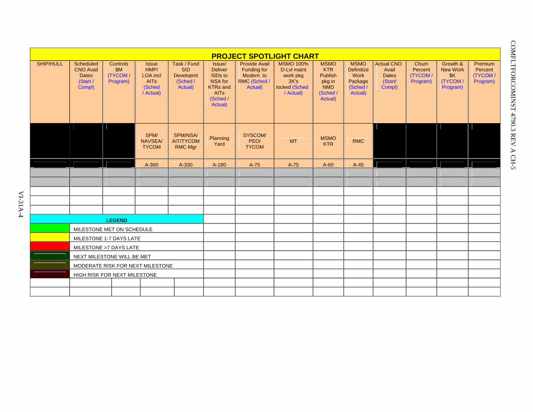
PROJECT SPOTLIGHT CHART SHIP/HULL Scheduled
CNO Avail Dates (Start / Compl)
Controls $M
(TYCOM / Program)
Issue HMP/
LOA incl AITs
(Sched / Actual)
Task / Fund SID
Developmt (Sched / Actual)
Issue/ Deliver SIDs to NSA for
KTRs and AITs
(Sched / Actual)
Provide Avail Funding for Modern. to
RMC (Sched / Actual)
MSMO 100% D-Lvl maint work pkg
2K's locked (Sched
/ Actual)
MSMO KTR
Publish pkg in NMD
(Sched / Actual)
MSMO Definitize
Work Package (Sched / Actual)
Actual CNO Avail Dates (Start/ Compl)
Churn Percent
(TYCOM / Program)
Growth & New Work
$K (TYCOM / Program)
Premium Percent
(TYCOM / Program)
SPM/ NAVSEA/ TYCOM
SPM/NSA/ AIT/TYCOM
RMC Mgr
Planning Yard
SYSCOM/ PEO/
TYCOM MT MSMO
KTR RMC
A-360 A-330 A-180 A-75 A-75 A-60 A-45
LEGEND
MILESTONE MET ON SCHEDULE
MILESTONE 1-7 DAYS LATE
MILESTONE >7 DAYS LATE
NEXT MILESTONE WILL BE MET
MODERATE RISK FOR NEXT MILESTONE
HIGH RISK FOR NEXT MILESTONE
CO
MFLTFO
RC
OM
INST 4790.3 R
EV A
CH
-5
VI-31A
-4

Premium Performance Chart
4%
8% 4%
CO
MFLTFO
RC
OM
INST 4790.3 R
EV A
CH
-5
VI-31A
-5
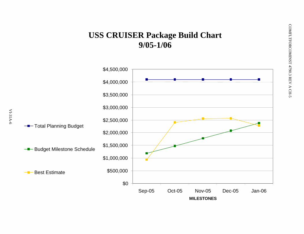
CO
MFLTFO
RC
OM
INST 4790.3 R
EV A
CH
-5
USS CRUISER Package Build Chart9/05-1/06
$0
$500,000
$1,000,000
$1,500,000
$2,000,000
$2,500,000
$3,000,000
$3,500,000
$4,000,000
$4,500,000
Sep-05 Oct-05 Nov-05 Dec-05 Jan-06MILESTONES
Total Planning Budget
Budget Milestone Schedule
Best Estimate
$0
$500,000
$1,000,000
$1,500,000
$2,000,000
$2,500,000
$3,000,000
$3,500,000
$4,000,000
$4,500,000
Sep-05 Oct-05 Nov-05 Dec-05 Jan-06MILESTONES
Total Planning Budget
Budget Milestone Schedule
Best Estimate
VI-31A
-6

Hot Wash Status Report
U S S P O R T R O Y A L (C G 7 3 )
U S S R JA M E S (F F G 5 7 )
U S S R U S S E L L (D D G 5 9 )
U S S C R O M M E L IN (F F G 3 7 )
U S S S A L V O R (A R S 5 2 )
U S S H O P P E R (D D G 7 0 )
9 /8 /0 4 1 2 /1 /0 4 1 2 /1 5 /0 4 3 /2 3 /0 5 6 /1 5 /0 5 9 /7 /0 5
1 0 /7 /0 4 1 /2 5 /0 5 1 /2 6 /0 5 3 /3 1 /0 5 7 /1 1 /0 5 9 /2 8 /0 5
R e q 'ts (C F T 1 ) 0 1 2 0 0 0 3 3
P P /P & O C F T 2 3 0 1 1 3 4 2 1 1 1 1
A l ts & M o d s (C F T 4 ) 1 1 3 0 0 5 1 0 1 0
T o ta l 1 3 6 3 4 7 2 4 2 4
T e c h n ic a l 0 0 0 0 0 0 0 0
M o d e rn iz a tio n 0 0 1 0 0 0 1 1
P ro je c t T e a m 0 0 0 0 0 2 2 2
T o ta l 0 0 1 0 0 2 3 3
A l ts & M o d s 2 0 0 1 2 5 1 0 5
M o d e rn iz a tio n 0 0 0 0 0 0 0 0
P & O 3 2 1 3 2 3 1 4 7
T e c h n ic a l 0 0 0 0 3 0 3 2
R e q 'ts 5 5 1 2 4 0 1 7 1 2
P ro je c t T e a m 1 6 1 0 8 8 1 3 2 2 7 7 4 1
P a c k a g e P re p 5 4 2 2 5 1 1 9 1 2
T o ta l 3 1 2 1 1 2 1 6 2 9 3 1 1 4 0 7 9
G lo b a l N o n -S h ip m a in Issu e s
L o c a l I ssu e s
G lo b a l S h ip m a in Issu e s
T o ta l R e s o lv e d
H R M C F E E D B A C K IS S U E M E T R IC S
S h ip / H u l l
E O A
H W M tg D a te
T o ta ls
Global Non-SHIPMAIN Feedback Issues (XX RMC)
0
0.5
1
1.5
2
2.5
Technical Modernization Project Team
Category
No. o
f Iss
ues
Total No. of IssuesResolved
Global SHIPMAIN Feedback Issues (XXRMC)
0
2
4
6
8
10
12
Req'ts (CFT1) PP/P&O CFT23 Alts & Mods (CFT4)
Global Shipmain Issues
No. o
f Iss
ues
TotalsTotal Resolved
Local Feedback Issues (XX RMC)
0
10
20
30
40
50
60
70
80
90
Alts &
Mod
sMode
rnizatio
n
P&OTe
chnica
l
Req'ts
Project
Team
Packag
e Prep
Local Issue Categories
No. o
f Iss
ues
Total No. of IssuesResolved
VI-31A
-7
CO
MFLTFO
RC
OM
INST 4790.3 R
EV A
CH
-5
COMFLTFORCOMINST 4790.3 REV A CH-5
Global Hot Wash Data
Bullets include as a minimum:
• Discussion of best practices.
• Discussion of global issues.
• Premium goal vs. actual (and if exceeded, an explanation as to why).
• Identify premium drivers.
VI-31A-8

COMFLTFORCOMINST 4790.3 REV A CH-4
VOLUME VI
CHAPTER 32
TOP MANAGEMENT ATTENTION TOP MANAGEMENT ISSUES
REFERENCES.
(a) OPNAVINST 4700.7 - Maintenance Policy for U.S. Naval Ships (b) OPNAVINST 3000.12 - Operational Availability of Equipments and Weapons Systems
LISTING OF APPENDICES.
A Top Management Attention and Top Management Issues Flowchart
32.1 PURPOSE. Reference (a) provides Chief of Naval Operations (CNO) Maintenance Policy for U.S. Navy Ships, which includes the Top Management Attention/Top Management Issues (TMA/TMI) program for addressing chronic maintenance problems. Commander, Fleet Forces Command (CFFC) is tasked with developing and forwarding Hull, Mechanical and Electrical (HM&E) and Combat System (CS) Technical Ticklers to identify common maintenance issues between Fleets. This chapter provides CFFC policy, procedures and standardized metrics for selecting systems/equipment for inclusion in the TMA/TMI process.
32.2 BACKGROUND. The TMA/TMI process is the Navy's priority corrective action process for Fleet Forces Command, Fleet Commanders, Type Commanders (TYCOM), Systems Commands (SYSCOM) and Office of the CNO (OPNAV) Resource Sponsors. This process is the means to identify top material readiness and cost problems and develop solutions that effectively and efficiently achieve approved levels of performance while realizing near-term returns on investment.
32.3 APPLICABILITY AND SCOPE.
a. The TMA/TMI process encompasses all surface ship, carrier, and submarine installed equipment and systems, including aviation-oriented items that are integral parts of the ship. This process supports Navy goals and initiatives that improve fleet material readiness and increase the operational availability of those items that are identified by the fleet as needing primary attention and action. The TMA/TMI process excludes equipment under the responsibility of Director, Strategic Systems Programs and Director of Naval Nuclear Propulsion Program.
b. The TMA/TMI process uses data from diverse sources to:
(1) Objectively identify critical fleet problems that impact material readiness, maintenance cost and manpower/skill requirements, and warrant top-level attention.
(2) Focus management attention and resources needed to correct these problems.
(3) Enhance communication among CNO Resource Sponsors, Fleet Commanders, TYCOMs and Systems Command Program Offices.
(4) Execute the TMA/TMI process in accordance with the TMA/TMI Process Flowchart in Appendix A.
VI-32-1

COMFLTFORCOMINST 4790.3 REV A CH-1
c. The TMA/TMI process is the Navy's priority corrective action process for Fleet Commanders, SYSCOMs and OPNAV Resource Sponsors. This process is the means for the Fleet, OPNAV, and SYSCOMs to identify top material readiness and cost problems and develop solutions that effectively and efficiently achieve approved levels of performance while realizing near-term Returns on Investment (ROI).
d. The TMA/TMI candidate selection process uses Maintenance and Material Management (3-M) data prepared by the TMA/TMI Analysis Center to objectively identify critical fleet HM&E and CS problems that impact material readiness, maintenance cost and manpower/skill requirements and warrant top-level attention. Fleet and TYCOMs use this data to aid in the selection of their TMA/TMI candidate systems/equipment.
e. Candidate systems/equipment metrics are forwarded from the TYCOMs to Naval Sea Systems Command (NAVSEA) for inclusion in the TMA/TMI process. The candidate selection process is a semi-annual process commencing immediately after TMA Fleet Week and culminating at Mid-Cycle with the nomination of new systems/equipment.
32.4 RESPONSIBILITIES.
32.4.1 Commander Fleet Forces Command. CFFC Maintenance Officer (N43) is the Staff Officer responsible for implementation of this chapter and for selecting the HM&E and CS/equipment for inclusion in the TMA/TMI process.
32.4.1.1 Duties. TYCOM Maintenance Officers shall:
a. Develop TYCOM HM&E and CS Technical Ticklers and identify common issues between ships every six months. Establish a priority ranking of systems based on selected attributes (e.g. man-hours, cost, readiness). Forward TYCOM HM&E and CS Technical Ticklers to Commander, Naval Sea Systems Command (COMNAVSEASYSCOM) 05 for surface ships and COMNAVSEASYSCOM 07 for submarines, with copy to OPNAV Resource Sponsors, via a joint cover letter.
b. Coordinate TMI Panel agendas and dates with TMA/TMI Working Group Chair(s).
c. Participate on TMA/TMI Panels.
d. Coordinate Fleet participation in the TMA/TMI process (TYCOMs and Regional Maintenance Center Supports).
32.4.2 Naval Sea Systems Command. COMNAVSEASYSCOM (09) coordinates overall SYSCOM participation in the TMA/TMI process. Specifically, (SEA 07) coordinates the efforts for submarine platforms. NAVSEA (05) coordinates efforts for surface and carrier platforms.
32.4.2.1 Duties.
32.4.2.1.1 Commander, Naval Sea Systems Command (05) and Commander, Naval Sea Systems Command (07). COMNAVSEASYSCOM (05) for surface ships or the Deputy Commander Submarines COMNAVSEASYSCOM (07) shall:
a. Form the TMA/TMI Working Groups and Panels and staff with appropriate representatives.
b. Receive and disseminate the TYCOM HM&E and CS/C4I Surface Ship Technical Ticklers or submarine issues white paper to the appropriate TMA/TMI Working Groups.
VI-32-2

COMFLTFORCOMINST 4790.3 REV A CH-1
c. Review and forward Plan of Action and Milestones and ROIs, or other technical presentations from TMA/TMI Working Groups to Fleet and TYCOMs.
d. Chair the TMI Panel and establish the NAVSEA response to Fleet identified TMI issues.
32.4.2.1.2 Commander, Naval Sea Systems Command Program Offices. COMNAVSEASYSCOM Program Offices shall:
a. Chair TMA and TMI Panels in accordance with paragraph 32.4.2.1.4 of this chapter.
b. Participate on TMA/TMI Panels as requested.
c. Develop Plan of Action and Milestones and ROIs to address TYCOM HM&E and CS Technical Tickler issues.
d. Coordinate other activities as required to determine root causes and develop corrective actions.
e. Review minutes from TMA/TMI Panels and take action as appropriate.
f. Work with TYCOMs for resolution of HM&E and CS Technical Issues and Action Items.
32.4.2.1.3 Program Executive Officers and Direct Reporting Program Managers. Program Executive Officers (PEO) and Direct Reporting Program Managers shall:
a. Assign representatives to the appropriate TMA/TMI Working Groups.
b. Chair the applicable submarine TMI Panels as described in paragraph 32.4.2.1.4 of this chapter.
c. Review minutes from TMA/TMI Panels and take action as appropriate.
32.4.2.1.4 Top Management Attention/Top Management Issues Panels. The TMA/TMI Panels shall:
a. Review, discuss, and agree on the course of action to resolve each technical issue presented.
b. Publicize minutes of the Panel Meetings.
32.4.2.1.4.1 Top Management Attention Panels. TMA Panels meet every six months, to assess the applicability of Plan of Action and Milestones and ROIs, and monitor the progress of issues. TMI panels are meetings chaired and attended by an O-6 at the flag level for those issues requiring identification or realignment of resources (funding and manpower), or flag level participation, to resolve. In general, TMA Panels discuss those issues that can be handled within the SYSCOM organizations. The TMA Panel will identify top surface ship and submarine issues based on specific attributes (e.g. man-hours, cost, readiness) for presentation at TMI.
a. TMA Panels: TMA Panel composition and agendas are coordinated between applicable TYCOM staffs, Fleet staffs and SYSCOM Program Offices. Attendees to the appropriate TMA Panels include, but are not limited to, the following:
(1) COMNAVSEASYSCOM (09) representative as chairman for the Surface, Carrier and CS panels and COMNAVSEASYSCOM (SEA 92) representative as chairman for the Submarine panel.
(2) CNO (N43) and applicable Resource Sponsor (N7, N6) representative(s).
VI-32-3

COMFLTFORCOMINST 4790.3 REV A CH-1
(3) Maintenance and Supply representatives from Fleet, TYCOMs, and Regional Maintenance Centers (RMC).
(4) COMNAVSEASYSCOM Program Offices, engineering codes and logistics codes representative(s).
(5) Commander, Space and Naval Warfare Systems Command (COMSPAWARSYSCOM) Program Office representative(s) as requested.
(6) Commander, Naval Air Systems Command (COMNAVAIRSYSCOM) Engineering representative(s) as requested.
(7) In-Service Engineering Agent representatives.
(8) Naval Inventory Control Point (NAVICP) representative.
(9) Training Command representative.
(10) Naval Research Laboratory representative.
(11) Board of Inspection and Survey representative.
b. Submarine TMI Panel: The Submarine TMI Panel is chaired by NAVSEA 05. NAVSEA 05, COMSUBLANT, and COMSUBPAC jointly coordinate the agenda.
c. Surface Ship TMI Panel: The Surface Ship TMI Panel is chaired by NAVSEA 09. NAVSEA 09, NAVSEA 05, PEO Theater Surface Combatants, PEO Expeditionary Warfare, PEO Mine and Undersea Warfare, PEO CARRIERS and PEO Surface Strike jointly coordinate the agenda.
d. Panel Members: Attendees of the appropriate TMI Panels include, but are not limited to, the following:
(1) PEO Expeditionary Warfare, PEO Theater Surface Combatants, PEO CARRIERS (Surface/Carrier), PEO Mine and Undersea Warfare, PEO Surface Strike, SEA 92 (Submarine).
(2) CNO (N43), and applicable Resource Sponsor (N7, N6) representative(s).
(3) COMLANTFLT, COMPACFLT, COMNAVSURFLANT, COMNAVSURFPAC, COMNAVAIRLANT, COMNAVAIRPAC, COMSUBLANT, and COMSUBPAC Maintenance and Supply Officers.
(4) COMNAVSEASYSCOM program offices, engineering code and logistics code representatives.
(5) COMSPAWARSYSCOM representative.
(6) COMNAVAIRSYSCOM representative.
(7) In-Service Engineering Agent representative(s).
(8) RMC and RMC representatives.
(9) NAVICP representative.
(10) Chief of Naval Education and Training representative.
VI-32-4

COMFLTFORCOMINST 4790.3 REV A CH-1
(11) Naval Research Laboratory representative.
(12) Board of Inspection and Survey representative.
e. Combat Systems: The CS Troubled Systems Process supports the TMA/TMI process with selected inputs for the COMLANTFLT/COMPACFLT CS Technical Tickler.
32.4.2.1.5 Top Management Attention/Top Management Issues Working Groups. The TMA/TMI Working Groups shall:
a. Receive TYCOM HM&E and CS Technical Ticklers or Issues White Papers as appropriate from NAVSEA 09 for surface ships or from NAVSEA 05 for submarines and identify common and platform specific issues as appropriate.
b. Review TYCOM HM&E and CS Technical Ticklers, White Papers or Action Items. Verify applicability of Fleet-recommended actions and achieve agreement with appropriate Fleet and TYCOM staff(s) as appropriate.
c. Notify appropriate COMNAVSEASYSCOM Program Offices and other SYSCOMs when equipment or systems under their care are identified as fleet material readiness issues.
32.4.2.1.6 Review. TMA/TMI Working Groups, comprised of SYSCOM representatives designated by NAVSEA 05 and 07, PEO SUBS, PEO Ships, PEO Integrated Warfare Systems, and PEO CARRIERS, review Fleet inputs to determine common and platform specific issues and assign issues to the appropriate SYSCOM Program Offices.
32.4.3 Top Management Attention/Top Management Issues Analysis Center.
32.4.3.1 Candidate Identification. The TMA/TMI Analysis Center will provide a combined Ranking Matrix to help determine the relative ranking of systems/equipment on a Navy wide basis. The TMA/TMI Analysis Center, using the TYCOM input plus RMC and TYCOM technical experts, will prepare a preliminary set of Fleet generated system problems and potential solutions, the Technical Tickler, for the systems/equipment chosen for inclusion in the TMA/TMI process. The TMA/TMI Analysis Center, using 3-M data, also provides the TYCOMs with a Ranking Matrix, Figures 32-1 and 32-2, and Impact Chart, Figure 32-3, by Allowance Parts List (APL) and Equipment Identification Code (EIC) for their review. The Ranking Matrix will be TYCOM specific, using the Ranking Matrix as a guide, the TYCOMs select systems/equipment for further evaluation and possible induction into the TMA/TMI process.
32.4.3.2 Candidate Expanded Metrics. The TMA/TMI Analysis Center provides the TYCOMs with a tailored TMA Report for their identified systems/equipment. This report contains a Balanced Score Card (BSC), Problem Free Time, Failure Rate, Parts Ranking and modified Ship's Logistics Indicator Computerized Report (SLICR) for the specific candidate system/equipment defined by APL or EIC nominated by the TYCOM. These are 3-M based reports that require no special data collection or analysis efforts.
32.4.4 Type Commanders. The TYCOMs, using the data provided in the TMA Report and other (RMC, SYSCOMs, etc.) Casualty Report (CASREP), maintenance, logistics or training inputs will determine which systems/equipment to nominate for inclusion into the TMA/TMI process. The nomination should include the TMA Metrics plus additional justification including the TYCOM's initial Root Symptom Analysis as to the causes of poor performance. Systems/equipment will be nominated at the lowest component level that can be identified as the reliability or cost driver. When multiple APLs or EICs from the same "System" appear at or near the top of the Ranking Matrix, the entire "System" can be nominated.
VI-32-5
COMFLTFORCOMINST 4790.3 REV A CH-1
32.5 METRICS. Metrics used are generated directly from the 3-M database via Open Architecture Retrieval System (OARS) and require no subsequent data collection or analysis efforts. All Navy systems/equipment that generate maintenance data are included and considered as part of this methodology. This is a three month process, starting after Fleet Week and culminating at the Mid-Cycle review that gets new systems nominated by the Fleet to TMA. Systems not selected for TMA can be re-nominated by a TYCOM Representative at least 4.5 months prior to any future Fleet Week.
32.5.1 Top Management Attention/Top Management Issues Candidate Selection Metrics.
32.5.1.1 Top Management Attention/Top Management Issues Ranking Matrix. Six attributes are used to rank systems/equipment as TMA/TMI Program candidates. Data for five of the attributes are downloaded directly from the 3-M database via OARS. The CASREP Volume data is extracted and sanitized from the NAVICP CASREP Database. The attributes are:
a. 2-Kilo Volume - Total number of Maintenance Actions (2-Kilos) generated by the system/equipment.
b. Man-hours - Total Ship's Force and Intermediate Maintenance Activity (IMA) man-hours expended on system/equipment maintenance.
c. Parts Cost - Total net cost of repair parts used to support the system/equipment.
d. Hi-Priority Failures - Total number of 2-Kilos that are Status 2 or 3 and Priority 1, 2 or 3 CASREPs generated for a system/equipment.
e. Hi-Priority Down Time - Total days of down time for the system/equipment based on hi-priority failures.
f. CASREP Volume - Number of CASREPs generated by the system/equipment.
Data on each attribute is collected over a two-year period. The Ranking Matrix is a multivariable pareto ranking technique that avoids the distortion inherent in ordinary ranking schemes where variables representing different aspects of a system/equipment may have different units of measurement with widely differing scales. The technique gives full visibility to systems where even only one of the descriptive attributes has a high impact level. As a result the "top ten pareto" of each of the attributes winds up on or near page one of the overall ranking. The process is easily automated in MS Excel or MS Access. This method is applied to approximately 43,000 APL and 4,200 EIC systems/equipment. The resultant Ranking Matrix provides Fleet decision makers a list of potential TMA/TMI candidates.
32.5.1.1.1 Ranking Matrix Calculation. Data for each attribute are scaled/normalized/standardized (depending on the language in your field of study) in a way that creates unit vectors (0 to 1, with a few high outliers > 1) in statistical units (Standard Deviation multiples sometime referred to as "Z" scores). The scaling used results in the 3-sigma value of the data being scaled to equal one. The 99.86th percentile of the data is used to locate that value in the ranked raw data, which is a percentile commonly used for "normal" distributions with a single tail as being equivalent to the 3-sigma value. Although our five attribute distributions are not "normal", they are close to being "log normal" so the percentile technique works. The percentile technique works well regardless since the data is a 100% sample and the statistical distribution (which should be known if samples are used for estimating) is not a critical issue. After scaling the attributes, the vector equivalents are then combined using vector addition to create a balanced rank value that can be used for final ordering of the ranking. The vector addition technique is straightforward (Pythagorean). For over three years this has produced a tight pattern of the top ten for each attribute falling within the top 50 fleet-wide. The method is objective, repeatable, and robust and uses the "actual data", not a representation of the data.
VI-32-6
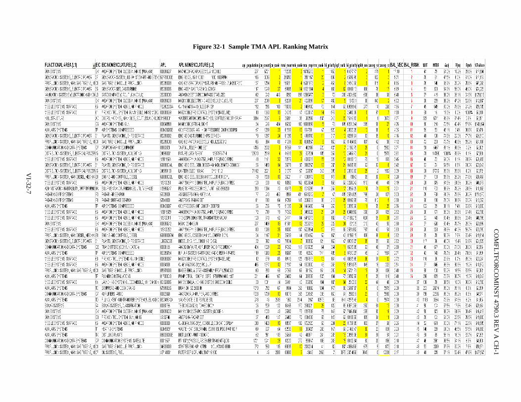
Figure 32-1 Sample TMA APL Ranking Matrix
VI-32-7
CO
MFLTFO
RC
OM
INST 4790.3 R
EV A
CH
-1

Figure 32-2 Sample TMA EIC Ranking Matrix CO
MFLTFO
RC
OM
INST 4790.3 R
EV A
CH
-1
VI-32-8

COMFLTFORCOMINST 4790.3 REV A CH-1
32.5.1.2 Impact Chart. The Impact Chart provides a means of plotting the Ranking Matrix and showing, using a two-axis display, the TMA/TMI systems/equipment and potential candidate systems/equipment. Annual Cost of Parts and Labor are combined to form the X-axis and Days Down Time the Y-axis, providing a visual "high cost", "high down time" display of TMA/TMI current and candidate systems/equipment.
Figure 32-3 Sample Impact Diagram
32.5.1.3 Balanced Score Card.
a. Ratio analysis is a valuable tool for interpreting financial and operating data (from balance sheets, profit-and-loss statements, production data, etc.) to detect favorable or unfavorable conditions in business performance.
b. Ratios are used to show the proportional relationship of data from a variety of sources. Business owners should compare their ratios for a specific period with previous periods to ascertain possible reasons for change. They may also choose to compare the ratios for their operation with the industry standard.
c. After an operation has been in existence for a reasonable time, the ratios tend to stabilize and in many industries desirable ratios are well established. Therefore, there is a minimum percentage that an operation can cost (manpower/capital) and still provide proper service, and a maximum that it can cost before the operation is shut down or re-engineered.
d. This business approach can be applied to the management of systems in the fleet. The BSC developed by the TMA/TMI Analysis Center allows the user to:
(1) Observe the shape, or system behavior/maintenance strategy (relative proportions or ratios, variable to variable).
VI-32-9

COMFLTFORCOMINST 4790.3 REV A CH-2
(2) Compare a single variable with the entire fleet (since the data is scaled using the upper control limit of all fleet data for each variable as the 100% mark).
(3) Observe the enclosed area which is proportional to the TMA/TMI balanced ranking value.
(4) Identify problem areas for follow-on analysis.
Notice that ratios of variables that have the same value on the grid (1:1) are at the fleet average or norm. For example, if Hi-Priority Failures and Hi-Priority Downtime are equal, the connecting line is parallel to the grid and that system has an Average Logistics Response Time equal to the fleet average. Other ratios behave in the same way. A typical BSC has six sides representing the six TMA/TMI attributes. Additional variables from other data sources may be added and, if scaled to the upper control limit of that data source, will achieve similar results.
Figure 32-4 Sample BSC
TMA/TMI CYCLE 04-1MK 92 MOD 2 FIRE CONTROL SYSTEM (APL: 006080059)
BALANCED SCORE CARD
0.0
1.0
2.0
3.0
4.0PARTS COST
HI-PRIORITY FAILURES
HI-PRIORITY DT
CASREP VOL
MANHOURS
2K VOL
MAINTENANCEVOLUME HIGH
RELIABILITYPROBLEMS
HIGH COST"BIG"
"UGLY""BAD"
1.0 = 3 Sigma
Cycle 04-1 Cycle 04-2
32.5.1.4 Time (problem free). Reference (b), establishes Operational Availability (Ao) as the primary measure of material readiness for navy mission-essential systems, subsystems and equipment installed in platforms. Ao represents the expected percentage of time that system or individual equipment will be ready to perform satisfactorily in an operating environment when called for at any random point in time. To provide the primary measure of material readiness for the TMA/TMI systems/equipment, the TMA/TMI Analysis Center has developed a measure of Ao for selecting, tracking and trending TMA/TMI systems/equipment called Time Problem Free (T (pf)).
a. T (pf) uses the mathematical description of Ao provided by reference (b). Generally, Ao is interpreted as the percentage of time that the system will be ready to perform satisfactorily in an operating environment. T (pf) is interpreted as the percentage of time that the system or equipment is free of hi-priority failures during that same period. Quantitatively, this is expressed in the formula:
Ao = Uptime/Uptime + Downtime
VI-32-10

COMFLTFORCOMINST 4790.3 REV A CH-1
For the purposes of describing TMA/TMI systems/equipment, Uptime is equal to Mean Time Between Failure (MTBF) and Downtime is equal to Mean Down Time (MDT). The TMA/TMI formula for T (pf) becomes:
T (pf) = MTBF/(MTBF + MDT)
Data to calculate T (pf) is extracted from the Navy's 3-M Database via the OARS. OARS provides a ten-year maintenance history of system/equipment performance.
MTBF (in days) is calculated using the formula:
MTBF = 1/(No. Failures/(30.44*0.667*Population)) where
b. No. Failures = the number of Status 2 and 3 2-Kilos written per month. Status 2 is defined by 3-M as inoperative and Status 3 is degraded performance. Limiting 2-Kilo data to Status 2 and 3 eliminates approximately 75% of all 2-Kilos written and provides the basis for measuring mission degrading performance. Together the TMA/TMI process identifies these as "Deck Plate" CASREPs or maintenance actions that reduce a system or equipment's ability to satisfactorily perform in an operating environment. 30.44*0.667 = 30.44 days in an average month times 0.667, which is defined by reference (b) as "the percentage of time that the system will be ready to perform satisfactorily in an operating environment". For sea-going systems this operating tempo is approximated as 2/3-calendar time.
c. Population = the actual population of the system/equipment under evaluation or the number of platforms the system/equipment is installed in. Actual numbers of equipment is generally used for CS and larger HM&E items such as Main Engines or Ships Service Generators. Number of platforms is used for multiple installations of smaller HM&E items such as pumps or valves.
d. MDT is computed by month directly from OARS and is the mean number of days from the opening of Status 2 or 3 2-Kilos until the Deck Plate CASREPs are corrected and the 2-Kilos closed. MDT is all-inclusive. It contains such items as Mean Logistics Delay Time, Administrative Time, Mean Total Time to Repair, etc. Breaking MDT down into the contributing elements requires expensive data collection and analysis and is not necessary for TMA/TMI purposes.
32.5.1.4.1 Time (problem free) Assessment. The resultant T (pf) meets the requirements of reference (b) and provides a means of assessing:
a. Operational Availability of TMA/TMI systems/equipment.
b. Effectiveness of the TMA/TMI program in resolving chronic problems in those systems/equipment.
c. Systems/equipment trends in T (pf), MTBF and MDT over time.
VI-32-11

COMFLTFORCOMINST 4790.3 REV A CH-1
Figure 32-5 Sample T(pf)
RM&A PARAMETERS FOR MK 46 MOD 0 OPTICAL SIGHT(TIME PROBLEM FREE (Tpf) IS % OPERATING TIME FREE OF PROBLEMS)
0
100
200
300
400
500
600
700
800
1998
3
1998
4
1999
1
1999
2
1999
3
1999
4
2000
1
2000
2
2000
3
2000
4
2001
1
2001
2
2001
3
2001
4
2002
1
2002
2
2002
3
2002
4
2003
1
2003
2
CY QUARTER
MTB
F &
MD
T (D
AYS
)
0%
20%
40%
60%
80%
100%
TIM
E Pr
oble
m F
ree
T(pf
), %
MDT MTBF T(pf)MDT TREND MTBF TREND TIME Problem Free, T(pf)
32.5.1.5 Failure Trend. The failure trend provides a failure history for the candidate TMA/TMI system/equipment. Hi-Priority Failures are plotted quarterly for the past five years and a polynomial trend line provides the direction of movement.
Figure 32-6 Sample Hi-Priority Failure Trend
VI-32-12

COMFLTFORCOMINST 4790.3 REV A CH-1
32.5.1.6 Parts Ranking. The Supply Parts Ranking Report, L0201, is a Ships 3-M Standard Report extracted from OARS. This report provides a quick method for determining fleet material problems based on total parts issued and total cost. Parts Ranking is the ten highest "TOTAL_PRICE" parts extracted from OARS. This represents total cost to the Navy, not necessarily to the individual unit. Cost to the unit will be increased for failure to turn in a Depot Level Repairable carcass. The Parts Ranking provides the National Item Identification Number (NIIN), abbreviated NIIN nomenclature, quantity and total cost per NIIN for the ten most expensive repair parts for the candidate system/equipment.
Figure 32-7 Sample Parts Ranking
32.5.1.7 Ship's Logistics Indicator Computerized Report. The SLICR, L0106, is a Ships 3-M Standard Report extracted from OARS. The SLICR is intended to identify problem equipments within the fleet. The SLICR provides the following metrics:
a. APL/EIC.
b. APL_NOMENCLATURE/EIC_NOMENCLATURE.
c. FAILURES: Count of maintenance actions with Status_Code 2 or 3.
d. SF_MNHRS: Total number of Ship's Force man-hours expended by Ship's Force personnel or other installing personnel in completing and documenting the maintenance action.
e. PART_ISSUES: Total number of 1250 and 1348 Supply Order Forms processed in support of maintenance.
f. REPLCMNT_COST: The cost to replace parts used in maintenance with new (not refurbished) parts.
VI-32-13
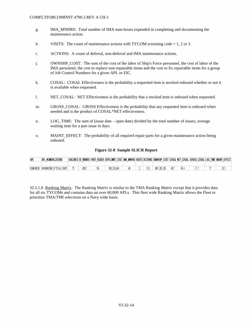
COMFLTFORCOMINST 4790.3 REV A CH-1
g. IMA_MNHRS: Total number of IMA man-hours expended in completing and documenting the maintenance action.
h. VISITS: The count of maintenance actions with TYCOM screening code = 1, 2 or 3.
i. ACTIONS: A count of deferral, non-deferral and IMA maintenance actions.
j. OWNSHP_COST: The sum of the cost of the labor of Ship's Force personnel, the cost of labor of the IMA personnel, the cost to replace non-repairable items and the cost to fix repairable items for a group of Job Control Numbers for a given APL or EIC.
k. COSAL: COSAL Effectiveness is the probability a requested item is stocked onboard whether or not it is available when requested.
l. NET_COSAL: NET Effectiveness is the probability that a stocked item is onboard when requested.
m. GROSS_COSAL: GROSS Effectiveness is the probability that any requested item is onboard when needed and is the product of COSAL*NET effectiveness.
n. LOG_TIME: The sum of (issue date – open date) divided by the total number of issues; average waiting time for a part issue in days.
o. MAINT_EFFECT: The probability of all required repair parts for a given maintenance action being onboard.
Figure 32-8 Sample SLICR Report
32.5.1.8 Ranking Matrix. The Ranking Matrix is similar to the TMA Ranking Matrix except that it provides data for all six TYCOMs and contains data on over 60,000 APLs. This fleet wide Ranking Matrix allows the Fleet to prioritize TMA/TMI selections on a Navy wide basis.
VI-32-14

Figure 32-9 Sample Ranking Matrix
VI-32-15
CO
MFLTFO
RC
OM
INST 4790.3 R
EV A
CH
-1

COMFLTFORCOMINST 4790.3 REV A CH-1
32.5.1.9 Summary. This combination of metrics provides a cost effective method of screening and selecting Navy systems/equipment for the TMA/TMI program. By using the Ranking Matrix, Parts Ranking and the SLICR, a preliminary Root Symptom Analysis process is accomplished with the candidate selection process. Using EICs/APLs can provide failure indicators at or below the "System" level, the Parts Ranking points out high failure/high cost repair parts and the SLICR illuminates logistics problems that contribute to poor system/equipment repair performance. 3-M data via OARS is available with a ten-year system/equipment history. Ongoing improvements in maintenance processes as a result of Ship Main and Port Engineer initiatives will continue to improve the quality of 3-M data and will further validate this selection process.
VI-32-16

COMFLTFORCOMINST 4790.3 REV A CH-1
APPENDIX A
TOP MANAGEMENT ATTENTION AND TOP MANAGEMENT ISSUES
FLOWCHART
T op M anagement A ttention
(TMA)
T op M anagement I ssues
(TMI)
Coordinate Agendas for TMAand TMI Panels.
Identify Joint Fleet HM&E and
CS Issues D + 90
Update Ticklers & Track Issues/Actions
For Follow up.
CONTINUOUS
Provide Courses of Action for Fleet Review
D + 150
Resolve OutstandingIssues at TMA and TMI
Panels D + 165
Disseminate TMA and TMI
Panel Minutes andPresentations
D+180
D = 1 October or 1 April
Develop Courses of Action to Resolve
Issues
Collect Data andDevelop Technical
Ticklers
CYCLE BEGINS (D)
HM&E and CS Working Groups assign
SYSCOM Code Responsibility for Issues
Consolidate HM&E and CS TMA/TMI Issues
into Joint COMLANTFLT/ COMPACFLT Package
VI-32A-1

COMFLTFORCOMINST 4790.3 REV A CH-1
(This Page Intentionally Left Blank)
VI-32A-2

COMFLTFORCOMINST 4790.3 REV A CH-3
VI-33-1
VOLUME VI
CHAPTER 33
CONTRACT ADMINISTRATION QUALITY ASSURANCE PROGRAM
33.1 LOCATION. This chapter has been moved to Volume VII, Chapter 11.

COMFLTFORCOMINST 4790.3 REV A CH-3
VI-33-2
(This Page Intentionally Left Blank)

COMFLTFORCOMINST 4790.3 REV A CH-1
VOLUME VI
CHAPTER 34
SUBMARINE FLY-BY-WIRE SHIP CONTROL SYSTEM MAINTENANCE AND CERTIFICATION
REFERENCES.
(a) NAVSEA T9044-AD-MAN-010 – Requirements Manual For Submarine Fly-By-Wire Ship Control Systems
(b) NAVSEA SL720-AA-MAN-010 – Fleet Modernization Program (FMP) Management and Operation Manual
(c) NAVSEAINST 4720.14 – Temporary Alterations to Active Fleet Submarines; Control of
34.1 PURPOSE. To provide guidance for the proper administration of a uniform maintenance program in support of the certification requirements for Submarine Fly-By-Wire (FBW) Ship Control Systems (SCS).
34.1.1 Applicability. The requirements in this chapter shall apply to SEAWOLF and VIRGINIA Class submarine FBW SCSs and all future submarines that are designed with Fly-By-Wire technology.
34.2 SUBMARINE FLY-BY-WIRE MAINTENANCE AND CERTIFICATION.
34.2.1 General. The Submarine FBW SCS Flight Critical Component Boundary consists of electronic hardware components and software units within the submarine FBW Boundary that process safety critical functions and data elements.
a. Safety critical electronic components within the Submarine Flight Critical Component Boundary shall be determined per reference (a) and shall be identified as Submarine Flight Critical Components (SFCC).
b. Safety critical software units within the SFCC Boundary shall be determined per reference (a). Safety critical software units shall require additional testing and/or analysis, be marked, configuration managed, and controlled per the requirements in reference (a).
34.2.2 Objective. The objective of the maintenance and certification process is to verify that SFCCs provide acceptable levels of performance in direct support of ship safety throughout the allowable operating range when used with approved operating and maintenance procedures. This chapter provides the policy by which repairs, maintenance, alterations and material control shall be accomplished to those components within the FBW SCS Certification Boundary as described in reference (a).
34.2.3 Maintenance and Repair Requirements. Following initial submarine FBW SCS certification by Naval Sea Systems Command (NAVSEA), the Submarine Type Commander, irrespective of the activity accomplishing the work, the ships operating status and/or contract/task the work is authorized under, is responsible for maintaining the submarine FBW SCS certification per the requirements of reference (a). The underlying principals for sustaining FBW SCS certification are:
a. All work and testing within the FBW SCS and SFCC Boundaries shall be accomplished and documented per the requirements in reference (a).
b. Unrestricted Operations/Maintenance Requirement Card 19 shall be accomplished within required periodicity and as required to sustain system certification following work/maintenance on the SCS.
VI-34-1

COMFLTFORCOMINST 4790.3 REV A CH-1
c. All fleet activities, In-Service Engineering Activities (ISEA), repair activities or shipyards (public or private) must use Controlled Work Packages (CWP), Task Group Instructions (TGI), or ripouts to document the accomplishment of work within the SFCC Boundary. CWPs/TGIs/ripouts shall provide greater assurance that any work accomplished is authorized, documented and executed per specifications and requirements, and is supported by Objective Quality Evidence.
d. Work control documents shall be clearly marked as SFCC for auditing purposes.
e. All CWPs/TGIs/ripouts for work in the SFCC Boundary shall be closed prior to the system being released for unrestricted use/Fast Cruise/Sea Trials. As part of the work control procedure closeout process, CWPs/TGIs/ripouts shall receive an independent review within the activity performing the work to verify:
(1) Work was authorized and approved.
(2) Work stayed within the authorized boundaries.
(3) Post work/maintenance testing was accomplished satisfactorily.
(4) Appropriate Quality Assurance Forms are included to document Certification of Maintenance, and all forms are completed with required signatures.
f. All testing of the FBW SCS Boundary shall be verified closed prior to the system being released for unrestricted use/Fast Cruise/Sea Trials.
g. As a policy, CWPs/TGIs/ripouts for work within the SFCC Boundary or test documents within the FBW SCS Boundary shall not be closed out until resolution of all actions necessary to verify certification has been maintained when any breach of the boundary has occurred. An acceptable alternative, however, is to close out a CWP/TGI/ripout or test documents within the FBW SCS Boundary by transferring remaining at sea testing actions to a separate auditable accountability system (e.g., Sea Trial Agenda). All CWPs/TGIs/ripouts closed in this manner shall be annotated by the activity with the reference documents that contained the transfer actions. This policy shall be verified by the activity accomplishing the work, supervising authority, submarine Commanding Officer and Immediate Superior In Command (ISIC).
h. Closed TGIs/CWPs/ripouts shall be retained by the work accomplishing activity and are subject to audit by cognizant activities (Type Commander, ISIC, shipyard, supervising authority or NAVSEA) during audits such as functional or certification audits.
i. Maintain records in accordance with Volume V, Part I, Chapter 10 of this manual.
34.2.4 Upgrades/Alteration Requirements. Upgrades/alterations within the FBW SCS Boundary or SFCC Boundary shall follow the same design and test requirements called out in Section 4 of reference (a) for initial system design. Proposals for upgrades or alterations within the FBW SCS Boundary shall identify the extent of system retest required based on the proposed changes to the FBW SCS baseline design. Anything less than that required for initial system acceptance testing shall be justified in the change proposal for disposition during the change proposal approval process.
a. All proposed upgrades to submarine FBW SCS and components shall be prepared, submitted and approved in accordance with references (b) or (c).
VI-34-2

COMFLTFORCOMINST 4790.3 REV A CH-1
b. Submarine FBW SCS software upgrades and alterations impacting hardware and software components within the SFCC Boundary shall only be performed by the submarine class FBW SCS Software Support Activity assigned by the Submarine Program manager. Software upgrades impacting safety critical software units within the SFCC Boundary shall require conduct of a system safety analysis to identify potential new safety critical functions and data elements. To ensure the baseline software safety pedigree has not been compromised by the change, safety critical software components shall be analyzed using safety analysis checklists tied to the initial system design safety analyses. All safety related Priority 3 and higher Problem Trouble Reports or non-conformances, as defined in reference (a), shall be adjudicated prior to system certification.
c. Major repair work performed within the SFCC Boundary shall only be performed by the FBW SCS ISEA or maintenance activity under the direction of the ISEA. Major repair work within the FBW Boundary can be performed by another maintenance activity other than the ISEA using existing maintenance procedures and drawings from the submarine class maintenance plan. Otherwise, the maintenance activity shall seek guidance from the ISEA prior to performing work.
d. Upgrades/alterations or major repair work within the SFCC Boundary shall be performed by the ISEA or an activity under the direction of the ISEA using CWPs or equivalent as identified in reference (a). Completion of work performed shall be verified by ensuring all CWPs or equivalent procedures are closed, or that outstanding liabilities are transferred to a separate auditable accountability system per reference (a).
e. Testing shall be carried out in accordance with class specific system maintenance documentation or as identified by the ISEA for major repair work, and as part of the upgrade/alteration installation documentation (e.g., Ship Alteration or Engineering Change) developed in accordance with references (b) or (c). The class specific system maintenance documentation corrective maintenance sections and FBW SCS upgrade/alteration installation documentation must specify when applicable portions of Unrestricted Operations/Maintenance Requirement Card 019 operability verification testing is to be completed. Following installation of the FBW SCS upgrades/alterations, major repair work, at sea testing/Sea Trials shall be planned and conducted in accordance with Section 4 of reference (a) when required by the upgrade/alteration installation documentation test procedures or determined necessary by the Submarine Program Manager with NAVSEA 05 concurrence. Following completion of all installation and test activities, the installing activity shall notify the ship, ISIC, TYCOM, and NAVSEA by naval message (Appendix G) of reference (a) that the system is satisfactory for unrestricted use. This message will also identify any operating restrictions of the ship and/or system and any submarine FBW SCS non-conformance with conditions until disposition in accordance with Section 3 of reference (a).
34.2.5 Material Control Requirements. The requirements associated with SFCCs are designed to ensure the correct components are installed in FBW SCS subassemblies that process flight critical functions and that those SFCCs are traceable to records of Objective Quality Evidence. They provide for the procurement, receipt inspection, storage, installation, and verification of SFCCs during construction, conversion, overhaul, repair, and alteration of Naval ships. These requirements are contained in reference (a) and are described in Volume V, Part I, Chapter 6 of this manual.
VI-34-3

COMFLTFORCOMINST 4790.3 REV A CH-1
(This Page Intentionally Left Blank)
VI-34-4

COMFLTFORCOMINST 4790.3 REV A CH-1
VOLUME VI
CHAPTER 35
REGIONAL MAINTENANCE CENTERS
REFERENCES.
(a) NAVSEAINST 5400.95 - Waterfront Engineering and Technical Authority Policy (b) NAVSEA Technical Specification 9090-310 - Ship Alteration Accomplishment by Installation Teams
LISTING OF APPENDICES.
A Regional Maintenance Center Standard Departments B Regional Maintenance Center Departmental Numbering Table
35.1 PURPOSE. This chapter provides background on the formation of Regional Maintenance Centers (RMC), defines reporting relationships, provides guidance on RMC organizational structure and lists responsibilities.
35.2 BACKGROUND. Genesis of the present day RMCs is based on a Waterfront Integration study that determined a significant efficiency increase was possible if all Fleet maintenance and modernization activities in a port were consolidated into a single command. The RMCs encompass the former Repair Supervisors of Shipbuilding, Conversion and Repair, Supervisor of Shipbuilding Detachments, Shore Intermediate Maintenance Activities, Fleet Technical Support Centers, Fleet Technical Support Center Detachments, Consolidated Diving Unit, Regional Support Groups and Port Engineers.
There are seven RMCs. Southwest Regional Maintenance Center (SWRMC) is located in San Diego, CA. Hawaii Regional Maintenance Center (HRMC) is located in Pearl Harbor, HI and is synonymous with Pearl Harbor Naval Shipyard and Intermediate Maintenance Facility (PHNSY and IMF). Northwest Regional Maintenance Center (NWRMC) is located in Bremerton, WA and is synonymous with Puget Sound Naval Shipyard and IMF (PSNS and IMF). NWRMC also includes Everett, WA maintenance operations. Japan Regional Maintenance Center (JRMC) is located in Yokosuka, Japan and is synonymous with Ship Repair Facility (SRF) Yokosuka, Japan and SRF Detachment, Sasebo, Japan. Mid-Atlantic Regional Maintenance Center (MARMC) is located in Norfolk, VA and also encompasses detachments in Naples, Italy and Bahrain. Southeast Regional Maintenance Center (SERMC) is located in Mayport, FL and also encompasses Pascagoula, MS. South Central Regional Maintenance Center (SCRMC) is located in Ingleside, TX.
35.3 REPORTING RELATIONSHIPS. SWRMC, MARMC, SERMC, SCRMC and JRMC are echelon III commands under the Fleet Commanders and the RMC Commanders report Primary Duty to the cognizant Fleet Maintenance Officer. The two Naval Shipyard RMCs report Primary Duty to Commander, Naval Sea Systems Command (NAVSEA) and report in an Additional Duty capacity to the Fleet Maintenance Officer. Each of the RMC Commanders has an Additional Duty relationship with supported Type Commanders (TYCOM) to ensure the TYCOMs' material condition of his ships are factored into general RMC operations. SCRMC is Additional Duty to Commander Mine Warfare Command to ensure Commander Mine Warfare Command desires with regard to material condition of Mine Warfare specific equipment are factored into general RMC operations. The contracting warrant holder at MARMC, SERMC, SCRMC and SWRMC is Primary Duty to NAVSEA 02 and Additional Duty to the RMC Commander.
VI-35-1

COMFLTFORCOMINST 4790.3 REV A CH-1
35.4 ORGANIZATIONAL STRUCTURE. Appendix A provides the standard departmental numbering. Appendix B is the common organizational structure that applies to SWRMC, SCRMC, SERMC and MARMC. Each of these RMCs will generate a local organizational structure based on Appendix B. Blocks may not be added to this structure but any blocks not required in a particular region may be deleted. Additionally, existing blocks may be combined if an RMC Commander determines that the size of a particular work center/branch/division is so small that it makes sense to do so. JRMC organizational structure will be aligned as closely as possible to Appendices A and B, taking into account the unique nature of the foreign national workforce.
35.4.1 Hawaii Regional Maintenance Center and Northwest Regional Maintenance Center. HRMC and NWRMC shipyard organizational structure is defined by NAVSEA. Responsibilities described in this section will be performed by the appropriate functional area within that structure.
35.5 RESPONSIBILITIES.
35.5.1 Fleet Maintenance Officers.
a. Set joint Fleet policy for the operation of all non-shipyard RMCs.
b. Ensure available funding is apportioned to the RMCs to best meet TYCOMs' ship material readiness requirements.
c. Ensure that TYCOMs are kept appraised of funding issues that may impact RMCs' ability to meet TYCOM ship material readiness requirements.
d. Represent RMC funding shortfalls to higher authority for resolution as necessary.
e. Ensure close coordination with Program Executive Offices and Systems Commands to facilitate highest level of RMC effectiveness.
f. Coordinate with NAVSEA to ensure that NAVSEA policy for operation of PSNS and IMF and PHNSY and IMF fully supports the Fleets' maintenance and modernization requirements and meets TYCOMs' ship material readiness needs.
g. Ensure sufficient military billets and civilian Full Time Equivalents are provided to RMCs to meet mission needs.
35.5.2 Regional Maintenance Center Commander.
a. Adhere to established policy, guidance and regulations regarding expenditure of government funds.
b. Comply with all applicable environmental, safety and health requirements.
c. Ensure appropriately trained personnel are available to meet mission requirements.
d. Submit budget and ensure fiscal execution information is provided as directed by higher authority.
e. Focus command on improving operations to achieve efficiencies.
f. Comply with all NAVSEA Technical Warrant requirements.
g. Comply with Federal Acquisition Regulations and NAVSEA Contracting Warrant guidance.
h. Accomplish Navy Supervising Activity responsibilities for RMC administered work.
VI-35-2

COMFLTFORCOMINST 4790.3 REV A CH-4
i. Maintain quality surveillance system to ensure contractors' quality systems are in compliance with NAVSEA guidance and that internal RMC quality meets all technical requirements.
j. Accomplish maintenance, repair and modernization of ships in accordance with this instruction and all other applicable guidance.
35.5.2.1 Engineering Department.
a. Provide waterfront technical support in accordance with reference (a) and as authorized by the technical warrant guidance provided by NAVSEA.
b. Ensure all technical documentation (e.g., technical publications, drawings, technical standards, etc.) is available in sufficient quantities and maintained in a current, up to date state. Conduct periodic on-site assessments of other RMC departments to ensure documentation being used is current.
c. Ensure contractor workmanship, quality and documentation is in compliance with Volume VII, Chapter 11 of this manual.
d. Provide management and oversight of the "common" assessment process.
e. Conduct certifications of commercial dry-docks used for dry-docking US Naval vessels.
f. Ensure all RMC Quality Assurance (QA) and Quality Control (QC) programs are in place and functioning effectively. Conduct periodic formal assessments to ensure QA and QC programs are effective.
35.5.2.2 Waterfront Operations Department.
a. Accomplish the Regional Maintenance and Modernization Coordination Office functions ensuring compliance with reference (b).
b. Plan depot level jobs brokered to non-Multi-Ship/Multi-Option private sector companies.
c. Provide full support as required by the Fleet Messing and Berthing Program Manager to ensure that all messing and berthing assets are maintained in a high state of readiness and that off-ship messing and berthing requirements for ships declared "uninhabitable" are met.
d. Execute ship maintenance and modernization using Class Teams and Maintenance Teams.
e. Provide on-site supervision and support for Alteration Installation Teams in accordance with reference (b).
f. Provide oversight for all contractor work accomplished onboard ship.
35.5.2.3 Contracts Department.
a. Comply with Federal Acquisition Regulations and NAVSEA Contracting Warrant guidance.
b. Serve as Primary Contracting Officer or Administrative Contracting Officer when appropriate/so delegated.
c. Accept/reject contractor performance based on report of quality assurance manager/waterfront oversight personnel.
VI-35-3

COMFLTFORCOMINST 4790.3 REV A CH-1
d. Initiate Quality Deficiency Reports as necessary.
NOTE: JRMC CONTRACTING FUNCTIONS ARE PERFORMED BY FLEET AND INDUSTRIAL SUPPLY CENTER YOKOSUKA/SASEBO.
35.5.2.4 Logistics Department.
a. Procure, expedite, receive, store, issue and dispose of all government furnished material.
b. Handle all material in accordance with all technical and environmental requirements.
c. Provide Integrated Logistics Support assistance to ships.
d. Accomplish Integrated Logistics Overhaul requirements.
e. Provide Integrated Logistics Support certification for ship availabilities where the RMC is the Navy Supervising Activity.
35.5.2.5 Financial Department.
a. Administer the laws, policies, regulations and directives pertaining to the financial systems and financial operations of the RMC.
b. Manage budgetary controls, obligations, accounting and disbursing operations.
c. Provide the Comptroller function and keep the RMC Commander directly informed on relevant Comptroller/financial issues.
d. Administer the civilian payroll.
e. Administer the command Activity Purchase Card and Travel Card Programs.
35.5.2.6 Production Department.
a. Conduct maintenance, repair and modernization of all assigned systems and equipment in accordance with this manual and all other applicable maintenance documents.
b. Perform shipboard Planned Maintenance System in support of Commander, Naval Surface Force optimal manning program.
c. Provide radiological support, maintenance, repair and modernization for Nuclear Propulsion Systems and Nuclear Propulsion Support Systems assigned to the Nuclear Regional Maintenance Department.
d. Provide or obtain technical assistance for Naval operating forces in accordance with Chapter 2 of this volume.
e. Conduct shipboard assessments in accordance with Chapter 5 of this volume.
f. Provide calibration and support for shipboard instruments and systems in accordance with Chapter 9 of this volume.
g. Plan and schedule maintenance, repair and modernization work brokered to the RMC Production Department.
VI-35-4

COMFLTFORCOMINST 4790.3 REV A CH-1
h. Provide or obtain diving services for underwater ship's husbandry support and maintenance.
i. Maintain an effective QA/QC/In-Process Control program to ensure maintenance, repair and modernization actions are accomplished in accordance with technical specifications.
35.5.2.7 Command Support Services Department.
a. Provide physical and personnel security services for the RMC.
b. Provide military and civilian personnel services for all RMC personnel.
c. Manage RMC manning and take action to ensure appropriately skilled personnel are obtained.
d. Originate and transmit personnel documents to satisfy all manpower, billet, manning and personnel needs.
e. Provide general administrative support services to all RMC personnel. These services include such categories as: travel planning and travel claim processing, career counseling, drug/alcohol counseling, etc.
f. Manage all RMC training, to include Navy Afloat Maintenance Training Strategy/Battle Force Intermediate Maintenance Activity/Job Qualification Requirements programs and educational services.
g. Manage all aspects of RMC facilities, to include facilities maintenance, services and improvements.
h. Manage Industrial Plant Equipment and minor property.
35.5.2.8 Business Office.
a. Provide workload forecasting and long range scheduling to obtain economical port loading.
b. Act as the command's customer interface for administering, evaluating, and accepting all work consistent with the command's capabilities, capacity and mission and higher authority direction.
c. Serve as the RMC's focal point for Enterprise Resource Planning and Navy Enterprise Maintenance Automated Information System issues. Responsible for the integration, administration, oversight, personnel proficiency and development of improvements for these systems.
d. Serve as the RMC's focal point for measuring, tracking and evaluating command processes and provide recommendations/targets for improvements. Provide metrics, reports and analysis to RMC departments and higher authority as directed.
e. Oversee and coordinate the command's continuous process improvement initiatives including use of techniques such as LEAN Manufacturing, SIX Sigma, etc.
f. Serve as the command's focal point for strategic and business planning, customer relations, Memoranda of Agreement generation and inter-regional communications.
g. Perform internal operating procedure audits and conduct Fraud, Waste and Abuse investigations resulting from internal/external "Hotline" allegations.
VI-35-5

COMFLTFORCOMINST 4790.3 REV A CH-1
35.5.2.9 Information Technology Department.
a. Coordinate, manage and supervise computer software, computer hardware, Local Area Networks, including the Navy Marine Corps Internet and Base Level Information Infrastructure [OCONUS only], and associated support equipment procurement, maintenance and troubleshooting.
b. Serve as the command's primary Navy Marine Corps Internet point of contact.
c. Comply with all computer information assurance requirements.
d. Responsible for all command web administration and development and compliance with all higher level security and technical requirements.
VI-35-6

COMFLTFORCOMINST 4790.3 REV A CH-1
APPENDIX A
REGIONAL MAINTENANCE CENTER STANDARD DEPARTMENTS
NAVSEAINST 5450.14A CH-2
dtd 1/16/98
Non-Shipyard RMC Departments PHNSY PSNSY
Non-Shipyard RMCs (note 3)
Commander & Staff 100 100 100 100 Engineering 200 200 200 200
Waterfront Operations 300 300 300 300 530 (note 1) Contracts 400 400 400
Logistics 500 500 500 500 Financial 600 600 600 600
Production 900 900 900 900 Command Support Services 1100 1100 1100 1100
Business Office 1200 1200 1200 1200 Information Technology
(note 2) 1230 1230 1230 1230
Note 1: PSNSY plans to bring SUPSHIP Puget into the RMC as code 400. PHNSY has submitted their shipyard organizational manual to NAVSEA showing code 400 as a stand-alone Contracting Department numbered "400". Intent is to obtain a change to NAVSEAINST to reflect "400" for Shipyard Contracts Dept.
Note 2: The Information Technology (IT) Department number of "1230" is not ideal since it connotes IT as being part of the Business Office, which it currently is not. However, both PHNSY and PSNSY do intend to take the current stand-alone IT Department and make it a part of the Business Office, retaining the "1230" number for it. Fleet Maintenance Officers concur with using "1230" as the non-shipyard IT Departmental number as it will provide numbering consistency even though there is currently no intent to consolidate the non-shipyard RMC IT Department into the Business Office.
Note 3: Departmental numbering in this column applies to SWRMC, MARMC, SERMC and SCRMC. Given the unique structure of JRMC (SRF Yokosuka and Det Sasebo with Japanese national workforce), it is not fully applicable there.
VI-35A-1

COMFLTFORCOMINST 4790.3 REV A CH-1
(This Page Intentionally Left Blank)
VI-35A-2

Commander & Staff (Code 100)
Office ofCounsel
Code 100C
CommandMaster ChiefCode 100D
Environmental,Safety and Health
OfficeCode 106
EngineeringCode 200
WaterfrontOperationsCode 300
ContractsCode 400
LogisticsCode 500
FinancialCode 600
ProductionCode 900
CommmandSupport Services
Code 1100
BusinessOffice
Code 1200
InformationTechnologyCode 1230
ExecutiveDirector
Code 100B
DeputyRMC Commander
Code 100A
RMC CommanderCode 100
RE
GIO
NA
L M
AIN
TE
NA
NC
E C
EN
TE
R
DE
PAR
TM
EN
TA
L N
UM
BE
RIN
G T
AB
LE
MARMC Det Naples Code 101 DSXY72
MARMC Det Bahrain Code 102 DSXY73
SERMC Det Pascagoula Code 103
APPE
ND
IX B
VI-35B
-1
CO
MFLTFO
RC
OM
INST 4790.3 R
EV A
CH
-4
RMC Departments
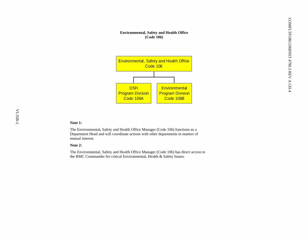
CO
MFLTFO
RC
OM
INST 4790.3 R
EV A
CH
-4
Environmental, Safety and Health Office (Code 106)
OSHProgram Division
Code 106A
EnvironmentalProgram Division
Code 106B
Environmental, Safety and Health OfficeCode 106
V
I-35B-2
Note 1:
The Environmental, Safety and Health Office Manager (Code 106) functions as a Department Head and will coordinate actions with other departments in matters of mutual interest.
Note 2:
The Environmental, Safety and Health Office Manager (Code 106) has direct access to the RMC Commander for critical Environmental, Health & Safety Issues.

Engineering Department (Code 200)
HM&E AssessmentsBranch
Code 211
C5RA AssessmentsBranch
Code 212
Alterations SupportBranch
Code 213
HM&ERADistributed Systems Branch
Code 214
Assessments, Analysis &Alterations
DivisionCode 210
QA prograrm managementQC Inspector CertificationQC Inspector Training
Quality AssuranceBranch
Code 221
NDT Technician CertificationNOAP / JOAP MonitoringMETCAL / SYSCAL Program Monitoring2M Program Monitoring
Laboratory Certificationand Monitoring Branch
Code 222
Private Sector QualityAssurance System Audits
Audit BranchCode 223
Quality ManagementDivision
Code 220
Data AnalysisBranch
Code 231
Technical LibraryBranch
Code 232
TechnicalDocumentation
DivisionCode 230
Naval Architecture BranchCode 241
Mechanical/Propulsion BranchCode 242
Electrical BranchCode 243
Combat Systems &Electronics
BranchCode 244
Engineering SupportDivision
Code 240
Chief Engineer (SW, MA & SERMCs)Engineering Assistant Department Head (SCRMC only)
Code 200A
EngineeringDepartment
HeadCode 200 NAVSEASYSCOM Technical
Warrant
VI-35B
-3
CO
MFLTFO
RC
OM
INST 4790.3 R
EV A
CH
-4

CO
MFLTFO
RC
OM
INST 4790.3 R
EV A
CH
-4
Waterfront Operations Department (Code 300)
RMMCO DivisionCode 305
Messing andBerthing Division
Code 310
Carrier ClassTeam
Code 350
MCM/MHC Class Team
Code 360
LHA/LHDClass TeamCode 315
Aux LCC/LPD/LSDClass TeamCode 330
Small BoatClass TeamCode 370
SubmarineClass TeamCode 380
DDG Class TeamCode 321
CG Class TeamCode 322
FFG/PC Class TeamCode 323
CombatantClass TeamCode 320
Depot LevelPlanning Division
Code 390
Waterfront OperationsAssistant Department Head
Code 300B
Waterfront OperationsManager
Code 300A
Waterfront OperationsDepartment Head
Code 300
VI-35B
-4
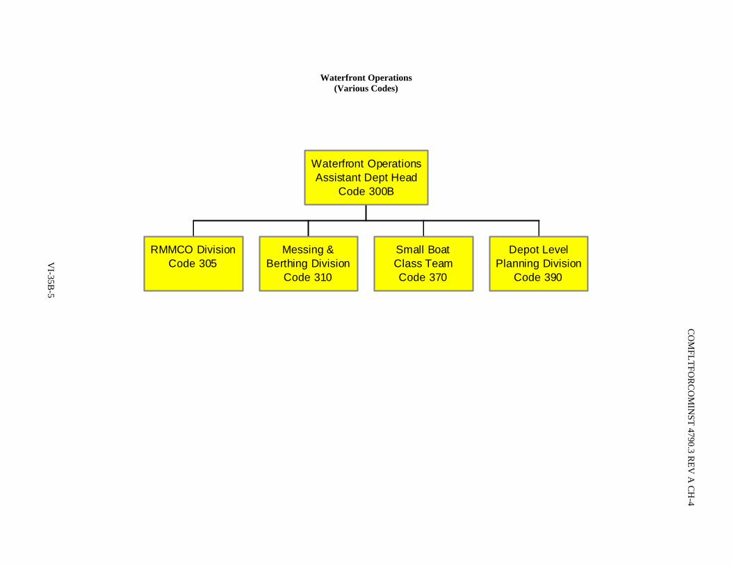
Waterfront Operations (Various Codes)
RMMCO DivisionCode 305
Messing &Berthing Division
Code 310
Small BoatClass TeamCode 370
Depot LevelPlanning Division
Code 390
Waterfront OperationsAssistant Dept Head
Code 300B
VI-35B
-5
CO
MFLTFO
RC
OM
INST 4790.3 R
EV A
CH
-4

CO
MFLTFO
RC
OM
INST 4790.3 R
EV A
CH
-4
Waterfront Operations Combatant Class (Code 320)
Maintenance Team Blocks are representative.
RMCs will populate sufficient maintenance team blocks to support homeported ships. Maintenance Team numbers for each class ofship will begin with "One" and go sequentially until all requirements for the port are met.
Maintenance Team Codes will be the 3-digit division number followed by an alpha character beginning with "A" ending sequentiallywith last alpha character required.
Do not use letter "O" for any Maintenance Team Code.
DDGMaintenance Team One
Code 321A -"X"
DDMaintenance Team One
Code 321B -"X"
DD/DDG Class TeamCode 321
CGMaintenance Team One
Code 322A -"X"
CG Class TeamCode 322
FFGMaintenance Team One
Code 323A - "X"
PCMaintenance Team One
Code 323B - "X"
FFG/PC Class TeamCode 323
CombatantClass TeamCode 320
VI-35B
-6
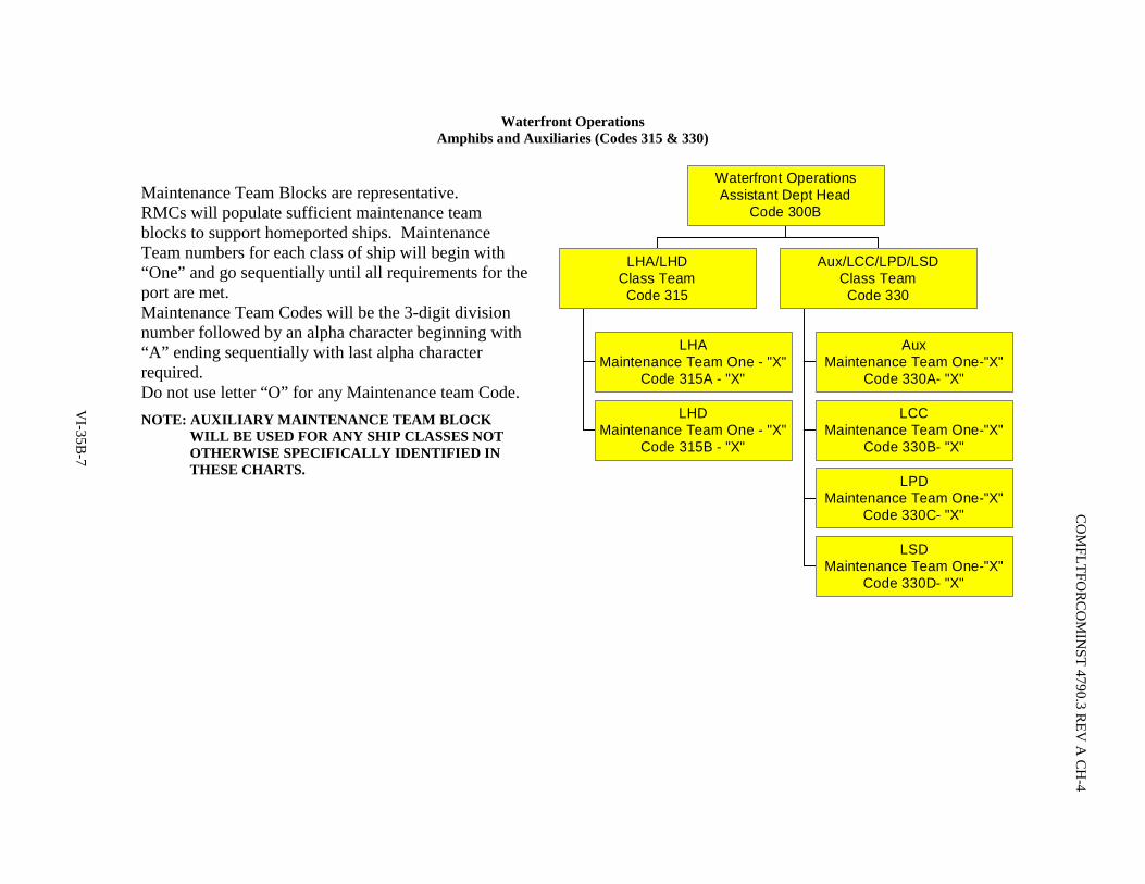
Waterfront Operations Amphibs and Auxiliaries (Codes 315 & 330)
LHAMaintenance Team One - "X"
Code 315A - "X"
LHDMaintenance Team One - "X"
Code 315B - "X"
LHA/LHDClass TeamCode 315
AuxMaintenance Team One-"X"
Code 330A- "X"
LCCMaintenance Team One-"X"
Code 330B- "X"
LPDMaintenance Team One-"X"
Code 330C- "X"
LSDMaintenance Team One-"X"
Code 330D- "X"
Aux/LCC/LPD/LSDClass TeamCode 330
Waterfront OperationsAssistant Dept Head
Code 300BMaintenance Team Blocks are representative. RMCs will populate sufficient maintenance team blocks to support homeported ships. Maintenance Team numbers for each class of ship will begin with “One” and go sequentially until all requirements for the port are met. Maintenance Team Codes will be the 3-digit division number followed by an alpha character beginning with “A” ending sequentially with last alpha character required. Do not use letter “O” for any Maintenance team Code. NOTE: AUXILIARY MAINTENANCE TEAM BLOCK
WILL BE USED FOR ANY SHIP CLASSES NOT OTHERWISE SPECIFICALLY IDENTIFIED IN THESE CHARTS.
VI-35B
-7
CO
MFLTFO
RC
OM
INST 4790.3 R
EV A
CH
-4

CO
MFLTFO
RC
OM
INST 4790.3 R
EV A
CH
-4
Waterfront Operations Carrier (Code 350)
Maintenance Team Blocks are representative.
RMCs will populate sufficient maintenance team blocks to support homeported ships. Maintenance Team numbers for each class of shipwill begin with "One" and go sequentially until all requirements for the port are met.
Maintenance Team Codes will be the 3-digit division number followed by an alpha character beginning with "A" ending sequentially withlast alpha character required.
Do not use letter "O" for any Maintenance Team Code.
CarrierMaintenance Team One - "X"
Code 350A - "X"
Carrier Class TeamCode 350
VI-35B
-8
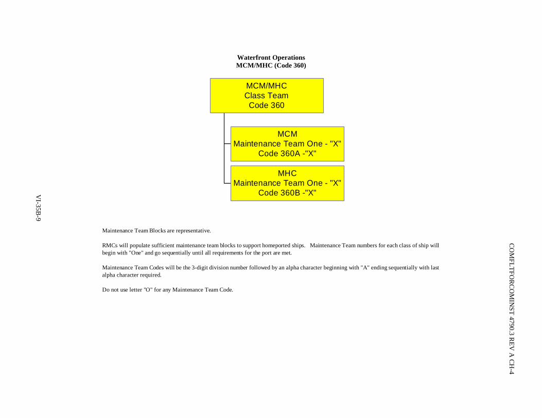
Waterfront Operations MCM/MHC (Code 360)
Maintenance Team Blocks are representative.
RMCs will populate sufficient maintenance team blocks to support homeported ships. Maintenance Team numbers for each class of ship willbegin with "One" and go sequentially until all requirements for the port are met.
Maintenance Team Codes will be the 3-digit division number followed by an alpha character beginning with "A" ending sequentially with lastalpha character required.
Do not use letter "O" for any Maintenance Team Code.
MCMMaintenance Team One - "X"
Code 360A -"X"
MHCMaintenance Team One - "X"
Code 360B -"X"
MCM/MHCClass TeamCode 360
VI-35B
-9
CO
MFLTFO
RC
OM
INST 4790.3 R
EV A
CH
-4

C
OM
FLTFOR
CO
MIN
ST 4790.3 REV
A C
H-4
Waterfront Operations Submarines (Code 380)
Maintenance Team Blocks are representative.
RMCs will populate sufficient maintenance team blocks to support homeported submarines. Maintenance Team numbers will begin with"One" and go sequentially until all requirements for the port are met.
Maintenance Team Codes will be the 3-digit division number followed by an alpha character beginning with "A" ending sequentially withlast alpha character required.
Do not use letter "O" for any Maintenance Team Code.
SubmarineMaintenance Team One - "X"
Code 380A - "X"
SubmarineClass TeamCode 380
VI-35B
-10

Contracts Department (Code 400)
ProcurementDivison
Code 410
ACO ADivision
Code 420
ACO BDivision
Code 430
ACO CDivision
Code 440
ACO DDivision
Code 450
ACO EDivision
Code 460
Policy andSupport
Code 470
MSR/ABR Cert(MA only)Code 480
NNSY Support(MA only)Code 490
Carrier Support(MA only)Code 495
ContractsDepartment Manager
Code 400A
ContractsDepartment Head
Code 400
Contracting Warrant NAVSEASYSCOM
VI-35B
-11
CO
MFLTFO
RC
OM
INST 4790.3 R
EV A
CH
-4

C
OM
FLTFOR
CO
MIN
ST 4790.3 REV
A C
H-4
Logistics Department (Code 500)
ILO BranchCode 511
ICAV BranchCode 512
Repair/NSA BranchCode 513
FMP/CTRA BranchCode 514
Integrated Logistics Support DivisionCode 510
ProcurementWork CenterCode 521A
ExpeditingWork CenterCode 521B
Customer Service BranchCode 521
Warehouse MgmtWork CenterCode 522A
Shipping/ReceivingWork CenterCode 522C
Physical Distribution BranchCode 522
Material DivisionCode 520
Logistics DepartmentManager
Code 500A
LogisticsDepartment Head
Code 500
Class Team Support
PEO Ships PMR/OLSR
VI-35B
-12

Financial Department (Code 600)
BudgetFormulation
DivisionCode 610
FundsProcessing
DivisionCode 620
BudgetExecutionDivision
Code 630
ShipRepair
DivisionCode 640
FinancialAnalysisDivision
Code 650
FinancialDepartment Manager
Code 600A
FinancialDepartment Head
(Comptroller)Code 600
RMC Commander
Title 10 Requirement
VI-35B
-13
CO
MFLTFO
RC
OM
INST 4790.3 R
EV A
CH
-4

C
OM
FLTFOR
CO
MIN
ST 4790.3 REV
A C
H-4
Production Department (Code 900)
Production AdminCode 900B
Regional CalibrationCenter
Code 910(MA, SW RMC only)
Submarine ProductionDivision
Code 920(MA,SW RMC only)
Surface HM&EProduction Division
Code 930
Nuclear RegionalMaintenance Division
Code 940(MA RMC only)
Surface Combat SystemsProduction Division
Code 950
SchedulingBranch
Code 961
PlanningBranch
Code 962
Surface Planning& Scheduling
DivisionCode 960
HM&E PMSBranch
Code 971
Combat SystemsPMS Branch
Code 972
Optimal ManningPMS Division
Code 970
Production QualityControl Division
Code 980
Diving Production DivisionCode 990
FTA DistanceSupport Ops Center
DivisionCode 995
Production DepartmentManager
Code 900A
Production DepartmentHead
Code 900
VI-35B
-14
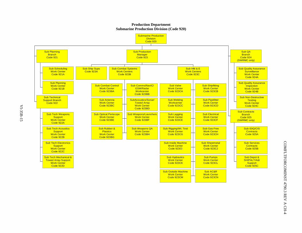
Production Department Submarine Production Division (Code 920)
Sub SchedulingWork CenterCode 921A
Sub PlanningWork CenterCode 921B
Sub PlanningBranch
Code 921
Sub Tech WeaponsSupport
Work CenterCode 922A
Sub Tech AcousticsSupport
Work CenterCode 922B
Sub Tech ElectronicsSupport
Work CenterCode 922C
Sub Tech Mechanical &Towed Array Support
Work CenterCode 922D
Sub TechnicalSupport Branch
Code 922
Sub Ship SupsCode 923A
Sub Combat ControlWork CenterCode 923BA
Sub Comms/NavIC/ESM/RadarWorkcenter
Code 923BB
Sub AntennaWork CenterCode 923BC
SubAcoustics/Sonar/Towed ArrayWork CenterCode 923BD
Sub Optical PeriscopeWork CenterCode 923BE
Sub Weapons/LaunchersWork CenterCode 923BF
Sub Rubber &Plastics
Work CenterCode 923BG
Sub Weapons QAWork CenterCode 923BH
Sub Combat SystemsWork Centers
Code 923B
Sub ValveWork CenterCode 923CA
Sub ShipfittingWork CenterCode 923CB
Sub WeldingWorkcenter
Code 923CC
Sub PipefitterWork CenterCode 923CD
Sub LaggingWork CenterCode 923CE
Sub ElectricalWork CenterCode 923CF
Sub Rigging/Wt. TestWork CenterCode 923CG
Sub Gas FreeWork CenterCode 923CH
Sub Inside MachineWork CenterCode 923CI
Sub SheetmetalWork CenterCode 923CJ
Sub HydraulicsWork CenterCode 923CK
Sub PumpsWork CenterCode 923CL
Sub Outside MachineWork CenterCode 923CM
Sub AC&RWork CenterCode 923CN
Sub HM & EWork CentersCode 923C
Sub ProductionManagerCode 923
Sub Quality AssuranceSurveillanceWork CenterCode 924A
Sub Quality AssuranceInspection
Work CenterCode 924B
Sub Non-DestructiveTesting
Work CenterCode 924C
Sub QABranch
Code 924(SWRMC only)
Sub IDIQ/CISContracts
Code 925A
Sub ServicesContracts
Code 925B
Sub Depot &SHIPALT/A&I
SupportCode 925C
Sub ContractsBranch
Code 925(SWRMC only)
Submarine ProductionDivision
Code 920
VI-35B
-15
CO
MFLTFO
RC
OM
INST 4790.3 R
EV A
CH
-4

C
OM
FLTFOR
CO
MIN
ST 4790.3 REV
A C
H-4
Production Department Surface HM&E (Code 930)
Small Boat ShipfitterWork CenterCode 931A
Small BoatPaint, Fiberglass, Sail
Work CenterCode 931B
Small BoatCorrosion Control
Work CenterCode 931C
Small BoatEngine
Work CenterCode 931D
Small BoatMachine
Work CenterCode 931E
Small BoatElectrical
Work CenterCode 931F
Small BoatTool Issue
Work CenterCode 931G
Small BoatMovement & Trans
Work CenterCode 931H
Small BoatsBranch
Code 931
Sheet MetalWork CenterCode 934A
WatertightDoor
Work CenterCode 934B
WatertightFittings & EnclosuresWork Center (tech)
Code 934C
ShipfitterWork CenterCode 934D
WeldingWork CenterCode 934E
PipeWork CenterCode 934F
Structure & CoatingsWork Center (tech)
Code 934G
Structural ReportsWork Center (tech)
Code 934H(MA-RMC only)
CarpenterWork CenterCode 934I
Advanced WeldingSchool FTCCode 934J
HullBranch
Code 934
Gas Turb& Controls (tech)
Work CenterCode 935A
Gas Turbine& Calib
Work CenterCode 935B
ElectricalWork Center (tech)
Code 935C
Out Electrical &Cable Insp
Work CenterCode 935D
Diesels &Controls
Work Center (tech)Code 935E
Diesel EngineWork CenterCode 935F
Diesel GovernorWork CenterCode 935G
BoilerWork CenterCode 935H
ValveWork CenterCode 935I
Steam MP& Vibes
Work Center (tech)Code 935J
Inside MachineWork CenterCode 935K
PumpWork CenterCode 935L
Motor RewindWork CenterCode 935M
SYSCALWork CenterCode 935N
MachaltWork CenterCode 935P
Sound AnalysisWork CenterCode 935Q
Main Propulson &Electrical Branch
Code 935
AC&R/AIrWork CenterCode 936A
Air CompressorWork CenterCode 936B
AC&R/AirWork Center (tech)
Code 936C
HyrdraulicsWork CenterCode 936D
Outside MachineWork CenterCode 936E
Hydraulics & ShipControls
Work Center (tech)Code 936F
ROG &Sea Valve (tech)
Work CenterCode 936G
Elevators &Handling
Work Center (tech)Code 936H
LO/FOPollution Abate
Work Center (tech)Code 936I
ALREWork CenterCode 936J
(SWRMC only)
RASTWork CenterCode 936K
HabitabilityWork CenterCode 936L
Flex HoseWork CenterCode 936M
Key & LockWork CenterCode 936N
DC & VentWork Center (tech)
Code 936P
Engraving &Photo Engraving
Work CenterCode 936Q
AuxiliariesBranch
Code 936
Sail LoftWork CenterCode 937A
Flight SupportWork CenterCode 937B
Flight Deck OpsWork CenterCode 937C
RiggingWork CenterCode 937D
Corrison ControlWork CenterCode 937E
LaggingWork CenterCode 937F
Life RaftWork CenterCode 937G
Tool IssueWork CenterCode 937H
Weight TestWork CenterCode 937I
ServicesBranch
Code 937
Surface HM&EProduction Division
Code 930
VI-35B
-16
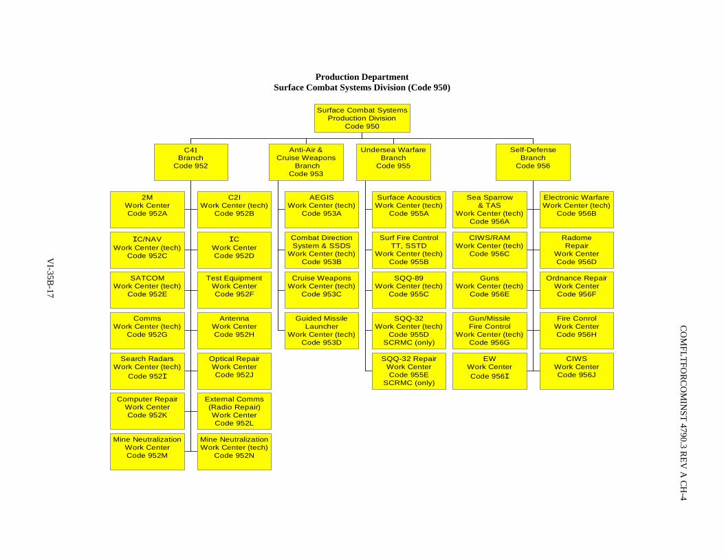
Production Department Surface Combat Systems Division (Code 950)
2MWork CenterCode 952A
C2IWork Center (tech)
Code 952B
IC/NAVWork Center (tech)
Code 952C
ICWork CenterCode 952D
SATCOMWork Center (tech)
Code 952E
Test EquipmentWork CenterCode 952F
CommsWork Center (tech)
Code 952G
AntennaWork CenterCode 952H
Search RadarsWork Center (tech)
Code 952I
Optical RepairWork CenterCode 952J
Computer RepairWork CenterCode 952K
External Comms(Radio Repair)Work CenterCode 952L
Mine NeutralizationWork CenterCode 952M
Mine NeutralizationWork Center (tech)
Code 952N
C4IBranch
Code 952
AEGISWork Center (tech)
Code 953A
Combat DirectionSystem & SSDS
Work Center (tech)Code 953B
Cruise WeaponsWork Center (tech)
Code 953C
Guided MissileLauncher
Work Center (tech)Code 953D
Anti-Air &Cruise Weapons
BranchCode 953
Surface AcousticsWork Center (tech)
Code 955A
Surf Fire ControlTT, SSTD
Work Center (tech)Code 955B
SQQ-89Work Center (tech)
Code 955C
SQQ-32Work Center (tech)
Code 955DSCRMC (only)
SQQ-32 RepairWork CenterCode 955E
SCRMC (only)
Undersea WarfareBranch
Code 955
Sea Sparrow& TAS
Work Center (tech)Code 956A
Electronic WarfareWork Center (tech)
Code 956B
CIWS/RAMWork Center (tech)
Code 956C
RadomeRepair
Work CenterCode 956D
GunsWork Center (tech)
Code 956E
Ordnance RepairWork CenterCode 956F
Gun/MissileFire Control
Work Center (tech)Code 956G
Fire ConrolWork CenterCode 956H
EWWork CenterCode 956I
CIWSWork CenterCode 956J
Self-DefenseBranch
Code 956
Surface Combat SystemsProduction Division
Code 950
VI-35B
-17
CO
MFLTFO
RC
OM
INST 4790.3 R
EV A
CH
-4

C
OM
FLTFOR
CO
MIN
ST 4790.3 REV
A C
H-4
Production Department Quality Control Division (Code 980)
Sub QualityControl Branch
Code 981(MARMC Only)
SurfaceQuality Control
BranchCode 982
Non-DestructiveTest Branch
Code 983
Quality ControlDivision
Code 980
VI-35B
-18

Production Department Diving Production Division (Code 990)
Team 1Code 990AA
Team 2Code 990AB
Team 3Code 990AC
Team 4Code 990AD
Team 5Code 990AE
Team 6Code 990AF
Team 7Code 990AG
Weld TeamCode 990AH
Underwater RepairWork CenterCode 990A
DivingSupport/Equipment MaintenanceWork CenterCode 990B
Recompression Chamber/MedicalWork CenterCode 990C
Diver TrainingWork CenterCode 990D
Scheduling/QAWork CenterCode 990E
Diving Production DivisionCode 990
EDO Diving Officer(Collateral Duty)
VI-35B
-19
CO
MFLTFO
RC
OM
INST 4790.3 R
EV A
CH
-4
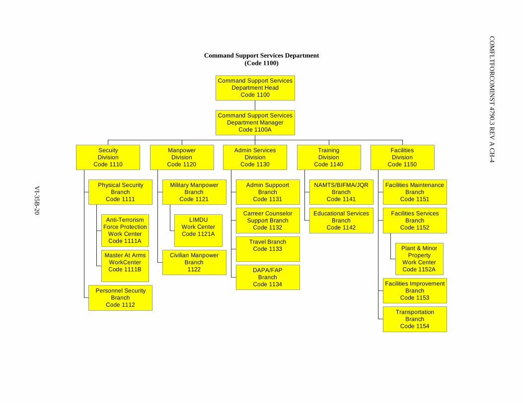
C
OM
FLTFOR
CO
MIN
ST 4790.3 REV
A C
H-4
Command Support Services Department (Code 1100)
Anti-TerrorismForce Protection
Work CenterCode 1111A
Master At ArmsWorkCenterCode 1111B
Physical SecurityBranch
Code 1111
Personnel SecurityBranch
Code 1112
SecuityDivision
Code 1110
LIMDUWork CenterCode 1121A
Military ManpowerBranch
Code 1121
Civilian ManpowerBranch1122
ManpowerDivision
Code 1120
Admin SuppoortBranch
Code 1131
Carreer CounselorSupport Branch
Code 1132
Travel BranchCode 1133
DAPA/FAPBranch
Code 1134
Admin ServicesDivision
Code 1130
NAMTS/BIFMA/JQRBranch
Code 1141
Educational ServicesBranch
Code 1142
TrainingDivision
Code 1140
Facilities MaintenanceBranch
Code 1151
Plant & MinorProperty
Work CenterCode 1152A
Facilities ServicesBranch
Code 1152
Facilities ImprovementBranch
Code 1153
TransportationBranch
Code 1154
FacilitiesDivision
Code 1150
Command Support ServicesDepartment Manager
Code 1100A
Command Support ServicesDepartment Head
Code 1100
VI-35B
-20
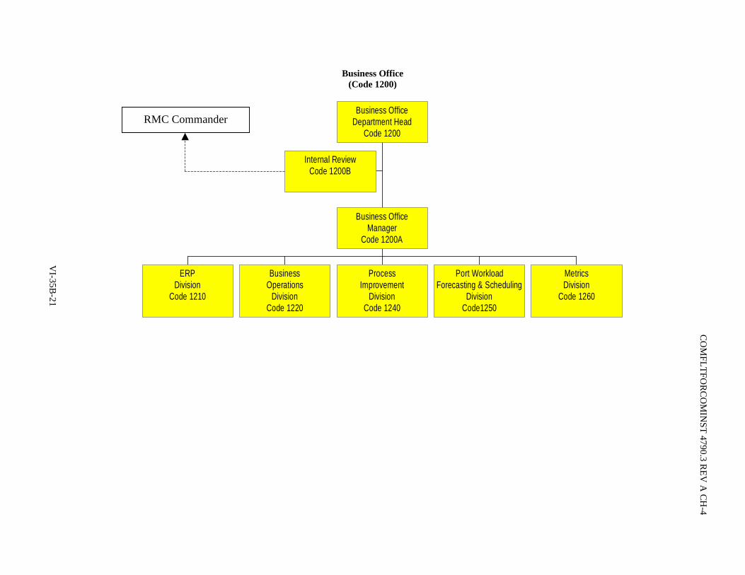
Business Office (Code 1200)
Internal ReviewCode 1200B
ERPDivision
Code 1210
BusinessOperations
DivisionCode 1220
ProcessImprovement
DivisionCode 1240
Port WorkloadForecasting & Scheduling
DivisionCode1250
MetricsDivision
Code 1260
Business OfficeManager
Code 1200A
Business OfficeDepartment Head
Code 1200RMC Commander
VI-35B
-21
CO
MFLTFO
RC
OM
INST 4790.3 R
EV A
CH
-4

C
OM
FLTFOR
CO
MIN
ST 4790.3 REV
A C
H-4
Information Technology (Code 1230)
NMCI Admin OfficeACTR
Code 1230B
Admininstrative SupportOffice
Code 1230C
LAN Service & Repair Work CenterCode 1231A
Microcomputer Repair Work CenterCode 1231B
Communications Center Work CenterCode 1231C
Network & CommunicationManagement Division
Code 1231
Application Development Work CenterCode 1232A
Application Support Work CenterCode 1232B
Web Development & ApplicationsManagement Division
Code 1232
Information Assurance/ISSMCode 1233
Information TechnologyManager
Code 1230A
Information TechnologyDept HeadCode 1230
VI-35B
-22

COMFLTFORCOMINST 4790.3 REV A CH-2
VOLUME VI
CHAPTER 36
SURFACE SHIP/AIRCRAFT CARRIER MODERNIZATION PROGRAM (SHIPMAIN)
REFERENCES.
(a) OPNAVINST 4720.2 - Fleet Modernization Program (FMP); Policy For (b) NAVSEA SL720-AA-MAN-010/020 - Fleet Modernization Program (FMP) Management and
Operations Manual (c) CLF/CPFINST 4720.3 - Management of Afloat Combat Systems and C4I Installations and
Improvements (d) DODINST 5000.2 - Operation of the Defense Acquisition System
LISTING OF APPENDICES.
A Modernization Plan Flowchart B Ship Change Document Template C Technical Assessment Flowchart D Cost Benefit Analysis Flowchart E Alteration Figure of Merit Flowchart F Voting Database Flowchart G Entitled Process Milestones
36.1 SCOPE. This chapter is applicable to all Surface/Carrier Force ships and shore activities involved in ship modernization. The provisions of this chapter have been developed in collaboration with Naval Operations (OPNAV). Where there are conflicts with references (a) and (b), this chapter shall take precedence until such time as OPNAV implementing directives can be modified/issued. References (c) and (d) govern the management of afloat Combat Systems and Command, Control, Communications, Computers, Collaboration and Intelligence installations and improvements, and Initial Adversary Vulnerability Assessment policies and remain in effect as written. Type Commander (TYCOM) Maintenance Directorates shall be the lead for ensuring implementation. Ships will continue the current practice of forwarding change requests to the Immediate Superior In Command (ISIC), who will forward the change request to the respective TYCOM for entry into the Navy Data Environment (NDE). Only alterations entered in NDE will be considered for inclusion in Modernization Programs. This chapter is not applicable to submarines. Submarines will continue to utilize existing instructions.
36.2 PURPOSE. The purpose of this chapter is to document the Surface Ship/Aircraft Carrier Modernization Program, which emphasizes early decisions under the control of Commander Fleet Forces Command (CFFC), Commander Pacific Fleet, and Commander Naval Network Warfare Command, and expands on the decision process for deciding which alterations and modifications will be developed, procured, certified and installed on all surface ships and aircraft carriers. The objective is to assure that fleet modernization investments address the fleet's greatest concerns and are integrated and prioritized across Strike Groups, ships, systems and warfare areas. The process directly involves Navy leadership at all levels (Fleet, OPNAV, Force TYCOMs, Systems Commands (SYSCOM) and Program Executive Offices (PEO)) in the programming, planning and installation of modernization in a consistent and disciplined manner.
VI-36-1
COMFLTFORCOMINST 4790.3 REV A CH-3
36.3 BACKGROUND. The program is implemented as part of Ship Maintenance (SHIPMAIN) to modify the Fleet Modernization Program (FMP) due to Fleet concerns with the FMP which include alterations developed and hardware procured but never installed, significant changes to availability work packages after authorization letter issuance, and alteration installation problems caused by failure to satisfy planning milestones. While these issues are often times driven by overall funding instability in Navy budgets and changing priorities, the associated costs consume modernization funding which minimizes the ability to modernize ships to meet Fleet requirements. The current FMP, documented in reference (b), provides a structure for the orderly identification, approval, design, planning, programming, budgeting, installation, life cycle support and configuration control of military, technical, and survivability improvements to all ships of the active and reserve fleets. SHIPMAIN was developed to concentrate on the early decision process regarding which alterations are to be accomplished. This process provides timely Fleet involvement and the assurance that changes are driven by current fleet requirements. This chapter also provides overall prioritization in the alterations to be accomplished and discipline and accountability in the adherence to FMP processes.
36.4 PROCESS. Appendix A provides a flowchart of the entitled modernization process decision and prioritization.
36.4.1 Key Elements. Key elements of the Ship/Carrier Modernization Program are:
a. A single process to identify, evaluate and approve all hardware and computer software modifications to all ships and ship's systems. The process is based on approved business rules and is owned by the Force TYCOMs Commander Naval Surface Forces/Commander Naval Air Forces (COMNAVSURFOR/COMNAVAIRFOR). The process operates in concert with Acquisition Program processes of reference (c).
b. Consolidation of all alterations into two types:
(1) Fleet alterations funded by the Fleet.
(2) Program alterations funded by the SYSCOMs/PEOs.
c. A four-phase process (Preliminary Analysis, Concept Design, Design Development, Ship Integration) supported by Decision Points at the end of Phases I-III. Senior Fleet/OPNAV personnel comprise the Decision Boards identified in paragraph 36.6 of this chapter. Provisions exist to combine Phases II and III for less complex changes as delineated in paragraph 36.4.8 of this chapter. Any major changes encountered during Ship Integration will require reporting back to Decision Point 3 for approval to continue the Ship Change.
d. A single NDE database, maintained by Naval Sea Systems Command (NAVSEA) 04. The Ship Change Document (SCD), which replaces the Justification Change Form, Ship Alteration Record, in service Engineering Change Proposal and all other alteration documents used in the FMP, will be entered and tracked in NDE from inception through installation in the last applicable ship. Appendix B illustrates the SCD template. This SCD is a living document and may not look the same in NDE. Only SCDs entered in NDE will be considered for inclusion in modernization plans for specific hulls.
e. Involvement of Fleet, OPNAV, TYCOMs, SYSCOMS and PEOs in the decision making process, utilizing three boards of stakeholders at the O-6, one and two star Admiral, and three star Admiral level. Voting members of the boards represent appropriate Fleet and OPNAV organizations. SYSCOM and PEO representation is included to validate the readiness of the alteration to proceed to the next step. Paragraph 36.5.2 of this chapter addresses the business rules associated with the voting process. Depending on cost and impact thresholds, decisions are made by one of the three boards. An electronic voting capability (eVote), embedded in NDE, will be used on a continuing basis to facilitate timely action by the boards, and minimize the need for boards to formally convene. NAVSEA 04 will ensure
VI-36-2
COMFLTFORCOMINST 4790.3 REV A CH-3
data is available to voting members 10 to 14 days prior to required voting. As noted on the SHIPMAIN Modernization Flow Chart, Appendix A of this chapter, Technical Assessments are conducted at three points in the process, and in conjunction with the Alteration Figure of Merit (AFOM) and Cost Benefit Analysis (CBA) blocks, are assembled in a Recommended Change Package (RCP) which provide the basis for decisions made by the O-6, 1/2 Star and 3 Star Boards.
(1) The O-6 level board approves Fleet alterations except in cases where the scope and complexity dictate referral to a higher level board, makes the majority of decisions involving the lower cost and lesser impact Program alterations, and provides recommendations for the higher level boards.
(2) The one and two star board validates the O-6 board decisions and provides Fleet/OPNAV/claimant recommendations to Acquisition Category (ACAT) III and ACAT IV and below program milestone decision authorities.
(3) The three star board sets overall priorities, makes the decisions involving the higher cost and higher impact alterations, validates one and two star board decisions, provides Fleet/OPNAV/claimant recommendations to ACAT I and ACAT II program milestone decision authorities, and approves the Ship/Carrier Modernization Pre-Overseas Movement (POM) Submission (Capability Plan).
f. The SHIPMAIN Modernization process is designed to accommodate initial submission of an SCD early in the life of requirements definition for a ship or system capability/program. This is accomplished by submitting an SCD for the system/program across the Five Year Defense Program (this includes all software support programs). As changes are more definitively identified, separate SCDs will be developed as supportive to the capability/program SCD (examples of supportive SCDs can include hardware updates, software upgrades, Hull, Mechanical and Electrical (HM&E) changes, etc.).
36.4.2 Decision Points. There are three main decision points exercised by the review boards (Steps 60, 140 and 220 of Appendix A); and all three are supported by technical assessments, cost benefit analyses and figure of merit assessment reviews.
a. Decision Point 1: The purpose of Decision Point 1 is to approve the entry of the concept design and to include the proposed change in the Modernization Plan. Approval at this point constitutes Resource Sponsor commitment to fully fund the change in the POM. It is recognized that follow-on budget decisions beyond the control of the Resource Sponsor may require relief from that commitment, however, the Resource Sponsor will then advise the Voting Boards for consideration of the change in future budgets. Some programs/capabilities may not be defined to the alteration level based on the need for further technical definition. In those cases, the program/capability will be submitted as a single SCD for consideration at Decision Point 1. In Phases II and III, the program/capability will be defined in multiple alterations as required.
b. Decision Point 2: The purpose of Decision Point 2 is to validate/update the Modernization Plan and to proceed with design development, with Resource Sponsor confirmation that funds exist in the budget to fully execute the Ship Change.
c. Decision Point 3: The purpose of Decision Point 3 is to validate/update the Modernization Plan and to proceed with material procurement and scheduling installations with Resource Sponsor confirmation that funds exist in the budget to fully execute the Ship Change.
36.4.3 Ship Change Document. The principal document used in the Technical Assessments is the SCD which remains with an alteration throughout its development. The SCD replaces the Justification Cost Form, In-service Engineering Change Proposal, the Ship Alteration Record and all other alteration documents (e.g., Field Change, Ordnance Alteration) which were used in the former FMP. The SCD is prepared by any activity and must meet
VI-36-3
COMFLTFORCOMINST 4790.3 REV A CH-3
VI-36-4
specific minimum requirements addressed in paragraph 36.5 of this chapter, in order to proceed beyond block 10. After the SCD is prepared it is forwarded to an authorized submitting activity for entry into NDE. For SCDs submitted as described in paragraph 36.4.1 of this chapter, all cost information shall be complete and cover the entire program. A submitted supportive SCD's costs will be decremented from the capability/program SCD. Authorized submitting activities are:
a. TYCOMs.
b. OPNAV.
c. PEOs.
d. Participating Managers (PARM).
e. Life Cycle Managers.
f. Commander Fleet Forces Command.
36.4.3.1 Phase I. The Phase I steps consist of:
a. The initiator shall provide data for all SCD Phase I fields at a minimum prior to submission to the submitter.
b. A preliminary tracking number shall be automatically assigned by the system (NDE).
c. The initiator and the submitter shall have the ability to review the draft SCD at any time in the preparation process.
d. This form shall be able to be viewed at any point in the process once submitted.
e. Minimum header data required uniquely defining the Configuration Change (functional definition, class affectivity, functional areas).
f. Fleet requirement, description of change, and impact to the Fleet if not accomplished.
g. The submitter will either approve the change and put into NDE officially or kill the change. Entering an SCD at this point establishes that the SCD has officially entered the SHIPMAIN Entitled Process.
h. The submitter will ensure there are no duplicate SCDs.
i. The submitter shall be able to expedite Alterations that are considered to be critical by Fleet by setting an "Expedite" flag in SCD. Expedited SCDs are considered first in any process work queue.
j. The submitter shall be able to identify previously shelved alterations and resubmit to the process using previously assigned SCD identification via TYCOM or OPNAV Sponsor.
k. The expedite alert box should be checked "yes" when operational readiness (i.e., correction of a C4 Casualty Report) or safety to personnel is effected.
l. All authorized SCDs shall be assigned a sequential Ship Change Number by the system (NDE).
NOTE: THE PROCESS ENABLES LESS COMPLEX CHANGES TO COMBINE PHASES II AND III, AS DETERMINED IN THE INITIAL TECHNICAL ASSESSMENT.
COMFLTFORCOMINST 4790.3 REV A CH-2
36.4.3.2 Phase II. The Phase II steps consist of:
a. The Submitter receives approval of SCD Phase I and notification to complete SCD Phase II or IIa, if approved by Voting Board, form.
b. The submitter will utilize internal processes to complete preliminary engineering and provide a draft SCD Phase II to the Change Manager in the respective Ship Program Manager Office.
36.4.3.3 Phase III. The Phase III steps consist of:
a. Submitter receives approved SCD Phase II.
b. The submitter will utilize internal processes to complete engineering and design development and provide a draft SCD Phase II (a) or III.
36.4.4 Technical Assessment Teams. Technical Assessment Teams (TAT) are assigned at NAVSEA and will be made up of subject matter technical experts related to the scope of the SCD.
36.4.4.1 Technical Assessments. Technical Assessments are performed at three separate stages in the process to support decisions to complete preliminary engineering, design development and detail specifications.
36.4.4.2 Technical Assessment Business Rules. Appendix C reflects the Technical Assessment flowchart.
36.4.4.3 Phase I Technical Assessment Rules. The following Phase I Technical Assessment Business Rules apply:
a. Ship's Program Manager (SPM) cannot send a change idea to history.
b. TAT review process will take no longer then 5 days.
c. Any negative recommendation must include a justification.
d. Due to limited engineering requirements and limited impacts to existing equipments and the ships, some changes may be permitted to have Phase II and Phase III combined. In order to determine if there is sufficient reason to combine these two phases for a particular change, the TAT must consider the Scope (SCD Phase I, Item 3.a) of the change.
36.4.4.4 Technical Assessment Teams. TATs will be allowed to change fields to correct data. If any information is changed a record of the change will be kept and the submitting Point of Contact notified for concurrence.
36.4.4.5 Changes. Identify changes that may supersede or be redundant with an existing change. Should the SPM require additional clarification, endorsement will not be forwarded prior to attempting issue resolution via TAT Lead. Unresolved issues will be noted in the Technical review comments and forwarded.
36.4.4.6 Phase II Technical Assessment Rules. Should the SPM require additional clarification, endorsement will not be forwarded prior to attempting issue resolution via TAT Lead. Unresolved issues will be noted in the Technical Assessment comments and forwarded. TAT will take no longer than 45 days to complete.
36.4.4.7 Phase II(a) Update Technical Assessment. In this phase, complete technical data will be available for review in the draft Phase II(a) SCD. Phase II(a) will combine Phases II and III in order to streamline the process. The same basic tenets of the process described for Phases II and III will apply. The TAT will complete their review within 60 days.
VI-36-5
COMFLTFORCOMINST 4790.3 REV A CH-2
36.4.4.8 Phase III Technical Assessment Rules. In this phase, complete technical data will be available for review in the draft Phase III SCD, but the basic tenets of the process described for Phases I and II will apply. TAT will complete their review in this phase in no more than 60 days.
36.4.5 Cost Benefit Analysis. A CBA is conducted at step 40 of the process, and then updated at steps 120 and 200, to support Modernization Plan decisions by the three established review boards. Appendix D reflects the Cost Benefit Analysis Flowchart. It is imperative that sound cost estimates be developed to make these analyses valid. The CBAs, the Technical Assessments and AFOM assignments together form the RCP which are provided to the respective review boards to support board decisions on proposed shipboard changes. These analyses are accomplished by Independent Cost Review (ICR) Teams under the direction of NAVSEA 017. All cost data to support the CBA process is derived from the SCD, initially submitted by the activity proposing the change, and then updated throughout the process.
36.4.5.1 Phase I Preliminary Analysis Business Rules. In this phase, the purpose of the ICR Team is to review cost data entered in the SCD for completeness and reasonableness to support Decision Point I. The input to the CBA process is an affirmative designation by the Technical Analysis Team. In this phase, the ICR Team is expecting high-level cost information (e.g. Concept Development Cost, Preliminary Engineering Cost, Design Development Cost, Procurement Cost and Installation Cost). This cost data will be provided by responsible PARMs and SPMs as direct inputs into the SCD resident in NDE. NDE maps this data into a Cost Reduction and Effectiveness Improvement (CREI) document designated as the CREI Template which automatically calculates cost metrics such as Return on Investment, Net Present Value (NPV) and Payback Period. When the calculations have been made by the CREI Template, a notification is electronically forwarded to Subject Matter Expert (SME) members of the ICR Team. The cost data fields in NDE will be locked precluding uncontrolled changes and can only be unlocked by a member of the ICR Team. If the ICR Team has questions about the data, they will be provided back to the data source through a "feedback" loop managed by NAVSEA 017. The feedback process will only be exercised one time (if necessary), and will then be forwarded to the Decision Board for their review and decision. The ICR Team will not alter cost data; but will use the feedback loop as the conduit for questioning submitted cost data. Should the source of the cost data determine a change to submitted cost information is warranted based on ICR Team questions, he/she will enter the corrected data in NDE after consultation with the NAVSEA 017 Area Coordinator. The Area Coordinator will obtain concurrence from respective ICR Team members and unlock applicable cost data fields. The source of the cost data will have two (2) working days to make the change to appropriate fields, at which time the fields will again lock and the data passed to the RCP and review by the appropriate board. In those instances where the source of the cost data does not agree with changes proposed by the ICR Team, the unaltered data will be forwarded for inclusion in the RCP as well as the ICR Team comments.
36.4.5.2 Phase II Concept Design Cost Benefit Analysis Update. In this phase, the ICR Team is looking for more fidelity in the cost data provided to support Decision Point 2. The basic CBA Process in this phase mirrors Phase I, with the following exceptions/additions:
a. If the Program Manager (PM) experiences cost growth of greater than 10% in the total program budget, the PM shall notify the appropriate Sponsor (Fleet or OPNAV). The Sponsor may decide to address this issue with the Decision Board.
b. In the year of execution, if a cost shortfall identified is within the Program Managers ability to cover within his program, the Sponsor shall be notified if there is any change to the Modernization Plan.
c. If the total cost estimate of an alteration exceeds the appropriate threshold for the respective phase (i.e. 40% Phase I, 25% Phase II, 15% Phase III), the PM shall notify the appropriate Sponsor (Fleet or OPNAV). At that point, the Sponsor may decide to address the issue with the Decision Board.
36.4.5.3 Phase III Design Development Cost Benefit Analysis Update. In this phase, the ICR Team is expecting detailed cost data to be available to support Decision Point 3, however, the basic CBA Process mirrors that conducted in Phases I and II.
VI-36-6

COMFLTFORCOMINST 4790.3 REV A CH-2
36.4.6 Alteration Figure of Merit. The AFOM is used in concert with the Technical Assessment and the CBA to form the RCP, which is provided to and forms the basis for the Board Decisions. The AFOM is initially calculated prior to Decision Point 1, and then updated to support Decision Points 2 and 3. The AFOM is defined as the quantitative "War Fighting or Readiness Benefit" assigned to each proposed alteration. Appendix E reflects the AFOM Flowchart. Fleet and OPNAV members of the 3-Star Board weight this structure annually, on or about October of the fiscal year, using Fleet Forces Command guidance which is based on numbered Fleet and TYCOM Integrated War Fighting and Readiness priorities and additional inputs from the Chief of Naval Operations (CNO) Campaign Analysis and Sea Trials processes. There are two components to the process of assigning AFOMs to each SCD:
a. The annual establishing of weights based on Fleet priorities.
b. The continuous action by respective TYCOMs to assign index values to standardized rating scales that address:
(1) Suitability (Reliability, Maintainability, Operational Availability, Supportability, Safety).
(2) Quality of Service/Quality of Life (QOS/QOL).
(3) Capability.
Separate from this annual event, TYCOMs continue to review and assign index values to the previously noted standard rating scales for each change as part of the throughput of SCDs. COMNAVSURFOR/COMNAVAIRFOR will rate each proposed alteration using established rating scales and Fleet Staff SME recommendations to calculate the AFOM through a Flag-weighted algorithm that resides in NDE. The TYCOM Rating Scale Index Value assignments are entered in NDE and calculated to provide an overall AFOM and nested AFOMs that articulate the change benefits of Capability, Suitability and QOS/QOL to the SHIPMAIN Decision Board members.
36.4.7 Annual Assignment of Weights. The annual assignment of weights is a key component of the AFOM assignment and ensures the AFOM process remains current with Fleet/Navy priorities. The weights are the foundation of the algorithm in NDE which calculates the AFOM assignment for each alteration.
a. The SHIPMAIN 3 Star Board shall annually determine the numerical weights of the Naval Power 21-based AFOM Benefit Structure using the Merit Assessment Questionnaire. The determination of AFOM Benefit weights will be executed using a pair-wise mathematical analysis tool. Each SHIPMAIN Fleet 3 Star Board member indicates his/her preferences using the formatted pair-wise questionnaire provided in the Merit Assessment Questionnaire.
b. Respective TYCOMs will continue to review and assign initial AFOMs as dictated by the throughput of SCDs, using SMEs from activities in the area associated with each SCD. Each SCD that successfully completes the Technical Assessment block in each phase is mapped by the submitter in NDE by Naval Capability and routed to cognizant TYCOMs. The TYCOMs will canvass appropriate SMEs for input, providing relevant TYCOM-generated questions to the SME to assist in their review. Using these questions, the TYCOM SME representative will review the information listed in the SCD and will provide inputs back to the TYCOM by recommending the Index values associated with the AFOM Benefit Structure Rating Scales discussed earlier. The TYCOM will review inputs and enter the final Index value in NDE. NDE will aggregate TYCOM inputs and automatically calculate or recalculate the AFOM based on the algorithm which reflects the weights described above. This process is replicated in each of the first three phases (Preliminary Analysis, Concept Design, Design Development) to support the three decision points. An overall AFOM score and a breakout of AFOM by Capability, Suitability, QOS/QOL and each of the four Naval Power 21 Capabilities (Sea Base, Sea Strike, Sea Shield, ForceNet) will be included on the RCP.
VI-36-7

COMFLTFORCOMINST 4790.3 REV A CH-3
36.4.8 Combining of Phases. Guidelines for combining of Phases II and III:
a. If the Scope is Internal Equipment Modification, all of the following criteria must be met:
(1) The change can be accomplished without changing an interface external to the equipment or system.
(2) The change is made within the equipment or system.
(3) The change does not negatively impact Battle Force/Strike Force Interoperability.
(4) The change does not impact shipboard distributive systems (i.e., water, ventilation, electrical, power, etc.), Ship Selected Records or interfacing equipment or systems, compartmental arrangement records or Damage Control records.
b. If the scope is Ship Modification all of the following criteria must be met:
(1) The change does not negatively impact Battle Force/Strike Force Interoperability.
(2) The change does not impact ship's stability records (weight & moment).
(3) The change does not impact or alter the 3-dimensional footprint of the equipment being replaced.
(4) The change does not impact shipboard distributive systems (i.e., water, ventilation, electrical, power, etc.), Ship Selected Records or interfacing equipment or systems, compartmental arrangement records, or Damage Control records.
(5) The change does not impact manning levels.
c. If all of the guidelines listed above are met, the technical assessment team may recommend Phases II and III be combined.
d. If the Phase I O-6 Board determines Phases II and III can be combined, then both Phases II and III of the SCD must be completed before going to the Decision Point 3 O-6 Board.
e. Duration of Alteration is designated as a Non Permanent Installation (Previously termed Temporary Alteration). These changes will include prototypes, proof-ins and current TEMPALTS. This type of change will adhere to the following guidance:
(1) A non-permanent install will start in Phase I and must be approved at Decision Point 1. After Decision Point 1, the change will proceed to SCD Phase II for concept design.
(2) During concept design a Ship Change Data Package, including Plan of Action and Milestones, will be prepared and the proposal sent through the review process to Decision Point 2 for approval to install.
(3) Approval at Decision Point 2 constitutes approval to install the non-permanent installation. At the completion of the authorized install period the change will either be:
(a) Removed and all documentation forwarded to the review teams and Decision Point 3 to inform all parties of the results.
VI-36-8

COMFLTFORCOMINST 4790.3 REV A CH-3
(b) Make install permanent by forwarding results and Phase III SCD reflecting the need to make the change permanent and to install on other platforms.
(4) Installation will be onboard for pre-specified amount of time not to exceed one deployment cycle or one (1) year.
(5) Sponsoring Activity may utilize internal process to complete preliminary engineering and provide a draft Phase III SCD to the SPM Change Manager, or the SPM may task the Planning Yard to develop a Phase III SCD.
(6) Sponsoring Activity shall provide required documentation (e.g., ICDs) to support completion of the Phase III SCD.
(7) Plan of Action and Milestones required for equipment development.
f. If all of the guidelines listed above are met, the technical assessment team may recommend Phases II and III be combined.
g. If the Phase I O-6 Board determines Phases II and III can be combined, Phases II and IIa of the SCD must be completed before going to the Decision Point 3 O-6 Board.
36.5 VOTING RULES.
36.5.1 Voting Database Rules. The principal document in the voting process is the RCP. The RCP is prepared electronically in NDE, and presents information from the Technical Assessment, AFOM, and CBA. While the RCP provides summary information, the capability exists to drill down to view more detail from the Technical Assessment/AFOM/CBA. The three Decision Boards mentioned in paragraph 36.6 of this chapter will be in place to approve RCPs and authorize SCDs to proceed to the next phase of the process. NDE will be the single authoritative database for Ship Modernization and will support the entire process, from alteration inception through installation of the alteration. NDE will include an electronic voting capability (eVote) to enable Decision Boards to convene virtually and on a continuous basis.
36.5.2 Initiate Ship Change Document Business Rules. The SCD will initially capture the basic idea and associated cost and mission capability information, but will be updated with more detailed information as the change matures through the process. The initiator of the change will prepare the SCD and forward to the organization, in their chain of command, authorized to submit the SCD into NDE (e.g., TYCOMs, OPNAV, PEO, PARM/Life Cycle Managers). The appropriate technical authority will be assigned at NAVSEA and will be responsible for providing updated data in the SCD to support the process through final disposition of the change.
36.6 DECISION BOARDS. The three decision points in the process (i.e., Authorize and Fund Preliminary Engineering, Design Development and Procurement/Installation) are accomplished through the three Decision Boards (O-6, 1/2 Star, 3 Star). These decisions feed the POM/Budget process to create and sustain a fully funded ship Modernization Plan (MP). A positive decision at Decision Point 1 constitutes Resource Sponsor commitment to fund the alteration through development and final installation. Appendix F reflects the Decision Point Flowchart. For each alteration the Technical Assessment, AFOM Assignment and Cost Benefit Analysis are completed prior to each decision, and aggregated in a RCP to be considered by the voting boards. The RCP will be available on a read only basis in NDE for review by SPM/PM/PARM personnel prior to consideration by the boards. NDE will provide for electronic workflow such that SCD processing up to and including voting by board members can be done virtually. While the boards will operate in a hierarchical mode where decisions made at a lower level board will be validated by the senior board, the following thresholds are established for approval authority:
a. O-6 Board- < $50M Total Cost
b. 1/2 Star Board $50-200M Total Cost
VI-36-9

COMFLTFORCOMINST 4790.3 REV A CH-2
c. 3 Star Board > $200M Total Cost
36.6.1 Board Specific Rules. The following specific rules apply to each Board:
a. O-6 Review Board
(1) Shall meet continuously on a virtual basis and consider all RCPs. For items that are outside their fiscal threshold ($50M total program value) they make recommendations to higher boards.
(2) All members have the opportunity to vote on all RCPs.
(3) Concur or non-concur with recommendation to expedite.
(4) Concur or non-concur with recommendation to go to Phase IIA.
(5) Voting process will be achieved within the following timelines:
(a) 5 working days to vote.
(b) 5 working days to adjudicate funding issues (associated with Funding Concurrence-resource identification). If resource sponsor fails to provide acceptable trade-off, the board has the authority to approve in accordance with SCD.
b. 1-2 Star Review Board
(1) Will meet monthly to review Modernization Plan and to consider forwarded RCPs that fall within their monetary threshold (>$50M and <$200M total program cost).
(2) Concur or non-concur with recommendation to expedite.
(3) Concur or non-concur with recommendation to go to Phase IIA.
(4) Voting process will be achieved within the following timelines:
(a) 20 working days to vote.
(b) 5 working days to adjudicate funding issues (associated with Funding Concurrence-resource identification). If resource sponsor fails to provide acceptable trade-offs, the board has the authority to approve in accordance with SCD.
c. 3 Star Review Board
(1) Will meet quarterly to review Modernization Plan and to consider forwarded RCPs that fall within their monetary threshold (above $200M total program costs).
(a) Approve/disapprove 1-2 Star Board recommendations.
(b) Voting process will be achieved within following timelines:
1 60 days to vote.
VI-36-10
COMFLTFORCOMINST 4790.3 REV A CH-4
2 5 days to adjudicate funding issues (associated with Funding Concurrence-resource identification). If resource sponsor fails to provide acceptable trade-offs, the Board has the authority to approve in accordance with SCD.
(2) Submits annual Modernization Plan to OPNAV N7.
36.7 APPROVAL FOR FLEET ALTERATIONS. Approval for Fleet Alterations shall be via official TYCOM Letter of Authorization at A-12, and entered into NDE. Alterations shall not be authorized for installation unless included in NDE. The TYCOM shall establish Fleet Alteration funding policies for each fiscal year by defining a "fleet modernization control" (i.e. a specified percent of the maintenance budget set aside for Fleet Alteration modernization). Resource sponsor (OPNAV N43) approval to fund alterations that result in exceeding the fleet modernization control will require offsets to be identified to keep the fleet modernization control at the specified level/percentage. If offsets cannot be identified, it will be the responsibility of the TYCOM to increase the fleet modernization control within the constraints of the maintenance budget (i.e. increases to the fleet modernization control will be offset by decreasing the amount of the maintenance budget allotted for maintenance).
36.8 EXECUTION YEAR CHANGES TO MODERNIZATION PLANS. It is expected this process will minimize changes during the execution year. Operational priorities may require some changes after the approved Modernization Plan has been submitted with the annual President's budget submission to Congress. Execution year changes to the approved Modernization Plan will be limited and only as approved by the Voting Boards in accordance with fiscal statutes and regulations.
36.9 METRICS. A goal of the Ship Modernization Program is to instill discipline in the process to ensure stability from alteration inception through final installation, minimizing the deficiencies noted above. To support this stability a number of business rules have been established within this chapter. The metrics established by SHIPMAIN are used by all levels of the chain of command to measure the process, to determine what barriers exist in the entitled process and to predict downstream milestone attainment. Metrics are not to be used to measure performance of individuals. Any methods employed to circumvent collection of valid metrics are counterproductive, mask real process improvement, and often create more work for Maintenance Team members. From a process improvement standpoint, it is far preferable to miss a metric milestone based on good business decisions rather than to work around the process measures to avoid the "hit". Examples of undesirable actions:
a. Cancellation of an aged, unscreened job with subsequent production of a new identical job for the sole purpose of avoiding a high cycle time.
b. Having the ship re-upline a Maintenance and Material Management Maintenance Action Form (2-Kilo) with desired changes, knowing it will over write the shore file, rather than taking the First Pass Yield (FPY) hit and changing the original 2-Kilo.
c. Not making needed changes to a 2-Kilo before screening it to a planning activity just to avoid an FPY hit.
d. Utilizing the date the 2-Kilo is written and uplined as the "when discovered date" vice the date the deficiency was actually discovered in order to avoid a high ship to shore cycle time.
36.9.1 Evaluation. The five selected metrics below will be used to evaluate the Ship Modernization Program processes.
36.9.1.1 Process Effectiveness. For all alteration installation completions, determine if it was accomplished in the same fiscal year as called for in the Modernization Plan developed during the most recent POM cycle. (Example: The Modernization Plan used as the baseline for this metric will be set by POM06 for Fiscal Year (FY)06 and FY07 and set by POM08 for FY08 and FY09.) Metric data will be collected and analyzed monthly with Fleet and Program alterations plotted separately. This same data will be tallied by SYSCOM on an annual basis.
VI-36-11

COMFLTFORCOMINST 4790.3 REV A CH-4
CALCULATION:
1. Total # of Fleet Alterations completed as per the Modernization Plan schedule Total # of Fleet Alterations completed
2. Total # of Program Alterations completed as per the Modernization Plan schedule Total # of Program Alterations completed
a. Source Data and Reporting Frequency for Measurement. All data used for this metric shall come from Navy Data Environment-Navy Modernization (NDE-NM). A separate monthly tally of Fleet and Program alterations installed in accordance with the Modernization Plan will be plotted to provide a trend on the "effectiveness" of the process.
b. Basis for Baseline: Since this metric is based solely on the entitled process, the baseline will be established after 12 months of data collection.
c. Required NDE Fields:
(1) Alteration Identifier.
(2) Alteration Type (Fleet or Program).
(3) Installation FY from most recent POM cycle.
(4) Actual completion FY.
36.9.1.2 Process Efficiency. The process efficiency is the percentage of planned installation dollars that were actually expensed. Comparison of the planned installation dollars to the actual cost of installations performed. For all alteration installation completions, determine if it was accomplished for the estimated cost as provided in the Modernization Plan developed during the most recent POM cycle. (Example: The Modernization Plan used as the baseline for this metric will be set by POM06 for FY06 and FY07 and set by POM08 for FY08 and FY09.) Metric data will be collected and analyzed monthly with Fleet and Program alterations plotted separately.
CALCULATION:
1. Total estimated cost of Fleet Alterations completed as per the Modernization Plan schedule Total actual cost of completed Fleet Alterations
2. Total estimated cost of Program Alterations completed per the Modernization Plan schedule Total actual cost of completed Program Alterations
a. Source Data and Reporting Frequency for Measurement. All data used for this metric shall come from NDE-NM. A separate monthly tally of Fleet and Program alterations installed in accordance with the Modernization Plan will be plotted to provide a trend.
Source Data: NDE-NM
b. Basis for Baseline. Since this metric is based solely on the entitled process, the baseline will be established after 12 months of data collection.
c. Required NDE Fields:
(1) Alteration Identifier.
(2) Alteration Type (Fleet or Program).
VI-36-12

COMFLTFORCOMINST 4790.3 REV A CH-4
(3) Installation cost estimate from most recent POM cycle.
(4) Actual installation completion cost.
36.9.1.3 First Pass Yield. For all SCDs, keep a count of how many are being reviewed for the first time at each major decision point and of these how many are "approved". "Approved" are those that are not "killed" or sent back for rework. Metric data will be collected and analyzed monthly and tallied by SYSCOM on an annual basis.
CALCULATION:
a. FPY 1 (Decision Point 1 - "Authorize Fund Preliminary Engineering")
Total # of SCDs being reviewed for the first time and approved at Decision Point 1 Total # of SCDs being reviewed for the first time at Decision Point 1
b. FPY 2 (Decision Point 2 - "Authorize Fund Design Development")
Total # of SCDs being reviewed for the first time and approved at Decision Point 2 Total # of SCDs being reviewed for the first time at Decision Point 2
c. FPY 3 (Decision Point 3 - "Fund Procurement & Installation")
Total # of SCDs being reviewed for the first time and approved at Decision Point 3 Total # of SCDs being reviewed for the first time at Decision Point 3
d. FPY 4 ("Ship Change (SC) Ready to Install")
Total # of SCDs being reviewed for the first time and Ready to Install (Block 270) Total # of SCDs being reviewed for the first time at "SC ready to install"
36.9.1.4 Productivity. For all SCDs, keep a count of how many are approved at each major decision point. Metric data will be collected and analyzed monthly, and tallied by SYSCOM on an annual basis.
CALCULATION:
1. Total number of alterations approved at Decision Point 1 "Authorize Fund Preliminary Engineering"
2. Total number of alterations approved at Decision Point 2 "Authorize Fund Design Development"
3. Total number of alterations approved at Decision Point 3 "Fund Procurement & Installation"
4. Total number of alterations approved at "SC ready to install" point
a. Source Data and Reporting Frequency for Measurement. All data used for this metric shall come from NDE-NM. Each SCD is assigned a unique identification number in NDE on submission. A separate monthly tally of alterations approved at each point will be plotted to provide a trend on the "productivity" of the process.
b. Basis for Baseline. Since this metric is based solely on the entitled process, the baseline will be established after 12 months of data collection.
c. Required NDE Fields:
(1) SCD identification number.
VI-36-13
COMFLTFORCOMINST 4790.3 REV A CH-4
VI-36-14
(2) Approval status of SCD at each of the decision points Status will be blank for a specific decision point if SCD has not yet reached that block in the process.
(3) Date that decision at each point was reached. Date will be blank for a specific decision point if the SCDs approval status at that point is blank.
36.9.1.5 Sunk Cost. For all SCDs that are entered into NDE under the entitled process, identify and measure the total resources (dollars) invested in SCDs that are subsequently voted to be "Inactive and Killed" at various process decision points. Metric data will be collected and analyzed monthly, and tallied by type of appropriation on an annual basis.
CALCULATION: For all SCDs that are entered into NDE
a. Total of actual dollars expended in all FY for an SCD "killed" at Decision Point 1 (Authorize Preliminary Engineering).
(1) Capture actual expenditures as recorded in NDE as part of the CBA prepared for Decision Point 1.
(2) Metric may be further refined for phase of development and type appropriation per the cost categories recorded in the CBA as follows:
(a) Infrastructure investment – Appropriation/Preliminary Engineering (APPN/PE)
(b) Preliminary Engineering – APPN/PE
b. Total of actual dollars expended in all FY for an SCD "killed" at Decision Point 2 (Authorize Design Development).
(1) Capture actual expenditures as recorded in NDE as part of the CBA prepared for Decision Point 2.
(2) Metric may be further refined for phase of development and type appropriation per the cost categories recorded in the CBA as follows:
(a) Infrastructure investment – APPN/PE
(b) Preliminary Engineering – APPN/PE
c. Total of actual dollars expended in all FY for an SCD "killed" at Decision Point 3 (Authorize Procurement and Installation).
(1) Capture actual expenditures as recorded in NDE as part of the CBA prepared for Decision Point 3.
(2) Metric may be further refined for phase of development and type appropriation per the cost categories recorded in the CBA as follows:
(a) Infrastructure investment – APPN/PE
(b) Preliminary Engineering – APPN/PE
(c) Design Development – APPN/PE
36.10 MILESTONES. Consolidated Cross Functional Team (CFT)-4 and CFT-2, Entitled Process Milestones, are documented in Appendix G of this chapter.

RCP
Alts & MODs Process Map 11 June 03 page 1
OPN
AV
PEO
SYSC
OM
SC
om-
men
tsFl
eet Commander
TYCOM
N6-N7
Nxx
SPM
PARM
PARM
NAVSEA
SPAWARS
NAVAIR
TechnicalAuthority
BInactive
A lts & MODs Process Map 03Jun 04
OPN
AV
PEO
SYSC
OM
SC
om-
men
tsFl
eet CFFC
TYCOM
N6-N7
Nxx
SPM(Indluding
PY)
PARM
PARM
NAVSEA
SPAWAR
NAVAIR
TechnicalAuthority
A
Complete Ship ChangeDocument (SCD). Thiswill be the singledocument that remainswith an Ship Change(SC) throughout itsdevelopment.
Minimum informationlevel is equivalent tothat required to supportAcuisition Milestone Aas defined in DOD 5000series.
Concept Developmentlevel engineering is theresponsibility of thesubmitting activity.
TechAssess
Independent Cost ReviewTeam reviews cost
estimates.
10
20
AFOM and CBA areindependent and executed in
parallel.
NDE CBA
50
Recommendated ChangePackage (RCP) is an executive
summary document withrecommendations.
40
Authorize FundPrelim
Engineering
60
Decision Point 1
Inactive
Yes
No
AFOM
30
50
Idea
APPEN
DIX
A
MO
DER
NIZA
TION
PLAN
FLOW
CH
AR
T
VI-36A
-1 Tech Assessment
CO
MFLTFO
RC
OM
INST 4790.3 R
EV A
CH
-2
CBA Overview
Phase I: Preliminary Analysis
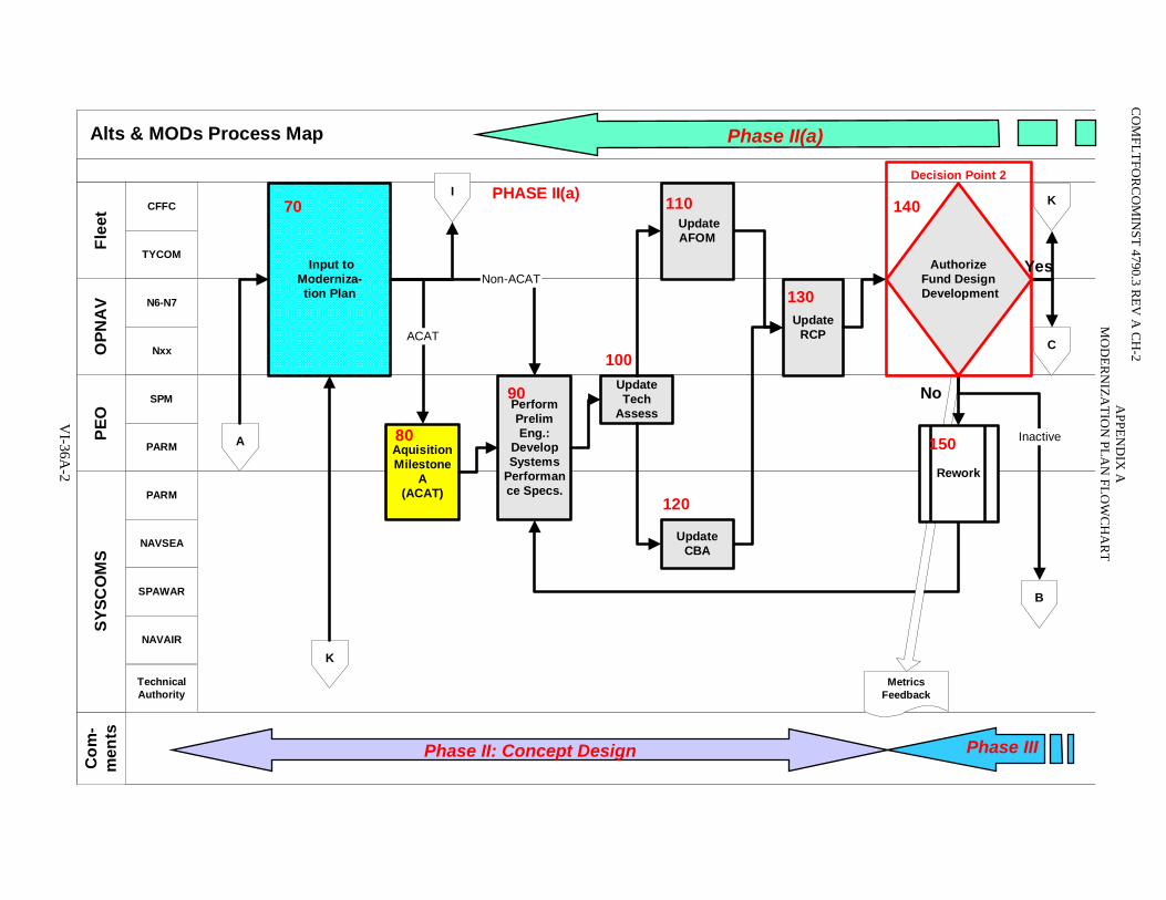
CO
MFLTFO
RC
OM
INST 4790.3 R
EV A
CH
-2
Alts & MODs Process Map 03Jun04
Com
-m
ents
SYSC
OM
SPE
OO
PNA
VFl
eet CFFC
TYCOM
N6-N7
Nxx
SPM
PARM
PARM
NAVSEA
SPAWAR
NAVAIR
TechnicalAuthority
A
ACATC
B
MetricsFeedback
UpdateCBA
UpdateTech
Assess
I
K
K
Input toModerniza-tion Plan
70 UpdateAFOM
UpdateRCP
130
80Aqui80
sitionMilestone
A(ACAT)
Per90
formPrelimEng.:
DevelopSystems
Performance Specs.
Rework
150
PHASE II(a)
Inactive
AuthorizeFund Design Development
Phase II(a)
140
Decision Point 2
Non-ACATYes
No
100
120
110
APPEN
DIX
A
MO
DER
NIZA
TION
PLAN
FLOW
CH
AR
T
VI-36A
-2
Phase IIIPhase II: Concept Design
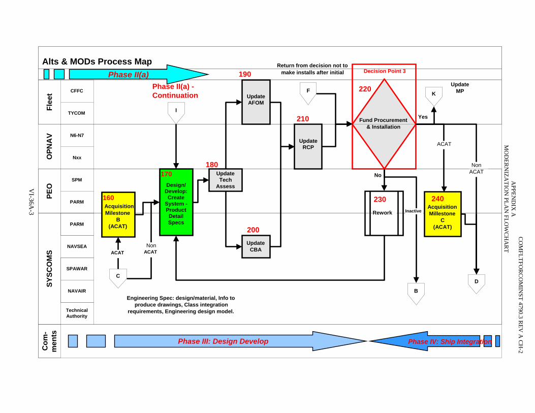
Update RCP
210
Alts & MODs Process Map Return from decision not tomake installs after initial
Com
- m
ents
SY
SCO
MS
PEO
O
PNA
V Fl
eet CFFC
TYCOM
N6-N7
Nxx
SPM
PARM
PARM
NAVSEA
SPAWAR
NAVAIR
Technical Authority
C D
Update Tech Assess
UpdateCBA
200
180
Update AFOM
ACAT
Engineering Spec: design/material, Info toproduce drawings, Class integration
requirements, Engineering design model.
No
Yes
NonACAT 170
Design/ Develop: Create
System - Product Detail Specs
160 Acquisition Milestone
(ACAT) B
A itionMillestone
(ACAT)
cquis240
C
B
I
F Phase II(a) - Continuation K
Rework
230
Fund Procurement& Installation
220Update
MP
Phase II(a)
Phase III: Design Develop Phase IV: Ship Integration
Non ACAT
ACAT
Decision Point 3190
Update RCP
APPEN
DIX
A
MO
DER
NIZA
TION
PLAN
FLOW
CH
AR
T
VI-36A
-3 Inactive
CO
MFLTFO
RC
OM
INST 4790.3 R
EV A
CH
-2
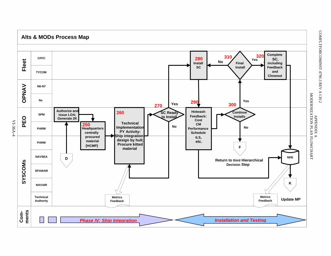
Phase IV: Ship Integration Installation and Testing
Alts & MODs Process Map C
om-
men
tsSY
SCO
Ms
PEO
O
PNA
V Fl
eet
CO
MFLTFO
RC
OM
INST 4790.3 R
EV A
CH
-2
CFFC TYCOM N6-N7 Nx
SPM PARM PARM
NAVSEA SPAWAR NAVAIR
Technical Authority
SC Readyto Install
D
MetricsFeedback
Yes
No
270
MetricsFeedback
NDE
Head25
quarters centrally procured material (HCMP)
0 TechnicalImplementation
PY Activity:Ship integration
design by hull;Procure kitted
material
260
310
F
No
Return to third HierarchicalDecision Step
ContinueInstalls
290 300Hotwash
Feedback:Cost CM
PerformanceSchedule
ILS, etc.
Authorize and issue LOA;
Generate 2K
Install 280 SC
FinalInstall
Yes
CompleteSC,
includingFeedback
andCloseout
No
K
Ye
Yes
Update MP
s320
APPEN
DIX
A
MO
DER
NIZA
TION
PLAN
FLOW
CH
AR
T
VI-36A
-4
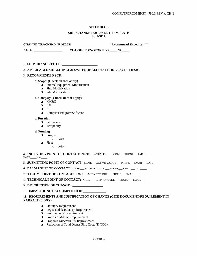
COMFLTFORCOMINST 4790.3 REV A CH-2
APPENDIX B
SHIP CHANGE DOCUMENT TEMPLATE PHASE I
CHANGE TRACKING NUMBER_______________ Recommend Expedite DATE: __________________ CLASSIFIED/NOFORN: YES____ NO____
1. SHIP CHANGE TITLE: ______________________
2. APPLICABLE SHIP/SHIP CLASS/SITES (INCLUDES SHORE FACILITIES): ________________
3. RECOMMENDED SCD:
a. Scope: (Check all that apply) Internal Equipment Modification Ship Modification Site Modification
b. Category (Check all that apply) HM&E C4I CS Computer Program/Software
c. Duration Permanent Temporary
d. Funding Program
o Joint Fleet
o Joint
4. INITIATING POINT OF CONTACT: NAME___ ACTIVITY _____CODE___ PHONE___ EMAIL___ DATE_____N/A_____
5. SUBMITTING POINT OF CONTACT: NAME___ ACTIVITY/CODE ___ PHONE___ EMAIL___DATE_____
6. PARM POINT OF CONTACT: NAME___ ACTIVITY/CODE ___ PHONE___ EMAIL___TBD_____
7. TYCOM POINT OF CONTACT: NAME___ ACTIVITY/CODE ___ PHONE___ EMAIL___
8. TECHNICAL POINT OF CONTACT: NAME___ ACTIVITY/CODE ___ PHONE___ EMAIL___
9. DESCRIPTION OF CHANGE: ___________________
10. IMPACT IF NOT ACCOMPLISHED: ______________
11. REQUIREMENTS AND JUSTIFICATION OF CHANGE (CITE DOCUMENT/REQUIREMENT IN NARRATIVE BOX)
Statutory Requirement Legislated Regulatory Requirement Environmental Requirement Proposed Military Improvement Proposed Survivability Improvement Reduction of Total Owner Ship Costs (R-TOC)
VI-36B-1
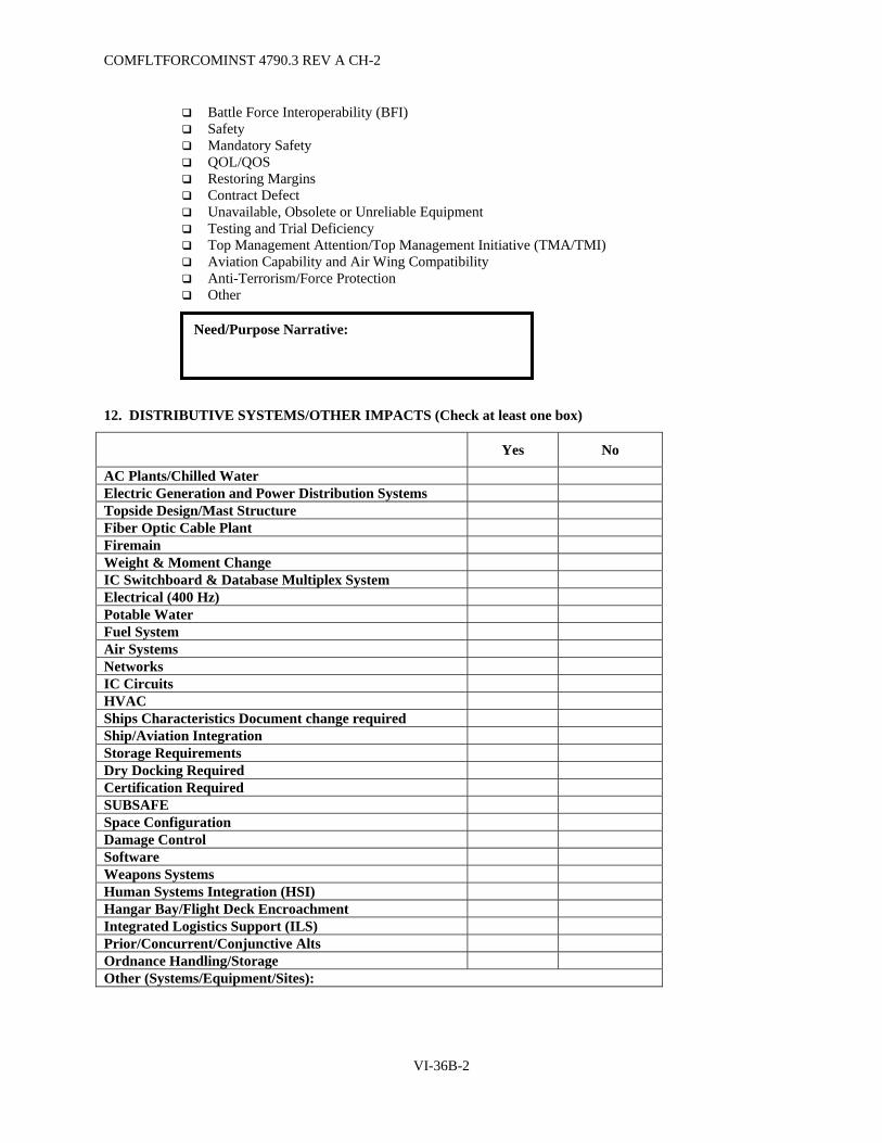
COMFLTFORCOMINST 4790.3 REV A CH-2
Battle Force Interoperability (BFI) Safety Mandatory Safety QOL/QOS Restoring Margins Contract Defect Unavailable, Obsolete or Unreliable Equipment Testing and Trial Deficiency Top Management Attention/Top Management Initiative (TMA/TMI) Aviation Capability and Air Wing Compatibility Anti-Terrorism/Force Protection Other
12. DISTRIBUTIVE SYSTEMS/OTHER IMPACTS (Check at least one box)
Yes No
AC Plants/Chilled Water Electric Generation and Power Distribution Systems Topside Design/Mast Structure Fiber Optic Cable Plant Firemain Weight & Moment Change IC Switchboard & Database Multiplex System Electrical (400 Hz) Potable Water Fuel System Air Systems Networks IC Circuits HVAC Ships Characteristics Document change required Ship/Aviation Integration Storage Requirements Dry Docking Required Certification Required SUBSAFE Space Configuration Damage Control Software Weapons Systems Human Systems Integration (HSI) Hangar Bay/Flight Deck Encroachment Integrated Logistics Support (ILS) Prior/Concurrent/Conjunctive Alts Ordnance Handling/Storage Other (Systems/Equipment/Sites):
Need/Purpose Narrative:
VI-36B-2

COMFLTFORCOMINST 4790.3 REV A CH-2
13. AFOM
SEA SHIELD
Force Protection Protect against SOF & Terrorist Threats Mitigate effects of CBRNE
Surface Warfare Provide Self Defense against Surface Threats Conduct Offensive Operations against Surface Threats
Under Sea Warfare Provide Self Defense against Subsurface Threats Neutralize Submarine threats in the Littorals Neutralize open oceans Submarine Treats Counter Minefields from deep to shallow water Breach Minefields, Obstacles, and Barriers from very shallow water to the beach exit
zone Conduct Mining Operations
Theater Air and Missile Defense Provide Self Defense against Air and Missile Threats Provide Maritime Air and Missile Defense Provide Overland Air and Missile Defense Conduct Sea-Based Missile Defense
SEA STRIKE
Strike Conduct Strike OPS
o Engage Fixed Land Targets o Engage Moving Land Targets
Conduct Special OPS o Provide Precision Targeting o Conduct Direct Action
Conduct Offensive Information Operations o Jam Potential Threats o Conduct Network Attacks
Provide Aircraft Survivability
Naval Fire Support Provide Precision Fires Provide High Volume Fires Provide Extended Range Fires
Maneuver Project/Reposition Forces Assault Centers of Gravity and Critical Vulnerabilities Conduct Concurrent/Follow-on Missions
Strategic Deterrence Conduct Nuclear Strike Provide Assured Survivability
VI-36B-3

COMFLTFORCOMINST 4790.3 REV A CH-2
SEA BASING
Close, Assemble, Employ & Reconstitute Close the Force & Maintain Mobility Provide at Sea Arrival & Assembly Allow Selective Offload Reconstitute & Regenerate at Sea
Provide Integrated Joint Logistics Provide Sustainment for Operations at Sea Provide Sustainment for Operations Ashore Provide Focused Logistics Provide Shipboard and Mobile Maintenance Provide Force Medical Services Provide Advance Base Support
Preposition Joint Assets Afloat Integrate and Support Joint Personnel and Equipment Provide Afloat C2 Physical Infrastructure Provide AFSB Capability for Joint Operations
FORCENET
Communications and Data Networks Provide Communication Infrastructure Provide Network Protection Provide Network Synchronization Provide Information Transfer
Intel, Surveillance and Recon Conduct Sensor management and Information Processing Detect and ID Targets
o Fixed Land Targets o Moving Land Targets o Air and Missile Targets o Surface Targets o Submarine Targets o Mines
Provide Cueing and Targeting Information Assess Engagement Results
Common Operational and Tactical Pictures Provide Mission Planning Provide Battle Management Synchronization Provide Common PNT and Environmental Info Integrate and Distribute Sensor Info Track and Facilitate Engagement of Time Sensitive Targets Track and Facilitate Engagement of Non-Time Sensitive Targets
VI-36B-4

COMFLTFORCOMINST 4790.3 REV A CH-2
14. CONCEPT DEVELOPMENT COST INFORMATION:
15. APPROVAL RECOMMENDATION: Recommended Not Recommended Recommend Re-Work
NUCLEAR POWER DIRECTORATE (As Required) Signature DATE _________ ________ ________
SHIP PROGRAM MANAGER Signature DATE _________ ________ ________
CHANGE TRACKING NUMBER_______________ Recommend Expedite SHIP CHANGE TITLE: ______________________ TECHNICAL REVIEW COMMENTS:
VI-36B-5

COMFLTFORCOMINST 4790.3 REV A CH-2
PHASE II
CHANGE TRACKING NUMBER_______________ Expedite Approved
SHIP CHANGE TITLE: ______________________
DESCRIPTION OF CHANGE: ___________________
IMPACT IF NOT ACCOMPLISHED: ______________
APPLICABLE SHIP/SHIP CLASS/SITES: ________________
DATE: __________________
1. LIST APPLICABLE SHIP(s) WITHIN 5-YEAR DECOMMISIONING WINDOW: ____________________
2. DISTRIBUTIVE SYSTEMS IMPACT: (check box that applies)
Net Increase
No Net Net Decrease Unknown Impact AC Plants/Chilled Water Electric Generation and Power Distribution Systems Topside Design/Mast Structure Fiber Optic Cable Plant Firemain Weight & Moment Change IC Switchboard & Database Multiplex System
3. OTHER CONSIDERATIONS (IF YES, PROVIDE EXPLANATION):
(i) Topside: Yes No
Explanation:
a. Ship Characteristics Document change required: Yes No
Explanation:
b. Ship/Aviation Integration Impact: Yes No
Explanation:
i. Storage Requirements: Yes No
Explanation:
ii. Dry Docking Required: Yes No
Explanation:
iii. Certification Required: Yes No
Explanation (include responsible activity):
(1) SUBSAFE Impact: Yes No N/A
(i) Network Impact: Yes No
Explanation:
(ii) Fuel System Impact: Yes No
Explanation:
VI-36B-6
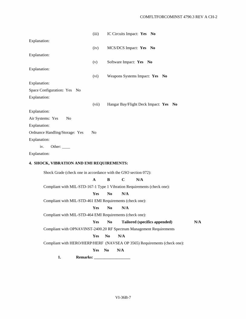
COMFLTFORCOMINST 4790.3 REV A CH-2
(iii) IC Circuits Impact: Yes No
Explanation:
(iv) MCS/DCS Impact: Yes No
Explanation:
(v) Software Impact: Yes No
Explanation:
(vi) Weapons Systems Impact: Yes No
Explanation:
Space Configuration: Yes No
Explanation:
(vii) Hangar Bay/Flight Deck Impact: Yes No
Explanation:
Air Systems: Yes No
Explanation:
Ordnance Handling/Storage: Yes No
Explanation:
iv. Other: ____
Explanation:
4. SHOCK, VIBRATION AND EMI REQUIREMENTS:
Shock Grade (check one in accordance with the GSO section 072):
A B C N/A
Compliant with MIL-STD-167-1 Type 1 Vibration Requirements (check one):
Yes No N/A
Compliant with MIL-STD-461 EMI Requirements (check one):
Yes No N/A
Compliant with MIL-STD-464 EMI Requirements (check one):
Yes No Tailored (specifics appended) N/A
Compliant with OPNAVINST-2400.20 RF Spectrum Management Requirements
Yes No N/A
Compliant with HERO/HERP/HERF (NAVSEA OP 3565) Requirements (check one):
Yes No N/A
1. Remarks: __________________
VI-36B-7
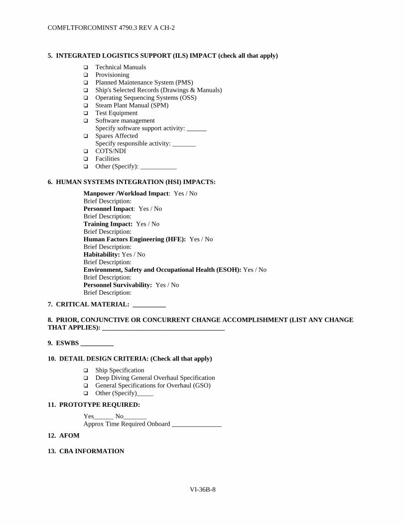
COMFLTFORCOMINST 4790.3 REV A CH-2
5. INTEGRATED LOGISTICS SUPPORT (ILS) IMPACT (check all that apply)
Technical Manuals Provisioning Planned Maintenance System (PMS) Ship's Selected Records (Drawings & Manuals) Operating Sequencing Systems (OSS) Steam Plant Manual (SPM) Test Equipment Software management
Specify software support activity: ______ Spares Affected
Specify responsible activity: _______ COTS/NDI Facilities Other (Specify): ___________
6. HUMAN SYSTEMS INTEGRATION (HSI) IMPACTS:
Manpower /Workload Impact: Yes / No Brief Description: Personnel Impact: Yes / No Brief Description: Training Impact: Yes / No Brief Description: Human Factors Engineering (HFE): Yes / No Brief Description: Habitability: Yes / No Brief Description: Environment, Safety and Occupational Health (ESOH): Yes / No Brief Description: Personnel Survivability: Yes / No Brief Description:
7. CRITICAL MATERIAL: __________
8. PRIOR, CONJUNCTIVE OR CONCURRENT CHANGE ACCOMPLISHMENT (LIST ANY CHANGE THAT APPLIES): _____________________________________
9. ESWBS __________
10. DETAIL DESIGN CRITERIA: (Check all that apply)
Ship Specification Deep Diving General Overhaul Specification General Specifications for Overhaul (GSO) Other (Specify)_____
11. PROTOTYPE REQUIRED:
Yes______ No_______ Approx Time Required Onboard _______________
12. AFOM
13. CBA INFORMATION
VI-36B-8
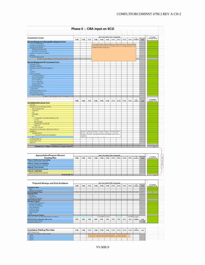
COMFLTFORCOMINST 4790.3 REV A CH-2
VI-36B-9

COMFLTFORCOMINST 4790.3 REV A CH-2
14. APPROVAL RECOMMENDATION:
Recommended Not Recommended Recommend Re-Work
NUCLEAR POWER DIRECTORATE (As Required)
Signature____________ DATE _________ __________ __________
SHIP PROGRAM MANAGER
Signature____________ DATE _________ __________ __________
TECHNICAL REVIEW COMMENTS:
VI-36B-10

COMFLTFORCOMINST 4790.3 REV A CH-2
PHASE III
CHANGE TRACKING NUMBER_______________ Recommend Expedite SHIP CHANGE TITLE: ______________________ DESCRIPTION OF CHANGE: ___________________ IMPACT IF NOT ACCOMPLISHED: ______________ APPLICABLE SHIP/SHIP CLASS/SITES: ________________ DATE: __________________
1. SYSTEM/EQUIPMENT DESIGNATION: ______
2. MODEL NO.____
3. CAGE CODE____
4. DETAILED DESCRIPTION OF CHANGE:__________________
5. DISTRIBUTIVE SYSTEMS IMPACT:
Added Removed
A/C Plants / Chilled Water Dist (Tons A/C)
(CHW GPM) Electrical Generation and Power Dist Sys (kW) Topside Design / Mast Structure (Weight in Tons) Fiber Optic Cable Plant (Yes / No) Firemain (GPM) Ship's Stability (Weight in Tons) IC SWBD and Database Multiplex Sys (Loads)
6. ARE THERE REFERENCES/SUPPORTING DOCUMENTATION IN ADDITION TO STANDARD REQUIREMENTS? Yes____ No_____
7. ESTIMATED WEIGHT AND MOMENT:
WEIGHT VCG LCG TCG
Stability Statement
8. CHANGE MATERIAL/SOFTWARE LIST:
PROCURING ACTIVITY
UNIT OF ISSUE QUANTITY ITEM NO. DESCRIPTION
VI-36B-11

COMFLTFORCOMINST 4790.3 REV A CH-2
9. ARE THERE QUALITY ASSURANCE REQUIREMENTS IN ADDITION TO STANDARD REQUIREMENTS? Yes____ No_______
If Yes, List Requirements:_____________________________
10. SPECIAL DISPOSITION REQUIREMENTS FOR REMOVED MATERIAL:
MATERIAL DISPOSITION
11. INSTALLATION SUPPORT AND TEST EQUIPMENT:_____________
12. SHIPBOARD STOWAGE DETAILS:_______________
13. NAVSEA SHIP INSTALLATION DRAWING (SID) REVIEW REQUIRED: YES___ NO___
14. SPECIAL INDUSTRIAL STOWAGE REQUIREMENTS:_____________________
15. REQUIRED PRIOR, CONJUNCTIVE OR CONCURRENT CHANGES:__________________
16. OTHER SYSTEMS IMPACTS:______________________
17. INSTALLATION DURATION:_____________________
18. HUMAN SYSTEMS INTEGRATION (HSI): Manpower/Workload:__________________________ Personnel:___________________________ Training:____________________________ Human Factors Engineering (HFE):_________________________ Habitability:__________________________ Environment, Safety and Occupational Health (ESOH):__________________ Personnel Survivability:________________________
19. CERTIFICATIONS/QUALIFICATIONS REQUIRED (CHECK ALL THAT APPLY):
ILS Cert _______ Estimated Completion Date _______ HSI Cert _______ Estimated Completion Date _______ EMI Cert_______ Estimated Completion Date _______ WSESRB_______Estimated Completion Date _______ Software Cert______ Estimated Completion Date ________ Shock Qualification____ Estimated Completion Date _________ SPAWAR PPL/SSIL (IT-21) Cert_________Estimated Completion Date________ SEA 62 Interoperability Cert________Estimated Completion Date________ Other Cert (Specify)________ Estimated Completion Date ________ Other Cert (Specify)________ Estimated Completion Date ________
20. DETAILED COST STRUCTURE:
VI-36B-12
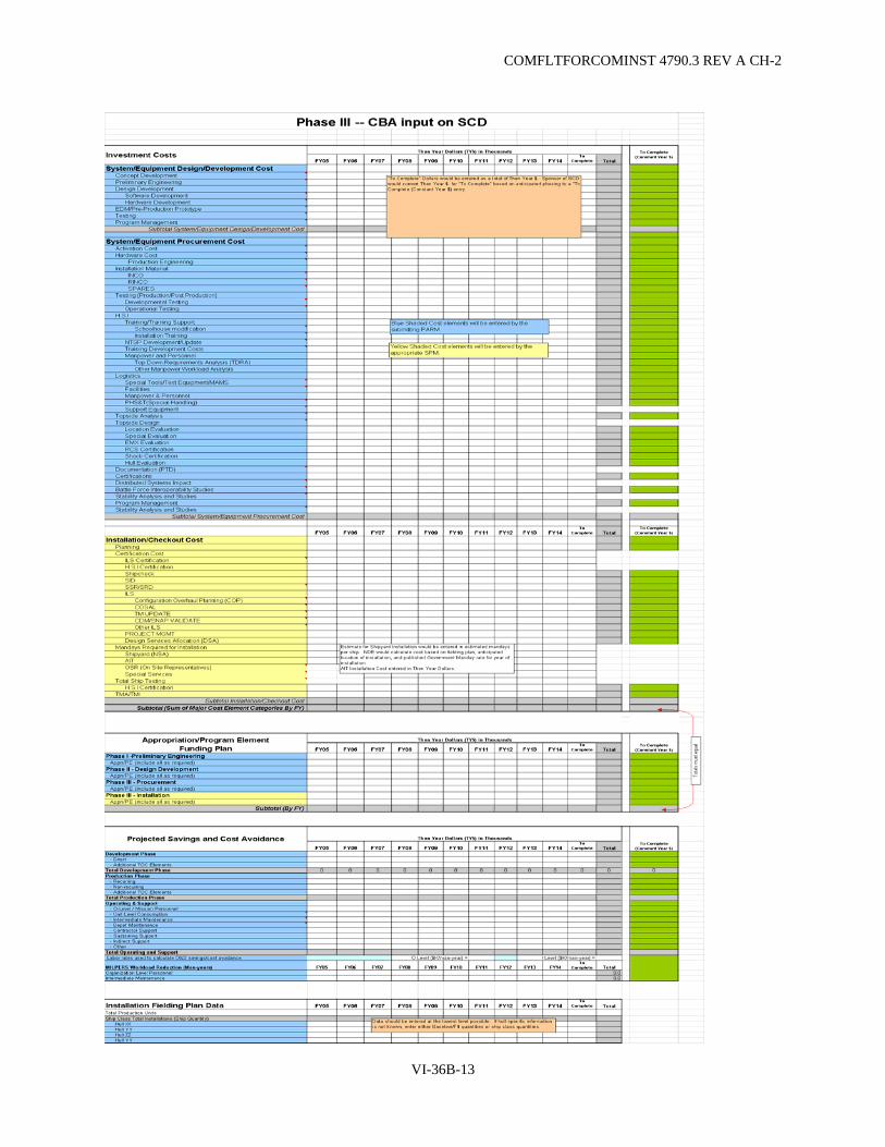
COMFLTFORCOMINST 4790.3 REV A CH-2
VI-36B-13

COMFLTFORCOMINST 4790.3 REV A CH-2
21. APPROVAL RECOMMENDATION:
Recommended Not Recommended Recommend Re-Work
NUCLEAR POWER DIRECTORATE (As Required)
Signature____________ DATE _________ ________ ________
SHIP PROGRAM MANAGER
Signature____________ DATE _________ ________ ________
TECHNICAL EVALUATION COMMENTS:
VI-36B-14

COMFLTFORCOMINST 4790.3 REV A CH-2
CHANGE TRACKING NUMBER_______________ Recommend Expedite SHIP CHANGE TITLE: ______________________ DESCRIPTION OF CHANGE: ___________________ IMPACT IF NOT ACCOMPLISHED: ______________ APPLICABLE SHIP/SHIP CLASS/SITES: ________________ DATE: __________________
1. LIST APPLICABLE SHIP(s) WITHIN 5-YEAR DECOMMISIONING WINDOW: ____________________
2. SYSTEM/EQUIPMENT DESIGNATION: ______
3. MODEL NO.____
4. CAGE CODE____
5. DETAILED DESCRIPTION OF CHANGE:__________________
6. ESWBS __________
7. PROTOTYPE REQUIRED:
Yes_____ No_________ Approx Time Required Onboard_______________
8. DISTRIBUTIVE SYSTEMS IMPACT: (check box that applies)
Added Removed
A/C Plants / Chilled Water Dist (Tons A/C)
(CHW GPM) Electrical Generation and Power Dist Sys (kW) Topside Design / Mast Structure (Weight in Tons) Fiber Optic Cable Plant (Yes / No) Firemain (GPM) Ship's Stability (Weight in Tons) IC SWBD and Database Multiplex Sys (Loads)
9. OTHER CONSIDERATIONS (IF YES, PROVIDE EXPLANATION):
(i) Topside: Yes No
Explanation:
a. Ship Characteristics Document change required: Yes No
Explanation:
b. Ship/Aviation Integration Impact: Yes No
Explanation:
i. Storage Requirements: Yes No
Explanation:
VI-36B-15

COMFLTFORCOMINST 4790.3 REV A CH-2
ii. Dry Docking Required: Yes No
Explanation:
iii. Certification Required: Yes No
Explanation (include responsible activity):
(1) SUBSAFE Impact: Yes No N/A
(i) Network Impact: Yes No
Explanation:
(ii) Fuel System Impact: Yes No
Explanation:
(iii) IC Circuits Impact: Yes No
Explanation:
(iv) MCS/DCS Impact: Yes No
Explanation:
(v) Software Impact: Yes No
Explanation:
(vi) Weapons Systems Impact: Yes No
Explanation:
Space Configuration: Yes No
Explanation:
(vii) Hangar Bay/Flight Deck Impact: Yes No
Explanation:
Air Systems: Yes No
Explanation:
Ordnance Handling/Storage: Yes No
Explanation:
iv. Other: ____
Explanation:
10. SHOCK, VIBRATION AND EMI REQUIREMENTS:
Shock Grade (check one in accordance with the GSO section 072):
A B C N/A
Compliant with MIL-STD-167-1 Type 1 Vibration Requirements (check one):
Yes No N/A
Compliant with MIL-STD-461 EMI Requirements (check one):
Yes No N/A
VI-36B-16
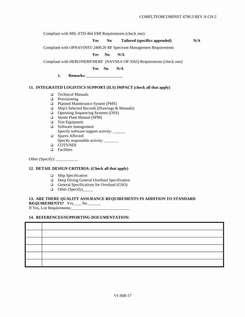
COMFLTFORCOMINST 4790.3 REV A CH-2
Compliant with MIL-STD-464 EMI Requirements (check one):
Yes No Tailored (specifics appended) N/A
Compliant with OPNAVINST-2400.20 RF Spectrum Management Requirements
Yes No N/A
Compliant with HERO/HERP/HERF (NAVSEA OP 3565) Requirements (check one):
Yes No N/A
1. Remarks: __________________
11. INTEGRATED LOGISTICS SUPPORT (ILS) IMPACT (check all that apply)
Technical Manuals Provisioning Planned Maintenance System (PMS) Ship's Selected Records (Drawings & Manuals) Operating Sequencing Systems (OSS) Steam Plant Manual (SPM) Test Equipment Software management
Specify software support activity: ______ Spares Affected
Specify responsible activity: _______ COTS/NDI Facilities
Other (Specify): ___________
12. DETAIL DESIGN CRITERIA: (Check all that apply)
Ship Specification Deep Diving General Overhaul Specification General Specifications for Overhaul (GSO) Other (Specify)_____
13. ARE THERE QUALITY ASSURANCE REQUIREMENTS IN ADDITION TO STANDARD REQUIREMENTS? Yes____ No_______ If Yes, List Requirements:_____________________________
14. REFERENCES/SUPPORTING DOCUMENTATION:
VI-36B-17

COMFLTFORCOMINST 4790.3 REV A CH-2
15. ESTIMATED WEIGHT AND MOMENT:
WEIGHT VCG LCG TCG
Stability Statement
16. CHANGE MATERIAL/SOFTWARE LIST:
UNIT OF ISSUE
PROCURING ACTIVITY ITEM NO. DESCRIPTION QUANTITY
17. SPECIAL DISPOSITION REQUIREMENTS FOR REMOVED MATERIAL:
MATERIAL DISPOSITION
18. INSTALLATION SUPPORT AND TEST EQUIPMENT:_____________
19. SHIPBOARD STOWAGE DETAILS:_______________
20. NAVSEA SHIP INFORMATION DRAWING (SID) REVIEW REQUIRED: YES___ NO___
21. SPECIAL INDUSTRIAL STOWAGE REQUIREMENTS:_____________________
22. REQUIRED PRIOR, CONJUNCTIVE OR CONCURRENT CHANGES:__________________
23. INSTALLATION DURATION:_____________________
24. HUMAN SYSTEMS INTEGRATION (HSI):
Manpower/Workload:__________________________ Personnel:___________________________ Training:____________________________ Human Factors Engineering (HFE):_________________________ Habitability:__________________________ Environment, Safety and Occupational Health (ESOH):__________________ Personnel Survivability:________________________
VI-36B-18
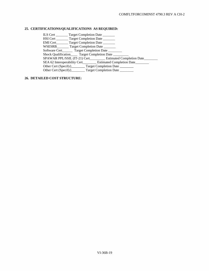
COMFLTFORCOMINST 4790.3 REV A CH-2
25. CERTIFICATIONS/QUALIFICATIONS AS REQUIRED:
ILS Cert _______ Target Completion Date _______ HSI Cert _______ Target Completion Date _______ EMI Cert_______ Target Completion Date _______ WSESRB_______ Target Completion Date _______ Software Cert______ Target Completion Date ________ Shock Qualification____ Target Completion Date _________ SPAWAR PPL/SSIL (IT-21) Cert_________ Estimated Completion Date________ SEA 62 Interoperability Cert________ Estimated Completion Date________ Other Cert (Specify)________ Target Completion Date ________ Other Cert (Specify)________ Target Completion Date ________
26. DETAILED COST STRUCTURE:
VI-36B-19
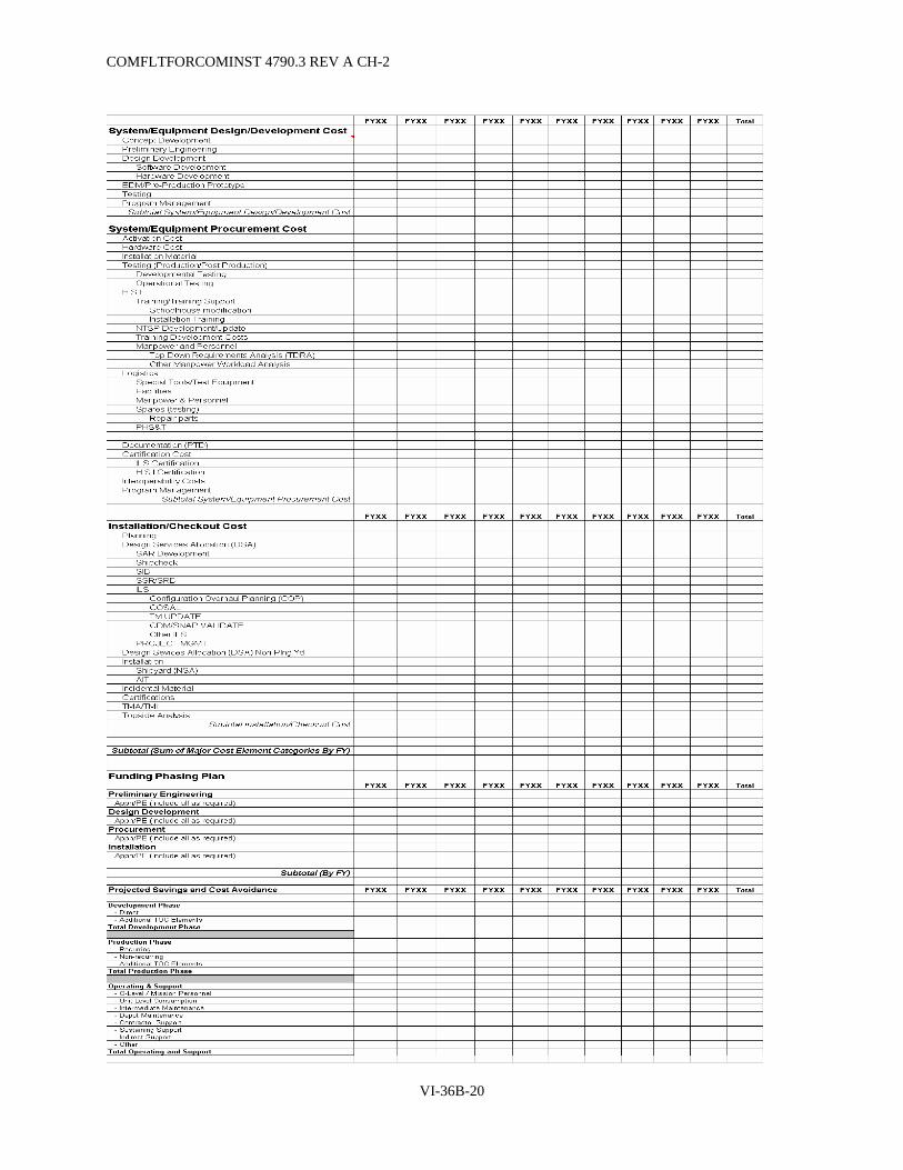
COMFLTFORCOMINST 4790.3 REV A CH-2
VI-36B-20
COMFLTFORCOMINST 4790.3 REV A CH-2
27. APPROVAL RECOMMENDATION:
Recommended Not Recommended Recommend Re-Work
NUCLEAR POWER DIRECTORATE (As Required)
Signature_________________ DATE _________ _________ ________
SHIP PROGRAM MANAGER
Signature_________________ DATE _________ _________ ________
TECHNICAL REVIEW COMMENTS:
VI-36B-21

COMFLTFORCOMINST 4790.3 REV A CH-2
(This Page Intentionally Left Blank)
VI-36B-22
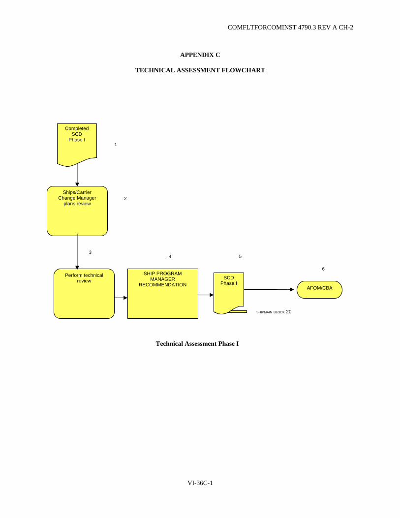
COMFLTFORCOMINST 4790.3 REV A CH-2
APPENDIX C
TECHNICAL ASSESSMENT FLOWCHART
SHIPMAIN BLOCK 20
Ships/Carrier Change Manager
plans review
SCD Phase I
Completed SCD
Phase I
AFOM/CBA
3 5
2
4
1
6 SHIP PROGRAM
MANAGER RECOMMENDATION
Perform technical review
Technical Assessment Phase I
VI-36C-1

COMFLTFORCOMINST 4790.3 REV A CH-2
TECHNICAL ASSESSMENT FLOWCHART
1 2 3
SHIPMAIN BLOCK 80
SHIPMAIN BLOCK 100
Ship Program Manager
recommends
Conduct
Configuration Change Board
Carrier/Ships Change Manager
coordinates review
Ships and Carrier Change Manager reviews/resolves
issues
Sponsoring
Activity Performs Preliminary Engineering
Approved SCD
Phase I
Draft SCD
Phase II
Y SCD
Phase II
Perform technical
review
AFOM/CBA
4 5
6
8 9
10
N
7
Technical Assessment Phase II
VI-36C-2
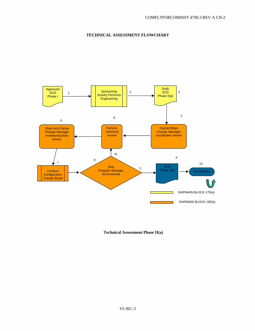
COMFLTFORCOMINST 4790.3 REV A CH-2
TECHNICAL ASSESSMENT FLOWCHART
1 2 3
7 Ship
Program Manager recommends
Conduct
Configuration Change Board
Carrier/Ships Change Manager
coordinates review
Ships and Carrier Change Manager reviews/resolves
issues
Sponsoring
Activity Performs Engineering
Approved SCD
Phase I
Draft SCD
Phase II(a)
SCD Phase II(a)
Perform technical
review
AFOM/CBA
4 5
8 9
SHIPMAIN BLOCK 170(a)
SHIPMAIN BLOCK 180(a)
N
Y
6
10
Technical Assessment Phase II(a)
VI-36C-3

COMFLTFORCOMINST 4790.3 REV A CH-2
TECHNICAL ASSESSMENT FLOWCHART
SHIPMAIN BLOCK 180
Ship Program Manager
recommends
Conduct
Configuration Change Board
Ships Change Manager
Reviews and Carrier Change Manager Resolves Issues
Perform technical
review
Planning Yard Review
Sponsoring
Activity Performs Detailed
Engineering
Approved SCD
Phase II
Draft SCD
Phase III
Does the Planning Yard need to review SCD
Phase III
Y
Y
N
SCD Phase III
AFOM/CBA
Carrier/Ships Change Manager receives
Draft SCD Phase III
Ships/Carriers Change Manager reviews
Ships and Carrier Change Manager reviews/resolves
issues
N
1
2 3 4
5
6 8 7
SHIPMAIN BLOCK 170
9
10 11 12
13
Technical Assessment Phase III
VI-36C-4

COMFLTFORCOMINST 4790.3 REV A CH-2
TECHNICAL ASSESSMENT FLOWCHART
Procure Material/Software
Approved SCD
Phase III, et al
Scope of Change
Internal Equip/Software Only
Drawing Development
Ready to install
1
4
2
5 Certification and
Testing
Complete Design requirements
6
7
3
2
SHIPMAIN BLOCK 270
SHIPMAIN BLOCKS 220
SHIPMAIN BLOCKS 260
Technical Implementation Phase IV
VI-36C-5

COMFLTFORCOMINST 4790.3 REV A CH-2
(This Page Intentionally Left Blank)
VI-36C-6

COMFLTFORCOMINST 4790.3 REV A CH-2
VI-36D-1
APPENDIX D
COST BENEFIT ANALYSIS FLOWCHART
CBA PROCESS FLOW, BLKS 40/120/200
SSuubbmmiitttteerr pprroovviiddeess CCoosstt DDaattaa//BBaacckkuupp
IInnffoorrmmaattiioonn ttoo SCD
NNDDEE MMaappss ddaattaa TToo CCRR&&EEII
TTeemmppllaattee aanndd ccaallccuullaatteess ccoosstt mmeettrriiccss ((RROOII,,
NNPPVV,, PPaayybbaacckk))
NNDDEE IIddeennttiiffiiccaattiioonn ooff NNeeww PPkkggss
ttoo SSMMEE aannaallyysstt
SSEEAA001177 CChheecckk:: AAllll rreeqquuiirreedd DDaattaa FFiieellddss CCoommpplleettee
RReevviieeww ooff SSMMEE CCBBAA CCoommmmeennttss FFoorrwwaarrdd PPkkgg oorr
RReettuurrnn ttoo SSuubbmmiitttteerr ww//CCoommmmeennttss
BBLLOOCCKK 4400//112200//220000 FFeeeeddbbaacckk LLoooopp
OOuuttppuutt ffrroomm BBllkk 3300,, 110000,, 118800
FFAAIILL –– CCaannnnoott MMaakkee BBuussiinneessss
CCaassee ffoorr tthhee AALLTT GGoo HHiissttoorryy
AApppprroovvee
DDiissaapppprroovvee
FFoorrwwaarrdd ttoo NNeexxtt PPhhaassee
UUppddaattee SSCCDD
PPrroovviiddee PPkkgg ttoo
DDeecciissiioonn BBooaarrdd
AApppprroovvaall DDeecciissiioonn
AFOM
TE
11
22
Forward

COMFLTFORCOMINST 4790.3 REV A CH-2
COST BENEFIT ANALYSIS FLOWCHART
COST BENEFIT ANALYSIS (CBA) BOX #40 - LEVEL 3
No
Process Boundary
SCD Submitter
Comments
Yes
SEA 017 Forward to
SEA 04
Out In SCD ICR Analysis
of team comments
SEA 017 Dist. SCD To
Lead Function
Area Team
Process Cycle Time2 - 3 Working Days
VI-36D-2
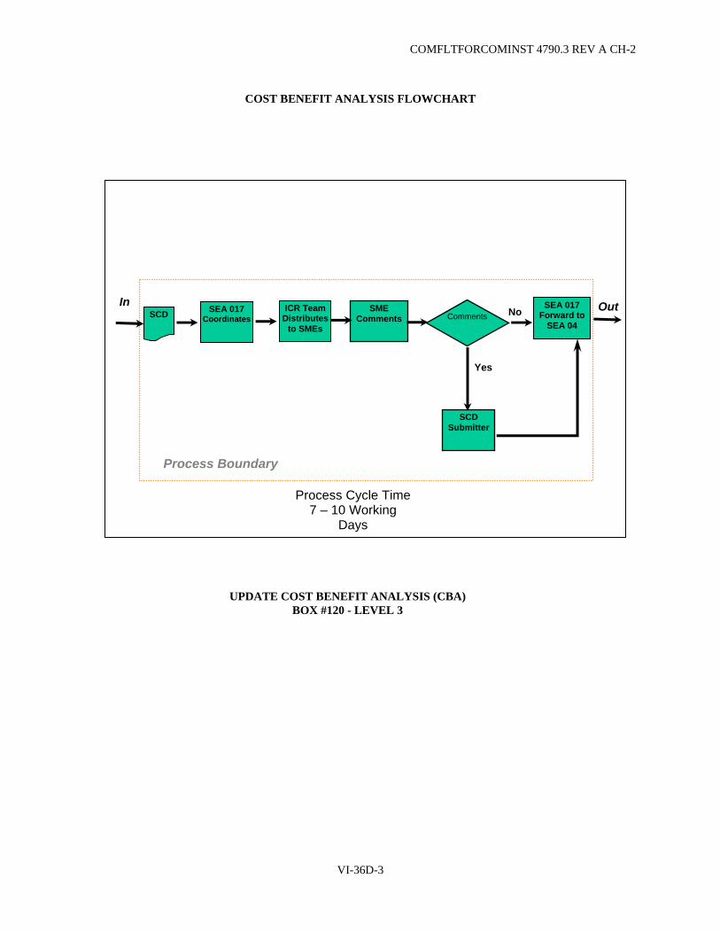
COMFLTFORCOMINST 4790.3 REV A CH-2
COST BENEFIT ANALYSIS FLOWCHART
No
Process Boundary
SCD Submitter
Comments
Yes
SEA 017Forward to
SEA 04
In SCD
ICR Team Distributes
to SMEs
SEA 017 Coordinates
SME Comments
Process Cycle Time 7 – 10 Working
Days
Out
UPDATE COST BENEFIT ANALYSIS (CBA) BOX #120 - LEVEL 3
VI-36D-3

COMFLTFORCOMINST 4790.3 REV A CH-2
COST BENEFIT ANALYSIS FLOWCHART
No
Process Boundary
SCD Submitter
Comments
Yes
SEA 017 Forward to
SEA 04
Out In SCD
ICR Team Distributes
to SMEs
SEA 017 Coordinates
SME Comments
Process Cycle Time 7 – 10 Working Days
UPDATE COST BENEFIT ANALYSIS (CBA) BOX #200 - LEVEL 3
VI-36D-4

COMFLTFORCOMINST 4790.3 REV A CH-2
APPENDIX E
ALTERATION FIGURE OF MERIT FLOWCHART
Enter Rating Scale Index Values into
NDE
SCD received by TYCOM(s)
Index Values rolled-up in
weighted AFOM Benefit Structure
(weighted by 3-Star Board)
AFOM Calculated
by NDE Algorithm
TYCOM
NDE/SEA 04R
Annually
12
CONTINUOUS SCDs X TYCOM RATINGS X NAVY PRIORITIES (WEIGHTS)=AFOM VALUE
AFOM PROCESS (INITIAL AND UPDATE)
VI-36E-1

COMFLTFORCOMINST 4790.3 REV A CH-2
ALTERATION FIGURE OF MERIT FLOWCHART
7 days
*180 days
CNO N60, N7, N8, N42 C2F C3F FFC N6, N8, N43
Set Weights: Naval
Capabilities, Pillars, and
Mission Capability
Packages (A3)
Generate Board
Precept (A1)
1 day
3 Star Board Members
NAVSEA 04R
Entitled State: Level III Periodic External Process
Level IV: Requirements definition Process
Level IV diagram
Offline of NDE
* April-September of Current Cycle
Weighted AFOM Benefit Structure (Static for fiscal year)
FFC
Fleet Requirements and Issues; Campaign Analysis
1
Enter Weights into Expert Choice (A4)
Enter Multipliers from Expert Choice to build NDE algorithm
VI-36E-2

COMFLTFORCOMINST 4790.3 REV A CH-2
ALTERATION FIGURE OF MERIT FLOWCHART
Outputs from Block
Outputs to Block
SCDs from Block
SCD mapped to MCPs by
Naval Capability
SCD routed to cognizant TYCOMs
Breakout into Mission Capability
SEA04R SEA04R
Identification of SMEs
Canvases appropriate
SMEs for input
TYCOM
Review SME inputs
TYCOM
Cognizant TYCOM Inputs consolidated(if multiple TYCOM)
SEA04R
NDE Algorithm calculates
Total AFOM and AFOMBreakouts *
AFOM scores entered
into NDE
SEA04R AFOMs on SCDs to Block
SME develops Input
Enter Indexed values
into NDE
TYCOM
Review Process
SEA04R
Tech Assessment Phase I
AFOM Benefit Structure Weights from 3-Star and Fleet O-6 Weighting Board
Standing TYCOM Suitability and Capability Rating Scales in NDE
* See Business Rules HM&E: COMNAVSURFOR/COMNAVAIRFOR
7 days
2
PROCESS FLOW (LEVEL III) - CALCULATE INITIAL AFOM
VI-36E-3
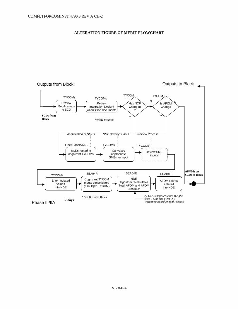
COMFLTFORCOMINST 4790.3 REV A CH-2
ALTERATION FIGURE OF MERIT FLOWCHART
Outputs from Block Outputs to Block
SCDs from Block
SCDs routed to cognizant TYCOMs
Fleet Panels/NDE
Identification of SMEs
Canvases appropriate
SMEs for input
TYCOMs
Review SME inputs
TYCOMs
Cognizant TYCOM Inputs consolidated (if multiple TYCOM)
NDE Algorithm recalculates
Total AFOM and AFOM Breakout*
AFOM scores entered
into NDE
SEA04R AFOMs on SCDs to Block
SME develops Input
Enter Indexed values
into NDE
TYCOMs
Review Process
Review Modifications
to SCD
Review Integration Design/
Acquisition documents
TYCOMs TYCOMs
Is AFOM Change
Review process
Has NCPChanged
?
Y
N
Y
N
TYCOM TYCOM
SEA04R SEA04R
Phase III/IIA
AFOM Benefit Structure Weights from 3-Star and Fleet O-6 Weighting Board Annual Process
* See Business Rules 7 days
VI-36E-4

COMFLTFORCOMINST 4790.3 REV A CH-2
APPENDIX F
VOTING DATABASE FLOWCHART
Prepare SCD
Yes
No
No
Process Boundary
ReworkPrep.
AuthorizeSCD
Authorize SCD
Yes
Rework
No
Yes
SCD Entered In NDE
Out In
Does not get entered into NDE
CREATE SHIP CHANGE DOCUMENT (SCD) BOX #10 - LEVEL 3
PROCESS FLOW (LEVEL III) BLOCK - 2ND UPDATE AFOM
VI-36F-1

COMFLTFORCOMINST 4790.3 REV A CH-2
VOTING DATABASE FLOWCHART
DECISION POINT 1 - O6 REVIEW BOARD AUTHORIZE FUNDING FOR PREL. ENGINEERING
(BOX #60 - LEVEL 3)
Yes
No
No
Process Boundary
RS Ad ateFundin Line
and/or Tradeoffs
judicg
O-6 RBApprove
Agree with Revised Funding
Inactive SCD
Adjustment
to
Draft
MP
In RCP Documentation
O-6 RB Recom. Funding
O-6 RBLevel
No
Yes
Yes
Funding Line
Concurrence
Yes
No
VI-36F-2
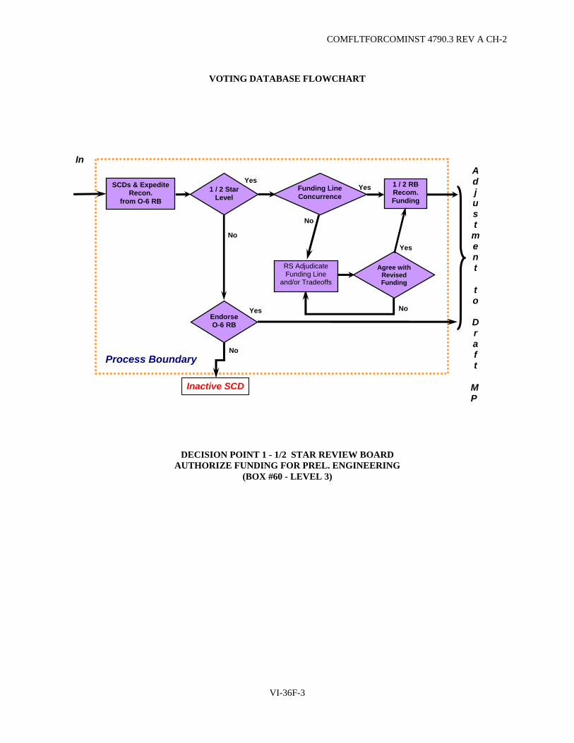
COMFLTFORCOMINST 4790.3 REV A CH-2
VOTING DATABASE FLOWCHART
In
DECISION POINT 1 - 1/2 STAR REVIEW BOARD AUTHORIZE FUNDING FOR PREL. ENGINEERING
(BOX #60 - LEVEL 3)
Yes
No
No
Process Boundary
EndorseO-6 RB
Agree with Revised Funding
Inactive SCD
1 / 2 StarLevel
SCDs & Expedite Recon.
from O-6 RB
1 / 2 RB Recom. Funding
Yes
Yes
No
Yes
No
RS Adjudicate Funding Line
and/or Tradeoffs
Funding Line Concurrence
Adjustment
to
Draft
MP
Yes
VI-36F-3

COMFLTFORCOMINST 4790.3 REV A CH-2
VOTING DATABASE FLOWCHART
Yes
Process Boundary
Endorse1/ 2 RBs
Level
No
Yes
Inactive SCD
Approved
MP
In 3 Star RB
Level
SCDs & Expedite Recon. from
O-6 & 1 / 2 RBs
Yes
No
Yes
No
Funding LineConcurrence
Agree with Revised FundinRS Adjudicate
Funding Line and/or Tradeoffs
g
No
DECISION POINT 1 - 3 STAR REVIEW BOARD AUTHORIZE FUNDING FOR PREL. ENGINEERING
(BOX #60 - LEVEL 3)
VI-36F-4

CO
MFLTFO
RC
OM
INST 4790.3 R
EV A
CH
-5A
PPEND
IX G
EN
TITLED PR
OC
ESS MILESTO
NES
Entitled Process Milestones CFT 4 and CFT 2 Entitled Process (in days) Item
# Task / Milestone Responsible
Activity CFT 4 Critical
CNO MSMO
CNO FFP
CMAV MSMO
CMAV FFP/IDIQ
Comments / Remedial Action
1 Establish CNO / CM Availability Schedule TYCOM A-720 A-720 FRP Baselines are developed on a 3 year cycle. ID CNO avails IAW with that cycle.
2 Fund Modernization Procurement & Installation - Decision Point 3
OPNAV / FLEET Varies Varies Depends on development and procurement timeline requirements.
3 Issue 2-year rolling Hull Modernization Plan (HMP) SPM / NAVSEA / TYCOM
A-810 to A-450
A-810 to A-450
Advance planning document to be issued in July each year.
4 Identification of initial list HCPM for ALTS PARM / Planning Yard
A-660 A-660 HCPM - HQ Centrally Procured Material. This should be for the entire ship class. This should include all known requirements.
5 Provide Incremental Funding for HCPM / LLTM to meet req'd delivery dates
PARM / SPM A-600 A-600
6 Initiate procurement of HCMP LLTM PARM / SPM A-600 A-600 7 PY Submit Funding Request for work assigned Planning Yard A-480 A-480 8 Ship Change (SC) Design / Planning Funds provided NAVSEA / TYCOM A-420 A-420 SPAWAR generally funds in FY prior to execution year. 9 Interface Control Drawing (ICD) delivered to alteration
developer / PY PARM A-420 A-420
10 Identify drawing development assignments, including Class Drawings
PARMS / TYCOM / NAVSEA
A-390 A-390 A-390 A-390 Send to RMC and Planning Yard.
12 Modernization Work package to support Shipcheck (Locked)
SYSCOM / TYCOM A-390 A-390
13 Issue Hull Modernization Plan / Letter Of Authorization (including AITs)
SPM / NAVSEA / TYCOM
A-360 A-360 A-360 A-360 A-360 HMPs to be issued in March each year to maintenance Teams to support MMBP. LOAs will be posted at A-360.
14 Establish Availability in NMD Maintenance Team A-360 A-360 A-360 A-360 15 Request Availability Funding for planning repair work NSA A-345 A-345 A-345 A-345 This provides funds for early executor planning. 16 Task / Fund SID Development SPM / NSA / AIT /
TYCOM / RMC Manager
A-330 A-330 A-330 A-330 A-330
17 Shipchecks completed Planning Yard A-270 A-270 A-270 A-270 No FRP considerations relate to this date. 18 Screen ICMP / TYCOM routines TYCOM PC A-270 A-270 A-270 A-270 Push ICMP work items to CSMP NLT A-270. 19 Provide incremental funds for ordering LLTM for
both repair and alt / mod work to meet req'd dates SYSCOM / TYCOM A-270 A-270 A-270 A-270 A-270
20 50% of D-level maintenance work package 2K's locked based on $
Maintenance Team A-240 A-240 NA NA Intent is that the planning activity continually develops specs in the most cost effective manner and not batch this work in front of the next pkg development milestone.
21 MSMO contractor complete planning and estimating of work assigned as required by the above A-240 milestone
MSMO Contractor A-190 Intent is to have a continuous flow of planning quality estimates to eliminate churn in the work package.
22 Issue/ Deliver SIDs to NSA for KTRs and AITs Planning Yard A-180 A-180 A-240 A-180 A-180 This is a change from A-4. Including all SIDs for AITs. For FFP contracts, this milestone should occur at A-8 when possible and NLT A-180.
23 Request Availability Funding for both repair & modernization work
NSA / RMC A-180 A-180 A-180 A-180
24 All Modernization Risk Assessments (including waivers) submitted
PARM/SPM/TYCOM A-175 A-175 A-175 A-175
25 All Modernization Risk Assessments (including waivers) approved
TYCOM A-150 A-150 A-150 A-150
26 Identification of AIT Support / Schedule / Impact requirements
AIT Manager A-135 A-135 A-180 A-135 A-168 Need to develop a complete requirements list. Needs to be integrated with repair reqmt's by the KTR and presented at the WPER.
27 80% of D-level maintenance work package 2K's locked based on $
Maintenance Team A-120 A-210 NA NA Intent is that the planning activity continually develops specs in the most cost effective manner and not batch this work in front of the next pkg development milestone.
VI-36G
-1

Entitled Process Milestones CFT 4 and CFT 2 Entitled Process (in days) Item
# Task / Milestone Responsible
Activity CFT 4 Critical
CNO MSMO
CNO FFP
CMAV MSMO
CMAV FFP/IDIQ
Comments / Remedial Action
28 Cert Plan(s) (eg ILS, software etc) approved. Final date for modernization Ship Change (SC) approval. LOA locked.
SPM / PARM / PM A-120 A-120 A-120 A-120 A-120 SPM approves Hull Certification. All unresolved PNA modernization Ship Changes (SCs) are removed from the authorization letter at this date. Please note: There is an Interim Policy covering the Fleet Commanders C5I MP policy for approving the Weapon System Baseline Certification at A-30 (CFFC MSG 032037Z MAY 2004).
29 100% of O level maintenance work package locked Ship's Force A-120 A-120 A-30 A-30 Intent is to provide work to be accomplished so that an integrated execution sked can be developed for the WPER.
30 MSMO contractor complete planning and estimating of work assigned as required by the above A-120 milestone
MSMO Contractor A-95 Intent is to have a continuous flow of planning quality estimates to eliminate churn in the work package.
31 Award AIT contracts for work not being done by prime KTR AIT Sponsor A-90 A-90 A-90 A-90 32 I-level work package fully brokered Maint Team / Ship's
Force A-90 A-90 A-40 A-40 Intent is to fully broker all known work to I-level by this date.
33 I-level work package fully accepted RMC A-75 A-75 A-33 A-33 Intent is for I-level to accept or reject all work brokered to it up to this point in time, work entering later in the process will be subject to normal Business Case Analysis.
34 100% of D-level maintenance work package 2K's locked based on $
Maintenance Team A-75 A-170 A-30 A-60
35 Solicit Bids RMC N/A A-120 N/A A-50 If CMAV is to be performed under an IDIQ contract and is over $500k we may need to add 30 days for solicitation IAW Fair Value purchasing policy. This would reset the CMAV solicit bid milestone to A - 70.
36 100% of D-level maintenance work package 2K's planned, estimated
Planning Activity A-60 A-155 A-35 A-60
37 Submit I-level work package and schedule to KTR for integration
RMC A-60 A-60 A-30 A-15
38 Perform risk assessments and verify deliverables to KTR (O,I,D work items and AIT sked reqmts)
Maintenance Team A-60 NLT A-60
A-25 A-25 This is to confirm that the KTR has all input for his development of the integrated avail sked. Note that for FFP CMAV KTR will not be identified until A-15, verification with KTR will take place at WPER.
39 SHAPEC Package turnover SHAPEC N/A A-135 N/A N/A 40 MSMO contractor "publish" pkg in NMD MSMO Contractor A-60 N/A A-25 N/A 42 Cutoff for bidders questions PCO N/A A-100 N/A A-30 43 Submit Bids Contractor N/A A-90 N/A A-20 44 Award Contract RMC N/A A-60 N/A A-15 45 MSMO contractor submit final package cost proposal MSMO contractor A-55 N/A A-25 N/A 46 Complete TAR RMC A-50 N/A A-20 47 Provide Availability Funding for Modernization to the
RMC SYSCOMS / PEO / TYCOM
A-45 A-45 A-45 A-45 A-45 Includes funding for AIT's support services.
48 Definitize Work Packages RMC A-35 N/A A-18 N/A 49 Deliver Material (LLTM and Kitted Materials) to
Executing Activity Planning Yards / PARM
A-30 A-30 A-20 A-15
50 Conduct Work Package Execution Review (WPER) - finalize funding
Maintenance Team A-30 A-30 A-21 A-10 KTR presents fully planned execution sked (could be a Gantt chart) to the full MT.
51 Start of Availability Maintenance Team A-0 A-0 A-0 A-0
Provide Maintenance and Modernization Business Plan (MMBP) budget guidance to RMC
TYCOM Feb of Prior FY
Feb of Prior FY
Feb of Prior FY
Feb of Prior FY
Negotiate MMBPs with TYCOM RMC / SPM Mar of
Prior FYMar of
Prior FYMar of Prior FY
Mar of Prior FY
Start in March complete by June.
VI-36G
-2
CO
MFLTFO
RC
OM
INST 4790.3 R
EV A
CH
-5
COMFLTFORCOMINST 4790.3 REV A CH-3
VOLUME VI
CHAPTER 37
REGIONAL MAINTENANCE CENTER PASSIVE COUNTERMEASURE SYSTEM SUPPORT REQUIREMENTS
REFERENCES.
(a) COMFLTFORCOM 181810Z Mar 03 - Establishment of Regional Maintenance Centers (b) NAVSEA ltr - Ser 05T1/009 of 06 April 04, Passive Countermeasure System (PCMS) Waterfront
Support Requirements for Regional Maintenance Centers (c) OPNAVINST 9070.2 - Signature Control Policy for Ships and Craft of the U.S. Navy (d) Maintenance Index Page 4722/007 - Passive Countermeasure System (PCMS) (e) NAVSEA RIM 05T1-99 - PCMS Repair and Installation Methods (f) NAVSEA SE400-DA-MMO-010 - Passive Countermeasure System (PCMS) Technical Manual (g) NAVSEA S-30-9412 - Passive Countermeasure System (PCMS) Naval Training System Plan
37.1 PURPOSE. To provide guidance in the execution of a shore based Passive Countermeasure System (PCMS) maintenance program in the U.S. Surface and Submarine Fleets.
37.1.1 Background. Historically, waterfront support for the PCMS has been focused through Fleet Technical Support Centers Atlantic and Pacific, with principal support and coordination provided through the respective offices at Norfolk and San Diego. In accordance with reference (a), Navy-wide waterfront support is transitioning from the current centralized model to one of homeport organic capabilities. To support the Fleet PCMS program each Regional Maintenance Center (RMC) shall be capable of conducting the following core PCMS activities:
a. PCMS Readiness Improvement Program (RIP).
b. Installation and removal of Motion Measurement System.
c. Combat Systems, Command, Control, Communications and Computer Readiness Review (C5RA).
d. Technical assists.
Resources and procedures required for these tasks are identified in reference (b).
37.2 PASSIVE COUNTERMEASURE SYSTEM EVENT DESCRIPTION.
a. PCMS RIP. Ships normally conduct RIPs in close proximity to performance of radar cross-section testing or C5RA. RIPs are scheduled by the Type Commander (TYCOM) via the Immediate Superiors In Command. Immediate Superiors In Command obtain primary and secondary dates, submit via message action to TYCOM with information to the local RMC. This weeklong event provides on board training to the entire ship PCMS team, focused on maintenance and inspection training. Curricula are available for both the maintenance person and supervisor courses. The latter includes an effectiveness module, which is classified SECRET. This effort includes a full visual assessment of the ship using the Q-1/S-1R Maintenance Requirement Cards. This is the primary method of delivering training and PCMS certification for Ship's Force personnel. A subset of this is the standalone PCMS Maintainer's Course, which can be provided by the RMC when periodicity is inappropriate for a RIP and PCMS supervisor training is not required.
b. Motion Measurement System. In accordance with references (c) and (d), ships without installed telemetry equipment require installation and removal of Motion Measurement System for radar cross-section testing. This is accomplished by the RMC.
VI-37-1
COMFLTFORCOMINST 4790.3 REV A CH-2
c. C5RA. PCMS is assessed during C5RA. RMC personnel, utilizing the Q-1/S-1R inspection process, will accomplish these inspections.
37.3 PASSIVE COUNTERMEASURE SYSTEM PERSONNEL CERTIFICATION.
37.3.1 Passive Countermeasure System In-Service Engineering Activity. The PCMS In-Service Engineering Activity (ISEA) determines final approval for PCMS personnel certification.
37.3.2 Training Requirements. In accordance with reference (e), Naval Sea Systems Command (NAVSEA) 05T1 has established the requirement that all personnel involved in PCMS installation and maintenance, including inspection/assessment, surface preparation, material application, final painting or quality assurance, shall be U.S. citizens trained in the specifics of PCMS installation procedures prior to any actual tile installation work. As waterfront experience has underscored the absolute importance of limiting PCMS work to properly trained personnel, the certification process is the single most important element of quality assurance for the fleet customer.
37.3.3 Support Personnel. In accordance with reference (e), PCMS personnel certification is required every two years. Qualifications for PCMS certification are successful completion of NAVSEA sponsored PCMS installation course conducted by Port Hueneme Detachment (PHD) Naval Surface Warfare Center (NSWC) (S13) and on-the-job-training witnessed by a certified PCMS instructor within the past two years. This certification enables RMCs and shipyards to maintain a cadre of qualified PCMS personnel and with the assistance of the PCMS ISEA, to coordinate further certification or recertification training as required.
37.3.4 Japan Regional Maintenance Center. Due to the special circumstances of the Forward Deployed Naval Forces, Japan Regional Maintenance Center is authorized to execute all PCMS maintenance and installation work using the PCMS training guide number 7623399. Training materials used to train Fleet sailors and U.S. contractors cannot be used to instruct Japan Regional Maintenance Center personnel and/or contractors.
37.3.5 Ship's Force Personnel. In accordance with the requirements of MRCs Q-1/S-1R, fleet personnel conducting PCMS assessments must be graduates of a PCMS ISEA approved course which includes an assessment/inspection training module.
37.4 PASSIVE COUNTERMEASURE SYSTEM TECHNICAL ASSISTANCE.
37.4.1 Technical Assistance. PCMS technical assistance is available through distance support.
37.5 RESPONSIBILITIES.
a. Commander, Naval Sea Systems Command:
(1) Certify personnel, facilities, and activities in PCMS handling, application, and destruction, maintaining records for each certification.
(2) Provide Equipment Guide List (EGL) packages for RIPs.
(3) Incorporate and distribute ship configuration revisions submitted following RIPs and C5RAs.
b. Fleet Commander: Ensure that RMCs have adequate PCMS technicians to support PCMS core activities. If qualified PCMS Technicians are not available at local RMC, the RMC should contact the following (in order of contact) for assistance:
(1) Other RMCs.
(2) PCMS ISEA (NSWC PHD). This request shall include funding for the performance of the activity.
VI-37-2
COMFLTFORCOMINST 4790.3 REV A CH-2
c. Type Commander shall:
(1) Coordinate with the System Commands in identifying, solving and correcting PCMS deficiencies.
(2) Arrange for PCMS Maintenance services when required and schedule technician training/certification visits for RMC technicians.
(3) Prior to promulgation, review and authorize all documents prepared by technical agencies that contain procedures relative to PCMS and the fleet PCMS program.
(4) Evaluate comments and recommendations regarding the fleet PCMS program. If necessary, promulgate changes to existing policy and procedures.
d. Group/Squadron/Regional Support Group/Regional Maintenance Center Commanders shall:
(1) Schedule PCMS core activities prior to deployment for each unit.
(2) Review and take the appropriate action to correct PCMS discrepancies for subordinate units.
(3) Request NAVSEA engineering assistance when determined necessary.
e. RMCs shall:
(1) Maintain qualified PCMS personnel, in accordance with reference (b) and ensure assets are available to perform PCMS core activities.
(2) Provide Technical Assistance via distance support/on site visit as appropriate.
(3) Conduct PCMS core activities in accordance with reference (b). Provide the following to the PCMS ISEA following RIP and C5RA events:
(a) Redline updates to key plans and detailed drawings.
(b) Completed EGL inspection checklist, including revised items.
(c) Complete digital photo survey in accordance with PCMS ISEA guidance.
(d) Access 97 database file (for all C5RA events).
(4) Ensure participation of each RMC PCMS Supervisor in at least one PCMS core activities every 18 months. Qualified PCMS Supervisors must meet this requirement to retain qualification status.
(5) Maintain an active account in NAVSEA Configuration Data Management System.
(6) Ensure that contracted or I-level jobs activities, facilities, and personnel selected to conduct PCMS work are certified for the work being conducted.
(7) Include in contracted or I-level jobs the provision of PCMS tiles for planned PCMS repairs and interference areas. Ships shall not be tasked to provide tiles or other PCMS Allowance Parts List/Allowance Equipage List items to support work undertaken by other than Ship's Force, except with the specific concurrence of the TYCOM.
VI-37-3

COMFLTFORCOMINST 4790.3 REV A CH-2
f. Surface Ship Commanding Officers shall:
(1) Establish and maintain the following shipboard organization:
(a) PCMS Department Head: in accordance with reference (c), the Commanding Officer will appoint a Department Head responsible for coordinating operation and maintenance of PCMS. Their responsibilities include:
1 Providing the Commanding Officer monthly PCMS effectiveness summaries including major PCMS deficiencies, the compliance of the ship with personnel certification requirements, an abbreviated Plan of Action and Milestones for correction of Category 1/2/3 deficiencies and corrosion items, and the due date for the next 18M-1R.
2 Coordinating shipboard PCMS indoctrination for newly reported personnel.
3 Coordinating ship-wide PCMS preventive and corrective maintenance schedule.
4 Coordinating distribution and update of Planned Maintenance System (PMS) materials including ship specific PCMS keyplan drawings and EGLs required for PMS inspections.
5 Serving as single point of contact for Quality Assurance of PCMS related Current Ship's Maintenance Project (CSMP) entries, review of all topside configuration changes (including program alterations, fleet alterations, field changes, etc.) to ensure Radar Cross Section reduction has been considered.
6 Ensuring PCMS is included in the command PMS spotcheck program.
7 Assigning a command PCMS coordinator responsible to the PCMS Department Head for the detailed implementation of PCMS maintenance and operation.
(b) Command PCMS coordinator: The command PCMS coordinator is the primary assistant to the PCMS Department Head in carrying out responsibilities outlined in paragraph 36.5 f.(1)(a) of this chapter. Additional responsibilities include:
1 Scheduling PCMS supervisor and maintenance courses with local RMC as noted below:
a PCMS supervisor course: Command PCMS Coordinator and Department PCMS coordinators must be graduates of this course. Attendance is highly encouraged for division officers with significant PCMS responsibilities.
b PCMS maintenance course: Each work center with PCMS maintenance responsibilities will have a minimum of two graduates from this course. Each CG/LPD will have a minimum of eighteen (18) trained maintainers. Each DDG/FFG will have a minimum of twelve (12) maintainers.
2 Prepare and distribute PMS inspection keyplans and EGLs to appropriate work centers.
VI-37-4
COMFLTFORCOMINST 4790.3 REV A CH-3
3 Submit required updates/corrections/additions to ship specific keyplan drawings to local RMC PCMS supervisor and ISEA (NSWC Port Hueneme, CA).
4 Request and maintain access to the PCMS web site to download keyplan updates and other PCMS related data.
5 Maintain a PCMS library consisting of references (b), (c), (f) and (g), NAVSEA 05T1 PCMS program newsletters, NSWC PHD PCMS Technical Bulletins, and related PCMS message traffic.
(c) Supply Officer: Maintain Allowance Parts List stocks of PCMS materials and sufficient Allowance Equipage List items to support maintenance requirements. All shipboard stocks must be within shelf life.
(d) Department Heads: Department Heads with PCMS maintenance responsibilities will designate a minimum of two supervisor level personnel to attend the PCMS supervisor course and serve as Departmental PCMS Coordinator.
(e) Department PCMS Coordinator: Department Coordinators responsibilities include:
1 Review results of required PCMS PMS inspections for accuracy. Particular attention must be paid to required repairs annotated on EGLs to ensure corrosion related jobs and I-level repairs are flagged for proper CSMP entry.
2 Ensure adequate numbers of trained maintenance personnel are available to maintain assigned department areas.
(f) Division Officers: Directly responsible for the PCMS applications in their assigned topside spaces. His/her responsibilities include:
1 Review and update PCMS EGLs and keyplans assigned to their work center(s) by the Command PCMS Coordinator for accuracy. Submit required updates/changes to the Command PCMS Coordinator via Department PCMS Coordinator.
2 Submit CSMP entries for all PCMS repairs requiring tile removal/replacement. CSMP entries for ship to shop repairs screened to Intermediate Maintenance Activity must specifically state that PCMS tile replacement is required.
3 Routine inspection of assigned PCMS material and material stowage ensuring compliance with reference (f).
(2) Ensure the following general maintenance policy is adhered to:
(a) Painting: The effectiveness of PCMS tile is dramatically reduced when covered with 20 mils (approx four coats) or more of paint. Painting will only be performed as directed by references (d) and (f). Ships are responsible for developing and implementing a PCMS paint removal plan that will ensure no more than 20 mils of paint thickness occurs on any PCMS material. Latex based paint is the only paint authorized for in service application to PCMS "paint required" tiles. Tiles installed as bow flare coverage are authorized/required for the application of oil based paint.
VI-37-5

COMFLTFORCOMINST 4790.3 REV A CH-2
(b) "No Paint" Tile: If your ship is outfitted with "no paint" tile, painting will negate its "no paint" properties. If a ship is unable to comply with the "no paint" requirement, commanding officers shall request and document the painting of "no-paint" tiles as a Departure From Specifications. As noted in the paragraph above, the Type 18 tiles installed as bow flare coverage shall be painted, with no deviation from specifications necessary.
(c) I-Level PCMS repairs: All referrals must note that restoration of tile coverage, new application of tile, or other PCMS features is required. RMCs perform ship to shop PCMS restoration after the lead corrosion control or paint shop is complete. Any PCMS treated item that can be removed from the ship is an ideal candidate for I-level repair. Proper referral to RMC is cost effective, takes advantage of the superior quality of work resulting from their controlled environment, and allows Ship's Force maintainers to focus on those tasks that must be accomplished on board. Water-tight doors, life line stanchions, antenna pedestals, and gun mounts are all examples of jobs that can and should be screened to the RMC. RMCs also have the capability to test and perform minor repairs to type 6 blankets/covers and type 15 tarpaulins.
VI-37-6

COMFLTFORCOMINST 4790.3 REV A CH-4
VI-38-1
VOLUME VI
CHAPTER 38
DEEP SUBMERGENCE SYSTEMS HULL INTEGRITY PROCEDURES
REFERENCES.
(a) NAVSEA SS800-AG-MAN-010/P-9290 - System Certification Procedures and Criteria Manual for Deep Submergence Systems
LISTING OF APPENDICES.
A SUBMEPP DSS HIP Inventory B SUBMEPP DSS HIP Schedule C Request for DSS HIP Periodicity Extension Format
38.1 PURPOSE. This chapter provides guidance and definition for the requirements, responsibilities and actions for Deep Submergence Systems (DSS) Hull Integrity Procedures (HIP) to continue certification for manned operations. The DSS HIP program is invoked on Dry Deck Shelter (DDS) and Advanced SEAL Delivery System (ASDS) certified under reference (a).
38.2 HULL INTEGRITY PROCEDURES MAINTENANCE SCHEDULING, PLANNING AND REPORTING.
38.2.1 Maintenance Requirements for Continued Certification. Reference (a) establishes the Maintenance Requirements and identifies the responsibilities and actions required to support continued unrestricted Submarine/DSS manned operations. In conjunction with reference (a), Naval Sea Systems Command (NAVSEA) has issued individual manuals containing required, periodic Scope of Certification (SOC) maintenance actions for each DSS. The DSS HIP procedures identify degradation of the material condition of the hull integrity boundary and of those systems affecting occupant safety. SOC certification indicates that a valid recommendation for continued manned operations can be made. Maintenance of certification is dependent on the positive control of all re-entries into the SOC boundaries per Volume V, Part III, Chapter 5 of this manual, the satisfactory and timely completion of applicable DSS HIP procedures as required by reference (a) and any necessary repairs. Accomplishment of the DSS HIPs specified with this program identify changes within the SOC boundary which result from inadvertent error and/or from degradation caused by the service environment.
38.2.2 Scheduling and Reporting. To enable the Type Commanders (TYCOM) to carry out their responsibilities in the maintenance of certification of DSSs and to aid in decisions concerning operational restrictions, an auditable system of scheduling the performance and reporting of DSS HIPs has been developed. This system provides visibility to problem areas, facilitates verification and provides a permanent record of DSS HIP accomplishment in the ship's Maintenance and Material Management (3-M) machinery history maintained at the NAVSEA Logistics Center.
38.2.2.1 Dry Deck Shelter and Advanced SEAL Delivery System. Submarine Maintenance Engineering, Planning and Procurement (SUBMEPP) Activity provided Periodic Maintenance Requirement (PMR) inventories and schedules are used for scheduling and reporting. The scheduled DSS HIP requirements are added to the Current Ship's Maintenance Project (CSMP) from the local scheduling system and the Automated Work Requests (AWR) produced. Appendices A and B of this chapter show examples of the SUBMEPP DSS HIP inventories and schedules respectively.
38.2.2.2 Submarine Maintenance Engineering, Planning and Procurement Activity Inventories and Schedules. The SUBMEPP inventories and schedules are provided quarterly. The SUBMEPP schedules reflect all DSS HIP requirements coming due within the next 9 months. A description of the data elements used in the inventories and schedules is provided with each issue.

COMFLTFORCOMINST 4790.3 REV A CH-6
VI-38-2
38.2.3 Baseline and Due Dates. The baseline date for determining DSS HIP due dates is the Last Maintenance Action (LMA) date. LMA dates for new requirements will be based on the Change Issue Date of the DSS HIP invoking the new requirement unless otherwise directed from NAVSEA. Due dates are calculated based on LMA dates in accordance with paragraph 38.2.3.2 of this chapter. It is recognized that upkeep and docking schedules for vehicles which are well into the operating cycle may not permit full compliance with the scheduled due dates. In such cases, a Departure From Specification (DFS) for the DSS HIP will be addressed on a case-by-case basis as specified in Volume V, Part I, Chapter 8 or Volume V, Part III, Chapter 8 of this manual. LMA dates and DSS HIP due dates are determined as follows:
38.2.3.1 Last Maintenance Action Date. For new construction vehicles, all DSS HIPs have an initial LMA date established at delivery from new construction or from Post Shakedown Availability to start the operating cycle in accordance with the applicable DSS HIP manual. During the operating period between commissioning and start of Post Shakedown Availability and during the operating cycle following Post Shakedown Availability, an adjusted LMA, as discussed below, is used for DSS HIP. Calculate the adjusted LMA date as follows:
a. If the PMR is accomplished during a period other than a scheduled Chief of Naval Operations (CNO) Availability (e.g., voyage repair periods, at sea, port calls, Fleet Maintenance Activity (FMA) Availability, refit, upkeep, Technical Availability, etc.) the adjusted LMA date will be the first of the month following the PMRs completion date.
b. If the PMR is accomplished during a scheduled CNO Availability (e.g., Selected Restricted Availability, Extended Refit Period, Depot Modernization Period, Engineered Refueling Overhaul, Interim Dry Docking and other CNO Availabilities), the adjusted LMA date will be the first of the month following the scheduled availability's actual completion date.
38.2.3.2 Calculating Due Dates. Next due dates are calculated based on an adjusted LMA date. Due dates are calculated, for scheduling purposes, by taking the adjusted LMA date month (number) and adding the periodicity months (number) to show the month due (i.e., an item with an adjusted LMA date of February 2005 (2/05) with a six month periodicity would be due in August 2005 (8/05)). The PMR will be accomplished prior to midnight of the last calendar day of the month due.
38.2.4 Periodicity Extensions. When determining the due date for certain DSS HIPs inspections, inactive time may be excluded from the time elapsed since the last inspection. Extensions of periodicity from the next due date identified in the SUBMEPP PMR inventory for these DSS HIPs can be requested by the TYCOM and require NAVSEA approval. However, they are not automatic and such requests shall be submitted by letter, in the format of Appendix C of this chapter, to SUBMEPP via the TYCOM. Upon receipt of TYCOM authorization, SUBMEPP will reflect the periodicity extension and the revised due date in the next issue of the ship's PMR inventories and schedules.
38.2.5 Scheduling, Planning and Reporting Hull Integrity Procedure Accomplishment at Ship/Fleet Maintenance Activity Level.
38.2.5.1 Scheduling. The TYCOM PMR Scheduling System Inventories and Schedules are distributed by SUBMEPP to the appropriate Immediate Superior In Command (ISIC) every quarter. A copy of each Compact Disk (CD) is to be provided to each applicable vehicle by the ISIC. As a minimum, ISICs will schedule applicable DSS HIPs 60 days prior to FMA Availability. Those DSS HIP AWRs requiring work packages or other planning are forwarded to the FMA Planning Section. In the case of operational type DSS HIPs the AWRs are sent to Ship's Force Lead Work Center (LWC) 991.
38.2.5.2 Planning. FMA Planners will requisition materials, obtain plans and drawings, prepare Formal Work Procedures and/or Controlled Work Packages and coordinate the scheduling with the Ship Superintendent, Production Officer and ISIC Material Office. Then the job will be turned over to the production Work Center for accomplishment. For Ship's Force accomplishment of DSS HIP, the ISIC will provide an AWR to the vehicle.
COMFLTFORCOMINST 4790.3 REV A CH-4
VI-38-3
38.2.5.3 Reporting to the Maintenance and Material Management (3-M) System. Each DSS HIP AWR contains specific instructions on reporting the completed action and on use of a special feedback code to identify the material condition or that a change in inspection frequency is required. In order to ensure DSS HIPs are correctly accomplished and reported to SUBMEPP, the following actions are to be taken prior to closeout of the AWR by Analysis, Records and Reports Section (ARRS):
a. Ships/DSSs completing DSS HIP AWRs are to fill in the AWR with action taken codes and suffix of A, B or C for material condition assessment, if applicable. Ship/DSS will sign for completion, ISIC will sign for acceptance. Include a narrative statement, if required, and return the original AWR to the ISIC. The ISIC will review the AWR and forward to ARRS to close out the computer AWR and update SUBMEPP inventories and schedules.
b. FMA LWCs completing DSS HIP AWRs must ensure that all assist Work Centers have completed their work. The LWC then completes the AWR by filling in action taken codes, signing for completion and obtains acceptance signature from Ship's Force. The AWR is then returned to ARRS. The ARRS will verify that all participating Work Centers have documented completion of their assigned tasks and then pass the AWR to the ISIC for review and updating of SUBMEPP inventories and schedules prior to close-out of the AWR by ARRS. Until there is a fleet scheduling system in use, PMR Schedules and Inventories should be annotated to indicate completion and forwarded to SUBMEPP.
38.2.6 Deep Submergence System Hull Integrity Procedures Accomplishment During Chief of Naval Operations Maintenance Availabilities.
a. The Availability Work Package (AWP) prepared by SUBMEPP will reflect all DSS HIPs authorized for accomplishment during the availability at the AWP Ship Work List Item Number level.
b. For DSS HIPs assigned to the depot, the ISIC will enter "Assigned to <depot name> by AWP <AWP number>" in the Remarks/Completion block of the DSS HIP Schedule/Inventory and in the local scheduling system.
c. DSS HIP completions by an industrial activity during CNO Availabilities will be retrieved from AIM (shipyard information system) by SUBMEPP. The ISIC will verify that all DSS HIPs assigned to the depot were reported and subsequently updated by SUBMEPP.
38.2.7 Deep Submergence System Hull Integrity Procedures Completion Reporting.
a. Within 30 days after the completion of an availability the activity accomplishing the DSS HIP is required to provide a report of accomplishment to SUBMEPP and the DSS ISIC as well as other technical codes as designated in the DSS HIP. Specific information to be included in the report is identified in the applicable DSS HIP. The accomplishing activity shall retain a legible copy of the most current inspection report until the DSS is disposed of or stricken from the Naval Register.
b. Prior to Manned Operations for CNO Availabilities, the industrial activity is required to provide the DSS and ISIC with a letter of certification (including final inspection categories A, B or C when applicable) that certifies all required inspections have been satisfactorily completed.
c. Upon identifying a material condition that would result in a reduced inspection periodicity if not restored to Category A condition during the availability in which the condition was found, a special report is required to be submitted by the accomplishing activity in accordance with the applicable DSS HIP and, if applicable, the AWP. This special report shall be provided immediately to NAVSEA (PMS 399)(SEA 07), TYCOM, ISIC and SUBMEPP indicating:
(1) Applicable DSS HIP.

COMFLTFORCOMINST 4790.3 REV A CH-4
VI-38-4
(2) Equipment component identification.
(3) Inspection category.
(4) The reduced or deferred periodicity of each equipment component that should be inspected at less than its normal periodicity. This reduced periodicity report requirement is in addition to the completion reporting requirements.
38.2.8 Operating Cycle/Interval Extensions. An Audit Plan to assess the material condition of vehicles prior to extending their operating cycle/intervals beyond DSS HIP periodicities due to changing CNO Availability dates or operational schedules, is required.
38.3 RESPONSIBILITIES.
38.3.1 Type Commander.
a. Perform periodic audits of the ISICs and FMAs to verify full compliance with the provisions of reference (a), Volume V, Part I, Chapter 9 of this manual and this chapter.
b. Provide guidance to the ISICs, obtaining NAVSEA concurrence as necessary, when deviations in the scheduling or accomplishment of maintenance or repairs are required by a DFS request and resolution per Volume V, Part I, Chapter 8 and Part III, Chapter 8 of this manual.
38.3.2 Submarine Maintenance Engineering, Planning and Procurement Activity.
a. Receive reports of completion of DSS HIPs from all completing activities.
b. Review completion reports for compliance with the scheduled periodicity requirements and any change in the status category.
c. Establish an LMA date per paragraph 38.2.3.1 of this chapter.
d. Revise the periodicity and next due dates in DSS HIP inventories and schedules to reflect any NAVSEA approved periodicity change, or TYCOM approved periodicity extensions as allowed for in the individual DSS HIP.
e. Notify the TYCOM via the on-site SUBMEPP Representative of any DSS HIP beyond periodicity for TYCOM resolution.
f. Provide updated DSS HIP inventories and schedules CD in accordance with the distribution.
g. Provide, as enclosures to the quarterly inventories and schedules forwarding letter, a list of DSS HIPs that appear overdue in the schedules and a list of DSS HIPs that have been reported complete by the fleet but Objective Quality Evidence has not been received by SUBMEPP.
h. Receive and review DSS HIP Objective Quality Evidence for technical accuracy and maintain DSS HIP completion history.
38.3.3 Immediate Superior In Command.
a. Maintain auditable records of DSS HIP accomplishment for each DSS. These records will include the current SUBMEPP Quarterly inventories and schedules, completed AWRs for DSS HIPs completed, data report forms/reports submitted as a result of last accomplishment and all approved DFSs.
COMFLTFORCOMINST 4790.3 REV A CH-4
VI-38-5
b. Conduct periodic audits of assigned FMAs and units to verify full compliance with the provisions of reference (a), Volume V, Part I, Chapter 9 and Part III, Chapter 9 of this manual and this chapter.
c. In addition to the records of audits, maintain a file, by ship, of the current DSS HIP inventories and schedules as provided by SUBMEPP. The schedules (Appendix B of this chapter) for each ship shall be annotated with the Job Sequence Number (JSN), the new adjusted LMA date and the next due dates for the completions and any periodicity extensions authorized.
d. Although the responsibility for the accomplishment of DSS HIPs must rest with the DSS Commanding Officer, the nature and scope of the DSS HIPs dictate that the ISIC coordinate the accomplishment of DSS HIPs in accordance with the SUBMEPP provided PMR inventories and schedules. Accordingly, the ISIC shall assist in the preparation of, and approve each DSS HIP performance schedule. In addition, the ISIC shall:
(1) Unless previously notified by SUBMEPP of delays, notify the SUBMEPP Representative at TYCOM of the non-receipt of schedules and reports.
(2) Upon receipt from SUBMEPP, review each vehicle's quarterly DSS HIP inventory and schedule against the schedule information on the individual DSS HIP to verify DSS HIP scheduling/periodicity is accurate and that any rescheduling data which has been submitted to SUBMEPP has been accurately incorporated. PMRs accomplished during the month preceding the quarterly report may or may not be reflected in the issue received. Similarly, upon receipt of DSS HIP changes, audit the individual DSS HIP procedural and schedule information against each ship's PMR inventory and schedule to verify that the component/equipment and periodicity has not changed and that provided changes do not impact current schedules. Resolve identified deficiencies through the SUBMEPP Representative at TYCOM.
(3) Review the enclosures to the PMR procedural inventories and the schedule forwarding letter and advise SUBMEPP of the completion dates and JSNs for DSS HIPs listed. Forward copies of completed Data Report Forms for these and any other DSS HIP completions identified by SUBMEPP as having missing Data Report Forms.
e. Ensure that all DSS HIP requirements with the appropriate screening (Ship's Force, FMA) are in the CSMP for subsequent development by SUBMEPP of forthcoming CNO Availability AWPs.
f. In the event that deviations from required periodicities or full requirements of the DSS HIPs are required, request approval from the TYCOM by submitting a DFS request in accordance with Volume V, Part I, Chapter 8 of this manual. Such DFS requests will be a Major DFS for DSS HIP program deviations. DFS requests are also to be submitted when repairs arising from the DSS HIP inspections cannot be completely accomplished. Periodicity extension requests for all DSS HIPs shall be submitted in accordance with paragraph 38.2.4 of this chapter.
g. Establish procedures to affect routing of completed AWRs from the FMA ARRS or from the Ship/DSS (LWC 991) through the ISIC for all DSS HIP transactions. The ISIC should ensure proper documentation has been completed as described in the special reporting procedures of the AWR. This must include the material condition feedback code as part of the final action, if required. A rejection series code (6A-6I) should not be accepted unless the FMA Repair Officer cannot accomplish the DSS HIP at that site. Delays in accomplishment are to be reported as status changes so that the job remains in the production system and is visible as a "to-be-done" requirement. If the DSS HIP requirement cannot be accomplished at the site, the ISIC must ensure update (re-screening) of the CSMP concurrently with DFS notification, if necessary. Each processed AWR is to be validated with the PMR
COMFLTFORCOMINST 4790.3 REV A CH-4
VI-38-6
Special Report described in the Maintenance Resource Management System section of Volume II, Part I, Chapter 2 of this manual and, if satisfactory, passed to the Automated Data Processing Center for computer input. Upon receipt of the report of maintenance action accomplishment from an assigned unit or the FMA, review the report for completeness, consistency, acceptability of conditions and material trends. Where unsatisfactory conditions are found, direct repairs. Where repairs cannot be made, submit a DFS in accordance with Volume V, Part I, Chapter 8 and Part III, Chapter 8 of this manual. Ensure SUBMEPP inventories and schedules are updated in accordance with paragraph 38.3.3.c of this chapter. Clear DSS HIP major DFS upon TYCOM or NAVSEA approval and upon receipt of the SUBMEPP Quarterly PMR inventories and schedules, and ensure they accurately reflect the new due date of the DSS HIP as stated in the approved DFS.
h. Upon identifying a material condition that would result in a reduced inspection periodicity, ensure the accomplishing activity immediately reports the condition found via faxed letter to NAVSEA (PMS 399), the TYCOM and SUBMEPP in accordance with paragraph 38.2.7.c of this chapter.
i. Monitor the timely submission of DSS HIP data report forms and the report of accomplishment for DSS HIPs completed by the FMA and Ship's Force to ensure required documentation is submitted in accordance with paragraph 38.2.7 of this chapter. Ensure data report forms are submitted to report component replacement/repair/operation out of specification. Review all Ship's Force accomplished DSS HIP data for compliance with the requirements of the DSS HIP Program prior to submittal to SUBMEPP.
j. Prior to a DSS's underway period, review the vehicle's certification continuity report, if submitted, to ensure the ISIC and ship's records (including the CSMP) accurately reflect DSS HIP status.
k. The Parent ISIC of deploying ships will:
(1) Ensure that any DSS HIP due for accomplishment by the ship/DSS during its deployment period is identified in the CSMP transfer file and that the ship possesses the AWRs and DSS HIP data report forms (if applicable) for reporting job completion.
NOTE: THIS IN NO WAY RELIEVES THE PARENT ISIC OF THE RESPONSIBILITY TO ENSURE THAT THE REQUIRED DSS HIPs ARE ACCOMPLISHED WITHIN THE SPECIFIED PERIODICITIES.
(2) Provide a message to the applicable deployed FMA/Squadron identifying any DSS HIP expected to be accomplished by the deployed FMA and the status of required materials for each DSS deploying to cover the period of the deployment.
l. Deployed Squadrons will review the DSS HIP status of deployed DSSs upon in-chop. Perform the function of the Parent ISIC in ensuring all DSS HIPs are accomplished and reported within the required periodicity while the DSS is deployed.
m. Prior to the start of a CNO availability, ISIC DSS HIP coordinators will:
(1) Assign Job Control Numbers to DSS HIP items assigned to Forces Afloat in the AWP and screen them to an availability prior to the start of the CNO availability or to the concurrent availability in accordance with the directions in the AWP. Forces Afloat items are accomplished by Ship's Force or Performance Monitoring Team. Care must be taken to appropriately assign DSS HIP items to the correct accomplishing activity.
COMFLTFORCOMINST 4790.3 REV A CH-4
VI-38-7
(2) ISIC DSS HIP coordinators will not assign Job Control Numbers to DSS HIP items assigned to the shipyard in the AWP. In the DSS HIP inventories and schedules, in the remarks/completion information area, enter "assigned to (name of shipyard) by AWP (name and number of availability)". The shipyard is responsible for performing, auditing and reporting all DSS HIP items assigned by the AWP.
(3) DSS HIPs assigned to Forces Afloat by the AWP for accomplishment prior to the start of the depot period, but for some reason were not completed, will be reassigned to a concurrent availability or formally reassigned to the shipyard via a supplemental work request.
n. During a CNO availability, DSS HIPs assigned to the shipyard by the AWP which are not accomplished during the depot period will be placed on the guarantee list or reassigned to a fleet availability by the TYCOM following the depot period provided the DSS HIP does not exceed its due date. The ISIC will be notified of this reassignment by formal correspondence which will include justification and reason why the scheduled and planned requirements were not met.
o. Prior to CNO availability completion, ISICs will audit DSS HIPs assigned to Forces Afloat by the AWP and ensure all have been satisfactorily completed and documented within the required periodicity. The ISIC audit will also verify that all DSS HIP items coming due within six months of availability completion are complete or assigned to a follow-on fleet availability. Under no circumstances are DSS HIP due dates to be exceeded. ISIC Quality Assurance Officers will not be responsible for auditing DSS HIPs assigned to the depot in the AWP.
p. Following CNO availability completion, the ISIC DSS HIP coordinator will ensure that all DSS HIPs assigned to the shipyard were reported and subsequently updated by SUBMEPP. ISICs will only upline the closed Job Control Numbers for DSS HIPs completed by Forces Afloat.
38.3.4 Deep Submergence System Commanding Officer.
a. Ensure all DSS HIPs are accomplished within the required periodicity as specified by SUBMEPP.
b. Maintain auditable records of the accomplishment of DSS HIPs to permit verification of compliance with reference (a), Volume V, Part I, Chapter 10 and Part III, Chapter 10 of this manual and this chapter. These records shall consist of:
(1) A copy of the TYCOM and NAVSEA SOC Material Certification message from new construction, Depot Modernization Period or overhaul until the ship's current status.
(2) Copies of letter of completion for all DSS HIP work accomplishment by other activities.
(3) Copies of letters of completion and inspection reports for work accomplished by Ship's Force. The required report forms are located at the end of the individual DSS HIPs. A copy of each completed report shall be submitted to the ISIC for review a minimum of 24 hours prior to underway.
(4) One copy each of the current Quarterly DSS HIP inventories and schedules as printed from the CD provided by SUBMEPP via the ISIC. Annotate the DSS HIP Inventory Report when accepting completed work requests from the FMA or Ship's Force (LWC 991). It is the DSS responsibility for ensuring that the reports reflect the actual configuration, especially with regards to the equipment identity and the Allowance Parts List.
(5) Copy of outstanding DSS HIP AWRs to be accomplished by Ship's Force.

COMFLTFORCOMINST 4790.3 REV A CH-4
VI-38-8
(6) One copy of each approved DFS from the requirements of reference (a), Volume V, Part I, Chapter 8 and Part III, Chapter 8 of this manual and this chapter. This authority is based on the following factors and considerations:
(a) The completion of all DSS HIPs, or portions thereof, will be reported on AWRs provided by the ISIC in accordance with paragraph 38.2.5.3 of this chapter. Particular care must be exercised to ensure that existing conditions found at the time of inspection and/or need for repair or replacement of components is recorded in detail as prescribed by the DSS HIP.
(b) Deviations from DSS HIP requirements or periodicities may result in operational restrictions being placed on a unit. In order to determine whether such restrictions are necessary, the TYCOM must be fully apprised of the number and extent of deviations involved.
(c) Allow no deviations in the scheduling or accomplishment of required DSS HIP maintenance actions unless formal NAVSEA approval of such deviations has been granted by an approved DFS or as allowed in paragraph 38.2.4 of this chapter. All system disassembles, repairs, and reassemblies must be conducted in accordance with Volume V of this manual, including requests for a DFS, if necessary.
(d) Except in an emergency, refrain from manned operations if all required DSS HIP maintenance actions have not been completed within the specified periodicities unless formal authorization to deviate from these requirements has been granted by NAVSEA. NAVSEA recommendation and TYCOM authority to conduct manned operations are contingent upon the satisfactory completion of these maintenance actions.

VI-38A
-1
CO
MFLTFO
RC
OM
INST 4790.3 R
EV A
CH
-4
APPENDIX A
SUBMEPP DSS HIP INVENTORY
FOR OFFICIAL USE ONLY
PERIODIC MAINTENANCE REQUIREMENTS REPORT DATE. 01 Nov 2005 HIP CHANGE: 39 Sep 2005 INVENTORY URO/HIP SORTED BY URO/HIP
DRY DECK SHELTER 03P DDS 03P SDVT-2
SHIP'S UIC: 59603
LINE COMP COMPID ITEM SERIAL MJC NO
PROC
TYPE MRN LAST WRK CTR JSN
LMA DATE
DUE DATE
REMARKS/COMPLETION INFO JSN DATE
MJFCN URO ITEM HSC RIC
SYSTEM: 1310 PRESSURE HULL
MID
NO
RML
D D
MCC
PER
ALT
1310 270137 L901 ITEM-01
596003AP01 XCONFIGITEM
PENDING HIP 001 D
X Dec 2002 Dec 2009 84M
1310 270137 L901 ITEM-02 596003AP02 XCONFIGITEM
PENDING HIP 001 D
X Dec 2002 Dec 2009 84M
1310 270137 L901 ITEM-03 596003AP03 XCONFIGITEM
PENDING HIP 001 D
X Dec 2002 Dec 2009 84M
1310 270137 L901 ITEM-04 596003AP04 XCONFIGITEM
PENDING HIP 001 D
X Dec 2002 Dec 2009 84M
1310 270137 L901 ITEM-05
596003AP05 XCONFIGITEM
PENDING HIP 001 D
X Dec 2002 Dec 2009 84M
1310 270137 L901ITEM-06
596003AP06 XCONFIGITEM
PENDING HIP 001 D
X Dec 2002 Dec 2009 84M
1310 270137 L901 ITEM-07 596003AP07 XCONFIGITEM
PENDING HIP 001 D
X Dec 2002 Dec 2009 84M
1310 270137 L901 ITEM-08
596003AP08 XCONFIGITEM
PENDING HIP 001 D
X Dec 2002 Dec 2009 84M
1310 270137 L901 ITEM-09 596003AP09 XCONFIGITEM
PENDING HIP 001 D
X Dec 2002 Dec 2009 84M
1310 270137 L901 ITEM-10 596003AP10 XCONFIGITEM
PENDING HIP 001 D
X Dec 2002 Dec 2009 84M
1310 270137 L901 ITEM-11
596003AP11 XCONFIGITEM
PENDING HIP 001 D
X Dec 2002 Dec 2009 84M U
FOR OFFICIAL USE ONLY URO/HIP INVENTORY BY URO/HIP PAGE: 1 DDS 03P
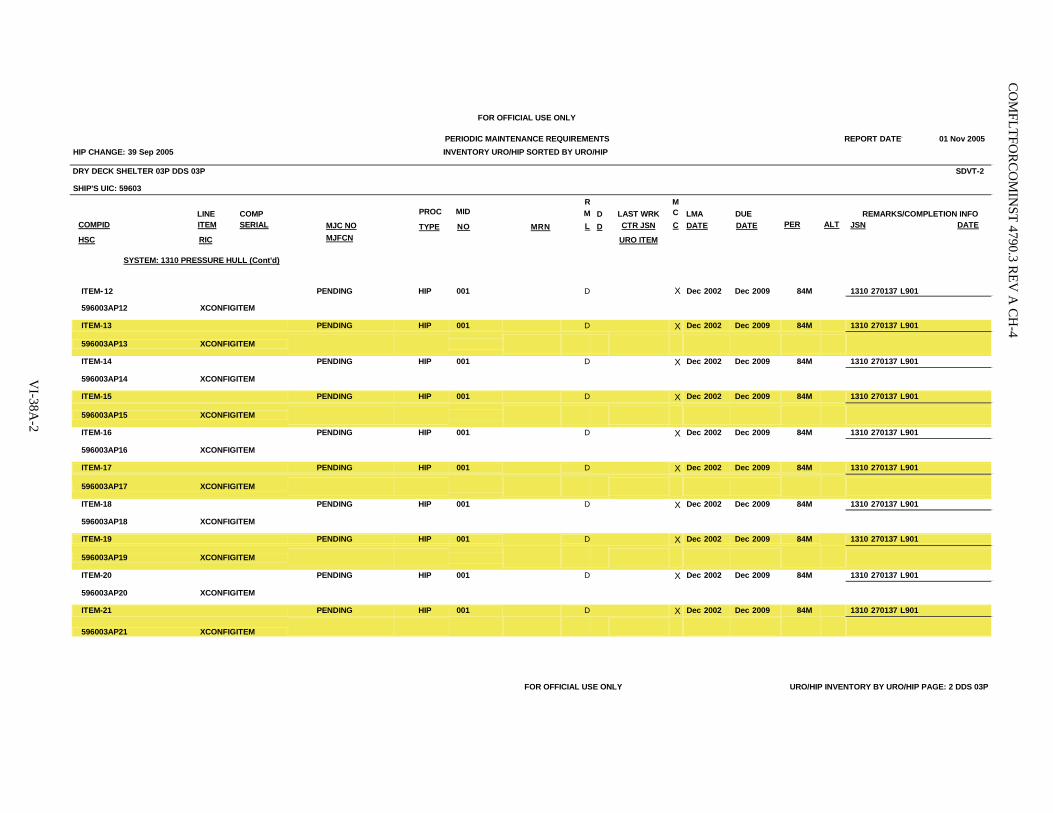
VI-38A
-2
CO
MFLTFO
RC
OM
INST 4790.3 R
EV A
CH
-4
FOR OFFICIAL USE ONLY
PERIODIC MAINTENANCE REQUIREMENTS REPORT DATE. 01 Nov 2005 HIP CHANGE: 39 Sep 2005 INVENTORY URO/HIP SORTED BY URO/HIP
DRY DECK SHELTER 03P DDS 03P SDVT-2
SHIP'S UIC: 59603
LINE COMP COMPID ITEM SERIAL MJC NO
PROC
TYPE MRN LAST WRK CTR JSN
LMA DATE
DUE DATE
REMARKS/COMPLETION INFO JSN DATE
MJFCN URO ITEM HSC RIC
SYSTEM: 1310 PRESSURE HULL (Cont'd)
MID
NO
RML
D D
MCC
PER
ALT
ITEM-12 PENDING HIP 001 D X Dec 2002 Dec 2009 84M 1310 270137 L901
596003AP12 XCONFIGITEM
ITEM-13 PENDING HIP 001 D X Dec 2002 Dec 2009 84M 1310 270137 L901
596003AP13 XCONFIGITEM
ITEM-14 PENDING HIP 001 D X Dec 2002 Dec 2009 84M 1310 270137 L901
596003AP14 XCONFIGITEM
ITEM-15 PENDING HIP 001 D X Dec 2002 Dec 2009 84M 1310 270137 L901
596003AP15 XCONFIGITEM
ITEM-16 PENDING HIP 001 D X Dec 2002 Dec 2009 84M 1310 270137 L901
596003AP16 XCONFIGITEM
ITEM-17 PENDING HIP 001 D X Dec 2002 Dec 2009 84M 1310 270137 L901
596003AP17 XCONFIGITEM
ITEM-18 PENDING HIP 001 D X Dec 2002 Dec 2009 84M 1310 270137 L901
596003AP18 XCONFIGITEM
ITEM-19 PENDING HIP 001 D X Dec 2002 Dec 2009 84M 1310 270137 L901
596003AP19 XCONFIGITEM
ITEM-20 PENDING HIP 001 D X Dec 2002 Dec 2009 84M 1310 270137 L901
596003AP20 XCONFIGITEM
ITEM-21 PENDING HIP 001 D X Dec 2002 Dec 2009 84M 1310 270137 L901
596003AP21 XCONFIGITEM FOR OFFICIAL USE ONLY URO/HIP INVENTORY BY URO/HIP PAGE: 2 DDS 03P
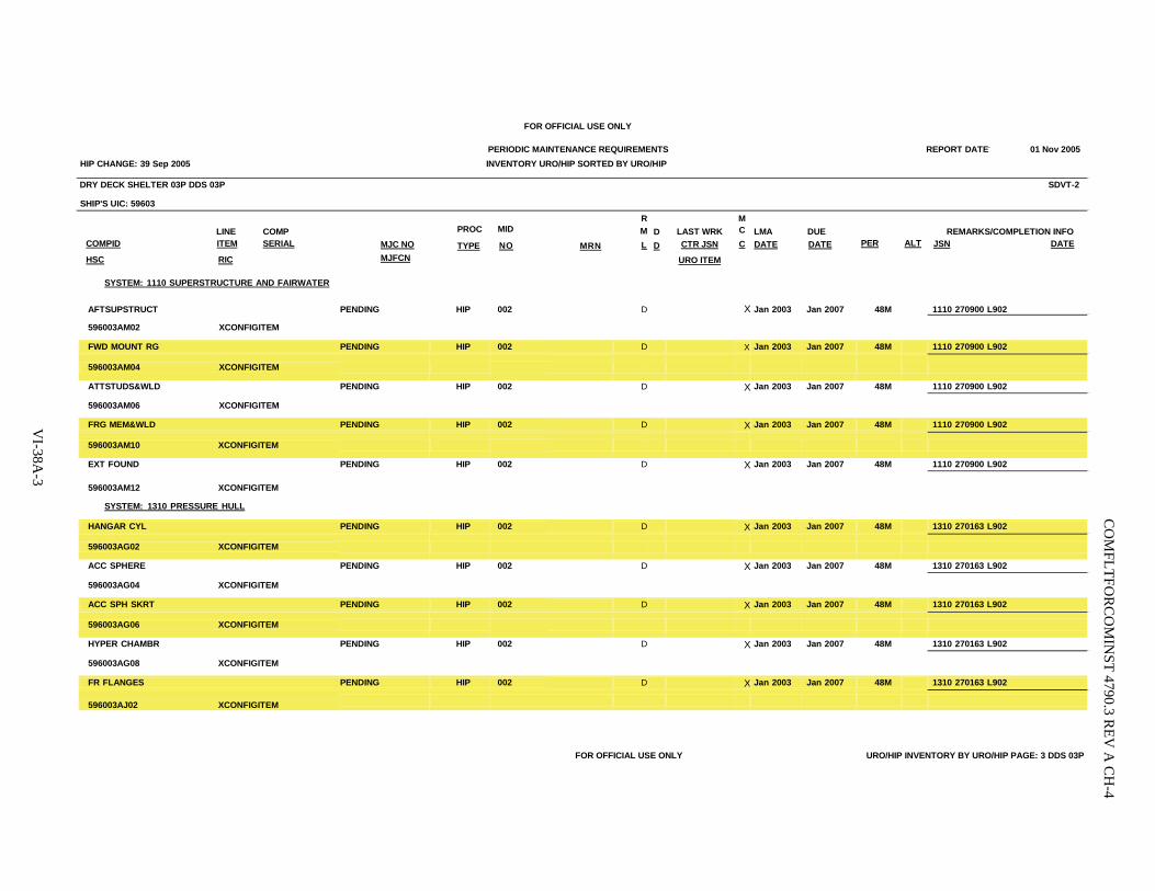
VI-38A
-3
CO
MFLTFO
RC
OM
INST 4790.3 R
EV A
CH
-4
FOR OFFICIAL USE ONLY
PERIODIC MAINTENANCE REQUIREMENTS REPORT DATE. 01 Nov 2005 HIP CHANGE: 39 Sep 2005 INVENTORY URO/HIP SORTED BY URO/HIP
DRY DECK SHELTER 03P DDS 03P SDVT-2
SHIP'S UIC: 59603
LINE COMP COMPID ITEM SERIAL MJC NO
PROC
TYPE MRN LAST WRK CTR JSN
LMA DATE
DUE DATE
REMARKS/COMPLETION INFO JSN DATE
MJFCN URO ITEM HSC RIC
SYSTEM: 1110 SUPERSTRUCTURE AND FAIRWATER
MID
NO
RML
D D
MCC
PER
ALT
AFTSUPSTRUCT PENDING HIP 002 D X Jan 2003 Jan 2007 48M 1110 270900 L902
596003AM02 XCONFIGITEM
FWD MOUNT RG PENDING HIP 002 D X Jan 2003 Jan 2007 48M 1110 270900 L902
596003AM04 XCONFIGITEM
ATTSTUDS&WLD PENDING HIP 002 D X Jan 2003 Jan 2007 48M 1110 270900 L902
596003AM06 XCONFIGITEM
FRG MEM&WLD PENDING HIP 002 D X Jan 2003 Jan 2007 48M 1110 270900 L902
596003AM10 XCONFIGITEM
EXT FOUND PENDING HIP 002 D X Jan 2003 Jan 2007 48M 1110 270900 L902
596003AM12 XCONFIGITEM
SYSTEM: 1310 PRESSURE HULL
HANGAR CYL PENDING HIP 002 D X Jan 2003 Jan 2007 48M 1310 270163 L902
596003AG02 XCONFIGITEM
ACC SPHERE PENDING HIP 002 D X Jan 2003 Jan 2007 48M 1310 270163 L902
596003AG04 XCONFIGITEM
ACC SPH SKRT PENDING HIP 002 D X Jan 2003 Jan 2007 48M 1310 270163 L902
596003AG06 XCONFIGITEM
HYPER CHAMBR PENDING HIP 002 D X Jan 2003 Jan 2007 48M 1310 270163 L902
596003AG08 XCONFIGITEM
FR FLANGES PENDING HIP 002 D X Jan 2003 Jan 2007 48M 1310 270163 L902
596003AJ02 XCONFIGITEM FOR OFFICIAL USE ONLY URO/HIP INVENTORY BY URO/HIP PAGE: 3 DDS 03P
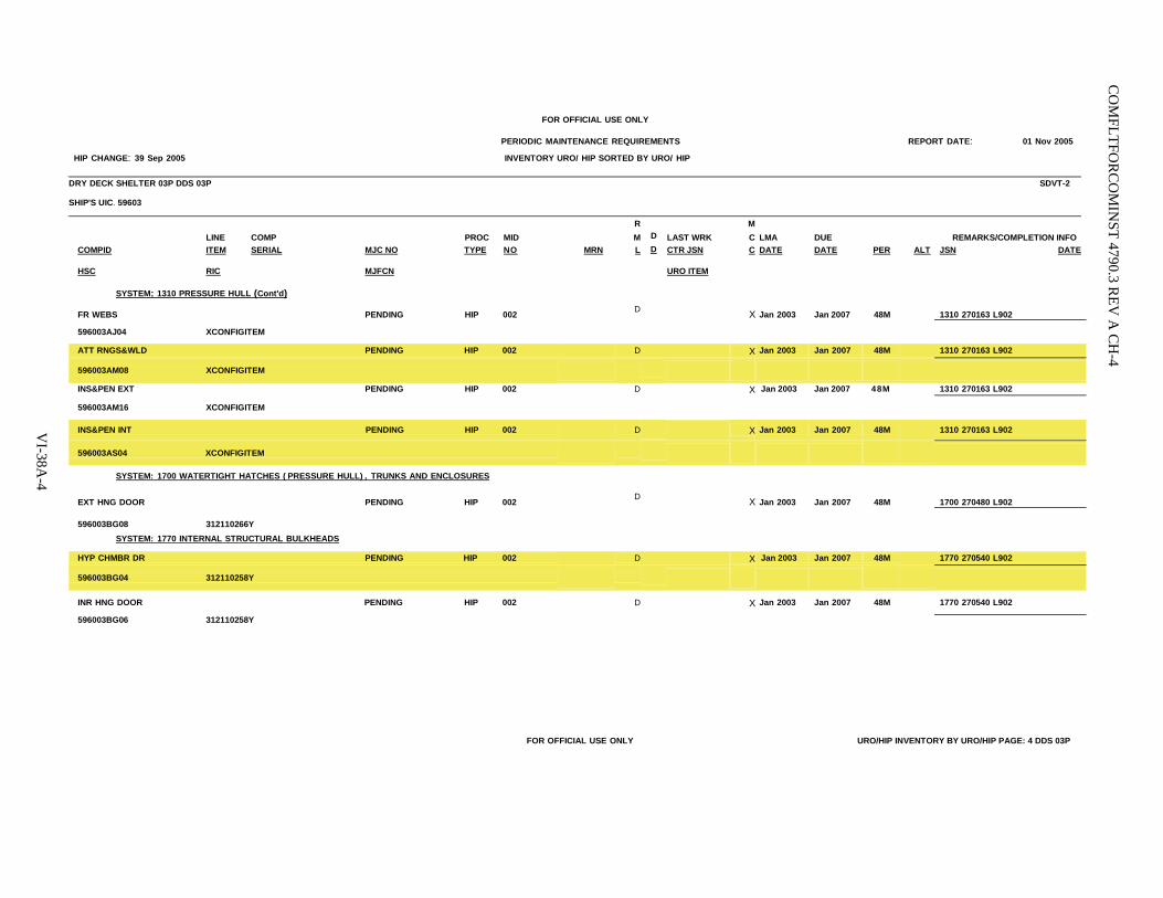
VI-38A
-4
CO
MFLTFO
RC
OM
INST 4790.3 R
EV A
CH
-4
FOR OFFICIAL USE ONLY
PERIODIC MAINTENANCE REQUIREMENTS REPORT DATE: 01 Nov 2005
HIP CHANGE: 39 Sep 2005 INVENTORY URO/HIP SORTED BY URO/HIP
DRY DECK SHELTER 03P DDS 03P SDVT-2
SHIP'S UIC. 59603
R MLINE COMP PROC MID M D LAST WRK C LMA DUE REMARKS/COMPLETION INFO
COMPID ITEM SERIAL MJC NO TYPE NO MRN L D CTR JSN C DATE DATE PER ALT JSN DATE
HSC RIC MJFCN
URO ITEM
SYSTEM: 1310 PRESSURE HULL (Cont'd)
FR WEBS PENDING HIP 002 D X Jan 2003 Jan 2007 48M 1310 270163 L902
596003AJ04 XCONFIGITEM
ATT RNGS&WLD PENDING HIP 002 D X Jan 2003 Jan 2007 48M 1310 270163 L902
596003AM08 XCONFIGITEM
INS&PEN EXT PENDING HIP 002 D X Jan 2003 Jan 2007 48M 1310 270163 L902
596003AM16 XCONFIGITEM
INS&PEN INT PENDING HIP 002 D X Jan 2003 Jan 2007 48M 1310 270163 L902
596003AS04 XCONFIGITEM
SYSTEM: 1700 WATERTIGHT HATCHES (PRESSURE HULL), TRUNKS AND ENCLOSURES
EXT HNG DOOR PENDING HIP 002 D X Jan 2003 Jan 2007 48M 1700 270480 L902
596003BG08 312110266Y
SYSTEM: 1770 INTERNAL STRUCTURAL BULKHEADS
HYP CHMBR DR PENDING HIP 002 D X Jan 2003 Jan 2007 48M 1770 270540 L902
596003BG04 312110258Y
INR HNG DOOR PENDING HIP 002 D X Jan 2003 Jan 2007 48M 1770 270540 L902
596003BG06 312110258Y
FOR OFFICIAL USE ONLY URO/HIP INVENTORY BY URO/HIP PAGE: 4 DDS 03P
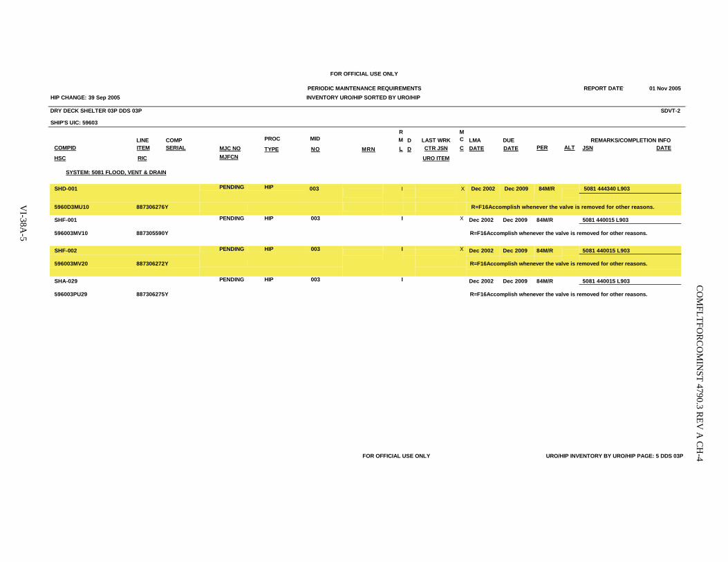
CO
MFLTFO
RC
OM
INST 4790.3 R
EV A
CH
-4
VI-38A
-5
FOR OFFICIAL USE ONLY
PERIODIC MAINTENANCE REQUIREMENTS REPORT DATE. 01 Nov 2005 HIP CHANGE: 39 Sep 2005 INVENTORY URO/HIP SORTED BY URO/HIP
DRY DECK SHELTER 03P DDS 03P SDVT-2
SHIP'S UIC: 59603
LINE COMP COMPID ITEM SERIAL MJC NO
PROC
TYPE MRN LAST WRK CTR JSN
LMA DATE
DUE DATE
REMARKS/COMPLETION INFO JSN DATE
MJFCN URO ITEM HSC RIC
SYSTEM: 5081 FLOOD, VENT & DRAIN
MID
NO
RML
D D
MCC
PER
ALT
5081 444340 L903 SHD-001
PENDING HIP 003
I
X Dec 2002 Dec 2009 84M/R
5960D3MU10 887306276Y R=F16Accomplish whenever the valve is removed for other reasons.
5081 440015 L903 SHF-001 PENDING HIP 003 I X Dec 2002 Dec 2009 84M/R
596003MV10 887305590Y R=F16Accomplish whenever the valve is removed for other reasons.
5081 440015 L903 SHF-002 PENDING HIP 003 I X Dec 2002 Dec 2009 84M/R
596003MV20 887306272Y R=F16Accomplish whenever the valve is removed for other reasons.
5081 440015 L903 SHA-029 PENDING HIP 003 I Dec 2002 Dec 2009 84M/R
596003PU29 887306275Y R=F16Accomplish whenever the valve is removed for other reasons.
FOR OFFICIAL USE ONLY URO/HIP INVENTORY BY URO/HIP PAGE: 5 DDS 03P

CO
MFLTFO
RC
OM
INST 4790.3 R
EV A
CH
-4VI-38A
-6
FOR OFFICIAL USE ONLY
PERIODIC MAINTENANCE REQUIREMENTS REPORT DATE. 01 Nov 2005 HIP CHANGE: 39 Sep 2005 INVENTORY URO/HIP SORTED BY URO/HIP
DRY DECK SHELTER 03P DDS 03P SDVT-2
SHIP'S UIC: 59603
LINE COMP COMPID ITEM SERIAL MJC NO
PROC
TYPE MRN LAST WRK CTR JSN
LMA DATE
DUE DATE
REMARKS/COMPLETION INFO JSN DATE
MJFCN URO ITEM HSC RIC
SYSTEM: 0611 AUDITS AND CERTIFICATION
MID
NO
RML
D D
MCC
PER
ALT
0611 603040 L904VITAL EQUIP PENDING HIP 004 0 May 2002 May 2006 48M/R
596003AD02 XCONFIGITEM R=N97 Accomplish after each TAV, RAV or ROH, or after installation or other configuration change which adds equipment or significantly changes existing design.
FOR OFFICIAL USE ONLY URO/HIP INVENTORY BY URO/HIP PAGE: 6 DDS 03P

VI-38A
-7
CO
MFLTFO
RC
OM
INST 4790.3 R
EV A
CH
-4
FOR OFFICIAL USE ONLY
PERIODIC MAINTENANCE REQUIREMENTS 01 Nov 2005 HIP CHANGE: 39 Sep 2005 INVENTORY URO/HIP SORTED BY URO/HIP
DRY DECK SHELTER 03P DDS 03P SDVT-2
SHIP'S UIC: 59603
LINE COMP COMPID ITEM SERIAL MJC NO
PROC
TYPE MRN LAST WRK CTR JSN
LMA DATE
DUE DATE
REMARKS/COMPLETION INFO JSN DATE
MJFCN URO ITEM HSC RIC
SYSTEM: 5081 FLOOD, VENT & DRAIN
MID
NO
RML
D D
MCC
PER
ALT
SHF-001 PENDING HIP 005 D A Dec 2002 Dec 2009 84M 5081 440015 L905
596003MV10 887305590Y
SHF-002 PENDING HIP 005 D A Dec 2002 Dec 2009 84M 5081 440015 L905
596003MV20 887306272Y
FOR OFFICIAL USE ONLY URO/HIP INVENTORY BY URO/HIP PAGE: 7 DDS 03P

COMFLTFORCOMINST 4790.3 REV A CH-4
VI-38A-8
(This Page Intentionally Left Blank)
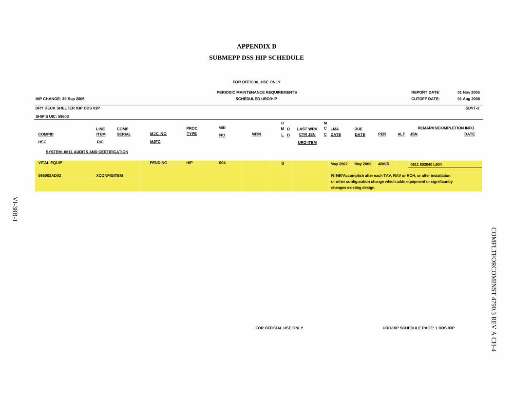
VI-38B
-1
CO
MFLTFO
RC
OM
INST 4790.3 R
EV A
CH
-4
APPENDIX B
SUBMEPP DSS HIP SCHEDULE
FOR OFFICIAL USE ONLY
PERIODIC MAINTENANCE REQUIREMENTS REPORT DATE. 01 Nov 2005 HIP CHANGE: 39 Sep 2005 SCHEDULED URO/HIP CUTOFF DATE: 01 Aug 2006
DRY DECK SHELTER 03P DDS 03P SDVT-2
SHIP'S UIC: 59603
LINE COMP COMPID ITEM SERIAL MJC NO
PROC TYPE
MRN
LAST WRK CTR JSN
LMA DATE
DUE DATE
REMARKS/COMPLETION INFO JSN DATE
MJFC URO ITEM HSC RIC
SYSTEM: 0611 AUDITS AND CERTIFICATION
MID
NO
RML
D D
MCC
PER
ALT
0611 803040 L904 VITAL EQUIP PENDING HIP 004 0
May 2002 May 2006 48M/R
596003AD02 XCONFIGITEM R=N97Accomplish after each TAV, RAV or ROH, or after installation
or other configuration change which adds equipment or significantly changes existing design.
FOR OFFICIAL USE ONLY URO/HIP SCHEDULE PAGE: 1 DDS 03P

COMFLTFORCOMINST 4790.3 REV A CH-4
VI-38B-2
(This Page Intentionally Left Blank)

COMFLTFORCOMINST 4790.3 REV A CH-6
VI-38C-1
APPENDIX C
REQUEST FOR DSS HIP PERIODICITY EXTENSION FORMAT
4790 Ser
From: Commander, DSS Squadron ___ To: Commanding Officer, Submarine Maintenance Engineering, Planning and Procurement (SUBMEPP)
Activity Via: COMNAVSPECWARCOM
Subj: REQUEST FOR EXTENSION OF PERIODICITY FOR DSS HIP (S) ON DSS Vehicle/Shelter and Hull No.)
Ref: (a) Applicable DSS HIP (b) COMFLTFORCOMINST 4790.3; Joint Fleet Maintenance Manual, Volume VI, Chapter 38 (c) COMSUB(LANT/PAC) ltr 4790 Ser of (previous letter granting extension of periodicity)
1. In accordance with references (a) and (b), request extension of DSS HIP periodicity for Deep Submergence System (Vehicle/Shelter and Hull No.) to coincide with Selected Restricted Availability/Overhaul/Depot Modernization Period/Interim Dry-Docking as follows:
DSS HIP
Equipment Guide List
Item Number or Component
Ident
LMA Date
Current Due Date
Inactive Time Extension Required
Required Next Due
Date
Inactive
Days
001 All June 82 Apr 91 100 days 7 months Nov 91 002 All June 82 Aug 91 100 days 3 months Nov 91 003 All June 82 Aug 91 100 days 3 months Nov 91 004 All June 84 Apr 91 100 days 7 months Nov 91 005 VB-10 June 84 Apr 91 100 days 7 months Nov 91
2. Inactive time identified for the DSS HIPs listed in paragraph 1 above is the actual allowable time accrued to date since DSS HIP was last accomplished/previous extension of periodicity was granted by reference (c).
Copy to: COMNAVSEASYSCOM (PMS 399) Commanding Officer, _____________________

COMFLTFORCOMINST 4790.3 REV A CH-4
VI-38C-2
(This Page Intentionally Left Blank)

COMFLTFORCOMINST 4790.3 REV A CH-5
VOLUME VI
CHAPTER 39
HOT WASH PROCESS BUSINESS RULES
LISTING OF APPENDICES.
A Submitting and Processing Feedback B Availability Feedback Form/Availability Feedback Form Instructions C Feedback Issue Filter Process
39.1 PURPOSE. The Hot Wash process provides the maintenance and modernization community with a process to identify, resolve and provide feedback communication on barriers causing inefficiencies or waste within business processes. The process is applicable to Surface Ships. The Hot Wash feedback process addresses issues at the lowest level in the Maintenance and Modernization Chain of Command. It encompasses the established milestones and meetings within the planning and execution of an availability in accordance with Volume II, Part II, Chapter 2, paragraph 2.5 of this manual. Appendix D of Volume II, Part II, Chapter 2 of this manual includes a detailed table of milestones. While there are several milestone meetings within the availability planning and execution process, the feedback process exists to continually collect information to improve processes.
39.2 INTERACTION AMONG FEEDBACK PROCESSES. The Hot Wash process business rules recognize the need for other feedback processes (such as Contractors Performance Appraisal Reporting System and Award Fee Boards and other software related feedback systems within the Navy Maintenance Database and the Navy Enterprise Maintenance Automated Information System) and the need for all to exist. The Hot Wash process meetings shall remain focused on process improvement and allow for other issues to remain within the scope of their existing feedback and review processes.
39.3 HOT WASH MEETING OVERVIEW.
39.3.1 Hot Wash Meeting Concept. The Hot Wash is a process review, an evaluation of process execution and a place to resolve process issues to improve process execution.
39.3.2 Timing. The Hot Wash meeting will be conducted within two to four weeks following the availability's completion in order to capture information while it is still fresh.
39.3.3 Responsibilities.
a. Commander, Naval Surface Force (COMNAVSURFOR). COMNAVSURFOR is the overall Hot Wash process owner. As such, COMNAVSURFOR is responsible for the general management of implementing the Hot Wash process to ensure process fluidity and effectiveness.
b. Regional Maintenance Center (RMC). The RMC Class Team Leader has been designated as the overall Hot Wash meeting facilitator and will work with the Maintenance Team and RMC Feedback Coordinator to ensure a productive meeting. The Class Team Leader is the central point of contact for all ships within a particular RMC and brings continuity to the Hot Wash process. As the facilitator, the Class Team Leader should consider process issues and areas for improvement throughout the execution of the availability as well as those that have occurred within other availabilities. The Class Team Leader should also maintain communication with the Maintenance Team and Sustainment and Modernization Team in order to ensure a full review. Note that while the Class Team Leader possesses many responsibilities as the facilitator of the Hot Wash process meetings, he is to be considered the coordinator and should expect to receive assistance from all stakeholders.
VI-39-1

COMFLTFORCOMINST 4790.3 REV A CH-5
39.3.4 Hot Wash Process Meeting Objective. The objective of the Hot Wash process meeting is to identify process improvements that are to be shared and embedded into the maintenance and modernization processes. It provides a method to identify opportunities for improvement in Surface Warfare Enterprise (SWE) and specific processes as they relate to project teams, technical and modernization issues. "Best practices" and "lessons learned" derived from ship availabilities may also be shared via this forum within the Ship Maintenance and Modernization Community.
39.4 PREPARING FOR THE HOT WASH MEETING.
39.4.1 Feedback Sources. Throughout the planning stages and execution of the availability, Maintenance Team members, support personnel and those in key availability positions shall submit process issues in accordance with Appendix A. Barriers to existing processes shall be identified and submitted using Appendix B. Feedback may also be gathered from the ship's Commanding Officer's Weekly Situation Reports, the RMC Project Manager's input to the Weekly Situation Reports and the Monthly Availability Status Reports.
39.4.2 Metrics. At availability completion, the Class Team Leader shall review the following availability metrics. The purpose of the metric review is to determine what areas need additional attention or analysis.
a. Funding Stability (Funding Profile).
b. Growth and New Work.
c. Churn/Authorized Alterations Installed.
d. Milestone Conformance (Flow Metric).
e. Late Work Premiums.
f. Planning Performance Milestone Table (Red and Green Table accompanied by jobs authorized/pre-availability time line graph).
g. Phasing Plans in Dollars, Man Days and Material.
h. Port Loading.
i. Cost by System.
j. Regional Calibration Center Count by System.
k. Gap Analysis (Coded by Count).
l. Gap Analysis (Coded by Dollar).
39.4.3 Invitees. Key personnel involved with the follow-on availability shall be invited to attend the Hot Wash process meeting for the previous availability either within the ship class, with the same contractor or within the same port to ensure lessons learned are passed on and utilized.
39.4.4 Announcement. The Class Team Leader will publish a meeting notice at Completion minus 14 weeks along with a request to identify both positive and adverse process issues. The Class Team Leader or a designated project maintenance team member will chair the meeting. The Class Team Leader and Feedback Coordinator will serve as facilitators. Someone shall be assigned to take minutes.
VI-39-2

COMFLTFORCOMINST 4790.3 REV A CH-5
39.4.5 Feedback Submission. The Hot Wash Process is intended to address process issues. Feedback shall be submitted to the Class Team Leader as early as possible but no later than five working days prior to the Hot Wash process meeting. The Class Team Leader shall review and integrate Situation Report Hot Wash Process Report issues as applicable in accordance with Volume II, Part I, Chapter 3 of this manual.
39.4.6 Feedback Analysis and Categorization. The Class Team Leader and RMC Feedback Coordinator shall conduct an initial analysis of feedback issues upon receipt and prior to the Hot Wash process meeting. The analysis should include a validation that the issue is process related, a determination of the root cause of the issue, identification of associated metrics and categorization of the issue. This preliminary analysis will help scope the Hot Wash process meeting discussion in order to identify and confirm the root causes and best resolution paths.
39.4.7 Metrics Analysis. The RMC Feedback Coordinator and Class Team Leader will analyze the specified metrics provided by the Business Office Metrics Team to identify availability trends or spikes along with the apparent root causes. The feedback issues and metrics analysis, along with root causes, will be grouped under one of the established process categories.
39.4.8 Issue Categorization. The RMC Feedback Coordinator will "filter" the issues by identifying in which feedback category the issue belongs using the guidance of Appendix C. The Feedback Coordinator will determine whether an issue is a local issue, a local issue with global interest, a global SWE/SHIPMAIN related issue or a global non-SWE/SHIPMAIN related issue. These designations are classified as follows:
a. Local Issues: Issues that can be solved within a single region, area or organization.
b. Local with Global Interest Issues: Issues that can be solved within a single region, area or organization but might offer critical information or resolution ideas to similar issues facing other regions.
c. Global SWE/SHIPMAIN Related Issues: Process issues that affect multiple regions, organizations or ship classes and can be identified with the purpose/goals of a SWE/SHIPMAIN Cross-Functional Team or Process Team. These issues will be reviewed by the Sustainment and Modernization teams for resolution. Categories include: Requirements (CFT1), Package Preparation/Placement and Oversight (CFT2/3), Alterations and Modifications (CFT4), Process Team.
d. Global Non-SWE/SHIPMAIN Related Issues: Process issues that affect multiple regions, organizations or ship classes that are technical in nature, project team related or regarding modernization.
39.5 CONDUCTING A HOT WASH MEETING.
39.5.1 Agenda. The focus of the meeting includes process issues, business rules, metrics and training. Specific agenda topics to review include, but are not limited to, the items listed below.
a. Statement or Purpose/Goals.
b. Availability Background.
(1) Schedule.
(2) Budget/Cost.
(3) Planned Alterations.
(4) Planned/Authorized after A-120.
VI-39-3

COMFLTFORCOMINST 4790.3 REV A CH-5
c. Process Improvement Areas.
(1) Local Issues.
(2) Local with Global Interest Issues.
(3) Global SWE/SHIPMAIN Related Issues.
(a) Requirements (CFT1) Issues.
(b) Package Preparation (CFT2) Issues.
(c) Placement and Oversight (CFT3) Issues.
(d) Alterations and Modifications (CFT4) Issues.
(e) SWE/SHIPMAIN Process Team.
(4) Global Non-SWE/SHIPMAIN Related Issues.
(a) Project Team/Execution Issues.
(b) Technical Issues.
(c) Modernization Issues.
d. Best Practices/Success Stories.
e. Breakout Team Identification (if necessary).
f. Summary/Conclusion.
39.5.2 Identification of Time Critical Items. Agenda items deemed to have an immediate impact on availability management or execution, such as improving ship alteration installations and availability best practices, shall be compiled into a short list for consideration by follow-on availability personnel. The RMC Feedback Coordinator shall forward this list to the relevant Maintenance Teams for review, integration and inclusion into Maintenance Team training. Additionally, the RMC Feedback Coordinator shall enter the data into Livelink and forward the list to the designated RMC contacts and COMNAVSURFOR to provide for the widest dissemination of identified process issues and contribute toward fleet-wide knowledge sharing.
39.5.3 Breakout Sessions. As a result of the Hot Wash process meeting, breakout sessions may be scheduled as necessary in regard to specific issues or concerns. The format is intended to allow people to use their time more effectively and participate in those discussions in which they have interest and expertise. It is important that there be a broad representation, since a single person or organization seldom resolves process issues. The Class Team Leader shall identify and invite the appropriate subject matter experts to lead each breakout session and to aid in understanding and developing the recommended process change. Each breakout session shall have a designated leader.
39.6 POST HOT WASH PROCESS MEETING ACTIVITY.
39.6.1 Hot Wash Livelink Web Site. Hot Wash process meeting documents and information shall be posted on the Hot Wash Livelink web site. This site will also be used to track and archive feedback issues. The web site is located at https://chantry.submepp.navy.mil/livelink/livelink.exe. See Appendix A for details.
VI-39-4

COMFLTFORCOMINST 4790.3 REV A CH-5
39.6.2 Hot Wash Minutes. The RMC Feedback Coordinator, with the assistance of the RMC Class Team Leader, will prepare the minutes from the meeting utilizing the standard templates and e-mail them to [email protected] within 30 days of the meeting. The e-mail shall include: the Hot Wash meeting Executive Summary, Meeting Presentation including discussion points and attendance list. This information will be posted by COMNAVSURFOR to Livelink.
39.6.3 Action Item Routing. The RMC Feedback Coordinator is responsible for ensuring "local issues" are routed for resolution within his RMC and tracked/archived in Livelink. "Global issues" and "local issues with global interest issues" are entered into Livelink, using the Feedback Form (Appendix B), for resolution by the appropriate Global Feedback Coordinators/Action Officers. COMNAVSURFOR will ensure proper resolution routing within Livelink in accordance with Appendices B and C. The RMC Commanders, Waterfront Operations Officers and Business Office shall review the outstanding process issues within Livelink monthly and track to completion.
39.6.4 Coordinated Resolution Effort. Feedback may be reviewed and considered by various subject matter experts to determine resolution or improvement in the relevant process. Numerous methodologies exist to facilitate the discussion and development of process improvement recommendations. Some methods include barrier removal teams, corrective action plans/meetings, work strategy development and integrated project teams. By focusing the right people on an issue, feedback will positively impact the community via process improvement. This may occur in the form of advance planning efforts, future availabilities, Maintenance Teams, Project Team integration, policy changes, etc.
39.7 SUPER HOT WASH MEETINGS.
39.7.1 Mission. The Super Hot Wash Process Meetings provide a forum for maintenance professionals to improve SWE processes in order to save the Navy money. The Super Hot Wash Process provides an organizational structure between the individual Project/Ship Hot Wash Process meetings, top-level SWE Forums, the RMC Board of Directors and the Surface Warfare Enterprise, Sustainment and Modernization Teams.
39.7.2 Scope. Topics shall be relevant to process improvements and cost savings for future availabilities and may include ship class or port specific process issues, best practices, success stories, industry feedback, technical issues, SWE processes and new developments, AIT management and cost analysis. Breakout Team sessions with smaller groups of subject matter experts will be utilized as necessary to further refine specific processes.
39.7.3 Action Items. Global process action items resulting from a Super Hot Wash Process meeting shall be entered into Livelink for action officer assignments and resolution tracking. The minutes and select presentations will be posted to the Livelink and the SWE websites.
VI-39-5

COMFLTFORCOMINST 4790.3 REV A CH-5
(This Page Intentionally Left Blank)
VI-39-6

COMFLTFORCOMINST 4790.3 REV A CH-5
APPENDIX A
SUBMITTING AND PROCESSING FEEDBACK
1. Feedback should be submitted via the Availability Feedback Form (see Appendix B, "Feedback Form"). These forms may be submitted by Maintenance Team members, support personnel or anyone desiring to identify a barrier within the existing business processes.
2. Feedback forms and instructions for their completion may be obtained at the following web sites: www.submepp.navy.mil/jfmm and https://chantry.submepp.navy.mil/livelink/livelink.exe. The form is filled out and submitted via email to the designated "Local (RMC) Feedback Coordinator". This person is responsible for reviewing applicable barriers/issues submitted. If they are "global issues" and beyond RMC resolution or "local issues with global interest", the RMC Feedback Coordinator will forward the Feedback Form for inclusion into the Livelink database to the Submarine Maintenance Engineering, Planning and Procurement Activity (SUBMEPP) Livelink feedback manager at: [email protected] until direct Livelink Feedback Form data entry is available.
NOTE: WHEN LOCAL ISSUES WITH A GLOBAL INTEREST ARE IDENTIFIED, THE SOURCE RMC WILL BE TASKED WITHIN LIVELINK AS THE ACTION OFFICER. IT WILL BE SOLVED AND TRACKED LOCALLY, BUT REPORTED PUBLICLY VIA LIVELINK.
3. Based on the category designation on the Feedback Form, the feedback item will be routed to the appropriate category owner. Status of the item is to be entered by the assigned action official who will determine the anticipated completion date and will enter appropriate status (either in-process or completed). Completed items will include a summary of resolution. Action addressees may change the status as progress is made, but at a minimum, assigned action items will be reviewed monthly. Review/discussion of feedback issues and status will be performed monthly by the COMNAVSURFOR Process Owner as well as at the Process Team meetings.
4. Those issues that cannot be resolved without additional guidance from higher authority will be referred to the Fleet Maintenance Officer.
VI-39A-1

COMFLTFORCOMINST 4790.3 REV A CH-5
(This Page Intentionally Left Blank)
VI-39A-2
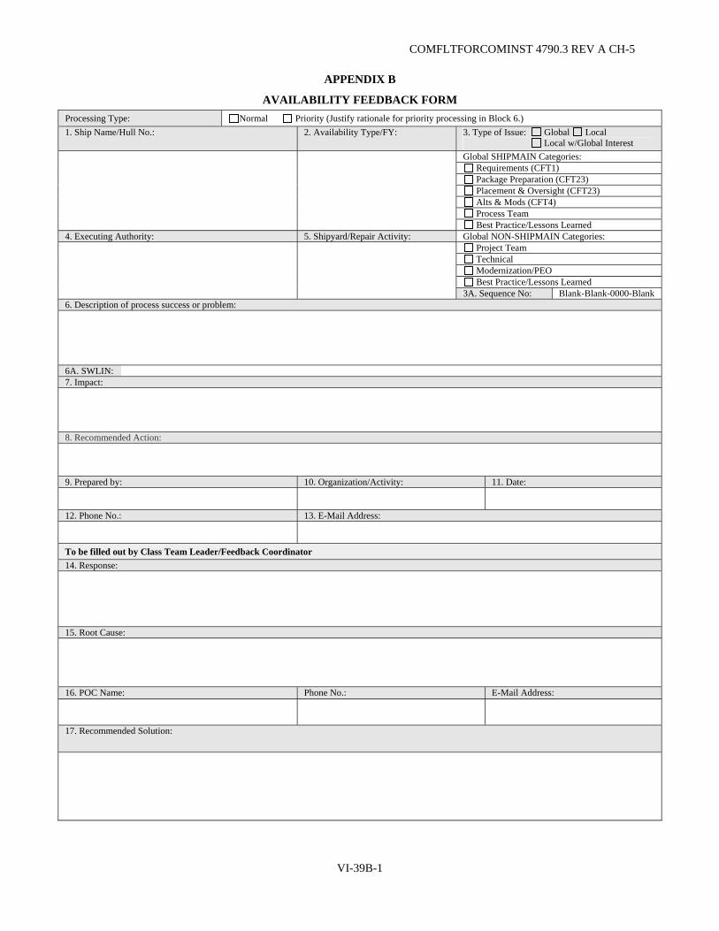
COMFLTFORCOMINST 4790.3 REV A CH-5
VI-39B-1
APPENDIX B
AVAILABILITY FEEDBACK FORM Processing Type: Normal Priority (Justify rationale for priority processing in Block 6.) 1. Ship Name/Hull No.: 2. Availability Type/FY: 3. Type of Issue: Global Local
Local w/Global Interest
Global SHIPMAIN Categories: Requirements (CFT1)
Package Preparation (CFT23) Placement & Oversight (CFT23) Alts & Mods (CFT4) Process Team Best Practice/Lessons Learned
4. Executing Authority: 5. Shipyard/Repair Activity: Global NON-SHIPMAIN Categories: Project Team Technical
Modernization/PEO Best Practice/Lessons Learned
3A. Sequence No: Blank-Blank-0000-Blank 6. Description of process success or problem: 6A. SWLIN: 7. Impact: 8. Recommended Action: 9. Prepared by: 10. Organization/Activity: 11. Date:
12. Phone No.: 13. E-Mail Address:
To be filled out by Class Team Leader/Feedback Coordinator 14. Response:
15. Root Cause:
16. POC Name: Phone No.: E-Mail Address:
17. Recommended Solution:

COMFLTFORCOMINST 4790.3 REV A CH-5
VI-39B-2
(This Page Intentionally Left Blank)
COMFLTFORCOMINST 4790.3 REV A CH-5
AVAILABILITY FEEDBACK FORM INSTRUCTIONS
In order to support the SHIPMAIN processes and Continuous Maintenance philosophies, a "Hot Wash" Feedback Process has been developed. This process will ensure that vital feedback information is continually being collected by the process participants and corrective action/process improvements developed and instituted by the process owners. It is requested that any process issue be documented on the attached Availability Feedback Form, and routed to the Class Team Leader for action. Below are simple guidelines for filling this form out, blocks that do not apply should be identified with "N/A".
This form is available on the SUBMEPP web site (http://www.submepp.navy.mil/jfmm/index.htm). It should also be provided by the Class Team Leader to all participants at the ship's arrival conference.
Block 1. Ship Name/Hull Number: Input the alpha-numeric designator for the ship worked, i.e., CG-XX, DDG-XX.
Block 2. Availability Type/FY: Input the type of maintenance availability and the fiscal year accomplished, i.e., SRA/2004, CMAV 2005.
Block 3. Type of Issue: Type of Issue to be filled in by the Class Team Leader. The identified process categories are divided between Global, Local and Local with Global Interest: Requirements, Package Preparation, Placement and Oversight, Alterations and Modernization, Process Team, Metrics, Best Practice/Lessons Learned, Project Team, Technical, Modernization/PEO SHIPS.
Block 3A. Sequence Number: To be filled in by RMC Feedback Coordinator and should be in following order: RMC location (MARMC, HRMC, NWRMC, SWRMC, SERMC, SCRMC), - Ship Class (FFG, DDG, MCM, LHA, CG, etc.) - Fiscal Year (05, 06, etc.) - Sequential Item Number (3 digits which start at 001) -. Examples: MARMC-DDG-05-001; PHRMC-FFG-05-003.
Block 4. Executing Authority: Input the name of the organization involved.
Block 5. Shipyard/Repair Activity: Input the name of the repair activity.
Block 6. Description of process success or problem: Input a brief description of the process issue in question, i.e., late funding receipt, contract change processing, availability scheduling.
Block 6A. SWLIN: Provide SWLIN number (if known) for particular issue.
Block 7. Impact: Input a brief description of the resultant impact to the process in question.
Block 8. Recommended Action: Input a brief description of the recommended corrective action that could correct the overall process problem.
Block 9. Prepared by: Input your name.
Block 10. Organization/Activity: Input the name of your parent organization, activity or command.
Block 11. Date: Input the date of submittal.
Block 12. Phone number: Input the phone number that would provide the most success in contacting you.
Block 13. E-Mail Address: Input the E-Mail address that would provide the most success in contacting you.
Blocks 14.-17. Are completed if feedback issue is local or if this is best practice.
Block 14. Response: Include Class Team Leader or actionee response.
Block 15. Root Cause: Identify the process to which the issue is originally associated with.
Block 16. POC: Class Team Leader to include contact information.
Block 17. Recommended Solution: Input recommended solution as discussed at Hot Wash meeting or in Breakout Team meetings.
VI-39B-3

COMFLTFORCOMINST 4790.3 REV A CH-5
(This Page Intentionally Left Blank)
VI-39B-4

APPENDIX C
TEAM SHIPS
RMC
LIVELINK:
Catalogue and Store Feedback
Issues
LIVELINK:
Catalogue and Store Feedback
Issues
SHIP-MAIN
Maintenance Team
No Action Required
-Follow Process -1 Time Event
Local Solution Possible
Local Issue Only
Global Interest
LOCAL FILTER RMCs
1. ‘Bin’ into major issue type
2. Can it be solved locally?
-Does process exist to solve?
-Time critical?
-ROI/Priority
Feedback Issue Filter Process Green: Local Activity Blue: Global Activity Purple: Global Non-SHIPMAIN Activity
Time-Critical ‘Heads-up’
No Local Solution Possible: Global Non-SHIPMAIN
Issues
CFT1, CFT2, CFT3, CFT4, Process Team
Technical, Project Team,
Modernization
GLOBAL SHIPMAIN ISSUE
FILTER Process Team
SHIPMAIN Process Issues
Class Team Leader
ISSUES Hotwash
Escalation
Feedback utilized in Advance Planning Efforts, Future Availabilities, Project Team Integration, Policy Change, etc.
TEAM SHIPS
Feedback utilized in Advance Planning Efforts, Future Availabilities, Project Team Integration, Policy Change, etc.
BRT
Corrective Action Plan /
Meeting
Work Strategy V
I-39C-1 IPT
Single Person /
Single Org Assess-
ment
CO
MFLTFO
RC
OM
INST 4790.3 R
EV A
CH
-5
Process Review Team

c200 W3
Global SHIPMAIN
Filter Process Team
Global Issue
Assign Local W3
Can it be solved
locally?
Global interest
? No Yes
No
(Global interest resolved locally)
Track W3s Locally
Dept Head / Port Mtg
LOCAL FILTER RMCs
‘Bin’ issue into major issue type
RMC
LIVELINK: Catalogue and Store Feedback
Issues
c400 W3
Local Feedback Issue Filter
Global Non-SHIPMAIN
Filter
BRT
Corrective Action Plan /
Meeting
Work Strategy
IPT
Single Person /
Single Org Assess-
ment
Process Review Team
Take Local Action
Feedback utilized in Advance Planning Efforts, Future Availabilities, Project Team Integration, Policy Change, etc.
c300 W3
Yes
TEAM SHIPS
Green: Local Activity
Blue: Global Activity
Purple: Global Non-SHIPMAIN Activity
etc W3
CO
MFLTFO
RC
OM
INST 4790.3 R
EV A
CH
-5
VI-39C
-2
COMFLTFORCOMINST 4790.3 REV A CH-6
VI-40-1
VOLUME VI
CHAPTER 40
SUBMARINE MESSAGE REPORTING
REFERENCES.
(a) SECNAVINST 5510.36 - Department of the Navy Information Security Program Regulation, Chapter 6 (b) NAVSEAINST 4720.14B - Temporary Alterations to Active Fleet Submarines, Control of (c) NAVSEA SL720-AA-MAN-010 - Fleet Modernization Program Management and Operations Manual
LISTING OF APPENDICES.
A Sample (SUBS) Initial Message B Sample (SUBS) Update Message C Sample (SUBS) Final/Closeout Message D Sample (SUBS) Shipalt/Tempalt Installation Message E Sample (SUBS) Shipalt/Tempalt Removal Message
40.1 PURPOSE. This chapter provides policy and guidance regarding the utilization of (SUBS) messages. Reactor Plant and Strategic Weapons Systems material issues are not governed by this document and shall not to be reported via (SUBS) message format. (SUBS) message requirements for New Construction, Chief of Naval Operations, (CNO) and Type Commander (TYCOM) depot availabilities are addressed in Volume II, Part I, Chapters 3 and 4 of this manual and will not be addressed in this chapter. This chapter supercedes all other policy, procedures or guidance previously promulgated regarding (SUBS) messages.
40.2 BACKGROUND. Submarine material and equipment problems or requests for technical assistance reported via message have experienced delays receiving the required resolutions for identified problems. Delays were associated with insufficient data and or improper message addressing.
40.3 SCOPE. To establish protocol for the reporting of submarine equipment, systems and material issues that affect ship's mission or ship/personnel safety. To establish a reporting procedure that will ensure all necessary commands and technical authorities are contacted without delay. To ensure the correct action is identified and provided to the ship using the most rapid means.
40.4 POLICY.
a. The parenthetical code word (SUBS) shall appear as the first word in the subject line before the subject description.
b. (SUBS) messages shall identify its status by using the words INITIAL, UPDATE or FINAL at the end of the subject line.
c. The (SUBS) message shall not be used as a substitute for any Casualty Report, Situation Report or Incident Report that may be required by higher authority. A (SUBS) message shall be sent to provide further supplemental information needed to explain the problem, provide troubleshooting support and identify its effect on the ship.
d. (SUBS) messages are intended for material and technical assistance request issues pertaining to ship's mission or personnel safety and should not be used to report routine administrative items such as visit requests, post tech assist visit reports or any other event not requiring the urgency of a (SUBS) message.

COMFLTFORCOMINST 4790.3 REV A CH-6
VI-40-2
e. (SUBS) messages originated by submarines will be updated by the submarine at a periodicity not greater than once every 30 days. UPDATES should include equipment status, repair efforts in progress and if known anticipated repair date.
f. To identify (SUBS) message priority use the following precedence:
(1) ROUTINE - REQUEST ANSWER WITHIN 5 WORKING DAYS.
(2) PRIORITY - REQUEST ANSWER WITHIN 3 WORKING DAYS.
(3) IMMEDIATE - REQUEST ANSWER WITHIN 24 HOURS.
g. (SUBS) messages shall be used to identify the installation and removal of Temporary Alterations (TEMPALT) and Ship Alterations (SHIPALT). However the 30-day UPDATE requirement and precedence identification is waived for these instances.
h. (SUBS) messages identifying the installation or removal of a TEMPALT or SHIPALT will identify such message by placing the words (TEMPALT) or (SHIPALT) at the end of the subject line.
i. (SUBS) messages are to be classified appropriately in accordance with reference (a).
j. (SUBS) messages shall be addressed to the controlling Immediate Superior In Command (ISIC) for action and INFO Naval Sea Systems Command (NAVSEA), TYCOM's and Technical Authority as appropriate ensuring parent commands are included as addressees.
k. A FINAL close out (SUBS) message shall be sent upon the correction of the reported material problem.
l. NAVSEA shall review all (SUBS) messages and provide responses to the ISIC within the precedence time line as identified in paragraph 40.4 f. of this chapter.
m. (SUBS) messages initiated by NAVSEA requesting information from one or more Commands shall be tracked by NAVSEA.
n. (SUBS) messages being initiated for the purpose of gathering technical information from submarines shall be provided to the TYCOM for action.
o. Technical Authorities shall provide all (SUBS) message responses to NAVSEA, TYCOM and ISIC for review and action.
p. (SUBS) messages shall not be initiated by a Technical Authority unless authorized by NAVSEA, TYCOM or ISIC.
40.5 RESPONSIBILITIES.
40.5.1 Type Commanders.
a. Review (SUBS) message traffic and when necessary readdress or forward to ensure the proper Technical Authority was identified and aware of the message.
b. Assist and support the ISIC as required to generate (SUBS) messages.
c. (SUBS) messages initiated by the TYCOM, requesting information from one or more Commands are to be tracked by the TYCOM department generating the message.

COMFLTFORCOMINST 4790.3 REV A CH-6
VI-40-3
d. Track all (SUBS) messages generated by submarines under its cognizance.
40.5.2 Immediate Superior In Command.
a. Review and take for action all (SUBS) messages coordinating with NAVSEA, TYCOM and the Technical Authority to generate and provide message responses as required and within the precedence time line as identified in paragraph 40.4 f. of this chapter.
b. (SUBS) messages sent to or initiated by a submarine under its cognizance shall be tracked by the ISIC.
c. (SUBS) messages initiated by the ISIC requesting information from one or more commands shall be tracked by the ISIC.
40.5.3 Ship's Commanding Officer.
a. (SUBS) messages initiated by the ship shall be tracked by the ship until closeout.
b. Responses to technical assistance (SUBS) messages shall be answered as soon as the troubleshooting efforts have results. If requested troubleshooting efforts are not accomplished due to ship's operations or lack of test equipment, generate a (SUBS) message containing efforts taken, results, effect on ship and any further assistance needed.
c. When requesting onboard technical assistance, Chapter 2 of this volume, Fleet Technical Assistance, shall be used as guidance.
d. Issue a (SUBS) message to identify the installation and removal of TEMPALTs and SHIPALTs.
40.6 MESSAGE REQUIREMENTS.
a. All (SUBS) messages requesting technical assistance will contain, as a minimum, the following requirements:
(1) EXECUTIVE SUMMARY – faulted equipment, when the fault occurred, functions lost and equipment effected.
(2) BACKGROUND (if any) – previous related equipment problems, when experienced, corrective action taken, last completed system certification.
(3) DESCRIPTION OF THE PROBLEM – affected equipment, type of fault, fault indications, system indications.
(4) TROUBLESHOOTING EFFORTS – procedures used, documentation held onboard, Ship's Force training and experience with the equipment, troubleshooting limitations, special equipment held, any possible fault identified during Ship's Force troubleshooting.
(5) ASSISTANCE DESIRED – repair parts needed, distance support or onboard technical assistance needed, if known identify the technical authority and the next available ship operation where a technician could board the ship. Identify the problem as corrected, no further assistance required and justify it as a FINAL REPORT with no additional action required. When answering an information request (SUBS) message a closeout message is not required and should be identified as such in Paragraph 5 of the message. (i.e., no additional action required by this message)
(6) COMMANDING OFFICER'S ASSESSMENT – level of impact assessment of ship's capabilities to complete operational commitments, any additional backup or redundant systems and its operational status.

COMFLTFORCOMINST 4790.3 REV A CH-6
VI-40-4
b. All (SUBS) messages reporting TEMPALT and SHIPALT completion will contain, in accordance with references (b) and (c), the following requirements:
(1) ACTIVITIES: Unit and installing activity identified.
(2) BACKGROUND: TEMPALT number, TEMPALT name, installation period dates, installation completion date, Ship's Force operational testing completion acceptance date.
(3) PROVIDED INFORMATION:
(a) Type of installation: New equipment, Upgrade, Design change, etc.
(b) TEMPALT number: XXXX K/D.
(c) Certifying Statement: "all work was accomplished in full compliance with applicable contractual standards, specifications and installation drawings as outlined in reference ( )". System Operation Verification Testing (SOVT) was completed on XX NOV XXXX, results were provided to Ship's Force.
(d) TEMPALT installation issues resolved: Ship's Installation Drawings require revision. All Liaison Action Requests submitted to the planning yard were resolved. Ship's Force has been provided copies of all Liaison Action Requests and red line drawings. Red line drawing forwarded to planning yard.
(e) TEMPALT Completion Report completed and forwarded XX Dec XXXX, results provided to Ship's Force.
(f) Equipment installed: example AN-BLQ-10 ES SYSTEM.
(g) Integrated Logistics Support provided: Tech manuals, Maintenance Requirement Cards library data, On Board Repair Parts.
(h) Training Provided: identify by name all personnel trained.
(i) Summary: installation schedule issues, delays, support required, etc.
(j) Anticipated TEMPALT removal date.
(4) POC: Point of Contact (POC) at installing activity.
(5) COMMANDING OFFICER COMMENTS: Describe any issues of concern, provide positive and negative comments and identify any other pertinent information.
c. All (SUBS) messages reporting TEMPALT removal will contain, in accordance with reference (b), the following requirements:
(1) ACTIVITIES: Ship's name and Hull number.
(2) BACKGROUND: TEMPALT Number and Title.
COMFLTFORCOMINST 4790.3 REV A CH-6
VI-40-5
(3) PROVIDED INFORMATION:
(a) Date of removal.
(b) Certifying statement the ship was restored to original configuration.
(c) Removal Issues; any outstanding item preventing restoration.
(4) POC: Removal Activity POC.
d. To ensure the appropriate Technical Agencies are informed of the material problems or request for technical assistance the addressee guidance provided for Casualty Reporting located at www.hq.navy.mil/n3n5/ncc/casrep.htm (use all lower case) should be used for (SUBS) messages.
e. Appendices A through E provide samples of the message format to be used for (SUBS) messages.

COMFLTFORCOMINST 4790.3 REV A CH-6
VI-40-6
(This Page Intentionally Left Blank)
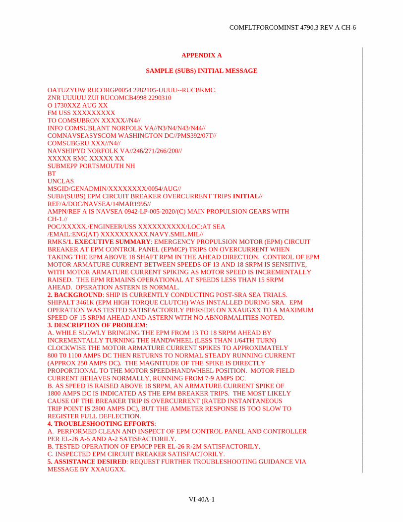
COMFLTFORCOMINST 4790.3 REV A CH-6
VI-40A-1
APPENDIX A
SAMPLE (SUBS) INITIAL MESSAGE
OATUZYUW RUCORGP0054 2282105-UUUU--RUCBKMC. ZNR UUUUU ZUI RUCOMCB4998 2290310 O 1730XXZ AUG XX FM USS XXXXXXXXX TO COMSUBRON XXXXX//N4// INFO COMSUBLANT NORFOLK VA//N3/N4/N43/N44// COMNAVSEASYSCOM WASHINGTON DC//PMS392/07T// COMSUBGRU XXX//N4// NAVSHIPYD NORFOLK VA//246/271/266/200// XXXXX RMC XXXXX XX SUBMEPP PORTSMOUTH NH BT UNCLAS MSGID/GENADMIN/XXXXXXXX/0054/AUG// SUBJ/(SUBS) EPM CIRCUIT BREAKER OVERCURRENT TRIPS INITIAL// REF/A/DOC/NAVSEA/14MAR1995// AMPN/REF A IS NAVSEA 0942-LP-005-2020/(C) MAIN PROPULSION GEARS WITH CH-1.// POC/XXXXX./ENGINEER/USS XXXXXXXXXX/LOC:AT SEA /EMAIL:ENG(AT) XXXXXXXXXX.NAVY.SMIL.MIL// RMKS/1. EXECUTIVE SUMMARY: EMERGENCY PROPULSION MOTOR (EPM) CIRCUIT BREAKER AT EPM CONTROL PANEL (EPMCP) TRIPS ON OVERCURRENT WHEN TAKING THE EPM ABOVE 18 SHAFT RPM IN THE AHEAD DIRECTION. CONTROL OF EPM MOTOR ARMATURE CURRENT BETWEEN SPEEDS OF 13 AND 18 SRPM IS SENSITIVE, WITH MOTOR ARMATURE CURRENT SPIKING AS MOTOR SPEED IS INCREMENTALLY RAISED. THE EPM REMAINS OPERATIONAL AT SPEEDS LESS THAN 15 SRPM AHEAD. OPERATION ASTERN IS NORMAL. 2. BACKGROUND: SHIP IS CURRENTLY CONDUCTING POST-SRA SEA TRIALS. SHIPALT 3461K (EPM HIGH TORQUE CLUTCH) WAS INSTALLED DURING SRA. EPM OPERATION WAS TESTED SATISFACTORILY PIERSIDE ON XXAUGXX TO A MAXIMUM SPEED OF 15 SRPM AHEAD AND ASTERN WITH NO ABNORMALITIES NOTED. 3. DESCRIPTION OF PROBLEM: A. WHILE SLOWLY BRINGING THE EPM FROM 13 TO 18 SRPM AHEAD BY INCREMENTALLY TURNING THE HANDWHEEL (LESS THAN 1/64TH TURN) CLOCKWISE THE MOTOR ARMATURE CURRENT SPIKES TO APPROXIMATELY 800 T0 1100 AMPS DC THEN RETURNS TO NORMAL STEADY RUNNING CURRENT (APPROX 250 AMPS DC). THE MAGNITUDE OF THE SPIKE IS DIRECTLY PROPORTIONAL TO THE MOTOR SPEED/HANDWHEEL POSITION. MOTOR FIELD CURRENT BEHAVES NORMALLY, RUNNING FROM 7-9 AMPS DC. B. AS SPEED IS RAISED ABOVE 18 SRPM, AN ARMATURE CURRENT SPIKE OF 1800 AMPS DC IS INDICATED AS THE EPM BREAKER TRIPS. THE MOST LIKELY CAUSE OF THE BREAKER TRIP IS OVERCURRENT (RATED INSTANTANEOUS TRIP POINT IS 2800 AMPS DC), BUT THE AMMETER RESPONSE IS TOO SLOW TO REGISTER FULL DEFLECTION. 4. TROUBLESHOOTING EFFORTS: A. PERFORMED CLEAN AND INSPECT OF EPM CONTROL PANEL AND CONTROLLER PER EL-26 A-5 AND A-2 SATISFACTORILY. B. TESTED OPERATION OF EPMCP PER EL-26 R-2M SATISFACTORILY. C. INSPECTED EPM CIRCUIT BREAKER SATISFACTORILY. 5. ASSISTANCE DESIRED: REQUEST FURTHER TROUBLESHOOTING GUIDANCE VIA MESSAGE BY XXAUGXX.
COMFLTFORCOMINST 4790.3 REV A CH-6
VI-40A-2
6. CO ASSESSMENT AND REPAIR DESIRES : ORIG IS CONTINUING WITH POST-SRA SEA TRIALS, LIMITING EPM TO 15 SRPM AHEAD. ADDITIONAL TROUBLESHOOTING WILL BE PERFORMED UPON SURFACING.// BT #0054 NNNN
NOTE: ENSURE MESSAGES ARE IN ACCORDANCE WITH NTP-3 FORMAT AND CURRENT PLAIN LANGUAGE ADDRESS DIRECTORY (PLAD) IS UTILIZED.

COMFLTFORCOMINST 4790.3 REV A CH-6
VI-40B-1
APPENDIX B
SAMPLE (SUBS) UPDATE MESSAGE
OATUZYUW RUCORGP0054 2282105-UUUU--RUCBKMC. ZNR UUUUU ZUI RUCOMCB4998 2290310 O 1730XXZ AUG XX FM USS XXXXXXXXX TO COMSUBRON XXXXX//N4// INFO COMSUBLANT NORFOLK VA//N3/N4/N43/N44// COMNAVSEASYSCOM WASHINGTON DC//PMS392/07T// COMSUBGRU XXX//N4// NAVSHIPYD NORFOLK VA//246/271/266/200// XXXXX RMC XXXXX XX SUBMEPP PORTSMOUTH NH BT UNCLAS MSGID/GENADMIN/XXXXXXXX/0054/AUG// SUBJ/(SUBS) EPM CIRCUIT BREAKER OVERCURRENT TRIPS UPDATE// REF/A/DOC/NAVSEA/14MAR1995// AMPN/REF A IS NAVSEA 0942-LP-005-2020/(C) MAIN PROPULSION GEARS WITH CH-1.// POC/XXXXX./ENGINEER/USS XXXXXXXXXX/LOC:AT SEA /EMAIL:ENG(AT) XXXXXXXXXX.NAVY.SMIL.MIL// RMKS/1. EXECUTIVE SUMMARY: EMERGENCY PROPULSION MOTOR (EPM) CIRCUIT BREAKER AT EPM CONTROL PANEL (EPMCP) IS STILL EXPERIENCING TRIPS ON OVERCURRENT WHEN TAKING THE EPM ABOVE 18 SHAFT RPM IN THE AHEAD DIRECTION. CONTROL OF EPM MOTOR ARMATURE CURRENT BETWEEN SPEEDS OF 13 AND 18 SRPM IS SENSITIVE, WITH MOTOR ARMATURE CURRENT SPIKING AS MOTOR SPEED IS INCREMENTALLY RAISED. THE EPM REMAINS OPERATIONAL AT SPEEDS LESS THAN 15 SRPM AHEAD. OPERATION ASTERN IS NORMAL. 2. BACKGROUND: SHIP IS CURRENTLY CONDUCTING POST-SRA SEA TRIALS. SHIPALT 3461K (EPM HIGH TORQUE CLUTCH) WAS INSTALLED DURING SRA. EPM OPERATION WAS TESTED SATISFACTORILY PIERSIDE ON XXAUGXX TO A MAXIMUM SPEED OF 15 SRPM AHEAD AND ASTERN WITH NO ABNORMALITIES NOTED. 3. DESCRIPTION OF PROBLEM: A. WHILE SLOWLY BRINGING THE EPM FROM 13 TO 18 SRPM AHEAD BY INCREMENTALLY TURNING THE HANDWHEEL (LESS THAN 1/64TH TURN) CLOCKWISE THE MOTOR ARMATURE CURRENT SPIKES TO APPROXIMATELY 800 T0 1100 AMPS DC THEN RETURNS TO NORMAL STEADY RUNNING CURRENT (APPROX 250 AMPS DC). THE MAGNITUDE OF THE SPIKE IS DIRECTLY PROPORTIONAL TO THE MOTOR SPEED/HANDWHEEL POSITION. MOTOR FIELD CURRENT BEHAVES NORMALLY, RUNNING FROM 7-9 AMPS DC. B. AS SPEED IS RAISED ABOVE 18 SRPM, AN ARMATURE CURRENT SPIKE OF 1800 AMPS DC IS INDICATED AS THE EPM BREAKER TRIPS. THE MOST LIKELY CAUSE OF THE BREAKER TRIP IS OVERCURRENT (RATED INSTANTANEOUS TRIP POINT IS 2800 AMPS DC), BUT THE AMMETER RESPONSE IS TOO SLOW TO REGISTER FULL DEFLECTION. 4. TROUBLESHOOTING EFFORTS: A. PERFORMED CLEAN AND INSPECT OF EPM CONTROL PANEL AND CONTROLLER PER EL-26 A-5 AND A-2 SATISFACTORILY. B. TESTED OPERATION OF EPMCP PER EL-26 R-2M SATISFACTORILY. C. INSPECTED EPM CIRCUIT BREAKER SATISFACTORILY. D. MEASURED RESISTANCE OF FIELD RHEOSTAT THROUGH ITS ENTIRE RANGE OF MOTION. INITIALLY DISCOVERED SEVERAL REGIONS OF HIGH RESISTANCE

COMFLTFORCOMINST 4790.3 REV A CH-6
VI-40B-2
CONTACT. CLEANED RHEOSTAT TO LESS THAN 0.1 OHM THROUGHOUT RANGE OF MOTION, WITH NO RESULTANT CHANGE IN OPERATING BEHAVIOR. 5. ASSISTANCE DESIRED: REQUEST FURTHER TROUBLESHOOTING GUIDANCE BY XXAUGXX. 6. CO ASSESSMENT AND REPAIR DESIRES: ORIG IS CONTINUING WITH POST-SRA SEA TRIALS, LIMITING EPM TO 15 SRPM AHEAD. ADDITIONAL TROUBLESHOOTING WILL BE PERFORMED UPON SURFACING. PER REF A VOL 2 TAB V-A TABLE 4-3, SHIP'S FORCE WILL INSPECT FIELD RESISTOR FOR A POSSIBLE OPEN CIRCUIT.// BT #0054 NNNN
NOTE: ENSURE MESSAGES ARE IN ACCORDANCE WITH NTP-3 FORMAT AND CURRENT PLAD IS UTILIZED.

COMFLTFORCOMINST 4790.3 REV A CH-6
VI-40C-1
APPENDIX C
SAMPLE (SUBS) FINAL/CLOSEOUT MESSAGE
OATUZYUW RUCORGP0054 2282105-UUUU--RUCBKMC. ZNR UUUUU ZUI RUCOMCB4998 2290310 O 1730XXZ AUG XX FM USS XXXXXXXXX TO COMSUBRON XXXXX//N4// INFO COMSUBLANT NORFOLK VA//N3/N4/N43/N44// COMNAVSEASYSCOM WASHINGTON DC//PMS392/07T// COMSUBGRU XXX//N4// NAVSHIPYD NORFOLK VA//246/271/266/200// XXXXX RMC XXXXX XX SUBMEPP PORTSMOUTH NH BT UNCLAS MSGID/GENADMIN/XXXXXXXX/0054/AUG// SUBJ/(SUBS) EPM CIRCUIT BREAKER OVERCURRENT TRIPS FINAL// REF/A/DOC/NAVSEA/14MAR1995// AMPN/REF A IS NAVSEA 0942-LP-005-2020/(C) MAIN PROPULSION GEARS WITH CH-1.// POC/XXXXX./ENGINEER/USS XXXXXXXXXX/LOC:AT SEA /EMAIL:ENG(AT) XXXXXXXXXX.NAVY.SMIL.MIL// RMKS/1. EXECUTIVE SUMMARY: THE MATERIAL ISSUE OF OVERCURRENT TRIPS OF THE EMERGENCY PROPULSION MOTOR (EPM) CIRCUIT BREAKER HAS BEEN CORRECTED. 2. BACKGROUND: SHIP WAS CONDUCTING POST-SRA SEA TRIALS. SHIPALT 3461K (EPM HIGH TORQUE CLUTCH) HAD BEEN INSTALLED DURING SRA. EPM OPERATION WAS TESTED SATISFACTORILY PIERSIDE ON XXAUGXX TO A MAXIMUM SPEED OF 15 SRPM AHEAD AND ASTERN WITH NO ABNORMALITIES NOTED. 3. DESCRIPTION OF PROBLEM: A. WHILE SLOWLY BRINGING THE EPM FROM 13 TO 18 SRPM AHEAD BY INCREMENTALLY TURNING THE HANDWHEEL (LESS THAN 1/64TH TURN) CLOCKWISE THE MOTOR ARMATURE CURRENT SPIKES TO APPROXIMATELY 800 T0 1100 AMPS DC THEN RETURNS TO NORMAL STEADY RUNNING CURRENT (APPROX 250 AMPS DC). THE MAGNITUDE OF THE SPIKE IS DIRECTLY PROPORTIONAL TO THE MOTOR SPEED/HANDWHEEL POSITION. MOTOR FIELD CURRENT BEHAVED NORMALLY, RUNNING FROM 7-9 AMPS DC. B. AS SPEED WAS RAISED ABOVE 18 SRPM, AN ARMATURE CURRENT SPIKE OF 1800 AMPS DC WAS EXPERIENCED AND THE EPM BREAKER TRIPPED. 4. TROUBLESHOOTING EFFORTS: A. PERFORMED TROUBLESHOOTING AS IDENTIFIED IN PROVIDED TECHNICAL ASSIST MESSAGES. B. PROBLEM WAS FOUND TO BE THE FIELD RESISTOR WAS EXPERIENCING AN OPEN CIRCUIT DUE TO A LOOSE CONNECTOR LUG CAUSING A HIGH RESISTANCE CONNECTION. THIS PROBLEM WAS IDENTIFIED DURING THE INSPECTION OF EPM CONTROL PANEL AS DESCRIBED IN THE PROVIDED TECH ASSIST MESSAGE. 5. ASSISTANCE DESIRED: PROBLEM CORRECTED, NO FURTHER ASSISTANCE REQUIRED. THIS IS THE FINAL REPORT NO ADDITIONAL ACTION REQUIRED. 6. CO ASSESSMENT AND REPAIR DESIRES: EPM RESTORED TO FULL SERVICE. // BT #0054 NNNN
NOTE: ENSURE MESSAGES ARE IN ACCORDANCE WITH NTP-3 FORMAT AND CURRENT PLAD IS UTILIZED.

COMFLTFORCOMINST 4790.3 REV A CH-6
VI-40C-2
(This Page Intentionally Left Blank)

COMFLTFORCOMINST 4790.3 REV A CH-6
VI-40D-1
APPENDIX D
SAMPLE (SUBS) SHIPALT/TEMPALT INSTALLATION MESSAGE
RATUZYUW RHBPHVA0098 0441139-UUUU--RUCBKMC. ZNR UUUUU ZUI RUCOMCB0075 0472222 R 13XXXXZ FEB XX FM USS XXXXXX TO COMSUBLANT NORFOLK VA INFO CNO WASHINGTON DC CNO WASHINGTON DC COMLANTFLT NORFOLK VA COMSUBGRU TWO COMSUBRON EIGHT NAVSUBSCOL GROTON CT SPAWARSYSCEN CHARLESTON SC SPAWARSYSCEN SAN DIEGO CA CBTDIRSYSACT DAM NECK VA NAVSURFWARCEN CARDEROCKDIV BETHESDA MD NAVSURFWARCENDIV CRANE IN SUPSHIP GROTON CT SUPSHIP NEWPORT NEWS VA NAVSHIPYD NORFOLK VA BT UNCLAS MSGID/GENADMIN/UNIT NAME/FEB// SUBJ/(SUBS)COMPLETION OF TEMPALT XXXXK FIRE FIGHTING STATION UPGRADE INSTALLATION (TEMPALT)// REF/A/MSG/CSL/XXXXXXJUN05// REF/B/DOC/NAVSEA/MARXXXX// NARR/REF A IS COMSUBLANT MESSAGE AUTHORIZING INSTALLATION OF TEMPALT XXXXK FIRE FIGHTING STATION UPGRADE ON USS XXXXX. REF B IS NAVSEA TECHNICAL SPECIFICATION XXXXXXXXXX SHIP ALTERATION ACCOMPLISHMENT BY INSTALL TEAMS.// POC/JOHN SMITH/INSTALLATION MGR/NUWC DIV NEWPORT/- /TEL:XXX-XXX-XXXX// RMKS/1. ACTIVITIES: THIS IS A JOINT USS XXXXX NUWC DIV NEWPORT MESSAGE. 2. BACKGROUND: TEMPALT 000K FIRE FIGHTING STATION UPGRADE WAS INSTALLED DURING PERIOD XXAUGXXXX THROUGH XXSEPXXXXX. SOVT WAS COMPLETED XXNOVXXXX AND THE FIRE FIGHTING STATION WAS ACCEPTED AS OPERATIONAL. 3. PROVIDED INFORMATION: A. TYPE INSTALLATION: FIRE FIGHTING STATION UPGRADE. B. ALTERATION NUMBER: XXXXK. C. CERTIFYING STATEMENT: ALL WORK WAS ACCOMPLISHED IN FULL COMPLIANCE WITH APPLICABLE CONTRACTUAL STANDARDS, SPECIFICATIONS AND INSTALLATION DRAWINGS. AS OUTLINED IN REF (A) SYSTEM OPERATION VERIFICATION TESTING (SOVT) WAS COMPLETED ON XXNOVXXXX. RESULTS WERE PROVIDED TO SHIP'S FORCE. D. INSTALLATION ISSUES: SHIP'S INSTALLATION DRAWINGS (SID) REQUIRE REVISION. ALL LIAISON ACTION REQUESTS (LAR) SUBMITTED TO THE PLANNING YARD WERE RESOLVED. SHIP'S FORCE HAS BEEN PROVIDED COPIES OF ALL LARS. RED LINE SHIPALT DRAWINGS WERE PROVIDED TO THE SHIP AND WILL BE PROVIDED TO PLANNING YARD. E. ALTERATION COMPLETION REPORT COMPLETED AND FORWARDED XXDECXXXX.

COMFLTFORCOMINST 4790.3 REV A CH-6
VI-40D-2
F. EQUIPMENT INSTALLED: FIRE FIGHTING PRESSURE ENHANCER. G. ILS PROVIDED: TECHNICAL MANUALS ITEM (CD), MIP# 0000/000-00 AND MRC CARDS, FIRE FIGHTING STATION LIBRARY DATA (CLASSIFIED), SSN-XXX COP, (CDMD-OA WORK FILE). THE ON BOARD REPAIR PARTS (OBRP). WILL BE PROVIDED BY NAVICP WHEN THEY ARE PRODUCED BY SHIP'S FORCE. H. TRAINING PROVIDED: MM1 JONES RECEIVED TWO HOURS OF OPERATIONAL TRAINING. I. SUMMARY: THE INSTALLATION PROGRESSED ON SCHEDULE WITH NO MAJOR DELAYS. THE SUPPORT PROVIDED BY SHIP'S FORCE WAS EXCELLENT. J. ANTICIPATED REMOVAL DATE. XXMARXXXX. 4. POC: NUWC DIV NEWPORT POC MR. JOHN SMITH (XXX)XXX-XXXX, E-MAIL SMITH (AT)NPT.NUWC.NAVY.MIL. 5. COMMANDING OFFICERS COMMENTS: NONE// BT #0098 NNNN
NOTE: ENSURE MESSAGES ARE IN ACCORDANCE WITH NTP-3 FORMAT AND CURRENT PLAD IS UTILIZED.

COMFLTFORCOMINST 4790.3 REV A CH-6
VI-40E-1
APPENDIX E
SAMPLE (SUBS) SHIPALT/TEMPALT REMOVAL MESSAGE
RATUZYUW RHBPHVA0098 0441139-UUUU--RUCBKMC. ZNR UUUUU ZUI RUCOMCB0075 0472222 R 13XXXXZ FEB XX FM USS XXXXXX TO COMSUBLANT NORFOLK VA INFO CNO WASHINGTON DC CNO WASHINGTON DC COMLANTFLT NORFOLK VA COMSUBGRU TWO COMSUBRON EIGHT NAVSUBSCOL GROTON CT SPAWARSYSCEN CHARLESTON SC SPAWARSYSCEN SAN DIEGO CA CBTDIRSYSACT DAM NECK VA NAVSURFWARCEN CARDEROCKDIV BETHESDA MD NAVSURFWARCENDIV CRANE IN SUPSHIP GROTON CT SUPSHIP NEWPORT NEWS VA NAVSHIPYD NORFOLK VA BT UNCLAS MSGID/GENADMIN/UNIT NAME/FEB// SUBJ/(SUBS) COMPLETED REMOVAL OF TEMPALT XXXXK FIRE FIGHTING STATION UPGRADE (TEMPALT)// REF/A/MSG/CSL/XXXXXXJUN05// REF/B/DOC/NAVSEA/MARXXXX// NARR/REF AIS COMSUBLANT MESSAGE AUTHORIZING REMOVAL OF TEMPALT XXXXK FIRE FIGHTING STATION UPGRADE ON USS XXXXX. REF B IS NAVSEA TECHNICAL SPECIFICATION XXXXXXXXXX SHIP ALTERATION ACCOMPLISHMENT BY INSTALL TEAMS.// POC/JOHN SMITH/INSTALLATION MGR/NUWC DIV NEWPORT/- /TEL:XXX-XXX-XXXX// RMKS/1. ACTIVITIES: THIS IS A JOINT USS XXXXX NUWC DIV NEWPORT MESSAGE. 2. BACKGROUND: TEMPALT 000K FIRE FIGHTING STATION UPGRADE WAS INSTALLED DURING PERIOD XXAUGXXXX THROUGH XXSEPXXXXX. SOVT WAS COMPLETED XXNOVXXXX AND THE FIRE FIGHTING STATION WAS ACCEPTED AS OPERATIONAL. 3. PROVIDED INFORMATION: A. REMOVAL DATE: XXJUNXXXX B. CERTYFING STATEMENT: SHIP RESTORED TO ORIGINAL CONFIGURATION. C. REMOVAL ISSUES: ANY OUTSTANDING ISSUE PREVENTING FULL RESTORATION. 4. POC: NUWC DIV NEWPORT POC MR. JOHN SMITH (XXX)XXX-XXXX, E-MAIL SMITH(AT)NPT.NUWC.NAVY.MIL. 5. COMMANDING OFFICERS COMMENTS: NONE// BT #0098 NNNN
NOTE: ENSURE MESSAGES ARE IN ACCORDANCE WITH NTP-3 FORMAT AND CURRENT PLAD IS UTILIZED.

COMFLTFORCOMINST 4790.3 REV A CH-6
VI-40E-2
(This Page Intentionally Left Blank)