
Service Manual - Plaza Fleet Parts
68
Eaton ® Heavy-Duty Clutches Service Manual CLSM0200 March 2011 Solo Heavy-Duty Easy-Pedal Value Clutch UltraShift DM Heavy-Duty Heavy-Duty ECA Clutch Solo Advantage Easy Pedal Advantage EverTough More time on the road ® TM TM ® TM TM TM TM
-
Upload
khangminh22 -
Category
Documents
-
view
2 -
download
0
Transcript of Service Manual - Plaza Fleet Parts
Eaton® Heavy-Duty Clutches
Service ManualCLSM0200
March 2011
Solo Heavy-Duty
Easy-Pedal
Value Clutch
UltraShift DM Heavy-Duty
Heavy-Duty ECA Clutch
Solo Advantage
Easy Pedal Advantage
EverTough
More time on the road®
TM
TM
®
TM
TM
TM
TM

Table of Contents
Warnings and Cautions Repair Warnings ........................................................................................................................................................ i
Out of Vehicle Resetting Procedure for Heavy-Duty ECA or Solo AdvantageTM Clutches Out of Vehicle Resetting Procedure for Heavy-Duty ECA or Solo AdvantageTM Clutches ......................................... 1
Install Solo® & Solo AdvantageTM Heavy-Duty 15.5" ClutchClutch Removal Procedure ........................................................................................................................................ 2Install Solo® & Solo AdvantageTM Heavy-Duty 15.5" Clutch .................................................................................... 3Measure Engine Flywheel Housing and Flywheel ....................................................................................................... 3Install Clutch to Flywheel .......................................................................................................................................... 4Install Transmission................................................................................................................................................... 6Set-up ....................................................................................................................................................................... 8Lubricate ................................................................................................................................................................... 10
Solo AdvantageTM Heavy-Duty 15.5" Clutch Troubleshooting Symptom-Driven Diagnostics .................................................................................................................................... 12Too Much Free Pedal or Too Much Clutch Brake ...................................................................................................... 13In Vehicle Resetting Procedure ................................................................................................................................. 14Not Enough Free Pedal or No Clutch Brake ............................................................................................................... 15In Vehicle Resetting Procedure Using the Solo Resetting Tool ................................................................................. 16
Easy-PedalTM, Easy-Pedal AdvantageTM and Value ClutchTMasMeasure Engine Flywheel Housing and Flywheel ....................................................................................................... 18Install Clutch to Flywheel .......................................................................................................................................... 19Install Transmission................................................................................................................................................... 21Set-up ....................................................................................................................................................................... 23
UltraShiftTM DM Heavy Duty Clutch Remove Clutch........................................................................................................................................................... 27Measure Engine Flywheel Housing and Flywheel ....................................................................................................... 28Install Clutch to Flywheel .......................................................................................................................................... 29Install Transmission................................................................................................................................................... 30HD Ultrashift Clutch Recalibration ............................................................................................................................. 31
15.5" Heavy-Duty ECA Clutch Installation Clutch Removal Procedure ........................................................................................................................................ 3415.5" Heavy-Duty ECA Clutch Installation .................................................................................................................. 37Measure Engine Flywheel Housing and Flywheel ....................................................................................................... 37Install Clutch to Flywheel .......................................................................................................................................... 38Install Transmission................................................................................................................................................... 39Lubricate ................................................................................................................................................................... 41ECA Clutch Adjustment ............................................................................................................................................. 43Grease Interval Count Reset ...................................................................................................................................... 45ServiceRanger Procedure........................................................................................................................................... 45Operator Triggered Procedure.................................................................................................................................... 47ECA Clutch In-Vehicle Resetting Procedure .............................................................................................................. 48Low Capacity Inertia Brake Wear Life Measurement ................................................................................................. 51

Table of ContentsTable of Contents
Hydraulic Linkage Hydraulic Linkage ...................................................................................................................................................... 52Verify Linkage System Stroke .................................................................................................................................... 52Master Cylinder Installation........................................................................................................................................ 52Transmission Installation ........................................................................................................................................... 53Hose Assembly .......................................................................................................................................................... 54Solo Advantage Lube Hose Assembly With Hydraulic Linkage .................................................................................. 55Installation process .................................................................................................................................................... 55General Clutch Information ....................................................................................................................................... 57Function of a Clutch ................................................................................................................................................... 57Neutral Idle Rattle ...................................................................................................................................................... 57Self-Adjusting Clutches.............................................................................................................................................. 58Clutch Disc Friction Material ...................................................................................................................................... 59Clutch Slippage .......................................................................................................................................................... 59Clutch Torque Capacity .............................................................................................................................................. 59Clutch Wear ............................................................................................................................................................... 59Cover Assembly ......................................................................................................................................................... 59Driven Disc................................................................................................................................................................. 60Facings....................................................................................................................................................................... 60Intermediate Plate ...................................................................................................................................................... 60Positive Separator Pin™............................................................................................................................................. 606-Position Kwik-Adjust® ........................................................................................................................................... 60Clutch Brakes ............................................................................................................................................................. 60Factors that Effect Clutch Performance ..................................................................................................................... 61When to Inspect the Clutch ........................................................................................................................................ 62Inspection for Clutch Life ........................................................................................................................................... 62Designing a Clutch for a Specific Application ............................................................................................................. 62Preventive Maintenance Overview ............................................................................................................................. 63Lubrication................................................................................................................................................................. 63Recommended Lubrication ........................................................................................................................................ 63Lubrication Interval .................................................................................................................................................... 63

Warnings
Warnings and Cautions
Repair Warnings
The major cause of clutch failure is excessive heat. Excessive heat generated between the flywheel, driven discs, intermedi-ate plate and pressure plate can cause the metal to flow and the material to be destroyed. If this occurs, the clutch can burst which can cause property damage, serious bodily injury or death. In order to prevent clutch failure resulting from excessive heat:
1. Do not exceed recommended vehicle loads.
2. The clutch should only be used for the recom-mended applications.
3. Drivers should be properly trained in starting, shift-ing and operation of the clutch.
4. Drivers should report erratic clutch operation as soon as possible to permit maintenance personnel to inspect, adjust or lubricate as required.
5. Mechanics must be familiar with proper clutch adjustment, linkage adjustment, lubrication and other maintenance troubleshooting procedures out-lined in the Failure Analysis Guide.
When disassembling various assemblies, lay all parts on a clean bench in the same sequence as removed to simplify and reduce the possibility of losing parts.
Since the cost of a new part is generally a small fraction of the cost of downtime and labor, avoid reusing a questionable part that could lead to additional repairs and expense.
Use of other than recommended tools, parts, and instructions listed in this manual may place the safety of the service tech-nician or vehicle driver in jeopardy.
The removal and installation procedure described for each component may vary for your vehicle.
For Solo and Heavy-Duty ECA clutches only, install shipping bolts before removing clutch.
For service information and assistance, call the Roadranger Help Desk at 1-800-826-HELP (4357) (Mexico: 01-800-826-HELP (4357). You may also find more information about Eaton Clutches at www.Roadranger.com.
Every effort has been made to ensure the accuracy of the information contained in this manual. However, Eaton Corpo-ration makes no warranty, expressed or implied, based on the information provided.
IMPORTANT

1
Out of Vehicle ResettingOut of Vehicle
Resetting
Out of Vehicle Resetting Procedure for Heavy-Duty ECA or Solo AdvantageTM Clutches
Slide the wear indicator tab to the "GOOD" position and hold it in place with a magnet
4
Install four (4) shipping bolts (7/16" x 14 x 1-3/4" UNC, hex head). Progressively tighten (no air wrenches) the four (4) shipping bolts (criss-cross pattern) until the face of the pressure plate is 1.75" - 1.78" (44.4 - 45.2 mm) below the mounting surface.
5
Good
Good
Remove the four (4) shipping bolts if they have been installed
1 Center the ram and press downward on the retainer until it comes to a stop. Lock the ram in position.
3
Reinstall the clutch using the original installation instructions.
6
Support the clutch in an arbor press with the bearing facing down.
Shipping Bolts
Note: Make sure there is at least 1 inch of space to allow the bearing to move down and to provide access to the shipping bolts.
Note: This important step will reset the pressure plate spacers and allow the clutch to release after reinstallation
2
1.75" - 1.78" (44.4 - 45.2 mm)
2
Self-Adjusting Clutches
Clutch Removal Procedure
(If clutch is to be reinstalled and transmission is still in vehicle)
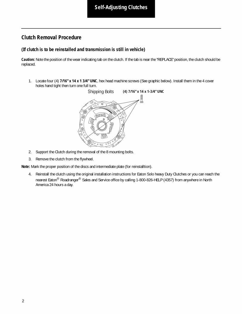
Caution: Note the position of the wear indicating tab on the clutch. If the tab is near the "REPLACE" position, the clutch should be replaced.
1. Locate four (4) 7/16" x 14 x 1 3/4" UNC, hex head machine screws (See graphic below). Install them in the 4 cover holes hand tight then turn one full turn.
2. Support the Clutch during the removal of the 8 mounting bolts.
3. Remove the clutch from the flywheel.
Note: Mark the proper position of the discs and intermediate plate (for reinstalltion).
4. Reinstall the clutch using the original installation instructions for Eaton Solo heavy Duty Clutches or you can reach the nearest Eaton® Roadranger® Sales and Service office by calling 1-800-826-HELP (4357) from anywhere in North America 24 hours a day.
(4) 7/16" x 14 x 1-3/4" UNCShipping Bolts

3
Self-Adjusting ClutchesInstall
Install Solo® & Solo AdvantageTM Heavy-Duty 15.5" Clutch
Measure Engine Flywheel Housing and Flywheel
Engine flywheel housing and flywheel must meet these specifications or there will be premature clutch failure. Remove and replace old pilot bearing per engine manufacturer instructions. All gauge contact surfaces must be clean and dry. Clean flywheel surfaces of all grease, oil, and rust preventatives. Failure to perform this function can affect the performance of the clutch.
Use a dial indicator and check the following:
Pilot Bearing Bore Runout
Flywheel Housing Face Runout
Secure dial indicator base to flywheel housing face.
Secure dial indicator base to flywheel near the outer edge.
Rotate flywheel one revolution. Maximum runout is .005" (.13 mm)
Rotate flywheel one revolution. Maximum runout is .008" (.20 mm).
Position gauge finger so that it contacts pilot bearing bore.
Put gauge finger in contact with face of flywheel housing.
1 2
3
1
23
Flywheel Face Runout
Flywheel Housing I.D. Runout
Secure dial indicator base to crankshaft.
1 Put gauge finger against flywheel housing pilot I.D.
2
Rotate flywheel one revolution. Maximum runout is .008" (.20 mm).
3
Rotate flywheel one revolution. Maximum runout is .008" (.20 mm).
3
Put gauge finger in contact with flywheel face near the outer edge.
2Secure dial indicator base to flywheel housing face.
1

4
Self-Adjusting Clutches
Install Clutch to Flywheel
Install Clutch to Flywheel
Use the Eaton ClutchSelector Guide (CLSL1511) to make sure you have the right clutch
An assembled clutch weighs about150 lbs. (68 kg). Avoid the risk of injury. Use proper equipment when lifting a clutch.
Progressively tighten mounting bolts in a crisscross pattern starting with the lower left bolt (1,2,3,4,5,6,7,8). Torque to 40-50 lb-ft (54-68 Nm). Failure to do this could result in improper piloting of the clutch and cause clutch damage.
8
Install lock washers and mounting bolts (7/16" x 14 UNC x 2-1/4" grade 5) finger tight. Replace studs with lock washers and bolts.
7
Install second disc onto aligning tool. Follow the orientation instructions on the disc.
5
Install intermediate plate into slots on the clutch cover. Flywheel Side must face the flywheel.
4
Install disc onto aligning tool. Follow the orientation instructions on the disc.
3
Insert aligning tool through bearing.
2
Install two 7/16" x 14 UNC x 5" studs into upper mounting holes. Install assembled clutch.
6
Measure the flywheel bore. Use the Eaton Clutch Selector Guide to verify that the damper will fit into the flywheel bore.
1
3
4
5
6
7
8 2
7.0" (8-spring) 8.5" (10-spring) 10.0" (7-spring and Mack 9-spring)NOTE: Mack 9-spring for Mack and Volvo
engines 2007 and newer only.
IMPORTANT WARNING
1

5
Self-Adjusting ClutchesInstall
Use a six once hammer and a 1/4" flat nose punch to lightly tap the four separator plate pins toward the flywheel. Only part of the pin should be visible. If Installing Solo Advantage Clutch, proceed to Step 12
Remove the aligning tool.
Remove four yellow shipping bolts in a crisscrosspattern.
Pin
10
9
11
12
13
14
Install brass fitting into grease port on left side of release bearinghousing using weatherhead socket.Tighten hand tight and continue toturn until the opening of the fitting is facing toward the 6 o’clock position.
Install lube hose into brass fitting and tighten until hand tight,then turn an additional 2 turns.
Lubricate release bearing until grease purges from release bearing housing. Use NLGI #2or #3 Lithiumcomplex grease. Reference Eaton lubrication manual TCMT0021for specific instructions.
Note: Note: The example shown is of a Lube Hose Attatchment for an HD Hyraulic release system.
HD Solo Advantage Lube Hose Attachment
NOTE: NOTE: A-8173 hand hole cover with grommet is required with HD Solo Advantage clutchused with Hydraulic release system

6
Self-Adjusting Clutches
Install Transmission
Check Transmission For WearReplace any worn components.
Clutch BrakeReplace.
Cross Shaft and BushingsExcessive wear at these points can cause side loading on the sleeve bushing, bushing failures and yoke bridge contact with the clutch when the pedal is down.
Input Shaft SplinesAny wear on the splines will prevent the driven discs from sliding freely, causing poor clutch release (clutch drag). Slide discs full length of shaft to check for twisted shaft splines.
Measure Input ShaftLength should be 8.657" (219.89 mm) nominal, and not greater than 8.71" (221.23 mm). Ref. 1990 SAE handbook 4:36.106. Replace transmission bearing retainer cap if length is greater than 8.71" (219.89 mm).
Transmission Bearing Retainer CapA worn/rough bearing retainer cap may cause the clutch brake to wear prematurely.
Release YokeWorn fingers can cause bushing wear and yoke interference when the pedal is down.
Input Shaft Wear (roughness) can reduce sleeve bushing life and cause it to come out.
IMPORTANTDo not add lube to the input shaft splines (Never seize or grease). The discs must be free to slide.
Do not use the cross-shaft release lever (or a pipe over it) to pull the transmission into its final position. Pulling the bearing too far during installation can cause an overstroke causing the release bearing to move closer to the transmission (less than .490"). Follow the Out of Vehicle Resetting Procedure on page 1.
Do not let the transmission drop or hang unsupported in the driven discs. This can bend the discs and the clutch will not release causing damage that is not warrantable.
NOTE: Adjust the linkage until pushing the pedal down moves the bearing against the clutch brake. Let up on the pedal and measure the distance between the bearing and clutch brake (should be .490" - .560").
Do not excessively force the transmission into the clutch assembly or engine housing. This will cause damage to the splines of the rear disc hub that is not warrantable. If the discs do not slide freely in the input shaft, investigate the cause of the problem and make any necessary changes. If the discs do not slide freely, the clutch will not release and the transmission will grind going into gear.
CAUTION

7
Self-Adjusting ClutchesInstall
Fasten Transmission to Flywheel Housing
1 Put transmission in gear. Be sure new clutch brake has been installed.
3 Position transmission so it is square to and aligned with engine.
4 Mesh splines by moving transmission forward and rotating the output shaft.
2 Make sure that the yoke fingers remain in the up position until they are over the release bearing housing.
5 Install mounting bolts and torque to OEM specs. If installing Solo Advantage clutch, procede to Step 6
Do not let the transmission drop or hang unsupported in the driven discs. This can cause the discs to become distorted and the clutch to not release.
Do not pull on release arm to install transmission. This will cause the clutch to over adjust.
Do not force transmission against clutch with yoke fingers in the UP position. This will break the cast webbing of the clutch causing damage that is not warrantable.
Do not use excessive force. If it does not enter freely, investigate the cause of problem and make any necessary changes.
WARNING
CAUTION
IMPORTANT
Do not add lube to the input shaft splines (Never seize or grease). The discs must be free to slide.
6
7
Install hand hold cover A-8173 with grommet positioned toward rear of hand hold opening in the clutch housing. Sercure the hand hole cover with two 5/16X18X1/2 inch long bolts.
Insert plug into hole in the upper left side of the clutch housing where the horizontal lube hose is utilized. (Image not shown)
Note: If the lube hose assembly should need servicing it can bereplaced without removal of thetransmission

8
Self-Adjusting Clutches
Set-up
0.00"
Hydraulic Linkages:Skip to Step 2.
Mechanical Linkages Only: Adjust the clutch linkage until the yoke fingers contact the release bearing (zero free-play in cab).
Press the pedal to the floor up to 5 times, this:• Moves release bearing
slightly closer to the transmission
• Gains free-play in cab
With the pedal up, measure the distance between the release bearing and the clutch brake. The correct distance should be .490" - .560" (12.70 - 14.22 mm):• If the distance is more the .560"
(14.22 mm), return to Step 1 and readjust the clutch linkage.
• If the distance is less the .490" (12.70 mm), see Troubleshooting on
Adjust Clutch Linkage
.490" - 560"(12.70 - 14.22 mm)
Release Bearing
Yoke Finger
5X
1
2
3
page 12.

9
Self-Adjusting ClutchesSet-up
Less than 1"(25.4 mm)
Slowly let up on the pedal and measure the pedal position at the moment the gauge can be removed:• If pedal is more than 1" (25.4 mm)
from the floor, readjust the truck linkage to move the yoke fingers further from the release bearing. Return to Step 4.
5
Have an assistant insert .010" (.25 mm) feeler gauge between the release bearing and the clutch brake. Press the pedal down to the floor to reclamp the gauge:• If the gauge does not clamp,
readjust the truck linkage and move yoke fingers closer to the bearing.
Use a gauge long enough to keep hands away from moving parts.
4
Verify Clutch Brake Squeeze
WARNING
Release Bearing
Yoke Finger
Clutch Brake
Verify Free-Play
Verify there is free-play in the cab. If not, the truck linkage is not providing enough stroke, consult OEM manual for free-play dimension. For Solo clutches procede to Step 8. For Solo Advantage clutches, procede to step 10.
DO NOT RESET THE CLUTCH. Do not change free-play by readjusting the clutch linkage.
6
IMPORTANT

10
Self-Adjusting Clutches
Lubricate
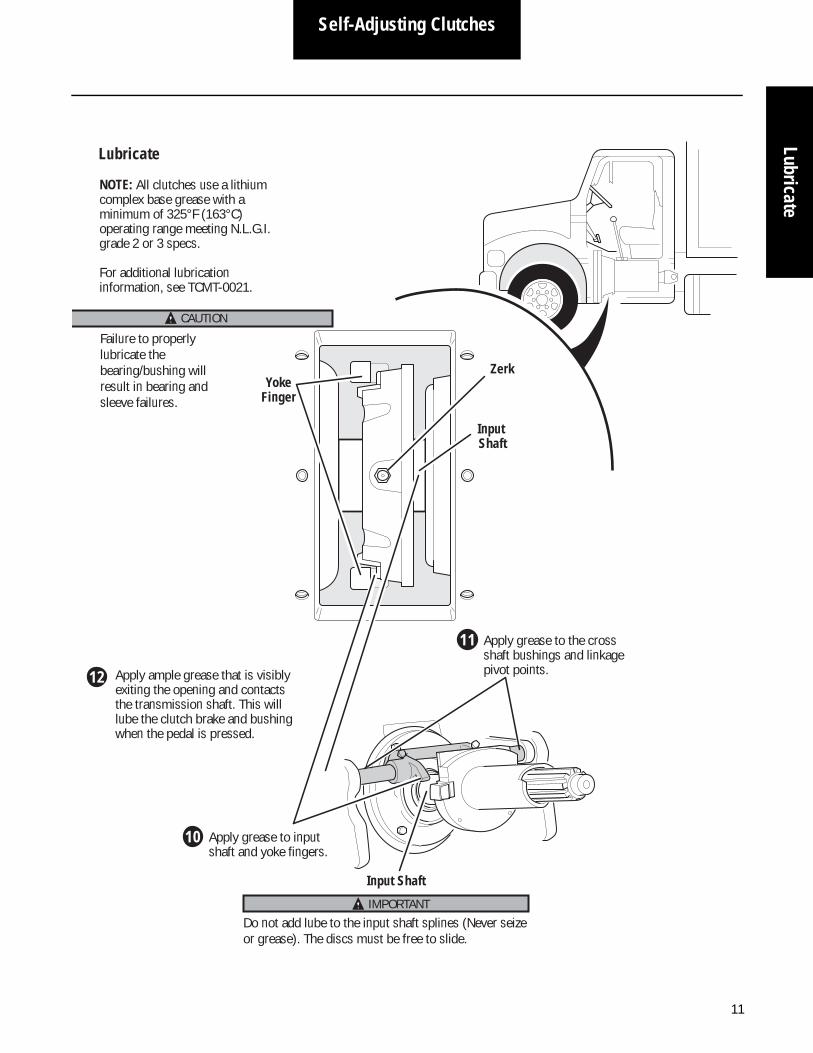
Apply grease to input shaft and yoke fingers.
Apply grease to the cross shaft bushings and linkage pivot points.
Input Shaft
NOTE: All clutches use a lithium complex base grease with a minimum of 325°F (163°C) operating range meeting N.L.G.I. grade 2 or 3 specs.
For additional lubrication information, see TCMT-0021.
7
28
Lubricate
Failure to properly lubricate the bearing/bushing will result in bearing and sleeve failures.
CAUTION
IMPORTANTDo not add lube to the input shaft splines (Never seize or grease). The discs must be free to slide.
Apply ample grease that is visibly exiting the opening and contacts the transmission shaft. This will lube the clutch brake and bushing when the pedal is pressed.
29
11
Self-Adjusting ClutchesLubricate
Apply grease to input shaft and yoke fingers.
Apply grease to the cross shaft bushings and linkage pivot points.
Input Shaft
Zerk
Input Shaft
NOTE: All clutches use a lithium complex base grease with a minimum of 325°F (163°C) operating range meeting N.L.G.I. grade 2 or 3 specs.
For additional lubrication information, see TCMT-0021.
10
211
Lubricate
Yoke Finger
Failure to properly lubricate the bearing/bushing will result in bearing and sleeve failures.
CAUTION
IMPORTANTDo not add lube to the input shaft splines (Never seize or grease). The discs must be free to slide.
Apply ample grease that is visibly exiting the opening and contacts the transmission shaft. This will lube the clutch brake and bushing when the pedal is pressed.
212

12
Self-Adjusting Clutches
Solo AdvantageTM Heavy-Duty 15.5" Clutch Troubleshooting
Symptom-Driven Diagnostics
Pedal travels too far before engaging clutch. Clutch does not disengage.
No Clutch Brake: Too Much Clutch Brake:
Too Much Free Pedal:
Pedal travels too little before engaging the clutch.
Not enough brake squeeze
Too little travel
Too muchbrake squeeze
Too much travel
Not Enough Free Pedal:
If clutch is out of vehicle, go to out of vehicle resetting procedure on page 1.
Based on your symptom, the chart will direct you to the correct solution.
Go to page 13 Go to page 15
Go to page 13 Go to page 15

13
Self-Adjusting ClutchesTroubleshooting
Too Much Free Pedal or Too Much Clutch Brake
Measure distance between release bearing and clutch brake.
1
Use chart to find solution.
2
Measurement Status Solution
If distance is correct.490" -.560"
(12.45 - 14.22 mm)
If distance is Less than .490"
(12.45 mm)
Clutch is set up correctly
Problem exists with truck linkage. Repair according to OEM specifications.
Hydraulic Linkage:
Clutch is not set up correctly
Release Bearing
Clutch Brake
If clutch was factory installed and was never removed or if clutch was removed from engine and reinstalled,
If new/reman clutch was installed and it never operated properly, check wear tab position.
If tab at NEW position:• disc installed incorrectly
• damper is too large for the flywheel opening
If tab not at NEW position, the bearing may have been pulled during installation causing an overadjust.
NOTE: Before measuring the distance between the release bearing and clutch brake depress clutch pedal to remove free pedal in the cab.
Too muchbrake squeeze
Too much travel
Go to page 14
Go to page 4, Step 4 and 5
Go to page 1
Go to page 4, Step 1
Go to page 52

14
Self-Adjusting Clutches
In Vehicle Resetting Procedure
Have assistant hold clutch pedal down.
Install and tighten 4 shipping bolts (7/16" x 14 x 1-3/4 UNC) until they quit turning.
While pedal is held down, move wear tab to the left (Good) position.
NOTE: If the cam does not move, loosen transmission and install 1/2” spacers between the clutch housing and engine housing to increase stroke.
•With spacers in place, follow steps 1-3 in this procedure.•Remove spacers and torque transmission mounting bolts.•Continue process starting at Step 4.
Go to Page 15.
Let up on pedal. DO NOT push pedal down again or wear tab will return to the wrong position.
Go
1
2
34
Remove shipping bolts.
5
Push pedal down and squeeze clutch brake 5 times to reposition bearing.
6
5X
Before After
No gap between sleeve and pin
Gap
NOTE: This will remove the gap between the sleeve and the pin.
Shipping bolt
Sleeve Pin
Go

15
Self-Adjusting ClutchesTroubleshooting
Not Enough Free Pedal or No Clutch Brake
Measure distance between release bearing and clutch brake.
1
Use chart to find solution.
2
Release Bearing
Clutch Brake
Not enough brake squeeze
Too little travel
Measurement Status Solution
If distance is correct.490" -.560"
(12.45 - 14.22 mm)
If distance is More than .560"
(14.22 mm)
Clutch is set up correctly
Problem exists with truck linkage. Repair according to OEM specifications.
Hydraulic Linkage:
Clutch is not set up correctly
If clutch was factory installed and was never removed,
Mechanical Linkage:
Hydraulic Linkage:
If clutch was removed from engine and reinstalled,
(Setup)
If new/reman clutch was installed and it never operated properly,
(Setup)
NOTE: Before measuring the distance between the release bearing and clutch brake depress clutch pedal to remove free pedal in the cab.
Go to page 16
Go to page 8
Go to page 8
Go to page 52
Go to page 52

16
Self-Adjusting Clutches
In Vehicle Resetting Procedure Using the Solo Resetting Tool
1 Determine if the release bearing travel is correct. Measure the distance between the clutch brake and the release bearing with the clutch pedal up. If the measurement is between 0.490 and 0.590, the Solo has set itself correctly.
REPLACE
Tool Part Code: CLPI-SOLOTOOL
NOTE: Yoke gap only applies to mechanical linkage. Most hydraulic linkages operate without yoke gap.
2 If the release bearing travel is less than 0.490” the Solo must be reset. A common cuase of this is the transmission was pulled in with the release arm during clutch installation.
3 Rotate the engine so that the cam tab can be reached through the transmission inspection opening.
4 Push the clutch pedal to the floor. While the clutch pedal is pushed to the floor have someone push the cam tab to the new position using finger pressure or the Solo tool.Once the cam tab is pushed to the new position you can release the clutch pedal.
NOTE: If the cam tab does not move, there is not enough release bearing travel to allow the cams to seperate. In this case, loosen the transmission and install 1/2” spacers between the flywheel housing and bell housing.
With the spacers in place push the clutch pedal to the floor while someone pushes the cam tab to the new position. Once the tab is in the new position release the clutch pedal and remove the spacers. Torque the transmission mounting bolts.
Release Bearing
Clutch Brake
Measure the release bearing travel
Good

17
Self-Adjusting ClutchesTroubleshooting
5
6
Install (4) shipping bolts and progressively tighten by hand until they bottom out. Rotate the engine to access all 4 bolts.
• 15 1/2” Solo use 7/16 x 14 UNC x 1 3/4” • Stamped 14” Solo use 3/8 x 16 UNC x 1
1/4”
Remove the (4) shipping bolts. The release bearing and sleeve will move forward towards the engine when the bolts are removed. The Solo is now in the new position.
8 Measure the distance between the clutch brake and the release bearing. It should be between 0.490 and 0.590”.
10 Adjust the clutch linkage to achieve 1/8” clearance between the release yoke and the release bearing. Verify proper clutch brake squeeze.
9 If the release bearing travel is still greater than 0.590” between the clutch brake and the release bearing, repeat steps 7 and 8.
Slowly let up on the pedal and measure the pedal position at the moment the gauge can be removed:• If pedal is more than 1" (25.4 mm) from
the floor, readjust the truck linkage to move the yoke fingers further from the release bearing. Repeat Step 4.
Verify Clutch Brake Squeeze
Have an assistant insert .010" (.25 mm) feeler gauge between the release bearing and the clutch brake. Press the pedal down to the floor to clamp the gauge:• If the gauge does not clamp,
readjust the truck linkage and move the yoke finger closer to the bearing.
WARNING: Use a gauge long enough to keep hands away from moving parts.
1
2
Release Bearing
Yoke Finger
Clutch Brake
7 With the free pedal removed push the clutch pedal down at least 5 times. Make sure the clutch release bearing contacts the clutch brake.
While you enage and release the clutch the cab free pedal will increase. This indicates the Solo is adjusting to the environment.
Shipping Bolts
Go
Shipping Bolt
Tamper ProofBolt
Good

18
Manual Adjust
Easy-PedalTM, Easy-Pedal AdvantageTM and Value ClutchTM
Measure Engine Flywheel Housing and Flywheel
Engine flywheel housing and flywheel must meet these specifications or there will be premature clutch failure. Remove and replace old pilot bearing per engine manufacturer instructions. All gauge contact surfaces must be clean and dry. Clean flywheel surfaces of all grease, oil, and rust preventatives. Failure to perform this function can affect the performance of the clutch.
Use a dial indicator and check the following:
Pilot Bearing Bore Runout
Flywheel Housing Face Runout
Secure dial indicator base to flywheel housing face.
Secure dial indicator base to flywheel near the outer edge.
Rotate flywheel one revolution. Maximum runout is .005" (.13 mm)
Rotate flywheel one revolution. Maximum runout is .008" (.20 mm).
Position gauge finger so that it contacts pilot bearing bore.
Put gauge finger in contact with face of flywheel housing.
1 2
3
1
23
Flywheel Face Runout
Flywheel Housing I.D. Runout
Secure dial indicator base to crankshaft.
1 Put gauge finger against flywheel housing pilot I.D.
2
Rotate flywheel one revolution. Maximum runout is .008" (.20 mm).
3
Rotate flywheel one revolution. Maximum runout is .008" (.20 mm).
3
Put gauge finger in contact with flywheel face near the outer edge.
2Secure dial indicator base to flywheel housing face.
1

19
Manual AdjustInstall
Install Clutch to Flywheel
Measure the flywheel bore. Use the Eaton Clutch Selector Guide to verify that the damper will fit into the flywheel bore.
1
7.0" (8-spring) 8.5" (10-spring) 10.0" (7-spring and Mack 9-spring)NOTE: Mack 9-spring for Mack and Volvo engines 2007 or newer only
An assembled clutch weighs about 150 lbs. (68 kg). Avoid the risk of injury. Use proper equipment when lifting a clutch.
Use the Eaton Clutch Selector Guide (CLSL1511) to make sure you have the right clutch.
For 15.5" Clutch Only (Easy Pedal shown)
IMPORTANT WARNING
Progressively tighten mounting bolts in a crisscross pattern starting with the lower left bolt (1,2,3,4,5,6,7,8). Torque to 40-50 lb-ft (54-68 Nm). Failure to do this could result in improper piloting of the clutch and cause clutch damage.
8
Install lock washers and mounting bolts (7/16" x 14 UNC x 2-1/4" grade 5) finger tight. Replace studs with lock washers and bolts.
7
Insert aligning tool through bearing.
2
Install second disc onto aligning tool. Follow the orientation instructions on the disc.
5
Install intermediate plate into slots on the clutch cover. Flywheel Side must face the flywheel.
4
Install disc onto aligning tool. Follow the orientation instructions on the disc.
3
Verify bearing position is 3/8"–5/8" (9.5–15.9 mm) from cover.
9
Remove the aligning tool. Be sure shipping blocks are removed.
10
Use a six ounce hammer and a 1/4" flat nose punch to lightly tap the four separator plate pins toward the flywheel (New EP Only). Reman and Value clutches do not have pins. Only part of the pin should be visible.
11
TO TURN
DEPRE
SSBO
LT
Install two 7/16" x 14 UNC x 5" studs into upper mounting holes. Install assembled clutch.
6
1
3
4
5
6
7
8
TO TURN
DEPRE
SSBO
LT
2
Pin
NOTE: NOTE: Are not recommended for use with hydraulic release systems

20
Manual Adjust
For 14" Clutch Only
Install three equally spaced anti-rattle springs
3
Super-duty clutch only:Ensure the correct flywheel depth is 2-15/16".
1
Put front disc into flywheel. Flywheel side must be toward engine. Use new slots to put intermediate plate on pins.
2
Turn intermediate plate left. Use .006" feeler gauge to check left pin clearance on all 6 drive pins. NOTE: Remove two set screws. Straighten pins to increase clearance and reinstall set screws. Do not file slots.
4
Progressively tighten mounting bolts in a crisscross pattern starting with the lower left bolt (1,2,3,4,5,6,7,8). Torque to 25-35 lb-ft (34-47 Nm). Failure to do this could result in improper piloting of the clutch and cause clutch damage.
12
Install lock washers and mounting bolts (3/8" x 1-1/4" grade 5) finger tight. Replace studs with lock washers and bolts.
11
Slide cover over aligning tool.
10
Install disc into flywheel. Follow the orientation instructions on the disc.
6Install intermediate plate onto drive pins.
7Install second disc onto flywheel. Follow the orientation instructions on the disc.
8
Remove the aligning tool. Be sure shipping blocks are removed.
13
Install two 3/8" x 2-1/2" studs into upper mounting holes.
5
Insert aligning tool through discs.
9
1
3
4
5
6
7
8 2
TO TURN
DEPRE
SS B
OLT

21
Manual AdjustInstall
Install Transmission
Check Transmission For WearReplace any worn components.
Clutch BrakeReplace.
Cross Shaft And BushingsExcessive wear at these points can cause side loading on the sleeve bushing, bushing failures and yoke bridge contact with the clutch when
Input Shaft SplinesAny wear on the splines will prevent the driven discs from sliding freely, causing poor clutch release (clutch drag). Slide discs full length of shaft to check for twisted shaft splines.
Measure Input ShaftLength should be 8.657" (219.89 mm) nominal, and not greater than 8.71" (221.23 mm). Ref. 1990 SAE handbook 4:36.106. Replace transmission bearing retainer cap if length is
Transmission Bearing Retainer CapA worn/rough bearing retainer cap may cause the clutch brake to wear prematurely.
Release YokeWorn fingers can cause bushing wear and yoke interference
Input Shaft Wear (roughness) can reduce sleeve bushing life and
Do not let the transmission drop or hang unsupported in the driven discs. This can bend the discs and the clutch will not release causing damage that is not warrantable.
Do not excessively force the transmission into the clutch assembly or engine housing. This will cause damage to the splines of the rear disc hub that is not warrantable. If the discs do not slide freely in the input shaft, investigate the cause of the problem and make any necessary changes. If the discs do not slide freely, the clutch will not release and the transmission will grind going into gear.
CAUTION
IMPORTANT
Do not add lube to the input shaft splines (Never seize or grease). The discs must be

22
Manual Adjust
Fasten Transmission to Flywheel HousingTransmission installation and clutch set-up procedures are the same for the 14" and 15.5" clutch.
1 Put transmission in gear. Be sure new clutch brake has been installed.
3 Position transmission so it is square to and aligned with engine.
4 Mesh splines by moving transmission forward and rotating the output shaft. Do not use excessive force. Do not let the transmission hang unsupported in the discs.
5 Install mounting bolts and torque to OEM specs.
2 Make sure that the yoke fingers remain in the up position until they are over the release bearing housing.
NOTE: If you have a hydraulic linkage, go to
CAUTION
IMPORTANT
Do not add lube to the input shaft splines (Never seize or grease). The discs must be free to slide.
Do not pull on release arm to install transmission. This will cause the clutch to over adjust.
Do not force transmission against clutch with yoke fingers in the UP position. This will break the cast webbing of the clutch causing damage that is not warrantable.
Do not use excessive force. If it does not enter freely, investigate the cause of problem and make any necessary changes.
Do not let the transmission drop or hang unsupported in the driven discs. This can cause the discs to become distorted and the clutch to not release.
WARNING
page 52.

23
Manual AdjustSet-up
Set-up
Adjust Bearing Position
Measure the distance between the release bearing and the clutch brake: • If the distance is correct,
.500" -.560" (12.70 - 14.22 mm), then Verify Clutch Brake Squeeze, Step 4.
• If the distance is not between 500" -.560" (12.70 - 14.22 mm), then Change Bearing Position, Step 2.
1
TOTURN
DEPRESS
BOLT
Adjusting Nut
.500" - 560"(12.70 - 14.22 mm)
Release Bearing
Hold
Clutch Brake
Have an assistant hold down clutch pedal so internal adjustment can be made.
2
While pedal is held down, remove lockstrap and move adjusting lug:• If measurement was more than .560" (14.22 mm),
move adjusting lug to the left (shown).• If measurement was less than .500" (12.77 mm),
move adjusting lug to the right.
Lockstrap
AdjustingLug
3
Easy-Pedal & Easy Pedal Advantage Only: Value Clutch Only:
While pedal is held down, push adjusting nut and turn:• If measurement was more than .560"
(14.22 mm), turn adjusting nut clockwise.• If measurement was less than .500"
(12.77 mm), turn adjusting nut counterclockwise.
Adjust bearing position:
( Part number 125489 )
NOTE: Before measuring the distance between the release bearing and clutch brake depress clutch pedal to remove free pedal in the cab.

24
Manual Adjust
Slowly let up on the pedal and measure the pedal position at the moment the gauge can be removed:• If pedal is more than 1" (25.4 mm) from
the floor, readjust the truck linkage to move the yoke fingers further from the release bearing. Repeat Step 4.
Verify Clutch Brake Squeeze
Less than 1"( 25.4 mm)
Have an assistant insert .010" (.25 mm) feeler gauge between the release bearing and the clutch brake. Press the pedal down to the floor to clamp the gauge:• If the gauge does not clamp,
readjust the truck linkage and move the yoke finger closer to the bearing.
Use a gauge long enough to keep hands away from moving parts.
4
5
Release Bearing
Yoke Finger
Clutch Brake
WARNING

25
Manual AdjustSet-up
Verify Free-Play
1/8"(3.2 mm)
Release Bearing
Yoke Finger
6 Measuren the distance between yoke tips and bearing wear pads simultaneously. This distance should be 1/8" (3.2 mm). If distance is not 1/8" (3.2 mm), go to Step 7.
2 The truck linkage should allow for a minimum of .685" of yoke finger movement; .125" for free-play, .500" for the bearing and .060" for clutch brake squeeze. If it is necessary to increase the free-play, adjust upper pedal stop to raise or lower the pedal in the cab. If this is not possible, check the OEM parts manual to verify the correct clutch arm was installed at the factory.
Do not change free-play by changing the bearing position. Correct bearing position is .500"-.560" (12.70 - 14.22 mm)
NOTE: 1/8" (3.2 mm) distance will create free-play in cab. Free-play in cab may be different on different truck makes, models and years.
7
Do not change bearing position.
IMPORTANT
IMPORTANT
1/8"(3.2 mm)

26
Manual Adjust
Input Shaft
Zerk
NOTE: All clutches use a lithium complex base grease with a minimum of 325°F (163°C) operating range meeting N.L.G.I. grade 2 or 3 specs.
NOTE: Apply ample grease that is visibly exiting the opening and contacts the transmission shaft. This will lube the clutch brake and bushing when the pedal is pressed.
For additional lubrication information, see TCMT0021.
Lubricate
Yoke Finger
Failure to properly lubricate the bearing/bushing will result in bearing and sleeve failures.
Apply grease to input shaft and yoke fingers.
Apply grease to the cross shaft bushings and linkage pivot points.
Input Shaft
8
29
CAUTION
IMPORTANTDo not add lube to the input shaft splines (Never seize or grease). The discs must be free to slide.

27
UltraShift®Rem
ove
UltraShiftTM DM Heavy Duty Clutch
Remove Clutch
Prior to removing the transmission, rotate the engine until one of the jack screw locations can be viewed through the clutch housing inspection opening.
1
Using a piece of 5/16" x 18 UNC x 3" threaded rod (jack screw), install two nuts on one end and lock them together. This will allow you to turn the jack screw in and out of the cover assembly.
2
An assembled clutch weighs about 182 lbs. (82 kg). Avoid the risk of injury. Use proper equipment when lifting a clutch.
Do not overtighten the jack screw. Tightening more than 9 lbs. ft. can cause permanent clutch damage.
CAUTION
CAUTION
Unbolt the clutch from the flywheel and slide the clutch away from the flywheel.
7
Remove the jack screw.6
Remove the transmission, supporting its weight to prevent damage to the clutch discs.
4
Install the jack screw into one of the four holes located adjacent to the clutch mounting bolts. This forces the pressure plate forward clamping the discs and holding them in place.
3
Insert alignment shaft and clutch jack.
5
Remove the old pilot bearing.
8
An assembled clutch weighs about 182 lbs. (82 kg). Avoid the risk of injury. Use proper equipment when lifting a clutch.
When removing the clutch, the flywheel side disc can fall off of the alignment shaft, permanently damaging the driven disc.
WARNING
WARNING

28
UltraShift®
Measure Engine Flywheel Housing and Flywheel
Engine flywheel housing and flywheel must meet these specifications or there will be premature clutch failure. Remove and replace old pilot bearing per engine manufacturer instructions. All gauge contact surfaces must be clean and dry. Clean flywheel surfaces of all grease, oil, and rust preventatives. Failure to perform this function can affect the performance of the clutch.
Use a dial indicator and check the following:
Pilot Bearing Bore Runout
Flywheel Housing Face Runout
Secure dial indicator base to flywheel housing face.
Secure dial indicator base to flywheel near the outer edge.
Rotate flywheel one revolution. Maximum runout is .005" (.13 mm)
Rotate flywheel one revolution. Maximum runout is .008" (.20 mm).
Position gauge finger so that it contacts pilot bearing bore.
Put gauge finger in contact with face of flywheel housing.
1 2
3
1
23
Flywheel Face Runout
Flywheel Housing I.D. Runout
Secure dial indicator base to crankshaft.
1 Put gauge finger against flywheel housing pilot I.D.
2
Rotate flywheel one revolution. Maximum runout is .008" (.20 mm).
3
Rotate flywheel one revolution. Maximum runout is .008" (.20 mm).
3
Put gauge finger in contact with flywheel face near the outer edge.
2Secure dial indicator base to flywheel housing face.
1

29
UltraShift®Install
Install Clutch to FlywheelNote: If installing a new DM, follow the installation directions that are provided in the box.
Install new pilot 1
10.0" (7-spring & VCT Plus)
Measure the flywheel bore to verify that the damper will fit into the flywheel bore.
2
An assembled clutch weighs about 182 lbs. (82 kg). Avoid the risk of injury. Use proper equipment when
The intermediate plate is bolted to the cover assembly and the rear driven disc is held in place between the pressure plate and intermediate plate. DO NOT UNBOLT the intermediate plate from the
Progressively tighten mounting bolts in a crisscross pattern starting with the lower left bolt (1,2,3,4,5,6,7,8). Torque to 40-50 lb-ft (54-68 Nm). Failure to do this could result in improper piloting of the clutch and cause clutch damage.
7
Install lock washers and mounting bolts (7/16" x 14 UNC x 2-1/4" grade 5) finger tight. Replace studs with lock washers and bolts.
6
Install second disc onto aligning tool. Follow the orientation instructions on the
4Insert aligning tool through DM Clutch and
3
Install two 7/16" x 14 UNC x 5" studs into upper mounting holes. Using clutch jack or other lifting device, install
5
26
4
8 7
3
5
1
Remove the aligning 10
Using a piece of 5/16" x 18 UNC x 3" threaded rod (jack screw), install two nuts on one end and lock them together. This will allow you to turn the jack screw in and out of the cover assembly.
8Install the jack screw into one of the four holes located adjacent to the clutch mounting bolts. This forces the pressure plate forward clamping the discs and holding them in place. Be sure the hole chosen is at the 6 o'clock position to allow for removal after the transmission is installed.
9
Do not overtighten the jack screw. Tightening more than 9 lbs. ft. can cause permanent clutch
WARNING
CAUTION
WARNING
30
UltraShift®
Install Transmission
Check Transmission for WearReplace any worn components.
Fasten Transmission to Flywheel Housing
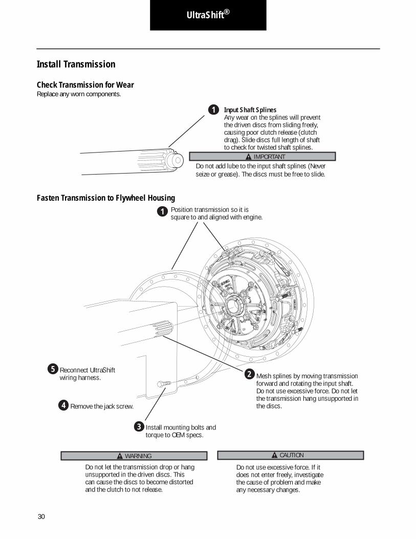
Input Shaft SplinesAny wear on the splines will prevent the driven discs from sliding freely, causing poor clutch release (clutch drag). Slide discs full length of shaft to check for twisted shaft splines.
1
IMPORTANTDo not add lube to the input shaft splines (Never seize or grease). The discs must be free to slide.
5 Reconnect UltraShift wiring harness.
1 Position transmission so it is square to and aligned with engine.
2 Mesh splines by moving transmission forward and rotating the input shaft. Do not use excessive force. Do not let the transmission hang unsupported in the discs.
3 Install mounting bolts and torque to OEM specs.
4 Remove the jack screw.
Do not use excessive force. If it does not enter freely, investigate the cause of problem and make any necessary changes.
Do not let the transmission drop or hang unsupported in the driven discs. This can cause the discs to become distorted and the clutch to not release.
CAUTIONWARNING

31
UltraShift Clutch Recalibration
Install
HD Ultrashift Clutch Recalibration1. Turn key on.
2. Verify a solid "N" is on the gear display.
3. Start engine.
4. Increase engine RPM above 1500. This will unlock the clutch. Failure to do this will set a clutch disengagement code and the code and transmission will not go into gear.
Note: Programmable VSS Tamper Resistance options or other artificial engine speed limits which prevent reaching the required 1500 RPM may prevent proper disengagement of the clutch locking device after initial installation. These options may need to be disabled until after the clutch-locking device is disengaged.
Note: If ServiceRanger is available, proceed to Step 12.
5. Start with the system powered down, the vehicle stationary, and the engine not running.
6. Key on and allow the system to completely power up but do not start the engine.
7. Select "LOW" mode on the shift controller (UltraShift system will begin to emit an audible tone).
8. Select an upshift once (UltraShift gear display will display a "0" with down arrows and discontinue the tone indicating "Special Functions" mode is activated.
9. Once in Special Functions mode, select one additional upshift (UltraShift gear display will display a "1" with up arrows indicating UltraShift Touch Point Resent is selected.)
10. After the "1" is displayed, depress the throttle pedal to the floor and hold for 3-5 seconds (the gear display will change back to a "0" with down arrows indicating the routine has been successfully completed.
11. Key off or select any mode and the UltraShift system returns to normal operation.
12. Save clutch data / Recalibrate clutch with ServiceRanger.
1

32
UltraShift Clutch Recalibration
Gen 2• Using ServiceRanger, select the "Advanced Product Functions" button located on the main menu.
• Select Eaton AutoShift Gen-2 from the product selection screen.
Note: This screen will only appear if the vehicle is equipped with more than one supported Roadranger product.
• Select Clutch Data from the "Advanced Product Functions" screen.
• Save the clutch data by selecting the "Save Abuse Info to a File" button.
Note: Use the truck VIN as the file name. The data file will be saved to the ServiceRanger folder in the Clutch Data subfolder (e.g. C:\Serviceranger\Clutch Data).
• Reset clutch abuse info by selecting the "Reset Clutch Abuse Info" button.
• Recalibrate the new clutch by selecting the "Calibrate Clutch" button.
Note: Failure to calibrate a newly installed clutch may result in some initial harsh vehicle launches, as the system is required to manually recalibrate.
Gen 3• Using ServiceRanger, select "Advanced Product Function" button.
• Select UltraShift transmission model (Gen 3) from menu tree in the upper left.
• Select the VPA/SnapShot Utility and launch the function.
• Read the APF description and select "Next."
• Enter the vehicle info and select "Next."
• Select "VPA" from the dropdown "Data Source" field.
• Enter an output file name and location using Browse Button or use default filename and location shown.
Note: If the default filename and location is used, the VPA data file will be saved to the ServiceRangerData folder in the VPA sub-folder on the C:\drive.
• Select the "start transer" button to download data from transmission controller and then select "Next."
• The output file can now be viewed, select "Finish."
• Select "Clear Clutch Data" button to clear data from transmission controller.
• If successful proceed to next step, if unsuccessful exit function and re-enter. Contact Roadranger Call Center 1-800-826-4357 for help.
• Select the "Calibrate Clutch" button to calibrate new clutch and the select "Finish" when complete.

33
UltraShift Clutch Recalibration
Install

34
ECA Clutch
Clutch Removal Procedure
(If clutch is to be reinstalled and transmission is still in vehicle)
Caution: Note the position of the wear indicating tab on the clutch. If the tab is near the "REPLACE" position, the clutch should be replaced.
1. Use Eaton Service Ranger Daignostic Software in order to command the ECA to open the clutch.
Caution: Ensure that hands are not inside the clutch housing while opening or closing the clutch.
3
Turn ignition switch to on.
b Plug 9-pin connector into dash port.
Click on ServiceRanger icon to launch program.
a
2
FFO
NO
TRATS
c
Opening the ECA Clutch

35
ECA ClutchInstall
Click on Clear Grease Interval Counter.
i
Choose Grease Interval Reset tab.
g h
Confirm Positive results.
Open and expand the Advanced Product Functions tree.
d e f Click on ECA Clutch Service.
Click on transmission.NOTE: Advanced Product Functions
NOTE: ServiceRanger will require engine running in order to open clutch.
Caution: Ensure that hands are not inside the cltuch housing while opeing or closing the clutch.

36
ECA Clutch
2. Slide the wear indicating tab to the left until it is at the "NEW" position.
Note: If the cam does not move, loosen transmission and install 1/2" spacers between clutch housing to increase stroke.
3. Close the clutch by switching the ignition to ON, and the wear indicating tab will stay in the "NEW" position.
Caution: Ensure that hands are not inside the clutch housing when opening or closing the clutch.
4. Remove the transmission, supporting its weight to prevent damage to the bearing and discs.
5. Locate four (4) 7/16" x 14 x 1 3/4" UNC, hex head machine screws. Install them in the 4 cover holes and turn them fin-ger-tight.
6. Remove the clutch from the flywheel.
7. Progressively tighten (no air guns) the four (4) shipping bolts (criss-cross pattern) 1/4 turn at a time for a total of two turns for each bolt.
Note: This important step will reset the pressure plate spacers and allow the clutch to release after the installation.
8. Reinstall the clutch using the original installation instructions for Eaton Heavy Duty ECA Clutches or you can reach the nearest Eaton® Roadranger® Sales and Service office by calling 1-800-826-HELP (4357) from anywhere in North America 24 hours a day.
WEARTAB
(4) 7/16" x 14 x 1-3/4" UNCShipping Bolts

37
ECA ClutchInstall
15.5" Heavy-Duty ECA Clutch Installation
Measure Engine Flywheel Housing and Flywheel
Engine flywheel housing and flywheel must meet these specifications or there will be premature clutch failure. Remove and replace old pilot bearing per engine manufacturer instructions. All gauge contact surfaces must be clean and dry. Clean flywheel surfaces of all grease, oil, and rust preventatives. Failure to perform this function can affect the performance of the clutch.
Use a dial indicator and check the following:
Pilot Bearing Bore Runout
Flywheel Housing Face Runout
Secure dial indicator base to flywheel housing face.
Secure dial indicator base to flywheel near the outer edge.
Rotate flywheel one revolution. Maximum runout is .005" (.13 mm)
Rotate flywheel one revolution. Maximum runout is .008" (.20 mm).
Position gauge finger so that it contacts pilot bearing bore.
Put gauge finger in contact with face of flywheel housing.
1 2
3
1
23
Flywheel Face Runout
Flywheel Housing I.D. Runout
Secure dial indicator base to crankshaft.
1 Put gauge finger against flywheel housing pilot I.D.
2
Rotate flywheel one revolution. Maximum runout is .008" (.20 mm).
3
Rotate flywheel one revolution. Maximum runout is .008" (.20 mm).
3
Put gauge finger in contact with flywheel face near the outer edge.
2Secure dial indicator base to flywheel housing face.
1

38
ECA Clutch
Install Clutch to Flywheel
NOTE: The clutch release yoke fingers must be positioned so they clear the release bearing housing when removing and installing the transmission. One method to achieve this is to remove the ECA prior to removing the transmission and then manipulating the fingers by hand. The preferred method is to move the release yoke to the service position via ServiceRanger's Advanced Product Functions.
Note: A clutch adjustment should always be performed after a clutch replacement. See the "ECA Clutch Adjustment" Section.
Install Clutch to Flywheel
CAUTION: An assembled clutch weighs about 150 lbs. (68 kg). Avoid the risk of injury. Use proper equipment when lifting a clutch.
Warning: Do not unbolt the intermediate plate from the cover assembly.
Progressively tighten mounting bolts in a crisscross pattern starting with the lower left bolt. Torque to 40–50 lbs. ft. (54–68 N•m). Failure to do this could result in improper piloting of the clutch and cause clutch damage.
5
Slide the clutch assembly over the guide studs and install six lock washers and mounting bolts (7/16"x14 UNC x 2 1/4" grade 5) finger tight. Replace studs with remaining two lock washers and bolts.
4
2
Insert aligning tool through bearing.1
1
3
4
5
6
7
8
2
Install second disc onto aligning tool. Follow the orientation instructions on the disc.
Install two 7/6" x 14 UNC x 5" studs into upper mounting holes. Install assembled clutch.
3
8 Position the release bearing so the orientation of the lube fitting is in the 4 O'clock position.
Remove the aligning tool.
7
Remove four yellow shipping bolts in an even 1/4 turn crisscross pattern.
6
NOTE: The ECA Clutch alignment tool is a 14 tooth shaft and is 1-3/4" longer than the standard shaft.
Generic graphic

39
ECA ClutchInstall
Install TransmissionNote: Check Transmission For Wear
Replace any worn components.
Cross Shaft And BushingsExcessive wear at these points can cause side loading on the sleeve bushing, bushing failures and yoke bridge contact with the clutch in the release/open position.
Input ShaftWear (roughness) can reduce sleeve bushing life and cause it to become dislodged.
Release YokeWorn fingers can cause bushingwear and yoke interference whenthe Electronic Clutch Actuator is at the released position.
Input Shaft SplinesAny wear on the splines will prevent the driven discs from sliding freely, causing poor clutch release (clutch drag). Slide discs full length of shaft to check for twisted shaft splines.Low Capacity Inertia Brake (LCIB)
Eaton requires that you replace the LCIB when replacing the clutch. See Appendix A for LCIB removal and installation instructions.
Fasten Transmission To Flywheel HousingTransmission installation and clutch set-up procedures.
1 Put transmission in neutral. Be sure new LCIB has been installed.
3 Position transmission so it is square to and aligned with engine.
4 Mesh splines by moving transmission forward and rotating the input shaft. Do not use excessive force. Do not let the transmission hang unsupported in the discs.
6 Install mounting bolts and torque to OEM specs.
2 Make sure that the yoke fingers are rolled and remain in the up position until they are over the release bearing housing.
5 Before installing the mounting bolts the lube tube will have to be reconnected to the clutch housing.
NOTE:NOTE: If the ECA has been removed, ensure the yoke fingers remainin the up position. Use the opening vacated by the ECA to rotate the yoke in the up position just before the transmission is going to be aligned.
Generic graphic

40
ECA Clutch
Install Electronic Clutch Actuator (ECA)
1
2 Install the ECA into the clutch housing bore and align it with the lower cross-shaft.
3 Install the 4 cap screws from the ECA mounting flange and tighten to 35 - 45 lb-ft. (47 - 61 Nm).
4 Install the 4 cap screws for the ECA bracket and tighten to 35 - 45 lb-ft. (47 - 61 Nm).
5 Apply Eaton lubricant (P/N 5564527) to the 8 and 3-way connector terminals and reconnect the connectors to the ECA.
6 Reconnect the negative 12-volt battery cable.
NOTE: The ECA will have to be rotated to align with the slot in the clutch housing.
NOTE: Ensure you rotate the release yoke close to the cast dowel in the clutch housing prior to mating with the cross-shaft. This allows the release yoke to clear the release bearing during installation.
NOTE: The 4 cap screws for the ECA are longer than the ECA bracket cap screws.
Apply 1” band of anit-seize to barrel of ECU.
1"

41
ECA ClutchLubrication
Lubricate1. Open the inspection cover and verify the cross-shaft
and release bearing lube tubes are properly attached and functional.
Note: Failed lube lines will prevent grease from reaching the release bearing causing premature clutch release bear-ing failure.
2. Apply grease through the release bearing lube tube and continue to apply lube to cause enough grease to purge out of the release bearing housing and onto the transmission input shaft.
Note: Do not be concerned if excess grease gets onto the LCIB friction surface, it will not affect the brake’s stopping ability.
3. Apply grease to the cross-shaft bushing lube tube so that a visual purge can be observed at the cross-shaft bushing weep hole.
4. Reset the grease interval count if the optional auto-mated lube schedule has been activated.

42
ECA Clutch
Note: See the "Grease Interval Count Reset" section.
IMPORTANT
Do not add lube to the input shaft splines (Never seize or grease). The discs must be free to slide.
CAUTION
Failure to properly lubricate the bearing/bushing will result in bearing and sleeve failures.
Note: Zerk fitting are labeled RS (Release Bearing) and CS (Cross Shaft) on the clutch housing case.
Grease should purge
Cross-shaft Grease Fitting
Release Bearing Grease Fitting
Inspection Cover
Cross-shaft
Cross-shaft Lube Tube
Release Bearing Lube Tube
NOTE: All clutches use a lithium base grease with a minimum of325 F (163°C) operating range meeting N.L.G.I. grade #2 or #3specs.
°
NOTE: Apply ample grease thatis visibly exiting the opening andcontacting the transmission shaft. This will lube the clutchbrake when the pedal is pressed.

43
ECA ClutchSet-up
ECA Clutch Adjustment
This command signals the ECA to actuate the clutch in order to set the adjustment after an ECA Clutch has been reset or replaced. FC26 or FC27 indicate that the clutch may have come out of adjustment. Refer to Troubleshooting Guide TRTS0930 for more fault code detail. A clutch adjustment should always be performed after a clutch replacement.
3
Open and expand the Advanced Product Functions tree.
Turn ignition switch to on. 2 Plug 9-pin connector
into dash port.
Click on ServiceRanger icon to launch program.
4
1
5 6 Click on ECA Clutch Service.Click on transmission.NOTE: Advanced Product Functions appear.
2
FFO
NO
TRATS

44
ECA Clutch
Click on Request Clutch Adjustment.
9
Choose Clutch Position Tab.
7 8 NOTE: ECA will actuate the clutch five times to perform adjustment.
Confirm Positive results.
45
ECA ClutchSet-up
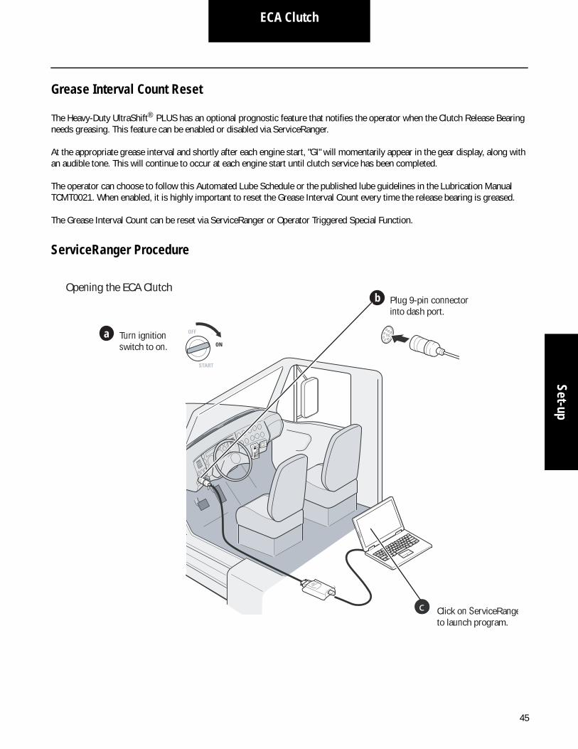
Grease Interval Count Reset
The Heavy-Duty UltraShift® PLUS has an optional prognostic feature that notifies the operator when the Clutch Release Bearing needs greasing. This feature can be enabled or disabled via ServiceRanger.
At the appropriate grease interval and shortly after each engine start, "GI" will momentarily appear in the gear display, along with an audible tone. This will continue to occur at each engine start until clutch service has been completed.
The operator can choose to follow this Automated Lube Schedule or the published lube guidelines in the Lubrication Manual TCMT0021. When enabled, it is highly important to reset the Grease Interval Count every time the release bearing is greased.
The Grease Interval Count can be reset via ServiceRanger or Operator Triggered Special Function.
ServiceRanger Procedure
3
Turn ignition switch to on.
b Plug 9-pin connector into dash port.
Click on ServiceRangeto launch program.
a
2
FFO
NO
TRATS
c
Opening the ECA Clutch

46
ECA Clutch
Click on Clear Grease Interval Counter.
9
Choose Grease Interval Reset tab.
7 8
Confirm Positive results. 10 Turn ignition switch to off to save reset.
Open and expand the Advanced Product Functions tree.
4 5 6 Click on ECA Clutch Service.
Click on transmission.NOTE: Advanced Product Functions

47
ECA ClutchSet-up
Operator Triggered Procedure
2
R
N
D
LOW
MANUAL
SHIFT
1
2 3
5
4
6
From the “Off” position, turn ignition to “On” without cranking the engine.
Select Low Mode on the Shift Device.
Press the Manual Up-Shift Button until the Gear Display
Press Accelerator to the floor. Gear Display will show a “Down Arrow.”
dloH
Release the Accelerator. Gear Display will show a “0.”
esaeleR
Select Neutral and turn ignition to “Off” in order to save the reset.
R
N
D
WOL
LAUNAM
TFIHS
FFO
NO
TRATS
FFO
NO
TRATS
3
0
48
In-Vehicle Resetting Procedure
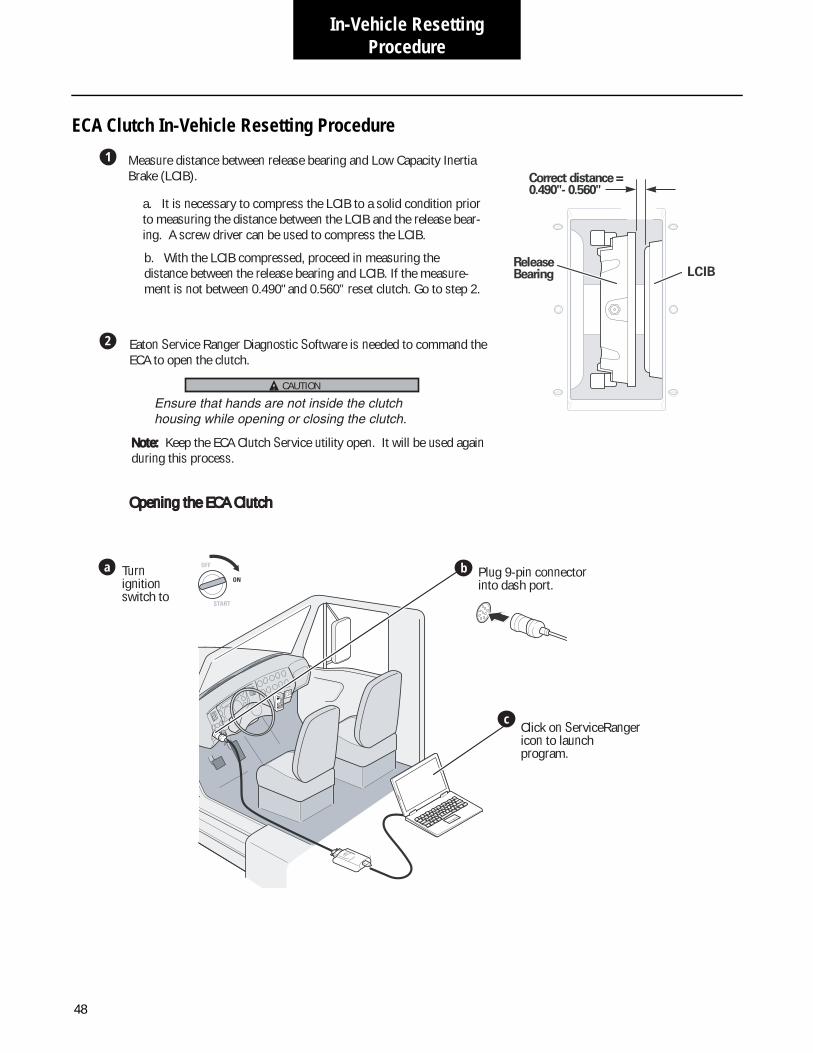
ECA Clutch In-Vehicle Resetting Procedure
2
1 Measure distance between release bearing and Low Capacity Inertia Brake (LCIB).
a. It is necessary to compress the LCIB to a solid condition prior to measuring the distance between the LCIB and the release bear-ing. A screw driver can be used to compress the LCIB.
b. With the LCIB compressed, proceed in measuring the distance between the release bearing and LCIB. If the measure-ment is not between 0.490" and 0.560” reset clutch. Go to step 2.
Eaton Service Ranger Diagnostic Software is needed to command the ECA to open the clutch.
Ensure that hands are not inside the clutch housing while opening or closing the clutch.
Note: Note: Keep the ECA Clutch Service utility open. It will be used again during this process.
esaeleRgniraeB LCIB
= ecnatsid tcerroC"065.0 -"094.0
c
Turn ignition switch to
b Plug 9-pin connector into dash port.
Click on ServiceRanger icon to launch program.
a
2
FFO
NO
TRATS
Opening the ECA ClutchOpening the ECA Clutch
CAUTION

49
In-Vehicle Resetting Procedure
ECA Clutch
Open and expand the Advanced Product Functions tree.
d e f Click on ECA Clutch Service.
Click on transmission.NOTE: Advanced Product Functions appear.
Ensure that hands are not inside the clutch housing while opening or closing the clutch.
Note:Note: Keep the ECA Clutch Service utility open. It will be used again during this process.
g Choose Clutch Position Tab.
h Click on Open Clutch.
NOTE: ServiceRanger will require engine running in order to open clutch.
i Confirm Positive
CAUTION

50
In-Vehicle Resetting Procedure
Close the clutch by switching the ignition to ON.
Install and tighten 4 ship-ping bolts (7/16” x 14 x 1-3/4 UNC) to remove gap between sleeve and pin.
Remove the 4 shipping bolts in a crisscross pattern a 1/4 turn at a time.
In the ECA Clutch Service utility, select the Request Clutch Adjustment command, and follow ServiceRanger instructions.
The Request Clutch Adjustment command will automatically initiate the ECA to open and close the clutch causing a clutch adjustment to take place.
Verify reset. Go to step 1.
Ensure that hands are not inside the clutch housing when opening or closing the clutch.
Position Reset Tool:• Through the access panel• Under the release bearing• Threaded bolt in cam slot
Use tool to move cam to New position.
Note: If the cam does not move, loosen transmission and install 1/2” spacers between clutch housing and engine housing to increase stroke.
• With spacers in place, follow steps 2 through 5 in this proce-dure.• Remove spacers and torque transmission mounting bolts.• Continue process starting at step 6.
7
9
3
4
erofeB
gnippihStloBpaG
oNpaG
eveelSniP
sseccAlenaP
retfA
5
6
8CAUTION

51
Out of Vehicle Resetting Procedure
Out of Vehicle Resetting
Low Capacity Inertia Brake Wear Life Measurement
2
1
3
4Compress down the LCIB by hand.
Using a shim or a feeler/thickness gauge measure the gap between the mounting stud nut/washer and the front of the LCIB, caused when the LCIB is compressed.
Measure the thickness of your gauge with calipers and if the thickness/gap between the mounting stud nut/washer and front of the LCIB is 0.140 inch then there is approximately 50% wear life left.
Measure the thickness of your gauge with calipers and if the thickness/gap between the mounting stud and front of the LCIB is 0.220 inch then the LCIB should be replaced soon.
Transmission Removed
Transmission in Chassis
1
2 3
4Open inspection cover.
Through the inspection cover lightly compress down the (LCIB) by hand.
With your other hand, use a shim or a feeler/thickness gauge to measure the gap between the mounting stud nut/washer and the front of the LCIB, caused when the LCIB is compressed.
Measure the thickness of your gauge with calipers and if the thickness/gap between the mounting stud and front of the LCIB is 0.140 inch then there is approximately 50% wear life left.
5 Measure the thickness of your gauge with calipers and if the thickness/gap between the mounting stud and front of the LCIB is 0.220 inch then the LCIB should be replaced soon.
6 After measurements have been taken close inspection cover.

52
Hydraulic Linkage
Hydraulic Linkage
Verify Linkage System Stroke
Measure the release bearing position with the pedal up and pedal down to verify bearing travel.
The hydraulic linkage should allow for a minimum of .600" of yoke finger movement: .500"-.560" for clutch release plus additional movement for clutch brake squeeze.
If the system does not provide enough movement of the release bearing, the clutch will not adjust and the bearing will move away from the transmission and lose clutch brake squeeze.
If the system is operational, clutch replacement may be nec-essary. If replacing the clutch, you must adhere to OEM war-ranty guidelines prior to claim disposition.
Master Cylinder Installation
Master Cylinder
Master cylinder may be mounted at any angle ranging from vertical to horizontal, depending on application.
Remote Reservoir
Constant rise in hose from master cylinder to reservoir.
1 - Master cylinder2 - Reservoir3 - Pushrod4 - Bolts (2), M8 x 1.25 mm (torque 20-25 N•m)5 - To booster or slave
3
5
1
4
2

53
Hydraulic LinkageHydraulic Linkage
Adjustment
Freeplay
Depending on the application, freeplay can be achieved by adjusting upper pedal stop or by adjusting master cylinder pushrod.
Clutch Brake Squeeze
For non-synchronized applications only.
Transmission Installation
Non-Synchronized
Slave Cylinder
1 - Freeplay 3-8 mm
1 - Clutch brake squeeze 13-50 mm
1
1
1 - Clutch servo2 - To master cylinder3 - Connect air supply 30 psi source; Bolts (4), M16 x 1.5 mm (torque 20-25 N•m)4 - Bolts (2), M8 x 1.25 mm (torque 20-25 N•m)5 - Pushrod
1 - Slave cylinder
2
5
3
4
1
1
54
Hydraulic Linkage
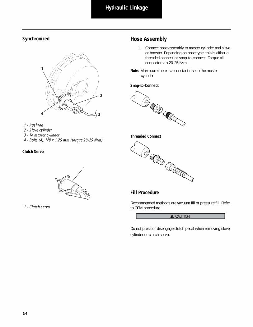
Synchronized
Clutch Servo
Hose Assembly1. Connect hose assembly to master cylinder and slave
or booster. Depending on hose type, this is either a threaded connect or snap-to-connect. Torque all connectors to 20-25 N•m.
Note: Make sure there is a constant rise to the master cylinder.
Snap-to-Connect
Threaded Connect
Fill Procedure
Recommended methods are vacuum fill or pressure fill. Refer to OEM procedure.
Do not press or disengage clutch pedal when removing slave cylinder or clutch servo.
1 - Pushrod2 - Slave cylinder3 - To master cylinder4 - Bolts (4), M8 x 1.25 mm (torque 20-25 N•m)
1 - Clutch servo
3
1
4
2
1
CAUTION

55
Hydraulic LinkageHydraulic Linkage
Solo Advantage Lube Hose Assembly With Hydraulic Linkage
Installation process1. Install brass fitting into grease port on left side of
release bearing housing using weatherhead socket. Tighten hand tight and continue to turn until the opening of the fitting is facing toward the 6 o’clock position
2. Install lube hose into brass fitting and tighten until hand tight, then turn an additional 2 turns.
3. Lubricate release baering until grease purges from release bearing housing. Use NLGI #2 or #3 Lithium complex grease. Reference Eaton lubrication manual TCMT0021 for specific instructions.
4. Install hand hole cover A-8173 with grommet biased towards transmission in the clutch housing. Secure the hand hold cover with two 5/16X18X1/2 inch long bolts.
5. Insert plug into hole in upper left side of the clutch housing where the horizontal lube hose is utilized.
Note: If the lube hose assembly should need servicing it can be replaced without removal of transmission.
Parts Required:1 - K-4050 Lube hose assembly kit (includes brass fitting, lube hose, and plug)2 - A-8173 Hand hold cover with grommet

56
Hydraulic Linkage
1. Fitting is assembled to hose hand tight. Attach the brass fitting to the release bearing housing hand tight and turn fitting until opening of fitting is at the 9 o’clock position when facing the engine. Install the hose into fitting until hand tight and turn 1/6 turn. Refer to diagram.
2. Transmission installation; remove the nuts from the brass fitting with the grease zerk. Install the trans-mission and insert the brass fitting through the hole in the left side of the clutch housing. Reinstall the brass nuts and tighten.
3. Lubricate release bearing until grease purges from release bearing housing. Use NLGI #2 or #3 Lithium complex grease. Reference Eaton lubrication manual TCMT0021 for specific instructions.
4. Install 4305231 hand hole cover to protect the clutch from contamination.

57
General InformationGeneral Inform
ation
General Clutch Information
Function of a ClutchAny modern day clutch, whether designed for an automobile or heavy truck, performs several important tasks allowing for safe and convenient operation of the vehicle.
In a vehicle powertrain, the clutch is the device that interrupts the flow of power from the engine flywheel to the transmis-sion. To start a gasoline or diesel engine, the flywheel must be able to turn freely without propelling the vehicle. By disengag-ing the clutch, the drivetrain is effectively disconnected from the rotation of the flywheel allowing the engine to start.
Manual transmissions, whether synchronized (synchromesh) or non-synchronized (constant mesh), require an interruption of engine torque to complete a gear change. To make a gear change, the clutch pedal is depressed, breaking torque. This is followed by altering engine speed to more closely match the transmission input shaft (clutch disc) speed. After the proper gear is selected, the clutch pedal is then slowly released. As the clutch disc(s) are compressed, the relative slip speed between the flywheel and the transmission input shaft reaches zero and the clutch is completely engaged and capable of car-rying full engine torque. With non-synchronized gearboxes, double clutching (a momentary partial engagement of the clutch made while the transmission is in neutral) is often nec-essary to allow rotational speeds of gears to become the same and complete the gear change.
With the advent of transmission automation, breaking torque and altering flywheel speed is accomplished via electronic throttle control and engine braking. The clutch pedal is used only when starting the engine, launching the vehicle from a stop, and when the vehicle slows to a stop.
The last function of the clutch is mitigating torsional vibra-tions. With any in-line, six-cylinder engine there are three (3) distinct power pulses occurring during each revolution of the flywheel. With each firing of a cylinder, the flywheel speeds up then slows down, very quickly, resulting in a torsional vibra-tion. This vibration can damage drivetrain components in short order if left uncontrolled. The coil springs in a driven disc damper absorb much of the vibration. The resonant (gen-erally the least expensive drivetrain component) is considered the “fuse” of the system. Failure of a clutch damper section is usually an indication of a serious torsional vibration systems problem or shock loading due to driver abuse.
Clutches are assemblies made up of many different compo-nents utilizing many different types of materials. This section
describes the major components which make up a complete Eaton Clutch installation.
The following are the major components used to make up a clutch installation:
• Cover Assembly (contains pressure plate)• Intermediate Plate – (only in 2-plate clutches)• Driven Disc(s)• Clutch Brake
Neutral Idle Rattle
Neutral idle rattle is a system issue. It occurs when the engine is idling with the transmission in neutral and the clutch pedal in the up position. As the engine idles, the firing pulses cause the flywheel to oscillate as it is rotating. This oscillation is transmitted through the input shaft and into the transmission gearing. This oscillation causes the transmission gears to impact one another resulting in a sometimes objectionable noise. While this noise is an annoyance, it is in no way dam-aging to the transmission and other components.
In the past, free travel dampers have been used to overcome this phenomenon. As systems have changed, in terms of mass, inertia, and fuel injection pressures, free travel has become a less effective means of control.
Free travel, simply stated, is the free left or right rotation of the driven disc hub before engaging the clutch damper. This first stage isolates some of the flywheel oscillation energy and prevents or reduces the idle rattle.
Pre-damper technology is now available in some medium- and heavy-duty clutch applications and performs the same function as the free travel. By adding a dampened first stage, it is more effective at limiting neutral idle rattle. Generally, the pre-damper springs are very small and softer in rate than the main damper springs.
In diagnosing neutral idle rattle complaints, first try to fully depress the clutch pedal. This will disconnect the engine from the transmission. Secondly, try raising the engine idle speed with the clutch pedal up. This may smooth out the engine fir-ing and may reduce, or eliminate, the noise.
If you have neutral idle rattle, determine what clutch is installed in the vehicle. It may already have a pre-damper clutch in it. If it is already equipped with a pre-damper clutch, then there is no benefit to changing the clutch.

58
General Information
Self-Adjusting Clutches
The Eaton Solo is the industry’s first adjustment-free clutch. With every push of the pedal, Solo’s innovative wear-adjust-ing technology senses for wear and makes any adjustments necessary.
Why There is No Need to Adjust Eaton Self-Adjusting Clutches
If theSelf-Adjusting Clutch is properly installed and the linkage is set-up properly, the Self-Adjusting Clutch should never need internal or external adjusting.
The Self-Adjusting Clutch automatically keeps the proper release bearing position and clutch free pedal position with two opposing cams. As the Self-Adjusting Clutch wears, the cams separate from each other keeping the proper release bearing position. This in turn maintains the proper clutch free pedal position.
How it Works
Eaton Self-Adjusting Clutches wear-adjusting technology comes from two sliding cams. With every push of the pedal, the clutch senses for wear and makes any adjustments neces-sary. The cams rotate to maintain the proper adjustment throughout the life of the clutch. On top of the upper cam, a clutch wear indicating tab mirrors the cams’ movement to let you know when it’s time to replace the clutch. The result of Solo’s constant adjustment is greater longevity and a reduc-tion in maintenance and labor costs.
Clutch Disc Dampening Characteristics
A key function of a clutch is to mitigate naturally occurring vibrations of the engine flywheel from reaching the transmis-sion and the other components further down the drivetrain. This is accomplished by employing torsional spring dampers to the clutch pack. These springs take the form of coil springs, configured inside the clutch disc, that compress with the application of torque. The torque path through the damper begins at the friction interface at the facings, proceeds to the steel carrier disc and moves into the disc reinforcing plates where the springs are located. The springs are compressed, transmitting force to the spring covers which are rigidly attached to the hub. Torsional rate is defined as the amount of torque required per degree of center hub rotation. There are three basic categories of torsional rates for clutch dampers: rigid, standard, soft.
Rigid and Clutch Discs - Rigid discs and clutch discs with no spring package whatsoever, act as a nearly direct link from the engine flywheel to the transmission and offer no protec-tion against torsional vibration. Their use should be limited to older mechanically-fueled engines where clutch replacement cost is paramount over long component life. Rigid clutch discs are never used in new OEM applications.
Standard Dampers - Standard dampers include all 10-spring and most 8- spring types. The springs used in these dampers are approximately 1.5" long and do not offer a large amount of deflection before coil lock takes place. While these dampers were completely adequate for most heavy duty applications several years ago, they are generally incapable of reducing the engine flywheel vibrations developed with slow speed elec-tronically fueled engines. The use of standard dampers in heavy duty applications has virtually ceased in OEM applica-tions. The trend is to use more capable soft-rate dampers.
Soft-Rate Dampers - Soft-rate dampers, like the heavy-duty 7-spring and VCT Plus, offer much better protection against engine flywheel induced torsional vibrations. Their springs are characteristically longer than springs used in standard rate dampers and offer more deflection before coil lock occurs. This larger spring deflection is equated to lower torsional spring rate. With lower torsional rate, the resonant frequency of the complete drivetrain is lowered; usually to a point of a few hundred RPM below normal engine operating range. With the addition of hysteresis or Coulomb dampening (the energy expelled as the damper is exercised), the magnitude of the vibrations is reduced further, adding to the dampers benefit.
Pre-Dampers - Pre-damper is a feature designed for reducing idle rattle noise in various applications, where torsional vibra-tions are growing more erratic. That is why Eaton is now introducing the latest option for heavy-duty applications, the VCT Plus PD, where "PD" stands for Pre-Damper. The Pre-Damper consists of seven small springs, surrounding the hub that reduce idle rattle when operating at low torque or engine speed with the transmission in neutral, prior to operation of the primary damper stage.

59
General InformationGeneral Inform
ation
Clutch Disc Friction Material
Organic facings, often called “rag” facings, get their name from the high concentration of organic rubber and binder agents that make up their composition. Fiberglass cord (or similar material) is woven into the material matrix and adds burst strength and improves friction and wear properties. Asbestos has not been used in organic friction material since the early 1980's. Organic facings are used without exception in passenger car and light truck applications. This is so because of smooth engagement properties and the relative light torque loads imposed on the clutch. In general, organic friction material lacks in performance in wear rate, coefficient of friction (ability to carry torque), and resistance to fade (abuse tolerance) when compared to cera-metallic friction material. The use of organic friction material in heavy vehicles has significantly declined over the past decade. Wear life and its maximum limit to 1,400 ft. lbs. (1892 N•m) of torque in 15.5" clutches are the primary reasons.
Cera-metallic (Ceramic) friction facings are composite mate-rial (copper, sand and other friction modifiers and binder agents). The dry raw materials are mixed in bulk, poured into die cavities, compressed, sintered in an controlled atmo-sphere, then brazed into a steel backer plate to facilitate rivet attachment to the driven disc. Compared to organic friction material, cera-metallics have improved performance in the areas of wear rate, resistance to fade (abuse tolerance), and coefficient of friction (ability to carry torque). It is for this rea-son that cera-metallics make up the vast majority of OEM builds.
Clutch Slippage
Slippage will cause significant heat build-up and rapid wear of the clutch pack. If the clutch pack temperature raises beyond the facing threshold temperature, the facing may disintegrate. Slippage is the result of loss of clamp load due to lack of adjustment, loading the clutch beyond its design torque rat-ing, or the clutch has reached the end of its design life. With the ability to re-rate an electronic controlled diesel engine, it is quite easy to delivery torque to the clutch beyond its design capacity. Before an engine re-rating is performed, confirm that the clutch and other drivetrain components are capable of carrying the increased torque and power.
Clutch Torque Capacity
It is imperative to understand the factors that influence fric-tion force because this device transmits torque via friction. The fundamental equations that describes friction is:
F(f) = uN
Where F(f) = Force due to friction
U = Coefficient of friction
N = Load applied to the friction interface
T = F(f)r
Since torque (T) is equal to force friction F(f) multiplied by the moment arm (R) (distance from application of force to center or rotation) must be known. To exactly calculate the moment arm, the mean radius of a clutch (R), integration must be per-formed. However, for clutches in the size range offered by Eaton, the calculation can be simplified to:
(r) = (ID + OD) / 4
Clutch Wear
Clutch wear happens because the clutch discs slip relative to the engine flywheel and the pressure plate surface, and in the case of a two plate clutch, the intermediate plate, during vehi-cle launch and gear change. As the clutch disc friction mate-rial and mating flywheel and pressure plate surfaces wear, the gage thickness of the clutch pack decreases (moving the pressure plate closer to the engine flywheel). This movement of the pressure plate causes the pressure spring(s) to elon-gate and loose clamping load. If clamping load is allowed to decrease beyond a critical point, the clutch will be unable to carry full engine torque and slip.
Cover Assembly
The cover assembly, constructed of either stamped steel or cast iron, is bolted to the flywheel. It contains the pressure plate, which is fitted to the cover with pressure springs. It also contains the release bearing and levers, which move the pres-sure plate back and forth, thereby making or breaking contact with the disc assembly.

60
General Information
Driven DiscEaton offers a variety of 14" and 15.5" driven disc designs. The selection of driven discs depends on many factors.
Excessive torsional vibration can significantly reduce the life of all drivetrain components. That’s why Eaton has engineered soft-rate dampers to reduce critical vibrations in today’s elec-tronic, high horsepower engines. Eaton recommends the use of soft-rate dampers (7-spring or VCT Plus) for all vehicles over 1,000 ft. lbs.
Specifically, Eaton offers driven discs with different numbers of springs in the center section of the damper. 7, 8, 9 and 10-spring configurations are available. The proper selection depends on many factors including the engine, flywheel and transmission of the vehicle.
FacingsThe disc facings are critical to clutch life and performance because they directly receive the torque of the engine each time the clutch is engaged.
In general, ceramic facings have greater heat tolerance and torque capacity than organic facings. As such, they engage quicker, reduce slippage and deliver longer life.
Organic facings (non-asbestos) are adequate for lower horse-power, on-highway applications. However, Eaton recom-mends ceramic facings for most applications.
Intermediate PlateThe intermediate plate or center plate, increases the torque capacity of the clutch by providing additional surface area for facing material and torque capacity. The intermediate plate is driven by the clutch cover or by the flywheel on the 14" Easy-Pedal Plus design.
Positive Separator Pin™
Eaton’s Positive Pin Separator improves clutch life and perfor-mance by providing cooler operation, smoother engagement and equal plate separation. The pin restricts intermediate plate movement when the clutch is released, giving constant gap on both sides of the plate, therefore, allowing the driven discs to spin freely.
6-Position Kwik-Adjust®
Eaton’s Easy-Pedal Plus® 14" and Easy-Pedal ™ 2000 15.5" Clutches feature the Kwik-Adjust component and the easy-to-reach external manual adjustment mechanism that allows for quick adjustment of release bearing travel without the use of special tools or the need to remove any bolts. Using a com-mon box end wrench, simply depress the Kwik-Adjust bolt and turn the standard 6-point hex head adjustor as needed.
Clutch Brakes
Clutch brakes are designed to extend the life of a vehicle’s transmission by eliminating damaging gear clash while reduc-ing the effort required to shift into first or reverse from a standstill. Eaton offers two separate clutch brake options.
• Torque Limiting• Kwik-Konnect®
Torque Limiting Clutch BrakeThe Eaton Torque Limiting Clutch Brake has a self-contained torque limiting feature which prevents tang breakage from driver misuse of the clutch brake.
• Part Number 127740: 1.75" spline• Part Number 127760: 2" spline
Kwik-Konnect® Two-Piece Clutch BrakeThe two-piece clutch brake provides cooler operation than competitive clutch brakes. It is designed for service applica-tions, and can be quickly installed without removing the trans-mission.
Part Number: 125489
Part Number: 127200

61
General InformationGeneral Inform
ation
Factors that Effect Clutch Performance
Excessive slipping is the major cause of clutch failure. Extreme operating temperatures can cause the clutch to fail because the heat generated between the flywheel, driven discs, intermediate plate, and pressure plate is high enough to cause the metal to flow and the friction material to be destroyed.
An improperly adjusted or slipping clutch will produce suffi-cient heat to rapidly burn up.
There are many factors which have significant impact on clutch life:
• Application (torque capacity)
• GCW/Weight
• Number of starts per day
• Maintenance/Adjustment
1. Starting the Vehicle in the Proper Gear - The cor-rect gear will allow you to start the vehicle with your foot off the throttle.
2. Gear Shifting Techniques - Many drivers upshift into the next gear or even skip-shift into a higher gear before the vehicle has reached the proper speed. This type of shifting is almost as damaging as starting off in a gear that is too high, since the engine speed and vehicle speeds are too far apart, requiring the clutch to absorb the speed difference as heat.
3. Excessive Vehicle Overload or Overloading the Clutch - Clutches are designed and recommended for specific vehicle applications and loads. These limitations should not be exceeded. Excessive or extreme overloading is not only damaging to the clutch but to the entire vehicle powertrain as well. If the total gear reduction in the powertrain is not suffi-cient to handle excessive overloads, the clutch will suffer, since it is forced to pick up the load at a higher speed differential.
4. Do Not Ride the Clutch Pedal - Riding the clutch is very destructive to the clutch since a partial clutch engagement permits slippage and excessive heat. Riding the clutch pedal will also put a constant thrust load on the release bearing, which can thin out the lubricant and also cause excessive wear on the pads. Release bearing failures can often be attributed to this type of operation.
5. Do Not Slip the Clutch to Hold the Vehicle on an Incline - This procedure uses the clutch to do the job
normally expected of the wheel brakes. A slipping clutch accumulates heat faster than it can be dissi-pated, resulting in early failures.
6. Do Not Coast with the Clutch Released and Trans-mission in Gear - This procedure can cause high driven disc RPM through multiplication of ratios from the final drive and transmission. It can result in “throwing” the facing off the clutch discs. Driven disc speeds of over 10,000 RPM have been encoun-tered in such simple procedures as coasting tractors down an unloading ramp. While an ample safety fac-tor is provided for normal operation, the burst strength of the facing is limited.
7. Do Not Engage the Clutch while Coasting - This procedure can result in tremendous shock loads and possible damage to the clutch, as well as the entire drivetrain.
8. Reporting Erratic Clutch Operation Promptly - Driv-ers should report erratic clutch operation as soon as possible, to give the maintenance personnel a chance to make the necessary inspection, internal clutch adjustment, linkage adjustment and lubrica-tions, thereby avoiding possible clutch failures and breakdowns while on the road. The importance of free pedal travel (sometimes referred to as a pedal lash) should be brought to the driver’s attention as well as the mechanic. This item should be included and commented on daily in the driver’s report, since clutch free pedal is the maintenance personnel’s guide to the condition of the clutch and the release mechanism.
9. Clutch Adjustments - Manual Adjustment- The importance of proper and timely clutch adjustments and lubrication can not be over stated. Internally adjusting the clutch properly and when needed will keep the clutch components in the proper position and extend the life of the clutch. See the adjustment section for more information.
Solo Adjustment-Free If your truck is equipped with an Eaton Self-Adjusting Clutch, then the clutch will always be in proper adjustment. Possible lubrication and inspection are needed. See “Inspection and Lubrication”.

62
General Information
When to Inspect the Clutch
The clutch should be inspected during the regularly scheduled lubrication intervals as dictated in the Lubrication section or when one of the following occur:
• Clutch Free Pedal - If the clutch free pedal is one-half of OEM specifications, not less than one-half inch. During normal clutch use, the release bearing will move toward the fork fingers and reduce “in cab” free pedal.
• Clutch Is Slipping - If the clutch is slipping, it may require adjustment. If proper internal (clutch adjuster) and external (clutch linkage) adjustment has been made and the clutch still slips, it is likely worn beyond its useful life and needs replacement.
Inspection for Clutch Life
If your vehicle is equipped with a Eaton Solo or Solo XL (Extended Lube) Clutch, the clutch is equipped with a clutch wear indicating tab that can be seen through the inspection window. To calculate the expected life of a Solo, apply a paint mark indicating the start point of the clutch wear indicating tab. Record the mileage when this mark was made. After a few months, reinspect the position of the clutch wear indicating tab and record the new mileage. The difference between the two readings can be used to estimate when the clutch will need to be replaced.
For Example:
Starting Mileage = 10,000
After six (6) months mileage = 75,000
Clutch wear indicating tab movement = .625" (16 mm)
75,000-10,000 = 65,000 miles
65,000 miles/.625" = 104,000 miles per inch of tab movement
3.5" remaining tab movement
3.5" remaining tab movement X 104,000 miles per inch of tab movement = 364,000 expected clutch life.
Designing a Clutch for a Specific Application
There are three parts to designing a clutch for a specific appli-cation. If the correct clutch is chosen, the truck will have good engagement, protection for the driveline, long clutch life, and minimal loss of torque.
1. Check the Flywheel Bore (15.5" Clutch) - The fly-wheel environment must be checked to make sure a clutch can be used with it. The bore is important when deciding what type of driven disc to use. The bore must be large enough to allow for a proper fit of the disc. See chart below.
2. Torque Capacity - A clutch must be chosen that has a torque capacity that is greater than or equal to the peak torque of the engine. This is very important today when an engine can be easily adjusted elec-tronically to produce greater torque. There are two factors in determining torque capacity. These two factors are friction force and damper capacity.
• Friction force is a product of the cover assem-blies clamp load (also called plate load). This factor was explained in the previous section, and is stated as F(f) = uNPr. Determining the friction force is important because if this force is not greater than or equal to the peak torque of the engine, the clutch will slip.
• Damper capacity is what allows the clutch to provide torsional protection for the entire drive-line. If the peak engine torque exceeds this capacity, the driveline will be abused. This abuse will cause faster wear and possible destruction of driveline components. Since damper capacity is a product of the springs used in the damper, changing the number and type of springs changes the stiffness of the entire system.
3. Application - Service replacement clutches should have the same plate loads, damper and friction mate-rial. Substituting from the original could shorten the life of the clutch and drivetrain components.
# of Springs Bore size 8 spring 7 1/4" (184.15mm)10 spring 8 9/16" (217.48mm)7 spring 9 3/4" (247.65mm)9 spring* 9 3/4" (247.65mm)*Mack/Volvo Engine 2007 and newer only
Measurebore size
Engine Flywheel

63
General InformationGeneral Inform
ation
Preventive Maintenance Overview
To ensure long life and proper operation of the release mech-anism of the clutch, it is important to properly lubricate the following areas.
Lubrication1. Release Bearing - The cast iron bearing housing will
be equipped with either a standard grease fitting or a lube tube extension. If a lube tube is not present, it is necessary to remove the inspection cover to gain access to the grease fitting. Apply grease until it purges from the rear of the housing. Grease on the clutch brake friction surface and the transmission input shaft will extend the life of the clutch brake and bronze bushings inside the release sleeve.
2. Release Bearing Wear Pads - Where the release fork contacts the bearing housing, there are small hardened steel pads. Apply a small amount of grease to the wear pads where the clutch release fork con-tacts.
3. Clutch Brake - The clutch brake friction material is designed to operate with lubricant. While lubricating the release bearing, grease should purge from the housing and contact the clutch brake. This is benefi-cial for long clutch brake life. If desired, a small amount of grease could be applied to both sides of the clutch brake.
4. Cross-Shaft Bushings - Lubricate both the left and the right cross-shaft bushings per OEM recommen-dations.
5. Clutch Control Linkage - Lubricate the clutch linkage bell cranks and pivot pins per OEM recommenda-tions.
6. Pilot Bearing - The pilot bearing inside the flywheel is a sealed for life bearing and requires no lubrica-tion. Use a premium pilot bearing to prevent clutch drag and early bearing failures. (C-3, C-4, C-5 Suffix)
Lube Tube Assembly
The Eaton Lube Tube Assembly enables the release bearings in Eaton medium and heavy duty clutches to be greased with-out removing the bell housing inspection cover. The Lube Tube Hose replaces the original zerk fitting on the release bearing and protrudes through the bell housing window.
Lube Tube Lengths
Lube Hose Kits/Assemblies for Hydraulic Release System
Recommended Lubrication
Incorrect grease and improper lube procedures will cause bearing failures, bushing wearout, yoke tip and bearing wear pad wear.
For a list of recommended lubricants, see TCMT-0020 or call 1-800-826-HELP (4357).
Lubrication Interval
The DM UltraShift clutch does not require any lubrication or adjustment. There is no clutch linkage associated with this product, therefore there is no linkage adjustment or mainte-nance requirements.
For recommended lubrication intervals, see TCMT-0021 or call 1-800-826-HELP (4357).
Length in Inches Part Number
12" CLT012
9" CLT009
8" CLT008
7" CLT007
6" CLT006
Kit/Assembly Description
K-4050 Used with Solo AdvantageTM clutches
A-7857 Used with Non-Solo AdvantageTM clutches
CAUTION

For spec’ing or service assistance call 1-800-826-HELP (4357 or visit our web site at www.roadranger.com.In Mexico, call 001-800-826-4357.
Eaton Corporation • Truck Components Operations • P.O. Box 4013 • Kalamazoo, MI 49003 • U.S.A. • www.roadranger.com
Roadranger: Eaton, Dana and other trusted partners providing the best products and services in the industry, ensuring more time on the road.
©2008 Eaton Corporation · All rights reserved.Printed in USA
Copyright Eaton Corporation and Dana Limited, 2011. Eaton and Dana
hereby grant their customers, vendors, or distributors permission to freely copy,reproduce and/or distribute this documentin printed format. It may be copied only in itsentirety without any changes or modifications.THIS INFORMATION IS NOT INTENDEDFOR SALE OR RESALE, AND THIS NOTICEMUST REMAIN ON ALL COPIES.