Combined numerical and experimental investigation of the micro-hydrodynamics of chevron-based...
22
Loughborough University Institutional Repository Combined numerical and experimental investigation of the micro-hydrodynamics of chevron-based textured patterns influencing conjunctional friction of sliding contacts This item was submitted to Loughborough University’s Institutional Repository by the/an author. Citation: MORRIS, N. ... et al., 2015. Combined numerical and experimental investigation of the micro-hydrodynamics of chevron-based textured patterns influencing conjunctional friction of sliding contacts. Proceedings of the Insti- tution of Mechanical Engineers, Part J: Journal of Engineering Tribology, 229 (4), pp. 316-335. Additional Information: • This article is distributed under the terms of the Creative Commons Attri- bution 3.0 License (http://www.creativecommons.org/licenses/by/3.0/) which permits any use, reproduction and distribution of the work without fur- ther permission provided the original work is attributed as specified on the SAGE and Open Access page (http://www.uk.sagepub.com/aboutus/openaccess.htm). Metadata Record: https://dspace.lboro.ac.uk/2134/17147 Version: Published Publisher: Sage (IMechE) Rights: This work is made available according to the conditions of the Creative Commons Attribution-NonCommercial-NoDerivatives 4.0 International (CC BY-
Transcript of Combined numerical and experimental investigation of the micro-hydrodynamics of chevron-based...
Loughborough UniversityInstitutional Repository
Combined numerical andexperimental investigation
of themicro-hydrodynamics ofchevron-based texturedpatterns influencing
conjunctional friction ofsliding contacts
This item was submitted to Loughborough University’s Institutional Repositoryby the/an author.
Citation: MORRIS, N. ... et al., 2015. Combined numerical and experimentalinvestigation of the micro-hydrodynamics of chevron-based textured patternsinfluencing conjunctional friction of sliding contacts. Proceedings of the Insti-tution of Mechanical Engineers, Part J: Journal of Engineering Tribology, 229(4), pp. 316-335.
Additional Information:
• This article is distributed under the terms of the Creative Commons Attri-bution 3.0 License (http://www.creativecommons.org/licenses/by/3.0/) whichpermits any use, reproduction and distribution of the work without fur-ther permission provided the original work is attributed as specified on theSAGE and Open Access page (http://www.uk.sagepub.com/aboutus/openaccess.htm).
Metadata Record: https://dspace.lboro.ac.uk/2134/17147
Version: Published
Publisher: Sage (IMechE)
Rights: This work is made available according to the conditions of the CreativeCommons Attribution-NonCommercial-NoDerivatives 4.0 International (CC BY-

NC-ND 4.0) licence. Full details of this licence are available at: https://creativecommons.org/licenses/by-nc-nd/4.0/
Please cite the published version.
2
Special Issue Article
Combined numerical and experimentalinvestigation of the micro-hydrodynamicsof chevron-based textured patternsinfluencing conjunctional frictionof sliding contacts
N Morris1, M Leighton1, M De la Cruz1, R Rahmani1,H Rahnejat1 and S Howell-Smith2
Abstract
Reciprocating and low-speed sliding contacts can experience increased friction because of solid boundary interactions.
Use of surface texturing has been shown to mitigate undue boundary friction and improve energy efficiency. A combined
numerical and experimental investigation is presented to ascertain the beneficial effect of pressure perturbation caused
by micro-hydrodynamics of entrapped reservoirs of lubricant in cavities of textured forms as well as improved micro-
wedge flow. The results show good agreement between numerical predictions and experimental measurements using a
precision sliding rig with a floating bed-plate. Results show that the texture pattern and distribution can be optimised for
given conditions, dependent on the intended application under laboratory conditions. The translation of the same into
practical in-field applications must be carried out in conjunction with the cost of fabrication and perceived economic gain.
This means that near optimal conditions may suffice for most application areas and in practice lesser benefits may accrue
than that obtained under ideal laboratory conditions.
Keywords
Laser surface texturing, chevron features, mixed regime of lubrication, micro-hydrodynamics, friction
Date received: 30 January 2014; accepted: 23 October 2014
Introduction
Energy efficiency is progressively viewed as the mostessential attribute for all machines and mechanisms.An important source of energy inefficiency is friction,which may be viewed as an energy sink. Therefore,except for some occasions where friction is crucialfor fulfilling certain functions, such as intraction, braking or locomotion, its minimisationis an important design goal. The increasing scar-city of fossil fuels with the associated increase incost and their adverse effect on the environment arekey motivators in the drive to mitigate the effects offriction.
As friction occurs naturally, there have been manyattempts since antiquity to minimise the requiredeffort to overcome it, as well as forming an under-standing of it. Amontons1 described the underlyingmechanism of friction as the interaction of roughsurfaces, independent of their apparent area of con-tact. Later Euler2 provided the first definition for thecoefficient of friction and its relation to the stateof motion. Coulomb3 confirmed the findings of
Amontons and Euler in distinguishing between staticand kinetic states of friction.
The Amontons–Coulomb fundamental laws implyfriction as an inherent property of surfaces; theirtopography and mechanical properties. However, bythe turn of the 20th century it became clear that thesefundamental laws do not apply to real surfaces whichare invariably wetted either by an applied film oflubricant or their contact tribo-chemistry leads tothe formation of an oxide surface layer when exposedto normal atmosphere.4,5 In fact, nature itself hasmade use of rough surface topography in the presenceof a fluid to enhance load-carrying capacity and alsoreduce friction. One example is the combined action
1Wolfson School of Mechanical and Manufacturing Engineering,
Loughborough University, Loughborough, UK2Capricorn Automotive Ltd., Basingstoke, Hampshire, UK
Corresponding author:
H Rahnejat, Wolfson School of Mechanical and Manufacturing
Engineering, Loughborough University, Loughborough, UK.
Email: [email protected]
Proc IMechE Part J:
J Engineering Tribology
2015, Vol. 229(4) 316–335
! IMechE 2014
Reprints and permissions:
sagepub.co.uk/journalsPermissions.nav
DOI: 10.1177/1350650114559996
pij.sagepub.com
at Loughborough University on March 27, 2015pij.sagepub.comDownloaded from
of fairly rough cartilage covered surfaces and synovialfluid in the endo-articular joints of all vertebratesthrough the mechanism of micro-elastohydrodynamiclubrication.6 Therefore, nature’s own choice seems torun contrary to Amontons–Coulomb laws of friction.The perspective appears to be that of surface-lubricant as a system.
At the diminutive physical scale of surface asperi-ties, boundary-active fluid species can adsorb to sur-face features, as well as being entrapped and entrainedinto the asperities’ interspatial valleys.7,8 Therefore,unlike the idealised dry friction, wet rough contactingsurface topography can actually aid lubrication andreduce friction. The realisation of this point has grad-ually led to the introduction of engineered texturedfeatures on sliding surfaces. In fact, the use of varioussurface texture forms has been shown to improvetribological performance in Costa and Hutchings,9
Etsion and Burstein10 and Ronen et al.11 amongothers. Numerical and analytical analyses have alsoled to the determination of ‘optimal’ texture form,geometry and distribution for sliding contacts, forexample by Rahmani et al.12,13
The introduction of surface textures is most effect-ive in circumstances when poor contact kinematicssuch as stop-start, reciprocating motion or low rela-tive surface speed leads to lack of lubricant entrain-ment into the contact. These circumstances lead toboundary regime of lubrication. There are manysuch instances in various machines. For example, ininternal combustion engines, piston motion reversalsat top and bottom dead centres are accompanied bythe momentary cessation of lubricant entrainmentinto the piston skirt and ring pack. Use of surfacetexturing, introduced in the vicinity of piston rever-sals, has shown to reduce frictional power loss, bothanalytically,14 as well as through testing by Etsion15
and combined studies by Rahnejat et al.16 Otherinvestigations include that of Yu et al.17 for theeffect of texturing during sudden changes of speed inmechanical face seals and that of Pettersson andJacobson18 for reciprocating ring/roller contact inhydraulic motors. It is suggested that the cavitiesformed by the introduced micro-structures can actas lubricant reservoirs or encourage micro-wedgeeffect (micro-hydrodynamics) for lubricant entrain-ment.15,16,19,20 The micro-hydrodynamic effect isanalogous to the pressure perturbations in naturalmammalian joints,6 which improve the contact load-carrying capacity.13 In fact, aside from this localisedeffect, surface textures have also been shown toexpand the region in which hydrodynamic lubricationoccurs.21
The geometric form and distribution of texture fea-tures have also been investigated by many authors.The form largely depends on the method of manufac-ture/fabrication such as vibro-rolling,22 ion reactiveetching, indentation,23,24 abrasive jet machining,25
photo-lithography,26 anisotropic etching26 and laser
surface texturing (LST),15,16,27,28 the last of whichhas gradually become the process of choice. This isbecause LST lends itself to a greater degree of auto-mation as well as a better control for application tocurved surfaces such as cylinder liners16 and pistonring face-width,29 as well as fabrication of differenttexture geometries. Ryk et al.29 introduced partial tex-turing on the compression ring’s flat chamfered face-width, noting this to be the most effective in reductionof friction in their engine tests. On the other hand,Howell-Smith et al.30 noted that whilst texturefeatures can act as reservoirs of lubricant and aidreduction of friction, they may also cause oil loss inpiston cylinder system as well as breach the sealingfunction of the compression ring. This suggests thatit is better to introduce these features on the station-ary cylinder bore/liner in the vicinity of the top ringreversal. Their results show that indented liners withfeatures resembling the cross section of a Vickers toolprovide optimum performance in a high performancefired engine. However, laser-etched crescent shapes(analogous to a chevron) are more practical andcost effective to produce on curved concave surfacesand perform nearly as well as the indented features.Costa and Hutchings9 also investigated a range ofsurface texture shapes, including chevrons under slid-ing conditions, where the largest improvement in gen-eration of a hydrodynamic film was observed.
The current study combines numerical analysis andexperimental measurement of chevron-shaped surfacetextures under sliding conditions. A numerical para-metric study of the chevron shape design has beencarried out, using improved chevron textures and dis-tribution. The results are validated experimentallywith the use of a reciprocating precision slidingbench-top test rig. The aims of the investigation aretwo-fold; firstly to further the fundamental knowledgeof surface texturing and secondly, to demonstrate thedesign and development process for a suitable surfacetexture which can be used in real engineeringapplications.
Reciprocating sliding contact
Reciprocating or low-speed sliding contacts are sub-ject to a transient regime of lubrication. Poor tribo-logical conditions invariably occur at contactreversals, where lack of any relative sliding motionof the mating surfaces results in the momentary ces-sation of lubricant entrainment into the contact zone.This leads progressively to a greater number of ubi-quitous asperities on the counterfaces coming intocontact, leading to mixed or boundary regimes oflubrication. Such conditions are quite prevalent inmany forms of contact, such as piston-cylindersystem.31 Sliding contacts operating in the mixed orboundary regimes of lubrication experience increasedfrictional power loss when compared to fluid regimesof lubrication such as hydrodynamics, thus the reason
Morris et al. 317
at Loughborough University on March 27, 2015pij.sagepub.comDownloaded from
for the various applications of texturing to the con-tiguous surfaces,14–16 all of which have shown 2–4%reduction in in-cylinder frictional losses, ascertainedthrough improved BMEP. A more direct method ofmeasurement would be preferred as well as linkingany reduction in friction to the prevailing regime oflubrication. A direct in situ method of measurementfor cylinder applications has been through the use of afloating liner, which is dragged by the reciprocatingpiston relative to the bore surface by an infinitesimalamount. The floating liner is flexibly mounted to thecylinder bore through intervening load cells which dir-ectly measure friction. Such arrangements have beenreported by Furuhama and Sasaki32 and Gore et al.33
for engine testing conditions, although not includingsurface textures. However, friction in the engine cylin-der is dependent on the many physical interactionsarising from variations in the combustion chamberpressure, heat generation and thermo-elastic deform-ation of contiguous solids. Therefore, a fundamentalscientific study is preferred to focus on the effect ofsurface texturing under controlled laboratory condi-tions, at least in the first instance, prior to engineapplications. Hence, development of a precision reci-procating slider on a floating base-plate analogous toa floating cylinder liner would be advantageous. Thefocus of this study is mixed lubrication conditions atlow sliding speed, whilst traversing a textured region.These conditions were noted for the engine case inRahnejat et al.,16 where the textured area was pro-vided at the top compression ring reversal point.
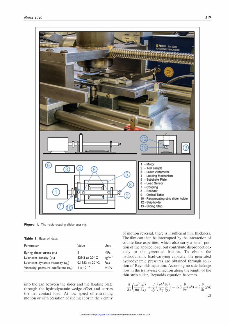
A reciprocating slider bench test rig has been devel-oped and described by Chong and De la Cruz et al.34
(Figure 1). A sliding thin strip slider with a face-widthprofile, representative of an engine compression ringis loaded against the flat plate, with a thin layer oflubricant applied. The plate is mounted upon preci-sion, low friction bearings and is allowed to float,when dragged by the sliding strip. An electric motoris directly coupled to the loaded sliding strip via a lowfriction and almost backlash-free lead-screw drive.Piezo-resistive force sensors, positioned at eitherends of the plate directly measure the inertial forceof the floating plate, which is due to the generatedcontact friction as
XF ¼ �ft ¼ ma ð1Þ
Short run times and suitable intervals areimplemented to ensure repeatable testing conditions(See Appendix 2). A rotational laser Doppler vibrom-eter is used to record the actual speed of the slidingstrip and a base oil is selected to lubricate the contact.This is a Grade 3 base stock (highly paraffinic withultra-low sulphur content, with a viscosity index,VI> 125). No boundary active lubricant species areused in the base oil, as these would adsorb to thesurfaces and form an ultra-thin low shear strength
film, which would affect the repeatability of theexperimental work. Further data for the base oil arelisted in Table 1.
The thin strip is made of martensitic AISI 440Cstainless steel hardened to 62 HRC. The flat plate ismade of 150M19 (EN 14) carbon manganese steel,electroplated with a 140 mm thick nickel-based coatingcontaining co-deposited silicon carbide particulate(Ni–SiC). This coating is the choice for many cylinderliners of high performance race engines. The surface isthen ground and polished. The corresponding data isgiven in Table 2.
Laser surface texturing
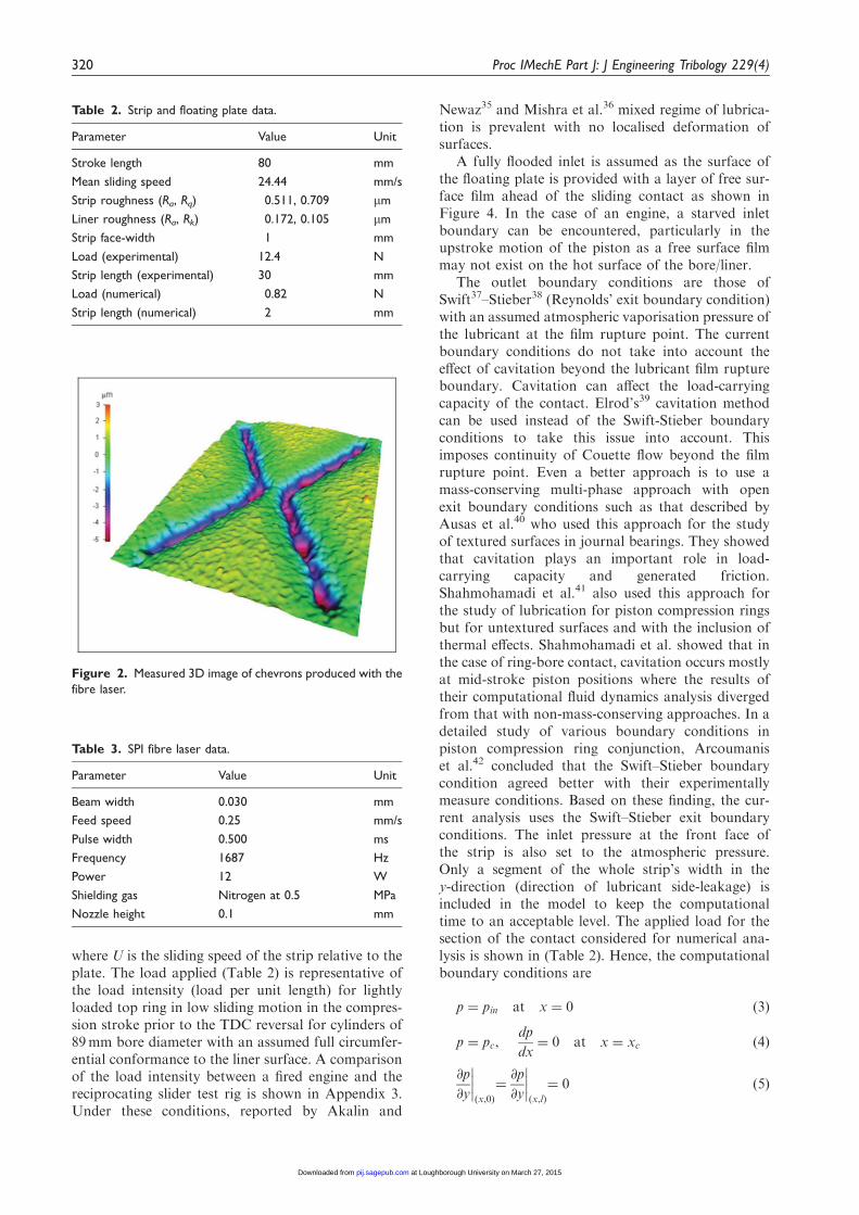
Chevron-shaped textures were laser etched onto aregion of the floating plate as shown in Figure 2.A SPI 50 Watt fibre laser was used to create the chev-rons. The laser parameters are provided in Table 3.
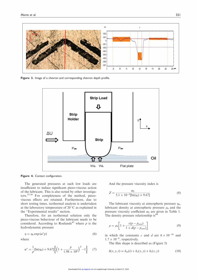
After the LST process, the plate is polished for ashort period of time to remove any residual splatter ordebris protruding from the surface. Figure 3 shows animage of typical laser-etched chevrons obtainedthrough the Alicona infinite focus microscope with ameasurement resolution of 1 nm.
The surface roughness of the plate and the flat ringwere measured (Table 2), as well as the chevron depthand the sliding strip’s face profile. The chevrons havea thickness-to-depth ratio of 0.11 (representative of anoptimised ratio as demonstrated by Etsion andSher28), although some variation in the chevrondepth is produced in the LST process.
The LST produces chevrons with a cross-sectionalprofile similar to that of a parabola (Figure 3), and aretherefore, modelled accordingly.
Numerical analysis
Prior to laser texturing of any form, geometry anddistribution of chevron-type textures onto the surfaceof the sliding plate, it is important to undertakenumerical analysis of the contact. This is due to thefact that there can be numerous combinations of geo-metrical parameters and distribution patterns withdifferent outcomes. Therefore, the numerical analysiscan provide the range of values that it is expected toyield desired performance from the textured surface.This can be carried out at low cost in comparison tothe manufacture of a sufficiently varied set of samples.Then, a parametric study can be undertaken to striveto optimise the texture pattern and form with respectto minimisation of friction. A limited number ofcases, advised through numerical simulation, canthen be physically tested.
Numerical method
The reciprocating sliding contact is subjected to atransient regime of lubrication. Lubricant is entrained
318 Proc IMechE Part J: J Engineering Tribology 229(4)
at Loughborough University on March 27, 2015pij.sagepub.comDownloaded from
into the gap between the slider and the floating platethrough the hydrodynamic wedge effect and carriesthe net contact load. At low speed of entrainingmotion or with cessation of sliding at or in the vicinity
of motion reversal, there is insufficient film thickness.The film can then be interrupted by the interaction ofcounterface asperities, which also carry a small por-tion of the applied load, but contribute disproportion-ately to the generated friction. To obtain thehydrodynamic load-carrying capacity, the generatedhydrodynamic pressures are obtained through solu-tion of Reynolds equation. Assuming no side leakageflow in the transverse direction along the length of thethin strip slider, Reynolds equation becomes
@
@x
�h3
6�
@p
@x
� �þ
d
dy
�h3
6�
@p
@y
� �¼ �U
@
@x�hð Þ þ 2
@
@t�hð Þ
ð2Þ
Figure 1. The reciprocating slider test rig.
Table 1. Base oil data.
Parameter Value Unit
Eyring shear stress (�o) 2 MPa
Lubricant density (�0) 839.3 at 20 �C kg/m3
Lubricant dynamic viscosity (�0) 0.1583 at 20 �C Pa.s
Viscosity–pressure coefficient (a0) 1� 10�8 m2/N
Morris et al. 319
at Loughborough University on March 27, 2015pij.sagepub.comDownloaded from
where U is the sliding speed of the strip relative to theplate. The load applied (Table 2) is representative ofthe load intensity (load per unit length) for lightlyloaded top ring in low sliding motion in the compres-sion stroke prior to the TDC reversal for cylinders of89mm bore diameter with an assumed full circumfer-ential conformance to the liner surface. A comparisonof the load intensity between a fired engine and thereciprocating slider test rig is shown in Appendix 3.Under these conditions, reported by Akalin and
Newaz35 and Mishra et al.36 mixed regime of lubrica-tion is prevalent with no localised deformation ofsurfaces.
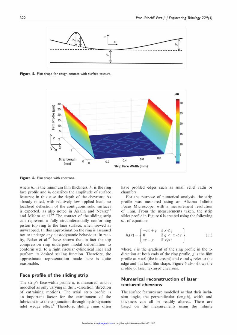
A fully flooded inlet is assumed as the surface ofthe floating plate is provided with a layer of free sur-face film ahead of the sliding contact as shown inFigure 4. In the case of an engine, a starved inletboundary can be encountered, particularly in theupstroke motion of the piston as a free surface filmmay not exist on the hot surface of the bore/liner.
The outlet boundary conditions are those ofSwift37–Stieber38 (Reynolds’ exit boundary condition)with an assumed atmospheric vaporisation pressure ofthe lubricant at the film rupture point. The currentboundary conditions do not take into account theeffect of cavitation beyond the lubricant film ruptureboundary. Cavitation can affect the load-carryingcapacity of the contact. Elrod’s39 cavitation methodcan be used instead of the Swift-Stieber boundaryconditions to take this issue into account. Thisimposes continuity of Couette flow beyond the filmrupture point. Even a better approach is to use amass-conserving multi-phase approach with openexit boundary conditions such as that described byAusas et al.40 who used this approach for the studyof textured surfaces in journal bearings. They showedthat cavitation plays an important role in load-carrying capacity and generated friction.Shahmohamadi et al.41 also used this approach forthe study of lubrication for piston compression ringsbut for untextured surfaces and with the inclusion ofthermal effects. Shahmohamadi et al. showed that inthe case of ring-bore contact, cavitation occurs mostlyat mid-stroke piston positions where the results oftheir computational fluid dynamics analysis divergedfrom that with non-mass-conserving approaches. In adetailed study of various boundary conditions inpiston compression ring conjunction, Arcoumaniset al.42 concluded that the Swift–Stieber boundarycondition agreed better with their experimentallymeasure conditions. Based on these finding, the cur-rent analysis uses the Swift–Stieber exit boundaryconditions. The inlet pressure at the front face ofthe strip is also set to the atmospheric pressure.Only a segment of the whole strip’s width in they-direction (direction of lubricant side-leakage) isincluded in the model to keep the computationaltime to an acceptable level. The applied load for thesection of the contact considered for numerical ana-lysis is shown in (Table 2). Hence, the computationalboundary conditions are
p ¼ pin at x ¼ 0 ð3Þ
p ¼ pc,dp
dx¼ 0 at x ¼ xc ð4Þ
@p
@y
����x,0ð Þ
¼@p
@y
����x,lð Þ
¼ 0 ð5Þ
Figure 2. Measured 3D image of chevrons produced with the
fibre laser.
Table 2. Strip and floating plate data.
Parameter Value Unit
Stroke length 80 mm
Mean sliding speed 24.44 mm/s
Strip roughness (Ra, Rq) 0.511, 0.709 mm
Liner roughness (Ra, Rk) 0.172, 0.105 mm
Strip face-width 1 mm
Load (experimental) 12.4 N
Strip length (experimental) 30 mm
Load (numerical) 0.82 N
Strip length (numerical) 2 mm
Table 3. SPI fibre laser data.
Parameter Value Unit
Beam width 0.030 mm
Feed speed 0.25 mm/s
Pulse width 0.500 ms
Frequency 1687 Hz
Power 12 W
Shielding gas Nitrogen at 0.5 MPa
Nozzle height 0.1 mm
320 Proc IMechE Part J: J Engineering Tribology 229(4)
at Loughborough University on March 27, 2015pij.sagepub.comDownloaded from
The generated pressures at such low loads areinsufficient to induce significant piezo-viscous actionof the lubricant. This is also noted by other investiga-tors.35,36 For completeness of the method, piezo-viscous effects are retained. Furthermore, due toshort testing times, isothermal analysis is undertakenat the laboratory temperature of 20 �C as explained inthe ‘‘Experimental results’’ section.
Therefore, for an isothermal solution only thepiezo-viscous behaviour of the lubricant needs to beconsidered. According to Roelands43 where p is thehydrodynamic pressure
� ¼ �0 exp ð��pÞ ð6Þ
where
�� ¼1
pln �0ð Þ þ 9:67½ � 1þ
p
1:98� 108
� �Z�1
� �ð7Þ
And the pressure viscosity index is
Z ¼�0
5:1� 10�9 ln �0ð Þ þ 9:67½ �ð8Þ
The lubricant viscosity at atmospheric pressure �0,lubricant density at atmospheric pressure �0 and thepressure viscosity coefficient �0 are given in Table 1.The density pressure relationship is44
� ¼ �0 1þc p� patmð Þ
1þ d p� patmð Þ
ð9Þ
in which the constants c and d are 6� 10�10 and1:7� 10�9, respectively.
The film shape is described as (Figure 5)
h x, y, tð Þ ¼ hm tð Þ þ hs x, yð Þ þ ht x, yð Þ ð10Þ
Figure 4. Contact configuration.
Figure 3. Image of a chevron and corresponding chevron depth profile.
Morris et al. 321
at Loughborough University on March 27, 2015pij.sagepub.comDownloaded from
where hm is the minimum film thickness, hs is the ringface profile and ht describes the amplitude of surfacefeatures; in this case the depth of the chevrons. Asalready noted, with relatively low applied load, nolocalised deflection of the contiguous solid surfacesis expected, as also noted in Akalin and Newaz35
and Mishra et al.36 The contact of the sliding stripcan represent a fully circumferentially conformingpiston top ring to the liner surface, when viewed asunwrapped. In this approximation the ring is assumednot to undergo any elastodynamic behaviour. In real-ity, Baker et al.45 have shown that in fact the topcompression ring undergoes modal deformation toconform well to a right circular cylindrical liner andperform its desired sealing function. Therefore, theapproximate representation made here is quitereasonable.
Face profile of the sliding strip
The strip’s face-width profile hs is measured, and ismodelled as only varying in the x -direction (directionof entraining motion). The axial strip profile isan important factor for the entrainment of thelubricant into the conjunction through hydrodynamicinlet wedge effect.6 Therefore, sliding rings often
have profiled edges such as small relief radii orchamfers.
For the purpose of numerical analysis, the stripprofile was measured using an Alicona InfiniteFocus Microscope; with a measurement resolutionof 1 nm. From the measurements taken, the stripslider profile in Figure 6 is created using the followingset of equations
hs xð Þ ¼�sxþ g if x4q0 if q5 x5 rsx� g if x5r
8<:
9=; ð11Þ
where, s is the gradient of the ring profile in the x-direction at both ends of the ring profile, g is the filmprofile at x¼ 0 (the intercept) and r and q refer to theedge and flat land film shape. Figure 6 also shows theprofile of laser textured chevrons.
Numerical reconstruction of lasertextured chevrons
The surface features are modelled so that their inclu-sion angle, the perpendicular (length), width andthickness can all be readily altered. These arebased on the measurements using the infinite
Figure 6. Film shape with chevrons.
Figure 5. Film shape for rough contact with surface texture.
322 Proc IMechE Part J: J Engineering Tribology 229(4)
at Loughborough University on March 27, 2015pij.sagepub.comDownloaded from
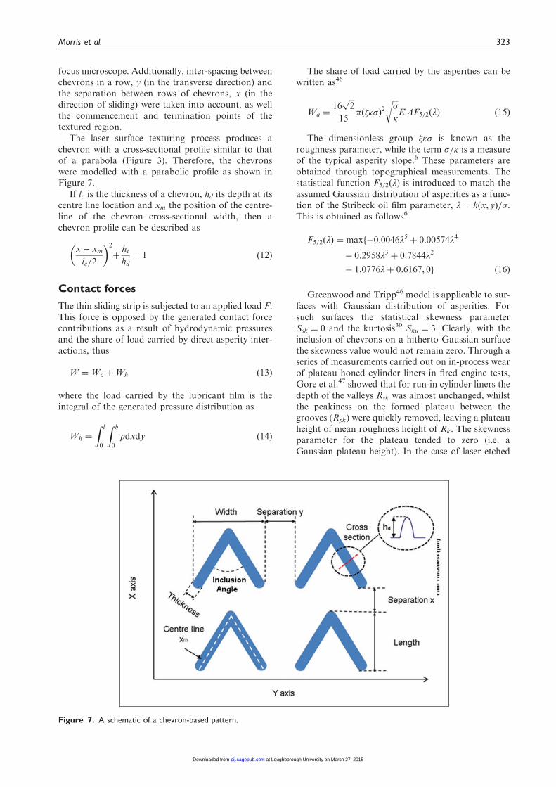
focus microscope. Additionally, inter-spacing betweenchevrons in a row, y (in the transverse direction) andthe separation between rows of chevrons, x (in thedirection of sliding) were taken into account, as wellthe commencement and termination points of thetextured region.
The laser surface texturing process produces achevron with a cross-sectional profile similar to thatof a parabola (Figure 3). Therefore, the chevronswere modelled with a parabolic profile as shown inFigure 7.
If lc is the thickness of a chevron, hd its depth at itscentre line location and xm the position of the centre-line of the chevron cross-sectional width, then achevron profile can be described as
x� xmlc=2
� �2
þhthd¼ 1 ð12Þ
Contact forces
The thin sliding strip is subjected to an applied load F.This force is opposed by the generated contact forcecontributions as a result of hydrodynamic pressuresand the share of load carried by direct asperity inter-actions, thus
W ¼Wa þWh ð13Þ
where the load carried by the lubricant film is theintegral of the generated pressure distribution as
Wh ¼
Z l
0
Z b
0
pdxdy ð14Þ
The share of load carried by the asperities can bewritten as46
Wa ¼16
ffiffiffi2p
15� ��ð Þ
2
ffiffiffi
�
rE0AF5=2 lð Þ ð15Þ
The dimensionless group � is known as theroughness parameter, while the term =� is a measureof the typical asperity slope.6 These parameters areobtained through topographical measurements. Thestatistical function F5=2 lð Þ is introduced to match theassumed Gaussian distribution of asperities as a func-tion of the Stribeck oil film parameter, l ¼ h x, yð Þ=.This is obtained as follows6
F5=2ðlÞ ¼ maxf�0:0046l5 þ 0:00574l4
� 0:2958l3 þ 0:7844l2
� 1:0776lþ 0:6167, 0g ð16Þ
Greenwood and Tripp46 model is applicable to sur-faces with Gaussian distribution of asperities. Forsuch surfaces the statistical skewness parameterSsk ¼ 0 and the kurtosis30 Sku ¼ 3. Clearly, with theinclusion of chevrons on a hitherto Gaussian surfacethe skewness value would not remain zero. Through aseries of measurements carried out on in-process wearof plateau honed cylinder liners in fired engine tests,Gore et al.47 showed that for run-in cylinder liners thedepth of the valleys Rvk was almost unchanged, whilstthe peakiness on the formed plateau between thegrooves (Rpk) were quickly removed, leaving a plateauheight of mean roughness height of Rk. The skewnessparameter for the plateau tended to zero (i.e. aGaussian plateau height). In the case of laser etched
Figure 7. A schematic of a chevron-based pattern.
Morris et al. 323
at Loughborough University on March 27, 2015pij.sagepub.comDownloaded from
plates in the current work, the chevron depth acts in asimilar manner to that of Gore et al.47 engine tests ofcylinder liners. No boundary interactions are expectedover the chevron areas, but only on the plateausformed between them, the roughness distributionover which may be considered to follow a Gaussiandistribution. In the absence of an alternative, simpleanalytical method to that of Greenwood and Tripp46
and the evidence of similar representative surface byGore et al.47 such an approach is assumed here. Later,the close agreement between the experimental meas-urements and the numerical predictions give furthercredence to the assumption made.
Method of solution
Reynolds equation is discretised using finite differencemethod, including density and viscosity as functionsof generated pressure for the sake of completeness ofthe method, although the generated hydrodynamicpressures are insufficient in this instance to signifi-cantly alter the lubricant rheological state. Thus
@ i
@xk¼
@ i
@p
� �@p
@xk
� �;
i ¼ 1, 2k ¼ 1, 2
�ð17Þ
where 1 ¼ �, 2 ¼ �, x1 ¼ x, x2 ¼ y. After combin-ing the above derivatives in the Reynolds equationand using central differences for the second-order pres-sure differentials, pressure at each computationalnode is obtained through the recursive relationship
pi,j ¼Ai,j þMi,jpx þNi,jpy � 6Ri,j
2 1�x2þ 1
�y2
� � ð18Þ
where px ¼@p@x ¼
piþ1,j�pi�1,j2�x and py ¼
@p@y ¼
pi,jþ1�pi,j�12�y . The
other terms are provided in Appendix 4. Pressure atany computational node (i,j) is obtained through apoint successive over-relaxation (PSOR) iterativemethod. The pressure for each node is updatedusing under or over-relaxation, subscripts n and odenote new and old iteration steps.
pni,j ¼ 1� �ð Þ poi,j þ �pni,j; 05 �5 2ð Þ ð19Þ
The relaxation factor � is problem-dependent andan optimum value which provides rapid convergenceis usually obtained after some numerical tests.
Convergence criteria
A two stage convergence process is sought. The firstcriterion is based on the convergence of generatedhydrodynamic pressures and the lubricant rheologicalstate as
Errpressure ¼
PIi¼1
PJj¼1 pni,j � p0i,j
��� ���PIi¼1
PJj¼1 p
ni,j
41� 10�5 ð20Þ
Also
Errrheological properties
¼
PIi¼1
PJj¼1
ni,j �
0i,j
��� ���PIi¼1
PJj¼1
ni,j
41� 10�3ð21Þ
The second criterion is load balance for instantan-eous quasi-static equilibrium, where the contact loadmust equate the applied load to the sliding strip
Errload ¼Fr �Wj j
Fr41� 10�3 ð22Þ
If this criterion is not met, then the minimum filmthickness is adjusted as
hnm ¼ 1þ � ð Þhom ð23Þ
where is an adjusting parameter, ¼W� Fr=max W,Frf g. A damping coefficient of� ¼ 0:05 is used to effect faster load convergence,whilst avoiding numerical instability.
Finally, a typical analysis cycle requires an initialguess as the nominal minimum clearance.
Friction and power loss
In the mixed regime of lubrication, anticipated in thecase of contact of the sliding strip against the flatfloating plate, two sources contribute to friction; vis-cous shear of the lubricant entrained into the conjunc-tion and any direct interaction of counterfaceasperities.
At any time the viscous shear of a lubricant film hcan be obtained as:
�*¼ �
h
2r*
p�� V*�
h
�������� ð24Þ
The gradient is defined as r*� @=@xiþ @=@yj� �
.The Eyring shear stress48 for the base oil used inthis study is 2MPa. The maximum shear stress calcu-lated using equation (24) under the testing conditionsreported in this paper is only 7 kPa. Thus, the base oilis subjected to Newtonian shear for this lightly loadedlow sliding speed conditions
fv ¼ �Av ¼ �A ð25Þ
where A is the apparent contact area. Since the area ofasperity contact is usually very small, then:Av ¼ A� Aa ¼ A. It should be noted that the asperitycontact area is less than 1% of the apparent contactarea. The asperity contact area for their assumedGaussian distribution is46
Aa ¼ �2 �kð Þ2AF2 lð Þ ð26Þ
324 Proc IMechE Part J: J Engineering Tribology 229(4)
at Loughborough University on March 27, 2015pij.sagepub.comDownloaded from
where6,46
F2 lð Þ ¼max �0:002l5 þ 0:028l4 � 0:173l3�þ0:526l2 � 0:804lþ 0:500, 0
ð27Þ
Under the mixed regime of lubrication, boundaryfriction must also be taken into account.
It is assumed that boundary friction comprises twocontributions; one is as the result of direct contact ofasperities in the form of their adhesive junctions, whichmust be broken in order to sustain the sliding motion.If the pressure-induced shear strength of asperities is ,then the direct asperity friction is obtained as: Wa.Secondly, a thin film of lubricant is also entrappedbetween the interspatial cavities of asperities. Briscoeand Evans49 assume that such diminutive films act innon-Newtonian shear, at the limiting Eyring shearstress, �0, thus their frictional contribution is �0Aa.Hence, boundary friction is obtained as
fb ¼ �0Aa þ Wa ð28Þ
For a ferrous oxide layer50 ¼ 0:17 and for thebase oil used: �0 ¼ 2 MPa. An important point tonote is that lubricants used in most applications,
including in internal combustion engines include addi-tives within the base oil, some of which are boundaryactive and form thin, low shear strength filmsadsorbed to the boundary solids. These tend toreduce the boundary shear strength at the asperitylevel. Description of surface adsorb films does notconform to the continuum mechanics approach ofReynolds equation.4,5 A statistical mechanicsapproach, including surface adsorption and elasto-plastic deformation of wetted asperities is providedelsewhere.51
Thus, the total friction is obtained as
ft ¼ fv þ fb ð29Þ
The total power loss from the conjunction friction is
Pf ¼ ft �Uj j ð30Þ
Results of numerical analysis
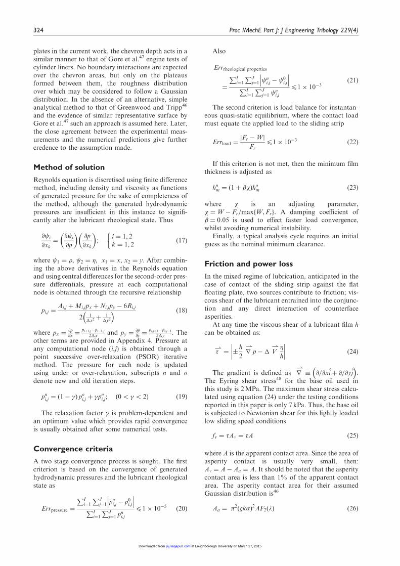
Figure 8(a) and (c) shows the pressure distribution forthe contact of the thin strip sliding on an un-textured
Figure 8. Pressure distribution and film shape for smooth (untextured) and textured surfaces.
Morris et al. 325
at Loughborough University on March 27, 2015pij.sagepub.comDownloaded from
surface and that for a textured surface with chevronfeatures, respectively. Pressure perturbations are evi-dent in the case of the latter, with magnitudes well inexcess of the average pressure of 0.15MPa. These per-turbations are as the result of micro-hydrodynamics,induced by the wedge effect at the inlet to each chev-ron feature as shown in Figure 8(d), which is notevident in the case of the nominally smooth plate(Figure 8(b)). The initial pressure spike at the contactinlet in both cases is caused by the pressure-inducedPoiseuille shear flow with the commencement ofentraining motion. There is a less pronouncedPoiseuille shear at the contact entrance in the caseof the textured surface on the account of a shallowerpressure gradient due to a larger volume of lubricant.Note that in the case of the untextured surface, theviscous pressure falls gradually back to the atmos-pheric value at the diverging section of the strip asthe profile of the central portion of the strip is flatand hence there would be no contribution due toany changes in the conjunctional profile as is thecase for a parabolic profile.6
The results in Figure 8 confirm the enhanced load-carrying capacity of the contact with the introducedtextured features in almost the same manner as thatnoted for rough articular cartilage.6 The pressure dis-tribution in Figure 8(d) is as the result of combinedmicro-hydrodynamics of individual chevrons as wellas the effect of their collective effect. This collectiveeffect of texture forms; chevrons or dimples, is as theresult of interactions of their individual micro-hydro-dynamics as noted by Brizmer et al.52 Therefore, thedistribution and spatial disposition of the textures aswell as the geometry of individual features play animportant role in lubricant film formation, load-car-rying capacity and generated friction, a parametricstudy of which is an important undertaking.
Numerical parametric studies
A parametric study of the chevron textures is carriedout to determine the most influential geometrical anddistribution parameters, which would enhance thehydrodynamic load-carrying capacity, thus reducingthe chance of asperity interactions. A test matrix forthe input data is shown in Table 4, listing the range ofgeometric parameters considered.
The first parameter considered is the chevrondepth. Feature depth has been reported as a key par-ameter by Ryk et al.53 The thickness of chevrons isalso considered, so that the reported ‘optimal’ height-to-width ratio reported by Ronen et al.11 can be inves-tigated. It has also been reported by Etsion et al.54
that the texture density has a significant effect onthe tribological performance of the contact. The chev-ron inclusion angle is also considered to be of interestfor the investigation. In effect, chevrons represent aform of cross-hatched surface which is often a processof choice for cylinder liner technology. Spencer et al.55
have shown the influence of cross-hatch angle to thehorizontal (direction of side-leakage flow) to be opti-mum at 28�–30�.
The distribution or the pattern of the chevrons wasalso deemed worthy of investigation. A study byWakuda et al.25 indicated that the surface texture dis-tribution can affect the tribological properties of thecontact.
The improvement in friction for a range of thechevrons with different depths is shown inFigure 9(d). The chevron depth has a clear effect onthe percentage reduction in friction. A depth of 3 mmindicated the maximum predicted friction reduction.Table 4 shows that these analyses were carried outwith a chevron thickness of 30 mm, representing aheight-to-width ratio of 0.1.
The results for the variation of chevron thicknessare also shown in Figure 9(a). The chevron depth waskept at 3 mm for all other analyses. Therefore, thedepth-to-thickness ratio only varies in the range:0.03–0.075.
The effect of chevron inclusion angle is also pre-sented in Figure 9(c). An angle of 80� was found togive the greatest reduction in friction. If chevron tex-ture is to be regarded as being analogous to the usualcross-hatch honed cylinder liner surfaces, then theequivalent cross-hatch angle (measured with respectto the direction of side leakage, y) would be 50� inthis case. The analysis by Spencer et al.55 for the caseof cross-hatched cylinders indicated an overall betterperformance for a cross-hatch angle of around 30�.However, this is dependent on the sliding speed andthe depth of the grooves. Furthermore, the currentanalysis assumes a nominally smooth land/plateaubetween the chevron features, which is not the casein Spencer et al.55 A more detailed analysis, includingthe effect of surface roughness would be required.
As well as the individual chevron properties such asthe chevron depth, thickness and inclusion angle,there are also other group-type parameters of interestsuch as the texture density and pattern. Group par-ameters are defined as properties which are dependenton a combination of two or more chevrons. The nextpart of the parametric study is concerned with thesegroup parameters and their effects upon generatedfriction. Increasing the texture density leads to agreater improvement in friction. In applications such
Table 4. Test matrix for parametric study.
Parameter
test type
Depth
(mm)
Inclusion
angle (�)
Thickness
(mm) Pattern
Density
(%)
Depth test 1–9 120 30 1 3.4
Angle test 3 30–120 30 1 2–2.4
Thickness test 3 120 30–100 1 3.4–9.0
Pattern test 3 120 30 1–8 5.1
Density test 3 120 30 1 10–35
326 Proc IMechE Part J: J Engineering Tribology 229(4)
at Loughborough University on March 27, 2015pij.sagepub.comDownloaded from
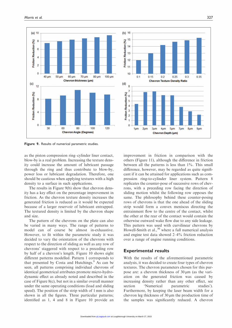
as the piston compression ring–cylinder liner contact,blow-by is a real problem. Increasing the texture dens-ity could increase the amount of lubricant passagethrough the ring and thus contribute to blow-by,power loss or lubricant degradation. Therefore, oneshould be cautious when applying textures with a highdensity to a surface in such applications.
The results in Figure 9(b) show that chevron dens-ity has a key effect on the percentage improvement infriction. As the chevron texture density increases thegenerated friction is reduced as it would be expectedbecause of a larger reservoir of lubricant entrapped.The textured density is limited by the chevron shapeand size.
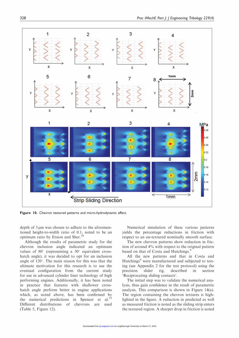
The pattern of the chevrons on the plate can alsobe varied in many ways. The range of patterns tomodel can of course be almost in-exhaustive.However, to fit within the parametric study it wasdecided to vary the orientation of the chevrons withrespect to the direction of sliding as well as any row ofchevrons’ staggered with respect to a preceding rowby half of a chevron’s length. Figure 10 shows eightdifferent patterns modelled. Pattern 1 corresponds tothat presented by Costa and Hutchings.9 As can beseen, all patterns comprising individual chevrons ofidentical geometrical attributes promote micro-hydro-dynamic effect as already noted and described in thecase of Figure 8(c), but not in a similar overall mannerunder the same operating conditions (load and slidingspeed). The position of the strip width of 1mm is alsoshown in all the figures. Three particular patterns;identified as 1, 4 and 8 in Figure 10 provide an
improvement in friction in comparison with theothers (Figure 11), although the difference in frictionbetween all the patterns is less than 1%. This smalldifference, however, may be regarded as quite signifi-cant if it can be attained for applications such as com-pression ring-to-cylinder liner system. Pattern 8replicates the counter-pose of successive rows of chev-rons, with a preceding row facing the direction ofsliding motion whilst the following row opposes thesame. The philosophy behind these counter-posingrows of chevrons is that the one ahead of the slidingstrip would form a convex meniscus directing theentrainment flow to the centre of the contact, whilstthe other at the rear of the contact would contain theotherwise outward wake flow due to any side leakage.This pattern was used with curvilinear chevrons byHowell-Smith et al.,30 where a full numerical analysisand engine test data showed 2–4% friction reductionover a range of engine running conditions.
Experimental results
With the results of the aforementioned parametricanalysis, it was decided to create four types of chevrontextures. The chevron parameters chosen for this pur-pose are: a chevron thickness of 30 mm (as the vari-ation on the generated friction was caused byincreasing density rather than any other effect, seesection ‘Numerical parametric studies’).Furthermore, by keeping the laser beam width for achevron leg thickness of 30 mm the production time ofthe samples was significantly reduced. A chevron
Figure 9. Results of numerical parametric studies.
Morris et al. 327
at Loughborough University on March 27, 2015pij.sagepub.comDownloaded from
depth of 3 mm was chosen to adhere to the aforemen-tioned height-to-width ratio of 0.1, noted to be anoptimum ratio by Etsion and Sher.28
Although the results of parametric study for thechevron inclusion angle indicated an optimumvalues of 80� (representing a 50� equivalent cross-hatch angle), it was decided to opt for an inclusionangle of 120�. The main reason for this was that theultimate motivation for this research is to use theeventual configuration from the current studyfor use in advanced cylinder liner technology of highperforming engines. Additionally, it has been notedin practice that features with shallower cross-hatch angle perform better in engine applicationswhich, as noted above, has been confirmed bythe numerical predictions in Spencer et al.55
Different distributions of chevrons are used(Table 5, Figure 12).
Numerical simulation of these various patternsyields the percentage reductions in friction withrespect to an un-textured nominally smooth surface.
The new chevron patterns show reduction in fric-tion of around 4% with respect to the original patternbased on that of Costa and Hutchings.9
All the new patterns and that in Costa andHutchings9 were manufactured and subjected to test-ing (see Appendix 2 for the test protocol) using theprecision slider rig, described in section‘Reciprocating sliding contacts’.
The initial step was to validate the numerical ana-lysis, thus gain confidence in the result of parametricanalysis. This comparison is shown in Figure 14(a).The region containing the chevron textures is high-lighted in the figure. A reduction in predicted as wellas measured friction is noted as the sliding strip entersthe textured region. A sharper drop in friction is noted
Figure 10. Chevron textured patterns and micro-hydrodynamic effect.
328 Proc IMechE Part J: J Engineering Tribology 229(4)
at Loughborough University on March 27, 2015pij.sagepub.comDownloaded from
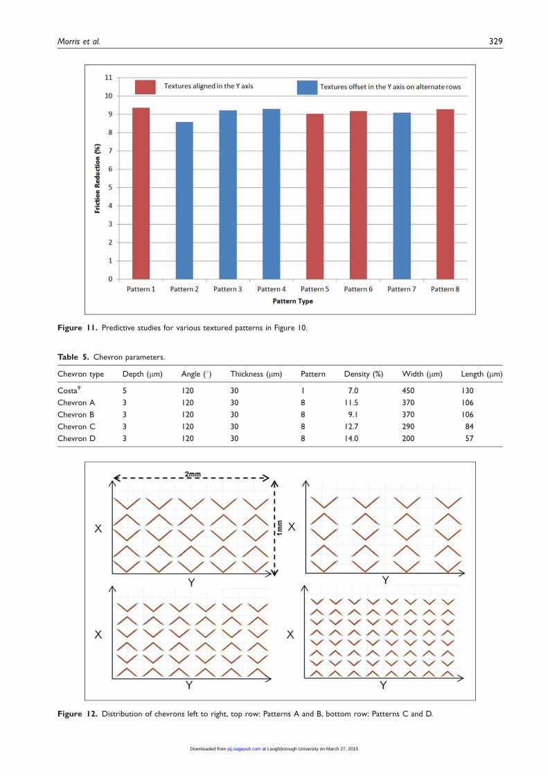
Figure 11. Predictive studies for various textured patterns in Figure 10.
Figure 12. Distribution of chevrons left to right, top row: Patterns A and B, bottom row: Patterns C and D.
Table 5. Chevron parameters.
Chevron type Depth (mm) Angle (�) Thickness (mm) Pattern Density (%) Width (mm) Length (mm)
Costa9 5 120 30 1 7.0 450 130
Chevron A 3 120 30 8 11.5 370 106
Chevron B 3 120 30 8 9.1 370 106
Chevron C 3 120 30 8 12.7 290 84
Chevron D 3 120 30 8 14.0 200 57
Morris et al. 329
at Loughborough University on March 27, 2015pij.sagepub.comDownloaded from
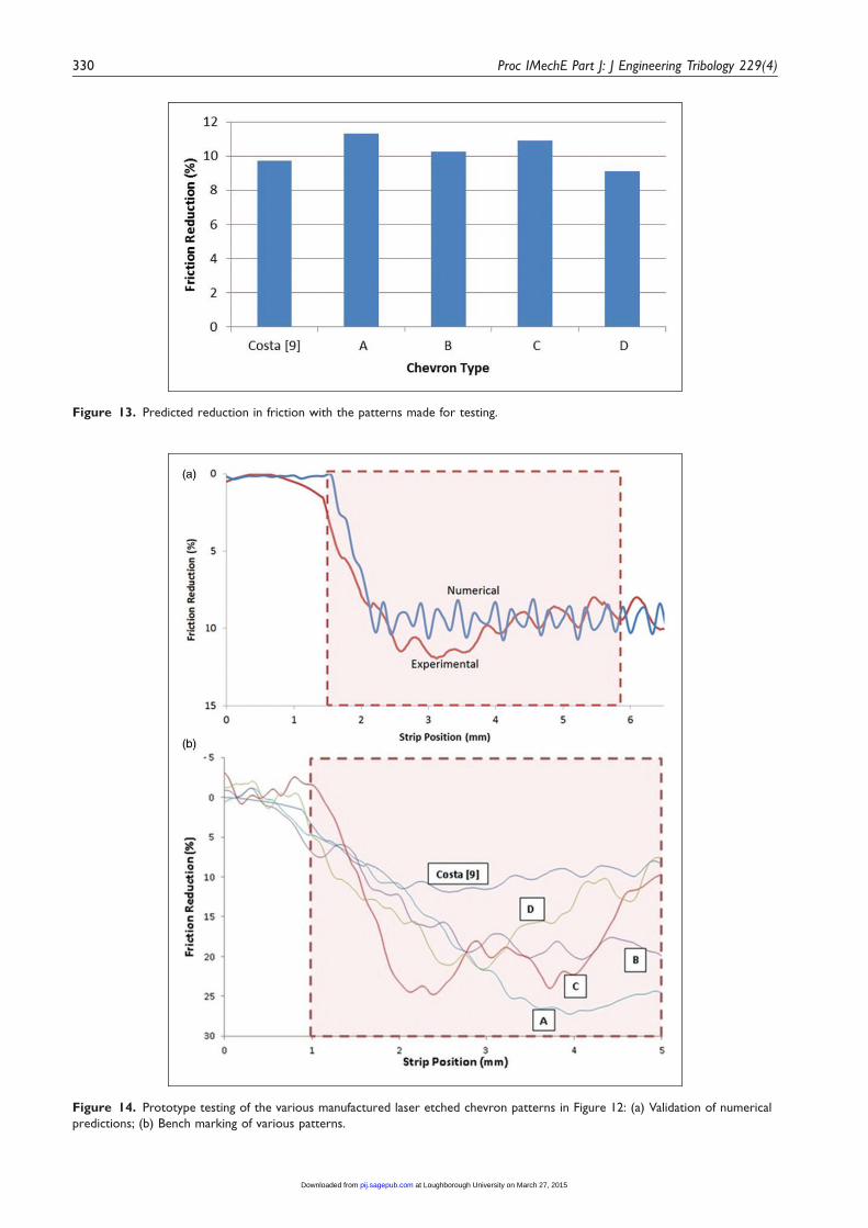
Figure 14. Prototype testing of the various manufactured laser etched chevron patterns in Figure 12: (a) Validation of numerical
predictions; (b) Bench marking of various patterns.
Figure 13. Predicted reduction in friction with the patterns made for testing.
330 Proc IMechE Part J: J Engineering Tribology 229(4)
at Loughborough University on March 27, 2015pij.sagepub.comDownloaded from
in the case of measured results at the onset of texturedregion. This indicates that in practice a lesserPoiseuille shear exists at contact inlet. This meansthat there must be a greater volume of lubricant inthe inlet region of the contact than the just floodedcondition assumed in the numerical analysis.Nevertheless, an overall good agreement is notedbetween the numerical prediction and that measured.
The next step was to measure friction for the vari-ous patterns in Table 5. The results are shown interms of friction reduction with respect to an un-textured surface in Figure 14(b). All textured patternsshow significant reduction in friction relative to anuntreated surface. There is a difference in an initialdrop in friction between different textured patternsat the onset of entry into the textured region. Asalready noted, this is mainly due to Poiseuille shearon the account of encountered inlet pressure gradientin the presence of identical measured sliding speed(thus almost the same nominal Couette shear) andload (see also ‘Concluding remarks’).
Concluding remarks
It is shown through numerical analysis and precisionmeasurement that for low sliding motion textured sur-faces of suitable geometry, pattern and distributioncan induce micro-hydrodynamic pressure perturb-ations, thus enhance lubricant film thickness. Thisleads to a reduction in generated conjunctional fric-tion. It is also shown that various texture geometricalattributes and distribution can be used to ‘optimise’the prevailing regime of lubrication, thus reducingfriction. It is clear that a choice of these pertinentparameters depends on the application in mind andthe operating conditions such as sliding speed andconjunctional load. Therefore, ‘optimisation’ wouldbe application dependent.
In particular, the study shows that lubricant reten-tion in the created micro-reservoirs as well as pressureperturbations at the inlet conjunction can result indiffering extent of effective micro-wedge effect,which is also crucially dependent on the supply ofthe lubricant at the contact inlet. In practice, suchas in light-to-medium loaded reversal region ofpiston–cylinder liner contact in transition from com-pression to power stroke, supply of inlet meniscus tothe contact cannot be controlled on the account ofhigh surface temperatures in the combustion cham-ber. There is also modal deformation of contiguoussurfaces, such as the piston compression ring and thecylinder liner45 which deviate from their ideal circum-ferential conformity. Therefore, unlike mechanicalseals and rings where entrance wedge geometry canbe controlled to a certain extent as well as a fullyflooded inlet, optimisation to the degree of minutiaein cylinder technology would be cost inefficient solong as any significant reduction can be achieved inline with the cost of manufacture. The study shows
that texturing has the potential to meet the practicalrequirements, but as shown by Howell-Smith et al.30
not to the extent indicated under controlled and rela-tively ideal laboratory conditions.
Acknowledgements
The authors thank the EPSRC and all the partner organ-isations in the Encyclopaedic project, in particular in thisinstance to Capricorn Automotive.
Conflict of interest
None declared.
Funding
The authors wish to express their gratitude to the
Engineering and Physical Sciences Research Council(EPSRC) for the sponsorship of this research under theEncyclopaedic Program Grant (www.Encyclopaedic.org).
References
1. Amontons G. De la resistance causee dans les machines.Mem Acad Roy 1699; 275–282.
2. Euler L. Sur le frottement des corps solides. Memoiresde l’Academie des sciences de Berlin 1750; 4: 122–132.
3. Coulomb CA. Theorie des machines simples. MemMath Phys Acad Sci 1785; 10: 161–331.
4. Petrov NP. Friction in machines and the effect of the
lubricant. Inzhenerno Zhurnal St. Petersburg 1883; 1:71–140.
5. Hardy WB and Doubleday I. Boundary lubrication.
The paraffin series. Proc Roy Soc Lond Ser A 1922;100(707): 550–574.
6. Gohar R and Rahnejat H. Fundamentals of tribology.
London: Imperial College Press, 2008.7. Chong WWF, Teodorescu M and Rahnejat H. Physio-
chemical hydrodynamic mechanism underlying the for-mation of thin adsorbed boundary films. Faraday
Discuss 2012; 156: 123–136.8. Teodorescu M and Rahnejat H. Dry and wet nano-scale
impact dynamics of rough surfaces with or without a
self-assembled monolayer. Proc IMechE, Part N:J Nanoengineering and Nanosystems 2008; 221: 49–58.
9. Costa HL and Hutchings IM. Hydrodynamic lubrica-
tion of textured steel surfaces under reciprocating slid-ing conditions. Tribol Int 2007; 40(8): 1227–1238.
10. Etsion I and Burstein L. Improving tribological per-
formance of piston rings by partial surface texturing.Tribol Trans 1996; 39(3): 677–683.
11. Ronen A, Etsion I and Kligerman Y. Friction-reducingsurface-texturing in reciprocating automotive compo-
nents. Tribol Trans 2001; 44(3): 359–366.12. Rahmani R, Shirvani A and Shirvani H. Optimization
of partially textured parallel thrust bearings with
square-shaped micro-dimples. Tribol Trans 2007;50(3): 401–406.
13. Rahmani R. An Investigation into analysis and optimisa-
tion of textured slider bearings with application in pistonring/cylinder liner contact. PhD Thesis, Anglia RuskinUniversity, 2008.
14. Balakrishnan S, Howell-Smith S and Rahnejat H.
Investigation of reciprocating conformal contact ofpiston skirt-to-surface modified cylinder liner in high
Morris et al. 331
at Loughborough University on March 27, 2015pij.sagepub.comDownloaded from
performance engines. Proc IMechE, Part C:J Mechanical Engineering Science 2005; 219(11):1235–1247.
15. Etsion I. Surface texturing for in-cylinder frictionreduction. In: H Rahnejat (ed.) Tribology and dynamicsof engine and powertrain. Cambridge, UK: Woodhead
Publishing, 2010, pp.458–467.16. Rahnejat H, Balakrishnan S, King PD, et al. In-cylinder
friction reduction using a surface finish optimization
technique. Proc IMechE, Part D: J AutomobileEngineering 2006; 220(9): 1309–1318.
17. Yu XQ, He S and Cai RL. Frictional characteristics ofmechanical seals with a laser-textured seal face. J Mater
Process Technol 2002; 129(1): 463–466.18. Pettersson U and Jacobson S. Textured surfaces for
improved lubrication at high pressure and low sliding
speed of roller/piston in hydraulic motors. Tribol Int2007; 40(2): 355–359.
19. Wang X, Kato K, Adachi K, et al. The effect of laser
texturing of SiC surface on the critical load for the tran-sition of water lubrication mode from hydrodynamic tomixed. Tribol Int 2001; 34(10): 703–711.
20. Wang X, Kato K, Adachi K, et al. Loads carryingcapacity map for the surface texture design of SiCthrust bearing sliding in water. Tribol Int 2003; 36(3):189–197.
21. Erdemir A. Review of engineered tribological interfacesfor improved boundary lubrication. Tribol Int 2005;38(3): 249–256.
22. Schneider YG. Formation of surfaces with uniformmicropatterns on precision machine and instrumentparts. Precision Eng 1984; 6: 219–225.
23. Krupka I and Hartl M. The effect of surface texturingon thin EHD lubrication films. Tribol Int 2007; 40(7):1100–1110.
24. Morris NJ, Rahnejat H and Rahmani R. Tribology of
partial pad journal bearings with textured surfaces. In:3 rd European conference on tribology (ECOTRIB),Vienna, Austria, 7–9 June 2011, Osterreichische
Tribologische Gesellschaft (The Austrian TribologySociety).
25. Wakuda M, Yamauchi Y, Kanzaki S, et al. Effect of
surface texturing on friction reduction between ceramicand steel materials under lubricated sliding contact.Wear 2003; 254(3): 356–363.
26. Pettersson U and Jacobson S. Influence of surface tex-ture on boundary lubricated sliding contacts. Tribol Int2003; 36(11): 857–864.
27. Etsion I. State of the art in laser surface texturing. Trans
ASME Ser F: J Tribol 2005; 127(1): 248–253.28. Etsion I and Sher E. Improving fuel efficiency with laser
surface textured piston rings. Tribol Int 2009; 42(4):
542–547.29. Ryk G and Etsion I. Testing piston rings in partial laser
surface texturing for friction reduction. Wear 2006;
261(7): 792–796.30. Howell-Smith S, Rahnejat H, King PD, et al. Reducing
in-cylinder parasitic losses through surface modificationand coating. Proc. IMechE, Part D: J Automobile
Engineering 2014; 228: 391–402.31. Balakrishnan S and Rahnejat H. Isothermal transient
analysis of piston skirt-to-cylinder wall contacts under
combined axial, lateral and tilting motion. J Phys D:Appl Phys 2005; 38(5): 787–799.
32. Furuhama S and Sasaki S. New device for the measure-ment of piston frictional forces in small engines. SAEpaper 831284, 1983.
33. Gore M, Theaker M, Howell-Smith S, et al. Directmeasurement of piston friction of internal-combustionengines using the floating-liner principle. Proc IMechE,
Part D: J Automobile Engineering 2014; 228(3):344–354.
34. Chong WWF and De la Cruz M. Elastoplastic
contact of rough surfaces: A line contact model forboundary regime of lubrication. Meccanica. Epubahead of print January 2014. DOI: 10.1007/s11012-013-9861-1.
35. Akalin O and Newaz GM. Piston ring-cylinder borefriction modeling in mixed lubrication regime, part I:Analytical results. Trans ASME J Tribol 2001; 123:
211–218.36. Mishra PC, Balakrishnan S and Rahnejat H. Tribology
of compression ring-to-cylinder contact at reversal.
Proc IMechE, Part J: J Engineering Tribology 2008;222: 815–826.
37. Swift HW. The stability of lubricating films in journal
bearings. J Inst Civil Eng 1932; 233(1): 267–288.38. Stieber W. Dus Schwimmlager. Verein Deutscher.
Berlin: Ingenieurre, 1933.39. Elrod HG. A cavitation algorithm. J Lubric Technol
1981; 103(3): 350–354.40. Ausas R, Ragot P, Leiva J, et al. The impact of the
cavitation model in the Analysis of micro-textured
lubricated journal bearings. Trans ASME J Tribol2009; 129: 868–875.
41. Shahmohamadi H, Rahmani R, Rahnejat H, et al.
Thermo-mixed hydrodynamics of piston compressionring conjunction. Tribol Lett 2013; 51(3): 323–340.
42. Arcoumanis C, Duszynski M, Flora H, et al.Development of a piston-ring lubrication test-rig and
investigation of boundary conditions for modellinglubricant film properties. SAE paper 952468, 1996.
43. Roelands CJA. Correlation aspects of the viscosity-
temperature-pressure relationships of lubricating oils.Druk VRB Kleine der A3-4 Groningen, 1966.
44. Dowson D and Higginson GR. A numerical solution to
the elastohydrodynamic problem. J Mech Eng Sci 1959;10(Part 1): 6–15.
45. Baker CE, Theodossiades S, Rahnejat H, et al.
Influence of in-plane dynamics of thin compressionrings on friction in internal combustion engines. TransASME J Eng Gas Turb Power 2012; 134(9): 092801.
46. Greenwood JA and Tripp JH. The contact of two nom-
inally flat rough surfaces. Proc IMechE: J MechanicalEngineering Science 1970–1971; 185(1): 625–633.
47. Gore M, Perera M, Styles G, et al. Wear characteristics
of advanced honed and cross-hatched coated cylinderliners. In: Proceedings of the 66th annual meeting andexhibition of the STLE, 2011, p. 73.
48. Eyring H. Viscosity, plasticity and diffusion as exam-ples of reaction rates. J Chem Phys 1936; 4: 283–291.
49. Briscoe BJ and Evans DCB. The shear properties ofLangmuir-Blodgett layers. Proc Roy Soc Ser A Math
Phys Sci 1982; 380: 389–407.50. Teodorescu M, Balakrishnan S and Rahnejat H.
Integrated tribological analysis within a multi-physics
approach to system dynamics. Tribol Interf Eng Ser2005; 48: 725–737.
332 Proc IMechE Part J: J Engineering Tribology 229(4)
at Loughborough University on March 27, 2015pij.sagepub.comDownloaded from
51. Chong WWF, Teodorescu M and Rahnejat H.Nanoscale elastoplastic adhesion of wet asperities.Proc IMechE, Part J: J Engineering Tribology 2013;
227: 996–1010.52. Brizmer V, Kligerman Y and Etsion I. A laser surface
textured parallel thrust bearing. Tribol Trans 2003;
46(3): 397–403.53. Ryk G, Kligerman Y and Etsion I. Experimental inves-
tigation of laser surface texturing for reciprocating
automotive components. Tribol Trans 2002; 45(4):444–449.
54. Etsion I, Halperin G, Brizmer V, et al. Experimentalinvestigation of laser surface textured parallel thrust
bearings. Tribol Lett 2004; 17(2): 295–300.55. Spencer A, Almqvist A and Larsson R. A numerical
model to investigate the effect of honing angle on the
hydrodynamic lubrication between a combustion enginepiston ring and cylinder liner. Proc IMechE, Part J:J Engineering Tribology 2011; 225(7): 683–689.
56. Rahnejat H. Multi-body dynamics: Vehicles, machinesand mechanisms. Bury St Edmunds, UK: ProfessionalEngineering Publishers, 1998.
Appendix 1
Notation
a accelerationA apparent contact areaAa asperity contact areaAv viscous contact areab sliding strip face-widthE0 reduced (effective) elastic modulus of
the contacting pairfb boundary frictionft total frictionfv viscous frictionF forceF2,F5
2statistical functions
Fr load on sliding stripg constanthm minimum film thicknesshd maximum texture depthht texture profilehs profile of sliding striph film thicknessl length of sliding striplc thickness of chevron leg‘ connecting rod lengthm massp hydrodynamic pressurepc cavitation pressurepatm atmospheric pressurepin inlet pressurepout outlet pressurePf total frictional power lossPfb frictional power loss due to boundary
interactionsPfv frictional power loss due to lubricant
viscous shear
q, r constantsrc crank-pin radiusRa average height of roughnessRk average core roughness on the plateauRpk average peak heights on the unworn
plateauRq root mean squared roughnessRvk average valley depths constantSsk skewness of the roughness frequency
distributionSku kurtosist timeU speed of entraining motionV*
velocity vectorW contact loadWa load share of the asperitiesWh load share of the lubricant filmx direction along the strip face-width
(direction of entraining motion)xc film rupture boundaryxm centre line of the chevrony direction along the strip length (direc-
tion of side leakage)Z viscosity–pressure index
�� viscosity–pressure coefficient�0 atmospheric viscosity–pressure
coefficient� numerical damping factor adjusting parameter�U sliding velocity�0 lubricant dynamic viscosity at atmo-
spheric pressure and ambienttemperature
� lubricant dynamic viscosity� relaxation factor� average radius of curvature of asperity
summitsl Stribeck’s oil film parameter! crankshaft speed’ crank angle� lubricant density�0 lubricant density at atmospheric
pressure root mean square roughness of the
counterfaces� shear stress�0 Eyring shear stress coefficient of boundary shear strength
of a surface� asperity density per unit contact area
Appendix 2
Test protocol
Repeatability of testing conditions is crucial in abenchmarking exercise, comprising different textured
Morris et al. 333
at Loughborough University on March 27, 2015pij.sagepub.comDownloaded from
configurations. For this purpose a test protocol wasdevised. The load cells were calibrated before each setof tests. The contacting surface topography of thestrip and the floating plate specimen were measuredusing an Alicona Infinite Focus microscope with anominal measurement resolution of the order ofwavelength of light propagation. The strip and thefloating plate specimen were then mounted onto theslider test rig, care was taken to ensure proper align-ment was attained for all tests. A controlled volume ofbase oil (0.15mL) was applied to the flat liner plateusing a hypodermic syringe. No boundary active spe-cies are present in the base oil as these would adsorbto the conjunctional surfaces and cannot be easily andreliably removed, thus affecting repeatable testingconditions. An initial running-in period was allowedprior to each test. Each test consisted of a single passover the textured area. A settling time of 5minbetween successive runs were allowed in order toallow any rise in temperature to be dissipated. Foreach textured case 15 runs were carried out. Aftereach test the surfaces of the strip and the floatingplate were again measured.
Appendix 3
Load intensity
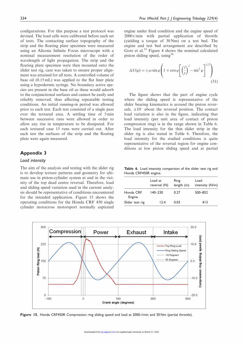
The aim of the analysis and testing with the slider rigis to develop texture patterns and geometry for ulti-mate use in piston-cylinder system at and in the vici-nity of the top dead centre reversal. Therefore, loadand sliding speed variation used in the current analy-sis should be representative of conditions encounteredfor the intended application. Figure 15 shows theoperating conditions for the Honda CRF 450 singlecylinder motocross motorsport normally aspirated
engine under fired condition and the engine speed of2000 r/min with partial application of throttle(yielding a torque of 30Nm) on a test bed. Theengine and test bed arrangement are described byGore et al.33 Figure 4 shows the nominal calculatedpiston sliding speed, using56
�Uð’Þ ¼ rc! sin ’ 1þ cos ’l
r
� �2
� sin2 ’
" #1=20@
1Að31Þ
The figure shows that the part of engine cyclewhere the sliding speed is representative of theslider bearing kinematics is around the piston rever-sals, �10� about the reversal position. The contactload variation is also in the figure, indicating thatload intensity (per unit area of contact of pistoncompression ring) is in the range shown in Table 6.The load intensity for the thin slider strip in theslider rig is also stated in Table 6. Therefore, theload intensity for the studied conditions is quiterepresentative of the reversal region for engine con-ditions at low piston sliding speed and at partial
Figure 15. Honda CRF450R Compression ring sliding speed and load at 2000 r/min and 30 Nm (partial throttle).
Table 6. Load intensity comparison of the slider test rig and
Honda CRF450R engine.
Load at
reversal (N)
Ring
length (m)
Load
intensity (N/m)
Honda CRF
Engine
140–230 0.27 500–852
Slider test rig 12.4 0.03 413
334 Proc IMechE Part J: J Engineering Tribology 229(4)
at Loughborough University on March 27, 2015pij.sagepub.comDownloaded from

throttle, where worst tribological conditions areoften noted.
Appendix 4
Discretised terms
The following discretised terms are used inequation (18)
Ai,j ¼pi�1,j þ piþ1,j
�x2þpi,j�1 þ pi,jþ1
�y2ð32Þ
Mi,j ¼1
�
@�
@x�1
�
@�
@xþ 3
1
h
@h
@x
i,j
ð33Þ
Ni,j ¼1
�
@�
@y�1
�
@�
@yþ 3
1
h
@h
@y
i,j
ð34Þ
Ri, j ¼�
h2
n�U
1
�
@�
@xþ1
h
@h
@x
� �� �
þ21
�
@�
@tþ1
h
@h
@t
� ��i, j
ð35Þ
The side-leakage due to Poiseuille flow is taken intoaccount. There is no sliding in the lateral y-direction.Hence, the side-leakage due to Couette flow isignored.
Morris et al. 335
at Loughborough University on March 27, 2015pij.sagepub.comDownloaded from