performance studies of textured journal bearing
155
PERFORMANCE STUDIES OF TEXTURED JOURNAL BEARING A Thesis submitted to the Delhi Technological University, Delhi in fulfilment of the requirements for the award of the degree of DOCTOR OF PHILOSOPHY in Mechanical Engineering by VIPIN KUMAR SHARMA (2K15/PhD/ME/06) Under the Supervision of Dr. R. C. SINGH Dr. RAJIV CHAUDHARY (Professor) (Professor) DEPARTMENT OF MECHANICAL ENGINEERING DELHI TECHNOLOGICAL UNIVERSITY Shahbad Daultpur Bawana Road DELHI-110042, INDIA 2019
-
Upload
khangminh22 -
Category
Documents
-
view
2 -
download
0
Transcript of performance studies of textured journal bearing

PERFORMANCE STUDIES OF TEXTURED
JOURNAL BEARING
A Thesis submitted to the Delhi Technological University, Delhi in fulfilment of
the requirements for the award of the degree of
DOCTOR OF PHILOSOPHY
in
Mechanical Engineering
by
VIPIN KUMAR SHARMA (2K15/PhD/ME/06)
Under the Supervision of
Dr. R. C. SINGH Dr. RAJIV CHAUDHARY (Professor) (Professor)
DEPARTMENT OF MECHANICAL ENGINEERING
DELHI TECHNOLOGICAL UNIVERSITY
Shahbad Daultpur Bawana Road
DELHI-110042, INDIA
2019

© DELHI TECHNOLOGICAL UNIVERSITY-2019
ALL RIGHTS RESERVED

i
DECLARATION
I hereby declare that the thesis work entitled “PERFORMANCE STUDIES OF
TEXTURED JOURNAL BEARING” is an original work carried out by me under the
supervision of Dr. R.C. Singh, Professor, Department of Mechanical Engineering, Delhi
Technological University, Delhi, and Dr. Rajiv Chaudhary, Professor, Department of
Mechanical Engineering, Delhi Technological University, Delhi. This thesis has been
prepared in conformity with the rules and regulations of the Delhi Technological
University, Delhi. The research work presented and reported in the thesis has not been
submitted either in part or full to any other university or institute for the award of any
other degree or diploma.
VIPIN KUMAR SHARMA
(Regd. No: 2K15/PhD/ME/06)
Deptt. of Mechanical Engineering
Delhi Technological University,
Delhi
Date: 10th August 2019
Place: Delhi

ii
CERTIFICATE
This is to certify that the thesis entitled, “PERFORMANCE STUDIES OF
TEXTURED JOURNAL BEARING” submitted by Mr. Vipin Kumar Sharma to
the Delhi Technological University, Delhi for the award of the degree of Doctor of
Philosophy in Mechanical Engineering is a bona fide record of original research work
carried out by him under our supervision in accordance with the rules and regulations of
the institute. The results presented in this thesis have not been submitted, in part or full,
to any University or Institute for the award of any degree or diploma.
Dr. Ramesh Chandra Singh
Professor,
Department of Mechanical Engineering
Delhi Technological University,
Delhi, India
Dr. Rajiv Chaudhary
Professor,
Department of Mechanical Engineering
Delhi Technological University,
Delhi, India

iii
Dedicated to
My Father (Sh. Mani Ram Sharma)
My Mother (Smt. Gayatri Sharma)
My Wife (Smt. Poonam)
&
My Sweet Lovely Daughter Baby Aradhya Sharma

iv
ACKNOWLEDGMENTS
I would like to express my deep gratitude, sincere thanks and appreciation to my
supervisors Prof. Ramesh Chandra Singh and Prof. Rajiv Chaudhary for their valuable
guidance during this Ph.D. work. I am thankful from my heart for all the help,
encouragement, and support you generously extended to me.
I would like to express, a sincere gratitude to Prof. R.S. Mishra, Chairman,
DRC, Mechanical Engineering Department and Prof. Vipin, Head of the Department,
Mechanical Engineering, Delhi Technological University, for their valuable help,
motivation and extending all the necessary processing and experimental facilities during
my research work.
Thanks are also due to Prof. R.K. Pandey, Prof. Surjit Angra, Prof. D.S. Nagesh,
Prof. Reeta Wattal, Prof. Rajesh Aggarwal and Prof. Naokant Deo for serving my SRC
committee and many critical help without which I would not be able to complete my
thesis in time.
I am also grateful to Prof. Ranganathan M. S. and Prof. Naveen Kumar for all
the motivation and their teachings, without that I would not be able to finish my thesis
work.
My sincere thanks to all the faculty and staff members of Department of
Mechanical Engineering (DTU), who supported me during my entire course work and
research work. I am grateful to Mr. Rajesh Bohra, Mr. Tekchand, Mr. Manmohan and
Mr. Rakesh Sharma (MAIT) for their technical and experimental support.
I am grateful to the management of at Maharaja Agrasen Institute of
Technology, Delhi, particularly Dr. Nand Kishor Garg, Founder Chairman, Sh. Prem
Sagar Goel, Chairman, Prof. M. L. Goyal, Vice Chairman (Academics), Prof. Neelam
Sharma, Director and Prof. Vednath Mathur, Head, Department of Mechanical and
Automation Engineering for the timely help and support in every possible way to finish
this thesis work.
I would like to express my sincere thanks to Mr. Sidharth, Assistant Professor,
MAIT, Mr. Ramakant Rana, Assistant Professor, MAIT, Mr. Sumit Chaudhary

v
(Research Scholar, DTU), and my students for their support and encouragement
throughout this period.
I am also grateful to the expert examiners for improving the overall quality of
the thesis.
I am short of words to express my sincere gratitude to my parents. Whatever I
have achieved in my professional life; it is because of them. I cannot express in words
their efforts to nurture me. I am also indebted to my brother Mr. Naresh and my sister
Ms. Jyoti who always extended help whenever required.
I am unable to express my sincere gratitude in words for the affection,
encouragement and support by my wife during the entire research work, without their
support I could not have completed my work. They happily permitted me to focus all
my attention on my research work and continuously provided me the encouragement to
complete my Ph.D. Finally, I dedicate this Ph.D. thesis to my dearest Daughter
Aradhya, for her love and care.
Last but not the least; I thank the Almighty for giving me strength to complete this work
in all respects.
(Vipin Kumar Sharma)
Delhi
2019

vi
ABSTRACT
The conventional journal bearing material contains varying amounts of lead (Pb) in it.
Pb provides the anti-wear and anti-friction properties. However, Pb has hazardous
effects on health and the environment and disposal of lead contained bearing and
lubricant having lead particles from the bearing surface is an important issue which
needs to be dealt with. Surface texturing of the bearing surface, the material of bearing
surface, use of better lubricating conditions are some of the methods which could be
utilized to reduce the wear and friction coefficient of the bearing material.
In this work, attempts have been made to improve the performance of a journal bearing.
A lead-free bearing material is proposed which showed better tribological properties as
compared to the conventional journal bearing material. Also, spherical surface textures
were produced on the bearing inner surface to improve its performance.
Two copper based composites, Copper-Aluminium (Cu-Al), Copper-Phosphorous (Cu-
P) and two aluminium based composite, Aluminium-Graphite (Al-Gr) and Aluminium-
Flyash (Al-F) have been fabricated using the stir casting technique. Friction and wear
properties of the fabricated materials have been studied using a pin on disc test
configuration as per ASTM-G99 standards. The conventional lead-bronze bearing
material (Cu-Pb) was also studied as a reference material and results of fabricated
materials were compared with that of lead bronze material.
The Copper-Phosphorus material resulted in the least amount of wear as compared to
other materials in this experimental study and Aluminium Flyash composite material
resulted in the least value of the coefficient of friction, however, it exhibits maximum
wear. The copper-phosphorous material exhibits a lower coefficient of friction value as
compared to the conventional journal bearing material (Cu-Pb). Electric discharge
machining methods have been used to generate spherical surface textures on the inner
bearing surface. Experiments were performed for the conventional journal bearing and
textured journal bearing using a journal bearing test rig. Frictional torque and fluid film
pressure were measured for both the cases and results were compared. The textured
journal bearing reduces the frictional torque significantly and improves the maximum
fluid film pressure.

vii
List of Publications
International Journals
1. R.C. Singh, Rajiv Chaudhary, Vipin K. Sharma, Fabrication and Sliding Wear
Behavior of some lead-free Bearing Materials, Material Research Express, Vol.
6, Issue 6, 2019, pp. 066533, (SCIE, SCOPUS Indexed) IOP Publishing.
2. Vipin K. Sharma, R.C. Singh, Rajiv Chaudhary, Experimental Study of Sliding
Wear Behavior of the Casted Lead Bronze Journal Bearing Material, SAE
Technical Paper 2019-01-0824, 2019, (SCOPUS Indexed) SAE Publications
3. Vipin K. Sharma, R.C. Singh, Rajiv Chaudhary, Wear and Friction behaviour
of Aluminium metal composite reinforced with graphite particles, International
Journal of Surface Science and Engineering, Vol. 12 Issue 5/6, 2018, pp. 419-
432 (SCIE, SCOPUS Indexed) Inderscience Publication
4. Vipin K. Sharma, R.C. Singh, Rajiv Chaudhary, An experimental study of
tribological behaviors of Aluminium- and copper-based metal matrix
composites for bearing applications, Int. Journal of Materials Engineering
Innovation (Accepted 17 October 2018) (SCOPUS Indexed) Inderscience
Publication
5. Vipin K. Sharma, R.C. Singh, Rajiv Chaudhary, Study of Starting Friction
during the Running of Plain Journal Bearing under Hydrodynamic Lubrication
Regime, SAE Technical Paper, 2018-01-0838, 2018 (SCOPUS Indexed) SAE
Publications
6. Vipin K. Sharma, R.C. Singh, Rajiv Chaudhary, Experiental Study of
Tribological properties of casted aluminium bronze, Materials Today:
Proceedings, Vol. 5 Issue (14), Part 2, 2018, pp. 28008-28017 (SCOPUS
Indexed) Elsevier Publication.
7. Vipin K. Sharma, R.C. Singh, Rajiv Chaudhary, Effect of flyash particles with
aluminium melt on the wear of aluminium metal matrix composites,
Engineering Science and Technology, An International Journal, Vol. 20 Issue
(4), 2017, pp 1318-1323, (ESCI, SCOPUS Indexed), Elsevier Publication
8. Vipin K. Sharma, R.C. Singh, Rajiv Chaudhary, Experimental Analysis of
Journal Bearing Under Hydrodynamic Lubrication, International journal of
advanced production and industrial engineering, Vol. 1 Issue 3, 2016, pp.16-17
(ISSN: ISSN: 2455–8419)

viii
International Conferences
1. Vipin K. Sharma, R.C. Singh, Rajiv Chaudhary, Analysis of leaded bronze
hydrodynamic journal bearing: Experimental and Artificial Neural Network
approach, New frontiers in engineering, science and technology-2018, January
2018, pp. 731-735.(978-93-86238-41-2)
2. Vipin K. Sharma, R.C. Singh, Rajiv Chaudhary, Wear Testing of Al-Si Alloy
Fabricated by Stir Casting, ISFT-2016, 2016, pp. 660-663 (ISBN: 978-93-84935-
64-1)
3. Prem Kumar Aggarwal, Vipin K. Sharma, R.C. Singh, Modelling for the
pressure distribution in fluid film of hydrodynamic journal bearing using SAE
20W40 lubricant, New frontiers in engineering, science and technology-2018,
January 2018, (ISBN: 978-93-86238-41-2)
4. Sumit Chaudhary, Vipin K. Sharma, R.C. Singh, Rajiv Chaudhary,
Experimental Investigation of the Temperature Variation and Vibrations at
Different Loads at the Periphery of Single Cylinder Diesel Engine, ISFT-2016,
2016, pp. 660-663 (ISBN: 978-93-84935-64-1)

ix
List of Contents
Page
No.
Declaration i
Certificate ii
Acknowledgement iv
Abstract vi
List of Publication vii
List of Contents ix
List of Figures xii
List of Tables xvii
Chapter 1 Introduction
1.1 Purpose of Lubrication 2
1.2 Types of Lubrication 3
1.2.1 Hydrodynamic Journal Bearings 4
1.2.2 Hydrostatic Journal Bearings 4
1.2.3 Hybrid Journal Bearings 4
1.3 Petroff’s Equation 6
1.4 Stable Lubrication 7
1.5 Formation of Thick Film 8
1.6 Journal and Bearing Configurations 10
1.6.1 Bearing Geometries 10
1.6.2 Journal configuration 12
1.7 Bearing Materials 12
1.7.1 Tribological Requirements 13
1.7.1.1 Wear and Friction 13
1.7.1.2 Seizure Resistance 14
1.7.1.3 Embedability 14
1.7.1.4 Corrosion Resistance 14
1.8 Organization of Thesis 15
Chapter 2 Literature Review
2.1 Journal Bearing Performance 16-21
2.2 Journal Bearing Material 21-27
2.3 Surface Textures 27-31
2.4 Literature Gap 32
2.5 Objectives 33

x
Chapter 3 Methodology and Experiment
3.1 Fabrication and Processing of Materials 34
3.1.1 Material and Testing 34
3.1.2 Measurement of Wear and Friction 34
3.1.3 Measurement of Hardness 37
3.1.4 Fabrication of Materials 38
3.2 Conventional Journal Bearing Material-Leaded
Bronze (Cu-Pb)
39
3.3 Aluminium Bronze (Cu-NiAl) Material 41
3.4 Phosphorous Bronze 42
3.5 Aluminium Flyash Composites 43
3.6 Aluminium Graphite Composite 44
3.7 Counter Surface 46
3.8 Lubricating Oil 46
3.9 Wear and Friction Testing 46
3.10 Hardness Tests 48
3.11 Journal bearing test Rig Experiments 50
3.11.1 Measurement of Friction Torque 53
3.11.2 Measurement of Oil Film Pressure 53
3.12 Texturing Method-Electric Discharge
Machining (EDM)
54
3.12.1 Machine and Method 55
3.12.2 Lubricating Oils 58
3.13 Computational Fluid Dynamics (CFD) 59
3.13.1 Governing Equations 59
3.13.2 Simulation Model 59
Chapter 4 Results and Discussion
4.1 Wear and Friction Testing 67
4.1.1 Aluminium Flyash Composite 67
4.1.1.1 Surface Analysis 69
4.1.2 Aluminium Graphite Composite 74
4.1.2.1 Wear Analysis 74

xi
4.1.2.2 Coefficient of Friction 75
4.1.2.3 Surface Analysis 77
4.1.3 Copper Composites 79
4.1.3.1 Wear and Friction Properties 79
4.1.3.2 Surface Analysis 88
4.1.3.3 Microscopic Study 90
4.1.4 Comparison of Copper composites with
Aluminium Flyash Composite
92
4.1.4.1 Wear analysis in Starved Lubrication Regime 92
4.1.4.2 Surface Analysis 94
4.1.4.3 Coefficient of Friction in Starved Lubrication
Regime
98
4.1.4.4 Comparison in Unlubricated Condition
99
4.2 Journal Bearing Performance 103
4.2.1 Friction Torque in Starved Lubrication
103
4.2.2 Frictional Torque in Hydrodynamic
Lubrication
105
4.2.3 Oil Film Pressure 114
4.3 Simulation Results 118
Chapter 5 Conclusions and Future works
5.1 Conclusions 120
5.2 Scope for Future Works 122
References 123
Appendix 132
Biographic Sketch 136

xii
List of Figures
Figure
Number
Title Page
No.
Figure 1.1 (a) Schematic presentation of hydrodynamic journal bearing (b)
hydrostatic journal bearing system (c) Hybrid journal bearing
5-6
Figure 1.2 Presentation of concentric journal and bearing assembly 6
Figure 1.3 Stribeck Curve 7
Figure 1.4 Journal bearing operation in lubricated and unlubricated
condition.
9
Figure 1.5 Basic Nomenclature of the journal bearing assembly 9
Figure 1.6 Shapes of bearings used for the journal bearing system (a) Full
journal bearing profile (b) partial bearing; (c) elliptical bearing
profile (d) offset type bearing; (e) rocking type journal bearing;
(J) pressure dam type bearing; (g) three-lobe type bearing; (h)
four-lobe bearing; (/) multileaf type bearing; (/) floating ring
type bearing; (k) pivoted pad bearing; (/) foil type bearing.
10
Figure 1.7 Journal shapes used in the journal bearing system (a) Hourglass
(b) tapered (c) barrel
12
Figure 3.1 (a) Pin on Disc Tribometer 36
Figure 3.1 (b) Sketch of Pin on Disc tribometer (i) Front View (ii) Top
View
36
Figure 3.2 (a)Vickers hardness tester
(b) Schematic presentation of Vickers hardness tester
37
38
Figure 3.3 Stir casting setup used for the fabrication of materials 39
Figure 3.4 Constitutional Diagram for Copper Tin alloys 40
Figure 3.5 Microscopic image of leaded bronze material at 20X
magnification
41
Figure 3.6 Copper-Aluminium equilibrium diagram. 42
Figure 3.7 Optical microscopic image of Aluminium bronze material 20X
magnification.
42

xiii
Figure 3.8 Optical microscopic image of Phosphorous bronze at 20X
magnification 20X magnification
43
Figure 3.9 Optical microscopic image of Aluminium Flyash composite (2%
wt) at 20X magnification.
44
Figure 3.10 Optical microscopic image of Aluminium Graphite composite
(2% wt) at 20X magnification
45
Figure 3.11 (a) Pin and disc specimens for dry sliding wear test. (b) testing
chamber during the wear test.
46
Figure 3.12 Loading and unloading diagrams for the measurement of Vicker
hardness
48
Figure 3.13 Vicker Hardness Number for fabricated materials. 48
Figure 3.14 (a) Schematic diagram of Journal bearing set-up.
(b) Journal bearing experimental set-up.
51
Figure 3.15 The Assembly of journal and bearing for the experimental test
rig.
52
Figure 3.16 Location of friction force transducer 53
Figure 3.17 Location of pressure sensors, with its acquisition system 54
Figure 3.18 Untextured bearing 54
Figure 3.19 Schematic diagram of electric discharge machining principle 55
Figure 3.20: (a) Flat fixture for holding the ball (b) The prepared electrode (c)
Electric discharge machining set up and positioning of electrode
and work-piece
56
Figure 3.21 Representation of EDM operation on bearing surface. 57
Figure 3.22 Textured journal bearing surface 58
Figure 3.23 (a) Density meter (b) Viscometer 58
Figure 3.24 Flowchart for the modelling and analysis of lubricant film. 61
Figure 3.25 Geometry of lubricant oil film. 62
Figure 3.26 Meshed lubricant fluid film. 62
Figure 3.27 Selction of viscous model 63
Figure 3.28 Properties of lubricating oil used. 63
Figure 3.29 Boundary conditions for lubricating oil film. 63
Figure 3.30 Converging results 64
Figure 3.31 Pressure profile for lubricant fluid film 64
Figure 3.32 Textured fluid film profile 65

xiv
Figure 3.33 Meshed fluid film 65
Figure 3.34 Converging results 66
Figure 3.35 Pressure profile 66
Figure 4.1: Variation of Wear for low, medium and high content flyash
specimens
68
Figure 4.2 Coefficient of frictional with sliding time 69
Figure 4.3 (a): Micrograph for low flyash sample Figure 4.3 (b):
Micrograph for medium flyash sample, Figure 4.3 (c):
Micrograph for high flyash sample
70
Figure 4.4 (a): SEM images of 2% flyash sample.
(b): SEM images of 4% flyash sample.
(c): SEM images of 6% flyash sample.
71
Figure 4.5 (a): SEM images of 2% flyash sample after the wear test.
(b): SEM images of 4% flyash sample after the wear test
(c): SEM images of 6% flyash sample after the wear test.
(d): EDX analysis of worn Al-F with 6% flyash sample for
analysis of debris.
72-73
Figure 4.6 Variation of wear for Al-Gr composites. 74
Figure 4.7 Variation of specific wear rate for Al-Gr composite 75
Figure 4.8 Variation of coefficient of friction for Al-Gr composite. 76
Figure 4.9 (a, b, c): SEM images for Al-Gr (2%), Al-Gr (4%), Al-Gr (6%)
composite after the wear testing.
77-78
Figure 4.10 (a) Variation of the coefficient of friction at 0.31 Pa and 4.29
m/s in starved condition (b) COF with sliding speed in fully
flooded lubrication condition (c) COF with sliding speed in
Starved lubrication condition (d) COF with sliding speed in
unlubricated condition
81-82
Figure 4.11 Presentation of layers on the disc surface (a) for Cu-AlNi (b) Cu-
P material (c) Cu-Pb material.
84-85
Figure 4.12 ED analysis for the worn disc surface obtained by mating with
(a) Cu-AlNi material (b) Cu-PAl material (c) Cu-Pb material
86
Figure 4.13 Variation of specific wear rate for the pin samples in (a) fully
flooded lubrication (b) starved lubrication (c) unlubricated
condition.
87-88

xv
Figure 4.14 (a) SEM and EDX analysis image for the worn Cu-NiAl material
after unlubricated tests, (b) SEM and EDX analysis image for
the worn Cu-PAl material after unlubricated tests, (c) SEM and
EDX analysis image for the worn Cu-Pb material after
unlubricated tests.
89
Figure 4.15 Optical micrographs for (a) Cu-AlNi (b) Cu-Pb (c) Cu-PAl 90-91
Figure 4.16 Variation of wear (g) of material after the testing 93
Figure 4.17 Variation of wear in pin length of material after the testing 94
Figure 4.18 (a) SEM image for Aluminium-Flyash (Al-F) composite (b)
SEM image for Copper-Aluminium (Cu-Al) (c) SEM image for
Copper-Lead (Cu-Pb) (d) SEM image for Copper-Phosphorous
(Cu-P) material.
95-96
Figure 4.19 (a) EDX analysis for aluminium flyash (Al-F) composite (b)
EDX analysis for Copper- Phosphorous (Cu-P) material
97
Figure 4.20 (a) EDX analysis for Copper- Aluminium (Cu-Al) material (b)
EDX analysis for Copper- Lead (Cu-Pb) material.
98
Figure 4.21 Variation of the coefficient of friction 99
Figure 4.22 Mass loss (g) for the fabricated materials. 100
Figure 4.23 Variation of coefficient of friction in unlubricated condition 101
Figure 4.24 Wear scar depth in unlubricated condition 101
Figure 4.25 Wear scar depth in unlubricated condition (For 1500 m sliding
distance)
102
Figure 4.26 (a) Variation of friction torque at 250N load, (b) Variation of
friction torque at 500N load, (c) Variation of friction torque at
750N load.
103-104
Figure 4.27 (a): Friction torque variation with SAE 10W 40 lubricating oil at
250N load
(b): Friction torque variation with SAE 10W 40 lubricating oil at
500N load (c): Friction torque variation with SAE 10W 40
lubricating oil at 750N load (d):Friction torque variation with
SAE 10W 40 lubricating oil at 1000N load (e):Friction torque variation with SAE 15W 40 lubricating oil at
250N load,
(f): Friction torque variation with SAE 15W 40 lubricating oil at
500N load (g): Friction torque variation with SAE 15W 40
lubricating oil at 750N load (h):Friction torque variation with SAE
15W 40 lubricating oil at 1000N load
(i): Friction torque variation with SAE 20W 40 lubricating oil at
106-112

xvi
250N load (j): Friction torque variation with SAE 20W 40
lubricating oil at 500N load (k): Friction torque variation with
SAE 20W 40 lubricating oil at 750N load
Figure 4.28 (a) Variation of friction torque with applied load with SAE 15W
40 lubricating oil
(b) Variation of friction torque with different lubricating oils at
250 N load.
113
Figure 4.29 Pressure variation with rotational speed at 250N with SAE 10W
40 lubricant
114
Figure 4.30 Pressure variation with rotational speed at 250N with SAE 15W
40 lubricant
115
Figure 4.31 Pressure variation with rotational speed at 250N with SAE 20W
40 lubricant
115
Figure 4.32 Pressure variation with rotational speed at 500N with SAE 10W
40 lubricant
116
Figure 4.33 Pressure variation with rotational speed at 500N with SAE 15W
40 lubricant
116
Figure 4.34 Pressure variation with rotational speed at 500N with SAE 20W
40 lubricant
117
Figure 4.35 Oil film pressure for non-textured bearing surface. 118
Figure 4.36 Oil film pressure variation for textured bearing surface. 118
.

xvii
List of Tables
Table
Number
Title Page
No.
Table 1.1 Features of different lubrication regimes. 08
Table 3.1 Chemical composition of copper composites 43
Table 3.2 Elemental percentage in various specimens 44
Table 3.3 Composition and basic properties of graphite used for composite 45
Table 3.4 Chemical composition of Aluminium Alloy 45
Table 3.5 Wear and friction parameters for aluminium composite testing 47
Table 3.6 Wear and friction testing conditions for copper materials 47
Table 3.7 Experimental testing conditions for the comparison of wear and
friction for selected aluminium and copper composite materials.
47
Table 3.8 Vicker hardness values for prepared specimens 48
Table 3.9 Main bearing characteristics, lubricant properties and operating
conditions.
52
Table 3.10 Geometrical dimensions of the bearing 57
Table 4.1 Experimental results values for friction coefficient and Sp. Wear
rate for tribological testing
76
Table 4.2 Mechanical properties of fabricated materials 92
Table 4.3 Average wear scar depth and friction force
102

Performance Studies of Textured Journal Bearing
1
Chapter 1 Introduction
Hydrodynamic journal bearings are the most used machine components which are used to
support the shafts. Turbines and engines directly depend on the performance on journal
bearings for their high reliability. Usually, the supporting shafts of turbines and engines are
subjected to high speed and load conditions. Under such conditions journal bearings are the
one successful component to support the shafts, as the other bearings (Rolling element
bearing) would likely to results in short lifespan.
The studies related to the journal bearings revolves around three categories. (1) measurement
of friction as a function of bearing materials, (2) measurement of friction as a mean of
lubricant oil, (3) measurement of friction around the bearing periphery.
The first ever work published on the performance of journal bearing was done by von Pauli
(von Pauli, 1849). The friction was measured for a 120º partial journal bearings. The
researchers tested 13 different bearing metals and a bearing alloy (91% Sn, 6% Cu, and 3%
Zn) had the minimum friction coefficient as 0.0033.
Thurston (1879) provides the early work on the journal bearing friction by considering the
effects of lubricating oils. The authors provided the early work on the journal bearing friction
by considering the effects of lubricating oils. Goodman (1886) performed a number of
experiments on lubricated journal bearings and concluded that the friction between the
journal bearing system is due to interlocking and interference between the asperities.
Petroff (1883) attempts to correlate the friction calculations with the hydrodynamic theory of
lubrication. With help from Margule’s theory, Petroff proposed a formula for friction force
(F).
)( areawettedh
UF
av
(1.1)
avh =mean effective film thickness, =viscosity, U = velocity
The third category of work comes from the Beauchamp Tower. Tower (1891) proposed a
new tactic to the experimental study of lubricated contacts. A series of experiments were
conducted for the lubrication of railroad bearings. A hole was drilled for feeding the lubricant
in the bearings, however, lubricant tends to come out from that hole whenever the shaft
rotates with high speeds. It was concluded that the pressure was generated by the rotating

Performance Studies of Textured Journal Bearing
2
shaft in the lubricant film. This work laid the foundation for further studies in the field of
journal bearings.
During the operation of the journal bearing, the shaft rolls itself up in the bearing in a
direction opposite to the desired rotation. This was due to the initial metal to metal friction
between the shaft and bearing. As adequate lubricant was supplied, the wedge-shaped
lubricant film forms up immediately which lift the shaft in steady-state position.
Friction and wear are the two most critical factors due to which a particular machine
component fails. During the designing of the elements, these two are kept in mind by the
designers. The material of the journal (shaft) and bearing, surface roughness values, operating
conditions are some of the factors on which the wear and friction coefficient value in a
journal bearing depend.
In journal bearings, the relative motion between the bearing and shaft is sliding in nature. It
has surface contact and makes a lower pair.
1.1 Purpose of Lubrication
In most of the industrial applications, lubricating oils are used to prevent the friction between
the tribo-pairs. These oils also helps in reducing the wear. A lubricating oil is a substance
which is applied in between two parts to reduce or decrease the friction and wear. Apart from
separating the two parts, lubricants also helps in lowering the temperature of the system and
also takes away or removes the wear debris.
A lubrication oil is a balanced mixtures of different components. A typical lubricating oil
contains nearly 90 % base stock and rests amount consists of various additives. Petroleum
derived compounds are the commonly used base stock, however, liquid solutions obtained
through chemical actions or edible / non edible oils can also be used as base stock.
The primary functions of the lubricating oil are to:
Lubricating oil must keep the surface separated under all the operating conditions.
Operating conditions like speed, load and temperature. This keeps the friction and
wear values to least.
Apart from lubrication, lubricating oil also should act as the cooling medium between
the tribo-pairs.

Performance Studies of Textured Journal Bearing
3
The properties of lubricating oil like viscosity, density does not get change with
operation and remains same.
1.2 Types of Lubrication
Hydrodynamic lubrication
Hydrostatic lubrication
Elasto-hydrodyanamic lubrication
Boundary lubrication
Solid Film lubrication
In hydrodynamic lubrication regime, material surfaces which carries the load are separated
with the help of a thick lubricating oil film. This oil film avoids the metal to metal contact.
This type of lubrication requires adequate amount of oil at all the time during the operation of
the system. The geometric position and motion of the shaft pulls the oil into a wedge shaped
region at a sufficient velocity and generates the pressure enough to separates contacting
surfaces against the load on the system. For the analysis of hydrodynamic lubrication, basic
laws of fluid mechanics are used. Hydrostatic lubrication is produced by providing the
lubrication oil (air or water may also be used) to the load carrying region with the help of
external agencies. The pressure applied by the external agencies should be high enough to
separate the contacting systems. The velocity of the shaft does not greatly affect the
performance of the system. Elastohydrodynamic lubrication phenomenon occurs when the
lubricating oil is poured in between the material surfaces which are normally in rolling
contact (rolling element bearings or meshing gears). The mathematical explanation of this
requires the Hertzian theory of contacting stress along with fluid dynamic equations are
required to completely explain this phenomenon.
During the operation, if the surface area is slow, reduction in velocity of the moving surfaces,
an increase in applied load, lessening of lubricating oil are the possible reasons due to which
the lubricating oil film between the mating parts gets thin which prevents the formation of
full film lubrication regime. This type of lubrication is known as boundary lubrication.
During this, the asperities are separated by several molecular dimensions in thickness only.
The change from full film lubrication regime to the boundary lubrication regime does not
happen abruptly. Firstly, a mixed region of lubrication is formed and as the surfaces come

Performance Studies of Textured Journal Bearing
4
closer to each other with time, the mixed region of lubrication changes to boundary
lubrication.
The ordinary lubrication oils does not perform efficiently at extreme temperature conditions,
a solid lubricant layer of molybdenum or graphite is generally used to separate the contacting
systems. The graphite or molybdenum powders are efficient enough to work in elevated
temperature conditions as well. This type of lubrication is called as solid-film lubrication
Based on the lubrication type, there are three categories of journal bearings, (1)
hydrodynamic, (2) hydrostatic and (3) hybrid journal bearing.
1.2.1 Hydrodynamic Journal Bearings
In the hydrodynamic type of journal bearings, the clearance between the journal and bearing
(shaft) is filled with lubricant. The bearing remains fixed and journal is located with some
eccentricity with the bearing surface. With the rotation of the journal, the lubricating oil
moves and creates a wedging section. This wedging section generates the pressure which is
used to lift the journal. By this action of the lubricant, the applied external load can be
buoyed by the lubricant oil film without metal to metal contact between the journal and
bearing.
1.2.2 Hydrostatic Journal Bearings
In the hydrostatic type of journal bearing, a thick film of lubricant is made to form between
the journal (shaft) and bearing material surfaces by continuously providing the lubricating oil
at some pressures with the help of several flow control/restricter devices. Various restrictors
along with several flow control devices which are generally used for these type of bearing are
represented by Figure. The oil from the oil tank is pumped with help of a motor operated
pump. This pressurized lubricating oil is made to pass through various restrictors and flow
control devices to the spaces between bearing and shaft.
1.2.3 Hybrid Journal Bearings
The hybrid journal bearings use the mechanism of hydrodynamic lubrication system as well
as a hydrostatic lubrication system. In the operation of hydrodynamic journal bearing
systems, the starting and stopping friction are the main reasons of wear. In hybrid journal
bearing systems, the wear which is produces during the starting and stopping duration of the
journal bearing system is normally avoided. These bearings are also capable to tolerate loads
above the designed loads as well

Performance Studies of Textured Journal Bearing
5
(a)
(b)
(c)

Performance Studies of Textured Journal Bearing
6
Figure 1.1: (a) Sketch of hydrodynamic journal bearing system (b) hydrostatic journal
bearing (c) Hybrid journal bearing
1.3 Petroff’s Equation
Petroff’s equation explained the bearing friction by assuming that, the shaft and bearing are
concentric. Petroff was the first who introduced the bearing friction. It defines the bearing
friction in terms of dimensionless parameters. Equation 1.2 presents Petroff’s equation
c
r
P
Nf
22 (1.2)
Figure 1.2: Presentation of concentric journal and bearing assembly
Further, friction torque (Tf) may be given as,
wfTf (1.3)

Performance Studies of Textured Journal Bearing
7
1.4 Stable Lubrication
The transition or difference between the hydrodynamic and boundary lubrication can be
explained with the help of a stribeck curve. Stribeck curve, presents the coefficient of friction
with bearing characteristic number. This curve defines the stability of the lubrication and
helps in better understanding of the hydrodynamic and boundary lubrication.
Figure 1.3: Stribeck Curve
In this curve, the left part of AB presents the thin film region lubrication region and right side
of AB presents the thick film lubrication section. For the applications operating on the right
side of AB, if there is some increase in temperature value, the viscosity values of the
lubricant get a decrease. With this decrease in viscosity, the friction coefficient also gets
decreases. During this, not much amount of heat is produces in shearing the lubricating oil
film and hence the temperature of the lubricating oil film reduces. Therefore the region to the
right of AB represents the stable lubrication region as the changes are self-correcting. On the
other hand, on the left side of AB with increase in temperature viscosity gets decreased and
hence the coefficient of friction further increase. This increase in coefficient of friction will
generate more heat and will decrease the viscosity. Due to this the results will be get add up.
Therefore this region presents unstable lubrication. Table 1.1 presents the features of different
lubrication regimes.

Performance Studies of Textured Journal Bearing
8
Table 1.1: Features of different lubrication regimes.
Lubrication
Regime
Bearing and Journal
contacts
Film
thickness
range
Friction
coefficient
Wear Features
Thick Film Contacts are
only during start-
up and stopping
10-3-10-4 0.01-0.005 None Light applied loads
and high journal
rotation speed.
The friction of
coefficient is related to
µN/[W/LD]
Thin Film Intermittent
dependence on
surface
roughness values
10-4 to
0.5×10⁻⁴
0.005-0.05 Mild High operating
temperatures
Boundary Surface to
surface contact
To
molecular
level
thickness
0.05- 0.15 Large Heavy applied loading
and slow speeds. Heat
generation and friction
coefficient does not
depend on viscosity of
the lubricating oil.
1.5 Formation of Thick Film
Figure 1.4 presents, the formation of thick film lubrication in journal bearing operation.
During the starting condition when there is no lubricating oil in the between the clearance
space, the bearing will be dry and shaft will try to climb on the right side. Now with the
addition of lubricating oil into the system, the rotation shaft will move the oil around the
periphery of the bearing in the rotating direction. The lubricating oil forces itself to a wedge-
shaped section and pushed the shaft to the other side.

Performance Studies of Textured Journal Bearing
9
Figure 1.4: Journal bearing operation in lubricated and unlubricated condition.
Figure 1.5: Basic Nomenclature of the journal bearing assembly
The Figure 1.5 presents the basic nomenclature of the journal bearing, ‘Oj’ and ‘Ob’ shows
the journal center and bearing center. Symbol ‘e’ presents the difference between the center
of journal and bearing. It is termed as eccentricity. The parameter ‘hmin’ shows the minimum
film thickness. Rj is the journal radius and ‘N’ represents speed of the journal in revolution

Performance Studies of Textured Journal Bearing
10
per minute (rpm). ‘L’ is the bearing length and ratio of eccentricity to the radial clearance is
known as the eccentricity ratio.
1.6 Journal and Bearing Configurations
1.6.1 Bearing Geometries
The cost and ease of producing the bearing geometry, working loading conditions, power loss
during operation, dynamic properties, and ease of installation are some of the factors on
which the choice of a particular bearing depends. The design of bearing varies from simple
plain to complex titling pad bearings.
Figure 1.6: Shapes of bearings used for the journal bearing system (a) Full journal bearing
profile (b) partial bearing; (c) elliptical bearing profile (d) offset type bearing; (e) rocking
type journal bearing; (J) pressure dam type bearing; (g) three-lobe type bearing; (h) four-lobe
bearing; (/) multileaf type bearing; (/) floating ring type bearing; (k) pivoted pad bearing; (/)
foil type bearing.
Full bearing configurations are those in which the bearing surface completely surrounds itself
around the journal (shaft) surface. These are easy to construct and are the most used bearings
in rotating machinery. However, during the installation process, the circularity of the bearing
distorts slightly. If the bearing surface only surrounds for 180º or less, then it is termed as
partial bearings. Partial bearings are used when the load is unidirectional only. These

Performance Studies of Textured Journal Bearing
11
bearings result in lower frictional force values and these do not require many tolerances
during the manufacturing. If the radius of the bearing is more than the radius of journal, these
type of bearings are known as clearance bearings and if the radius of bearing and journal are
same it is termed as a fitted bearing.
Configurations in which two circular bearing half are machined and joined together are
termed as elliptical/lemon bearings. These type of bearings are used in applications of slow
and moderated speeds. In elliptical bearings, if the two halves of the bearing are displaced
about the major axis. These are known as offset bearings. These bearings have high
horizontal stiffness, which provides dynamic stability. Further, offset bearings allows a
greater flow of the lubricating oil which in result reduces the overall temperature of the
journal bearing system.
Journal bearing configuration in which shaft as well as bearing surfaces are separated axially
into slices with the offset centerlines. This type of arrangement of shaft and bearing generates
a dynamic rocking movement which in result produces a thick lubricating oil film. These type
of bearing are called as rocking journal bearing.
When a step is machined from the bearing surface, the resulting bearing configuration is
termed as a step, or pressure dam, bearing. This additional step in the bearing provides the
extra hydrodynamic pressure when the lubricating oil rotates in the machines step. This extra
pressure buildup improves the load carrying ability of the bearing and diminishes the problem
of vibration during the operation of the journal bearing system.
Bearing configurations having three or more than three sectors are called as lobed or multi-
lobed bearings. These bearings perform as a number of different partial bearings and are used
in gas-bearing applications.
The multi-leaf journal bearings consist of a number of similar circular arcs or grooves. The
operating features of a multi-leaf bearing does not depend on the loading directions for
bearings having eight or more grooves.
In the floating-ring type bearing system, the lubricant oil film is separated in two by
introducing a floating ring between bearing and journal. These bearings have relatively low
frictional losses, low heat generations and provide greater stability. Pivot-type bearings have
also been used as these can accommodate small variations of journal deflection or
misalignments. A foil journal bearing has a thin compliant bearing surface which rests atop a
number of different corrugations. With comparison to the conventional journal bearing

Performance Studies of Textured Journal Bearing
12
system, the foil bearings have thicker oil film, better load carrying capacity, low power loss,
better vibrational stability, and endurance at higher operating temperatures.
1.6.2 Journal configuration
In the journal bearing system, it is expected that the journal surface should be a perfect
circular. However, due to limitations in manufacturing and wear effects, the journal of
different shapes and profile are used. These different shapes of the of the journal are
presented in Figure 1.7 (a-c). The grooving in the journal surfaces has also been done to
enhance the performance of the journal bearing setup.
Figure 1.7: Journal shapes used in the journal bearing system (a) Hourglass (b) tapered type
(c) barrel
1.7 Bearing Materials
Good anti-wear and frictionless properties are the basic requirements of the bearing material.
Apart from them, embeddability, machinability, anti-seizure and corrosion resistance
properties are also expected from the bearing material. Copper (Cu) alloy is the most used
material for the bearing fabrications, as it offers good strength and corrosion resistance. By
considering the various desired properties for a bearing material, copper alloy as tin bronze,
phosphorous bronze, and lead (Pb) bronze materials are largely used. The alloying of Pb in
Cu improves the sliding properties of the Cu. The Cu-Pb alloy system is generally
characterized by partial solubility in a liquid state and insolubility in a solid state. The final
structure, after the solidification process, has Cu and Pb crystals. Pb provides the soft phase
to the copper which lubricates it under sliding applications. Besides having very good
properties, the disposal of Pb is a difficult task. A substantial amount of Pb contents are
released in the environment during the fabrication and working of machine components made
up of Pb contained alloys. So attempts were made by researchers to minimize the usage of Pb
contained alloys or to minimize the wastage which contains lead contents. Researchers had
suggested replacing the conventional Cu-Pb alloy with Cu-Carbon fiber, Cu-graphite, and
Cu-Aluminium. The disposal of lead in the Cu-Pb alloys is a big concern which needs to be
dealt with. Lead contains inherent toxicity which causes chronic effects on animals and

Performance Studies of Textured Journal Bearing
13
humans as well. So the harmful effects related to the use of lead contained machine parts and
disposal of it have been noticed in recent times and numerous studies have been performed in
the field of the journal bearing materials.
1.7.1 Tribological Requirements
Good wear resistance, embed-ability, corrosion resistance, seizure resistance and low friction
are the basic tribological requirement of the journal bearings.
1.7.1.1 Wear and Friction
In general, the properly lubricated bearing does get to wear very easily. It can operate without
any damage for a long time. When operating under the hydrodynamic regime, the rheological
properties of the lubricant used determines the friction. Under boundary and mixed
lubrication regime, the tribological properties are calculated by the material of the journal and
the bearing. The choice of optimized bearing design and bearing material helps in reducing
this wear and friction. Apart from this, nowadays formulated lubricants with nano-particles
are used to reduce the wear and friction. However, if the operating conditions are not
controlled, this may lead to damage of bearing surface, as the shaft (journal) material is
harder than the bearing material. Misalignment of journal, extreme operating conditions, and
incorrect design cause the wear of bearing surfaces. With misalignment or faulty design of
the journal bearing assembly, the clearance between the journal and shaft reduces which may
result in damage of the bearing surface. The cavitation erosion is another big cause for the
wear of the bearing surface. The cavitation region occurs in the journal bearing assembly
when the continuity of the lubricant oil breaks. It occurs on the regions of bearing surface that
has under the effect of low lubricant pressure.
1.7.1.2 Seizure Resistance
This type of failure in the bearing system occurs when it runs at extreme loads, speed, and
temperature and under the oil starvation condition. In these conditions, the chances of the
breaking of the lubricant oil film get increased. This may give rise to direct metal to metal
contact. Due to this contact, severe adhesion of the bearing surface and journal occurs and
result in damage to bearing and journal. Ideally, if a material has good wear resistance, it
shall survive the metal contact with the counter surface in the situation of starvation of
lubricating oil. Heavy wear, noise, and vibration are the after effects of the seizure. In
lubricated conditions, scarcity of lubricant oil is the main cause of seizure in the journal
bearing system. The metal to metal contact results in heavy wearing and increase in

Performance Studies of Textured Journal Bearing
14
temperature. The wear debris produces during this also helps in initializing the seizure. In dry
conditions, loss of clearance, thermal expansion, and wear debris agglomeration are the main
causes of seizure. Due to the higher friction, the clearance between the journal and bearing
changes and interlocking between the mating parts takes place. This agglomeration of wear
debris also increases the contact pressure which in the result, increases the torque required for
the rotation of the shaft.
1.7.1.3 Embeddability
The ability of the bearing material to embed the wear debris particles and contamination so
that, it does not damage the journal surface is called as embeddability. In journal bearings, the
oil film thickness varies with the oil film pressure. There is a larger tendency to wear at the
lowest oil film area. In the operation of the journal bearings, the wear debris travels with the
lubricant. If the size of the wear debris or contaminations is smaller than the minimum oil
film thickness, then the wear particle keeps on traveling with the lubricant. For the cases,
where the size of the wear particle is greater than the least oil film thickness, the wear particle
may damage the shaft surface. For preventing this, the bearing materials play a pivotal role.
The presence of soft phases in the bearing material helps in providing the required
embeddability properties of the bearing material. The lead (Pb) particles in Copper alloys and
tin (Sn) in aluminium alloys helps provides the embed-ability to the materials.
1.7.1.4 Corrosion resistance
The lubricating oil used in the journal bearing systems tends to oxidize under high operating
temperatures which causes deterioration of bearing and shaft properties. For lead contained
bearing materials, the soft lead phases get leached away from the material which results in
corrosion damage.

Performance Studies of Textured Journal Bearing
15
1.8 Organization of Thesis
The whole thesis work is divided into five chapters.
Chapter 1 – Introduction
This chapter deals with the history and introduction about the journal bearing performance.
Different properties of the journal material were discussed along with its types.
Chapter 2 – Literature Review
This chapter describes the previous works carried in the field of the journal bearing analysis.
In this chapter, previous works in the areas such as performance studies of journal bearing,
journal bearing materials and textured journal bearing systems are reviewed. The gap in
literature and the objectives of the present work were also discussed in this chapter.
Chapter 3 - Methodology and Experimentation
This chapter discusses the methodology and experimentation for achieving the objectives of
the thesis. This chapter is divided into three parts. In the first part, two aluminium and two
copper-based materials were fabricated using the stir casting method. Pin on disc experiments
were carried out as per ASTM-G99 standards. In the second parts, a journal bearing tribo-
system is fabricated, one without textures and one by incorporating the textured surface.
Design and development of the surface textures on the bearing surface are also discussed.
The experimental tests for both, conventional and textured surfaces were carried out. In the
third part, the computational fluid dynamics module of the ANSYS software is used to model
a journal bearing system.
Chapter 4-Result and Discussion.
This chapter presents the results of experimental work and ANSYS modeling. The results of
computational fluid dynamics study, pin on disc experimentation and journal bearing
experimentation with discussion were presented.
Chapter 5-Conclusions and Future Works
This chapter highlights the main conclusions of the work. Scope for future works was also
discussed.

Performance Studies of Textured Journal Bearing
16
Chapter 2 Literature Review
This chapter presents the research findings in the field of journal bearings. The whole chapter
is divided into three parts. The first part presents the works of the researchers in the area of
the journal bearing performance. The second part includes research work from the field of
bearing materials. The third part has recent works related to the effects of textured surfaces
on the performance of journal bearings. After reviewing the research articles the possible
gaps in the literature were discussed.
Based on the literature gaps and discussions with the experts from the field of the journal
bearing research, objectives of the present work were selected.
2.1 Journal Bearing Performance
Bouyer and Fillon (2011) experimentally found out the effect of different shaft materials,
bearing roughness, and journal rotational speed on the friction coefficient in a lubricated
journal bearing system. It is reported that the friction coefficient during the start-up of the
journal bearing system increases with the increase in surface roughness. Three bronze bearing
with varying length and one steel bearing with babbit overlay were used to conduct the
experimental study. The friction coefficient value almost remains constant between 0.16-
0.20. Ahmad et al. (2014) experimentally found out the effects of oil groove location and
lubrication supply pressure on the temperature and lubricant film pressure. Experiments were
performed at different load and journal speeds. Authors reported that the temperature profile
decreases when the oil groove is located in the converging section or minimum film thickness
region.
Gao et al. (2014) utilized the concepts of computational fluid dynamics to evaluate the effects
of eccentricity ratio on the pressure profile for a water lubricated journal bearing system. It is
reported by authors that high and low eccentricity ratios are not preferred for designing the
water lubricated journal bearing system. Eccentricity ratio of 0.6 and 0.7 are the better
choices for a journal bearing system with water as lubricating oil. With this study, authors
suggest the initial diameter dimension, to design an efficient plain journal bearing under
water lubricated hydrodynamic lubrication.
Muzakkir et al. (2015) analyzed the effects of cylindricity and bearing clearance on the
performance of a heavily loaded slow speed journal bearing system. A lubricity tester having
block and disc system was used to estimate the sliding distance required to reach the steady

Performance Studies of Textured Journal Bearing
17
wear. A mathematically model was also developed to estimate the wear. This model gave the
results with an error of about 8.8 % and suggests that wear in journal bearing system is a
localized phenomenon which directly depends on the cylindricity.
Durak (2016) designed and developed a journal bearing test rig for the measurement of
fretting wear in the journal bearing system. A micro vibration motor was attached with the
shaft system to provide the vibrations of the amplitude ranging between 0-100µm. An
AlSn20Cu bearing was used for the analysis and formation of fretting wear patterns are
studied at different frequencies. An increase in remainder force, surface roughness and wear
scar and decrease in friction coefficient were observed by the authors.
McCarthy and Glavatskih (2009), measured the friction coefficient during the dry starting
condition. The friction coefficient and wear values were evaluated during the transition
between the stationary state and moving state at the startup. A block ring test apparatus was
used by authors for the investigation. Christensen and Tonder (1971) described the
application of the hydrodynamic theory of lubrication of rough bearing surfaces. The analysis
of a full journal bearing (with finite width) is done with the help of this theory. This paper
mainly focuses on how the roughness influences the characteristics of the bearing and
corresponding bearing response is obtained. The result shows that the effect of surface
roughness on the characteristics of a journal bearing is small in most cases. The result of this
experiment agrees with the hydrodynamic theory of lubrication of rough bearing surfaces.
Near the hydrodynamic limit, roughness shows an appreciable effect. The expression is
obtained from Reynolds’s equation. Tzeng and Saibel (1967) studied the friction, pressure
generation, load carrying capacity under the effect of surface roughness of the journal bearing
surfaces. The surface roughness is represented as a probability density function and evaluated
experimentally. With the surface roughness the friction force between the journal and bearing
assembly increases, however, the increase in the load carrying capacity is very significant. It
is reported that, a very finished surface leads to less satisfactory results from the
hydrodynamic lubrication theory. Wang et al. (1997) studied the phenomenon of mixed
lubrication in a finite journal bearing having large eccentricity ratios. This study was based
on the effects of bearing deformation, surface finish and asperity interactions. In this study,
authors utilized the average Reynolds equation to analyse the effects of surface roughness on
lubricant flow. The FEM-based influence-function method was considered to calculate the
deformations under hydrodynamic pressures. The results showed that the maximum average

Performance Studies of Textured Journal Bearing
18
pressure, corresponding to the highest eccentricity ratio was approximately 40 MPa at 1500
rpm. In most of the cases, the journal bearing was operating under a mixed lubrication regime
without any seizure.
Poddar and Tandon (2016) experimentally studied the vapour cavitation of journal bearing
using vibration, acoustic emission, and oil film photography. Their set-up consisted of a
journal bearing rig with transparent sleeve, a bronze bearing insert and LED illuminator.
Their study found the cavitation to be of a vaporous type. The acoustic emission results
confirmed the occurrence of vapour cavitation due to the generation of the elastic transient
wave. From the vibration results, it was found that the vapour cavitation played a significant
role in dampening of rotor vibrations. Harnoy (1995) develops an analysis for the time-
variable friction during the start-up of a journal in a lubricated-sleeve bearing. A dynamic
friction model has been developed from the theory of unsteady lubrication. A stribeck curve
is also developed between the friction vs. Steady velocity and hysteresis curve is obtained in
case of oscillating velocity. The result shows that friction can be reduced by high start-up
acceleration. A reduction in the maximum friction force and friction energy losses is obtained
when bearing support is flexible. High start-up acceleration can't be achieved in every
bearing. This paper indicates various alternatives to increase the torsional stiffness of the
shaft which provides flexible bearing support. Desai and Patel (2005) studied about the
pressure distribution analysis in hydrodynamic journal bearing for various loading conditions
and various operating parameters like materials, types of lubricant, size, clearance, rotational
speed, supply pressure range etc. In the experimental work, the test bearing was located
between two anti-friction bearings. The bearing is then tested under different parameters like
type of lubricant, loading conditions and speed etc. in the last they have compared the
experimental result to the theoretical values and results are found satisfactory. Abhijeet et al.
(2015) studied the variations in vibrations of journal bearing due to different lubrications,
which has a significant impact on the stability, performance on an operational point of view.
The research investigated the impact of viscosity on the stability of plain hydrodynamic
journal bearing. As part of this research, experimental data was collected for different
combinations of lubricant viscosity, shaft speed and load. The study after analysis concluded
that lubricant viscosity has an evident effect on vibrations of the system. Thinner oils show
fewer vibrations at higher speeds, while thicker oils show less vibrations at low speeds. A
numerical and experimental approach has been developed to study the vibrations of the
journal bearing.

Performance Studies of Textured Journal Bearing
19
Keogh et al. (1997) used the CFD based design techniques to predict the bearing thermal
conditions. They were applied to a generic two-axial groove circular bearing. Two-
dimensional parameters which incorporated the lubricant shearing, convection, conduction,
and viscosity-temperature variations were taken into account. The numerical solutions
obtained on CFD were based on FVM approach. These parameters were varied using CFD
computations to obtain a design chart for maximum bearing shell and journal temperature.
The design charts are efficient and without numerical complexity. Dhande and Pande (2016)
study about implemented a fully three-dimensional CFD analysis and multi-phase flow
phenomenon for stimulation of hydrodynamic journal bearing considering the realistic
deformations of the bearing with Fluid-Structure Interactions (FSI) along with cavitation. In
this, a new numerical method comprising CFD and FSI methodology with optimization is
proposed where both inertial as well as cavitation effects are considered. It is obtained that
the pressure build up in journal bearing is lower with cavitation as compared without
cavitation. The peak pressure increases with an increase in both shaft speed as well as
eccentricity ratio. The computation time also reduces. Vijayaraghavan and Brewe (1998)
studied the rate of viscosity variation on the performance of journal bearing. In this study,
they utilized the Roeland model on viscosity-temperature-pressure which characterizes the
viscosity profile of a lubricant when viscosity values are known corresponding to two unique
temperatures and pressures. To incorporate the cavitation effects and distribution of fluid
properties across film thickness, THD numerical model was used. A high viscosity lubricant
was used for the study and performance parameters and pressure distribution are determined.
The results showed that the effects of rate of viscosity variation are diminished if the
lubricant supply temperature is lower than the temperature at which the viscosity of the
lubricants is same. Santos et al. (2012) studied hydrodynamic journal bearing by applying the
ideas in Generalized Integral Transform Technique (GITT) to solve the Reynolds equation.
This approach is an Eigen function expansion methodology for solving multiphysics
problems. Extensive parametric analysis was done and the results were compared with the
GITT approach to show its consistency. The GITT approach was successfully employed in
the analysis and can be extended to take into account the dynamic cavitation, bearing
deformations and heat exchange.
Some authors also developed software models to predict the behavior of the system during
start-up. Krithivasan and Khonsari (2003) modeled a finite element model for the journal

Performance Studies of Textured Journal Bearing
20
bearing system and predict the seizure of the journal during startup conditions. Ettles et al.
(2003) generates some design models for the thrust bearings and suggested the technique of
jacking oil lift during the shut-down and start-up of the thrust bearing to prevent its seizure.
The starting friction also causes a rise in temperature of the oil film. Wang et al. (1997)
compare the fast and slow start-up conditions for the measurement of oil film temperature.
The amount of temperature rise of the oil film in case of a fast start-up was low as compared
to slow start-up conditions. Pistner (1996) conducted an experimental study of the start-up
friction of the shoe bearing of a hydraulic pump. The temperature of the thrust pad increases
very fast during the initial stage of the running i. e. start-up, which is results, induces the
rupture of the lubricant film. This problem of sudden temperature rise could be minimized by
preheating the thrust pad before using for the actual working or supplying the lubricating oil
at a bit higher temperature. Similarly, the use of mineral and synthetic oils can also minimize
the friction and wear of the elements. There is a number of different methods which are used
by researchers to reduce the friction force and wear from the journal bearing tribopair.
A polymer liner was incorporated by Linjamaa et al. (2016) in a hybrid journal bearing and
various elastic and thermal deformations of the surface of bearing were evaluated to enhance
the performance of the bearing. Finite element modeling technique was used by authors to
evaluate the parameters. To improve the load carrying capacity and coefficient of friction
improvement Bompos et al. (2016) proposed a multistep journal bearing. Overall there was
an improvement of 38 % in coefficient of friction and 9.7 % in load carrying capacity of the
multistep bearing as compared to the plain journal bearing. Khatri and Sharma (2016) used
FEM for solving the Reynolds equation. Power law was used for shear stress-strain relation.
Textured and untextured bearing surfaces were studied and textured resulted in better
stability. Kim and Jeon (2008) experimentally found out the effects of engine oil viscosity
change on the engine oil seat frictional torque. It is reported by authors that, engine oil seat
frictional torque decreases with low viscosity engine oil.

Performance Studies of Textured Journal Bearing
21
2.2 Journal Bearing Material
One feasible solution to reduce the wear from the bearing is to change the bearing material to
one which shows better wear resistance as well as good machinability, embed-ability, and
anti-seizure properties. Lead bronze is mostly used for the fabrication of journal bearings
because of its very good anti-friction properties. The lead element in the bronze helps in
providing the anti-friction properties. However, the disposal of lead contained bearing and
lubricant having lead particles from the bearing surface is an important issue which needs to
be dealt with. The lead contains inherent toxicity which causes chronic effects on animals and
humans as well. So the harmful effects related to the use of lead contained machine parts and
disposal of it have been noticed in recent times and numerous studies have been performed in
the field of the journal bearing materials. A brief review of research articles on the wear and
friction analysis of different lead-free bearing materials is presented here.
Al-bronze materials are also used as the bearing material [W. Boltan (1981)]. Aluminium
bronze (Al-bronze) is an alloy of copper which consist of up to 12 % of Al, Ni, Mn, and Si
are also present as the secondary alloying elements. High wear resistance, strength, corrosion
resistance are some properties which make the Al-bronze use in many mechanical
applications. The addition of Nickel (Ni) greatly increases the wear resistance of Al bronze.
The formation of an intrinsic thin aluminium oxide film helps in protecting the Al bronze
material from any wear and corrosive effects. There are various types of Al bronze materials,
the materials having less than 8% Al are called as single-phase alpha alloys and the other one
which contains aluminium in the range of 8-11 % are called as duplex alloys. Al-bronzes are
generally used as bearing materials where any other materials would fail rapidly. As Al
bronze is used for heavy working equipment’s, so it is important to know the wear behavior
of the Al-bronze material as well. The wear studies of bronze alloys have been reported
extensively in the past.
Al-Bronze material having 10% Al is used for the casting process and it gives high corrosion
resistance and high strength [Schmidt (1992)]. This alloy (10% Al) also has better
comprehensive properties, and it is the widely used alloy in its family (Al-Bronze) [Li et al.
(2006)]. Al-bronze material keeps their strength at high temperature as well. Phosphorous
bronze is the potential copper alloy which has good corrosion resistance, wear resistance and
machinability. These properties of phosphorous bronze make it suitable for bearing
applications. Gebretsadik et al. (2015a) studied the tribological performance of tin-based

Performance Studies of Textured Journal Bearing
22
plated bearing in boundary as well as mixed lubricating conditions and compared with the
conventional lead-based overlay bearing material. Authors used a block on ring test method
for the analysis. It is reported that tin-based overlay shows comparable tribological properties
for longer test durations. In mixed lubricating condition, tin-based overlay exhibits better
wear resistance as compared to lead-based overlay.
In another research article by Gebretsadik et al. (2015b) Polyamide-lmide overlay with
graphite and MoS2 and Al-Sn materials were tested for tribological properties and compared
with lead-based materials. The Polyamide-lmide overlay with graphite and MoS2 resulted in
better wear and friction properties as compared to Al-SN and Pb based materials. The Pb
based material also resulted in the maximum amount of wear as well.
For the applications of journal bearings, steel is the most used material for journal (shaft) part
of the bearing assembly. So the new journal bearing material should also have better
adherence properties concerning steel. It is reported by Li et al. (1996) that, materials like Al,
Cu, and Zn have very low adherence to steel. It indicates that an alloy of Al-Cu-Zn may be
possibly used to make bearings. Authors (Li et al.) developed a Cu-14 Al-X alloy and
reported less wear rate and coefficient of friction when tested against 1Cr18Ni9Ti steel.
When the Al bronze alloy is tested against steel material for wear and friction, it reduces the
coefficient of friction, however, the wear rate increases [Shi et al. (1996), Blau (1984)].
During the experimentation, the complex Al-bronze phases got heat-treated and may produce
different results. Chmura and Gronostajski mixed the granular aluminium chips and
aluminium bronze alloy (8% Al) to develop a composite material for bearings. Authors
reported that with the increase of aluminium in bronze the wear intensity tends to decrease
[Chmura and Gronostajski (2006)].
Yan et al. (2018) performed the scratch tests using the nano-indentor for evaluating the
sliding wear nature of Cu-Al and Cu-Ni nano-twinned metals. The wear and hardness of Cu –
Al increases with an increase in Al contents in Cu. Also, the Ni content in Cu improves the
wear behavior. Saud et al. (2015) investigated the effects of Mn or Ti on the microstrure and
corrosion behavior of Cu-Ni-Al alloys. The alloys with 0.7% Mn or Ti resulted in highest
strain recovery as compared to other compositions. Panagopopoulos et al. (2012)
investigated the friction behavior of leaded (α+β) brass against stainless steel. A pin on disk
tribometer was used for the experimentation. Distilled water and NaCl solution was used as
the lubricating medium and results were compared with the commercial SAE 80 W lubricant.

Performance Studies of Textured Journal Bearing
23
It is concluded by authors that, aqueous solutions may be used for improving the tribological
properties of (α+β) brass. The aqueous solution helps in making a protective oxide layer
which prevents the wearing.
The Cu-Al alloys also behave excellently to the heat treatment processes. Ding et al. (2018)
evaluated the stress corrosion cracking susceptibility of the heat treated Cu-Ni-Al alloys. The
heat treatment significantly improved the microstructure of the copper alloys. The stress
corrosion cracking susceptibility also increases with the heat treatment process. The
maximum stress corrosion cracking susceptibility was obtained with annealing heat treatment
process. Song et al. (2013) reported that the corrosion behavior of Cu-Ni-Al was closely
related to the microstructure. During the tribological testing of material in NaCl solution, it
was observed by authors that the finely homogeneous microstructure of the material did not
allow the easy penetration of the chloride solution and makes a dense protective film which
in result improves the corrosion resistance. The hard faces like β and k phases can be
generated by using the heat treatment process. These phases provide the necessary corrosion
resistance to the alloy.
Wu et al. (2015) observed the improvement in the mechanical and corrosion resistive
properties of the Cu-Ni-Al alloys with the heat treatment process. For further improving the
surface properties and corrosive resistance of the Cu-Al alloys, Qin et al. (2018) used the
chromium implantation on the Cu-Al alloys. The chromium content rapidly forms a coating
on the Cu-Al surface and enhances the corrosion resistance. Using the similar technique Luo
et al. (2017) applied the double layers of Ni-Cu and Ni-Al-Cu on copper alloys. The modified
Ni-Cu layer on the material improved the corrosion resistance by growing a protective film of
Ni(OH)2 and Cu2O.
Wert et al. (1993), studied a series of copper-aluminum alloys for different mechanical
properties. The wear is found to be linearly related to the compressive stress induced during
the wear process.
Aluminium bronze has been developed by Yuanyuan et al. (1996), by optimizing the
microstructure, introducing special elements and controlling the parameters of the casting
process. Equey et al. (2001), studied bronze materials for different surface roughness values
and alloy microstructures. Gao and Cheng (2008), fabricated an aluminium bronze material
using hot rolling. Equal channel angular extrusion (ECAE) was subjected to elevated
temperatures. The effects of ECAE were evaluated by Authors for microstructure and

Performance Studies of Textured Journal Bearing
24
tribological properties. It is reported that ECAE improves the wear resistance of the alloy.
Feyzullahoglu and Sakiroglu (2010) developed aluminium based journal bearing alloys by
metal mold casting and were investigated for tribological performances. Wear and friction
behavior of developed Al-Si, Al-Sn, and Al-Pb alloys was investigated using a pin on disc
machine. Authors found that Al-Si alloys have the lowest friction coefficient values, highest
hardness value, and superior tribological properties as compared to other developed alloys.
Al-Si-Pb alloys were produced by Pathak et al. (1997) and tested for various anti-friction and
anti-seizure properties. The lower amount of Si (5-11.5 %) results in the seizure of the
materials. Alloys having (11.5-15%) Si content improves the anti-seizure properties of the
alloys. Similarly, Pathak and Mohan (2003) fabricated Al-Sn and Al-Pb alloys and compared
for various mechanical properties. The addition of Sn and Pb both decreases the coefficient of
friction for the aluminium base alloys, however, Al-Pb alloy performed better as compared to
Al-Sn alloys. Gao et al. (2011) developed a tin/bronze based coating and applied it on the
bushing of the bearing surfaces. The friction and wear tests were performed and results were
compared with a lead-bronze bushing of the bearing. The bearing coated with tin/bronze
coating represents better tribological properties as compared with the lead/bronze bearing.
Voong et al. (2003) evaluated the tribological properties of the Cr-bearing steel and Al-Si
alloys with two lubricants. Pin on reciprocating plate type system was used for the friction
and wear studies.
Zhang et al. (2016) studied the tin-copper overlay, tin-nickel and nickel barrier overlay for
the diesel engines bearings. Tribological properties of the prepared overlay material were
found out using the ring on disc tribometer at 0.013 m/s sliding speed and 12 MPa load for
100 m of sliding distance. The tin-nickle overlay shows the highest hardness and lowest
coefficient of friction values. Tin-nickel has a desirable combination of hardness and
frictional resistance which provides better seizure resistance to the bearing materials.
Sharma et al. (1998) used the liquid metallurgical technique to cast ZA-27/graphite journal
bearing materials. The prepared materials were tested using a bearing test rig in dry,
lubricated and semi-lubricated condition. It is reported by authors that graphite particles in
ZA-27 help in reducing the friction coefficient of the material. The composite materials run
with low friction coefficient even in a semi-lubricated and dry condition as well. The
unreinforced ZA-27 alloy also gets jammed at much lower loads as compared to the
fabricated composite materials.

Performance Studies of Textured Journal Bearing
25
To solve the jamming problem of metallic bearings, Kim et al. (2004) fabricated a hybrid
composite journal bearing having carbon fibre reinforced phenolic composite liner with
backing. In the developed composite material, carbon fibre provides the self-lubricating
properties and phenolic resin have very good thermal resistance. Pin on disc tests were
performed at several velocities and pressure values to check the reliability of the developed
material. Kaplan and Yildiz (2003) fabricated the aluminium bronze (Cu4Ni9Al4Fe) material
by using sand casting and die casting method. The change in microstructure and mechanical
properties due to the fabrication methods. It was observed by authors that the metallographic
structure of the aluminium bronze was heterogeneous in die casting, whereas it is
homogeneous in sand casting method. The heat treatment of aluminium bronze also helped in
increasing the hardness and tensile strength.
Thapliyal and Dwivedi (2016) evaluated the tribological behaviour of friction stir fabricated
nickel aluminium bronze alloy. Pin on disc experiments were performed using a full factorial
design. The results obtained for friction stirred alloy were compared with the casted Ni
aluminium alloy. It is reported that, sliding velocity, load and specimen temperature greatly
affects the wear rate of the material.
Patel et al. (2017) evaluated the effect of ferro-fluids on the performance of a journal bearing.
Two combinations of the material of shaft and journal were used in the analysis. In the first
combination, a ferrous shaft and an AISI-410 steel bearing was used. In the second
combination, a ferrous shaft and a brass bearing was used. Experiments were performed at
different load and rotational speed values. After the analysis, it is concluded by authors that
the combination of ferrous shaft and brass bearing resulted in better performance as
compared to the ferrous and steel shaft bearing combination.
Mathavan and Patnaik (2016) prepared and investigated the wear and friction behavior of Al-
Si, Al-Si-Cr, and Al-Si-Ni bearing alloys. The experiments were performed on a pin on disc
machine as per ASTM-G99 standards. SAE 1050 steel was used as the counter surface for the
pin on disc experiments. It is reported by authors that, Al-Si-Ni resulted in maximum value of
coefficient of friction and Ai-Si had minimum coefficient of friction.
In the recent past graphite has also been successfully used by researchers to fabricate the
aluminium matrix composites for bearings, pistons, bearings, and impellers. The graphite
content helps in improving the machinability and wear resistance. Liu et al. (1997) performed
the wear tests for Al-Si-Graphite composites. 1.55 wt % of graphite content was used for the

Performance Studies of Textured Journal Bearing
26
fabrication of composite. The surface of the composite was treated with laser beams and wear
resistance was evaluated between the laser beam treated ans as cast matrix composites. The
laser beam treated composite resulted in better wear resistance. Baradeswaran and Perumal
(2014) fabricated the aluminium-graphite composite with 5, 10, 15, 20 wt % of graphite
particles. The wear and friction properties of composite material were evaluated. It is
reported by authors that, the presence of 5 wt % graphite can provide superior wear particles
to aluminium, however lower that 5 wt % graphite particles is need to be evaluated.
Akhlaghi and Bidaki (2007) prepared aluminium graphite composites with 5-20 wt %
graphite flakes. Experiments were performed in dry and impregnated conditions. Aluminium
graphite composite having 5 wt % resulted with better tribological properties.
Chen and Huang (2013) used the hot pressing technique to prepare Al-Gr composites. The
graphite particle helps in increasing the thermal conductivity of the composite. Sahoo et al.
(2016) prepared aluminium-graphite composite using the heat-assisted pressing technique.
The surface mechanism properties were evaluated and the aluminium-graphite material
resulted in five times more hardness as compared to the aluminium alloy. Singh et al. (2001)
tested the wear behaviour of aluminium – silicon alloy with graphite reinforcement. 10 wt. %
graphite particles were reinforced in the aluminium-silicon matrix. Sliding wear tests were
conducted at 0.2–1.6 Mpa pressure and 1.89, 3.96 and 5.55 m/s sliding speed conditions
using a pin on disc setup. Authors reported that the Al-Gr composite exhibits low wear rates
as compared to aluminium silicon alloy at the operating conditions. Also increasing the load
on the pin sample increases the wear rate of the composite and increasing sliding speeds
decreases it except at maximum pressure value.
Basavarajappa et al. (2007) evaluated the wear rate of the glass epoxy polymer composites
with graphite as the secondary filler. 10% vol. of graphite particles were used with SiCp. Pin
on disc experiments were performed by authors at various sliding distances, speeds, and
loading conditions. The graphite particles helped in increasing the wear resistance of the
fabricated composite. Panda et al. (2016) used the thermo-graphites for preparing the
composites. Authors prepared two composites, one with 10% natural graphite and other with
10% thermo-graphite material. It is reported by authors that the composite with thermo-
graphite particles works betters than the normal graphite contained composite material at
several conditions. However, the difference between the performance of composites with
thermo-graphite and normal graphite was not clear at low pressure and velocity values.

Performance Studies of Textured Journal Bearing
27
The other reinforcement agents which are generally used with matrix of aluminium are, SiC
(Lee et al. (1992), Izciler and Muratoglu (2003), Candan et al. (2001), Sahin (2003)), Copper
(Dinaharan et al. (2017)), alumina (Al-Qutub et al. (2006), Yang (2003)), TiC (Shamsipour et
al. (2016)), lead (Sastry (2010)), Coated B4C (Shabani et al. (2012), Mazahery and Shabani
(2012) and uncoated B4C (Rahimipour et al. (2013)).
2.3 Surface Textures
In the last few decades, operating characteristics of mechanical components have becomes
very extreme. This has reduced the lubricating film between the mating components to the
dimensions of surface roughness. Numerous research is going on to improve the performance
of mechanical systems by incorporating surface modification. Surface texturing is one of the
most used surface enhancement methods. Intentional grooves of various shapes are generated
on the mating parts which help in improving the performance of the mechanical systems. In
recent time surface texturing has been utilized by a number of researchers for improving the
friction and wear behavior of the tribo-pairs. It is reported that these microcavities act as a
reservoir for the lubricating oil and provides the necessary lubrication for the tribo-pairs in
mixed or boundary lubrication regime. In hydrodynamic lubrication regime, extra pressure is
generated by the textured surface which consequently reduces the friction coefficient and
wear between the mating parts [Scaraggi et al. (2014), Zhang et al. (2014)]. In some cases,
these textures also act as debris entrapping areas and minimize the third body abrasion (Wang
et al. (2013)). A textured surface also has less contact area as compared to a non-textured
one, which may reduce the stiction and hence reduce the wear and increases the durability
(Costa and Hutchings (2007)). For the fabrication of surface textures, there are four possible
mechanisms of obtaining the dimples. (a) Adding material: the desired amount of material are
added at the appropriate areas (b) removing material: small depressions are created by
extracting the material (c) moving material: the material from the required areas are
redistributed and dimple is obtained by using the plastic deformation (d) self-forming: wear
resistant area are formed on specific areas and a dimple is produced by wear between the
surfaces
In a hydrodynamic journal bearing system, the lubricating film operates in converging and
diverging regions. The fabrication of surface textures in these converging and diverging gaps
is a challenging task. Due to this difficulty, very few articles are published on the friction and

Performance Studies of Textured Journal Bearing
28
wear measurement of textured surface which were based on the experimental studies. Most of
the experimental studies were performed on the commonly used wear and friction testing
machines, pin on disc and ball on the disc. Tala-Ighil et al. (2011) investigated the effects of
spherical and cylindrical surface textures on the performance characteristics of hydrodynamic
journal bearings. Full textures and partial textures were considered on the surface on journal
bearing surface. Four cases on spherical surface textures were considered by authors and
Reynolds equation was solved using the finite difference method. In another research
cylindrical surface textures were created (Texture height= 15 µm, length=2 mm and texture
aspect ratio= 0.0075) and 25 different combinations of the textured surfaces were studied
considering full and partial texturing. It is reported that full texturing is completely
ineffective and partial one improves the performance of the bearing.
Lu and Khonsari (2007) investigated the textured journal bearings by considering different
sizes of textures and by using two different methods for the fabrication of textures. Authors
used, chemical etching and machining methods to produce the dimples. Dimples were
produced by varying the dimple diameter as 2mm and 4mm, dimple depth as 0.165mm and
0.448mm and bur diameter as 6.223mm and 9.373 mm. During the mixed lubrication regime,
the full textured bearing performed better as compared to the partial textured bearing. For
hydrodynamic lubrication regime, the dimples surfaces produce the extra pressure which
separated the journal and bearing surfaces and reduces the coefficient of friction.
Kango et al. (2013) numerically compared the effects of surface textures of spherical shape
and of micro-grooving on the coefficient of friction temperature generation in journal
bearing. The authors took three cases of the different number of surface textures having
spherical dimples were considered. The first case had one texture with four dimples, second
with five textures with four dimples each and ten textures with four dimples each. For
grooved bearing, transverse grooves and longitudinal grooves were used. A numerical study
was conducted at different eccentricity ratios. Authors concluded that surface
textures/grooves improve the output performance of the journal bearing system. With
comparison to surface textures, micro-grooves reduces the coefficient of friction
significantly.
In another research by Kango et al. (2012) sinusoidal, spherical and dimple surface textures
were incorporated in the bearing inner surface and the governing equations by considering

Performance Studies of Textured Journal Bearing
29
the surface textures were solved using the finite difference method. In this numerical study, it
is reported that surface textures enhance the bearing performance significantly.
Ausas et al. (2007) used the Reynolds equation and p-theta model as proposed by Elrod and
Adams (1974) to examine the journal bearing performance with full textured with rectangular
dimples. The considered textured has different depths. Authors reported that for textured
surfaces, a Reynolds cavitation equation underestimates the cavitation regions in the journal
bearing. So one needs to use mass conserving techniques for solving textured surface areas
for journal bearings.
Brizmer and Klingerman (2012) used the parametric study on the full textured and partial
textured bearing surfaces. Author considered the textured surfaces for infinitely long as well
as finite length journal bearings and reported that full textures reduce the load carrying
capacity with very marginal improvement in attitude angle for the considered range of
eccentricity ratios (0-1). For finite bearings the full textures result in significant reduction in
attitude angle, however, the load capacity reduces. For partial textured surfaces, the load
carrying capacity and attitude angle improve for low eccentricity ratios. Full higher
eccentricity ratios, full texturing and partial texturing both were not able to improve the
performance factors.
Fowell et al. (2012) analyzed the effects of a textured surface in hydrodynamic bearing using
the numerical techniques. Regularly spaced rectangular textures were considered for the
study.
Khatri and Sharma (2016), numerically found out the effects of surface textures and non-
Newtonian lubricant on the performance factors of a journal bearing. The Reynolds equation
was solved using the finite element method. A power law model was used to draw the shear
stress-strain diagram for the lubricant. Three cases with textured surfaces were considered for
the evaluation. Bearing surface with full texturing (0º-360º) and partial texturing (0º-180º and
180º-360º) were considered for the numerical analysis. It is reported by authors that frictional
torque values reduces significantly for the textured bearing. The lowest frictional torque
values were obtained for fully textured bearing surface followed by (180º-360º) and (0º-
180º).

Performance Studies of Textured Journal Bearing
30
Sinanoglu et al. (2005) developed a neural network and analyse the pressure development of
journal bearing in different surface textures (trapezoidal and saw profile) of the shaft and also
with various rotational speeds (1000-2000 rpm).
The effects of the compound and simple dimple surface textures on the performance of
journal bearing were studied by Meng (2015), two-layer pores were used by authors to
generate the dimples on the bearing surface. A rectangular-spherical shape compound
dimples were used in the analysis. Fluid-solid interaction (FSI) method along with Navier
strokes equation was solved for the analysis of the dimple effects. The compound dimple
resulted in better tribological properties like low friction coefficient and increases the load
carrying capacity as compared to the simple dimple. The change in the viscosity of the
lubricating oil also influences the starting friction torque greatly.
Qiu and Khonsari (2009) used the theories of “Floberg–Jakobsson–Olsson cavitation” with a
“mass conservative algorithm” to precisely expect the conduct of cavitation in flat surfaces
improved with dimples. The dimple shape for the analysis was assumed to be circular in
shape. It is reported in their work that, if cavitation did not occur, the Reynolds equation and
solution of Navier–Stokes equation resulted same for estimation of pressure in a dimple.
Shinde and Pawar (2017) used the partial grooving of the bearing surface to improve the
performance of the journal bearing assembly. Authors used the COMSOL Multi-physics
software for the numerical analysis of the grooved bearing. The maximum lubricant film
pressure, capacity, frictional torque and power were evaluated and for 90-180 partial
grooving, it is reported that maximum lubricant pressure increased by 81.9 % and load
carrying capacity by 75.9 %, however, there were no improvement in frictional torque and
power loss. The bearing surface with 90-360 partial grooving resulted in maximum decrease
in power loss and frictional torque. Computational fluid dynamics (CFD) study has been
conducted by Cupillard et al. (2007) for evaluating the effects of deep and shallow textures.
Simulations were performed using the mesh deformation technique with CFD. High load
condition with 125 N load and deep grooves (d = 1.15 mm) were used in the area of
maximum pressure and, low load of 200 N with shallow grooves (d = 45 μm) are used in the
area of maximum film thickness. For low loading condition, the frictional force reduces with
textures and textures in maximum pressure area resulted in maximum reduction in friction
force as compared to the use of thin viscous lubricant.

Performance Studies of Textured Journal Bearing
31
Etsion (2004) evaluated the effects of surface textures on the trobological parts. Laser
texturing methods were used to produce surface textures. It is observed that each micro
texture acts as an individual hydrodynamic bearing, in the case of mixed lubrication and fully
flooded lubrication. In experimental tests the friction was reduced with laser surface
texturing.
Hsu et al. (2013) studied the effects of roughness and magnetic field on the performance of
short journal bearings. The performance factors include loading capacity, the coefficient of
friction and attitude angle. A concentric wire was used with the shaft of the journal bearing
system to evaluate the magnetic field effects. The combined effects of longitudinal surface
roughness and magnetic field enhance the maximum oil film pressure which in result
improves the performance of the journal bearing system. On the other hand, the transverse
roughness had negative effects on the friction coefficient.

Performance Studies of Textured Journal Bearing
32
2.4 Literature Gap
It is observed from the literature review that, limited research has been conducted for
experimentally examine the performance of textured journal bearings. As far as the lead
contained materials of the bearing are concerned, attempts have been made by several authors
to minimize the lead contents in the journal bearing material. In this work, these two prime
factors are considered and investigated to enhance the performance of the journal bearing
systems. The main points observed by studying the literature are mentioned below.
The partial texturing to the bearing surface is found to have positive effects on the
performance of the bearing system, however, the improvements in the performance
factors is not very high. The performance also gets decreases with increase in the
eccentricity ratio. The full texturing of the bearing surface has proved to be
detrimental. In some cases, the full texturing resulted in enhancement of bearing
performance. So contrary results have been observed in the experimental findings.
The optimal shape of the textures and size of the textures greatly depends on the
operating conditions and eccentricity ratio.
The location of the textures also plays a very important role. However, contrary
results have been reported and more research is needed to be carried out in this area.
Attempts have been made by researchers to find out the tribology properties (e. g.
Wear, frictional, and lubrication effects) independently and then incorporate to journal
bearings. The simultaneous effect of all (wear, friction and lubrication effects) has not
been incorporated to journal bearings.
Most of the work related to surface texturing of the journal bearing are based on
theoretical investigations, and very little amount of experimental work has been
reported. So this area of the journal bearing research is needed to be explored more.
Very few attempts have been made to replace the lead bronze material of the bearing.
In the present study, attempts has been made to find out the tribological properties of the
journal bearing materials using a pin on disc setup. Two aluminium and two copper-based
materials were fabricated using the stir casting method. Later the frictional torque and
pressure distribution around the periphery of the untextured and textured journal bearing were
evaluated on a journal bearing test rig using various lubricants at different speed and loading
conditions. A computational fluid dynamic model is also proposed to evaluate the
performance parameters of the untextured and textured journal bearing.

Performance Studies of Textured Journal Bearing
33
2.5 Objectives:
The presented research work has incorporated the following analyses:
1. Theoretical studies for performance behaviours of conventional and textured
journal bearing.
2. Tribological studies of different bearing materials for performance of journal
bearing for experiment.
3. Experimental studies for performance behaviour of conventional and textured
journal bearing under flooded and starved condition

Performance Studies of Textured Journal Bearing
34
Chapter 3 Methodology and Experiments
3.1 Fabrication and Processing of Materials
Journal bearings are used in subsystems of different power trains and engines. These bearings
are mostly operated in hydrodynamic lubrication regimes as low pressures are generated in
them with compared to rolling element bearings. The performance of a journal bearing
depends on its working conditions. The speed of the journal and load on the journal are the
two main parameters which affect its performance. Besides these, the lubricant oil nature,
material of bearing and surface roughness values of journal and bearing are the other factors.
For selecting the bearing materials, several materials were fabricated and processed for
evaluating the tribological properties.
In the recent past, experimental as well as theoretical research is going on to select an
appropriate material and design for the better performance of the journal bearing system. It is
evident from previous literature that, leaded bronze material is the commonly used material
for the bearing of a journal bearing system. The antifriction nature of the lead contents in the
bronze help in providing the antifriction properties to the material. Apart from antifriction,
conformability, embeddability, wettability and hardness are some of the desired properties of
bearing material.
3.1.1 Material and Testing
Generally, the foremost criteria for the performance evaluation of a journal bearing material
are the minimum wear of the two mating tribopairs and no mechanical failure, seizure cracks
during or after its operation. The lubricant used in between the journal and bearing system
helps in reducing the coefficient of friction by providing the hydrodynamic lubrication and
also by providing the boundary lubrication.
3.1.2Measurement of Wear and Friction
Wear and friction coefficient between the tribo-pairs are measured by a number of different
methods. Some of the famous methods include, ball on disc, pin on drum, and pin on disc. In
the present thesis work, pin on disc method was used to evaluate the wear and friction
parameters. The experiments were performed as per ASTM-G99 standards (Anil et al. 2017,
Davim and Marques 2001, Davim et al. 2001, Petrica et al. 2017). In pin on disc method, a
pin of required material who’s wear and friction properties are to be evaluated, is made to
slide on a much harder counter disc. The disc is securely held on a chamber which is further
connected with a motor. This motor helps in rotating the disc at a specified speed. The pin is

Performance Studies of Textured Journal Bearing
35
held against the disc with the help of holder, which is further connected with one end of a bell
crank lever. The other end of the bell crank lever is connected with a loading pan through
wire and pulley system. The dead weights applied on the loading pan are transferred to the
pin with the help of bell crank lever in 1:1 ratio.
Two sensors, namely wear and friction sensors are installed on the machine for detecting the
wear from the pin and, the friction force between the pin and disc surfaces. The wear sensor
detects the change in length of the pin in micrometer units.
A pumping system is attached with the pin and disc chamber for the continuous supply of the
lubricating oil. A Lubricating tank is used to store the lubricating oil. The pump lifts the oil
from this tank and supplies at the interface of pin and disc with the help of a tube. A
measuring scale is also attached with the pin on disc platform to varying the track distance of
the pin on disc surface. The disc rotates with specified speed. In the present work, the tip of
the pin was in the form of a non-rotating flat surface.
The pin on disc machine consists of a motor which rotates the disc at variable speeds using
the rheostat position. The speed can be varied from 200 to 2000 rpm. For the loading
purpose, the weights are placed on a flat pan and transmitted via wire, pulleys and a bell-
crank mechanism. After each run of the experimental plan, wear of the pin in the form of
mass loss was evaluated by measuring its weight before the start and after the experimental
run using a precise weighing balance which has 0.0001g accuracy.
The wear from the pin surface is also recorded by a wear sensor in micrometer (μm) units.
From the data of wear loss, wear volume and specific wear coefficient (Ka) was calculated to
assess the wear from the pin samples.
SFV
Kload
weara
(3.1)
Where, wearV [m3] is the measured wear volume, loadF [N] is the applied load and S [m] is
the sliding distance.

Performance Studies of Textured Journal Bearing
36
Figure 3.1 (a): Pin on Disc Tribometer
Figure 3.1 (b): Sketch of Pin on disc tribometer (i) Front View (ii) Top View

Performance Studies of Textured Journal Bearing
37
3.1.3 Measurement of Hardness
The Vickers hardness test method was developed by Smith and Sandland in 1924 In case of
Vickers test, the required calculations of the hardness measurement are independent of the
size of the indenter used. This quality makes this hardness method a most versatile method
for all the materials. The unit of hardness obtained from this method is expressed as the
Vickers Pyramid Number (HV).
A Fischer made microhardness tester was used in the present investigation for the
measurement of hardness of the fabricated materials.
The hardness measurement was done as per ASTM E-384 standards (ASTM E-384 standards,
(2017)). In this test, the test surfaces were cleaned and placed perpendicularly to the indenter.
For obtaining the indentation load is applied very smoothly on the surface. A diamond
indenter of square base pyramid shape was used to indent on a surface of the specimens at a
load of 3000 mN for 20 seconds. To obtain the quality of tests, the load should be accurately
applied on each measurement.
The hardness measurement instrument measures the diagonals of the indentation and
calculates the Vicker hardness number. The Vicker hardness number is defined as the ratio of
the load applied by the indenter to the pyramidal contact area of the indentation. In this work
for each specimen, three hardness values were measured and an average of three was taken
for the analysis.
Figure 3.2: (a) Vickers hardness tester

Performance Studies of Textured Journal Bearing
38
Figure 3.2: (b) Schematic presentation of Vickers hardness tester
3.1.4 Fabrication of Materials
There are numerous technique for the fabrication of composite materials. The choice of a
particular fabrication method depends on the material and design specification of the product
to be made. Liquid state, semisolid and powder metallurgy are the famous fabrication
techniques used to produce aluminium and copper composite (Baradeswaran and Perumal
2014, Vettivel et al., 2012, Kandave et al., 2017). Many researchers investigated the effect of
different fabrication method on the properties of the composite materials (Wang and Rack,
1991, Taya et al., 1991, Bhansali and Mehrabian, 1982). Stir casting method is the mostly
used fabrication method (Rohatgi et al., 1998). The low operating cost and high production
rate makes the stir casting as the economical method. Formation of clusters and
agglomeration of reinforced particles are the problems which should be dealt properly to
prepare a sound composite with stir casting method (Mazahery and Shabani, 2014). Materials
were manufactured with the help of a stir casting process. Stir-casting is the process of
melting the material with continuous stirring and immediately pouring the melt into a
preformed cavity, then cooling it and allowing it to solidify. In conventional casting, the
particles often tend to form agglomerates, which can be only dissolved by vigorous stirring at
high temperature. The stir casting set up (Figure) consists of a furnace, crucible and a rotor
attached to the motor.

Performance Studies of Textured Journal Bearing
39
Figure 3.3: Stir casting setup used for melting the fabrication of materials
3.2 Conventional Journal Bearing Material-Leaded Bronze (Cu-Pb)
The leaded-tin bronzes are used in industrial applications since the 20th century. The lead
contents of the bronze provide the necessary anti-friction and anti-seizure properties. The
distribution of lead particles in the copper matrix helps in achieving these properties.
The lead content remains almost insoluble in copper. The two metals remain insoluble in
molten state. When the molten mixture of lead and copper freezes with time, the copper
freeze first and lead particles freezes as globules. By the equilibrium phase diagram of the
lead and copper, it is seen that lead has 0.003 % solubility in copper matrix. In the
microstructure of the lead copper material, the lead particles replace the Tin particles which
results in diminishing the strength of the material. The introduction of lead in copper also

Performance Studies of Textured Journal Bearing
40
believed to reduce the hot hardness/shortness of the material. Based on these conclusions, the
lead contents are used in the range of 1-10% for most of the industrial applications.
Figure 3.4: Constitutional Diagram for Copper Tin alloys
The presence of free lead globules in the copper matrix provides the inherent solid lubrication
between the mating parts. These lead particles layer gets transferred to the steel shaft and
provides the necessary friction resistance. This low shear strength lead film layer also reduces
the overheating of the shaft and bearing interface.
During the optimal running conditions, the lead globules come to the mating surfaces and
make a very soft and anti-friction layer. This layer prevents the seizure between the mating
parts (Prasad et al. (1996)). However, the boundaries between the lead particles and copper
matrix also act at weak sections, which could lead to cracks. These cracks progresses and
may fracture the material. On the other hand, the lead contents are hazardous to the
environment. The disposal of lead contained bearing and lubricant having lead particles from
bearing surface is an important issue which need to be dealt with proper care. The lead
contains the inherent toxicity which causes chronic effects on animals and humans as well.

Performance Studies of Textured Journal Bearing
41
The Cu-Pb material was casted using the stir casting process. The amounts of Nickel and Tin
added in the melt were in the account of desired wt% of alloying elements. For Cu-Pb, copper
was first melted at 1100° C and Tin and Lead were added after melting the copper in the
crucible. The melt was continuously stirred for the homogenous mixing of the elements.
After the complete melting, the melt was superheated to a temperature to 50°C above the
pouring temperature.
Figure 3.5: Microscopic image of Cu-Pb material at 20X magnification.
3.3 Aluminium Bronze (Cu-NiAl) Material
The addition of aluminium in the copper matrix increases the strength and corrosion
resistance appreciably. The phase diagram of alminium bronze indicates the presence of
alpha phase solid solution with the 8% addition of aluminium in copper. At above 9%
aluminium, the beta phase also gets formed in the copper matrix. The presence of aluminium
also improves the hardness of the materials and hence makes it brittle. The introduction of
Nickel and Iron helps in improving the ductility. These elements prolong the alpha field in
the matrix.

Performance Studies of Textured Journal Bearing
42
Figure 3.6 : Copper-Aluminium equilibrium diagram.
Figure 3.7: Optical microscopic image of Cu-NiAl material 20X magnification.
3.4 Phosphorous Bronze
Phosphorous bronze (Cu-PAl) contains tin and phosphorous as the alloying elements in the
copper matrix. The presence of tin provides the strength and corrosion resistance and

Performance Studies of Textured Journal Bearing
43
phosphorous helps in making the material more wear resistive. The spectroscopic analysis of
the prepared materials is given in Table 3.1.
Table 3.1: Chemical composition of copper composites
wt. % Sn Pb Si Al P Zn Mg Mn Ni Cu
Cu-Pb 6.8 1.2 0.018 - - - 0.0001 0.0018 0.29 Bal.
Cu-NiAl 0.0478 - 0.150 9.2 - - 0.0012 0.3340 4.0 Bal.
Cu-PAl 4.2 0.05 - 0.25 0.30 0.30 - - Bal.
Figure 3.8: Optical microscopic image of Cu-PAl at 20X magnification
3.5 Aluminium Flyash Composites
The aluminium metal was melted in the crucible which was heated to a temperature of about
900°C, while the reinforcement material (flyash) was added externally in a fixed proportion
of 2-4-6 % weight. Aluminium and flyash were mixed with the help of a specially designed
stirrer, at a rotational speed of 100 rpm with the aid of the rotor forhomogeneous mixing.

Performance Studies of Textured Journal Bearing
44
Table 3.2 Elemental percentage in various specimens
Element Sample 1 (low
flyash 2 % wt)
Sample 2 (Medium
flyash 4 % wt)
Sample 3 (High
flyash 6 % wt)
Si 9.901 10.296 10.35
Fe 1.202 1.313 1.2266
Cu 0.6284 0.6703 0.694
Mg 0.0723 0.097 0.876
Zn 0.5841 0.6021 0.636
Ni 0.106 0.1155 0.1157
Pb 0.400 0.3177 0.2937
Al 86.886 86.355 86.30
Figure 3.9: Optical microscopic image of Aluminium Flyash composite (2% wt) at 20X
magnification.
3.6 Aluminium Graphite Composite
Commercially available Aluminium and graphite powders were used in the investigation. The
aluminium was melted in a crucible and graphite particulates were added externally to the
melt. The graphite powder particles of size 0.1 mm were used for the fabrication of the
composite. A specially designed stirrer having blades of 9cm length in plus sign was rotated

Performance Studies of Textured Journal Bearing
45
with the help of a rotor to mix the aluminium and graphite. For the uniform mixing the stirrer
was rotated at a speed of 100 rpm.
Table 3.3: Composition and basic properties of graphite used for composite
Element Unit Value
Graphite wt.% 99.9
Particle diameter mm 0.1
Density g/cm3 1.8
Table 3.4: Chemical composition of Aluminium Alloy
Element wt. %
Si 0.1697
Mg 0.6492
Zn 1.0259
Ni 0.1207
Cu 1.2
Fe 0.4102
Al. Bal.
Figure 3.10: Optical microscopic image of Aluminium Graphite composite (2% wt) at 20X
magnification.

Performance Studies of Textured Journal Bearing
46
3.7 Counter Surface Material
For the pin on disc studies, mild steel disc (C-0.16 %, Mn-0.80 %, Si-0.40%, S-0.03%, Ph-
0.03%) were used for the investigation of the wear and friction properties of the fabricated
materials.
3.8 Lubricating Oil
For wear and friction tests a commercially available Shell made SAE 15W-40 lubricating oil
was used. A viscometer was used to measure the viscosity and density of the lubricating oil
as per ASTM D-445 (ASTM Standard D445 (1970)), D-4052 standards (ASTM Standard
D4052 (1984)). The lubricant had 106.39 mm2/s at 40ºC and 13.6 mm2/s at 100ºC. The
density of the used lubricant was 0.83 g/cm3.
3.9 Wear and Friction Testing
The wear and friction testing of the prepared materials was done in two phases. In this first
phase, dry sliding tests were conducted for Al-F and Al-Gr materials. The input factors used
for the testing of the aluminium composites (Al-F and Al-Gr) are given in Table 3.5. For each
experimental run, three observations were obtained and the average of three was taken to
draw the graphs. The one material which yields better tribological properties was selected for
further investigation.
Figure 3.11: Pin and disc specimens for the dry sliding wear test
In this study, the Al-F material exhibits lower values of coefficient of friction as compared to
the Al-Gr material. In the second phase of pin on disc testing, the copper-based materials, Cu-
NiAl, and Cu-PAl were tested for various operating conditions. Table 3.6 presents the testing
conditions for copper composites. The hardness value for the aluminium composites was

Performance Studies of Textured Journal Bearing
47
much less as compared to the copper composite. So to obtain wear in copper composite a
much larger load/pressure values were used. After getting the desired results, the selected
copper and aluminium composites tribological nature was compared at common testing
conditions as mentioned in Table 3.7.
Table 3.5: Wear and friction parameters Table 3.6: Wear and friction parameters
for aluminium composite for copper composites
Test Condition Values
Speed (m/s) 4.39, 5.18,
5.97
Normal Pressure (Mpa) 0.31
Track Diameter (mm) 120
Pin diameter, Height
(mm)
10, 30
Disc diameter, Height
(mm)
165, 10
Sliding distance (m) 4000
Temperature (°C) 22
Humidity (%) 50
Lubricating condition Dry, Starved,
Fully
Flooded
Table 3.7: Experimental testing conditions for the comparison of wear and friction for
selected aluminium and copper composite materials.
Test Condition Values
Speed (m/s) 4.39
Normal Pressure (Mpa) 0.31
Track Diameter (mm) 120
Pin diameter, Height (mm) 10, 30
Disc diameter, Height (mm) 165, 10
Sliding distance (m) 4000
Temperature (°C) 22
Humidity (%) 50
Lubricating condition Dry, Fully
Flooded
Test Condition Values
Speed (m/s) 4.39
Load (N) 9.81
Track Diameter (mm) 90
Pin diameter, Height (mm) 10, 30
Disc diameter, height
(mm)
165, 10
Sliding distance (m) 2000
Temperature (°C) 22
Humidity (%) 50
Lubricating condition Dry

Performance Studies of Textured Journal Bearing
48
3.10 Hardness Tests
The tribological behavior of the materials is directly related to its hardness and fracture
toughness. However, in this work, the study is limited to the determination of hardness using
Vickers hardness measurement method and further research needs to be carried out for the
clear understanding of the effect of fracture toughness on the tribological behavior of the
material. The hardness (HV) of the prepared specimens is listed in Table 3.8. The Cu-Al
exhibits maximum hardness value of 243.6 HV followed by 212.9 HV for Cu-PAl material.
The conventional Cu-Pb has a hardness value of 116.6 HV. The presence of aluminium
particles in Cu-Al and Cu-PAl helped in achieving the more hardness to the copper matrix.
The Al-F and Al-Gr materials have hardness value in the range of 92-97 HV.
Table 3.8: Vicker hardness values for prepared specimens
Material Hardness
(HV)
Cu-Pb 116.6
Cu-NiAl 243.6
Cu-PAl 212.9
Al-F 96.5
Al-Gr 92.6
Mild Steel 379.8

Performance Studies of Textured Journal Bearing
49
Figure 3.12: Loading and unloading diagrams for the measurement of Vicker hardness
Figure 3.13 : Vicker Hardness Number for fabricated materials.
96.5 92.6116.6
243.6212.9
379.8
0
50
100
150
200
250
300
350
400
450
Al-F Al-Gr Cu-Pb Cu-Al Cu-P Mild Steel
VIC
KE
R H
AR
NE
SS
NU
MB
ER
MATERIALS
Hardness

Performance Studies of Textured Journal Bearing
50
3.11 Journal bearing test Rig Experiments
A journal bearing has a cylindrical component around a rotating shaft. It is used to support
the radial load or used to guide for the smooth and efficient transfer of torque. The space
between the bearing and shafts is filled with lubricating oil. In hydrodynamic lubrication
technique, as the shaft starts to rotate, it tries to climbs the bearing surface and as the
rotational speed of the shaft is further increased, the lubricating oil forces itself into a wedge-
shaped region. This wedging action of the lubricating oil helps in generating the pressure
within the system. In the present work, in order to find out the pressure and frictional torque,
a journal bearing rig TR-660 was used. Figure 3.14 (a) represents the basic parts of the test
rig and Figure 3.15 shows the location of pressure sensors. Journal bearing test rig is a sturdy
versatile apparatus, easy to operate with provision to measure pressure at a different angular
position on the bottom half of journal bearing. The journal is mounted horizontally on a shaft
supported on self-aligned bearings, the shaft is rotated with by a motor with timer belt. A
loaded bronze flawless bearing freely slides over the journal and as it rotates bearing is
formed, radial load is applied on bearing by pulling it upwards against journal by a loading
lever. Ten numbers of sensors were fixed on the circumference of bearing with their terminal
ends ending in the junction box. The permissible error in the measurement of pressure was ±
1 % Mpa. A friction sensor was used to measure the frictional torque with a permissible error
of ± 1% Nm. The journal is driven by belt & two-step pulley arrangement and speed required
is set on software. Radial load & journal speed were varied to suit the test conditions.
The test rig is capable of measuring the friction torque and pressure generation for a
maximum shaft speed of 8000 rpm and a load of 3000 N (maximum). A hydraulic system is
used to supply the lubricating oil at a constant flow. The maximum lubricant oil pressure
provided by system is 0.25 Mpa. SAE 10W 40, SAE 15W 40 and SAE 20W 40 lubricating
oils were used for the experimentation and each experiment was performed three times with
measurement of frictional torque for accurate analysis of it. Table 3.7 provides the details of
the journal bearing setup and input parameters of the experimentation.

Performance Studies of Textured Journal Bearing
51
Figure 3.14: (a) Schematic of Journal bearing set-up
Figure 3.14: (b) Journal bearing experimental set-up.

Performance Studies of Textured Journal Bearing
52
Figure 3.15: The Assembly of journal and bearing for the experimental test rig.
Table 3.9: Main bearing characteristics, lubricant properties and operating conditions.
Parameter Symbol Unit Value/Range
Geometrical bearing characteristic
Bearing diameter (Nomial) d mm 22.035
Outer Bush diameter D mm 40.01
Bearing length/diameter ratio l/d 1
Bearing diameter clearance Cd mm 0.0027
Oil properties
Lubricating Oil SAE 10W-40/SAE
15W-40/SAE 20W-
40
Dynamic viscosity at 40° C μ40 Ns/m2 86.10/106.39/110.067
Density ρ g/cm3 0.816/0.831/0.895
Operating conditions
Rotational Speed N rpm 900, 1150, 1400,
1650, 1900, 2150
Applied load W N 250, 500, 750, 1000
Supply conditions
Oil supply pressure Pf kPa 0.5
Oil supply temperature Tf T° 30

Performance Studies of Textured Journal Bearing
53
3.11.1 Measurement of Friction Torque
The Figure 3.16 represents the journal bearing with all the sensors. Friction torque, pressure,
and temperature sensor were calibrated before using for the experimental work. Frictional
torque measurement unit consists of an arm which is in contact with the journal bearing
assembly. The data acquisition system which connects the sensor measures the startup torque.
For the measurements of friction toque, all other pressure probes were removed in order to
get the minimum disturbances from the other components.
Figure 3.16: Location of friction force transducer
3.11.2 Measurement of Oil Film Pressure
During the running of the journal, the eccentricity between the journal and bearing generates
a wedging section in the clearance space between the journal and bearing. This wedging
section creates a pressure on the journal surface, which in result lifts the journal and helps in
providing the smooth rotation of it. For the measurement of fluid film pressure, a total of ten
(10) pressure sensors were used around the periphery of the bearing surface. Figure 3.17
presents the location of pressure sensors.

Performance Studies of Textured Journal Bearing
54
Figure 3.17: Location of pressure sensors, with its acquisition system
Figure 3.18: Untextured Bearing
3.12 Texturing Method-Electric Discharge Machining (EDM)
The bearing inner surfaces were textured using the electrical discharge machining process.
Half spherical textures were fabricated with varying cross-sectional area and number of
dimples.
From the literature review, it is found that it is very difficult to texture the inner surface of the
bearing. Chemical machining is the most used texturing method adopted by researchers. The
time consumption in printing the maskant and etching process are the main drawbacks of this
method. In the present work , Electrical discharge machining process is utilized to produce
the textures on the bearing surface. A specially designed electrode was prepared to produce

Performance Studies of Textured Journal Bearing
55
the spherical dimples on the bearings. This section also cover the fabrication process of the
electrode along with the texture generation on the bearing surface.
3.12.1 Machine and Methods
In the electric discharge machining process, a thermal spark is generated between the
electrode and the work-piece in some die-electric medium. The work-piece and electrode
both should be made of conductive material. This thermal spark dissociates the ions of the
die-electric fluid and liberates the high energy on the working surface which in result softens
the material. The dissociation of the ions produces a pressure wave and removes the soft
material and material debris from the working area.
The location of the spark generation is determined by the slightest gap between the electrode
and the work-piece. During the machining process, the spark duration is generally in micro-
second (µsec), however, the temperature of the area which is to be removed is very high.
With this temperature, the spark partly melts the material and partially vaporizes. The final
geometry obtained on the work-piece is the replica of the electrode shape. The intensity of
thermal spark directly depends on the current value. With an increase in current, the electrons
will strike with greater velocity and hence liberate more thermal energy at the work-piece
surface.
Figure 3.19: Schematic diagram of the electric discharge machining principle
The die-electric fluid in the process isolates the work-piece and electrode surfaces. Apart
from this, it also helps in cooling the electrodes and removes the unwanted debris from the
machining area and prevents the short-circuiting due to the debris.
For achieving the desired accuracy and shape of the machined work-piece, the gap between
the electrode and work-piece should be maintained constant. This is achieved by connecting

Performance Studies of Textured Journal Bearing
56
the electrode with a servo system. Servo system controls the movement of the electrode and
maintains constant gap between the two. Smoother surface, greater accuracy and absence of
any mechanical stresses on the work-piece are some of the main advantages of using the
EDM process.
In the EDM processing, the shape of the electrode is replicated onto the work-piece surface.
In the present work, 7 half spherical dimples of 2 mm diameter and 0.5mm depth are
prepared on the inner surface of bearing. For this 7 spherical hardened steel balls of 3mm
diameter were attached on a specially designed fixture for making the electrode. The balls
were attached on the fixtures by creating a counterbore on the fixture surface of 3 mm
diameter and 1.5 mm depth. The balls are fixed on these counterbore with the help of
adhesives. The straightness of all the ball surfaces were checked and maintained in level.
Figure 3.20 below represents the fabrication process of the electrode.
(a) (b) (c)
Figure 3.20: (a) Flat fixture for holding the ball (b) The prepared electrode (c) Electric
discharge machining set up and positioning of electrode and work-piece.

Performance Studies of Textured Journal Bearing
57
Figure 3.21 : Representation of EDM operation on bearing surface.
Table 3.10: Geometrical dimensions of the bearing
Input Parameter Numerical Value
Bearing Diameter 40
Bearing Length 40
Clearnace (mm) 0.027
Dimple Diameter (mm) 2.3
Dimple Depth (mm) 0.5
No. of Dimples in circumferential
direction
5
No.of Dimples in Axial Direction 7
Area Density (%) 0.997 %
Total number of dimples 35

Performance Studies of Textured Journal Bearing
58
Figure 3.22: Textured journal bearing surface
3.12.2 Lubricating Oils
The performance of a journal bearing system is directly linked with the properties of the
lubricating oil. For the experimental investigation, three different grades SAE 10W-40, 10W-
15 and 20W-40 were used. The viscosity and density of the oils were measured with the help
of “Automated Kinematic Viscometer” and a “U shaped oscillating apparatus” respectively.
(a) (b)
Figure 3.23: (a) Density meter (b) Viscometer

Performance Studies of Textured Journal Bearing
59
3.13 Computational Fluid Dynamics (CFD)
In this study, a plain journal bearing system and a textured journal bearing system are
studied. For maintaining the similarity in the results, the dimensions of the two different
bearing geometries are not changed throughout this work. For both geometries, 3 D models
are investigated. The dimensions of the journal bearing system are kept same as that of the
experimental setup.
3.13.1 Governing Equations
The analysis of CFD model are based on the fundamental equations of fluid dynamics. The
continuity equation, momentum equation and Navier-Stokes equations.
The continuity equation presents the conservation of mass. The momentum equation is an
equation of conservation for surface forces and volume and “Energy Equation” gives the
relationship between the internal energy and other energies related to the fluid.
3.13.2 Simulation Model
A three-dimensional model is developed by using the CFX module. The basic sketch and
geometric modeling of the fluid film is created using the SolidWorks software, then the
geometry is transferred to ANSYS 19. Further, operations of meshing, model properties and
results and analysis are performed using the ANSYS 19.
The basic steps of the performance analysis are presented in Figure 3.24. For analyzing the
journal bearing system, it is assumed that, the flow is laminar, the lubricant properties are
constant for the complete analysis and a steady state operation is considered.
The parameters used in journal bearing modeling and analyses are:
The diameter of journal (D) = 40.00 mm,
Clearance (radial) = 0.0027mm,
L/D ratio = 1,
Lubricant viscosity=106.39 mm2/s,
Density=886 kg/m3,

Performance Studies of Textured Journal Bearing
60
Angular velocity=8.75 rad/s.
The first step in the modeling of the journal bearing system is the geometric modeling. The
clearance between the journal and bearing is filled with lubricant film. This lubricant film is
modeled using the design modular. The thickness of this film is kept at 0.027 mm. the top
layer of the lubricant layer is named as the “bearing” as it will be in contact with the bearing
surface.
The inner part of the lubricant film is named as “journal”. For simplifying the geometrical
parameters, one side of lubricant oil film is considered as an “inlet” and the other one as an
“outlet” (Figure 3.25).
After the design modeling step, next is the meshing of this lubricant film. Meshing defined as
the discretization of the continuous body. With this discretization divides the body into finite
number of elements. The lubricant film meshed with 40065 Nodes and 118348 elements
(Figure 3.26).
The boundary conditions, lubricant properties and material of the components are defined in
the “setup” section of the CFX module.
The governing equation for the analysis of the lubricating oil film was solved by assuming
the steady-state flow. The gravity forces were not considered in the analysis and operating
pressure was set at 101325 Pa.
Based on the geometry of the journal bearing, standard laminar with enhanced wall treatment
was is selected as the viscous model along with the energy equation.
The boundary conditions as “pressure inlet” and “pressure outlet” were selected with gauge
pressure at zero Pascal. The outer surface of the lubricating oil film is treated as the bearing
and inner as the journal.
The bearing surface was modeled as “stationary wall” and journal surface as the “moving
wall”. An angular velocity equal to the speed of the journal was given to the journal surface
of the model.

Performance Studies of Textured Journal Bearing
61
Figure 3.24: Flowchart for the modeling and analysis of lubricant film.
During the analysis of the meshed surface, the size of meshed gets changed with time. To
include these changes in the analysis, the dynamic mesh condition was also selected.
Dynamic mesh with the “smoothing” option was selected. After incorporating all the
boundary conditions, the model was initialized and the solution is iterated for detecting the
convergence in the system. For the numerical analysis, pressure based solver was chosen and
the coupling between the velocity and pressure is treated by using the SIMPLE algorithm. All
other options were kept as default.
Figure 3.25 presents the modeled lubricating oil film. It is modeled using the geometric
modeling option from the FLUENT software. After modeling the geometry, the whole
geometric surface was mesh into a number of small segments using the meshing technique
(Figure 3.26)

Performance Studies of Textured Journal Bearing
62
Figure 3.25: Geometry of lubricant oil film.
Figure 3.26: Meshed lubricant fluid film.

Performance Studies of Textured Journal Bearing
63
Figure 3.27: Selction of viscous model
Figure 3.28: Properties of lubricating oil used.
Figure 3.29: Boundary conditions for lubricating oil film.

Performance Studies of Textured Journal Bearing
64
Figure 3.30: Converging results
Figure 3.31: Pressure profile for lubricant fluid film

Performance Studies of Textured Journal Bearing
65
Figure 3.32: Textured fluid film profile
Figure 3.33: Meshed fluid film

Performance Studies of Textured Journal Bearing
66
Figure 3.34: Converging results
Figure 3.35: Pressure profile

Performance Studies of Textured Journal Bearing
67
Chapter 4 Results and Discussion
This chapter presents the results of the objectives of this thesis work. Graphs and tabular
values are used to presents the results. Section 4.1 presents the wear and friction test results
for the fabricated materials. In this, the optical micrographs, pin on disc testing results and
scanning electron microscope and electric dispersive analysis results have been explained. In
section 4.2 the results obtained from the journal bearing test rig with considering the surface
textures have been plotted and explained for the frictional torque and maximum oil film
pressure generation. The last section, 4.3 presents the results of the ANSYS modelling.
4.1 Wear and Friction Testing
Two aluminium matrix composites with flyash and graphite as the reinforcing elements have
been prepared using the stir casting method. These prepared composites were tested for the
proper mixing of reinforcing elements and tribological properties. 2 %, 4% and 6% by weight
amount of flyash and graphite were used to fabricate the material. These two aluminium
composites were compared for the tribological testing and best one between these was
selected for the further investigation.
4.1.1 Aluminium Flyash Composite
The weight loss of the aluminium composite reinforced with different flyash contents is
represented in Figure 4.1. It is quite clear that the weight loss of the composites decreases as
the flyash contents in the composite increases. The flyash contents present in aluminium
matrix resist the destructive action of the wear tests and hence increases the wear resistance
of the composites. For sample1 (2% Flyash), Sample 2 (4 % flyash) and sample3 (6 %
flyash), the amount of wear obtained are 0.415 × 10⁻⁶, 0.405 × 10⁻⁶, and 0.366 × 10⁻⁶
mm3/N.m respectively. The nature of wear was mostly abrasive.
The coefficient of friction is plotted with respect to sliding time. Data was accumulated for
the coefficient of friction with the help of frictional sensor which is linked to the pin on disc
machine through computer software. It can be seen from Figure 4.2 that the coefficient of
friction is maximum for a sample having a high content of flyash for the initial stages and

Performance Studies of Textured Journal Bearing
68
lowest for a sample having medium flyash content. It is observed that the coefficient of
friction in the medium flyash content sample is less as compared to the other two samples. In
composites, the reinforcement in the composite supports the applied load which in result
decreases the contact area between the pin and disc surface. Hence Sample 2 resulted in less
coefficient of friction as compared to sample 1. It can also be seen from Figure 4.2 that as the
flyash content further increases from 4% to 6%, the coefficient of friction increases with
sliding time. A large number of flyash particles come in contact with the counter disc and
these particles start destructing itself, and thus increase the coefficient of friction. So higher
amount of flyash contents are not desirable for obtaining the low coefficient of friction
values, although higher amount yield lowest wear rate. The flyash particles are lighter in
weight and it wears themselves and protects the aluminium surface from wearing. Also an
Al2O3 layer prevents the further wearing.
Figure 4.1: Variation of Wear for low, medium and high content flyash specimens

Performance Studies of Textured Journal Bearing
69
Figure 4.2: Coefficient of frictional with sliding time
4.1.1.1 Surface Analysis
The performance of the aluminium matrix composite depends on the uniformity of the
reinforced particles in its matrix. Agglomeration and sedimentation of the reinforced particle
results in the fabrication of non-homogeneous composite. To determine the distribution of
flyash particles and the presence of the porosity in the composite an optical microscope was
used. For optical micrographs, the three samples surfaces were cleaned properly. The cleaned
samples were then inspected under a microscope and images have been obtained (Figure
4.3(a), 4.3(b), 4.3(c)). It is seen that for all samples the flyash particles are evenly distributed
in the aluminium matrix. Figure 4.3 (b) and (c) also represents the accumulative nature of the
flyash particles as their amount increases. Later SEM analysis of the wear area on the
composite was also done to understand the different mechanisms of wear during the frictional
and wear testing of the composite.

Performance Studies of Textured Journal Bearing
70
Figure 4.3 (a): Micrograph for low flyash sample
Figure 4.3 (b): Micrograph for medium flyash sample
Figure 4.3 (c): Micrograph for high flyash sample
The SEM analysis was done using a scanning electron microscope (HITACHI E 3700N) at
1000 magnification. The obtained SEM images of the different samples are presented in
Figure 4.4(a), (b), (c).

Performance Studies of Textured Journal Bearing
71
Figure 4.4 (a): SEM images of 2% flyash sample.
Figure 4.4 (b): SEM images of 4% flyash sample.
Figure 4.4 (c): SEM images of 6% flyash sample.

Performance Studies of Textured Journal Bearing
72
Figure 4.5 (a): SEM images of 2% flyash sample after wear test.
Figure 4.5 (b): SEM images of 4% flyash sample after wear test

Performance Studies of Textured Journal Bearing
73
Figure 4.5 (c): SEM images of 6% flyash sample after the wear test
Figure 4.5 (d): EDX analysis of worn Al-F with 6% flyash sample.
Figure 4.5 (a), (b), (c) represents the SEM images of the wear area on the three samples. It is
seen from Figure 4.5 (a) that the wear surface of the flyash content sample has many grooves,
wedge sections and some plastic yielding on it, 2% flyash content sample clearly indicates
the abrasive wear of the surface. These grooves, wedge sections and plastic yielding are also
visible in a very limited amount in the 4% flyash content sample. The sample with 6 % flyash
contents indicates the very low amount of wedge sections, grooves, and ploughing as visible
from Figure 4.5 (c).
Figure 4.5 (d) presents the EDX analysis of the worm Al-F composite. The wear debris on the
surface of the worn surface indicates the abrasive wear and flyash contents along with Al2O3
layer which was developed due to atmospheric air helped in keeping the surface particles
together and increases the wear resistance.

Performance Studies of Textured Journal Bearing
74
4.1.2 Aluminium Graphite Composite
4.1.2.1 Wear Analysis
The three pin specimens with 2-4-6 wt. % graphite in aluminium were tested against mild
steel on a pin on disc tribometer. The wear was recorded with the help of a wear sensor in
micrometer units as a function of the length of the pin and plotted for sliding distance (Figure
4.6). Initially, the sensor indicates some negative wear, and after that a transition to abrupt
wear because of the breakdown of the wear particle deposits between the pin and disc
surfaces.
Figure 4.6: Variation of wear for Al-Gr composites.
Figure 4.6 also represents that as the graphite content increases in the aluminium melt, the
amount of wear decreases. This decrease in the wear of the Al-Gr composite is due to the
reinforcement of graphite particles. The graphite particles behave like a lubricant between the

Performance Studies of Textured Journal Bearing
75
pin and disc surface and form a very thin layer, thus prevents the metal to metal contact. This
nature of wear from the Al-Gr is in good agreement with the results reported by Krishan and
Rohatgi (1984).
In the second method, the wear in gram was measured by weighing the pin samples before
and after the experimentations. This wear loss was later converted to specific wear rate.
Figure 4.7 represents the specific wear loss for the three pin samples and it represents a
decrease in specific wear loss with increases in graphite contents.
Figure 4.7: Variation of specific wear rate for Al-Gr composite.
4.1.2.2 Coefficient of friction
The variation of coefficient of friction for the three Al-Gr composite materials can be
observed from Figure 4.8. Initially, an increase in the value of friction coefficient is observed
for all the composite specimens. After the starting running distance of about 200 m, the
friction coefficient stabilizes. The specimen with the highest graphite content resulted in the
lowest friction coefficient value, followed by medium graphite content specimen and low
graphite content specimen resulted in maximum friction coefficient value.
The smeared graphite particles layer which acts as a solid lubricant between the pin and disc
surfaces is the possible reason for this decreases in friction coefficient values with increase in
graphite contents. Also some protective layer of Al2O3 helped in improveing the tribological
nature of the developed material. For the composite with 2 wt% graphite particles, the

Performance Studies of Textured Journal Bearing
76
smeared layer developed is very thin which may cause some metal to metal contact and hence
the friction coefficient values is high and as the graphite particles are increasing in the
aluminium matrix, the smeared layer of graphite plays a significant role in decreasing the
friction coefficient.
Figure 4.8: Variation of the coefficient of friction for Al-Gr composite.
Table 4.1: Experimental results values for friction coefficient and Sp. Wear rate for
tribological testing
S.
no.
Pin
Specimen
Disc
Specimen
Friction
coefficient
Sp. Wear
Rate
(mm3/N.m)
1 Al-Gr (2%) Mild Steel 0.815 1.480 × 10⁻⁶
2 Al-Gr (4%) Mild Steel 0.722 1.155 × 10⁻⁶
3 Al-Gr (6%) Mild Steel 0.712 0.643× 10⁻⁶
Table 4.1 represents the average value of the friction coefficient and specific wear rate values
for the three Al-Gr composites. There is a 21. 9% decrease in the specific wear rate of Al-Gr

Performance Studies of Textured Journal Bearing
77
(4%) as compared to Al-Gr (2%) composite material and 11.4 % decreases in the value of
friction coefficient.
For comparing the Al-Gr (6%) with Al-Gr (4%), there is 44.3% decrease in the specific wear
rate of Al-Gr (6%) as compared to Al-Gr (4%) composite material and 1.3% decreases in the
value of friction coefficient.
4.2.1.3 Surface Analysis
Figure 4.9 (a, b, c) represents the scanning electron microscope images for the worn samples
of the Al-Gr composites. Figure 4.9 (a) shows the wear area for the low graphite content Al-
Gr (2%), composite. The wear marks are visible on the images for the whole area with small
debris and wear wedges.
Figure 4.9 (b) depicts the wear area for medium graphite content composite. Al-Gr (4%),
samples resulted in less wear as compared to the low graphite content composite. Figure 4.9
(c) represents the wear area Al-Gr (6%), composite. There are very less wear marks visible
on the surface of the specimens, which indicates less wear from the composite surface. All
the SEM images were obtained at working voltage of 15kV.
Figure 4.9 (a): SEM images for Al-Gr (2%) composite after the wear testing.

Performance Studies of Textured Journal Bearing
78
Figure 4.9 (b,c) SEM image Al-Gr (4%), Al-Gr (6%) composite after the wear testing.
After analysis the dry sliding behaviour of the Aluminum-flyash and Aluminium-Graphite
composites, it is observed that coefficient of friction value decreases with addition of graphite
and flyash particles in the aluminium. The graphite being the solid lubricant decreases the
coefficient of friction with increasing graphite contents, which is not in the case of flyash

Performance Studies of Textured Journal Bearing
79
particles. The composite sample with 4% flyash content yields minimum coefficient of
friction value. By comparing the two fabricated aluminium composites, it is observed that
aluminium flyash composite resulted in low values of coefficient of friction. Based on this
analysis, aluminium flyash composite was considered for further study.
4.1.3 Copper composites
After fabricating and testing the aluminium based composites, two copper-based materials
were fabricated and compared with the conventional copper-lead journal bearing material for
the tribological properties. Copper (Cu) with Nickel (Ni) and Aluminium (Al) as major
alloying elements and copper (Cu) with phosphorous (P) and Aluminium (Al) were
fabricated. These fabricated materials were tested for wear and friction properties and
compared with copper (Cu)-Lead (Pb) journal bearing material.
4.1.3.1 Wear and Friction Properties
The friction sensor installed on a pin on disc machine measures the friction force between the
pin and disc samples. The measured friction force from the sensors is used to calculate the
coefficient of friction. The friction sensor records the friction force for a complete run of the
sliding distance (4000 m). These continuous measurements were analyzed and average COF
values were calculated and plotted against the sliding speed in Figure 4.10 (b-d). The
coefficient of friction contains three basic parts as ‘running in’, ’steady state’, and ‘wear out’.
For explaining these three parts, Figure 4.10 (a) presents the COF with sliding distance at
0.31 MPa pressure and 4.39 m/s sliding speed values under starved lubrication regime. At the
beginning of the running in the stage, the surface asperities of the mating parts generate the
substantial friction. The coefficient of friction increases and reaches a maximum value. In the
running-in stage, the surface asperities get removed from the mating surfaces and the surfaces
become smooth at the steady-state stage. An intermediate stage of the mixed zone is also
observed during the testing. This mixed zone represents the transition of the coefficient of
friction from running in stage to the steady-state region. During the steady state, the
coefficient of friction is nearly constant and minimum. It is desirable for the mating parts to
run in the steady-state region. This helps in increasing the life of the components. The wear
out stage starts after the steady-state region. In this the coefficient of friction again starts
increasing, indicating the massive wear between the mating parts.

Performance Studies of Textured Journal Bearing
80
The frictional behavior of the three materials is presented in Figure 4.10 (b-d), which shows
the variation of COF as a Stribeck curve obtained from the experimental data. For the
Stribeck curve, the experiments were performed at three sliding speed values and COF is
plotted against the lubrication parameter. For low sliding speed values the COF values are
maximum in all the lubrication regimes, and with an increase in sliding speed, the COF starts
reducing. It is seen from Figure 4.10 (b) that the average coefficient of friction in fully
flooded condition reaches to 0.02 for Cu-Pb, 0.016 for Cu-NiAl and 0.015 for the Cu-PAl
material at 4.39 m/s sliding speed value. With further increase in the sliding speed, the COF
reduces for all the three considered materials. The Cu-PAl material resulted in least amount
of coefficient of friction. The range of COF (0.009-0.020) indicates that the contacts were in
hydrodynamic lubrication regime. The presence of aluminium in the copper matrix for Cu-
NiAl and Cu-PAl helps in maintaining the low values of COF. The oxygen in SAE 15W-40
lubricating oil combines with aluminium and makes a layer of Al2O3 which protects the
material from wearing and reduces the COF. This Al2O3 oxide layer is also reported by
Basumatary and Wood (2017) in the NaCl solution.
Figure 4.10 (c) presents the average COF values for the starved lubrication condition. In
starved condition, a single layer of oil was applied on the disc surface and experiments were
performed. In this, the lubricating oil prevents the metal to metal contact for some-time after
which, a heavy amount of wearing was observed during the experimentation. This leads to
higher COF for all three materials. Cu-NiAl resulted in the maximum amount of COF and
Cu-PAl performs slightly better than the Cu-Pb material at all sliding speed values. However,
for a particular material, the COF value reduces considerably at higher sliding speeds. The
soft phases of lead and phosphorous helped in reducing the COF for Cu-PAl and Cu-Pb
materials. The soft phases in the Cu-PAl and Cu-Pb detached themselves from the copper
matrix and leave behind microvoids. These microvoids act as the lubricant reservoir and
provide the lubricant oil in case of scarcity of lubricating oil.
The dry sliding results for COF with a varying sliding speed are presented in Figure 4.10 (d).
The presence of lead and phosphorous in Cu-Pb and Cu-PAl helps in reducing the COF
values. Figure 4.11 (a-c) shows a transfer of metal layer on the disc surface, which prevents
the wear of the pin and disc surfaces and hence the two surfaces remain smooth and resulted
in low COF values.

Performance Studies of Textured Journal Bearing
81
Figure 4.10: (a) Variation of the coefficient of friction at 0.31 Pa and 4.29 m/s in starved condition
(b) COF with sliding speed in fully flooded lubrication condition

Performance Studies of Textured Journal Bearing
82
Figure 4.10: (c) COF with sliding speed in Starved lubrication condition (d) COF with sliding speed
in unlubricated condition
During the testing of the wear, the change in weight of the pin samples was recorded to
evaluate the specific wear rate. Equation (3.1) was used to calculate it. It is seen from Figure
4.13 (a,b,c) that, in case of fully flooded condition the Cu-NiAl resulted in low specific wear

Performance Studies of Textured Journal Bearing
83
rate as compared to Cu-Pb and Cu-PAl for all the considered sliding speed values. Formation
of the aluminium oxide layer due to the presence of oxygen in lubricating oil on the surface
of the material could be a reason for this improvement in wear properties [Prasad (2000),
Hutchings (1992)]. The oxide film formed on the Cu-NiAl materials consists of alumina-rich
inner layer and copper oxide film as an outer layer. During the initial sliding of the pin on
disc specimen, the alumina oxide layer transfers and adheres itself to the steel disc. This
phenomenon forms a stable layer on the steel disc surface and a stable copper-rich oxide
layer remain on the pin surface. This stable combination of two oxide layers on the disc and
pin provides the excellent wear resistance to the Cu-NiAl. The oxygen present in the
lubricant oil helps in maintaining the continuous formation of this oxide layer [Prasad
(1997)]. Since aluminium oxide is a very hard compound, so it works as a load carrying
phase. The presence of zinc in the material also forms an oxide as zinc oxide which helps the
material in lubrication [Torabian et al. (1994)].
In the case of starved and unlubricated conditions, Cu-NiAl resulted in the maximum amount
of SWR. In the absence of lubricating oil, the lead and phosphorous in Cu-Pb and Cu-PAl
transfer a thin layer on the disc surface and promotes the easy shearing between the layer
particles. This also ensures a low friction coefficient in the absence of lubricating oil as well.
The formation of this layer is a significant characteristic of the Cu-Pb and Cu-PAl material.
These two-layers were clearly visible during the tribological testing of the Cu-Pb and Cu-
PAl. Figure 4.11 shows these layers on the surface of disc specimens. The Cu-PAl resulted
in lowest SWR for starved as well as unlubricated conditions.
The presence of lead and phosphorous particles was also verified by the EDX analysis of the
disc. Figure 4.12 (a,b,c) presents the EDX results for the disc specimens used for wear and
friction testing of Cu-NiAl, Cu-Pb, and Cu-PAl materials. The EDX results were obtained at
10 keV with nearly 1700 counts. Small peaks of Cu with other alloying elements are visible
on the EDX pattern clearly. The EDX analysis of the disc samples revealed the presence of
lead and phosphorous elements on the surface of the disc. These layers helped in reducing the
wear from the pin specimens.

Performance Studies of Textured Journal Bearing
84
Figure 4.11: Presentation of layers on the disc surface of (a) for Cu-NiAl (b) Cu-PAl
material

Performance Studies of Textured Journal Bearing
85
Figure 4.11: (c) Presentation of layers on the disc surface of Cu-Pb material.

Performance Studies of Textured Journal Bearing
86
Figure 4.12: EDX analysis for the worn disc surface obtained by mating with (a) Cu-NiAl
material (b) Cu-PAl material (c) Cu-Pb material.

Performance Studies of Textured Journal Bearing
87
Figure 4.13: Variation of specific wear rate for the pin samples in (a) fully flooded
lubrication (b) starved lubrication

Performance Studies of Textured Journal Bearing
88
Figure 4.13: Variation of specific wear rate for the pin samples in unlubricated condition.
4.1.3.2 Surface Analysis
Figure 4.14 (a) presents the scanning electron microscopy (SEM) image of the worn Cu-NiAl
pin sample. The SEM images show the deep grooves and wear a wedge section on the worn
pin sample. The large friction coefficient on the Cu-NiAl surface promotes the formation of
the damaged layer which undergoes plastic deformation. The Cu-NiAl suffered heavy wear in
unlubricated condition, which is evidenced by deep grooves on the worn pin surfaces. Figure
4.14 (b) presents the SEM image of the worn Cu-PAl pin sample. Flat wear areas were
observed on the Cu-PAl worn pin samples. Some thin wear wedges are also visible on the
surface of the worn sample. Thin wear lines are also visible on the optical micrograph obtains
at 10X magnification. The presence of iron particle (Fe) is also visible on the worn surface of
the Cu-Pb material. The embed-ability property of the copper material plays a significant role
in entrapping the iron particles in the copper matrix. Some amount of the carbon layer is also
visible on the wear surfaces of both the materials. Figure 4.14 (c) presents the SEM image of
the worn Cu-Pb pin sample. Some shallow grooves are visible on the surface of the worn
sample. These shallow grooves are also visible on the optical micrograph obtained at 10X
magnification.

Performance Studies of Textured Journal Bearing
89
Figure 4.14: (a) SEM and EDX analysis image for the worn Cu-NiAl material after
unlubricated tests, (b) SEM and EDX analysis image for the worn Cu-PAl material after
unlubricated tests, (c) SEM and EDX analysis image for the worn Cu-Pb material after
unlubricated tests.

Performance Studies of Textured Journal Bearing
90
The presence of iron particles (Fe) is also visible on the worn surface of the Cu-Pb material.
The embed-ability property of the copper material plays a significant role in entrapping the
iron particles in the copper matrix.
4.1.3.3 Microscopic Study
The microscopic images of Cu-NiAl, Cu-PAl, and Cu-Pb are shown in Figure 4.15. An
optical microscope was used to obtain the optical micrographs at 10X magnification. It is
seen from Fig. 3 (a) that the Cu-NiAl has copper-rich solid solution α phases and retained β
phases throughout the matrix. The overall distribution is uniform and homogeneous. Some
areas of very fine precipitates in the α phase are iron-rich and are termed as kiv phase
(precipitates of Ni-Fe-Al). The microstructure of Cu-Pb indicates the large evenly distributed
lead particles. The lead is practically insoluble in copper, as the mixture freezes, the copper
particles freeze first and lead make the globules shape in the copper matrix. In Figure 4.15
(a), the δ phase is shown in dark color and lead is seen as light globules. Figure 4.15 (b)
presents the distribution of alloying elements for Cu-PAl material. Aluminium is seen
distributed throughout the matrix of the copper.
Figure 4.15: (a) Optical micrographs for Cu-NiAl

Performance Studies of Textured Journal Bearing
91
Figure 4.15: Optical micrographs for (b) Cu-Pal (c) Cu-Pb
Table 4.2 presents the mechanical properties of the prepared materials. For the evaluation of
microhardness of the fabricated materials, a Fischer made microhardness tester was used. The
instrument facilitates digital measurement and control. In its procedure, the head of the
system is lowered until the indenter touches the material surface, after this the loading and
unloading of the force is carried out. A diamond indenter of square base pyramid shape was
used to indent on a cleaned surface of the specimens at a load of 3000 mN for 20 seconds.
For each specimen, three hardness values were measured and the average of three was taken
for the analysis. The tensile and yield strength were measured by using an INSTRON
universal tensile testing machine. Specimens were prepared as ASTM-E8M for strength
testing. The testing was with a tension rate of 1mm/min.

Performance Studies of Textured Journal Bearing
92
The Cu-NiAl has the maximum hardness value as 243.6. The precipitation of the α phase into
the β phase helped in achieving the higher hardness value. The soft globules of lead particles
limited the hardness of Cu-Pb material to 116.6 HV. The Cu-NiAl had a maximum tensile
strength of 610 MPa and yield strength of 430 MPa. The presence of high amount of Al and
Ni provides the strength to the copper matrix.
Table 4.2: Mechanical properties of fabricated materials
Property/Material Tensile
Strength(MPa)
Yield
Strength(MPa)
Vicker
Hardness
(Hv)
Cu-NiAl 610 430 243.6
Cu-PAl 550 450 212.9
Cu-Pb 269 207 116.6
4.1.4 Comparison of Copper composites with Aluminium Flyash Composite
In this section, the selected aluminium flyash composite was compared with the copper alloys
different lubrication regimes.
4.1.4. 1 Wear analysis in Starved Lubrication Regime
The wear from the pin surfaces was measured in the form of mass loss (g). The wear sensor
installed on the pin on disc machine also measured the wear from the pin in the form of a
decrease in length of the pin (μm). The variation of wear in mass loss for the Al-F, Cu-NiAl,
Cu-Pb and Cu-PAl materials is represented in Figure 4.16. It is clearly seen that Cu-PAl
material resulted in the least amount of wear (0.0007 g) as compared to other materials and
Al-F composite material gives the maximum wear (0.0042 g). The Cu-PAl material gave
36% less wear as compared to the conventional journal bearing material (Cu-Pb).

Performance Studies of Textured Journal Bearing
93
Figure 4.16: Variation of wear (g) of material after the testing
Figure 4.17 represents the wear loss from the pin surface as recorded by the wear sensor of
the pin on disc machine. Because of the initial asperities on the surface of pins, the wear
increases sharply for the initial sliding distance and after that, it attains a maximum value and
stabilizes itself. The Al-F wears more as compared to other materials and Cu-PAl resulted in
the smallest wear scar on the pin.

Performance Studies of Textured Journal Bearing
94
Figure 4.17: Variation of wear in pin length of material after the testing
4.1.4.2 Surface Analysis
For the better understanding of the wear pattern, scanning electron microscope (SEM) images
and energy dispersive X-Ray (EDX) analysis of the worn pin samples were conducted. The
SEM images of the worm pin samples are shown in Figure 4.18 (a, b, c, d). The SEM images
were obtained at 1500X magnification, 15000 V accelerating voltage and 1750 mA filament
current settings.

Performance Studies of Textured Journal Bearing
95
Figure 4.18: (a) SEM image for Aluminium-Flyash (Al-F) composite (b) SEM image for
Copper-Aluminium (Cu-NiAl)

Performance Studies of Textured Journal Bearing
96
Figure 4.18: (c) SEM image for Copper-Lead (Cu-Pb) (d) SEM image for Copper-
Phosphorous (Cu-PAl) material.
The SEM image for AL-F composite material indicates the wear tracks with fretting wear and
crater. The bulk of the material from the pin surface is removed due to the heavy wearing.
The SEM image of Cu-NiAl represents the sharp wear wedges throughout the whole surface
of the material with predominantly abrasive wear with fretting. Similarly, for Cu-Pb material,
wear wedges with some plastic yielding are clearly seen from the SEM images. The SEM

Performance Studies of Textured Journal Bearing
97
images of the Cu-PAl shows some narrow wear wedges in some areas and slight crater at
upper side with not much wear on the other areas. The deposition of carbon particles on the
surface of all the materials is also visible from the SEM images.
Figure 4.19 (a, b) shows the EDX analysis of Al-F and Cu-PAl materials respectively. The
EDX analysis of Cu-PAl materials represents the presence of some iron (Fe) particles which
might be embedded into the matrix of Cu from the disc surface (mild steel) during the pin on
disc testing. Similar trends were obtained for Cu-NiAl and Cu-Pb materials as represented in
Figure 4.20 (a, b).
(a)
(b)
Figure 4.19: (a) EDX analysis for aluminium flyash (Al-F) composite (b) EDX analysis for
Copper- Phosphorous (Cu-PAl) material
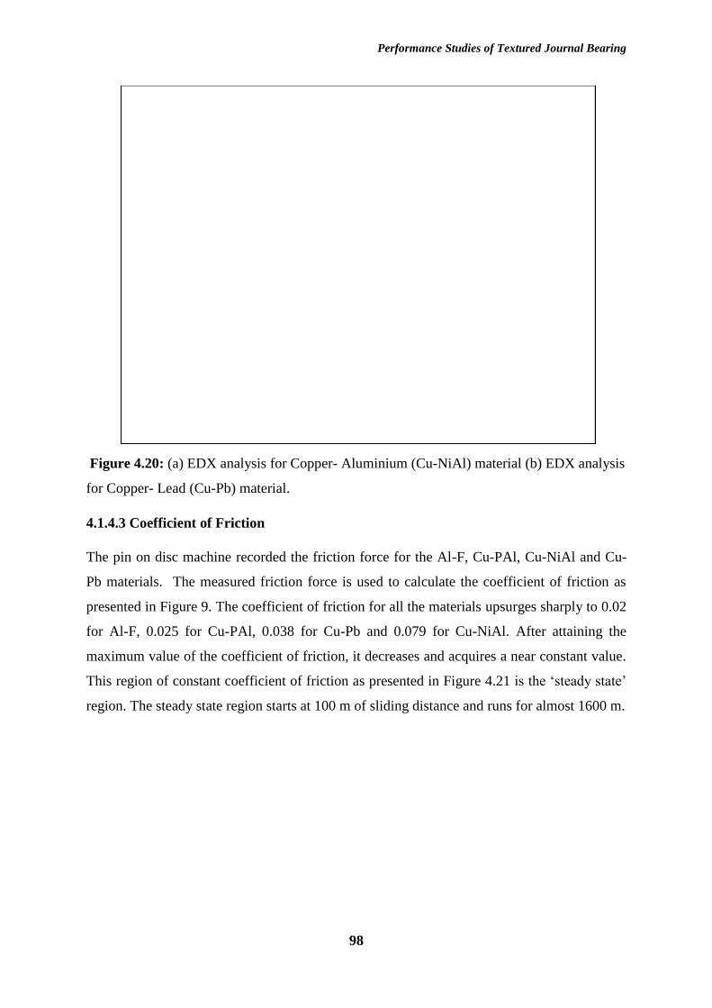
Performance Studies of Textured Journal Bearing
98
Figure 4.20: (a) EDX analysis for Copper- Aluminium (Cu-NiAl) material (b) EDX analysis
for Copper- Lead (Cu-Pb) material.
4.1.4.3 Coefficient of Friction
The pin on disc machine recorded the friction force for the Al-F, Cu-PAl, Cu-NiAl and Cu-
Pb materials. The measured friction force is used to calculate the coefficient of friction as
presented in Figure 9. The coefficient of friction for all the materials upsurges sharply to 0.02
for Al-F, 0.025 for Cu-PAl, 0.038 for Cu-Pb and 0.079 for Cu-NiAl. After attaining the
maximum value of the coefficient of friction, it decreases and acquires a near constant value.
This region of constant coefficient of friction as presented in Figure 4.21 is the ‘steady state’
region. The steady state region starts at 100 m of sliding distance and runs for almost 1600 m.
subhash tokoo
Text Box

Performance Studies of Textured Journal Bearing
99
Figure 4.21: Variation of the coefficient of friction
It is seen that Al-F composite material results in the lowest coefficient of friction value. The
flyash contents of the composite provide the anti-friction properties to the aluminium material
which decreases the coefficient of friction. The coefficient of friction for Al-F was 32% less
as compared to the average coefficient of friction for the conventional journal bearing
material (Cu-Pb). The maximum friction coefficient was obtained between the Cu-NiAl and
mild steel tribopairs.
4.1.4.4 Comparison in Unlubricated Condition
For the complete understanding of the tribological behaviour of the journal bearing materials,
it is equally important to evaluate and calculate the wear and friction properties of the
prepared materials in unlubricated conditions as well.

Performance Studies of Textured Journal Bearing
100
Figure 4.22: Mass loss (g) for the fabricated materials.
Figure 4.22 represents the mass loss from the pin samples during the wear testing. The Al-
Flyash pin experienced maximum mass loss as compared to other materials. The presence of
soft phases may have resulted in more wear. The Cu-NiAl also exhibits more wear as
compared to the conventional journal bearing material (Cu-Pb). However, Cu-PAl material
behaved slightly better than the Cu-Pb material. The presence of a smooth layer on the disc
surface is the possible reason for this lower wearing of the Cu-Pb and Cu-PAl material.
The variation of coefficient of friction is presented in Figure 4.23, the presence of flyash
particles in aluminium matrix helped in lowering the friction coefficient values for the Al-
Flyash composite. The Cu-NiAl material resulted in maximum friction coefficient values.
The Cu-PAl has a better friction coefficient values as compared to the Cu-Pb material. The
average values of friction coefficient are presented in Table 4.3.
This lowest coefficient of friction value for the Al-F composite is mainly attributed due to the
nature of the flyash particles, the flyash particles are generally spherical in shape which
makes the surface of aluminium smooth and hence the coefficient of friction value decreases.
However, the presence of aluminium and low hardness value of the Al-F composite as
compared to the other copper composite materials resulted in high mass loss.

Performance Studies of Textured Journal Bearing
101
Figure 4.23: Variation of the coefficient of friction in unlubricated condition
Figure 4.24: Wear scar depth in unlubricated condition
For further understanding of the wear of the material, the wear depth in the form of length of
pin is plotted against the time. Figure 4.24 presents this wear depth for the considered
materials. for the initial sliding of the materials, the Cu-NiAl, Cu-Pb and Cu-PAl material has
almost similar wear depth. After that, the wear depth for Cu-NiAl increases with more
sliding, the hard particles of the Cu-NiAl may have resulted in three body wear. With further

Performance Studies of Textured Journal Bearing
102
sliding, the Cu-PAl material resulted in the least amount of wear. The elements like
aluminium and phosphorous in the bronze matrix help in reducing the wear (Figure 4.25).
Figure 4.25: Wear scar depth in unlubricated condition (For 1500 m sliding distance)
Table 4.3: Average wear scar depth and friction force
Material Avg Wear Scar
Depth (Micro-
meter)
Coefficient of
Friction
Al-Flyash 641.6 0.24
Cu-NiAl 286.5 0.30
Cu-Pb 49.3 0.29
Cu-PAl 31.1 0.26

Performance Studies of Textured Journal Bearing
103
4.2 Journal Bearing Performance
The performance of a journal bearing system directly depends on the lubricant oil type, the
load on the shaft and rotational speed of the shaft. In the present analysis, the journal bearing
performance has been evaluated by incorporating surface textures on the bearing surface. In
this section of the chapter, the effects of surface textures on the friction torque between the
bearing and journal have been evaluated for starved as well as hydrodynamic lubrication
regimes. In the last part of the section, the maximum oil film pressure due to the surface
textures has also been studied.
4.2.1 Friction Torque in Starved Lubrication
The whole experimental work was divided into two phases. In the first phase, journal bearing
test rig experiments were performed by using the conventional bearing at different load and
rotational speeds of the journal. In the second phase, the surface textures of half-spherical
shape were produced on the bearing surface and frictional torque was measured at the same
input parameters of load and speed as used in the first phase. The results of the conventional
bearing testing and textured bearing are evaluated and compared.
SAE 15W40 at 250N Load
Journal Rotational Speed (rpm)
800 1000 1200 1400 1600 1800
Friction T
orq
ue (
N.m
)
0.22
0.24
0.26
0.28
0.30
0.32
0.34
0.36
Without Textures
With Textures
Figure 4.26: (a) Variation of friction torque at 250N load.

Performance Studies of Textured Journal Bearing
104
SAE 15W 40 at 500N
Journal Rotational Speed (rpm)
800 1000 1200 1400 1600 1800
Frictio
na
l T
orq
ue
(N
.m)
0.35
0.40
0.45
0.50
0.55
0.60
0.65
Without Textures
With Textures
Figure 4.26: (b) Variation of friction torque at 500N load.
SAE 15W 40 at 750N Load
Journal Rotational Speed (rpm)
800 1000 1200 1400 1600 1800
Frictional T
orq
ue (
N.m
)
0.70
0.75
0.80
0.85
0.90
0.95
Without Textures
With Textures
Figure 4.26: (c) Variation of friction torque at 750N load.

Performance Studies of Textured Journal Bearing
105
Figure 4.26 (a-c) presents the variation of frictional torque for conventional and textured
bearing system during the starved lubrication regime. It is seen that at lower speeds (910
rpm), the average frictional torque is minimum as compared to the frictional torque at 1150,
1400, 1650 rpm speed of journal. At higher speeds, a fluid film layer thickness between the
bearing and shaft becomes very thin which may result in higher frictional torque.
This rise indicates the low strength of the fluid film at higher journal speeds and represents
the scarcity of the lubricating oil.
It is also observed that as the load on the shaft of the system increases, the frictional torque
values also increase. This increased load on the shaft may result in a decrease in thickness of
the lubricating oil which increases the frictional torque.
For the textured bearing system, the average friction torque for the 250N and 500N
considered cases reduces significantly (except at 1650rpm, 500N). This reduction in frictional
torque helps in improving the performance of the journal bearing system. The surface
textures on the inner surface of the bearing act as the reservoir and hold the lubricating oil in
it. This lubricating oil present in the surface textures help in reducing the frictional torque
between the journal and the bearing. However, with further increase in the load value to
750N, the lubricant film get very thin, and surface texture burrs may have contacted with the
shaft surfaces as well. This phenomenon, increases the frictional torque.
4.2.2 Frictional Torque in Hydrodynamic Lubrication
In this work, attempts have been made to evaluate the effects of partial surface textures on the
frictional torque of the journal bearing. For these several experiments were conducted a
varying journal speed and loading conditions. In the first section of the experimental work,
three synthetic lubricating oils SAE 10W-40, SAE 15W-40 and SAE 20W-40 were used and
compared for friction torque measurements. Figure 4.27 (a-d) presents the variation of
frictional torque with the rotational speed of journal at loads 250N-1000N under the
hydrodynamic effect of SAE 10W 40 lubricating oil. These graphs were obtained by
measuring the average frictional torque values for the considered rotational speed and load
values in fully flooded hydrodynamic lubrication condition. The theoretical values of the
frictional torque were also calculated for the comparison using equation (1.3). It is observed
that with increase in journal speed the friction torque value also gets increased for all the

Performance Studies of Textured Journal Bearing
106
loading values. The low viscosity of the lubricating oil resulted in shear thinning of the oil
which raises the frictional torque values. With increases in load the friction torque values get
reduced, the possible cause for this reduction would be higher eccentricity ratio which is
produced due to an increase in applied load. These variations in the results are consistent with
the findings observed by Lu (2006). Figure 4. 27 (e-h), presents the friction torque with SAE
15W 40 and Figure 4. 27 (i-l) shows the variation with SAE 20W 40 lubricating oil. From the
figures 4.27 (a-l), it is observed that, the variation of friction torque was in the range of 2.8-
23 % for the textured bearing as compared to theoretical value. There was an improvement in
the average friction torque from textured bearing was in the range of 2.7 % - 13.5 %
compared to the non-textured bearing.
Journal Rotational Speed (rpm)
800 1000 1200 1400 1600 1800 2000 2200 2400
Frictional T
orq
ue (
N.m
)
0.03
0.04
0.05
0.06
0.07
0.08
0.09
0.10
Theoritical
Without Textures
With Textures
SAE 10W 40 at 250N Load
Figure 4.27 (a): Friction torque variation with SAE 10W 40 lubricating oil at 250N load

Performance Studies of Textured Journal Bearing
107
SAE 10W-40 at 500N Load
Journal Rotational Speed (rpm)
800 1000 1200 1400 1600 1800 2000 2200 2400
Frictional T
orq
ue (
N.m
)
0.015
0.020
0.025
0.030
0.035
0.040
0.045
Theoritical
Without Textures
With Textures
Figure 4.27 (b): Friction torque variation with SAE 10W 40 lubricating oil at 500N load
SAE 10W-40 at 750N Load
Journal Rotational Speed (rpm)
800 1000 1200 1400 1600 1800 2000 2200 2400
Frictio
na
l T
orq
ue
(N
.m)
0.010
0.015
0.020
0.025
0.030
0.035
Theoritical
Without Textures
With Textures
Figure 4.27 (c): Friction torque variation with SAE 10W 40 lubricating oil at 750N load

Performance Studies of Textured Journal Bearing
108
SAE 10W-40 at 1000N Load
Journal Rotational Speed (rpm)
800 1000 1200 1400 1600 1800 2000 2200 2400
Frict
ion
al T
orq
ue
(N
.m)
0.006
0.008
0.010
0.012
0.014
0.016
0.018
0.020
0.022
0.024
0.026
Theoritical
Without Textures
With Textures
Figure 4.27 (d): Friction torque variation with SAE 10W 40 lubricating oil at 1000N load
SAE 15W 40 at 250N Load
Journal Rotational Speed (rpm)
800 1000 1200 1400 1600 1800 2000 2200 2400
Frictional T
orq
ue (
N.m
)
0.03
0.04
0.05
0.06
0.07
0.08
0.09
0.10
0.11
Theoritical
Without Texture
With Texture
Figure 4.27 (e): Friction torque variation with SAE 15W 40 lubricating oil at 250N load

Performance Studies of Textured Journal Bearing
109
SAE 15W 40 at 500N Load
Journal Rotational Speed (rpm)
800 1000 1200 1400 1600 1800 2000 2200 2400
Frictio
na
l T
orq
ue
(N
.m)
0.015
0.020
0.025
0.030
0.035
0.040
0.045
0.050
0.055
Theoritical
Without Texture
With Texture
Figure 4.27 (f): Friction torque variation with SAE 15W 40 lubricating oil at 500N load
SAE 15W 40 at 750N Load
Journal Rotational Speed (rpm)
800 1000 1200 1400 1600 1800 2000 2200 2400
Frictio
na
l T
orq
ue
(N
.m)
0.010
0.015
0.020
0.025
0.030
0.035
0.040
Theoritical
Without Texture
With Texture
Figure 4.27 (g): Friction torque variation with SAE 15W 40 lubricating oil at 750N load

Performance Studies of Textured Journal Bearing
110
SAE 15W 40 at 1000N Load
Journal Rotational Speed (rpm)
800 1000 1200 1400 1600 1800 2000 2200 2400
Frictio
na
l T
orq
ue
(N
.m)
0.005
0.010
0.015
0.020
0.025
0.030
Theoritical
Without Texture
With Texture
Figure 4.27 (h): Friction torque variation with SAE 15W 40 lubricating oil at 1000N load
SAE 20W 40 at 250N Load
Journal Rotational Speed (rpm)
800 1000 1200 1400 1600 1800 2000 2200 2400
Frictional T
orq
ue (
N.m
)
0.04
0.05
0.06
0.07
0.08
0.09
0.10
0.11
0.12
Theoritical
Without Texture
With Texture
Figure 4.27 (i): Friction torque variation with SAE 20W 40 lubricating oil at 250N load

Performance Studies of Textured Journal Bearing
111
SAE 20W 40 at 500N Load
Journal Rotational Speed (rpm)
800 1000 1200 1400 1600 1800 2000 2200 2400
Frictio
na
l T
orq
ue
(N
.m)
0.020
0.025
0.030
0.035
0.040
0.045
0.050
0.055
0.060
Theoritical
Without Textures
With Textures
Figure 4.27 (j): Friction torque variation with SAE 20W 40 lubricating oil at 500N load
SAE 20W 40 at 750N Load
Journal Rotational Speed (rpm)
800 1000 1200 1400 1600 1800 2000 2200 2400
Frictio
na
l T
orq
ue
(N
.m)
0.010
0.015
0.020
0.025
0.030
0.035
0.040
0.045
0.050
Theoritical
Without Textures
With Textures
Figure 4.27 (k): Friction torque variation with SAE 20W 40 lubricating oil at 750N load

Performance Studies of Textured Journal Bearing
112
SAE 20W 40 at 1000N Load
Journal Rotational Speed (rpm)
800 1000 1200 1400 1600 1800 2000 2200 2400
Frictio
na
l T
orq
ue
(N
.m)
0.010
0.015
0.020
0.025
0.030
0.035
Theoritical
Without Textures
With Textures
Figure 4.27 (l): Friction torque variation with SAE 20W 40 lubricating oil at 1000N load
In order to understand the effects of load and viscosity, graphs were obtained at varying
rotational speeds. Figure 4.28 (a) presents the effect of applied load on the frictional torque. It
is observed that, with the increase in the applied load the friction torque value reduces. In
hydrodynamic lubrication conditions, the higher loads may have resulted in higher
eccentricity ratio and at low loading conditions, the chances of journal misalignment may
occur, which might result in higher friction torque values. The average friction torque values
achieved are 0.067 N.m, 0.036 N.m, 0.025 N.m and 0.019 N.m for 250N, 500N, 750N and
1000N load. Figure 4.28 (b) presents the variation of friction torque with journal speed at 250
N load. Three lubricating oil were used. It is observed that with the increase in oil viscosity,
the frictional torque value also increases. The viscosity of the oil played an important role in
increasing the frictional torque value.

Performance Studies of Textured Journal Bearing
113
SAE 15W 40
Journal Rotational Speed (rpm)
800 1000 1200 1400 1600 1800 2000 2200 2400
Friction T
orq
ue (
N.m
)
0.00
0.02
0.04
0.06
0.08
0.10
250 N
500 N
750 N
1000 N
Figure 4.28 (a): Variation of friction torque with applied load with SAE 15W 40
lubricating oil
Journal Rotational Speed (rpm)
800 1000 1200 1400 1600 1800 2000 2200 2400
Friction T
orq
ue (
N.m
)
0.00
0.05
0.10
0.15
0.20
SAE 10W 40
SAE 15W 40
SAE 20W 40
Figure 4.28 (b): Variation of friction torque with different lubricating oils at 250 N load.

Performance Studies of Textured Journal Bearing
114
4.2.3 Oil Film Pressure
The pressure around the periphery of the bearing surface was measured with the help of
pressure sensors. The maximum pressure obtained at a particular load and rotational speed of
the journal is plotted in Figure 4.29 to Figure 4.33. Figure 4.29 is obtained at 250N of applied
load with variable rotational speeds of the journal with SAE 10W40 lubricants. It is observed
that maximum pressure value increases with the increased rotational speed. The increased
speed of the journal helped in providing an extra force on the lubricating oil which increases
the pressure generation. However, at 1900rpm and 2150 rpm rotational speed, the maximum
pressure values decrease slightly. This reduction in pressure is obtained because of low
viscosity of the SAE 10W40 lubricating oil and very light loading. Due to these conditions, at
higher speeds, the lubricant film may get weak and thus reduces the maximum pressure.
Figure 4.29: Pressure variation with rotational speed at 250N with SAE 10W 40 lubricant
Figure 4.30 is obtained at 250N with variable journal speed values. SAE 15W40 lubricating
oil was used for the experiments. With SAE 15W40 lubricating oil, the lubricating film
pressure increases slightly as compared to the SAE 15W40. It is also seen that there is no
reduction in the maximum pressure value even at higher journal speeds. The high viscosity of
lubricating oil helps in maintaining sufficient lubricant film thickness. Similarly, Figure 4.31
presents the lubricant film pressure with SAE 20W40 lubricating oil. SAE 20W40 maintains
the higher pressure values and lubricating oil film does not get rupture at higher speeds as
well.
0
1
2
3
4
5
6
900 1150 1400 1650 1900 2150
Pre
ssu
re (
MP
a)
Journal Speed (rpm)
Load=250 N Oil=SAE10W40
Pressure Untextured Pressure Textured

Performance Studies of Textured Journal Bearing
115
Figure 4.30: Pressure variation with rotational speed at 250N with SAE 15W 40 lubricant
Figure 4.31: Pressure variation with rotational speed at 250N with SAE 20W 40 lubricant
Figure 4.32 presents the maximum lubricant film pressure at 500N load with SAE 10W40
lubricating oil. The oil film pressure increases with the increases in journal speed and
achieves a maximum value at 2150 rpm. No oil film rupture was reported during the
experimentation.
For SAE 15W40 oil, the oil film pressure also gets increases and the oil film becomes more
stable and support the applied load.
5.3
5.4
5.5
5.6
5.7
5.8
5.9
6
900 1150 1400 1650 1900 2150
Pre
ssure
(M
Pa)
Journal Speeed (rpm)
Load=250 N Oil=SAE15W40
Pressure Untextured Pressure Textured
4.9
5
5.1
5.2
5.3
5.4
5.5
900 1150 1400 1650 1900 2150
Pre
ssu
re (
MP
a)
Journal Speed (rpm)
Load=250 N Oil=SAE20W40
Pressure Untextured Pressure Textured

Performance Studies of Textured Journal Bearing
116
Figure 4.32: Pressure variation with rotational speed at 500N with SAE 10W 40 lubricant
Figure 4.33: Pressure variation with rotational speed at 500N with SAE 15W 40 lubricant
With further increase in the lubricant viscosity, not much rise in the oil film pressure was
reported. For SAE 20W40 oil, the maximum oil film pressure gets a slight decrease and
fluctuates at higher journal speeds (Figure 4.34).
0
1
2
3
4
5
6
900 1150 1400 1650 1900 2150
Pre
ssu
re (
MP
a)
Journal Speed (rpm)
Load=500 N Oil=SAE10W40
Pressure Untextured Pressure Textured
0
1
2
3
4
5
6
7
900 1150 1400 1650 1900 2150
Pre
ssu
re (
MP
a)
Journal Speed (rpm)
Load=500 N Oil=SAE15W40
Pressure Untextured Pressure Textured

Performance Studies of Textured Journal Bearing
117
Figure 4.34: Pressure variation with rotational speed at 500N with SAE 20W 40 lubricant
4.7
4.8
4.9
5
5.1
5.2
5.3
5.4
900 1150 1400 1650 1900 2150
Pre
ssu
re (
MP
a)
Journal Speed (rpm)
Load=500 N Oil=SAE20W40
Pressure Untextured Pressure Textured

Performance Studies of Textured Journal Bearing
118
4.3 Simulation
Figure 4.34 shows the variation of oil film pressure for the non-textured bearing surface. The
red zone indicates the maximum pressure area whereas a blue part shows the minimum
pressure area. The usually the pressure in the blue part is negative because of the cavitation
region. The maximum pressure value achieved in the red zone is 10.97 MPa.
Figure 4.35: Oil film pressure for non-textured bearing surface.
Figure 4.36: Oil film pressure variation for textured bearing surface.
Figure 4.35 shows the oil film pressure variation for the textured bearing surfaces. The
textures present on the bearing surface produces some extra pressure which helps in
improving the performance of the journal bearing system. The region of maximum pressure
and negative pressure are similar to the non-textured bearing. The maximum oil film pressure
achieved in case of the textured bearing surface is 11.04 MPa. The distribution of oil film

Performance Studies of Textured Journal Bearing
119
pressure is also a non-uniform in nature. The small textures on the surface of the bearing act
as small bearing surfaces and produce the extra pressure in-between them. This extra pressure
help in improving the performance of the journal bearing system.

Performance Studies of Textured Journal Bearing
120
Chapter 5 Conclusions and Future Works
5.1 Conclusions
In the present thesis work, attempts have been made to improve the performance parameters
of a journal bearing. The designing of the bearing surface and material of the bearing were
considered and worked upon for the possible improvement in the journal bearing
performance. Four bearing materials were fabricated and experimentally tested and compared
with the conventional journal bearing material. The main conclusions drawn from this thesis
work are given below.
Two aluminium based composites were prepared by using flyash and graphite as the
reinforcing agents. The flyash and graphite both have proved to improve the wear and
friction properties of the aluminium material. Two copper based material, namely,
copper-aluminium (Cu-NiAl) and copper-phosphorous (Cu-PAl) were fabricated and
tested for mechanical properties. It is observed that the addition of aluminium to the
copper matrix have improved the properties of the copper, however, higher amounts
of aluminium may have produced some negative results. The prepared aluminium
composite and copper alloys were compared for the wear and friction properties with
the conventional lead bronze (Cu-Pb) bearing material and it is observed that copper-
phosphorous (Cu-PAl) resulted in the lowest amount of wear and friction in starved
and unlubricated conditions. Cu-NiAl performed better under fully flooded lubrication
regime.
In fully flooded tribological studies, the three copper based fabricated materials
resulted in very low amounts of specific wear rate and coefficient of friction. The
presence of aluminium and nickel contents in Cu-NiAl helped in maintaining low
specific wear rate and coefficient of friction values as compared to Cu-PAl and Cu-
Pb.
During the starved and unlubricated condition, Cu-PAl has shown better results with
low specific wear rate and coefficient of friction as compared to Cu-NiAl and Cu-Pb.
A soft layer of copper and phosphorous-rich elements formed on the disc surface,

Performance Studies of Textured Journal Bearing
121
which reduces the coefficient of friction and specific wear rate. However, Aluminium
Flyash composite exhibits lowest coefficient of friction and largest specific wear rate.
The scanning electron microscopy examination of the unlubricated pin samples
reveals thick wear lines and wear grooves on the surface of Cu-NiAl material. Smaller
and thin wear lines were visible for Cu-PAl material which indicates low wear.
The EDX analysis of worn disc samples indicates the presence of copper-phosphorous
layer for Cu-PAl and copper-lead layer for Cu-Pb, which reduces the wear and
coefficient of friction. No such permanent layer was visible for Cu-NiAl material,
rather wear debris were seen scattered around the disc surface.
It is also observed that Flyash particles and graphite particles mix very well in the
aluminium and makes an aluminium metal matrix composite. These particles help in
improving the tribological properties of the aluminium, however, for heavy duty work
in journal bearing, these were not suitable materials to operate.
Surface texturing technique was used to improve the operating performance of the
journal bearing system. A specific pattern of concave surface textures was designed
and produced on the inner surface of the bearing. The maximum pressure zone of the
bearing circumference was selected as the area for fabricating the surface textures and
Electric Discharge Machining (EDM) process was used to generate the designed
texture pattern. A specialized electrode was fabricated for this purpose. The textured
journal bearing performed better as compared to the conventional journal bearing
system for the considered operating parameters of the journal bearing in
hydrodynamic lubrication regime.
A simple, Computational fluid dynamics (CFD) methodology was applied to inspect
the pressure profile of the lubricating film for a non-textured and textured bearing
surface. This model could be utilized to inspect the behaviour of the lubricating film
at different rotational speeds and lubricant properties.

Performance Studies of Textured Journal Bearing
122
5.2 Future Scope of work
This thesis work presents the insights about the tribological properties of the lead-free
journal bearing material and compared their properties with the conventional lead bronze
material. Other properties of the bearing materials could be evaluated further for the broad
analysis of the lead-free bearing materials.
The effects of surface textures have found to improve the performance of the journal bearing.
However, further study on the effects of different surface texture shapes and sizes could be
conducted to inspect their effects.

Performance Studies of Textured Journal Bearing
123
References
1. Abhijeet, G Chavan, D.G., Thombare, N.K., Chhapkhane.Eexperimental investigation
of effect of lubricant viscosity on vibrations of plain hydrodynamic journal bearing
system. International journal for research & development in technology 3 (4), 31-36
(2015).
2. Ahmad, M. A., Kasolang, S. & Dwyer-Joyce, R. S. Experimental study on the effects
of oil groove location on temperature and pressure profiles in journal bearing
lubrication. Tribol. Int. 74, 79–86 (2014).
3. Akhlaghi, F. & Zare-Bidaki, A. Influence of graphite content on the dry sliding and oil
impregnated sliding wear behavior of Al 2024–graphite composites produced by in
situ powder metallurgy method. Wear 266, 37–45 (2009).
4. Al-Qutub, A. M., Allam, I. M. & Qureshi, T. W. Effect of sub-micron Al2O3
concentration on dry wear properties of 6061 aluminum based composite. J. Mater.
Process. Technol. 172, 327–331 (2006).
5. Anil, P. M., Kumar, R. & Sethuramiah, A. Effect of initial roughness and oxidation on
the running-in wear of machined surfaces under dry sliding. Int. J. Surf. Sci. Eng. 11,
45 (2017).
6. ASTM Standard D4052. Standard Test Method for Density and Relative Density of
Liquids by Digital Density Meter. (ASTM International, West Conshohocken, PA,
United States, 1984).
7. ASTM Standard D445. Standard Method of Test for Viscosity of Transparent and
Opaque Liquids (Kinematic and Dynamic Viscosities). (ASTM International, West
Conshohocken, PA, United States., 1970).
8. ASTM Standard E387. in (ASTM International, West Conshohocken, PA, United
States., 2017).
9. ASTM Standard G99. in (ASTM International, West Conshohocken, PA, United
States., 2005).
10. Ausas, Roberto, Ragot, Patrick, Leiva, Jorge, Jai, Mohammed, Bayada, Guy & C.
Gustavo. Buscaglia . The Impact of the Cavitation Model in the Analysis of
Microtextured Lubricated Journal Bearings. J. Tribol. 129, 868 (2007).
11. Baradeswaran, A. & Perumal, A. E. Wear and mechanical characteristics of Al
7075/graphite composites. Compos. Part B Eng. 56, 472–476 (2014).
12. Basavarajappa, S., Chandramohan, G. & Paulo Davim, J. Application of Taguchi
techniques to study dry sliding wear behaviour of metal matrix composites. Mater.
Des. 28, 1393–1398 (2007).

Performance Studies of Textured Journal Bearing
124
13. Basavarajappa, S., Chandramohan, G. & Paulo Davim, J. Application of Taguchi
techniques to study dry sliding wear behaviour of metal matrix composites. Mater.
Des. 28, 1393–1398 (2007).
14. Basumatary, J. & Wood, R. J. K. Synergistic effects of cavitation erosion and
corrosion for nickel aluminium bronze with oxide film in 3.5% NaCl solution. Wear
376–377, 1286–1297 (2017).
15. Bhansali, K. J. & Mehrabian, R. Abrasive Wear of Aluminum-Matrix Composites.
JOM 34, 30–34 (1982).
16. Blau, P. J. Investigation of the nature of micro-indentation hardness gradients below
sliding contacts in five copper alloys worn against 52100 steel. J. Mater. Sci. 19,
1957–1968 (1984).
17. Bompos, D. A. & Nikolakopoulos, P. G. Tribological design of a multistep journal
bearing. Simul. Model. Pract. Theory 68, 18–32 (2016).
18. Bouyer, J. & Fillon, M. Experimental measurement of the friction torque on
hydrodynamic plain journal bearings during start-up. Tribol. Int. 44, 772–781 (2011).
19. Brizmer, V. & Kligerman, Y. A Laser Surface Textured Journal Bearing. J. Tribol.
134, 031702 (2012).
20. Candan, E., Ahlatci, H. & Çı̈menoğlu, H. Abrasive wear behaviour of Al–SiC
composites produced by pressure infiltration technique. Wear 247, 133–138 (2001).
21. Chen, J. K. & Huang, I. S. Thermal properties of aluminum–graphite composites by
powder metallurgy. Compos. Part B Eng. 44, 698–703 (2013).
22. Chmura, W. & Gronostajski, Z. Bearing composites made from aluminium and
aluminium bronze chips. J. Mater. Process. Technol. 178, 188–193 (2006).
23. Christensen, H. & Tonder, K. The Hydrodynamic Lubrication of Rough Journal
Bearings. J. Lubr. Technol. 95, 166 (1973).
24. Costa, H. L. & Hutchings, I. M. Hydrodynamic lubrication of textured steel surfaces
under reciprocating sliding conditions. Tribol. Int. 40, 1227–1238 (2007).
25. Cupillard, S., Glavatskih, S. & Cervantes, M. J. Computational fluid dynamics analysis
of a journal bearing with surface texturing. Proc. Inst. Mech. Eng. Part J J. Eng.
Tribol. 222, 97–107 (2008).
26. Davim, J. P., Marques, N. & Baptista, A. M. Effect of carbon fibre reinforcement in
the frictional behaviour of Peek in a water lubricated environment. Wear 251, 1100–
1104 (2001).
27. Dhande, D. Y. & Pande, D. W. Multiphase flow analysis of hydrodynamic journal
bearing using CFD coupled Fluid Structure Interaction considering cavitation. J. King
Saud Univ. - Eng. Sci. 30, 345–354 (2018).

Performance Studies of Textured Journal Bearing
125
28. Dinaharan, I., Kalaiselvan, K., Akinlabi, E. T. & Davim, J. P. Microstructure and wear
characterization of rice husk ash reinforced copper matrix composites prepared using
friction stir processing. J. Alloys Compd. 718, 150–160 (2017).
29. Ding, Y., Lv, Yuting, Chen, Kai, Zhao, Bingjai, Han, Yuanfei, Wang, Liqiang, Lu,
Weijie. Effects of microstructure on the stress corrosion cracking behavior of nickel-
aluminum bronze alloy in 3.5% NaCl solution. Mater. Sci. Eng. A 733, 361–373
(2018).
30. Edalati, K., Ashida, M., Horita, Z., Matsui, T. & Kato, H. Wear resistance and
tribological features of pure aluminum and Al–Al2O3 composites consolidated by
high-pressure torsion. Wear 310, 83–89 (2014).
31. Elrod, H. G. and A. A computer program for cavitation and starvation problems.
Technical report 190. 1st LEEDS LYON Symp. Cavitation Relat. Phenom. Lubr. I.M.E.
37–41 (1974).
32. Equey, S., Houriet, A. & Mischler, S. Wear and frictional mechanisms of copper-based
bearing alloys. Wear 273, 9–16 (2011).
33. Equey, S., Houriet, A. & Mischler, S. Wear and frictional mechanisms of copper-based
bearing alloys. Wear 273, 9–16 (2011).
34. Etsion, I. Improving Tribological Performance of Mechanical Components by Laser
Surface Texturing. Tribol. Lett. 17, 733–737 (2004).
35. Ettles, C. M., Seyler, J. & Bottenschein, M. Some Effects of Start-Up and Shut-Down
on Thrust Bearing Assemblies in Hydro-Generators. J. Tribol. 125, 824 (2003).
36. Feyzullahoğlu, E. & Şakiroğlu, N. The wear of aluminium-based journal bearing
materials under lubrication. Mater. Des. 31, 2532–2539 (2010).
37. Fowell, M., Olver, A. V., Gosman, A. D., Spikes, H. A. & Pegg, I. Entrainment and
Inlet Suction: Two Mechanisms of Hydrodynamic Lubrication in Textured Bearings. J.
Tribol. 129, 336 (2007).
38. Gao, F., Liu, R. & Wu, X. J. Tribaloy alloy reinforced tin–bronze composite coating
for journal bearing applications. Thin Solid Films 519, 4809–4817 (2011).
39. Gao, G., Yin, Z., Jiang, D. & Zhang, X. Numerical analysis of plain journal bearing
under hydrodynamic lubrication by water. Tribol. Int. 75, 31–38 (2014).
40. Gao, L. L. & Cheng, X. H. Microstructure and dry sliding wear behavior of Cu–
10%Al–4%Fe alloy produced by equal channel angular extrusion. Wear 265, 986–991
(2008).
41. Gebretsadik, D. W., Hardell, J. & Prakash, B. Tribological performance of tin-based
overlay plated engine bearing materials. Tribol. Int. 92, 281–289 (2015).

Performance Studies of Textured Journal Bearing
126
42. Gebretsadik, D. W., Hardell, J. & Prakash, B. Friction and wear characteristics of
different Pb-free bearing materials in mixed and boundary lubrication regimes. Wear
340–341, 63–72 (2015).
43. Goodman John. Recent advances in Friction. Proc. Inst. Civ. Eng 85, 376–392 (1886).
44. Harnoy, A. Model-Based Investigation of Friction During Start-Up of Hydrodynamic
Journal Bearings. J. Tribol. 117, 667 (1995).
45. Hsu, T.-C., Chen, J.-H., Chiang, H.-L. & Chou, T.-L. Lubrication performance of short
journal bearings considering the effects of surface roughness and magnetic field.
Tribol. Int. 61, 169–175 (2013).
46. Huei-Long, L., Wun-Hwa, L. & Sammy Lap-Ip Chan. Abrasive wear of powder
metallurgy Al alloy 6061-SiC particle composites. Wear 159, 223–231 (1992).
47. I M Hutchings. in Tribology: Friction and Wear of Engineering Materials (Edward
Arnold, London, 1992).
48. İzciler, M. & Muratoglu, M. Wear behaviour of SiC reinforced 2124 Al alloy
composite in RWAT system. J. Mater. Process. Technol. 132, 67–72 (2003).
49. J. Paulo DavimNuno Marques. Evaluation of Tribological Behaviour of Polymeric
Materials for Hip Prostheses Application. Tribol. Lett. 11, 91–94 (2001).
50. Kandavel, T. K., Panneerselvam, T. & Mohan, V. Experimental investigation on wear
characteristics of sintered Fe-C-Cr low alloy steels. Int. J. Surf. Sci. Eng. 11, 381
(2017).
51. Kango, S., Singh, D. & Sharma, R. K. Numerical investigation on the influence of
surface texture on the performance of hydrodynamic journal bearing. Meccanica 47,
469–482 (2012).
52. Kango, S., Sharma, R. & Pandey, R. Comparative analysis of textured and grooved
hydrodynamic journal bearing. Proc. Inst. Mech. Eng. Part J J. Eng. Tribol. 228, 82–
95 (2014).
53. Kaplan, M. & Yildiz, A. K. The effects of production methods on the microstructures
and mechanical properties of an aluminum bronze. Mater. Lett. 57, 4402–4411 (2003).
54. Keogh, P. S., Gomiciaga, R. & Khonsari, M. M. CFD Based Design Techniques for
Thermal Prediction in a Generic Two-Axial Groove Hydrodynamic Journal Bearing. J.
Tribol. 119, 428 (1997).
55. Khatri, C. B. & Sharma, S. C. Influence of textured surface on the performance of non-
recessed hybrid journal bearing operating with non-Newtonian lubricant. Tribol. Int.
95, 221–235 (2016).

Performance Studies of Textured Journal Bearing
127
56. Khatri, C. B. & Sharma, S. C. Influence of textured surface on the performance of non-
recessed hybrid journal bearing operating with non-Newtonian lubricant. Tribol. Int.
95, 221–235 (2016).
57. Kim, H. G. & Jeon, S. I. Effect on friction of engine oil seal with engine oil viscosity.
Int. J. Automot. Technol. 9, 601–606 (2008).
58. Kim, S. S., Park, D. C. & Lee, D. G. Characteristics of carbon fiber phenolic
composite for journal bearing materials. Compos. Struct. 66, 359–366 (2004).
59. Kim, S. S., Yu, H. N., Hwang, I. U. & Lee, D. G. Characteristics of wood–polymer
composite for journal bearing materials. Compos. Struct. 86, 279–284 (2008).
60. Krishnan, B. P. & Rohatgi, P. K. Modification of Al–Si alloy melts containing graphite
particle dispersions. Met. Technol. 11, 41–44 (1984).
61. Krithivasan, R. & Khonsari, M. M. Thermally Induced Seizure in Journal Bearings
During Startup and Transient Flow Disturbance. J. Tribol. 125, 833 (2003).
62. Li, W. S., Wang, Z.P., Lu, Y., Jin, Y.H., Yuan, L.H., Wang, F. Mechanical and
tribological properties of a novel aluminum bronze material for drawing dies. Wear
261, 155–163 (2006).
63. Li, Y., Ngai, T. L. & Xia, W. Mechanical, friction and wear behaviors of a novel high-
strength wear-resisting aluminum bronze. Wear 197, 130–136 (1996).
64. Lin, C. B., Chang, R. J. & Weng, W. P. A study on process and tribological behavior
of Al alloy/Gr. (p) composite. Wear 217, 167–174 (1998).
65. Linjamaa, A., Lehtovaara, A., Larsson, R., Kallio, M. & Söchting, S. Modelling and
analysis of elastic and thermal deformations of a hybrid journal bearing. Tribol. Int.
118, 451–457 (2018).
66. 7Lu, X. & Khonsari, M. M. An Experimental Investigation of Dimple Effect on the
Stribeck Curve of Journal Bearings. Tribol. Lett. 27, 169–176 (2007).
67. Luo, Q., Wu, Z., Qin, Z., Liu, L. & Hu, W. Surface modification of nickel-aluminum
bronze alloy with gradient Ni-Cu solid solution coating via thermal diffusion. Surf.
Coatings Technol. 309, 106–113 (2017).
68. Mathavan, J. J. & Patnaik, A. Analysis of wear properties of aluminium based journal
bearing alloys with and without lubrication. IOP Conf. Ser. Mater. Sci. Eng. 149,
012052 (2016).
69. Mazahery, A. & Shabani, M. O. Experimental Investigation on the Aging Response,
Hardness and Total Impact Energy Absorption of Sr-Modified Heat-Treatable Cast
Automotive Aluminum Alloys. Trans. Indian Inst. Met. 67, 753–759 (2014).

Performance Studies of Textured Journal Bearing
128
70. Mazahery, A. & Shabani, M. O. Tribological behaviour of semisolid–semisolid
compocast Al–Si matrix composites reinforced with TiB2 coated B4C particulates.
Ceram. Int. 38, 1887–1895 (2012).
71. McCarthy, D. M. C. & Glavatskih, S. B. Assessment of polymer composites for
hydrodynamic journal-bearing applications. Lubr. Sci. 21, 331–341 (2009).
72. Meng, F. M., Zhang, L., Liu, Y. & Li, T. T. Effect of compound dimple on tribological
performances of journal bearing. Tribol. Int. 91, 99–110 (2015).
74. Muzakkir, S., Lijesh, K., Hirani, H. & Thakre, G. Effect of cylindricity on the
tribological performance of heavily loaded slow-speed journal bearing. Proc. Inst.
Mech. Eng. Part J J. Eng. Tribol. 229, 178–195 (2015).
75. Petrov., P. N. Friction in machines and the effect of the lubricant. Inzhenernii Zhurnat
St. Petersbg. 1, 71–140 (1883).
76. Panagopoulos, C. N., Georgiou, E. P. & Simeonidis, K. Lubricated wear behavior of
leaded α+β brass. Tribol. Int. 50, 1–5 (2012).
77. Panda, J. N., Bijwe, J. & Pandey, R. K. Role of treatment to graphite particles to
increase the thermal conductivity in controlling tribo-performance of polymer
composites. Wear 360–361, 87–96 (2016).
78. Patel, N. S., Vakharia, D. P., Deheri, G. M. & Patel, H. C. Experimental performance
analysis of ferrofluid based hydrodynamic journal bearing with different combination
of materials. Wear 376–377, 1877–1884 (2017).
79. Pathak, J. P. & Mohan, S. Tribological behaviour of conventional Al-Sn and
equivalent Al-Pb alloys under lubrication. Bull. Mater. Sci. 26, 315–320 (2003).
80. Pathak, J. P., Torabian, H. & Tiwari, S. N. Antiseizure and antifriction characteristics
of Al-Si-Pb alloys. Wear 202, 134–141 (1997).
81. Petrica, M., Duscher, B., Koch, T. & Archodoulaki, V. M. Impact of surface roughness
and contact pressure on wear behaviour of PEEK, POM, and PE-UHMW. Int. J. Surf.
Sci. Eng. 11, 65 (2017).
82. Pistner, C. A. Some Effects of Start-Up Transient Loads on Shoe Bearings for Large
Hydraulic Pump/Turbines. Tribol. Trans. 39, 93–98 (1996).
83. Poddar, S. & Tandon, N. Detection of journal bearing vapour cavitation using
vibration and acoustic emission techniques with the aid of oil film photography.
Tribol. Int. 103, 95–101 (2016).
84. Prasad, B. K. Effects of Silicon Addition and Test Parameters on Sliding Wear
Characteristics of Zinc-Based Alloy Containing 37.5% Aluminium. Mater. Trans. JIM
38, 701–706 (1997).

Performance Studies of Textured Journal Bearing
129
85. Prasad, B. K., Patwardhan, A. K. & Yegneswaran, A. H. Factors controlling dry
sliding wear behaviour of a leaded tin bronze. Mater. Sci. Technol. 12, 427–435
(1996).
86. Prasad, B. . Effect of microstructure on the sliding wear performance of a Zn–Al–Ni
alloy. Wear 240, 100–112 (2000).
87. Qin, Z. et al. Improving corrosion resistance of nickel-aluminum bronzes by surface
modification with chromium ion implantation. Surf. Coatings Technol. 334, 402–409
(2018).
88. Qiu, Y. & Khonsari, M. M. On the Prediction of Cavitation in Dimples Using a Mass-
Conservative Algorithm. J. Tribol. 131, 041702 (2009).
89. Rahimipour, M. R., Tofigh, A. A., Mazahery, A. & Shabani, M. O. Strategic
developments to improve the optimization performance with efficient optimum
solution and produce high wear resistance aluminum–copper alloy matrix composites.
Neural Comput. Appl. 24, 1531–1538 (2014).
90. RF, S. ASM Specialty Handbook Copper and Copper Alloys. (ASM International,
1992).
91. Rohatgi, P. K., Sobczak, J., Asthana, R. & Kim, J. K. Inhomogeneities in silicon
carbide distribution in stirred liquids—a water model study for synthesis of
composites. Mater. Sci. Eng. A 252, 98–108 (1998).
91. Sahin, Y. Wear behaviour of aluminium alloy and its composites reinforced by SiC
particles using statistical analysis. Mater. Des. 24, 95–103 (2003).
92. Sahoo, B., Kumar, R., Joseph, J., Sharma, A. & Paul, J. Preparation of aluminium
6063-graphite surface composites by an electrical resistance heat assisted pressing
technique. Surf. Coatings Technol. 309, 563–572 (2017).
93. Santos, E. N., Blanco, C. J. C., Macêdo, E. N., Maneschy, C. E. A. & Quaresma, J. N.
N. Integral transform solutions for the analysis of hydrodynamic lubrication of journal
bearings. Tribol. Int. 52, 161–169 (2012).
94. Sastry, C. V. S. H. S. R. & Janardhana, G. R. Influence of process and test parameters
on the dry sliding wear behaviour of Al-Pb alloys produced by mechanical alloying.
Int. J. Surf. Sci. Eng. 4, 377 (2010).
95. SAUD, S. N., HAMZAH, E., ABUBAKAR, T. & BAKHSHESHI-RAD, H. R.
Correlation of microstructural and corrosion characteristics of quaternary shape
memory alloys Cu–Al–Ni–X (X=Mn or Ti). Trans. Nonferrous Met. Soc. China 25,
1158–1170 (2015).
96. Scaraggi, M., Mezzapesa, Francesco, Carbone, Giuseppe, Ancona, Antonia, Sorgente,
Donato, Lugara, Pietro M. Minimize friction of lubricated laser-microtextured-
surfaces by tuning microholes depth. Tribol. Int. 75, 123–127 (2014).

Performance Studies of Textured Journal Bearing
130
97. Shabani, M. O., Mazahery, A., Davami, P. & Razavi, M. Silicon morphology
modelling during solidification process of A356 Al alloy. Int. J. Cast Met. Res. 25, 53–
58 (2012).
98. Shamsipour, M., Pahlevani, Z., Shabani, M. O. & Mazahery, A. Optimization of the
EMS process parameters in compocasting of high-wear-resistant Al-nano-TiC
composites. Appl. Phys. A 122, 457 (2016).
99. Sharma, S. C., Girish, B. M., Kamath, R. & Satish, B. M. Graphite particles reinforced
ZA-27 alloy composite materials for journal bearing applications. Wear 219, 162–168
(1998).
100. Shi, Z., Sun, Y., Bloyce, A. & Bell, T. Unlubricated rolling-sliding wear mechanisms
of complex aluminium bronze against steel. Wear 193, 235–241 (1996).
101. Shinde, A. B. & Pawar, P. M. Multi-objective optimization of surface textured journal
bearing by Taguchi based Grey relational analysis. Tribol. Int. 114, 349–357 (2017).
102. Sinanoğlu, C., Nair, F. & Karamış, M. B. Effects of shaft surface texture on journal
bearing pressure distribution. J. Mater. Process. Technol. 168, 344–353 (2005).
103. Singh, M., Prasad, B. ., Mondal, D. . & Jha, A. . Dry sliding wear behaviour of an
aluminium alloy–granite particle composite. Tribol. Int. 34, 557–567 (2001).
104. Song, Q. N., Zheng, Y. G., Jiang, S. L., Ni, D. R. & Ma, Z. Y. Comparison of
Corrosion and Cavitation Erosion Behaviors Between the As-Cast and Friction-Stir-
Processed Nickel Aluminum Bronze. CORROSION 69, 1111–1121 (2013).
105. Sriram, S. B. and G. No Title. IEEE-International Conf. Adv. Eng. Sci. Manag. 132–
135 (2012).
106. Tala-Ighil, N., Fillon, M. & Maspeyrot, P. Effect of textured area on the performances
of a hydrodynamic journal bearing. Tribol. Int. 44, 211–219 (2011).
107. Taya, M., Lulay, K. E. & Lloyd, D. J. Strengthening of a particulate metal matrix
composite by quenching. Acta Metall. Mater. 39, 73–87 (1991).
108. Thapliyal, S. & Dwivedi, D. K. Study of the effect of friction stir processing of the
sliding wear behavior of cast NiAl bronze: A statistical analysis. Tribol. Int. 97, 124–
135 (2016).
109. Thurston Robert H. Friction and Lubrication. (Railroad Gazette Publication Co, 1879).
110. Torabian, H., Pathak, J. P. & Tiwari, S. N. Wear characteristics of Al-Si alloys. Wear
172, 49–58 (1994).
111. Tower Beauchamp. 1st report on Friction Experiments. Proc. Inst. Mech. Eng. 1, 632–
666 (1891).

Performance Studies of Textured Journal Bearing
131
112. Tzeng, S. T. & Saibel, E. On the effects of surface roughness in the hydrodynamic
lubrication theory of a short journal bearing. Wear 10, 179–184 (1967).
113. Vettivel, S. C., Selvakumar, N. & Ponraj, P. V. Mechanical Behaviour of Sintered Cu-
5%W Nano Powder Composite. Procedia Eng. 38, 2874–2880 (2012).
114. Vijayaraghavan, D. & Brewe, D. E. Effect of Rate of Viscosity Variation on the
Performance of Journal Bearings. J. Tribol. 120, 1 (1998).
115. Von Pauli, F.A. Uber den Widerstand der Zapfenreibung, Kunst und Gewerbeblatt des
Polytechnischen Verein des Konigreich Bayern. 8/9, 452–469 (1849).
116. Voong, M., Neville, A. & Castle, R. The Compatibility of Crankcase Lubricant–
Material Combinations in Internal Combustion Engines. Tribol. Lett. 15, 431–441
(2003).
117. W., B. Materials Technology for Technicians. (Butterworth, 1981).
118. Wang, A. & Rack, H. J. Transition wear behavior of SiC-particulate- and SiC-whisker-
reinforced 7091 Al metal matrix composites. Mater. Sci. Eng. A 147, 211–224 (1991).
119. Wang, H., Liu, Z., Zou, L. & Yang, J. Influence of both friction and wear on the
vibration of marine water lubricated rubber bearing. Wear 376–377, 920–930 (2017).
120. Wang, Q. Seizure failure of journal-bearing conformal contacts. Wear 210, 8–16
(1997).
121. Wang, W., Huang, Z., Shen, D., Kong, L. & Li, S. The Effect of Triangle-Shaped
Surface Textures on the Performance of the Lubricated Point-Contacts. J. Tribol. 135,
021503 (2013).
122. Wert, J. J., Singerman, S. A., Caldwell, S. G. & Quarles, R. A. The role of stacking
fault energy and induced residual stresses on the sliding wear of aluminum bronze.
Wear 91, 253–267 (1983).
123. Wu, Z., Cheng, Y. F., Liu, L., Lv, W. & Hu, W. Effect of heat treatment on
microstructure evolution and erosion–corrosion behavior of a nickel–aluminum bronze
alloy in chloride solution. Corros. Sci. 98, 260–270 (2015).
124. Yan, J., Lindo, A., Schwaiger, R. & HODGE, A. M. Sliding wear behavior of fully
nanotwinned Cu alloys. Friction (2018). doi:10.1007/s40544-018-0220-z
125. Yang, L. J. The transient and steady wear coefficients of A6061 aluminium alloy
reinforced with alumina particles. Compos. Sci. Technol. 63, 575–583 (2003).
126. Zhang, H., Zhang, D. Y., Hua, M., Dong, G. N. & Chin, K. S. A Study on the
Tribological Behavior of Surface Texturing on Babbitt Alloy under Mixed or Starved
Lubrication. Tribol. Lett. 56, 305–315 (2014).

Performance Studies of Textured Journal Bearing
132
Appendix-I
A1: Specifications of Journal bearing rig TR-660
Table A1.1: Specification of machine
S.No. Test Parameters Details
1 Pressure Digital Pressure Sensor
2 Friction Factor
3 Oil Flow Rate
4 Temperature of Inlet of Bearing Thermocouple
5 Bearing Specifications Cylindrical Bearing, id=40mm,
length=40mm, wall thickness 10mm,
c/r=0.0015, hole dia for oil supply=6mm, 10
holes for pressure data
6 Load Applied 3000N
7 Speed Range 40 to 8000 rpm
8 Permissible Error in Performance Thermocouple= ± 1°C
Pressure= ± 1% Mpa
Frictional Torque= ± 2%Nm
Shaft Speed= ± 0.1% rpm
Flow Rate= ± 0.5%lit/min
Table A1.2: Electrical Specification
S.No. Part Detail Range
1
AC Induction motor Make Seimens 2.2 kw
Specifications 2.2 kw, 1435 rpm
415V/ 3 ph/ 50 Hz, 4.4 A, foot
mounted
2 Variable frequency drive Make TB woods
Output supply 415V, 5.8 A, 3 ph
Specifications 2.2 kw, 5.8 A, 415 V, 3 ph
3 AC motor for lubrication Make; Capacity SEF Induction motor
Specifications 0.37 kw, 1350 rpm, 1.2 A,
flange mounted, 230 V
Input supply 230 V/ 50 Hz/ 1 ph, 0.5 A
4 Power Required 2.5 KVA

Performance Studies of Textured Journal Bearing
133
Table A1.3: Sensor Specifications
S.No. Part Detail Specifications
1 Speed Sensor Output from drive
Range Min ;40 rpm, Max 8000 rpm
Least Count 1 rpm
Accuracy (1 ± 2% measured speed) rpm
2 Temperature Type PT 100, make ; Hot set
Range Max 200°C
Least Count 0.1°C
Accuracy (0.1 ± 1% measured temp) °C
3 Pressure Sensor Digital stainless steel isolated pressure sensor,
make ; measurement specialties
Range 10 Mpa, or 100 bar
Least Count 0.001 Mpa (1 Kpa)
Accuracy (0.001 ± 1% measured value) Mpa
4 Frictional Torque Sensor Beam type load cell make ; sensortronics, cap
30 kg
Range 15 Nm
Least Count 0.01 Nm
Accuracy (0.1 ± 1% measured value) Nm

Performance Studies of Textured Journal Bearing
134
Table A1.4: Mechanical Specification
SI NO. Part detail Range
1. Shaft detail 22 ± 0.005mm
Journal outer diameter fitted on shaft 40 -0.005/0.006mm
Journal inner diameter fitted on shaft 22.035mm
2. Bearing Inner dia 40 +0.050/006mm
Width 40.04mm
3. Radial clearance 0.027mm
4. Length/ dia (l/d) ratio 1
c/r ratio 0.00135
5. Base plate height from floor 800mm
6. Journal height from base plate 150mm
7. Loading bracket height from base plate 760mm
8. Maximum load 3000N
Loading ratio 1:5
Frictional torque distance 51mm
9. Spindle speed Min speed 40
Max speed 8000rpm
10. Pulley ratio Speed upto 300 rpm 4:1
Speed above 300rpm 1:4
11. Overall size of the machine L*W*H 100*750*1560mm
12. Weight of the machine 240kg
Weight of controller 11kg
Total weight 60kg
13. Floor size L*W 2000*1500mm
14. Lubrication unit Make Cenlube system
Oil pressure 5 to 10 bar
Tank capacity 25 lit
Size l*b*h 370*290*300mm

Performance Studies of Textured Journal Bearing
135
Appendix-II
A2: Specifications of Pin on Disc Tribometer
Table A2.1: Pin on Disc tribometer specifications
Parameter Value
Disc speed
Range (rpm) 200-2000
Sensor Drive output
Least count
(rpm)
1
Load Parameters
Range (N) 0-200
Specification 20 Kg Beam
type load
cell
Least count
(N)
0.1
Machine
Parameters
Range (mm) 2
Sensors
specs
LVDT,
make:
Syscon
Least count
(μm)
0.1
Wear Track Diameter (mm) 150-50

Performance Studies of Textured Journal Bearing
136
A Brief Biographical Sketch
Vipin Kumar Sharma
Mr. Vipin Kuamr Sharma received his B.Tech degree in Mechanical Engineering from
Amritsar College of Engineering and Technology, (Affiliated to Punjab Technical
University), Punjab, India and M.E. Degree from Delhi College of Engineering (Delhi
University), Delhi, India. He is working as an Assistant Professor in the Department of
Mechanical and Automation Engineering at Maharaja Agrasen Institute of Technology,
Delhi, India. He is actively engaged in teaching and research. As a recognition of his
academic achievements, He was awarded the first rank merit certificate by Delhi
Technological University for securing 1st rank in ME (Production Engineering) course. He
has many research publications in reputed journals/conference proceedings. He is currently
working in the area of tribology and advanced materials.