
Combined Class 2 Permit Modification Request Package
444
Class 2 Permit Modification Request Package Waste Isolation Pilot Plant Carlsbad, New Mexico WIPP HWFP #NM4890139088 May 12, 2003
-
Upload
khangminh22 -
Category
Documents
-
view
2 -
download
0
Transcript of Combined Class 2 Permit Modification Request Package

Class 2 Permit Modification Request Package
Waste Isolation Pilot PlantCarlsbad, New Mexico
WIPP HWFP #NM4890139088
May 12, 2003

Table of Contents
Item 1 Packaging-Specific Drum Age Criteria for New Approved Waste Containers
Item 2 Removal of Booster Fans
Item 3 LANL Sealed Sources Waste Streams Headspace Gas Sampling andAnalysis Requirements
Item 4 Remove Formaldehyde as a Required Analytical Parameter for LANL
Item 5 Add New Hazardous Waste Numbers

Item 1
Class 2 Permit Modification Request
Packaging-Specific Drum Age Criteria for New Approved Waste Containers
Waste Isolation Pilot PlantCarlsbad, New Mexico
WIPP HWFP #NM4890139088-TSDF

i
Table of Contents
Table of Contents . . . . . . . . . . . . . . . . . . . . . . . . . . . . . . . . . . . . . . . . . . . . . . . . . . . . . . . . . . . . . i
Acronyms and Abbreviations . . . . . . . . . . . . . . . . . . . . . . . . . . . . . . . . . . . . . . . . . . . . . . . . . . . ii
Overview of the Permit Modification Request . . . . . . . . . . . . . . . . . . . . . . . . . . . . . . . . . . . . . 1
Attachment A . . . . . . . . . . . . . . . . . . . . . . . . . . . . . . . . . . . . . . . . . . . . . . . . . . . . . . . . . . . . . A-1Table of Changes . . . . . . . . . . . . . . . . . . . . . . . . . . . . . . . . . . . . . . . . . . . . . . . . . . . . A-2
Attachment B . . . . . . . . . . . . . . . . . . . . . . . . . . . . . . . . . . . . . . . . . . . . . . . . . . . . . . . . . . . . . B-1Proposed Revised Permit Text . . . . . . . . . . . . . . . . . . . . . . . . . . . . . . . . . . . . . . . . B-2
Attachment C . . . . . . . . . . . . . . . . . . . . . . . . . . . . . . . . . . . . . . . . . . . . . . . . . . . . . . . . . . . . . C-1Determination of Drum Age Criteria Values for Ten-Drum Overpacks, 85-GallonDrums and 100-Gallon Drums

ii
Acronyms and Abbreviations
CFR Code of Federal RegulationsDAC Drum Age CriteriaHWDU Hazardous Waste Disposal UnitHWFP Hazardous Waste Facility PermitNMAC New Mexico Administrative CodeNMED New Mexico Environment DepartmentPMR Permit Modification RequestTDOP Ten-Drum OverpackWIPP Waste Isolation Pilot Plant

1
Overview of the Permit Modification Request
This document contains a Class 2 Permit Modification Request (PMR) for the Waste IsolationPilot Plant (WIPP) Hazardous Waste Facility Permit (HWFP), Number NM4890139088-TSDF,hereinafter referred to as the WIPP HWFP.
This PMR is being submitted by the U.S. Department of Energy, Carlsbad Field Office andWashington TRU Solutions, LLC, collectively referred to as the Permittees, in accordance withthe WIPP HWFP, Condition I.B.1 (20.4.1.900 New Mexico Administrative Code (NMAC)incorporating Title 40, Code of Federal Regulations (CFR), §270.42(b)). The modification willestablish packaging-specific drum age criteria (DAC) values for waste containers that haverecently been added to the WIPP HWFP. The proposed changes will not reduce the ability ofthe Permittees to provide continued protection to human health and the environment.
The requested modifications to the WIPP HWFP and related supporting documents are providedin this PMR. The proposed modifications to the text of the WIPP HWFP have been identifiedusing a double underline and a revision bar in the right hand margin for added information, and a |strikeout font for deleted information. All direct quotations are indicated by italicized text. Thefollowing information specifically addresses how compliance has been achieved with the WIPPHWFP requirement, Permit Condition I.B.1 for submission of this Class 2 PMR.
1. 20.4.1.900 NMAC (incorporating 40 CFR §270.42(b)(1)(i)) requires theapplicant to describe the exact change to be made to the permit conditionsand supporting documents referenced by the permit.
The modification proposes to establish packaging-specific DAC values for 85-gallon drums, 100-gallon drums, and ten-drum overpacks (TDOPs). The proposed packaging-specific DAC valueshave been determined using the methodology in Determination of Drum Age Criteria andPrediction Factors Based on Packaging Configurations (BWXT, 2000), which is the samemethodology used to calculate currently permitted DAC values. This PMR has been preparedas directed by Section B1-1a(3) of Attachment B1 of the WIPP HWFP, which requires thefollowing: If additional packaging configurations are identified, an appropriate Permit Modificationwill be submitted to incorporate the DAC using the methodology in BWXT (2000).
The determination of packaging-specific DAC values for specific packaging configurations andfilter hydrogen diffusivities using the BWXT (2000) methodology is described in a report entitledDetermination of Drum Age Criteria Values for Ten-Drum Overpacks, 85-Gallon Drums, and100-Gallon Drums. A copy of this report is provided as Attachment C of this PMR. The reportdocuments how the BWXT (2000) methodology was used to determine the DAC values for85-gallon drums, 100-gallon drums, and TDOPs that are proposed for addition to Tables B1-9and B1-10 of Attachment B1 of the WIPP HWFP. The addition of the DAC values for 85-gallondrums, 100-gallon drums, and TDOPs also requires the revision of text in Sections B1-1a(1),B1-1a(2), and B1-1a(3) and Tables B1-5 and B1-8. Details of these revisions are summarizedin Attachment A of this PMR.
The proposed changes to the WIPP HWFP text are presented in Attachment B of this PMR.

2
2. 20.4.1.900 NMAC (incorporating 40 CFR §270.42(b)(1)(ii)) requires theapplicant to identify that the modification is a Class 2 modification.
The proposed modification is classified as a Class 2 permit modification because it isconsidered an other change to waste sampling and analysis methods in accordance with20.4.1.900 NMAC incorporating 40 CFR §270.42 Appendix I, Item B.1.d. A Class 2 PermitModification approved by the New Mexico Environment Department (NMED) on November 25,2002, authorized the Permittees to dispose of transuranic mixed waste at WIPP that arrives indirect-loaded 85-gallon drums, 100-gallon drums, and direct-loaded TDOPs. A Class 3 PermitModification approved by the NMED on December 31, 2002, established the BWXT (2000)methodology as the appropriate method for determining packaging-specific DAC values. Themethodology used to determine the packaging-specific DAC values for new approved wastecontainers is the BWXT (2000) methodology, as directed by Section B1-1a(3) of Attachment B1of the WIPP HWFP.
3. 20.4.1.900 NMAC (incorporating 40 CFR §270.42(b)(1)(iii)) requires theapplicant to explain why the modification is needed.
As required by 20.4.1.500 NMAC incorporating 40 CFR §264.13(a), samples used to determinethe characteristics of hazardous waste must be representative. The purpose of the DAC is toensure that samples of gaseous volatile organic compounds collected from within a wastecontainer have reached concentrations that are at least 90 percent of the equilibrium steady-state concentrations, after which the collection of a representative headspace gas sample isensured. As stated in Section B1-1a(3) of Attachment B1 of the WIPP HWFP, drum age criteriaare to ensure that the container contents have reached 90 percent of steady state concentrationwithin each layer of confinement. The DAC values are implemented on a container basis interms of the number of days required to reach 90 percent of steady-state.
The 85-gallon drum, 100-gallon drum, and TDOP have been added as permitted containers forwaste management at the WIPP. Packaging-specific and default DAC values for these newapproved containers are now required.
4. 20.4.1.900 NMAC (incorporating 40 CFR §270.42 (b)(1)(iv)) requires theapplicant to provide the applicable information required by 40 CFR §§270.13through 270.21, 270.62, and 270.63.
The regulatory crosswalk describes those portions of the WIPP HWFP that are affected by thisPMR. Where applicable, regulatory citations in this modification reference Title 20, Chapter 4,Part 1, NMAC, revised June 14, 2000, incorporating the CFR, Title 40 (40 CFR Parts 264 and270). 40 CFR §§270.16 through 270.22, 270.62, 270.63, and 270.66 are not applicable at WIPP. Consequently, they are not listed in the regulatory crosswalk table. 40 CFR §270.23 isapplicable to the WIPP Hazardous Waste Disposal Units (HWDUs). This modification does notimpact the conditions associated with the HWDUs.

3
5. 20.4.1.900 NMAC (incorporating 40 CFR §270.11(d)(1) and 40 CFR§270.30(k)) requires that any person signing under paragraph a and b mustcertify the document in accordance with 20.4.1.900 NMAC.
The transmittal letter for this PMR contains the signed certification statement in accordance withModule I.F of the WIPP HWFP.

4
Regulatory Crosswalk
RegulatoryCitation(s)20.4.1.900 NMAC(incorporating40 CFR Part 270)
RegulatoryCitation(s)20.4.1.500 NMAC(incorporating40 CFR Part 264)
Description of Requirement
Added or Clarified Information
Section of theHWFP
Yes No
§270.13 Contents of Part A permitapplication
Attachment O,Part A T
§270.14(b)(1) General facility description Attachment A T
§270.14(b)(2) §264.13(a) Chemical and physical analyses Attachment B T
§270.14(b)(3) §264.13(b) Development and implementation ofwaste analysis plan
Attachment B T
§264.13(c) Off-site waste analysisrequirements
Attachment B T
§270.14(b)(4) §264.14(a-c) Security procedures and equipment Attachment C T
§270.14(b)(5) §264.15(a-d) General inspection requirements Attachment D T
§264.174 Container inspections Attachment D T
§270.23(a)(2) §264.602 Miscellaneous units inspections Attachment D T
§270.14(b)(6) Request for waiver frompreparedness and preventionrequirements of Part 264 Subpart C
NA
§270.14(b)(7) 264 Subpart D Contingency plan requirements Attachment F T
§264.51 Contingency plan design andimplementation
Attachment FT
§264.52 (a) & (c-f )
Contingency plan content Attachment FT
§264.53 Contingency plan copies Attachment F T
§264.54 Contingency plan amendment Attachment F T
§264.55 Emergency coordinator Attachment F T
§264.56 Emergency procedures Attachment F T
§270.14(b)(8) Description of procedures,structures or equipment for:
Attachment ET
§270.14(b)(8)(i)
Prevention of hazards in unloadingoperations (e.g., ramps and specialforklifts)
Attachment E
T
§270.14(b)(8)(ii)
Runoff or flood prevention (e.g.,berms, trenches, and dikes)
Attachment ET
§270.14(b)(8)(iii)
Prevention of contamination ofwater supplies
Attachment ET
§270.14(b)(8)(iv)
Mitigation of effects of equipmentfailure and power outages
Attachment ET
§270.14(b)(8)(v)
Prevention of undue exposure ofpersonnel (e.g., personal protectiveequipment)
Attachment E
T
§270.14(b)(8)(vi)§270.23(a)(2)
§264.601 Prevention of releases to theatmosphere
Module IIModule IV
Attachment M2Attachment N T
264 Subpart C Preparedness and Prevention Attachment E T
§264.31 Design and operation of facility Attachment E T

RegulatoryCitation(s)20.4.1.900 NMAC(incorporating40 CFR Part 270)
RegulatoryCitation(s)20.4.1.500 NMAC(incorporating40 CFR Part 264)
Description of Requirement
Added or Clarified Information
Section of theHWFP
Yes No
5
§264.32 Required equipment Attachment EAttachment F T
§264.33 Testing and maintenance ofequipment
Attachment DT
§264.34 Access to communication/alarmsystem
Attachment ET
§264.35 Required aisle space Attachment E T
§264.37 Arrangements with local authorities Attachment F T
§270.14(b)(9) §264.17(a-c) Prevention of accidental ignition orreaction of ignitable, reactive, orincompatible wastes
Attachment E
T
§270.14(b)(10)
Traffic pattern, volume, andcontrols, for example:Identification of turn lanesIdentification of traffic/stackinglanes, if appropriateDescription of access road surfaceDescription of access road load-bearing capacityIdentification of traffic controls
Attachment G
T
§270.14(b)(11)(i) and (ii)
§264.18(a) Seismic standard applicability andrequirements
Part B, Rev. 6Chapter B T
§270.14(b)(11)(iii-v)
§264.18(b) 100-year floodplain standard Part B, Rev. 6Chapter B T
§264.18(c) Other location standards Part B, Rev. 6Chapter B T
§270.14(b)(12)
§264.16(a-e) Personnel training program Permit Module IIAttachment H T
§270.14(b)(13)
264 Subpart G Closure and post-closure plans Attachment I & JT
§270.14(b)(13) §264.111 Closure performance standard Attachment I T
§270.14(b)(13) §264.112(a), (b) Written content of closure plan Attachment I T
§270.14(b)(13) §264.112(c) Amendment of closure plan Attachment I T
§270.14(b)(13) §264.112(d) Notification of partial and finalclosure
Attachment IT
§270.14(b)(13) §264.112(e) Removal of wastes anddecontamination/dismantling ofequipment
Attachment I
T
§270.14(b)(13) §264.113 Time allowed for closure Attachment I T
§270.14(b)(13) §264.114 Disposal/decontamination Attachment I T
§270.14(b)(13) §264.115 Certification of closure Attachment I T
§270.14(b)(13) §264.116 Survey plat Attachment I T
§270.14(b)(13) §264.117 Post-closure care and use ofproperty
Attachment JT
§270.14(b)(13) §264.118 Post-closure plan; amendment ofplan
Attachment JT

RegulatoryCitation(s)20.4.1.900 NMAC(incorporating40 CFR Part 270)
RegulatoryCitation(s)20.4.1.500 NMAC(incorporating40 CFR Part 264)
Description of Requirement
Added or Clarified Information
Section of theHWFP
Yes No
6
§270.14(b)(13) §264.178 Closure/containers
Attachment I T
§270.14(b)(13) §264.601 Environmental performancestandards-Miscellaneous units
Attachment IT
§270.14(b)(13) §264.603 Post-closure care Attachment I T
§270.14(b)(14) §264.119 Post-closure notices Attachment J T
§270.14(b)(15) §264.142 Closure cost estimate NA T
§264.143 Financial assurance NA T
§270.14(b)(16) §264.144 Post-closure cost estimate NA T
§264.145 Post-closure care financialassurance
NAT
§270.14(b)(17) §264.147 Liability insurance NA T
§270.14(b)(18) §264.149-150 Proof of financial coverage NA T
§270.14(b)(19)(i),(vi), (vii), and (x)
Topographic map requirementsMap scale and dateMap orientationLegal boundariesBuildingsTreatment, storage, and disposaloperationsRun-on/run-off control systemsFire control facilities
Attachment OPart A
T
§270.14(b)(19)(ii) §264.18(b) 100-year floodplain Attachment OPart A
T
§270.14(b)(19)(iii) Surface waters Attachment OPart A
T
§270.14(b)(19)(iv) Surrounding Land use Attachment OPart A
T
§270.14(b)(19)(v) Wind rose Attachment OPart A
T
§270.14(b)(19)(viii)
§264.14(b) Access controls Attachment OPart A
T
§270.14(b)(19)(ix) Injection and withdrawal wells Attachment OPart A
T
§270.14(b)(19)(xi) Drainage on flood control barriers Part B, Rev. 6Chapter B, E, F T

RegulatoryCitation(s)20.4.1.900 NMAC(incorporating40 CFR Part 270)
RegulatoryCitation(s)20.4.1.500 NMAC(incorporating40 CFR Part 264)
Description of Requirement
Added or Clarified Information
Section of theHWFP
Yes No
7
§270.14(b)(19)(xii)
Location of operational units Part B, Rev. 6Chapter B T
§270.14(b)(20) Other federal lawsWild and Scenic Rivers ActNational Historic Preservation ActEndangered Species ActCoastal Zone Management ActFish and Wildlife Coordination ActExecutive Orders
Part B, Rev. 6Chapter K
T
§270.15 §264 Subpart I Containers Attachment M1 T
§264.171 Condition of containers Attachment M1 T
§264.172 Compatibility of waste withcontainers
Attachment M1T
§264.173 Management of containers Attachment M1 T
§264.174 Inspections Attachment DAttachment M1 T
§270.15(a) §264.175 Containment systems Attachment M1 T
§270.15(c) §264.176 Special requirements for ignitable orreactive waste
Attachment EPermit Module II T
§270..15(d) §264.177 Special requirements forincompatible wastes
Attachment EPermit Module II T
§264.178 Closure Attachment I T
§270.15(e) §264.179 Air emission standards Attachment EAttachment N T
§270.23 264 Subpart X Miscellaneous units Attachment M2 T
§270.23(a) §264.601 Detailed unit description Attachment M2 T
§270.23(b) §264.601 Hydrologic, geologic, andmeteorologic assessments
Permit Module IVAttachment M2 T
§270.23(c) §264.601 Potential exposure pathways Permit Module IVAttachment M2Attachment N T
§270.23(d) Demonstration of treatmenteffectiveness
Permit Module IVAttachment M2Attachment N T
§264.602 Monitoring, analysis, inspection,response, reporting, and correctiveaction
Permit Module IVAttachment M2Attachment N T
§264.603 Post-closure care Attachment JAttachment J1 T
264 Subpart E Manifest system, record keeping,and reporting
Permit Module IPermit Module IIPermit Module IVAttachment B T

A-1
Attachment A
Table of Changes

A-2
Table of Changes
Affected Permit Section Explanation for Change
a.1. Attachment B1, Section B1-1a(1) Text has been revised in Sections B1-1a(1) and B1-1a(2) as follows:• To specify the conservative default Packaging Configuration Group 3 for 85-
and 100-gallon drums and Packaging Configuration Group 6 for ten-drumoverpacks (TDOPs).
• To indicate that Packaging Configuration Group 7 (which has been added forspecific packaging configurations of 85- and 100-gallon drums) is notSummary Category Group dependent.
• To clarify that the Packaging Configuration Group requirements apply whenthe 85-gallon drum, 100-gallon drum, or TDOP is used for the direct loading ofwaste.
• To specify that compacted 55-gallon drums must have met the appropriate55-gallon drum DAC.
a.2. Attachment B1, Section B1-1a(2)
a.3. Attachment B1, Section B1-1a(3) Text has been revised as follows:• To specify the conservative default Packaging Configuration Group 3 for 85-
and 100-gallon drums and Packaging Configuration Group 6 for TDOPs.• To expand the statement pertaining to the applicability of the DAC to include
85-gallon drums, 100-gallon drums, and TDOPs.
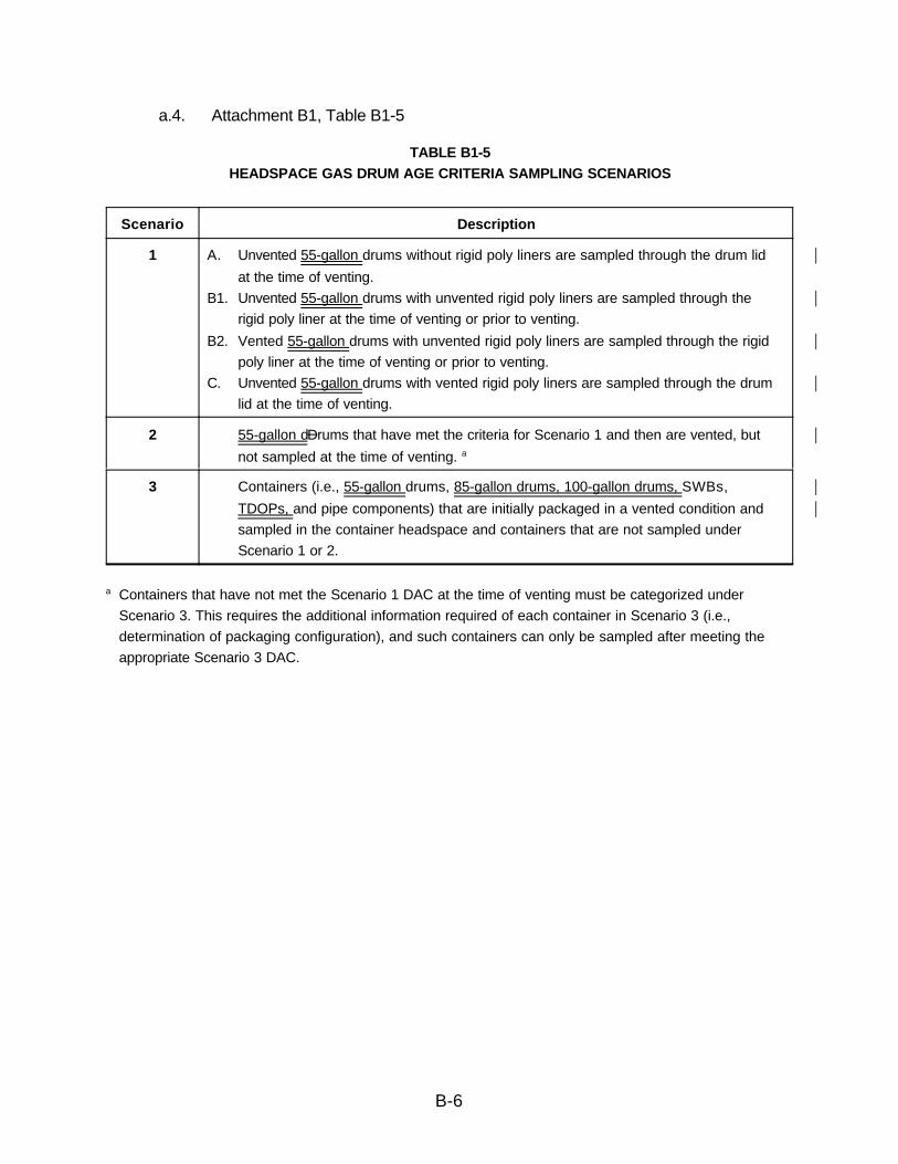
a.4. Attachment B1, Table B1-5 Table B1-5 has been revised as follows:• To clarify that the descriptions for Scenarios 1 and 2 apply to 55-gallon
drums.• To clarify that Scenario 3 applies to 55-gallon drums, 85-gallon drums,
100-gallon drums, and TDOPs.
a.5. Attachment B1, Table B1-8 Table B1-8 has been revised as follows:• To add the TDOP configuration to Packaging Configuration Groups 5 and 6.• To add Packaging Configuration Group 7 to describe specific packaging
configurations for 85- and 100-gallon drums that are directly loaded withwaste.
• To specify (in Footnote “a”) the conservative default Packaging ConfigurationGroup 3 for 85- and 100-gallon drums and Packaging Configuration Group 6for TDOPs.

Affected Permit Section Explanation for Change
A-3
a.6. Attachment B1, Table B1-9 Tables B1-9 and B1-10 have been revised as follows:• To specify TDOP DAC values for Packaging Configuration Groups 5 and 6
and 85- and 100-gallon drum DAC values for Packaging Configuration Group7.
• To clarify (in Footnote “c”) that, similar to the standard waste box, the filterH2 diffusivity specified for a TDOP is the sum of the diffusivities for all of thefilters on the container.
• To add a new Footnote “d” for Packaging Configuration Group 7 (85- and100-gallon drums) to clarify that the DAC values apply when the headspacegas sample is taken between the inner and outer drum lids. Footnote “d”specifies a DAC value of 2 days for an 85- or 100-gallon drum in which theheadspace gas sample is taken inside the filtered inner drum lid.
• To add a new Footnote “e” to clarify that while a DAC value of 2 days may bedetermined, containers must also comply with the equilibrium requirements ofSection B1-1a (i.e., 72 hours at 18EC or higher). Generator sites may complywith these requirements simultaneously.
a.7. Attachment B1, Table B1-10

B-1
Attachment B
Proposed Revised Permit Text

B-2
Proposed Revised Permit Text:
a.1. Attachment B1, Section B1-1a(1)
B1-1a(1) Summary Category S5000 Requirements
All waste containers or randomly selected containers from waste streams that meet theconditions for reduced headspace gas sampling listed in Permit Attachment B, Section
B-3a(1), designated as summary category S5000 (Debris waste) shall be categorizedunder one of the sampling scenarios shown in Table B1-5 and depicted in Figure B1-1. Ifthe container is categorized under Scenario 1, the applicable drum age criteria (DAC) from
Table B1-6 must be met prior to headspace gas sampling. If the container is categorizedunder Scenario 2, the applicable Scenario 1 DAC from Table B1-6 must be met prior toventing the container and then the applicable Scenario 2 DAC from Table B1-7 must bemet after venting the container. The DAC for Scenario 2 containers that contain filters or
rigid liner vent holes other than those listed in Table B1-7 shall be determined usingfootnotes “a” and “b” in Table B1-7. Containers that have not met the Scenario 1 DAC atthe time of venting must be categorized under Scenario 3. Containers categorized under
Scenario 3 must be placed into one of the Packaging Configuration Groups listed in TableB1-8. If a specific packaging configuration cannot be determined based on the datacollected during packaging and/or repackaging (Attachment B, Section B-3(d)1), aconservative default Packaging Configuration Group of 3 for 55-gallon, 85-gallon, and |100-gallon drums and 6 for Standard Waste Boxes (SWBs) and ten-drum overpacks |(TDOPs) must be assigned, provided the drums do not contain pipe component packaging. |If a container is designated as Packaging Configuration Group 4 (i.e., a pipe component),
the headspace gas sample must be taken from the pipe component headspace. If a 100- |gallon drum (i.e. Packaging Configuration Group 7) contains a compacted 55-gallon drum |containing a rigid liner, the 55-gallon drum must meet the appropriate 55-gallon drum DAC |listed in Table B1-6, B1-7 or B1-10 to ensure that VOC solubility associated with the |presence of the 55-gallon rigid drum liner does not impact the DAC for the 100-gallon drum. |The DAC for Scenario 3 containers that contain rigid liner vent holes that are |undocumented during packaging (Attachment B, Section B-3(d)1), repackaging(Attachment B, Section B-3(d)1), and/or venting (Section B1-1a[6][ii]) shall be determined
using the default conditions in footnote “b” in Table B1-9.The DAC for Scenario 3 containersthat contain filters that are either undocumented or are other than those listed in Table B1-9 shall be determined using footnote ‘a’ in Table B1-9. Each of the Scenario 3 containers
shall be sampled for headspace gas after waiting the DAC in Table B1-9 based on itspackaging configuration (note: Packaging Configuration Groups 4, 5, and 6, and 7 are not |summary category group dependent, and 85-gallon drum, 100-gallon drum, SWB, and |TDOP requirements apply when the 85-gallon drum, 100-gallon drum, SWB, or TDOP itself |is used for the direct loading of waste).

B-3
a.2. Attachment B1, Section B1-1a(2)
B1-1a(2) Summary Category S3000/S4000 Requirements
All waste containers or randomly selected containers from waste streams that meet theconditions for reduced headspace gas sampling listed in Permit Attachment B, Section B-
3a(1), designated as summary categories S3000 (Homogenous solids) and S4000(Soil/gravel) shall be categorized under one of the sampling scenarios shown in Table B1-5and depicted in Figure B1-1. If the container is categorized under Scenario 1, the
applicable DAC from Table B1-6 must be met prior to headspace gas sampling. If thecontainer is categorized under Scenario 2, the applicable Scenario 1 DAC from Table B1-6must be met prior to venting the container and then the applicable Scenario 2 DAC fromTable B1-7 must be met after venting the container. The DAC for Scenario 2 containers
that contain filters or rigid liner vent holes other than those listed in Table B1-7 shall bedetermined using footnotes “a” and “b” in Table B1-7. Containers that have not met theScenario 1 DAC at the time of venting must be categorized under Scenario 3. Containers
categorized under Scenario 3 must be placed into one of the Packaging ConfigurationGroups listed in Table B1-8. If a specific packaging configuration cannot be determinedbased on the data collected during packaging and/or repackaging (Attachment B, SectionB-3(d)1), a conservative default Packaging Configuration Group of 3 for 55-gallon, 85-gallon, |and 100-gallon drums and 6 for SWBs and TDOPs must be assigned, provided the drums |do not contain pipe component packaging. If a container is designated as PackagingConfiguration Group 4 (i.e., a pipe component), the headspace gas sample must be taken
from the pipe component headspace. If a 100-gallon drum (i.e. Packaging Configuration |Group 7) contains a compacted 55-gallon drum containing a rigid liner, the 55-gallon drum |must meet the appropriate 55-gallon drum DAC listed in Table B1-6, B1-7 or B1-10 to |ensure that VOC solubility associated with the presence of the 55-gallon rigid drum liner |does not impact the DAC for the 100-gallon drum. The DAC for Scenario 3 containers that |contain rigid liner vent holes that are undocumented during packaging (Attachment B,Section B-3(d)1), repackaging (Attachment B, Section B-3(d)1), and/or venting (SectionB1-1a[6][ii]) shall be determined using the default conditions in footnote “b” in Table B1-10.
The DAC for Scenario 3 containers that contain filters that are either undocumented or areother than those listed in Table B1-10 shall be determined using footnote ‘a’ in Table B1-10. Each of the Scenario 3 containers shall be sampled after waiting the DAC in Table B1-
10 based on its packaging configuration (note: Packaging Configuration Groups 4, 5, and6, and 7 are not summary category group dependent, and 85-gallon drum, 100-gallon drum, |SWB, and TDOP requirements apply when the 85-gallon drum, 100-gallon drum, SWB, or |TDOP itself is used for the direct loading of waste). |

B-4
a.3. Attachment B1, Section B1-1a(3)
B1-1a(3) General Requirements
The determination of packaging configuration consists of identifying the number ofconfinement layers and the identification of rigid poly liners when present.
Generator/storage sites shall use either the default conditions specified in Tables B1-7through B1-10 for retrievably stored waste or the data documented during packaging(Attachment B, Section B-3(d)1), repackaging (Attachment B, Section B-3(d)1), and/or
venting (Section B1-1a[6][ii]) for determining the appropriate DAC for each container fromwhich a headspace gas sample is collected. These drum age criteria are to ensure that thecontainer contents have reached 90 percent of steady state concentration within each layerof confinement (Lockheed, 1995; BWXT, 2000). The following information must be reported
in the headspace gas sampling documents for each container from which a headspace gassample is collected:
• sampling scenario from Table B1-5 and associated information from Tables B1-6and/or Table B1-7;
• the packaging configuration from Table B1-8 and associated information fromTables B1-9 or B1-10, including the diameter of the rigid liner vent hole, the number
of inner bags, the number of liner bags, the presence/absence of drum liner, andthe filter hydrogen diffusivity,
• the permit-required equilibrium time, and
• the drum age.
For all retrievably stored waste containers, the rigid liner vent hole diameter must beassumed to be 0.3 inches unless a different size is documented during drum venting or
repackaging. For all retrievably store waste containers, the filter hydrogen diffusivity mustbe assumed to be the most restrictive unless container-specific information clearlyidentifies a filter model and/or diffusivity characteristic that is less restrictive. For allretrievably stored waste containers that have not been repackaged, acceptable knowledge
shall not be used to justify any packaging configuration less conservative than the default(i.e., Packaging Configuration Group 3 for 55-gallon, 85-gallon, and 100-gallon drums and 6 |for SWBs and TDOPs). For information reporting purposes listed above, sites may report |the default packaging configuration for retrievably stored waste without further confirmation.
All waste containers with unvented rigid containers greater than 4 liters (exclusive of rigidpoly liners) shall be subject to innermost layer of containment sampling or shall be vented
prior to initiating drum age and equilibrium criteria. When sampling the rigid poly liner underScenario 1, the sampling device must form an airtight seal with the rigid poly liner toensure that a representative sample is collected (using a sampling needle connected to the
sampling head to pierce the rigid poly liner, and that allows for the collection of arepresentative sample, satisfies this requirement). The configuration of the containmentarea and remote-handling equipment at each sampling facility are expected to differ.Headspace-gas samples will be analyzed for the analytes listed in Table B3-2 of Permit

B-5
Attachment B3. If additional packaging configurations are identified, an appropriate PermitModification will be submitted to incorporate the DAC using the methodology in BWXT(2000). Consistent with footnote “a” in Table B1-8, any waste container that cannot beassigned a packaging configuration specified in Table B1-8 shall not be shipped to or
accepted for disposal at WIPP.
Drum age criteria apply only to 55-gallon drums, 85-gallon drums, 100-gallon drums, and |standard waste boxes, and TDOPs. Drum age criteria for all other container types must be |established through permit modification prior to acceptance of these containers at WIPP.
B-6
a.4. Attachment B1, Table B1-5
TABLE B1-5HEADSPACE GAS DRUM AGE CRITERIA SAMPLING SCENARIOS
Scenario Description
1 A. Unvented 55-gallon drums without rigid poly liners are sampled through the drum lid |at the time of venting.
B1. Unvented 55-gallon drums with unvented rigid poly liners are sampled through the |rigid poly liner at the time of venting or prior to venting.
B2. Vented 55-gallon drums with unvented rigid poly liners are sampled through the rigid |poly liner at the time of venting or prior to venting.
C. Unvented 55-gallon drums with vented rigid poly liners are sampled through the drum |lid at the time of venting.
2 55-gallon dDrums that have met the criteria for Scenario 1 and then are vented, but |not sampled at the time of venting. a
3 Containers (i.e., 55-gallon drums, 85-gallon drums, 100-gallon drums, SWBs, |TDOPs, and pipe components) that are initially packaged in a vented condition and |sampled in the container headspace and containers that are not sampled underScenario 1 or 2.
a Containers that have not met the Scenario 1 DAC at the time of venting must be categorized underScenario 3. This requires the additional information required of each container in Scenario 3 (i.e.,determination of packaging configuration), and such containers can only be sampled after meeting theappropriate Scenario 3 DAC.

B-7
a.5. Attachment B1, Table B1-8
TABLE B1-8SCENARIO 3 PACKAGING CONFIGURATION GROUPS
Packaging Configuration Group Covered S3000/S4000Packaging Configuration
Groups
Covered S5000 PackagingConfiguration Groups
Packaging Configuration Group 1,55 gal. drums a
• No layers of confinement,filtered inner lid b
• No inner bags, no liner
bags (bounding case)
• No layers of confinement,filtered inner lid b
• No inner bags, no liner
bags (bounding case)
Packaging Configuration Group 2,
55 gal. drums a
• 1 inner bag
• 1 filtered inner bag• 1 liner bag (bounding
case)
• 1 filtered liner bag
• 1 inner bag
• 1 filtered inner bag• 1 liner bag• 1 filtered liner bag
• 1 inner bag, 1 liner bag• 1 filtered inner bag, 1
filtered liner bag• 2 inner bags
• 2 filtered inner bags• 2 inner bags, 1 liner bag• 2 filtered inner bags, 1
filtered liner bag• 3 inner bags• 3 filtered inner bags• 3 filtered inner bags, 1
filtered liner bag• 3 inner bags, 1 liner bag
(bounding case)
Packaging Configuration Group 3,55 gal. drums a
• 1 inner bag, 1 liner bag• 1 filtered inner bag, 1
filtered liner bag• 2 inner bags• 2 filtered inner bags
• 2 liner bags (boundingcase)
• 2 filtered liner bags
• 2 liner bags• 2 filtered liner bags
• 1 inner bag, 2 liner bags• 1 filtered inner bag, 2
filtered liner bags
• 2 inner bags, 2 liner bags• 2 filtered inner bags, 2
filtered liner bags• 3 filtered inner bags, 2
filtered liner bags• 4 inner bags• 3 inner bags, 2 liner bags • 4 inner bags, 2 liner bags
(bounding case)

Packaging Configuration Group Covered S3000/S4000Packaging Configuration
Groups
Covered S5000 PackagingConfiguration Groups
B-8
Packaging Configuration Group 4, pipecomponents
• No layers of confinementinside a pipe component
• 1 filtered inner bag, 1filtered metal can inside apipe component
• 2 inner bags inside a pipe
component• 2 filtered inner bags inside
a pipe component
• 2 filtered inner bags, 1filtered metal can inside apipe component
• 2 inner bags, 1 filtered
metal can inside a pipecomponent (boundingcase)
Packaging Configuration Group 5,Standard Waste Box or Ten-Drum |Overpack a |
• No layers of confinement• 1 SWB liner bag
(bounding case)
• No layers of confinement• 1 SWB liner bag
(bounding case)
Packaging Configuration Group 6,Standard Waste Box or Ten-Drum |Overpack a |
• any combination of innerand/or liner bags that isless than or equal to 6
• 5 inner bags, 1 SWB liner
bag (bounding case)
• any combination of innerand/or liner bags that isless than or equal to 6
• 5 inner bags, 1 SWB liner
bag (bounding case)
Packaging Configuration Group 7, |85-gal. drums and 100-gal. drums a |
• No inner bags, no liner |bags, no rigid liner, filtered |inner lid (bounding case) b |
• No inner bags, no liner |bags, no rigid liner |
• No inner bags, no liner |bags, no rigid liner, filtered |inner lid (bounding case) b |
• No inner bags, no liner |bags, no rigid liner |
a If a specific Packaging Configuration Groups cannot be determined based on the data collected duringpackaging (Attachment B, Section B-3(d)1) and/or repackaging (Attachment B, Section B-3(d)1), a
conservative default Packaging Configuration Group of 3 for 55-gallon, 85-gallon, and 100-gallon drums |and 6 for SWBs and TDOPs must be assigned provided the drums do not contain pipe component |packaging. If pipe components are present as packaging in the drums, the pipe components must besampled following the requirements for Packaging Configuration Group 4.
b A “filtered inner lid” is the inner lid on a double lid drum that contains a filter.
Definitions:

B-9
Liner Bags: One or more optional plastic bags that are used to control radiological contamination. Linerbags for drums have a thickness of approximately 11 mils. SWB/TDOP liner bags have a thickness of |approximately 14 mils. Liner bags are typically similar in size to the container.
Inner Bags: One or more optional plastic bags that are used to control radiological contamination. Innerbags have a thickness of approximately 5 mils and are typically smaller than liner bags.

B-10
a.6. Attachment B1, Table B1-9
TABLE B1-9SCENARIO 3 DRUM AGE CRITERIA (in days) MATRIX FOR S5000 WASTE
BY PACKAGING CONFIGURATION GROUP
Packaging Configuration Group 1
Filter H2 Diffusivity a
(mol/s/mol fraction)
Rigid Liner Vent Hole Diameter b
No LinerLid No Liner
0.3-inchDiameter
Hole
0.375-inchDiameter
Hole
0.75-inchDiameter
Hole
1-inchDiameter
Hole
1.9 x 10⁻⁶ 131 95 37 24 4 4
3.7 x 10⁻⁶ 111 85 36 24 4 4
3.7 x 10⁻⁵ 28 28 23 19 4 4
Packaging Configuration Group 2
Filter H2 Diffusivity a
(mol/s/mol fraction)
Rigid Liner Vent Hole Diameter b
No Liner
Lid No Liner
0.3-inchDiameter
Hole
0.375-inchDiameter
Hole
0.75-inchDiameter
Hole
1-inchDiameter
Hole
1.9 x 10⁻⁶ 175 138 75 60 30 11
3.7 x 10⁻⁶ 152 126 73 59 30 11
3.7 x 10⁻⁵ 58 57 52 47 28 8
Packaging Configuration Group 3
Filter H2 Diffusivity a
(mol/s/mol fraction)
Rigid Liner Vent Hole Diameter b
No LinerLid No Liner
0.3-inch
DiameterHole
0.375-inch
DiameterHole
0.75-inch
DiameterHole
1-inch
DiameterHole
1.9 x 10⁻⁶ 199 161 96 80 46 16
3.7 x 10⁻⁶ 175 148 93 79 46 16
3.7 x 10⁻⁵ 72 72 67 62 42 10
Packaging Configuration Group 4
Filter H2 Diffusivity a
(mol/s/mol fraction) Headspace Sample Taken Inside Pipe Component

B-11
> 1.9 x 10⁻⁶ 152
Packaging Configuration Group 5
Filter H2 Diffusivity a, c
(mol/s/mol fraction) Headspace Sample Taken Inside SWB/TDOP |
> 7.4 x 10⁻⁶ (SWB) |15
> 3.33 x 10⁻⁵ (TDOP) |15 |
Packaging Configuration Group 6
Filter H2 Diffusivity a, c
(mol/s/mol fraction) Headspace Sample Taken Inside SWB/TDOP |
> 7.4 x 10⁻⁶ (SWB) |56
> 3.33 x 10⁻⁵ (TDOP) |56 |
Packaging Configuration Group 7 d |
Filter H2 Diffusivity a |(mol/s/mol fraction) |
Inner Lid Filter Vent Minimum H2 Diffusivity (mol/s/mol fraction) a ||
7.4 x 10⁻⁶ |1.85 x 10⁻⁵ |9.25 x 10⁻⁵ e |
3.7 x 10⁻⁶ |13 |7 |2 |
7.4 x 10⁻⁶ |10 |6 |2 |
1.85 x 10⁻⁵ |6 |4 |2 |
a The documented filter H2 diffusivity must be greater than or equal to the listed value to use the DAC for thelisted filter H2 diffusivity (e.g., a container with a filter H2 diffusivity of 4.2 x 10⁻⁶ must use a DAC for a filter
with a 3.7 x 10⁻⁶ filter H2 diffusivity). If a filter H2 diffusivity for a container is undocumented or unknown oris less than 1.9 x 10⁻⁶ filter H2 diffusivity, a filter of known H2 diffusivity that is greater than or equal to 1.9 x10⁻⁶ filter H2 diffusivity must be installed prior to initiation of the relevant DAC period.
b The documented rigid liner vent hole diameter must be greater than or equal to the listed value to use theDAC for the listed rigid liner vent hole diameter (e.g., a container with a rigid liner vent hole of 0.5 in. mustuse a DAC for a rigid liner vent hole of 0.375 in.). If the rigid liner vent hole diameter for a container is
undocumented during packaging (Attachment B, Section B-3(d)1), repackaging (Attachment B, SectionB-3(d)1), and/or venting (Section B1-1a[6][ii]), that container must use a DAC for a rigid liner vent holediameter of 0.30 in.
CThe filter H2 diffusivity for SWBs or TDOPs is the sum of the diffusivities for all of the filters on the |container because SWBs and TDOPs have more than 1 filter. |

B-12
d Headspace sample taken between inner and outer drum lids. If headspace sample is taken inside the |filtered inner drum lid prior to placement of the outer drum lid, then a DAC value of 2 days may be used. |Footnote e is also applicable. |
|e While a DAC value of 2 days may be determined, containers must comply with the equilibrium |
requirements specified in Section B1-1a (i.e., 72 hours at 18EC or higher). Generator sites may |comply with these requirements simultaneously. |
a.7. Attachment B1, Table B1-10
TABLE B1-10SCENARIO 3 DRUM AGE CRITERIA (in days) MATRIX FOR S3000 AND S4000 WASTE BY
PACKAGING CONFIGURATION GROUP
Packaging Configuration Group 1
Filter H2 Diffusivity a
(mol/s/mol fraction)
Rigid Liner Vent Hole Diameter b
No Liner
Lid No Liner
0.3-inchDiameter
Hole
0.375-inchDiameter
Hole
0.75-inchDiameter
Hole
1-inchDiameter
Hole
1.9 x 10⁻⁶ 131 95 37 24 4 4
3.7 x 10⁻⁶ 111 85 36 24 4 4
3.7 x 10⁻⁵ 28 28 23 19 4 4
Packaging Configuration Group 2
Filter H2 Diffusivity a
(mol/s/mol fraction)
Rigid Liner Vent Hole Diameter b
No LinerLid No Liner
0.3-inchDiameter
Hole
0.375-inchDiameter
Hole
0.75-inchDiameter
Hole
1-inchDiameter
Hole
1.9 x 10⁻⁶ 213 175 108 92 56 18
3.7 x 10⁻⁶ 188 161 105 90 56 17
3.7 x 10⁻⁵ 80 80 75 71 49 10
Packaging Configuration Group 3
Filter H2 Diffusivity a
(mol/s/mol fraction)
Rigid Liner Vent Hole Diameter b
No LinerLid No Liner
0.3-inchDiameter
Hole
0.375-inchDiameter
Hole
0.75-inchDiameter
Hole
1-inchDiameter
Hole

B-13
1.9 x 10⁻⁶ 283 243 171 154 107 34
3.7 x 10⁻⁶ 253 225 166 151 106 31
3.7 x 10⁻⁵ 121 121 115 110 84 13
Packaging Configuration Group 4
Filter H2 Diffusivity a
(mol/s/mol fraction) Headspace Sample Taken Inside Pipe Component
> 1.9 x 10⁻⁶ 152
Packaging Configuration Group 5
Filter H2 Diffusivity a, c
(mol/s/mol fraction) Headspace Sample Taken Inside SWBS/TDOP |
> 7.4 x 10⁻⁶ (SWB) |15
> 3.33 x 10⁻⁵ (TDOP) |15 |
Packaging Configuration Group 6
Filter H2 Diffusivity a, c
(mol/s/mol fraction) Headspace Sample Taken Inside SWBS/TDOP |
> 7.4 x 10⁻⁶ (SWB) |56
> 3.33 x 10⁻⁵ (TDOP) |56 |
Packaging Configuration Group 7 d |
Filter H2 Diffusivity a |(mol/s/mol fraction) |
Inner Lid Filter Vent Minimum H2 Diffusivity (mol/s/mol fraction) a ||
7.4 x 10⁻⁶ |1.85 x 10⁻⁵ |9.25 x 10⁻⁵ e |
3.7 x 10⁻⁶ |13 |7 |2 |
7.4 x 10⁻⁶ |10 |6 |2 |
1.85 x 10⁻⁵ |6 |4 |2 |
a The documented filter H2 diffusivity must be greater than or equal to the listed value to use the DAC for the
listed filter H2 diffusivity (e.g., a container with a filter H2 diffusivity of 4.2 x 10⁻⁶ must use a DAC for a filterwith a 3.7 x 10⁻⁶ filter H2 diffusivity). If a filter H2 diffusivity for a container is undocumented or unknown oris less than 1.9 x 10⁻⁶ filter H2 diffusivity, a filter of known H2 diffusivity that is greater than or equal to 1.9 x10⁻⁶ filter H2 diffusivity must be installed prior to initiation of the relevant DAC period.
b The documented rigid liner vent hole diameter must be greater than or equal to the listed value to use theDAC for the listed rigid liner vent hole diameter (e.g., a container with a rigid liner vent hole of 0.5. in mustuse a DAC for a rigid liner vent hole of 0.375 in.). If the rigid liner vent hole diameter for a container is

B-14
undocumented during packaging (Attachment B, Section B-3(d)1), repackaging (Attachment B, SectionB-3(d)1), and/or venting (Section B1-1a[6][ii]), that container must use a DAC for a rigid liner vent holediameter of 0.30 in.
C The filter H2 diffusivity for SWBs or TDOPs is the sum of the diffusivities for all of the filters on the |container because SWBs and TDOPs have more than 1 filter. |
d Headspace sample taken between inner and outer drum lids. If headspace sample is taken inside the |filtered inner drum lid prior to placement of the outer drum lid, then a DAC value of 2 days may be used. |Footnote e is also applicable. |
|e While a DAC value of 2 days may be determined, containers must comply with the equilibrium |
requirements specified in Section B1-1a (i.e., 72 hours at 18EC or higher). Generator sites may comply |with these requirements simultaneously. |

C-1
Attachment C
Determination of Drum Age Criteria Values forTen-Drum Overpacks, 85-Gallon Drums, and 100-Gallon Drums

i
DETERMINATION OF DRUM AGE CRITERIA VALUES FOR TEN-DRUM OVERPACKS,85-GALLON DRUMS, AND 100-GALLON DRUMS
REVISION 0
Shaw Environmental & Infrastructure, Inc.5301 Central Avenue NE, Suite 700Albuquerque, New Mexico 87108
December 2002

ii
Table of Contents ________________________________________
Background and Purpose ________________________________________________________ 1Assumptions _________________________________________________________________ 1
TDOP ________________________________________________________________ 1100-Gallon Drum ________________________________________________________ 185-Gallon Drum _________________________________________________________ 2
Defining DAC Values for TDOP, 100-Gallon Drum, and 85-Gallon Drum ___________________ 2References ___________________________________________________________________ 3Appendix A Input and Output Files Associated with DAC Value Determination for the TDOP, 85-
Gallon Drum, and 100-Gallon Drum ________________________________________ A-1

1
Background and Purpose _________________________________
Containers of transuranic (TRU) waste must meet a minimum age criterion before a gas samplecollected from the waste container is considered representative of the gas within the containerheadspace. The drum age criterion (DAC) is the time required after container closure, or aftercontainer closure and container venting, before a headspace gas sample can be collected. Themethodology described in “Determination of Drum Age Criteria and Prediction Factors Based onPackaging Configurations” (Bechtel BWXT Idaho, LLC [BWXT], 2000) [1] is the basis for thepackaging-specific DAC values currently approved in the Hazardous Waste Facility Permit for theWaste Isolation Pilot Plant (WIPP) (“Permit”) [2].
The following three new waste containers have been approved in the Permit for disposal at the WIPP:direct-loaded ten-drum overpack (TDOP), 100-gallon drum, and direct-loaded 85-gallon drum.
The purpose of this report is to document packaging-specific DAC values for the TDOP, 100-gallondrum, and 85-gallon drum as determined using the BWXT (2000) methodology [1]. The application ofthe BWXT (2000) methodology [1] to the TDOP, 100-gallon drum, and 85-gallon drum is consistentwith the direction provided by Section B1-1a (3) of Attachment B1 of the Permit [2], which requiresthe following: “If additional packaging configurations are identified, an appropriate Permit Modificationwill be submitted to incorporate the DAC using the methodology in BWXT (2000).” Modelparameters and assumptions used in determining the DAC values are also documented in this report.
Assumptions ____________________________________________
The BWXT (2000) report documents all parameters and assumptions used in previous DACcalculations [1]. Parameter values specific to the TDOP, 100-gallon drum, and 85-gallon drum arelisted in the input and output files included in Appendix A. Additional assumptions used in determiningthe DAC values for the TDOP, 100-gallon drum, and 85-gallon drum are presented in this section.
TDOP
The TDOP packaging configurations consist of (1) up to one SWB liner bag and (2) up to six baglayers total, up to one of which may be an SWB liner bag. The TDOP has nine filter vents withminimum hydrogen diffusivity values of 3.7E-6 moles per second per mole fraction (mol/s/mol fraction). All other configuration parameters for the TDOP are assumed to be the same as those used fordetermining the packaging-specific DAC values for the SWB [1]. The inner bags and SWB liner bagsused in the TDOP packaging configurations are of the same dimensions as those used in an SWB.

2
100-Gallon Drum
The modeled 100-gallon drum packaging configuration includes one filtered non-polymeric (e.g., steel)inner drum lid, no layers of confinement, and no rigid drum liner. The DAC values are calculated forthe case in which the headspace gas sample is collected between the inner and outer drum lids, as wellas for the case in which the headspace gas sample is collected inside the inner drum lid. The DACvalues for this 100-gallon drum packaging configuration were determined for three hydrogen diffusionvalues for the inner drum lid filter vent (i.e., 7.4E-6 mol/s/mol fraction, 1.85E-5 mol/s/mol fraction, and9.25E-5 mol/s/mol fraction) in combination with three hydrogen diffusion values for the outer drum lidfilter vent (i.e., 3.7E-6 mol/s/mol fraction, 7.4E-6 mol/s/mol fraction, and 1.85E-5 mol/s/mol fraction).
In some cases, 55-gallon drums may be supercompacted and packaged as “pucks” directly into 100-gallon drums. Compacted 55-gallon drums containing rigid drum liners placed inside the 100-gallondrum must meet the appropriate 55-gallon drum DAC value established by the Permit [2] prior tocompaction. This ensures that VOC solubility associated with the presence of the 55-gallon rigid drumliner does not impact the calculated DAC for a 100-gallon drum.
85-Gallon Drum
The packaging configuration and possible sampling locations with respect to the inner and outer drumlids for the 85-gallon drum are assumed to be the same as the 100-gallon drum.
Defining DAC Values for TDOP, 100-Gallon Drum, and 85-GallonDrum __________________________________________________
The DAC values calculated using the methodology described in BWXT (2000) [1] for the TDOP,100-gallon drum, and 85-gallon drum packaging configurations are documented in the output filesincluded in Appendix A. In some cases, a more conservative DAC value than that shown in the outputfiles was selected to simplify and facilitate implementation at the generator sites. These differences aresummarized, with explanations as needed, in Table A-1 of Appendix A. Table 1 presents the DACvalues applicable to the TDOP, 100-gallon drum, and 85-gallon drum packaging configurations.
As shown in Table 1, the DAC values for the TDOP are the same as those determined for the SWB[1]. Except for the total hydrogen diffusivity of the TDOP filters, all input parameters are the same asthe SWB. The minimum total hydrogen diffusivity of the TDOP filters (nine filters, each with ahydrogen diffusivity value of 3.7E-6 mol/s/mol fraction) is 4.5 times greater than the minimum totalhydrogen diffusivity of the SWB filters (two filters, each with a hydrogen diffusivity value of 3.7E-6mol/s/mol fraction). As shown in the output files in Appendix A, the difference in the total hydrogendiffusivity values between the TDOP and the SWB filters results in the calculation of shorter DACvalues for the TDOP. The SWB DAC values bound the DAC values for the modeled TDOPpackaging configurations.

3
Table 1DAC Values (in days) for Summary Category Groups S3000, S4000, and S5000
TDOP with Up to One Liner BagTDOP Minimum Total Filter Diffusivitya
(mol/s/mol fraction) Headspace Sample Taken Inside Direct Load TDOP3.33E-5 15
TDOP with Up to Five Inner Bags and One Liner BagTDOP Minimum Total Filter Diffusivitya
(mol/s/mol fraction)Headspace Sample Taken Inside Direct Load TDOP
3.33E-5 56
100-Gallon Drum and 85-Gallon Drumwith Headspace Samples Taken between Inner and Outer Drum Lidsb
Outer Lid Minimum FilterDiffusivity
(mol/s/mol fraction)
Inner Lid Filter Minimum Diffusivity(mol/s/mol fraction)
7.4E-6 1.85E-5 9.25E-53.7E-6 13 7 27.4E-6 10 6 21.85E-5 6 4 2
a Sum of all filters in the lid of the TDOP.b If headspace sample is taken inside the non-polymeric (e.g., steel) inner drum lid with a filter vent ofhydrogen diffusivity value equal to or greater than 7.4E-6 mol/s/mol fraction prior to placement of theouter drum lid, then a DAC value of 2 days is applicable.
The DAC values calculated for 85-gallon drums are less than the DAC values for the 100-gallon drumas shown in the output files included in Appendix A due to the smaller void volume in the 85-gallondrum. As documented in Table A-1 of Appendix A, the 100-gallon drum DAC values bound the DACvalues for the 85-gallon drum packaging configurations that were modeled.
For the case in which the 100-gallon drum or 85-gallon drum headspace gas sample is taken inside theinner drum lid, the highest DAC value determined was one day for a drum with an inner drum lid filtervent with a hydrogen diffusivity value equal to or greater than 7.4E-6 mol/s/mol fraction. Asdocumented in Appendix A, a 2-day DAC value bounds the 100-gallon drum and 85-gallon drumpackaging configurations sampled inside the inner drum lid.
References _____________________________________________
32 Liekhus, K.J., Djordjevic, S.M., Devarakonda, M., and Connolly, M.J., October 2000,“Determination of Drum Age Criteria and Prediction Factors Based on Packaging Configurations,”INEEL/EXT-2000-01207, Bechtel BWXT Idaho, LLC, Idaho Falls, Idaho.

A-1
33 New Mexico Environment Department, “Waste Isolation Pilot Plant Hazardous Waste FacilityPermit,” NM4890139088-TSDF, New Mexico Environment Department, Santa Fe, NewMexico.
1.18Input and Output Files Associated with DAC Value Determination for the TDOP, 85-Gallon
Drum, and 100-Gallon Drum
This appendix includes the input and output files for the TDOP, 85-gallon drum, and 100-gallon drumthat document the calculation of DAC values using the methodology described in BWXT (2000) [1]. In some cases, a more conservative DAC value than that shown in the output files was selected tosimplify and facilitate implementation at the generator sites. These differences are summarized, withexplanations as needed, in Table A-1.
Table A-1Correlation between Calculated DAC Values and DAC Values Selected for Use
for the TDOP, 100-Gallon Drum, and 85-Gallon Drum
Input/OutputFilename
Waste Container Type andPackaging
DAC ValueCalculatedby VDRUM
DAC ValueSelected for
Use Justification for Difference(if applicable)
TDOPtdop02/tdop02.out
TDOP with one SWB liner bag andnine 3.7E06 mol/s/mf filters
13 15 Bounded by DAC value forSWB configuration with oneSWB liner bag [1]
tdop01/tdop01.out
TDOP with five inner bags and oneSWB liner bag and nine3.7E06 mol/s/mf filters
40 56 Bounded by DAC value forSWB configuration with fiveinner bags and one SWBliner bag [1]
100-Gallon Drum – Headspace Sample Taken between Inner and Outer Drum Lidst7037074/t7037074.out
100-gallon drumouter lid filter = 3.7E-06 mol/s/mfinner lid filter = 7.4E06 mol/s/mf
13 13 NA
t7037185/t7037185.out
100gallon drum outer lid filter = 3.7E-06 mol/s/mfinner lid filter = 1.85E05 mol/s/mf
7 7 NA
t7037925/t7037925.out
100-gallon drum outer lid filter = 3.7E-06 mol/s/mfinner lid filter = 9.25E05 mol/s/mf
2 2 NA
t7074074/t7074074.out
100-gallon drum
outer lid filter = 7.4E-06 mol/s/mf
inner lid filter = 7.4E06 mol/s/mf
10 10 NA
t7074185/t7074185.out
100gallon drum outer lid filter = 7.4E06 mol/s/mfinner lid filter = 1.85E05 mol/s/mf
6 6 NA

Input/OutputFilename
Waste Container Type andPackaging
DAC ValueCalculatedby VDRUM
DAC ValueSelected for
Use Justification for Difference(if applicable)
A-2
t7074925/t7074925.out
100gallon drum outer lid filter = 7.4E06 mol/s/mfinner lid filter = 9.25E05 mol/s/mf
2 2 NA
t7185074/t7185074.out
100gallon drum outer lid filter = 1.85E05 mol/s/mfinner lid filter = 7.4E06 mol/s/mf
6 6 NA
t7185185/t7185185.out
100gallon drum outer lid filter = 1.85E05 mol/s/mfinner lid filter = 1.85E05 mol/s/mf
4 4 NA

Table A-1Correlation between Calculated DAC Values and DAC Values Selected for Use
for the TDOP, 100-Gallon Drum, and 85-Gallon Drum (continued)
A-3
Input/OutputFilename
Waste Container Type andPackaging
DAC ValueCalculatedby VDRUM
DAC ValueSelected for
Use Justification for Difference(if applicable)
t7185925/t7185925.out
100gallon drum outer lid filter = 1.85E05 mol/s/mfinner lid filter = 9.25E05 mol/s/mf
2 2 NA
100-Gallon Drum – Headspace Sample Taken Inside Inner Drum Lidt7000074/t7000074.out
100gallon druminner lid filter = 7.4E6 mol/s/mf
1 2 Bounded by DAC value for100gallon drum with two lids(t7185925/t7185925.out)
t7000185/t7000185.out
100gallon druminner lid filter = 1.85E5 mol/s/mf
1 2 Bounded by DAC value for100gallon drum with two lids(t7185925/t7185925.out)
t7000925/t7000925.out
100gallon druminner lid filter = 9.25E-5 mol/s/mf
1 2 Bounded by DAC value for100-gallon drum with twolids(t7185925/t7185925.out)

Table A-1Correlation between Calculated DAC Values and DAC Values Selected for Use
for the TDOP, 100-Gallon Drum, and 85-Gallon Drum (continued)
Input/OutputFilename
Waste Container Type andPackaging
DAC ValueCalculatedby VDRUM
DAC ValueSelected for
Use Justification for Difference(if applicable)
A-4
85-Gallon Drum – Headspace Sample Taken between Inner and Outer Drum Lidst8037074/t8037074.out
85gallon drum outer lid filter = 3.7E6 mol/s/mfinner lid filter = 7.4E6 mol/s/mf
9 13 Bounded by DAC value forcorresponding 100-gallondrum configuration
t8037185/t8037185.out
85gallon drum outer lid filter = 3.7E6 mol/s/mfinner lid filter = 1.85E5 mol/s/mf
5 7 Bounded by DAC value forcorresponding 100-gallondrum configuration
t8037925/t8037925.out
85gallon drum outer lid filter = 3.7E6 mol/s/mfinner lid filter = 9.25E5 mol/s/mf
2 2 Bounded by DAC value forcorresponding 100-gallondrum configuration
t8074074/t8074074.out
85-gallon drum outer lid filter = 7.4E6 mol/s/mfinner lid filter = 7.4E6 mol/s/mf
7 10 Bounded by DAC value forcorresponding 100-gallondrum configuration
t8074185/t8074185.out
85gallon drum outer lid filter = 7.4E6 mol/s/mfinner lid filter = 1.85E5 mol/s/mf
4 6 Bounded by DAC value forcorresponding 100-gallondrum configuration
t8074925/t8074925.out
85gallon drum outer lid filter = 7.4E6 mol/s/mfinner lid filter = 9.25E5 mol/s/mf
2 2 Bounded by DAC value forcorresponding 100-gallondrum configuration
t8185074/t8185074.out
85gallon drum outer lid filter = 1.85E5 mol/s/mfinner lid filter = 7.4E6 mol/s/mf
4 6 Bounded by DAC value forcorresponding 100-gallondrum configuration
t8185185/t8185185.out
85gallon drum outer lid filter = 1.85E5 mol/s/mfinner lid filter = 1.85E5 mol/s/mf
3 4 Bounded by DAC value forcorresponding 100-gallondrum configuration
t8185925/t8185925.out
85gallon drum outer lid filter = 1.85E5 mol/s/mfinner lid filter = 9.25E5 mol/s/mf
2 2 Bounded by DAC value forcorresponding 100-gallondrum configuration
85-Gallon Drum – Headspace Sample Taken Inside Inner Drum Lidt8000074/t8000074.out
85gallon drumNo outer lidinner lid filter = 7.4E6 mol/s/mf
1 2 Bounded by DAC value forcorresponding 100-gallondrum configuration
t8000185/t8000185.out
85gallon drumNo outer lidinner lid filter = 1.85E-5 mol/s/mf
1 2 Bounded by DAC value forcorresponding 100-gallondrum configuration
t8000925/t8000925.out
85gallon drumNo outer lidinner lid filter = 9.25E5 mol/s/mf
1 2 Bounded by DAC value forcorresponding 100-gallondrum configuration
mol/s/mf = mole per second per mole fractionNA = Not applicable

A-5
The computer program VDRUM used for deriving DAC values in BWXT (2000) [1] employs inputfiles of required data and reports the time for volatile organic compounds (VOCs) to reach at least 90percent of their steady state concentrations. The input file for each packaging configuration includes thesame data structure beginning with the input and output file names and the number of VOCs evaluated. Each VOC included in the analysis has two lines of input data, the initial concentrations in the layers ofconfinement and the physical and chemical properties. The physical characteristics, such as thicknessand surface area, of each type of confinement layer are entered. Specific information about data inputincludes the following:
� For the 100-gallon drum in which the headspace sample is taken between the filtered innerand outer drum lids, the configuration modeled by VDRUM includes one filtered non-polymeric (e.g., steel) inner drum lid and one filtered outer lid. The packaging configurationhas no plastic layers of confinement (i.e., no inner bags and no liner bags) or rigid drumliner. The hydrogen release rate across the inner drum lid is defined by the hydrogendiffusivity of the filter vent. The DAC value was calculated for three hydrogen diffusivityvalues for the inner drum lid (i.e., 7.4E-6 mol/s/mol fraction, 1.85E-5 mol/s/mol fraction,and 9.25E-5 mol/s/mol fraction).
� For the 100-gallon drum in which the headspace sample is taken inside the filtered non-polymeric (e.g., steel) inner drum lid prior to placement of the outer drum lid, VDRUMmodels this packaging configuration with a hypothetical innermost layer that is very thin. Bymaking the innermost layers very thin as shown in the input files, their resistance to therelease of hydrogen is removed from the analysis.
� Tc, Pc are required if D = 0. (See input file format for parameter definitions.)� Tc, Pc, Dv* are required if D* = 0 and drum is vented.� If D > 0 and D* > 0, Tc and Pc can equal zero.� In case of VOCs, gas generation does not occur (g = 0) at all times.� Only gas permeation across bags is considered, so Ad = xd = 0 (for bags only).� Although gas permeation across drum liner is not considered, specification of Ap and xp is
required to estimate the volume of liner material. xp is set to a small, non-zero value asshown in the input files.
� TDOP packaging configuration parameter values are assumed to be the same as those forthe SWB [1] given the normal packaging of large items (e.g., gloveboxes) directly in theTDOP. These values are shown in the corresponding input files.
� Assumptions for 100-gallon drum and 85-gallon drum headspace void volumes are basedon 20% of the container volume outside of the waste packaging. Assumptions for the voidvolumes between the drum lids (if two lids are used) are determined based on 100-gallondrum dimensions and by scaling the 100-gallon drum dimensions for the 85-gallon drum.
� When the headspace sample is taken between inner and outer drum lids, Dv*, the release
rate of the outermost layer of confinement, is set to the diffusivity of the outer lid filter. Because VDRUM only allows entry of one filtered layer of confinement, the filter on theinner lid can be accounted for by adjusting the parameter values for the rigid liner. Thedimensions of the drum liner are adjusted so the effective release rate equals the inner lidfilter vent (Given Ad = (D*)(xd)/(Dc0), where D* = diffusivity of the inner lid filter vent, xd =

A-6
1.0, and Dc0 = hydrogen diffusivity at standard temperature and pressure). The resultingdrum liner dimensions are shown in the corresponding input files.
� When headspace sample is taken inside inner drum lid, Dv*, the release rate of the
outermost layer of confinement, is set to the diffusivity of the inner lid filter.
To determine the drum age criteria from each analysis, the greatest time in days is selected from theVOCs (shown in bold in the output data listing). The data structures for the input and output files areshown in the following sections.

A-7
Input File Format
Line 1: Input file name, output file name, number of VOCs evaluated
Line 2: Name of VOC #1, [IB]0, [LB]0, [LHS]0, [DHS]0
Where:[IB]0 – Initial VOC concentration (ppmv) in inner bags[LB]0 – Initial VOC concentration (ppmv) in liner bags[LHS]0 – Initial VOC concentration (ppmv) in drum liner headspace[DHS]0 – Initial VOC concentration (ppmv) in drum headspace
Line 3: MW, ?, D, Tc, Pc, D*, H, k, G (see Reference 1 for VOC-specific values)Where:
MW – VOC molecular weight (g/gmol)? – VOC permeability in polyethylene @ 25ºC, Ba x (1.e-10)D – VOC diffusivity in air @ 25ºC, cm2 s-1
Tc – VOC critical temperature, KPc – VOC critical pressure, atmD* – VOC diffusivity across filter vent, mol/s/mol fractionH – VOC Henrys constant for polyethylene drum liner, (cm3 polymer) atm/(cm3 (STP)
gas)k – VOC mass transfer coefficient at drum liner surface, s-1
G – VOC generate rate (always set to 0 (zero)).
Lines (2n, 2n+1): Information for nth (last) VOC
Line (2n+2): Ap(1), Ad(1), V(1), xp(1), xd(1)Line (2n+3): Ap(2), Ad(2), V(2), xp(2), xd(2)Line (2n+4): Ap(3), Ad(3), V(3), xp(3), xd(3)Line (2n+5): Ap(4), Ad(4), V(4), xp(4), xd(4)
Where:Ap – permeable surface area, cm2
Ad – diffusional cross-sectional area, cm2
V – void volume inside layer of confinement, cm3
xp – layer thickness, cmxd – length of diffusional path length, cm1 – inner bag2 – drum liner bag3 – drum liner headspace4 – drum headspace
Line (2n+6): T, P, Dv*Where:
T – gas temperature = 25°C

A-8
P – gas pressure = 76 cm HgDv* – hydrogen diffusion characteristic across drum filter vent, mol/s/mol fraction

A-9
Output File Format
Line 1: Input file name
Lines 2, n+1: VOC, DAC, [DAC], [SS]Where:
VOC – name of VOCDAC – drum age criterion, days[DAC] – VOC concentration at the time of the DAC value, ppmv[SS] – VOC concentration at steady-state conditions, ppmv

A-10
TDOP with Up to One SWB Liner Bag
TDOP02 Input File'tdop02','tdop02.out',12'carbon tetrachloride',0.,1000.,0.,0.153.82,193.e-10,0.0828,556.4,45.0,0.,0.0217,6.e-5,0.'methanol',0.,1000.,0.,0.32.0,135.e-10,0.152,513.2,78.5,0.,0.0272,2.4e-7,0.'dichloromethane',0.,1000.,0.,0.84.9,263.e-10,0.104,510.,62.2,0.,0.0431,2.e-6,0.'toluene',0.,1000.,0.,0.92.1,669.e-10,0.0849,591.8,40.5,0.,0.002857,7.e-6,0.'trichloroethylene',0.,1000.,0.,0.131.4,583.e-10,0.0875,572.0,49.8,0.,0.00640,6.e-5,0.'butanol',0.,1000.,0.,0.74.1,300.e-10,0.,563.1,43.6,0.,0.02273,8.e-6,0.'chloroform',0.,1000.,0.,0.119.4,260.e-10,0.,536.4,53.0,0.,0.04545,8.e-6,0.'1,1-dichloroethene',0.,1000.,0.,0.96.9,110.e-10,0.,513.0,47.5,0.,0.09091,8.e-6,0.'methyl ethyl ketone',0.,1000.,0.,0.72.1,165.e-10,0.,536.8,41.5,0.,0.03704,8.e-6,0.'methyl isobutyl ketone',0.,1000.,0.,0.100.2,130.e-10,0.,571.0,32.3,0.,0.01724,8.e-6,0.'1,1,2,2-tetrachloroethane',0.,1000.,0.,0.167.9,2300.e-10,0.,661.2,57.6,0.,0.003846,8.e-6,0.'chlorobenzene',0.,1000.,0.,0.112.6,600.e-10,0.,632.4,44.6,0.,0.007692,8.e-6,0.0.,0.,0.,0.,0.1.4e4,0.,0.,0.036,0.1.4e4,150.,1.e5,0.0001,1.40.,0.,1.e5,0.,0.25.,76.,333.e-7
c Case 02: Ten-drum overpack (TDOP)c One liner bag (xp=0.036 cm)c No rigid liner (estimated by Ad=150 cm2, xp = 0.0001, xd=1.4 cm)c Void volume in layers of confinement same as in case of SWBc Void volume in headspace = 100000 cm3c D*H2 = total H2 diffusivity characteristic across (9) TDOP vents = 333.e-7 mol/s/mol frc VOC diffusivity characteristic estimated knowing D*H2, VOC Tc, VOC Pc
TDOP02 Output Filetdop02carbon tetrachloride 8 793.7534 873.4544methanol 10 694.2427 760.2239dichloromethane 6 804.3660 883.2648toluene 3 889.4951 954.5489trichloroethylene 3 860.2493 947.2747butanol 6 843.0952 906.8333chloroform 6 807.2958 892.39961,1-dichloroethene 13 720.5433 785.3380methyl ethyl ketone 9 768.9844 847.1186methyl isobutyl ketone 11 755.0751 836.7894

A-11
1,1,2,2-tetrachloroethane 1 891.8437 979.1128chlorobenzene 3 865.7315 950.6065

A-12
TDOP with up to Five Inner Bags and One SWB Liner Bag
TDOP01 Input File'tdop01','tdop01.out',12'carbon tetrachloride',1000.,0.,0.,0.153.82,193.e-10,0.0828,556.4,45.0,0.,0.0217,6.e-5,0.'methanol',1000.,0.,0.,0.32.0,135.e-10,0.152,513.2,78.5,0.,0.0272,2.4e-7,0.'dichloromethane',1000.,0.,0.,0.84.9,263.e-10,0.104,510.,62.2,0.,0.0431,2.e-6,0.'toluene',1000.,0.,0.,0.92.1,669.e-10,0.0849,591.8,40.5,0.,0.002857,7.e-6,0.'trichloroethylene',1000.,0.,0.,0.131.4,583.e-10,0.0875,572.0,49.8,0.,0.00640,6.e-5,0.'butanol',1000.,0.,0.,0.74.1,300.e-10,0.,563.1,43.6,0.,0.02273,8.e-6,0.'chloroform',1000.,0.,0.,0.119.4,260.e-10,0.,536.4,53.0,0.,0.04545,8.e-6,0.'1,1-dichloroethene',1000.,0.,0.,0.96.9,110.e-10,0.,513.0,47.5,0.,0.09091,8.e-6,0.'methyl ethyl ketone',1000.,0.,0.,0.72.1,165.e-10,0.,536.8,41.5,0.,0.03704,8.e-6,0.'methyl isobutyl ketone',1000.,0.,0.,0.100.2,130.e-10,0.,571.0,32.3,0.,0.01724,8.e-6,0.'1,1,2,2-tetrachloroethane',1000.,0.,0.,0.167.9,2300.e-10,0.,661.2,57.6,0.,0.003846,8.e-6,0.'chlorobenzene',1000.,0.,0.,0.112.6,600.e-10,0.,632.4,44.6,0.,0.007692,8.e-6,0.1.4e4,0.,0.,0.063,0.1.4e4,0.,1.9e5,0.036,0.1.4e4,150.,1.e5,0.0001,1.40.,0.,1.e5,0.,0.25.,76.,333.e-7
c Case 01: Ten-drum overpack (TDOP)c Small bags, 5 polymer bags, xp=0.063 cm, Asb=Alb=14,000 cm2c One liner bag (xp=0.036 cm)c No rigid liner (estimated by Ad=150 cm2, xp=0.0001 cm, xd=1.4 cm)c Assume same void volumes between layers of confinement as in SWBc Void volume in headspace = 100000 cm3c D*H2 = total H2 diffusivity characteristic across 9 TDOP vents = 333.e-7 mol/s/mol frc VOC diffusivity characteristic estimated knowing D*H2, VOC Tc, VOC Pc
TDOP01 Output Filetdop01carbon tetrachloride 28 656.5827 723.6465methanol 31 489.2478 539.6707dichloromethane 21 673.3795 742.2752toluene 10 815.8182 896.8104trichloroethylene 11 795.8295 879.5875butanol 19 712.1110 790.4583chloroform 22 692.4474 760.95151,1-dichloroethene 40 521.8710 576.6337methyl ethyl ketone 30 608.8997 676.2224

A-13
methyl isobutyl ketone 38 596.2039 658.38131,1,2,2-tetrachloroethane 4 912.9481 960.4730chlorobenzene 11 807.3900 888.5585

A-14
100-Gallon Drum with Headspace Sample Taken between Inner and Outer Drum Lids
T7037074: Input File 't7037074','t7037074.out',12'carbon tetrachloride',0.,1000.,0.,0.153.82,193.e-10,0.0,556.4,45.0,0.,0.0217,0.,0.'methanol',0.,1000.,0.,0.32.0,135.e-10,0.,513.2,78.5,0.,0.0272,0.,0.'dichloromethane',0.,1000.,0.,0.84.9,263.e-10,0.,510.,62.2,0.,0.0431,0.,0.'toluene',0.,1000.,0.,0.92.1,669.e-10,0.0,591.8,40.5,0.,0.002857,7.e-6,0.'trichloroethylene',0.,1000.,0.,0.131.4,583.e-10,0.0,572.0,49.8,0.,0.00640,6.e-5,0.'butanol',0.,1000.,0.,0.74.1,300.e-10,0.,563.1,43.6,0.,0.02273,8.e-6,0.'chloroform',0.,1000.,0.,0.119.4,260.e-10,0.,536.4,53.0,0.,0.04545,0.,0.'1,1-dichloroethene',0.,1000.,0.,0.96.9,110.e-10,0.,513.0,47.5,0.,0.09091,0.,0.'methyl ethyl ketone',0.,1000.,0.,0.72.1,165.e-10,0.,536.8,41.5,0.,0.03704,0.,0.'methyl isobutyl ketone',0.,1000.,0.,0.100.2,130.e-10,0.,571.0,32.3,0.,0.01724,0.,0.'1,1,2,2-tetrachloroethane',0.,1000.,0.,0.167.9,2300.e-10,0.,661.2,57.6,0.,0.003846,0.,0.'chlorobenzene',0.,1000.,0.,0.112.6,600.e-10,0.,632.4,44.6,0.,0.007692,0.,0.0.,0.,0.,0.,0.1.e5,150.,1.e4,0.1,0.31.e3,0.241,3000.,0.0001,1.00.,0.,12400.,0.,0.25.,76.,3.7e-6
c 100-gallon, w/inner and outer lids, each w/ filter ventc Only two void volumes: Below inner lid and between inner and outer lidsc Value for volume underneath inner lid not required.c Void volume between lids: 12,400 cm3c Inner lid exhibits no solubility for VOCsc Effective surface area across liner (xd= 1.0 cm): Ad = 0.241 cm2c so effectiveH2 release rate equals inner lid filter vent, D*(H2)=7.4e-6 mol/s/mol fractionc D*H2 = total H2 diffusivity characteristic across outer filter vent = 3.7e-6 mol/s/mol frc VOC diffusivity characteristic estimated knowing D*H2, VOC Tc, VOC Pc
T7037074: Output Filet7037074carbon tetrachloride 12 601.8119 666.0402methanol 8 605.2756 662.7805dichloromethane 10 606.5364 666.2781toluene 12 601.9334 667.8255trichloroethylene 12 609.1254 667.6917butanol 12 611.9651 666.8453chloroform 11 603.7357 666.50991,1-dichloroethene 11 600.6257 663.6120

A-15
methyl ethyl ketone 12 611.3821 665.3754methyl isobutyl ketone 13 599.9965 665.09851,1,2,2-tetrachloroethane 12 603.7464 668.0729chlorobenzene 13 610.4804 667.7682

100-Gallon Drum with Headspace Sample Taken between Inner and Outer Drum Lids(continued)
A-16
T7037185: Input File't7037185','t7037185.out',12'carbon tetrachloride',0.,1000.,0.,0.153.82,193.e-10,0.0,556.4,45.0,0.,0.0217,0.,0.'methanol',0.,1000.,0.,0.32.0,135.e-10,0.,513.2,78.5,0.,0.0272,0.,0.'dichloromethane',0.,1000.,0.,0.84.9,263.e-10,0.,510.,62.2,0.,0.0431,0.,0.'toluene',0.,1000.,0.,0.92.1,669.e-10,0.0,591.8,40.5,0.,0.002857,7.e-6,0.'trichloroethylene',0.,1000.,0.,0.131.4,583.e-10,0.0,572.0,49.8,0.,0.00640,6.e-5,0.'butanol',0.,1000.,0.,0.74.1,300.e-10,0.,563.1,43.6,0.,0.02273,8.e-6,0.'chloroform',0.,1000.,0.,0.119.4,260.e-10,0.,536.4,53.0,0.,0.04545,0.,0.'1,1-dichloroethene',0.,1000.,0.,0.96.9,110.e-10,0.,513.0,47.5,0.,0.09091,0.,0.'methyl ethyl ketone',0.,1000.,0.,0.72.1,165.e-10,0.,536.8,41.5,0.,0.03704,0.,0.'methyl isobutyl ketone',0.,1000.,0.,0.100.2,130.e-10,0.,571.0,32.3,0.,0.01724,0.,0.'1,1,2,2-tetrachloroethane',0.,1000.,0.,0.167.9,2300.e-10,0.,661.2,57.6,0.,0.003846,0.,0.'chlorobenzene',0.,1000.,0.,0.112.6,600.e-10,0.,632.4,44.6,0.,0.007692,0.,0.0.,0.,0.,0.,0.1.e5,150.,1.e4,0.1,0.31.e3,0.603,3000.,0.0001,1.00.,0.,12400.,0.,0.25.,76.,3.7e-6
c 100-gallon, w/inner and outer lids, each w/ filter ventc Only two void volumes: Below inner lid and between inner and outer lidsc Value for volume underneath inner lid not required.c Void volume between lids: 12,400 cm3c Inner lid exhibits no solubility for VOCsc Effective surface area across liner (xd= 1.0 cm): Ad = 0.603 cm2c so effective H2 release rate equals inner lid filter vent, D*(H2)=1.85e-5 mol/s/mol fraction c D*H2 = total H2 diffusivity characteristic across outer filter vent = 3.7e-6 mol/s/mol frc VOC diffusivity characteristic estimated knowing D*H2, VOC Tc, VOC Pc
T7037185: Output File t7037185carbon tetrachloride 7 773.9869 830.6156methanol 4 746.8693 825.5425dichloromethane 5 753.8060 830.9875toluene 6 750.5147 833.4372trichloroethylene 6 759.3613 833.2187butanol 6 761.6123 831.8758chloroform 6 766.0889 831.3501

100-Gallon Drum with Headspace Sample Taken between Inner and Outer Drum Lids(continued)
A-17
1,1-dichloroethene 6 757.9824 826.8342methyl ethyl ketone 6 758.6458 829.5781methyl isobutyl ketone 7 757.3309 829.14701,1,2,2-tetrachloroethane 6 753.7183 833.9962chlorobenzene 7 773.5806 833.3430

100-Gallon Drum with Headspace Sample Taken between Inner and Outer Drum Lids(continued)
A-18
T7037925: Input File 't7037925','t7037925.out',12'carbon tetrachloride',0.,1000.,0.,0.153.82,193.e-10,0.0,556.4,45.0,0.,0.0217,0.,0.'methanol',0.,1000.,0.,0.32.0,135.e-10,0.,513.2,78.5,0.,0.0272,0.,0.'dichloromethane',0.,1000.,0.,0.84.9,263.e-10,0.,510.,62.2,0.,0.0431,0.,0.'toluene',0.,1000.,0.,0.92.1,669.e-10,0.0,591.8,40.5,0.,0.002857,7.e-6,0.'trichloroethylene',0.,1000.,0.,0.131.4,583.e-10,0.0,572.0,49.8,0.,0.00640,6.e-5,0.'butanol',0.,1000.,0.,0.74.1,300.e-10,0.,563.1,43.6,0.,0.02273,8.e-6,0.'chloroform',0.,1000.,0.,0.119.4,260.e-10,0.,536.4,53.0,0.,0.04545,0.,0.'1,1-dichloroethene',0.,1000.,0.,0.96.9,110.e-10,0.,513.0,47.5,0.,0.09091,0.,0.'methyl ethyl ketone',0.,1000.,0.,0.72.1,165.e-10,0.,536.8,41.5,0.,0.03704,0.,0.'methyl isobutyl ketone',0.,1000.,0.,0.100.2,130.e-10,0.,571.0,32.3,0.,0.01724,0.,0.'1,1,2,2-tetrachloroethane',0.,1000.,0.,0.167.9,2300.e-10,0.,661.2,57.6,0.,0.003846,0.,0.'chlorobenzene',0.,1000.,0.,0.112.6,600.e-10,0.,632.4,44.6,0.,0.007692,0.,0.0.,0.,0.,0.,0.1.e5,150.,1.e4,0.1,0.31.e3,3.01,3000.,0.0001,1.00.,0.,12400.,0.,0.25.,76.,3.7e-6
c 100-gallon, w/inner and outer lids, each w/ filter ventc Only two void volumes: Below inner lid and between inner and outer lidsc Value for volume underneath inner lid not required.c Void volume between lids = 12,400 cm3c Inner lid exhibits no solubility for VOCsc Effective surface area across liner (xd= 1.0 cm): Ad = 3.01 cm2c so effective H2 release rate equals inner lid filter vent, D*(H2)=9.25e-5 mol/s/mol fractionc D*H2 = total H2 diffusivity characteristic across outer filter vent = 3.7e-6 mol/s/mol frc VOC diffusivity characteristic estimated knowing D*H2, VOC Tc, VOC Pc
T7037925: Output File t7037925carbon tetrachloride 2 906.2675 956.4536methanol 2 932.0639 949.7148dichloromethane 2 933.2397 956.9498toluene 2 921.7203 960.2800trichloroethylene 2 926.4282 959.9716butanol 2 922.3661 958.1394chloroform 2 923.1623 957.4349

100-Gallon Drum with Headspace Sample Taken between Inner and Outer Drum Lids(continued)
A-19
1,1-dichloroethene 2 898.1718 951.4270methyl ethyl ketone 2 910.4037 955.0713methyl isobutyl ketone 2 881.8886 954.49781,1,2,2-tetrachloroethane 2 927.2952 961.3068chlorobenzene 2 918.4125 960.1464

100-Gallon Drum with Headspace Sample Taken between Inner and Outer Drum Lids(continued)
A-20
T7074074: Input File 't7074074','t7074074.out',12'carbon tetrachloride',0.,1000.,0.,0.153.82,193.e-10,0.0,556.4,45.0,0.,0.0217,0.,0.'methanol',0.,1000.,0.,0.32.0,135.e-10,0.,513.2,78.5,0.,0.0272,0.,0.'dichloromethane',0.,1000.,0.,0.84.9,263.e-10,0.,510.,62.2,0.,0.0431,0.,0.'toluene',0.,1000.,0.,0.92.1,669.e-10,0.0,591.8,40.5,0.,0.002857,7.e-6,0.'trichloroethylene',0.,1000.,0.,0.131.4,583.e-10,0.0,572.0,49.8,0.,0.00640,6.e-5,0.'butanol',0.,1000.,0.,0.74.1,300.e-10,0.,563.1,43.6,0.,0.02273,8.e-6,0.'chloroform',0.,1000.,0.,0.119.4,260.e-10,0.,536.4,53.0,0.,0.04545,0.,0.'1,1-dichloroethene',0.,1000.,0.,0.96.9,110.e-10,0.,513.0,47.5,0.,0.09091,0.,0.'methyl ethyl ketone',0.,1000.,0.,0.72.1,165.e-10,0.,536.8,41.5,0.,0.03704,0.,0.'methyl isobutyl ketone',0.,1000.,0.,0.100.2,130.e-10,0.,571.0,32.3,0.,0.01724,0.,0.'1,1,2,2-tetrachloroethane',0.,1000.,0.,0.167.9,2300.e-10,0.,661.2,57.6,0.,0.003846,0.,0.'chlorobenzene',0.,1000.,0.,0.112.6,600.e-10,0.,632.4,44.6,0.,0.007692,0.,0.0.,0.,0.,0.,0.1.e5,150.,1.e4,0.1,0.31.e3,0.241,3000.,0.0001,1.00.,0.,12400.,0.,0.25.,76.,7.4e-6
c 100-gallon, w/inner and outer lids, each w/ filter ventc Only two void volumes: Below inner lid and between inner and outer lidsc Value for volume underneath inner lid not required.c Void volume between lids: 12,400 cm3c Inner lid exhibits no solubility for VOCsc Effective surface area across liner (xd= 1.0 cm): Ad = 0.241 cm2c so effectiveH2 release rate equals inner lid filter vent, D*(H2)=7.4e-6 mol/s/mol fractionc D*H2 = total H2 diffusivity characteristic across outer filter vent = 7.4e-6 mol/s/mol frc VOC diffusivity characteristic estimated knowing D*H2, VOC Tc, VOC Pc
T7074074: Output Filet7074074carbon tetrachloride 9 451.1305 499.3073methanol 6 452.7901 495.6459dichloromethane 8 461.4175 499.5759toluene 9 451.7497 501.3458trichloroethylene 9 457.1228 501.1881butanol 9 458.9934 500.2180chloroform 9 461.8291 499.8379

100-Gallon Drum with Headspace Sample Taken between Inner and Outer Drum Lids(continued)
A-21
1,1-dichloroethene 9 458.6552 496.5774methyl ethyl ketone 9 458.1097 498.5578methyl isobutyl ketone 10 452.3305 498.24651,1,2,2-tetrachloroethane 9 453.2619 501.7290chlorobenzene 10 460.7854 501.2778

100-Gallon Drum with Headspace Sample Taken between Inner and Outer Drum Lids(continued)
A-22
T7074185: Input File't7074185','t7074185.out',12'carbon tetrachloride',0.,1000.,0.,0.153.82,193.e-10,0.0,556.4,45.0,0.,0.0217,0.,0.'methanol',0.,1000.,0.,0.32.0,135.e-10,0.,513.2,78.5,0.,0.0272,0.,0.'dichloromethane',0.,1000.,0.,0.84.9,263.e-10,0.,510.,62.2,0.,0.0431,0.,0.'toluene',0.,1000.,0.,0.92.1,669.e-10,0.0,591.8,40.5,0.,0.002857,7.e-6,0.'trichloroethylene',0.,1000.,0.,0.131.4,583.e-10,0.0,572.0,49.8,0.,0.00640,6.e-5,0.'butanol',0.,1000.,0.,0.74.1,300.e-10,0.,563.1,43.6,0.,0.02273,8.e-6,0.'chloroform',0.,1000.,0.,0.119.4,260.e-10,0.,536.4,53.0,0.,0.04545,0.,0.'1,1-dichloroethene',0.,1000.,0.,0.96.9,110.e-10,0.,513.0,47.5,0.,0.09091,0.,0.'methyl ethyl ketone',0.,1000.,0.,0.72.1,165.e-10,0.,536.8,41.5,0.,0.03704,0.,0.'methyl isobutyl ketone',0.,1000.,0.,0.100.2,130.e-10,0.,571.0,32.3,0.,0.01724,0.,0.'1,1,2,2-tetrachloroethane',0.,1000.,0.,0.167.9,2300.e-10,0.,661.2,57.6,0.,0.003846,0.,0.'chlorobenzene',0.,1000.,0.,0.112.6,600.e-10,0.,632.4,44.6,0.,0.007692,0.,0.0.,0.,0.,0.,0.1.e5,150.,1.e4,0.1,0.31.e3,0.603,3000.,0.0001,1.00.,0.,12400.,0.,0.25.,76.,7.4e-6
c 100-gallon, w/inner and outer lids, each w/ filter ventc Only two void volumes: Below inner lid and between inner and outer lidsc Value for volume underneath inner lid not required.c Void volume between lids: 12,400 cm3c Inner lid exhibits no solubility for VOCsc Effective surface area across liner (xd= 1.0 cm): Ad = 0.603 cm2c so effective H2 release rate equals inner lid filter vent, D*(H2)=1.85e-5 mol/s/mol fractionc D*H2 = total H2 diffusivity characteristic across outer filter vent = 7.4e-6 mol/s/mol frc VOC diffusivity characteristic estimated knowing D*H2, VOC Tc, VOC Pc
T7074185: Output File t7074185carbon tetrachloride 6 662.1140 710.3344methanol 4 658.4371 702.9286dichloromethane 5 666.6730 710.8815toluene 6 666.0765 714.5515trichloroethylene 5 646.4292 714.2118butanol 5 647.8604 712.1941chloroform 5 651.6139 711.4163

100-Gallon Drum with Headspace Sample Taken between Inner and Outer Drum Lids(continued)
A-23
1,1-dichloroethene 5 642.5233 704.8059methyl ethyl ketone 5 644.2461 708.8116methyl isobutyl ketone 6 647.2314 708.18031,1,2,2-tetrachloroethane 6 668.8201 715.6432chlorobenzene 6 663.0890 714.4037

100-Gallon Drum with Headspace Sample Taken between Inner and Outer Drum Lids(continued)
A-24
T7074925: Input File 't7074925','t7074925.out',12'carbon tetrachloride',0.,1000.,0.,0.153.82,193.e-10,0.0,556.4,45.0,0.,0.0217,0.,0.'methanol',0.,1000.,0.,0.32.0,135.e-10,0.,513.2,78.5,0.,0.0272,0.,0.'dichloromethane',0.,1000.,0.,0.84.9,263.e-10,0.,510.,62.2,0.,0.0431,0.,0.'toluene',0.,1000.,0.,0.92.1,669.e-10,0.0,591.8,40.5,0.,0.002857,7.e-6,0.'trichloroethylene',0.,1000.,0.,0.131.4,583.e-10,0.0,572.0,49.8,0.,0.00640,6.e-5,0.'butanol',0.,1000.,0.,0.74.1,300.e-10,0.,563.1,43.6,0.,0.02273,8.e-6,0.'chloroform',0.,1000.,0.,0.119.4,260.e-10,0.,536.4,53.0,0.,0.04545,0.,0.'1,1-dichloroethene',0.,1000.,0.,0.96.9,110.e-10,0.,513.0,47.5,0.,0.09091,0.,0.'methyl ethyl ketone',0.,1000.,0.,0.72.1,165.e-10,0.,536.8,41.5,0.,0.03704,0.,0.'methyl isobutyl ketone',0.,1000.,0.,0.100.2,130.e-10,0.,571.0,32.3,0.,0.01724,0.,0.'1,1,2,2-tetrachloroethane',0.,1000.,0.,0.167.9,2300.e-10,0.,661.2,57.6,0.,0.003846,0.,0.'chlorobenzene',0.,1000.,0.,0.112.6,600.e-10,0.,632.4,44.6,0.,0.007692,0.,0.0.,0.,0.,0.,0.1.e5,150.,1.e4,0.1,0.31.e3,3.01,3000.,0.0001,1.00.,0.,12400.,0.,0.25.,76.,7.4e-6
c 100-gallon, w/inner and outer lids, each w/ filter ventc Only two void volumes: Below inner lid and between inner and outer lidsc Value for volume underneath inner lid not required.c Void volume between lids = 12,400 cm3c Inner lid exhibits no solubility for VOCsc Effective surface area across liner (xd= 1.0 cm): Ad = 3.01 cm2c so effective H2 release rate equals inner lid filter vent, D*(H2)=9.25e-5 mol/s/mol fractionc D*H2 = total H2 diffusivity characteristic across outer filter vent = 7.4e-6 mol/s/mol frc VOC diffusivity characteristic estimated knowing D*H2, VOC Tc, VOC Pc
T7074925: Output Filet7074925carbon tetrachloride 2 874.2328 916.5488methanol 2 890.4756 904.2483dichloromethane 2 898.0670 917.4614toluene 2 890.9562 923.6190trichloroethylene 2 894.8422 923.0439butanol 2 889.7288 919.6536chloroform 2 889.8145 918.3541

100-Gallon Drum with Headspace Sample Taken between Inner and Outer Drum Lids(continued)
A-25
1,1-dichloroethene 2 863.1685 907.3582methyl ethyl ketone 2 876.7394 914.0121methyl isobutyl ketone 2 851.1620 912.96171,1,2,2-tetrachloroethane 2 896.7982 925.5728chlorobenzene 2 887.9434 923.3690

100-Gallon Drum with Headspace Sample Taken between Inner and Outer Drum Lids(continued)
A-26
T7185074: Input File 't7185074','t7185074.out',12'carbon tetrachloride',0.,1000.,0.,0.153.82,193.e-10,0.0,556.4,45.0,0.,0.0217,0.,0.'methanol',0.,1000.,0.,0.32.0,135.e-10,0.,513.2,78.5,0.,0.0272,0.,0.'dichloromethane',0.,1000.,0.,0.84.9,263.e-10,0.,510.,62.2,0.,0.0431,0.,0.'toluene',0.,1000.,0.,0.92.1,669.e-10,0.0,591.8,40.5,0.,0.002857,7.e-6,0.'trichloroethylene',0.,1000.,0.,0.131.4,583.e-10,0.0,572.0,49.8,0.,0.00640,6.e-5,0.'butanol',0.,1000.,0.,0.74.1,300.e-10,0.,563.1,43.6,0.,0.02273,8.e-6,0.'chloroform',0.,1000.,0.,0.119.4,260.e-10,0.,536.4,53.0,0.,0.04545,0.,0.'1,1-dichloroethene',0.,1000.,0.,0.96.9,110.e-10,0.,513.0,47.5,0.,0.09091,0.,0.'methyl ethyl ketone',0.,1000.,0.,0.72.1,165.e-10,0.,536.8,41.5,0.,0.03704,0.,0.'methyl isobutyl ketone',0.,1000.,0.,0.100.2,130.e-10,0.,571.0,32.3,0.,0.01724,0.,0.'1,1,2,2-tetrachloroethane',0.,1000.,0.,0.167.9,2300.e-10,0.,661.2,57.6,0.,0.003846,0.,0.'chlorobenzene',0.,1000.,0.,0.112.6,600.e-10,0.,632.4,44.6,0.,0.007692,0.,0.0.,0.,0.,0.,0.1.e5,150.,1.e4,0.1,0.31.e3,0.241,3000.,0.0001,1.00.,0.,12400.,0.,0.25.,76.,1.85e-5
c 100-gallon, w/inner and outer lids, each w/ filter ventc Only two void volumes: Below inner lid and between inner and outer lidsc Value for volume underneath inner lid not required.c Void volume between lids: 12,400 cm3c Inner lid exhibits no solubility for VOCsc Effective surface area across liner (xd= 1.0 cm): Ad = 0.241 cm2c so effectiveH2 release rate equals inner lid filter vent, D*(H2)=7.4e-6 mol/s/mol fractionc D*H2 = total H2 diffusivity characteristic across outer filter vent = 1.85e-5 mol/s/mol frc VOC diffusivity characteristic estimated knowing D*H2, VOC Tc, VOC Pc
T7185074: Output Filet7185074carbon tetrachloride 6 266.4749 285.1615methanol 4 265.9663 282.1786dichloromethane 5 268.1931 285.3818toluene 6 267.4534 286.8574trichloroethylene 5 259.6295 286.7212butanol 5 260.5563 285.9102chloroform 5 262.1724 285.5971

100-Gallon Drum with Headspace Sample Taken between Inner and Outer Drum Lids(continued)
A-27
1,1-dichloroethene 5 259.6579 282.9348methyl ethyl ketone 5 259.7001 284.5482methyl isobutyl ketone 6 260.9685 284.29401,1,2,2-tetrachloroethane 6 268.3491 287.2862chlorobenzene 6 266.2579 286.7982

100-Gallon Drum with Headspace Sample Taken between Inner and Outer Drum Lids(continued)
A-28
T7185185: Input File't7185185','t7185185.out',12'carbon tetrachloride',0.,1000.,0.,0.153.82,193.e-10,0.0,556.4,45.0,0.,0.0217,0.,0.'methanol',0.,1000.,0.,0.32.0,135.e-10,0.,513.2,78.5,0.,0.0272,0.,0.'dichloromethane',0.,1000.,0.,0.84.9,263.e-10,0.,510.,62.2,0.,0.0431,0.,0.'toluene',0.,1000.,0.,0.92.1,669.e-10,0.0,591.8,40.5,0.,0.002857,7.e-6,0.'trichloroethylene',0.,1000.,0.,0.131.4,583.e-10,0.0,572.0,49.8,0.,0.00640,6.e-5,0.'butanol',0.,1000.,0.,0.74.1,300.e-10,0.,563.1,43.6,0.,0.02273,8.e-6,0.'chloroform',0.,1000.,0.,0.119.4,260.e-10,0.,536.4,53.0,0.,0.04545,0.,0.'1,1-dichloroethene',0.,1000.,0.,0.96.9,110.e-10,0.,513.0,47.5,0.,0.09091,0.,0.'methyl ethyl ketone',0.,1000.,0.,0.72.1,165.e-10,0.,536.8,41.5,0.,0.03704,0.,0.'methyl isobutyl ketone',0.,1000.,0.,0.100.2,130.e-10,0.,571.0,32.3,0.,0.01724,0.,0.'1,1,2,2-tetrachloroethane',0.,1000.,0.,0.167.9,2300.e-10,0.,661.2,57.6,0.,0.003846,0.,0.'chlorobenzene',0.,1000.,0.,0.112.6,600.e-10,0.,632.4,44.6,0.,0.007692,0.,0.0.,0.,0.,0.,0.1.e5,150.,1.e4,0.1,0.31.e3,0.603,3000.,0.0001,1.00.,0.,12400.,0.,0.25.,76.,1.85e-5
c 100-gallon, w/inner and outer lids, each w/ filter ventc Only two void volumes: Below inner lid and between inner and outer lidsc Value for volume underneath inner lid not required.c Void volume between lids: 12,400 cm3c Inner lid exhibits no solubility for VOCsc Effective surface area across liner (xd= 1.0 cm): Ad = 0.603 cm2c so effective H2 release rate equals inner lid filter vent, D*(H2)=1.85e-5 mol/s/mol fractionc D*H2 = total H2 diffusivity characteristic across outer filter vent = 1.85e-5 mol/s/mol frc VOC diffusivity characteristic estimated knowing D*H2, VOC Tc, VOC Pc
T7185185: Output Filet7185185carbon tetrachloride 4 457.1677 495.1866methanol 3 461.6198 486.2546dichloromethane 3 450.1259 495.8524toluene 4 461.6954 500.3499trichloroethylene 4 466.0166 499.9299butanol 4 465.7081 497.4536chloroform 4 467.3599 496.5041

100-Gallon Drum with Headspace Sample Taken between Inner and Outer Drum Lids(continued)
A-29
1,1-dichloroethene 4 458.6048 488.5053methyl ethyl ketone 4 461.7789 493.3380methyl isobutyl ketone 4 445.2887 492.57361,1,2,2-tetrachloroethane 4 464.1890 501.7484chlorobenzene 4 459.3393 500.1672

100-Gallon Drum with Headspace Sample Taken between Inner and Outer Drum Lids(continued)
A-30
T7185925: Input File't7185925','t7185925.out',12'carbon tetrachloride',0.,1000.,0.,0.153.82,193.e-10,0.0,556.4,45.0,0.,0.0217,0.,0.'methanol',0.,1000.,0.,0.32.0,135.e-10,0.,513.2,78.5,0.,0.0272,0.,0.'dichloromethane',0.,1000.,0.,0.84.9,263.e-10,0.,510.,62.2,0.,0.0431,0.,0.'toluene',0.,1000.,0.,0.92.1,669.e-10,0.0,591.8,40.5,0.,0.002857,7.e-6,0.'trichloroethylene',0.,1000.,0.,0.131.4,583.e-10,0.0,572.0,49.8,0.,0.00640,6.e-5,0.'butanol',0.,1000.,0.,0.74.1,300.e-10,0.,563.1,43.6,0.,0.02273,8.e-6,0.'chloroform',0.,1000.,0.,0.119.4,260.e-10,0.,536.4,53.0,0.,0.04545,0.,0.'1,1-dichloroethene',0.,1000.,0.,0.96.9,110.e-10,0.,513.0,47.5,0.,0.09091,0.,0.'methyl ethyl ketone',0.,1000.,0.,0.72.1,165.e-10,0.,536.8,41.5,0.,0.03704,0.,0.'methyl isobutyl ketone',0.,1000.,0.,0.100.2,130.e-10,0.,571.0,32.3,0.,0.01724,0.,0.'1,1,2,2-tetrachloroethane',0.,1000.,0.,0.167.9,2300.e-10,0.,661.2,57.6,0.,0.003846,0.,0.'chlorobenzene',0.,1000.,0.,0.112.6,600.e-10,0.,632.4,44.6,0.,0.007692,0.,0.0.,0.,0.,0.,0.1.e5,150.,1.e4,0.1,0.31.e3,3.01,3000.,0.0001,1.00.,0.,12400.,0.,0.25.,76.,1.85e-5
c 100-gallon, w/inner and outer lids, each w/ filter ventc Only two void volumes: Below inner lid and between inner and outer lidsc Value for volume underneath inner lid not required.c Void volume between lids = 12,400 cm3c Inner lid exhibits no solubility for VOCsc Effective surface area across liner (xd= 1.0 cm): Ad = 3.01 cm2c so effective H2 release rate equals inner lid filter vent, D*(H2)=9.25e-5 mol/s/mol fractionc D*H2 = total H2 diffusivity characteristic across outer filter vent = 1.85e-5 mol/s/mol frc VOC diffusivity characteristic estimated knowing D*H2, VOC Tc, VOC Pc
T7185925: Output Filet7185925carbon tetrachloride 2 788.9644 814.5905methanol 1 716.1101 790.6883dichloromethane 2 805.6757 816.3956toluene 2 808.6757 828.7056trichloroethylene 2 810.6393 827.5430butanol 2 803.0712 820.7515chloroform 2 801.5262 818.1659

100-Gallon Drum with Headspace Sample Taken between Inner and Outer Drum Lids(continued)
A-31
1,1-dichloroethene 2 771.0909 796.6581methyl ethyl ketone 2 787.7059 809.5967methyl isobutyl ketone 2 769.0125 807.53891,1,2,2-tetrachloroethane 2 815.1512 832.7104chlorobenzene 2 806.3532 828.1990

A-32
100-Gallon Drum with Headspace Sample Taken Inside Inner Drum Lid
T7000074: Input File't7000074','t7000074.out',12'carbon tetrachloride',0.,1000.,0.,0.153.82,193.e-10,0.0828,556.4,45.0,0.,0.0217,6.e-5,0.'methanol',0.,1000.,0.,0.32.0,135.e-10,0.152,513.2,78.5,0.,0.0272,2.4e-7,0.'dichloromethane',0.,1000.,0.,0.84.9,263.e-10,0.104,510.,62.2,0.,0.0431,2.e-6,0.'toluene',0.,1000.,0.,0.92.1,669.e-10,0.0849,591.8,40.5,0.,0.002857,7.e-6,0.'trichloroethylene',0.,1000.,0.,0.131.4,583.e-10,0.0875,572.0,49.8,0.,0.00640,6.e-5,0.'butanol',0.,1000.,0.,0.74.1,300.e-10,0.,563.1,43.6,0.,0.02273,8.e-6,0.'chloroform',0.,1000.,0.,0.119.4,260.e-10,0.,536.4,53.0,0.,0.04545,8.e-6,0.'1,1-dichloroethene',0.,1000.,0.,0.96.9,110.e-10,0.,513.0,47.5,0.,0.09091,8.e-6,0.'methyl ethyl ketone',0.,1000.,0.,0.72.1,165.e-10,0.,536.8,41.5,0.,0.03704,8.e-6,0.'methyl isobutyl ketone',0.,1000.,0.,0.100.2,130.e-10,0.,571.0,32.3,0.,0.01724,8.e-6,0.'1,1,2,2-tetrachloroethane',0.,1000.,0.,0.167.9,2300.e-10,0.,661.2,57.6,0.,0.003846,8.e-6,0.'chlorobenzene',0.,1000.,0.,0.112.6,600.e-10,0.,632.4,44.6,0.,0.007692,8.e-6,0.0.,0.,0.,0.,0.3000.,0.,20000.,0.0005,0.12800.,150.,40000.,0.00005,1.40.,0.,40000.,0.,0.25.,76.,74.e-7
c 100-gallon drum w/inner lid only w/ filter ventc No plastic liner bag (xp=0.0005 cm)c No liner (estimated by Ad=150 cm2, xd=1.4 cm, xp=0.00005)c Void volume under inner lid = 80,000 cm3, equally divided betweenc "liner" and outer headspacec H2 diffusion characteristic across drum filter vent = 74.e-7 mol/s/mol fr
T7000074: Output Filet7000074carbon tetrachloride 1 995.4536 995.9554methanol 1 992.2009 993.7885dichloromethane 1 996.1278 996.1657toluene 1 997.3411 997.4221trichloroethylene 1 997.2678 997.2731butanol 1 996.3918 996.4465chloroform 1 996.1041 996.19171,1-dichloroethene 1 987.1293 994.0134methyl ethyl ketone 1 994.2435 995.3361methyl isobutyl ketone 1 990.8757 995.12851,1,2,2-tetrachloroethane 1 997.5544 997.6054

A-33
chlorobenzene 1 997.1347 997.1719

100-Gallon Drum with Headspace Sample Taken Inside Inner Drum Lid (continued)
A-34
T7000185: Input File't7000185','t7000185.out',12'carbon tetrachloride',0.,1000.,0.,0.153.82,193.e-10,0.0828,556.4,45.0,0.,0.0217,6.e-5,0.'methanol',0.,1000.,0.,0.32.0,135.e-10,0.152,513.2,78.5,0.,0.0272,2.4e-7,0.'dichloromethane',0.,1000.,0.,0.84.9,263.e-10,0.104,510.,62.2,0.,0.0431,2.e-6,0.'toluene',0.,1000.,0.,0.92.1,669.e-10,0.0849,591.8,40.5,0.,0.002857,7.e-6,0.'trichloroethylene',0.,1000.,0.,0.131.4,583.e-10,0.0875,572.0,49.8,0.,0.00640,6.e-5,0.'butanol',0.,1000.,0.,0.74.1,300.e-10,0.,563.1,43.6,0.,0.02273,8.e-6,0.'chloroform',0.,1000.,0.,0.119.4,260.e-10,0.,536.4,53.0,0.,0.04545,8.e-6,0.'1,1-dichloroethene',0.,1000.,0.,0.96.9,110.e-10,0.,513.0,47.5,0.,0.09091,8.e-6,0.'methyl ethyl ketone',0.,1000.,0.,0.72.1,165.e-10,0.,536.8,41.5,0.,0.03704,8.e-6,0.'methyl isobutyl ketone',0.,1000.,0.,0.100.2,130.e-10,0.,571.0,32.3,0.,0.01724,8.e-6,0.'1,1,2,2-tetrachloroethane',0.,1000.,0.,0.167.9,2300.e-10,0.,661.2,57.6,0.,0.003846,8.e-6,0.'chlorobenzene',0.,1000.,0.,0.112.6,600.e-10,0.,632.4,44.6,0.,0.007692,8.e-6,0.0.,0.,0.,0.,0.3000.,0.,20000.,0.0005,0.12800.,150.,40000.,0.00005,1.40.,0.,40000.,0.,0.25.,76.,1.85e-5
c 100-gallon drum w/inner lid only w/ filter ventc No plastic liner bag (xp=0.0005 cm)c No liner (estimated by Ad=150 cm2, xd=1.4 cm, xp=0.00005)c Void volume under inner lid = 80,000 cm3, equally divided betweenc fictional "liner" and outer headspacec H2 diffusion characteristic across drum filter vent = 1.85e-5 mol/s/mol fr
T7000185: Output Filet7000185carbon tetrachloride 1 989.4744 989.9521methanol 1 983.1256 984.6177dichloromethane 1 990.4398 990.4753toluene 1 993.5066 993.5869trichloroethylene 1 993.2097 993.2147butanol 1 991.1147 991.1666chloroform 1 990.4536 990.53671,1-dichloroethene 1 978.6265 985.1689methyl ethyl ketone 1 987.3871 988.4250methyl isobutyl ketone 1 983.8448 987.91281,1,2,2-tetrachloroethane 1 993.9983 994.0485

100-Gallon Drum with Headspace Sample Taken Inside Inner Drum Lid (continued)
A-35
chlorobenzene 1 992.9288 992.9655

100-Gallon Drum with Headspace Sample Taken Inside Inner Drum Lid (continued)
A-36
T7000925: Input File't7000925','t7000925.out',12'carbon tetrachloride',0.,1000.,0.,0.153.82,193.e-10,0.0828,556.4,45.0,0.,0.0217,6.e-5,0.'methanol',0.,1000.,0.,0.32.0,135.e-10,0.152,513.2,78.5,0.,0.0272,2.4e-7,0.'dichloromethane',0.,1000.,0.,0.84.9,263.e-10,0.104,510.,62.2,0.,0.0431,2.e-6,0.'toluene',0.,1000.,0.,0.92.1,669.e-10,0.0849,591.8,40.5,0.,0.002857,7.e-6,0.'trichloroethylene',0.,1000.,0.,0.131.4,583.e-10,0.0875,572.0,49.8,0.,0.00640,6.e-5,0.'butanol',0.,1000.,0.,0.74.1,300.e-10,0.,563.1,43.6,0.,0.02273,8.e-6,0.'chloroform',0.,1000.,0.,0.119.4,260.e-10,0.,536.4,53.0,0.,0.04545,8.e-6,0.'1,1-dichloroethene',0.,1000.,0.,0.96.9,110.e-10,0.,513.0,47.5,0.,0.09091,8.e-6,0.'methyl ethyl ketone',0.,1000.,0.,0.72.1,165.e-10,0.,536.8,41.5,0.,0.03704,8.e-6,0.'methyl isobutyl ketone',0.,1000.,0.,0.100.2,130.e-10,0.,571.0,32.3,0.,0.01724,8.e-6,0.'1,1,2,2-tetrachloroethane',0.,1000.,0.,0.167.9,2300.e-10,0.,661.2,57.6,0.,0.003846,8.e-6,0.'chlorobenzene',0.,1000.,0.,0.112.6,600.e-10,0.,632.4,44.6,0.,0.007692,8.e-6,0.0.,0.,0.,0.,0.3000.,0.,20000.,0.0005,0.12800.,150.,40000.,0.00005,1.40.,0.,40000.,0.,0.25.,76.,9.25e-5
c 100-gallon drum w/inner lid only w/ filter ventc No plastic liner bag (xp=0.0005 cm)c No liner (estimated by Ad=150 cm2, xd=1.4 cm, xp=0.00005)c Void volume under inner lid = 80,000 cm3, equally divided betweenc fictional "liner" and outer headspacec H2 diffusion characteristic across drum filter vent = 9.25e-5 mol/s/mol fr
T7000925: Output Filet7000925carbon tetrachloride 1 951.3634 951.7078methanol 1 926.5816 927.5541dichloromethane 1 954.1159 954.1395toluene 1 968.6768 968.7536trichloroethylene 1 966.9766 966.9810butanol 1 957.3126 957.3516chloroform 1 954.3596 954.41751,1-dichloroethene 1 925.3331 930.0065methyl ethyl ketone 1 943.9569 944.6948methyl isobutyl ketone 1 939.3307 942.35901,1,2,2-tetrachloroethane 1 970.9238 970.9720

100-Gallon Drum with Headspace Sample Taken Inside Inner Drum Lid (continued)
A-37
chlorobenzene 1 965.7707 965.8041

A-38
85-Gallon Drum with Headspace Sample Taken between Inner and Outer Drum Lids
T8037074: Input File't8037074','t8037074.out',12'carbon tetrachloride',0.,1000.,0.,0.153.82,193.e-10,0.0,556.4,45.0,0.,0.0217,0.,0.'methanol',0.,1000.,0.,0.32.0,135.e-10,0.,513.2,78.5,0.,0.0272,0.,0.'dichloromethane',0.,1000.,0.,0.84.9,263.e-10,0.,510.,62.2,0.,0.0431,0.,0.'toluene',0.,1000.,0.,0.92.1,669.e-10,0.0,591.8,40.5,0.,0.002857,7.e-6,0.'trichloroethylene',0.,1000.,0.,0.131.4,583.e-10,0.0,572.0,49.8,0.,0.00640,6.e-5,0.'butanol',0.,1000.,0.,0.74.1,300.e-10,0.,563.1,43.6,0.,0.02273,8.e-6,0.'chloroform',0.,1000.,0.,0.119.4,260.e-10,0.,536.4,53.0,0.,0.04545,0.,0.'1,1-dichloroethene',0.,1000.,0.,0.96.9,110.e-10,0.,513.0,47.5,0.,0.09091,0.,0.'methyl ethyl ketone',0.,1000.,0.,0.72.1,165.e-10,0.,536.8,41.5,0.,0.03704,0.,0.'methyl isobutyl ketone',0.,1000.,0.,0.100.2,130.e-10,0.,571.0,32.3,0.,0.01724,0.,0.'1,1,2,2-tetrachloroethane',0.,1000.,0.,0.167.9,2300.e-10,0.,661.2,57.6,0.,0.003846,0.,0.'chlorobenzene',0.,1000.,0.,0.112.6,600.e-10,0.,632.4,44.6,0.,0.007692,0.,0.0.,0.,0.,0.,0.1.e5,150.,1.e4,0.1,0.31.e3,0.241,3000.,0.0001,1.00.,0.,8600.,0.,0.25.,76.,3.7e-6
c 85-gallon, w/inner and outer lids, each w/ filter ventc Only two void volumes: Below inner lid and between inner and outer lidsc Value for volume underneath inner lid not required.c Void volume between lids: 8600 cm3c Inner lid exhibits no solubility for VOCsc Effective surface area across liner (xd= 1.0 cm): Ad = 0.241 cm2c so effective release rate equals inner lid filter vent, D*(H2)=7.4e-6 mol/s/mol fractionc D*H2 = total H2 diffusivity characteristic across outer filter vent = 3.7e-6 mol/s/mol frc VOC diffusivity characteristic estimated knowing D*H2, VOC Tc, VOC Pc
T8037074: Output Filet8037074carbon tetrachloride 9 612.8494 666.0497methanol 6 615.4465 662.7847dichloromethane 7 607.7523 666.2886toluene 9 613.1368 667.8586trichloroethylene 8 603.2639 667.7193butanol 8 606.2864 666.8591chloroform 8 610.4658 666.52151,1-dichloroethene 8 607.2196 663.6169

A-39
methyl ethyl ketone 8 605.6772 665.3828methyl isobutyl ketone 9 599.5219 665.10551,1,2,2-tetrachloroethane 9 614.9422 668.1911chlorobenzene 9 610.1865 667.7986

85-Gallon Drum with Headspace Sample Taken between Inner and Outer Drum Lids(continued)
A-40
T8037185: Input File't8037185','t8037185.out',12'carbon tetrachloride',0.,1000.,0.,0.153.82,193.e-10,0.0,556.4,45.0,0.,0.0217,0.,0.'methanol',0.,1000.,0.,0.32.0,135.e-10,0.,513.2,78.5,0.,0.0272,0.,0.'dichloromethane',0.,1000.,0.,0.84.9,263.e-10,0.,510.,62.2,0.,0.0431,0.,0.'toluene',0.,1000.,0.,0.92.1,669.e-10,0.0,591.8,40.5,0.,0.002857,7.e-6,0.'trichloroethylene',0.,1000.,0.,0.131.4,583.e-10,0.0,572.0,49.8,0.,0.00640,6.e-5,0.'butanol',0.,1000.,0.,0.74.1,300.e-10,0.,563.1,43.6,0.,0.02273,8.e-6,0.'chloroform',0.,1000.,0.,0.119.4,260.e-10,0.,536.4,53.0,0.,0.04545,0.,0.'1,1-dichloroethene',0.,1000.,0.,0.96.9,110.e-10,0.,513.0,47.5,0.,0.09091,0.,0.'methyl ethyl ketone',0.,1000.,0.,0.72.1,165.e-10,0.,536.8,41.5,0.,0.03704,0.,0.'methyl isobutyl ketone',0.,1000.,0.,0.100.2,130.e-10,0.,571.0,32.3,0.,0.01724,0.,0.'1,1,2,2-tetrachloroethane',0.,1000.,0.,0.167.9,2300.e-10,0.,661.2,57.6,0.,0.003846,0.,0.'chlorobenzene',0.,1000.,0.,0.112.6,600.e-10,0.,632.4,44.6,0.,0.007692,0.,0.0.,0.,0.,0.,0.1.e5,150.,1.e4,0.1,0.31.e3,0.603,3000.,0.0001,1.00.,0.,8600.,0.,0.25.,76.,3.7e-6
c 85-gallon, w/inner and outer lids, each w/ filter ventc Only two void volumes: Below inner lid and between inner and outer lidsc Value for volume underneath inner lid not required.c Void volume between lids: 8600 cm3c Inner lid exhibits no solubility for VOCsc Effective surface area across liner (xd= 1.0 cm): Ad=0.603 cm2c so effective release rate equals inner lid filter vent, D*(H2)=1.85e-5 mol/s/mol fractionc D*H2 = total H2 diffusivity characteristic across outer filter vent = 3.7e-6 mol/s/mol frc VOC diffusivity characteristic estimated knowing D*H2, VOC Tc, VOC Pc
T8037185: Output Filet8037185carbon tetrachloride 5 778.1249 830.6254methanol 3 759.9813 825.5470dichloromethane 4 777.2415 830.9981toluene 5 781.1744 833.4702trichloroethylene 4 751.9364 833.2465butanol 4 754.3072 831.8897chloroform 4 759.0244 831.3619

85-Gallon Drum with Headspace Sample Taken between Inner and Outer Drum Lids(continued)
A-41
1,1-dichloroethene 4 750.2961 826.8392methyl ethyl ketone 4 751.0662 829.5859methyl isobutyl ketone 5 761.9965 829.15411,1,2,2-tetrachloroethane 5 783.9984 834.1088chlorobenzene 5 778.0529 833.3735

85-Gallon Drum with Headspace Sample Taken between Inner and Outer Drum Lids(continued)
A-42
T8037925: Input File't8037925','t8037925.out',12'carbon tetrachloride',0.,1000.,0.,0.153.82,193.e-10,0.0,556.4,45.0,0.,0.0217,0.,0.'methanol',0.,1000.,0.,0.32.0,135.e-10,0.,513.2,78.5,0.,0.0272,0.,0.'dichloromethane',0.,1000.,0.,0.84.9,263.e-10,0.,510.,62.2,0.,0.0431,0.,0.'toluene',0.,1000.,0.,0.92.1,669.e-10,0.0,591.8,40.5,0.,0.002857,7.e-6,0.'trichloroethylene',0.,1000.,0.,0.131.4,583.e-10,0.0,572.0,49.8,0.,0.00640,6.e-5,0.'butanol',0.,1000.,0.,0.74.1,300.e-10,0.,563.1,43.6,0.,0.02273,8.e-6,0.'chloroform',0.,1000.,0.,0.119.4,260.e-10,0.,536.4,53.0,0.,0.04545,0.,0.'1,1-dichloroethene',0.,1000.,0.,0.96.9,110.e-10,0.,513.0,47.5,0.,0.09091,0.,0.'methyl ethyl ketone',0.,1000.,0.,0.72.1,165.e-10,0.,536.8,41.5,0.,0.03704,0.,0.'methyl isobutyl ketone',0.,1000.,0.,0.100.2,130.e-10,0.,571.0,32.3,0.,0.01724,0.,0.'1,1,2,2-tetrachloroethane',0.,1000.,0.,0.167.9,2300.e-10,0.,661.2,57.6,0.,0.003846,0.,0.'chlorobenzene',0.,1000.,0.,0.112.6,600.e-10,0.,632.4,44.6,0.,0.007692,0.,0.0.,0.,0.,0.,0.1.e5,150.,1.e4,0.1,0.31.e3,3.01,3000.,0.0001,1.00.,0.,8600.,0.,0.25.,76.,3.7e-6
c 85-gallon, w/inner and outer lids, each w/ filter ventc Only two void volumes: Below inner lid and between inner and outer lidsc Value for volume underneath inner lid not required.c Void volume between lids = 8600 cm3c Inner lid exhibits no solubility for VOCsc Effective surface area across liner (xd= 1.0 cm): Ad = 3.01 cm2c so effective H2 release rate equals inner lid filter vent, D*(H2)=9.25e-5 mol/s/mol fractionc D*H2 = total H2 diffusivity characteristic across outer filter vent = 3.7e-6 mol/s/mol frc VOC diffusivity characteristic estimated knowing D*H2, VOC Tc, VOC Pc
T8037925: Output Filet8037925carbon tetrachloride 2 942.6307 956.4561methanol 1 892.5570 949.7159dichloromethane 1 888.6439 956.9526toluene 1 865.2738 960.2883trichloroethylene 1 873.6000 959.9783butanol 1 867.0313 958.1431chloroform 1 868.5789 957.4379

85-Gallon Drum with Headspace Sample Taken between Inner and Outer Drum Lids(continued)
A-43
1,1-dichloroethene 2 936.0296 951.4285methyl ethyl ketone 2 943.3093 955.0734methyl isobutyl ketone 2 930.8121 954.49961,1,2,2-tetrachloroethane 1 874.5450 961.3323chlorobenzene 2 949.6926 960.1537

85-Gallon Drum with Headspace Sample Taken between Inner and Outer Drum Lids(continued)
A-44
T8074074: Input File't8074074','t8074074.out',12'carbon tetrachloride',0.,1000.,0.,0.153.82,193.e-10,0.0,556.4,45.0,0.,0.0217,0.,0.'methanol',0.,1000.,0.,0.32.0,135.e-10,0.,513.2,78.5,0.,0.0272,0.,0.'dichloromethane',0.,1000.,0.,0.84.9,263.e-10,0.,510.,62.2,0.,0.0431,0.,0.'toluene',0.,1000.,0.,0.92.1,669.e-10,0.0,591.8,40.5,0.,0.002857,7.e-6,0.'trichloroethylene',0.,1000.,0.,0.131.4,583.e-10,0.0,572.0,49.8,0.,0.00640,6.e-5,0.'butanol',0.,1000.,0.,0.74.1,300.e-10,0.,563.1,43.6,0.,0.02273,8.e-6,0.'chloroform',0.,1000.,0.,0.119.4,260.e-10,0.,536.4,53.0,0.,0.04545,0.,0.'1,1-dichloroethene',0.,1000.,0.,0.96.9,110.e-10,0.,513.0,47.5,0.,0.09091,0.,0.'methyl ethyl ketone',0.,1000.,0.,0.72.1,165.e-10,0.,536.8,41.5,0.,0.03704,0.,0.'methyl isobutyl ketone',0.,1000.,0.,0.100.2,130.e-10,0.,571.0,32.3,0.,0.01724,0.,0.'1,1,2,2-tetrachloroethane',0.,1000.,0.,0.167.9,2300.e-10,0.,661.2,57.6,0.,0.003846,0.,0.'chlorobenzene',0.,1000.,0.,0.112.6,600.e-10,0.,632.4,44.6,0.,0.007692,0.,0.0.,0.,0.,0.,0.1.e5,150.,1.e4,0.1,0.31.e3,0.241,3000.,0.0001,1.00.,0.,8600.,0.,0.25.,76.,7.4e-6
c 85-gallon, w/inner and outer lids, each w/ filter ventc Only two void volumes: Below inner lid and between inner and outer lidsc Value for volume underneath inner lid not required.c Void volume between lids: 8,600 cm3c Inner lid exhibits no solubility for VOCsc Effective surface area across liner (xd= 1.0 cm): Ad = 0.241 cm2c so effectiveH2 release rate equals inner lid filter vent, D*(H2)=7.4e-6 mol/s/mol fractionc D*H2 = total H2 diffusivity characteristic across outer filter vent = 7.4e-6 mol/s/mol frc VOC diffusivity characteristic estimated knowing D*H2, VOC Tc, VOC Pc
T8074074: Output Filet8074074carbon tetrachloride 7 462.9562 499.3145methanol 4 448.1745 495.6491dichloromethane 5 450.2094 499.5838toluene 7 463.8074 501.3706trichloroethylene 6 452.7051 501.2088butanol 6 454.7096 500.2283chloroform 6 457.7333 499.8467

85-Gallon Drum with Headspace Sample Taken between Inner and Outer Drum Lids(continued)
A-45
1,1-dichloroethene 6 454.4194 496.5810methyl ethyl ketone 6 453.7969 498.5635methyl isobutyl ketone 7 453.1532 498.25171,1,2,2-tetrachloroethane 7 465.2824 501.8274chlorobenzene 7 461.6931 501.3006

85-Gallon Drum with Headspace Sample Taken between Inner and Outer Drum Lids(continued)
A-46
T8074185: Input File't8074185','t8074185.out',12'carbon tetrachloride',0.,1000.,0.,0.153.82,193.e-10,0.0,556.4,45.0,0.,0.0217,0.,0.'methanol',0.,1000.,0.,0.32.0,135.e-10,0.,513.2,78.5,0.,0.0272,0.,0.'dichloromethane',0.,1000.,0.,0.84.9,263.e-10,0.,510.,62.2,0.,0.0431,0.,0.'toluene',0.,1000.,0.,0.92.1,669.e-10,0.0,591.8,40.5,0.,0.002857,7.e-6,0.'trichloroethylene',0.,1000.,0.,0.131.4,583.e-10,0.0,572.0,49.8,0.,0.00640,6.e-5,0.'butanol',0.,1000.,0.,0.74.1,300.e-10,0.,563.1,43.6,0.,0.02273,8.e-6,0.'chloroform',0.,1000.,0.,0.119.4,260.e-10,0.,536.4,53.0,0.,0.04545,0.,0.'1,1-dichloroethene',0.,1000.,0.,0.96.9,110.e-10,0.,513.0,47.5,0.,0.09091,0.,0.'methyl ethyl ketone',0.,1000.,0.,0.72.1,165.e-10,0.,536.8,41.5,0.,0.03704,0.,0.'methyl isobutyl ketone',0.,1000.,0.,0.100.2,130.e-10,0.,571.0,32.3,0.,0.01724,0.,0.'1,1,2,2-tetrachloroethane',0.,1000.,0.,0.167.9,2300.e-10,0.,661.2,57.6,0.,0.003846,0.,0.'chlorobenzene',0.,1000.,0.,0.112.6,600.e-10,0.,632.4,44.6,0.,0.007692,0.,0.0.,0.,0.,0.,0.1.e5,150.,1.e4,0.1,0.31.e3,0.603,3000.,0.0001,1.00.,0.,8600.,0.,0.25.,76.,7.4e-6
c 85-gallon, w/inner and outer lids, each w/ filter ventc Only two void volumes: Below inner lid and between inner and outer lidsc Value for volume underneath inner lid not required.c Void volume between lids: 8,600 cm3c Inner lid exhibits no solubility for VOCsc Effective surface area across liner (xd= 1.0 cm): Ad = 0.603 cm2c so effective H2 release rate equals inner lid filter vent, D*(H2)=1.85e-5 mol/s/mol fractionc D*H2 = total H2 diffusivity characteristic across outer filter vent = 7.4e-6 mol/s/mol frc VOC diffusivity characteristic estimated knowing D*H2, VOC Tc, VOC Pc
T8074185: Output Filet8074185carbon tetrachloride 4 656.5002 710.3384methanol 3 666.9961 702.9305dichloromethane 3 646.2015 710.8859toluene 4 660.5712 714.5654trichloroethylene 4 666.9238 714.2237butanol 4 667.6109 712.2000chloroform 4 670.3872 711.4213

85-Gallon Drum with Headspace Sample Taken between Inner and Outer Drum Lids(continued)
A-47
1,1-dichloroethene 4 661.5505 704.8081methyl ethyl ketone 4 663.8907 708.8149methyl isobutyl ketone 4 640.6293 708.18331,1,2,2-tetrachloroethane 4 663.5662 715.6915chlorobenzene 4 657.4636 714.4169

85-Gallon Drum with Headspace Sample Taken between Inner and Outer Drum Lids(continued)
A-48
T8074925: Input File't8074925','t8074925.out',12'carbon tetrachloride',0.,1000.,0.,0.153.82,193.e-10,0.0,556.4,45.0,0.,0.0217,0.,0.'methanol',0.,1000.,0.,0.32.0,135.e-10,0.,513.2,78.5,0.,0.0272,0.,0.'dichloromethane',0.,1000.,0.,0.84.9,263.e-10,0.,510.,62.2,0.,0.0431,0.,0.'toluene',0.,1000.,0.,0.92.1,669.e-10,0.0,591.8,40.5,0.,0.002857,7.e-6,0.'trichloroethylene',0.,1000.,0.,0.131.4,583.e-10,0.0,572.0,49.8,0.,0.00640,6.e-5,0.'butanol',0.,1000.,0.,0.74.1,300.e-10,0.,563.1,43.6,0.,0.02273,8.e-6,0.'chloroform',0.,1000.,0.,0.119.4,260.e-10,0.,536.4,53.0,0.,0.04545,0.,0.'1,1-dichloroethene',0.,1000.,0.,0.96.9,110.e-10,0.,513.0,47.5,0.,0.09091,0.,0.'methyl ethyl ketone',0.,1000.,0.,0.72.1,165.e-10,0.,536.8,41.5,0.,0.03704,0.,0.'methyl isobutyl ketone',0.,1000.,0.,0.100.2,130.e-10,0.,571.0,32.3,0.,0.01724,0.,0.'1,1,2,2-tetrachloroethane',0.,1000.,0.,0.167.9,2300.e-10,0.,661.2,57.6,0.,0.003846,0.,0.'chlorobenzene',0.,1000.,0.,0.112.6,600.e-10,0.,632.4,44.6,0.,0.007692,0.,0.0.,0.,0.,0.,0.1.e5,150.,1.e4,0.1,0.31.e3,3.01,3000.,0.0001,1.00.,0.,8600.,0.,0.25.,76.,7.4e-6
c 85-gallon, w/inner and outer lids, each w/ filter ventc Only two void volumes: Below inner lid and between inner and outer lidsc Value for volume underneath inner lid not required.v Void volume between lids = 8,600 cm3c Inner lid exhibits no solubility for VOCsc Effective surface area across liner (xd= 1.0 cm): Ad = 3.01 cm2c so effective H2 release rate equals inner lid filter vent, D*(H2)=9.25e-5 mol/s/mol fractionc D*H2 = total H2 diffusivity characteristic across outer filter vent = 7.4e-6 mol/s/mol frc VOC diffusivity characteristic estimated knowing D*H2, VOC Tc, VOC Pc
T8074925: Output Filet8074925carbon tetrachloride 2 905.5261 916.5511methanol 1 856.9254 904.2494dichloromethane 1 858.9792 917.4639toluene 1 840.2369 923.6269trichloroethylene 1 847.6193 923.0502butanol 1 840.4010 919.6570chloroform 1 841.2959 918.3570

85-Gallon Drum with Headspace Sample Taken between Inner and Outer Drum Lids(continued)
A-49
1,1-dichloroethene 2 895.3182 907.3596methyl ethyl ketone 2 904.7638 914.0140methyl isobutyl ketone 2 893.7937 912.96361,1,2,2-tetrachloroethane 1 849.4408 925.5973chlorobenzene 1 834.5157 923.3759

85-Gallon Drum with Headspace Sample Taken between Inner and Outer Drum Lids(continued)
A-50
T8185074: Input File't8185074','t8185074.out',12'carbon tetrachloride',0.,1000.,0.,0.153.82,193.e-10,0.0,556.4,45.0,0.,0.0217,0.,0.'methanol',0.,1000.,0.,0.32.0,135.e-10,0.,513.2,78.5,0.,0.0272,0.,0.'dichloromethane',0.,1000.,0.,0.84.9,263.e-10,0.,510.,62.2,0.,0.0431,0.,0.'toluene',0.,1000.,0.,0.92.1,669.e-10,0.0,591.8,40.5,0.,0.002857,7.e-6,0.'trichloroethylene',0.,1000.,0.,0.131.4,583.e-10,0.0,572.0,49.8,0.,0.00640,6.e-5,0.'butanol',0.,1000.,0.,0.74.1,300.e-10,0.,563.1,43.6,0.,0.02273,8.e-6,0.'chloroform',0.,1000.,0.,0.119.4,260.e-10,0.,536.4,53.0,0.,0.04545,0.,0.'1,1-dichloroethene',0.,1000.,0.,0.96.9,110.e-10,0.,513.0,47.5,0.,0.09091,0.,0.'methyl ethyl ketone',0.,1000.,0.,0.72.1,165.e-10,0.,536.8,41.5,0.,0.03704,0.,0.'methyl isobutyl ketone',0.,1000.,0.,0.100.2,130.e-10,0.,571.0,32.3,0.,0.01724,0.,0.'1,1,2,2-tetrachloroethane',0.,1000.,0.,0.167.9,2300.e-10,0.,661.2,57.6,0.,0.003846,0.,0.'chlorobenzene',0.,1000.,0.,0.112.6,600.e-10,0.,632.4,44.6,0.,0.007692,0.,0.0.,0.,0.,0.,0.1.e5,150.,1.e4,0.1,0.31.e3,0.241,3000.,0.0001,1.00.,0.,8600.,0.,0.25.,76.,1.85e-5
c 85-gallon, w/inner and outer lids, each w/ filter ventc Only two void volumes: Below inner lid and between inner and outer lidsc Value for volume underneath inner lid not required.c Void volume between lids: 8600 cm3c Inner lid exhibits no solubility for VOCsc Effective surface area across liner (xd= 1.0 cm): Ad = 0.241 cm2c so effectiveH2 release rate equals inner lid filter vent, D*(H2)=7.4e-6 mol/s/mol fractionc D*H2 = total H2 diffusivity characteristic across outer filter vent = 1.85e-5 mol/s/mol frc VOC diffusivity characteristic estimated knowing D*H2, VOC Tc, VOC Pc
T8185074: Output Filet8185074carbon tetrachloride 4 264.2713 285.1635methanol 3 269.1919 282.1795dichloromethane 3 260.1237 285.3840toluene 4 265.2476 286.8644trichloroethylene 4 267.8394 286.7272butanol 4 268.3908 285.9131chloroform 4 269.5879 285.5996

85-Gallon Drum with Headspace Sample Taken between Inner and Outer Drum Lids(continued)
A-51
1,1-dichloroethene 4 266.9504 282.9358methyl ethyl ketone 4 267.3745 284.5498methyl isobutyl ketone 4 258.3938 284.29551,1,2,2-tetrachloroethane 4 266.2293 287.3104chlorobenzene 4 263.9991 286.8047

85-Gallon Drum with Headspace Sample Taken between Inner and Outer Drum Lids(continued)
A-52
T8185185: Input File't8185185','t8185185.out',12'carbon tetrachloride',0.,1000.,0.,0.153.82,193.e-10,0.0,556.4,45.0,0.,0.0217,0.,0.'methanol',0.,1000.,0.,0.32.0,135.e-10,0.,513.2,78.5,0.,0.0272,0.,0.'dichloromethane',0.,1000.,0.,0.84.9,263.e-10,0.,510.,62.2,0.,0.0431,0.,0.'toluene',0.,1000.,0.,0.92.1,669.e-10,0.0,591.8,40.5,0.,0.002857,7.e-6,0.'trichloroethylene',0.,1000.,0.,0.131.4,583.e-10,0.0,572.0,49.8,0.,0.00640,6.e-5,0.'butanol',0.,1000.,0.,0.74.1,300.e-10,0.,563.1,43.6,0.,0.02273,8.e-6,0.'chloroform',0.,1000.,0.,0.119.4,260.e-10,0.,536.4,53.0,0.,0.04545,0.,0.'1,1-dichloroethene',0.,1000.,0.,0.96.9,110.e-10,0.,513.0,47.5,0.,0.09091,0.,0.'methyl ethyl ketone',0.,1000.,0.,0.72.1,165.e-10,0.,536.8,41.5,0.,0.03704,0.,0.'methyl isobutyl ketone',0.,1000.,0.,0.100.2,130.e-10,0.,571.0,32.3,0.,0.01724,0.,0.'1,1,2,2-tetrachloroethane',0.,1000.,0.,0.167.9,2300.e-10,0.,661.2,57.6,0.,0.003846,0.,0.'chlorobenzene',0.,1000.,0.,0.112.6,600.e-10,0.,632.4,44.6,0.,0.007692,0.,0.0.,0.,0.,0.,0.1.e5,150.,1.e4,0.1,0.31.e3,0.603,3000.,0.0001,1.00.,0.,8600.,0.,0.25.,76.,1.85e-5
c 85-gallon, w/inner and outer lids, each w/ filter ventc Only two void volumes: Below inner lid and between inner and outer lidsc Value for volume underneath inner lid not required.c Void volume between lids: 8,600 cm3c Inner lid exhibits no solubility for VOCsc Effective surface area across liner (xd= 1.0 cm): Ad = 0.603 cm2c so effective H2 release rate equals inner lid filter vent, D*(H2)=1.85e-5 mol/s/mol fractionc D*H2 = total H2 diffusivity characteristic across outer filter vent = 1.85e-5 mol/s/mol frc VOC diffusivity characteristic estimated knowing D*H2, VOC Tc, VOC Pc
T8185185: Output Filet8185185carbon tetrachloride 3 464.1280 495.1895methanol 2 458.0754 486.2559dichloromethane 3 479.8765 495.8555toluene 3 468.8475 500.3598trichloroethylene 3 472.6285 499.9384butanol 3 471.9816 497.4577chloroform 3 473.2405 496.5075

85-Gallon Drum with Headspace Sample Taken between Inner and Outer Drum Lids(continued)
A-53
1,1-dichloroethene 3 464.3555 488.5069methyl ethyl ketone 3 467.8936 493.3403methyl isobutyl ketone 3 453.1476 492.57571,1,2,2-tetrachloroethane 3 471.3279 501.7823chlorobenzene 3 466.8141 500.1764

85-Gallon Drum with Headspace Sample Taken between Inner and Outer Drum Lids(continued)
A-54
T8185925: Input File't8185925','t8185925.out',12'carbon tetrachloride',0.,1000.,0.,0.153.82,193.e-10,0.0,556.4,45.0,0.,0.0217,0.,0.'methanol',0.,1000.,0.,0.32.0,135.e-10,0.,513.2,78.5,0.,0.0272,0.,0.'dichloromethane',0.,1000.,0.,0.84.9,263.e-10,0.,510.,62.2,0.,0.0431,0.,0.'toluene',0.,1000.,0.,0.92.1,669.e-10,0.0,591.8,40.5,0.,0.002857,7.e-6,0.'trichloroethylene',0.,1000.,0.,0.131.4,583.e-10,0.0,572.0,49.8,0.,0.00640,6.e-5,0.'butanol',0.,1000.,0.,0.74.1,300.e-10,0.,563.1,43.6,0.,0.02273,8.e-6,0.'chloroform',0.,1000.,0.,0.119.4,260.e-10,0.,536.4,53.0,0.,0.04545,0.,0.'1,1-dichloroethene',0.,1000.,0.,0.96.9,110.e-10,0.,513.0,47.5,0.,0.09091,0.,0.'methyl ethyl ketone',0.,1000.,0.,0.72.1,165.e-10,0.,536.8,41.5,0.,0.03704,0.,0.'methyl isobutyl ketone',0.,1000.,0.,0.100.2,130.e-10,0.,571.0,32.3,0.,0.01724,0.,0.'1,1,2,2-tetrachloroethane',0.,1000.,0.,0.167.9,2300.e-10,0.,661.2,57.6,0.,0.003846,0.,0.'chlorobenzene',0.,1000.,0.,0.112.6,600.e-10,0.,632.4,44.6,0.,0.007692,0.,0.0.,0.,0.,0.,0.1.e5,150.,1.e4,0.1,0.31.e3,3.01,3000.,0.0001,1.00.,0.,8600.,0.,0.25.,76.,1.85e-5
c 85-gallon, w/inner and outer lids, each w/ filter ventc Only two void volumes: Below inner lid and between inner and outer lidsc Value for volume underneath inner lid not required.c Void volume between lids = 8600 cm3c Inner lid exhibits no solubility for VOCsc Effective surface area across liner (xd= 1.0 cm): Ad = 3.01 cm2c so effective H2 release rate equals inner lid filter vent, D*(H2)=9.25e-5 mol/s/mol fractionc D*H2 = total H2 diffusivity characteristic across outer filter vent = 1.85e-5 mol/s/mol frc VOC diffusivity characteristic estimated knowing D*H2, VOC Tc, VOC Pc
T8185925: Output Filet8185925carbon tetrachloride 1 745.0896 814.5927methanol 1 763.4553 790.6893dichloromethane 1 779.3246 816.3979toluene 1 771.8720 828.7120trichloroethylene 1 776.8860 827.5488butanol 1 768.1018 820.7542chloroform 1 767.4163 818.1684

85-Gallon Drum with Headspace Sample Taken between Inner and Outer Drum Lids(continued)
A-55
1,1-dichloroethene 1 725.8295 796.6593methyl ethyl ketone 1 747.1299 809.5983methyl isobutyl ketone 2 797.2639 807.54051,1,2,2-tetrachloroethane 1 780.8831 832.7335chlorobenzene 1 767.2780 828.2053

A-56
85-Gallon Drum with Headspace Sample Taken Inside Inner Drum Lid
T8000074: Input File't8000074','t8000074.out',12'carbon tetrachloride',0.,1000.,0.,0.153.82,193.e-10,0.0828,556.4,45.0,0.,0.0217,6.e-5,0.'methanol',0.,1000.,0.,0.32.0,135.e-10,0.152,513.2,78.5,0.,0.0272,2.4e-7,0.'dichloromethane',0.,1000.,0.,0.84.9,263.e-10,0.104,510.,62.2,0.,0.0431,2.e-6,0.'toluene',0.,1000.,0.,0.92.1,669.e-10,0.0849,591.8,40.5,0.,0.002857,7.e-6,0.'trichloroethylene',0.,1000.,0.,0.131.4,583.e-10,0.0875,572.0,49.8,0.,0.00640,6.e-5,0.'butanol',0.,1000.,0.,0.74.1,300.e-10,0.,563.1,43.6,0.,0.02273,8.e-6,0.'chloroform',0.,1000.,0.,0.119.4,260.e-10,0.,536.4,53.0,0.,0.04545,8.e-6,0.'1,1-dichloroethene',0.,1000.,0.,0.96.9,110.e-10,0.,513.0,47.5,0.,0.09091,8.e-6,0.'methyl ethyl ketone',0.,1000.,0.,0.72.1,165.e-10,0.,536.8,41.5,0.,0.03704,8.e-6,0.'methyl isobutyl ketone',0.,1000.,0.,0.100.2,130.e-10,0.,571.0,32.3,0.,0.01724,8.e-6,0.'1,1,2,2-tetrachloroethane',0.,1000.,0.,0.167.9,2300.e-10,0.,661.2,57.6,0.,0.003846,8.e-6,0.'chlorobenzene',0.,1000.,0.,0.112.6,600.e-10,0.,632.4,44.6,0.,0.007692,8.e-6,0.0.,0.,0.,0.,0.3000.,0.,20000.,0.0005,0.12800.,150.,32500.,0.00005,1.40.,0.,32500.,0.,0.25.,76.,74.e-7
c 85-gallon drum w/inner lid only w/ filter ventc No plastic liner bag (xp=0.0005 cm)c No liner (estimated by Ad=150 cm2, xd=1.4 cm, xp=0.00005)c Void volume under inner lid = 65,000 cm3, equally divided betweenc "liner" and outer headspacec H2 diffusion characteristic across drum filter vent = 74.e-7 mol/s/mol fr
T8000074: Output Filet8000074carbon tetrachloride 1 995.8677 995.9557methanol 1 993.4168 993.7886dichloromethane 1 996.1627 996.1661toluene 1 997.3427 997.4229trichloroethylene 1 997.2693 997.2736butanol 1 996.4285 996.4465chloroform 1 996.1760 996.19201,1-dichloroethene 1 991.8830 994.0137methyl ethyl ketone 1 995.1074 995.3364methyl isobutyl ketone 1 993.9341 995.12881,1,2,2-tetrachloroethane 1 997.5565 997.6067chlorobenzene 1 997.1373 997.1726

A-57
T8000185: Input File't8000185','t8000185.out',12'carbon tetrachloride',0.,1000.,0.,0.153.82,193.e-10,0.0828,556.4,45.0,0.,0.0217,6.e-5,0.'methanol',0.,1000.,0.,0.32.0,135.e-10,0.152,513.2,78.5,0.,0.0272,2.4e-7,0.'dichloromethane',0.,1000.,0.,0.84.9,263.e-10,0.104,510.,62.2,0.,0.0431,2.e-6,0.'toluene',0.,1000.,0.,0.92.1,669.e-10,0.0849,591.8,40.5,0.,0.002857,7.e-6,0.'trichloroethylene',0.,1000.,0.,0.131.4,583.e-10,0.0875,572.0,49.8,0.,0.00640,6.e-5,0.'butanol',0.,1000.,0.,0.74.1,300.e-10,0.,563.1,43.6,0.,0.02273,8.e-6,0.'chloroform',0.,1000.,0.,0.119.4,260.e-10,0.,536.4,53.0,0.,0.04545,8.e-6,0.'1,1-dichloroethene',0.,1000.,0.,0.96.9,110.e-10,0.,513.0,47.5,0.,0.09091,8.e-6,0.'methyl ethyl ketone',0.,1000.,0.,0.72.1,165.e-10,0.,536.8,41.5,0.,0.03704,8.e-6,0.'methyl isobutyl ketone',0.,1000.,0.,0.100.2,130.e-10,0.,571.0,32.3,0.,0.01724,8.e-6,0.'1,1,2,2-tetrachloroethane',0.,1000.,0.,0.167.9,2300.e-10,0.,661.2,57.6,0.,0.003846,8.e-6,0.'chlorobenzene',0.,1000.,0.,0.112.6,600.e-10,0.,632.4,44.6,0.,0.007692,8.e-6,0.0.,0.,0.,0.,0.3000.,0.,20000.,0.0005,0.12800.,150.,32500.,0.00005,1.40.,0.,32500.,0.,0.25.,76.,1.85e-5
c 85-gallon drum w/inner lid only w/ filter ventc No plastic liner bag (xp=0.0005 cm)c No liner (estimated by Ad=150 cm2, xd=1.4 cm, xp=0.00005)c Void volume under inner lid = 65,000 cm3, equally divided betweenc fictional "liner" and outer headspacec H2 diffusion characteristic across drum filter vent = 1.85e-5 mol/s/mol fr
T8000185: Output Filet8000185carbon tetrachloride 1 989.8693 989.9524methanol 1 984.2750 984.6179dichloromethane 1 990.4725 990.4758toluene 1 993.5079 993.5881trichloroethylene 1 993.2111 993.2153butanol 1 991.1495 991.1669chloroform 1 990.5217 990.53711,1-dichloroethene 1 983.1649 985.1692methyl ethyl ketone 1 988.2098 988.4253methyl isobutyl ketone 1 986.7792 987.91321,1,2,2-tetrachloroethane 1 994.0003 994.0502chlorobenzene 1 992.9312 992.9661

A-58
T8000925: Input File't8000925','t8000925.out',12'carbon tetrachloride',0.,1000.,0.,0.153.82,193.e-10,0.0828,556.4,45.0,0.,0.0217,6.e-5,0.'methanol',0.,1000.,0.,0.32.0,135.e-10,0.152,513.2,78.5,0.,0.0272,2.4e-7,0.'dichloromethane',0.,1000.,0.,0.84.9,263.e-10,0.104,510.,62.2,0.,0.0431,2.e-6,0.'toluene',0.,1000.,0.,0.92.1,669.e-10,0.0849,591.8,40.5,0.,0.002857,7.e-6,0.'trichloroethylene',0.,1000.,0.,0.131.4,583.e-10,0.0875,572.0,49.8,0.,0.00640,6.e-5,0.'butanol',0.,1000.,0.,0.74.1,300.e-10,0.,563.1,43.6,0.,0.02273,8.e-6,0.'chloroform',0.,1000.,0.,0.119.4,260.e-10,0.,536.4,53.0,0.,0.04545,8.e-6,0.'1,1-dichloroethene',0.,1000.,0.,0.96.9,110.e-10,0.,513.0,47.5,0.,0.09091,8.e-6,0.'methyl ethyl ketone',0.,1000.,0.,0.72.1,165.e-10,0.,536.8,41.5,0.,0.03704,8.e-6,0.'methyl isobutyl ketone',0.,1000.,0.,0.100.2,130.e-10,0.,571.0,32.3,0.,0.01724,8.e-6,0.'1,1,2,2-tetrachloroethane',0.,1000.,0.,0.167.9,2300.e-10,0.,661.2,57.6,0.,0.003846,8.e-6,0.'chlorobenzene',0.,1000.,0.,0.112.6,600.e-10,0.,632.4,44.6,0.,0.007692,8.e-6,0.0.,0.,0.,0.,0.3000.,0.,20000.,0.0005,0.12800.,150.,32500.,0.00005,1.40.,0.,32500.,0.,0.25.,76.,9.25e-5
c 85-gallon drum w/inner lid only w/ filter ventc No plastic liner bag (xp=0.0005 cm)c No liner (estimated by Ad=150 cm2, xd=1.4 cm, xp=0.00005)c Void volume under inner lid = 65,000 cm3, equally divided betweenc fictional "liner" and outer headspacec H2 diffusion characteristic across drum filter vent = 9.25e-5 mol/s/mol fr
T8000925: Output Filet8000925carbon tetrachloride 1 951.6512 951.7082methanol 1 927.3497 927.5541dichloromethane 1 954.1380 954.1399toluene 1 968.6779 968.7537trichloroethylene 1 966.9775 966.9815butanol 1 957.3364 957.3524chloroform 1 954.4067 954.41801,1-dichloroethene 1 928.6652 930.0061methyl ethyl ketone 1 944.5496 944.6951methyl isobutyl ketone 1 941.5576 942.36001,1,2,2-tetrachloroethane 1 970.9257 970.9733chlorobenzene 1 965.7715 965.8041

Item 2
Class 2 Permit Modification Request
Removal of Booster Fans
Waste Isolation Pilot PlantCarlsbad, New Mexico
WIPP HWFP #NM4890139088-TSDF

i
Table of Contents
Table of Contents ______________________________________________________________ i
Acronyms and Abbreviations ____________________________________________________ iii
Overview of the Permit Modification Request _______________________________________ 1
Attachment A ______________________________________________________________ A-1Table 1. Class 2 Hazardous Waste Facility Permit Modification _________________ A-2
1.0 Introduction _______________________________________________________ A-31.1 Why is the WIPP Requesting this Permit Modification? ______________ A-31.2 Classification of this Permit Modification Request ___________________ A-4
2.0 Underground Ventilation Systems and How They Work ____________________ A-52.1 Features of Underground Mine Ventilation Systems _________________ A-5
3.0 The WIPP's Underground Ventilation System ____________________________ A-73.1 The Main Fans ______________________________________________ A-83.2 The Booster Fans ___________________________________________ A-93.3 The Shafts ________________________________________________ A-103.4 Ventilation Control Devices ___________________________________ A-11
4.0 Evolution of the WIPP Underground Ventilation System ___________________ A-124.1 Original Purpose of the Booster Fans ___________________________ A-124.2 Expansion of the Ventilation System ____________________________ A-124.3 Airflow Reversal Mode Using the Booster Fans ___________________ A-124.4 Present Conclusions Regarding the Protective Value of the Booster Fans ______________________________________________ A-12
5.0 Review of the MSHA Regulations Related to Underground Ventilation and EvacuationA-135.1 Mine Ventilation Plans _______________________________________ A-135.2 Ventilation Control Measures __________________________________ A-13
5.2.1 Control Doors ______________________________________ A-145.2.2 Mechanical Ventilation Reversal ________________________ A-155.2.3 Evacuation _________________________________________ A-15
5.2.3.1 Origin of the Ten-Minute Evacuation Standard _____ A-165.2.3.2 Why Does it Take Longer Than Ten Minutes to Evacuate
Persons from the WIPP Underground to the Surface? ___________________________________ A-16
5.2.4 The WIPP Uses Control Doors to Satisfy the Ventilation ControlMeasures Requirement _____________________________ A-17
5.3 Evacuation Requirements ____________________________________ A-185.3.1 Escapeways and Refuges ____________________________ A-18
5.3.1.1 The One-Hour Evacuation Standard _____________ A-185.3.1.2 Origin of the One-Hour Evacuation Standard ______ A-18
5.3.2 Underground Evacuation Drills _________________________ A-195.3.3 The WIPP Complies with the One-Hour Evacuation Standard __________________________________________ A-19
6.0 Rationale for Removal of the Booster Fans _____________________________ A-216.1 Problems Associated With Ventilation Reversal in the Event of Fire ___ A-21

ii
6.2 Presence of a Better and Safer Method of Controlling Ventilation in the Event of Fire ____________________________________________ A-216.3 Evaluation of Removal of the Booster Fans by Mine Safety and Health
Regulators _____________________________________________ A-217.0 Operational Aspects of Removal of the Booster Fans ____________________ A-238.0 Conclusion ______________________________________________________ A-249.0 Revised Permit Text _______________________________________________ A-25
FiguresFigure 1 - Features of Underground Ventilation Systems ______________________ A-5Figure 2 - The WIPP’s Underground Ventilation System _______________________ A-7
PhotographsPhoto 1 - Main Fan Installation at the Surface _______________________________ A-8Photo 2 - Booster Fan Installation Above Bulkhead ___________________________ A-9Photo 3 - Control Doors Adjacent to SHS Station ___________________________ A-11
TablesTable A-1 - Summary of the WIPP Underground Evacuation Times ____________ A-20
Attachment B - Drawing No. 54-W-001-W, Underground Mine Ventilation System ________ B-1
Attachment C - Letter Report - Removal of Underground Booster Fans at the WIPP Facility _________________________________________________________ C-1
Attachment D - Documentation of WIPP Underground Evacuation Times _______________ D-1
Attachment E - MSHA Mine Ventilation Investigation Report No. P434-V339 Dated June 12, 2001 _________________________________________________ E-1
Attachment F - New Mexico Bureau of Mine Inspection Letter Dated January 17, 2001 _____ F-1

iii
Acronyms and Abbreviations
AIS Air Intake ShaftDOE U. S. Department of EnergyEFB Exhaust Filtration BuildingEPA United States Environmental Protection AgencyES Exhaust ShaftHEPA high-efficiency particulate airHWFP Hazardous Waste Facility PermitMOU Memoranda of UnderstandingMSHA Mine Safety and Health AdministrationMVS Mine Ventilation Services, Inc.NMAC New Mexico Administrative CodeNMBMINew Mexico Bureau of Mine InspectionNMED New Mexico Environment DepartmentPMR Permit Modification RequestRCRA Resource Conservation and Recovery ActSHS Salt Handing ShaftTRU TransuranicTSDF Treatment, Storage and Disposal FacilityWIPP Waste Isolation Pilot PlantWS Waste Shaft

1letter from J. Bearzi of the New Mexico Environment Department (NMED) to I. Triay of the Waste Isolation Pilot Plant (WIPP), July15, 2002, “...NMED concurs with the Permittees’ decision to revise the modification request and submit it for public commentas a Class 2 modification. NMED recommends classifying it under 40 CFR §270.42 Appendix I, Item B.6.a. This item isintended for changes to emergency procedures in RCRA contingency plans, such as this proposal to eliminate the options toreverse air flow in the event of a fire as currently specified in Attachment F, RCRA Contingency Plan...”
1
Overview of the Permit Modification Request
This document contains one Class 2 Permit Modification Request (PMR) for the HazardousWaste Facility Permit (HWFP) at the Waste Isolation Pilot Plant (WIPP), Permit NumberNM4890139088-TSDF hereinafter referred to as the WIPP HWFP.
This PMR is being submitted by the U.S. Department of Energy (DOE), Carlsbad Field Office(CBFO) and Washington TRU Solutions LLC (WTS), collectively referred to as the Permittees,in accordance with the WIPP HWFP, Condition I.B.1 (20.4.1.900 New Mexico AdministrativeCode (NMAC) incorporating Title 40 Code of Federal Regulations (CFR) §270.42(b)). Thismodification seeks to remove from the WIPP HWFP all references to airflow reversal mode ofoperation of the underground ventilation system, and all references to booster fans. If this PMRis approved by the NMED, WIPP personnel will physically remove the booster fans and theirancillary equipment and controls. These changes do not reduce the ability of the Permittees toprovide continued protection to human health and the environment.
The supporting documents relative to this request are provided in this PMR. The proposedmodification to the text of the WIPP HWFP has been identified using a double underline and a |revision bar in the right hand margin for added information, and a strikeout font for deletedinformation. All direct quotations are indicated by italicized text. The following informationspecifically addresses how compliance has been achieved with the WIPP HWFP requirement,Permit Condition I.B.1 for submission of this Class 2 PMR.
13. 20.4.1.900 NMAC (incorporating 40 CFR §270.42(b)(1)(i)), requires theapplicant to describe the exact change to be made to the permit conditionsand supporting documents referenced by the permit.
Specifically, this PMR seeks to modify language in Section F-4d of Attachment F to the WIPPHWFP, and in Section M2-2 of Attachment M2 to the WIPP HWFP. The exact wording of theproposed changes to Attachment F and M2 of the WIPP HWFP is included in Item 1, Section 9of this PMR.
2. 20.4.1.900 NMAC (incorporating 40 CFR §270.42(b)(1)(ii)), requires theapplicant to identify that the modification is a Class 2 modification.
This PMR is classified as a Class 2 because it involves changes related to emergencyprocedures described in WIPP’s Contingency Plan related to operation of the booster fans1. Theapplicable regulation in 40 CFR Part 270, Appendix I, for Classification of Permit Modificationsstates:
“B. General Facility Standards...6. Contingency plan: a. Changes in emergencyprocedures (i.e., spill or release response procedures)”.

2
3. 20.4.1.900 NMAC (incorporating 40 CFR §270.42(b)(1)(iii)), requires theapplicant to explain why the modification is needed.
The WIPP is seeking to modify the WIPP HWFP because:
• The booster fans are not needed to supply ventilation air to the WIPP underground;• The spread of fire, smoke, or toxic gases in the event of a fire can be more safely
controlled using devices other than the booster fans - namely control doors;• Use of the booster fans to control the spread of fire, smoke, or toxic gases in an actual
emergency could pose unintentional adverse consequences for workers attempting toescape the underground;
• Various experts in mine ventilation engineering and safety, including those at the MineSafety and Health Administration (MSHA) and the New Mexico Bureau of Mine Inspection(NMBMI) have determined that the booster fans are not needed to protect the health andsafety of WIPP workers; and,
• The booster fans are not necessary to protect the environment, or otherwise satisfy anyResource Conservation and Recovery Act (RCRA) hazardous waste regulation, or anyrequirement under the New Mexico Hazardous Waste Act.
4. 20.4.1.900 NMAC (incorporating 40 CFR §270.42 (b)(1)(iv)), requires theapplicant to provide the applicable information required by 40 CFR §§270.13through 270.21, 270.62 and 270.63.
The regulatory crosswalk in the following section describes those portions of the WIPP HWFPthat are affected by this PMR. Where applicable, regulatory citations in this modificationreference Title 20, Chapter 4, Part 1, NMAC, revised June 14, 2000, incorporating the CFR, Title40 (40 CFR Parts 264 and 270). 40 CFR §§270.16 through 270.22, 270.62, 270.63 and 270.66are not applicable at WIPP. Consequently, they are not listed in the regulatory crosswalk table. 40 CFR §270.23 is applicable to the WIPP Hazardous Waste Disposal Units.
5. 20.4.1.900 NMAC (incorporating 40 CFR §270.11(d)(1) and 40 CFR§270.30(k)), requires any person signing under paragraph a and b mustcertify the document in accordance with 20.4.1.900 NMAC.
The transmittal letter for this PMR contains the signed certification statement in accordance withModule I.F of the WIPP HWFP.

3
Regulatory Crosswalk
RegulatoryCitation(s)20.4.1.900 NMAC(incorporating40 CFR Part 270)
RegulatoryCitation(s)20.4.1.500 NMAC(incorporating40 CFR Part 264)
Description of Requirement
Added or Clarified Information
Section of theHWFP or Permit
Application Yes No
§270.13 Contents of Part A permitapplication
Attachment O,Part A %
§270.14(b)(1)General facility description
Attachment A %
§270.14(b)(2) §264.13(a)Chemical and physical analyses
Attachment B %
§270.14(b)(3) §264.13(b)Development and implementation ofwaste analysis plan Attachment B %
§264.13(c)Off-site waste analysisrequirements Attachment B %
§270.14(b)(4) §264.14(a-c)Security procedures and equipment
Attachment C %
§270.14(b)(5) §264.15(a-d)General inspection requirements
Attachment D %§264.174 Container inspections Attachment D %
§270.23(a)(2) §264.602Miscellaneous units inspections
Attachment D %
§270.14(b)(6)Request for waiver frompreparedness and preventionrequirements of Part 264 Subpart C
NA
§270.14(b)(7) 264 Subpart DContingency plan requirements
Attachment F %
§264.51Contingency plan design andimplementation Attachment F %
§264.52 (a) & (c-f )
Contingency plan contentAttachment F
%
§264.53Contingency plan copies
Attachment F %
§264.54 Contingency plan amendment Attachment F %
§264.55Emergency coordinator
Attachment F %
§264.56Emergency procedures
Attachment F %
§270.14(b)(8)Description of procedures,structures or equipment for: Attachment E %
§270.14(b)(8)(i)
Prevention of hazards in unloadingoperations (e.g., ramps and specialforklifts)
Attachment E%
§270.14(b)(8)(ii)
Runoff or flood prevention (e.g.,berms, trenches, and dikes) Attachment E
%
§270.14(b)(8)(iii)
Prevention of contamination ofwater supplies Attachment E
%

RegulatoryCitation(s)20.4.1.900 NMAC(incorporating40 CFR Part 270)
RegulatoryCitation(s)20.4.1.500 NMAC(incorporating40 CFR Part 264)
Description of Requirement
Added or Clarified Information
Section of theHWFP or Permit
Application Yes No
4
§270.14(b)(8)(iv)
Mitigation of effects of equipmentfailure and power outages Attachment E
%
§270.14(b)(8)(v)
Prevention of undue exposure ofpersonnel (e.g., personal protectiveequipment)
Attachment E%
§270.14(b)(8)(vi)§270.23(a)(2)
§264.601 Prevention of releases to theatmosphere
Module IIModule IV
Attachment M2Attachment N %
264 Subpart CPreparedness and Prevention
Attachment E %
§264.31Design and operation of facility
Attachment E %
§264.32Required equipment Attachment E
Attachment F %
§264.33Testing and maintenance ofequipment Attachment D %
§264.34Access to communication/alarmsystem Attachment E %
§264.35 Required aisle space Attachment E%
§264.37Arrangements with local authorities
Attachment F %
§270.14(b)(9) §264.17(a-c)Prevention of accidental ignition orreaction of ignitable, reactive, orincompatible wastes
Attachment E%
§270.14(b)(10)
Traffic pattern, volume, andcontrols, for example:Identification of turn lanesIdentification of traffic/stackinglanes, if appropriateDescription of access road surfaceDescription of access road load-bearing capacityIdentification of traffic controls
Attachment G
%
§270.14(b)(11)(i) and (ii)
§264.18(a)Seismic standard applicability andrequirements Part B, Rev. 6
Chapter B %
§270.14(b)(11)(iii-v)
§264.18(b)100-year floodplain standard
Part B, Rev. 6Chapter B %
§264.18(c)Other location standards
Part B, Rev. 6Chapter B %
§270.14(b)(12)
§264.16(a-e) Personnel training program Attachment H %
§270.14(b)(13)
264 Subpart G Closure and post-closure plansAttachment I & J %

RegulatoryCitation(s)20.4.1.900 NMAC(incorporating40 CFR Part 270)
RegulatoryCitation(s)20.4.1.500 NMAC(incorporating40 CFR Part 264)
Description of Requirement
Added or Clarified Information
Section of theHWFP or Permit
Application Yes No
5
§270.14(b)(13)§264.111
Closure performance standardAttachment I %
§270.14(b)(13) §264.112(a)(b)
Written content of closure planAttachment I %
§270.14(b)(13)§264.112(c)
Amendment of closure planAttachment I %
§270.14(b)(13)§264.112(d)
Notification of partial and finalclosure Attachment I %
§270.14(b)(13)§264.112(e)
Removal of wastes anddecontamination/dismantling ofequipment
Attachment I%
§270.14(b)(13)§264.113
Time allowed for closureAttachment I %
§270.14(b)(13)§264.114
Disposal/decontaminationAttachment I %
§270.14(b)(13)§264.115
Certification of closureAttachment I %
§270.14(b)(13) §264.116 Survey plat Attachment I %§270.14(b)(13)
§264.117Post-closure care and use ofproperty Attachment J %
§270.14(b)(13)§264.118
Post-closure plan; amendment ofplan Attachment J %
§270.14(b)(13)§264.178
Closure/containers Attachment I %
§270.14(b)(13)§264.601
Environmental performancestandards-Miscellaneous units Attachment I %
§270.14(b)(13) §264.603 Post-closure care Attachment I %§270.14(b)(14)
§264.119 Post-closure notices Attachment J%
§270.14(b)(15) §264.142 Closure cost estimate NA %§264.143 Financial assurance NA %
§270.14(b)(16)
§264.144 Post-closure cost estimate NA%
§264.145 Post-closure care financialassurance
NA%
§270.14(b)(17)
§264.147 Liability insurance NA%
§270.14(b)(18)
§264.149-150 Proof of financial coverage NA%
§270.14(b)(19)(i), (vi),(vii), and (x)
Topographic map requirementsMap scale and dateMap orientationLegal boundariesBuildingsTreatment, storage, and disposaloperationsRun-on/run-off control systemsFire control facilities
Attachment OPart A
Part B, Rev. 6Chapter B, E
%

RegulatoryCitation(s)20.4.1.900 NMAC(incorporating40 CFR Part 270)
RegulatoryCitation(s)20.4.1.500 NMAC(incorporating40 CFR Part 264)
Description of Requirement
Added or Clarified Information
Section of theHWFP or Permit
Application Yes No
6
§270.14(b)(19)(ii)
§264.18(b) 100-year floodplain Attachment OPart A
Part B, Rev. 6Chapter B, E %
§270.14(b)(19)(iii)
Surface waters Attachment OPart A
Part B, Rev. 6Chapter B, E %
§270.14(b)(19)(iv)
Surrounding Land use Attachment OPart A
Part B, Rev. 6Chapter B, E %
§270.14(b)(19)(v)
Wind rose Attachment OPart A
Part B, Rev. 6Chapter B, E %
§270.14(b)(19)(viii)
§264.14(b) Access controls Attachment OPart A
Part B, Rev. 6Chapter B, E, F %
§270.14(b)(19)(ix)
Injection and withdrawal wells Attachment OPart A
Part B, Rev. 6Chapter B, E, F %
§270.14(b)(19)(xi)
Drainage on flood control barriers Part B, Rev. 6Chapter B, E, F %
§270.14(b)(19)(xii)
Location of operational units Part B, Rev. 6Chapter B %
§270.14(b)(20)
Other federal lawsWild and Scenic Rivers ActNational Historic Preservation ActEndangered Species ActCoastal Zone Management ActFish and Wildlife Coordination ActExecutive Orders
Part B, Rev. 6Chapter K
%§270.15 §264 Subpart I Containers Attachment M1 %
§264.171 Condition of containers Attachment M1 %§264.172 Compatibility of waste with
containersAttachment M1
%§264.173 Management of containers Attachment M1 %§264.174 Inspections Attachment D
Attachment M1 %§270.15(a) §264.175 Containment systems Attachment M1 %§270.15(c) §264.176 Special requirements for ignitable or
reactive wasteAttachment EPermit Module II %
§270..15(d) §264.177 Special requirements forincompatible wastes
Attachment EPermit Module II %
§264.178 Closure Attachment I %§270.15(e) §264.179 Air emission standards Attachment E
Attachment N %§270.23 264 Subpart X Miscellaneous units Attachment M2 %§270.23(a) §264.601 Detailed unit description Attachment M2 %§270.23(b) §264.601 Hydrologic, geologic, and
meteorologic assessmentsPermit Module IVAttachment M2 %

RegulatoryCitation(s)20.4.1.900 NMAC(incorporating40 CFR Part 270)
RegulatoryCitation(s)20.4.1.500 NMAC(incorporating40 CFR Part 264)
Description of Requirement
Added or Clarified Information
Section of theHWFP or Permit
Application Yes No
7
§270.23(c) §264.601 Potential exposure pathways Permit Module IVAttachment M2Attachment N %
§270.23(d) Demonstration of treatmenteffectiveness
Permit Module IVAttachment M2Attachment N %
§264.602 Monitoring, analysis, inspection,response, reporting, and correctiveaction
Permit Module IVAttachment M2Attachment N %
§264.603 Post-closure care Attachment JAttachment J1 %
264 Subpart E Manifest system, record keeping,and reporting
Permit Module IPermit Module IIPermit Module IVAttachment B %

A-1
Attachment A
Description of the Class 2 Permit Modification Request

A-2
Table 1. Class 2 Hazardous Waste Facility Permit Modification
No. Affected Permit Section Item Category Attachment 1Page #
1 a.1. Permit Attachment Fb.1. Permit Attachment M2
Eliminate airflow reversal mode ofoperation of the undergroundventilation system and remove threebooster fans from the WIPPunderground ventilation system.
A.8 A-3

A-3
1.0 Introduction
There are fans in the WIPP underground called booster fans. The booster fans were originallyinstalled in the WIPP underground in the early 1980s to provide ventilation air during the earlyconstruction activities.
In 1988, the WIPP's underground ventilation system was upgraded with the construction of theAir Intake Shaft (AIS) and installation of two additional main fans at the surface. In 1999, a thirdmain fan was added to the system. With these upgrades, the booster fans were no longerneeded to ventilate the WIPP underground.
A re-examination of the role and function of the booster fans, as well as the applicable MSHAregulations, by mine ventilation and safety experts has resulted in a new conclusion that thebooster fans and associated airflow reversal mode of operation: 1) are unnecessary, 2) do notcontribute to WIPP safety, 3) could potentially result in adverse consequences for workersescaping the underground in the event of a fire, and 4) should be removed. The MSHA andNMBMI have also concluded that the use of the booster fans is not necessary.
The remainder of this PMR: 1) describes how the WIPP underground ventilation system works,2) explains the evolution of WIPP's underground ventilation system, 3) reviews mine safety andhealth regulations related to ventilation and evacuation, and 4) demonstrates why removal of thebooster fans will improve WIPP safety.
1.1 Why is the WIPP Requesting this Permit Modification?
The WIPP is seeking these changes to the HWFP because:
• The booster fans are not needed to supply ventilation air to the WIPP underground;
• The spread of fire, smoke, or toxic gases in the event of a fire can be more safelycontrolled using devices other than the booster fans - namely control doors;
• Use of the booster fans to control the spread of fire, smoke, or toxic gases in an actualemergency could result in unintentional adverse consequences for workers attemptingto escape the underground;
• Various experts in mine ventilation engineering and safety, including those at the MSHAand the NMBMI, have determined that the booster fans are not needed to protect thehealth and safety of WIPP workers; and,
• The booster fans are not necessary to protect the environment, or otherwise satisfy anyRCRA hazardous waste regulation, or any requirement under the New MexicoHazardous Waste Act.

2 letter from J. Bearzi of New Mexico Environment Department (NMED) to I. Triay of Waste Isolation Pilot Plant (WIPP), July 15, 2002,"…NMED concurs with the Permittees' decision to revise the modification request and submit it for public comment as a Class2 modification. NMED recommends classifying it under 40 CFR §270.42 Appendix I, Item B.6.a. This item is intended for changesto emergency procedures in RCRA contingency plans, such as this proposal to eliminate the options to reverse air flow in the eventof a fire as currently specified in Attachment F, RCRA Contingency Plan…"
A-4
1.2 Classification of this Permit Modification Request
This PMR is classified as Class 2 because it involves changes related to emergencyprocedures described in WIPP's Contingency Plan related to operation of the booster fans2. Theapplicable regulation in 40 CFR Part 270, Appendix I, for Classification of Permit Modificationsstates:
"B. General Facility Standards… 6. Contingency plan: a. Changes in emergencyprocedures (i.e., spill or release response procedures)".
This PMR seeks to remove from the HWFP all references to booster fans and airflow reversalmode of operation of the underground ventilation system. If this PMR is approved by the NMED,WIPP personnel will physically remove the booster fans and their ancillary equipment andcontrols.

3 from Subsurface Ventilation and Environmental Engineering, Malcolm J. McPherson, 1993, Chapman & Hall Press, Chapter 4, Figure4.1
4 lbid., Chapter 4
5 MSHA Safety and Health Standards, Underground Metal and Nonmetal Mines, 33 CFR §57.2 Definitions, "Main fan means a fanthat controls the entire airflow of the mine, or the airflow of one of the major air circuits"6 Ibid., "Booster fan means a fan installed in the main airstream or a split of the main airstream to increase airflow through asection or sections of a mine"
A-5
2.0 Underground Ventilation Systems and How They Work
Underground mines have systems that provide fresh air to the mine workings. Theseunderground ventilation systems have features that provide the necessary airflow to the mine. Asimple, three-dimensional diagram of an underground ventilation system and its features isshown in Figure 1.
Figure 1, Features of Underground Ventilation Systems3
2.1 Features of Underground Mine Ventilation Systems
The mining industry worldwide uses various standard terms to describe the features ofunderground ventilation systems4. Many of these standard terms are incorporated into theMSHA regulations applicable to underground mining activities.
Main Fans: Most underground mines are equipped with one or more main fans5, usually locatedat the surface in association with upcast shafts, that provide ventilation airflow to the mine. Mainfans typically provide airflow to the mine workings by applying a suction to the upcast shafts.
Booster Fans: Some mines are equipped with one or more booster fans6 in the undergroundarea of the mine to augment the airflow provided by the main fans. Unlike main fans, booster

7 from Subsurface Ventilation and Environmental Engineering, Malcolm J. McPherson, 1993, Chapman & Hall Press, Chapter 4, pg.93, "…brattice curtains may be tacked to roof, sides, and floor to provide temporary stoppings where pressure differentials arelow such as in locations close to the working areas…"
A-6
fans only handle airflows in localized areas of a mine. In some mines, booster fans are onlyused temporarily during construction and initial development of the mine - i.e. until such time asthe mine's ventilation system is fully developed with main fans capable of ventilating allunderground areas.
Downcast Shafts: Underground mines have airways, called shafts, that convey the intakeventilation airflow to the underground areas of the mine. These shafts are called downcast orintake shafts.
Upcast Shafts: Underground mines have airways, called shafts, that convey the return(sometimes referred to as "exhaust") ventilation airflow from the underground areas of the mineto the surface.
Ventilation Control Devices: In addition to fans and shafts, underground mines are equippedwith a variety of devices that allow the airflow in the mine to be controlled and directed. Thesedevices can take several standard forms, including:
Doors, or "Control Doors": There are several types of control doors, including ventilationdoors, isolation doors, fire doors, and man doors. Control doors can be selectively openedand closed to control airflow in underground areas of mines. As explained in more detail inSections 3.4 and 5.2.1 below, the term “control door” is a term that has special meaningunder MSHA regulations applicable to underground mine ventilation systems.
Regulators: Underground mines can also be equipped with regulators - control doors fittedwith one or more adjustable orifices to control airflow through the door.
Stoppings: When a mine is being developed, sometimes connections between intakes andreturns must be sealed to prevent short-circuiting the ventilation airflow. These barriers,called stoppings, or bulkheads, are put in place to stop the air flow. Stoppings can betemporary or permanent, and can be constructed with a variety of materials, including steeland concrete. Temporary stoppings are often constructed using brattice7 cloth or curtains.

8 from U.S. Department of Energy Waste Isolation Pilot Plant Underground Ventilation System (VU00) System Design Description(SDD), Rev. 3, June, 1997, Figure VU-G-2
A-7
3.0 The WIPP's Underground Ventilation System
The underground ventilation system at the WIPP includes many of the features described inSection 2, above. A simplified, three-dimensional diagram of the WIPP underground ventilationsystem, including its major features, is shown in Figure 2.
Figure 2, The WIPP's Underground Ventilation System8
(Note: this diagram is a simplified depiction for illustration purposes only, for a detailed depiction of the WIPP's Underground Ventilation System,
see Drawing No. 54-W-001-W in Attachment B)

A-8
3.1 The Main Fans
There are three main fans located on the surface that provide airflow to the WIPP undergroundduring normal operating mode (see Photo 1 below). These main fans are known as the 700 A,-B, and -C fans. Two of these fans are normally operated with a third serving as a backup. There are also three fans located on the surface that can provide airflow to the WIPPunderground during filtration mode (i.e., the mode of operation used to contain a radiologicalrelease, see Attachment C). These fans are known as the Exhaust Filtration Building (EFB)Fans or 860 fans and are associated with the high-efficiency particulate air (HEPA) filtrationsystem at the EFB. The EFB fans and main fans are depicted on the schematic at the bottomof Drawing 54-W-001-W in Attachment B.
Photo 1, Main Fan Installation at the SurfaceNear the Exhaust Shaft, 700-A and 700-B Fans

A-9
3.2 The Booster Fans
The booster fans are located in the WIPP underground at the W-30 drift between the S-1000 andS-1300 drifts, and consist of three axial vane type fan units (see note regarding “Fan Equipment#14" on Drawing 54-W-001-W in Attachment B, and Photo 2, below).
Photo 2, Booster Fan Installation Above Bulkheadat W-30 between S-1000 and S-1300 - looking South

A-10
The booster fans were installed in the 1980s to provide ventilation to the WIPP undergroundduring the early mining and construction activities. With the addition of the 700 fans, andconstruction of the fourth shaft (i.e., the AIS, see Section 3.3 below), the booster fans were nolonger needed for general ventilation purposes. A more detailed discussion of the evolution ofthe WIPP's underground ventilation system is included in Section 4 below, and Attachment C tothis PMR.
3.3 The Shafts
Airflow in the WIPP underground is accomplished with four separate shafts - three function asdowncast, or intake shafts, and the fourth acts as an upcast, or exhaust shaft. The four shaftsare the:
• AIS;• Salt Handling Shaft (SHS);• Waste Shaft (WS); and,• Exhaust Shaft (ES).
The AIS is the primary fresh air supply to the WIPP underground (see Drawing 54-W-001-W inAttachment B). The AIS also serves as a secondary means of hoisting personnel from theunderground to the surface in the event of an emergency. The AIS is approximately 16 feet indiameter near the surface, and about 20 feet in diameter over most of its length. A single-deckworking platform comprises a part of the hoist system for the AIS (defined by MSHA as aconveyance). This conveyance is used for routine inspection and maintenance of the shaft. The AIS conveyance is normally positioned at the base of the shaft.
The SHS is the secondary fresh air supply to the WIPP underground (see Drawing No.54-W-001-W in Attachment B). The SHS is also used to transport salt to the surface, totransport personnel and non-radiological materials, and as a conduit for various power, control,and communications cables. The SHS is approximately ten feet in diameter near the surface,and about 12 feet in diameter over most of its length. The SHS conveyance is a two-deck workplatform used for transporting personnel and salt, as well as for routine inspection andmaintenance of the shaft. The SHS is one of the primary escapeways used to evacuate theWIPP underground.
The WS is the fresh air supply for the underground WS Station (see Drawing 54-W-001-W inAttachment B). The airflow in the WS is drawn from the Waste Handling Building, and is onlyused for ventilation of the WS Station at the base of the shaft. From the WS Station at the baseof the WS, the airflow is routed directly to the ES. The WS conveyance is used as the primarytransport for radioactive waste, underground mining equipment, materials, and personnel to andfrom the WIPP underground. The WS is approximately 19 feet in diameter near the surface, andabout 20 feet in diameter over most of its length. The WS is one of the primary escapewaysused to evacuate the WIPP underground - the other is the SHS.
The ES is used exclusively for exhausting the return air from the WIPP underground to thesurface (see Drawing 54-W-001-W in Attachment B). The ES is approximately 14 feet indiameter near the surface, and about 15 feet in diameter over most of its length. There is noconveyance in the ES.

A-11
Photo 3, Control Doors Adjacent to SHS Station at the W-30 and N-150 Drifts - looking South
3.4 Ventilation Control Devices
The WIPP underground is equipped with a variety of ventilation control devices that allow theairflow to be regulated and directed to and from different portions of the underground. Theseventilation control devices take several forms, including bulkheads, fire doors, shaft isolationdoors, vehicle doors, and regulators, and are shown on Drawing 54-W-001-W in Attachment B. These ventilation control devices are referred to in the MSHA regulations as control doors. Photo 3 below shows an open set of control doors near the SHS Station (in the event of a fire,these control doors can be closed to isolate the SHS and SHS Station).
In addition to regulating and directing ventilation airflow during normal mining operations, thecontrol doors at the WIPP can be configured in a variety of ways to control the spread of smoke,fire, or toxic gases in the event of a fire in the underground (see Section 5.2.1 below, andAttachment C to this PMR).

A-12
4.0 Evolution of the WIPP Underground Ventilation System
This section describes how the underground ventilation system at the WIPP has evolved sinceconstruction began in the early 1980s. Attachment C to this PMR contains more details withrespect to the evolutionary history of the WIPP's underground ventilation system.
4.1 Original Purpose of the Booster Fans
The WIPP’s underground ventilation system originally consisted of three main exhaust fans atthe surface (now known as the 860 fans, see Section 3.1 above), booster fans in theunderground, and a network of ventilation control doors. In the early- to mid- 1980s there wereonly three shafts at the WIPP - the SHS, the WS and the ES. At the time, because there wereonly three shafts, and because the 860 fans could not supply all of the needed air, the boosterfans were needed to supply air to all areas of the mine. With the early underground ventilationsystem, based on the availability of air, WIPP personnel would not have been able to performwaste disposal activities and mining/construction activities simultaneously.
4.2 Expansion of the Ventilation System
In the late 1980s, the WIPP made significant upgrades to the underground ventilation system. These upgrades included the construction of a fourth shaft (the AIS), and the installation of new,larger main fans on the surface (i.e., the 700 fans). These changes allowed mining/constructionand waste handling activities to occur simultaneously. With these upgrades, the booster fanswere no longer needed to ventilate areas of the WIPP underground, because the 700 fansprovided all necessary ventilation air.
4.3 Airflow Reversal Mode Using the Booster Fans
In the early 1990s, it was determined that the booster fans, although no longer needed forgeneral ventilation, could be used to reverse airflow in portions of the WIPP underground in caseof a fire. It was believed at the time that such reversal capability was necessary for compliancewith MSHA regulations for ventilation control (see more detailed discussion of these MSHArequirements and their current applicability to WIPP in Section 5, below). As a result, WIPPadopted procedures to utilize the booster fans to reverse airflow in the underground in case of afire.
4.4 Present Conclusions Regarding the Protective Value of the Booster Fans
In light of the evolutionary advances in the WIPP’s underground ventilation system, mineventilation experts, including those with the MSHA, have re-examined the role of the booster fansin controlling the spread of fire, smoke, or toxic gases in the event of a fire underground. This re-examination has resulted in new conclusions regarding the protective value of the booster fansand associated airflow reversal mode of operation - namely that the booster fans: 1) areunnecessary, 2) do not contribute to WIPP safety, 3) could cause adverse consequences toworkers attempting to escape the underground in the event of fire, and 4) should be removed(see Section 6 below, and Attachment C to this PMR).

9 Federal Mine Safety & Health Act of 1977, Public Law 91-173, as amended by Public Law 95-164,http://www.msha.gov/REGS/ACT/ACTTC.HTM
10 The Waste Isolation Pilot Plant Land Withdrawal Act, Public Law 102-579, Sec. 11. MINE SAFETY. " (a) MINE SAFETY ANDHEALTH ADMINISTRATION: The Mine Safety and Health Administration of the Department of Labor shall inspect WIPP not lessthan 4 times each year and in the same manner as it evaluates mine sites under the Federal Mine Safety and Health Act of 1977(30 U.S.C. 801 et seq.), and shall provide the results of its inspections to the Secretary. The Secretary shall make the results ofsuch inspections publicly available and shall take necessary actions to ensure the prompt and effective correction of anydeficiency, including suspending specific activities as necessary to address identified health and safety deficiencies",http://www.emnrd.state.nm.us/wipp/lwa.htm
11 33 CFR §57.8520, Ventilation Plan, "A plan of the mine ventilation system shall be set out by the operator in written form…Theplan shall…contain the following:…Locations of all main, booster and auxiliary fans…Locations of air regulators and stoppingsand ventilation doors…", http://www.msha.gov/regdata/msha/57.8520.htm
12 Waste Isolation Pilot Plant Mine Ventilation Plan, July 16, 2002, Westinghouse TRU Solutions, LLC
13 Ibid., pg. 11, "…Note: There is currently an action in process which will eliminate reversal mode and remove these fans fromthe underground…"
A-13
5.0 Review of the MSHA Regulations Related to Underground Ventilation andEvacuation
This section examines two key mine safety regulations relevant to the removal of the boosterfans - one deals with ventilation, the other with evacuation. These regulations are not onlyimportant to understanding the context in which this PMR is being sought, but also to evaluatingthe rationale in Section 6 below supporting elimination of the airflow reversal mode and removalof the booster fans.
The Mine Safety and Health Act9 of 1977 established the MSHA within the U.S. Department ofLabor. The MSHA develops and enforces safety and health rules that apply to U.S. mines. Pursuant to Section 11 of the Land Withdrawal Act10, the MSHA is authorized to inspect theWIPP no less than four times annually and provide its inspection results to the DOE forappropriate response.
5.1 Mine Ventilation Plans
The DOE implements numerous MSHA regulations at the WIPP. For example, the MSHAregulations address the development and annual update of Mine Ventilation Plans11. The WIPPMine Ventilation Plan12 explains how the underground ventilation system works, describes theprincipal air flows within the mine, and identifies the various ventilation system components.
Although the current Mine Ventilation Plan includes language referencing the booster fans andairflow reversal mode, the latest revision also includes a note referencing elimination of thislanguage in connection with this PMR 13. If this PMR is approved, the WIPP Mine Ventilation Planwill be revised to eliminate references to the booster fans and reversal mode.
5.2 Ventilation Control Measures
The MSHA regulations specify that nonmetal mines must be able to control the ventilation in theevent of an underground fire. This regulation, in 30 CFR §57.4760(a) says:
"(a) Shaft mines shall be provided with at least one of the following means to control thespread of fire, smoke, and toxic gases underground in the event of a fire: control doors,

14 30 CFR §57.4760 , Ventilation Control Measures, http://www.msha.gov/regdata/msha/57.4760.htm
15 Safety Standards for Fire Prevention and Control at Metal and Nonmetal Mines, Mine Safety and Health Administration ProposedRule, Federal Register, October 4, 1983, 48 FR 45345, "Ventilation Control Measures…the intent of the standard [is] to providefor the safe evacuation of persons in the event of a fire underground…this standard would function to prevent spread of smokeand toxic gases in order to permit the safe escape of persons underground, not extinguish fires…", emphasis added
16 30 CFR §57.4760(a)(1) , Ventilation Control Measures, http://www.msha.gov/regdata/msha/57.4760.htm
A-14
reversal of mechanical ventilation, or effective evacuation procedures…"14
The intent of this particular regulation is not to provide a means of extinguishing fire, but rather toensure that mines provide at least one of the three means to allow for the safe evacuation ofpersons underground in case of fire15.
5.2.1 Control Doors
The first method of controlling the spread of fire, smoke, and toxic gases in case of fire, asdescribed in the MSHA ventilation control measures regulation, is the use of control doors. Thisregulation, in 30 CFR §57.4760(a)(1), says:
"… (1) Control Doors. If used as an alternative, control doors shall be --
(a)(1)(i) Installed at or near shaft stations of intake shafts and any shaft designatedas an emergency escapeway under §57.11053 or at other locations that provideequivalent protection;
(a)(1)(ii) Constructed and maintained according to Table C-3;
(a)(1)(iii) Provided with a means of remote closure at landings of timbered intakeshafts unless a person specifically designated to close each door in the event of a firecan reach the door within three minutes;
(a)(1)(iv) Closed or opened only according to predetermined conditions andprocedures;
(a)(1)(v) Constructed so that once closed they will not reopen as a result of adifferential in air pressure;
(a)(1)(vi) Constructed so that they can be opened from either side by one person,or be provided with a personnel door that can be opened from either side; and
(a)(1)(vii) Clear of obstructions…."16
Control doors are the means by which the WIPP satisfies the ventilation control regulation in30 CFR §57.4760(a). The network of control doors in the WIPP underground (including thebulkheads, shaft isolation doors, man doors, fire doors, and regulators), used in conjunction withthe main fans on the surface, allow the WIPP great flexibility to control and direct the spread offire, smoke, and toxic gases underground in the event of a fire (see Attachments C and E to thisPMR).

17 30 CFR §57.4760(a)(2) , Ventilation Control Measures, http://www.msha.gov/regdata/msha/57.4760.htm18 30 CFR §57.4760(a)(3) , Ventilation Control Measures, http://www.msha.gov/regdata/msha/57.4760.htm
A-15
5.2.2 Mechanical Ventilation Reversal
The second method of controlling the spread of fire, smoke, and toxic gases in case of fire, asdescribed in the MSHA ventilation control measures regulation, is the use of mechanicalventilation reversal. This regulation, at 30 CFR §57.4760(a)(2), says:
"…(2) Mechanical ventilation reversal. If used as an alternative, reversal ofmechanical ventilation shall -
(a)(2)(i) Provide at all times at least the same degree of protection to personsunderground as would be afforded by the installation of control doors;
(a)(2)(ii) Be accomplished by a main fan. If the main fan is located underground-
(a)(2)(ii)(A) The cable or conductors supplying power to the fan shall be routedthrough areas free of fire hazards; or
(a)(2)(ii)(B) The main fan shall be equipped with a second, independent power
cable or set of conductors from the surface. The power cable or conductors shall belocated so that an underground fire disrupting power in one cable or set of conductorswill not affect the other; or
(a)(2)(ii)(C) A second fan capable of accomplishing ventilation reversal shall beavailable for use in the event of failure of the main fan;
(a)(2)(iii) Provide rapid air reversal that allows persons underground time to exit infresh air by the second escapeway or find a place of refuge; and
(a)(2)(iv) Be done according to predetermined conditions and procedures…"17
The WIPP's underground ventilation system does not satisfy the three specific criteria of thisportion of the regulation because: reversal mode using the booster fans does not provide thesame degree of protection as control doors; the booster fans are not main fans; and the boosterfans cannot provide for rapid air reversal (see more detailed discussion in Section 6 below andAttachments C and E to this PMR).
5.2.3 Evacuation
The third method of controlling the spread of fire, smoke, and toxic gases in case of fire, asdescribed in the MSHA ventilation control measures regulation, is evacuation. This regulation, in30 CFR §57.4760(a)(3), says:
"…(3) Evacuation. If used as an alternative, effective [emphasis added] evacuationshall be demonstrated by actual evacuation of all persons underground to the surfacein ten minutes or less through routes that will not expose persons to heat, smoke, ortoxic fumes in the event of a fire"18

19 The Carnegie Mellon University Motion of Body (MoBo) Database, R. Gross and J. Shi, June 2001, Section 2.2, pg. 4,http://rincewind.hid.ri.cmu.edu/ralph/Publications/CMU-RI-TR-01-18.pdf
A-16
5.2.3.1 Origin of the Ten-Minute Evacuation Standard
The MSHA regulation states that to be "effective" for purposes of satisfying the ventilation controlrequirement, evacuation must occur in less than ten minutes. The ten-minute evacuationstandard in 30 CFR §57.4760 is geared toward small mining operations where it is actuallypossible to evacuate all persons from the underground within 10 minutes. It is not physicallypossible to evacuate all persons from the WIPP underground in less than ten minutes, and asexplained in detail below, the WIPP applies a one-hour evacuation standard.
5.2.3.2 Why Does it Take Longer Than Ten Minutes to Evacuate Persons from the WIPPUnderground to the Surface?
There are several factors that constrain the evacuation time of mines (e.g. aerial extent of mineworkings, depth of shafts, working speed of conveyances, etc.). Many of these factors arepresent at the WIPP and constrain the time it takes to evacuate personnel from theunderground.
One factor is the areal extent of the underground area at the WIPP. The WIPP's undergroundworkings span more than half a mile in a North-South direction (see Drawing No. 54-W-001-Win Attachment B). A time-distance calculation illustrates how areal extent of the WIPPunderground affects evacuation time. Consider the following:
Assumptions
Distance: An underground worker is located at the extreme Southeast corner of Panel 2. If sucha worker were to travel directly west along the S-2520 drift to the E-140 drift, and then directlynorth along the E-140 drift to the WS Station, the worker would travel a distance of approximately3,450 linear feet (obtained from Drawing 54-W-001-W in Attachment B).
Rate: At a fast walk a person travels at an average speed of 2.82 miles per hour19, or about 248feet per minute.
Using the standard equation of distance = rate x time, how long would it take for theworker to walk from the Southeast corner of Panel 2 to the Waste Shaft?
Answer: rearranging the standard equation to time = distance/rate
time = 3,450 feet/248 feet per minute = 13.91 minutes
Note: This calculation does not account for the time it takes to open and close controldoors along the route of travel.
This calculation shows that it can take a worker approximately 14 minutes to walk from a distant

20 Waste Handling Hoist Operation, Normal Operating Procedure, Revision 7, WP04-HO1003, 6/6/01, Section 5.3.30[B], pg. 15
A-17
area of the underground to the WS Station.
Another constraint on the minimum time it takes WIPP personnel to evacuate the underground isthe depth of the shafts and working speed of the conveyances in those shafts. As stated inSection 3.3 above, the WS and SHS are the primary escapeways from the WIPP underground. The WIPP underground is approximately 2,150 feet below the surface. The working speed ofthe conveyance in the WS is 510 feet per minute20. A simple time-distance calculationillustrates how the shaft depth and conveyance speed constrain the minimum evacuation time. Consider the following:
Assumptions
Distance: 2,150 feet from the base of the WS to the surface.
Rate (or Speed) of Conveyance: 510 feet per minute.
Using the standard equation of distance = rate x time, how long would it take for theconveyance to travel from the base of the WS to the surface?
Answer: rearranging the standard equation to time = distance/rate
time = 2,150 feet/510 feet per minute = 4.22 minutes
Note: this calculation does not account for 1) the time it would take to load workers ontothe conveyance, 2) the time to offload workers from the conveyance, or 3) the fact thatit may take more than one round-trip of the conveyance to evacuate personnel to thesurface.
Given these two constraints, the minimum amount of time it would take to safely evacuate ahypothetical worker from the most distant reaches of Panel 2, via the WS conveyance, is 18.13minutes (i.e. 13.91 minutes plus 4.22 minutes). This shows that the ten-minute evacuationstandard at 30 CFR §57.4760(a)(3) is neither appropriate nor achievable in the WIPP's case. Asexplained in Section 5.3.1 below, rather than meet this ten-minute evacuation standard, theWIPP, like most medium to large scale underground mines, satisfies a one-hour MSHAevacuation standard.
5.2.4 The WIPP Uses Control Doors to Satisfy the Ventilation Control Measures Requirement
Of the three options available under the MSHA ventilation control measures regulation, the WIPPuses control doors in the underground to control the spread of fire, smoke, or toxic gases in theevent of a fire. Of the three options, control doors afford the greatest degree of protectionbecause they offer the most flexibility to direct - and even contain in the case of the shaftisolation doors - the flow of fire, smoke, and toxic gases in case of fire. As explained in Section6 below and Attachment C to this PMR, mechanical ventilation reversal in the WIPP's caseusing the booster fans has inherent dangers and time limitations that speak strongly forelimination of the reversal mode of operation and removal of the booster fans.

21 30 CFR §57.11050(a), Escapeways and Refuges, http://www.msha.gov/regdata/msha/57.11050.htm
22 30 CFR §57.11050(b), Escapeways and Refuges, http://www.msha.gov/regdata/msha/57.11050.htm
23 Subsurface Ventilation and Environmental Engineering, Malcolm J. McPherson, 1993, Chapman & Hall Press, pg. 881 - 882,"…In many countries, it is mandatory for all persons who enter an underground mine to carry a self-rescuer…The purpose ofself-rescuers is to allow the wearers to escape from or through contaminated atmospheres…The period of operation is,typically, about 1 h for saturated conditions and carbon monoxide concentrations of up to 1.5%…"
A-18
5.3 Evacuation Requirements
Another key MSHA regulation relevant to elimination of the airflow reversal mode of operation andremoval of the booster fans is that which deals with evacuation of personnel from undergroundmines in the event of an emergency.
5.3.1 Escapeways and Refuges
A MSHA regulation requires that underground mines have at least two separate escapeways tothe surface that allow workers to exit the underground. This regulation, in 30 CFR §57.11050(a),says:
"(a) Every mine shall have two or more separate, properly maintainedescapeways to the surface from the lowest levels which are so positioned thatdamage to one shall not lessen the effectiveness of the others. A method of refugeshall be provided while a second opening to the surface is being developed. A secondescapeway is recommended, but not required, during the exploration or development ofan ore body" 21, emphasis added
In the WIPP's case, there are three escapeways with conveyances that could be used toevacuate workers from the underground - the WS, SHS, and the AIS. The primary escapewaysare the WS and SHS.
5.3.1.1 The One-Hour Evacuation Standard
In addition to two or more escapeways, MSHA specifies a one-hour evacuation standard. Thisregulation, 30 CFR §57.11050(b), says:
"(b) In addition to separate escapeways, a method of refuge shall be provided for everyemployee who cannot reach the surface from his working place through at least twoseparate escapeways within a time limit of one hour when using the normal exitmethod. These refuges must be positioned so that the employee can reach one ofthem within 30 minutes from the time he leaves his workplace" 22, emphasis added
The WIPP applies this standard.
5.3.1.2 Origin of the One-Hour Evacuation Standard
The one-hour evacuation standard derives from international mining industry practices related tothe use of self-rescuers. Self-rescuers are small, self-contained breathing devices that allowpersonnel to escape through contaminated atmospheres in mines23. The internationallyaccepted one-hour evacuation standard is reflected in the MSHA regulation in 30 CFR

24 30 CFR §57.15030, Provisions and maintenance of self-rescue devices, http://www.msha.gov/regdata/msha/57.15030.htm
25 30 CFR §57.4361, Underground evacuation drills, http://www.msha.gov/regdata/msha/57.4361.htm
26 Records documenting WIPP Underground Evacuation Drills are kept by the Radiation and Safety Management Group forpurposes of MSHA compliance
A-19
§57.15030 which says:
"Provisions and maintenance of self-rescue devices. A 1-hour [emphasis added]self-rescue device approved by MSHA and NIOSH under 42 CFR part 84 shall bemade available by the operator to all personnel underground. Each operator shallmaintain self-rescue devices in good condition"24
Every person working in or visiting the WIPP underground is trained in the use of self rescuedevices, and such persons carry a self-rescue device at all times when underground.
5.3.2 Underground Evacuation Drills
The WIPP performs underground evacuation drills consistent with the MSHA regulations todemonstrate that personnel can be evacuated from the underground in less than one hour. TheMSHA regulation, in 30 CFR §57.4361, says:
"Underground evacuation drills.
(a) At least once every six months, mine evacuation drills shall be held to assessthe ability of all persons underground to reach the surface or other designatedpoints of safety within the time limits of the self-rescue devices that would beused during an actual emergency.
(b) The evacuation drills shall-- (1) Be held for each shift at some time other than a shift change andinvolve all persons underground;(2) Involve activation of the fire alarm system; and(3) Include evacuation of all persons from their work areas to the surfaceor to designated central evacuation points.
(c) At the completion of each drill, the mine operator shall certify the date and thetime the evacuation began and ended. Certifications shall be retained for at leastone year after each drill"25, emphasis added
5.3.3 The WIPP Complies with the One-Hour Evacuation Standard
Every six months, consistent with the MSHA regulations, the WIPP performs evacuation drills ofthe underground to assess the ability to evacuate the underground in less than one hour. Theresults of these drills demonstrate that the WIPP consistently satisfies the one-hour standard. Table A-1 below is a summary of recent evacuation drills of the WIPP underground.
Table A-1, Summary of the WIPP Underground Evacuation Times26
(Note: copies of records documenting these evacuationtimes are included in this PMR in Attachment D)

A-20
Date Drill/ExerciseNumber
Length of Time toEvacuate WIPPUnderground
January 12, 1999 FY2000-06 22 minutes
November 28, 2000 FY2001-01 20 minutes
January 18, 2001 FY2001-06 27 minutes
March 14, 2001 FY2001-18 26 minutes
July 27, 2001 FY2001-21 30 minutes
December 4, 2001 FY2002-06 30 minutes
December 4, 2001 FY2002-076 15 minutes
May 22, 2002 D2002-21 20 minutes

27 Web site for Ventilation Division of MSHA's Safety and Health Technology Center, "…Mission: Conduct field evaluations ofplant and mine ventilation systems…Investigate the causes and means to prevent future accidents, including mine fires andexplosions. Train mining industry personnel in plant and mine ventilation, gas detection, and prevention and control of firesand explosions…", http://www.msha.gov/techsupp/pshtcweb/ventilat.htm
A-21
6.0 Rationale for Removal of the Booster Fans
The role of the booster fans to control the spread of fire, smoke, and toxic gases has been re-examined by mine ventilation and safety experts. Mine Ventilation Services, Inc. (MVS), aconsulting firm specializing in engineering, health and safety aspects of mine ventilationsystems, has assessed the role and function of the booster fans in reversing airflow in the eventof a fire. Included as Attachment C to this PMR is a letter report from MVS titled "Removal of theUnderground Booster Fans at the WIPP Facility".
6.1 Problems Associated With Ventilation Reversal in the Event of Fire
Among other things, the report included in Attachment C examines the problems associated withairflow reversal to control ventilation in the event of a fire. The report concludes that removal ofthe booster fans will improve safety by eliminating reversal modes of operation that couldpotentially have unintended, adverse consequences for workers attempting to escape theunderground in the event of a fire. The problems associated with ventilation reversal as amethod of controlling the spread of fire, smoke, and toxic gases, include:
• Confusion of workers attempting to escape the underground;
• Potential re-circulation and risk of leakage of air from the disposal ventilationcircuit to the mining ventilation circuit;
• Length of time needed to effectuate reversal; and,
• Potential exposure of underground workers executing reversal procedures tocontrol the spread of fire, smoke, or toxic gases.
These problems, and why the booster fans should be removed and the reversal mode ofoperation eliminated, are described in detail in Attachment C to this PMR.
6.2 Presence of a Better and Safer Method of Controlling Ventilation in the Event of Fire
As described in Sections 3.4, and 5.2.1, WIPP utilizes control doors to control the spread of fire,smoke, and toxic gases in the event of a fire. This method of ventilation control is safer becauseit does not have the inherent dangers associated with the airflow reversal via the booster fans(i.e., re-circulation, confusion of escaping workers, etc.). Control doors provide the greatestdegree of protection to persons underground, and afford the needed flexibility to controlventilation in specific areas of the WIPP underground in the event of fire.
6.3 Evaluation of Removal of the Booster Fans by Mine Safety and Health Regulators
As set forth in Section 5.2 above, the MSHA regulations require that mines utilize at least one ofthree methods to control the spread of fire, smoke, and toxic gases in the event of anunderground fire. In 2001, officials from the Ventilation Division27 of the MSHA's PittsburghSafety and Health Technology Center conducted an investigation of the WIPP's underground

28 Mine Ventilation Investigation, Investigative Report No. P434-V339-Revised, March, 1989, W. Francart and G. Aul, pg. 4, "…Thecontrol doors are constructed as defined by the above criteria [30 CFR §57.4760(a)(1)] and could be used as an alternative tocomply with 57.4760(a). They are in proximity of each of the shafts and are operated either remotely or can be reached within the3 minute requirement. Doors are operated pneumatically and can be opened and closed from either side of the door by oneperson…The intake shafts can be isolated by closing the doors at underground locations in an event of fire in the mine…"
A-22
ventilation system. The purpose of this investigation was to assess the WIPP's proposal toremove the booster fans with respect to mine health and safety. As a result of the investigation,MSHA issued a report concluding that the WIPP's control doors could be used as an alternativeto the booster fans28. A copy of the MSHA's investigation report is included in this PMR asAttachment E.
The NMBMI has also examined the WIPP's underground ventilation system and proposal toremove the booster fans. Like the MSHA, the NMBMI has determined that removal of the boosterfans will not affect the WIPP's ability to provide a safe and healthy workplace, or the WIPP'sability to safely and effectively evacuate underground personnel in the event of an emergency. Acopy of the NMBMI's determination letter is included in this PMR as Attachment F.

A-23
7.0 Operational Aspects of Removal of the Booster Fans
As described in Section 4.2 above, the addition of the AIS and the main 700 fans on the surfacenegated the need for the booster fans to provide ventilation air to the underground areas of theWIPP. Main surface fan capacity at the WIPP is sufficient for all current activities and those ofthe foreseeable future. If this PMR is approved by the NMED, the WIPP will initiate the processto physically remove the booster fans and all associated controls. The WIPP will also updatenon-HWFP related documents to reflect elimination of the reversal mode operation and theremoval of the booster fans (e.g., the WIPP Mine Ventilation Plan referenced in Section 5.1above). There are no anticipated impacts to current or future WIPP operations as a result ofremoval of the booster fans or elimination of the reversal mode of operation.

A-24
8.0 Conclusion
In the 1990s, it was believed that the booster fans were needed to demonstrate airflow reversalin the event of a fire in the WIPP underground. A re-examination of the role and function of thebooster fans, as well as the applicable MSHA regulations, by mine ventilation and safety expertshas resulted in the conclusion that the airflow reversal mode of operation and the booster fans:1) are unnecessary, 2) do not contribute to WIPP safety, 3) could potentially result in adverseconsequences for workers escaping the underground if ever used, and 4) should be eliminatedfrom the WIPP's underground ventilation system.
The WIPP's proposal to remove the booster fans has also been evaluated by federal and stateregulators charged with ensuring the health and safety of mine workers, and the safe operationof underground mines. These agencies have concluded that removal of the booster fans will nothinder the WIPP's ability to protect its workers, or to maintain safe underground operations. Both the MSHA and the NMBMI have also concluded that the booster fans and associated airflowreversal mode of operation are not necessary.
Therefore, the Permittees respectfully request that the NMED modify the HWFP to removereferences to 1) the booster fans and 2) ventilation reversal mode of operation. The followingsection contains proposed revisions to the text of the WIPP's HWFP.

A-25
9.0 Revised Permit Text
a. 1. Permit Attachment F, Section F-4d, Fire
Fire
The incident level emergency response identified in Section F-3 includes fire/explosionpotential. WIPP fire response includes incipient, exterior structure fires, and internalstructure fires. The RCRA Emergency Coordinator can implement the Memoranda ofUnderstanding (MOU) for additional support.
The first option in mine fire response will be to apply mechanical methods to stop fires(e.g., cut electrical power). The last option in mine fire response will be to reconfigureventilation using control doors associated with the underground ventilation system. The |following actions are implemented in the event of a fire:
1. All emergency response personnel at an incident will wear appropriate
PPE.
2. Only fire extinguishing materials that are compatible with the materialsinvolved in the fire will be used to extinguish fires. Compatibility with
materials involved in a fire are determined by pre-fire plans, EmergencyResponse Guide Book (DOT, 1993), DOT labeling, and site-specificknowledge of the emergency response personnel. Water and dry chemical
materials have been determined to be compatible with all components ofthe TRU mixed waste. Pre-fire plans for the WHB are included in FiguresF-10 and F-11.
Fires in areas of the WHB Unit should not propagate, due to limitedamount of combustibles, and the concrete and steel construction of thestructures. Administrative controls, such as landlord inspections and
EST/FPT inspections, help to insure good housekeeping is maintained.Combustible material and TRU mixed waste will be isolated, if possible.Firewater drain trenches collect the water and channel it into a sump. Inareas not adjacent to the trenches, portable absorbent dikes (pigs) will be
used to retain as much as possible, until it can be transferred tocontainers or sampled and analyzed for hazardous constituents.
In a mine fire, if reconfiguring ventilation is necessary, a set of three
booster fans will allow selective reversal of airflow in the mining area, theAir Intake Shaft and its associated station, and the Salt Handling Shaftand its associated station. In these modes, airflow can be reversed by
opening and closing certain ventilation doors and air regulators and byoperating the underground booster fans (in either the forward or the reversedirection). These fans will normally be turned off and will be isolated, withair bypassing the fans and flowing through the air lock. The surface fans
will be stopped before attempting any underground air reversals. These

A-26
modes of ventilation will only be implemented under manual control foroff-normal conditions (such as a fire).
b.1. Permit Attachment M2, Section M2-2a(3), Underground Ventilation Modes ofOperation
Overall, there are six seven possible modes of exhaust fan operation: |
! 2 main fans in operation! 1 main fan in operation
! 1 filtration fan in filtered operation! Reversal
! 1 filtration fan in unfiltered operation
! 2 filtration fans in unfiltered operation! 1 main and 1 filtration fan (unfiltered) in operation
Under some circumstances (such as power outages and maintenance activities, etc.), all
mine ventilation may be discontinued for short periods of time.
In the normal mode, two main surface exhaust fans, located near the Exhaust Shaft, will
provide continuous ventilation of the underground areas. All underground flows join at thebottom of the Exhaust Shaft before discharge to the atmosphere.
Outside air will be supplied to the mining areas and the waste disposal areas through the
Air Intake Shaft, the Salt Handling Shaft, and access entries. A small quantity of outsideair will flow down the Waste Shaft to ventilate the Waste Shaft station. The ventilationsystem is designed to operate with the Air Intake Shaft as the primary source of fresh air.
Under these circumstances, sufficient air will be available to simultaneously conduct allunderground operations (e.g., waste handling, mining, experimentation, and support).Ventilation may be supplied by operating one main exhaust fan, or one or two filtrationexhaust fans, or an combination of the three.
If the nominal flow of 425,000 cfm (12,028 m3/min) is not available (i.e., only one of themain ventilation fans is available) underground operations may proceed, but the number ofactivities that can be performed in parallel may be limited depending on the quantity of air
available. Ventilation may be supplied by operating one or two of the filtration exhaust fans.To accomplish this, the isolation dampers will be opened, which will permit air to flow fromthe main exhaust duct to the filter outlet plenum. The filtration fans may also be operated
to bypass the HEPA plenum. The isolation dampers of the filtration exhaust fan(s) to beemployed will be opened, and the selected fan(s) will be switched on. ln this mode,underground operations will be limited, because filtration exhaust fans cannot providesufficient airflow to support the use of diesel equipment.
In the filtration mode, the exhaust air will pass through two identical filter assemblies, withonly one of the three Exhaust Filter Building filtration fans operating (all other fans are
stopped). This system provides a means for removing the airborne particulates that maycontain radioactive and hazardous waste contaminants in the reduced exhaust flow before

A-27
they are discharged through the exhaust stack to the atmosphere. The filtration mode isactivated manually or automatically if the radiation monitoring system detects abnormallyhigh concentrations of airborne radioactive particulates (an alarm is received from the
continuous air monitor in the exhaust drift of the active waste panel) or a waste handlingincident with the potential for a waste container breach is observed. The filtration mode isnot initiated by the release of gases such as VOCs.
A set of three booster fans will allow selective reversal of airflow in the mining area, the AirIntake Shaft and its associated station, and the Salt Handling Shaft and its associatedstation. In these modes, airflow can be reversed by opening and closing certain ventilation
doors and air regulators and by operating the underground booster fans (in either theforward or the reverse direction). These fans will normally be turned off and will be isolated,with air bypassing the fans and flowing through the air lock. The surface fans will bestopped before attempting any underground air reversals. These modes of ventilation will
only be implemented under manual control for off-normal conditions (such as a fire).

B-1
Attachment B
Drawing No. 54-W-001-W, Underground Mine Ventilation System


C-1
Attachment C
Letter Report - Removal of Underground Booster Fan at the WIPP Facility

Mine Ventilation Services, Inc. 4946 E. Yale Ave., Suite 103, Fresno, CA 93727 U.S.A. Telephone: (559) 452-0182, Facsimile (559) 452-0184, e-mail:[email protected]
Page 1 of 10
November 12, 2002 Mr. Subhash Sethi Manager of Repository Development Projects Westinghouse TRU Solutions, LLC P.O. Box 2078 Carlsbad, NM 88220 Re: Removal of Underground Booster Fans at the WIPP Facility Dear Mr. Sethi: Mine Ventilation Services, Inc. (MVS) has been involved in the testing and operation of the ventilation system at the Waste Isolation Pilot Plant (WIPP) since 1988. Over the past 14 years many improvements and enhancements have been designed and installed to enhance the underground ventilation system. However, one component of the system that has been in place since the early 1980s that does not contribute to enhancing safety at the facility is the use of booster fans to reverse the airflow in the underground. This letter describes the history of the fans, their original intent, and their present function at the WIPP facility. This letter also discusses why MVS believes these fans should be removed from the facility. Historical Information The ventilation system at WIPP is designed with the goal of protecting the health and safety of all individuals working or visiting the underground facility. This goal is achieved by providing sufficient airflow to all areas of the underground where personnel work or travel to ensure that any contaminants, such as diesel engine emissions, are adequately diluted. The system is also designed to protect personnel working in the underground living or working on the surface in the unlikely event of an airborne release of radioactive material. Underground worker exposure is minimized by designing the ventilation system such that all air leakage is from the construction and north circuit to the disposal circuit. To protect personnel and the public on surface, the ventilation system is designed such that the exhaust air can be diverted through a series of high efficiency particulate air (HEPA) filters should a radioactive release be detected. Figure 1 illustrates the four main air routes in the present underground facility layout. Figure 2 shows the present, generalized configuration of the main (700 series) fans, the exhaust filter building and the filtration (860 series) fans.

Page 2 of 10
Figure 1. Ventilation system at the WIPP facility (showing booster fan locations and main circuits).

Page 3 of 10
Figure 2. Main fan configuration.

Page 4 of 10
When the facility was first constructed there were only three shafts in the system. These were the small diameter (10 ft) Salt Handling Shaft, the Waste Shaft and the Exhaust Shaft. The three fans attached to the filter building were used to ventilate the underground (called the 860 fans). With only a small intake shaft it was necessary to add pressure to the system with a “booster fan”. Booster fans are installed in underground mines when the main fans are not capable of providing the pressure necessary to push air in the desired amount to certain areas of the facility. This was accomplished by installing booster fans in W-30 between S-1000 and S-1300 and in the north in E-140 between N-780 and N-1100. The 860 fans, operating in by-pass mode (that is not through the HEPA filters) did not generate sufficient pressure to pass air to all areas of the underground; hence, the booster fans were necessary. The three 860 fans could generate about 210,000 cubic feet per minute (cfm) at a pressure of approximately 7 inches water gauge (in. w.g.) The original design was to operate all three 860 fans and divert the air in the underground as needed to achieve the necessary flows to the construction, disposal, and north side of the facility. Because, at the time, there was insufficient air to ventilate all areas of the underground simultaneously, the design philosophy was to ventilate each main area on different shifts during the day. For example, waste handling could be ventilated on day shift, construction on an afternoon shift and the north side on night shift. The underground booster fans were necessary at this time to force sufficient air to the mining or north side of the facility. In the 1980s, as WIPP construction progressed, the ventilation operating philosophy changed. It was decided that the facility could operate more efficiently by having airflow available to all circuits in the underground simultaneously. This is when a major upgrade to the system was proposed. The upgrade necessary to achieve airflow in all areas of the facility included a new intake shaft and the addition of two new main exhaust fans on the surface. This new infrastructure was installed in 1988. When MVS conducted the first ventilation testing of the underground ventilation system in 1988 both sets of booster fans were in operation. During this testing it became obvious that the two new main fans did not require the booster fans to ventilate the north or the construction circuits. MVS recommended removing the north booster fans and not operating the construction circuit booster fans. The north booster fans were removed in late 1988. In the early 1990s WIPP determined that the construction booster fans in W-30 between S-1000 and S-1300 could be used to demonstrate air reversal capabilities in both the underground construction and north ends of the facility and the intake shafts. This determination was based on the understanding at the time of a Mine Safety and Health Administration (MSHA) regulation that states:
“Shaft mines shall be provided with at least one of the following means to control the spread of fire, smoke, and toxic gases underground in the event of a fire: control doors, reversal of mechanical ventilation, or effective evacuation procedures (30CFR57.4760).”

Page 5 of 10
Since the mid 1990s reversal capabilities of the booster fans in W-30 between S-1000 and S-1300 were kept in the operational procedures as a means, in theory, of reversing airflow in the facility. Reversal modes were established for upcasting air in the Salt Handling Shaft, upcasting air in the Air Intake Shaft and to reverse the airflow direction in the north side of the facility. However, as shown by actual field testing, there are significant problems with the booster fans being used for this purpose. Because of these problems, and because WIPP has other, safer and more effective ventilation control methods to control the spread of fire, smoke, and toxic gases in the underground in the event of an emergency, MVS recommends the that the booster fans be removed. Airflow Reversal Requirement MSHA has historically required the capability to reverse airflow in the event of a mine fire. This requirement is based on the logic that in the event of an underground or intake shaft fire, reversing the airflow direction could enhance safety since personnel who were downstream of the fire would now be in fresh intake air. However, in practice airflow reversal has rarely been attempted. The reasons that mine management teams have very rarely decided to reverse ventilation during an emergency are directly related to the safety of underground personnel in the event of a fire. The textbook1 by Dr. Malcolm McPherson describes the problems associated with airflow reversal very succinctly:
“During the trauma of a major emergency involving changing condition in air quality and possibly disruptions of ventilation structures and communications, it may be impossible to know with certainty the locations, movements and dispersal of the workforce. Reversal of the airflows could then result in smoke and toxic gases being drawn over personnel who had assembled in a previously unpolluted zone. It may be expected that people who work routinely in a section of the mine will be familiar with the local ventilation system and, in case of an emergency, will act in accordance with that knowledge. Reversing the airflow could create additional uncertainty and confusion in their actions. In many mines, the doors between intake and return airways are designed to be self closing, assisted by the mine ventilating pressure. In the event of air reversal these doors could be blown open resulting in a short circuit (unless the doors are fitted with self locking devises)”.
The inherent dangers described above are the major reason why actual case studies involving the reversal of air are so rare. In reviewing literature for actual case studies involving fan reversal, MVS could not find a single reference. In fact, the National Mine Rescue Association’s web site2 does not make a single comment on reversing airflow during a rescue attempt. 1 McPherson, M. J. (1982) Subsurface Ventilation and Environmental Engineering Chapman and Hall 2 http://www.miningorganizations.org/nmra.htm

Page 6 of 10
Airflow Reversal Procedure at WIPP To enter a reversal mode requires the opening and closing of certain ventilation control doors throughout the underground facility. Because not all underground doors in the WIPP facility can be controlled from surface, this function is a manual operation. It takes time to configure the system for reversal mode. For example, to reverse air to upcast the Salt Handling Shaft requires the following procedure:
1. Turn off all main surface fans. 2. Close the isolation doors to the north of the Salt Handling Shaft and in the
primary intake from the Air Intake Shaft. 3. Open the airlock doors on the back side of the Air Intake Shaft (in S-90). 4. Close both regulators that allow air into the disposal side of the facility. 5. Close the regulator that controls the exhaust air from the return on the mining
circuit. 6. Close the doors under the booster fans. 7. Start the booster fans to operate in the reverse (backward) direction.
To force air up the Air Intake Shaft, the same configuration is required except that the booster fans are operated in the forward direction. To reverse the airflow on the north side of the facility the following procedure is necessary:
1. Turn off all main surface fans. 2. Close the isolation doors to the north of the Salt Handling Shaft. 3. Keep the airlock doors on the back side of the Air Intake Shaft closed and the
isolation door open. 4. Close both regulators that allow air into the disposal side of the facility. 5. Fully open the regulator that controls the exhaust air from the return on the
mining circuit. 6. Fully open the regulator exhausting the main shop on the north side of the facility. 7. Close the door in E-300 isolating the exhaust airflow from the exhaust shaft
access drift. 8. Close the doors under the booster fans. 9. Start up the booster fans in the forward direction.
Under this configuration (reversal on the north side of the facility) air will enter the mine through the salt handling shaft move to the booster fans, pass around the mining circuit through the mining control regulator and back through the north shop. The air will then course backwards around the north area of the facility and exhaust up the air intake shaft. Figure 3 shows the location of the various regulators and isolation doors that are adjusted to implement the reversal modes. MVS testing of the reversal modes indicates that it takes between 20 and 30 minutes to configure the system and start the booster fans.

Page 7 of 10
Figure 3. Main infrastructure locations for air reversal modes.

Page 8 of 10
Problems with Air Reversal at WIPP Requiring underground personnel to manually configure the ventilation system and the time required to make the system operational are two significant problems with the reversal modes. First, in a real emergency, the personnel responsible for opening and closing the doors are likely to be placed in a hazardous condition since they could be exposed to any fumes of a fire while trying to reconfigure the system. Second, given the egress time from the most remote area of the facility is under 30 minutes by the time the reversal mode was established most personnel could have already been evacuated from the underground (making reversing the air a moot point). Another major concern with airflow reversal is the fact that the total air passing through the booster fans is not the total air intaking and exhausting the facility. The underground booster fans will push air in a circle around their location. This is called recirculation. Recirculation is a significant hazard if smoke is already entrained in the underground. Testing of the various reversal modes has shown that between 50 and 75% of the air passing through the fans is going in and out of the facility from surface. In other words, 25 to 50% of the fan airflow is recirculating in the underground. Figure 4 shows actual survey data observed during a reversal mode test conducted in October 2002. As can be seen from the data of the 81,100 cfm passing through the booster fans, only 63,000 is actually entering through the Air Intake Shaft. Over 18,000 cfm is recirculating around the underground (28.7%). Furthermore, from the figure it is noted that air leakage is from the disposal circuit to the mining circuit for all bulkheads (walls) to the south of the booster fans. This recirculation breaches one of WIPPs ventilation safety tenets - that is that air must always leak from the mining circuit to the disposal circuit. The Effect of Removing the Booster Fans from the WIPP Facility Removing the booster fans from the WIPP ventilation system will not compromise any safety requirements in the underground. To the contrary, removal of the booster fans will improve safety by eliminating a potentially dangerous airflow configuration that could have life-threatening and unintended consequences in an emergency. MSHA mandates that a mine must have one of the following capabilities: reversal of airflow, isolation doors at each intake shaft, or an evacuation plan where personnel can be withdrawn from the mine in less than 10 minutes. These regulations protect underground miners in the event of a mine fire. Three components make up a fire; heat, oxygen and fuel. With the exception of mobile diesel equipment, there is minimal combustible material (fuel) in the underground (including the host rock – salt). The only exception to this is the wood guides in the Salt Handling Shaft. These guides are used to steer the conveyance as it moves up and down the shaft. The guides were treated with a fire retardant prior to installation in the shaft. The other hoisting shafts at the facility have steel rope guides for the conveyances. .

Page 9 of 10
Figure 4. Airflow measurements during actual reversal mode testing.

Page 10 of 10
The risk of these guides catching on fire is remote because they are treated with a fire retardant. However, to ensure underground employees are protected from such an event, every intake shaft at the facility, including the Salt Handling Shaft, is equipped with isolation doors at its base. These doors can be closed in the event of a fire with the result being the complete isolation of this shaft from the ventilation system. These doors meet the MSHA requirement. Although personnel cannot be withdrawn from the underground facility at WIPP in less than 10 minutes, there is an excellent evacuation/communication plan in place at the facility. Should there be a mine fire personnel are instructed via both mine pager phones and site wide communication systems where to assemble for evacuation. The size of the facility results in all personnel being able to assemble at an evacuation location in about 20 minutes. Furthermore, a significant benefit of the WIPP ventilation system is that the Waste Shaft provides intake air that is sent directly to the Exhaust Shaft. This means that unless the fire is in the Waste Shaft or station, this area will be free of smoke and toxic fumes. Thus, in the event of a fire in the mining, north end or disposal circuit, a fresh air assembly area will be available at the Waste Shaft Station. Conclusion The reversal modes of operation at the WIPP facility do not enhance safety in the event of a shaft or mine fire – to the contrary, the reversal modes, if used, could potentially have unintended, and life-threatening consequences for workers attempting to escape the underground. The time required to implement the system is too long and the risk imposed on the underground operators required to configure the system are significant problems. In addition, airflow re-circulating around the booster fans has the predicament of potentially entraining hazardous smoke and gas in the underground and breaches the WIPP requirement that air leak from the mining circuit to the disposal circuit. Given that the facility has isolation doors on each intake shaft, the requirement for air reversal is not necessary. MVS strongly recommends that the booster fans be removed from service for the purpose of airflow reversal. Sincerely, Keith G. Wallace Vice President cc. Mr. Sean White, Westinghouse TRU Solutions, LLC.

D-1
Attachment D
Documentation of WIPP Underground Evacuation Times

INTER-OFFICE CORRESPONDENCE
DA:99:01529UFC:4400.00
DATE: December 20,1999
A.J.Hill~ES&H Integration
TO: G. L. Young FROM:
LOCATION ES&H Integration LOCATION:
SUBJECT: UNDERGROUND EVACUATION DRILL FY2000-06 CRITIQUE
The ability of Underground personnel to evacuate and be accounted for was evaluated onJanuary 12,1999.
The main objective of this drill was to demonstrate the ability of Underground personnel toevacuate the Underground and be accounted for within 60 minutes. The scenario was the
following:
The Central Monitoring Room Operator (CMRO) will be requested to make the necessarysite announcements to evacuate the underground. The drill will terminate when allpersonnel have been brought to the surface and the Underground Controller notifies theCMRO that all personnel have been accounted for.
The drill commenced at and was completed at. The following were the objectives per assign~area:
Objective 1: Demonstrate the ability of undergroundin accordance with the requirements ofEvacuation Drills.
Objective 2: Demonstrate the ability of Facility personnel to perform appropriate actions for anEmergency Event in accordance with WPO4-CO Conduct of Operations
Demonstrate the ability of the Drill team to perform appropriate actions for aRadiological event in accordance with WP 12-ES3004, WIPP EvolutionslDril/sand Exercises?
Objective 3:
There were areas of strong performances, Observations, Findings, and recommendationsQbserved. The following are the observations:
personnel to evacuate the Underground30 CFR 57.4361, Underground

Mr. G. L. Young -2- DA:99:001529
Strong Performances:
1 Personnel evacuated the Underground within 22 minutes.
2.
Personnel demonstrated a high level of team work in effective and efficiently evacuatingthe Underground
3. Personnel gathered brass away from the shaft to prevent accidental dropping of brassdown shaft (recommendation from prior evacuation drill).
Minor Weakness:
None
FindinQs:
1 Underground Exercise package needs to include a limitation to ensure that the Salt Skippocket is empty before conducting a drill that would run several days, or make provisions toensure personnel are available after the drill (i.e., incoming shift) to empty the Salt Skippocket so that the salt doesn't sit for several days and harden. This finding will posted on theSTAR and tracked until closure (Cognizant Manager, G. Young, Responsible Person, A. J.
Hill).
2. Underground drill evacuation package needs to have message adjusted to include, "Report toHoist Egress StationD in announcement to be consistent with WP 12-ER4907, UndergroundEvacuation. This finding will posted on the STAR and tracked until closure (CognizantManager, G. Young, Responsible Person, A. J. Hiil).
Recommendations:
Underground personnel suggested running this drill in the middle of a shift.
Overall the drill was rated satisfactory in meeting the underground evacuation requirements of 30CFR 57.4361, Underground Evacuation Drills.
eh
Attachment
H. W. BellowsN. CoxK. S. DonovanR. F. KirbyS. Sethi
E. L. BostickM. G. DanielsD. H. HaarD. P. ReberFSM Distribution
*cc:
*Electronically Distributed

INTER-OFFICE CORRESPONDENCE
DA:01 :01407UFC:5500.00
DATE: January 22, 2001
FROM:452-06TO:
-D. J. Harward
LOCATION:LOCATION: Radiation Safety and Emergency Management
A. J. Hill, WIPP EmergencyPreparedness Coordinator(Original signature on file)Radiation Safety andEmergency Management
IUNDERGROUND EVACUATION DRILL FY2001-0' CRITIQUESUBJECT:
The ability of underground personnel to evacuate and be accounted for was evaluated on November 28,2000.
The main objective of this drill was to demonstrate the ability of underground personnel to evacuate the undergroundand be accounted for within 60 minutes. The scenario was the following:
The Central Monitoring Room Operator (CMRO) will be requested to make the necessary siteannouncements to evacuate the underground. The drill will terminate when all personnel have beenbrought to the surface and the Underground Controller notifies the CMRO that all personnel have beenaccounted for.
The drill commenced at 1655 and was completed at 1722. The following were the objectives per assigned area:
Demonstrate the ability of underground personnel to evacuate the underground in accordance withthe requirements of 30 CFR 57.4361, Underground Evacuation Drills.
Objective #1 :
There were areas of strong performances, observations, findings, and recommendations observed. The followingare the observations:
Strong Perfonnances:
1. ':-" underground personnel were evacuated from the WIPP underground within 20 minutes.
2. Personnel evacuated the underground in an orderly and timely manner.
Minor Weakness:
None
FindinQs:
None

D. J. Harward -2- DA:01 :01407
Recommendations:
None
Observations
1 Circuit # 2 and Public Address were tagged for construction won< on North end of the mine, and as a result thealarms didn't activate. However, the interim actions taken as a result of these alarms being tagged out weresatisfactory in notifying personnel and evacuating the underground in 20 minutes (40 minutes below the
requirements).
Overall the drill was rated satisfactory in meeting the underground evacuation requirements of 30 CFR 57.4361 JUnderground Evacuation Drills.
If you have any questions, please contact me at Extension 8223.
bd
EDEDEDEDEDEDEDEDED
R. F. KirbyR. MarshallJ. NeatherlinD. P. ReberM. Rosenthals. C. SethiR. C. StrobleM. L. Winans
EDEDEDEDEDEDEDED
cc: H. W. BellowsE. L. BostickN. R. BoweringG. A. BumsN. G. CoxG. M. DanielsK. S. DonovanJ. D. EasthamD. H. Haar

INTER-OFFICE CORRESPONDENCE
DA:01 :01406
UFC:5500.00
DATE: January 24,2001
TO: FROM:D. J. Harward 452-06
LOCATION: LOCATION:Radiation Safety and Emergency Management
A. J. Hill, WIPP EmergencyPreparedness Coordinator(Original signature on file)Radiation Safety andEmergency Management
SUBJECT: UNDERGROUND EVACUATION DRILL FY2001-06 CRITIQUE
The ability of Underground personnel to evacuate and be accounted for was evaluated on January 18, 2001.
The main objective of this drill was to demonstrate the ability of underground personnel to evacuate the undergroundand be accounted for within 60 minutes. The scenario was the following:
The Central Monitoring Room Operator (CMRO) will be requested to make the necessary siteannouncements to evacuate the underground. The drill will terminate when all personnel have beenbrought to the surface and the Underground Controller notifies the CMRO that all personnel have beenaccounted for.
The drill commenced at 1630 and was completed at 1650. The following were the objectives per assigned area:
Objective #1 : Demonstrate the ability of underground personnel to evacuate the underground in accordance withthe requirements of 30 CFR 57..4361, Underground Evacuation Drills.
There were areas of strong performances, observations, findings, and recommendations observed. The followingare the observations:
Strong Performances:
1. All underground personnel were evacuated from the WIPP underground within 27 minutes.
2. Personnel evacuated the underground in an orderly and timely manner.
3. Strong Performance by Underground Service~j and Mine Managers to locate and evacuate all personnel.
Minor Weakness:
None
FindinQs:
None

D. J. Harward -2- DA:01 :01406
Recommendations:
None
Observations
1. Circuit #2 and Public Address were tagged for construction work on North end of the mine, and as a result thealarms didn't activate. However, the interim actions taken as a result of these alarms being tagged out weresatisfactory in notifying personnel and evacuating the underground in 20 minutes (40 minutes below therequirements).
Overall the drill was rated satisfactory in meeting the underground evacuation requirements of 30 CFR 57.4361,Underground Evacuation Drills.
If you have any questions, please contact me at Extension 8223.
bd
cc: H.W.BeliowsE. L. BostickN. R. BoweringG. A. BumsN. G. CoxG. M. DanielsK. S. DonovanJ. D. EasthamD. H. Haar
EDEDEDEDEDEDEDEDED
R. F. KirbyR. MarshallJ. NeatherlinD. P. ReberM. RosenthalS. C. SethiR. C. StrobleM. L. Winans
EDEDEDEDEDEDEDED

WESTINGHOUSE TRU SOLUTIONS, LLCEMERGENCY MANAGEMENT
DRIU CRITIQUE
Drill/Exercise Number: FY 2001-18Surface and Underground Site Evacuation
Date Conducted: March 14, 2001
Lead Controller: Mickey Lovell
pu rpoSe; -sCope, Objectives:
Provide training and to demonsb"ate the ability of personnel to evacuate the site and underground in accordancewith 30 CFR requirements.
DRILL RESULTS SUMMARY:
The personnel evacuated in an orderly manner. All personnel were accounted for in twenty-six minutes.Security personnel were efficient in directing employees.
DRILL FINDINGS AND OBSERVATIONS
FINDINGS:
None
OBSERV A nONS:
None
M!(d~~ ~ --'/-0 :z.Date
Approved by:
s!~ rOc:9-Date
.~ ~ ~~P1~:f::::!::~:~~ =D. R. Kump, ManagerRadiation Safety and Emergency Management
Page

WESTINGHOUSE TRU SOLUTIONS, UCEMERGENCY MANAGEMENT
DRIU CRITIQUE
Drill/Exercise Number: FY 2001-21Underground Evacuation
Date Conducted: July, 27, 2001
Lead Controller: Mickey Lovell
Purpose, Scope, Objectives:
Provide training and to den'K>nstrate the ability of all personnel to evacuate the Underground in accordance with30 CFR requirements.
DRILL RESULTS SUMMARY:
All personnel were accounted for in thirty minutes, which is satisfactory to meet the 30 CFR requirements.
DRIll FINDINGS AND OBSERVAnONS
FINDINGS:Responses to findings are to be provided to the Emergency Management Lead Controller within 10working days from the transmittal date.
None
OBSERVATIONS:Observations that are noted as such will require responses to be provided to the EmergencyManagement Lead Controller within 10 working days from the transmittal date.
Observation D2001-21-OO1
There was some confusion as to the proper method for activating the evacuation notification for theUnderground. This was discussed with Operations Management. As a result, clarification for the correctmethod for notification was placed in the Operations Standing Instructions. No further action is necessary.
~ J/. L.-' ..t/::~II~ ~~troIler
o--/I/-t1.,%-Date
Approved by:
-->-1 er ( cJ ~.Date
~ : 1< '~~~~~F= =D. R. Kump, ManagerRadiation Safety and Emergency Management
1Page

IHU SO/LIT/OKWestinghouse TRU Solutions LLC
DA:01 :01469UFC:5500.00
December 11, 2001DATE:
FROM: LOCATION:,E,.
J. ~ Eastham, Emergency PreparednessCoordinator
Radiation Safety and Emergency
Management
TO: D. R. Kump lOCATION:452-06 Radiation Safety and Emergency
Management
SUBJECT: DRILL FY 2002-06 AND FY 2002-07 UNDERGROUND EVACUATION CRITIQUE
WTS Emergency Planning conducted drills on December 4, 2001, to determine the ability of underground'-
personnel to evacuate and be accounted for. The main objective of this drill was to demonstrate the abilityof underground personnel to evacuate the underground and complete accountability within sixty minutes.The completed drills demonstrated that both underground crew were aware of the importance of a timelyunderground evacuation.
The scenario and Objective were the following:
Scenario: The Central Monitoring Room Operator (CMRO) will be requested to make the necessary siteannouncements to evacuate the underground. The drill will terminate when all personnel havebeen brought to the surface and the Underground Controller notifies the CMRO that allpersonnel have been accounted for.
Objective: Demonstrate the ability of underground personnel to evacuate the Underground in accordancewith the requirements of 30 CFR 57.4361, Underground Evacuation Drills.
The results of the drills include areas of three strong performances, and no observations, findings, orrecommendations observed.
Strong Performances:
1. Sixty miners were evacuated from the WIPP Underground in FY 2002-06 within thirty minutes.
2. Thirteen miners were evacuated from the WIPP Underground in FY 2002-076 within fifteen minutes.
3. Personnel evacuated the underground in an orderly and timely manner.
A member of Washington Group International, Inc

D. R. Kump -2- DA:01 :01469
Emergency Management reviewed the drill package and determined the rating of "Satisfactory" for meetingthe underground evacuation requirements of 30 CFR 57.4361, Underground Evacuation Drills.
If you have any questions, please contact me at Extension 8588.
bd
cc: E. L. BostickG. A. BurnsJ. R. FrancoC. C. JierreeR. F. KirbyR. MarshallD. P. ReberS. C. SethiR. C. StrobleM. L. WinansS. P. Youngerman
486-02451-13950-28452-07451-19451-13451-12486-02451-13451-13950-28
A member of Washington Group International, Inc.

Attachment toDA:O2:01436
Page 1 of 2
WESTINGHOUSE TRU SOLUTIONS, LLCEMERGENCY MANAGEMENT
DRILL CRITIQUE
Drill/Exercise/Event Number: D2002-21
Date Conducted: May 22, 2002
Lead Controller: Jim Eastham
PURPOS£;SCOPE, AND OBJECTIVES:
On May 22, 2002, WIPP Emergency Management conducted a site evacuation drill. The drill was started by acontroller providing a message to the CMR operator and advising them to evacuate the site, to include theunderground personnel
The Objectives used for this drill were the following:
To demonstrate the ability of personnel to performance evacuation and accountability inaccordance with OSHA Regulation 29 CFR 1910.38.
Objective # 1
DRILL RESULTS SUMMARY
Personnel evacuated the site in a timely and orderly fashion. The underground and the surface fadlities wereevacuated within twenty minutes and accountability of all personnel was obtained within twenty-five minutes.This drill den'K>nstrated satisfactory perfomlance.
FINDINGS AND OBSERVAllONS
Strong PerfOmlances:
...
Personnel evacuated the surface facilities in an orderly manner.Personnel evacuated the underground in an orderly manner.Office Wardens performed as intended and had accountability of personnel within twenty-five minutes ofthe announcement.
Findinas:
None
D2002-21

Page 2 of 2
Observations:
Observation D2002-21-OQ1Some offICe wardens do not have the correct vests. Emergency Management needs to order more vests for theoffICe wardens.
Responsible Manager:Dave KumpES&H
--~~ .z:
Approved by:
toLl! (0,,-Date
~ ~ -~~:l:~:1#~ : .D. R. Kump, ManagerRadiation Safety and Emergency Management
D2002-21

E-1
Attachment E
MSHA Mine Ventilation Investigation Report No. P434-V339 Dated June 12, 2001

us. Department of labor Mine Safety and Health Adm in istrationPittsburqh Safety & Health Technoloqy CenTerp.O. Box 18233Pittsbur'}h. P A 1 5236
VENnLA nON DMSION
Jun:e 12, 2001
MEMORANDUM FOR DOYLE D. FINK .
District ~er, M&NMS&H, South Central DistrictDallas, Texas
,<~~~;.~~/ .::::?/-~~~~~~rnROUGH: EDWARD J~ MH..LER
Chief, pj~b~ Safety and Health Technology CenterL!{ g tU~
FROM: Jb~~ UROSEKChief, VentiJation Division
SUBJECT: Report ofinvestigation -Waste Isolation Pilot Plant
An additional copy of the report is attached for distribution to the plant operator. If you have anyquestions concerning the report, please contact this office at 412-386-6936.
Attachments
cc: Westinghouse True Solutions(Kirk McDaniel)
bcc: VENT(W. Francart)
(G. Aut)(D. Beiter)Vent. Files SUB-D75
MSHA:TS: WFrancart:05/29/0 I:Rm 205 :B38:412-386-6913 :1\Vent\-ghwipp2

UNITED STATES DEPARTMENT OF LABORMINE SAFETY AND HEALTH ADMINISTRATION
TECHNICAL SUPPORT
MINE VENTI.LATION INVESTIGATION
Investigative Report No. P43.4-V339-Revised
(WIPP)Waste Isolation pilot Plant
March 6-1, 2001
William J. Francart,Mining Engineer
P.E.
and
George N. Aul'
Mining Engineer
Originating Office
Pittsburgh Safety and Health Technology CenterVentilation DivisionJohn E. Urosek, Chief
Cochrans Mill Road, P.o. Box 18233Pittsburgh, Pennsylvania 15236

MINE VENllLA nON INVESn GA 11 ON
Investigative Report No. P434- V339
Waste Isolation Pilot Plant (WIPP)CarJsbad, Lea County, New Mexico
March 6-7,2001
by
William J. Francartl and George N. Aull
INTRODUcnON
O.n March 6-7,2001, an investigation was cOnducted at the Waste Isolation Pilot Plant (WIPP),~uested through the Assistant District Manager, Metal and Nonmetal Mine Safety and Health,Sbuth Central District. The operator of the facility requested to remove three 50-horsepower (hp)~ InStalled in a underground bulkhead. These fans were previously used as booster fans, butWere no longer used for ventilation of the mine. At the time of the study, the fans provided thecapability to reverse airflow in the shafts. The objective of the study was to evaluate theproposed change to the ventilation system with regard to the Code of Federal Regulations,Title 30.
DESCRIP1l0N OF OPERAnON
The operation was designed and operated to pennanently isolate transmanic waste produced byth~ l!nited States defense programs. This waste consists of rags, tools. clothing, and other sucharticles, which contain trace amounts of radioactive isotopes with atomic numbers higher than~um. The underground mine, plant, and storage area was.developed in the Salado FoImation.The storage areas and associated mine areas were developed using continuous mining methods:WJ8Ste was concurrently being stowed in the previously developed rooms as mining developmentadvanced. The mining operation was classified as a Category VI mine under 30 CPR. 57.22003."r1)e facility operated two shifts per day.
1l!e use of three intake shafts and one return shaft accomplished ventilation of the Wldergrotindowration. The Waste Shaft is isolated from the remainder of the mine by bulkheads. A portionoflthe air entering the mine through the Air Intake Shaft ventilates the North (Experimental) Areaot'lthe mine. The remainder of the airflow joins the air coming down the Salt Handling Shaft andsubsequently ventilates the waste storage and development (mining) areas of the facility. Avariety of ventilation "modes" can be provided to support Wlderground activities depending onday-to-day needs. The desired mode is achieved by running the surface fans in various parallel
I Mining Engineer, Pittsburgh Safety and Health Technology Center, VentilationDivisi~n

2
combinations. The undeI-ground airflow achieved in these modes ranges from appro:x.imateiy66,000 cubic feet per miimte (cfm) (telmed Minimum Mode) to approximately 460,000 cfm(termed Notmal Mode).
Prior to 1988, v~lation was achieved through the use of three 26O-hp centrifugal fans located~n the surface. At this time, nonna1 airflow capacity undeI-ground was limited to approximately190,000 cfm and entered the mine through either the Salt Shaft or the Waste Handling Shaft. In~on 1;0 providing normal daily veirtilationrequire ments, these fans could also be 3JTanged toPJOvide Filtration Mode. In the event of an accidental radiological release, the exhaust aifflowWould be reduced to 66.000 cfm induced by a single 26O-bp fan. which is routed through a series~fHigh Efficiency Particulate Air ~ A) filteIs prior to release into the environment.
The ventilation configurations achievable with the three 260-hp fans would limit theunderground activity to either development or waste emplacement (although waste was not beingreceived at this time). In addition, three 5O-hp axial fans were installed UIlderground as boosterfans to support the mine development activities. They were installed in a buL~ in the mineentry at the location shown on Figure 1. A set ofbulkbead dOOIS was used to close the entrybeneath the fan installation when booster fan operation was required as shown in Figme 2.
In 1988, two 600-hp centrifugal fans were installed in parallel with the 26O-bp fans and the AirIiltake Shaft was installed. This increased the v~tibtion capacity of the mine to approximately4'60,000 cfm. The 600-hp fans became the primary ventilating fans and the 260-hp fan use~ secondary for daily ventilation needs as well as providing for the Filtration Mode. Thisincreased airflow allowed for simultaneous development and waste disposal activities.. It alsOeliminated the need to operate the booster fanS since adequate airflow could be achieved in allaieas of the mine without them. However, the booster fans were retained so that m~h~calreversal of the Air Intake and Salt Handling Shafts could be achieved in the event of a shaft fire.Air reversal is notpermi tted in the Waste DiSpQsal area due to the radiological considerations..
.Irll998. a third 600-hp main fan was installed. While it did not increase overall ventilatingcapacity of the mine. it did improve the operational readiness and availability of the main fans.The main fans are electrically interlocked such that only two of the three 600-hp fans can be
operated at any given time.
REVIEW OF VENnI..A1l0N SYSTEM DATA
The pressure loss across the underground a.'Ua1 fans bulkhead on March 6, 200 1 ~ was measurable"with tubing and a magnebelic gauge. A pressme loss of 0.03 to 0.04 inches of water wasInt3SUred. The pressure differential for a length of open entry with the same air quantity was notmeasmable. Although the bulkhead does increase pressure losses in the ventilation systemslightly, it is negliglole as compared to 4.28 inches water in the Exhaust Shaft, 0.84 inches in theIntake Shaft, and 1.45 inches in the Salt Handling Shaft as measured in a previous ventilation
survey.

3
;Ventilation measurements were made at a number of)ocations Wlderground. They are includedin the schematic depicted in Figure 3. These readings were obtained Using a calibrated vaneanemometer by traversing the surveyed cross-sectionaJ areas. Additional data was obtained fromve)ocity sensors installed at specific locations underground. A comparison betWeen the velocity$ensors and anemometer traverses showed the sensors to be very accurat~ with differencesbetween the readings within the margin of elroJ for vane anemometer traverse measurements.
DISCUSSION
Title 30 Section 57.4760 states that shaft mines shall be provided with at least one of thefbllowing means to control the spread of file. smoke and toxic gases underground in the event ofa: fire: control doors, reversal of mechanical ventilation,. or effective evacuation procedures.
Evacuation Procedmes
If evacuation is used as an alternative for compliance with Section 57.476O(a). effectiveevacuation shall be demonstrated by actUal evacuation of all persons undergro\D1d to the surfaceill 10 minutes or less through routes that will not expose persons to heat, smoke, or toxic fumesiri the event of a fire.
The last recorded evacuation drill. which complied with Section 57.4361, was held onJanuary 22. 200 1. According to the records maintained on site. evacuation was demonstrated onthe two operating shifts. Evacuation was completed to the surface in 20 and 27 minutes. Exitfrom the mining unit was through the use of the salt shaft hoist. The length of time required fore~cuation was greater than that allowed tor use of evacuation as an alternative for compliancewith Section 57.4760(a).
Mechanical Ventilation Reversal
If mechanical ventilation reversal is used as an alternative, Title 30 CFR requires that reversal ofmechanical ventilation shall (i) provide at all times at least the same degree of protection topersons underground as would be afforded by the installation of control doors; (ii) beaccomplished by a main fan; (iii) provide rapid air reversal that allows persons underground timeto exit in fresh air by the second escapeway or find a place of refuge; (iv) be done according to
pre-detennined conditions and procedures.
Three modes of air reversal using the axial fans were identified. These modes reverse the airflowin e.ither the Salt Handling Shaft or the Air Intake Shaft. These air reversal modes using the axialfans were intended to prevent air reversal in the waste disposal air split. The reversal modesincluded the operation of the a.~al fans in combination with the opening and closing isolationdoors in the entries and crosscuts and shutting down the main fans. It is reported that some areas
undergro\U1d are unventilated in the reversal mode.

4
~e reversal modes have been physically tested. however they have not been implemented due to.any emergency. Reportedly. implementation of the individual reversal modes could requite~pproximately one hour to complete.
The main fans on the surface cannot be reversed. Air reversaJs underground can beaccomplished by a series of bulkhead changes (opening and closing bullchead doors). Airljeversal in the shaft is not possible using this method.
Control Doors
If control doors are used as the alternative for compliance with 57.476O(a). These requirementsa:re: (i) they must be installed at or near shaft stations of intake shafts and any other shaftdesignated as an escapeway under 57.11053, or at other locations that provide equivalentprotection;(ii) constructed and maintained according to Table C-3; [IiI) provided with means ofremote closure at landings of timbered intake shafts unless a person specifically designated toclose each door in the event of a fire can reach the door within 3 minutes; (iv) closed or openo~y according to pre-determined conditions and procedures; (v) COnstIucted so that once closedthey will not reopen as a result of differential air pressure; (vi) constructed so that they can beopened from either side by one person or be provided with a personnel door that can be openedfrom either side; (vii) clear of obstructions..
The control doors are constructed as defined by the above criteria .and could be used as analternative to comply with 57.4760(a). They are in proximity of each of the shafts and areoperated either remotely or can be reached within the 3 minute requirement. Doors are operatedpneumatically and can be opened and closed from either side of the door by one person.
CONCLUSION
~e purpose of this investigation was to evaluate the proposed change to remove the three SQ-hpaxial fans formerly used as booster fans. These fans are no longer needed to meet ventilationrequirements for either mine development or waste isolation air splits and therefore are not
noImally operated.
While the axial fans can be used to reverse airflow in the intake shafts, the practicalimplementation of this action seems unlikely. MSHA regulations do not require the use of theair reversal fans if control doors are provided in accordance with 57.4760(aXl). The intake~ can be isolated by closing doors at underground locations in an event of fire in the mine.

APPENDIX
Westin2house True SolutjQ~
Kirk McDaniel, Ventilation EngineerDavid Loring, Ventilation Engineer
AJ Hill, Safety, Engineer
Department of En~
Don Galbraith, Facility Representative
Mine SafetY and Health Administration
William J. Francart. Mining Engineer. P .E.George N. AuI. Mining Engineer


~~
~~
"..
~(:'i-
~'":t"N

n"14.r
-lJn
.~.
~
t
Ao
~
IL-l, .-1
~
n
::JlI
n ~
C? -
n
I
-,
-
Cl-.
~~.
(Y')~

F-1
Attachment F
New Mexico Bureau of Mine Inspection Letter Dated January 17, 2001

NM ~eau of Mine Inspection801 Leroy Place
Sococro, New Mexico 87801(505) 835-5400
fax: (505) 835-5430email: [email protected]
January 17.2001
Mr. Bruce LillyAssistant Manager ofOfficeofSafuty BOO OperationDepartment of Energy -Carlsbad Field OfficeP.O. Box 3090Carlsbild. NM 88221
Dear Mr. Lilly,
~ have reviewed the attachments sent to my office in Socom>, New Mexico that addresses theIremoval of the underground booster fans and I also visited the WIPP underground facility on1Oct0ber 31, 2000. The intent of adequate ventilation in an underground mine is to provide a safeIaDd healthy work environment for the persom wo~ underground. It bas been my experiencejIdt:er visiting the WIPP site for the last twelve (12) years that this project has always met and!exceeded the mandated ventilation and safety regulatiom for an w1derground mine.
trreatment of fires: The one shaft of the total three shafts is equipped wjth wooden shaft guides.In- guides are treated with fire retarding substance. The other 1:wo shafts have steel cable~ides. These shafts are inspected weekly and deficiencies. if any', are corrected immediately.
Iveatilation Controb: All tmee shafts are equipped with doors. Ventilation can be directed and~otroUed with the use of these doors, providing state required veluilation for employees and~iesel equipment used.
Evacuation Procedures: Holding periodic evacuation drills tests 1~ effectiveness of~persolmel evacuation procedW'es. WIPP bas in place an effective, documented evacuationprogram.
trbe change proposed by the U.S. Depart~nt of Energy and Westinghouse Governmental~nvironmental SeIVice, in my opinion as a mine safety professional with over 30 years of~ie~ in undergrotmd operation, will not in any way limit or impede the operators fiom~viding a safe am healthy environment for their employees, nor would it affect their ability toFffectively evacuate underground persomel in the event of an emergency.
Sincerely,
~ "'D~ ~ ~ \.\.J\.A)-.G. E. MieraNew M~xiCo :State Mine Inspector
~:'~~~ Ncw p.~ InslitU« of Mining and Tt:duaoiogy is an Eqtdl Opponunity Inslimrion

Item 3
Class 2 Permit Modification Request
LANL Sealed Sources Waste StreamsHeadspace Gas Sampling and Analysis Requirements
Waste Isolation Pilot PlantCarlsbad, New Mexico
WIPP HWFP #NM4890139088-TSDF

i
Table of Contents
Acronyms and Abbreviations ____________________________________________________ ii
Overview of the Permit Modification Request _______________________________________ 1
Attachment A ______________________________________________________________ A-1Table of Changes _____________________________________________________ A-2
Attachment B ______________________________________________________________ B-1Proposed Revised Permit Text __________________________________________ B-2
Attachment C ______________________________________________________________ C-1Example - LANL Sealed Sources Waste Streams
Acceptable Knowledge Documentation ______________________________ C-2
Attachment D ______________________________________________________________ D-1Headspace Gas Sampling and Analysis Evaluation for LANL Sealed Sources

ii
Acronyms and Abbreviations
AK Acceptable KnowledgeCFR Code of Federal RegulationsDOE U. S. Department of EnergyDOT U. S. Department of TransportationHWDU Hazardous Waste Disposal UnitHWFP Hazardous Waste Facility PermitLANL Los Alamos National LaboratoryNMAC New Mexico Administrative CodeNMED New Mexico Environment DepartmentOSRP Off-Site Source Recovery ProjectPMR Permit Modification RequestVE Visual ExaminationVOC Volatile Organic CompoundWIPP Waste Isolation Pilot Plant

1
Overview of the Permit Modification Request
This document contains a Class 2 Permit Modification Request (PMR) for the Hazardous WasteFacility Permit (HWFP) at the Waste Isolation Pilot Plant (WIPP), Number NM4890139088-TSDFhereinafter referred to as the WIPP HWFP.
This PMR is being submitted by the U.S. Department of Energy (DOE), Carlsbad Field Officeand Washington TRU Solutions LLC, collectively referred to as the Permittees, in accordancewith the WIPP HWFP, Condition I.B.1 (20.4.1.900 New Mexico Administrative Code (NMAC)incorporating Title 40, Code of Federal Regulations (CFR), §270.42(b)). The modification willestablish specific criteria for the assignment of headspace gas volatile organic compound(VOC) concentration values in lieu of headspace gas sampling and analysis for thecharacterization of waste containers belonging to Los Alamos National Laboratory (LANL)sealed sources waste streams. These changes do not reduce the ability of the Permittees toprovide continued protection to human health and the environment.
The requested modification to the WIPP HWFP and related supporting documents are providedin this PMR. The proposed modification to the text of the WIPP HWFP has been identified usinga double underline and a revision bar in the right hand margin for added information, and a |strikeout font for deleted information. All direct quotations are indicated by italicized text. Thefollowing information specifically addresses how compliance has been achieved with the WIPPHWFP requirement, Permit Condition I.B.1 for submission of this Class 2 PMR.
1. 20.4.1.900 NMAC (incorporating 40 CFR §270.42(b)(1)(i)), requires theapplicant to describe the exact change to be made to the permit conditionsand supporting documents referenced by the permit.
The LANL sealed sources waste streams are generated by the activities of the DOE Off-SiteSource Recovery Project (OSRP) managed by LANL. The mission of the OSRP is defined bythe U.S. Congress in Conference Report 107-593, to accompany House Resolution 4775,Making Supplemental Appropriations for Further Recovery from and Response to TerroristAttacks on the United States For the Fiscal Year Ending September 30, 2002, and for OtherPurposes, http://www.cfo.doe.gov/budget/billrept/fy02/02supp_conf_hrpt_107-593.pdf). HouseResolution 4775 subsequently became Public Law 107-206. The OSRP mission is funded byPublic Law 107-206, Making Supplemental Appropriations for Further Recovery from andResponse to Terrorist Attacks on the United States For the Fiscal Year Ending September 30,2002, and for Other Purposes, http://www.cfo.doe.gov/budget/billrept/fy02/02supp_PL_107-206.pdf). Conference Report 107-593 (page 142) shows $10,000,000 for the “Return ofDomestic Sealed Sources” under the heading of “Defense Nuclear Nonproliferation”. Public Law107-206 shows $100,000,000 for “Defense Nuclear Nonproliferation” (page 32) of which$10,000,000 is designated by Conference Report 107-593 for the “Return of Domestic SealedSources”. The scope of the OSRP is to recover, transport, and store at LANL radioactive sealedsources that are not currently being used. A sealed source is defined by 10 CFR §30.4 and 10CFR §70.4 as any special nuclear material or byproduct material that is encased in a capsuledesigned to prevent leakage or escape of the special nuclear material or byproduct material.
Under the existing WIPP HWFP these sources would be required to undergo the samecharacterization activities as other contact handled transuranic mixed waste. Specifically ofimportance to this PMR are the headspace gas requirements. These requirements dictate thatevery mixed waste container or statistically selected containers from waste streams that meet

2
the conditions for reduced headspace gas sampling listed in Section B-3 will be sampled andanalyzed to determine the concentrations of VOCs in headspace gases.
This PMR proposes to assign headspace gas VOC concentration values which are attributableto the packaging material, in lieu of headspace gas sampling and analysis, to radioactivesources that are sealed, certified as U.S. Department of Transportation (DOT) special formradioactive material, and do not contain VOCs in the source material. The PMR delineatescriteria for the assignment of headspace gas VOC concentration values in lieu of headspacegas sampling and analysis for the characterization of qualifying containers of sealed sources. Compliance with the defined criteria must be determined and documented as part of the LANLacceptable knowledge (AK) record and the LANL visual examination (VE) technique.
The assignment of packaging specific headspace gas VOC concentration values in lieu ofheadspace gas sampling and analysis is proposed for LANL sealed sources containers basedprimarily on the following key criteria:
• The LANL inventory under consideration consists only of sealed sources that are certifiedas DOT special form Class 7 (radioactive) material, or equivalent, which is defined by49 CFR §173.403 as Class 7 (radioactive) material which satisfies the followingconditions: (1) It is either a single solid piece or is contained in a sealed capsule that canbe opened only by destroying the capsule; (2) The piece or capsule has at least onedimension not less than 5 millimeters (0.2 inch); and (3) It satisfies the test requirementsof 49 CFR §173.469. Among other test requirements, 49 CFR §173.469 specifies thatthe special form radioactive material may not break or shatter when subjected to theimpact, percussion, or bending test, may not melt or disperse when subjected to the heattest, and after each test, leaktightness or indispersibility of the specimen must bedetermined.
• The sealed sources do not include VOCs or VOC-bearing materials and the outermostcasings of the sealed sources are metal or similar non-VOC bearing material. Thesealed sources are subject to the same hazardous waste determinations andassociated hazardous waste number assignments as other waste characterized underthe HWFP.
• The determination of the impact of packaging materials on the VOCs in the headspacegas from containers of sealed sources is detailed in Attachment D entitled: “HeadspaceGas Sampling and Analysis Evaluation for LANL Sealed Sources”.
The addition of a new Section B-3a(1)(iii) is proposed to specify the criteria for assignment ofheadspace gas VOC concentration values in lieu of headspace gas sampling and analysis forthe characterization of containers belonging to LANL sealed sources waste streams. Thesecriteria require that compliance be determined and documented as part of the LANL AK recordand the LANL VE technique. The use of the LANL VE technique at the time of packaging isproposed for the verification and documentation that sealed sources are the only non-packagingitems in the container, each sealed source is no greater than four liters in size, and the outercasing of each sealed source is of a non-VOC bearing material. The use of the LANL AK recordis proposed for the evaluation and documentation that the contents of each container meet thedefinition of sealed sources, each sealed source is certified as DOT special form radioactivematerial, the integrity of each sealed source has been validated by contamination survey results,and no VOCs or VOC bearing materials are constituents of the sealed sources. Suchinformation is easily known for sealed sources, which were manufactured according to a strictset of procedures. Attachment C of this PMR describes the types of AK documentation

3
available for use in demonstrating compliance with the proposed criteria for LANL sealedsources containers.
Because no VOCs are present in the sealed sources, a headspace gas sample of a containerwith sealed sources would represent only the VOCs resulting from the packaging materials. These VOCs are not related to the sealed sources in the container, however, they couldpotentially contribute to VOC emissions from the disposal unit. To identify and quantify theseVOCs, headspace gas samples were collected from ten empty 55-gallon drums containing onlythe materials used to package the sealed sources. These drums contained no sealed sources. The evaluation of the headspace gas sampling and analysis results is provided in a reportentitled Headspace Gas Sampling and Analysis Evaluation for LANL Sealed Sources, a copy ofwhich is provided as Attachment D of this PMR. This report also presents data on otherpotential sources of VOCs from the packaging materials including radiolysis. The reportdocuments the determination of VOC concentration values for assignment to the LANL sealedsources containers for reporting target analytes as required by WIPP HWFP Module II, SectionII.C.3.i and for tracking compliance with the room-based VOC emissions limits established inWIPP HWFP Module IV, Table IV.D.1 for protection of human health and the environment.
A new Section B-3a(1)(iii) has been added to specify criteria for the contents of a containerbelonging to a LANL sealed sources waste stream that must be met for assignment ofheadspace gas VOC concentration values in lieu of headspace gas sampling and analysis forcharacterization of that container. Section B-3a(1)(iii) also specifies requirements for thedetermination of the VOC source term to be assigned to qualifying containers. For consistency,the addition of Section B-3a(1)(iii) requires the revision of the Attachment B Table of Contents; revision of text in Sections B-3a(1), B-3d, B-3d(1), B-3d(2), B1-1a(1), B1-1a(2), B3-2, and B4-3d;and revision of Tables B-6, B3-12, and B3-13. In addition, Sections B3-10b(1) and B3-10b(2)have been revised to require the Site Project Quality Assurance Officer and the Site ProjectManager to ensure that the VOC source term is properly developed and/or used in accordancewith Section B-3a(1)(iii) for LANL sealed sources waste streams. Text has been added toSection B3-12b(2) to require the inclusion in the Characterization Information Summary of theVOC source term determination data for LANL sealed sources waste streams. Section B4-2chas been revised to specify the additional AK documentation requirements for LANL sealedsources containers meeting the criteria of Section B-3a(1)(iii). Attachment B6 has been revisedto reflect revisions to these sections, as appropriate. Details of these revisions are summarizedin Attachment A of this PMR.
The proposed changes to the WIPP HWFP text are presented in Attachment B of this PMR.
2. 20.4.1.900 NMAC (incorporating 40 CFR §270.42(b)(1)(ii)), requires theapplicant to identify that the modification is a Class 2 modification.
The proposed modification is classified as a Class 2 permit modification because it isconsidered an other change to waste sampling and analysis methods in accordance with20.4.1.900 NMAC incorporating 40 CFR §270.42 Appendix I, Item B.1.d. This classification isconsistent with a similar PMR submitted to the New Mexico Environment Department (NMED)in April 2000, and approved in August 2000, concerning reduced headspace gas sampling forwaste streams that meet criteria now established in Sections B-3a(1)(i) and B-3a(1)(ii).
3. 20.4.1.900 NMAC (incorporating 40 CFR §270.42(b)(1)(iii)), requires theapplicant to explain why the modification is needed.

4
The proposed modification is needed to obtain relief from characterization requirements thatshould not be applied to the LANL sealed sources waste streams. These changes to theheadspace gas characterization requirements are requested because these are non-VOCbearing waste streams and it is therefore, unnecessary to perform this characterizationtechnique.
The WIPP HWFP issued by the NMED in October 1999 required headspace gas sampling andanalysis of 100 percent of mixed contact-handled transuranic waste containers (WIPP HWFPModule II, Section II.C.3.i) and that non-mixed TRU waste will be characterized to the samedegree as mixed TRU waste (WIPP HWFP Module IV, Section IV.B.2.b). The WIPP HWFP wasmodified via Class 2 Modifications on August 8, 2000, to allow reduced headspace gas samplingfor waste streams that do not contain VOC’s. The HWFP currently allows for the application ofstatistical headspace gas sampling and analysis requirements when characterizing wastestreams that have no VOC-related hazardous waste numbers assigned or which haveundergone thermal processing. Sections B-3a(1)(i) and B-3a(1)(ii) establish criteria forqualifying such waste streams for statistical sampling and analysis.
This PMR proposes a headspace gas characterization process for a specific debris wastestream (sealed sources) that is very similar to those allowances previously approved. This PMRestablishes specific criteria for the assignment of headspace gas VOC concentration values inlieu of headspace gas sampling and analysis for the characterization of containers belonging toLANL sealed sources waste streams. In addition, the PMR establishes additional AK and VEtechnique requirements that must be met by LANL for qualifying sealed sources containersunder these criteria.
An urgency based on issues of homeland security is associated with the characterization andpermanent disposal of the LANL sealed sources waste streams. Subsequent to the events ofSeptember 11, 2001, and based on homeland security concerns the DOE and the U.S.Congress have identified significant risk associated with the large number of excess andunsecured sealed sources remaining in the environment and have directed the DOE toaccelerate recovery and disposition of the known backlog of sealed sources (Conference Report107-593 to accompany House Resolution 4775,Making Supplemental Appropriations for FurtherRecovery from and Response to Terrorist Attacks on the United States For the Fiscal YearEnding September 30, 2002, and for Other Purposes,). This recovery is to be completed by theOSRP in an 18-month period that began in October 2002. Disposition of these recoveredsources in a timely manner is essential to national security. It is estimated that the OSRPactivities could result in approximately 1,000 sources being shipped from LANL to WIPP fordisposal.
4. 20.4.1.900 NMAC (incorporating 40 CFR §270.42 (b)(1)(iv)), requires theapplicant to provide the applicable information required by 40 CFR §§270.13through 270.21, 270.62 and 270.63.
The regulatory crosswalk describes those portions of the WIPP HWFP that are affected by thisPMR. Where applicable, regulatory citations in this modification reference Title 20, Chapter 4,Part 1, NMAC, revised June 14, 2000, (incorporating 40 CFR Parts 264 and 270). 40 CFR§§270.16 through 270.21, 270.62 and 270.63 are not applicable at WIPP. Consequently, theyare not listed in the regulatory crosswalk table. 40 CFR §270.23 is applicable to the WIPPHazardous Waste Disposal Units (HWDUs). This modification does not impact the conditionsassociated with the HWDUs.

5
5. 20.4.1.900 NMAC (incorporating 40 CFR §270.11(d)(1) and 40 CFR§270.30(k)), requires any person signing under paragraph a and b mustcertify the document in accordance with 20.4.1.900 NMAC.
The transmittal letter for this PMR contains the signed certification statement in accordance withModule I.F of the WIPP HWFP.

6
Regulatory Crosswalk
RegulatoryCitation(s)
20.4.1.900 NMAC(incorporating 40
CFR Part 270)
RegulatoryCitation(s)20.4.1.500
NMAC(incorporating
40 CFR Part 264)
Description of Requirement
Added or Clarified Information
Section of theHWFP
Yes No
§270.13Contents of Part A permitapplication
Attachment O,Part A
T
§270.14(b)(1) General facility description Attachment A T
§270.14(b)(2) §264.13(a) Chemical and physical analyses Attachment B T
§270.14(b)(3) §264.13(b)Development and implementation ofwaste analysis plan
Attachment B T
§264.13(c)Off-site waste analysisrequirements
Attachment B T
§270.14(b)(4) §264.14(a-c) Security procedures and equipment Attachment C T
§270.14(b)(5) §264.15(a-d) General inspection requirements Attachment D T
§264.174 Container inspections Attachment D T
§270.23(a)(2) §264.602 Miscellaneous units inspections Attachment D T
§270.14(b)(6)Request for waiver frompreparedness and preventionrequirements of Part 264 Subpart C
NA
§270.14(b)(7) 264 Subpart D Contingency plan requirements Attachment F T
§264.51Contingency plan design andimplementation
Attachment F T
§264.52 (a) & (c-f )
Contingency plan content Attachment F T
§264.53 Contingency plan copies Attachment F T
§264.54 Contingency plan amendment Attachment F T
§264.55 Emergency coordinator Attachment F T
§264.56 Emergency procedures Attachment F T
§270.14(b)(8)Description of procedures,structures or equipment for:
Attachment E T
§270.14(b)(8)(i)Prevention of hazards in unloadingoperations (e.g., ramps and specialforklifts)
Attachment E T
§270.14(b)(8)(ii)Runoff or flood prevention (e.g.,berms, trenches, and dikes)
Attachment E T
§270.14(b)(8)(iii)Prevention of contamination ofwater supplies
Attachment E T
§270.14(b)(8)(iv)Mitigation of effects of equipmentfailure and power outages
Attachment E T
§270.14(b)(8)(v)Prevention of undue exposure ofpersonnel (e.g., personal protectiveequipment)
Attachment E T
§270.14(b)(8)(vi)§270.23(a)(2)
§264.601 Prevention of releases to theatmosphere
Module IIModule IV
Attachment M2Attachment N
T
264 Subpart C Preparedness and prevention Attachment E T
§264.31 Design and operation of facility Attachment E T
§264.32 Required equipmentAttachment EAttachment F
T

RegulatoryCitation(s)
20.4.1.900 NMAC(incorporating 40
CFR Part 270)
RegulatoryCitation(s)20.4.1.500
NMAC(incorporating
40 CFR Part 264)
Description of Requirement
Added or Clarified Information
Section of theHWFP
Yes No
7
§264.33Testing and maintenance ofequipment
Attachment D T
§264.34Access to communication/alarmsystem
Attachment E T
§264.35 Required aisle space Attachment E T
§264.37 Arrangements with local authorities Attachment F T
§270.14(b)(9) §264.17(a-c)Prevention of accidental ignition orreaction of ignitable, reactive, orincompatible wastes
Attachment E T
§270.14(b)(10)
Traffic pattern, volume, andcontrols, for example:Identification of turn lanesIdentification of traffic/stackinglanes, if appropriateDescription of access road surfaceDescription of access road load-bearing capacityIdentification of traffic controls
Attachment G T
§270.14(b)(11)(i)and (ii)
§264.18(a)Seismic standard applicability andrequirements
Part B, Rev. 6Chapter B
T
§270.14(b)(11)(iii-v)
§264.18(b) 100-year floodplain standardPart B, Rev. 6
Chapter BT
§264.18(c) Other location standardsPart B, Rev. 6
Chapter BT
§270.14(b)(12) §264.16(a-e) Personnel training programPermit Module IIAttachment H
T
§270.14(b)(13) 264 Subpart G Closure and post-closure plans Attachment I & J T
§270.14(b)(13) §264.111 Closure performance standard Attachment I T
§270.14(b)(13) §264.112(a), (b) Written content of closure plan Attachment I T
§270.14(b)(13) §264.112(c) Amendment of closure plan Attachment I T
§270.14(b)(13) §264.112(d)Notification of partial and finalclosure
Attachment I T
§270.14(b)(13) §264.112(e)Removal of wastes anddecontamination/dismantling ofequipment
Attachment I T
§270.14(b)(13) §264.113 Time allowed for closure Attachment I T
§270.14(b)(13) §264.114 Disposal/decontamination Attachment I T
§270.14(b)(13) §264.115 Certification of closure Attachment I T
§270.14(b)(13) §264.116 Survey plat Attachment I T
§270.14(b)(13) §264.117Post-closure care and use ofproperty
Attachment J T
§270.14(b)(13) §264.118Post-closure plan; amendment ofplan
Attachment J T
§270.14(b)(13) §264.178 Closure/containers Attachment I T
§270.14(b)(13) §264.601Environmental performancestandards-Miscellaneous units
Attachment I T
§270.14(b)(13) §264.603 Post-closure care Attachment I T
§270.14(b)(14) §264.119 Post-closure notices Attachment J T
§270.14(b)(15) §264.142 Closure cost estimate NA T
§264.143 Financial assurance NA T

RegulatoryCitation(s)
20.4.1.900 NMAC(incorporating 40
CFR Part 270)
RegulatoryCitation(s)20.4.1.500
NMAC(incorporating
40 CFR Part 264)
Description of Requirement
Added or Clarified Information
Section of theHWFP
Yes No
8
§270.14(b)(16) §264.144 Post-closure cost estimate NA T
§264.145Post-closure care financialassurance
NA T
§270.14(b)(17) §264.147 Liability insurance NA T
§270.14(b)(18) §264.149-150 Proof of financial coverage NA T

RegulatoryCitation(s)
20.4.1.900 NMAC(incorporating 40
CFR Part 270)
RegulatoryCitation(s)20.4.1.500
NMAC(incorporating
40 CFR Part 264)
Description of Requirement
Added or Clarified Information
Section of theHWFP
Yes No
9
§270.14(b)(19)(i),(vi), (vii), and (x)
Topographic map requirementsMap scale and dateMap orientationLegal boundariesBuildingsTreatment, storage, and disposaloperationsRun-on/run-off control systemsFire control facilities
Attachment OPart A
Part B, Rev. 6Chapter B, E
T
§270.14(b)(19)(ii) §264.18(b) 100-year floodplain
Attachment OPart A
Part B, Rev. 6Chapter B, E
T
§270.14(b)(19)(iii) Surface waters
Attachment OPart A
Part B, Rev. 6Chapter B, E
T
§270.14(b)(19)(iv) Surrounding Land use
Attachment OPart A
Part B, Rev. 6Chapter B, E
T
§270.14(b)(19)(v) Wind rose
Attachment OPart A
Part B, Rev. 6Chapter B, E
T
§270.14(b)(19)(viii) §264.14(b) Access controls
Attachment OPart A
Part B, Rev. 6Chapter B, E, F
T
§270.14(b)(19)(ix) Injection and withdrawal wells
Attachment OPart A
Part B, Rev. 6Chapter B, E, F
T
§270.14(b)(19)(xi) Drainage on flood control barriersPart B, Rev. 6Chapter B, E, F
T
§270.14(b)(19)(xii) Location of operational unitsPart B, Rev. 6
Chapter BT
§270.14(b)(20)
Other federal lawsWild and Scenic Rivers ActNational Historic Preservation ActEndangered Species ActCoastal Zone Management ActFish and Wildlife Coordination ActExecutive Orders
Part B, Rev. 6Chapter K
T
§270.15 §264 Subpart I Containers Attachment M1 T
§264.171 Condition of containers Attachment M1 T
§264.172Compatibility of waste withcontainers
Attachment M1 T
§264.173 Management of containers Attachment M1 T
§264.174 InspectionsAttachment DAttachment M1
T
§270.15(a) §264.175 Containment systems Attachment M1 T
§270.15(c) §264.176Special requirements for ignitable orreactive waste
Attachment EPermit Module II
T

RegulatoryCitation(s)
20.4.1.900 NMAC(incorporating 40
CFR Part 270)
RegulatoryCitation(s)20.4.1.500
NMAC(incorporating
40 CFR Part 264)
Description of Requirement
Added or Clarified Information
Section of theHWFP
Yes No
10
§270.15(d) §264.177Special requirements forincompatible wastes
Attachment EPermit Module II
T

RegulatoryCitation(s)
20.4.1.900 NMAC(incorporating 40
CFR Part 270)
RegulatoryCitation(s)20.4.1.500
NMAC(incorporating
40 CFR Part 264)
Description of Requirement
Added or Clarified Information
Section of theHWFP
Yes No
11
§264.178 Closure Attachment I T
§270.15(e) §264.179 Air emission standardsAttachment EAttachment N
T
§270.23 264 Subpart X Miscellaneous units Attachment M2 T
§270.23(a) §264.601 Detailed unit description Attachment M2 T
§270.23(b) §264.601Hydrologic, geologic, andmeteorologic assessments
Permit Module IVAttachment M2
T
§270.23(c) §264.601 Potential exposure pathwaysPermit Module IVAttachment M2Attachment N
T
§270.23(d)Demonstration of treatmenteffectiveness
Permit Module IVAttachment M2Attachment N
T
§264.602Monitoring, analysis, inspection,response, reporting, and correctiveaction
Permit Module IVAttachment M2Attachment N
T
§264.603 Post-closure careAttachment JAttachment J1
T
264 Subpart EManifest system, record keeping,and reporting
Permit Module IPermit Module IIPermit Module IVAttachment B
T

A-1
Attachment A
Table of Changes

A-2
Table of Changes
Affected Permit Section Explanation for Change
a.1. Attachment B, Table of Contents The Table of Contents has been revised to reflect the addition of the newSection B-3a(1)(iii), Sampling Requirements for Waste Containers of LANL SealedSources Waste Streams.
a.2. Attachment B, Section B-3a(1) Text has been added to require that LANL sealed sources waste containers thatmeet specified conditions must be assigned headspace gas VOC concentrationvalues in accordance with Section B-3a(1)(iii) in lieu of headspace gas samplingand analysis.
a.3. Attachment B, Section B-3a(1)(iii) Section B-3a(1)(iii) has been added to specify the following:• Criteria for the contents of a container belonging to a LANL sealed sources
waste stream that must be met for assignment of headspace gas VOCconcentration values in lieu of headspace gas sampling and analysis forcharacterization of that container. Compliance with each criterion must bedetermined and documented as part of the LANL AK record and the LANL VEtechnique as specified by the criteria.
• Determination of a packaging VOC source term for containers meeting thecriteria.
a.4. Attachment B, Section B-3d Text has been added to Sections B-3d, B-3d(1), and B-3d(2) to require that LANLsealed sources waste containers that meet specified conditions must be assignedheadspace gas VOC concentration values in accordance with Section B-3a(1)(iii)in lieu of headspace gas sampling and analysis.
a.5. Attachment B, Section B-3d(1)
a.6. Attachment B, Section B-3d(2)
a.7. Attachment B, Table B-6 Table B-6 has been revised to add references to sampling requirements for LANLsealed sources waste containers described in Section B-3a(1)(iii) using theexisting Footnote "a," which refers to Section B-3a(1).
b.1. Attachment B1, Section B1-1a(1) Text has been added to Sections B1-1a(1) and B3-2 to require that LANL sealedsources waste containers that meet specified conditions must be assignedheadspace gas VOC concentration values in accordance with Section B-3a(1)(iii)in lieu of headspace gas sampling and analysis.c.1. Attachment B3, Section B3-2
c.2. Attachment B3, Section B3-10b(1)
Text has been added to require the Site Project Quality Assurance Officer toensure by signature release that for LANL sealed sources waste streams thequality control provisions for VOC source term development were properlyimplemented in accordance with Section B-3a(1)(iii).
c.3. Attachment B3, Section B3-10b(2)
Text has been added to require the Site Project Manager to ensure by signaturerelease that for LANL sealed sources waste streams the VOC source term wasproperly developed and used in accordance with Section B-3a(1)(iii).
c.4. Attachment B3, Section B3-12b(2)
Text has been added to require the inclusion of VOC source term determinationdata for LANL sealed sources waste streams in the Characterization InformationSummary that accompanies the Waste Stream Profile Form.
c.5. Attachment B3, Table B3-12 Table B3-12 has been revised to add a new Footnote “a” to indicate that theheadspace gas sampling batch data report is not required for LANL sealed sourceswaste containers that meet specific conditions and are assigned headspace gasVOC concentration values in accordance with Section B-3a(1)(iii).
c.6. Attachment B3, Table B3-13 Table B3-13 has been revised to add a new Footnote “a” to indicate that theheadspace gas analytical batch data report is not required for LANL sealedsources waste containers that meet specific conditions and are assignedheadspace gas VOC concentration values in accordance with Section B-3a(1)(iii).

Affected Permit Section Explanation for Change
A-3
d.1. Attachment B4, Section B4-2c Text has been added to specify additional AK documentation requirements forLANL sealed sources waste containers meeting the criteria established inSection B-3a(1)(iii).
d.2. Attachment B4, Section B4-3d Text has been added to require that LANL sealed sources waste containers thatmeet specified conditions must be assigned headspace gas VOC concentrationvalues in accordance with Section B-3a(1)(iii) in lieu of headspace gas samplingand analysis.
e.1. Attachment B6, Table B6-1 • Items 27, 28, and 29 have been revised to reflect revisions to Sections B-3a(1),B-3d, B-3d(1), and B-3d(2) to clarify that the LANL sealed sources wastecontainers that meet specified conditions must be assigned VOC concentrationvalues in accordance with Section B-3a(1)(iii) in lieu of headspace gas samplingand analysis.
• Items 40 and 41 have been revised to reflect revisions to Sections B3-10b(1)and B3-10b(2) to require that the Site Project Manager and the Site ProjectQuality Assurance Officer ensure that for LANL sealed sources waste streamsthe VOC source term was properly developed and/or used in accordance withSection B-3a(1)(iii).
• Item 56a has been revised to reflect the revision to Section B3-12b(2) to requirethe inclusion of VOC source term determination data for LANL sealed sourceswaste streams in the Characterization Information Summary that accompaniesthe Waste Stream Profile Form.
e.2. Attachment B6, Table B6-3 New Item 145a has been added to reflect the revision to Section B4-2c to requirethe verification that procedures are in place to assure the collection ofsupplemental AK as defined in Section B4-2c for containers that belong to LANLsealed sources waste streams and meet the criteria specified in Section B-3a(1)(iii).
e.3. Attachment B6, Table B6-4 • Items 182 and 183 have been revised to reflect the revision to Section B1-1a(1) to indicate that headspace gas sampling and analysis is not required for wastecontainers that belong to LANL sealed sources waste streams and meet thecriteria specified in Section B-3a(1)(iii).
• New Item 182a has been added to require the verification that the LANL QualityAssurance Project Plan directs the assignment of VOC concentration values towaste containers that belong to LANL sealed sources waste streams and meetthe criteria specified in Section B-3a(1)(iii).
• Item 223 has been revised to reflect the revision to Section B3-2 to indicate thatheadspace gas sampling and analysis is not required for waste containers thatbelong to LANL sealed sources waste streams and meet the criteria specified inSection B-3a(1)(iii).

B-1
Attachment B
Proposed Revised Permit Text

B-2
Proposed Revised Permit Text:
a.1. Attachment B , Table of Contents
List of Tables ___________________________________________________________ B-iii
List of Figures ___________________________________________________________ B-iii
Introduction and Attachment Highlights ______________________________________ B-1
B-1 Identification of TRU Mixed Waste to be Managed at the WIPP Facility _________ B-5B-1a Waste Stream Identification ____________________________________ B-5B-1b Waste Summary Category Groups and Hazardous Waste Accepted
at the WIPP Facility ________________________________________ B-6B-1c Waste Prohibited at the WIPP Facility ___________________________ B-6B-1d Control of Waste Acceptance ___________________________________ B-8B-1e Waste Generating Processes at the WIPP Facility _________________ B-9
B-2 Waste Parameters ___________________________________________________ B-9
B-3 Characterization Methods _____________________________________________ B-10B-3a Sampling and Analytical Methods ______________________________ B-10
B-3a(1) Headspace Gas Sampling and Analysis ________________ B-10B-3a(1)(i) Reduced Sampling Requirements for Homogeneous
Solid or Soil/Gravel Waste Streams with no VOC-RelatedHazardousWaste Codes _____________________________ B-11B-3a(1)(ii) Reduced Sampling Requirements for Thermally TreatedWaste Streams ____________________________________ B-11
B-3a(1)(iii) Sampling Requirements for Waste Containers of |LANLSealed Sources Waste Streams __________ B-11 |
B-3a(2) Homogeneous Waste Sampling and Analysis ____________ B-12
B-3a(3) Laboratory Qualification ______________________________ B-13B-3b Acceptable Knowledge _______________________________________ B-13B-3c Radiography and Visual Examination ____________________________ B-13B-3d Characterization Techniques and Frequency for Newly Generated
and Retrievably Stored Waste _______________________________ B-14
a.2. Attachment B, Section B-3a(1)
B-3a(1) Headspace Gas Sampling and Analysis
Headspace-gas samples are used to determine the types and concentrations of VOCs inthe void volume of waste containers. Measured headspace VOC concentrations in wastecontainers received at the WIPP facility will be compared routinely and in accordance with
requirements of Permit Attachment N to ensure that, on an annual basis, there are noassociated adverse worker or public-health impacts. In addition, VOC constituents will becompared to those assigned by acceptable knowledge, and the Permittees will assign

B-3
hazardous waste codes, as warranted. This comparison may include an analysis ofradiolytically derived VOCs. The Permittees may also consider radiolysis when assessingthe presence of listed waste, and whether radiolysis would generate wastes which exhibit
the toxicity characteristic. Refer to Permit Attachment B4 for additional clarificationregarding hazardous waste code assignment and headspace gas results.
With the exception of qualifying LANL sealed sources waste containers, eEvery TRU |mixed waste container or statistically selected containers from waste streams that meetthe conditions for reduced headspace gas sampling listed in this section will be sampledand analyzed to determine the concentrations of VOCs (presented in Table B-3) in
headspace gases. Los Alamos National Laboratory (LANL) sealed sources waste |containers that meet specified conditions must be assigned VOC concentration values in |accordance with Section B-3a(1)(iii). If composite samples are used, containers used in |the composite sample must be from the same waste stream with no more than 20
containers being included in a single composite sample. Sampling protocols, equipment,and QA/QC methods for headspace-gas sampling are provided in Permit Attachment B1. Inaccordance with EPA convention, identification of hazardous constituents detected by gas
chromatography/mass spectrometry methods that are not on the list of target analytesshall be reported. These compounds are reported as tentatively identified compounds(TICs) in the analytical batch data report and shall be added to the target analyte list ifdetected in a given waste stream, if they appear in the 20.4.1.200 NMAC (incorporating 40
CFR §261) Appendix VIII, and if they are reported in 25% of the waste containers sampledfrom a given waste stream. The headspace gas analysis method Quality AssuranceObjectives (QAOs) are specified in Permit Attachment B3.
a.3. Attachment B, Section B-3a(1)(iii)
Section B-3a(1)(iii) Sampling Requirements for Waste Containers of LANL Sealed Sources |Waste Streams |
|Headspace gas sampling and analysis of a waste container belonging to a LANL sealed |sources waste stream is not required if compliance with the following criteria has been |determined and documented by LANL for its individual contents: |
|• The waste container contents meet the definition of sealed sources per |
10 CFR §30.4 or 10 CFR §70.4, evidence of which must be assembled as part of |the AK documentation. |
|• Sealed sources must be the only non-packaging items in the waste container, |
which must be verified using the VE technique at the time of packaging. ||
• The sealed sources must be U.S. Department of Transportation Special Form |Class 7 (Radioactive) Material, or equivalent, per 49 CFR §173.403, the |certification of which must be assembled as part of the AK documentation. |
|

B-4
• The integrity of each sealed source must be validated by documented |contamination survey results, which must be assembled as part of the AK |documentation. |
|• Each sealed source must be, or be contained in, a rigid sealed container less than |
or equal to 4 liters in size, which must be verified using the VE technique at the |time of packaging. |
|• AK documentation does not indicate the use of VOCs or VOC-bearing materials |
as constituents of the sealed sources. ||
• The outer casing of each sealed source must be of a non-VOC bearing material, |which must be verified using the VE technique at the time of packaging. |
|A packaging VOC source term for waste containers meeting these criteria must be |established on a waste-stream basis for each headspace target analyte listed in Table B-3 |as follows: |
|• Samples must be collected from the headspace of a minimum of five containers, |
each containing only packaging materials typical and representative of the |packaging materials used in containers belonging to the LANL sealed sources |waste stream under consideration. In no case is this sampling required to occur |on containers that hold sealed sources. Each headspace gas sample must be |analyzed for the target analytes listed in Table B-3. Using the statistical approach |in Permit Attachment B2, Section B2-3b, VOC concentration values shall be |calculated. For each result that is nondetectable, the value calculated as one-half |the method detection limit shall be used. For all detectable results, the mean |values shall be used. The calculated VOC concentration values shall be assigned |to each waste container meeting the criteria of this section. |
|• Sampling and analysis must be managed in accordance with the approved LANL |
headspace gas sampling and analysis program. ||
• The VOC source term also must be re-evaluated if any significant change is made |to the packaging materials used in the sealed sources waste stream. |
|If a waste container meets these criteria, concentrations for the headspace gas target |analytes (Table B-3) must be assigned based on the VOC source term developed as |described above. The assignment of VOC concentration values for qualifying waste |containers belonging to LANL sealed sources waste streams must be directed as |documented and approved in the LANL QAPjP. |
a.4. Attachment B, Section B-3d

B-5
B-3d Characterization Techniques and Frequency for Newly Generated and Retrievably Stored Waste
With the exception of qualifying LANL sealed sources waste containers, aAll waste |containers (retrievably stored and newly generated) or randomly selected containers fromwaste streams that meet the conditions for reduced headspace gas sampling listed in
Section B-3a(1) are sampled and analyzed for VOCs in the headspace gas. The LANL |sealed sources waste containers that meet specified conditions must be assigned VOC |concentration values in accordance with Section B-3a(1)(iii). A statistically selected |portion of each homogeneous solids and soil/gravel waste stream is sampled and analyzed
for RCRA-regulated total VOCs, SVOCs, and metals (see Permit Attachment B2).Sampling and analysis methods used for waste characterization are discussed in SectionB-3a. In the process of performing organic headspace and solid sample analyses,
nontarget compounds may be identified. These compounds will be reported as TICs. TICsreported in 25% of the samples and listed in 20.4.1.200 NMAC (incorporating 40 CFR§261) Appendix VIII, will be compared with acceptable knowledge data to determine if theTIC is in a listed hazardous waste in the waste stream. TICs identified through headspace
gas analyses that meet the Appendix VIII list criteria and the 25 percent reporting criteriafor a waste stream will be added to the headspace gas waste stream target list, regardlessof the hazardous waste listing associated with the waste stream. TICs subject to inclusion
on the target analyte list that are toxicity characteristic parameters shall be added to thetarget analyte list regardless of origin because the hazardous waste designation for thesecodes is not based on source. However, for toxicity characteristic and non-toxic F003constituents, the site may take concentration into account when assessing whether to add
a hazardous waste code. TICs reported from the Totals VOC or SVOC analyses may beexcluded from the target analyte list for a waste stream if the TIC is a constituent in an F-listed waste whose presence is attributable to waste packaging materials or radiolyticdegradation from acceptable knowledge documentation. If the TIC associated with a total
VOC or SVOC analysis cannot be identified as a component of waste packaging materialsor as a product of radiolysis, the Permittees will add these TICs to the list of hazardousconstituents for the waste stream (and assign additional EPA listed hazardous waste
codes, if appropriate). A permit modification will be submitted to NMED for their approval toadd these constituents (and waste codes), if necessary. For toxicity characteristiccompounds and non-toxic F003 constituents, the Permittees may consider wasteconcentration when determining whether to change a hazardous waste code. Refer to
Permit Attachment B3 for additional information on TIC identification.
a.5. Attachment B, Section B-3d(1)
B-3d(1) Newly Generated Waste
With the exception of qualifying LANL sealed sources waste containers, aAll containers of |newly generated waste or newly generated waste containers randomly selected from wastestreams that meet the conditions for reduced headspace gas sampling listed in Section B-
3a(1) will undergo headspace-gas analysis for VOC concentrations prior to shipment. The |LANL sealed sources waste containers that meet specified conditions must be assigned |

B-6
VOC concentration values in accordance with Section B-3a(1)(iii). If the Permittees believe |the frequency can be reduced in the future based on trends in analytical results, they mayprovide technical arguments for such a reduction and request a permit modification from
NMED. The headspace-gas sampling method is provided in Permit Attachment B1.Headspace gas data will be used to confirm acceptable knowledge waste characterization,as specified in Permit Attachment B4.
a.6. Attachment B, Section B-3d(2)
B-3d(2) Retrievably Stored Waste
With the exception of qualifying LANL sealed sources waste containers, aAll retrievably |stored containers or retrievably stored containers randomly selected from waste streamsthat meet the conditions for reduced headspace gas sampling listed in Section B-3a(1) willundergo headspace gas analysis for VOC concentrations. The LANL sealed sources |waste containers that meet specified conditions must be assigned VOC concentration |values in accordance with Section B-3a(1)(iii). Retrievably stored waste that is repackaged |will be subject to the DAC determination specified in Section B-3d(1). The headspace gassampling method is provided in Permit Attachment B1. All headspace gas data will be
used to confirm acceptable knowledge waste characterization, as specified in PermitAttachment B4.
A statistically selected portion of retrievably stored homogeneous solids and soil/gravel
wastes will be sampled and analyzed for total VOCs, SVOCs, and metals. The approachused to statistically select drums for homogeneous solids and soil/gravel wastes isdifferent than the method used to select waste containers for visual examination. Thismethod is also included in Permit Attachment B2. The sampling methods for these wastes
are provided in Permit Attachment B1.

B-7
a.7. Attachment B, Table B-6TABLE B-6
SUMMARY OF PARAMETERS, CHARACTERIZATION METHODS, AND RATIONALEFOR CH TRANSURANIC MIXED WASTE (STORED WASTE)
Waste Matrix CodeSummary
Categories Waste Matrix Code Groups Characterization Parameter Method Rationale
S3000-HomogeneousSolids
S4000-Soil/Gravel
C Solidified inorganicsC Salt wasteC Solidified organics
C Contaminated soil/debris
Physical waste form 100% radiography orvisual examination
C Verify waste matrixC Demonstrate
compliance with wasteacceptance criteria(e.g., no free liquids, noincompatible wastes,no compressed gases)
Headspace gasesC Gas volatile organic
compounds (VOC)
100% gas sampling andanalysis or statisticalsamplinga, b (seeTable B-3)
C Quantify concentrationof flammable VOCs
C Determine potentialflammability oftransuranic (TRU)mixed wasteheadspace gases
C Quantify concentrationsof VOC constituents inheadspace ofcontainers
C Ensure thatenvironmentalperformance standardsare not exceeded
Hazardous constituentsC TCLP/total metalsC TCLP/total VOCsC TCLP/total semi-VOCs
Statistical samplinga (seeTables B-4 and B-5)
C Determinecharacteristic metalsand organics
C Determine totalquantity of metals,VOCs, and semi-VOCs

B-8
TABLE B-6 (CONTINUED)SUMMARY OF PARAMETERS, CHARACTERIZATION METHODS, AND RATIONALE
FOR CH TRANSURANIC MIXED WASTE (STORED WASTE)
Waste Matrix CodeSummary
Categories Waste Matrix Code Groups Characterization Parameter Method Rationale
S5000–DebrisWaste
C Uncategorized metal (metalwaste other than lead/cadmium)
C Lead/cadmium wasteC Inorganic nonmetal wasteC Combustible wasteC Graphite wasteC Heterogeneous wasteC Composite filter waste
Physical waste form 100% RadiographyVisual examination(statistical sample)a
or visual examination
C Verify waste matrixC Demonstrate
compliance with wasteacceptance (e.g., nofree liquids, noincompatible wastes,no compressed gases)
Headspace gasesC Gas VOCs
100% gas sampling andanalysis , statistical |sampling or assignment |of VOC concentrationsa |(see Table B-3)
C Quantify concentrationof flammable VOCs
C Determine potentialflammability of TRUmixed wasteheadspace gases
C Quantify concentrationsof VOC constituents inheadspace ofcontainers
C Ensure thatenvironmentalperformance standardsare not exceeded
C Verify acceptableknowledge
Hazardous constituentsC TCLP/total metalsC TCLP/total VOCsC TCLP/total semi-VOCs
Acceptable knowledge C Determinecharacteristic metalsand organics
C Determine totalquantity of metals,VOCs, and semi-VOCs

B-9
TABLE B-6 (CONTINUED)SUMMARY OF PARAMETERS, CHARACTERIZATION METHODS, AND RATIONALE
FOR CH TRANSURANIC MIXED WASTE (NEWLY GENERATED WASTE)
Waste Matrix CodeSummary
Categories Waste Matrix Code Groups Characterization Parameter Method Rationale
S3000-HomogeneousSolids
S4000-Soil/Gravel
C Solidified inorganicsC Salt wasteC Solidified organics
C Contaminated soil/debris
Physical waste form Documentation andverificationb orradiography.Applies to 100% ofcontainers
C Verify waste matrixC Demonstrate
compliance with wasteacceptance criteria(e.g., no free liquids, noincompatible wastes,no compressed gases)
Headspace gasesC Gas VOCs (VOCs)
100% gas sampling andanalysis or statisticalsamplinga, b (seeTable B-3)
C Quantify concentrationof flammable VOCs
C Determine potentialflammability of TRUmixed wasteheadspace gases
C Quantify concentrationsof VOC constituents inheadspace ofcontainers
C Ensure thatenvironmentalperformance standardsare not exceeded
Hazardous constituentsC TCLP/total metalsC TCLP/total VOCsC TCLP/total semi-VOCs
Statistical samplinga
(see Tables B-4 and B-5)
C Determinecharacteristic metalsand organics
C Determine totalquantity of metals,VOCs, and semi-VOCs

B-10
TABLE B-6 (CONTINUED)SUMMARY OF PARAMETERS, CHARACTERIZATION METHODS, AND RATIONALE
FOR CH TRANSURANIC MIXED WASTE (NEWLY GENERATED WASTE)
Waste Matrix CodeSummary
Categories Waste Matrix Code Groups Characterization Parameter Method Rationale
S5000–DebrisWaste
C Uncategorized metal (metalwaste other than lead/cadmium)
C Lead/cadmium wasteC Inorganic nonmetal wasteC Combustible wasteC Graphite wasteC Heterogeneous wasteC Composite filter waste
Physical waste form Documentation andverificationb orradiography.Applies to 100% ofcontainers
C Verify waste matrixC Demonstrate
compliance with wasteacceptance (e.g., nofree liquids, noincompatible wastes,no compressed gases)
Headspace gasesC Gas VOCs
100% gas sampling andanalysis, statistical |sampling or assignment |of VOC concentrationsa |(see Table B-3)
C Quantify concentrationof flammable VOCs
C Determine potentialflammability of TRUmixed wasteheadspace gases
C Quantify concentrationsof VOC constituents inheadspace ofcontainers
C Ensure thatenvironmentalperformance standardsare not exceeded
C Verify acceptableknowledge
Hazardous constituentsC TCLP/total metalsC TCLP/total VOCsC TCLP/total semi-VOCs
Acceptable knowledge C Determinecharacteristic metalsand organics
C Determine totalquantity of metals,VOCs, and semi-VOCs
a Applies to certain waste streams that meet the conditions in Section B-3a(1).

B-11
b Number determined as specified in Permit Attachment B2.c See discussion in Permit Attachment B4.

B-12
b.1. Attachment B1, Section B1-1a(1)
B1-1a(1) Summary Category S5000 Requirements
With the exception of qualifying LANL sealed sources waste containers, aAll waste |containers or randomly selected containers from waste streams that meet the conditionsfor reduced headspace gas sampling listed in Permit Attachment B, Section B-3a(1),designated as summary category S5000 (Debris waste) shall be categorized under one of
the sampling scenarios shown in Table B1-5 and depicted in Figure B1-1. The LANL sealed |sources waste containers that meet specified conditions must be assigned VOC |concentration values in accordance with Section B-3a(1)(iii). If the container is categorized |under Scenario 1, the applicable drum age criteria (DAC) from Table B1-6 must be met
prior to headspace gas sampling. If the container is categorized under Scenario 2, theapplicable Scenario 1 DAC from Table B1-6 must be met prior to venting the container andthen the applicable Scenario 2 DAC from Table B1-7 must be met after venting the
container. The DAC for Scenario 2 containers that contain filters or rigid liner vent holesother than those listed in Table B1-7 shall be determined using footnotes “a” and “b” inTable B1-7. Containers that have not met the Scenario 1 DAC at the time of venting mustbe categorized under Scenario 3. Containers categorized under Scenario 3 must be placed
into one of the Packaging Configuration Groups listed in Table B1-8. If a specific packagingconfiguration cannot be determined based on the data collected during packaging and/orrepackaging (Attachment B, Section B-3(d)1), a conservative default Packaging
Configuration Group of 3 for drums and 6 for Standard Waste Boxes (SWBs) must beassigned, provided the drums do not contain pipe component packaging. If a container isdesignated as Packaging Configuration Group 4 (i.e., a pipe component), the headspacegas sample must be taken from the pipe component headspace. The DAC for Scenario 3
containers that contain rigid liner vent holes that are undocumented during packaging(Attachment B, Section B-3(d)1), repackaging (Attachment B, Section B-3(d)1), and/orventing (Section B1-1a[6][ii]) shall be determined using the default conditions in footnote “b”
in Table B1-9.The DAC for Scenario 3 containers that contain filters that are eitherundocumented or are other than those listed in Table B1-9 shall be determined usingfootnote ‘a’ in Table B1-9. Each of the Scenario 3 containers shall be sampled forheadspace gas after waiting the DAC in Table B1-9 based on its packaging configuration
(note: Packaging Configuration Groups 4, 5, and 6 are not summary category groupdependent, and SWB requirements apply when the SWB itself is used for the directloading of waste).
c.1. Attachment B3, Section B3-2
B3-2 Headspace-Gas Sampling
Quality Assurance Objectives
With the exception of qualifying LANL sealed sources waste containers, hHeadspace-gas |sampling will occur from the headspace within each drum of transuranic (TRU) mixed

B-13
waste or randomly selected containers from waste streams that meet the conditions forreduced headspace gas sampling listed in Attachment B, Section B-3a(1). The LANL |sealed sources waste containers that meet specified conditions must be assigned VOC |concentration values in accordance with Section B-3a(1)(iii). |
The precision and accuracy of the drum headspace-gas sampling operations must be
assessed by analyzing field QC headspace-gas samples. These samples must includeequipment blanks, field reference standards, field blanks, and field duplicates. If the QAOsdescribed below are not met, a nonconformance report must be prepared, submitted, andresolved (Section B3-13).
c.2. Attachment B3, Section B3-10b(1)
B3-10b(1) Site Project QA Officer
The Site Project QA Officer review ensures that the Batch Data Reports received from the
data generation level is complete, validates and verifies that the QC checks were doneproperly and meet program criteria, and ensures that the QAOs have been met.
One hundred percent of the Batch Data Reports must receive Site Project QA Officersignature release. The Site Project QA Officer signature release must occur as soon aspracticably possible in order to determine and correct negative quality trends in thesampling or analytical process. However at a minimum, the Site Project QA Officer
signature release must be performed before any waste associated with the data reviewed ismanaged, stored, or disposed at WIPP. This signature release must ensure the following:
! Batch Data Reports are complete and data are properly reported (i.e., data are
reported in correct units, with correct significant figures, and with correct qualifyingflags).
! Sampling batch QC checks (e.g., equipment blanks, field duplicates, fieldreference standards) were properly performed, and meet the established QAOsand are within established data useability criteria.
! Testing batch QC checks (e.g., replicate scans, measurement system checks)were properly performed. Radiography data are complete and acceptable based onevidence of videotape review of one waste container per day or once per testing
batch, whichever is less frequent, as specified in B1-3b(2).
! Analytical batch QC checks (e.g., laboratory duplicates, laboratory blanks, matrixspikes, matrix spike duplicates, laboratory control samples) were properly
performed and meet the established QAOs and are within established datauseability criteria.

B-14
! On-line batch QC checks (e.g., field blanks, on-line blanks, on-line duplicates, on-line control samples) were properly performed and meet the established QAOs andare within established data useability criteria.
! Proper procedures were followed to ensure representative samples of headspacegas and homogenous solids and soil/gravel were taken.
|! For LANL sealed sources waste streams, the quality control provisions for VOC |
source term development were properly implemented in accordance with Permit |Attachment B, Section B-3a(1)(iii). |
|c.3. Attachment B3, Section B3-10b(2)
B3-10b(2) Site Project Manager
The Site Project Manager Review is the final validation that all of the data contained in
Batch Data Reports have been properly reviewed as evidenced by signature release andcompleted checklists.
One hundred percent of the Batch Data Reports must have Site Project Manager signaturerelease. The Site Project Manager signature release must occur as soon as practicablypossible after the Site Project QA officer signature release in order to determine andcorrect negative quality trends in the sampling or analytical process. However at a
minimum, the Site Project Manager signature release must be performed before any wasteassociated with the data reviewed is managed, stored, or disposed at WIPP. Thissignature release must ensure the following:
! The Site Project Manager or designee shall determine the validity of the drum agecriteria (DAC) assignment made at the data generation level based upon anassessment of the data collection and evaluation necessary to make the
assignment.|
! For LANL sealed sources waste streams, the VOC source term was properly |developed and used in accordance with Permit Attachment B, Section B-3a(1)(iii). |
! Data generation level independent technical, technical supervisory, and QA officer(or designee) review, validation, and verification have been performed as evidenced
by the completed review checklists and appropriate signature releases.
! Batch data review checklists are complete.
! Batch Data Reports are complete and data are properly reported (e.g., data arereported in the correct units, with the correct number of significant figures, and withqualifying flags).

B-15
! Verify that data are within established data assessment criteria and meet allapplicable QAOs (Section B3-11).
c.4. Attachment B3, Section B3-12b(2)
B3-12b(2) Characterization Information Summary
The Characterization Information Summary shall include the following elements:
! Data reconciliation with DQOs
! Headspace gas summary data listing the identification numbers ofsamples used in the statistical reduction, the maximum, mean, standarddeviation, UCL90, RTL, and associated EPA hazardous waste codes thatmust be applied to the waste stream.
|! For LANL sealed sources waste streams, the VOC source term |
determination data (as defined by Attachment B, Section B-3a(1)(iii)) |listing the identification numbers of samples used in the statistical |reduction, one-half the method detection limits, mean, standard deviation, |UCL90, and RTL used to assign concentrations for the headspace gas |target analytes. |
! Total metal, VOC, and SVOC analytical results for homogeneous solidsand soil/gravel (if applicable), and demonstration that control chartingcannot be applied effectively, if this option is implemented.
! TIC listing and evaluation, and verification that acceptable knowledge (AK)was confirmed.
! Radiography and visual examination summary to document that allprohibited items are absent in the waste and to confirm AK, anddocumentation and justification for the use of radiography in lieu of or in
combination with visual examination/visual examination technique fornewly generated waste.
! A complete listing of all container identification numbers used to generatethe WSPF, cross-referenced to each Batch Data Report
! Complete AK summary, including stream name and number, point of
generation, waste stream volume (current and projected), generationdates, TRUCON codes, Summary Category Group, Waste Matrix Code(s)and Waste Matrix Code Group, other TWBIR information, waste stream

B-16
description, areas of operation, generating processes, RCRAdeterminations, radionuclide information, all references used to generatethe AK summary, and any other information required by Permit
Attachment B4, Section B4-2b.
! Certification through acceptable knowledge or testing and/or analysis that
any waste assigned the hazardous waste number of U134 (hydrofluoricacid) no longer exhibits the characteristic of corrosivity. This is confirmedby assuring that no liquid is present in U134 waste.
c.5. Attachment B3, Table B3-12
TABLE B3-12SAMPLING BATCH DATA REPORT CONTENTS
Required Information Headspace Gas a |Solid
Sampling
Comment
Batch Data Report Date X X
Batch number X X
Waste stream name and/or number O O
Waste Matrix Code X Summary Category Group included in Waste
Matrix Code
Procedure (specific version used) X X If procedure cited contains more than one
method, the method used must also be cited.
Can use revision number, date, or other
means to track specific version used.
Container number X X
Container type O O Drums, Standard Waste Box, Ten DrumOverpack, etc.
Sample matrix and type X X
Analyses requested and
laboratory
X X
Point of origin for sampling X X Location where sample was taken (e.g.,
building number, room)
Sample number X X
Sample size X X
Sample location X X Location within container where sample is
taken. (For HSG, specify what layer ofconfinement was sampled. For solids,
physical location within container.)
Sample preservation X X

Required Information Headspace Gas a |Solid
Sampling
Comment
B-17
Person collecting sample X X
Person attaching custody seal O O May or may not be the same as the personcollecting the sample
Chain of custody record X X Original or copy is allowed
Sampling equipment numbers X X For disposable equipment, a reference to the
lot
Drum age X Must include all supporting determinative
information, including but not limited to
packaging date, equilibrium start time,
storage temperature, and sampling date/time.
If Scenario 3 is used, the packagingconfiguration, filter diffusivity, liner
presence/absence, and rigid liner vent hole
diameter used in determining the DAC must
be documented. If Scenario 1 and 2 are used
together, the filter diffusivity and rigid liner
vent hole diameter used in determining the
DAC must be documented. If default values
are used for retrievably stored waste, these
values must clearly be identified as such.
Cross-reference of sampling
equipment numbers with
associated cleaning batch
numbers
O X As applicable to the equipment used for the
sampling. For disposable equipment, a
reference to the lot and procurement
records to support cleanliness is sufficient
Drum age X
Equilibration time X
Verification of rigid liner venting X Only applicable to containers with rigid liners
Verification that sample volume
taken is small in comparison to the
available volume
X Must include headspace gas volume when it
can be estimated
Scale Calibration O
Depth of waste X For newly generated waste, if a sampling
method other than coring is used, this is
replaced by documentation that a
representative sample has been taken.
Calculation of core recovery X For newly generated waste, if a sampling
method other than coring is used, this is
replaced by documentation that a
representative sample has been taken.

Required Information Headspace Gas a |Solid
Sampling
Comment
B-18
Co-located core description X For newly generated waste, if a sampling
method other than coring is used, this isreplaced by documentation that a QC sample
has been taken.
Time between coring and
subsampling
X Only applicable to coring.
OVA calibration and reading O Only applicable to manifold systems. Must be
done in accordance with manufacturer’s
specifications
Field Records X X Must contain the following as applicable to
the sampling method used: Collectionproblems, Sequence of sampling collection,
Inspection of the solids sampling area,
Inspection of the solids sampling equipment,
Coring tool test, random location of sub-
sample, canister pressure, and ambient
temperature and pressure.
Reference to or copy of
associated NCRs, if any
X X Copies of associated NCRs must be
available.
Operator Signature and date andtime of sampling
X X
Data review checklists X X All data review checklists will be identified
|a The headspace gas sampling batch data report is not required for the LANL sealed sources waste containers that |
meet specified conditions and are assigned VOC concentration values in accordance with Section B-3a(1)(iii). |
LEGEND:
X - Required in batch data report.
O - Information must be documented and traceable; inclusion in batch data report is optional.

B-19
c.6. Attachment B3, Table B3-13
TABLE B3-13ANALYTICAL BATCH DATA REPORT CONTENTS
Required Information Headspace Gas |a |
Solid
Sampling
Comment
Batch Data Report Date X X
Batch number X X
Sample numbers X X
QC designation for sample X X
Implementing procedure (specificversion used)
X X If procedure cited contains more than onemethod, the method used must also be cited.
Can use revision number, date, or other
means to track specific version used.
QC sample results X X
Sample data forms X X Form should contain reduced data for target
analytes and TICs
Chain of custody X X Original or copy
Gas canister tags X Original or copy
Sample preservation X X
Holding time X
Cross-reference of field numbers tolaboratory sample numbers
X X
Date and time analyzed X X
Confirmation of spectra used for
results
O O Analyst must qualitatively evaluate the
validity of the results based on the spectra,
can be implemented as a check box for each
sample
TIC evaluation X X
Reporting flags, if any X X Table B3-14 lists applicable flags
Case narrative X X
Reference to or copy of associatedNCRs, if any
X X Copies of associated NCRs must beavailable.
Operator signature and analysis
date
X X
Data review checklists X X All data review checklists will be identified
|a The headspace gas analytical batch data report is not required for the LANL sealed sources waste containers that |
meet specified conditions and are assigned VOC concentration values in accordance with Section B-3a(1)(iii). |

B-20
LEGEND:
X - Required in batch data report.
O - Information must be documented and traceable; inclusion in batch data report is optional.

B-21
d.1. Attachment B4, Section B4-2c
B4-2c Supplemental Acceptable Knowledge Information
The generator/storage sites shall obtain supplemental acceptable knowledge information.The amount and type of supplemental information is site-specific and cannot be mandated,but sites shall collect information as appropriate to support required information. Adequacyof supplemental information shall be assessed by the Permittees during audits (Section
B4-3f). Sites will use this information to compile the acceptable knowledge written record.Supplemental acceptable knowledge documentation that may be used (if available) inaddition to the required information specified above include, but are not limited to, thefollowing information:
! Process design documents (e.g., Title II Design)
! Standard operating procedures that may include a list of raw materials or reagents,a description of the process or experiment generating the waste, and a descriptionof wastes generated and how the wastes are managed at the point of generation
! Preliminary and final safety analysis reports and technical safety requirements
! Waste packaging logs
! Test plans or research project reports that describe reagents and other rawmaterials used in experiments
! Site databases (e.g., chemical inventory database for Superfund Amendments andReauthorization Act Title III requirements)
! Information from site personnel (e.g., documented interviews)
! Standard industry documents (e.g., vendor information)
! Analytical data relevant to the waste stream, including results from fingerprintanalyses, spot checks, or routine verification sampling. This may also include newinformation acquired apart from the confirmatory process which supplementsrequired information (e.g., visual examination not performed in compliance with the
WAP)
! Material Safety Data Sheets, product labels, or other product package information
! Sampling and analysis data from comparable or surrogate waste streams (e.g.,equivalent nonradioactive materials)

B-22
! Laboratory notebooks that detail the research processes and raw materials usedin an experiment
For waste containers that belong to LANL sealed sources waste streams and meet the |criteria of Permit Attachment B, Section B-3a(1)(iii), the following information is required as |part of the AK documentation: |
|! Documentation that the waste container contents meet the definition of sealed |
sources per 10 CFR §30.4 or 10 CFR §70.4. ||
! Documentation of the certification of the sealed sources as U.S. Department of |Transportation Special Form Class 7 (Radioactive) Material or equivalent per 49 |CFR §173.403,. |
|! Documentation of contamination survey results that validate the integrity of each |
sealed source. ||
! AK documentation does not indicate the use of VOCs or VOC-bearing materials |as constituents of the sealed sources. |
|! The outer casing of each sealed source must be of a non-VOC bearing material, |
which must be verified using the VE technique at the time of packaging. |||
All specific, relevant supplemental acceptable knowledge documentation assembled andused in the acceptable knowledge process, whether it supports or contradicts any requiredacceptable knowledge documentation, shall be identified and an explanation provided for itsuse (e.g., identification of a toxicity characteristic). Supplemental documentation may be
used to further document the rationale for the hazardous characterization results. Thecollection and use of supplemental information shall be assessed by the Permittees duringsite audits to ensure that hazardous waste characterization is supported, as necessary, by
supplemental information. Similar to required information, if discrepancies exist betweensupplemental information and the required information, then sites shall apply all hazardouswaste codes indicated by the supplemental information to the subject waste stream unlessthe sites choose to justify an alternative assignment and document the justification in the
auditable record.
d.2. Attachment B4, Section B4-3d
B4-3d Requirements for Confirmation of Acceptable Knowledge Information
With the exception of qualifying LANL sealed sources waste containers, hHeadspace-gas |sampling and analysis shall be conducted on all TRU mixed waste or randomly selectedcontainers from waste streams that meet the conditions for reduced headspace gas

B-23
sampling listed in Permit Attachment B, Section B-3a(1), to be sent to the WIPP facility.(The LANL sealed sources waste containers that meet specified conditions must be |assigned VOC concentration values in accordance with Section B-3a(1)(iii).) Headspace- |gas data will be used to confirm the presence or absence of volatile organic compounds(VOCs) identified using acceptable knowledge.
e.1. Attachment B6, Table B6-1
27 Are procedures in place to ensure that the following characterization activities
shall occur for newly generated wastes:
C Acceptable Knowledge for all wastes, with confirmatory:
- Either visual examination during packaging orradiography (or VE in lieu of radiography) afterpackaging for all waste containers, ensuring thisoccurs prior to any treatment designed to
supercompact waste- Headspace gas analysis for all waste containers or
randomly selected containers from waste streams that
meet the conditions for reduced headspace gassampling listed in Section B-3a(1), except for qualifying |waste containers belonging to LANL sealed sources |waste streams as specified in Section B-3a(1)(iii) |
- Total VOC, SVOC, and Metals analyses for a selectednumber of homogeneous solids and soil/gravel wastecontainers for control charting purposes (annuallythereafter), as specified in Attachment B2
- Evaluation of any TICs found in headspace gas andtotals analyses
(Section B-3d(1))

B-24
28 Are procedures in place to ensure that the following characterization activitiesshall occur for retrievably stored wastes:
C Acceptable Knowledge for all wastes, with confirmatory:- Visual examination or radiography for all waste
containers
- Confirmatory visual examination of a statisticallydetermined number of waste containers as specified inAttachment B2 (when radiography is performed)
- Headspace gas analysis for all waste containers or
randomly selected containers from waste streams thatmeet the conditions for reduced headspace gassampling listed in Section B-3a(1), except for qualifying |waste containers belonging to LANL sealed sources |waste streams as specified in Section B-3a(1)(iii) |
- Total VOC, SVOC, and Metals analyses for astatistically selected number of homogeneous solids
and soil/gravel waste containers as specified inAttachment B2 (containers opened for sampling maybe used to fulfill the visual examination requirements)
- Evaluation of any TICs found in headspace gas and
totals analyses(Section B-3d(2))

B-25
29 Are procedures in place to ensure that the following characterization activitiesshall occur for repackaged waste:
C Acceptable Knowledge, with confirmatory:- Either visual examination during repackaging or
radiography (or VE in lieu of radiography) after
repackaging for all waste containers, ensuring thisoccurs prior to any treatment designed tosupercompact waste
- Headspace gas analysis for all waste containers or
randomly selected containers from waste streams thatmeet the conditions for reduced headspace gassampling listed in Section B-3a(1), except for qualifying |waste containers belonging to LANL sealed sources |waste streams as specified in Section B-3a(1)(iii) |
- Total VOC, SVOC, and Metals analyses followingeither the retrievably stored or newly generated waste
characterization process, whichever results in greatersampling requirements, unless it is demonstrated thatcontrol charting cannot be applied effectively.
- Evaluation of any TICs found in headspace gas and
totals analyses(Section B-3d, B-3d(1))

B-26
40 Are procedures in place to ensure that 100 percent of all batch data reportsreceive a Site Project Manager signature release with an associated reviewchecklist prior to characterization of the associated waste and shipment to the
WIPP. This release shall ensure the following:
C The Site Project Manager or designee shall determine the validity of the
drum age criteria (DAC) assignment made at the data generation levelbased upon an assessment of the data collection and evaluationnecessary to make the assignment.
• For LANL sealed sources waste streams, the VOC source term was |properly developed and used in accordance with Permit Attachment B, |Section B-3a(1)(iii). |
C Non-programmatic technical reviews, technical supervisory reviews, andQA Officer reviews have been performed and documented throughsignature
C Data have been verified to be within established data assessmentcriteria and meet all applicable QAOs
C Sampling, testing, and analytical batches are complete and data arereported to the correct units, qualifier flags, and significant figures.
C The testing, sampling, and QA data review checklists are complete(Section B3-10b(2))

B-27
41 At the project level, are procedures in place to ensure that 100 percent of allbatch data reports shall have a Site Project QA Officer signature release with anassociated review checklist prior to characterization of the associated waste
and shipment to the WIPP. This release shall ensure the following:
C Sampling batch field QC checks were properly performed and meet
established QAOs and data usability criteria
C Testing batch QC checks were properly performed
C Analytical batch and on-line QC Checks were properly performed andmeet established QAOs and data usability criteria
C Radiography data are complete and acceptable
C Data are properly reported (i.e., correct units, correct significant figures,and appropriate qualifier flags)
C Proper procedures were used to ensure that representative headspacegas and core samples were collected
|• For LANL sealed sources waste streams, the quality control provisions |
for VOC source term development were properly implemented in |accordance with Permit Attachment B, Section B-3a(1)(iii). |
(Section B3-10b(1))

B-28
56a Are procedures in place to ensure that hard copy or electronic CharacterizationInformation Summary will include the following:
C Data reconciliation with DQOsC Headspace gas summary data listing the identification numbers of
samples used in the statistical reduction, the maximum, mean,
standard deviation, UCL90, RTL, and associated EPA hazardous wastecodes that must be applied to the waste stream.
• For LANL sealed sources waste streams, the VOC source term |determination data must comply with Attachment B, Section B- |3a(1)(iii). |
C Total metal, VOC, and SVOC analytical results for homogeneous solidsand soil/gravel (if applicable), and demonstration that control chartingcannot be applied effectively, if this option is implemented.
C TIC listing and evaluation, and verification that acceptable knowledge(AK) was confirmed.
C Radiography and visual examination summary to document that all
prohibited items are absent in the waste and to confirm AK, anddocumentation and justification for the use of radiography in lieu of or incombination with visual examination/visual examination technique fornewly generated waste.
C A complete listing of all container identification numbers used togenerate the Waste Stream Profile Form, cross-referenced to eachBatch Data Report
C Complete AK summary, including stream name and number, point ofgeneration, waste stream volume (current and projected), generationdates, TRUCON codes, Summary Category Group, Waste MatrixCode(s) and Waste Matrix Code Group, other TWBIR information,
waste stream description, areas of operation, generating processes,RCRA determinations, radionuclide information, all references used togenerate the AK summary, and any other information required by
Permit Attachment B4, Section B4-2b.C Certification through acceptable knowledge or testing and/or analysis
that any waste assigned the hazardous waste number of U134(hydrofluoric acid) no longer exhibits the characteristic of corrosivity.
This is confirmed by assuring that no liquid is present in U134 waste.
(Section B3-12b(2))

B-29
e.2. Attachment B6, Table B6-3
145 Does the generator provide procedures or written commitment to collectsupplemental acceptable knowledge information, as available and as necessary to
supplement mandatory information?(Section B4-2c)
145a |For waste containers that belong to LANL sealed sources waste streams and meet |the criteria of Section B-3a(1)(iii) are there procedures in place to assure the |collection of the following supplemental AK: |
|• Documentation that the waste container contents meet the definition of |
sealed sources per 10 CFR §30.4 or 10 CFR §70.4, ||
• Documentation of the certification of the sealed sources as U.S. |Department of Transportation Special Form Class 7 (Radioactive) Material |per 49 CFR §173.403, or equivalent. |
|• Documentation of contamination survey results that validate the integrity of |
each sealed source. ||
• AK documentation does not indicate the use of VOCs or VOC-bearing |materials as constituents of the sealed sources. |
|• The outer casing of each sealed source must be of a non-VOC bearing |
material, which must be verified using the VE technique at the time of |packaging. |
|(Section B4-2c) |

B-30
e.3. Attachment B6, Table B6-4
182 Are procedures in place to ensure that every retrievably stored and newly generatedwaste containers or randomly selected containers from waste streams that meet
the conditions for reduced headspace gas sampling listed in Section B-3a(1), |except for waste containers belonging to LANL sealed sources waste streams as |specified in Section B-3a(1)(iii), will undergo headspace gas sampling and |analysis? (Section B-3a, -3b)
182a |Are procedures in place or is a program described in the LANL QAPjP to assure |that VOC concentrations are determined and assigned in accordance with Permit |Attachment B, Section B-3a(1)(iii) for waste containers that belong to LANL sealed |sources waste streams and meet the criteria specified in Section B-3a(1)(iii)? |(Section B-3a(1)(iii)) |
183 Are procedures in place to ensure that all waste containers or randomly selectedcontainers from waste streams that meet the conditions for reduced headspace gas
sampling listed in Section B-3a(1) (except for qualifying waste containers belonging |to LANL sealed sources waste streams as specified in Section B-3a(1)(iii)) will be |allowed to equilibrate to sampling room temperature for 72 hours prior to sampling
(18º C or higher) and that the drum ages specified in accordance with Section B1-1a(1) and B1-1a(2) are met? All information necessary to determine drum agecriteria must be determined, including but not limited to:
C Scenario DeterminationC Packaging ConfigurationC Filter Diffusivity
C Liner/Lid Opening Diameter
Are procedures in place to ensure that equilibrium time and drum ages aredocumented for each container from which a headspace gas sample is collected as
specified in Section B1-1a(3)? (Section B1-1a)
223 Are procedures in place to ensure that headspace gas sampling will occur from thedrum headspace for all drums or randomly selected containers from waste streamsthat meet the conditions for reduced headspace gas sampling listed in Section B-3a(1) (except for qualifying waste containers belonging to LANL sealed sources |waste streams as specified in Section B-3a(1)(iii))? (Section B3-2) |

C-1
Attachment C
Example - LANL Sealed Sources Waste StreamsAcceptable Knowledge Documentation

C-2
Example - LANL Sealed Sources Waste StreamsAcceptable Knowledge Documentation
This permit modification request proposes criteria for the assignment of headspace gas volatileorganic compound (VOC) concentration values in lieu of headspace gas sampling and analysisfor the characterization of specific waste containers belonging to the Los Alamos NationalLaboratory (LANL) sealed sources waste streams. In order the meet these criteria, thefollowing information must be part of the LANL acceptable knowledge (AK) record:
• Documentation that the waste container contents meet the definition of sealedsources per Title 10, Code of Federal Regulations (CFR), Section 30.4(10 CFR §30.4) or 10 CFR §70.4
• Documentation of the certification of the sealed sources as U.S. Department ofTransportation (DOT) Special Form Class 7 (Radioactive) Material or equivalentper 49 CFR §173.403.
• Documentation of contamination survey results that validate the integrity of eachsealed source.
• AK documentation does not indicate the use of VOCs or VOC-bearing materialsas constituents of the sealed sources.
• Documentation that the outer casing of each sealed source is of a non-VOCbearing material, which must be verified using the VE technique at the time ofpackaging.
Such information exists for the sealed sources because they are manufactured as precisiontools with a well-defined pedigree. They have a design history and have been manufactured to arigid set of specifications. There are only a finite number of sealed sources manufacturers,models, and sizes. Commonly, an individual serial number uniquely defines each sealedsource. Often only the specific source serial number differentiates it from other identical sealedsources of a particular model or series. The sealed source containment materials are welldefined, and the sealing procedures used are a matter of documented record. LANL compilesall such records as part of the AK documentation for sealed sources.
For a specific sealed source, documentation is compiled on the content and design/constructionfrom the U.S. Nuclear Regulatory Commission (NRC) registry of sealed sources, themanufacturer, the original shipping paper and specification sheet, and data from the NRC/U.S. Department of Energy (DOE) Nuclear Material Management and Safeguards System(NMMSS), as well as other physical information about the sealed source. Records areaccumulated for the individual sealed sources, typically identified by unique serial number, andtracked over the years in organizational records starting with manufacturers’ records, recordsassociated with the control of special nuclear materials, or NRC licensing and device registries. Such records provide a complete history of the sealed source from the cradle to its acquisitionand management at LANL.

C-3
The following list provides examples of the types of AK documentation (followed by the currentLANL Transuranic Waste Characterization/Certification Program [TWCP] AK recordidentification number) that exist for the LANL sealed sources waste streams:
• Source manufacturers’ sales catalogues identify sealed source models, isotopes,activity, neutron/gamma emission rates, and dimensional drawings (TWCP-03759, TWCP-09462).
• Original purchase records identify design information for a specific source(identified by a unique serial number). This information may includeencapsulation requirements; source loading information, source model used,American National Standards Institute test conducted, and DOT Special FormClass 7 (Radioactive) Material qualifications (TWCP-06723).
• Source manufacturers’ fabrication documents identify activity, neutron/gammaemission rates, radioactive source materials, source configuration, sourceloading, and source testing (TWCP-05462).
• Source manufacturers’ drawings provide dimensional information, containmentmaterials, and shape of sources (TWCP-10565).
• Source manufacturers’ fuel capsule assembly reports identify material batchnumber, weight percent of the isotope, isotope powder weight, weldingdocumentation, leak test information, and neutron emission rates (TWCP-05611).
• Source manufacturers’ operational procedures identify cleanliness requirements,testing methods, and acceptance criteria (TWCP-06723).
• Source manufacturers’ shipping documents identify by unique serial number theisotope, activity, loading, containment material, dimensions, method of sealing,neutron/gamma emission, and special form qualification for a specific sealedsource (TWCP-05760).
• Source manufacturers’ welding records provide information regarding cleaningagents and welding procedures (TWCP-09293, TWCP-09299).
• Transuranic batch material records trace the radioactive material from theoriginator (Atomic Energy Commission/DOE) to the source manufacture and, insome cases, to source owners (TWCP-09268, TWCP-09269, TWCP-09267,TWCP-09356).
• National database, NMMSS, identifies the source owner, material type, date ofmanufacture, and isotopic grams of the nuclide by unique serial number for aspecific sealed source. The database provides a listing of sealed sourcesmanufactured containing Pu238 and Pu239 special nuclear material. The last reportissued was in 1985. Additions to the database are now made using NRC/DOEForm 741 (e.g., Am 241 is treated as special nuclear material by the DOE and isbeing added to this database) (TWCP-05463).

C-4
• NRC/DOE Form 741 defines where radioactive material originated, material type,and batch material information (TWCP-05602, TWCP-05752, TWCP-05630,TWCP-05445, TWCP-05662).
• National database, NRC Registry of Radioactive Sealed Sources and DeviceRegistry, identifies source device, isotope, activity, source marking, source ordevice diagram, and testing conducted on the source (TWCP-03758).
• DOT Special Form Class 7 (Radioactive) Material documentation identifies if thesource has a special form certificate and if the certificate is current (TWCP-05465).

D-1
Attachment D
Headspace Gas Sampling and Analysis Evaluationfor LANL Sealed Sources

Page 1 of 8
HEADSPACE GAS SAMPLING AND ANALYSIS EVALUATION FOR LANL SEALED SOURCES
LAUR-03-0917
L. LeonardLos Alamos National Laboratory
INTRODUCTION
Since 1999, the Los Alamos National Laboratory (LANL), Off-Site Source Recovery (OSR) Project hasbeen identifying and collecting radioactive sealed sources that are no longer needed. There is an existingbacklog of sealed sources in known locations that are not secure. The OSR Project’s mission is to secureand safely dispose of these sealed sources. The basis for this action is to eliminate the homeland securityissues associated with this excess material while it remains unsecured. The vast majority of thesesources contain transuranic (TRU) isotopes. Most of the TRU sealed sources are beyond the activitylimits for acceptance at low-level waste disposal facilities. However, these sealed sources are candidatesfor disposal at the Waste Isolation Pilot Plant (WIPP). Many of these sources are the result of “atomicenergy defense activity.” Many more may be determined to meet this WIPP eligibility requirement atsome time in the future.
In all cases, the excess unwanted TRU materials are considered to be of high attractiveness, whichpresents a homeland security risk if not appropriately secured and safeguarded. The Department ofEnergy (DOE) and the National Nuclear Security Administration have determined that the maximum levelof risk reduction will occur only when the recovered sealed sources are dispositioned as TRU waste bypermanent isolation. The objective, therefore, is to recover, package as waste, and transfer all eligible-sealed sources to WIPP as expeditiously as possible. To achieve this objective it is necessary tocharacterize the sealed source waste stream to WIPP requirements resulting in WIPP-certifiable waste.
Among other requirements, the characterization requirements of the Waste Analysis Plan (WAP) of theWIPP Hazardous Waste Facility Permit (HWFP; No. NM4890139088-TSDF) (Ref. 1) must be met inorder to certify TRU waste for disposal at WIPP. Of particular interest for sealed sources is the WAPrequirement for headspace gas sampling and analysis. The data quality objectives (DQOs) established bythe WAP for headspace gas sampling and analysis are as follows:
· To confirm hazardous waste identification by acceptable knowledge (AK)
· To identify volatile organic compounds (VOCs) and quantify the concentrations of VOCconstituents in the total waste inventory to ensure compliance with the performance standardsof 20.4.1.500 NMAC (New Mexico Administrative Code; incorporating Title 40, Code ofFederal Regulations, §264.601(c)) (Ref. 1).
Based on Acceptable Knowledge Summary Report for Off-Site Source Recovery Sealed Sources(OSR-MISC-03) (Ref. 2), the LANL sealed sources do not contain VOCs. However, packagingmaterials are a potential source for VOCs. The WAP does not require the assignment of hazardouswaste codes for organic constituents associated with packaging materials. As such, no hazardous wastecodes are assigned to the LANL sealed sources waste stream. Therefore, with respect to the first DQO,because AK assigns no hazardous waste codes and demonstrates that the sealed sources meet thestringent criteria for qualification as U.S. Department of Transportation (DOT) special form and comply

Page 2 of 8
with the associated leak test requirement, headspace gas sampling and analysis confirmation is notnecessary.
The objective of this report is to demonstrate that the second DQO can be fulfilled without headspace gassampling and analysis of the waste containers comprising the LANL sealed sources waste stream.Because the TRU sealed sources do not contain VOCs, a headspace gas sample collected from a wastecontainer packaged with the sealed sources would only represent the characterization of the packagingmaterials. The bounding quantification of potential VOCs from materials to be used for packaging theLANL sealed sources is the subject of this report.
PURPOSE
Headspace gas sampling and analysis was performed for the purpose of quantifying VOCs, hydrogen, andmethane present in the headspace of waste containers packaging LANL sealed sources. The purpose ofthis report is as follows:
· To summarize the results obtained from the analysis of headspace gas samples collected fromwaste containers including only the materials used to package LANL sealed sources
· To present a justification for assigning VOC concentration values for each waste container ofLANL sealed sources in lieu of performing headspace gas sampling and analysis
· To determine the VOC concentrations of the target analytes that will be used to satisfy thereporting requirement of the WIPP HWFP (Module II.C.3.i): “Any waste container that does nothave VOC concentration values reported for the headspace is not acceptable at WIPP” (Ref. 1).
QUANTIFICATION OF POTENTIAL VOCs FROM PACKAGING MATERIALS
Drum Preparation
In accordance with OSR Project Drum Test-VOC Evolutions From Packaging Material (Ref. 3) theLANL OSR Project prepared ten (10) standard pipe overpack containers. As directed by the procedure,each drum was prepared with an identical configuration. These drums contained only the packagingmaterials that are used in OSR Project drums. No sealed sources were present in any of the drums.
Each empty standard pipe overpack container was initially inspected by performing the following steps:
· Open 55-gallon drum and inspect lid, locking ring, and gasket · Remove rigid liner lid and fiberboard disk shim. Inspect rigid liner lid to ensure vent hole is open.· Remove fiberboard packing top and fiberboard flange shims· Loosen all bolts in pipe component cap and hoist lid vertically off of the pipe component· Inspect pipe component O-ring for damage· Verify serial numbers on pipe component lid matches pipe component body.
Each container was prepared for evaluation as follows:
· Place the poly shield insert into the payload cavity of the pipe component.· The flanged lid of the pipe component was not installed to allow equilibration of VOCs throughout
the pipe overpack container.

Page 3 of 8
· Replace cane fiberboard flange shims, matching flange areas with cutouts in fiberboard· Replace cane fiberboard packing top· Install spacer(s) on top of cane fiberboard liner top· Install rigid liner lid, verifying vent hole with a minimum 0.3 in. diameter· Measure vertical distance between the bottom of the rigid liner lid and the upper surface of the
top fiberboard shim. Verify distance is less than or equal to 0.5 in.· Install drum lid (with filter previously installed) and closure ring, orient bolt closure ends
downward and over the drum seam· Ensure ring is properly seated on drum, thread drum closure bolt through the threaded drum
closure ring lug and lightly tighten drum closure bolt. Torque to 40 ft-lb using calibrated torquewrench.
· Tighten lock nut against unthreaded drum closure ring lug· Apply Tamper Indication Device (TID) to drum.
Table 1 presents the materials included in each standard pipe overpack container.
Table 1 Packaging Materials *
Packaging Components Material of Construction Weight (kg)
Poly Shield Insert High density polyethylene 29.512” Pipe Component, without lid Stainless Steel,
12-7/8 in. bolts82.6
Dunnage Cane Fiberboard 28.6Rigid Liner and Liner Lid High density polyethylene 7.7DOT Type 7A 55 Gallon Drum,including lid and bolt ring
Steel 27.2
Drum gasket Type I—tubular styrene-butadieneType II—foam styrene-butadiene
Drum Filter (NucFil-013) Carbon composite3.70E-6 mol/s/mol fraction
*The packaging components used in this evaluation are compliant with the transportation specifications ofthe TRUPACT-II Authorized Methods for Payload Control (TRAMPAC), Revision 19a.
As required by OSR Project Drum Test-VOC Evolutions From Packaging Material, (Ref. 3) a LANLRecord of Drum Closure was completed for each drum. Table 2 summarizes the information recorded onthe LANL Record of Drum Closure Forms.
Table 2 Drum Information
Drum Serial # Drum Vent Type Drum Vent Serial # TID # Date ClosedDB4342 NucFil-013 RFP-6798 0000019 11/21/01DB4340 NucFil-013 RFP-6782 0000063 11/21/01DB4339 NucFil-013 RFP-6781 0000043 11/21/01DB3724 NucFil-013 RFP-6779 0000037 11/21/01DB4345 NucFil-013 RFP-6796 0000001 11/21/01DB3725 NucFil-013 RFP-6784 0000024 11/21/01DB3726 NucFil-013 RFP-6800 0000066 11/21/01DB3723 NucFil-013 RFP-6795 0000071 11/21/01DB3721 NucFil-013 RFP-6777 0000039 11/21/01DB3720 NucFil-013 RFP-6778 0000202 11/21/01
The packaged drums were placed in a secure storage location at LANL.

Page 4 of 8
Headspace Gas Sampling and Analysis
The drums were removed and transported to the LANL Headspace Gas sampling area. Sampling wasconducted on September 9, 2002, in accordance with Manual Headspace Gas Sampling for Analysisby INEEL (TWCP-DTP-1.2-074) (Ref. 4). A 250-milliliter sample was collected in a SUMMA®canister from each drum and transported to the Idaho National Engineering and EnvironmentalLaboratory (INEEL) for analysis for VOCs, hydrogen and methane with chain-of-custody (COC) forms.None of the samples were composited before analysis.
In accordance with Manual Headspace Gas Sampling for Analysis by INEEL (TWCP-DTP-1.2-074)(Ref. 4) a field blank, field duplicate, and field reference standard were collected during sampling andwere included in the sampling batch sent to INEEL for analysis. The analysis was conducted inaccordance with Analysis of Gas Samples for VOCs by GC/MS (ACMM-9930) (Ref. 5) and Analysisof Gas Samples for VOCs by GC/FID (ACMM-9910) (Ref. 6). The analytical batch data report (BDR)LA02-HGAS/IA-006 was subject to INEEL data generation verification and validation in accordancewith RWMC Data Generation Level Data Validation (MCP-1850) (Ref. 7). The sampling BDR LA02-HGAS/IS-006 and the analytical BDR were validated and verified by LANL in accordance with ProjectLevel Data Validation and Verification (TWCP-QP-1.1-010) (Ref. 8). The sampling and analyticalquality control samples met acceptance criteria and the headspace gas sampling and analysis qualityassurance objectives specified by the WAP were met.
Analytical Results
The analytical results for the headspace gas samples collected from the 10 standard pipe overpackcontainers are tabulated in Table 3. The program required quantitation limit (PRQL) for the alcohols andketones is 100 parts per million by volume (ppmv) and 10 ppmv for the remaining VOCs. With theexception of three out of 32 analytes measured, the concentrations are reported at the method detectionlimit (MDL). For acetone, cyclohexane, and toluene, the results are just slightly above detectable. Theanalytical results identified no tentatively identified compounds (TICs) as determined in accordance withAnalysis of Gas Samples for VOCs by GC/MS (ACMM-9930) (Ref. 5). As shown in Table 3, theresults are clearly orders of magnitude below the PRQL for the regulated VOCs. The concentrations ofregulated and flammable VOCs and hydrogen and methane are very small and, in most cases, notdetectable. Therefore, VOC contributions from packaging materials are insignificant for the sealedsources waste stream.

Page 5 of 8
Table 3 Analyte Concentrations Resulting from Packaging Materials
DRUM DB4345 DB4340 DB3721 DB4339 DB3726 DB3723 DB3724 DB3725 DB3720 DB4342Lab sample ID (INEEL) 022620
02022620
05022620
06022620
07022620
08022620
09022620
10022620
11022620
12022620
13Acetone ppmv 1.1 J 1.5 J 1.7 J 1.2 J 1.2 J 1.5 J 1.7 J 0.80 J 1.6 J 0.86 JBenzene ppmv 0.055 U 0.056 U 0.055 U 0.054 U 0.056 U 0.054 U 0.056 U 0.057 U 0.055 U 0.058 UBromoform ppmv 0.018 U 0.018 U 0.018 U 0.017 U 0.018 U 0.017 U 0.018 U 0.018 U 0.018 U 0.019 UButanol ppmv 0.059 U 0.060 U 0.060 U 0.058 U 0.060 U 0.058 U 0.060 U 0.062 U 0.060 U 0.062 UCarbon tetrachloride ppmv 0.033 U 0.034 U 0.034 U 0.033 U 0.034 U 0.033 U 0.034 U 0.035 U 0.034 U 0.035 UChlorobenzene ppmv 0.031 U 0.032 U 0.032 U 0.031 U 0.032 U 0.031 U 0.032 U 0.033 U 0.032 U 0.033 UChloroform ppmv 0.030 U 0.031 U 0.031 U 0.030 U 0.031 U 0.030 U 0.031 U 0.032 U 0.031 U 0.032 UCyclohexane ppmv 1.9 J 2.1 J 2.6 J 2.2 J 1.8 J 2.4 J 2.2 J 1.7 J 1.9 J 1.0 J1,1-Dichloroethane ppmv 0.047 U 0.048 U 0.048 U 0.047 U 0.048 U 0.047 U 0.048 U 0.049 U 0.048 U 0.050 U1,2-Dichloroethane ppmv 0.052 U 0.053 U 0.052 U 0.051 U 0.053 U 0.051 U 0.052 U 0.054 U 0.052 U 0.054 U1,1-Dichloroethylene ppmv 0.074 U 0.075 U 0.075 U 0.073 U 0.076 U 0.073 U 0.075 U 0.077 U 0.075 U 0.078 Ucis-1,2-Dichloroethylene ppmv 0.038 U 0.039 U 0.039 U 0.038 U 0.039 U 0.038 U 0.039 U 0.040 U 0.039 U 0.040 Utrans-1,2-Dichloroethylene ppmv 0.052 U 0.053 U 0.052 U 0.051 U 0.053 U 0.051 U 0.053 U 0.054 U 0.052 U 0.055 UEthyl benzene ppmv 0.045 U 0.046 U 0.046 U 0.045 U 0.047 U 0.045 U 0.046 U 0.048 U 0.046 U 0.048 UEthyl ether ppmv 0.079 U 0.080 U 0.080 U 0.078 U 0.081 U 0.078 U 0.080 U 0.083 U 0.080 U 0.083 UMethyl ethyl ketone ppmv 0.098 U 0.10 U 0.099 U 0.097 U 0.10 U 0.097 U 0.099 U 0.10 U 0.099 U 0.10 UMethyl isobutyl ketone ppmv 0.040 U 0.041 U 0.040 U 0.040 U 0.041 U 0.040 U 0.040 U 0.042 U 0.040 U 0.042 UMethylene chloride ppmv 0.082 U 0.084 U 0.083 U 0.081 U 0.084 U 0.081 U 0.083 U 0.086 U 0.083 U 0.087 U1,1,2,2-Tetrachloroethane ppmv 0.030 U 0.031 U 0.031 U 0.030 U 0.031 U 0.030 U 0.031 U 0.032 U 0.031 U 0.032 UTetrachloroethylene ppmv 0.028 U 0.029 U 0.028 U 0.028 U 0.029 U 0.028 U 0.028 U 0.029 U 0.028 U 0.030 UToluene ppmv 0.052 J 0.062 J 0.054 J 0.061 J 0.062 J 0.047 J 0.092 J 0.075 J 0.063 J 0.038 J1,1,1-Trichloroethane ppmv 0.032U 0.033 U 0.032 U 0.032 U 0.033 U 0.032 U 0.033 U 0.034 U 0.032 U 0.034 UTrichloroethylene ppmv 0.028 U 0.029 U 0.029 U 0.028 U 0.029 U 0.028 U 0.029 U 0.030 U 0.029 U 0.030 U1,1,2-Trichloro-1,2,2-trifluoroethane
ppmv 0.021 U 0.022 U 0.022 U 0.021 U 0.022 U 0.021 U 0.022 U 0.022 U 0.022 U 0.022 U
1,3,5-Trimethylbenzene ppmv 0.032 U 0.032 U 0.032 U 0.031 U 0.032 U 0.031 U 0.032 U 0.033 U 0.032 U 0.033 U1,2,4-Trimethylbenzene ppmv 0.036 U 0.036 U 0.036 U 0.035 U 0.036 U 0.035 U 0.036 U 0.037 U 0.036 U 0.038 Up/m-Xylene ppmv 0.045 U 0.046 U 0.046 U 0.045 U 0.047 U 0.045 U 0.046 U 0.048 U 0.046 U 0.048 Uo-Xylene ppmv 0.033 U 0.034 U 0.034 U 0.033 U 0.034 U 0.033 U 0.034 U 0.035 U 0.034 U 0.035 UHydrogen Vol% 0.011 U 0.012 U 0.012 U 0.011 U 0.012 U 0.011 U 0.012 U 0.012 U 0.012 U 0.012 UMethane Vol% 0.004 U 0.004 U 0.004 U 0.004 U 0.004 U 0.004 U 0.004 U 0.004 U 0.004 U 0.004 UMethanol ppmv 2.6 U 2.7 U 2.7 U 2.5 U 2.7 U 2.6 U 2.7 U 2.7 U 2.6 U 2.8 U

Page 6 of 8
POTENTIAL VOCs FROM RADIOLYSIS
Sealed radioactive sources, as packaged by the OSR Project, are not capable of significant hydrogen orVOC generation from radiolytic interaction. The AK documentation available demonstrates that sourcesmeet DOT special form, and comply with the requirement for a leak test (Ref. 2). In addition, physicalinspection during the visual examination assures that no VOC-bearing materials are associated with theTRU sealed source waste. Thus the sealed barrier prevents any possible interaction between alpharadiation and the compounds present in the packaging. By definition, no radiolytic gas generation ispossible from the alpha and beta energy contained by the sealed sources.
The release of VOCs and hydrogen from the interactions of gamma radiation or neutron particles is zeroor nearly zero as shown by the following analysis. Six hydrogen generation test vessels, or canisters,were loaded with a variety of materials, including the high density polyethylene used for packaging sealedsources, and were exposed to a neutron source loaded in each canister in the center of the material. Theheadspace gas in the canisters was sampled and subjected to gas chromatography measurements. Withthe exception of some residual hydrogen being released from packaging materials observed during curing,there was no hydrogen detected from radiolysis. The results from the tests are given in Table 4.
Table 4 Empirical Measurement Results of H2 Released From Irradiated Packaging Materials
Canister # Material H2 Concentration After 114 Days Effective “G”Value*
1 Concrete andPolybeads
<1.29 ppmv** <0.012
2 High DensityPolyethylene
<1.29 ppmv** <0.045
3 Borated Polyethylene <1.29 ppmv** <0.0174 Water-Extended
Polyethylene<1.29 ppmv**
(H2 evolution from residual curing = 35 ppmv)
<0.026
5 Poly Cast <1.29 ppmv**(H2 evolution from
residual curing = 41 ppmv)
<0.024
* The units for the effective “G” value are molecules of H2 released per 100 electron volts of energyabsorbed.** 1.29 ppm is the lower limit of detection for the gas chromatograph.
As shown in Table 4, the effective G values (gas generation release potential) measured in this test areinsignificant for all tested materials. A low G value indicates low gas generation release and is associatedwith low hydrogen concentration also presented in Table 4. Low hydrogen generation has beencorrelated to low VOC generation. The G values for VOCs observed in previous studies (Ref. 9) wereconsistently more than a factor of 200 below those observed for hydrogen generation. Therefore, thegeneration of VOCs from non-alpha radiolysis is inconsequential for these packaging materials.
CONCLUSIONS
The analytical results listed in Table 3 for the packaging materials alone demonstrate that VOC, hydrogen,and methane concentrations are well below the PRQLs for those compounds. The headspace gasanalysis taken from the combination of packaging materials and neutron sources provide confirmation thatradiolytic generation of headspace gas from alpha, beta, gamma, and neutron emissions is inconsequential.

Page 7 of 8
Therefore, the WAP DQO for identifying VOCs and quantifying the concentrations of VOC constituentscan be fulfilled without headspace gas sampling and analysis of the waste containers comprising theLANL sealed source waste stream.
For the purpose of assigning headspace gas VOC concentration values to the OSR Project sealed sourcewaste stream, UCL90 calculations were performed in accordance with Calculation of UCL90 Values(TWCP-DTP-1.2-006) (Ref. 10) using the results listed in Table 3. The resulting concentrations arepresented in Table 5.
Table 5 Proposed LANL Sealed Sources Waste Container Headspace Gas VOC Concentration Values
Compound Concentration (ppmv)
Acetone 1.46Benzene 0.03Bromoform 0.01Butanol 0.03Carbon Tetrachloride 0.02Chlorobenzene 0.02Chloroform 0.02Cyclohexane 2.171,1-Dichloroethane 0.021,2-Dichloroethane 0.031,1-Dichloroethylene 0.04cis-1,2-Dichloroethylene 0.02trans-1,2-Dichloroethylene 0.03Ethyl Benzene 0.02Ethyl Ether 0.04Methanol 1.35Methyl ethyl ketone 0.05Methyl isobutyl ketone 0.02Methylene Chloride 0.041,1,2,2-Tetrachloroethane 0.02Tetrachloroethylene 0.01Toluene 0.071,1,1-Trichloroethane 0.02Trichloroethylene 0.021,1,2-Trichloro-1,2,2-trifluoroethane 0.011,3,5-Trimethylbenzene 0.021,2,4-Trimethylbenzene 0.02p/m-Xylene 0.02o-Xylene 0.02Hydrogen 0.01 (vol %)Methane 0.002 (vol %)

Page 8 of 8
REFERENCES
1. Waste Isolation Pilot Plant Hazardous Waste Facility Permit, NM 4890139088-TSDF
2. Acceptable Knowledge Summary Report for Off-Site Source Recovery Sealed Sources (OSR-MISC-03)
3. OSR Project Drum Test-VOC Evolutions From Packaging Material
4. Manual Headspace Gas Sampling for Analysis by INEEL (TWCP-DTP-1.2-074)
5. Analysis of Gas Samples for VOCs by GC/MS (ACMM-9930)
6. Analysis of Gas Samples for VOCs by GC/FID (ACMM-9910)
7. RWMC Data Generation Level Data Validation (MCP-1850)
8. Project Level Data Validation and Verification (TWCP-QP-1.1-010)
9. Calculations by S.T. Kosiewicz, June 1998
10. Calculation of UCL90 Values (TWCP-DTP-1.2-006)

Item 4
Class 2 Permit Modification Request
Remove Formaldehyde as a Required Analytical Parameter for LANL
Waste Isolation Pilot PlantCarlsbad, New Mexico
WIPP HWFP #NM4890139088-TSDF

i
Table of Contents
Acronyms and Abbreviations ____________________________________________________ ii
Overview of the Permit Modification Request _______________________________________ 1
Attachment A ______________________________________________________________ A-1Table of Changes _____________________________________________________ A-2
Attachment B ______________________________________________________________ B-1Proposed Revised Permit Text __________________________________________ B-2
Attachment C ______________________________________________________________ C-1Comment Received During Public Comment on Permit Application _____________ C-2
Attachment D ______________________________________________________________ D-1No-Migration Variance Petition
Attachment E ______________________________________________________________ E-1LANL Inventory Information
Attachment F ______________________________________________________________ F-1LANL Part A Information
Attachment G ______________________________________________________________ G-1Investigation into the Use and Disposal of Formaldehyde at LANL

ii
Acronyms and Abbreviations
AK Acceptable KnowledgeCFR Code of Federal RegulationsDOE U. S. Department of EnergyEPA Environmental Protection AgencyHWDU Hazardous Waste Disposal UnitHWFP Hazardous Waste Facility PermitINEEL Idaho National Engineering and Environmental LaboratoryLANL Los Alamos National LaboratoryNMAC New Mexico Administrative CodeNMED New Mexico Environment DepartmentPMR Permit Modification RequestRCRA Resource Conservation and Recovery ActTRU TransuranicTWBIR TRU Waste Baseline Inventory ReportTRUCON TRU Waste Content CodeWIPP Waste Isolation Pilot Plant

1
Overview of the Permit Modification Request
This document contains a Class 2 Permit Modification Request (PMR) for the Hazardous WasteFacility Permit (HWFP) at the Waste Isolation Pilot Plant (WIPP), Number NM4890139088-TSDF, hereinafter referred to as the WIPP HWFP.
This PMR is being submitted by the U.S. Department of Energy (DOE), Carlsbad Field Officeand Washington TRU Solutions LLC, collectively referred to as the Permittees, in accordancewith the WIPP HWFP, Condition I.B.1 (20.4.1.900 New Mexico Administrative Code (NMAC)incorporating Title 40, Code of Federal Regulations (CFR), §270.42(b)). The modification willremove formaldehyde from the HWFP as a required analyte at the Los Alamos NationalLaboratory (LANL) for summary category groups S3000 and S4000 transuranic (TRU) waste. These changes do not reduce the ability of the Permittees to provide continued protection tohuman health and the environment.
The requested modification to the WIPP HWFP and related supporting documents are providedin this PMR. The proposed modification to the text of the WIPP HWFP has been identified usinga double underline and a revision bar in the right hand margin for added information, and a |strikeout font for deleted information. All direct quotations are indicated by italicized text. Thefollowing information specifically addresses how compliance has been achieved with the WIPPHWFP requirement, Permit Condition I.B.1 for submission of this Class 2 PMR.
1. 20.4.1.900 NMAC (incorporating 40 CFR §270.42(b)(1)(i)), requires theapplicant to describe the exact change to be made to the permit conditionsand supporting documents referenced by the permit.
The current HWFP requires LANL to perform analysis for formaldehyde on its homogenoussolids (S3000) and soil/gravel (S4000) TRU waste streams. The requirement for LANL toperform analysis of samples for formaldehyde was included during the initial permitting process. During the public comment period on the draft HWFP, LANL formally requested that thisrequirement be removed from the HWFP (Attachment C). This request was made since noLANL homogenous solids nor soils/gravels TRU waste streams contain formaldehyde as ahazardous waste constituent. With this PMR the Permittees request the removal of formaldehyde as a target analyte for those LANL TRU waste streams.
This PMR will provide information described below as justification for the requested change:
• formaldehyde is a listed hazardous waste • why formaldehyde was initially reported by LANL for inclusion in the permit
application• what documents have been generated to ensure that no formaldehyde is present
in the LANL TRU waste being sent to WIPP
Formaldehyde is a Listed WasteFormaldehyde, as a constituent of a hazardous waste, is not assigned a “D”, “F”, “K” or “P”hazardous waste number. However, under some circumstances formaldehyde can be a listedwaste designated as U122. In order to be a “U” listed waste the waste must result fromdiscarded commercial chemical products , manufacturing chemical intermediates, off-specification commercial chemical products and container residues (20.4.1.200 NMACincorporating 40 CFR §261.33).

2
The determination as to whether a waste is a “U” listed waste is made through knowledge of the materials or the processes that generated the waste (20.4.1.300 NMAC incorporating 40 CFR§262.11(c)(2)). The United States Environmental Protection Agency (USEPA) has providednumerous positions, examples and interpretations as shown below to support this method ofwaste determination.
Hazardous waste listings are identified by the sources of the wastes rather than by theconcentrations of hazardous constituents; therefore, analytical testing alone, without informationon the wastes source will not produce information that will conclusively indicate whether a givenwaste is a listed waste. This has been EPA’s longstanding policy as indicated in the 1992 EPAletter.
“If the waste in question cannot be traced back to an original process that would generatea waste meeting any listing description, then it is exempt from regulation providing that itdoes not fail a hazardous waste characteristic test.” (USEPA Letter from SylviaLowrance, Director OSW to Jackie Noles, December 24, 1992)
According to EPA, the mere presence of contaminants in an environmental media does notautomatically make the media a hazardous waste. The origin of the contaminants must beknown in order for the media to require management as a listed waste.
“...the presence of these toxicants in the soil does not automatically make the soil aRCRA hazardous waste. The origin of the toxicants must be known in order todetermine that they are derived from a listed hazardous waste(s). If the exact origins ofthe toxicants is not known, then the soils cannot be considered RCRA hazardous wasteunless they exhibit one or more of the characteristics of hazardous waste.” (emphasisadded)(USEPA Memorandum from John Skinner, Director to David Wagoner, January 6,1984)
This position was further enhanced and reaffirmed in 1998 as indicated in an excerpt from theEPA memorandum shown below.
“Where a facility owner/operator makes a good faith effort to determine if a material is alisted hazardous waste but cannot make such a determination because documentationregarding a source of contamination, contaminant, or waste is unavailable orinconclusive, EPA has stated that one may assume the source, contaminant or waste isnot listed hazardous waste, and therefore, provided the material in question does notexhibit a characteristic of hazardous waste, RCRA Requirements do not apply.” (USEPA Memorandum from Timothy Fields, Jr. and Steven Herman to RCRA SeniorPolicy Managers and Regional Counsels, October 14, 1998)
As stated and intended by the USEPA, if a waste generator has Acceptable Knowledge (AK)information or through a good faith effort has determined that the generated waste was notderived from a listed hazardous waste (formaldehyde in this particular case) or a process thatwould generate a listed waste, then such information is sufficient to make the determination thatthe waste is not a U122 listed waste. Since the LANL AK information is available that shows thatno unused or off-specification formaldehyde was disposed at LANL, this is sufficient todetermine that no mixed TRU waste at LANL would be listed for formaldehyde as U122. Therefore, no sampling and analysis of S3000 and S4000 mixed TRU wastes for formaldehydeat LANL should be required.
Copies of these EPA letters and memoranda are enclosed with this PMR.

3
The Addition of Formaldehyde to the HWFPDuring the initial permitting process for the WIPP HWFP it was necessary to determine whichhazardous waste numbers should be included in the Part A Application (Attachment E). Theoriginal WIPP Part A was prepared in 1988 and included information from the generator sitesregarding their hazardous waste and hazardous waste constituents. The generator sites did notindicate formaldehyde as a hazardous waste constituent at that time. The original wasteanalysis plan was prepared to satisfy the requirements of 40 CFR §268.6 (Petitions to allow landdisposal of a waste prohibited under Subpact C of Part 268) in 1990 and was used in the No-Migration Variance Petition, Volume II, March, 1990. It indicated that a waste stream having TRUWaste Content Code (TRUCON) Code LA 125 and LA 125A may contain formaldehyde as aRCRA regulated constituent. This waste stream consists of Mixed Metal Scrap & IncidentalCombustibles and does not correspond to a S3000 or S4000 TRU waste stream. Thesedocuments are included in Attachment D. There are no S3000 and S4000 waste streamsshown to contain formaldehyde or which have had the formaldehyde waste number applied nordoes the formaldehyde hazardous waste number apply to any debris waste stream at LANL asshown on the initial TRU Waste Baseline Inventory Report (TWBIR) prepared in 1995 nor in thesubsequent revision entitled TRU Waste Inventory Report, Update 2003 (Attachment E).
Los Alamos recognized that the permit requirement to sample LANL S3000 and S4000 waste forformaldehyde was inappropriate and attempted to correct this issue during the public commentperiod. Dr. Ines Triay commented for LANL during the public comment period that“Formaldehyde is not present in LANL wastes. It has been removed from Table V.D, so deletingit from Table B-3 would be consistent.” (Comment X.1-87, NMED’s Responses to Written PublicComment Submitted on the Revised Draft Permit, Module II). The New Mexico EnvironmentDepartment (NMED) response was that the Permittees did not comment on the removal offormaldehyde as an analyte for LANL and therefore no changes were made. This comment isincluded in Attachment C.
LANL Acceptable KnowledgeThe LANL currently has the U122 hazardous waste number assigned to their Hazardous WasteFacility Permit but this number does not apply to TRU waste destined for disposal at WIPP. Thewaste number has never been assigned to any TRU waste container or TRU waste stream atLANL but has been applied to non-TRU hazardous waste. Copies of the original LANL Part AApplication from 1994 as well as a list of the non-TRU hazardous waste containers to which theU122 hazardous waste number has been applied are included as Attachment F.
The LANL has completed a comprehensive review to determine if any unused or off-specification formaldehyde was disposed into any wastewater treatment system whichgenerated TRU waste or if any unused or off-specification formaldehyde was spilled andresulted in contaminated homogenous solids or soils/gravels (S3000 or S4000) wastes. Fromall the documents reviewed which included procedures, personal interviews, and logbooks LANLhas determined that no unused or off-specification formaldehyde was ever disposed in a mannerwhich would cause the U122 hazardous waste number to be applied to any TRU waste destinedto be disposed at WIPP.
A report entitled “Investigation Into the Use and Disposal of Formaldehyde at LANL” is includedin Attachment G.
Details of the proposed revisions are summarized in Attachment A.
The proposed changes to the WIPP HWFP text are presented in Attachment B of this PMR.

4
2. 20.4.1.900 NMAC (incorporating 40 CFR §270.42(b)(1)(ii)), requires theapplicant to identify that the modification is a Class 2 modification.
The proposed modification is classified as a Class 2 permit modification because it isconsidered an other change to waste sampling and analysis methods in accordance with20.4.1.900 NMAC incorporating 40 CFR §270.42 Appendix I, Item B.1.d. Specifically, LANLrelated footnotes are being removed from the tables in the HWFP that specifiy sampling andanalysis methods.
3. 20.4.1.900 NMAC (incorporating 40 CFR §270.42(b)(1)(iii)), requires theapplicant to explain why the modification is needed.
Acceptable knowledge research (Included as Attachments D and G of the PMR) shows that noformaldehyde contaminated TRU solids were generated at LANL. The recent inventorycompleted by LANL indicates that no TRU waste streams at LANL currently carry the hazardouswaste number (U122) for formaldehyde (TRU Waste Inventory Report Update, 2003). At theIdaho National Engineering and Environmental Laboratory (INEEL), coring of solids is about tobegin for the first time on LANL homogenous TRU wastes. The analytical procedure is difficult,costly and time consuming and unnecessary since the available AK, the TWBIR and the revisedinventory report indicate that no TRU waste streams carry the formaldehyde waste number(U122).
4. 20.4.1.900 NMAC (incorporating 40 CFR §270.42 (b)(1)(iv)), requires theapplicant to provide the applicable information required by 40 CFR §§270.13through 270.21, 270.62 and 270.63.
The regulatory crosswalk describes those portions of the WIPP HWFP that are affected by thisPMR. Where applicable, regulatory citations in this modification reference Title 20, Chapter 4,Part 1, NMAC, revised June 14, 2000, (incorporating 40 CFR Parts 264 and 270). 40 CFR§§270.16 through 270.21, 270.62 and 270.63 are not applicable at WIPP. Consequently, theyare not listed in the regulatory crosswalk table. 40 CFR §270.23 is applicable to the WIPPHazardous Waste Disposal Units (HWDUs). This modification does not impact the conditionsassociated with the HWDUs.

5
5. 20.4.1.900 NMAC (incorporating 40 CFR §270.11(d)(1) and 40 CFR§270.30(k)), requires any person signing under paragraph a and b mustcertify the document in accordance with 20.4.1.900 NMAC.
The transmittal letter for this PMR contains the signed certification statement in accordance withModule I.F of the WIPP HWFP.

6
Regulatory Crosswalk
RegulatoryCitation(s)20.4.1.900 NMAC(incorporating 40CFR Part 270)
RegulatoryCitation(s)20.4.1.500NMAC(incorporating40 CFR Part 264)
Description of Requirement
Added or Clarified Information
Section of theHWFP
Yes No
§270.13 Contents of Part A permitapplication
Attachment O,Part A T
§270.14(b)(1) General facility description Attachment A T
§270.14(b)(2) §264.13(a) Chemical and physical analyses Attachment B T
§270.14(b)(3) §264.13(b) Development and implementation ofwaste analysis plan
Attachment B T
§264.13(c) Off-site waste analysisrequirements
Attachment B T
§270.14(b)(4) §264.14(a-c) Security procedures and equipment Attachment C T
§270.14(b)(5) §264.15(a-d) General inspection requirements Attachment D T
§264.174 Container inspections Attachment D T
§270.23(a)(2) §264.602 Miscellaneous units inspections Attachment D T
§270.14(b)(6) Request for waiver frompreparedness and preventionrequirements of Part 264 Subpart C
NA
§270.14(b)(7) 264 Subpart D Contingency plan requirements Attachment F T
§264.51 Contingency plan design andimplementation
Attachment FT
§264.52 (a) & (c-f )
Contingency plan content Attachment FT
§264.53 Contingency plan copies Attachment F T
§264.54 Contingency plan amendment Attachment F T
§264.55 Emergency coordinator Attachment F T
§264.56 Emergency procedures Attachment F T
§270.14(b)(8) Description of procedures,structures or equipment for:
Attachment ET
§270.14(b)(8)(i) Prevention of hazards in unloadingoperations (e.g., ramps and specialforklifts)
Attachment E
T
§270.14(b)(8)(ii) Runoff or flood prevention (e.g.,berms, trenches, and dikes)
Attachment ET
§270.14(b)(8)(iii) Prevention of contamination ofwater supplies
Attachment ET
§270.14(b)(8)(iv) Mitigation of effects of equipmentfailure and power outages
Attachment ET
§270.14(b)(8)(v) Prevention of undue exposure ofpersonnel (e.g., personal protectiveequipment)
Attachment E
T
§270.14(b)(8)(vi)§270.23(a)(2)
§264.601 Prevention of releases to theatmosphere
Module IIModule IV
Attachment M2Attachment N T
264 Subpart C Preparedness and prevention Attachment E T
§264.31 Design and operation of facility Attachment E T
§264.32 Required equipment Attachment EAttachment F T
§264.33 Testing and maintenance ofequipment
Attachment DT
§264.34 Access to communication/alarm Attachment E T

RegulatoryCitation(s)20.4.1.900 NMAC(incorporating 40CFR Part 270)
RegulatoryCitation(s)20.4.1.500NMAC(incorporating40 CFR Part 264)
Description of Requirement
Added or Clarified Information
Section of theHWFP
Yes No
7
system§264.35 Required aisle space Attachment E T
§264.37 Arrangements with local authorities Attachment F T
§270.14(b)(9) §264.17(a-c) Prevention of accidental ignition orreaction of ignitable, reactive, orincompatible wastes
Attachment E
T
§270.14(b)(10) Traffic pattern, volume, andcontrols, for example:Identification of turn lanesIdentification of traffic/stackinglanes, if appropriateDescription of access road surfaceDescription of access road load-bearing capacityIdentification of traffic controls
Attachment G
T
§270.14(b)(11)(i)and (ii)
§264.18(a) Seismic standard applicability andrequirements
Part B, Rev. 6Chapter B T
§270.14(b)(11)(iii-v)
§264.18(b) 100-year floodplain standard Part B, Rev. 6Chapter B T
§264.18(c) Other location standards Part B, Rev. 6Chapter B T
§270.14(b)(12) §264.16(a-e) Personnel training program Permit Module IIAttachment H T
§270.14(b)(13) 264 Subpart G Closure and post-closure plans Attachment I & J T
§270.14(b)(13) §264.111 Closure performance standard Attachment I T
§270.14(b)(13) §264.112(a), (b) Written content of closure plan Attachment I T
§270.14(b)(13) §264.112(c) Amendment of closure plan Attachment I T
§270.14(b)(13) §264.112(d) Notification of partial and finalclosure
Attachment IT
§270.14(b)(13) §264.112(e) Removal of wastes anddecontamination/dismantling ofequipment
Attachment I
T
§270.14(b)(13) §264.113 Time allowed for closure Attachment I T
§270.14(b)(13) §264.114 Disposal/decontamination Attachment I T
§270.14(b)(13) §264.115 Certification of closure Attachment I T
§270.14(b)(13) §264.116 Survey plat Attachment I T
§270.14(b)(13) §264.117 Post-closure care and use ofproperty
Attachment JT
§270.14(b)(13) §264.118 Post-closure plan; amendment ofplan
Attachment JT
§270.14(b)(13) §264.178 Closure/containers Attachment I T
§270.14(b)(13) §264.601 Environmental performancestandards-Miscellaneous units
Attachment IT
§270.14(b)(13) §264.603 Post-closure care Attachment I T
§270.14(b)(14) §264.119 Post-closure notices Attachment J T
§270.14(b)(15) §264.142 Closure cost estimate NA T
§264.143 Financial assurance NA T
§270.14(b)(16) §264.144 Post-closure cost estimate NA T
§264.145 Post-closure care financialassurance
NAT
§270.14(b)(17) §264.147 Liability insurance NA T

RegulatoryCitation(s)20.4.1.900 NMAC(incorporating 40CFR Part 270)
RegulatoryCitation(s)20.4.1.500NMAC(incorporating40 CFR Part 264)
Description of Requirement
Added or Clarified Information
Section of theHWFP
Yes No
8
§270.14(b)(18) §264.149-150 Proof of financial coverage NA T

RegulatoryCitation(s)20.4.1.900 NMAC(incorporating 40CFR Part 270)
RegulatoryCitation(s)20.4.1.500NMAC(incorporating40 CFR Part 264)
Description of Requirement
Added or Clarified Information
Section of theHWFP
Yes No
9
§270.14(b)(19)(i),(vi), (vii), and (x)
Topographic map requirementsMap scale and dateMap orientationLegal boundariesBuildingsTreatment, storage, and disposaloperationsRun-on/run-off control systemsFire control facilities
Attachment OPart A
Part B, Rev. 6Chapter B, E
T
§270.14(b)(19)(ii) §264.18(b) 100-year floodplain Attachment OPart A
Part B, Rev. 6Chapter B, E T
§270.14(b)(19)(iii) Surface waters Attachment OPart A
Part B, Rev. 6Chapter B, E T
§270.14(b)(19)(iv) Surrounding Land use Attachment OPart A
Part B, Rev. 6Chapter B, E T
§270.14(b)(19)(v) Wind rose Attachment OPart A
Part B, Rev. 6Chapter B, E T
§270.14(b)(19)(viii) §264.14(b) Access controls Attachment OPart A
Part B, Rev. 6Chapter B, E, F T
§270.14(b)(19)(ix) Injection and withdrawal wells Attachment OPart A
Part B, Rev. 6Chapter B, E, F T
§270.14(b)(19)(xi) Drainage on flood control barriers Part B, Rev. 6Chapter B, E, F T
§270.14(b)(19)(xii) Location of operational units Part B, Rev. 6Chapter B T
§270.14(b)(20) Other federal lawsWild and Scenic Rivers ActNational Historic Preservation ActEndangered Species ActCoastal Zone Management ActFish and Wildlife Coordination ActExecutive Orders
Part B, Rev. 6Chapter K
T
§270.15 §264 Subpart I Containers Attachment M1 T
§264.171 Condition of containers Attachment M1 T
§264.172 Compatibility of waste withcontainers
Attachment M1T
§264.173 Management of containers Attachment M1 T
§264.174 Inspections Attachment DAttachment M1 T
§270.15(a) §264.175 Containment systems Attachment M1 T
§270.15(c) §264.176 Special requirements for ignitable or Attachment E T

RegulatoryCitation(s)20.4.1.900 NMAC(incorporating 40CFR Part 270)
RegulatoryCitation(s)20.4.1.500NMAC(incorporating40 CFR Part 264)
Description of Requirement
Added or Clarified Information
Section of theHWFP
Yes No
10
reactive waste Permit Module II§270.15(d) §264.177 Special requirements for
incompatible wastesAttachment EPermit Module II T

RegulatoryCitation(s)20.4.1.900 NMAC(incorporating 40CFR Part 270)
RegulatoryCitation(s)20.4.1.500NMAC(incorporating40 CFR Part 264)
Description of Requirement
Added or Clarified Information
Section of theHWFP
Yes No
11
§264.178 Closure Attachment I T
§270.15(e) §264.179 Air emission standards Attachment EAttachment N T
§270.23 264 Subpart X Miscellaneous units Attachment M2 T
§270.23(a) §264.601 Detailed unit description Attachment M2 T
§270.23(b) §264.601 Hydrologic, geologic, andmeteorologic assessments
Permit Module IVAttachment M2 T
§270.23(c) §264.601 Potential exposure pathways Permit Module IVAttachment M2Attachment N T
§270.23(d) Demonstration of treatmenteffectiveness
Permit Module IVAttachment M2Attachment N T
§264.602 Monitoring, analysis, inspection,response, reporting, and correctiveaction
Permit Module IVAttachment M2Attachment N T
§264.603 Post-closure care Attachment JAttachment J1 T
264 Subpart E Manifest system, record keeping,and reporting
Permit Module IPermit Module IIPermit Module IVAttachment B T

A-1
Attachment A
Table of Changes

A-2
Table of Changes
Affected Permit Section Explanation for Change
a.1. Table B-1 Revise footnote “b” to remove reference to Los Alamos National Laboratory
a.2. Table B-3 Revise footnote “b” to remove reference to Los Alamos National Laboratory
a.3. Table B3-2 Revise footnote “c” to remove reference to Los Alamos National Laboratory
a.4. Table B3-4 Revise footnote “f” to remove reference to Los Alamos National Laboratory

B-1
Attachment B
Proposed Revised Permit Text

B-2
Proposed Revised Permit Text:
a.1. Attachment B, Table B-1
TABLE B-1SUMMARY OF HAZARDOUS WASTE CHARACTERIZATION REQUIREMENTS
FOR TRANSURANIC MIXED WASTE a
Parameter Techniques and Procedure
Physical Waste Form
SummaryCategory NamesS3000 Homogeneous SolidS4000 Soil/GravelS5000 Debris Wastes
Waste Inspection Procedures
RadiographyVisual Examination(Permit Attachment B1-3)
Headspace Gases
Volatile Organic Compounds
Benzene Alcohols and KetonesBromoform AcetoneCarbon tetrachloride ButanolChlorobenzene MethanolChloroform Methyl ethyl ketone1,1-Dichloroethane Methyl isobutyl ketone1,2-Dichloroethane1,1-Dichloroethylene(cis)-1,2-Dichloroethylene(trans)-1,2-DichloroethyleneEthyl benzeneEthyl etherFormaldehydeb
Hydrazinec
Methylene chloride1,1,2,2-TetrachloroethaneTetrachloroethyleneToluene1,1,1-TrichloroethaneTrichloroethylene1,1,2-Trichloro-1,2,2-trifluoroethaneXylenes
Gas Analysis
Gas Chromatography /Mass Spectroscopy(GC/MS), EPA TO-14 or modified SW-8468240/8260( Permit Attachment B3 )
GC/Flame Ionization Detector (FID), foralcohols and ketones, SW-846 8015( Permit Attachment B3 )
Fourier Transform Infrared Spectroscopy(FTIRS), SW-846

TABLE B-1SUMMARY OF HAZARDOUS WASTE CHARACTERIZATION REQUIREMENTS
FOR TRANSURANIC MIXED WASTE a
Parameter Techniques and Procedure
B-3
Total Volatile OrganicCompounds
AcetoneBenzeneBromoformButanolCarbon disulfideCarbon tetrachlorideChlorobenzeneChloroform1,4-Dichlorobenzened
1,2-Dichlorobenzened
1,2-Dichloroethane1,1-DichloroethyleneEthyl benzeneEthyl etherFormaldehydeb
Hydrazinec
IsobutanolMethanolMethyl ethyl ketoneMethylene chloridePyridined
1,1,2,2-TetrachloroethaneTetrachloroethyleneToluene1,1,2-Trichloro-1,2,2-trifluoroethaneTrichlorofluoromethane1,1,1-Trichloroethane1,1,2-TrichloroethaneTrichloroethyleneVinyl chlorideXylenes(trans)-1,2-Dichloroethylene
Total Volatile Organic Compound Analysis
TCLP, SW-846 1311GC/MS, SW-846 8260 or 8240GC/FID, SW-846 8015( Permit Attachment B3 )
Acceptable Knowledge for Summary CategoryS5000 (Debris Wastes)
Total Semivolatile Organic Compounds
Cresols1,4-Dichlorobenzenee
1,2-Dichlorobenzenee
2,4-Dinitrophenol2,4-DinitrotolueneHexachlorobenzeneHexachloroethaneNitrobenzenePolychlorinated biphenylsPentachlorophenolPyridinee
Total Semivolatile Organic CompoundAnalysis
TCLP, SW-846 1311GC/MS, SW-846 8250 or 8270GC/ECD for PCBs , SW-846 8082( Permit Attachment B3 )
Acceptable Knowledge for Summary CategoryS5000 (Debris Wastes)
Total Metals
Antimony MercuryArsenic NickelBarium SeleniumBeryllium SilverCadmium ThalliumChromium VanadiumLead Zinc
Total Metals Analysis
TCLP, SW-846 1311ICP- MS, SW-846 6020 , ICP Emission Spectroscopy, SW-846 6010Atomic Absorption Spectroscopy , SW-8467000( Permit Attachment B3 )
Acceptable Knowledge for Summary CategoryS5000 (Debris Wastes)
a Permit Attachment Bb Required only for homogeneous solids and soil/gravel waste from Los Alamos National Laboratory andSavannah River Site.c Required only for homogeneous solids and soil/gravel waste from Oak Ridge National Laboratory andSavannah River Site.d Can also be analyzed as a semi-volatile organic compound.e Can also be analyzed as a volatile organic compound.

B-4
a.2. Attachment B, Table B-3
TABLE B-3HEADSPACE TARGET ANALYTE LIST AND METHODS
Parameter EPA Specified Analytical Method
BenzeneBromoformCarbon tetrachlorideChlorobenzeneChloroform1,1-Dichloroethane1,2-Dichloroethane1,1-Dichloroethylene(cis)-1,2-Dichloroethylene(trans)-1,2-DichloroethyleneEthyl benzeneEthyl etherFormaldehydeb
Hydrazinec
Methylene chloride1,1,2,2-TetrachloroethaneTetrachloroethyleneToluene1,1,1-TrichloroethaneTrichloroethylene1,1,2-Trichloro-1,2,2-trifluoroethaneXylenes
EPA: Modified TO-14a;Modified 8240/8260
EPA - ApprovedFTIRS
AcetoneButanolMethanolMethyl ethyl ketoneMethyl isobutyl ketone
EPA: Modified TO-14a;Modified 8240/8260
Method 8015
EPA - ApprovedFTIRS
a U.S. Environmental Protection Agency (EPA), 1988, "Compendium Method TO-14, the Determination of VolatileOrganic Compounds (VOC) in Ambient Air Using SUMMA® Passivated Canister Sampling and GasChromatographic Analysis," in Compendium of Methods for the Determination of Toxic Organic Compounds onAmbient Air. Research Triangle Park, North Carolina, Quality Assurance Division, Monitoring System Laboratory,U.S. EPA. The most current revision of the specified methods may be used.b Required only for containers of homogeneous solids and soil/gravel waste from Los Alamos NationalLaboratory and Savannah River Site.c Required only for containers of homogeneous solids and soil/gravel waste from Oak Ridge National Laboratoryand Savannah River Site.

B-5
b.1 Attachment B3, Table B3-2
TABLE B3-2GAS VOLATILE ORGANIC COMPOUNDS TARGET ANALYTE LIST
AND QUALITY ASSURANCE OBJECTIVES
CompoundCAS
Number
Precisiona
(%RSD orRPD)
Accuracya
(%R)MDLb,f
(ng)
FTIRSMDLb
(ppmv)PRQL
(ppmv)
Completeness(%)
BenzeneBromoformCarbon tetrachlorideChlorobenzeneChloroform1,1-Dichloroethane1,2-Dichloroethane1,1-Dichloroethylenecis-1,2-Dichloroethylenetrans-1,2-DichloroethyleneEthyl benzene fEthyl etherFormaldehydec
Hydrazined
Methylene chloride1,1,2,2-TetrachloroethaneTetrachloroethyleneToluene1,1,1-TrichloroethaneTrichloroethylene1,1,2-Trichloro-1,2,2- trifluoroethanem-Xylenee
o-Xylenep-Xylenee
AcetoneButanolMethanolMethyl ethyl ketoneMethyl isobutyl ketone
71-43-275-25-256-23-5
108-90-767-66-375-34-3
107-06-275-35-4
156-59-2156-60-5100-41-460-29-750-00-0
302-01-275-09-279-34-5
127-18-4108-88-371-55-679-01-676-13-1
108-38-395-47-6
106-42-367-64-171-36-367-56-178-93-3
108-10-1
#25#25#25#25#25#25#25#25#25#25#25#25#25#25#25#25#25#25#25#25#25
#25#25#25#25#25#25#25#25
70-13070-13070-13070-13070-13070-13070-13070-13070-13070-13070-13070-13070-13070-13070-13070-13070-13070-13070-13070-13070-130
70-13070-13070-13070-13070-13070-13070-13070-130
101010101010101010101010101010101010101010
101010150150150150150
555555555510510105555555
5555050505050
101010101010101010101010101010101010101010
101010100100100100100
909090909090909090909090909090909090909090
9090909090909090
a Criteria apply to PRQL concentrations.b Values based on delivering 10 mL to the analytical system.c Required only for homogenous solids and soil/gravel waste from Los Alamos National Laboratory and Savannah River Site.d Required only for homogenous solids and soil/gravel waste from Oak Ridge National Laboratory and Savannah River Site.e These xylene isomers cannot be resolved by GC/MS.f The ethyl benzene PRQL for FTIRS is 20 ppm
CAS = Chemical Abstract Service%RSD = Percent relative standard deviationRPD = Relative percent difference%R = Percent recoveryMDL = Method detection limit (maximum permissible value), for GC/MS and GC/FID; total number of
nanograms delivered to the analytical system per sample (nanograms); for FTIRS based on 1 msample cell
PRQL = Program required quantitation limit (parts per million/volume basis)

B-6
b.2 Attachment B3, Table B3-4
TABLE B3-4VOLATILE ORGANIC COMPOUNDS TARGET ANALYTE LIST
AND QUALITY ASSURANCE OBJECTIVES
CompoundCAS
NumberPrecisiona
(%RSD or RPD)Accuracya
(%R)MDLb
(mg/kg)PRQLb
(mg/kg)Completeness
(%)
BenzeneBromoformCarbon disulfideCarbon tetrachlorideChlorobenzeneChloroform1,4-Dichlorobenzenec
ortho-Dichlorobenzenec
1,2-Dichloroethane1,1-Dichloroethylenetrans-1,2-DichloroethyleneEthyl benzeneMethylene chloride1,1,2,2-TetrachloroethaneTetrachloroethyleneToluene1,1,1-Trichloroethane1,1,2-TrichloroethaneTrichloroethyleneTrichlorofluoromethane1,1,2-Trichloro-1,2,2- trifluoroethaneVinyl chloridem-xyleneo-xylenep-xyleneAcetoneButanolEthyl etherFormaldehydef
Hydrazineg
IsobutanolMethanolMethyl ethyl ketonePyridinec
71-43-275-25-275-15-056-23-5
108-90-767-66-3
106-46-795-50-1
107-06-275-35-4
156-60-5100-41-475-09-279-34-5
127-18-4108-88-371-55-679-00-579-01-675-69-476-13-1
75-01-4108-38-395-47-6
106-42-367-64-171-36-360-29-750-00-0
302-01-278-83-167-56-178-93-3
110-86-1
#45#47#50#30#38#44#60#60#42
#250#50#43#50#55#29#29#33#38#36
#110#50
#200#50#50#50#50#50#50#50#50#50#50#50#50
37-15145-16960-15070-14037-16051-13818-19018-19049-155D-234d
60-15037-162D-221d
46-15764-14847-15052-16252-15071-15717-18160-150
D-251d
60-15060-15060-15060-15060-15060-15060-15060-15060-15060-15060-15060-150
111111111111111111111
1111
10e
10e
10e
10e
10e
10e
10e
10e
10e
101010101010101010101010101010101010101010
4101010
100100100100100100100100100
909090909090909090909090909090909090909090
90909090909090909090909090
a Applies to laboratory control samples and laboratory matrix spikes. If a solid laboratory control sample material which hasestablished statistical control limits is used, then the established control limits for that material should be used for accuracyrequirements.b TCLP MDL and PRQL values are reported in units of mg/l and limits are reduced by a factor of 20.c Can also be analyzed as a semi-volatile organic compound. If analyzed as a semi-volatile compound, the QAOs of Table B3-6apply.d Detected; result must be greater than zero.e Estimate, to be determined.f Required only for homogenous solids and soil/gravel waste from Los Alamos National Laboratory and Savannah River Site.g Required only for homogenous solids and soil/gravel waste from Oak Ridge National Laboratory and Savannah River Site.
CAS = Chemical Abstract Service%RSD = Percent relative standard deviationRPD = Relative percent difference%R = Percent recoveryMDL = Method detection limit (maximum permissible value) (milligrams per kilogram)PRQL = Program required quantitation limit; calculated from the toxicity characteristic level for benzene
assuming a 0.9 oz (25-gram [g]) sample, 0.1 gal (0.5 liter [L]) of extraction fluid, and 100 percentanalyte extraction (milligrams per kilogram)

C-1
Attachment C
Comment Received During Public Comment on Permit Application

C-2

D-1
Attachment D
LANL Inventory Information

Initial TRU Waste Baseline Inventory JReport


A-M:u-
c.Go
Go
c( -..---~S8
N00to;je~.~
I
1
-<-<
-----N~~i~:)«l-I"8000
a~
ii.ii ii
0 .0 .
0 ~
~
u
.-.LD
..~u
« ..
~
~IIIL..':tl-Ie~
w..u-~0.
!.s .
..E2a
l,g. --O,S
m~
ja~~
~
~~
~
a~~C1
.C't
~~
~--
~riri
I:: ;1--ariri
I~~
:INN
~.sw
i
~ ~~
g
Igg~
00--e2"0j..GI!. e.2"6
Ot-
.
~
-.j... ----t

Q.
)(
~c.G..
G.
c( -..--.....~§
~00";je~.~-
I
iO,
i$I::
~
I~
0 ~
~
,
.....~
0- ;:-
d ~
-0-0" ..u..~0. '!I-
-,§Ii
O.IE
;
I~1
31v-~
c~
~o.I.~IL.
I .
I. i
i 'I
--~
a E
-2
.Q
I..i- --
&.m~
---1C1~
~~
~oo~
B
~oo--
~ddgg
-~
~:J o";o~
O;;"
-'0t
G
-'~
~
q q
~
'0:ao
0 ~:~
:: ;':"
I]
...1
-~
-j
" D
>
->->
--c ~
J~
~
=
~
.2.2.2_c-.a'S
_101 E
aO
OO
D
ccc-;~.g3.s.-;~
.I.8.--
Jdo..i
~~
~~
>-=
-..ss- '-!
_.~,S
,s.o. .9.--1
'I-.
---;c 0
c-- '8
--
~~
~:.
.I~.
2.i!
JJi] i'l
r~I';
jj~i
i!O
.il.i~
-=
c.eo C
:v 0.-1.5
~~
. ~
i :18.1
~
o' 8.
0C
..
..-
~0 13:0
m}"11
1~~
~":
!oo...~r
~
~
~
"0: ",:
soo..»
!~~
aGG
~to:-~
.9--
~~
~--xij0---..i18': '2g~
)----oE
E.
~ ~
~-
UO
O.!
~--
~gft
~;;
~.."0..~1-0-~..~I. ~::s~B1'0'~.....
~~.j.... ----i
~~
~

::o.
j0
.. ---w-
i

a..M=Dc.Q.
Q.
c(
-eo«-~-...~I
n00~Se«.~
II.
-N1"-
--I~8I&.
II
\! 8-..'.
! ~~
IC
1-
It-!I ~
i I
m1-
0 0
() E
~~
z
z z
--2: .
~
a~I~
-.smf.
Ic:~
0
~.
~
R
~i'
~.
f 0
-.-3~-.A
.-C
'J
...'"', -
' ()
C
oC
-, m
I ~
=ooo~
cio-j
o a
~
~°c1:2
85~
--
g -
aqq
.io08-'-
o _?
aO
q,"-. -.ioo:1
-,~
11111111111111]1 ~
;~~
i;~
~~
i~~
CLS
~i'iii!
=.
,s,s:!.2' .2.2~
-;'5~
.
ii~
i ()
i ~
'E
i'5~-!
j~
qqC~
,II
~
eo r~
~
aC~
r! m
OO
Itj
80 °i
_D_-
".c.e .=
~()
1=lc
,C
5~
1C
: .-I"-~
e.! C
:u' 1~
lo-c
5.. :u':g
"'."'.
-e :g
~~
..
~
..-
~~..1Ii
jIe
'I.o.Ic..-l~,~O
,vc:w
-~
c:~
~1=
C
0-.-~~
~
0
~
0 ~0
~
I"'" "'".. g~
.r::=.
--l'i
i ;.~~
i
~;~
:;
ai~!
~!~
!
I~!i
I~
~~
~
--~--E2"Vjj.."
.
i1;1
_-. E
E'5.
22:50000t-
~~~jiI'~I-. ~.-.!
~1l~oj..0....
......j... ----.t

-..-~-~~u§A..
K~C.Q,
Q,
41(~0~e«.~
...~:)~.--sc -
~.0 0
0C
J~ 0
! !
.J
~
.a 2
...() ~
.c
"~()'IfI!~
~
..u$0. I]I,§~K-,0.
l~:~§
!~§
j-i~~
.--x0m
E~
2: =o~
jC
'2 .g .a.~
.m
£
ji;1..0. 00-
~...o
mgo
iC
1o. ~
O,
~9':0.
~ftO
I;;
-ja~~~
~:lG
O
~...o
mgo
~..o
~~
d
~_o
..-arid
ri
ji_.So
...lCj
-..i l-
Eo
--.
E!. -
a~G
...! ~0- ~-C1
G ~0-",:! ...'0.-~I
wi;
..,.c)...
...2~8- ;s
~i~t"0"-L
~I0....
----..&--.j...
1"C't
0.as!~
. ~

TRU Waste Inventory Report. Updat{: 2003

Q.
Q.
~Po.E0uP
o
j'Sj~CO
~Iu.'C';~000~08
g0..,(/)
='i.E.!;;B.~oJ
~
!~~
:
IJ:~'
,c.
, ;
: ;
i :
! !
; ;
; ~
1
' :
: i
: :
~
! :
i
, .,
, '"
I" 1
.t. "I,
I
i! j
~ !
! Iii
~ !
i 1 !
; ~
1 :
:~i
i !
!
1 '
! Iii'
I ' i
I ; ;
: ,
,~,
:~, , 1 ,
:! i
! "
; i
, i
i i
~
! :
! '
~-:
is! !
i ;
1 :
i I
! :
I i
I'
! ,
I I
' ,
, ;
: ,~
; ;
! ;
; !
I ' ,
; I; Ii,
i ! : i
~ :
i : -~
I 1
! I
I~
I ;
I'I
!I
":
II1,
: i
1 !
,oi! !~
!I'
;
I ,."
, "
,~,
8,i
I t
Ii! :'!
I I
' i
i ;
: ; -,
I-j;
i Ii!
I ' ! i
I ! !
; ! I
~ : :§!
i3;; ,
" ,
' "
, '
I '
, ,
,"I
' ,
, '
'~,
'8;.I
,,
,,
'I
:.'1
:'i
,-,,
-;"
., ,
.I ~
, I i
I I I ,
t ~
., ~
'~;
i~;
i!
i j i
i j i !
i ! ! !
! ; !
11 ~
! -j j -I !
i Ii
I ! :
i i I
: i
: I ,
i I ! '
i :., :~
I ; ,I,
; i
, !
' I
Iii I
I :
I '
, :~
;§I
Ii' !
"i'I !
! 1 i
1 ' Ii!
I ! I
; ! ! -; : !
!.:I I
j..-!
,!..!I~I'
II,!,1
!8,~;,i!'
I§!iIH
I ,
" I'
!" I
,~"!
I 'I
',
I" i
.I I
I' :
I il,!
il-:"-:
i':i ..-,
i '1
-' ;
I I
; I
; i
II
I';
~
; ;~
; I~
, !~
, II
: ; I
' ,
! ,
I I !',
,a, ,a, ,ai,
; i : !
i :
i ; i
: : i
i j'::£i
1=1 :-i
! ':1
I ",
;"
,; i
: ii,
, i
I' i ~
i 8
I i 8
'I i S
i
I' 'I
§ !
., ,
t,
'-I
~"
-, ,-I
-,,
I' I
II
,~g
'-, -.G
'i
; :
!I
I : ":
18:S' 1S
1 !Si
IS
Ii
I !
: i
; i
j i
-1 -;
i -j
i -1__1.::
; !
1 ;
! ;
I I
l i§i~
; i~
i 1~
!SI818!
i ! !
!; jgit1
it! 181818181
, ' 'I
,8,8, ,8
1,88,818
I I
" :
-, -,
I -:
-! -,
-I -I
t ,
: ,
! ~
~
~8::!~
:8:~1 1
!~!18IS
;Si
: ,
, ' , ,
" ,88,8
,8 88,8,:,1;
;i:1 i ~-:1
-1§-' I'I~
-I§-:§
-'I":i
, ~
~
",'
, i
Ii' I
: i:
! i
: '
; '"'
: ~
i
S
, 'I
'"'" ,...,"
a ~
;J!!1!lj!I'
I'I'!!!8!tl~
iti:8jt!tlti ..-
, 1 I '
! I !
! II'
I 1 ;8!8,~'81
!8:8!8181 ii
~ ! I
! :
I ; !
Ii; I i~
it;8!t! !titjtit!
&1w
!J!W!l!!J!W
!lww
!J!!I!!Iww
UJU
JUJI!!U
J!J!!I~!I!
~~
~
~
~
~
~~
~
~~
~
~
~
~
~
~
~
~~
;~~
:~~
Q
~N
_~~
ON
NG
--G-G
~G
-GN
N--~
, :
' "
, ;
ito
-,-,- -.-:-~
~;-~
-~-:-:-,~
;-:-;- -,"
-~:
:-_1, i~l
-,,-:-:-j-:-'-'-:-,-: ::::-'-:"i-'~
!!.. t,
;; "
; ':
!,
; 1
' ,
, ;
..
8'88'8
1;8:8'88:8'8:8~
8:8:1
88;8:1
1118181
~IR
--- .~
~
J' ~
J;.J;~;;J;
;;;: : :;~
%
%
%%
~
%'~
:~%
'~.~
~'O
'%:~
:~~
%
;Oio:~
:o!o'~'
I~
QU
U
Q;
u:u U
,:::';
.Po
~
---~~
-,-"-~
--"-~~
-N
~-~
--99?~
+????+
???9~+
??~?~
~~
w~
w
Y!
w
w
w
!!! w
w
ww
W
W
W
W
W
ww
W
!!!'W
W~
8 ~~
~
~~
~~
~~
~~
~~
~
~~
~~
8'~~
~
N
~
-" ~
~
N
N
m~
L
m~
G.~
~
.N
~N
'~~
~~
~~
~'~
~~
~~
? ~
~~
~
~
~~
~??~
:~§~
~
~~
~~
~'~
~~
~~
~88S
~
~~
:~~
'I'"""""""'dd
d'"""'"""'driri '"'"'"""'
"'.:ri.;
~ ~
~, ~
'~~
'q~ ~
:~=
~~
~2 ~
~;:~
';:;.;~
~~
~~
~~
~~
~~
~~
~~
~
~~
~:~
'~.~
.~~
~~
~S
~~
~S
SS
SS
SS
~S
~S
~S
S~
\ I
! I
! i
I 1
! j
!,
.i j
,:
! I
! I
I !
i !
i
I ! ! 'II
., ,
i ! I !! iI'
iI
I. .
, ,I
,fI~,f;!.I
I1~
tj :.11

E-1
Attachment E
No-Migration Variance Petition

1988 WIPP Part A Permit Application

WESTINGHOUSE CERTJFICA TtOI~
1. To be signed by preparer -of application:
I certify that I have personally examined and am fa"railiar with the in-formation submitted in this and all attached documEtnts. I believe thatthe submitted information is true, accurate and com,plete. I am awarethat there are significant penatties for submitting fal~se information, in-cluding the possibility of fine and imprisonment.
~~~ <=1~M4 ,jjL,.e~::t-~t.. .t: J ~'iNAME (TYPE OR PRINT) SIGNATURE DATE SIGNED
2. To be signed by Plant or General Manager:
I certify under penalty of law that I have personally E~xamined and amfamiliar with the information submitted in this and all attached docu-ments, and that based on my -nquiry of those indivi<'uals responsiblefor obtaining the information, I believe that the submitted informationtrue. accurate and complete. I am aware that there ,are significantpenalties for submining false information, including the possibility offine and imprisonment.
~n~~
-0~~-i
~-0m~3
-i
~-0::0rn~-i
C>:z
+::'r :7NAME (TYPE OR PRINT)
3. For comments and recommended qpproval of Corporate Environmen-tal Control: -.
S rt\ (:(;~"Z:.J ~-~~~( ~L-<:-Q ft61_~ £:I~ .~;~;~ ~T-;;RE DATE SlGNED-
4. For comments and recommended approval of Wes'tinghouse LawDepartment:

DOE-WI PP 88-019

EPA Form 3510-1Jun. 1980
UnltedSmesEnvironmental Prot8C1lonA~ncy
Offica ofEnforcamentW..hington. C~C 2O4SO
PermiU Division
,


8. ..COHO
~ 9' 5 ~ l(sprdjYJ~I
~~REFUSE SYS1EMS
D. FOURTH
1(.rpc-dfYJ I (specify)
.-:
ES1INGHOUSE E lE C T R c 'C 0 R P FOR u s 0 0 f:. ..-
~.
-ONE (- code 6rCI c
'=AI ..~ 0 5-' - 8 7
BOX 2 0 7 8
..;~"~n
A R l S B AD ~,.- ..- 1.. .;.-', '~~'.::
I (6pecifY)See ~ppendix A
-, .'~
r~
The Waste Isolation Pilot Plant (WIPP) is a U.S. Department of Energy facility intended toiemonstrate the technical and operational principles involved in the permanent isolation ofietense-generated transuranic waste. WIPP operations entail receiving, unloading, andtransferring radioactive-mixed waste from the surface of the site to the undergroundrooms. Waste will be emplaced in a horizon located in a deep-bedded salt formationlpproximately 2,150 feet beneath the surface.
't~':r. ~, t.J ., ','/:'"
/f 7/"ck B. Tillman>ject Manager
~
4;.~J .*:~"
Izoo r~:.J

Office of Water an,dHazardous \'JasteWashington, DC 2(1460
EPA Form 3510-3June 1980
United StatesEnvironmental ProtectionAgency
So~w..t. ---Application Form 3 -Hazardous Waste Information

FomJ Aooroved OMS No.
IF
io
9 ~~;dat8d Petmia ~(Thu i"fo1'm4t#on i8 nquhTd U"Mr S«ti.o" 3005 of RCRA.}
COMMENTS
,
APPROVEO!! --
revised application. If this is yourEPA I.D. Number in Item I above.
PRo.CESS
---, ---
: [XI' 0 EXISTING FACILITY (Be. in.tMIctio~ (or definition o( "..xi8ttn," r«fflty. n ZoNEW FACI1..1" (CompUU ikm below.)71 Complete it.m b.low.) '7i' FOR NEW P"ACILITIEs,
I PROVIDE THK DATEc FOR EXISTING FACILITIES. PROVIDE THE DATE (yr_. mo.. &. do"Y) (y~ mG ~ day) OP~RA"8 OPERATION BEGAN OR THE DATE CONSTRUCTION COMMENC:ED TION 8"£GAN OR IS
(UM th. bo.xe. to the I.(t) EXPECTED TO BEGIN.s
, 8 N (plac. an "X" below and complet. Item I abov.)
0 I. FACILITY HAS INTERIM STATUS 02- FACILITY HAS A RCRA PERMIT7% 7
III. PROCESSES -CODES AND DESIGN CAPACITIES
: A. PROCESS CODE -Enter the code from the list of process codes below that best describes each process to be used at the facility 0 Ten lines -provided forI entering codes. If more lines are needed. enter the coders) in the space provided. If a process ~ill be used that is not included in the list of codes below.,then
describe the process (including itt design capacity) in the space provided on the form (Item III-C).
B. PROCESS DESIGN CAPACITY -For each code entered in column A enter the capacity of the plrocess.,. AMOUNT -Enter the ~nt.2. UNIT OF MEASURE -For each amount entered in column B11), enter the ccxfe frcm the list of unit measure codes betowthat describes the unit of
measure used. Only the units of measure that are listed below should be used.
PRO- APPROPR lATE UNITS OF,I CESS MEASURE FOR PROCESSI ~ PROCESS CODE DESIGN CAPACITY , 1t:':o~~:- ~?,1~:::'::~'::
CONTAINER (~dnIm. etc.! SOl GAL1..0NS OR LITERS :YAJtK " :- , :TANK soa GALLONS OR LITERS '. c' -"WASTE PILE SG3 CU81C YARDS OR SURFACE tMPOUwDMsaTCU81C MKTKRS .SURFACE IMPOUNDMENT 504 GAL1..0NS OR 1..ITKRS IJtCINERATOR-"-" ".~: .,,'-IltJECTION WELl.. D7' ..-
LANDP"ILL D8.
:"TO",Tear~:~-.,;.
~;~:~~~~~";1,' -
LAND ~ATION D8'OCEAN OISPOSAL "gIZ
i SURFACE IMPOUNDME~ .Dn -,c.. -:, ~UNIT OF ::
MEASURE .UNIT OF MEASURE COOE .
GALLONS G LlTERSPERDAY Y ..;';'. c LITERS...: L TONSPERHOUR ~...D '..;...P
CU81C YARDS. Y METRIC TONS PER HDUR. w -".-. ~. ..~ ..CU.ICMETERS C GALLONS PER HOUR --.:~...o..o~.oo...oQ
-' or :;'io";- '--GALLONSPERDAY U LI~RSPERHOUR R e. "..","'--c:.;.EXAWLE FOR C<»otPLETING ITEM '" (shOMlln Jine numben X.I Md X.2 below/; A facility h81 two~"ks."" tank C8t hold 200 gallons end 1heou- ~ hold 400 gallons. The facifity also h. an incinerator that can bum up to 20 gallons per '-Ir.. .'
~~t.:'
\,~;~f~::;';1.~.-1::.::
.~-.";:~~1\::~~'
".. .."..,
.;.~C
DOP
B. PROCESS DESIGN CAPACITYCESS jCODE I ~~:,:~t.~J~SURE
(ent.,code}
,
-1=:-r:ar
5
IG~~-
-r.,.."..'
I::'"0 3 l~i6
,.--,
71 iC178,2901*1
f-
8:92
~
I+-.
-
3 - -104
CONTINUE ON REVERSIEPA Fonn 3510.3 I6-SO)--
PAGE 1 OF 5
t1

Continued from the front
:. SPACE FO-R AOOITIONAL PROCESS COOES OR FOR DESCRIBING OTHER PROCESSES (coM "T04"). FOR EACH PROCESS ENTERED HEREINCLUDE DESIGN CAPACITY.
The Waste Isolation Pilot Plant (WIPP) is defined as a "Miscellaneous unit" under 40 CFRPart 260.10. "Miscellaneous unit" means a hazardous waste management unit where hazardouswaste is treated, stored, or disposed of, and that is not a container, tank, surfaceimpoundment, waste pile, land treatment unit, landfill, incinerator, boiler, industrialfurnace, or underground injection well with appropriate technical standards under 40 CFRPart 146. WIPP is a geologic repository designed f~r the disposal of defense-generatedtransuranic waste. Some of the transuranic wastes disposed of at the WIPP contain hazardolwastes as co-contaminants. WIPP will be permitted as a "miscellaneous unit" under 40CFRPart 264, Subpart X. The Part A permit application (EPA Form 3510-3) does not includea code for "miscellaneous unit," and therefore, no code has been included in Sections IlIAand IV O. of the form.
IS
t:~t~:::~t~: ~~f~:';:'i~:
-~ .
whidt ~ ttIat dlaracterlstic ~ « ,li-~::~: -cd,
.UNIT OF MEASURE -For each quantity entered In column 8 enter icodes Me:
'\'r~~~;;~
"'-'C:,;\:.£:~:i~-:!,
;_c.:.
:,/~~/-f."I'~:;'.
:~:~..
ENGUSH UljlTOF~,. COM
If~.~::,~~,
~;~;;~~;;;;::'"!;..~iR--:.:~SSE.':" ..,:,~:..."-'c'1. PROCESSCODES: '
Fw ~ ~oiZa'" .-c
:C;';"~ - ~.., .:_;~
Note: codes.
~,,1jJ-;.~
;':'~i.,~;
2. PROCESS DESCRIJrTION:
IOTE: ~ ~ then one EP A Haz.'douI W8SI8 ~ shell be ~~ on 1118 fonn .~ .
1.
2.'"ind~with~.'and'tft8b ~c;..d18tnne. --,' ij~;t~.,::.;,,~ ,- --i,
3 R 2 for eedt other EPA ~ NUmber that C8\tIe "'~-"'~~w..I8..epeet s1ap JC---' -';1at~'.'c ,. ,~, -'
XAWLE FOR COWLET1NG ITEM IV ~ in g". numIJ.s X-I. X.2, X.,.f;~»4 below)';; --~---cIt' y... of dlrome shavings from 'wther tanning end flnithing operBJlon. In ~. 1118 facility wm ft. and cRSPCJ8 of-ttvee non-tis!8d Two.-lsre COITosive only and there will be en estimated 200 pou,q per V- of each wat8. The o1tI« ~ itl axTosi\I8 ~ ~..~ end "*-- be ~ ~:=~:="DO ~nds per ye.- of that Waste. Treatment will be .n ..incinerator and disPOSll wit' be in alandflH. -.., -,-
D. PROCESSESI A. EPAHAZAR D.WASTE
NO(-ta.. coM'
C.UNIT0.. MEA"
SURK(-- IcoM} I
B. ESTIMATED ANNUALQUANTITY OF W~STE
~-ll
;K1015141
900 !Pl
...,'..;J;~2!D'O/ 0 \ 2 400 p
'1;~:~'100
!P
included with ~re-"
CONTINUE ON PAGE 3PAGE Z OF 5
handle hazardous wastes which are not listed in 40 CFR, SUbpart D. enter the four-dlgit number(J/ from 40 CFR, Subpart Cthat describer h d,-.«.t8I.tia and/or the toxic contaminants of those hazardous wastes.
...-.ESTIMATED ANNUAL QUANTITY -For each I~ ~ e?tered in column A ~ the q\Rlfltlty of that ~ that wiH fit; ~ ~ ..~

Continued from page 2..NO TE: P/Jot~OPY this P6ge before completing if you h~"e-'!7°re r17~n 26 -res to list. Form Approved OMS No. 758-580004
..NUM8£R (,nt,r (rom po,' 1)i i : f .C
12 2i8 5l4 8 8
I. I POOR ~POPOICIAL USE ONLY
~___~D U P -Ffi1 D UP -~
I C.UNIT,OFMEA-i SURE
I(e"ter
code)
D. PROCESSESB. ESTIMATED ANNUALQUANTITY OF WASTE t. PROCESS COOES
(enter)Z. ~ROCESS OESCRI~TION
(if 0 codL ~ not ~nt~ryd In D( 1»
l.JL
il',-,"!I',-,",I',.,"
Miscellaneous unit -SeeSectio~_III.C.10.1 -Moo
:
, I : I I I , I
Included with aboveI I I I ., ..~ I ,
3 F,OfO'3 Included wi th aboveI I j I I I I I
4 ID~OIOI8 Inc luded with aboveI , I I I I , I I ..I
5 289.1!F'OIOll.Mj I I I I I , I .,
6 IFlolo'2Included with above
I I~ I I I I I
7
~DIOIO
18 Included with aboveI , , I I I ..I ..
21.18 IFlolol2
.MJ
I I I I Ii. .
9 IF 10 10 13Included with above
, , I , .~ I ,IOIFlo!ols' Included with above
I I I .I I .I i
I ./FJolo 11 21.4
.M..
I 1\ ., , ., , , ,-
121Flolo/2 Included wi th aboveI I I , , , ., I I I
I
131plo11/s Included wi th aboveI I I .I I I I
141Dlolol4 83.9 !M1" I I I ; I I
1510101016 Included with aboveI I ~ I I , I , , I ,-
16 ID 10 1017 IIncluded with above
I Ii. I I I I I
17IDlo/O/8 Included wi th above, , I I I
1810\01016 112.2
M
I I I I I I I I I I I
191Djolol7 Included with aboveI I I I I I .I I I .-
20 jDlo'ol8 Included with above, I I I , I , , I I ,-
21 10101018 0.1 M
I I I I I I I I
22 Ip 10 Included witn abovet I I t I I I I
23 ID 10 10 42.7
M
I I I , I I I I I I r-
2~ ID 101017 Included wi th aboveI I I II I I I I ,,-
25 ID 10 10 1.8 Included with aboveI I I I I I I I II ,-
26
EPA Form 351G-3 16-80) CONTINUE ON REVER:
PAGE 3 ~OF 5(enter "A ", "s", "C", etc. b.hind the "3" to identify photocopied POle.)

Continued from page 2.NO TE: Photcx:opy th~ pege before completing if YOC/ have more man 26 -res to list. ~Olm Approved OMS No. 158-SBOOO4
£~A I.D. NUM8£R (ente,. from pqe 1)
IW N M- Dr~118Ii2!_2 8 51141:8 8
~ ~O; ~~;ICIA~ U!OR O~~ICIAi. U!IE OHm DuPlE OHi.Y.T C
DUP2 DUP
D. PROCESSES~ A. EPA I I C UNOT ..HAZARD. B ESTIMATED ANNUAL °"""-
1~O ASTENO QUANTITY OF WASTE ~e';:;'e~-'Z 'e"'"code) code) I. PROCESS COOES
(~"t~r)l.. ~ROCESS DESCRI~ION
(if a code i6 not ~nt~,.d in D(!))
~!M
'7."1'7.~~I I I I. I
I 81.801 ol._~I_~1I I I I I I ,
2 FIC! 011 104.5 M
:
I I
335.23 FI 01011MI
-I I I I J I I I J ~ I I
4
IF1010/2
Included with aboveI I ~ I I I I , I ..
5 0.7FIO'O'I MI I I I ,
6 FIO' 013 Included with aboveI I I I I
7 FjOIOll 0.2 MI I I I I I I , I ..I
8 IF! 01 012Included with above
I I I I I I
9 FI o~ oj 3 Included with aboveI I I I I I
10 I FI 01 01 4 Included with above, , I I I
] ] FIOIOIS] Included with aboveI I ..
12/Fl%ll 7.1 MI I I I , I , , i
13 'FI 01 012Included with above
I
, I I ..I ..I I II
14 FI 0' 013 Incl uded wi th above1" I .I I I I I I I
15 F\ 01 0141 Incl uded wi th aboveI I 1.1 I " I ' ,-
161Floiois Included with above, I I I I I I I
17 Di 01 018 Included with aboveI I
~-!
18 I pi 01115 Included with aboveI I I I Ii I I I I I I
19 ,I FI 010 4.2 MI I I I I j I I
20 I FI 0; 012 Incl uded wi th aboveI I I I I I I I I I I
21 FI. 01 013 Included with aboveI I I I " I I I ,,-
22 FI, 01 011 329.9 MI I I I I ..I 1 I I 1-
23 1 FI 01 01 2 Included with aboveI I I I I " I , I I ,-
2,! I FI 01013 Included with aboveI I I I I I I I
25 D' 0\ 0\6 Inc luded wi th aboveI I I I I I J I I J .-
26 i gl o~ 0 I ~ Included with aboveEPA Fonn 3510.3 16-801 CONTINUE ON REVER:
PA(;E 3 -!::- OF 5(ente,. "A ..."B... .'C.., etc. behind the "3.. to identify photocopied POleo)

Continued from page 2.NO TE: Pfrotoc-opy this p,~ before compfetinq if y~h.ve more than 26 -~ to fist Fonn ~!'~ OMS No. '58-580004
E~A I.D. NUM8ER (~~!! ~~ 1) FOR OFFICIAL U1JE ONLY
21 81 51.wi N! M Q IWI D_UP OUP
~A. EPA 11/ HAZARD.
Zo ASTENOI~ Z (~nt~r cod~J I
C.UNIT IOF MEA-SURE(rn trrcodr)
D. PROCESSESB. ESTIMATED ANNUALQUANTITY OF WASTE 1. PROCESS CODES
(~,.t~r)t. P'ROCESS OESCRIP'TION
(if 0 code i8 not rntr~d in D(I))
~
M
27 ~r-1
'0101016
0.1I I
2 D~OIO~8 Included with above..3 0\01016 !M I~
, I , I I
4 101010,18 M0.6-I 1
5 D 10 ~O '9Included with above
-.-,-
6 DIDIO 16 M0.2
-,-,-
7 ID 10 10 17
~I
Included wi th above..~8 ID 10 10 18
Incl uded with above, .I , ,
9 1010,10Included with above
.I I , .10 ID 10
Included wi th above-I , I I I
1 IF 10 10
M
0.3I I
12 to 10Included wi th above
i ..I I , II
13
0
~oIncluded with above
:
..I I I1.414 ID 10 10
I I I I ,-1.515~-
1610 Included with above-I I I ..1710
0
1.4-, , I, I I
I81D Included wi 1i:.h above-, I I I I
1910 Included wi th above-I I I I I
20 Included wi th aboveI I I I I
21 12.5, I I. , ,
22 0 Included with above-I I I I I
23 In Included with above-II , I I
2~ jD Included with aboveI I ! I I
25, , , I I
26
EPA Form 3510.3 (~t CONTINUE ON REVER:
PAGE 3~OF 5(ente,. "A ", "B", "C", etc. behind the "3" to identify photocopied pa.e.)

Continued from page 2.,NOTE: Photcx:opy d7i.s ~.ge Mfon camp/erin,1f ifjrou have man than 26 wasre.s to /i.sr. form Appro~d OMS No. 158-580004~====~~ ~;'CI~~OR OFFICIAL U!'£ ONLY
.~:DUP I 121 DUP
ErA I.D. NUM8EA (~nkr (rom p..,~ 1) I~~7 ---, r " ~
i C.UNITIOF-MEA-
SURE(~"t~rcod~)
~ A. EPA .., HAZARD.,
Zo ASTENO~ Z (enter code) I
D. PROCESSESB. ESTIMATED ANNUALQUANTITY OF WAS:TE I. PROCESS CODES
(~" t~r)2. ~ROCESS OESCRI"ION
(i(o "ode;' not rnt~~d in D(I))
!:-r~~:.Jl-
MZ7,-,a'Z7,-,aIZ7,",JL
I 51.8! I I ~ I I I I I I
2FI 0\ 01
i
In£luded with aboveI
.., ' .~ ..I I I I3 FI 0' 0 Included wi, th above
I
' I I , , , I I , I I
4D 01 b Included ~~ above
I I--AI I~~I I I I .
5 u Incl uded wi th above.., ,6
Included with above-I I
7Incl uded wi th abov~
~3Y
I I
I ,8 54.1
FI 01011 MI
'~-I
9xloj oj
_~ncluded
with ~I I I I .\ ' I
10
F'
01 0 Included with above-I I I I .i .., ..
11oj 01 O~I 6- Inclu~dwi th above
i I I .I I , .I I .,
12_QJQlOI8, Included with aboveI , , ' , I ..I I .:
13DI 010191 Included wi th above--
,I 1 , , I I I14 38.4
1~1~'_o~
1 M -1" I .., .I , I I15
FIOlol Included wi th above
:
I I I I I , .., I .
16FI 010131 Included wi th above
I I I I I , I I I I I
17
E",OIOI6
Included with above, , , ' , I I , I , ,-
18iDI01018 Included with above-, , , ' I I , I I I t
'19DI.OIOl91 Included wi th above
., I ., I .I I , , !20 PIO'l!S] Included with above-'I I I I I I I I I I I
21
-iI I I I , I , I I I I
22
-',I I I I I I I I I I I
23..I I , I I I I I ,-
I
24., , I , , I I I I .I I
25
-1' I I I I I I I I I I26
EPA Form 3510-3 16-801 CONTINue ON ReveR~PAGE 3 ~OF 5
(enter "A ", "B", "C", etc. behind the "3" to identify photocopied POle.)

Continued from page 2.,NOTE: Ph_otocopy this p6ge beofo~ c~~~tingify- have mo~ than 26 _res to fist Form Approved OMS No. 158-580004
FOR O,.'-ICIAL USE ONLY£PA 1.0. NUM8£R (~"U,. from PG6~ 1)
DUP~/IWIN
D.PROCESSESC.UNITOf"MEA-
SURE(~"t~r
I C'od~)
A. EPAW HAZARD.ZcilWASTENO~Z i (~"t~rcod~)
B. ESTIMATED ANNUALQUANTITY OF WASTE
~
2. ~ROCESS DESCRI~TION(if a co~ ~ not rntrnd in D(I))
r:1
I
'F'O~O'I
0.2I , ~ I I
2IF\OIO!2 Included with above
I
I I , I I
3 IFIO'O~3 Included with abovei I I ~ I I ~ I I , ' .
4,F~oloI4 Included wi th aboveI I I:=::::2: J I I I ' .
5 '~~OIOI5 Included wi th above""
i
I .~
6 1°1°1018 Incl uded wi th above
I1-'rr-
DIO~O\97 Included with above~-
7
~
FIO~O~l86~7
1M
I , I I I ~ ' I
9 jFloIOl2 Incl uded with aboveI , I , I
10 jFIOjOj3 Included with aboveI ..
) IFlojOj4 Included with abover I I , I I I I I
I
)2IF~OIOI5 Included with above
!
I I ~ I I
13 jolOIOlS Incl tided wi th aboveI I \ I I
I
, I
141DlojOj6 Incl uded with above1'1 I I .; I , j ..
15 ID!olol71 Included wi th aboveI I I I I ~ ' I ~ I ,
161°\°1°18 Included with above
I
I I I I I I I I
17 ~DIO\O~9 Included with above
,
I I j I I I I I
lsjDIOjljO Included with above
I
I I j I I i I I \ I ,I
191°101111 Included with above
I
I I j I I I I II
20
I
I I ~ I I I I , \ ' I
2JI I I \ I I I I ,
22I I I ~ I I I I II
23, , I. , ,I
24.I I I \ I I I I I
25
I
I I \ I I I I I
26
CONTINUE ON REVER!EPA Form 3510-3 I~I
PAGE 3 ~OF 5(~"t~r "A ", "B", "C". ~tc. b~"i"d t"~ "J" to id~"tify p"ot04:opi~d POl~.)

Continued from page 2.NOTE: Photcx:opy mis p.ge ~fo~ compfeting if you have m~~ m.n 26 wastes to fist. Fom! Approved OMS No. 158-580004
£R (~nkr from pq~ I)I ! A C
I 2 8 5 41 81: 8
C.UNITOFMEA-
SURE(~nt~rcod~)
~A. EPA 11/ HAZARD.
Zcj ASTENO.~ Z (rntrr code)
D.PROCESSESB. ESTIMATED ANNUALQUANTITY OF WA$TE
I
t. PROCESS COOES I(rntrr)
107,- 1",U,-,-107,-,-:0',-,:ii:
Z. PROCESS OESCRIPTION(if a code ia not ~"t~~d i" D( 1»
..K.
M
'FIO~Qlll
6.0, I I I I I I , I I ,
2F~orO121 Included with above, .I I I I I
3IF/OIOI3 Incl~ded with above
I I I I I I I I
4FIO!O'4 Included with above
I II I I I ..I
5
IF,ololsJ~cluded
~;j._th aboveI I II I I I I I
6
[DIDiO
16 Included with above
~!--"T~
" I .I
7DIOIO '7
-,
IIncluded wi ~_oy~
.I ,
8 D 10 '0 IsIncluded with above1--'-'--,
9ID '°10119 Included with above-
~~/7' ,!
i I I I
,I I I
;~I10 D 10 !V Included with. above~-I I ]0 1011 '1
Included with above-i I Ii. .I ..I .II
12, " ' I I I .I I ,-
13, I I .I j ., I I Ii
14, .I I , I I ., I .l-j
15
I I I I I I I I I I I
16..I i_.! .'\ ..I .., ..-
17
:
' , I I , I I I
18
I I , I I I I I I I ,-
19II I I I I I I I I 1-
20.I I ..I ..I ..-
21I I I I I I I I I ..-
22I I I I I I I I I I ,-
23., I ..I I I I I ,
24.I I I I I I I I I ' ,-
25I I I I I I I I I I .-
26
EP'A Fonn 3510.3 1&..-) CONTINUE ON REVER~

ALL ~ASTES LISTED IN SECTION r'~ ARE RADIOACTIVE MIXED ~ASTES
.~
.~A I.D. NO. (..~tt II
218~5141.8
..~
-
LA TlTVDC :~~ ~-"
3-i-::10 \3 17
-.' --
~:~~J" ---
~. -..:.:i.-! ~ -/C'; -.:;-,- -}':~,:f'~~,~~~
L~- ~ -*'...0..'" '- ~ ~ ,
~9I~
~_-cooc :-1;,":
I. NAMa OF FACILITY"' La.AL. ~_R
u.s. Department of Energy 10
11-:-.~8t'.1
So 8TR88T ~ p.o. eo. ~ CITY O. TOW"
P.O. Box 3090
IN
Carlsbad
, ~"J
Jack B. Tillman../
.fj
c. DATa SIGN~
7 rr'-
,
~ un<*I' p-.hy of ~ th.Il hawp. ~~;n.d .and ." (."iIiat' Mth dw ;.~ ~t8d ..~ ~ ~
".1t'f;. .:';'..r. fo':-t
.A. ~M~ (PR"' ~ ~J\JaCK D. 1111man
I James S. Moore
!
c';fi):1'PD1-",~.,/gt(US DOE)(Westinghouse) -
EPA F- 3516.."1 I--*,a

DOE/VIPP 89 -004 Rev. 1, May 1989
CONTENT CODE: L\ lllA
CONTENT DESCRIPTION: Concreced Aqueous wasce
Los Alamos National LaboratoryGENER.4. TDTG SITE:
~ASTE DESCRIPTION: Aqueous effluenc from the processing of plutonium at the Los
Alamos Plutonium Facility (TA-SS) is treated in Room" 60 of TA-SO-l. The
resultant sludge is packaged as content code LA UlA. The final Waste product
is obtained by mixing the TRU sludge with portland cemenc.
GENEMTING SOURCE:
~"iL.
The waste originates from Technical Area 50-1 (TA-50-l) at
~ASTE FOR~: Solidified aqueous was~e is the residue from trea~ing blended acidic
and caus~ic aqueous liquid radioactive waS~8 by use of calcium hydroxide. ferric
sulfate and a flocculation aid. This treatment produces a thin caustic sludge
(approximacely 251 solids) that is always alkaline and compa~ible with portland
cement. The final cemented waste monolith is produced by tumbling 55-gallon
drums containing empirically determined quancities of sludge. porcland cemen~.
vermiculice and sodium silicace.
VASTE PACKAGIN~: The wasce is placed inco a 55-gallon drum. AS-mil
polyechylene sleeve is ins called in che drum for concaminacion concrol while
adding che sludge. This sleeve is noc considered to be part of che packaging
because the boccom of che sleeve is open, and che cop is folded over and noC
caped.
If drums are overpacked in Standard Waste Boxes (SYB), no sealed liner bags are
used in the SYB.
ASSAY: A sample of the sludge from each bacch 1s caken Co decermine che amounC
and identi~ of che radionuclides in the sludge. The sludge sample is analyzed
using a radiochemical assay method. The resulcs of che analysis are expressed
in terms of curies of each radionuclide present. Assay resulcs are used to
calculate Pu-239 fissile equivalenc (plus err9r) and decay heat (plus error).
14.1

DOE/VIPP 89-004 Re~r. 1, May 1989
~~~ ~:CUIDS: The TRU sludge is case inco a solid monolith by mixing porcland
cemenc and sludge in a concrolled process per w-riccen procedures. The final
conc:,ece '...aste form concains no free liquids. Inspected drums have demonscraced
all liquid is fixed in c~e concreca. A sample of drums from each batch will be
real-ti~e radiographed to ensure the absence of free liquids prior co shipmenc
to fJIPP.
E:<?LcSt'lE/COMPRESSED GASES: the waste is produced in a closed system which
precludes any mechanism in the process from producing compressed gas or the
introduction of extraneous material such as pressure vessels or explosives. In
addition, neither the ingredients nor the finished concrete is explosive.
Explosives are prohibited at the TA-50-1 that generates this waste form.
PYROPHORIC: No pyrophoric mace rials have been idencified in this vas~e fo~ and
are prohibited by TRU vaste packaging procedures.
CORROSIVES: The wasCe exhibics none of che cbaracteriscics specified in 40 CFR
261 (SubparcC) and is noc lisced in Subpart D. Ferric sulface and sodium
hydroxide are corrosive when in solucion buc che final form of che wasce is a
dry. solid concrece monolich.
CHL~ICAL COMPATIBILITY: A chemical compatibility study has been performed on
t.his content code,and all waste is chemically compatible for materials in
g=eacer ~~an trace (>lX'weight) quantities. the chemicals found in this content
code are list.ed and rest=icted ~o the tables found in Appendix 1.3.7 of the SAR.
ADD!TIONAL CRITERIA: Each drum will be fitted with a carbon composite filter,
and the rigid lin.r will be punccured (if present). Each SYB is fitted with at
least tWo and up to four carbon composite filters.
SHIPPING CATEGORY: This contenC code is packaged in 55-gallon drums with only
an open plastic sleeve which is not taped. This contenc code is assigned to the
shipping cacegories I.2AO (drums) and I.2BO (SWB overpack).
14-2

OOF-IVIPP 89 -004 Rev. 3, July 1989
!
AI."lALYTICAL CAnGaRY -MAXIMUM ALI.OfJABLE fJATTAGE: The maximum allowable wac~age
is 0.2536 for a single drum and 0.1793 for an overpacked drum. (See Table 6-
1. ) The maximum wact:age per TRUPACT -II is 3.5504 for drums and 1.4344 for
overpacked drums. (See Tabl. 6-2.)
TEST C.\Tr:GORY .MAXIMUM ALl.OVABU '1ATTAGE: The maximum allowable wattage is 10
per drum and per TRUPACT.II;. (See Table 6.3.)
CORRElATION TABU:
following IOC:
This content code h&s previously been idencified as che
~002
DESCRIPTION
Solidified Aqueous Yaste
fJASTE GENERATOR
Los Alamos Nacional Lab
14-3

DOE/WIPP 89-°0:4Rev. 1, ~a:/' 1989
r.')~!~-:~ r~n'"D .~\.;,. :. --'.. ~vv... !..\ 1113
CO~~ !)ESCR!~T!ON: Solidified Aqueous waste
GE~IER.-\ TI~G S I1'~: Los Alamos National taboratorj
Yr.ST! DESCRI?rIO~: Aqueous effluent f=om plutonium processing activities at the
Los Alamos Plutonium Facility (TA-S5) is treated in building !A-SO-I. The
resul:an: sludge is packaged as content code LA lllS.
G~ERAT!~G SOURC~: The waste originates from TA-SO.l (Los Alamos National
Laboratory Liquid ~aste Treatment Facility).
' AST£ FOBli: The sludge is produced by vacUWD filtracion of solids from
pre treated aqueous was te slurry. The fil ter agent is an inert diacomaceous earth
medium that accumulates on a rotation drum. Solids are trapped on the surfaces
of the filter medium as the pretreated solution passes through. The surface of
the filter medium with entrapped filtrate is skimmed off as wet sludge. The
precipitated solids are chiefly mecallic hydroxide with a ph of 10-12.
I~ASTE PAC~~GIN~: The waste is placed into a 55-gallon drum which is lined wich
a 90-mil thick HDPF. liner (Ud has a one-inch diamecer hole) and a 5-lIil
polyethylene bag. The 5-.il polyechylene bag is not considered as parc of the
~aste packaging buc is used for con~aminacion concrol. In addicion. chis bag
i~ :'lOC sealed wich cape.
!: C~~s a=e overpacked in Standard Waste Boxes (S~~). no sealed liner bags are
used in the SwB.
ASSAY; A sample of the sludge from each batch is taken Co determine the amounc
and ider.t::'~J of the radionuclides in the sludge. The sludge sample is analyzed
using a radiochemical assay method. The results of the analysis are expressed
in terms of curies of each radionuclide present. Assay results are used to
calc~late Pu-239 fissi~e equivalent (plus error) and decay heat (plus error).
.. 4_-4-

DOE/f.lI?~ 89-004 Rev. 1, MAy 1989
~~~ ::Ce!DS: The ?repared drum is initially filled ~ith approximacely 6-8
?ounds of por~~anc cemenc. ~.e sludge is then placed in co the drum, and an
addi.:ional si:( -;:0 eighc pounds of cemenc is chen added on cop of che sludge.
~.e ?or~land :amenc is used to absorb any free liquids thac may come ouc of che
sludge during sco=age at L...\..'{L and transporcacion to TJIPP. Recenc studies
c,:,ncuc:ed ac ~'{L on ~hese dr.llDs have shown the absence of any free liquids as
cef:':1ed by the 'JIPP ,...AC. A sample of drums from each batch ~ill be examined by
=ea~.t:.~e radiography (RIR) to ensure the continued absence of any free liquids
prior :0 shipment to ,...IPP.
E:{:~osrVES/CCMP~ESSED GASE~: The waste is produced in a ~losed sys~em which
?recludes the introduction of ex~raneous ma~erials such a:s pressure vessels or
explosives. No explosives, explosive mixtures, or compressed gases have been
idencified in chis wasce. Explosives are prohibited a~ TA-SO-l that genera~es
this wasce form.
PYROPHORI~:
No PYTophoric materials have been identified in this waste form
Pyrophorics are prohibited by TRU ~aste Procedures.
CORROSIVES: No corrosives materials have been identified in this waste.
Precipitated sludges are chiefly hydroxides with a ph of 10-12. Using the W'IPP
~AC for corrosivicy in 40 CFR 261, this waste form is not considered a corrosive.
CH~ICAL COMPATIBILITY: A chemical compacibili~ scudy has been performed on
:his cont~nt code, and all waste is chemically compacible for materials in
g:eacer :han trace (>1% weighc) quancicies. The chemicals found in chis concent
code a=e lisced and rescricced ~o che tables found in Appendix 1.3.7 of che SAR.
ADDI:'!O~lAL CRITERIA: Each drum will be fitted with a carbon composite filter,
and the rigid liner will be punctured (if pres~nt). Each SWB is fit~ed with at
least CO..ro and up to four carbon composice fil~ers.
SHI??I~lG CATEGORY: This content code is packaged in 55-gallon drums with only
one plas~ic bag that is not taped, but folded over the waste. This content code
is assigned to the shipping categories I.2AO (drums) and 1.250 (S~~ overpack).
14.5

DOE;wrPP 89-004 Rev. 3, July 1989
1,I
ANALYTICAL CATEGORY -~~,(I~'M ALLO'.;ABLE fJAT1'_~GE: The maximwa allowable '.,at:t:age
is 0.2536 for a single CrUll and 0.1793 for an overpacked drum. (See 7able 6-
1. ) The maximum '.,at:t:age per TRUPACT. II is 3.5504 for drums and 1.4344 for
overpacked drums. (See Table 6-2.)
T~ST CATEGORY .~A-XI~~ :\LLO~ABLE TJATl'AGE: The maximum allowable ..,ac~age is 10
per drum and per TRUPACT.!I. (See 'table 6.3.)
This concenc code has previously been idencified as cheCORREtAT!ON T.~LF.:
following IDC:
W'ASTE GENERATOR
Los Alamos Nacional Lab
~003
DESCRIPTION
Dewacered Sludge
14-6

DOEjVIPP 89-004
Rev.
1. May 1989
t.\ ].14.\rf'\~':'~ rr";n;oC"'D .,",vl"..-,-_'- "'VVw.
Solidified Inorganic Process SolidsCONTENT DESCRIPTION:
G~tERATING SITE: Los Alamos National Laboratory
fJASTE DESCRI?T!ON: Aqueous effluent and leached solids are from the processing
of plutonium aC the Los Alamos Plutonium Facility (TA-55). The resultant was~e
is immobilized in gypsum cement as contenc code LA, 114A.
GENERATING SOURCE: The wasce originaces from Technical Area 55 (TA-55) ac LANL.
fJASTE FOR.~: Solidified process solids (process residue from evaporator bottom
and other discardable solutions, process leached solids, ash, filter cakes,
salts, metal oxides. fines, etc.) are immobilized in gypsum cement to form a
noncorrosive solid matrix in a 55-gallon drum or one-gallon cans.
This contenc code is placed into a 55. gallon drum prepared ast.'ASTE PACKAGING:
described below:
Max 1987 -Se~t:ember 1988: One-Callon Cement Fixation Process
In the one-gallon cement fixation process, the vaste vas mixed with a cemenc
?o~~e~ in one-gallon cans to form a noncorrosive solid macrix. The one-gallon
cans ser/ed only as mixing containers for the cement parcs and noC as che
ul~imAca packaging conf~nemenc. The one-gallon cans were chen packagad in a 55-
gallon drum. The packaging vichin the drum included a 1/16-inch thick lead
sheec, a 5-mil polyethylene bag, and a l2-mil PVC vinyl bag that contains the
cans. The ~ead serIes as a shielding material for gamma radiation co reduce
persor.r.el exposure during dr\:m mixing and subsequent drwa handling. The lead
shielding consiscs of CWo disks, placed at che top and bot~om of a 1/16-inch
thick lead sheec ficced to the inside circumference of the drum vall. All bag
closures are by che c-Jisc and tape mechod.
14-7

DOE/TJI?!
89-004
Rev.
I, May 1989
.. 0 " 8 ~-~se ~-' ,~ -'--' 55 -Ga 1 !.on C~ment: ~~:{at:ion ?~~ce~~
::1 ~he: 55-gal~on cemenc fixacionprocess. che wasCe is mixed with.a cemenc powder
i:1 a l/8-inch chick polyechylene :nixing concainer Co form a noncorrosive solid
:nonoli~h. !he :nixing concainer is used only as a concainer for che cement paste..and is noc considered as an incagral par~ of the packaging. The packaging wichin
the dr-Jm. includes a ljl6-inch chick lead sheet and cwo l2-m1l PVC vinyl bags.
The inner l2-mil bag contains the liS-inch poly mixing container. One or more
~'JO- inch :hick scyrofoam disks are placed on cop of the l2-mil outer bag as
braCl:1g for the top lead disk, The lead serves as a shielding material for gamma
radiacion ~o reduce personnel exposure during drum mixing and ~Ubsequenc drum
handling. The lead shielding consists of CWo disks~ placed a~ the ~op andboCtom
of a lj16-inch ~hick lead sheet fitted to the inside circumference of che drumwall.
All bag closures are by che t'Jist and tape method.
If drums are overpacked in Standard Waste Boxes (SW'B). no sealed liner bags are
used in the SYB.
ASSAY: Aqueous effluent and ocher discardable solutions are sampled for analysis
by radiochemical assay mechods. Process leached solids, ash, filcer cake, salts.
me cal oxides and other leachable solids are assayed by means of a the~ neutron
coincidence counter or segmented gamma scan counter according to written
procedures. The results of the assays are expressed in the terms of grams of
each radionuclidepresent. Assay results are used to calculate Pu-239 fissile
equivalent (plus error) and deca:l' heat (plus error).
FREE LIOUID~: The TRU aqueous effluent is cast into a solid monolith by mixing
with gypsum cemenc in a controlled process per written procedures.. Each monolith
drum is in~pected for hardness and t.~e absence of free liquids prior to drum
closure. The final concret;e wast;e foa contains no free liquids.
~XPLOSIVE/COMPRESSED GASES: Neither the ingredients nor the finished cement are
explosive. Explosives are neither used nor permitted within TA-55. All
~aterials entering TA-S5 are inspected by Protective Force personnel at the front
gate. No pressure vessels or spray cans that can contain gases under pressure
et'.t:.er t~ese waste s::::-eams. St::-ong acids that might react yith other materials
14-8

DOEroPP 89-004Rev
).
J~ly 1989
SHIPPING CATEG~~: This concenc code has che wasce packaged in a maximum of two
layers of ~~1sc and taped plascic bags in 55-gallon drums or drums overpacked
in a SYB. In a drum, ac leasc one layer of plasC1c is a drum liner bag. This
content code has been assigned shipping categories I.tAl (drums) and I.LB2 (S'J!over?ack).
MALnICAL CATEGORY -MAXIML'M AL!.OYABLE Y~: The ma.x:lmum allowable waccage
is 0.1594 for a single drum and 0.1207 for an overpacked drum. (See Table 6-1.)
The maximum waccage per TRUPACT-II is 2.2316 for drums and 0.9656 for overpacked
drums. (See Table 6.2.)
lliI CATEGORY. MAXIMUM ALLOtlABLE fJ~: The maximwa allowable waccage is 10
per drum and per TRUPACT-II. (See Table 6-3.)
14-9

DOF./VIPP 89-004 R.ev. 3. July 1989
CORRE~T!ON TABU:following rDC: ..
This contenc code has previously been idenc1f1ed as the
~006
DESCRIPT!ON
Solidified Process Solids
W'ASn: GENERATOR.
1.0. Ai... National L&b
14.10

DOEjVIP!
89-004
Rev.
1. ~ay 1989
LA 115ACONT::~ '=ODE:
C~NT~~TT !)ESCR!?::O~f: nu Graphite was~e
GENER.A.T!~G SITE: Los Alamos Nacional Laboraco~
~AST~DESCR!?!!ON: Graphita TRU wasce is generaced fro. pl.uconi~ processing
acci'ri~ies aC che Los Alamos Plutoni~ Facili~ (TA-S5). The resulcanc graphite
TRU wasce is packaged as contenc code L\ 11SA.
GE~ER.\T!~G SOURCE: The waste originates from Technical Area-55 (TA-55) ar. LANL.
IJASTE ,FORM: TRU graphite wasce consiscs of discarded graphice mold and furnace
equipmenc fro. pluconium cascing operations, etc., which may ~oncain some small
fraccion of combu-'tible wasce such as plascics (mainly packaging), etc.
~AS7E PACKAGING: Graphite waste is placed in tin or stainless steel cans which
are placed in tWo t,o three layers of plastic bags in a 55-gallon drum. The drum
liner bags are 5-mil PVC. Each bag is sealed by the tWist -.nd tape method.
If drums are overpacked in Standard flute Boxes (SW). no sealed ,liner bags are
used in the SW'B.
ASSAY: E~c.h wast;e it;em is assayed prio.r to placement into a drua. Th. fiU~d
drum is chen assayed. All assays are per:fomed by means of a thermal neut;ron
coinc:cence count;e,r or segment;ed gamma scan count;er according t;o writ;t;en
procedures. Which instrument is used depends on the matrix and nuclide cont;ent
of t;he: drum. The results of the assay are expressed in terms of grams of each
radionuclida present. Assay results are us..d to calculate Pu-239 fissile
equi-ralent; (plus error) and decay heat; (plus error).
FREE LIQUIDS: Visual inspec.tions, of each wute i,tea for fr.e liquids are,
performed by. cercified TRU waste inspectors in accordance with wr1cten and
approved procedures. Special emphasis during vaste inspection i$ alvays applied
:'0 containe:-s such as bot::.les and cans. Real-ti~e radiography (RTR) examination
14-11

DOEjV1'PP 89-004
Rev.
1. May 1989
of a sample of ~hese d~ "Jill be perfo~ed :0 verify ~'ac free liquids are noc
prase!'.\:.
:::{?~::)S!~l!/COM~ESSED GASe:S: Explosives are prohibited at 'lA-55. Only used
pressure vessels or spray cans could potentially contain gases under pressur~.
ar.d :~e:' are blocked open by cer~ified 1:RU "'asce :.nspeccors in accordance ..,it.;
~ic:en and approved procedures.
?~C?~OR!~: No pyrophoric mace rials will be presenc as decermined by visual
inspeccion of each waste item by cereified TRU wasce inspeceors in accordance
~ich 'Jriccen and approved procedures.
CORROSIVES: Visual inspeccions of each waSCe iCes for corrosives materials are
performed by cercified TRU waste inspeccors in accordance vich vric~en and
approved procedures. ':orrosive ma.~erials idencified during this inspeccion are
either neucralized or diverced from thewast.e scream..
CHEMICAL COMPATIBILITY: A cheaical compatibility study has been performed on
this content code, and all wasce is chemically compacible for aacerials in
greacer chan trace (>: ~weighc) quancicies. The chemicals found in this concenc
code are listed and restricced to the cables found in Appendix 1.3.7 of the SAR..
ADD!T!ONAL CRITERIA: Each drum will be fitted with a carbon composite filter.
and the r;gid liner will be punctured (if present). Each S'JB is fitced with at
leasc tWo and up to four carbon colD'posite filcers.
SHI?P!~G CATEGORY: This contenC code has been packaged with a .etal can as the
innermost layer of corifinement in ..55-gallon drwa or drwu overpacked in a SYB.
This content code has been assigned shipping categories II.2AK (~) and II.2M
(SwB overpack).
ANAL't."TICAL CATEGORY -MAXIMUM ALLOUABLE fJAT'fAG~: The maxiJDWI allowable wattage
is 40.0 for a single drum and 40;0 for an overpacked drUm. (See Table 6-1.)
The maximum wattage perTRUPACT-II is 40.0 for drums and 40.0 for overpackeddrums.
(See Table 6-2.) .
14-12

DOE;vT.?! 89-004 Rev. 1. M&y 1989
CCR..~E:...\!rOY TABLE:
follovi~g IDC:
This conten~ code has previously been identified as che
DF.SCRIP'!!ON
nu Graphite Yasce
'.1ASn: GENERATOR.
Los Alamos Nacional Lab~005 ?2G
14-13

DOE/VIl'l' 89-004Rev 2 '.._~ ~ o 3~
.~ "7
CONT~ CODE: U "l16A
ca~ DESCR!P'!!ON: Combustible waste
G ~E?.-\ T!~TG S tT~ : Los Alamos ~acional Laboracory
AST=: D~SCRI?!'!O~: Combuscible TAU vasca is generaced from, plu:oni'um procass:.:-.g
accivicies ac c"'1e Los Alamos Pluconium Facili~/ (LA- :>5) .The r~sui~an~
combus:ible nu vasce is packaged as concenc code LA ll6A.
GENERA TI~lG SOURCE:
ecc
t:AST!PA~GING: Yuce 1s placed e1t:her direct:~y in t:he d1:\1m or ."it:h a ma..,,<i~um
of COIlO layers of pla..sc1e bags. ~e "'u~e 1s placed inco a. 55-gallon drum :hac.
is lined .,,1ch tVo 5-m1l polyet:hylene bags. All bag closures are by che ~Jis:
and t:ape met:hod.
If d~ are overpacked in Standard ~..ce Boxes (SYI). no sealed liner bags are
used in the SW.
ASSAY: Drums are assayed by means of a thermal neucron coincidence counter or
segmented , scan counter according to wriccen procedures. The inscrumenc
used depends GO the ucrix and nuclide: contenc of the drua. The resulcs of t~e
assay are espr...ed in terms of grams of each radionuclide presence Assay
results are. used to calculate Pu.239 fissile equivalenc (plus error) and decay
heac (plus error).
FREE T..IOU!DS~ Visual inspeccions of each wasce icem for free liquids ara
performed by cer'Cified n.U wasce inspect:.ors in accordance wich wri~cen and
approved procedures. Special emphasis during wast:.e 1nspeccion is always applied
co concainers such as boc'Cles and cans. Real- cime radiography (RTR) examination
14-14

DOE/Tn:?P 89-004 " 2 T .,.~~~ev. ...une ;.~W~
of a sample of ~~e.se drums ill ':>e per:or::l.ed ~o veri.:y ~~a~ :=ee l~quic.s a::a :".c:
?resenc.
~{?LaS!.!!/C::~'?~ESSE!)GASE5: r:xplosi~.res are prohibitad at !.\- 53. Oni:, ":'Scd.
~ressure 'lessels or spray cans could ?ocenciall:, concain gasas under p'rassure.
and ~'ey are blocked open by cer~i:~ed TRU '.aste inspec~ors i~ accordance .4i:~
.~itten and approved procedures.
?~OP~OR!C: ~o pyrophoric macerials ~ill be presenc as dece~ined by visuai
inspeccion of each ~asca icem by cercifiad 7RU vasce inspec~ors in acco~danca
'Jich wri~~en and approved procedures.
COR-~OSI~1ES: Visual inspections of each vaste icem for corrosives macerials a:'~
performed by cer~ified nu vasce inspectors in accordance '"i:h 'Jric':en ar-.d
approved procedures. Corrosive materials idencified during this i~s?ec:ion ara
either neutralized or diver~ed from the ~aste s~ream.
CHEMICAL COMPATIB!LITY: A chemical compacib1l1cy scudy has been perfo~ed on
this concenc code, and all vasce is chemically compacib1e for mac:eria1s :.:-.
greacer chan crace (>1% veighc) quanc1cies. !he chemicals found in chis concenc
code are 1isced and rescr1cced to the tables fo\U1d in Appendix 1.-3.7 of :he SI\R..
ADDITIONAL CRITERIA: Each drum will b. fi~~ed with a carbon composite fil:ar.
and the rigid liner '~1ll b. punccured (if presen~)" Each SYB is fi~~ed "Ji:h a~
leasc c-.a and up ~o four carbon composite filters.
SHIPPING CAT!:GORY: This concenc code is pack.aged wich a maximum of four layers
of plasc1c bass in a 55-gallon drum or dr\:zJDs overpacked in a SYB. In a drum.
ac leasc o~ layer of plasc1c is a drUm liner bag. This concenc code is assigned
co che shipping cacegories l11.lA4 (drums) and 111.1&4 (SYB overpack).
:\NAL'rr!CAL CATEGORY -M.A.X!MtTM ALLO~ABl.E YATTAGE: The maximum allowable W'a~:age
is 0.0207 for a single drum and 0.0196 for an overpacked drum. (See Table 6-1.)
The maximum wac~age pertRUPACT-II is 0.2898 for drums and 0.1568 for overpacked
drums. (See Table 6-2.)
14-15

DOE/VIPP 89-004
Rev.
I, May 1989
T=:S:- CATEGORY -MAXl~'M ALLOt;ABU wATTAGE: The maximUII allowable wat:t:age is 20
per dr.Jm and per TRUPAC!-IL (See Table 6-3.)
CORREUTION TABU::
following rDC:
This content code has previously been idencified as the
~004
YOAST! GENERATOR
-Los Alamos Nacional Lab
DESCRIPT:ON
Combuscible r.lasce
14.16

DO!/VIP:P 8'-004 Rav. 1, May 1989
CONTE~ CODE: 1..\ 117A
CONT~ DESaIPTION. nu Kecal WUC8
G~~T!~G SIn: Los Alamos ~at1onal Labora~ory
'.ASTE DESCRIPTION: !lU metal vasta is I.ftera~ed fr08 plu~oniua proce..ing
acc1.li~ies at che Los Ala.os Plutoniua Facility (fA-55). The resultant TaU ..tal
vasce 1. packaged as content coda 1..\ 1171.
GENERATING SOURCE: The vaate or1,1nace. fr08 Technical Area-55 (TA-55) ac LANL.
YASTE FORM: taU.. tal vas te consists of 8Otors, pU8ps, tools, process equip..nt,
etc., which ..y contain so.. s..ll fraction of co8buatible vaste, such as
plastics (..inly packaliftl>, etc.
YASTE PAaAGtM;: the V88~e 1. packa," 1D a -yl-~ of four layer. of plu~ic.
ballinc prior to plae...nt 1D the Standard Vute lox (SUB). A 12-811 vinyl (rvC)sleeve i. used u .baa-out bal vith OM e. .e.led 41rectly to che inside of
che $VI body. After the $VI i. fUled, the 'Y1.ayl .leeve f.8 lathered vich a bo.e
cl&8p aDd cut to fora a hor.etail. Th1. .leeve 1. not coas1dered to be part of
che packalinl. All baa liD8r8 are .ealed ~ tapinc alonc the folda.
~: ~jJ. are assayed by ..ans of portable noodestruet1Y8 as.ay bold-up sy.te.
accordin& to written procedures. the results of the a.say are expressed in teras
of grams of each radionuc11de pre.enc. Prior to .hipaent co VIPP, eacb ~ vill
then be as..yed ~y a paSslve-active Mutton (PAS) y syscea. y reaults
are used to calculate Pu-239 fi..ile equivalene (plus error) and decay beat (plus
error).
nEE LtOUtDS: Visual inspections of each ve.te it.. for free liquids are
?e~formed by certified TAU was~e inspectors in accordance with written and
approved procedures. Special emphasis during waste inspeccion is always applied
to motors and pw.ps to asSure that all liquids are properly drained and/or
solidified.

!}OEjTJ'Ii'P 89-004
Rev.
1, May 1989
=::\?!.OS:::.'=:/CC~PRESSED GASES: ~xplosi'res are prohibiced ac TA-55;. only. used
?ressure vessels or spray cans could pocentially conca in gases under pressure,
~nc. chey are blocked open bycer~ified TAU ~aSCe inspectors in accordance wtt.."l
"'ri ~~.en and approved procecures.
?~~OP~ORI~: ~o ?~ophoric matar!als ~ill be present as deter2ined by ~risual
:.:'\Spec::.on o.t each was:a item by .cerci:'i,~d tau v.st. inspeccors .In accordance..,
~it.h written and approved procedure.s.- ,:
CC~~OS!~.~: Visual inspec~ions of each .Jas~e i~em for corrosives ma~erials are
?erformed by cer~ified TRU waSCe inspeccors in ,accordance wich wri~~en and
approved procedures. Corrosive materials idencified during chis inspeccion are
aicher neucralized or diver~ed from the was~e s~reaa.
CHE.~ICAL COMPATIBILITY: A chemical compacibility s~ has been performed on
chis concenc code, and all waste .1s chemically compatible for mater1als in
greacer than crace (>1% weight) quancities. The chemicals found in this content
code are listed and restricted to, the tables found in Appendix 1.3.1 of the SAR.
ADDITIONAL ~~m~~:composite filters.
Each SYB is fitted with at: least cwo and up t:o four carbon
SHIPPING CATEGORY: This contenc code has the vaste packaged in a maximum of
four layers. of plascic bags in a SW. This concent code has been assigned
shipping cacegory II.1C4 (SYB);
A-~.A.LYT!CALCA'fEGORY --t'.AX~MUM ALLOYABlcE wATrAGE: The maxiIIWI allqwable watuge
is 0.0690 for a single StandardW'aste Box. (See Table 6-1.) The ux1m.Wl wattage.
per TRUPACT-IIls 0.1380 for Standard waste Boxes. (See Table 6-2.)
I
I.1
This con~ent code has previously been identified as theCaR-~El.A T!ON T.~B1.E:,
following IDCs:
YASTE(;~ERA TOR
Los Alamos ~ational Lab
~005 !-'f
DESCR!?T!ON
TRU Me~al fJas~e
14-18

DOEjVIP! 89-004 Rev~ 1. ~y 1989
1..\ 118ACONTENT CODE:
CCN7ENT DESCR!?T!ON: nu Glass Waste
GENWTI~G SITE: Los Alamos Nac1onal Laboracory
IJASTE DESCRIPT!ON: nu glass .,.,aste is generat:ed from plutonium processing
activicies at: the Los Alamos Plutonium Faciliry (TA-55). The resultant: TRU glass
.,.,aste is packaged as content: code 1A 118A..
GENERATI~G SOURCE: The was~e originates from Technical Area-55 (~-55) ac LANL.
YASTE FORM: TaU glass vasta consists of discarded labware, windows, bottles,
etc., vhich may contain some small fraction of combustible vasta, such as
plastics (mainly packaging), eCc.
YASTE PA~~GING: The was~e is packaged in tin or stainless s~eel cans and bagged
ouc in one layer of plasclc bagging prior to placemenc 10 the drum. The drum
used 15 a 55-gallon drum lined with two 5-al1 polyethylene bags. All bag
closures are by the t:Wisc and tape mechod.
If drums are overpacked in Standard Vasta Boxes (SWB). no sealed liner bags are
used in the SWB.
ASSAY: Each waste item is assayed prior co placemenc inco a drum. The filled
drum is then assayed. All assays are perfot'Il:ed by means of a thermal neutron
coincidence councer or segmented gamma scan councer according Co wriccen
procedures. Vhich inscrumenc is ~ed depends on the matrix and nuclide concenc
of t:he drum. The res~lts of the assay are expressed in cerJIS of grams of each
radionuclide presenc. Assay results are used co calculate Pu-239 fissile
equivalenc (plus error) and decay heat (plus error).
FREE LIOUIDS: Visual inspeccions of each waste item for free liquids are
performed by certified TRU waste inspectors in accordance with written and
approved procedures. Special emphasis during waste inspection is always applied
:0 conta:r.ers such as bot:les and car-.s. Real-time radiography (RTR) examination
14-19

DOE/VI?!
89-004 Rev. 1, ~y 1989
Q: a sa~p:~ 0: :~ese drums will be perf~r3ed to 'Terify thac free liquids are noc
?resenc
:::{?,-as~v~,/l:a~p~ESSED GASES: Explosi',es are prohibited .LC TA-55. Only used
?=assure "essels or spray cans could potenti.lly concain gases under pressure~
and :hey are blocked open by certified TRU wasce inspectors in accordance '.ich
-..r:.::en and approved procedures.
P~OP~CR:C-: Yo pyrophoric matEiria.ls '"ill be presenc as determined by visual
inspection of each was~e item by certified TRU waste inspectors in accordance
with wtit~en and approved procedure~.
CORROSIVES: Visual inspections of each waste item for corrosives materials are
performed by certified TRU waste inspectors in accordance with written and
approved procedures. Corrosive materials identified during this inspection are
either neutralized or diverted from the waste stream.
CHEMICAL COMPATIBILITY: A chemical compacibilicy scudy has been performed on
this con~enc code. and all va.s~e is chemically compatible for materials in
greacer than ~race (>1% weigh~) quan~ities. The chemicals found in this concenc
code are list~dand res~ric~ed ~o the tables found in Appendix 1.3.7 of the SAR..
ADDIT!ONAL a!TF...~IA: Each drum will be fitted with a carbon composite filter.!
and the rigid liner will be punctured (if presene). EachSYB is fitted with ae
I ieasc r:-IlO and up to four carbon composite filters.
SHIPPI~G CATEGORY: This conCent code has been packaged wich a metal can as che
innermost layer of confinemenC in, a 55-gallon drum or drums overpacked in a Sw~.
This conCenc code has been assigned shipping cacegories II.2M (drums) and II.2BH
(Sw~ overpack). ' :
! ~~~AL'rrTC~.T CATEGOR ALLO~~BLE ~ATTAGE: ~3 maximum allowable wattage
I is 4C.O for a single dr~ and 40..0 for an overpacked drum. (See Table 6-1.)
I The ma.,,<imum wattage per tRUPACT-II is 40.0 for drums and 40.0 for overpacked"
I dr~s. (See Table 6-2.)
14-20

DOE/VIPP 89-004
Rev.
1. MAy 1989
C'JR..~EL~'I':CN ':".\3LE:
followi:-.g IDC:
This concenc code has previously been idencified as che
DESCRI?'!'!ON
TRU Glass TJas~e
'JASTF. GENERATOR
Los Alamos National Lab
1Q.c.
005 LG
14-21

DOE/VIPP 89-004 Rev. 2. June 'l.;o~
co~rr~17 t:C~E: U .123A
CC~~r: DESaI?T!ON: TRU Leaded Rubber ~asce and TaU Mecal
G~~T!~G SIT!: Los Alamos ~acional Laboracory
~AST! DESCRI~ON: !R.U leaded. rubber and meul vuces are generacad ::-om
plutonium processing accivicies at the Los Alamos Pluconium Facili:y (7.\-55).
The resultanc TRU leaded rUbber and metal VUC8S are packaged as contan: cod~
U 123A.
G~ERATIYG SOURCE: The vas~. origina~.$ fro. technical Area-55 (tA~5S) ac ~1~~t.
~ASTE FOL~: taad-lined glovebox glove. are di.car~d along with metal 'Jasce
(discarded metals, motors, tools, etc.)
--
~ASTE PACKAGING: The vasce is double balled prior co placemenc in 55-ga~lon
drums. The drum is lined vith cwo 5-.il polyechylene b-S.. Occasionally a 1/8-
inch poly liner is used in me packaging of heavy. bulky. sharp-edged metal i:ams
(liner is used vichouc. a lid). All bag closure. are by che t:"-is~ and ~ape
mechod.
If drums are overpacked in Standard Vaste Boxe. (SYI). no .ealed 11ne~ bags ara
used in the SYI.
ASSAY: Each V&8ce 1c.. 1s assayed prior co pl~e..nc 1nco a drum. !he filled
drum is cheD "..1ed. All assay. are performed by means of a thermal neucron
coincidence coUDcer or segmencad gamma scan coUncer accordina to vriccen
procedure.. Vbich 1Dscruaenc 1s used depends OD Che 8&cr1x and nuclide concenc
of tn. drua. The resulcs of Che assay are expressed in cerms of grams of each
=adlonuclide preseDc. Assay resulcs are used co calculace Pu-239 fissile
equlvalenc (plus error) and decay heat (plus error).
~EE LIQUIDS: Visual inspeccions of each wasce item for free liquids are
performed by c8rcified TaU waste 1nspeccors in accordance withwric:.en and
approved p-cocedur83. Special emphasis during wasce inspection is al..,ays applied
14.22
DOE@?P 89-004Rev. 2. ':une
?resent
~"{P!.CS:'lE/C~MPR~SS~D C;AS~S: ~losives are ?ronibiced ac T.\-SS" anl:, -S~C
pressure vessels or spray cans could pocencially concain gases under ?ressur~.
and chey are blocked open by cer~ified 'l'i.U 'Jasce inspecco~s in accordance "'i.::--.
"J't'i':':en and apP:L".°ved procedures.
PYROP~CR!C: ~o pyrophoric materials will be present as dete~ined by 'risua:
inspection of each was~e item by c.r~i~ied ~U w~t. inspectors in accorda~ce
wi~~ writ~en and approved procedures.
CO~~OSP~S: Visual inspeccions of each wa.ce iCe. for corrosive. macerials are
performed by cercified n.u 'Jute i~p.ccor. in accordance with vrit:en and
approved procedure.. Corrosive mace rial. idencified during this ~nspeccion areeither neutralized or diverced fro. che wue. scream.
C"riDfICAL COMPATIB!LITY: A cbemical collpaeib11icy scudy ha.s been perfor:ned on
this coneene code, and all wut8 is chemically compatible for mae-.rials ~:t
greater than crace (>1% weighc) quaneicies. The chemicals found in this contenc
code are 11sced and rescric~ed to che cables found in Appendix 1.3.7 of :he SA.~.
ADDITIONAL CRITERIA: Each drum viii b. fitted viCb a carbon ~omposit. fil:er.
and the rigid liner will b. punccured (if pres.n~). Each SYB i~ fitted ..i:h at
1 ea~ t cvo and up to four c;arbon collpos 1. te fll t.rs .
SHIPP!~C CAT!CORY: This concenc code'bas che.v~ce packaged in a maximum of four
layers of plucic bap in 55-sallon ~ or dr\aS overpacked in a $VB. In a
drua. ac leasc one layer of plascic is a drua liner bas. This contenc code has
~een ass1~ed shlppi",S cacegorie. III.lA4 (druas), and 111.114 (SVB overpack).
.-'.J.~ALY'!'!CAL CATEGORY -MAXIMUM AUDYABU 'JATrAGE: Th. maximum allowable W'ac~age
is Q. 0207 for a single drUII and 0.0196 for an ov.rpacked drum. (S.. Table 6 -1. )
The maximum wac~g. per TRUPACT-II is 0.2898 for drums and 0.1568 for overpacked
drums. (See Table 6-2.) '.
14.23

DOE/VIPP 89.004 ~ ev ? -"- e ~ 0 89t\,
'!"~S1" t;A1'~CORY -.'4-Ul.'it.'M ~LLOt;~U r;,\T'!"_~c~: The max~ allowable ..,ac:age is 2'}
per d:1Jm and per nupACT-II. (S.. table 6-3.)
COR..~EL~T!ON 'l'UU:
following IDC:
!his concenc coda has previously been idencified as ~~e
DESC~ImONTRU Le&ded Rubber &nd M.t&l
Q&SC8
~005 Pl
tJAS~ GENERATOR
Los Alamos Natlon£l Lao
14-24

~OErJIPP 89-004 Rev. 1. May 1989
.-""\J~-:'r!' rnnc-o .IJ,"",. :'.i L-vv L~ 124A
C~N-r~ DESCRIPT!ON: TRU Pyrochemical Sa.l~
GE~rE?,-\TI~G SI1'E: Los Alamos Nacional Laboracorj
";AST:. DESCRIPi!ON:TR.U pyrochemical salt wasce is generaced from pluconiwa
processing acc1vicies ac che Los Alamos Plut:oniwa Facility (TA-55). The
=esul:anc TR~py~ochemical sal: ~aste is packaged as contenc cooe LA124A.
GENER.~T!~G SOURCE: The waste originates from Technical Area-55 (TA-55) ac ~.
~ASTE FO~~: TRU pyrochemical salc vas~e consis~s of used chloride sal~s from
pyrochemical processes such a~ electrorefining, molten salt ex~rac~ion, salt
stripping. fluoride reduc~ion. direc~ oxide reduction, etc., which may contain
some small fraction of combustible vas~. such as plastics (mainly packaging).
etc.
fJASTE PACKAGING: The waste is packaged in tin or stainless steel cans and
bagged-our. in one layer of plascic prior to placement in the 55-gallon drum.
The drum is lined with tWo 5-mil polyethylene bags. All bag closures are by the
~.ist and tape method.
If drums are overpacked in Standard Vasce Boxes (SVB). no sealed liner bags are
used in the.SWB.
ASSAY: Each waste item is assayed prior to placement into a drum- The filled
dr~ is then assayed. All assays are performed by means of a thermal neutron
coincidence counter or segmented gamma scan counter according to written
procedures. Yhich instrument is used depends on the matrix and nuclide content
of ~~e drum. The resulcs of the assay are expressed in terms of grams of each
~adionuclide presenc. Assay results are used to calculate Pu-239 fissile
equi-;alent (plus error) and decay heac (plus error).
:RE~ ,-ICG!DS: Visual i:1spections of each waste item for free liquids are
:>er:o:-:ned by certified TRU waste i:1S..,ectors in accordance with writt:en and.--
14-25

DOE/TJI?P 89-004 Rev. 1. .\fay 1989
a;pro',ed ?rocecures. Special emphasis during .~asCe inspeccion is always applied
:0 ~o~~a~~ers such as bot~les and cans. Real- C~e radiography (RTR) examinacion
of a samp1.e of ~hese drums i11 be perfor:ned Co verify chic free liquids ar:e-rioc
?resct'.\:.
=-:':?~~S:-:::/COM!'RESSED GASES: Explosi',es are prohibited- ac TA-S5. Only used
p;ressure vessels or spray cans could pocentially cont.ain gases under pressure~
and ~hey are blocked open by cercified:TRU wasce inspect.ors in accordance With
wri::en and approved procedures~
P:JROPHORIC: No pyrophoric materials will be presenc as determined by visual
inspeccion of each waste i:em by cer~ified TRU waste inspectors in accordance
..,ich written and approved procedures. Any small amouncs of pyrophoric mace rials
thac could be present in the concent code are oxidized ac high temperatures in
the presence of oxygen.
CORROSIVES: Visual inspections of each waste item for corrosives materials are
perfor:ned by certifie~ nu waste inspectors in accordance with written and
approved procedures. Corrosive m.acerials identified during this inspection are
either neutralized or diverted fro. the waste strea..
CH~ICAL COMPATIBILITY: A chemical compacibili~ study has been performed on
chis concenc code, and all wasce is chemically compacible for materials in
greacer than trace (>1% wei~c) quancicies. The ~hemicals found in this concenc
coca are lis~ed and restric:ed:o the cables found in Appendix 1.3.7 of the SAR..
ADD!T:ONAL CRITERIA: Each drum will be fi'Cted with a carbon compos it. filter.
and the rigid liner will be punctured (if present). Each SYB is fitted with at:.
leas~ C-,",o and up t:o.four:carbon compositefilt:ers.
SnIPP!~G CATEGORY: This contenc code has been packaged with a metal can as the
innermost :3.yer of confinemenc in a 55-gallon drum or drums overpacked in a SW.
~,:s cor.~enc code has b~en assigned shippirtg cacegories II.LAM (drums) and II.2BM
(S 8 over?ack).
14-26

DOErJIPP 89-004
Rev.
1, ~y 1989
..\1:A!..'!7:!:CAL CA7EGORY .~.x:~ -~T,1ABU: 'JAT'!'.o\GE: The maximum allowable wac'::age
is 40.0 for a single drtm and 40.0 for an ove~acked drum. (See Table 6-1.)
The maximum wac'::age per TRUPAC*:-II is 40.0 for drums and 40.0 for overpacked
dr-.JmS. (See Table 6-2.)
caRR~L-\T!ON T.~LE:
following roc:
This content code has previously.been identified as t.."te
DESaIPTION
TRU ~Jrochellical Salt. Vast..
TJASTE GENERATOR
Los Alamcls National Lab
~OOS P2S
14-27

DOE/VIPP 89 -004
Rev.
1. ~y 1989
(,,!'!M"!"~r,- r~"C'c'" .'~V~"'-""~V~.. L\ USA
CG~En DESCRI?'!~O~I: Mixed Mecal Scrap and IncidencaJ. Combuscibles
GE~R..\ T:YG SIn::
G~ERATI~G SOURCE: The wasC8 originaces fro. Technical Area-54 (TA-54) ac LANL.
VASTE PACKAGING: The vasee is placed 1neo a Seandard Vasee Box (SYB). A 12-
.il vinyl (PVC) sleeve is used with ..a bag-oue b~g vith on. end sealed direcely
eo .the inside of ehe SW body. Afeer the sva is filled, ehe vinyl sleeve is
gaehered wtch a hose claap and cuc eo fora a borseeall. ntis sleeve is DOe
considered eo b. pare of ehe packaging.
ASSAY:
Input radionuclide content is based on.& completed Radioactive Solid
'Jaste D!sPo:sal a.ecord (R.SWR.). vbich contains the weight. voluae, a description
of the vaste, and the radionuclide content. Each SVB will then be assayed by
a ?ass:.',e-active neutron (PAN) assai' systell to determine ~he radionucllde contenc
pr:.or to shipllent to '.nPP. Assay results are used to calculate Pu-239 fissile
equi'~alent (plus error) and decay heat (plus error)..;:... "
~EE LICUInS: The inpuc vasC. co che SIF is normally drj. ~e 1npuc vas ce is
visually inspecced for free liquids during disaSs.lIb~y. Noching in ch. s1ze
reduc~!on process produces sludges, pyrophoric macerial, compressed gases or
explosives. Hovever, 1f any free liquids are dececced, chey are collecced and
solidified in one-gallon tin cans by stirring vich ,eithex~ gypsum or porcland
cemenc.- The resulting concalner(s) of concrete is cesced for proper
14-28

DOE/WI?P 89-004
Rev.
1, May 1989
so!.:.di:~cat:ion b:~ ?robing !Ji,:~ a rod; then it is placed inco cheoucput:. Swo wit:.h..-
':~e ~as':a l': Cdme rrom.
~:{~,-OS!~l~S/Ga .P~E SED GAS~C:: Explosives and compressed gases are prohibited in
c:tis input: ast:e. Absence: of foroidden mace rials is 'vis\JLally veri;ied by che
SRF operator in accordance ~ith written and approved procedures.
?~OP~bRIC': .Pyrophorics are prohibited in this input waste. Absence of
forbidden matar:.als is visually ver1":'led by the SRF ope:rator in accordance -.lith
-.lri::an and approved procedures. No pyrophoric materj~als have ever been-
~dentified in the material. Pyrophorics are prohibited by SRF TRU Yaste
Operating Procedures.
CORROSIVES: SRF procedural concrols require che SRF opera.cors co bring co che
ac:encion of che TRU 'Jasce Operacion Seccion Leader any unus1~1 chemical macerial
found during inspeccion/disa5sembly of che input waste. The TRU Yasce Operacions
Section Leader will idencify whecher che macerial meet:s che criCeria for
corrosivity in 40 CFR 261 and s-pecify ic5 dispo5icion (e.g., neucralizacion/solidification).
CH~~ICAL COMPAT!BILIrl: A che~ical compatibilicy scucly has been performed on
this content code, and all waste is chemically comp.!tible for materials in
greater thari trace (>1% weight) quantities. The chemicals, found in this content
code are listed and restricted to the tables found in Appendix 1.3.7 of the SAR.
ADD!'!'!CN~.L CRli=:RI.o\:
composite filters.
The $'w"B is fi::ed ...ithat least t."o and up to four carbon
SH!?P!~G CATEGORY: This concenc c()de has only a plas:ic sl.eeve atcached to the
inside walls of the Sw'B at the bot:om ~nd gathered with a hose clamp at the cop.
-r:,is contenc code is assigned tc .:~ipping category III.1Cl.
:"..'i:".1 '.rr CAL C.\TEGCRY -: The maximum -allowable wattage
is 0.3515 for a single Standard 'Jaste Box. (See Table 6..1.) The maximum wattage
per 7Rt:PACT-!! is 0.7030 for Standard ~aste Boxes. (S4!e Table 6-2~)
14-29

DOEI'.1IPP 89-004
Rev.
1, May 1989
COR..~~\1'!ON 1'.-\BLE:
:ollo'l1i:\g IDC:
This concenc code has previously been idenc1fied as t~e
.',lAST;: GENERATOR
Los Alamos National Lab
~001
DESaIPTION
Mixed ~ecal Scrap and
Incidencal Combuscibles
14-30

DOE~JIP! 89-004 Rev. 1. May 1989
1...\ 125A-""--' 1-r" D'".'~'.I";.=
CC~f'7~l7 !)ESCRI?:!O~J: Solidified Organic Process Solids
GE~-\T!~G SITE: Los Alamos Na~ional Laboratory
f;AST~ DESCRIPTION: Aqueous effluent and leached solids are from the processing
of plutonium at che Los Alamos Pluconium Facl1lty(TA-55). The resultanc wasce
is immobilized in gypsum cemenc as contenc code LA l14A.
GENER.1. T!~G SOURCE: The waste originates from Technical Area 55 (TA-55) at ~~.
YASTE FORM: Solidified process solids (process residue from evaporator bottom
and other discarda.ble solutions, ~rocess leached solids, ash, filter cakes.
salts, metal oxides, fines, et:~.) are immobilized in gypsum cement to form a
noncorrosive solid matrix in a 55-gallon ~ or one-gallon cans.
'JASTEPAC.<AGING:
described below:
This content code is placed into a 55-gallon drum prepared as
Mav 1987 .Sent-ember 1988: One-Gallon Cement: Fixat:ion~~
In the one-gallon cement fixation process, the waste was mixed with a cemenc
povder in one-gallon cans co form ..noncorrosive solid JDat:rix. n..e one-gallon
cans serred only as mixing concainers for the cemenc parcs and not as t;..,e
ul~imate pac~aging confinemenc. The one-gallon cans were chen packaged in aSS-
gallon drum. n..e p_ckaging wichin t.he drum included a l/16-inch thick lead
sheec, as-mil polyechylene bag, and a l2-ail PVC vinyl bag that contains the
cans. :he ~ead serves as a shielding macerial for gamma radiaCion co reduce
personnel exposure during drum mixing and subsequenc drum handling. The lead
shielding consiscs of cwo disks, placed ac che top and bott:oa of a l/16-inch.chick lead sheet: fitted co che inside circumference of the drum wall. All bag
closures are by che ~~isc and cape method.
14-31

:OEj',iI?P 89-004 Rev 1, ~ay
~..~.. ~.')Q,3 -t)!"esen'::---' _.CJ- 55-Gal:on t:;~menr: Fi:<ar:ion ?~oceu
!~ ~~e 55-gallo~ cemen~ fi:<acionprocess. che waSCe is mixed with a cemenc powder
:n a ~/8-inch :hick pulyechylene mixing container co form ~ noncorrosive solid
~o~o~ic~. The mi:<i~g concainer is used only as a concainer for che cemenc pasce
a~d is noc considered as an integral par: of che packaging. The packaging ."ichin
t:.he dr'.im'includes a 1/16-inch :hick lead sheec and t"l1o'12-mil PVC vinyl bags.
:he inner l2-mil bag concains che l/8-inch poly mixing container. One or more
2-i~ch thick scyrofoam disks are placed on top of the 12-mil oucer bag as bracing
:or the top lead disk. The lead serves as a shielding material for gamma
~adiation co reduce personnel exposure during drum mixing and subsequent drum
handling. The lead shielding consiscs of t"JO disks, placed at the cop and bottom
of a l/16-inch chick lead sheec ficced co the inside <:ircuaference of che drum
wall. All bag closures are by che t"~isc and cape mechod.
If drums are overpacked in Standard Waste Boxes (SYB). no sealed liner bags are
used in the STJB.
:\.SSAY: Aqueous effluenc and ocher discardable solucions are sampled for analysis
by radiochemical assay methods. Process leached solids, ash, filter cake~ salts,
metal oxides and other leachable solids are assayed by means of a thermal neucron
.;.;i:1cidence councer "or segJRent&d gamma scan councer according. co written
procedures. The resulcs of the assays are expressed in the terms of grams of
eac~ radionuclide present~ Assay results are used to calculate Pu.239 fissile
equivalent (plus error) and decay hea~(plus error).
FREE LIQU!DS = The TRU "aqueous effluenc is cast into a solid monolith by mixing
'.lith g"JPsum cement in a. concrolled process per written procedures, Each monolith
drum is inspected for hardness and the absence of free liquids prior to dr\JJa
closure. Th~ final concrete '.aste form contains no free liquids.
~:{~~OSI.~lE D GASES: ~feither t~e ingredients nor the finished cement are
explosi';e. Explosives are neither used nor permitted within TA-55. All
materials entering TA-55 are inspected by Protective Force personnel aC the fronc
gate .~o pressu=e "esse is or s?ra:, cans that can concain gases under pressure
!.4.32

DO!;vI?l 89-004Rev. 2. June l.9a9
enter t..'1ese vasCe screams. Strong acids chac might: ra.lC: vit::I. oc.~e:- ma.t:a:-:'a:3
co gene race gases "a.re neucralized so chac reaccion is t10 longer ?ossi'ole. A::
.Jasce ?ackages are 'renced.
~OP~CRI~: All pyrophorics will be passivace4 prior to mixing ~i:h aq~eous
solution-cemenc powder combinacions. Any pyrophorics placed in t~is aq~eoU$
svstem would react with the ~ater~ Immobil1:acion in cement. renders ovroohor::'cs~ ...
non-reactive.
COR..~OSt~iF:~: All aqueous effluents and" other disc:ardable solut.ior.s are
neucralized c.o a pH bec-Je.n 2 and 6 wich a ca\J.scic: solution per wri::en
procedures. This neucralized solucion is chen miXed. wic:h gypsum cement :0 for::!
a noncorrosive solid monolich.
CHEMICAL COMPATIBILITY: A chemical compacibiliry sCUdy has been performed on
this concenc code, and all vase. 1s chemically cc)mpacib1e for :nacarials in
greacer chan crace (>1% veighc) quanci~ies. nte chealicaJLs found in- '\:his concanc
code are l1sced and res~ric~ed co the ~ab1.s foU;nd 111, Appendix 1.3.7 of che S;'.R.
ADDITIONAL CRITERI.~: Each drum will be fit~ed with a carbon composi:e fil:er.
and the rigid liner will be punc~red (1f presenc). Each Sw'"B .is fi::ad 'Ji.:h at
leasc ~JO and up co four carbon composite filters.
SHI~~!NC CAT[CORY: Thi. concenc code has the v"Ce packaged in a max~ of ~JO
layers of. pl"cic bags in 55-gallon dr\JmS or ~ ovet"P&cked in a S~. In a
d~. aCo leasc one layer of plut.ic is ..drua liner bag. This cont.ent. code has
been assi&n8d. shipplns categories 111.1A2 (dr\U8.s) ULd 111.132 (S,-~ overpack).
k'lAL"irICAL anGaRY -MAXIMUM ALl..OVABU YATTA~: nt.. maxiJIUII allowable watcage
is 0.0434 for a. sin&la dr\D and 0.0387 for an ovarpac:ked drwa. (See Table 6-1.)
Tha max~ wactaga par TRUPACT-II is 0.6076 for drums and 0.3096 for overpacked
drums. (See Tabla 6-2.)
TESTC.\TECORY -MAxI~ ALI.OfJABU fJ.\TT.\CE: The maximWI allowable wattage is 20
per drum and per tRUPACT-II. (See Table 6-3.)
14-33

DOE/VIPP 39.004 ~ev" -"" e ' ::89:\.
C:)R..q~L~TION TABU,:.
foLlowing IOC: .'
This contanc code has previously been "idenc'if::ed as '::-.~
~006
D£SCRIP'!!ON
Solidified Organic Process
,Solids
'.lAST! GrnE..~TOR
Los Alamos National Lab
14-34

DOE/VIPP 89-004 Rev. 1. May 1989
CON"!'::~:- ':OOE: L\ 21lA
CONTE':iT DESCRIPTION: Cemenced Aqueous ~aste
G~ T!~G S I'l'E : Los Alamos Nacional Laboracory
~ASTE DESCRIPTION: Aqueous effluenc from Che processing of plutonium ac the Los
Alamos Plutonium Facility (TA-55) was treated in room 60 of TA-50-l. The
resultant sludge was packAged as concent code LA 21lA. The final wasce producc
was obtained by mixing the TRU sludge with portland c:ement:.
GENERATING SOURCE:
UNL.Ihewaste originates from Technical Area SO-l (TA-SO-l) at
wASTE FORM: Solidified aqueous waste was the residue from treating blended
acidic and caustic aqueous liquid radioactive waste by use of calcium hydroxide.
ferric sulfate, and a flocculation aid. This treatment produced a thin caustic
sludge (approximately 2SX solids) that was always alkaline and compat,ible with
portland cement. The final cemented waste monolith was produced by tumbling 55-
gallon drums containing empirically determined quantities of sludge. por~land
cement, vermiculite and sodium silica~e.
VASTE PACKAGING: The vaste vas placed into a S~j-gallon drua. A. S-mil
polyethylene sleeve vas installed in the drum for contamination control while
adding the sludge. This sleeve is not considered to be part of the packaging
because the bottom of ~'e sleeve is open, and the cop is simply folded over and
not caped.
If drums ar.e ov.~acked in Standard Vasta Boxes (SWB). no sealed liner bags are
used in the SYB. ,
ASSAY: A sample of the sludge from each bacch was taken to determine the amounC
and idencicy of che radionuclides in che sludge. The sludge sample was analyzed
using a radiochemical assay method. The results of the analysis were expressed
in ~~r~s of curies of each radionuclide present. Assay results are used to
calculate P~-239 fissile equivalenc(plus error) and decay heat (plus error).
14-35

DOE/'rlIPP 89-004 Rev
1.
May 1989
:R~E ~:OUIDS: 7he 7RU sludge '~as cas~ into a solid monolith by mixing por~land
ce~e~~ and sludge in a controlled process per vric~en procedures. The final
conc=eta ~asce for2 contains no free liquids. Inspected drums have demonstra~ed
:hac all liquid is. fixed in the concrete. Each. drum will be real-time
radiographed to assure the absence of free liquids p~ior ~o shipmenc to WIPP.
:':{?LOSI7E,'COMPRESSED GASES: The waste vas produced in a closed syst:em vhich,
precluded any mechanism in the process for producing compressed gas or the
introduc:ion of ext:raneous :Daterial suc~ as pressure vessels or explosives. In
addi:ion, neither t:he ingredient:s nor the finished ,concret:e are explosives.
Explosives are prohibited at the TA-50-1 vhere this vast:e form vas generat:ed.
P":'ROPHORIC: No pyrophoric materials have been identified in this vaste form.
Pyrophorics vere prohibited by vast:e packaging procedures.
CORROSIVES: This waste exhibits none of the characteristics specified in 40 CFR
261 (Subpart C) and is not listed in Subpart D. Ferric sulfate and sodium
hydroxide are corrosive when in solution, but the final form of the waste is a
dry, solid concrete monolith.
CH~ICAL COMPATIBILITY: A chemical co~atibility study has been performed on
this content code, and all wasta is chemically compatible for materials-in
greater than trace (>1% weight) quantities. The chemic.l.ls found in this content
code are listed and rest:icted to the tables found in Appendix 1.3.7 of the SAR..
PA~_C~_D CONTAI~R VEN7:~JG .~~ AS?!~::C~t: The payload containers in this content
code 'Jill be aspirat:ed using one of the three opt.ions described in Appendix
3.6.11 of the SAR. Aspiration times are shown in Table 7 for Option 1 (the
headspace is not sampled for gases), Table 8 for Option 2 (the headspace 1s
sampled at time of venting), and Table 9 for Option 3 (the headspace is sampled
at least. tWo weeks after venting).
_~DDITIONAL CRITERIA: Upon retrieval from scorage. each drum will be ficced with
a carbon composice filcer. and the rigid liner will be punctured (if present).
Each S".lB is fit:t:ad 'Ji:h at laasc c'..ro and up to four carbon composite filters.
14-36

DOE/VIPP 89-004 Rev. 3. July 1989
SHI?PI~G CATEGORY: This content code is packaged in 55-gallon drums with only
an open plastic sleeve which is not ~ap.d. Tnis content cod. is assigned to the
shipping cacegories I.2AO (drums) and I.2BO (SYB overpack).
.o\NALYTICAL CATEGORY -~I~ ALLOYABLE '1ATT.~GF.: Tho. maximwa allowable vaccag~
is 0.2536 for a single drua~ 0.1793 for an overpacked drum. (See Ta.~le 6-1.)
The maximum vaccage perTR.UPACT-II is 3.5504 for drums and 1.4344 for overpacked
drums. {See Table 6-2.) ..
TEST CATEGORY -~I~ ALLO'JAALF. '.:ATTAGF.: The maximum allov&ble v&t.t.age is 10
per drum and per TRUPACT-II. (See Table 6-3.)
CORRElATION TABU:
following IOC:
This contenccode has previously been idencified as che
~002
DESCRIPTION
Solidified Aqueous Yaste
fJASTE GENERATOR
Los Alamos National Lab
14-.17

DOEjT.1:I'PP 89-004 Rev 1. May 1989
rt"~J~':',"" rnn~l~- r o .'~V\' , :'., ._v~... 1..\ ::!11B.
CONTENT DESCR!PT!O~: Solidified Aqueous 'Jaste
GENER.A.TI~G SITE: Los Alamos National Laboracory
~ASTE ~ESCRIPTION: Aqueous effluenc from pluconium processing activities at ~~e
Los Alamos Plutonium Facility (TA-SS) vas treaced in building TA-SO-l. The
rasulcant sludge was packaged as content code LA 2llB~
GENER.~I!NG SOURCE:
Treatment: Facilicy)
The wasCe originaces from TA-50-1 (LANL Liquid W'a.st:e
t;ASTEFORM: The sludge was produced by vacuum filtration of solids from
pretreated aqueous wasce slurry. The filcer agenc was. an inerc diatomaceous
earch medium that accumulates on a rotation drua. Solids were trapped on the
surfaces of the filcer medium as the pretreated solution passed through. The
surface of the filter medium wich encrapped filcrace vas skimmed off as weC
sludge. The precipitaced solids were chiefly meca11ic hydroxides with a ph of
10-12.
~ASTE PACKAGING: The waste was placed into a 55-gallon~. As stored from
1979-1987, the drum was lined with a 90-8i1 thick HDPE liner and a 5-811
polye~hylene bag. The 5-8il polyethylene bag vas not considered as a parc of
the 'Jas~e packaging buc was used for contaminacion concrol. In addicion, this
bag '.ias noC sealed wich tape.
If drxms are overpacked in Standard Yaste Boxes (SYB). no sealed liner bag.s are
used in the SVB.
ASSAY: A sample of the sludge from each batch was taken co determine the amount
and identicy of the radionuclides in the sludge. The sludge sample was analyzed
using a radiochemical assay method. The results of the analysis were expressed
in ter~s of curies of each radionuclide present. Assay results are used to
calcula-=.e Pu-239 fissile equivalent (plus er:-or) and decay heat (plus error).
14-38

DOE/Wrpp 89-004
Rev.
1; May 1989
~~~ :::~!J~: ~e prepared dr~ was initially filled ~ith approximately 6-8
;:ou:-.cs of por:!.and cement:. The sludge 'Jas then placed into the drum and an
acc:.::.onal 6-8 pounds of cemen~ ~as then added on top of tlie sludge. .The
por~land cement '.as used :0 absorb any free liquids that may have come out: of
:~e sludge during s:orage at LANL. Recent studies conducted at LANL on these
cr-..:.1\S have shown the absence of any free liquids as defined by the YIPP 'JAG.
Each drum will be examined by real..time radiography (RTR.) to ensure the continued
absence of any free liquids prior to shipment to W'IPP,
E:{?!.OSI~1ES/COMP~ESSE!) G!~: The waste Was produced in a closed system which
precluded the introduction of ext:raneous materials sU4:h as pressure vessels or
explosives. No explosives, explosi'J'e mixture or colnpressed gases have been
idencified in chis waste. Explosi'J'es are prohibited at TA-SO-l where this waste
form was generated.
PYROPHORI~: No pyrophoric materials have' b4!en identified in this waste: fo~.
Pyrophorics are prohibited by wast:e procedures.
CORROSIVES: No corrosives materials have been identified in this waste.
Precipitated sludges are chiefly hydroxides "ith a ph of 10-12. Using the YIPP
WAC for corrosivi~J in 40 CFR 261, this waste form is not considered a corrosive.
CHEMICAL COMPATIBILITY: A chemical compatibility study' has been performed on
chis contenc code, and all wa..ste is chemic:ally compatible for materials in
greater than trace (>1% weight) quantities. jl11e ~hemicals found in this concenc
code are listed and restricted to the tables J:olmd in Appendix 1.3.7 of the SAR.
PA'r"tOAD CONTAINER VENTING AND ASPIRATIQH: The payload containers in this concenc
coce ..,i1l be aspirated using one of the th]~ee options described in Appendix
3.6.11 of. the SAR. Aspiracion times are shown in Table 7 for Option 1
(aspiration time cased on date of drum clOSUrE!) '0 Table 8 for Option 2 (headspace
gas sampling at tha time .)f venting). and Table 9 for Option 3 (headspace gas
sampling during aspiration.)
14-39

DOE/VIPP 89-004 Rev. 3, July 1989
ADDt!!ONAL C~I~ERI.~: Upon retrieval from s:orage. each drum will be fi:~ed 'Jich
a carbon composite filter. and che rigid liner vill be punctured (if presenC).
~ach 5 8 is fit:ed vich aC leasct'Jo and up co four carbon composite fil~ers.
SHr?P!~G CoTEGORY: This contenc code is packaged in 55-gallon drums ~ich only
one plastic bag that is not taped, but only folded over the vaste. This concent
code is assigned to the shipping cacegories I.2AO (drums) and' I.2BO (Sw~
overpack).
.o\..'lAL"!'!!CAL CATEGORY -MAXI~ ALLOYABU 'JATTAGE: ~e maxillua allowable waccage
is 0.2536 for a single drum and 0.1793 for an overpacked drum. (See Table 6-1.)
The maximum waccage per TRUPACT-II is 3.5504 for drums and 1.4344 for overpacked
drums. (See Table 6-2.)
IEST CATEGORY -~IMm1 ALLOTJABLE ';ATTAGF.: Th. maximum allowable wattage is 10
per drum and per TRUPACT-II. (Se. Table 6-3.)
This concenc code has previously been 1d8ncif1ed as theCORREUTIONTABLE:
following IDC:
~003
YASTF. GENERATOR
Los Alamos National Lab
DESCRIPT!ON-
Dewacered Sludge
14-40

LANL TRUCON Code Chemical Compositions

Rev. 2. J\1U8 : 989
Lo. Alaao. National ~boratoryLilt of Ch..icall and Kat.riall
in rlU Ya.te Content Cod..
ConC8nc Codes LA lllA. LA 2~lAIDC 002
CDtDrrED AQUEOUS 'JAST!
"'~~" p""\.1- ..: ALCOHOLS AND C...YCOLS
E!HANOL~£!HANOL
T3T3
Gaot"P 10: CAUSTICS(Conltitu8n~1 reacted prior to load1na in payload containerl.)
A..8IV'ONtUM KYDI.OXIDE!AlIUM KYDI.OXIDEBEI'n,l.IUK HYDI.OXIDECALCIUM OXIDEPOTASSIUK HYDaOXIDESODltJK CAL~nSODIUM HYDao%tDE
T2T3T2T2T2T2T2
CROt'P 1.5: Ft.tJORIDtS. INORGANIC(Conlt1CUent8 reacted prior to load1nl1n payload containers.)
~ONIUK FU10IID!CAlC:UK FWOIIDEPOTASSIUK FWOaIDE
r2r2r2
CR.OL'P 19: KITONtS
~rnm rom. KETONE !3
~ROt:P 24: KEtAU AlID KETAL COKPOUNDS. TOXIC
TJTJT3T3T2T3T3
A.I.S D1 CaAAIUK OILOUDIaAl.I'CK KYDIOXID!!DYUI'CK!DYUI'CK HYDIOXIDECADKlt.'MtE..\n
~ .Do.1nan~ Co8ponen: (>10 X by v~.)~ .Minor Co8ponen~ (1 .10 X by Vt.)7 .Trace Co8ponent «1 1 by v~.)7: .Trace CO8Ponent «0.1 1 by v~.):: .Trac. Co8pon.n~ (lov p~ ran..)7~ .:rac. Co8pon.n~ «1 p~ ran.e)
3-1

bv. 2. J~. t989
~I Al&80. National LaboratoryLilt of Ch..ieal. and Kat.rials
in TlU Ya.c. Coftc.nt C04.,
Concenc Code. LA lllA. LA 2::A(ConC11N8d)
tOC 002
ctJ!-mrtn AQutOUS 'JASTE
~R.OCP 24: METALS AND KETAl COKPOUNOS. TOXIC (COKTtJCUED)
~D~"Y 13
GROUP 101: COKIUSTIIU AllD ~U KATD.1AU. KISClUANIOUS
RUllO G1.DVU T2CROUP 102: aPLOSIVU .
(ConaCi~ent. reac:ed prior :0 10adin,1n payload conea1nert:)
~NIUK KtTlAtt t2
GROUP 104: OXIDIZING AGENTS, STl~ .
(Co~cieu.ac. r.acc.d prior co load1ft11a payload coftc.1n.~..)
SODIUM NITIATE T2
G~OUP 106: ~ATtR AND KIXTL~tS CONTAINING ~ATtR
AQUEOUS SOLL~IONS AND KtXTURlSYArD
Tln
GROUP 107: VATER REACTIVE SUBSTANCES(Conacicu8nca r8aC~8d prior co load1nl1n payload eon~ain8rl.)
CALCIUM OXIDE T2
OTHER SOUDlnCATIOIf KA.TEl.IAL/ AlSOUENTS
K0K
CAlCrcK stLl-CATE (~atar 11... .Na 1111cata)POI~ CIJmfT (Hydrated)VD.KICt.~n
~ -DO81nant Coapon.nt (>10 1 b~ vt.)~ -M1nor Co8pon.nt (1 .10 x bv vt.)':' -Trac. Cospon.nt «1 x bv vt'.)':'~ -Trac. Co8pon.n~ «0.11'bv v~.)7~ -Trac. Co8pon.n~ (low PPK ranCe)73 -!rac8 Co8pon.n~ «1 p~ ran,.)
3.2

R8v. 2. June 1989
Loa Al.-o8 N.c1onal Labor.coryL1at of Ch..1c.la and ~c.r1.1a
in !aU Y.ac. Content Cod..
Content Co~.. LA 1111. LA 2111:-'C 003
SOLIDtnED AQUEOUS VAST!
ALCOHOLS AND CLYCOLS~RCi:P -
E':'HANOL:SOPROPANOL
T3T3
GR.Ci:P :0: CAUSTICS(Coftlc1cuaftCI r..c~8d prior ~o loadlfti 1ft payload coftca1n8rl.)
~ONIW HYDROXIDE!AAIUM HYDROXIDE!DYU.IW HYDROXIDECALCIUM OXIDEPOTASSIW ImI.OXIDESOD 1UK CAUONA TtSODIW HYDROXIDE
T2T3T312121212
.;a.ot'P 15: ~JJOIIDtS. I~OICANIC(Con.t1~ent. reacted prior to load1nl in payload conca1nerJ.)
A1(J'.ONtTJM FU10I.IDECALCtTJM FU10I.IDEPOTASSITJM FU10I.IDE
T2T2T2
GROUP 19: KETONtS
T3!3T3
AcrrONE~E!H"11. ACrrON!MEnm mm. Knoll
:aCl"P 24 KETALS AND K!TAL COKPOt.'NDS. rOXIC
T3T3':'3T3T3
AJ.S 01 C!Aa.1'JK CHLOI.I D EBARItJK KYnROXIDE!ER.Y'.J.IW"!ER.Y'-=-:~'M HYDROXIDE
: .Dominant Cospon8nt (>10 X by vt.)~ .~1nor Co.~on8nt (1 .10 X by v~.)7 .Trac8 Co~on8nt «l % by v~.)~: .!:ac. Co~onent «O.l X'b~ vt.):: .Trac. Coaponent (lov p~ ranl8)~3 -!rac8 Component «1 p~ rani.)
3-3

laV'. 2. June 1989
Loa Alamoa Nacional LaboracoryLilc of Ch8a1eala and KaC8r1ala
in TaU Yaac8 C~nc8nc Co48a
Coft~.n~ COd88 LA l~ll. ~ 2l11(Coft~1rN8d)
tDC 003
SOLIDtnm AQUf,OUS YAST!
2 t. : METALS AND KETAL COKlOtmDS. TOXI C (COIITUUID);RCt:P
T3T3T3
CADKI\JM~~aC'JR.Y
29: HYDROCAI.IOII. AU PRATt C .SA.'nJIATmGROUP
T2~!'-S (C6 TO C20)
C101:' 101: COMBUSTIBLE AND ~L! MATDtALS. KlS~..!'cIOUS
t2t2T3t2
CUoASEOILPOLYITHn!1f! (Packal1ftl Mac.rial)RESINS
GROUP 102: EXl1.o$IVU(Co~~icu.ft~. r.ac~.d prior ~o load1ftl1n payload con~a1n.r..)
T2~ONIU!t NITlAn
caoup lO~: OXIDI%INC AGENTS. STRONC(Co~~1~.nt. r.acted prio~ to loa41nl 1n payload cont81n.~..)
nSODIUM NITlATt
:~OUP 106: VAt!I AlfD K1X'nI'US CONTAINING VATD.
TlTl
AQUIOUS SO~O"S AllD KtX't'JI.£S...AID. .
~ -Doa1nanc Co8Pon8nc (>10 x by vc.)~ -~1nor Co8Pon8nt (1 .10 X by vt.)7. -:rac8 Co8POn8nt «1 X bv wt.)7~ -:rac8 Co8POn8nt «O.lX'bv wc.)~2 -~raC8 Co~on8nt (low p~ ~anle)73 -:'rac8 Co~on8nt «1 p~ ranle)
3-4

Rav. 2, June 1989
:Os Alamo. ~a:ional ~boratory~.t of ~..ical. and Kat.rial,
in TlU ~a.~. Con~.nt Code.
Concenc COdal LA 1111. LA 2111(Conc1nueG)
I~C 003
SOL:~IFI!D AQUEOUS 'JASTE
G~O~P ~:~: ~ATtR RIAC::VE SUBSTANCES{Co~t~:uent. reacted prior :0 10ad1nl1n payload conca1ner..}
CALC:t.'M OX!OE T2
OTHER :~ORCANICS
CAJ.::t.'M CAaJONATEF!UIC HYDROXIDEP~:ESA.;..:
PI
~PIT2
:THD SOL:DtnCATION MATO,lAL/AISOUDTS
ItIt
PD.LlTEPOR.Tt.AND CEKENT (Hydrated)
j -Do.1nan~ Co~on.n~ (>10 t by v~.)~ -~1nor Co~on.n~ (1 .~O t by v~.)7 -,race Co~on.n~ «1 % by v~.)7: -Trac. Coapon.nt «0.1 t by vc.)72 -Trac. Coapon.nt (lov p~ rani.)~3 -7rac. Comport.n~ «1 p~ rans.)
3-5

?e'.. ~ - ;.:".e ~::
Los Alamos National ~abora~::y~~s~ of C~e~i:a~s and ~~er~a:s
in TRU Was~. Con~.nt Codes
Con~en~ Coae LA l~4A::C 006
sot.:::r!c :NORGAN:C PROCESS SOt.:O$
-~~.' p~"w,. 1: AC:OS, MINERAL, NON-OX:OIZING --
(Conl~~~u.n~s r.ac~.d prior ~o load1nq in payload con~ai~e=s-;
HYt)ROCHLORIC ACr~KYt)ROrLUORIC AC:~NITRIC ACIDPHOSPHORIC ACIDSULFURIC ACID «70')
':'2':'2':'2T2T2
-~ "..ft-.J"""vC" 2: ACIDS, MINERAL, oXt~:ZING
(Con,,~i~u.nts r.act.c1 prl.or to loac1inq in paylOAc1 conta:.~ers..
NITRIC ACIDPERCHLORIC ACID
':'2':2
GROUP 3: ACIDS, ORGANIC(COn8~~~U.n~8 r..e~.d prio: ~O loadinq in payload c:~~.i~.r'.'
OXALIC ACID ':'2
~RCt.."P 4: ALCOHOLS AND GtYCOLS
£'!HANOLMETHANOL
':2T2
GRCtJP 7: AMINE!, ALIPHATIC AND AROMATIC
HYD~X'rLAMIII& T2
GP;OUP 10: CAUSTICS(Co~c1cueftt. reacted prior to loaainq in payload c~n~a~~..rs.j
CALC~ OXIDEPOTASSIUM HYD~XIDESOD IUM HYD~XIDE
-...':'2-:2
j -Dom1n.n~ Compon.n~ (>10 , by wt.)~ -Mino~ Compon.nt (1 -~O , by w~.): -T~.c. Compon.n~ «1 , cy w~.):~ -T~.c. Compon.n~ «0.1 , by w~.)~2 -T~.c. Compon.n~ (low PPM ~.~q.t:3 -T~.c. Compon.n~ «1 ?PM ~.nq.)
)-6

~e'.. .., ;~:".~ ::::
~os Alamos N&~ion&l L&bor&~:ryL~st 0: Ch.m~c&l, an~ ~:.r~a~s
~n TRU Wast. Content C:d8S
~ontent Code LA ~:4A( "-~.' ~"e" )'"'."~-'.- ...
:0:: 006
s:~:::::[~ :NORGAN:: PROCESS SC~IOS
~~:-.:~ ls:rL~ORIC£S, :NORGAN:C(Cons~~:~.n~s :.ac~.d pr~or ~o loadinq in payload con~a~~e=s
CAI.C:"JH rLl70R:~tH~ROrL"JORIC AC:~
-...':2
17: HALOGENATED ORGANICS-~ -" p.3",",.1
':'2':'2':2:'2':2
~,l,l-TRICHLOROE~HANEBROMOFORMCAUON TETRACHLORIDEDICHLOROETHANE':'RICHLOROETHYLENE
21: METALS, ALKALI AND ALKALINE ~TH, ELEMENTAL AND A~~:~S(Con~~ituent~ reacted prior to loadinq in payload cor.~a~~e='
~ROr.;P
CALC:'JK -.23: METALS, OTHER E:..EKENTA1. AND ALLOYS, AS SHEETS, RC:S, MC:'::::~5,
CROPS, ETC.GROUP
':313':2
!RONSTAINLESS STEEL':'ANTALUM
GROUP 24: KETAL! AND KETAL COMPOUNDS, TOXIC
~arICIDTLLI~CADMI~LI.AD~Y
':'2
':'2':'2Tl':'2
: .:ominant Component (>l~ , by wt.)~ .M~nor Component I~ -l~ , by w~..: .~race Component I<l , by w~..:: .~race Component I<O.~ , by wt.):2 .::ac. ~omponen~ I~Ow PPM ranqe.:3 .~:ac. Ccmpon.n~ 1<: PPM ranqe.
3-1

~ .~ , w .;.:-.eRev
Los Alamos National Labora~oryLil~ of Chemicals and Ma~.r~als
in TRU N.,~. Con~.nt Co~s
Content Code LA 114A(Continued)
IDC 006
SOLIOIrItD INORGANIC PROCESS SOLIOS
GROUP 27: NITRO COMPOUNDS(Constituents reactea prior to loaainq in payloaa containers.)
NIT~OCELLULOSEU'-EA NITnn
T2T2
29: HYD~~N, ALIPHAtIC, SAtURAtEDGROUP
12OILS (C6 TO C20)
GROUP 101: COMBUSTIILE AND rLAKHAlLE MATERIALS, MISCELLANEOUS
T1T2T1TT1':'1T1':'2':'2
CELLULOSEOILPOLYETHYLENE (Pack_q1nq Mat.~1al)POLYP~'YLENE (rul-rlo r11t.~.)POLYVINYL CHLOaIDE (packa91n9 Mat.~ial)P.E.SINSRua8ta GLOVES, LEADEDSYNTHETIC ~U8.EaWOOD
GROUP 102: EXPLOSIVES(Con.~1~u.n~. r.acted prior to loadinq in payload containers.)
T
'r2Al9«:JNIUM NI'fUUNInoclLLUtOSI
GaoUP 104: oxmu~ AGIN'TS, ST~ONG(CODaC1CueDCt r..c~ed prior ~O loadin9 in payloaa ~on~ain.rs.)
Hm?--=-===-= .'~EVI:--- .ITMD SALTSS~~ .I'raAft
T2M:>
D -Doa1nan~ Componen~ (>10 , by Vt.)M -Minor Componen~ (1 -10 , by Vt.)': -Trace CoD;>Onenf; «1 , byVt.1:1 -Trace Componen~ «0.1 , by w~.):2 -Trace Component (low PPM ran;e)~3 -':race Component «1 PPM ranqe)
3-8

~.e.J ---~ .-.::'
Los Alamos Natl0nal :aocra::=y~is~ c! Chemi:als and Mat.:ia:s
in TRU Wast. Con~.n~ Codes
Content Code LA l14A(Cont:.:-.~ed)
::)C 006
S:~:~Ir:E~ :NORGAN:: PROCESS SC~::S
~~:~p :06: WATER ANO H:X~~RES CON:A:N:NG WA~ER
AQUEOUS SC~~~Z:NS AND M:X:~RESWATER
-...T:'
~~O~, 107: WATER REAC::VE SUBSTANCES(Constituents reac~ed prior to loadinq in payload c~ntai~e~s.)
CALCIUM OXIDE ':'1
~:'H£R ORGANICS
MOLDS AND CRUCIBLES, GRAPHITE T
;':'HEP. INORGANICS
M
':'1T
':'1':'2':'':'1-...
1':'':'2
ASHF!P.E8RICItGLASS, LA8WAREGRITINSULATIONHOLDS AND C~UCIBLES, CERAMICSALT (Calc1ws rluori~. .n~ C.lci~ Chlori~.)SANDSLAGSOOT
C':'HER SOLIDIFICATION MATERIAL! ABSORBENTS
~STONl-ODLAft SALtSSUUAC'fMTSVERMICt11.ItE
:>M':'1-...
~ -Oominan~ Compon.n~ (>10 , by Vt.)M -Minor Compon.n~ (1 -10 , by w~.)~ -Trace Componen~ 1<1 , by W~.I~~ -Trace Componen~ 1<0.1 , by Vt.)~2 -Trace Componen~ Ilow PPM ranqe)~~ -~r.ce Compon.n~ 1<1 PPM ra~q.)
~-~

~e.: :.:;:-.e :::::
~o, Alamo, National ~abora::~yL.~~ of Ch~cal~ ana Materia:s
in tRU' W.,te Content Coae,
Cont..nt; Cod. LA 11511.ICC OC~ P2G
GRAiHITE WASTE
-~ _..~...,, 22: HE:ALS, O~HtR ELEMENTAL ANO A~LOYS IN THE r:RM cr ?:W:~?~. ':.~.::~~OR SPONGES
HERC"JRY (VAPOR)
NICKELZ:RCONIUM
~2~2~2
-~~.!ft~""""", 23: METALS, OTHER ELEMENTAl. AND ALLOYS, AS SHEETS, ROOS, ~C:':::~~$.CROPS, ETC.
ALUMImJMCOPPERIRONLEADSTAINLESS STEELTANTALUMZIRCONIUM
'!'1':'l':'2'!'2
Tl':'1':'2
GROUP 24: METALS AND METAL COKIOUNCS, TOXIC
ARSENICBE~YLLIUM8E~n1.IUM HYD~OXIDECADMIUMCOPPERI.EADMERCURYZI~ONIUH
T2
T2
':'2
':'2
T:'
:'2':'2
':'2
GROUP 101: C~S'fI.L& AND FLAtOCAILE MATERIALS, KISCI:LLANtOUS
T:'-=1':'l':'1-...
~_~LIft8D8LDPL&XIqLA.sPOL~THYLENE (Packaqinq Ma~.rial)POLYPROPYLENt
J -Dominant Component (>10 , by Vt.)~ -Hino~ :~mponent (1 ..10 , by vt.)~ -T~ace ;~mponent «1 , by Vt.)7: -!race Component «0.1 , by w~.):2 -~~ace Component (low PPH ~.nqe)73 -~r.ce Component «1 PPH ranqe)
3 .'"-.J

aev. 2, J~n8 : 989
~I AlAmOS ~&t1on&1 Laboratory~~It of Cham1cals and ~tar1&11
tn!1U ~a.ta Content Code.
Content Code LA ::SA(Continued)!DC 005 P2G
CRAPHI:t 'JAS!t
:RC~P :01: COKIUSTIJL£ AND r~L! ~TE11ALS. MISCELlANEOUS (CO~::~~:
?OLYV~mr- CHLO1IDE (PacKaainl Kat,rial> -~4.
C!HER ORGANICS
~Ot.DS AND C1tJC:SUS. GRAPHITE D
:::HEJ. INOI.CANICS
nTnnnn
ASHnJ.!UI CXG~ S. t.AlYAU.G1.ITSLAGSOOT
j -Oo81nant Coaponent (>10 % by ~.)~- Minor CO8pOn8nt (1 .10 % by we.): -Trac8 Co8pOn8nt «1 % by w~.)~~ -T~ac. CO8pOn8nt «0.11 by wt.)~2 -Trac8 Co8pOn8n~ (lov 'PM ranl8):3 -!raci Co~on8nt «1 p~ ranll)
~_II

Reo.. :. : ~:-.e : ~: ~
Los Ala~.os National Labora::~yLis~ of Chemicals and ~~.r~a15
in ~RU w.s~. Con~.n~ :~d.5
Con~8n~ COci8 LA :'16AIOC 004
CCHBUS":I!LE: WAS":t
-~, ~..Jr.."wC" l: AC:CS, H:NERAL, NON-OXIC:Z:NG(Con3t.it.~ent3 reacted prior to loadin; in payload c=nta:.:-.e:s.1
BORIC ACI:>HYDRO8ROMIC AC:D
HYDROCHLORIC AC:OHYDROFLUORIC AC:~NITRIC ACIDPHOSPHORIC ACI:>
T2':'2.,..':'1.....-:2
~~CUP 2: ACIDS, MINERAL, OXIDIZING(Constituents r..ct.4 prioc to loa4in; in payloa4 ~on:ain.rs.)
NIT~IC ACmPERCHLO~IC ACID
T1T2
GROUP 3: ACIDS, ORGANIC{CQns~itu.nts r..c~.d prior to loadinq in payloaa con~ai~.rs.J
ACETIC ACI:>.ASCOQIC ACI~CITJ.IC ACIDO)W.IC ACID
:'2-.T
-...
~ROUP 4: ALCOHOLS AND GLYCOLS
£TKANOLI SO'~O' ANal.MEfUllOl.
T:'!'2!2
GROUP 7: AII~S, ALIPHATIC AND AROMATIC
~aoxn.AMIR ':'1
0 .Dominant Component 1>10 , by vt.M .Minor Component 11 -10' by vt.-: .Trace Component «1 , by vt.)-:l -~rac8 Compon8n~ «0.1 \ by v~.)-:2 .!raC8 Compon8n~ (lov PPM ranq8):3 .!race Compon8n~ «: PPM ranq8)
3-:'2

?~..' ~. ---~ .::;::
:os Alamos Natl0nal :abora:::y~.st ct Ch~cals an~ Mat.r~a4s
~n ~RU Wast. C:~t.~.: :o~.S
Con~en~ COQe ~ ~:6AICont.:':-".Iec)
I~C 004
CO$UST:S:..r: WASTt
_~A'-..J"~V", 10: CATJS-:::S(Cons~~~u.n~s r.ac~.d pri~r ~o load~nq in payload c=~:a~~.e:s
':'2~2....T............-:2
~ONItJM H~ROX:::E
BMItJM HYDRCX::EBERYL:'IUM KYDROX:DECALC:UM OXIDE
POTASSIUM KYDROX::>ESOD:'JM CAQONATESOCI'JM HYDROXI~ESODIUM HnOCHLORI':'E
GROUP 15: FLUORI~ES, :NORGANIC(Constituents reacted prior to loadinq in payload con~ai~e='.!
CALCIUM FLUORI:>tHYDROFLUORIC AC:jPOTASSIUM rLCORI~t
T':'2-:2
16: HYDROCARBONS, AROMAT:CGRCt.7P
':'2TOLUENE
GROUP 17: HALOGENATED ORGANICS
...,..:2
,...':'2
....
1,1,1-T~ICKLOROETHANE8~rOMc.."_.~ nTMCKLO~IDED Icno~ITKAHIm CB1.O ~ E T H YLr.NE
it: DTONESGROUP
-.,...-
ACETONE!HENOY~ ~R:r~UOROACE!:NE (!TA)
~ .Dominan~ Compon.n~ 1>10 , by w~.)M .Minor Compon.n~ 11 -l~ , by wt.)~ .:rac. Compon.n~ «~ , by Wt.):~ .:~ac. Compon.n~ 1<0.1 , by w~.)~2 .Trace Compon.n~ (low PPM :anq..~3 .':race Compon.n~ «1 PPM ranq..
3-:3

Rev. 2. June 1989
:os Alamos ::.tion&l ~boratoryList of Che.ic.ls and ~teri.ls
in!i~ ~..te Content Code.
Content Code U l16A«:ont1nu84 )
:~C 004
COMlUS!:!L£ ...,\51£
GAC~? :~2: EX1LOSI.1ES (CONTI~EC)
~tnOCE!.:..t."LOSE t2
GRO~P 104: OX:CIZING AGENTS. STRONC;(Coft8e1tuanta reaceed prior 1:0 load1nl 1n payload, conea1nerl.)
~2!2':'2T2':'1
~ONtUM PBCHLOIATE!J.OKtNEHYDJ.OCD PD.OXtDESODIUM KYlOCHLOIITtSODIW NITl.ATE
C~O~P 106: UATta AND KIXTURlS CONTAINtNC UATtI
AQUIOUS SOLUTIONS AND KtXTUI!SA'tD.
':'1n
CROUP 107: ~ATti REAc::vE SUBSTANCES(Coucicuenca r.acc.4 prior ~O 10a41nl in payloa4 con:ainers.)
AltJKIlMf CHLOI.IDECALCIUM OXIDEKYDI.OIJ.OKIC ACID
n112
OTHER. OlGAatcS
':'2n
EDTA.KOLDS AID cauCUW. GaAPHITE
OTHER. I~K-"~CS
ASHF1 J.Ill.l CX
71T1
0 -Oo.1naft~ Co8pone~: (>10 % b~ vt.)~ -~1ftor Co8ponent (1 .LO % by v~.)7 -Trace Co8ponent «11 by vt.)~: -Trace CO8ponent «0.L1 by v~.):2 -Trace Co~onenc (Low p~ rani.):3 -:rac. Co8ponen~ «1 p~ rani.)
1-16

?e'.. --.-_:-.~ :.:;.:~
~cs Alamos National ~abcra:cryList of Ch~c.l' an~ Hat.:~a:s
i~ TRU Wast. Con~.n~ :ode,
Con~en~ Code ~ ~~6A'(Cont.:.n\;ed)
::)C 004
COMBUS!:Sl.E WASTE
:7H£R INORGANICS (CONT:NUEC)
.,......T1-...
.,.4
':'1':1-...T2
GLAS S , LABWMEGRITINSUUT:ONHOLDS AND CRUC:8LES, CERAMICOTHER FILTERSSALT (Nitrate,)SANDSLAGSOOT
CTHER SOLIDIFICATION MATERIAL! ABSORBENTS
EMULSIFIERSENVIROSTONESUP.rACTANTSVEP:.HIC'JLITE
':'2':1
'!'2
.,
:: .Oominant. Component. (>10 , by Vt..)M .Mino~ Component. (1 -l' , by wt..)7 .:~aee Component. «1 , by wt..)7: .:~aee Component. «0.: , oy wt..)72 .'!rae. Component. (low PPM ranqe.7) .'!raee Componen~ «~ ?PM ranqe'
3-17

Rev. 2. J~ 1989
~I Alamol National t&boratory~ist of Ch..icals and Kat.rials
i~ rRU Va.t. Cont.nt COd..
Content Code LA 117AtOc 005 t.-f
.'fETAL ...AS!!
CRC P 1: AC:~S. ~INERAL. ~ON.OXIDIZI~C(Con':i:~8n:. r8aC:80 pr10r to 10ao1nl1n payload contain.rs.~
T2..,..!2!2':2T2
HYDROBROMIC AC:DHYDROCHLOIIC AC:OHYDa.Oru;ORIC AC:DNI':'RIC ACIDPHOSPHORIC AC:OSt.,"Ll'.'R.IC ACID «101)
GRO~P 2: ACIDS. ~INEIAl. OXIDIZING(Co~Citu8nc. reacced pr1or co loadinl1n payload concainer..)
PDCHLOI.IC ACID T2
ca.OUP 3: ACInS. OaCANIC(Conlc1tuaftt. reacted prior co loadinl1n payload conca1ners.)
ACETIC ACIDOXALIC AC:O
T2T2
GR.Ol'P 4: ALCOHOLS AN'D GLYCOLS
rnwrOLrSO'IOPANOLM~OL
!2-.,..-.,.-
CROUP10: CAUStICS(Conac1cuftcl r.acted prior to load1ftl1n payload con~..in.rl.)
AJ-.tUK mtoxID!IAI.mI HYDIOXIDECALCIUM OXIDEPOTASSIUK HYDIOXID!SODIUM CAUOlCAtISODIUK HYDROXIDE
:2':2T2:2T2T2
0 -Do81n&nc Coaponenc (>10 I by v~.)~ -Minor Co8pon.nt (1 .10 1 by v~.)~ -Trac. Co8pon.n~ «11 by V~.)~~ -Trac. Co8pOft.ft~ «0.1 1 by V~.)~2 -Trac. Coapon8ft~ (lov p~ ran,.)~) -Trac. Co8pon8ftt «1 p~ ran,.)
'-1~

Rev. 2, JW28 1989
~I Alamol ~I:ional Llborl:oryL~I: of Chemicals and ~Iterials
in !RU '~.I:e Content Code.
Content Code LA 1:'7 (Continued)
:~C 005 1..'1
~ETA1. '.'ASTE
-~ ~"V...Av~. :~: CAUS::CS (CONT:~EO) .(ConJt~:uenc. reacted ~rior to loadin, in payload cont'ain8rs
SOO:tJM KYPOCHLOR.:':'!. ':'2
-~ C'.~"'I\. ... :5: ~~OR:O£S. I~ORCANIC(Conlci.:uenci reacce4 prior co loadinl 1n payload.con~ai:'.ers.)
CALCIt.'M FUJOIIDEHYDIOFU10IIC ACIDPOTASSIUM ruJOIIDE
n':'2':'2
CROt'P 17: H.W>CDA tEn ORCANI CS
CAUOM TInAOILOIIDE T2
~ROt.'P :. 9: mONES
!2!2
ACETONE.".E':Hn. ISOItJ'n'""- KnONE
cao\:p 23: ~r:ALS. OTHD ELL-..!NTAL AlfO ALLOYS. AS SH£E!S. RODS. .'10~::;CSDROPS. ETC.
A.L:..'M!~"MCOPPa.11011tl.ADSTAlNUSS STEIL
~T~T~
Gi.O\J7 24: KItALS AID KEtAL COKPOtJNDS. TOXIC
SAlmI CHtDa 1 D EaAl.IW HYDIOXIDEcoppa
':'2':2T
~ .Do.inanc Coapon.nc (>10 t by Yc.)~ .~i.nor Co~on.nc (1 .10 X by "c.)7 .Trac. Co~oft8nc «1 X bv "c.)71 -Trac. Co.pon.nc «0.1 X-by "c.)72 .!rac. Co~on.nc (10" p~ ran,.)7~ -Trac. Co8Pon.nc «l p~ ran,.)
3-l9

Rav. 2, J~ 1989
Los Aluo. .'la:ional'...bora:or:..Li.t of Chemical. and ~at.rials
in:AU ~aste Conc!nc Code.
Concenc CO48 LA ..:~A.(COftCinu8d)ID"C 005 ~'t
.'tETAL 'JASTE
.;a.Ol"?24 ~!TALS AND METAL COKPOUND$. TOXIC (CONTINVtD)
t.tAD T
GR.ot:P 32: ORGANOPHOSPHATES. PHOSPHOTHtOATES ANn PHOSPKODtnltOATES
!R.IBU'rr- PHOSPHAT! 12
GRCt:P 101: COKIUSTIIU AND ~U MATDIAU. MISC!:U.ANEOUS
t2t2T2T2nT2T2T2T2T2T2T2T2T2
aAXIUnGI.EA.5 £OILPAID.POLYITKYLENI ('ackal1nl Kaelr1al)POLYrtOPYLDI£PO L YSn'UlfIPO LYUJ. mwr £POLYVINYL CHLO.ID£ ('ackal1nl Kaelr1al)USINSRUllo. GLOVtSSYNtHEtlC IUllnYAXtS'JOOD
CiOUP lO~: OXIDIZIIC AGtNTS. STiONC(COD8CiW8AU reacc8d prior to load1nlln payload contaln8rl.)
AleG1~ PDaILOIAt!uaan ..
SODItM nTI.A.TI
T2nT2-
~ .Do.inanc Co~on.nc (>10 % by vc.)~ .~inor Coaponlnc (1 .10 % by vc.)7 .Traci Coaponlnc «1 X by vc.)~~ -Trace Co~on.nc «0.11 by v~.)~: .Trace Co~onlnc (lov p~ ranll)~3 .7race Co8Ponenc «1 p~ ranll)
3-20

Rev. 2. J\m8 1989
~Ol Alamol National ~boratory~It of Ch..icall and ~t.riall
in rlU ~a.t. Cont.nt Cod..
Con~.:-.: Coda LA :'17"(Con~1nv.d):~C 005 1.'1
~nAL '..AS"rE
:AC~? :06; ~A!ER AND ~I~w~S CONTAI~INC ~ATta
AQUEOUS SOLL~IONS AND ~IX!UR£SwAIn
':'2T2
~RC~P 107: ..ATEI RIACTIVE SUISTANCtS(Conl~icuenci reacted prior co 10ad1nl in payload containers.)
Au.'MINUM CHLOI:~ECALCIUM OXIDEHYDIOllOKtC ACID
':'2T2T2
OTHD I~OICANtCS
D.~
GLASS. tAl" AU.~OL.DS AND aUCIIUS. COAK!C
OTHER SOLIDtF1CAtIOM KATtiIAL/AISORJENTS
POR.Tt.ANn CDmrT (Hyd:raC8d:)VERMICULITE
nTl
, -0O81n&ftC Co8Ponenc (>10 1 by vt.)~ -~1nor Co8ponent (1 .10 % by v~.): -Trace Co8Ponent «1 % by v~.)7: -Trace Coaponenc «0.1 ~ by vc.):2 -Trace Co8ponenc <low p~ ranle)73 -!race Co.ponent «1 pp~ ran,e)
3-21

Rav. 2. JI.m8 1989
Loa Al-.o. Nacional LaboracoryLilc of Ch..icall and Mac.rials
in!lU Va.c. Conc.nc Code.
Con~.n~ Code LA 11811.IDC 005 LC
CL\S S ...AST!
~aot:p 1: AC:~S. MINERAL. ~ON.OXIDIZING(Con.ci:ueft~. reacced prior to load1nl1ft payload con~&1nerl.)
T2T2T2T2-:;T2
HYDROIROKIC ACIDHYDROCHLORIC ACID1rtDROru;OIIC ACtD~InI.C ActDPHOSPHOJ.IC ACtDSt."U'i1Itc ACtD «10%)
GROt:P 2: ACInS. ~IN1IAL. OXIDIZING(Con.cicuenc8 r.acc.4 prior co loa41ft11n payloa4 conCa1n8rJ.)
PD.CHLOI.I C ACID T2
GR.OUP 3: ACtOS. OIGANIC(CO~~1CU8ftU r.ac~.d prior ~o 10a41ftl1n payload; coft~a1ft.rl.)
ACETIC ACIDOXALIC ACID
':'2!2
GROUP '": ALCOHOLS AliD GLYCOLS
ETHA..'fOL:SOnOPANOL.".mIANOL
nT2T2
GI.OUP 10: CAUSTICS(CO~C1CU8ftC8 r.acc8d pr1or to loadift,1ft payload conca1n8rs.)
~t1JK HmIaIID£IAl.I1II HmIOXlD£CALCtQI OXIDIPOtASSIUM HmI.OXIDESODltnt CAUORAnSODltJK KYDI.OXIDI
nnnnnn
0 -Do.inane Co8pon.nc (>10 % by v:.)~ -~inor Co8pon.n: (1 .lO % by vc.)! -Trac. Co8pon.n: «1 % by v:.)~l -Trac. Co8Pon.nc «0.11 by vc.)72 -Trace Co8ponenc (lov p~ rans.)73 -~race Co8pon.nt «1 p~ ran,_,
1-"

Rev. 2. J\1n8 ~ 989
tot A~&Do. ~at1onal tabora:o~~~i.: o! Che.icala an~ ~at.rlalJ
~~:a~ ~a.te Content Co~..
:onclnc Cod. LA :18A(Conc1nu.d):~C 005 :..C
C:.A.SS ...ASTt
=~~t:P :0: CACS~I:S CCONTtYUED)(~on.;~;~.nt. reacted prior ;0 loadin& in payload containers.;
sc~:...'M HYPOCHLORItE T2
=R~~P ~5: r_~ORIDtS. :~ORCANIC~Cona;i~en;. reac:ed prior to load1nl 1n p~yload containers.)
:ALC:...'M rt.t:OIIDEHYDIOF'U101IC ACIDPOTASSIUM FU1011DE
T2T2T2
..7: HALOCDlATtD OKCANICSGRO'-'P
T2CAP..ION ttTl.A.aIt.olIDE
~ 9: KETONES~RO~P
':'212
ACE':'ONE~Enm.. I SOa~4. mONE
23: ~ALS. OTHtl E~AL ANn ALLOYS. AS SHEEtS. RODS. ~Ol::~CS.DR-O'S. ETC.
G~ot:P
ALUMINUMCOPPEI.IRONLEADS!AlKUSS Srm.
~T.'tTM
24: K!tALS AlfD mAl. COKPOUNDS.. TOXICCR.OUP
T2':'2T
8AJ..IUK CHlOIIDtaAAIUK KYDI.OXIDtCOPPD.
: -Dominanc Co8Pon.nc (>10 X by vc.)~ -~1nor Co8Pon.nc (l .lO X b~ vc.): -Trac. Co8Pon.nc «1 t b~ v~.):: -~raC8 Co8Ponenc «0.1 X b~ vc.):: -!rac8 Co~on.nc (lov pp~ ran,.>:~ -Trac8 Co~on.nc «1 p~ :an'8>
3-23

~e... ~ :_:-e ~;:
Los Alamos Na~ional ~&cor.~o=1~~s: of Chemicals ana Kater~.:s
in ~RU Waste =Qnten~ C~d.s
Con~.n~ Cod. ~ 123A(Con~.~u.d)IOC 005 P1
LEADED RU88ER WASTE AND HET AL
-~_..~~""v.. 23: METALS, OTHER- ET-£:«.N":AL AND ALLOYS, AS SHEE':'S, P.C:S, ~::: :::~~.OR-O'S, ETC. (CON!INUEC'
LEADS:AINLESS STEELT ANT AI. t1MZIRCONIt1M
H
0HT2
"'8""' p"'"".. 24: METALS AND METAL COMPOUNDS, TOXIC
.1211111H
12:2
MSENICBERYLLI~ HYDROXIDECADKI~COPPERLEADMERCURYZIRCONI~
GROUP 27: NITRO COMPOUNDS(Cons~ituents reacted prior to load1nq in payload cor.tal~.~'
NITROCELLULOSE T2
32: O~GANOPKOSPHATES, PHOSPHOTHIOATES ANb PHOSPHOC::H::A:ESGRO'JP
':'RI8UTn. PHOSPHATE ....GROU? 101: C0H8USTlILE AND rLAHHA8~ HATE~IALS, MISC£~~£:~S
':'1..................
aADLITI. ..8D1L~~a~~, SPENT, ACTIVATEDaLLULOSEGREASEc::.
~ -Oominan~ Compon.n~ 1>10 , by w~.)~ -Minor Compon.n~ 11 -10 , by w~.): -~rac. Compon.n~ 1<1 , by w~.):: .~rac. Compon.n~ 1<0.1 , by w~.):2 -~rac. Compon.n~ Claw PPK ranq.):3 -~rac. Compon.n~ «l PPK ~an9.)
3-29

?ev : --_:-~
~os Alamos Na:icnal Labora:::y:~sc of :hem~ca:s and Ma~er~a:s
~~ ~RU Waste C~ncen: Coaes
Con~.n~ Cod. ~ 123AICon~;.nu.d)::>C ~O5 Pi
:E~E: R~BBtR WAS~t AND ME~A~
~~: ~ :01: COKBUS':'IB:'£ AND F~L£ HATE~IALS, MISCE:'I..A.'ftCt'S 1:::::- :::"::::
-.-........,..':'1....
':'l':'10':'1......
PAPERP:'EXIGLASPOLYETHYLENEPOLYPROPYLENEPOLYSTYRENEPOL YURETKANEPOLyVINYL CHLORIDE
RESINSRt188ER GLOVES, LEADED
SYNTHETIC Rt188ERWAXESWOOD
~R~~P 102: EXPLOSIVES(Const~tu.nts r.ac~.d prior ~o loadinq in payload :ont.~~.r5.1
~ONIt1M NITRATENITROCEL:'ULOSE
T2'!'2
~RC~~ 104: OXIDIZING AGENTS, STRONG(Constituents re.cted pr~or :0 loadinq in p.ylo.~ ::~.:a~~.rs
SOC!UM NITRATE ....GRC~' 106: MAttA AND MIXTURES CONTAIN:NG WATER
AQUEOUS SOLUTIONS AND HIX~URESWATD
-:2-.,..
:':'HER O~ICS
KOLOS AND CRUCIBLES, GRAPKI~£ ..
~ .Dominant Compon8nt 1>10 , by vt.)~ .Minor Componen~ 11 -10 , by vt.): .Tra~8 Component «1 , by v~.):: .~:a~8 Component «0.1 , by ~.):~ -~r.~8 Componen~ 11ov PPK ranqe):~ .Tra~8 Componen~ «1 PPK ranQ8)
3-29

;'ev :. :-:".e :':::
Los Alamos National ~abcrat:ryList of Chemicals and Mate:ia:s
~n TRU Wast. C~nt.nt C~c.s
Cont.ent. Code :.A :'23A(Con:'~nued)IOC 005 Pl
LE~EO RUB8ER WASTE AND ME~A~
:-:HER INORGANICS
.....,..TTl'1'2T3'1'1Tl'P'..T1TlT2
I
ASHBATTERIES (Alkaline)FIREBRICKGLASS, LABNME .GRITHElA rI!.TERSINSULATIONMOLDS AND CRUCIBLES, CEP.AMICOTHEJ. rIL':ERSSALT (Calci~ rluori~ and Calci~ Chlori~)SANDSLAG
:~HER SOLIDIFICATION MATERIAL/AlSO~ENTS
ENVt'-OSTONESUUACTANTSVEN1ICTJI.tTE
':'1':'2T2
~ .Dominan~ Componen~ (>10 , by w~.)M .Minor Compoften~ (1 -10 , by w~.)~ .:race Componen~ «1 , by w~.)~: .:race Componen~ «0.1 , by w~.)~2 .:race Component (low PPM ranq8)~3 .":rac8 Component «1 PPM ranq8)
3-30

~e..r -- =-9 ~::
:'os Alamos Natior.al :'aborato:y:'.St of Chem.:als ana Ma~.r~a:s
~~ :RU Wast. :~r.~.~t :~a.s
Con~.n~ Cod. LA :24A:OC C05 ?2S
PYROCHEKICAL SAL~ WASTE
A~~.' p;.I",~w 1: ACIDS, HINt~, NON-OX:~:Z:NG(Constituents reacted prior to loading in payload con~a~~e:!
H'n'ROFLUORIC AC:~ ....
~ROUP 10: CAUST::S(Cons~~~uen~s reacted pr~or to loadinq ~n payload con~a~~ers.)
B£~YLLIUM HYOROXIOECAI.C:UM OXIDE
POTASSIUM HYOROXID£SOD IUM HYOROXIDE
T:'
~Tl....
~ROUP 15: FLUORIDES, INORGANIC(Cons~itu.nt' reacted prior to loadin; in payload con:.aJ.:1ers.1
CALCIUM FLUORIDEHYDROFLUORIC AC:DPOTASSIUM FLUOR:~E
:>-...-:2
GROt,.7 21: METALS, ALKALI AND ALKALINE EARTH, E~EHEN~A~ AND A~:CYS(Const~tu.nts r.ac~.a prior to loadinq in payloaa co~c.~~.e=s.)
CALCIUM ':'
~ROUP 22: KETALS, OTHER ELEMENTAL AND ALLOYS IN THE FORM OF POWt£RS, ":;.?:?!,
o~ SPONGES
HUCUl.Y (VUOa, ':'2NICUL ':'2ZI~ItJM .':'2
23: t8'fAl.S, OTHEa ELEMENTAL AND AL:'OYS, AS SKEE':'S, R:::S, ~::'::~:~3.DaoPS, ETC.
GROUP
AI. UM I HUM ....
j -Dominant Component (>10 , by wt.)~ -K1nor Component (1 -:0 , by w~.): -Trace Component «l , by vt.)7: -~race Component «o.~ , by wt.):2 -!race Component (low PPK ranqe):3 -~race Componen~ 1<1 PPK ranqe)
)-31

lev. 2, J~ne 1989~s Alamos ~ational ~boratorvLis:
of Chlm1cals an4 ~tlrial~in tau ~..t. Contln~ C04..
Cont.n~ Cod.~ lZ'AIcC 001
~:~ ~E!AL SCRAP AND !~C:O£YtAL COMJUST:!L!S
~ROt:P .. AA..COHOLS Ao-ID CLYCOL.S
POI.Y!':'HYUNE C...YCOI.':'2
;ROt:P 5: ALDDfYDES
F'OR.~£HYDE ':2
~KKDDT
AUJHlNUKCOPPD.IICKLEADSTAlNUSS STEIL!AlfTALUK
GR.OUP 24: .'{!TAU AND METAL COMPOUNDS. TOXI C
CAOKlt.'KCOPPEI.lEAn!U:1 Ct1I Y
T~0T2
GROUP ~Ol COKIUSTIIU AND ~U ~mIAI.S. o-tISCELl.ANEOUS
T~TTTTTKK
aAXIUTIIENtLEI (PolY88tbyl ..cbacrylac8)r:A!-~. SP~. .ACTIVATEOCEwn.DS !caw!OILPAID.PLEXICtAS (Poly..chyl ..db.cryla~.)POLYInrYLDJ!
J .Do81nanc Coapoft8nc (>10 t by vt.)~ -.~1nor Coapon8nc (1 .10 % b~ vt.):
.Trace Co8ponenc «1 % by vt.):~ .Trace Co8ponent «0.1 : by vt.):2 .Trac. Co8pOnent <lov PPK ranle):3 .7:ac. Co8ponen~ «1 p~ rani.)

Rav. 2, J~ne 1989
Loa Alamo. ~ation&l Laboracory~ia: of Ch..teal, and Kat.rial,
~n 71U ~a't. Cont.nt Cod.,
Content Code LA 12'A(Continued)
toc 001
MIXED METAL SCtAP AND INC:OENTAL COKJUS!~!L£S
~ao~p :O~: COMBUSTIBLE ~~D FlAKMAJL£ ~TE1tALS. MISCELLANEOUS (:CN7:=~~: ~
TK~~TK
..
K..D
PO L. YPR.O ~...DEPOL.YSn'R.ENEPOL. \'UR.ETHANEPOL.YVIN"i1. CHLORIDE.RESt~sRUllO CLOVISRUllO CtOVES. t.E.\DEDSYNTHETIC RUlln...AXIS...000
GRO~P lO6: YATEI AND KtXTUIIS CONTAIRINC YATEa
AQUEOUS SOLUTIONS AND KIXTUIlS...AID
nT2
OTHEJ. INOlCANICS
T2!2TM.~
tT.~
ASH (Burned .aak8c8. .cc.)MTTD.ltS (Carbon/Zinc and AlkalIne)FIJ.UJ.ICXCLAjS. LAlVAII (Clove 80x W1ndovl)HErA nt-IDSINSULAtIONOtHII rtt.r!lS (Cla88 fiber. furnace)SLAG (Orol. fro. pla... arc cutt1nl)
C!HE1 SOLlDtFtCATtOJ KATtRIAL/A!SOIJEKTS
CORCUTtENVtl.OSTONIOt1..01.1
~~T
~ -Doa1nan~ Coapon_nt (>10 % by v~.)~ -~1nor Coapon.nt (1 .10 % by v~.): -Trac. Coapon.nt «1 %by vt.):: -Trac. Coapon.n~ «0.1 % by vt.):1 -~:ac. Coapon.nt (lov PPK ran,_):3 .T=ac. Coapon.nt «1 PPK rani.)
3-15

F-1
Attachment F
LANL Part A information

Contract 9-XV2-139-EE 1Project No. 301608.14
September 1994
Revision 2.0
Controlled Copy No. ..L

Page G(i) of 7

LANL List of Hazardous Wastes That Have Been Assigned the U122 Hazardous Waste Number


It)~G;
"0 CO
)00~~
NN1-::? cn
0- -'-'=
-(\1 N
cn 0
'9; '8
i81
80
cn 0
'N!
! I
0
~
~
:~
!~
~
i~
i~~
~
'-
i;; ,;;
1- ~
-",.
-_'~I~
.~,~
IlJ -~
i
: ""
it']
co0,..;
1I
!~ ~-i :
IE!
,I
,-,
1 :5;
i-J: i
10;(/)
10
I .1(fJ
I
0 (fJ'
I I
Ir ~
~
:
~;
c( ""
"" '","'
0 (')
1(')
,(') 1
Zc(W
W
w
:w
iw
iw
0 ,0
0 '0
'10 '0
I- >
- '>
- >
- >
- >
- ,>
-(/)
:I: 1:1:
1:1: :I:
:I: 1:1:
:I: W
,w
W
w
w
,w
_00
:0 10
0 0
;0-J
-J ..J
..J ,-I
.-JW
c(
Ic( ;c(
c( 1<
ic(
!;: ~
;~
!~
~
~
!~
Q.
Ir 'Ir
IIr Ir
Ir Ir
X
0 :0
10 0
10 0
l1!_~
u. u.
U-
"- ,.
5 5
0 0
0 0
8- ~
m~-~
~
iLj il)
"(?8-
N
'88
<I)
0) ,
-,<
I) ,
-.-."
'.9: 10
~
0 :0
iq !
0 i
0 i
, i
!M
:1()
11m~
'M
'"
~---"-cD
-i~~
:~
I",
U)
,~
!~..:
ci ci
0000~8g
0) Ion ~
'" I",
:.., I:
~--j~
-~~
-_.!~_.:.8_..1~
-~
I~
lIDI~
,~
f~
M
,~
M
CO
0
'lID
-IN
!on .N
C
O
N
-: i<
'! C
3It'!
~
t'!0
1M.
0 -0
; 0
!
I ~
I
I !
i ;.
I1
,
-80g
N
,~
8 18
g :~
N
g~i;;
~
...I§§
100
;iIi 8 :8
I~0
,8 18
8 ,8
18
-I'- N
a) 'a)
-0-,It)'"
lIt)N
IN
0 0
() ()
0 :0
t'.-~{ij
-,(0)~
iN
~
:~(0)
~N
N
N
N
: I
! III
::J'0z<
IX
'
I- :
w
,~
'
~
'.,In
,::.
i~
!
r;; Iz
'Q
I
'I- 'I
,::>,-''0
J(/)
:w
w
Iw
a a
10>
- >
- >
-xxixw
w
'w
a '0
a-'
-' ,-'
<
<
,<~
;~
I~
CI:
'CI:
IC
I: 0
:0 0
IL ,IL
IL
N
NN
N
~
'5
,~;0
10
ci ici
I
NQ)
0)CD
Il.

G-1
Attachment G
Investigation into the Use and Disposal of Formaldehyde at LANL

G-2
Investigation Into the Presence of Formaldehyde in LANL TRU Waste
Dr. S. KosiewiczLos Alamos National Laboratory
Introduction
The Los Alamos National Laboratory (LANL) is required to analyze its homogeneous solids (S3000)and soils/gravels (S4000) transuranic (TRU) waste streams for specific analytes. Formaldehyde iscurrently one of the required analytes. However, the acceptable knowledge (AK) information collectedon TRU waste has not revealed any evidence that formaldehyde was present in any of the LANL TRUwaste streams as a listed waste.
The U122 hazardous waste number is currently shown on the LANL Part A Permit. LANL usesformaldehyde in their daily operations and has the potential to generate hazardous waste with the U122hazardous waste number assigned. This waste is not TRU waste.
The objective of this report is to provide adequate AK documentation to indicate that no unused, off-specification or spill residues of formaldehyde are present in any LANL TRU waste streams.
Discussion
LANL has produced homogenous wastes (cemented and non-cemented homogeneous TRU wastes)which are categorized as S3000 wastes between the late 1970s and the present. The primary generatorof LANL homogeneous TRU wastes has been the Radioactive Liquid Waste Treatment Facility(RLWTF) at TA-50, Building 1. It received waste liquids from facilities that process radioactivematerials throughout the LANL facility.
The largest volume of TRU homogeneous waste was vacuum filter cake sludge produced at theRLWTF in the years just after TA-55 began operations in 1979. Vacuum filter cake sludge accountsfor about 4,500 drums of the LANL homogeneous wastes. This is approximately 47% of the totalS3000 waste generated at LANL. Operating engineers and managers of the RLWTF state that therehas never been any formaldehyde processed at the RLWTF (Personal Communication--Dave Moss toStan Kosiewicz via e-mail - TWCP-12408). TA-55 is a secondary generator of S3000 wastes andhas produced cemented and non-cemented homogeneous wastes. However, formaldehyde was notused at TA-55 for any operations.
Consequently, TA-55 operations did not produce any formaldehyde-contaminated homogeneouswastes nor formaldehyde-contaminated effluents that became influents of the RLWTF.
Although, small quantities of formaldehyde were used at LANL, no unused or off-specificationformaldehyde nor formaldehyde spill residues were ever disposed at the RLWTF. Two of the largerLANL users of formaldehyde were the Tissue Analysis Project at TA-59, Building 1, and variousgroups in the LANL Life Sciences Division. Neither of these users produced an effluent that could becontaminated with formaldehyde and subsequently treated at the RLWTF. Formaldehyde-contaminated wastes from projects in the Life Sciences Division were collected in carboys anddisposed directly into shafts at TA-21 (Personal Communication--Dave Moss to Stan Kosiewicz via e-mail - TWCP-12408 and Personal Communication--Dave Moss to Stan Kosiewicz--interview –TWCP- 12404). Neither used or unused formaldehyde was treated in a flocculation process at TA-21. Further, there is no drain line or direct connection between the Health Research Laboratory (HRL)

G-3
and the RLWTF. Consequently, the LANL Life Sciences Division did not produce any formaldehyde-contaminated effluents that became influents of the RLWTF.
The analytical procedure for the Tissue Analysis Project required ashing of the tissues and theirassociated formaldehyde. This was done to assure complete recovery of any trace radionuclides thatmight have leached out of the tissues and into their formaldehyde preservative (PersonalCommunication--Ed Gonzales interview with Stan Kosiewicz– TWCP-12405, and Analytical MethodRT100 for Tissue Analysis – TWCP-12407). The ashing process thermally destroyed theformaldehyde.
Formaldehyde was also used by the Project to preserve tissue specimens from cadavers from theTransuranium Registry for off-site analyses. In this case, the specimens were shipped off the LANLsite. Consequently, the Tissue Analysis Project did not produce any formaldehyde-contaminatedeffluents that became influents of the RLWTF.
Conclusions
AK research leads to the conclusion that no formaldehyde-contaminated homogeneous TRU wasteswere generated at LANL.
Removing formaldehyde from the list of compounds that LANL must analyze would save an estimated$1M per 3 year period in reduced headspace gas analysis (HGAS) costs alone (PersonalCommunication--Geoff Miller with Stan Kosiewicz). Additional savings would be realized sinceformaldehyde would not have to be analyzed from solid coring samples.
References
Dave Moss (LANL) e-mail to Stan Kosiewicz dated 28 March 2003, “Formaldehyde” - TWCP-12408.
Dave Moss (LANL) AK interview dated 25 March 2003 – TWCP- 12404.
Ed Gonzales (LANL) AK interview dated 24 March 2003 – TWCP-12405.
Geoff Miller (LANL), personal communication, March 2003.
Juan Corpion (LANL) e-mail to Stan Kosiewicz dated 27 March 2003, “FFCA 180-Day Report TRUWaste Classification” – TWCP-12406.
LANL Group EM-9 Analytical Method RT100, “Tissue Ashing, Sample Dissolution, Sample AliquotSelection, and Tracer Addition for Anion Exchange Isolation of Radionuclides,” Sept. 1987 – TWCP-12407

Item 5
Class 2 Permit Modification Request
Add New Hazardous Waste Numbers
Waste Isolation Pilot PlantCarlsbad, New Mexico
WIPP HWFP #NM4890139088-TSDF

i
Table of Contents
Acronyms and Abbreviations ____________________________________________________ ii
Overview of the Permit Modification Request _______________________________________ 1
Attachment A ______________________________________________________________ A-1Table of Changes _____________________________________________________ A-2
Attachment B ______________________________________________________________ B-1Proposed Revised Permit Text __________________________________________ B-2
Attachment C ______________________________________________________________ C-1Revised Inventory Report, April 2003
Attachment D ______________________________________________________________ D-1Hexachlorobutadiene Material Safety Data Sheet
Attachment E ______________________________________________________________ E-1Chemical Compatibility Analysis of Waste Forms and Container Materials

ii
Acronyms and Abbreviations
CFR Code of Federal RegulationsCH Contact HandledDOE U. S. Department of EnergyEPA U.S. Environmental Protection AgencyHWDU Hazardous Waste Disposal UnitsHWFP Hazardous Waste Facility PermitLDR Land Disposal RestrictionsMSDS Material Safety Data SheetNMAC New Mexico Administrative CodeNMED New Mexico Environment DepartmentPMR Permit Modification RequestRFETS Rocky Flats Environmental Technology SiteTRU TransuranicUV UltravioletWIPP Waste Isolation Pilot Plant

1
Overview of the Permit Modification Request
This document contains a Class 2 Permit Modification Request (PMR) for the Hazardous WasteFacility Permit (HWFP) at the Waste Isolation Pilot Plant (WIPP), Number NM4890139088-TSDFhereinafter referred to as the WIPP HWFP.
This PMR is being submitted by the U.S. Department of Energy (DOE), Carlsbad Field Officeand Washington TRU Solutions LLC, collectively referred to as the Permittees, in accordancewith the WIPP HWFP, Condition I.B.1 (20.4.1.900 New Mexico Administrative Code (NMAC)incorporating Title 40, Code of Federal Regulations (CFR), §270.42(b)). The modification willadd new hazardous waste numbers to the HWFP which have been identified by variousgenerator/storage sites throughout the DOE complex. These changes do not reduce the abilityof the Permittees to provide continued protection to human health and the environment.
The requested modification to the WIPP HWFP and related supporting documents are providedin this PMR. The proposed modification to the text of the WIPP HWFP has been identified usinga double underline and a revision bar in the right hand margin for added information, and a |strikeout font for deleted information. All direct quotations are indicated by italicized text. Thefollowing information specifically addresses how compliance has been achieved with the WIPPHWFP requirement, Permit Condition I.B.1 for submission of this Class 2 PMR.
1. 20.4.1.900 NMAC (incorporating 40 CFR §270.42(b)(1)(i)), requires theapplicant to describe the exact change to be made to the permit conditionsand supporting documents referenced by the permit.
The WIPP facility is permitted to accept containers of transuranic (TRU) waste which have beenassigned only specific hazardous waste numbers previously approved by the New MexicoEnvironment Department (NMED). Module II.C.4 of the WIPP HWFP states “The Permitteesshall accept containers which contain only those TRU mixed wastes listed in the HazardousWaste Permit Application Part A, Permit Attachment O.” These numbers are included in theHWFP in Module II, Table II.C.4 and in the previously referenced Attachment O (Part AApplication). These portions of the HWFP must be modified to reflect the new hazardous wastenumbers which are required. Since the Part A must be revised as part of this PMR, thePermittees will update the entire Part A at this time as well. This will include revisions to TableO1-1 (Active Environmental Permits).
New hazardous waste numbers have been identified on contact handled (CH) TRU waste whichis destined for disposal at the WIPP facility. These are based on acceptable knowledge and theapplication of the derived-from rule in the Resource Conservation and Recovery Act.
These new numbers must be added to the HWFP so that this waste may be disposed at WIPP.
These new hazardous waste numbers are:
D033 HexachlorobutadieneP030 Cyanides (soluble cyanide salts), not otherwise specifiedP098 Potassium CyanideP099 Potassium Silver CyanideP106 Sodium CyanideU003 AcetonitrileU103 Dimethyl SulfateU108 1,4-Dioxane
U and P Listed Numbers

2
With the exception of the D033 number, the additional hazardous waste numbers requestedhave been assigned to TRU waste as a result of the derived-from rule as defined in 20.4.1.200NMAC (incorporating 40 CFR §261.3[c and d]). The derived-from rule states that any solidwaste generated from the treatment, storage or disposal of a listed waste remains regulated asa hazardous waste with the same listed hazardous waste number(s) and that residues resultingfrom treating, storing or disposing of a listed hazardous waste are themselves listed hazardouswastes.
This holds true even if the resulting residues contain only very small amounts of listed wasteand/or very low concentrations of hazardous constituents as indicated in an excerpt from anEnvironmental Protection Agency (EPA) memorandum which states, “there is no de minimisamount below which a listed waste need not be identified.” (Memorandum from Jeffery Denit,Acting Director, OSW to Phillip Bobel, Chief, Waste Programs, Region IX, February 22, 1988). This memorandum is included as an enclosure to this document.
EPA listed hazardous wastes which were treated in a hazardous waste treatment system mustbe carried forward on the resultant treated waste residue as indicated in the following, “Under 40CFR §261.3(c)(2)(i), any waste derived-from treating a hazardous waste is itself a hazardouswaste. Such “derived-from” wastes are assigned the waste code(s) of the incoming (i.e.,treated) wastes. Thus, if more than one listed waste was treated, the treated residue would beidentified by all of the listed wastes treated.” (Letter from Sylvia Lowrance, Acting Director to NeilGingold, General Counsel, August 31, 1987). This letter is included as an enclosure to thisdocument.
The WIPP HWFP also requires that hazardous waste numbers be carried forward aftertreatment. Section B-3d states “Treated waste shall retain the original waste stream’s listedhazardous waste code designation.”
Between 1995 and 1997, the U- and P-listed excess chemicals including soluble cyanide salts,potassium cyanide, potassium silver cyanide, sodium cyanide, acetonitrile, dimethyl sulfate, and1,4-dioxane (EPA hazardous waste numbers P030, P098, P099, P106, U003, U103, and U108)at the Rocky Flats Environmental Technology Site (RFETS) were treated in Building 881 usingultraviolet (UV) oxidation or alkaline chlorination techniques.
The UV oxidation process used an UV lamp and concentric flow reaction chamber to convertorganic compounds into carbon dioxide and water. The materials used in the process includedthe chemical to be treated, deionized water, and hydrogen peroxide. A measured volume of theselected organic compound was mixed with deionized water in a holding tank. The solution wasrecirculated for 30 minutes before collecting a sample to determine the initial concentration oforganic material in solution. An UV lamp and hydrogen peroxide metering pump were turned onwhile the solution continued to recirculate. Samples for organic analysis were collectedperiodically to monitor the destruction rate. Once the organic levels were below the landdisposal restrictions (LDR) treatment standards, the process was stopped and samples for finalanalysis were collected. Those LDR levels are indicated below:
• Cyanides (soluble cyanide salts),0.86 milligrams/liter (mg/l)• Potassium Cyanide0.86 mg/l• Potassium Silver Cyanide0.86 mg/l• Sodium Cyanide0.86 mg/l• Acetonitrile5.6 mg/l• Dimethyl SulfateCHOXD• 1,4-DioxaneCHOXD
For chemical compounds which have a technology based standard (dimethyl sulfate and 1,4-dioxane), the LDR treatment is expressed as a specific technology rather than a concentration

29Letter from Ms. Karen North of Kaiser-Hill Company, LLC and Mr. Joseph A. Legare of the U.S.Department of Energy Rocky Flats Field Office to Mr. James Hindman of the ColoradoDepartment of Public Health and Environment. Response to Request for Additional Informationon Environmental Protection Agency (EPA) Hazardous Waste “P” and “U” Codes Relative toB374 Operations. KN-111-01. August 29, 2001.30Waste Stream and Residue Identification and Characterization Building 881, Version 7.0.Process 881-66, U.V. Oxidation/Reactive Chemical Destruction. Rocky Flats EnvironmentalTechnology Site. May 21, 2002.31Waste Stream and Residue Identification and Characterization Building 881, Version 7.0.Process 881-76, Alkaline Chlorination-Cyanide/Sulfide Destruction. Rocky Flats EnvironmentalTechnology Site. May 21, 2002.32Waste Stream and Residue Identification and Characterization Building 374, Version 7.0.Process 374-06, General Building Operations and Deactivation. Rocky Flats EnvironmentalTechnology Site. March 27, 2003.
3
level. For these two parameters the technology based standard includes chemical or electrolyticoxidation (CHOXD). This treatment process specifically includes alkaline chlorination.
The resulting process water was either re-used for the next process run or placed in permittedstorage prior to final treatment by cementation.
The alkaline chlorination process destroyed reactive chemical cyanide compounds by convertingthem to carbon dioxide and nitrogen. The materials used in the process included the reactivecyanide chemical to be treated, deionized water, sodium hydroxide, and sodium hypochlorite. The reactive cyanide chemical was dissolved in approximately 100 milliliters of caustic solution(water and sodium hydroxide at a pH of 8 to 10). Approximately 5%, by weight, sodiumhypochlorite was added to initiate the reaction. Additional sodium hydroxide was added asnecessary to maintain the pH above 8. Additional sodium hypochlorite and/or agitation were alsoadded/performed as necessary to enhance the reaction. Samples were collected for analysiswhen no further reaction was observed. The process was stopped once the cyanide levelswere below the LDR treatment standards. The precipitate containing precious metals (i.e., gold,silver) was managed as part of the DOE precious metals inventory while the precipitatecontaining other heavy metals was immobilized in cement or polymer. The residual solutionproduced by the process was sent to the Building 374 radioactive aqueous waste treatmentfacility (if the EPA hazardous waste numbers were accepted in Building 374). Otherwise, thesolution was immobilized in cement.
All of this information will become part of the auditable acceptable knowledge record.
The treatment of organic compounds and cyanides employing UV oxidation and/or alkalinechlorination resulted in the organic compounds or cyanides being treated sufficiently to meet theLDR treatment standards but continued to carry EPA hazardous waste numbers P030, P098,P099, P106, U003, U103, and U108 because of the RCRA derived-from rule. Any liquids will besolidified prior to shipment to WIPP to meet the WIPP Waste Acceptance Criteria.29,30,31,32
The inventory report update for 2003 (Attachment C) shows that a number of waste streamsfrom RFETS require the addition of these U and P hazardous waste numbers. The wastestreams requiring these new hazardous waste numbers are indicated in bold underline withinAttachment C.
Since these waste streams have undergone treatment to remove the U and P listed chemicalsby proven technologies and have verified that the resultant liquids remaining after treatment metthe LDR standards the concentration of those compounds is in less than trace amounts and willhave no impact on container compatibility.

4
No changes to any management practices are necessary to accept these U and P listed wastenumbers at WIPP.
D033 - HexachlorobutadieneD033 (hexachlorobutadiene) is a toxicity characteristic hazardous waste number. It is currentlyrequired by RFETS for a variety of waste streams (Attachment C). This chemical has beenidentified in wastes at RFETS and must be added to the HWFP so that these wastes may beshipped to WIPP. These wastes do not contain hexachlorobutadiene as a discarded commercialchemical product, off-specification species, container residue, or spill residue thereof; therefore,the U128 hazardous waste number does not apply to the wastes.
Hexachlorobutadiene is a colorless liquid which is chemically stable but is harmful to humansvia, inhalation, ingestion and skin contact. A Material Safety Data Sheet (MSDS) for thiscompound is included as Attachment D.
Similar halogenated semivolatile organics such as hexachlorobenzene and hexachloroethanehave been evaluated with respect to chemical compatibility and performance of the undergroundrepository in the Permit Application Appendix C1 (Attachment E). No incompatibility was found. No adverse impact from the acceptance of hexachlorobutadiene is anticipated. No changes toany management practices are necessary to accept hexachlorobutadiene at WIPP.
The proposed changes to the WIPP HWFP text are presented in Attachment B of this PMR.
2. 20.4.1.900 NMAC (incorporating 40 CFR §270.42(b)(1)(ii)), requires the applicant toidentify that the modification is a Class 2 modification.
The proposed modification is classified as a Class 2 permit modification because it isconsidered storage of different wastes in containers that do not require additional or differentmanagement practices from those authorized in the permit in accordance with 20.4.1.900 NMAC(incorporating 40 CFR §270.42 Appendix I, Item F.3.b). Since these wastes are either notvolatile organic compounds or have been treated to a level that their concentration will not impactthe repository and they will meet the TSDF-WAC requirements, no changes are necessary tothe HWFP regarding container management, storage or disposal. Therefor, no otherclassification in 40 CFR §270.42 applies. The classification (F.3.b) is consistent with a similarPMR submitted to the New Mexico Environment Department (NMED) in March, 2001, andapproved in July, 2001, concerning the addition of new hazardous waste numbers.
3. 20.4.1.900 NMAC (incorporating 40 CFR §270.42(b)(1)(iii)), requires the applicantto explain why the modification is needed.
The WIPP may accept only waste containers that have been assigned EPA hazardous wastenumbers that are included in the HWFP. RFETS has identified additional hazardous wastenumbers which must be assigned to mixed CH TRU waste. This PMR is required so that thiswaste may be shipped to WIPP. If these numbers are not added to the HWFP this waste willhave no avenue for disposal.
The HWFP Section B-1b (Waste Summary Category Groups and Hazardous Waste Acceptedat the WIPP Facility) states that: “If during the characterization process, new EPA hazardouswaste codes are identified, those wastes will be prohibited for disposal at the WIPP facility until apermit modification has been submitted to and approved by the NMED for those new EPAhazardous waste codes.” This permit modification request will satisfy that requirement.
4. 20.4.1.900 NMAC (incorporating 40 CFR §270.42 (b)(1)(iv)), requires the applicant

5
to provide the applicable information required by 40 CFR §§270.13 through270.21, 270.62 and 270.63.
The regulatory crosswalk describes those portions of the WIPP HWFP that are affected by thisPMR. Where applicable, regulatory citations in this modification reference Title 20, Chapter 4,Part 1, NMAC, revised June 14, 2000, (incorporating 40 CFR Parts 264 and 270). 40 CFR§§270.16 through 270.21, 270.62 and 270.63 are not applicable at WIPP. Consequently, theyare not listed in the regulatory crosswalk table. 40 CFR §270.23 is applicable to the WIPPHazardous Waste Disposal Units (HWDUs). This modification does not impact the conditionsassociated with the HWDUs.
5. 20.4.1.900 NMAC (incorporating 40 CFR §270.11(d)(1) and 40 CFR §270.30(k)),requires any person signing under paragraph a and b must certify the documentin accordance with 20.4.1.900 NMAC.
The transmittal letter for this PMR contains the signed certification statement in accordance withModule I.F of the WIPP HWFP.

6
Regulatory Crosswalk
RegulatoryCitation(s)20.4.1.900 NMAC(incorporating 40CFR Part 270)
RegulatoryCitation(s)20.4.1.500NMAC(incorporating40 CFR Part 264)
Description of Requirement
Added or Clarified Information
Section of theHWFP
Yes No
§270.13 Contents of Part A permitapplication
Attachment O,Part A T
§270.14(b)(1) General facility description Attachment AModule II T
§270.14(b)(2) §264.13(a) Chemical and physical analyses Attachment B Module II T
§270.14(b)(3) §264.13(b) Development and implementation ofwaste analysis plan
Attachment B T
§264.13(c) Off-site waste analysisrequirements
Attachment B T
§270.14(b)(4) §264.14(a-c) Security procedures and equipment Attachment C T
§270.14(b)(5) §264.15(a-d) General inspection requirements Attachment D T
§264.174 Container inspections Attachment D T
§270.23(a)(2) §264.602 Miscellaneous units inspections Attachment D T
§270.14(b)(6) Request for waiver frompreparedness and preventionrequirements of Part 264 Subpart C
NA
§270.14(b)(7) 264 Subpart D Contingency plan requirements Attachment F T
§264.51 Contingency plan design andimplementation
Attachment FT
§264.52 (a) & (c-f )
Contingency plan content Attachment FT
§264.53 Contingency plan copies Attachment F T
§264.54 Contingency plan amendment Attachment F T
§264.55 Emergency coordinator Attachment F T
§264.56 Emergency procedures Attachment F T
§270.14(b)(8) Description of procedures,structures or equipment for:
Attachment ET
§270.14(b)(8)(i) Prevention of hazards in unloadingoperations (e.g., ramps and specialforklifts)
Attachment E
T
§270.14(b)(8)(ii) Runoff or flood prevention (e.g.,berms, trenches, and dikes)
Attachment ET
§270.14(b)(8)(iii) Prevention of contamination ofwater supplies
Attachment ET
§270.14(b)(8)(iv) Mitigation of effects of equipmentfailure and power outages
Attachment ET
§270.14(b)(8)(v) Prevention of undue exposure ofpersonnel (e.g., personal protectiveequipment)
Attachment E
T
§270.14(b)(8)(vi)§270.23(a)(2)
§264.601 Prevention of releases to theatmosphere
Module IIModule IV
Attachment M2Attachment N T
264 Subpart C Preparedness and prevention Attachment E T
§264.31 Design and operation of facility Attachment E T
§264.32 Required equipment Attachment EAttachment F T
§264.33 Testing and maintenance ofequipment
Attachment DT

RegulatoryCitation(s)20.4.1.900 NMAC(incorporating 40CFR Part 270)
RegulatoryCitation(s)20.4.1.500NMAC(incorporating40 CFR Part 264)
Description of Requirement
Added or Clarified Information
Section of theHWFP
Yes No
7
§264.34 Access to communication/alarmsystem
Attachment ET
§264.35 Required aisle space Attachment E T
§264.37 Arrangements with local authorities Attachment F T
§270.14(b)(9) §264.17(a-c) Prevention of accidental ignition orreaction of ignitable, reactive, orincompatible wastes
Attachment E
T
§270.14(b)(10) Traffic pattern, volume, andcontrols, for example:Identification of turn lanesIdentification of traffic/stackinglanes, if appropriateDescription of access road surfaceDescription of access road load-bearing capacityIdentification of traffic controls
Attachment G
T
§270.14(b)(11)(i)and (ii)
§264.18(a) Seismic standard applicability andrequirements
Part B, Rev. 6Chapter B T
§270.14(b)(11)(iii-v)
§264.18(b) 100-year floodplain standard Part B, Rev. 6Chapter B T
§264.18(c) Other location standards Part B, Rev. 6Chapter B T
§270.14(b)(12) §264.16(a-e) Personnel training program Permit Module IIAttachment H T
§270.14(b)(13) 264 Subpart G Closure and post-closure plans Attachment I & J T
§270.14(b)(13) §264.111 Closure performance standard Attachment I T
§270.14(b)(13) §264.112(a), (b) Written content of closure plan Attachment I T
§270.14(b)(13) §264.112(c) Amendment of closure plan Attachment I T
§270.14(b)(13) §264.112(d) Notification of partial and finalclosure
Attachment IT
§270.14(b)(13) §264.112(e) Removal of wastes anddecontamination/dismantling ofequipment
Attachment I
T
§270.14(b)(13) §264.113 Time allowed for closure Attachment I T
§270.14(b)(13) §264.114 Disposal/decontamination Attachment I T
§270.14(b)(13) §264.115 Certification of closure Attachment I T
§270.14(b)(13) §264.116 Survey plat Attachment I T
§270.14(b)(13) §264.117 Post-closure care and use ofproperty
Attachment JT
§270.14(b)(13) §264.118 Post-closure plan; amendment ofplan
Attachment JT
§270.14(b)(13) §264.178 Closure/containers Attachment I T
§270.14(b)(13) §264.601 Environmental performancestandards-Miscellaneous units
Attachment IT
§270.14(b)(13) §264.603 Post-closure care Attachment I T
§270.14(b)(14) §264.119 Post-closure notices Attachment J T
§270.14(b)(15) §264.142 Closure cost estimate NA T
§264.143 Financial assurance NA T
§270.14(b)(16) §264.144 Post-closure cost estimate NA T
§264.145 Post-closure care financialassurance
NAT
§270.14(b)(17) §264.147 Liability insurance NA T

RegulatoryCitation(s)20.4.1.900 NMAC(incorporating 40CFR Part 270)
RegulatoryCitation(s)20.4.1.500NMAC(incorporating40 CFR Part 264)
Description of Requirement
Added or Clarified Information
Section of theHWFP
Yes No
8
§270.14(b)(18) §264.149-150 Proof of financial coverage NA T

RegulatoryCitation(s)20.4.1.900 NMAC(incorporating 40CFR Part 270)
RegulatoryCitation(s)20.4.1.500NMAC(incorporating40 CFR Part 264)
Description of Requirement
Added or Clarified Information
Section of theHWFP
Yes No
9
§270.14(b)(19)(i),(vi), (vii), and (x)
Topographic map requirementsMap scale and dateMap orientationLegal boundariesBuildingsTreatment, storage, and disposaloperationsRun-on/run-off control systemsFire control facilities
Attachment OPart A
Part B, Rev. 6Chapter B, E
T
§270.14(b)(19)(ii) §264.18(b) 100-year floodplain Attachment OPart A
Part B, Rev. 6Chapter B, E T
§270.14(b)(19)(iii) Surface waters Attachment OPart A
Part B, Rev. 6Chapter B, E T
§270.14(b)(19)(iv) Surrounding Land use Attachment OPart A
Part B, Rev. 6Chapter B, E T
§270.14(b)(19)(v) Wind rose Attachment OPart A
Part B, Rev. 6Chapter B, E T
§270.14(b)(19)(viii) §264.14(b) Access controls Attachment OPart A
Part B, Rev. 6Chapter B, E, F T
§270.14(b)(19)(ix) Injection and withdrawal wells Attachment OPart A
Part B, Rev. 6Chapter B, E, F T
§270.14(b)(19)(xi) Drainage on flood control barriers Part B, Rev. 6Chapter B, E, F T
§270.14(b)(19)(xii) Location of operational units Part B, Rev. 6Chapter B T
§270.14(b)(20) Other federal lawsWild and Scenic Rivers ActNational Historic Preservation ActEndangered Species ActCoastal Zone Management ActFish and Wildlife Coordination ActExecutive Orders
Part B, Rev. 6Chapter K
T
§270.15 §264 Subpart I Containers Attachment M1 T
§264.171 Condition of containers Attachment M1 T
§264.172 Compatibility of waste withcontainers
Attachment M1T
§264.173 Management of containers Attachment M1 T
§264.174 Inspections Attachment DAttachment M1 T
§270.15(a) §264.175 Containment systems Attachment M1 T
§270.15(c) §264.176 Special requirements for ignitable orreactive waste
Attachment EPermit Module II T
§270.15(d) §264.177 Special requirements for Attachment E T

RegulatoryCitation(s)20.4.1.900 NMAC(incorporating 40CFR Part 270)
RegulatoryCitation(s)20.4.1.500NMAC(incorporating40 CFR Part 264)
Description of Requirement
Added or Clarified Information
Section of theHWFP
Yes No
10
incompatible wastes Permit Module II

RegulatoryCitation(s)20.4.1.900 NMAC(incorporating 40CFR Part 270)
RegulatoryCitation(s)20.4.1.500NMAC(incorporating40 CFR Part 264)
Description of Requirement
Added or Clarified Information
Section of theHWFP
Yes No
11
§264.178 Closure Attachment I T
§270.15(e) §264.179 Air emission standards Attachment EAttachment N T
§270.23 264 Subpart X Miscellaneous units Attachment M2 T
§270.23(a) §264.601 Detailed unit description Attachment M2 T
§270.23(b) §264.601 Hydrologic, geologic, andmeteorologic assessments
Permit Module IVAttachment M2 T
§270.23(c) §264.601 Potential exposure pathways Permit Module IVAttachment M2Attachment N T
§270.23(d) Demonstration of treatmenteffectiveness
Permit Module IVAttachment M2Attachment N T
§264.602 Monitoring, analysis, inspection,response, reporting, and correctiveaction
Permit Module IVAttachment M2Attachment N T
§264.603 Post-closure care Attachment JAttachment J1 T
264 Subpart E Manifest system, record keeping,and reporting
Permit Module IPermit Module IIPermit Module IVAttachment B T

A-1
Attachment A
Table of Changes

A-2
Table of Changes
Affected Permit Section Explanation for Change
a.1. Module II, Table II.C.4 Table II.C.4 has been revised to add additional hazardous waste numbers
b.1 Attachment O, Part A Application The Part A application has been revised to add new hazardous waste numbersand to update Table O1-1

B-1
Attachment B
Proposed Revised Permit Text

B-2
Proposed Revised Permit Text:
a.1. Module II, Table II.C.4
Table II.C.4 - Permitted TRU Mixed Wastes
EPAHazardousWaste Code Hazardous Waste¹
ChemicalAbstractNumber
F001 Spent halogenated solvents:TetrachloroethyleneTrichloroethyleneMethylene chloride1,1,1-TrichloroethaneCarbon tetrachlorideChlorinated fluorocarbons
127-18-479-01-675-09-271-55-656-23-5NA
F002 Spent halogenated solvents:TetrachloroethyleneMethylene chlorideTrichloroethylene1,1,1-TrichloroethaneChlorobenzene1,1,2-Trichloro-1,2,2-trifluoroethaneOrtho-dichlorobenzeneTrichlorofluoromethane1,1,2-Trichloroethane
127-18-475-09-279-01-671-55-6108-90-776-13-195-50-175-69-479-00-5
F003 Spent non-halogenated solvents:XyleneAcetoneEthyl acetateEthyl benzeneEthyl etherMethyl isobutyl ketonen-Butyl alcoholCyclohexanoneMethanol
1330-20-767-64-1141-78-6100-41-460-29-7108-10-171-36-3108-94-167-56-1
F004 Spent non-halogenated solvents:Cresols and cresylic acidNitrobenzene
1319-77-398-95-3
F005 Spent non-halogenated solvents:TolueneMethyl ethyl ketoneCarbon disulfideIsobutanolPyridineBenzene2-Ethoxyethanol2-Nitropropane
108-88-378-93-375-15-078-83-1110-86-171-43-2110-80-579-46-9

Table II.C.4 - Permitted TRU Mixed Wastes
EPAHazardousWaste Code Hazardous Waste¹
ChemicalAbstractNumber
B-3
F006 Wastewater treatment sludges from electroplatingoperations:
CadmiumChromiumCyanideLeadNickelSilver
7440-43-97440-47-357-12-57439-92-17440-02-07440-22-4
F007 Spent cyanide plating bath solutions from electroplatingoperations:
See F006F009 Spent stripping and cleaning bath solutions from
electroplating operations where cyanides are used in theprocess:
See F006D004 Arsenic 7440-38-2D005 Barium 7440-39-3D006 Cadmium 7440-43-9D007 Chromium 7440-47-3D008 Lead 7439-92-1D009 Mercury 7439-97-6D010 Selenium 7782-49-2D011 Silver 7440-22-4D018 Benzene 71-43-2D019 Carbon Tetrachloride 56-23-5D021 Chlorobenzene 108-90-7D022 Chloroform 67-66-3D026 Cresol 1319-77-3D027 1,4-Dichlorobenzene 106-46-7D028 1,2-Dichloroethane 107-06-2D029 1,1-Dichloroethylene 75-35-4D030 2,4-Dinitrotoluene 121-14-2D032 Hexachlorobenzene 118-74-1D033 |Hexachlorobutadiene |87-68-3 |D034 Hexachloroethane 67-72-1D035 Methyl ethyl ketone 78-93-3D036 Nitrobenzene 98-95-3D037 Pentachlorophenol 87-86-5D038 Pyridine 110-86-1D039 Tetrachloroethylene 127-18-4D040 Trichloroethylene 79-01-6

Table II.C.4 - Permitted TRU Mixed Wastes
EPAHazardousWaste Code Hazardous Waste¹
ChemicalAbstractNumber
B-4
D043 Vinyl chloride 75-01-4P015 Beryllium powder (H) 7440-41-7P030 |Cyanides (soluble cyanides salts), not otherwise |
specified |NA |
P098 |Potassium Cyanide |151-50-8 |P099 |Potassium Silver Cyanide |506-61-6 |P106 |Sodium Cyanide |143-33-9 |P120 Vanadium Pentoxide (H) 1314-62-1U002 Acetone (I) 67-64-1U003 |Acetonitrile |75-05-8 |U019 Benzene (I,T) 71-43-2U037 Chlorobenzene (T) 108-90-7U043 Vinyl Chloride (T) 75-01-4U044 Chloroform (T) 67-66-3U052 Cresol (T) 1319-77-3U070 1,2-Dichlorobenzene (T) 95-50-1U072 1,4-Dichlorobenzene (T) 106-46-7U078 1,1-Dichloroethylene (T) 75-35-4U079 1,2-Dichloroethylene (T) 156-60-5U103 |Dimethyl Sulfate |77-78-1 |U105 2,4-Dinitrotoluene (T) 121-14-2U108 |1,4-Dioxane |123-91-1 |U122 Formaldehyde (T) 50-00-0U133 Hydrazine (R,T) 302-01-2U134 Hydrofluoric Acid (C,T) 7664-39-3U151 Mercury (T) 7439-97-6U154 Methanol (I) 67-56-1U159 Methyl Ethyl Ketone (I,T) 78-93-3U196 Pyridine (T) 110-86-1U209 1,1,2,2-Tetrachloroethane (T) 79-34-5U210 Tetrachloroethylene (T) 127-18-4U220 Toluene (T) 108-88-3U226 1,1,1-Trichloroethane (T) 71-55-6U228 Trichloroethylene (T) 79-01-6U239 Xylene (I,T) 1330-20-7
¹ Designations in parentheses for P- and U-coded wastes reflect the basis for thelisting and are as follows:
H - acute toxicityT - toxicity

B-5
R - reactivityI - ignitabilityC - corrosivity
Acceptance of U-coded wastes listed for reactivity, ignitability, or corrosivitycharacteristics is contingent upon a demonstration that the wastes meet therequirements specified in Permit Condition II.C.3.g

B-6
b.1. Attachment O, Part A Application

ATTACHMENT O
HAZARDOUS WASTE PERMIT APPLICATION PART A

(This page intentionally blank)

ATTACHMENT O
HAZARDOUS WASTE PERMIT APPLICATION PART A
TABLE OF CONTENTS
Part A - Hazardous Waste Permit Application
RCRA Part A Application Certification
Appendix O1 (Other Environmental Permits)
Appendix O2 (Maps)O2-1 General Location of the WIPP FacilityO2-2 Planimetric Map-WIPP Facility BoundariesO2-2a Legend to Figure O2-2O2-3 Topographic Map Designating WIPP Property Boundaries and Underground
Facilities
Appendix O3 (Facilities)O3-1 Spatial View of the WIPP FacilityO3-2 Repository HorizonO3-3 Waste Handling Building-Container Storage UnitO3-4 Parking Area-Container Storage Unit
Appendix O4 (Photographs)O4-1 Aerial Photograph of the Waste Isolation Pilot PlantO4-2 Underground - Panel One - Waste Storage RoomO4-3 Aerial Photograph of the Waste Handling BuildingO4-4 TRUDOCKs in CH Bay of the Waste Handling BuildingO4-5 NE Corner of CH Bay of the Waste Handling BuildingO4-6 Westward View of CH Bay of the Waste Handling BuildingO4-7 Waste Hoist Conveyance - Loading Facility Pallet with CH Waste, Waste Handling
Building
NOTE: The "Part A - Hazardous Waste Permit Application" is the document submitted by thePermittees. It refers to management, storage, and disposal of remote-handled (RH) transuranicwaste. This Permit does not authorize these activities and they have been included only toindicate what the Permittees submitted to NMED. However, maps, facility drawings, andphotographs in Appendices O2, O3, and O4 which depicted RH waste activities have been editedor removed.

(This page intentionally blank)

1 of 7
X 15
N M 4 8 9 0 1 3 9 0 8 8
W A S T E I S O L A T I O N P I L O T P L A N T
3 0 M I L E S E A S T O F C A R L S B A D O N
J A L H I G H W A Y
C A R L S B A D N M 8 8 2 2 1
0 3 E D D Y
F 3 2 2 2 3 0 N 1 0 3 4 7 3 0 W 0 5 1 8 1 9 8 1
P O B O X 3 0 9 0
C A R L S B A D N M 8 8 2 2 1 3 0 9 0
T R I A Y I N È S
M A N A G E R 5 0 5 2 3 4 7 3 0 0
X P O B O X 3 0 9 0
C A R L S B A D N M 8 8 2 2 1 3 0 9 0

2 of 7
N M 4 8 9 0 1 3 9 0 8 8
U S D E P A R T M E N T O F E N E R G Y
P O B O X 3 0 9 0
C A R L S B A D N M 8 8 2 2 1 3 0 9 0
5 0 5 2 3 4 7 3 0 0 F X
U S D E P A R T M E N T O F E N E R G Y
P O B O X 3 0 9 0
C A R L S B A D N M 8 8 2 2 1 3 0 9 0
5 0 5 2 3 4 7 3 0 0 F X
4 9 5 3
REFUSE SYSTEMS
E *See Appendix 01, Table 01-1

3 of 7
N M 4 8 9 0 1 3 9 0 8 8
The Waste Isolation Pilot Plant (WIPP) is a U.S. Department of Energy facility intended to demonstrate the technical and operational principles involved in the permanent isolation and disposal of defense-generated transuranic waste. For purposes of RCRA, WIPP operations entail receiving, unloading, and transferring radioactive-mixed waste from the surface of the site to the underground hazardous waste management units. Waste will be emplaced in an underground geologic repository horizon located in a deep-bedded salt formation approximately 2,150 feet beneath the surface.

4 of 7
N M 4 8 9 0 1 3 9 0 8 8
S 0 1 1 8 5 0 0 G 0 0 3*
1
1
1
1
1
1
1
1
1
1
1
1 X 0 4 175,600 Total (54,064 in 10 years) C 0 1 0
2 See attached page for additional process information
3 S 0 1 91.9 C 0 0 1
4 WHB Container Storage Unit See attached page for additional process information
5 S 0 1 47.1 C 0 0 1
6 Parking Area Container Storage Unit See attached page for additional process information
7
8
9
1 0
1 1
1 2 1 3

NM48901390881
XII. PROCESS—CODES AND DESIGN CAPACITIES (continued)2
The Waste Isolation Pilot Plant (WIPP) geologic repository is defined as a "miscellaneous unit"3
under 40 CFR §260.10. "Miscellaneous unit" means a hazardous waste management unit where4
hazardous waste is treated, stored, or disposed of and that is not a container, tank, surface5
impoundment, waste pile, land treatment unit, landfill, incinerator, containment building, boiler,6
industrial furnace, or underground injection well with appropriate technical standards under 407
CFR Part 146, corrective action management unit, or unit eligible for research, development, and8
demonstration permit under 40 CFR §270.65. The WIPP is a geologic repository designed for the9
disposal of defense-generated transuranic (TRU) waste. Some of the TRU wastes disposed of at10
the WIPP contain hazardous wastes as co-contaminants. More than half the waste to be11
disposed of at the WIPP also meets the definition of debris waste. The debris categories include12
manufactured goods, biological materials, and naturally occurring geological materials.13
Approximately 120,000 cubic meters (m3) of the 175,600 m3 of WIPP wastes is categorized as14
debris waste. The geologic repository has been divided into ten discrete hazardous waste15
management units (HWMU) which are being permitted under 40 CFR Part 264, Subpart X.16
During the Disposal Phase of the facility, which is expected to last 25 years, the total amount of17
waste received from off-site generators and any derived waste will be limited to 175,600 m3 of18
TRU waste of which up to 7,080 m3 may be remote-handled (RH) TRU mixed waste. For19
purposes of this application, all TRU waste is managed as though it were mixed.20
On March 25, 1996, the DOE reached the conclusion that in order to comply with 40 CFR 19121
§13 which regulates the long-term release of radionuclides from a geologic disposal facility, it is22
necessary to add magnesium oxide to each disposal room. This additive is to be placed as a23
backfill. The function of the backfill is to chemically alter the composition of brine that may24
accumulate in the disposal region. The result of the chemical alteration is to significantly reduce25
the solubility of the prevalent TRU radionuclides.26
The process design capacity for the miscellaneous unit (composed of ten underground HWMUs27
in the geologic repository) shown in Section XII B, is for the maximum amount of waste that may28
be received from off-site generators plus the maximum expected amount of derived wastes that29
may be generated at the WIPP facility. In addition, two HWMUs have been designated as30
container storage units (S01) in Section XII. One is inside the Waste Handling Building (WHB)31
and consists of the contact-handled (CH) bay, conveyance loading room, waste hoist entry room,32
RH bay, cask unloading room, hot cell, transfer cell, and facility cask loading room. This HWMU33
will be used for waste receipt, handling, and storage (including storage of derived waste) prior to34
emplacement in the underground geologic repository. No treatment or disposal will occur in this35
S01 HWMU. The capacity of this S01 unit for storage is 87.7 m3, based on 40 standard waste36
boxes or seven-packs of drums on pallets and in the TRUDOCKs, one standard waste box of37
derived waste, seven RH canisters in the transfer cell, and five RH canisters in the hot cell. The38
second S01 HWMU is the parking area outside the WHB where the Contact Handled Package39
trailers and the road cask trailers will be parked awaiting waste handling operations. The capacity40
of this unit is 12 TRUPACT-IIs and three road casks or four rail casks with a combined volume of41

Waste Isolation Pilot PlantHazardous Waste PermitJanuary 30, 2003
47.1 m3. The railroad side tracks are included in this area to accommodate rail shipments of RH1
TRU mixed waste. The HWMUs are shown in Appendix O3 as Figures O3-2, O3-3, and O3-4.2
During the ten year period of the permit, up to 52,110 m3 of CH waste and 1,954 m3 of RH waste3
could be emplaced in Panels 1 to 3. A fourth HWMU (Panel 4), plus disposal area access drifts4
(designated as Panels 9 and 10), will be constructed under this permit. These latter areas will not5
receive waste for disposal under this permit. 6

5 of 7
N M 4 8 9 0 1 3 9 0 8 8

N M 4 8 9 0 1 3 9 0 8 8
1 F 0 0 1 1,891 M X 0 4 S 0 1 S 0 1
2 F 0 0 2 1,860 M X 0 4 S 0 1 S 0 1
3 F 0 0 3 1,593 M X 0 4 S 0 1 S 0 1
4 F 0 0 4 26 M X 0 4 S 0 1 S 0 1
5 F 0 0 5 1,829 M X 0 4 S 0 1 S 0 1
6 F 0 0 6 915 M X 0 4 S 0 1 S 0 1
7 F 0 0 7 915 M X 0 4 S 0 1 S 0 1
8 F 0 0 9 915 M X 0 4 S 0 1 S 0 1
9 D 0 0 4 903 M X 0 4 S 0 1 S 0 1
1 0 D 0 0 5 484 M X 0 4 S 0 1 S 0 1
1 1 D 0 0 6 1,819 M X 0 4 S 0 1 S 0 1
1 2 D 0 0 7 1,248 M X 0 4 S 0 1 S 0 1
1 3 D 0 0 8 3,246 M X 0 4 S 0 1 S 0 1
1 4 D 0 0 9 1,727 M X 0 4 S 0 1 S 0 1
1 5 D 0 1 0 186 M X 0 4 S 0 1 S 0 1
1 6 D 0 1 1 1,090 M X 0 4 S 0 1 S 0 1
1 7 D 0 1 8 749 M X 0 4 S 0 1 S 0 1
1 8 D 0 1 9 761 M X 0 4 S 0 1 S 0 1
1 9 D 0 2 1 26 M X 0 4 S 0 1 S 0 1
2 0 D 0 2 2 1,098 M X 0 4 S 0 1 S 0 1
2 1 D 0 2 6 609 M X 0 4 S 0 1 S 0 1
2 2 D 0 2 7 26 M X 0 4 S 0 1 S 0 1
2 3 D 0 2 8 449 M X 0 4 S 0 1 S 0 1
2 4 D 0 2 9 478 M X 0 4 S 0 1 S 0 1
2 5 D 0 3 0 26 M X 0 4 S 0 1 S 0 1
2 6 D 0 3 2 26 M X 0 4 S 0 1 S 0 1
2 7 D 0 3 4 26 M X 0 4 S 0 1 S 0 1
2 8 D 0 3 5 139 M X 0 4 S 0 1 S 0 1
2 9 D 0 3 6 26 M X 0 4 S 0 1 S 0 1
3 0 D 0 3 7 26 M X 0 4 S 0 1 S 0 1
3 1 D 0 3 8 26 M X 0 4 S 0 1 S 0 1
3 2 D 0 3 9 26 M X 0 4 S 0 1 S 0 1
3 3 D 0 4 0 140 M X 0 4 S 0 1 S 0 1
3 4 D 0 4 3 26 M X 0 4 S 0 1 S 0 1
3 5 P 0 1 5 945 M X 0 4 S 0 1 S 0 1
EPA Form 8700-23 (Rev. 10/99) 6 of 7

N M 4 8 9 0 1 3 9 0 8 8
1 U 0 0 2 344 M X 0 4 S 0 1 S 0 1
2 U 0 1 9 344 M X 0 4 S 0 1 S 0 1
3 U 0 3 7 344 M X 0 4 S 0 1 S 0 1
4 U 0 4 3 344 M X 0 4 S 0 1 S 0 1
5 U 0 4 4 344 M X 0 4 S 0 1 S 0 1
6 U 0 5 2 344 M X 0 4 S 0 1 S 0 1
7 U 0 7 0 344 M X 0 4 S 0 1 S 0 1
8 U 0 7 2 344 M X 0 4 S 0 1 S 0 1
9 U 0 7 8 344 M X 0 4 S 0 1 S 0 1
1 0 U 0 7 9 344 M X 0 4 S 0 1 S 0 1
1 1 U 1 0 5 344 M X 0 4 S 0 1 S 0 1
1 2 U 1 2 2 344 M X 0 4 S 0 1 S 0 1
1 3 U 1 3 3 344 M X 0 4 S 0 1 S 0 1
1 4 U 1 5 1 344 M X 0 4 S 0 1 S 0 1
1 5 U 1 5 4 344 M X 0 4 S 0 1 S 0 1
1 6 U 1 5 9 344 M X 0 4 S 0 1 S 0 1
1 7 U 1 9 6 344 M X 0 4 S 0 1 S 0 1
1 8 U 2 0 9 344 M X 0 4 S 0 1 S 0 1
1 9 U 2 1 0 344 M X 0 4 S 0 1 S 0 1
2 0 U 2 2 0 344 M X 0 4 S 0 1 S 0 1
2 1 U 2 2 6 344 M X 0 4 S 0 1 S 0 1
2 2 U 2 2 8 344 M X 0 4 S 0 1 S 0 1
2 3 U 2 3 9 344 M X 0 4 S 0 1 S 0 1
2 4 P 1 2 0 3.3 M X 0 4 S 0 1 S 0 1
2 5 U 1 3 4 344 M X 0 4 S 0 1 S 0 1
2 6 D 0 3 3 344 M X 0 4 S 0 1 S 0 1
2 7 P 0 3 0 344 M X 0 4 S 0 1 S 0 1
2 8 P 0 9 8 344 M X 0 4 S 0 1 S 0 1
2 9 P 0 9 9 344 M X 0 4 S 0 1 S 0 1
3 0 P 1 0 6 344 M X 0 4 S 0 1 S 0 1
3 1 U 0 0 3 344 M X 0 4 S 0 1 S 0 1
3 2 U 1 0 3 344 M X 0 4 S 0 1 S 0 1
3 3 U 1 0 8 344 M X 0 4 S 0 1 S 0 1
3 4
3 5
EPA Form 8700-23 (Rev. 10/99) 6 of 7 (cont.)

7 of 7
N M 4 8 9 0 1 3 9 0 8 8
Inès R.Triay, Manager, DOE/Carlsbad Field Office
Inès R.Triay, Manager, DOE/Carlsbad Field Office
S. D. Warren, President – Washington TRU Solutions, LLC
Section XVIII Operator Signature - *See attached “RCRA Part A Application Certification”
• Date of submittal of clarifying information January XX, 2003
• Additional dataPrevious revisions were submitted on July 9, 1991; November 12, 1992; January 29, 1993;
March 2, 1995; May 26, 1995; April 12, 1996; May 29, 1996; April 21, 1999; May 10, 1999;
February 2, 2001; March 7, 2001; June 18, 2001; and December 27, 2002; and January 16, 2003.
• Part A originally signed on January 18, 1991, and submitted on January 22, 1991.

NM48901390881
RCRA PART A APPLICATION CERTIFICATION2
The U.S. Department of Energy (DOE), through its Carlsbad Field Office, has signed as "owner and3
operator," and Washington TRU Solutions LLC, the Management and Operating Contractor (MOC),4
has signed this application for the permitted facility as "co-operator."5
The DOE has determined that dual signatures best reflect the actual apportionment of Resource6
Conservation and Recovery Act (RCRA) responsibilities as follows:7
The DOE's RCRA responsibilities are for policy, programmatic directives, funding and8scheduling decisions, Waste Isolation Pilot Plant (WIPP) requirements of DOE generator9
sites, auditing, and oversight of all other parties engaged in work at the WIPP, as well as10
general oversight.11
The MOC's RCRA responsibilities are for certain day-to-day operations (in accordance with12
general directions given by the DOE and in the Management and Operating Contract as part13
of its general oversight responsibility), including, but not limited to, the following: certain waste14
handling, monitoring, record keeping, certain data collection, reporting, technical advice, and15contingency planning.16
For purposes of the certification required by Title 20 of the New Mexico Administrative Code,17
Chapter 4, Part 1 (20.4.1 NMAC), Subpart IX, §270.11(d), the DOE's and the MOC's18
representatives certify, under penalty of law that this document and all attachments were19
prepared under their direction or supervision in accordance with a system designed to assure20
that qualified personnel properly gather and evaluate the information submitted. Based on21
their inquiry of the person or persons who manage the system, or those persons directly22responsible for gathering the information, the information submitted is, to the best of their23
knowledge and belief, true, accurate, and complete for their respective areas of responsibility.24
We are aware that there are significant penalties for submitting false information, including25
the possibility of fine and imprisonment for knowing violations.26
Owner and Operator Signature:27
Title: Manager, Carlsbad Field Office28for: U.S. Department of Energy29
Date: 1/13/0330
Co-Operator Signature:31
Title: President32
for: Washington TRU Solutions LLC33
Date: 1/16/0334

(This page intentionally blank)1

APPENDIX O1OTHER ENVIRONMENTAL PERMITS

(This page intentionally blank)

ACTIVE ENVIRONMENTAL PERMITS AND APPROVALS FOR THE WASTE ISOLATION PILOT PLANTAS OF APRIL 1, 2003
Granting Agency Type of Permit Permit Number Granted/Submitted
Expiration CurrentPermit Status
1. Department of the Interior,Bureau of Land Management
Right-of-Way for WaterPipeline
NM53809 08/17/83 In Perpetuity Active
2. Department of the Interior,Bureau of Land Management
Right-of-Way for the NorthAccess Road
NM55676 08/24/83 None Active
3. Department of the Interior,Bureau of Land Management
Right-of-Way for Railroad NM55699 09/27/83 None Active
4. Department of the Interior,Bureau of Land Management
Right-of-Way for Dosimetryand Aerosol Sampling Sites
NM63136 07/31/86 07/31/11 Active
5. Department of the Interior,Bureau of Land Management
Right-of-Way for SevenSubsidence Monuments
NM65801 11/07/86 None Active
6. Department of the Interior,Bureau of Land Management
Right-of-Way for AerosolSampling Site
NM77921 08/18/89 08/18/19 Active
7. Department of the Interior,Bureau of Land Management
Right-of-Way for 2 SurveyMonuments
NM82245 12/13/89 12/13/19 Active
8. Department of the Interior,Bureau of Land Management
Right-of-Way for telephonecable
NM46029 07/03/90 09/04/11 Active
9. Department of the Interior,Bureau of Land Management
Right-of-Way for SPS Powerline NM43203 02/20/96 10/19/11 Active
10. Department of the Interior,Bureau of Land Management
Right-of-Way for South AccessRoad
NM46130 09/26/94 08/17/31 Active
11. Department of the Interior,Bureau of Land Management
Right-of-Way for Duvaltelephone line
NM60174 11/06/96 03/08/15 Active
12. Department of the Interior,Bureau of Land Management
Right-of-Way for Wells AEC-7 &AEC-8
NM108365 08/30/02 08/30/32 Active
13. Department of the Interior,Bureau of Land Management
Right-of-Way for ERDA-6 NM108365 08/30/02 08/30/32 Active
14. Department of the Interior,Bureau of Land Management
Right-of-Way for Well C-2756(P-18)
NM108365 08/30/02 08/30/32 Active
15. Department of the Interior,Bureau of Land Management
Right-of-Way for MonitoringWell C-2664 (Cabin Baby)
NM107944 04/23/02 04/23/32 Active

Granting Agency Type of Permit Permit Number Granted/Submitted Expiration Current
Permit Status16. Department of the Interior,
Bureau of Land ManagementRight-of-Way for SeismicMonitoring Station
NM85426 09/23/91 None Active
17. Department of the Interior,Bureau of Land Management
Right-of-Way for Wells C-2725(H-4A), C-2775 (H-4B), & C-2776 (H-4C)
NM108365 08/30/02 08/30/32 Active
18. Department of the Interior,Bureau of Land Management
Right-of-Way for MonitoringWells C-2723 (WIPP-25), C-2724 (WIPP-26), C-2722(WIPP-27), C-2636 (WIPP-28), C-2743 (WIPP-29), & C-2727 (WIPP-30)
NM108365 08/30/02 08/30/32 Active
19. Department of the Interior,Bureau of Land Management
Right-of-Way for AerosolSampling Sites
NM77921 10/03/89 08/18/19 Active
20. Department of the Interior,Bureau of Land Management
Right-of-Way easement foraccessing state trust lands inEddy & Lea Counties
NM25430 02/29/00 09/28/04 Active
21. U.S. Department of theInterior, Fish and WildlifeService
Concurrence that WIPPconstruction activities will haveno significant impact onfederally-listed threatened orendangered species
None 05/29/80 None Active
22. U.S. Department of theInterior, Fish and WildlifeService
Master Personal Banding #22478 05/19/93 Auto. Renewedevery 3 years
Active
23. New Mexico Commissionerof Public Lands
Right-of-Way for HighVolume Air Sampler
RW-22789 10/03/85 10/03/20 Active
24. New Mexico EnvironmentDepartment GroundwaterBureau
Discharge Permit DP-831 07/03/97 07/03/02(Comments onDraft Renewalsubmitted April10, 2003)
Active
25. New Mexico EnvironmentDepartment Air QualityBureau
Operating Permit for twobackup diesel generators
310-M-2 12/07/93 None Active
26. New Mexico Department ofGame and Fish
Concurrence that WIPPconstruction activities will haveno significant impact on state-listed threatened or endangered
None07/25/83
05/26/89 None Active

Granting Agency Type of Permit Permit Number Granted/Submitted Expiration Current
Permit Statusspecies
27. New Mexico EnvironmentDepartment-UST Bureau
Underground Storage Tanks NMED11811(Number changesannually)
07/01/02 06/30/03(2003registrationsubmitted6/18/02)
Active
28. New Mexico State EngineerOffice
Monitoring Well Exhaust ShaftExploratory Borehole
C-2801, 02/23/01 None Active
29. New Mexico State EngineerOffice
Monitoring Well Exhaust ShaftExploratory Borehole
C-2802 02/23/01 None Active
30. New Mexico State EngineerOffice
Monitoring Well Exhaust ShaftExploratory Borehole
C-2803 02/23/01 None Active
31. New Mexico State EngineerOffice
Monitoring Well C-2811 03/02/02 None Active
32. New Mexico State EngineerOffice
Appropriation: WQSP-1 Well C-2413 10/21/96 None Active
33. New Mexico State EngineerOffice
Appropriation: WQSP-2 Well C-2414 10/21/96 None Active
34. New Mexico State EngineerOffice
Appropriation: WQSP-3 Well C-2415 10/21/96 None Active
35. New Mexico State EngineerOffice
Appropriation: WQSP-4 Well C-2416 10/21/96 None Active
36. New Mexico State EngineerOffice
Appropriation: WQSP-5 Well C-2417 10/21/96 None Active
37. New Mexico State EngineerOffice
Appropriation: WQSP-6 Well C-2418 10/21/96 None Active
38. New Mexico State EngineerOffice
Appropriation: WQSP-6a Well C-2419 10/21/96 None Active
39. New Mexico State EngineerOffice
Monitoring WellAEC-7
C-2742 11/06/00 None Active
40. New Mexico State EngineerOffice
Monitoring WellAEC-8
C-2744 11/06/00 None Active
41. New Mexico State EngineerOffice
Monitoring WellCabin Baby
C-2664 07/30/99 None Active
42. New Mexico State EngineerOffice
Monitoring Well D-268Plugged to 220’. Livestockwatering
C-2638 01/12/99 None Active

Granting Agency Type of Permit Permit Number Granted/Submitted Expiration Current
Permit Status43. New Mexico State Engineer
OfficeMonitoring WellDOE-1
C-2757 11/06/00 None Active
44. New Mexico State EngineerOffice
Monitoring WellDOE-2
C-2682 04/17/00 None Active
45. New Mexico State EngineerOffice
Monitoring WellERDA-9
C-2752 11/06/00 None Active
46. New Mexico State EngineerOffice
Monitoring WellH-1
C-2765 11/06/00 None P&A
47. New Mexico State EngineerOffice
Monitoring WellH-2A
C-2762 11/06/00 None Active
48. New Mexico State EngineerOffice
Monitoring WellH-2B1
C-2758 11/06/00 None Active
49. New Mexico State EngineerOffice
Monitoring WellH-2B2
C-2763 11/06/00 None Active
50. New Mexico State EngineerOffice
Monitoring WellH-2C
C-2759 11/06/00 None Active
51. New Mexico State EngineerOffice
Monitoring WellH-3B1
C-2764 11/06/00 None Active
52. New Mexico State EngineerOffice
Monitoring WellH-3B2
C-2760 11/06/00 None Active
53. New Mexico State EngineerOffice
Monitoring WellH-3B3
C-2761 11/06/00 None Active
54. New Mexico State EngineerOffice
Monitoring WellH-3D
pending 11/06/00 None Active
55. New Mexico State EngineerOffice
Monitoring WellH-4A
C-2725 11/06/00 None P&A
56. New Mexico State EngineerOffice
Monitoring WellH-4B
C-2775 11/06/00 None Active
57. New Mexico State EngineerOffice
Monitoring WellH-4C
C-2776 11/06/00 None Active
58. New Mexico State EngineerOffice
Monitoring WellH-5A
C-2746 11/06/00 None Active
59. New Mexico State EngineerOffice
Monitoring WellH-5B
C-2745 11/06/00 None Active
60. New Mexico State EngineerOffice
Monitoring WellH-5C
C-2747 11/06/00 None Active
61. New Mexico State Engineer Monitoring Well C-2751 11/06/00 None Active

Granting Agency Type of Permit Permit Number Granted/Submitted Expiration Current
Permit StatusOffice H-6A
62. New Mexico State EngineerOffice
Monitoring WellH-6B
C-2749 11/06/00 None Active
63. New Mexico State EngineerOffice
Monitoring WellH-6C
C-2750 11/06/00 None Active
64. New Mexico State EngineerOffice
Monitoring WellH-7A
C-2694 04/17/00 None P&A
65. New Mexico State EngineerOffice
Monitoring WellH-7B1
C-2770 11/06/00 None Active
66. New Mexico State EngineerOffice
Monitoring WellH-7B2
C-2771 11/06/00 None Active
67. New Mexico State EngineerOffice
Monitoring WellH-7C
C-2772 11/06/00 None Active
68. New Mexico State EngineerOffice
Monitoring WellH-8A
C-2780 11/06/00 None Active
69. New Mexico State EngineerOffice
Monitoring WellH-8B
C-2781 11/06/00 None Active
70. New Mexico State EngineerOffice
Monitoring WellH-8C
C-2782 11/06/00 None Active
71. New Mexico State EngineerOffice
Monitoring WellH-9A
C-2785 11/06/00 None P&A
72. New Mexico State EngineerOffice
Monitoring WellH-9B
C-2783 11/06/00 None Active
73. New Mexico State EngineerOffice
Monitoring WellH-9C
C-2784 11/06/00 None Active
74. New Mexico State EngineerOffice
Monitoring WellH-10A
C-2779 11/06/00 None Active
75. New Mexico State EngineerOffice
Monitoring WellH-10B
C-2778 11/06/00 None P&A
76. New Mexico State EngineerOffice
Monitoring WellH-10C
C-2695 04/17/00 None Active
77. New Mexico State EngineerOffice
Monitoring WellH-11B1
C-2767 11/06/00 None Active
78. New Mexico State EngineerOffice
Monitoring WellH-11B2
C-2687 04/17/00 None Active
79. New Mexico State EngineerOffice
Monitoring WellH-11B3
C-2768 11/06/00 None Active

Granting Agency Type of Permit Permit Number Granted/Submitted Expiration Current
Permit Status80. New Mexico State Engineer
OfficeMonitoring WellH-11B4
C-2769 11/06/00 None Active
81. New Mexico State EngineerOffice
Monitoring WellH-12
C-2777 11/06/00 None Active
82. New Mexico State EngineerOffice
Monitoring WellH-14
C-2766 11/06/00 None Active
83. New Mexico State EngineerOffice
Monitoring WellH-15
C-2685 04/17/00 None Active
84. New Mexico State EngineerOffice
Monitoring WellH-16
C-2753 11/06/00 None Active
85. New Mexico State EngineerOffice
Monitoring WellH-17
C-2773 11/06/00 None Active
86. New Mexico State EngineerOffice
Monitoring WellH-18
C-2683 04/17/00 None Active
87. New Mexico State EngineerOffice
Monitoring WellH-19B0
C-2420 01/25/95 01/31/98 InactiveRenew whennecessary
88. New Mexico State EngineerOffice
Monitoring WellH-19B1
C-2420 01/25/95 01/31/98 InactiveRenew whennecessary
89. New Mexico State EngineerOffice
Monitoring WellH-19B2
C-2421 01/25/95 01/31/98 InactiveRenew whennecessary
90. New Mexico State EngineerOffice
Monitoring WellH-19B3
C-2422 01/25/95 01/31/98 InactiveRenew whennecessary
91. New Mexico State EngineerOffice
Monitoring WellH-19B4
C-2423 01/25/95 01/31/98 InactiveRenew whennecessary
92. New Mexico State EngineerOffice
Monitoring WellH-19B5
C-2424 01/25/95 01/31/98 InactiveRenew whennecessary
93. New Mexico State EngineerOffice
Monitoring WellH-19B6
C-2425 01/25/95 01/31/98 InactiveRenew whennecessary
94. New Mexico State EngineerOffice
Monitoring WellH-19B7
C-2426 01/25/95 01/31/98 InactiveRenew whennecessary
95. New Mexico State EngineerOffice
Monitoring WellP-14
C-2637 01/02/99 None P&A

Granting Agency Type of Permit Permit Number Granted/Submitted Expiration Current
Permit Status96. New Mexico State Engineer
OfficeMonitoring WellP-15
C-2686 04/17/00 None P&A
97. New Mexico State EngineerOffice
Monitoring WellP-17
C-2774 11/06/00 None Active
98. New Mexico State EngineerOffice
Monitoring WellP-18
C-2756 11/06/00 None P&A
99. New Mexico State EngineerOffice
Monitoring WellWIPP-12
C-2639 01/12/99 None Active
100. New Mexico State EngineerOffice
Monitoring WellWIPP-13
C-2748 11/06/00 None Active
101. New Mexico State EngineerOffice
Monitoring WellWIPP-18
C-2684 04/17/00 None Active
102. New Mexico State EngineerOffice
Monitoring WellWIPP-19
C-2755 11/06/00 None Active
103. New Mexico State EngineerOffice
Monitoring WellWIPP-21
C-2754 11/06/00 None Active
104. New Mexico State EngineerOffice
Monitoring WellWIPP-25
C-2723 07/26/00 None Active
105. New Mexico State EngineerOffice
Monitoring WellWIPP-26
C-2724 11/06/00 None Active
106. New Mexico State EngineerOffice
Monitoring WellWIPP-27
C-2722 11/06/00 None Active
107. New Mexico State EngineerOffice
Monitoring WellWIPP-28
C-2636 01/12/99 None P&A
108. New Mexico State EngineerOffice
Monitoring WellWIPP-29
C-2743 11/06/00 None Active
109. New Mexico State EngineerOffice
Monitoring WellWIPP-30
C-2727 08/04/00 None Active
P&A – Plugged and Abandoned

C-1
Attachment C
Revised Inventory Report, 2003
All Waste Streams at RFETS Which Have Been Assigned Hazardous Waste Numbers

Rocky Flats Waste Streams with EPA Codes
AppendixO Site_Code WIPP_ID Handling MWIR_matrix_code Final_Waste_Form EPA_CodesFALSE RF RF-MT0001 CH S3121 Solidified Inorganics D004, D005, D009, D010, F001, F002, F005, F006, F007, F009
FALSE RF RF-MT0002 CH S3121 Solidified Inorganics D004, D005, D009, D010, F001, F002, F005, F006, F007, F010
FALSE RF RF-MT0003 CH S3290 Solidified Organics F001, F002
FALSE RF RF-MT0007 CH S3190 Solidified Inorganics F001, F002, F005, F006, F007, F009
FALSE RF RF-MT0089 CH S3229 Solidified Inorganics D007
FALSE RF RF-MT0090 CH S3119 Solidified Inorganics D005, D006, D007, D008, D010, D011
FALSE RF RF-MT0091 CH S3119 Solidified Inorganics D005, D006, D007, D008, D010, D011
FALSE RF RF-MT0092 CH S3119 Solidified Inorganics D005, D006, D007, D008, D010, D011
FALSE RF RF-MT0093 CH S3119 Solidified Inorganics D005, D006, D007, D008, D010, D011
FALSE RF RF-MT0097 CH S3119 Solidified Inorganics D005, D006, D007, D008, D010, D011
FALSE RF RF-MT0099 CH S3229 Solidified Organics D007
FALSE RF RF-MT0290 CH S3129 Solidified Inorganics D006, D007, D008, F001, F002, F005
FALSE RF RF-MT-0292 CH S3129 Solidified Inorganics D004, D005, D006, D007, D008, D009, D010, D011, F001, F002, F003, F005
FALSE RF RF-MT-0299 CH S3129 Solidified Inorganics D006, D007, D008, D011, F001, F002, F005
FALSE RF RF-MT0302 CH S5313 Combustible Waste D005, D008
FALSE RF RF-MT0320 CH S5112 Uncategorized Metal D008
FALSE RF RF-MT0321 CH S5112 Lead/Cadmium Metal Waste D008
FALSE RF RF-MT-0328 CH S5410 Filter D004, D005, D006, D007, D008, D009, D010, D011, F001, F002, F005
FALSE RF RF-MT0330 CH S5390 Combustible
D004, D005, D006, D007, D008, D009, D010, D011, D018, D019, D022, D028, D029, D035, D038, D040, D043, F001, F002, F005, F006, F007, F009, P030, P098, P099, P106, U003, U103, U108
FALSE RF RF-MT-0331 CH S5410 Filter D006, D008, F001, F002
FALSE RF RF-MT0332 CH S3229 Solidified Organics D007, D008, F001, F002
FALSE RF RF-MT-0335 CH S5410 Filter D007, D008, D011, F001, F002, F005
FALSE RF RF-MT0336 CH S5390 Combustible
D004, D005, D006, D007, D008, D009, D010, D011, D018, D019, D022, D028, D029, D035, D038, D040, D043, F001, F002, F005, F006, F007, F009, P030, P098, P099, P106, U003, U103, U108
FALSE RF RF-MT0337 CH S5390 Combustible
D004, D005, D006, D007, D008, D009, D010, D011, D018, D019, D022, D028, D029, D035, D038, D040, D043, F001, F002, F005, F006, F007, F009, P030, P098, P099, P106, U003, U103, U108
FALSE RF RF-MT0339 CH S5311 Combustible D006, D007, D008, F001, F002, F005
FALSE RF RF-MT-0342 CH S5410 Filter D008
FALSE RF RF-MT0371 CH S5123 Inorganic Non-Metal D004, D005, D006, D007, D008, D009, D010, D011, F001, F002, F005
FALSE RF RF-MT-0372 CH S5123 Inorganic Non-Metal D007
FALSE RF RF-MT0373 CH S3119 Solidified Inorganics D004, D005, D006, D007, D008, D009, D010, D011, F001, F002, F005
FALSE RF RF-MT0374 CH S5420 Heterogeneous D007, F001, F002, F003, F005, F006, F007, F009, P030, P098, P099, P106, U003, U103, U108
FALSE RF RF-MT0377 CH S5123 Solidified Inorganics D004, D005, D006, D007, D008, D009, D010, D011, F001, F002, F005
FALSE RF RF-MT0378 CH S5123 Inorganic Non-Metal D004, D005, D006, D007, D008, D009, D010, D011, F001, F002, F005
FALSE RF RF-MT0419 CH S3111 Solidified Inorganics D004, D005, D006, D007, D008, D009, D010, D011, F001, F002, F005
FALSE RF RF-MT0420 CH S3111 Solidified Inorganics D004, D005, D006, D007, D008, D009, D010, D011, F001, F002, F005
FALSE RF RF-MT0423 CH S3111 Solidified Inorganics D004, D005, D006, D007, D008, D009, D010, D011, F001, F002, F005
FALSE RF RF-MT0425 CH S3111 Solidified Inorganics D007
FALSE RF RF-MT-0438 CH S5129 Inorganic Non-metal F001, F002, F005, F006, F007, F009
Page 1 of 3

Rocky Flats Waste Streams with EPA Codes
AppendixO Site_Code WIPP_ID Handling MWIR_matrix_code Final_Waste_Form EPA_CodesFALSE RF RF-MT0440 CH S5122 Inorganic Non-metal D005, D008, D009, F001, F002
FALSE RF RF-MT0442 CH S5122 Inorganic Non-Metal F001, F002
FALSE RF RF-MT0443 CH S5122 Inorganic Non-metal Waste F001, F002, F005
FALSE RF RF-MT0444 CH S5122 Inorganic Non-Metal D005, D006, D009
FALSE RF RF-MT0480 CH S5119 Lead/Cadmium Metal Waste D004, D005, D006, D007, D008, D009, D011, D019, F001, F002, F005, F006, F007, F009
FALSE RF RF-MT0488 CH S5112 Uncategorized Metal D008
FALSE RF RF-MT0490 CH S5410 Filters F001, F002, F005, F006, F007, F009
FALSE RF RF-MT-0491 CH S5410 Filter D008, D010, F001, F002, F005, F006, F007, F009
FALSE RF RF-MT0523A CH S3219 Solidified OrganicsD004, D005, D006, D007, D008, D009, D010, D011, D022, D027, D028, D029, D032, D033, D034, D043, F001, F002, F005, F006, F007, F009, P030, P098, P099, P106, U003, U103, U108
FALSE RF RF-MT0523B CH S3900 Solidified OrganicsD004, D005, D006, D007, D008, D009, D010, D011, D022, D027, D028, D029, D032, D033, D034, D043, F001, F002, F005, F006, F007, F009, P030, P098, P099, P106, U003, U103, U108
FALSE RF RF-MT0523C CH S5420 Heterogeneous Debris WasteD004, D005, D006, D007, D008, D009, D010, D011, D022, D027, D028, D029, D032, D033, D034, D043, F001, F002, F005, F006, F007, F009, P030, P098, P099, P106, U003, U103, U108
FALSE RF RF-MT0523D CH S5440 Heterogeneous Debris WasteD004, D005, D006, D007, D008, D009, D010, D011, D022, D027, D028, D029, D032, D033, D034, D043, F001, F002, F005, F006, F007, F009, P030, P098, P099, P106, U003, U103, U108
FALSE RF RF-MT0523E CH S5490 Heterogeneous Debris WasteD004, D005, D006, D007, D008, D009, D010, D011, D022, D027, D028, D029, D032, D033, D034, D043, F001, F002, F005, F006, F007, F009, P030, P098, P099, P106, U003, U103, U108
FALSE RF RF-MT0531 CH S3229 Solidified Organics F001, F002, F005
FALSE RF RF-MT0532E CH S3119 Solidified InorganicsD004, D005, D006, D007, D008, D009, D010, D011, D018, D019, D035, D040, F001, F002, F005, F006, F007, F009
FALSE RF RF-MT0532F CH S5129 Inorganic Non-metal WasteD004, D005, D006, D007, D008, D009, D010, D011, D018, D019, D035, D040, F001, F002, F005, F006, F007, F009
FALSE RF RF-MT0541 CH L1190 Solidified Inorganics D004, D005, D006, D007, D008, D009, D010, D011
FALSE RF RF-MT0800 CH S3190 Solidified Inorganics D006, D007, D011, F001, F002
FALSE RF RF-MT0801 CH S3190 Solidified Organics D005, D006, D007, D010, F001, F002
FALSE RF RF-MT0803 CH S3190 Solidified Inorganics F001, F002, F005, F006, F007, F009
FALSE RF RF-MT0806 CH S3119 Solidified Inorganics D004, D008
FALSE RF RF-MT0807 CH S3190 Solidified Inorganics F001, F002, F005, F006, F007, F009
FALSE RF RF-MT0816 CH S3290 Solidified Organics D006, D007, D008, D010, D022, D029, F001, F002, F005
FALSE RF RF-MT-0823 CH S3900 Solidified Inorganics D006, D007, D008, F001, F002, F005
FALSE RF RF-MT0827 CH S3290 Solidified OrganicsD004, D005, D006, D007, D008, D009, D010, D011, D022, D027, D028, D029, D034, D041, D043, F001, F002, F005
FALSE RF RF-MT0831 CH S5390 Combustible
D004, D005, D006, D007, D008, D009, D010, D011, D018, D019, D022, D028, D029, D035, D038, D040, D043, F001, F002, F005, F006, F007, F009, P030, P098, P099, P106, U003, U103, U108
FALSE RF RF-MT0832 CH S5390 Combustible
D004, D005, D006, D007, D008, D009, D010, D011, D018, D019, D022, D028, D029, D035, D038, D040, D043, F001, F002, F005, F006, F007, F009, P030, P098, P099, P106, U003, U103, U108
Page 2 of 3

Rocky Flats Waste Streams with EPA Codes
AppendixO Site_Code WIPP_ID Handling MWIR_matrix_code Final_Waste_Form EPA_Codes
FALSE RF RF-MT0833 CH S5390 Combustible
D004, D005, D006, D007, D008, D009, D010, D011, D018, D019, D022, D028, D029, D035, D038, D040, D043, F001, F002, F005, F006, F007, F009, P030, P098, P099, P106, U003, U103, U108
FALSE RF RF-MT0855 CH S5122 Inorganic Non-Metal D009
FALSE RF RF-MT0857 CH S3119 Solidified Inorganics D006, D007, D008, F001, F002, F005
FALSE RF RF-MT0H61 CH S3119 Solidified Inorganics D006, D007, D008, D018, D019
FALSE RF RF-MT2116 CH S5390 Combustible D007, D008, F001, F002, F005
FALSE RF RF-MT3010 CH S5420 Heterogeneous Debris Waste D008, D011, F001, F002
FALSE RF RF-MT3011 CH S5490 Heterogeneous Debris Waste D004, D005, D006, D007, D008, D009, D010, D011, F001, F002, F005
FALSE RF RF-MT420P CH S3111 Solidified Inorganics D004, D005, D006, D007, D008, D009, D010, D011, F001, F002, F005
FALSE RF RF-MT532A CH S3119 Solidified Inorganics TBD
FALSE RF RF-MT532B CH S3119 Solidified Inorganics TBD
FALSE RF RF-MT532C CH S3119 Solidified Inorganics TBD
FALSE RF RF-MT532D CH S3119 Solidified Inorganics TBD
TRUE RF RF-MT0375A CH S3113 Solidified Organics F001, F002, TBD
TRUE RF RF-MT0375B CH S3114 Solidified Organics F001, F002, TBD
TRUE RF RF-MT0505 CH TBD TBD F001, F002, F005, F006, F007, F009
TRUE RF RF-MT0529 CH TBD TBDD004, D005, D006, D007, D008, D009, D010, D011, D018, D019, D022, D027, D028, D029, D034, D039, D040, D043, F001, F002, F003, F005, F006, F007, F009
TRUE RF RF-MT0533 CH TBD TBD D007, D010, D022, D028, D029, D043, F001, F002, F005
TRUE RF RF-MT0535 CH TBD TBD D004, D005, D006, D007, D008, D009, D010, D011, F001, F002, F003, F005
TRUE RF RF-MT0828 CH S3190 Solidified InorganicsD004, D005, D009, D010, F001, F002, F005, F006, F007, F009, P030, P098, P099, P106, U003, U103, U108
TRUE RF RF-MT0829 CH S3190 Solidified Inorganics D004, D005, D009, D010, F001, F002, F005, F006, F007, F009
Page 3 of 3

D-1
Attachment D
Hexachlorobutadiene Material Safety Data Sheet

*** CHEMICAL IDENTIFICATION *** RTECS NUMBER : EJ0700000 CHEMICAL NAME : 1,3-Butadiene, hexachloro- CAS REGISTRY NUMBER : 87-68-3 BEILSTEIN REFERENCE NO. : 1766570 REFERENCE : 4-01-00-00988 (Beilstein Handbook Reference) LAST UPDATED : 200007 DATA ITEMS CITED : 71 MOLECULAR FORMULA : C4-Cl6 MOLECULAR WEIGHT : 260.74 WISWESSER LINE NOTATION : GYGUYGYGUYGG COMPOUND DESCRIPTOR : Agricultural Chemical Tumorigen Mutagen Reproductive Effector Primary Irritant SYNONYMS/TRADE NAMES : * Dolen-pur * GP-40-66:120 * HCBD * Hexachlor-1,3-butadien * Hexachlorbutadiene * Hexachlorobutadiene * 1,3-Hexachlorobutadiene * 1,1,2,3,4,4-Hexachloro-1,3-butadiene * Hexachlorobutadiene * Perchlorobutadiene * RCRA waste number U128 *** HEALTH HAZARD DATA *** ** SKIN/EYE IRRITATION DATA ** TYPE OF TEST : Standard Draize test ROUTE OF EXPOSURE : Administration onto the skin SPECIES OBSERVED : Rodent - rabbit DOSE/DURATION : 810 mg/24H REACTION SEVERITY : Moderate REFERENCE : EJTXAZ European Journal of Toxicology and Environmental Hygiene. (Paris, France) V.7-9, 1974-76. For publisher information, see TOERD9. Volume(issue)/page/year: 9,171,1976 TYPE OF TEST : Standard Draize test ROUTE OF EXPOSURE : Administration onto the skin SPECIES OBSERVED : Rodent - rabbit DOSE/DURATION : 500 mg/24H REACTION SEVERITY : Mild REFERENCE : 85JCAE "Prehled Prumyslove Toxikologie; Organicke Latky," Marhold, J., Prague, Czechoslovakia, Avicenum, 1986 Volume(issue)/page/year: -,116,1986 TYPE OF TEST : Standard Draize test ROUTE OF EXPOSURE : Administration into the eye SPECIES OBSERVED : Rodent - rabbit DOSE/DURATION : 162 mg REACTION SEVERITY : Mild REFERENCE : EJTXAZ European Journal of Toxicology and Environmental Hygiene. (Paris, France) V.7-9, 1974-76. For publisher information, see TOERD9. Volume(issue)/page/year: 9,171,1976
Page 1 of 11
4/30/03http://hazard.com/msds/tox/tf/q36/q554.html

TYPE OF TEST : Standard Draize test ROUTE OF EXPOSURE : Administration into the eye SPECIES OBSERVED : Rodent - rabbit DOSE/DURATION : 500 mg/24H REACTION SEVERITY : Mild REFERENCE : 85JCAE "Prehled Prumyslove Toxikologie; Organicke Latky," Marhold, J., Prague, Czechoslovakia, Avicenum, 1986 Volume(issue)/page/year: -,116,1986 ** ACUTE TOXICITY DATA ** TYPE OF TEST : LD50 - Lethal dose, 50 percent kill ROUTE OF EXPOSURE : Oral SPECIES OBSERVED : Rodent - rat DOSE/DURATION : 82 mg/kg TOXIC EFFECTS : Details of toxic effects not reported other than lethal dose value REFERENCE : GISAAA Gigiena i Sanitariya. For English translation, see HYSAAV. (V/O Mezhdunarodnaya Kniga, 113095 Moscow, USSR) V.1- 1936- Volume(issue)/page/year: 37(2),32,1972 TYPE OF TEST : LD50 - Lethal dose, 50 percent kill ROUTE OF EXPOSURE : Intraperitoneal SPECIES OBSERVED : Rodent - rat DOSE/DURATION : 175 mg/kg TOXIC EFFECTS : Behavioral - somnolence (general depressed activity) Behavioral - irritability REFERENCE : EJTXAZ European Journal of Toxicology and Environmental Hygiene. (Paris, France) V.7-9, 1974-76. For publisher information, see TOERD9. Volume(issue)/page/year: 8,180,1975 TYPE OF TEST : LD50 - Lethal dose, 50 percent kill ROUTE OF EXPOSURE : Oral SPECIES OBSERVED : Rodent - mouse DOSE/DURATION : 87 mg/kg TOXIC EFFECTS : Details of toxic effects not reported other than lethal dose value REFERENCE : GISAAA Gigiena i Sanitariya. For English translation, see HYSAAV. (V/O Mezhdunarodnaya Kniga, 113095 Moscow, USSR) V.1- 1936- Volume(issue)/page/year: 28(2),9,1963 TYPE OF TEST : LC50 - Lethal concentration, 50 percent kill ROUTE OF EXPOSURE : Inhalation SPECIES OBSERVED : Rodent - mouse DOSE/DURATION : 370 mg/m3 TOXIC EFFECTS : Details of toxic effects not reported other than lethal dose value REFERENCE : GISAAA Gigiena i Sanitariya. For English translation, see HYSAAV. (V/O Mezhdunarodnaya Kniga, 113095 Moscow, USSR) V.1- 1936- Volume(issue)/page/year: 37(2),32,1972 TYPE OF TEST : LD50 - Lethal dose, 50 percent kill ROUTE OF EXPOSURE : Administration onto the skin SPECIES OBSERVED : Rodent - mouse DOSE/DURATION : 150 mg/kg TOXIC EFFECTS : Details of toxic effects not reported other than lethal dose value
Page 2 of 11
4/30/03http://hazard.com/msds/tox/tf/q36/q554.html

REFERENCE : GISAAA Gigiena i Sanitariya. For English translation, see HYSAAV. (V/O Mezhdunarodnaya Kniga, 113095 Moscow, USSR) V.1- 1936- Volume(issue)/page/year: 37(2),32,1972 TYPE OF TEST : LD50 - Lethal dose, 50 percent kill ROUTE OF EXPOSURE : Intraperitoneal SPECIES OBSERVED : Rodent - mouse DOSE/DURATION : 76 mg/kg TOXIC EFFECTS : Details of toxic effects not reported other than lethal dose value REFERENCE : EJTXAZ European Journal of Toxicology and Environmental Hygiene. (Paris, France) V.7-9, 1974-76. For publisher information, see TOERD9. Volume(issue)/page/year: 7,247,1974 TYPE OF TEST : LD50 - Lethal dose, 50 percent kill ROUTE OF EXPOSURE : Oral SPECIES OBSERVED : Mammal - cat DOSE/DURATION : 187 mg/kg TOXIC EFFECTS : Details of toxic effects not reported other than lethal dose value REFERENCE : GISAAA Gigiena i Sanitariya. For English translation, see HYSAAV. (V/O Mezhdunarodnaya Kniga, 113095 Moscow, USSR) V.1- 1936- Volume(issue)/page/year: 37(2),32,1972 TYPE OF TEST : LD50 - Lethal dose, 50 percent kill ROUTE OF EXPOSURE : Administration onto the skin SPECIES OBSERVED : Rodent - rabbit DOSE/DURATION : 100 mg/kg TOXIC EFFECTS : Details of toxic effects not reported other than lethal dose value REFERENCE : GISAAA Gigiena i Sanitariya. For English translation, see HYSAAV. (V/O Mezhdunarodnaya Kniga, 113095 Moscow, USSR) V.1- 1936- Volume(issue)/page/year: 37(2),32,1972 TYPE OF TEST : LD50 - Lethal dose, 50 percent kill ROUTE OF EXPOSURE : Oral SPECIES OBSERVED : Rodent - guinea pig DOSE/DURATION : 90 mg/kg TOXIC EFFECTS : Details of toxic effects not reported other than lethal dose value REFERENCE : GISAAA Gigiena i Sanitariya. For English translation, see HYSAAV. (V/O Mezhdunarodnaya Kniga, 113095 Moscow, USSR) V.1- 1936- Volume(issue)/page/year: 28(2),9,1963 TYPE OF TEST : LD50 - Lethal dose, 50 percent kill ROUTE OF EXPOSURE : Oral SPECIES OBSERVED : Rodent - hamster DOSE/DURATION : 960 mg/kg TOXIC EFFECTS : Details of toxic effects not reported other than lethal dose value REFERENCE : TXAPA9 Toxicology and Applied Pharmacology. (Academic Press, Inc., 1 E. First St., Duluth, MN 55802) V.1- 1959- Volume(issue)/page/year: 48,A192,1979 TYPE OF TEST : LC50 - Lethal concentration, 50 percent kill ROUTE OF EXPOSURE : Inhalation SPECIES OBSERVED : Mammal - species unspecified
Page 3 of 11
4/30/03http://hazard.com/msds/tox/tf/q36/q554.html

DOSE/DURATION : 370 mg/m3 TOXIC EFFECTS : Details of toxic effects not reported other than lethal dose value REFERENCE : GISAAA Gigiena i Sanitariya. For English translation, see HYSAAV. (V/O Mezhdunarodnaya Kniga, 113095 Moscow, USSR) V.1- 1936- Volume(issue)/page/year: 55(5),72,1990 TYPE OF TEST : LD50 - Lethal dose, 50 percent kill ROUTE OF EXPOSURE : Unreported SPECIES OBSERVED : Mammal - species unspecified DOSE/DURATION : 200 mg/kg TOXIC EFFECTS : Details of toxic effects not reported other than lethal dose value REFERENCE : 30ZDA9 "Chemistry of Pesticides," Melnikov, N.N., New York, Springer-Verlag New York, Inc., 1971 Volume(issue)/page/year: -,40,1971 ** OTHER MULTIPLE DOSE TOXICITY DATA ** TYPE OF TEST : TDLo - Lowest published toxic dose ROUTE OF EXPOSURE : Oral SPECIES OBSERVED : Rodent - rat DOSE/DURATION : 1274 mg/kg/26W-I TOXIC EFFECTS : Brain and Coverings - other degenerative changes Behavioral - alteration of operant conditioning Blood - changes in serum composition (e.g. TP, bilirubin, cholesterol) REFERENCE : GTPZAB Gigiena Truda i Professional'nye Zabolevaniya. Labor Hygiene and Occupational Diseases. (V/O Mezhdunarodnaya Kniga, 113095 Moscow, USSR) V.1-36, 1957-1992. For publisher information, see MTPEEI Volume(issue)/page/year: 11(3),23,1967 TYPE OF TEST : TDLo - Lowest published toxic dose ROUTE OF EXPOSURE : Oral SPECIES OBSERVED : Rodent - rat DOSE/DURATION : 14600 mg/kg/2Y-C TOXIC EFFECTS : Kidney, Ureter, Bladder - other changes in urine composition Kidney, Ureter, Bladder - other changes Nutritional and Gross Metabolic - weight loss or decreased weight gain REFERENCE : EVHPAZ EHP, Environmental Health Perspectives. (U.S. Government Printing Office, Supt of Documents, Washington, DC 20402) No.1- 1972- Volume(issue)/page/year: 21,49,1977 TYPE OF TEST : TDLo - Lowest published toxic dose ROUTE OF EXPOSURE : Oral SPECIES OBSERVED : Rodent - rat DOSE/DURATION : 105 mg/kg/14D-C TOXIC EFFECTS : Kidney, Ureter, Bladder - changes in bladder weight Nutritional and Gross Metabolic - weight loss or decreased weight gain REFERENCE : TXAPA9 Toxicology and Applied Pharmacology. (Academic Press, Inc., 1 E. First St., Duluth, MN 55802) V.1- 1959- Volume(issue)/page/year: 47,1,1979 TYPE OF TEST : TDLo - Lowest published toxic dose ROUTE OF EXPOSURE : Oral SPECIES OBSERVED : Rodent - rat DOSE/DURATION : 794 mg/kg/18W-I
Page 4 of 11
4/30/03http://hazard.com/msds/tox/tf/q36/q554.html

TOXIC EFFECTS : Kidney, Ureter, Bladder - changes in tubules (including acute renal failure, acute tubular necrosis) Kidney, Ureter, Bladder - changes in bladder weight Liver - changes in liver weight REFERENCE : TXAPA9 Toxicology and Applied Pharmacology. (Academic Press, Inc., 1 E. First St., Duluth, MN 55802) V.1- 1959- Volume(issue)/page/year: 47,1,1979 TYPE OF TEST : TCLo - Lowest published toxic concentration ROUTE OF EXPOSURE : Inhalation SPECIES OBSERVED : Rodent - rat DOSE/DURATION : 100 ppm/6H/2W-I TOXIC EFFECTS : Kidney, Ureter, Bladder - changes in tubules (including acute renal failure, acute tubular necrosis) Nutritional and Gross Metabolic - weight loss or decreased weight gain Related to Chronic Data - death REFERENCE : BJIMAG British Journal of Industrial Medicine. (British Medical Journal, Box 560B, Kennebunkport, ME 04046) V.1- 1944- Volume(issue)/page/year: 27,1,1970 TYPE OF TEST : TDLo - Lowest published toxic dose ROUTE OF EXPOSURE : Oral SPECIES OBSERVED : Rodent - rat DOSE/DURATION : 560 mg/kg/4W-C TOXIC EFFECTS : Kidney, Ureter, Bladder - other changes in urine composition Endocrine - changes in adrenal weight Biochemical - Enzyme inhibition, induction, or change in blood or tissue levels - transaminases REFERENCE : FCTOD7 Food and Chemical Toxicology. (Pergamon Press Inc., Maxwell House, Fairview Park, Elmsford, NY 10523) V.20- 1982- Volume(issue)/page/year: 31,125,1993 TYPE OF TEST : TCLo - Lowest published toxic concentration ROUTE OF EXPOSURE : Inhalation SPECIES OBSERVED : Rodent - rat DOSE/DURATION : 26 mg/m3/2H/30D-I TOXIC EFFECTS : Blood - other changes Blood - changes in leukocyte (WBC) count Nutritional and Gross Metabolic - weight loss or decreased weight gain REFERENCE : GISAAA Gigiena i Sanitariya. For English translation, see HYSAAV. (V/O Mezhdunarodnaya Kniga, 113095 Moscow, USSR) V.1- 1936- Volume(issue)/page/year: 37(2),32,1972 TYPE OF TEST : TDLo - Lowest published toxic dose ROUTE OF EXPOSURE : Intraperitoneal SPECIES OBSERVED : Rodent - rat DOSE/DURATION : 313 mg/kg/3D-I TOXIC EFFECTS : Liver - other changes Blood - changes in serum composition (e.g. TP, bilirubin, cholesterol) Biochemical - Enzyme inhibition, induction, or change in blood or tissue levels - phosphatases REFERENCE : TIHEEC Toxicology and Industrial Health. (Princeton Scientific Pub. Co., POB 2155, Princeton, NJ 08540) V.1- 1985- Volume(issue)/page/year:
Page 5 of 11
4/30/03http://hazard.com/msds/tox/tf/q36/q554.html

8,191,1992 TYPE OF TEST : TDLo - Lowest published toxic dose ROUTE OF EXPOSURE : Oral SPECIES OBSERVED : Rodent - mouse DOSE/DURATION : 540 mg/kg/15D-C TOXIC EFFECTS : Cardiac - changes in heart weight Endocrine - changes in spleen weight Nutritional and Gross Metabolic - weight loss or decreased weight gain REFERENCE : JEPOEC Journal of Environmental Pathology, Toxicology and Oncology. (Chem-Orbital, POB 134, Park Forest, IL 60466) V.5(4)- 1984- Volume(issue)/page/year: 9,323,1989 TYPE OF TEST : TDLo - Lowest published toxic dose ROUTE OF EXPOSURE : Oral SPECIES OBSERVED : Rodent - mouse DOSE/DURATION : 1092 mg/kg/13W-C TOXIC EFFECTS : Cardiac - changes in heart weight Kidney, Ureter, Bladder - changes in bladder weight Nutritional and Gross Metabolic - weight loss or decreased weight gain REFERENCE : NTIS** National Technical Information Service. (Springfield, VA 22161) Formerly U.S. Clearinghouse for Scientific & Technical Information. Volume(issue)/page/year: PB91-185884 TYPE OF TEST : TDLo - Lowest published toxic dose ROUTE OF EXPOSURE : Oral SPECIES OBSERVED : Rodent - guinea pig DOSE/DURATION : 420 mg/kg/30W-I TOXIC EFFECTS : Liver - other changes Blood - changes in serum composition (e.g. TP, bilirubin, cholesterol) Immunological Including Allergic - increase in cellular immune response REFERENCE : GTPZAB Gigiena Truda i Professional'nye Zabolevaniya. Labor Hygiene and Occupational Diseases. (V/O Mezhdunarodnaya Kniga, 113095 Moscow, USSR) V.1-36, 1957-1992. For publisher information, see MTPEEI Volume(issue)/page/year: 9(11),50,1965 ** TUMORIGENIC DATA ** TYPE OF TEST : TDLo - Lowest published toxic dose ROUTE OF EXPOSURE : Oral SPECIES OBSERVED : Rodent - rat DOSE/DURATION : 15 gm/kg/2Y-C TOXIC EFFECTS : Tumorigenic - Carcinogenic by RTECS criteria Kidney, Ureter, Bladder - Kidney tumors REFERENCE : AIHAAP American Industrial Hygiene Association Journal. (AIHA, 475 Wolf Ledges Pkwy., Akron, OH 44311) V.19- 1958- Volume(issue)/page/year: 38,589,1977 ** REPRODUCTIVE DATA ** TYPE OF TEST : TDLo - Lowest published toxic dose ROUTE OF EXPOSURE : Oral SPECIES OBSERVED : Rodent - rat DOSE : 45 mg/kg SEX/DURATION : male 13 week(s) pre-mating
Page 6 of 11
4/30/03http://hazard.com/msds/tox/tf/q36/q554.html

female 13 week(s) pre-mating - 3 week(s) post-birth TOXIC EFFECTS : Reproductive - Effects on Newborn - biochemical and metabolic REFERENCE : TXAPA9 Toxicology and Applied Pharmacology. (Academic Press, Inc., 1 E. First St., Duluth, MN 55802) V.1- 1959- Volume(issue)/page/year: 42,387,1977 TYPE OF TEST : TDLo - Lowest published toxic dose ROUTE OF EXPOSURE : Oral SPECIES OBSERVED : Rodent - rat DOSE : 4 gm/kg SEX/DURATION : male 13 week(s) pre-mating female 13 week(s) pre-mating - 3 week(s) post-birth TOXIC EFFECTS : Reproductive - Effects on Newborn - growth statistics (e.g.%, reduced weight gain) REFERENCE : TXAPA9 Toxicology and Applied Pharmacology. (Academic Press, Inc., 1 E. First St., Duluth, MN 55802) V.1- 1959- Volume(issue)/page/year: 42,387,1977 TYPE OF TEST : TDLo - Lowest published toxic dose ROUTE OF EXPOSURE : Oral SPECIES OBSERVED : Rodent - rat DOSE : 178 mg/kg SEX/DURATION : female 1-22 day(s) after conception TOXIC EFFECTS : Reproductive - Specific Developmental Abnormalities - Central Nervous System Reproductive - Effects on Newborn - growth statistics (e.g.%, reduced weight gain) REFERENCE : AAGEAA Arkhiv Anatomii, Gistologii i Embriologii. Archives of Anatomy, Histology and Embryology. (V/O Mezhdunarodnaya Kniga, 113095 Moscow, USSR) V.1-101, 1916-91. Discontinued Volume(issue)/page/year: 89(8),44,1985 TYPE OF TEST : TCLo - Lowest published toxic concentration ROUTE OF EXPOSURE : Inhalation SPECIES OBSERVED : Rodent - rat DOSE : 15 ppm/6H SEX/DURATION : female 6-20 day(s) after conception TOXIC EFFECTS : Reproductive - Effects on Embryo or Fetus - fetotoxicity (except death, e.g., stunted fetus) REFERENCE : TOLED5 Toxicology Letters. (Elsevier Science Pub. B.V., POB 211, 1000 AE Amsterdam, Netherlands) V.1- 1977- Volume(issue)/page/year: 47,235,1989 TYPE OF TEST : TDLo - Lowest published toxic dose ROUTE OF EXPOSURE : Intraperitoneal SPECIES OBSERVED : Rodent - rat DOSE : 150 mg/kg SEX/DURATION : female 1-15 day(s) after conception TOXIC EFFECTS : Reproductive - Fertility - post-implantation mortality (e.g. dead and/or resorbed implants per total number of implants) Reproductive - Effects on Embryo or Fetus - fetotoxicity (except death, e.g., stunted fetus) REFERENCE : SWEHDO Scandinavian Journal of Work, Environment and Health. (Haartmaninkatu 1, SF-00290 Helsinki, 29, Finland) V.1- 1975- Volume(issue)/page/year: 7(Suppl 4),66,1981
Page 7 of 11
4/30/03http://hazard.com/msds/tox/tf/q36/q554.html

TYPE OF TEST : TDLo - Lowest published toxic dose ROUTE OF EXPOSURE : Subcutaneous SPECIES OBSERVED : Rodent - rat DOSE : 20 mg/kg SEX/DURATION : female 1 day(s) pre-mating TOXIC EFFECTS : Reproductive - Effects on Newborn - weaning or lactation index (e.g., # alive at weaning per # alive at day 4) REFERENCE : GISAAA Gigiena i Sanitariya. For English translation, see HYSAAV. (V/O Mezhdunarodnaya Kniga, 113095 Moscow, USSR) V.1- 1936- Volume(issue)/page/year: 31,33,1966 TYPE OF TEST : TDLo - Lowest published toxic dose ROUTE OF EXPOSURE : Oral SPECIES OBSERVED : Rodent - mouse DOSE : 10920 ug/kg SEX/DURATION : male 13 week(s) pre-mating TOXIC EFFECTS : Reproductive - Paternal Effects - spermatogenesis (incl. genetic material, sperm morphology, motility, and count) REFERENCE : NTIS** National Technical Information Service. (Springfield, VA 22161) Formerly U.S. Clearinghouse for Scientific & Technical Information. Volume(issue)/page/year: PB91-185884 ** MUTATION DATA ** TYPE OF TEST : Mutation in microorganisms TEST SYSTEM : Bacteria - Salmonella typhimurium DOSE/DURATION : 1 mg/plate REFERENCE : DHEFDK HEW Publication (FDA. United States). (Washington, DC) ?-1979(?). For publisher information, see HPFSDS. Volume(issue)/page/year: FDA-78-1046,1978 TYPE OF TEST : Mutation in microorganisms TEST SYSTEM : Bacteria - Salmonella typhimurium DOSE/DURATION : 320 ug/plate REFERENCE : CRNGDP Carcinogenesis (London). (Oxford Univ. Press, Pinkhill House, Southfield Road, Eynsham, Oxford OX8 1JJ, UK) V.1- 1980- Volume(issue)/page/year: 7,431,1986 TYPE OF TEST : Cytogenetic analysis TEST SYSTEM : Human Lymphocyte DOSE/DURATION : 1 mg/L REFERENCE : CYGEDX Cytology and Genetics (English Translation). Translation of TGANAK. (Allerton Press Inc., 150 Fifth Ave., New York, NY 10011) V.8- 1974- Volume(issue)/page/year: 22(4),46,1988 TYPE OF TEST : Unscheduled DNA synthesis ROUTE OF EXPOSURE : Oral TEST SYSTEM : Rodent - rat DOSE/DURATION : 77 gm/kg/11W REFERENCE : TXAPA9 Toxicology and Applied Pharmacology. (Academic Press, Inc., 1 E. First St., Duluth, MN 55802) V.1- 1959- Volume(issue)/page/year: 60,287,1981 TYPE OF TEST : Cytogenetic analysis ROUTE OF EXPOSURE : Oral
Page 8 of 11
4/30/03http://hazard.com/msds/tox/tf/q36/q554.html

TEST SYSTEM : Rodent - mouse DOSE/DURATION : 2 mg/kg REFERENCE : CYGEDX Cytology and Genetics (English Translation). Translation of TGANAK. (Allerton Press Inc., 150 Fifth Ave., New York, NY 10011) V.8- 1974- Volume(issue)/page/year: 22(4),46,1988 TYPE OF TEST : Cytogenetic analysis ROUTE OF EXPOSURE : Inhalation TEST SYSTEM : Rodent - mouse DOSE/DURATION : 10 mg/m3 REFERENCE : CYGEDX Cytology and Genetics (English Translation). Translation of TGANAK. (Allerton Press Inc., 150 Fifth Ave., New York, NY 10011) V.8- 1974- Volume(issue)/page/year: 22(4),46,1988 TYPE OF TEST : Unscheduled DNA synthesis TEST SYSTEM : Rodent - hamster Embryo DOSE/DURATION : 2 mg/L REFERENCE : CALEDQ Cancer Letters (Shannon, Ireland). (Elsevier Scientific Pub. Ireland Ltd., POB 85, Limerick, Ireland) V.1- 1975- Volume(issue)/page/year: 23,297,1984 TYPE OF TEST : Sister chromatid exchange TEST SYSTEM : Rodent - hamster Ovary DOSE/DURATION : 1400 ug/L REFERENCE : EMMUEG Environmental and Molecular Mutagenesis. (Alan R. Liss, Inc., 41 E. 11th St., New York, NY 10003) V.10- 1987- Volume(issue)/page/year: 10(Suppl 10),1,1987 TYPE OF TEST : Morphological transformation TEST SYSTEM : Rodent - hamster Embryo DOSE/DURATION : 10 mg/L REFERENCE : CALEDQ Cancer Letters (Shannon, Ireland). (Elsevier Scientific Pub. Ireland Ltd., POB 85, Limerick, Ireland) V.1- 1975- Volume(issue)/page/year: 23,297,1984 *** REVIEWS *** ACGIH TLV-Confirmed animal carcinogen DTLVS* The Threshold Limit Values (TLVs) and Biological Exposure Indices (BEIs) booklet issues by American Conference of Governmental Industrial Hygienists (ACGIH), Cincinnati, OH, 1996 Volume(issue)/page/year: TLV/BEI,1999 ACGIH TLV-TWA 0.02 ppm (skin) DTLVS* The Threshold Limit Values (TLVs) and Biological Exposure Indices (BEIs) booklet issues by American Conference of Governmental Industrial Hygienists (ACGIH), Cincinnati, OH, 1996 Volume(issue)/page/year: TLV/BEI,1999 IARC Cancer Review:Animal Limited Evidence IMEMDT IARC Monographs on the Evaluation of Carcinogenic Risk of Chemicals to Man. (WHO Publications Centre USA, 49 Sheridan Ave., Albany, NY 12210) V.1- 1972- Volume(issue)/page/year: 20,179,1979 IARC Cancer Review:Animal Limited Evidence IMEMDT IARC Monographs on the Evaluation of Carcinogenic Risk of Chemicals to Man. (WHO Publications Centre USA, 49 Sheridan Ave., Albany, NY 12210) V.1- 1972- Volume(issue)/page/year: 73,277,1999
Page 9 of 11
4/30/03http://hazard.com/msds/tox/tf/q36/q554.html

IARC Cancer Review:Human No Adequate Data IMEMDT IARC Monographs on the Evaluation of Carcinogenic Risk of Chemicals to Man. (WHO Publications Centre USA, 49 Sheridan Ave., Albany, NY 12210) V.1- 1972- Volume(issue)/page/year: 20,179,1979 IARC Cancer Review:Human Inadequate Evidence IMEMDT IARC Monographs on the Evaluation of Carcinogenic Risk of Chemicals to Man. (WHO Publications Centre USA, 49 Sheridan Ave., Albany, NY 12210) V.1- 1972- Volume(issue)/page/year: 73,277,1999 IARC Cancer Review:Group 3 IMEMDT IARC Monographs on the Evaluation of Carcinogenic Risk of Chemicals to Man. (WHO Publications Centre USA, 49 Sheridan Ave., Albany, NY 12210) V.1- 1972- Volume(issue)/page/year: 73,277,1999 *** OCCUPATIONAL EXPOSURE LIMITS *** OEL-AUSTRALIA: TWA 0.02 ppm (0.24 mg/m3), Skin, Carcinogen, JAN1993 OEL-AUSTRIA: Skin, Suspected Carcinogen, JAN1999 OEL-BELGIUM: TWA 0.02 ppm (0.21 mg/m3), Skin, Carcinogen, JAN1993 OEL-FINLAND: Carcinogen, JAN1999 OEL-GERMANY: Skin, Carcinogen, JAN1999 OEL-THE NETHERLANDS: MAC-TGG 0.02 ppm (0.24 mg/m3), JAN1999 OEL-NORWAY: TWA 0.02 ppm (0.24 mg/m3), JAN1999 OEL-RUSSIA: STEL 0.005 mg/m3, Skin, JAN1993 OEL-SWITZERLAND: MAK-W 0.02 ppm (0.24 mg/m3), Skin, JAN1999 OEL IN ARGENTINA, BULGARIA, COLOMBIA, JORDAN, KOREA check ACGIH TLV; OEL IN NEW ZEALAND, SINGAPORE, VIETNAM check ACGIH TLV *** NIOSH STANDARDS DEVELOPMENT AND SURVEILLANCE DATA *** NIOSH RECOMMENDED EXPOSURE LEVEL (REL) : NIOSH REL TO HEXACHLOROBUTADIENE-air:10H CA TWA 0.02 ppm (Sk) REFERENCE : NIOSH* National Institute for Occupational Safety and Health, U.S. Dept. of Health, Education, and Welfare, Reports and Memoranda. Volume(issue)/page/year: DHHS #92-100,1992 NIOSH OCCUPATIONAL EXPOSURE SURVEY DATA : NOES - National Occupational Exposure Survey (1983) NOES Hazard Code - X6278 No. of Facilities: 3 (estimated) No. of Industries: 1 No. of Occupations: 11 No. of Employees: 1010 (estimated) No. of Female Employees: 26 (estimated) *** STATUS IN U.S. *** EPA TSCA Section 8(b) CHEMICAL INVENTORY EPA TSCA 8(a) PRELIMINARY ASSESSMENT INFORMATION, FINAL RULE
Page 10 of 11
4/30/03http://hazard.com/msds/tox/tf/q36/q554.html

FEREAC Federal Register. (U.S. Government Printing Office, Supt. of Documents, Washington, DC 20402) V.1- 1936- Volume(issue)/page/year: 47,26992,82 EPA TSCA Section 8(d) unpublished health/safety studies On EPA IRIS database EPA TSCA TEST SUBMISSION (TSCATS) DATA BASE, JULY 2000 NIOSH Analytical Method, 1994: Hexachlorobutadiene, 2543 NTP Toxicity studies, RPT# TOX-01, April 2000 *** END OF RECORD ***
Page 11 of 11
4/30/03http://hazard.com/msds/tox/tf/q36/q554.html

E-1
Attachment E
Chemical Compatibility Analysis of Waste Forms and Container Materials

APPENDIX C1CHEMICAL COMPATIBILITY ANALYSIS
OF WASTE FORMS AND CONTAINER MATERIALS

WIPP RCRA Part B Permit ApplicationDOE/WIPP 91-005
Revision 6
C1-1 04/10/96 1:22PM
APPENDIX C11CHEMICAL COMPATIBILITY ANALYSIS2
OF WASTE FORMS AND CONTAINER MATERIALS34
The chemical compatibility analysis was carried out with all defense generated, contact-handled5(CH) and remote-handled (RH) transuranic (TRU)-mixed waste streams reported in the Waste6Isolation Pilot Plant (WIPP) Transuranic Waste Baseline Inventory Report (WTWBIR) (DOE, 1995).7A summary of these waste streams is given in Table C-1 (Chapter C). The reported content of CH8and RH streams will be verified through the WIPP Generator/Storage Site Waste Screening and9Acceptance Audit Program (Appendix C11).10
11All information for the chemical lists and compatibility study is maintained in databases on a12personal computer. The chemicals reported by the generator sites are classified into reaction13groups as defined by the U.S. Environmental Protection Agency (EPA) document, A Method for14Determining the Compatibility of Hazardous Wastes (Hatayama et al., 1980). The chemical lists15are derived from the TRUPACT-II database, EPA hazardous waste codes listed in the WTWBIR,16and waste descriptions.17
18A database program was developed to evaluate the chemical compatibility of the WTWBIR waste19streams. Potential incompatibilities are defined on Figure 6 of the EPA document (Hatayama et al.,201980), which identifies combinations of chemical groups that are incompatible and the21consequences (e.g., heat generation) of mixing incompatible chemical groups. All incompatible22mixtures have been entered into a reference data base to be used in assessing the chemical23compatibility of a given list of chemicals. The logic of the program used in evaluating the chemical24compatibility by content code is described in detail below.25
26As an initial step, the program indexes the entire database according to the WTWBIR waste stream27codes. The program then locates the first reaction group within the first waste stream code and28picks the highest concentration of any chemical in that group. The selected reaction group is then29paired with every other reaction group in the waste stream to check for incompatibility. If a potential30incompatibility is found, it is printed out along with the corresponding waste stream codes. After31finding all potential incompatibilities for a given waste stream code, the program moves on to the32next waste stream code until all waste stream codes have been processed.33
34To ensure accuracy, the reference database was printed and checked against the EPA document35for chemical compatibility, and the WTWBIR waste stream database was printed and checked36against the original WTWBIR forms from the generator sites. The list of potential chemical37incompatibilities reported by the program was hand checked using the EPA document as a38reference to assure proper functioning of the program. All potential chemical incompatibilities were39then evaluated on a case-by-case basis to identify which, if any, of the reactions could occur, given40the nature of the waste, and the its chemical constituents, and final waste form.41

WIPP RCRA Part B Permit ApplicationDOE/WIPP 91-005Revision 6
C1-2 04/10/96 1:22PM
Waste streams are classified as "incompatible" if the potential exists for any of the following1reactions:2
3! corrosion 4! explosion5! heat generation6! gas generation (flammable gases)7! pressure build-up (nonflammable gases)8! toxic by-product generation9
10Each generator and storage site has produced a comprehensive list of all possible chemicals11present in its waste. The chemical components found in each waste generation process are12determined by examination of the process technology, by chemical analysis, or by process flow13analysis. Under this system, all chemical inputs into the system are accounted for, even though all14of these components may not be a part of the waste. For example, generator sites might include15both acids and bases in their lists, even though the two groups have been neutralized prior to16placement in a waste container.17
18In addition to the chemicals listed in Appendix 2 of the EPA document (Hatayama et al., 1980), the19following components that exhibit toxicity characteristics defined under 40 CFR §261.24 were added20to the chemical list in trace (<1 weight percent) quantities:21
22Group 3 Acids, Organic23
2,4-D242,4,5-TP (Silvex)25
26Group 17 Halogenated Organics27
Methoxychlor28Toxaphene292,4-D30Hexachlorobutadiene31Hexachloroethane32Tetrachloroethylene332,4,5-Trichlorophenol342,4,6-Trichlorophenol35
36All hazardous constituents listed in the Part A Permit are present in the chemical lists and37accounted for in the compatibility analysis.38

WIPP RCRA Part B Permit ApplicationDOE/WIPP 91-005
Revision 6
C1-3 04/10/96 1:22PM
The compounds listed on the Material Safety Data Sheet for Radiac™ wash were added to the1chemical compatibility assessment. The reactive compounds associated with Radiac™ wash are:2
3GROUP COMPOUND CONCENTRATION43 citric acid M5106 water D6
7The compounds found in the fire suppressants in use at the WIPP facility were added to evaluate8chemical compatibility of these materials with the test wastes. The following reactive compounds9were added:10
11GROUP COMPOUND CONCENTRATION1214 diethylene glycol monobutyl ether D1315 fluorosurfactants D14106 water D15
16Ansulite 6 percent AFFF (AFC-3) contains diethylene glycol monobutyl ether, fluorosurfactants, and17water. The FORAY Dry Chemical Extinguishing Agent contains potassium aluminum silicate,18magnesium aluminum silicate, monoammonium phosphate, ammonium sulfate, and methyl19hydrogen polysiloxane, which are not hazardous reactive constituents.20
21To account for packaging, container, and backfill materials, the following components were added22to the database for each content code in dominant (>10 weight %) quantities:23
24Group 10 Caustics25
Magnesium Oxide2627
Group 23 Metals, other elemental and alloys as sheets, rods, moldings, drops, etc.28Low Carbon Steel D29
30Group 101 Combustible Materials31
Polyethylene D3233
The chemical concentration levels are reported as either Trace (T) (<1% by weight), Minor (M)34(1-10%), or Dominant (D) (>10%). The chemical list is divided into groups based on chemical35properties and structure (e.g., acids, caustics, metals, etc.). If incompatible groups are combined,36the possibility exists for the reactions listed above. For example, a reaction between Group 137(Acids, Mineral, Non-oxidizing) and Group 10 (Caustics) could result in heat generation.38
39Possible chemical incompatibilities between compounds present in trace quantities (<1 percent by40weight) and compounds present in concentrations > 1 percent by weight (i.e., D x T, D x T1, D x T2,41D x T3, M x T, M x T1, M x T2, or M x T3) are included in this report. However, interactions between42

WIPP RCRA Part B Permit ApplicationDOE/WIPP 91-005Revision 6
C1-4 04/10/96 1:22PM
compounds present in trace quantities (<1 percent by weight) and compounds present in1concentrations < 1 percent by weight do not pose an incompatibility problem for the following2reasons:3
! The trace chemicals reported by the sites are in concentrations well below the trace limit4of 1 weight percent. Sampling programs show that the concentration levels of these5compounds are significantly lower than the upper limit of 1 percent. 6
7! The trace chemicals are usually dispersed in the waste, which further dilutes8
concentrations of these materials. 910
! Trace chemicals that might be incompatible with major and dominant11materials/chemicals would have reacted during the waste treatment process prior to12placement in waste containers.13
14! Because of restrictions imposed by the EPA on reporting of hazardous wastes, some15
chemicals are listed in trace quantities even if they have already reacted. Hazardous16waste regulations as promulgated by the EPA (EPA, 1988) (known as the mixture rule)17require that a mixture of any solid waste and a hazardous waste listed in 40 CFR Part18261, Subpart D, be considered a hazardous waste subject to Resource Conservation19and Recovery Act regulations. However, Subpart D does not list minimum20concentrations for these listed wastes, with the result that any such mixtures must be21considered hazardous waste even if the Subpart D constituent is at or below detection22limits.23
24! The waste is either solidified and immobilized (solidified materials) or present in bulk form25
as a solid (solid materials). In almost all cases, any possible reactions take place before26the waste is generated in its final form. 27
28! Total trace chemicals within a payload container are limited to less than 5 weight percent.29
30All potential incompatibilities between trace, minor, and dominant compounds have been analyzed31on a case-by-case basis for each waste stream reported in Table C-2 (Chapter C). Some32chemicals listed as being present in the waste have reacted prior to placement in a waste container.33For example, a site listing a caustic (Group 10) and an acid (Group 1) in its waste has only the34neutralized product present in an immobilized form. Further reactions of this type do not occur once35the waste is neutralized in its final form. An additional constraint on the chemicals and materials36that can be present within each waste stream code is their gas generation potential due to37radiolysis. 38
39Unresolved incompatibilities between trace and minor, trace and dominant, minor and dominant,40minor and minor, or dominant and dominant waste constituents were identified and segregated.41These wastes cannot be transported until the incompatibilities are resolved (NuPac, 1989). Table42

WIPP RCRA Part B Permit ApplicationDOE/WIPP 91-005
Revision 6
C1-5 04/10/96 1:22PM
C1-1 presents the chemical compatibility analysis for the modified chemical lists for the waste1streams presented in Table C-2 (Chapter C). A list of explanations describing any noted2incompatibilities precedes Table C1-1. 3
4Summary of Potential Incompatibilities for Waste Forms and Container Material5
6The following is a listing and explanation of compatibility code numbers used to identify potential7incompatibilities in Table C1-1. Where incompatibilities are noted, it is important to remember that8these potential incompatibilities will be removed prior to shipment of the waste to WIPP. That is,9unacceptable waste properties listed in Chapter C, Section C1-b will be removed prior to shipping.10Verification of the compatibility of final waste forms will be carried out by the WIPP11Generator/Storage Site Waste Screening and Acceptance Audit Program (Appendix C8).12
13Explanation Code Number Descriptions 14
1500 (1 x 10, 2 x 10, 3 x 10, 5 x 10, 10 x 13, 10 x 17, 10 x 18, 10 x 19, 10 x 21, 10 x 22, 10 x 23,16
10 x 24, 10 x 25, 10 x 27, 10 x 32, 10 x 102, 10 x 107) These potential incompatibilities17result from the addition of magnesium oxide backfill material. However, the hydration of18magnesium oxide results in the formation of brucite (Mg[OH]2), which buffers the pH of the19solution at approximately 8.5. Therefore, caustic conditions are not produced by the use20of magnesium oxide backfill.21
220a. (1 x 4) The potential chemical incompatibility is the possible dehydration or displacement23
reactions between non-oxidizing mineral acids (Group 1) and alcohols and glycols in waste24forms (Group 4) resulting in heat generation. The potential chemical incompatibility results25from reporting trace quantities (<1%) of non-oxidizing acid in generator waste streams.26However, the non-oxidizing mineral acids are neutralized prior to packaging, and the27materials in this waste stream are considered chemically compatible.28
290aa. (1 x 10) The potential chemical incompatibility is the possible acid-base reaction between30
strong mineral acids (Group 1) and strong caustics (Group 10) resulting in heat generation.31The potential chemical incompatibility results from reporting trace quantities (<1%) of non-32oxidizing acid in generator waste streams. However, the non-oxidizing mineral acids are33neutralized prior to packaging, and the materials in this waste stream are considered34chemically compatible.35
360aaa. (1 x 14) The potential chemical incompatibility is the possible hydrolysis reaction between37
strong mineral acids (Group 1) and ethers (Group 14), resulting in heat generation. The38potential chemical incompatibility results from reporting trace quantities (<1%) of non-39oxidizing acid in generator waste streams. However, the non-oxidizing mineral acids are40neutralized prior to packaging, and the materials in this waste stream are considered41chemically compatible.42

WIPP RCRA Part B Permit ApplicationDOE/WIPP 91-005Revision 6
C1-6 04/10/96 1:22PM
10aaaa. (1 x 15) The potential chemical incompatibility is the possible formation of hydrogen2
fluoride when strong mineral acids (Group 1) mix with inorganic fluorides (Group 15),3resulting in toxic gas generation. The potential chemical incompatibility results from4reporting trace quantities (<1%) of non-oxidizing acid in generator waste streams.5However, the non-oxidizing mineral acids are neutralized prior to packaging, and the6materials in this waste stream are considered chemically compatible.7
80b. (1 x 17) The potential chemical incompatibility is the possible reaction between strong9
mineral acids (Group 1) and halogenated organics (Group 17), resulting in generation of10heat and toxic hydrogen halide fumes. The potential chemical incompatibility results from11reporting trace quantities (<1%) of non-oxidizing acid in generator waste streams.12However, the non-oxidizing mineral acids are neutralized prior to packaging, and the13materials in this waste stream are considered chemically compatible.14
150bb. (1 x 19) The potential chemical incompatibility is the possible condensation reaction16
between strong mineral acids (Group 1) and ketones (Group 19), resulting in generation17of heat. The potential chemical incompatibility results from reporting trace quantities (<1%)18of non-oxidizing acid in generator waste streams. However, the non-oxidizing mineral19acids are neutralized prior to packaging, and the materials in this waste stream are20considered chemically compatible.21
221. (1 x 23) The potential chemical incompatibility is the possible reaction between non-23
oxidizing mineral acids (Group 1) and metals and other elemental alloys as sheets, rods,24moldings, drops, etc. (Group 23). The non-oxidizing mineral acids are present only in25trace quantities (<1%) and are neutralized and bound in the cemented waste form. Due26to the immobilization and prior reaction of the acids, the materials in this waste stream are27considered chemically compatible.28
292. (1 x 24) The potential chemical incompatibility is the tendency of non-oxidizing mineral30
acids (Group 1) to solubilize toxic metals and metal compounds (Group 24). The mineral31acids are present only in trace quantities (<1%) and are neutralized and bound in the32cemented waste form. Due to the immobilization and prior reaction of the non-oxidizing33acids, the materials in this waste stream are considered chemically compatible.34
353. (1 x 101) The potential chemical incompatibility is the possible reaction between non-36
oxidizing mineral acids (Group 1) and combustible materials (Group 101). The mineral37acids are present only in trace quantities (<1%) and are neutralized and bound in the38cemented waste form. An absorbent has been added to immobilize free liquids. Due to39the immobilization and prior reaction of the non-oxidizing acids, the materials in this waste40stream are considered chemically compatible.41
42

WIPP RCRA Part B Permit ApplicationDOE/WIPP 91-005
Revision 6
C1-7 04/10/96 1:22PM
3a. (1 x 10²) The potential chemical incompatibility is the possible violent reaction between1non-oxidizing mineral acids (Group 1) and explosives (Group 102). However, explosives2are not allowed to be shipped to WIPP unless treatment renders them inert. Additionally,3mineral acids are present only in trace quantities (<1%) and are neutralized prior to loading4in waste containers. Therefore, the materials in this waste stream are considered5chemically compatible.6
73aa. (1 x 10⁴) The potential chemical incompatibility is the possible reaction between non-8
oxidizing mineral acids (Group 1) and strong oxidizing agents (Group 104), resulting in heat9and generation of toxic and corrosive gases. However, the mineral acids and oxidizing10agents are present in trace quantities (<1%) and neutralized prior to loading in waste11containers. Therefore, the materials in this waste stream are considered chemically12compatible. 13
143b. (1 x 10⁶) The potential chemical incompatibility is the possible reaction between mineral15
acids (Group 1) and water (Group 106), resulting in the generation of heat. This potential16incompatibility results from the presence of water in Ansulite™ fire extinguishing agents17and/or Radiac™ wash solutions and/or absorbed water. However, the mineral acids are18present only in trace quantities (<1%) and are neutralized prior to loading in waste19containers. In addition, the presence of any absorbed liquids are immobilized in an20absorbent and would not be available for reaction.21
223c. (2 x 3) The potential chemical incompatibility is the reaction of oxidizing mineral acids23
(Group 2) with organic acids (Group 3) resulting in heat and gas generation. The potential24chemical incompatibility results from the use of citric acid in Radiac™ wash solutions. The25solid citric acid is diluted during preparation of the Radiac™ wash and is often further26diluted prior to use for decontamination. As a result, the potential for reactions of solid citric27acid with oxidizing mineral acids in waste forms is removed. 28
293d. (2 x 4) The potential chemical incompatibility is the possible dehydration or displacement30
reactions between oxidizing mineral acids (Group 2) and alcohols and glycols (Group 4),31resulting in heat generation. The potential chemical incompatibility results from reporting32trace quantities (<1%) of oxidizing acid in generator waste streams. However, the oxidizing33mineral acids are neutralized prior to packaging, and the materials in this waste stream are34considered chemically compatible.35
363e. (2 x 10) The potential chemical incompatibility is the possible acid-base reaction between37
oxidizing mineral acids (Group 2) and strong caustics (Group 10), resulting in heat38generation. The potential chemical incompatibility results from reporting trace quantities39(<1%) of oxidizing acid in generator waste streams. However, the oxidizing mineral acids40are neutralized prior to packaging, and the materials in this waste stream are considered41chemically compatible.42

WIPP RCRA Part B Permit ApplicationDOE/WIPP 91-005Revision 6
C1-8 04/10/96 1:22PM
3ee. (2 x 13) The potential chemical incompatibility is the possible reaction between oxidizing1mineral acids (Group 2) and esters (Group 13), resulting in heat generation. The potential2chemical incompatibility results from reporting trace quantities (<1%) of oxidizing acid in3generator waste streams. However, the oxidizing mineral acids are neutralized prior to4packaging, and the materials in this waste stream are considered chemically compatible.5

WIPP RCRA Part B Permit ApplicationDOE/WIPP 91-005
Revision 6
C1-9 04/10/96 1:22PM
3f. (2 x 14) The potential chemical incompatibility is the possible hydrolysis reaction between1oxidizing mineral acids (Group 2) and ethers (Group 14), resulting in heat generation. The2potential chemical incompatibility results from reporting trace quantities (<1%) of oxidizing3acid in generator waste streams. However, the oxidizing mineral acids are neutralized4prior to packaging, and the materials in this waste stream are considered chemically5compatible.6
73g. (2 x 15) The potential chemical incompatibility is the possible formation of hydrogen8
fluoride when oxidizing mineral acids (Group 2) mix with inorganic fluorides (Group 15),9resulting in toxic gas generation. The potential chemical incompatibility results from10reporting trace quantities (<1%) of oxidizing acid in generator waste streams. However,11the oxidizing mineral acids are neutralized prior to packaging, and the materials in this12waste stream are considered chemically compatible.13
143gg. (2 x 16) The potential chemical incompatibility is the possible reaction between oxidizing15
mineral acids (Group 2) and aromatic hydrocarbons (Group 16). Oxidation of the16hydrocarbon may produce enough heat to ignite the mixture. The potential chemical17incompatibility results from reporting trace quantities (<1%) of oxidizing acid in generator18waste streams. However, the oxidizing mineral acids are neutralized prior to packaging,19and the materials in this waste stream are considered chemically compatible.20
213h. (2 x 17) The potential chemical incompatibility is the possible reaction between oxidizing22
mineral acids (Group 2) and halogenated organics (Group 17), resulting in generation of23heat and toxic hydrogen halide fumes. The potential chemical incompatibility results from24reporting trace quantities (<1%) of oxidizing acid in generator waste streams. However,25the oxidizing mineral acids are neutralized prior to packaging, and the materials in this26waste stream are considered chemically compatible.27
283i. (2 x 19) The potential chemical incompatibility is the possible condensation reaction29
between oxidizing mineral acids (Group 2) and ketones (Group 19), resulting in generation30of heat. The potential chemical incompatibility results from reporting trace quantities (<1%)31of oxidizing acid in generator waste streams. However, the oxidizing mineral acids are32neutralized prior to packaging, and the materials in this waste stream are considered33chemically compatible.34
353j. (2 x 20) The potential chemical incompatibility is the possible reaction between oxidizing36
mineral acids (Group 2) and mercaptans (Group 20), resulting in generation of heat and37toxic hydrogen sulfide fumes. The potential chemical incompatibility results from reporting38trace quantities (<1%) of oxidizing acid in generator waste streams. However, the oxidizing39mineral acids are neutralized prior to packaging, and the materials in this waste stream are40considered chemically compatible.41
42

WIPP RCRA Part B Permit ApplicationDOE/WIPP 91-005Revision 6
C1-10 04/10/96 1:22PM
4. (2 x 23) The potential chemical incompatibility is the possible reaction between oxidizing1mineral acids (Group 2) and metals and other elemental alloys as sheets, rods, moldings,2drops, etc. (Group 23). The oxidizing mineral acids are present only in trace quantities3(<1%) and are reacted prior to loading in waste containers. In addition, the oxidizing4mineral acids are fixed in the solidified product and would not be available to react with the5metal.6
75. (2 x 23) The potential chemical incompatibility is the possible reaction between oxidizing8
mineral acids (Group 2) and metals and other elemental alloys as sheets, rods, moldings,9drops, etc. (Group 23). The oxidizing mineral acids are present only in trace quantities10(<1%) as residues on glass or rubber gloves, and not as free liquids that could react with11metals.12
136. (2 x 24) The potential chemical incompatibility is the solubilization of toxic metals and14
metal compounds (Group 24) in oxidizing mineral acids (Group 2). The oxidizing mineral15acids are present only in trace quantities (<1%) and are reacted prior to loading in waste16containers. In addition, the oxidizing mineral acids are fixed in the solidified product and17would not be available to react with the metal.18
197. (2 x 24) The potential chemical incompatibility is the possible reaction between oxidizing20
mineral acids (Group 2) and toxic metals and compounds (Group 24). The oxidizing21mineral acids are present only in trace quantities (<1%) as residues on glass or rubber22gloves, and not as free liquids that could react with metals.23
247a. (2 x 27) The potential chemical incompatibility is the possible reaction between oxidizing25
mineral acids (Group 2) and nitro compounds (Group 27), resulting in generation of heat26and toxic nitrogen oxide fumes. The potential chemical incompatibility results from27reporting trace quantities (<1%) of oxidizing acid in generator waste streams. However,28the oxidizing mineral acids are neutralized prior to packaging, and the materials in this29waste stream are considered chemically compatible.30
318. (2 x 101) The potential chemical incompatibility is the possible reaction between oxidizing32
mineral acids (Group 2) and combustible materials (Group 101). The oxidizing mineral33acids are present only in trace quantities (<1%) as residues on glass or rubber gloves, and34not as free liquids that could react with metals.35
369. (2 x 101) The potential chemical incompatibility is the possible decomposition of37
combustible materials (Group 101) by the oxidizing mineral acids (Group 2). The oxidizing38mineral acids are present only in trace quantities (<1%) and are reacted prior to loading in39waste containers. In addition, the oxidizing mineral acids are fixed in the solidified product40and would not be available to react with the combustible materials. 41

WIPP RCRA Part B Permit ApplicationDOE/WIPP 91-005
Revision 6
C1-11 04/10/96 1:22PM
9a. (2 x 10²) The potential chemical incompatibility is the possible violent reaction between1oxidizing mineral acids (Group 2) and explosives (Group 102). However, explosives are2not allowed to be shipped to WIPP unless treatment renders them inert. Additionally,3mineral acids are present only in trace quantities (<1%) and are neutralized prior to loading4in waste containers. Therefore, the materials in this waste stream are considered5chemically compatible.6
710. (2 x 10⁶) The potential chemical incompatibility is the possible dissolution of oxidizing8
mineral acids (Group 2) by water (Group 106). The oxidizing mineral acids are present9only in trace quantities (<1%) and reacted prior to loading in waste containers. Both the10water and the oxidizing mineral acids are fixed in the solidified product and would not be11available for reaction.12
1310a. (2 x 10⁶) The potential chemical incompatibility is the possible reaction between oxidizing14
mineral acids (Group 2) and water (Group 106), resulting in the generation of heat. This15potential incompatibility results from the presence of water in Ansulite™ fire extinguishing16agents and/or Radiac™ wash solutions and/or absorbed water. However, the mineral17acids are present only in trace quantities (<1%) and are neutralized prior to loading in waste18containers. In addition, the presence of any absorbed liquids are immobilized in an19absorbent and would not be available for reaction.20
2111. (3 x 4) The potential chemical incompatibility is the possible reaction between organic22
acids (Group 3) and alcohols and glycols (Group 4). The organic acids are immobilized23in a cement matrix and not available to react with the alcohols and glycols. The alcohols24and glycols are also immobilized in the solidified product.25
2611aa. (3 x 4) The potential chemical incompatibility is the heat generated by polymerization of27
alcohols and glycols (Group 4) by organic acids (Group 3). Carboxylic acids with a-28halogen substituents, or a- or ß-hydroxyl substituents (e.g., citric acid) are the main29concern among the organic acids (Group 3). The potential chemical incompatibility results30from the use of citric acid in Radiac™ wash solutions. The solid citric acid is diluted during31preparation of the Radiac™ wash and is often further diluted prior to use for32decontamination. As a result, the potential for reactions of solid citric acid with alcohols33and glycols (Group 4) that are dispersed and fixed in waste forms is removed. 34
11b. (3 x 10) The potential chemical incompatibility is the possibility of acid-base reactions. The35organic acids (Group 3) are neutralized in a cement matrix and are not available to react36with the Caustics (Group 10). Thus, this potential chemical incompatibility would not occur.37
3811c. (3 x 10) The potential chemical incompatibility is the heat generated by reactions of organic39
acids (Group 3) with caustics (Group 10). The potential chemical incompatibility results40from the use of citric acid in Radiac™ wash solutions. The solid citric acid is diluted during41preparation of the Radiac™ wash and is often further diluted prior to use for42

WIPP RCRA Part B Permit ApplicationDOE/WIPP 91-005Revision 6
C1-12 04/10/96 1:22PM
decontamination. As a result, the potential for reactions of solid citric acid with caustics in1test waste forms is removed. The caustic in the waste forms is calcium oxide. Thus, the2more significant incompatibility is potential hydrolysis reaction between water and calcium3oxide to release heat. Because the calcium oxide is dispersed in the wastes, reaction is4considered unlikely. 5
611d. (3 x 15) The potential chemical incompatibility is toxic and corrosive fumes generated by7
reactions of organic acids (Group 3) with metal fluoride salts (Group 15). The potential8chemical incompatibility results from the use of citric acid in Radiac™ wash solutions. The9solid citric acid is diluted during preparation of the Radiac™ wash and is often further10diluted prior to use for decontamination. As a result, the potential for reactions of solid citric11acid with fluoride salts in waste forms is removed. 12
1312. (3 x 24) The potential chemical incompatibility is the possible reaction between organic14
acids (Group 3) and toxic metals and compounds (Group 24). The organic acids are15basified prior to cementation and do not exist as free acids in the resulting product. Based16on the immobilization of the acids, reactions are considered highly unlikely. In this case,17solubilization is not possible.18
1912aa. (3 x 24) The potential chemical incompatibility is solubilization of toxic metals (Group 24)20
by complexation with organic acids (Group 3). The potential chemical incompatibility21results from the use of citric acid in Radiac™ wash solutions. The solid citric acid is22diluted during preparation of the Radiac™ wash and is often further diluted prior to use for23decontamination. As a result, the potential for reactions of solid citric acid with toxic metals24in waste forms is removed. 25
2612bbb. (3 x 10⁴) The potential chemical incompatibility is decomposition of the hydrocarbon27
moiety of organic acids (Group 3) by oxidizing agents (Group 104) resulting in heat and gas28formation. The potential chemical incompatibility results from the use of citric acid in29Radiac™ wash solutions. The solid citric acid is diluted during preparation of the Radiac™30wash and is often further diluted prior to use for decontamination. As a result, the potential31for reactions of solid citric acid with oxidizing agents that are dispersed and fixed in waste32forms is removed.33
3412bb. (4 x 10⁴) The potential chemical incompatibility is formation of unstable compounds by35
reaction of alcohols and glycols (Group 4) with oxidizing agents (Group 104). However the36alcohols and glycols are present as trace quantities (<1%) in the waste stream, and they37are further isolated by dissemination within the waste stream. Additionally, oxidizing agents38must be neutralized prior to shipment to WIPP. Therefore, the final waste form will contain39compatible materials.40

WIPP RCRA Part B Permit ApplicationDOE/WIPP 91-005
Revision 6
C1-13 04/10/96 1:22PM
12b. (7 x 17) The potential chemical incompatibility between amines (Group 7) and halogenated1organics (Group 17) would not occur because the halogenated organics are solidified and2are not available for reaction.3
412c. (7 x 24) The potential chemical incompatibility is the possible increase in the solubility of5
toxic metal compounds in water due to amines acting as potential surfactants. The amines6are present only in trace (<1%) and are immobilized through absorption on sorbent7materials. Also, these solid waste forms usually contain very little water and excess8sorbents are added to waste containers to sorb any fluids.9
1012d. (7 x 10⁴) The potential chemical incompatibility is formation of toxic nitrogen oxide fumes11
by reaction of amines (Group 7) with oxidizing agents (Group 104). However, the alcohols12and glycols are present as trace quantities (<1%) in the waste stream, they are further13isolated by dissemination within the waste stream. Additionally, oxidizing agents must be14neutralized prior to shipment to WIPP. Therefore, the final waste form will contain15compatible materials.16
1712e. (8 x 23) The potential chemical incompatibility is combustion of some azo compounds18
(Group 8) on contact with surfaces of metal sheets, rods, drops, etc (Group 23). However19the azo compounds are present as trace quantities (<1%) in the waste stream and are20further isolated by dissemination within the waste stream. Therefore, spontaneous21combustion by reaction with metal surfaces is unlikely.22
2312f. (8 x 10⁶) The potential chemical incompatibility is the generation of nitrogen gas by24
reaction of some azo compounds (Group 8) with water (Group 106). This potential25incompatibility results from the presence of water in Ansulite™ fire extinguishing agents26and/or Radiac™ wash solutions and/or absorbed water. However, the azo compounds are27present only in trace quantities (T<1%) and are disseminated in the waste containers,28which minimizes their potential to form nitrogen gas. In addition, the presence of any29absorbed liquids are immobilized in an absorbent and would not be available for reaction.30
3113. (10 x 17) The potential chemical incompatibility is the possible reaction between caustics32
(Group 10) and halogenated organics (Group 17). The caustic in this content code is33calcium oxide, a solid, which is dispersed in the chloride salts. The halogenated organics34are present in only trace quantities (T<1%) and are absorbed, immobilized, or solidified.35Due to the immobilization of the calcium oxide in the salt, reactions are considered highly36unlikely.37
3813a. (10 x 19) The potential chemical incompatibility is the possible self-condensation of39
ketones (Group 19) catalyzed by caustics (Group 10). The caustic in this content code is40calcium oxide, a solid, which is dispersed in the chloride salts. Due to the immobilization41of the calcium oxide in salt, reactions are considered highly unlikely.42

WIPP RCRA Part B Permit ApplicationDOE/WIPP 91-005Revision 6
C1-14 04/10/96 1:22PM
14. (10 x 23) The potential incompatibility is the possible reaction between caustics (Group 10)1metals and other elemental alloys as sheets, rods, moldings, drops, etc. (Group 23). The2caustic in this waste stream code is calcium oxide, a solid, which is dispersed in the3chloride salts. Due to the immobilization of the calcium oxide in salt, dissolution of metals4in caustics is not possible.5
615. (10 x 23) The potential incompatibility is the possible dissolution of metals and other7
elemental alloys as sheets, rods, moldings, drops, etc. (Group 23) in caustics (Group 10).8The caustics are present only in trace quantities (<1%) and are reacted prior to loading in9waste containers. In addition, the caustics are fixed in the cemented sludge and would not10be available to react with the metals.11
1216. (10 x 24) The potential chemical incompatibility is the possible solubilization of toxic metals13
(Group 24) in caustics (Group 10). The caustic in this content code is calcium oxide, a14solid, which is dispersed in the chloride salts. In this case, solubilization is not possible.15
1616a. (10 x 24) The potential incompatibility is the possible solubility of toxic metals (Group 24)17
in caustics (Group 10). The caustics are present only in trace (<1% quantities and are18reacted prior to loading in waste containers. In addition, the caustics are fixed in the19cemented sludge and would not be available to react with the metals.20
2116b. (10 x 27) The potential chemical incompatibility is the formation of salts from nitro alkanes22
(Group 27) and caustics (Group 10) in the presence of water. The only caustic in this23content code is calcium oxide, a solid, which is dispersed in the chloride salts. In addition,24liquids are immobilized through absorption on sorbent materials. Due to the immobilization25of the caustic in the fused salt, this reaction would not occur.26
2716c. (10 x 102) The potential chemical incompatibility is the possible violent reaction between28
caustics (Group 10) and explosives (Group 102) due to the generation of heat. However,29explosives are not allowed to be shipped to WIPP unless treatment renders them inert.30Additionally, caustics are present only in minor quantities (<10%) and are neutralized prior31to loading in waste containers. Therefore, the materials in this waste stream are32considered chemically compatible.33
3417. (10 x 107) This potential incompatibility is an artifact of the EPA method. Calcium oxide35
appears in Groups 10 and 107, and is compatible within itself.3637
17a. (14 x 104) This potential incompatibility is the reaction of ethers (Group 14) with strong38oxidizers (Group 104) to produce heat, and possibly ignition or explosions. This39incompatibility arises from the presence of diethylene glycol monobutyl ether in Ansulite™40fire extinguishing agents. However, the strong oxidizers are present in trace quantities41

WIPP RCRA Part B Permit ApplicationDOE/WIPP 91-005
Revision 6
C1-15 04/10/96 1:22PM
(<1%) and disseminated in the waste, making ignition or explosions unlikely in the event1the fire extinguishers are used.2
317b. (14 x 107) This potential chemical incompatibility is the reaction of ethers (Group 14) with4
water reactives (Group 107). This incompatibility arises from the presence of diethylene5glycol monobutyl ether in Ansulite™ fire extinguishing agents. However, the water reactive6substances are present in trace quantities (<1%) and disseminated in the waste, making7reactions unlikely in the event the fire extinguishers are used.8
918. (15 x 107) This potential chemical incompatibility is the reaction of fluorides (Group 15) and10
water reactive substances (Group 107). The solid fluorides are present in only trace11quantities (T<1%) and form part of the pyrochemical salt matrix. Calcium oxide, the only12water reactive substance present, is a solid dispersed in the pyrochemical salt matrix.13These salts always occur with each other and are compatible.14
1518a. (17 x 20) The potential chemical incompatibility is the possible reaction between16
halogenated organics (Group 17) and mercaptans (Group 20), resulting in generation of17heat. The potential chemical incompatibility results from reporting trace quantities (<1%)18of halogenated organics and mercaptans in generator waste streams. However, the19chemicals are neutralized prior to packaging, and the materials in this waste stream are20considered chemically compatible.21
2219. (17 x 23) The potential chemical incompatibility is the reaction of halogenated organics23
(Group 17) with metals and other elemental alloys as sheets, rods, moldings, drops, etc.24(Group 23). The halogenated organics are present in only trace quantities (T1<1%) and25are fixed in cemented sludge and would not be available to react with the metals.26
2720. (17 x 23) The potential chemical incompatibility is the reaction of halogenated organics28
(Group 17) with metals and other elemental alloys, as sheets, rods, moldings, drops, etc.29(Group 23). The halogenated organics are present in only trace quantities (T<1%) and are30absorbed on combustibles. The halogenated organics are not present as free liquids to31react with the metals.32
3321. (17 x 23) The potential chemical incompatibility is the potential reaction between34
halogenated organics (Group 17) and metals and other elemental alloys as sheets, rods,35drops, moldings, etc. (Group 23). Aluminum and magnesium in bulk forms are especially36reactive with halogenated hydrocarbons, releasing much heat. Although this is a potential37incompatibility, the potential effects are considered minimal for the following reasons. First,38the halogenated hydrocarbons are only present in trace quantities (<1 percent by weight)39and are immobilized through absorption on sorbent materials or solidification with calcium40silicates or gypsum-base processes. Second, although the metals of concern may occur41in dominant quantities in the content code, the metals only occur as large pieces and not42

WIPP RCRA Part B Permit ApplicationDOE/WIPP 91-005Revision 6
C1-16 04/10/96 1:22PM
in powder form. Due to the trace quantities of immobilized halogenated organics and the1non-powder size of the metal pieces, any reaction that may occur will produce minimal2heat.3
422. (17 x 23) The potential chemical incompatibility is the reaction of halogenated organics5
(Group 17) with metals and other elemental alloys, as sheets, rods, moldings, drops, etc.6(Group 23). The halogenated organics are present in only very small trace quantities (<17part per million) as residual films on the glass and not as free liquids that could react with8metals.9
1023. (17 x 23) The potential chemical incompatibility is the reaction of halogenated organics11
(Group 17) with metals and other elemental alloys as sheets, rods, moldings, drops, etc.12(Group 23). The halogenated organics are present in only trace quantities (<1%) as13coatings on solid organic materials and are not present as free liquids that could react with14metals.15
1624. (17 x 23) The potential chemical incompatibility is the reaction of halogenated organics17
(Group 17) with metals and other elemental alloys as sheets, rods, moldings, drops, etc.18(Group 23). The halogenated organics are present in only trace quantities (<1%) as19coating on the inorganic solid materials and are not present as free liquids that could react20with metals.21
2225. (17 x 23) The potential chemical incompatibility is the reaction of halogenated organics23
(Group 17) with metals and other elemental alloys as sheets, rods, moldings, drops, etc.24(Group 23). The halogenated organics are fixed in the cemented product and would not be25available for reaction.26
2726. (17 x 23) The potential chemical incompatibility is the reaction of halogenated organics28
(Group 17) with metals and other elemental alloys, as sheets, rods, moldings, drops, etc.29(Group 23). The halogenated organics are fixed in the solidified product and are not30available for reaction with the metals.31
3227. (17 x 23) The potential chemical incompatibility is the reaction of halogenated organics33
(Group 17) with metals and other elemental alloys, as sheets, rods, moldings, drops, etc.34(Group 23). An absorbent has been added to immobilize any free liquids that may exist.35Due to the trace quantities and immobilization of the halogenated organics, reactions are36highly unlikely.37
3828. (17 x 104) The potential chemical incompatibility is the reaction of halogenated organics39
(Group 17) with oxidizing agents (Group 107), resulting in the liberation of heat and40formation of toxic gases. The halogenated organics are present in only trace quantities41(<1%) and are not in the form of free liquids. Additionally, the oxidizing agents are42

WIPP RCRA Part B Permit ApplicationDOE/WIPP 91-005
Revision 6
C1-17 04/10/96 1:22PM
neutralized prior to loading waste containers. Therefore, based on the neutralization of the1oxidizing agents, reactions are considered highly unlikely.2
328a. (18 x 106) The potential incompatibility is the possible reaction between isocyanates4
(Group 18) with water (Group 106). The isocyanates are present only in trace quantities5(<1%). The water is usually fixed in the solidified product and would not be available for6reaction.7
828aa. (18 x 106) The potential chemical incompatibility is between isocyanates (Group 18) and9
water (Group 106) to generate carbon dioxide gas and heat. The potential chemical10incompatibility results from the use of water in Ansulite™ fire extinguishing agents and11Radiac™ wash solutions. However, isocyanates in the waste forms are present in trace12quantities (<1%), are neutralized and fixed prior to loading the waste containers, and are13not available for reaction. Therefore, the final waste form contains compatible materials.14
1528aaa. (19 x 20) The potential chemical incompatibility is the reaction between ketones (Group16
19) and mercaptans (Group 20), resulting in heat generation. These chemicals are present17only in trace quantities (<1%) as coatings on laboratory glassware. Therefore, contact18between the chemicals, if it occurs, will be limited.19
2028b. (21 x 101) The potential chemical incompatibility is the reaction of alkali and alkaline earth21
metals (Group 21) with residual water present in the combustible materials (101), resulting22in heat generation and ignition of the combustible materials. However, the combustible23materials are polyethylene and polyvinyl chloride packaging materials which contain no24residual water. Additionally, alkali and alkaline earth metals must be neutralized prior to25shipment to WIPP. Therefore, the final waste form will contain compatible materials.26
2728c. (21 x 104) The potential chemical incompatibility is the violent reaction between alkali and28
alkaline earth metals (Group 21) and oxidizing agents (Group 104). Oxidizing agents are29present in trace quantities (<1%) and are neutralized prior to packaging. Additionally, alkali30and alkaline earth metals must be neutralized prior to shipment to WIPP. Therefore, the31final waste form will contain compatible materials.32
3328d. (21 x 106) The potential chemical incompatibility is the violent reaction between alkali and34
alkaline earth metals (Group 21) and water (Group 106), resulting in the evolution of35hydrogen gas and formation of strong caustics. However, alkali and alkaline earth metals36must be neutralized prior to shipment to WIPP. Therefore, the final waste form will contain37compatible materials.38
3928e. (22 x 106) The potential chemical incompatibility is the reaction of metal powders (Group40
22) with water (Group 106), resulting in the evolution of hydrogen gas and production of41heat. Metal powders or shavings are present as trace quantities (<1%) on paper, rags, and42

WIPP RCRA Part B Permit ApplicationDOE/WIPP 91-005Revision 6
C1-18 04/10/96 1:22PM
rubber. This potential incompatibility results from the presence of water in Ansulite™ fire1extinguishing agents and/or Radiac™ wash solutions and/or absorbed water. However,2metal powders or shavings are present as trace quantities (<1%) on paper, rags, and3rubber, which minimizes their potential to form hydrogen gas. In addition, the presence of4any absorbed liquids are immobilized in an absorbent and would not be available for5reaction.6
729. (23 x 104) The potential incompatibility is the possible reaction between metals and other8
elemental alloys as sheets, rods, moldings, drops, etc. (Group 23) and oxidizing agents9(Group 104). The oxidizing agents are present only in trace quantities (<1%) and reacted10prior to loading in waste containers. The waste is mixed with cement to absorb any11residual liquid. Due to the immobilization and prior reaction of the oxidizing agents,12reactions are highly unlikely.13
1430. (23 x 104) The potential incompatibility is the possible reaction between metals, other15
elemental alloys as sheets, rods, moldings, drops, etc. (Group 23) and oxidizing agents16(Group 104). The oxidizing agents are present only in trace quantities (<1%) and dissolved17in aqueous solutions that were cemented into a solid monolith-type structure. Due to the18immobilization and prior reaction of the oxidizing agents, reactions will not occur.19
2031. (23 x 107) The potential incompatibility is the possible reaction between metals and other21
elemental alloys, as sheets, rods, moldings, drops, etc. (Group 23) and water reactive22substances (Group 107). The outer low carbon steel drum is the only Group 23 metal23found in this content code. Calcium oxide, the only water reactive substance present, is24a solid dispersed in the chloride salts. Based on the immobilization of the calcium oxide25in the salt, reactions are considered highly unlikely.26
2732. (23 x 107) The potential incompatibility is the possible reaction between metals and other28
elemental alloys as sheets, rods, moldings, drops, etc. (Group 23) and water reactive29substances (Group 107). Calcium oxide, the only water reactive substance present, is a30solid dispersed in the chloride salts. Based on the immobilization of the calcium oxide in31the salt, reactions are considered highly unlikely.32
3333. (24 x 106) The potential chemical incompatibility is the possible solubilization of toxic34
metals (Group 24), which is not a concern since the water (Group 106) from the sludge is35fixed in the cemented product and would not be available for reaction.36
3733a. (24 x 106) The potential chemical incompatibility is the possible solubilization of toxic38
metals (Group 24) by water (Group 106). This potential chemical incompatibility results39from the use of water in Ansulite™ fire extinguishing agents or Radiac™ wash solutions.40Metals in the test waste forms are present in trace quantities (T<1%) as large pieces and41not in powdered form. As a result, only minimal heat is expected to be formed. 42

WIPP RCRA Part B Permit ApplicationDOE/WIPP 91-005
Revision 6
C1-19 04/10/96 1:22PM
34. (24 x 106) The potential incompatibility is the possible solubilization of toxic metals (Group124). The water (Group 106) is fixed the in the cemented product and would not be available2for reaction.3
35. (24 x 107) The potential incompatibility is the possible reaction between toxic metals and4metal compounds (Group 24) and water reactive substances (Group 107). The metals are5present only in trace quantities (<1% by weight). Calcium oxide, the only water reactive6substance present, is a solid dispersed in the chloride salts. Based on the immobilization7of the calcium oxide in the salt, reactions are considered highly unlikely.8
936. (24 x 107) The potential incompatibility is the possible reaction between toxic metals and10
metal compounds (Group 24) and water reactive substances (Group 107). Calcium oxide,11the only water reactive substance present, is dispersed in chloride salts. Based on the12immobilization of the calcium oxide in the salts, reactions are considered highly unlikely.13
1436a. (25 x 101) The potential chemical incompatibility is the reaction of nitrides (Group 25) with15
residual water present in the combustible materials (Group 101), resulting in formation of16ammonia gas, heat generation, and possible ignition of the combustible materials.17However, the combustible materials are polyethylene and polyvinyl chloride packaging18materials which contain no residual water. Additionally, any reactive nitrides must be19neutralized prior to shipment to WIPP. Therefore, the final waste form will contain20compatible materials. 21
2236aa. (25 x 106) The potential chemical incompatibility is the reaction of nitrides (Group 25) with23
water present in the combustible materials (101), resulting in formation of ammonia gas,24heat generation, and possible ignition of the combustible materials. However, any reactive25nitrides must be neutralized prior to shipment to WIPP. Therefore, the final waste form will26contain compatible materials. 27
2836b. (27 x 104) The potential incompatibility is the possible reaction between nitro compounds29
(Group 27) and oxidizing agents (Group 107). Calcium oxide, the only water reactive30substance present, is dispersed in chloride salts. Reactive oxidizing agents must be31neutralized prior to shipment to WIPP. Based on the immobilization of the calcium oxide32in the salts and neutralization of oxidizing agents, reactions are considered highly unlikely.33
3436c. (29 x 104) The potential incompatibility is the possible reaction between saturated35
aliphatics (Group 29) and oxidizing agents (Group 104). However, reactive oxidizing agents36must be neutralized prior to shipment to WIPP. Therefore, the final waste form will contain37compatible materials.38
3936d. (101 x 102) The potential incompatibility is the possible oxidation reaction between40
combustibles (Group 101) and explosives (102). However, explosives must be reacted41

WIPP RCRA Part B Permit ApplicationDOE/WIPP 91-005Revision 6
C1-20 04/10/96 1:22PM
prior to shipment to WIPP. Therefore, the final waste form will contain compatible1materials.2
337. (101 x 104) The potential incompatibility is the possible reaction between combustible4
materials (Group 101) and oxidizing agents (Group 104). The oxidizing agents are present5only in trace quantities (<1%) and are reacted prior to loading in waste containers. In6addition, cement is added to absorb any residual liquid. Due to the immobilization and prior7reaction of the oxidizing agents, this content code is considered to be chemically8compatible.9
1038. (101 x 104) The potential incompatibility is the possible reaction between combustible11
materials (Group 101) and oxidizing agents (Group 104). The oxidizing agents are present12only in trace quantities (<1%) and are fixed in the solidified product. Due to the13immobilization and prior reaction of the oxidizing agents, this content code is considered14to be chemically compatible.15
1639. (101 x 107) The potential incompatibility is the possible reaction between combustible and17
flammable materials (Group 101) and water reactive substances (Group 107). The18dominant combustible material in Group 101 is the polyethylene rigid drum liner. Calcium19oxide, the only water reactive substance present, is a solid dispersed in the chloride salts.20Based on the immobilization of the calcium oxide in the salt, reactions are considered21highly unlikely.22
2340. (102 x 104) The potential incompatibility is the possible violent reaction between explosives24
(Group 102) and oxidizing agents (Group 104). However, both of these groups must be25neutralized before shipment to WIPP. Therefore, the final waste form will contain26compatible materials.27
2841. (104 x 107) The potential incompatibility is the possible violent reaction between oxidizing29
agents (Group 104) and water reactives (Group 107). However, both of these groups must30be neutralized before shipment to WIPP. Therefore, the final waste form will contain31compatible materials.32

WIPP RCRA Part B Permit ApplicationDOE/WIPP 91-005
Revision 6
C1-21 04/10/96 1:22PM
List of References for Appendix C1123
Hatayama, H. K., J. J. Chen, E. R. de Vera, R. D. Stephens, and D. L. Storm, 1980, "A Method for4Determining the Compatibility of Hazardous Wastes," EPA-600/2-80-076, U.S. Environmental5Protection Agency, Cincinnati, Ohio.6
7Nuclear Packaging, Inc. (NuPac), 1989, "Safety Analysis Report for the TRUPACT-II Shipping8Package," Revision 4, Appendix 2.10.12, Nuclear Packaging, Inc., Federal Way, Washington.9
10U.S. Department of Energy (DOE), 1989, "TRUPACT-II Content Codes" (TRUCON), Revision 3,11DOE/WIPP 89-004, U.S. Department of Energy, Carlsbad, New Mexico.12
13U.S. Environmental Protection Agency (EPA), 1988, Code of Federal Regulations, Part 190 to 399,14U.S. Government Printing Office, Washington, D.C.15