r13 permit application
82
-
Upload
khangminh22 -
Category
Documents
-
view
9 -
download
0
Transcript of r13 permit application


Environmental solutions delivered uncommonly well
R13 PERMIT APPLICATION Dominion Transmission, Inc. > Deep Valley Compressor Station
Taylor County, West Virginia
PreparedBy:
TRINITYCONSULTANTS102PickeringWay
Suite506Exton,PA19341
(610)280‐3902
March2015
Project153902.0022

Dominion Transmission Inc.| Deep Valley Compressor Station Trinity Consultants 2
TABLE OF CONTENTS
1. INTRODUCTION 3
1.1.FACILITYANDPROJECTDESCRIPTION 3
1.2.R‐13APPLICATIONORGANIZATION 4
2. SAMPLE EMISSION SOURCE CALCULATIONS 5
3. R13 APPLICATION FORM 6
ATTACHMENT A: CURRENT BUSINESS CERTIFICATE
ATTACHMENT B: MAP
ATTACHMENT C: INSTALLATION AND START UP SCHEDULE
ATTACHMENT D: REGULATORY DISCUSSION
ATTACHMENT E: PLOT PLAN
ATTACHMENT F: DETAILED PROCESS FLOW DIAGRAM
ATTACHMENT G: PROCESS DESCRIPTION
ATTACHMENT I: EMISSION UNITS TABLE
ATTACHMENT J: EMISSION POINTS DATA SUMMARY SHEET
ATTACHMENT K: FUGITIVE EMISSIONS DATA SUMMARY SHEET
ATTACHMENT L: EMISSIONS UNIT DATA SHEETS
ATTACHMENT M: AIR POLLUTION CONTROL DEVICE SHEET
ATTACHMENT N: SUPPORTING EMISSION CALCULATIONS
ATTACHMENT O: MONITORING/RECORDKEEPING/REPORTING/TESTING PLANS
ATTACHMENT P: PUBLIC NOTICE
ATTACHMENT S: TITLE V PERMIT REVISION INFORMATION

Dominion Transmission Inc.| Deep Valley Compressor Station Trinity Consultants 3
1. INTRODUCTION
DominionTransmission,Inc.(Dominion)issubmittingthisRule13(R‐13)modificationpermitapplicationtotheWestVirginiaDepartmentofEnvironmentalProtection(WVDEP)fortheproposedmodificationofanexistingnaturalgascompressorstationlocatedinTaylorCounty,WestVirginia(DeepValleyCompressorStation).
1.1. FACILITY AND PROJECT DESCRIPTION
TheDeepValleyCompressorStationisanaturalgasgatheringfacilitycoveredunderStandardIndustrialClassification(SIC)code4922.Thefacilityhasthepotentialtooperate24hoursperday,and7daysperweek.Thestationconsistsoftwo(2)leanburnnaturalgasfiredcompressorengines(eachratedat800horsepower[hp]),two(2)naturalgasfiredemergencygenerators(eachratedat192.5hp),one(1)triethyleneglycol(TEG)dehydrationunit(ratedat18millionstandardcubicfeetperday[MMscfd]),withanassociatedreboiler(ratedat960standardcubicfeetperhour[scf/hr])andcontrolledbyanenclosedflare,aswellasseven(7)miscellaneousstoragetanks.DominionproposestoreplacetheexistingTEGdehydrationunitwitha10MMscfdunit,completewithnewreboiler(ratedat0.275millionBritishthermalunitsperhour[MMBtu/hr])andcontrolledbyathermaloxidizer(ratedat64.68MMscfd).Theexistingdehydrator,reboiler,andflarewillberemoved.ThepurposeofthedehydrationunitistoremovewaterfromthenaturalgasstreamusingTEG.Intheabsorbertower,theTEGabsorbswaterfromthegasstream.ThewaterrichglycolthenpassesthroughaflashtankwherethepressureoftherichTEGisdropped.Duringthisprocess,naturalgasentrainedintheglycolstreamisflashedoff.Theflashgasisroutedtothestationcompressorsuction.Thewaterrichglycolisthenheatedinareboilerwherewaterandimpuritiesareliberatedfromtheglycolbeforeitisrecycledthroughtheunit.Theemissionsfromthedehydrationregeneratorventarecontrolledbythethermaloxidizer.Thedehydrationunithasthepotentialtooperate8,760hoursperyear,whichisreflectedinemissioncalculations.AprocessflowdiagramisincludedasAttachmentF.
Dominion Transmission Inc.| Deep Valley Compressor Station Trinity Consultants 4
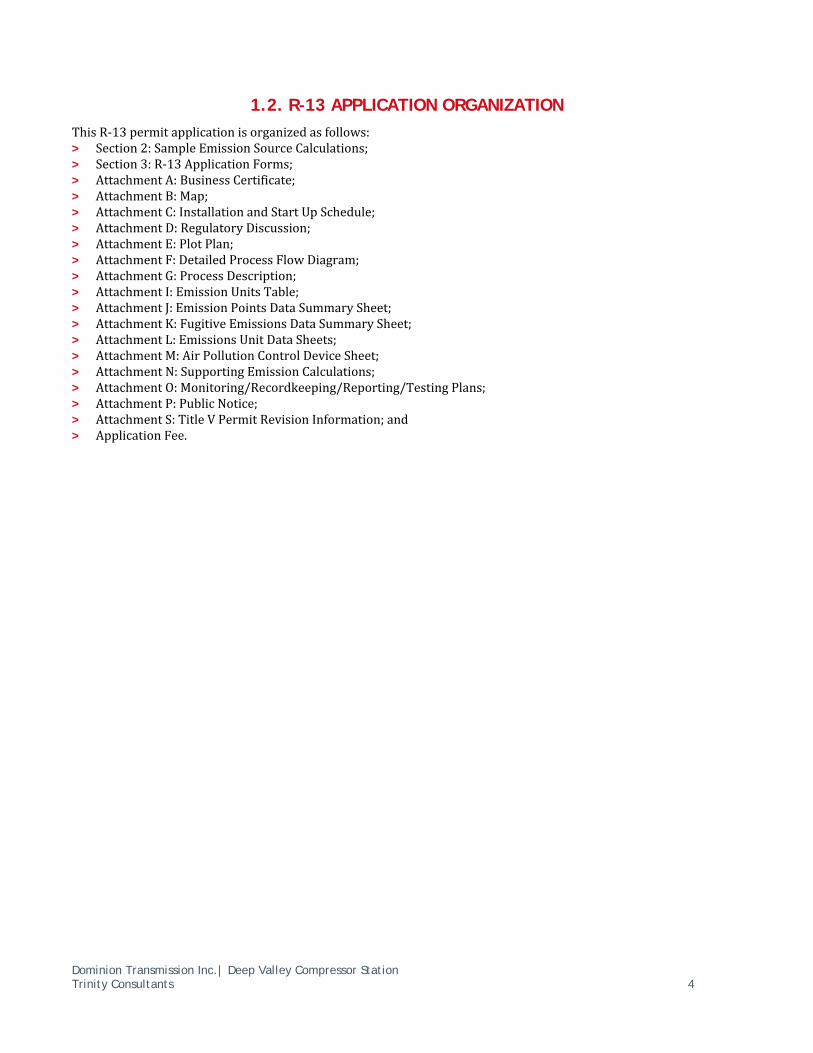
1.2. R-13 APPLICATION ORGANIZATION
ThisR‐13permitapplicationisorganizedasfollows:> Section2:SampleEmissionSourceCalculations;> Section3:R‐13ApplicationForms;> AttachmentA:BusinessCertificate;> AttachmentB:Map;> AttachmentC:InstallationandStartUpSchedule;> AttachmentD:RegulatoryDiscussion;> AttachmentE:PlotPlan;> AttachmentF:DetailedProcessFlowDiagram;> AttachmentG:ProcessDescription;> AttachmentI:EmissionUnitsTable;> AttachmentJ:EmissionPointsDataSummarySheet;> AttachmentK:FugitiveEmissionsDataSummarySheet;> AttachmentL:EmissionsUnitDataSheets;> AttachmentM:AirPollutionControlDeviceSheet;> AttachmentN:SupportingEmissionCalculations;> AttachmentO:Monitoring/Recordkeeping/Reporting/TestingPlans;> AttachmentP:PublicNotice;> AttachmentS:TitleVPermitRevisionInformation;and> ApplicationFee.

Dominion Transmission Inc.| Deep Valley Compressor Station Trinity Consultants 5
2. SAMPLE EMISSION SOURCE CALCULATIONS
ThecharacteristicsofairemissionsfromtheDeepValleyCompressorStation,alongwiththemethodologyusedforcalculatingemissionsfromtheproposednewsources,aredescribedinnarrativeformbelow.DetailedsupportingcalculationsarealsoprovidedinAttachmentN.TheproposednewemissionsourcesattheDeepValleyCompressorStationincludetheTEGdehydrationunit,reboiler,andthermaloxidizer.Asmentionedabove,thesearereplacementunits.Themethodologiesemployedincalculatingemissionsfromthesesourceshavebeensummarizedbelow.
> Reboiler:Potentialemissionsfromtheproposednaturalgasfiredreboilerofallcriteriapollutantsandhazardous
airpollutants(HAPs)arecalculatedusingU.S.EnvironmentalProtectionAgency’s(EPA’s)AP‐42factorsfornaturalgascombustionequipment.1Thesecalculationsassumeahigherheatingvalueofnaturalgasof1,000Btu/scf.GreenhousegasemissionsarecalculatedaccordingtoTitle40,Part98oftheCodeofFederalRegulations(40CFR98),SubpartC.2
> DehydrationUnit:PotentialemissionsofHAPs,volatileorganiccompounds(VOC),andmethanefromthe
dehydrationunitarecalculatedusingGRI‐GLYCalc.EmissionsofothercriteriapollutantsarecalculatedfornaturalgascombustioninthethermaloxidizerusingU.S.EPA’sAP‐42factorsforexternalcombustionofnaturalgas.1Greenhousegasemissionsfromcombustioninthethermaloxidizerarecalculatedaccordingtotheproceduresin40CFR98SubpartC.
1U.S.EPA,AP42,FifthEdition,VolumeI,Chapter1.4,NaturalGasCombustion,SupplementD,July1998.
240CFR98SubpartC,GeneralStationaryFuelcombustionSources,TablesC‐1andC‐2.

Dominion Transmission Inc.| Deep Valley Compressor Station Trinity Consultants 6
3. R13 APPLICATION FORM
TheWVDEPpermitapplicationformscontainedinthisapplicationincludeallapplicableR‐13applicationformsincludingtherequiredattachments.

NSR/Title V Permit Revision Application Form (Revision form.doc)
Revised - 05/2010
Page 1 of 4
WEST VIRGINIA DEPARTMENT OF ENVIRONMENTAL PROTECTION
DIVISION OF AIR QUALITY 601 57th Street, SE
Charleston, WV 25304 (304) 926-0475
www.dep.wv.gov/daq
APPLICATION FOR NSR PERMIT
AND
TITLE V PERMIT REVISION (OPTIONAL)
PLEASE CHECK ALL THAT APPLY TO NSR (45CSR13) (IF KNOWN):
CONSTRUCTION MODIFICATION RELOCATION
CLASS I ADMINISTRATIVE UPDATE TEMPORARY
CLASS II ADMINISTRATIVE UPDATE AFTER-THE-FACT
PLEASE CHECK TYPE OF 45CSR30 (TITLE V) REVISION (IF ANY):
ADMINISTRATIVE AMENDMENT MINOR MODIFICATION SIGNIFICANT MODIFICATION
IF ANY BOX ABOVE IS CHECKED, INCLUDE TITLE V REVISION INFORMATION AS ATTACHMENT S TO THIS APPLICATION
FOR TITLE V FACILITIES ONLY: Please refer to “Title V Revision Guidance” in order to determine your Title V Revision options (Appendix A, “Title V Permit Revision Flowchart”) and ability to operate with the changes requested in this Permit Application.
Section I. General
1. Name of applicant (as registered with the WV Secretary of State’s Office): Dominion Transmission, Inc.
2. Federal Employer ID No. (FEIN): 550629203
3. Name of facility (if different from above):
Deep Valley Compressor Station
4. The applicant is the:
OWNER OPERATOR BOTH
5A. Applicant’s mailing address: 445 West Main Street Clarksburg, WV 26301
5B. Facility’s present physical address: CR 56/1 Deep Valley, WV, 26415
6. West Virginia Business Registration. Is the applicant a resident of the State of West Virginia? YES NO
If YES, provide a copy of the Certificate of Incorporation/Organization/Limited Partnership (one page) including any name change amendments or other Business Registration Certificate as Attachment A.
If NO, provide a copy of the Certificate of Authority/Authority of L.L.C./Registration (one page) including any name change amendments or other Business Certificate as Attachment A.
7. If applicant is a subsidiary corporation, please provide the name of parent corporation:
8. Does the applicant own, lease, have an option to buy or otherwise have control of the proposed site? YES NO
If YES, please explain: Dominion Transmission, Inc. owns site
If NO, you are not eligible for a permit for this source.
9. Type of plant or facility (stationary source) to be constructed, modified, relocated, administratively updated or temporarily permitted (e.g., coal preparation plant, primary crusher, etc.): Natural Gas Compressor Station
10. North American Industry Classification System (NAICS) code for the facility:
486210
11A. DAQ Plant ID No. (for existing facilities only): 0 9 5 –0 0 0 0 7
11B. List all current 45CSR13 and 45CSR30 (Title V) permit numbers associated with this process (for existing facilities only):
R30-09500007-2010(SM01), R13-1104E, G60-C029
All of the required forms and additional information can be found under the Permitting Section of DAQ’s website, or requested by phone.

NSR/Title V Permit Revision Application Form (Revision form.doc)
Revised - 05/2010
Page 2 of 4
12A.
For Modifications, Administrative Updates or Temporary permits at an existing facility, please provide directions to the present location of the facility from the nearest state road;
For Construction or Relocation permits, please provide directions to the proposed new site location from the nearest state road. Include a MAP as Attachment B.
Travel northwest on State Route 18 from West Union. At Deep Valley, take Route 56 and then follow approximately 2 miles up
Raymond Ridge Road (County Route 56/1) to the site.
12.B. New site address (if applicable):
12C. Nearest city or town:
Deep Valley, WV
12D. County:
Taylor
12.E. UTM Northing (KM): 4355.01 12F. UTM Easting (KM): 512.34 12G. UTM Zone: 17
13. Briefly describe the proposed change(s) at the facility: Installation of replacement dehydrator, reboiler, and thermal oxidizer.
14A. Provide the date of anticipated installation or change: 08/01/2015
If this is an After-The-Fact permit application, provide the date upon which the proposed change did happen: / /
14B. Date of anticipated Start-Up if a permit is granted: 11/01/2015
14C. Provide a Schedule of the planned Installation of/Change to and Start-Up of each of the units proposed in this permit application as Attachment C (if more than one unit is involved).
15. Provide maximum projected Operating Schedule of activity/activities outlined in this application: Hours Per Day 24 Days Per Week 7 Weeks Per Year52
16. Is demolition or physical renovation at an existing facility involved? YES NO
17. Risk Management Plans. If this facility is subject to 112(r) of the 1990 CAAA, or will become subject due to proposed
changes (for applicability help see www.epa.gov/ceppo), submit your Risk Management Plan (RMP) to U. S. EPA Region III.
18. Regulatory Discussion. List all Federal and State air pollution control regulations that you believe are applicable to the
proposed process (if known). A list of possible applicable requirements is also included in Attachment S of this application
(Title V Permit Revision Information). Discuss applicability and proposed demonstration(s) of compliance (if known). Provide this
information as Attachment D.
Section II. Additional attachments and supporting documents. 19. Include a check payable to WVDEP – Division of Air Quality with the appropriate application fee (per 45CSR22 and
45CSR13).
20. Include a Table of Contents as the first page of your application package.
21. Provide a Plot Plan, e.g. scaled map(s) and/or sketch(es) showing the location of the property on which the stationary source(s) is or is to be located as Attachment E (Refer to Plot Plan Guidance) .
Indicate the location of the nearest occupied structure (e.g. church, school, business, residence).
22. Provide a Detailed Process Flow Diagram(s) showing each proposed or modified emissions unit, emission point and control device as Attachment F.
23. Provide a Process Description as Attachment G.
Also describe and quantify to the extent possible all changes made to the facility since the last permit review (if applicable).
All of the required forms and additional information can be found under the Permitting Section of DAQ’s website, or requested by phone.
NSR/Title V Permit Revision Application Form (Revision form.doc)
Revised - 05/2010
Page 3 of 4
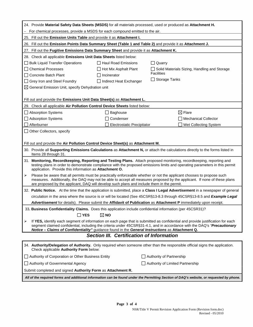
24. Provide Material Safety Data Sheets (MSDS) for all materials processed, used or produced as Attachment H.
For chemical processes, provide a MSDS for each compound emitted to the air.
25. Fill out the Emission Units Table and provide it as Attachment I.
26. Fill out the Emission Points Data Summary Sheet (Table 1 and Table 2) and provide it as Attachment J.
27. Fill out the Fugitive Emissions Data Summary Sheet and provide it as Attachment K.
28. Check all applicable Emissions Unit Data Sheets listed below:
Bulk Liquid Transfer Operations
Chemical Processes
Concrete Batch Plant
Grey Iron and Steel Foundry
Haul Road Emissions
Hot Mix Asphalt Plant
Incinerator
Indirect Heat Exchanger
Quarry
Solid Materials Sizing, Handling and Storage Facilities
Storage Tanks
General Emission Unit, specify Dehydration unit
Fill out and provide the Emissions Unit Data Sheet(s) as Attachment L.
29. Check all applicable Air Pollution Control Device Sheets listed below:
Absorption Systems
Adsorption Systems
Afterburner
Baghouse
Condenser
Electrostatic Precipitator
Flare
Mechanical Collector
Wet Collecting System
Other Collectors, specify
Fill out and provide the Air Pollution Control Device Sheet(s) as Attachment M.
30. Provide all Supporting Emissions Calculations as Attachment N, or attach the calculations directly to the forms listed in Items 28 through 31.
31. Monitoring, Recordkeeping, Reporting and Testing Plans. Attach proposed monitoring, recordkeeping, reporting and testing plans in order to demonstrate compliance with the proposed emissions limits and operating parameters in this permit application. Provide this information as Attachment O.
Please be aware that all permits must be practically enforceable whether or not the applicant chooses to propose such measures. Additionally, the DAQ may not be able to accept all measures proposed by the applicant. If none of these plans are proposed by the applicant, DAQ will develop such plans and include them in the permit.
32. Public Notice. At the time that the application is submitted, place a Class I Legal Advertisement in a newspaper of general
circulation in the area where the source is or will be located (See 45CSR§13-8.3 through 45CSR§13-8.5 and Example Legal
Advertisement for details). Please submit the Affidavit of Publication as Attachment P immediately upon receipt.
33. Business Confidentiality Claims. Does this application include confidential information (per 45CSR31)?
YES NO
If YES, identify each segment of information on each page that is submitted as confidential and provide justification for each segment claimed confidential, including the criteria under 45CSR§31-4.1, and in accordance with the DAQ’s “Precautionary Notice – Claims of Confidentiality” guidance found in the General Instructions as Attachment Q.
Section III. Certification of Information
34. Authority/Delegation of Authority. Only required when someone other than the responsible official signs the application. Check applicable Authority Form below:
Authority of Corporation or Other Business Entity
Authority of Governmental Agency
Authority of Partnership
Authority of Limited Partnership
Submit completed and signed Authority Form as Attachment R.
All of the required forms and additional information can be found under the Permitting Section of DAQ’s website, or requested by phone.

Dominion Transmission Inc.| Deep Valley Compressor Station Trinity Consultants
ATTACHMENT A
Current Business Certificate

Dominion Transmission Inc.| Deep Valley Compressor Station Trinity Consultants
ATTACHMENT B
Map

512,200 512,250 512,300 512,350 512,400 512,450 512,500
4,354
,850
4,354
,900
4,354
,950
4,355
,000
4,355
,050
4,355
,100
4,355
,150
4,355
,200
4,355
,250
Attachment B - Aerial Map - Deep Valley StationDominion Transmission, Inc
UTM Easting (m)
UTM
Nor
thing
(m)
All Coordinates shown in UTM Projection,Zone 17, NAD83
Area Map Extent
Deep Valley Station

Dominion Transmission Inc.| Deep Valley Compressor Station Trinity Consultants
ATTACHMENT C
Startup and Installation Schedule

ATTACHMENT C
Schedule of Planned Installation and Start-Up
Unit InstallationSchedule StartupSchedule
10MMSCFDDehydrationUnit
08/01/2015 11/01/2015
Reboiler 08/01/2015 11/01/2015
ThermalOxidizer 08/01/2015 11/01/2015

Dominion Transmission Inc.| Deep Valley Compressor Station Trinity Consultants
ATTACHMENT D
Regulatory Discussion

1
ATTACHMENT D – REGULATORY APPLICABILITY
ThissectiondocumentstheapplicabilitydeterminationsmadeforFederalandStateairqualityregulations.Themonitoring,recordkeeping,reporting,andtestingplanispresentedinAttachmentO.Inthissection,applicabilityornon‐applicabilityofthefollowingregulatoryprogramsisaddressed:
> PreventionofSignificantDeterioration(PSD)permitting;> TitleVofthe1990CleanAirActAmendments;> NewSourcePerformanceStandards(NSPS);> NationalEmissionStandardsforHazardousAirPollutants(NESHAP);and> WestVirginiaStateImplementationPlan(SIP)regulations.
Thisreviewispresentedtosupplementand/oraddclarificationtotheinformationprovidedintheWestVirginiaDepartmentofEnvironmentalProtection(WVDEP)Rule13(R‐13)permitapplicationforms.Inadditiontoprovidingasummaryofapplicablerequirements,thissectionoftheapplicationalsoprovidesnon‐applicabilitydeterminationsforcertainregulations,allowingtheWVDEPtoconfirmthatidentifiedregulationsarenotapplicabletotheDeepValleyCompressorStation.Notethatexplanationsofnon‐applicabilityarelimitedtothoseregulationsforwhichtheremaybesomequestionofapplicabilityspecifictotheoperationsattheDeepValleyCompressorStation.Regulationsthatarecategoricallynon‐applicablearenotdiscussed(e.g.,NSPSSubpartJ,StandardsofPerformanceforPetroleumRefineries).
Prevention of Significant Deterioration (PSD) Source Classification
FederalconstructionpermittingprogramsregulatenewandmodifiedsourcesofattainmentpollutantsunderPreventionofSignificantDeterioration(PSD)andnewandmodifiedsourcesofnon‐attainmentpollutantsunderNon‐AttainmentNewSourceReview(NNSR).TheDeepValleyCompressorStationislocatedinTaylorCounty,WestVirginia,whichisdesignatedasinattainment/unclassifiableforallpollutants.Therefore,PSDpermittingispotentiallyapplicabletothefacility.PSDpermittinginWestVirginiaisregulatedunderTitle45,Series14,WestVirginiaCodeofStateRegulations(45CSR14).PSDpermittingappliestoconstructionofnewmajorstationarysourcesoranyphysicalchangein,orchangeinthemethodofoperationofanexistingmajorstationarysourcethatresultsinasignificantemissionsincrease.AmajorstationarysourceforPSDisdefinedas:> Anysourceinoneofthe28namedsourcecategorieswiththepotential‐to‐emit(PTE)of100tonsperyear(tpy)
ormoreoftraditionallyregulatedpollutants,or> Anysourcenotinoneofthe28namedsourcecategorieswithaPTEof250tpyormoreofanytraditionally
regulatedpollutant.Naturalgascompressorstationsarenotincludedinthelistedsourcecategoriesunder45CSR14‐2.43,sothePSDmajorsourcethreshold(MST)applicabletotheDeepValleyCompressorStationis250tpy.Becausetheexistingfacility‐widePTEforoxidesofnitrogen(NOX)isgreaterthan250tpy,theDeepValleyCompressorStationisanexistingmajorsourceunderPSD.Forexistingmajorsources,PSDapplicabilityisdeterminedbasedonwhetheraphysicalchangeand/orachangeinthemethodofoperationresultsinanincreaseofpotentialairemissionsabovethesignificantemissionrate(SER)ofanyPSD‐regulatedpollutant.

2
Thisprojectinvolvesreplacementoftheexisting18millionstandardcubicfeetperday(MMscfd)triethyleneglycol(TEG)dehydratorwithasmallerunit(10MMscfd).ThepotentialtoemitfortheproposednewequipmentdoesnotexceedtheSERforanyPSDpollutants.Assuch,PSDpermittingisnottriggeredbythisconstructionactivity.
Title V Operating Permit Program
Title40oftheCodeofFederalRegulationsPart70(40CFR70)establishesthefederalTitleVoperatingpermitprogram.WestVirginiahasincorporatedtheprovisionsofthisfederalprograminitsTitleVoperatingpermitprograminWestVirginiaCodeofStateRegulations(CSR)45‐30.ThemajorsourcethresholdswithrespecttotheWestVirginiaTitleVoperatingpermitprogramregulationsare10tonsperyear(tpy)ofasinglehazardousairpollutant(HAP),25tpyofanycombinationofHAPs,and100tpyofallotherregulatedpollutants.1ThepotentialemissionsofNOXandvolatileorganiccompounds(VOC)areabovethe100tpythresholdatthisfacility.Therefore,theDeepValleyCompressorStationisamajorsourceforTitleVpurposes.TheDeepValleyCompressorStationcurrentlyoperatesunderTitleVpermitR30‐09500007‐2010,issuedonNovember30,2010andmodifiedonJuly26,2012.AttachmentSprovidesarequestforincorporationofthisproject(replacementofexistingdehydrationunitandassociatedflarewithnewdehydrationunitandassociatedthermaloxidizer)intotheTitleVpermituponcompletionofconstruction.
New Source Performance Standards
NewSourcePerformanceStandards(NSPS),locatedin40CFR60,requirenew,modified,orreconstructedsourcestocontrolemissionstothelevelachievablebythebestdemonstratedtechnologyasspecifiedintheapplicableprovisions.Moreover,anysourcesubjecttoanNSPSisalsosubjecttothegeneralprovisionsofNSPSSubpartA,exceptwhereexpresslynoted.Thefollowingisasummaryofapplicabilityandnon‐applicabilitydeterminationsforNSPSregulationsofrelevancetotheDeepValleyCompressorStation.
NSPS Subparts D, Da, Db, and Dc – Industrial – Commercial – Institutional Steam Generating Units
Thesesubpartsapplytosteamgeneratingunitsofvarioussizes,allgreaterthan10MMBtu/hr.Theproposedreboilerwillhavearatedcapacityof0.275MMBtu/hrandthereforetherequirementsofthesesubpartsdonotapply.
NSPS Subpart OOOO—Crude Oil and Natural Gas Production, Transmission, and Distribution
SubpartOOOOappliestoaffectedfacilitiesthatcommencedconstruction,reconstruction,ormodificationafterAugust23,2011.ThisNSPSwaspublishedintheFederalRegisteronAugust16,2012,withaneffectivedateofOctober15,2012.OnJuly1,2014,theEPAproposedsecondrevisionstoNSPSOOOO.Thelistofpotentiallyaffectedfacilitiesincludes:
> Gaswells> Centrifugalcompressors> Reciprocatingcompressors> Pneumaticcontrollers> Storagevessels> Equipment(asdefinedin§60.5430)locatedatonshorenaturalgasprocessingplants> Sweeteningunitslocatedonshorethatprocessnaturalgasproducedfromeitheronshoreoroffshorewells
1EPA’sTailoringRulehadestablishedaTitleVmajorsourcethresholdof100,000tpyofgreenhousegaspollutantsorGHGs(onacarbondioxideequivalent[CO2e]basis).However,onJune23,2014,theU.S.SupremeCourtissueditsdecisioninUtilityAirRegulatoryGroupv.EPA,wherebytheCourtsaidthatEPAmaynottreatGHGsasanairpollutantforpurposesofdeterminingwhetherasourceisamajorsourcerequiredtoobtainaPSDorTitleVpermit.CaseNo.12‐1146,decidedJune23,2014.http://www.supremecourt.gov/opinions/13pdf/12‐1146_4g18.pdf.

3
TheDeepValleyCompressorStationisproposingtoreplacethedehydrationunit,whichisnotanaffectedfacilityunderthissubpart.Assuch,SubpartOOOOisnotapplicabletotheproject.
Non-Applicability of All Other NSPS
NSPSaredevelopedforparticularindustrialsourcecategories.OtherthanNSPSdetailedabove,theapplicabilityofaparticularNSPStotheDeepValleyCompressorStationcanbereadilyascertainedbasedontheindustrialsourcecategorycovered.AllotherNSPSarecategoricallynotapplicabletotheproposedchange.
National Emission Standards for Hazardous Air Pollutants (NESHAP)
Part63NESHAPallowableemissionlimitsareestablishedonthebasisofamaximumachievablecontroltechnology(MACT)determinationforaparticularsource.AHAPmajorsourceisdefinedashavingpotentialemissionsinexcessof25tpyfortotalHAPand/orpotentialemissionsinexcessof10tpyforanyindividualHAP.TheDeepValleyCompressorStationisanarea(minor)sourceofHAPssinceitspotentialemissionsofHAPsarelessthanthe10/25majorsourcethresholds.NESHAPapplytosourcesinspecificallyregulatedindustrialsourcecategories(CleanAirActSection112(d))oronacase‐by‐casebasis(Section112(g))forfacilitiesnotregulatedasaspecificindustrialsourcetype.ThefollowingNESHAParepotentiallyapplicabletotheDeepValleyCompressorStation:> 40CFRPart63SubpartHH–OilandNaturalGasProductionFacilities> 40CFRPart63HHH–NaturalGasTransmissionandStorageFacilities> 40CFRPart63SubpartDDDDD–Industrial,Commercial,andInstitutionalBoilers–MajorSources> 40CFRPart63SubpartJJJJJJ–Industrial,Commercial,andInstitutionalBoilers‐AreaSourcesTheapplicabilityoftheseNESHAPSubpartsisdiscussedinthefollowingsections.
40 CFR 63 Subpart HH – Oil and Natural Gas Production Facilities
ThissubpartappliestoaffectedemissionpointsthatarelocatedatfacilitiesthataremajorandareasourcesofHAPandeitherprocess,upgrade,orstorehydrocarbonliquidspriortocustodytransferorthatprocess,upgrade,orstorenaturalgaspriortoenteringthenaturalgastransmissionandstoragesourcecategory.Forpurposesofthissubpart,naturalgasentersthenaturalgastransmissionandstoragesourcecategoryafterthenaturalgasprocessingplant,ifpresent.Assuch,thissubpartappliestoaffectedunitslocatedatnaturalgasprocessingfacilitiesand/oranyproductionfacilitiesupstream.TheDeepValleyCompressorStationisanareasourceofHAPemissions.Thestationprocessesnaturalgasinitsglycoldehydratorpriortothepointofcustodytransfer;therefore,theprovisionsofNESHAPSubpartHHareapplicabletotheDeepValleyCompressorStation.Thebenzeneemissionsfromtheglycoldehydratorventsarelessthan0.90megagramsperyear(1tpy),asindicatedintheemissioncalculationsinAttachmentN.Dominionisclaimingtheexemptionspecifiedin40CFR63.764(e)(1)(ii)andthereforeisnotsubjecttothecontrolrequirementsforglycoldehydratorunitprocessventsin40CFR63.675.TheDeepValleyCompressorStationisonlyrequiredtokeeprecordsoftheactualannualaveragenaturalgasthroughput(intermsofnaturalgasflowratetotheglycoldehydrationunitperday)oractualaveragebenzeneemissions(intermsofbenzeneemissionsperyear)fromthedehydrator,per40CFR63.774(d)(1).
40 CFR 63 Subpart HHH – Natural Gas Transmission and Storage Facilities
ThisstandardappliestoaffectedunitsatnaturalgastransmissionandstoragefacilitiesthataremajorsourcesofHAPemissionslocateddownstreamofthepointofcustodytransfer(afterprocessingand/ortreatmentintheproductionsector),butupstreamofthedistributionsector.Aspreviouslyindicated,theDeepValleyCompressorStationisagatheringfacilitylocatedupstreamofthepointofcustodyandisanarea(minor)sourceofHAPs;therefore,theprovisionsofNESHAPSubpartHHHdonotapply.

4
40 CFR 63 Subpart DDDDD – Industrial, Commercial, and Institutional Boilers (Major Source Boiler MACT)
ThisMACTstandardappliestoindustrial,commercial,andinstitutionalboilersandprocessheatersofvarioussizesandfueltypeslocatedatmajorsourcesofHAP.TheDeepValleycompressorstationisanareasourceofHAPemissions,thereforethissubpartdoesnotapply.
40 CFR 63 Subpart JJJJJJ – Industrial, Commercial, and Institutional Boilers (Area Source Boiler MACT)
ThisMACTstandardappliestoindustrial,commercial,andinstitutionalboilersofvarioussizesandfueltypeslocatedatareasourcesofHAP.Gas‐firedboilersareexemptfromtherequirementsunder40CFR63.11195(e).Therefore,thissubpartdoesnotapplytotheproposedgas‐firedreboiler.
Non-Applicability of All Other NESHAP
SimilartoNSPS,NESHAParedevelopedforparticularindustrialsourcecategories.OtherthantheNESHAPdevelopedforboilersandheaters(SubpartsDDDDD,andJJJJJJ)andnaturalgassectorfacilities(SubpartHH,HHH),theapplicabilityofaparticularNESHAPtotheproposedprojectattheDeepValleyCompressorStationcanbereadilyascertainedbasedontheindustrialsourcecategorycovered.AllotherNESHAParecategoricallynotapplicabletotheproposedchange.
West Virginia SIP Regulations
TheproposedprojectattheDeepValleyCompressorStationispotentiallysubjecttoregulationscontainedintheWestVirginiaCodeofStateRegulations,Chapter45(CodeofStateRegulations).WestVirginiaregulationspotentiallyapplicabletotheproposedprojectarediscussedbelow.
45 CSR 2: Particulate Air Pollution from Combustion of Fuel in Indirect Heat Exchangers
45CSR2appliestofuelburningunits,definedasequipmentburningfuel“fortheprimarypurposeofproducingheatorpowerbyindirectheattransfer”.ThereboilerattheDeepValleyCompressorStationmeetsthisdefinitionandisthereforepotentiallysubjectto45CSR2.Per45CSR2‐3,opacityofemissionsfromthereboilershallnotexceed10percentbasedonasixminuteblockaverage.Per45CSR2‐11.1,thereboilerisexemptfromthePMemissionslimitsinsections4,5,6,8and9oftherulebecauseithasaratedheatinputcapacitylessthan10MMBtu/hr.
45 CSR 6: To Prevent and Control Air Pollution from Combustion of Refuse
45CSR6setsforthrequirementsforlimitingemissionsfromincinerationwhichisdefinedas“thedestructionofcombustiblerefusebyburninginafurnacedesignedforthatpurpose.Forthepurposesofthisrule,thedestructionofanycombustibleliquidorgaseousmaterialbyburninginaflareorflarestack,thermaloxidizer,orthermalcatalyticoxidizerstackshallbeconsideredincineration.”Theproposedthermaloxidizermeetsthisdefinitionandisthereforesubjecttothisregulation.Thethermaloxidizerwillbesubjecttotheparticulatematter(PM)emissionlimitsin45CSR6‐4.1.Inaddition,opacityfromthethermaloxidizerwillbelimitedto20%per45CSR6‐4.3exceptasprovidedin45CFR6‐4.4.Operatinginstructionswillbepostedasrequiredby45CSR6‐4.9.
45 CSR 10: To Prevent and Control Air Pollution from the Emission of Sulfur Oxides
45CSR10appliestofuelburningunits,definedasequipmentburningfuel“fortheprimarypurposeofproducingheatorpowerbyindirectheattransfer”.ThereboilerattheDeepValleyCompressorStationmeetsthisdefinitionandis

5
thereforepotentiallysubjectto45CSR10.However,per45CSR10‐10.1,thereboilerisexemptfromtheSO2emissionslimitsbecauseithasaratedheatinputcapacitylessthan10MMBtu/hr.
45 CSR 13: Permits for Construction, Modification, Relocation and Operation of Stationary Sources of Air Pollutants, Notification Requirements, Administrative Updates, Temporary Permits, General Permits, and Procedures for Evaluation
Accordingto45CSR13,“Nopersonshallcause,suffer,alloworpermittheconstruction,modification,orrelocationofanystationarysourcetobecommencedwithoutnotifyingtheSecretaryofsuchintentandobtainingapermittoconstruct,modify,orrelocatethestationarysourceasrequiredinthisruleoranyotherapplicablerulepromulgatedbytheSecretary.”Incompliancewiththisrequirement,DominionissubmittingtheattachedpermitapplicationforthereplacementofthedehydrationunitattheDeepValleyCompressorStation.
45 CSR 16: Standards of Performance for New Stationary Sources
Thisruleadoptsthestandardsofperformancefornewstationarysourcessetforthin40CFRPart60byreference.PotentiallyapplicableNSPSarediscussedabove.
45 CSR 21: To Prevent and Control Air Pollution from the Emission of Volatile Organic Compounds
45CSR21isintendedtorequirereasonablyavailablecontroltechnologyforVOCsourcesinPutnam,Kanawha,Cabell,Wayne,andWoodCounties.Assuch,theserequirementsdonotapplytoVOCsourcesinTaylorCounty.
45 CSR 27: To Prevent and Control the Emissions of Toxic Air Pollutants
WestVirginiaregulatestheemissionsoftoxicairpollutantemissionsthrough45CSR27.Afacilitythatdischarges,ormaydischarge,atoxicpollutantintotheopenatmosphereinquantitiesgreaterthanthosedelineatedinTableAofthisruleisrequiredtoemployBestAvailableTechnology(BAT)onallchemicalprocessingequipmentemittingthepollutant.TheTEGdehydratormeetsthedefinitionofchemicalprocessingequipmentandispotentiallysubjecttothisregulationforbenzeneemissions.Thepotentialtoemitthresholdquantitylistedforbenzeneis1,000poundsperyear.EmissionsofbenzenefromtheTEGdehydratorarelessthan1,000poundsperyear.Assuch,thisregulationdoesnotapplytotheprojectattheDeepValleyCompressorStation.
45 CSR 17: To Prevent and Control Particulate Matter Air Pollution from Materials Handling, Preparation, Storage and Other Sources of Fugitive Particulate Matter
Accordingto45CSR17‐3.1:Nopersonshallcause,suffer,alloworpermitfugitiveparticulatemattertobedischargedbeyondtheboundarylinesofthepropertylinesofthepropertyonwhichthedischargeoriginatesoratanypublicorresidentiallocation,whichcausesorcontributestostatutoryairpollution.DuetothenatureoftheactivitiesattheDeepValleyCompressorStationitisunlikelythatfugitiveparticulatematteremissionswillbeemittedundernormaloperatingconditions.However,Dominionwilltakemeasurestoensureanyfugitiveparticulatematteremissionswillnotcrossthepropertyboundaryshouldanysuchemissionsoccur.
45 CSR 34: Emission Standards for Hazardous Air Pollutants
ThisruleadoptstheNationalEmissionsStandardsforHazardousAirPollutants(NESHAPsbyreference.)PotentiallyapplicableNESHAParediscussedabove.

Dominion Transmission Inc.| Deep Valley Compressor Station Trinity Consultants
ATTACHMENT E
Plot Plan


Dominion Transmission Inc.| Deep Valley Compressor Station Trinity Consultants
ATTACHMENT F
Detailed Process Flow Diagram

Flow Legend
Process Flow Diagram Deep Valley Compressor Station
Stack Emissions
Gas/Water/Condensate Flow
March 2015153902.0022
Dominion Transmission, Inc.
Inlet Pipeline Natural Gas
Outlet Pipeline Natural Gas
EN01Compressor
Engine (800 hp)
EN02Compressor
Engine (800 hp)
TEG Dehydration Unit (10 MMSCFD)
DEHY02
RBR02 Reboiler
(0.275 MMBtu/hr Heat Input)
TEG
Th
erm
al O
xid
izer
-C
2
RegeneratorStill Gas
TK01Horizontal
Ethylene Glycol Tank
(1000 gallons)
TK02Horizontal TEG Tank
(1000 gallons)
TK03Horizontal
Wastewater Storage Tank(230 gallons)
EG02Emergency Generator (192.5 hp)
EG01Emergency Generator (192.5 hp)
TK04Horizontal
Produced Fluids Storage Tank(4000 gallons)
TK05Horizontal Lube
Oil Storage Tank
(3040 gallons)
TK06Vertical
Wastewater Storage Tank (500 gallons)
TK07Horizontal Used
Oil Storage Tank (1000
gallons)
Station Compressor
Suction
Dominion Transmission Inc.| Deep Valley Compressor Station Trinity Consultants
ATTACHMENT G
Process Description

ATTACHMENT G – PROCESS DESCRIPTION
Naturalgasentersthestationviaapipelinesystemandiscompressedusingthetwo(2)naturalgas‐firedcompressorengines(identifiedasEN01andEN02andratedat800hpeach).Thecompressednaturalgasstreamisthenprocessedthroughthetriethyleneglycol(TEG)dehydrationunit(withassociatedreboiler),identifiedasDEHY02.ThedehydrationunitwillintroduceTEGtothegasstreaminacontacttowertoabsorbwatervaporfromthegastoalevelnotexceeding7poundspermillionstandardcubicfeet(lb/MMscf).TheTEGisthensenttothenaturalgas‐firedreboiler,ratedat0.275MMBtu/hrheatinput(RBR02).ThewaterisevaporatedfromtheTEGinthereboileranddischarged,andtheglycolisthensentbacktothecontacttowerforreuse.Thedehydrationunitisequippedwithathermaloxidizer(2C)whichwillcontrolemissionsfromthedehydrationstillvent,andtheemissionsfromtheflashtankwillberoutedtothestationcompressorsuction.Thenaturalgasstreamfromthecontacttowerflowsintothepipelinetobetransportedfurtheralongthepipelinesystem.Thestationisalsoequippedwithseven(7)storagetanksandtwo(2)emergencybackupgenerators,ratedat192.5hpeach.AprocessflowdiagramisincludedasAttachmentF.

Dominion Transmission Inc.| Deep Valley Compressor Station Trinity Consultants
ATTACHMENT I
Emission Units Table

Emission Units Table Page __1____ of __1____ 03/2007
Attachment I
Emission Units Table (includes all emission units and air pollution control devices
that will be part of this permit application review, regardless of permitting status)
Emission Unit ID1
Emission Point ID2
Emission Unit Description Year Installed/ Modified
Design Capacity
Type3 and Date of Change
Control Device 4
DEHY02 DEHY02 Dehydration Unit
(Regenerator Still)
2015 10 MMSCFD
New 2C
RBR02 RBR02 Reboiler
(associated with Dehydration Unit)
2015 0.275 MMBtu/hr
New None
2C 2C Thermal Oxidizer 2015 95% Destruction Efficiency
New None
DEHY01 DEHY01 Dehydration Unit
(Regenerator Still)
1989 18 MMSCFD
Removal F1
RBR01 RBR01 Reboiler
(associated with Dehydration Unit)
1989 960 SCFH Removal None
F1 F1 Thermal Oxidizer 1989 5 MMBtu/hr Removal None
0001 0001 Dehydration unit flare pilot 1989 18.5 scf/hr Removal None
1 For Emission Units (or Sources) use the following numbering system:1S, 2S, 3S,... or other appropriate designation. 2 For Emission Points use the following numbering system:1E, 2E, 3E, ... or other appropriate designation. 3 New, modification, removal 4 For Control Devices use the following numbering system: 1C, 2C, 3C,... or other appropriate designation.

Dominion Transmission Inc.| Deep Valley Compressor Station Trinity Consultants
ATTACHMENT J
Emission Points Data Summary Sheet

page _1_ of _2_ WVDEP-DAQ Revision 2/11
Attachment J EMISSION POINTS DATA SUMMARY SHEET
Table 1: Emissions Data
Emission Point ID No. (Must match
Emission Units Table & Plot Plan)
Emission Point Type1
Emission Unit Vented Through This Point
(Must match Emission Units Table & Plot Plan)
Air Pollution Control Device
(Must match Emission Units Table
& Plot Plan)
Vent Time for Emission Unit
(chemical processes only)
All Regulated Pollutants - Chemical
Name/CAS3
(Speciate VOCs & HAPS)
Maximum Potential
Uncontrolled Emissions 4
Maximum Potential Controlled Emissions 5
Emission Form or Phase
(At exit
conditions, Solid, Liquid
or Gas/Vapor)
Est. Method Used 6
Emission Concentration 7
(ppmv or mg/m4)
ID No. Source ID No. Device Type
Short Term2
Max (hr/yr)
lb/hr ton/yr lb/hr ton/yr
DEHY02
Upward Vertical Stack
DEHY02
Dehydration Unit (Emissions only)
2C Thermal Oxidizer
NA NA
VOC Total HAP
CO2e
24 5.3 434
106 23
1,901
1.0
0.25 18
4.2 1.1 78 Gas/Vapor
OA OA
OA,B
RBR02 Upward Vertical Stack
RBR02 Reboiler NA NA NA NA NOx CO
PM/PM10/PM2.5 SO2 VOC
Total HAP CO2e
0.038 0.032
0.0029 0.0002 0.0021 0.0007
45
0.17 0.14
0.013 0.001 0.009 0.003 197
0.038 0.032
0.0029 0.0002 0.0021 0.0007
45
0.17 0.14
0.013 0.001 0.009 0.003 197
Gas/Vapor
OC OC OC OC OC OC OD
2C Upward Vertical Stack
2C Thermal Oxidizer
NA NA NA NA NOx CO
PM/PM10/PM2.5 SO2
CO2e
N/A N/A 0.4 0.3
0.03 0.002 472
1.8 1.5
0.13 0.01
2,067
Gas/Vapor
OC OC OC OC OD
A- GRI-GLYCalc B- 40 CFR 98, Subpart A, global warming potentials. C- AP Section 1.4 Tables 1.4-1, 1.4-2, 1.4-3, and 1.4-4 July 1998. D- 40 CFR 98, Subpart C for natural gas fired combustion, The EMISSION POINTS DATA SUMMARY SHEET provides a summation of emissions by emission unit. Note that uncaptured process emission unit emissions are not typically considered to be fugitive and must be accounted for on the appropriate EMISSIONS UNIT DATA SHEET and on the EMISSION POINTS DATA SUMMARY SHEET. Please note that total emissions from the source are equal to all vented emissions, all fugitive emissions, plus all other emissions (e.g. uncaptured emissions). Please complete the FUGITIVE EMISSIONS DATA SUMMARY SHEET for fugitive emission activities.
1 Please add descriptors such as upward vertical stack, downward vertical stack, horizontal stack, relief vent, rain cap, etc. 2 Indicate by "C" if venting is continuous. Otherwise, specify the average short-term venting rate with units, for intermittent venting (ie., 15 min/hr). Indicate as many rates as needed to
clarify frequency of venting (e.g., 5 min/day, 2 days/wk). 3 List all regulated air pollutants. Speciate VOCs, including all HAPs. Follow chemical name with Chemical Abstracts Service (CAS) number. LIST Acids, CO, CS2, VOCs, H2S,
Inorganics, Lead, Organics, O3, NO, NO2, SO2, SO3, all applicable Greenhouse Gases (including CO2 and methane), etc. DO NOT LIST H2, H2O, N2, O2, and Noble Gases. 4 Give maximum potential emission rate with no control equipment operating. If emissions occur for less than 1 hr, then record emissions per batch in minutes (e.g. 5 lb VOC/20
minute batch). 5 Give maximum potential emission rate with proposed control equipment operating. If emissions occur for less than 1 hr, then record emissions per batch in minutes (e.g. 5 lb VOC/20
minute batch). 6 Indicate method used to determine emission rate as follows: MB = material balance; ST = stack test (give date of test); EE = engineering estimate; O = other (specify). 7 Provide for all pollutant emissions. Typically, the units of parts per million by volume (ppmv) are used. If the emission is a mineral acid (sulfuric, nitric, hydrochloric or phosphoric)
use units of milligram per dry cubic meter (mg/m3) at standard conditions (68 °F and 29.92 inches Hg) (see 45CSR7). If the pollutant is SO2, use units of ppmv (See 45CSR10).

page _2_ of _2_ WVDEP-DAQ Revision 2/11
Attachment J EMISSION POINTS DATA SUMMARY SHEET
Table 2: Release Parameter Data
Emission Point ID
No. (Must match
Emission Units Table)
Inner Diameter
(ft.)
Exit Gas Emission Point Elevation (ft) UTM Coordinates (km)
Temp.
(oF)
Volumetric Flow 1 (acfm)
at operating conditions
Velocity
(fps)
Ground Level (Height above
mean sea level)
Stack Height 2 (Release height of emissions above
ground level)
Northing Easting
RBR02 0.72 1,073 411.8 9.7 750 21 4,355.01 512.34
2C 1.43 1,600 3,633.9 37.5 750 40 4,355.01 512.34
1 Give at operating conditions. Include inerts. 2 Release height of emissions above ground level.

Dominion Transmission Inc.| Deep Valley Compressor Station Trinity Consultants
ATTACHMENT K
Fugitive Emissions Data Summary Sheet

Page 1 of 2 Revision 2/11
Attachment K
FUGITIVE EMISSIONS DATA SUMMARY SHEET
The FUGITIVE EMISSIONS SUMMARY SHEET provides a summation of fugitive emissions. Fugitive emissions are those emissions which could not reasonably pass through a stack, chimney, vent or other functionally equivalent opening. Note that uncaptured process emissions are not typically considered to be fugitive, and must be accounted for on the appropriate EMISSIONS UNIT DATA SHEET and on the EMISSION POINTS DATA SUMMARY SHEET.
Please note that total emissions from the source are equal to all vented emissions, all fugitive emissions, plus all other emissions (e.g. uncaptured emissions).
APPLICATION FORMS CHECKLIST - FUGITIVE EMISSIONS
1.) Will there be haul road activities?
Yes No
If YES, then complete the HAUL ROAD EMISSIONS UNIT DATA SHEET.
2.) Will there be Storage Piles?
Yes No
If YES, complete Table 1 of the NONMETALLIC MINERALS PROCESSING EMISSIONS UNIT DATA SHEET.
3.) Will there be Liquid Loading/Unloading Operations?
Yes No
If YES, complete the BULK LIQUID TRANSFER OPERATIONS EMISSIONS UNIT DATA SHEET.
4.) Will there be emissions of air pollutants from Wastewater Treatment Evaporation?
Yes No
If YES, complete the GENERAL EMISSIONS UNIT DATA SHEET.
5.) Will there be Equipment Leaks (e.g. leaks from pumps, compressors, in-line process valves, pressure relief devices, open-ended valves, sampling connections, flanges, agitators, cooling towers, etc.)?
Yes No
If YES, complete the LEAK SOURCE DATA SHEET section of the CHEMICAL PROCESSES EMISSIONS UNIT DATA SHEET.
6.) Will there be General Clean-up VOC Operations?
Yes No
If YES, complete the GENERAL EMISSIONS UNIT DATA SHEET.
7.) Will there be any other activities that generate fugitive emissions?
Yes No
If YES, complete the GENERAL EMISSIONS UNIT DATA SHEET or the most appropriate form.
If you answered “NO” to all of the items above, it is not necessary to complete the following table, “Fugitive Emissions Summary.”

Page 2 of 2 Revision 2/11
FUGITIVE EMISSIONS SUMMARY All Regulated Pollutants -
Chemical Name/CAS 1
Maximum Potential Uncontrolled Emissions 2
Maximum Potential Controlled Emissions 3
Est. Method Used 4lb/hr ton/yr lb/hr ton/yr
Haul Road/Road Dust Emissions Paved Haul Roads
NA -- -- -- -- --
Unpaved Haul Roads NA -- -- -- -- --
Storage Pile Emissions NA --- --- --- --- ---
Loading/Unloading Operations NA --- --- --- --- ---
Wastewater Treatment Evaporation & Operations NA --- --- --- --- ---
Equipment Leaks NA --- --- --- --- ---
General Clean-up VOC Emissions NA --- --- --- --- ---
Other NA --- --- --- --- ---
1 List all regulated air pollutants. Speciate VOCs, including all HAPs. Follow chemical name with Chemical Abstracts Service (CAS) number. LIST Acids, CO, CS2, VOCs, H2S, Inorganics, Lead, Organics, O3, NO, NO2, SO2, SO3, all applicable Greenhouse Gases (including CO2 and methane), etc. DO NOT LIST H2, H2O, N2, O2, and Noble Gases.
2 Give rate with no control equipment operating. If emissions occur for less than 1 hr, then record emissions per batch in minutes (e.g. 5 lb VOC/20 minute batch). 3 Give rate with proposed control equipment operating. If emissions occur for less than 1 hr, then record emissions per batch in minutes (e.g. 5 lb VOC/20 minute
batch). 4 Indicate method used to determine emission rate as follows: MB = material balance; ST = stack test (give date of test); EE = engineering estimate; O = other
(specify).

Dominion Transmission Inc.| Deep Valley Compressor Station Trinity Consultants
ATTACHMENT L
Emission Unit Data Sheet

NATURAL GAS GLYCOL DEHYDRATION UNIT DATA SHEET
General Glycol
Dehydration Unit Data
Manufacturer and Model Inegral
Max Dry Gas Flow Rate (mmscf/day) 10 MMscf/day
Design Heat Input (mmBtu/hr) 0.275 MMBtu/hr
Design Type (DEG or TEG) TEG
Source Status2 NS
Date Installed/Modified/Removed3 November 2015
Regenerator Still Vent APCD4 TO
Fuel HV (Btu/scf) 1,000
H2S Content (gr/100 scf) 0 ppm
Operation (hrs/yr) 8,760 Source ID #1
Vent
Reference5 Potential Emissions6 lbs/hr tons/yr
RBR02 Reboiler
Vent
AP NOX 0.04 0.17
AP CO 0.03 0.14
AP VOC 0.002 0.009
AP SO2
0.0002 0.001
AP PM10 0.003 0.01
DEHY02 Glycol
Regenerator Still Vent
GR VOC 1 4.2
GR Benzene 0.02 0.1
GR Ethylbenzene 0.01 0.04
GR Toluene 0.07 0.3
GR Xylenes 0.1 0.5
GR n-Hexane 0.02 0.1
1. Enter the appropriate Source Identification Numbers for the glycol dehydration unit Reboiler Vent and glycol
Regenerator Still Vent. The glycol dehydration unit Reboiler Vent and glycol Regenerator Still Vent should be designated RBV-1 and RSV-1, respectively. If the compressor station incorporates multiple glycol dehydration units, a Glycol Dehydration Unit Data Sheet shall be completed for each, using Source Identification #s RBV-2 and RSV-2, RBV-3 and RSV-3, etc.
2. Enter the Source Status using the following codes:
NS Construction of New Source ES Existing Source MS Modification of Existing Source RS Removal of Source
3. Enter the date (or anticipated date) of the glycol dehydration unit’s installation (construction of source),
modification or removal. 4. Enter the Air Pollution Control Device (APCD) type designation using the following codes:
NA None CD Condenser FL Flare CC Condenser/Combustion Combination
TO Thermal Oxidizer

5. Enter the Potential Emissions Data Reference designation using the following codes:
MD Manufacturer’s Data AP AP-42 GR GRI-GLYCalcTM OT Other (please list)
6. Enter the Reboiler Vent and glycol Regenerator Still Vent Potential to Emit (PTE) for the listed regulated
pollutants in lbs per hour and tons per year. The glycol Regenerator Still Vent potential emissions may be determined using the most recent version of the thermodynamic software model GRI-GLYCalcTM (Radian International LLC & Gas Research Institute). Attach all referenced Potential Emissions Data (or calculations) and the GRI-GLYCalc Aggregate Calculations Report to this Glycol Dehydration Unit Data Sheet(s). This PTE data shall be incorporated in the Emissions Summary Sheet.
Include a copy of the GRI-GLYCalcTM analysis. This includes a printout of the aggregate calculations report, which shall include emissions reports, equipment reports, and stream reports. *An explanation of input parameters and examples, when using GRI-GLYCalcTM is available on our website.

West Virginia Department of Environmental Protection
Division of Air Quality
40 CFR Part 63; Subpart HH & HHH Registration Form
DIVISION OF AIR QUALITY : (304) 926-0475 WEB PAGE: http:\\www.wvdep.org
Complete this form for any oil and natural gas production or natural gas transmission and storage facility that uses an affected unit under
HH/HHH, whether subject or not.
Section A: Facility Description
Affected facility actual annual average natural gas throughput (scf/day): 10 MMscf/day
Affected facility actual annual average hydrocarbon liquid throughput: (bbl/day): N/A
The affected facility processes, upgrades, or stores hydrocarbon liquids prior to custody transfer. Yes No
The affected facility processes, upgrades, or stores natural gas prior to the point at which natural gas
(NG) enters the NG transmission and storage source category or is delivered to the end user.
The affected facility is: prior to a NG processing plant a NG processing plant
prior to the point of custody transfer and there is no NG processing plant
Yes No
The affected facility transports or stores natural gas prior to entering the pipeline to a local
distribution company or to a final end user (if there is no local distribution company).
Yes No
The affected facility exclusively processes, stores, or transfers black oil.
Initial producing gas-to-oil ratio (GOR): _______scf/bbl API gravity: ________degrees
Yes No
Section B: Dehydration Unit (if applicable) 1
Description: Inegral 10 MMscf/day Dehydration Unit
Date of Installation: 2015 Annual Operating Hours:
8,760
Burner rating (MMbtu/hr):
0.275 MMBtu/hr
Exhaust Stack Height (ft): 40 Stack Diameter (ft): 1.4 Stack Temp. (oF): 1,600
Glycol Type: TEG EG Other:
Glycol Pump Type: Electric Gas If gas, what is the volume ratio? _______ACFM/gpm
Condenser installed? Yes No Exit Temp. _____ oF Condenser Pressure ______psig
Incinerator/flare installed? Yes No Destruction Eff. _95__%
Other controls installed? Yes No Describe:
Wet Gas2:
(Upstream of Contact Tower)
Gas Temp.: _120__oF Gas Pressure __500__ psig
Saturated Gas? Yes No If no, water content _____ lb/MMSCF
Dry Gas:
(Downstream of Contact Tower)
Gas Flowrate(MMSCFD) Actual _______ Design _10 MMscf/day__
Water Content __7__ lb/MMSCF
Lean Glycol: Circulation rate (gpm) Actual3 _ _____ Maximum4 __3.0 gal/lb H2O
Pump make/model: Rotor – Tech GA 4
Glycol Flash Tank (if applicable): Temp.: __150____oF Pressure __60___ psig Vented? Yes No
If no, describe vapor control:
Stripping Gas (if applicable): Source of gas: Dry Gas Rate _5.904_ scfm

Please attach the following required dehydration unit information: 1. System map indicating the chain of custody information. See Page 43 of this document for an example of a gas flow schematic. It is not intended that the
applicant provide this level of detail for all sources. The level of detail that is necessary is to establish where the custody transfer points are located. This can be accomplished by submitting a process flow diagram indicating custody transfer points and the natural gas flow. However, the DAQ reserves the right to request more detailed information in order to make the necessary decisions.
2. Extended gas analysis from the Wet Gas Stream including mole percents of C1-C8, benzene, ethylbenzene, toluene, xylene and n-Hexane, using Gas Processors Association (GPA) 2286 (or similar). A sample should be taken from the inlet gas line, downstream from any inlet separator, and using a manifold to remove entrained liquids from the sample and a probe to collect the sample from the center of the gas line. GPA standard 2166 reference method or a modified version of EPA Method TO-14, (or similar) should be used.
3. GRI-GLYCalc Ver. 3.0 aggregate report based on maximum Lean Glycol circulation rate and maximum throughput. 4. Detailed calculations of gas or hydrocarbon flow rate.
Section C: Facility NESHAPS Subpart HH/HHH status
Affected facility
status:
(choose only one)
Subject to Subpart HH – Benzene Exemption Claimed
Subject to Subpart HHH
Not Subject
because:
< 10/25 TPY
Affected facility exclusively handles black oil
The facility wide actual annual average NG throughput is < 650 thousand
scf/day and facility wide actual annual average hydrocarbon liquid is < 250 bpd
No affected source is present
Dominion Transmission Inc.| Deep Valley Compressor Station Trinity Consultants
ATTACHMENT M
Air Pollution Control Device Sheet

AIR POLLUTION CONTROL DEVICE Vapor Combustion Control Device Sheet
Complete this vapor combustion control device sheet for each enclosed combustion device, flare, thermal oxidizer,
or completion combustion device that is located at the natural gas production pad for the purpose of thermally destructing waste gas to control emissions of regulated pollutants to the atmosphere.
IMPORTANT: READ THE INSTRUCTIONS ACCOMPANYING THIS FORM BEFORE COMPLETING.
General Information
1. Control Device ID#: 2C 2. Installation Date: 2015 New
3. Maximum Rated Total Flow Capacity: 64,680 scf/d
4. Maximum Design Heat Input:
4 MMBtu/hr
5. Design Heat Content:
1,231 Btu/scf
Control Device Information
6. Select the type of vapor combustion control device being used: Enclosed Combustion Device
Elevated Flare Ground Flare Thermal Oxidizer Completion Combustion Device
7. Manufacturer: Questor Technologies Inc. Model No.: Q100
8. Hours of operation per year: 8,760
9. List the emission units whose emissions are controlled by this vapor combustion control device: Emission Units: DEHY02
10. Emission Unit ID# Emission Source Description: Emission Unit ID# Emission Source Description:
DEHY02 Dehydration Unit Still
If this vapor combustor controls emissions from more than six emission units, please attach additional pages.
11. Assist Type 12. Flare
Height 13. Tip Diameter
14. Was the design per §60.18?
Steam - Air - Pressure - Non -40 ft 17 in Yes No
Waste Gas Information
15. Maximum waste gas flow rate (scfm):
16. Heat value of waste gas stream (BTU/ft3)
17. Temperature of the emissions stream (°F)
18. Exit Velocity of the emissions stream (ft/s)
44.92 scfm 1,231 Btu/ft3 1,900 °F 38 ft/s
19. Provide an attachment with the characteristics of the waste gas stream to be burned.

Pilot Information
20. Type/Grade of pilot fuel:
21. Number of pilot lights:
22. Fuel flow rate to pilot flame per pilot
(scf/hr):
23. Heat input per pilot (BTU/hr):
24. Will automatic re-ignition be used?
Pipeline quality Natural Gas
1 ~542 scf/hr 30,000 Btu/hr Yes No
25. If automatic re-ignition will be used, describe the method: N/A 26. Describe the method of controlling flame: There are 3 flame cells to stop the main flame front and two (2) 2” flame arrestors on the piping from the drip pot to the burner assembly. 27. Is pilot flame equipped with a monitor
to detect the presence of the flame?
Yes No
28. If yes, what type? Thermocouple Infra-Red Ultra Violet
Camera with monitoring control room Other, describe:
29. Pollutant(s) Controlled 30. % Capture Efficiency
31. Manufacturer’s Guaranteed Control Efficiency (%)
HC 100 >95
VOC 100 >95
HAP 100 >95
32. Has the control device been tested by the manufacturer and certified? Pending Testing
33. Describe all operating ranges and maintenance procedures required by the manufacturer to maintain warranty: See Attached
34. Additional Information Attached? YES NO Please attach a copy of manufacturer’s data sheet. Please attach a copy of manufacturer’s drawing. Please attach a copy of the manufacturer’s performance testing.

Table M-1Section 60.18 Demonstration
Type Unassisted
Throat Diameter (inches) 17.2
2695 scf/h
INPUT Compound Net Mixture Net
mole Heating Value Heating Value
Compound percent (Btu/scf) (Btu/scf)
water 77.900 0 0.0
carbon dioxide 0.066 0 0.0
nitrogen 0.210 0 0.0
methane 14.700 913 134.2
ethane 2.810 1641 46.1
propane 1.460 2385 34.8
Isobutane 0.268 3105 8.3
n-butane 0.612 3113 19.1
Isopentane 0.200 3716 7.4
n-pentane 0.197 3709 7.3
cyclopentane 0.001 3516 0.0
n-hexane 0.097 4412 4.3
cyclohexane 0.066 4185 2.8
other hexanes 0.132 4870 6.4
heptane 0.233 4925 11.5
benzene 0.093 3601 3.4
toluene 0.262 4284 11.2
ethylbenzene 0.031 4977 1.5
xylene 0.324 4980 16.1
octane (C8+) 0.302 5804 17.5
hydrogen sulfide 0.000 596 0.0
TOTALS: 100 332.0
Assist gas requirements for nonassisted flare per 40 CFR 60.18(c)(3):
Minimum allowable net heating value 200 Btu/scf
Additional assist gas required 0.0 scfh
Assist (fuel) gas supplied 0 scfh
Composite net heating value 342.43 Btu/scf
Maximum allowable flare exit velocity (Vmax) for nonassisted flare per 40 CFR 60.18(f)(5):
Lower (Net) Heating Value Btu/scf MJ/scm
(1000 Btu/scf = 37.3 MJ/scm) 332 12.4
Vmax = 10^[(LHV+28.2)/31.7] for Vmax in m/sec and LHV in MJ/scm m/sec ft/sec
(1 m = 3.28 ft) 19.9 65.3
Vmax limit based on 40 CFR 60.18(b)(4)(iii) 19.9 65.3
Actual flare exit velocity:
Total volumetric flow (vent gas + assist gas in scfh/3600 sec/hr) = 0.75 scf/sec
Total volumetric flow at 180F & atmospheric pressure = 0.97 cf/sec
Flare exit cross-sectional area based on throat diameter = 1.61 ft2
Velocity = volumetric flow / cross-sectional area = 0.6 ft/sec
Deep Valley
GLYCalc

Greg Harasym
Greg Harasym
Greg Harasym
Greg Harasym

QUESTOR Q100 INCINERATOR TECHNICAL SPECIFICATIONS
Design Basis Maximum throughput: 100,000 scf/d of methane equivalent gas Fuel requirement: (varies depending upon waste gas composition) Design operating temperature: 600 to 1200 oC Questor Q100 Incinerator Detail Total height: 25 ½ feet (7.7 meters) Total weight: 6,000 lbs (2,120 kg) Foot print: 2 feet – 7 ¾ inch Dia (0.86 m Dia) Number of sections: 3 – Stack and air induction Stack material: A36 - Refractory lined Stack OD: 24.0 inches (61 cm) Stack Refractory I.D.: 17.5 inches (44.5 cm) Stack length: 16.0 feet (4.9 m) Stack wall thickness: 0.25 inches (6.35 mm) Air induction material: A36 Air induction OD: 24 inches (61 cm) Air induction length: 8 feet – 5 inches (2.5 m) Air induction wall thickness: 0.500 inches (12.7 mm) Wind shroud: Stainless steel, 2 feet – 10 inches OD Flanges A105 BWRF Bolting A335 Refractory Specification Type: 4LI Thickness: 3 inches Manufacturer: Rescocast Maximum working temperature: 2600 oF 1427 oC Gas Supply Connections Waste gas: 3 inch 150ANSI RFWN Pilot gas: ¼ inch NPT Fuel gas: 2 inch 150ANSI RFWN
Page 1 of 1
Questor Technology Inc., Suite 510, 100 - 4th Avenue SW, Calgary, Alberta, Canada, T2P 3N2 Phone: (403) 571 - 1530 Fax: (403) 571 - 1539 http://www.questortech.com/

QUESTOR Q100 INCINERATOR TECHNICAL SPECIFICATIONS
Combustion Air Natural draft: 3 openings c/w flame arrestor cells (Optional) Pilot Gas Burner Pilot Ignition Control: Profire 1100, Number of Igniters: 1 Capacity at 3 psi: 34 m3/d Fuel Gas Burner Operating Pressure Range: 5-7 psig Manifold material: Stainless steel 304 Waste Gas Burner Operating Pressure Range: Atmospheric Manifold material: Stainless steel 304 Control Panel – (Solar Power Battery) NEMA 4, local control panel: 24 VDC controls Ignition panel: NEMA 4 x enclosure Surface Preparation Sand blast: SP6 Top coat: High temperature aluminum
Page 2 of 2
Questor Technology Inc., Suite 510, 100 - 4th Avenue SW, Calgary, Alberta, Canada, T2P 3N2 Phone: (403) 571 - 1530 Fax: (403) 571 - 1539 http://www.questortech.com/

QUESTOR Q100 INCINERATOR TECHNICAL SPECIFICATIONS
Optional Equipment Stack top temperature: 2 – Alltemp Type K Thermocouple, Inconel 600
& Hastelloy X thermowell 2 – Rosemount 644 Temperature Transmitters
Air intake flame arrestors: 3 – Circular wrapped corrugated aluminum flash Back arrestors 4" thick x 17" diameter 1 – Zirco burner box housing flame arrestor
Inline flame arrestor: 1 - 3" 150ANSI RF flanged, CS body, SS element Flame arrestor
Matching base plate: 1 – ½" x 2' 7 ¾" plate with matching ⅞" bolt holes
Guy Wires 3 - ⅜" x 100' guy wires
Page 3 of 3
Questor Technology Inc., Suite 510, 100 - 4th Avenue SW, Calgary, Alberta, Canada, T2P 3N2 Phone: (403) 571 - 1530 Fax: (403) 571 - 1539 http://www.questortech.com/

Dominion Transmission Inc.| Deep Valley Compressor Station Trinity Consultants
ATTACHMENT N
Supporting Emission Calculations

Dominion Transmission, Inc.
Reboiler Glycol Dehy TOTotal
EmissionsComponent (tpy) (tpy) (tpy) (tpy)Criteria Pollutants
NOX 1.68E-01 --- 1.77 1.93CO 1.41E-01 --- 1.48 1.62PM Total 1.28E-02 --- 1.34E-01 0.15PM10 Total 1.28E-02 --- 1.34E-01 0.15PM2.5 Total 1.28E-02 --- --- 0.01SO2 1.01E-03 --- 1.06E-02 0.01VOCs 9.25E-03 4.25 --- 4.26
Greenhouse GasesCO2 197 --- 2,065 2,262CH4 3.71E-03 3.13 3.89E-02 3.18N2O 3.71E-04 --- 3.89E-03 4.26E-03CO2e 197 78.37 2,067 2,343
Hazardous Air PollutantsMethylnaphthalene (2-) 4.04E-08 --- --- 4.04E-08Methylchloranthrene (3-) 3.03E-09 --- --- 3.03E-09Dimethybenz(a)anthracene (7,12-) 2.69E-08 --- --- 2.69E-08Acenaphthene 3.03E-09 --- --- 3.03E-09Acenaphthylene 3.03E-09 --- --- 3.03E-09Anthracene 4.04E-09 --- --- 4.04E-09Benz(a)anthracene 3.03E-09 --- --- 3.03E-09Benzene 3.53E-06 9.67E-02 --- 9.67E-02Benzo(a)pyrene 2.02E-09 --- --- 2.02E-09Benzo(b)fluoranthene 3.03E-09 --- --- 3.03E-09Benzo(g,h,i)perylene 2.02E-09 --- --- 2.02E-09Benzo(k)fluoranthene 3.03E-09 --- --- 3.03E-09Chrysene 3.03E-09 --- --- 3.03E-09Dibenzo(a,h)anthracene 2.02E-09 --- --- 2.02E-09Dichlorobenzene 2.02E-06 --- --- 2.02E-06Fluoranthene 5.05E-09 --- --- 5.05E-09Fluorene 4.71E-09 --- --- 4.71E-09Formaldehyde 1.26E-04 --- --- 1.26E-04Hexane, n- 3.03E-03 1.11E-01 --- 1.14E-01Indeno(1,2,3-cd)pyrene 3.03E-09 --- --- 3.03E-09Naphthalene 1.03E-06 --- --- 1.03E-06Phenanthrene 2.86E-08 --- --- 2.86E-08Pyrene 8.41E-09 --- --- 8.41E-09Toluene 5.72E-06 3.21E-01 --- 3.21E-01Arsenic 3.36E-07 --- --- 3.36E-07Beryllium 2.02E-08 --- --- 2.02E-08Cadmium 1.85E-06 --- --- 1.85E-06Chromium 2.35E-06 --- --- 2.35E-06Cobalt 1.41E-07 --- --- 1.41E-07Lead 8.41E-07 -- 8.83E-06 9.67E-06Manganese 6.39E-07 --- --- 6.39E-07Mercury 4.37E-07 --- --- 4.37E-07Nickel 3.53E-06 --- --- 3.53E-06Selenium 4.04E-08 --- --- 4.04E-08Ethylebenzene --- 4.31E-02 --- 4.31E-02Trimethylpentane (2,2,4-) --- 7.88E-02 --- 7.88E-02Xylene --- 4.57E-01 --- 4.57E-01Total HAP: 3.18E-03 1.11 0.00 1.11
Deep Valley Compressor Station
Deep Valley Compressor StationEmission Calculations 1 of 7
Trinity Consultants
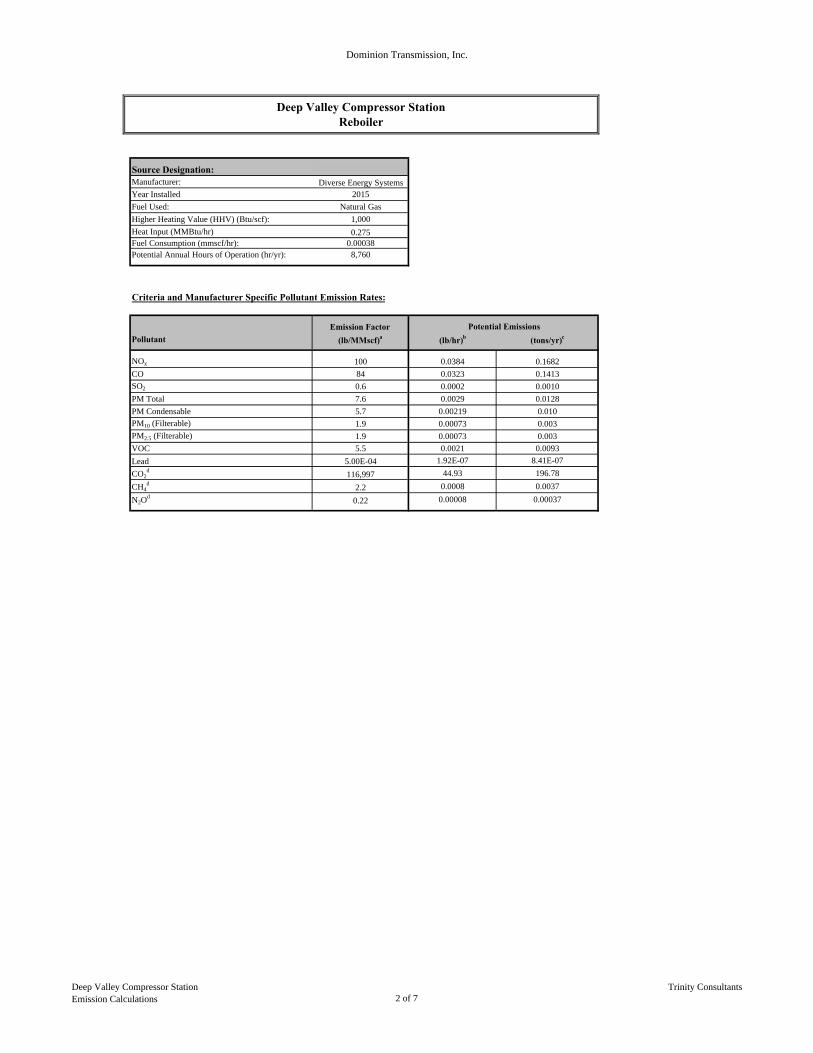
Dominion Transmission, Inc.
Source Designation:Manufacturer: Diverse Energy SystemsYear Installed 2015
Fuel Used: Natural Gas
Higher Heating Value (HHV) (Btu/scf): 1,000
Heat Input (MMBtu/hr) 0.275Fuel Consumption (mmscf/hr): 0.00038Potential Annual Hours of Operation (hr/yr): 8,760
Criteria and Manufacturer Specific Pollutant Emission Rates:
Emission Factor
Pollutant (lb/MMscf)a (lb/hr)b (tons/yr)c
NOx 100 0.0384 0.1682
CO 84 0.0323 0.1413
SO2 0.6 0.0002 0.0010
PM Total 7.6 0.0029 0.0128
PM Condensable 5.7 0.00219 0.010
PM10 (Filterable) 1.9 0.00073 0.003
PM2.5 (Filterable) 1.9 0.00073 0.003
VOC 5.5 0.0021 0.0093
Lead 5.00E-04 1.92E-07 8.41E-07
CO2d
116,997 44.93 196.78
CH4d
2.2 0.0008 0.0037
N2Od
0.22 0.00008 0.00037
Deep Valley Compressor StationReboiler
Potential Emissions
Deep Valley Compressor StationEmission Calculations 2 of 7
Trinity Consultants

Dominion Transmission, Inc.
Hazardous Air Pollutant (HAP) Potential Emissions:
Emission Factor
Pollutant (lb/MMscf)a (lb/hr)b (tons/yr)c
HAPs:
Methylnaphthalene (2-) 2.40E-05 9.22E-09 4.04E-08
3-Methylchloranthrene 1.80E-06 6.91E-10 3.03E-09
7,12-Dimethylbenz(a)anthracene 1.60E-05 6.14E-09 2.69E-08
Acenaphthene 1.80E-06 6.91E-10 3.03E-09
Acenaphthylene 1.80E-06 6.91E-10 3.03E-09
Anthracene 2.40E-06 9.22E-10 4.04E-09
Benz(a)anthracene 1.80E-06 6.91E-10 3.03E-09
Benzene 2.10E-03 8.06E-07 3.53E-06
Benzo(a)pyrene 1.20E-06 4.61E-10 2.02E-09
Benzo(b)fluoranthene 1.80E-06 6.91E-10 3.03E-09
Benzo(g,h,i)perylene 1.20E-06 4.61E-10 2.02E-09
Benzo(k)fluoranthene 1.80E-06 6.91E-10 3.03E-09
Chrysene 1.80E-06 6.91E-10 3.03E-09
Dibenzo(a,h) anthracene 1.20E-06 4.61E-10 2.02E-09
Dichlorobenzene 1.20E-03 4.61E-07 2.02E-06
Fluoranthene 3.00E-06 1.15E-09 5.05E-09
Fluorene 2.80E-06 1.08E-09 4.71E-09
Formaldehyde 7.50E-02 2.88E-05 1.26E-04
Hexane 1.80E+00 6.91E-04 3.03E-03
Indo(1,2,3-cd)pyrene 1.80E-06 6.91E-10 3.03E-09
Naphthalene 6.10E-04 2.34E-07 1.03E-06
Phenanthrene 1.70E-05 6.53E-09 2.86E-08
Pyrene 5.00E-06 1.92E-09 8.41E-09
Toluene 3.40E-03 1.31E-06 5.72E-06
Arsenic 2.00E-04 7.68E-08 3.36E-07
Beryllium 1.20E-05 4.61E-09 2.02E-08
Cadmium 1.10E-03 4.22E-07 1.85E-06
Chromium 1.40E-03 5.38E-07 2.35E-06
Cobalt 8.40E-05 3.23E-08 1.41E-07
Manganese 3.80E-04 1.46E-07 6.39E-07
Mercury 2.60E-04 9.98E-08 4.37E-07
Nickel 2.10E-03 8.06E-07 3.53E-06
Selenium 2.40E-05 9.22E-09 4.04E-08
Total HAP 7.25E-04 3.18E-03
a
b Emission Rate (lb/hr) = Rated Capacity (MMscf/hr) × Emission Factor (lb/MMscf).c Annual Emissions (tons/yr)Potential = (lb/hr)Emissions × (Maximum Allowable Operating Hours, 8760 hr/yr) × (1 ton/2000 lb).d
Emission Rate (lb/hr) = Rated Capacity (MMscf/hr) × Emission Factor from Subpart C (kg/MMBtu) × (2.205 lb/kg) × HHV (Btu/scf)
Potential Emissions
Emission factors from AP-42 Section 1.4 "Natural Gas Combustion" Tables 1.4-1, 1.4-2, 1.4-3, & 1.4-4.
GHG Emission factors from Tables C-1 and C-2, 40 CFR 98, Subpart C.
Deep Valley Compressor StationEmission Calculations 3 of 7
Trinity Consultants
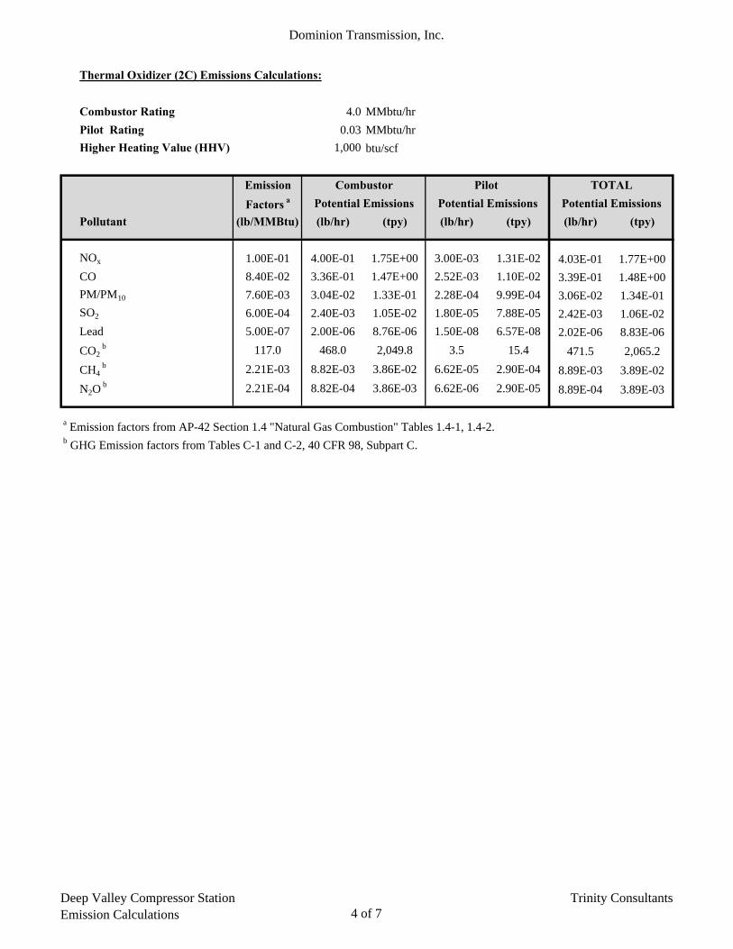
Dominion Transmission, Inc.
Thermal Oxidizer (2C) Emissions Calculations:
Combustor Rating 4.0 MMbtu/hr
Pilot Rating 0.03 MMbtu/hr
Higher Heating Value (HHV) 1,000 btu/scf
Emission Combustor Pilot TOTAL
Factors a Potential Emissions Potential Emissions Potential Emissions
Pollutant (lb/MMBtu) (lb/hr) (tpy) (lb/hr) (tpy) (lb/hr) (tpy)
NOx 1.00E-01 4.00E-01 1.75E+00 3.00E-03 1.31E-02 4.03E-01 1.77E+00
CO 8.40E-02 3.36E-01 1.47E+00 2.52E-03 1.10E-02 3.39E-01 1.48E+00
PM/PM10 7.60E-03 3.04E-02 1.33E-01 2.28E-04 9.99E-04 3.06E-02 1.34E-01
SO2 6.00E-04 2.40E-03 1.05E-02 1.80E-05 7.88E-05 2.42E-03 1.06E-02
Lead 5.00E-07 2.00E-06 8.76E-06 1.50E-08 6.57E-08 2.02E-06 8.83E-06
CO2 b 117.0 468.0 2,049.8 3.5 15.4 471.5 2,065.2
CH4 b 2.21E-03 8.82E-03 3.86E-02 6.62E-05 2.90E-04 8.89E-03 3.89E-02
N2O b 2.21E-04 8.82E-04 3.86E-03 6.62E-06 2.90E-05 8.89E-04 3.89E-03
a Emission factors from AP-42 Section 1.4 "Natural Gas Combustion" Tables 1.4-1, 1.4-2.b GHG Emission factors from Tables C-1 and C-2, 40 CFR 98, Subpart C.
Deep Valley Compressor StationEmission Calculations 4 of 7
Trinity Consultants

Dominion Transmission, Inc.
GRI-GLYCalc Version 4.0 - EMISSIONS SUMMARY GRI-GLYCalc Version 4.0 - EMISSIONS SUMMARY
Regenerator Emissions (Controlled) Flash Tank Emissions (Recycle/Recompression)
Pollutant (lbs/hr) (lbs/day) (tons/yr) Pollutant (lbs/hr) (lbs/day) (tons/yr)
Methane 0.5964 14.31 2.612 Methane 0.00 0.000
Ethane 0.2137 5.13 0.936 Ethane 0.00 0.000
Propane 0.1628 3.91 0.713 Propane 0.00 0.000
Isobutane 0.0393 0.94 0.172 Isobutane 0.00 0.000
n-Butane 0.0899 2.16 0.394 n-Butane 0.00 0.000
Isopentane 0.0364 0.87 0.159 Isopentane 0.00 0.000
n-Pentane 0.0359 0.86 0.157 n-Pentane 0.00 0.000
Cyclopentane 0.0002 0.00 0.001 Cyclopentane 0.00 0.000
n-Hexane* 0.0212 0.51 0.093 n-Hexane* 0.00 0.000
Cyclohexane 0.0141 0.34 0.062 Cyclohexane 0.00 0.000
Other Hexanes 0.0288 0.69 0.126 Other Hexanes 0.00 0.000
Methylcyclohexane 0.0006 0.01 0.003 Methylcyclohexane 0.00 0.000
Heptanes 0.0590 1.42 0.258 Heptanes 0.00 0.000
2,2,4-Trimethylpentane* 0.0150 0.36 0.066 2,2,4-Trimethylpentane* 0.00 0.000
Benzene* 0.0184 0.44 0.081 Benzene* 0.00 0.000
Toluene* 0.0610 1.46 0.267 Toluene* 0.00 0.000
Ethylbenzene* 0.0082 0.20 0.036 Ethylbenzene* 0.00 0.000
Xylenes* 0.0869 2.09 0.381 Xylenes* 0.00 0.000
C8 + Heavier Hydrocarbons 0.1301 3.12 0.570 C8 + Heavier Hydrocarbons 0.00 0.000
Total Emissions 1.6179 38.83 7.086 Total Emissions 0.0000 0.00 0.000
Total Hydrocarbon Emissions 1.6179 38.83 7.086 Total Hydrocarbon Emissions 0.0000 0.00 0.000
Total VOC Emissions 0.8078 19.39 3.538 Total VOC Emissions 0.0000 0.00 0.000
Total HAP Emissions 0.2107 5.06 0.923 Total HAP Emissions 0.0000 0.00 0.000
GRI-GLYCalc Version 4.0 - EMISSIONS SUMMARY1
Controlled Total Emission Rates (w/ safety factor)
Pollutant (lbs/hr) (lbs/day) (tons/yr)
Methane 0.7157 17.1763 3.1347
Ethane 0.2564 6.1546 1.1232
Propane 0.1954 4.6886 0.8557
Isobutane 0.0472 1.1318 0.2066
n-Butane 0.1079 2.5891 0.4725
Isopentane 0.0437 1.0483 0.1913
n-Pentane 0.0431 1.0339 0.1887
Cyclopentane 0.0002 0.0058 0.0011
n-Hexane* 0.0254 0.6106 0.1114
Cyclohexane 0.0169 0.4061 0.0741
Other Hexanes 0.0346 0.8294 0.1514
Heptanes 0.0007 0.0173 0.0032
Methylcyclohexane 0.0708 1.6992 0.3101
2,2,4-Trimethylpentane* 0.0180 0.4320 0.0788
Benzene* 0.0221 0.5299 0.0967
Toluene* 0.0732 1.7568 0.3206
Ethylbenzene* 0.0098 0.2362 0.0431
Xylenes* 0.1043 2.5027 0.4567
C8 + Heavier Hydrocarbons 0.1561 3.7469 0.6838
Total Emissions 1.9415 46.60 8.504
Total Hydrocarbon Emissions 1.9415 46.60 8.504
Total VOC Emissions 0.9694 23.26 4.246
Total HAP Emissions 0.2528 6.07 1.107
* HAPs
Glycol Dehydrator Emission Calculations - GLY-CALC Output1
1. Based on GRI GlyCalc 4.0 run at dry gas flowrate of 10 MMscf/day and T and P of 120°F and 500 psig, respectively, controlled by a TO at 95% destruction efficiencyA safety factor of 20% is included in the total.
Deep Valley Compressor StationEmission Calculations 5 of 7
Trinity Consultants

Dominion Transmission, Inc.
GRI-GLYCalc Version 4.0 - EMISSIONS SUMMARY GRI-GLYCalc Version 4.0 - EMISSIONS SUMMARY
Regenerator Emissions (Uncontrolled) Flash Tank Off Gas Emissions
Pollutant (lbs/hr) (lbs/day) (tons/yr) Pollutant (lbs/hr) (lbs/day) (tons/yr)
Methane 11.9276 286.26 52.243 Methane 2.5421 61.01 11.134
Ethane 4.2732 102.56 18.717 Ethane 2.0552 49.32 9.002
Propane 3.2565 78.16 14.263 Propane 1.6054 38.53 7.032
Isobutane 0.7865 18.88 3.445 Isobutane 0.3656 8.77 1.601
n-Butane 1.7986 43.17 7.878 n-Butane 0.7743 18.58 3.391
Isopentane 0.7276 17.46 3.187 Isopentane 0.2944 7.07 1.289
n-Pentane 0.7173 17.22 3.142 n-Pentane 0.2638 6.33 1.155
Cyclopentane 0.0043 0.10 0.019 Cyclopentane 0.0006 0.01 0.003
n-Hexane* 0.4235 10.16 1.855 n-Hexane* 0.1090 2.62 0.477
Cyclohexane 0.2814 6.75 1.233 Cyclohexane 0.0224 0.54 0.098
Other Hexanes 0.5753 13.81 2.520 Other Hexanes 0.1778 4.27 0.779
Heptanes 1.1807 28.34 5.171 Heptanes 0.1781 4.27 0.780
Methylcyclohexane 0.0118 0.28 0.052 Methylcyclohexane 0.0008 0.02 0.004
2,2,4-Trimethylpentane* 0.3000 7.20 1.314 2,2,4-Trimethylpentane* 0.0759 1.82 0.332
Benzene* 0.3685 8.84 1.614 Benzene* 0.0046 0.11 0.020
Toluene* 1.2201 29.28 5.344 Toluene* 0.0105 0.25 0.046
Ethylbenzene* 0.1646 3.95 0.721 Ethylbenzene* 0.0009 0.02 0.004
Xylenes* 1.7372 41.69 7.609 Xylenes* 0.0064 0.15 0.028
C8 + Heavier Hydrocarbons 2.6021 62.45 11.397 C8 + Heavier Hydrocarbons 0.0678 1.63 0.297
Total Emissions 32.3568 776.56 141.723 Total Emissions 8.5556 205.33 37.474
Total Hydrocarbon Emissions 32.3568 776.56 141.723 Total Hydrocarbon Emissions 8.5556 205.33 37.474
Total VOC Emissions 16.1560 387.74 70.763 Total VOC Emissions 3.9583 95.00 17.337
Total HAP Emissions 4.2139 101.13 18.457 Total HAP Emissions 0.2073 4.98 0.908
GRI-GLYCalc Version 4.0 - EMISSIONS SUMMARY1
Controlled Total Emission Rates (w/ safety factor)
Pollutant (lbs/hr) (lbs/day) (tons/yr)
Methane 17.3636 416.7274 76.0527
Ethane 7.5941 182.2579 33.2621
Propane 5.8343 140.0227 25.5541
Isobutane 1.3825 33.1805 6.0554
n-Butane 3.0875 74.0995 13.5232
Isopentane 1.2264 29.4336 5.3716
n-Pentane 1.1773 28.2557 5.1567
Cyclopentane 0.0059 0.1411 0.0258
n-Hexane* 0.6390 15.3360 2.7988
Cyclohexane 0.3646 8.7494 1.5968
Other Hexanes 0.9037 21.6893 3.9583
Methylcyclohexane 1.6306 39.1334 7.1419
Heptanes 0.0151 0.3629 0.0662
2,2,4-Trimethylpentane* 0.4511 10.8259 1.9757
Benzene* 0.4477 10.7453 1.9610
Toluene* 1.4767 35.4413 6.4680
Ethylbenzene* 0.1986 4.7664 0.8699
Xylenes* 2.0923 50.2157 9.1644
C8 + Heavier Hydrocarbons 3.2039 76.8931 14.0330
Total Emissions 49.0949 1178.28 215.036
Total Hydrocarbon Emissions 49.0949 1178.28 215.036
Total VOC Emissions 24.1372 579.29 105.721
Total HAP Emissions 5.3054 127.33 23.238
* HAPs
Glycol Dehydrator Emission Calculations - GLY-CALC Output1
1. Based on GRI GlyCalc 4.0 run at dry gas flowrate of 10 MMscf/day and T and P of 120°F and 500 psig, respectively, controlled by a TO at 95% destruction efficiencyA safety factor of 20% is included in the total.
Deep Valley Compressor StationEmission Calculations 6 of 7
Trinity Consultants

Dominion Transmission, Inc.
Pollutant New Units Existing Units1 Δ PTEtpy tpy tpy
VOC 4.2 52.3 -48.0HAP 1.1 9.6 -8.5
1. Source: Dehydrator Permit Application (R13 and Title V Modification) - Deep Valley Compressor Station - March 30, 2010 - Attachment J
Deep Valley Compressor StationEmission Calculations 7 of 7
Trinity Consultants

Page: 1GRI-GLYCalc VERSION 4.0 - SUMMARY OF INPUT VALUES
Case Name: Deep Valley Compressor StationFile Name: W:\Dominion\WV - Craig_Deep Valley_Yellow Creek\153902_0022 Dominion WV DehyProject\04 Deliverables\Deep Valley\Attachment N - Emission Calculations\Deep Valley.ddf Date: March 21, 2015
DESCRIPTION: -------------------------------------------------------------------
Description: 10 MMScf/day new TEG dehydrator
Annual Hours of Operation: 8760.0 hours/yr
WET GAS: -------------------------------------------------------------------
Temperature: 120.00 deg. F Pressure: 500.00 psig Wet Gas Water Content: Saturated
Component Conc. (vol %) ------------------------------- ----------- Carbon Dioxide 0.1410 Nitrogen 1.1090 Methane 77.7640 Ethane 12.6370 Propane 4.9670
Isobutane 0.7270 n-Butane 1.3570 Isopentane 0.4210 n-Pentane 0.3410 Cyclopentane 0.0005
n-Hexane 0.1040 Cyclohexane 0.0160 Other Hexanes 0.1820 Heptanes 0.1320 Methylcyclohexane 0.0005
2,2,4-Trimethylpentane 0.0620 Benzene 0.0030 Toluene 0.0060 Ethylbenzene 0.0005 Xylenes 0.0040
C8+ Heavies 0.0270
DRY GAS: -------------------------------------------------------------------
Flow Rate: 10.0 MMSCF/day Water Content: 7.0 lbs. H2O/MMSCF
LEAN GLYCOL: -------------------------------------------------------------------
Glycol Type: TEG Water Content: 1.0 wt% H2O Recirculation Ratio: 3.0 gal/lb H2O
PUMP:

Page: 2 -------------------------------------------------------------------
Glycol Pump Type: Electric/Pneumatic
FLASH TANK: -------------------------------------------------------------------
Flash Control: Recycle/recompression Temperature: 150.0 deg. F Pressure: 60.0 psig
STRIPPING GAS: -------------------------------------------------------------------
Source of Gas: Dry Gas Gas Flow Rate: 5.904 scfm
REGENERATOR OVERHEADS CONTROL DEVICE: -------------------------------------------------------------------
Control Device: Combustion Device Destruction Efficiency: 95.0 % Excess Oxygen: 0.0 % Ambient Air Temperature: 0.0 deg. F

Page: 1GRI-GLYCalc VERSION 4.0 - AGGREGATE CALCULATIONS REPORT
Case Name: Deep Valley Compressor StationFile Name: P:\01 Clients\Dominion\WV - TEG Dehys - 153902.0022\03 Deliverables\DeepValley\Attachment N - Emission Calculations\Deep Valley.ddf Date: March 13, 2015
DESCRIPTION:
Description: 10 MMScf/day new TEG dehydrator
Annual Hours of Operation: 8760.0 hours/yr
EMISSIONS REPORTS: -------------------------------------------------------------------
CONTROLLED REGENERATOR EMISSIONS ------------------------------------------------------------------- Component lbs/hr lbs/day tons/yr ------------------------------- ----------- ----------- ----------- Methane 0.5964 14.313 2.6122 Ethane 0.2137 5.128 0.9358 Propane 0.1628 3.908 0.7132 Isobutane 0.0393 0.944 0.1722 n-Butane 0.0899 2.158 0.3939
Isopentane 0.0364 0.873 0.1593 n-Pentane 0.0359 0.861 0.1571 Cyclopentane 0.0002 0.005 0.0009 n-Hexane 0.0212 0.508 0.0928 Cyclohexane 0.0141 0.338 0.0616
Other Hexanes 0.0288 0.690 0.1260 Heptanes 0.0590 1.417 0.2586 Methylcyclohexane 0.0006 0.014 0.0026 2,2,4-Trimethylpentane 0.0150 0.360 0.0657 Benzene 0.0184 0.442 0.0807
Toluene 0.0610 1.464 0.2672 Ethylbenzene 0.0082 0.198 0.0361 Xylenes 0.0869 2.085 0.3805 C8+ Heavies 0.1301 3.122 0.5699 ------------------------------- ----------- ----------- ----------- Total Emissions 1.6178 38.828 7.0861
Total Hydrocarbon Emissions 1.6178 38.828 7.0861 Total VOC Emissions 0.8078 19.387 3.5382 Total HAP Emissions 0.2107 5.057 0.9229 Total BTEX Emissions 0.1745 4.189 0.7644
UNCONTROLLED REGENERATOR EMISSIONS ------------------------------------------------------------------- Component lbs/hr lbs/day tons/yr ------------------------------- ----------- ----------- ----------- Methane 11.9276 286.263 52.2430 Ethane 4.2732 102.556 18.7164 Propane 3.2565 78.155 14.2634 Isobutane 0.7865 18.877 3.4450 n-Butane 1.7986 43.166 7.8778
Isopentane 0.7276 17.462 3.1867 n-Pentane 0.7173 17.214 3.1416 Cyclopentane 0.0043 0.102 0.0186 n-Hexane 0.4235 10.164 1.8550

Page: 2 Cyclohexane 0.2814 6.755 1.2327
Other Hexanes 0.5753 13.806 2.5196 Heptanes 1.1807 28.337 5.1716 Methylcyclohexane 0.0118 0.284 0.0518 2,2,4-Trimethylpentane 0.3000 7.200 1.3140 Benzene 0.3685 8.843 1.6139
Toluene 1.2201 29.282 5.3439 Ethylbenzene 0.1646 3.952 0.7212 Xylenes 1.7372 41.694 7.6091 C8+ Heavies 2.6021 62.450 11.3971 ------------------------------- ----------- ----------- ----------- Total Emissions 32.3567 776.562 141.7225
Total Hydrocarbon Emissions 32.3567 776.562 141.7225 Total VOC Emissions 16.1560 387.743 70.7631 Total HAP Emissions 4.2140 101.135 18.4571 Total BTEX Emissions 3.4904 83.770 15.2881
FLASH GAS EMISSIONS -------------------------------------------------------------------
Note: Flash Gas Emissions are zero with the Recycle/recompression control option.
FLASH TANK OFF GAS ------------------------------------------------------------------- Component lbs/hr lbs/day tons/yr ------------------------------- ----------- ----------- ----------- Methane 2.5421 61.010 11.1344 Ethane 2.0552 49.326 9.0019 Propane 1.6054 38.529 7.0316 Isobutane 0.3656 8.775 1.6014 n-Butane 0.7743 18.584 3.3916
Isopentane 0.2944 7.066 1.2895 n-Pentane 0.2638 6.331 1.1555 Cyclopentane 0.0006 0.013 0.0025 n-Hexane 0.1090 2.617 0.4776 Cyclohexane 0.0224 0.538 0.0982
Other Hexanes 0.1778 4.267 0.7787 Heptanes 0.1781 4.273 0.7799 Methylcyclohexane 0.0008 0.019 0.0034 2,2,4-Trimethylpentane 0.0759 1.822 0.3324 Benzene 0.0046 0.110 0.0201
Toluene 0.0105 0.251 0.0458 Ethylbenzene 0.0009 0.021 0.0038 Xylenes 0.0064 0.153 0.0279 C8+ Heavies 0.0678 1.627 0.2969 ------------------------------- ----------- ----------- ----------- Total Emissions 8.5555 205.332 37.4732
Total Hydrocarbon Emissions 8.5555 205.332 37.4732 Total VOC Emissions 3.9582 94.996 17.3369 Total HAP Emissions 0.2073 4.974 0.9078 Total BTEX Emissions 0.0223 0.535 0.0977
EQUIPMENT REPORTS: -------------------------------------------------------------------

Page: 3
COMBUSTION DEVICE -------------------------------------------------------------------
Ambient Temperature: 0.00 deg. F Excess Oxygen: 0.00 % Combustion Efficiency: 95.00 % Supplemental Fuel Requirement: 1.67e-001 MM BTU/hr
Component Emitted Destroyed ------------------------------- ----------- ----------- Methane 5.00% 95.00% Ethane 5.00% 95.00% Propane 5.00% 95.00% Isobutane 5.00% 95.00% n-Butane 5.00% 95.00%
Isopentane 5.00% 95.00% n-Pentane 5.00% 95.00% Cyclopentane 5.00% 95.00% n-Hexane 5.00% 95.00% Cyclohexane 5.00% 95.00%
Other Hexanes 5.00% 95.00% Heptanes 5.00% 95.00% Methylcyclohexane 5.00% 95.00% 2,2,4-Trimethylpentane 5.00% 95.00% Benzene 5.00% 95.00%
Toluene 5.00% 95.00% Ethylbenzene 5.00% 95.00% Xylenes 5.00% 95.00% C8+ Heavies 5.00% 95.00%
ABSORBER -------------------------------------------------------------------
Calculated Absorber Stages: 1.60 Specified Dry Gas Dew Point: 7.00 lbs. H2O/MMSCF Temperature: 120.0 deg. F Pressure: 500.0 psig Dry Gas Flow Rate: 10.0000 MMSCF/day Glycol Losses with Dry Gas: 0.2012 lb/hr Wet Gas Water Content: Saturated Calculated Wet Gas Water Content: 176.45 lbs. H2O/MMSCF Specified Lean Glycol Recirc. Ratio: 3.00 gal/lb H2O
Remaining Absorbed Component in Dry Gas in Glycol ------------------------------- ----------- ----------- Water 3.95% 96.05% Carbon Dioxide 99.75% 0.25% Nitrogen 99.98% 0.02% Methane 99.98% 0.02% Ethane 99.93% 0.07%
Propane 99.88% 0.12% Isobutane 99.84% 0.16% n-Butane 99.79% 0.21% Isopentane 99.78% 0.22% n-Pentane 99.72% 0.28%
Cyclopentane 98.83% 1.17% n-Hexane 99.54% 0.46% Cyclohexane 98.03% 1.97% Other Hexanes 99.65% 0.35% Heptanes 99.15% 0.85%

Page: 4
Methylcyclohexane 97.75% 2.25% 2,2,4-Trimethylpentane 99.60% 0.40% Benzene 85.58% 14.42% Toluene 79.81% 20.19% Ethylbenzene 71.68% 28.32%
Xylenes 62.67% 37.33% C8+ Heavies 94.79% 5.21%
FLASH TANK -------------------------------------------------------------------
Flash Control: Recycle/recompression Flash Temperature: 150.0 deg. F Flash Pressure: 60.0 psig
Left in Removed in Component Glycol Flash Gas ------------------------------- ----------- ----------- Water 99.97% 0.03% Carbon Dioxide 53.02% 46.98% Nitrogen 9.59% 90.41% Methane 9.98% 90.02% Ethane 26.13% 73.87%
Propane 43.04% 56.96% Isobutane 51.78% 48.22% n-Butane 57.87% 42.13% Isopentane 60.36% 39.64% n-Pentane 65.09% 34.91%
Cyclopentane 87.59% 12.41% n-Hexane 75.85% 24.15% Cyclohexane 92.56% 7.44% Other Hexanes 71.01% 28.99% Heptanes 85.67% 14.33%
Methylcyclohexane 93.90% 6.10% 2,2,4-Trimethylpentane 75.88% 24.12% Benzene 98.82% 1.18% Toluene 99.21% 0.79% Ethylbenzene 99.53% 0.47%
Xylenes 99.68% 0.32% C8+ Heavies 97.73% 2.27%
REGENERATOR -------------------------------------------------------------------
Regenerator Stripping Gas: Dry Product Gas Stripping Gas Flow Rate: 5.9040 scfm
Remaining Distilled Component in Glycol Overhead ------------------------------- ----------- ----------- Water 21.78% 78.22% Carbon Dioxide 0.00% 100.00% Nitrogen 0.00% 100.00% Methane 0.00% 100.00% Ethane 0.00% 100.00%
Propane 0.00% 100.00% Isobutane 0.00% 100.00% n-Butane 0.00% 100.00%

Page: 5 Isopentane 0.83% 99.17% n-Pentane 0.77% 99.23%
Cyclopentane 0.57% 99.43% n-Hexane 0.66% 99.34% Cyclohexane 3.46% 96.54% Other Hexanes 1.41% 98.59% Heptanes 0.58% 99.42%
Methylcyclohexane 4.26% 95.74% 2,2,4-Trimethylpentane 1.98% 98.02% Benzene 5.06% 94.94% Toluene 7.97% 92.03% Ethylbenzene 10.46% 89.54%
Xylenes 12.97% 87.03% C8+ Heavies 12.32% 87.68%
STREAM REPORTS: -------------------------------------------------------------------
WET GAS STREAM ------------------------------------------------------------- Temperature: 120.00 deg. F Pressure: 514.70 psia Flow Rate: 4.18e+005 scfh
Component Conc. Loading (vol%) (lb/hr) ------------------------------- --------- --------- Water 3.72e-001 7.38e+001 Carbon Dioxide 1.40e-001 6.82e+001 Nitrogen 1.10e+000 3.41e+002 Methane 7.75e+001 1.37e+004 Ethane 1.26e+001 4.17e+003
Propane 4.95e+000 2.41e+003 Isobutane 7.24e-001 4.64e+002 n-Butane 1.35e+000 8.66e+002 Isopentane 4.19e-001 3.34e+002 n-Pentane 3.40e-001 2.70e+002
Cyclopentane 4.98e-004 3.85e-001 n-Hexane 1.04e-001 9.85e+001 Cyclohexane 1.59e-002 1.48e+001 Other Hexanes 1.81e-001 1.72e+002 Heptanes 1.32e-001 1.45e+002
Methylcyclohexane 4.98e-004 5.39e-001 2,2,4-Trimethylpentane 6.18e-002 7.78e+001 Benzene 2.99e-003 2.57e+000 Toluene 5.98e-003 6.07e+000 Ethylbenzene 4.98e-004 5.83e-001
Xylenes 3.99e-003 4.67e+000 C8+ Heavies 2.69e-002 5.05e+001 ------------------------------- --------- --------- Total Components 100.00 2.33e+004
DRY GAS STREAM ------------------------------------------------------------- Temperature: 120.00 deg. F Pressure: 514.70 psia
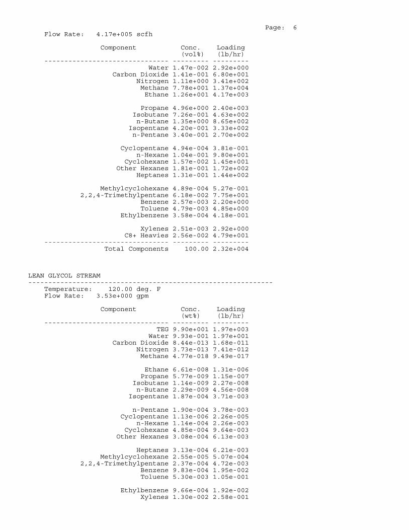
Page: 6 Flow Rate: 4.17e+005 scfh
Component Conc. Loading (vol%) (lb/hr) ------------------------------- --------- --------- Water 1.47e-002 2.92e+000 Carbon Dioxide 1.41e-001 6.80e+001 Nitrogen 1.11e+000 3.41e+002 Methane 7.78e+001 1.37e+004 Ethane 1.26e+001 4.17e+003
Propane 4.96e+000 2.40e+003 Isobutane 7.26e-001 4.63e+002 n-Butane 1.35e+000 8.65e+002 Isopentane 4.20e-001 3.33e+002 n-Pentane 3.40e-001 2.70e+002
Cyclopentane 4.94e-004 3.81e-001 n-Hexane 1.04e-001 9.80e+001 Cyclohexane 1.57e-002 1.45e+001 Other Hexanes 1.81e-001 1.72e+002 Heptanes 1.31e-001 1.44e+002
Methylcyclohexane 4.89e-004 5.27e-001 2,2,4-Trimethylpentane 6.18e-002 7.75e+001 Benzene 2.57e-003 2.20e+000 Toluene 4.79e-003 4.85e+000 Ethylbenzene 3.58e-004 4.18e-001
Xylenes 2.51e-003 2.92e+000 C8+ Heavies 2.56e-002 4.79e+001 ------------------------------- --------- --------- Total Components 100.00 2.32e+004
LEAN GLYCOL STREAM ------------------------------------------------------------- Temperature: 120.00 deg. F Flow Rate: 3.53e+000 gpm
Component Conc. Loading (wt%) (lb/hr) ------------------------------- --------- --------- TEG 9.90e+001 1.97e+003 Water 9.93e-001 1.97e+001 Carbon Dioxide 8.44e-013 1.68e-011 Nitrogen 3.73e-013 7.41e-012 Methane 4.77e-018 9.49e-017
Ethane 6.61e-008 1.31e-006 Propane 5.77e-009 1.15e-007 Isobutane 1.14e-009 2.27e-008 n-Butane 2.29e-009 4.56e-008 Isopentane 1.87e-004 3.71e-003
n-Pentane 1.90e-004 3.78e-003 Cyclopentane 1.13e-006 2.26e-005 n-Hexane 1.14e-004 2.26e-003 Cyclohexane 4.85e-004 9.64e-003 Other Hexanes 3.08e-004 6.13e-003
Heptanes 3.13e-004 6.21e-003 Methylcyclohexane 2.55e-005 5.07e-004 2,2,4-Trimethylpentane 2.37e-004 4.72e-003 Benzene 9.83e-004 1.95e-002 Toluene 5.30e-003 1.05e-001
Ethylbenzene 9.66e-004 1.92e-002 Xylenes 1.30e-002 2.58e-001

Page: 7 C8+ Heavies 1.81e-002 3.60e-001 ------------------------------- --------- --------- Total Components 100.00 1.99e+003
RICH GLYCOL STREAM ------------------------------------------------------------- Temperature: 120.00 deg. F Pressure: 514.70 psia Flow Rate: 3.71e+000 gpm NOTE: Stream has more than one phase.
Component Conc. Loading (wt%) (lb/hr) ------------------------------- --------- --------- TEG 9.46e+001 1.97e+003 Water 4.36e+000 9.07e+001 Carbon Dioxide 8.07e-003 1.68e-001 Nitrogen 3.56e-003 7.40e-002 Methane 1.36e-001 2.82e+000
Ethane 1.34e-001 2.78e+000 Propane 1.36e-001 2.82e+000 Isobutane 3.65e-002 7.58e-001 n-Butane 8.84e-002 1.84e+000 Isopentane 3.57e-002 7.43e-001
n-Pentane 3.64e-002 7.56e-001 Cyclopentane 2.17e-004 4.51e-003 n-Hexane 2.17e-002 4.52e-001 Cyclohexane 1.45e-002 3.01e-001 Other Hexanes 2.95e-002 6.13e-001
Heptanes 5.98e-002 1.24e+000 Methylcyclohexane 6.10e-004 1.27e-002 2,2,4-Trimethylpentane 1.51e-002 3.15e-001 Benzene 1.88e-002 3.91e-001 Toluene 6.41e-002 1.33e+000
Ethylbenzene 8.87e-003 1.84e-001 Xylenes 9.62e-002 2.00e+000 C8+ Heavies 1.44e-001 2.99e+000 ------------------------------- --------- --------- Total Components 100.00 2.08e+003
FLASH TANK OFF GAS STREAM ------------------------------------------------------------- Temperature: 150.00 deg. F Pressure: 74.70 psia Flow Rate: 1.15e+002 scfh
Component Conc. Loading (vol%) (lb/hr) ------------------------------- --------- --------- Water 5.50e-001 3.00e-002 Carbon Dioxide 5.91e-001 7.88e-002 Nitrogen 7.87e-001 6.69e-002 Methane 5.23e+001 2.54e+000 Ethane 2.25e+001 2.06e+000
Propane 1.20e+001 1.61e+000 Isobutane 2.08e+000 3.66e-001 n-Butane 4.40e+000 7.74e-001 Isopentane 1.35e+000 2.94e-001 n-Pentane 1.21e+000 2.64e-001
Cyclopentane 2.63e-003 5.60e-004

Page: 8 n-Hexane 4.17e-001 1.09e-001 Cyclohexane 8.79e-002 2.24e-002 Other Hexanes 6.81e-001 1.78e-001 Heptanes 5.86e-001 1.78e-001
Methylcyclohexane 2.60e-003 7.73e-004 2,2,4-Trimethylpentane 2.19e-001 7.59e-002 Benzene 1.94e-002 4.60e-003 Toluene 3.75e-002 1.05e-002 Ethylbenzene 2.69e-003 8.66e-004
Xylenes 1.98e-002 6.38e-003 C8+ Heavies 1.31e-001 6.78e-002 ------------------------------- --------- --------- Total Components 100.00 8.73e+000
FLASH TANK GLYCOL STREAM ------------------------------------------------------------- Temperature: 150.00 deg. F Flow Rate: 3.69e+000 gpm
Component Conc. Loading (wt%) (lb/hr) ------------------------------- --------- --------- TEG 9.49e+001 1.97e+003 Water 4.38e+000 9.06e+001 Carbon Dioxide 4.30e-003 8.90e-002 Nitrogen 3.43e-004 7.09e-003 Methane 1.36e-002 2.82e-001
Ethane 3.51e-002 7.27e-001 Propane 5.86e-002 1.21e+000 Isobutane 1.90e-002 3.93e-001 n-Butane 5.14e-002 1.06e+000 Isopentane 2.17e-002 4.48e-001
n-Pentane 2.38e-002 4.92e-001 Cyclopentane 1.91e-004 3.95e-003 n-Hexane 1.65e-002 3.42e-001 Cyclohexane 1.35e-002 2.79e-001 Other Hexanes 2.10e-002 4.35e-001
Heptanes 5.14e-002 1.06e+000 Methylcyclohexane 5.75e-004 1.19e-002 2,2,4-Trimethylpentane 1.15e-002 2.39e-001 Benzene 1.87e-002 3.86e-001 Toluene 6.38e-002 1.32e+000
Ethylbenzene 8.87e-003 1.83e-001 Xylenes 9.63e-002 1.99e+000 C8+ Heavies 1.41e-001 2.92e+000 ------------------------------- --------- --------- Total Components 100.00 2.07e+003
FLASH GAS EMISSIONS ------------------------------------------------------------- Control Method: Recycle/recompression Control Efficiency: 100.00
Note: Flash Gas Emissions are zero with the Recycle/recompression control option.
REGENERATOR OVERHEADS STREAM -------------------------------------------------------------

Page: 9 Temperature: 212.00 deg. F Pressure: 14.70 psia Flow Rate: 1.92e+003 scfh
Component Conc. Loading (vol%) (lb/hr) ------------------------------- --------- --------- Water 7.79e+001 7.09e+001 Carbon Dioxide 6.60e-002 1.47e-001 Nitrogen 2.10e-001 2.97e-001 Methane 1.47e+001 1.19e+001 Ethane 2.81e+000 4.27e+000
Propane 1.46e+000 3.26e+000 Isobutane 2.68e-001 7.87e-001 n-Butane 6.12e-001 1.80e+000 Isopentane 2.00e-001 7.28e-001 n-Pentane 1.97e-001 7.17e-001
Cyclopentane 1.20e-003 4.25e-003 n-Hexane 9.72e-002 4.24e-001 Cyclohexane 6.62e-002 2.81e-001 Other Hexanes 1.32e-001 5.75e-001 Heptanes 2.33e-001 1.18e+000
Methylcyclohexane 2.38e-003 1.18e-002 2,2,4-Trimethylpentane 5.20e-002 3.00e-001 Benzene 9.33e-002 3.68e-001 Toluene 2.62e-001 1.22e+000 Ethylbenzene 3.07e-002 1.65e-001
Xylenes 3.24e-001 1.74e+000 C8+ Heavies 3.02e-001 2.60e+000 ------------------------------- --------- --------- Total Components 100.00 1.04e+002
COMBUSTION DEVICE OFF GAS STREAM ------------------------------------------------------------- Temperature: 1000.00 deg. F Pressure: 14.70 psia Flow Rate: 2.10e+001 scfh
Component Conc. Loading (vol%) (lb/hr) ------------------------------- --------- --------- Methane 6.73e+001 5.96e-001 Ethane 1.29e+001 2.14e-001 Propane 6.68e+000 1.63e-001 Isobutane 1.22e+000 3.93e-002 n-Butane 2.80e+000 8.99e-002
Isopentane 9.13e-001 3.64e-002 n-Pentane 9.00e-001 3.59e-002 Cyclopentane 5.49e-003 2.13e-004 n-Hexane 4.45e-001 2.12e-002 Cyclohexane 3.03e-001 1.41e-002
Other Hexanes 6.04e-001 2.88e-002 Heptanes 1.07e+000 5.90e-002 Methylcyclohexane 1.09e-002 5.92e-004 2,2,4-Trimethylpentane 2.38e-001 1.50e-002 Benzene 4.27e-001 1.84e-002
Toluene 1.20e+000 6.10e-002 Ethylbenzene 1.40e-001 8.23e-003 Xylenes 1.48e+000 8.69e-002 C8+ Heavies 1.38e+000 1.30e-001 ------------------------------- --------- ---------

Page: 10 Total Components 100.00 1.62e+000

Houston Laboratories8820 Interchange Drive
Houston, TX 77054Phone 713-660-0901
Certificate of AnalysisNumber: 1030-14090256-001A
Sep. 10, 2014W. Steven KiserDominion Transmission335 US Highway 33 WestWeston , WV 26452
Station Name:Deep Valley Sampled By: NSSample Point: Before Dehy Sample Of: Gas SpotCylinder No: 0340 Sample Date: 08/27/2014 14:55Analyzed: 09/09/2014 14:38:27 by Derma Saltibus Sample Conditions:11.2 psig, @ 79.2 °F
Method: GPA 2286
Analytical Data
Components Mol. % Wt. % GPM at14.696 psia
Nitrogen 1.109 1.472Carbon Dioxide 0.141 0.294Methane 77.764 59.126Ethane 12.637 18.009 3.383Propane 4.967 10.380 1.370Iso-butane 0.727 2.003 0.238n-Butane 1.357 3.738 0.428Iso-pentane 0.421 1.440 0.154n-Pentane 0.341 1.166 0.124Hexanes Plus 0.536 2.372 0.228
100.000 100.000 5.925
GPM TOTAL C2+ 5.925GPM TOTAL C3+ 2.542GPM TOTAL iC5+ 0.506
Physical Properties Total C6+Relative Density Real Gas 0.7309 3.2263Calculated Molecular Weight 21.10 93.44Compressibility Factor 0.9964GPA 2172-09 Calculation:Calculated Gross BTU per ft³ @ 14.696 psia & 60°FReal Gas Dry BTU 1264 5090Water Sat. Gas Base BTU 1242 5001
Comments: H2O Content: 100 #/MMCF ; H2O Mol% : 1.744 ; Wt% : 1.493H2S 0 ppm
Hydrocarbon Laboratory Manager
Quality Assurance: The above analyses are performed in accordance with ASTM, UOP, GPA guidelines for qualityassurance, unless otherwise stated.
Page 1 of 13

Houston Laboratories8820 Interchange Drive
Houston, TX 77054Phone 713-660-0901
Certificate of AnalysisNumber: 1030-14090256-001A
Sep. 10, 2014W. Steven KiserDominion Transmission335 US Highway 33 WestWeston , WV 26452
Station Name:Deep Valley Sampled By: NSSample Point: Before Dehy Sample Of: Gas SpotCylinder No: 0340 Sample Date: 08/27/2014 14:55Analyzed: 09/09/2014 14:38:27 by Derma Saltibus Sample Conditions:11.2 psig, @ 79.2 °F
Method: GPA 2286
Analytical Data
Components Mol. % Wt. % GPM at14.696 psia
Nitrogen 1.109 1.472Carbon Dioxide 0.141 0.294Hydrogen Sulfide NIL NILMethane 77.764 59.126Ethane 12.637 18.009 3.383Propane 4.967 10.380 1.370Iso-Butane 0.727 2.003 0.238n-Butane 1.357 3.738 0.428Iso-Pentane 0.421 1.440 0.154n-Pentane 0.341 1.166 0.124Hexanes 0.286 1.145 0.115Heptanes Plus 0.250 1.227 0.113
100.000 100.000 5.925
GPM TOTAL C2+ 5.925GPM TOTAL C3+ 2.542GPM TOTAL iC5+ 0.506
Physical Properties Total C7+Relative Density Real Gas 0.7309 3.5382Calculated Molecular Weight 21.10 102.48Compressibility Factor 0.9964GPA 2172-09 Calculation:Calculated Gross BTU per ft³ @ 14.696 psia & 60°FReal Gas Dry BTU 1264 5525Water Sat. Gas Base BTU 1242 5429
Comments: H2O Content: 100 #/MMCF ; H2O Mol% : 1.744 ; Wt% : 1.493H2S 0 ppm
Hydrocarbon Laboratory Manager
Quality Assurance: The above analyses are performed in accordance with ASTM, UOP, GPA guidelines for qualityassurance, unless otherwise stated.
Page 2 of 13

Houston Laboratories8820 Interchange Drive
Houston, TX 77054Phone 713-660-0901
Certificate of AnalysisNumber: 1030-14090256-001A
Sep. 10, 2014W. Steven KiserDominion Transmission335 US Highway 33 WestWeston , WV 26452
Station Name:Deep Valley Sampled By: NSSample Point: Before Dehy Sample Of: Gas SpotCylinder No: 0340 Sample Date: 08/27/2014 14:55Analyzed: 09/09/2014 14:38:27 by Derma Saltibus Sample Conditions:11.2 psig, @ 79.2 °F
Method: GPA 2286
Analytical Data
Components Mol. % Wt. % GPM at14.696 psia
Nitrogen 1.109 1.472Methane 77.764 59.126Carbon Dioxide 0.141 0.294Hydrogen Sulfide NIL NILEthane 12.637 18.009 3.383Propane 4.967 10.380 1.370Iso-Butane 0.727 2.003 0.238n-Butane 1.357 3.738 0.428Iso-Pentane 0.421 1.440 0.154n-Pentane 0.341 1.166 0.124i-Hexanes 0.182 0.723 0.073n-Hexane 0.104 0.422 0.042Benzene 0.003 0.011 0.001Cyclohexane 0.016 0.065 0.005i-Heptanes 0.099 0.438 0.042n-Heptane 0.033 0.157 0.015Toluene 0.006 0.024 0.002i-Octanes 0.062 0.329 0.029n-Octane 0.010 0.050 0.005Ethylbenzene NIL NIL NILXylenes 0.004 0.023 0.002i-Nonanes 0.010 0.075 0.007n-Nonane 0.003 0.020 0.002i-Decanes 0.003 0.026 0.002n-Decane 0.001 0.007 0.001Undecanes NIL 0.002 NILDodecanes NIL NIL NILTridecanes NIL NIL NILTetradecanes Plus NIL NIL NIL
100.000 100.000 5.925
GPM TOTAL C2+ 5.925
Page 3 of 13

Houston Laboratories8820 Interchange Drive
Houston, TX 77054Phone 713-660-0901
Certificate of AnalysisNumber: 1030-14090256-001A
Sep. 10, 2014W. Steven KiserDominion Transmission335 US Highway 33 WestWeston , WV 26452
Station Name:Deep Valley Sampled By: NSSample Point: Before Dehy Sample Of: Gas SpotCylinder No: 0340 Sample Date: 08/27/2014 14:55Analyzed: 09/09/2014 14:38:27 by Derma Saltibus Sample Conditions:11.2 psig, @ 79.2 °F
Method: GPA 2286
Physical Properties TotalCalculated Molecular Weight 21.100GPA 2172-09 Calculation:Calculated Gross BTU per ft³ @ 14.696 psia & 60°FReal Gas Dry BTU 1264.3Water Sat. Gas Base BTU 1242.3Relative Density Real Gas 0.7309Compressibility Factor 0.9964
Comments: H2O Content: 100 #/MMCFH2S 0 ppm
Hydrocarbon Laboratory Manager
Quality Assurance: The above analyses are performed in accordance with ASTM, UOP, GPA guidelines for qualityassurance, unless otherwise stated.
Page 4 of 13

Dominion Transmission Inc.| Deep Valley Compressor Station Trinity Consultants
ATTACHMENT O
Monitoring/Recordkeeping/Reporting/Testing Plans

ATTACHMENT O - MONITORING, RECORDING, REPORTING, AND TESTING PLANS
Plan Type Emission unit
Pollutant Requirements Frequency Method of Measurement
Regulatory Reference
Recordkeeping Dehydration Unit
HAP Maintain following records:
Actual annual natural gas throughput OR actual average
annual benzene emissions
Annual Station natural gas throughput flowmeter
40 CFR 63.774(d)(1)

Dominion Transmission Inc.| Deep Valley Compressor Station Trinity Consultants
ATTACHMENT P
Public Notice

AIR QUALITY PERMIT NOTICE Notice of Application
Notice is given that Dominion Transmission, Inc. has applied to the West Virginia Department of Environmental Protection, Division of Air Quality, for a modification permit (R-13) to modify the natural gas compressor station (the Deep Valley Compressor Station) located near the town of Deep Valley, in Taylor County, West Virginia. The site latitude and longitude coordinates are: 39.34444 N, 80.85680 W. The applicant estimates that the change in potential to emit for the facility of the following Regulated Air Pollutants will be: Particulate Matter (PM) = ~0 tpy Sulfur Dioxide (SO2) = ~0 tpy Volatile Organic Compounds (VOC) = -48 tpy Carbon Monoxide (CO) = ~0 tpy Nitrogen Oxides (NOx) = ~0 tpy Hazardous Air Pollutants (HAPs) = -9 tpy Startup of operation will begin during or about November of 2015. Written comments will be received by the West Virginia Department of Environmental Protection, Division of Air Quality, 601 57th Street, SE, Charleston, WV 25304, for at least 30 calendar days from the date of publication of this notice. Any questions regarding this permit application should be directed to the DAQ at (304) 926-0499, extension 1242 during normal business hours. Dated this the (Day) day of (Month), (Year). By: Dominion Transmission, Inc.
Brian Sheppard Vice President, Pipeline Operations 445 West Main Street Clarksburg WV 26301

Dominion Transmission Inc.| Deep Valley Compressor Station Trinity Consultants
ATTACHMENT S
Title V Permit Revision Information

Attachment S
03/2007
Page __1__ of __3___
Attachment S
Title V Permit Revision Information
1. New Applicable Requirements Summary
Mark all applicable requirements associated with the changes involved with this permit revision:
SIP FIP
Minor source NSR (45CSR13) PSD (45CSR14)
NESHAP (45CSR15) Nonattainment NSR (45CSR19)
Section 111 NSPS (Subpart(s)_____________________________________)
Section 112(d) MACT standards (Subpart(s)__Subpart HH________________)
Section 112(g) Case-by-case MACT 112(r) RMP
Section 112(i) Early reduction of HAP Consumer/commercial prod. reqts., section 183(e)
Section 129 Standards/Reqts. Stratospheric ozone (Title VI)
Tank vessel reqt., section 183(f) Emissions cap 45CSR§30-2.6.1
NAAQS, increments or visibility (temp. sources) 45CSR27 State enforceable only rule
45CSR4 State enforceable only rule Acid Rain (Title IV, 45CSR33)
Emissions Trading and Banking (45CSR28) Compliance Assurance Monitoring (40CFR64) (1)
NOx Budget Trading Program Non-EGUs (45CSR1) NOx Budget Trading Program EGUs (45CSR26)
(1) If this box is checked, please include Compliance Assurance Monitoring (CAM) Form(s) for each Pollutants Specific Emission Unit (PSEU) (See Attachment H to Title V Application). If this box is not checked, please explain why Compliance Assurance Monitoring is not applicable:
Unit is exempt from CAM because it is subject to emission standards proposed after 11/15/90 to Section 112 of the Act (i.e., 40 CFR 63, Subpart HH)
2. Non Applicability Determinations
List all requirements, which the source has determined not applicable to this permit revision and for which a permit shield is requested. The listing shall also include the rule citation and a rationale for the determination.
40 CFR 60, Subparts D, Da, Db, Dc, OOOO
40 CFR 63, Subparts HHH, DDDDD, JJJJJJ
45 CSR 21
45 CSR 27
See rationale for determination in Attachment D.
Permit Shield Requested (not applicable to Minor Modifications)

Attachment S
03/2007
Page __2__ of __3___
All of the required forms and additional information can be found under the Permitting Section of DAQ’s website, or requested by phone.
3. Suggested Title V Draft Permit Language
Are there any changes involved with this Title V Permit revision outside of the scope of the NSR Permit revision? Yes No If Yes, describe the changes below.
Also, please provide Suggested Title V Draft Permit language for the proposed Title V Permit revision (including all applicable requirements associated with the permit revision and any associated monitoring /recordkeeping/ reporting requirements), OR attach a marked up pages of current Title V Permit. Please include appropriate citations (Permit or Consent Order number, condition number and/or rule citation (e.g. 45CSR§7-4.1)) for those requirements being added / revised.
4. Active NSR Permits/Permit Determinations/Consent Orders Associated With This Permit Revision
Permit or Consent Order Number Date of Issuance Permit/Consent Order Condition Number
R30-09500007-2010 11/30/2010
R13-2497 9/27/2002
R13-2503 2/9/2003
5. Inactive NSR Permits/Obsolete Permit or Consent Orders Conditions Associated With This Revision
Permit or Consent Order Number Date of Issuance Permit/Consent Order Condition Number
MM/DD/YYYY
/ /
/ /
6. Change in Potential Emissions
Pollutant Change in Potential Emissions (+ or -), TPY
Nitrogen Oxides ~ 0
Carbon Dioxide ~ 0
Particulate Matter ~ 0
Sulfur Dioxide ~ 0
Volatile Organic Compounds -48 tpy
Hazardous Air Pollutants -9 tpy
All of the required forms and additional information can be found under the Permitting Section of DAQ’s website, or requested by phone.