Colorado Field Guide Weatherization Assistance Program
256
Colorado Weatherization Field Guide 1 Colorado Field Guide Weatherization Assistance Program This is the latest version of the Field Guide offered in the State of Colorado and describes procedures to conduct energy audits, perform energy retrofits, and conduct final inspections of existing homes retrofitted in the Department of Energy’s Weatherization Assistance Program. All of the input and effort by Colorado Weatherization Agency staff in working with the Colorado Energy Office is recognized and appreciated. This version is dedicated to the memory and contributions made by Winnie Zeisel (October 28,1950 - November 1, 2012). Produced by John Krigger Illustrated by John Krigger, Bob Starkey, Steve Hogan Copyright 2012 by The Colorado Energy Office and Saturn Resource Management, Inc. Printed in the U.S. Version 113012
-
Upload
khangminh22 -
Category
Documents
-
view
1 -
download
0
Transcript of Colorado Field Guide Weatherization Assistance Program

Colorado Weatherization Field Guide 1
Colorado Field GuideWeatherization
Assistance Program
This is the latest version of the Field Guide offered in the State of Colorado and describes procedures to conduct energy audits, perform energy
retrofits, and conduct final inspections of existing homes retrofitted in the Department of Energy’s Weatherization Assistance Program. All of the
input and effort by Colorado Weatherization Agency staff in working with the Colorado Energy Office is recognized and appreciated.
This version is dedicated to the memory and contributions made by Winnie Zeisel (October 28,1950 - November 1, 2012).
Produced by John KriggerIllustrated by John Krigger, Bob Starkey, Steve Hogan
Copyright 2012 by
The Colorado Energy Office and Saturn Resource Management, Inc.Printed in the U.S.
Version 113012

2

Colorado Weatherization Field Guide 3
PrefaceThe Colorado Weatherization Field Guide outlines a set of best practices for energy audits, in-progress inspections, and final inspections in Colorado. This guide speaks to the weatheriza-tion specialist whose main focus is on energy auditing, work scope development, quality control, and inspection.The purpose of this guide is to provide specific guidance on evaluating a home’s existing condition of insulation, air sealing, heating, cooling, baseload, and health and safety. This guide incorporates information from the following standards and specifications.
• DOE Standardized Work Specifications (2011)• DOE Weatherization Job Task Analysis (2011)• WAP Policy Directives from 2005 to 2011• Building Performance Institute (BPI) Standards (2012)• International Residential Code 2009• International Energy Conservation Code 2009• National Fuel Gas Code (NFPA 54) 2009• International Mechanical Code 2009• ASHRAE Ventilation Standard 62.2 2010
The National Renewable Energy Laboratory (NREL) completed a review of this guide’s content in late 2010 that greatly improved its alignment with DOE and BPI standards along with suggest-ing many other substantial technical enhancements.This guide begins with a discussion of energy auditing, inspect-ing, customer relations, and work-scope development. A discussion of Health and Safety follows as an important topic for everyone. There are many DOE directives and long-standing weatherization practices discussed in this chapter. The last part of the chapter covers the most statistically threatening hazards

4
to workers, including driving, falls, back injuries, and respira-tory ailments.Chapter 3 discusses baseload measures such as water heaters and refrigerators from a weatherization perspective. Chapter 4 is a long and important discussion on heating sys-tems. Chapter 5 discusses energy conservation measures (ECMs) that are applied to the building shell.Chapter 6 is a dedicated chapter on mobile homes where we dis-cuss the ECMs particular to mobile homes. We hope you find this guide informative and easy to use, and we welcome all your feedback. Thanks for your hard work on behalf of low-income families in the Department of Energy’s Weatherization Assistance Program.

Colorado Weatherization Field Guide 5
TABLE OF CONTENTS
1: Energy Audits, Inspections, and Client Relations
General Specifications . . . . . . . . . . . . . . . . . . . . . . . . . . . . . . . . . . 11
Parts of an Energy Audit . . . . . . . . . . . . . . . . . . . . . . . . . . . . . . . . 11Energy-Auditing Judgment and Ethics . . . . . . . . . . . . . . . . 12Communication Best Practices . . . . . . . . . . . . . . . . . . . . . . . . 12Deferral of Weatherization Services . . . . . . . . . . . . . . . . . . . 13Visual Inspection . . . . . . . . . . . . . . . . . . . . . . . . . . . . . . . . . . . . . 14Diagnostic Testing . . . . . . . . . . . . . . . . . . . . . . . . . . . . . . . . . . . 20SIR Calculations with ECM Selection. . . . . . . . . . . . . . . . . . . 21
The Work Order . . . . . . . . . . . . . . . . . . . . . . . . . . . . . . . . . . . . . . . . 21
Doing the Work . . . . . . . . . . . . . . . . . . . . . . . . . . . . . . . . . . . . . . . . 21
Work Inspections . . . . . . . . . . . . . . . . . . . . . . . . . . . . . . . . . . . . . . . 24In-Progress Site Visits . . . . . . . . . . . . . . . . . . . . . . . . . . . . . . . . . 24Final Inspections . . . . . . . . . . . . . . . . . . . . . . . . . . . . . . . . . . . . . 25
Client Relations. . . . . . . . . . . . . . . . . . . . . . . . . . . . . . . . . . . . . . . . . 26Client Interview . . . . . . . . . . . . . . . . . . . . . . . . . . . . . . . . . . . . . . 26
Client Education. . . . . . . . . . . . . . . . . . . . . . . . . . . . . . . . . . . . . . . . 27Reducing Heating Consumption . . . . . . . . . . . . . . . . . . . . . . 28Reducing Electric Baseload . . . . . . . . . . . . . . . . . . . . . . . . . . . 29Reducing Hot Water and Laundry Consumption . . . . . . . 29
2: Health and Safety
Carbon Monoxide (CO) . . . . . . . . . . . . . . . . . . . . . . . . . . . . . . . . . 32Causes of Carbon Monoxide . . . . . . . . . . . . . . . . . . . . . . . . . . 32Gas Range and Oven Safety (Optional) . . . . . . . . . . . . . . . . 33
Smoke and Carbon Monoxide Alarms . . . . . . . . . . . . . . . . . . . 36Smoke Alarms . . . . . . . . . . . . . . . . . . . . . . . . . . . . . . . . . . . . . . . . 36CO Alarms. . . . . . . . . . . . . . . . . . . . . . . . . . . . . . . . . . . . . . . . . . . . 37

Table of Contents6
Moisture Problems . . . . . . . . . . . . . . . . . . . . . . . . . . . . . . . . . . . . . 38Symptoms of Moisture Problems. . . . . . . . . . . . . . . . . . . . . . 40Preventing Moisture Problems . . . . . . . . . . . . . . . . . . . . . . . . 40
Asbestos . . . . . . . . . . . . . . . . . . . . . . . . . . . . . . . . . . . . . . . . . . . . . . . 42
Lead-Safe Procedures. . . . . . . . . . . . . . . . . . . . . . . . . . . . . . . . . . . 43EPA RRP Requirements . . . . . . . . . . . . . . . . . . . . . . . . . . . . . . . 43Lead-Safe Work Practices . . . . . . . . . . . . . . . . . . . . . . . . . . . . . 44
Evaluating Building Ventilation Levels . . . . . . . . . . . . . . . . . . . 46Verifying Fan Airflows for Ventilation. . . . . . . . . . . . . . . . . . 47
Whole-Building Ventilation Systems. . . . . . . . . . . . . . . . . . . . . 48Duct Specifications for Ventilation . . . . . . . . . . . . . . . . . . . . 48Exhaust Ventilation . . . . . . . . . . . . . . . . . . . . . . . . . . . . . . . . . . . 49Balanced Ventilation . . . . . . . . . . . . . . . . . . . . . . . . . . . . . . . . . 51Electrical Safety . . . . . . . . . . . . . . . . . . . . . . . . . . . . . . . . . . . . . . 52Worker Health and Safety. . . . . . . . . . . . . . . . . . . . . . . . . . . . . 54Commitment to Safety . . . . . . . . . . . . . . . . . . . . . . . . . . . . . . . 55New Employees . . . . . . . . . . . . . . . . . . . . . . . . . . . . . . . . . . . . . . 56Driving. . . . . . . . . . . . . . . . . . . . . . . . . . . . . . . . . . . . . . . . . . . . . . . 57Lifting and Back Injuries . . . . . . . . . . . . . . . . . . . . . . . . . . . . . . 58Respiratory Health. . . . . . . . . . . . . . . . . . . . . . . . . . . . . . . . . . . . 59Hazardous Materials . . . . . . . . . . . . . . . . . . . . . . . . . . . . . . . . . . 60Equipment for Personal and Crew Safety . . . . . . . . . . . . . . 60Falls. . . . . . . . . . . . . . . . . . . . . . . . . . . . . . . . . . . . . . . . . . . . . . . . . . 61Tool Safety . . . . . . . . . . . . . . . . . . . . . . . . . . . . . . . . . . . . . . . . . . . 63Repetitive Stress Injuries . . . . . . . . . . . . . . . . . . . . . . . . . . . . . . 64Safety for Extreme Weather . . . . . . . . . . . . . . . . . . . . . . . . . . . 64
3: Baseload Measures
Water-Heating Energy Savings . . . . . . . . . . . . . . . . . . . . . . . . . . 67Determining the Water Heater’s Insulation Level . . . . . . 68Water Heater Blankets . . . . . . . . . . . . . . . . . . . . . . . . . . . . . . . . 69Measuring and Adjusting Hot Water Temperature . . . . . 70Water-Heater Pipe Insulation . . . . . . . . . . . . . . . . . . . . . . . . . 71Water-Saving Shower Heads . . . . . . . . . . . . . . . . . . . . . . . . . . 71Water Heater Installation . . . . . . . . . . . . . . . . . . . . . . . . . . . . . 73

Colorado Weatherization Field Guide 7
Refrigerator Replacement. . . . . . . . . . . . . . . . . . . . . . . . . . . . . . . 73Refrigerator Evaluation . . . . . . . . . . . . . . . . . . . . . . . . . . . . . . . 74Refrigerator Metering Protocol. . . . . . . . . . . . . . . . . . . . . . . . 74Refrigerator Operations. . . . . . . . . . . . . . . . . . . . . . . . . . . . . . . 77
Lighting Improvements. . . . . . . . . . . . . . . . . . . . . . . . . . . . . . . . . 77Dryer Venting/Ducts. . . . . . . . . . . . . . . . . . . . . . . . . . . . . . . . . . 78
4: Heating Systems
Essential Combustion Safety Tests . . . . . . . . . . . . . . . . . . . . . . 81Leak-Testing Gas Piping . . . . . . . . . . . . . . . . . . . . . . . . . . . . . . 81Worst-Case Combustion Safety Testing . . . . . . . . . . . . . . . 82Spillage and CO Testing . . . . . . . . . . . . . . . . . . . . . . . . . . . . . . 83Worst-Case CAZ Depressurization Test (OPTIONAL) . . . . 85Improving CAZ Depressurization and Draft . . . . . . . . . . . . 87Zone Isolation Testing for Atmospherically Vented Appli-
ances . . . . . . . . . . . . . . . . . . . . . . . . . . . . . . . . . . . . . . . . . . . . . . . . . . . . 89
Heating System Replacement . . . . . . . . . . . . . . . . . . . . . . . . . . . 90Combustion Furnace Replacement. . . . . . . . . . . . . . . . . . . . 90Gas-Fired Heating Installation. . . . . . . . . . . . . . . . . . . . . . . . . 92Combustion Boiler Replacement . . . . . . . . . . . . . . . . . . . . . . 94
Gas Space Heater Replacement . . . . . . . . . . . . . . . . . . . . . . . . . 96Space Heater Operation . . . . . . . . . . . . . . . . . . . . . . . . . . . . . . 97Unvented Space Heaters. . . . . . . . . . . . . . . . . . . . . . . . . . . . . . 97
Electronic Combustion Analysis . . . . . . . . . . . . . . . . . . . . . . . . . 98Combustion Efficiency Test for Furnaces . . . . . . . . . . . . . 101
Ducted Air Distribution . . . . . . . . . . . . . . . . . . . . . . . . . . . . . . . . 106Solving Airflow Problems . . . . . . . . . . . . . . . . . . . . . . . . . . . . 107Evaluating Furnace Performance. . . . . . . . . . . . . . . . . . . . . 111Improving Forced-Air System Airflow . . . . . . . . . . . . . . . . 115
Evaluating Duct Air Leakage . . . . . . . . . . . . . . . . . . . . . . . . . . . 117Troubleshooting Duct Leakage . . . . . . . . . . . . . . . . . . . . . . 117Measuring House Pressure Caused by Duct Leakage . . 121
Sealing Duct Leaks . . . . . . . . . . . . . . . . . . . . . . . . . . . . . . . . . . . . 124Sealing Return Ducts . . . . . . . . . . . . . . . . . . . . . . . . . . . . . . . . 124

Table of Contents8
Sealing Supply Ducts . . . . . . . . . . . . . . . . . . . . . . . . . . . . . . . . 125Duct Boots, Registers, and Chases . . . . . . . . . . . . . . . . . . . . 128Materials for Duct Sealing. . . . . . . . . . . . . . . . . . . . . . . . . . . . 128
Hot-Water Space-Heating Distribution . . . . . . . . . . . . . . . . . 129Boiler Efficiency and Maintenance . . . . . . . . . . . . . . . . . . . 129Distribution System Improvements . . . . . . . . . . . . . . . . . . 130
5: Building Shell
Blower Door Testing . . . . . . . . . . . . . . . . . . . . . . . . . . . . . . . . . . . 133Blower-Door Principles . . . . . . . . . . . . . . . . . . . . . . . . . . . . . . 133Preparing for a Blower Door Test . . . . . . . . . . . . . . . . . . . . . 135Blower-Door Test Procedures . . . . . . . . . . . . . . . . . . . . . . . . 136Approximate Leakage Area . . . . . . . . . . . . . . . . . . . . . . . . . . 139
Testing Air Barriers . . . . . . . . . . . . . . . . . . . . . . . . . . . . . . . . . . . . 140Simple Pressure Tests. . . . . . . . . . . . . . . . . . . . . . . . . . . . . . . . 142Simple Zone Pressure Testing. . . . . . . . . . . . . . . . . . . . . . . . 143
Controlling House Pressure . . . . . . . . . . . . . . . . . . . . . . . . . . . . 147Duct-Induced Room Pressures . . . . . . . . . . . . . . . . . . . . . . . 148
Air Sealing Fundamentals . . . . . . . . . . . . . . . . . . . . . . . . . . . . . . 148Air Sealing Strategy. . . . . . . . . . . . . . . . . . . . . . . . . . . . . . . . . . 149
Air Sealing Safety . . . . . . . . . . . . . . . . . . . . . . . . . . . . . . . . . . . . . . 150Liquid Foam Air Sealant . . . . . . . . . . . . . . . . . . . . . . . . . . . . . 151
Sealing Major Air Leaks and Bypasses . . . . . . . . . . . . . . . . . . 153Removing Insulation for Air Sealing . . . . . . . . . . . . . . . . . . 154Major Air Leak Locations & Treatments . . . . . . . . . . . . . . . 154
Attic and Roof Insulation. . . . . . . . . . . . . . . . . . . . . . . . . . . . . . . 166Preparing for Attic Insulation . . . . . . . . . . . . . . . . . . . . . . . . 167Blowing Attic Insulation . . . . . . . . . . . . . . . . . . . . . . . . . . . . . 169Insulating Closed Roof Cavities . . . . . . . . . . . . . . . . . . . . . . 170Finished Knee Wall Attics . . . . . . . . . . . . . . . . . . . . . . . . . . . . 173Walk-Up Stairways and Doors . . . . . . . . . . . . . . . . . . . . . . . . 176
Wall Insulation . . . . . . . . . . . . . . . . . . . . . . . . . . . . . . . . . . . . . . . . 178Preparing for Retrofit Wall Insulation . . . . . . . . . . . . . . . . . 179

Colorado Weatherization Field Guide 9
Exterior Siding: Removal and Replacement . . . . . . . . . . . 180Blowing Dense-Packed Wall Insulation . . . . . . . . . . . . . . . 185Exterior Wall Insulation: Drill and Blow . . . . . . . . . . . . . . . 188Interior Drill and Blow . . . . . . . . . . . . . . . . . . . . . . . . . . . . . . . 189
Floor and Foundation Insulation . . . . . . . . . . . . . . . . . . . . . . . 192Ground Moisture Barriers . . . . . . . . . . . . . . . . . . . . . . . . . . . . 192Foundation Wall Vapor Barrier . . . . . . . . . . . . . . . . . . . . . . . 193Floor Insulation . . . . . . . . . . . . . . . . . . . . . . . . . . . . . . . . . . . . . 193Crawl Space Wall Insulation. . . . . . . . . . . . . . . . . . . . . . . . . . 195Rim Joist Insulation for Basements . . . . . . . . . . . . . . . . . . . 196
Duct Insulation . . . . . . . . . . . . . . . . . . . . . . . . . . . . . . . . . . . . . . . . 196
6: Mobile Homes
Mobile Home Auditing . . . . . . . . . . . . . . . . . . . . . . . . . . . . . . . . 200
Mobile Home Air Sealing. . . . . . . . . . . . . . . . . . . . . . . . . . . . . . . 202Shell Air Leakage Locations . . . . . . . . . . . . . . . . . . . . . . . . . . 204Duct Leak Locations . . . . . . . . . . . . . . . . . . . . . . . . . . . . . . . . . 204
Mobile Home Insulation . . . . . . . . . . . . . . . . . . . . . . . . . . . . . . . 207Insulating Mobile Home Roof Cavities . . . . . . . . . . . . . . . . 207
Mobile Home Sidewall Insulation . . . . . . . . . . . . . . . . . . . . . . 213
Mobile Home Perimeter Insulation . . . . . . . . . . . . . . . . . . . . . 215
Mobile Home Floor Insulation. . . . . . . . . . . . . . . . . . . . . . . . . . 216Blowing Mobile Home Bellies . . . . . . . . . . . . . . . . . . . . . . . . 217Wing Blow . . . . . . . . . . . . . . . . . . . . . . . . . . . . . . . . . . . . . . . . . . 219
Mobile Home Windows and Doors . . . . . . . . . . . . . . . . . . . . . 219Mobile Home Storm Windows . . . . . . . . . . . . . . . . . . . . . . . 220Replacing Mobile Home Windows . . . . . . . . . . . . . . . . . . . 220Mobile Home Doors . . . . . . . . . . . . . . . . . . . . . . . . . . . . . . . . . 221

Table of Contents10
Exterior Water Heater Closet Treatment . . . . . . . . . . . . . . . . 221
Mobile Home Skirting. . . . . . . . . . . . . . . . . . . . . . . . . . . . . . . . . . 222
Appendices
R-values for Common Materials . . . . . . . . . . . . . . . . . . . . . . . . 223
Baseload Tables . . . . . . . . . . . . . . . . . . . . . . . . . . . . . . . . . . . . . . . 224
Appliance Tables . . . . . . . . . . . . . . . . . . . . . . . . . . . . . . . . . . . . . . 225
Calculating Attic Insulation . . . . . . . . . . . . . . . . . . . . . . . . . . . . 226
Calculating Wall Insulation . . . . . . . . . . . . . . . . . . . . . . . . . . . . . 230
Calculating Mobile Home Insulation. . . . . . . . . . . . . . . . . . . . 233
ASHRAE 62.2-2010 Standard . . . . . . . . . . . . . . . . . . . . . . . . . . . 235
ASHRAE 62.2 Calculation Sheet . . . . . . . . . . . . . . . . . . . . . . . . 239
Refrigerator Dating Chart . . . . . . . . . . . . . . . . . . . . . . . . . . . . . . 240
Measuring BTU Input on Natural Gas Appliances. . . . . . . . 241
Colorado WAP Policy . . . . . . . . . . . . . . . . . . . . . . . . . . . . . . . . . . 244
Heating Degree Days for CO Cities . . . . . . . . . . . . . . . . . . . . . 245
Useful Formulas . . . . . . . . . . . . . . . . . . . . . . . . . . . . . . . . . . . . . . . 248
Useful Formulas Continued . . . . . . . . . . . . . . . . . . . . . . . . . . . . 249
Useful Formulas Continued . . . . . . . . . . . . . . . . . . . . . . . . . . . . 250
Index

Colorado Weatherization Field Guide 11
CHAPTER 1: ENERGY AUDITS, INSPECTIONS, AND CLIENT RELATIONS
This chapter outlines the operational process of energy audits, work orders, and final inspections as practiced by non-profit agencies and contractors working in the Department of Energy’s (DOE) Weatherization Assistance Program (WAP) in Colorado. The mission of DOE WAP is “To reduce energy costs for low-income families, particularly for the elderly, people with dis-abilities, and children, by improving the energy efficiency of their homes while ensuring their health and safety.”
1.1 GENERAL SPECIFICATIONS
Administrators, managers, and installers must observe the fol-lowing general specifications in the execution of residential energy programs governed by these specifications.
1. Weatherization measures must be installed in accor-dance with all applicable State codes, local codes, and Federal regulations.
2. The specifications in this document are minimum requirements but are intended to meet or exceed appli-cable existing codes and regulations.
3. Users of these specifications may apply more restrictive requirements than those given here. When more than one specification applies to the work being done, the most stringent should apply.
1.2 PARTS OF AN ENERGY AUDIT
Visual inspection, diagnostic testing, and SIR analysis (SIR = Savings-to-Investment Ratio) are the three types of energy

Energy Audits, Inspections, and Client Relations12
auditing procedures we discuss. These procedures should aid you in evaluating all the possible ECMs that are cost-effective according to DOE-approved software: Weatherization Assistant or approved equivalent. See “SIR Calculations with ECM Selec-tion” on page 21.The energy audit must also propose solutions to health and safety problems related to the energy conservation measures.
1.2.1 Energy-Auditing Judgment and Ethics
The auditor’s good decisions are extremely important to the suc-cess of a weatherization program. Good decisions depend on judgment and ethics. Know and understand the requirements of the WAP pro-
gram. Develop the inspection, diagnosis, and software skills nec-
essary for WAP energy auditing. Choose ECMs according to their cost-effectiveness along
with DOE and State policy, not personal preference or cus-tomer preference.
Don’t manipulate Weatherization Assistant to choose or avoid particular ECMs.
Communicate honestly with customers, coworkers, con-tractors, and supervisors.
Avoid personal bias in your influence on purchasing, hir-ing, and contracting.
Know the limits of your authority, and ask for guidance when you need it.
1.2.2 Communication Best Practices
Making a good first impression is important for client relations. Friendly, honest, and straightforward communication helps cre-

Colorado Weatherization Field Guide 13
ate an atmosphere where problems and solutions can be openly discussed.Setting priorities for client communication is important for the efficient use of your time. Auditors and inspectors must com-municate clearly and directly. Limit your communication with the client to the most important energy, health, safety, and dura-bility issues. Introduce yourself, identify your employer, and state the
reason for your visit. Explain the requirements and benefits of the WAP pro-
gram. Listen carefully to your client’s reports, complaints, ques-
tions, and ideas about their home’s energy efficiency. Ask questions to clarify your understanding of your cli-
ent’s concerns. Before you leave, give the client a quick summary of what
you found during the energy audit or inspection. Avoid making promises until you have time to estimate the
job and discuss the home with a crew leader or contractor. Make arrangements for additional visits by crews and con-
tractors as appropriate. Schedule in-progress site visit and the final inspection at
the appropriate times.
1.2.3 Deferral of Weatherization Services
When you find major health, safety, or durability problems in a home, sometimes it’s necessary to defer (delay) the client weather-ization services until those problems are solved. The problems that are cause for denial of services include but are not limited to the following. Document these problems with digital photos if possi-ble.
• Major roof leakage.

Energy Audits, Inspections, and Client Relations14
• Major foundation damage.• Major mold infestation and other moisture deterioration.• Major plumbing problems.• Human or animal waste in, around or under the home.• Major electrical problems or fire hazards.• The home is vacant or the client is moving.• The home is for sale.
Major behavioral problems may also be a reason to deny ser-vices to a client, including but not limited to the following.
• Illegal activity on the premises.• Occupant’s hoarding makes it difficult or impossible to per-
form a complete audit.• The home is being renovated.• Lack of cooperation by the client.
1.2.4 Visual Inspection
Visual inspection orients the energy auditor to the physical real-ities of home and home site. Among the areas of inspection are the following:
• Building interior and exterior• Heating systems• Baseload energy uses• Health and safety issues• The home’s physical dimensions: area and volume
Inspecting the Building’s Exterior
The energy auditor should inspect the home from the exterior first, to understand the home’s major components such as floors, additions, and intermediate zones like attics and crawl spaces.

Colorado Weatherization Field Guide 15
Notice the building’s exterior maintenance condition, its site issues, and its main utility connections like plumbing stacks and electrical service. Inspect the characteristics and condition of the founda-
tion, roof, siding, windows, doors, and overhangs. Measure the building’s floor space and interior volume. Inspect the foundation, and find the crawl space or base-
ment entrance. Identify boundary areas between major building compo-
nents like building stories, additions, attics, and crawl spaces.
Evaluate the site drainage, and look for evidence of mois-ture accumulation and damage.
Notice any additions or remodeled sections of the build-ing.
View the building through an infrared scanner, if available, to identify thermal flaws.
Evaluate roof.
Energy Audits, Inspections, and Client Relations16
Visualization: Auditors learn to visualize the home and make simple drawings to aid in communication.
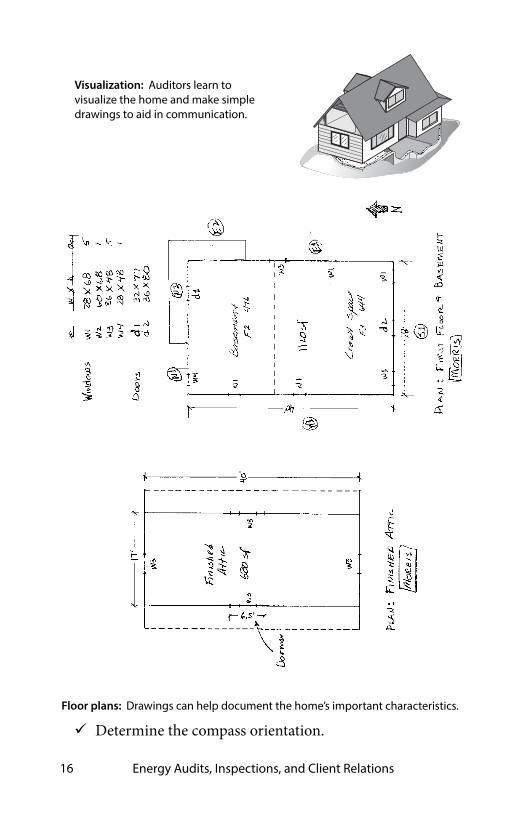
Floor plans: Drawings can help document the home’s important characteristics.
Determine the compass orientation.

Colorado Weatherization Field Guide 17
Inspect the chimney(s) and exhaust vents. Note their loca-tion and condition.
Inspecting the Building’s Interior
Inspect the interior using the mental map you developed from exterior inspection. Consider these activities when you inspect the home’s interior. Locate and identify components of the thermal boundary. Inspect boundary areas between major building compo-
nents such as: building stories, additions, attics, and crawl spaces.
Evaluate the type, thickness, and condition of insulation in the attic, walls, floors, and foundation.
Look for obvious air leaks, especially around chimneys, vent stacks, recessed light fixtures, ductwork, and built-ins.
Inspect for evidence of moisture problems such as mold, water stains, or musty smells.
Inspect the wiring in the attic or other areas affected by weatherization measures.
Identify other health and safety issues.

Energy Audits, Inspections, and Client Relations18
Interior and exterior inspection: When combined with testing, the inspection of the home’s exterior and interior helps the auditor decide on the energy conservation and repair priorities for the home.
Crawl space
Damaged Plumbingpenetrations
Chimney
Combustionzone
Windows
Doors
Roof
plaster
Dryer
DH
WH
Heating-System Inspection
Inspect the heating-system to identify problems to be solved during weatherization by a heating technician. Look for signs of spillage, backdrafting, and flame rollout. Check for fuel leaks and ensure approved delivery piping
and connections for the fuel being used. See “Leak-Testing Gas Piping” on page 81.
Inspect the condition of chimneys or vent connectors. Inspect all forced-air heat exchangers for deterioration. Recommend to disable or remove ventless combustion
space heaters. See “Unvented Space Heaters” on page 97. Look for improper heating-system installations. Examples:
in bedrooms or closets; installed with no return air; no service access; mobile homes with open-combustion fur-naces or space heaters.

Colorado Weatherization Field Guide 19
Baseload Inspection
Baseload energy consumption is comprised of energy uses that remain constant throughout the year, as opposed to seasonal energy consumption such as heating and air conditioning. The water heating system, the refrigerator, lights and the clothes dryer are all important baseload energy consumers and should be evaluated during an energy audit. Check for excessive dust on the refrigerator coil. Measure or use a data base to estimate refrigerator elec-
tricity consumption. Refrigerator temperature should be 36–40°F, and freezer
temperature should be 0–5°F. Inspect the water heater and piping for insulation, leakage
and safety problems. Water heater temperature should be 120°F. Inspect the dryer and dryer vent for lint and debris. Inspect lighting and recommend compact-fluorescent
replacement bulbs as appropriate.See “Baseload Measures” on page 67.
Health and Safety Inspection
Identify energy-related health and safety deficiencies, which could be created or worsened by weatherization activities. Be very careful and courteous about discussing these problems with clients so you don’t alarm them needlessly. Determine the severity of the deficiencies, and whether
there is an immediate threat to the health or safety of household members. Address emergencies immediately.
Check for presence and proper placement of CO alarms and smoke alarms.

Energy Audits, Inspections, and Client Relations20
Test combustion appliances for excessive carbon monox-ide.
Inspect for moisture, for example roof leaks and plumbing leaks.
Notice indoor air pollution problems. Interview the homeowner about the family’s health with
relation to weatherization services, including the chemical sensitivity interview.
Document existing health-and-safety problems and take photos as needed.
Explain all health and safety problems clearly, and answer questions patiently.
1.2.5 Diagnostic Testing
Measurement instruments provide important information about a building’s unknowns, such as air leakage and combus-tion efficiency. Use these diagnostic tests as appropriate during the energy audit.
• Blower door testing: A variety of procedures using a blower door to evaluate the airtightness of a home and parts of its air barrier.
• Duct airtightness testing: A variety of tests using a blower door and pressure pan to locate duct leaks.
• Combustion safety and efficiency testing: Combustion ana-lyzers sample combustion by-products to evaluate safety and efficiency.
• Infrared scanning: Viewing building components through an infrared scanner, shows differences in the temperature of building components inside building cavities.
• Appliance consumption testing: If refrigerator consump-tion information isn’t available in an approved data base,

Colorado Weatherization Field Guide 21
refrigerators must be metered with logging watt-hour meters to estimate annual electricity consumption.
1.2.6 SIR Calculations with ECM Selection
Energy auditors currently use Weatherization Assistant (WA) or other DOE-approved software, to determine which ECMs have the highest Savings-to-Investment Ratio (SIR). WA contains both NEAT for site-built homes and MHEA for mobile homes.
SIR = LIFETIME SAVINGS ÷ INITIAL INVESTMENT
1.3 THE WORK ORDER
The work order is a list of materials and tasks that are recom-mended as a result of an energy audit. Consider these steps in developing the work order. Specify corrections to health and safety problems. Provide detailed specifications for crews or contractors,
including procedures, materials, hazards, repairs, and other important details.
Estimate the materials and labor needed to complete the job.
Obtain estimates from sub-contractors. Consider in-progress inspections and schedule the final
inspection for the job’s final day if possible.
1.4 DOING THE WORK
Though installation activities may vary from house to house, the following work-flow for installers pertains to most homes. Do the following before leaving the shop. Review the audit and work order.

Energy Audits, Inspections, and Client Relations22
Make sure all the materials and tools necessary for the job are in the vehicle.
Make sure you can find the home. If you are unsure, get directions.
Note any mechanical work that was to be completed prior to the start of building shell activities.
Know what repairs need to be completed before installing weatherization measures.
Clarify with the auditor anything about the job that is unclear or incomplete.
Contact the client to make sure that they will be home and that they understand what you will be doing.
At the Job Site
The crew leader or installer do the following tasks shortly after arriving at the job site on the first day. Walk around the exterior and interior to confirm the
information on the audit form and work order. Document any problems that could interfere with installa-
tion activities. The crew leader shows the crew the locations and details
of the ECM installation. Explain to the client what will be happening, and approxi-
mately how long it will take. Ask for the client’s assistance for such things as controlling
children or pets and moving possessions out of the way. Contact your supervisor if you encounter issues such as the fol-lowing.
• There are problems with heating systems, or if you smell gas. If the gas smell is strong, turn off the gas, then open

Colorado Weatherization Field Guide 23
windows, evacuate the house, and call the gas company, if necessary.
• Conditions have changed and you can’t do your work, or if it will take much longer than normal to get the job done.
• If the house is for sale, don’t start work. Talk to the client and call your supervisor.
Verify that the necessary health, safety, and durability measures are complete or are part of the work order, such as the following.
• Furnace replacements. • Carbon monoxide mitigation. • Heat exchanger replacements. • Burner cleaning. • Combustion air installation. • Seal return-duct air leaks in the CAZ if atmospherically
venting combustion appliances are present.• Repairs of gas and propane leaks. • Chimney cleaning or lining. • Water heater tank replacements. • Ground moisture barrier.• Plumbing repairs. • Clothes dryer venting (maintenance, repair)• Install whole building mechanical ventilation.
Complete these energy conservation measures. Set up the blower door and check the building shell for air
leaks. Find and seal large air leaks. Seal leakage from the ducts.

Energy Audits, Inspections, and Client Relations24
Check your progress with the blower door after you com-plete an area.
Record blower door test results, materials, and your time. Seal supply ducts and return ducts that are outside of the
heated space. Stop air leakage work when it is no longer cost-effective. Repair the building shell where cost-effective and neces-
sary to install measures. Install insulation materials. Install other ECMs.
1.5 WORK INSPECTIONS
Good inspections provide an incentive for workers to follow specifications and maintain good quality. The agency’s inspector is responsible for the quality control. There are two common inspections: in-progress inspections and final inspections.
1.5.1 In-Progress Site Visits
Many energy conservation procedures are best inspected while the job is in progress. Visiting while the job is in progress demonstrates a commitment to getting the job done correctly. The energy auditor or the inspector may conduct an in-progress site visit.These measures are good candidates for in-progress inspections because of the difficulty of evaluating them after completion.
• Attic preparation and air sealing before insulation• Dense-pack wall insulation• Insulating closed roof cavities• Furnace installation or tune-up• Duct testing and sealing

Colorado Weatherization Field Guide 25
In-progress inspections are also an excellent way to provide training and technical assistance.
1.5.2 Final Inspections
A qualified inspector completes a final inspection before the weatherization job is reported to DOE as a completion. Final inspections ensure that weatherization services were provided as specified in the work order, and that the home is left in a safe condition. The weatherization agency does the final inspection for quality control, in-house self evaluation and finalizing client education and satisfaction. Confirm that the crew installed the approved materials in
a safe, effective, and neat way. Confirm that the crew performed the necessary repairs
and solved the health, safety, and durability problems as specified in the work order.
Review all completed work with the client. Confirm that the client is satisfied and obtain their signature.
Verify that combustion appliances operate safely. Do worst-case draft tests and CO tests as appropriate.
Do a final blower door test when necessary. Use an infrared scanner to inspect insulation and air seal-
ing quality. Specify corrective actions when the work doesn’t meet
standards. Verify that the crew used the correct lead-safe procedures
if these procedures were necessary in installing ECMs. Obtain any required signatures. Formulate any necessary go-back work orders.

Energy Audits, Inspections, and Client Relations26
Inspection of the Energy Audit and Work Order
The inspector asks these questions during the final inspection.• Did the auditor find all the opportunities and identify all
the hazards?• Do the audit’s ECMs comply with DOE standards the
Weatherization Assistant computer analysis?• Did the work order adequately specify the labor and mate-
rials required by the energy audit?• Did the crew follow the work order?• What changes did the crew leader make to the work order?• Were the changes documented?• Did the changes meet the SIR requirement?• Did the completed weatherization job fulfill the mission of
WAP as stated on page 11.
1.6 CLIENT RELATIONS
Client satisfaction depends on the agency staff ’s reputation, pro-fessional courtesy, and ability to communicate.
1.6.1 Client Interview
A client interview is an important part of the energy audit and final inspection. Even if clients have little understanding of energy and buildings, they can provide useful observations that can save you time and help you choose the right ECMs.
The Energy Audit Interview
Ask the client about comfort problems, including zones that are too cold or hot.
Ask the client to see their energy bills if you haven’t already evaluated them.

Colorado Weatherization Field Guide 27
Ask the client if there is anything relevant they notice about the performance of their mechanical equipment.
Ask about family health, especially respiratory problems afflicting one or more family members.
Discuss space heaters, fireplaces, attached garages, and other combustion hazards.
Discuss drainage issues, wet basements or crawl spaces, leaky plumbing, and mold infestations.
Discuss the home’s existing condition and how the home will change with proposed retrofits.
Identify existing damage to finishes to insure that weather-ization workers aren’t blamed for existing damage. Docu-ment damage with digital photos.
The Final Inspection Interview
Ask the client about his or her level of satisfaction. Review the benefits of the WAP program.
Ask follow-up questions about the client’s complaints to determine the causes.
Make specific notes about client comments on the crew’s professionalism.
Evaluate the client’s understanding of the ECMs and about behavioral changes to save energy that are part of the agency’s client-education policy.
Ask the client for the required signatures to complete the client file.
1.7 CLIENT EDUCATION
Client education is a potent energy conservation measure. A well-designed education program engages clients in household energy management and assures the success of installed energy conservation measures (ECMs).

Energy Audits, Inspections, and Client Relations28
1.7.1 Reducing Heating Consumption
For many clients, increasing comfort and reducing heating and air conditioning costs are the primary reasons they are inter-ested in a home’s performance.
Building Shell
The following are the most important client-education priorities relating to the building shell. Explain the options for attic, wall, and floor insulation. Explain the options for testing and sealing air leaks in the
building shell. Explain how major window upgrades don’t fit into the
overall home energy package. The installed cost of major window upgrades generally fails to provide an adequate SIR, and so window ECMs aren’t usually recommended by the Weatherization Assistant softwares.
Forced-Air Systems
The following are the most important client-related energy mea-sures for forced-air furnaces: Locate the furnace filter and demonstrate how to change
or clean it. Show the client how to clean supply and return grilles
periodically. Show the client how to open floor registers. Help them
remove obstructions like rugs and furniture from registers. Explain the process used for testing and sealing air leaks in
the duct systems. Show the client how to use a programmable thermostat if
they have one or if one will be installed. Explain that the energy savings depend on the number of degrees of tem-

Colorado Weatherization Field Guide 29
perature-setpoint reduction and the amount of time the setpoint is reduced.
1.7.2 Reducing Electric Baseload
Electric baseload includes the refrigerator, lighting, the clothes dryer and other loads such as computers, TVs, and entertain-ment equipment. Water heating and baseload ECMs are dis-cussed in “Baseload Measures” on page 67. Inspect lighting to determine whether incandescent light-
ing remains in the home. Recommend replacing incandes-cent lighting with fluorescent or LED lamps.
Recommend lighting controls for lights that are frequently left on.
Inspect the clothes dryer and its vent for lint. Advise the client to remove lint from the dryer and vent.
Recommend reduction of standby power consumption by using switchable plug strips for entertainment centers, computers, and computer peripherals.
Advise the client to buy ENERGY STAR appliances.
1.7.3 Reducing Hot Water and Laundry Consumption
The auditor should explain or demonstrate the following habits for reducing hot water and laundry energy costs. Advise the client to wash clothes in cold water unless
warm water is needed to get dirty clothes clean. Also advise them to wash and dry full loads of clothes.
Show the client how to clean the dryer lint filter after each load and how to remove lint and outdoor debris from the dryer vent termination.

Energy Audits, Inspections, and Client Relations30
Show the client how to use the electronic or moisture-sensing clothes-dryer cycle. Have them note the dial reading that gets clothes acceptably dry and use that setting consistently.
If the water heater has been recently replaced, educate the client how to drain a gallon or two of water to clean sedi-ment from the bottom of the tank.
10 20
30 40 50
60 T I M
E D D R Y I N G
A U
T O
M A
T I C E L E C T R O N I C C Y C
L E
V E R Y D R Y
L E
S S
D R Y
O
F F
O F F
Modern dryer dials: Somewhere in the middle of the electronic or automatic cycle is the most conservative setting.

Colorado Weatherization Field Guide 31
CHAPTER 2: HEALTH AND SAFETY
This chapter discusses some of the most important hazards that you find both in residential buildings and on the job.
Client Health and Safety
House fires, carbon-monoxide poisoning, moisture problems, and lead-paint poisoning are the most common and serious health and safety problems found in homes. Energy auditors, inspectors, and crew leaders share the responsibility for alerting residents to any health and safety hazards that you find. Ask occupants to discuss known or suspected health con-
cerns, and take extra precautions based on occupant sensi-tivity to environmental hazards.
Inspect the home for obvious fire hazards. Discuss these hazards with the occupant, and remove these hazards if possible.
Test combustion appliances for carbon monoxide (CO) and related hazards. Also measure carbon monoxide in the ambient air. Investigate and eliminate CO.
Find moisture problems, and discuss them with the occu-pant. Eliminate moisture problems that affect the ECMs. See page 38.
Obey the EPA Repair, Renovation, and Painting rules when working on homes built before 1978. Prevent dust during all weatherization projects. Explain the lead paint hazard and tell residents what you’re doing to protect them. See page 44.
Worker Health and Safety
In the worker-safety section at the end of this chapter, we dis-cuss the most dangerous hazards present during weatherization

Health and Safety32
and how to avoid these hazards. Hazards include: driving, falls, back injuries, struck-by injuries, and chemical exposure.
2.1 CARBON MONOXIDE (CO)The EPA’s suggested maxi-mum 8-hour CO exposure is 9 ppm in room air. CO at or above 9 ppm is often caused by malfunctioning combus-tion appliances in the home, although cigarette smoking or automobile exhaust are also common CO sources.
2.1.1 Causes of Carbon Monoxide
CO is often caused by unvented gas space heaters, kerosene space heaters, backdrafting vented space heaters, gas ranges, leaky wood stoves, and motor vehicles idling near the home. Central furnaces and boilers that backdraft may also lead to high levels of CO.Measure CO at the exhaust port of the heat exchanger. CO is usually caused by these things.
• Gas appliances that are overfired compared to their rated input.
• Backdrafting of combustion gases that are smothering the flame.
• An object interferes with the flame (a pan over a gas burner on a range top, for example).
• Too-little combustion air.
10
20
30
40
50
60
70
80
90
1 2 3 4
Collapse
Headache Dizziness
Impaired judgement
Fatal
Hour s of Exposure
CO
per
cen
t blo
od
sat
ura
tion
100
200
400
800
1600 3200
Effects of CO: This graph’s 6 curves represent different CO exposure levels in parts per million.

Colorado Weatherization Field Guide 33
• Rapidly moving combustion air or pressurized air from a heat-exchanger leaks interferes with the flame.
• Misalignment of the burner causes a distorted flame.• Blockage in the flue or heat exchanger interferes with the
flow of flue gases.Identify and correct these problems.
Testing for Carbon Monoxide
The most common CO-test instruments use electronic sensors with a digital displays showing parts per million (ppm). Read the manufacturer’s instructions on zeroing the meter — usually by adjusting the meter in outdoor air. CO test equipment must usually be re-calibrated every 6 months, using factory-specified procedures.Air-free CO measurement includes both CO and O2 sensing with a calculation to find the CO concentration in undiluted flue gases that contain no oxygen. Air-free CO measurement avoids the perception that moving the testing probe or diluting CO are solutions to elevated levels of CO. See "Spillage and CO Testing" on page 83.Technicians should test for CO both before and after weather-ization.
2.1.2 Gas Range and Oven Safety (Optional)
Gas ovens can release CO into a kitchen. Oven burners are far more likely to release CO compared to range top burners so the oven burner is the most important burner to evaluate. Test the oven for combustion safety and consider these recommended actions.
1. Turn the oven on and set it to bake on high tempera-ture. Sample the CO level in exhaust gases at the oven vent and in the ambient air after 10 minutes.

Health and Safety34
2. If the CO reading is over 100 ppm or if the ambient-air reading rises to 35 ppm or more during the test, discontinue testing. Consider actions to reduce CO, including removing aluminum foil, adjusting the burner’s gas control, or replacing the range and oven. Many range and oven burners are equipped with adjustable air and gas controls.
3. If you suspect that the stove burners are producing CO, test each stove-top burner separately, using a digital combustion analyzer or CO meter. Hold the probe about 8 inches above the flame.
4. Clean and adjust burners producing more than 25 parts per million (ppm). Burners may have adjustable air or gas controls.
Client Education about Ranges
Educate clients about the following safety practices in using their gas range. Never use a range burner or gas oven as a space heater. Open a window, and turn on the kitchen exhaust fan when
using the range or oven. Buy and install a CO alarm, and discontinue use of the
oven and range burners if the CO level rises above 9 ppm. Never install aluminum foil around a range burner or oven
burner. Keep range burners and ovens clean to prevent dirt from
interfering with combustion.
100
300
CO from range and oven: Measure CO at oven in undiluted flue gases. Measure CO at burners from8” away.

Colorado Weatherization Field Guide 35
Burners should display hard blue flames. Yellow or white flames, wavering flames, or noisy flames should be investi-gated by a trained gas technician.
Caution: To protect yourself and the occupants, measure ambi-ent air in the kitchen during these tests. The ambient air should never be more than 35 parts per million (ppm) for one hour or 9 ppm (as measured) for any 8-hour period.
CO Mitigation for Ovens
When you measure CO at 100 ppm, either at the oven vent while the oven is lit or one foot above the burners while they are lit, do these two steps.
1. Make adjustments to reduce the CO level, or recom-mend a service call by a gas combustion specialist to adjust the fuel-air mixture of the burners.
2. Install a CO alarm in the kitchen.In the case of CO measure-ments greater than the above standards, consider scheduling a service call to identify and correct the cause of CO produc-tion. Install an exhaust fan with a capacity of 100 cubic feet per minute (cfm) in the kitchen.Kitchen exhaust fans installed as part of weatherization work must vent to outdoors and be equipped with these features.
Advanced 4-speed range fan: Lower speeds for continuous ventilation and higher ones for spot ventilation.
• Solid metal ducting to the outdoors.• A weatherproof termination fitting.• A backdraft damper, installed in the fan housing or termi-
nation fitting.• Noise rating of less than 3 sones.

Health and Safety36
2.2 SMOKE AND CARBON MONOXIDE ALARMS
All homes should have at least one smoke alarm on each level, including one near the combustion zone and at least one near the bedrooms. Carbon monoxide (CO) alarms are appropriate wherever the CO hazard is likely.Combination CO alarm/smoke alarms are now available. Sin-gle-function alarms or combination alarms can be intercon-nected for whole-building protection. If one alarm sounds the other alarms sound too.Educate occupants about the alarms and what to do if an alarm sounds. Also discuss alarm testing and lifespan. These are the specifications for installing CO alarms and smoke alarms.
2.2.1 Smoke Alarms
Install smoke alarms in homes where they don’t exist or don’t work. Install one smoke alarm in each home on each floor. If mounted on a wall, mount the alarm from 4 to 12 inches
from the ceiling. If mounted on a ceiling, mount the alarm at least 6 inches
from the nearest wall. If battery powered, prefer long-life lithium batteries. If hard wired, connect the alarm to a circuit that is ener-
gized at all times.Don’t install smoke alarms in these situations.
• Within 12 inches of exterior doors and windows.• With an electrical connection to a switched circuit.• With a connection to a ground-fault interrupter circuit
(GFCI).

Colorado Weatherization Field Guide 37
2.2.2 CO Alarms
Install at least one CO alarm in all weatherized homes or weath-erized apartments. CO alarms must comply with these specifi-cations. Have a label with a UL 2034 listing. If hard wired, connect to a circuit that is energized at all
times by plugging in to an electrical receptacle. If battery powered, prefer long-life lithium batteries. Have a sensor-life alarm.
Don’t install CO alarms in these situations.• In a room that may get too hot or cold for alarm to function
properly.• Within 5 feet of a combustion appliance, vent, or chimney.• Within 5 feet of a storage area for vapor-producing chemi-
cals.• Within 12 inches of exterior doors and windows.• Within a furnace closet or room.• With an electrical connection to a switched circuit.• With a connection to a ground-fault interrupter circuit
(GFCI).

Health and Safety38
2.3 MOISTURE PROBLEMS
Moisture causes billions of dollars worth of property damage, respiratory sickness, and high energy bills each year in Ameri-can homes. Water damages building materials by dissolving glues and mor-tar, corroding metal, and nurturing pests like mold, dust mites, and insects. Water reduces the thermal resistance of insulation and other building materials. High humidity also increases air-condition-ing costs because the air conditioner removes moisture from the air to provide comfort.The most common sources of moisture are leaky roofs and damp foundations. Other critical moisture sources include dry-ers venting indoors, showers, cooking appliances, and unvented gas appliances like ranges or decorative fireplaces. Clients con-trol many of these moisture sources, so educate them about how to reduce the moisture sources discussed here.
soil moisture
oven & range
perspiration
showeringwasher & dryer
aquariumhumidifier
Moisture sources: Household moisture can often be controlled at the source by informed and motivated occupants, who work to control moisture sources like these.
Reducing moisture sources is the first priority for solving mois-ture problems. Next most important are air and vapor barriers

Colorado Weatherization Field Guide 39
to prevent water vapor from migrating through building cavi-ties. Relatively tight homes need mechanical ventilation to remove accumulating water vapor.
Table 2-1: Moisture Sources and Their Potential Contributions
Moisture Source Potential Amount Pints
Ground moisture 0–105 per day
Unvented combustion space heater 0.5–20 per hour
Seasonal evaporation from materials 6–19 per day
Dryers venting indoors 4–6 per load
Dish washing 1–2 per day
Cooking (meals for four persons) 2–4 per day
Showering 0.5 per shower

Health and Safety40
2.3.1 Symptoms of Moisture Problems
Condensation on windows, walls, and other cool surfaces sig-nals high relative humidity and the need to reduce moisture sources. During very cold weather, condensation occurs on cold surfaces. If condensation is a persistent problem, reduce mois-ture sources. Adding insulation helps eliminate cold walls, ceil-ings, or air-conditioning ducts where water vapor condenses.Moisture problems arise when parts of the building become wet often and stay wet for periods of time. Moisture in organic or porous building materi-als allows pests like mold, dust mites, and insects to damage building mate-rials. These pests can also cause or aggravate asthma, bronchitis, and other respiratory ailments because they produce potent biological aller-gens.Peeling, blistering, or cracking paint indicates that moisture is moving through a wall, causing damage.Corrosion, oxidation, and rust on metal signal moisture prob-lems. Deformed wooden surfaces may appear as the damp wood swells, and later warps and cracks as it dries.Concrete and masonry efflorescence often indicates excess moisture at the home’s foundation. Efflorescence is a white, powdery deposit left by water that moves through masonry and leaves minerals from mortar or the soil behind as it evaporates from the masonry surface.
2.3.2 Preventing Moisture Problems
Preventing moisture problems is the best way to guarantee a building’s durability and its occupant’s respiratory health. Fol-
Dust mites: Biological pests create bioaerosols that can cause allergies and asthma.

Colorado Weatherization Field Guide 41
low these preventive measures before trying any of the solutions in the next section. Rainwater flowing fro
roofs often plays a major role in dampen-ing foundations. In rainy climates, install orepair rain gutters with downspouts that drain roof water away from the foundation.
Install a ground mois-ture barrier, which is a piece of heavy plastic sheeting (6 mil mini-mum) laid on the ground. Heavy plastic film works well, but tough cross-linked
m
r
polyethylene is even more durable. The edges should be secured to the foundation walls with polyurethane adhe-sive and/or mechanical fasteners.
Verify that clothes dryers and exhaust fans vent to the out-doors and not into crawl spaces or attics.
Educate clients to avoid excessive watering around the home’s perimeter. Watering lawns and plants close to the house can dampen its foundation. In moist climates, keep shrubbery away from the foundation, to allow wind circu-lation near the foundation.
Solving Moisture Problems
If moisture source reduction isn’t adequate to prevent moisture problems, try these solutions after preventive measures are in place.
Stopping water intrusion: Take all necessary steps protect homes from water intrusion.
rain gutter
sloped groundperforated drain pipe
downspout directs water away
gravel drainage
sump pump

Health and Safety42
Seal water leaks in the foundation, if possible. Seal water leaks in the roof, gutters, and downspouts. Install or improve air barriers and vapor barriers to pre-
vent air leakage and vapor diffusion from transporting moisture into building cavities.
Add insulation to the walls, floor, and ceiling of a home to keep the indoor surfaces warmer and less prone to winter condensation. During cold weather, well-insulated homes can tolerate higher humidity without condensation than can poorly insulated homes.
Educate clients about ways of reducing home moisture that are under their control.
Remove unvented space heaters from the home.
2.4 ASBESTOS
Asbestos is classified as a “known carcinogen.” Asbestos is found in the following materials: boiler and steam-pipe insulation, duct insulation, floor tile, siding, roofing, and some adhesives. Workers who may encounter asbestos in the workplace must be trained to recognize asbestos and to avoid disturbing it. Penal-ties for mishandling asbestos-containing materials can amount to $25,000 per day.DOE weatherization policy requires weatherization agencies to observe the following safety precautions regarding asbestos.
• Remove asbestos siding only if you can remove the siding without damaging it excessively. Don’t cut or drill asbestos siding.
• Don’t remove vermiculite. Testing vermiculite isn’t allowed.• Don’t perform a blower door test when vermiculite is pres-
ent.• Assume that asbestos is present in old grey-colored pipe
insulation and duct insulation. Don’t disturb asbestos-con-

Colorado Weatherization Field Guide 43
taining pipe insulation, duct seam sealant, or duct insula-tion; also caution occupants to avoid disturbing asbestos.
2.5 LEAD-SAFE PROCEDURES
In 2010, The Environmental Protection Agency’s (EPA) Lead-Safe Renovation, Repair, and Painting (RRP) rule became a legal mandate for weatherization work. Lead dust is dangerous because it damages the neurological sys-tems of people who ingest it. Children are often poisoned in pre-1978 homes because of paint disturbance during home improve-ment and because hand-to-mouth behavior is common. Lead paint was commonly used in homes built before 1978. Contractors working on these older homes should either assume the presence of lead paint or perform tests to rule out its presence.
2.5.1 EPA RRP Requirements
The RRP rule requires lead-safe containment procedures when-ever workers disturb painted surfaces of more than 6 square feet of interior surface per room or more than 20 square feet of exte-rior surface by cutting, scraping, drilling, or other dust-creating activities in pre-1978 homes. Disturbing paint on windows always requires containment.The RRP requires certifications, warnings, dust-prevention, dust collection, and housecleaning as summarized here. With pre-1978 homes, either test for lead-based paint or
assume that lead-based paint is present. Every pre-1978 weatherization or renovation job must be
supervised by a certified renovator with 8 hours of EPA-approved training when workers will disturb more than the minimum paint area or when they will disturb paint on windows.

Health and Safety44
Renovation firms must be registered with the EPA and employ one or more certified renovators.
Signs and barriers must warn occupants and passersby not to enter the work area.
Floor-to-ceiling dust-tight barriers must prevent the spread of dust from the work area.
Protective sheeting: Dust-tight floor-to-ceiling barriers must separate work areas from living areas, according to EPA’s RRP rule.
Plastic sheeting must protect surfaces and fixtures within the work area.
Workers must clean work surfaces sufficiently to pass an EPA-approved dust-wipe test, conducted by the certified renovator.
Workers must not track dust from the work area into the home.
2.5.2 Lead-Safe Work Practices
Lead-Safe Weatherization (LSW) is a set of procedures devel-oped prior to the enactment of the RRP rule. LSW requires the

Colorado Weatherization Field Guide 45
same basic procedures as RRP in pre-1978 homes. When engag-ing in the paint-disturbing weatherization activities, follow these lead-safe work practices that were established by weather-ization experts. Wear a tight-fitting res-
pirator to protect your-self from breathing dust or other pollutants.
Confine your work area within the home to the smallest possible floor area. Seal this area off carefully with floor-to-ceiling barriers made of disposable plastic sheet-ing, sealed at floor and ceiling with tape.
Don’t use heat guns or power sanders in LSW work.
Spray water on the painted surfaces to keep dust out of the air during drilling, cutting, or scraping painted sur-faces.
Erect an effective dust-containment system out-doors to prevent dust contamination to the soil around the home.
Use a dust-containment system with a HEPA vacuum when drilling holes indoors.
Drill shroud or BitBuddy connected to HEPA vacuum: Collect dust where you’re generating it.
Bit Buddy
drill shroud

Health and Safety46
Avoid taking lead dust home on clothing, shoes, or tools. Wear boot covers while in the work area, and remove them to avoid tracking dirt from the work area to other parts of the house. Wear disposable coveralls, or vacuum cloth coveralls with a HEPA vacuum before leaving the work area.
Wash thoroughly before eating, drinking, or quitting for the day.
2.6 EVALUATING BUILDING VENTILATION LEVELS
Most homes in North America currently rely on air leakage for ventilation. The American Society of Heating, Refrigera-tion, and Air Conditioning Engineers (ASHRAE) pub-lishes ventilation standards. Their current standard, ASHRAE 62.2-2010, requires fan-powered ventilation in all homes with the exception of very leaky homes. If you air-seal homes during weatheriza-tion, you are usually required to install whole-building mechan-ical ventilation systems under ASHRAE 62.2–2010, which has 3 distinct components.
• Whole-building ventilation requirement• Local ventilation requirement• Infiltration credit
Use the Colorado approved “ASHRAE 62.2 Calculation Sheet” on page 239 in order to determine the necessary ventilation needed in a home. For an explanation of how the field sheet calculates the amount of ventilation needed, please refer to “ASHRAE 62.2-2010 Standard” on page 235.
(60 CFM from the table)
60 + 25 – 22 = 63 CFM
(from blower door test and formula)
Local Ventilation su
btract add25 CFM
22 CFM
ASHRAE 62.2 Process: First determine the fan airflow. Then subtract the infiltration credit and add the local ventilation deficit.

Colorado Weatherization Field Guide 47
2.6.1 Verifying Fan Airflows for Ventilation
To fully implement ASHRAE 62.2–2010, measure the airflow of local exhaust fans in order to calculate the local ventilation defi-cit. Verify that central ventilation fans achieve the calculated adjusted fan airflow.
Exhaust Fan Flow Meter
Follow these simple steps for measuring flow through a exhaust fan.
1. Choose one of the three positions of the flow meter’s sliding door based on the ranges of CFM shown for each door position on the large sticker on the side of the flow control box.
2. First turn on the DG 700 gauge, and then put it in the PR/FL mode by pressing the MODE button once.
3. Adjust the selected test device (shown in the upper left hand corner of the gauge display) by pressing the DEVICE button until the DEVICE icon is set to EXH.
4. Finally, adjust the selected device configuration (shown in the upper right hand corner of the gauge display) by pressing the CONFIG button until the CONFIG icon is matched with the door position you chose.
5. Place the flow-meter box over the exhaust fan inlet grille and note the CFM number on the display.
Measuring fan airflow: Use an exhaust-fan flow meter or a flow hood to verify the airflows through local exhaust fans and whole-building ventilation fans.
sliding 3-position doorsticker showing CFM rangesDG-700 gauge

Health and Safety48
2.7 WHOLE-BUILDING VENTILATION SYSTEMS
This section discusses three options for design of whole-build-ing ventilation systems. Exhaust ventilation Balanced ventilation
See “Evaluating Building Ventilation Levels” on page 46.We begin by discussing ducts for all types of ventilation systems.
2.7.1 Duct Specifications for Ventilation
Duct sizing, materials, and installation determine whether air-flow meets the design amount (CFM). Most of existing ventila-tion systems don’t achieve their design airflow because of duct flaws. Begin the installation with these best practices. Size the ducts generously. Install the fan or ventilator as close as possible to its termi-
nation outdoors. Limit elbows to a maximum of two per duct run. Orient the fan or ventilator housing so that the exit fittings
face toward their termination fittings if possible. Check all fans and/or termination fittings for proper back-
draft damper operation. Repair or replace the damper if the damper doesn’t open and close freely.
Duct Sizing
Most ventilation installers install ducts that are too small. If you connect 25 feet of flex duct to a inexpensive 50 CFM bathroom fan, you may only measure only 10 CFM of actual airflow. A ventilator rated at 200 CFM may only deliver 50 CFM unless you increase the duct size at the exit fitting. Backdraft dampers alone can reduce design airflow by 25% or more.

Colorado Weatherization Field Guide 49
If you follow the sizing in this table, you may achieve the fan’s rated airflow for short duct runs with a maximum of two elbows.
Table 2-2: Round Duct Diameters (inches) for Desired Airflows
DesiredCFM
25 50 75 100 150 200
Rigid 4 5 6 7 8 9
Flex duct 5 6 7 8 9 10
Friction rate = 0.05; maximum equivalent length =100 feet
Duct Materials and Installation
Observe these best practices for rigid ducts. Prefer rigid smooth metal pipe (30 gauge or thicker) or
plastic pipe (Schedule 30 or thicker) for ventilation duct. Join rigid duct sections so the edge of a section isn’t oppos-
ing airflow. Seal all metal duct joints and seams with either UL181
labeled mastic or UL181 labeled metal tape. Insulate metal ducts to R-6 to prevent condensation if they
travel through unconditioned spaces. Observe these best practices for flex ducts. Stretch flex duct and support it every 4 feet with a 1.5-inch
duct support. Use tool-tensioned plastic straps to join both the inner
liner and the outer liner of flex duct.
2.7.2 Exhaust Ventilation
Exhaust ventilation systems employ an exhaust fan to remove indoor air, which is replaced by infiltrating outdoor air.

Health and Safety50
Installing a two-speed bath-room fan is a common ventila-tion strategy. The new fan runs continuously on low speed for whole-building ventilation. A built-in occupancy sensor switches the fan automatically to a high speed to remove moisture and odors from the bathroom quickly.
f
Fan Specifications
Continuous ventilation is highly recommended because it simpli-fies design and control. Continu-ous ventilation also minimizes depressurization by allowing selection of the minimum-sized fan. Exhaust fans, installed as part of weatherization work, must vent to outdoors and include the following features.
1. Permanent split-capacitor (PSC) or electrically commu-tated motor (ECM).
2. The ENERGY STAR® label.3. Rated for continuous operation.4. A weatherproof termination fitting.5. A backdraft damper, installed in the fan housing or ter-
mination fitting.6. Noise rating and ventilation efficacy as specified.
LIVING ROOM
KITCHEN
BA THROOM BEDROOM
–
– –
–
Multi-port exhaust ventilation: A multi-port ventilator creates better resh-air distribution than a single
central exhaust fan.
Specifying exhaust fans: Specify quiet energy-efficient fans.

Colorado Weatherization Field Guide 51
Table 2-3: Fan Capacity, Maximum Noise Rating, & Efficacy
Fan Capacity Noise Rating (sones) Efficacycfm/Watt
<50 CFM <1 sone 2.8
50–100 CFM <1.5 sones 2.8
>100 CFM <2.0 sones 2.8
2.7.3 Balanced Ventilation
Balanced ventilation systems exhaust stale air and provide fresh air through a ducted distribution system. Of the three ventila-tion systems discussed here, balanced systems do the best job of controlling pollutants in the home.Balanced systems move equal amounts of air into and out of the home. Most balanced sys-tems incorporate heat-recoveryventilators or energy-recovery ventilators that reclaim heat andmoisture from the exhaust air stream.
Heat-Recovery and Energy-Recovery Ventilators
The difference between heat-recovery ventilators (HRVs) and energy-recovery ventilators (ERVs) is that HRVs transfer heat only, while ERVs transfer both sensible heat and latent heat (moisture) between airstreams.HRVs are often installed as balanced whole-building ventilation systems. The HRV core is an air-to-air heat exchanger in which
Centralized balanced ventilation: Air is exhausted from areas most likely to contain pollutants and fresh air is supplied to living areas.

Health and Safety52
the supply and exhaust air streams pass one another and exchange heat without mixing.
Heat-recovery ventilator: Heat from the exhaust air heats a plastic or aluminum heat exchanger, which in turn heats the fresh intake air. Two matched fans provide balanced ventilation.
2.7.4 Electrical Safety
Electrical safety is a basic housing need affecting home weatherization and repair. Observe the following specifi-cations for electrical safety in weatherizing existing homes. Whenever working
around wiring, use a non-contact voltage tes-ter to determine whether circuits are live. Turn cir-cuits off at circuit break-ers as appropriate.
Don’t allow metal insula-tion shields to contact wiring.
Install S-type fuses where appropriate to prevent occu-pants from installing oversized fuses.
Non contact voltage tester: Test voltage wires near your work area and take action to turn off the circuit if appropriate.
S-type fuse: An S-type fuse prohibits residents from oversizing the fuse and overloading an electrical circuit.

Colorado Weatherization Field Guide 53
Receptacles for new refrigerators should be grounded receptacles.
Inspect wall and ceiling receptacles before installing wall insulation.
Whenever you doubt the integrity of a clients electrical system, use a generator to operate power equipment.
Decommissioning Knob-and-Tube Wiring
Decommission knob-and-tube wiring before or during weatherization if possible. Discuss with your clients or their landlords replacing knob-and-tube wiring with their own funds.Use a non-contact voltage tes-ter to determine whether the knob-and-tube wiring is live. If you’re unsure about whether the wiring is still live, schedule an inspection by a qualified and experienced electri-cian.If the knob-and-tube wiring in an attic is live, ask an electrician and/or an electrical inspector to determine whether the attic wiring can be decommissioned and replaced with non-metallic sheathed electrical cable. Depending on the situation, the elec-trician may choose one of these two options.
1. Terminate the existing attic knob-and-tube correctly, and connect the new circuit directly to the main service box.
2. Install a junction box in the attic to connect the knob-and-tube riser to new cable in the attic.
Knob and tube wiring: Obsolete and worn wiring should be replaced during energy retrofit work so that building cavities can be sufficiently insulated.

Health and Safety54
Constructing Shielding for Knob-and-Tube Wiring
You may install attic insulation up to the bottom of knob-and-tube wiring, but never surround knob-and-tube wiring with insulation that covers the wires. Use unfaced fiberglass insulation to lay underneath knob-
and-tube wiring. Lay unfaced batts beside. Construct structural shielding to maintain a 3-inch clear-
ance between insulation and knob-and-tube insulation and the shield. Then cover the shielding with insulation to achieve the required R-value.
2.7.5 Worker Health and Safety
Injuries are the fourth leading cause of death in the United States, while long-term exposure to toxic materials contributes to sickness, absenteeism, and death of workers. The Occupational Safety and Health Administration (OSHA) establishes workplace safety standards. Weatherization staff and contractors must attend training on OSHA standards and observe these standards on the job. Safety always has priority over other factors affecting weatherization operations. DOE and CEO policy requires all workers to be OSHA 10 hour certified, and all crew leaders to be OSHA 30 hour certified as part of the agency safety program.Some hazards deserve attention because of their statistical dan-ger. Become aware of these most common workplace hazards. Vehicle accidents Falls Back injuries Exposure to hazardous materials Electrical hazards

Colorado Weatherization Field Guide 55
Repetitive stress injuries
2.7.6 Commitment to Safety
Workers may not remember safe work practices unless safety is periodically reinforced.
Safety education: Safety meetings are an essential part of a successful safety program.
Arrange regular health and safety training. Conduct monthly safety meetings at headquarters and
weekly safety meetings on the current jobsite. Provide well-equipped first-aid kits in the work vehicles
and in the warehouse. Provide or require personal protective equipment for
workers appropriate for their job duties. Provide a fire exchanger in the warehouse and each work
vehicle. Keep equipment in good condition. Observe all state and federal standards relating to worker
health and safety. Keep lists of emergency-contact phone numbers for both
employees and emergency services in the warehouse and in the work vehicles.
Keep Material Safety Data Sheets (MSDSs) in the ware-house and in the work vehicles.

Health and Safety56
Safety requires communication and action. To protect yourself from injury and illness, learn to recognize hazards, communi-cate with co-workers and supervisors, and take action to reduce or eliminate hazards.
2.7.7 New Employees
New employees are several times more likely to injure themselves on the job com-pared to experienced workers. Before their first day on the job, new employees should learn about safety basics such as proper lifting, safe ladder usage, and safe operation of the power tools they will use on the job. Be sure to inform new employees about hazardous materials they may encounter on the job. Show new hires the Material Safety Data Sheets (MSDS) required by OSHA for each material.
New employees should be required to use this common safety equipment. Proper clothing Leather gloves with cuffs Respirators Safety glasses Hearing protectors
New hire: New hires are several times more likely to be injured than are experienced workers.

Colorado Weatherization Field Guide 57
Ban alcohol and drugs from agency headquarters and the job. Staff members should be encouraged to follow agency rules regarding smoking.
2.7.8 Driving
According to the Bureau of Labor Statistics, one-third of all occupational fatalities in the United States occur in motor-vehicle accidents. Staff mem-bers should organize their errands and commuting to the job site so as to minimize vehi-cle travel. Vehicles should be regularly inspected and repaired if neces-sary. Verify that these safety features are present and function-ing. Brake system Steering system Horn Headlights Rear-view and side-view mirrors Directional signals Backup lights A fire extinguisher
Always wear seat belts. Never talk on a cell phone or use text messaging while driving. Before traveling to the job, secure tools and materials in the vehicle’s cargo area to prevent shifting.
Safe vehicles: Maintain vehicles in good repair. Drivers and passengers should always wear seat belts.

Health and Safety58
2.7.9 Lifting and Back Injuries
Back injuries account for one out of every five workplace inju-ries. Most of these injuries are to the lower back and result from improper lifting, crawling in tight spaces, and using heavy tools. Workers often injure their backs by lifting heavy or awkward loads improperly or without help. Use proper lifting techniques such as lifting with the legs and keeping a straight back when-ever possible. To avoid back injury, get help before trying to lift heavy or awkward loads, stay in good physical condition, and control your weight through diet and exercise. Workers with limited lifting abilities because of weakness or prior injury should avoid heavy lifting.These policies help prevent jobsite injuries. Redesign work activities:
adapt equipment and to minimize awkward movements on the job site.
Perform strength-test-ing of workers, set lifting limits, and provide train-ing for all workers on the causes and prevention of back injuries.
Encourage breaks to pre-vent workers from being in straining positions for long time periods.
Share the most difficult work among all capable crew members.
Awkward loads: Ask for help when moving heavy or awkward loads.

Colorado Weatherization Field Guide 59
2.7.10 Respiratory Health
Wear your respirator when working in a polluted environment. Common construction dust can contain toxins including lead, asbestos, and chemicals released by drilling, cutting, scraping. Liquid foam, caulking, and solvents release toxic organic vapors that require either organic vapor cartridges or a fresh-air supply.Test your respirators to be sure they have a good fit. Check the straps and face piece to be sure they are soft and
free of cracks. Strap on the respirator and adjust the straps to be snug but
comfortable. Close the exhalation valve with a hand. Exhale gently and check for leaks around the edges. If there are leaks, adjust or repair the respirator.
Workers with beards, facial scars, and thick temple bars on eye-glasses must use full-face respirators to achieve a good seal. OSHA requires a completed form documenting employees’ fit tests each year. When spraying polyurethane foam, use a respirator cartridge designed to filter organic vapors, and ventilate the area where you’re spraying the foam. For confined spaces, like crawl spaces that are difficult to ventilate, use a supplied-air, positive-pres-sure respirator.Learn how to recognize asbestos insulation that may be installed around older furnaces and boilers.Control dust in your client’s homes by erecting temporary barri-ers when you are doing work that may release toxic dust. Wear coveralls when entering attics or crawl spaces. Coveralls should be disposable or laundered professionally.

Health and Safety60
2.7.11 Hazardous Materials
Workers must protect themselves from hazardous materials. Breath-ing hazardous materials, absorb-ing them through the skin, and coming into eye contact with haz-ardous materials are common ways workers are injured or sick-ened.OSHA regulations require employers to notify and train employees about hazardous mate-rials used on the job. A Material Safety Data Sheet (MSDS) for every workplace hazardous mate-rial should be readily available to employees. Obtain copies of MSDSs from manufacturers or their distributors. OSHA requires that the MSDSs be available at headquarters and at the jobsite for worker reference.Learn how to handle hazardous materials used on the job. Use the personal protective equipment that is recommended by the MSDS.
2.7.12 Equipment for Personal and Crew Safety
Worker should have their own personal protective equipment.• Respirators • Clean cloth coveralls or disposable coveralls• Gloves• Safety glasses
Personal protective equipment: Employees should own and maintain protective equipment to protect themselves from hazardous materials.

Colorado Weatherization Field Guide 61
• Hearing protection• Hard hat for head-injury hazards
Crews should equip themselves with the safety equipment listed here.
• First aid kit• Ladder levelers and stabilizers• Portable lights for work in dark areas• A water jug• Insect spray• Safe, heavy electrical cords with GFCI receptacles
2.7.13 Falls
Falls off ladders and stairs cause 13% of workplace inju-ries according to the National Safety Council. Falls from the same elevation such as slips and trips account for approxi-mately 7% of workplace inju-ries. Broken ladders and unstable ladders are both major causes of on-the-job falls. Step lad-ders, for instance, are often used for work that is too far off the ground, forcing workers to stand on the top step or to reach too far.OSHA regulations include these important guidelines for ladder use.
Ladders: Ladders are the most dangerous tools workers use.

Health and Safety62
Don’t use broken ladders. Discard them. Anchor ladders properly so they can’t slip. Use the right size ladder for the job. Maintain all ladders in good repair, and replace ladders if
they have missing or damaged steps, cracked side-rails, or damaged feet.
Extend extension ladders at least three feet above the area they access.
Ladders shouldn’t have a pitch steeper than four feet of rise for each foot that the ladder’s feet are away from the build-ing.
Block or tie ladders firmly in place at the top and bottom if you install the ladder at a steeper angle than suggested above or on windy days.
Don’t use metal ladders where they may accidentally touch electrical conductors.
Maintain ladders free of oil, grease, and other slipping haz-ards. Inspect your shoes for slipping hazard before climb-ing a ladder.
Don’t over-reach: instead move the ladder.

Colorado Weatherization Field Guide 63
Build scaffolding when workinabove-ground for sustained time periods. Each scaffold legshould be stabilized so that it supports an equal weight as other legs. Secure planks to thstructure and provide handrailon the sides and ends of the walkway. Workplaces should be inspecteregularly to remove slipping and tripping hazards. Workerscarrying loads should create and maintain a debris-free walkway.
2.7.14 Tool Safety
The tools used in constructionwork are dangerous if used improperly. About 90,000 peo-ple hurt themselves with hand tools each year. The crew chiefshould conduct tool safety training as frequently as necessary to insure safe tool use.These basic safety rules can reduce the hazards of using hand and power tools. Use the right tool for the
job. Keep all tools in good
g
e s
d
-
condition with regular maintenance. Inspect tools for damage before using them.
Good housekeeping: Clear stairs and walkways are essential to protect workers and clients alike from falls.
Electrical safety: Maintain cords in good condition. Use ground-fault-circuit interrupter (GFCI) cords or outlets in wet conditions.

Health and Safety64
Operate tools according to the manufacturer’s instruc-tions.
Use appropriate personal protective equipment. Use ground-fault-circuit-interrupter (GFCI) outlets or
extension cords. Use generators for electrical service on the jobsite and
ground them. Verify that generator exhaust is directed away from the
home, the vehicle, and the crew. Stay aware of blades and bits when operating a tool. Keep
clear! Unplug tools before touching or removing a blade or a bit.
2.7.15 Repetitive Stress Injuries
Repetitive stress injuries are caused by over-working certain parts of your body. Poor body posture, such as reaching above your head when operating a power drill, can encourage these injuries. Good work habits prevent this type of injury. Use proper posture, hand, and arm coordination in the use
of tools or equipment. Mix your difficult tasks with easier ones. Take short rest breaks periodically, and stretch any tight
muscles during this time.When you purchase hand and power tools, look for models with ergonomic designs that place less stress on your body.
2.7.16 Safety for Extreme Weather
Extreme weather is a common cause of job-related sickness and injury. You can avoid sickness and injury by awareness and pre-ventive measures.

Colorado Weatherization Field Guide 65
Hot Weather Safety
Know the signs of heat ailments and take action if you or a co-worker experiences the beginning of symptoms. Observe these hot-weather suggestions for staying cool and preventing heat ailments. Drink plenty of water and take salt tablets. Ventilate attics with fans. Rotate workers in attics to prevent overheating. Use water or ice to cool your skin. Rest when you feel fatigued.
Heatstroke is similar to heat exhaustion, but more serious. Look for these symptoms.
• Fever, fainting, confusion or seizures occur. • Rapid heartbeat. Rapid and shallow breathing. • Cessation of sweating. Irritability, confusion or uncon-
sciousness. If you suspect heat exhaustion or heat stroke, take the following actions. Get the person out of the sun and into a shady or air-con-
ditioned location. Lay the person down and elevate the feet slightly. Loosen or remove the person’s clothing. Have the person drink cool water, not iced, or sports drink
containing electrolytes. Cool the person by spraying him or her with cool water
and fanning. Monitor the person carefully. Heat exhaustion can quickly
become heatstroke.

Health and Safety66
Cold Weather Safety
Workers and supervisors should know the temperature, wind speed, and precipitation forecast. Dress for extreme cold and plan work around storms and other extreme weather events. Dress in layers for comfort and changing temperatures. Wear insulated boots or heavy socks. Wear insulated gloves. Seek warm shelter if you experience numbness or uncom-
fortable chilling.
Windy Weather Safety
Be aware of forecast for windy weather and take precautions before beginning work of before the wind blows. Tie ladders off high and anchor them low. Avoid carrying sheet goods that could act as a sail allowing
the wind to blow you over. Store materials and tools where the wind can’t move them.

Colorado Weatherization Field Guide 67
CHAPTER 3: BASELOAD MEASURES
Baseload energy consumption — water heating, refrigeration, lighting, clothes drying, and plug loads — accounts for a large part of the energy use in most homes. In many homes, part of the baseload energy use is combustion fuel and part is electricity. In other homes, all the baseload con-sumption is electricity.
3.1 WATER-HEATING ENERGY SAVINGS
The most important tasks in evaluating hot water energy savings are determining the water heater’s insulation level, measuring the shower’s flow rate, and measuring the water temperature.For safety information on combustion water heaters, see “Spillage and CO Testing” on page 83.

Baseload Measures68
3.1.1 Determining the Water Heater’s Insulation Level
Common storage water heat-ers consist of a tank, insula-tion surrounding the tank, and an outer shell. There is typically either 1 or 2 inches of insulation surrounding the tank. The insulation is either fiberglass or polyisocyanu-rate.Follow this procedure to determine the water heater’s insulation level. Look for a listing of R-
value on a label on the water heater.
Find a hole in the outer shell where the flue pipes emerges or where plumbing connects. Look around the hole for either fiberglass or polyisocyanurate insula-tion.
If the hole isn’t large enough to see the insulation level on an electric water heater, try removing the access panel for the heating ele-ment after disconnecting power from the unit.
You may just be able to see the gap between the tank and outer shell. If you can’t see this gap, use a ruler or probe to push through the insulation along side of a pipe connect-ing to the tank until the probe hits the steel tank to deter-
Look here: gap around hot and cold lines
Table 3-1: Insulation R-Values
Identifying Tank InsulationLook here: gap around flue
Insulation/thickness R
Fiberglass 1 inch 3
Fiberglass 2 inches 6
Isocyanurate 1 inch 6.5
Isocyanurate 2 inches 13
Isocyanurate 3 inches 19.5

Colorado Weatherization Field Guide 69
mine thickness. Make sure that the probe is against the tank and not against a nut welded to the tank.
Insulate fiberglass-insulated water heaters with an R-11 insulation blanket, if cost effective.
3.1.2 Water Heater Blankets
When installing an insulation blanket don’t cover draft divert-ers, pressure relief valve and discharge pipe, thermostats, high-limit switch, access plates or side combustion air vents if the water heater is so equipped.It isn’t necessary to insulate over the combustion chamber, below the water vessel. When installing the blanket use metal tape to seal the seams. Duct tape is not allowed. After taping the seams, a best practice is to secure the blanket with bailing wire around the tank and blanket to ensure the blanket stays in place should the tape fail.
insulated top pressure-relief valve
no insulation on top
discharge line
Electric WaterHeater
insulation cut insulation cut at burner away at access access door, doors for gas valve, and elements and fibergl- ass drain.their controls
Gas WaterHeater
Water heater insulation: Insulation should be installed carefully so it doesn’t interfere with the burner, elements, draft diverter, FVIR combustion intake, or pressure relief valve and discharge line.

Baseload Measures70
3.1.3 Measuring and Adjusting Hot Water Temperature
Use the following instructions to adjust water. Shut off power to an electric water heater before opening
thermostat access panels. Measure the water temperature at the nearest faucet to the
water heater. Reduce the temperature to 120° F with the client’s permission.
On electric water heaters, set both upper and lower ther-mostats to the same temperature.
9 0
110 1 3 0 150
Electric water heater control
UNITROL
WA
RM H
OT
Gas water heater control
Setting hot-water temperature: Getting the temperature correct can take a few measurements and re-adjustments.

Colorado Weatherization Field Guide 71
3.1.4 Water-Heater Pipe Insulation
Install pipe insulation to slow convection of hot water into the water lines near the tank. Insulate the first 3 feet of
hot and cold water pipe from the water heater.
Cover elbows, unions and other fittings with the same insulation thick-ness as the pipe.
Corners must be mitered, tight fitting, sealed and secured with appropriate material to prevent failure.
Unless the product is rated for closer installation, keep pipe insulation 6 inches away from single-wall vent pipe and 1 inch away from Type B vent.
Interior diameter of pipe sleeve must match exterior diam-eter of pipe.
Fasten pipe insulation with zip ties, tape, or other approved method.
3.1.5 Water-Saving Shower Heads
Most families use more hot water in the shower than for any other use. A water-saving shower head reduces this consump-tion, while using water and energy more efficiently.

Baseload Measures72
Replace high-flow shower heads with a water-saving shower head rated for a flow of 1.5 gallons per minute. Avoid installing low quality shower heads as they often provide a less satisfying shower and are prone to clogging.Use caution in removing the existing shower head from old, fragile plumb-ing systems. To be safe, don’t attempt to remove the shower arm that connects the shower head to the fitting inside the wall, but replace just the shower head itself.
Measuring Shower Flow Rate
You can determine flow rate by measuring the time needed to fill a one-gallon plastic container. If the one-gallon container fills in less than 20 seconds, your flow rate is more than 3 gallons per minute.
1. Start the shower and set it to the maximum showering rate.
2. Start a stopwatch at the same time you move the con-tainer underneath the shower, capturing its entire flow.
3. Note the number of seconds and divide 60 by that num-ber to find gallons per minute.
Water-saving shower heads: Two styles of water-saving shower heads give consumers a choice between steamy showers and less steamy ones.

Colorado Weatherization Field Guide 73
Measuring shower flow rate: If you divide 60 by the number of seconds needed to fill a gallon container, you will calculate flow in gallons per minute.
1 gal 60 sec galX = 415 sec 1 min min
3.1.6 Water Heater Installation
Follow local building code procedures when replacing a storage water heater.
3.2 REFRIGERATOR REPLACEMENT
There are two common options for evaluating refrigerator energy consumption for replacement. The first option is to use the resources included in the Refrigerator Guide on the WAP-TAC web site (www.waptac.org). These resources include a database of refrigerators by model with approximate electricity usage and a refrigerator analysis tool. The second and less desir-able option is to is to follow the metering procedure presented here. No refrigerator, taken out of service, should be returned to ser-vice by sale, barter, or for free. Refrigerators that are replaced should be taken to a facility that is licensed to reclaim their refrigerant and recycle the refrigerator’s parts. The use of multiple refrigerators in homes is common and this practice increases electricity usage. Energy auditors should inform clients about the use of more than one refrigerator and suggest consolidating food storage into a large single refrigera-tor.

Baseload Measures74
3.2.1 Refrigerator Evaluation
The minimum time duration of the metering is a two hour period, uninterrupted by a defrost cycle. If the defrost timer cannot be advanced, a meter capable of detecting the defroster run time must be used to meter for a minimum of 3 hours.
3.2.2 Refrigerator Metering Protocol
Recording watt-hour meter: Measures energy consumption over time. The better units can also calculate monthly consumption, or record maximum current draw to help identify the defrost cycle.
If the refrigerator is an automatic defrost model, an inaccurate reading could result if the unit goes into the electric defrost mode during the test period. This test protocol includes provi-sions to prevent the defrost mode from activating.
1. Determine if the refrigerator is equipped with auto-matic defrost. This is usually stated on the manufac-turer’s data plate or on the outside of the unit. If the refrigerator is equipped with a manual defrost, proceed to step 3.
2. If the unit is equipped with automatic defrost, follow this sub-procedure.

Colorado Weatherization Field Guide 75
a. Locate the defrost timer. This small electrical box is usually located behind the front kick-plate, though you may need to move some wires and use a flashlight to see it. It may also be located on the rear of the unit or inside the main compart-ment behind the lighting panel.
b. Open the defrost timer and locate the advance pinion. This shaft usually has a screwdriver slot to allow you to manually advance the timer.
c. Turn the timer clockwise (you can break the timer if you turn counter-clockwise) until you hear a loud click. This turns the defrost heaters on. Turn it 10-20 degrees fur-ther until it clicks loudly again, turning the heaters off.
d. You can now perform your measurement since the timer won’t call for defrost heat again for several hours.
3. Connect the refrigerator to a recording watt-hour meter. Run the test for at least two hours. You don’t need to stop at exactly two hours, and a longer mea-surement is OK. During the test, avoid opening the refrigerator, or do so briefly.
4. At the end of the test, read the kilowatt/hours of con-sumption measured by the meter. Divide this number by the number of hours in the test. This gives you the number of kilowatts consumed each hour. Multiply this number times the total number of hours in a year (8760 hours per year). The product of this calculation is the annual kilowatt-hours expected to be consumed by the unit.
5. Plug the refrigerator back into its outlet.
Defrost timer

Baseload Measures76
0.32 ÷ 2 = 0.16 X 8760 = 1402
kilowatt-hoursconsumed
length of testin hours
hourlyconsumption
in kilowatt-hours
number of hours in a year
predicted annualconsumption inkilowatt-hours
Refrigerator consumption example: In this example, a 2-hour measurement was performed. During this time, the appliance consumed 0.32 kilowatt-hours of electricity, or 0.16 kilowatt-hours for every hour. The annual total of 1402 kilowatt-hours is well beyond the 450 kilowatt-hours per year consumed by today’s most efficient refrigerators.
Table 3-2: Kilowatt-Hours per Hour vs. Kilowatt-Hours per Year
kWh/hour kWh/year kWh/hour kWh/year
0.23 2000 0.16 1400
0.22 1900 0.15 1300
0.21 1800 0.14 1200
0.19 1700 0.13 1100
0.18 1600 0.11 1000
0.17 1500 0.10 900
Tool List
• Electrical circuit analyzer (Sure-Test or equivalent) • kWh plug-load meter • Pen/pencil and Refrigerator Replacement Form • Flashlight and pocket calculator • 3 to 2 way electrical adapter • A piece of carpet or cardboard for moving the appliance

Colorado Weatherization Field Guide 77
3.2.3 Refrigerator Operations
Consider these operating tips to save energy and money on refrigeration:
• Using a thermometer, measure refrigerator and freezer temperature. If the refrigerator temperature is less than 38° F, or freezer temperature is below 0° F, adjust the dials inside the refrigerator until the thermometer reads 38–40° F for the refrigerator and 0–5° F for the freezer.
• Activate the ‘energy saver’ switch, which turns off the heat-ers around the refrigerator door, unless frost forms on the door seals.
• Clean refrigerator condenser coil to increase airflow through coils.
• Encourage clients to avoid operating two refrigerators. Instead, use one larger model.
3.3 LIGHTING IMPROVEMENTS
Most homes have 6 to 12 incandescent lamps that burn for more than two hours per day. These should be considered for retrofit by more-efficient compact fluorescent lamps (CFLs). This easy retrofit has as good an economic return as any weatherization measure. Ask the client about their lighting usage, and explain the
electrical savings potential for switching to compact fluo-rescent lamps (CFLs).
Demonstrate a CFL bulb to the client if they are unsure about replacing their incandescent light bulbs.
Select the type of CFL and its wattage, according to its use and the light level to which the client is accustomed.
Turn on each CFL after installation to ensure that it oper-ates. Make sure that the client is satisfied with the light level.

Baseload Measures78
Inform clients about proper recycling of fluorescent bulbs by stores, municipal waste departments, or other recycling organizations.
Fluorescenttorchiere
Spiral
Quad
Circline
Compact fluorescent lamps: These advanced lamps use about one-third of the electricity of the incandescent lamps they usually replace, and they last about ten times as long.
3.3.1 Dryer Venting/Ducts
Dryer ducts must terminate outside of the building shell. Duct material must be metal and have a smooth interior
finish (rigid duct). Flex ducting is allowed where physical constraints prohibit the use of rigid duct material.
Use short, stretched pieces of flexible metal dryer vent, listed and labeled in accordance with UL 2158A, to con-nect the dryer to the rigid vent through difficult framing or to allow dryer to be moved in and out.
Dryer ducts should not exceed 25 feet in length. A deduction of 5 feet must be made for each 90 degree
bend, and 2.5 feet for every 45 degree bend. Bends must be less than or equal to 90 degrees whenever possible.

Colorado Weatherization Field Guide 79
If the 25 feet limit is not possible, the use of a power vent or lint trap is acceptable providing the lint trap is accessi-ble to the client and instruction on cleaning the trap is provided to the client.
Duct must be supported every 8 feet or less by metal or plastic strapping and no penetrations through the vent pipe, such as sheet-metal screws. The male end of the duct at overlapped duct joints must extend in the direction of airflow.
Joints must be sealed with silver metal tape and/or silicone caulking.

Baseload Measures80

Colorado Weatherization Field Guide 81
CHAPTER 4: HEATING SYSTEMS
This chapter specifies energy efficiency improvements to heat-ing systems. It is divided into these main sections.
1. Essential combustion safety testing.2. Heating system replacement.3. Servicing gas heating systems.4. Forced-air distribution systems: duct leakage and sys-
tem airflow.
4.1 ESSENTIAL COMBUSTION SAFETY TESTS
Perform gas leak-testing and CO testing on all combustion appliances. For naturally drafting appliances, a worst-case CAZ depressurization test is also necessary.
4.1.1 Leak-Testing Gas Piping
Natural gas and propane piping systems may leak at their joints and valves. Find gas leaks with an electronic combustible-gas detector (often called a gas sniffer) or a noncorrosive bubbling solution. Remember that natural gas rises from a leak and propane falls, so position the sensor accordingly. Use a gas sniffer or bubbling solu-
tion on all valves and joints. If using a gas sniffer, accurately locate suspected leaks
using the bubbling solution. Repair all gas leaks.
of f on
Gas sniffer

Heating Systems82
Replace kinked or corroded flexible gas connectors. Replace flexible gas lines manufactured before 1973. The
date is stamped on a date ring attached to the flexible gas line.
Notice copper gas pipe on natural gas systems, which must be replaced by corrugated stainless-steel tubing (CSST) or black iron pipe.
4.1.2 Worst-Case Combustion Safety Testing
CAZ depressurization often causes backdrafting and flame roll-out in furnaces and water heaters that vent into naturally draft-ing chimneys. Perform the worst-case testing procedures docu-mented here.Worst-case vent testing uses exhaust airflow through the home’s exhaust fans, air handler, and chimneys to create worst-case depressurization in the combustion-appliance zone (CAZ). The CAZ is an area containing one or more combustion appliances. During this worst-case testing, you can test for spillage and CO and then measure the CAZ pressure difference with reference (WRT) to outdoors, if appropriate.Worst-case conditions do occur, and venting systems must exhaust combustion byprod-ucts even under these extreme conditions. Take all necessary steps to mini-mize combustion spillage, based on your tests.
Preliminary Combustion Safety Tests
Verify that there are no obvious combustion-safety problems in the CAZ.
Combustion air down chimney
Flame roll-out: A serious fire hazard that can occur when the chimney is blocked, when the combustion zone is depressurized, or during extremely cold weather.

Colorado Weatherization Field Guide 83
1. Begin ambient-air monitoring of CO and discontinue testing if it reaches 35 parts per million (ppm).
2. Check all gas fittings from the gas meter to the appli-ances to ensure that they are not leaking. If using an electronic analyzer, such as a gas sniffer, confirm any leaks with a leak detecting solution.
3. Look for soot, rust, burned wires, venting problems, and fire hazards.
4.1.3 Spillage and CO Testing
CO testing is essential for evaluating combustion and venting. Measure CO in the vent of every combustion appliance you inspect and service. Measure CO in ambient air in both the home and CAZ during your inspection and testing of combus-tion appliances.Next, test the combustion appliances for spillage and CO under worst-case conditions with these minimum requirements described here.
1. Turn off all combustion appliances.2. Close all exterior doors, windows, and fireplace
damper(s).3. Turn on the dryer and all exhaust fans.4. Close interior doors to rooms that contain only a supply
register. Open interior doors to rooms that have a return register or exhaust fan. Leave the CAZ door open.
5. Fire the smallest combustion appliance (usually the water heater) first, and test it for spillage. Then turn on the furnace’s air handler and retest the water heater. If the thermostat doesn’t have a “fan on” option, fire the furnace, wait for the blower to turn on, and retest the water heater. Finally, test the furnace for spillage.

Heating Systems84
6. Test for spillage at each draft diverter with a smoke gen-erator, a lit match, or a mirror. Observe whether com-bustion products spill and how long it takes after ignition for it to stop.
7. Close the CAZ door to determine if its position makes an impact on spillage.
8. If spillage in one or more appliances continues under worst-case conditions for 5 minutes or more, the prob-lem needs to be corrected.
9. In addition, if spillage continues for more than 5 min-utes, open the CAZ door, or exterior door or window closest to the CAZ to observe whether the spillage con-tinues or stops. If this additional air improves draft, the problem is usually depressurization. If this additional air doesn’t improve draft, there may be issues concern-ing the chimney that need to be addressed. For poten-tial solutions to these issues, refer to “Improving CAZ Depressurization and Draft” on page 87.
10. Measure CO in the undiluted flue gases after 5 minutes of operation at worst-case conditions. If CO in undi-luted flue gases is more than 100 ppm, reduce the CO level (unless your CO measurement is within manufac-turers specifications).
Negative versus positive draft: Air flows down the chimney and out the draft diverter with positive draft. A smoke generator helps distinguish between positive and negative draft in atmospheric chimneys.
positive draftnegative draft

Colorado Weatherization Field Guide 85
4.1.4 Worst-Case CAZ Depressurization Test (OPTIONAL)
Follow the steps below to find the worst-case depressurization level in the CAZ if you believe that depressurization is the cause of spillage beyond the five-minute limit.
1. Set all combustion appliances to the pilot setting or turn them off at the service disconnect. Don’t fire the burner of the combustion appliance yet.
2. Measure and record the base pressure of the combus-tion appliance zone (CAZ) with reference to outdoors. If the digital manometer has a baseline function, use this function to cancel out the baseline pressure now.
3. Turn on the dryer and all exhaust fans.
combustion zone WRT outdoors
Reference
Input
-5Digital Manometer
A reading in the combustion appliance zone more negative than -5 pascals indicates a significant possibility of backdrafting.
Worst-case depressurization: Worst-case depressurization tests identify problems that weaken draft and restrict combustion air. The testing described here is intended to reveal the cause of the CAZ depressurization and spillage.
4. Close all interior doors that make the CAZ more nega-tive. In order to determine this, use one of the following methods:
• Use a smoke generator to puff smoke at the bottom of a closed interior door or edge of a slightly opened door to determine if the room is pressurized or depressurized. If you are on the CAZ side of the door and smoke enters the room, it is depressurized and the door should be open. If

Heating Systems86
the smoke doesn’t enter the room, it is pressurized and the door should be closed.
• Connect a tube to the input port of the manometer under the mode P/P. Place the end of the tube under the closed door to the room in which you are testing. If the manome-ter is reading a positive pressure, close the door. If it is read-ing a negative pressure, open the door.
5. Measure and record the CAZ pressure.6. Turn on the furnace’s air handler. If the thermostat does
not have a “fan on” option, fire the furnace and wait for the blower to turn on.
7. Repeat step 4.8. Measure and record the adjusted CAZ pressure.9. Determine which scenario created the worst-case pres-
sure and compare this number to the table on page 87.

Colorado Weatherization Field Guide 87
Table 4-1: CAZ Depressurization Limits
Venting Conditions Limit (Pascals)
Orphan natural draft water heater (including out-side chimneys) -2
Natural draft boiler or furnace with vent damper commonly vented with water heater -3
Natural draft boiler or furnace with vent damper commonly vented with water heater -5
Individual natural draft boiler or furnace -5
Mechanically assisted draft boiler or furnace com-monly vented with water heater -5
Mechanically assisted draft boiler or furnace alone, or fan assisted DHW alone -15
Exhaust to chimney-top draft inducer (fan at chimney top); Sealed combustion appliances; -50
4.1.5 Improving CAZ Depressurization and Draft
If you find problems with CAZ depressurization or spillage, consider the improvements discussed next to solve the prob-lems. In addition, if spillage continues for more than 5 minutes, open the CAZ door, or exterior door or window closest to the CAZ to observe whether the spillage continues or stops. If this addi-tional air improves draft, the problem is usually depressuriza-tion. If this additional air doesn’t improve draft, there may be issues concerning the chimney that need to be addressed.
Improvements to Solve CAZ Depressurization
This list of duct improvements may solve draft problems discov-ered during the previous tests on a forced air heating system.

Heating Systems88
• Seal all return duct leaks near the furnace.• Isolate the CAZ from return registers by air-sealing the
CAZ from the zone containing the return register.• Reduce depressurization from exhaust appliances.
These two suggestions may reduce depressurization caused by the home’s exhaust appliances.
1. Isolate combustion appliances from exhaust fans and clothes dryers by air sealing between the CAZ and zones containing these exhaust devices.
2. Provide make-up air for dryers and exhaust fans and/or provide combustion air inlet(s) to combustion zone.
Table 4-2: Draft Problems and Solutions
Problem Possible Solutions
Adequate draft never established
Remove chimney blockage, seal chimney air leaks, or provide additional combus-tion air as necessary.
Blower activation weakens draft
Seal leaks in the furnace and in nearby return ducts. Isolate the furnace from nearby return registers.
Exhaust fans weaken draft
Provide make-up or combustion air if opening a door or window to outdoors improves draft during testing.
Chimney Improvements to Solve Draft Problems
Suggest the following chimney improvements to solve draft problems uncovered during the previous testing.
• Remove chimney obstructions.• Repair disconnections or leaks at joints and where the vent
connector joins a masonry chimney.• Measure the size of the vent connector and chimney and
compare to vent-sizing information listed in Chapter 13 of

Colorado Weatherization Field Guide 89
the National Fuel Gas Code (NFPA 54). A vent connector or chimney liner that is either too large or too small can reduce draft.
• If wind interferes with draft, install a wind-dampening chimney cap.
• If the masonry chimney is corroded, install a new chimney liner.
• Increase the pitch of horizontal sections of vent.
4.1.6 Zone Isolation Testing for Atmospherically Vented Appliances
An isolated CAZ improves the safety of atmospherically vented appliances. The CAZ is isolated if it receives combustion air only from outdoors. An isolated CAZ doesn’t require worst-case depressurization and spillage tests. However you should inspect the CAZ for connections with the home’s main zone and make sure it is isolated.
1. Look for connections between the isolated CAZ and the home. Examples include joist spaces, transfer grills, leaky doors, and holes for ducts or pipes.
2. Measure a base pressure from the CAZ to outdoors.3. Perform 50-pascal blower door depressurization test.
The CAZ-to-outdoors pressure should not change more than 5 pascals during the blower door test.
4. If the CAZ-to-outdoors pressure changed more than 5 pascals, air-seal the zone, and retest as described in steps 2 and 3.
5. If you can’t air-seal the CAZ adequately to isolate the zone, solve worst-case depressurization and spillage problems as described in “Worst-Case CAZ Depressur-ization Test (OPTIONAL)” on page 85.

Heating Systems90
4.2 HEATING SYSTEM REPLACEMENT
This section discusses replacing combustion furnaces or boilers.
4.2.1 Combustion Furnace Replacement
This section discusses air handlers of combustion furnaces. Suc-cessful furnace replacement requires selecting the right furnace, making repairs to ducts and other remaining components, and testing to verify that the new furnace operates correctly.
• Measure the building to determine the correct size of the furnace, using a method such as Manual J.
• Verify that all accessible ducts were sealed as part of the furnace’s installation, including the air handler, the ple-nums, and the branch connections.
• If flue-gas temperature or supply air temperature are unusually high, check static pressure and fuel input. See “Ducted Air Distribution” on page 106.
• Filters should be held firmly in place and provide complete coverage of blower intake or return register. Filters should not permit air to bypass the filter and the filters must be easy to replace.
• Attach the manufacturer’s literature including, operating manual and service manual, to the furnace.

Colorado Weatherization Field Guide 91
Sealed combustion heaters: Sealed-combustion furnaces prevent the air pollution and house depressurization caused by some open-combustion furnaces.
Reference
Input
0.32Digital Manometer
Static pressure and temperature rise: Measure static pressure and temperature rise across the new furnace to verify that the duct system isn’t restricted. The correct airflow, specified by the manufacturer, is necessary for high efficiency.
condensing heat exchanger
burner
draft fan
combustion air
90+ Gas furnace: A 90+ furnace has a condensing heat exchanger and a stronger draft fan for pulling combustion gases through its more restrictive heat exchanger and establishing a strong positive draft.
80+ Gas furnace: An 80+ furnace has a restrictive heat exchanger and draft fan, but has no draft diverter and no standing pilot light.

Heating Systems92
Supporting Air Handlers
Support the new air handlers using these specifications.• Support horizontal air handlers from below with a non-
combustible, water-proof, and non-wicking material. Or support the horizontal air handler with angle iron and threaded rod from above.
• Support upflow air handlers with a non-flammable mate-rial from below when necessary to hold it above a damp basement floor.
• Support downflow air handlers with a strong, airtight sup-ply plenum. Insulate this supply plenum with rigid duct insulation on the exterior of the plenum.
4.2.2 Gas-Fired Heating Installation
The goal of appliance replacement is to save energy and provide safer heating. The heating replacement project should produce a gas-fired heating system in virtually new condition, even though existing components like the gas lines, chimney, or ducts may remain. Include maintenance or repair on these remaining components as part of the installation. Analyze design defects in the original system and correct the defects during the heating system’s replacement.
• If budget allows, select a 90+ AFUE furnace, and install it as a sealed-combustion (direct vent) unit.
• Non-condensing furnaces with a minimum AFUE of 80% may be installed if the 90% replacement furnace isn’t cost-effective or there isn’t any place to drain the condensing furnace’s condensate.
• Install new gas-fired furnaces with adequate clearances to allow maintenance.
• Follow manufacturer’s venting instructions along with the NFPA 54 to install a proper venting system.

Colorado Weatherization Field Guide 93
• Check clearances of the heating unit and its vent connector to nearby combustibles, according to the National Fuel Gas Code (NFPA 54).
• Clock gas meter to measure gas input and adjust gas input if necessary. See page 241.
draft diverter
pressurized plastic vent
vent connector to chimney
draft inducer fan
70+ AFUE 80+ AFUE
90+ AFUEvent collar
Gas furnace evolution: Energy auditors should be able to identify the 3 types of gas and propane furnaces. Only the 90+ AFUE furnace has a pressurized vent. The two earlier models vent into traditional atmospheric chimneys.
Testing New Gas-Fired Heating Systems
Do a combustion test, and adjust fuel-air mixture to mini-mize O2. However don’t increase CO with this adjustment.
Measure CO in the new venting system. See pages 82 and 98.
Verify that the gas water heater vents properly after instal-lation of a sealed-combustion, 90+ AFUE furnace. Install a chimney liner if necessary to improve the water heater’s venting.

Heating Systems94
4.2.3 Combustion Boiler Replacement
Technicians replace boilers as an energy-conservation measure or for health and safety reasons. A boiler’s seasonal efficiency is more sensitive to correct sizing than is a furnace’s efficiency.Boiler piping and controls present many options for zon-ing, boiler staging, and energy-saving controls. Divid-ing homes into zones, with separate thermostats, can sig-nificantly improve energy effi-ciency compared to operating a single zone. Modern hydronic controls can provide different water temperatures to different zones with varying heating loads.Follow these specifications when recommending a replacement boiler.
• Verify an accurate sizing calculation for the new boiler, tak-ing into account weatherization work that reduced the heating load serviced by the previous boiler. (Boilers are sized according to the installed radiation surface connected to them. The radiators are sized according to room heat loss.)
• Specify radiator temperature controls for areas with a his-tory of overheating.
• A functioning pressure-relief valve, expansion tank, air-excluding device, back-flow preventer, and an automatic fill valve must be part of the new hydronic system.
• Suggest that the pump be installed near the downstream side of the expansion tank to prevent the suction side of the
Radiator temperature control: RTCs work well for controlling room temperature, especially in overheated rooms.

Colorado Weatherization Field Guide 95
pump from depressurizing the piping, which can pull air into the piping system.
• The expansion tank should be replaced, unless it is verified to be the proper size for the new system and adjusted for correct pressure during boiler installation. See page 130.
• Verify that return-water temperature is above 130° F, to prevent acidic condensation within the boiler, unless the boiler is designed for condensation. Install piping bypasses, mixing valves, primary-secondary piping, or other strate-gies, as necessary, to prevent condensation within a non-condensing boiler.
• Verify that flue-gas oxygen and temperature are within the ranges specified in Table 4-4 on page 104.
• Maintaining a low-limit boiler-water temperature is waste-ful. Boilers should be controlled for a cold start, unless the boiler is used for domestic water heating.
• Verify that all supply piping is insulated with foam or fiber-glass pipe insulation.
• Extend new piping and radiators to conditioned areas, like additions and finished basements, which are currently heated by space heaters.
• For large boilers, install reset and cut-out control-lers that adjust supply water temperature according to outdoor temperature and prevent the boiler from firing when the outdoor temperature is above a setpoint where heat isn’t needed.
outdoor sensorreset controller
aquastat boiler-water sensor
Reset controller: This control adjusts circulating-water temperature depending on the outdoor temperature.

Heating Systems96
• Verify that the chimney was inspected and upgraded if nec-essary. This important task is sometimes neglected.
4.3 GAS SPACE HEATER REPLACEMENT
Space heaters are inherently more efficient than central heaters, because they have no ducts or distribution pipes.
combustio
combustion
air
by-products
n
Sealed-combustion space heater: Sealed-combustion space heaters draw combustion air in, using a draft fan.
Space heater controls: Many modern energy-efficient space heaters have programmable thermostats as a standard feature.
Weatherization agencies replace space heaters as an energy-con-servation measure or for health and safety reasons. Use the highest efficiency space heater available. Inspect existing space heaters for health and safety problems. Follow manufacturer’s venting instructions carefully. Don’t
vent sealed-combustion or induced-draft space heaters into naturally drafting chimneys.
Verify that flue-gas oxygen and temperature are within the ranges specified in Table 4-4 on page 104.
If the space heater sits on a carpeted floor, install a fire-rated floor protector.
Install the space heater away from traffic, draperies, and furniture.

Colorado Weatherization Field Guide 97
Provide the space heater with a correctly grounded duplex receptacle for its electrical service.
4.3.1 Space Heater Operation
Inform the client of the following operating instructions. Don’t store any objects near the space heater that would
restrict airflow around it. Don’t use the space heater to dry clothes or for any pur-
pose other than heating the home. Don’t allow anyone to lean or sit on the space heater. Don’t spray aerosols near the space heater. Many aerosols
are flammable or can cause corrosion to the space heater’s heat exchanger.
4.3.2 Unvented Space Heaters
Unvented space heaters include ventless gas fireplaces and gas logs installed in fireplaces previously designed for wood-burn-ing or coal-burning. These unvented space heaters create indoor air pollution because they deliver all their combustion byprod-ucts to the indoors. Unvented space heaters aren’t safe. Replace them with vented space heaters or electric space heaters.DOE forbids unvented space heaters as primary heating units in weatherized homes. However, unvented space heaters may be used as secondary heaters, under these six requirements.
1. The heater must have an input rating less than 40,000 BTUH.
2. If located in a bedroom, the heater must have an input rating of less than 10,000 BTUH.
3. The heater must be equipped with an oxygen-depletion sensor.

Heating Systems98
4. The home must have carbon monoxide alarms as dis-cussed in “CO Alarms” on page 37.
5. The room containing the heater must have adequate combustion air.
6. Home must have adequate ventilation: See “Evaluating Building Ventilation Levels” on page 46.
4.4 ELECTRONIC COMBUSTION ANALYSIS
The goal of a combustion analysis is to quickly analyze combus-tion and heat exchange. When the furnace reaches steady-state efficiency (SSE), you can measure its most critical operating parameters. The furnace reaches SSE when the stack tempera-ture becomes stable and doesn’t rise 2°F within one minute. This information can save you time and unnecessary maintenance procedures.
CH4 + O2 CO2 + H2O + CO + O2 Some oxygen goes through combustion without reacting. This percent of excess oxygen informs us about the fuel-air mixture.
Carbon dioxide and water are the products of complete combustion.
Carbon monoxide is the product of incomplete combustion
Methane, the principle component of natural gas.
Oxygen from the air
Modern flue-gas analyzers measure O2, CO, and flue-gas tem-perature. The better models also measure draft. Flue-gas analyz-ers also calculate combustion efficiency or steady-state efficiency (SSE). A common combustion-efficiency problem is low fuel input and high O2, which produce ineffective heat transfer. This condition

Colorado Weatherization Field Guide 99
can only be detected by combustion analysis. Adjust the fuel-air mixture to save 2–8% of the heater’s fuel consumption.Flue-gas temperature is another important indicator of combus-tion efficiency. A low flue-gas temperature is usually an indica-tor of efficient performance. However, if the flue-gas temperature is too low in traditional furnaces and boilers, acidic condensation forms in the vent or even inside the heat exchanger. This acidic condensation can corrode metal vents, metal heat exchangers, and masonry chimneys.
primary air
secondary air
dilution air
draft diverter
fluid in
fluid out
spud and orifice
Atmospheric, open combustion gas burners: Combustion air comes from the indoors in open combustion appliances. These burners use the heat of the flame to pull combustion air into the burner. Dilution air, entering at the draft diverter, prevents overfire draft from becoming excessive.

Heating Systems100
70+ Furnace: Sample flue gases within the draft diverter inside each exhaust port.
80+ Furnace: Measure draft and sample flue gases in the vent connector above the furnace.

Colorado Weatherization Field Guide 101
4.4.1 Combustion Efficiency Test for Furnaces
Perform the following procedures at steady-state efficiency (SSE) to verify a furnace’s correct operation.
• Perform a combustion test using a electronic flue-gas ana-lyzer. Recommended flue-gas temperature depends on the type of furnace and is listed in the table titled, “Combustion Standards for Gas Furnaces” on page 104.
• Measure temperature rise (supply minus return tempera-tures). Temperature rise should be within the manufac-turer’s specifications for a furnace or boiler.
• If O2 is high, or the estimated output from the table is low, increase gas pressure to 6% O2 if possible as long as you don’t create CO. See “Measuring BTU Input on Natural Gas Appliances” on page 241.
• Increase gas pressure if needed to increase temperature rise and flue-gas temperature.
If you know the airflow through the furnace from measure-ments described in “Ducted Air Distribution” on page 106, you can use the table, “Gas-Furnace Output from Temperature Rise and Airflow (1000s BTUH)” on page 103, to check whether out-put is approximately what the manufacturer intended.

Heating Systems102
Too Low
Too
Hig
h
Still Too High
OK
Temperature Rise Test
Remove Blower compartment door and re-measure temperature rise.
7. Install turning vanes in 90 main return.
6. Install new return air duct or jumper duct.
5. Clean or remove AC coil. 4. Test gas BTUH input; reduce if high.3. Clean blower. Increase blower speed. 2. Clean or replace filter.
and registers. 1. Look for restrictions in the return ducts Return airflow is inadequate
4. Increase size of supply ducts and registers to hard-to-heat areas.
3. Add additional supply branches to hard-to-heat areas.
supply ducts and registers. 2. Find and remove restrictions in the 1. Clean blower. Increase blower speed.
Supply airflow is inadequate
4. Reduce fan speed.
3. Check for return air leakage from outdoors.
2. Test gas input and increase if too low.
1. Look for signs of corrosion in the vent and heat exchanger.
Temperature rise is too low
Troubleshooting Temperature Rise

Colorado Weatherization Field Guide 103
Table 4-3: Gas-Furnace Output from Temperature Rise and Airflow (1000s BTUH)
CFMTemperature Rise (Supply F° – Return F°)
30 40 50 60 70 80
600 19.4 25.9 32.4 38.9 45.4 51.8
700 22.7 30.2 37.8 45.4 52.9 60.5
800 25.9 34.6 43.2 51.8 60.4 69.1
900 29.2 38.9 48.6 58.3 68.0 77.8
1000 32.4 43.2 54.0 64.8 75.6 86.4
1100 35.6 47.5 59.4 71.3 83.2 95.0
1200 38.9 51.8 64.8 77.8 90.7 103.7
1300 42.1 56.2 70.2 84.2 98.3 112.3
1400 45.4 60.5 75.6 90.7 105.8 121.0
1500 48.6 64.8 81.0 97.2 113.4 129.6

Heating Systems104
Table 4-4: Combustion Standards for Gas Furnaces
Performance Indicator SSE 70+ SSE 80+ SSE 90+
Carbon monoxide (CO) (ppm) <100 ppm <100 ppm <100 ppm
Stack temperature (°F) 350°–475° 325°–450° <120°
Temperature rise (°F) 40–70°* 40–70°* 30–70°*
Oxygen (%O2) 5–10% 4–9% 4–9%
Natural gas pressure inches water column (IWC)
3.2–4.2 IWC*
3.2–4.2 IWC*
3.2–4.2 IWC*
LP gas pressure 10–12 IWC 10–12 IWC 10–12 IWC
Steady-state efficiency (SSE) (%) 72–78% 78–82% 92–97%
Draft (Pa) –5 Pa –5 Pa +25–60 Pa
* pmi = per manufacturer’s instructionsUse these standards also for boilers except for temperature rise.
Table 4-5: Carbon Monoxide Causes and Solutions
Cause Analysis & Solution
Flame smothered by com- Chimney backdrafting from CAZ bustion gases. depressurization or chimney blockage.
Burner or pilot flame Align burner or pilot burner. Reduce gas impinges. pressure if excessive.
Inadequate combustion O2 is <6%. Gas input is excessive or air with too rich fuel-air combustion air is lacking. Reduce gas or mixture. add combustion air.
Blower interferes with Inspect heat exchanger. Replace fur-flame. nace or heat exchanger.
Primary air shutter closed. Open primary air shutter.
Dirt and debris on burner. Clean burners.
Excessive combustion air cooling flame. O2 is >11%. Increase gas pressure.

Colorado Weatherization Field Guide 105
Table 4-6: Combustion Problems and Possible Solutions
Problem Possible causes and solutions
Weak draft with CAZ depressurization
Supply duct leaks, clothes dryer, exhaust fans, other combustion vents. Seal return leaks. Isolate CAZ. Provide make-up air.
Weak draft with no Chimney or vent connector is blocked, leaky, CAZ depressuriza- incorrectly sized, or has inadequate slope. Or tion else CAZ is too airtight.
Mixture too rich or too lean. Adjust gas pres-Carbon monoxide sure. Check chimney and combustion air for
code compliance.
Stack temperature or temperature rise too high or low
Adjust fan speed or gas pressure. Improve ducts to increase airflow.
Oxygen too high or Adjust gas pressure, but don’t increase CO low level.

Heating Systems106
4.5 DUCTED AIR DISTRIBUTION
The forced-air system consists of an air handler (furnace, heat pump, air conditioner) with its heat exchanger along with attached ducts. The annual system efficiency of forced-air heat-ing and air-conditioning systems is affected by the following issues.
• Duct leakage• System airflow• Blower operation• Balance between supply and return air• Duct insulation levels
The forced-air system usually offers more opportunity for energy savings and comfort improvement than improving com-bustion or refrigeration equipment.
Sequence of Operations
The evaluation and improvement of ducts has a logical sequence of steps. First, solve the airflow problems because a contractor might have to replace ducts or install additional ducts. After duct modifications, evaluate the ducts for leakage and evaluate whether the ducts are located inside the thermal boundary or outside it. Decide whether duct-sealing is important and if so, find and seal the duct leaks. Finally, if supply ducts are outside the thermal boundary, insulate the ducts. This list shows the logical sequence of operations.
1. Evaluate and/or measure duct air leakage.2. Find duct leaks and seal them.3. Consider insulating ducts.

Colorado Weatherization Field Guide 107
4.5.1 Solving Airflow Problems
You don’t need test instruments to discover dirty blowers or dis-connected branch ducts. Find these problems before measuring duct airflow, troubleshooting the ducts, or duct sealing. These steps go before airflow measurements.
1. Ask the client about comfort problems and temperature differences in different rooms of the home.
2. Based on the clients comments, look for disconnected ducts, restricted ducts, and other obvious problems.
3. Inspect the filter(s), blower, and indoor coil for dirt. Clean them if necessary. If the indoor coil isn’t easily visible, a dirty blower means that the coil is probably also dirty.
4. Look for dirty or damaged supply and return grilles that restrict airflow. Clean and repair them.
5. Look for closed registers or closed balancing dampers that could be restricting airflow to rooms.
6. Notice moisture problems like mold and mildew. Mois-ture sources, like a wet crawl space, can overpower air conditioners by introducing more moisture into the air than the air conditioner can remove.

Heating Systems108
Measuring Total External Static Pressure
The blower creates the duct pressure, which is measured in inches of water column (IWC) or pascals. The return static pressure is negative and the supply static pressure is posi-tive. Total external static pres-sure (TESP) is the sum of the absolute values of the supply and return static pressures. Absolute value means that you ignore the positive or negative signs when adding supply static pressure and return static pressure to get TESP. This addition represents the distance on a number line as shown in the illus-tration here.
1000–100
0.40.20.0–0.2–0.4
Pascals (metric)
Inches of water column (IWC)
50–50
TESP: 50 + 75 = 125 Pa.
or: 0.2 + 0.3 = 0.5 IWCReturn Supply
TESP number line: the TESP represents the distance on a number line between the return and supply ducts.

Colorado Weatherization Field Guide 109
TESP gives a rough indicator of whether airflow is adequate. The greater the TESP, the less the airflow. The supply and return static pressures by themselves can indicate whether the supply or the return or both sides are restricted. For example, if the supply static pressure is 0.1 and the return static pressure is 0.5, you can assume that most of the airflow problems are due to a restricted or undersized return. The TESP give a rough estimate of airflow if the manufacturer’s graph or table for static pressure versus airflow is available.
1. Attach two static pressure probes to tubes leading to the two ports of the manometer. Attach the high-side port to the probe inserted downstream of the air handler in the supply duct. The other tube goes upstream of the air handler in the return duct. The manometer adds the supply and return static pressures to measure TESP.
0
+0.1
+0.2
+0.3
+0.4
–0.1
–0.2
0
25
50
75
100
Pasc
als
Inch
es o
f Water
Colum
n (IW
C)
Tota
l Extern
al Static
Pressure
(TES
P)
Supply
Return
Heat Exchanger
Coo
ling
Coi
l
Filter
BlowerIWC Pa.
Return grille 0.03 7
Return duct 0.08 17
Filter 0.07 20
Cooling coil 0.20 50
Supply duct 0.14 35
Registers 0.03 7
Total 0.55 136
Adapted from Heating, Ventilating, and Air Conditioning:Analysis and Design, by McQuiston and
Parker, John Wiley and Sons Publishers.
d
www .srmi.biz
Visualizing TESP: The blower creates a suction at its inlet and a positive pressure at its outlet. As the distance between the measurement and blower increase, pressure decreases because of the system’s resistance.

Heating Systems110
2. Consult manufacturer’s literature for a table of TESP versus airflow for the blower or the air handler. Find airflow for the TESP measured in Step 1.
3. Measure pressure on each side of the air handler to obtain both supply and return static pressures sepa-rately. This test helps to locate the main problems as related to either the supply or the return.
Static Pressure Guidelines
Air handlers deliver their air-flow at TESPs ranging from 0.20 IWC (75 Pascals) to 1.0 IWC (250 Pascals) as found in the field. Manufacturers maxi-mum recommended static pres-sure is usually a maximum 0.50 IWC for standard air handlers. TESPs greater than 0.50 IWC indicate the possibility of poor airflow in standard residential forced-air systems.The popularity of pleated filters, electrostatic filters, and high-static high-efficiency evapora-tor coils, prompted manufacturers to introduce premium air handlers that can deliver adequate airflow at a TESPs of greater than 0.50 IWC. Premium residential air handlers can provide adequate airflow with TESPs of up to 0.90 IWC through more powerful blowers and variable-speed blowers. TESPs greater than 0.90 IWC (225 pascals) indicate the possibility of poor air-flow in these premium residential forced-air systems.
Ducts
Filters
Coil
40% = 0.2 IWC40% = 0.2 IWC
20% = 0.1 IWC
Static pressure budget: Typical static pressures in IWC and the percent of total static pressure for a marginally effective duct system.

Colorado Weatherization Field Guide 111
Reference
Input
0.32Digital Manometer
Total external static pressure (TESP): The positive and negative pressures created by the resistance of the supply and return ducts produces TESP. The measurement shown here simply adds the two static pressures without regard for their signs. As TESP increases, airflow decreases. Numbers shown below are for example only.
Table 4-7: Total External Static Pressure Versus System Airflow for a Particular System
TESP (IWC) 0.3 0.4 0.5 0.6 0.7 0.8
CFM 995 945 895 840 760 670
Example only
4.5.2 Evaluating Furnace Performance
The effectiveness of a furnace depends on its temperature rise, fan-control temperatures, and flue-gas temperature. For effi-ciency, you want a low temperature rise. However, you must maintain a minimum flue-gas temperature to prevent corrosion in the venting of 70+ and 80+ AFUE furnaces. Apply the follow-ing furnace-operation standards to maximize the heating sys-tem’s seasonal efficiency and safety. Perform a combustion analysis as described in “Electronic
Combustion Analysis” on page 98. Check temperature rise after 5 minutes of operation. Refer
to manufacturer’s nameplate for acceptable temperature rise (supply temperature minus return temperature). The temperature rise should be between 40°F and 70°F with the lower end of this scale being preferable for energy effi-ciency.

Heating Systems112
Verify that the fan-off temperature is between 95° and 105° F. The lower end of this scale is preferable for maximum efficiency.
Verify that the fan-on temperature is 120–140° F. The lower the better.
On time-activated fan controls, verify that the fan is switched on within two minutes of burner ignition and is switched off within 2.5 minutes of the end of the combus-tion cycle.
Verify that the high limit controller shuts the burner off before the furnace temperature reaches 200°F.
All forced-air heating systems must deliver supply air and collect return air only from inside the intentionally heated portion of the house. Taking return air from an un-heated area of the house such as an unoccupied basement is not acceptable.
Verify that there is a strong noticeable airflow from all supply registers.
Furnace Cleaning and Adjustment
If the forced-air heating system doesn’t meet these standards, consider the following improvements. Clean or change dirty filters. Clean air-conditioning coils. Clean the blower, increase fan speed, and improve ducted
air circulation. See page 115. Adjust fan control to conform to these standards, or
replace the fan control if adjustment fails. Some fan con-trols aren’t adjustable.
Adjust the high limit control to conform to the above stan-dards, or replace the high limit control.

Colorado Weatherization Field Guide 113
Table 4-7: Furnace Operating Parameters
Inadequate temperature rise:condensation andcorrosion possible.
Temperature rise OK for both efficiency and avoidance ofcondensation.
Temperature is excessive: Check fan speed, heat exchanger and ducts.
Excellent fan-off temperature if comfort is acceptable.
Bor derline acceptable: Consider replacing fan control.
Unacceptable range: Significant savingspossible by adjusting or replacing fan control.
Ex cellent fan-on temperature range: No change needed.
Fair: Consider fan-control replacement if fan-offtemperature is also borderline.
Poor: Adjust or replace fan control.
20° 45° 70° 95°
85° 100° 115° 130°
100° 120° 140° 160°
Temperature Rise = Supply Temperature – Return Temperature
Fan-off Temperature
Fan-on Temperature
After adjustments, the measured temperature rise should be no lower than manufacturer’s specifications or the listed minimum values in Table 4-4 on page 104.
terminals
bimetal element
adjustable dial
Fan/limit control: Turns the furnace blower on and off, according to temperature. Also turns the burner off if the heat exchanger gets too hot.
Unbalanced Supply-Return Airflow Test
Closing interior doors often iso-lates supply registers from return registers in homes with central returns. This imbalance often pressurizes bedrooms and depressurizes central areas with return registers. These pressures can drive air leakage through the building shell, create moisture problems, and bring pollutants
in from the crawl space, garage, or CAZ.

Heating Systems114
The following test uses only the air handler and a digital manometer to evaluate whether the supply air is able to cycle back through the return registers. Activate the air handler and close interior doors.First, measure the pressure difference between the home’s cen-tral living area and the outdoors with a digital manometer. Then, measure the bedrooms’ pressure difference with reference to outdoors. As a simpler alternative, you can measure the pres-sure difference between the central zone and the bedroom. If the difference between those two measurements is more than ±3.0 pascals with the air handler operating, pressure relief is desirable. To estimate the amount of pressure relief needed, slowly open the bedroom door until the pressure difference drops below 1 pascal. Estimate the surface area of the door opening. This is the area of the permanent opening required to provide pressure relief. Pressure relief may include undercutting the door or installing transfer grilles or jumper ducts.
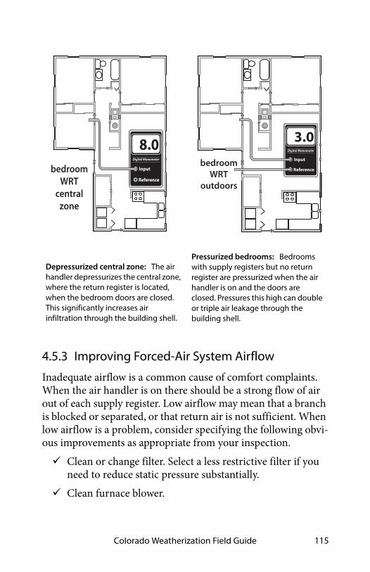
Colorado Weatherization Field Guide 115
Reference
Input
8.0Digital Manometer
bedroom WRT
central zone
Depressurized central zone: The air handler depressurizes the central zone, where the return register is located, when the bedroom doors are closed. This significantly increases air infiltration through the building shell.
Reference
Input
3.0Digital Manometer
bedroom WRT
outdoors
Pressurized bedrooms: Bedrooms with supply registers but no return register are pressurized when the air handler is on and the doors are closed. Pressures this high can double or triple air leakage through the building shell.
4.5.3 Improving Forced-Air System Airflow
Inadequate airflow is a common cause of comfort complaints. When the air handler is on there should be a strong flow of air out of each supply register. Low airflow may mean that a branch is blocked or separated, or that return air is not sufficient. When low airflow is a problem, consider specifying the following obvi-ous improvements as appropriate from your inspection. Clean or change filter. Select a less restrictive filter if you
need to reduce static pressure substantially. Clean furnace blower.

Heating Systems116
Clean air-conditioning or heat pump coil. (If the blower is dirty, the coil is probably also dirty.)
Increase blower speed. Make sure that balancing dampers to rooms that need
more airflow are wide open. Lubricate blower motor, and check tension on drive belt.
Washable filter installed on a rack inside the blower compartment.
Panel filter installed in return register
Panel filter installed in filter slot in return plenum
Furnace filter location: Filters are installed on the return-air side of forced air systems. Look for them in one or more of the above locations.
Duct Improvements to Increase Airflow
Consider specifying the following duct changes to increase sys-tem airflow and reduce the imbalance between supply and return. Modify the filter installation to allow easier filter chang-
ing, if filter changing is currently difficult. Install a slanted filter bracket assembly or an enlarged filter
fitting to accommodate a larger filter with more surface area and less static-pressure drop than the existing filter.

Colorado Weatherization Field Guide 117
Remove obstructions to registers and ducts such as rugs, furniture, and objects placed inside ducts, such as chil-dren’s toys and water pans for humidification.
Remove kinks from flex duct, and replace collapsed flex duct and fiberglass duct board.
Remove excessive lengths of snaking flex duct, and stretch the duct to enhance airflow.
Install additional supply ducts and return ducts as needed to provide heated air throughout the building, especially in additions to the building.
Undercut bedroom doors, especially in homes with single return registers.
Repair or replace bent, damaged, or restricted registers. Install premium low-resistance registers and grilles.
4.6 EVALUATING DUCT AIR LEAKAGE
Duct air leakage is a major energy-waster in homes where the ducts are located outside the home’s thermal boundary in a crawl space, attic, attached garage, or leaky unoccupied base-ment. When these intermediate zones remain outside the ther-mal boundary, duct air sealing is usually cost-effective.Duct leakage within the thermal boundary isn’t usually a signifi-cant energy problem.
4.6.1 Troubleshooting Duct Leakage
There are several simple procedures for finding the locations of the duct leaks and evaluating their severity.
Finding Duct Leaks Using Touch and Sight
One of the simplest ways of finding duct leaks is feeling with your hand for air leaking out of supply ducts, while the ducts are

Heating Systems118
pressurized by the air handler’s blower. Duct leaks can also be located using light. Use one of these 4 tests to locate air leaks.
1. Use the air han-dler blower to pressurize supply ducts. Closing the dampers on sup-ply registers tem-porarily or partially blocking the register with pieces of carpet, magazines, or any object that won’t be blown off by the register’s air-flow increases the duct pressure and make duct leaks easier to find. Dampening your hand makes your hand more sensitive to airflow, helping you to find duct air leaks.
2. Place a trouble light, with a 100-watt bulb, inside the duct through a register. Look for light emanating from the exterior of duct joints and seams.
3. Determine which duct joints were difficult to fasten and seal during installation. These joints are likely duct-leakage locations.
4. Use a trouble light, flashlight, and mirror or a digital camera help you to visually examine duct interiors.
Feeling air leaks establishes their exact location. Ducts must be pressurized in order to feel leaks. You can feel air leaking out of pressurized ducts, but you can’t feel air leaking into depressur-ized return ducts. Pressurizing the home with a blower door forces air through duct leaks, located in intermediate zones, where you can feel the leakage coming out of both supply and return ducts.
looking for light
examining
feeling for air
duct interiors
Finding duct air leaks: Finding the exact location of duct leaks precedes duct air sealing.

Colorado Weatherization Field Guide 119
Pressure Pan Testing
Pressure pan tests can help both auditors and contractors iden-tify leaky or disconnected ducts located in intermediate zones. With the house depressurized by the blower door to –50 pascals with reference to outdoors, pressure pan readings are taken at each supply and return register. Pressure pan testing is reliable for homes where the ducts are outside the air barrier.Basements are often part of a home’s conditioned living space. In this case, pressure pan testing isn’t necessary, although air sealing the return ducts for safety is still very important. If instead, the base-ment is accessed from the out-side and rarely used, the basement may be considered outside the conditioned living space. In this case, open a win-dow or door between the basement and outdoors, and close any door or hatch between conditioned spaces and basement during pressure pan testing.
1. Install blower door and set-up house for winter condi-tions. Open all interior doors.
2. If the basement is conditioned living space, open the door between the basement and upstairs living spaces. If the basement isn’t conditioned living space, close the door between basement and upstairs, and open a base-ment window.
3. Turn furnace off at the thermostat or main switch. Remove furnace filter, and tape filter slot if one exists. Be sure that all grilles, registers, and dampers are fully open.
Reference
Input
4Digital Manometer
A pressure pan: Blocks a single register and measures the air pressure behind it, during a blower door test. The magnitude of that pressure is an indicator of duct leakage.

Heating Systems120
4. Temporarily seal any outside fresh-air intakes to the duct system. Seal supply registers in zones that are not intended to be heated — an uninhabited basement or crawl space, for example.
5. Open attics, crawl spaces, and garages as much as possi-ble to the outside so they don’t create a secondary air barrier.
6. Connect hose between pressure pan and the input tap on the digital manometer. Leave the reference tap open.
7. With the blower door’s manometer reading –50 pascals, place the pressure pan completely over each grille or register one by one to form a tight seal. Leave all other grilles and registers open when making a test. Record each reading, which should give a positive pressure.
8. If a grille is too large or a supply register is difficult to cover with the pressure pan (under a kitchen cabinet, for example), seal the grille or register with masking tape. Insert a pressure probe through the masking tape and record the reading. Remove the tape after the test, and test the other over-sized registers in the same way.
9. Use either the pressure pan or tape to test each register and grille in a systematic way.
Pressure Pan Duct Standards
If the ducts are perfectly sealed with no leakage to the outside, you won’t measure any pressure difference (0.0 pascals) during a pressure-pan test. The higher the measured pressure reading, the more connected the duct is to the outdoors.
• If the median pressure pan reading is 4 pascals or more and/or if one reading is more than 8 pascals, duct-sealing is usually very cost effective.
• Following duct-sealing work, no more than three registers should have pressure-pan readings greater than 2 pascals. No single reading should be greater than 4 pascals.

Colorado Weatherization Field Guide 121
• The reduction you achieve depends on your ability to find the leaks and whether you can access the leaky ducts. The best weatherization providers use 1 pascal or less as a gen-eral goal for all registers.
Examine the registers connected to ducts that are located in areas outside the conditioned living space. Unconditioned spaces containing ducts include attics, crawl spaces, garages, and unoccupied basements. Also evaluate registers attached to stud cavities or panned joists used as return ducts. Leaky ducts, located outside the conditioned living space, may lead to pres-sure-pan measurements more than 30 pascals if the ducts have large holes.
50pa
Reference
Input
2.0Digital Manometer
Pressure pan test: A pressure pan reading of 2 indicates moderate duct air leakage in the supply ducts.
50pa
Reference
Input
7.0Digital Manometer
Problem return register: A pressure reading of 7 pascals indicates major air leakage near the tested register.
4.6.2 Measuring House Pressure Caused by Duct Leakage
The following test measures pressure differences between the main body of the house and outdoors, caused by the air handler and ducts.

Heating Systems122
Dominant Duct Leakage
This test helps determine whether duct-sealing efforts should be directed to the supply or return duct system. This test doesn’t measure the amount of duct leakage. See “Evaluating Duct Air Leakage” on page 117.
1. Set-up house for winter conditions. Close all windows and exterior doors. Turn-off all exhaust fans.
2. Open all interior doors, including door to basement.3. Measure the baseline house-to-outdoors pressure dif-
ference and zero it out using the baseline procedures described in “Blower Door Testing” on page 133.
4. Turn on air handler.5. Measure the house-to-outdoors pressure difference.
This test indicates dominant duct leakage as shown here.
Reference
Input
2Digital Manometer
leak
leak leaks
house WRT outdoors
Dominant return leaks: When return leaks are larger than supply leaks, the house shows a positive pressure with reference to the outdoors.
Reference
Input
-3Digital Manometer
leak
leakleak leak
house WRT outdoors
Dominant supply leaks: When supply leaks are larger than return leaks, the house shows a negative pressure with reference to the outdoors.
A positive pressure indicates that the return ducts (which pull air from leaky intermediate zones) are leakier than the supply ducts. A negative pressure indicates that the supply ducts (which

Colorado Weatherization Field Guide 123
push air into intermediate zones through their leaks) are leakier than return ducts. A pressure at or near zero indicates equal supply and return leakage or else little duct leakage.
Room Pressure Imbalance
This test identifies room-pressure imbalances caused by closed doors in bedrooms, equipped with supply registers but no return registers.
1. Leave the house in winter conditions, and leave the air handler running.
2. Close interior doors. 3. Place hose from input tap on the manometer under one
of the closed interior doors. Connect the reference tap to outdoors with a hose.
4. Read and record this room-to-outdoors pressure mea-surement for each room. This pressure’s magnitude indicates the degree to which the air-handler’s airflow is unbalanced between supply and return ducts in that room or zone.
If the pressure difference is more than ± 3.0 pascals with the air handler operating, pressure relief is necessary. To estimate the amount of pressure relief, slowly open door until pressure differ-ence drops to between +3.0 pascals and –3.0 pascals. Estimate area of open door. Pressure relief may include undercutting the door or installing transfer grilles.

Heating Systems124
Reference
Input
3.0Digital Manometer
bedroom WRT
outdoors
Blocked return path: With interior doors closed, the large positive pressure in the bedroom is caused by the lack of a air return register in the bedroom. The airflow in this forced-air system is unbalanced, creating this pressure, and forcing room air through the room’s air leaks to outdoors.
4.7 SEALING DUCT LEAKS
Ducts are often considered part of the thermal boundary because they are full of house air. Return ducts that are con-nected to attics, crawl spaces, or attached garages can create a lot of air leakage.Ducts located outside the thermal boundary or in an intermedi-ate zone like a ventilated attic or crawl space should be sealed. The following is a list of duct leak locations in order of their rel-ative importance. Leaks nearer to the air handler are exposed to higher pressure and are more important than leaks further away.
4.7.1 Sealing Return Ducts
Return leaks are important for combustion safety and for effi-ciency. Use the following techniques to seal return ducts. First, seal all return leaks within the combustion zone to
prevent this leakage from depressurizing the combustion zone and causing backdrafting.

Colorado Weatherization Field Guide 125
Seal panned return ducts using mastic to seal all cracks and gaps within the return duct and register.
return register
return duct
leakage
leakage
metal panningPanned floor joists: These return ducts are often very leaky and may require removing the panning to seal the cavity.
Lining a panned cavity: Foil-faced foam board, designed for lining cavities is sealed with duct mastic to provide an airtight return.
Seal leaky joints between building materials composing cavity return ducts, like panned floor cavities and furnace return platforms. Remove the panning to seal cavities con-taining joints in building materials.
Carefully examine and seal leaks at transitions between panned floor joists and metal trunks that change the direc-tion of the return ducts. You may need a mirror to find some of the biggest return duct leaks in these areas.
Seal filter slots with an assembly that allows easy changing of filters.
Seal the joint between the furnace and return plenum with silicone caulking or foil tape.
4.7.2 Sealing Supply Ducts
Inspect these places in the duct system and seal them as needed. Plenum joint at air handler: Technicians might have had
problems sealing these joints because of a lack of space. Seal these plenum connections thoroughly even if you

Heating Systems126
must cut an access hole in the plenum. Use silicone caulk-ing or foil tape instead of mastic and fabric mesh here for future access — furnace replacement, for example.
access panel
Plenums, poorly sealed to air handler: When air handlers are installed in tight spaces, plenums may be poorly fastened and sealed. Cutting a hole in the duct may be the only way to seal this important joint.
Sectioned elbows: Joints in sectioned elbows known as gores are usually quite leaky and require sealing with duct mastic.
Joints at branch takeoffs: Seal these important joints with a thick layer of mastic. Fabric mesh tape should cover gaps and reinforce the seal at gaps.
Joints in sectioned elbows: Known as gores, these are usu-ally leaky and require sealing with duct mastic.
Tabbed sleeves: Attach the sleeve to the main duct with 3-to-5 screws and apply mastic plentifully. Or better, remove the tabbed sleeve and replace it with a manufactured take-off.
Flexduct-to-metal joints: Apply a 2-inch band of mastic to the end of the metal connector. Attach the flexduct’s inner liner with a plastic strap, tightening it with a strap ten-sioner. Attach the insulation and outer liner with another strap.
Damaged flex duct: Replace flex duct when it is punctured, deteriorated, or otherwise damaged.

Colorado Weatherization Field Guide 127
Deteriorating ductboard facing: Replace ductboard, prefer-ably with metal ducting, when the facing deteriorates because this deterioration leads to a lot of air leakage.
strap tightener
sheet-metal screw
metal sleeve
inner linerinsulation
tightened straps
beaded takeoff
mastic
Flexduct joints: Flexduct itself is usually fairly airtight, but joints, sealed improperly with tape, can be very leaky. Use methods shown here to make flexduct joints airtight.
Consider closing supply and return registers in unoccu-pied basements or crawl spaces.
Seal penetrations made by wires or pipes traveling through ducts.
Support the ducts and duct joints with duct hangers at least every 5 feet or as necessary to prevent sagging of more than one-half inch.

Heating Systems128
4.7.3 Duct Boots, Registers, and Chases
Apply caulk or foam to the joint between the boot and the ceiling, wall, or floor between conditioned and unconditioned areas. If chase opening is large, seal it with a rigid barrier such as plywood or drywall, and seal the new barrier to ducts with caulk or foam.
4.7.4 Materials for Duct Sealing
Apply mastic at least 1/ -16inch thick, and use reinforcing mesh for all joints wider than /8-inch or joints that may move.Install screws to prevent joint movement or separation. Existing tape should be covered with mastic to prevent its adhesive from drying out and failing if used for duct-sealing.
1

Colorado Weatherization Field Guide 129
4.8 HOT-WATER SPACE-HEATING DISTRIBUTION
The most significant energy wasters in hot-water systems are poor steady-state effi-ciency, off-cycle flue losses stealing heat from the stored water, and boilers operating at a too-high water temperature. For information about boiler installation, see page 94.
4.8.1 Boiler Efficiency and Maintenance
Boiler performance and effi-ciency improve after effective maintenance and tune-up procedures. There are more ways for performance and efficiency to deteriorate in boilers compared to furnaces.
• Corrosion, scaling, and dirt on the water side of the heat exchanger.
• Corrosion, dust, and dirt on the fire side of the heat exchanger, sometimes clogging burner ports.
• Excess air during combustion from air leaks and incorrect fuel-air mixture.
• Off-cycle air circulation through the firebox and heat exchanger, removing heat from stored water.
Boiler Efficiency Improvements
Consider specifying the following maintenance and efficiency improvements for both hot-water and steam boilers based on boiler inspection. Check for leaks on the boiler, around its fittings, or on any
of the distribution piping connected to the boiler.
cast-iron section
burner
Tankless coil water heater found on some boilers
controls
Cast-iron sectional boilers: The most common boiler type for residential applications.

Heating Systems130
Clean fire side of heat exchanger of noticeable dirt. Drain water from the boiler drain until the water flows
clean.
4.8.2 Distribution System Improvements
Hydronic distribution systems consist of the supply and return piping, the circulator, expansion tank, air separator, air vents, and heat emitters. A properly designed and installed hydronic distribution system can operate for decades without service. However, many systems have installation flaws or need service.
Note: You can recognize a hot-water boiler by its expansion tank, located somewhere near the boiler. The expansion tank provides an air cushion to allow the system’s water to expand and contract as it is heated and cooled. Without a functioning expansion tank excessive pressure in the boiler discharges water through the pressure-relief valve.
Safety Checks and Improvements
Work with contractors and technicians to specify and verify the following safety and efficiency tests and inspections.
• Verify the existence of a 30-psi-rated pressure-temperature (P&T) relief valve. The P&T relief valve should have a drain pipe that terminates 6 inches from the floor. Replace a mal-functioning valve or add a P&T relief valve if none exists. Look for signs of leakage or discharges. Find out why the relief valve is discharging.
• Verify that the expansion tank isn’t waterlogged or too small for the system. A non-operational expansion tank can cause the pressure-relief valve to discharge. Measure the expansion tank’s air pressure. The pressure should be one (1) psi per 2.3 feet of the distribution system’s height.

Colorado Weatherization Field Guide 131
• If you observe rust in venting, verify that the return water temperature is warmer than 140° F for gas boilers. These minimum water temperatures prevent acidic condensation.
• Verify that high-limit control disengages the burner at a water temperature of 200°F or less.
• Lubricate circulator pump(s) if necessary.
Zone valves: Separate thermostats control each zone valve. Zone valves have switches that activate the burner.
air separator vent
Expansion tank, air separator, and Vent: Preventing excessive pressure and eliminating air from the systems are important for hydronic distribution systems.
Simple Efficiency Improvements
Do the following energy-efficiency improvements.• Repair water leaks in the system.• Remove corrosion, dust, and dirt on the fire side of the heat
exchanger.• Check for excess air during combustion from air leaks and
incorrect fuel-air mixture.

Heating Systems132
• Bleed air from radiators and piping through air vents on piping or radiators. Most sys-tems have an automatic fill valve. If there is a manual fill valve for refilling system with water, it should be open to push water in and air out, during air-purging.
• Vacuum and clean fins of fin-tube convectors if you notice dust and dirt there.
• Insulate all supply and return piping, passing through unheated areas, with foam pipe insulation, at least one-inch thick, rated for temperatures up to 200° F.
Improvements to Boiler Controls
Consider these improvements to control systems for hot-water boilers.
• Install outdoor reset controllers on larger boilers to regulate water temperature, depending on outdoor temperature.
• If possible, operate the boiler without a low-limit control for maintaining a minimum boiler-water temperature. If the boiler heats domestic water in addition to space heating the low-limit control may be necessary.
• After control improvements like two-stage thermostats or reset controllers, verify that return water temperature is high enough to prevent condensation and corrosion in the chimney as noted previously.
• Install electric vent dampers on atmospheric gas-fired high-mass boilers.
Purging air: Trapped air collects at the hot-water system’s highest parts. Bleeding air from radiators fills the radiator and gives it more heating surface area.
trapped air
air bleed valve

Colorado Weatherization Field Guide 133
CHAPTER 5: BUILDING SHELL
This chapter covers blower door testing, air sealing, and insula-tion.
5.1 BLOWER DOOR TESTING
House airtightness testing was made possible by the develop-ment of the blower door. The blower door measures a home’s leakage rate at a standard pressure of 50 pascals. This leakage measurement can be used to compare homes with one another and to established air-leakage standards.
Digital Manometer
RefInput
A: -50B:2800
fan
digital manometerframe
panel
tube goes to outdoors
tube goes to fitting on fan
Blower Door Components
5.1.1 Blower-Door Principles
The blower door creates a 50-pascal pressure difference across the building shell and measures airflow in cubic feet per minute (CFM50), in order to measure the leakiness of homes. The

Building Shell134
blower door also creates pressure differences between rooms in the house and intermediate zones like attics and crawl spaces. These pressure differences can give clues about the location and combined size of a home’s hidden air leaks.
50pa
Digital Manometer
RefInput
A: -50B:2800
Blower door test: Air barriers are tested during a blower-door test, with the house at a pressure of 50 pascals negative with reference to outdoors. This house has 2800 CFM50 of air leakage. Further diagnostic tests can help determine where that leakage is coming from.
Blower-Door Terminology
Connecting the digital manometer’s hoses correctly is essential for accurate testing. This method uses the phrase with-reference-to (WRT), to distin-guish between the input zone and reference zone for a particular measurement. The outdoors is the most commonly used refer-ence zone for blower door testing. The reference zone is consid-ered to be the zero point on the pressure scale. For example, house WRT out-doors = –50 pascals means that the house (input) is 50 pascals negative compared to the out-doors (reference or zero-point). This pressure reading is called the house pressure.
–50 –25 0 +25House WRT Outdoors Pressure in Pascals
Outdo
ors
Hou
se

Colorado Weatherization Field Guide 135
A B
Input pressure ports: connect to area to be tested
reference ports: connect to reference area
display
A BDigital manometers: Used to diagnose house and duct pressures quickly and accurately.
Low-Flow Rings
During the blower door test, the manometer measures airflow through the fan. This airflow (CFM50) is the primary measure-ment of a home’s airtightness and is directly proportional to the surface area of the home’s air leaks. For the blower door to mea-sure airflow accurately, the air must be flowing at an adequate speed. Tighter buildings and smaller buildings don’t have enough air leakage to create an adequate airspeed to create the minimum fan pressure. This low-flow condition requires using one or two low-flow rings, to reduce the blower-door fan’s open-ing and to increase air speed, fan pressure, and measurement accuracy.When the air speed is too low, the DG-700 displays “LO” in the Channel B display. After installing one of the low-flow rings, fol-low the manufacturer’s instructions for selecting the proper range or configuration on the digital manometer.
5.1.2 Preparing for a Blower Door Test
Preparing the house for a blower door test involves putting the house in its normal heating-season operation with all condi-tioned zones open to the blower door. Try to anticipate safety problems that the blower door test could cause, particularly with combustion appliances.

Building Shell136
• Identify the location of the thermal boundary and deter-mine which house zones are conditioned.
• Identify large air leaks that could prevent the blower door from achieving adequate pressure, such as a pet-door.
• Put the house into its heating-season operation with win-dows, doors, and vents closed and air registers open.
• Turn off combustion appliances temporarily.• Open interior doors so that all indoor areas inside the ther-
mal boundary are connected to the blower door. This could include the basement, conditioned kneewall areas, and closets.
Avoiding Risky Situations
Don’t perform a blower door test in risky situations like the fol-lowing until you remove the risk or perform an acceptable building repair.
• A wood stove is burning.• Holes in the ceiling that could lead to dust pollution during
a blower door test.• Extremely weak building components, like a poorly
installed suspended ceiling or loose wood wall paneling.• Lead or asbestos dust is present.
5.1.3 Blower-Door Test Procedures
Follow this general procedure when performing a blower-door test. Set up the house for winter conditions with exterior doors,
primary windows and storm windows closed. The door to the basement should be either open or closed, according to whether or not the basement is considered to be within the thermal boundary.

Colorado Weatherization Field Guide 137
Install blower door frame, panel, and fan in an exterior doorway with a clear path to outdoors. On windy days, install the blower door on the home’s leeward side if possi-ble. Pay attention to the blower door’s location and any other conditions that may affect test results.
Follow manufacturer’s instructions for fan orientation and digital-manometer setup for either pressurization or depressurization. Depressurization is the most common orientation.
Connect Channel A of the digital manometer to measure house WRT outdoors. Place the outside hose at least 5 feet away from the fan.
Connect Channel B to measure fan WRT zone near fan inlet. The zone near the fan inlet is indoors for depressur-ization and outdoors for pressurization. (Hose must run from the reference port on channel B to outdoors for pres-surization.)
Ensure that children, pets, and other potential interfer-ences are at a safe distance from the fan.
–50 pascals (Pa)0 +50 pascals (Pa)0
house pressurehouse WRT outdoorshouse-to-outdoors pressure
house pressurehouse WRT outdoorshouse-to-outdoors pressure
Conducting the Blower Door Test
Follow these instructions for performing a blower door test, using a digital manometer. Turn on the manometer by pushing the ON/OFF button Select the MODE: PR/FL@50.

Building Shell138
Select the correct DEVICE that matches the blower door you’re using.
With the fan covered, conduct the BASELINE procedure to cancel out the background wind and stack pressures. Let the manometer average the baseline pressure for at least 30 seconds.
Remove the cover from the blower door fan. Complete the next two steps for tighter buildings.
Install the flow ring in the blower door fan which matches the expected flow rate. The fan pressure should be at least 25 Pa while measuring CFM@50.
Push CONFIG or Range button until you match the flow ring being used.
Turn on the blower door fan slowly with the controller. Increase fan speed until the building depressurization on the Channel A screen is between –45 and –55 pascals. It doesn’t need to be exactly –50 pascals.
The Channel B screen will display the single-point CFM50 air leakage of the building. If this number is fluctuating a lot, push the TIME AVG button to increase the averaging time period.
You can also use the cruise-control function to automati-cally control the fan speed to create and hold –50 pascals of pressure.
Blower-Door Test Follow-Up
Be sure to return the house to its original condition. Inspect combustion appliance pilot lights to ensure that
blower door testing didn’t extinguish them. Reset thermostats of heaters and water heaters that were
turned down for testing.

Colorado Weatherization Field Guide 139
Remove any temporary plugs that were installed to increase house pressure.
Document the location where the blower door was installed.
Document any unusual conditions affecting the blower door test.
5.1.4 Approximate Leakage Area
There are several ways to convert blower-door CFM50 measure-ments into square inches of total leakage area. A simple and rough way to convert CFM50 into an approximate leakage area (ALA) is to divide CFM50 by 10. The ALA can help you visual-ize the size of openings you’re looking for in a home or section of a home.
ALA (SQUARE INCHES) = CFM50 ÷ 10

Building Shell140
5.2 TESTING AIR BARRIER
Leaks in air barriers cause energy and moisture prob-lems in many homes. Air-bar-rier leak-testing avoids unnecessary visual inspection and unnecessary air sealing in hard-to-reach areas. Advanced pressure tests mea-sure pressure differences between zones in order to esti-mate air leakage between zones. Use these tests to make decisions about where to direct your air-sealing efforts, for example.
• Evaluate the airtightness
S
of portions of a building’s air barrier, especially floors and ceilings.
• Decide which of two possible air barriers to air seal — for example, the floor versus foundation walls.
• Determine whether building cavities like porch roofs, floor cavities, and overhangs are conduits for air leakage.
• Determine whether building cavities, intermediate zones, and ducts are connected together through air leaks.
• Estimate the air leakage in CFM50 through a particular air barrier, for the purpose of estimating the effort and cost necessary to seal the leaks.
Air-Barrier Test Results
Air-barrier tests provide a range of information from simple clues about which parts of a building leak the most, to specific
50Pa
Digital Manometer
RefInput
A: -50B:1800
Blower door test: Air barriers are tested during a blower-door test, with the house at a pressure of 50 pascals negative with reference to outdoors. This house has 3000 CFM50 of air leakage. Further diagnostic tests can help determine where that leakage is coming from.

Colorado Weatherization Field Guide 141
estimates of the airflow and hole size through a particular air barrier.The next table shows examples of how common building mate-rials perform as air barriers. This information is helpful in inter-preting blower door tests and selecting air-sealing materials.
Table 5-1: Building Components and Their Air Permeance
Good air barriers:<2 CFM50 per
100 sq. ft.
Poor air barriers:10–1000 CFM50 per
100 sq. ft.
5/8” oriented strand board 5/8” tongue-and-groove wood sheeting
1/2” drywall 6" fiberglass batt
4-mil air barrier paper 1.5" wet-spray cellulose
Asphalt shingles and perforated felt over 1/2” plywood
wood siding over plank sheath-ing
1/8” tempered hardboard wood shingles over plank sheathing
painted un-cracked lath and plaster blown fibrous insulation
Measurements taken at 50 pascals pressure.Based on information from: “Air Permeance of Building Materials” by Canada Mortgage Housing Corporation, and estimates of comparable assemblies by the author.Although cellulose reduces air leakage when blown into walls, it isn’t considered an air-barrier material.

Building Shell142
5.2.1 Simple Pressure Test
Blower door tests give us valuable information about the relative leakiness of rooms or sections of the home. Listed below are five simple methods.
1. Feeling zone air leakage: Close an interior door partially so that there is a one-inch gap between the door and door jamb. Feel the airflow along
Ithe length of that crack, yand compare that air-flow intensity with air- l
flow from other rooms, t
using this same tech-
s
50 pa.
nterior door test: Feeling airflow with our hand at the crack of an interior door
gives a rough indication of the air eakage coming from the outdoors hrough that room.
nique. 2. Observing the ceiling/attic floor: Pressurize the home
and observe the top-floor ceiling from the attic with a good flashlight. Air leaks will show in movement of loose-fill insulation, blowing dust, moving cobwebs, etc. You can also use a small piece of tissue paper to dis-close air movement.
3. Observing smoke movement: Pressurize the home and observe the movement of smoke through the house and out of its air leaks.
4. Room pressure difference: Check the pressure difference between a closed room or zone and the main body of a home. Larger pressure differences indicate larger potential air leakage within the closed room or else a tight air barrier between the room and main body. A small pressure difference means little leakage to the

Colorado Weatherization Field Guide 143
outdoors through the room or a leaky air barrier between the house and room.
5. Room airflow difference: Measure the house CFM50 with all interior doors open. Close the door to a single room, and note the difference in the CFM50 reading. The dif-ference is the approximate leakage through that room’s air barrier.
Tests 1, 2, and 3 present good client education opportuni-ties. Feeling airflow or observ-ing smoke are simple observations, but have helped identify many air leaks that could otherwise have remained hidden.When airflow within the home is restricted by closing a door, as in tests 4 and 5, it may take alternative indoor paths that render these tests some-what misleading. Only prac-tice and experience can guide your decisions about the applicability and usefulness of these general indicators.
5.2.2 Simple Zone Pressure Testing
Manometers aren’t limited to finding indoor WRT outdoor dif-ferences. They can also measure pressure differences between the house and its intermediate zones during blower-door tests. The purpose of these tests is to evaluate the air-tightness of the home’s interior air barriers.The blower door, when used to create a house-to-outdoors pres-sure of –50 pascals, also creates house-to-zone pressures of between 0 and –50 pascals in the home’s intermediate zones.
50pa
House WRT room
Reference
Input
-20Digital Manometer
Bedroom test: This bedroom pressure difference may be caused by its leaky exterior walls or tight interior walls, separating it from the main body of the home. This test can determine whether or not a confined combustion zone is connected to other rooms.

Building Shell144
The amount of depressurization depends on the relative leaki-ness of the zone’s two air barriers.
Manometer measures house wrt zone
Insulated walls are dark colored
zone
zone
zone
zone
50 pa.
Reference
Input
-47Digital Manometer
Reference
Input
-27Digital Manometer
Reference
Input
-34Digital Manometer
Reference
Input
-38Digital Manometer
air barrier
air barrier
Pressure-testing building zones: Measuring the pressure difference across the assumed thermal boundary (house wrt zone) tells you whether the air barrier and insulation are aligned. If the manometer reads close to –50 pascals, the air barrier and insulation are aligned, if the tested zones are well-connected to outdoors.
For example, in an attic with a fairly airtight ceiling and a well-ventilated roof, the attic will indicate that it is mostly outdoors by having a house-to-zone pressure of –45 to –50 pascals. The leakier the ceiling and the tighter the roof, the smaller that the negative house-to-zone pressure will be. This holds true for other intermediate zones like crawl spaces, attached garages, and unheated basements.

Colorado Weatherization Field Guide 145
Zone Leak-Testing Methodolog
Depressurize house to –50 pas-cals with a blower door.
1. Find an existing hole, or drill a hole through the floor, wall, or ceiling between the conditioned space and the intermedi-ate zone.
2. Connect the reference
y
port of a digital manometer to a hose reaching into the zone.
3. Leave the input port of the digital manometer open to the indoors.
4. Read the negative pressure given by the manometer. This is the house-to-zone pressure, which will be –50 pascals if the air barrier between house and zone is air-tight and the zone itself is well-connected to outdoors.
5. If the reading is significantly less negative than –45 pas-cals, find the air barrier’s largest leaks and seal them.
6. Repeat steps 1 through 5, performing more air-sealing as necessary, until the pressure is as close to –50 pascals as possible.
0–50 –40 –30 –20 –10House WRT Zone Pressure in Pascals
Outdoors
Hal
fway
Ho
useZone is more
connected to house than to outdoors
Zone is more connected to outdoors
than to house
Interpreting house-to-zone pressure: The greater the negative number the better the air barrier is performing.

Building Shell146
50pa Reference
Input
-13Digital Manometer
attic WRT outdoors
Attic-to-outdoors pressure: This measurement confirms the first because the two add up to –50 pascals.
House-to-attic pressure: This commonly used measurement is convenient because it requires only one hose.
50pa
house WRT attic
Reference
Input
-37Digital Manometer
Leak-Testing Building Cavities
Building cavities such as wall cavities, floor cavities between sto-ries, and dropped soffits in kitchens and bathrooms can also be tested as described above to determine their connection to the outdoors as shown here.
50pa Reference
Input
-20Digital Manometer
Porch roof WRT outdoors = -20 pa
50pa Reference
Input
-30Digital Manometer
Cantilevered floor WRToutdoors = -30pa
These examples assume that the manometer is outdoors with the reference port open to outdoors
Porch roof test: If the porch roof were
outdoors, the manometer would read near 0 pascals. We hope that the porchroof is outdoors because it is outside the insulation. We find, however, that itis partially indoors, indicating that it may harbor significant air leaks through the thermal boundary.
Cantilevered floor test: We hope to find the cantilevered floor to be indoors. A reading of –50 pascals would indicate that it is completely indoors. A reading less negative than –50 pascals is measured here, indicating that the floor cavity is partially connected to outdoors.

Colorado Weatherization Field Guide 147
Testing Zone Connectedness
Sometimes it’s useful to determine whether two zones are con-nected by a large air leak. Measuring the house-to-zone pressure during a blower door test, before and then after opening the other zone to the outdoors, can establish whether the two zones are connected by a large air leak. You can also open an interior door to one of the zones and check for pressure changes in the other zone.
50pa
Reference
Input
-41Digital Manometer
50pa
Reference
Input
-47Digital Manometer
Zone connectedness: The attic measures closer to outdoors after the basement window is opened, indicating that the attic and basement are connected by a large bypass.
Leak-Testing Building Cavities
You can also test building cavities such as wall cavities, floor cavities between stories, and dropped soffits in kitchens and bathrooms with a digital manometer to evaluate their possible connection to the outdoors by way of air leaks.
5.3 CONTROLLING HOUSE PRESSURE
House pressures drive air through leaks in the building shell and can cause open-combustion appliances to backdraft. For energy conservation and safety, you should measure house pressures and try to limit them.The causes of house pressures include the following.

Building Shell148
• Duct air leakage• Unbalanced ducted airflow• Central ventilation systems• Exhaust fans in kitchens and bathrooms• Wind• Cold weather
5.3.1 Duct-Induced Room Pressures
An improperly balanced air-handling system or leaky ducts can reduce comfort, building durability, and indoor air quality. Duct-induced room pressures can increase air leakage through the building shell from 1.5 to 3 times, compared to when the air handler is off. To learn how the air handler and ducts affect house pressure, see “Measuring House Pressure Caused by Duct Leakage” on page 121.
5.4 AIR SEALING FUNDAMENTALS
Air leakage in homes accounts for 5% to 40% of annual heating and cooling costs. Air sealing is one of the most important energy-saving retrofits, and often the most difficult. Air travels into and out of the building by three main pathways. Major air leaks, which are significant flaws in the home’s
air barrier. Minor air leaks, which are often seams between building
materials. Through the building materials themselves.

Colorado Weatherization Field Guide 149
5.4.1 Air Sealing Strategy
The first step to improving a building’s airtightness is to for-mulate a strategy. Building a strategy starts by asking ques-tions like these. What are the building’s
major substructures: attic, living spaces, basement, porches, additions?
What air pathways link the building’s substruc-tures together and to the outdoors?
What interior and exteriorfeatures create large air leaks: cantilevered floors,
Air-porous sheeting materials: Building materials such as tongue-and-
groove paneling, suspended ceilings, lap siding, concrete block, and wood shingles are porous to airflow.
interior soffits, air-porous building materials, built-in furniture?
How do we air-seal the border areas between the building’s substructures and components?
Which building assemblies contain functional air barriers and which don’t?
When a building assembly has no functional air barrier, where within that building assembly (ceiling, wall, floor) do we establish one?
How do we air-seal various penetrations through the air barrier?
How does whole-house ventilation relate to shell air leak-age? See "Evaluating Building Ventilation Levels" on page 46.

Building Shell150
rim joist area
joint between collar beam and rafter
cantilevered floorcorner at garage ceiling
joint between porch and house
joint between finished-attic floor and kneewall
basementgarage
1
2
3
45
1
2
3
first floor
second floor
Air barrier flaws: The building’s air barrier is often weak or broken where the building’s substructures join together (where we’ve placed circles). This home has 3 conditioned substructures and 5 unconditioned substructures (or intermediate zones). Understanding the airflow among these substructures and the outdoors is essential to successful air sealing
5.5 AIR SEALING SAFETY
Air sealing reduces the exchange of fresh air in the home, and can alter the pressures within the home. Before air sealing, sur-vey the home to identify both air pollutants that may be concen-trated by air sealing efforts and open combustion appliances that may be affected by changes in house pressure. Don’t perform air sealing when there are obvious threats to the occupants’ health, the installers’ health, or the building’s dura-bility that are related to air sealing. If any of the following cir-cumstances are present, either postpone air sealing until they’re corrected or correct the problems as part of the project’s work scope. Measured carbon monoxide levels exceed the suggested
action level. See "Carbon Monoxide (CO)" on page 32.

Colorado Weatherization Field Guide 151
The building requires a ventilation fan according to ASHRAE 62.2–2012, and no mechanical ventilation exists or is planned. See "Evaluating Building Ventilation Levels" on page 46.
Combustion zone depressurization exceeds –4 pascals during a worst-case test.
Combustion appliance chimneys don’t meet minimum standards.
Unvented space heaters will be used after air sealing work. Moisture is present which may cause structural damage or
respiratory hazards from rot, mold, or dust mites. See "Moisture Problems" on page 38.
Infestations, vermin, or other sanitary issues are present.Installation of a mechanical ventilation system may be required when performing effective home air sealing.
5.5.1 Liquid Foam Air Sealant
Liquid closed-cell polyure-thane foam is a versatile air sealing material. Closed-cell foam is packaged in a one-part injectable variety and a two-part sprayable variety. It has a very high R-value per inch and is ideal for insulating and air sealing small, poorly insulated, and leaky areas in a single application.Installation is easy compared to other materials to accom-plish the same air sealing tasks. However, cleanup is dif-ficult enough that you probably don’t want to clean up multiple
One-part foam: A technician uses an applicator gun to seal spaces between framing members and around windows.

Building Shell152
times on the same job. Instead identify all the spots needing foam application, make a list, and foam them one after another.
One-Part Foam
One-part foam is best applied with a foam-applicator gun rather than the disposable cans with self-dispensing nozzles and straws. Cleanup is difficult if you get careless. When squirted skillfully into clean and dry gaps, one-part foam reduces air leakage, thermal bridging, and air convection through the assemblies to which it is applied. One-part foam isn’t effective or easy to apply to gaps over about one inch or to bottomless gaps. This product can leave small air leaks unless applied with skill.Caution: Wear a tight-fitting organic-vapor respirator, eye pro-tection, and nitrile gloves when installing two-part foam and power-ventilate the work area.
Two-Part Foam
Good for bridging gaps up to one inch. Two-part foam has become popular for use around the perimeter of rigid patching materials to seal large openings. Installers cut the rigid patch to less than one-inch tolerances around obstacles (like drain pipes) and fill the edges with the two-part foam. Two-part foam should be sprayed to at least an inch of thickness when it serves as an adhesive for foamboard patches over large holes for strength. Caution: Wear a tight-fitting organic-vapor respirator, eye pro-tection, and nitrile gloves when installing two-part foam and power-ventilate the work area.
Foam Construction Adhesive
Polyurethane foam dispensed from foam applicator guns is an excellent adhesive for joining many kinds of building materials. It works well in joining foam sheets together into thick slabs for access doors through insulated building assemblies.

Colorado Weatherization Field Guide 153
5.6 SEALING MAJOR AIR LEAKS AND BYPASSES
Major air sealing involves finding and sealing the building’s major air leaks. Sealing major air leaks is one of the most cost-effective energy-saving opportunities, especially in cold cli-mates.Complete major air sealing activities prior to insulating, espe-cially where insulation would be an obstacle to air sealing. Effec-tive air sealing results in a significant drop in reduced blower door readings and/or changes in pressure-diagnostics readings. See "Blower Door Testing" on page 133.Bypasses are pathways that allow air to migrate around the insu-lation. Bypasses are sometimes direct air leaks between indoors and outdoors and sometimes not. In many cases, bypasses merely allow air from indoors or outdoors to circulate around within the building cavities. They can still be a significant energy loss, however, when they are adjacent to interior surfaces of the home where circulating air can convect heat into or out of the home. Major air leaks aren’t always easily accessible without demolish-ing the sheeting materials. When large air leaks are behind walls, ceilings, or other building parts, contractors sometimes blow dense-packed fibrous insulation to fill surrounding inac-cessible cavities, hoping that the dense-packed insulation fills resists airflow and plugs cracks between building materials.

Building Shell154
foam-board seal
knee wall
fiberglass
batts
Sealing under knee walls: Here an undersized piece of foam board is sealed into the joist spaces with one-part foam, forming a strong and airtight seal.
5.6.1 Removing Insulation for Air Sealing
Attics are a particularly critical area for air sealing. The cost of removing insulation from an attic for the purpose of air sealing the attic may be well worth the price. Batts and blankets can be rolled up, moved out of the way, and re-used. Loose fill insula-tion can be vacuumed with commercial vacuum machines avail-able from the same suppliers that sell insulation-blowing machines. Many insulation companies have these large vacuums already. Don’t let existing insulation stop you from air sealing the attic.
5.6.2 Major Air Leak Locations & Treatments
This section provides a list of the most important large air leak-age areas commonly found in North American residential buildings. This section also provides suggestions for sealing major air leaks.

Colorado Weatherization Field Guide 155
Joist Cavities Under Knee Walls
Floor joist cavities beneath knee walls allow air from a ventilated attic space to enter the floor cavity between stories. This is a problem of homes with a finished attic, also known as half-story homes.Connect the knee wall with the plaster ceiling of the space below by creating an effective air seal under the knee wall, using one of these options.
• Blow densely packed fibrous insulation. • Use a combination of an air barrier reinforced and sealed
around its perimeter with caulk or foam.• Use fiberglass batt rolled up and compressed into the cavity.
Kitchen or Bathroom Interior Soffits
Many modern homes have soffited areas above kitchen cabinets and in bathrooms. Large rectangular passages link the attic with the soffit cavity. At best, the air convects heat into, or out of, the conditioned space. At worst, attic air infiltrates the conditioned space through openings in the soffit or associated framing.Seal the top of the soffit with foam board, plywood, or drywall fastened and sealed to ceiling joists and soffit framing. Seal the patch’s perimeter with two-part foam or caulking.

Building Shell156
recessed light
eave vents
air leakage
Kitchen soffits: The ventilated attic is connected to the soffit and the wall cavity through framing flaws. Any hole in the soffit creates a direct connection between the kitchen and attic. The photo shows a soffit sealed from the attic with foam board reinforced with two-part spray foam.
Plumbing Penetrations
Seal gaps with expanding foamor caulk. If the gap is too large, stuff it with fiberglass insula-tion, and spray foam over the top to seal the surface of the plug.Seal holes and cracks from underneath with expanding foam. Seal large openings with rigid materials caulked or foamed at edges.
Sealing large plumbing penetrations: Foam board is attached with screws and washers. Gaps around the penetrations are filled with one-part foam to form a complete airtight seal.

Colorado Weatherization Field Guide 157
Two-Level Attics in Split-Level or Tri-Level Houses
Split-level and tri-level homes have a particular air leakage problem related to the walls and stairways dividing the homes’ levels.Seal wall cavities from the attic with a rigid material fastened to studs and wall material. Or insert folded fiberglass batt and spray with at least one inch of two-part foam to create a rigid air seal. Stapling house wrap to the exposed wall over the insulation retards both air leakage and convec-tion.Also seal all penetrations between both attics and conditioned areas.
Chimneys and Chimney Chases
Fireplace chimneys are some of the most dramatic and serious air leaks commonly found in homes. The existing damper or “airtight” doors are seldom a good air seal. There are a number of commercial solutions for leaky or non-existent fireplace dampers. They include new tight dampers and inflatable pil-lows.
recessed light
soil stack
chimney
open wall cavities
duct
wire
Two-level attic: Split-level homes create wall cavities connected to the ventilated attic. Other air leaks shown are duct, recessed light, and chimney.
Tri-level home
problem wall

Building Shell158
If the fireplace is never used, it can be air sealed from the roof with a watertight, airtight seal and also from the living space with foamboard, covered with airtight drywall. If you install a permanent chimney seal in this way, be sure to install a notice in the fireplace warning future occupants of the blockage.Seal chimney and fireplace bypasses with sheet metal (minimum 26 gauge thickness). Fasten the sheet metal with nails, staples, or screws and construc-tion adhesive. Seal the metal patch to chimney or flue with a high temperature silicone seal-ant or chimney cement.
Exhaust Fans and Recessed Lights
Consider the following options for air sealing recessed light and fan fixtures and enhancing the fire safety of the ceiling assem-bly. Replace the existing
recessed fixture with one rated: Insulation Contact Air Tight (ICAT). You can also buy airtight inserts that turn an existing round can-type fixture into an ICAT fixture.
Sealing around chimneys: Chimneys - require careful selection of materials - for air sealing.
non-combustible air seal
Fireplace and chimney chase: These structures can leak air to and from the outdoors and between floors.

Colorado Weatherization Field Guide 159
Caulk joints where hous-ing comes in contact with the ceiling with high tem-perature silicone sealant to reduce air leakage around the housing.
Build a metal (26-gauge galvanized steel) or dry-wall box over the fixture leaving at least 3 inches clearance from insulation on all sides including between the top of the fix-ture and the lid of the enclosure. Seal the airtight box to surrounding materials with foam to form an airtight assembly. However don’t insulate the top of the enclosure.
Recessed light fixtures should contain 60-watt bulbs or less. Compact fluorescent lamps (CFLs) are preferred for recessed light fixtures because CFLs run cooler than incandescent lamps.Caution: Don’t cover IC-rated or airtight IC-rated fixtures with spray foam insulation. The high R-value and continuous contact could overheat the fixture.
drywall box air seal
Recessed light fixtures: These are major leakage sites, but these fixtures require some air circulation to cool their incandescent bulbs.
recessed light fixture

Building Shell160
Attic Hatches
Attic hatches provide access from the building to an insu-lated attic. These access doors or panels and the framing and sheeting surrounding them often constitute a major air leakage path. Consider the following improvements. Weatherstrip around
doors and hatches. Install a latch to hold the door or panel against its weatherstrip.
Seal gaps around frame perimeters with one-part foam, two-part foam, or caulking.
Clear fibrous insulation from around the hatch framing and spray two-part foam around the perimeter to reduce heat transmission and air leakage through the hatch framing.
Some attics, especially in larger buildings, have framed stairways with interior doors for access into attics. In this case, installers insulate and air seal the walls of the stair-well and then weatherstrip the door at the top or bottom of the stairway. Installers may also replace an uninsulated inte-
Sealing and insulating the attic-hatch frame: A technician air seals and insulates around an attic hatch dam with two-part spray foam.
Leakage into attic: A closeted space beneath attic stairs provides large air leakage channels into the ventilated attic.
air l
eaka
ge ch
anne
l

Colorado Weatherization Field Guide 161
rior door with an insulated exterior door to separate the venti-lated attic from the conditioned space.
Incomplete Finished Basements
In buildings with heated base-ments, the insulated stud walls are often omitted in areas like laundry rooms and mechanical rooms. Missing wall segments and unsealed rim joists can allow heated basement air to circumvent an insulated base-ment wall, carrying heat with it.Installers should finish incom-plete basement stud walls or at least install air barriers between finished stud walls and unfin-ished foundation walls. Seal edges of discontinuous walls thoroughly from the basement floor to all the way to the floor sheathing of the first floor. Seal and insulate the exposed rim joists if this retrofit was omitted during the basement insulation job.
Air leakage behind a basement stud wall: Plumbing and a shower enclosure allow heated basement air to travel behind the basement’s insulated stud wall.
Furring strip leakage: Unsheeted furring strips behind a stairway opens a channel between basement and attic at a party wall between townhouses.
l l aw noi tad
p nir ut os f g kn ci or lr buf
llaw tnn e
o vi t ga nd ibnu mo uf l e p ll
n a
o w
st d u sttne
mse ea rb suolcne re
wosh

Building Shell162
Porch Roof Structures
Porch roofs on older homes were often built at the framing stage or before the water-resis-tive barrier (WRB) and siding were installed. The sheeting around the porch: roof sheath-ing, roofing, and tongue-and-groove ceiling aren’t air barri-ers. The plank wall sheathing orunsheathed exterior wall allowsair into the wall cavities where itcan migrate into the condi-tioned space or convect heat into or out of the building. Among the available solutions are these.
• Dense-pack the walls behind the porch roof.
• Remove part of the porch ceiling and installing an air bar-rier against the building’s exterior wall.
• Blow the entire roof cavity full of fibrous insulation to reduce the airflow through the roof and wall cavities (a less effective solution, which requires a lot of insulation).
Cooling Appliances Installed in Walls, Roofs, or Windows
Room air conditioners, room heat pumps, evaporative coolers, and whole-house fans are sometimes installed through walls, roofs, ceilings, or windows. Evaporative coolers, whole-house fans, air conditioners, or heat pumps installed through walls, roofs, and ceilings, should be housed in a sheet-metal sleeve or airtight curb that seals well to the surrounding framing and finish. This sleeve or curb pro-vides a smooth surface to seal the cooling unit to the building
air-porous siding
air-porous sheathing
air-porousroofing
Porch air leakage: Porch roof cavities often allow substantial air leakage because of numerous joints, air-porous building materials, and because there may be no siding or sheathing installed in hidden areas.

Colorado Weatherization Field Guide 163
assembly and separate and protect it from the assembly’s insula-tion. Insulate carefully around the cooling unit and seal the unit’s perimeter with one-part foam or caulking, depending on the width of the joint.The room air conditioners installed in windows are often leaky because of the temporarynature of their air seals. It’s bestto remove these window units in the fall and re-install them inthe spring. If the client doesn’t want to remove the unit seasonally, improve the perimeter air seal. Then, cover the room-air-conditioner with a manufac-tured or custom-built airtight cover as shown here. Airtight panels or boxes also seal air leakage from inactive
-
whole-house fans and evaporative coolers whenever the heating system or central air conditioner operates. Weatherstripping for these panels or boxes includes foam tape, magnetic tape, and velcro.
Room-air-conditioner cover: If you can’t take the unit out, cover it with a room-air-conditioner cover.

Building Shell164
Built-In Furniture and Decorative Elements
Built-in furniture and decora-tive elements are typically sig-nificant air leaks, which present challenges for air sealing. These building elements typically cre-ate a protrusion, an indentation, a shaft, or a hidden cavity that connects living areas to inter-mediate zones like an attics, crawl spaces, or floor cavities. These building elements include the following.
• Built in cabinets, shelves, and seats
• Decorative elements such as tray ceilings and fancy doorways
Close off vertical shafts on the top and bottom and wherever else you can gain access. When built-in furniture is on an exte-rior wall or borders an interme-diate zone, find a way to insulate and air-seal between the living space and outdoors within the cavity of the built-in element.
Pocket Door Cavities
When located on the second floor, cap the top of the entire wall cavity in the attic with rigid board, caulked and mechanically fastened.
tray ceiling
decorative doorway
Tray ceiling and decorative doorway: These decorative elements create cavities, shafts, and multiple seams in the interior finish.
Built-in cabinet: This built-in connects to an exterior wall and to the fireplace shaft.

Colorado Weatherization Field Guide 165
rier with insulation around the underside and perimeter of the overhanging floor. Also seal any ducts you find in the cantile-vered floor sections.
Balloon Framed Walls
The floor joists of balloon-framed walls are often nailed tolong wall studs, creating a con-tinuous cavity through uninsu-lated wall into the uninsulated floor. Insulate the wall cavities to reduce air leakage and con-vection. During the wall insula-tion, blow fibrous insulation into a mesh bag at the second-story rim joist to plug the floor cavity.
Seal stud cavities from the attic and the basement, or crawl space with a fiberglass insulation plug, covered with a 2-part foam air seal. Or seal the cavities
Cantilevered Floors
Floors that hang over their lower story are called cantile-vered floors. The underside of the overhanging floor can leak considerably. Many balconies and bay windows have cantile-vered floors that leak air into a building’s floor cavity. Remove a piece of soffit under the overhanging floor to deter-mine the condition of insula-tion and air barrier. Use foam board, spray foam, and caulking as necessary to create an air bar-
cantilevered floor
cantilevered balcony
cantilevered bay window
Cantilevered floors under construction: Cantilevered floors allow air leakage into floor cavities.
Balloon framing at the second floor: Floor joists sit on a ledger board and are nailed to the long studs. The floor cavity is open to the wall cavity and the wall cavities are often connected to the attic and basement.

Building Shell166
with a rigid barrier, such as 1/4-inch plywood or 1-inch foam board sealed to surrounding materials with caulk or liquid foam.
fiberglassbatt
interior wall
ceiling joist
wall stud
Balloon framed interior walls: Fiberglass insulation covered by a 1-inch layer of two-part foam seals wall cavities.
open wall cavities
Balloon framed gable: Studs extend above the ceiling allowing convection from the attic.
blown cellulose
bag
Sealing wall-floor junction: Blown fibrous insulation reduces convection through walls and floors. A netted bag helps contain and pack the blown insulation.
5.7 ATTIC AND ROOF INSULATION
Attic insulation is one of the most cost-effective energy conser-vation measures available.

Colorado Weatherization Field Guide 167
5.7.1 Preparing for Attic Insulation
Moisture is the enemy of attic insulation. Preventing attic mois-ture requires effective attic air sealing. Adding more ventilation to the attic only causes more moisture to enter the attic from the building if installers don’t air seal the ceiling. Poor air sealing and increased attic ventilation may accelerate wood rot in and around the attic.Perform these preparatory steps before installing attic insula-tion. Before insulating the attic, seal air leaks and bypasses as
described previously. See “Major Air Leak Locations & Treatments” on page 154.
Repair roof leaks and remove other large moisture sources and repair other attic-related moisture problems before insulating attic. If attic-related moisture problems can’t be repaired, don’t insulate the attic.
Vent all kitchen and bath fans outdoors through appropri-ate soffit fittings, side wall fittings, or roof fittings. Use gal-vanized steel vent pipe, and insulate the pipe to prevent condensation. Avoid using flexible plastic or aluminum duct because these materials restrict airflow. Minimize the duct length whenever possible. Check all fans for proper back-draft damper operation. Repair or replace the damper or the entire fan assembly if the damper doesn’t operate freely. See also "Evaluating Building Ventilation Levels" on page 46.

Building Shell168
Install an attic access hatch if none is pres-ent, preferably at the exterior of the home. The attic hatch should be at least 22 inches on each side if possi-ble. Insulate the hatch to the maximum prac-tical R-value.
Build an insulation dam around the attic access hatch. Build the dam with rigid mate-rials like plywood or oriented-strand board so that the dam sup-ports the weight of a person entering or leaving the attic.
2-inch foam insulation
plywood dam ceiling joists
latch holds hatch tight to stops
2-inch foam insulation
Insulated attic hatch: Building a dam prevents loose-fill insulation from falling down the hatchway. Foam insulation board prevents the access hatch from being a thermal weakness. Install foam to achieve attic-insulation R-value or at least R-30. Foam board can be glued together in layers.

Colorado Weatherization Field Guide 169
Install vent chutes, baffles, tubes, or other devices to pre-vent blown insulation
Soffit chute or dam: Allows installation of maximum amount of insulation in this cold area. Also prevents wind washing and airway blockage by blown insulation.
from plugging air channels between soffit vents and the attic. These devices should maximize the amount of insulation that may be installed over top plates with-out clogging ventila-tion paths. They also help prevent the wind-washing of insulation caused by cold air entering soffit vents.
With knob and tube wiring, installers have the choice of decommissioning the wiring with the help of an electri-cian or damming around the wiring. See "Electrical Safety" on page 52.
5.7.2 Blowing Attic Insulation
Install attic insulation to a cost effective R-value, depending upon existing insulation level and climatic region. Air sealing attics must precede attic insulation and this may require remov-ing existing insulation and debris that currently prevents effec-tive air sealing. See “Removing Insulation for Air Sealing” on page 154.Blown insulation is usually preferable to batt insulation because blown insulation forms a seamless blanket. Follow these specifi-cations when installing loose-fill attic insulation. Calculate how many bags of insulation are needed to
achieve the R-value specified in the work order.

Building Shell170
Maintain a high density by moving as much insulation as possible through the hose with the available air pressure. The more the insulation is packed together in the blowing hose, the greater is the insulation’s density.
When filling a tight eaves space, snake the hose out to the edge of the ceiling. Allow the insulation to fill and pack before pulling the hose back towards you. The eave area is the home’s largest thermal bridge and it’s important to put as much insulation into the eaves as possible, even if a little insulation spills into the soffit. The baffles provide the air space for ventilation.
Fill the edges of the attic first, near the eaves or gable end, and move toward the center.
Install insulation at a consistent depth. Level the insulation with a stick if necessary.
Post an insulation certificate near the attic entrance to facilitate inspection.
Blown-in attic insulation: Blown insulation is more continuous than batts and produces better coverage. Insulation should be blown at a high density to minimize settling and air convection.
5.7.3 Insulating Closed Roof Cavities
Many homes have cathedral ceilings or flat roofs that are only partially filled with insulation. Many cathedral roof cavities have been dense-packed with fibrous insulation without space for ventilation and some experts believe this is an effective solution.

Colorado Weatherization Field Guide 171
Dense-Packing Closed Roof Cavities
Many homes have cathedral ceilings or flat roofs that are only partially filled with insulation. Whether these cavities can be dense-packed with fiberglass insulation is controversial. Dense-packing the cavities prevents most convection and infiltration, which are leading causes of moisture problems in roof cavities. Consult a knowledgeable local engineer before deciding to dense-pack a roof cavity with fiberglass.

Building Shell172
To prepare for roof-cavity insu-lation, observe the following steps. In cold climates, the ceil-
ing should have a vapor barrier on the inside.
Seal other air leaks with great care.
Reduce or eliminate sources of moisture in the home. See "Preventing Moisture Problems" on page 40.
Always use a fill tube when blowing closed roof cavities. The tube should reach into thecavity to within a foot of the end points of the cavity. Access the cavity through the eaves, the roof ridge, the roof deck, or the ceiling. Consider the following procedures. Drilling holes in the roof
deck after removing shin-gles or ridge roofing.
Removing soffit and installing insulation from the eaves.
Drilling through a drywall ceiling.
Carefully removing a tongue-and-groove plank and filling cavities through this slot.
Blowing from the roof deck: Technicians remove a row of shingles,
drill, and blow fiberglass into this vaulted roof cavity.
Blowing from the eaves: Some cathedral ceilings can be blown from the eaves and/or the ridge.

Colorado Weatherization Field Guide 173
5.7.4 Finished Knee Wall Attics
Finished attics require special care when installing insulation. They often include five separate sections that require different sealing and insulating methods. Seal air leaks in all these assem-blies before insulating them. If necessary, remove the planking and insulation from the side-attic floor to expose the air leaksFollow these specifications when insulating finished attics. Seal large air leaks between conditioned and non-condi-
tioned spaces. See “Air Sealing Fundamentals” on page 148. Inspect the structure to confirm that it has the strength to
support the weight of the insulation. Insulate access hatches to the approximate R-value of the
assembly through which it is located.
Exterior Walls of Finished Attic
Insulate these walls as described in “Wall Insulation” on page 178.
Collar-Beam Attic
Insulate this type of half-story attic as described in “Blowing Attic Insulation” on page 169.

Building Shell174
roof insulation
side attic
knee wall
collar beam
ceiling joist
insulated ceiling joist, knee wall, and slope
Method A
Method B
(cathedralized attic)
Finished attic: This illustration depicts two approaches to insulating a finished attic. Either A) insulate the knee wall and side attic floor, or B) insulate the roof deck.
Sloped Roof
Insulate sloped roof with densepack fiberglass or cellulose insu-lation. Install plugs of fiberglass batt, or other vapor permeable material, at the ends of this cavity to contain the blown insula-tion while allowing it to breathe.

Colorado Weatherization Field Guide
flexible fill-tube
lath and plaster
celluloseinsulation
fiberglassinsulation
joist
rafter
fiberglass batt or
2-part spray foam seal
air-barrier paper
densepack plug
Finished attic best practices: Air sealing and insulation combine to dramatically reduce heat transmission and air leakage in homes with finished attics.
Side Attic: Outer Ceiling Joists
Insulate this small attic as
175
described in “Blowing Attic Insulation” on page 169. If this attic has a floor, remove one or more pieces of flooring to access the cavity and blow insulation to a medium pack (3 pcf for cellulose or 1 pcf for fiberglass).
Knee Walls
Insulate knee walls using any of the following methods.

Building Shell176
Install un-faced fiberglass batts and cover the insulation with house wrap on the attic side. Prefer R-15, 3.5-inch batts to the older lower-resistance batts.
Install the house wrap first and blow fibrous insulation into the cavity through the house wrap.
Spray the cavities with open-cell or closed-cell polyure-thane foam only if there is a vapor barrier on the warm side of the wall.
To seal and insulate under the knee wall, create an airtight and structurally strong seal in the joist space under the knee wall. This can be done by inserting 2-inch-thick foam sheets and foaming their perimeters with one-part or two-part foam, or by inserting a fiberglass batt into the cavity and foaming its face with an inch or two-part closed-cell spray foam.For kneewall hatches, observe the following. Insulate knee-wall access
hatches and collar-beam access hatch with 3 or more inches of rigid-foam insula-tion. Or install a fiberglass batt or batts wrapped with house wrap stapled to the hatch door.
Weatherstrip the hatch and provide a latch to hold the door against the weather-strip.
5.7.5 Walk-Up Stairways and Doors
Think carefully about how to establish a continuous insulation and air barrier around or over the top of an attic stairway. If the attic is accessed by a stairwell and standard vertical door, you can blow dense pack fibrous insulation into walls of the stair-well. Install a threshold or door sweep, and weatherstrip the
two 2-inch foam panels
Insulated access door in knee wall: Try to achieve at least R-15, or the highest R-value practical.

Colorado Weatherization Field Guide 177
door. Also, blow packed cellulose insulation into the cavity beneath the stair treads and risers.
Insulating and sealing attic stair walls, doors, and stairs: Insulating and air sealing these is one way of establishing the thermal boundary.
Insulating and weatherstripping the attic hatch: Air sealing around the hatch is an alternative way of establishing the thermal boundary.
You can also establish the thermal boundary at the ceiling level, but this requires a horizontal hatch at the top of the stairs.When planning to insulate stairwells, investigate barriers such as fire blocking that might prevent insulation from filling cavi-ties you want to fill, and consider what passageways may lead to other areas you don’t want to fill such as closets. Balloon-framed walls and deep stair cavities complicate this measure.
Insulating & Sealing Retractable Attic Stairways
Retractable attic stairways are sometimes installed above the access hatch. Building an insulated box or buying a manufac-tured stair-and-hatchway cover are good solutions to insulating and sealing this weak point in the thermal boundary.

Building Shell178
polystyrene cover
magnetic tape
retractable stair
attic floor joists
Manufactured retractable-stair cover: Magnetic tape forms the seal of this manufactured molded polystyrene insulated cover.
5.8 WALL INSULATION
If you find the existing walls uninsulated or partially insulated, add insulation to provide complete coverage for all the home’s exterior walls.Install wall-cavity insulation with a uniform coverage and den-sity. Wall cavities encourage airflow like chimneys. Convection currents or air leakage can significantly reduce wall insulation’s thermal performance if channels remain for air to migrate or convect.
Blown Wall-Insulation Types
Cellulose, fiberglass, and open-cell polyurethane foam are the leading insulation products for retrofit-installation into walls.
Table 5-2: Wall Insulation Density and R-Value per Inch
Insulation Material Density R-Value/in.
Fiberglass (virgin fiber) 2.2 pcf 4.1
Cellulose 3.5 pcf 3.4
Open-cell polyurethane foam 0.5 pcf 3.8
pcf = pounds per cubic foot

Colorado Weatherization Field Guide 179
5.8.1 Preparing for Retrofit Wall Insulation
Inspect and repair walls thoroughly to avoid damaging the walls, blowing insulation into unwanted areas, or causing a haz-ard.
Inspecting and Repairing Walls
Before starting to blow insulation into walls, take the following preparatory steps. Calculate how many bags of insulation are needed to
achieve the R-value specified on the bag’s label. See “Wall Insulation” on page 178.
Inspect walls for evidence of moisture damage. If condi-tion of the siding, sheathing, or interior wall finish indi-cates an existing moisture problem, no sidewall insulation should be installed until the moisture problem has been identified and corrected.
Seal gaps in external window trim and other areas that may admit rain water into the wall.
Inspect indoor surfaces of exterior walls to assure that they are strong enough to withstand the force of insulation blowing. Reinforce siding and sheathing as necessary.
Inspect for interior openings from which insulation may escape such as balloon framing openings in the attic or crawl space, pocket doors, un-backed cabinets, interior soffits, openings around pipes under sinks, and closets. Seal openings as necessary to prevent insulation from escaping.
Tip: Use temporary braces (1 x 4 or 2 x 4 screwed to the wall) to secure the wall if necessary; remove the braces after the walls are insulated and patch screw holes with spackle.
Confirm that exterior wall cavities aren’t used as return or supply ducts. Avoid these cavities, or re-route the ducting.

Building Shell180
interior drywall
voids from settlinginsulation that bridged and never filled the bottom of cavity
Problems with low density insulation: Blowing insulation through one or two small holes usually creates voids inside the wall cavity. This is because insulation won’t reliably blow at an adequate density more than about one foot from the nozzle. Use tube-filling methods whenever possible, using a 1.5-inch hose inserted through a 2-inch or larger hole.
5.8.2 Exterior Siding: Removal and Replacement
The most common way to access the wall cavities is to remove siding and drill through the sheathing. If you drill through both the siding and sheathing, it is difficult to push the fill-tube in and out. If the wall contains blocking, remove the siding at the blocking so that you can drill above and below the blocking.
Wood or Masonite Lap Siding
• Explain and show pictures of the sidewall method to the client before beginning the work.
• Remove all interior wall hangings.• Use a utility knife to scribe the paint on the pieces of siding
that will be removed. • Remove a row of siding below windows around the perime-
ter of the house. • To remove siding, pull the nails with a flat bar and hammer
or use a pin punch to drive the nails through the siding to

Colorado Weatherization Field Guide 181
be removed and the pieces of siding above the siding to be removed.
• Set siding out of the way to avoid damage. • Drill through sheathing (lumber or plywood) to access the
cavity. Drill or knock a hole into the sheathing board. If no sheathing exists, use batt material to block the cavity as it is blown.
• Insert a tape measure or wire into the drilled hole and push to the stud cavity to locate the next stud.
• Insert fill tube into the cavity and dense pack the wall cav-ity.
• Use a small nozzle and matching hole to insulate smaller wall cavities. Follow drill-and-blow hole-sealing proce-dures.
• Remove additional siding as needed if there is blocking in the wall cavity.
• Re-install siding, use longer galvanized nails if necessary to secure the siding.
• Re-hang wall hangings taken down.
Wood-Shingle Siding
• Cut the wood shingle with a utility knife at the bottom edge of the upper row of shingles where insulation is to be installed.
• Remove shingle and drill through the now exposed shingle and sheathing to access the cavity.
• Insert a tape measure or wire into the drilled hole to locate the stud.
• Insert fill tube into the cavity and dense pack the wall cav-ity.
• Install wood plugs with adhesive at the hole.

Building Shell182
• Re-install the removed portion of shingle with adhesive and galvanized nails as necessary.
• Drill holes through the shingles to be replaced to prevent the siding from splitting when re-nailed.
• Touch up any areas in need with paint if shingles are painted.
Wood Shingles on a Sheathing Backing
• Shingles on a sheathing backing will have to be removed in sections (usually 2 to 3 feet) This type of siding will be removed like lap siding, only in shorter sections.
• Remove the siding above the doors and windows in the same manner.
• Insert fill tube into the cavity and dense pack the wall cav-ity.
• Re-install the removed sections of shingles with adhesive and galvanized nails as necessary.
• Touch up any areas in need with paint if shingles are painted.
Vinyl or Metal Siding
Vinyl and metal siding is usually installed over the original sid-ing with ¼-inch to 1-inch thick board insulation.
• Unzip vinyl siding (at the piece of siding above the piece to be removed) with a zip tool.
• Remove roofing nails from the flange. • Unzip siding piece to be removed. • Cut out board insulation to gain access to original siding. • Drill or remove original siding as feasible to access the cav-
ity.

Colorado Weatherization Field Guide 183
• Note: Once you have removed the vinyl or metal siding, don't try to remove the original wood siding underneath it. Just drill through the wood.
• Insert fill tube into the cavities and dense pack the wall cav-ities.
• Re-install board insulation with adhesive or nails. • Re-install the vinyl siding.
Metal siding is much more difficult to remove than vinyl siding. Note: Additional sheet metal can be added over holes cut through metal siding. It is difficult to re-install the siding with-out doing some kind of damage. Use the same method as vinyl siding. The top row of siding can sometimes be removed much easier than a row of siding in the middle of the wall section.
Transite (Asbestos) Siding
Use caution removing nails. This siding will crack and break if you pry against it. Talk to clients and inform them that some siding may be damaged.
• End-cutting nippers are needed to remove this type of sid-ing.
• Drill the sheathing and dense pack the cavities. • Replace the shingles using aluminum or galvanized nails.

Building Shell184
Removing asbestos shingles: End-cutting nippers are used to pull the two face nails out of each shingle. Holes are then drilled in the sheathing for tube filling.
asbestos shingle sheathing
nails
end-cutting nippers
zip tool
metal siding
board
zip tool
metal siding
Removing metal siding: A zip tool separates joints in metal siding.

Colorado Weatherization Field Guide 185
5.8.3 Blowing Dense-Packed Wall Insulation
Dense-pack wall insulation is best installed using a blower equipped with separate con-trols for air and material feed. Mark the fill tube in one-foot intervals to help the installer verify when the tube has reached the top of the wall cavity.To prevent settling, cellulose insulation must be blown to at least 3.5 pounds per cubic foot (pcf) density. Fiberglass dense-pack must be 2.2 pcf and the fiberglass material must be designed for dense-pack installation. Blowing fibrous insulation this densely requires using a fill tube.
• Ensure that your insula-tion blowing equip-ment is producing enough air pressure to densely pack the fibrous insulation.
• Drill 2-to-3-inch diame-ter holes to access stud cavity. To prevent set-tling, cellulose insula-tion must be blown to at least 3.25 pounds per cubic foot density. (This amounts to 9 pounds per full-
Tube-filling walls: This method can be accomplished from inside or outside the home. It is the preferred wall insulation method because it is a reliable way to achieve a uniform coverage and density.

Building Shell186
height cavity or about 0.82 pounds per square foot of wall area for standard 2-by-4 wall.)
Dust Control
Follow dust-control procedures and lead safe practices. Document pre-existing paint in the soil. Cover on the ground below and adjacent to the work area
with durable protective plastic sheeting(4 or 6ml.). Drill all the holes only in the prepared area. HEPA vacuum clean the wall areas, drill shroud, drill, vac-
uum and worker clothing and equipment, before leaving the area.
Roll up the plastic sheeting carefully, so that no debris or dust can spill. Place the plastic in a garbage bag and tape it shut.
Clean Up and Disposal:
Empty debris from HEPA vacuums off-site. Follow the manufacturer's instructions for emptying and cleaning.
Dispose of bagged paint dust and debris off-site.
Blowing Walls with a Fill-Tube
Insulate walls by this procedure.1. Drill 2-to-3-inch diameter holes to access each stud cav-
ity.2. Probe all wall cavities through holes, as you fill them
with the fill tube, to identify fire blocking, diagonal bracing, and other obstacles. After probing and filling, drill whatever additional holes are necessary to ensure complete coverage.
3. Start with several full-height, unobstructed wall cavities so you can measure the insulation density and calibrate

Colorado Weatherization Field Guide 187
the blower. An 8-foot cavity (2-by-4 on 16-inch centers) should consume a minimum of 10 pounds of cellulose.
4. Insert the hose all the way to the top of the cavity. Start the machine, and back the hose out slowly as the cavity fills.
5. Then fill the bottom of the cavity in the same way.6. Learn to use the blower control to achieve a dense pack
near the hole while limiting spillage.7. Seal and plug the holes, repair the weather barrier, and
replace the siding.
Insulation hoses, fittings, and the fill tube: Smooth, gradual transitions are important to the free flow of insulation. Make marks on the fill tube so that you know how far up or down a wall that the fill tube has gone.
When insulating balloon-framed walls, try to blow an insulation plug into each floor cavity to insulate the perimeter between the two floors. This also seals the floor cavity so it does not become a conduit for air migration. If the process is requiring too much insulation, try placing a netted bag over the end of the fill tube and blowing the insulation into the bag. The bag limits the amount of insulation it takes to plug this area.

Building Shell188
baseboard
wind wall cavity
siding
Balloon framing: Floor cavities are usually connected to wall cavities. Blow a plug of insulation into the floor cavity to seal this bypass.
lath and plaster
5.8.4 Exterior Wall Insulation: Drill and Blow
Follow Dust Control procedures and lead safe practices. See “Lead-Safe Work Practices” on page 44.Tube-filling walls is the only reliable wall insulation method because it is the only way to consistently achieve a uniform cov-erage and density. Empty wall cavities above windows and doors, and the area below windows must be insulated, where possible. Use a direc-tional nozzle for this.
• When drilling through paint, use a drill shroud and HEPA vacuum. Once the paint has been removed, a shroud and HEPA vacuum are not necessary. Consider the use of two separate drill set ups to help speed the work.
• Drill holes at a height that is comfortable. Drilling too high or too low can cause injuries.
• Drill holes at a slight angle. This will help when inserting the fill tube into the wall cavity.
• When insulating balloon-framed walls, try to blow an insu-lation plug into each floor cavity to insulate the perimeter between the two floors. This also seals the floor cavity so it

Colorado Weatherization Field Guide 189
does not become a conduit for air migration. If the process is requiring too much insulation, try placing a plastic bag over the end of the fill tube and blowing the insulation into the plastic bag. The bag will limit the amount of insulation it takes to plug this area.
• Probe wall cavities to determine location of obstacles and nature of cavities around window and door areas.
• Note: Blowing large areas with a nozzle isn’t recommended. When using a nozzle of 11/2 inches or less in diameter, three or more holes per stud cavity are required.
Plugs and Patching
• Plugs that are compatible with the siding or wall type must be used to cover the exposed surface that has been drilled.
• Plugs must be seated tightly and the finished patch must be flush with the finished wall or siding.
• Plugs and patching must be presentable and ready for a final coat of paint. Use a paintable sealant to seal the patch.
• Plugs must be primed and glued in place when exposed to weather. Use exterior grade materials.
• The grain of the plug must match the grain of the existing siding.
• The patches may be painted to match the existing color of the home.
5.8.5 Interior Drill and Blow
When installing wall insulation from the interior, practice lead-safe weatherization techniques.
• Cover furniture with plastic. • Tent off the area where work is to be performed by taping a
continuous sheet of plastic from floor to ceiling.

Building Shell190
• Deactivate the furnace and swamp cooler air handler so that it cannot be energized while disturbing painted sur-faces. Close all windows.
• Drill through paint using a drill with shroud and HEPA vacuum.
• Holes can be completed with ordinary equipment. Foam inserts placed in the hole saw automatically eject the hole core into the wall cavity.
• Use a tape measure or wire to determine where to drill into the next cavity.
• Insert a fill tube and dense-pack the cavity. • Slightly recess wood plugs into the holes. • Use spackle or drywall compound in conjunction with
mesh tape to seal the holes.
Interior Brick Veneer
If possible, consider drilling into the wall cavity from below. It will be easier and much faster. Be sure that the exterior sits to the interior side of the
foundation wall. From the crawlspace or basement, drill 1 or 2-inch holes
through the sub floor and sole plate, angled toward the exterior of the wall cavity.
Make sure that you don’t drill through door thresholds. Insert a small diameter fill tube into the wall cavity. Make
sure that it gets to the top of the wall. Use a sponge or some batt material to prevent back pressure from blowing.
Exterior Brick Veneer (Last Resort)
The right hammer drill and 5/ 8-inch masonry bit are required for a brick veneer wall.

Colorado Weatherization Field Guide 191
A minimum of three (3) holes per full height stud cavity is required for this method.
Drill a hole into a stud wall cavity at the corner of a mortar joint in the brick veneer at 4 feet from the top of the wall.
Note: There will be a finger space between the brick and the sheathing, usually ½ to 1 inch.
Drill a hole in the same stud cavity within one foot from the top of the cavity.
Drill a hole in the same stud cavity two feet up from the bottom.
Drill a third hole halfway between the top and the bottom hole.
Turn material feed way down. Obtain a brick nozzle available at your insulation supply
house or make one out of copper tubing. Insert brick nozzle into the bottom hole and fill this por-
tion of the wall cavity. Fill the bottom section of the wall cavity. Insert brick nozzle into the middle cavity and fill this por-
tion of the wall cavity. Insert brick nozzle into the top cavity and fill this portion
of the wall cavity. Repeat this procedure until all wall cavities are insulated. Fill holes with pre-mix mortar compound or mix mortar
compound on site. Use a jointer tool to smooth out the mortar in the joint.
Multi-Hole Blowing Method for Fibrous Insulation
The multi-hole method is often used when the insulator doesn’t want to remove siding. The multi-hole method is the least pref-erable wall-insulation method because it often results in voids

Building Shell192
and sub-standard density. However, installers use it effectively when tube-filling to fill small cavities around doors or windows. If you employ this method, use a powerful blowing machine. Drill holes into each stud
cavity large enough to admit a directional nozzle. The holes should be spaced so that the insulation is blown no more than 12 inches upward or 24 inches down-ward.
Probe wall cavities to deter-mine location of obstacles and nature of cavities around window and door areas.
All wall cavities around windows and doors should be filled with insulation.
Seal all holes with wood or plastic plugs.
5.9 FLOOR AND FOUNDATION INSULATION
5.9.1 Ground Moisture Barriers
• A ground moisture barrier must always be installed in a crawl space whenever feasible.
• Use 6-mil plastic and overlap the edges 24 inches. • Secure the ground moisture barrier with rocks, earth or use
U shaped sod staples to secure the seams.
Directional nozzle: t’s difficult to chieve the correct ensity with the ulti-hole method
ecause the densitecreases as the istance from the ozzle increases.
Iadmb y ddn

Colorado Weatherization Field Guide 193
5.9.2 Foundation Wall Vapor Barrier
If there is evidence of bulk water leakage through the foundation wall, install 6-mil moisture barrier that covers the entire foundation wall.
Fold the plastic two or three times (a couple of inches) and secure it to the sill plate or cripple wall sill plate (just above the concrete) with staples.
Overlap the seams at least 24 inches. Run the bottom of the foundation vapor barrier out at least
12 inches from the foundation wall. Taping the edges and seams of the vapor barrier is preferred.
Place the ground moisture barrier over the bottom of the foundation wall vapor barrier.
5.9.3 Floor Insulation
Blowing Floor Insulation
Many installers prefer to blow fiberglass insulation into the floor, rather than installing batts, to insulate more easily and effectively around obstacles. Cellulose isn’t recommended for blowing floors because of concerns about settling and moisture. Observe these specifications for blown-in floor insulation. The entire under-floor
surface must be covered by a vapor permeable air barrier: insulation dust-free mesh, Tyvek®, perfo-rated 1/4-inch foam board, or equivalent mate-rial.
A flexible or semi-flexible air barrier or containment barrier must be supported by
air barrier
blown
floor truss
insulation
Blown floor insulation: This method works particularly well with floor trusses.

Building Shell194
twine or wood strips unless specifically designed to sup-port floor insulation without reinforcement.
Twine must be fastened with staples at least 9/16 inches in length.
Install rock wool or fiberglass blowing wool through V-shaped holes in the air barrier.
Use a fill tube for installing the blown insulation. Insula-tion must travel no more than 12 inches from the end of the fill tube to its final destination.
All air-barrier penetrations must be sealed with a tape, approved for sealing seams in the air-barrier material.
air barrier
First Floor
Blowing floor cavity: Uninsulated floor cavities can be blown with fiberglass or rock wool insulation, using a fill tube.
Installing Batt Floor Insulation
Comply with these specifications for insulating under floors. Using strong airtight materials, seal all significant air leaks
through the floor before insulating the floor. Install batts in continuous contact with the subfloor. Batts must be neatly installed, fitting tightly together at
joints, fitting closely around obstructions, and filling all the space within the floor cavity.
Insulate horizontal crawlspace access hatches, adjacent to a conditioned space, and weatherstrip the hatch.
Fasteners for floor insulation must resist gravity, the weight of insulation, and moisture condensation.

Colorado Weatherization Field Guide 195
Floor insulating with batts: Use unfaced fiberglass batts, installed flush to the floor bottom, to insulate floors. The batt should fill the whole cavity if it is supported by lath or plastic twine underneath. For batts that don’t fill the whole cavity, staple twine or mesh to the side of the joist.
5.9.4 Crawl Space Wall Insulation
• The insulation must be installed so that it is durable and effective.
• Unfaced fiberglass or FSK are the CEO approved materials for foundation walls.
Fiberglass Crawl-Space Wall Insulation
Roll out insulation blanket along the foundation wall with the facing to the ground.
Lift approximately 5 feet of the insulation blanket up to the sill plate.
Staple the tab of the insulation blanket to the plate. Cut insulation pieces to fit into box sills and insulate. Cover all the exterior surfaces of the foundation wall. If
codes allow, install the insulation over foundation vents and air seal vents with appropriate material such as foil ray and house wrap.
Don’t leave a space between the batt and floor bottom
This batt is fastened so that it touches the floor’s underside.

Building Shell196
Keep the blanket flat against the foundation wall. Insulate between any water pipes or furnace delivery boots
and the exterior rim joists so as not to isolate water pipes and keep the residual heat in the crawl space.
Insulate water pipes separately as necessary to prevent freezing.
If the heating system is located in the crawl space, precau-tions must be taken to assure that adequate outside com-bustion air is available.
Encapsulated fiberglass batts may be used in place of installing vapor barrier against the foundation wall.
5.9.5 Rim Joist Insulation for Basements
Install insulation at the rim joist areas in all accessible areas. Fiberglass insulation must not to be left exposed in the living area.
Seal air leaks to the outside with caulk, foam or other air sealing materials.
Cut pieces of batt material to fit the cavity sizes; cut the pieces larger than the cavity to allow for stapling.
Insert insulation into the cavity and secure with staples to the floor, floor joists and sill plate as necessary.
Remove panels along the exterior wall. If a suspended ceil-ing is present, seal leaks at the rim joist and install insula-tion. Re-install the panels when insulation work is completed.
5.10 DUCT INSULATION
Insulate supply ducts that run through unconditioned areas out-side the thermal boundary such as crawl spaces, attics, and attached garages with a minimum of R-6 vinyl- or foil-faced

Colorado Weatherization Field Guide 197
duct insulation. Don’t insulate ducts that run through condi-tioned areas unless they cause overheating in winter or conden-sation in summer. Follow the best practices listed below for installing insulation.Always perform necessary duct sealing before insulating
ducts. Duct-insulation for ducts outside the thermal boundary
must have a minimum thermal resistance of R-8. Insulation should cover
all exposed supply ducts, without significant areas of bare duct left uninsu-lated.
Insulation’s compressed thickness must be more than 75% of its uncom-pressed thickness. Don’t compress duct insula-tion excessively at corner bends.
Fasten insulation using mechanical means such as stick pins, twine, sta-ples, or plastic straps. Tape is essential for covering joints in the insulation to prevent air convection and the condensation that could result from convection. However, tape often fails as a sup-porting material if expected to resist the force of the insu-lation’s compression or weight.
Caution: Burying ducts in attic insulation is a common practice in some regions and clearly reduces energy losses from ducts. However, burying ducts in attic insulation can cause condensa-tion on ducts in humid climates.
joints sealed
plastic strap holds insulation to round duct
duct insulation fastened with stick pins
stick pins
Duct insulation: Supply ducts, located in unheated areas, should be insulated to a minimum of R-6.

Building Shell198

Colorado Weatherization Field Guide 199
CHAPTER 6: MOBILE HOMES
Mobile homes typically use more energy per square foot than site-built homes. Fortunately, their consistent construction makes them easy to weatherize.
Typical components of a mobile home: 1–Steel chassis. 2–Steel outriggers and cross members. 3–Underbelly. 4–Fiberglass insulation. 5–Floor joists. 6–Heating/air conditioning duct. 7–Decking. 8–Floor covering. 9–Top plate. 10–Interior paneling. 11–Bottom plate. 12–Fiberglass insulation. 13–Metal siding. 14–Ceiling board. 15–Bowstring trusses. 16–Fiberglass insulation. 17–Vapor barrier. 18–Galvanized steel one-piece roof. 19–Metal windows.
Insulation upgrades save the most energy in mobile homes, though sealing shell and duct air leaks presents good opportuni-

Mobile Homes200
ties, too. Mobile home heating replacement is often cost-effec-tive when a client’s energy usage is high.
6.1 MOBILE HOME AUDITING
• Introduce yourself to the client and associate yourself with your agency.
• Explain to the client that you will need access to all areas of the home including bedrooms, bathrooms, and closets.
• Ask the client if there are problems with the furnace, water heater or any problems in general with the mobile home.
• Advise the client that inspection holes will need to be made in inconspicuous locations throughout the mobile for auditing and inspection purposes.
• Explain the general procedure of the audit and the weather-ization process including the blower door test, health and safety tests, insulation levels, etc.
• Keep the client informed throughout the entire weatheriza-tion process.
Health and Safety
• Check the furnace for cracks in the heat exchanger, gas leaks, carbon monoxide, flex connector, and venting.
• Check the water heater for carbon monoxide, spillage, venting, gas leaks, and adequate combustion air.
• Open-combustion furnaces and water heaters located in the living space and experiencing safety problems should be replaced. New furnaces and water heaters should be sealed-combustion units, labeled and approved for mobile or manufactured homes.
• Check gas range and dryer gas line flex connector. See “Leak-Testing Gas Piping” on page 81.

Colorado Weatherization Field Guide 201
• Check dryer (gas or electric). It must be vented to the out-side.
• Check for mold and mildew especially at the bath and kitchen areas. See “Moisture Problems” on page 38.
• Assess the structural conditions of the mobile home for potentially dangerous situations.
• Repair of moisture problems is required if they degrade any weatherization measures to be installed (plumbing leaks, roof leaks).
• Repair any health and safety issues as necessary.
Evaluating Space for Insulation
• Using a 4-inch hole saw and plastic hole cover allows the auditor to get a good look in ceiling and wall cavities. Be sure to locate the hole in an inconspicuous place.
• Measure the ceiling cavity at the center and the edge of the mobile home.
• Measure the wall cavity and batt sizes within the wall. • Ask the client if they have any electrical problems. For
example: lights flickering, non-functioning outlets, and other signs of problems.
• Check the electrical breaker/fuse box and wiring for ade-quacy.
• #12 aluminum or #14 copper must be protected with 15 amp fuses or breakers.
• #10 aluminum or #12 copper must be protected with 20 amp fuses or breakers.
• Also check for reversed polarity, correct voltage, and proper grounding, using a circuit analyzer.

Mobile Homes202
• Document electrical safety problems and have them repaired by a qualified technician. The repair with the energy-conservation measure must be cost-effective.
• Measure the depth of the wing and center belly cavities. Also measure the original batt size at the more than one location within the belly.
• Assess the belly condition, plumbing leaks, exposed ductwork, and necessary repairs.
• Check the general condition of the ceiling, walls, floors, doors, windows, and ductwork from inside the home.
• Check supply ducts and registers for air leaks. Check for a return air system in the belly and or ceiling.
Repairs
Do cost-effective repairs to the ceiling, sidewall and belly as nec-essary. Much of this type of work is related to the insulation preparation and usually needed before adding the insulation. Some examples of necessary repairs are these.
• Roof leaks and repairs. • Moisture and drainage repairs. • Ceiling panel repair and or replacement. • Belly repairs. • Plumbing repairs. • Ductwork repairs.
6.2 MOBILE HOME AIR SEALING
The location and relative importance of mobile home air leaks was a mystery before blower doors. Some mobile homes are fairly airtight, and others are very leaky. Air leakage serves as ventilation in most mobile homes. Observe the Minimum Ven-

Colorado Weatherization Field Guide 203
tilation Guidelines outlined in “Evaluating Building Ventilation Levels” on page 46.A duct airtightness tester, which pressurizes the ducts and mea-sures their air leakage, is the best way to measure and evaluate duct air sealing. See “Evaluating Duct Air Leakage” on page 117. For simply locating duct leaks, the blower door used in conjunc-tion with a pressure pan does a good job. See "Pressure Pan Test-ing" on page 119. Technicians seal mobile home duct leaks primarily from indoors through the register openings and the furnace opening. Larger leaks around the furnace or at a branch duct may require cutting open the belly. This work is more difficult once the belly has been re-insulated. Inspect the ductwork and seal any major leaks, such as disconnected trunk lines, before insulating the belly.
Table 6-1: Air Sealing Locations & Typical CFM50 Reduction
Typical CFM50 air sealing Procedure Reduction
Patching large air leaks in the floor, walls and ceiling 200–900
Sealing floor cavity used as return-air plenum (See 300–900“Floor return air” on page 206.)
Sealing leaky water-heater closet 200–600
Sealing leaky supply ducts 100-500
Installing tight interior storm windows 100-250
Caulking and weatherstripping 50–150
Mobile home shell air leakage is often substantially reduced when insulation is installed in roofs, walls, and belly cavities. Prioritize your efforts by performing these tasks in this order.
1. Evaluate the insulation levels. If adding insulation is cost-effective, perform the usual pre-insulation air seal-ing measures that also prevent spillage of insulation out of the cavity.

Mobile Homes204
2. Install cavity insulation. Perform duct sealing first if the belly is to be insulated.
3. Re-check the air leakage rate.4. Perform additional air sealing as needed.
6.2.1 Shell Air Leakage Locations
Blower doors have pointed out the following shell locations as the most serious air leakage sites. Plumbing penetrations in floors, walls, and ceilings.
Water-heater closets with exterior doors are particularly serious Air Leakage problems, having large openings into the bathroom and other areas.
Torn or missing underbelly, exposing flaws in the floor to the ventilated crawl space.
Large gaps around furnace and water heater chimneys. Severely deteriorated floors in water heater compartments. Gaps around the electrical service panel box, light fixtures,
and fans. Joints between the halves of double-wide mobile homes
and between the main dwelling and additions.Note: Window and door air leakage is more of a comfort prob-lem than a serious energy problem.
6.2.2 Duct Leak Locations
Blower doors and duct testers have pointed out the following duct locations as the most serious energy problems. Floor and ceiling cavities used as return-air plenums:
These floor return systems should be eliminated and replaced with return-air through the hall or a large grille in the furnace-closet door.

Colorado Weatherization Field Guide 205
Joints between the furnace and the main duct: The main duct may need to be cut open from underneath to access and seal these leaks between the furnace, duct connector, and main duct. With electric furnaces you can access the duct connector by removing the resistance elements. For furnaces with empty A-coil compartments, you can simply remove the access panel to seal the duct connector.
Joints between the main duct and the short duct sections joining the main duct to a floor register.
Joints between register boots and floor. The poorly sealed ends of the duct trunk, which often
extend beyond the last supply register. Disconnected, damaged or poorly joined crossover ducts. Supply and return ducts for outdoor air conditioner units. Holes cut in floors by
tradesmen. New ductwork added
to supply heat to room additions.
Be sure to seal floor pene-trations and ductwork before performing any belly repair. Pollutants in the crawl space such as mold and dust will be disturbed by repair work and can be drawn into the home by duct depres-surization.Note: While sealing the plenum, you can install a gull-wing turning vane that improves airflow. This turning vane can also direct more airflow in the direction where more airflow is needed.
Duct
Furnace airflow
Floor cavity Floor cavity
Furnace
Gull wing turning vane
Gull wing turning vaneAdding a turning vane to the plenum below a downflow furnace improves furnace air distribution.

Mobile Homes206
furnace
duct
return grille
floor cavity
duct connector
furnace closet door
main return
return grilles
furnace
supply registers main return
Floor return air: Return-air registers at the floor’s perimeter bring air back to the furnace. The floor cavity serves as one big leaky return duct. When leakage is serious, the floor return system should be eliminated.
furnace
register boot
branch duct
crossover ductduct end
duct connector
furnace base
Mobile home ducts: Mobile home ducts leak at their ends and joints — especially at the joints beneath the furnace. The furnace base attaches the furnace to the duct connector. Leaks occur where the duct connector meets the main duct and where it meets the furnace. Branch ducts are rare, but easy to find, because their supply register isn’t in line with the others. Crossover ducts are found only in double-wide and triple-wide homes.

Colorado Weatherization Field Guide 207
6.3 MOBILE HOME INSULATION
Address all significant moisture problems before insulating. The most important single moisture-control measure is installing a ground-moisture barrier.
6.3.1 Insulating Mobile Home Roof Cavities
Blowing a closed mobile home roof cavity is similar to blowing a closed wall cavity, only the insulation doesn’t have to be as dense. Use fiberglass blowing wool because cellulose is too heavy and absorbs water too readily for use around a mobile home’s lightweight sheeting materials.There are three common and effective methods for blowing mobile home roof cavities.
1. Cutting a square hole in the metal roof and blowing fiberglass through a flexible fill-tube.
2. Disconnecting the metal roof at its edge and blowing fiberglass through a rigid fill-tube.
3. Blowing fiberglass through holes drilled in the ceiling.
stud
galvanized-steel roof
J-rail
metal trim
insulationtruss
3/4-inch top plate
fiberboard
Bowstring roof details: Hundreds of thousands of older mobile homes were constructed with these general construction details.

Mobile Homes208
Preparing to Blow a Mobile Home Roof
Perform these steps before insulating mobile home roofs. Reinforce weak areas in the ceiling. Inspect the ceiling thoroughly, and seal all penetrations. Take steps to maintain safe clearances between insulation
and recessed light fixtures and ceiling fans.
Blowing Through the Top
Blowing through the roof top does a good job of filling the criti-cal edge area with insulation, and the patches are easy to install if you have the right materials. It is important to complete the work during good weather, however, since the roof will be vul-nerable to rain or snow during the job.If the roof contains a strong-back running the length of the roof, the holes should be centered over the strong-back, which is usually near the center of the roof ’s width. A strongback is a 1-by-4 or a 1-by-6, installed at a right angle to the trusses near their center point, that adds strength to the roof structure.
1. Cut 8-inch square holes at the roof ’s apex on top of every second truss. Each square hole permits access to two truss cavities.
2. Use a 2-inch or 2-1/2-inch diameter fill-tube.
Roof-top insulation: Blowing fiberglass insulation through the roof top is effective at achieving good coverage and density on almost any metal roof.

Colorado Weatherization Field Guide 209
Insert the fill-tube and push it forcefully out toward the edge of the cavity.
3. Blow fiberglass insulation into each cavity.4. Stuff the area under each square hole with a piece of
unfaced fiberglass batt so that the finished roof patch will stand a little higher than the surrounding roof.
5. Patch the hole with a 12-inch-square piece of stiff galva-nized steel, sealed with roof cement and screwed into the existing metal roof.
6. Cover the first patch with a second patch, consisting of an 16-inch-square piece of foil-faced butyl rubber.
Square roof patch: An 18-inch square of foil-faced butyl rubber covers a base patch of galvanized steel, which is cemented with roof cement and screwed with self-drilling screws.
foil-faced butyl rubber patch
galvanized steel patch
trap door cut in roof steel
mobile home truss

Mobile Homes210
Blowing a Mobile Home Roof from the Gable End
Erect scaffold to perform this procedure safely and efficiently. Mobile home gable sheeting is usually fas-tened to lightweight framing
1. Remove the fasteners from the gable-end sheeting and remove the sheeting.
2. Insert a 2-inch-diame-ter, 10- to 14-foot-longrigid fill-tube. Two good choices are 2-inch insulation hose used with an extendable painters pole or 2-inch ABS schedule 40 pipe. Inspect the cavity with a bright light to identify any wires or piping that could be damaged by the fill tube.
3. Blow insulation through the fill-tube into the cavity. Turn off the insulation-material feed and blower on the blowing machine when the tube is a couple feet from the roof edge, in order to avoid blowing insulation out through the opening in the roof edge. Stuff the last foot or two with unfaced fiberglass batts.
4. Fasten the gable sheeting back to the gable framing using sheet metal screws, galvanized hails, or air-driven galvanized staples.
This method can be very fast and doesn’t require cutting into the roof. The disadvantages of this procedure are that you may have voids behind truss gussets and at the roof edge. For long mobile homes you may have to blow the middle of the roof from the roof top because of the difficulty of reaching the center from the gable end.
Gable-end blowing: Use a rigid fill tube to blow insulation through the gable end. This avoids making holes in the roof itself, though this process requires much care in
distributing the insulation evenly.

Colorado Weatherization Field Guide 211
Blowing a Mobile Home Roof from Indoors
The advantage to this method is that you are indoors, out of the weather. The disadvantages include being indoors where you can make a mess — or worse, damage something. Blowing the roof cavity from indoors requires the drilling of straight rows of 3-inch or 4-inch holes and blowing insulation into the roof cavity through a fill tube. Follow this procedure.
1. Drill a 3-inch or 4-inch hole in an unseen location to discover whether the roof structure contains a strong-back that would prevent blowing the roof cavity from a single row of holes.
2. Devise a way to drill a straight row of holes down the center of the ceiling. If a strongback exists, drill two rows of holes at the quarter points of the width of the ceiling.
3. Insert a flexible plastic fill tube into the cavity, and push it as far as possible toward the edge of the roof.
4. Fill the cavity with tightly packed fiberglass insulation.5. Cap the holes with manufactured plastic caps. Careful
not to damage the holes so that the plastic hole covers fit properly. You can also install a piece of painted wood trim over the line of holes.

Mobile Homes212
Blowing through the ceiling: The contractor pushes the fill-tube into the cavity and out near the edge of the roof. The holes are drilled in a straight line for appearance sake.

Colorado Weatherization Field Guide 213
6.4 MOBILE HOME SIDEWALL INSULATION
The sidewalls of many mobile homes are not completely filled with insulation. This reduces the nominal R-value of the existing wall insulation because of convection currents and air leakage. Consider the following steps for adding insulation to partially filled mobile home walls.
1. Check the interior panel-ing and trim to make sure they are securely fastened to the wall. Repair holes in interior paneling and caulk cracks at seams to pre-vent indoor air from entering the wall. Note the location of electrical boxes and wire to avoid hitting them when you push the fill tube up the wall.
2. Remove the bottom hori-zontal row of screws from the exterior siding. If the vertical joints in the siding interlock, fas-ten the bottom of the joints together with1/2-inch sheet metal screws to prevent the joints from coming apart. Pull the siding and existing insulation
Standard mobile home construction: 2-by-4 walls and 2-by-6 floor joists are the most common construction details
Adding insulation to mobile home walls: A contractor uses a fill tube to install more insulation in a partially filled mobile home wall.

Mobile Homes214
away from the studs, and insert the fill tube into the cavity with the point of its tip against the interior panel-ing.
3. Push the fill tube up into the wall cavity until it hits the top plate of the wall. The tube should go in to the wall cavity 7-to-8 feet. It is important to insert the tube so that its natural curvature presses its tip against the inte-rior paneling. When the tip of the fill tube, cut at an angle, is pressed against the smooth paneling, it is least likely to snag the existing insulation on its way up the wall. If the fill tube hits a belt rail or other obstruction, twisting the tube will help its tip get past the obstruc-tion.
4. Stuff a piece of fiberglass batt into the bottom of the wall cavity around the tube to prevent insulation from blow-ing out of the wall cavity. Leave the batt in-place at the bottom of the wall, when you pull the fill tube out of the cavity. This piece of batt acts as temporary gasket for the hose and insulates the very bottom of the cavity after the hose is removed. This batt also eliminates the need to blow fiberglass insulation all the way to the bot-tom, preventing possible spillage and overfilling. If you happen to overfill the bottom of the cavity, reach up inside the wall to pack or remove some fiberglass insu-lation, particularly any that lies between the loose sid-ing and studs.
5. Draw the tube down and out of the cavity about 6 inches at a time. Listen for the blower fan to indicate strain from back-pressure in the wall. Watch for the fiberglass insulation to slow its flow rate through the blower hose at the same time. Also watch for slight bulging of the exterior siding. These signs tell the installer when to pull the tube down.

Colorado Weatherization Field Guide 215
6. Carefully refasten the siding using the same holes. Use screws that are slightly longer and thicker than the orig-inal screws.
6.5 MOBILE HOME PERIMETER INSULATION
This measure won’t be affected by leaking plumbing, which is a problem that shortens the life span of belly insulation. It also appears to be effective in reducing energy consump-tion. The key is for crews to learn how to install the mea-sure quickly. Some agencies have learned how to install this measure quickly.
• Perimeter insulation must be durable. This is the reason for using 6-mil plastic sheeting to protect it from moisture and from critters.
• Perimeter insulation must enclose the entire area under the mobile and stop air movement.
• Costs for this measure can be held down by using unfaced fiberglass insulation blanket.
• The insulation blanket must be long enough to at
Encasing batts in plastic: Begin by creating a long, custom plastic bag with the batts inside.
Securing the insulation in place: Screws and washers or Capnails are a best practice for attaching the insulation into place. Stapling is not preferred as it does not provide a durable, long-term attachment.

Mobile Homes216
least touch the ground. Excess insulation may be folded along the bottom edge, toward the interior.
• The key is for crews to develop a system for quickly install-ing the material.
• Lay out 6-mil plastic sheeting that is wide enough to wrap around the insulation blanket.
• Place the insulation blanket on top of the plastic and fold it over. Spray adhesive to the plastic to hold the batt in place inside the plastic once the perimeter is installed vertically.
• Remove the skirting and attach the sealed seam to the rim joist.
• Drag the insulation in underneath the mobile and then attach it in place.
• Make small sections of insulation as a crawl space access panels. Place these access panels to allow access to the main utilities.
6.6 MOBILE HOME FLOOR INSULATION
Prior to installing floor insulation, always perform these repairs. Repair plumbing leaks. Tightly seal all holes in the floor. Inspect and seal ducts. Repair the rodent barrier. Install a ground-moisture barrier in the crawl space if the
site is wet.
Patching the Belly
Mobile homes have two common types of belly covering: rigid fiber board and flexible paper or fabric. The fiberboard is nor-mally stapled to the bottom of the floor joists. To patch a rigid

Colorado Weatherization Field Guide 217
belly, simply screw or staple plywood or another rigid material over the hole.Flexible belly material may have no solid backing behind the hole or tear because the material forms a bag around the main duct, which is installed below the floor joists. In this case, use both adhe-sive and stitch staples to bind the flexible patch to the flexible belly material.
6.6.1 Blowing Mobile Home Bellies
Blowing mobile home bellies has proven to be expensive, and not as effective as originally thought. Low quality plumbing is known to shorten the life of the measure. Belly insulation should only be considered under the following conditions.
• The plumbing is in good condition, • And the home has a high heating load and/or high cost
fuel, • And there are no other cost effective major measures to
install (For example: Ceiling insulation, wall insulation, high efficiency furnace installation),
• Or the mobile home has a flat belly. In the cases where mobile home belly insulation is the best option, there are three common methods.
1. Wing blow (transverse floor joists).2. Blowing from underneath.
Patching a flexible belly: The technicians uses both adhesive andstitch staples to fasten a patch.

Mobile Homes218
3. Blowing through the rim joist from both ends of the home (longitudinal floor joists).
First repair all holes in the belly. Use mobile home belly-paper, silicone seal-ant, and stitch staples. Use these same patches over the holes cut for fill-tubes. Screw wood lath over weak areas if needed.When blowing through holes from underneath the home, consider blowing through damaged areas before patching them.Identify any plumbing lines, and avoid installing insula-tion between them and the living space if freezing could be an issue. This may require running a piece of belly-paper under the pipes, and insulating the resulting cav-ity, to include them in the heated envelope of the home.Unfaced fiberglass batts may also be used to insulate floor sections where the insula-tion and belly are missing. The insulation should be supported by lath, twine, or insulation supports. This is a good approach when it is not cost-effective to insulate the entire belly.
Blowing a floor through the belly: The contractor inserts a rigid fill tube through the belly to blow insulation into the floor cavity and underbelly.
Blowing lengthwise cavities: Floors with lengthwise joists can rarely be filled completely from the ends because of the long tubing needed. The middle can be filled from underneath.

Colorado Weatherization Field Guide 219
6.6.2 Wing Blow
Use this method for crosswise joists. Remove trim and skirting as necessary to access the wing
area. Cut, or knock a hole into the belly at the wing as close to
the rim joist as possible. Set machine settings according to the size of the fill pipe
being used. Adjust insulation blower to open-blow settings to achieve the desired density and prevent clogging the hose.
Install 2-inch muffler or copper pipe into the cavity. Ease the rigid pipe into the cavity until it hits the other side
of the rim joist, avoiding the duct. Mark any cavity that can’t be insulated from the wing. Pull the pipe back a foot or less and begin to fill the cavity. Pull the pipe back as the cavity fills. Fill any cavities and or portions of cavities from under-
neath with a fill tube that could not be blown through the wing access hole.
Patch the access holes with belly paper/material with adhesive and staples as necessary.
Self-inspect belly while equipment is set up. Insulate any areas that were not insulated.
6.7 MOBILE HOME WINDOWS AND DOORS
Storm windows and window replacements must have an SIR of greater than 1 as determined by MHEA.

Mobile Homes220
6.7.1 Mobile Home Storm Windows
• Storm windows are a required measure, if they are cost-effective to install.
• Interior storm windows are common in mobile homes. These stationary interior storms serve awning and jalousie windows.
• Sliding interior storm windows pair with exte-rior sliding prime win-dows.
• Interior storm win-dows double the R value of a single pane window. They also reduce infiltration, especially in the case of leaky jalousie prime windows.
• Avoid replacing existing storm windows unless the existing storm win-dows cannot be re-glazed or repaired.
• When sliding primary windows are installed, use a sliding storm window that slides from the same side as the primary window. Sliding storm windows stay in place and aren’t removed seasonally, and are therefore less likely to be lost or broken.
6.7.2 Replacing Mobile Home Windows
Replacement windows should have lower U-factors than the windows they are replacing. Inspect condition of rough opening
Mobile home primary and storm windows: Many mobile homes have two lightweight aluminum windows: the primary facing outdoors and the storm facing indoors
Primary Storm

Colorado Weatherization Field Guide 221
members before replacing windows. Replace deteriorated, weak, or waterlogged framing members.Prepare replacement window by lining the perimeter of the inner lip with 1/8-inch thick putty tape. Caulk exterior window frame perimeter to wall after installing window.
6.7.3 Mobile Home Doors
Mobile home doors come in two basic types: the mobile home door and the house-type door. Mobile home doors swing outwardly, and house-type doors swing inwardly. House-type doors are avail-able with pre-hung storm doors included.
6.8 EXTERIOR WATER integral weatherstrip.
HEATER CLOSET TREATMENT
Repair any plumbing leaks. Replace the floor in the water-heater closet as necessary. Seal any large holes between the closet and interior. Install a collar at the vent, if necessary. Verify the presence of combustion air from outdoors. If
the combustion air currently flows through the door, seal that opening and make an equal sized dedicated opening in the floor if feasible and if allowed by local code jurisdic-tion.
Install a jacket on the water heater. Install insulation on the water-heater closet door. Insulate any water pipes susceptible to freezing.
Mobile home door: Mobile home doors swing outwardly and have

Mobile Homes222
6.9 MOBILE HOME SKIRTING
• Skirting may be added as a necessary repair to protect belly insulation, if it is cost-effective.
• Insulating skirting is allowed if it is cost-effective as an energy conservation measure.

Colorado Weatherization Field Guide 223
APPENDICES
A–1 R-VALUES FOR COMMON MATERIALS
Material R-value
Fiberglass or rock wool batts and blown 1” 2.8–4.0
Blown cellulose 1” 3.0–4.0
Vermiculite loose fill 1” 2.7
Perlite 1” 2.4
White expanded polystyrene foam (beadboard) 1” 3.9–4.3
Polyurethane/polyisocyanurate foam 1” 6.2–7.0
Sprayed 2-part polyurethane foam 1” 5.8–6.6
Icynene foam 1” 3.6
Extruded polystyrene 1” 5.0
Concrete or stucco 1” 0.1
Wood 1” 1.0
Oriented strand board (OSB) or plywood 1/2” 1.6
Carpet/pad 1/2” 2.0
Wood siding 3/8–3/4” 0.6–1.0
Concrete block 8” 1.1
Asphalt shingles 0.44
Fired clay bricks 1” 0.1–0.4
Gypsum or plasterboard 1/2” 0.4
Single pane glass 1/8” 0.9
Low-e insulated dbl. pane unit glass (Varies accord-ing to Solar Heat Gain Coefficient (SHGC) rating.) 3.3–4.2
Triple glazed glass with 2 low-e coatings 8.3

Appendices224
A–2 BASELOAD TABLES
Levels of Household Electric Baseload Consumption
Indicator Low Medium High
kWh per Year <4500 4500–8500 >8500
kWh per Month <375 375–700 >700
kWh per Day <12 12–23 >23
kWh per Person (Annual) <1900 1900–3500 >3500
Doesn’t include heating, cooling, or water heating. Assumes 2.4 per-sons per household and average annual consumption of 6500 kWh per household.
Water Heating Consumption According to Family Size
Number of Residents Annual kWh Annual
Therms GallonsPer Day
1 2700 180 25
2 3500 230 40
3 4900 320 50
4 5400 350 65
5 6300 410 75
6 7000 750 85
Author’s interpretation of data from single-family homes with exist-ing water heaters from Energy Information Administration, Law-rence Berkeley Laboratory, Home Energy Magazine, and others.

Colorado Weatherization Field Guide 225
A–3 APPLIANCE TABLES
Electrical Consumption of Typical Appliances
Appliance Annual usage (kWh) Annual cost
Ten-year-old refrigera-tor or freezer
New ENERGY STAR refrigerator or freezer
Television
Clothes dryer
Well pump
Furnace fan
Computer
Hot tub, spa
Water bed
1250
500
100–1000
1200
500
500
50–400
2300
1000
$188
$75
$15–$150
$180
$75
$75
$8–$60
$345
$150
Data from Lawrence Berkeley Laboratory and others. Based on 15¢ per kilowatt-hour for electricity.

Appendices226
A–4 CALCULATING ATTIC INSULATION
Auditors and inspectors also help crews determine how much insulation is needed for ceilings and walls.
Calculating Attic Loose-Fill Insulation
Loose-fill attic insulation should be installed to a uniform depth to attain proper coverage (bags per square foot) so it attains the desired R-value at the settled thickness. Follow the manufac-turer’s labeling in order to achieve the correct density to meet the required R-value. Attic insulation always settles: cellulose settles between 10% to 20% and fiberglass settles between 3% to 10%. For this reason, it’s best to calculate insulation density in square feet per bag rather than installed thickness

Colorado Weatherization Field Guide 227
Insulation Calculation Table
R-Value at 75° F mean
Temperature
Minimum Thickness Maximum Net Coverage
Desired R-Value of
Insulation
Minimum Insulation
Depth
Maximum Coverage per
Bag (sq. ft.)
Bags per 1000 sq. ft.
R-60 16.0 11.7 85.8
R-50 13.3 14.0 71.5
R-44 11.7 15.9 62.9
R-40 10.7 17.5 57.2
R-38 10.1 18.4 54.4
R-32 8.5 21.6 45.8
R-30 8.0 23.3 42.9
R-24 6.4 29.1 34.3
R-22 5.9 31.8 31.5
R-19 5.1 36.8 27.2
R-13 3.5 53.8 18.6
R-11 2.9 63.6 15.7Insulation Coverage Table: This table is provided by Weather Blanket Corporation. Coverage and other insulation characteristics will vary from manufacturer to manufacturer.

Appendices228
Example: Calculating Number of Bags
Step 1: Calculate area of atticMultiple length times width of the attic to get the area of attic.
30 FT X 50 FT= 1500 SQ FT
Width Length Area of Attic
Step 2: Calculate R-value that you need to addSubtract existing R from desired R to get the R-value you need to add.
R-50 – R-26 = R-24
Desired R Existing R R Needed to Add
STEP 3: Calculate bag countDivide area of attic by coverage per bag from the chart on the bag (number highlighted in chart on “Insulation Calculation Table” on page 227) to get your Estimated Bag Count.
1500 SQ FT ÷ 29.1 = 52 BAGS
Attic floor Estimated Bag Sq. Ft.
Area CountCoverage per
Bag(from chart)

Colorado Weatherization Field Guide 229
Example: Calculating Density of Attic Insulation
Step 1: Calculate volume of installed insulationMultiple area times depth of the attic insulation to get the volume of insulation.
1500 SQ FT X 6.4 IN X FT/12 IN= 800 CU FT
Depth in Inches per Volume of Area Inches Foot Insulation
Step 2: Calculate the weight of insulation you installedTake the number of bags times the weight per bag to get the total weight.
52 BAGS X 24 LBS/BAG = 1248 LBS
Weight of a Number of Installed WeightBagBags
STEP 3: Calculate density of installed insulationDivide pounds of insulation by cubic feet of insulation volume to get density.
1248 LBS ÷ 800 CU FT = 1.56 LBS/CU FT
Pounds of Insulation Installed DensityInsulation Volume
NoteDensity should be between 1.3 and 2.0 pounds per cubic foot or conform to manufacturer’s specifications for density, coverage, and bag count for the desired R-value.

Appendices230
A–5 CALCULATING WALL INSULATION
Wall insulation should be installed to a density of 3.5 to 4.5 pounds per cubic foot. These calculations serve to calculate the number of bags necessary to insulate walls and to judge density after completing the wall-insulation job. Calculate the bag count based on information from the agency’s insulation supplier.
Example: Calculating Number of Bags for Wall Insulation
STEP 1: Calculate perimeter of houseCalculate the perimeter of the house. If the house is a simple rectangle or near a simple rectangle, use the formula above. If the house has numerous unequal sides,simply add the lengths together to find the perimeter.
(2 X 50 FT) + (2 X 30 FT) = 160 FT
Length Width Perimeter of House
STEP 2: Calculate total wall areaMultiply the perimeter of house times the height of the wall.
160 FT X 8 FT= 1280 SQ FT
Perimeter of Height of Total Wall AreaHouse Wall

Colorado Weatherization Field Guide 231
STEP 3: Calculate net wall areaCalculate the sum of the areas of windows and doors. Subtract them from the total wall area to get net wall area.
1280 SQ FT - 150 SQ FT = 1130 SQ FT
Area of Windows Net Wall AreaTotal Wall Areaand Doors
Example: Calculating Density of Wall Insulation
STEP 1: Calculate total wall areaMultiply the wall’s surface area times the depth on the wall cavity converted to feet.
1130 SQ FT X 3.5 X FT/12 IN= 330 CU FT
Net Wall Wall VolumeInches of Wall Area Depth Inches per
Foot
Step 2: Calculate bag countTo achieve 4.0 lbs. per cubic foot, multiply net wall area by 1.2 pounds per square foot for a 2-by-4 wall ((4.0 lbs. per cubic foot ÷ 12) x 3.5 = 1.2). Then divide by the number of pounds per bag to get the bag count.
1130 SQ FT X 1.2 LBS/SQ FT = 57 BAGS24 LB PER BAG
Net Wall PoundsArea Bags of Insulation per Square
NeededFoot
Weight of a Bag

Appendices232
STEP 3: Calculate weight of insulationMultiply number of bags you installed times the weight of a single bag to get the weight of the installed insulation.
57 BAGS X 24 LBS/BAG = 1368 LBS
Bags Installed Pounds of Insulation
Weight of a Bag
STEP 4: Calculate density of installed insulationDivide pounds of insulation by cubic feet of insulation volume to calculate density.
1368 LBS ÷ 330 CU FT= 4.15 LBS/CU FT
Pounds of Insulation Installed DensityInsulation Volume

Colorado Weatherization Field Guide 233
A–6 CALCULATING MOBILE HOME INSULATION
Consider a 14´ x 66´ mobile home, totaling 924 square feet. Ceiling: 9˝ cavity at the center and 2˝ cavity at the edge
with a 2˝ batt Belly: 51/2˝ cavity at the wings and 161/2˝ cavity at the cen-
ter with a 2˝ batt fastened to floor bottom Walls: 31/2˝ cavity with a 11/2˝ batt at 71/2´ high
General formulas
CAVITY VOLUME X DESIRED DENSITY = WEIGHT OF INSULATION
WEIGHT OF INSULATION ÷ POUNDS PER BAG = BAGS OF INSULATION
Ceiling Bag Count Estimates
1. Calculate the average ceiling cavity (9˝ + 2˝ = 11˝) (11˝ ÷ 2 = 51/2˝ average cavity)
2. (51/2˝ cavity minus the 2˝ batt = 31/2˝ cavity). The exist-ing insulation batt will compress when additional insu-lation is added, allow 1˝ for compression (31/2˝ + 1˝ = 41/2˝ cavity)
3. Convert 41/2˝ to feet (4.5˝/12˝ = 0.375´)4. Multiply 0.375´ x 924 sq. ft. = 346.5 cubic feet5. Multiply cubic feet by desired density: Fiberglass ceiling
insulation density must be 1.0 to 1.5 lbs/cubic foot.a. 347 x 1.0 = 347 lbs. / 35(lbs/bag) = 9.9 bagsb. 347 x 1.25 = 434 lbs. / 35(lbs/bag) = 12.4 bagsc. 347 x 1.5 = 521 lbs. / 35(lbs/bag) = 14.9 bags

Appendices234
Belly Bag Count Estimates
Calculate the average belly cavity (5-1/ ˝ + 16-12 /2˝ = 22˝)
(22˝ ÷ 2 = 11˝ average cavity) (11˝ cavity – 2˝ batt = 9˝ cavity) The existing insulation batt will compress when additional insu-lation is added, allow 1˝ for compression (9˝ + 1˝ = 10˝ cavity)
1. Convert 10˝ to feet (10˝ / 12˝ = 0.83´)2. Multiply 0.83´ x 924 square feet = 767 cubic feet3. Multiply cubic feet by desired density.4. Belly insulation density at 1.0 to 1.5 lbs/cubic foot.
a. 767 x 1.0 = 767 lbs. / 35(lbs/bag) = 22 bagsb. 767 x 1.25 = 959 lbs. / 35(lbs/bag) = 27 bagsc. 767 x 1.5 = 1151 lbs. / 35(lbs/bag) = 33 bags

Colorado Weatherization Field Guide 235
A–7 ASHRAE 62.2-2010 STANDARD
Whole-Building Ventilation RequirementTo comply with ASHRAE 62.2–2010 Ventilation Standard, you can use the formula below to determine the ventilation-fan air-flow. You can provide this fan-powered airflow in a number of ways.
• A dedicated exhaust or supply fan running continuously or cycling by automatic control.
• A bathroom or kitchen exhaust fan running continuously or cycling by automatic control.
• A central air handler drawing outdoor air into its return.• A balanced ventilation system such as a heat-recovery ven-
tilator (HRV) or energy-recovery-ventilator (ERV).
The Formula
Use this formula to determine the fan airflow under 62.2–2010.1. Determine the floor area of the conditioned space of the
home in square feet (Afloor).2. Determine the number of bedrooms (Nbr).3. Insert these numbers in the formula below.
Fan Airflow(CFM) = 0.01Afloor + 7.5(Nbr + 1)
Local Exhaust Ventilation RequirementThere are two options for complying with the kitchen and bath-room ventilation requirements. Both bathroom and kitchen requirements may be met by dedicated exhaust fans and/or a central ventilation system.

Appendices236
• Option 1: Specify that each bathroom receives a minimum of 50 CFM of intermittent exhaust (with appropriate con-trols), or 20 CFM of continuous exhaust. Also specify that each kitchen receives a minimum of 100 CFM of intermit-tent exhaust or 5 air changes per hour (ACH) of continuous exhaust based on kitchen volume. When computing these airflow rates, count an opening window in a kitchen or bathroom as 20 CFM.
• Option 2: If operating existing ventilation equipment with open windows doesn’t fulfill Option 1’s requirements, and existing local-ventilation equipment will remain the same, then airflow from the whole-building ventilation system must be increased to compensate for the insufficiency of local ventilation, according to ASHRAE 62.2–2010. Total the deficits from the kitchen and bathroom(s) and increase the whole-building ventilation system’s airflow by one-quarter of that total deficit CFM airflow.
Example of Local Ventilation Deficit Calculation
Example: The kitchen of a home has a small range hood provid-ing 30 CFM and a window for an additional 20 CFM. The main bathroom has a fan providing around 30 CFM and no opening window. The second bath has an opening window but no fan. Follow the steps below to find the necessary additional airflow.
How to Find the Local Ventilation Deficit: 5 Steps
1. Kitchen Deficit: 100 CFM – (30 + 20) CFM = 50 CFM
2. Bathroom 1 Deficit: 50 CFM – 30 CFM = 20 CFM
3. Bathroom 2 Deficit: 50 CFM – 20 CFM = 30 CFM
4. Total Deficit: 50 CFM + 20 CFM + 30 CFM = 100 CFM
5. Added CFM Needed (Idef): 100 CFM ÷ 4 = 25 CFM
See “Fan Specifications” on page 50 and “Gas Range and Oven Safety (Optional)” on page 33 for more information.

Colorado Weatherization Field Guide 237
The ASHRAE 62.2–2010 Infiltration CreditASHRAE 62.2–2010 allows users to reduce the ventilation-fan airflow by an infiltration credit (Icred) if the actual measured air infiltration (ICFM) is greater than the air infiltration assumed by this ASHRAE standard (Id). If the ICFM is less than or equal to the assumed air leakage (Id), the home doesn’t qualify for the infiltration credit. If the infiltration credit is greater than the fan airflow, this cancels out the required fan airflow and the home doesn’t require a fan.
Three Parts to Determining the Infiltration Credit
Measured infiltration: I M ÷ NCF = CFM50
Assumed infiltration: Id = Floor area X 0.02
Infiltration Credit: I = 1cred /2 (ICFM – Id)
Table Appendices-2:Revised N-Values for Colorado Cities
Example Calculation: Infiltration Credit
Example: A 3 bedroom 2025 square-foot two-story home in Denver has a measured blower-door air leakage of 2100 CFM50. From the formula, the home requires 50 CFM of fan-powered airflow. Does this home get an infiltration credit? How much
Number of Stories
City 1 1.5 2 2.5 3
Colorado Springs 20.1 17.8 16.3 15.3 14.4Denver 22.6 20.0 18.4 17.2 16.3Eagle 24.6 21.8 20.0 18.7 17.7
Grand Junction 22.6 20.0 18.4 17.2 16.3Pueblo 23.2 20.5 18.8 17.6 16.7

Appendices238
fan-powered airflow do the air-sealers need to add? Follow the steps below to find the answers.
How to Find the Infiltration Credit
1. Find ICFM: 2100 CFM50 ÷ 18.4 = 114 CFM
2. FIND Id: 2025 X 0.02 = 40 CFM
3. Find Icred = 1/2 (114 – 40) = 37 CFM
Example Calculation: Adjusted Fan Airflow
The final step is to find the adjusted fan airflow by adding the local ventilation deficit and subtracting the infiltration credit from the initial fan airflow.
How to Find the Adjusted Fan Airflow
Adjusted fan CFM: 50 CFM + Idef – Icred
Find adjusted fan CFM: 60 CFM + 25 – 37 CFM = 38 CFM

Colorado Weatherization Field Guide 239
A–8 ASHRAE 62.2 CALCULATION SHEET
BR+1
orPe
ople(X
7.5cfm
)
7.5
1SQ
FT(/100)
100
2Ro
omExists?
Requ
iredCFM
Windo
wMeasuredCFM
Deficit
Post
Deficit
Kitche
n(100
)Ba
th1(50)
Bath
2(50)
Bath
3(50)
Yor
N^
3/3a
Post
WX
CFM50
/NVa
lue
CFM50
/NVa
lue
AA
SQFT(x
02)
SQFT(x
02)
ASHRA
E62
.2Ve
ntilatio
nCa
lculation
Ventilatio
nNeede
d
TotalD
eficit
Deficit/4
Ventilatio
nNeede
d
PreWX
InfiltrationCred
itInfiltrationCred
it
CalculateCO
NTINUOUSVe
ntilatio
nne
eded
1)Multip
lyGreatestof
Bedroo
ms+
1or
Num
bero
fPeo
plex7.5cfm
2)Ca
lculate1cfm
per1
00Sq
ftFloo
rArea.
3)Ca
lculateLocal(Spot)V
entilationDe
ficitby
taking
requ
iredventilatio
n(e.g.Kitche
n100cfm
orBa
throom
50cfm)a
ndsubtracting20
cfm
ifop
erab
lewindo
winroom
and
subtractingmeasuredcfm
ofexistingfan.
Divide
TotalD
eficitby
4.
3a)For
Post
Deficitcalculations,d
eterminewhe
rethelocatio
nof
theventilatio
nfanwillbe
andremovethede
ficitfrom
thislocatio
nwhe
nde
term
iningthefin
alCFM
requ
iremen
t.Ad
dCa
lculations
(1,2
and3or
3a)toDetermineVe
ntilatio
nNeede
d.
CalculateInfiltrationCred
it
A)Ca
lculateInfiltrationCred
itBy
taking
theCFM50
Blow
erDo
orRe
adingan
dDividing
bytheNVa
lue.(See
TableBe
low).Do
thisforb
oththePreWxan
dtheestim
ated
orfin
alize
dPo
stWxcalculations.
B)Ca
lculateSq
FtFloo
rAreaan
dMultip
lyby
.02
IFAisGreater
than
B,Th
entake
differen
ce(C)a
n dDivide
by2forC
redit
(ifAisno
tgreater
that
B,then
thereisno
cred
it)
Determ
ineVe
ntilatio
nto
Add
SQFT(x.02)
SQFT(x.02)
B0.02
0.02
BC
Diffe
rence(A
B)C
Locatio
n1
1.5
22.5
3
(C/2)
Colorado
Sprin
gs20.1
17.8
16.3
15.2
14.5
Denver
22.6
20.0
18.4
17.1
16.3
Eagle
24.6
21.8
20.0
18.6
17.7
Grand
Junctio
n22.6
20.0
18.4
17.1
16.3
Pueb
lo23.2
20.5
18.8
17.5
16.7
NVa
lues
forInfiltratio
nCred
it
Diffe
rence(A
B)
InfiltrationCred
itInfiltrationCred
it
Continuo
usVe
ntilatio
nto
Add
Continuo
usVe
ntilatio
nto
Add
(Neede
dCred
it)(Neede
dCred
it)
Determ
ineVe
ntilatio
nto
Add

Appendices240
A–9 REFRIGERATOR DATING CHARTRe
frige
rato
rs ar
e list
ed b
y br
and
nam
e, fo
llow
ed b
y th
e cod
ing
syste
m.
If se
vera
l man
ufac
ture
rs us
ed th
e sam
e sys
tem, t
hey
are l
isted
toge
ther
. So
me r
ules
of t
hum
b fo
r eas
y id
entif
icatio
n ar
e: (1
) Ref
riger
ators
that
are a
ny co
lor o
f gre
en, b
row
n, y
ellow
, pin
k, o
r blu
e (ac
tuall
y K
itche
nAid
mak
es a
new
uni
t in
coba
lt bl
ue);
have
mec
hani
cal h
andl
es; h
ave d
oors
held
shut
with
mag
netic
strip
s; ha
ve ro
unde
d sh
ould
ers;
have
a ch
rom
ed h
andl
e; or
hav
e exp
osed
“hou
se d
oor”
type
hin
ges a
re at
leas
t 10
year
s old
, and
(2) t
he fo
llow
ing
bran
ds h
ave
only
bee
n m
anuf
actu
red
since
arou
nd 1
984
- Rop
er, E
state,
Kitc
henA
id, C
aloric
, Mod
ern
Maid
, and
May
tag.
Bra
nd(s
)W
hat t
o lo
ok fo
r W
hat t
o av
oid
How
to d
ecod
e Ex
ampl
e
Mon
tgom
ery
War
ds, S
igna
ture
(2
000)
Seria
l # -
1st two
digi
ts n/
aRe
verse
the d
igits
56
xxxx
x = 19
65
Sear
s, K
enm
ore,
Cold
spot
M
odel
# -
1st & 3
rd d
igits
afte
r (.)
n/a
Com
bine
the d
igits
xx
.6x2x
xx =
1962
Whi
rlpoo
lM
odel
# -
1st 3 le
tters
(pre
198
2)
Seria
l # -
2nd d
igit
(pos
t 198
2)
Seria
ls w
ith le
tters
N
o ne
ed
as 1
st two
digi
ts A
dd “1
98 ”
to it
A
BCxx
x =
pre 1
982
x2xx
x =
1982
Am
ana
Seria
l # -
1st dig
it (p
re 1
986)
n/
aBL
ACK
HO
RSE
B=1,
L=2
Hx
xxx =
1966
or 1
976
61 is
the o
ldes
t
Frig
idair
eSe
rial #
- 1st &
4th d
igit
(pre
198
9)
Seria
ls w
ith n
o let
ter in
the
4th sp
ace
Add
“196
, 197
, or 1
98” t
o th
e 1st d
igit.
The
lette
r in
the 4
th sp
ace i
s a m
onth
code
use
d on
ly o
n ol
der m
odels
.
3xxB
xx =
197
3 or
198
3
Gib
son,
Kelv
inato
r Se
rial #
- 3rd
dig
it (p
re 1
989)
n/
aA
dd “1
96, 1
97, o
r 198
” to
it xx
3xx
= 19
63 o
r 73
or 8
3
Whi
te, W
estin
ghou
se
Seria
l # -
2nd le
tter (
pre 1
989)
Se
rials
with
out l
ette
rs
A,V
,W=7
8, B
=79,
C=8
0 etc
. pr
e-19
78, R
=74,
U=7
7 etc
. xL
xxx =
1988
74 is
the o
ldes
t yea
r
Tapp
an, O
’Kee
fe &
Mer
ritt
Seria
l # -
7th d
igit
(pre
198
9)
n/a
Add
“196
, 197
, or 1
98” t
o it
xx xx
x-x8
xx =
1968
or 7
8 or
88
Adm
iral,
Cros
ley, N
orge
, Mag
ic Ch
ef, J
enn
Air
Seria
l # -
last
lette
r n/
aA
=195
0 or
197
4 (+
14 y
rs)
B=19
51 o
r 197
5, et
c. xx
xxxx
D =
1953
or 1
977
Gen
eral
Elec
tric (
GE)
Se
rial #
- 2nd
lette
r n/
aSe
e cha
rt be
low
xG
xxx =
1950
or 1
980
Hot
poin
tSa
me a
s GE
with
som
e exc
eptio
ns.
See G
E an
d H
otpo
int e
xcep
tions
char
t belo
w
GE
Dec
oder
Cha
rt:
A =
44,
65,
77,
89
B =
45, 6
6 C
= 46
, 67
D =
47,
68,
78,
90
E =
48, 6
9 F
= 49
, 79,
91
G =
50,
80,
92
H =
51,
81,
93
J = 5
2 K
= 5
3 L
= 54
, 70,
82,
94
M =
55,
71,
83
N =
56,
72
P =
57, 7
3 R
= 58
, 84
S =
59, 8
5 T
= 60
, 74,
86
V =
61,
75,
87
W =
62
X =
63
Y =
64
Z =
76, 8
8
Hot
poin
t Exc
eptio
ns:
U =
61,
V =
62,
W =
63,
X =
64,
Y =
65,
Z =
66,
A =
67,
B =
68
Revi
sed
5/6/
94

Colorado Weatherization Field Guide 241
A–10 MEASURING BTU INPUT ON NATURAL GAS APPLIANCES
Use the following procedure when it’s necessary to measure the input of a natural gas appliance.
1. Turn off all gas combustion appliances such as water heaters, dryers, cook stoves, and space heaters that are connected to the meter you are timing, except for the appliance you wish to test.
2. Fire the unit being tested, and watch the dials of the gas meter.
3. Carefully count how long it takes for one revolution of 1/2, 1, or 2 cubic-foot dial. Find that number of seconds in Table Appendices-3 in the columns marked “Seconds per Revolution.” Follow that row across to the right to the correct column for the 1/2, 1, or 2 cubic-foot dial. Note that you must multiply the number in the table by 1000. Record the input in thousands of BTUS per hour.
4. If the measured input is higher or lower than input on the name plate by more than 10%, a licensed HVAC technician or gas company service person can adjust gas pressure up or down within a range of 3.2 to 3.9 IWC until the approximately correct input is achieved.
5. If the measured input is still out of range after adjusting gas pressure to these limits, a licensed HVAC techni-cian or gas company service person can replace the existing orifices with larger or smaller orifices sized to give the correct input.

Appendices242
Table Appendices-3:Input in Thousands of Btu/hr for 1000 Btu/cu. ft. Gas
Seconds per
Revolution
Size of Meter Dial Seconds per
Revolution
Size of Meter Dial Seconds per
Revolution
Size of Meter Dial
1/2 cu. ft. 1 cu. ft. 2 cu. ft. 1/2 cu. ft. 1 cu. ft. 2 cu. ft. 1/2 cu. ft. 1 cu. ft. 2 cu. ft.
15 120 240 480 40 45 90 180 70 26 51 103
16 112 225 450 41 44 88 176 72 25 50 100
17 106 212 424 42 43 86 172 74 24 48 97
18 100 200 400 43 42 84 167 76 24 47 95
19 95 189 379 44 41 82 164 78 23 46 92
20 90 180 360 45 40 80 160 80 22 45 90
21 86 171 343 46 39 78 157 82 22 44 88
22 82 164 327 47 38 77 153 84 21 43 86
23 78 157 313 48 37 75 150 86 21 42 84
24 75 150 300 49 37 73 147 88 20 41 82
25 72 144 288 50 36 72 144 90 20 40 80
26 69 138 277 51 35 71 141 94 19 38 76
27 67 133 267 52 35 69 138 98 18 37 74
28 64 129 257 53 34 68 136 100 18 36 72
29 62 124 248 54 33 67 133 104 17 35 69
30 60 120 240 55 33 65 131 108 17 33 67
31 58 116 232 56 32 64 129 112 16 32 64
32 56 113 225 57 32 63 126 116 15 31 62
33 55 109 218 58 31 62 124 120 15 30 60
34 53 106 212 59 30 61 122 130 14 28 55
35 51 103 206 60 30 60 120 140 13 26 51
36 50 100 200 62 29 58 116 150 12 24 48
37 49 97 195 64 29 56 112 160 11 22 45
38 47 95 189 66 29 54 109 170 11 21 42
39 46 92 185 68 28 53 106 180 10 20 40

Colorado Weatherization Field Guide 243
Natural Gas Heat Content
Note that Table Appendices-3 on page Appendices-242 assumes that gas is 1000 BTUs per cubic foot. Where BTU values differ from this figure — especially at high elevations — obtain the correct BTU value from the gas supplier and apply the formula shown below.
(BTU VALUE FROM SUPPLIER ÷ 1000) X BTU/HR INPUT FROM TABLE = ACTUAL BTU/HR INPUT OF APPLIANCE
1
2
3 4 5 6
7
8 9
0 1
2
3
4 5 6
7
8
9 0
1
2
3 4 5 6
7
8
9 0 1
2
3 4
5 6 7
8
9 0
F O O T
O N E
1 M I L L I O N 1 0 T H O U S A N D
1 0 0 T H O U S A N D 1 T H O U S A N D
H A L F
F O O T
Clocking the Meter: Count the number of seconds per revolution of the one-foot dial and refer toTable Appendices-3 on page 242 to find the appliance’s input.

Appendices244
A–11 COLORADO WAP POLICYDo
cumen
tNum
Title
RelatedDo
cumen
tsAd
ditio
nalR
elated
Form
sKe
ywords
LastUpd
ate
CEOWx80
0FieldPo
licyGo
al&De
finition
sDe
finition
s1/31/2011
CEOWx80
1Gen
eralRe
quire
men
tsGen
eralRe
quire
m9/18
/201
2CE
OWx80
2Training
andCe
rtificatio
nRe
qts
Training
Plan
Template
Path
toCe
rtificatio
nTraining
2/3/2012
CEOWx80
3Ag
ency
SubCo
ntractor
Requ
iremen
tsSubCo
ntractors
7/1/20
09CE
OWx80
4QualityAssurance&Co
mplianceVisits
QualityAssurance10
/30/20
10CE
OWX80
5QualityCo
mplaints
Complaint
Form
Complaint
Log
Complaints
7/1/2009
CEOWx80
6Waivers
Waivers
7/1/20
09CE
OWx80
7Re
pairs
Repairs
10/30/20
10CE
OWx80
8He
alth
&SafetyRe
quire
men
tsHe
alth
&Safety
7/1/20
10CE
OWx80
9Mold
MoldRe
leaseForm
MoldRe
leaseSpanish
Mold
7/14
/201
1CE
OWx81
0Ce
ntrally
Heated
Multifam
ilyBldg
Multifam
ily9/11/2009
CEOWx81
2Client
FileDo
cumen
tatio
nClient
File
1/10/2012
CEOWx81
3Au
ditR
equiremen
tsCE
OAu
ditF
orm
R3Site
AuditF
orm
Audit
5/25
/201
2CE
OWx81
3Ag
ency
AuditF
orms
R3Mob
ileAu
ditF
orm
R4Au
ditF
orm
Audit
5/25
/201
2CE
OWx81
3Ag
ency
AuditF
orms
R4.5Au
ditP
art1
R4.5Au
ditP
art2
Audit
5/25
/201
2CE
OWx81
3Au
ditA
uditForm
sR4
.5WorkOrder
Form
R5Mob
ileAu
ditF
orm
Audit
5/25
/201
2CE
OWx81
3Au
ditA
uditForm
sR5
Site
AuditF
orm
R6SpecificAu
ditF
orm
Audit
5/25
/201
2CE
OWx81
3Ag
ency
AuditF
orms
R7Au
ditF
orm
R10Mob
ileAu
ditF
orm
Audit
5/25
/201
2CE
OWx81
3Ag
ency
AuditF
orms
R10Site
AuditF
orm
R9Au
ditF
orm
Audit
5/25
/201
2CE
OWx81
3Ag
ency
AuditF
orms
R10Site
AuditF
orm
Audit
5/25
/201
2CE
OWx81
4Lead
Base
PaintR
equiremen
tsLead
Base
Paint
7/1/20
10CE
OWx81
5Inspectio
nRe
quire
men
tsInspectio
nForm
Inspectio
n2/15
/201
2CE
OWx81
6Bu
ildingShellReq
uiremen
tsBu
ildingShell
11/15/20
10CE
OWx81
7AirLeakage
&Co
nvectio
nAirLeakage
1/31
/201
1CE
OWx81
8Insulatio
nInsulatio
n9/18/2012
CEOWx81
9Windo
wsa
ndDo
ors
Windo
ws
2/28
/201
1CE
OWx82
0Co
mbu
stionAp
plianceRe
quire
men
tsCo
mbu
stion
1/31/2011
CEOWx82
1Bo
ilerE
fficien
cyandMainten
ance
Boilers
7/1/20
10CE
OWx82
2Du
ctsa
ndDryerV
entin
gDu
cts
9/7/20
11CE
OWX82
3Ba
seload
Measure
Requ
iremen
tsRe
frigerator
Replacem
entF
orm
Refrigerators
10/27/20
11CE
OWx82
4Do
mestic
HotW
ater
Domestic
Water
9/7/20
11CE
OWx82
5Show
erHe
ads
Show
erHe
ads
9/8/20
11CE
OWx82
6Lightin
gAssessmen
t&Re
placem
ent
Lightin
g/C
FL9/8/20
11CE
OWx82
7Mob
ileHo
mes
Mob
ileHo
mes
9/8/20
11CE
OWx82
8Pe
sts,Biologicalsa
ndUnsanita
ryCo
ndition
sBe
dBu
gsInform
ation
Pests
7/1/20
12CE
OWx82
9Ve
ntilatio
nAS
HRAE
62.2CalculationFieldSheet1
0.15
ASHR
AE62
.2Client
EducationForm
Rado
n7/1/20
12CE
OWx83
0Ra
don
Rado
nEnglish
Rado
nSpanish
Rado
n7/1/20
12CE
OWx83
1Asbe
stos
Asbe
stos
8/10
/201
2

Colorado Weatherization Field Guide 245
A–12 HEATING DEGREE DAYS FOR CO CITIES
Historical Heating Degree Days for Colorado Cities
City HDD City HDD
Alamosa 8749 Lake City 9569
Altenbern 7102 Lake George 10,022
Antero Reservoir 11,033 Lakewood 6158
Bailey 8944 Lamar 5414
Blanca 8759 Las Animas 5455
Bonny Dam 6216 Leroy 6683
Boulder 5554 Leadville 10,960
Briggsdale 6803 Longmont 6443
Buena Vista 8003 Manasa 8375
Burlington 6320 Meredith 9922
Byers 6473 Mesa Verde NP 6432
Canon City 4987 Maybell 8765
Castle Rock 6932 Monte Vista 9003
Center 8968 Montrose 6383
Cheesman 7820 New Raymer 6672
Cherry Creek Dam 6343 Northdale 7401
Cheyenne Wells 5925 Norwood 7643
Cimarron 8719 Ordway 6326
Climax 12,684 Ouray 7639
Cochetopa Creek 10,116 Palisade 5152

Appendices246
City HDD City HDD
Collbran 7363 Paonia 6350
Colorado NM 5799 Pueblo 5413
Colorado Springs 6415 Rocky Ford 5289
Cortez 6667 Rangely 7328
Crested Butte 11,292 Rico 9585
Del Norte 7980 Rifle 6881
Delta 5927 Rush 7222
Denver Stapleton 6020 Ruxton Park 10,778
Dillon 11,218 Salida 7355
Eagle 8843 Saguache 8781
Evergreen 8094 Sedgwick 6221
Flagler 6280 Silverton 11,064
Fort Collins 6368 Spicer 10,469
Fort Lewis 8074 Steamboat Springs 9779
Fort Morgan 6460 Sterling 6541
Fruita 6247 Stratton 6405
Gateway 5267 Taylor Park 12006
Glenwood Springs 7313 Telluride 8986
Grand Junction 5620 Trinidad 5339
Grand Lake 10,605 Twin Lakes 10,896
Grant 9777 Uravan 5726
Greeley 6306
Historical Heating Degree Days for Colorado Cities

Colorado Weatherization Field Guide 247
City HDD City HDD
Green Mountain Dam 9248 La Junta 5265
Gunnison 10,516 Vallecito Dam 8248
Eads 6129 Walden 10,378
Hayden 8403 Walsenburg 5438
Hermit 11,375 Waterdale 6648
Holly 5588 Westcliffe 8318
Holyoke 6583 Wolf Creek Pass 11,169
John Martin Dam 5603 Wray 6160
Julesburg 6447 Yampa 9316
Kassler 6243 Yellow Jacket 6889
Kit Carson 6372
Kremmling 10,095
Historical Heating Degree Days for Colorado Cities

Appendices248
A–13 USEFUL FORMULASTransmission heat flow
There are two common forms of the transmission heat flow equation. The first equation is for heating load in BTUH. The second equation is heat loss in BTU.
q U= A T
q is heating load in BTUs per hour.U (BTU/hr•ft2•°F) is the conduction heat transfer coeffi-cient.A is the surface area of the building component under con-sideration.ΔT is the temperature difference between the design tem-perature and 65°F.
24hrsQ U= A HDD ---------------
dayQ is BTUs of heat crossing the building shell annually.
Cost effectiveness
Cost effectiveness of energy retrofits is usually expressed as savings-to-investment ratio.
AS LSIR = ----------------IC
SIR is savings-to-investment ratio, a dimensionless number.L is lifespan of the measure.AS is annual savings in dollars per year.

Colorado Weatherization Field Guide 249
USEFUL FORMULAS CONTINUEDHome heating index
Home heating index (HHI) can be used to compare the energy efficiency of homes in cold climates. HHI can also be used to estimate the input capacity of heating systems.
qHHI = -----------------------A HDD
HHI is home heating index in BTUs/sf/HDDQ is actual BTUs of the main heating fuel converted within the home during the chosen time period.A is the heated floor area.HDD is the number of heating degree-days recorded over the chosen time period.
HHI A TI = -----------------------------------24
Heating improvement savings
If you have a reasonable, accurate comparison of the steady-state efficiencies (SSE) or annual fuel utilization efficiencies (AFUE) of two heating systems, use the formula below to find annual savings from the more efficient system.
EfAS = 1 – --------b- HC Efa
AS is annual savings in dollars per year.Efb is existing efficiency.Efa is improved efficiency.HC is the annual heating cost for the existing system.

Appendices250
USEFUL FORMULAS CONTINUED
To convert square feet to square inches
• Multiply by 144• Example: 2 square feet = 2 x 144= 288 square inches
To convert square inches to square feet
• Divide by 144• Example: 36" x 80" door = 2880 square inches• Therefore: 2880 square inches/144 = 20 square feet
Area of rectangle
• Length x width• Example: 60 feet x 12 feet = 720 square feet
Volume of rectangle
• Length x width x height• Example: 60 feet x 12 feet x 7 feet = 5040 cubic feet
Perimeter of a rectangle
• Add the length of all sides• Side A + side B + side C + side D = perimeter
Area of triangle, as for gable end
• Base x height x 0.5• Example: 24 feet across gable x 5 feet high at center• 24 x 5 x .5 = 60 square feet• Base x height x length x 0.5• Example: 24 feet across gable x 5 feet high x 20 long• 24 x 5 x 20 x .5 = 1200 cubic feet

Colorado Weatherization Field Guide 251
INDEX
A
Air barriersair permeance of 141primary vs. secondary 141testing for leaks 140-147
Air handlersSee also Air Handlers, Blowersand house pressures 121-123sealing holes in 90
Air leakageof materials, rates 141sealing 150-166
Air leaksceilings 155-157chimneys 157floor cavities 155plumbing 156porches 162size, type 150soffits 155stairways 160, 165types, locations 153-166
Air permeanceof building materials 141
Air quality 31See also Indoor air quality
Air sealing 150-166duct boots 128mobile homes 202-204return ducts 124-125supply ducts 125-127
Air separator 131Airflow
improving low 115testing for unbalanced 113-114troubleshooting 107-114
Air-free CO measurement 33Air-to-air heat exchangers 51-52Alarms
carbon monoxide 36smoke 36
Appliancesenergy measures 67-71
Asbestos 42-43, 59Attics
air leakage 160air sealing 157finished 154, 173-176hatches 160insulation 167-177
Automatic fill valve 132
B
Backdrafting 82Balloon framing 188Baseload
measures 67-73Basements
air sealing 161testing for air leakage 147
Bathtubair sealing 156
Blower doorspreparing for tests 135pressure diagnostics 140-147simple zone testing 142-143test procedures 136testing 133-138testing air barriers 143-147
Blowerscontrols 112
Boilerscorrosion 129efficiency 131-132low-limit control 132maintenance/efficiency 129-130sizing 94
Burnersgas, servicing 81

252
Bypasses 153-166
C
Cantilevered floortesting 146
Cantilevered floorsair sealing 165
Carbon monoxide 32-37, 104air-free measurement 33alarms 36causes of 32causes/solutions 104exposure limits 33testing 33
Caulking 203Ceilings
air leakage 155-157insulation 167-177
CFL 77See also Compact fluorescent lamps
CFM50defined 133
Chimney effect. See Stack effectChimneys
air leakage 157measures to improve draft 88
Clothes dryers 78-79, 225efficient use 29
CO 31See also Carbon monoxide
Combustionproblems/solutions 105testing/analysis 98-105the chemical process 98
Combustion aircfm requirements 82
Combustion lossesexcess air 131
Combustion zonedefinition 82depressurization 151
Compact fluorescent lamps 77-78,
159Computers, energy consumption225Convectors
fin-tube 132Corrosion 129
D
Dampersbalancing 107
Dense-packed insulation 186-188Diagnostics
airflow 107-114building shell 140-147house pressure 121-123pressure-pan testing 119-121unbalanced airflow 113-114
Doorsmobile home 221
Draftand duct improvements 87strength & types of 82
Draft proofingsee also Air sealing
Drywall 159Ductboard
deteriorating facing 127Duct-induced house pressure121-123Ducts 106-110, 196-197
air sealing boots 128and house pressures 121-123evaluating leakage 117-120finding leaks 117-120improvements to solve draft problems 87Insulation 196-197mobile home leakage 204-205pressure-pan testing 119-121return, blocked 124sealing leaks 124-127sealing return 124-125sealing supply 125-127

Colorado Weatherization Field Guide 253
static pressure 108-110troubleshooting leakage 117-128
Dustand respirators 45protecting clients from 59worker hazard 59
E-F
Efflorescence 40Electrical safety 52-53Energy
baseload measures 67-73Energy audit
health and safety 19-20interior/exterior inspection14-17mechanical inspection 18
Energy auditsethics, bias 12
Energy consumption 225Energy recovery ventilators 51-52EPA lead rules 43-44Ethics 12Expansion tanks 130, 131Fiberglass insulation
floor blowing 193-194mobile homes 207-218R-value 178
Fill tubesuse for wall insulation 214
Filtersair, installation 90changing 28
Fire safetylight fixtures 159
Fireplacesair leakage 157
Flexductjoints 126
Floorscantilevered 146, 165insulation 193-194mobile homes 217-218sealing cavities 155
Flue dampers. See vent dampersFluorescent lamps
compact 77, 159Foam
liquid sealant 151-152one-part 152two-part 152
Foundation insulation 192-196Furnace fans, energy consumption225Furnaces 106-110
installation 90-93operating parameters 112replacement 90-93sealing holes in 90temperature rise 111
G
Gas burnersclocking gas meter 241operation of 99
Gores 126Grilles
cleaning 28
H
Hazardous materials 60-61protective equipment 45, 60
Hazardsavoiding 31-64
Health and safety 31-64communication 55-56, 60customer 32-53inspection 19-20MSDS 60worker 54-64
Heat recovery ventilators 51-52Heating systems
forced-air 106-110hot-water 129hydronic 94-95, 130-132replacement 95

254
High limithot-water heating 131
Hot tubs, energy consumption 225House pressures
duct-induced 121-123limits 114, 123measuring 134reducing 88unbalanced airflow 113-114
HRVs.See Heat recovery ventilators
Hydronic heating systems 130-132
I
IAQ 31See also indoor air quality
IC-rated fixtures 159Indoor air pollution
controlling 32-46Indoor air quality 32-46
see also Ventilationworker 59
Infiltration. See Air sealing, See Air leakageInjuries
preventing 54-64Inspections
final 25health and safety 19-20in-progress 24interior/exterior 14-17mechanical systems 18
Insulationattic 167-177dense-packed cellulose 186-188fiberglass batts 194-197fiberglass, blown 193-194foundation 192-196hydronic pipe 95hydronic piping 132mobile home 207-218steam piping 132to reduce condensation 42
wall 178-192wall, mobile home 213water heaters 68-69
Insulation Contact Air Tightlight fixture 158
Intermediate zonesdefined 134
J-M
Kneewalls 155, 175-176Ladders
safety 61-62Laundry
energy savings in 30Lawrence Berkeley Laboratory (LBL) 225Lead safety 43-46
EPA RRP rule 43-44Lead-safe weatherization 44-46Leakage area 139Light fixtures
fire safety 159recessed 158
Lighting 77-78Low-limit 95Lungs
protecting 59Manometers
digital 46, 135Material Safety Data Sheets 56, 60Mesh tape 126Metering
refrigerators 74-75Mobile homes 199-221
air sealing 202-204air-leakage locations 204construction/components 199doors 221duct leaks 204-205duct pressure testing 207floor insulation 217-218insulation 207-218roof insulation 207-210

Colorado Weatherization Field Guide 255
wall insulation 213windows 220-221
Moistureand health 40barriers, ground 41problems 38-42source reduction 41-42sources 38-40water leaks 40-41
MSDS. See Material Safety Data Sheet
N-O
National Safety Council 61Natural gas
heat content 243leak testing 241
Occupational Safety and Health Administration 54Oil burners
performance indicators 104Oil pressure 104
P-Q
Pipe insulation 132DHW 71
Plaster 155Plumbing penetrations
sealing around 156Pollution
controlling sources 32-46Polyurethane
foam sealant 151-152Porch roof
testing air leakage through 146Porches
air leakage 162Pressure
See also House pressuresmeasuring differences in 134pan testing 119-121WRT notation 134
zone leak-testing 142-147Pressure boundary. See Air barrierPressure diagnostics. See House pressures, See DiagnosticsPressure pan testing 119-121Pressure tank 95
and pump 94Pressure-relief valve 94, 130Propane
finding leaks 81Pumps
hydronic, installation 94Quality control 25
R-S
Radiators 132Recessed lights
air sealing 158, 159Refrigerators
evaluation and replacement73-75metering 74-75
Registersopening 28sealing around 128unoccupied spaces 127
Renovation, repair and painting rule43-44Reset controllers 132Respirators 45, 56, 59Roofs
mobile homes 207-210R-values
of blown insulation 178Safety
commitment to 55-56communication 31, 55-56electrical 52-53ladders 61-62new employees 56of residents 42preventing falls 61-63tools 63-64

256
vehicles 57worker 54-64
Safety and health 31-64Scaffolding
safety 63Sealants
foam 151-152one-part foam 152two-part foam 152
Smoke alarms 36Soffits
kitchen 155Split-level homes 157Stairways
air leakage 160, 165Static pressure 108-110Steady-state efficiency 104Stick pins 197
T-V
Tapeholding power 128
Televisions 225Temperature rise
furnace 104, 111Thermal boundary
see also InsulationThermal bypasses
locations of 153-166sealing 153-166
Thermal resistanceimproving 207-221of insulation materials 223
Toolssafety 63-64
Tri-level homes 157Vehicle safety 57Vent dampers 132Ventilation
balanced 51exhaust 49-50systems 48-52whole house 48-52
see also Indoor air quality
W-Z
Wallsdense-packing 186-188inspection 179-180insulation 178-192
Waterleakage 40-41
Water heatersdraining sediment 30efficient use 30energy efficiency 67-70insulation 68-69pipe insulation 71setting temperature 70
Water temperaturesetting 70
Weatherstripattic hatches 160
Well pumps, energy consumption of 225Windows
mobile home 220-221Work orders 21Worst-case draft test 82, 151Zones
combustion-appliance 82input vs. reference 134intermediate 117, 134pressure testing 142-147simple pressure test 142