Colloidal dispersions of monodisperse magnetite nanoparticles modified with poly(ethylene glycol)
7
Journal of Colloid and Interface Science 329 (2009) 107–113 Contents lists available at ScienceDirect Journal of Colloid and Interface Science www.elsevier.com/locate/jcis Colloidal dispersions of monodisperse magnetite nanoparticles modified with poly(ethylene glycol) Carola Barrera, Adriana P. Herrera, Carlos Rinaldi ∗ Department of Chemical Engineering, University of Puerto Rico, Mayagüez, PO Box 9046, Mayagüez, PR 00680 and Puerto Rico Institute for Functional Nanomaterials, Puerto Rico article info abstract Article history: Received 25 July 2008 Accepted 24 September 2008 Available online 1 October 2008 Keywords: Magnetite Thermal decomposition PEG PEG–silane APS Steric stabilization Monodisperse magnetite nanoparticles modified with poly(ethylene glycol) (PEG) were synthesized using a silane functionalized PEG obtained by reacting 3-aminopropyl triethoxysilane with carboxylic acid- methoxy PEG (mPEG–COOH) using amide reactions. Transmission electron microscopy (TEM), dynamic light scattering (DLS), and zeta potential measurements show the particles are monodisperse (σ gv ∼ 0.2) and stable in water for pH of 3–9 and ionic strengths, up to 0.3 M NaCl. Thermogravimetric analysis coupled with TEM and DLS indicates formation of a dense graft layer on the particle surface. An analysis of the interparticle interaction energy indicates that the particles are stabilized by strong steric repulsions between PEG chains on their surface. © 2008 Elsevier Inc. All rights reserved. 1. Introduction The design of magnetic nanoparticles dispersible in aqueous media is under intense investigation due to increased interest in their potential applications such as cancer treatment [1–4], con- trast and targeting agents [5–8], biosensors [9–12], and separations [13–19]. In many of these applications it is desirable to obtain sta- ble aqueous colloidal dispersions consisting of particles of uniform size and properties. Polymers and natural polymer-like materials have been used as surfactants to stabilize the particles. Exam- ples include dextran [20–22], chitosan [23], poly(vinyl alcohol) [24], poly(ε-caprolactone) [25,26], and poly(ethylene glycol) [27]. Among these polymers, poly(ethylene glycol) (PEG) is of great in- terest, specially in biological applications since it has been shown to enhance particle stability in water due to its high solubility. This reduces particle agglomeration that could lead to non-specific ad- sorption of plasma proteins and a rapid clearance of the particles by the immune system [28]. Other potential applications of PEG modified magnetic nanoparticles include nanocomposites such as magnetic nanofibers that can be used for protective clothing, mag- netic filters, magnetic imaging, and magnetic storage [29]. Several techniques have been employed to obtain PEG modi- fied magnetic nanoparticles using functional PEG’s [30] or engi- neered co-polymers of PEG [31] with functional groups such as –OH and –COOH that can interact with the surface of the parti- cle. Most often, these groups are physisorbed on the surface of * Corresponding author. Fax: +1 787 265 3818. E-mail address: [email protected] (C. Rinaldi). the particle limiting stability to certain time and pH ranges [32]. In situations were particle stability is of utmost importance, as in biomedical applications, silane chemistry is being explored as an alternative functionalization route because molecules can bind with the surface of the particle, enhancing particle stability in suspensions at physiological conditions [33–35]. The preparation of PEG modified magnetic nanoparticles synthesized by the well known co-precipitation technique has been reported using com- mercial PEG–silanes that are either expensive or difficult to obtain [6,36–38]. The co-precipitation technique is suitable for the pro- duction of large quantities of magnetic nanoparticles but does not provide control over the nucleation and growth stages that govern the formation of the nanoparticles. This results in particles with a broad size distribution (e.g., between 5 and 30 nm in diameter) and that are usually agglomerated, even after surface modifica- tion with surfactants or polymers. Polydispersity and agglomera- tion could potentially affect the uniformity and reproducibility of the magnetic and physico-chemical properties of these magnetic suspensions in different settings, which is undesirable in many ap- plications. An alternative to control particle size and size distribution is the use of the thermal decomposition technique where iron pre- cursors decompose in the presence of a non-polar surfactant us- ing high boiling point solvents [39,40]. This technique produces highly monodisperse magnetic nanoparticles with almost no ag- glomeration during synthesis. However, the resulting particles are hydrophobic, hence additional steps are needed after synthesis to make the particles water dispersible by replacing the non- polar surfactant on the surface of the particle with a hydrophilic molecule. There are a few reports on the synthesis of PEG–silane 0021-9797/$ – see front matter © 2008 Elsevier Inc. All rights reserved. doi:10.1016/j.jcis.2008.09.071
-
Upload
independent -
Category
Documents
-
view
0 -
download
0
Transcript of Colloidal dispersions of monodisperse magnetite nanoparticles modified with poly(ethylene glycol)
Journal of Colloid and Interface Science 329 (2009) 107–113
Contents lists available at ScienceDirect
Journal of Colloid and Interface Science
www.elsevier.com/locate/jcis
Colloidal dispersions of monodisperse magnetite nanoparticles modifiedwith poly(ethylene glycol)
Carola Barrera, Adriana P. Herrera, Carlos Rinaldi ∗
Department of Chemical Engineering, University of Puerto Rico, Mayagüez, PO Box 9046, Mayagüez, PR 00680 and Puerto Rico Institute for Functional Nanomaterials, Puerto Rico
a r t i c l e i n f o a b s t r a c t
Article history:Received 25 July 2008Accepted 24 September 2008Available online 1 October 2008
Keywords:MagnetiteThermal decompositionPEGPEG–silaneAPSSteric stabilization
Monodisperse magnetite nanoparticles modified with poly(ethylene glycol) (PEG) were synthesized usinga silane functionalized PEG obtained by reacting 3-aminopropyl triethoxysilane with carboxylic acid-methoxy PEG (mPEG–COOH) using amide reactions. Transmission electron microscopy (TEM), dynamiclight scattering (DLS), and zeta potential measurements show the particles are monodisperse (σgv ∼ 0.2)and stable in water for pH of 3–9 and ionic strengths, up to 0.3 M NaCl. Thermogravimetric analysiscoupled with TEM and DLS indicates formation of a dense graft layer on the particle surface. An analysisof the interparticle interaction energy indicates that the particles are stabilized by strong steric repulsionsbetween PEG chains on their surface.
© 2008 Elsevier Inc. All rights reserved.
1. Introduction
The design of magnetic nanoparticles dispersible in aqueousmedia is under intense investigation due to increased interest intheir potential applications such as cancer treatment [1–4], con-trast and targeting agents [5–8], biosensors [9–12], and separations[13–19]. In many of these applications it is desirable to obtain sta-ble aqueous colloidal dispersions consisting of particles of uniformsize and properties. Polymers and natural polymer-like materialshave been used as surfactants to stabilize the particles. Exam-ples include dextran [20–22], chitosan [23], poly(vinyl alcohol)[24], poly(ε-caprolactone) [25,26], and poly(ethylene glycol) [27].Among these polymers, poly(ethylene glycol) (PEG) is of great in-terest, specially in biological applications since it has been shownto enhance particle stability in water due to its high solubility. Thisreduces particle agglomeration that could lead to non-specific ad-sorption of plasma proteins and a rapid clearance of the particlesby the immune system [28]. Other potential applications of PEGmodified magnetic nanoparticles include nanocomposites such asmagnetic nanofibers that can be used for protective clothing, mag-netic filters, magnetic imaging, and magnetic storage [29].
Several techniques have been employed to obtain PEG modi-fied magnetic nanoparticles using functional PEG’s [30] or engi-neered co-polymers of PEG [31] with functional groups such as–OH and –COOH that can interact with the surface of the parti-cle. Most often, these groups are physisorbed on the surface of
* Corresponding author. Fax: +1 787 265 3818.E-mail address: [email protected] (C. Rinaldi).
0021-9797/$ – see front matter © 2008 Elsevier Inc. All rights reserved.doi:10.1016/j.jcis.2008.09.071
the particle limiting stability to certain time and pH ranges [32].In situations were particle stability is of utmost importance, asin biomedical applications, silane chemistry is being explored asan alternative functionalization route because molecules can bindwith the surface of the particle, enhancing particle stability insuspensions at physiological conditions [33–35]. The preparationof PEG modified magnetic nanoparticles synthesized by the wellknown co-precipitation technique has been reported using com-mercial PEG–silanes that are either expensive or difficult to obtain[6,36–38]. The co-precipitation technique is suitable for the pro-duction of large quantities of magnetic nanoparticles but does notprovide control over the nucleation and growth stages that governthe formation of the nanoparticles. This results in particles with abroad size distribution (e.g., between 5 and 30 nm in diameter)and that are usually agglomerated, even after surface modifica-tion with surfactants or polymers. Polydispersity and agglomera-tion could potentially affect the uniformity and reproducibility ofthe magnetic and physico-chemical properties of these magneticsuspensions in different settings, which is undesirable in many ap-plications.
An alternative to control particle size and size distribution isthe use of the thermal decomposition technique where iron pre-cursors decompose in the presence of a non-polar surfactant us-ing high boiling point solvents [39,40]. This technique produceshighly monodisperse magnetic nanoparticles with almost no ag-glomeration during synthesis. However, the resulting particles arehydrophobic, hence additional steps are needed after synthesisto make the particles water dispersible by replacing the non-polar surfactant on the surface of the particle with a hydrophilicmolecule. There are a few reports on the synthesis of PEG–silane

108 C. Barrera et al. / Journal of Colloid and Interface Science 329 (2009) 107–113
Fig. 1. Schematic representation of the synthesis of magnetite nanoparticles coatedwith PEG–silane. I. mPEG–COOH obtained by oxidation of mPEG using Jone’sreagent. II. PEG–silane obtained by reacting mPEG–COOH with APS. III. Exchangeof OA molecules for PEG–silane.
modified magnetic nanoparticles using thermal decomposition, inwhich commercial PEG–silanes are employed or several steps arerequired to obtain PEG–silane modified magnetic nanoparticles [41,42].
PEG has been shown to enhance the stability of magneticnanoparticles in suspension due to its high solubility in polar andnon-polar solvents such as water and toluene. PEG grafted on thesurface of the nanoparticles provides steric stabilization that com-petes with the destabilizing effects of van der Waals and magneticattraction energies. This can be modeled using the DLVO theorywhich describes the interparticle forces affecting particle stabilityin suspensions [43]. This theory has not been widely applied tomagnetic nanoparticles coated with polymer chains since most ofthe derived models apply for cases when the polymer layer on thesurface of the particles is very thin compared to the particle ra-dius of curvature (the Derjaguin approximation). This condition isoften not the case experimentally, as the particle radii are ∼5 nmand the coatings are 2–10 nm in thickness. Expressions are nowavailable that can be used to describe the effective volume ofoverlap between two spheres with grafted polymer chains withoutresorting to the Derjaguin approximation, which tends to overes-timate the steric interaction energy when particles come close toa distance equal to the polymer layer thickness. In this case, theinteraction potential between particles is evaluated using the ex-act volume of overlap calculated analytically assuming the polymerlayer on the surface of the particles is characterized by a fixedwidth of uniform distribution of polymer segments [44].
The present contribution describes the synthesis and stabilityof colloidal dispersions of monodisperse PEG–silane modified mag-netite nanoparticles. PEG–silane was prepared in our lab using anaffordable technique by reacting mPEG-COOH with 3-aminopropyltriethoxysilane (APS) as shown in Fig. 1. Particle stability in aque-ous media was studied through dynamic light scattering and zetapotential measurements. The DLVO theory was used to model theeffect of PEG–silane on particle stability using analytical expres-sions derived for steric repulsion applicable to the case wherethe particle radius is comparable to the polymer layer thickness,as is the case in our PEG–silane coated magnetite nanoparticles.Techniques developed as part of this work can be applied in thefunctionalization of other metal or silicon oxides where particlestability in water is of utmost importance.
2. Experimental
2.1. Materials
Iron(III) acetylacetonate (Fe(acac)3), 1,2 hexadecanediol, oleicacid, oleylamine, benzyl ether, poly(ethylene glycol) methyl ether(mPEG, 2000 molecular weight), chromium trioxide, acetic acid,and sulfuric acid were purchased from Sigma Aldrich and usedas received. Toluene and 3-aminopropyl triethoxysilane (APS) werepurchased from TCI America and used as received.
2.2. Synthesis of PEG–silane
The synthesis of PEG–silane is divided into two steps as shownin Fig. 1. First, mPEG–COOH was synthesized using a strong oxi-dizing agent that converts terminal hydroxyl groups in mPEG tocarboxylic acids. This was done using Jone’s reagent prepared byadding 70 g of chromium trioxide to 500 mL of distilled water inan ice bath. To this solution 61 mL of concentrated sulfuric acidwas added slowly [45]. To obtain mPEG–COOH, 40 g of mono-methoxy PEG (mPEG) were dissolved in 400 mL of acetone fol-lowed by the addition of 17 mL of Jone’s reagent. The mixturewas stirred at room temperature for 24 h and quenched by addi-tion of 5 mL of isopropyl alcohol. The blue–green colored solutionobtained at the end of the reaction indicates the successful oxida-tion of terminal hydroxyl groups to carboxylic acids, precipitatingchromium salts as by-products. To remove these chromium salts,the reaction mixture was filtered under vacuum until a clear ace-tone solution was obtained. This solution was then concentrated toa viscous liquid using a rotary-evaporator and then dried in air toobtain a powder. To estimate the amount of carboxylic acid presentin mPEG after treatment, titration was performed using KOH andphenolphthalein as indicator.
Carboxyl groups now available in mPEG–COOH are reacted in asecond step with –NH2 in APS via amidation reaction to finally ob-tain PEG–silane following a procedure similar to the one describedby Darwin [46]. In a reaction vessel, mPEG–COOH was mixed witha stoichiometric amount of APS at 180 ◦C for 2 h under a nitro-gen atmosphere. After reaction, the mixture was cooled to roomtemperature and stored in a desiccator.
2.3. Synthesis of magnetic nanoparticles coated with oleic acid (OA)
Magnetite nanoparticles were synthesized in 100 mL of benzylether where 12.92 g of 1,2-hexadecanediol and 3.22 g of Fe(acac)3were dissolved until a clear solution was obtained. To this solution8.5 g of oleic acid and 8.0 g of oleylamine were added to controlparticle agglomeration during synthesis. The solution was heatedfirst to 150 ◦C for 1 h to promote nucleation and then to 300 ◦Cfor another hour under reflux to allow particles to growth. Af-ter cooling, particles were precipitated by adding ethanol in a 3:1ethanol:solution proportion and using a permanent magnet. Theprecipitate was washed again with ethanol to remove free oleicacid, oleylamine, and benzyl ether.
2.4. Surface modification of magnetite-OA nanoparticles withPEG–silane
Oleic acid on the surface of magnetite nanoparticles was ex-changed for PEG–silane by dissolving 3 g of PEG–silane in 180 mLof toluene. To this solution 0.2 g of magnetite-OA nanoparticleswere added and dispersed using a sonicator. To catalyze the hy-drolysis and condensation of silane groups on the surface of theparticle 25 μL of acetic acid were added and the solution wasplaced in a shaker for 72 h at room temperature. Particles werethen precipitated by adding ethyl ether until a turbid solution was
C. Barrera et al. / Journal of Colloid and Interface Science 329 (2009) 107–113 109
Fig. 2. Oxidation of hydroxyl groups to carboxylic acids in mPEG using Jone’sreagent. Spectrum (a) shows characteristic bands of mPEG before and (b) after oxi-dation of –OH groups to –COOH.
observed. The precipitate was then suspended in acetone and pre-cipitated again using ethyl ether.
2.5. Characterization techniques
Infrared spectroscopy using a Varian 800 Fourier Transform In-frared (FTIR) was used to study the synthesis of mPEG–COOH,PEG–silane, and surface modification of magnetite nanoparticles.PEG–silane was also analyzed using 1H NMR spectra using a Bruker500 Ultrashield. Particle size was measured using a Zeiss 922 TEM.A Brookhaven Instruments BI-90 Plus Particle Size Analyzer andZeta Potential Analyzer was used to determine the hydrodynamicsize and zeta potential of the particles. Magnetic properties of oleicacid and PEG–silane coated magnetic nanoparticles were studiedusing a Quantum Design MPMS XL-7 SQUID Magnetometer. Theamount of bound PEG–silane was analyzed by thermogravimetricanalysis using a TA-2950 Thermo Gravimetric Analyzer under anair atmosphere.
3. Results and discussion
3.1. Characterization of PEG–silane magnetite nanoparticles
3.1.1. FT-IR analysisOxidation of hydroxyl groups to carboxylic acids in mPEG was
confirmed through FT-IR by the appearance of bands at 1722 cm−1
and 3420 cm−1, characteristic of the –C=O and –OH vibration of–COOH. These were not present in the FT-IR spectrum of mPEG(Fig. 2). The –COC vibration at 1104 cm−1, characteristic of PEG,can be observed in both sprectra.
The amount of carboxylic groups obtained was estimated bytitration against KOH and using phenolphthalein as indicator. Onegram of mPEG–COOH was dissolved in 10 mL of distilled waterand titrated against KOH 0.0168 M by adding two drops of phe-nolphthalein to the mPEG–COOH solution. An 80 to 90% conversionof hydroxyl groups to carboxylic acids was obtained, compared to0.5 mmol COOH/g mPEG–COOH calculated assuming all hydroxylgroups available in mPEG were converted to carboxylic acids andusing a mean molecular weight of 2000, as reported by the sup-plier.
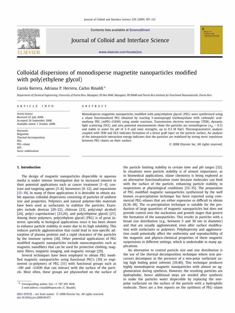
The reaction of terminal –NH2 groups in APS with terminal–COOH groups in mPEG–COOH was confirmed by FT-IR. Fig. 3shows that the band at 1584 cm−1, characteristic of –NH2 in APS,shifted to 1540 cm−1 in PEG–silane indicative of the formationof an amide bond (–C(=O)-NHR) between APS and PEG. Also, theband at 1722 cm−1 characteristic of –C=O in oxidized mPEG dis-appeared after reaction with APS and a new band at 1655 cm−1
appeared characteristic of –C=O in –C(=O)–NH [35,47,48].
Fig. 3. Reaction of terminal –NH2 groups in APS with –COOH groups in mPEG–COOH. Spectrum (a) shows band at 1584 cm−1, characteristic of –NH2 in APS.Spectrum (b) shows this band has shifted to 1540 cm−1, characteristic of forma-tion of an amide bond between APS and mPEG–COOH.
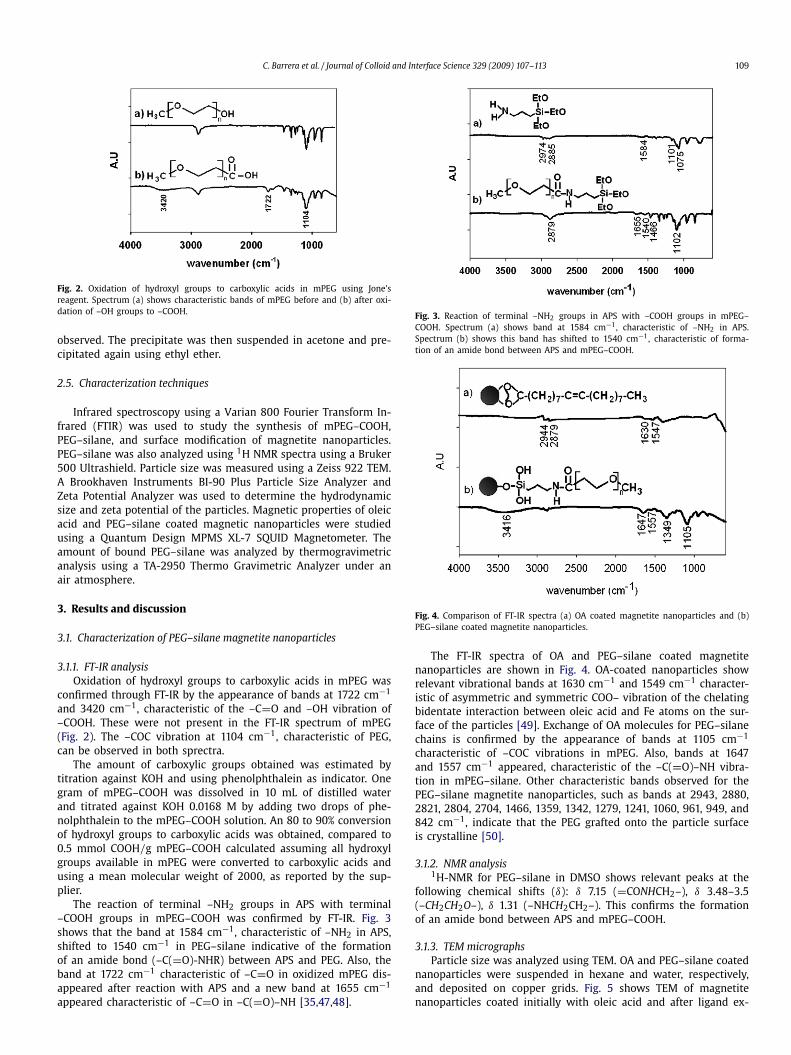
Fig. 4. Comparison of FT-IR spectra (a) OA coated magnetite nanoparticles and (b)PEG–silane coated magnetite nanoparticles.
The FT-IR spectra of OA and PEG–silane coated magnetitenanoparticles are shown in Fig. 4. OA-coated nanoparticles showrelevant vibrational bands at 1630 cm−1 and 1549 cm−1 character-istic of asymmetric and symmetric COO– vibration of the chelatingbidentate interaction between oleic acid and Fe atoms on the sur-face of the particles [49]. Exchange of OA molecules for PEG–silanechains is confirmed by the appearance of bands at 1105 cm−1
characteristic of –COC vibrations in mPEG. Also, bands at 1647and 1557 cm−1 appeared, characteristic of the –C(=O)–NH vibra-tion in mPEG–silane. Other characteristic bands observed for thePEG–silane magnetite nanoparticles, such as bands at 2943, 2880,2821, 2804, 2704, 1466, 1359, 1342, 1279, 1241, 1060, 961, 949, and842 cm−1, indicate that the PEG grafted onto the particle surfaceis crystalline [50].
3.1.2. NMR analysis1H-NMR for PEG–silane in DMSO shows relevant peaks at the
following chemical shifts (δ): δ 7.15 (=CONHCH2–), δ 3.48–3.5(–CH2CH2O–), δ 1.31 (–NHCH2CH2–). This confirms the formationof an amide bond between APS and mPEG–COOH.
3.1.3. TEM micrographsParticle size was analyzed using TEM. OA and PEG–silane coated
nanoparticles were suspended in hexane and water, respectively,and deposited on copper grids. Fig. 5 shows TEM of magnetitenanoparticles coated initially with oleic acid and after ligand ex-

110 C. Barrera et al. / Journal of Colloid and Interface Science 329 (2009) 107–113
Fig. 5. Transmission electron microscopy images of (a) OA coated magnetitenanoparticles and (b) magnetite nanoparticles coated with PEG–silane. In both casesparticles appear to be spherical and separated by a shell which has no contrastagainst the amorphous carbon background.
change with PEG–silane. A volume mean diameter Dpgv of 10 nmand a geometric deviation σg of 0.24 were obtained by analyzing250 particles. Particles have a narrow size distribution and are notagglomerated even after the exchange of OA to PEG–silane.
3.1.4. DLS measurementsDLS measurements of particles coated with OA show a parti-
cle volume mean diameter of ∼13 nm after suspension in hexaneand filtering using a 0.22 μm PTFE filter. The increase in particlediameter of about 3 nm relative to TEM measurements is in goodagreement with reported values of ∼2 nm for the chain length ofoleic acid [49].
For PEG–silane coated nanoparticles suspended in water andfiltered using a 0.22 μm Nylon filter, the volume mean diameterincreased to ∼35 nm which indicates that OA previously on thesurface of the particles was exchanged for PEG–silane chains. Thisvalue is close to the expected diameter of ∼36 nm estimated usingthe particle diameter obtained by TEM and assuming a linear PEG–silane chain length of ∼13 nm, calculated for a molecular weightof 2000 using GaussView 3.07.
3.1.5. TGA analysisTo determine the amount of OA and PEG–silane on the surface
of the particles, TGA analysis was performed from 20 to 800 ◦C ata heating rate of 10 ◦C/min under an air atmosphere. A mass lossof about 15% at 250 ◦C was found for OA-coated nanoparticles, at-tributed to the degradation of oleic acid. This weight loss indicatesthat the ratio of the mass of OA ws to the mass of magnetite wp is0.18 which is close to the theoretical value of 0.21 calculated from
ws
wp= ρs
ρp
(D3DLS − D3
TEM)
D3TEM
, (1)
based on the hydrodynamic diameter DDLS of 13 nm measured byDLS, the core diameter DTEM of 10 nm determined by TEM, using avalue of 0.895 g/mL for the OA density ρs, and a value of 5.2 g/mLfor the magnetite density ρp.
The PEG–silane coated nanoparticles showed a mass loss of 84%at 398 ◦C indicative of a stronger interaction between PEG–silaneand the surface of the particles than with OA. This mass loss cor-responds to a mass ratio of PEG–silane to magnetite of ∼5 whichis in agreement with the value of ∼8 obtained using Eq. (1), a hy-drodynamic diameter of 35 nm from DLS, a core diameter of 10 nmfrom TEM, and an assumed polymer density of 1 g/mL. This andthe DLS measurements indicate that the PEG–silane coating on theparticle surface is fairly dense.
Fig. 6. Stability of PEG–silane coated magnetite nanoparticles as a function of pH.(a) Zeta potential vs pH for PEG–silane magnetite nanoparticles suspended in waterand (b) particle hydrodynamic diameter as a function of pH.
Fig. 7. Stability of PEG–silane coated magnetite nanoparticles as a function of ionicstrength. (a) Zeta potential and (b) hydrodynamic diameter vs NaCl concentrationfor PEG–silane magnetite nanoparticles suspended in water at pH 7.
Fig. 8. Magnetization curves for OA and PEG–silane magnetite nanoparticles. Bothsuspensions are superparamagnetic, with different saturation magnetizations dueto the different particle concentrations in each. The negative slope at high magneticfields in the PEG–silane sample is due to the diamagnetic background of the sampleholder.
3.1.6. Stability analysis of PEG–silane magnetic nanoparticles atphysiological conditions
The zeta potential of PEG–silane magnetite nanoparticles sus-pended in 0.1 M KNO3 aqueous solution was studied from pH 3 to9 by adding 0.1 M KOH and HNO3 to adjust pH. As seen in Fig. 6,the particle surface is charged through most of the pH range ex-cept close to 7.5 where the isoelectric point, pI, of the particlesis obtained. PEG–silane does not have any ionizable groups, hencethe surface charge is attributed to ions absorbed from solution tothe PEG–silane layer surrounding the particles [41]. The hydrody-namic diameter of the particles varies between 35 and 45 nm asthe pH changes, with no visible precipitation.
Particle stability was also studied as a function of ionic strengthby measuring zeta potential as a function of NaCl concentration atpH 7. The NaCl concentration was varied from 0.038 M to 0.32 Mand, as seen in Fig. 7, particles were stable in this range withno precipitation. Also, as salt concentration increased the zeta po-tential of the suspension decreased, as expected from the Debye–Hückel theory.

C. Barrera et al. / Journal of Colloid and Interface Science 329 (2009) 107–113 111
Fig. 9. Schematic representation of the core–shell model used to study particle sta-bility. Inorganic hard spheres of radius R are coated with uniform polymer shells ofthickness δ and separated by a distance h measured from the surface of the inor-ganic cores.
3.1.7. Magnetic measurementsThe magnetic core size of the particles was estimated for sam-
ples of OA and PEG–silane coated magnetite nanoparticles sus-pended in hexane and water, respectively. For both cases, a mag-netic core size of 10–12 nm with a volume mean diameter Dpgv of12 nm and a geometric standard deviation σg of 0.19 was obtainedusing magnetization M data shown in Fig. 8 and the equations dueto Chantrell et al. [51]
Dpgv =(
18kBT
π Md
[χi
3ϕMd H0
]1/2)1/3
, (2)
lnσg = 1
3
[ln
(3χi H0
ϕMd
)]1/2
, (3)
where Md is the domain magnetization (446 kA for magnetite), χiis the initial susceptibility of the suspension, ϕ is the particle vol-ume fraction, and H0 is the magnetic field extrapolated to zero Mwhen M is plotted versus 1/H using data obtained at high fields.As seen in Fig. 8, particles remain magnetic after functionalizationwith PEG–silane. The difference in Ms is primarily due to differ-ences in particle volume fraction in the two suspensions.
3.2. Stability analysis of PEG–silane magnetic nanoparticles
The role of the PEG–silane layer δ thickness on particle stabilitycan be modeled by considering the total interaction energy be-tween two polymer-coated nanoparticles of diameter d suspendedin water, as shown schematically in Fig. 9. The total interactionenergy may be expressed as the sum of van der Waals forces,magnetic dipole-dipole interactions, and electrostatic and steric re-pulsion as a function of surface-to-surface particle distance h.
The van der Waals attraction energy UVDW for coated particlescan be calculated for two identical interacting particles of radius Rwith a homogeneous layer of adsorbed polymer δ by [52]
UVDW = − 1
12
[(A0.5
m − A0.5s
)2H
(h
2R + 2δ;1
)
+ (A0.5
s − A0.5p
)2H
(h + 2δ
2R;1
)
+ 2
((A0.5
m − A0.5s
)(A0.5
s − A0.5p
)H
(h + δ
2R; R + δ
R
))], (4)
where Am, As, and Ap are the Hamaker constants for the medium(water, 4.15 × 10⁻¹⁹ J [53]), surface coating (PEG, 7.20 × 10⁻²⁰ J[54]), and particles (magnetite, 5.09 × 10⁻¹⁹ J [53]), respectively,and H(x, y) is
H(x, y) = y
x2 + 2xy + x+ y
x2 + 2xy + x + y
+ 2 ln
(x2 + 2xy + x
x2 + 2xy + x + y
). (5)
To protect particles against the van der Waals attraction, theparticle surface is modified with suitable polymers that providesteric repulsion against aggregation. Estimation of the total steric
interaction between two approaching particles is commonly di-vided into osmotic and elastic contributions that depend on thedistance between the approaching particles. When the particle–particle separation reaches a distance that is smaller than 2δ,polymer chains of opposing particles interpenetrate resulting in anosmotic pressure leading to spontaneous flow of the solvent intothe interpenetrated volume, pushing the particles apart. This os-motic repulsion can be calculated from [44]
Uosmotic = 4πkBT
3Vϕ2
(1
2− χ
)(δ − h
2
)2(3R + 2δ + h
2
);
δ < h < 2δ, (6)
where φ is the volume fraction occupied by PEG–silane, V is themolecular volume of water (0.03 nm3), kB is Boltzman’s constant,T is the absolute temperature, and χ is the Flory Huggins parame-ter. For PEG–silane, a value of χ = 0.4 was used, obtained for PEGwith a molecular weight of 4000 in water [55]. A value of 0.89 wasestimated for the volume fraction φ using the expression
φ = 6ws
πρsNp(D3DLS − D3
TEM), (7)
where Np is the number of particles calculated by dividing themass of magnetic nanoparticles obtained from TGA measurementsby the mass of a 10 nm magnetic nanoparticle. When the distancebetween particles becomes less than δ, polymer chains attachedto the particle surface compress each other restricting their move-ment towards the solvent. This results in a loss of configurationalentropy that can be described by an elastic repulsion given by [44]
Uelastic = 2πkBTϕ2
V(1/2 − χ)
(2V 2
a
V c− V a
); 0 < h < δ, (8)
V a = πδ(−24R2h + 36δR2 − 12Rh2 + 28δ2 R − 6h2δ + 3δ3 + 8hδ2)
12(2R + h),
(9)
V c = π(24R2δ2 − 12R2h2 + 24δ3 R − 8Rh3 + 6δ4 − h4)
12(2R + h), (10)
where V a and V c are the effective volume of overlap between twoapproaching spheres in the region of osmotic and elastic repulsion,respectively.
The magnetic attractive interactions between PEG–silane mag-netite nanoparticles can be estimated from [53]
Um = −2
3
(μ0Md(π/6)d3)4
(4πμ0)2 S6kBT, (11)
where μ0 is the permittivity of free space (1.26 × 10⁻⁶ H/m), d isthe particle diameter, and S is the center-to-center particle sepa-ration (S = h + d). Magnetic attractive interactions were less than1 kBT at a particle–particle separation of 2δ and were thereforenot included in subsequent figures.
Fig. 10 shows the total steric and van der Waals interaction en-ergy for the PEG–silane magnetite nanoparticles with R = 5 nmand δ = 12.5 nm. The PEG–silane layer on the surface of the parti-cle at the given surface density and particle volume fraction pro-vides sufficient repulsion to counteract the van der Waals attractiveinteraction.
The calculated total interaction energy for the PEG–silane mag-netite nanoparticles suspended in water is shown in Fig. 11. Elec-trostatic repulsions are not considered since at physiological-likeconditions (pH 7 and high salt concentrations) the zeta potentialis small as seen in Figs. 8 and 9. The interaction curve shows aminimum at a distance close to 2δ followed by a rapid increasecharacteristic of sterically stabilized systems. Steric repulsion be-tween overlapping polymer chains of approaching particles pre-vents particles from reaching a distance closer than 2δ, avoiding

112 C. Barrera et al. / Journal of Colloid and Interface Science 329 (2009) 107–113
Fig. 10. Comparison of the steric and van der Waals contributions to the particle–particle interaction energy between two approaching PEG–silane coated magnetitenanoparticles. The particle radius R = 5 nm and the polymer shell thickness δ =12.5 nm.
Fig. 11. Total interaction energy for PEG–silane coated magnetite nanoparticles inwater. The inset shows the prediction of a shallow energy minimum at contact be-tween particles.
agglomeration and resulting in highly stable suspensions in wa-ter. The magnitude of the calculated minimum is much less than1 kBT , indicating that aggregates formed at this distance break dueto thermal agitation [56].
4. Summary
Stable colloidal dispersions of monodisperse magnetic nanopar-ticles in water were obtained by synthesizing magnetite nanopar-ticles by the thermal decomposition method, and exchanging theOA molecules on the surface of the particles for PEG–silane chains.The size of the particles and the chemical nature of the coatingwere determined by TEM and FTIR, respectively. TGA measure-ments show a mass loss of about 84% at 398 ◦C indicative of stronginteraction between silanol groups of PEG–silane with the surfaceof the nanoparticles. The procedure produces highly stable suspen-sions of magnetite nanoparticles in water at pH of 3 to 9 and atsalt concentrations as high as 0.32 M NaCl. The stability of thenanoparticles in suspension is further confirmed using DLVO the-ory and expressions for the steric repulsion between approachinghard particles coated with thick polymer shells. The analysis showsparticles are stabilized by steric repulsion between the PEG–silanechains, preventing particle agglomeration in suspension.
PEG–silane was obtained using a single step reaction betweenterminal amines in APS with carboxylic acid groups in mPEG–COOH by heating at 180 ◦C for 2 h, as confirmed by FT-IR andNMR. This allowed us to obtain large quantities of silane modifiedPEG using an inexpensive, straightforward technique, that can beused to covalently attach PEG to magnetic nanoparticles or other
metal oxide surfaces. These particles could potentially be used in awide range of applications such as biotechnology, MRI, magneticfluid hyperthermia, nanocomposites, or smart/functional textiles.Additionally, because of their uniform size, polymer coating, andstability in aqueous media, these particles could be used as modelcolloids in studies of magnetic particle–particle interactions.
Acknowledgments
This work was supported by the US National Science Founda-tion Nanoscale Interdisciplinary Research Teams program (GrantNo. CBET-0329374), the Partnerships for Research and Educationin Materials program (Grant No. DMR-0351449), the Experimen-tal Program to Stimulate Competitive Research (Grant No. OIA-0701525), and NASA (Grant No. NCC5-595). The authors are grate-ful to Victoria Calero for TEM measurements and Edwin de la Cruzfor NMR measurements and analysis.
References
[1] A. Jordan, R. Scholz, K. Maier-Hauff, M. Johannsen, P. Wust, J. Nadobny, H.Schirra, H. Schmidt, S. Deger, S. Loening, W. Lanksch, R. Felix, J. Magn. Magn.Mater. 225 (2001) 118.
[2] A. Jordan, R. Scholz, P. Wust, H. Fahling, R. Felix, J. Magn. Magn. Mater. 201(1999) 413.
[3] A.P. Herrera, M. Rodriguez, M. Torres-Lugo, C. Rinaldi, J. Mater. Chem. 18 (2008)855.
[4] A.K. Gupta, S. Wells, IEEE Trans. Nanobiosci. 3 (2004) 1536.[5] H. Lee, M.K. Yu, S. Park, S. Moon, J.J. Min, Y.Y. Jeong, H. Kang, S. Jon, J. Am.
Chem. Soc. 129 (2007) 12739.[6] C. Sun, R. Sze, M. Zhang, J. Biomed. Mater. Res. Part A (2006) 550.[7] M.O. Aviles, H.T. Chen, A.D. Ebner, A.J. Rosengart, M.D. Kaminski, J.A. Ritter,
J. Magn. Magn. Mater. 311 (2007) 306.[8] M.O. Aviles, A.D. Ebner, J.A. Ritter, J. Magn. Magn. Mater. 310 (2007) 131.[9] V.L. Calero, C. Rinaldi, M. Zahn, in: C.A. Grimes, E.C. Dickey, M.V. Pishko (Eds.),
Encyclopedia of Sensors, vol. 5, American Scientific Publishers, Valencia, CA,2006, p. 389.
[10] J.M. Perez, L. Josephson, T. O’Loughlin, D. Hogemann, R. Weissleder, Nat.Biotech. 20 (2002) 816.
[11] J.M. Perez, T. O’Loughlin, F.J. Simeone, R. Weissleder, L. Josephson, J. Am. Chem.Soc. 124 (2002) 2856.
[12] S.-H. Chung, A. Hoffman, K. Guslienko, S.D. Bader, C. Liu, B. Kay, L. Makowski,L. Chen, J. Appl. Polym. Sci. 97 (2005) 10R101.
[13] S. Bucak, D.A. Jones, P.E. Laibinis, T.A. Hatton, Biotechnol. Progr. 19 (2003) 477.[14] A. Ditsch, S. Lindenmann, P.E. Laibinis, D.I.C. Wang, T.A. Hatton, Ind. Eng. Chem.
Res. 44 (2005) 6824.[15] G.D. Moeser, K.A. Roach, W.H. Green, T.A. Hatton, P.E. Laibinis, AIChE J. 50
(2004) 2835.[16] H. Chen, A.D. Ebner, J.A. Ritter, M.D. Kaminski, A.J. Rosengart, Sep. Sci. Tech-
nol. 43 (2008) 996.[17] H.T. Chen, M.D. Kaminski, A.D. Ebner, J.A. Ritter, A.J. Rosengart, J. Magn. Magn.
Mater. 313 (2007) 127.[18] I.J. Bruce, J. Taylor, M. Todd, M.J. Davies, E. Borioni, C. Sangregorio, T. Sen,
J. Magn. Magn. Mater. 284 (2004) 145.[19] A.d. Campo, T. Sean, J. Lellouche, I.J. Bruce, J. Magn. Magn. Mater. 293 (2005)
33.[20] T. Kawaguchi, M. Hasegawa, J. Mater. Sci. 11 (2000) 31.[21] T. Kawaguchi, T. Hanaichi, M. Hasegawa, S. Maruno, J. Mater. Sci.-Mater.
Med. 12 (2001) 121.[22] H.T. Chan, Y.Y. Do, P.L. Huang, P.L. Chien, T.S. Chan, R.S. Liu, C.Y. Huang, S.Y.
Yang, H.E. Horng, J. Magn. Magn. Mater. 304 (2006) e415.[23] L. Li, D. Chen, Y. Zhang, Z. Deng, X. Ren, X. Meng, F. Tang, J. Ren, L. Zhang,
Nanotechnology 18 (2007) 405102.[24] H. Pardoe, W. Chua-anurson, T.G.S. Pierre, J. Dobson, J. Magn. Magn. Mater. 225
(2001) 41.[25] A.M. Schmidt, J. Magn. Magn. Mater. 289 (2005) 5.[26] J.A. Park, J.J. Lee, I.S. Kim, B.H. Park, G.H. Lee, T.J. Kim, H.C. Ri, H.J. Kim, Y. Chang,
Colloids Surf. A 313-314 (2008) 288.[27] J. Sun, S. Zhou, P. Hou, Y. Yang, J. Weng, X. Li, M. Li, J. Biomed. Mater. Res. Part
A (2006) 333.[28] A.K. Gupta, M. Gupta, Biomaterials 25 (2005) 3995.[29] H.S.M. Wang, T.A. Hatton, G.C. Rutledge, Polymer 45 (2004) 5505.[30] F. Hu, L. Wei, Z. Zhou, Y. Ran, Z. Li, M. Gao, Adv. Mater. 18 (2006) 2553.[31] H. Ai, C. Flask, B. Weinberg, X. Shuai, M.D. Pagel, D. Farrell, J. Duerk, J. Gao,
Adv. Mater. 17 (2005) 1949.[32] J. Xi, C. Xu, Z. Xu, Y. Hou, K.L. Young, S.X. Wang, N. Pourmand, S. Sun, Chem.
Mater. 18 (2006) 5401.
C. Barrera et al. / Journal of Colloid and Interface Science 329 (2009) 107–113 113
[33] I.J. Bruce, J. Taylor, M. Todd, M.J. Davies, E. Borioni, C. Sangregorio, T. Sen,J. Magn. Magn. Mater. 284 (2004) 145.
[34] Z. Xu, Q. Liu, J.A. Finch, Appl. Surf. Sci. 120 (1997) 269.[35] H. Iida, T. Nakanishi, T. Osaka, Electrochim. Acta 51 (2005) 855.[36] M.D. Butterworth, L. Illum, S.S. Davis, Colloids Surf. A 179 (2001) 93.[37] Y. Zhang, J. Zhang, J. Colloid Interface Sci. 283 (2005) 352.[38] N. Kohler, Y. Zhang, B. Busche, M. Zhang, Proc. SPIE 4810 (2002) 28.[39] S. Sun, H. Zeng, D.B. Robinson, S. Raoux, P.M. Rice, S.X. Wang, G. Li, J. Am.
Chem. Soc. 126 (2003) 273.[40] S. Sun, H. Zeng, J. Am. Chem. Soc. 124 (2002) 8204.[41] R.D. Palma, S. Peeters, J.M.V. Bael, H.V.d. Rul, K. Bonroy, W. Laureyn, J. Mullens,
G. Borghs, G. Maes, Chem. Mater. 19 (2007) 1821.[42] N. Kohler, G.E. Fryxell, M. Zhang, J. Am. Chem. Soc. 126 (2004) 7206.[43] P.C. Hiemenz, R. Rajagopalan, Principles of Colloid and Surface Chemistry, Mar-
cel Dekker, New York, 1997.[44] M.G.-S.A. Lozsan, G. Urbina-Villalba, Phys. Rev. E. 72 (2005) 061405.
[45] B.S. Lele, M.G. Kulkarni, J. Appl. Polym. Sci. 70 (1998) 883.[46] D.C. Darwin, E.M. Gartner, B. Chum, H. Koyata, L.L. Kuo, Patent No. 5,583,183.[47] D. Lin-Vien, N. Colthup, W. Fateley, J. Graselli, The Handbook of Infrared and
Raman Characteristic Frequencies of Organic Molecules, Academic Press, SanDiego, 1991.
[48] S. Mornet, J. Portier, E. Duguet, J. Magn. Magn. Mater. 293 (2005) 127.[49] L. Zhang, R. He, H. Gu, Appl. Surf. Sci. 253 (2006) 2611.[50] H. Matsuura, T. Miyazawa, J. Polym. Sci. Part A2 7 (1969) 1735.[51] R. Chantrell, J. Popplewell, S. Charles, IEEE Trans. Magn. 14 (1978) 975.[52] M.J. Vold, J. Colloid Sci. 16 (1961) 1.[53] L. Shen, A. Stachowiak, S.K. Fateen, P.E. Laibinis, T.A. Hatton, Langmuir 17
(2000) 288.[54] J. Chan, J.J. Popov, S. Kolisnek-Kehl, D.G. Leaist, J. Solution Chem. 32 (2003)
197.[55] A. Eliassi, H. Modarress, G.A. Mansoori, J. Chem. Eng. Data 44 (1999) 52.[56] T. Tadros, Colloid Interface Sci. Ser. 1 (2007) 1.