Coated magnetic carrier particles for targeted drug delivery
198
This document is downloaded from DR‑NTU (https://dr.ntu.edu.sg) Nanyang Technological University, Singapore. Coated magnetic carrier particles for targeted drug delivery Sibnath Kayal 2011 Sibnath Kayal. (2011). Coated magnetic carrier particles for targeted drug delivery. Doctoral thesis, Nanyang Technological University, Singapore. https://hdl.handle.net/10356/45161 https://doi.org/10.32657/10356/45161 Downloaded on 12 Sep 2022 02:47:56 SGT
-
Upload
khangminh22 -
Category
Documents
-
view
4 -
download
0
Transcript of Coated magnetic carrier particles for targeted drug delivery
This document is downloaded from DR‑NTU (https://dr.ntu.edu.sg)Nanyang Technological University, Singapore.
Coated magnetic carrier particles for targeteddrug delivery
Sibnath Kayal
2011
Sibnath Kayal. (2011). Coated magnetic carrier particles for targeted drug delivery. Doctoralthesis, Nanyang Technological University, Singapore.
https://hdl.handle.net/10356/45161
https://doi.org/10.32657/10356/45161
Downloaded on 12 Sep 2022 02:47:56 SGT
COATED MAGNETIC CARRIER PARTICLES FOR
TARGETED DRUG DELIVERY
SIBNATH KAYAL
SCHOOL OF MATERIALS SCIENCE AND ENGINEERING
2011
CO
AT
ED
MA
GN
ET
IC C
AR
RIE
R P
AR
TIC
LE
S F
OR
TA
RG
ET
ED
DR
UG
DE
LIV
ER
Y
201
1
SIB
NA
TH
KA
YA
L
COATED MAGNETIC CARRIER PARTICLES FOR
TARGETED DRUG DELIVERY
SIBNATH KAYAL
School of Materials Science and Engineering
A thesis submitted to the Nanyang Technological University
in partial fulfillment of the requirement for the degree of
Doctor of Philosophy
2011
i
Acknowledgements
I express my sincere gratitude to my supervisor Prof. R. V. Ramanujan for his constant
guidance throughout my PhD duration. He has enlightened me throughout the work by his
rich experience in the area of Materials Science.
I am thankful to Prof. D. Bandyapadhaya, IIT, Guwahati, India who helped me in all
possible ways during the modelling work. I had many interactive sessions with him,
which was extremely useful in giving direction to my research work.
I am thankful to my group members, Sreekanth, Derrik, Vinh, Pratap, Shashwat and
Jiayan for their prompt help.
I am thankful to Patrick Lai and Yeow Swee Kuan from Electromagnetic Materials Lab
for their kind help during the experiments.
I am thankful to the technical staff of Electron Microscopy & X-Ray Diffraction Lab,
Polymer Lab, Biomaterials Lab and Computer Facilities Lab for their help in equipment
operation.
I am thankful to my family and friends for their support, encouragement and inspiration
not only in my research, but in all aspects of my life.

ii
Abstract
Magnetic drug targeting, using coated magnetic carrier particles (MCP), is an efficient
method to localize drugs at the tumor site. In magnetically targeted drug delivery, MCP
loaded with anti-cancer drugs are injected into the patient and an external magnetic field
is used to concentrate MCP at the tumor site. Advantages include reduction in the drug
dose and minimization of systemic side effects. The objective of this work is the
synthesis, characterization and property evaluation of coated MCP, and experimental and
modelling studies of the efficacy with which such particles can be captured by an external
magnetic field.
Gold coated iron (Fe@Au) and polyvinylalcohol coated iron oxide (PVA-IO)
nanoparticles were synthesized and characterized by XRD, TEM, DLS, TGA, XPS, FTIR
and VSM techniques. The particles were superparamagnetic, with saturation
magnetization decreasing with increasing coating thickness. Fe@Au nanoparticles was
found to bind with doxorubicin (DOX) drug by the interaction of the amine (–NH2) group
of DOX with the gold (Au) shell, whereas the binding of DOX with PVA-IO occurred
through hydrogen bonding by the interaction of the –NH2 and –OH groups of DOX with
the –OH group of PVA. Up to 25% and 45% of adsorbed drug was released from Fe@Au
and PVA-IO MCP, respectively. Up to 90% of PVA-IO and 86% of Fe@Au MCP were
retained at a field gradient of 25 T m-1 and flow rate of 1 mm s-1.
The transport and capture of MCP in the tumor vasculature by an external permanent
magnet was modelled. The trajectories of various MCP showed that it is easier to capture
larger MCP with superior magnetic properties. It was found that Fe3O4, Fe@Au, PVA-IO
MCP (100 nm) can be targeted to breast tumors and other skin tumors located in the hand,

iii
leg and neck by a typical permanent magnet. In order to target tumors situated deep inside
the body, MCP with higher saturation magnetization, such as Fe and FeCo, or an external
magnet with higher magnetic field gradient (100 T m-1) must be chosen.
Trapping of MCP using nonlinear computational fluid dynamics (CFD) simulations
showed that when a suspension of MCP (ferrofluid) is injected and subjected to an
external magnetic field, ferrofluid creeps along the wall of the blood vessel. Therefore,
drug injection should be as close as possible to the tumor to minimize the drug friction
with the wall. The time of exposure to the magnetic field can be optimized and deposition
of MCP can be maximized by suitable magnetic field, minimizing loss of MCP due to
convection and diffusion. Thus, Fe@Au and PVA-IO MCP exhibit high capture efficiency
in magnetic drug targeting, the capture efficiency depends on the magnetic properties and
size of MCP, blood flow rate, time of capture, convection and diffusion effects can
significantly influence the capture efficiency of MCP.
iv
Table of Contents
ACKNOWLEDGEMENTS............................................................................................ i
ABSTRACT ................................................................................................................... ii
TABLE OF CONTENTS ............................................................................................. iv
LIST OF FIGURES...................................................................................................... ix
LIST OF TABLES...................................................................................................... xvi
LIST OF ABBREVIATIONS.................................................................................... xvii
LIST OF SYMBOLS ................................................................................................ xviii
CHAPTER 1 .................................................................................................................. 1
INTRODUCTION ......................................................................................................... 1
1.1 BIOMEDICAL APPLICATIONS OF MAGNETIC NANOPARTICLES ................................ 3
1.1.1 Therapeutic applications ................................................................................. 3
1.1.2 Diagnostic applications.................................................................................... 4
1.2 THE NEED FOR DRUG TARGETING: MOTIVATION............................................... 6
1.3 MAGNETIC DRUG TARGETING: THE SOLUTION.................................................. 7
1.4 OBJECTIVE AND SCOPE OF THE WORK ............................................................ 8
1.5 NOVELTY OF WORK ........................................................................................ 12
v
1.6 METHODOLOGY .............................................................................................. 14
1.7 ORGANIZATION OF THE THESIS....................................................................... 15
CHAPTER 2 ................................................................................................................ 16
LITERATURE REVIEW ........................................................................................... 16
2.1 CLASSES OF MAGNETIC MATERIALS................................................................ 16
2.1.1 M–H curves.................................................................................................... 17
2.1.2 Action of forces on magnetic nanoparticles.................................................. 21
2.2. MAGNETICALLY TARGETED DRUG DELIVERY ................................................ 22
2.2.1. Prior efforts towards magnetically targeted drug delivery.......................... 23
2.2.2 Magnetic nanoparticles : property requirements......................................... 25
2.2.3 Magnetic core materials ................................................................................ 26
2.2.4 Coating materials .......................................................................................... 26
2.3 SYNTHESIS OF MAGNETIC NANOPARTICLES .................................................... 35
2.3.1 Precipitation from solution ........................................................................... 35
2.3.2 Chemical vapour condensation (CVC) ......................................................... 40
2.4 MAGNETIC COMPOSITES ................................................................................. 40
2.4.1 Magnetic nanoparticles encapsulated in polymer matrices ......................... 41
vi
2.4.2 Magnetic nanoparticles encapsulated in inorganic matrices ....................... 42
2.5 INNOVATIVE ASPECTS OF THE CURRENT WORK .............................................. 42
CHAPTER 3 ................................................................................................................ 45
EXPERIMENTAL PROCEDURES AND MODEL DEVELOPMENT ................... 45
3.1 SYNTHESIS OF GOLD COATED IRON (FE@AU) MCP ............................................ 45
3.2 SYNTHESIS OF PVA COATED IRON OXIDE (PVA-IO) MCP .................................. 47
3.3 CHARACTERIZATION AND IN-VITRO TESTS ........................................................... 49
3.3.1 Transmission electron microscopy ..................................................................... 49
3.3.2 X-ray diffraction ................................................................................................. 49
3.3.3 Magnetic measurements ..................................................................................... 50
3.3.4 Dynamic light scattering ..................................................................................... 50
3.3.5 X-ray photoelectron spectroscopy ...................................................................... 50
3.3.6 Thermo gravimetric analysis .............................................................................. 50
3.3.7 Fourier transform infrared spectra ................................................................... 51
3.3.8 Doxorubicin (DOX) drug loading and release .................................................. 51
3.3.9 In-vitro targeting of MCP................................................................................... 52
3.4 MODEL DEVELOPMENT ....................................................................................... 53
vii
3.4.1 Magnetic field...................................................................................................... 55
3.4.2 Flow velocity........................................................................................................ 56
3.4.3 Equation of motion ............................................................................................. 57
3.5 CFD SIMULATIONS .............................................................................................. 60
3.5.1 Boundary conditions ........................................................................................... 61
3.5.2 Magnetic force field ............................................................................................ 62
3.5.3 Grid generation and solution methodology........................................................ 62
CHAPTER 4 ................................................................................................................ 64
RESULTS AND DISCUSSION................................................................................... 64
4.1 GOLD COATED IRON (FE@AU) MCP SYSTEM...................................................... 64
4.1.1 Physical properties.............................................................................................. 64
4.2 PVA COATED IRON OXIDE (PVA-IO) MCP SYSTEM ............................................ 78
4.2.1 Physical properties.............................................................................................. 78
4.2.2 PVA adorption onto iron oxide nanoparticles ................................................... 83
4.2.3 Magnetic properties ............................................................................................ 88
4.3 DOXORUBICIN (DOX) DRUG LOADING AND RELEASE........................................... 90
4.3.1 Gold coated iron (Fe@Au) MCP system............................................................ 91
viii
4.3.2 PVA-IO MCP system.......................................................................................... 95
4.4 IN-VITRO EXPERIMENTAL TARGETING OF MCP ................................................. 101
4.5 MODELLING OF TARGETING MCP ..................................................................... 106
4.5.1 Model Parameters............................................................................................. 107
4.5.2 Magnetic Field Components ............................................................................. 108
4.5.3 MCP trajectories............................................................................................... 110
4.5.4 Distance of Capture (d)..................................................................................... 112
4.5.5 Numerical Simulations...................................................................................... 115
CHAPTER 5 .............................................................................................................. 127
CONCLUSIONS AND FUTURE WORK ................................................................ 127
REFERENCES .......................................................................................................... 133
APPENDIX-A ............................................................................................................ 175
PUBLICATIONS AND CONFERENCES .............................................................. 177
ix
List of Figures
Figure 1.1 Global incidence and mortality rates for cancer.............................................. 1
Figure 1.2 Schematic representation of magnetic drug targeting to a specific region ....... 8
Figure 1.3 Overview of the thesis.................................................................................... 9
Figure 1.4 chemical structure of DOX........................................................................... 11
Figure 2.1. Magnetic responses associated with different classes of magnetic material.. 17
Figure 2.2 Particles stabilized by (a) the electrostatic layer, (b) steric repulsion ............ 27
Figure 2.3 Mechanism of formation of uniform particles in solution: curve I: single
nucleation and uniform growth by diffusion (classical model of LaMer and Dinegar);
curve II: nucleation, growth and aggregation of smaller subunits; curve III: multiple
nucleation events and Ostwald ripening growth ............................................................. 36
Figure 3.1 Schematic diagram showing a typical procedure for formation of Fe@Au
MCP by the reverse micelle technique. FeSO4 and HAuCl4 are reduced by NaBH4, CTAB
is surfactant, 1-butanol is co-surfactant and octane is oil phase. ..................................... 46
Figure 3.2 Schematic of an in-vitro experiment simulating the human circulatory system;
A: intake beaker, B: vibrating plate, C: peristaltic pump, D: syringe, E: silicone tube, F:
permanent magnet, H: outlet beaker, G: region of targeting. .......................................... 52
Figure 3.3 The 2-D rectangular channel mimicking a cylindrical tube and frame of
reference for analysis..................................................................................................... 53
x
Figure 4.1 X-ray diffraction pattern of (a) S-1 (uncoated), (b) S-2 (0.102 mmol gold
coated iron nanoparticles) and (c) S-3 (0.204 mmol gold coated iron nanoparticles). The
uncoated particles are oxidized to iron oxide whereas in gold coated particles, iron peaks
overlap with gold peaks. ................................................................................................ 65
Figure 4.2 Selected area electron diffraction (SAED) pattern of S-3 (0.204 mmol gold
coated iron nanoparticles). Gold 200, 220, 222 diffraction peaks overlap with iron 110,
200, 211 peaks............................................................................................................... 66
Figure 4.3 EDX spectrum of S-3 (0.204 mmol gold coated iron nanoparticles). The
absence of oxygen peak indicates that iron is not oxidized when coated with gold. The
peaks of carbon and copper arise from the sample holder............................................... 67
Figure 4.4 XPS spectra and peak fit of the (a) Fe 2p and (b) Au 4f regions of (i) S-2
(0.102 mmol gold coated iron nanoparticles) and (ii) S-3 (0.204 mmol gold coated iron
nanoparticles). The detection of Fe with the Au coating in XPS spectra suggests that Au
coating is thin ................................................................................................................ 68
Figure 4.5 TEM micrographs of (a) S-1 (uncoated) and (b) S-3 (0.204 mmol gold coated
iron nanoparticles). The corresponding size distribution of (c) S-1 (uncoated) and (d) S-3
(0.204 mmol gold coated iron nanoparticles). ................................................................ 69
Figure 4.6 Average hydrodynamic diameter of S-1 (uncoated), S-2 (0.102 mmol gold
coated iron nanoparticles) and S-3 (0.204 mmol gold coated iron nanoparticles) in PBS.
Uncoated iron nanoparticles flocculate within 1 h, whereas Fe@Au nanoparticles are
relatively stable up to 4 h. .............................................................................................. 70
xi
Figure 4.7 VSM plots of magnetization vs field of (a) S-1 (uncoated), (b) S-2 (0.102
mmol gold coated iron nanoparticles) and (c) S-3 (0.204 mmol gold coated iron
nanoparticles). Particles are superparamagnetic, Ms decreases with an increase in gold
concentration. ................................................................................................................ 71
Figure 4.8 X-ray diffraction pattern of (a) S-8 (5 wt% PVA coated iron oxide), (b) S-6 (1
wt% PVA coated iron oxide) and (c) S-4 (Uncoated iron oxide). The phase is magnetite
(Fe3O4), peaks corresponding to reflection planes are indexed. ...................................... 78
Figure 4.9 Rietveld refinement of X-ray diffraction pattern of (a) S-4 (uncoated iron
oxide) and (b) S-8 (5 wt% PVA coated iron oxide). Peak broadening occurs in PVA
coated iron oxide nanoparticles due to decrease in crystallinity...................................... 79
Figure 4.10 TEM micrographs of (a) S-4, corresponding to the uncoated iron oxide
nanoparticles and (b) S-8, coated with 5 wt% PVA. The corresponding size distribution
of (c) S-4 (uncoated iron oxide) and (d) S-8 (5 wt% PVA coated iron oxide). ................ 80
Figure 4.11 Average hydrodynamic diameter of S-4 (uncoated iron oxide nanoparticles),
S-6 (iron oxide nanoparticles coated with 1 wt% PVA) and S-8 (iron oxide nanoparticles
coated with 5 wt% PVA) in PBS.................................................................................... 81
Figure 4.12 Weight loss vs. temperature TGA curves of (a) S-4 (uncoated iron oxide), (b)
S-5 (iron oxide coated with 0.5 wt% PVA), (c) S-6 (iron oxide coated with 1 wt% PVA),
(d) S-7 (iron oxide coated with 2 wt% PVA) and (e) S-8 (iron oxide coated with 5 wt%
PVA) heated up to 600ºC in air. The inset shows the TGA curve of pure PVA indicating
complete degradation of PVA when heated up to 600ºC. ............................................... 83
xii
Figure 4.13 FTIR spectra of (a) uncoated iron oxide and (b) PVA-IO nanoparticles.
Bands at 2912, 1416, 1092 and 850 cm-1 in PVA-IO confirm the attachment of PVA to
iron oxide nanoparticles................................................................................................. 85
Figure 4.14 Magnetization vs. field curves measured at room temperature of (a) S-4,
corresponding to uncoated iron oxide nanoparticles, (b) S-5, iron oxide coated with 0.5
wt% PVA, (c) S-6, iron oxide coated with 1 wt% PVA, (d) S-7, iron oxide coated with 2
wt% PVA and (e) S-8, iron oxide coated with 5 wt% PVA. Particles are
superparamagnetic, Ms decreases with increase in PVA concentration. .......................... 88
Figure 4.15 The color of (a) pure DOX solution, (b) DOX solution after 26 h mixing with
uncoated iron nanoparticles and (c) DOX solution after 26 h mixing with gold coated iron
(Fe@Au) nanoparticles. The change in color of DOX indicates that the DOX is attached
onto Fe@Au nanoparticles only..................................................................................... 91
Figure 4.16 DOX (a) loading and (b) release profile of gold coated iron (Fe@Au) MCP.
...................................................................................................................................... 92
Figure 4.17 FTIR spectra of (a) Fe@Au, (b) pure DOX and (c) DOX-attached Fe@Au
nanoparticles. Amine (–NH2) group of DOX is involved in attachment to the Fe@Au
nanoparticles. ................................................................................................................ 93
Figure 4.18 UV-vis spectra of (a) pure DOX, (b) DOX-attached Fe@Au and (c) Fe@Au
colloid. Peak is broadened and red shifted at 535 nm upon addition of colloidal Fe@Au to
DOX.............................................................................................................................. 94
Figure 4.19 DOX loading on to PVA-IO nanoparticles, DOX loading increases with
increase in PVA concentration. ...................................................................................... 96

xiii
Figure 4.20 DOX release from PVA-IO, DOX release follows the Fickian diffusion
controlled process. ......................................................................................................... 97
Figure 4.21 FTIR spectra of (a) pure DOX and (b) DOX-conjugated PVA-IO.
Conjugation of DOX to the PVA-IO occurs via the interaction of –NH2 and –OH groups
of DOX with –OH groups of PVA. ................................................................................ 98
Figure 4.22 Percent retention of (a) S-2 (0.102 mmol gold coated iron nanoparticles) and
(b) S-3 (0.204 mmol gold coated iron nanoparticles) at various flow rates of fluid.. ..... 101
Figure 4.23 Percent retention of (a) S-4 (uncoated Fe3O4), (b) S-6 (Fe3O4 coated with 1
wt% PVA), (c) S-7 (Fe3O4 coated with 2 wt% PVA) and (d) S-8 (Fe3O4 coated with 5
wt% PVA) at various flow rates of fluid. ..................................................................... 103
Figure 4.24 components of (a) Nd-Fe-B rectangular permanent magnet and (b) Nd-
Fe-B cylindrical permanent magnet along the axis of vessel, when the vessel is at a
distance of 5, 10 and 15 mm from the surface of magnet.............................................. 108
Figure 4.25 Trajectories of Fe3O4 MCP (particle size 100, 200 and 500 nm) in the vessel
when (v ) = 5 mm s-1, d = 30 mm. ............................................................................... 110
Figure 4.26 Trajectories of different MNCP of radius of 100 nm in the vessel when ( v )
= 5 mm s-1, d = 30mm.................................................................................................. 111
Figure 4.27 Representative plots of distance of capture vs MCP size for different flow
rates of fluid. ............................................................................................................... 112
Figure 4.28 Distance of capture for various MCP with size of 100 nm and v = 5 mm.s-1
using a typical permanent magnet. ............................................................................... 113
xiv
Figure 4.29 Distance of capture for various MCP with size of 100 nm and v = 5 mm.s-1
using a higher magnetic field gradient (100 T m-1)....................................................... 114
Figure 4.30 Temporal evolution of the concentration profile when a ferrofluid (Rp = 100
nm and χ = 0.4) is continuously injected at the inlet of a 2-D channel. Initially the vessel
is assumed to be filled with a PBS buffer flowing at 10 mm.s-1. The centre of the magnet
is placed at the mid point of the lateral coordinate. The vertical distance, d from the
bottom wall of the vessel to surface of the magnet is 10 mm........................................ 116
Figure 4.31 Temporal evolution of the concentration profile when a ferrofluid (Rp=100
nm and χ = 0.4) is continuously injected at the inlet of a 2-D channel. In this simulation d
is kept constant at 10 mm. The contour plots represent: (a) v = 1 mm.s-1, (b) v = 5 mm.s-
1, and (c) v = 40 mm.s-1. .............................................................................................. 118
Figure 4.32 Temporal evolution of the concentration profile when a ferrofluid (v = 10
mm s-1) is continuously injected at the inlet of a 2-D channel. In this contour plots: (a) d =
5 mm, Rp = 100 nm and χ = 0.4; (b) d = 15 mm, Rp = 100 nm and χ = 0.4; (c) d = 10
mm, Rp = 200 nm and χ = 0.4...................................................................................... 120
Figure 4.33 (a) Temporal evolution of the concentration profile when a ferrofluid
(Rp=100 nm and χ = 0.4) is continuously injected at the inlet of a 2-D channel at flow
rate (v ) of 10 mm.s-1 under weak magnetic field (d = 50 mm). (b)The streamline contour
plot of frame (i) in magnified view shows the trade off between the magnetic force and
the convective force leading to the formation of vortices near the wall......................... 121
Figure 4.34 Temporal evolution of the concentration profile of a ferrofluid (Rp = 100 nm
and χ = 0.4) in a 2-D channel under the influence of a cylindrical magnet (d = 10 mm).

xv
The contour plots represent: (a) v = 1 mm.s-1, (b) v = 10 mm.s-1, and (c) v = 40 mm.s-1.
.................................................................................................................................... 123
xvi
List of Tables
Table 2.1 Some useful polymers to coat nanoparticles for biomedical applications....... 32
Table 3.1 Summary of sample sets synthesized by the reverse micelle technique. ......... 47
Table 3.2 Summary of sample sets synthesized by the co-precipitation technique. ........ 48
Table 4.1 Saturation magnetization (Ms) of Fe@Au. ..................................................... 72
Table 4.2 Comparison of gold coated magnetic nanoparticles of current work with
selected literature........................................................................................................... 77
Table 4.3 Weight loss due to PVA in thermogravimetric analysis (TGA) in air. ............ 84
Table 4.4 Assignment of FTIR spectra of uncoated iron oxide, PVA-IO. ...................... 87
Table 4.5 Saturation magnetization (Ms) of uncoated and PVA-IO nanoparticles. ......... 89
Table 4.6 Parameters used in modelling and simulations. ............................................ 107

xvii
List of Abbreviations
CFD Computational fluid dynamics
DLS Dynamic light scattering
DOX Doxorubicin
Fe@Au Gold coated iron
FTIR Fourier transform infrared
HCC Hepato cellular carcinoma
MCP Magnetic carrier particles comprising of small aggregates of nanoparticles
MDT Magnetic drug targeting
MNP Magnetic nanoparticles
MRI Magnetic resonance imaging
PVA Polyvinylalcohol
PVA-IO Polyvinylalcohol coated iron oxide
TEM Transmission electron microscopy
TGA Thermo-gravimetric analysis
VSM Vibrating sample magnetometry
XPS X-ray photoelectron spectroscopy
XRD X-ray diffraction

xviii
List of Symbols
0µ Magnetic permeability of free space
χ Magnetic susceptibility
H Magnetic field strength
B Magnetic field gradient
pR Hydrodynamic radius of particle
V Volume of particle
η Viscosity of fluid
ρ Density of fluid
pv Particle velocity
v Average velocity of fluid
D Mass diffusivity
h Half-height of rectangular magnet
w Half-width of rectangular magnet
magR Radius of cylindrical magnet
d Distance between magnet and blood vessel
R Radius of blood vessel

Chapter 1 – Introduction
1
Chapter 1
Introduction
Cancer treatment is a key challenge in biomedicine with more than 10 million new cases
every year [1]. Global cancer rates are expected to double by the year 2020, according to
a report from the International Agency for Research on Cancer (IARC), a branch of the
World Health Organization (WHO) [2]. The statistics for the global incidence and
mortality rates for major types of cancer are shown in Fig.1.1 [3].
Figure 1.1 Global incidence and mortality rates for cancer [3].

Chapter 1 – Introduction
2
In developed countries, cancer is the second biggest cause of death after cardiovascular
disease. The situation is also alarming in developing countries. Some cancers are more
common in developed countries, e.g., prostate, breast and colon cancer. Cancer is
characterized by a population of cells that grow and divide without respect to normal
limits, these cells invade and destroy adjacent tissues and may spread to distant anatomic
sites through a process called metastasis [4]. Cancer is caused by a number of factors such
as unhealthy lifestyle (tobacco and alcohol use, inadequate diet, physical inactivity),
exposure to environmental carcinogens (ultraviolet and ionizing radiation), chemical
carcinogens (asbestos, tobacco) and biological carcinogens (virus, bacteria, fungi). There
are different types of cancers according to localization, cell type, malignancy etc., but all
share a common trait – if undetected and untreated at an early stage, the risk of death is
high [3].
Nanotechnology is a multi-disciplinary field, integrating traditional disciplines such as
physics, materials science, biology and chemistry for the development of novel materials
and technologies. Nanotechnology is a growing area of research and has developed to
such an extent that it has become possible to synthesize, characterize and tailor the
functional properties of nanoparticles for improved therapeutics and diagnostics in
medicine [5-8]. A major thrust of research in nanomedicine has been the development of
nanocarriers for passively or actively targeted drug delivery for cancer therapy [9-13].
Magnetic nanoparticles (MNP) are a major class of nanoscale materials, which offer very
attractive possibilities in biomedicine. MNP have sizes smaller than or comparable to
those of a cell (10–100 µm), a virus (20–450 nm), a protein (5–50 nm) or a gene (2 nm
wide and 10–100 nm long). MNP can be functionalized by either polymers or inorganic
materials to which drugs or biological agents can be attached and driven by an external

Chapter 1 – Introduction
3
magnetic field gradient. The penetrability of magnetic fields into human tissue enables
such functionalized MNP to deliver anticancer drugs, radionuclide atoms and genes to a
targeted region of the body, such as a tumor [14]. MNP can also be heated by an external
high frequency alternating magnetic field, resulting in a moderate degree of tissue
warming causing malignant cell destruction by thermal ablation/ hyperthermia of tumors
[15]. MNP are also used as contrast agents to improve the resolution of tumor imaging in
magnetic resonance imaging (MRI) [16].
Several types of MNP with various chemical compositions have been proposed and
evaluated for biomedical applications to exploit nanoscale magnetic phenomena, such as
enhanced magnetic moments and superparamagnetism [17]. Composition, size,
morphology and surface chemistry can now be tailored by various processes to tune the
in-vivo behaviour of nanoparticles [18]. Coated magnetic carrier particles (MCP) are
comprised of small aggregates of magnetic nanoparticles with a biocompatible coating,
which provides stabilization under physiological condition. Targeting MCP to the tumor
using an external magnetic field enables the functionalized particles to be used as
multimodal therapeutic agents combining drug delivery, hyperthermia and in-vivo
imaging, which is a major advantage over non-magnetic particles.
1.1 Biomedical applications of magnetic nanoparticles
The major biomedical applications of magnetic nanoparticles are as follows:
1.1.1 Therapeutic applications
Drug delivery: Since the pioneering concept proposed by Freeman et al [19] that fine
iron particles could be transported through the vascular system and concentrated in a
specific region of the body with the aid of a magnetic field, the use of magnetic particles

Chapter 1 – Introduction
4
for the delivery of drugs or antibodies to the organs or tissues has become an attractive
field of research [20]. MNP have been evaluated extensively for the targeted delivery of
pharmaceuticals through magnetic drug targeting (MDT) [21, 22] as well as for active
targeting through the attachment of high affinity ligands [23]. Drug localization is based
on the application of an external magnetic field, which retains the drug loaded MCP at a
specific target site. They can then be internalized by the endothelial cells of the tissue.
The small size of MNP enables their transport through the capillary systems of organs and
tissues. MNP offer an attractive means of targeting therapeutic agents specifically to a
diseased site, while simultaneously reducing dosage and deleterious side effects
associated with non-specific uptake of cytotoxic drugs by healthy tissue, hence they have
the potential to overcome the limitations associated with systemic distribution of
conventional chemotherapies.
Hyperthermia: Hyperthermia is a therapeutic procedure used to raise the temperature of
a region of the body affected by malignancy. Tumor cells are more sensitive to
temperature than normal cells, hence there is a direct cancer cell killing effect for
temperatures in the range of 42-47˚C [24-27]. Hyperthermia involves dispersing MNP
throughout the target tissue and then applying an AC magnetic field of sufficient strength
and frequency to heat up the particles. This heat is conducted into the surrounding
diseased tissue and the temperature is maintained above the therapeutic threshold of 42˚C
for 30 min or more to destroy the tumor.
1.1.2 Diagnostic applications
NMR imaging: The development of the NMR imaging technique for clinical diagnosis
has suggested the exciting possibility of a new class of pharmaceuticals, called
magnetopharmaceuticals. MNP are administered to a patient to enhance the image
Chapter 1 – Introduction
5
contrast between normal and diseased tissue, thus indicating the status of organ functions
or blood flow [28]. The contrast agents used in most NMR imaging studies to date have
been paramagnetic. Superparamagnetic particles represent an alternative class of NMR
contrast agents that are usually referred to as T2 (transversal relaxation time) or T2∗
contrast agents as opposed to T1 (longitudinal relaxation time) agents such as
paramagnetic gadolinium (III) chelates [29]. Commercial iron oxide nanoparticles of
maghemite (Endorem® and Resovit®) have been used as contrast agents in NMR
imaging for the location and diagnosis of brain and cardiac infarcts, liver lesions and
tumors [30].
Cell labelling and magnetic separation: Magnetic separation is based on the following
processes: (i) tagging or labelling of the desired biological entity with biocompatible
magnetic nanoparticles and (ii) separation of these tagged entities via a fluid-based
magnetic separation device. Magnetic separation has been successfully applied to many
aspects of biomedical and biological research. It has proven to be a highly sensitive
technique for the selection of rare tumor cells from blood [31]. This has led to the
enhanced detection of malarial parasites in blood samples, either by utilizing the magnetic
properties of the parasite [32] or through labelling the red blood cells with an
immunospecific magnetic fluid [33].
Researchers are seeking to exploit the properties of MNP to obtain medical breakthroughs
in diagnosis [34-36] and improved drug delivery for cancer treatment [14, 21, 37-39]. The
synthesis, characterization, property evaluation and modelling of MCP for magnetically
targeted drug delivery are described in this thesis.
Chapter 1 – Introduction
6
1.2 The need for drug targeting: motivation
The common methods of cancer treatment are surgery, radiotherapy, thermotherapy and
chemotherapy [24]. However, conventional cancer therapies suffer from numerous
drawbacks. Surgery is an invasive method by which the tumor is physically removed
from the body. There is a risk of complications during the surgical process and also the
possibility of post operative problems such as pain, infection, bleeding, blood clots and
slow recovery of organ functions [40]. Radiotherapy involves exposing cancer cells to
high-energy radiation such as gamma rays or X-rays to kill cancer cells. However,
radiotherapy is non-specific in nature, i.e., it destroys healthy cells as well as cancerous
cells. Side effects from radiotherapy include fatigue, damage to the skin, lungs, digestive
tract, mouth and throat, changes in brain function, decrease in fertility and in some cases
triggering of secondary cancers [40].
Common hyperthermia techniques are radiofrequency capacitance hyperthermia (RFCH),
whole body hyperthermia (WBH) and isolated hepatic perfusion hyperthermia (IHPH)
[24, 41, 42]. Due to the non-specificity of these methods, attainable tumor temperatures
are limited to minimize the risk of collateral organ damage. There is high risk of death by
organ failure due to the uniformly elevated body and hepatic temperatures, particularly in
the case of WBH and IHPH [41].
In chemotherapy, highly cytotoxic drugs are injected intravenously and transported to the
tumor site through blood flow. This treatment involves a schedule of regular
administrations of drugs distributed over several days. The major disadvantage associated
with chemotherapy is the general systemic distribution of drug throughout the body,
which results in insufficient drug concentration at the tumor, decreasing the effectiveness
of treatment. More importantly, these cytotoxic drugs are highly non-specific in nature,
Chapter 1 – Introduction
7
i.e., they kill both healthy as well as tumor cells, resulting in serious side effects. These
side effects include hair loss, nausea, diarrhea, infertility, cognitive impairment, heart
damage, nerve damage, liver damage, lung damage, etc [40]. It is therefore very
important to selectively target chemotherapeutic agents to the tumor as precisely as
possible in order to reduce systemic distribution of cytotoxic drugs and to reduce the
associated side effects. Targeted drug delivery can improve the outcome of chemotherapy
by allowing the maximum fraction of drugs to interact exclusively with cancer cells,
without adverse side effects to non-targeted sites [43]. This need has prompted a search
for drug delivery method, which can address the limitations of conventional cancer
treatment and provide more effective cancer therapy.
1.3 Magnetic drug targeting: the solution
There has been keen interest in the development of a novel drug delivery system, which
can deliver drug exclusively to specific parts of the body. A magnetically targeted drug
delivery system using MCP targeted by an external magnetic field is a promising
alternative to solve critical issues associated with conventional cancer therapies [18, 37,
38, 44-46]. In magnetically targeted drug delivery, MCP loaded with anti-cancer drug are
injected into the patient body via the human circulatory system. These MCP are localized
at the tumor by applying an external magnetic field near the tumor (Fig. 1.2). Drug
release occurs following the localization of MCP in the tumor, either via enzymatic
activity or changes in physiological conditions, e.g., pH, osmolality, or temperature [47].
Thus magnetically targeted drug delivery increases drug concentration at the tumor and
minimizes the distribution of drug in healthy tissue. If the magnetic particles are coated
with a gold shell, this shell can provide advantages such as improved computed
tomography (CT) contrast, it can be heated by near infrared (NIR) light irradiation due to

Chapter 1 – Introduction
8
photothermal effect; this multi modal treatment (synergistic effects of thermo therapy and
chemotherapy) improves the efficacy of cancer therapy [48-51]. Despite the fact that
systemic chemotherapy offers no survival benefit for cases of advanced Hepato Cellular
Carcinoma (HCC), magnetically targeted chemotherapy offers improved survival and
quality of life for these patients [52-54].
Figure 1.2 Schematic representation of magnetic drug targeting to a specific region [55].
1.4 Objective and scope of the work
The delivery of anti-cancer drugs to specific target sites with minimum side effects is a
challenge in conventional cancer treatments. The objective of this work is to study the

Chapter 1 – Introduction
9
conditions for targeting of MCP to site specific drug delivery. The focus is on the
synthesis, characterization and property evaluation of coated MCP with in-vitro
experiments and modelling studies of the efficacy with which such particles can be
captured by an external magnetic field. Figure 1.3 provides an overview of the thesis.
Figure 1.3 Overview of the thesis.
Problem identification and definition
Determination of parameters and properties of MCP for magnetic drug targeting
Chemical synthesis of coated MCP: • PVA coated iron oxide (co-precipitation technique) • Gold coated iron (reverse micelle technique)
Characterization, property evaluation
Modelling of MCP targeting
In- vitro targeting of MCP
Doxorubicin drug (DOX) loading and release study of MCP
Conclusions

Chapter 1 – Introduction
10
Iron oxide nanoparticles are biocompatible in the doses required for therapeutic use and
are sold commercially (i.e., Endorem, Feridex IV), they are currently in routine use as
MRI contrast enhancement agents [36, 56, 57]. Superparamagnetic iron oxides
nanoparticles, e.g., the commercially available Combidex, have undergone clinical trials
for the use in detection of lymph node metastases [58]. The favourable biocompatibility
and biodegradability of iron oxide nanoparticles have contributed greatly to their
widespread use in biomedical applications, iron ions are incorporated as hemoglobin by
erythrocytes during metabolism [59]. In-vivo experiments on animal models have shown
that iron oxides are suitable for drug delivery [37, 60]. Human clinical trials for drug
delivery have been conducted with iron oxide based ferrofluids, the injected dosage being
well tolerated by patients [44].
Generally, particles with hydrophobic surfaces are more readily removed by the body’s
reticulo-endothelial system (RES) [61, 62]. However, hydrophilic coatings increase
circulation time of MCP by reducing immediate clearance by the RES [63]. Hydrophilic
polymer polyvinyl alcohol (PVA) is useful as a coating of magnetic particles because of
its biocompatibility, biodegradability and it can also be readily functionalized [18, 64-66].
Another carrier system comprising of gold coated iron (Fe@Au) nanoparticles is of
special interest. Bare iron nanoparticles can not be directly used for drug delivery since
(a) free iron induces the formation of dangerous free radicals, (b) iron nanoparticles can
aggregate resulting in the formation of thromboses and (c) free iron nanoparticles are
easily oxidized. By coating the iron nanoparticles with gold, the oxidation of iron can be
minimized. The interaction of gold nanoparticles with phagocytes showed the
biocompatible properties of gold nanoparticles such as nontoxicity, nonimmunogenicity
and high tissue permeability without hampering cell functionality [67]. Gold can also be

Chapter 1 – Introduction
11
readily functionalized by the use of amine [68] and thiol groups [69], which facilitates the
attachment of biologically relevant molecules.
In this work, Doxorubicin (DOX) was chosen as a model drug for drug loading and
release studies of MCP. DOX is an anti-cancer drug used in chemotherapy. It is classified
as an anthracycline antiobiotic which interacts with DNA by intercalation [70]. DOX is
orange-red crystalline solid, its chemical structure is given below:
Figure 1.4 Chemical structure of DOX [70].
Doxorubicin is commonly used to treat cancers of the bladder, breast, stomach, lung,
ovaries, thyroid, multiple myeloma, pancreas, prostate, sarcomas, testis (germ cell),
hyroid and uterus [71].
In this work, gold coated iron (Fe@Au) and PVA coated iron oxide (PVA-IO) MCP were
investigated. The anti-cancer drug doxorubicin (DOX) was attached to these MCP and the
binding mechanism of DOX with the coating was examined. DOX loading and release
profiles as well as in-vitro targeting of these MCP were studied in order to determine the
suitability of these MCP for magnetically targeted drug delivery. From the in-vitro
experimental targeting of MCP results, it was found that 90% of PVA-IO and 86% of
Fe@Au MCP can be retained at a field gradient of 25 T m-1 and a flow rate of 1 mm s-1.

Chapter 1 – Introduction
12
The modelling of targeting of MCP showed that Fe3O4, Fe@Au, PVA-IO MCP (100 nm)
can be targeted to the breast tumor and other skin tumors by a typical permanent magnet
(maximum field gradient of 25 T m-1). The modelling results also showed that MCP with
higher saturation magnetization e.g., Fe and FeCo can be targeted to lung, liver, kidney,
pancreas tumors or a higher magnetic field gradient (100 T m-1) can be used to localize
these MCP to tumors situated deep inside the body. Computational Fluid Dynamics
(CFD) simulations showed that when a suspension of MCP (ferrofluid) enters into the
blood vessel, ferrofluid creeps along the wall of the blood vessel under an external
magnetic field. Simulations also showed that for a given magnetic field strength, the time
of exposure of magnetic field can be optimized for a given diameter of blood vessel and
blood flow rate.
1.5 Novelty of work
The delivery of anticancer agents to specific target sites with minimum side effects is a
challenge in conventional cancer treatments. Using a magnetic field to capture MCP
loaded with anticancer drugs at the tumor site offers an alternative methodology for the
targeted delivery of drugs. So far, studies of the conditions under which magnetic
targeting is feasible have been mostly empirical. The novelty of the work lies in the
synthesis, characterization and property evaluation of MCP for drug targeting combined
with in-vitro experiments and modelling studies of the efficacy with which these particles
can be retained at a given site by an external magnetic field. Concurrent drug loading and
release studies of these MCP were also conducted. Contributions of this work are:
• Fe@Au nanoparticles were synthesized by the reverse micelle method and
particles were characterized. DOX was attached to Fe@Au MCP and the
interaction of DOX with the gold coating was examined. For the first time, DOX

Chapter 1 – Introduction
13
loading and release profiles of Fe@Au MCP as well as in-vitro targeting of these
MCP at flow rates of the fluid comparable to that encountered in the capillary bed
of a tumor were studied. A significant quantity of DOX (94%) was loaded onto
the Fe@Au MCP and 25% of adsorbed DOX was released. Up to 86% of Fe@Au
MCP was captured at a field gradient of 25 T m-1 and flow rate of 1 mm s-1.
• Another MCP system, i.e., PVA coated iron oxide (PVA-IO) nanoparticles was
studied. The synthesis, characterization, property evaluation as well as combined
in-vitro drug loading, drug release and drug targeting using these PVA-IO MCP
were carried out. PVA-IO nanoparticles were loaded with DOX and 45% of
adsorbed drug was released. Up to 90% of PVA-IO MCP was captured at a field
gradient of 25 T m-1 and flow rate of 1 mm s-1.
• Modelling of the targeting of MCP at the tumor site was performed by
determining the trajectory and distance of capture of MCP under various flow
rates of fluid, magnetic properties of MCP and MCP size. The modelling results
showed that Fe3O4, Fe@Au, PVA-IO MCP (100 nm size) can be targeted to breast
tumors and other skin tumors by a typical permanent magnet. To target tumors
situated deep inside the body, MCP with superior magnetic property, e.g., Fe and
FeCo, or an external magnet having higher magnetic field gradient (100 T m-1)
must be chosen.
• The trapping of MCP was studied using nonlinear CFD simulations and these
results were compared qualitatively with experimental results. Simulations
showed that the ferrofluid creeps along the bottom wall under the influence of a
magnetic field, which may cause friction and remove the drug before it reaches
the targeted zone, hence drug injection should be as close as possible to the
malignant location. For a given magnetic field strength, the time of exposure to
Chapter 1 – Introduction
14
the magnetic field can be optimized once the diameter of the blood vessel and
blood flow rate are known.
1.6 Methodology
A literature survey was carried out to examine the choice of synthesis procedure of coated
magnetic nanoparticle carriers. The following routes were carried out to synthesize the
magnetic carriers:
• Fe@Au nanoparticles were synthesized by the reverse micelle method.
• PVA-IO nanoparticles were synthesized by coprecipitation of iron oxide and
subsequently coated with polyvinyl alcohol (PVA).
Phase identification and structural analysis of the carriers were performed by X-ray
diffraction (XRD). The size and morphological characterization of the individual particles
were carried out by transmission electron microscopy (TEM). Magnetic measurements
were performed by vibrating sample magnetometry (VSM). The mass fraction of polymer
attached to the magnetic particles was determined by thermo-gravimetric analysis (TGA).
Fe@Au and PVA-IO nanoparticles were loaded with the anti-cancer drug DOX, drug
loading and release properties were studied by measuring the DOX concentration using a
UV-vis spectrophotometer. The binding mechanism of DOX with the coating was
examined by Fourier transform infrared (FTIR) spectroscopy. An in-vitro apparatus
simulating the human circulatory system was constructed and used to determine the
retention of MCP under different flow rates of fluid and varying magnetic field gradients.
CFD simulations of MCP trapping by an external magnetic field were carried out using
Ansys-Fluent software.

Chapter 1 – Introduction
15
In summary, the synthesis, characterization, property evaluation and modelling of MCP
were performed to examine their potential for magnetic drug targeting applications.
1.7 Organization of the thesis
The thesis consists of 5 chapters.
• Chapter 1 is the introduction of the thesis. The limitations of conventional cancer
treatments are highlighted and a possible solution, i.e., magnetically targeted drug
delivery is suggested. The objective and scope of the thesis are presented along
with a brief description of methodology.
• Chapter 2, literature review contains an introduction to magnetism and its
relevance to medical applications. The state of the art of the development of
various magnetic drug carriers, their synthesis techniques as well as in-vitro and
in-vivo magnetic targeting using these magnetic carriers are discussed.
• Chapter 3 describes the experimental procedures for synthesis, characterization,
property evaluation and in-vitro targeting as well as drug loading and drug release
of MCP used in this work. The development of a magnetic drug targeting model is
also presented.
• Chapter 4 presents results and discussion related to synthesis and characterization
of Fe@Au as well as PVA-IO nanoparticles, DOX loading and release studies and
in-vitro experimental capture of these MCP. Modelling of magnetic drug targeting
and the CFD simulation results are also presented.
• Chapter 5 presents the conclusions and future scope of this work.
Chapter 2 – Literature Review
16
Chapter 2
Literature Review
In this chapter, some fundamental concepts of magnetism are briefly discussed. To
control the motion of MCP within the body, the magnetic force due to an externally
applied magnetic field and a hemodynamic drag force due to blood flow combine to exert
a total vector force on the MCP. To overcome the influence of blood flow to achieve the
desired external magnetic field controlled trapping, the magnetic force due to the external
magnetic field must be larger than the drag force. The relevant equations to model this
targeting are discussed. The magnetic core materials, coating materials and the role of
coatings are discussed. Wet chemical routes to synthesize magnetic nanoparticles are
simpler and more efficient than physical methods with appreciable control over size,
composition and sometimes even the shape of the nanoparticles [72, 73]. In this chapter
different synthesis methods to produce magnetic nanoparticles for biomedical
applications are presented.
2.1 Classes of magnetic materials
Magnetism arises from the orbital and spin motion of electrons in the material. Magnetic
materials are classified on the basis of their response to an external magnetic field. Some
fundamental concepts of magnetism are briefly discussed here. Further details can be
found in textbooks on magnetism [74, 75].

Chapter 2 – Literature Review
17
2.1.1 M–H curves
Figure 2.1 represents a schematic diagram of a blood vessel in which magnetic particles
are present. The magnetic particles and the biomolecules in the blood vessel have
different magnetic properties, which are illustrated in Fig. 2.1.
Figure 2.1. Magnetic responses associated with different classes of magnetic material, illustrated for a hypothetical situation in which ferromagnetic particles of a range of sizes from nanometre up to micron scale are injected into a blood vessel. M–H curves are shown for diamagnetic (DM) and paramagnetic (PM) biomaterials in the blood vessel, and for the ferromagnetic (FM) injected particles, where the response can be either multi-domain (- - - - in FM diagram), single-domain (—— in FM diagram) or superparamagnetic (SPM), depending on the size of the particle [76].

Chapter 2 – Literature Review
18
If a magnetic material is placed in a magnetic field of strength ( H ), the magnetic
induction ( B ) is given as,
0 ( + )µ=B H M (2.1)
where 0µ is the permeability of free space, M is the magnetization (=m /V) represented
as magnetic moment per unit volume, where m is the magnetic moment and V is the
volume of the material. All materials respond to the magnetic field depending on their
atomic structure. The classification of a material's magnetic properties is based on its
magnetic susceptibility ( χ ), which is defined by the ratio of the induced magnetization
( M ) to the applied magnetic field ( H ) as,
M Hχ = , (2.2)
χ holds in the limit that H approaches 0. In SI units, χ is dimensionless and both M and
H are expressed in A.m−1.
Diamagnetism arises from orbiting electrons when these electrons are subjected to an
applied magnetic field. Diamagnetism is found in all materials but it is usually very weak
and characterized by negative susceptibility. In diamagnetic materials, the magnetic
moment is anti-parallel to H resulting in very small and negative susceptibilities ( χ =
− 10− 6 to − 10− 3). They do not retain magnetic properties when the external field is
removed. For paramagnetic materials, partial alignment of atomic magnetic moments in
the direction of external magnetic field takes place, leading to positive susceptibility ( χ =
10− 6 to 10− 1). The magnetization is zero when the field is removed, since the magnetic
moments associated with individual atoms do not interact magnetically in paramagnetic
materials. However, some materials exhibit a permanent magnetic moment in the absence
Chapter 2 – Literature Review
19
of an external field; these are classified as ferromagnets, ferrimagnets and
antiferromagnets, where the prefix refers to the nature of the coupling interaction between
the electrons within the material [75]. In ferromagnets, the atomic moments exhibit strong
interactions produced by large exchange forces, which result in the alignment of atomic
moments in the same direction. In ferrimagnets, two sublattices couple through a super
exchange mechanism resulting in antiparallel alignment. In antiferromagnets, the
exchange coupling between neighboring moments causes moments to align in an
antiparallel fashion.
The M–H curve has a characteristic sigmoidal shape, M reaches a saturation value at large
value of H. Furthermore, a hysteresis loop is observed in ferromagnets and ferrimagnets.
Hysteresis arises from the irreversibility in the magnetization process due to (a) pinning
of magnetic domain walls at impurities or grain boundaries within the material, and (b)
intrinsic effects such as the magnetic anisotropy of the crystalline lattice [77]. The shape
of the hysteresis loop depends on particle size, e.g., large particles (of the order of micron
size or more) have a multi-domain structure and a narrow hysteresis loop, whereas
smaller particles have a single domain structure and a broad hysteresis loop. All ferro-
and ferrimagnets above their corresponding threshold temperatures behave like
paramagnets, since thermal energy is sufficiently high to cause random fluctuations of
magnetic moments, eliminating magnetic order. On the other hand, superparamagnetism
is observed in particles that are so small that they consist of a single magnetic domain and
ambient thermal energy is sufficient to overcome coupling forces, causing the atomic
magnetic moment to fluctuate randomly. This leads to the anhysteretic but still sigmoidal
M–H curve (Fig. 2.1).

Chapter 2 – Literature Review
20
The value of coercivity is also size-dependent. As particle size decreases, coercivity
increases to reach a maximum at a threshold particle size (typical values are 15 and 35 nm
for Fe and Co metallic particles, respectively, while for SmCo5
it is 750 nm) [78] due to
the transformation from a multi domain to a single domain structure. In bulk magnetic
materials, a multidomain structure is constituted by regions of uniform magnetization,
separated by domain walls, which minimize the sum of the energy due to the external
magnetic field (magnetostatic energy) and the energy of the domain walls. As the volume
of the magnetic particle decreases, the size of the domains and the width of the walls
reduces until the energy cost to produce a domain wall is greater than the corresponding
reduction in magnetostatic energy. Consequently, the system no longer divides itself into
smaller domains, instead the structure maintains a single domain. In a single domain
particle, it is not possible for magnetization reversal to take place by means of the
boundary displacement process, which requires relatively weaker fields. Instead the
magnetization of the particle must rotate as a whole, a process that requires a large field,
depending on the anisotropy energy of the material. A further decrease in particle size
causes the coercivity value to decrease rapidly to zero resulting in a transition to the
superparamagnetic state. Superparamagnetism follows the activation law for the
relaxation time τ of the net magnetization of the particle [79].
τ = τ0 exp (∆E/kBT), (2.3)
where ∆E is the energy required for moment reversal and kBT is the thermal energy (kB is
Boltzman constant, T is temperature) . The energy barrier is expressed as ∆E = KV, where
K is the anisotropy energy density and V is the particle volume. For small particles ∆E is
comparable to kBT at room temperature, hence superparamagnetism is observed in small
particles.

Chapter 2 – Literature Review
21
2.1.2 Action of forces on magnetic nanoparticles
Vector field theory can be used to understand the magnetic force needed to manipulate
magnetic nanoparticles using an external magnetic field. The following discussion
follows that of Pankhurst [76]. The magnetic force ( magF ) acting on a point-like
magnetic dipole moment ( m ) under a magnetic field gradient ( B ) is given by:
( )mag = ∇F m. B (2.4)
When magnetic nanoparticles are suspended in a weakly diamagnetic medium, such as
water, the total moment on the particle can be expressed as V=m M , where V is the
volume of the particle and M is its volumetric magnetization. Further, M = ∆χH, where
∆χ = χm − χw is the effective susceptibility of the particle relative to the water. For the
case of a dilute suspension of nanoparticles in water, the overall response of the particles
can be approximated by B = µ0H, so that Eqn. 2.4 becomes
0V∆χ( ) /µmag = ∇F B. B (2.5)
Furthermore, if there are no time-varying electric fields or currents in the medium, the
Maxwell equation 0∇ =× B can be applied to the following mathematical identity,
( ) 2( )∇ = ∇B.B B. B , (2.6)
to obtain a more intuitive form of Eqn. 2.5,
20V∆χ B / 2µmag = ∇F , or
0.5 ( )mag V χ= ∆ ∇F B.H (2.7)

Chapter 2 – Literature Review
22
in which the magnetic force is related to the differential of the magnetostatic field energy
density, 0.5 B.H .
The force that counteracts the magnetic force on the particle in the bloodstream is due to
blood flow. Stokes law governs the hemodynamic forces on a particle in a flowing liquid,
F = 6 π η v r, (2.8)
where F is the drag force, η is the viscosity of the fluid, v is the relative velocity of a
spherical particle, and r is the radius.
2.2. Magnetically targeted drug delivery
The basic shortcoming of most chemotherapeutic agents is their relative non-specificity
and thus potential side effects to healthy tissues. To overcome this problem, magnetically
targeted drug delivery utilizes an external magnetic field to localize the MCP to increase
the site-specific delivery of therapeutic agents. In general, this process involves the
attachment of a cytotoxic drug to biocompatible MCP, intravenous injection of these
MCP in the form of a colloidal suspension, application of a magnetic field gradient to trap
the MCP at the tumor site and the release of drug from the MCP. There are several
variables, such as the physicochemical properties of the drug-loaded MCP, magnetic field
strength, depth of the target tissue and rate of blood flow, which play a role in
determining the effectiveness of this method of drug delivery.
Chapter 2 – Literature Review
23
2.2.1. Prior efforts towards magnetically targeted drug delivery
The use of magnetic nanoparticle carriers for the delivery of chemotherapeutic drugs has
evolved since the 1970s. Zimmermann et al used magnetic erythrocytes for the delivery
of cytotoxic drugs in 1976 [80]. Widder et al reported the targeting of magnetic albumin
microspheres encapsulating anticancer drug doxorubicin to sarcoma tumors implanted in
rat tails [81]. The initial results were encouraging, showing remission of the sarcomas
compared to no remission in another group of rats, which were administered with ten
times the dose but without magnetic targeting. Since that study, several researchers have
reported magnetic drug delivery using animals models including swine [20, 82], rabbits
[47] and rats [83-85]. Hafeli et al [86] synthesized biodegradable polylactic acid
microspheres encapsulating magnetite and the beta-emitter 90Y for targeted radiotherapy
and successfully applied them to tumors [87]. Kubo et al [88] implanted permanent
magnet at solid osteosarcoma in hamsters in order to deliver cytotoxic drugs using
magnetic liposomes, they reported a four-fold increase of drug to the osteosarcoma sites
compared to normal intravenous delivery. They also showed a significant increase in anti-
tumor activity and no weight-loss as a side effect [89].
Magnetic drug targeting has also been employed to target cytotoxic drugs to brain tumors.
Brain tumors are difficult to target because the drug must cross the blood–brain barrier.
Pulfer and Gallo [84] reported that magnetic particles (1–2 µm) could be concentrated at
the site of intracerebral rat glioma-2 (RG-2) tumors. Although the concentration of the
particles in the tumor was low, it was significantly higher than non-magnetic particles. In
a later study, they demonstrated that 10–20 nm magnetic particles were even more
effective at targeting these tumors [85]. Mykhaylyk et al [90] used magnetite/dextran
nanoparticles to target rat glial tumors. Deposition of adriamycin-associated magnetic
albumin microspheres was also demonstrated in normal rats by James et al [91]. The
Chapter 2 – Literature Review
24
transmission electron micrographs showed the extravascular transport of microspheres as
early as 2 h after dosing, the microspheres remained in the extravascular tissue for up to
72 h. A Phase I clinical trial was conducted by Lubbe et al [44, 92], they demonstrated
that the infusion of ferrofluids was well tolerated in most of the patients studied and the
ferrofluid was successfully directed to advanced sarcomas without associated organ
toxicity. Wilson et al reported encouraging results of a clinical study combining magnetic
targeting and MRI, in which they were able to monitor the trans-catheter delivery of
magnetically targeted doxorubicin to the hepatic artery using intra-procedural MRI [93].
In addition to the clinical trials, theoretical research has been conducted to study the
magnetic drug targeting process. It was reported that a magnetic field of 0.8 T is sufficient
to exceed linear blood flow in the intratumoral vasculature to localize magnetic carriers
[22]. Goodwin et al used magnetic carriers (0.5-5 µm) for drug targeting at the liver and
lungs (8-12 cm) in the swine model using a permanent magnet (0.1 T) [94]. Preliminary
investigations of the hydrodynamics of drug targeting suggested that a magnetic field of
0.2 T with field gradient of 8 T m-1 is sufficient to target magnetic nanoparticle carriers in
femoral arteries [95]. Theoretical studies of magnetically targeted drug delivery were
reported using a two-dimensional (2D) model, suitable for studying the deposition of
magnetic particles under the influence of Stokes drag and a magnetic force within a
network of blood vessels [96]. Furlani et al derived an analytical expression of a
cylindrical magnet to calculate the trajectories of magnetic particles and proposed a
parametric analysis of magnetic targeting as a function of parameters such as the carrier
particle size, properties and volume fraction of the embedded magnetic nanoparticles,
properties of the magnet and blood flow rate [97, 98]. Rotariu et al used computer
simulation of magnetic field of different magnetic configurations such as cylindrical
magnet, magnetic circuit with parabolic shape confocal poles and needle magnet to

Chapter 2 – Literature Review
25
determine the trajectories of magnetic particles within tumor microvasculature [99].
Another model has been reported to optimize the necessary magnetic field by simulating
the magnetic particle’s trajectory [100]. A CFD analysis was used for Y-shaped model
flow system of blood vessel and the capture efficiency of magnetic particles was
determined [101]. Analysis of magnetically induced localization of the ferrofluid at a
targeted region was also reported, it was shown that ferrofluid accumulation behaved as a
solid obstacle in the flow [102]. Li et al simulated the streamlines and contours of
concentration of a ferrofluid in a vessel and showed that particle accumulation was
affected by the magnetic property of the particles, magnetic field strength and gradient as
well as fluid flow rate [103].
2.2.2 Magnetic nanoparticles: property requirements
Magnetic nanoparticles for drug delivery should be endowed with specific characteristics
including:
• Biocompatibility - particles should not have toxic or carcinogenic effects in the
body.
• Size – particles should be able to diffuse through the intercellular space to achieve
uniform distribution in a short time.
• Colloidal stability – particles must be stable in solution. Particles must be small
enough to avoid sedimentation due to gravity. They should also avoid segregation,
which means their surface needs to be engineered to provide steric or Coulombic
repulsion.
• Superparamagnetism – Superparamagnetic nanoparticles are desirable in drug
delivery, since such particles do not retain magnetization before and after
Chapter 2 – Literature Review
26
exposure to an external magnetic field, thus the probability of particle aggregation
and possible embolization of capillary vessels can be avoided.
• Functionalization – In the case of intravascular injection, which delivers particles
throughout the body, particles need to be conjugated with chemical groups that
facilitate preferential targeting to the tumor.
2.2.3 Magnetic core materials
There are many magnetic materials available with a wide range of magnetic properties.
However, biocompatibility requirement rules out magnetic materials such as cobalt and
nickel, which are toxic and unlikely to be used as in-vivo biomedical agents without a
non-toxic, protective coating. The magnetic core material usually chosen is iron oxide,
e.g., magnetite (Fe3O
4) and maghemite (γ-Fe
2O
3), mainly due to its low toxicity. The
advantage of this magnetic material is that our body is designed to process excess iron,
e.g., haemoglobin in our blood is an iron complex and is magnetic in nature.
Superparamagnetic iron oxide nanoparticles (SPIONs) are also considered to be
biodegradable, with Fe being reused/recycled by cells using normal biochemical
pathways for Fe metabolism [104].
2.2.4 Coating materials
Nanoparticles are more reactive than bulk materials due to their high surface to volume
ratio. As a result, these magnetic nanomaterials need to be protected by a biocompatible
coating. This coating also prevents the leaching of potentially toxic components into the
body during in-vivo applications. There are many choices of coating materials. One has to
consider the nature of the coating and the ease of further functionalization to suit specific
applications.
Chapter 2 – Literature Review
27
There are generally two routes to administer magnetic particles to a particular site in the
body. Particles may be injected intravenously to let blood circulation transport them to the
region of interest. Alternatively, a suspension of particles can be injected directly into the
area where treatment is desired. Both techniques require that the particles do not
aggregate and block their own spread. Magnetic nanoparticles have a high tendency to
agglomerate and build larger structures even in the absence of a magnetic field.
Therefore, these particles need to be coated with a protective shell, which prevents
agglomeration. Stabilization of magnetic particles is important to obtain stable magnetic
colloidal ferrofluids. The stability of a magnetic colloidal suspension results from the
equilibrium between attractive and repulsive forces. Theoretically, four kinds of forces
can contribute to the interparticle potential in the system: van der Waals attractive forces,
electrostatic repulsive forces, magnetic dipolar forces between two particles and steric
repulsion forces [105-107]. Stabilization of magnetic particles can be achieved by tuning
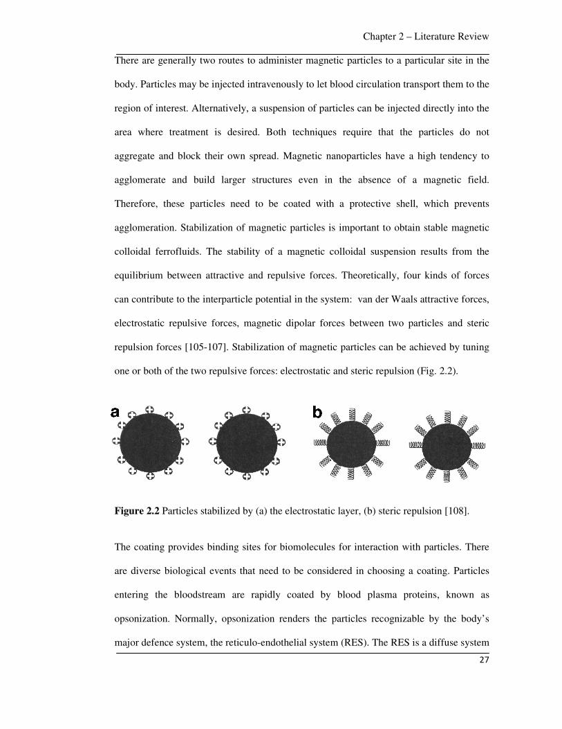
one or both of the two repulsive forces: electrostatic and steric repulsion (Fig. 2.2).
Figure 2.2 Particles stabilized by (a) the electrostatic layer, (b) steric repulsion [108].
The coating provides binding sites for biomolecules for interaction with particles. There
are diverse biological events that need to be considered in choosing a coating. Particles
entering the bloodstream are rapidly coated by blood plasma proteins, known as
opsonization. Normally, opsonization renders the particles recognizable by the body’s
major defence system, the reticulo-endothelial system (RES). The RES is a diffuse system
Chapter 2 – Literature Review
28
of specialized phagocytic cells, which can engulf inert materials associated with the
connective tissue framework of the liver, spleen and lymph nodes. The RES can remove
the opsonized particles, hence surface modification is required to ensure particles not only
non-toxic and biocompatible, but also stable to the RES. To reduce RES uptake,
nanoparticles are sterically stabilized by coating the surface with nonionic surfactants or
polymeric macromolecules [63]. This can be achieved by physical adsorption,
incorporation during the production of nanoparticles or by covalent attachment to any
reactive surface groups.
Particles with highly hydrophobic surfaces are efficiently coated with plasma components
and thus rapidly removed from circulation, whereas particles with more hydrophilic
surfaces can resist the coating process and therefore are cleared more slowly [61]. Hence
the coating should completely cover the particles and be as dense as possible to protect
the magnetic core against contact with blood protein and phagocytosis-associated
receptors. Longer polymer chains are more effective in suppressing opsonization.
In summary, the coating of magnetic nanoparticles for drug delivery should:
- stabilize nanoparticles in a biological suspension of pH around 7.4.
- reduce polydispersity.
- reduce uptake by the RES.
- provide functional groups at the surface for further derivatization.
2.2.4.1 Monomeric stabilizers
Chapter 2 – Literature Review
29
Functional groups such as carboxylates, phosphates, sulphates are known to bind to the
surface of magnetite [109].
• Carboxylates
The surface of magnetite nanoparticles can be stabilized in an aqueous dispersion by the
adsorption of citric acid [110]. Citric acid is adsorbed on the surface of the magnetite
nanoparticles by coordinating via one or two of the carboxylate functional group, leaving
at least one carboxylic acid group exposed to the solvent. This makes the surface
negatively charged. VSOP C184, an iron oxide particle stabilized by citric acid coating is
under clinical investigation [111]. Other monomeric carboxylate coatings, such as
gluconic acid [112], dimercaptosuccinic acid [113], and phosphorylcholine [114] have
also been used for the stabilization of iron oxide in aqueous medium. The stability range
is strongly dependent on pH and the concentration of adsorbed acids.
• Phosphates
Several researchers have studied the possibility of using alkanephosphonic acid as
efficient binding ligands on the surface of Fe2O3 nanoparticles and as stabilizer for
particle dispersion in organic solvents [115, 116]. Sahoo et al reported that alkyl
phosphonates and phosphates could be used for obtaining thermodynamically stable
dispersions of magnetic ferrite nanoparticles [109]. Superparamagnetic nanosized
magnetite particles have also been prepared by controlled coprecipitation from solution
containing Fe2+ and Fe3+ ions in the presence of highly hydrophilic poly(vinylalcohol
phosphate) (PVAP) [64].

Chapter 2 – Literature Review
30
2.2.4.2 Inorganic stabilizers
Magnetic nanoparticles can be coated with silica [117, 118], gold [119, 120] and
gadolinium(III) [121]. These coatings not only provide stability to the nanoparticles in
solution but also help in the binding of various biological ligands to the nanoparticle
surface.
• Silica
Silica coating on the surfaces of magnetite nanoparticles reduces aggregation in the
liquid, improves chemical stability and provides better protection against toxicity [122].
This coating stabilizes the magnetite nanoparticles by (a) shielding the magnetic dipole
interactions and (b) since silica nanoparticles are negatively charged, this coating
enhances the Coulombic repulsion of the magnetic nanoparticles [123]. Ferumoxsil
(AMI-121) composed of iron oxide particles coated with a layer of inert silicon ([3-(2-
amino-ethylamino)propyl]trimethoxysilane) has been tested in clinical trials by oral
administration [124]. Various approaches have been explored to generate magnetic silica
nanospheres. The Stober process involves hydrolysis and condensation of a sol-gel
precursor e.g., tetraethyl orthosilicate (TEOS), by this process silica colloids loaded with
superparamagnetic iron oxide nanoparticles have been prepared [125]. Another method is
based on the deposition of silica from silicic acid solution, this method is easy to perform,
more efficient in covering a higher proportion of the magnetite surface than the TEOS
method, the particle size can also be controlled by changing the ratio of SiO2/Fe3O4 [126].
Another synthesis method is an emulsion method, in which micelles or reverse micelles
are used to confine and control the silica coating. Yang et al prepared monodisperse silica
coated superparamagnetic iron oxide nanoparticles by the emulsion method and
Chapter 2 – Literature Review
31
demonstrated entrapment of biological macromolecules in the pore of the nanoparticles
[127]. Tartaj et al synthesized submicron size silica coated magnetic spheres by the
pyrolysis method [118]. The advantage of having surface enriched in silica is the presence
of surface silanol (–Si–OH) groups, which can easily react with various coupling agents
to covalently attach specific ligands to these magnetic particles. For example, amine
groups have been introduced on the surface of silica coated Fe3O4 nanoparticles by
hydrolysis and condensation of an organosilane, such as aminopropyltriethoxysilane, on
the surfaces of Fe3O4 nanoparticles [128].
• Gold
Gold is another inorganic coating, which is highly useful in imparting functionality to
magnetic nanoparticles as well as to improve their stability in aqueous dispersions [129].
Lin et al synthesized core/shell structured Fe/Au nanoparticles by a reverse micelle
approach [119]. The Au shell was used to protect the Fe core and provide further organic
functionalization. Au coated magnetite nanoparticles (60 nm) were synthesized by the
reduction of Au (III) onto the surface via iterative hydroxylamine seeding [130].
Magnetite nanoparticles were stabilized by oleic acid and gold seed nanoparticles were
covalently attached, resulting gold nanoshells [131]. It is well-known that thiols (–SH)
have high affinity to the gold surface, this property can be used in biotechnology, e.g., for
binding antigens in immunoassay [132].
2.2.4.3 Polymer stabilizers
Several approaches have been developed to coat iron oxide nanoparticles, including in-
situ coatings and post-synthesis coatings. Coating magnetic nanoparticles with natural
polymers such as carbohydrates and proteins are common [133-137]. Many natural

Chapter 2 – Literature Review
32
polymers are biocompatible and therefore suitable for coating nanoparticles in biomedical
applications.
The most common coatings are dextran, carboxymethylated dextran, carboxydextran,
starch, chitosan, polyacrylic acid, polyethylene glycol (PEG), polyvinyl alcohol (PVA)
[23]. The most common natural or synthetic organic polymers shells are described in
Table 2.1.
Table 2.1 Some useful polymers to coat nanoparticles for biomedical applications [18].
Polymers Applications Polyethylene glycol (PEG) Improves biocompatibility, blood circulation
time and internalization efficiency Dextran Enhances circulation time, stabilizes
colloidal solution Polyvinylpyrrolidone (PVP) Enhances circulation time, stabilizes
colloidal solution Fatty acids Colloidal stability, functional carboxyl
groups Polyvinyl alcohol (PVA) Prevents coagulation of monodisperse
particles Polyacrylic acid Increases stability and biocompatibility,
helps bioadhesion Polypeptides Useful in cell biology, e.g,. cell targeting Poly (D,L-lactide) Biocompatible, low toxicity Poly (N-isopropylacryl-amide) (PolyNIPAAM)
Thermosensitive drug delivery and cell separation
Chitosan Natural hydrophilic and cationic linear polymer widely used as non-viral gene delivery system, biocompatible
Gelatin Natural polymer used as gelling agent, hydrophilic emulsifier, biocompatible
• Dextran
Dextran is a polysaccharide polymer composed exclusively of R-D-glucopyranosyl units
with varying degrees of chain length and branching. Dextran has been often used as a
polymer coating mostly because of its biocompatibility [138]. The formation of
Chapter 2 – Literature Review
33
magnetite in the presence of dextran (M. Wt: 40,000) has been reported [139], dextran
was functionalized with hydroxyl groups to allow for binding of amino groups of
proteins. The same process was used for ferucarbotran and ferumoxytol with in-situ
coating of carboxydextran and carboxymethyl dextran, respectively. An important factor
in the choice of dextran is the favorable size of dextran chains, which enables optimum
polar interactions (mainly chelation and hydrogen bonding) with iron oxide surfaces.
Although single hydrogen bonds are relatively weak, the total bonding energy of
hydrogen bonds over the length of a polysaccharide molecule can be very high because of
the large number of hydroxyl groups per molecule [140]. Bautista et al described dextran
surface modification of pure superparamagnetic iron oxide nanoparticles prepared by
laser pyrolysis and co-precipitation methods [141].
• Polyethylene glycol (PEG)
PEG is a hydrophilic, water-soluble, biocompatible polymer. Several investigations have
reported the use of PEG to increase biocompatibility of iron oxide dispersions and blood
circulation times [142-145]. Superparamagnetic iron oxide nanoparticles coated with
polymerized polyethylene glycolylated bilayers were prepared [146]. Kumagai et al
reported a simple route to synthesize PEG-coated iron oxide nanoparticles by hydrolysis
of FeCl3·6H2O in water and the subsequent treatment with poly(ethylene glycol)-
poly(aspartic acid) block copolymer [147]. The PEG-coated nanoparticles revealed
excellent solubility and stability in aqueous solution as well as in physiological saline.
• Polyvinyl alcohol (PVA)
PVA is a hydrophilic, biocompatible polymer. PVA coating onto the particle surface
prevents their agglomeration, ideally resulting in monodisperse particles [148, 149]. Lee
Chapter 2 – Literature Review
34
et al modified the surface of magnetite nanoparticles with PVA by precipitation of iron
salts in PVA aqueous solution to form a stable dispersion [150]. Chastellain et al
synthesized PVA coated iron oxide nanoparticles and demonstrated colloidal stability of
the final polymer coated product [151]. The cytotoxicity and uptake of PVA coated iron
oxide nanoparticles by human melanoma cells were determined for various iron/polymer
mass ratios [65]. PVA is an synthetic polymer that can transform into a polymer gel,
which is a type of macromolecular network [152].
• Alginate
Alginate is an electrolytic polysaccharide with several carboxyl groups, the COO- of the
alginate can interact with iron ions, the resulting electrostatic repulsion can make the
superparamagnetic iron oxide nanoparticles (SPIONs)-alginate system stable. Several
researchers have reported the preparation of iron oxide nanoparticles with alginate [153-
155] : the standard chemical synthesis consists of three steps: (a) gelation of alginate and
ferrous ions, (b) in-situ precipitation of ferrous hydroxide by the alkaline treatment of
alginate and (c) oxidation of ferrous hydroxide with an oxidizing agent (O2 or H2O2).
Morales et al described the synthesis of magnetic iron oxide nanoparticles into alginate
beads with controlled size and magnetic properties for drug delivery applications [156].
• Chitosan
Chitosan is an alkaline, nontoxic, hydrophilic, biocompatible and biodegradable polymer.
The synthesis of magnetic nanoparticles encapsulated in chitosan is of great interest [157,
158]. Kim et al synthesized superparamagnetic iron oxide nanoparticles (SPIONs) by a
sonochemical method and dispersed them in chitosan with oleic acid as a surfactant [159].
Microspheres composed of SPIONs and chitosan were reported as a novel MRI detectable

Chapter 2 – Literature Review
35
embolic material [160], the SPION-chitosan microspheres showed a strong enhancement
of MRI contrast.
Other different polymers that have been used for coating of magnetic nanoparticles
include poly-L-lactic acid (PLA) [161], polymethacrylic acid [162], polyvinylpyrrolidone
(PVP) [163] and polyacrylic acid (PAA) [164].
2.3 Synthesis of magnetic nanoparticles
Numerous chemical methods such as co-precipitation, microemulsion, sol-gel method,
polyol method, hydrolysis and thermolysis of precursors can be used to synthesize
magnetic nanoparticles for biomedical applications. The synthesis of superparamagnetic
nanoparticles is a complex process because of their colloidal nature. The main chemical
challenge consists of defining experimental conditions, leading to formation of
monodisperse magnetic grains of suitable size. Another critical point is to select a
reproducible process that can be industrialized without any complex purification
procedures such as ultra-centrifugation, size exclusion chromatography, magnetic
filtration or flow field gradient. Some common methods to prepare particles with
homogeneous composition and narrow size distribution are discussed below.
2.3.1 Precipitation from solution
There are many different synthesis methods for magnetic nanoparticles of uniform size
and shape. For drug delivery applications, it is generally desired to synthesize magnetic
nanoparticles having a narrow size distribution. The most common approach is solution
chemistry, wet chemical routes are considered simpler, more tractable, and more efficient,
with appreciable control over size and composition of the nanoparticles compared to
physical methods such as gas phase deposition or electron beam lithography.

Chapter 2 – Literature Review
36
Uniform particles are usually prepared via homogeneous precipitation reactions [165].
Figure 2.3 shows a schematic diagram of the different mechanisms proposed to explain
the formation of uniform particles. In homogeneous precipitation, first a single burst of
nucleation occurs when the concentration of constituent species reaches critical
supersaturation. These nuclei formed are allowed to grow uniformly by diffusion of
solutes from the solution. To achieve monodispersity, these two stages must be separated
and nucleation should be avoided during the period of growth. This is the classical model
proposed by LaMer and Dinegar [166] to explain the mechanism of formation of sulfur
colloids (curve I of Fig. 2.3). However, uniform particles have been obtained after
multiple nucleation events via a self-sharpening growth process (Ostwald ripening, curve
III of Fig. 2.3) [167]. In addition, uniform particles have also been obtained as a result of
aggregation of much smaller subunits rather than continuous growth by diffusion (curve
II of Fig. 2.3) [168-170]. An artificial separation between nucleation and growth
processes may be achieved by seeding, in which foreign particles are introduced into the
solution of monomers below the critical supersaturation [165].
Figure 2.3 Mechanism of formation of uniform particles in solution: curve I: single
nucleation and uniform growth by diffusion (classical model of LaMer and Dinegar);
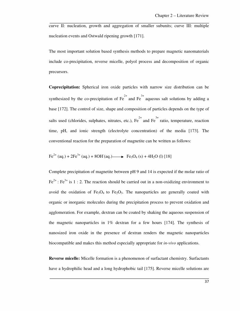
Chapter 2 – Literature Review
37
curve II: nucleation, growth and aggregation of smaller subunits; curve III: multiple
nucleation events and Ostwald ripening growth [171].
The most important solution based synthesis methods to prepare magnetic nanomaterials
include co-precipitation, reverse micelle, polyol process and decomposition of organic
precursors.
Coprecipitation: Spherical iron oxide particles with narrow size distribution can be
synthesized by the co-precipitation of Fe2+
and Fe3+
aqueous salt solutions by adding a
base [172]. The control of size, shape and composition of particles depends on the type of
salts used (chlorides, sulphates, nitrates, etc.), Fe2+
and Fe3+
ratio, temperature, reaction
time, pH, and ionic strength (electrolyte concentration) of the media [173]. The
conventional reaction for the preparation of magnetite can be written as follows:
Fe2+ (aq.) + 2Fe3+ (aq.) + 8OH-(aq.) Fe3O4 (s) + 4H2O (l) [18]
Complete precipitation of magnetite between pH 9 and 14 is expected if the molar ratio of
Fe2+ : Fe3+ is 1 : 2. The reaction should be carried out in a non-oxidizing environment to
avoid the oxidation of Fe3O4 to Fe2O3. The nanoparticles are generally coated with
organic or inorganic molecules during the precipitation process to prevent oxidation and
agglomeration. For example, dextran can be coated by shaking the aqueous suspension of
the magnetic nanoparticles in 1% dextran for a few hours [174]. The synthesis of
nanosized iron oxide in the presence of dextran renders the magnetic nanoparticles
biocompatible and makes this method especially appropriate for in-vivo applications.
Reverse micelle: Micelle formation is a phenomenon of surfactant chemistry. Surfactants
have a hydrophilic head and a long hydrophobic tail [175]. Reverse micelle solutions are
Chapter 2 – Literature Review
38
clear, isotropic liquid mixtures of oil, water and surfactants, which are rendered
thermodynamically stable by the presence of a surfactant. In this system, surfactant
molecules are dispersed in a continuous oil phase and microdroplets of aqueous phase are
trapped within assemblies of surfactants. The surfactant stabilized microcavities (10 nm)
provide a confinement effect, which limits particle nucleation, growth, and agglomeration
[176]. This technique is a versatile and simple method to prepare nanosized particles,
which are useful for both in-vivo and in-vitro applications [177-182]. Magnetic particles
with average sizes of 4-12 nm were synthesized using microemulsions of ferrous dodecyl
sulphate, the particle size could be controlled by the surfactant concentration and
temperature [183]. Ultrafine magnetite nanoparticles (4 nm) were prepared by the
reaction of aqueous FeCl2 and FeCl3 solutions with ammonium hydroxide within reverse
micelle nanocavities using AOT as surfactant and heptane as the oil phase [184].
Carpenter et al [185] prepared metallic iron particles coated with a thin layer of gold by
the reverse micelle reaction using cetyltrimethylammonium bromide (CTAB) as the
surfactant, octane as the oil phase, and aqueous reactants of iron salts and sodium
borohydride. The sequential synthesis by reverse micelles is utilized to prepare an iron
core by the reduction of ferrous sulphate with sodium borohydride, the shell layer is then
formed using an aqueous hydrogen tetrachloroaurate solution in the presence of excess
sodium borohydride. The particle size can be controlled by the micelle size.
Polyols: Liquid polyol is used as a solvent of metallic precursor, reducing agent and in
some cases as a complexing agent for the metallic cations [165]. The reaction involves
reducing metallic salts directly to metals by a polyol. The solution of metal precursors in
polyol is stirred and heated at a fixed temperature. Metal particles with well-defined
shape and size can be obtained by controlling the precipitation kinetics. This method was
first employed to synthesize noble metals such as Ru, Pd, Pt, Au, and other metals such as

Chapter 2 – Literature Review
39
Co, Ni or Cu [186, 187]. Iron particles (100 nm) can be prepared by the
disproportionation reaction of ferrous hydroxide in organic media [187]. FeCl2 and NaOH
react in ethylene glycol (EG) or polyethylene glycol (PEG), the precipitation occurs at
temperature of 80–100˚C. Iron alloys can also be prepared by co-precipitation of Fe, Ni,
and/or Co in EG and PEG [188, 189].
High-temperature decomposition of organic precursors: The decomposition of iron
precursors at high temperatures results in magnetic iron oxide nanoparticles with a narrow
size distribution and crystallinity, e.g., Alivisatos et al synthesized nanocrystals (4-10 nm)
of maghemite by adding solutions of FeCup3 (Cup: N-nitrosophenylhydroxylamine) in
octylamine into long chain amines at 250–300˚C [190]. Hyeon et al synthesized
monodisperse maghemite nanoparticles (13 nm) by addition of Fe(CO)5 to a mixed
solution of surfactant and oxidant (trimethylamine oxide) [191]. Sun et al prepared
monodispersed magnetite nanoparticles (3-20 nm) by high-temperature (265˚C)
decomposition of iron (III) acetylacetonate in phenyl ether in the presence of alcohol,
oleic acid, and oleylamine [192].
Other solution techniques: Ferritin consists of a central core of hydrated iron (III) oxide
encapsulated with a protein shell [193]. Mann et al reported the synthesis of
magnetite/maghemite nanoparticles (6–7 nm) by oxidation of ferritin with
trimethylamino-N-oxide [194]. Another method is the use of dendrimers as templating
hosts for the production of iron ferrite nanoparticles [195]. Carboxylated polyamidoamine
PAMAM dendrimers (generation 4.5) were utilized for the synthesis and stabilization of
ferrimagnetic iron oxide nanoparticles. Other solution techniques for the preparation of
magnetite and maghemite nanoparticles include sonochemical-assisted synthesis [196-
198] and electrochemical methods [199].
Chapter 2 – Literature Review
40
2.3.2 Chemical vapour condensation (CVC)
Spray pyrolysis and laser pyrolysis have been employed to synthesize large quantities of
homogeneous magnetic nanoparticles. These methods allow for continuous operation.
Spray pyrolysis: In spray pyrolysis, a metal precursor solution is fed into a rotating
furnace through a nozzle. The solvent evaporates and the metal precursor decomposes to
metal oxide powders [200]. This method is useful to prepare uniformly dispersed particles
with well-defined shape and size. It was reported that Fe3+ is partially reduced to a
mixture of Fe2+ and Fe3+ in the presence of organic reducing agents resulting in the
formation of magnetite, which is oxidized to maghemite. [201].
Laser pyrolysis: In this process, a carbon dioxide laser is used to heat up a mixture of
gases, which initiates the chemical reaction. Pure, crystalline γ-Fe2O3 nanoparticles (5
nm) with narrow size distribution have been prepared using Fe(CO)5 (iron pentacarbonyl)
as a precursor together with ethylene [202]. As Fe(CO)5 does not absorb the laser
radiation, ethylene is used to absorb the radiation and heat the iron pentacarbonyl, which
is decomposed to iron oxide.
2.4 Magnetic composites
Magnetic composites consisting of superparamagnetic nanoparticles dispersed in
diamagnetic matrices are used for in-vivo applications. The diamagnetic matrices provide
functionality and biocompatibility. The synthesis procedures of superparamagnetic
composites are as follows:
Chapter 2 – Literature Review
41
2.4.1 Magnetic nanoparticles encapsulated in polymer matrices
Encapsulation of magnetic particles in polymers results in enhanced compatibility with
biological entities compared to bare particles [203]. The coating also reduces
susceptibility to leaching and protects particle surfaces from oxidation. Therefore,
encapsulation improves dispersibility, chemical stability and reduced toxicity [204].
Polymer coated magnetite nanoparticles were synthesized by seed precipitation
polymerization of methacrylic acid and hydroxyethyl methacrylate in the presence of the
magnetite nanoparticles [205]. Sometimes cross-linking of polymers is used to
encapsulate magnetic nanoparticles. When magnetite is dispersed in aqueous albumin
[206], or chitosan [207], or PVA [208], and a cross-linker is added, a polydispersed
magnetic latex (0.3 microns) with 24 wt% magnetite content is formed [206]. Reverse
emulsion polymerization technique can also be used for the preparation of
superparamagnetic latex [209]. In this process, a ‘double-hydrophilic’ diblock copolymer
is used to precipitate magnetic iron oxide. This diblock copolymer sterically stabilizes
superparamagnetic iron oxide. An inverse emulsion, comprising of magnetic particles and
monomer in decane with a little concentration of diblock copolymer, is ultrasonicated and
magnetic latex is formed after subsequent polymerization. Superparamagnetic magnetite
core and polymeric shell in a inverse microemulsion was synthesized by Chu et al [210].
The copolymerization of methacrylic acid, hydroxyethyl methacrylate and cross-linker in
microemulsion resulted a stable hydrophilic polymeric shell around the magnetic
nanoparticles. The particle size is governed by the monomer concentration and
water/surfactant ratio.

Chapter 2 – Literature Review
42
2.4.2 Magnetic nanoparticles encapsulated in inorganic matrices
Superparamagnetic composites in inorganic matrices, e.g., silica as dispersion media,
have been reported [181, 211, 212]. The advantage of using silica is that the presence of
surface silanol groups reacts with alcohols and silane coupling agents to produce
dispersions that are stable in non-aqueous solvents [213]. In addition, the silica surface
provides stability in suspensions even with a high volume fraction of particles [214].
Silica coated γ-Fe2O3 hollow spherical particles (150 nm) were synthesized by the aerosol
pyrolysis of methanol solutions containing iron ammonium citrate and tetraethoxysilane
(TEOS) [215]. Rapid evaporation of methanol favours the surface precipitation of iron
oxide [200]. The low solubility of iron ammonium citrate in methanol compared to TEOS
promotes the initial precipitation of the iron salt solid shell. The continuous shrinkage of
this iron salt solid shell facilitates enrichment of the silicon oxide precursor (TEOS) at the
surface. The thermal decomposition of the precursor results in the formation of silica
coated γ-Fe2O3 hollow spheres. The reverse micelle method has also been used for the
synthesis of silica coated iron oxide nanoparticles [216]. Non-ionic surfactants (Triton X-
100, Igepal CO-520 and Brij-97) were used to form microemulsions in which
superparamagnetic iron oxide nanoparticles were formed by the co-precipitation reaction
of ferrous and ferric ions with inorganic bases (NaOH or NH4OH).
2.5 Innovative aspects of the current work
From the literature survey, it is evident that the potential application of magnetic
nanoparticles in cancer therapy is enormous. Although there is a significant progress in
the development of different magnetic drug carrier systems, so far studies of the
conditions under which magnetic targeting is feasible have been mostly empirical. Hence,
Chapter 2 – Literature Review
43
the current work was undertaken with the aim of synthesis, characterization and property
evaluation of MCP with an experimental and modelling study of the efficacy with which
these particles can be retained in the tumor.
1. Most of the prior work on gold coated iron (Fe@Au) nanoparticles mainly focused on
structural, optical, photothermal and magnetic properties, no drug loading and release
studies were conducted. In this work, the anti-cancer drug DOX was attached to
Fe@Au nanoparticles. The binding of DOX with the gold coating was studied, which
was due to the interaction of amine (–NH2) group of DOX with the Au shell. DOX
loading and release profiles of Fe@Au nanoparticles were also studied. Up to 94% of
DOX was loaded and 25% of adsorbed DOX was released.
2. Previous work on gold coated magnetic nanoparticles was focused on the
thermotherapy application due to photothermal effect of gold [217-219]. However,
their magnetic drug targeting application was not studied. The current work addressed
this topic, for the first time the in-vitro targeting of Fe@Au nanoparticles at flow rates
of the fluid comparable to that encountered in the capillary bed of tumor was studied
in this work, 86% of Fe@Au nanoparticles was captured at a field gradient of 25 T m-
1 and flow rate of 1 mm s-1.
3. Prior work on PVA coated iron oxide nanoparticles was concentrated mostly on
synthesis, characterization and functionalization studies [150, 151, 220]. Combined
drug loading, drug release and in-vitro drug targeting of this system was not studied.
The current work investigated the drug loading and release of DOX for different PVA
coated iron oxide nanoparticles as well as in-vitro experimental targeting of this
carrier system to study its feasibility to be used in magnetically targeted drug delivery.
A maximum of 45% of adsorbed drug was released from PVA-IO nanoparticles and
Chapter 2 – Literature Review
44
90% of these MCP were captured at a field gradient of 25 T m-1 and flow rate of 1 mm
s-1.
4. There is insufficient work on combined modelling and experimental magnetic drug
targeting [20, 22, 38]. The capture of MCP inside the blood vessel was modelled,
which showed that Fe3O4, Fe@Au, PVA-IO of 100 nm size can be targeted to breast
tumors and other skin tumors located in the hand, leg and neck by a typical permanent
magnet. In order to target tumors situated deep inside the body, MCP with higher
saturation magnetization, such as Fe and FeCo, or an external magnet with higher
magnetic field gradient (100 T m-1) must be chosen. MCP deposition inside the blood
vessel was also studied by simulating a time dependent CFD model, which showed
that for a given magnetic field strength and vessel diameter, efficient MCP deposition
was possible only for a certain window of flow rate. The simulations also showed that
the ferrofluid creeps along the bottom wall under the influence of magnetic field,
which can cause friction to the attached drug; therefore, drug injection should be as
close as possible to the tumor site.
Chapter 3 – Experimental Procedures and Model Development
45
Chapter 3
Experimental Procedures and Model Development
This chapter describes the experimental procedures for the synthesis, characterization,
property evaluation of uncoated as well as gold coated iron (Fe@Au) and PVA coated
iron oxide (PVA-IO) MCP used in the current work. In-vitro drug loading, drug release
and magnetic drug targeting procedures are also described. A model is presented to
predict the transport and capture of MCP by an external magnet.
3.1 Synthesis of gold coated iron (Fe@Au) MCP
Fe@Au nanoparticles were synthesized by the reverse micelle technique. Reagents used
for the synthesis of Fe@Au nanoparticles were cetyltrimethylammonium bromide
(CTAB) (C19H42BrN, Acros Organics), iron (II) sulphate heptahydrate (FeSO4.7H2O,
Fischer Chemicals), hydrogen tetrachloroaurate (HAuCl4), sodium borohydride (NaBH4,
Fluka Chemical), octane (C8H18, Aldrich) and n-butanol (C4H10O, Aldrich). In this
reaction, CTAB was used as surfactant, n-butanol as co-surfactant and octane as oil
phase.
The synthesis reaction was performed in an oxygen free glove box in two steps, in each
step predetermined amount of aqueous reactants were mixed with CTAB, n-butanol and
octane to form the reverse micelle solution. The procedure and the quantity of
components used for the synthesis are schematically presented in Fig. 3.1.

Chapter 3 – Experimental Procedures and Model Development
46
Figure 3.1 Schematic diagram showing a typical procedure for formation of Fe@Au
MCP by the reverse micelle technique. FeSO4 and HAuCl4 are reduced by NaBH4, CTAB
is surfactant, 1-butanol is co-surfactant and octane is oil phase.

Chapter 3 – Experimental Procedures and Model Development
47
In a typical experiment, 0.333 g FeSO4 was dissolved in 2.4 ml deionised water in a
beaker and 6 g CTAB, 5 g 1-butanol and 15 g octane were added to it. In another beaker,
0.9 g NaBH4 was dissolved in 2.4 ml water and mixed with 6 g CTAB, 5 g 1-butanol and
15 g octane. Micellar solutions containing FeSO4 and NaBH4 were mixed together under
stirring, color change from pale green to black was observed. NaBH4 reduces FeSO4
resulting in the formation of iron core. Once the iron nanoparticles formed, a micellar
solution containing 0.0245 (M) HAuCl4 (aq), 3 g CTAB, 2.5 g 1-butanol and 15 g octane
was added followed by the addition of a micellar solution of NaBH4 (aq). Au (III) is
reduced to Au (0) by NaBH4 and gold forms a coating on the outer surface of the iron
particles [74]. The volume of HAuCl4 was varied to alter the thickness of gold coating.
The synthesized nanoparticles were washed with 1:1 methanol/water mixture and dried
under vacuum and stored, the resulting powder was black. Following the above synthesis
procedure, three sample sets were prepared by varying the concentration of gold (Table
3.1). Increasing the gold concentration beyond the range studied in this work resulted in
very low saturation magnetization (Ms), hence they were not examined further.
Table 3.1 Summary of sample sets synthesized by the reverse micelle technique.
Sample set S-1 S-2 S-3
mmol of Au/ mmol of Fe 0 0.102 0.204
3.2 Synthesis of PVA coated iron oxide (PVA-IO) MCP
PVA-IO nanoparticles were synthesized by co-precipitation of iron oxide at high pH,
followed by coating with PVA solution. Chemicals used for the synthesis of PVA-IO

Chapter 3 – Experimental Procedures and Model Development
48
nanoparticles were ferrous chloride tetrahydrate (FeCl2.4H2O, Aldrich), ferric chloride
hexahydrate (FeCl3.6H2O, Aldrich), sodium hydroxide (NaOH, Merck Inc.) and polyvinyl
alcohol (PVA, Fluka) with average molecular weight of 31000-50000 (99% degree of
hydrolysis). A mixed solution of ferrous and ferric ions (molar ratio 1:2) was prepared by
dissolving 0.15 mol FeCl2.4H2O and 0.3 mol FeCl3.6H2O in 30 mL water. Black iron
oxide was precipitated by adding mixed solution of ferrous and ferric ions drop by drop to
100 mL of 0.4 M NaOH solution (pH=13) while stirring at 600 rpm with an impeller and
purging with N2. The mixture was continuously purged by N2 for 20 minutes. Precipitates
were separated from the supernatant liquid by centrifugation. The precipitates were
washed with deionized water (purged with N2) by ultrasonication and then separated by
centrifugation at 5000 rpm.
For coating of iron oxide nanoparticles, aqueous PVA solutions were prepared by
dissolving dry PVA powder in deionized water at 55ºC. Iron oxide nanoparticles were
added and mixed with PVA solution by stirring with an impeller for 12 hours. PVA-IO
were separated by the use of a permanent magnet and dried in a vacuum oven for
characterization. Following the above synthesis procedure, 5 sets of samples were
prepared by varying the concentration of PVA (Table 3.2).
Table 3.2 Summary of sample sets synthesized by the co-precipitation technique.
Sample set S-4 S-5 S-6 S-7 S-8
PVA concentration (wt%) 0 0.5 1 2 5
Chapter 3 – Experimental Procedures and Model Development
49
3.3 Characterization and in-vitro tests
The synthesized Fe@Au and PVA-IO nanoparticles were characterized by transmission
electron microscopy (TEM), X-ray diffraction (XRD), vibrating sample magnetometry
(VSM), dynamic light scattering (DLS), X-ray photoelectron spectroscopy (XPS),
thermal gravimetric analysis (TGA) and Fourier transform infrared (FTIR) spectroscopy.
In-vitro targeting of these MCP, their drug loading and release studies were carried out.
3.3.1 Transmission electron microscopy
The size and morphological characterization of individual nanoparticles were performed
using a JEOL 2010 transmission electron microscope (TEM) operating at 200 kV. TEM
samples were prepared by dispersing nanoparticles in acetone for 30 min by ultrasonic
vibration. The dilute suspension was dropped on a carbon coated copper grid and dried in
vacuum.
3.3.2 X-ray diffraction
X-ray diffraction (XRD) measurements were performed on dry powder using a Shimadzu
XRD-6000 X-ray diffractometer with Cu-Kα radiation (wavelength = 0.154 nm). The
powder was packed in a glass sample holder and the XRD patterns were collected in the
2θ range of 10º to 90º with a step size of 0.02º. Phase identification was carried out by
matching peak positions and relative intensities to reference JCPDS files. The Rietveld
refinement of the XRD pattern was conducted using TOPAS (version 4.1) software.
Chapter 3 – Experimental Procedures and Model Development
50
3.3.3 Magnetic measurements
A LakeShore 7404 vibrating sample magnetometer was used to measure the magnetic
properties of the synthesized nanoparticles at room temperature in an applied magnetic
field range of 0 to 10 kOe.
3.3.4 Dynamic light scattering
Dynamic light scattering was used to measure the hydrodynamic diameters of aggregates
of magnetic nanoparticles in PBS. Dilute suspensions (< 0.2 mg.ml-1) were taken in
quartz cuvettes and investigated using a Malvern Instruments Zetasizer Nano DLS unit.
The samples were equilibrated for 5 min before each measurement.
3.3.5 X-ray photoelectron spectroscopy
X-ray photoelectron spectra were recorded using the Kratos Ultra system with a
monochromatic Al Kα X-ray source operating at 15 kV and 10 mA. The sampling area on
the specimen was typically about 700 µm by 400 µm. A step-scan interval of 1 eV was
used for wide scans, and 0.1 eV for high-resolution scans with acquisition times of 60 sec
for both resolutions.
3.3.6 Thermo gravimetric analysis
Thermo gravimetric analysis was performed to determine the polymer content of PVA-
IO nanoparticles. Powder sample was placed in a ceramic pan, heated to 600°C at a ramp
rate of 10ºC min-1 under oxygen flow in TGA Q500 thermo gravimetric analyzer. The
weight loss was measured as a function of temperature.
Chapter 3 – Experimental Procedures and Model Development
51
3.3.7 Fourier transform infrared spectra
Fourier transform infrared (FTIR) spectra were recorded by a Nicolet Magna-IR 550
spectrometer in the region of 4000-400 cm-1 with 4 cm-1 resolution. FTIR samples were
prepared by mixing and grinding nanoparticles with KBr powder followed by pelletizing.
3.3.8 Doxorubicin (DOX) drug loading and release
The water-soluble anti-cancer drug DOX was chosen as a model drug for drug loading
and release study. The DOX loading was carried out by dispersing 5 mg of Fe@Au /
PVA-IO nanoparticles in 5 mL aqueous DOX solution (drug concentration = 0.1 mg/mL)
following the experimental procedure described by Kuznetsov et al [221]. The suspension
of coated magnetic nanoparticles in DOX solution was shaken in a rotary shaker (200
rpm) for 26 h to facilitate DOX uptake. At different time intervals, the magnetic
nanoparticles were removed from DOX solution using a permanent magnet and the
optical density of particle free DOX solution was measured at 498 nm by a UV-vis
spectrophotometer [222]. After the measurements, magnetic nanoparticles were
redispersed for further DOX loading. Beyond a certain time, there was no concentration
change of DOX in the solution since the loading capacity of the particles had reached the
saturation. The drug loading capacity was determined as the difference between the initial
DOX concentration and the DOX concentration left in the supernatant. The drug loaded
magnetic nanoparticles were then magnetically separated and dried in the vacuum oven.
The drug release test was performed by dispersing the dried drug loaded nanoparticles in
5 mL PBS buffer at 37ºC. The released concentration of DOX was measured at fixed time
intervals by UV-vis spectrophotometry at 498 nm.
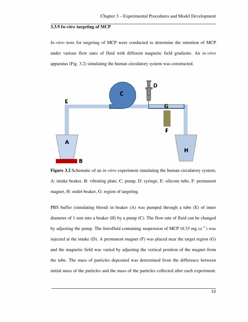
Chapter 3 – Experimental Procedures and Model Development
52
3.3.9 In-vitro targeting of MCP
In-vitro tests for targeting of MCP were conducted to determine the retention of MCP
under various flow rates of fluid with different magnetic field gradients. An in-vitro
apparatus (Fig. 3.2) simulating the human circulatory system was constructed.
Figure 3.2 Schematic of an in-vitro experiment simulating the human circulatory system;
A: intake beaker, B: vibrating plate, C: pump, D: syringe, E: silicone tube, F: permanent
magnet, H: outlet beaker, G: region of targeting.
PBS buffer (simulating blood) in beaker (A) was pumped through a tube (E) of inner
diameter of 1 mm into a beaker (H) by a pump (C). The flow rate of fluid can be changed
by adjusting the pump. The ferrofluid containing suspension of MCP (0.33 mg cc-1 ) was
injected at the intake (D). A permanent magnet (F) was placed near the target region (G)
and the magnetic field was varied by adjusting the vertical position of the magnet from
the tube. The mass of particles deposited was determined from the difference between
initial mass of the particles and the mass of the particles collected after each experiment.
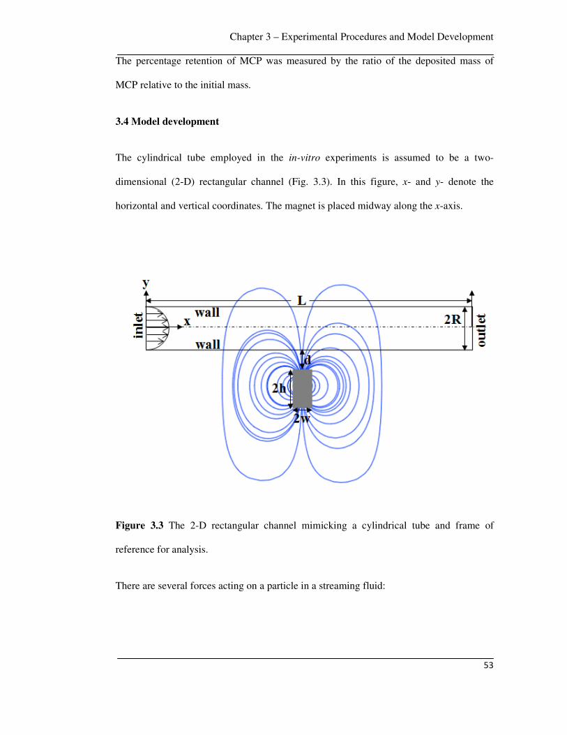
Chapter 3 – Experimental Procedures and Model Development
53
The percentage retention of MCP was measured by the ratio of the deposited mass of
MCP relative to the initial mass.
3.4 Model development
The cylindrical tube employed in the in-vitro experiments is assumed to be a two-
dimensional (2-D) rectangular channel (Fig. 3.3). In this figure, x- and y- denote the
horizontal and vertical coordinates. The magnet is placed midway along the x-axis.
Figure 3.3 The 2-D rectangular channel mimicking a cylindrical tube and frame of
reference for analysis.
There are several forces acting on a particle in a streaming fluid:
Chapter 3 – Experimental Procedures and Model Development
54
• Hydrodynamic force ( fF ): This force is generated by the pressure difference due
to the heartbeat. This force creates velocity field and defines the flow speed of
the carriers in fluid.
• Magnetic force ( magF ): This force is due to an external magnetic field, which
accelerates MCP perpendicular to the flow direction.
• Inertia forces: Normally the inertia forces are several orders of magnitude smaller
than the accelerating force and hence neglected.
• Gravitational and buoyancy forces: These forces are negligible for monodisperse
suspensions with a particle diameter smaller than 1 µm.
Therefore, the transport of MCP is predicted by balancing the dominant magnetic and
fluidic forces as [97],
0mag f+ =F F (3.1)
The magnetic force acting on a particle is determined from the following expression
[103]:
200.5mag pVM B V Hµ χ= ∇ = ∇F (3.2)
Here, 0µ is the magnetic permeability of free space, V is the volume of MCP, χ is the
magnetic susceptibility of MCP, H and B are the magnetic field strength and gradient of
the magnet.
The fluidic force is predicted using Stokes’ approximation for the drag on a sphere in a
laminar flow field [223]
Chapter 3 – Experimental Procedures and Model Development
55
( )6f p p fRπη= − −F v v (3.3)
Here, pR is the hydrodynamic size of MCP, pv is the velocity of MCP, η and fv are
the viscosity and flow rate of fluid, respectively.
3.4.1 Magnetic field
The magnetic field strength can be decomposed into components as,
( ) ( ) ( ), , ,x yH x y H x y H x y= +x y� �
(3.4)
The analytical expressions obtained for the x- and y-component of the magnetic field
strength for rectangular magnet can be expressed as follows [224]:
( )( ) ( )
( ) ( )
( ) ( )
( ) ( )
2 2 2 2
2 2 2 2, ln ln
4 2 2
sx
x w y d R x w y d RMH x y
x w y d R h x w y d R h
+ + + + − + + + = − π + + + + + − + + + +
(3.5)
( )( )
( ) ( )
( )
( ) ( )1 1
2 2 2 22 2
2 2, tan tan
2s
y
h x w h x wMH x y
x w y d R h h x w y d R h hπ− −
+ − = − + + + + + − − + + + + −
(3.6)
Here the width and the height of the rectangular magnet are 2w and height 2h,
respectively; d is the distance between the surface of the magnet and the bottom wall of
tube, R is the half-width of the channel (Fig. 3.3).
The analytical expressions for the x- and y-component of the magnetic field strength for a
cylindrical magnet having radius magR is expressed as [97]:

Chapter 3 – Experimental Procedures and Model Development
56
( )2
22 2
2( ),
2( )
s mag magx
mag
M R y d R R xH x y
y d R R x
+ + +
= + + + +
(3.7)
( )2 2 2
22 2
( ),
2( )
s mag magy
mag
M R y d R R xH x y
y d R R x
+ + + −
= + + + +
(3.8)
3.4.2 Flow velocity
The nature of the flow, whether laminar or turbulent, is determined by Reynolds number
(Re); Re = vfD , where D is the diameter of the vessel, ρ and η are the density and
viscosity of the fluid, respectively. For a dilute particle suspension (0.33 mg/cc) in a fluid
and a given vessel diameter, this Reynolds number is dependent on flow rate of fluid. In
the flow regime (up to 40 mm/s) studied in this work, the Reynolds number is 33 (i.e. Re
< 1100). Therefore, the flow was assumed to be fully developed laminar flow. Based on
these assumptions, the fluid velocity is given by
( )( )22 1 /xv v x R= − (3.9)
where v is the average velocity of fluid and R is the radius of the vessel.
The fluidic force components are
6fx p xF R vπη= − (3.10)
and
6fy p yF R vπη= − (3.11)
Chapter 3 – Experimental Procedures and Model Development
57
The viscosity of blood plasma (η = 1.2 10-3 N.s.m-2 ) was used in Eqns. 3.10 and 3.11
[225].
3.4.3 Equation of motion
The equation of motion of MCP in the vessel can be written by balancing the magnetic
and fluidic forces in component form as,
magx fxF F= and magy fyF F= (3.12)
From Eqns. 3.5 and 3.6 we obtain,
( )
( ) ( )
( ) ( )
( ) ( )
( ) ( )
2 2
2 20
2 2
2 2
ln2
,4
ln2
sx
x w y d R
x w y d R hMB x y
x w y d R
x w y d R h
µ
+ + + + + + + + + = π − + + + − − + + + +
(3.13)
( )
( )
( ) ( )
( )
( ) ( )
12 2 2
0
12 2 2
2tan
,2 2
tan
sy
h x w
x w y d R h hMB x y
h x w
x w y d R h h
µ
π
−
−
+ + + + + + − = − − − + + + + −
(3.14)
From Eqns. 3.13 and 3.14 we get,
( )
( ) ( ) ( ) ( )
( )( ) ( ) ( )( )( )
1 1
022
1 1
,
4 0.25 ln ln tan tan
ln( ) ln( ) + 4 tan tan
sB x y M
xa b c d
a b e f g q c d m n
µ
− −
− −
∂=
∂ π − + −
× − − − + − −
(3.15)
Chapter 3 – Experimental Procedures and Model Development
58
( )
( ) ( ) ( ) ( )
( )( ) ( ) ( )( )( )
1 1
022
1 1
,
4 0.25 ln ln tan tan
ln( ) ln( ) + 8 tan tan
sB x y M
ya b c d
a b i j k l c d o p
µ
− −
− −
∂=
∂ π − + −
× − − − + − −
(3.16)
where,
( ) ( )
( ) ( )
2 2
2 22
x w y d Ra
x w y d R h
+ + + +=
+ + + + +,
( ) ( )
( ) ( )
2 2
2 22
x w y d Rb
x w y d R h
− + + +=
− + + + + ,
( )
( ) ( )2 2 2
2h x wc
x w y d R h h
+=
+ + + + + − ,
( )
( ) ( )2 2 2
2h x wd
x w y d R h h
−=
− + + + + −,
( )
( ) ( )2 2
x we
x w y d R
+=
+ + + + ,
( )
( ) ( )2 22
x wf
x w y d R h
+=
+ + + + +,
( )
( ) ( )2 2
x wg
x w y d R
−=
− + + + ,
( )
( ) ( )2 22
x wq
x w y d R h
−=
− + + + +,
( )
( ) ( )2 2
y d Ri
x w y d R
+ +=
+ + + + ,
( )
( ) ( )2 2
y d Rj
x w y d R
+ +=
− + + + ,
( )
( ) ( )2 2
2
2
y d R hk
x w y d R h
+ + +=
+ + + + + ,
( )
( ) ( )2 2
2
2
y d R hl
x w y d R h
+ + +=
− + + + + ,

Chapter 3 – Experimental Procedures and Model Development
59
( ) ( )( )( ) ( )( ) ( )
2 2 2
22 2 22 24
h y d R h x w h
m
x w y d R h h h x w
+ + + − + −=
+ + + + + − + +
,
( ) ( )( )( ) ( )( ) ( )
2 2 2
22 2 22 24
h y d R h x w h
n
x w y d R h h h x w
+ + + − − −=
− + + + + − + −
,
( )( )
( ) ( )( ) ( )22 2 22 24
h y d R h x wo
x w y d R h h h x w
+ + + −=
− + + + + − + −
,
( )( )
( ) ( )( ) ( )22 2 22 24
h y d R h x wp
x w y d R h h h x w
+ + + +=
+ + + + + − + +
, (3.17)
The magnetic force can be decomposed into components as,
( ) ( ) ( ), , ,mag magx magyx y F x y F x y= +F x y� �
(3.18)
where,
magx pB
F VMx
∂=
∂ and magy p
BF VM
y
∂=
∂ (3.19)
Combining Eqns. 3.10, 3.11, 3.12 and 3.19 we get,
22
9p pM Rdy B
dt yη
∂=
∂ (3.20)
and
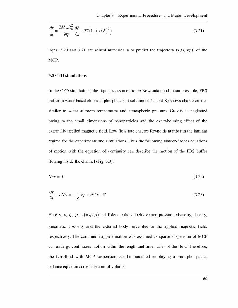
Chapter 3 – Experimental Procedures and Model Development
60
( )( )2
222 1 /
9p pM Rdx B
v x Rdt xη
∂= + −
∂ (3.21)
Eqns. 3.20 and 3.21 are solved numerically to predict the trajectory (x(t), y(t)) of the
MCP.
3.5 CFD simulations
In the CFD simulations, the liquid is assumed to be Newtonian and incompressible, PBS
buffer (a water based chloride, phosphate salt solution of Na and K) shows characteristics
similar to water at room temperature and atmospheric pressure. Gravity is neglected
owing to the small dimensions of nanoparticles and the overwhelming effect of the
externally applied magnetic field. Low flow rate ensures Reynolds number in the laminar
regime for the experiments and simulations. Thus the following Navier-Stokes equations
of motion with the equation of continuity can describe the motion of the PBS buffer
flowing inside the channel (Fig. 3.3):
0∇ =vi , (3.22)
21p v
t ρ
∂+ ∇ = − ∇ + ∇ +
∂
vv v v Fi (3.23)
Here v , p, η , ρ , ( )/v η ρ= and F denote the velocity vector, pressure, viscosity, density,
kinematic viscosity and the external body force due to the applied magnetic field,
respectively. The continuum approximation was assumed as sparse suspension of MCP
can undergo continuous motion within the length and time scales of the flow. Therefore,
the ferrofluid with MCP suspension can be modelled employing a multiple species
balance equation across the control volume:

Chapter 3 – Experimental Procedures and Model Development
61
( ) ( ) ( ). .pY Y D Yt
ρ ρ ρ∂
+ ∇ = ∇ ∇ ∂v
(3.24)
Here Y , pv and D are the mass fraction of MCP in ferrofluid, velocity of MCP and
mass diffusivity, respectively. The equations of motion, the continuity equation and the
species balance equation were solved employing the software ANSYS FLUENTTM. Mass
and volume weighted mixing law was employed to calculate η and ρ of the mixture, a
dilute-approximation with constant diffusion coefficient was employed for mass
diffusivity constant ( D ). The velocity of MCP ( magv ) due to magnetic field was
obtained by balancing hydrodynamic drag forces and magnetic forces
as / 6mag mag pRπη=v F , where pR is the size of MCP. The total velocity pv of MCP in
the species balance (Eqn. 3.24) is p mag= +v v v [103].
3.5.1 Boundary conditions
The walls in the geometries are considered to be no-slip and impermeable:
0x yv v= = (3.25)
0p
z
∂=
∂ (3.26)
In the velocity inlet boundary condition, ANSYS FLUENT uses the velocity and scalar
quantities to compute inlet mass flow rate. The mass flow rate entering a fluid cell
adjacent to a velocity inlet boundary is computed as,
∫ ⋅= dAvm�
� ρ . (3.27)
Chapter 3 – Experimental Procedures and Model Development
62
The inlet flow was modelled as a fully developed parabolic profile
( )( )22 1 /xv v x R = −
where the average velocity ( v ) was incorporated from the range
of flow rates used in the experiments (1.5 mm. s-1 to 40 mm. s-1). The typical inlet MCP
concentration (0.33 mg cc-1) was also obtained from the experiments. At the channel exit,
the ‘pressure outlet’ boundary condition was used in simulations.
3.5.2 Magnetic force field
The magnetic field imposed by the permanent magnet was modelled as a source term to
the momentum equation. In this study, rectangular and cylindrical magnets were
considered to study the influence of the magnet shape on the deposition of MCP. It was
assumed that at any instant the magnetic force per unit volume is magn=F F where n is
the number of MCP present per unit volume of PBS. The magnetic force ( magF ) acting
on each particle was calculated from Eqn. 3.2.
3.5.3 Grid generation and solution methodology
In the pre-processing stage the grid was prepared using commercial software GAMBIT.
The equations of motion, continuity equation and the species balance equation together
with the boundary conditions were solved employing the commercial software ANSYS
FLUENTTM. Fluent uses a control-volume based technique to convert the governing
equations to algebraic equations, which are again solved numerically in time. This control
volume technique consists of integrating the governing equations about each control
volume, yielding discrete equations that conserve each quantity on a control-volume
basis. The co-located scheme used by ANSYS FLUENT solver stores both pressure and
velocity at cell centers. The default ‘standard’ interpolation scheme was used, which

Chapter 3 – Experimental Procedures and Model Development
63
interpolates the pressure values at the faces using momentum equation coefficients. The
momentum and species equations were solved employing the ‘first order upwind’
discretization scheme. The unsteady solver was used for time marching over a period
after ensuring a converged solution at each time step. The results obtained are grid
independent.

Chapter 4 – Results and Discussion
64
Chapter 4
Results and Discussion
This chapter describes the results and discussion of the synthesis, characterization, in-
vitro tests and modelling of MCP targeting. Comparison of the current work to selected
reports from literature is also presented.
4.1 Gold coated iron (Fe@Au) MCP system
Here structural, morphological and magnetic properties of Fe@Au nanoparticles are
presented. The particles were characterized by XRD, TEM, XPS and VSM. DOX loading
and release studies as well as in-vitro targeting of Fe@Au MCP under physiologically
relevant flow speeds of fluid are also presented.
4.1.1 Physical properties
Representative powder X-ray diffraction patterns of reverse micelle synthesized Fe@Au
nanoparticles are presented in Fig. 4.1.

Chapter 4 – Results and Discussion
65
Figure 4.1 X-ray diffraction pattern of (a) S-1 (uncoated), (b) S-2 (0.102 mmol gold
coated iron nanoparticles) and (c) S-3 (0.204 mmol gold coated iron nanoparticles). The
uncoated particles are oxidized to iron oxide whereas in gold coated particles, iron peaks
overlap with gold peaks.
The X-ray diffraction pattern of S-1 shows peaks corresponding to the magnetite (Fe3O4)
phase. As there was no coating of gold in S-1, iron was oxidized to form iron oxide
(Fe3O4). For sample sets S-2 and S-3, peaks corresponding to gold were observed at 2θ =
38.1º, 44.4º, 64.6º, 77.6º and 81.8º. In sample sets S-2 and S-3, the peaks of α-iron were
overlapped with the peaks of gold at 2θ = 44.4º, 64.6º and 81.8º, consistent with previous
reports [119, 226]. The Rietveld refinement of corresponding powder diffraction pattern
was performed and it was found that 83 atomic % Fe, 17 atomic % Au and 49.5 atomic
% Fe, 50.5 atomic % Au were present in S-2 and S-3, respectively. Figure 4.2 shows the
selected area electron diffraction (SAED) pattern of S-3 obtained from transmission
10 20 30 40 50 60 70 80 90
(222)Au
(211)Fe(c)
(b)
Fe3O4Fe3O4Fe3O4Fe3O4
Fe & AuFe & Au
Fe & Au
Au
Au
(311)Au
(220)Au
(200)Fe
Inte
nsity (
a.u
)
2θ (degree)
(111)Au
(200)Au
(110)Fe
Fe3O4(a)

Chapter 4 – Results and Discussion
66
electron microscopy. The diffraction rings were indexed and it was observed that gold
200, 220, 222 peaks overlapped with iron 110, 200, 211 peaks (Fig. 4.2).
Figure 4.2 Selected area electron diffraction (SAED) pattern of S-3 (0.204 mmol gold
coated iron nanoparticles). Gold 200, 220, 222 diffraction peaks overlap with iron 110,
200, 211 peaks.
The EDX spectrum of S-3 generated with an electron nanoprobe (~20 nm in diameter)
revealed both iron and gold peaks (Fig. 4.3). No oxygen peak was found, suggesting that
there was negligible oxidation of iron. The peaks corresponding to carbon and copper
were from the sample holder.
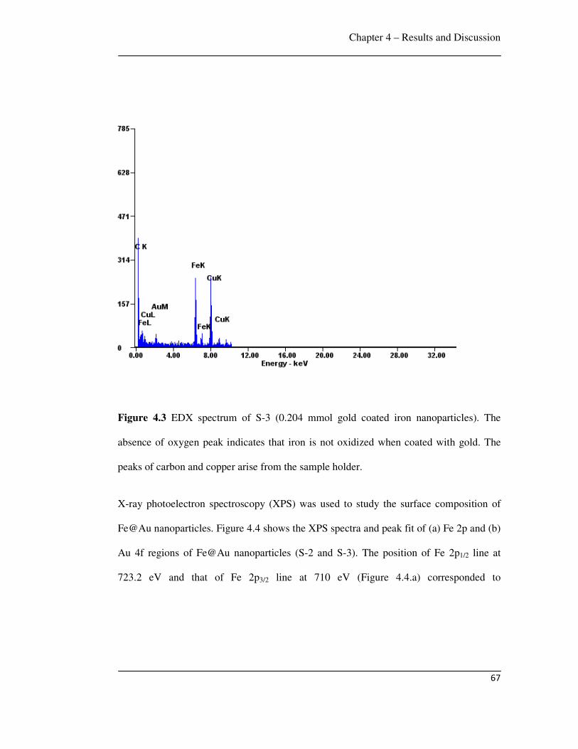
Chapter 4 – Results and Discussion
67
Figure 4.3 EDX spectrum of S-3 (0.204 mmol gold coated iron nanoparticles). The
absence of oxygen peak indicates that iron is not oxidized when coated with gold. The
peaks of carbon and copper arise from the sample holder.
X-ray photoelectron spectroscopy (XPS) was used to study the surface composition of
Fe@Au nanoparticles. Figure 4.4 shows the XPS spectra and peak fit of (a) Fe 2p and (b)
Au 4f regions of Fe@Au nanoparticles (S-2 and S-3). The position of Fe 2p1/2 line at
723.2 eV and that of Fe 2p3/2 line at 710 eV (Figure 4.4.a) corresponded to
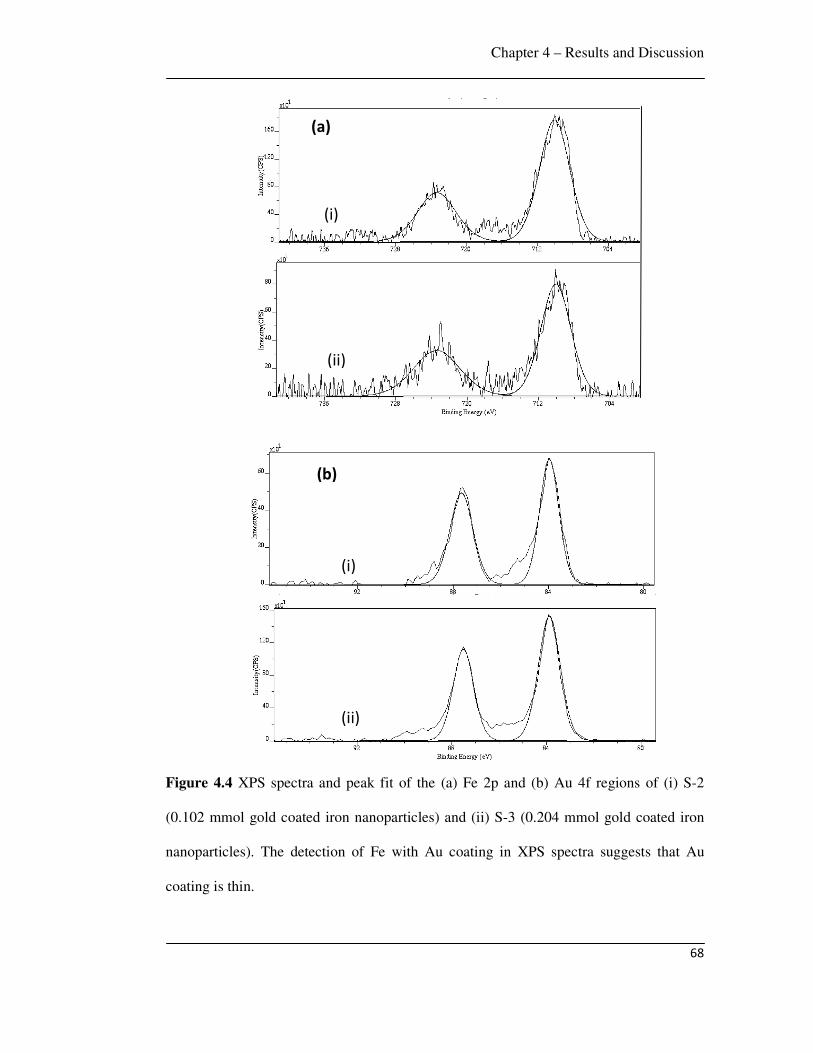
Chapter 4 – Results and Discussion
68
Figure 4.4 XPS spectra and peak fit of the (a) Fe 2p and (b) Au 4f regions of (i) S-2
(0.102 mmol gold coated iron nanoparticles) and (ii) S-3 (0.204 mmol gold coated iron
nanoparticles). The detection of Fe with Au coating in XPS spectra suggests that Au
coating is thin.
(b)
(ii)
(i)
(a)
(i)
(ii)

Chapter 4 – Results and Discussion
69
(b)
the Fe (0) state [227] in both the gold coated samples. Analysis of XPS spectra revealed
that the surface elemental atomic ratio of gold to iron increased from S-2 to S-3 with
increasing gold concentration. The detection of Fe with Au coating in XPS spectra
suggests that the gold coating thickness is less than 5 nm [228].
The size and morphology of individual particles were observed in the TEM micrographs
(Fig. 4.5). It was observed that the particles were equiaxed for both coated and uncoated
samples. The average size of uncoated particles was 10 nm (SD 1), gold coated iron
nanoparticles particles had an average size of 15 nm (SD 5). The corresponding size
distribution of S-1 and S-3 are shown in Fig. 4.5 c and Fig. 4.5 d, respectively.
Figure 4.5 TEM micrographs of (a) S-1 (uncoated) and (b) S-3 (0.204 mmol gold coated
iron nanoparticles). The corresponding size distribution of (c) S-1 (uncoated) and (d) S-3
(0.204 mmol gold coated iron nanoparticles).
20 nm
(a)
10 nm
(c)
(d)
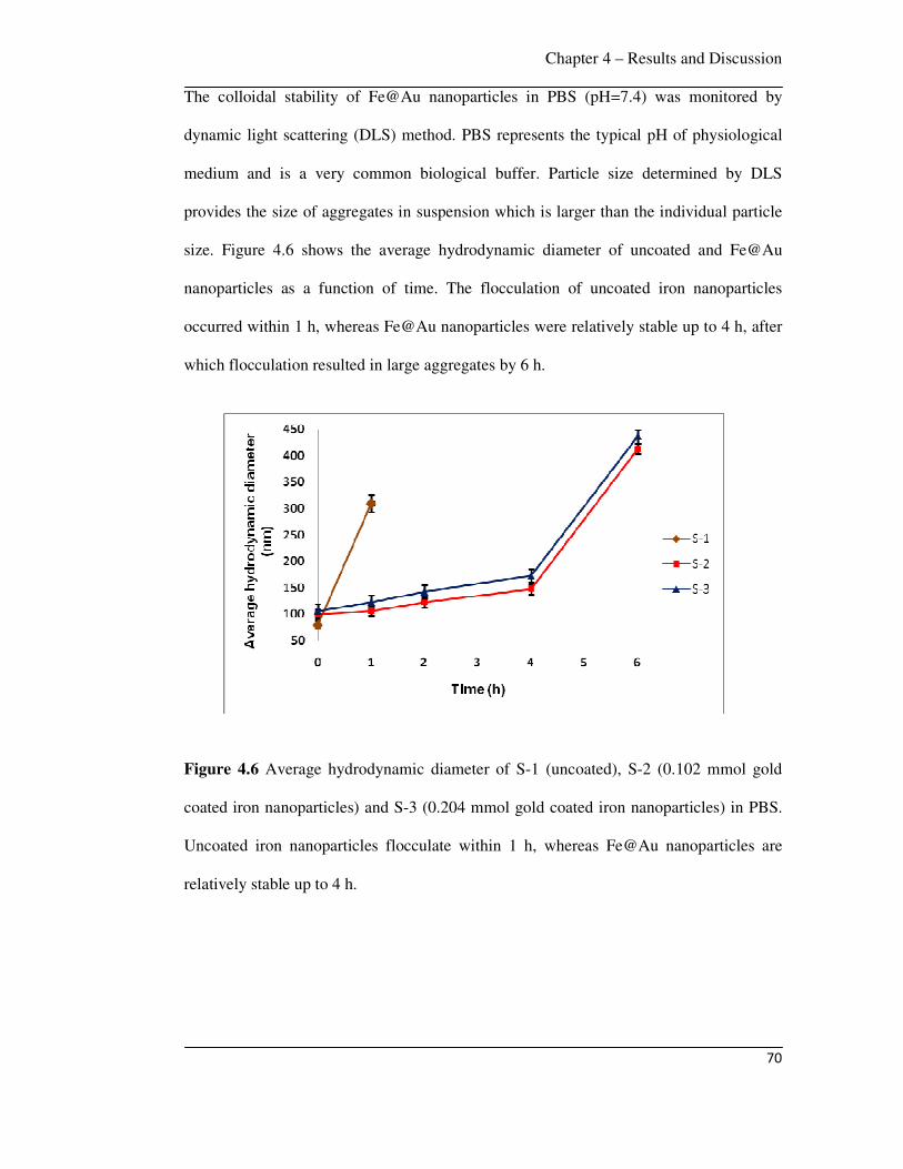
Chapter 4 – Results and Discussion
70
The colloidal stability of Fe@Au nanoparticles in PBS (pH=7.4) was monitored by
dynamic light scattering (DLS) method. PBS represents the typical pH of physiological
medium and is a very common biological buffer. Particle size determined by DLS
provides the size of aggregates in suspension which is larger than the individual particle
size. Figure 4.6 shows the average hydrodynamic diameter of uncoated and Fe@Au
nanoparticles as a function of time. The flocculation of uncoated iron nanoparticles
occurred within 1 h, whereas Fe@Au nanoparticles were relatively stable up to 4 h, after
which flocculation resulted in large aggregates by 6 h.
Figure 4.6 Average hydrodynamic diameter of S-1 (uncoated), S-2 (0.102 mmol gold
coated iron nanoparticles) and S-3 (0.204 mmol gold coated iron nanoparticles) in PBS.
Uncoated iron nanoparticles flocculate within 1 h, whereas Fe@Au nanoparticles are
relatively stable up to 4 h.
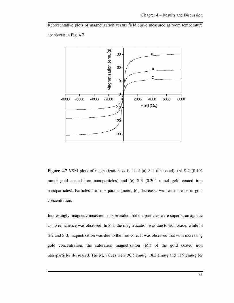
Chapter 4 – Results and Discussion
71
-8000 -6000 -4000 -2000 0 2000 4000 6000 8000
-30
-20
-10
0
10
20
30
Ma
gn
etisa
tio
n (
em
u/g
)Field (Oe)
a
b
c
Representative plots of magnetization versus field curve measured at room temperature
are shown in Fig. 4.7.
Figure 4.7 VSM plots of magnetization vs field of (a) S-1 (uncoated), (b) S-2 (0.102
mmol gold coated iron nanoparticles) and (c) S-3 (0.204 mmol gold coated iron
nanoparticles). Particles are superparamagnetic, Ms decreases with an increase in gold
concentration.
Interestingly, magnetic measurements revealed that the particles were superparamagnetic
as no remanence was observed. In S-1, the magnetization was due to iron oxide, while in
S-2 and S-3, magnetization was due to the iron core. It was observed that with increasing
gold concentration, the saturation magnetization (Ms) of the gold coated iron
nanoparticles decreased. The Ms values were 30.5 emu/g, 18.2 emu/g and 11.9 emu/g for
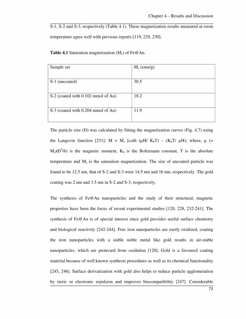
Chapter 4 – Results and Discussion
72
S-1, S-2 and S-3, respectively (Table 4.1). These magnetization results measured at room
temperature agree well with previous reports [119, 229, 230].
Table 4.1 Saturation magnetization (Ms) of Fe@Au.
Sample set Ms (emu/g)
S-1 (uncoated) 30.5
S-2 (coated with 0.102 mmol of Au) 18.2
S-3 (coated with 0.204 mmol of Au) 11.9
The particle size (D) was calculated by fitting the magnetization curves (Fig. 4.7) using
the Langevin function [231]: M = Ms [coth (µH/ KbT) – (KbT/ µH); where, µ (=
MsπD3/6) is the magnetic moment, Kb is the Boltzmann constant, T is the absolute
temperature and Ms is the saturation magnetization. The size of uncoated particle was
found to be 12.5 nm, that of S-2 and S-3 were 14.5 nm and 16 nm, respectively. The gold
coating was 2 nm and 3.5 nm in S-2 and S-3, respectively.
The synthesis of Fe@Au nanoparticles and the study of their structural, magnetic
properties have been the focus of recent experimental studies [120, 228, 232-241]. The
synthesis of Fe@Au is of special interest since gold provides useful surface chemistry
and biological reactivity [242-244]. Free iron nanoparticles are easily oxidized, coating
the iron nanoparticles with a stable noble metal like gold results in air-stable
nanoparticles, which are protected from oxidation [120]. Gold is a favoured coating
material because of well known synthesis procedures as well as its chemical functionality
[245, 246]. Surface derivatization with gold also helps to reduce particle agglomeration
by steric or electronic repulsion and improves biocompatibility [247]. Considerable
Chapter 4 – Results and Discussion
73
interest has been directed towards the functionalization of gold nanoparticles by the use
of thiol chemistry, which facilitates the attachment of biologically relevant molecules
using a variety of thiol linkers [69, 248].
Gold shell magnetic core nanostructures are of special interest because of their potential
application in diagnostics and therapy [249]. Gold nanostructures possess unique
physical and chemical properties, one of the most fascinating aspects being their strong
absorption of light in the visible and near-infrared (NIR) region. The origin of this
absorption is attributed to collective conduction band electron oscillation in response to
the electrical field of the electromagnetic radiation of light. Termed “surface plasmon,”
this optical absorption is strongly dependent on the shape and size of the nanostructure.
By coating gold on the surface of the iron core, it is possible to tune these nanoparticles
to absorb light in the NIR region. The tuneable optical properties of gold nanostructures
are highly desired for many applications that rely on light absorption, including imaging
and therapy. Other attractive features of gold shell magnetic nanostructures include easy
reductive preparation, high chemical stability, biocompatibility, and affinity for binding
to amine and thiol terminal groups in organic molecules. While the gold shell offers
useful optical properties, the magnetic core provides the potential for noninvasive
imaging using magnetic resonance imaging (MRI), for therapeutic heating in the
presence of an alternating magnetic field and for directing nanoparticles to tumors using
an external magnetic field. MRI is a noninvasive technique used to obtain anatomic and
functional information with high spatial and temporal resolution. Thus, by combining the
magnetic property of core and the optical property of the gold shell, the multifunctional
gold-shelled magnetic nanostructures can find applications in multimodal imaging,
therapeutic combinations such as drug delivery, photothermal therapy and image-guided
minimally invasive intervention.
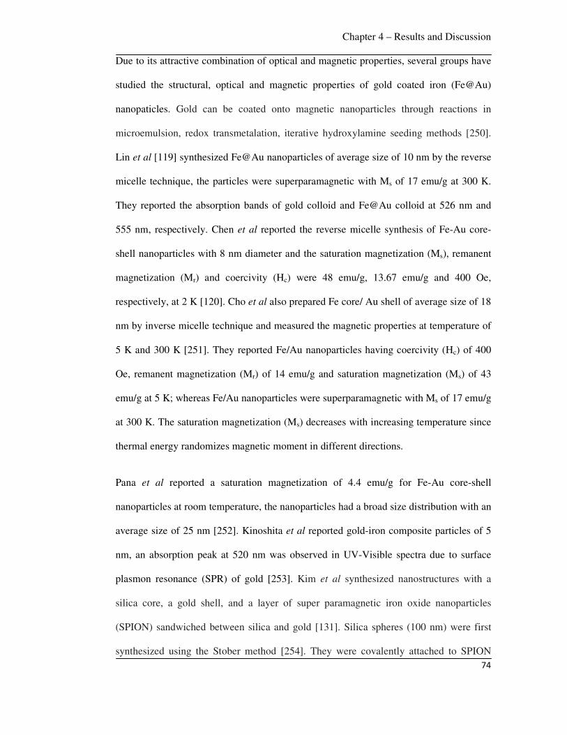
Chapter 4 – Results and Discussion
74
Due to its attractive combination of optical and magnetic properties, several groups have
studied the structural, optical and magnetic properties of gold coated iron (Fe@Au)
nanopaticles. Gold can be coated onto magnetic nanoparticles through reactions in
microemulsion, redox transmetalation, iterative hydroxylamine seeding methods [250].
Lin et al [119] synthesized Fe@Au nanoparticles of average size of 10 nm by the reverse
micelle technique, the particles were superparamagnetic with Ms of 17 emu/g at 300 K.
They reported the absorption bands of gold colloid and Fe@Au colloid at 526 nm and
555 nm, respectively. Chen et al reported the reverse micelle synthesis of Fe-Au core-
shell nanoparticles with 8 nm diameter and the saturation magnetization (Ms), remanent
magnetization (Mr) and coercivity (Hc) were 48 emu/g, 13.67 emu/g and 400 Oe,
respectively, at 2 K [120]. Cho et al also prepared Fe core/ Au shell of average size of 18
nm by inverse micelle technique and measured the magnetic properties at temperature of
5 K and 300 K [251]. They reported Fe/Au nanoparticles having coercivity (Hc) of 400
Oe, remanent magnetization (Mr) of 14 emu/g and saturation magnetization (Ms) of 43
emu/g at 5 K; whereas Fe/Au nanoparticles were superparamagnetic with Ms of 17 emu/g
at 300 K. The saturation magnetization (Ms) decreases with increasing temperature since
thermal energy randomizes magnetic moment in different directions.
Pana et al reported a saturation magnetization of 4.4 emu/g for Fe-Au core-shell
nanoparticles at room temperature, the nanoparticles had a broad size distribution with an
average size of 25 nm [252]. Kinoshita et al reported gold-iron composite particles of 5
nm, an absorption peak at 520 nm was observed in UV-Visible spectra due to surface
plasmon resonance (SPR) of gold [253]. Kim et al synthesized nanostructures with a
silica core, a gold shell, and a layer of super paramagnetic iron oxide nanoparticles
(SPION) sandwiched between silica and gold [131]. Silica spheres (100 nm) were first
synthesized using the Stober method [254]. They were covalently attached to SPION

Chapter 4 – Results and Discussion
75
nanospheres and then functionalized with amine so that the gold will attach on the
surface. A complete 15-nm thick gold shell was formed in the last step. Similarly, Stoeva
et al synthesized structured gold nanoshells embedded with silica-stabilized magnetite
nanoparticles [255].
Chen et al reported a sandwich-like nanostructure composed of a magnetic silica core, an
outer silver shell, and a thin layer of gold between the silica and the silver [256].
Nanorice is another gold coated magnetic nanoparticle, shaped like rice that absorbs in
the NIR region. These nanostructures display two distinct absorptions observed coming
from transverse and longitudinal plasmons. The shorter wavelength is at about 860 nm,
while the longer wavelength is at 1160 nm [257]. Wang et al synthesized a gold-shelled
Fe3O4 nanostructure with a polymer layer, poly(allylamine hydrochloride), interfacing
the Fe3O4 nanoparticle and the gold shell [258]. Lim et al synthesized yolk-shell
structured gold nanoparticles that contain SPION in the core and water as the dielectric
interface [259].
In this work, superparamagnetic Fe@Au nanoparticles with an average size of 15 nm
(SD 5) were synthesized by the reverse micelle technique. The uncoated particles were
highly aggregated compared to gold coated particles. The nanoparticles have a tendency
to aggregate to reduce their surface energy regardless of the magnetic properties. When
the particles are coated with surfactant [260], polymer [113] and dispersed in a carrier
fluid, this aggregation is reduced. The uncoated particles (S-1) were oxidized to Fe3O4
(magnetite) due to exposure to air (Fig. 4.1) as nanoparticles have very large surface area
to volume ratio, promoting oxidation to more stable state. By coating with the noble
metal gold, this oxidation of iron can be prevented. The gold coating is thin (2 nm and
3.5 nm in S-2 and S-3, respectively), hence Fe as well as Au peaks were observed in XPS
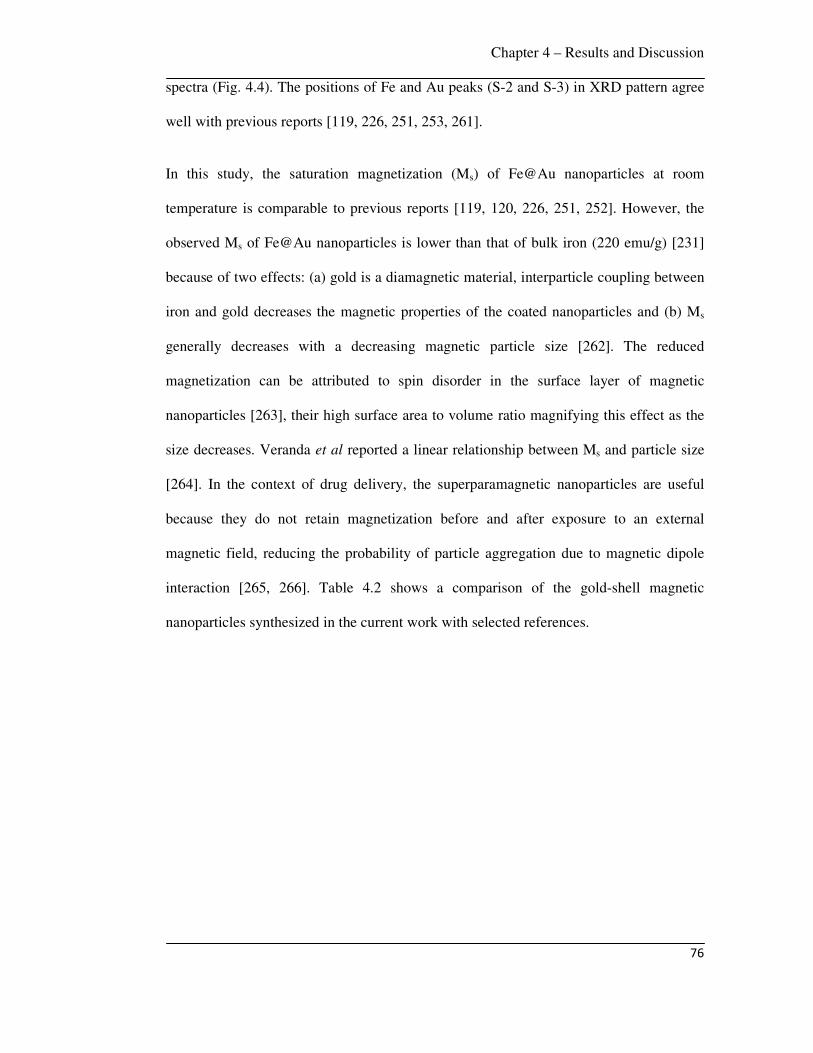
Chapter 4 – Results and Discussion
76
spectra (Fig. 4.4). The positions of Fe and Au peaks (S-2 and S-3) in XRD pattern agree
well with previous reports [119, 226, 251, 253, 261].
In this study, the saturation magnetization (Ms) of Fe@Au nanoparticles at room
temperature is comparable to previous reports [119, 120, 226, 251, 252]. However, the
observed Ms of Fe@Au nanoparticles is lower than that of bulk iron (220 emu/g) [231]
because of two effects: (a) gold is a diamagnetic material, interparticle coupling between
iron and gold decreases the magnetic properties of the coated nanoparticles and (b) Ms
generally decreases with a decreasing magnetic particle size [262]. The reduced
magnetization can be attributed to spin disorder in the surface layer of magnetic
nanoparticles [263], their high surface area to volume ratio magnifying this effect as the
size decreases. Veranda et al reported a linear relationship between Ms and particle size
[264]. In the context of drug delivery, the superparamagnetic nanoparticles are useful
because they do not retain magnetization before and after exposure to an external
magnetic field, reducing the probability of particle aggregation due to magnetic dipole
interaction [265, 266]. Table 4.2 shows a comparison of the gold-shell magnetic
nanoparticles synthesized in the current work with selected references.

Chapter 4 – Results and Discussion
77
Table 4.2 Comparison of gold coated magnetic nanoparticles of current work with
selected literature.
Structure Characteristics In-vitro In-vivo Ref.
SiO2/SPION/Au Size: ~120 nm Surface: PEG and anti-HER2/neu
T2-weighted MRI
None [131]
SiO2/SPION/Au Size: >200 nm Surface: thiol modified DNA
None None [255]
SPION/SiO2/Au Size: >200 nm Surface: None
None None [267]
SPION/polymer/Au Size: 273 ± 17.9 nm Surface: None
None None [258]
SPION/Au Size: Longitudinal = 340 ± 20 nm; transverse = 54 ± 4 nm Surface: None
None None [257]
SPION/SiO2/Au Size: ~80 nm Surface: PEG
Photothermal ablation using 808 nm laser
Darkening of tumor in mice in T2-weighted MRI, increase in temperature of ~60°
[268]
Hollow Au
nanoshell
Size: 30.4 ± 4.4 nm Surface: C225 monoclonal antibody
Selective binding of C225-HGN with A431 cells
More C225-HGN localized into tumor
[249]
Fe/Au Size: individual particle of 15 nm, Aggregate size: 100 nm
Dox loading/ release and targeting
None This
work
In summary, gold coated iron (Fe@Au) individual nanoparticles of average size 15 nm
(aggregate size ~ 100 nm) were synthesized by the reverse micelle technique, these
nanoparticles exhibited superparamagnetic character and decreasing saturation
magnetization with increasing Au coating thickness.
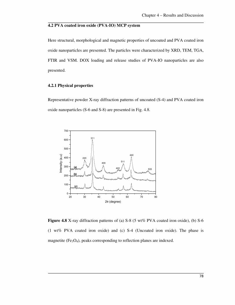
Chapter 4 – Results and Discussion
78
4.2 PVA coated iron oxide (PVA-IO) MCP system
Here structural, morphological and magnetic properties of uncoated and PVA coated iron
oxide nanoparticles are presented. The particles were characterized by XRD, TEM, TGA,
FTIR and VSM. DOX loading and release studies of PVA-IO nanoparticles are also
presented.
4.2.1 Physical properties
Representative powder X-ray diffraction patterns of uncoated (S-4) and PVA coated iron
oxide nanoparticles (S-6 and S-8) are presented in Fig. 4.8.
20 30 40 50 60 70 80
0
100
200
300
400
500
600
700
(c)
(b)
533
440
511
422
400
311
220
Inte
nsity (
a.u
)
2θ (degree)
(a)
Figure 4.8 X-ray diffraction patterns of (a) S-8 (5 wt% PVA coated iron oxide), (b) S-6
(1 wt% PVA coated iron oxide) and (c) S-4 (Uncoated iron oxide). The phase is
magnetite (Fe3O4), peaks corresponding to reflection planes are indexed.
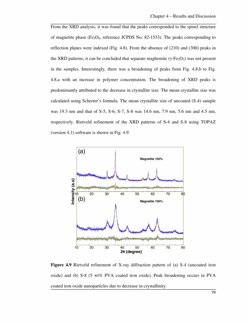
Chapter 4 – Results and Discussion
79
From the XRD analysis, it was found that the peaks corresponded to the spinel structure
of magnetite phase (Fe3O4, reference JCPDS No. 82-1533). The peaks corresponding to
reflection planes were indexed (Fig. 4.8). From the absence of (210) and (300) peaks in
the XRD patterns, it can be concluded that separate maghemite (γ-Fe2O3) was not present
in the samples. Interestingly, there was a broadening of peaks from Fig. 4.8.b to Fig.
4.8.a with an increase in polymer concentration. The broadening of XRD peaks is
predominantly attributed to the decrease in crystallite size. The mean crystallite size was
calculated using Scherrer’s formula. The mean crystallite size of uncoated (S-4) sample
was 19.3 nm and that of S-5, S-6, S-7, S-8 was 14.6 nm, 7.9 nm, 5.6 nm and 4.5 nm,
respectively. Rietveld refinement of the XRD patterns of S-4 and S-8 using TOPAZ
(version 4.1) software is shown in Fig. 4.9.
Figure 4.9 Rietveld refinement of X-ray diffraction pattern of (a) S-4 (uncoated iron
oxide) and (b) S-8 (5 wt% PVA coated iron oxide). Peak broadening occurs in PVA
coated iron oxide nanoparticles due to decrease in crystallinity.
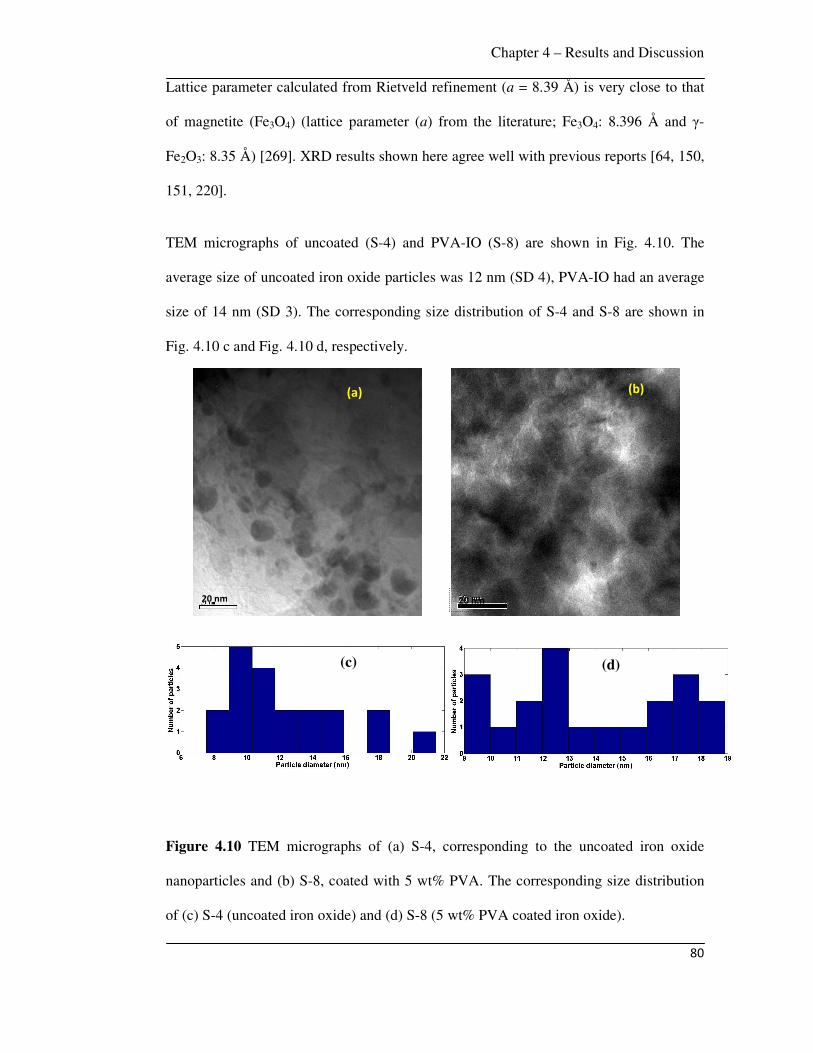
Chapter 4 – Results and Discussion
80
Lattice parameter calculated from Rietveld refinement (a = 8.39 Å) is very close to that
of magnetite (Fe3O4) (lattice parameter (a) from the literature; Fe3O4: 8.396 Å and γ-
Fe2O3: 8.35 Å) [269]. XRD results shown here agree well with previous reports [64, 150,
151, 220].
TEM micrographs of uncoated (S-4) and PVA-IO (S-8) are shown in Fig. 4.10. The
average size of uncoated iron oxide particles was 12 nm (SD 4), PVA-IO had an average
size of 14 nm (SD 3). The corresponding size distribution of S-4 and S-8 are shown in
Fig. 4.10 c and Fig. 4.10 d, respectively.
Figure 4.10 TEM micrographs of (a) S-4, corresponding to the uncoated iron oxide
nanoparticles and (b) S-8, coated with 5 wt% PVA. The corresponding size distribution
of (c) S-4 (uncoated iron oxide) and (d) S-8 (5 wt% PVA coated iron oxide).
20 nm
(a)
(b)
(c)
(d)
20 nm
(b)
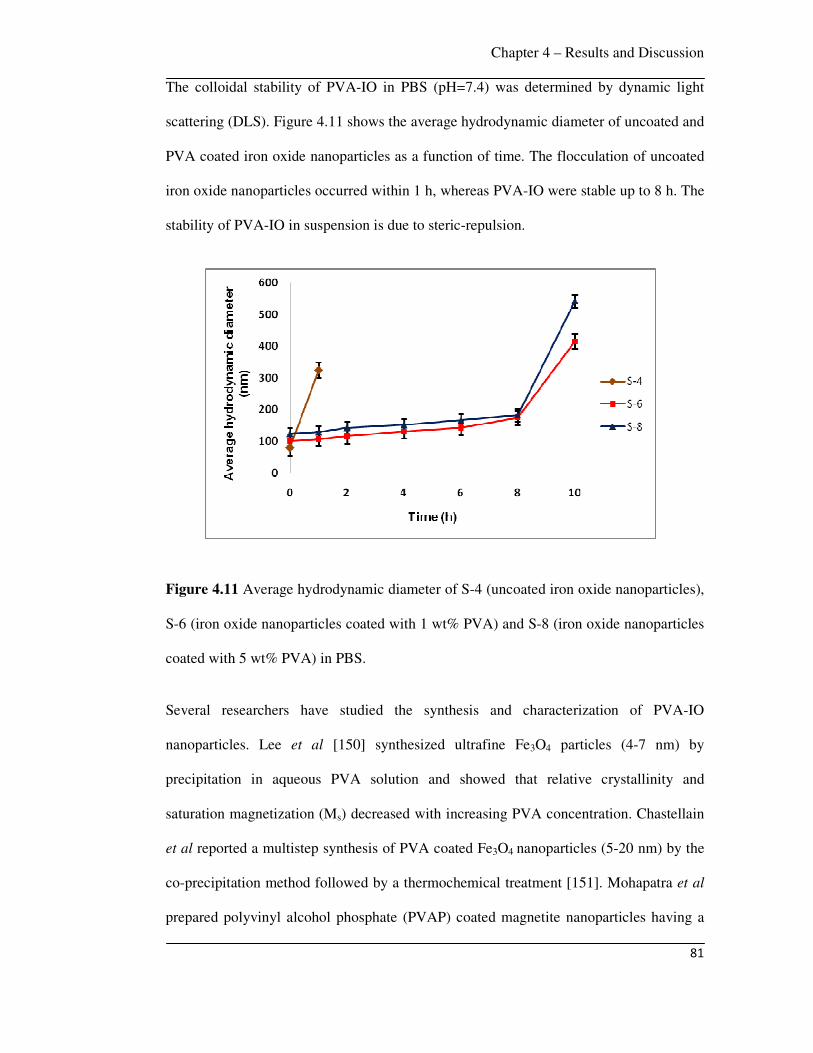
Chapter 4 – Results and Discussion
81
The colloidal stability of PVA-IO in PBS (pH=7.4) was determined by dynamic light
scattering (DLS). Figure 4.11 shows the average hydrodynamic diameter of uncoated and
PVA coated iron oxide nanoparticles as a function of time. The flocculation of uncoated
iron oxide nanoparticles occurred within 1 h, whereas PVA-IO were stable up to 8 h. The
stability of PVA-IO in suspension is due to steric-repulsion.
Figure 4.11 Average hydrodynamic diameter of S-4 (uncoated iron oxide nanoparticles),
S-6 (iron oxide nanoparticles coated with 1 wt% PVA) and S-8 (iron oxide nanoparticles
coated with 5 wt% PVA) in PBS.
Several researchers have studied the synthesis and characterization of PVA-IO
nanoparticles. Lee et al [150] synthesized ultrafine Fe3O4 particles (4-7 nm) by
precipitation in aqueous PVA solution and showed that relative crystallinity and
saturation magnetization (Ms) decreased with increasing PVA concentration. Chastellain
et al reported a multistep synthesis of PVA coated Fe3O4 nanoparticles (5-20 nm) by the
co-precipitation method followed by a thermochemical treatment [151]. Mohapatra et al
prepared polyvinyl alcohol phosphate (PVAP) coated magnetite nanoparticles having a

Chapter 4 – Results and Discussion
82
broad size distribution (13-55 nm), which were superparamagnetic at room temperature
with 35 emu/g and 15 emu/g for 0.5 % and 1 % PVAP respectively [64]. Petri-Fink et al
coated superparamagnetic iron oxide nanoparticles (9 nm) with amino functionalized
PVA and demonstrated the interactions with human melanoma cells [65].
In this work, PVA-IO individual particles of average size 14 nm (SD 3) were synthesized
by the co-precipitation technique. The broadening of XRD peaks with increasing PVA
concentration was observed due to a decrease in crystallinity. The broadening of XRD
peaks is attributed to the decrease in crystallite size, which can be explained by the
Scherrer’s formula i.e., D = (0.9 λ) / (β cosθ); where D = Mean crystallite size, λ = X-ray
wave length, β = broadening of diffraction line at half of its maximum intensity in
radians and θ = diffraction angle. As the crystallite size is inversely proportional to peak
width, a decrease in crystallite size causes the peak to broaden.

Chapter 4 – Results and Discussion
83
4.2.2 PVA adsorption onto iron oxide nanoparticles
The amount of PVA adsorbed onto the iron oxide nanoparticles was studied by
thermogravimetric analysis (TGA). Figure 4.12 shows the weight loss vs. temperature
curves of pure PVA (inset), uncoated iron oxide and PVA-IO heated up to 600ºC in air.
Figure 4.12 Weight loss vs. temperature TGA curves of (a) S-4 (uncoated iron oxide),
(b) S-5 (iron oxide coated with 0.5 wt% PVA), (c) S-6 (iron oxide coated with 1 wt%
PVA), (d) S-7 (iron oxide coated with 2 wt% PVA) and (e) S-8 (iron oxide coated with 5
wt% PVA) heated up to 600ºC in air. The inset shows the TGA curve of pure PVA
indicating complete degradation of PVA when heated up to 600ºC.
The inset shows that pure PVA degrades completely when heated up to 600ºC. There is
no significant weight loss in the TGA curve of uncoated iron oxide nanoparticles (Fig.
100 200 300 400 500 600
65
70
75
80
85
90
95
100
(c)
We
igh
t (%
)
Temperature (oC)
(b)
(d)
(e)
(a)
100 200 300 400 500 600
0
20
40
60
80
100
We
igh
t (%
)
Temperature (oC)
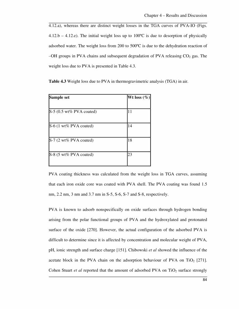
Chapter 4 – Results and Discussion
84
4.12.a), whereas there are distinct weight losses in the TGA curves of PVA-IO (Figs.
4.12.b – 4.12.e). The initial weight loss up to 100ºC is due to desorption of physically
adsorbed water. The weight loss from 200 to 500ºC is due to the dehydration reaction of
–OH groups in PVA chains and subsequent degradation of PVA releasing CO2 gas. The
weight loss due to PVA is presented in Table 4.3.
Table 4.3 Weight loss due to PVA in thermogravimetric analysis (TGA) in air.
Sample set Wt loss (%)
S-5 (0.5 wt% PVA coated) 11
S-6 (1 wt% PVA coated) 14
S-7 (2 wt% PVA coated) 18
S-8 (5 wt% PVA coated) 23
PVA coating thickness was calculated from the weight loss in TGA curves, assuming
that each iron oxide core was coated with PVA shell. The PVA coating was found 1.5
nm, 2.2 nm, 3 nm and 3.7 nm in S-5, S-6, S-7 and S-8, respectively.
PVA is known to adsorb nonspecifically on oxide surfaces through hydrogen bonding
arising from the polar functional groups of PVA and the hydroxylated and protonated
surface of the oxide [270]. However, the actual configuration of the adsorbed PVA is
difficult to determine since it is affected by concentration and molecular weight of PVA,
pH, ionic strength and surface charge [151]. Chibowski et al showed the influence of the
acetate block in the PVA chain on the adsorption behaviour of PVA on TiO2 [271].
Cohen Stuart et al reported that the amount of adsorbed PVA on TiO2 surface strongly
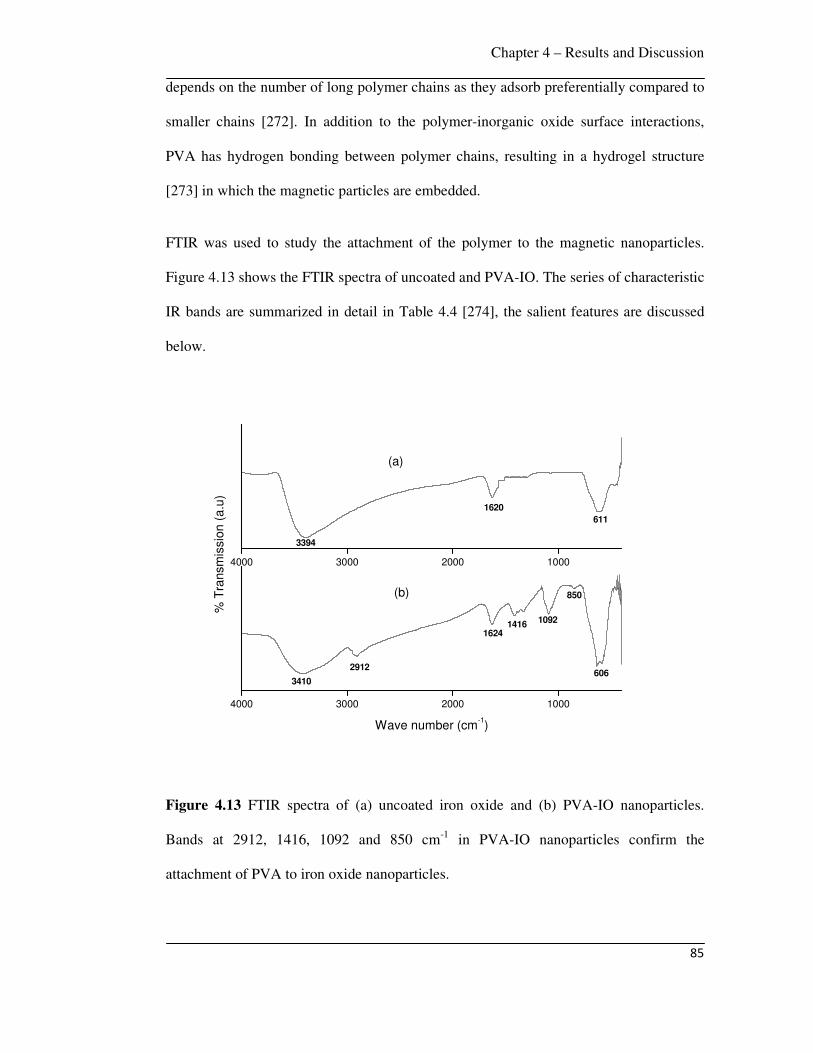
Chapter 4 – Results and Discussion
85
depends on the number of long polymer chains as they adsorb preferentially compared to
smaller chains [272]. In addition to the polymer-inorganic oxide surface interactions,
PVA has hydrogen bonding between polymer chains, resulting in a hydrogel structure
[273] in which the magnetic particles are embedded.
FTIR was used to study the attachment of the polymer to the magnetic nanoparticles.
Figure 4.13 shows the FTIR spectra of uncoated and PVA-IO. The series of characteristic
IR bands are summarized in detail in Table 4.4 [274], the salient features are discussed
below.
4000 3000 2000 1000
4000 3000 2000 1000
3394
1620
611
(a)
% T
ransm
issio
n (
a.u
)
Wave number (cm-1)
3410
2912
1624
1092
850
606
1416
(b)
Figure 4.13 FTIR spectra of (a) uncoated iron oxide and (b) PVA-IO nanoparticles.
Bands at 2912, 1416, 1092 and 850 cm-1 in PVA-IO nanoparticles confirm the
attachment of PVA to iron oxide nanoparticles.
Chapter 4 – Results and Discussion
86
In the case of uncoated iron oxide, the band at 3394 cm-1 was assigned to O-H stretching
( ) vibrations and the band at 1620 cm-1 was assigned to O-H bending ( ) vibrations due
to adsorbed water on the surface of the iron oxide nanoparticles. The band observed at
611 cm-1 corresponded to stretching vibrations of MTh-O-MOh, where MTh and MOh
represented the iron occupying tetrahedral and octahedral positions, respectively. In
PVA-IO, the MTh-O-MOh stretching band at 606 cm-1 and the alcoholic O-H stretching
band at 3410 cm-1 were observed. The additional bands at 2912 cm-1 corresponding to C-
H stretching vibrations, at 1416 cm-1 corresponding to C-C stretching vibrations, at 1092
cm-1 attributable to M-O-H (M=Fe) bond and at 850 cm-1 corresponding to CH2 rocking
were observed in PVA-IO nanoparticles, confirming the attachment of PVA onto iron
oxide nanoparticles, which was also supported by thermal analysis.
The interaction between polymer coating and Fe3O4 particles was studied earlier [275-
279]. Polymer interactions were studied in Fe3O4/polypyrrole and Fe3O4/polyaniline
nanocomposites, where interactions exist between the lone pair electrons of the N atom
in the polypyrrole chain or in the polyaniline chain with the 3d orbital of the Fe atom to
form a coordinate bond [275, 276]. Li et al reported that oleic acid adsorption on the
surface of Fe3O4 nanoparticles could be due to hydrogen bonding or a coordination
linkage [277]. Zhang et al reported the attachment of polymethacrylic acid to Fe3O4
nanoparticles via coordination linkages between the carboxyl groups and iron [278]. In
the present work, it is confirmed by FTIR analysis (Fig. 4.13) that the attachment of PVA
to iron oxide nanoparticles occurs via hydrogen bonding between hydroxyl group of
PVA and protonated surface of the oxide.

Chapter 4 – Results and Discussion
87
Table 4.4 Assignment of FTIR spectra of uncoated iron oxide, PVA-IO [274].
Samples IR region or bands (cm-1) Description
3394 (H-O)
1620 (H-O-H) of adsorbed
water
Uncoated iron oxide
611 (MTh-O-MOh)
3410 (H-O)
2912 (C-H)
1624 (H-O-H)
1416 (C-C)
1092 (M-O-H (M=Fe))
850 CH2 rocking
PVA coated iron oxide
606 (MTh-O-MOh)
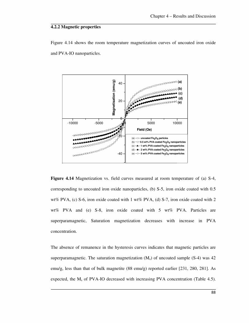
Chapter 4 – Results and Discussion
88
4.2.2 Magnetic properties
Figure 4.14 shows the room temperature magnetization curves of uncoated iron oxide
and PVA-IO nanoparticles.
Figure 4.14 Magnetization vs. field curves measured at room temperature of (a) S-4,
corresponding to uncoated iron oxide nanoparticles, (b) S-5, iron oxide coated with 0.5
wt% PVA, (c) S-6, iron oxide coated with 1 wt% PVA, (d) S-7, iron oxide coated with 2
wt% PVA and (e) S-8, iron oxide coated with 5 wt% PVA. Particles are
superparamagnetic, Saturation magnetization decreases with increase in PVA
concentration.
The absence of remanence in the hysteresis curves indicates that magnetic particles are
superparamagnetic. The saturation magnetization (Ms) of uncoated sample (S-4) was 42
emu/g, less than that of bulk magnetite (88 emu/g) reported earlier [231, 280, 281]. As
expected, the Ms of PVA-IO decreased with increasing PVA concentration (Table 4.5).
-10000 -5000 0 5000 10000
-40
-20
0
20
40
(e)(d)
(c)
(b)
Mag
neti
sati
on
(em
u/g
)
Field (Oe)
(a) uncoated Fe3O4 particles
(b) 0.5 wt% PVA coated Fe3O4 nanoparticles
(c) 1 wt% PVA coated Fe3O4 nanoparticles
(d) 2 wt% PVA coated Fe3O4 nanoparticles
(e) 5 wt% PVA coated Fe3O4 nanoparticles
(a)
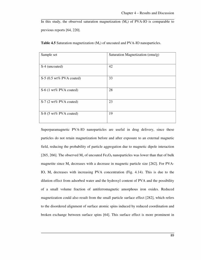
Chapter 4 – Results and Discussion
89
In this study, the observed saturation magnetization (Ms) of PVA-IO is comparable to
previous reports [64, 220].
Table 4.5 Saturation magnetization (Ms) of uncoated and PVA-IO nanoparticles.
Sample set Saturation Magnetization (emu/g)
S-4 (uncoated) 42
S-5 (0.5 wt% PVA coated) 33
S-6 (1 wt% PVA coated) 28
S-7 (2 wt% PVA coated) 23
S-8 (5 wt% PVA coated) 19
Superparamagnetic PVA-IO nanoparticles are useful in drug delivery, since these
particles do not retain magnetization before and after exposure to an external magnetic
field, reducing the probability of particle aggregation due to magnetic dipole interaction
[265, 266]. The observed Ms of uncoated Fe3O4 nanoparticles was lower than that of bulk
magnetite since Ms decreases with a decrease in magnetic particle size [262]. For PVA-
IO, Ms decreases with increasing PVA concentration (Fig. 4.14). This is due to the
dilution effect from adsorbed water and the hydroxyl content of PVA and the possibility
of a small volume fraction of antiferromagnetic amorphous iron oxides. Reduced
magnetization could also result from the small particle surface effect [282], which refers
to the disordered alignment of surface atomic spins induced by reduced coordination and
broken exchange between surface spins [64]. This surface effect is more prominent in

Chapter 4 – Results and Discussion
90
small particles as the ratio of surface atoms to the interior atoms increases with a
decrease in particle size.
In summary, PVA-IO individual particles with average size of 14 nm (SD 3) were
synthesized by co-precipitation technique; these particles were superparamagnetic with
decreasing Ms with increasing PVA concentration. The attachment of PVA to iron oxide
nanoparticles occurred via hydrogen bonding between hydroxyl group of PVA and
protonated surface of the oxide.
4.3 Doxorubicin (DOX) drug loading and release
DOX was used to study the drug loading and release behaviour of Fe@Au and PVA-IO
MCP. The starting ratio by weight of MCP to DOX was 10 for drug loading. The drug
loading of Fe@Au MCP was qualitatively monitored by a change in the color of DOX,
which changed from deep orange (Fig. 4.15.a) to a much lighter color with increasing
time as DOX was adsorbed to MCP (Fig. 4.15.c). When only uncoated iron nanoparticles
were used for drug loading, no change in the color and concentration of DOX was
observed (Fig. 4.15.b), which indicates that there is no drug adsorption onto the uncoated
nanoparticles.
The zeta potential of Fe@Au, PVA-IO, DOX-attached Fe@Au and DOX-attached PVA-
IO was determined by Malvern Zetasizer. The average values of zeta potential of
Fe@Au, PVA-IO, DOX-attached Fe@Au and DOX-attached PVA-IO were -33.3 mV, -
38.3 mV, -24.3 mV and -23.6 mV, respectively. Loading of DOX onto Fe@Au and
PVA-IO surface increases positive potential, since DOX is a cationic drug.
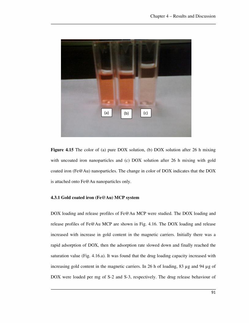
Chapter 4 – Results and Discussion
91
Figure 4.15 The color of (a) pure DOX solution, (b) DOX solution after 26 h mixing
with uncoated iron nanoparticles and (c) DOX solution after 26 h mixing with gold
coated iron (Fe@Au) nanoparticles. The change in color of DOX indicates that the DOX
is attached onto Fe@Au nanoparticles only.
4.3.1 Gold coated iron (Fe@Au) MCP system
DOX loading and release profiles of Fe@Au MCP were studied. The DOX loading and
release profiles of Fe@Au MCP are shown in Fig. 4.16. The DOX loading and release
increased with increase in gold content in the magnetic carriers. Initially there was a
rapid adsorption of DOX, then the adsorption rate slowed down and finally reached the
saturation value (Fig. 4.16.a). It was found that the drug loading capacity increased with
increasing gold content in the magnetic carriers. In 26 h of loading, 83 µg and 94 µg of
DOX were loaded per mg of S-2 and S-3, respectively. The drug release behaviour of
(a) (b) (c)
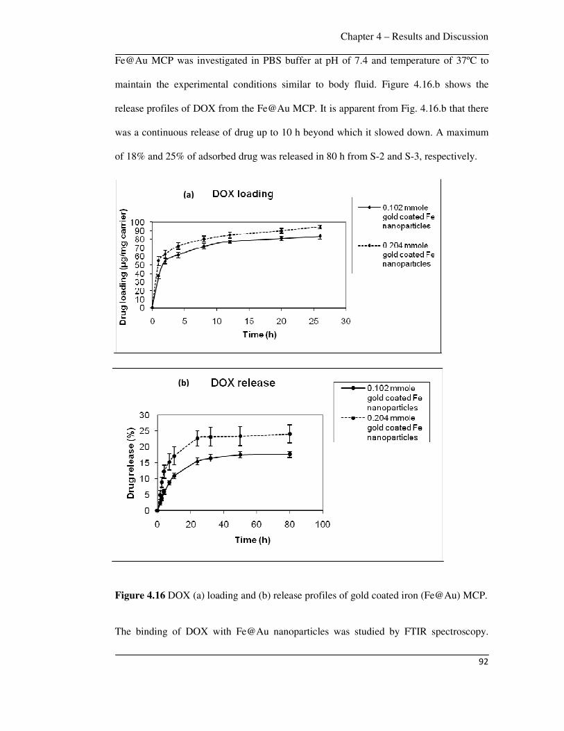
Chapter 4 – Results and Discussion
92
Fe@Au MCP was investigated in PBS buffer at pH of 7.4 and temperature of 37ºC to
maintain the experimental conditions similar to body fluid. Figure 4.16.b shows the
release profiles of DOX from the Fe@Au MCP. It is apparent from Fig. 4.16.b that there
was a continuous release of drug up to 10 h beyond which it slowed down. A maximum
of 18% and 25% of adsorbed drug was released in 80 h from S-2 and S-3, respectively.
Figure 4.16 DOX (a) loading and (b) release profiles of gold coated iron (Fe@Au) MCP.
The binding of DOX with Fe@Au nanoparticles was studied by FTIR spectroscopy.
(a)
(b)
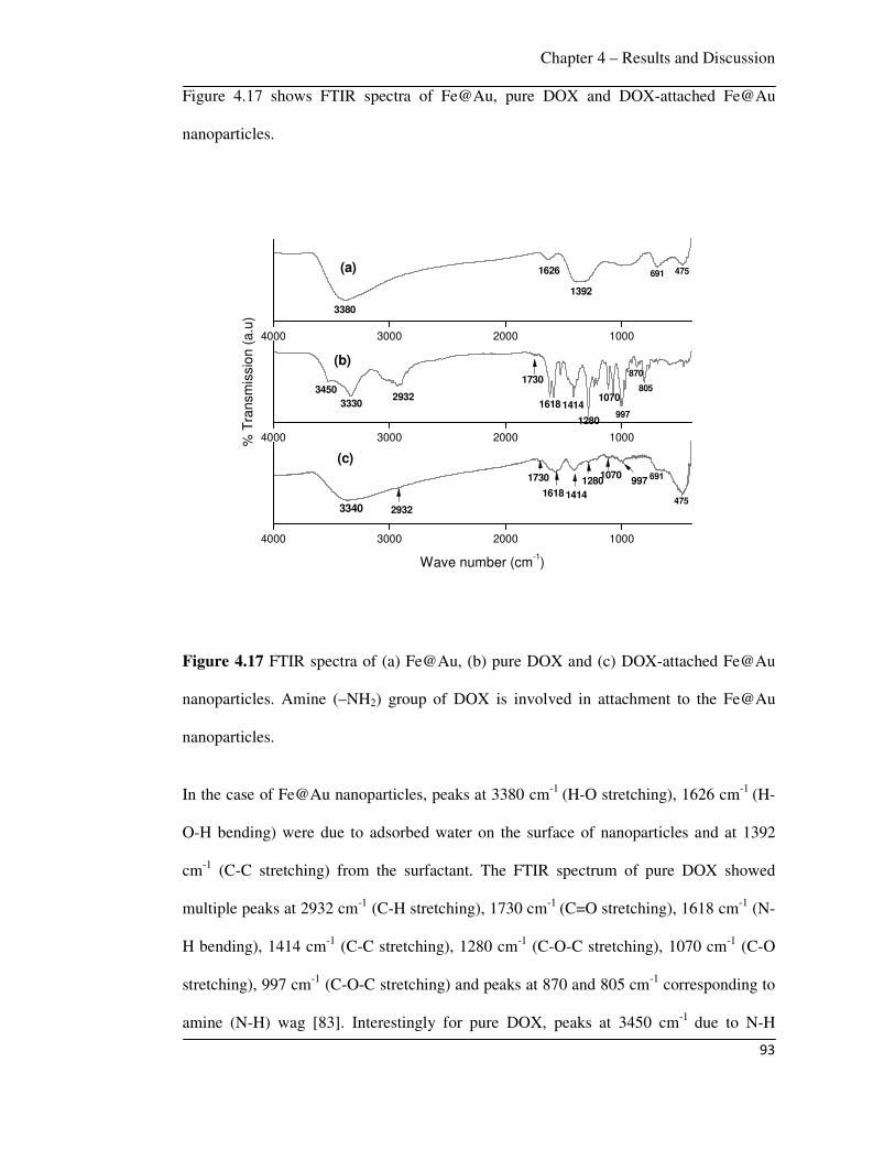
Chapter 4 – Results and Discussion
93
Figure 4.17 shows FTIR spectra of Fe@Au, pure DOX and DOX-attached Fe@Au
nanoparticles.
Figure 4.17 FTIR spectra of (a) Fe@Au, (b) pure DOX and (c) DOX-attached Fe@Au
nanoparticles. Amine (–NH2) group of DOX is involved in attachment to the Fe@Au
nanoparticles.
In the case of Fe@Au nanoparticles, peaks at 3380 cm-1 (H-O stretching), 1626 cm-1 (H-
O-H bending) were due to adsorbed water on the surface of nanoparticles and at 1392
cm-1 (C-C stretching) from the surfactant. The FTIR spectrum of pure DOX showed
multiple peaks at 2932 cm-1 (C-H stretching), 1730 cm-1 (C=O stretching), 1618 cm-1 (N-
H bending), 1414 cm-1 (C-C stretching), 1280 cm-1 (C-O-C stretching), 1070 cm-1 (C-O
stretching), 997 cm-1 (C-O-C stretching) and peaks at 870 and 805 cm-1 corresponding to
amine (N-H) wag [83]. Interestingly for pure DOX, peaks at 3450 cm-1 due to N-H
4000 3000 2000 1000
4000 3000 2000 1000
4000 3000 2000 1000
475691
1392
1626
3380
(a)
(b)
805
870
997
1070
1280
1618 1414
1730
29323330
3450
(c)
475
691
3340 2932
1730 9971070
1280
1618 1414
% T
ransm
issio
n (
a.u
)
Wave number (cm-1)
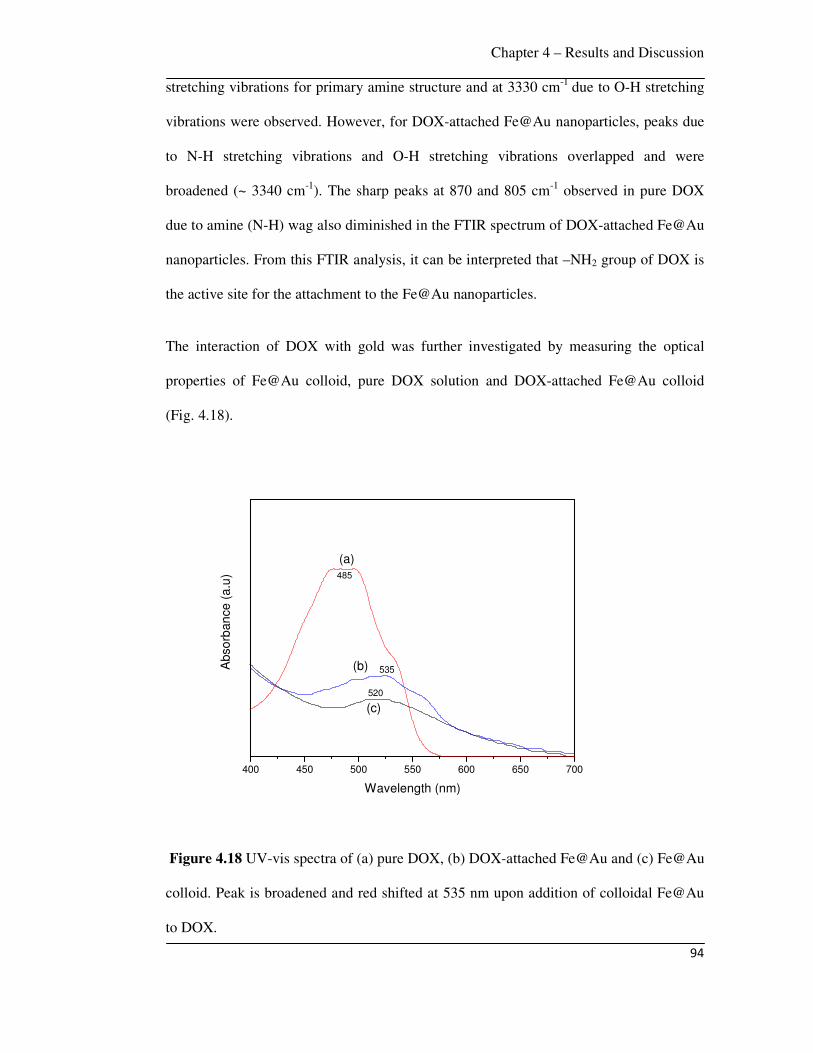
Chapter 4 – Results and Discussion
94
stretching vibrations for primary amine structure and at 3330 cm-1 due to O-H stretching
vibrations were observed. However, for DOX-attached Fe@Au nanoparticles, peaks due
to N-H stretching vibrations and O-H stretching vibrations overlapped and were
broadened (~ 3340 cm-1). The sharp peaks at 870 and 805 cm-1 observed in pure DOX
due to amine (N-H) wag also diminished in the FTIR spectrum of DOX-attached Fe@Au
nanoparticles. From this FTIR analysis, it can be interpreted that –NH2 group of DOX is
the active site for the attachment to the Fe@Au nanoparticles.
The interaction of DOX with gold was further investigated by measuring the optical
properties of Fe@Au colloid, pure DOX solution and DOX-attached Fe@Au colloid
(Fig. 4.18).
400 450 500 550 600 650 700
535
(c)
(b)Abso
rban
ce
(a
.u)
Wavelength (nm)
(a)
485
520
Figure 4.18 UV-vis spectra of (a) pure DOX, (b) DOX-attached Fe@Au and (c) Fe@Au
colloid. Peak is broadened and red shifted at 535 nm upon addition of colloidal Fe@Au
to DOX.
Chapter 4 – Results and Discussion
95
The absorption band observed for Fe@Au colloid at 520 nm in the UV–visible spectrum
was due to surface plasmon resonance (SPR), which is characteristic of gold
nanoparticles [228]. Pure DOX showed an absorption maximum at 485 nm and it was
observed that with the addition of colloidal Fe@Au to DOX, peak was broadened and red
shifted at 535 nm due to interaction of DOX with the Au surface [283]. This interaction
is due to the attachment of DOX with gold, arising from a large electrostatic attraction of
active groups (-NH2) in DOX with gold.
The interaction of DOX with the Fe@Au nanoparticles is due to the attachment of –NH2
group of DOX with the gold shell, as evidenced by the peak broadening of N-H
stretching vibrations of DOX-conjugated Fe@Au nanoparticles in FTIR spectra (Fig.
4.17) and red shifting of absorption band of Fe@Au colloid with addition of DOX in
UV-visible spectra (Fig. 4.18). Selvaraj et al reported that –NH group of 5-Fluorouracil
drug was involved in binding the drug onto the gold nanoparticle surface [68] and Aslam
et al showed that gold has a strong affinity to the amino group [284]. The drug release
can be explained by the covalent conjugation model postulated by Ringsdorf [285],
where the cleavage of Au-DOX coordinate linkers results in the release of attached drug.
The DOX loading of Fe@Au nanoparticles is comparable to that of Arruebo et al [222]
where zeolite-magnetite nanocomposite was loaded with DOX. Kuznetsov et al reported
that a maximum of 62 µg of DOX was loaded per mg of ferro-carbon adsorbent and
approximately 25% of adsorbed DOX was released from iron-carbon adsorbent in 24 h
[221].
4.3.2 PVA-IO MCP system
The DOX loading and release profiles of PVA-IO nanoparticles are shown in Figs. 4.19
and 4.20, respectively. Initially there was a rapid adsorption of DOX, then the adsorption
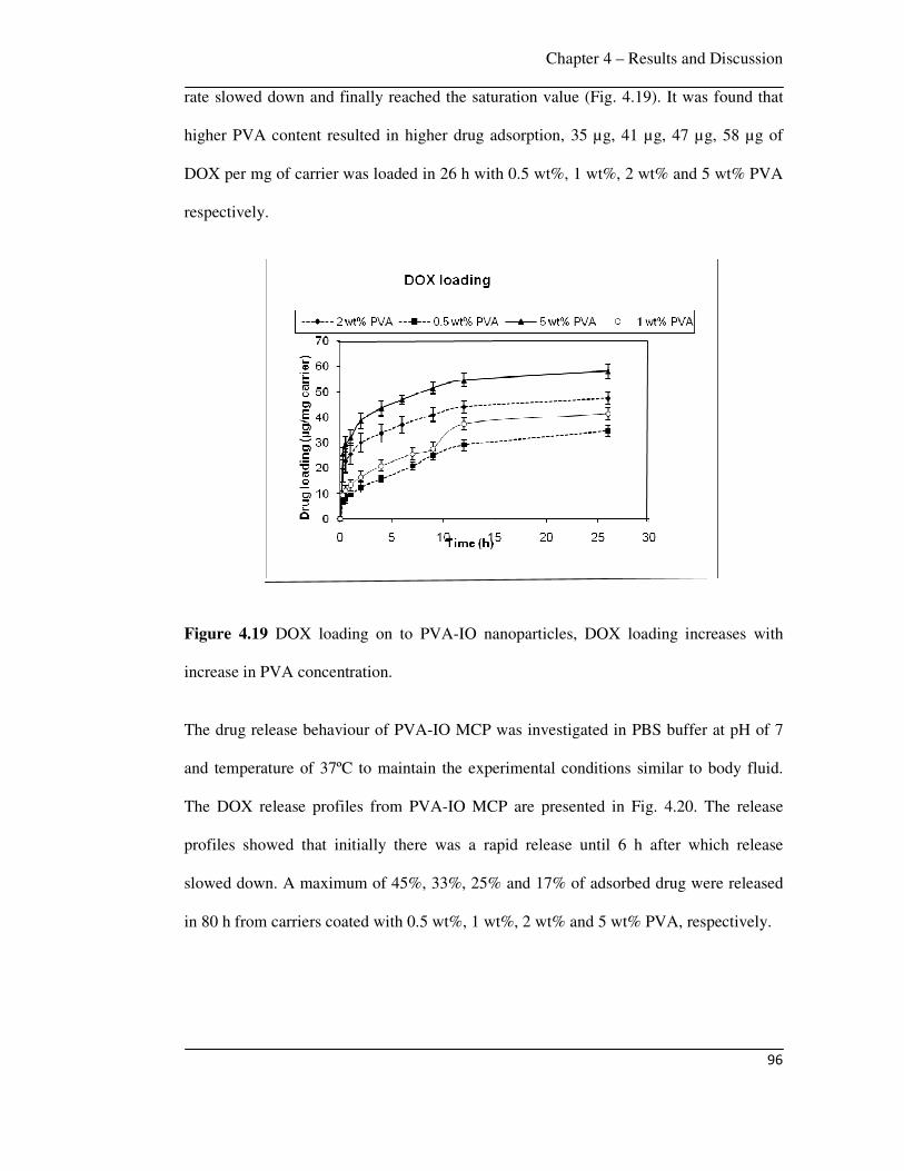
Chapter 4 – Results and Discussion
96
rate slowed down and finally reached the saturation value (Fig. 4.19). It was found that
higher PVA content resulted in higher drug adsorption, 35 µg, 41 µg, 47 µg, 58 µg of
DOX per mg of carrier was loaded in 26 h with 0.5 wt%, 1 wt%, 2 wt% and 5 wt% PVA
respectively.
Figure 4.19 DOX loading on to PVA-IO nanoparticles, DOX loading increases with
increase in PVA concentration.
The drug release behaviour of PVA-IO MCP was investigated in PBS buffer at pH of 7
and temperature of 37ºC to maintain the experimental conditions similar to body fluid.
The DOX release profiles from PVA-IO MCP are presented in Fig. 4.20. The release
profiles showed that initially there was a rapid release until 6 h after which release
slowed down. A maximum of 45%, 33%, 25% and 17% of adsorbed drug were released
in 80 h from carriers coated with 0.5 wt%, 1 wt%, 2 wt% and 5 wt% PVA, respectively.
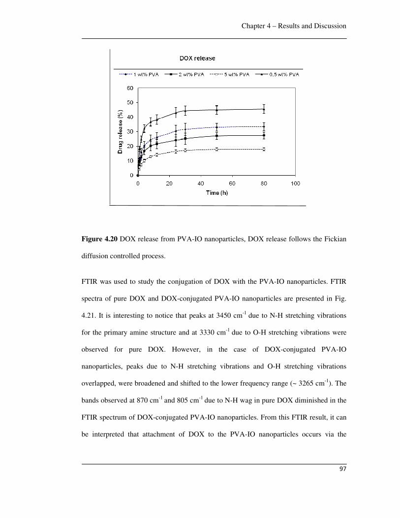
Chapter 4 – Results and Discussion
97
Figure 4.20 DOX release from PVA-IO nanoparticles, DOX release follows the Fickian
diffusion controlled process.
FTIR was used to study the conjugation of DOX with the PVA-IO nanoparticles. FTIR
spectra of pure DOX and DOX-conjugated PVA-IO nanoparticles are presented in Fig.
4.21. It is interesting to notice that peaks at 3450 cm-1 due to N-H stretching vibrations
for the primary amine structure and at 3330 cm-1 due to O-H stretching vibrations were
observed for pure DOX. However, in the case of DOX-conjugated PVA-IO
nanoparticles, peaks due to N-H stretching vibrations and O-H stretching vibrations
overlapped, were broadened and shifted to the lower frequency range (~ 3265 cm-1). The
bands observed at 870 cm-1 and 805 cm-1 due to N-H wag in pure DOX diminished in the
FTIR spectrum of DOX-conjugated PVA-IO nanoparticles. From this FTIR result, it can
be interpreted that attachment of DOX to the PVA-IO nanoparticles occurs via the
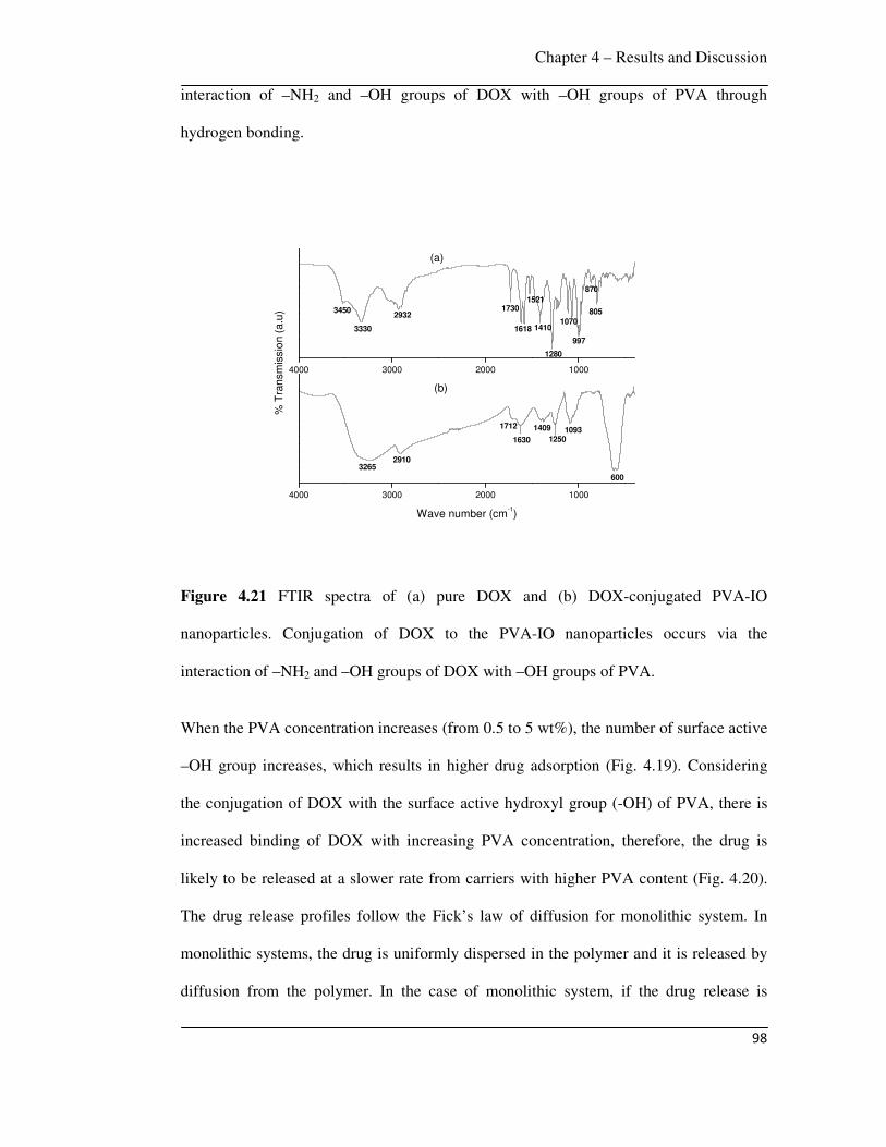
Chapter 4 – Results and Discussion
98
interaction of –NH2 and –OH groups of DOX with –OH groups of PVA through
hydrogen bonding.
Figure 4.21 FTIR spectra of (a) pure DOX and (b) DOX-conjugated PVA-IO
nanoparticles. Conjugation of DOX to the PVA-IO nanoparticles occurs via the
interaction of –NH2 and –OH groups of DOX with –OH groups of PVA.
When the PVA concentration increases (from 0.5 to 5 wt%), the number of surface active
–OH group increases, which results in higher drug adsorption (Fig. 4.19). Considering
the conjugation of DOX with the surface active hydroxyl group (-OH) of PVA, there is
increased binding of DOX with increasing PVA concentration, therefore, the drug is
likely to be released at a slower rate from carriers with higher PVA content (Fig. 4.20).
The drug release profiles follow the Fick’s law of diffusion for monolithic system. In
monolithic systems, the drug is uniformly dispersed in the polymer and it is released by
diffusion from the polymer. In the case of monolithic system, if the drug release is
4000 3000 2000 1000
4000 3000 2000 1000
3330
34502932
1730
1618
1521
1410
1280
1070
997
870
805
(a)
% T
ransm
issio
n (
a.u
)
Wave number (cm-1)
29103265
1712
1630
1409
12501093
600
(b)

Chapter 4 – Results and Discussion
99
primarily controlled by diffusion through the carrier matrix, then the drug release can be
calculated by following equation [286]:
2 2
2 2 21
6 11 expt
n p
M Dn t
M n R
π
π
∞
=∞
= − −∑
(4.1)
where tM and M∞ are the cumulative amounts of drug released at time t and infinity,
respectively; n is a dummy variable, D is the diffusion coefficient of the drug and pR is
the particle size. In Eqn. 4.1, it is assumed that there is no significant change in the
carrier matrix during drug release (e.g., constant porosity, no swelling, time-independent
permeability of the drug) [286]. The curve fitting of DOX release profiles with Eqn. 4.1
shows that the DOX release from PVA-IO nanoparticles is a Fickian diffusion-controlled
process. The diffusion coefficient ( D ) of DOX (1.5 10-18 cm2/s) is calculated from
Eqn. 4.1, which is close to previous reports [287] ( D of DOX for PEG-b-PCL and PEG-
b-PLA is 1.13 10-18 cm2/s and 1.82 10-18 cm2/s, respectively).
Considering breast cancer, the required dosage of anti-cancer drug is calculated based on
Mosteller equation [288] to find the BSA (body surface area). Mosteller equation is: BSA
(m2) = [Height (cm) Weight (kg) /3600]1/2. If a female patient of body weight of 55 kg
and height of 165 cm, then her BSA is 1.59 m2. Generally, the treatment of DOX requires
a dose of 50 mg/m2 [289]. Therefore, the required dosage of DOX is (1.59 m2 50
mg/m2) = 79.5 mg. The total body water (TBW) is calculated by Watson’s formula :
TBW = (-2.097) + [0.1069 height (cm)] + [0.2466 weight (kg)] [290]. So the total
body water is 29.1 L. Therefore, the optimum DOX concentration should be 2.73 µg
/mL. In the present work, the optimum DOX concentration (2.73 µg /mL) was released in
1 h.
Chapter 4 – Results and Discussion
100
Conjugation of drugs to hydrophilic polymers has been actively pursued to improve the
pharmacological and pharmacokinetic properties of therapeutic drugs. In general,
therapeutic drugs conjugated to polymers through cleavable covalent bonds have
enhanced solubility, reduced toxicity and prolonged plasma circulation time compared to
free drugs [291]. Polymers that have track records of preclinical success for conjugation
of drug molecules include polyethyleneglycol (PEG) [292], N-2-
hydroxypropylmethacrylamide (HPMA) copolymer [293-295], polyglutamate [296, 297],
dextran [298-300]. Conjugates of various anti-cancer drugs with these polymers are
currently in clinical trials [301].
PEG has been used for the conjugation and delivery of anti-cancer drugs such as
paclitaxel [302], DOX [303] and camptothecin [304]. Conjugation of PEG to these drugs
dramatically increases solubility and improves retention in circulation [303]. Enhanced
antitumor efficacy in various preclinical studies [305, 306] and clinical studies [307] was
observed with these PEG-drug conjugates. HPMA copolymers are water soluble and
biocompatible [308]. HPMA-drug conjugates evaluated clinically include HPMA-
paclitaxel [309], HPMA-camptothecin [310], HPMA-DOX [311] and HPMA-platinate
[312]. Polyglutamates are a class of anionic polymers, which have a large number of
pendant carboxylate groups to make them water soluble and high drug loading capacities
[296, 313]. Rana et al reported the attachment of DOX with PMMA by amine (–NH2)
group of DOX with –COOH group of PMMA in DOX-conjugated PMMA coated nickel
ferrite nanoparticles [265]. Cavalieri et al reported hydrogel microparticles of
methacrylate derivatized polyvinyl alcohol (PVA-MA) loaded with DOX and showed the
cellular uptake of DOX by LoVo human colon carcinoma cells [314]. Orienti et al
employed polymeric micelles of oleoyl conjugated polyvinyl alcohol (PVA-OL) to

Chapter 4 – Results and Discussion
101
encapsulate DOX and showed drug release activated by proteolytic enzyme pronase-E
[315].
In summary, Fe@Au nanoparticles attached to DOX by interaction of amine (–NH2)
group of DOX with the Au shell, whereas the binding of DOX to the PVA-IO
nanoparticles occurred via the interaction of –NH2 and –OH groups of DOX with –OH
group of PVA through hydrogen bonding. Up to 25% and 45% of adsorbed drug was
released from Fe@Au and PVA-IO nanoparticles, respectively.
4.4 In-vitro experimental targeting of MCP
An in-vitro apparatus simulating the human circulatory system was constructed to
determine the retention of MCP under different flow rates of fluid at various distance of
the magnet from the tube simulating the blood vessel. The retention of Fe@Au MCP (S-2
and S-3) at distances of 5, 10 and 15 mm away from the magnet surface with various
flow rates of fluid ( v = 1 to 40 mm s-1) is presented in Fig.4.22.
Figure 4.22 Percent retention of (a) S-2 (0.102 mmol gold coated iron nanoparticles) and
(b) S-3 (0.204 mmol gold coated iron nanoparticles) at various flow rates of fluid.
(a) (b)
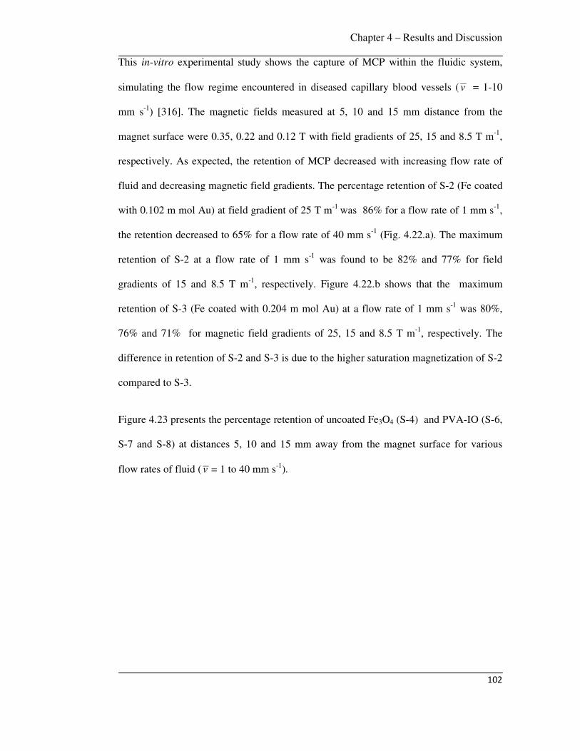
Chapter 4 – Results and Discussion
102
This in-vitro experimental study shows the capture of MCP within the fluidic system,
simulating the flow regime encountered in diseased capillary blood vessels ( v = 1-10
mm s-1) [316]. The magnetic fields measured at 5, 10 and 15 mm distance from the
magnet surface were 0.35, 0.22 and 0.12 T with field gradients of 25, 15 and 8.5 T m-1,
respectively. As expected, the retention of MCP decreased with increasing flow rate of
fluid and decreasing magnetic field gradients. The percentage retention of S-2 (Fe coated
with 0.102 m mol Au) at field gradient of 25 T m-1 was 86% for a flow rate of 1 mm s-1,
the retention decreased to 65% for a flow rate of 40 mm s-1 (Fig. 4.22.a). The maximum
retention of S-2 at a flow rate of 1 mm s-1 was found to be 82% and 77% for field
gradients of 15 and 8.5 T m-1, respectively. Figure 4.22.b shows that the maximum
retention of S-3 (Fe coated with 0.204 m mol Au) at a flow rate of 1 mm s-1 was 80%,
76% and 71% for magnetic field gradients of 25, 15 and 8.5 T m-1, respectively. The
difference in retention of S-2 and S-3 is due to the higher saturation magnetization of S-2
compared to S-3.
Figure 4.23 presents the percentage retention of uncoated Fe3O4 (S-4) and PVA-IO (S-6,
S-7 and S-8) at distances 5, 10 and 15 mm away from the magnet surface for various
flow rates of fluid ( v = 1 to 40 mm s-1).

Chapter 4 – Results and Discussion
103
Figure 4.23 Percent retention of (a) S-4 (uncoated Fe3O4), (b) S-6 (Fe3O4 coated with 1
wt% PVA), (c) S-7 (Fe3O4 coated with 2 wt% PVA) and (d) S-8 (Fe3O4 coated with 5
wt% PVA) at various flow rates of fluid.
The trend was found to be similar to the case as discussed earlier, the retention of MCP
decreased with increasing flow rate of fluid and decreasing magnetic field gradients. The
maximum retention at field gradient of 25 T m-1 and flow rate of 1 mm s-1 was found to
be 98%, 90%, 88% and 86% for S-4, S-6, S-7 and S-8, respectively. This in-vitro study
quantifies the extent of capture of MCP within the tumor, which is influenced by the
magnetic field gradient, flow rate of fluid and magnetic properties of MCP.
(a) (b)
(d) (c)
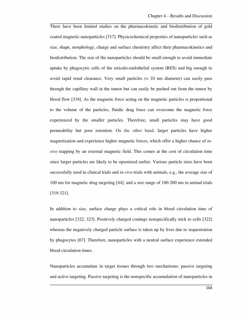
Chapter 4 – Results and Discussion
104
There have been limited studies on the pharmacokinetic and biodistribution of gold
coated magnetic nanoparticles [317]. Physicochemical properties of nanoparticles such as
size, shape, morphology, charge and surface chemistry affect their pharmacokinetics and
biodistribution. The size of the nanoparticles should be small enough to avoid immediate
uptake by phagocytic cells of the reticulo-endothelial system (RES) and big enough to
avoid rapid renal clearance. Very small particles (< 10 nm diameter) can easily pass
through the capillary wall in the tumor but can easily be pushed out from the tumor by
blood flow [318]. As the magnetic force acting on the magnetic particles is proportional
to the volume of the particles, fluidic drag force can overcome the magnetic force
experienced by the smaller particles. Therefore, small particles may have good
permeability but poor retention. On the other hand, larger particles have higher
magnetization and experience higher magnetic forces, which offer a higher chance of in-
vivo trapping by an external magnetic field. This comes at the cost of circulation time
since larger particles are likely to be opsonized earlier. Various particle sizes have been
successfully used in clinical trials and in-vivo trials with animals, e.g., the average size of
100 nm for magnetic drug targeting [44], and a size range of 100-200 nm in animal trials
[319-321].
In addition to size, surface charge plays a critical role in blood circulation time of
nanoparticles [322, 323]. Positively charged coatings nonspecifically stick to cells [322]
whereas the negatively charged particle surface is taken up by liver due to sequestration
by phagocytes [67]. Therefore, nanoparticles with a neutral surface experience extended
blood circulation times.
Nanoparticles accumulate in target tissues through two mechanisms: passive targeting
and active targeting. Passive targeting is the nonspecific accumulation of nanoparticles in
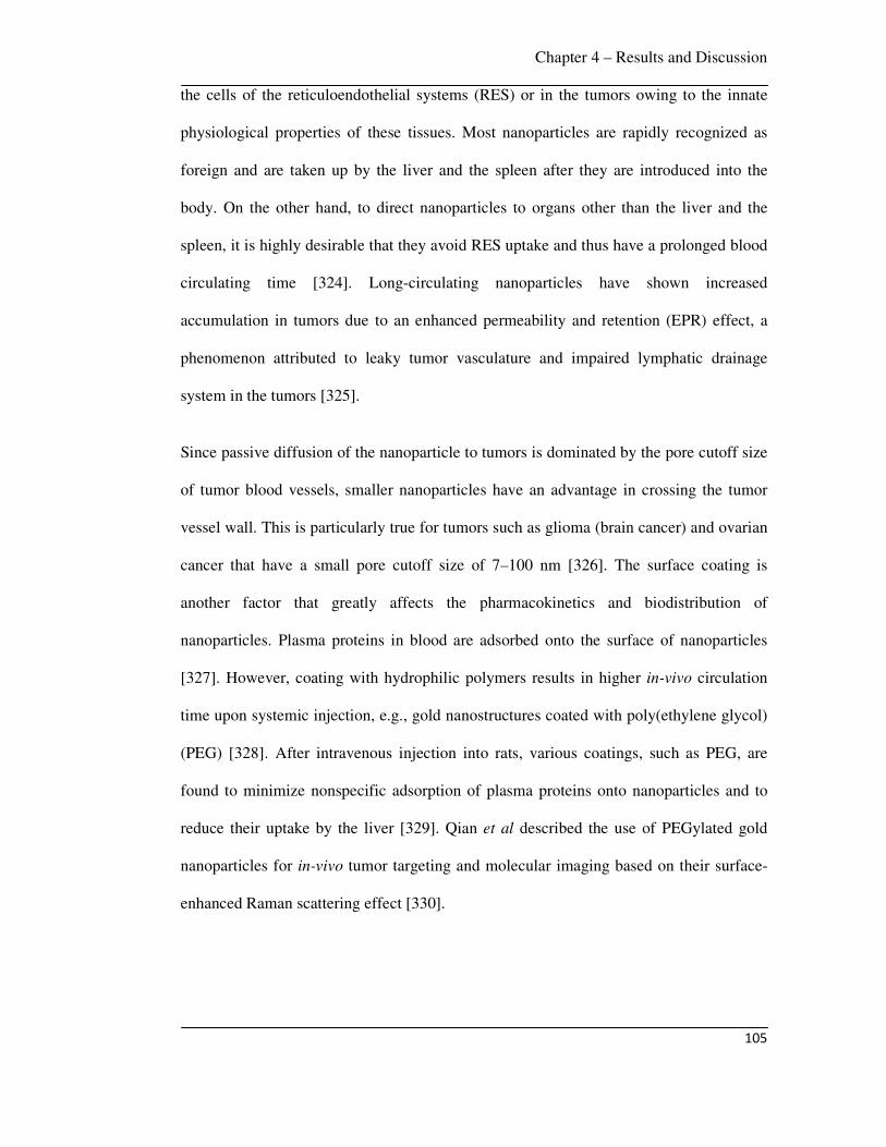
Chapter 4 – Results and Discussion
105
the cells of the reticuloendothelial systems (RES) or in the tumors owing to the innate
physiological properties of these tissues. Most nanoparticles are rapidly recognized as
foreign and are taken up by the liver and the spleen after they are introduced into the
body. On the other hand, to direct nanoparticles to organs other than the liver and the
spleen, it is highly desirable that they avoid RES uptake and thus have a prolonged blood
circulating time [324]. Long-circulating nanoparticles have shown increased
accumulation in tumors due to an enhanced permeability and retention (EPR) effect, a
phenomenon attributed to leaky tumor vasculature and impaired lymphatic drainage
system in the tumors [325].
Since passive diffusion of the nanoparticle to tumors is dominated by the pore cutoff size
of tumor blood vessels, smaller nanoparticles have an advantage in crossing the tumor
vessel wall. This is particularly true for tumors such as glioma (brain cancer) and ovarian
cancer that have a small pore cutoff size of 7–100 nm [326]. The surface coating is
another factor that greatly affects the pharmacokinetics and biodistribution of
nanoparticles. Plasma proteins in blood are adsorbed onto the surface of nanoparticles
[327]. However, coating with hydrophilic polymers results in higher in-vivo circulation
time upon systemic injection, e.g., gold nanostructures coated with poly(ethylene glycol)
(PEG) [328]. After intravenous injection into rats, various coatings, such as PEG, are
found to minimize nonspecific adsorption of plasma proteins onto nanoparticles and to
reduce their uptake by the liver [329]. Qian et al described the use of PEGylated gold
nanoparticles for in-vivo tumor targeting and molecular imaging based on their surface-
enhanced Raman scattering effect [330].
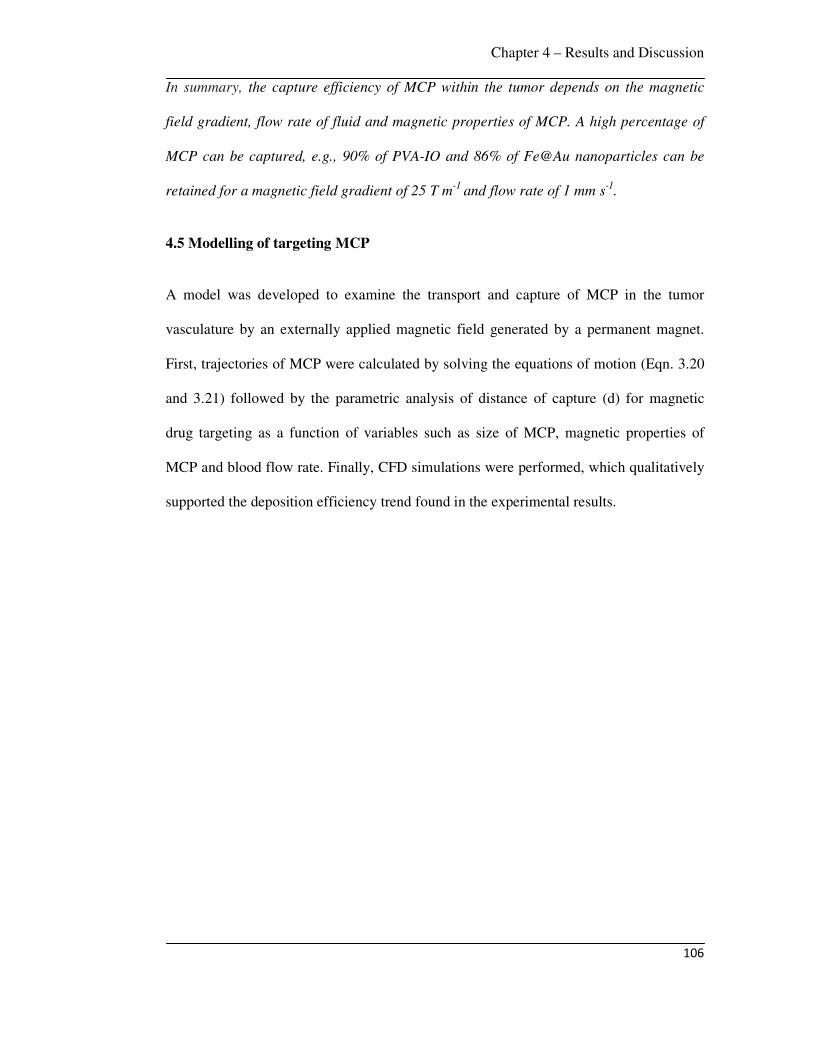
Chapter 4 – Results and Discussion
106
In summary, the capture efficiency of MCP within the tumor depends on the magnetic
field gradient, flow rate of fluid and magnetic properties of MCP. A high percentage of
MCP can be captured, e.g., 90% of PVA-IO and 86% of Fe@Au nanoparticles can be
retained for a magnetic field gradient of 25 T m-1
and flow rate of 1 mm s-1
.
4.5 Modelling of targeting MCP
A model was developed to examine the transport and capture of MCP in the tumor
vasculature by an externally applied magnetic field generated by a permanent magnet.
First, trajectories of MCP were calculated by solving the equations of motion (Eqn. 3.20
and 3.21) followed by the parametric analysis of distance of capture (d) for magnetic
drug targeting as a function of variables such as size of MCP, magnetic properties of
MCP and blood flow rate. Finally, CFD simulations were performed, which qualitatively
supported the deposition efficiency trend found in the experimental results.
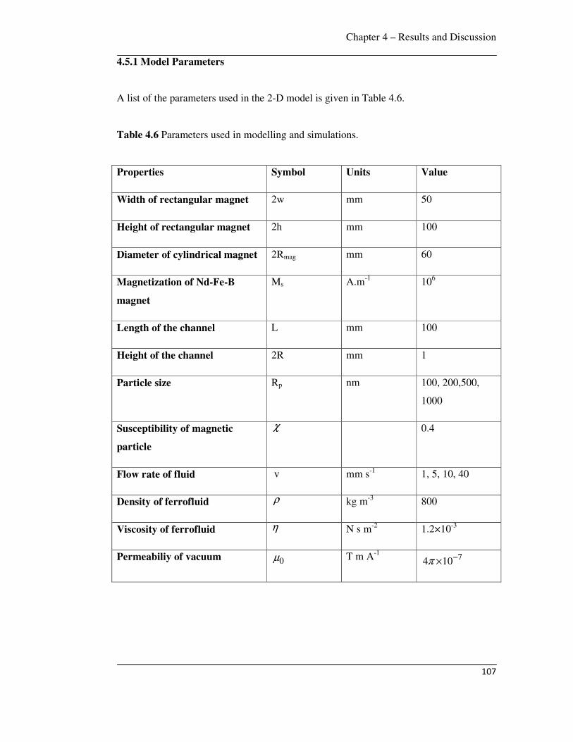
Chapter 4 – Results and Discussion
107
4.5.1 Model Parameters
A list of the parameters used in the 2-D model is given in Table 4.6.
Table 4.6 Parameters used in modelling and simulations.
Properties Symbol Units Value
Width of rectangular magnet
2w mm 50
Height of rectangular magnet 2h mm 100
Diameter of cylindrical magnet 2Rmag mm 60
Magnetization of Nd-Fe-B
magnet
Ms A.m-1 106
Length of the channel L mm 100
Height of the channel 2R mm 1
Particle size Rp nm 100, 200,500,
1000
Susceptibility of magnetic
particle
χ 0.4
Flow rate of fluid v mm s-1 1, 5, 10, 40
Density of ferrofluid ρ kg m-3 800
Viscosity of ferrofluid η N s m-2 1.2×10⁻³
Permeabiliy of vacuum 0µ T m A-1 74 10π −×

Chapter 4 – Results and Discussion
108
4.5.2 Magnetic Field Components
Figure 4.24 shows the variation in 2xH∇ and 2
yH∇ (calculated from Eqns. 3.5, 3.6, 3.7
and 3.8) across the dimensionless length (x/L) of the vessel. The curves in Figs. 4.24.a
and 4.24.b depict the profiles for rectangular and cylindrical magnet, respectively.
Figure 4.24 components of (a) Nd-Fe-B rectangular permanent magnet and (b) Nd-
Fe-B cylindrical permanent magnet along the axis of vessel, when the vessel is at a
distance of 5, 10 and 15 mm from the surface of magnet.
The 2xH∇ plots [curves (i) - (iii)] indicate that upstream to the magnet the magnitude of
the force field ( 2xH∇ ) gradually increases and downstream it progressively decreases.
The y-component gradients 2yH∇ [curves (iv) - (vi)] creates a gradient of magnetic force
in the -y direction, which moves the MCP towards the magnet. These curves also show
that 2yH∇ decays sharply away from the magnet towards the inlet and outlet of the
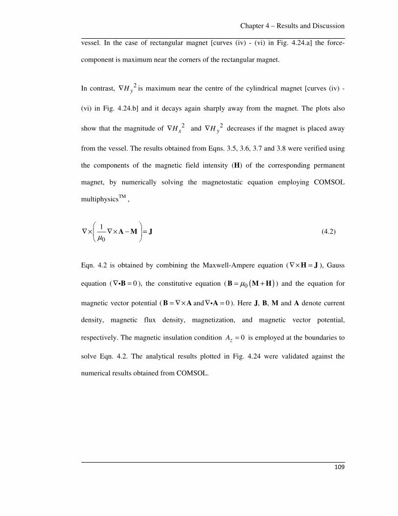
Chapter 4 – Results and Discussion
109
vessel. In the case of rectangular magnet [curves (iv) - (vi) in Fig. 4.24.a] the force-
component is maximum near the corners of the rectangular magnet.
In contrast, 2yH∇ is maximum near the centre of the cylindrical magnet [curves (iv) -
(vi) in Fig. 4.24.b] and it decays again sharply away from the magnet. The plots also
show that the magnitude of 2xH∇ and 2
yH∇ decreases if the magnet is placed away
from the vessel. The results obtained from Eqns. 3.5, 3.6, 3.7 and 3.8 were verified using
the components of the magnetic field intensity (H) of the corresponding permanent
magnet, by numerically solving the magnetostatic equation employing COMSOL
multiphysicsTM ,
0
1µ
∇ × ∇ × − =
A M J (4.2)
Eqn. 4.2 is obtained by combining the Maxwell-Ampere equation (∇× =H J ), Gauss
equation ( 0∇ =Bi ), the constitutive equation ( ( )0µ= +B M H ) and the equation for
magnetic vector potential ( = ∇×B A and 0∇ =Ai ). Here J, B, M and A denote current
density, magnetic flux density, magnetization, and magnetic vector potential,
respectively. The magnetic insulation condition 0zA = is employed at the boundaries to
solve Eqn. 4.2. The analytical results plotted in Fig. 4.24 were validated against the
numerical results obtained from COMSOL.
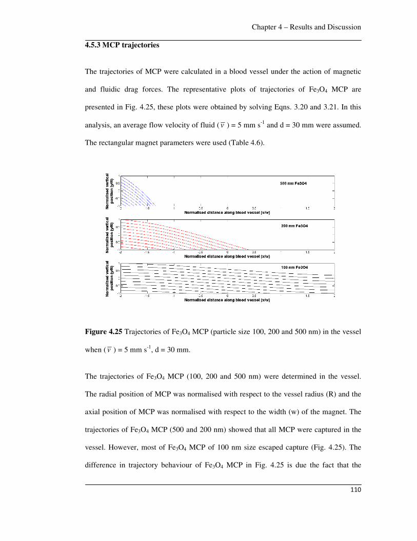
Chapter 4 – Results and Discussion
110
4.5.3 MCP trajectories
The trajectories of MCP were calculated in a blood vessel under the action of magnetic
and fluidic drag forces. The representative plots of trajectories of Fe3O4 MCP are
presented in Fig. 4.25, these plots were obtained by solving Eqns. 3.20 and 3.21. In this
analysis, an average flow velocity of fluid ( v ) = 5 mm s-1 and d = 30 mm were assumed.
The rectangular magnet parameters were used (Table 4.6).
Figure 4.25 Trajectories of Fe3O4 MCP (particle size 100, 200 and 500 nm) in the vessel
when ( v ) = 5 mm s-1, d = 30 mm.
The trajectories of Fe3O4 MCP (100, 200 and 500 nm) were determined in the vessel.
The radial position of MCP was normalised with respect to the vessel radius (R) and the
axial position of MCP was normalised with respect to the width (w) of the magnet. The
trajectories of Fe3O4 MCP (500 and 200 nm) showed that all MCP were captured in the
vessel. However, most of Fe3O4 MCP of 100 nm size escaped capture (Fig. 4.25). The
difference in trajectory behaviour of Fe3O4 MCP in Fig. 4.25 is due the fact that the

Chapter 4 – Results and Discussion
111
magnetic force is proportional to the volume of the MCP, hence larger MCP experience a
stronger capture force and can be captured easily.
The effect of magnetic properties of MCP on the trajectories is presented in Fig. 4.26.
Figure 4.26 Trajectories of different MCP of 100 nm size in the vessel when ( v ) = 5
mm s-1, d = 30 mm.
In this calculation of the trajectories, Fe, FeCo, Fe3O4 MCP with 100 nm size were
considered, an average flow velocity of fluid ( v ) of 5 mm s-1 and d of 30 mm were
assumed. It was observed that all Fe and FeCo MCP were captured in the vessel, but
most of Fe3O4 MCP escaped capture. The difference in the trajectory behaviour of Fe,
FeCo and Fe3O4 MCP in Fig. 4.26 is attributed to the different magnetic properties of
MCP. As the order of magnetization value is Fe > FeCo > Fe3O4, therefore, MCP with
higher magnetization can be captured easily.
Chapter 4 – Results and Discussion
112
4.5.4 Distance of Capture (d)
The optimum distance of magnet from the blood vessel to capture the MCP was
determined from Eqn. 3.20 and 3.21. Figure 4.27 shows the representative plots of
distance of capture (d) of various MCP as a function of their size for different flow rates
of fluid (1, 5, 10 mm s-1).
Figure 4.27 Representative plots of distance of capture of various MCP as a function of
MCP size for different flow rates of fluid.
From the Fig. 4.27, it is evident that as the MCP size increases, particles can be captured
from further distance. For Fe particles at a given fluid flow rate of 5 mm s-1, the distance
of capture of 100 and 1000 nm size was 31 and 43 mm, respectively. At the fluid velocity
of 5 mm s-1, the distance of capture of 100 and 1000 nm size [email protected] mol Au was 9.6

Chapter 4 – Results and Discussion
113
and 22 mm, and that of PVA-IO (2 wt% PVA coated) was 11.5 and 23.5 mm. The
distance of capture decreased with increasing flow rate of fluid, e.g., d is 34 and 30 mm
at flow rates of 1 and 10 mm s-1, respectively for Fe particle (100 nm).
The distance of capture for various MCP with size of 100 nm at a given fluid flow rate (5
mm s-1) using a typical permanent magnet (field gradient of 25 T m-1) is presented in Fig.
4.28.
Figure 4.28 Distance of capture for various MCP with size of 100 nm and v = 5 mm s-1
using a typical permanent magnet.
From the results in Fig. 4.28, it can be concluded that in the context of drug targeting
Fe3O4, Fe@Au, PVA-IO MCP (100 nm) can be targeted to the breast tumor and other
skin tumors located in the hand, leg and neck by a typical permanent magnet. The
average distances of internal organs such as lung, liver, kidney, pancreas from the skin
are 20, 25, 30 and 32 mm, respectively [331, 332]. Therefore, Fe3O4, Fe@Au, PVA-IO
MCP of 100 nm size are not suitable to be targeted to the tumors situated at lung, liver,
kidney, pancreas by a typical permanent magnet. However, MCP with higher
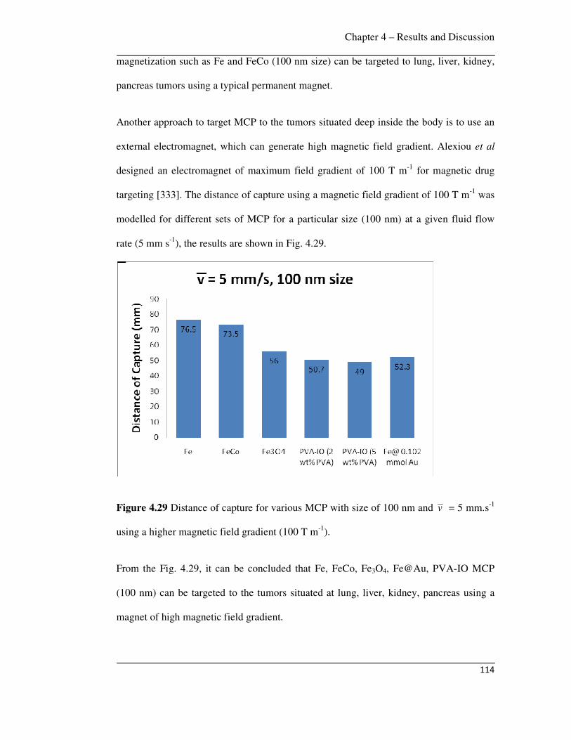
Chapter 4 – Results and Discussion
114
magnetization such as Fe and FeCo (100 nm size) can be targeted to lung, liver, kidney,
pancreas tumors using a typical permanent magnet.
Another approach to target MCP to the tumors situated deep inside the body is to use an
external electromagnet, which can generate high magnetic field gradient. Alexiou et al
designed an electromagnet of maximum field gradient of 100 T m-1 for magnetic drug
targeting [333]. The distance of capture using a magnetic field gradient of 100 T m-1 was
modelled for different sets of MCP for a particular size (100 nm) at a given fluid flow
rate (5 mm s-1), the results are shown in Fig. 4.29.
Figure 4.29 Distance of capture for various MCP with size of 100 nm and v = 5 mm.s-1
using a higher magnetic field gradient (100 T m-1).
From the Fig. 4.29, it can be concluded that Fe, FeCo, Fe3O4, Fe@Au, PVA-IO MCP
(100 nm) can be targeted to the tumors situated at lung, liver, kidney, pancreas using a
magnet of high magnetic field gradient.

Chapter 4 – Results and Discussion
115
4.5.5 Numerical simulations
The success of magnetic drug targeting depends on the extent to which MCP can be
deposited at the desired location. The following factors have a significant influence: (i)
the distance between the injection point of MCP and the position of the tumor, (ii) size,
and magnetic properties of MCP, (iii) magnetic field distribution and (iv) loss of drugs
because of convective flow. The effect of convective and diffusive fluxes due to fluid
flow on the deposition of MCP at the targeted location was studied. The results obtained
from this study reveal the importance of optimizing the location for injection with respect
to the magnetic field intensity. The study also emphasises the influence of size and
magnetic properties of MCP. The trapping of MCP was studied using nonlinear CFD
simulations.
Numerical simulations were performed to study the spatio-temporal evolution of the
concentration profile of ferrofluid deposition in the vessel. The contours displayed in Fig.
4.30 are the spatio-temporal evolution of ferrofluid ((Rp = 100 nm and χ = 0.4)) inside
the vessel when v = 10 mm.s-1 and d = 10 mm.
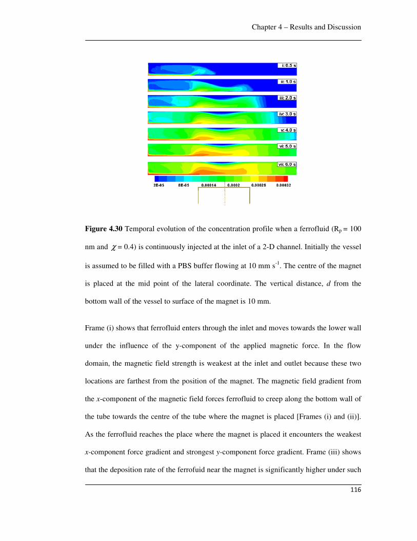
Chapter 4 – Results and Discussion
116
Figure 4.30 Temporal evolution of the concentration profile when a ferrofluid (Rp = 100
nm and χ = 0.4) is continuously injected at the inlet of a 2-D channel. Initially the vessel
is assumed to be filled with a PBS buffer flowing at 10 mm s-1. The centre of the magnet
is placed at the mid point of the lateral coordinate. The vertical distance, d from the
bottom wall of the vessel to surface of the magnet is 10 mm.
Frame (i) shows that ferrofluid enters through the inlet and moves towards the lower wall
under the influence of the y-component of the applied magnetic force. In the flow
domain, the magnetic field strength is weakest at the inlet and outlet because these two
locations are farthest from the position of the magnet. The magnetic field gradient from
the x-component of the magnetic field forces ferrofluid to creep along the bottom wall of
the tube towards the centre of the tube where the magnet is placed [Frames (i) and (ii)].
As the ferrofluid reaches the place where the magnet is placed it encounters the weakest
x-component force gradient and strongest y-component force gradient. Frame (iii) shows
that the deposition rate of the ferrofuid near the magnet is significantly higher under such
Chapter 4 – Results and Discussion
117
condition. Frames (iv) to (vii) show that when ferrofluid starts deposition near the
magnet, diffusive and convective forces spread the ferrofluid in the vertical and lateral
direction of the vessel, respectively. The convective forces are particularly important in
reducing deposition of ferrofluid near the magnet, making the ferrofluid flowing away
from the targeted zone, especially in the downstream. Frames (iv) to (vii) also show that
maximum deposition of particles takes place near the corners of the magnet where the y-
component of the magnetic force is strongest. The contour plots confirm that there is
ferrofluid deposition near the bottom wall and it is thickest in the region where the
magnet is placed. This result is important for magnetic drug targeting, because it reveals
that deposition is highest near the magnet and when the drug loaded MCP are injected
and subjected to an external magnetic field, they creep along the wall of the blood
vessels. Thus special care may be necessary to protect drugs from friction/adsorption
with the wall before reaching the targeted location.
In Fig. 4.31 a comparison of the MCP deposition rate was presented when v is varied
from 1 mm s-1 to 40 mm s-1 and d is kept constant at 10 mm. Figs. 4.31.a to 4.31.c show
that the mechanism of deposition remains the same as that described for Fig. 4.30,
however, the time required to deposit MCP changes as v is varied. For example, for d =
10 mm, Fig. 4.31.a shows that when v = 1 mm s-1 deposition near the magnet at 15 s is
similar to the case of (i) deposition at 3 s when v = 10 mm s-1 [Fig. 4.30, frame (iv)] or
(ii) deposition at 5 s when v = 5 mm s-1 [Fig. 4.31.b, frame (vi)]. Thus, as the flow rate
is reduced the rate of deposition is higher due to lower loss of ferrofluid through the
outlet. This is in accordance with the experimental results presented in Fig. 4.23.
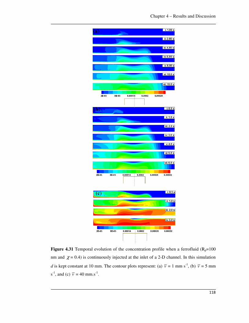
Chapter 4 – Results and Discussion
118
Figure 4.31 Temporal evolution of the concentration profile when a ferrofluid (Rp=100
nm and χ = 0.4) is continuously injected at the inlet of a 2-D channel. In this simulation
d is kept constant at 10 mm. The contour plots represent: (a) v = 1 mm s-1, (b) v = 5 mm
s-1, and (c) v = 40 mm.s-1.
(c)
(b)
(a)

Chapter 4 – Results and Discussion
119
The simulations in the Figs. 4.30 and 4.31 suggest that the time of exposure of magnetic
field can be optimized once the diameter of the blood vessel and blood flow rate is
known. For example, Fig. 4.31.c shows that when v = 40 mm s-1 and d = 10 mm, 0.5 to
1.0 s exposure is sufficient for significant MCP deposition. Thereafter, dispersion of
MCP along and across the vessel leads to loss of MCP from the targeted location.
The magnetic field gradient is another very useful parameter, which is decreased with
increasing distance of the magnet from the vessel. For example, when v = 10 mm s-1 and
d = 5 mm, the rectangular magnet ensures higher deposition near the corners (Fig.
4.32.a). However, a weaker magnetic field ( v = 10 mm s-1 and d = 15 mm) leads to early
dispersion of ferrofluid and its loss from the outlet because now convective effect
dominates over the magnetic effect (Fig. 4.32.b). The effect of magnetic force can also be
changed by varying the size of the MCP. Fig. 4.32.c shows that for larger MCP (200
nm), high and smooth deposition can be expected near the magnet within 1.0 s when v =
10 mm s-1 and d = 10 mm. In Fig. 4.30, we can achieve similar deposition near the
targeted zone only after 2.0 s with a particle size of 100 nm.

Chapter 4 – Results and Discussion
120
Figure 4.32 Temporal evolution of the concentration profile when a ferrofluid ( v = 10
mm s-1) is continuously injected at the inlet of a 2-D channel. In this contour plots: (a) d
= 5 mm, Rp = 100 nm and χ = 0.4; (b) d = 15 mm, Rp = 100 nm and χ = 0.4; (c) d = 10
mm, Rp = 200 nm and χ = 0.4.
(a) (b)
(c)

Chapter 4 – Results and Discussion
121
Interestingly, a very weak magnetic field can also lead to change in the flow mechanism
(Fig. 4.33). Fig. 4.33.a shows the temporal evolution of ferrofluid (Rp=100 nm and χ =
0.4), when v = 10 mm s-1 and d = 50 mm.
Figure 4.33 (a) Temporal evolution of the concentration profile when a ferrofluid
(Rp=100 nm and χ = 0.4) is continuously injected at the inlet of a 2-D channel at flow
rate ( v ) of 10 mm s-1 under weak magnetic field (d = 50 mm). (b)The streamline contour
plot of frame (i) in magnified view shows the trade off between the magnetic force and
the convective force leading to the formation of vortices near the wall.
Frame (i) in Fig. 4.33.a shows that the magnetic field initially directs the ferrofluid to
move towards the bottom wall, however, convective force takes over quickly.
Consequently, the ferrofluid dislodges from the bottom wall and flows through the
central portion of the vessel. The streamlines shown in the magnified view (Fig. 4.33.b)
indicate that the competition between magnetic and convective forces leads to formation
(a)

Chapter 4 – Results and Discussion
122
of vortices near the wall reducing the movement of ferrofluid towards the wall. Frames
(ii) to (vi) in Fig. 4.33.a show that at later stages the magnetic field directs ferrofluid to
touch the lower wall near the inlet but most of the ferrofluid passes through the central
part of the tube to the downstream. The flow in the downstream is similar to the flow in a
2-D channel in the absence of a magnetic field. Hence the magnetic field strength and
respective convective forces due to flow of the fluid has to be optimized to maximize
MCP deposition.
Figure 4.34 shows the effect of magnet shape in magnetic drug targeting. A cylindrical
magnet shows that deposition of MCP is maximum near the centre of the magnet.
Figures 4.34.a, 4.34.b and 4.34.c show the spatio-temporal evolution of ferrofluid in the
vessel when d = 10 mm and flow rate is varied ( v = 1 mm s-1, 10 mm s-1, and 40 mm s-1,
respectively). Deposition is maximum near the centre of the magnet (Fig. 4.34.a) because
the magnetic force is maximum at the centre of the cylindrical magnet (Fig. 4.24.b). This
is in contrast to the case of a rectangular magnet where the magnetic force is maximum at
the corners. However, the change of deposition with the change in flow rate is similar to
the case of a rectangular magnet.
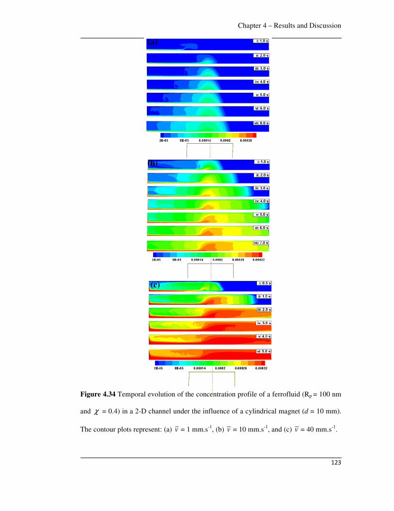
Chapter 4 – Results and Discussion
123
Figure 4.34 Temporal evolution of the concentration profile of a ferrofluid (Rp = 100 nm
and χ = 0.4) in a 2-D channel under the influence of a cylindrical magnet (d = 10 mm).
The contour plots represent: (a) v = 1 mm.s-1, (b) v = 10 mm.s-1, and (c) v = 40 mm.s-1.
(a)
(b)
(c)

Chapter 4 – Results and Discussion
124
Several researchers have studied the magnetic drug targeting. In previous studies, it was
reported that a magnetic field of 0.8 T is sufficient to exceed linear blood flow in the
intratumoral vasculature to localize magnetic carriers [22]. Lubbe et al studied the
targeting of ferrofluid containing starch coated iron oxide nanoparticles (100 nm) loaded
with mitoxantrone anti-cancer drug using a permanent magnet (0.5 T) in animal model
[60]. Clinical trials in human patients using magnetic drug targeting (0.8 T) were
conducted by Lubbe et al using anti-cancer drug epirubicin attached to starch coated iron
oxide nanoparticles in form of ferrofluid (100 nm) and demonstrated that the infusion of
ferrofluid was well tolerated by patients [44, 45]. Goodwin et al used magnetic carriers
(0.5-5 µm) for drug targeting at the liver and lungs (8-12 cm) in the swine model using a
permanent magnet (0.1 T) [94]. Preliminary investigations of the hydrodynamics of drug
targeting suggest that a magnetic field of 0.2 T with field gradient of 8 T m-1 is sufficient
to target magnetic nanoparticle carriers in femoral arteries [95].
In this work, a Nd-Fe-B permanent magnet was used for targeting of MCP, magnetic
field generated by this magnet was 0.45 T with field gradient of 25 T m-1, which is
comparable to previous reports [44, 45, 60]. A high percentage of MCP could be
captured (90% of PVA-IO and 86% of Fe@Au) by this magnet for fluid flow rate of 1
mm s-1.
In previous modelling of magnetic drug targeting, Furlani et al derived an analytical
expression of a cylindrical magnet to calculate the trajectories of magnetic particles and
proposed a parametric analysis of magnetic targeting as a function of parameters such as
the carrier particle size, properties and volume fraction of the embedded magnetic
nanoparticles, properties of the magnet and blood flow rate [97, 98]. Rotariu et al used
computer simulation of magnetic field of different magnetic configurations such as
cylindrical magnet, magnetic circuit with parabolic shape confocal poles and needle
Chapter 4 – Results and Discussion
125
magnet to determine the trajectories of magnetic particles within tumor microvasculature
[99]. Another model has been reported to optimize the necessary magnetic field by
simulating the magnetic particle’s trajectory [100]. A CFD analysis was used for Y-
shaped model flow system of blood vessel and the capture efficiency of magnetic
particles was determined [101]. Analysis of magnetically induced localization of the
ferrofluid at a targeted region was also reported, it was shown that ferrofluid
accumulation behaved as a solid obstacle in the flow [102]. Li et al simulated the
streamlines and contours of concentration of a ferrofluid in a vessel and showed that
particle accumulation was affected by the magnetic property of the particles, magnetic
field strength and gradient as well as fluid flow rate [103].
In this work, the modelling of MCP targeting was performed by solving the equation of
motion considering magnetic and fluidic forces. The trajectories of MCP as a function of
flow rate of fluid, magnetic property of MCP and size of MCP were determined; the
results are consistent with previous reports [97, 98]. Further, the optimum distance of
capture of various MCP as a function of flow rate of fluid, magnetic property of MCP
and size of MCP were determined in this work to establish the parameters for effective
magnetic drug targeting, which was not reported earlier. The finer features of MCP
deposition as well as the factors influencing capture efficiency of MCP using CFD
simulations were studied, which is comparable to previous report [103]. The simulations
show that the capture efficiency is dependent on the magnetic properties and size of MCP
and that creep of MCP, convection and diffusion effects influence the efficacy of
magnetic drug targeting. CFD simulations qualitatively support the deposition efficiency
trend found in the experiments.
In summary, Fe3O4, Fe@Au, PVA-IO MCP (100 nm) are best suitable for targeting to
the breast tumor and other skin tumor by a typical permanent magnet. Fe and FeCo

Chapter 4 – Results and Discussion
126
MCP or higher magnetic field gradient (100 T m-1
) are useful for targeting tumors
situated deep inside the body. The creeping of ferrofluid along the wall of blood vessel
suggests that drug injection should be as close as possible to the tumor.
Conclusions and Future Work
127
Chapter 5
Conclusions and Future Work
This chapter lists the significant findings of the present work and the scope of future
work which could be made by utilizing the results obtained in this work.
5.1 Conclusions
The delivery of anti-cancer drugs to specific target sites with minimum side effects is a
challenge in conventional cancer treatments. Magnetically targeted drug delivery system
using MCP targeted by an external magnetic field is a promising alternative to avoid
several issues associated with conventional cancer therapies. In the present work, the
synthesis, characterization and property evaluation of coated MCP with an experimental
and modelling study of the efficacy with which these particles can be retained in the
tumor were investigated. These MCP were extensively characterized using TEM, VSM,
XRD, TGA, XPS, FTIR and DLS. MCP were loaded with anti-cancer drug DOX, drug
loading and release properties were studied. An in-vitro apparatus simulating the human
circulatory system was constructed and used to determine the retention of MCP under
various flow rates of fluid and varying the magnetic field gradients. A time dependent
CFD modelling of MCP deposition was carried out by Ansys-Fluent. The conclusions of
this work are summarized:
• Gold coated iron (Fe@Au) nanoparticles (15 nm) were synthesized by the reverse
micelle technique with sodium borohydride reduction of ferrous sulphate and
Conclusions and Future Work
128
HAuCl4 using CTAB as surfactant, n-butanol as co-surfactant and octane as oil
phase.
• Pure iron (Fe) nanoparticles are oxidized to iron oxide. This oxidation of Fe can
be minimized by coating with gold (Au), which also provides biocompatibility,
useful surface chemistry and biological reactivity. Fe@Au nanoparticles
exhibited superparamagnetic character having decreasing saturation
magnetization with increasing Au coating. Since gold is a diamagnetic material,
interparticle coupling between iron and gold decreases the magnetic properties of
the coated nanoparticles.
• Fe@Au nanoparticles attached to DOX by the interaction of amine (–NH2) group
of DOX with Au, as evidenced by the peak broadening of N-H stretching
vibrations of DOX-conjugated Fe@Au nanoparticles in FTIR spectra and red
shifting of absorption band of gold colloid with addition of DOX in UV-visible
spectra. A significant quantity of DOX was loaded (94%) by the Fe@Au
nanoparticles and up to 25% of adsorbed DOX was released.
• PVA-IO nanoparticles of average size 14 nm (SD 3) were synthesized by the co-
precipitation of iron oxide followed by coating with different weight percentage
of PVA solution. Up to 23% of PVA was attached to iron oxide nanoparticles as
determined by TGA. This attachment of PVA to iron oxide nanoparticles
occurred via hydrogen bonding between hydroxyl group of PVA and protonated
surface of the oxide.
• The crystal structure of the magnetic core in PVA-IO was magnetite. There was a
broadening of XRD peaks with an increase in PVA concentration, due to decrease
in crystallite size.

Conclusions and Future Work
129
• PVA-IO nanoparticles were superparamagnetic with decreasing Ms with
increasing PVA concentration. This is due to the dilution effect from adsorbed
water and the hydroxyl content of PVA.
• In the context of drug delivery, superparamagnetic nanoparticles (both Fe@Au
and PVA-IO) are useful as they do not retain magnetization before and after
exposure to an external magnetic field, reducing the probability of particle
aggregation due to magnetic dipole interaction.
• The attachment of DOX to the PVA-IO nanoparticles occurred via the interaction
of –NH2 and –OH groups of DOX with –OH group of PVA through hydrogen
bonding as evidenced by FTIR spectra. Up to 60% of DOX was loaded with
PVA-IO nanoparticles and 45% of adsorbed drug was released. The drug release
profiles followed the Fick’s law of diffusion with diffusion coefficient (D) of 1.5
10-18 cm2.s-1.
• The in-vitro experimental targeting of MCP shows that a high percentage of MCP
could be captured. e.g., 90% of PVA-IO and 86% of Fe@Au MCP were captured
at a field gradient of 25 T m-1 and flow rate of 1 mm s-1.
• The modelling results of trajectories of MCP show that it is easier to capture
particles with higher saturation magnetization and larger size at low flow rate of
fluid. The calculation of distance of capture from the modelling predicts that
Fe3O4, Fe@Au, PVA-IO MCP (100 nm) are best suitable for targeting to the
breast tumor and other skin tumor located in hand, leg, neck by a typical
permanent magnet. In order to target tumors situated deep inside the body, MCP
with higher saturation magnetization such as Fe and FeCo or an external magnet
with higher magnetic field gradient must be chosen.
Conclusions and Future Work
130
• The simulations of CFD model show that for a given magnetic field strength, the
time of exposure to the magnetic field can be optimized once the diameter of the
blood vessel and blood flow rate are known. Lower flow rate increases the time
required for magnetic field exposure, higher flow rate leads to larger loss of MCP
due to dispersion of particles.
• The magnetic field strength, the magnet shape, magnetic properties and size of
the MCP significantly influence deposition rate. A weaker magnetic field leads to
early dispersion of ferrofluid and its loss from the outlet since convective effect
dominates over the magnetic effect. High and smooth deposition is found near the
magnet within short time for larger MCP. Deposition is maximum near the centre
of the cylindrical magnet and corners of the rectangular magnet.
• CFD simulations show that the ferrofluid creeps along the bottom wall of the
vessel under the influence of a magnetic field, this may cause friction leading to
loss of coating and drug prior to reaching the tumor, hence drug injection should
be as close as possible to the tumor.
• In a very weak magnetic field, creep flow is absent and ferrofluid flows along the
centre of the vessel, recirculation zones near the wall boundary hinder the
movement of MCP back to the targeted region.
In summary, this work shows that Fe@Au and PVA-IO MCP have excellent potential for
tumor targeted magnetic drug delivery, that the capture efficiency is dependent on the
magnetic properties and size of MCP, blood flow rate, time of capture, and that
convection and diffusion effects can significantly influence the capture efficiency of
MCP for magnetically targeted drug delivery.
Conclusions and Future Work
131
5.2 Future scope of work
This section presents the scope of future work which can be extended from this work.
This present work provides a platform to further research in the area of magnetically
targeted drug delivery.
• In this work, it was shown that Fe@Au nanoparticles are potential magnetic drug
carriers for tumor targeted drug delivery in terms of drug loading (94%), drug
release (25%) and drug targeting (86%). This work can be extended to study the
photothermal therapy of Fe@Au nanoparticles. As gold can be heated by near
infrared (NIR) light irradiation; the resulting heat can destroy tumor cells, this
modality of treatment is known as hyperthermia resulting from this photothermal
effect [217-219]. Therefore, Fe@Au nanoparticles with different gold coating
thickness can be synthesized, targeted to the tumor and then exposed to deep
penetrating near infrared (NIR) laser to study the heating and therapeutic efficacy.
• In this work, the functionalization of magnetic iron oxide nanoparticles by PVA
to conjugate with DOX was studied which shows that PVA coated iron oxide
nanoparticles have great potential to be used in magnetically targeted drug
delivery. This work can be extended by derivatization of PVA by phosphate
group which improves stability and dispersability of magnetic nanoparticles
[334]. Therefore, iron oxide can be coated with different polyvinyl alcohol
phosphate (PVAP) and interaction of DOX with PVAP coated iron oxide MCP,
DOX loading and release kinetics can be studied.
• In case of CFD simulations, a two-dimensional (2-D) model was employed,
which helps in quick implementation of the magnetohydrodynamic formulation
and provides results on the mechanism of deposition in the initial stages. The
Conclusions and Future Work
132
experimental capture efficiency was compared to the results of this 2D model.
This work can be extended by considering a 3-D model, CFD simulations can be
performed using this 3-D model to determine the deposition efficiency and
compare these results quantitatively with the experimental observations.
References
133
References
[1] B. W. Stewart and P. Kleihues, World Cancer Report, (2003).
[2] International Agency for Research on Cancer, http://www-dep.iarc.fr/.
[3] D. M. Parkin, F. Bray, J. Ferlay and P. Pisani, Global cancer statistics 2002, CA:
Cancer Journal for Clinicians 55 (2005), 74-108.
[4] D. Hanahan and R. A. Weinberg, The hallmarks of cancer, Cell 100 (2000), 57-
70.
[5] R. J. Narayan, S. P. Adiga, M. J. Pellin, L. A. Curtiss, A. J. Hryn, S. Stafslien, B.
Chisholm, C. C. Shih, C. M. Shih, S. J. Lin, Y. Y. Su, C. Jin, J. Zhang, N. A. Monteiro-
Riviere and J. W. Elam, Atomic layer deposition-based functionalization of materials for
medical and environmental health applications, Philosophical Transactions of the Royal
Society A: Mathematical, Physical and Engineering Sciences 368 (2010), 2033-2064.
[6] R. J. Narayan and R. Roeder, The development of novel materials for medical
devices, JOM Journal of the Minerals, Metals and Materials Society 61 (2009), 13-13.
[7] J. M. Wilkinson, Nanotechnology applications in medicine, Medical Device
Technology 14 (2003), 29-31.
[8] J. Panyam and V. Labhasetwar, Biodegradable nanoparticles for drug and gene
delivery to cells and tissue, Advanced Drug Delivery Review 55 (2003), 329-347.
[9] F. X. Gu, R. Karnik, A. Z. Wang, F. Alexis, E. Levy-Nissenbaum, S. Hong, R. S.
Langer and O. C. Farokhzad, Targeted nanoparticles for cancer therapy, Nano Today 2
(2007), 14-21.
[10] R. Singh and J. W. Lillard Jr, Nanoparticle-based targeted drug delivery,
Experimental and Molecular Pathology 86 (2009), 215-223.

References
134
[11] D. Peer, J. M. Karp, S. Hong, O. C. Farokhzad, R. Margalit and R. Langer,
Nanocarriers as an emerging platform for cancer therapy, Nature Nanotechnology 2
(2007), 751-760.
[12] T. Lammers, W. E. Hennink and G. Storm, Tumour-targeted nanomedicines:
principles and practice, British Journal of Cancer 99 (2008), 392-407.
[13] O. C. Farokhzad and R. Langer, Impact of nanotechnology on drug delivery, ACS
Nano 3 (2009), 16-20.
[14] R. Jurgons, C. Seliger, A. Hilpert, L. Trahms, S. Odenbach and C. Alexiou, Drug
loaded magnetic nanoparticles for cancer therapy, Journal of Physics : Condensed Matter
18 (2006), S2893-S2902.
[15] M. Johannsen, U. Gneveckow, L. Eckelt, A. Feussner, N. Waldofner, R. Scholz,
S. Deger, P. Wust, S. A. Loening and A. Jordan, Clinical hyperthermia of prostate cancer
using magnetic nanoparticles: Presentation of a new interstitial technique, International
Journal of Hyperthermia 21 (2005), 637-647.
[16] C. H. Cunningham, T. Arai, P. C. Yang, M. V. McConnell, J. M. Pauly and S. M.
Conolly, Positive Contrast Magnetic Resonance Imaging of Cells Labeled with Magnetic
Nanoparticles, Magnetic Resonance in Medicine 53 (2005), 999-1005.
[17] P. Tartaj, M. Del Puerto Morales, S. Veintemillas-Verdaguer, T. Gonzalez-
Carreno and C. J. Serna, The preparation of magnetic nanoparticles for applications in
biomedicine, Journal of Physics D: Applied Physics 36 (2003), R182-R197.
[18] A. K. Gupta and M. Gupta, Synthesis and surface engineering of iron oxide
nanoparticles for biomedical applications, Biomaterials 26 (2005), 3995-4021.
[19] M. W. Freeman, A. Arrott and J. H. L. Watson, Magnetism in medicine, Journal
of Applied Physics 31 (1960), S404-S405.
References
135
[20] S. Goodwin, C. Peterson, C. Hoh and C. Bittner, Targeting and retention of
magnetic targeted carriers (MTCs) enhancing intra-arterial chemotherapy, Journal of
Magnetism and Magnetic Materials 194 (1999), 132-139.
[21] T. Neuberger, B. Schöpf, H. Hofmann, M. Hofmann and B. von Rechenberg,
Superparamagnetic nanoparticles for biomedical applications: Possibilities and
limitations of a new drug delivery system, Journal of Magnetism and Magnetic Materials
293 (2005), 483-496.
[22] A. Senyei, K. Widder and G. Czerlinski, Magnetic guidance of drug-carrying
microspheres, Journal of Applied Physics 49 (1978), 3578-3583.
[23] Y. Zhang, N. Kohler and M. Zhang, Surface modification of superparamagnetic
magnetite nanoparticles and their intracellular uptake, Biomaterials 23 (2002), 1553-
1561.
[24] P. Wust, B. Hildebrandt, G. Sreenivasa, B. Rau, J. Gellermann, H. Riess, R. Felix
and P. M. Schlag, Hyperthermia in combined treatment of cancer, The Lancet Oncology
3 (2002), 487-497.
[25] W. Andra, C. G. d'Ambly, R. Hergt, I. Hilger and W. A. Kaiser, Temperature
distribution as function of time around a small spherical heat source of local magnetic
hyperthermia, Journal of Magnetism and Magnetic Materials 194 (1999), 197-203.
[26] A. Jordan, R. Scholz, P. Wust, H. Fahling and F. Roland, Magnetic fluid
hyperthermia (MFH): Cancer treatment with AC magnetic field induced excitation of
biocompatible superparamagnetic nanoparticles, Journal of Magnetism and Magnetic
Materials 201 (1999), 413-419.
[27] I. Hilger, R. Hergt and W. A. Kaiser, Effects of magnetic thermoablation in
muscle tissue using iron oxide particles: An in vitro study, Investigative Radiology 35
(2000), 170-179.

References
136
[28] I. Coroiu, Relaxivities of different superparamagnetic particles for application in
NMR tomography, Journal of Magnetism and Magnetic Materials 201 (1999), 449-452.
[29] A. E. Merbach and E. Toth, The chemistry of contrast agents in medical magnetic
resonance imaging, (2001), Wiley, Chichester.
[30] D. K. Kim, Y. Zhang, J. Kehr, T. Klason, B. Bjelke and M. Muhammed,
Characteriasation and MRI study of surfactant coated superparamagnetic nanoparticles
administered into the rat brain, Journal of Magnetism and Magnetic Materials 225
(2001), 256-261.
[31] P. A. Liberti, C. G. Rao and L. W. M. M. Terstappen, Optimization of ferrofluids
and protocols for the enrichment of breast tumor cells in blood, Journal of Magnetism
and Magnetic Materials 225 (2001), 301-307.
[32] F. Paul, D. Melville, S. Roath and D. Warhurst, A bench top magnetic separator
for malarial parasite concentration, IEEE Transactions on Magnetics 17 (1981), 2822–
2824.
[33] N. Seesod, P. Nopparat, A. Hedrum, A. Holder, S. Thaithong, M. Uhlen and J.
Lundeberg, An integrated system using immunomagnetic separation, polymerase chain
reaction, and colorimetric detection for diagnosis of Plasmodium Falciparum American
Journal of Tropical Medicine and Hygiene 56 (1997), 322-328.
[34] S. Mornet, S. Vasseur, F. Grasset and E. Duguet, Magnetic nanoparticle design
for medical diagnosis and therapy Journal of Materials Chemistry 14 (2004), 2161-2175.
[35] G. P. Yan, L. Robinson and P. Hogg, Magnetic resonance imaging contrast
agents: Overview and perspectives, Radiography 13 (2007), e5-e19.
[36] C. Corot, P. Robert, J.-M. Idée and M. Port, Recent advances in iron oxide
nanocrystal technology for medical imaging, Advanced Drug Delivery Reviews 58
(2006), 1471-1504.
References
137
[37] C. Alexiou, W. Arnold, R. J. Klein, F. G. Parak, P. Hulin, C. Bergemann, W.
Erhardt, S. Wagenpfeil and A. S. Lubbe, Locoregional cancer treatment with magnetic
drug targeting, Cancer Research 60 (2000), 6641-6648
[38] C. Alexiou, R. Schmid, R. Jurgons, M. Kremer, G. Wanner, C. Bergemann, E.
Huenges, T. Nawroth, W. Arnold and F. Parak, Targeting cancer cells: magnetic
nanoparticles as drug carriers, European Biophysics Journal 35 (2006), 446-450.
[39] R. V. Ramanujan, Magnetic particles for biomedical applications, In Biomedical
Materials, R. Narayanan, ed., (2009), Springer.
[40] American Cancer Society, http://www.cancer.org/docroot/ETO/ETO_1.asp.
[41] P. Moroz, S. K. Jones and B. N. Gray, Magnetically mediated hyperthermia:
current status and future directions, International Journal of Hyperthermia 18 (2002),
267-284.
[42] C. L. Ondeck, A. H. Habib, P. Ohodnicki, K. Miller, C. A. Sawyer, P. Chaudhary,
M. E. McHenry, Theory of magnetic fluid heating with an alternating magnetic field with
temperature dependent materials properties for self-regulated heating, Journal of Applied
Physics 105 (2009) 07B324.
[43] J. A. Ritter, A. D. Ebner, K. D. Daniel and K. L. Stewart, Application of high
gradient magnetic separation principles to magnetic drug targeting, Journal of
Magnetism and Magnetic Materials 280 (2004), 184-201.
[44] A. S. Lubbe, C. Bergemann, H. Riess, F. Schriever, P. Reichardt, K. Possinger,
M. Matthias, B. Dorken, F. Herrmann, R. Gurtler, P. Hohenberger, N. Haas, R. Sohr, B.
Sander, A.-J. Lemke, D. Ohlendorf, W. Huhnt and D. Huhn, Clinical Experiences with
Magnetic Drug Targeting: A Phase I Study with 4'-Epidoxorubicin in 14 Patients with
Advanced Solid Tumors, Cancer Research 56 (1996), 4686-4693.
References
138
[45] A. S. Lubbe, C. Alexiou and C. Bergemann, Clinical Applications of Magnetic
Drug Targeting, Journal of Surgical Research 95 (2001), 200-206.
[46] Q. A. Pankhurst, J. Connolly, S. K. Jones and J. Dobson, Applications of
magnetic nanoparticles in biomedicine Journal of Physics D: Applied Physics 36 (2003),
R167-181.
[47] C. Alexiou, W. Arnold, R. J. Klein, F. G. Parak, P. Hulin, C. Bergemann, W.
Erhardt, S. Wagenpfeil and A. S. Lubbe, Locoregional cancer treatment with magnetic
drug targeting, Cancer Research 60 (2000), 6641-6648.
[48] A. H. Habib, C. L. Ondeck, P. Chaudhary, M. R. Bockstaller and M. E. McHenry,
Evaluation of iron-cobalt/ferrite core-shell nanoparticles for cancer thermotherapy,
Journal of Applied Physics,103 (2008) 07A307.
[49] C. A. Sawyer, A. H. Habib, K. Miller, K. N. Collier, C. L. Ondeck and M. E.
McHenry, Modeling of temperature profile during magnetic thermotherapy for cancer
treatment, Journal of Applied Physics, 105 (2009) 07B320.
[50] S. Purushotham, P. E. J. Chang, H. Rumpel, I. H. C. Kee, R. T. H. Ng, P. K. H.
Chow, C. K. Tan and R. V. Ramanujan, Thermoresponsive core–shell magnetic
nanoparticles for combined modalities of cancer therapy, Nanotechnogy 20 (2009),
305101-305111.
[51] S. Purushotham and R. V. Ramanujan, Thermoresponsive magnetic composite
nanomaterials for multimodal cancer therapy, Acta Biomaterialia 6 (2010), 502-510.
[52] T. F. Greten, F. Korangy, M. P. Manns and N. P. Malek, Molecular therapy for
the treatment of hepatocellular carcinoma, British Journal of Cancer 100 (2009), 19-23.
[53] S. Tanaka and S. Arii, Molecularly targeted therapy for hepatocellular carcinoma,
Cancer Science 100 (2009), 1-8.

References
139
[54] S. Faivre, C. Dreyer, G. El Maalouf, M. P. Sablin and E. Raymond, Rationale for
targeted therapies in hepatocellular carcinoma, Targeted Oncology 3 (2008), 81-85.
[55] www.biomagres.com.
[56] Y. X. J. Wang, S. M. Hussain and G. P. Krestin, Superparamagnetic iron oxide
contrast agents: Physicochemical characteristics and applications in MR imaging,
European Radiology 11 (2001), 2319-2331.
[57] Y. Wang, Y. W. Ng, Y. Chen, B. Shuter, J. Yi, J. Ding, S. C. Wang and S. S.
Feng, Formulation of superparamagnetic iron oxides by nanoparticles of biodegradable
polymers for magnetic resonance Imaging, Advanced Functional Materials 18 (2008),
308-318.
[58] M. G. Harisinghani, J. Barentsz, P. F. Hahn, W. M. Deserno, S. Tabatabaei, C. H.
Van de Kaa, J. De la Rosette and R. Weissleder, Noninvasive detection of clinically
occult lymph-node metastases in prostate cancer, New England Journal of Medicine 348
(2003), 2491-2499.
[59] R. Weissleder, D. D. Stark, B. L. Engelstad, B. R. Bacon, C. C. Compton, D. L.
White, P. Jacobs and J. Lewis, Superparamagnetic iron oxide: Pharmacokinetics and
toxicity, American Journal of Roentgenology 152 (1989), 167-173.
[60] A. S. Lubbe, C. Bergemann, W. Huhnt, T. Fricke, H. Riess, J. W. Brock and D.
Huhn, Preclinical experiences with magnetic drug targeting: Tolerance and efficacy,
Cancer Research 56 (1996), 4694-4701.
[61] C. C. Berry and A. S. G. Curtis, Functionalization of magnetic nanoparticles for
application in biomedicine, Journal of Physics D: Applied Physics 36 (2003), R198-
R206.
[62] S. M. Moghimi, A. C. Hunter and J. C. Murray, Long-circulating and target-specific nanoparticles: Theory to practice, Pharmacological Reviews 53 (2001), 283.
References
140
[63] U. Gaur, S. K. Sahoo, T. K. De, P. C. Ghosh, A. Maitra and P. K. Ghosh,
Biodistribution of fluoresceinated dextran using novel nanoparticles evading
reticuloendothelial system, International Journal of Pharmaceutics 202 (2000), 1-10.
[64] S. Mohapatra, N. Pramanik, S. K. Ghosh and P. Pramanik, Synthesis and
characterisation of ultrafine polyvinyl alcohol phosphate coated magnetic nanoparticles
Journal of Nanoscience and Nanotechnology 6 (2006), 823-829.
[65] A. Petri-Fink, M. Chastellain, L. Juillerat-Jeanneret, A. Ferrari and H. Hofmann,
Development of functionalized superparamagnetic iron oxide nanoparticles for
interaction with human cancer cells, Biomaterials 26 (2005), 2685-2694.
[66] F. Cavalieri, E. Chiessi, R. Villa, L. Vigano, N. Zaffaroni, M. F. Telling and G.
Paradossi, Novel PVA based hydrogel microparticles for doxorubicin delivery,
Biomacromolecules 9 (2008), 1967-1973.
[67] R. Shukla, V. Bansal, M. Chaudhary, A. Basu, R. R. Bhonde and M. Sastry,
Biocompatibility of gold nanoparticles and their endocytotic fate inside the cellular
compartment: A microscopic overview, Langmuir 21 (2005), 10644-10654.
[68] V. Selvaraj and A. Muthukaruppan, Analytical detection and biological assay of
antileukemic drug 5-fluorouracil using gold nanoparticles as probe, International Journal
of Pharmaceutics 337 (2007), 275-281.
[69] L. M. Demers, C. A. Mirkin, R. C. Mucic, R. A. Reynolds, R. L. Leitsinger and
G. Viswanadham, A fluorescence-based method for determining the surface coverage
and hybridization efficiency of thiol-capped oligonucleotides bound to gold thin films
and nanoparticles, Analytical Chemistry 72 (2000), 5535-5541.
[70] F. A. Fornari, J. K. Randolph, J. C. Yalowich, M. K. Ritke and D. A. Gewirtz,
Interference by doxorubicin with DNA unwinding in MCF-7 breast tumor cells,
Molecular Pharmacology 45 (1994), 649-656.
References
141
[71] K. M. Laginha, S. Verwoert, G. J. R. Charrois and T. M. Allen, Determination of
doxorubicin levels in whole tumor and tumor nuclei in murine breast cancer tumors,
Clinical Cancer Research 11 (2005), 6944-6949.
[72] A. Gupta and S. Wells, Surface modified superparamagnetic nanoparticles for
drug delivery: preparation, characterization and cytotoxicity studies, IEEE Transaction
on Nanobioscience 3 (2004), 66-73.
[73] A. K. Gupta and A. S. G. Curtis, Lactoferrin and ceruloplasmin derivatized
superparamagnetic iron oxide nanoparticles for targeting cell surface receptors,
Biomaterials 25 (2004), 3029-3040.
[74] D. Jiles, Introduction to Magnetism and Magnetic Materials, (1991), Chapman
and Hall, London.
[75] A. H. Morrish, The Physical Principles of Magnetism (2001), IEEE Press, New
York.
[76] Q. A. Pankhurst, J. Connolly, S. K. Jones and J. Dobson, Applications of
magnetic nanoparticles in biomedicine Journal of Physics D: Applied Physics 36 (2003),
R167-R181.
[77] C. Kittel, Introduction to Solid State Physics, no. 7th (1996), Wiley, New York.
[78] D. Givord, Q. Lu and M. F. Rosignol, Science and Technology of Nanostructured
Materials, (1991), Plenum Press, New York.
[79] W. F. Brown, Thermal fluctuations of a single-domain particle, Physical Review
130 (1963), 1677–1686.
[80] U. Zimmermann and G. Pilwat, Organ specific application of drugs by means of
cellular capsule systems, Journal of Bioscience 31 c (1976), 732-736.
[81] K. J. Widder, R. M. Morris, G. A. Poore, D. P. Howard and A. E. Senyei,
Selective targeting of magnetic albumin microspheres containing low-dose
References
142
doxorubicin—total remission in Yoshida sarcoma-bearing rats, European Journal of
Cancer and Clinical Oncology 19 (1983), 135–139.
[82] S. C. Goodwin, B. C. A, P. C. L and W. G, Single-dose toxicity study of hepatic
intra-arterial infusion of doxorubicin coupled to a novel magnetically targeted drug
carrier Toxicological Sciences 60 (2001), 177–183.
[83] A. S. Lubbe, C. Bergemann, J. Brock and D. G. McClure, Physiological aspects
in magnetic drug-targeting, Journal of Magnetism and Magnetic Materials 194 (1999),
149-155.
[84] S. K. Pulfer and J. M. Gallo, Enhanced brain tumor selectivity of cationic
magnetic polysaccharide microspheres Journal of Drug Targeting 6 (1999), 215–228.
[85] S. K. Pulfer, S. L. Ciccotto and J. M. Gallo, Distribution of small magnetic
particles in brain tumor-bearing rats, Journal of Neuro-Oncology 41 (1999), 99–105.
[86] U. O. Hafeli, S. M. Sweeney, B. A. Beresford, E. H. Sim and R. M. Macklis,
Magnetically directed poly(lactic acid) Y-microspheres: Novel agents for targeted
intracavitary radiotherapy, Journal of Biomedical Materials Research 28 (1994), 901-
908.
[87] U. O. Hafeli, S. M. Sweeney, B. A. Beresford, J. L. Humm and R. M. Macklis,
Effective targeting of magnetic radioactive Y-microspheres to tumor cells by an
externally applied magnetic field: Preliminary in vitro and in vivo results, Nuclear
Medicine and Biology 22 (1995), 147-155.
[88] T. Kubo, T. Sugita, S. Shimose, Y. Nitta, Y. Ikuta and T. Murakami, Targeted
delivery of anticancer drugs with intravenously administered magnetic liposomes in
osteosarcoma-bearing hamsters International Journal of Oncology 17 (2000), 309–316.

References
143
[89] T. Kubo, T. Sugita, S. Shimose, Y. Nitta, Y. Ikuta and T. Murakami, Targeted
systemic chemotherapy using magnetic liposomes with incorporated adriamycin for
osteosarcoma in hamsters, International Journal of Oncology 18 (2001), 121–126.
[90] O. Mykhaylyk, A. Cherchenko, A. Ilkin, N. Dudchenko, V. Ruditsa, M.
Novoseletz and Y. Zozulya, Glial brain tumor targeting of magnetite nanoparticles in
rats, Journal of Magnetism and Magnetic Materials 225 (2001), 241-247.
[91] M. G. James, C. T. Hung, P. K. Gupta and G. P. Donald, Physiological
pharmacokinetie model of adriamycin delivered via magnetic albumin microspheres in
the rat, Journal of Pharmacokinetics and Pharmacodynamics V17 (1989), 305-326.
[92] A. S. Lubbe, C. Bergemann, W. Huhnt, T. Fricke, H. Riess, J. W. Brock and D.
Huhn, Preclinical experiences with magnetic drug targeting: Tolerance and efficacy,
Cancer Research 56 (1996), 4694-4701.
[93] M. W. Wilson, R. K. Kerlan, N. A. Fidelman, A. P. Venook, J. M. LaBerge, J.
Koda and R. L. Gordon, Hepatocellular Carcinoma: Regional therapy with a magnetic
targeted carrier bound to doxorubicin in a dual MR Imaging/ conventional angiography
:initial experience with four patients, Radiology 230 (2004), 287-293.
[94] S. Goodwin, C. Peterson, C. Hoh and C. Bittner, Targeting and retention of
magnetic targeted carriers (MTCs) enhancing intra-arterial chemotherapy, Journal of
Magnetism and Magnetic Materials 194 (1999), 132-139.
[95] P. A. Voltairas, D. I. Fotiadis and L. K. Michalis, Hydrodynamics of magnetic
drug targeting, Journal of Biomechanics 35 (2002), 813-821.
[96] A. Grief and G. Richardson, Mathematical modelling of magnetically targeted
drug delivery, Journal of Magnetism and Magnetic Materials 293 (2005), 455–463.

References
144
[97] E. J. Furlani and E. P. Furlani, A model for predicting magnetic targeting of
multifunctional particles in the microvasculature, Journal of Magnetism and Magnetic
Materials 312 (2007), 187-193.
[98] E. P. Furlani and K. C. Ng, Analytical model of magnetic nanoparticle transport
and capture in the microvasculature, Physical Review E 73 (2006), 061919.
[99] O. Rotariu and N. J. C. Strachan, Modelling magnetic carrier particle targeting in
the tumor microvasculature for cancer treatment, Journal of Magnetism and Magnetic
Materials 293 (2005), 639-646.
[100] B. Gleich, N. Hellwig, H. Bridell, R. Jurgons, C. Seliger, C. Alexiou, B. Wolf and
T. Weyh, Design and evaluation of magnetic fields for nanoparticle drug targeting in
cancer, IEEE Transactions on Nanotechnology 6 (2007), 164-170.
[101] F. Mishima, S. Fujimoto, S. Takeda, Y. Izumi and S. Nishijima, Development of
control system for magnetically targeted drug delivery, Journal of Magnetism and
Magnetic Materials 310 (2007), 2883-2885.
[102] R. Ganguly, A. P. Gaind, S. Sen and I. K. Puri, Analyzing ferrofluid transport for
magnetic drug targeting, Journal of Magnetism and Magnetic Materials 289 (2005), 331-
334.
[103] X. L. Li, K. L. Yao and Z. L. Liu, CFD study on the magnetic fluid delivering in
the vessel in high-gradient magnetic field, Journal of Magnetism and Magnetic Materials
320 (2008), 1753-1758.
[104] J. W. M. Bulte and D. L. Kraitchman, Iron oxide MR contrast agents for
molecular and cellular imaging, NMR in Biomedicine 17 (2004), 484-499.
[105] B. Vincent, J. Edwards, S. Emment and A. Jones, Depletion flocculation in
dispersions of sterically-stabilised particles (soft spheres), Colloids and Surfaces 18
(1986), 261-281.

References
145
[106] B. V. Derjaguin and L. Landau, Theory of the stability of strongly charged
lyophobic sols and of the adhesion of strongly charged particles in solutions of
electrolytes, Acta Physicochimica URSS 14 (1941), 633-662.
[107] E. J. W. Verwey and J. T. G. Overbeek, Theory of the Stability of Lyophobic
Colloids, (1948) Elsevier Inc., Amsterdam.
[108] R. M. Cornell and U. Schertmann, Iron Oxides in the Laboratory: Preparation
and Characterization, (1991), WILEY-VCH, Weinheim.
[109] Y. Sahoo, H. Pizem, T. Fried, D. Golodnitsky, L. Burstein, C. N. Sukenik and G.
Markovich, Alkyl phosphonate/phosphate coating on magnetite nanoparticles:a
comparison with fatty acids Langmuir 17 (2001), 7907-7911.
[110] Y. Sahoo, A. Goodarzi, M. T. Swihart, T. Y. Ohulchanskyy, N. Kaur, E. P.
Furlani and P. N. Prasad, Aqueous ferrofluid of magnetite nanoparticles: Fluorescence
labeling and magnetophoretic control, Journal of Physical Chemistry B 109 (2005),
3879-3885.
[111] M. Taupitz, S. Wagner, J. Schnorr, I. Kravec, H. Pilgrimm, H. Bergmann-Fritsch
and B. Hamm, Phase I clinical evaluation of citrate-coated monocrystalline very small
superparamagnetic iron oxide particles as a new contrast medium for magnetic resonance
imaging, Investigative Radiology 39 (2004), 394-405.
[112] N. Fauconnier, A. Bee, J. Roger and J. N. Pons, Adsorption of gluconic and citric
acids on maghemite particles in aqueous medium, Progress in Colloid and Polymer
Science 100 (1996), 212-216.
[113] N. Fauconnier, J. N. Pons, J. Roger and A. Bee, Thiolation of maghemite
nanoparticles by dimercaptosuccinic acid, Journal of Colloid and Interface Science 194
(1997), 427-433.
References
146
[114] D. Portet, B. Denizot, E. Rump, J. J. LeJeune and P. Jallet, Nonpolymeric
coatings of iron oxide colloids for biological use as magnetic resonance imaging contrast
agents, Journal of Colloid and Interface Science 238 (2001), 37-42.
[115] P. H. Mutin, G. Guerrero and A. Vioux, Organic-inorganic hybrid materials based
on organophosphorus coupling molecules: from metal phosphonates to surface
modification of oxides, Comptes Rendus Chimie 6 (2003), 1153-1164.
[116] D. I. Kreller, G. Gibson, W. Novak, G. W. Van Loon and J. Hugh Horton,
Competitive adsorption of phosphate and carboxylate with natural organic matter on
hydrous iron oxides as investigated by chemical force microscopy, Colloids and Surfaces
A 212 (2003), 249-264.
[117] C. Zhang, B. Wangler, B. Morgenstern, H. Zentgraf, M. Eisenhut, H. Untenecker,
R. Kruger, R. Huss, C. Seliger, W. Semmler and F. Kiessling, Silica- and alkoxysilane-
coated ultrasmall superparamagnetic iron oxide particles: A promising tool to label cells
for magnetic resonance imaging, Langmuir 23 (2007), 1427-1434.
[118] P. Tartaj, T. Gonzalez-Carreno and C. J. Serna, Synthesis of nanomagnets
dispersed in colloidal silica cages with applications in chemical separation, Langmuir 18
(2002), 4556-4558.
[119] J. Lin, W. Zhou, A. Kumbhar, J. Wiemann, J. Fang, E. E. Carpenter and C. J.
O'Connor, Gold-coated Iron (Fe@Au) nanoparticles: synthesis, characterization, and
magnetic field-induced self-assembly, Journal of Solid State Chemistry 159 (2001), 26-
31.
[120] M. Chen, S. Yamamuro, D. Farrell and S. Majetich, Gold-coated magnetic
nanoparticles for biomedical applications, Journal of Applied Physics, 93 (2003), 7551-
7553.
References
147
[121] A. M. Morawski, P. M. Winter, K. C. Crowder, S. D. Caruthers, R. W. Fuhrlop,
M. J. Scott, J. D. Robertson, D. R. Abendschein, G. M. Lanza and S. A. Wickline,
Targeted nanoparticles for quantitative imaging of sparse molecular epitopes with MRI,
Magnetic Resonance in Medicine 51 (2004), 480-486.
[122] A. E. Lesnikovich, T. M. Shunkevich, V. N. Naumenko, S. A. Vorobyova and M.
W. Baykov, Dispersity of magnetite in magnetic liquids and the interaction with a
surfactant, Journal of Magnetism and Magnetic Materials 85 (1990), 14-16.
[123] Y. Sun, L. Duan, Z. Guo, Y. DuanMu, M. Ma, L. Xu, Y. Zhang and N. Gu, An
improved way to prepare superparamagnetic magnetite-silica core-shell nanoparticles for
possible biological application, Journal of Magnetism and Magnetic Materials 285
(2005), 65-70.
[124] W. K. Johnson, C. Stoupis, G. M. Torres, E. B. Rosenberg and R. R. Ros,
Superparamagnetic iron oxide (SPIO) as an oral contrast agent in gastrointestinal (GI)
magnetic resonance imaging (MRI): Comparison with state-of-the-art computed
tomography (CT), Magnetic Resonance Imaging 14 (1996), 43-49.
[125] S. H. Im, T. Herricks, Y. T. Lee and Y. Xia, Synthesis and characterization of
monodisperse silica colloids loaded with superparamagnetic iron oxide nanoparticles,
Chemical Physics Letters 40 (2005), 19-23.
[126] M. D. Butterworth, S. A. Bell, S. P. Armes and A. W. Simpson, Synthesis and
characterization of polypyrrole– magnetite–silica particles, Journal of Colloid and
Interface Science 183 (1996), 91-99.
[127] H. H. Yang, S. Q. Zhang, X. L. Chen, Z. X. Zhuang, J. G. Xu and X. R. Wang,
Magnetite-containing spherical silica nanoparticles for biocatalysis and bioseparations,
Analytical Chemistry 76 (2004), 1316-1321.

References
148
[128] S. Mornet, J. Portier and E. Duguet, A method for synthesis and functionalization
of ultrasmall superparamagnetic covalent carriers based on maghemite and dextran,
Journal of Magnetism and Magnetic Materials 293 (2005), 127-134.
[129] M. Hu, J. Chen, Z. Y. Li, L. Au, G. V. Hartland, X. Li, M. Marquez and Y. Xia,
Gold nanostructures: engineering their plasmonic properties for biomedical applications,
Chemical Society Reviews 35 (2006), 1084-1094.
[130] J. L. Lyon, D. A. Fleming, B. Stone, P. Schiffer and M. E. Willians, Synthesis of
Fe oxide core/Au shell nanoparticles by iterative hydroxylamine seeding, Nano Letters 4
(2004), 719.
[131] J. Kim, S. Park, J. E. Lee, S. M. Jin, J. H. Lee, I. S. Lee, I. Yang, J. S. Kim, S. K.
Kim, M. H. Cho and T. Hyeon, Designed fabrication of multifunctional magnetic gold
nanoshells and their application to magnetic resonance imaging and photothermal
therapy, Angewandte Chemie International Edition 45 (2006), 7754-7758.
[132] S. Susmel, C. K. O’Sullivan and G. G. Guilbault, Human cytomegalovirus
detection by a quartz crystal microbalance immunosensor Enzyme and Microbial
Technology 27 (2000), 639-645.
[133] M. Michael Alexander and L. W. Kenneth, Investigations into the
physicochemical properties of dextran small particulate gadolinium oxide nanoparticles,
Academic Radiology 13 (2006), 421-427.
[134] J. M. de la Fuente and S. Penades, Glyconanoparticles: Types, synthesis and
applications in glycoscience, biomedicine and material science, Biochimica et Biophysica
Acta (BBA) 1760 (2006), 636-651.
[135] A. Ito, K. Ino, T. Kobayashi and H. Honda, The effect of RGD peptide-
conjugated magnetite cationic liposomes on cell growth and cell sheet harvesting,
Biomaterials 26 (2005), 6185-6193.
References
149
[136] N. Nitin, L. E. W. LaConte, O. Zurkiya, X. Hu and G. Bao, Functionalization and
peptide-based delivery of magnetic nanoparticles as an intracellular MRI contrast agent,
Journal of Biological Inorganic Chemistry 9 (2004), 706-712.
[137] C. C. Berry, S. Wells, S. Charles and A. S. G. Curtis, Dextran and albumin
derivatised iron oxide nanoparticles: influence on fibroblasts in vitro, Biomaterials 24
(2003), 4551-4557.
[138] L. F. Gamarra, G. E. S. Brito, W. M. Pontuschka, E. Amaro, A. H. C. Parma and
G. F. Goya, Biocompatible superparamagnetic iron oxide nanoparticles used for contrast
agents: a structural and magnetic study, Journal of Magnetism and Magnetic Materials
289 (2005), 439-441.
[139] R. S. Molday and D. MacKenzie, Immunospecific ferromagnetic iron-dextran
reagents for the labeling and magnetic separation of cells, Journal of Immunological
Methods 52 (1982), 353-367.
[140] P. Tartaj, M. P. Morales, S. Veintemillas-Verdaguer, T. Gonzalez-Carreno and C.
J. Serna, Handbook of Magnetic Materials, (2006) Elsevier, Buschow.
[141] M. C. Bautista, O. Bomati-Miguel, M. P. Morales, C. J. Serna and S.
Veintemillas-Verdaguer, Surface characterisation of dextran-coated iron oxide
nanoparticles prepared by laser pyrolysis and coprecipitation, Journal of Magnetism and
Magnetic Materials 293 (2005), 20-27.
[142] D. K. Kim, Y. Zhang, J. Kehr, T. Klason, B. Bjelke and M. Muhammed,
Characterization and MRI study of surfactant-coated superparamagnetic nanoparticles
administered into the rat brain, Journal of Magnetism and Magnetic Materials 225
(2001), 256-261.

References
150
[143] M. D. Shultz, S. Calvin, P. P. Fatouros, S. A. Morrison and E. E. Carpenter,
Enhanced ferrite nanoparticles as MRI contrast agents, Journal of Magnetism and
Magnetic Materials 311 (2007), 464-468.
[144] N. Kohler, G. E. Fryxell and M. Zhang, A bifunctional poly(ethylene glycol)
silane immobilized on metallic oxide-based nanoparticles for conjugation with cell
targeting agents, Journal of the American Chemical Society 126 (2004), 7206-7211.
[145] S. M. Moghimi, A. C. H. Hunter and J. C. Murray, Long-circulating and target-
specific nanoparticles: theory to practice, Pharmacological Reviews 53 (2001), 283–318.
[146] H. Ya ci Acar, R. S. Garaas, F. Syud, P. Bonitatebus and A. M. Kulkarni,
Superparamagnetic nanoparticles stabilized by polymerized PEGylated coatings, Journal
of Magnetism and Magnetic Materials 293 (2005), 1-7.
[147] M. Kumagai, Y. Imai, T. Nakamura, Y. Yamasaki, M. Sekino, S. Ueno, K.
Hanaoka, K. Kikuchi, T. Nagano, E. Kaneko, K. Shimokado and K. Kataoka, Iron
hydroxide nanoparticles coated with poly(ethylene glycol)-poly(aspartic acid) block
copolymer as novel magnetic resonance contrast agents for in vivo cancer imaging,
Colloids and Surfaces B: Biointerfaces 56 (2007), 174-181.
[148] M. Sairam, B. V. K. Naidu, S. K. Nataraj, B. Sreedhar and T. M. Aminabhavi,
Poly(vinyl alcohol)-iron oxide nanocomposite membranes for pervaporation dehydration
of isopropanol, 1,4-dioxane and tetrahydrofuran, Journal of Membrane Science 283
(2006), 65-73.
[149] B. Schopf, T. Neuberger, K. Schulze, A. Petri, M. Chastellain, M. Hofmann, H.
Hofmann and B. von Rechenberg, Methodology description for detection of cellular
uptake of PVA coated superparamagnetic iron oxide nanoparticles (SPION) in synovial
cells of sheep, Journal of Magnetism and Magnetic Materials 293 (2005), 411-418.
References
151
[150] J. Lee, T. Isobe and M. Senna, Preparation of ultrafine Fe3O4 particles by
precipitation in the presence of PVA at high pH, Journal of Colloid and Interface
Science 177 (1996), 490-494.
[151] M. Chastellain, A. Petri and H. Hofmann, Particle size investigations of a
multistep synthesis of PVA coated superparamagnetic nanoparticles, Journal of Colloid
and Interface Science 278 (2004), 353-360.
[152] Y. Osada and J. Gong, Soft and wet materials: Polymer gels, Advanced Materials
10 (1998), 827-837.
[153] Y. Nishio, A. Yamada, K. Ezaki, Y. Miyashita, H. Furukawa and K. Horie,
Preparation and magnetometric characterization of iron oxide-containing
alginate/poly(vinyl alcohol) networks, Polymer 45 (2004), 7129-7136.
[154] F. Llanes, D. H. Ryan and R. H. Marchessault, Magnetic nanostructured
composites using alginates of different M/G ratios as polymeric matrix, International
Journal of Biological Macromolecules 27 (2000), 35-40.
[155] P. V. Finotelli, M. A. Morales, M. H. Rocha-Leao, E. M. Baggio-Saitovitch and
A. M. Rossi, Magnetic studies of iron(III) nanoparticles in alginate polymer for drug
delivery applications, Materials Science and Engineering 24 (2004), 625-629.
[156] M. A. Morales, P. V. Finotelli, J. A. H. Coaquira, M. H. M. Rocha-Leao, C. Diaz-
Aguila, E. M. Baggio-Saitovitch and A. M. Rossi, In situ synthesis and magnetic studies
of iron oxide nanoparticles in calcium-alginate matrix for biomedical applications,
Materials Science and Engineering: C 28 (2008), 253-257.
.[157] Z. Jia, W. Yujun, L. Yangcheng, M. Jingyu and L. Guangsheng, In situ
preparation of magnetic chitosan/Fe3O4 composite nanoparticles in tiny pools of water-
in-oil microemulsion, Reactive and Functional Polymers 66 (2006), 1552-1558.

References
152
[158] S. R. Bhattarai, K. C. Bahadur, S. Aryal, M. S. Khill and H. Y. Kim, N-Acylated
chitosan stabilized iron oxide nanoparticles as a novel nano-matrix and ceramic
modification, Carbohydrate Polymers 69 (2007), 467-477.
[159] E. H. Kim, H. S. Lee, B. K. Kwak and B. K. Kim, Synthesis of ferrofluid with
magnetic nanoparticles by sonochemical method for MRI contrast agent, Journal of
Magnetism and Magnetic Materials 289 (2005), 328-330.
[160] H. S. Lee, E. H. Kim, H. Shao and B. K. Kwak, Synthesis of SPIO-chitosan
microspheres for MRI-detectable embolotherapy, Journal of Magnetism and Magnetic
Materials 293 (2005), 102-105.
[161] M. Mikhaylova, Y. S. Jo and D. K. Kim, The effect of biocompatible coating
layers on magnetic properties of superparamagnetic iron oxide nanoparticles, Hyperfine
interactions 156 (2004), 257-263.
[162] G. D. Mendenhall, Y. Geng and J. Hwang, Optimization of Long-Term Stability
of Magnetic Fluids from Magnetite and Synthetic Polyelectrolytes, Journal of Colloid
and Interface Science 184 (1996), 519-526.
[163] H. L. Liu, S. P. Ko, J. H. Wu, M. H. Jung, J. H. Min, J. H. Lee, B. H. An and Y.
K. Kim, One-pot polyol synthesis of monosize PVP-coated 5 nm Fe3O4 nanoparticles for
biomedical applications, Journal of Magnetism and Magnetic Materials 310 (2007),
e815-e817.
[164] M. Iijima, Y. Yonemochi, M. Tsukada and H. Kamiya, Microstructure control of
iron hydroxide nanoparticles using surfactants with different molecular structures,
Journal of Colloid and Interface Science 298 (2006), 202-208.
[165] T. Sugimoto, Fine Particles: Synthesis, Characterisation and Mechanism of
Growth, (2000), Marcel Dekker, New York.
References
153
[166] V. K. LaMer and R. H. Dinegar, Theory, production and mechanism of formation
of monodispersed hydrosols, Journal of American Chemical Society 72 (1950), 4847-
4854.
[167] C. J. Den Ouden and R. W. Thompson, Analysis of the formation of
monodisperse populations by homogeneous nucleation, Journal of Colloid and Interface
Science 143 (1991), 77-84.
[168] M. Ocana, R. Rodriguez-Clemente and C. J. Serna, Uniform colloidal particles in
solution: Formation mechanisms, Advanced Materials 7 (1995), 212-216.
[169] D. Farrell, S. Majetich and J. P. Wilcoxon, Preparation and characterization of
monodisperse Fe nanoparticles, Journal of Physical Chemistry B, 107 (2003), 11022-
11030.
[170] H. Shang, W. S. Chang, S. Kan, S. A. Majetich and G. U. Lee, Synthesis and
characterization of paramagnetic microparticles through emulsion-templated free radical
polymerization, Langmuir, 22 (2006), 2516-2522.
[171] P. Tartaj, M. P. Morales, S. Veintemillas-Verdaguer, T. Gonzalez-Carreno and C.
Serna, The preparation of magnetic nanoparticles for applications in biomedicine,
Journal of Physics D: Applied Physics 36 (2003), R182–197.
[172] R. Massart and V. Cabuil, Effect of some parameters on the formation of
colloidal magnetite in alkaline medium: yield and particle size control, Journal of
Chemical Physics 84 (1987), 967-973.
[173] J. P. Jolivet, Metal Oxide Chemistry and Synthesis: From Solutions to Solid State
(2000), Wiley-VCH, Weinheim.
[174] R. Hergt, R. Hiergeist, I. Hilger, W. A. Kaiser, Y. Lapatnikov, S. Margel and U.
Richter, Maghemite nanoparticles with very high AC-losses for application in RF-

References
154
magnetic hyperthermia, Journal of Magnetism and Magnetic Materials 270 (2004), 345-
357.
[175] D. Myers, Surfactant Science and Technology, (2005) John Wiley and Sons Inc.,
Chichester.
[176] M. P. Pileni, Reverse micelles as microreactors, The Journal of Physical
Chemistry 97 (1993), 6961-6973.
[177] I. Lisiecki and M. P. Pileni, Synthesis of copper metallic clusters using reverse
micelles as microreactors, Journal of the American Chemical Society 115 (1993), 3887-
3896.
[178] K. Zhang, C. H. Chew, G. Q. Xu, J. Wang and L. M. Gan, Synthesis and
characterization of silica-copper oxide composite derived from microemulsion
processing, Langmuir 15 (1999), 3056-3061.
[179] A. J. Zarur and J. Y. Ying, Reverse microemulsion synthesis of nanostructured
complex oxides for catalytic combustion, Nature 403 (2000), 65-67.
[180] P. Tartaj and DeJonghe, Preparation of nanospherical amorphous zircon powders
by a microemulsion-mediated process, Journal of Materials Chemistry 10 (2000), 2786-
2790.
[181] P. Tartaj and C. J. Serna, Microemulsion-assisted synthesis of tunable
superparamagnetic composites, Chemistry of Materials 14 (2002), 4396-4402.
[182] M. P. Pileni, The role of soft colloidal templates in controlling the size and shape
of inorganic nanocrystals, Nature Materials 2 (2003), 145-150.
[183] N. Feltin and M. P. Pileni, New technique for synthesizing iron ferrite magnetic
nanosized particles, Langmuir 13 (1997), 3927-3933.

References
155
[184] M. A. Lopez-Quintela and J. Rivas, Chemical reactions in microemulsions: A
powerful method to obtain ultrafine particles, Journal of Colloid and Interface Science
158 (1993), 446-451.
[185] E. E. Carpenter, Iron nanoparticles as potential magnetic carriers, Journal of
Magnetism and Magnetic Materials 225 (2001), 17-20.
[186] G. Viau, F. Ravel, O. Acher, F. Fievet-Vincent and F. Fievet, Preparation and
microwave characterization of spherical and monodisperse Co20Ni80 particles, The 6th
Joint Magnetism and Magnetic Materials (MMM)-Intermag Conference, (1994), New
Mexico, USA.
[187] F. Fievet, J. P. Lagier, B. Blin, B. Beaudoin and M. Figlarz, Homogeneous and
heterogeneous nucleations in the polyol process for the preparation of micron and
submicron size metal particles, Solid State Ionics 32-33 (1989), 198-205.
[188] G. Viau, F. Fievet-Vincent and F. Fievet, Nucleation and growth of bimetallic
CoNi and FeNi monodisperse particles prepared in polyols, Solid State Ionics 84 (1996),
259-270.
[189] G. Viau, F. Fiévet-Vincent and F. Fievet, Monodisperse iron-based particles:
precipitation in liquid polyols, Journal of Materials Chemistry 6 (1996), 1047-1053.
[190] J. Rockenberger, E. C. Scher and A. P. Alivisatos, A new nonhydrolytic single-
precursor approach to surfactant-capped nanocrystals of transition metal oxides, Journal
of the American Chemical Society 121 (1999), 11595-11596.
[191] T. Hyeon, S. S. Lee, J. Park, Y. Chung and H. B. Na, Synthesis of highly
crystalline and monodisperse maghemite nanocrystallites without a size-selection
process, Journal of the American Chemical Society 123 (2001), 12798-12801.
[192] S. Sun and H. Zeng, Size-controlled synthesis of magnetite nanoparticles, Journal
of the American Chemical Society 124 (2002), 8204-8205.

References
156
[193] N. D. Chasteen and P. M. Harrison, Mineralization in ferritin: An efficient means
of iron storage, Journal of Structural Biology 126 (1999), 182-194.
[194] K. K. W. Wong, T. Douglas, S. Gider, D. D. Awschalom and S. Mann,
Biomimetic synthesis and characterization of magnetic proteins (magnetoferritin),
Chemistry of Materials 10 (1998), 279-285.
[195] E. Strable, J. W. M. Bulte, B. Moskowitz, K. Vivekanandan, M. Allen and T.
Douglas, Synthesis and characterization of soluble iron oxide-dendrimer composites,
Chemistry of Materials 13 (2001), 2201-2209.
[196] X. Cao, R. Prozorov, Y. Koltypin, G. Kataby, I. Felner and A. Gedanken,
Synthesis of pure amorphous Fe2O3 Journal of Materials Research 12 (1997), 402-406
[197] K. V. P. M. Shafi, A. Ulman, A. Dyal, X. Yan, N. L. Yang, C. Estournes, L.
Fournes, A. Wattiaux, H. White and M. Rafailovich, Magnetic enhancement of gamma -
Fe2O3 nanoparticles by sonochemical coating, Chemistry of Materials 14 (2002), 1778-
1787.
[198] K. V. P. M. Shafi, A. Ulman, A. Dyal, X. Yan, N. L. Yang, C. Estournes, L.
Fournes, A. Wattiaux, H. White and M. Rafailovich, Sonochemical synthesis of
functionalized amorphous iron oxide nanoparticles, Langmuir 17 (2001), 5093-5097.
[199] C. Pascal, J. L. Pascal, F. Favier, M. L. Elidrissi Moubtassim and C. Payen,
Electrochemical synthesis for the control of gamma Fe2O3 nanoparticle size:
Morphology, microstructure, and magnetic behavior, Chemistry of Materials 11 (1999),
141-147.
[200] G. L. Messing, S. C. Zhang and G. V. Jayanthi, Ceramic powder synthesis by
spray pyrolysis, Journal of the American Ceramic Society 76 (1993), 2707-2726.

References
157
[201] P. Carlos, T. Gonzalez-Carreno and E. I. Juan, The infrared dielectric properties
of maghemite, γ-Fe2O3, from reflectance measurement on pressed powders, Physics and
Chemistry of Minerals V22 (1995), 21-29.
[202] S. Veintemillas-Verdaguer, M. P. Morales and C. J. Serna, Continuous
production of gamma Fe2O3 ultrafine powders by laser pyrolysis, Materials Letters 35
(1998), 227-231.
[203] R. F. Ziolo, E. P. Giannelis, B. A. Weinstein, M. P. O'Horo, B. N. Ganguly, V.
Mehrotra, M. W. Russell and D. R. Huffman, Matrix-mediated synthesis of
nanocrystalline gamma Fe2O3: A new optically transparent magnetic material, Science
257 (1992), 219-223.
[204] E. Bourgeat-Lami and J. Lang, Encapsulation of inorganic particles by dispersion
polymerization in polar media: Silica nanoparticles encapsulated by polystyrene, Journal
of Colloid and Interface Science 197 (1998), 293-308.
[205] V. S. Zaitsev, D. S. Filimonov, I. A. Presnyakov, R. J. Gambino and B. Chu,
Physical and chemical properties of magnetite and magnetite-polymer nanoparticles and
their colloidal dispersions, Journal of Colloid and Interface Science 212 (1999), 49-57.
[206] P. K. Gupta, C. T. Hung, F. C. Lam and D. G. Perrier, Albumin microspheres. III.
Synthesis and characterization of microspheres containing adriamycin and magnetite,
International Journal of Pharmaceutics 43 (1988), 167-177.
[207] H. Emad Eldin, C. P. Roy and M. G. James, Optimized formulation of magnetic
chitosan microspheres containing the anticancer agent, oxantrazole, Pharmaceutical
Research V9 (1992), 390-397.
[208] D. Muller-Schulte and H. Brunner, Novel magnetic microspheres on the basis of
poly(vinyl alcohol) as affinity medium for quantitative detection of glycated
haemoglobin, Journal of Chromatography A 711 (1995), 53-60.
References
158
[209] K. Wormuth, Superparamagnetic latex via inverse emulsion polymerization,
Journal of Colloid and Interface Science 241 (2001), 366-377.
[210] P. A. Dresco, V. S. Zaitsev, R. J. Gambino and B. Chu, Preparation and
properties of magnetite and polymer magnetite nanoparticles, Langmuir 15 (1999), 1945-
1951.
[211] F. del Monte, M. P. Morales, D. Levy, A. Fernandez, M. Ocana, A. Roig, E.
Molins, K. O'Grady and C. J. Serna, Formation of gamma-Fe2O3 isolated nanoparticles in
a silica matrix, Langmuir 13 (1997), 3627-3634.
[212] G. Ennas, A. Musinu, G. Piccaluga, D. Zedda, D. Gatteschi, C. Sangregorio, J. L.
Stanger, G. Concas and G. Spano, Characterization of iron oxide nanoparticles in an
Fe2O3-SiO2 composite prepared by a sol-gel method, Chemistry of Materials 10 (1998),
495-502.
[213] A. Ulman, Formation and structure of self-assembled monolayers, Chemical
Reviews 96 (1996), 1533-1554.
[214] P. Mulvaney, L. M. Liz-Marzán, M. Giersig and T. Ung, Silica encapsulation of
quantum dots and metal clusters, Journal of Materials Chemistry 10 (2000), 1259 - 1270.
[215] P. Tartaj, T. Gonzalez-Carreño and C. J. Serna, Single-step nanoengineering of
silica coated maghemite hollow spheres with tunable magnetic properties, Advanced
Materials 13 (2001), 1620-1624.
[216] S. Santra, R. Tapec, N. Theodoropoulou, J. Dobson, A. Hebard and W. Tan,
Synthesis and characterization of silica-coated iron oxide nanoparticles in
microemulsion: The effect of nonionic surfactants, Langmuir 17 (2001), 2900-2906.
[217] R. K. Visaria, R. J. Griffin, B. W. Williams, E. S. Ebbini, G. F. Paciotti, C. W.
Song and J. C. Bischof, Enhancement of tumor thermal therapy using gold nanoparticle-

References
159
assisted tumor necrosis factor-alpha delivery, Molecular Cancer Therapeutics 5 (2006),
1014-1020.
[218] D. P. O'Neal, L. R. Hirsch, N. J. Halas, J. D. Payne and J. L. West, Photo-thermal
tumor ablation in mice using near infrared-absorbing nanoparticles, Cancer Letters 209
(2004), 171-176.
[219] T. B. Huff, L. Tong, Y. Zhao, M. N. Hansen, J. X. Cheng and A. Wei,
Hyperthermic effects of gold nanorods on tumor cells, Nanomedicine 2 (2007), 125-132.
[220] M. Mahmoudi, A. Simchi, M. Imani, A. S. Milani and P. Stroeve, Optimal design
and characterization of superparamagnetic iron oxide nanoparticles coated with polyvinyl
alcohol for targeted delivery and imaging, The Journal of Physical Chemistry B 112
(2008), 14470-14481.
[221] A. A. Kuznetsov, V. I. Filippov, O. A. Kuznetsov, V. G. Gerlivanov, E. K.
Dobrinsky and S. I. Malashin, New ferro-carbon adsorbents for magnetically guided
transport of anti-cancer drugs, Journal of Magnetism and Magnetic Materials 194
(1999), 22-30.
[222] M. Arruebo, R. Fernández-Pacheco, S. Irusta, J. Arbiol, M. R. Ibarra and J.
Santamaría, Sustained release of doxorubicin from zeolite–magnetite nanocomposites
prepared by mechanical activation Nanotechnology 17 (2006), 4057-4064.
[223] G. K. Batchelor, An Introduction to Fluid Dynamics, (1970) Cambridge
University Press, U.K.
[224] E. P. Furlani, Permanent Magnet and Electromechanical Device: Materials,
Analysis and Aplications, (2001) Academic Press, New York.
[225] A. R. Pries, T. W. Secombb and P. Gaehtgensa, Biophysical aspects of blood
flow in the microvasculature, Cardiovascular Research 32 (1996), 654-667.
References
160
[226] S. J. Cho, S. M. Kauzlarich, J. Olamit, K. Liu, F. Grandjean, L. Rebbouh and G.
J. Long, Characterization and magnetic properties of core/shell structured Fe/Au
nanoparticles, Journal of Applied Physics 95 (2004), 6804-6806.
[227] V. Crist, Handbook of Monochromatic XPS Spectra, (2004) XPS International
LLC, Mountain View.
[228] I. Y. Goon, L. M. H. Lai, M. Lim, P. Munroe, J. J. Gooding and R. Amal,
Fabrication and dispersion of gold-shell protected magnetite nanoparticles: Systematic
control using polyethyleneimine, Chemistry of Materials 21 (2009), 673-681.
[229] S. J. Cho, J. C. Idrobo, J. Olamit, K. Liu, N. D. Browning and S. M. Kauzlarich,
Growth mechanisms and oxidation resistance of Gold-coated Iron nanoparticles,
Chemistry of Materials 17 (2005), 3181-3186.
[230] C. T. Seip and C. J. O’Connor, The fabrication and organization of self-
assembled metallic nanoparticles formed in reverse micelles, Nanostructured Materials
12 (1999), 183-186.
[231] B. D. Cullity, Introduction to Magnetic Materials, (1972) Addition Wesley,
Reading.
[232] J. Zhang, M. Post, T. Veres, Z. J. Jakubek, J. Guan, D. Wang, F. Normandin, Y.
Deslandes and B. Simard, Laser-assisted synthesis of superparamagnetic Fe@Au core-
shell nanoparticles, The Journal of Physical Chemistry B 110 (2006), 7122-7128.
[233] Y. P. Bao, H. Calderon and K. M. Krishnan, Synthesis and characterization of
magnetic-optical Co-Au core-shell nanoparticles, Journal of Physical Chemistry C 111
(2007), 1941-1944.
[234] S. Pal, M. Morales, P. Mukherjee and H. Srikanth, Synthesis and magnetic
properties of gold coated iron oxide nanoparticles, Journal of Applied Physics 105
(2009), 07B504.
References
161
[235] J. Lim, A. Eggeman, F. Lanni, R. D. Tilton and S. A. Majetich, Synthesis and
single-particle optical detection of low-polydispersity plasmonic-superparamagnetic
nanoparticles, Advanced Materials 20 (2008), 1721-1726.
[236] I. C. Chiang and D. H. Chen, Synthesis of monodisperse Fe-Au nanoparticles
with tunable magnetic and optical properties, Advanced Functional Materials 17 (2007),
1311-1316.
[237] Y. H. Wei, R. Klajn, A. O. Pinchuk and B. A. Grzybowski, Synthesis, shape
control, and optical properties of hybrid Au/Fe3O4 "nanoflowers", Small 4 (2008), 1635-
1639.
[238] E. E. Carpenter, Iron nanoparticles as potential magnetic carriers, Journal of
Magnetism and Magnetic Materials 225 (2001), 17-20.
[239] Q. Sun, A. K. Kandalam, Q. Wang, P. Jena, Y. Kawazoe and M. Marquez, Effect
of Au coating on the magnetic and structural properties of Fe nanoclusters for use in
biomedical applications: A density-functional theory study, Physical Review B
(Condensed Matter and Materials Physics) 73 (2006), 134409-134406.
[240] A. Gole, J. W. Stone, W. R. Gemmill, H. C. zur Loye and C. J. Murphy, Iron
oxide coated gold nanorods: Synthesis, characterization and magnetic manipulation,
Langmuir 24 (2008), 6232-6237.
[241] I. C. Chiang and D. H. Chen, Structural characterization and self-assembly into
superlattices of iron oxide-gold core-shell nanoparticles synthesized via a high-
temperature organometallic route, Nanotechnology 20 (2009), 015602.
[242] M. C. Daniel and D. Astruc, Gold nanoparticles: Assembly, supramolecular
chemistry, quantum size related properties, and applications toward biology, catalysis,
and nanotechnology, Chemical Reviews 104 (2004), 293-346.
References
162
[243] Y. Xia, B. Gates, Y. Yin and Y. Lu, Monodispersed colloidal spheres: Old
materials with new applications, Advanced Materials 12 (2000), 693-713.
[244] D. S. Grubisha, R. J. Lipert, H. Y. Park, J. Driskell and M. D. Porter, Femtomolar
detection of prostate-specific antigen: An immunoassay based on surface-enhanced
Raman scattering and immunogold labels, Analytical Chemistry 75 (2003), 5936-5943.
[245] M. Brust, D. J. Schiffrin, D. Bethell and C. J. Kiely, Novel gold-dithiol nano-
networks with non-metallic electronic properties, Advanced Materials 7 (1995), 795-797.
[246] H. Y. Park, M. J. Schadt, Wang, I. I. S. Lim, P. N. Njoki, S. H. Kim, M. Y. Jang,
J. Luo and C. J. Zhong, Fabrication of magnetic core@shell Fe Oxide@Au nanoparticles
for interfacial bioactivity and bio-separation, Langmuir 23 (2007), 9050-9056.
[247] D. Gerion, F. Pinaud, S. C. Williams, W. J. Parak, D. Zanchet, S. Weiss and A. P.
Alivisatos, Synthesis and properties of biocompatible water-soluble silica-coated
CdSe/ZnS semiconductor quantum dots, The Journal of Physical Chemistry B 105
(2001), 8861-8871.
[248] C. M. Basquin, R. Kügler, N. N. Matsuzawa and A. Yasuda, Gold-nanoparticles-
assisted oligonucleotides immobilization for improved DNA detection, IEEE Proc-
Nanobiotechnology 152 (2005), 97-103.
[249] M. P. Melancon, W. Lu, Z. Yang, Z. Cheng, R. Zhang, A. M. Elliot, J. Stafford,
T. Olson, J. Z. Zhang and C. Li, In vitro and in vivo targeting of hollow gold nanoshells
directed at epidermal growth factor receptor for photothermal ablation therapy,
Molecular Cancer Therapeutics 7 (2008), 1730-1739.
[250] S. Laurent, D. Forge, M. Port, A. Roch, C. Robic, L. Vander Elst and R. N.
Muller, Magnetic iron oxide nanoparticles: Synthesis, stabilization, vectorization,
physicochemical characterizations and biological applications, Chemical Reviews 108
(2008), 2064-2110.
References
163
[251] S. J. Cho, J. C. Idrobo, J. Olamit, K. Liu, N. D. Browning and S. M. Kauzlarich,
Growth mechanisms and oxidation resistance of gold-coated iron nanoparticles,
Chemistry of Materials 17 (2005), 3181-3186.
[252] O. Pana, C. M. Teodorescu, O. Chauvet, C. Payen, D. Macovei, R. Turcu, M. L.
Soran, N. Aldea and L. Barbu, Structure, morphology and magnetic properties of Fe-Au
core-shell nanoparticles, Surface Science 601 (2007), 4352-4357.
[253] T. Kinoshita, S. Seino, K. Okitsu, T. Nakayama, T. Nakagawa and T. A.
Yamamoto, Magnetic evaluation of nanostructure of gold-iron composite particles
synthesized by a reverse micelle method, Journal of Alloys and Compounds 359 (2003),
46-50.
[254] W. Stober, A. Fink and E. Bohn, Controlled growth of monodisperse silica
spheres in micron size range, Journal of Colloid and Interface Science 26 (1968), 62-63.
[255] S. I. Stoeva, F. Huo, J. S. Lee and C. A. Mirkin, Three-layer composite magnetic
nanoparticle probes for DNA, Journal of American Chemical Society 127 (2005), 15362-
15363.
[256] M. Chen, Y. N. Kim, H. M. Lee, C. Li and S. O. Cho, Multifunctional magnetic
silver nanoshells with sandwichlike nanostructures, Journal of Physical Chemistry B 112
(2008), 8870-8874.
[257] H. Wang, D. W. Brandl, F. Le, P. Nordlander and N. J. Halas, Nanorice: A hybrid
plasmonic nanostructures, Nano Letters 6 (2006), 827-832.
[258] L. Wang, J. Bai, Y. Li and Y. Huang, Multifunctional nanoparticles displaying
magnetization and near-IR absorption, Angewandte Chemie International Edition 47
(2008), 2439-2442.
References
164
[259] I. S. Lim, P. N. Njoki, H. Y. Park, X. Wang, L. Wang, D. Mott and C. J. Zhong,
Gold and magnetic oxide/gold core/shell nanoparticles as bio-functional nanoprobes,
Nanotechnogy 19 (2008), 305102(1-11).
[260] N. S. Kommareddi, M. Tata, V. T. John, G. L. McPherson, M. F. Herman, Y. S.
Lee, C. J. O'Connor, J. A. Akkara and D. L. Kaplan, Synthesis of superparamagnetic
polymer-ferrite composites using surfactant microstructures, Chemistry of Materials 8
(1996), 801-809.
[261] E. E. Carpenter, C. Sangregorio and C. J. O'Connor, Effects of shell thickness on
blocking temperature of nanocomposites of metal particles with gold shells, IEEE
Transactions on Magnetics 35 (1999), 3496-3498.
[262] S. J. Cho, B. R. Jarrett, A. Y. Louie and S. M. Kauzlarich, Gold coated iron
nanoparticles: A novel magnetic resonance agent for T1 and T2 weighted imaging,
Nanotechnology 17 (2006), 640-644.
[263] T. Kim and M. Shima, Reduced magnetization in magnetic oxide nanoparticles,
Journal of Applied Physics 101 (2007), 513-516.
[264] L. C. Varanda, J. M. Jafelicci, P. Tartaj, K. O. Grady, T. Gonzalez-Carreno, M. P.
Morales, T. Munoz and C. J. Serna, Structural and magnetic transformation of
monodispersed iron oxide particles in a reducing atmosphere, Journal of Applied Physics
92 (2002), 2079-2085.
[265] S. Rana, A. Gallo, R. S. Srivastava and R. D. K. Misra, The suitability of
nanocrystalline ferrites as a magnetic carrier for drug delivery: Functionalization,
conjugation and drug release kinetics, Acta Biomaterialia 3 (2007), 233-242.
[266] P. Tartaj, M. P. Morales, T. Gonzalez-Carreño, S. Veintemillas-Verdaguer and C.
J. Serna, Advances in magnetic nanoparticles for biotechnology applications, Journal of
Magnetism and Magnetic Materials 290-291 (2005), 28-34.
References
165
[267] V. Salgueirino-Maceira, M. A. Correa-Duarte, M. Farle, A. Lopez-Quintela, K.
Sieradzki and R. Diaz, Bifunctional gold-coated magnetic silica spheres, Chemistry of
Materials 18 (2006), 2701-2706.
[268] M. P. Melancon, W. Lu, Z. Yang, Z. Cheng, R. Zhang, A. M. Elliot, J. Stafford,
T. Olson, J. Z. Zhang and C. Li, World Molecular Imaging Congress, (2008), Kyoto,
Japan.
[269] R. M. Cornell and U. Schwertmann, The Iron Oxides, (1996), Wiley-VCH,
Weinheim.
[270] L. T. Lee and P. Somasundaran, Adsorption of polyacrylamide on oxide minerals,
Langmuir 5 (2002), 854-860.
[271] P. Chibowski and M. Paszkiewicz, Studies of the influence of acetate groups
from polyvinyl alcohol on adsorption and electrochemical properties of the TiO2 -
polymer solution interface, Journal of Dispersion Science and Technology 22 (2001),
281-289.
[272] M. A. Cohen Stuart, J. M. H. M. Scheutjens and G. J. Fleer, Polidispersity effects
and the interpretation of polymer adsorption isotherms, Journal of Polymer Science. Part
A-2, Polymer Physics 18 (1980), 559-573.
[273] T. F. Tadros, The interaction of cetyltrimethylammonium bromide and sodium
dodecylbenzene sulfonate with polyvinyl alcohol. adsorption of the polymer-surfactant
complexes on silica, Journal of Colloid and Interface Science 46 (1974), 528-540.
[274] A. Lee Smith, Applied Infrared Spectroscopy, (1979), John Wiley & Sons, New
York.
[275] J. G. Deng, Y. X. Peng, C. L. He, X. P. Long, P. Li and A. S. C. Chan, Magnetic
and conducting Fe3O4-polypyrrole nanoparticles with core-shell structure, Polymer
International 52 (2003), 1182-1187.

References
166
[276] J. Deng, X. Ding, W. Zhang, Y. Peng, J. Wang, X. Long, P. Li and A. S. C. Chan,
Magnetic and conducting Fe3O4 cross-linked polyaniline nanoparticles with core-shell
structure Polymer 43 (2002), 2179-2184.
[277] P. Li, B. Yu and X. Wei, Synthesis and characterization of a high oil-absorbing
magnetic composite material, Journal of Applied Polymer Science 93 (2004), 894-900.
[278] H. Zhang, R. Wang, G. Zhang and B. Yang, A covalently attached film based on
poly(methacrylic acid)-capped Fe3O4 nanoparticles, Journal of Applied Polymer Science
429 (2003), 167-173.
[279] H. L. Ma and X. R. Qia, Preparation and characterization of superparamagnetic
iron oxide nanoparticles stabilized alginate, International Journal of Pharmacology 333
(2007), 177-186.
[280] W. Jiang, H. C. Yang, S. Y. Yang, H. E. Horng, J. C. Hung, Y. C. Chen and C. Y.
Hong, Preparation and properties of superparamagnetic nanoparticles with narrow size
distribution and biocompatible, Journal of Magnetism and Magnetic Materials 283
(2004), 210-214.
[281] S. A. Gomez-Lopera, R. C. Plaza and A. V. Delgado, Synthesis and
characterization of spherical magnetite/biodegradable polymer composite particles,
Journal of Colloid and Interface Science 240 (2001), 40-47.
[282] B. Martínez, X. Obradors, L. Balcells, A. Rouanet and C. Monty, Low
temperature surface spin-glass transition in gamma-Fe2O3 nanoparticles, Physical Review
Letters 80 (1998), 181-184.
[283] K. Yokoyama and D. R. Welchons, The conjugation of amyloid beta protein on
the gold colloidal nanoparticles surfaces, Nanotechnogy 18 (2007), 105101-105107.
References
167
[284] M. Aslam, L. Fu, M. Su, K. Vijayamohanan and V. P. Dravid, Novel one-step
synthesis of amine-stabilized aqueous colloidal gold nanoparticles, Journal of Materials
Chemistry 14 (2004), 1795-1797.
[285] H. Ringsdorf, Structure and properties of pharmacologically active polymers,
Journal of Polymer Science 51 (1975), 135-153.
[286] J. Siepmann and F. Siepmann, Mathematical modeling of drug delivery,
International Journal of Pharmaceutics 364 (2008), 328-343.
[287] D. Sutton, S. Wang, N. Nasongkla, J. Gao and E. E. Dormidontova, Doxorubicin
and beta-lapachone release and interaction with micellar core materials: Experiment and
modeling, Experimental Biology and Medicine 232 (2007), 1090-1099.
[288] D. S. Fischer, M. T. Knobf, H. Durivage and N. Beaulieu, The Cancer
Chemotherapy Handbook, (1997), Mosby, St.Louis.
[289] C. F. Lacy, L. L. Armstrong, M. P. Goldman and L. L. Lance, Drug Information
Handbook, (2005), Lexi-Comp, Hudson.
[290] P. E. Watson, I. D. Watson and R. D. Batt, Total body water volumes for adult
males and females estimated from simple anthropometric measurements, American
Journal of Clinical Nutrition 33 (1980), 27-39.
[291] R. Tong, D. A. Christian, L. Tang, H. Cabral, J. R. Baker, Jr. K. Kataoka, D. E.
Discher and J. Cheng, Nanopolymeric therapeutics, MRS Bulletin 34 (2009), 422-431.
[292] R. B. Greenwald, C. D. Conover and Y. H. Choe, Poly(ethylene glycol)
conjugated drugs and prodrugs: A comprehensive review, Critical Reviews in
Therapeutic Drug Carrier Systems 17 (2000), 101-161.
[293] T. Minko, P. Kopeckova and J. Kopecek, Comparison of the anticancer effect of
free and HPMA copolymer-bound adriamycin in human ovarian carcinoma cells,
Pharmaceutical Research 16 (1999), 986-996.
References
168
[294] M. Jelinkova, B. Rihova, T. Etrych, J. Strohalm, K. Ulbrich, K. Kubackova and
L. Rozprimova, Antitumor activity of antibody-targeted HPMA copolymers of
doxorubicin in experiment and clinical practice, Clinical Cancer Research 7 (2001),
3677s–3678s.
[295] V. R. Calolfa, M. Zamai, A. Ghiglieri, M. Farao, M. vandeVen, E. Gratton, M. G.
Castelli, A. Suarato and A. C. Geroni, In vivo biodistribution and antitumor activity of
novel HPMAcopolymers of camptothecin, Clinical Cancer Research 6 (2000), 4490s-
4491s.
[296] R. Bhatt, P. D. Vries, J. Tulinsky, G. Bellamy, B. Baker, J. W. Singer and P.
Klein, Synthesis and in vivo antitumor activity of poly(L-glutamic acid) conjugates of
20(S)-camptothecin, Journal of Medicinal Chemistry 46 (2003), 190-193.
[297] C. Li, D. F. Yu, R. A. Newman, F. Cabral, L. C. Stephens, N. Hunter, L. Milas
and S. Wallace, Complete regression of well-established tumors using a novel water-
soluble poly(L-glutamic acid)-paclitaxel conjugate, Cancer Research 58 (1998), 2404-
2409.
[298] I. Mitsui, E. Kumazawa, Y. Hirota, M. Aonuma, M. Sugimori, S. Ohsuki, K.
Uoto, A. Ejima, H. Terasawa and K. Sato, A new water-soluble camptothecin derivative,
Dx-8951f, exhibits potent antitumor-activity against human tumors in-vitro and in-vivo,
Japanese Journal of Cancer Research 86 (1995), 776-782.
[299] Y. Ochi, Y. Shiose, H. Kuga and E. Kumazawa, A possible mechanism for the
long-lasting antitumor effect of the macromolecular conjugate DE-310: mediation by
cellular uptake and drug release of its active camptothecin analog DX-8951, Cancer
Chemotherapy and Pharmacology 55 (2005), 323-332.
References
169
[300] M. Harada, H. Sakakibara, T. Yano, T. Suzuki and S. Okuno, Determinants for
the drug release from T-0128, camptothecin analogue-carboxymethyl dextran conjugate,
Journal of Controlled Release 69 (2000), 399-412.
[301] R. Haag and F. Kratz, Polymer therapeutics: Concepts and applications,
Angewandte Chemie International Edition 45 (2006), 1198-1215.
[302] A. Pendri, C. D. Conover and R. B. Greenwald, Antitumor activity of paclitaxel-
20-glycinate conjugated to poly(ethylene glycol): a water-soluble prodrug, Anti-Cancer
Drug Design 13 (1998), 387-395.
[303] F. M. Veronese, O. Schiavon, G. Pasut, R. Mendichi, L. Andersson, A. Tsirk, J.
Ford, G. F. Wu, S. Kneller, J. Davies and R. Duncan, PEG-doxorubicin conjugates:
Influence of polymer structure on drug release, in vitro cytotoxicity, biodistribution, and
antitumor activity, Bioconjugate Chemistry 16 (2005), 775-784.
[304] R. B. Greenwald, A. Pendri, C. D. Conover, C. W. Gilbert, R. Yang and J. Xia,
Drug delivery systems. 2. Camptothecin 20-O-poly(ethylene glycol) ester transport
forms, Journal of Medicinal Chemistry 39 (1996), 1938-1940.
[305] T. Minko, P. V. Paranjpe, B. Qiu, A. Lalloo, R. Won, S. Stein and P. J. Sinko,
Enhancing the anticancer efficacy of camptothecin using biotinylated poly(ethylene
glycol) conjugates in sensitive and multidrug-resistant human ovarian carcinoma cells,
Cancer Chemotherapy and Pharmacology 50 (2002), 143-150.
[306] C. D. Conover, R. B. Greenwald, A. Pendri, C. W. Gilbert and K. L. Shum,
Camptothecin delivery systems: Enhanced efficacy and tumor accumulation of
camptothecin following its conjugation to polyethylene glycol via a glycine linker,
Cancer Chemotherapy and Pharmacology 42 (1998), 407-414.
[307] E. K. Rowinsky, J. Rizzo, L. Ochoa, C. H. Takimoto, B. Forouzesh, G. Schwartz,
L. A. Hammond, A. Patnaik, J. Kwiatek, A. Goetz, L. Denis, J. McGuire and A. W.

References
170
Tolcher, A phase I and pharmacokinetic study of pegylated camptothecin as a 1-hour
infusion every 3 weeks in patients with advanced solid malignancies, Journal of Clinical
Oncology 21 (2003), 148-157.
[308] L. Seymour, R. Duncan, J. Strohalm and J. Kopecek, Effect of molecular weight
(MW) of N-(2-hydroxypropyl) methacrylamide copolymers on body distribution and rate
of excretion after subcutaneous, intraperitoneal, and intravenous administration to rats,
Journal of Biomedical Materials Research 21 (1987), 1341-1358.
[309] J. M. M. Terwogt, W. W. T. Huinink, J. H. M. Schellens, M. Schot, I. A. M.
Mandjes, M. G. Zurlo, M. Rocchetti, H. Rosing, F. J. Koopman and J. H. Beijnen, Phase
I clinical and pharmacokinetic study of PNU166945, a novel water-soluble polymer-
conjugated prodrug of paclitaxel, Anticancer Drugs 12 (2001), 315-323.
[310] D. Bissett, J. Cassidy, J. S. de Bono, F. Muirhead, M. Main, L. Robson, D. Fraier,
M. L. Magne, C. Pellizzoni, M. G. Porro, R. Spinelli, W. Speed and C. Twelves, Phase I
and pharmacokinetic (PK) study of MAG-CPT (PNU 166148): a polymeric derivative of
camptothecin (CPT), British Journal of Cancer 91 (2004), 50-55.
[311] P. A. Vasey, S. B. Kaye, R. Morrison, C. Twelves, P. Wilson, R. Duncan, A. H.
Thomson, L. S. Murray, T. E. Hilditch, T. Murray, S. Burtles, D. Fraier, E. Frigerio and
J. Cassidy, Phase I clinical and pharmacokinetic study of PK1 [N-(2-
hydroxypropyl)methacrylamide copolymer doxorubicin]: first member of a new class of
chemotherapeutic agents-drugpolymer conjugates, Clinical Cancer Research 5 (1999),
83-94.
[312] M. Bouma, B. Nuijen, D. R. Stewart, J. R. Rice, B. A. J. Jansen, J. Reedijk, A.
Bult and J. H. Beijnen, Stability and compatibility of the investigational polymer-
conjugated platinum anticancer agent AP 5280 in infusion systems and its hemolytic
potential, Anticancer Drugs 13 (2002), 915-924.
References
171
[313] J. W. Singer, S. Shaffer, B. Baker, A. Bernareggi, S. Stromatt, D. Nienstedt and
M. Besman, Paclitaxel poliglumex (XYOTAX; CT-2103): an intracellularly targeted
taxane, Anticancer Drugs 16 (2005), 243-254.
[314] F. Cavalieri, E. Chiessi, R. Villa, L. Viganò, N. Zaffaroni, M. F. Telling and G.
Paradossi, Novel PVA-based hydrogel microparticles for doxorubicin delivery,
Biomacromolecules 9 (2008), 1967-1973.
[315] I. Orienti, G. Zuccari, A. Fini, A. M. Rabasco, P. Montaldo, L. Raffaghello and
R. Carosio, Modified doxorubicin for improved encapsulation in PVA polymeric
micelles, Drug Delivery 12 (2005), 15-20.
[316] L. E. Udrea, N. J. C. Strachan, V. Bădescu and O. Rotariu, An in vitro study of
magnetic particle targeting in small blood vessels, Physics in Medicine and Biology 51
(2006), 4869-4881.
[317] M. P. Melancon, W. Lu and C. Li, Gold based magneto/optical nanostructures:
challenges for in vivo applications in cancer diagnostics and therapy, MRS Bulletin 34
(2009), 415-421.
[318] H.S. Choi, W. Liu, P. Misra, E. Tanaka, J. P. Zimmer, B. I. Ipe, M. G. Bawendi
and J. V. Frangioni, Renal clearance of quantum dots, Nature Biotechnology 25 (2007),
1165-1170.
[319] C. Alexiou, W. Arnold, R. J. Klein, F. G. Parak, P. Hulin, C. Bergemann, W.
Erhardt, S. Wagenpfeil and A. S. Lübbe, Locoregional cancer treatment with magnetic
drug targeting, Cancer Research 60 (2000), 6641-6648.
[320] P. Moroz, S. K. Jones and B. N. Gray, Tumor response to arterial embolization
hyperthermia and direct injection hyperthermia in a rabbit liver tumor model, Journal of
Surgical Oncology 80 (2002), 149-156.
References
172
[321] P. Moroz, S. K. Jones and B. N. Gray, The effect of tumour size on ferromagnetic
embolization hyperthermia in a rabbit liver tumour model, International Journal of
Hyperthermia 18 (2002), 129-140.
[322] T. Fujita, M. Nishikawa, Y. Ohtsubo, J. Ohno, Y. Takakura, H. Sezaki and M.
Hashida, Control of In Vivo Fate of albumin derivatives utilizing combined chemical
modification, Journal of Drug Targeting 2 (1994), 157-165.
[323] M. I. Papisov, A. Bogdanov Jr, B. Schaffer, N. Nossiff, T. Shen, R. Weissleder
and T. J. Brady, Colloidal magnetic resonance contrast agents: effect of particle surface
on biodistribution, Journal of Magnetism and Magnetic Materials 122 (1993), 383-386.
[324] S. D. Li and L. Huang, Pharmacokinetics and biodistribution of nanoparticles,
Molecular Pharmaceutics 5 (2008), 496-504.
[325] H. Maeda, J. Wu, T. Sawa, Y. Matsumura and K. Hori, Tumor vascular
permeability and the EPR effect in macromolecular therapeutics: a review, Journal of
Controlled Release 65 (2000), 271-284.
[326] G. Kong, R. D. Braun and M. W. Dewhirst, Hyperthermia enables tumor-specific
nanoparticle delivery: Effect of particle size, Cancer Research 60 (2000), 4440-4445.
[327] F. Zhang, M. W. Skoda, R. M. Jacobs, S. Zorn, R. A. Martin, C. M. Martin, G. F.
Clark, G. Goerigk and F. Schreiber, Gold nanoparticles decorated with oligo(ethylene
glycol) thiols: protein resistance and colloidal stability, The Journal of Physical
Chemistry A 111 (2007), 12229-12237.
[328] T. Niidome, M. Yamagata, Y. Okamoto, Y. Akiyama, H. Takahashi, T. Kawano,
Y. Katayama and Y. Niidome, PEG-modified gold nanorods with a stealth character for
in vivo applications, Journal of Controlled Release 114 (2006), 343-347.
[329] H. Otsuka, Y. Nagasaki and K. Kataoka, PEGylated nanoparticles for biological
and pharmaceutical applications, Advanced Drug Delivery Reviews 55 (2003), 403-419.
References
173
[330] X. Qian, X. H. Peng, D. O. Ansari, Q. Yin-Goen, G. Z. Chen, D. M. Shin, L.
Yang, A. N. Young, M. D. Wang and S. Nie, In vivo tumor targeting and spectroscopic
detection with surface-enhanced Raman nanoparticle tags, Nature Biotechnology 26
(2008), 83-90.
[331] A. Bleetman and J. Dyer, Ultrasound assessment of the vulnerability of the
internal organs to stabbing: determining safety standards for stab-resistant body armour,
Injury 31 (2000), 609-612.
[332] S. M. Rahman, Personal Communication, (All India Institute of Medical
Sciences, Delhi, India, 2010).
[333] C. Alexiou, D. Diehl, P. Henninger, H. Iro, R. Rockelein, W. Schmidt and H.
Weber, A high field gradient magnet for magnetic drug targeting, IEEE Transactions on
Applied Superconductivity 16 (2006), 1527-1530.
[334] S. Mohapatra, N. Pramanik, S. K. Ghosh and P. Pramanik, Synthesis and
characterisation of ultrafine polyvinyl alcohol phosphate coated magnetic nanoparticles
Journal of Nanoscience and Nanotechnology 6 (2006), 823-829.
[335] R. Baker, Controlled Release of Biologically Active Agents, (1987), John Wiley
& Sons, New York.
[336] J. M. Vergnaud, Controlled Drug Release of Oral Dosage Forms, (1993), Ellis
Horwood, New York.
[337] M. Hombreiro-Perez, J. Siepmann, C. Zinutti, A. Lamprecht, N. Ubrich, M.
Hoffman, R. Bodmeier and P. Maincent, Non-degradable microparticles containing a
hydrophilic and/or a lipophilic drug: Preparation, characterization and drug release
modeling, Journal of Controlled Release 88 (2003), 413-428.
References
174
[338] S. Herrmann, G. Winter, S. Mohl, F. Siepmann and J. Siepmann, Mechanisms
controlling protein release from lipidic implants: Effects of PEG addition, Journal of
Controlled Release 118 (2007), 161–168.
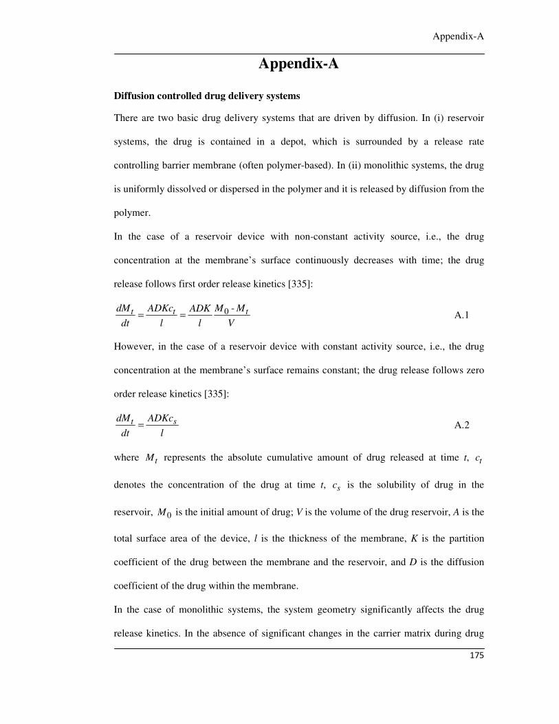
Appendix-A
175
Appendix-A
Diffusion controlled drug delivery systems
There are two basic drug delivery systems that are driven by diffusion. In (i) reservoir
systems, the drug is contained in a depot, which is surrounded by a release rate
controlling barrier membrane (often polymer-based). In (ii) monolithic systems, the drug
is uniformly dissolved or dispersed in the polymer and it is released by diffusion from the
polymer.
In the case of a reservoir device with non-constant activity source, i.e., the drug
concentration at the membrane’s surface continuously decreases with time; the drug
release follows first order release kinetics [335]:
0 -t t tdM ADKc M MADK
dt l l V= = A.1
However, in the case of a reservoir device with constant activity source, i.e., the drug
concentration at the membrane’s surface remains constant; the drug release follows zero
order release kinetics [335]:
t sdM ADKc
dt l= A.2
where tM represents the absolute cumulative amount of drug released at time t, tc
denotes the concentration of the drug at time t, sc is the solubility of drug in the
reservoir, 0M is the initial amount of drug; V is the volume of the drug reservoir, A is the
total surface area of the device, l is the thickness of the membrane, K is the partition
coefficient of the drug between the membrane and the reservoir, and D is the diffusion
coefficient of the drug within the membrane.
In the case of monolithic systems, the system geometry significantly affects the drug
release kinetics. In the absence of significant changes in the carrier matrix during drug

Appendix-A
176
release (e.g., constant porosity, no swelling, time-independent permeability for the drug)
and if perfect sink conditions are maintained throughout the release period and if the drug
release is primarily controlled by diffusion through the carrier matrix, the drug release
can be calculated as follows, depending on the geometry of monolithic system:
(i) In the case of spherical dosage forms [286]:
2 2
2 2 21
6 11 expt
n p
M Dn t
M n R
π
π
∞
=∞
= − −∑
A.3
and
(ii) In the case of cylinders (considering axial as well as radial mass transport) [336]:
2 2 2
2 2 2 2 21 0
32 1 1 (2 1)1 exp exp
(2 1)t n
n pn
M q Dt p Dt
M q R p H
π
π
∞ ∞
= =∞
+= − − × − ∑ ∑
+ A.4
where tM and M∞ are the cumulative amounts of drug released at time t and infinity,
respectively; n and p denote dummy variables, nq is the roots of the Bessel functions,
D is the diffusion coefficient of the drug, R and H denote the radius and height of the
cylinder, D is the diffusion coefficient of the drug and pR is the radius of the sphere.
Eqn. A.3 was used to quantify drug release from ammonio methacrylate copolymer-
based microparticles [337] and Eqn. A.4 was used to describe the release of the drug
from tristearin-based cylinders [338].
In the present work, it is assumed that the drug DOX is uniformly dispersed in PVA and
it is released by diffusion from the polymer. The curve fitting of DOX release profiles
(Fig. 4.20) with Eqn. A.3 shows that this DOX release follows the Fick’s law of diffusion
for monolithic systems.
Publications and Conferences
177
PUBLICATIONS AND CONFERENCES
Journals:
1. S. Kayal and R. V. Ramanujan, “Anti cancer drug loaded iron core / gold shell (Fe@Au) nanoparticles for magnetic drug targeting”, Journal of
Nanoscience and Nanotechnology 10, (2010) 5527-5539.
2. S. Kayal and R. V. Ramanujan, “Doxorubicin loaded superparamagnetic PVA coated iron oxide nanoparticles for targeted drug delivery”, Materials science
and Engineering: C 30, (2010) 484-490.
3. D. Ang, Q. V. Nguyen, S. Kayal, P. R. Preiser, R. S. Rawat and R. V. Ramanujan, “Insights into the mechanism of magnetic particle assisted gene delivery”, Acta Biomaterialia, 7, (2011) 1319-1326.
4. S. Kayal, D. Bandyopadhyay, T. Mandal and R. V. Ramanujan, “Flow of magnetic nanoparticles in magnetic drug targeting”, accepted in RSC
Advances, (2011).
Conference Presentations:
1. S. Kayal and R. V. Ramanujan, “Magnetic nanoparticle carriers for drug targeting in cancer treatment” Advanced delivery of therapeutics symposium in International Conference on Materials for Advanced Technologies (ICMAT), 2009, Singapore.
2. R. V. Ramanujan, S. Kayal, S. Purushotham, “Targeted dual therapy for disease treatment by multifunctional coated magnetic nanoparticles” TMS 2008, 137 annual meeting & exhibition, 2008, New Orleans, Louisiana, USA.
3. S. Kayal and R. V. Ramanujan, “PVA coated magnetic nanoparticle carriers for delivery of anticancer drug” International Conference on Cellular and Molecular Bioengineering (ICCMB), 2007, Singapore.
4. R. V. Ramanujan, S. Purushotham and S. Kayal, “Multifunctional coated magnetic nanoparticles for disease treatment” Advanced functional biomaterials symposium in International Conference on Materials for Advanced Technologies (ICMAT), 2007, Singapore.
5. R. V. Ramanujan, S. Purushotham and S. Kayal, “Multimodal cancer therapy using coated magnetic nanoparticles” TMS 2007, 136 annual meeting & exhibition, 2007, Orlando, Florida, USA.
6. S. Kayal and R. V. Ramanujan, “PVA coated iron oxide nanoparticle carriers for magnetic drug targeting” The 5th International Conference on Materials Processing for Properties and Performance (MP3), 2006, Institute of Materials (East Asia), Singapore.