Engineering Data Book - Carrier
26
Manufacturer reserves the right to discontinue, or change at any time, specifications or designs without notice and without incurring obligations. Catalog No. 20-40VMU001-03 Printed in U.S.A. Form 40VMU-2ED Pg 1 03-20 Replaces: 40VMU-1ED Engineering Data Book 40VMU012-048 Underceiling/Floor Indoor Unit for Variable Refrigerant Flow (VRF) Systems
-
Upload
khangminh22 -
Category
Documents
-
view
5 -
download
0
Transcript of Engineering Data Book - Carrier

Manufacturer reserves the right to discontinue, or change at any time, specifications or designs without notice and without incurring obligations.Catalog No. 20-40VMU001-03 Printed in U.S.A. Form 40VMU-2ED Pg 1 03-20 Replaces: 40VMU-1ED
Engineering Data Book
40VMU012-048Underceiling/Floor Indoor Unit for
Variable Refrigerant Flow (VRF) Systems

2
TABLE OF CONTENTSUNDER CEILING/FLOOR UNIT BASIC INFORMATION.....................................................................................................3
External Appearance......................................................................................................................................................................3
Specifications.................................................................................................................................................................................4
Accessories....................................................................................................................................................................................8
PIPING DIAGRAM........................................................................................................................................................................ 9
DIMENSIONS................................................................................................................................................................................10
WIRING DIAGRAM.....................................................................................................................................................................12
ELECTRICAL CHARACTERISTICS........................................................................................................................................14
AIR THROW CHARTS................................................................................................................................................................15
SOUND DATA................................................................................................................................................................................22
Sound Pressure Levels.................................................................................................................................................................22
Floor Installation..........................................................................................................................................................................23
NC Curves...................................................................................................................................................................................24
CAPACITY DATA TABLES........................................................................................................................................................26

3
UNDER CEILING/FLOOR UNIT BASIC INFORMATIONExternal Appearance
Fig. 1 —40VMU012/015/018/024---3
Fig. 2 —40VMU030---3
Fig. 3 —40VMU036/048---3
4
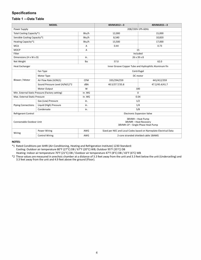
SpecificationsTable 1 —Data Table
NOTES:*1 Rated Conditions per AHRI (Air-Conditioning, Heating and Refrigeration Institute) 1230 Standard:
Cooling: Outdoor air temperature 80°F (27°C) DB / 67°F (20°C) WB; Outdoor 95°F (35°C) DBHeating: Indoor air temperature 70°F (21°C) DB / Outdoor air temperature 47°F (8°C) DB / 43°F (6°C) WB
*2 These values are measured in anechoic chamber at a distance of 3.3 feet away from the unit and 3.3 feet below the unit (Underceiling) and3.3 feet away from the unit and 4.9 feet above the ground (Floor).
MODEL 40VMU012---3 40VMU015---3
Power Supply 208/230V-1Ph-60Hz
Total Cooling Capacity*1 Btu/h 12,000 15,000
Sensible Cooling Capacity*1 Btu/h 8,540 10,820
Heating Capacity*1 Btu/h 13,500 17,000
MCA A 0.44 0.73MOCP A 15Filter IncludedDimensions (H x W x D) in. 26 x 39 x 8
Net Weight lbs 57.0 62.0
Heat Exchanger Inner Groove Copper Tube and Hydrophilic Aluminum fin
Blower / Motor
Fan Type Centrifugal
Motor Type DC motor
Air Flow Rate (H/M/L) CFM 335/294/259 441/412/359
Sound Pressure Level (H/M/L)*2 dBA 40.5/37.7/35.8 47.2/45.4/41.7
Motor Output W 100Min. External Static Pressure (Factory setting) in. WG 0Max. External Static Pressure in. WG 0.04
Piping Connections
Gas (Low) Pressure in. 1/2
Liquid (High) Pressure in. 1/4
Condensate in. 5/8
Refrigerant Control Electronic Expansion Valve
Connectable Outdoor Unit38VMH – Heat Pump
38VMR – Heat Recovery38VMH-1P – Single Phase Heat Pump
WiringPower Wiring AWG Sized per NEC and Local Codes based on Nameplate Electrical Data
Control Wiring AWG 2-core stranded shielded cable 18AWG

5
Table 2 —Data Table
NOTES:*1 Rated Conditions per AHRI (Air-Conditioning, Heating and Refrigeration Institute) 1230 Standard:
Cooling: Outdoor air temperature 80°F (27°C) DB / 67°F (20°C) WB; Outdoor 95°F (35°C) DBHeating: Indoor air temperature 70°F (21°C) DB / Outdoor air temperature 47°F (8°C) DB / 43°F (6°C) WB
*2 These values are measured in anechoic chamber at a distance of 3.3 feet away from the unit and 3.3 feet below the unit (Underceiling) and3.3 feet away from the unit and 4.9 feet above the ground (Floor).
MODEL 40VMU018---3 40VMU024---3
Total Cooling Capacity*1 Btu/h 18,000 24,000
Sensible Cooling Capacity*1 Btu/h 12,420 15,980
Heating Capacity*1 Btu/h 21,000 27,000
Power Supply 208/230V-1Ph-60Hz
MCA A 0.87 1.20
MOCP A 15
Filter IncludedDimensions (H x W x D) in. 26 x 39 x 8Net Weight lbs 62.0Heat Exchanger Inner Groove Copper Tube and Hydrophilic Aluminum fin
Blower / Motor
Fan Type Centrifugal
Motor Type DC motorAir Flow Rate (H/M/L) CFM 471/424/394 571/529/494Sound Pressure Level (H/M/L)*2 dBA 48.5/46.5/44.1 53.8/52.0/50.2
Motor Output W 100Min. External Static Pressure (Factory setting) in. WG 0Max. External Static Pressure in. WG 0.04
Piping Connections
Gas (Low) Pressure in. 5/8
Liquid (High) Pressure in. 3/8
Condensate in. 5/8
Refrigerant Control Electronic Expansion Valve
Connectable Outdoor Unit38VMH – Heat Pump
38VMR – Heat Recovery38VMH-1P – Single Phase Heat Pump
WiringPower Wiring AWG Sized per NEC and Local Codes based on Nameplate Electrical Data
Control Wiring AWG 2-core stranded shielded cable 18AWG

6
Table 3 —Data Table
NOTES:*1 Rated Conditions per AHRI (Air-Conditioning, Heating and Refrigeration Institute) 1230 Standard:
Cooling: Outdoor air temperature 80°F (27°C) DB / 67°F (20°C) WB; Outdoor 95°F (35°C) DBHeating: Indoor air temperature 70°F (21°C) DB / Outdoor air temperature 47°F (8°C) DB / 43°F (6°C) WB
*2 These values are measured in anechoic chamber at a distance of 3.3 feet away from the unit and 3.3 feet below the unit (Underceiling) and3.3 feet away from the unit and 4.9 feet above the ground (Floor).
MODEL 40VMU030---3 40VMU036---3
Power Supply 208/230V-1Ph-60Hz
Total Cooling Capacity*1 Btu/h 30,000 36,000
Sensible Cooling Capacity*1 Btu/h 20,080 26,230
Heating Capacity*1 Btu/h 34,000 40,000
MCA A 1.40 1.80
MOCP A 15
Filter Included
Dimensions (H x W x D) in. 26 x 50-1/2 x 8 27 x 66 x 10
Net Weight lbs 77.0 106.0Heat Exchanger Inner Groove Copper Tube and Hydrophilic Aluminum fin
Blower / Motor
Fan Type CentrifugalMotor Type DC motor
Air Flow Rate (H/M/L) CFM 729/676/624 1094/976/906
Sound Pressure Level (H/M/L)*2 dBA 53.9/52.1/50.4 53.0/50.3/48.4Motor Output W 100 100*2
Min. External Static Pressure (Factory Setting) in. WG 0
Max. External Static Pressure in. WG 0.04
Piping Connections
Gas (Low) Pressure in. 5/8
Liquid (High) Pressure in. 3/8
Condensate in. 5/8
Refrigerant Control Electronic Expansion Valve
Connectable Outdoor Unit38VMH – Heat Pump
38VMR – Heat Recovery38VMH-1P – Single Phase Heat Pump
WiringPower Wiring AWG Sized per NEC and Local Codes based on Nameplate Electrical Data
Control Wiring AWG 2-core stranded shielded cable 18AWG

7
Table 4 —Data Table
NOTE:*1 Rated Conditions per AHRI (Air-Conditioning, Heating and Refrigeration Institute) 1230 Standard:
Cooling: Outdoor air temperature 80°F (27°C) DB / 67°F (20°C) WB; Outdoor 95°F (35°C) DBHeating: Indoor air temperature 70°F (21°C) DB / Outdoor air temperature 47°F (8°C) DB / 43°F (6°C) WB
*2 These values are measured in anechoic chamber at a distance of 3.3 feet away from the unit and 3.3 feet below the unit (Underceiling) and3.3 feet away from the unit and 4.9 feet above the ground (Floor).
MODEL 40VMU048---3
Power Supply 208/230V-1Ph-60Hz
Total Cooling Capacity*1 Btu/h 48,000
Sensible Cooling Capacity*1 Btu/h 33,660
Heating Capacity*1 Btu/h 54,000
MCA A 2.80
MOCP A 15
Filter Included
Dimensions (H x W x D) in. 27 x 66 x 10
Net Weight lbs. 106.0
Heat Exchanger Inner Groove Copper Tube and Hydrophilic Aluminum fin
Blower / Motor
Fan Type CentrifugalMotor Type DC motorAir Flow Rate (H/M/L) CFM 1353/1000/929Sound Pressure Level (H/M/L)*2 dBA 59.8/52.3/50.6
Motor Output W 100*2
Min. External Static Pressure (Factory Setting) in. WG 0
Max. External Static Pressure in. WG 0.04
Piping Connections
Gas (Low) Pressure in. 5/8
Liquid side (High) Pressure in. 3/8
Condensate in. 5/8
Refrigerant Control Electronic Expansion Valve
Connectable Outdoor Unit38VMH – Heat Pump
38VMR – Heat Recovery38VMH-1P – Single Phase Heat Pump
Wiring Power Wiring AWG Sized per NEC and Local Codes based on Nameplate Electrical Data
Control Wiring AWG 2-core stranded shielded cable 18AWG

8
AccessoriesTable 5 —Table of Accessories
NAME OF ACCESSORIES QUANTITY OUTLINE USAGE
Condensate connector 1 For drainage
Copper Nut 1 Pipe connection
Clamp 1 Connect the drain hose to condensate connection
Flexible conduit and connectors 1 Routing power lines
Hanging bracket 4 Used for hanging the unit
Installation guide for metallic flexible pipe 1
Mounting bracket 4 Used for mounting the unit---
PQ Connection Wire 2 Connect indoor unit, outdoor unit, and sub MDC
Connection wire 1 Occupancy sensor connecting wire
Gas side copper pipe (for 012-024 only) 1For routing refrigerant pipes to side of the unit
Liquid side copper pipe (for 012-024 only) 1
Gas side copper pipe 1 For routing refrigerant pipes to side of the unit
Liquid side copper pipe 1 For routing refrigerant pipes to rear or bottom of the unit
Bolt assembly 4 ---
Fig. 4 —Under Connection Fig. 5 —Side Connection
Table 6 —Under/Side Connection
CAPACITY INDEX 36/48 12 15 18 30
a 2-3/4 2-1/4 2-1/4 4-3/4 5
b 2-3/4 2-1/4 2 4 5-1/4
c - 4 4 4 -
d - 4 4 4 -

9
PIPING DIAGRAM
Fig. 6 —PipingTable 6 —Piping
Table 7 —Gas / Liquid Line Sizes
NUMBER SYMBOL NAME
1 T1 Room temperature sensor2 T2A Inlet pipe temperature sensor3 T2B Outlet pipe temperature sensor4 EEV Electronic expansion valve
MODEL GAS LIQUID
40VMU012/015---3 1/2 1/4
40VMU018/024/030/036/048---3 5/8 3/8

10
DIMENSIONS
NOTE: All dimensions are shown in inches.
Fig. 7 —40VMU012/015/018/024/030---3
Table 8 —Dimensions (40VMU012/015/018/024/030---3)
MODEL A B C D
40VMU012/015/018/024---3 39 26 8 19-7/8
40VMU030---3 50-1/2 26 8 31-1/4

11
DIMENSIONS (CONT.)
NOTE: All dimensions are shown in inches.
Fig. 8 —40VMU036/048Table 9 —Dimensions (036/048)
MODEL A B C D
40VMU036/048---3 66 27 10 42-1/8

12
WIRING DIAGRAM
Fig. 9 —40VMU All Models

13
40VMU012---3 to 40VMU048---3 Wiring Diagram Definitions and Settings
Table 10 —Code/Title
CODE TITLE
FM Indoor fan motor
T1/T0 Room temperature sensor
T2A Inlet pipe temperature sensor
T2B Outlet pipe temperature sensor
ALARM Warning lamp
EEV Electronic expansion valve
XP1-8Connectors
XS1-4
XT1-2 Terminal
PUMP Pump motor
CS Condensate switch
GM Swing motor
Table 14 —SW1 Definition
0 means auto addressing mode (Default)
1 means factory test mode (Default)
0 means normal mode (Default)
1 means factory self-checking mode (Reserved)
Reserved
0 means standard indoor unit (Default)
1 means main indoor unit (Must be addressed #63)
Table 12 —ENC1 Definition
(Reserved)
Table 13 —J1 Definition
Without jumper “J1” for auto restart function
With jumper “J1” for manual restart function
Table 15 —SW8 Definitions
Reserved
Reserved
Table 17 —0/1 Definition
Means 0
Means 1
Table 11 —Error CodesERROR CODE ERROR CONTENT
dd Heating/cooling conflictE1 Communication error with outdoor unitE2 Temperature sensor (T1/T0) errorE4 Temperature sensor (T2B) errorE5 Temperature sensor (T2A) errorE6 DC fan errorE7 EEPROM error (data storage)UU MDC error in auto system-check modeE9 Communication error with wired controllerEb EEV errorEC Indoor fan error in auto system-check modeEd Outdoor unit errorEE Condensate errorFE No address when first powered on
Table 16 —ENC2 Definitions
Reserved

14
ELECTRICAL CHARACTERISTICSTable 18 —Electrical Characteristics
MODELPOWER SUPPLY IFM
HZ VOLTS VOLTAGE RANGE MCA MOCP kW FLA40VMU012---3
60 208/230VMax.253VMin.187V
0.44 15 0.01 0.35
40VMU015---3 0.73 15 0.01 0.58
40VMU018---3 0.87 15 0.01 0.69
40VMU024---3 1.20 15 0.01 0.92
40VMU030---3 1.40 15 0.01 1.10
40VMU036---3 1.80 15 0.1*2 0.69*2
40VMU048---3 2.80 15 0.1*2 1.1*2
SYMBOLS:
MCA: Minimum Circuit Amps (A)MOCP: Maximum Overcurrent Protection (A)kW: Fan Motor Rated Output (kW)FLA: Full Load Amps (A)IFM: Indoor Fan Motor

15
AIR THROW CHARTS40VMU012---3
Fig. 10 —Cooling mode with 60° swing
Fig. 11 —Heating mode with 60° swing

16
40VMU015---3
Fig. 12 —Cooling mode with 60° swing
Fig. 13 —Heating mode with 60° swing

17
40VMU018---3
Fig. 14 —Cooling mode with 60° swing
Fig. 15 —Heating mode with 60° swing

18
40VMU024---3
Fig. 16 —Cooling mode with 60° swing
Fig. 17 —Heating mode with 60° swing

19
40VMU030---3
Fig. 18 —Cooling mode with 60° swing
Fig. 19 —Heating mode with 60° swing
20
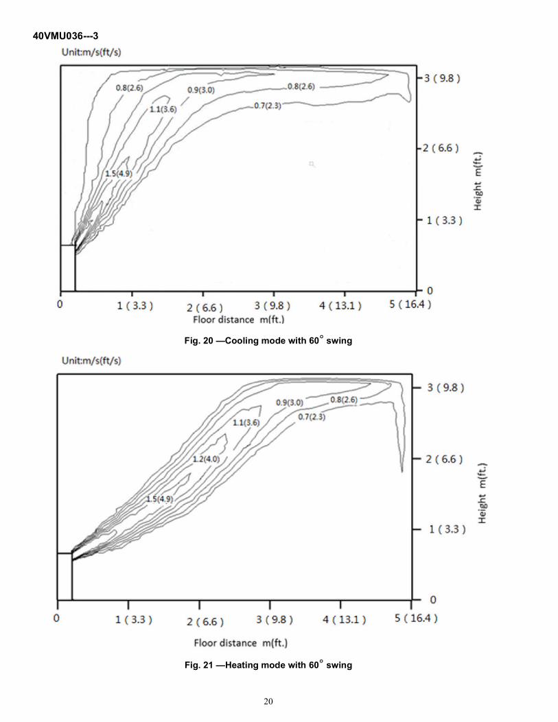
40VMU036---3
Fig. 20 —Cooling mode with 60° swing
Fig. 21 —Heating mode with 60° swing

21
40VMU048---3
Fig. 22 —Cooling mode with 60° swing
Fig. 23 —Heating mode with 60° swing

22
SOUND DATASound Pressure Levels
Fig. 24 —Overall Sound LevelsTable 19 —Cooling Mode
Table 20 —Heating Mode
NOTE: Units are in dBA
MODEL H M L
40VMU012---3 37.7 35.7 33.9
40VMU015---3 45.2 43.6 40.2
40VMU018---3 46.3 44.2 42.3
40VMU024---3 51.3 49.4 47.5
40VMU030---3 51.5 49.6 47.9
40VMU036---3 52.1 49.3 47.7
40VMU048---3 59 51.4 49.8
MODEL H M L
40VMU012---3 39.5 36.4 34.7
40VMU015---3 45.6 43.9 40.5
40VMU018---3 46.9 45.1 42.5
40VMU024---3 52.6 50.5 48.5
40VMU030---3 52.4 50.6 48.6
40VMU036---3 51.6 49 46.6
40VMU048---3 58 50.6 48.6

23
Floor Installation
Fig. 25 —Floor InstallationTable 21 —Cooling Mode
Table 22 —Heating Mode
MODEL H M L
40VMU012---3 39.9 37.3 35.8
40VMU015---3 46.7 45 41.5
40VMU018---3 48.1 46.5 44.1
40VMU024---3 53.7 51.8 50
40VMU030---3 53 51.4 49.7
40VMU036---3 53 50.3 48.4
40VMU048---3 59.8 52.3 50.6
MODEL H M L
40VMU012---3 40.5 37.7 35.5
40VMU015---3 47.2 45.4 41.7
40VMU018---3 48.5 46.3 44
40VMU024---3 53.8 52 50.2
40VMU030---3 53.9 52.1 50.4
40VMU036---3 51.3 48.8 46.8
40VMU048---3 57.8 50.5 48.7

24
NC CurvesNOTES:External Static Pressure: 0 in. (0 Pa)Power source: 208/230V-1Ph-60Hz
Fig. 26 —40VMU012---3 Fig. 27 —40VMU015---3
Fig. 28 —40VMU018---3 Fig. 29 —40VMU024---3

25
Fig. 30 —40VMU030---3 Fig. 31 —40VMU036---3
Fig. 32 —40VMU048---3

Manufacturer reserves the right to discontinue, or change at any time, specifications or designs without notice and without incurring obligations.Catalog No. 20-40VMU001-03 Printed in U.S.A. Form 40VMU-2ED Pg 26 03-20 Replaces: 40VMU-1ED
© Carrier Corporation 2020
CAPACITY DATA TABLESTable 23 —Cooling Capacity
Table 24 —Heating Capacity
Rated Condition: Condensation temperature is 114.8°F.TC = Total capacity; KBTU/hSC = Sensible capacity; KBTU/h
INDOOR UNIT ENTERINGAIR CONDITIONS:
COOLING CAPACITY INDICATION
12K 15K 18K 24K 30K 36K 48K
drybulb(°F) wetbulb(°F) TC SC TC SC TC SC TC SC TC SC TC SC TC SC
70 58 7.54 6.22 9.42 7.86 11.31 9.03 15.07 11.55 18.84 14.56 22.61 19.02 30.15 24.39
70 62 9.52 5.85 11.9 7.32 14.28 8.6 19.04 11.21 23.8 14.06 28.56 17.59 38.08 22.88
70 67 12 5.25 15 6.46 18 7.85 24 10.5 30 13.08 36 15.37 48 20.41
70 72 / / / / / / / / / / / / / /
70 76 / / / / / / / / / / / / / /
75 58 7.59 7.52 9.49 9.42 11.39 10.84 15.18 13.75 18.97 17.37 22.77 22.61 30.36 29.61
75 62 9.59 7.15 11.98 9.02 14.38 10.41 19.17 13.41 23.97 16.87 28.76 21.81 38.35 28.09
75 67 12.08 6.54 15.11 8.16 18.13 9.65 24.17 12.69 30.21 15.89 36.25 19.57 48.34 25.61
75 72 12.99 5.10 16.24 6.27 19.49 7.63 25.98 10.22 32.48 12.74 38.98 14.92 51.97 19.83
75 76 / / / / / / / / / / / / / /
80 58 7.65 7.54 9.55 9.42 11.47 11.31 15.28 15.07 19.10 18.84 22.93 22.61 30.57 30.15
80 62 9.65 8.44 12.07 10.72 14.48 12.23 19.31 15.61 24.13 19.68 28.96 26.04 38.61 33.32
80 67 12.17 7.83 15.21 9.86 18.25 11.47 24.34 14.89 30.42 18.69 36.51 23.79 48.67 30.82
80 72 13.08 6.39 16.35 7.97 19.63 9.44 26.16 12.42 32.71 15.54 39.25 19.13 52.33 25.04
80 76 13.79 5.20 17.23 6.41 20.68 7.76 27.57 10.36 34.46 12.92 41.36 15.28 55.14 20.25
85 58 7.70 7.54 9.62 9.42 11.55 11.31 15.39 15.07 19.24 18.84 23.09 22.61 30.79 30.15
85 62 9.72 9.52 12.15 11.90 14.58 14.28 19.44 19.04 24.30 23.80 29.16 28.56 38.89 38.08
85 67 12.25 9.12 15.32 11.56 18.38 13.28 24.51 17.09 30.63 21.51 36.76 28.02 49.02 36.05
85 72 13.17 7.68 16.47 9.67 19.76 11.26 26.34 14.61 32.94 18.35 39.53 23.35 52.70 30.25
85 76 13.89 6.49 17.35 8.11 20.82 9.57 27.76 12.56 34.70 15.73 41.65 19.50 55.53 25.46
90 58 7.75 7.54 9.69 9.42 11.63 11.31 15.50 15.07 19.37 18.84 23.25 22.61 31.00 30.15
90 62 9.79 9.52 12.24 11.90 14.68 14.28 19.58 19.04 24.47 23.80 29.37 28.56 39.16 38.08
90 67 12.34 12.00 15.42 15.00 18.51 18.00 24.68 24.00 30.85 30.00 37.02 36.00 49.36 48.00
90 72 13.26 8.98 16.58 11.38 19.90 13.07 26.53 16.82 33.17 21.17 39.80 27.58 53.07 35.48
90 76 13.98 7.79 17.47 9.82 20.97 11.39 27.96 14.75 34.94 18.54 41.94 23.73 55.91 30.68
MODEL CAPACITYINDICATION
HEATING INDOOR AIR TEMPERATURE
61 °FDB 64 °FDB 67 °FDB 70 °FDB 73 °FDB 75 °FDB 77 °FDB 80 °FDB
TC TC TC TC TC TC TC TC
40VMU
12 14.31 14.04 13.77 13.50 12.60 11.99 11.39 10.49
15 18.02 17.68 17.34 17.00 15.86 15.10 14.34 13.21
18 22.27 21.84 21.42 21.00 19.59 18.66 17.72 16.31
24 28.63 28.08 27.54 27.00 25.19 23.99 22.78 20.97
30 36.05 35.37 34.68 34.00 31.72 30.21 28.69 26.41
36 42.41 41.61 40.80 40.00 37.32 35.54 33.75 31.07
48 57.25 56.17 55.08 54.00 50.38 47.97 45.56 41.95