CNC Milling System Operation Manual - HNC Electric
205
HNC-08M CNC SYSTEM CNC Milling System Operation Manual V1.22 2011/01 WuHan HuaZhong Numerical Control Co., Ltd
-
Upload
khangminh22 -
Category
Documents
-
view
1 -
download
0
Transcript of CNC Milling System Operation Manual - HNC Electric

HNC-08M CNC SYSTEM
CNC Milling System Operation Manual
V1.22 2011/01
WuHan HuaZhong Numerical Control Co., Ltd

Table of Contents
1 SUMMARIZE............................................................................................................1
1.1 CNC SOFTWARE SYSTEM INTRODUCTION ..............................................................1 1.1.1 CNC System Interface ......................................................................................1 1.1.2 CNC System Operation Mode...........................................................................3
2 MANUAL OPERATION ...........................................................................................4
2.1 MANUAL REFERENCE POINT RETURN ....................................................................4 2.1.1 Process of Reference Point Return and Speed Setting .......................................4 2.1.2 Direction Setting of Reference Point Return......................................................6 2.1.3 Operation Sequence of Reference Point Return.................................................6 2.1.4 Termination of the Reference Point Approach ...................................................6
2.2 MANUAL FEED OPERATION ..................................................................................7 2.2.1 Manual Step Feed ............................................................................................8 2.2.2 Manual Jog Feed .............................................................................................8 2.2.3 Manual Rapid Traverse ....................................................................................9
2.3 HANDWHEEL OPERATION .................................................................................... 10 2.3.1 Parameter Setting About Handwheel Control ................................................. 10 2.3.2 Operation Sequence of Handwheel Control .................................................... 11
2.4 TOOL’S FIXED COORDINATE SYSTEM HANDWHEEL /JOG / INCREMENTAL FEED .... 11
3 AUTOMATIC OPERATION .................................................................................. 13
3.1 LOADING A MACHINING PROGRAM ..................................................................... 14 3.1.1 Program Preview ........................................................................................... 15 3.1.2 Loading a System Program ............................................................................ 15 3.1.3 Loading a External Program .......................................................................... 16 3.1.4 Loading a Network Program .......................................................................... 18 3.1.5 Loading an Extended Program ....................................................................... 19 3.1.6 The Syntax Checking Setting .......................................................................... 20
3.2 START/PAUSE/STOP PROGRAM OPERATION .......................................................... 21 3.3 VERIFYING A PROGRAM ...................................................................................... 22 3.4 PROGRAM BREAKPOINT ...................................................................................... 23
3.4.1 Saving a Breakpoint ....................................................................................... 24 3.4.2 Resuming a Breakpoint .................................................................................. 24
3.5 DEBUGGING A PROGRAM .................................................................................... 25 3.6 HANDWHEEL INTERRUPTION ............................................................................... 28

1
3.7 DNC .................................................................................................................. 29 3.7.1 Transferring a File ......................................................................................... 29 3.7.2 On-Line Operation ........................................................................................ 30 3.7.3 DNC Setting .................................................................................................. 30
3.8 MDI OPERATION ................................................................................................ 31 3.8.1 MDI code input format ................................................................................... 31 3.8.2 Sequence of MDI Operation ........................................................................... 32 3.8.3 Suspending/Recovering/Terminating a Command ........................................... 33
4 MANAGING A PROGRAM .................................................................................... 35
4.1 CLASSIFICATION OF PROGRAM FILE .................................................................... 35 4.2 EDITING A PROGRAM FILE................................................................................... 35
4.2.1 Opening a Program File ................................................................................ 35 4.2.2 Saving a File ................................................................................................. 37 4.2.3 Saving a File As ............................................................................................. 38 4.2.4 Finding/ Finding on ....................................................................................... 39 4.2.5 Replacing ...................................................................................................... 40 4.2.6 Block Operation ........................................................................................... 41
4.3 MANAGING A PROGRAM FILE .............................................................................. 43 4.3.1 The Window Of Program Management ........................................................... 44 4.3.2 Delete a Program File ................................................................................... 46 4.3.3 Copy a Program File ..................................................................................... 47 4.3.4 Backup a Program File .................................................................................. 48 4.3.5 Rename a Program File ................................................................................. 49 4.3.6 Sort a Program File ....................................................................................... 50
5 GRAPHICS DISPLAY ............................................................................................ 52
5.1 SUMMARIZE ....................................................................................................... 52 5.2 ENTER THE GRAPHICS SIMULATION INTERFACE ................................................... 52 5.3 GRAPHICS OPERATION ........................................................................................ 53 5.4 GRAPHICS PARAMETER ....................................................................................... 54
5.4.1 Graphics Zoom Coefficient ............................................................................ 54 5.4.2 Workpiece Size Range .................................................................................... 54
5.5 SPEED CURVE DISPLAY ....................................................................................... 55
6 DATA INPUT ........................................................................................................... 56
6.1 TOOL MAGAZINE CONFIGURATION ..................................................................... 56 6.2 TOOL COMPENSATION ........................................................................................ 58
2
6.2.1 Summarize ..................................................................................................... 58 6.2.2 Enter the Tool Compensation Table Interface.................................................. 58 6.2.3 Method of Tool Compensation Parameter Setting ........................................... 59
6.3 COORDINATE SYSTEM SETTING........................................................................... 61 6.3.1 Coordinate System Summary .......................................................................... 61 6.3.2 Workpiece Coordinate System Setting ............................................................. 66
6.4 SYSTEM PARAMETERS SETTING .......................................................................... 69 6.4.1 Parameter Classification Explanation ............................................................ 69 6.4.2 Paramter Type ............................................................................................... 70 6.4.3 Paramter Setting ............................................................................................ 70 6.4.4 Parameter Searching ..................................................................................... 72 6.4.5 Parameter’s Backup and Recovery ................................................................. 73 6.4.6 Parameters Export and Import ....................................................................... 74
6.5 LOGIC AXIS CONFIGURATION .............................................................................. 75 6.6 M-CODE’S EXTENSION DEFINITION ..................................................................... 78
6.6.1 M-Code Summarize ....................................................................................... 78 6.6.2 M-Code’s Definition and Extension ................................................................ 79
6.7 SYSTEM ALARM DEFINITION AND EXTENSION ..................................................... 80 6.7.1 System Alarm Summarize ............................................................................... 80 6.7.2 System Alarm’s Extension ............................................................................... 81
6.8 AUTHORITY MANAGEMENT ................................................................................ 82 6.8.1 Summarize ..................................................................................................... 82 6.8.2 Authority Management ................................................................................... 82
6.9 MACRO VARIABLE’S VIEW AND MODIFICATION ................................................... 83 6.10 STATISTIC INFORMATION ..................................................................................... 84
7 PLC .......................................................................................................................... 85
7.1 PLC ONLINE PROGRAMMING AND DIAGNOSIS ................................................... 85 7.1.1 Ladder Diagram Programming Interface ....................................................... 85 7.1.2 Ladder Diagram program Structural Unit ...................................................... 86 7.1.3 Programming Menu Illustration ..................................................................... 87 7.1.4 Ladder Diagram Programming Demonstration .............................................. 96 7.1.5 PLC Online Diagnosis ................................................................................... 97
7.2 I/O DIAGNOSIS ................................................................................................... 97 7.2.1 I/O Diagnosis Summarize............................................................................... 97 7.2.2 I/O Diagnosis Interface .................................................................................. 97
7.3 PLC DATA TABLE SETTING ................................................................................. 98 7.3.1 Summarize ..................................................................................................... 98

3
7.3.2 Data Table Operation Interface .................................................................... 100 7.3.3 Method of Data Table Setting ....................................................................... 101
7.4 PLC ELEMENT DEFINITION ............................................................................... 102 7.4.1 PLC Element Definition Summarize ............................................................. 102 7.4.2 PLC Element Definition Interface ................................................................ 102
7.5 B REGISTER ..................................................................................................... 104 7.5.1 B Register Summarize .................................................................................. 104 7.5.2 B Register Operation Interface ..................................................................... 104
7.6 PLC MESSAGE ................................................................................................. 106 7.6.1 PLC Message Summarize ............................................................................. 106 7.6.2 PLC Message Operation Interface ............................................................... 106
8 ROTATIONAL AXIS CIRCULATORY FUNCTION........................................... 108
9 SPINDLE GEAR CONTROL ............................................................................... 110
9.1 METHOD OF SPINDLE GEAR CONTROL ............................................................... 110 9.2 SPINDLE GEAR CONTROL DEMONSTRATION ....................................................... 112
10 MEASUREMENT ................................................................................................. 114
10.1 TOOL MEASUREMENT ....................................................................................... 114 10.1.1 Tool Measuring Principle and Process ..................................................... 114 10.1.2 Tool Measure Operation Sequence ........................................................... 115
11 COMPENSATION SETTING ............................................................................... 121
11.1 REVERSE BACKLASH COMPENSATION ............................................................... 121 11.2 PITCH ERROR COMPENSATION .......................................................................... 121 11.3 DEFLECTION COMPENSATION ............................................................................ 128 11.4 CIRCULAR ARC ACROSS QUADRANT COMPENSATION ......................................... 129
12 SYSTEM ERROR AND SOLUTION ................................................................... 131
12.1 SYSTEM ALARM INDICATION ............................................................................. 131 12.2 ALARM INFORMATION QUERY WINDOW ............................................................ 131 12.3 EMERGENCY STOP ............................................................................................ 132 12.4 STROKE TRAVEL SWITCH .................................................................................. 132 12.5 SYSTEM SOFTWARE LIMITS ALARM ................................................................... 133 12.6 SYSTEM ALARM RECORD QUERY WINDOW ....................................................... 134
13 APPENDIX ............................................................................................................ 136
13.1 APPENDIX ONE, SYSTEM PARAMETER DEFINITION ............................................. 136

4
13.2 APPENDIX TWO, SYSTEM ALARM DEFINITION&SOLUTION ................................. 163 13.3 APPENDIX THREE, MACHINE TOOL STRUCTURE CODE ....................................... 182
13.3.1 Tool Swing Head Structure ....................................................................... 182 13.3.2 Workbench Structure ................................................................................ 186
13.4 APPENDIX FOUR, MENU TREE STRUCTURE ...................................................... 189
14 OPERATION CORRECTING RECORDS........................................................... 198

1
1 Summarize
1.1 CNC Software System Introduction
1.1.1 CNC System Interface
Figure 1-1 CNC System Interface
1、Alarm Show
This area displays alarm status of the system .Alarm status are divided into the following:

2
1) System Reset: After press Overtravel released key when release Emergency Stop Switch or over travel, system needs certain time to reset. During this period, system can not be operated, and the Alarm Display area shows “Reset”.
2) Over Travel: When the workbench stroke travel switch, system turns up overtravel alarm and the Alarm Display area shows “Reset”.
3) Emergency Stop: When press E-Stop button down, system turns up emergency stop alarm and the Alarm Display area shows “E-Stop”.
4) System Alarm: When turns up other alarms except the mentioned above, the Alarm Display area shows “System-Alarm”.
When the alarms above occur at the same time, the priority displayed in the Alarm Display area is the following (the left has high priority, that means it will be shown in front of others when alarm appear):
2、Working and Running Status
There are three kinds of operation modes: Automatic,Manual and Handwheel. Every mode has stop, run and pause status by machine tool’s running status. The Working and Running Status area shows in real-time what is the current operation mode and running state. For example, “Manu/Stop”means the current operation mode is “Manual”, and machine tool’s running status is “Stop”(halted state).
3、Main Window Show
The Main Window displays tool’s position in workpiece coordinate system or machine coordinate system, that is workpiece coordinate or machine coordinate. The coordinate system which displays can be changed by setting parameter P0017.
4、First Side Window Show
First Side Window displays tool’s position in machine coordinate system or workpiece coordinate system, that is machine coordinate or workpiece coordinate.The coordinate system which displays can be changed by setting parameter P0017.
5、Second Side Window Show
Second Side Window can display workpiece coordinate zero, synchronization error
Reset Overtravel E-Stop System-Alarm

3
or tracking error by setting parameter P0016.
6、System Information Area
The System Information Area displays machining information of CNC, include: actual speed, instruction speed, feedrate override, rapid traverse speed override, spindle speed, spindle override, current tool, tool length, tool radius and machining time ect.
7、Code Window
In automatic mode, the window displays machining code and index of current machining line. when the mode is MDI, you can input MDI instructions in the window.
1.1.2 CNC System Operation Mode
All of this CNC system function is followed by operation mode, that is to say all of functions belong to part of functions in a certain operation mode, you can only operate under the appropriate operation mode.
CNC is divided into the following three operation mode: 1) Automatic Mode: In automatic mode, you can automatically execute part
programs, transfer file and machining while transfering ect. Automatic mode can be switched by pressing <AUTO> key.
2) Manual Mode:In manual mode, you can operate reference point return, Jog and step control ect. Manual mode can be switched by pressing < MANU > key.
3) Handwheel Mode:In handwheel mode, you can control machine tool by hand. Handwheel mode can be switched by pressing < Increment > key.
During CNC running, there are two methods to judge the current operation mode: 1) among operation mode switch keys, which the indicator lights of keys is on indicates
in which mode the machine is working; 2) CNC software interface show the current operation mode in Working and Running
Status bar, such as“Manual/Stop”.
When switched operation mode, system menu automaticly return main menu mode.
4
2 Manual Operation
Manual operations include two kinds of operation modes:reference point return mode and manual feed mode. The first mode is used to set up the machine coordinate system with all axes returned to the origin position; the second mode is used to move all coordinate axis manually. The two modes can be switched to each other by pressing <REF> key. The first mode is active when the indicator light of < REF > key is on. The second mode is active when the light is off.
2.1 Manual Reference Point Return
2.1.1 Process of Reference Point Return and Speed
Setting
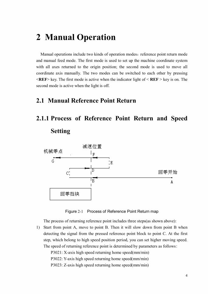
Figure 2-1 Process of Reference Point Return map
The process of returning reference point includes three steps(as shown above): 1) Start from point A, move to point B. Then it will slow down from point B when
detecting the signal from the pressed reference point block to point C. At the first step, which belong to high speed position period, you can set higher moving speed. The speed of returning reference point is determined by parameters as follows:
P3021: X-axis high speed returning home speed(mm/min) P3022: Y-axis high speed returning home speed(mm/min) P3023: Z-axis high speed returning home speed(mm/min)

5
P3024: Fourth-axis high speed returning home speed(degree/min) P3025: Fifth-axis high speed returning home speed(degree/min) P3026: Sixth-axis high speed returning home speed(degree/min) P3027: Seventh-axis high speed returning home speed(degree/min) P3028: Eighth-axis high speed returning home speed(degree/min)
2) From point C move to point D backward. It will slow down from point D when detecting the signal from the up reference point block to point E. Then reverse again, move to point F when detect the signal again from the pressed reference point block. The second step belongs to low speed return period, which speed of returning reference point is determined by parameters as follows:
P3031: X-axis low speed returning home speed(mm/min) P3032: Y-axis low speed returning home speed(mm/min) P3033: Z-axis low speed returning home speed(mm/min) P3034: Fourth-axis low speed returning home speed(degree/min) P3035: Fifth-axis low speed returning home speed(degree/min) P3036: Sixth-axis low speed returning home speed(degree/min) P3037: Seventh-axis low speed returning home speed(degree/min) P3038: Eighth-axis low speed returning home speed(degree/min)
3) After move to point F when detect the signal from the pressed reference point block, it enters into the third step: searching for zero. Due to the limited of motor’s zero pulse width, the speed of searching for zero can’t be set too high, or it’s possible failure to return reference point for missing zero pulse. On the other hand, it could affect precision of reference point return if the speed is too large. The speed of returning reference point is determined by parameters as follows:
P3041: X-axis searching for zero speed at low speed(mm/min) P3042: Y-axis searching for zero speed at low speed(mm/min) P3043: Z-axis searching for zero speed at low speed(mm/min) P3044: Fourth-axis searching for zero speed at low speed(degree/min) P3045: Fifth-axis searching for zero speed at low speed(degree/min) P3046: Sixth-axis searching for zero speed at low speed(degree/min) P3047: Seventh-axis searching for zero speed at low speed(degree/min) P3048: Eighth-axis searching for zero speed at low speed(degree/min) The actual speed of reference point return can be adjusted by feedrate override at
the first two steps(high speed position period and low speed return period), that is:

6
the actual returning speed = the parameter value * feedrate override.
At the third step, that is searching for zero at low speed, the actual speed of reference point return is equal to the parameter value for ensuring precision and repetition, no feedrate override.
2.1.2 Direction Setting of Reference Point Return
Each axis’s direction of returning reference point is determined by parameters as follows:
P3011: X-axis returning direction [0- positive direction; 1- negative direction] P3012: Y-axis returning direction [0- positive direction; 1- negative direction] P3013: Z-axis returning direction [0- positive direction; 1- negative direction] P3014: Fourth-axis returning direction [0- positive direction; 1- negative direction] P3015: Fifth-axis returning direction [0- positive direction; 1- negative direction] P3016: Sixth-axis returning direction [0- positive direction; 1- negative direction] P3017: Seventh-axis returning direction [0- positive direction; 1- negative direction] P3018: Eighth-axis returning direction [0- positive direction; 1- negative direction]
2.1.3 Operation Sequence of Reference Point Return
1) Press <MANU> key on the Machine Control Panel (MCP). Be sure the key’s indicator light is on and “Manual/Stop” is displayed in the status bar;
2) Press < REF > key in manual mode. Be sure the key’s indicator light is on; 3) Press one of the feed axis keys: X, Y, Z, 4, 5, 6 ,7 or 8 on the MCP that the
corresponding axis needs reference point return. For example, the X-axis will return to the reference point when press the <X> key. Furthermore, the specified axes will return to the reference point simultaneously when select more than one axis in turn;
4) The reference point return for the specified axis is finished when the specific machine coordinate value retains 0 and doesn’t change.
2.1.4 Termination of the Reference Point Approach
Two methods of terminating the operation during the returning (including three

7
periods: high speed return, low speed return, searching for zero):
a) Press the < REF > key to make sure the key’s indicator light is off, Then the returning is terminated and the system is switched to the manual feed mode, which can move each axis using Jog manner;
b) Press the <FDHD> key, then the returning is terminated. To switch to the manual feed mode that you need to press < REF > key again and make sure the indicator light of < REF > key is off.
Note that each method above will terminate the returning for all axes.
2.2 Manual Feed Operation
Two kinds of the manual feed operation:
Note: 1、 Adjust the position of the workbench and cutter before the operation, in case to
avoid movement interference during the returning; 2、 The return speed can be adjusted by feedrate only in the high speed return period or
low speed return period. It is invalidation for the speed in the period of searching for zero;
3、 It is not appropriate to setting the speed of searching for zero too large, or the position error will be very large.

8
1、 Manual Step Feed: When an axis key is pressed, the workbench will move one step
distance and then stop automatically.
2、 Manual Jog Feed: Move the tool along a motion axis in the specific direction, while
an axis key is being pressed. The motion continues as long as the axis key is pressed.
The tool will decelerate to stop when the axis key is released.
2.2.1 Manual Step Feed
It is the manual step feed mode when the LED indicator light of one of the step length keys like <×1>、<×10>、<×100>、<×1000> is on. The step length is followed by the keys:
<×1> ----- 0.001mm <×10> ----- 0.01mm <×100> ----- 0.1mm <×1000> ----- 1mm
Sequence of manual step feed:
① Switch to the manual mode; ② Press one of the step length keys according to step length. Be sure the LED indicator
light of the selected key is on; ③ Select a feed axis. Be sure the LED indicator light of the selected key is on; ④ When press <-> or <+> key according to the need of the moving direction, the
selected asix begins to move, and decelerates to stop after moves one step length distance.
2.2.2 Manual Jog Feed
It is the manual point feed mode when all of the indicator lights of the step length keys like <×1>、<×10>、<×100>、<×1000> is off.
Sequence of manual jog feed:

9
① Switch to the manual mode; ② Be sure all of the indicator lights of the step length keys is off; ③ Select a feed axis. Be sure the LED indicator light of the selected key is on; ④ When press <-> or <+> key according to the need of the moving direction, the
selected asix begins to move. Release the key after it gets to the target position, and the asix will decelerate to stop automatically.
2.2.3 Manual Rapid Traverse
There are high gear and normal gear for the theoretical speed of an axis in the manual feed mode. They can be switched to each other using <SPUP> key.
High Gear: The manual feed is on high gear when the LED indicator light of the <SPUP> key is on. The instruction speed is set by the parameters P2011~P2018. The actual moving speed = the parameter value * feedrate override.
Normal Gear: The manual feed is on normal gear when the LED indicator light of the < SPUP > key is off. The instruction speed is set by the parameters P2021~P2028. The actual moving speed = the parameter value * feedrate override.
Note: Due to the process of deceleration stop when the axis stops(release <JOG> key) in
the manual jog feed mode, it is necessary to remain enough space for extra motion to avoid some accidents.
Note: 1、 Both high gear and normal gear are effective in the manual step feed mode or the
manual jog feed mode; 2、 The acceleration of the manual operation is set by the parameters P2080~P2087.

10
2.3 Handwheel Operation
2.3.1 Parameter Setting About Handwheel Control
1) Handwheel Pulse Equivalent Handwheel pulse equivalent means the moving distances (or rotary angles) of
the axis by rotating one pulse(one frame) when handwheel is at the ×1 times. The moving distances when you rotate handwheel is:
the moving distances(or angles) = handwheel pulse number * handwheel Magnification * handwheel pulse equivalent
handwheel pulse equivalent is set by the following parameters: P0237: Handwheel equivalent for linear axis(mm/frame) P0238: Handwheel equivalent for rotational axis(degree /frame)
2) The Maximum Speed Limit Under Handwheel Operation
When control the motion of workbench by handwheel, the maximum speed of the workbench’s motion will be less than the value by setting the following parameter:
P0234: The maximum speed of Handwheel for linear axis(mm/frame) P0235: The maximum speed of Handwheel for rotational axis(degree /min)
3) The Maximum Acceleration Limit Under Handwheel Operation
When control the motion of workbench by handwheel, the maximum acceleration of the workbench’s motion will be less than the value by setting the following parameter:
P0231: The maximum acceleration of Handwheel for linear axis P0232: The maximum acceleration of Handwheel for rotational axis
4) Direction Setting of Handwheel
When the direction of the workbench’s motion by handwheel control is incorrect, the direction of the workbench’s motion can be changed by setting the following parameter:
P0230=1: reverse the direction of handwheel control P0230=0: not reverse the direction of handwheel control

11
2.3.2 Operation Sequence of Handwheel Control
In the handwheel mode, you can using the micro-feed by turning the handwheel pulser as follow: 1) Press< Increment >key to switch to the handwheel mode (Be sure the indicator
light of the < Increment >key is on, and the CNC system shows“Handwheel/Stop”in Working and Running Status bar);
2) Turn the axis switch, and select the axis which you want to operate (when the switch points to OFF, the handwheel is closed and you can operate no axis);
3) Turn the magnification switch, and select an appropriate magnification; 4) Turn the handwheel, and move the selected axis.
2.4 Tool’s Fixed Coordinate System Handwheel /JOG
/ Incremental Feed
The tool’s fixed coordinate system means the local coordinate system which is set up on the tool and parallel to machine coordinate system when the tool is at the beginning position(the tool axis is parallel to the Z-axis in machine coordinate system). During the tool rotating, coordinate system rotate along with the tool, fixed joint the tool all the time.
Wherever the coordinate system rotate to along with the tool, it can be moved along the axis of the tool’s fixed coordinate system by hand. The operation includes handwheel, jog and incremental mode.

12
Figure 2-2 Tool’s Fixed Coordinate System
The method of opening up the feed function of tool’s fixed coordinate system: <Manual/Increment> →[\] → [Tool Axis Feed] → [Open]
The method of closing up the feed function of tool’s fixed coordinate system: < Manual/Increment> →[\] → [Tool Axis Feed] → [Close]
After opening up the feed function, when move the Z-axis by handwheel, jog or increment mode, the tool will move along the Z-axis’s direction in the tool’s fixed coordinate system(tool aixs’s direction ); Similarly, when move the X-axis,Y-axis by handwheel, jog or increment mode, the tool will move along the direction of X-axis,Y-axis in the tool’s fixed coordinate system.
Note: 1、 It’s necessary to set the machine’s structure type correctly by the parameter of
P400 and P401, or the feed function can not be implement accurately; 2、 Only the machine’s structure type which system support can be implemented the
feed function, or the correctness of machine tool’s motion cannot be guaranteed.

13
3 Automatic Operation
In Automatic machining mode, you can execute a part program or a MDI command.
Four types of programs can be executed in automatic mode: system program, external program , network program and DNC on-line program.
System Program: It is stored in the system’s built-in disk;
External Program: It is stored in some removable storage devices with USB interface, such as U disk, removable disk etc.;
Network Program: It shares the storage area which is a directory of computer by network mapping.
DNC On-Line Program: Receive the part programs from the DNC server, and execute while transmit.
A program should be loaded to memory before automatic machining. System program, external program and network program can be loaded to memory by CNC system and executed directly.

14
3.1 Loading a Machining Program
Figure 3-1 Program Selection Screen
Sequence of entering the program loading screen:
<AUTO> → [\] → [PROG] → [LDPG].
It is shown in the figure 3-1 above. The system menu which is workable in program selection screen includes: [LOAD]: Load the selected program to the memory.
[SPGM]: Show a list of program files from the system’s internal storage. [UPGM]: Show a list of program files from the external storage. [NPGM]: Show a list of program files from the NC port by network mapping. [EPGM]: Show a list of extended program files. [NSRT]: Sort a list of program files by name; [TSRT]: Sort a list of program files by modification time; [PRET]: Load nothing and return to previous menu.

15
3.1.1 Program Preview
In the program selection screen, after the cursor select a program, you can preview the selected program in the program preview screen on the right, as figure 3-1shown.
3.1.2 Loading a System Program
Sequence of loading a system program is as follows:
1) Switch to the program selection screen;
2) Show a list of system program files. The LCD screen shows a list of system program conventionally when you enter into the program selection screen at the first time. If it doesn’t show the list after some operations, you need press [SPGM] key to switch to it. The list window title bar shows the storage of the current indicated program. It shows “System Program” means that the displaying program is from the system’s internal storage, as figure 3-2 shown;
3) Use the [↑]、[↓] or [PageUp]、[PageDown] keys to select a program which need loading, or input the filename into the window of program filename directly.
4) Press the [LOAD] key to load the selected program to memory.
Figure 3-2 A list of system program files
If the parameter P0003 value is 1, CNC system will check the syntax of the loaded

16
program after loading (as figure 3-3 shown). If you are sure that the program has no syntax error, you can press the [ESC] key to cancel syntax checking.
Figure 3-1 Program Syntax Checking
the content of the loaded program is shown in the code window, as figure 3-4 shown. Use the [↑]、[↓] or [PageUp]、[PageDown] keys to read the program before automatic operation.
Figure 3-2 Code Display Window
3.1.3 Loading a External Program
Sequence of loading an external program is as follows:
1) Switch to the program selection screen; 2) Show a list of external program files. The LCD screen shows a list of system
program conventionally when you enter into the program selection screen at the first time. Press the [UPGM] key to switch the screen to it. The list window title bar shows the storage of the current indicated program. It shows “External Program” means that the displaying program is from the external storage device, as figure 3-5 shown;

17
3) Use the [↑]、[↓] or [PageUp]、[PageDown] keys to select a program which need loading, or input the filename into the window of program filename directly.
4) Press the [LOAD] key to load the selected external program to memory.
Figure 3-5 A list of external program files
If there are no external storage devices and you press the [UPGM] key, the title bar will show a warning prompt, as figure 3-6 shown. Press any key in the panel can remove this prompt .

18
Figure 3-6 No External Storage Devices
3.1.4 Loading a Network Program
The operation of loading a network program is the same as loading an external program. If the CNC syatem has been configured the network-mapping device, the program in the network-mapping device can be shown after you select the network program, as figure 3-7 shown.

19
Figure 3-3 Network Program Loading Interface
3.1.5 Loading an Extended Program
In general, the extended program key is gray, which is not operating. The key can be recovered operation by setting the parameter P0002, as figure 3-8 shown.

20
Figure 3-4 Extended Program Loading Interface
The extended program can be loaded into memory to read、edit、modify、save, but it is not recommended to operate the extended program, so you’d better set 1 for the parameter P0002 to hide and protect it.
3.1.6 The Syntax Checking Setting
Generally, CNC system will check the syntax of the loaded program after loading. If there are some mistakes in syntax checking, the loaded program can’t be executed. The function of syntax checking is set by the parameter P0003:
P0003=0: Don’t check the syntax when loading program P0003=1: Check the syntax when loading program
You’d better use this function in practice to ensure the loaded program works normally.
21
3.2 Start/Pause/Stop Program Operation
1、 Program Startup
Press the <CYCL> key to execute the program when it has been loaded into memory. Then the LED indicator light of the < CYCL > key is on and “Auto/Run” is shown in Working and Running Status bar. Press the [↑]、[↓] or [PageUp]、[PageDown] keys to position the current cursor where the program begins to be executed before starting.
2、 Program Pause
Press <FDHD> key to stop the running program during execution. After that, The
LED indicator light of <FDHD> key is on and “AUTO/PAUS” is displayed in Working
and Running Status bar. The program is paused but doesn’t exit from the processing state,
then pressing <CYCL> key can resume the execution.
You can switch to the manual mode or the handwheel mode to move an axis in state suspended. Note when you switch back to the automatic mode to resume the execution, system will automatically return to the position of interruption, so be sure there is no motion disturbance in the returning process.
3、 Program Stop
Two methods to terminate the current process of execution: 1)Method with pressing the [STOP] key
Note: Be careful of starting from a random segment to execute the program. Because the
beginning segment of the program hasn’t been executed, If the loaded program includes some subroutine calls or macro programs and the codes after the selected segment doesn’t contain the whole information of establishment process (such as establishing the stack for a subroutine call, assigning variables etc.), there may be an exception occured during the program execution. Furthermore, the MST codes before the beginning segment are not effective, so you should ensure that the auxiliary functions are effective, such as spindle rotation, cooling on etc..

22
Firstly, press the <FDHD> key (or SBL stop)to make the execution pause, then press the [PROG] key→[STOP] key in turn and then it will pop up a dialog, as figure 3-9 shown. At the time, pressing the [ENTER] key will terminate the execution or pressing the [ESC] key will cancel the stop operation. CNC system’s state is the same as that before running (the modal codes of the program have been stored), Then the Working and Running Status bar will show “AUTO/STOP”.
Figure 3-9 A dialog of terminating a running program
2)Method with pressing the [RNGN] key This method is similar to the prior method. Both of them can exit from the current
processing state. The difference is: In the first method, the current line remains the machining line when exit, but in the second method, the current line automatically returns to the first line of the program.
3.3 Verifying a Program
When write a new program, you can use the program verification function to test the working path is right or not.
During the process of verifying a program, the M codes except M00,M01,M06,M30,M98,M99,M128,M129 and all the S, T codes aren’t effective.
Sequence of verifying a program is as follows:
1) Switch to the mode of verifying a program. Press these keys as follows in turn: <AUTO> →[\] → [PROG] → [TEST];
2) Press the <CYCL> key to start the program verification.
The mode of verifying a program will be closed in these situations as follows:
1) When verifying a program, Press<FDHD>, and then select <STOP> or <RNGN>,

23
the system will automatically close the program verification mode;
2) When verifying a program, Press<FDHD>key and then quit from the automatic mode, the system will automatically close the program verification mode;
When the program verification mode is closed, it returns to the normal running mode.
Figure 3-10 Verifying a program
3.4 Program Breakpoint
During the process of machining, For some reason you may turn off the machine
halfway. The breakpoint means that the segment of the program executing and the
machine tool’s position and status messages when turn off. So the breakpoint saving and
recovering fuction is important when resume running from the program breakpoint.

24
3.4.1 Saving a Breakpoint
After a running program is feed hold, if you select [BRPT], the system will enter into the program breakpoint interface. Then, if select [SVBP], the system will automatically store the current breakpoint information in the relevant breakpoint file and replace the previous breakpoint file of this program saved before.
A filename of the breakpoint stored is determined according to the program’s filename, that is, the name is the program’s filename that the postfix substituted to “.BPT”. For example, if a program’s filename is “TEST.NC” , then the breakpoint’s filename will be “TEST. BPT” .
3.4.2 Resuming a Breakpoint
Switch to the screen of breakpoint management: <AUTO> → [\] → [PROG] → [BRPT], as figure 3-11 shown.
Sequence of resuming a saved breakpoint: 1) Turn to the screen of breakpoint management; 2) Use the [↑]、[↓] or [PageUp]、[PageDown] keys to select an target breakpoint file; 3) Press the [BRES] key. If the breakpoint file is effective, the system will load the file
and resume the breakpoint. If The spindle is in the rotation state when saving the breakpoint, the spindle will
rotate automatically when resuming the breakpoint. Otherwise, all other auxiliary functions should be turned on manually.

25
Figure 3-11 Program Breakpoint
3.5 Debugging a Program
1、 Single Block Operation Press <SGSG> key before or during the automatic operation, then the indicator
light of the key is on, it is in the single block state, that means the tool executes a single block of program and then stops. At the time, the indicator light of <CYCL> key is on,
Note: If the machining parameters (such as tool length compensation, tool radius
compensation, workpiece coordinate origin etc.) are changed after saved the breakpoint, you can’t resume the breakpoint from the breakpoint file which saved before changed to machining, or else, it won’t work normally.

26
and the <FDHD> is off. Press <CYCL> key again, the tool executes the next single block. When the indicator light of <SGSG> is off, it is in the continuous operation mode, which means it doesn’t execute pause between blocks until the end of program.
Pressing the <SGSG> key will be able to switch to the other between single block operation and continuous operation.
2、 Optional Block Skip
Press <JMSG> key before or during the automatic operation, then the indicator light of the key is on, which means optional block skip is in force. At that time, the blocks which contains a slash “\” in front will be jumped(non-execution). When the indicator light of <SGSG> is off, the optional block skip function is ineffective, that is, the tool executes every block even though it contains a slash “\” in front.
Pressing < JMSG > key will be able to switch the optional block skip function between effective and ineffective.
3、 Machine Tool Lock
Press <MLCK> key before automatic operation (in automatic but non-running
state). then the indicator light of the key is on, it is in simulation operation state, that
means executing the program, refreshing coordinates and displaying tool-path are
normal, but each axis’s actual position of machine tool keep still. It is usually used to see
the program’s operation to examine the correctness of program by tool-path displayed
and axis’s change.
Pressing < MLCK > key will be able to switch the machine tool lock function between effective and ineffective.
Note: The sign of optional block skip is a slash “\”, not the division sign “/” which is
used for division function in this system.

27
4、 Z-Axis Lock Press <ZLCK> key before automatic operation (in automatic but non-running state).
then the indicator light of the key is on, it is in Z-axis’s simulation operation state, that means executing the program, refreshing coordinates and displaying tool-path are normal, but the Z-axis’s actual position of machine tool keep still.
Pressing < ZLCK > key will be able to switch the Z-axis lock function between effective and ineffective.
5、 Dry Run Press < DRUN > key before or during the automatic operation, then the indicator
light of the key is on, which means dry run is in force. During the program operation , the feedrate specified by the F codes in the program is ineffective, the feedrate is specified by the parameter P2003, the feedrate override is also effective. When the indicator light of < DRUN > is off, the function is ineffective, the feedrate specified by the F codes in the program.
Pressing < DRUN > key will be able to switch the dry run function between effective and ineffective.
6、 Handwheel Debugging Opening or closing the handwheel debugging function is determined by the control
signal (G15.6) of PLC. When the G15.6 is high level, the fuction is open; when it’s low
Note: Opening or closing the machine tool lock function must be in the program stop
state, or else, maybe the machine tool won’t work normally (this limitation is guaranteed by the PLC program).
Note: 1、 If this function is effective, the feedrate set by the parameter P2003 is always the
feed each minute (G94) even though specified each rotation(G95) in the program. 2、 Because of interpolation device’s forward-looking control function, it needs some
delay time to come into force when you switch to dry run during the execution.

28
level, the fuction is close. If the handwheel debugging functionis is open, the keys of feedrate override and rapid traverse speed override on the system panel are ineffective during the execution. At that time, those override are generated by the speed which controls the speed of machine tool’s operation by turning the handle.
If you stop the handle turning, the generated override is 0.
3.6 Handwheel Interruption
Open or close the handwheel interruption function by the control signal (G15.6) of PLC.
When the interruption function is open, the value of turning the handle is added to the current axis’s movement in real time during the execution. The addition implements by the excursion of workpiece coordinate zero, that means the handle increment is directly added to the workpiece zero of the current axis.
The amount of interrupt which caused by handwheel interruption will make the workpiece coordinate system and local coordinate system offset. Therefore, although the machine tool’s movement has changed, the coordinate value of workpiece coordinate system and local coordinate system remain the same.
Only change the selected workpiece coordinate system in the current program, the others remain the same.
Figure 3-5 Handwheel Interruption

29
After executing the handwheel interruption function, the offset which added to the workpiece zero is volatile, it will be lost when the electricity goes off. In order to reserving the offset, you need to save the workpiece zero by the following methods: 1) Pressing [SCRD] → [WRST] keys can save the offset coordinate zero; 2) If you switch the automatic mode to others, system will save the offset coordinate
zero by itself; 3) If you press <CYCL> to rerun the program, system will save the offset coordinate
zero by itself;
3.7 DNC
The functions of DNC include: 1)Transferring a File; 2)On-line operation. Accomplish the functions of DNC by cooperating with the communication software
at the computer port. The direction of the software should be consulted for the user manual.
3.7.1 Transferring a File
Operation of the CNC port: <AUTO> →[\] → [DNC] → [FLTF]
After that, system shows the DNC window as the figure 3-13, the information about transferring a file includes: 1) Summation Received: shows the summation of file sizes received since entering
into the window.
2) The Last Received: shows the sizes of the file which is the last received.
3) Summation Sent: shows the summation of file sizes sent since entering into the window.
4) The Last Sent: shows the sizes of the file which is the last sent.
Switch the CNC port to the DNC mode when transferring a file. After the window of DNC is showed, you can transfer files by the communication software at the computer port.

30
Figure 3-13 Transferring a File Of DNC
3.7.2 On-Line Operation
Operation of the CNC port: <AUTO> →[\] → [DNC] → [WONL]
After that, system shows the waiting window as the figure 3-14.
Figure 3-14 Waiting For On-Line Operation
Switch the CNC port to the the on-line operation mode when doing on-line operation. After the waiting window is showed, you can do on-line operation at the computer port .
When the CNC receive a full buffer of DNC, the system will switch to the feed hold state of on-line operation by itself. Then press <CYCL> key to run the on-line program.
The size of the DNC’s on-line operation buffer is set by the parameter P0192.
3.7.3 DNC Setting
Method of operation: <AUTO> →[\] → [DNC] → [WONL]
After that, system enters into the DNC setting window as the figure 3-15. If the DNC is base on internet transmission, the parameters which need to set include:

31
communication mode, the computer port’s IP, the CNC port’s IP, network port, the others do not matter.
If the DNC is base on serial port transfer, the parameters which need to set include: communication mode, serial port number, serial port baud rate, parity bit, data bit, stop bit, the others do not matter.
The DNC parameters setting at the CNC port should be the same as the computer port.
Figure 3-15 DNC setting
3.8 MDI Operation
Method of operation : <AUTO> → [\] → [MDI] To execute the operation, system must be in the stop mode.
3.8.1 MDI code input format
The format of MDI command is the same as that of G code, so you can refer to the programming manual. However, the input MDI command should note the following two points:
1) The input is a single segment instruction, the ending sign ‘;’ can be ignored; 2) The input is a multiple segment instruction, the ending sign ‘;’ is required
between two segments, but it can be ignored when coming to the last segment
32
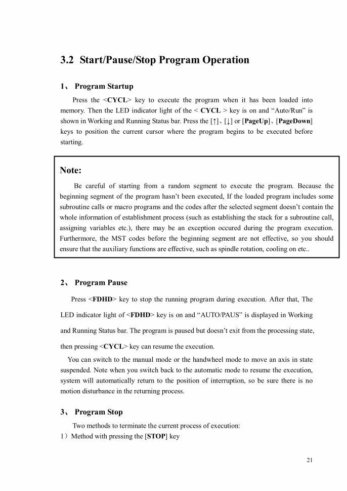
(as figure 3-16 shown).
Figure 3-16 Input for multiple segment instruction
3.8.2 Sequence of MDI Operation
When the cursor of the MDI instruction input window twinkles, the state of manual instruction input is activated and then you can input MDI command to the window. Sequence of MDI operation is as follows:
1) Switch to the AUTO mode; 2) Press < MDI > key to switch to the MDI instruction execution mode; 3) Input a command into the MDI window and press the <Enter> key to confirm the
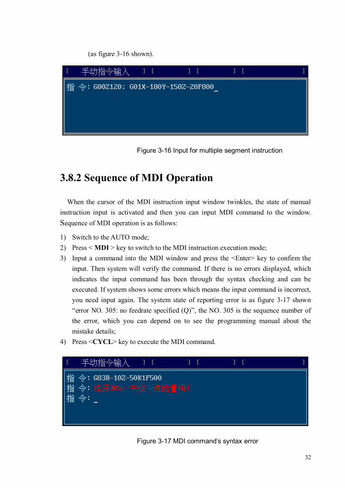
input. Then system will verify the command. If there is no errors displayed, which indicates the input command has been through the syntax checking and can be executed. If system shows some errors which means the input command is incorrect, you need input again. The system state of reporting error is as figure 3-17 shown “error NO. 305: no feedrate specified (Q)”, the NO. 305 is the sequence number of the error, which you can depend on to see the programming manual about the mistake details;
4) Press <CYCL> key to execute the MDI command.
Figure 3-17 MDI command’s syntax error
33
3.8.3 Suspending/Recovering/Terminating a Command
If a MDI command pauses during the execution, the command’s execution state and the data buffer are stored still, so it can be resumed to execute. But if a MDI command is terminated, the command’s execution state and the data buffer will be cleared, and it can’t be resumed to execute.
1、Suspending a Command
You can press <FDHD> key to make the operation pause in the process of executing a MDI command at any time.
2、Recovering a Command
In the command pause state, you can continue these operations as follows:
1) Press <CYCL> key again to resumed to execute the previous command.
2) After input a new command and confirm the input, the previous command will be covered, then press <CYCL> key again to execute the new command.
3) exit from the MDI mode.
3、Terminating a Command
A command will be terminated if any one of the following operations takes place:
1) After a command paused, exit from the MDI mode or switch to other operation mode.
2) After a command paused, input a new command, then the old command will be terminated automatically. The new command input is subject to the <Enter> key, that means after input a command, pressing the <Enter> key indicates the new command has been input(the old command will be terminated even though the new one has syntax errors).
Note: 1) After input a MDI command, you should press <Enter> key to send the code to
the code buffer to wait for executing, or else, it will not be executed even though you press <CYCL> key.
2) The instruction buffer’s size is fit for one instruction. The last input command can automatically cover the previous input command.

34
Note: After input a MDI command and press <Enter> key, then if system doesn’t indicate
syntax errors, that the command has been accepted and stored in the instruction buffer. So pressing <CYCL> will execute this command before it is terminated.

35
4 Managing a Program
4.1 Classification Of Program File
The program of this system refers to can be divided into four kinds as follows: 1) System Program: the programs which are stored in the system’s internal
storage. 2) External Program: the programs which are stored in U disk or removable
disk. The name of the external storage is set by the parameter P0012. 3) Network Program: the programs which are mapped to the NC port from the
computer’s port by network mapping. 4) Online Program: the programs which are received from the DNC server when
online machining. 5) Extended Program:the programs which are written for implementing some
motion’s sequence. The names of extended program are 9000~9999, these names are used for the extended program, the other programs can not use.
The type of program is determined by its storage position and form, when the
storage position or form is changed, the type of the program will change accordingly. For example, when copy a external program into the system’s internal storage, the type of this program is changed from external program to system program.
4.2 Editing a Program File
Before edit a program file, you should load the program at first. Only the program which has been loaded to memory can be edited.
editing a program file needs customer class or above power, or it isn’t available.
4.2.1 Opening a Program File
Two kinds of situations for opening a program file:
1、 Opening an existing program file:

36
1) Load the needed editing file to memory ( method of operation refer to 3.1); 2) Switch to the full screen for editing. Method of operation: <AUTO> → [\] →
[PROG] → [PEDT] 2、 Creating a new program file
Method of operation: <AUTO> → [\] → [PROG] → [NFIL]
After these operations, input a filename of the new program in the pop-up dialog
and press <Enter> key to confirm, then system will automatically switch to the full
screen for editing of creating a new program.
The new program’s name couldn’t conflict with the existing program name, or else some errors occur.
the length of program name is the 8.3 format. That is, the length of main name is no more than eight characters, the length of extension is no more than three characters.
The 9000~9999 names are used for the extended program, if the new program name is between 9000~9999, the system will prompt that the newly-built program is an extended program. The newly-built extended program will be stored in the extended program catalog of CNC.
After opening(or creating) a program file, system will switch to the full screen for editing in which you can edit or modify the open program, as figure 4-1 shown.
The content is shown on the top of the editing window includes:
1) Program Name: the filename of the current open program; 2) Program Type: If the open program is from the system’s internal storage, it will
display “[System Program]”; if the open program is from the external storage, it will display “[External Program]”; if the open program is an extended program, it will display “[Extended Program]”;
3) Current Row: The serial number of row in the file which the cursor is located at and the total number of rows.
4) Current Column: The serial number of column which the cursor is located at.

37
Figure 4-1 The Full Screen For Editing
4.2.2 Saving a File
Saving a program file means write a file into the program storage for permanent conservation. It will not vanish even though power is off.
If the open program which is in the system’s internal storage (system program) or extended program, then it will save the program in the corresponding catalogue of the internal storage; if the open program is in the external storage (external program), then it will save the program in the corresponding catalogue of the external storage.
As figure 4-2 shown, shows a progress bar in the process of saving.

38
Figure 4-2 A progress bar for saving a file
4.2.3 Saving a File As
Saving a file as is saving a file too, the difference is that when “save a file”, the filename doesn’t be changed, the file is saved as the old name. But when “save a file as”, the file is saved as a new file, and the old file still remains.
If the open file has been modified, saving the file as just saves the modification in a new file, the old file remains the same.
Operation sequence of saving a file as:
1) Press the system menu [SVAS] in the full screen for editing, it will pop up a dialog as figure 4-3 shown.
Figure 4-1 a Dialog For Saving a File As
2) Input a new filename in the pop-up dialog, press [Enter] key to confirm the input; 3) If the input filename doesn’t conflict with the other filename, saving a file as is
finished; or else, if the filename conflict, it will pop up a dialog as figure 4-4 shown.
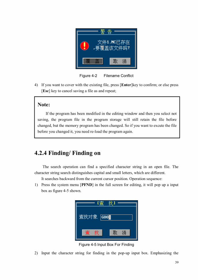
39
Figure 4-2 Filename Conflict
4) If you want to cover with the existing file, press [Enter]key to confirm; or else press [Esc] key to cancel saving a file as and repeat;
4.2.4 Finding/ Finding on
The search operation can find a specified character string in an open file. The character string search distinguishes capital and small letters, which are different.
It searches backward from the current cursor position. Operation sequence: 1) Press the system menu [PFND] in the full screen for editing, it will pop up a input
box as figure 4-5 shown.
Figure 4-5 Input Box For Finding
2) Input the character string for finding in the pop-up input box. Emphasizing the
Note: If the program has been modified in the editing window and then you select not
saving, the program file in the program storage will still retain the file before changed, but the memory program has been changed. So if you want to excute the file before you changed it, you need re-load the program again.

40
capital and lower case letters. 3) Press <Enter> key to confirm input. Then a window will search the input character
string backward from the current cursor position. During the searching, it will show a hint dialog as figure 4-6 shown, and then press <Esc> key will cancel search.
Figure 4-6 Finding a Character String
4) if finding the specified string, the system will locate the current cursor in back of the string and select the string, or else, if not finding by searching the entire file, it will pop up a hint box in the title bar to indicate that the finding is failure.
After the first finding operation, system will save the searched character string what
you input. So if you want to finding the same string in back of file, you can use [PFON] key without inputing the search string again.The “Finding on” operation will keep on searching backward from the current cursor position for the string you input last time.
4.2.5 Replacing
It is used to find the source character string in file and replace it with the new string. Both of them are input by the user. The replacing operation is applied to the whole file. That is after executing a replacing operation, all the source string in file will be replaced.
Replacing operation distinguishes capital letters and small letters. Operation sequence: 1) Locate the cursor at the position from which you want to start searching; 2) Press <RPLA> key in the full screen for editing. it will pop up a input box as figure
4-7 shown.

41
Figure 4-7 Input Box for Replacing
3) Input the search target string (the string will be replaced) and new character string in the pop-up input box. Emphasizing the capital and lower case letters.
4) Press <Enter> key to confirm the input. Then a window will replace the specified string backward from the current cursor position. During the replacing, press <Esc> key will cancel this operation.
4.2.6 Block Operation
The program block means a continuous character string unit in the program. The program block’s position is determined by block header(the beginning of the block) and block tail(the end of the block).
The defined program block is shown as figure 4-8.

42
Figure 4-3 The Defined Program Block
The program blcok operation includes some kinds as follows:
1) [Define a Header Block] Define the cunrrent cursor position as the beginning of the program block.
2) [Define a Tail Block] Define the cunrrent cursor position as the end of the program block.
3) [Clean Out a Block] Clean out the defined program block, but don’t clean out the paste buffer.
4) [Copy a Block] Copy the defined program block to the paste buffer. After that, you can use the paste operation to insert the copy block into the specified position in file.
5) [Cut a Block] Copy the defined program block to the paste buffer. It is different from copying a block, cutting a block will remove the block from the file. You can use the paste

43
operation to insert the cut block into the specified position in file.
6) [Paste a Block] Insert the program block of the paste buffer into the cunrrent cursor position. The paste operation don’t clean out the content of paste buffer. So you can continuously use the paste operation to insert the same block into the different position in file.
4.3 Managing a Program File
The object of the program file management can be a system program, an external
program or an extended program. The operation of the management includes:
1) Delete a Program File; 2) Copy a Program File; 3) Backup a Program File; 4) Rename a Program File; 5) Sort a Program File;
The method of entering into the program management window:
<AUTO> → [\] → [PROG] → [PMAN]

44
4.3.1 The Window Of Program Management
If the system has connected the external storage, it will open “System Program” and “External System” windows after entering into the program management interface, as figure 4-9 shown.
The operable window can be switched each other between system program window and external program window by pressing [WSWC] menu key.
Figure 4-4 The Program Management Interface Of System And External Program

45
If the system can’t connect the external storage or the parameter P0012 of the external storage is set incorrectly, it will only open “System Program” window after entering into the program management interface, as figure 4-10 shown.
Figure 4-5 The Program Management Interface Of System Program
46
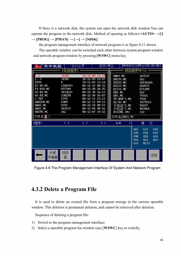
If there is a network disk, the system can open the network disk window.You can operate the program in the network disk. Method of opening as follows:<AUTO> →[\] → [PROG] → [PMAN] → [→] → [NDSK]
the program management interface of network program is as figure 4-11 shown. The operable window can be switched each other between system program window
and network program window by pressing [WSWC] menu key.
Figure 4-6 The Program Management Interface Of System And Network Program
4.3.2 Delete a Program File
It is used to delete an existed file from a program storage in the current operable window. This deletion is permanent deletion, and cannot be retrieved after deletion.
Sequence of deleting a program file:
1) Switch to the program management interface; 2) Select a operable program list window (use [WSWC] key to switch);

47
3) Use the [↑]、[↓] or [PageUp]、[PageDown] keys to select an existing program file in the program list or direct input the program filename what you want to delete.
4) Press <FDEL> key, then it will pop up a dialog, as figure 4-12 shown.
Figure 4-12 File Delete Confirmation
5) Check up whether the filename in the dialog is the file you want to delete, press <Enter> key to confirm, then the file deletion is finish; or else, press <Esc> key to cancel the deletion and repeat.
4.3.3 Copy a Program File
The program file copy needs two windows to operate. They may be “System Program”and “External Program”interface or “System Program”and “Network Program” interface.
When the system is in “System Program”and “External Program”interface, as Figure 4-9 shown, pressing [FCPY] menu key can copy the program which the current cursor selects into the other window. The window which the current cursor is in can be switched each other between “System Program”and “External Program” window by pressing [WSWC] menu key.
When the system is in “System Program”and “Network Program”interface, as Figure 4-11 shown, pressing [FCPY] menu key can copy the program which the current cursor selects into the other window. The window which the current cursor is in can be switched each other between “System Program”and “Network Program” window by pressing [WSWC] menu key.
The [FCPY] and [WSWC] menus are used for copying a program file:
1) [WSWC]
The program list window includes system program list window and external program list window. When one list window of them has the cursor display, the window is

48
operable. Pressing < WSWC > key in succession can switch to the other between them.
2) [FCPY]
It is used to complete the operation of copying a program, includes: a) output a program from the internal storage to the external storage or network disk; b) input a program from the external storage to the internal storage. Which operation is completion depends on the current operable window. That is: If the current operable window is the system program list window, this menu complete the a) operation. If the current operable window is the external program or network disk list window, this menu complete the b) operation.
Operation sequence of the program file copy (take input file operation of external
storage for example):
1) Save the program file which needs to copy into the internal storage in the external storage, and connect the external storage with the USB interface.
2) Switch the CNC to the program management interface; 3) If the interface doesn’t show the external program list window, which means system
doesn’t detect the external storage. Check the external storage is connected well and restart the CNC system. If the window appears already, continue the next operation;
4) Press [WSWC] key to switch the current operable window to the external program list window (Let the external program list window has the cursor display);
5) Reach the directory where the program is; 6) Use [↑]、[↓] or [PageUp]、[PageDown] keys to select the program file to copy into; 7) Press [FCPY] menu to copy the file into the internal storage.
The sequence of output operation is similar to the sequence above. Note that the output file is stored in the path what the external storage displays.
4.3.4 Backup a Program File
File’s Backup means copy an existing file which the cursor selects in the current operable window, and store in the program storage which the original file is located in as a different filename. The backup operation sequence is: 1) Select a operable program list window (use [WSWC] key to switch it); 2) Use the [↑]、[↓] or [PageUp]、[PageDown] keys to select an existing program file in
the program list or direct input the program filename what you want to backup;
49
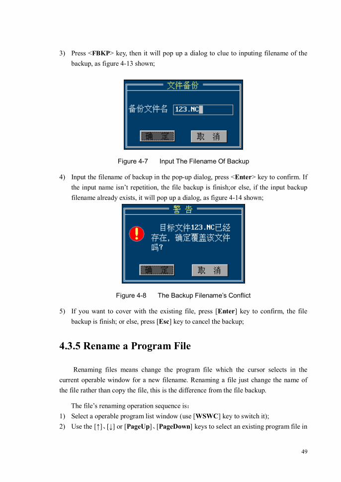
3) Press <FBKP> key, then it will pop up a dialog to clue to inputing filename of the backup, as figure 4-13 shown;
Figure 4-7 Input The Filename Of Backup
4) Input the filename of backup in the pop-up dialog, press <Enter> key to confirm. If the input name isn’t repetition, the file backup is finish;or else, if the input backup filename already exists, it will pop up a dialog, as figure 4-14 shown;
Figure 4-8 The Backup Filename’s Conflict
5) If you want to cover with the existing file, press [Enter] key to confirm, the file backup is finish; or else, press [Esc] key to cancel the backup;
4.3.5 Rename a Program File
Renaming files means change the program file which the cursor selects in the current operable window for a new filename. Renaming a file just change the name of the file rather than copy the file, this is the difference from the file backup.
The file’s renaming operation sequence is:
1) Select a operable program list window (use [WSWC] key to switch it); 2) Use the [↑]、[↓] or [PageUp]、[PageDown] keys to select an existing program file in

50
the program list or direct input the program filename what you want to rename; 3) Press <FREN> key, then it will pop up a dialog, as figure 4-15 shown;
Figure 4-9 a Dialog for Renaming a File
4) Input a new filename in the pop-up dialog, press <Enter> key to confirm the input. If the input name isn’t repetition, renaming the file is finish;or else, it will pop up a dialog, as figure 4-16 shown.
Figure 4-10 Conflict Of Renaming a File
5) If you want to cover with the existing file, press [Enter] key to confirm, Renaming the file is finish; or else, press [Esc] key to cancel the renaming.
4.3.6 Sort a Program File
Sorting Files means sort program files in the current operable program list window by Pressing [NSRT] or [TSRT] menu. When enter into the program list window, the system acquiescently sorts by time, the file of which last modification time is close to current time will sort in the above, followed by the farther.

51
1) Press [NSRT] menu Sort by the order of program filename’s ASCII code in the current operable program
list window. The small of default filename’s ASCII code sorts in front, followed by the larger of ASCII code. Repeatedly press [NSRT] menu, the sequence will reverse.
2) Press [TSRT] menu Sort by the order of program file’s last modification time in the current operable
program list window. The file of which last modification time is close to current time acquiescently sorts in the above, followed by the farther. Repeatedly press [TSRT] menu, the sequence will reverse.

52
5 Graphics Display
5.1 Summarize
Graphics display draws the tool path in the screen by the form of graphics simulation. The simulation graphics can be used to check the machining track and machining chape. According to machining position’s change and observational demand, you can operate up moving, down moving, left moving, right moving and view points shifting, graphics zoom etc. The graphics function can be used to simulate the tool’s motion trail, and examine the program’s validity by observing whether the motion trail is the same as the design path or not.
5.2 Enter the Graphics Simulation Interface
Machine positon’s display interface is divided into coordinate window, graphics window and speed curve window. The coordinate window is divided into workpiece coordinate window, remanent feed and relative coordinate window; The graphics window is divided into XYZ space graphics,XY plane graphics,YZ plane graphics and XZ plane graphics; The speed curve window can display the curve of speed and acceleration.
Press [VSWT] key can switch to the other among the seven interface, the graphics simulation interface is shown asFigure 5-1.
In the displayed graphics of machining track,the red line is the track of rapid traverse (G00), the green line is the track of tool feed (G01), and the tool’s axis is displayed by yellow.
Note that, the tool’s track which is displayed in the graphics window is in the workpiece coordinate system. So, if you change the workpiece coordinate system’s zero(namely change workpiece coordinate system) in the same machining program, then the two workpiece coordinate system which are before and after change will be mapped to the same coordinate system in the graphics window.

53
Figure 5-1 Graphics Simulation Interface
5.3 Graphics Operation
In the graphics simulation interface, there are the following system menus: [LMOV]: Move the graphics in the window left. If the simulation graphics goes beyond
the right of graphics window, you can press [LMOV] menu to move the graphics left to let the outside parts be visible.
[RMOV]: Move the window graphics left. [UMOV]: Move the window graphics up. [DMOV]: Move the window graphics down. [CLER] : Clear the display graphics in the window. [ZMUP]: Augment the zoom coefficient of the display graphics in the window. [ZMDW]: Minish the zoom coefficient of the display graphics in the window. [ZORG] :Restore the display multiple of the display graphics in the window to 1.

54
5.4 Graphics Parameter
5.4.1 Graphics Zoom Coefficient
The act machining track can be displayed by augmenting or minishing, and the multiple of augmenting or minishing is the graphics’s zoom coeffcient. The zoom coefficient >1, the graphics will be augmented; the zoom coefficient <1, the graphics will be minished; the zoom coefficient =1, the graphics will not be zoom.
The graphics zoom coefficient is set by the following parameter: P0181: the XY plane’s zoom coefficient in graphics mode P0182: the YZ plane’s zoom coefficient in graphics mode P0183: the XZ plane’s zoom coefficient in graphics mode P0184: the XYZ three-dimension strack’s zoom coefficient in graphics mode In the Graphics interface, press [ZMUP]、[ZMDW] or [ZORG] menu to zoom the
display graphics. During the program running, if you change the zoom coefficient, the graphics of the previous zoom coefficient displayed will be cleared out.
5.4.2 Workpiece Size Range
The workpiece size range of which this system can display is (take the workpiece coordinate system as center, the zoom coefficient =1):
XY plane: -320mm<X≤320mm,-240mm<Y≤240mm YZ plane: -320mm<Y≤320mm,-240mm<Z≤240mm XZ plane: -320mm<X≤320mm,-240mm<Z≤240mm XYZ space: -320mm<X≤320mm, -240/cos(45º) mm<Y≤240/cos(45º) mm,
-240mm<Z≤240mm, If the workpiece size goes beyond the display range, the outsides will can not
display. Then you can minish the zoom coefficient to display the minished graphics.
Note: If the workpiece machining track is in the display size range, but for the limit of
graphics window size, the display may be incomplete. Then press [LMOV]、[RMOV]、[UMOV] and [DMOV] to adjust the display positon of the graphics in the window to let the outside parts be visible.

55
5.5 Speed Curve Display
Display the speed and acceleration in the process of machining, and examine the speed change of the machine tool, as Figure 5-2 shown.
Figure 5-2 Curve Of Speed And Acceleration
The parameter about speed and acceleration curve display is: P0187 Whether display the speed curve or not [1-show; 0-no show] Whether display the speed curve interface by seting the [VSWT]menu. P0188 The maximum of speed curve
Set the upper limit of “speed curve” in speed curve interface displayed, the unit is (mm/m)
P0189 The maximum of acceleration curve Set the upper limit of “acceleration curve” in speed curve interface displayed, the unit is (mm/s2)
P0190 The type of displayed curve [0-instruction curve; 1-actual curve] Set the speed curve as instruction speed’s or actual feedback speed’s in speed curve interface displayed.

56
6 Data Input
The system data input mainly includes: Tool Magazine Configuration Tool compensation Coordinate system Setting Parameter Setting Axis Configuration M code’s definition and extension System Alarm’s definition and extension Authority Management Macro Variable modification
6.1 Tool Magazine Configuration
The tool magazine configuration table is used to configure the tool number on each tool position in tool magazine and the table’s correlative parameter.
Starting Address of Tool Magazine Table: The tool magazine table is stored into PLC data table. This configuration item is used to set the starting address of tool magazine table in the data table.It is the reference of parameter P0196, means its modification and the P0196 parameter modification are equivalent.
Tool Amount: Set the tool amount what tool magazine can store.This configuration item is the reference of parameter P0196, means its modification and the P0196 parameter modification are equivalent.
Current Tool Number: Set the tool number which is hold on the spindle. This configuration item is the reference of the D045 in data table.
Current Tool Position Number: Set the tool position number which is on the tool change position in tool magazine. The item is the reference of the D044 in data table.
Tool Number: Set the tool sequence number which is hold on each tool position in tool magazine.
The tool magazine table’s relative address is:
Tool magazine table first address = Tool magazine table starting address set value

57
Tool magazine table tail address = Tool magazine table starting address +Tool amount-1
Tool position address = Tool magazine table starting address +Tool position number-1
The address range of nonvolatile storage location in data table is D000~D399. So the tool magazine table tail address should be limited to 399,or else some errors occur.
Method of entering into tool magazine configuration interface: [\] → [MAGT] The interface is shown as figureFigure 6-1. The item which has “*” in front needs
machine tool class or above power that can be modified.
Figure 6-1 Tool Magazine Configuration Interface
58
6.2 Tool Compensation
6.2.1 Summarize
The setting parameters of tool compensation include:
Tool Length: The length offset by contrasting to the reference tool.
Generally, there is a reference tool in the tool magazine whose length is set to 0. The other tools’ length value is the length offset relatives to the reference tool.
Tool Radius: The radius of the tool’s cutting part.
Tool Wear: The tool used for a period of time will have a certain degree of wear and tear, the parameter is used as a correction when system executes the tool length compensation.
The actual compensation value = tool length - Tool Wear.
6.2.2 Enter the Tool Compensation Table Interface
Method of entering the tool compensation interface: [\] → [OFST] The tool compensation table interface is shown as figure 6-2:

59
Figure 6-2 Tool Parameter Table Interface
6.2.3 Method of Tool Compensation Parameter Setting
Method of tool parameter modification:
1) After entering the tool compentation management interface, press the [↑]、[↓] or [PageUp]、[PageDown] keys to select the parameter item needed to set.
2) Press [Enter] key to confirm the selected or direct input a tool parameter, then a input box will pop up above the selected item (as figure 6-3 shown);
3) Input a new parameter in the pop-up input box and press the [Enter] key to confirm input. After confirmed, the input box will disappear, and the selected parameter item’s value will update as the new input value;

60
Figure 6-3 Tool Parameter Input
If the input tool compensation value is the Z value in the current machine tool coordinate system, the machine tool coordinate value can be input into the selected item by pressing [TCUR] menu.
Note: 1) Press [Enter] key to make it valid after input a new parameter in the input box; 2) CNC system will save the new parameters when the compensation setting
window is closed.

61
6.3 Coordinate System Setting
6.3.1 Coordinate System Summary
Figure 6-4 Sketch map of coordinate system
1) Reference Coordinate System Reference point is a fixure on the machine tool. There are four reference points in all-
the first reference point, the second reference point, the third reference point and the fourth reference point. The first reference point’s position is determined by a mechanical switch while the others’ positions are specified by the system parameters.
Each reference point’s position parameters are as follows:
The first reference point:
P0081: X-axis first reference point P0082: Y-axis first reference point P0083: Z-axis first reference point P0084: Fourth-axis first reference point P0085: Fifth-axis first reference point P0086: Sixth-axis first reference point P0087: Seventh-axis first reference point P0088: Eighth-axis first reference point
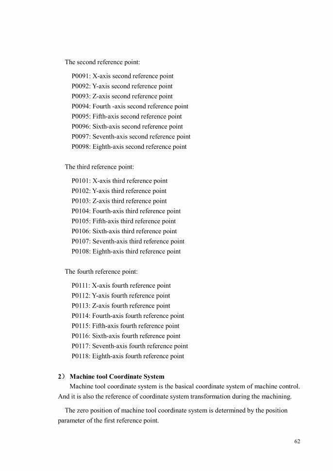
62
The second reference point:
P0091: X-axis second reference point P0092: Y-axis second reference point P0093: Z-axis second reference point P0094: Fourth -axis second reference point P0095: Fifth-axis second reference point P0096: Sixth-axis second reference point P0097: Seventh-axis second reference point P0098: Eighth-axis second reference point
The third reference point:
P0101: X-axis third reference point P0102: Y-axis third reference point P0103: Z-axis third reference point P0104: Fourth-axis third reference point P0105: Fifth-axis third reference point P0106: Sixth-axis third reference point P0107: Seventh-axis third reference point P0108: Eighth-axis third reference point
The fourth reference point:
P0111: X-axis fourth reference point P0112: Y-axis fourth reference point P0113: Z-axis fourth reference point P0114: Fourth-axis fourth reference point P0115: Fifth-axis fourth reference point P0116: Sixth-axis fourth reference point P0117: Seventh-axis fourth reference point P0118: Eighth-axis fourth reference point
2) Machine tool Coordinate System
Machine tool coordinate system is the basical coordinate system of machine control. And it is also the reference of coordinate system transformation during the machining.
The zero position of machine tool coordinate system is determined by the position parameter of the first reference point.

63
The first reference point’s position on machine tool is determined by the mechanical switch. If the mechanical switch is fixed, the first reference point’s position is fixed. Due to reference point position parameter settings are in the machine tool coordinate system, when the first reference point’s position parameters change, its physical location does not change and the actual change is the zero position of machine tool coordinate system.
After Power is on, executing returning the reference point in manual mode can establish the machine tool coordinate system. Once established, it will remain the same until cut off the power.
the position relationship between machine tool coordinate system and each reference points is shown as figure 6-5.
Figure 6-5 Position Relationship between Machine Tool Coordinate System and Reference Points
3) Workpiece Coordinate System The coordinate system which is used for programing machining program is workpiece
coordinate system.
System stores six workpiece coordinate system for selecting. The zero position of

64
workpiece coordinate system is set by the parameter, and the set value is the offset of workpiece coordinate system’s zero relative to machine tool coordinate system’s zero.
The first workpiece coordinate system (G54) will be selected automatically when power is on.
The first workpiece coordinate system (G54): P1021: X-axis zero point of the first workpiece coordinate system (G54.X)
P1022: Y-axis zero point of the first workpiece coordinate system (G54.Y)
P1023: Z-axis zero point of the first workpiece coordinate system (G54.Z)
P1024: Fourth-axis zero point of the first workpiece coordinate system (G54.4)
P1025: Fifth-axis zero point of the first workpiece coordinate system (G54.5)
P1026: Sixth-axis zero point of the first workpiece coordinate system (G54.6)
P1027: Seventh-axis zero point of the first workpiece coordinate system (G54.7)
P1028: Eighth-axis zero point of the first workpiece coordinate system (G54.8)
The second workpiece coordinate system (G55): P1031: X-axis zero point of the second workpiece coordinate system (G55.X)
P1032: Y-axis zero point of the second workpiece coordinate system (G55.Y)
P1033: Z-axis zero point of the second workpiece coordinate system (G55.Z)
P1034: Fourth-axis zero point of the second workpiece coordinate system (G55.4)
P1035: Fifth-axis zero point of the second workpiece coordinate system (G55.5)
P1036: Sixth-axis zero point of the second workpiece coordinate system (G55.6)
P1037:Seventh-axis zero point of the second workpiece coordinate system (G55.7)
P1038: Eighth-axis zero point of the second workpiece coordinate system (G55.8)
The third workpiece coordinate system (G56): P1041: X-axis zero point of the third workpiece coordinate system (G56.X)
P1042: Y-axis zero point of the third workpiece coordinate system (G56.Y)
P1043: Z-axis zero point of the third workpiece coordinate system (G56.Z)
P1044: Fourth-axis zero point of the third workpiece coordinate system (G56.4)

65
P1045: Fifth-axis zero point of the third workpiece coordinate system (G56.5)
P1046: Sixth-axis zero point of the third workpiece coordinate system (G56.6)
P1047: Seventh-axis zero point of the third workpiece coordinate system (G56.7)
P1048: Eighth-axis zero point of the third workpiece coordinate system (G56.8)
The fourth workpiece coordinate system (G57): P1051: X-axis zero point of the fourth workpiece coordinate system (G57.X)
P1052: Y-axis zero point of the fourth workpiece coordinate system (G57.Y)
P1053: Z-axis zero point of the fourth workpiece coordinate system (G57.Z)
P1054: Fourth-axis zero point of the fourth workpiece coordinate system (G57.4)
P1055: Fifth-axis zero point of the fourth workpiece coordinate system (G57.5)
P1056: Sixth-axis zero point of the fourth workpiece coordinate system (G57.6)
P1057: Seventh-axis zero point of the fourth workpiece coordinate system (G57.7)
P1058: Eighth-axis zero point of the fourth workpiece coordinate system (G57.8)
The fifth workpiece coordinate system (G58): P1061: X-axis zero point of the fifth workpiece coordinate system (G58.X)
P1062: Y-axis zero point of the fifth workpiece coordinate system (G58.Y)
P1063: Z-axis zero point of the fifth workpiece coordinate system (G58.Z)
P1064: Fourth-axis zero point of the fifth workpiece coordinate system (G58.4)
P1065: Fifth-axis zero point of the fifth workpiece coordinate system (G58.5)
P1066: Sixth-axis zero point of the fifth workpiece coordinate system (G58.6)
P1067: Seventh-axis zero point of the fifth workpiece coordinate system (G58.7)
P1068: Eighth-axis zero point of the fifth workpiece coordinate system (G58.8)
The sixth workpiece coordinate system (G59): P1071: X-axis zero point of the sixth workpiece coordinate system (G59.X)
P1072: Y-axis zero point of the sixth workpiece coordinate system (G59.Y)

66
P1073: Z-axis zero point of the sixth workpiece coordinate system (G59.Z)
P1074: Fourth-axis zero point of the sixth workpiece coordinate system (G59.4)
P1075: Fifth-axis zero point of the sixth workpiece coordinate system (G59.5)
P1076: Sixth-axis zero point of the sixth workpiece coordinate system (G59.6)
P1077: Seventh-axis zero point of the sixth workpiece coordinate system (G59.7)
P1078: Eighth-axis zero point of the sixth workpiece coordinate system (G59.8)
6.3.2 Workpiece Coordinate System Setting
Two methods to set workpiece coordinate system:
1) Directly set the corresponding parameter of coordinate system’s zero point in the system parameters table;
2) Quickly set the workpiece coordinate system in its setting interface.
Refer to the "System parameter setting" section for the first setting method. This section only introduces the second setting method. The second method is the same as the first in essence, which is also used to set workpiece coordinate system’s parameters mentioned above, the difference is that it is operated in the specialized interface.
Method of entering into the setting interface: [\] → [SCRD]
The workpiece coordinate system setting interface is shown as figure 6-6:

67
Figure 6-6 Workpiece Coordinate System Setting Interface
Sequence of workpiece coordinate system setting: 1) Use [→]、[←] or [PageUp]、[PageDown] keys to select the workpiece coordinate
system (G54~G59, external zero offset); 2) After the workpiece coordinate system selected, use [↑]、[↓] keys to select the set
coordinate axis; 3) After the coordinate axis selected, press [Enter] key or direct input a coordinate
value, then it will pup up a input box on the selected coordinate axis; 4) Enter a new workpiece coordinate zero offset into the pop-up input box. If the input
zero position is the actual location of the current axis, you can press [CCUR] key to automatically input the machine tool coordinate value of the axis’s current location as the zero offset value of the axis’s workpiece coordinate;
5) Press [ENTER] key to confirm the input. Then the input box disappears and the new input value is displayed as the axis’s coordinates offset value.
6) The external zero offset is the shortcut setting of the parameter P1220~P1227. Function menu of coordinates sets:
[CCUR]: The machine tool coordinate value of the coordinate axis’s location is used as

68
the workpiece zero location, and automatically input into the corresponding coordinate parameter. The menu is used in conjunction with the cursor, only operate to the coordinate axis selected by the current cursor. For example, if the cursor is displayed in the G56 Y-axis, and then press [CCUR] key, the machine tool coordinate value of the Y-axis’s location will be used as the G56 Y-axis offset value and automatically input into the G56 Y-axis parameter.
[ADD_]: Move the workpiece zero position of the coordinate axis selected by the current cursor in the positive direction for some distance. After input offset distance, the system automatically calculates the new zero position and stores it into the corresponding coordinate axis’s zero parameters.
[DEC_]: Move the workpiece zero position of the coordinate axis selected by the current cursor in the negative direction for some distance. After input offset distance, the system automatically calculates the new zero position and stores it into the corresponding coordinate axis’s zero parameters.
[REC1]: Store the position coordinate of the current machine tool into the recordⅠfor mid-division or difference-evaluation used.
[REC2]: Store the position coordinate of the current machine tool into the record for Ⅱ
mid-division or difference-evaluation used.
[MIDP]: Mid-division function use the average value(midpoint) of the coordinate value in the record anⅠ d the coordinate value in the recordⅡ as the new coordinate zero and automatically store into the coordinate system selected by the cursor.
[DECP]: Difference-evaluation function use the difference value of the coordinate value in the recordⅡsubtracted from the coordinate value in the record as the new Ⅰ
coordinate zero and automatically store into the coordinate system selected by the cursor.
[WRST]:Copy the workpiece zero coordinate in the second assistant window to the coordinate system which the current cursor locates in.
[RESM]: When the workpiece coordinate system’s zero was modified every time, the system automatically records the value before changed. Pressing the [RESM] menu can recover the modified coordinate zero for the old value. But this function can only recover the last value before changed.

69
6.4 System Parameters Setting
6.4.1 Parameter Classification Explanation
The system parameters of this CNC can be classified three grades according to the privilege level’s high or low: 1) Systyem Manufacturer Level: This grade parameters belong to the core parameters
which are in connection with system development. Modifying this kinds parameters may cause system’s abnormal execution, so it needs the highest authority demand.
2) Machine Manufacturer Level: This grade parameters belong to machine tool configuration parameters, it is modified by machine manufacturer. Its privilege level take second place.
3) End User Level: This grade parameters are a variety parameter of the end user using. Its privilege level is the lowest.
In the parameter setting interface, the parameters numbers of system manufacturer
level’s parameters begin with ‘S’, such as S2051; the machine tool manufacturer level’s parameters begin with ‘M’, such as M0237; the end user level’s parameters begin with ‘U’, such as U1021.
For more details about permission, see the " Authority Management" section. Mapping table of three grades authority and parameters modified is as follows: Parameters Authority
System Manufacturer Parameters
Machine Manufacturer Parameters
End User Parameters
System Manufacturer Authority
√ √ √
Machine Manufacturer Authority
× √ √
End User Authority × × √ ‘√’means this row’s authority can modify this column’s parameters
‘×’means this row’s authority can not modify this column’s parameters

70
6.4.2 Paramter Type
The system paramters are divided into three types: ① Decimal Integer
This kind parameters are decimal integer, not include decimal fraction part. When you modify them, you can only input the number of 0~9 and the sign of ‘+’ or ‘-’.
In system parameter setting interface, decimal integer paramters are displayed for five figures.
② Hexadecimal Integer
This kind parameters are hexadecimal integer, not include decimal fraction part. When you modify them, you can input the number of 0~9 and the six letters of A, B, C, D, E, F.
In system parameter setting interface, hexadecimal integer paramters are displayed for five figures.
③ Floating-Point Parameter This kind parameters are made of a floating point numbers, include integer part and
decimal fraction part. When you modify them, you can input the number of 0~9 and the characters of ‘+’ , ‘-’or ‘.’.
In system parameter setting interface, floating point paramters are displayed for ten figures when the parameter value is greater than zero, and displayed for eleven figures when less than zero(the redundant one used for a minus sign ‘-’ shown), thereinto, the integer part has five figures and the decimal fraction part has four figures.
6.4.3 Paramter Setting
Operation method of entering into system parameter setting interface: [\] → [SSET] → [PARA]
The course of system parameter setting is as follows: 1) Enter into the parameter setting window; 2) Select the parameter item: use [↑]、[↓] or [PageUp]、[PageDown] keys to locate the
parameter item which needed modified, or direct locate the needed parameter item by using search manner.
3) Enter into edit state: After select the item, press [Enter] or direct input parameter contents, if the current privilege level fill the parameter’s authority demand, it will

71
pop up a input box above the selected item (has a cursor twinkle), which can receive the user input, as figureFigure 6-2 shown;
Figure 6-2 System Parameter Setting
4) Modify the parameter value: Input a new parameter value into the pop-up input box; 5) Confirm the input: After input a new value, you should press [Enter] key again to
confirm the input, then the input box will disappear, and return to the parameter item selected state;
Note: 1、 After input a new parameter into the input box, you should press [Enter] key to
confirm, then the input parameter can be effective; 2、 CNC system will save the modified parameter when the parameter setting
window is closed.

72
6.4.4 Parameter Searching
Search the parameter item of the specified parameter number in the parameter table, and display the searching result as the current selected item. After press the [AFND] menu, it will pop up a input dialog box, as Figure 6-3 shown. Input the parameter number for searching in the pop-up input box , select “OK” button or press [Enter] key, then it will begin to search the specified parameter. If the searching is success, the parameter window will automatically go to the searched parameter and use the paramteter as the current cursor selected parameter; If it can’t search the specified parameter, the title bar will pop up a warning prompt box, as Figure 6-4 shown.
Figure 6-3 Input a Parameter Number for Searching

73
Figure 6-4 Parameter Searching Failure
6.4.5 Parameter’s Backup and Recovery
1、 Parameter Backup Parameter backup means copy the system parameters and store it into the backup
storage. When needed, it can be recovered to system parameters by using parameter recovery function. When backup parameters, the path and filename of parameter backup can be specified by a parameter backup dialog box. If the backup path and filename are the same, the last time backup will recover the previous backup parameters.
Method of parameter backup: [\] →[SSET] → [PARA] → [ABKP] And then, specify the path and filename to backup parameters. Finally, press [Enter]
key to confirm.
2、 Parameter Recovery Parameter recovery means recover the parameter backup file into the system default
parameter file. The recovery operation will cover the original parameter file with the

74
backup file, you should pay attention to when operate. In the system parameter interface, press [ARSM] menu, input the path and filename
of parameter backup into the parameter recovery dialog, and then press [Enter] key to confirm, the backup parameter’s recovery is finished.
If the path and filename has no backup parameter file which are specified by the parameter recovery dialog, the title bar will pop up a prompt box, as Figure 6-4 shown.
Method of parameter recovery:[\] →[SSET] → [PARA] → [ARSM] And then, specify path and filename of the parameter backup. Finally, press [Enter]
key to confirm.
Figure 6-5 No Backup Parameter File
6.4.6 Parameters Export and Import
1、 Parameters Export Export the parameters in the form of TXT text into the specified path by using [EXPT] menu.

75
Operation method: [\] →[SSET] → [PARA] →[EXPT] And then, set the path and filename of export file in the export TXT dialog box. Finally, press [Enter] key to confirm.
2、 Parameters Import Import the parameters in the form of TXT text into the system directory by using [IMPT] menu. Operation method: [\] →[SSET] → [PARA] →[IMPT]
And then, set the path and filename of import file in the import TXT dialog box. Finally, press [Enter] key to confirm. If there is no export parameter file of which filename is specified in the system
directory, the title bar will pop up a prompt box.
6.5 Logic Axis Configuration
This system’s logic axis means the coordinate axis which interpolator supports, the purpose of logic axis configuration is mapping the logical axis into the specific physical axis, and control the motor’s running by the physical axis. At present, the interpolator support eight coordinate axis’s interpolation control at most, so, the CNC system can collocate eight logical axis at most.
Method of entering into axis configuration interface: [\] →[SSET] → [CHNL] The axis configuration interface is shown as Figure 6-6.

76
Figure 6-6 Logic Axis Configuration Interface
Contents of logic axis configuration mainly includes several kinds as follows: 1、 Physical axis information
Physical axis information means NC system’s hardware information, includes: 1) Whether to install?: Means whether the logic aixs has the corresponding
physical axis. If the installation symbol is 0, means the logic axis doesn’t physically assign the actual axis, namely, the logic axis hasn’t been used. Therefore, when the installation symbol is 0, all of the logic axis’s confiuration items are invisible ( needn’t configure).
2) Installed axis name: The name of installed physic axis, such as X, Y, Z ect. 3) Axis type: Select the usage type of the axis. 4) Installed axis (physical): Index of the physical axis which the logic axis
corresponds to. 5) Whether has feedback?: Whether the system deals with the feedback signal
from the coder. If dealing with the feedback signal, set it as 1; or else set as 0.
2、 Display information setting The parameter of whether display the coordinate axis:

77
Display coordinate: if set as 1, the logic axis’s coordinate will be displayed in all coordinate display of interface; if set as 0, the logic axis’s coordinate will not be displayed in all coordinate display of interface;
3、 Machine tool relevant information For specific machine tool, every axis needs corresponding configuration, includes: 1) Screw-pitch or rotation axis revolutions per degree 2) Coder type 3) Coder pulse number 4) Electron gear ratio 5) Pulse type 6) Instruction type 7) Motor’s maximum revolution 8) Motor’s revolution direction 9) Check whether return the reference point 10) Feedback electron gear ratio
4、 Synchronizing shaft information
Every installed physical axis can be defined a synchronizing shaft. When the driving shaft moves, the synchronizing shaft move driving shaft in step. If there has installed a synchronizing shaft, you should define the shaft’s relevant information in logic configuration, includes:
1) Whether to install synchronizing shaft: If the synchronizing shaft has been installed, this item is set as 1, or else set as 0;
2) Synchronizing shaft’s installed axis: similar to driving shaft’s installed axis; 3) Synchronizing shaft’s motor reverse: set as 0 or 1, this setting item can change
the diversion turning direction of synchronizing shaft’s motor; 4) Synchronizing shaft’s feedback electron gear ratio; 5) Double-shaft’s acceptable synchronization error: The error which the driving
shaft and driven shaft accept in the process of synchronization, CNC detects the synchronization error of driving and driven shafts all the time, if the error is greater than acceptable value, the system will warn and deal with .
6) Synchronization error compensation parameter: The compensation parameter which is used to compensate synchronization error by system.

78
6.6 M-Code’s Extension Definition
6.6.1 M-Code Summarize
After auxiliary function M-code executed, system will export the specified signal (high or low level) to the appointed I/O address, you can use this signal to control all kinds of switches on the machine tool. After M-code executed, CNC will export the strobe signal R89.0 as 1, but CNC doesn’t see to reset the strobe signal, which is accomplished by the PLC program of your design.
The following M-codes are in the hands of system inside, you needn’t define them: M00:Program Pause M01:Program Optional Stop M02:When the program is finish, the program will rest on this line. M03:Spindle Clockwise Rotation M04:Spindle Counter-clockwise Rotation M05:Spindle Stop M30:Program End M98:Subroutine Call M99:Subroutine Return Except the M-codes of system internal processing, you can extend fifty M-codes at
most. For the M-codes of system internal processing, you can also define them for supplement, the method is the same as extending M-code.
The M-codes of user defined include several factors as follows: 1) Function Description: Describes the M-code implemented function, eight
characters at most(four Chinese characters); 2) M-code: Fill in the extended M-code’s name. Such as: M07; 3) Operation Signal: Specify output signal and address when the M-code executed.
The address only is the system PLC internal relay’s address room R90.x~R99.x (this address range only can be used for M-code’s extention, the user can’t use it). If you want to control the other switch, you need put through M-code’s operation signal to its switch’s signal address in PLC program.
4) Operation Result: Determine the output which is exported to operation signal is a high or low level, when M-code executed.
0—export low level

79
1—export high level 5) Wait Signal: If the M-code has been set a wait signal, and after M-code execution
is finished, the program will pause and don’t continue the following untill the wait signal become a high level. If the M-code has no wait signal, and after M-code execution is finished, the program’s pause time is specified by operation delay. M-code’s wait signal can be a normally open contact or a normally closed contact. When set as a normally closed contact, add “/” in front of input wait signal.
6) Operation Delay: Appoint the program’s pause time after M-code execution is finished, when the time is out, the program will continue to execute downwards. If set a wait signal, the pause time begins from the time the wait signal become to high level. The operation delay is set in milliseconds.
7) Call Program: Specify the extension program name which program calls after the M-code execution is finished. The specified program must exist in the system’s extension folder.
The executing flow of user defined M extension code:
1) If M extension code has “Operation Signal” and “Operation Result”, the system will transfer “Operation Result” to “Operation Signal” at first, and then enter into the next step; Or else, direct enter into the next step;
2) If M extension code has “Wait Signal”, the program will pause to await the specified “Wait Signal” arrival, after the “Wait Signal” coming, enter into the next step; If there is no “Wait Signal”, direct enter into the next step;
3) In this step, program will direct pause for a while which is specified by “Operation Delay”, in millisecond. If set as 0, it will pause for 0 millisecond. After the delay time arrives, direct enter into the next step;
4) If M extension code has “Call Program”, program will call the specified extension in this step. After the extension execution is finished, M extension code execution is over; If M extension code has no “Call Program”, the M extension code is over.
6.6.2 M-Code’s Definition and Extension
Method of entering into M-code extension interface: [\] →[SSET] → [MCOD] M-code extension interface is shown as Figure 6-7. The item which displays “*” in the window means the parameter item isn’t set
(namely this item is invalidation).

80
Figure 6-7 M-Code Extension Definition Interface
6.7 System Alarm Definition and Extension
6.7.1 System Alarm Summarize
System alarm has two kinds: the one is system internal alarm, the other is user defined extension alarm.
1) System Internal Alarm This part alarm is defined by CNC system inside, user can not modify. The alarm number of system internal alarm is No.0~No.399.
2) User Defined Extension Alarm User externsion alarm is defined by user, the alarm number is No.400~No.511.
The corresponding input point of every extension alarm is set by user, if the input point is set as 1, system will give the corresponding alarm information; On the contrary, if the input signal is 0, system will automatically clean the alarm information out.

81
6.7.2 System Alarm’s Extension
Method of entering into system alarm extension interface:[\] →[SSET] → [ALME] System alarm extension interface is shown as Figure 6-7.
Figure 6-8 Alarm Extension Interface
The alarm item shows by three columns, the first column is alarm number, the second column is used to set alarm input, the third is alarm display(namely displays the clew words when system pops alarm). When you use alarm extension, you need to set the input signal and alarm words.
The setting sequence of alarm extension definition is as follows:
1) Press [↑]、[↓]、[←]、[→] or [PageUp]、[PageDown] key to select the alarm item which is needed to define.
2) After select the item, press [Enter] key or direct input a set value, then a input box will pop up above the selected item;
3) Input the alarm’s relevant information into the pop-up input box; 4) After affirm the input correctness, Press [Enter] key again to confirm the input.

82
6.8 Authority Management
6.8.1 Summarize
The system authority is used for dividing and limiting the system function. You can only use the system function which is equal to the authority of you have. The high authority user can use the low authority function, but the low authority user can not use the high authority function.
The system authority levels have three grades: system manufacturer authority, machine manufacturer authority and end user authority. The authority level from high to low is: system level authority > machine level authority > end user level authority.
System level and machine level authority can be opened only by inputing the password, user level authority can be opened by the password and exterior input, namely: when G22.0 is 1, direct open the user authority(needn’t input password); if G22.0 is 0 , you need to input the password to open.
6.8.2 Authority Management
1、Authority Password Modification: Modification operation of system password: [\] →[PSWD] → [SPWD] → [SSPW] Modification operation of machine password:[\]→[PSWD] → [SPWD]→ [SMPW] Modification operation of user password: [\] →[PSWD] → [SPWD]→ [SUPW] When modify the password, you need to input the old password and input twice new
password. Only when the input old password is correct and the new passwords twice input are consistent, the password modification is successful.
2、Authority Password Input:
Input operation of system password: [\] →[PSWD] → [IPWD] → [ISPW] Input operation of machine password: [\] →[PSWD] → [IPWD] → [IMPW] Input operation of user password: [\] →[PSWD] → [IPWD] → [IUPW]

83
6.9 Macro Variable’s View and modification
The value of macro variables can be modified by code in macro program, as well as be looked at and modified in the window.
Method of entering into macro variables modification window: [\] → [VARI] The macro variables window is shown as Figure 6-9.
Figure 6-9 Variables View and Modification Window
The macro variables are divided into local variables, public variables and system variables, which can be switched by [LVAR], [PVAR], [SVAR] menus, the title bar will show the variables type of the current display window.
You can lookup the specified variable name in current window by pressing [VSCH] menu, but this can only search through variables type display in current window. Namely, when the current window shows public variables, you can’t search the local variables and system variables, the others are the same.

84
6.10 Statistic Information
Statistic information function is the statistic of workpiece machining number of pieces and machining time. Method of entering into statistic information menu is: [\] →[→] → [STAT], statistic information interface is shown as Figure 6-10.
Statistic information can count the workpiece machining by M extension code. Statistic information notes the statistic of all kinds of machining time in the process
of workpiece machining.
Figure 6-10 Statistic Information Interface
You can select “Workpiece Name”, “Plan Machining numbers”, “Already Machining numbers” to modify by pressing [←]、[→] 、[↑]、[↓]key; select “Cumulative Boot Time ”, “Cumulative Machining Time”, “Previous Machining Time” by pressing [←]、[→] 、[↑]、[↓]key and press [Del] key to delete the selected target item. The method of counting the workpiece machining numbers, please refer to the machine illustration of machine manufacturer.

85
7 PLC
7.1 PLC Online Programming and Diagnosis
This system use ladder diagram language to PLC program. Please refer to <<PLC Programming illustration>> about programming method of ladder diagram language. This section doesn’t explain the programming method, only detailedly introduce the usage of programming environment(programming interface).
7.1.1 Ladder Diagram Programming Interface
Method of entering into PLC programming interface: [\] →[DIAG] → [PDIA] PLC programming interface is shown as Figure 7-1.
Figure 7-1 PLC Programming Interface

86
7.1.2 Ladder Diagram program Structural Unit
The ladder diagram program is divided into calculation section and output section. The calculation section includes every semaphores which participate in ladder diagram operation. The semaphore in calculation section can be a input semaphore or a output semaphore. PLC program can only read the semaphores in calculation section. The output section is the output edit section of the calculation result, which is used to specify the output address of the calculation result. The semaphore of output section can only be a output semaphore, and PLC program can write this semaphore.
PLC ladder diagram program is made up of normally open contact, normally closed contact, level conduction line, vertical conduction line, output coil, normally open contact rising edge, normally open contact falling edge, normally closed contact rising edge, normally closed contact falling edge, set output, reset output and function commands etc. as Figure 7-2 shown.
Figure 7-2 PLC Ladder Diagram Program’s Basic Unit

87
7.1.3 Programming Menu Illustration
7.1.3.1 Basic Command Menu
Normally Open Contact
Normally Closed Contact
Output Coil
Output Coil(output in reverse)
Level Conduction Line
Vertical Conduction Line
Delete Vertical Conduction Line
Normally Open Contact Rising Edge
Normally Open Contact Falling Edge
Normally Closed Contact Rising Edge
Normally Closed Contact Falling Edge
Set Output
Reset Output
7.1.3.2 Function Command Menu
After select [FCMD] key in [PDIA] menu, the right of PLC edit interface will list a list selected box of PLC function commands. You can select the function command in

88
the lis box, as Figure 7-3 shown. Pressing [↑]、[↓] key to move cursor to select function command, as well as inputing function command name for searching in search box, or direct input the corresponding sequence number of function command. After the cursor selects the function command, press [Enter] key, and then the function command of cursor selected is input into PLC edit interface. Continue to press [FCMD] or [Esc] key to exit the right list selected box of PLC function commands.
Please refer to <<PLC Programming illustration>> about the concrete usage of function command.
Figure 7-3 PLC Function Menu Interface
Note: 1、 Due to the function command may take up more lines or more columns, you need
remain enough room to edit when input function command.

89
7.1.3.3 Ladder Diagram Edit Menu
1. [INSL] Insert a new line in front of the line in which the current cursor is positioned. After inserting a line, the line in which the current cursor is positioned becomes a
blank line, the line behind the cursor will move downwards one line distance in turn, as Figure 7-4 shown.
Figure 7-4 Insert a Line
2. [DELL] Delete the line in which the current cursor is positioned. After deleting a line, the line in which the current cursor is positioned is deleted, the
line behind the cursor will move upwards one line distance in turn, as Figure 7-5 shown.
Figure 7-5 Delete a Line
If the line in which the current cursor is positioned has function command, when the cursor rests on function command, [DELL] will delete the whole line program. If the cursor rests on basic command, [DELL] will delete a length of basic command in which the current cursor is positioned(do not delete function command).

90
3. [LSKR] Move the current line in which the cursor is positioned to any line of ladder
diagram, input the target position where the cursor is needed to move into the dialog box as Figure 7-6 shown. After pressing [Enter] key, the cursor will move to the new position.
Figure 7-6 Positioning Function
4. [FIND]、[FDON]
Finding function is used to search the specified element by name in ladder diagram. You should input a whole element name in finding dialog. Such as searching Y00.3,
you should input “Y00.3”, but not the simply name such as “Y3” or “Y03” ect. The small letter of input name will be translated into capital letter when searching.
After searching the target element, you can press [FDON] menu to find on the next target backwards without inputing the element name again.
5. [LSAV]
Save ladder diagram into system, and write into disk for permanent preservation. When edit ladder diagram, CNC will copy the system PLC program, all of the edit

91
are on this copy. Therefore, during edit, the CNC executive program is the old PLC program. After saving the ladder diagram, CNC will replace the old PLC program with the new program, so the CNC begin to execute the new PLC program after saving.
6. [PCPY]
Copy function means copy an area of ladder diagram into the paste buffer, which is used for paste function. When pressing [PCPY] menu, a dialog box appears as Figure 7-7 shown, input the start line and the end line are into the dialog and press [Enter] key, then the copy function is carried out.
Figure 7-7 Ladder Diagram Copy
7. [PPST]
Paste the content copied by copy function to the line position in which the current cursor is positioned.
8. [MASK] When use mask function, you should move the cursor to the right output node. You can mask this output node or cancel mask by pressing [MASK] menu, as Figure 7-8

92
shown. After the output node is masked, the node’s calculation section and output section turn gray, and drop out of PLC scan operation.
Figure 7-8 Mask Function
9. [LBKP]、[LRSM]
Ladder diagram backup means copy the PLC program file and store into backup storage, you can resume this backup PLC program as the system executive PLC program by using recovery function when you need.
Ladder diagram recovery means resume PLC backup program in backup storage as
Note: (1) [MASK] menu can only be operated in output node, the operation in the
other node is invalidation. (2) [MASK] operation modify PLC, so after [MASK] operation, you need
press [LSAV] to put the scan operation result of [MASK] into effect.

93
system executive PLC program. If there is no usable backup ladder diagram file in the backup storage, when you press [LRSM] menu, the system titile bar will pop up a prompt as Figure 7-9 shown.
Figure 7-9 No Backup Ladder Diagram
10. [INSN]
Insert a new blank node in front of the node which the current cursor selects. After insert a node, the node position where the current cursor is positioned turns
into a blank node, the nodes behind cursor will move backwards a node distance in turn (includes their vertical conduction lines), the position of output coil is fixed, as Figure 7-10 shown.
If the line in which the current cursor is positioned has function command, [INSN] menu is invalidation.

94
Figure 7-10 Insert a Node
11. [DELN] Delete the node which the cursor selects. After delete the cursor position node, the nodes behind cursor will move forward a
node distance in turn(includes their vertical conduction lines), the position of output coil is fixed, as Figure 7-11 shown.
If you want to delete the current node and keep the follow-up node’s position still, you can direct press the [Delete] key on edit keyboard to delete the node where the current cursor is positioned.
[DELN] menu is not valid for function command, If you want to delete function command, please move the cursor onto any place of function command, then press [Delete] key on edit keyboard to delete the function command.
Figure 7-11 Delete a Node
12. [REPL]
Replacing element function means replace all of the specified element in ladder diagram with the other specified element.
Note: If the line in which the current cursor is positioned has function command,
[DELN] menu is invalidation.

95
Input the replaced element name into “Search object” box and input the new element name after replacing into “replace with” box in the repalcing element dialog box, then press [Enter] key to replace all of the replaced element in PLC edit interface with the new element name.
13. [FINS] Insert the content of the specified ladder diagram’s subfile into the location where the current cursor is positioned, as Figure 7-12 shown.
Figure 7-12 Insert a Subfile
Note Repalcing a element is start from the location where the current cursor is
located, the replaced element in front of cursor can not be finded out and replaced.

96
7.1.4 Ladder Diagram Programming Demonstration
Using normally open, normally closed contacts and output coil to realize the command of and, or, invert ect.
For example, in order to realize the operation command of Y02.0 = (X02.0 & (/X01.5)) | (/X01.0)( thereinto, ‘/’ means in reverse), programming sequence of ladder diagram is as follows:
1) Locate the cursor in the section start of programming position, press
( normally open contact), input address number “X02.0” into element input box and press [Enter] to confirm, the X02.0 element will appear at the current cursor position;
2) Move the cursor to right for a bit, press ( normally closed contact),
input address number “X01.5” into element input box and press [Enter] to confirm, the X01.5 element will appear at the current cursor position;
3) Locate the cursor in the section start of next line, press ( normally
closed contact), input address number “X01.0” into element input box and press [Enter] to confirm, the X01.0 element will appear at the current cursor position;
4) Move the cursor to right for a bit, press (Level Conduction Line), draw a
level conduction line at the current cursor position;
5) Move the cursor up for a bit, press (Vertical Conduction Line), draw a
vertical conduction line at the lower right of current cursor position;
6) Press (Output Coil), input address number “Y02.0” into element input
box and press [Enter] to confirm, it will automatically create output coil and necessary level conduction line.
The finished ladder diagram is shown as Figure 7-13.
Figure 7-13 Ladder Diagram Demonstration
97
7.1.5 PLC Online Diagnosis
When PLC program is in the running process, you can observe its running process and result by ladder diagram display interface.
In the ladder diagram interface, in calculation section, green node shows its element is in the on-state, white node shows its element is in the off-state; In output section, green node shows its element outputs 1, white node shows its element outputs 0.
7.2 I/O Diagnosis
7.2.1 I/O Diagnosis Summarize
I/O diagnosis is used to diagnose the register’s state table of PLC running state by on-line observing every register’s state which is correlative with PLC.
The registers which can be seen in I/O diagnosis include:
X Register: the switching signal which machine tool inputs into PLC. Y Register: the switching signal which PLC outputs to machine tool. F Register:the switching signal which NC system inputs into PLC. G Register: the switching signal which PLC outputs to NC system. K Register: the switching signal which control panel inputs into PLC. L Register: the switching signal which PLC outputs to control panel. R Register: PLC internal middle register. B Register: PLC internal breakpoint save register.
7.2.2 I/O Diagnosis Interface
Method of entering into I/O diagnosis interface: [\] →[DIAG] → [SDIA] I/O diagnosis interface is shown as Figure 7-14 shown.

98
Figure 7-14 I/O Diagnosis Operation Interface
Select to corresponding I/O diagnosis by pressing register select keys at the bottom of interface.In the diagnosis list, group as a unit, each group has 8 bit to display. If one bit display color is green, means its semaphore is 1; if the display color is gray, means its semaphore is 0.
7.3 PLC Data Table Setting
7.3.1 Summarize
The bulk of the processing in PLC program are switching signal, their value are 0 or 1, but sometimes PLC program needs to deal with non-switching signal too. For the processing of non-switching signal, such as tool number when exchange tool and the processing of taking count of tool position, then you need to use data table.
The storage space size of data table is 512 cells(address range is 0~511), every cell can be used as single byte, double byte or four byte. Data table includes two parts,

99
thereinto, address range 0~399 are nonvolatility storage cells, the storage data can not be lost even power is off; Address range 400~511 are volatility storage cells, the storage data can be lost when power is off, reset as 0 after electrified over again.
The distribution condition of data table is shown as the following table: (the address space of the table list is CNC system fixed allocation).
Address Use Remark
D044 Current Tool Position Number the tool position number which is on the tool change position in tool magazine.
D045 Current Tool Number Store the tool number which is used on spindle, if the value is 0, means no tool is on the spindle.
D046 T command storage cell Store T command sended by CNC for change tool using.
D047 S command storage cell Store S command sended by CNC.
D060~D099 1~20 Counters take up They are storage cells of 1~20 counters in turn. Every counter has two continuous cells, the first cell stores preset value, the next stores count value. Twenty counters take up 20×2=40 cells in all.
D100~D139 1~40 Timers take up They are timing setting values of 1~40 timers in turn, in millisecond.
D150~D157 PMC axis command
D170~D189 1~10 Workpieces statistic They are statistic setting cells of 1~10 workpieces in turn. Every workpiece has two continuous cells, the first cell stores preset value, the next stores statistic.
D400 Feedrate override
D401 Rapid traverse speed override
D402 Spindle override

100
7.3.2 Data Table Operation Interface
Data table can be read out or written in. The operation about data table can be in the PLC program, or direct search and modify in data table operation interface. Method of entering into data table interface: [\] →[DIAG] → [DTBL]
The data table interface is shown as Figure 7-15.
Figure 7-15 Data Table Operation Interface
Each item of data table are made up of three parts: 1) Address The storage cell’s order address in data table. PLC program call on a
certain item in data table according to this address. 2) Data Table Item Explanation A sort of explanation for data table item’s
use condition. Such as: Address [60] is “NO. 1 counter preset value” for NO.1counter use. Address [61] is “NO. 1 counter count value” for NO.1counter use.
3) Value Means the data value which the data table’s storage cell stores.

101
7.3.3 Method of Data Table Setting
The data which is stored into every cell in data table can be modified by PLC program command(see <<Ladder Diagram Programming illustration>> for correlation command), or modified by hand in data table operation interface.
The sequence of data table setting by hand is as follows: 1) Switch to data table interface. 2) Press the [↑]、[↓] or [PageUp]、[PageDown] keys to select the data table cell
needed to modify; 3) Press [Enter] key to confirm the selected or direct input a set value, then a
input box will pop up above the selected data table item (as Figure 7-16 shown);
4) Input a new data in the pop-up input box; 5) Affirm the input is correct, then press the [Enter] key to confirm input. (the
input box will disappear, and the selected item shows the new input data);
Figure 7-16 Data Table Modification

102
7.4 PLC Element Definition
7.4.1 PLC Element Definition Summarize
PLC element definition define and remark the meaning of regsiter’s every signal bit for easy understanding the meaning of every register signal bit in PLC program. Element definition can define all of PLC registers, and support chinese definition.
7.4.2 PLC Element Definition Interface
Method of entering into element definition interface: [\] →[DIAG] → [LDEF] The element definition interface is shown as Figure 7-17.
Note: 1) Press [Enter] key to make it valid after input a new data in the input box; 2) CNC system will save new modified data when data table window is closed;
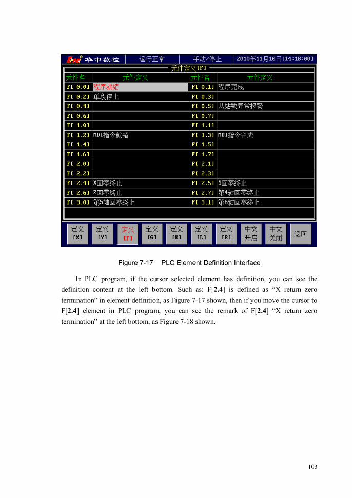
103
Figure 7-17 PLC Element Definition Interface
In PLC program, if the cursor selected element has definition, you can see the definition content at the left bottom. Such as: F[2.4] is defined as “X return zero termination” in element definition, as Figure 7-17 shown, then if you move the cursor to F[2.4] element in PLC program, you can see the remark of F[2.4] “X return zero termination” at the left bottom, as Figure 7-18 shown.

104
Figure 7-18 Element Remark in PLC Program
7.5 B Register
7.5.1 B Register Summarize
B register is a sort of power-off save register. The address range of B register is B00.0~B31.7, every B register can be read and
write by PLC, and the storage data can not be lost even though power is off.
7.5.2 B Register Operation Interface
The operation about B register can be in the PLC program, or search and modify in B register operation interface, thereinto, the modification of B00.0~B15.7 needs machine

105
tool level operating right, and the B16.0~B31.7 needs user level operating right. Method of entering into B register interface: [\] →[DIAG] → [BREG] The B register interface is shown as Figure 7-19.
Figure 7-19 B Register Interface
Each item of B register are made up of four parts :
1) Address B register’s address. 2) Right The needed authority of modifying this item in B register interface. 3) Register explanation A sort of explanation for B register use condition. 4) Value The value corresponding to B register’s address, which can be used
for searching and modifying.

106
7.6 PLC Message
7.6.1 PLC Message Summarize
The suggestive alarm messages which are disposed by PLC will be displayed in the system title bar by using the function command WMSG of PLC. Thereinto, the function command WMSG specifies PLC message number, the alarm content which the number corresponds to is set by【PLC Message】setting interface. If the title bar come forth a prompt alarm, pressing any key can remove the display alarm, as Figure 7-20 shown:
Figure 7-20 System Displays PLC Message
7.6.2 PLC Message Operation Interface
The definition of PLC message is in【PLC Message】interface, method of entering into PLC message interface is as follows: [\] →[DIAG] → [PMSG]

107
PLC message definition is shown as Figure 7-21. In the definition list of PLC message, the left is PLC message number which is called by the function command WMSG; the right is message content which is defined by PLC message number. If the function command WMSG in PLC is triggered, The title bar will display the content defined by the message number which WMSG appoints to.
Figure 7-21 PLC Message Definition Interface

108
8 Rotational Axis Circulatory Function The rotational axis circulatory function can avoid the coordinate overflow of
rotational axis. If the rotational axis’s circulatory function is valid, for increment programming
command, the tool will move the degree which specified in the command; for absolute value command, the disposal process of CNC is:
1) Round the command coordinate of programme by the degree of a rotation (namely convert the coordinate value into 0~360° );
2) If you have not specified that selecting the shortest path, the direction of tool motion is confirmed by the relationship between the converted target location and current location: if target location is less than current location, the tool will move in negative direction; if target location is greater than current location, the tool will move in positive direction;
3) If have specified that selecting the shortest path, the tool will move to the target location in the direction of the shortest path.
the rotational axis’s circulatory function is set by parameter P1005(if P1005=1,
enable circulatory function is open; if P1005=0, circulatory function is closed). The selection of the shortest path is set by parameter P1006(if P1006=1, select the
shortest path; if P1006=0, not select the shortest path). The selection of the shortest path is valid only when the circulatory function is open.
Demonstration
Assume A-axis is a rotational axis, and the amount of movement for each rotation is 360°.Open the rotational axis’s circulatory function(P1005=1), and set as selecting the shortest path(P1006=1). When execute the following program, A-axis’s motion is shown as Table-1 and Figure 8-1.
Table-1 rotational axis circulatory function demonstration
G90 A0; Sequence number
Actual movement absolute coordinate value after motion is finished
N1 G90 A-150.0; N1 -150° 210
N2 G90 A540.0; N2 -30° 180
N3 G90 A-620.0; N3 -80° 100

109
N4 G91 A380.0; N4 +380° 120
N5 G91 A-840.0; N5 -840° 0
Figure 8-1 Rotational Axis Circulatory Function Demonstration

110
9 Spindle Gear Control
9.1 Method of Spindle Gear Control
To meet the needs of machining, spindle needs to shift gear control some times. System supports 5 levels variable speed control of spindle at most——A gear, B
gear, C gear, D gear and E gear. System doesn’t set the range of each gear’s high\low rotational speed by itself. User can set each gear’s rotational speed range by parameter.
The spindle gear control is carried out by setting system parameters and programming PLC program. 1、 The parameters about spindle gear control
1) Spindle’s each gear rotational speed range setting Spindle’s each gear rotational speed range setting is used to plot out the shifting
range of spindle’s each gear. After rotational speed range setting, when system give spindle rotational command, system will automatically select the corresponding spindle gear accroding to rotational speed range setting.
P0351: Spindle A gear minimum rotational speed P0352: Spindle A gear maximum rotational speed P0353: Spindle B gear minimum rotational speed P0354: Spindle B gear maximum rotational speed P0355: Spindle C gear minimum rotational speed P0356: Spindle C gear maximum rotational speed P0357: Spindle D gear minimum rotational speed P0358: Spindle D gear maximum rotational speed P0359: Spindle E gear minimum rotational speed P0360: Spindle E gear maximum rotational speed
2) Spindle’s each gear feedback override If the rotational speed which spindle feeds back is not the same as the actual
rotational speed, you can amend it by spindle feedback override. P0362: Spindle A gear feedback override P0363: Spindle B gear feedback override P0364: Spindle C gear feedback override P0365: Spindle D gear feedback override P0366: Spindle E gear feedback override
111
3) Spindle’s each gear reduction ratio If spindle’s actual rotational speed is not the same as the instruction rotational
speed, an insure spindle’s other parameters setting correctness, then you can amend it by modifying each gear reduction ratio.
P0371: Spindle A gear reduction ratio P0372: Spindle B gear reduction ratio P0373: Spindle C gear reduction ratio P0374: Spindle D gear reduction ratio P0375: Spindle E gear reduction ratio
4) Spindle gear shifting rotational speed In order to finish the process of gear shifting all right, spindle usually turn at a
low speed in the process of gear shifting. This parameter is used to set spindle’s rotational speed in the process of gear shifting.
P0380: Spindle gear shifting rotational speed
5) Spindle gear shifting retry delay time This parameter is used as the time interval from spindle gear shifting is failure
to the next gear shifting retry. P0381: Spindle gear shifting retry delay time(millisecond)
6) Spindle gear shifting retry count When spindle shifts gear and retry this parameter count, but still not successful,
then give an alarm: Spindle gear shifting is failure.
2、 PLC signal about spindle gear control System side input signal:F12.4: Spindle change for A gear startup signal
F12.5: Spindle change for B gear startup signal F12.6: Spindle change for C gear startup signal F12.7: Spindle change for D gear startup signal F13.0: Spindle change for E gear startup signal
System side output signal: G20.0: Spindle A gear arrival signal
Note You can’t set the gear shifting speed too high, or else may damage machine.

112
G20.1: Spindle B gear arrival signal G20.2: Spindle C gear arrival signal G20.3: Spindle D gear arrival signal G20.4: Spindle E gear arrival signal
9.2 Spindle Gear Control Demonstration
For example: according to the need of machine design, spindle shifting range is(gear shifting speed is 10 r/min): 1) Low gear 0~880 r/min, reduction ratio 10.52, feedback override 1.0, gear shifting
signal Y02.0, arrival signal X04.0; 2) Mid gear 881~2200 r/min, reduction ratio 5.04, feedback override 1.1, gear shifting
signal Y02.1, arrival signal X04.1; 3) High gear 2201~4000 r/min, reduction ratio 1.01, feedback override 1.2, gear
shifting signal Y02.2, arrival signal X04.2.
The demonstration use A, B, C gears to control low, mid, high gear, you can also use the others gear to control, just need to ensure that each parameter and ladder diagram signal are the same when used.
The process of spindle gears control setting includes the following steps: 1) Set spindle shifting range. According to the forementioned instance, set:
P0351(Spindle A gear minimum rotational speed) = 0 P0352(Spindle A gear maximum rotational speed) = 880 P0353(Spindle B gear minimum rotational speed)= 881 P0354(Spindle B gear maximum rotational speed) = 2200 P0355(Spindle C gear minimum rotational speed)= 2201 P0356(Spindle C gear maximum rotational speed) = 4000
The minimum, maximum rotational speed of unused D, E gears are set as 0. 2) Set each gear feedback override
P0362(Spindle A gear feedback override) = 1.0 P0363(Spindle B gear feedback override) = 1.1 P0364(Spindle C gear feedback override) = 1.2 The feedback override of unused D, E gears are set as 0.
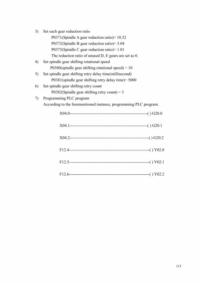
113
3) Set each gear reduction ratio P0371(Spindle A gear reduction ratio)= 10.52
P0372(Spindle B gear reduction ratio)= 5.04 P0373(Spindle C gear reduction ratio)= 1.01 The reduction ratio of unused D, E gears are set as 0.
4) Set spindle gear shifting rotational speed P0380(spindle gear shifting rotational speed) = 10
5) Set spindle gear shifting retry delay time(millisecond) P0381(spindle gear shifting retry delay time)= 5000
6) Set spindle gear shifting retry count P0382(Spindle gear shifting retry count) = 3
7) Programming PLC program According to the forementioned instance, programming PLC program.
X04.0---------------------------------------------------------( ) G20.0
X04.1---------------------------------------------------------( ) G20.1
X04.2----------------------------------------------------------( ) G20.2
F12.4-----------------------------------------------------------( ) Y02.0
F12.5-----------------------------------------------------------( ) Y02.1
F12.6-----------------------------------------------------------( ) Y02.2

114
10 Measurement
10.1 Tool Measurement
The tool measurement function can measure automatically the tool’s length compensation value, and save the value in the tool compensation table.
10.1.1 Tool Measuring Principle and Process
The measuring principle diagram of measurement function is shown as Figure 10-1.
Figure 10-1 Tool Measurement Process Principle Diagram

115
The process of measurement as follows: 2. If machine tool is machining center, exchange the first measure tool from tool
magazine to spindle; 3. Locate X, Y coordinates, the speed is the reference point positioning speed F1; 4. Then locate Z coordinate, the speed is the reference point positioning speed F1; 5. Tool explores downwards, the target location is the Z-axis’s lowest workpiece
coordinate, the speed is the measurement speed F2; 6. After tool touch the tool checking instrument, it will move 5mm upwards, the speed
is the measurement speed F2; 7. Tool explores downwards again, the detection distance is 6mm, the speed is the
trigger speed F3; 8. After tool touch the instrument, note the machine tool coordinate value Z1; 9. Move the tool 5mm upwards, the speed is the measurement speed F2; 10. Tool explores downwards again, the detection distance is 6mm, the speed is the
trigger speed F3; 11. After tool touch the instrument again, note the machine tool coordinate value Z2, at
the same time, calculate tool length= (Z1+Z2)/2, measurement error=Z2-Z1, and record it into tool measurement list. If the current measure tool number is the parameter of “external offset measure tool”, you need to calculate “external workpiece zero offset (Z)”, “external workpiece zero offset (Z)”= “external offset measurement base” -(Z1+Z2)/2.
12. Move 2mm upwards to leave the instrument, the speed is the measurement speed F2; 13. Position tool to reference point Z, the speed is reference point positioning speed F1; 14. If there are other tools to measure, system will automatically exchange next tool,
repeat the above measurement action.
10.1.2 Tool Measure Operation Sequence
The operation sequence of this function usage as follows: 1. At first, this function needs the support of PLC, the G31.0~G31.5 of PLC
correspond to No. 1~ No. 6 measuring head. If No. 3 measuring head is used during measuring, connect the measurement input signal of tool checking instrument to G31.2, as Figure 10-2 shown, X04.5 is the measurement signal of the instrument. In order to guarantee measurement precision, the programming of PLC should be written into the primary PLC;

116
Figure 10-2 Tool Measure PLC Connection Example
If machine tool is not machining center, you need add the following command in PLC:
2. Found measurement coordinate system: Select a coordinate system in G54~G59 as
the measurement coordinate system, the coordinate zero is measurement reference point. The definition of measurement reference point is: X, Y is the center of tool checking instrument, Z is the safety height, which means choose any position at the top of tool checking instrument as the reference point’s Z coordinate, and ensure that all of tools couldn’t collide with the tool checking instrument when moved to the coordinate in the condition of not compensating tool. Take G54 for example, the X, Y coordinate position of G54 coordinate system should be the center of the tool checking instrument; the Z coordinate position of G54 coordinate system is the middle reference point position of automatic toolsetting;
3. Import the measurement coordinate system under MDI mode; 4. Press <AUTO> →[\] →[→] → [TEST] → [TTST] keys to enter into the tool
length automatic measurement function interface, as Figure 10-3 shown.

117
Figure 10-3 Tool Measure Interface
5. Set the external zero offset measure parameter. Firstly, choose any tool under test to
fix on spindle, move tool to bring into contact with the upper surface of workpiece. Press [OFBS] menu, then system will automatically store the Z-axis machine coordinate value into “external offset measurement base”, and set the tool number which measurement uses into “external offset measure tool”;
6. Add the tool number under test: Press [ADDT] menu to set the measurement tool number, as Figure 10-4 shown. If machine is the machining center, all of the needed measurement tool number can be added to the left tool measure list box; if not, only one tool number can be added at a time. When add a tool number, just need to set the additive tool number to “initial tool number” in the addition tool dialog box. Press [DELT] menu to delete the corresponding tool number of the current cursor in the left tool measure list box. Press [CLRT] menu to clear up the setting content in the left tool measure list box.

118
Figure 10-4 Add Measure Tool Number
7. Set the tool measure parameter: press [←]、[→] key to move the cursor between the
left “tool measure list box” and the right “tool measure parameters box”, press [↑]、[↓] key to move cursor among the parameter items. Parameter items: Measuring Head Selection [1-6]: measuring head selection can use any measuring head from No.1 to No.6, meanwhile, measuring head needs the support of PLC. Measurement Coordinate System [54-59]: Select the cooridnate system used by measuring. If set as G54, G54 is the measure reference point, the X, Y cooridnate value of G54 is the center of the tool checking instrument; the Z coordinate value of G54 is the safety height value of automatic toolsetting. Z-axis Lowest Point Workpiece Coordinate: Set Z-axis’s lowest point in the process of automatic tool measure, the value is the coordinate value of Z-axis workpiece zero in measurement coordinate system. External Offset Measurement Base: At 5 step, press[OFBS] to automatic input. External Offset Measure Tool: Set the adoptive tool number at 5 step to here. Reference Point Positioning Speed(F1): The positioning speed of going to

119
measurement reference point position. Measurement Speed(F2): Set the measuring speed, the effective stage of F2, as measurement principle diagram shown. Trigger Speed (F3): Set the speed that tool touch the tool checking instrument when measuring, system will detect the touch signal in the process, so the speed should not be set too high. 8. Start measuring: In <AUTO> mode, after the measure tool number have been
added and the measurement parameters have been set, press [TTOK] menu, then system will automatically create a extended program called 9700, and automatically load 9700 program, the interface is shown as Figure 10-5.
Figure 10-5 Measure is Ready
Then press <CYCL> key to start automatic measuring, the interface is shown as
Figure 10-6.

120
Figure 10-6 Measuring
9. Save the measurement result: After measurement is finished, press [TTSV] menu to
store the tool length into tool compensation table, and save the external workpiece zero offset to the parameter of P1222.
10. Reset the Z value of the used workpiece coordinate system, because the tool length which tool measurement note and save are the values in the machine tool coordinate system.
Note: 1、 Can not exit from measure window in the process of measuring; 2、 The whole measured tool length are relative to Z-axis zero of the machine tool
coordinate system.

121
11 Compensation Setting
11.1 Reverse Backlash Compensation
Usually, there is a definite cooperation backlash between screw and workbench, the backlash may affect the positioning precision of workbench, you need to compensate it.
The reverse backlash values of machine tool are measured by machine tool factory, and set the measured backlash values into CNC system parameter, CNC will compensate automatically.
The compensation values of reverse backlash are set as follows:
P0021: X-axis reverse backlash(micron) P0022: Y-axis reverse backlash(micron) P0023: Z-axis reverse backlash(micron) P0024: Fourth-axis reverse backlash(micron, one thousandth of a degree) P0025: Fifth-axis reverse backlash (micron, one thousandth of a degree) P0026: Sixth-axis reverse backlash (micron, one thousandth of a degree) P0027: Seventh-axis reverse backlash (micron, one thousandth of a degree) P0028: Eighth-axis reverse backlash (micron, one thousandth of a degree)
11.2 Pitch Error Compensation
Usually, screw has a definite pitch error in manufacture, the error may affect the positioning precision of workbench, you need to compensate it.
The pitch error compensation is segmented. Firstly, divide the workbench’s travel range into several areas, then set the compensation value for each area.
Note: After change a certain axis’s reverse backlash compensation parameter, you
should let the axis return the reference point by hand, or else the compensation of CNC may be not correct.

122
1) Pitch Error Compensation Starting Point Confirm where to start compensation within the travel range of workbench. The
compensation starting points are set by the following parameters(setting value is the coodinate position under the machine tool coordinate system):
P0041: X-axis pitch error compensation starting point P0042: Y-axis pitch error compensation starting point P0043: Z-axis pitch error compensation starting point P0044: Fourth--axis pitch error compensation starting point P0045: Fifth-axis pitch error compensation starting point P0046: Sixth-axis pitch error compensation starting point P0047: Seventh-axis pitch error compensation starting point P0048: Eighth-axis pitch error compensation starting point
2) Pitch Error Compensation Interval Confirm the distance of each segment when pitch error compensation segments
workbench travel. If the compensation interval is positive number, it will start segmental compensation from compensation starting point towards the positive direction; if the compensation interval is negative, it will start the segmental compensation from compensation starting point towards the negative direction;
The compensation intervals are set by the following parameters:
P0051: X-axis pitch error compensation interval P0052: Y-axis pitch error compensation interval P0053: Z-axis pitch error compensation interval P0054: Fourth-axis pitch error compensation interval P0055: Fifth-axis pitch error compensation interval P0056: Sixth-axis pitch error compensation interval P0057: Seventh-axis pitch error compensation interval P0058: Eighth-axis pitch error compensation interval
3) Pitch Error Compensation Type Pitch error has one-way compensation and two-way compensation, the types are set by the following paramters: P200: X-axis pitch error compensation type P201: Y-axis pitch error compensation type P202: Z-axis pitch error compensation type P203: Fourth-axis pitch error compensation type

123
P204: Fifth-axis pitch error compensation type P205: Sixth-axis pitch error compensation type P206: Seventh-axis pitch error compensation type P207: Eighth-axis pitch error compensation type
4) Pitch Error Compensation Setting value After finished the workbench travel segmenting, the pitch error of each segment is
measured by machine tool factory, and input the measured error values into CNC system parameters, CNC will compensate automatically.
Compensation value = instruction position – actual measured position the pitch error compensation setting value of each segment should be the cumulative
sum of each segment’s pitch error which is before this segment (include this segment). If set as one-way compensation, the compensation value should be written into the
axis’s positive direction pitch compensation table. The pitch error compensation values are set by the following parameters:
P5101~P5200: X-axis positive direction pitch error compensation value[micron/one thousandth of a degree]
P5201~P5300: X-axis negative direction pitch error compensation value[micron/one thousandth of a degree]
P5301~P5400: Y-axis positive direction pitch error compensation value[micron/one thousandth of a degree]
P5401~P5500: Y-axis negative direction pitch error compensation value[micron/one thousandth of a degree]
P5501~P5600: Z-axis positive direction pitch error compensation value[micron/one thousandth of a degree]
P5601~P5700: Z-axis negative direction pitch error compensation value[micron/one thousandth of a degree]
P5701~P5800: Fourth-axis positive direction pitch error compensation value [micron/one thousandth of a degree]
P5801~P5900: Fourth-axis negative direction pitch error compensation value [micron/one thousandth of a degree]
P5901~P6000: Fifth-axis positive direction pitch error compensation value [micron/one thousandth of a degree]
P6001~P6100: Fifth-axis negative direction pitch error compensation value [micron/one thousandth of a degree]
P6101~P6200: Sixth-axis positive direction pitch error compensation value

124
[micron/one thousandth of a degree] P6201~P6300: Sixth-axis negative direction pitch error compensation value
[micron/one thousandth of a degree] P6301~P6400: Seventh-axis positive direction pitch error compensation value
[micron/one thousandth of a degree] P6401~P6500: Seventh-axis negative direction pitch error compensation value
[micron/one thousandth of a degree] P6501~P6600: Eighth-axis positive direction pitch error compensation value
[micron/one thousandth of a degree] P6601~P6700: Eighth-axis negative direction pitch error compensation value
[micron/one thousandth of a degree] Pitch Error Compensation Example 1(one-way pitch compensation---compensation interval is positive value)
The one-way pitch error compensation of machine tool coordinate positive direction starts from the compensation starting point.
Example: Suppose X-axis’s compensation starting point is reference point 0, travel is 550mm,
interval is 50mm, and measure once, the parameters are set as follows: P0041(X-axis pitch error compensation starting point) is set as 0; P0051(X-axis pitch error compensation interval) is set as 50(the pitch error
compensation of machine tool coordinate positive direction starts from the compensation starting point, so the value is positive);
P0200(X-axis pitch error compensation type[0-one way; 1-two way]) is set as 0.
The measured X-axis’s pitch error datas and compensation setting as follows: Motion
direction Instruction
position(mm) Actual
poistion(mm) Compensation table
setting(micron)
Positive direction
0 0 50 49.996 P5101 = 4 100 100.003 P5102 = -3 150 150.005 P5103 = -5 200 200.015 P5104 = -15 250 249.998 P5105 = 2 300 300.007 P5106 = -7 350 350.012 P5107 = -12

125
400 400.025 P5108 = -25 450 450.10 P5109 = -10 500 499.991 P5110 = 9 550 549.985 P5111 = 15
Pitch Error Compensation Example 2(one-way pitch compensation---compensation interval is negative value)
The one-way pitch error compensation of machine tool coordinate negative direction starts from the compensation starting point.
Example: Suppose X-axis’s compensation starting point is reference point 0, travel is -550mm,
interval is 50mm, and measure once, the parameters are set as follows: P0041(X-axis pitch error compensation starting point) is set as 0; P0051(X-axis pitch error compensation interval) is set as 50(the pitch error
compensation of machine tool coordinate negative direction starts from the compensation starting point, so the value is negative);
P0200(X-axis pitch error compensation type[0-one way; 1-two way]) is set as 0.
The measured X-axis’s pitch error datas and compensation setting as follows: Motion
direction Instruction
position(mm) Actual
position(mm) Compensation table
setting(micron)
Negative direction
0 0 -50 -49.996 P5101 = -4 -100 -100.003 P5102 = 3 -150 -150.005 P5103 = 5 -200 -200.015 P5104 = 15 -250 -249.998 P5105 = -2 -300 -300.007 P5106 = 7 -350 -350.012 P5107 = 12 -400 -400.025 P5108 = 25 -450 -450.10 P5109 = 10 -500 -499.991 P5110 = -9 -550 -549.985 P5111 = -15

126
Pitch Error Compensation Example 3(two-way pitch compensation---compensation interval is positive value)
The two-way pitch error compensation of machine tool coordinate positive direction starts from the compensation starting point.
Example: Suppose X-axis’s compensation starting point is reference point 0, travel is 550mm,
interval is 50mm, and measure once, the parameters are set as follows: P0041(X-axis pitch error compensation starting point) is set as 0; P0051(X-axis pitch error compensation interval) is set as 50(the pitch error
compensation of machine tool coordinate positive direction starts from the compensation starting point, so the value is positive);
P0200(X-axis pitch error compensation type[0-one way; 1-two way]) is set as 1.
The measured X-axis’s pitch error datas and compensation setting as follows: Motion
direction Instruction
position(mm) Actual
position(mm) Compensation table
setting(micron)
Positive direction
0 0 50 49.996 P5101 = 4 100 100.003 P5102 = -3 150 150.005 P5103 = -5 200 200.015 P5104 = -15 250 249.998 P5105 = 2 300 300.007 P5106 = -7 350 350.012 P5107 = -12 400 400.025 P5108 = -25 450 450.10 P5109 = -10 500 499.991 P5110 = 9 550 549.985 P5111 = 15
Negative direction
550 550.002 P5211 = -2 500 500.004 P5210 = -4 450 449.995 P5209 = 5 400 399.992 P5208 = 8 350 350.006 P5207 = -6 300 300.010 P5206 = -10 250 250.003 P5205 = -3 200 199.998 P5204 = 2 150 149.993 P5203 = 7

127
100 100.005 P5202 = -5 50 50.012 P5201 = -12 0 0
Pitch Error Compensation Example 4(two-way pitch compensation---compensation interval is negative value)
The two-way pitch error compensation of machine tool coordinate negative direction starts from the compensation starting point.
Example: Suppose X-axis’s compensation starting point is reference point 0, travel is -550mm,
interval is 50mm, and measure once, the parameters are set as follows: P0041(X-axis pitch error compensation starting point) is set as 0; P0051(X-axis pitch error compensation interval) is set as -50(the pitch error
compensation of machine tool coordinate negaitve direction starts from the compensation starting point, so the value is negative);
P0200(X-axis pitch error compensation type[0-one way; 1-two way]) is set as 1.
The measured X-axis’s pitch error datas and compensation setting as follows: Motion
direction Instruction
position(mm) Actual
position(mm) Compensation table
setting(micron)
Negative direction
0 0 -50 -49.996 P5201 = -4 -100 -100.003 P5202 = 3 -150 -150.005 P5203 = 5 -200 -200.015 P5204 = 15 -250 -249.998 P5205 = -2 -300 -300.007 P5206 = 7 -350 -350.012 P5207 = 12 -400 -400.025 P5208 = 25 -450 -450.10 P5209 = 10 -500 -499.991 P5210 = -9 -550 -549.985 P5211 = -15
-550 -550.002 P5111 = 2 -500 -500.004 P5110 = 4 -450 -449.995 P5109 = -5 -400 -399.992 P5108 = -8 -350 -350.006 P5107 = 6

128
Positive direction
-300 -300.010 P5106 = 10 -250 -250.003 P5105 = 3 -200 -199.998 P5104 = -2 -150 -149.993 P5103 = -7 -100 -100.005 P5102 = 5 -50 -50.012 P5101 = 12 0 0
11.3 Deflection Compensation
Deflection compensation is a kind of compensation for the gantry beam bending deformation, the setting method is the same as pitch error compensation. The main setting parameters include:
P0270: Beam direction. The parameter confirm the coordinate direction of gantry beam position.
P0270=0: gantry beam along the X-axis direction P0270=1: gantry beam along the Y-axis direction
P0271: deflection compensation starting point. P0272:deflection compensation interval. If compensation interval is positive, it will
start compensation from compensation starting point towards the positive direction; If compensation interval is negative, it will start compensation from compensation starting point towards the negative direction.
P5001~P5100: deflection compensation value. The unit is micron.
Note: After change a axis’s pitch error compensation parameter, you should let the axis
return reference point by hand, or else the compensation of CNC may be not correct.
Note: After change a axis’s deflection compensation parameter, you should let the axis
return reference point by hand, or else the compensation of CNC may be not correct.

129
11.4 Circular Arc Across Quadrant Compensation
Circular arc across quadrant is due to at the time of machine across quadrant, the static friction force of reverse axis is greater than dynamic friction force, which lead to the reverse axis lags behind other axis when reverse movement, this lag is called across quadrant error. In order to improve machining precision, it is necessary to compensate circular arc across quadrant for machine tool. The main setting parameters include: P0210: X-axis across quadrand compensation(micron). P0211: X-axis across quadrand compensation time(micron). P0212: X-axis across quadrand compensation delay time(micron). P0215: Y-axis across quadrand compensation(micron) P0216: Y-axis across quadrand compensation time(micron). P0217: Y-axis across quadrand compensation delay time(micron). P0220: Z-axis across quadrand compensation(micron) P0221: Z-axis across quadrand compensation time(micron). P0222: Z-axis across quadrand compensation delay time(micron) Take X-axis for example:
Figure 11-1 X-axis Across Quadrant

130
Figure 11-2 X-axis Circular Arc Across Quadrant Before Compensation
Through the correct setting of parameters P0210~P0212, commonly there can be a great improved in the machining precision of circular arc across quadrant, as Figure 11-3 shown.
Figure 11-3 X-axis Circular Arc Across Quadrant Compensation Before and After

131
12 System Error and Solution
12.1 System Alarm Indication
The alarm indicator above the CNC system screen is used to display system alarm status. Alarm state can be divided into the following categories:
1) System Reset: After press Overtravel released key when release Emergency Stop Switch or over travel, system needs certain time to reset. During this period, system can not be operated, and the Alarm Display area shows “Reset”.
2) Over Travel: When the workbench stroke travel switch, system turns up overtravel alarm and the Alarm Display area shows “Reset”.
3) Emergency Stop: When press E-Stop button down, system turns up emergency stop alarm and the Alarm Display area shows “E-Stop”.
4) System Alarm: When turns up other alarms except the mentioned above, the Alarm Display area shows “System-Alarm”.
When the alarms above occur at the same time, the priority displayed in the Alarm Display area is the following (the left has high priority, that means it will be shown in front of others when alarm appear):
12.2 Alarm Information Query Window
When an alarm occurs, you can refer to the alarm query window for the details of all alarms in the current system.
Alarm information query window is shown 错误!未找到引用源。. When a new alarm occurs, the window will pop up automatically, or you can press the system menu [\] →[DIAG] → [ALRM]to switch to the window.
The alarm information that the window displays includes:
1) Alarm Number: Identification number of system alarm, such as No.70, No.400 etc; 2) Alarm Commentary: Specific information to illustrate the alarm, such as “air
Reset Overtravel E-Stop System-Alarm

132
pressure alarm”, “Spindle overheat” etc.
Figure 12-1 Alarm Information Query Window
12.3 Emergency Stop
Press the emergency stop button, then the machine stops working and the spindle stops rotating immediately. other output is shut down or not depends on the definition specified by the machine tool plant, refer to the corresponding specifications provided by the plant for details.
To release the emergency stop to resume system operation, you just need to rotate the emergency stop button.
12.4 Stroke Travel Switch
When the motion of workbench is out of travel limit and stroke travel switch, the machine stops working and the spindle stops rotating immediately. Whether other output

133
is shut down or not depends on the definition specified by the machine tool plant, refer to the corresponding specifications provided by the plant for details.
To release the over travel state to resume system operation, you need to press <OTRL> button ( do not release it now) firstly, after the resetting is successful, move the axis in over travel state to the safety direction by hand. After move out the travel switch, release <OTRL> button, then system resume normal operation.
12.5 System Software Limits Alarm
The software limits are set by the system parameters to restrict the motion range of each axis. When the motion beyond the range, the system software limit alarm occurs and then all the axes decelerate to stop. In the case of software limit alarm, programs and MDI codes can’t be executed in auto mode. In manual mode or hand-wheel mode, you can move the axis in the alarm state toward the safety direction, but toward the opposite direction is not. Therefore, to release the software limit alarm, you need to switch to the manual or hand-wheel mode firstly and then move the axis in the alarm state to the safety range.
Positive software limits are set by the following parameters:
1) P0061: X-axis positive software limit(if greater than 99999, not detect)
2) P0062: Y-axis positive software limit(if greater than 99999, not detect)
3) P0063: Z-axis positive software limit(if greater than 99999, not detect)
4) P0064: Fourth-axis positive software limit(if greater than 99999, not detect)
5) P0065: Fifth-axis positive software limit(if greater than 99999, not detect)
6) P0066: Sixth-axis positive software limit(if greater than 99999, not detect)
7) P0067: Seventh-axis positive software limit(if greater than 99999, not detect)
8) P0068: Eighth-axis positive software limit(if greater than 99999, not detect)
Negative software limits are set by the following parameters:
1) P0071: X-axis negative software limit(if less than -99999, not detect)
2) P0072: Y-axis negative software limit(if less than -99999, not detect)
3) P0073: Z-axis negative software limit(if less than -99999, not detect)

134
4) P0074: fourth-axis negative software limit(if less than -99999, not detect)
5) P0075: fifth-axis negative software limit(if less than -99999, not detect)
6) P0076: sixth-axis negative software limit(if less than -99999, not detect)
7) P0077: seventh-axis negative software limit(if less than -99999, not detect)
8) P0078: eighth-axis negative software limit(if less than -99999, not detect)
When the specified positive software limit value is greater than 99999, CNC will
not detect the positive software limit; When the specified negative limit value is less than -99999, CNC will not detect the negative softeware limit.
12.6 System Alarm Record Query Window
Alarm record query window is the history alarm query window, as Figure 12-1 shown:
Figure 12-1 Alarm Record Query Window

135
In the alarm record query window, each item has “Alarm Number” and “Alarm Information” two parts, the “Alarm Information” includes the date, time that alarm occur and alarm content. The number of alarm records that the alarm record displays is set by parameter P0158 (the maximum number of alarm records ).

136
13 Appendix
13.1 Appendix one, System Parameter Definition
P0002 —— Program Hide Setting The parameter decides whether or not hide the [EPGM] menu in <AUTO> →[PROG] →[LDPG]. If the parameter is set as 1, [EPGM] menu is gray and can not be operated; if the parameter is set as 0, the [EPGM] menu is light and can be operated.
P0003 —— Program Syntax Checking Setting If the parameter is set as 1, system will automatically check the program syntax
after loading in automatic mode; if set as 0, it will not check the syntax after loading. P0004 —— Authority Checking Setting
If the parameter is set as 1, CNC system will check the authority, for the function which has the authority demand (or parameters), you can not operate if lack authority; If set as 0, system will not check the authority, all function can be operated( or parameters). P0005 —— Software Menu Manner Setting Modify the parameter to make the space between software menus match the panel key. Parameter System Type
21 —— HNC-21MD 22 —— HNC-22MD 2100 —— HNC-210A
2101 —— HNC-210B 2102 —— HNC-210C
P0007 —— Key-press Sound Switch Setting Modify the parameter to open or close key-press sound in the process of operation. Set as 0: close key-press sound; Set as 1: Open key-press sound. P0012 —— External Storage Index Setting
The parameter is used to set the subarea number’s index value of external storage. The relationship between subarea number and index value is: Subarea Number Index value
C —— 1

137
D —— 2 E —— 3 F —— 4
… —— … P0013 —— Network Sharing Disk Mapping Letter Setting
The parameter is used to set network sharing disk mapping letter. The relationship between disk letter and index value is: Disk letter Index value
C —— 1 D —— 2 E —— 3 F —— 4
… —— … P0015 —— The Display Coordinate Type Setting
The parameter is used to set the type of display coordinate value in the main window and the first side window.
0——Display interpolation coordinate value 1——Display the interpolation coordinate value which has been compensated (such
as reverse backlash compensation, pitch error compensation etc.) 2——Display the feedback coordinate value of machine tool
P0016 —— Setting the Display Content in the Second Side Window
0——The second side window displays workpiece coordinate zero value 1——The second side window displays synchronization error 2——The second side window displays tracking error
P0017 —— Setting the Display Content in the Main Window
0——Main window displays workpiece coordinate, and the first side window displays machine tool coordinate
1——Main window displays machine tool coordinate, and the first side window displays workpiece coordinate
P0019 —— Reverse Backlash Compensation Step Size
The parameter sets the maximum distance of each interpolation cycle compensation when compensating the reverse backlash. If the reverse backlash setting value is greater than the step size, it needs multiple cycles to compensate.

138
Unit: micron. P0021~P0028 —— Each Axis Reverse Backlash Compensation Value
These parameters are used to set the reverse backlash compensation value of each axis.
P0021: X-axis reverse backlash compensation value(micron) P0022: Y-axis reverse backlash compensation value(micron) P0023: Z-axis reverse backlash compensation value(micron) P0024: Fourth-axis reverse backlash compensation value(micron, one thousandth of
a degree) P0025: Fifth-axis reverse backlash compensation value(micron, one thousandth of a
degree) P0026: Sixth-axis reverse backlash compensation value(micron, one thousandth of a
degree) P0027: Seventh-axis reverse backlash compensation value(micron, one thousandth
of a degree) P0028: Eighth-axis reverse backlash compensation value(micron, one thousandth of
a degree) P0031~P0038 —— Setting the Precision of Each Axis Coordinate Display
These parameters are used to set the precision when system displays each axis’s data, namely the display decimal digits behind radix point.
P0031: X-axis coordinate display precision(decimal digits behind radix point) P0032: Y-axis coordinate display precision(decimal digits behind radix point) P0033: Z-axis coordinate display precision(decimal digits behind radix point) P0034: Fourth-axis coordinate display precision(decimal digits behind radix point) P0035: Fifth-axis coordinate display precision(decimal digits behind radix point) P0036: Sixth-axis coordinate display precision(decimal digits behind radix point) P0037: Seventh-axis coordinate display precision(decimal digits behind radix point) P0038: Eighth-axis coordinate display precision(decimal digits behind radix point)
P0041~P0048 —— Setting Each Axis Pitch Error Compensation Starting Point
These parameters are used to set the starting point of each axis pitch error compensation. Refer to the compensation setting relevant section for the definition of pitch error compensation starting point.
P0041: X-axis pitch error compensation starting point P0042: Y-axis pitch error compensation starting point P0043: Z-axis pitch error compensation starting point
139
P0044: Fourth--axis pitch error compensation starting point P0045: Fifth-axis pitch error compensation starting point P0046: Sixth-axis pitch error compensation starting point P0047: Seventh-axis pitch error compensation starting point P0048: Eighth-axis pitch error compensation starting point
P0051~P0058 —— Setting Each Axis Pitch Error Compensation Interval
These parameter are used to set the interval of each axis pitch error compensation. Refer to the compensation setting relevant section for the definition of pitch error compensation interval.
P0051: X-axis pitch error compensation interval P0052: Y-axis pitch error compensation interval P0053: Z-axis pitch error compensation interval P0054: Fourth-axis pitch error compensation interval P0055: Fifth-axis pitch error compensation interval P0056: Sixth-axis pitch error compensation interval P0057: Seventh-axis pitch error compensation interval P0058: Eighth-axis pitch error compensation interval
P0061~P0068 P0071~P0078 —— Setting Each Axis Software Limit
Each axis can be set a pair software limit to restrict its reasonable travel range. In normal sate, workbench should be moved in this range, when goes beyond the range, CNC will stop the machine tool moving and give an alarm. After software limit, the limit axis moving towards limit direction will be prohibited, you can move out toward safety direction by hand or handwheel.
P0061: X-axis positive software limit P0062: Y-axis positive software limit P0063: Z-axis positive software limit P0064: Fourth-axis positive software limit P0065: Fifth-axis positive software limit P0066: Sixth-axis positive software limit P0067: Seventh-axis positive software limit P0068: Eighth-axis positive software limit
P0071: X-axis negative software limit P0072: Y-axis negative software limit P0073: Z-axis negative software limit P0074: Fourth-axis negative software limit

140
P0075: Fifth-axis negative software limit P0076: Sixth-axis negative software limit P0077: Seventh-axis negative software limit P0078: Eighth-axis negative software limit
P0081~P0088 —— the First Reference Point for Each Axis
The first reference point can shift the machine tool coordinate system, the parameters are used to set the location where the first reference point is in machine tool coordinate system.
P0081: X-axis first reference point P0082: Y-axis first reference point P0083: Z-axis first reference point P0084: Fourth-axis first reference point P0085: Fifth-axis first reference point P0086: Sixth-axis first reference point P0087: Seventh-axis first reference point P0088: Eighth-axis first reference point
P0091~P0098 —— the Second Reference Point for Each Axis
the parameters are used to set the location where the second reference point is in machine tool coordinate system.
P0091: X-axis second reference point P0092: Y-axis second reference point P0093: Z-axis second reference point P0094: Fourth -axis second reference point P0095: Fifth-axis second reference point P0096: Sixth-axis second reference point P0097: Seventh-axis second reference point P0098: Eighth-axis second reference point
P0101~P0108 —— the Third Reference Point for Each Axis
the parameters are used to set the location where the third reference point is in machine tool coordinate system.
P0101: X-axis third reference point P0102: Y-axis third reference point P0103: Z-axis third reference point P0104: Fourth-axis third reference point P0105: Fifth-axis third reference point

141
P0106: Sixth-axis third reference point P0107: Seventh-axis third reference point P0108: Eighth-axis third reference point
P0111~P0118 —— the Fourth Reference Point for Each Axis
the parameters are used to set the location where the fourth reference point is in machine tool coordinate system.
P0111: X-axis fourth reference point P0112: Y-axis fourth reference point P0113: Z-axis fourth reference point P0114: Fourth-axis fourth reference point P0115: Fifth-axis fourth reference point P0116: Sixth-axis fourth reference point P0117: Seventh-axis fourth reference point P0118: Eighth-axis fourth reference point
P0120~P0128 —— Axis Lock Permission
If the axis lock permission value is 1, the corresponding axis allows lockup, then if axis lock signal G01.2~G02.2 is 1, the corresponding axis is locked up(namely can not be moved). If the axis lock permission value is 0, the corresponding axis doesn’t allow lockup, even if the axis lock signal is 1, the corresponding axis can be moved normally.
P0120: Spindle lock permission P0121: X-axis lock permission P0122: Y-axis lock permission P0123: Z-axis lock permission P0124: Fourth-axis lock permission P0125: Fifth-axis lock permission P0126: Sixth-axis lock permission P0127: Seventh-axis lock permission P0128: Eighth-axis lock permission
P0140~P0147 —— Each Axis Tracking Error Permission Value These parameters are used to set the tracking error permission value for each axis, when the actual tracking error is greater than the setting value, system will give an alarm and prohibit the operation of machine tool (includes Auto, MDI, Handwheel).
P0140: X-axis tracking error permission value(mm) P0141: Y-axis tracking error permission value(mm) P0142: Z-axis tracking error permission value(mm)
142
P0143: Fourth-axis tracking error permission value(mm) P0144: Fifth-axis tracking error permission value(mm) P0145: Sixth-axis tracking error permission value(mm) P0146: Seventh-axis tracking error permission value(mm) P0147: Eighth-axis tracking error permission value(mm)
P0158 —— the Maximum Number of Alarm Records Set the maximum history alarm amount recorded in the alarm record interface. P0160 —— Automatically Display the Alarm Window
If the parameter is set as 1, when system has a new alarm, system will automatically swtich to alarm information window; if set as 0, it can not automatically swtich to the alarm information window.
P0161 —— Whether or not Watch the Extended Program When system calls extended program, display the content of extended program in program box or not. Set as 1, Display the extended program content; set as 0, not display the extended program content. P0162 —— Autosave Position Information Setting If the parameter is set as 1, system will autosave position information of machine tool, the position can not be lost even if power is off ; If set as 0, it will not save the the position, after power is off and restart, all machine tool coordinates are reset. P0165 —— Reference Point Position Confirmation Tolerance When the error between each coordinate position and each reference point setting value is in the range of parameter setting, system exports the reference point confirmation signal as 1, or else, the output is 0;
Unit: micron(beeline axis) or one thousandth of a degree(rotation axis) Reference point confirmation signal is:
F14.0~F14.7: First reference point confirmation F16.0~F16.7: Second reference point confirmation F18.0~F18.7: Third reference point confirmation F20.0~F20.7: Fourth reference point confirmation P0170~P0177 —— Each Axis Lock Waiting Permission
0——axis lock waiting permission function close 1——axis lock waiting permission function open
143
After open axis lock waiting function, combined with PLC to set axis lock. Take the 以fourth-axis A for example, if P173 is set as 1, the A-axis opens the axis lock waiting function, when executes program, if there is a A-axis’s move command in the current executive program segment, A-axis automatically swtich to A-axis lock release state, wait for A-axis’s release signal arrives, then A-axis begins to execute move command; After A-axis’s move command has been executed, A-axis will automatically switch to lock up state, till A-axis’s lock signal arrives, then program continues to run.
P0180 —— Cycle Start Clean Out Graphics
The parameter is used to set whether or not automatically clean out the old machining simulation graphics track when cycle start to run program in automatic mode. If P0180=1, it will automatically clean out graphics window when cycle start; if P0180=0, not clean out. P0181~P0184 —— Graphics Zoom Coefficient
These parameters are used to set the zoom coefficient when displays machining track in graphics window. If the setting value is greater than 1, the track is zoomed in; if setting value is less than 1, the track is zoomed out.
P0181: the XY plane’s zoom coefficient in graphics mode P0182: the YZ plane’s zoom coefficient in graphics mode P0183: the XZ plane’s zoom coefficient in graphics mode P0184: the XYZ three-dimension strack’s zoom coefficient in graphics mode
P0187 —— Whehter or not Display Speed Curve Press [VSWT] menu, whether or not display speed curve interface.
0——not display speed curve 1——display speed curve
P0188 —— The Maximum of Speed Curve Set the maximum show value of display speed curve, unit: mm/min P0189 —— The Maximum of Acceleration Curve Set the maximum show value of display acceleration curve, unit: mm/s.s P0190 —— The Type of Display Curve
0——the display curve is instruction speed or acceleration value curve 1——the display curve is actual speed or acceleration value curve

144
P0192 —— DNC Buffer Size The parameter is used to set the code buffer size when machining while transfering
in DNC mode, the unit is program segment, such as, P0192 is set as 1000, means code buffer can store 1000 segments machining code. P0194 —— Tool Compensation Number
Set the tool compensation number in tool compensation table, restart to take effect.
P0195 —— Tool Magazine Capability The parameter is used to set the amount of tools that can be stored in tool magazine.
P0196 —— The Starting Address of Tool Magazine Table in Data Table
The parameter is used to set the starting position where tool magazine table stores in the data table.
P200~P207——Pitch Error Compensation Type Each axis pitch error compensation setting.
0— one-way pitch error compensation; 1— two-way pitch error compensation.
P210~P212——X-axis Across Quadrant Compensation Parameter
P210 set X-axis across quadrant compensation value, unit: micron; P211 set X-axis across quadrant compensation time, unit: ms; P212 set how long does it delay to compensate X-axis across quadrant after X-axis
across quadrant, unit: ms P215~P217——Y-axis Across Quadrant Compensation Parameter
P215 set Y-axis across quadrant compensation value, unit: micron; P216 set Y-axis across quadrant compensation time, unit: ms; P217 set how long does it delay to compensate Y-axis across quadrant after Y-axis
across quadrant, unit: ms P220~P222——Z-axis Across Quadrant Compensation Parameter
P210 set Z-axis across quadrant compensation value, unit: micron; P211 set Z-axis across quadrant compensation time, unit: ms; P212 set how long does it delay to compensate Z-axis across quadrant after Z-axis
across quadrant, unit: ms

145
P0227 ——Ratio Factor of Handwheel Debugging Set the handwheel ratio value when handwheel debugging. The greater ratio factor
is set, the greater feedrate override and rapid traverse speed override produced by turning the handle at the same speed when handwheel debugging.
P0228 ——Ratio Upper Limit of Handwheel Debugging Set the maximum of feedrate override and rapid traverse speed override in handwheel debugging state. P0230 —— Reverse Sign of Handwheel Direction
The parameter is used to reverse the motion direction of the axis which controlled by handwheel.
P0230=0: not reverse P0230=1: reverse
P0231~P0232 —— The Maximum Acceleration of Handwheel
The parameter is used to set the maximum acceleration when axis motion is controlled by handwheel.
P0231: The maximum acceleration of handwheel for linear axis P0232: The maximum acceleration of handwheel for rotational axis
P0234~P0235 —— The Maximum Speed of Handwheel
The parameter is used to set the maximum speed when axis motion is controlled by handwheel.
P0234: The maximum speed of Handwheel for linear axis P0235: The maximum speed of Handwheel for rotational axis
P0237~P0238 —— Handwheel Pulse Equivalent The parameter is used to set the handwheel pulse equivalent, namely the axis’s
moving distances by rotating one frame when handwheel is at the ×1 times. P0237: Handwheel equivalent for linear axis(mm/frame) P0238: Handwheel equivalent for rotational axis(degree /frame)
P0239 —— Handwheel Average Time
The parameter is used to set the handwheel speed average time in control cycle, that Actual average time = P0239 setting value×control cycle
P0260 ——The Second Level Program Block Size of Ladder Diagram

146
Ladder diagram second level program is executed in blocked mode, each control cycle executes a block. The parameter is used to set the blocked numbers. Therefore, the execution cycle of second level program is :
execution cycle = P0260 setting value×PLC scanning cycle P0270 —— Deflection Compensation Beam Direction Setting
The parameter is used to set the beam direction when compensate deflection. If the beam direction of deflection conpensation is X axial, the parameter is set as 0; If the beam direction of deflection conpensation is Y axial, the parameter is set as 1.
P0271 —— The Starting point of Deflection Compensation The parameter is used to set the starting point when compensate deflection.
P0272 —— The Interval of Deflection Compensation The parameter is used to set the compensation interval when compensate deflection. P0280~P0287 —— Reference Point Position Deviation
These parameters are used to set the deviation value of each axis reference point position, namely relative to the deviation value of reference point position determined by machine swtich. When return the reference point by hand, each axis return the reference point position determined by machine swtich firstly, then move a deviation to migrated reference point position.
P0280: X-axis reference point position deviation(mm) P0281: Y-axis reference point position deviation(mm) P0282: Z-axis reference point position deviation(mm) P0283: Fourth-axis reference point position deviation(degree, mm) P0284: Fifth-axis reference point position deviation(degree, mm) P0285: Sixth-axis reference point position deviation(degree, mm) P0286: Seventh-axis reference point position deviation(degree, mm) P0287: Eighth-axis reference point position deviation(degree, mm)
P0290~P0297 —— Setting Axis Returning Initial Position Detection
Axis returning initial position detection means detecting the axis’s machine tool coordinate value before returning home is within the returning swtich or not. If it is out of returning switch, system will give an alarm that axis returning initial position error. Set as 1, system will detect this item before returning home; Set as 0, system will not detect before returning home.

147
P0300~P0307 —— Synchronizing Shaft Returning Home Error Memory Value If the coordinate axis has been installed synchronizing shaft, the parameter records
the position deviation between driving shaft and synchronizing shaft when return machine zero for the first time, after that, system will compare the two axes’s returning position deviation with memeory value when return machine zero every time, if the error of them is more than permission value, system will give an alarm.
If the parameter value is 99999, automatically records the returning deviation value when returning for the first time(CNC automatically updates this parameter), not compares error.
If the parameter is not 99999, compares error when returning zeor every time(not updates parameter value).
P0300: X-axis biaxial returning deviation memory value(99999-auto record) P0301: Y-axis biaxial returning deviation memory value(99999-auto record) P0302: Z-axis biaxial returning deviation memory value(99999-auto record) P0303: Fourth-axis biaxial returning deviation memory value(99999-auto record) P0304: Fifth-axis biaxial returning deviation memory value(99999-auto record) P0305: Sixth-axis biaxial returning deviation memory value(99999-auto record) P0306: Seventh-axis biaxial returning deviation memory value(99999-auto record) P0307: Eighth-axis biaxial returning deviation memory value(99999-auto record)
P0340 —— System Power On Default S Command
The parameter is used to set the default S command(spindle instruction speed) when system starts up. After system starts up, if rotate the spindle in the condition of not executing S command, the spindle will be rotated at the speed of this parameter setting. P0341 —— Spindle Rotation Direction Control The parameter is used to set the control mode of spindle rotation direction. If set as 0, the spindle rotation direction is controlled by signal; If set as 1, the spindle rotation direction is controlled by DA(DA positive or negative control). P0342 —— Spindle Encoder Pulse Number Per Revolution
The parameter is used to set the pulse number of spindle encoder per revolution, it should be the value after 4 frequency multiplication.
When system receives the pulse which fed back by spindle encoder, and then use this parameter to work out the feedback spindle rotational speed. For the spindle controlled by analogue quantity, the parameter only affects the display feedback speed, but doesn’t affect the actual speed.

148
P0343 —— Spindle Maximun Rotational Speed The parameter is used to set the maximum rotational speed value of spindle. For the spindle controlled by analogue quantity, its maximum rotational speed value
should correspond to the maximum voltage 10V. Therefore, the parameter directly affect the actual rotational speed of spindle, if the actual speed discords with instruction speed, you can adujst this parameter to amend. P0344 —— Spindle Rotational Speed Display Type
The parameter is used to set the display type of spindle rotational speed. P0344=0: Display spindle instruction rotational speed P0344=1: Display spindle feedback rotational speed
P0345 —— Spindle Feedback Input Port The parameter is used to set the input port of spindle encoder feedback, the value
is(set as 0 means no feedback): 100: feed axis 0 200: the first spindle 101: feed axis 1 201: the second spindle 102: feed axis 2 203: the third spindle
…… …… P0346 —— Spindle Analogue Voltage Range
P0346=0: the spindle analogue voltage range is 0~10V P0346=1: the spindle analogue voltage range is -10V~+10V
P0347 —— DA Threshold Voltage Compensation Setting
P0347=0: not compensate DA threshold voltage P0347=1: compensate DA threshold voltage
P0348 —— Spindle DA Output Port Setting The spindle output setting parameter of bus structure system. P0351~P0360 —— Spindle’ Each Gear Rotational Speed Range Setting
CNC can control five levels variable speed of spindle(refer to spindle gear control section ), these parameters are used to set the rotational speed range of each gear.
P0351: Spindle A gear minimum rotational speed P0352: Spindle A gear maximum rotational speed P0353: Spindle B gear minimum rotational speed P0354: Spindle B gear maximum rotational speed

149
P0355: Spindle C gear minimum rotational speed P0356: Spindle C gear maximum rotational speed P0357: Spindle D gear minimum rotational speed P0358: Spindle D gear maximum rotational speed P0359: Spindle E gear minimum rotational speed P0360: Spindle E gear maximum rotational speed
P0362~P0366 —— Spindle’s Each Gear Feedback Override
These parameters can amend the rotational speed of spindle’s each gear feedback. The override only affect the display value of spindle feedback speed, not its actual speed. P0371~P0375 —— Spindle’s Each Gear Reduction Ratio
The parameter is used to set the reduction ratio of spindle’s each gear, Modifying these parameters will amend spindle’s DA output for linearity, which directly change the spindle rotational speed.
P0371: Spindle A gear reduction ratio P0372: Spindle B gear reduction ratio P0373: Spindle C gear reduction ratio P0374: Spindle D gear reduction ratio P0375: Spindle E gear reduction ratio
P0380 —— Spindle Gear Shifting Rotational Speed
The parameter is used to set the rotational speed when spindle shifts gear.
P0381 —— Spindle Gear Shifting Retry Delay Time The parameter is used to set the delay time of spindle gear shifting retry, namely if
it doesn’t detect gear shifting signal within the parameter setting time, it will automatically cancel gear and renewedly shift gear.
Unit: ms
P0382 —— Spindle Gear Shifting Retry Count The parameter is used to set the count of spindle gear shifting retry, if the retry
count is arrived at, but system still doesn’t detect gear shifting signal, then system will give an alarm and don’t shift gear again. P0400 —— Tool Swing Head Structure Type
The parameter is used to set the structure type of tool swing head, if there is no tool swing head, it should be set as 0. Refer to the appendix three for detailed setting method.

150
P0401 —— Workbench’s Structure Type
The parameter is used to set the workbench’s rotation type, if the workbench has no rotational axis, set it as 0. Refer to the appendix three for detailed setting method. P0405 —— [Swing Head Parameter]Knife Rest Offset Distance(mm)
Set the distance from spindle’s end face to the center of tool’s rotational axis. P0407 —— [Swing Head Parameter]Rotational Axis Offset Distance (mm)
Aim at double-swing head structure machine tool, the parameter is used to set the offset distance between the two rotational axis.
If machine tool’s structure is not double-swing head, the parameter is invalidation. P0408 —— [Swing Head Parameter]Spindle Offset Distance X(mm)
Set the X-axis’s offset distance between tool axial line and tool rotational axis. P0409 —— [Swing Head Parameter] Spindle Offset Distance Y(mm)
Set the Y-axis’s offset distance between tool axial line and tool rotational axis. P0412 —— [Turntable Parameter] Rotational Axis Offset Distance (mm)
Aim at double-turntable structure machine tool, the parameter is used to set the offset distance between the two rotational axis.
If machine tool’s structure is not double-turntable, the parameter is invalidation.
P0413 ~ P0415 —— [Turntable Parameter]Turntable Center Machine tool Coordinate(mm)
Set the machine tool coordinate value of the turntable center. The coordinate is the machine tool coordinate when spindle end face center coincides with turntable center. P0421 —— Swing Axis Direction Limit
0——Swing axis positive limited 1——Swing axis negative limited
P0423 —— Machine Tool Calibration Function Open
0——Machine tool calibration function close 1——Machine tool calibration function open
P0424 —— Machine Tool Calibration Measuring Head Trigger Count(Auto mode)

151
Set the measuring head trigger count in automatic mode after open machine tool calibration function. P0495 —— Workpiece Coordinate System Zero Selection(54~59)
The parameter is used for system storage, needn’t to be set. After system executes some workpiece coordinate system, it will record this coordinate on this, after power-off and restart next time, it will call the last called workpiece coordinate system all the same. P1005 —— Rotational Axis Circulatory Function Availability
If P1005 is set as 1, system will start up rotational axis’s circulatory function. After the function is valid, the rotational axis’s coordinate will be automatically switched to 0~360°.
If P1005 is set as 0, the rotational axis’s circulatory function will be closed. P1006 —— Rotational Axis Shortest Path Selection Availability
After open the rotational axis’s circulatory function(P1005=1), you can set whether the rotational axis moves along the shortest path or not. If close the function(P1005=0), the parameter is invalidation.
P1006=0: not select the shortest path P1006=1: select the shortest path
P1008 —— G00/G01 Modal Setting When System Power on
The parameter is used to set the G-code’s modal value in group 01 when powers on. P1008=0: the G-code’s modal value in group 01 is G00 when power on P1008=1: the G-code’s modal value in group 01 is G01 when power on
P1009 —— G90/G91 Modal Setting When System Start Up
The parameter is used to set the G-code’s modal value in group 03 when starts up. P1009=0: the G-code’s modal value in group 03 is G90 when start up P1009=1: the G-code’s modal value in group 03 is G91 when start up
P1011 —— Plane Selection When System Start Up
The parameter is used to set the G-code’s modal value in group 02 when system starts up (plane selection).
P1011=0: the G-code’s modal value in group 02 is G17 when start up(XY plane) P1011=1: the G-code’s modal value in group 02 is G18 when start up(ZX plane) P1011=2: the G-code’s modal value in group 02 is G19 when start up(YZ plane)

152
P1015 —— Expression Programming Open Setting The parameter is used to set whether the interpreter supports expression
programming or not. P1015=0: not support expression programming(close) P1015=1: support expression programming (open)
P1016 —— Macro Program Open Setting
The parameter is used to set whether the interpreter supports macroprogram programming or not.
P1016=0: not support macroprogram programming(close) P1016=1: support macroprogram programming(open)
P1021~P1028 —— The First Workpiece Coordinate System Zero(G54)
These parameters are used to set the position of the first workpiece coordinate system zero(G54) in machine tool coordinate system.
P1021: X-axis zero point of the first workpiece coordinate system (G54.X) P1022: Y-axis zero point of the first workpiece coordinate system (G54.Y) P1023: Z-axis zero point of the first workpiece coordinate system (G54.Z) P1024: Fourth-axis zero point of the first workpiece coordinate system (G54.4) P1025: Fifth-axis zero point of the first workpiece coordinate system (G54.5) P1026: Sixth-axis zero point of the first workpiece coordinate system (G54.6) P1027: Seventh-axis zero point of the first workpiece coordinate system (G54.7) P1028: Eighth-axis zero point of the first workpiece coordinate system (G54.8)
P1031~P1038 —— The Second Workpiece Coordinate System Zero(G55)
These parameters are used to set the position of the second workpiece coordinate system zero(G55) in machine tool coordinate system.
P1031: X-axis zero point of the second workpiece coordinate system (G55.X)
P1032: Y-axis zero point of the second workpiece coordinate system (G55.Y)
P1033: Z-axis zero point of the second workpiece coordinate system (G55.Z)
P1034: Fourth-axis zero point of the second workpiece coordinate system (G55.4)
P1035: Fifth-axis zero point of the second workpiece coordinate system (G55.5)
P1036: Sixth-axis zero point of the second workpiece coordinate system (G55.6)
P1037:Seventh-axis zero point of the second workpiece coordinate system (G55.7)
P1038: Eighth-axis zero point of the second workpiece coordinate system (G55.8)

153
P1041~P1048 —— The Third Workpiece Coordinate System Zero(G56)
These parameters are used to set the position of the third workpiece coordinate system zero(G56) in machine tool coordinate system.
P1041: X-axis zero point of the third workpiece coordinate system (G56.X)
P1042: Y-axis zero point of the third workpiece coordinate system (G56.Y)
P1043: Z-axis zero point of the third workpiece coordinate system (G56.Z)
P1044: Fourth-axis zero point of the third workpiece coordinate system (G56.4)
P1045: Fifth-axis zero point of the third workpiece coordinate system (G56.5)
P1046: Sixth-axis zero point of the third workpiece coordinate system (G56.6)
P1047: Seventh-axis zero point of the third workpiece coordinate system (G56.7)
P1048: Eighth-axis zero point of the third workpiece coordinate system (G56.8)
P1051~P1058 —— The Fourth Workpiece Coordinate System Zero(G57)
These parameters are used to set the position of the fourth workpiece coordinate system zero(G57) in machine tool coordinate system.
P1051: X-axis zero point of the fourth workpiece coordinate system (G57.X)
P1052: Y-axis zero point of the fourth workpiece coordinate system (G57.Y)
P1053: Z-axis zero point of the fourth workpiece coordinate system (G57.Z)
P1054: Fourth-axis zero point of the fourth workpiece coordinate system (G57.4)
P1055: Fifth-axis zero point of the fourth workpiece coordinate system (G57.5)
P1056: Sixth-axis zero point of the fourth workpiece coordinate system (G57.6)
P1057: Seventh-axis zero point of the fourth workpiece coordinate system (G57.7)
P1058: Eighth-axis zero point of the fourth workpiece coordinate system (G57.8)
P1061~P1068 —— The Fifth Workpiece Coordinate System Zero(G58)
These parameters are used to set the position of the fifth workpiece coordinate system zero(G58) in machine tool coordinate system.
P1061: X-axis zero point of the fifth workpiece coordinate system (G58.X)
P1062: Y-axis zero point of the fifth workpiece coordinate system (G58.Y)
P1063: Z-axis zero point of the fifth workpiece coordinate system (G58.Z)

154
P1064: Fourth-axis zero point of the fifth workpiece coordinate system (G58.4)
P1065: Fifth-axis zero point of the fifth workpiece coordinate system (G58.5)
P1066: Sixth-axis zero point of the fifth workpiece coordinate system (G58.6)
P1067: Seventh-axis zero point of the fifth workpiece coordinate system (G58.7)
P1068: Eighth-axis zero point of the fifth workpiece coordinate system (G58.8)
P1071~P1078 —— The Sixth Workpiece Coordinate System Zero(G59)
These parameters are used to set the position of the sixth workpiece coordinate system zero(G59) in machine tool coordinate system.
P1071: X-axis zero point of the sixth workpiece coordinate system (G59.X)
P1072: Y-axis zero point of the sixth workpiece coordinate system (G59.Y)
P1073: Z-axis zero point of the sixth workpiece coordinate system (G59.Z)
P1074: Fourth-axis zero point of the sixth workpiece coordinate system (G59.4)
P1075: Fifth-axis zero point of the sixth workpiece coordinate system (G59.5)
P1076: Sixth-axis zero point of the sixth workpiece coordinate system (G59.6)
P1077: Seventh-axis zero point of the sixth workpiece coordinate system (G59.7)
P1078: Eighth-axis zero point of the sixth workpiece coordinate system (G59.8)
P1082 —— G51 Default Zoom Coefficient
The parameter is used to set the default zoom coefficient when do scaling(G51). If not specifiy zoom coefficient in G51 command, it will use the parameter setting value as the zoom coefficient. P1083 —— G68 Default Rotation Angle
The parameter is used to set the default rotation angle when do coordinate system rotating(G68). If not specifiy rotation angle in G68 command, it will use the parameter setting value as the rotation angle.
The parameter takes degree as unit. P1085 —— Arc Maximum Error
In the arc specified by G02, G03, if the difference between the distance from the center of a circle to starting point and the distance from the center of a circle to finishing point is greater than this setting value, system will give an alarm.

155
P1091~P1098 —— G60 Overshooting
The parameter is used to set the overshooting when single direction location(G60). P1091: G60 overshooting(X-axis) P1092: G60 overshooting(Y-axis) P1093: G60 overshooting(Z-axis) P1094: G60 overshooting(Fourth-axis) P1095: G60 overshooting(Fifth-axis) P1096: G60 overshooting(Sixth-axis) P1097: G60 overshooting(Seventh-axis) P1098: G60 overshooting(Eighth-axis)
P1101~P1108 —— Each Coordinate Axis’s Approach Direction When Single Direction Location
These parameters are used to set each coordinate axis’s approach direction when execute G60 to do single direction location. If set as 0, which means approach along the positive direction; If set as 1, which means approach along the negative direction.
P1101: G60 X-axis approach direction [0-positive; 1-negative] P1102: G60 Y-axis approach direction [0-positive; 1-negative] P1103: G60 Z-axis approach direction [0-positive; 1-negative] P1104: G60 Fourth-axis approach direction [0-positive; 1-negative] P1105: G60 Fifth-axis approach direction [0-positive; 1-negative] P1106: G60 Sixth-axis approach direction [0-positive; 1-negative] P1107: G60 Seventh-axis approach direction [0-positive; 1-negative] P1108: G60 Eighth-axis approach direction [0-positive; 1-negative]
P1210~P1217 —— Set Axis Programming Instruction Minimum Unit
Set the minimum unit of axis programming instruction. If set as 0, there is no limit; If set as not 0, the programming instruction should be
integer multiples of the setting value when programming, or else, system reports error. P1220~P1227 —— Set Axis Exterior Workpiece Zero Offset
Set the workpiece zero offset of G54~G59. P2003 —— Dry Run Speed Setting
When the program is executed in dry run mode, The F command in the program is ineffective, the actual execution speed is set by this parameter.

156
P2005 —— Program Breakpoint Return Speed After program breaks off, the moving speed that machine tool returns to the
program breakpoint is set by this parameter when resume running. The unit is mm/m。
P2007 —— Interpolation Cycle
Set the system’s interpolation cycle time. Unit: 0.1ms
P2008 —— Number of Program Prereading Segments
Set the program segments size which system prereads. P2011~P2018 —— Manual Rapid Traverse Feed Speed
These parameters are used to set each axis’s instruction speed when rapidly feed by hand.
P2011: X-axis manual rapid traverse feed speed (mm/min) P2012: Y-axis manual rapid traverse feed speed (mm/min) P2013: Z-axis manual rapid traverse feed speed (mm/min) P2014: Fourth-axis manual rapid traverse feed speed (mm/min, degree/min) P2015: Fifth-axis manual rapid traverse feed speed (mm/min, degree/min) P2016: Sixth-axis manual rapid traverse feed speed (mm/min, degree/min) P2017: Seventh-axis manual rapid traverse feed speed (mm/min, degree/min) P2018: Eighth-axis manual rapid traverse feed speed (mm/min, degree/min)
P2021~P2028 —— Manual Normal Speed Feed Speed
These parameters are used to set each axis’s instruction speed when feed by hand at normal speed.
P2021: X-axis manual normal speed feed speed(mm/min) P2022: Y-axis manual normal speed feed speed(mm/min) P2023: Z-axis manual normal speed feed speed(mm/min) P2024: Fourth-axis manual normal speed feed speed(mm/min, degree/min) P2025: Fifth-axis manual normal speed feed speed(mm/min, degree/min) P2026: Sixth-axis manual normal speed feed speed(mm/min, degree/min) P2027: Seventh-axis manual normal speed feed speed(mm/min, degree/min) P2028: Eighth-axis manual normal speed feed speed(mm/min, degree/min)
P2030 —— Feed (G01) Jerk
The parameter is used to set the jerk when interpolator feeds(G01) in mm/s3.

157
P2031 —— Feed(G01) Acceleration
The parameter is used to set the acceleration when interpolator feeds(G01), the unit is mm/s2. P2032 —— Feed(G01) Maximum Speed Limit
The parameter is used to set the allowable maximum feed speed when execute G01. The speed specified by F command in program isn’t allowed to exceed this parameter setting value(if exceed it , CNC will automatically amends the F command to the parameter setting value), unit is mm/m. P2034 —— Quick Positioning(G00) Jerk
The parameter is used to set the jerk when interpolator do quick positioning(G00) in mm/s3. P2035 —— Rapid Traverse(G00) Acceleration
The parameter is used to set the acceleration when interpolator do quick positioning (G00) in mm/s2. P2036 —— Rapid Traverse(G00) Instruction Speed
The parameter is used to set the instruction speed when interpolator do quick positioning (G00) in mm/m. P2038 —— Rigidity Tapping Acceleration
The parameter is used to set the acceleration when executes rigidity tapping(G84), the uint is mm/s2. P2043 —— Arc Filtration Radius Threshold Value
The parameter is used to set the radius’s upper limit when arc filters, namely if the instruction arc radius in program is less than the parameter setting value, arc will be transformed to straight line. The unit is mm. P2045 —— Small Line Segments Combination Error Threshold Value
The parameter is used to set the maximum error value when small line segments are combined. Interpolator will combine small line segments when interpolates, and guarantee the error between the combined line segments and the program instruction is less than this parameter setting value.
If this parameter is set as 0, system will close small line segments function.

158
P2050 —— Spline Splicing Angle Limit
When splice small line segments to spline, you need to limit the angle between small line segments. If the angle is more than this parameter setting value, system will not do spline splicing again. P2051 —— Spline Splicing Chord Length Ratio Limit
When splice small line segments to spline, you need to limit the length ratio of adjacent line segments. If the length ratio is more than this parameter setting value, system will not do spline splicing again. P2060~P2067 —— Each Coordinate Axis Maximum Speed Limit
This group parameters are used to set each axis’s maximum speed, the limits are valid for G00 and G01 command.
P2060: X-axis maximum speed limit(mm/min) P2061: Y-axis maximum speed limit(mm/min) P2062: Z-axis maximum speed limit(mm/min) P2063: Fourth-axis maximum speed limit(mm/min, degree/min) P2064: Fifth-axis maximum speed limit(mm/min, degree/min) P2065: Sixth-axis maximum speed limit(mm/min, degree/min) P2066: Seventh-axis maximum speed limit(mm/min, degree/min) P2067: Eighth-axis maximum speed limit(mm/min, degree/min)
P2070~P2077 —— Each Coordinate Axis Manual Speed Filtering Time Constant
Each axis can be set a software filter to filter the manual speed, this section parameters items are used to set filter’s filtering time constant. P2080~P2087 —— Each Coordinate Axis Manual Acceleration
Set each axis’s acceleration when moved by hand. P2080: X-axis manual acceleration(mm/s.s) P2081: Y-axis manual acceleration(mm/s.s) P2082: Z-axis manual acceleration(mm/s.s) P2083: Fourth-axis manual acceleration(mm/s.s, degree/s.s) P2084: Fifth-axis manual acceleration(mm/s.s, degree/s.s) P2085: Sixth-axis manual acceleration(mm/s.s, degree/s.s) P2086: Seventh-axis manual acceleration(mm/s.s, degree/s.s) P2087: Eighth-axis manual acceleration(mm/s.s, degree/s.s)

159
P3001~P3008 —— Z Pulse Type 0——Internal Pulse 1——External Pulse Set the measuring Z pulse type in the process of axis returning home, if set as 0,
system will measure internal Z pulse; if set as 1, system will measure external Z pulse, G29.0~G29.7 in PLC mean separately the external Z pulse of 0th-axis ~ 7th-axis. P3011~P3018 —— Returning Home Direction Definition
Define the direction of each axis returning machine zero (0-positive direction returning, 1-negative direction returning)
P3011: X-axis returning direction [0- positive direction; 1- negative direction] P3012: Y-axis returning direction [0- positive direction; 1- negative direction] P3013: Z-axis returning direction [0- positive direction; 1- negative direction] P3014: Fourth-axis returning direction [0- positive direction; 1- negative direction] P3015: Fifth-axis returning direction [0- positive direction; 1- negative direction] P3016: Sixth-axis returning direction [0- positive direction; 1- negative direction] P3017: Seventh-axis returning direction [0- positive direction; 1- negative direction] P3018: Eighth-axis returning direction [0- positive direction; 1- negative direction]
P3021~P3028 —— High Speed Returning Home Speed
These parameters are used to set the instruction speeds which are the first step of returning machine zero(high speed returning home step).
P3021: X-axis high speed returning home speed(mm/min) P3022: Y-axis high speed returning home speed(mm/min) P3023: Z-axis high speed returning home speed(mm/min) P3024: Fourth-axis high speed returning home speed(degree/min) P3025: Fifth-axis high speed returning home speed(degree/min) P3026: Sixth-axis high speed returning home speed(degree/min) P3027: Seventh-axis high speed returning home speed(degree/min) P3028: Eighth-axis high speed returning home speed(degree/min)
P3031~P3038 —— Low Speed Returning Speed
These parameters are used to set the instruction speeds which are the second step of returning machine zero(low speed returning home step).
P3031: X-axis low speed returning home speed(mm/min) P3032: Y-axis low speed returning home speed(mm/min) P3033: Z-axis low speed returning home speed(mm/min) P3034: Fourth-axis low speed returning home speed(degree/min)

160
P3035: Fifth-axis low speed returning home speed(degree/min) P3036: Sixth-axis low speed returning home speed(degree/min) P3037: Seventh-axis low speed returning home speed(degree/min) P3038: Eighth-axis low speed returning home speed(degree/min)
P3041~P3048 —— Searching For Zero Pulse Speed
These parameters are used to set the instruction speeds which are the third step of returning machine zero(searching for zero step).
P3041: X-axis searching for zero speed(mm/min) P3042: Y-axis searching for zero speed(mm/min) P3043: Z-axis searching for zero speed(mm/min) P3044: Fourth-axis searching for zero speed(degree/min) P3045: FIfth-axis searching for zero speed(degree/min) P3046: Sixth-axis searching for zero speed(degree/min) P3047: Seventh-axis searching for zero speed(degree/min) P3048: Eighth-axis searching for zero speed(degree/min)
P3051~P3058 —— Searching For Zero Pulse Speed
These parameters are used to set the instruction speeds which are the finding on zero pulse step of returning machine zero. System will move the axis for a certain specified distance, then search for zero pulse again.
P3051: X-axis searching for zero speed(mm/min) P3052: Y-axis searching for zero speed(mm/min) P3053: Z-axis searching for zero speed(mm/min) P3054: Fourth-axis searching for zero speed(degree/min) P3055: Fifth-axis searching for zero speed(degree/min) P3056: Sixth-axis searching for zero speed(degree/min) P3057: Seventh-axis searching for zero speed(degree/min) P3058: Eighth-axis searching for zero speed(degree/min)
P5001~P5100 —— Deflection Compensation Value
This group parameters are used to set the compensation value of deflection error, you can compensate 100 groups at most.
The setting value takes micron as unit. P5101~P5200 —— X-axis Positive Direction Pitch Error Compensation Value
This group parameters are used to set the compensation value of X-axis’s positive direction pitch error, you can compensate 100 groups at most.

161
The setting value takes micron as unit.
P5201~P5300 —— X-axis Negative Direction Pitch Error Compensation Value This group parameters are used to set the compensation value of X-axis’s negative
direction pitch error, you can compensate 100 groups at most. The setting value takes micron as unit.
P5301~P5400 —— Y-axis Positive Direction Pitch Error Compensation Value This group parameters are used to set the compensation value of Y-axis’s positive
direction pitch error, you can compensate 100 groups at most. The setting value takes micron as unit.
P5401~P5500 —— Y-axis Negative Direction Pitch Error Compensation Value
This group parameters are used to set the compensation value of Y-axis’s negative direction pitch error, you can compensate 100 groups at most.
The setting value takes micron as unit. P5501~P5600 —— Z-axis Positive Direction Pitch Error Compensation Value
This group parameters are used to set the compensation value of Z-axis’s positive direction pitch error, you can compensate 100 groups at most.
The setting value takes micron as unit. P5601~P5700 —— Z-axis Negative Direction Pitch Error Compensation Value
This group parameters are used to set the compensation value of Z-axis’s negative direction pitch error, you can compensate 100 groups at most.
The setting value takes micron as unit. P5701~P5800——Fourth-axis Positive Direction Pitch Error Compensation Value
This group parameters are used to set the compensation value of fourth-axis’s positive direction pitch error, you can compensate 100 groups at most.
The setting value takes micron as unit. P5801~P5900——Fourth-axis Negative Direction Pitch Error Compensation Value
This group parameters are used to set the compensation value of fourth-axis’s negative direction pitch error, you can compensate 100 groups at most.
The setting value takes micron as unit. P5901~P6000 —— Fifth-axis Positive Direction Pitch Error Compensation Value

162
This group parameters are used to set the compensation value of Fifth-axis’s positive direction pitch error, you can compensate 100 groups at most.
The setting value takes micron as unit. P6001~P6100 ——Fifth-axis Negative Direction Pitch Error Compensation Value
This group parameters are used to set the compensation value of fifth-axis’s negative direction pitch error, you can compensate 100 groups at most.
The setting value takes micron as unit. P6101~P6200 —— Sixth-axis Positive Direction Pitch Error Compensation Value
This group parameters are used to set the compensation value of sixth-axis’s positive direction pitch error, you can compensate 100 groups at most.
The setting value takes micron as unit. P6201~P6300 ——Sixth-axis Negative Direction Pitch Error Compensation Value
This group parameters are used to set the compensation value of sixth-axis’s negative direction pitch error, you can compensate 100 groups at most.
The setting value takes micron as unit. P6301~P6400——Seventh-axis Positive Direction Pitch Error Compensation Value
This group parameters are used to set the compensation value of seventh-axis’s positive direction pitch error, you can compensate 100 groups at most.
The setting value takes micron as unit. P6401~P6500—Seventh-axis Negative Direction Pitch Error Compensation Value
This group parameters are used to set the compensation value of seventh-axis’s negative direction pitch error, you can compensate 100 groups at most.
The setting value takes micron as unit. P6501~P6600 ——Eighth-axis Positive Direction Pitch Error Compensation Value
This group parameters are used to set the compensation value of eighth-axis’s positive direction pitch error, you can compensate 100 groups at most.
The setting value takes micron as unit. P6601~P6700——Eighth-axis Negative Direction Pitch Error Compensation Value
This group parameters are used to set the compensation value of eighth-axis’s negative direction pitch error, you can compensate 100 groups at most.
The setting value takes micron as unit.

163
13.2 Appendix Two, System Alarm Definition&Solution
The alarm information listed in the following table is defined by CNC system interior. Refer to the machine tool factory operation for other extended alarm;
Alarm Number: No.001 Reason: System reset (release the emergency stop button) Solution: Reset successfully
Alarm Number: No.002 Reason: System use is mature Solution: Register the system again
Alarm Number: No.003 Reason: The number of slave station is abnormal Solution:
Alarm Number: No.005 Reason: Emergency stop(press the emergency stop button) Solution: Release the emergency stop button
Alarm Number: No.010 Reason: Machine tool position lost(system doesn’t correctly record the position information of machine tool when power is off last time) Solution: Return to the reference point again
Alarm Number: No.015 Reason: An error appears in the process of changing the cutter Solution:

164
Alarm Number: No.018 Reason: physics axes setting conflicts in the process of axis configuration setting Solution: Check the physics axes setting in the axis configuration again
Alarm Number: No.020 Reason: Spindle instruction speed should be in the range of spindle’s each gear rotational speed, or else system will give an alarm. Solution: Modify the range of spindle’s each gear rotational speed, or modify the spindle instruction rotational speed
Alarm Number: No.21 Reason: Spindle gear drop (system doesn’t detect the signal that spindle’s gear is in place). Solution: Check spindle gear switches and connections, and confirm whether the gear arrival signal is connected to the corresponding output signal of system side in ladder diagram. For the spindle which doesn’t need gear control, you should set the output signal to 1(refer to “PLC Programming instruction” for the output signal definition of DNC side).
Alarm Number: No.22 Reason: Spindle unclamping chuck alarm(system doesn’t detect the signal of clamping chuck). Solution: Check spindle unclamping chuck switches and connections, and confirm whether the signal is connected to the corresponding input signal of system side in ladder diagram(refer to “PLC Programming instruction” for the input signal definition of DNC side).
Alarm Number: No.023 Reason: Failure of spindle gear shifting Solution: Check whether the shifting system and input / output signal is normal; or, properly prolong the gear shifting retry delay time (P0381).

165
Alarm Number: No.024 Reason: In the process of spindle gear shifting, the shifting speed doesn’t reach the shifting rotational speed set by parameter P380 and exceeds a definite error. Solution: Check spindle’s rotational speed setting parameter to adjust the speed.
Alarm Number: No.030 Reason: X-axis positive software limit Solution: Switch to the manual mode or handwheel mode, then move X-axis along negative direction until the alarm is cleared.
Alarm Number: No.031 Reason: X-axis negative software limit Solution: Switch to the manual mode or handwheel mode, then move X-axis along positive direction until the alarm is cleared.
Alarm Number: No.032 Reason: Y-axis positive software limit Solution: Switch to the manual mode or handwheel mode, then move Y-axis along negative direction until the alarm is cleared.
Alarm Number: No.033 Reason: Y-axis negative software limit Solution: Switch to the manual mode or handwheel mode, then move Y-axis along positive direction until the alarm is cleared.
Alarm Number: No.034 Reason: Z-axis positive software limit Solution: Switch to the manual mode or handwheel mode, then move Z-axis along negative direction until the alarm is cleared.

166
Alarm Number: No.035 Reason: Z-axis negative software limit Solution: Switch to the manual mode or handwheel mode, then move Z-axis along positive direction until the alarm is cleared.
Alarm Number: No.036 Reason: Fourth-axis positive software limit Solution: Switch to the manual mode or handwheel mode, then move the fourth-axis along negative direction until the alarm is cleared.
Alarm Number: No.037 Reason: Fourth-axis negative software limit Solution: Switch to the manual mode or handwheel mode, then move the fourth-axis along positive direction until the alarm is cleared.
Alarm Number: No.038 Reason: Fifth-axis positive software limit Solution: Switch to the manual mode or handwheel mode, then move the fifth-axis along negative direction until the alarm is cleared.
Alarm Number: No.039 Reason: Fifth-axis negative software limit Solution: Switch to the manual mode or handwheel mode, then move the fifth-axis along positive direction until the alarm is cleared.
Alarm Number: No.040 Reason: Sixth-axis positive software limit Solution: Switch to the manual mode or handwheel mode, then move the sixth-axis along negative direction until the alarm is cleared.

167
Alarm Number: No.041 Reason: Sixth-axis negative software limit Solution: Switch to the manual mode or handwheel mode, then move the sixth-axis along positive direction until the alarm is cleared.
Alarm Number: No.042 Reason: Seventh-axis positive software limit Solution: Switch to the manual mode or handwheel mode, then move the seventh-axis along negative direction until the alarm is cleared.
Alarm Number: No.043 Reason: Seventh-axis negative software limit
Solution: Switch to the manual mode or handwheel mode, then move the seventh-axis along positive direction until the alarm is cleared.
Alarm Number: No.044 Reason: Eighth-axis positive software limit Solution: Switch to the manual mode or handwheel mode, then move the eighth-axis along negative direction until the alarm is cleared.
Alarm Number: No.045 Reason: Eighth-axis negative software limit Solution: Switch to the manual mode or handwheel mode, then move the eighth-axis along positive direction until the alarm is cleared.
Alarm Number: No.050 Reason: X-axis stroke positive travel switch Solution: Press <OTRL> button (do not release it), after system resets successful, move the X-axis along negative direction by manual or handwheel mode, after move out the travel switch, release <OTRL> button, then system resumes normal operation.

168
Alarm Number: No.051 Reason: X-axis stroke negative travel switch Solution: Press <OTRL> button (do not release it), after system resets successful, move the X-axis along positive direction by manual or handwheel mode, after move out the travel switch, release <OTRL> button, then system resumes normal operation.
Alarm Number: No.052 Reason: Y-axis stroke positive travel switch Solution: Press <OTRL> button (do not release it), after system resets successful, move the Y-axis along negative direction by manual or handwheel mode, after move out the travel switch, release <OTRL> button, then system resumes normal operation.
Alarm Number: No.053 Reason: Y-axis stroke negative travel switch Solution: Press <OTRL> button (do not release it), after system resets successful, move the Y-axis along positive direction by manual or handwheel mode, after move out the travel switch, release <OTRL> button, then system resumes normal operation.
Alarm Number: No.054 Reason: Z-axis stroke positive travel switch Solution: Press <OTRL> button (do not release it), after system resets successful, move the Z-axis along negative direction by manual or handwheel mode, after move out the travel switch, release <OTRL> button, then system resumes normal operation.
Alarm Number: No.055 Reason: Z-axis stroke negative travel switch Solution: Press <OTRL> button (do not release it), after system resets successful, move the Z-axis along positive direction by manual or handwheel mode, after move out the travel switch, release <OTRL> button, then system resumes normal operation.

169
Alarm Number: No.056 Reason: Fourth-axis stroke positive travel switch Solution: Press <OTRL> button (do not release it), after system resets successful, move the fourth-axis along negative direction by manual or handwheel mode, after move out the switch, release <OTRL> button, then system resumes normal operation.
Alarm Number: No.057 Reason: Fourth -axis stroke negative travel switch Solution: Press <OTRL> button (do not release it), after system resets successful, move the fourth-axis along positive direction by manual or handwheel mode, after move out the switch, release <OTRL> button, then system resumes normal operation.
Alarm Number: No.058 Reason: Fifth-axis stroke positive travel switch Solution: Press <OTRL> button (do not release it), after system resets successful, move the fifth-axis along negative direction by manual or handwheel mode, after move out the switch, release <OTRL> button, then system resumes normal operation.
Alarm Number: No.059 Reason: Fifth-axis stroke negative travel switch Solution: Press <OTRL> button (do not release it), after system resets successful, move the fifth-axis along positive direction by manual or handwheel mode, after move out the switch, release <OTRL> button, then system resumes normal operation.
Alarm Number: No.060 Reason: Sixth-axis stroke positive travel switch Solution: Press <OTRL> button (do not release it), after system resets successful, move the sixth-axis along negative direction by manual or handwheel mode, after move out the switch, release <OTRL> button, then system resumes normal operation.

170
Alarm Number: No.061 Reason: Sixth-axis stroke negative travel switch Solution: Press <OTRL> button (do not release it), after system resets successful, move the sixth-axis along positive direction by manual or handwheel mode, after move out the switch, release <OTRL> button, then system resumes normal operation.
Alarm Number: No.062 Reason: Seventh-axis stroke positive travel switch Solution: Press <OTRL> button (do not release it), after system resets successful, move the seventh-axis along negative direction by manual or handwheel mode, after move out the switch, release <OTRL> button, then system resumes normal operation.
Alarm Number: No.063 Reason: Seventh-axis stroke negative travel switch Solution: Press <OTRL> button (do not release it), after system resets successful, move the seventh-axis along positive direction by manual or handwheel mode, after move out the switch, release <OTRL> button, then system resumes normal operation.
Alarm Number: No.064 Reason: Eighth-axis stroke positive travel switch Solution: Press <OTRL> button (do not release it), after system resets successful, move the eighth-axis along negative direction by manual or handwheel mode, after move out the switch, release <OTRL> button, then system resumes normal operation.
Alarm Number: No.065 Reason: Eighth-axis stroke negative travel switch Solution: Press <OTRL> button (do not release it), after system resets successful, move the eighth-axis along positive direction by manual or handwheel mode, after move out the switch, release <OTRL> button, then system resumes normal operation.
Alarm Number: No. 070 Reason: X-axis synchronization error exceeds allowable value Solution:

171
Alarm Number: No. 071 Reason: Y-axis synchronization error exceeds allowable value Solution:
Alarm Number: No. 072 Reason: Z-axis synchronization error exceeds allowable value Solution:
Alarm Number: No. 073 Reason: Fourth-axis synchronization error exceeds allowable value Solution:
Alarm Number: No. 074 Reason: Fifth-axis synchronization error exceeds allowable value Solution:
Alarm Number: No. 075 Reason: Sixth-axis synchronization error exceeds allowable value Solution:
Alarm Number: No. 076 Reason: Seventh-axis synchronization error exceeds allowable value Solution:
Alarm Number: No. 077 Reason: Eighth-axis synchronization error exceeds allowable value Solution:

172
Alarm Number: No. 080 Reason: X-axis excessive tracking error Solution: If it’s the open loop system (without feedback), you need to set the address of the X-axis’s position counter to 0; if it’s the closed loop system (with feedback), please check whether the driver parameters setting and encoder lines are normal.
Alarm Number: No. 081 Reason: Y-axis excessive tracking error Solution: If it’s the open loop system (without feedback), you need to set the address of the Y-axis’s position counter to 0; if it’s the closed loop system (with feedback), please check whether the driver parameters setting and encoder lines are normal.
Alarm Number: No. 082 Reason: Z-axis excessive tracking error Solution: If it’s the open loop system (without feedback), you need to set the address of the Z-axis’s position counter to 0; if it’s the closed loop system (with feedback), please check whether the driver parameters setting and encoder lines are normal.
Alarm Number: No. 083 Reason: Fourth-axis excessive tracking error Solution: If it’s the open loop system (without feedback), you need to set the address of the fourth-axis’s position counter to 0; if it’s the closed loop system(with feedback), please check whether the driver parameters setting and encoder lines are normal.
Alarm Number: No. 084 Reason: Fifth-axis excessive tracking error Solution: If it’s the open loop system (without feedback), you need to set the address of the fifth-axis’s position counter to 0; if it’s the closed loop system(with feedback), please check whether the driver parameters setting and encoder lines are normal.

173
Alarm Number: No. 085 Reason: Sixth-axis excessive tracking error Solution: If it’s the open loop system (without feedback), you need to set the address of the sixth-axis’s position counter to 0; if it’s the closed loop system(with feedback), please check whether the driver parameters setting and encoder lines are normal.
Alarm Number: No. 086 Reason: Seventh-axis excessive tracking error Solution: If it’s the open loop system (without feedback), you need to set the address of the seventh-axis position counter to 0; if it’s the closed loop system(with feedback), please check whether the driver parameters setting and encoder lines are normal.
Alarm Number: No. 087 Reason: Eighth-axis excessive tracking error Solution: If it’s the open loop system (without feedback), you need to set the address of the eighth-axis’s position counter to 0; if it’s the closed loop system(with feedback), please check whether the driver parameters setting and encoder lines are normal.
Alarm Number: No. 90 Reason: X-axis motor overspeed Solution: Reset system to clear up
Alarm Number: No. 91 Reason: Y-axis motor overspeed Solution: Reset system to clear up
Alarm Number: No. 92 Reason: Z-axis motor overspeed Solution: Reset system to clear up

174
Alarm Number: No. 93 Reason: Fourth-axis motor overspeed Solution: Reset system to clear up
Alarm Number: No. 94 Reason: Fifth-axis motor overspeed Solution: Reset system to clear up
Alarm Number: No. 95 Reason: Sixth-axis motor overspeed Solution: Reset system to clear up
Alarm Number: No. 96 Reason: Seventh-axis motor overspeed Solution: Reset system to clear up
Alarm Number: No. 97 Reason: Eighth-axis motor overspeed Solution: Reset system to clear up
Alarm Number: No. 100 Reason: X-axis does not return to reference point Solution: Implement the X-axis manual returning reference point, the alarm will be automatically cleared up after finished.
Alarm Number: No. 101 Reason: Y-axis does not return to reference point Solution: Implement the Y-axis manual returning reference point, the alarm will be automatically cleared up after finished.
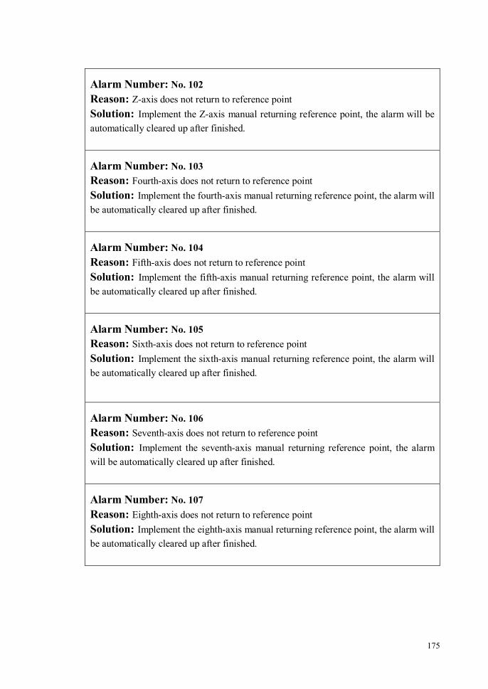
175
Alarm Number: No. 102 Reason: Z-axis does not return to reference point Solution: Implement the Z-axis manual returning reference point, the alarm will be automatically cleared up after finished.
Alarm Number: No. 103 Reason: Fourth-axis does not return to reference point Solution: Implement the fourth-axis manual returning reference point, the alarm will be automatically cleared up after finished.
Alarm Number: No. 104 Reason: Fifth-axis does not return to reference point Solution: Implement the fifth-axis manual returning reference point, the alarm will be automatically cleared up after finished.
Alarm Number: No. 105 Reason: Sixth-axis does not return to reference point Solution: Implement the sixth-axis manual returning reference point, the alarm will be automatically cleared up after finished.
Alarm Number: No. 106 Reason: Seventh-axis does not return to reference point Solution: Implement the seventh-axis manual returning reference point, the alarm will be automatically cleared up after finished.
Alarm Number: No. 107 Reason: Eighth-axis does not return to reference point Solution: Implement the eighth-axis manual returning reference point, the alarm will be automatically cleared up after finished.

176
Alarm Number: No. 110 Reason: X-axis electronic gear ratio setting error Solution: Check X-axis electronic gear ratio setting. Note that both the numerator and the denominator should not be less than 1×10⁻⁶.
Alarm Number: No. 111 Reason: Y-axis electronic gear ratio setting error Solution: Check Y-axis electronic gear ratio setting. Note that both the numerator and the denominator should not be less than 1×10⁻⁶.
Alarm Number: No. 112 Reason: Z-axis electronic gear ratio setting error Solution: Check Z-axis electronic gear ratio setting. Note that both the numerator and the denominator should not be less than 1×10⁻⁶.
Alarm Number: No. 113 Reason: Fourth-axis electronic gear ratio setting error Solution: Check the fourth-axis electronic gear ratio setting. Note that both the numerator and the denominator should not be less than 1×10⁻⁶.
Alarm Number: No. 114 Reason: Fifth-axis electronic gear ratio setting error Solution: Check the fifth-axis electronic gear ratio setting. Note that both the numerator and the denominator should not be less than 1×10⁻⁶.
Alarm Number: No. 115 Reason: Sixth-axis electronic gear ratio setting error Solution: Check the sixth-axis electronic gear ratio setting. Note that both the numerator and the denominator should not be less than 1×10⁻⁶.

177
Alarm Number: No. 116 Reason: Seventh-axis electronic gear ratio setting error Solution: Check the seventh-axis electronic gear ratio setting. Note that both the numerator and the denominator should not be less than 1×10⁻⁶.
Alarm Number: No. 117 Reason: Eighth-axis electronic gear ratio setting error Solution: Check the eighth-axis electronic gear ratio setting. Note that both the numerator and the denominator should not be less than 1×10⁻⁶.
Alarm Number: No. 120 Reason: X-axis screw pitch setting error Solution: Check the X-axis screw pitch setting value, which should not be less than 0.1.
Alarm Number: No. 121 Reason: Y-axis screw pitch setting error Solution: Check the Y-axis screw pitch setting value, which should not be less than 0.1.
Alarm Number: No. 122 Reason: Z-axis screw pitch setting error Solution: Check the Z-axis screw pitch setting value, which should not be less than 0.1.
Alarm Number: No. 123 Reason: Fourth-axis degrees setting error per revolution Solution: Check the fourth-axis degrees setting value per revolution, which should not be less than 0.1.

178
Alarm Number: No. 124 Reason: Fifth-axis degrees setting error per revolution Solution: Check the fifth-axis degrees setting value per revolution, which should not be less than 0.1.
Alarm Number: No. 125 Reason: Sixth-axis degrees setting error per revolution Solution: Check the sixth-axis degrees setting value per revolution, which should not be less than 0.1.
Alarm Number: No. 126 Reason: Seventh-axis degrees setting error per revolution Solution: Check the seventh-axis degrees setting value per revolution, which should not be less than 0.1.
Alarm Number: No. 127 Reason: Eighth-axis degrees setting error per revolution Solution: Check the eighth-axis degrees setting value per revolution, which should not be less than 0.1.
Alarm Number: No. 130 Reason: X-axis encoder pulses number setting error Solution: Check the X-axis pulses number setting value per revolution, which should not be less than 1.
Alarm Number: No. 131 Reason: Y-axis encoder pulses number setting error Solution: Check the Y-axis pulses number setting value per revolution, which should not be less than 1.

179
Alarm Number: No. 132 Reason: Z-axis encoder pulses number setting error Solution: Check the Z-axis pulses number setting value per revolution, which should not be less than 1.
Alarm Number: No. 133 Reason: Fourth-axis encoder pulses number setting error Solution: Check the fourth-axis pulses number setting value per revolution, which should not be less than 1.
Alarm Number: No. 134 Reason: Fifth-axis encoder pulses number setting error Solution: Check the fifth-axis pulses number setting value per revolution, which should not be less than 1.
Alarm Number: No. 135 Reason: Sixth-axis encoder pulses number setting error Solution: Check the sixth-axis pulses number setting value per revolution, which should not be less than 1.
Alarm Number: No. 136 Reason: Seventh-axis encoder pulses number setting error Solution: Check the seventh-axis pulses number setting value per revolution, which should not be less than 1.
Alarm Number: No. 137 Reason: Eighth-axis encoder pulses number setting error Solution: Check the eighth-axis pulses number setting value per revolution, which should not be less than 1.

180
Alarm Number: No. 160 Reason: when do tool measuring, system doesn’t detect the measuring head signal in the process of measuring the checking instrument by G31.X command. Solution: Check the measuring head signal of the checking instrument is normal.
Alarm Number: No. 300 Reason: R plane is not specified Solution:
Alarm Number: No. 301 Reason: Bottom coordinate is not specified Solution:
Alarm Number: No. 305 Reason: Feed quantity is not specified Solution:
Alarm Number: No. 306 Reason: Retract quantity is not specified Solution:
Alarm Number: No. 307 Reason: Pitch is not specified Solution:
Alarm Number: No. 308 Reason: Spindle rotational speed is not specified Solution:

181
Alarm Number: No. 310 Reason: The R plane should be on top of the Z plane Solution:

182
13.3 Appendix Three, Machine Tool Structure Code
For the machine tool without rotational axis, the structure code of tool swing head and workbench are 0. For the machine tool which has rotational axis, the rotatinal axis’s structure has tool swing head and workbench types, which can be set separately.
For the rotational axis in each machine tool structure form, please according to the arrowhead shown in the figure to define the rotational positive and negative direction(the direction of the arrowhead shown is the rotational positive direction). If the rotational direction definition is incorrect, system can’t execute the RTCP control correctly.
The direction of tool swing head rotational axis is defined by the right hand rule in the tool coordinate system, namely go down the rotational axis’s direction to see, the rotational axis’s direction is clockwise. The direction of workbench rotational axis is the opposite direction of swing head direction confirmed by the above principle.
The unlisted machine tool structure form in this appendix, system doesn’t support the RTCP control, do not use.
13.3.1 Tool Swing Head Structure
1、Single Swing Head A-axis Structure(Structure code: 10A0) Tool rotates around X-axis, as the following figure shown.

183
Figure 13-1 Single Swing Head A-axis Structure
2、Single Swing Head B-axis Structure(Structure code: 10B0)
Tool rotates around Y-axis, as the following figure shown.
Figure 13-2 Single Swing Head B-axis Structure

184
3、Double Swing Head C, A-axis Structure, C-axis driving, A-axis driven(structure code: 1CA0) Tool rotates around X-axis(A-axis), A-axis rotates around Z-axis(C-axis), as the following figure shown.
Figure 13-3 Double Swing Head C, A-axis Structure
4、Double Swing Head C, B-axis Structure, C-axis driving, B-axis driven(structure code: 1CB0)
Tool rotates around Y-axis(B-axis), B-axis rotates around Z-axis(C-axis), as the following figure shown.

185
Figure 13-4 Double Swing Head C, B-axis Structure
5、Double Swing Head B, A-axis Structure, B-axis driving, A-axis driven(structure code: 1BA0)
Tool rotates around X-axis(A-axis), A-axis rotates around Y-axis(B-axis), as the following figure shown.
Figure 13-5 Double Swing Head B, A-axis Structure

186
13.3.2 Workbench Structure
1、Single Turntable A-axis Structure(structure code: 20A0) Workbench rotates around X-axis, as the following figure shown.
Figure 13-6 Single Turntable A-axis Structure
2、Single Turntable B-axis Structure(structure code: 20B0) Workbench rotates around Y-axis, as the following figure shown.
Figure 13-7 Single Turntable B-axis Structure

187
3、Single Turntable C-axis Structure(structure code: 20C0) Workbench rotates around Z-axis, as the following figure shown.
Figure 13-8 Single Turntable C-axis Structure
4、Double Turntable A, C-axis Structure, A-axis driving, C-axis driven (structure code: 2AC0) Workbench rotates around Z-axis(C-axis), C-axis rotates around X-axis(A-axis), as the following figure shown.
Figure 13-9 Double Turntable A, C-axis Structure
5、Double Turntable C, A-axis Structure, C-axis driving, A-axis driven (structure code: 2CA0) Workbench rotates around X-axis(A-axis), A-axis rotates around Z-axis(C-axis), as the following figure shown.
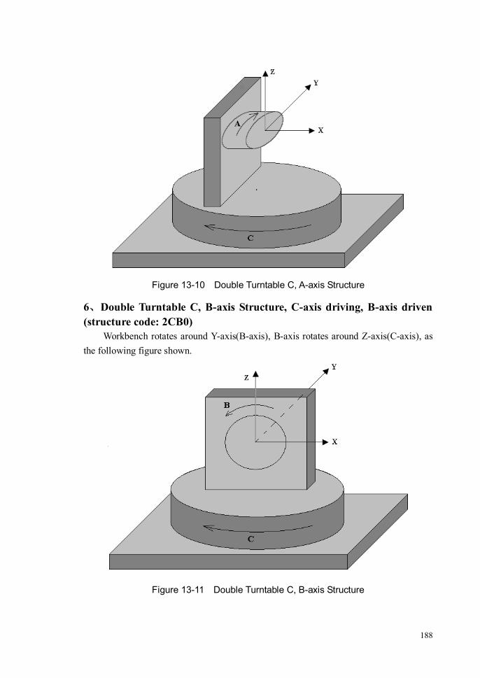
188
Figure 13-10 Double Turntable C, A-axis Structure
6、Double Turntable C, B-axis Structure, C-axis driving, B-axis driven (structure code: 2CB0) Workbench rotates around Y-axis(B-axis), B-axis rotates around Z-axis(C-axis), as the following figure shown.
Figure 13-11 Double Turntable C, B-axis Structure

189
13.4 Appendix Four, Menu Tree Structure
Submenus Tree Structure of Main Menu (1)
Main Menu (1)
PROG (F1)
MDI (F2)
MAGT (F3)
OFST (F4)
SCRD (F5)
REFC (F6)
SSET (F7)
DIAG (F8)
VSWT (F9)
MNUR (F10)
Main Menu (2)
MNUL (F1)
PSWD (F3)
VARI (F4)
DNC (F5)
TEST (F8)
TFED (F7)
TCS (F2)
STAT (F9)

190
LDPG (F1)
PEDT (F2)
NFIL (F3)
PMAN (F4)
PBRK (F5)
GTLN (F6)
RRUN (F8)
EXWK (F9)
PGMR (F10)
To load, select and sort a program
To edit a program
To delete, backup, rename, copy, sort a program file
To do correlation operations of a program breakpoint
PVRF (F7)
PROG (F1)

191
OFST (F4)
ORET (F10)
SCRD (F5)
CCUR (F1)
ADD (F2)
DEC (F3)
REC1 (F4)
REC2 (F5)
MIDP (F6)
CRET (F10)
RESM (F9)
TCUR (F1)
DECP (F7)
WRST (F8)
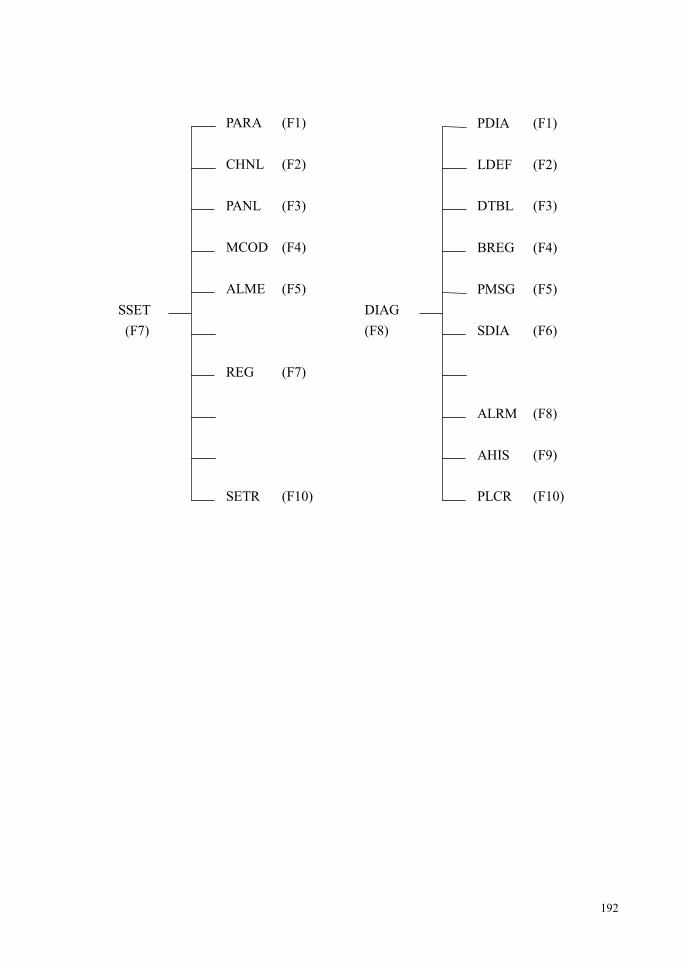
192
PARA (F1)
CHNL (F2)
SETR (F10)
PANL (F3)
MCOD (F4)
ALME (F5)
PDIA (F1)
LDEF (F2)
DTBL (F3)
PMSG (F5)
PLCR (F10)
DIAG (F8)
REG (F7)
BREG (F4)
SDIA (F6)
ALRM (F8)
AHIS (F9)
SSET (F7)

193
LMOV (F1)
RMOV (F2)
VSWT (F9)
UMOV (F3)
DMOV (F4)
CLER (F5)
ZMDW (F7)
ZMUP (F6)
ZORG (F5)
GRET (F10)
VSWT (F9)

194
Submenus Tree Structure of Main Menu (2)
TCS F2
3PTS (F1)
2VTR (F2)
EULR (F4)
TCSR (F10)
SPAN (F3)
PSWD F3
IPWD (F1)
SPWD (F2)
LGOF (F4)
PWRT (F10)

195
DNCR (F1)
WONL (F2)
RETD (F10)
VARI F4
DNC F5
LVAR (F1)
PVAR (F2)
SVAR (F3)
VSCH (F4)
VRET (F10)
DSET (F5)

196
TFOP (F1)
TFCL (F2)
TFRT (F10)
TTST (F1)
MCHK (F5)
TERT (F10)
TFED F4
TEST F5
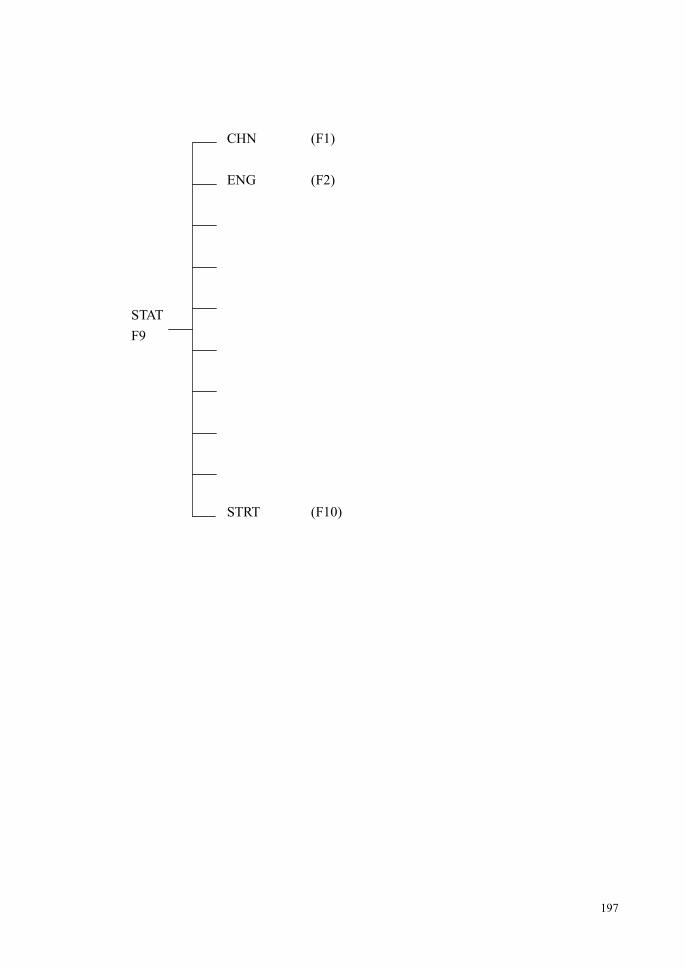
197
STAT F9
CHN (F1)
ENG (F2)
STRT (F10)
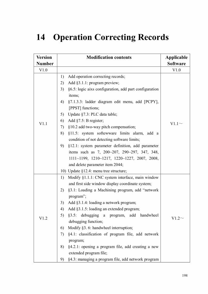
198
14 Operation Correcting Records Version Number
Modification contents Applicable Software
V1.0 V1.0
V1.1
1) Add operation correcting records; 2) Add §3.1.1: program preview; 3) §6.5: logic aixs configuration, add part configuration
items; 4) §7.1.3.3: ladder diagram edit menu, add [PCPY],
[PPST] functions; 5) Update §7.3: PLC data table; 6) Add §7.5: B register; 7) §10.2 add two-way pitch compensation; 8) §11.5: system softewware limits alarm, add a
condition of not detecting software limits; 9) §12.1: system parameter definition, add parameter
items such as 7, 200~207, 290~297, 347, 348, 1111~1199, 1210~1217, 1220~1227, 2007, 2008, and delete parameter item 2044;
10) Update §12.4: menu tree structure;
V1.1~
V1.2
1) Modify §1.1.1: CNC system interface, main window and first side window display coordinate system;
2) §3.1: Loading a Machining program, add “network program”;
3) Add §3.1.4: loading a network program; 4) Add §3.1.5: loading an extended program; 5) §3.5: debugging a program, add handwheel
debugging function; 6) Modify §3. 6: handwheel interruption; 7) §4.1: classification of program file, add network
program; 8) §4.2.1: opening a program file, add creating a new
extended program file; 9) §4.3: managing a program file, add network program
V1.2~
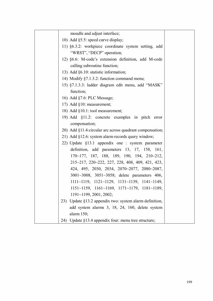
199
moudle and adjust interface; 10) Add §5.5: speed curve display; 11) §6.3.2: workpiece coordinate system setting, add
“WRST”, “DECP” operation; 12) §6.6: M-code’s extension definition, add M-code
calling subroutine function; 13) Add §6.10: statistic information; 14) Modify §7.1.3.2: function command menu; 15) §7.1.3.3: ladder diagram edit menu, add “MASK”
function; 16) Add §7.6: PLC Message; 17) Add §10: measurement; 18) Add §10.1: tool measurement; 19) Add §11.2: concrete examples in pitch error
compensation; 20) Add §11.4:circular arc across quadrant compensation; 21) Add §12.6: system alarm records query window; 22) Update §13.1 appendix one : system parameter
definition, add parameters 13, 17, 158, 161, 170~177, 187, 188, 189, 190, 194, 210~212, 215~217, 220~222, 227, 228, 408, 409, 421, 423, 424, 495, 2030, 2034, 2070~2077, 2080~2087, 3001~3008, 3051~3058; delete parameters 406, 1111~1119, 1121~1129, 1131~1139, 1141~1149, 1151~1159, 1161~1169, 1171~1179, 1181~1189, 1191~1199, 2001, 2002;
23) Update §13.2 appendix two: system alarm definition, add system alarms 3, 18, 24, 160, delete system alarm 150;
24) Update §13.4 appendix four: menu tree structure;