CITY OF MONONA
65
AGENDA - final CITY OF MONONA FACILITIES COMMITTEE City Hall Wednesday March 19, 2014 5:30 PM 1. Call to Order 2. Roll Call 3. Approval of Minutes from the January 16, 2014 meeting. 4. Appearances A. None 5. Unfinished Business A. Library Entry/Stair Renovation – 100% drawings review B. Oneida Park Shelter - Bids & CM Contract Review 6. New Business A. Lottes Park Shelter/Fish Cleaning Station - Architecture Design Contract 7. Miscellaneous Business A. None 8. Next Meeting: TBD 9. Adjournment If you cannot make it, please notify Janine Glaeser at 222-2525 or [email protected] Thank you for your service. NOTE: Upon reasonable notice, the City of Monona will accommodate the needs of disabled individuals through auxiliary aids or services. For additional information or to request this service, contact Joan Andrusz at (608) 222-2525 (not a TDD telephone number), FAX: (608) 222-9225, or through the City Police Department TDD telephone number 441-0399. The public is notified that any final action taken at a previous meeting may be reconsidered pursuant to the City of Monona ordinances. A suspension of the rules may allow for final action to be taken on an item of New Business. It is possible that members of and a possible quorum of members of other governmental bodies of the municipality may be in attendance at the above stated meeting to gather information or speak about a subject, over which they have decision-making responsibility. No action will be taken by any governmental body at the above stated meeting other than the governmental body specifically referred to above in this notice. Page 1 of 1
-
Upload
khangminh22 -
Category
Documents
-
view
0 -
download
0
Transcript of CITY OF MONONA
AGENDA - final
CITY OF MONONA FACILITIES COMMITTEE
City Hall Wednesday March 19, 2014
5:30 PM
1. Call to Order 2. Roll Call 3. Approval of Minutes from the January 16, 2014 meeting.
4. Appearances
A. None 5. Unfinished Business
A. Library Entry/Stair Renovation – 100% drawings review B. Oneida Park Shelter - Bids & CM Contract Review
6. New Business
A. Lottes Park Shelter/Fish Cleaning Station - Architecture Design Contract
7. Miscellaneous Business
A. None
8. Next Meeting: TBD 9. Adjournment
If you cannot make it, please notify Janine Glaeser at 222-2525 or [email protected] Thank you for your service.
NOTE: Upon reasonable notice, the City of Monona will accommodate the needs of disabled individuals through auxiliary aids or services. For additional information or to request this service, contact Joan Andrusz at (608) 222-2525 (not a TDD telephone number), FAX: (608) 222-9225, or through the City Police Department TDD telephone number 441-0399. The public is notified that any final action taken at a previous meeting may be reconsidered pursuant to the City of Monona ordinances. A suspension of the rules may allow for final action to be taken on an item of New Business.
It is possible that members of and a possible quorum of members of other governmental bodies of the municipality may be in attendance at the above stated meeting to gather information or speak about a subject, over which they have decision-making responsibility. No action will be taken by any governmental body at the above stated meeting other than the governmental body specifically referred to above in this notice.
Page 1 of 1
CITY OF MONONA FACILITIES COMMITTEE Wednesday, January 15, 2014
MINUTES – draft
1. The meeting was called to order at 5:30 pm 2. Roll Call: Members present include:, Staff - Janine Glaeser, Chair - Jim Busse, Jim Beyer, Philip Carlson,
Dan Eklof and Paul Ament. Guests included Pat Marsh, Sally Buffat, & Doug Pahl. Jim Dederich & Jim Lampe had an excused absence.
3. Approval of Minutes: Nov. 11, 2013 meeting minutes approved. 4. Appearances: None 5. Unfinished Business:
A. Library Entry/ Stair Renovation – 65% drawings review Committee comments/questions:
Jim Beyer: Electrical
− Review occupancy sensor options – must have an override option − Consider stair lighting – design will include fixture concept − Review Elec design/build approach– will need to identify more info up front − Review construction access & security, ADA – Schluter Rd. will be temporary entry − Add power under staircase for cleaning − Assess options for book drop interior and exterior lighting −
Philip Carlson: Landscape Design / Aesthetics − No exterior landscaping in this project. − Consider space under stair, behind seating
anything occupying this space? Maintenance? Is this a good place for artwork or planter? − Question – reason for round column enclosure. A: Match existing columns −
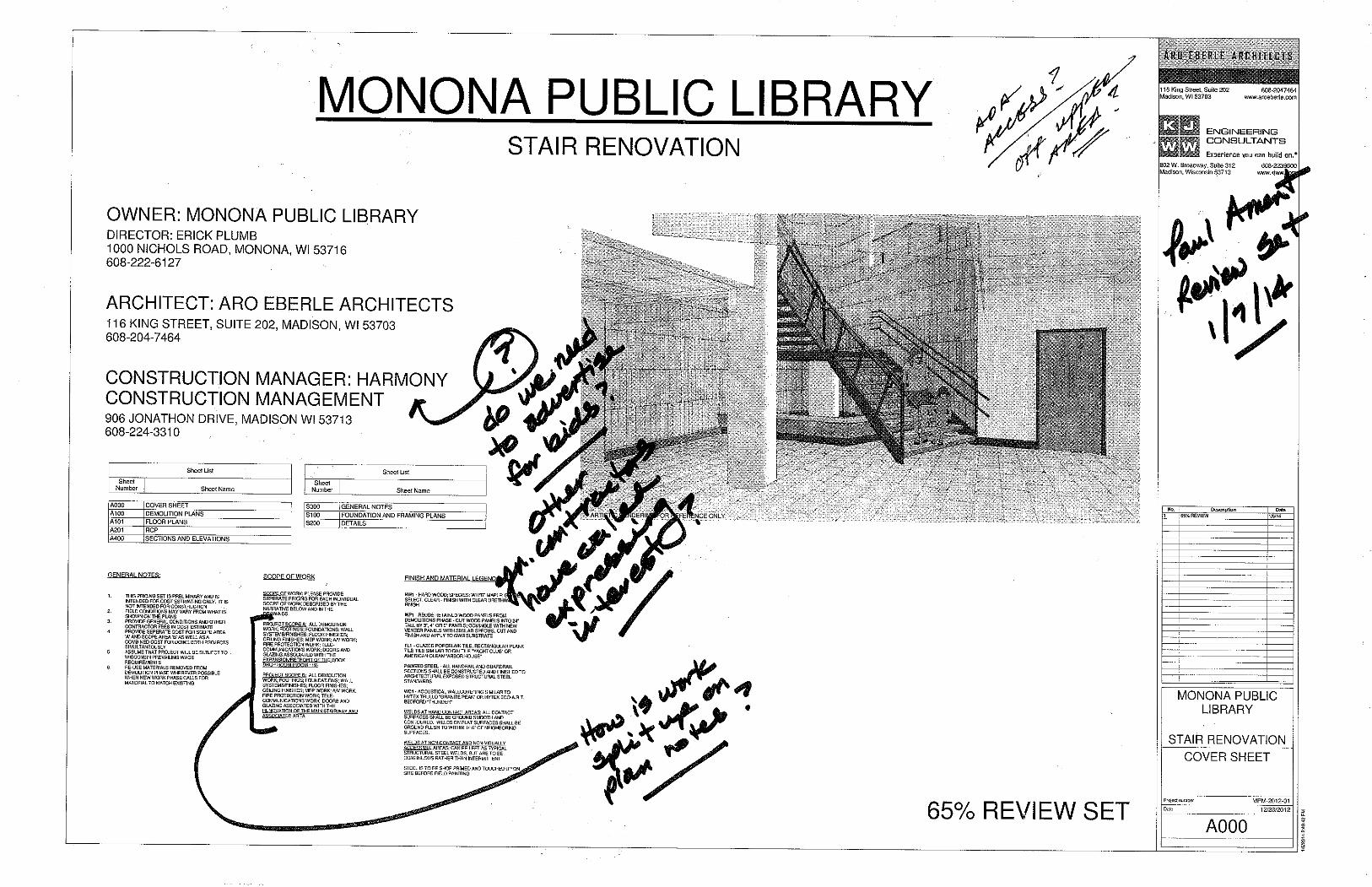
Paul Ament (see also attached dwgs w/notes): Architecture − Review access – ADA, add temp signage at lower level re: Schluter access − Scope of Work – how divide on plan notes − Review of gate outside main entry: lock locations & types, entry donation plaques − Assess – should be there a toe board on the landing? −
Dan Eklof: Fire / Safety − Review proposed paneling – flame spread − Review fire protection:
Fire draft curtain – important there is detection on both sides – confirm in scope of work
Jim Busse: general − Confirm bench location meets all codes − Review stair potential slip hazards, maintenance, and staining potential − Review locations for tv/cable display, i.e. entry video display/announcement board − How match existing masonry. A: blend new matching brick with reused existing bricks −
Janine Glaeser: general − Review demolition and construction recycling requirements − Review floor finish material options. Though tile identified on 65%, not final choice. − Confirm relocated roll down gate will work within top of stair structure − What is #19, solid surface shelf. A: for book drop patrons to set items while returning books − Is suspended ceiling required in book drop room? A: yes, there is one now and visible via new window
Discussion Items: − Discussion regarding advertising for bids process − Review City procedures for services contracts and bidding for construction contracts − Committee should be reviewing all facilities related contracts
B. Solar Project Update
- City Hall, Library, & PW Garage have been commissioned. Well #3 to be commissioned mid Jan. 6. New Business:
A. Fireman’s Park Facilities Report - final review - Committee reviewed final post construction report of project - Address final punchlist items in the spring (see list from P. Ament) B. Facilities – energy/utility tracking software options - City considering Energy Watchdog or EPA Energy Star software for tracking energy usage - Recommendation to talk with Brian Driscoll, WECC, for other software options.
7. Miscellaneous Business: A. None
8. Next Meeting: TBD – schedule a special meeting in Feb. to review Oneida Park bids & contracts. 9. Adjournment: The Facility Committee adjourned at 7:00 pm.
Questions, corrections, or additions – please notify Janine Glaeser at 222-2525 or [email protected]
GENERAL NOTES:
THE CONSTRUCTION MANAGER (CM) SHALL HEREBY BE REFERRED TOAS THE "CONTRACTOR" FOR THE PURPOSES OF THESE DRAWINGS
CONTRACTOR SHALL COMPLY WITH ALL APPLICABLE LOCAL, FEDERAL,AND STATE REGULATIONS, AND ALL OF THE REQUIREMENTS OF THELOCAL AUTHORITIES HAVING JURISDICTION.
THE CONTRACTOR SHALL OBTAIN AND PAY FOR ALL PERMITS,INSPECTION FEES, AND TAXES AS REQUIRED FOR THEIR PORTION OFTHE WORK.
THE CONTRACTOR SHALL VISIT THE SITE TO DETERMINE THE FULLEXTENT OF THE WORK AND BECOME FAMILIAR WITH THE LOCALCONDITIONS AND CODES RELATING TO THE WORK BEFORESUBMITTING A PROPOSAL. FAILURE TO DO SO WILL NOT RELIEVE THECONTRACTOR OF THE OBLIGATIONS OF THE CONTRACT.
THE CONTRACTOR SHALL NOTIFY THE ARCHITECT OF ANYDISCPREPANCIES IN THE CONTRACT DOCUMENTS, IN WRITING, ANDALLOW SUFFICIENT TIME FROM THE RECEIPT OF NOTIFICATION BY THEARCHITECT TO FURNISH A CLARIFICATION BEFORE PROCEEDING WITHTHE WORK IN QUESTION.
THE CONTRACTOR SHALL NOTIFY THE ARCHITECT, IN WRITING, OFANY DEFICIENCIES RELATED TO LOCAL CODES AND REGULATIONS ORUTILITIES, AND ALLOW SUFFICIENT TIME FROM THE RECEIPT OFNOTIFICATION BY THE ARCHITECT TO FURNISH A REVISION ORCLARIFICATION.
THE CONTRACTOR WILL ALLOW 7 CALENDAR DAYS FROM THE DATE OFRECEIPT BY THE ARCHITECT FOR RESPONSES TO REQUESTS FORINFORMATION
THE CONTRACTOR SHALL FURNISH SUBMITTALS FOR ALL BUILDINGCOMPONENTS AND ACCESSORIES NECESSARY FOR THE INTALLATIONOF EACH BUILDING COMPONENT DESCRIBED OR LISTED IN THEDRAWINGS
THE CONTRACTOR SHALL FURNISH SHOP DRAWINGS FOR WORKREQUIRING SHOP FABRICATION FOR THE ARCHITECT TO REVIEW. THECONTRACTOR SHALL ALLOW 10 CALENDAR DAYS FROM THE DATE OFRECEIPT BY THE ARCHITECT FOR REVIEW OF THE SHOP DRAWINGS.
CONTRACTOR SHALL APPLY, INSTALL, CONNECT, ERECT, USE,CLEAN AND CONDITION MANUFACTURED ARTICLES, MATERIALS,AND EQUIPMENT AS RECOMMENDED BY THE MANUFACTURER,UNLESS SPECIFIED TO THE CONTRARY. THE MANUFACTURER'SLATEST RECOMMENDATIONS AT THE TIME OF BIDDING SHALL BEUSED.
CONTRACTOR TO PROVIDE SUBMITTALS FOR ALL DOORHARDWARE
KEYNOTE NUMBERS ARE SHEET SPECIFIC - SEE KEYNOTELEGEND ON EACH SHEET FOR DEFINITION OF EACH NUMER
ALL GIVEN DIMENSIONS ARE TO BE FIELD VERIFIED
DESIGN BUILD:
CONTRACTOR SHALL INCLUDE ALL ELECTRICAL DESIGN FORPOWER, LIGHTING AND ASSOCIATED SYSTEMS AS PART OF THECONTRACT. ANY LIGHTING OR POWER SHOWN ON THE PLANS IS FORBIDDING PURPOSES AND SHOULD BE EVALUATED FOR CODECOMPLIANCE AND DESIGN PRACTICALITY
FIRE PROTECTION SYSTEM RECONFIGURATION SHALL BE DESIGNEDAND PERFORMED BY A LICENSED CONTRACTOR TO MEET NFPA 13STANDARDS, AND SHOULD BE INCLUDED AS PART OF THIS CONTRACT
FINISH AND MATERIAL LEGEND:
HW1 - HARD WOOD; SPECIES: WHITE MAPLE; GRADE:SELECT, CLEAR - FINISH WITH CLEAR URETHANE FINISH
GT-1 - BOSTICK SANDED GROUT IN COLOR: MOBE PEARLH145 WITH 3/16" GROUT LINE
PAINTED STEEL - ALL HANDRAIL AND GUARDRAILSECTIONS SHALL BE CONSTRUCTED AND FINISHED TOARCHITECTURAL EXPOSED STRUCTURAL STEELSTANDARDS - SEE STRUCTURAL SHEET S000
PT-1 - PAINTED STEEL PAINT COLOR SHERWIN WILLIAMSTHUNDER GRAY SW 7645
PT-2 - COLUMN PAINT COLOR SHERWIN WILLIAMSANONYMOUS SW 7046 IN SEMI-GLOSS FINISH; FORVESTIBULE WALL USE SATIN FINISH
PT-3 - WALL PAINT COLOR SHERWIN WILLIAMS GRECIANIVORY SW 7541 IN SATIN FINISH
PT-4 - GWB. CEILING PAINT COLOR SHERWIN WILLIAMSALABASTER SW 7008 IN FLAT FINISH
RB-1 - ECOLIBRIUM 6" RUBBER BASE WITH TOE PROFILEIN COLOR: CHARCOAL WG EB-20 BY JOHNSONITE
SS1 - HANEX SOLID SURFACE WITH 1-1/2" PROFILE INPATTERN: BELLASIMO AND COLOR: BL-003 PIETRAPANNA BY HANWHA L&C | SURFACES
ST1 - FOR HARDWOOD STAIR TREADS: USE GENERALFINISHES TWO-PART WATER BASED TOP COAT "PRO-SHIELD OR SIMILAR FINISH SUITABLE FOR TRAFFICBEARING SURFACES; FINISH ALL 4 SIDES OF LAMINATEDWOOD SECTIONS; 2 COATS ON NOSING AND TOPSURFACE, 1 COAT ON BACK, BOTTOM OR CONCEALEDSURFACES. APPLY TWO COATS TO HARDWOODFLOORING AT LANDING
ST2 - STAIN FOR NEW WP1: GENERAL FINISHES WATERBASED WOOD STAIN WITH HIGH PERFORMANCE WATERBASED POLYURETHANE TOP COAT OR SIMILAR; COLORAND SHEEN TO MATCH STAIN OF EXISTING BIRCHVENEER PLYWOOD PANELS
ST3 - STAIN FOR HANDRAILS TO MATCH HARDWOODSTAIR TREADS
TL1 - COLOR BODY PORCELAIN TILE IN BRICKINSTALLATION, 12x24 RECTANGULAR TILE INPATTERN: PARALLEL AND COLOR: JERUSALEM BONEBY RBC TILE & STONE
VCT1 - ESSENTIALS VINYL COMPOSITION TILE INSANDRIFT 137 BY MANNINGTON COMMERCIAL
WF1 - WALL FABRIC MADE OF 100% RECYCL. P.E.T.FELT; PRODUCT: BUZZISKIN; COLOR: ANTHRACTIE 68;FULL ROLL: 33 FT. x 3.21 FT. WITH SELF ADHESIVEBACKING; INSTALL STRIPS CUT TO 5-1/2"x24" ATVOIDS IN WOOD WALL PANELS
WP1 - REUSE RETAINED WOOD PANELS FROMDEMOLITIONS PHASE - CUT WOOD PANELS INTO 24"TALL BY 4" OR 8" PANELS; COMINGLE WITH NEWVENEER PANELS WITH SIMILAR SPECIES, CUT ANDFINISH AND APPLY TO GWB SUBSTRATE
FINISH NOTES:
1. PAINT EXISTING WALLS (PT3), COLUMNS (PT2)ANDCOLUMN COVERS (PT2) IN AREAS ADJACENT TOWORK AREA, INCLUDING CAFE AREA, LOBBY,VESTIBULE, SORTER ROOM AND OTHER AREASWITHIN THE SCOPE AREA THAT ARE NOT COVEREDWITH ANOTHER FINISH
2. PROVIDE NEW 6" RUBBER BASE IN CAFE LOBBY,VESTIBULE AND BOOKDROP / ELECTRICAL ROOMS
3. SEE STRUCTURAL DRAWING SHEET S000 FOR AESSREQUIREMENTS
Project number
Date
116 King Street, Suite 202Madison, WI 53703
608-2047464www.aroeberle.com
802 W. Broadway, Suite 312Madison, Wisconsin 53713
608-2239600www.kjww.com
2/20
/201
4 2:
48:5
0 PM
A000
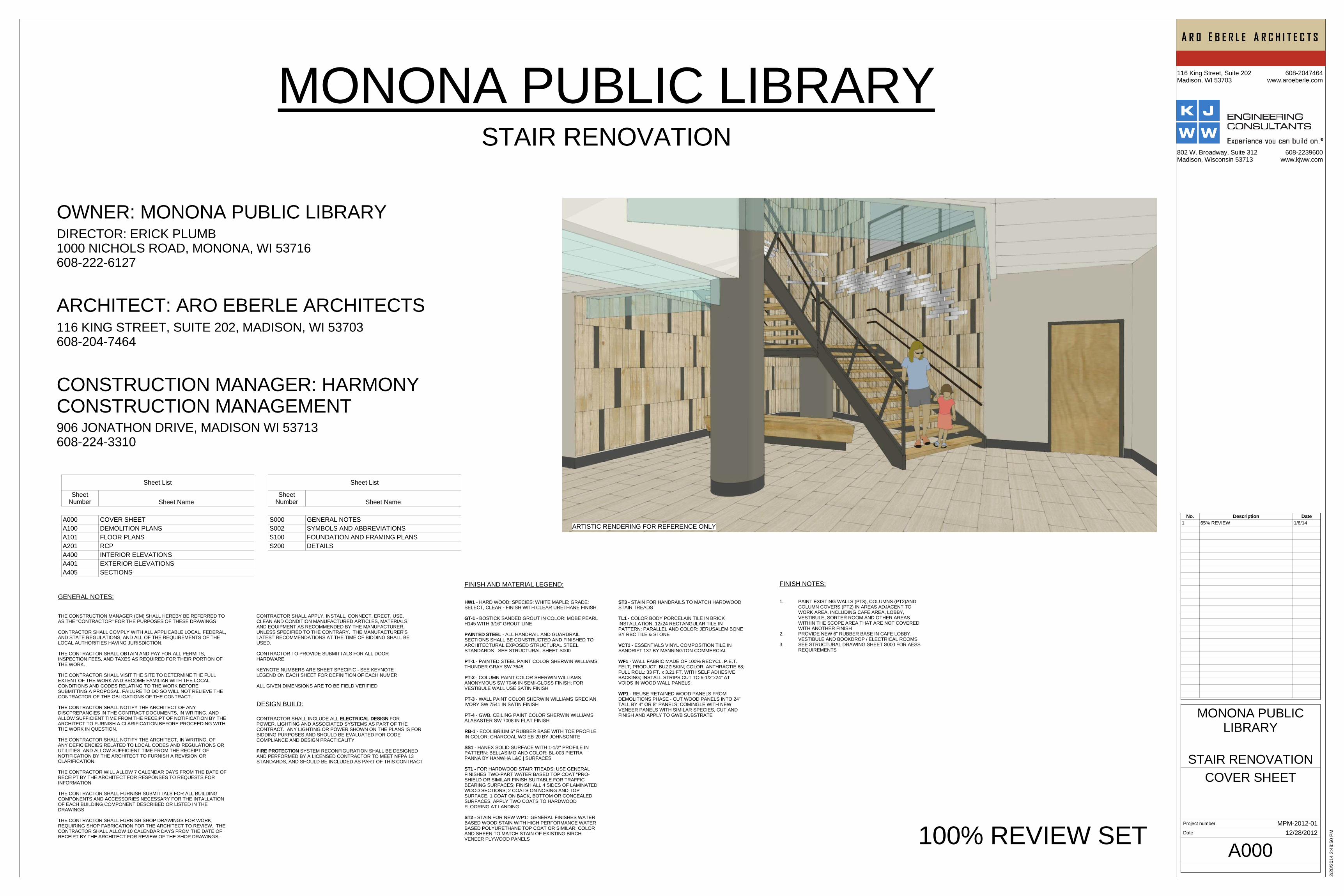
COVER SHEET
MPM-2012-01
STAIR RENOVATION
MONONA PUBLICLIBRARY
12/28/2012
MONONA PUBLIC LIBRARYSTAIR RENOVATION
Sheet List
SheetNumber Sheet Name
S000 GENERAL NOTESS002 SYMBOLS AND ABBREVIATIONSS100 FOUNDATION AND FRAMING PLANSS200 DETAILS
Sheet List
SheetNumber Sheet Name
A000 COVER SHEETA100 DEMOLITION PLANSA101 FLOOR PLANSA201 RCPA400 INTERIOR ELEVATIONSA401 EXTERIOR ELEVATIONSA405 SECTIONS
OWNER: MONONA PUBLIC LIBRARYDIRECTOR: ERICK PLUMB1000 NICHOLS ROAD, MONONA, WI 53716608-222-6127
ARCHITECT: ARO EBERLE ARCHITECTS116 KING STREET, SUITE 202, MADISON, WI 53703608-204-7464
100% REVIEW SET
ARTISTIC RENDERING FOR REFERENCE ONLY
No. Description Date1 65% REVIEW 1/6/14
CONSTRUCTION MANAGER: HARMONYCONSTRUCTION MANAGEMENT906 JONATHON DRIVE, MADISON WI 53713608-224-3310
BB.1
5
FED
AA
BB
CC
VESTIBULE
BOOK DROP/ELECTRICAL
ELEVATOR
CAFE
LOBBY
3
4
5
6
7
8
8
8
7'-1" TALL
3' - 8"
88 8
99
10
1111
1111
1111
12
1818
19
2020
921
21
2323
23
23
2626
23
23
12
1111
BB.1
FED
BB
CC
1314
ALIGN
ALIGN
4
OPEN TOBELOW
15
15
15
1616
A400 2
A400
3
A400
1
2323
23
BB.1
5 FED
BB
CC
11
116 SF
VESTIBULE101
256 SF
BOOK DROP/ELECTRICAL
105
517 SF
LOBBY102
139 SF
STAIR104
11
2
OPEN TOABOVE
2
172222
E
24
25
25
WORK AREA
Project number
Date
116 King Street, Suite 202Madison, WI 53703
608-2047464www.aroeberle.com
802 W. Broadway, Suite 312Madison, Wisconsin 53713
608-2239600www.kjww.com
2/20
/201
4 2:
48:5
2 PM
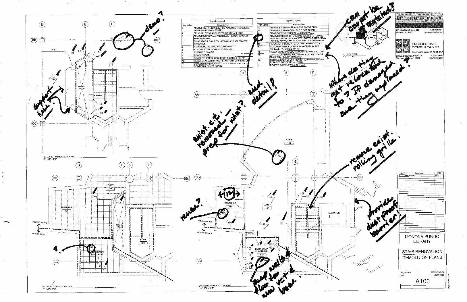
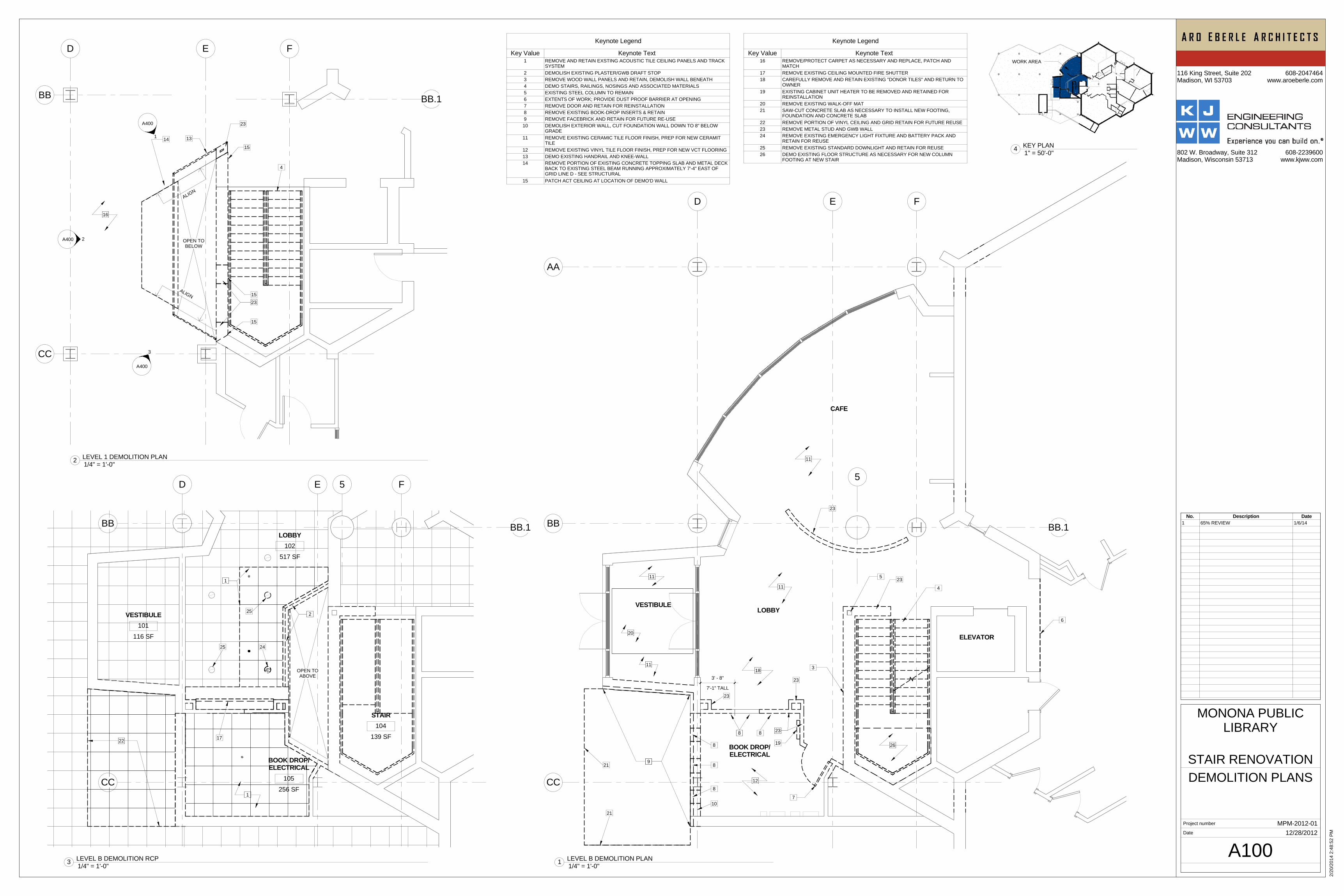
A100
DEMOLITION PLANS
MPM-2012-01
STAIR RENOVATION
MONONA PUBLICLIBRARY
12/28/2012
1/4" = 1'-0"1 LEVEL B DEMOLITION PLAN
1/4" = 1'-0"2 LEVEL 1 DEMOLITION PLAN
1/4" = 1'-0"3 LEVEL B DEMOLITION RCP
Keynote Legend
Key Value Keynote Text16 REMOVE/PROTECT CARPET AS NECESSARY AND REPLACE, PATCH AND
MATCH17 REMOVE EXISTING CEILING MOUNTED FIRE SHUTTER18 CAREFULLY REMOVE AND RETAIN EXISTING "DONOR TILES" AND RETURN TO
OWNER19 EXISTING CABINET UNIT HEATER TO BE REMOVED AND RETAINED FOR
REINSTALLATION20 REMOVE EXISTING WALK-OFF MAT21 SAW-CUT CONCRETE SLAB AS NECESSARY TO INSTALL NEW FOOTING,
FOUNDATION AND CONCRETE SLAB22 REMOVE PORTION OF VINYL CEILING AND GRID RETAIN FOR FUTURE REUSE23 REMOVE METAL STUD AND GWB WALL24 REMOVE EXISTING EMERGENCY LIGHT FIXTURE AND BATTERY PACK AND
RETAIN FOR REUSE25 REMOVE EXISTING STANDARD DOWNLIGHT AND RETAIN FOR REUSE26 DEMO EXISTING FLOOR STRUCTURE AS NECESSARY FOR NEW COLUMN
FOOTING AT NEW STAIR
Keynote Legend
Key Value Keynote Text1 REMOVE AND RETAIN EXSTING ACOUSTIC TILE CEILING PANELS AND TRACK
SYSTEM2 DEMOLISH EXISTING PLASTER/GWB DRAFT STOP3 REMOVE WOOD WALL PANELS AND RETAIN, DEMOLISH WALL BENEATH4 DEMO STAIRS, RAILINGS, NOSINGS AND ASSOCIATED MATERIALS5 EXISTING STEEL COLUMN TO REMAIN6 EXTENTS OF WORK; PROVIDE DUST PROOF BARRIER AT OPENING7 REMOVE DOOR AND RETAIN FOR REINSTALLATION8 REMOVE EXISTING BOOK-DROP INSERTS & RETAIN9 REMOVE FACEBRICK AND RETAIN FOR FUTURE RE-USE10 DEMOLISH EXTERIOR WALL, CUT FOUNDATION WALL DOWN TO 8" BELOW
GRADE11 REMOVE EXISTING CERAMIC TILE FLOOR FINISH, PREP FOR NEW CERAMIT
TILE12 REMOVE EXISTING VINYL TILE FLOOR FINISH, PREP FOR NEW VCT FLOORING13 DEMO EXISTING HANDRAIL AND KNEE-WALL14 REMOVE PORTION OF EXISTING CONCRETE TOPPING SLAB AND METAL DECK
BACK TO EXISTING STEEL BEAM RUNNING APPROXIMATELY 7'-4" EAST OFGRID LINE D - SEE STRUCTURAL
15 PATCH ACT CEILING AT LOCATION OF DEMO'D WALL
1" = 50'-0"4 KEY PLAN
No. Description Date1 65% REVIEW 1/6/14
UP
DN
BB.1
5 FED
AA
BB
CC
A400
41
A405
2A405
3A405
256 SF
BOOK DROP/ELECTRICAL
105
116 SF
VESTIBULE101
517 SF
LOBBY102
501 SF
CAFE103
50 SF
ELEVATOR100E
82 SF
EQUIPMENTROOM139 SF
STAIR104
7' - 0 1/4"
A401
1
9' - 4 3/4"
9"
1
2
3
44
5
44
6
6
7
7
88
1212
13
14
141416
STORAGE
17
182' - 2 3/4" 2' - 0"5"
F.V.
1' - 5" 8" 2' - 0"
44
4
2
A401
3
A400
8
7
4A405
A400
6
A400
5
8.80
°
1920 3'
- 0"
20
2121
23
3' - 3 1/2"
24
25
26
27
1' -
8"
3 3/
4"
7' - 6"2' - 5 9/16"
38.8
0°
1212
1' -
0"
28
BB.1
FE
BB
CC
CC.5
1A405
2A405
9
10
7
11
11
11
2' -
5"
14
14
15
A5001
A5002
A400 2
A400
3
A5006 A400 7
14
8.80
°
1' - 6"
STRINGER2"
5' - 0"STRINGER
2"
1' - 4"A400
1
22
22
22
6' - 3 3/8"
1' - 8 1/8"
2' - 8
1/4
"
2' - 8
13/
16"
1"
5' - 5
1/1
6"
WORK AREA
Project number
Date
116 King Street, Suite 202Madison, WI 53703
608-2047464www.aroeberle.com
802 W. Broadway, Suite 312Madison, Wisconsin 53713
608-2239600www.kjww.com
2/20
/201
4 2:
48:5
5 PM
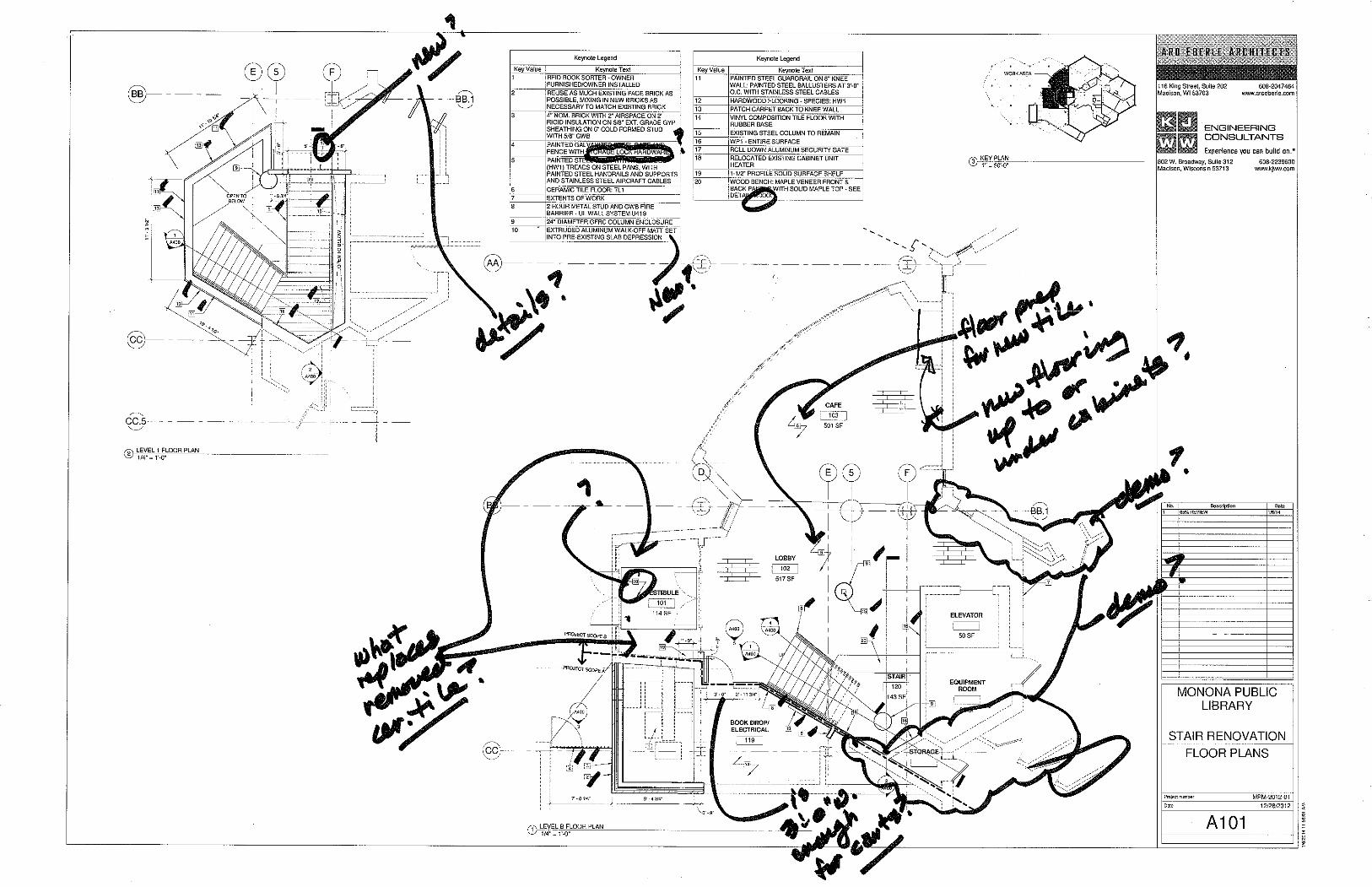
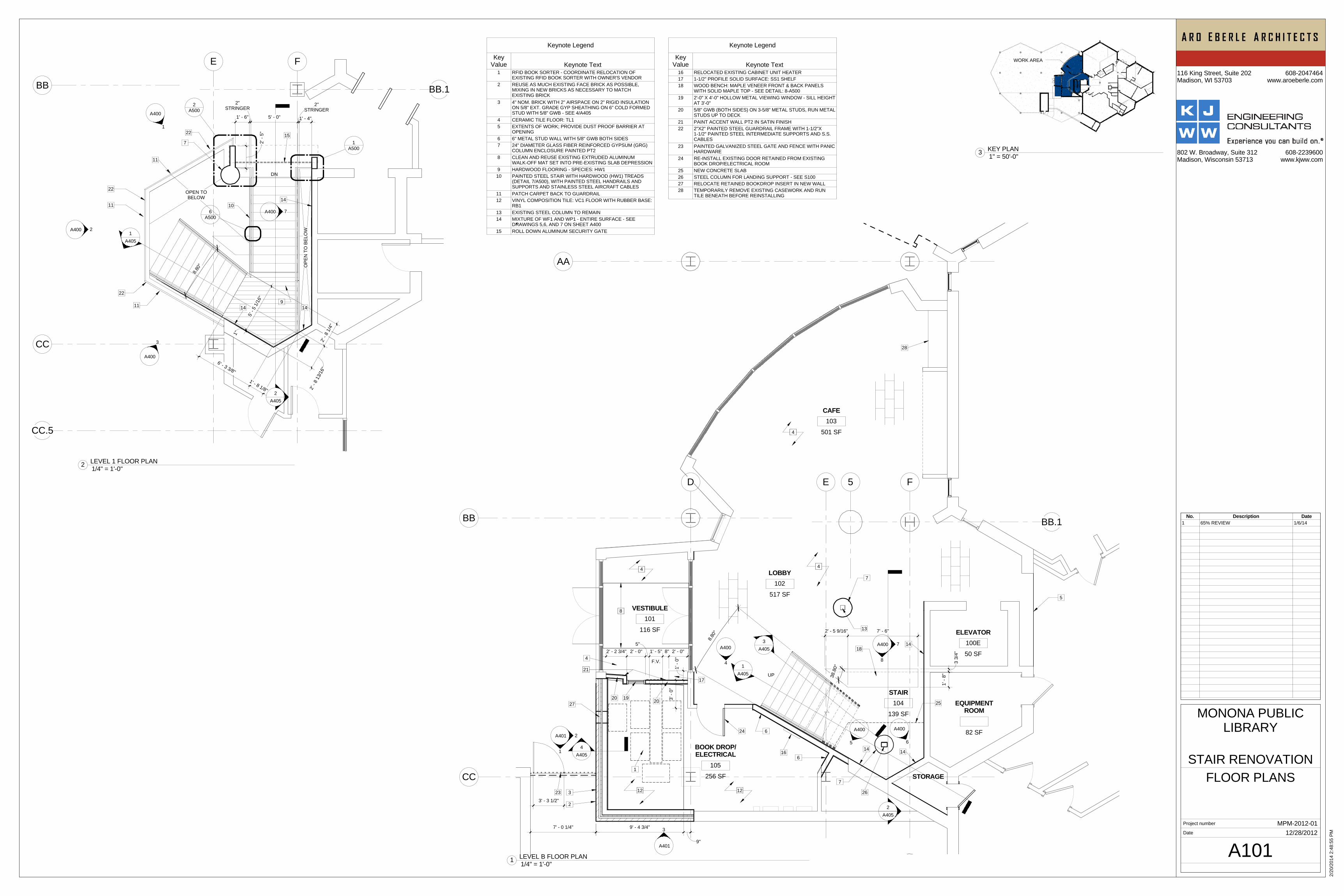
A101
FLOOR PLANS
MPM-2012-01
STAIR RENOVATION
MONONA PUBLICLIBRARY
12/28/2012
1/4" = 1'-0"1 LEVEL B FLOOR PLAN
1/4" = 1'-0"2 LEVEL 1 FLOOR PLAN
1" = 50'-0"3 KEY PLAN
Keynote Legend
KeyValue Keynote Text
16 RELOCATED EXISTING CABINET UNIT HEATER17 1-1/2" PROFILE SOLID SURFACE: SS1 SHELF18 WOOD BENCH: MAPLE VENEER FRONT & BACK PANELS
WITH SOLID MAPLE TOP - SEE DETAIL: 8-A50019 2'-0" X 4'-0" HOLLOW METAL VIEWING WINDOW - SILL HEIGHT
AT 3'-0"20 5/8" GWB (BOTH SIDES) ON 3-5/8" METAL STUDS, RUN METAL
STUDS UP TO DECK21 PAINT ACCENT WALL PT2 IN SATIN FINISH22 2"X2" PAINTED STEEL GUARDRAIL FRAME WITH 1-1/2"X
1-1/2" PAINTED STEEL INTERMEDIATE SUPPORTS AND S.S.CABLES
23 PAINTED GALVANIZED STEEL GATE AND FENCE WITH PANICHARDWARE
24 RE-INSTALL EXISTING DOOR RETAINED FROM EXISTINGBOOK DROP/ELECTRICAL ROOM
25 NEW CONCRETE SLAB26 STEEL COLUMN FOR LANDING SUPPORT - SEE S10027 RELOCATE RETAINED BOOKDROP INSERT IN NEW WALL28 TEMPORARILY REMOVE EXISTING CASEWORK AND RUN
TILE BENEATH BEFORE REINSTALLING
Keynote Legend
KeyValue Keynote Text
1 RFID BOOK SORTER - COORDINATE RELOCATION OFEXISTING RFID BOOK SORTER WITH OWNER'S VENDOR
2 REUSE AS MUCH EXISTING FACE BRICK AS POSSIBLE,MIXING IN NEW BRICKS AS NECESSARY TO MATCHEXISTING BRICK
3 4" NOM. BRICK WITH 2" AIRSPACE ON 2" RIGID INSULATIONON 5/8" EXT. GRADE GYP SHEATHING ON 6" COLD FORMEDSTUD WITH 5/8" GWB - SEE 4/A405
4 CERAMIC TILE FLOOR: TL15 EXTENTS OF WORK; PROVIDE DUST PROOF BARRIER AT
OPENING6 6" METAL STUD WALL WITH 5/8" GWB BOTH SIDES7 24" DIAMETER GLASS FIBER REINFORCED GYPSUM (GRG)
COLUMN ENCLOSURE PAINTED PT28 CLEAN AND REUSE EXISTING EXTRUDED ALUMINUM
WALK-OFF MAT SET INTO PRE-EXISTING SLAB DEPRESSION9 HARDWOOD FLOORING - SPECIES: HW110 PAINTED STEEL STAIR WITH HARDWOOD (HW1) TREADS
(DETAIL 7/A500), WITH PAINTED STEEL HANDRAILS ANDSUPPORTS AND STAINLESS STEEL AIRCRAFT CABLES
11 PATCH CARPET BACK TO GUARDRAIL12 VINYL COMPOSITION TILE: VC1 FLOOR WITH RUBBER BASE:
RB113 EXISTING STEEL COLUMN TO REMAIN14 MIXTURE OF WF1 AND WP1 - ENTIRE SURFACE - SEE
DRAWINGS 5,6, AND 7 ON SHEET A40015 ROLL DOWN ALUMINUM SECURITY GATE
No. Description Date1 65% REVIEW 1/6/14
OPEN TOBELOW
OPE
N T
O B
ELO
W
BB.1
5
FED
AA
BB
CC
1A405
2A405
3A405
116 SF
VESTIBULE101
256 SF
BOOK DROP/ELECTRICAL
105
139 SF
STAIR104
517 SF
LOBBY102
501 SF
CAFE103
50 SF
ELEVATOR100E
11
222
2
1
4A405
6
6
7
8
1
3
BB.1
5
FE
BB
CC
CC.5
1A405
2A405
34 5
99
Project number
Date
116 King Street, Suite 202Madison, WI 53703
608-2047464www.aroeberle.com
802 W. Broadway, Suite 312Madison, Wisconsin 53713
608-2239600www.kjww.com
2/20
/201
4 2:
48:5
7 PM
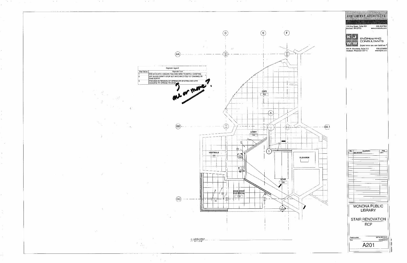
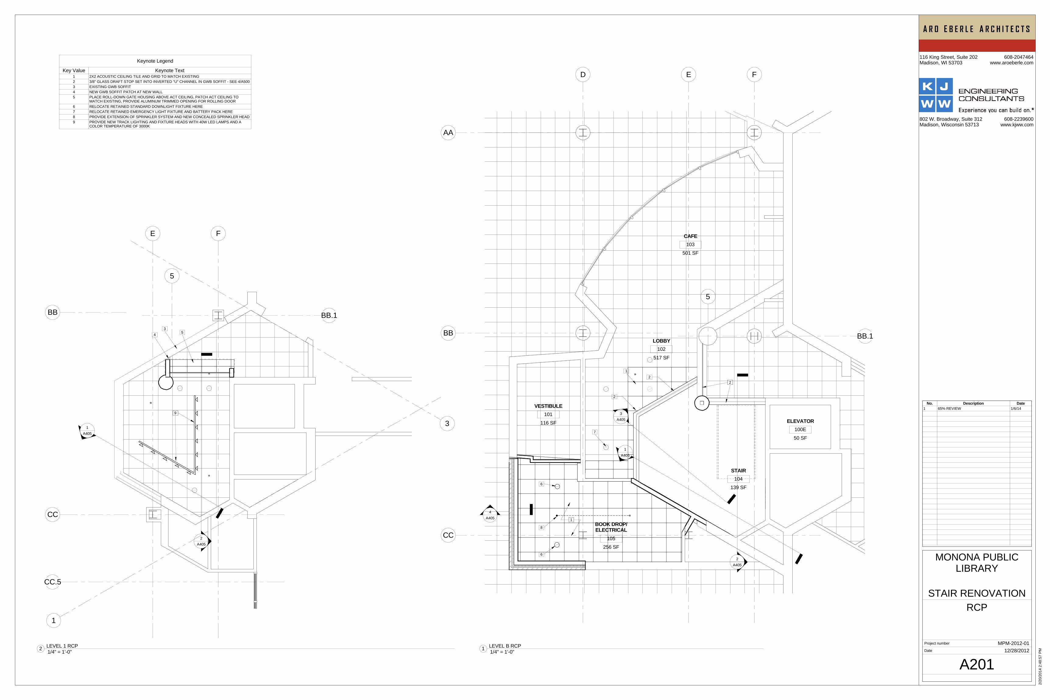
A201
RCP
MPM-2012-01
STAIR RENOVATION
MONONA PUBLICLIBRARY
12/28/2012 1/4" = 1'-0"1 LEVEL B RCP
Keynote Legend
Key Value Keynote Text1 2X2 ACOUSTIC CEILING TILE AND GRID TO MATCH EXISTING2 3/8" GLASS DRAFT STOP SET INTO INVERTED "U" CHANNEL IN GWB SOFFIT - SEE 4/A5003 EXISTING GWB SOFFIT4 NEW GWB SOFFIT PATCH AT NEW WALL5 PLACE ROLL-DOWN GATE HOUSING ABOVE ACT CEILING, PATCH ACT CEILING TO
MATCH EXISTING, PROVIDE ALUMINUM TRIMMED OPENING FOR ROLLING DOOR6 RELOCATE RETAINED STANDARD DOWNLIGHT FIXTURE HERE7 RELOCATE RETAINED EMERGENCY LIGHT FIXTURE AND BATTERY PACK HERE8 PROVIDE EXTENSION OF SPRINKLER SYSTEM AND NEW CONCEALED SPRINKLER HEAD9 PROVIDE NEW TRACK LIGHTING AND FIXTURE HEADS WITH 40W LED LAMPS AND A
COLOR TEMPERATURE OF 3000K
No. Description Date1 65% REVIEW 1/6/14
1/4" = 1'-0"2 LEVEL 1 RCP
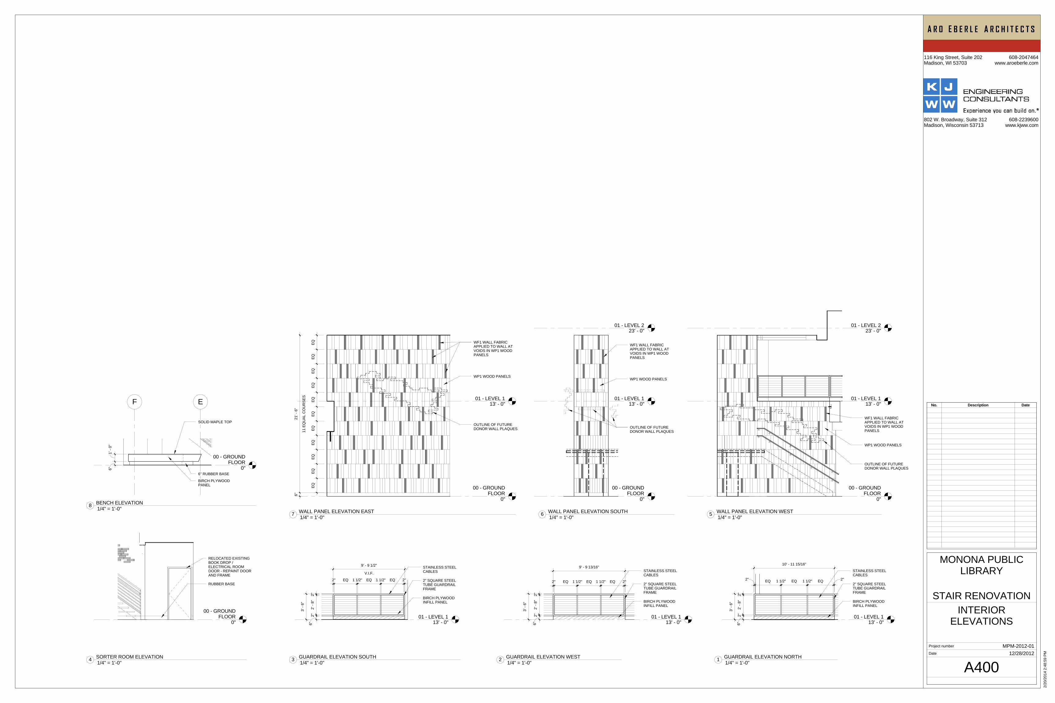
01 - LEVEL 113' - 0"
2"2'
- 8"
2"6"
3' -
6"
2" EQ 1 1/2" EQ 1 1/2" EQ 2" 2" SQUARE STEELTUBE GUARDRAILFRAME
STAINLESS STEELCABLES
BIRCH PLYWOODINFILL PANEL
9' - 9 13/16"
01 - LEVEL 113' - 0"
2" SQUARE STEELTUBE GUARDRAILFRAME
STAINLESS STEELCABLES
BIRCH PLYWOODINFILL PANEL
V.I.F.
9' - 9 1/2"
2" EQ 1 1/2" EQ 1 1/2" EQ 2"
2"2'
- 8"
2"6"
3' -
6"
00 - GROUNDFLOOR
0"
RELOCATED EXISTINGBOOK DROP /ELECTRICAL ROOMDOOR - REPAINT DOORAND FRAME
RUBBER BASE
00 - GROUNDFLOOR
0"
01 - LEVEL 113' - 0"
WF1 WALL FABRICAPPLIED TO WALL ATVOIDS IN WP1 WOODPANELS
WP1 WOOD PANELS
OUTLINE OF FUTUREDONOR WALL PLAQUES
EQEQ
EQEQ
EQEQ
EQEQ
EQEQ
EQ
11 E
QU
AL C
OU
RSE
S
21' -
6"
6"
00 - GROUNDFLOOR
0"
01 - LEVEL 113' - 0"
01 - LEVEL 223' - 0"
WF1 WALL FABRICAPPLIED TO WALL ATVOIDS IN WP1 WOODPANELS
WP1 WOOD PANELS
OUTLINE OF FUTUREDONOR WALL PLAQUES
00 - GROUNDFLOOR
0"
01 - LEVEL 113' - 0"
01 - LEVEL 223' - 0"
WF1 WALL FABRICAPPLIED TO WALL ATVOIDS IN WP1 WOODPANELS
WP1 WOOD PANELS
OUTLINE OF FUTUREDONOR WALL PLAQUES
00 - GROUNDFLOOR
0"
F E
1' -
0"6"
6" RUBBER BASE
BIRCH PLYWOODPANEL
SOLID MAPLE TOP
01 - LEVEL 113' - 0"
2"EQ1 1/2"EQ1 1/2"EQ2"
2"2'
- 8"
2"6"
3' -
6"
2" SQUARE STEELTUBE GUARDRAILFRAME
STAINLESS STEELCABLES
BIRCH PLYWOODINFILL PANEL
10' - 11 15/16"
Project number
Date
116 King Street, Suite 202Madison, WI 53703
608-2047464www.aroeberle.com
802 W. Broadway, Suite 312Madison, Wisconsin 53713
608-2239600www.kjww.com
2/20
/201
4 2:
48:5
9 PM
A400
INTERIORELEVATIONS
MPM-2012-01
STAIR RENOVATION
MONONA PUBLICLIBRARY
12/28/2012
No. Description Date
1/4" = 1'-0"2 GUARDRAIL ELEVATION WEST 1/4" = 1'-0"3 GUARDRAIL ELEVATION SOUTH
1/4" = 1'-0"4 SORTER ROOM ELEVATION
1/4" = 1'-0"7 WALL PANEL ELEVATION EAST 1/4" = 1'-0"6 WALL PANEL ELEVATION SOUTH
1/4" = 1'-0"5 WALL PANEL ELEVATION WEST 1/4" = 1'-0"8 BENCH ELEVATION
1/4" = 1'-0"1 GUARDRAIL ELEVATION NORTH
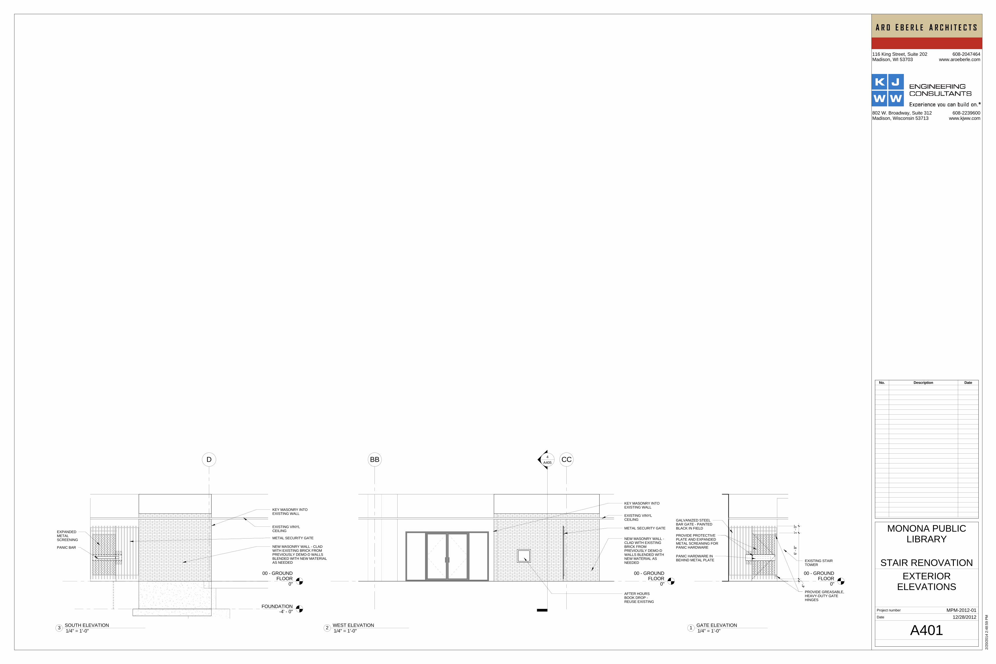
00 - GROUNDFLOOR
0"PROVIDE GREASABLE,HEAVY-DUTY GATEHINGES
EXISTING STAIRTOWER
PROVIDE PROTECTIVEPLATE AND EXPANDEDMETAL SCREANING FORPANIC HARDWARE
PANIC HARDWARE INBEHIND METAL PLATE
GALVANIZED STEELBAR GATE - PAINTEDBLACK IN FIELD
1' -
0"6'
- 8"
4"
00 - GROUNDFLOOR
0"
BB CC4A405
NEW MASONRY WALL -CLAD WITH EXISTINGBRICK FROMPREVIOUSLY DEMO-DWALLS BLENDED WITHNEW MATERIAL ASNEEDED
METAL SECURITY GATE
EXISTING VINYLCEILING
KEY MASONRY INTOEXISTING WALL
AFTER HOURSBOOK DROP -REUSE EXISTING
00 - GROUNDFLOOR
0"
D
FOUNDATION-4' - 0"
NEW MASONRY WALL - CLADWITH EXISTING BRICK FROMPREVIOUSLY DEMO-D WALLSBLENDED WITH NEW MATERIALAS NEEDED
METAL SECURITY GATE
EXISTING VINYLCEILING
KEY MASONRY INTOEXISTING WALL
PANIC BAR
EXPANDEDMETALSCREENING
Project number
Date
116 King Street, Suite 202Madison, WI 53703
608-2047464www.aroeberle.com
802 W. Broadway, Suite 312Madison, Wisconsin 53713
608-2239600www.kjww.com
2/20
/201
4 2:
48:5
9 PM
A401
EXTERIORELEVATIONS
MPM-2012-01
STAIR RENOVATION
MONONA PUBLICLIBRARY
12/28/2012
No. Description Date
1/4" = 1'-0"1 GATE ELEVATION 1/4" = 1'-0"2 WEST ELEVATION
1/4" = 1'-0"3 SOUTH ELEVATION
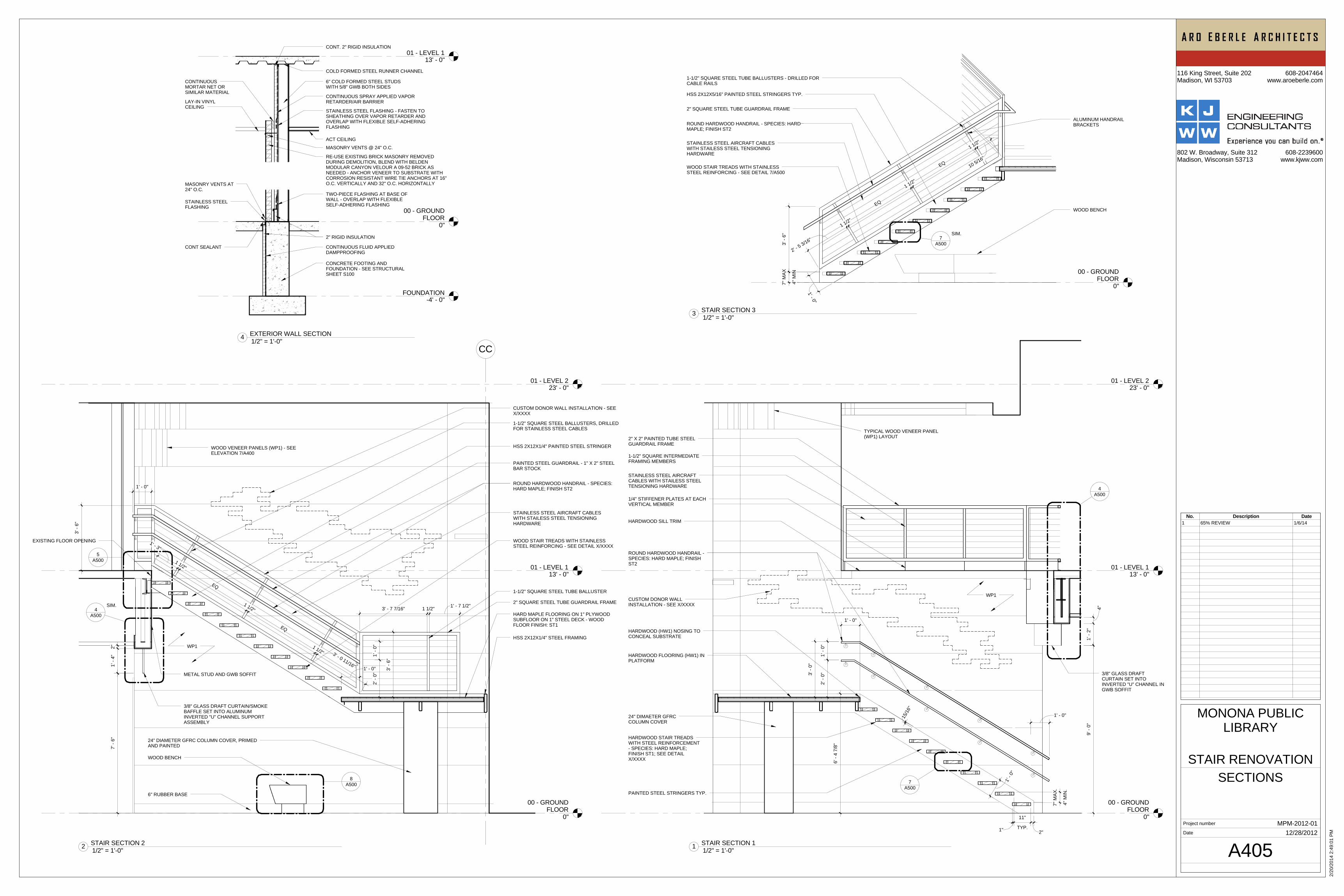
00 - GROUNDFLOOR
0"
01 - LEVEL 113' - 0"
01 - LEVEL 223' - 0"
1' - 0"
1' - 0"
3' -
0"
2"TYP.
11"
1"
4" M
IN.
7" M
AX.
1' -
2"
4"
9' -
0"
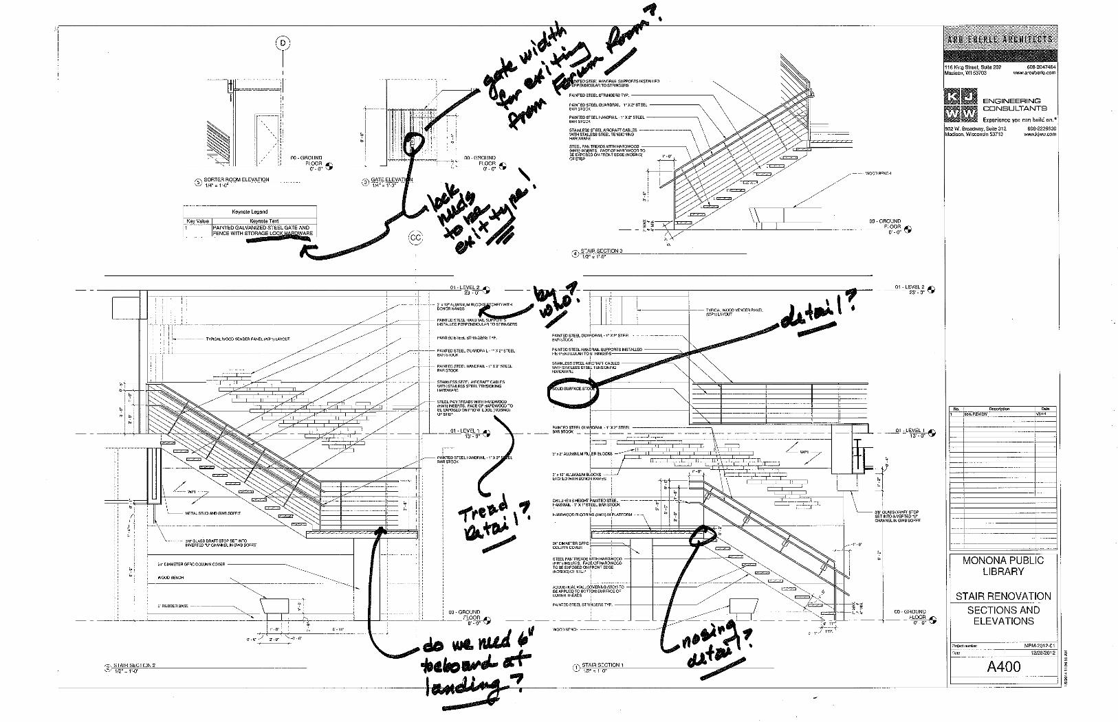
ROUND HARDWOOD HANDRAIL -SPECIES: HARD MAPLE; FINISHST2
HARDWOOD STAIR TREADSWITH STEEL REINFORCEMENT- SPECIES: HARD MAPLE;FINISH ST1; SEE DETAILX/XXXX
PAINTED STEEL STRINGERS TYP.
2" X 2" PAINTED TUBE STEELGUARDRAIL FRAME
STAINLESS STEEL AIRCRAFTCABLES WITH STAILESS STEELTENSIONING HARDWARE
HARDWOOD FLOORING (HW1) INPLATFORM
24" DIMAETER GFRCCOLUMN COVER
3/8" GLASS DRAFTCURTAIN SET INTOINVERTED "U" CHANNEL INGWB SOFFIT
TYPICAL WOOD VENEER PANEL(WP1) LAYOUT
WP1
2' -
0"1'
- 0"
CUSTOM DONOR WALLINSTALLATION - SEE X/XXXX
1' - 0
"
15/1
6"
A5007
6' -
4 7/
8"
A5004
1-1/2" SQUARE INTERMEDIATEFRAMING MEMBERS
1/4" STIFFENER PLATES AT EACHVERTICAL MEMBER
HARDWOOD SILL TRIM
HARDWOOD (HW1) NOSING TOCONCEAL SUBSTRATE
00 - GROUNDFLOOR
0"
01 - LEVEL 113' - 0"
CC
01 - LEVEL 223' - 0"
3/8" GLASS DRAFT CURTAIN/SMOKEBAFFLE SET INTO ALUMINUMINVERTED "U" CHANNEL SUPPORTASSEMBLY
1' -
4"2"
PAINTED STEEL GUARDRAIL - 1" X 2" STEELBAR STOCK
ROUND HARDWOOD HANDRAIL - SPECIES:HARD MAPLE; FINISH ST2
STAINLESS STEEL AIRCRAFT CABLESWITH STAILESS STEEL TENSIONINGHARDWARE
WOOD STAIR TREADS WITH STAINLESSSTEEL REINFORCING - SEE DETAIL X/XXXX
HSS 2X12X1/4" PAINTED STEEL STRINGER
1-1/2" SQUARE STEEL BALLUSTERS, DRILLEDFOR STAINLESS STEEL CABLES
METAL STUD AND GWB SOFFIT
7' -
6"
WOOD BENCH
6" RUBBER BASE
24" DIAMETER GFRC COLUMN COVER, PRIMEDAND PAINTED
WP1
WOOD VENEER PANELS (WP1) - SEEELEVATION 7/A400
2" SQUARE STEEL TUBE GUARDRAIL FRAME
CUSTOM DONOR WALL INSTALLATION - SEEX/XXXX
A5008
1' - 0"
1' -
0"2'
- 0"
1-1/2" SQUARE STEEL TUBE BALLUSTER
HARD MAPLE FLOORING ON 1" PLYWOODSUBFLOOR ON 1" STEEL DECK - WOODFLOOR FINISH: ST1
HSS 2X12X1/4" STEEL FRAMING
EXISTING FLOOR OPENING
3' - 0 11/16"
1 1/2"
EQ
1 1/2"
EQ
1 1/2"
1' - 3"
3' - 7 7/16" 1 1/2" 1' - 7 1/2"
A5005
A5004
SIM.
3' -
6"
1' - 0"
3' -
6"
00 - GROUNDFLOOR
0"4" M
IN
7" M
AX
2" SQUARE STEEL TUBE GUARDRAIL FRAME
ROUND HARDWOOD HANDRAIL - SPECIES: HARDMAPLE; FINISH ST2
STAINLESS STEEL AIRCRAFT CABLESWITH STAILESS STEEL TENSIONINGHARDWARE
WOOD STAIR TREADS WITH STAINLESSSTEEL REINFORCING - SEE DETAIL 7/A500
HSS 2X12X5/16" PAINTED STEEL STRINGERS TYP.
WOOD BENCH
1-1/2" SQUARE STEEL TUBE BALLUSTERS - DRILLED FORCABLE RAILS
1' - 0"
3' -
6"
ALUMINUM HANDRAILBRACKETS
A5007
SIM.
2' - 5 3/16"
1 1/2"
EQ
1 1/2"
EQ
1 1/2"
10 5/16"
00 - GROUNDFLOOR
0"
01 - LEVEL 113' - 0"
FOUNDATION-4' - 0"
6" COLD FORMED STEEL STUDSWITH 5/8" GWB BOTH SIDES
COLD FORMED STEEL RUNNER CHANNEL
CONTINUOUS SPRAY APPLIED VAPORRETARDER/AIR BARRIER
STAINLESS STEEL FLASHING - FASTEN TOSHEATHING OVER VAPOR RETARDER ANDOVERLAP WITH FLEXIBLE SELF-ADHERINGFLASHING
ACT CEILING
MASONRY VENTS @ 24" O.C.
RE-USE EXISTING BRICK MASONRY REMOVEDDURING DEMOLITION, BLEND WITH BELDENMODULAR CANYON VELOUR A 09-52 BRICK ASNEEDED - ANCHOR VENEER TO SUBSTRATE WITHCORROSION RESISTANT WIRE TIE ANCHORS AT 16"O.C. VERTICALLY AND 32" O.C. HORIZONTALLY
TWO-PIECE FLASHING AT BASE OFWALL - OVERLAP WITH FLEXIBLESELF-ADHERING FLASHING
2" RIGID INSULATION
CONT. 2" RIGID INSULATION
CONTINUOUSMORTAR NET ORSIMILAR MATERIAL
LAY-IN VINYLCEILING
CONTINUOUS FLUID APPLIEDDAMPPROOFING
CONCRETE FOOTING ANDFOUNDATION - SEE STRUCTURALSHEET S100
MASONRY VENTS AT24" O.C.
STAINLESS STEELFLASHING
CONT SEALANT
Project number
Date
116 King Street, Suite 202Madison, WI 53703
608-2047464www.aroeberle.com
802 W. Broadway, Suite 312Madison, Wisconsin 53713
608-2239600www.kjww.com
2/20
/201
4 2:
49:0
1 PM
A405
SECTIONS
MPM-2012-01
STAIR RENOVATION
MONONA PUBLICLIBRARY
12/28/2012
1/2" = 1'-0"1 STAIR SECTION 1 1/2" = 1'-0"2 STAIR SECTION 2
1/2" = 1'-0"3 STAIR SECTION 3
No. Description Date1 65% REVIEW 1/6/14
1/2" = 1'-0"4 EXTERIOR WALL SECTION
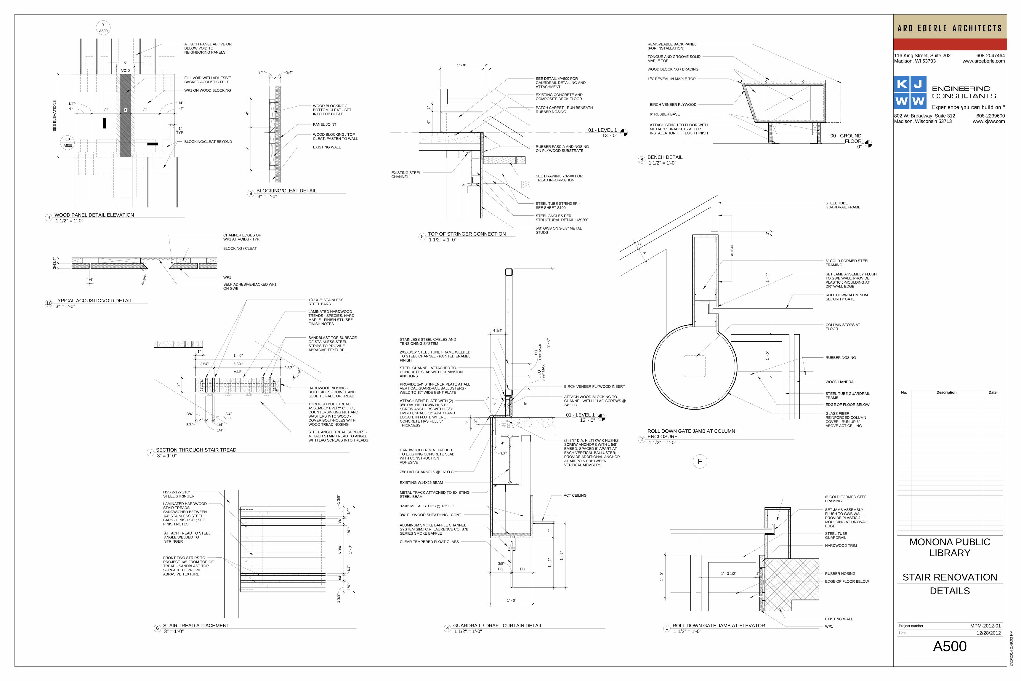
F
1' -
0"
EXISTING WALL
WP1
HARDWOOD TRIM
STEEL TUBEGUARDRAIL
1"1' - 3 1/2" RUBBER NOSING
EDGE OF FLOOR BELOW
SET JAMB ASSEMBLYFLUSH TO GWB WALL,PROVIDE PLASTIC J-MOULDING AT DRYWALLEDGE
6" COLD FORMED STEELFRAMING
EDGE OF FLOOR BELOW
GLASS FIBERREINFORCED COLUMNCOVER - RUN UP 6"ABOVE ACT CEILING
1' -
0"2'
- 4"
1"
4"
2"
ALIG
N
STEEL TUBE GUARDRAILFRAME
WOOD HANDRAIL
ROLL DOWN ALUMINUMSECURITY GATE
SET JAMB ASSEMBLY FLUSHTO GWB WALL, PROVIDEPLASTIC J-MOULDING ATDRYWALL EDGE
6" COLD-FORMED STEELFRAMING
STEEL TUBEGUARDRAIL FRAME
COLUMN STOPS ATFLOOR
RUBBER NOSING
1' -
0"
1 3/
8"
1/4"
3/4"
1/4"
6 3/
4"
1/4"
3/4"
1/4"
1 3/
8"
HSS 2x12x5/16"STEEL STRINGER
LAMINATED HARDWOODSTAIR TREADSSANDWICHED BETWEEN1/4" STAINLESS STEELBARS - FINISH ST1; SEEFINISH NOTES
FRONT TWO STRIPS TOPROJECT 1/8" FROM TOP OFTREAD - SANDBLAST TOPSURFACE TO PROVIDEABRASIVE TEXTURE
ATTACH TREAD TO STEELANGLE WELDED TOSTRINGER
2"
5/8"
3/4"
1/4"
V.I.F.3/4"
1/4"
1' - 0"1"
1/8"
SANDBLAST TOP SURFACEOF STAINLESS STEELSTRIPS TO PROVIDEABRASIVE TEXTURE
LAMINATED HARDWOODTREADS - SPECIES: HARDMAPLE - FINISH ST1; SEEFINISH NOTES
2 5/8"
V.I.F.
6 3/4"2 5/8"
THROUGH BOLT TREADASSEMBLY EVERY 8" O.C.,COUNTERSINKING NUT ANDWASHERS INTO WOOD -COVER BOLT-HOLES WITHWOOD TREAD NOSING
HARDWOOD NOSING -BOTH SIDES - DOWEL ANDGLUE TO FACE OF TREAD
1/4" X 2" STAINLESSSTEEL BARS
STEEL ANGLE TREAD SUPPORT -ATTACH STAIR TREAD TO ANGLEWITH LAG SCREWS INTO TREADS
00 - GROUNDFLOOR
0"
ATTACH BENCH TO FLOOR WITHMETAL "L" BRACKETS AFTERINSTALLATION OF FLOOR FINISH
6" RUBBER BASE
BIRCH VENEER PLYWOOD
TONGUE AND GROOVE SOLIDMAPLE TOP
REMOVEABLE BACK PANEL(FOR INSTALLATION)
WOOD BLOCKING / BRACING
1/8" REVEAL IN MAPLE TOP
01 - LEVEL 113' - 0"
2"6"
1' - 0" 2"
5/8" GWB ON 3-5/8" METALSTUDS
STEEL ANGLES PERSTRUCTURAL DETAIL 16/S200
STEEL TUBE STRINGER -SEE SHEET S100
SEE DRAWING 7/A500 FORTREAD INFORMATION
RUBBER FASCIA AND NOSINGON PLYWOOD SUBSTRATE
PATCH CARPET - RUN BENEATHRUBBER NOSING
EXISTING CONCRETE ANDCOMPOSITE DECK FLOOR
EXISTING STEELCHANNEL
SEE DETAIL 4/A500 FORGAURDRAIL DETAILING ANDATTACHMENT
01 - LEVEL 113' - 0"
4"
7/8"
1' -
6"
1' -
2"4"
1' - 0"
EQ3/8"EQ
8"
3.99
" MAX
EQ3.
99" M
AXEQ
CLEAR TEMPERED FLOAT GLASS
ALUMINUM SMOKE BAFFLE CHANNELSYSTEM SIM.: C.R. LAURENCE CO. B7BSERIES SMOKE BAFFLE
3/4" PLYWOOD SHEATHING - CONT.
3-5/8" METAL STUDS @ 16" O.C.
METAL TRACK ATTACHED TO EXISTINGSTEEL BEAM
EXISTING W14X26 BEAM
7/8" HAT CHANNELS @ 16" O.C.
HARDWOOD TRIM ATTACHEDTO EXISTING CONCRETE SLABWITH CONSTRUCTIONADHESIVE
STEEL CHANNEL ATTACHED TOCONCRETE SLAB WITH EXPANSIONANCHORS
ATTACH WOOD BLOCKING TOCHANNEL WITH 1" LAG SCREWS @24" O.C.
BIRCH VENEER PLYWOOD INSERT
2X2X3/16" STEEL TUNE FRAME WELDEDTO STEEL CHANNEL - PAINTED ENAMELFINISH
STAINLESS STEEL CABLES ANDTENSIONING SYSTEM
3' -
6"
ACT CEILING
4 1/4"
PROVIDE 1/4" STIFFENER PLATE AT ALLVERTICAL GUARDRAIL BALLUSTERS -WELD TO 15" WIDE BENT PLATE
3"
3"
2"
ATTACH BENT PLATE WITH (2)3/8" DIA. HILTI KWIK HUS-EZSCREW ANCHORS WITH 1 5/8"EMBED, SPACE 12" APART ANDLOCATE IN FLUTE WHERECONCRETE HAS FULL 5"THICKNESS
(2) 3/8" DIA. HILTI KWIK HUS-EZSCREW ANCHORS WITH 1 5/8"EMBED, SPACED 6" APART ATEACH VERTICAL BALLUSTER;PROVIDE ADDITIONAL ANCHORAT MIDPOINT BETWEENVERTICAL MEMBERS
SEE
ELEV
ATIO
NS
4"1/4"
8" 3" 8"
1/4"4"
FILL VOID WITH ADHESIVEBACKED ACOUSTIC FELT
WP1 ON WOOD BLOCKING
TYP.1"
VOID
5"
ATTACH PANEL ABOVE ORBELOW VOID TONEIGHBORING PANELS
BLOCKING/CLEAT BEYOND
9
A500
10
A500
WOOD BLOCKING /BOTTOM CLEAT - SETINTO TOP CLEAT
WOOD BLOCKING / TOPCLEAT, FASTEN TO WALL
PANEL JOINT
4"6" EXISTING WALL
3/4" 3/4"
SELF ADHESIVE-BACKED WF1ON GWB
WP1
CHAMFER EDGES OFWP1 AT VOIDS - TYP.
BLOCKING / CLEAT
3/4"3
/4"
1/4"
45.0
0°
Project number
Date
116 King Street, Suite 202Madison, WI 53703
608-2047464www.aroeberle.com
802 W. Broadway, Suite 312Madison, Wisconsin 53713
608-2239600www.kjww.com
2/20
/201
4 2:
49:0
3 PM
A500
DETAILS
MPM-2012-01
STAIR RENOVATION
MONONA PUBLICLIBRARY
12/28/2012
No. Description Date
1 1/2" = 1'-0"1 ROLL DOWN GATE JAMB AT ELEVATOR
1 1/2" = 1'-0"2
ROLL DOWN GATE JAMB AT COLUMNENCLOSURE
3" = 1'-0"6 STAIR TREAD ATTACHMENT
3" = 1'-0"7 SECTION THROUGH STAIR TREAD
1 1/2" = 1'-0"8 BENCH DETAIL
1 1/2" = 1'-0"5 TOP OF STRINGER CONNECTION
1 1/2" = 1'-0"4 GUARDRAIL / DRAFT CURTAIN DETAIL
1 1/2" = 1'-0"3 WOOD PANEL DETAIL ELEVATION
3" = 1'-0"9 BLOCKING/CLEAT DETAIL
3" = 1'-0"10 TYPICAL ACOUSTIC VOID DETAIL
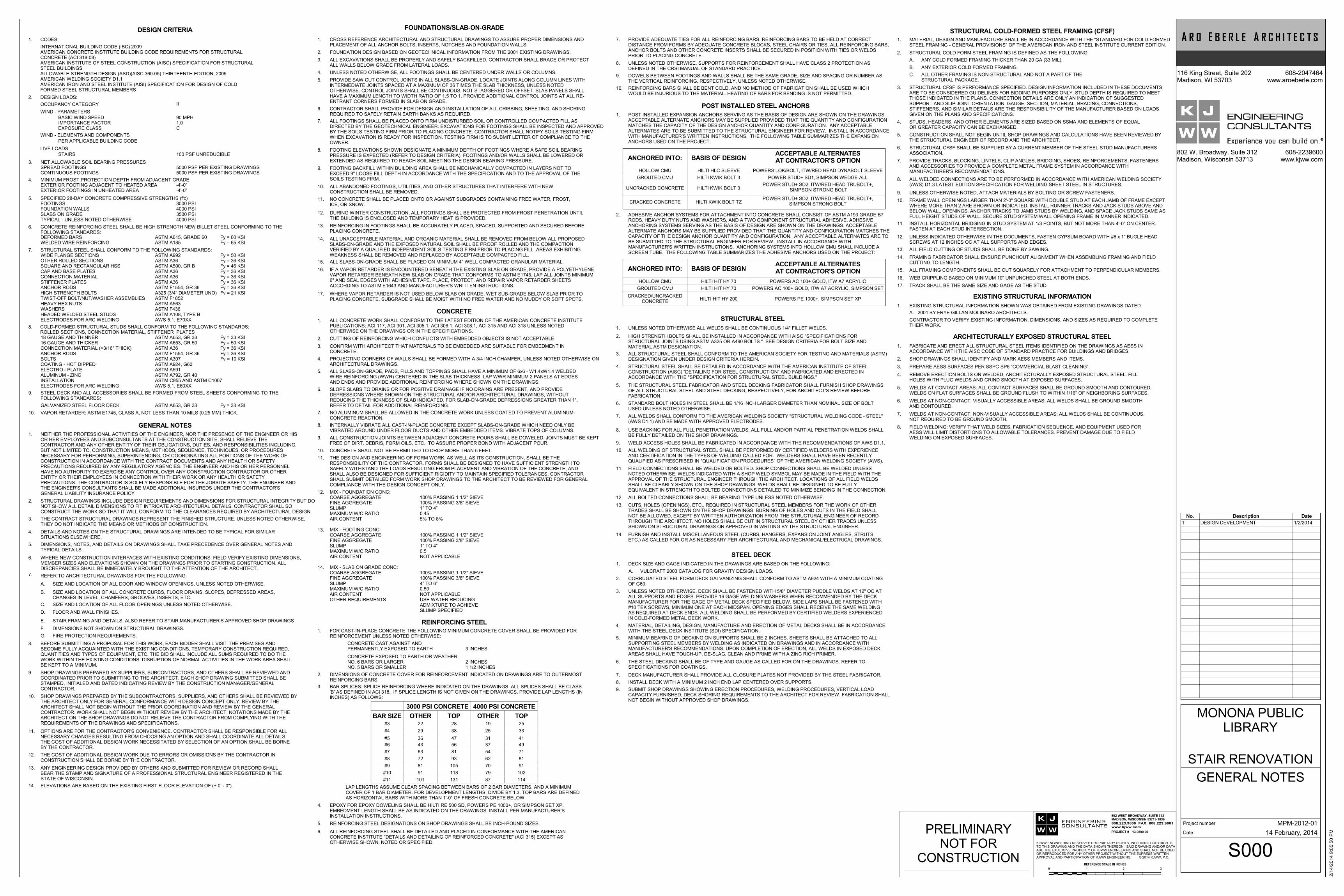
INTERNATIONAL BUILDING CODE (IBC) 2009AMERICAN CONCRETE INSTITUTE BUILDING CODE REQUIREMENTS FOR STRUCTURALCONCRETE (ACI 318-08)AMERICAN INSTITUTE OF STEEL CONSTRUCTION (AISC) SPECIFICATION FOR STRUCTURALSTEEL BUILDINGSALLOWABLE STRENGTH DESIGN (ASD)(AISC 360-05) THIRTEENTH EDITION, 2005AMERICAN WELDING SOCIETY D1.1AMERICAN IRON AND STEEL INSTITUTE (AISI) SPECIFICATION FOR DESIGN OF COLDFORMED STEEL STRUCTURAL MEMBERS
CODES:1.
DESIGN LOADS:2.
DESIGN CRITERIA
WIND - PARAMETERS
BASIC WIND SPEEDIMPORTANCE FACTOREXPOSURE CLASS
90 MPH1.0C
WIND - ELEMENTS AND COMPONENTS
PER APPLICABLE BUILDING CODE
LIVE LOADS
STAIRS 100 PSF UNREDUCIBLE
NET ALLOWABLE SOIL BEARING PRESSURES3.SPREAD FOOTINGSCONTINUOUS FOOTINGS
5000 PSF PER EXISTING DRAWINGS5000 PSF PER EXISTING DRAWINGS
MINIMUM FROST PROTECTION DEPTH FROM ADJACENT GRADE:4.EXTERIOR FOOTING ADJACENT TO HEATED AREAEXTERIOR FOOTINGS IN UNHEATED AREA
-4'-0"-4'-0"
SPECIFIED 28-DAY CONCRETE COMPRESSIVE STRENGTHS (f'c)5.FOOTINGSFOUNDATION WALLSSLABS ON GRADETYPICAL - UNLESS NOTED OTHERWISE
3000 PSI4000 PSI3500 PSI4000 PSI
CONCRETE REINFORCING STEEL SHALL BE HIGH STRENGTH NEW BILLET STEEL CONFORMING TO THEFOLLOWING STANDARDS:
6.
DEFORMED BARSWELDED WIRE REINFORCING
ASTM A615, GRADE 60ASTM A185
Fy = 60 KSIFy = 65 KSI
STRUCTURAL STEEL SHALL CONFORM TO THE FOLLOWING STANDARDS:7.WIDE FLANGE SECTIONSOTHER ROLLED SECTIONSSQUARE AND RECTANGULAR HSSCAP AND BASE PLATESCONNECTION MATERIALSTIFFENER PLATESANCHOR RODSHIGH STRENGTH BOLTSTWIST-OFF BOLT/NUT/WASHER ASSEMBLIESHEAVY HEX NUTSWASHERSHEADED WELDED STEEL STUDSELECTRODES FOR ARC WELDING
ASTM A992ASTM A36ASTM A500, GR BASTM A36ASTM A36ASTM A36ASTM F1554, GR 36A325 (3/4" DIAMETER UNO)ASTM F1852ASTM A563ASTM F436ASTM A108, TYPE BAWS 5.1, E70XX
Fy = 50 KSIFy = 36 KSIFy = 46 KSIFy = 36 KSIFy = 36 KSIFy = 36 KSIFy = 36 KSIFv = 21 KSI
COLD-FORMED STRUCTURAL STUDS SHALL CONFORM TO THE FOLLOWING STANDARDS:8.ROLLED SECTIONS, CONNECTION MATERIAL, STIFFENER PLATES18 GAUGE AND THINNER16 GAUGE AND THICKERCONNECTION MATERIAL (>3/16" THICK)ANCHOR RODSBOLTSCOATING - HOT DIPPEDELECTRO - PLATEALUMINUM - ZINCINSTALLATIONELECTRODES FOR ARC WELDING
ASTM A653, GR 33ASTM A653, GR 50ASTM A36ASTM F1554, GR 36ASTM A307ASTM A924, G60ASTM A591ASTM A792, GR 40ASTM C955 AND ASTM C1007AWS 5.1, E60XX
Fy = 33 KSIFy = 50 KSIFy = 36 KSIFy = 36 KSIFv = 10 KSI
STEEL DECK AND ALL ACCESSORIES SHALL BE FORMED FROM STEEL SHEETS CONFORMING TO THEFOLLOWING STANDARDS:
9.
ASTM A653, GR 33
NEITHER THE PROFESSIONAL ACTIVITIES OF THE ENGINEER, NOR THE PRESENCE OF THE ENGINEER OR HISOR HER EMPLOYEES AND SUBCONSULTANTS AT THE CONSTRUCTION SITE, SHALL RELIEVE THECONTRACTOR AND ANY OTHER ENTITY OF THEIR OBLIGATIONS, DUTIES, AND RESPONSIBILITIES INCLUDING,BUT NOT LIMITED TO, CONSTRUCTION MEANS, METHODS, SEQUENCE, TECHNIQUES, OR PROCEDURESNECESSARY FOR PERFORMING, SUPERINTENDING, OR COORDINATING ALL PORTIONS OF THE WORK OFCONSTRUCTION IN ACCORDANCE WITH THE CONTRACT DOCUMENTS AND ANY HEALTH OR SAFETYPRECAUTIONS REQUIRED BY ANY REGULATORY AGENCIES. THE ENGINEER AND HIS OR HER PERSONNELHAVE NO AUTHORITY TO EXERCISE ANY CONTROL OVER ANY CONSTRUCTION CONTRACTOR OR OTHERENTITY OR THEIR EMPLOYEES IN CONNECTION WITH THEIR WORK OR ANY HEALTH OR SAFETYPRECAUTIONS. THE CONTRACTOR IS SOLELY RESPONSIBLE FOR THE JOBSITE SAFETY. THE ENGINEER ANDTHE ENGINEER'S CONSULTANTS SHALL BE MADE ADDITIONAL INSUREDS UNDER THE CONTRACTOR'SGENERAL LIABILITY INSURANCE POLICY.
1.
STRUCTURAL DRAWINGS INCLUDE DESIGN REQUIREMENTS AND DIMENSIONS FOR STRUCTURAL INTEGRITY BUT DONOT SHOW ALL DETAIL DIMENSIONS TO FIT INTRICATE ARCHITECTURAL DETAILS. CONTRACTOR SHALL SOCONSTRUCT THE WORK SO THAT IT WILL CONFORM TO THE CLEARANCES REQUIRED BY ARCHITECTURAL DESIGN.
THE CONTRACT STRUCTURAL DRAWINGS REPRESENT THE FINISHED STRUCTURE. UNLESS NOTED OTHERWISE,THEY DO NOT INDICATE THE MEANS OR METHODS OF CONSTRUCTION.
DETAILS AND NOTES ON THE STRUCTURAL DRAWINGS ARE INTENDED TO BE TYPICAL FOR SIMILARSITUATIONS ELSEWHERE.
2.
3.
4.
GENERAL NOTES
DIMENSIONS, NOTES, AND DETAILS ON DRAWINGS SHALL TAKE PRECEDENCE OVER GENERAL NOTES ANDTYPICAL DETAILS.
WHERE NEW CONSTRUCTION INTERFACES WITH EXISTING CONDITIONS, FIELD VERIFY EXISTING DIMENSIONS,MEMBER SIZES AND ELEVATIONS SHOWN ON THE DRAWINGS PRIOR TO STARTING CONSTRUCTION. ALLDISCREPANCIES SHALL BE IMMEDIATELY BROUGHT TO THE ATTENTION OF THE ARCHITECT.
5.
6.
REFER TO ARCHITECTURAL DRAWINGS FOR THE FOLLOWING:
SIZE AND LOCATION OF ALL DOOR AND WINDOW OPENINGS, UNLESS NOTED OTHERWISE.
SIZE AND LOCATION OF ALL CONCRETE CURBS, FLOOR DRAINS, SLOPES, DEPRESSED AREAS,CHANGES IN LEVEL, CHAMFERS, GROOVES, INSERTS, ETC.
SIZE AND LOCATION OF ALL FLOOR OPENINGS UNLESS NOTED OTHERWISE.
FLOOR AND WALL FINISHES.
STAIR FRAMING AND DETAILS. ALSO REFER TO STAIR MANUFACTURER'S APPROVED SHOP DRAWINGS
DIMENSIONS NOT SHOWN ON STRUCTURAL DRAWINGS.
FIRE PROTECTION REQUIREMENTS.
7.
A.
B.
C.
D.
E.
F.
G.
BEFORE SUBMITTING A PROPOSAL FOR THIS WORK, EACH BIDDER SHALL VISIT THE PREMISES ANDBECOME FULLY ACQUAINTED WITH THE EXISTING CONDITIONS, TEMPORARY CONSTRUCTION REQUIRED,QUANTITIES AND TYPES OF EQUIPMENT, ETC. THE BID SHALL INCLUDE ALL SUMS REQUIRED TO DO THEWORK WITHIN THE EXISTING CONDITIONS. DISRUPTION OF NORMAL ACTIVITIES IN THE WORK AREA SHALLBE KEPT TO A MINIMUM.
8.
SHOP DRAWINGS PREPARED BY SUPPLIERS, SUBCONTRACTORS, AND OTHERS SHALL BE REVIEWED ANDCOORDINATED PRIOR TO SUBMITTING TO THE ARCHITECT. EACH SHOP DRAWING SUBMITTED SHALL BESTAMPED, INITIALED AND DATED INDICATING REVIEW BY THE CONSTRUCTION MANAGER/GENERALCONTRACTOR.
9.
SHOP DRAWINGS PREPARED BY THE SUBCONTRACTORS, SUPPLIERS, AND OTHERS SHALL BE REVIEWED BYTHE ARCHITECT ONLY FOR GENERAL CONFORMANCE WITH DESIGN CONCEPT ONLY. REVIEW BY THEARCHITECT SHALL NOT BEGIN WITHOUT THE PRIOR COORDINATION AND REVIEW BY THE GENERALCONTRACTOR. WORK SHALL NOT BEGIN WITHOUT REVIEW BY THE ARCHITECT. NOTATIONS MADE BY THEARCHITECT ON THE SHOP DRAWINGS DO NOT RELIEVE THE CONTRACTOR FROM COMPLYING WITH THEREQUIREMENTS OF THE DRAWINGS AND SPECIFICATIONS.
10.
OPTIONS ARE FOR THE CONTRACTOR'S CONVENIENCE. CONTRACTOR SHALL BE RESPONSIBLE FOR ALLNECESSARY CHANGES RESULTING FROM CHOOSING AN OPTION AND SHALL COORDINATE ALL DETAILS.THE COST OF ADDITIONAL DESIGN WORK NECESSITATED BY SELECTION OF AN OPTION SHALL BE BORNEBY THE CONTRACTOR.
11.
THE COST OF ADDITIONAL DESIGN WORK DUE TO ERRORS OR OMISSIONS BY THE CONTRACTOR INCONSTRUCTION SHALL BE BORNE BY THE CONTRACTOR.
12.
ANY ENGINEERING DESIGN PROVIDED BY OTHERS AND SUBMITTED FOR REVIEW OR RECORD SHALLBEAR THE STAMP AND SIGNATURE OF A PROFESSIONAL STRUCTURAL ENGINEER REGISTERED IN THESTATE OF WISCONSIN.
13.
ELEVATIONS ARE BASED ON THE EXISTING FIRST FLOOR ELEVATION OF (+ 0' - 0").14.
CROSS REFERENCE ARCHITECTURAL AND STRUCTURAL DRAWINGS TO ASSURE PROPER DIMENSIONS ANDPLACEMENT OF ALL ANCHOR BOLTS, INSERTS, NOTCHES AND FOUNDATION WALLS.
1.
FOUNDATIONS/SLAB-ON-GRADE
FOUNDATION DESIGN BASED ON GEOTECHNICAL INFORMATION FROM THE 2001 EXISTING DRAWINGS.2.
ALL EXCAVATIONS SHALL BE PROPERLY AND SAFELY BACKFILLED. CONTRACTOR SHALL BRACE OR PROTECTALL WALLS BELOW GRADE FROM LATERAL LOADS.
3.
UNLESS NOTED OTHERWISE, ALL FOOTINGS SHALL BE CENTERED UNDER WALLS OR COLUMNS.4.
PROVIDE SAW CUT CONTROL JOINTS IN ALL SLABS-ON-GRADE. LOCATE JOINTS ALONG COLUMN LINES WITHINTERMEDIATE JOINTS SPACED AT A MAXIMUM OF 36 TIMES THE SLAB THICKNESS, UNLESS NOTEDOTHERWISE. CONTROL JOINTS SHALL BE CONTINUOUS, NOT STAGGERED OR OFFSET. SLAB PANELS SHALLHAVE A MAXIMUM LENGTH TO WIDTH RATIO OF 1.5 TO 1. PROVIDE ADDITIONAL CONTROL JOINTS AT ALL RE-ENTRANT CORNERS FORMED IN SLAB ON GRADE.
5.
CONTRACTOR SHALL PROVIDE FOR DESIGN AND INSTALLATION OF ALL CRIBBING, SHEETING, AND SHORINGREQUIRED TO SAFELY RETAIN EARTH BANKS AS REQUIRED.
6.
ALL FOOTINGS SHALL BE PLACED ONTO FIRM UNDISTURBED SOIL OR CONTROLLED COMPACTED FILL ASDIRECTED BY THE GEOTECHNICAL ENGINEER. EXCAVATIONS FOR FOOTINGS SHALL BE INSPECTED AND APPROVEDBY THE SOILS TESTING FIRM PRIOR TO PLACING CONCRETE. CONTRACTOR SHALL NOTIFY SOILS TESTING FIRMWHEN EXCAVATION IS READY FOR INSPECTION. TESTING FIRM IS TO SUBMIT LETTER OF COMPLIANCE TO THEOWNER.
7.
FOOTING ELEVATIONS SHOWN DESIGNATE A MINIMUM DEPTH OF FOOTINGS WHERE A SAFE SOIL BEARINGPRESSURE IS EXPECTED (REFER TO DESIGN CRITERIA). FOOTINGS AND/OR WALLS SHALL BE LOWERED OREXTENDED AS REQUIRED TO REACH SOIL MEETING THE DESIGN BEARING PRESSURE.
8.
FOOTING BACKFILL WITHIN BUILDING AREA SHALL BE MECHANICALLY COMPACTED IN LAYERS NOT TOEXCEED 9" LOOSE FILL DEPTH IN ACCORDANCE WITH THE SPECIFICATION AND TO THE APPROVAL OF THESOILS TESTING FIRM.
9.
ALL ABANDONED FOOTINGS, UTILITIES, AND OTHER STRUCTURES THAT INTERFERE WITH NEWCONSTRUCTION SHALL BE REMOVED.
10.
NO CONCRETE SHALL BE PLACED ONTO OR AGAINST SUBGRADES CONTAINING FREE WATER, FROST,ICE, OR SNOW.
11.
DURING WINTER CONSTRUCTION, ALL FOOTINGS SHALL BE PROTECTED FROM FROST PENETRATION UNTILTHE BUILDING IS ENCLOSED AND TEMPORARY HEAT IS PROVIDED.
12.
REINFORCING IN FOOTINGS SHALL BE ACCURATELY PLACED, SPACED, SUPPORTED AND SECURED BEFOREPLACING CONCRETE.
13.
ALL UNACCEPTABLE MATERIAL AND ORGANIC MATERIAL SHALL BE REMOVED FROM BELOW ALL PROPOSEDSLABS-ON-GRADE AND THE EXPOSED NATURAL SOIL SHALL BE PROOF ROLLED AND THE COMPACTIONVERIFIED BY A QUALIFIED INDEPENDENT SOILS TESTING FIRM PRIOR TO PLACING FILL. AREAS EXHIBITINGWEAKNESS SHALL BE REMOVED AND REPLACED BY ACCEPTABLE COMPACTED FILL.
14.
ALL SLABS-ON-GRADE SHALL BE PLACED ON MINIMUM 4" WELL COMPACTED GRANULAR MATERIAL.15.
CONCRETE
ALL CONCRETE WORK SHALL CONFORM TO THE LATEST EDITION OF THE AMERICAN CONCRETE INSTITUTEPUBLICATIONS: ACI 117, ACI 301, ACI 305.1, ACI 306.1, ACI 308.1, ACI 315 AND ACI 318 UNLESS NOTEDOTHERWISE ON THE DRAWINGS OR IN THE SPECIFICATIONS.
1.
CUTTING OF REINFORCING WHICH CONFLICTS WITH EMBEDDED OBJECTS IS NOT ACCEPTABLE.2.
CONFIRM WITH ARCHITECT THAT MATERIALS TO BE EMBEDDED ARE SUITABLE FOR EMBEDMENT INCONCRETE.
3.
PROJECTING CORNERS OF WALLS SHALL BE FORMED WITH A 3/4 INCH CHAMFER, UNLESS NOTED OTHERWISE ONARCHITECTURAL DRAWINGS.
4.
ALL SLABS-ON-GRADE, PADS, FILLS AND TOPPINGS SHALL HAVE A MINIMUM OF 6x6 - W1.4xW1.4 WELDEDWIRE REINFORCING (WWR) CENTERED IN THE SLAB THICKNESS. LAP WWR MINIMUM 2 PANELS AT EDGESAND ENDS AND PROVIDE ADDITIONAL REINFORCING WHERE SHOWN ON THE DRAWINGS.
5.
SLOPE SLABS TO DRAINS OR FOR POSITIVE DRAINAGE IF NO DRAINS ARE PRESENT, AND PROVIDEDEPRESSIONS WHERE SHOWN ON THE STRUCTURAL AND/OR ARCHITECTURAL DRAWINGS, WITHOUTREDUCING THE THICKNESS OF SLAB INDICATED. FOR SLAB-ON-GRADE DEPRESSIONS GREATER THAN 1",REFER TO DETAIL FOR ADDITIONAL REINFORCING.
6.
NO ALUMINUM SHALL BE ALLOWED IN THE CONCRETE WORK UNLESS COATED TO PREVENT ALUMINUM-CONCRETE REACTION.
7.
INTERNALLY VIBRATE ALL CAST-IN-PLACE CONCRETE EXCEPT SLABS-ON-GRADE WHICH NEED ONLY BEVIBRATED AROUND UNDER FLOOR DUCTS AND OTHER EMBEDDED ITEMS. VIBRATE TOPS OF COLUMNS.
8.
ALL CONSTRUCTION JOINTS BETWEEN ADJACENT CONCRETE POURS SHALL BE DOWELED. JOINTS MUST BE KEPTFREE OF DIRT, DEBRIS, FORM OILS, ETC., TO ASSURE PROPER BOND WITH ADJACENT POUR.
9.
CONCRETE SHALL NOT BE PERMITTED TO DROP MORE THAN 5 FEET.10.
THE DESIGN AND ENGINEERING OF FORM WORK, AS WELL AS ITS CONSTRUCTION, SHALL BE THERESPONSIBILITY OF THE CONTRACTOR. FORMS SHALL BE DESIGNED TO HAVE SUFFICIENT STRENGTH TOSAFELY WITHSTAND THE LOADS RESULTING FROM PLACEMENT AND VIBRATION OF THE CONCRETE, ANDSHALL ALSO BE DESIGNED FOR SUFFICIENT RIGIDITY TO MAINTAIN SPECIFIED TOLERANCES. CONTRACTORSHALL SUBMIT DETAILED FORM WORK SHOP DRAWINGS TO THE ARCHITECT TO BE REVIEWED FOR GENERALCOMPLIANCE WITH THE DESIGN CONCEPT ONLY.
11.
MIX - FOUNDATION CONC:COARSE AGGREGATEFINE AGGREGATESLUMPMAXIMUM W/C RATIOAIR CONTENT
MIX - FOOTING CONC:COARSE AGGREGATEFINE AGGREGATESLUMPMAXIMUM W/C RATIOAIR CONTENT
MIX - SLAB ON GRADE CONC:COARSE AGGREGATEFINE AGGREGATESLUMPMAXIMUM W/C RATIOAIR CONTENTOTHER REQUIREMENTS
100% PASSING 1 1/2" SIEVE100% PASSING 3/8" SIEVE1” TO 4”0.455% TO 8%
100% PASSING 1 1/2" SIEVE100% PASSING 3/8" SIEVE1” TO 4”0.5NOT APPLICABLE
100% PASSING 1 1/2" SIEVE100% PASSING 3/8" SIEVE4” TO 6”0.50NOT APPLICABLEUSE WATER REDUCINGADMIXTURE TO ACHIEVESLUMP SPECIFIED
12.
13.
14.
REINFORCING STEEL
FOR CAST-IN-PLACE CONCRETE THE FOLLOWING MINIMUM CONCRETE COVER SHALL BE PROVIDED FORREINFORCEMENT UNLESS NOTED OTHERWISE:
1.
CONCRETE CAST AGAINST ANDPERMANENTLY EXPOSED TO EARTH
CONCRETE EXPOSED TO EARTH OR WEATHERNO. 6 BARS OR LARGERNO. 5 BARS OR SMALLER
3 INCHES
2 INCHES1 1/2 INCHES
DIMENSIONS OF CONCRETE COVER FOR REINFORCEMENT INDICATED ON DRAWINGS ARE TO OUTERMOSTREINFORCING BARS.
2.
BAR SPLICES: SPLICE REINFORCING WHERE INDICATED ON THE DRAWINGS. ALL SPLICES SHALL BE CLASS'B' AS DEFINED IN ACI 318. IF SPLICE LENGTH IS NOT GIVEN ON THE DRAWINGS, PROVIDE LAP LENGTHS (ININCHES) AS FOLLOWS:
3.
BAR SIZE
3000 PSI CONCRETE 4000 PSI CONCRETE
REINFORCING STEEL DESIGNATIONS ON SHOP DRAWINGS SHALL BE INCH-POUND SIZES.5.
ALL REINFORCING STEEL SHALL BE DETAILED AND PLACED IN CONFORMANCE WITH THE AMERICANCONCRETE INSTITUTE "DETAILS AND DETAILING OF REINFORCED CONCRETE" (ACI 315) EXCEPT ASOTHERWISE SHOWN, NOTED OR SPECIFIED.
6.
PROVIDE ADEQUATE TIES FOR ALL REINFORCING BARS. REINFORCING BARS TO BE HELD AT CORRECTDISTANCE FROM FORMS BY ADEQUATE CONCRETE BLOCKS, STEEL CHAIRS OR TIES. ALL REINFORCING BARS,ANCHOR BOLTS AND OTHER CONCRETE INSERTS SHALL BE SECURED IN POSITION WITH TIES OR WELDSPRIOR TO PLACING CONCRETE.
7.
UNLESS NOTED OTHERWISE, SUPPORTS FOR REINFORCEMENT SHALL HAVE CLASS 2 PROTECTION ASDEFINED IN THE CRSI MANUAL OF STANDARD PRACTICE.
8.
DOWELS BETWEEN FOOTINGS AND WALLS SHALL BE THE SAME GRADE, SIZE AND SPACING OR NUMBER ASTHE VERTICAL REINFORCING, RESPECTIVELY, UNLESS NOTED OTHERWISE.
9.
EPOXY FOR EPOXY DOWELING SHALL BE HILTI RE 500 SD, POWERS PE 1000+, OR SIMPSON SET XP.EMBEDMENT LENGTH SHALL BE AS INDICATED ON THE DRAWINGS. INSTALL PER MANUFACTURER'SINSTALLATION INSTRUCTIONS.
4.
REINFORCING BARS SHALL BE BENT COLD, AND NO METHOD OF FABRICATION SHALL BE USED WHICHWOULD BE INJURIOUS TO THE MATERIAL. HEATING OF BARS FOR BENDING IS NOT PERMITTED.
10.
STRUCTURAL STEEL
UNLESS NOTED OTHERWISE ALL WELDS SHALL BE CONTINUOUS 1/4" FILLET WELDS.1.
ALL STRUCTURAL STEEL SHALL CONFORM TO THE AMERICAN SOCIETY FOR TESTING AND MATERIALS (ASTM)DESIGNATION GIVEN UNDER DESIGN CRITERIA HEREIN.
3.
STRUCTURAL STEEL SHALL BE DETAILED IN ACCORDANCE WITH THE AMERICAN INSTITUTE OF STEELCONSTRUCTION (AISC) "DETAILING FOR STEEL CONSTRUCTION" AND FABRICATED AND ERECTED INACCORDANCE WITH THE "SPECIFICATION FOR STRUCTURAL STEEL BUILDINGS."
4.
THE STRUCTURAL STEEL FABRICATOR AND STEEL DECKING FABRICATOR SHALL FURNISH SHOP DRAWINGSOF ALL STRUCTURAL STEEL AND STEEL DECKING, RESPECTIVELY, FOR ARCHITECT'S REVIEW BEFOREFABRICATION.
5.
STANDARD BOLT HOLES IN STEEL SHALL BE 1/16 INCH LARGER DIAMETER THAN NOMINAL SIZE OF BOLTUSED UNLESS NOTED OTHERWISE.
6.
ALL WELDS SHALL CONFORM TO THE AMERICAN WELDING SOCIETY "STRUCTURAL WELDING CODE - STEEL"(AWS D1.1) AND BE MADE WITH APPROVED ELECTRODES.
7.
USE BACKING FOR ALL FULL PENETRATION WELDS. ALL FULL AND/OR PARTIAL PENETRATION WELDS SHALLBE FULLY DETAILED ON THE SHOP DRAWINGS.
8.
WELD ACCESS HOLES SHALL BE FABRICATED IN ACCORDANCE WITH THE RECOMMENDATIONS OF AWS D1.1.9.
ALL WELDING OF STRUCTURAL STEEL SHALL BE PERFORMED BY CERTIFIED WELDERS WITH EXPERIENCEAND CERTIFICATION IN THE TYPES OF WELDING CALLED FOR. WELDERS SHALL HAVE BEEN RECENTLYQUALIFIED AS PRESCRIBED IN "QUALIFICATION PROCEDURES" OF THE AMERICAN WELDING SOCIETY (AWS).
10.
FIELD CONNECTIONS SHALL BE WELDED OR BOLTED. SHOP CONNECTIONS SHALL BE WELDED UNLESSNOTED OTHERWISE. WELDS INDICATED WITH A SHOP WELD SYMBOL MAY BE MADE IN THE FIELD WITH THEAPPROVAL OF THE STRUCTURAL ENGINEER THROUGH THE ARCHITECT. LOCATIONS OF ALL FIELD WELDSSHALL BE CLEARLY SHOWN ON THE SHOP DRAWINGS. WELDS SHALL BE DESIGNED TO BE FULLYEQUIVALENT IN STRENGTH TO BOLTED CONNECTIONS DETAILED TO MINIMIZE BENDING IN THE CONNECTION.
11.
ALL BOLTED CONNECTIONS SHALL BE BEARING TYPE UNLESS NOTED OTHERWISE.12
HIGH STRENGTH BOLTS SHALL BE INSTALLED IN ACCORDANCE WITH AISC "SPECIFICATIONS FORSTRUCTURAL JOINTS USING ASTM A325 OR A490 BOLTS." SEE DESIGN CRITERIA FOR BOLT SIZE ANDMATERIAL ASTM DESIGNATION.
2.
CUTS, HOLES (OPENINGS), ETC., REQUIRED IN STRUCTURAL STEEL MEMBERS FOR THE WORK OF OTHERTRADES SHALL BE SHOWN ON THE SHOP DRAWINGS. BURNING OF HOLES AND CUTS IN THE FIELD SHALLNOT BE ALLOWED, EXCEPT BY WRITTEN AUTHORIZATION FROM THE STRUCTURAL ENGINEER OF RECORDTHROUGH THE ARCHITECT. NO HOLES SHALL BE CUT IN STRUCTURAL STEEL BY OTHER TRADES UNLESSSHOWN ON STRUCTURAL DRAWINGS OR APPROVED IN WRITING BY THE STRUCTURAL ENGINEER.
13.
FURNISH AND INSTALL MISCELLANEOUS STEEL (CURBS, HANGERS, EXPANSION JOINT ANGLES, STRUTS,ETC.) AS CALLED FOR OR AS NECESSARY PER ARCHITECTURAL AND MECHANICAL/ELECTRICAL DRAWINGS.
14.
STEEL DECK
DECK SIZE AND GAGE INDICATED IN THE DRAWINGS ARE BASED ON THE FOLLOWING:1.
CORRUGATED STEEL FORM DECK GALVANIZING SHALL CONFORM TO ASTM A924 WITH A MINIMUM COATINGOF G60.
2.
UNLESS NOTED OTHERWISE, DECK SHALL BE FASTENED WITH 5/8" DIAMETER PUDDLE WELDS AT 12" OC ATALL SUPPORTS AND EDGES. PROVIDE 16 GAGE WELDING WASHERS WHEN RECOMMENDED BY THE DECKMANUFACTURER FOR THE GAGE OF METAL DECK SPECIFIED BELOW. SIDE LAPS SHALL BE FASTENED WITH#10 TEK SCREWS, MINIMUM ONE AT EACH MIDSPAN. OPENING EDGES SHALL RECEIVE THE SAME WELDINGAS REQUIRED AT DECK ENDS. ALL WELDING SHALL BE PERFORMED BY CERTIFIED WELDERS EXPERIENCEDIN COLD-FORMED METAL DECK WORK.
3.
MATERIAL, DETAILING, DESIGN, MANUFACTURE AND ERECTION OF METAL DECKS SHALL BE IN ACCORDANCEWITH THE STEEL DECK INSTITUTE (SDI) SPECIFICATION.
4.
MINIMUM BEARING OF DECKING ON SUPPORTS SHALL BE 2 INCHES. SHEETS SHALL BE ATTACHED TO ALLSUPPORTING STEEL MEMBERS BY WELDING AS INDICATED ON DRAWINGS AND IN ACCORDANCE WITHMANUFACTURER'S RECOMMENDATIONS. UPON COMPLETION OF ERECTION, ALL WELDS IN EXPOSED DECKAREAS SHALL HAVE TOUCH-UP, DE-SLAG, CLEAN AND PRIME WITH A ZINC RICH PRIMER.
5.
THE STEEL DECKING SHALL BE OF TYPE AND GAUGE AS CALLED FOR ON THE DRAWINGS. REFER TOSPECIFICATIONS FOR COATINGS.
6.
DECK MANUFACTURER SHALL PROVIDE ALL CLOSURE PLATES NOT PROVIDED BY THE STEEL FABRICATOR.7.
INSTALL DECK WITH A MINIMUM 2 INCH END LAP CENTERED OVER SUPPORTS.8.
SUBMIT SHOP DRAWINGS SHOWING ERECTION PROCEDURES, WELDING PROCEDURES, VERTICAL LOADCAPACITY FURNISHED, DECK SHORING REQUIREMENTS TO THE ARCHITECT FOR REVIEW. FABRICATION SHALLNOT BEGIN WITHOUT APPROVED SHOP DRAWINGS.
9.
STRUCTURAL COLD-FORMED STEEL FRAMING (CFSF)
MATERIAL, DESIGN AND MANUFACTURE SHALL BE IN ACCORDANCE WITH THE "STANDARD FOR COLD-FORMEDSTEEL FRAMING - GENERAL PROVISIONS" OF THE AMERICAN IRON AND STEEL INSTITUTE CURRENT EDITION.
1.
STRUCTURAL COLD FORM STEEL FRAMING IS DEFINED AS THE FOLLOWING:2.
STRUCTURAL CFSF IS PERFORMANCE SPECIFIED. DESIGN INFORMATION INCLUDED IN THESE DOCUMENTSARE TO BE CONSIDERED GUIDELINES FOR BIDDING PURPOSES ONLY. STUD DEPTH IS REQUIRED TO MEETTHOSE INDICATED IN THE PLANS. CONNECTION DETAILS ARE ONLY AN INDICATION OF SUGGESTEDSUPPORT AND SLIP JOINT ORIENTATION. GAUGE, SECTION, MATERIAL, BRACING, CONNECTIONS,STIFFENERS, AND SIMILAR DETAILS ARE THE RESPONSIBILITY OF THE MANUFACTURER BASED ON LOADSGIVEN ON THE PLANS AND SPECIFICATIONS.
3.
STUDS, HEADERS, AND OTHER ELEMENTS ARE SIZED BASED ON SSMA AND ELEMENTS OF EQUALOR GREATER CAPACITY CAN BE EXCHANGED.
4.
CONSTRUCTION SHALL NOT BEGIN UNTIL SHOP DRAWINGS AND CALCULATIONS HAVE BEEN REVIEWED BYTHE STRUCTURAL ENGINEER OF RECORD AND THE ARCHITECT.
5.
ANY COLD FORMED FRAMING THICKER THAN 20 GA (33 MIL).A.
ANY EXTERIOR COLD FORMED FRAMING.B.
ALL OTHER FRAMING IS NON-STRUCTURAL AND NOT A PART OF THESTRUCTURAL PACKAGE.
C.
STRUCTURAL CFSF SHALL BE SUPPLIED BY A CURRENT MEMBER OF THE STEEL STUD MANUFACTURERSASSOCIATION.
6.
PROVIDE TRACKS, BLOCKING, LINTELS, CLIP ANGLES, BRIDGING, SHOES, REINFORCEMENTS, FASTENERSAND ACCESSORIES TO PROVIDE A COMPLETE METAL FRAME SYSTEM IN ACCORDANCE WITHMANUFACTURER'S RECOMMENDATIONS.
7.
ALL WELDED CONNECTIONS ARE TO BE PERFORMED IN ACCORDANCE WITH AMERICAN WELDING SOCIETY(AWS) D1.3 LATEST EDITION SPECIFICATION FOR WELDING SHEET STEEL IN STRUCTURES.
8.
UNLESS OTHERWISE NOTED, ATTACH MATERIALS BY BOLTING OR SCREW FASTENERS.9.
FRAME WALL OPENINGS LARGER THAN 2'-0" SQUARE WITH DOUBLE STUD AT EACH JAMB OF FRAME EXCEPTWHERE MORE THAN 2 ARE SHOWN OR INDICATED. INSTALL RUNNER TRACKS AND JACK STUDS ABOVE ANDBELOW WALL OPENINGS. ANCHOR TRACKS TO JAMB STUDS BY WELDING, AND SPACE JACK STUDS SAME ASFULL HEIGHT STUDS OF WALL. SECURE STUD SYSTEM WALL OPENING FRAME IN MANNER INDICATED.
10.
INSTALL HORIZONTAL BRIDGING IN STUD SYSTEM AT 1/3 POINTS, BUT NOT MORE THAN 4'-0" ON CENTER.FASTEN AT EACH STUD INTERSECTION.
11.
UNLESS INDICATED OTHERWISE IN THE DOCUMENTS, FASTEN GYPSUM BOARD WITH #6 x 1" BUGLE HEADSCREWS AT 12 INCHES OC AT ALL SUPPORTS AND EDGES.
12.
ALL FIELD CUTTING OF STUDS SHALL BE DONE BY SAWING.13.
FRAMING FABRICATOR SHALL ENSURE PUNCHOUT ALIGNMENT WHEN ASSEMBLING FRAMING AND FIELDCUTTING TO LENGTH.
14.
ALL FRAMING COMPONENTS SHALL BE CUT SQUARELY FOR ATTACHMENT TO PERPENDICULAR MEMBERS.15.
WEB CRIPPLING BASED ON MINIMUM 10" UNPUNCHED STEEL AT BOTH ENDS.16.
TRACK SHALL BE THE SAME SIZE AND GAGE AS THE STUD.17.
LAP LENGTHS ASSUME CLEAR SPACING BETWEEN BARS OF 2 BAR DIAMETERS, AND A MINIMUMCOVER OF 1 BAR DIAMETER. FOR DEVELOPMENT LENGTHS, DIVIDE BY 1.3. TOP BARS ARE DEFINEDAS HORIZONTAL BARS WITH MORE THAN 1'-0" OF FRESH CONCRETE BELOW.
#3
#4
#5
#6
#7
#8
#9
#10
#11
OTHER TOP OTHER TOP22 28 19 25
29 38 25 33
36 47 31 41
43 56 37 49
63 81 54 71
72 93 62 81
81 105 70 91
91 118 79 102
101 131 87 114
A. VULCRAFT 2003 CATALOG FOR GRAVITY DESIGN LOADS.
POST INSTALLED STEEL ANCHORS
POST INSTALLED EXPANSION ANCHORS SERVING AS THE BASIS OF DESIGN ARE SHOWN ON THE DRAWINGS.ACCEPTABLE ALTERNATE ANCHORS MAY BE SUPPLIED PROVIDED THAT THE QUANTITY AND CONFIGURATIONMATCHES THE CAPACITY OF THE DESIGN ANCHOR QUANTITY AND CONFIGURATION. ANY ACCEPTABLEALTERNATES ARE TO BE SUBMITTED TO THE STRUCTURAL ENGINEER FOR REVIEW. INSTALL IN ACCORDANCEWITH MANUFACTURER’S WRITTEN INSTRUCTIONS. THE FOLLOWING TABLE SUMMARIZES THE EXPANSIONANCHORS USED ON THE PROJECT:
1.
ADHESIVE ANCHOR SYSTEMS FOR ATTACHMENT INTO CONCRETE SHALL CONSIST OF ASTM A193 GRADE B7RODS, HEAVY DUTY NUTS AND WASHERS, AND A TWO COMPONENT STRUCTURAL ADHESIVE. ADHESIVEANCHORING SYSTEMS SERVING AS THE BASIS OF DESIGN ARE SHOWN ON THE DRAWINGS. ACCEPTABLEALTERNATE ANCHORS MAY BE SUPPLIED PROVIDED THAT THE QUANTITY AND CONFIGURATION MATCHES THECAPACITY OF THE DESIGN ANCHOR QUANTITY AND CONFIGURATION. ANY ACCEPTABLE ALTERNATES ARE TOBE SUBMITTED TO THE STRUCTURAL ENGINEER FOR REVIEW. INSTALL IN ACCORDANCE WITHMANUFACTURER’S WRITTEN INSTRUCTIONS. ANCHORING SYSTEMS INTO HOLLOW CMU SHALL INCLUDE ASCREEN TUBE. THE FOLLOWING TABLE SUMMARIZES THE ADHESIVE ANCHORS USED ON THE PROJECT:
2.
ANCHORED INTO: BASIS OF DESIGN
HOLLOW CMU HILTI HLC SLEEVE
GROUTED CMU HILTI KWIK BOLT 3
UNCRACKED CONCRETE HILTI KWIK BOLT 3
CRACKED CONCRETE HILTI KWIK BOLT TZ
ACCEPTABLE ALTERNATESAT CONTRACTOR'S OPTION
POWERS LOK/BOLT, ITW/RED HEAD DYNABOLT SLEEVE
POWER STUD+ SD1, SIMPSON WEDGE-ALL
POWER STUD+ SD2, ITW/RED HEAD TRUBOLT+, SIMPSON STRONG BOLT
POWER STUD+ SD2, ITW/RED HEAD TRUBOLT+,SIMPSON STRONG BOLT
ANCHORED INTO: BASIS OF DESIGN
HOLLOW CMU HILTI HIT HY 70
GROUTED CMU
CRACKED/UNCRACKEDCONCRETE
ACCEPTABLE ALTERNATESAT CONTRACTOR'S OPTION
POWERS AC 100+ GOLD, ITW A7 ACRYLIC
POWERS AC 100+ GOLD, ITW A7 ACRYLIC, SIMPSON SET
POWERS PE 1000+, SIMPSON SET XP EXISTING STRUCTURAL INFORMATION
EXISTING STRUCTURAL INFORMATION SHOWN WAS OBTAINED FROM EXISTING DRAWINGS DATED:1.
A. 2001 BY FRYE GILLAN MOLINARO ARCHITECTS.
CONTRACTOR TO VERIFY EXISTING INFORMATION, DIMENSIONS, AND SIZES AS REQUIRED TO COMPLETETHEIR WORK.
OCCUPANCY CATEGORY II
GALVANIZED STEEL FLOOR DECK
HILTI HIT HY 70
HILTI HIT HY 200
Fy = 33 KSI
VAPOR RETARDER: ASTM E1745, CLASS A, NOT LESS THAN 10 MILS (0.25 MM) THICK.10.
IF A VAPOR RETARDER IS ENCOUNTERED BENEATH THE EXISTING SLAB ON GRADE, PROVIDE A POLYETHYLENEVAPOR RETARDER BENEATH NEW SLAB ON GRADE THAT CONFORMS TO ASTM E1745. LAP ALL JOINTS MINIMUM6" AND SEAL EDGES WITH ADHESIVE TAPE. PLACE, PROTECT, AND REPAIR VAPOR RETARDER SHEETSACCORDING TO ASTM E1643 AND MANUFACTURER'S WRITTEN INSTRUCTIONS.
16.
WHERE VAPOR RETARDER IS NOT USED BELOW SLAB ON GRADE, WET SUB-GRADE BELOW SLAB PRIOR TOPLACING CONCRETE. SUBGRADE SHALL BE MOIST WITH NO FREE WATER AND NO MUDDY OR SOFT SPOTS.
17.
ARCHITECTURALLY EXPOSED STRUCTURAL STEEL
FABRICATE AND ERECT ALL STRUCTURAL STEEL ITEMS IDENTIFIED ON THE DRAWINGS AS AESS INACCORDANCE WITH THE AISC CODE OF STANDARD PRACTICE FOR BUILDINGS AND BRIDGES.
1.
SHOP DRAWINGS SHALL IDENTIFY AND MARK AESS MEMBERS AND ITEMS.2.
PREPARE AESS SURFACES PER SSPC-SP6 "COMMERCIAL BLAST CLEANING".3.
REMOVE ERECTION BOLTS ON WELDED, ARCHITECTURALLY EXPOSED STRUCTURAL STEEL. FILLHOLES WITH PLUG WELDS AND GRIND SMOOTH AT EXPOSED SURFACES.
4.
WELDS AT CONTACT AREAS: ALL CONTACT SURFACES SHALL BE GROUND SMOOTH AND CONTOURED.WELDS ON FLAT SURFACES SHALL BE GROUND FLUSH TO WITHIN 1/16" OF NEIGHBORING SURFACES.
5.
WELDS AT NON-CONTACT, VISUALLY ACCESSIBLE AREAS: ALL WELDS SHALL BE GROUND SMOOTHAND CONTOURED.
6.
WELDS AT NON-CONTACT, NON-VISUALLY ACCESSIBLE AREAS: ALL WELDS SHALL BE CONTINUOUS.NOT REQUIRED TO BE GROUND SMOOTH.
7.
FIELD WELDING: VERIFY THAT WELD SIZES, FABRICATION SEQUENCE, AND EQUIPMENT USED FORAESS WILL LIMIT DISTORTIONS TO ALLOWABLE TOLERANCES. PREVENT DAMAGE DUE TO FIELDWELDING ON EXPOSED SURFACES.
8.
PRELIMINARYNOT FOR
CONSTRUCTION
Project number
Date
116 King Street, Suite 202Madison, WI 53703
608-2047464www.aroeberle.com
802 W. Broadway, Suite 312Madison, Wisconsin 53713
608-2239600www.kjww.com
2/1
4/2
01
4 9
:05
:50
PM
S000
GENERAL NOTES
MPM-2012-01
STAIR RENOVATION
MONONA PUBLICLIBRARY
14 February, 2014
REFERENCE SCALE IN INCHES
0 1 2 3
ENGINEERINGCONSULTANTS
PROJECT #
608.223.9600 FAX: 608.223.9601www.kjww.com
802 WEST BROADWAY, SUITE 312MADISON, WISCONSIN 53713-1839
KJWW ENGINEERING RESERVES PROPRIETARY RIGHTS, INCLUDING COPYRIGHTS,TO THIS DRAWING AND THE DATA SHOWN THEREON. SAID DRAWING AND/OR DATAARE THE EXCLUSIVE PROPERTY OF KJWW ENGINEERING AND SHALL NOT BE USEDOR REPRODUCED FOR ANY OTHER PROJECT WITHOUT THE EXPRESS WRITTENAPPROVAL AND PARTICIPATION OF KJWW ENGINEERING. © 2014 KJWW, P.C.
13.0890.00
No. Description Date
1 DESIGN DEVELOPMENT 1/2/2014
1View Name1/8" = 1'-0"
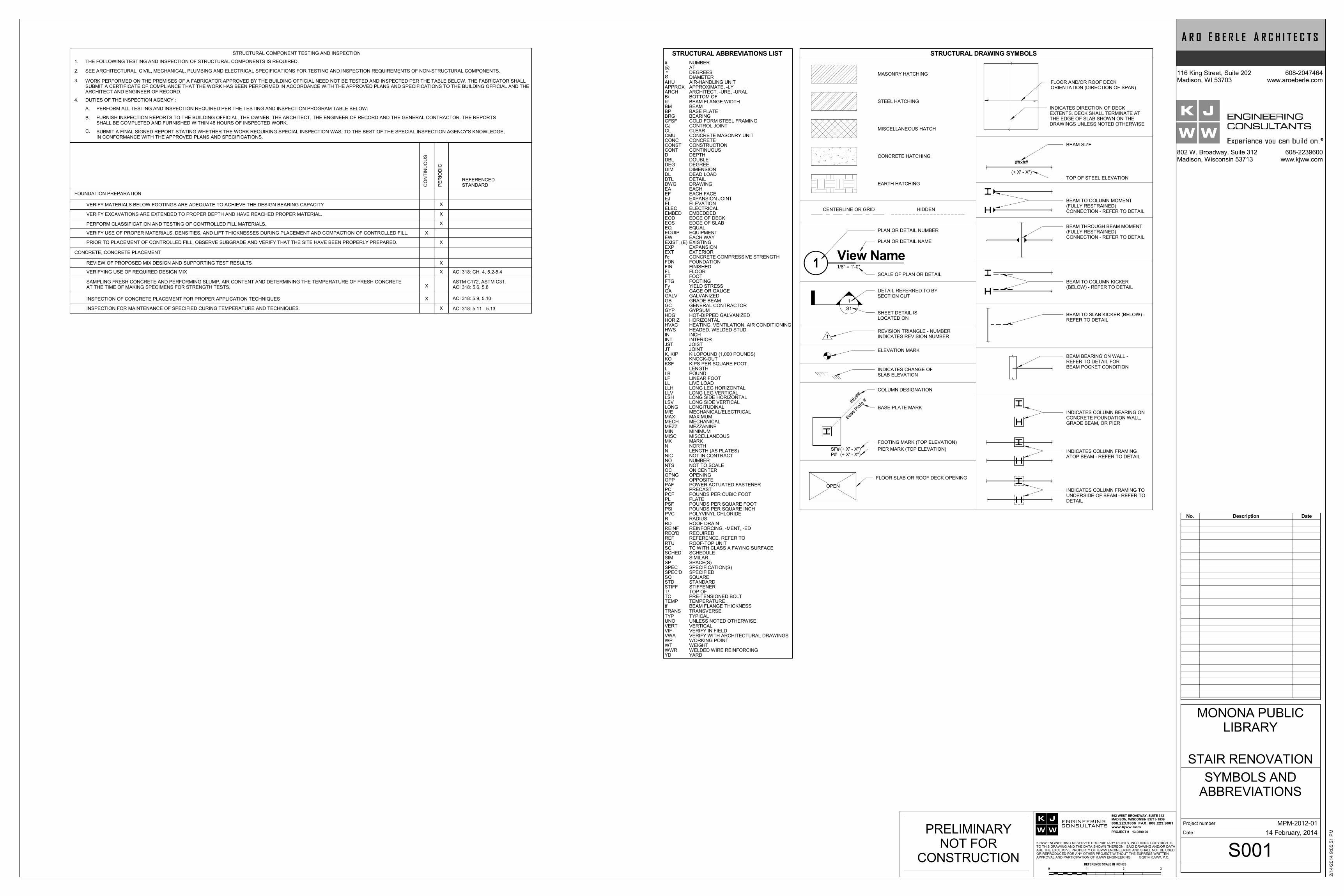
STRUCTURAL DRAWING SYMBOLS
MASONRY HATCHING
STEEL HATCHING
MISCELLANEOUS HATCH
CONCRETE HATCHING
EARTH HATCHING
CENTERLINE OR GRID HIDDEN
PLAN OR DETAIL NUMBER
PLAN OR DETAIL NAME
SCALE OF PLAN OR DETAIL
1
S1
DETAIL REFERRED TO BYSECTION CUT
SHEET DETAIL ISLOCATED ON
1REVISION TRIANGLE - NUMBERINDICATES REVISION NUMBER
ELEVATION MARK
INDICATES CHANGE OFSLAB ELEVATION
##x#
#
Base
Plate
#
COLUMN DESIGNATION
BASE PLATE MARK
SF#(+ X' - X")P# (+ X' - X")
FOOTING MARK (TOP ELEVATION)
PIER MARK (TOP ELEVATION)
BEAM BEARING ON WALL -REFER TO DETAIL FORBEAM POCKET CONDITION
FLOOR SLAB OR ROOF DECK OPENING
OPEN
FLOOR AND/OR ROOF DECKORIENTATION (DIRECTION OF SPAN)
INDICATES DIRECTION OF DECKEXTENTS. DECK SHALL TERMINATE ATTHE EDGE OF SLAB SHOWN ON THEDRAWINGS UNLESS NOTED OTHERWISE
##x##
(+ X' - X")
BEAM SIZE
TOP OF STEEL ELEVATION
BEAM TO COLUMN MOMENT(FULLY RESTRAINED)CONNECTION - REFER TO DETAIL
BEAM THROUGH BEAM MOMENT(FULLY RESTRAINED)CONNECTION - REFER TO DETAIL
BEAM TO COLUMN KICKER(BELOW) - REFER TO DETAIL
BEAM TO SLAB KICKER (BELOW) -REFER TO DETAIL
INDICATES COLUMN FRAMINGATOP BEAM - REFER TO DETAIL
INDICATES COLUMN FRAMING TOUNDERSIDE OF BEAM - REFER TODETAIL
INDICATES COLUMN BEARING ONCONCRETE FOUNDATION WALL,GRADE BEAM, OR PIER
STRUCTURAL ABBREVIATIONS LIST
EOS
YDWWRWTWP
VERTUNOTYP
tfTEMP
T/STIFFSTDSQSPEC'DSPECSPSIMSCHED
RTU
REQ'DREINFRDRPVCPSIPSFPLPCFPC
OPPOPNGOCNTSNONICNNMKMISCMINMEZZMECHMAXM/ELONG
LLVLLHLLLFLBLKSFKOK, KIPJTJSTINTIN
HVACHORIZ
GYPGCGBGALVGAFyFTGFTFLFINFDNf'cEXTEXPEXIST, (E)EWEQUIPEQ
EMBEDELECELEJEFEA
DTLDLDIMDEGDBLDCONTCONSTCONCCMUCLCJCFSF
BPBM
B/ARCHAPPROX
Ø
@#
HWS
EOD
AHU
°
VIF
HDG
VWA
DWG
EDGE OF SLAB
YARDWELDED WIRE REINFORCINGWEIGHTWORKING POINT
VERTICALUNLESS NOTED OTHERWISETYPICAL
BEAM FLANGE THICKNESSTEMPERATURE
TOP OFSTIFFENERSTANDARDSQUARESPECIFIEDSPECIFICATION(S)SPACE(S)SIMILARSCHEDULE
ROOF-TOP UNIT
REQUIREDREINFORCING, -MENT, -EDROOF DRAINRADIUSPOLYVINYL CHLORIDEPOUNDS PER SQUARE INCHPOUNDS PER SQUARE FOOTPLATEPOUNDS PER CUBIC FOOTPRECAST
OPPOSITEOPENINGON CENTERNOT TO SCALENUMBERNOT IN CONTRACTLENGTH (AS PLATES)NORTHMARKMISCELLANEOUSMINIMUMMEZZANINEMECHANICALMAXIMUMMECHANICAL/ELECTRICALLONGITUDINAL
LONG LEG VERTICALLONG LEG HORIZONTALLIVE LOADLINEAR FOOTPOUNDLENGTHKIPS PER SQUARE FOOTKNOCK-OUTKILOPOUND (1,000 POUNDS)JOINTJOISTINTERIORINCH
HEATING, VENTILATION, AIR CONDITIONINGHORIZONTAL
GYPSUMGENERAL CONTRACTORGRADE BEAMGALVANIZEDGAGE OR GAUGEYIELD STRESSFOOTINGFOOTFLOORFINISHEDFOUNDATIONCONCRETE COMPRESSIVE STRENGTHEXTERIOREXPANSIONEXISTINGEACH WAYEQUIPMENTEQUAL
EMBEDDEDELECTRICALELEVATIONEXPANSION JOINTEACH FACEEACH
DETAILDEAD LOADDIMENSIONDEGREEDOUBLEDEPTHCONTINUOUSCONSTRUCTIONCONCRETECONCRETE MASONRY UNITCLEARCONTROL JOINTCOLD FORM STEEL FRAMING
BASE PLATEBEAM
BOTTOM OFARCHITECT, -URE, -URALAPPROXIMATE, -LY
DIAMETER
ATNUMBER
HEADED, WELDED STUD
EDGE OF DECK
AIR-HANDLING UNIT
DEGREES
VERIFY IN FIELD
HOT-DIPPED GALVANIZED
VERIFY WITH ARCHITECTURAL DRAWINGS
DRAWING
REF REFERENCE, REFER TO
SC TC WITH CLASS A FAYING SURFACE
TC PRE-TENSIONED BOLT
BRG BEARING
bf BEAM FLANGE WIDTH
TRANS TRANSVERSE
PAF POWER ACTUATED FASTENER
LSVLSH
LONG SIDE VERTICALLONG SIDE HORIZONTAL
STRUCTURAL COMPONENT TESTING AND INSPECTION
FOUNDATION PREPARATION
CONCRETE, CONCRETE PLACEMENT
1.
2. SEE ARCHITECTURAL, CIVIL, MECHANICAL, PLUMBING AND ELECTRICAL SPECIFICATIONS FOR TESTING AND INSPECTION REQUIREMENTS OF NON-STRUCTURAL COMPONENTS.
VERIFY MATERIALS BELOW FOOTINGS ARE ADEQUATE TO ACHIEVE THE DESIGN BEARING CAPACITY
VERIFY EXCAVATIONS ARE EXTENDED TO PROPER DEPTH AND HAVE REACHED PROPER MATERIAL.
PERFORM CLASSIFICATION AND TESTING OF CONTROLLED FILL MATERIALS.
REVIEW OF PROPOSED MIX DESIGN AND SUPPORTING TEST RESULTS
X
X
X
CO
NT
INU
OU
S
C. SUBMIT A FINAL SIGNED REPORT STATING WHETHER THE WORK REQUIRING SPECIAL INSPECTION WAS, TO THE BEST OF THE SPECIAL INSPECTION AGENCY'S KNOWLEDGE,IN CONFORMANCE WITH THE APPROVED PLANS AND SPECIFICATIONS.
B.
PERFORM ALL TESTING AND INSPECTION REQUIRED PER THE TESTING AND INSPECTION PROGRAM TABLE BELOW.A.
FURNISH INSPECTION REPORTS TO THE BUILDING OFFICIAL, THE OWNER, THE ARCHITECT, THE ENGINEER OF RECORD AND THE GENERAL CONTRACTOR. THE REPORTSSHALL BE COMPLETED AND FURNISHED WITHIN 48 HOURS OF INSPECTED WORK.
4. DUTIES OF THE INSPECTION AGENCY :
THE FOLLOWING TESTING AND INSPECTION OF STRUCTURAL COMPONENTS IS REQUIRED.
PE
RIO
DIC
REFERENCEDSTANDARD
X
VERIFYING USE OF REQUIRED DESIGN MIX X ACI 318: CH. 4, 5.2-5.4
SAMPLING FRESH CONCRETE AND PERFORMING SLUMP, AIR CONTENT AND DETERMINING THE TEMPERATURE OF FRESH CONCRETEAT THE TIME OF MAKING SPECIMENS FOR STRENGTH TESTS.
ASTM C172, ASTM C31,ACI 318: 5.6, 5.8X
INSPECTION OF CONCRETE PLACEMENT FOR PROPER APPLICATION TECHNIQUES ACI 318: 5.9, 5.10
INSPECTION FOR MAINTENANCE OF SPECIFIED CURING TEMPERATURE AND TECHNIQUES.
X
ACI 318: 5.11 - 5.13X
WORK PERFORMED ON THE PREMISES OF A FABRICATOR APPROVED BY THE BUILDING OFFICIAL NEED NOT BE TESTED AND INSPECTED PER THE TABLE BELOW. THE FABRICATOR SHALLSUBMIT A CERTIFICATE OF COMPLIANCE THAT THE WORK HAS BEEN PERFORMED IN ACCORDANCE WITH THE APPROVED PLANS AND SPECIFICATIONS TO THE BUILDING OFFICIAL AND THEARCHITECT AND ENGINEER OF RECORD.
3.
VERIFY USE OF PROPER MATERIALS, DENSITIES, AND LIFT THICKNESSES DURING PLACEMENT AND COMPACTION OF CONTROLLED FILL. X
PRIOR TO PLACEMENT OF CONTROLLED FILL, OBSERVE SUBGRADE AND VERIFY THAT THE SITE HAVE BEEN PROPERLY PREPARED.
X
PRELIMINARYNOT FOR
CONSTRUCTION
Project number
Date
116 King Street, Suite 202Madison, WI 53703
608-2047464www.aroeberle.com
802 W. Broadway, Suite 312Madison, Wisconsin 53713
608-2239600www.kjww.com
2/1
4/2
01
4 9
:05
:51
PM
S001
SYMBOLS ANDABBREVIATIONS
MPM-2012-01
STAIR RENOVATION
MONONA PUBLICLIBRARY
14 February, 2014
REFERENCE SCALE IN INCHES
0 1 2 3
ENGINEERINGCONSULTANTS
PROJECT #
608.223.9600 FAX: 608.223.9601www.kjww.com
802 WEST BROADWAY, SUITE 312MADISON, WISCONSIN 53713-1839
KJWW ENGINEERING RESERVES PROPRIETARY RIGHTS, INCLUDING COPYRIGHTS,TO THIS DRAWING AND THE DATA SHOWN THEREON. SAID DRAWING AND/OR DATAARE THE EXCLUSIVE PROPERTY OF KJWW ENGINEERING AND SHALL NOT BE USEDOR REPRODUCED FOR ANY OTHER PROJECT WITHOUT THE EXPRESS WRITTENAPPROVAL AND PARTICIPATION OF KJWW ENGINEERING. © 2014 KJWW, P.C.
13.0890.00
No. Description Date
FED
BB.1
BB
C
5
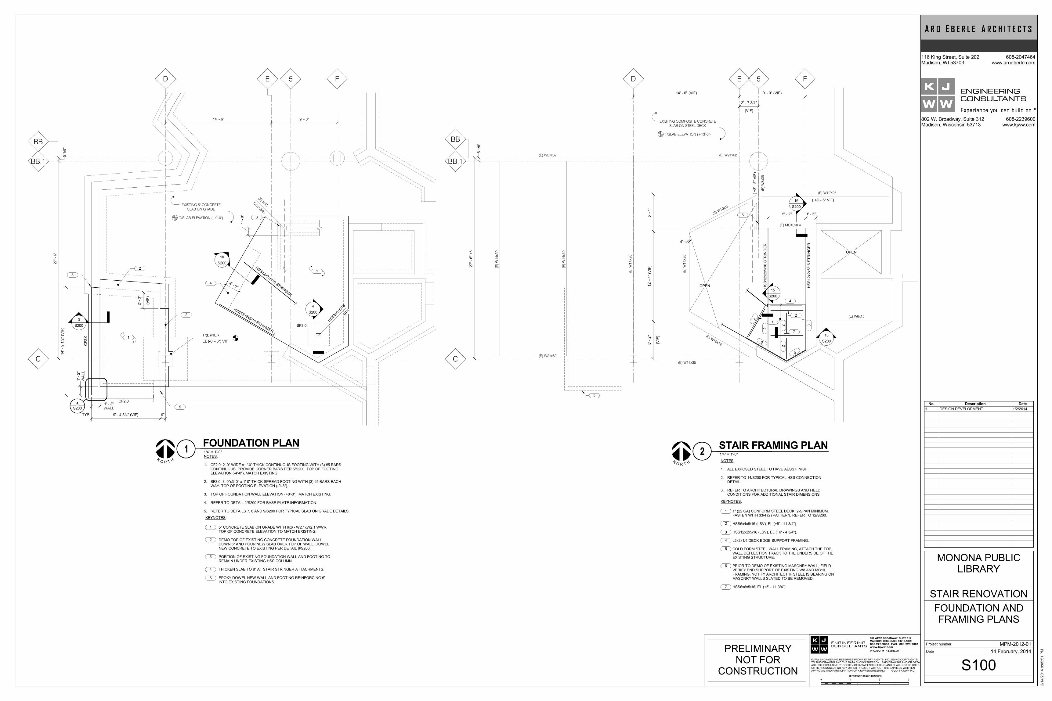
9' - 0"14' - 6"
HSS12x2x5/16 STRINGER
HSS12x2x5/16 STRINGER
HSS8x
6x5/
16
BP1
CF
2.0
CF2.0
14
' - 9
1/2
" (V
IF)
WA
LL
1' -
2"
WALL1' - 2"
9' - 4 3/4" (VIF) 9"
1
2
SF3.0
1
(E) HSS
CO
LUM
N
4
3
EXISTING 5" CONCRETE
SLAB ON GRADE
T/SLAB ELEVATION (+0'-0")
27
' - 6
"
5 1
/8"
1' -
0"
2
5
3
S200
S200
65
EL (-0' - 6") VIF
T/(E)PIER
2' - 0"
10
S200
4
S200
TYP
(VIF
)
2' -
3"
FED
BB.1
BB
C
5
(E)
W1
4X
26
(E) W18x35
(E)
W1
4X
26
(E) W10x12
(E) W10x12
(E)
W8
x35
(E) W12X26
5' -
1"
12
' - 4
" (V
IF)
(VIF
)
5' -
2"
(E) W6x15
HS
S12
x2
x5
/16
ST
RIN
GE
R
HS
S12
x2
x5
/16
ST
RIN
GE
R
( +
8' -
5"
VIF
)
( +8' - 5" VIF)
9' - 0" (VIF)14' - 6" (VIF)
(VIF)
2' - 7 3/4"
27
' - 6
" +
/-
5 1
/8"
EXISTING COMPOSITE CONCRETE
SLAB ON STEEL DECK
T/SLAB ELEVATION (+13'-0")
(E) W21x62
(E) MC10x8.4
OPEN
OPEN
1
2
2
22
7
3
3
3
4
(E)
W1
4x3
0
(E)
W1
4x3
0
(E) W21x62
(E) W21x62
6
4"
1' - 5"5' - 2"
2
15
S200
5
13
S200
16
S200
NOTES:
1.
2.
3.
4.
5.
CF2.0: 2'-0" WIDE x 1'-0" THICK CONTINUOUS FOOTING WITH (3) #5 BARSCONTINUOUS. PROVIDE CORNER BARS PER 5/S200. TOP OF FOOTINGELEVATION (-4'-0"), MATCH EXISTING.
SF3.0: 3'-0"x3'-0" x 1'-0" THICK SPREAD FOOTING WITH (3) #5 BARS EACHWAY. TOP OF FOOTING ELEVATION (-0'-8").
TOP OF FOUNDATION WALL ELEVATION (+0'-0"), MATCH EXISTING.
REFER TO DETAIL 2/S200 FOR BASE PLATE INFORMATION.
REFER TO DETAILS 7, 8 AND 9/S200 FOR TYPICAL SLAB ON GRADE DETAILS.
KEYNOTES:
5" CONCRETE SLAB ON GRADE WITH 6x6 - W2.1xW2.1 WWR,TOP OF CONCRETE ELEVATION TO MATCH EXISTING.
DEMO TOP OF EXISTING CONCRETE FOUNDATION WALLDOWN 6" AND POUR NEW SLAB OVER TOP OF WALL. DOWELNEW CONCRETE TO EXISTING PER DETAIL 8/S200.
PORTION OF EXISTING FOUNDATION WALL AND FOOTING TOREMAIN UNDER EXISTING HSS COLUMN.
THICKEN SLAB TO 8" AT STAIR STRINGER ATTACHMENTS.
EPOXY DOWEL NEW WALL AND FOOTING REINFORCING 6"INTO EXISTING FOUNDATIONS.
1
2
3
4
5
NOTES:
1.
2.
3.
ALL EXPOSED STEEL TO HAVE AESS FINISH.
REFER TO 14/S200 FOR TYPICAL HSS CONNECTIONDETAIL.
REFER TO ARCHITECTURAL DRAWINGS AND FIELDCONDITIONS FOR ADDITIONAL STAIR DIMENSIONS.
KEYNOTES:
1" (22 GA) CONFORM STEEL DECK, 2-SPAN MINIMUM.FASTEN WITH 33/4 (2) PATTERN, REFER TO 12/S200.
HSS6x4x5/16 (LSV), EL (+5' - 11 3/4").
HSS12x2x5/16 (LSV), EL (+6' - 4 3/4").
L2x2x1/4 DECK EDGE SUPPORT FRAMING.
COLD FORM STEEL WALL FRAMING, ATTACH THE TOP,WALL DEFLECTION TRACK TO THE UNDERSIDE OF THEEXISTING STRUCTURE.
PRIOR TO DEMO OF EXISTING MASONRY WALL, FIELDVERIFY END SUPPORT OF EXISTING W8 AND MC10FRAMING. NOTIFY ARCHITECT IF STEEL IS BEARING ONMASONRY WALLS SLATED TO BE REMOVED.
HSS6x6x5/16, EL (+5' - 11 3/4").
1
2
3
4
5
6
7
PRELIMINARYNOT FOR
CONSTRUCTION
Project number
Date
116 King Street, Suite 202Madison, WI 53703
608-2047464www.aroeberle.com
802 W. Broadway, Suite 312Madison, Wisconsin 53713
608-2239600www.kjww.com
2/1
4/2
01
4 9
:05
:51
PM
S100
FOUNDATION ANDFRAMING PLANS
MPM-2012-01
STAIR RENOVATION
MONONA PUBLICLIBRARY
14 February, 2014
NO R HT
1/4" = 1'-0"1FOUNDATION PLAN
NO R HT
1/4" = 1'-0"2STAIR FRAMING PLAN
REFERENCE SCALE IN INCHES
0 1 2 3
ENGINEERINGCONSULTANTS
PROJECT #
608.223.9600 FAX: 608.223.9601www.kjww.com
802 WEST BROADWAY, SUITE 312MADISON, WISCONSIN 53713-1839
KJWW ENGINEERING RESERVES PROPRIETARY RIGHTS, INCLUDING COPYRIGHTS,TO THIS DRAWING AND THE DATA SHOWN THEREON. SAID DRAWING AND/OR DATAARE THE EXCLUSIVE PROPERTY OF KJWW ENGINEERING AND SHALL NOT BE USEDOR REPRODUCED FOR ANY OTHER PROJECT WITHOUT THE EXPRESS WRITTENAPPROVAL AND PARTICIPATION OF KJWW ENGINEERING. © 2014 KJWW, P.C.
13.0890.00
No. Description Date
1 DESIGN DEVELOPMENT 1/2/2014
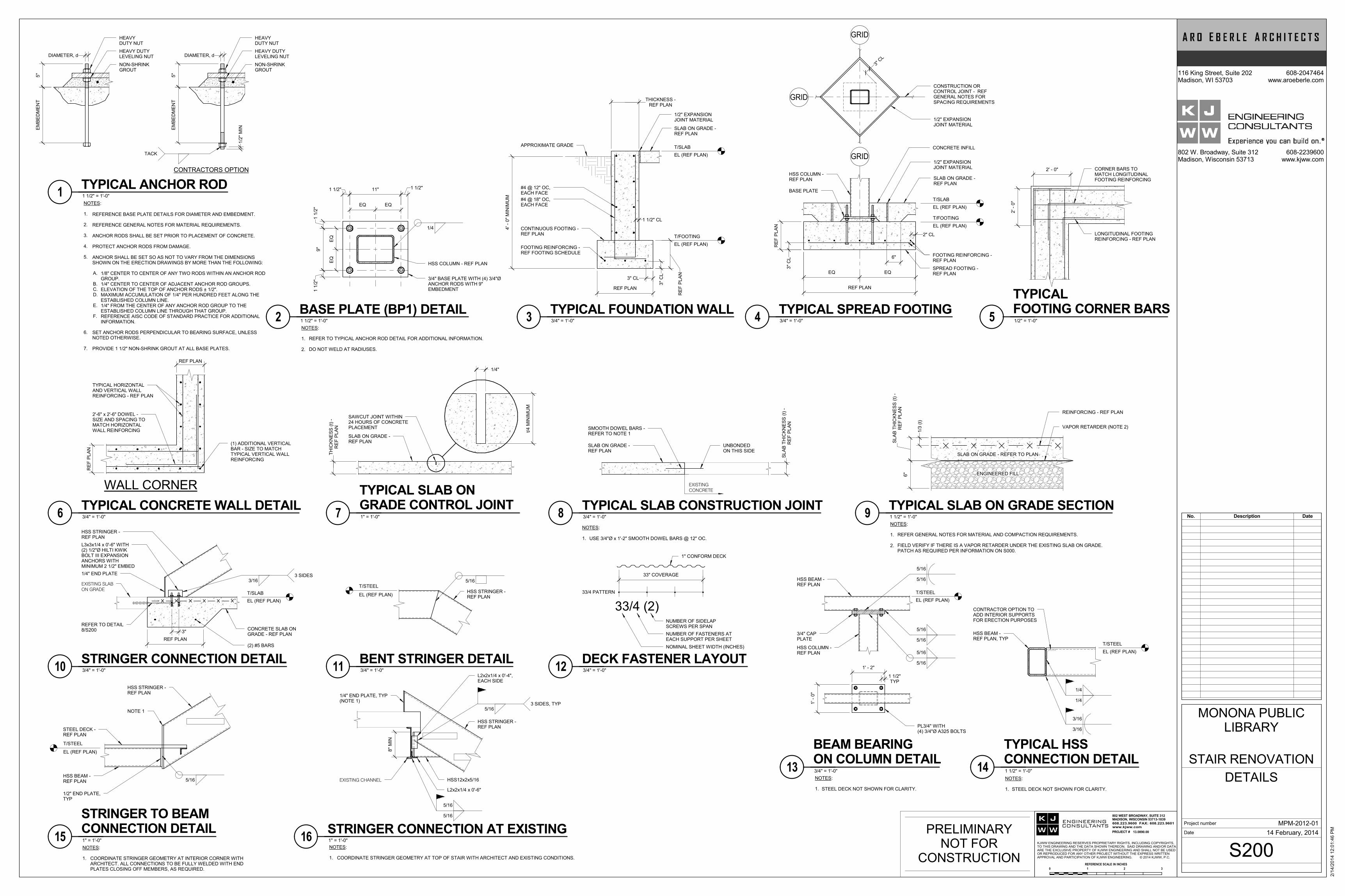
NON-SHRINKGROUT
HEAVY DUTYLEVELING NUT
HEAVYDUTY NUT
5"
DIAMETER, d
NON-SHRINKGROUT
HEAVY DUTYLEVELING NUT
HEAVYDUTY NUT
5"
EM
BE
DM
EN
T
1/2
" M
IN
SET ANCHOR RODS PERPENDICULAR TO BEARING SURFACE, UNLESSNOTED OTHERWISE.
PROVIDE 1 1/2" NON-SHRINK GROUT AT ALL BASE PLATES.
TACK
NOTES:
1.
2.
3.
4.
5.
A.
B. C. D.
E.
F.
6.
7.
REFERENCE BASE PLATE DETAILS FOR DIAMETER AND EMBEDMENT.
REFERENCE GENERAL NOTES FOR MATERIAL REQUIREMENTS.
ANCHOR RODS SHALL BE SET PRIOR TO PLACEMENT OF CONCRETE.
PROTECT ANCHOR RODS FROM DAMAGE.
ANCHOR SHALL BE SET SO AS NOT TO VARY FROM THE DIMENSIONSSHOWN ON THE ERECTION DRAWINGS BY MORE THAN THE FOLLOWING:
1/8" CENTER TO CENTER OF ANY TWO RODS WITHIN AN ANCHOR RODGROUP.1/4" CENTER TO CENTER OF ADJACENT ANCHOR ROD GROUPS.ELEVATION OF THE TOP OF ANCHOR RODS ± 1/2".MAXIMUM ACCUMULATION OF 1/4" PER HUNDRED FEET ALONG THEESTABLISHED COLUMN LINE.1/4" FROM THE CENTER OF ANY ANCHOR ROD GROUP TO THEESTABLISHED COLUMN LINE THROUGH THAT GROUP.REFERENCE AISC CODE OF STANDARD PRACTICE FOR ADDITIONALINFORMATION.
CONTRACTORS OPTION
EM
BE
DM
EN
T
DIAMETER, d
3/4" BASE PLATE WITH (4) 3/4"ØANCHOR RODS WITH 9"EMBEDMENT
HSS COLUMN - REF PLAN
1 1/2" 1 1/2"
1 1
/2"
1 1
/2"
1/4
9"
EQ EQ
11"
EQ
EQ
NOTES:
1.
2.
REFER TO TYPICAL ANCHOR ROD DETAIL FOR ADDITIONAL INFORMATION.
DO NOT WELD AT RADIUSES.
#4 @ 12" OC,EACH FACE
SLAB ON GRADE -REF PLAN
1/2" EXPANSIONJOINT MATERIAL
FOOTING REINFORCING -REF FOOTING SCHEDULE
4' -
0"
MIN
IMU
M
RE
F P
LA
N
EL (REF PLAN)
T/SLAB
EL (REF PLAN)
T/FOOTING
3" CL
3"
CL
1 1/2" CL
REF PLANTHICKNESS -
REF PLAN
CONTINUOUS FOOTING -REF PLAN
APPROXIMATE GRADE
#4 @ 18" OC,EACH FACE
BASE PLATE
SPREAD FOOTING -REF PLAN
CONSTRUCTION ORCONTROL JOINT - REFGENERAL NOTES FORSPACING REQUIREMENTS
1/2" EXPANSIONJOINT MATERIAL
CONCRETE INFILL
1/2" EXPANSIONJOINT MATERIAL
SLAB ON GRADE -REF PLAN
HSS COLUMN -REF PLAN
3"
CL
RE
F P
LA
N
2" CL
EL (REF PLAN)
T/SLAB
EL (REF PLAN)
T/FOOTING
EQ EQ
GRID
GRID
GRID
FOOTING REINFORCING -REF PLAN
6"
3" C
L
REF PLAN
CORNER BARS TOMATCH LONGITUDINALFOOTING REINFORCING
LONGITUDINAL FOOTINGREINFORCING - REF PLAN
2' -
0"
2' - 0"
WALL CORNER
TYPICAL HORIZONTALAND VERTICAL WALLREINFORCING - REF PLAN
2'-6" x 2'-6" DOWEL -SIZE AND SPACING TOMATCH HORIZONTALWALL REINFORCING
(1) ADDITIONAL VERTICALBAR - SIZE TO MATCHTYPICAL VERTICAL WALLREINFORCING
RE
F P
LA
N
REF PLAN
SAWCUT JOINT WITHIN24 HOURS OF CONCRETEPLACEMENT
SLAB ON GRADE -REF PLAN
t/4
MIN
IMU
M
0' - 3" 1/4"
RE
F P
LA
NT
HIC
KN
ES
S (
t) -
USE 3/4"Ø x 1'-2" SMOOTH DOWEL BARS @ 12" OC.
NOTES:
1.
EXISTING
CONCRETE
SMOOTH DOWEL BARS -REFER TO NOTE 1
SLAB ON GRADE -REF PLAN
UNBONDEDON THIS SIDE
RE
F P
LA
NS
LA
B T
HIC
KN
ES
S (
t) -
ENGINEERED FILL
NOTES:
1.
2.
VAPOR RETARDER (NOTE 2)
SLAB ON GRADE - REFER TO PLAN
REINFORCING - REF PLAN
6"
RE
F P
LA
NS
LA
B T
HIC
KN
ES
S (
t) -
REFER GENERAL NOTES FOR MATERIAL AND COMPACTION REQUIREMENTS.
FIELD VERIFY IF THERE IS A VAPOR RETARDER UNDER THE EXISTING SLAB ON GRADE.PATCH AS REQUIRED PER INFORMATION ON S000.
1/3
(t)
3"CONCRETE SLAB ONGRADE - REF PLAN
EL (REF PLAN)
T/SLAB
HSS STRINGER -REF PLAN
L3x3x1/4 x 0'-6" WITH(2) 1/2"Ø HILTI KWIKBOLT III EXPANSIONANCHORS WITHMINIMUM 2 1/2" EMBED
3/163 SIDES
EXISTING SLAB
ON GRADE
REFER TO DETAIL8/S200
1/4" END PLATE
(2) #5 BARS
REF PLAN
5/16
HSS STRINGER -REF PLANEL (REF PLAN)
T/STEEL
33/4 (2)NUMBER OF SIDELAPSCREWS PER SPAN
NUMBER OF FASTENERS ATEACH SUPPORT PER SHEET
NOMINAL SHEET WIDTH (INCHES)
33" COVERAGE
1" CONFORM DECK
33/4 PATTERN
5/16
5/16
5/16
5/16
EL (REF PLAN)
T/STEEL
HSS BEAM -REF PLAN
HSS COLUMN -REF PLAN
3/4" CAPPLATE
5/16
5/16
1' - 2"
TYP1 1/2"
1' -
0"
PL3/4" WITH(4) 3/4"Ø A325 BOLTS
NOTES:
1. STEEL DECK NOT SHOWN FOR CLARITY.
EL (REF PLAN)
T/STEEL
1/4
1/4
3/16
3/16
HSS BEAM -REF PLAN, TYP
NOTES:
1. STEEL DECK NOT SHOWN FOR CLARITY.
CONTRACTOR OPTION TOADD INTERIOR SUPPORTSFOR ERECTION PURPOSES
NOTES:
1. COORDINATE STRINGER GEOMETRY AT INTERIOR CORNER WITHARCHITECT. ALL CONNECTIONS TO BE FULLY WELDED WITH ENDPLATES CLOSING OFF MEMBERS, AS REQUIRED.
EL (REF PLAN)
T/STEEL
HSS BEAM -REF PLAN
1/2" END PLATE,TYP
5/16
STEEL DECK -REF PLAN
HSS STRINGER -REF PLAN
NOTE 1
HSS STRINGER -REF PLAN
EXISTING CHANNEL
1/4" END PLATE, TYP(NOTE 1)
HSS12x2x5/16
L2x2x1/4 x 0'-6"
5/16
5/16
5/163 SIDES, TYP
8"
MIN
NOTES:
1. COORDINATE STRINGER GEOMETRY AT TOP OF STAIR WITH ARCHITECT AND EXISTING CONDITIONS.
L2x2x1/4 x 0'-4",EACH SIDE
PRELIMINARYNOT FOR
CONSTRUCTION
Project number
Date
116 King Street, Suite 202Madison, WI 53703
608-2047464www.aroeberle.com
802 W. Broadway, Suite 312Madison, Wisconsin 53713
608-2239600www.kjww.com
2/1
4/2
01
4 1
2:0
1:4
6 P
M
S200
DETAILS
MPM-2012-01
STAIR RENOVATION
MONONA PUBLICLIBRARY
14 February, 2014
1 1/2" = 1'-0"1TYPICAL ANCHOR ROD
1 1/2" = 1'-0"2BASE PLATE (BP1) DETAIL
3/4" = 1'-0"3TYPICAL FOUNDATION WALL
3/4" = 1'-0"4TYPICAL SPREAD FOOTING
1/2" = 1'-0"5
TYPICALFOOTING CORNER BARS
3/4" = 1'-0"6TYPICAL CONCRETE WALL DETAIL
1" = 1'-0"7
TYPICAL SLAB ONGRADE CONTROL JOINT
3/4" = 1'-0"8TYPICAL SLAB CONSTRUCTION JOINT
1 1/2" = 1'-0"9TYPICAL SLAB ON GRADE SECTION
REFERENCE SCALE IN INCHES
0 1 2 3
ENGINEERINGCONSULTANTS
PROJECT #
608.223.9600 FAX: 608.223.9601www.kjww.com
802 WEST BROADWAY, SUITE 312MADISON, WISCONSIN 53713-1839
KJWW ENGINEERING RESERVES PROPRIETARY RIGHTS, INCLUDING COPYRIGHTS,TO THIS DRAWING AND THE DATA SHOWN THEREON. SAID DRAWING AND/OR DATAARE THE EXCLUSIVE PROPERTY OF KJWW ENGINEERING AND SHALL NOT BE USEDOR REPRODUCED FOR ANY OTHER PROJECT WITHOUT THE EXPRESS WRITTENAPPROVAL AND PARTICIPATION OF KJWW ENGINEERING. © 2014 KJWW, P.C.
13.0890.00
3/4" = 1'-0"10STRINGER CONNECTION DETAIL
3/4" = 1'-0"11BENT STRINGER DETAIL
3/4" = 1'-0"12DECK FASTENER LAYOUT
3/4" = 1'-0"13
BEAM BEARINGON COLUMN DETAIL
1 1/2" = 1'-0"14
TYPICAL HSSCONNECTION DETAIL
1" = 1'-0"15
STRINGER TO BEAMCONNECTION DETAIL
1" = 1'-0"16STRINGER CONNECTION AT EXISTING
No. Description Date

AIA®
Document C132TM – 2009 Standard Form of Agreement Between Owner and Construction Manager as Adviser
ADDITIONS AND DELETIONS: The author of this document has added information needed for its completion. The author may also have revised the text of the original AIA standard form. An Additions and Deletions Report that notes added information as well as revisions to the standard form text is available from the author and should be reviewed.
This document has important legal consequences. Consultation with an attorney is encouraged with respect to its completion or modification.
This document is intended to be used in conjunction with AIA Documents A132™–2009, Standard Form of Agreement Between Owner and Contractor, Construction Manager as Adviser Edition; A232™–2009, General Conditions of the Contract for Construction, Construction Manager as Adviser Edition; and B132™–2009, Standard Form of Agreement Between Owner and Architect, Construction Manager as Adviser Edition.
AIA Document A232™–2009 is adopted in this document by reference. Do not use with other general conditions unless this document is modified.
AGREEMENT made as of the « » day of « » in the year «2014 » (In words, indicate day, month and year.) BETWEEN the Owner: (Name, legal status, address and other information) «City of Monona»« » «5211 Schluter Road Monona, WI 53716» «Telephone Number: 608-222-2525» « » and the Construction Manager: (Name, legal status, address and other information) «Harmony Construction Management, Inc»« » «906 Jonathon Drive Madison, WI 53713» «Telephone Number: 608-224-3310» «Fax Number: 608-224-4392Email [email protected]» for the following Project: (Name, location and detailed description) «14-04 Oneida Park Shelter Replacement» «Tecumseh Ave & Neponset Tr» « Demolition of existing structure and construction of a new park shelter (approximately 1834SF), including site work, water & sewer laterals, concrete, CMU block construction with wood trusses, shingled roof, wood siding, soffit, fascia and ceilings, interior CMU walls, HM doors, rolling counter door, glazing, floor and wall finishes, plumbing, HVAC and electrical. » The Architect: (Name, legal status, address and other information) «Aro Eberle Architects»« » «116 King Street Suite 202 Madison, WI 53703» « » « » The Owner and Construction Manager agree as follows.
AIA Document C132™ – 2009 (formerly B801™CMa – 1992). Copyright © 1973, 1980, 1992 and 2009 by The American Institute of Architects. All rights reserved. WARNING: This AIA® Document is protected by U.S. Copyright Law and International Treaties. Unauthorized reproduction or distribution of this AIA® Document, or any portion of it, may result in severe civil and criminal penalties, and will be prosecuted to the maximum extent possible under the law. This draft was produced by AIA software at 15:21:58 on 02/26/2014 under Order No.9944481327_1 which expires on 02/25/2015, and is not for resale. User Notes: (1984575857)
1
ELECTRONIC COPYING of any portion of this AIA® Document to another electronic file is prohibited and constitutes a violation of copyright laws as set forth in the footer of this document.

TABLE OF ARTICLES 1 INITIAL INFORMATION 2 CONSTRUCTION MANAGER’S RESPONSIBILITIES 3 SCOPE OF CONSTRUCTION MANAGER’S BASIC SERVICES 4 ADDITIONAL SERVICES 5 OWNER’S RESPONSIBILITIES 6 COST OF THE WORK 7 COPYRIGHTS AND LICENSES 8 CLAIMS AND DISPUTES 9 TERMINATION OR SUSPENSION 10 MISCELLANEOUS PROVISIONS 11 COMPENSATION 12 SPECIAL TERMS AND CONDITIONS 13 SCOPE OF THE AGREEMENT ARTICLE 1 INITIAL INFORMATION § 1.1 This Agreement is based on the Initial Information set forth in this Section 1.1. (Note the disposition for the following items by inserting the requested information or a statement such as “not applicable,” “unknown at time of execution” or “to be determined later by mutual agreement.”) § 1.1.1 The Owner’s program for the Project: (Identify documentation or state the manner in which the program will be developed.) «Project Bid Drawings dated January 15, 2014; Project Manual dated January 15, 2014; Addendum #1 dated January 21, 2014; Addendum #2 dated January 30, 2014; Addendum #3 dated February 24, 2014; Appendix A Soils Reports dated May 16, 2013 » § 1.1.2 The Project’s physical characteristics: (Identify or describe, if appropriate, size, location, dimensions, or other pertinent information, such as geotechnical reports; site, boundary and topographic surveys; traffic and utility studies; availability of public and private utilities and services; legal description of the site; etc.) « Monona Oneida Park, intersection of Tecumseh Ave and Neposet Trail, Monona WI; Project Bid Drawings dated January 15, 2014; Project Manual dated January 15, 2014; Addendum #1 dated January 21, 2014; Addendum #2 dated January 30, 2014; Addendum #3 dated February 24, 2014; Appendix A Soils Reports dated May 16, 2013 » § 1.1.3 The Owner’s budget for the Cost of the Work, as defined in Section 6.1: (Provide total and, if known, a line item breakdown.) «TBD » § 1.1.4 The Owner’s anticipated design and construction schedule:
.1 Design phase milestone dates, if any:
«completed »
AIA Document C132™ – 2009 (formerly B801™CMa – 1992). Copyright © 1973, 1980, 1992 and 2009 by The American Institute of Architects. All rights reserved. WARNING: This AIA® Document is protected by U.S. Copyright Law and International Treaties. Unauthorized reproduction or distribution of this AIA® Document, or any portion of it, may result in severe civil and criminal penalties, and will be prosecuted to the maximum extent possible under the law. This draft was produced by AIA software at 15:21:58 on 02/26/2014 under Order No.9944481327_1 which expires on 02/25/2015, and is not for resale. User Notes: (1984575857)
2
.2 Commencement of construction:
«pending City Council approval » .3 Substantial Completion date or milestone dates:
«16 weeks after commencement date » .4 Other:
« » § 1.1.5 The Owner intends the following procurement method for the Project: (Identify method such as competitive bid, negotiated Contract or multiple Prime Contracts.) «Multiple prime contracts; bids received February 07, 2014 and March 11, 2014 » § 1.1.6 The Owner’s requirements for accelerated or fast-track scheduling, multiple bid packages, or phased construction are set forth below: (List number and type of bid/procurement packages.) «Bids received for contracts #1 – 12 #1 Demo, Site Clearing, Earthwork, Site Utilities, Curb & Gutter, Asphalt, Landscaping #2 Concrete #3 Masonry with Steel, Set HM Door Frames, Masonry Flashings, Caulking #4 Carpentry Labor and Materials: Roof Framing System, Soffit & Fascia, Laminated Beams, Gable End Walls with Siding, all fasteners & Simpson fasteners #5 Finish Carpentry Labor #6 Roofing, Flashings & Copings, Gutters & Downspouts #7 Supply Only Doors, Frames, Hardware, Toilet Partitions, Specialties #8 Painting, Staining, Caulking #9 Epoxy Flooring #10 Plumbing, incl Trench Drains #11 Mechanical #12 Electrical » § 1.1.7 Other Project information: (Identify special characteristics or needs of the Project not provided elsewhere, such as environmentally responsible design or historic preservation requirements.) «As specified in Site Documents, Project Manual and Soils Report by CGC, Inc. dated May 16, 2013 » § 1.1.8 The Owner identifies the following representative in accordance with Section 5.5: (List name, address and other information.) «Janine Glaeser» «5211 Schluter Road Monona, WI 53716» « Phone 608-222-2525 » « Email [email protected] » « » « » § 1.1.9 The persons or entities, in addition to the Owner’s representative, who are required to review the Construction Manager’s submittals to the Owner are as follows: (List name, address and other information.) AIA Document C132™ – 2009 (formerly B801™CMa – 1992). Copyright © 1973, 1980, 1992 and 2009 by The American Institute of Architects. All rights reserved. WARNING: This AIA® Document is protected by U.S. Copyright Law and International Treaties. Unauthorized reproduction or distribution of this AIA® Document, or any portion of it, may result in severe civil and criminal penalties, and will be prosecuted to the maximum extent possible under the law. This draft was produced by AIA software at 15:21:58 on 02/26/2014 under Order No.9944481327_1 which expires on 02/25/2015, and is not for resale. User Notes: (1984575857)
3

«Aro Eberle Architects Vierbicher Associates, Inc. » § 1.1.10 Unless provided by the Construction Manager, the Owner will retain the following consultants and contractors: (List name, legal status, address and other information.)
.1 Land Surveyor:
« Vierbicher Assoicates, Inc. »« » « Brad Schultz » «999 Fourier Drive » « Madison, WI 53717 » « Phone 608-826-0532 »
.2 Geotechnical Engineer:
«CGC, Inc. »« » «Eric Neuhauser » «2921 Perry Street » « Madison, WI 53713 » « Phone 608-288-4100 »
.3 Civil Engineer:
« Vierbicher Associates, Inc. »« » « Brad Schultz » « 999 Fourier Drive » « Madison, WI 53717 » « Phone 608-826-0532 »
.4 Other:
(List any other consultants retained by the Owner, such as a Project or Program Manager, or construction contractor.)
« »
§ 1.1.11 The Construction Manager identifies the following representative in accordance with Section 2.4: (List name, address and other information.) «Paul ReedHarmony Construction Management, Inc.» «906 Jonathon DrivePaul Reed Madison, WI 53713906 Jonathon Drive» «Madison, WI 53713 » «Phone 608-224-3310 » «Email [email protected] » « » § 1.1.12 The Construction Manager’s staffing plan as required under Section 3.3.2 shall include: (List any specific requirements and personnel to be included in the staffing plan, if known.) «Paul Reed, Project Manager Lori Reed, Asst to Project Manager Alex Crowley, Superintendent and Quality Control » § 1.1.13 The Construction Manager’s consultants retained under Basic Services, if any:
.1 Cost Estimator: (List name, legal status, address and other information.)
AIA Document C132™ – 2009 (formerly B801™CMa – 1992). Copyright © 1973, 1980, 1992 and 2009 by The American Institute of Architects. All rights reserved. WARNING: This AIA® Document is protected by U.S. Copyright Law and International Treaties. Unauthorized reproduction or distribution of this AIA® Document, or any portion of it, may result in severe civil and criminal penalties, and will be prosecuted to the maximum extent possible under the law. This draft was produced by AIA software at 15:21:58 on 02/26/2014 under Order No.9944481327_1 which expires on 02/25/2015, and is not for resale. User Notes: (1984575857)
4
« N/A »« » « » « » « » « »
.2 Other consultants:
«N/A » § 1.1.14 The Construction Manager’s consultants retained under Additional Services: « N/A » § 1.1.15 Other Initial Information on which the Agreement is based: « N/A » § 1.2 The Owner and Construction Manager may rely on the Initial Information. Both parties, however, recognize that such information may materially change and, in that event, the Owner and the Construction Manager shall appropriately adjust the schedules, the Construction Manager’s services and the Construction Manager’s compensation. ARTICLE 2 CONSTRUCTION MANAGER’S RESPONSIBILITIES § 2.1 The Construction Manager shall provide the services as set forth in this Agreement. § 2.2 The Construction Manager shall perform its services consistent with the skill and care ordinarily provided by construction managers practicing in the same or similar locality under the same or similar circumstances. The Construction Manager shall perform its services as expeditiously as is consistent with such skill and care and the orderly progress of the Project. § 2.3 The Construction Manager shall provide its services in conjunction with the services of an Architect as described in AIA Document B132™–2009, Standard Form ofthe Agreement Between Owner and Architect, Construction Manager as Adviser Edition. The Construction Manager shall not be responsible for actions taken by the Architect. § 2.4 The Construction Manager shall identify a representative authorized to act on behalf of the Construction Manager with respect to the Project. § 2.5 Except with the Owner’s knowledge and consent, the Construction Manager shall not engage in any activity, or accept any employment, interest or contribution that would reasonably appear to compromise the Construction Manager’s judgment with respect to this Project. § 2.6 The Construction Manager shall maintain the following insurance for the duration of this Agreement. If any of the requirements set forth below exceed the types and limits the Construction Manager normally maintains, the Owner shall reimburse the Construction Manager for any additional cost. § 2.6.1 Comprehensive General Liability with policy limits of not less than «See Exhibit A attached » ($ « » ) for each occurrence and in the aggregate for bodily injury and property damage. § 2.6.2 Automobile Liability covering owned and rented vehicles operated by the Construction Manager with policy limits of not less than « See Exhibit A attached » ($ « » ) combined single limit and aggregate for bodily injury and property damage. § 2.6.3 The Construction Manager may use umbrella or excess liability insurance to achieve the required coverage for Comprehensive General Liability and Automobile Liability, provided that such umbrella or excess insurance results in the same type of coverage as required for the individual policies. AIA Document C132™ – 2009 (formerly B801™CMa – 1992). Copyright © 1973, 1980, 1992 and 2009 by The American Institute of Architects. All rights reserved. WARNING: This AIA® Document is protected by U.S. Copyright Law and International Treaties. Unauthorized reproduction or distribution of this AIA® Document, or any portion of it, may result in severe civil and criminal penalties, and will be prosecuted to the maximum extent possible under the law. This draft was produced by AIA software at 15:21:58 on 02/26/2014 under Order No.9944481327_1 which expires on 02/25/2015, and is not for resale. User Notes: (1984575857)
5
§ 2.6.4 Workers’ Compensation at statutory limits and Employers Liability with a policy limit of not less than « See Exhibit A attached » ($ « » ). § 2.6.5 Professional Liability covering the Construction Manager’s negligent acts, errors and omissions in its performance of services with policy limits of not less than «One Million Dollars » ($ «1,000,000 » ) per claim and in the aggregate. § 2.6.6 The Construction Manager shall provide to the Owner certificates of insurance evidencing compliance with the requirements in this Section 2.6. The certificates will show the Owner as an additional insured on the Comprehensive General Liability, Automobile Liability, umbrella or excess policies. § 2.6.7 The Construction Manager shall guarantee to the Owner full performance of the construction of the Project to completion. No later than 10 days after execution of this Agreement, the Construction Manager shall provide to the Owner a fully executed Performance Bond, in a form acceptable to the Owner and in an amount no less that 100% of the Owner’s budget for the Cost of the Work set forth in §1.1.3 above. The cost of the Performance Bonds shall be reimbursed to the Construction Manager in an amount not to exceed 2% of total Project Costs. ARTICLE 3 SCOPE OF CONSTRUCTION MANAGER’S BASIC SERVICES § 3.1 Definition The Construction Manager’s Basic Services consist of those described in Sections 3.2 and 3.3 and include usual and customary construction coordination and scheduling, constructability review, cost estimating, and allocation of construction activities among the Multiple Prime Contractors. § 3.2 Preconstruction Phase § 3.2.1 The Construction Manager shall review the program furnished by the Owner and any evaluation of the Owner’s program provided by the Architect, to ascertain the requirements of the Project and shall arrive at a mutual understanding of such requirements with the Owner and Architect. § 3.2.2 The Construction Manager shall provide a preliminary evaluation of the Owner’s program, schedule and construction budget requirements, each in terms of the other. § 3.2.3 The Construction Manager shall prepare, and deliver to the Owner, a written Construction Management Plan that includes, at a minimum, the following: (1) preliminary evaluations required in Section 3.2.2, (2) a Project schedule, (3) cost estimates, (4) recommendations for Project delivery method, and (5) Contractors’ scopes of Work, if multiple Contractors or fast-track construction will be used. The Construction Manager shall periodically update the Construction Management Plan over the course of the Project. § 3.2.4 Based on preliminary design and other design criteria prepared by the Architect, the Construction Manager shall prepare preliminary estimates of the Cost of the Work or the cost of program requirements using area, volume or similar conceptual estimating techniques for the Architect’s review and Owner’s approval. If the Architect suggests alternative materials and systems, the Construction Manager shall provide cost evaluations of those alternative materials and systems and may also provide its own suggestions. § 3.2.5 The Construction Manager shall expeditiously review design documents during their development and advise the Owner and Architect on proposed site use and improvements, selection of materials, and building systems and equipment. The Construction Manager shall also provide recommendations to the Owner and Architect on constructability, availability of materials and labor, sequencing for phased construction, time requirements for procurement, installation and construction, and factors related to construction cost including, but not limited to, costs of alternative designs or materials, preliminary budgets, life-cycle data, and possible cost reductions. § 3.2.6 The Construction Manager shall prepare and periodically update the Project schedule included in the Construction Management Plan for the Architect’s review and the Owner’s acceptance. The Construction Manager shall obtain the Architect’s approval for the portion of the Project schedule relating to the performance of the Architect’s services. The Project schedule shall coordinate and integrate the Construction Manager’s services, the Architect’s services, other Owner consultants’ services, and the Owner’s responsibilities and highlight items that could affect the Project’s timely completion. AIA Document C132™ – 2009 (formerly B801™CMa – 1992). Copyright © 1973, 1980, 1992 and 2009 by The American Institute of Architects. All rights reserved. WARNING: This AIA® Document is protected by U.S. Copyright Law and International Treaties. Unauthorized reproduction or distribution of this AIA® Document, or any portion of it, may result in severe civil and criminal penalties, and will be prosecuted to the maximum extent possible under the law. This draft was produced by AIA software at 15:21:58 on 02/26/2014 under Order No.9944481327_1 which expires on 02/25/2015, and is not for resale. User Notes: (1984575857)
6
§ 3.2.7 As the Architect progresses with the preparation of the Schematic Design, Design Development and Construction Documents, the Construction Manager shall prepare and update, at appropriate intervals agreed to by the Owner, Construction Manager and Architect, estimates of the Cost of the Work of increasing detail and refinement. The Construction Manager shall include appropriate contingencies for design, bidding or negotiating, price escalation, and market conditions in the estimates of the Cost of the Work. Such estimates shall be provided for the Architect’s review and the Owner’s approval. The Construction Manager shall advise the Owner and Architect if it appears that the Cost of the Work may exceed the Owner’s budget and make recommendations for corrective action. § 3.2.8 As the Architect progresses with the preparation of the Schematic Design, Design Development and Construction Documents, the Construction Manager shall consult with the Owner and Architect and make recommendations whenever the Construction Manager determines that design details adversely affect constructability, cost or schedules. § 3.2.9 The Construction Manager shall provide recommendations and information to the Owner and Architect regarding the assignment of responsibilities for temporary Project facilities and equipment, materials and services for common use of the Contractors. The Construction Manager shall verify that such requirements and assignment of responsibilities are included in the proposed Contract Documents. § 3.2.10 The Construction Manager shall provide recommendations and information to the Owner regarding the allocation of responsibilities for safety programs among the Contractors. § 3.2.11 The Construction Manager shall provide recommendations to the Owner on the division of the Project into individual Contracts for the construction of various categories of Work, including the method to be used for selecting Contractors and awarding Contracts. If multiple Contracts are to be awarded, the Construction Manager shall review the Drawings and Specifications and make recommendations as required to provide that (1) the Work of the Contractors is coordinated, (2) all requirements for the Project are assigned to the appropriate Contract, (3) the likelihood of jurisdictional disputes is minimized, and (4) proper coordination is provided for phased construction. § 3.2.12 The Construction Manager shall update the Project schedule to include the components of the Work, including phasing of construction, times of commencement and completion required of each Contractor, ordering and delivery of products, including those that must be ordered well in advance of construction, and the occupancy requirements of the Owner. § 3.2.13 The Construction Manager shall expedite and coordinate the ordering and delivery of materials, including those that must be ordered well in advance of construction. § 3.2.14 The Construction Manager shall assist the Owner in selecting, retaining and coordinating the professional services of surveyors, special consultants and testing laboratories required for the Project. § 3.2.15 The Construction Manager shall provide an analysis of the types and quantities of labor required for the Project and review the availability of appropriate categories of labor required for critical phases. The Construction Manager shall make recommendations for actions designed to minimize adverse effects of labor shortages. § 3.2.16 The Construction Manager shall assist the Owner in obtaining information regarding applicable requirements for equal employment opportunity programs, and other programs as may be required by governmental and for quasi governmental authorities for inclusion in the Contract Documents. § 3.2.17 Following the Owner’s approval of the Drawings and Specifications, the Construction Manager shall update and submit the latest estimate of the Cost of the Work and the Project schedule for the Architect’s review and the Owner’s approval. § 3.2.18 The Construction Manager shall submit the list of prospective bidders for the Architect’s review and the Owner’s approval. § 3.2.19 The Construction Manager shall develop bidders’ interest in the Project and establish bidding schedules. The Construction Manager, with the assistance of the Architect, shall issue bidding documents to bidders and conduct AIA Document C132™ – 2009 (formerly B801™CMa – 1992). Copyright © 1973, 1980, 1992 and 2009 by The American Institute of Architects. All rights reserved. WARNING: This AIA® Document is protected by U.S. Copyright Law and International Treaties. Unauthorized reproduction or distribution of this AIA® Document, or any portion of it, may result in severe civil and criminal penalties, and will be prosecuted to the maximum extent possible under the law. This draft was produced by AIA software at 15:21:58 on 02/26/2014 under Order No.9944481327_1 which expires on 02/25/2015, and is not for resale. User Notes: (1984575857)
7

pre-bid conferences with prospective bidders. The Construction Manager shall issue the current Project schedule with each set of bidding documents. The Construction Manager shall assist the Architect with regard to questions from bidders and with the issuance of addenda. § 3.2.20 The Construction Manager shall receive bids, prepare bid analyses and make recommendations to the Owner for the Owner’s award of Contracts or rejection of bids. § 3.2.21 The Construction Manager shall assist the Owner in preparing Construction Contracts and advise the Owner on the acceptability of Subcontractors and material suppliers proposed by Multiple Prime Contractors. § 3.2.22 The Construction Manager shall advise Owner of all necessary permits and assist the Owner in obtaining building permits and special permits for permanent improvements, except for permits required to be obtained directly by the various Multiple Prime Contractors. The Construction Manager shall verify that the Owner has paid applicable fees and assessments. The Construction Manager shall assist the Owner and Architect in connection with the Owner’s responsibility for filing documents required for the approvals of governmental authorities having jurisdiction over the Project. § 3.3 Construction Phase Administration of the Construction Contract § 3.3.1 Subject to Section 4.3, the Construction Manager’s responsibility to provide Construction Phase Services commences with the award of the initial Contract for Construction and terminates on the date the Architect issues the final Certificate for Payment. § 3.3.2 The Construction Manager shall provide a staffing plan to include one or more representatives who shall be in attendance at the Project site whenever the Work is being performed. § 3.3.3 The Construction Manager shall provide on-site administration of the Contracts for Construction in cooperation with the Architect as set forth below and in AIA Document A232™–2009, General Conditions of the Contract for Construction, Construction Manager as Adviser Edition. If the Owner and Contractor modify AIA Document A232–2009, those modifications shall not affect the Construction Manager’s services under this Agreement unless the Owner and the Construction Manager amend this Agreement. § 3.3.4 The Construction Manager shall provide administrative, management and related services to coordinate scheduled activities and responsibilities of the Multiple Prime Contractors with each other and with those of the Construction Manager, the Owner and the Architect. The Construction Manager shall coordinate the activities of the Multiple Prime Contractors in accordance with the latest approved Project schedule and the Contract Documents. § 3.3.5 Utilizing the construction schedules provided by the Multiple Prime Contractors, the Construction Manager shall update the Project schedule, incorporating the activities of the Owner, Architect, and Multiple Prime Contractors on the Project, including activity sequences and durations, allocation of labor and materials, processing of Shop Drawings, Product Data and Samples, and delivery and procurement of products, including those that must be ordered well in advance of construction. The Project schedule shall include the Owner’s occupancy requirements showing portions of the Project having occupancy priority. The Construction Manager shall update and reissue the Project schedule as required to show current conditions. If an update indicates that the previously approved Project schedule may not be met, the Construction Manager shall recommend corrective action, if any, to the Owner and Architect. § 3.3.6 The Construction Manager shall schedule and conduct meetings to discuss such matters as procedures, progress, coordination, and scheduling of the Work. The Construction Manager shall prepare and promptly distribute minutes to the Owner, Architect and Multiple Prime Contractors. § 3.3.7 Utilizing information from the Multiple Prime Contractors, the Construction Manager shall schedule and coordinate the sequence of construction and assignment of space in areas where the Multiple Prime Contractors are performing Work, in accordance with the Contract Documents and the latest approved Project schedule. § 3.3.8 The Construction Manager shall schedule all tests and inspections required by the Contract Documents or governmental authorities, and arrange for the delivery of test and inspection reports to the Owner and Architect.
AIA Document C132™ – 2009 (formerly B801™CMa – 1992). Copyright © 1973, 1980, 1992 and 2009 by The American Institute of Architects. All rights reserved. WARNING: This AIA® Document is protected by U.S. Copyright Law and International Treaties. Unauthorized reproduction or distribution of this AIA® Document, or any portion of it, may result in severe civil and criminal penalties, and will be prosecuted to the maximum extent possible under the law. This draft was produced by AIA software at 15:21:58 on 02/26/2014 under Order No.9944481327_1 which expires on 02/25/2015, and is not for resale. User Notes: (1984575857)
8
§ 3.3.9 The Construction Manager shall endeavor to obtain satisfactory performance from each of the Multiple Prime Contractors. The Construction Manager shall recommend courses of actionpromptly advise to the Owner and Architect when requirements of a Contract are not being fulfilled and recommend courses of action to remedy same. § 3.3.10 The Construction Manager shall monitor and evaluate actual costs for activities in progress and estimates for uncompleted tasks and advise the Owner and Architect as to variances between actual and budgeted or estimated costs. If the Contractor is required to submit a Control Estimate, the Construction Manager shall meet with the Owner and Contractor to review the Control Estimate. The Construction Manager shall promptly notify the Contractor if there are any inconsistencies or inaccuracies in the information presented. The Construction Manager shall also report the Contractor’s cost control information to the Owner. § 3.3.11 The Construction Manager shall develop cash flow reports and forecasts for the Project and provide them to the Owner and Architect. § 3.3.12 The Construction Manager shall maintain accounting records on authorized Work performed under unit costs, additional Work performed on the basis of actual costs of labor and materials, and other Work requiring accounting records. § 3.3.12.1 The Construction Manager shall develop and implement procedures for the review and processing of Applications for Payment by Multiple Prime Contractors for progress and final payments. § 3.3.12.2 Not more frequently than monthly, the Construction Manager shall review and certify the amounts due the respective Contractors as follows:
.1 Where there is only one Contractor responsible for performing the Work, the Construction Manager shall, within seven days after the Construction Manager receives the Contractor’s Application for Payment, review the Application, certify the amount the Construction Manager determines is due the Contractor, and forward the Contractor’s Application and Certificate for Payment to the Architect.
.2 Where there are Multiple Prime Contractors responsible for performing different portions of the Project, the Construction Manager shall, within seven days after the Construction Manager receives each Contractor’s Application for Payment: (1) review the Applications and certify the amount the Construction Manager determines is due each Contractor, (2) prepare a Summary of Contractors’ Applications for Payment by summarizing information from each Contractor’s Application for Payment, (3) prepare a Project Application and Certificate for Payment, (4) certify the total amount the Construction Manager determines is due all Multiple Prime Contractors collectively, and (5) forward the Summary of Contractors’ Applications for Payment and Project Application and Certificate for Payment to the Architect.
§ 3.3.12.3 The Construction Manager’s certification for payment shall constitute a representation to the Owner, based on the Construction Manager’s evaluations of the Work and on the data comprising the Contractors’ Applications for Payment, that, to the best of the Construction Manager’s knowledge, information and belief, the Work has progressed to the point indicated and the quality of the Work is in accordance with the Contract Documents. The foregoing representations are subject to an evaluation of the Work for conformance with the Contract Documents upon Substantial Completion, to results of subsequent tests and inspections, to correction of minor deviations from the Contract Documents prior to completion and to specific qualifications expressed by the Construction Manager. The issuance of a Certificate for Payment shall further constitute a recommendation to the Architect and Owner that the Contractor be paid the amount certified. § 3.3.12.4 The certification of an Application for Payment or a Project Application for Payment by the Construction Manager shall not be a representation that the Construction Manager has (1) made exhaustive or continuous on-site inspections to check the quality or quantity of the Work; (2) reviewed construction means, methods, techniques, sequences for the Contractor’s own Work, or procedures; (3) reviewed copies of requisitions received from Subcontractors and material suppliers and other data requested by the Owner to substantiate the Contractor’s right to payment; or (4) ascertained how or for what purpose the Contractor has used money previously paid on account of the Contract Sum. § 3.3.13 The Construction Manager shall review the safety programs developed by each of the Multiple Prime Contractors solely and exclusively for purposes of coordinating the safety programs with those of the other Contractors and for making recommendations to the Owner for any safety programs not included in the Work of the AIA Document C132™ – 2009 (formerly B801™CMa – 1992). Copyright © 1973, 1980, 1992 and 2009 by The American Institute of Architects. All rights reserved. WARNING: This AIA® Document is protected by U.S. Copyright Law and International Treaties. Unauthorized reproduction or distribution of this AIA® Document, or any portion of it, may result in severe civil and criminal penalties, and will be prosecuted to the maximum extent possible under the law. This draft was produced by AIA software at 15:21:58 on 02/26/2014 under Order No.9944481327_1 which expires on 02/25/2015, and is not for resale. User Notes: (1984575857)
9

Multiple Prime Contractors. The Construction Manager’s responsibilities for coordination of safety programs shall not extend to direct control over or charge of the acts or omissions of the Contractor, Multiple Prime Contractors, Subcontractors, agents or employees of the Contractors or Multiple Prime Contractors or Subcontractors, or any other persons performing portions of the Work and not directly employed by the Construction Manager. § 3.3.14 The Construction Manager shall determine in general that the Work of each Contractor is being performed in accordance with the requirements of the Contract Documents and notify the Owner, Contractor and Architect of defects and deficiencies in the Work. The Construction Manager shall have the authority to reject Work that does not conform to the Contract Documents and shall notify the Architect about the rejection. The failure of the Construction Manager to reject Work shall not constitute the acceptance of the Work. The Construction Manager shall record any rejection of Work in its daily log and include information regarding the rejected Work in its progress reports to the Architect and Owner pursuant to Section 3.3.20.1. Upon written authorization from the Owner, the Construction Manager may require and make arrangements for additional inspection or testing of the Work in accordance with the provisions of the Contract Documents, whether or not such Work is fabricated, installed or completed, and the Construction Manager shall give timely notice to the Architect of when and where the tests and inspections are to be made so that the Architect may be present for such procedures. § 3.3.15 The Construction Manager shall advise and consult with the Owner and Architect during the performance of its Construction Phase Services. The Construction Manager shall have authority to act on behalf of the Owner only to the extent provided in this Agreement. The Construction Manager shall not have control over, charge of, or responsibility for the construction means, methods, techniques, sequences or procedures, or for safety precautions and programs in connection with the Work of each of the Contractors, since these are solely the Contractor’s rights and responsibilities under the Contract Documents. Except as provided in §3.3.14, tThe Construction Manager shall not be responsible for a Contractor’s failure to perform the Work in accordance with the requirements of the Contract Documents. The Construction Manager shall be responsible for the Construction Manager’s negligent acts or omissions, but except as provided otherwise in this Agreement, shall not have control over or charge of, and shall not be responsible for, acts or omissions of the Contractor or Multiple Prime Contractors, Subcontractors, or their agents or employees, or any other persons or any other persons or entities performing portions of the Work. § 3.3.16 The Construction Manager shall transmit to the Architect requests for interpretations and requests for information of the meaning and intent of the Drawings and Specifications with its written recommendation, and assist in the resolution of questions that may arise. § 3.3.17 The Construction Manager shall review requests for changes, assist in negotiating Contractors’ proposals, submit recommendations to the Architect and Owner, and, if they are accepted, prepare Change Orders and Construction Change Directives that incorporate the Architect’s modifications to the Contract Documents. § 3.3.18 The Construction Manager shall assist the Initial Decision Maker in the review, evaluation and documentation of Claims, subject to Section 4.3.1.7. § 3.3.19 Utilizing the submittal schedules provided by each Contractor, the Construction Manager shall prepare, and revise as necessary, a Project submittal schedule incorporating information from the Owner, Owner’s consultants, Owner’s separate contractors and vendors, governmental agencies, and all other participants in the Project under the management of the Construction Manager. The Project submittal schedule and any revisions shall be submitted to the Architect for approval. The Construction Manager shall promptly review all Shop Drawings, Product Data, Samples and other submittals from the Multiple Prime Contractors for compliance with the submittal requirements of the Contract, coordinate submittals with information contained in related documents, and transmit to the Architect those that the Construction Manager recommends for approval. The Construction Manager’s actions shall be taken in accordance with the Project submittal schedule approved by the Architect, or in the absence of an approved Project submittal schedule, with such reasonable promptness as to cause no delay in the Work or in the activities of the Contractor, other Multiple Prime Contractors, the Owner, or the Architect. § 3.3.20 The Construction Manager shall keep a daily log containing a record of weather, each Contractor’s Work on the site, number of workers, identification of equipment, Work accomplished, problems encountered, and other similar relevant data as the Owner may require.
AIA Document C132™ – 2009 (formerly B801™CMa – 1992). Copyright © 1973, 1980, 1992 and 2009 by The American Institute of Architects. All rights reserved. WARNING: This AIA® Document is protected by U.S. Copyright Law and International Treaties. Unauthorized reproduction or distribution of this AIA® Document, or any portion of it, may result in severe civil and criminal penalties, and will be prosecuted to the maximum extent possible under the law. This draft was produced by AIA software at 15:21:58 on 02/26/2014 under Order No.9944481327_1 which expires on 02/25/2015, and is not for resale. User Notes: (1984575857)
10
§ 3.3.20.1 The Construction Manager shall record the progress of the Project. On a monthly basis, or otherwise as agreed to by the Owner, the Construction Manager shall submit written progress reports to the Owner and Architect, showing percentages of completion and other information identified below:
.1 Work completed for the period;
.2 Project schedule status;
.3 Submittal schedule and status report, including a summary of remaining and outstanding submittals;
.4 Request for information, Change Order, and Construction Change Directive status reports;
.5 Tests and inspection reports;
.6 Status report of nonconforming and rejected Work;
.7 Daily logs;
.8 Summary of all Multiple Prime Contractors’ Applications for Payment;
.9 Cumulative total of the Cost of the Work to date including the Construction Manager’s compensation and reimbursable expenses at the job site, if any;
.10 Cash-flow and forecast reports; and
.11 Any other items the Owner may require:
« » § 3.3.20.2 In addition, for Projects constructed on the basis of the Cost of the Work, the Construction Manager shall include the following additional information in its progress reports:
.1 Contractor’s work force report;
.2 Equipment utilization report;
.3 Cost summary, comparing actual costs to updated cost estimates; and
.4 Any other items as the Owner may require:
« » § 3.3.21 Utilizing the documents provided by the Contractor, the Construction Manager shall maintain at the site one copy of all Contracts, Drawings, Specifications, addenda, Change Orders and other Modifications, in good order and marked currently to record all changes and selections made during construction, and in addition, approved Shop Drawings, Product Data, Samples and similar required submittals. The Construction Manager shall maintain records, in duplicate, of principal building layout lines, elevations of the bottom of footings, floor levels and key site elevations certified by a qualified surveyor or professional engineer. The Construction Manager shall make all such records available to the Architect and the Contractor, and upon completion of the Project, shall deliver them to the Owner. § 3.3.22 The Construction Manager shall arrange for the delivery, storage, protection and security of Owner-purchased materials, systems and equipment that are a part of the Project until such items are incorporated into the Work. § 3.3.23 With the Architect and the Owner’s maintenance personnel, the Construction Manager shall observe the Contractor’s or Multiple Prime Contractors’ final testing and start-up of utilities, operational systems and equipment and observe any commissioning as the Contract Documents may require. § 3.3.24 When the Construction Manager considers each Contractor’s Work or a designated portion thereof is substantially complete, the Construction Manager shall, jointly with the Contractor, prepare for the Architect a list of incomplete or unsatisfactory items and a schedule for their completion. The Construction Manager shall assist the Architect in conducting inspections to determine whether the Work or designated portion thereof is substantially complete. § 3.3.25 When the Work or designated portion thereof is substantially complete, the Construction Manager shall prepare, and the Construction Manager and Architect shall execute, a Certificate of Substantial Completion. The Construction Manager shall submit the executed Certificate to the Owner and Contractor. The Construction Manager shall coordinate the correction and completion of the Work. Following issuance of a Certificate of Substantial Completion of the Work or a designated portion thereof, the Construction Manager shall evaluate the completion of the Work of the Contractor or Multiple Prime Contractors and make recommendations to the Architect when Work is ready for final inspection. The Construction Manager shall assist the Architect in conducting final inspections. AIA Document C132™ – 2009 (formerly B801™CMa – 1992). Copyright © 1973, 1980, 1992 and 2009 by The American Institute of Architects. All rights reserved. WARNING: This AIA® Document is protected by U.S. Copyright Law and International Treaties. Unauthorized reproduction or distribution of this AIA® Document, or any portion of it, may result in severe civil and criminal penalties, and will be prosecuted to the maximum extent possible under the law. This draft was produced by AIA software at 15:21:58 on 02/26/2014 under Order No.9944481327_1 which expires on 02/25/2015, and is not for resale. User Notes: (1984575857)
11
§ 3.3.26 The Construction Manager shall forward to the Owner, with a copy to the Architect, the following information received from the Contractor or Multiple Prime Contractors: (1) certificates of insurance received from the Contractor or Multiple Prime Contractors; (2) consent of surety or sureties, if any, to reduction in or partial release of retainage or the making of final payment; (3) affidavits, receipts, releases and waivers of liens or bonds indemnifying the Owner against liens; and (4) any other documentation required of the Contractor under the Contract Documents, including warranties and similar submittals. § 3.3.27 The Construction Manager shall deliver all keys, manuals, record drawings and maintenance stocks to the Owner. The Construction Manager shall forward to the Architect a final Project Application for Payment and Project Certificate for Payment or final Application for Payment and final Certificate for Payment upon the Contractor’s compliance with the requirements of the Contract Documents. § 3.3.28 Duties, responsibilities and limitations of authority of the Construction Manager as set forth in the Contract Documents shall not be restricted, modified or extended without written consent of the Owner and, Construction Manager, Architect, Contractor and Multiple Prime Contractors. Consent shall not be unreasonably withheld. § 3.3.29 Upon request of the Owner, and prior to the expiration of one year from the date of Substantial Completion, the Construction Manager shall, without additional compensation, conduct a meeting with the Owner to review the facility operations and performance. ARTICLE 4 ADDITIONAL SERVICES § 4.1 Additional Services listed below are not included in Basic Services but may be required for the Project. The Construction Manager shall provide the listed Additional Services only if specifically designated in the table below as the Construction Manager’s responsibility, and the Owner shall compensate the Construction Manager as provided in Section 11.2. (Designate the Additional Services the Construction Manager shall provide in the second column of the table below. In the third column indicate whether the service description is located in Section 4.2 or in an attached exhibit. If in an exhibit, identify the exhibit.) Services Responsibility
(Construction Manager, Owner or
Not Provided)
Location of Service Description (Section 4.2 below or in an
exhibit attached to this document and identified below)
§ 4.1.1 Measured drawings Architect § 4.1.2 Architectural interior design (B252™–2007)
Architect
§ 4.1.3 Tenant-related services N/A § 4.1.4 Commissioning (B211™–2007) § 4.1.5 LEED® certification (B214™–2007) N/A § 4.1.6 Furniture, furnishings, and equipment
design (B253™–2007) N/A
§ 4.2 Insert a description of each Additional Service designated in Section 4.1, if not further described in an exhibit attached to this document. « » § 4.3 Additional Services may be provided after execution of this Agreement, without invalidating this Agreement. Except for services required due to the fault of the Construction Manager, any Additional Services provided in accordance with this Section 4.3 shall entitle the Construction Manager to compensation pursuant to Section 11.3. § 4.3.1 Upon recognizing the need to perform the following Additional Services, the Construction Manager shall notify the Owner with reasonable promptness and explain the facts and circumstances giving rise to the need. The Construction Manager shall not proceed to provide the following services until the Construction Manager receives the Owner’s written authorization:
.1 Services necessitated by a change in the Initial Information, previous instructions or approvals given by the Owner, or a material change in the Project including, but not limited to, size, quality,
Formatted: Tab stops: 1.48", Right
AIA Document C132™ – 2009 (formerly B801™CMa – 1992). Copyright © 1973, 1980, 1992 and 2009 by The American Institute of Architects. All rights reserved. WARNING: This AIA® Document is protected by U.S. Copyright Law and International Treaties. Unauthorized reproduction or distribution of this AIA® Document, or any portion of it, may result in severe civil and criminal penalties, and will be prosecuted to the maximum extent possible under the law. This draft was produced by AIA software at 15:21:58 on 02/26/2014 under Order No.9944481327_1 which expires on 02/25/2015, and is not for resale. User Notes: (1984575857)
12
complexity, the Owner’s schedule or budget for Cost of the Work, or procurement or delivery method, or bid packages in addition to those listed in Section 1.1.6;
.2 Services necessitated by the enactment or revision of codes, laws or regulations or official interpretations after the date of this Agreement;
.3 Preparation of documentation for alternate bid or proposal requests proposed by the Owner;
.4 Preparation for, and attendance at, a public presentation, meeting or hearing;
.5 Preparation for, and attendance at a dispute resolution proceeding or legal proceeding, except where the Construction Manager is party thereto;
.6 Providing consultation concerning replacement of Work resulting from fire or other cause during construction and furnishing services required in connection with the replacement of such Work;
.7 Assistance to the Initial Decision Maker, if other than the Architect; or
.8 Service as the Initial Decision Maker. § 4.3.2 To avoid delay in the Construction Phase, the Construction Manager shall provide the following Additional Services, notify the Owner with reasonable promptness, and explain the facts and circumstances giving rise to the need. If the Owner subsequently determines that all or parts of those services are not required, the Owner shall give prompt written notice to the Construction Manager, and the Owner shall have no further obligation to compensate the Construction Manager for those services:
.1 Services in evaluating an extensive number of Claims submitted by a Contractor or others in connection with the Work when the Architect is serving as the Initial Decision Maker.
.2 To the extent the Construction Manager’s Basic Services are affected, providing Construction Phase Services 60 days after (1) the date of Substantial Completion of the Work or (2) the anticipated date of Substantial Completion, identified in Initial Information, whichever is earlier.
.3 Services required in an emergency to coordinate the activities of a Contractor or Multiple Prime Contractors in the event of risk of personal injury or serious property damage, consistent with Section 3.3.13.
§ 4.3.3 If the services covered by this Agreement have not been completed within « five » ( «5 » ) months of the date of this Agreement, through no fault of the Construction Manager, extension of the Construction Manager’s services beyond that time shall be compensated as Additional Services. ARTICLE 5 OWNER’S RESPONSIBILITIES § 5.1 Unless otherwise provided for under this Agreement, the Owner shall provide information in a timely manner regarding requirements for and limitations on the Project, including the Owner’s program, other objectives, schedule, constraints and criteria, special equipment, systems, and site requirements. Within 15 days after receipt of a written request from the Construction Manager, the Owner shall furnish the requested information as necessary and relevant for the Construction Manager to evaluate, give notice of, or enforce any lien rights, if any. § 5.2 The Owner shall establish and periodically update the Owner’s budget for the Project, including (1) the budget for the Cost of the Work as defined in Section 6.1, (2) the Owner’s other costs, and (3) reasonable contingencies related to all of these costs. If the Owner significantly increases or decreases the Owner’s budget for the Cost of the Work, the Owner shall notify the Construction Manager and Architect. The Owner and the Architect, in consultation with the Construction Manager, shall thereafter agree to a corresponding change in the budget for the Cost of the Work or in the Project’s scope and quality. § 5.3 The Owner acknowledges that accelerated, phased or fast-track scheduling provides a benefit, but also carries with it the risk of additional costs. If the Owner selects accelerated, phased or fast-track scheduling, the Owner agrees to include in the budget for the Project sufficient contingencies to cover such costs. § 5.4 The Owner shall retain an Architect to provide services, duties and responsibilities as described in AIA Document B132–2009, Standard Form of Agreement Bthe agreement between Owner and Architect, Construction Manager as Adviser Edition. The Owner shall provide the Construction Manager a copy of the executed agreement between the Owner and Architect, and any further modifications to the agreement. § 5.5 The Owner shall identify a representative authorized to act on the Owner’s behalf with respect to the Project. The Owner shall render decisions pertaining to documents the Construction Manager submits in a timely manner in order to avoid unreasonable delay in the orderly and sequential progress of the Construction Manager’s services. AIA Document C132™ – 2009 (formerly B801™CMa – 1992). Copyright © 1973, 1980, 1992 and 2009 by The American Institute of Architects. All rights reserved. WARNING: This AIA® Document is protected by U.S. Copyright Law and International Treaties. Unauthorized reproduction or distribution of this AIA® Document, or any portion of it, may result in severe civil and criminal penalties, and will be prosecuted to the maximum extent possible under the law. This draft was produced by AIA software at 15:21:58 on 02/26/2014 under Order No.9944481327_1 which expires on 02/25/2015, and is not for resale. User Notes: (1984575857)
13
§ 5.6 Unless provided by the Construction Manager, the Owner shall furnish surveys to describe physical characteristics, legal limitations and utility locations for the site of the Project, and a written legal description of the site. The surveys and legal information shall include, as applicable, grades and lines of streets, alleys, pavements and adjoining property and structures; designated wetlands; adjacent drainage; rights-of-way, restrictions, easements, encroachments, zoning, deed restrictions, boundaries and contours of the site; locations, dimensions and necessary data with respect to existing buildings, other improvements and trees; and information concerning available utility services and lines, both public and private, above and below grade, including inverts and depths. All the information on the survey shall be referenced to a Project benchmark. § 5.7 Unless provided by the Construction Manager, the Owner shall furnish services of geotechnical engineers, which may include but are not limited to test borings, test pits, determinations of soil bearing values, percolation tests, evaluations of hazardous materials, seismic evaluation, ground corrosion tests and resistivity tests, including necessary operations for anticipating subsoil conditions, with written reports and appropriate recommendations. § 5.8 The Owner shall coordinate the services of its own consultants with those services provided by the Construction Manager. Upon the Construction Manager’s request, the Owner shall furnish copies of the scope of services in the contracts between the Owner and the Owner’s consultants. The Owner shall furnish the services of consultants other than those designated in this Agreement, or authorize the Construction Manager to furnish them as an Additional Service, when the Construction Manager requests such services and demonstrates to the Owner’s satisfaction that they are reasonably required by the scope of the Project. The Owner shall require that its consultants maintain professional liability insurance and other liability insurance as appropriate to the services provided. § 5.9 The Owner shall furnish tests, inspections and reports required by law or the Contract Documents, such as structural, mechanical, and chemical tests, tests for air and water pollution, and tests for hazardous materials. § 5.10 The Owner shall furnish all legal, insurance and accounting services, including auditing services, that may be reasonably necessary at any time for the Project to meet the Owner’s needs and interests. § 5.11 The Owner shall provide prompt written notice to the Construction Manager and Architect if the Owner becomes aware of any fault or defect in Project, including errors, omissions or inconsistencies in the Architect’s Instruments of Service or any fault or defect in the Construction Manager’s services. § 5.12 The Owner reserves the right to perform construction and operations related to the Project with the Owner’s own forces, and to award contracts in connection with the Project which are not part of the Construction Manager’s responsibilities under this Agreement. The Construction Manager shall notify the Owner if any such independent action will interfere with the Construction Manager’s ability to perform the Construction Manager’s responsibilities under this Agreement. When performing construction or operations related to the Project, the Owner agrees to be subject to the same obligations and to have the same rights as the Contractors. § 5.13 Except as otherwise provided in this Agreement, or when direct communications have been specially authorized, the Owner shall endeavor to communicate with the Contractor and the Construction Manager’s consultants through the Construction Manager about matters arising out of or relating to the Contract Documents. The Owner shall promptly notify the Construction Manager of any direct communications that may affect the Construction Manager’s services. § 5.14 Before executing the Contract for Construction, the Owner shall coordinate the Construction Manager’s duties and responsibilities set forth in the Contract for Construction with the Construction Manager’s services set forth in this Agreement. The Owner shall provide the Construction Manager a copy of the executed agreements between the Owner and Contractors, including the General Conditions of the Contracts for Construction. § 5.15 The Owner shall provide the Construction Manager access to the Project site prior to commencement of the Work and shall obligate the Contractor to provide the Construction Manager access to the Work wherever it is in preparation or progress. ARTICLE 6 COST OF THE WORK § 6.1 For purposes of this Agreement, the Cost of the Work shall be the total cost to the Owner to construct all elements of the Project designed or specified by the Architect and shall include the contractors’ general conditions costs, overhead and profit. The Cost of the Work includes the compensation of the Construction Manager and AIA Document C132™ – 2009 (formerly B801™CMa – 1992). Copyright © 1973, 1980, 1992 and 2009 by The American Institute of Architects. All rights reserved. WARNING: This AIA® Document is protected by U.S. Copyright Law and International Treaties. Unauthorized reproduction or distribution of this AIA® Document, or any portion of it, may result in severe civil and criminal penalties, and will be prosecuted to the maximum extent possible under the law. This draft was produced by AIA software at 15:21:58 on 02/26/2014 under Order No.9944481327_1 which expires on 02/25/2015, and is not for resale. User Notes: (1984575857)
14
Construction Manager’s Consultants during the Construction Phase only, including compensation for reimbursable expenses at the job site, if any. The Cost of the Work does not include the compensation of the Architect, the costs of the land, rights-of-way, financing, contingencies for changes in the Work or other costs that are the responsibility of the Owner. § 6.2 The Owner’s budget for the Cost of the Work is provided in Initial Information, and may be adjusted throughout the Project as required under Sections 5.2 and 6.4. Evaluations of the Owner’s budget, preliminary estimates for the Cost of the Work and detailed estimates of the Cost of the Work prepared by the Construction Manager represent the Construction Manager’s judgment as a person or entity familiar with the construction industry It is recognized, however, that neither the Construction Manager nor the Owner has control over the cost of labor, materials or equipment, over Contractors’ methods of determining bid prices, or over competitive bidding, market or negotiating conditions. Accordingly, the Construction Manager cannot and does not warrant or represent that bids or negotiated prices will not vary from the budget proposed, established or approved by the Owner, or from any cost estimate or evaluation prepared by the Construction Manager. § 6.3 If the Architect is providing detailed cost estimating services as an Additional Service, and a discrepancy exists between the Construction Manager’s cost estimates and the Architect’s cost estimates, the Architect and the Construction Manager shall work cooperatively to conform the cost estimates to one another. § 6.4 If, prior to the conclusion of the Design Development Phase, the Construction Manager’s estimate of the Cost of the Work exceeds the Owner’s budget for the Cost of the Work, the Construction Manager, in consultation with the Architect, shall make appropriate recommendations to the Owner to adjust the Project’s size, quality or budget, and the Owner shall cooperate with the Construction Manager and Architect in making such adjustments. § 6.5 If the estimate of the Cost of the Work at the conclusion of the Design Development Phase exceeds the Owner’s budget for the Cost of the Work, the Owner shall
.1 give written approval of an increase in the budget for the Cost of the Work;
.2 in consultation with the Construction Manager and Architect, revise the Project program, scope, or quality as required to reduce the Cost of the Work; or
.3 implement any other mutually acceptable alternative deemed appropriate by Owner. ARTICLE 7 COPYRIGHTS AND LICENSES The Construction Manager and the Construction Manager’s consultants, if any, shall not own or claim a copyright in the Instruments of Service. The Construction Manager, the Construction Manager’s consultants, if any, and the Owner warrant that in transmitting Instruments of Service, or any other information, the transmitting party is the copyright owner of such information or has permission from the copyright owner to transmit such information for its use on the Project. If the Owner and Construction Manager intend to transmit Instruments of Service or any other information or documentation in digital form, they shall endeavor to establish necessary protocols governing such transmissions. ARTICLE 8 CLAIMS AND DISPUTES § 8.1 General § 8.1.1 The Owner and Construction Manager shall commence all claims and causes of action, whether in contract, tort, or otherwise, against the other arising out of or related to this Agreement in accordance with the requirements of the method of binding dispute resolution selected in this Agreement within the period specified by applicable law, but in any case not more than 10 years after the date of Substantial Completion of the Work. The Owner and Construction Manager waive all claims and causes of action not commenced in accordance with this Section 8.1.1. § 8.1.2 If permitted by both parties current insurance policies, tTo the extent damages are covered by property insurance, the Owner and Construction Manager waive all rights against each other and against the contractors, consultants, agents and employees of the other for damages, except such rights as they may have to the proceeds of such insurance as set forth in AIA Document A232–2009, General Conditions of the Contract for Construction, CMa Advisor Edition. The Owner or the Construction Manager, as appropriate, shall make a good faith effort to require of the contractors, consultants, agents and employees of any of them similar waivers in favor of the other parties enumerated herein. § 8.1.3 The Construction Manager shall indemnify and hold the Owner and the Owner’s officers and employees harmless from and against damages, losses and judgments arising from claims by third parties, including reasonable AIA Document C132™ – 2009 (formerly B801™CMa – 1992). Copyright © 1973, 1980, 1992 and 2009 by The American Institute of Architects. All rights reserved. WARNING: This AIA® Document is protected by U.S. Copyright Law and International Treaties. Unauthorized reproduction or distribution of this AIA® Document, or any portion of it, may result in severe civil and criminal penalties, and will be prosecuted to the maximum extent possible under the law. This draft was produced by AIA software at 15:21:58 on 02/26/2014 under Order No.9944481327_1 which expires on 02/25/2015, and is not for resale. User Notes: (1984575857)
15
attorneys’ fees and expenses recoverable under applicable law, but only to the extent they are caused by the negligent acts or omissions of the Construction Manager, its employees and its consultants in the performance of professional services under this Agreement. The Construction Manager’s duty to indemnify the Owner under this provision shall be limited to the available proceeds of insurance coverage. § 8.1.4 The Construction Manager and Owner waive consequential damages for claims, disputes or other matters in question arising out of or relating to this Agreement. This mutual waiver is applicable, without limitation, to all consequential damages due to either party’s termination of this Agreement, except as specifically provided in Section 9.7. § 8.2 Mediation § 8.2.1 Any claim, dispute or other matter in question arising out of or related to this Agreement shall be subject to mediation as a condition precedent to binding dispute resolution. If such matter relates to or is the subject of a lien arising out of the Construction Manager’s services, the Construction Manager may proceed in accordance with applicable law to comply with the lien notice or filing deadlines prior to resolution of the matter by mediation or by binding dispute resolution. § 8.2.2 The Owner and Construction Manager shall endeavor to resolve claims, disputes and other matters in question between them by mediation which, unless the parties mutually agree otherwise, shall be administered by the American Arbitration Association in accordance with its Construction Industry Mediation Procedures in effect on the date of the Agreement. A request for mediation shall be made in writing, delivered to the other party to the Agreement, and filed with the person or entity administering the mediation. The request may be made concurrently with the filing of a complaint or other appropriate demand for binding dispute resolution but, in such event, mediation shall proceed in advance of binding dispute resolution proceedings, which shall be stayed pending mediation for a period of 60 days from the date of filing, unless stayed for a longer period by agreement of the parties or court order. If an arbitration proceeding is stayed pursuant to this section, the parties may nonetheless proceed to the selection of the arbitrator(s) and agree upon a schedule for later proceedings. § 8.2.3 The parties shall share the mediator’s fee and any filing fees equally. The mediation shall be held in the place where the Project is located, unless another location is mutually agreed upon. Agreements reached in mediation shall be enforceable as settlement agreements in any court having jurisdiction thereof. § 8.2.4 If the parties do not resolve a dispute through mediation pursuant to this Section 8.2, the method of binding dispute resolution shall be the following: (Check the appropriate box. If the Owner and Construction Manager do not select a method of binding dispute resolution below, or do not subsequently agree in writing to a binding dispute resolution method other than litigation, the dispute will be resolved in a court of competent jurisdiction.)
[ « » ] Arbitration pursuant to Section 8.3 of this Agreement [ « X » ] Litigation in a court of competent jurisdiction [ « » ] Other: (Specify) « »
§ 8.3 Arbitration § 8.3.1 If the parties have selected arbitration as the method for binding dispute resolution in this Agreement any claim, dispute or other matter in question arising out of or related to this Agreement subject to, but not resolved by, mediation shall be subject to arbitration which, unless the parties mutually agree otherwise, shall be administered by the American Arbitration Association in accordance with its Construction Industry Arbitration Rules in effect on the date of the Agreement. A demand for arbitration shall be made in writing, delivered to the other party to this Agreement, and filed with the person or entity administering the arbitration. § 8.3.1.1 A demand for arbitration shall be made no earlier than concurrently with the filing of a request for mediation, but in no event shall it be made after the date when the institution of legal or equitable proceedings based on the claim, dispute or other matter in question would be barred by the applicable statute of limitations. For statute of limitations purposes, receipt of a written demand for arbitration by the person or entity administering the AIA Document C132™ – 2009 (formerly B801™CMa – 1992). Copyright © 1973, 1980, 1992 and 2009 by The American Institute of Architects. All rights reserved. WARNING: This AIA® Document is protected by U.S. Copyright Law and International Treaties. Unauthorized reproduction or distribution of this AIA® Document, or any portion of it, may result in severe civil and criminal penalties, and will be prosecuted to the maximum extent possible under the law. This draft was produced by AIA software at 15:21:58 on 02/26/2014 under Order No.9944481327_1 which expires on 02/25/2015, and is not for resale. User Notes: (1984575857)
16
arbitration shall constitute the institution of legal or equitable proceedings based on the claim, dispute or other matter in question. § 8.3.2 The foregoing agreement to arbitrate and other agreements to arbitrate with an additional person or entity duly consented to by parties to this Agreement shall be specifically enforceable in accordance with applicable law in any court having jurisdiction thereof. § 8.3.3 The award rendered by the arbitrator(s) shall be final, and judgment may be entered upon it in accordance with applicable law in any court having jurisdiction thereof. § 8.3.4 Consolidation or Joinder § 8.3.4.1 Either party, at its sole discretion, may consolidate an arbitration conducted under this Agreement with any other arbitration to which it is a party and which pertains to the Project provided that (1) the arbitration agreement governing the other arbitration permits consolidation, (2) the arbitrations to be consolidated substantially involve common questions of law or fact, and (3) the arbitrations employ materially similar procedural rules and methods for selecting arbitrator(s). § 8.3.4.2 Either party, at its sole discretion, may include by joinder persons or entities substantially involved in a common question of law or fact whose presence is required if complete relief is to be accorded in arbitration, provided that the party sought to be joined consents in writing to such joinder. Consent to arbitration involving an additional person or entity shall not constitute consent to arbitration of any claim, dispute or other matter in question not described in the written consent. § 8.3.4.3 The Owner and Construction Manager grant to any person or entity made a party to an arbitration conducted under this Section 8.3, whether by joinder or consolidation, the same rights of joinder and consolidation as the Owner and Construction Manager under this Agreement. ARTICLE 9 TERMINATION OR SUSPENSION § 9.1 If the Owner fails to make payments to the Construction Manager in accordance with this Agreement, such failure shall be considered substantial nonperformance and cause for termination or, at the Construction Manager’s option, cause for suspension of performance of services under this Agreement. If the Construction Manager elects to suspend services, the Construction Manager shall give seven days’ written notice to the Owner before suspending services. In the event of a suspension of services, the Construction Manager shall have no liability to the Owner for delay or damage caused the Owner because of such suspension of services. Before resuming services, the Construction Manager shall be paid all sums due prior to suspension and any expenses incurred in the interruption and resumption of the Construction Manager’s services. The Construction Manager’s fees for the remaining services and the time schedules shall be equitably adjusted. § 9.2 If the Owner suspends the Project, the Construction Manager shall be compensated for services performed prior to notice of such suspension. When the Project is resumed, the Construction Manager shall be compensated for expenses incurred in the interruption and resumption of the Construction Manager’s services. The Construction Manager’s fees for the remaining services and the time schedules shall be equitably adjusted. § 9.3 If the Owner suspends the Project for more than 90 cumulative days for reasons other than the fault of the Construction Manager, the Construction Manager may terminate this Agreement by giving not less than seven days’ written notice. § 9.4 Either party may terminate this Agreement upon not less than seven days’ written notice should the other party fail substantially to perform in accordance with the terms of this Agreement through no fault of the party initiating the termination. § 9.5 The Owner may terminate this Agreement upon not less than seven days’ written notice to the Construction Manager for the Owner’s convenience and without cause. § 9.6 In the event of termination not the fault of the Construction Manager, the Construction Manager shall be compensated for services performed prior to termination, together with Reimbursable Expenses then due and all Termination Expenses as defined in Section 9.7. AIA Document C132™ – 2009 (formerly B801™CMa – 1992). Copyright © 1973, 1980, 1992 and 2009 by The American Institute of Architects. All rights reserved. WARNING: This AIA® Document is protected by U.S. Copyright Law and International Treaties. Unauthorized reproduction or distribution of this AIA® Document, or any portion of it, may result in severe civil and criminal penalties, and will be prosecuted to the maximum extent possible under the law. This draft was produced by AIA software at 15:21:58 on 02/26/2014 under Order No.9944481327_1 which expires on 02/25/2015, and is not for resale. User Notes: (1984575857)
17
§ 9.7 Termination Expenses are in addition to compensation for the Construction Manager’s services and include expenses directly attributable to termination for which the Construction Manager is not otherwise compensated, plus anbut not any amount for the Construction Manager’s anticipated profit on the value of the services not performed by the Construction Manager, as set forth below. § 9.7.1 In the event of termination for the Owner’s convenience prior to commencement of construction, the Construction Manager shall be entitled to receive payment for services performed, costs incurred by reason of such termination and reasonable overhead and profit on Preconstruction services not completed during the Preconstruction Phase. § 9.7.2 In the event of termination for the Owner’s convenience after commencement of construction, the Construction Manager shall be entitled to receive payment for services performed and costs incurred by reason of such termination, along with reasonable overhead and profit on services not completed during the Construction Phase. ARTICLE 10 MISCELLANEOUS PROVISIONS § 10.1 This Agreement shall be governed by the law of the place where the Project is located, except that if the parties have selected arbitration as the method of binding dispute resolution, the Federal Wisconsin Arbitration Act shall govern Section 8.3. § 10.2 Terms in this Agreement shall have the same meaning as those in AIA Document A232–2009, General Conditions of the Contract for Construction, CMa Advisor Edition except for purposes of this Agreement, the term “Work” shall include the work of all Contractors under the administration of the Construction Manager. § 10.3 The Owner and Construction Manager, respectively, bind themselves, their agents, successors, assigns and legal representatives to this Agreement. Neither the Owner nor the Construction Manager shall assign this Agreement without the written consent of the other, except that the Owner may assign this Agreement to a lender providing financing for the Project if the lender agrees to assume the Owner’s rights and obligations under this Agreement. § 10.4 If the Owner requests the Construction Manager to execute certificates, the proposed language of such certificates shall be submitted to the Construction Manager for review at least 14 days prior to the requested dates of execution. If the Owner requests the Construction Manager to execute consents reasonably required to facilitate assignment to a lender, the Construction Manager shall execute all such consents that are consistent with this Agreement, provided the proposed consent is submitted to the Construction Manager for review at least 14 days prior to execution. The Construction Manager shall not be required to execute certificates or consents that would require knowledge, services or responsibilities beyond the scope of this Agreement. § 10.5 Nothing contained in this Agreement shall create a contractual relationship with or a cause of action in favor of a third party against either the Owner or Construction Manager. § 10.6 Unless otherwise required in this Agreement, the Construction Manager shall have no responsibility for the discovery, presence, handling, removal or disposal of, or exposure of persons to, hazardous materials or toxic substances in any form at the Project site. § 10.7 The Construction Manager shall have the right to include photographic or artistic representations of the design of the Project as reasonable approved by Owner among the Construction Manager’s promotional and professional materials. The Construction Manager shall be given reasonable access to the completed Project to make such representations. However, the Construction Manager’s materials shall not include the Owner’s confidential or proprietary information if the Owner has previously advised the Construction Manager in writing of the specific information considered by the Owner to be confidential or proprietary. The Owner shall provide professional credit for the Construction Manager in the Owner’s promotional materials for the Project. § 10.8 If the Construction Manager or Owner receives information specifically designated by the other party as “confidential” or “business proprietary,” the receiving party shall keep such information strictly confidential and shall not disclose it to any other person except to (1) its employees, (2) those who need to know the content of such
AIA Document C132™ – 2009 (formerly B801™CMa – 1992). Copyright © 1973, 1980, 1992 and 2009 by The American Institute of Architects. All rights reserved. WARNING: This AIA® Document is protected by U.S. Copyright Law and International Treaties. Unauthorized reproduction or distribution of this AIA® Document, or any portion of it, may result in severe civil and criminal penalties, and will be prosecuted to the maximum extent possible under the law. This draft was produced by AIA software at 15:21:58 on 02/26/2014 under Order No.9944481327_1 which expires on 02/25/2015, and is not for resale. User Notes: (1984575857)
18
information in order to perform services or construction solely and exclusively for the Project, or (3) its consultants and contractors whose contracts include similar restrictions on the use of confidential information. ARTICLE 11 COMPENSATION § 11.1 For the Construction Manager’s Basic Services described under Article 3, the Owner shall compensate the Construction Manager as follows: § 11.1.1 For Preconstruction Phase Services in Section 3.2: (Insert amount of, or basis for, compensation, including stipulated sums, multiples or percentages.) « 7% of the final Project cost » § 11.1.2 For Construction Phase Services in Section 3.3: (Insert amount of, or basis for, compensation, including stipulated sums, multiples or percentages.) «Included in the 7% of the final Project cost payment set forth in §11.1.1 above » § 11.2 For Additional Services designated in Section 4.1, the Owner shall compensate the Construction Manager as follows: (Insert amount of, or basis for, compensation. If necessary, list specific services to which particular methods of compensation apply.) « Included in the 7% of the final Project cost payment set forth in §11.1.1 above » § 11.3 For Additional Services that may arise during the course of the Project, including those under Section 4.3, the Owner shall compensate the Construction Manager as follows: (Insert amount of, or basis for, compensation.) « Included in the 7% of the final Project cost payment set forth in §11.1.1 above » § 11.4 Compensation for Additional Services of the Construction Manager’s consultants when not included in Sections 11.2 or 11.3, shall be the amount invoiced to the Construction Manager plus « zero » percent ( «0 » %), or as otherwise stated below: « » § 11.5 The hourly billing rates for services of the Construction Manager and the Construction Manager’s consultants, if any, are set forth below. The rates shall be adjusted in accordance with the Construction Manager’s and Construction Manager’s consultants’ normal review practices. (If applicable, attach an exhibit of hourly billing rates or insert them below.) «N/A »
Employee or Category Rate ($0.00)
§ 11.6 Compensation for Reimbursable Expenses § 11.6.1 Reimbursable Expenses are in addition to compensation for Basic and Additional Services and include expenses incurred by the Construction Manager and the Construction Manager’s consultants directly related to the Project, as follows:
.1 Transportation and authorized out-of-town travel and subsistence;
.2 Long distance services, dedicated data and communication services, teleconferences, Project Web sites, and extranets;
.3 Fees paid for securing approval of authorities having jurisdiction over the Project;
.4 Printing, reproductions, plots, standard form documents;
.5 Postage, handling and delivery;
.6 Expense of overtime work requiring higher than regular rates, if authorized in advance by the Owner;
.7 Professional photography, and presentation materials requested by the Owner; AIA Document C132™ – 2009 (formerly B801™CMa – 1992). Copyright © 1973, 1980, 1992 and 2009 by The American Institute of Architects. All rights reserved. WARNING: This AIA® Document is protected by U.S. Copyright Law and International Treaties. Unauthorized reproduction or distribution of this AIA® Document, or any portion of it, may result in severe civil and criminal penalties, and will be prosecuted to the maximum extent possible under the law. This draft was produced by AIA software at 15:21:58 on 02/26/2014 under Order No.9944481327_1 which expires on 02/25/2015, and is not for resale. User Notes: (1984575857)
19
.8 Construction Manager’s consultant’s expense of professional liability insurance dedicated exclusively to this Project, or the expense of additional insurance coverage or limits if the Owner requests such insurance in excess of that normally carried by the Construction Manager’s consultants;
.9 All taxes levied on professional services and on reimbursable expenses;
.10 Site office expenses; and
.11 Other similar Project-related expenditures. § 11.6.2 For Reimbursable Expenses the compensation shall be the expenses incurred by the Construction Manager and the Construction Manager’s consultants plus «zero » percent ( «0 » %) of the expenses incurred. § 11.7 Payments to the Construction Manager § 11.7.1 An initial payment of «zero » ($ «0 » ) shall be made upon execution of this Agreement and is the minimum payment under this Agreement. It shall be credited to the Owner’s account in the final invoice. § 11.7.2 Unless otherwise agreed, payments for services shall be made monthly in proportion to services performed. Payments are due and payable upon presentation of the Construction Manager’s invoice. Amounts unpaid «thirty » ( «30 » ) days after the invoice date shall bear interest at the rate entered below, or in the absence thereof at the legal rate prevailing from time to time at the principal place of business of the Construction Manager. (Insert rate of monthly or annual interest agreed upon.) «0 » % « » § 11.7.3 The Owner shall not withhold amounts from the Construction Manager’s compensation to impose a penalty or liquidated damages on the Construction Manager, or to offset sums requested by or paid to Contractors for the cost of changes in the Work unless the Construction Manager agrees or has been found liable for the amounts in a binding dispute resolution proceeding.or the Owner has a good faith basis to dispute amounts the Construction Manager claims due. § 11.7.4 Records of Reimbursable Expenses, expenses pertaining to Additional Services, and services performed on the basis of hourly rates shall be available to the Owner at mutually convenient times. ARTICLE 12 SPECIAL TERMS AND CONDITIONS Special terms and conditions that modify this Agreement are as follows: « Subject to the provisions of Wisconsin’s Open Records Law, the Owner shall at all times reserve the right to release all information concerning the Project, as well as the time, form and content of the information. Within 10 days of request by the Owner, the Construction Manager shall provide to the Owner, any and all documents in the Construction Manager’s possession or control pertaining to the work performed pursuant to this Agreement. The Construction Manager agrees to indemnify the Owner and pay any and all costs, expenses (including reasonable attorney fees), fees, and damages incurred by, or assessed against, the Owner which arise or result from a failure by the Construction Manager to timely provide all such documents to the Owner. This reservation and indemnity shall survive the expiration or termination of this Agreement. Certain provisions of this Agreement refer to AIA Document A232™–2009, General Conditions of the Contract for Construction, Construction Manager as Adviser Edition. In the event the terms of this Agreement conflict with any terms of said AIA Document A232, the terms of this Agreement shall control. In the event the terms of this Agreement conflict with the terms of any agreements concerning the Project between the Owner and Architect or the Owner and any Contractor, the parties herein will endeavor in good faith to resolve the conflict. In the event the conflict cannot be resolved, the Owner shall determine which of the conflicting provisions shall prevail, with such decision being made in good faith and after giving due regard to the equities to all parties concerned. No additional compensation shall be due as a result of such decision unless it requires the Construction Manager to expend additional time or expense
Formatted: Font: 11 pt
AIA Document C132™ – 2009 (formerly B801™CMa – 1992). Copyright © 1973, 1980, 1992 and 2009 by The American Institute of Architects. All rights reserved. WARNING: This AIA® Document is protected by U.S. Copyright Law and International Treaties. Unauthorized reproduction or distribution of this AIA® Document, or any portion of it, may result in severe civil and criminal penalties, and will be prosecuted to the maximum extent possible under the law. This draft was produced by AIA software at 15:21:58 on 02/26/2014 under Order No.9944481327_1 which expires on 02/25/2015, and is not for resale. User Notes: (1984575857)
20
materially in excess of what is required under this Agreement, in which it shall be treated as an Additional Service. » ARTICLE 13 SCOPE OF THE AGREEMENT § 13.1 This Agreement represents the entire and integrated agreement between the Owner and the Construction Manager and supersedes all prior negotiations, representations or agreements, either written or oral. This Agreement may be amended only by written instrument signed by both Owner and Construction Manager. § 13.2 This Agreement is comprised of the following documents listed below:
.1 AIA Document C132™–2009, Standard Form Agreement Between Owner and Construction Manager as Adviser
.2 AIA Document E201™–2007, Digital Data Protocol Exhibit, if completed, or the following:
« » .3 AIA Document E202™–2008, Building Information Modeling Protocol Exhibit, if completed, or the
following:
« » .4 Other documents:
(List other documents, if any, including additional scopes of service forming part of the Agreement.)
«Exhibit A – Insurance Requirements » This Agreement is entered into as of the day and year first written above. CITY OF MONONA HARMONY CONSTRUCTION MGMT, INC.
OWNER (Signature) CONSTRUCTION MANAGER (Signature)
«Janine GlaeserRobert E. Miller,»«Mayor » «Paul Reed,»«President » (Printed name and title) (Printed name and title)
CITY OF MONONA CITY OF MONONA.
(Signature) APPROVED AS TO SUFFICIENCY OF FUNDS
(Signature)
«Joan Andrusz,,»«City Clerk » «Patrick Marsh,,»«Comptroller» (Printed name and title) (Printed name and title)
AIA Document C132™ – 2009 (formerly B801™CMa – 1992). Copyright © 1973, 1980, 1992 and 2009 by The American Institute of Architects. All rights reserved. WARNING: This AIA® Document is protected by U.S. Copyright Law and International Treaties. Unauthorized reproduction or distribution of this AIA® Document, or any portion of it, may result in severe civil and criminal penalties, and will be prosecuted to the maximum extent possible under the law. This draft was produced by AIA software at 15:21:58 on 02/26/2014 under Order No.9944481327_1 which expires on 02/25/2015, and is not for resale. User Notes: (1984575857)
21
1
EXHIBIT A INSURANCE REQUIREMENTS
Unless otherwise specified in this AGREEMENT, the CONTRACTOR shall, at its sole expense, maintain in effect at all times during the performance of the work, insurance coverage with limits not less than those set forth below with insurers and under forms of policies set forth below. Worker’s Compensation and Employer’s Liability Insurance—The CONTRACTOR shall cover or insure under the applicable labor laws relating to worker’s compensation insurance, all of its employees in accordance with the laws in the State of Wisconsin. The CONTRACTOR shall provide statutory coverage for work related injuries and employer’s liability insurance with limits of $1,000,000 each accident, $1,000,000 disease (policy limit), and $1,000,000 disease (each employee). Commercial General Liability and Automobile Liability Insurance—The CONTRACTOR shall provide and maintain the following commercial general liability and automobile liability insurance:
Coverage—Coverage for commercial general liability and automobile liability insurance shall be at least as broad as the following:
1. Insurance Services Office (ISO) Commercial General Liability Coverage (Occurrence Form CG 0001)
2. Insurance Services Office (ISO) Business Auto Coverage (Form CA 0001), covering Symbol 1 (any vehicle)
Limits—The CONTRACTOR shall maintain limits no less than the following: 1. General Liability—One million dollars ($1,000,000) per occurrence ($2,000,000
general aggregate if applicable) for bodily injury, personal injury and property damage. If Commercial General Liability Insurance or other form with a general aggregate limit is used, either the general aggregate limit shall apply separately to the project/location (with the ISO CG 2503, or ISO CG 2504, or insurer’s equivalent endorsement provided to the CITY) or the general aggregate including product-completed operations aggregate limit shall be twice the required occurrence limit.
2. Automobile Liability—One million dollars ($1,000,000) for bodily injury and property damage per occurrence limit covering all vehicles to be used in relationship to the AGREEMENT.
Required Provisions—The general liability and automobile liability policies are to contain, or be endorsed to contain, the following provisions:
1. The CITY, its elected and appointed officials, officers, employees or authorized representatives or volunteers are to be given additional insured status (via ISO endorsement CG 2010, CG 2033, or insurer’s equivalent for general liability coverage) as respects: liability arising out of activities performed by or on behalf of the CONTRACTOR; products and completed operations of the CONTRACTOR; premises occupied or used by the CONTRACTOR; and vehicles owned, leased, hired or borrowed by the CONTRACTOR. The coverage shall contain no special limitations on the scope of protection afforded to the CITY, its elected and appointed officials, officers, employees or authorized representatives or volunteers.
2
2. For any claims related to this project, the CONTRACTOR’S insurance shall be primary insurance as respects the CITY, its elected and appointed officials, officers, employees or authorized representatives or volunteers. Any insurance, self-insurance, or other coverage maintained by the CITY, its elected and appointed officials, officers, employees or authorized representatives or volunteers shall not contribute to it.
3. Any failure to comply with reporting or other provisions of the policies including breaches of warranties shall not affect coverage provided to the CITY, its elected and appointed officials, officers, employees or authorized representatives or volunteers.
4. The CONTRACTOR’S insurance shall apply separately to each insured against whom claim is made or suit is brought, except with respect to the limits of the insurer’s liability.
5. Each insurance policy required by this AGREEMENT shall state, or be endorsed to state, that coverage shall not be canceled by the insurance carrier or the CONTRACTOR, except after sixty (60) days (10 days for non-payment of premium) prior written notice by U.S. mail has been given to the CITY.
6. Such liability insurance shall indemnify the CITY against loss from liability imposed by law upon, or assumed under contract by, the CONTRACTOR for damages on account of such bodily injury (including death), property damage, personal injury, completed operations, and products liability.
7. The general liability policy shall cover bodily injury and property damage liability, owned and non-owned equipment and blanket contractual liability. The automobile liability policy shall cover all owned, non-owned, and hired vehicles. All of the insurance shall be provided on policy forms and through companies satisfactory to the CITY, and shall have a minimum A.M. Best’s rating of A-VII.
Deductibles and Self-Insured Retentions—Any deductible or self-insured retention must be declared to and approved by the CITY. At the option of the CITY, the insurer shall either reduce or eliminate such deductibles or self-insured retentions. Evidences of Insurance—Prior to the CONTRACTOR’S commencement of work under the AGREEMENT, the CONTRACTOR shall file with the CITY a certificate of insurance (Acord Form 25-S or equivalent) signed by the insurer’s representative evidencing the coverage required by this AGREEMENT. Such evidence shall include an additional insured endorsement signed by the insurer’s representative. Such evidence shall also include confirmation that coverage includes or has been modified to include all required provisions 1-7. The CONTRACTOR shall, upon demand of the CITY, deliver to the CITY such policy or policies of insurance and the receipts for payment of premiums thereon. Sub-Contractors—In the event that the CONTRACTOR employs other contractors (sub-contractors) as part of the work covered by this AGREEMENT, it shall be the CONTRACTOR’S responsibility to require and confirm that each sub-contractor meets the minimum insurance requirements specified above.
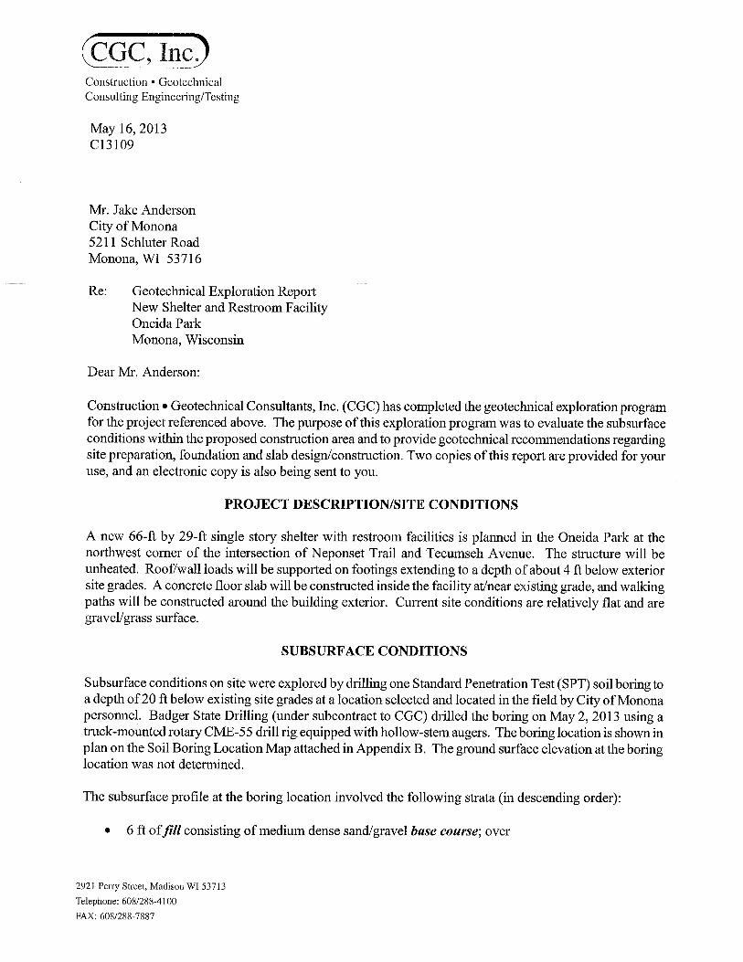
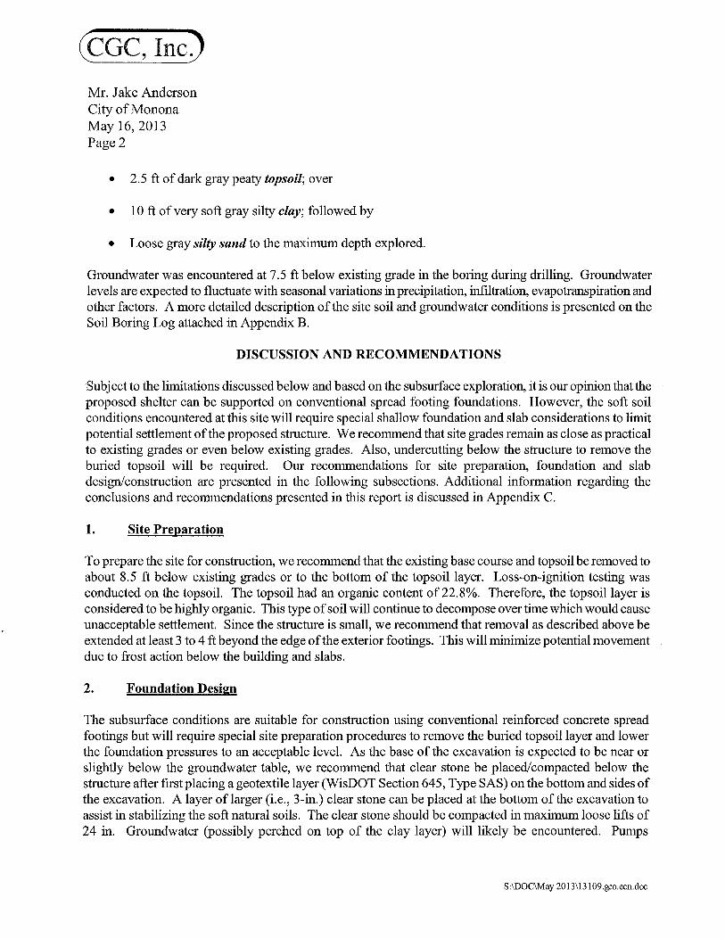
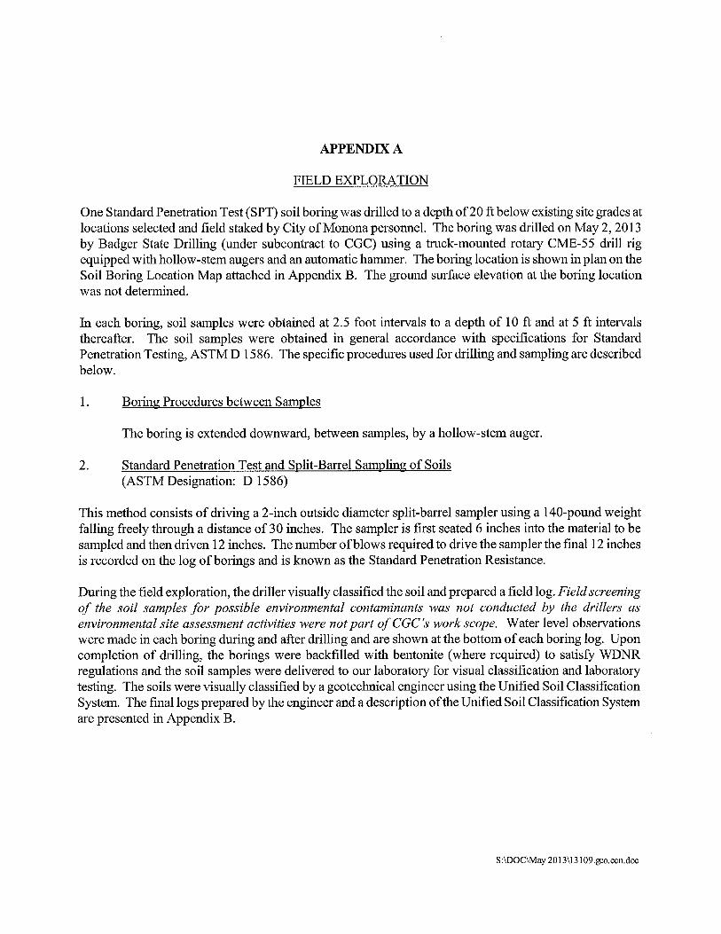

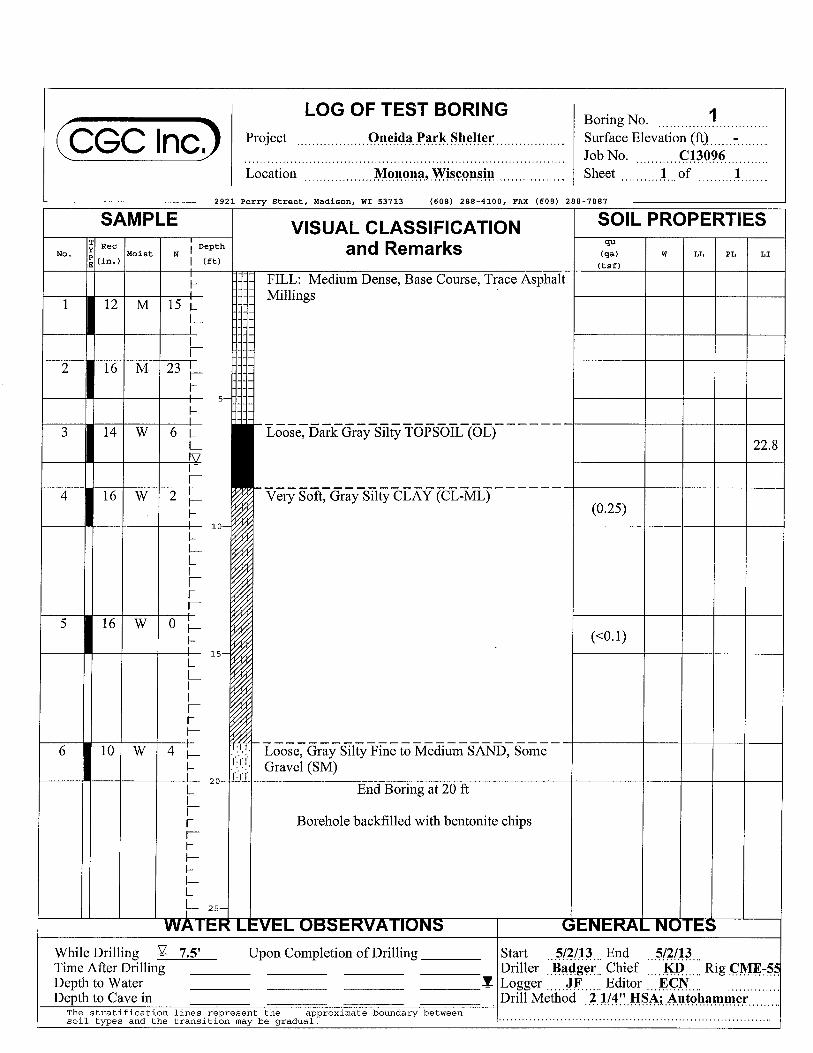
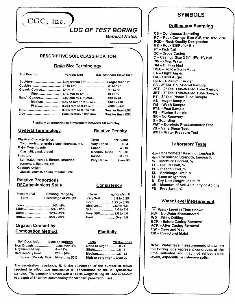
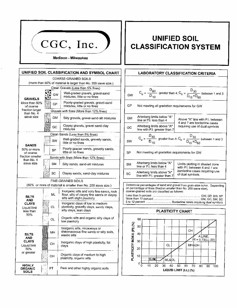
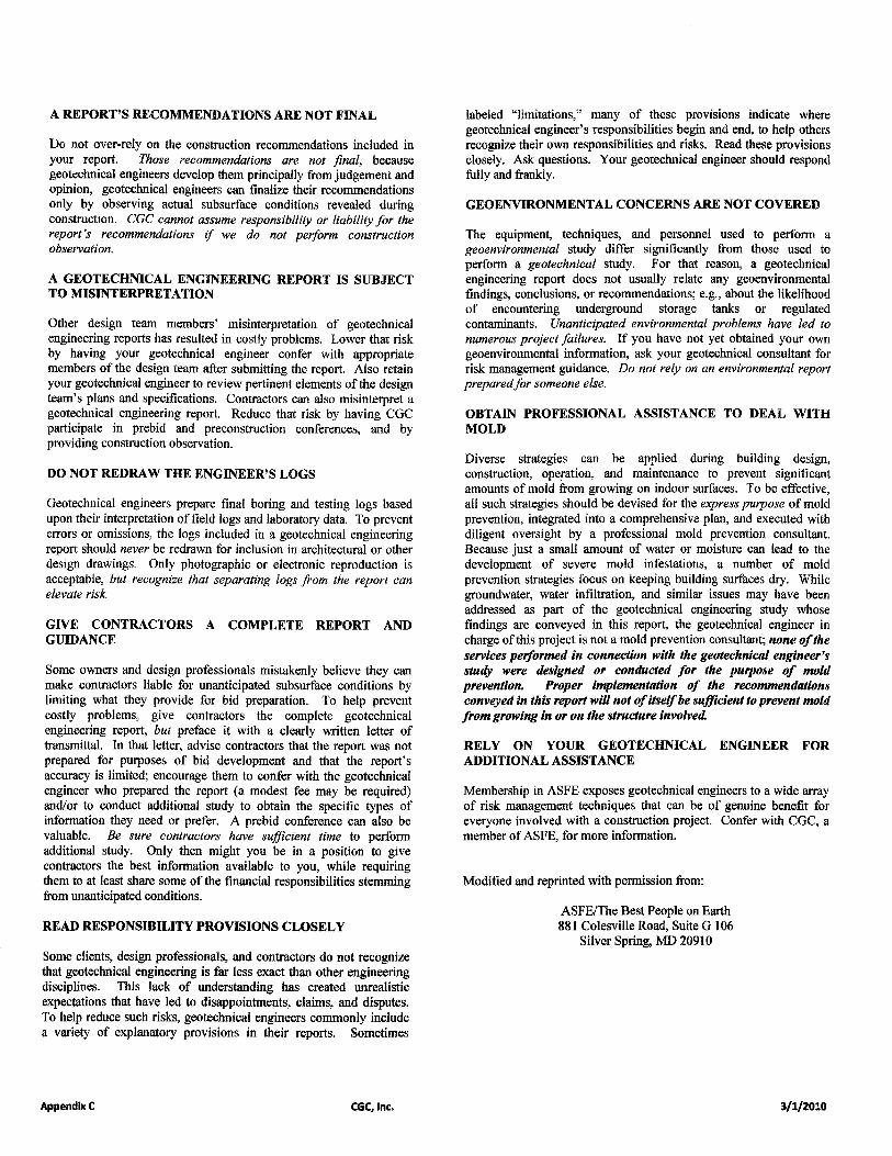
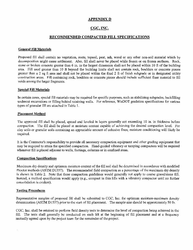
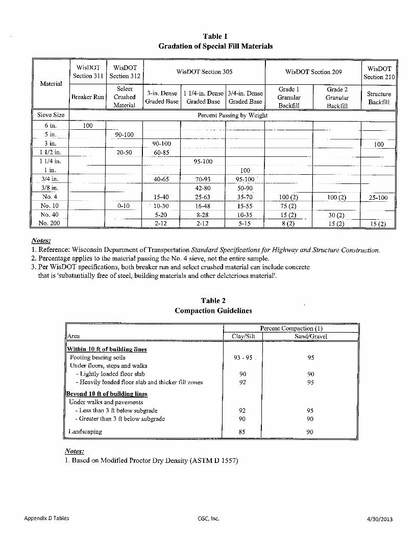
AIA®
Document B105TM – 2007 Standard Form of Agreement Between Owner and Architect for a Residential or Small Commercial Project
ADDITIONS AND DELETIONS: The author of this document has added information needed for its completion. The author may also have revised the text of the original AIA standard form. An Additions and Deletions Report that notes added information as well as revisions to the standard form text is available from the author and should be reviewed.
This document has important legal consequences. Consultation with an attorney is encouraged with respect to its completion or modification.
State or local law may impose requirements on contracts for home improvements. If this document will be used for Work on the Owner’s residence, the Owner should consult local authorities or an attorney to verify requirements applicable to this Agreement.
AGREEMENT made as of the «Tenth » day of «February » in the year «Two Thousand Fourteen » (In words, indicate day, month and year.) BETWEEN the Owner: (Name, legal status, address and other information) «City of Monona»«, Municipality» «5211 Schluter Rd. Monona, WI 53716» «Telephone Number: 608-222-2525» « » and the Architect: (Name, legal status, address and other information) «Aro Eberle Architects»«, Subchapter S Corporation» «116 King Street Suite 202 Madison, WI 53703» « » « » for the following Project: (Name, location and detailed description) «City of Monona - Lottes Park Restroom Building» «Lottes Park City of Monona 400 West Broadway Monona, WI 53716» «Architectural design and engineering services for a new restroom, fish cleaning, and shelter building at Lottes Park in the City of Monona.» The Owner and Architect agree as follows.
AIA Document B105™ – 2007 (formerly B155™ – 1993). Copyright © 1993 and 2007 by The American Institute of Architects. All rights reserved. WARNING: This AIA® Document is protected by U.S. Copyright Law and International Treaties. Unauthorized reproduction or distribution of this AIA® Document, or any portion of it, may result in severe civil and criminal penalties, and will be prosecuted to the maximum extent possible under the law. This draft was produced by AIA software at 14:07:34 on 02/08/2014 under Order No.2129602626_1 which expires on 11/03/2014, and is not for resale. User Notes: (2001694039)
1
ELECTRONIC COPYING of any portion of this AIA® Document to another electronic file is prohibited and constitutes a violation of copyright laws as set forth in the footer of this document.
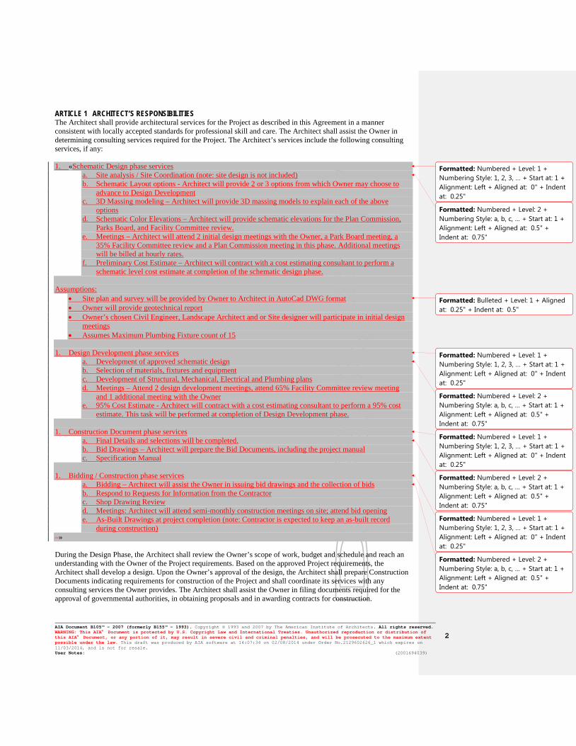
ARTICLE 1 ARCHITECT’S RESPONSIBILITIES The Architect shall provide architectural services for the Project as described in this Agreement in a manner consistent with locally accepted standards for professional skill and care. The Architect shall assist the Owner in determining consulting services required for the Project. The Architect’s services include the following consulting services, if any: 1. «Schematic Design phase services
a. Site analysis / Site Coordination (note: site design is not included) b. Schematic Layout options - Architect will provide 2 or 3 options from which Owner may choose to
advance to Design Development c. 3D Massing modeling – Architect will provide 3D massing models to explain each of the above
options d. Schematic Color Elevations – Architect will provide schematic elevations for the Plan Commission,
Parks Board, and Facility Committee review. e. Meetings – Architect will attend 2 initial design meetings with the Owner, a Park Board meeting, a
35% Facility Committee review and a Plan Commission meeting in this phase. Additional meetings will be billed at hourly rates.
f. Preliminary Cost Estimate – Architect will contract with a cost estimating consultant to perform a schematic level cost estimate at completion of the schematic design phase.
Assumptions:
• Site plan and survey will be provided by Owner to Architect in AutoCad DWG format • Owner will provide geotechnical report • Owner’s chosen Civil Engineer, Landscape Architect and or Site designer will participate in initial design
meetings • Assumes Maximum Plumbing Fixture count of 15
1. Design Development phase services
a. Development of approved schematic design b. Selection of materials, fixtures and equipment c. Development of Structural, Mechanical, Electrical and Plumbing plans d. Meetings – Attend 2 design development meetings, attend 65% Facility Committee review meeting
and 1 additional meeting with the Owner e. 95% Cost Estimate - Architect will contract with a cost estimating consultant to perform a 95% cost
estimate. This task will be performed at completion of Design Development phase. 1. Construction Document phase services
a. Final Details and selections will be completed. b. Bid Drawings – Architect will prepare the Bid Documents, including the project manual c. Specification Manual
1. Bidding / Construction phase services
a. Bidding – Architect will assist the Owner in issuing bid drawings and the collection of bids b. Respond to Requests for Information from the Contractor c. Shop Drawing Review d. Meetings: Architect will attend semi-monthly construction meetings on site; attend bid opening e. As-Built Drawings at project completion (note: Contractor is expected to keep an as-built record
during construction) » During the Design Phase, the Architect shall review the Owner’s scope of work, budget and schedule and reach an understanding with the Owner of the Project requirements. Based on the approved Project requirements, the Architect shall develop a design. Upon the Owner’s approval of the design, the Architect shall prepare Construction Documents indicating requirements for construction of the Project and shall coordinate its services with any consulting services the Owner provides. The Architect shall assist the Owner in filing documents required for the approval of governmental authorities, in obtaining proposals and in awarding contracts for construction.
Formatted: Numbered + Level: 1 +Numbering Style: 1, 2, 3, … + Start at: 1 +Alignment: Left + Aligned at: 0" + Indentat: 0.25"
Formatted: Numbered + Level: 2 +Numbering Style: a, b, c, … + Start at: 1 +Alignment: Left + Aligned at: 0.5" +Indent at: 0.75"
Formatted: Bulleted + Level: 1 + Alignedat: 0.25" + Indent at: 0.5"
Formatted: Numbered + Level: 1 +Numbering Style: 1, 2, 3, … + Start at: 1 +Alignment: Left + Aligned at: 0" + Indentat: 0.25"
Formatted: Numbered + Level: 2 +Numbering Style: a, b, c, … + Start at: 1 +Alignment: Left + Aligned at: 0.5" +Indent at: 0.75"
Formatted: Numbered + Level: 1 +Numbering Style: 1, 2, 3, … + Start at: 1 +Alignment: Left + Aligned at: 0" + Indentat: 0.25"
Formatted: Numbered + Level: 2 +Numbering Style: a, b, c, … + Start at: 1 +Alignment: Left + Aligned at: 0.5" +Indent at: 0.75"
Formatted: Numbered + Level: 1 +Numbering Style: 1, 2, 3, … + Start at: 1 +Alignment: Left + Aligned at: 0" + Indentat: 0.25"
Formatted: Numbered + Level: 2 +Numbering Style: a, b, c, … + Start at: 1 +Alignment: Left + Aligned at: 0.5" +Indent at: 0.75"
AIA Document B105™ – 2007 (formerly B155™ – 1993). Copyright © 1993 and 2007 by The American Institute of Architects. All rights reserved. WARNING: This AIA® Document is protected by U.S. Copyright Law and International Treaties. Unauthorized reproduction or distribution of this AIA® Document, or any portion of it, may result in severe civil and criminal penalties, and will be prosecuted to the maximum extent possible under the law. This draft was produced by AIA software at 14:07:34 on 02/08/2014 under Order No.2129602626_1 which expires on 11/03/2014, and is not for resale. User Notes: (2001694039)
2
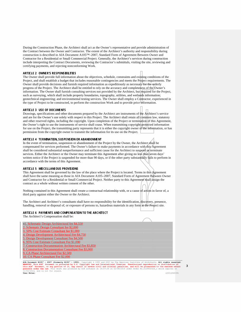
During the Construction Phase, the Architect shall act as the Owner’s representative and provide administration of the Contract between the Owner and Contractor. The extent of the Architect’s authority and responsibility during construction is described in AIA Document A105™–2007, Standard Form of Agreement Between Owner and Contractor for a Residential or Small Commercial Project. Generally, the Architect’s services during construction include interpreting the Contract Documents, reviewing the Contractor’s submittals, visiting the site, reviewing and certifying payments, and rejecting nonconforming Work. ARTICLE 2 OWNER’S RESPONSIBILITIES The Owner shall provide full information about the objectives, schedule, constraints and existing conditions of the Project, and shall establish a budget that includes reasonable contingencies and meets the Project requirements. The Owner shall provide decisions and furnish required information as expeditiously as necessary for the orderly progress of the Project. The Architect shall be entitled to rely on the accuracy and completeness of the Owner’s information. The Owner shall furnish consulting services not provided by the Architect, but required for the Project, such as surveying, which shall include property boundaries, topography, utilities, and wetlands information; geotechnical engineering; and environmental testing services. The Owner shall employ a Contractor, experienced in the type of Project to be constructed, to perform the construction Work and to provide price information. ARTICLE 3 USE OF DOCUMENTS Drawings, specifications and other documents prepared by the Architect are instruments of the Architect’s service and are for the Owner’s use solely with respect to this Project. The Architect shall retain all common law, statutory and other reserved rights, including the copyright. Upon completion of the Project or termination of this Agreement, the Owner’s right to use the instruments of service shall cease. When transmitting copyright-protected information for use on the Project, the transmitting party represents that it is either the copyright owner of the information, or has permission from the copyright owner to transmit the information for its use on the Project. ARTICLE 4 TERMINATION, SUSPENSION OR ABANDONMENT In the event of termination, suspension or abandonment of the Project by the Owner, the Architect shall be compensated for services performed. The Owner’s failure to make payments in accordance with this Agreement shall be considered substantial nonperformance and sufficient cause for the Architect to suspend or terminate services. Either the Architect or the Owner may terminate this Agreement after giving no less than seven days’ written notice if the Project is suspended for more than 90 days, or if the other party substantially fails to perform in accordance with the terms of this Agreement. ARTICLE 5 MISCELLANEOUS PROVISIONS This Agreement shall be governed by the law of the place where the Project is located. Terms in this Agreement shall have the same meaning as those in AIA Document A105–2007, Standard Form of Agreement Between Owner and Contractor for a Residential or Small Commercial Project. Neither party to this Agreement shall assign the contract as a whole without written consent of the other. Nothing contained in this Agreement shall create a contractual relationship with, or a cause of action in favor of, a third party against either the Owner or the Architect. The Architect and Architect’s consultants shall have no responsibility for the identification, discovery, presence, handling, removal or disposal of, or exposure of persons to, hazardous materials in any form at the Project site. ARTICLE 6 PAYMENTS AND COMPENSATION TO THE ARCHITECT The Architect’s Compensation shall be: «1. Schematic Design Architectural fee $4,550 2. Schematic Design Consultant fee $2,000 3. 50% Cost Estimate Consultant fee $1,000 4. Design Development Architectural Fee $4,750 5. Design Development Consultant Fee $4,500 6. 95% Cost Estimate Consultant Fee $1,000 7. Construction Documentation Architectural Fee $3,850 8. Construction Documentation Consultant Fee $3,000 9. CA Phase Architectural Fee $2,500 10. CA Phase Consultant Fee $2,000 AIA Document B105™ – 2007 (formerly B155™ – 1993). Copyright © 1993 and 2007 by The American Institute of Architects. All rights reserved. WARNING: This AIA® Document is protected by U.S. Copyright Law and International Treaties. Unauthorized reproduction or distribution of this AIA® Document, or any portion of it, may result in severe civil and criminal penalties, and will be prosecuted to the maximum extent possible under the law. This draft was produced by AIA software at 14:07:34 on 02/08/2014 under Order No.2129602626_1 which expires on 11/03/2014, and is not for resale. User Notes: (2001694039)
3
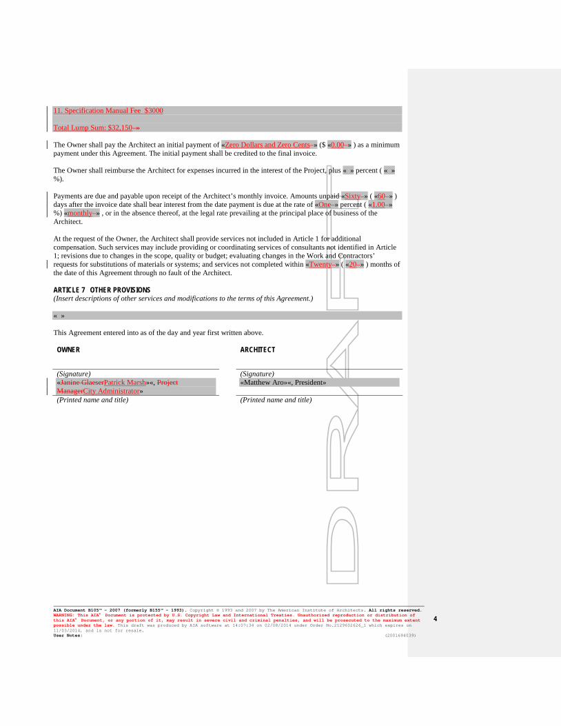
11. Specification Manual Fee $3000 Total Lump Sum: $32,150 » The Owner shall pay the Architect an initial payment of «Zero Dollars and Zero Cents » ($ «0.00 » ) as a minimum payment under this Agreement. The initial payment shall be credited to the final invoice. The Owner shall reimburse the Architect for expenses incurred in the interest of the Project, plus « » percent ( « » %). Payments are due and payable upon receipt of the Architect’s monthly invoice. Amounts unpaid «Sixty » ( «60 » ) days after the invoice date shall bear interest from the date payment is due at the rate of «One » percent ( «1.00 » %) «monthly » , or in the absence thereof, at the legal rate prevailing at the principal place of business of the Architect. At the request of the Owner, the Architect shall provide services not included in Article 1 for additional compensation. Such services may include providing or coordinating services of consultants not identified in Article 1; revisions due to changes in the scope, quality or budget; evaluating changes in the Work and Contractors’ requests for substitutions of materials or systems; and services not completed within «Twenty » ( «20 » ) months of the date of this Agreement through no fault of the Architect. ARTICLE 7 OTHER PROVISIONS (Insert descriptions of other services and modifications to the terms of this Agreement.) « » This Agreement entered into as of the day and year first written above.
OWNER ARCHITECT
(Signature) (Signature) «Janine GlaeserPatrick Marsh»«, Project ManagerCity Administrator»
«Matthew Aro»«, President»
(Printed name and title) (Printed name and title)
AIA Document B105™ – 2007 (formerly B155™ – 1993). Copyright © 1993 and 2007 by The American Institute of Architects. All rights reserved. WARNING: This AIA® Document is protected by U.S. Copyright Law and International Treaties. Unauthorized reproduction or distribution of this AIA® Document, or any portion of it, may result in severe civil and criminal penalties, and will be prosecuted to the maximum extent possible under the law. This draft was produced by AIA software at 14:07:34 on 02/08/2014 under Order No.2129602626_1 which expires on 11/03/2014, and is not for resale. User Notes: (2001694039)
4