City of Friendswood
77
City of Friendswood Acknowledgement of Addendums Date: January 25, 2020 To: Potential Consultants From: Bria A. Whitmire, PE, CFM, Projects Coordinator Re: RFQ 2021-01 Water System Improvements Addenda This signed document shall be included in the final RFQ submittal. This is to serve as an official acknowledgment any addenda that were issued have been received and the contents understood. Please list addenda by number and date. ___________________________________________________________________________ ___________________________________________________________________________ ___________________________________________________________________________ ___________________________________________________________________________ Name: ______________________________ (signature) Name: ______________________________ (printed name) Name: ______________________________ (company name)
-
Upload
khangminh22 -
Category
Documents
-
view
3 -
download
0
Transcript of City of Friendswood

City of Friendswood
Acknowledgement of Addendums
Date: January 25, 2020
To: Potential Consultants
From: Bria A. Whitmire, PE, CFM, Projects Coordinator
Re: RFQ 2021-01 Water System Improvements Addenda
This signed document shall be included in the final RFQ submittal. This is to serve as an official acknowledgment any addenda that were issued have been received and the contents understood. Please list addenda by number and date. ___________________________________________________________________________ ___________________________________________________________________________ ___________________________________________________________________________ ___________________________________________________________________________ Name: ______________________________ (signature) Name: ______________________________ (printed name) Name: ______________________________ (company name)
CITY OF FRIENDSWOOD TECHNICAL SPECIFICATIONS ADDENDUM
00085B-1 City of Friendswood
DOCUMENT 00085B
ADDENDUM
ADDENDUM NO. 1 Date of Addendum: 1/25/2021 PROJECT NAME: WATER SYSTEM IMPROVEMENTS RFQ NO: 2021-01 BID DATE: 2/4/2021 FROM: City of Friendswood Engineering Department 15355 Blackhawk Boulevard Friendswood, TX 77546 TO: Prospective Consultants This Addendum forms a part of the RFQ Documents and shall be incorporated into the Contract documents, as applicable. Insofar as the original Project Manual and Drawings may conflict, this Addendum governs. CLARIFICATIONS
1) Could you please clarify the extents of the transmission line mentioned ending at Sun Meadow?
The proposed current tentative extents are from the Surface Water #2 Station location, to the current Water Plant #4 location. Upon completion of updated review of the City’s utility infrastructure via this process (Water Model/Update to Master Utility Plan), the final route will be determined and designed. It is 5.24 miles point to point, but could be around 8 miles depending on the route.
2) Could you point me to where I can obtain a copy of the current/old “Water
Model/Utility Master Plan”? In an effort to maintain security protocol of our utility infrastructure, we will not be sharing that at this moment. Upon selection of the highest qualified firm, we will provide it then.
CITY OF FRIENDSWOOD TECHNICAL SPECIFICATIONS ADDENDUM
00085B-2 City of Friendswood
3) The RFQ refers to “Elevated Storage #2”. I see that Friendswood has two
elevated storage tanks; one on FM 528 by the Friendswood Sports Park, and one at 1100 Mustang Rd behind the high school. Could you clarify which elevated storage tank is being referenced in the RFQ?
Elevated Storage #2 is referencing the one on FM 528 by the Friendswood Sports Park.
4) Could you provide an address for Surface Water Plant #1? Drinking Water Watch lists a Surface Water Plant on FM 528, but no location data is provided, and I was not able to spot a water plant on FM 528 from satellite images. I see a plant on Blackhawk Blvd very close to FM 528, but DWW also lists a GW plant on Blackhawk. Could you clarify which plant is the Surface water plant mentioned in the RFQ and provide an address?
Surface Water Plant #1 is the plant you found on Blackhawk very close to FM 528. There are two other water wells along Blackhawk which may be what you found from DWW.
5) Is it possible to visit the water plants site and get a better understanding of the scope of services?
The City will not be hosting site visits at this time.
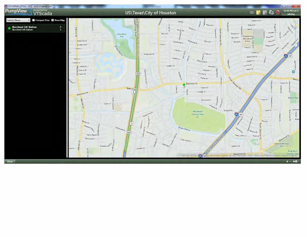
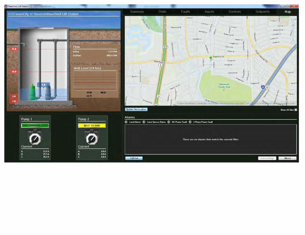
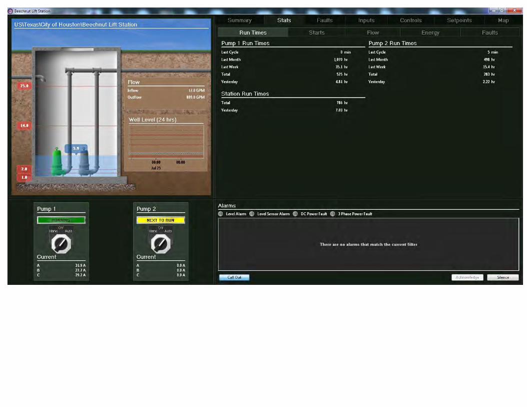
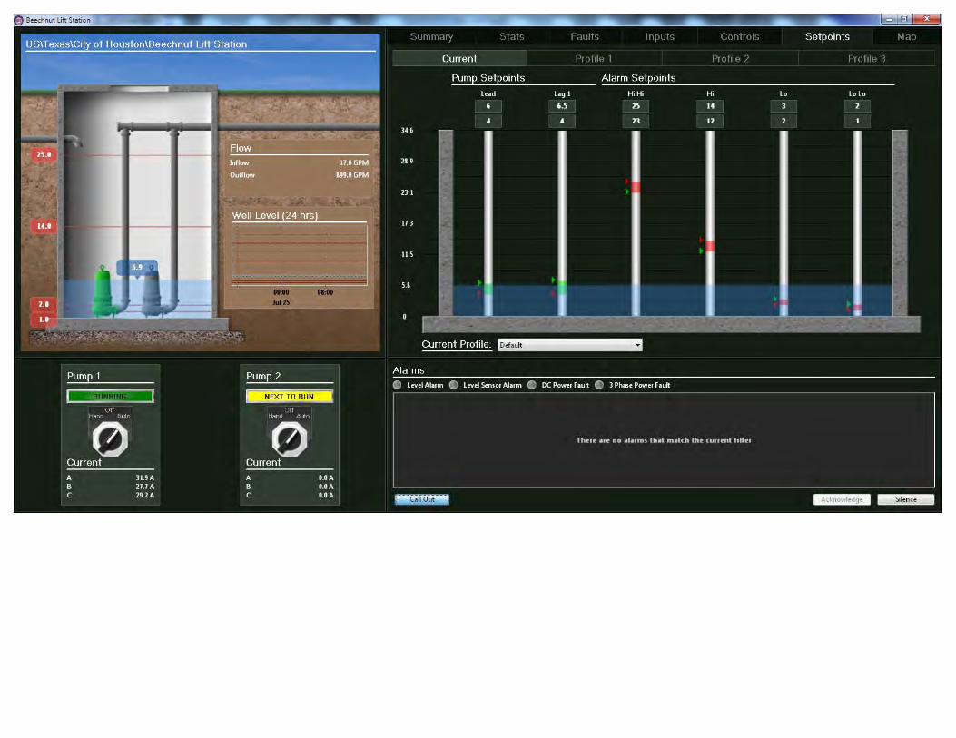
6) Can the City provide information on their existing SCADA system such as
SCADA software name and version, manufacture and model of PLC’s typically used.
VT SCADA Information attached.
7) Does the City see any issue with their SCADA communication such as communication lag or frequent signal drops? Can the City provide information on existing radio telemetry including radio models and frequency used?
SCADA uses cellular communication.
8) Is the master planning portion of the project only to update the new take point on Beamer Rd and transmission line to Sun Meadow in the water model or do they want a full city master plan update including updated demands and identification of additional projects needed to meet future demands?
The goal is to conduct an update to our Master Utility Plan, along with conducting a water model of our system for added back up support/data in outlining current and future projects. It will also be utilized to evaluate current demands and confirming future proposed demands line up with available capacity.
CITY OF FRIENDSWOOD TECHNICAL SPECIFICATIONS ADDENDUM
00085B-3 City of Friendswood
9) What type of Cathodic Protection system(s) do they currently have, if any? Corppro.
10) Are the Cathodic Protection system(s) presently operating? They are in need of replacement or repair.
11) Are tanks electrically isolate from inlet, outlet, drain, and overflow piping? Unsure.
12) Will the existing well(s) be decommissioned or remain in place as a backup source (blending)?
Existing wells will remain.
13) Will a flow meter be required for the new surface water supply? Yes.
14) What is the source of the surface water? City of Houston (Southeast Water Purification Plant).
15) What form of chlorine disinfection is used – free chlorine or chloramines? Chloramine.
16) Will there be a site visit allowed to the water tank sites? The City will not be hosting site visits at this time.
17) In Section VII G. – Is numbered right #4 reserved to the City missing, or is the numbering off?
This is a typo-the numbering is off.
END OF ADDENDUM NO. 1
END OF DOCUMENT
Hahn Equipment Co., Inc.
PROJECT INFORMATION
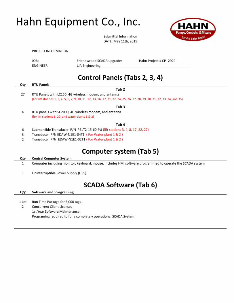
JOB: Friendswood SCADA upgrades Hahn Project # CP- 2929
ENGINEER: LJA Engineering
Qty RTU Panels
27
4 RTU panels with SC2000, 4G wireless modem, and antenna(for lift stations 8, 20, and water plants 1 & 2)
6 Submersible Transducer P/N PBLT2-15-60-PU (lift stations 3, 4, 8, 17, 22, 27)
3 Transducer P/N EDAW-N1E1-04T1 ( For Water plant 1 & 2 )
2 Transducer P/N EDAW-N1E1-02T1 ( For Water plant 1 & 2 )
Qty Central Computer System
1
1 Uninterruptible Power Supply (UPS)
Qty Software and Programing
1 Lot Run Time Package for 5,000 tags
2 Concurrent Client Licenses
1st Year Software Maintenance
Programing required to for a completely operational SCADA System
SCADA Software (Tab 6)
Tab 2
Tab 3
Tab 4
RTU Panels with LC150, 4G wireless modem, and antenna (For lift stations 1, 3, 4, 5, 6, 7, 9, 10, 11, 12, 13, 16, 17, 21, 22, 24, 25, 26, 27, 28, 29, 30, 31, 32, 33, 34, and 35)
Computer system (Tab 5)
Computer including monitor, keyboard, mouse. Includes HMI software programmed to operate the SCADA system
Submittal Information
DATE: May 11th, 2015
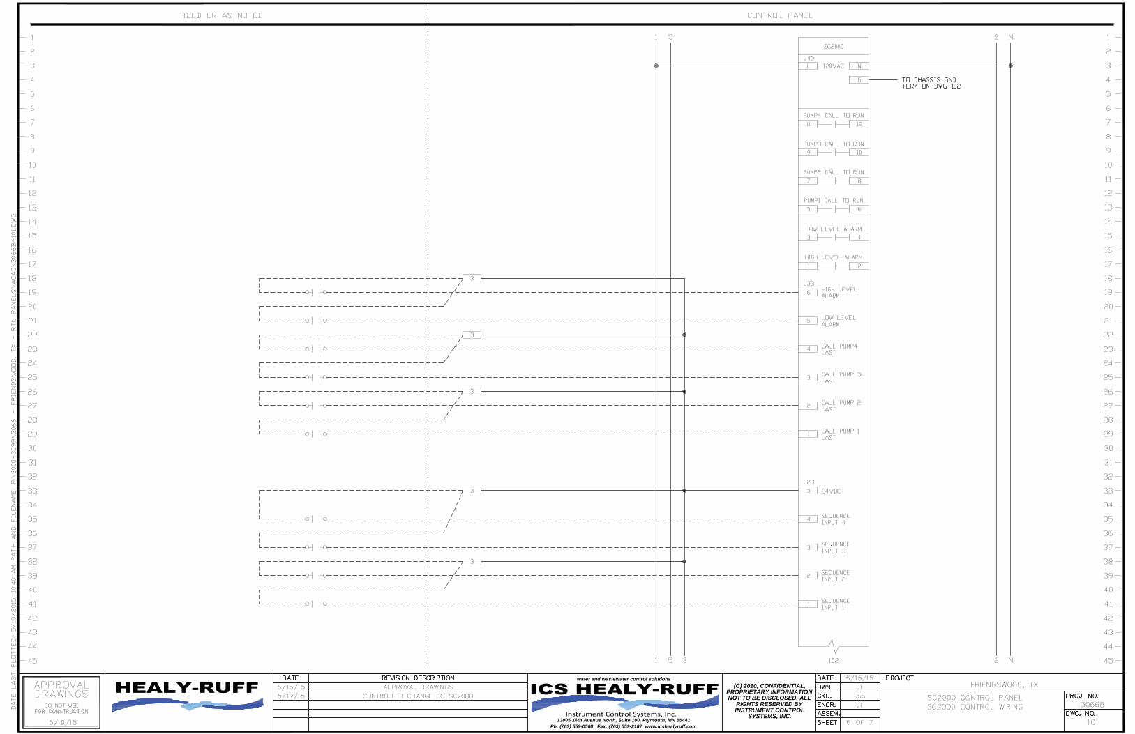
Control Panels (Tabs 2, 3, 4)

Friendswood, TX Project No.: 3066
3066ES Page 2 of 2 5/15/15
DOCUMENTATION
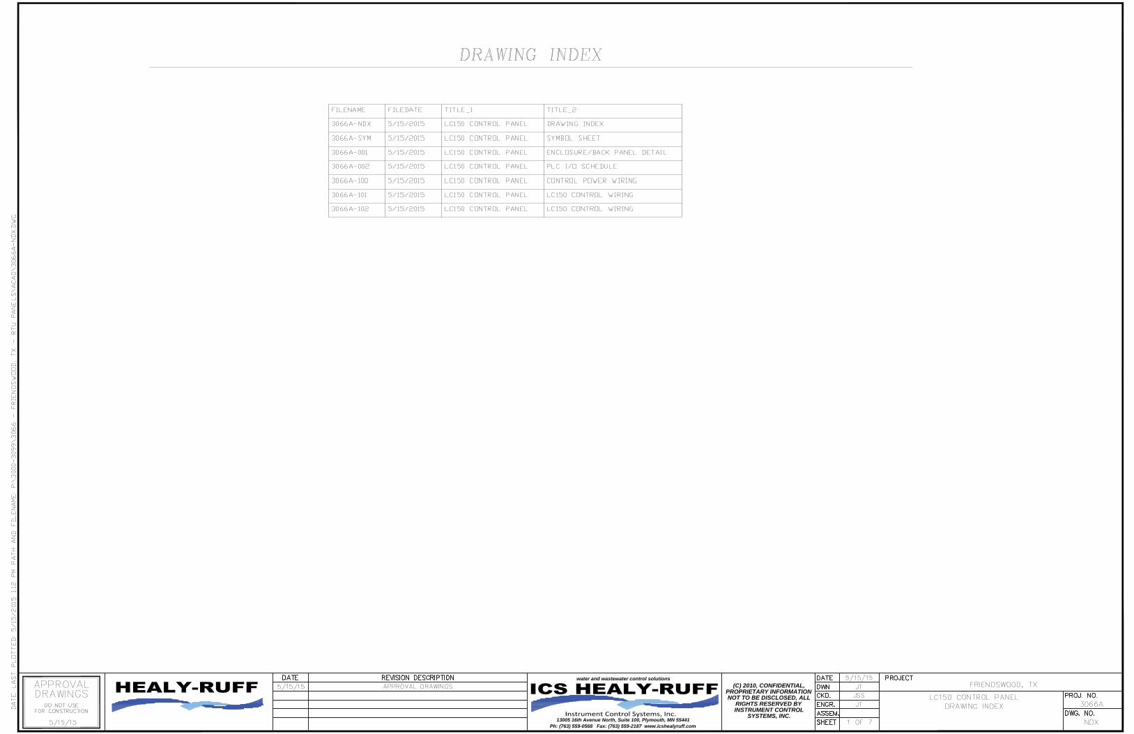
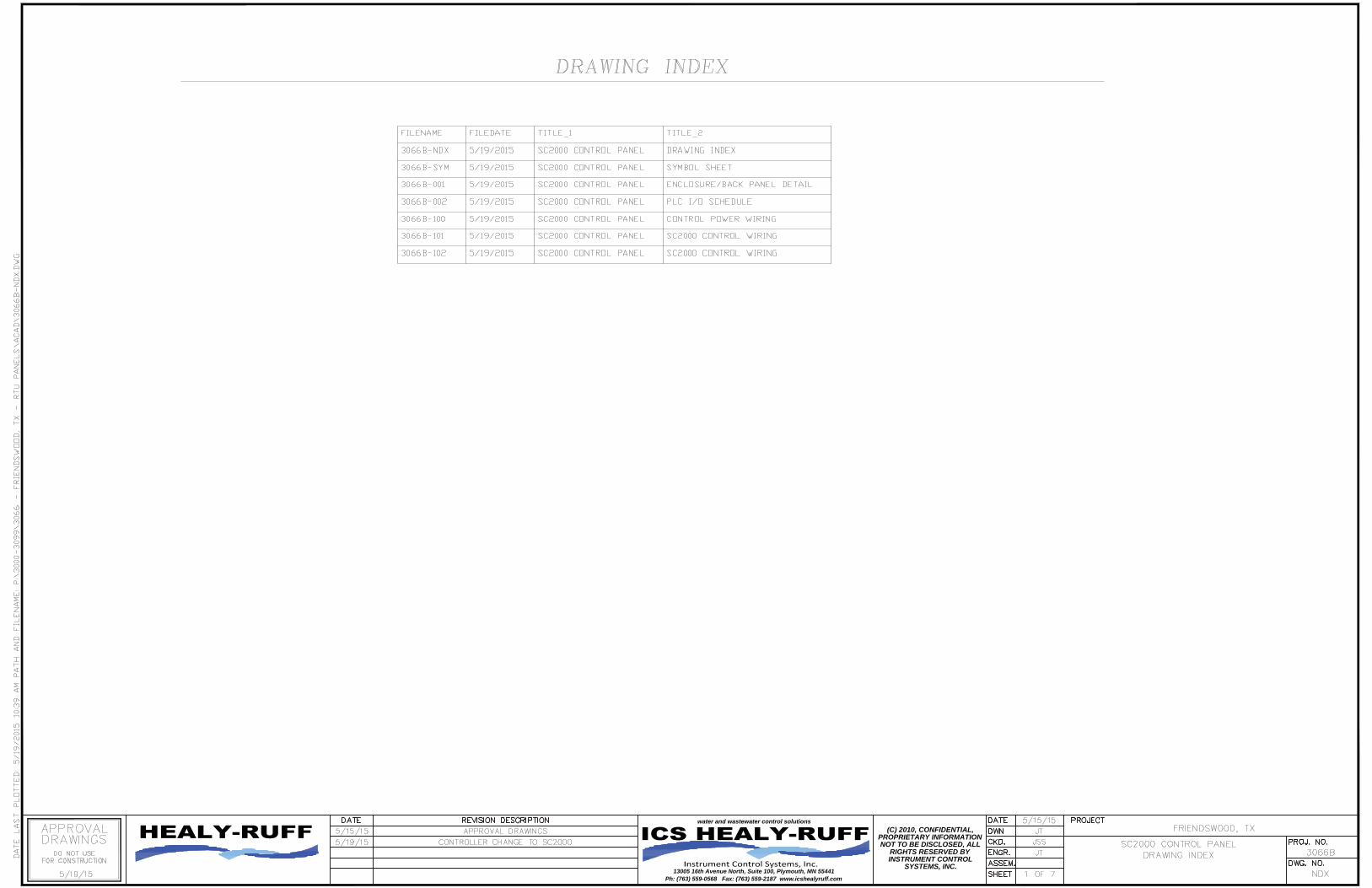
INDEX 1) Order Summary 2) Unit A Schematic Drawings 3066A-001 to 102 3) Unit B Schematic Drawings 3066B-001 to 103 4) Catalog Cuts and Information Sheets

13005 16TH AVE. NORTH • SUITE 100 • PLYMOUTH MN 55441
PHONE: (763) 559-0568 • FAX: (763) 559-2187 www.icshealyruff.com
ENGINEERING • INSTALLATION • SERVICE
TAB 1
Friendswood, TX Project No.: 3066
3066OS Page 1 of 1 5/1/15
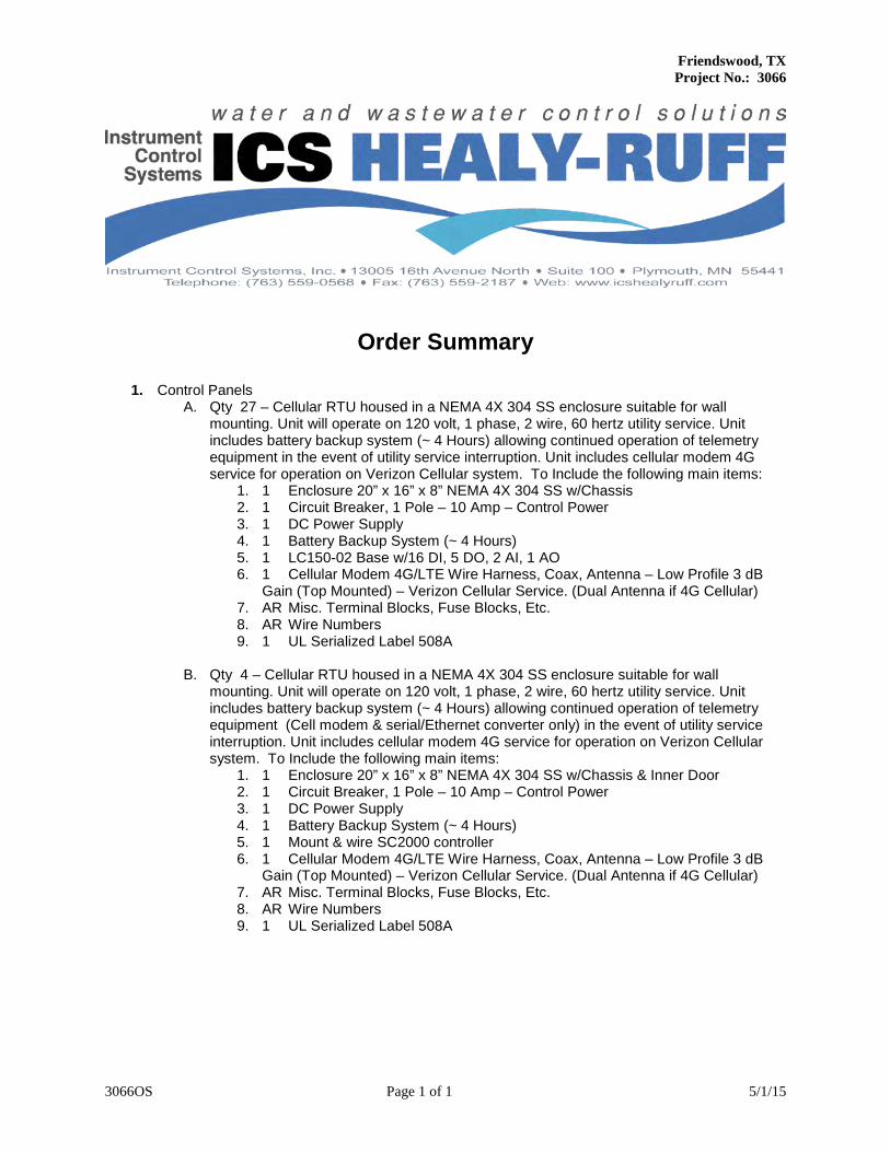
Order Summary
1. Control Panels
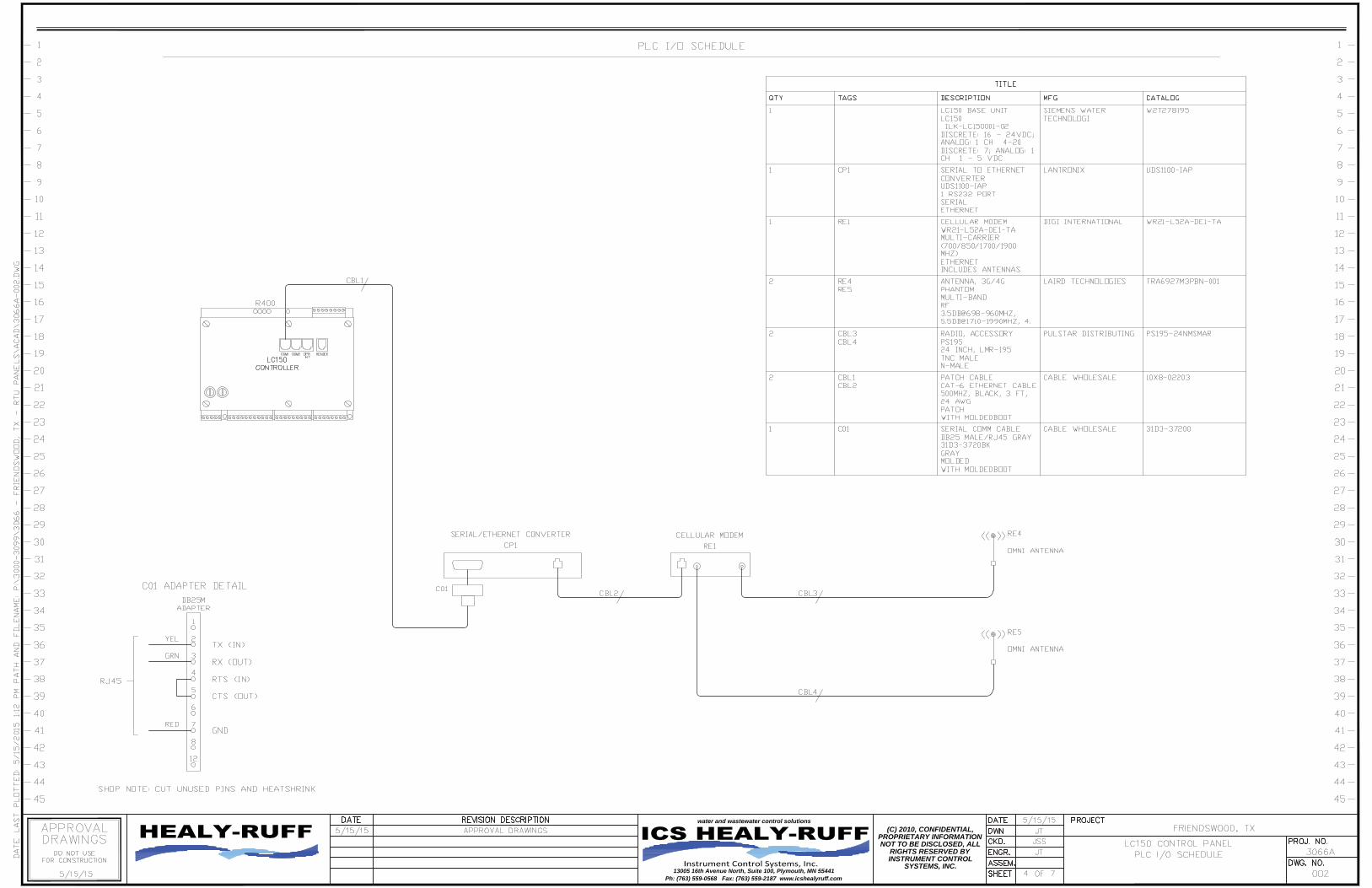
A. Qty 27 – Cellular RTU housed in a NEMA 4X 304 SS enclosure suitable for wall mounting. Unit will operate on 120 volt, 1 phase, 2 wire, 60 hertz utility service. Unit includes battery backup system (~ 4 Hours) allowing continued operation of telemetry equipment in the event of utility service interruption. Unit includes cellular modem 4G service for operation on Verizon Cellular system. To Include the following main items:
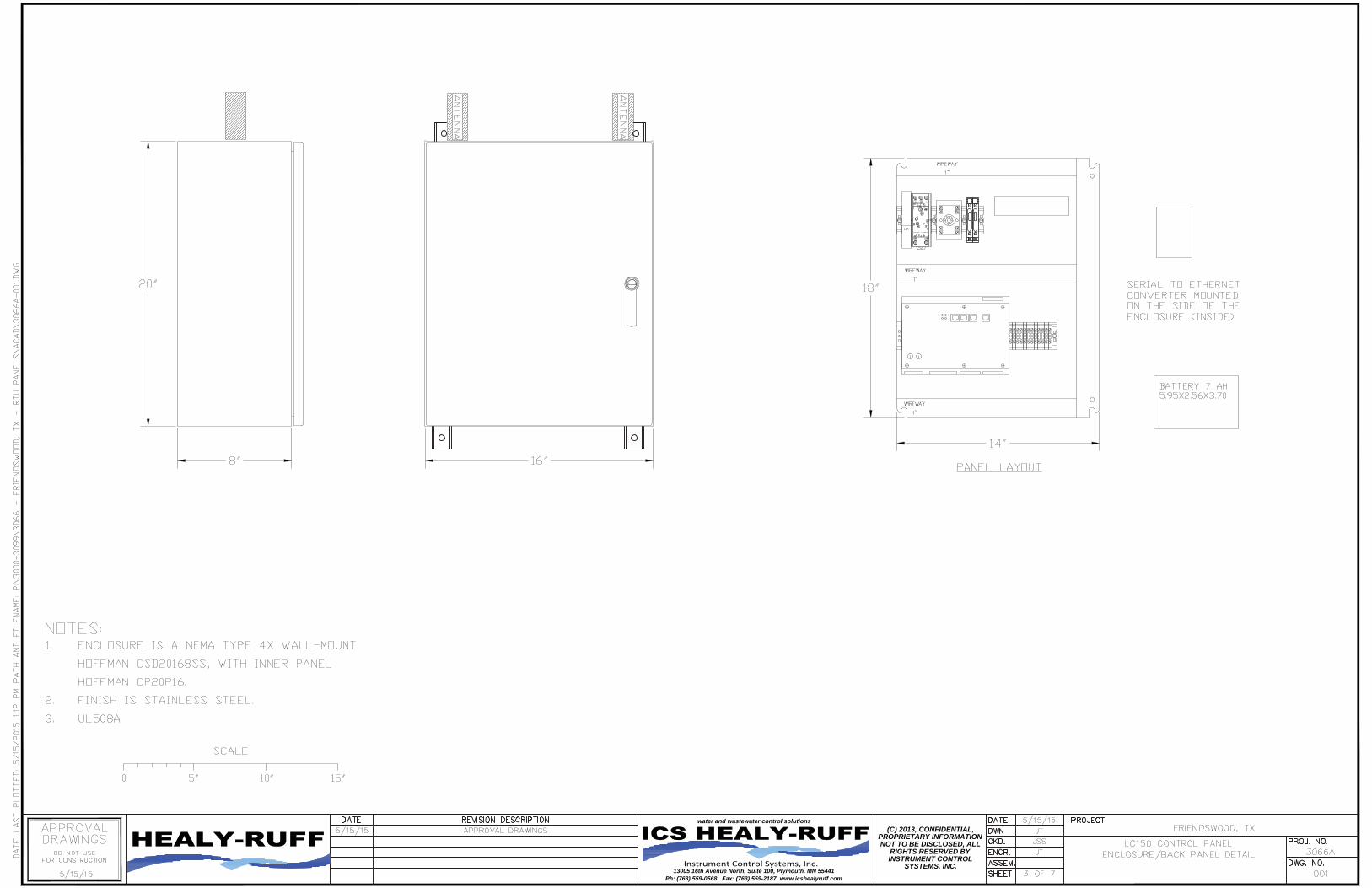
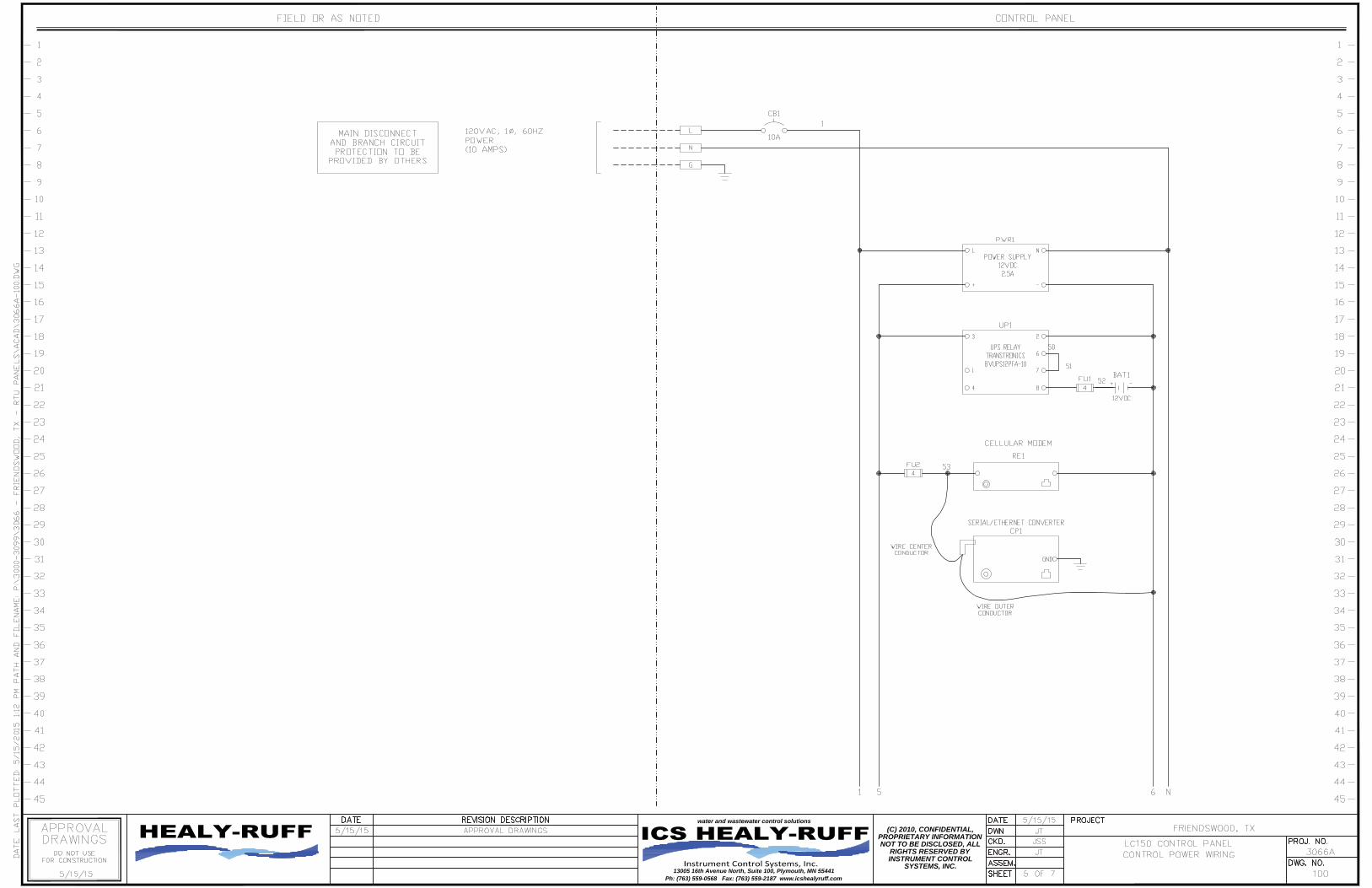
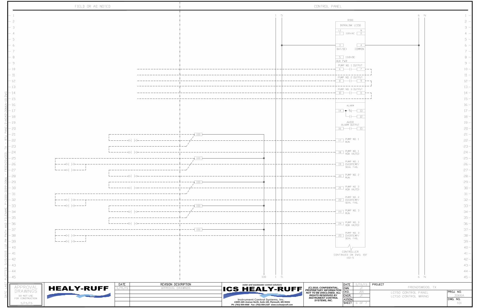
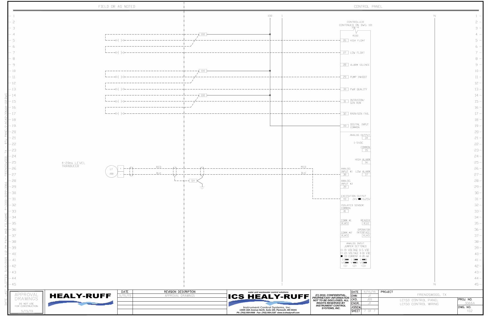
1. 1 Enclosure 20” x 16” x 8” NEMA 4X 304 SS w/Chassis 2. 1 Circuit Breaker, 1 Pole – 10 Amp – Control Power 3. 1 DC Power Supply 4. 1 Battery Backup System (~ 4 Hours) 5. 1 LC150-02 Base w/16 DI, 5 DO, 2 AI, 1 AO 6. 1 Cellular Modem 4G/LTE Wire Harness, Coax, Antenna – Low Profile 3 dB
Gain (Top Mounted) – Verizon Cellular Service. (Dual Antenna if 4G Cellular) 7. AR Misc. Terminal Blocks, Fuse Blocks, Etc. 8. AR Wire Numbers 9. 1 UL Serialized Label 508A
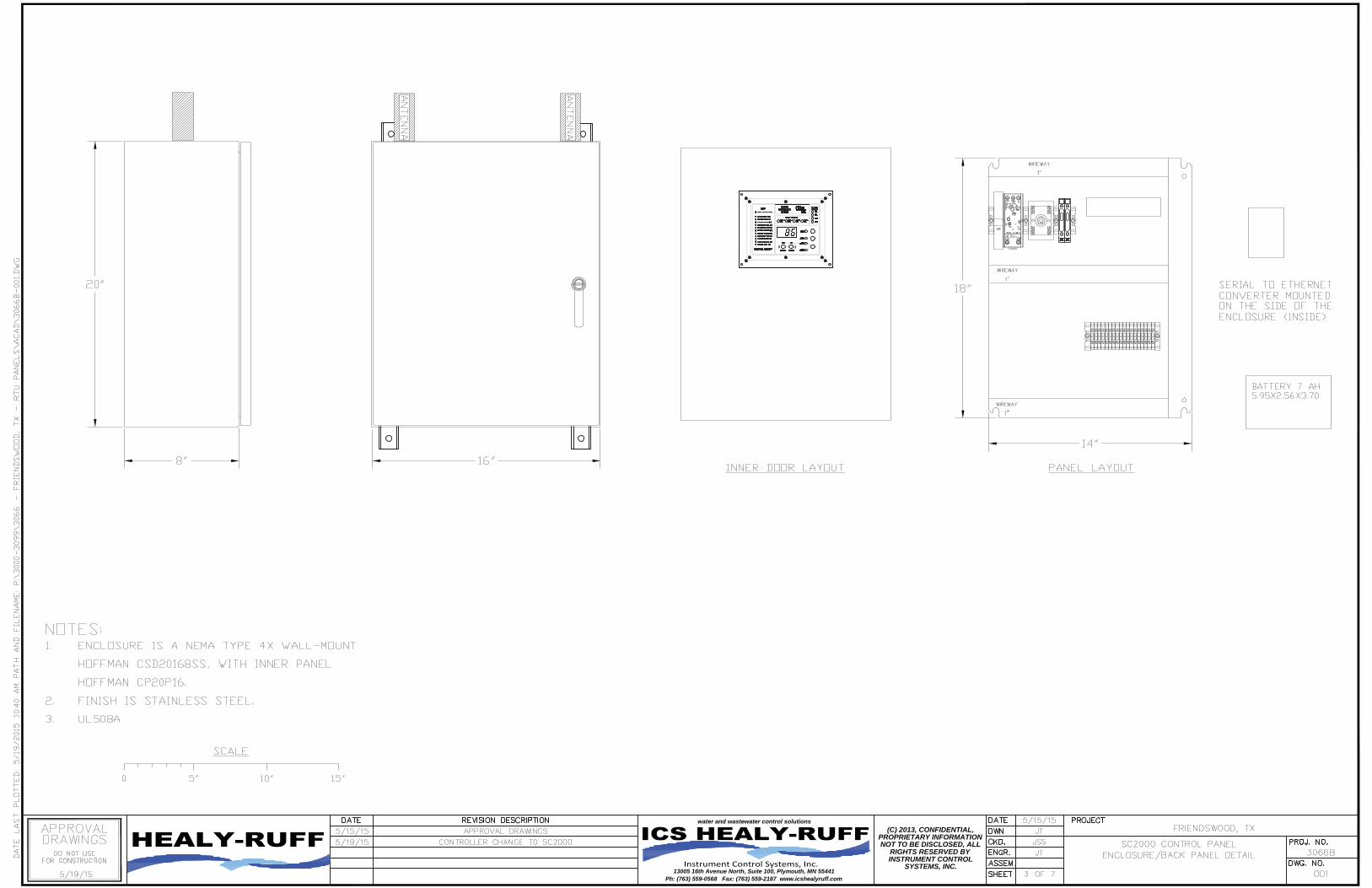
B. Qty 4 – Cellular RTU housed in a NEMA 4X 304 SS enclosure suitable for wall
mounting. Unit will operate on 120 volt, 1 phase, 2 wire, 60 hertz utility service. Unit includes battery backup system (~ 4 Hours) allowing continued operation of telemetry equipment (Cell modem & serial/Ethernet converter only) in the event of utility service interruption. Unit includes cellular modem 4G service for operation on Verizon Cellular system. To Include the following main items:
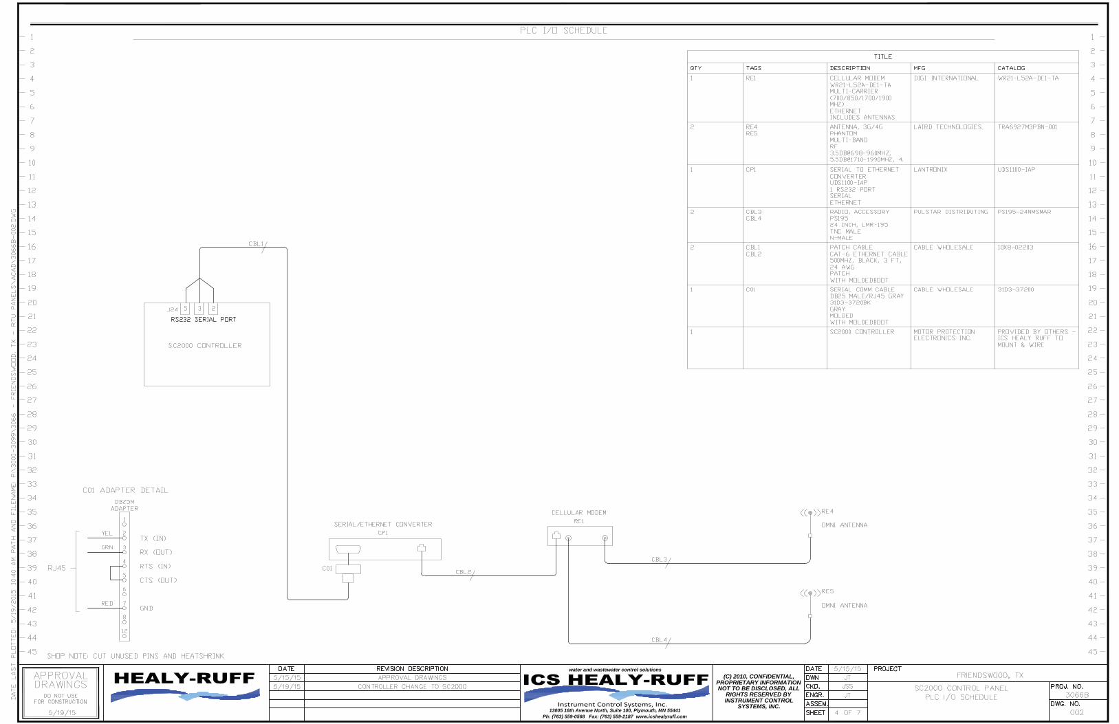
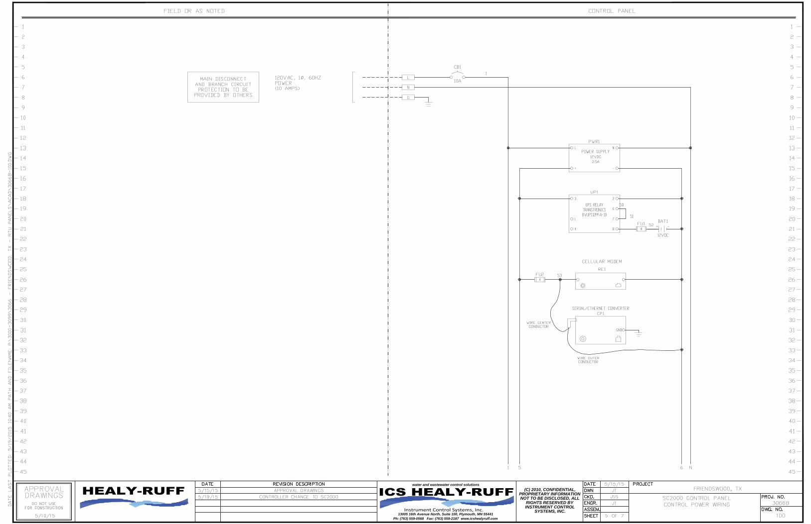
1. 1 Enclosure 20” x 16” x 8” NEMA 4X 304 SS w/Chassis & Inner Door 2. 1 Circuit Breaker, 1 Pole – 10 Amp – Control Power 3. 1 DC Power Supply 4. 1 Battery Backup System (~ 4 Hours) 5. 1 Mount & wire SC2000 controller 6. 1 Cellular Modem 4G/LTE Wire Harness, Coax, Antenna – Low Profile 3 dB
Gain (Top Mounted) – Verizon Cellular Service. (Dual Antenna if 4G Cellular) 7. AR Misc. Terminal Blocks, Fuse Blocks, Etc. 8. AR Wire Numbers 9. 1 UL Serialized Label 508A

13005 16TH AVE. NORTH • SUITE 100 • PLYMOUTH MN 55441
PHONE: (763) 559-0568 • FAX: (763) 559-2187 www.icshealyruff.com
ENGINEERING • INSTALLATION • SERVICE
TAB 2
(C) 2010, CONFIDENTIAL,PROPRIETARY INFORMATIONNOT TO BE DISCLOSED, ALL
RIGHTS RESERVED BYINSTRUMENT CONTROL
SYSTEMS, INC.13005 16th Avenue North, Suite 100, Plymouth, MN 55441
water and wastewater control solutions
Ph: (763) 559-0568 Fax: (763) 559-2187 www.icshealyruff.com
(C) 2010, CONFIDENTIAL,PROPRIETARY INFORMATIONNOT TO BE DISCLOSED, ALL
RIGHTS RESERVED BYINSTRUMENT CONTROL
SYSTEMS, INC.13005 16th Avenue North, Suite 100, Plymouth, MN 55441
water and wastewater control solutions
Ph: (763) 559-0568 Fax: (763) 559-2187 www.icshealyruff.com
(C) 2013, CONFIDENTIAL,PROPRIETARY INFORMATIONNOT TO BE DISCLOSED, ALL
RIGHTS RESERVED BYINSTRUMENT CONTROL
SYSTEMS, INC.13005 16th Avenue North, Suite 100, Plymouth, MN 55441
water and wastewater control solutions
Ph: (763) 559-0568 Fax: (763) 559-2187 www.icshealyruff.com
(C) 2010, CONFIDENTIAL,PROPRIETARY INFORMATIONNOT TO BE DISCLOSED, ALL
RIGHTS RESERVED BYINSTRUMENT CONTROL
SYSTEMS, INC.13005 16th Avenue North, Suite 100, Plymouth, MN 55441
water and wastewater control solutions
Ph: (763) 559-0568 Fax: (763) 559-2187 www.icshealyruff.com
(C) 2010, CONFIDENTIAL,PROPRIETARY INFORMATIONNOT TO BE DISCLOSED, ALL
RIGHTS RESERVED BYINSTRUMENT CONTROL
SYSTEMS, INC.13005 16th Avenue North, Suite 100, Plymouth, MN 55441
water and wastewater control solutions
Ph: (763) 559-0568 Fax: (763) 559-2187 www.icshealyruff.com
(C) 2010, CONFIDENTIAL,PROPRIETARY INFORMATIONNOT TO BE DISCLOSED, ALL
RIGHTS RESERVED BYINSTRUMENT CONTROL
SYSTEMS, INC.13005 16th Avenue North, Suite 100, Plymouth, MN 55441
water and wastewater control solutions
Ph: (763) 559-0568 Fax: (763) 559-2187 www.icshealyruff.com
(C) 2010, CONFIDENTIAL,PROPRIETARY INFORMATIONNOT TO BE DISCLOSED, ALL
RIGHTS RESERVED BYINSTRUMENT CONTROL
SYSTEMS, INC.13005 16th Avenue North, Suite 100, Plymouth, MN 55441
water and wastewater control solutions
Ph: (763) 559-0568 Fax: (763) 559-2187 www.icshealyruff.com

13005 16TH AVE. NORTH • SUITE 100 • PLYMOUTH MN 55441
PHONE: (763) 559-0568 • FAX: (763) 559-2187 www.icshealyruff.com
ENGINEERING • INSTALLATION • SERVICE
TAB 3
(C) 2010, CONFIDENTIAL,PROPRIETARY INFORMATIONNOT TO BE DISCLOSED, ALL
RIGHTS RESERVED BYINSTRUMENT CONTROL
SYSTEMS, INC.13005 16th Avenue North, Suite 100, Plymouth, MN 55441
water and wastewater control solutions
Ph: (763) 559-0568 Fax: (763) 559-2187 www.icshealyruff.com

(C) 2010, CONFIDENTIAL,PROPRIETARY INFORMATIONNOT TO BE DISCLOSED, ALL
RIGHTS RESERVED BYINSTRUMENT CONTROL
SYSTEMS, INC.13005 16th Avenue North, Suite 100, Plymouth, MN 55441
water and wastewater control solutions
Ph: (763) 559-0568 Fax: (763) 559-2187 www.icshealyruff.com
(C) 2013, CONFIDENTIAL,PROPRIETARY INFORMATIONNOT TO BE DISCLOSED, ALL
RIGHTS RESERVED BYINSTRUMENT CONTROL
SYSTEMS, INC.13005 16th Avenue North, Suite 100, Plymouth, MN 55441
water and wastewater control solutions
Ph: (763) 559-0568 Fax: (763) 559-2187 www.icshealyruff.com
(C) 2010, CONFIDENTIAL,PROPRIETARY INFORMATIONNOT TO BE DISCLOSED, ALL
RIGHTS RESERVED BYINSTRUMENT CONTROL
SYSTEMS, INC.13005 16th Avenue North, Suite 100, Plymouth, MN 55441
water and wastewater control solutions
Ph: (763) 559-0568 Fax: (763) 559-2187 www.icshealyruff.com
(C) 2010, CONFIDENTIAL,PROPRIETARY INFORMATIONNOT TO BE DISCLOSED, ALL
RIGHTS RESERVED BYINSTRUMENT CONTROL
SYSTEMS, INC.13005 16th Avenue North, Suite 100, Plymouth, MN 55441
water and wastewater control solutions
Ph: (763) 559-0568 Fax: (763) 559-2187 www.icshealyruff.com
(C) 2010, CONFIDENTIAL,PROPRIETARY INFORMATIONNOT TO BE DISCLOSED, ALL
RIGHTS RESERVED BYINSTRUMENT CONTROL
SYSTEMS, INC.13005 16th Avenue North, Suite 100, Plymouth, MN 55441
water and wastewater control solutions
Ph: (763) 559-0568 Fax: (763) 559-2187 www.icshealyruff.com

(C) 2010, CONFIDENTIAL,PROPRIETARY INFORMATIONNOT TO BE DISCLOSED, ALL
RIGHTS RESERVED BYINSTRUMENT CONTROL
SYSTEMS, INC.13005 16th Avenue North, Suite 100, Plymouth, MN 55441
water and wastewater control solutions
Ph: (763) 559-0568 Fax: (763) 559-2187 www.icshealyruff.com

13005 16TH AVE. NORTH • SUITE 100 • PLYMOUTH MN 55441
PHONE: (763) 559-0568 • FAX: (763) 559-2187 www.icshealyruff.com
ENGINEERING • INSTALLATION • SERVICE
TAB 4
6.20 Data subject to change without notice 763 422 2211 FAX 763 422 2600 ©2003 Hoffman Enclosures Inc.
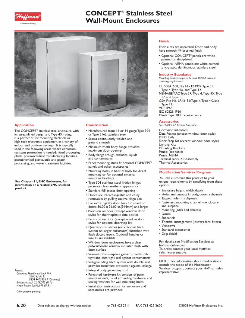
Application
The CONCEPT® stainless steel enclosure, withits streamlined design and Type 4X rating,is a perfect fit for mounting electrical or high-tech electronic equipment in a variety ofindoor and outdoor settings. It is typicallyused in the following areas where corrosion-resistant protection is needed: food processingplants, pharmaceutical manufacturing facilities,petrochemical plants, pulp and paperprocessing, and water treatment facilities.
Construction
• Manufactured from 16 or 14 gauge Type 304or Type 316L stainless steel
• Seams continuously welded and ground smooth
• Minimum width body flange providesmaximum door opening
• Body flange trough excludes liquids and contaminants
• Panel mounting studs fit optional CONCEPT®
panels and other accessories• Mounting holes in back of body for direct
mounting or for optional external mounting brackets
• Type 304 stainless steel hidden hingespromote clean aesthetic appearance
• Standard full access door opening• Doors are interchangeable and easily
removable by pulling captive hinge pins• For extra rigidity, door bars furnished on
doors 36.00 x 36.00 in.(914mm) and larger• Provision on door (except window door
style) for thermoplastic data pocket• Provision on door (except window door
style) for optional doorstop kit• Quarter-turn latches (or a 3-point latch
system on larger enclosures) furnished withflush slotted insert. Optional handles orinserts are available.
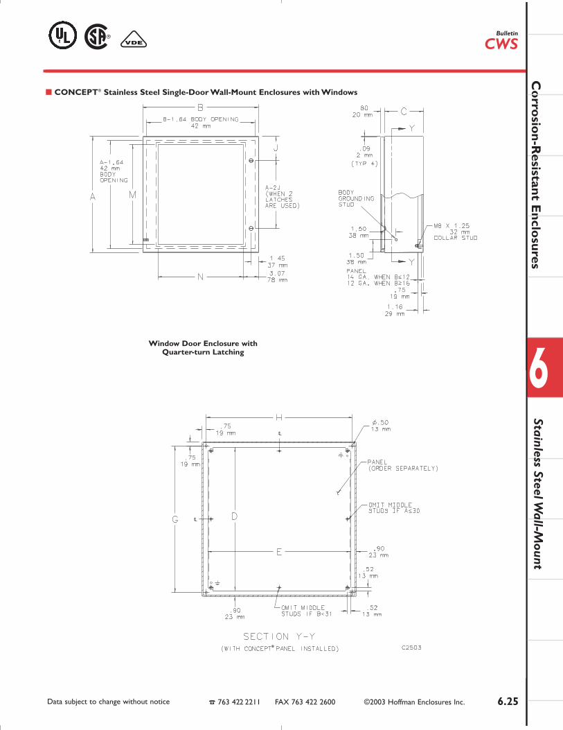
• Window door enclosures have a clearpolycarbonate window mounted flush withdoor surface
• Seamless foam-in-place gasket provides oil-tight and dust-tight seal against contaminants
• Self-grounding latch system with double sealprovides maximum protection against leakage
• Integral body grounding stud• Furnished hardware kit consists of panel
mounting nuts, panel grounding hardware, andsealing washers for wall-mounting holes
• Installation instructions for enclosure andaccessories are provided
Finish
Enclosures are unpainted. Door and bodyhave smooth #4 brushed finish.
• Optional CONCEPT® panels are whitepainted or zinc-plated.
• Optional NEMA panels are white painted,zinc-plated, aluminum, or stainless steel.
Industry StandardsMounting brackets required to meet UL/CSA externalmounting requirements.
UL 508A, 508, File No. E61997:Type 3R,Type 4,Type 4X, and Type 12
NEMA/EEMAC Type 3R,Type 4,Type 4X,Type12, and Type 13
CSA File No. LR42186:Type 4,Type 4X, andType 12
VDE IP66IEC 60529, IP66Meets Type 3RX requirements
AccessoriesSee Chapter 12, General Accessories.
Corrosion InhibitorsData Pocket (except window door style)DIN3 RailsDoor Stop Kit (except window door style)Lighting KitsMounting BracketsPanels (see table)Panels, NEMATerminal Block Kit AssemblyThermal Accessories
CONCEPT® Stainless Steel Wall-Mount Enclosures
Patents:Combined Handle and Lock Unit
360,345 (U.S.)DEM 9405854.7 (Germany)
Enclosure Latch 5,509,703 (U.S.)Hinge System 5,666,695 (U..S.)
Other patents pending.
Modification Services Program
You can customize this product to yourunique requirements by specifying from theseoptions:
• Enclosure height, width, depth• Holes and cutouts in body, doors, subpanels• Tapped holes in subpanels• Fasteners, mounting channel in enclosure
and subpanel• Mounting (adds and deletes)• Doors• Subpanels• Thermal management (louvers, fans, filters)• Windows• Standard accessories• Drip shield
For details, see Modification Services athoffmanonline.com.To order, contact your local Hoffmansales representative.
NOTE: For information about modificationsoutside the scope of the ModificationServices program, contact your Hoffman salesrepresentative.
See Chapter 11, EMC Enclosures, forinformation on a related EMC-shieldedproduct.
Co
rrosio
n-Resistant E
nclosures
6
Data subject to change without notice 763 422 2211 FAX 763 422 2600 ©2003 Hoffman Enclosures Inc. 6.21
Stainless steel strap withgalvanized unistrut.
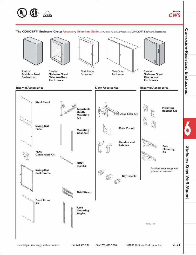
The CONCEPT® Enclosure Group Accessory Selection Guide See Chapter 12, General Accessories: CONCEPT® Enclosure Accessories
Steel or Stainless Steel Enclosures
Steel or Stainless Steel Window-Door Enclosures
Flush Mount Enclosures
Two-Door Enclosures
Steel or Stainless SteelDisconnect Enclosures
Steel Panel
Adjustable DepthMounting Kit
Pole Mounting Kit
Mounting Bracket Kit
Door Stop Kit
Data Pocket
Handles and Latches
Key Inserts
Mounting Channels
DIN3 Rail Kit
Grid Straps
Rack Mounting Angles
Swing-Out Panel
Panel Conversion Kit
Swing-Out Rack Frame
Dead Front Kit
Internal Accessories Door Accessories External Accessories
Stainless Steel Wall-M
ountBulletin
CWS

6.22 Data subject to change without notice 763 422 2211 FAX 763 422 2600 ©2003 Hoffman Enclosures Inc.
Type 304 Type 316LCatalog Catalog Door Body Enclosure Size * CONCEPT® Panel Panel Size Mounting LatchesNumber Number Gauge Gauge A x B x C Catalog Number D x E G x H qty style JCSD12126SS CSD12126SS6 16 16 12.00 x 12.00 x 6.00 CP1212 10.20 x 10.20 10.50 x 10.50 1 Quarter-turn 6.00
(305 x 305 x 152) (259 x 259) (267 x 267) (152)
CSD16126SS CSD16126SS6 16 16 16.00 x 12.00 x 6.00 CP1612 14.20 x 10.20 14.50 x 10.50 1 Quarter-turn 8.00(406 x 305 x 152) (361 x 259) (368 x 267) (203)
CSD16166SS CSD16166SS6 16 16 16.00 x 16.00 x 6.00 CP1616 14.20 x 14.20 14.50 x 14.50 1 Quarter-turn 8.00(406 x 406 x 152) (361 x 361) (368 x 368) (203)
CSD20166SS CSD20166SS6 16 16 20.00 x 16.00 x 6.00 CP2016 18.20 x 14.50 18.50 x 14.50 1 Quarter-turn 10.00(508 x 406 x 152) (462 x 361) (470 x 368) (254)
CSD20206SS CSD20206SS6 16 16 20.00 x 20.00 x 6.00 CP2020 18.20 x 18.20 18.50 x 18.50 1 Quarter-turn 10.00(508 x 508 x 152) (462 x 462) (470 x 470) (254)
CSD16128SS CSD16128SS6 16 16 16.00 x 12.00 x 8.00 CP1612 14.20 x 10.20 14.50 x 10.50 1 Quarter-turn 8.00(406 x 305 x 203) (361 x 259) (368 x 267) (203)
CSD16168SS CSD16168SS6 16 16 16.00 x 16.00 x 8.00 CP1616 14.20 x 14.20 14.50 x 14.50 1 Quarter-turn 8.00(406 x 406 x 203) (361 x 361) (368 x 368) (203)
CSD16208SS CSD16208SS6 16 16 16.00 x 20.00 x 8.00 CP2016 18.20 x 14.20 14.50 x 18.50 1 Quarter-turn 8.00(406 x 508 x 203) (462 x 361) (368 x 470) (203)
CSD20168SS CSD20168SS6 16 16 20.00 x 16.00 x 8.00 CP2016 18.20 x 14.20 18.50 x 14.50 1 Quarter-turn 10.00(508 x 406 x 203) (462 x 361) (470 x 368) (254)
CSD20208SS CSD20208SS6 16 16 20.00 x 20.00 x 8.00 CP2020 18.20 x 18.20 18.50 x 18.50 1 Quarter-turn 10.00(508 x 508 x 203) (462 x 462) (470 x 470) (254)
CSD24168SS CSD24168SS6 16 16 24.00 x 16.00 x 8.00 CP2416 22.20 x 14.20 22.50 x 14.50 1 Quarter-turn 12.00(610 x 406 x 203) (564 x 361) (572 x 368) (305)
CSD24208SS CSD24208SS6 16 16 24.00 x 20.00 x 8.00 CP2420 22.20 x 18.20 22.50 x 18.50 1 Quarter-turn 12.00(610 x 508 x 203) (564 x 462) (572 x 470) (305)
CSD24248SS CSD24248SS6 14 16 24.00 x 24.00 x 8.00 CP2424 22.20 x 22.20 22.50 x 22.50 2 Quarter-turn 5.00(610 x 610 x 203) (564 x 564) (572 x 572) (127)
CSD30248SS CSD30248SS6 14 16 30.00 x 24.00 x 8.00 CP3024 28.20 x 22.20 28.50 x 22.50 2 Quarter-turn 5.00(762 x 610 x 8.00) (716 x 564) (724 x 572) (127)
CSD30308SS CSD30308SS6 14 14 30.00 x 30.00 x 8.00 CP3030 28.20 x 28.20 28.50 x 28.50 2 Quarter-turn 5.00(762 x 762 x 203) (716 x 716) (724 x 724) (127)
CSD36248SS CSD36248SS6 14 16 36.00 x 24.00 x 8.00 CP3624 34.20 x 22.20 34.50 x 22.50 2 Quarter-turn 5.00(914 x 610 x 203) (869 x 564) (876 x 572) (127)
CSD36308SS CSD36308SS6 14 14 36.00 x 30.00 x 8.00 CP3630 34.20 x 28.20 34.50 x 28.50 2 Quarter-turn 5.00(914 x 762 x 203) (869 x 716) (876 x 724) (127)
CSD161210SS CSD161210SS6 16 16 16.00 x 12.00 x 10.00 CP1612 14.20 x 10.20 14.50 x 10.50 1 Quarter-turn 8.00(406 x 305 x 254) (361 x 259) (368 x 267) (203)
CSD161610SS CSD161610SS6 16 16 16.00 x 16.00 x 10.00 CP1616 14.20 x 14.20 14.50 x 14.50 1 Quarter-turn 8.00(406 x 406 x 254) (361 x 361) (368 x 368) (203)
CSD162010SS CSD162010SS6 16 16 16.00 x 20.00 x 10.00 CP2016 18.20 x 14.20 14.50 x 18.50 1 Quarter-turn 8.00(406 x 508 x 254) (462 x 361) (368 x 470) (203)
CSD201610SS CSD201610SS6 16 16 20.00 x 16.00 x 10.00 CP2016 18.20 x 14.20 18.50 x 14.50 1 Quarter-turn 10.00(508 x 406 x 254) (462 x 361) 470 x 368) (254)
CSD202010SS CSD202010SS6 16 16 20.00 x 20.00 x 10.00 CP2020 18.20 x 18.20 18.50 x 18.50 1 Quarter-turn 10.00(508 x 508 x 254) (462 x 462) (470 x 470) (254)
CSD202410SS CSD202410SS6 16 16 20.00 x 24.00 x 10.00 CP2420 22.20 x 18.20 18.50 x 22.50 1 Quarter-turn 10.00(508 x 610 x 254) (564 x 462) (470 x 572) (254)
CSD241610SS CSD241610SS6 16 16 24.00 x 16.00 x 10.00 CP2416 22.20 x 14.20 22.50 x 14.50 1 Quarter-turn 12.00(610 x 406 x 254) (564 x 361) (572 x 368) (305)
CSD242010SS CSD242010SS6 16 16 24.00 x 20.00 x 10.00 CP2420 22.20 x 18.20 22.50 x 18.50 1 Quarter-turn 12.00(610 x 508 x 254) (564 x 462) (572 x 470) (305)
CSD242410SS CSD242410SS6 14 16 24.00 x 24.00 x 10.00 CP2424 22.20 x 22.20 22.50 x 22.50 2 Quarter-turn 5.00(610 x 610 x 254) (564 x 564) (572 x 572) (127)
CSD243010SS CSD243010SS6 14 16 24.00 x 30.00 x 10.00 CP3024 28.20 x 22.20 22.50 x 28.50 2 Quarter-turn 5.00(610 x 762 x 254) (716 x 564) (572 x 724) (127)
CSD302010SS CSD302010SS6 14 16 30.00 x 20.00 x 10.00 CP3020 28.20 x 18.20 28.50 x 18.50 2 Quarter-turn 5.00(762 x 508 x 254) (716 x 462) (724 x 470) (127)
CSD302410SS CSD302410SS6 14 16 30.00 x 24.00 x 10.00 CP3024 28.20 x 22.20 28.50 x 22.50 2 Quarter-turn 5.00(762 x 610 x 254) (716 x 564) (724 x 572) (127)
CSD303010SS CSD303010SS6 14 14 30.00 x 30.00 x 10.00 CP3030 28.20 x 28.20 28.50 x 28.50 2 Quarter-turn 5.00(762 x 762 x 254) (716 x 716) (724 x 724) (127)
CSD362410SS CSD362410SS6 14 16 36.00 x 24.00 x 10.00 CP3624 34.20 x 22.20 34.50 x 22.50 2 Quarter-turn 5.00(914 x 610 x 254) (869 x 564) (876 x 572) (127)
CSD363010SS CSD363010SS6 14 14 36.00 x 30.00 x 10.00 CP3630 34.20 x 28.20 34.50 x 28.50 2 Quarter-turn 5.00(914 x 762 x 254) (869 x 716) (876 x 724) (127)
CSD363610SS CSD363610SS6 14 14 36.00 x 36.00 x 10.00 CP3636 34.20 x 34.20 34.50 x 34.50 2 Quarter-turn 5.00(914 x 914 x 254) (869 x 869) (876 x 876) (127
CSD423610SS CSD423610SS6 14 14 42.00 x 36.00 x 10.00 CP4236 40.20 x 34.20 40.50 x 34.50 1 3-point. 21.00(1067 x 762 x 254) (1021 x 869) (1029 x 876) (533)
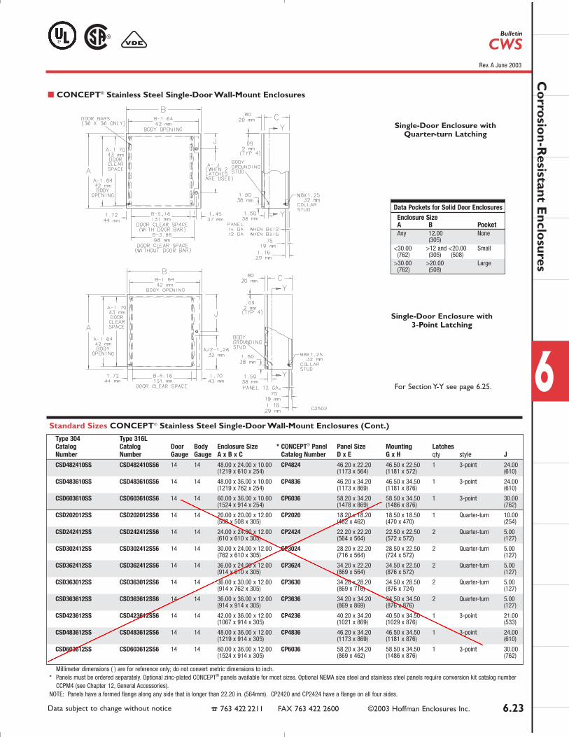
Standard Sizes CONCEPT® Stainless Steel Single-Door Wall-Mount Enclosures
CONCEPT® Stainless Steel Wall-Mount Enclosures
Continued on next page
jterrio
Rectangle
jterrio
Line
jterrio
Line
jterrio
Rectangle
jterrio
Line
jterrio
Line
jterrio
Line
jterrio
Line
jterrio
Line
jterrio
Line
6.23Data subject to change without notice 763 422 2211 FAX 763 422 2600 ©2003 Hoffman Enclosures Inc.
Co
rrosio
n-Resistant E
nclosures
6Standard Sizes CONCEPT® Stainless Steel Single-Door Wall-Mount Enclosures (Cont.)
Type 304 Type 316LCatalog Catalog Door Body Enclosure Size * CONCEPT® Panel Panel Size Mounting LatchesNumber Number Gauge Gauge A x B x C Catalog Number D x E G x H qty style JCSD482410SS CSD482410SS6 14 14 48.00 x 24.00 x 10.00 CP4824 46.20 x 22.20 46.50 x 22.50 1 3-point 24.00
(1219 x 610 x 254) (1173 x 564) (1181 x 572) (610)
CSD483610SS CSD483610SS6 14 14 48.00 x 36.00 x 10.00 CP4836 46.20 x 34.20 46.50 x 34.50 1 3-point 24.00(1219 x 762 x 254) (1173 x 869) (1181 x 876) (610)
CSD603610SS CSD603610SS6 14 14 60.00 x 36.00 x 10.00 CP6036 58.20 x 34.20 58.50 x 34.50 1 3-point 30.00(1524 x 914 x 254) (1478 x 869) (1486 x 876) (762)
CSD202012SS CSD202012SS6 14 14 20.00 x 20.00 x 12.00 CP2020 18.20 x 18.20 18.50 x 18.50 1 Quarter-turn 10.00(508 x 508 x 305) (462 x 462) (470 x 470) (254)
CSD242412SS CSD242412SS6 14 14 24.00 x 24.00 x 12.00 CP2424 22.20 x 22.20 22.50 x 22.50 2 Quarter-turn 5.00(610 x 610 x 305) (564 x 564) (572 x 572) (127)
CSD302412SS CSD302412SS6 14 14 30.00 x 24.00 x 12.00 CP3024 28.20 x 22.20 28.50 x 22.50 2 Quarter-turn 5.00(762 x 610 x 305) (716 x 564) (724 x 572) (127)
CSD362412SS CSD362412SS6 14 14 36.00 x 24.00 x 12.00 CP3624 34.20 x 22.20 34.50 x 22.50 2 Quarter-turn 5.00(914 x 610 x 305) (869 x 564) (876 x 572) (127)
CSD363012SS CSD363012SS6 14 14 36.00 x 30.00 x 12.00 CP3630 34.20 x 28.20 34.50 x 28.50 2 Quarter-turn 5.00(914 x 762 x 305) (869 x 716) (876 x 724) (127)
CSD363612SS CSD363612SS6 14 14 36.00 x 36.00 x 12.00 CP3636 34.20 x 34.20 34.50 x 34.50 2 Quarter-turn 5.00(914 x 914 x 305) (869 x 869) (876 x 876) (127)
CSD423612SS CSD423612SS6 14 14 42.00 x 36.00 x 12.00 CP4236 40.20 x 34.20 40.50 x 34.50 1 3-point 21.00(1067 x 914 x 305) (1021 x 869) (1029 x 876) (533)
CSD483612SS CSD483612SS6 14 14 48.00 x 36.00 x 12.00 CP4836 46.20 x 34.20 46.50 x 34.50 1 3-point 24.00(1219 x 914 x 305) (1173 x 869) (1181 x 876) (610)
CSD603612SS CSD603612SS6 14 14 60.00 x 36.00 x 12.00 CP6036 58.20 x 34.20 58.50 x 34.50 1 3-point 30.00(1524 x 914 x 305) (869 x 462) (1486 x 876) (762)
Millimeter dimensions ( ) are for reference only; do not convert metric dimensions to inch.* Panels must be ordered separately. Optional zinc-plated CONCEPT® panels available for most sizes. Optional NEMA size steel and stainless steel panels require conversion kit catalog number
CCPM4 (see Chapter 12, General Accessories).NOTE: Panels have a formed flange along any side that is longer than 22.20 in. (564mm). CP2420 and CP2424 have a flange on all four sides.
CONCEPT® Stainless Steel Single-Door Wall-Mount Enclosures
Single-Door Enclosure withQuarter-turn Latching
Bulletin
CWS
Single-Door Enclosure with3-Point Latching
For Section Y-Y see page 6.25.
Data Pockets for Solid Door EnclosuresEnclosure SizeA B PocketAny 12.00 None
(305)<30.00 >12 and <20.00 Small
(762) (305) (508)>30.00 >20.00 Large
(762) (508)
Rev. A June 2003
jterrio
Line
jterrio
Line
6.25Data subject to change without notice 763 422 2211 FAX 763 422 2600 ©2003 Hoffman Enclosures Inc.
Co
rrosio
n-Resistant E
nclosures
6Window Door Enclosure with
Quarter-turn Latching
CONCEPT® Stainless Steel Single-Door Wall-Mount Enclosures with Windows
Stainless Steel Wall-M
ountBulletin
CWS
CONTROL SYSTEMS
Product SpecificationLC150 Pump Controller
ILK-LC150001-01ILK-LC150020-01
1239 WILLOW LAKE BOULEVARD VADNAIS HEIGHTS, MINNESOTA 55110 651 – 766 – 2700 Fax: 651 – 766 – 2701 www.siemens.com/water
LC150 Prod Spec Ver 2.6.doc
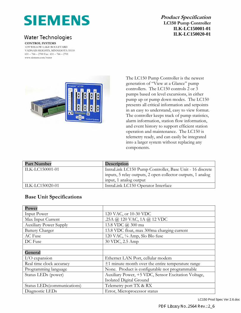
The LC150 Pump Controller is the newest generation of “View at a Glance” pump controllers. The LC150 controls 2 or 3 pumps based on level excursions, in either pump up or pump down modes. The LC150 presents all critical information and setpoints in an easy to understand, easy to view format. The controller keeps track of pump statistics, alarm information, station flow information, and event history to support efficient station operation and maintenance. The LC150 is telemetry ready, and can easily be integrated into a larger system without replacing any components.
Part Number Description ILK-LC150001-01 IntraLink LC150 Pump Controller, Base Unit - 16 discrete
inputs, 5 relay outputs, 2 open collector outputs, 1 analog input, 1 analog output
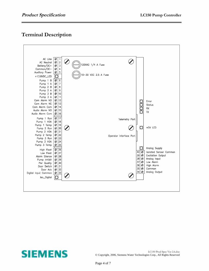
ILK-LC150020-01 IntraLink LC150 Operator Interface Base Unit Specifications Power Input Power 120 VAC, or 10-30 VDC Max Input Current .25A @ 120 VAC, 1A @ 12 VDC Auxiliary Power Supply 13.8 VDC @ 300 ma Battery Charger 13.8 VDC float, max 300ma charging current AC Fuse 120 VAC, ¼ Amp, Slo Blo fuse DC Fuse 30 VDC, 2.5 Amp General I/O expansion Ethernet LAN Port, cellular modem Real time clock accuracy ±1 minute month over the entire temperature range Programming language None. Product is configurable not programmable Status LEDs (power) Auxiliary Power, +5 VDC, Sensor Excitation Voltage,
Isolated Digital Ground Status LEDs(communications) Telemetry port TX & RX Diagnostic LEDs Error, Microprocessor status
jterrio
Rectangle
Product Specification LC150 Pump Controller
LC150 Prod Spec Ver 2.6.doc
© Copyright, 2006, Siemens Water Technologies Corp., All Rights Reserved
Page 2 of 7
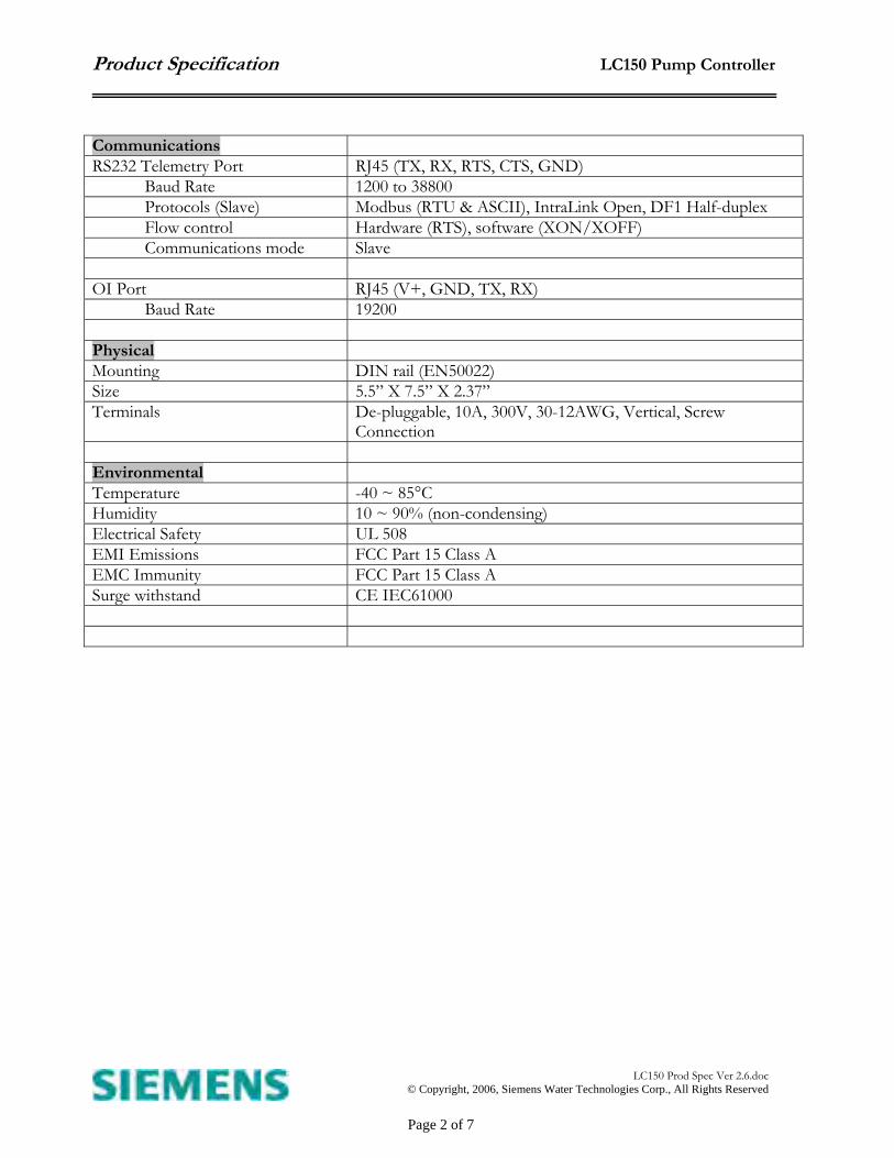
Communications RS232 Telemetry Port RJ45 (TX, RX, RTS, CTS, GND)
Baud Rate 1200 to 38800 Protocols (Slave) Modbus (RTU & ASCII), IntraLink Open, DF1 Half-duplex Flow control Hardware (RTS), software (XON/XOFF) Communications mode Slave
OI Port RJ45 (V+, GND, TX, RX)
Baud Rate 19200 Physical Mounting DIN rail (EN50022) Size 5.5” X 7.5” X 2.37” Terminals De-pluggable, 10A, 300V, 30-12AWG, Vertical, Screw
Connection Environmental Temperature -40 ~ 85°C Humidity 10 ~ 90% (non-condensing) Electrical Safety UL 508 EMI Emissions FCC Part 15 Class A EMC Immunity FCC Part 15 Class A Surge withstand CE IEC61000
Product Specification LC150 Pump Controller
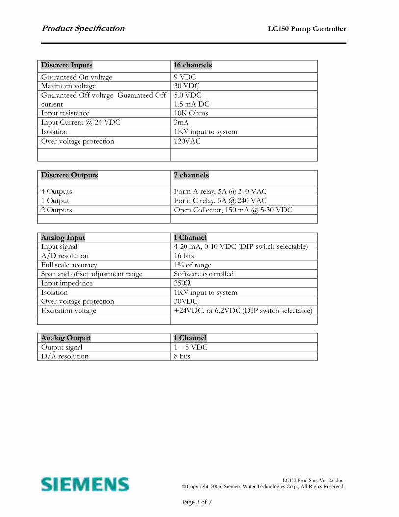
Discrete Outputs 7 channels
4 Outputs Form A relay, 5A @ 240 VAC 1 Output Form C relay, 5A @ 240 VAC 2 Outputs Open Collector, 150 mA @ 5-30 VDC Analog Input 1 Channel Input signal 4-20 mA, 0-10 VDC (DIP switch selectable) A/D resolution 16 bits Full scale accuracy 1% of range Span and offset adjustment range Software controlled Input impedance 250Ω Isolation 1KV input to system Over-voltage protection 30VDC Excitation voltage +24VDC, or 6.2VDC (DIP switch selectable) Analog Output 1 Channel Output signal 1 – 5 VDC D/A resolution 8 bits
Discrete Inputs 16 channels Guaranteed On voltage 9 VDC Maximum voltage 30 VDC Guaranteed Off voltage Guaranteed Off current
5.0 VDC 1.5 mA DC
Input resistance 10K Ohms Input Current @ 24 VDC 3mA Isolation 1KV input to system Over-voltage protection 120VAC
LC150 Prod Spec Ver 2.6.doc
© Copyright, 2006, Siemens Water Technologies Corp., All Rights Reserved
Page 3 of 7
Product Specification LC150 Pump Controller
Terminal Description
LC150 Prod Spec Ver 2.6.doc
© Copyright, 2006, Siemens Water Technologies Corp., All Rights Reserved
Page 4 of 7
Product Specification LC150 Pump Controller
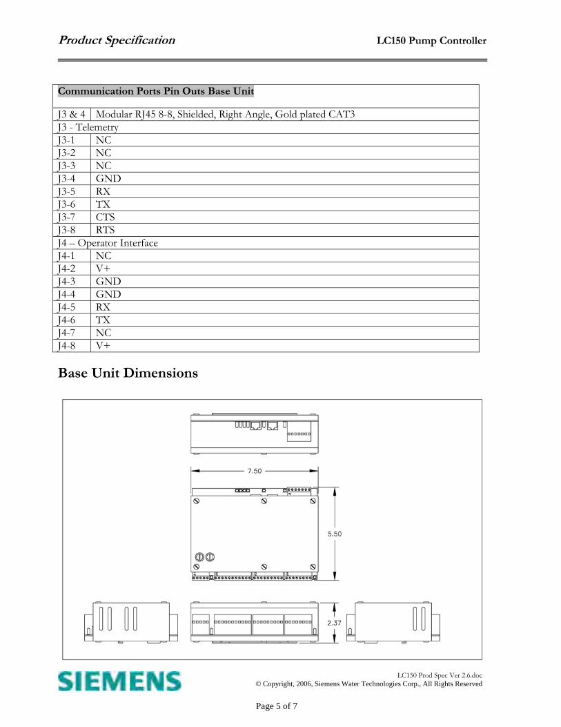
Communication Ports Pin Outs Base Unit
J3 & 4 Modular RJ45 8-8, Shielded, Right Angle, Gold plated CAT3 J3 - Telemetry J3-1 NC J3-2 NC J3-3 NC J3-4 GND J3-5 RX J3-6 TX J3-7 CTS J3-8 RTS J4 – Operator Interface J4-1 NC J4-2 V+ J4-3 GND J4-4 GND J4-5 RX J4-6 TX J4-7 NC J4-8 V+ Base Unit Dimensions
LC150 Prod Spec Ver 2.6.doc
© Copyright, 2006, Siemens Water Technologies Corp., All Rights Reserved
Page 5 of 7
www.digi.com
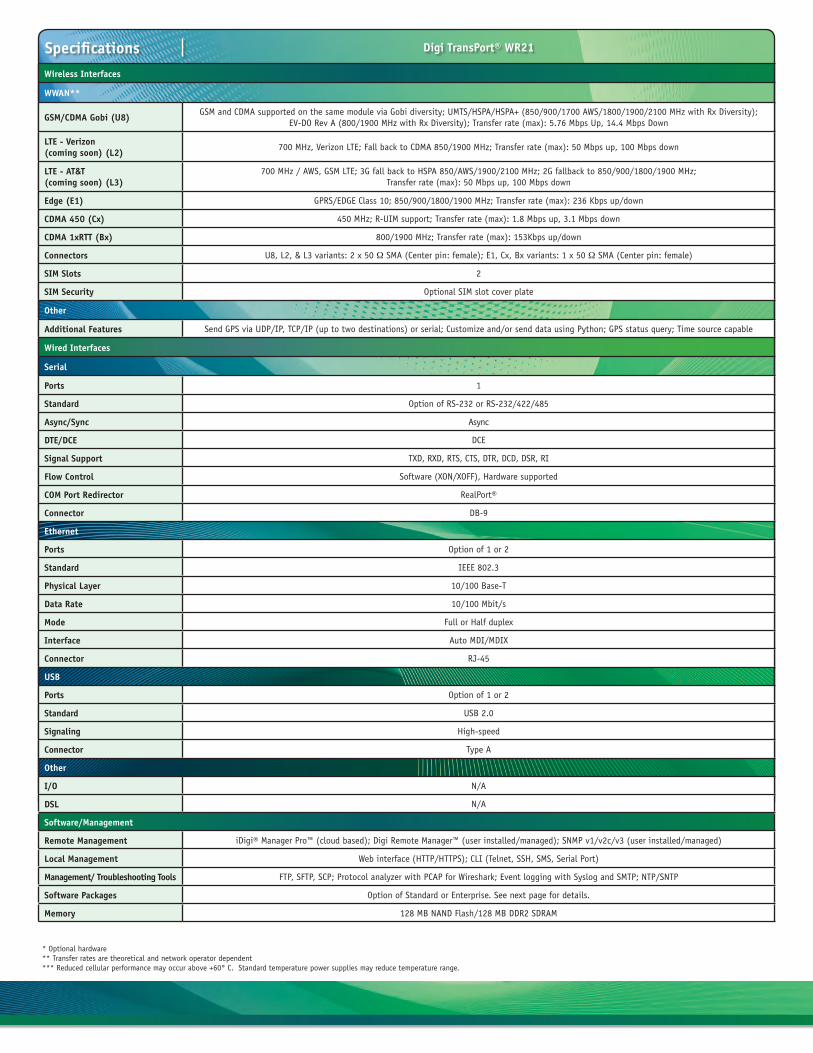
Application Highlight
Features/Benefits
Overview
Related Products
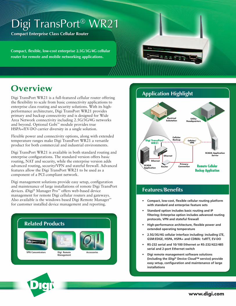
Digi TransPort WR21 is a full-featured cellular router offering the flexibility to scale from basic connectivity applications to enterprise class routing and security solutions. With its high-performance architecture, Digi TransPort WR21 provides primary and backup connectivity and is designed for Wide Area Network connectivity including 2.5G/3G/4G networks and beyond. Optional Gobi™ module provides true HSPA+/EV-DO carrier diversity in a single solution.
Flexible power and connectivity options, along with extended temperature ranges make Digi TransPort WR21 a versatile product for both commercial and industrial environments.
Digi TransPort WR21 is available in both standard routing and enterprise configurations. The standard version offers basic routing, NAT and security, while the enterprise version adds advanced routing, security/VPN and stateful firewall. Advanced features allow the Digi TransPort WR21 to be used as a component of a PCI compliant network.
Digi management solutions provide easy setup, configuration and maintenance of large installations of remote Digi TransPort devices. iDigi® Manager Pro™ offers web-based device management for remote Digi cellular routers and gateways. Also available is the windows based Digi Remote Manager™ for customer installed device management and reporting.
Compact, flexible, low-cost enterprise 2.5G/3G/4G cellular router for remote and mobile networking applications.
• Compact,low-cost,flexiblecellularroutingplatform withstandardandenterprisefeaturesets
• StandardoptionincludesbasicroutingandIP filtering;Enterpriseoptionincludesadvancedrouting protocols,VPNandstatefulfirewall
• High-performancearchitecture,flexiblepowerand extendedoperatingtemperature
• 2.5G/3G/4Gcellularinterfaceincluding:includingLTE, GSM:EDGE,HSPA,HSPA+andCDMA:1xRTT,EV-DO
• RS-232serialand10/100EthernetorRS-232/422/485 serialand2-portEthernetswitch
• Digiremotemanagementsoftwaresolutions (includingtheiDigi®DeviceCloud™service)provide easysetup,configurationandmaintenanceoflarge installations
Compact Enterprise Class Cellular Router
Digi TransPort® WR21
VPN Concentrators AccessoriesDigi Remote Management
Digi TransPort®
WR21Diiiggigg TTrraaaansPP t®
RouterSCADAApplication
Ethernet
Ethernet
CellularBackup
PrimaryConnection
UtilityHeadquarters
ElectricalSubstation
Cellular/VPN
SCADA ApplicationServer
Digi TransPort®
WR21
POWERSERVICEWWAN
SIGNAL
Digi TransPort WR21
SIM 1
SIM 2
Remote CellularBackup Application
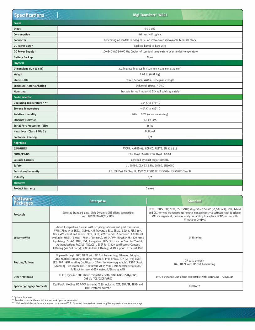
SpecificationsWireless Interfaces
WWAN**
GSM/CDMA Gobi (U8)GSM and CDMA supported on the same module via Gobi diversity; UMTS/HSPA/HSPA+ (850/900/1700 AWS/1800/1900/2100 MHz with Rx Diversity);
EV-DO Rev A (800/1900 MHz with Rx Diversity); Transfer rate (max): 5.76 Mbps Up, 14.4 Mbps Down
LTE - Verizon (coming soon) (L2)
700 MHz, Verizon LTE; Fall back to CDMA 850/1900 MHz; Transfer rate (max): 50 Mbps up, 100 Mbps down
LTE - AT&T (coming soon) (L3)
700 MHz / AWS, GSM LTE; 3G fall back to HSPA 850/AWS/1900/2100 MHz; 2G fallback to 850/900/1800/1900 MHz;Transfer rate (max): 50 Mbps up, 100 Mbps down
Edge (E1) GPRS/EDGE Class 10; 850/900/1800/1900 MHz; Transfer rate (max): 236 Kbps up/down
CDMA 450 (Cx) 450 MHz; R-UIM support; Transfer rate (max): 1.8 Mbps up, 3.1 Mbps down
CDMA 1xRTT (Bx) 800/1900 MHz; Transfer rate (max): 153Kbps up/down
Connectors U8, L2, & L3 variants: 2 x 50 Ω SMA (Center pin: female); E1, Cx, Bx variants: 1 x 50 Ω SMA (Center pin: female)
SIM Slots 2
SIM Security Optional SIM slot cover plate
Other
Additional Features Send GPS via UDP/IP, TCP/IP (up to two destinations) or serial; Customize and/or send data using Python; GPS status query; Time source capable
Wired Interfaces
Serial
Ports 1
Standard Option of RS-232 or RS-232/422/485
Async/Sync Async
DTE/DCE DCE
Signal Support TXD, RXD, RTS, CTS, DTR, DCD, DSR, RI
Flow Control Software (XON/XOFF), Hardware supported
COM Port Redirector RealPort®
Connector DB-9
Ethernet
Ports Option of 1 or 2
Standard IEEE 802.3
Physical Layer 10/100 Base-T
Data Rate 10/100 Mbit/s
Mode Full or Half duplex
Interface Auto MDI/MDIX
Connector RJ-45
USB
Ports Option of 1 or 2
Standard USB 2.0
Signaling High-speed
Connector Type A
Other
I/O N/A
DSL N/A
Software/Management
Remote Management iDigi® Manager Pro™ (cloud based); Digi Remote Manager™ (user installed/managed); SNMP v1/v2c/v3 (user installed/managed)
Local Management Web interface (HTTP/HTTPS); CLI (Telnet, SSH, SMS, Serial Port)
Management/ Troubleshooting Tools FTP, SFTP, SCP; Protocol analyzer with PCAP for Wireshark; Event logging with Syslog and SMTP; NTP/SNTP
Software Packages Option of Standard or Enterprise. See next page for details.
Memory 128 MB NAND Flash/128 MB DDR2 SDRAM
Digi TransPort® WR21
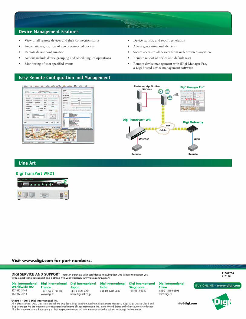
* Optional hardware ** Transfer rates are theoretical and network operator dependent *** Reduced cellular performance may occur above +60° C. Standard temperature power supplies may reduce temperature range.
Power
Input 9-30 VDC
Consumption 6W max, 4W typical
Connector Depending on model: Locking barrel or screw-down removeable terminal block
DC Power Cord* Locking barrel to bare wire
DC Power Supply* 100-240 VAC 50/60 Hz; Option of standard temperature or extended temperature
Battery Backup None
Physical
Dimensions (L x W x H) 3.9 in x 5.2 in x 1.3 in (100 mm x 131 mm x 32 mm)
Weight 1.08 lb (0.49 kg)
Status LEDs Power, Service, WWAN, 3x Signal strength
Enclosure Material/Rating Industrial (Metal)/ IP50
Mounting Brackets for wall mount & DIN rail sold separately
Environmental
Operating Temperature *** -35° C to +75° C
Storage Temperature -40° C to +85° C
Relative Humidity 20% to 95% (non-condensing)
Ethernet Isolation 1.5 kV RMS
Serial Port Protection (ESD) 15 kV
Hazardous (Class 1 Div 2) Optional
Conformal Coating N/A
Approvals
GSM/UMTS PTCRB, NAPRD.03, GCF-CC, R&TTE, EN 301 511
CDMA/EV-DO CDG TIA/EIA-690, CDG TIA/EIA-98-E
Cellular Carriers Certified by most major carriers.
Safety UL 60950, CSA 22.2 No. 60950, EN60950
Emissions/Immunity CE, FCC Part 15 Class B, AS/NZS CISPR 22, EN55024, EN55022 Class B
Industry N/A
Warranty
Product Warranty 5 years
Specifications Digi TransPort® WR21
* Optional hardware ** Transfer rates are theoretical and network operator dependent *** Reduced cellular performance may occur above +60° C. Standard temperature power supplies may reduce temperature range.
SoftwarePackages Standard
ProtocolsSame as Standard plus iDigi; Dynamic DNS client compatible
with BIND9/No-IP/DynDNS
HTTP, HTTPS, FTP, SFTP, SSL, SMTP, iDigi SNMP, SNMP (v1/v2c/v3), SSH, Telnet and CLI for web management; remote management via software tool (option);
SMS management, protocol analyzer, ability to capture PCAP for use with Wireshark; DynDNS
Security/VPN
Stateful inspection firewall with scripting, address and port translation; VPN: IPSec with IKEv1, IKEv2, NAT Traversal; SSL, SSLv2, SSLv3, FIPS 197,
Open VPN client and server; PPTP, L2TP; VPN Tunnels: 5 included. Additional available: WR21 (5 max.), WR41 (50 max.), WR44/WR44R/WR44RR (200 max.; Cryptology: SHA-1, MD5, RSA; Encryption: DES, 3DES and AES up to 256-bit;
Authentication: RADIUS, TACACS+, SCEP for X.509 certificates; Content Filtering (via 3rd party); MAC Address Filtering; VLAN support; Ethernet Port
IP filtering
Routing/Failover
IP pass-through; NAT, NAPT with IP Port Forwarding; Ethernet Bridging;GRE; Multicast Routing;Routing Protocols: PPP, PPPoE, RIP (v1, v2) OSPF,
SRI, BGP, iGMP routing (multicast); IPv6 (firmware upgradable); RSTP (Rapid Spanning Tree Protocol); IP Failover: VRRP, VRRP+TM; Automatic failover/
failback to second GSM network/Standby APN
IP pass-through NAT, NAPT with IP Port Forwarding
Other ProtocolsDHCP; Dynamic DNS client compatible with BIND9/No-IP/DynDNS;
QoS via TOS/DSCP/WREDDHCP; Dynamic DNS client compatible with BIND9/No-IP/DynDNS
Specialty/Legacy ProtocolsRealPort®; Modbus UDP/TCP to serial; X.25 including XOT, SNA/IP, TPAD and
PAD; Protocol switch*RealPort®
Enterprise
DIGISERVICEANDSUPPORT-YoucanpurchasewithconfidenceknowingthatDigiisheretosupportyouwithexperttechnicalsupportandastrongfive-yearwarranty.www.digi.com/support
Visit www.digi.com for part numbers.
Digi InternationalWorldwide HQ877-912-3444952-912-3444
Digi InternationalFrance+33-1-55-61-98-98www.digi.fr
Digi InternationalJapan+81-3-5428-0261www.digi-intl.co.jp
Digi InternationalIndia+91-80-4287-9887
Digi InternationalSingapore+65-6213-5380
Digi International China +86-21-5150-6898www.digi.cn
BUY ONLINE • www.digi.com
© 2011 - 2012 Digi International Inc.All rights reserved. Digi, Digi International, the Digi logo, Digi TransPort, RealPort, Digi Remote Manager, iDigi, iDigi Device Cloud and iDigi Manager Pro are trademarks or registered trademarks of Digi International Inc. in the United States and other countries worldwide. All other trademarks are the property of their respective owners. All information provided is subject to change without notice.
91001738B1/113
• Viewofallremotedevicesandtheirconnectionstatus
• Automaticregistrationofnewlyconnecteddevices
• Remotedeviceconfiguration
• Actionsincludedevicegroupingandschedulingofoperations
• Monitoringofuserspecifiedevents
• Devicestatisticandreportgeneration
• Alarmgenerationandalerting
• Secureaccesstoalldevicesfromwebbrowser,anywhere
• Remoterebootofdeviceanddefaultreset
• RemotedevicemanagementwithiDigiManagerPro, a Digi-hosted device management software
Device Management Features
Easy Remote Configuration and Management
Line Art
RemoteDevice
Ethernet Serial
RemoteDevice
iDigi® Manager Pro™Customer ApplicationServers
Digi TransPort® WRDigi Gateway
WAN
Cellular
need new
Link
ConnectP
ortX
4
Link
Digi TransPort WR21
Innovative Technology for a Connected World
global solutions: local support TM
Americas: +1.847 [email protected]
Europe: [email protected]
Asia: +1.65.6.243.8022 [email protected]
www.lairdtech.com
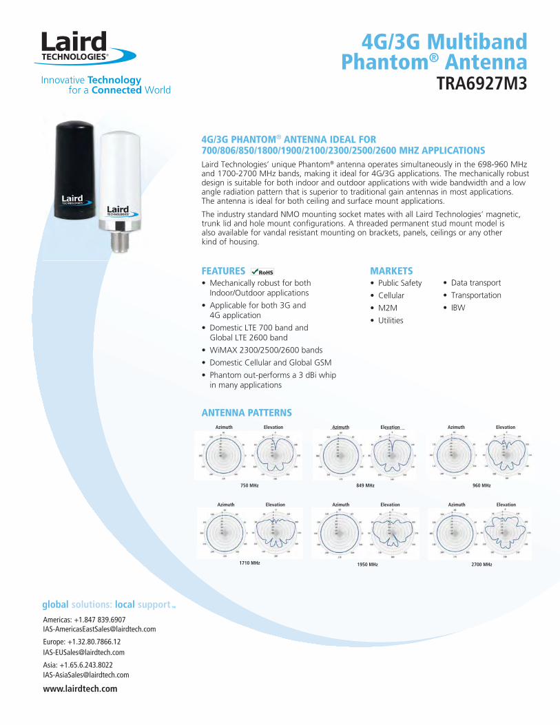
FEATURES
MARKETS
4G/3G PHANTOM® ANTENNA IDEAL FOR 700/806/850/1800/1900/2100/2300/2500/2600 MHZ APPLICATIONS
®
4G/3G Multiband Phantom® Antenna
TRA6927M3
ANTENNA PATTERNSAzimuth
750 MHz
Elevation Azimuth
960 MHz
ElevationAzimuth
849 MHz
Elevation
Azimuth
1710 MHz
Elevation Azimuth
1950 MHz
Elevation Azimuth
2700 MHz
Elevation
Innovative Technology for a Connected World
ANT-DS-TRA6927M3 0312Any information furnished by Laird Technologies, Inc. and its agents is believed to be accurate and reliable. All specifications are subject to change without notice. Responsibility for the use and application of Laird Technologies materials rests with the end user. Laird Technologies makes no warranties as to the fitness, merchantability, suitability or non-infringement of any Laird Technologies materials or products for any specific or general uses. Laird Technologies shall not be liable for incidental or consequential damages of any kind. All Laird Technologies products are sold pursuant to the Laird Technologies’ Terms and Conditions of sale in effect from time to time, a copy of which will be furnished upon request. © Copyright 2012 Laird Technologies, Inc. All Rights Reserved. Laird, Laird Technologies, the Laird Technologies Logo, and other marks are trade marks or registered trade marks of Laird Technologies, Inc. or an affiliate company thereof. Other product or service names may be the property of third parties. Nothing herein provides a license under any Laird Technologies or any third party intellectual property rights.
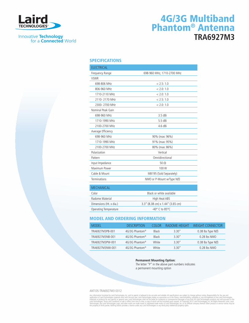
ELECTRICAL
Frequency Range 698-960 MHz, 1710-2700 MHz
VSWR
698-806 MHz < 2.5: 1.0
806-960 MHz < 2.0: 1.0
1710-2110 MHz < 2.0: 1.0
2110- 2170 MHz < 2.5: 1.0
2300- 2700 MHz < 2.0: 1.0
Nominal Peak Gain
698-960 MHz 3.5 dBi
1710-1990 MHz 5.5 dBi
2100-2700 MHz 4.6 dBi
698-960 MHz 90% (max: 96%)
1710-1990 MHz 91% (max: 95%)
2100-2700 MHz 80% (max: 86%)
Polarization Vertical
Pattern Omnidirectional
Input Impedance 50 Ω
Maximum Power 100 W
Cable & Mount MB195 (Sold Separately)
Terminations NMO or P-Mount w/Type N(f)
SPECIFICATIONS
MODEL DESCRIPTION COLOR RADOME HEIGHT WEIGHT CONNECTOR
TRA6927M3PB-001 4G/3G Phantom® Black 3.30” 0.38 lbs Type N(f)
TRA6927M3NB-001 4G/3G Phantom® Black 3.30” 0.28 lbs NMO
TRA6927M3PW-001 4G/3G Phantom® White 3.30” 0.38 lbs Type N(f)
TRA6927M3NW-001 4G/3G Phantom® White 3.30” 0.28 lbs NMO
MODEL AND ORDERING INFORMATION
MECHANICAL
Color Black or white available
Radome Material High Heat ABS
Dimensions (Ht. x dia.) 3.3” (8.38 cm) x 1.44” (3.65 cm)
Operating Temperature -40° C to 85°C
Permanent Mounting Option:The letter “P” in the above part numbers indicates a permanent mounting option
4G/3G Multiband Phantom® Antenna
TRA6927M3
jterrio
Rectangle
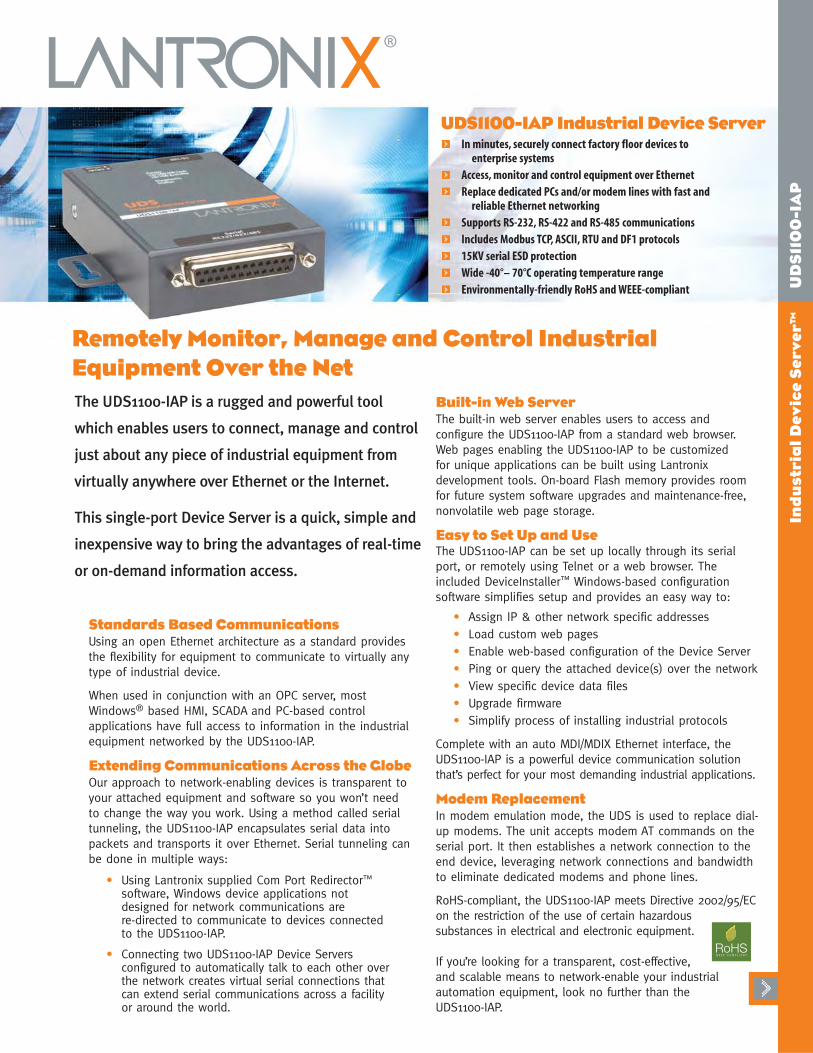
UDS1100-IAP Industrial Device ServerIn minutes, securely connect factory floor devices to
enterprise systems
Access, monitor and control equipment over Ethernet
Replace dedicated PCs and/or modem lines with fast and reliable Ethernet networking
Supports RS-232, RS-422 and RS-485 communications
Includes Modbus TCP, ASCII, RTU and DF1 protocols
15KV serial ESD protection
Wide -40°– 70°C operating temperature range
Environmentally-friendly RoHS and WEEE-compliant
Standards Based CommunicationsUsing an open Ethernet architecture as a standard provides
the flexibility for equipment to communicate to virtually any
type of industrial device.
When used in conjunction with an OPC server, most
Windows® based HMI, SCADA and PC-based control
applications have full access to information in the industrial
equipment networked by the UDS1100-IAP.
Extending Communications Across the GlobeOur approach to network-enabling devices is transparent to
your attached equipment and software so you won’t need
to change the way you work. Using a method called serial
tunneling, the UDS1100-IAP encapsulates serial data into
packets and transports it over Ethernet. Serial tunneling can
be done in multiple ways:
• Using Lantronix supplied Com Port Redirector™
software, Windows device applications not designed for network communications are re-directed to communicate to devices connected to the UDS1100-IAP.
• Connecting two UDS1100-IAP Device Servers configured to automatically talk to each other over the network creates virtual serial connections that can extend serial communications across a facility or around the world.
Built-in Web ServerThe built-in web server enables users to access and
configure the UDS1100-IAP from a standard web browser.
Web pages enabling the UDS1100-IAP to be customized
for unique applications can be built using Lantronix
development tools. On-board Flash memory provides room
for future system software upgrades and maintenance-free,
nonvolatile web page storage.
Easy to Set Up and UseThe UDS1100-IAP can be set up locally through its serial
port, or remotely using Telnet or a web browser. The
included DeviceInstaller™ Windows-based configuration
software simplifies setup and provides an easy way to:
• Assign IP & other network specific addresses
• Load custom web pages
• Enable web-based configuration of the Device Server
• Ping or query the attached device(s) over the network
• View specific device data files
• Upgrade firmware
• Simplify process of installing industrial protocols
Complete with an auto MDI/MDIX Ethernet interface, the
UDS1100-IAP is a powerful device communication solution
that’s perfect for your most demanding industrial applications.
Modem ReplacementIn modem emulation mode, the UDS is used to replace dial-
up modems. The unit accepts modem AT commands on the
serial port. It then establishes a network connection to the
end device, leveraging network connections and bandwidth
to eliminate dedicated modems and phone lines.
RoHS-compliant, the UDS1100-IAP meets Directive 2002/95/EC
on the restriction of the use of certain hazardous
substances in electrical and electronic equipment.
If you’re looking for a transparent, cost-effective,
and scalable means to network-enable your industrial
automation equipment, look no further than the
UDS1100-IAP.
The UDS1100-IAP is a rugged and powerful tool
which enables users to connect, manage and control
just about any piece of industrial equipment from
virtually anywhere over Ethernet or the Internet.
This single-port Device Server is a quick, simple and
inexpensive way to bring the advantages of real-time
or on-demand information access.
Remotely Monitor, Manage and Control IndustrialEquipment Over the Net
Ind
ust
ria
l D
ev
ice
Se
rve
r™
U
DS
110
0-I
AP
jterrio
Rectangle
15353 Barranca Parkway | Irvine | CA 92618 | USA | Tel: 800.422.7055 | Fax: 949.450.7232 | www.lantronix.com©2006, Lantronix, Inc. Lantronix is a registered trademark, and Device Server, DeviceInstaller and Com Port Redirector are trademarks of Lantronix, Inc. All other trademarks are the property of their
respective owners. Specifications subject to change without notice. All rights reserved. 910-502 09/06 DGS2500
Ind
ust
ria
l D
ev
ice
Se
rve
r™
U
DS
110
0-I
AP
Features and SpecificationsSerial Interface
Interface: Software-selectable RS232, RS422 or RS485 (2 and 4 wire support)
Connectors: 1 DB25F DCE serial portData Rates: Software-selectable baud rate from 300 to 230 KBaudCharacters: 7 or 8 data bitsParity: odd, even, noneStop Bits: 1 or 2Control Signals: CTS/RTS (Hardware)Flow Control: XON/XOFF (Software)
Network InterfaceInterface: 10Base-T/100Base-TX Ethernet portSoftware selectable Ethernet speed 10/100/AutoSoftware selectable Half/Full/Auto duplexConnector: RJ45Standards: ARP,UDP,TCP, ICMP,Telnet,TFTP, AutoIP,DHCP,HTTP,
SNMP, TCP,UDP, and Telnet,TFTP
Indicators (LED)Power, 10/100 Link/Activity (green), 100/100Link/Activity(green), Diagnostics (red), Status (green)
ProcessorCPU: Lantronix DSTNI-EX 48 MHz clockMemory: 256 KB zero wait state SRAM, 2 MB Flash
ManagementLantronix DeviceInstaller GUI, Serial login,SNMP,
Telnet login,HTTP
Power9-30 VDC or 9-24 VAC on barrel connector (1.5 Watts maximum
consumption)9-30 VDC on DB25F serial interface3.3vdc on serial interface
EnvironmentalOperating: -40° to 70° C (41° to 158° F)Storage: -40° to 85° C (-40 to 185° F)
PackagingMaterial: Metal enclosure with integrated wall mounts;
optional 35 mm DIN-rail mount availableDimensions (LxWxH): 9.0 x 6.4 x 2.3 cm (3.5 x 2.5 x 0.9 in)Weight: 0.20 kg (0.45 lb)IP Rating: 30
Agency ApprovalsUL, CSA, FCC, CE,TUV, CTick,VCCI
Warranty2-year limited warranty
Shipping DimensionsDimensions (LxWxH): 242 x 191 x 115 mm (9.5 x 7.5 x 4.5 in)Weight: 1.5 kg (3.0 lbs)
Included SoftwareWindows® 98/ME/NT/2000/XP-based DeviceInstallerconfiguration software, Com Port Redirector™software
and related utilities
Ordering Information Part Number Description
UD1100IA2-01 UDS1100-IAP Device Server, 100-240 VAC Internationalpower supply with regional adapters, includes 500-163 cable and ACDIN1001-01 Din rail mount
Accessories500-163 DB25M to DB9F serial cable (included)
ACDIN1001-01 Optional DIN-rail mount (included)
500-171-R DB25M to RS485 and power input screw terminaladapter (order separately)
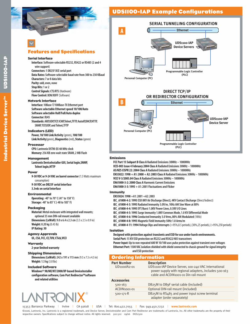
UDS1100-IAP Example Configurations
Ethernet
UDS1100-IAPDevice Servers
SERIAL TUNNELING CONFIGURATION
Programmable Logic Controller (PLC)
Personal Computer (PC)
Ethernet
Personal Computer (PC)
UDS1100-IAPDevice Server
Programmable Logic Controller (PLC)
DIRECT TCP/IP OR REDIRECTOR CONFIGURATION
B
A
EmissionsFCC Part 15 Subpart B Class A Radiated Emissions 30MHz – 1000MHzICES-003 Issue 4 February 2004 Class A Radiated Emissions 30MHz – 1000MHzAS/NZS CISPR 22: 2004 Class A Radiated Emissions 30MHz – 1000MHzEN55022: 1998 + A1: 2000 + A2: 2003 Class A Radiated Emissions 30MHz – 1000MHzVCCI V-3/2005.04 Class A Radiated Emissions 30MHz – 1000MHzEN61000-3-2: 2000 Class A Harmonic Current EmissionsEN61000-3-3: 1995 + A1: 2001 Fluctuations and Flicker
ImmunityEN55024: 1998 +A1: 2001 +A2: 2003IEC_61000-4-2: 1995 ESD 8KV Air Discharge (Direct), 4KV Contact Discharge (Direct/Indirect)IEC_61000-4-3: 1995 Radiated Immunity 3.0V/m, 1KHz AM Sine Wave at 80%IEC_61000-4-4: 1995 EFT/Burst 1.0KV Power Lines, 0.5KV I/O LinesIEC_61000-4-5: 1995 Surge Immunity 1.0KV Common Mode, 1.0 KV Differential ModeIEC_61000-4-6: 1996 Conducted Immunity 3.0 Vrms, 80% AM Modulated (1KHz)IEC_61000-4-8: 1993 Magnetic Field Immunity 50Hz 1.0 Arms/mIEC_61000-4-11: 1994 Voltage Dips and Interrupts (>95%,0.5 periods), (30%,25 periods), (>95%,250 periods)
IsolationDesigned with protection against transients and ESD for use under harsh environments.Serial Port: 15 KV ESD protection on RS232 and RS422/485 transceiversPower Input: Up to non-repeated 600 W 10/100 usec pulse protection against transient over voltagesEthernet Port: 1500 VAC isolation shielded with shield connected to chassis ground for signal integrity
and ESD protection
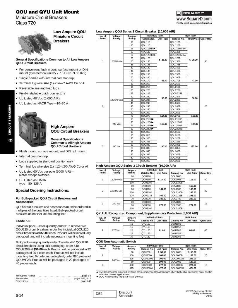
www.SquareD.comFor the most up-to-date information
6-14
QOU and QYU Unit MountMiniature Circuit BreakersClass 720
6C
IRC
UIT
BR
EA
KE
RS
© 2003 Schneider ElectricAll Rights Reserved
9/8/03
Low Ampere QOU Miniature Circuit Breakers
General Specifications Common to All Low Ampere QOU Circuit Breakers
• For convenient flush mount, surface mount or DIN mount (symmetrical rail 35 x 7.5 DIN/EN 50 022)
• Single handle with internal common trip
• Terminal lug wire size (1) #14–#2 AWG Cu or Al
• Reversible line and load lugs
• Field-installable quick connectors
• UL Listed 48 Vdc (5,000 AIR)
• UL Listed as HACR Type—10–70 A
High Ampere QOU Circuit Breakers
General Specifications Common to All High Ampere QOU Circuit Breakers
• Flush mount, surface mount, and DIN rail mount
• Internal common trip
• Lugs supplied in standard position only
• Terminal lug wire size (1) #12–#2/0 AWG Cu or Al
• UL Listed 60 Vdc per pole (5000 AIR)—Note: except switches
• UL Listed as HACR type—80–125 A
Special Ordering Instructions:
For Bulk-packed QOU Circuit Breakers and Accessories
QOU circuit breakers and accessories must be ordered in multiples of the quantities listed. Bulk-packed circuit breakers do not include mounting feet.
EXAMPLE:
Individual pack—small quantity orders: To receive five QOU220 circuit breakers, order five individual QOU220 circuit breakers at $58.00 each. Product will be individually packaged, and will include necessary mounting feet.
Bulk pack—large quantity order. To order 440 QOU220 circuit breakers using bulk packaging, order 440 QOU220B at $56.00 each. Product will be packaged in 22 packages of 20 pieces each. Product will not include mounting feet. To order mounting feet, order 880 pieces of QOUMF2B. Product will be packaged in 22 packages of 40 pieces each.
a HM High magnetic trip circuit breakers are recommended for applications where high initial inrush may occur and for individual dimmer applications.
b QOU-H interrupting rating is 5 kA at 240 Vac.
Low Ampere QOU Series 3 Circuit Breaker (10,000 AIR)No. of Poles
Voltage Rating
Ampere Rating
Individual Pack Bulk PackCatalog No. Unit Price Catalog No. Unit Price Qrder Qty.
1 120/240 Vac
10 QOU110
$ 26.80
QOU110B
$ 25.2040
15 QOU115 QOU115B15 QOU115HMa QOU115HMBa20 QOU120 QOU120B20 QOU120HMa QOU120HMBa25 QOU125 QOU125B30 QOU130 QOU130B35 QOU135 QOU135B40 QOU140 QOU140B45 QOU145 QOU145B50 QOU150 QOU150B60 QOU160 QOU160B70 QOU170 52.00 QOU170B 47.10
2
120/240 Vac
10 QOU210
58.00
QOU210B
56.00
20
15 QOU215 QOU215B20 QOU220 QOU220B25 QOU225 QQOU225B30 QOU230 QOU230B35 QOU235 QOU235B40 QOU240 QOU240B45 QOU245 QOU245B50 QOU250 QOU250B60 QOU260 QOU260B70 QOU270 114.00 QOU270B 112.00
240 Vac
15 QOU215Hb
112.00
QOU215HB
107.0020 QOU220Hb QOU220HB25 QOU225Hb QOU225HB30 QOU230Hb QOU230HB
3 240 Vac
10 QOU310
190.00
QOU310B
187.00 12
15 QOU315 QOU315B20 QOU320 QOU320B25 QOU325 QOU325B30 QOU330 QOU330B35 QOU335 QOU335B40 QOU340 QOU340B45 QOU345 QOU345B50 QOU350 QOU350B60 QOU360 QOU360B
High Ampere QOU Series 3 Circuit Breaker (10,000 AIR)No. of Poles
Voltage Rating
Ampere Rating
Individual Pack Bulk PackCatalog No. Unit Price Catalog No. Unit Price Qrder Qty.
1 120/240Vac80 QOU180
$117.00QOU180B
116.00 4090 QOU190 QOU190B100 QOU1100 QOU1100B
2 120/240 Vac
80 QOU280164.00
QOU280B 163.00
2090 QOU290 QOU290B 163.00
100 QOU2100 QOU2100B 163.00125 QOU2125 301.00 QOU2125B 298.00
3 240 Vac
70 QOU370 242.00 QOU370B 238.00
1280 QOU380
277.00QOU380B
274.0090 QOU390 QOU390B100 QOU3100 QOU3100B
QYU UL Recognized Component, Supplementary Protectors (5,000 AIR)No. of Poles
Voltage Rating
Ampere Rating
Individual Pack Bulk PackCatalog No. Unit Price Catalog No. Unit Price Qrder Qty.
1 277 Vac
10 QYU110
81.00
QYU110B
80.00 4015 QYU115 QYU115B20 QYU120 QYU120B25 QYU125 QYU125B30 QYU130 QYU130B
QOU Non-Automatic SwitchNo. of Poles
Voltage Rating
Ampere Rating
Individual Pack Bulk PackCatalog No. Unit Price Catalog No. Unit Price Qrder Qty.
2
240 Vac
60 QOU200 $ 58.00 QOU200B $ 56.0020100 QOU2000 164.00 QOU2000B 163.00
125 QOU20001 301.00 QOU20001B 298.00
360 QOU300 190.00 QOU300B 187.00
12100 QOU3000 277.00 QOU3000B 274.00125 QOU30001 477.00 QOU30001B 474.00
Interrupting Ratings. . . . . . . . . . . . . . . . . . . . . . . . . . . . . . . . . . . . . . .page 6-3Accessories . . . . . . . . . . . . . . . . . . . . . . . . . . . . . . . . . . . . . . pages 6-12, 6-15Dimensions . . . . . . . . . . . . . . . . . . . . . . . . . . . . . . . . . . . . . . . . . . . .page 6-49
9/8/03
DE2 DiscountSchedule
jterrio
Rectangle
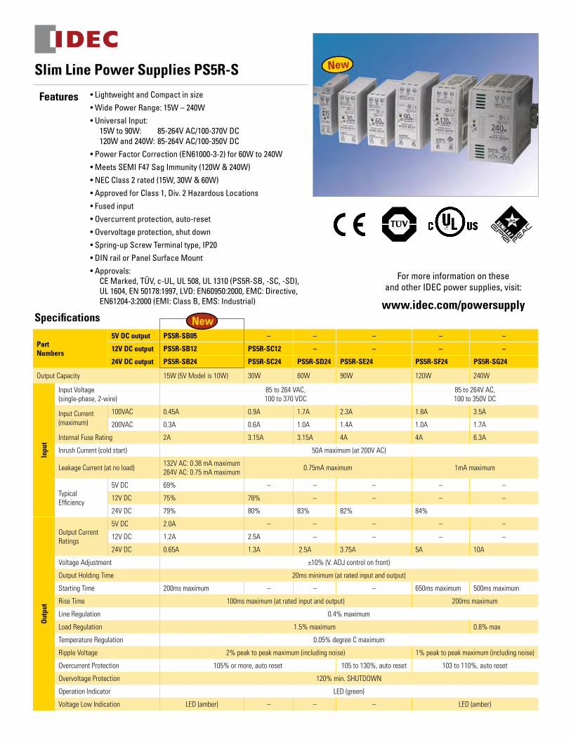
• Lightweight and Compact in size• Wide Power Range: 15W – 240W• Universal Input: 15W to 90W: 85-264V AC/100-370V DC 120W and 240W: 85-264V AC/100-350V DC • Power Factor Correction (EN61000-3-2) for 60W to 240W• Meets SEMI F47 Sag Immunity (120W & 240W)• NEC Class 2 rated (15W, 30W & 60W)• Approved for Class 1, Div. 2 Hazardous Locations• Fused input• Overcurrent protection, auto-reset• Overvoltage protection, shut down• Spring-up Screw Terminal type, IP20• DIN rail or Panel Surface Mount• Approvals: CE Marked, TÜV, c-UL, UL 508, UL 1310 (PS5R-SB, -SC, -SD), UL 1604, EN 50178:1997, LVD: EN60950:2000, EMC: Directive, EN61204-3:2000 (EMI: Class B, EMS: Industrial)
Slim Line Power Supplies PS5R-S
Features
Specifications
For more information on these and other IDEC power supplies, visit:
www.idec.com/powersupply
PartNumbers
5V DC output PS5R-SB05 – – – – –
12V DC output PS5R-SB12 PS5R-SC12 – – – –
24V DC output PS5R-SB24 PS5R-SC24 PS5R-SD24 PS5R-SE24 PS5R-SF24 PS5R-SG24
Output Capacity 15W (5V Model is 10W) 30W 60W 90W 120W 240W
Inpu
t
Input Voltage (single-phase, 2-wire)
85 to 264 VAC,100 to 370 VDC
85 to 264V AC,100 to 350V DC
Input Current (maximum)
100VAC 0.45A 0.9A 1.7A 2.3A 1.8A 3.5A
200VAC 0.3A 0.6A 1.0A 1.4A 1.0A 1.7A
Internal Fuse Rating 2A 3.15A 3.15A 4A 4A 6.3A
Inrush Current (cold start) 50A maximum (at 200V AC)
Leakage Current (at no load) 132V AC: 0.38 mA maximum264V AC: 0.75 mA maximum 0.75mA maximum 1mA maximum
TypicalEfficiency
5V DC 69% – – – – –
12V DC 75% 78% – – – –
24V DC 79% 80% 83% 82% 84%
Out
put
Output Current Ratings
5V DC 2.0A – – – – –
12V DC 1.2A 2.5A – – – –
24V DC 0.65A 1.3A 2.5A 3.75A 5A 10A
Voltage Adjustment ±10% (V. ADJ control on front)
Output Holding Time 20ms minimum (at rated input and output)
Starting Time 200ms maximum – – – 650ms maximum 500ms maximum
Rise Time 100ms maximum (at rated input and output) 200ms maximum
Line Regulation 0.4% maximum
Load Regulation 1.5% maximum 0.8% max
Temperature Regulation 0.05% degree C maximum
Ripple Voltage 2% peak to peak maximum (including noise) 1% peak to peak maximum (including noise)
Overcurrent Protection 105% or more, auto reset 105 to 130%, auto reset 103 to 110%, auto reset
Overvoltage Protection 120% min. SHUTDOWN
Operation Indicator LED (green)
Voltage Low Indication LED (amber) – – – LED (amber)
New
New
jtuttle
Rectangle
jtuttle
Line
jtuttle
Rectangle
jterrio
Line
jterrio
Line
jterrio
Line
jterrio
Line
jterrio
Line
jterrio
Line
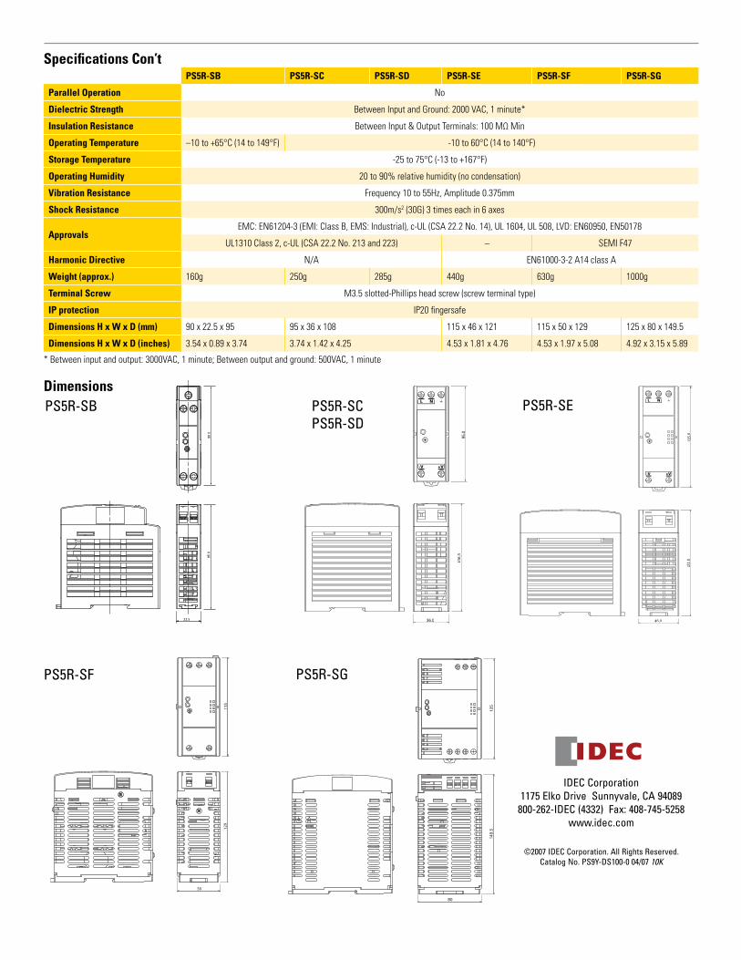
Specifications Con’t
IDEC Corporation 1175 Elko Drive Sunnyvale, CA 94089
800-262-IDEC (4332) Fax: 408-745-5258 www.idec.com
©2007 IDEC Corporation. All Rights Reserved. Catalog No. PS9Y-DS100-0 04/07 10K
PS5R-SB PS5R-SC PS5R-SD PS5R-SE PS5R-SF PS5R-SG
Parallel Operation No
Dielectric Strength Between Input and Ground: 2000 VAC, 1 minute*
Insulation Resistance Between Input & Output Terminals: 100 MΩ Min
Operating Temperature –10 to +65°C (14 to 149°F) -10 to 60°C (14 to 140°F)
Storage Temperature -25 to 75°C (-13 to +167°F)
Operating Humidity 20 to 90% relative humidity (no condensation)
Vibration Resistance Frequency 10 to 55Hz, Amplitude 0.375mm
Shock Resistance 300m/s2 (30G) 3 times each in 6 axes
ApprovalsEMC: EN61204-3 (EMI: Class B, EMS: Industrial), c-UL (CSA 22.2 No. 14), UL 1604, UL 508, LVD: EN60950, EN50178
UL1310 Class 2, c-UL (CSA 22.2 No. 213 and 223) – SEMI F47
Harmonic Directive N/A EN61000-3-2 A14 class A
Weight (approx.) 160g 250g 285g 440g 630g 1000g
Terminal Screw M3.5 slotted-Phillips head screw (screw terminal type)
IP protection IP20 fingersafe
Dimensions H x W x D (mm) 90 x 22.5 x 95 95 x 36 x 108 115 x 46 x 121 115 x 50 x 129 125 x 80 x 149.5
Dimensions H x W x D (inches) 3.54 x 0.89 x 3.74 3.74 x 1.42 x 4.25 4.53 x 1.81 x 4.76 4.53 x 1.97 x 5.08 4.92 x 3.15 x 5.89
* Between input and output: 3000VAC, 1 minute; Between output and ground: 500VAC, 1 minute
Dimensions
22.5
PS5R-SB
108.
095
.0
36.0
PS5R-SCPS5R-SD
46.0
115.
012
1.0
PS5R-SE
129
50
115
PS5R-SF
80
125
149.5
PS5R-SG
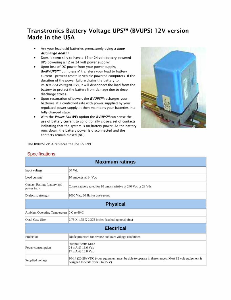
Transtronics Battery Voltage UPS™ (BVUPS) 12V version Made in the USA
• Are your lead-acid batteries prematurely dying a deep
discharge death? • Does it seem silly to have a 12 or 24 volt battery powered
UPS powering a 12 or 24 volt power supply? • Upon loss of DC power from your power supply,
theBVUPS™ "bumplessly" transfers your load to battery current - prevent resets in vehicle powered computers. If the duration of the power failure drains the battery to its Use EndVoltage(UEV), it will disconnect the load from the battery to protect the battery from damage due to deep discharge stress.
• Upon restoration of power, the BVUPS™ recharges your batteries at a controlled rate with power supplied by your regulated power supply. It then maintains your batteries in a fully charged state.
• With the Power Fail (PF) option the BVUPS™ can sense the use of battery current to conditionally close a set of contacts indicating that the system is on battery power. As the battery runs down, the battery power is disconnected and the contacts remain closed (NC)
The BVUPS12PFA replaces the BVUPS12PF
Specifications
Maximum ratings
Input voltage 30 Vdc
Load current 10 amperes at 14 Vdc
Contact Ratings (battery and power fail)
Conservatively rated for 10 amps resistive at 240 Vac or 28 Vdc
Dielectric strength 1000 Vac, 60 Hz for one second
Physical
Ambient Operating Temperature 0 C to 60 C
Octal Case Size 2.75 X 1.75 X 2.375 inches (excluding octal pins)
Electrical
Protection Diode protected for reverse and over voltage conditions
Power consumption 500 milliwatts MAX 24 mA @ 13.6 Vdc 17 mA @ 10.0 Vdc
Supplied voltage 10-14 (20-28) VDC (your equipment must be able to operate in these ranges. Most 12 volt equipment is designed to work from 9 to 15 V)
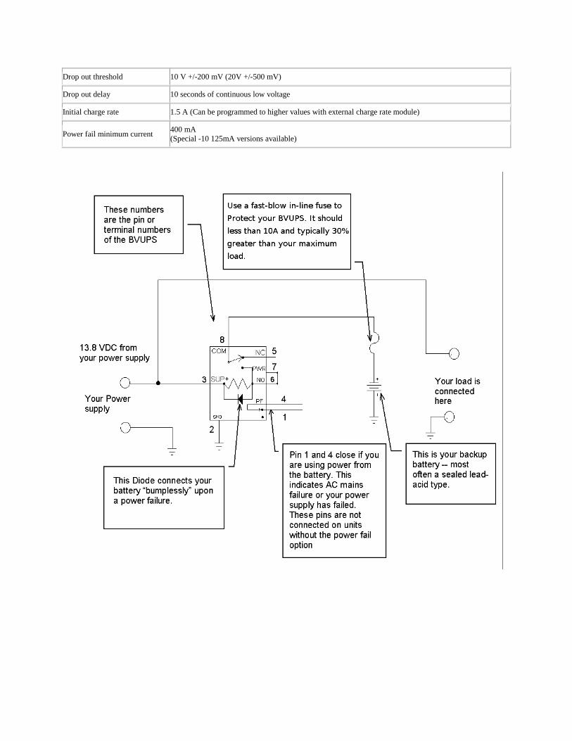
Drop out threshold 10 V +/-200 mV (20V +/-500 mV)
Drop out delay 10 seconds of continuous low voltage
Initial charge rate 1.5 A (Can be programmed to higher values with external charge rate module)
Power fail minimum current 400 mA (Special -10 125mA versions available)
MH20845
®
Sealed Rechargeable
MODEL PS-1270 F112 Volt 7.0 Amp. Hr.
Battery
www.power-sonic.com
BAT
T ER
Y
MUSTB ER
ECY
CL
ED
Pb
NONSPILLABLE
L
HT H
W
6.35
4.75
3.2F1 F2
0.87.95
6.35
3.4
0.8
Tolerances are +/- 0.04 in. (+/- 1mm) and +/- 0.08 in. (+/- 2mm) for height dimensions. All data subject to change without notice.
Physical Dimensions: in (mm)
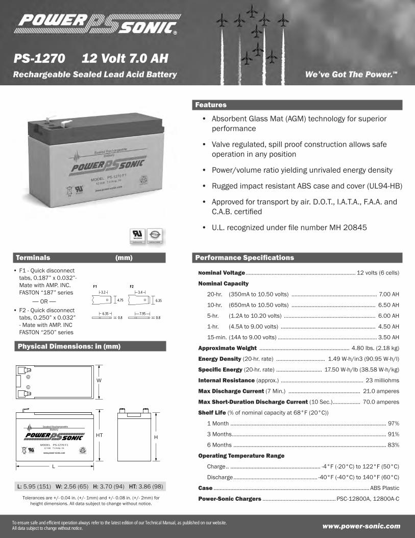
Features
Absorbent Glass Mat (AGM) technology for superior performance
Valve regulated, spill proof construction allows safe operation in any position
Power/volume ratio yielding unrivaled energy density
Rugged impact resistant ABS case and cover (UL94-HB)
Approved for transport by air. D.O.T., I.A.T.A., F.A.A. and C.A.B. certifi ed
U.L. recognized under fi le number MH 20845
•
•
•
•
•
•
Performance Specifi cations
Nominal Voltage ........................................................................ 12 volts (6 cells)
Nominal Capacity
20-hr. (350mA to 10.50 volts) ........................................................ 7.00 AH
10-hr. (650mA to 10.50 volts) ....................................................... 6.50 AH
5-hr. (1.2A to 10.20 volts) ............................................................ 6.00 AH
1-hr. (4.5A to 9.00 volts) .............................................................. 4.50 AH
15-min. (14A to 9.00 volts) ................................................................. 3.50 AH
Approximate Weight ........................................................... 4.80 lbs. (2.18 kg)
Energy Density (20-hr. rate) ................................ 1.49 W-h/in3 (90.95 W-h/l)
Specifi c Energy (20-hr. rate) .............................. 17.50 W-h/lb (38.58 W-h/kg)
Internal Resistance (approx.) ...................................................... 23 milliohms
Max Discharge Current (7 Min.) ............................................... 21.0 amperes
Max Short-Duration Discharge Current (10 Sec.) .................. 70.0 amperes
Shelf Life (% of nominal capacity at 68°F (20°C))
1 Month ...................................................................................................... 97%
3 Months ..................................................................................................... 91%
6 Months .................................................................................................... 83%
Operating Temperature Range
Charge .. ........................................................... -4°F (-20°C) to 122°F (50°C)
Discharge ....................................................... -40°F (-40°C) to 140°F (60°C)
Case ...................................................................................................... ABS Plastic
Power-Sonic Chargers ................................................ PSC-12800A, 12800A-C
PS-1270
www.power-sonic.comTo ensure safe and effi cient operation always refer to the latest edition of our Technical Manual, as published on our website.All data subject to change without notice.
Terminals (mm)
12 Volt 7.0 AH
L: 5.95 (151) W: 2.56 (65) H: 3.70 (94) HT: 3.86 (98)
F1 - Quick disconnect tabs, 0.187” x 0.032”- Mate with AMP. INC. FASTON “187” series
F2 - Quick disconnect tabs, 0.250” x 0.032” - Mate with AMP. INC FASTON “250” series
•
•OR
jterrio
Rectangle
CORPORATE OFFICE • 7550 Panasonic Way • San Diego, CA 92154 • USA • Tel: +1-619-661-2020 • Fax: +1-619-661-3650
CUSTOMER SERVICETel: +1-619-661-2030 Fax: [email protected]
INTERNATIONAL SALESTel: +1-650-364-5001 Fax: [email protected]
DOMESTIC SALESTel: +1-619-661-2020Fax: [email protected]
TECHNICAL SUPPORTTel: +1-619-661-2020 Fax: [email protected]
Contact Information www.power-sonic.com
0211 1M
© 2011. Power-Sonic Corporation. All rights reserved. All trademarks are the property of their respective owners.
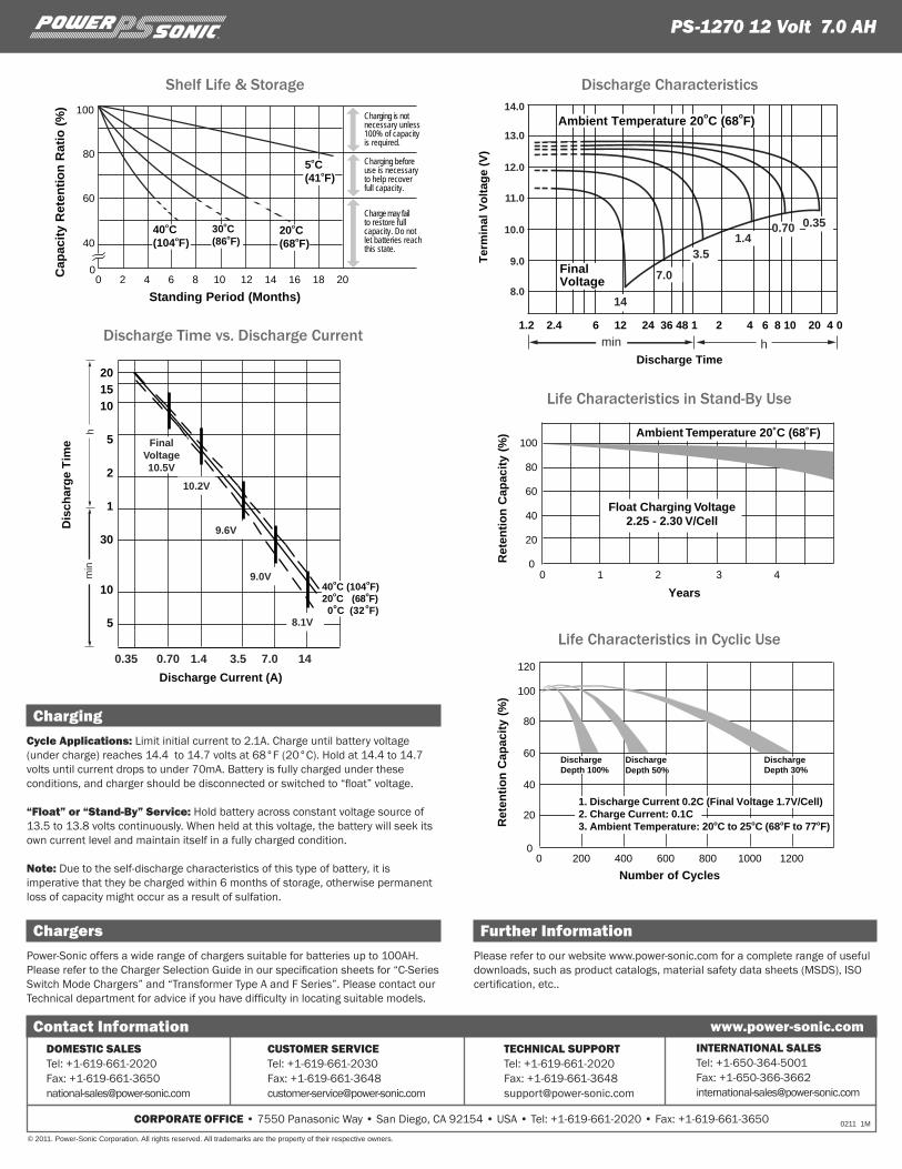
ChargingCycle Applications: Limit initial current to 2.1A. Charge until battery voltage (under charge) reaches 14.4 to 14.7 volts at 68°F (20°C). Hold at 14.4 to 14.7 volts until current drops to under 70mA. Battery is fully charged under these conditions, and charger should be disconnected or switched to “float” voltage.
“Float” or “Stand-By” Service: Hold battery across constant voltage source of 13.5 to 13.8 volts continuously. When held at this voltage, the battery will seek its own current level and maintain itself in a fully charged condition.
Note: Due to the self-discharge characteristics of this type of battery, it is imperative that they be charged within 6 months of storage, otherwise permanent loss of capacity might occur as a result of sulfation.
ChargersPower-Sonic offers a wide range of chargers suitable for batteries up to 100AH. Please refer to the Charger Selection Guide in our specification sheets for “C-Series Switch Mode Chargers” and “Transformer Type A and F Series”. Please contact our Technical department for advice if you have difficulty in locating suitable models.
Cap
acit
yR
eten
tio
nR
atio
(%)
Standing Period (Months)
100
80
60
40
00 2 4 6 8 10 12 14 16 18 20
40oC(104oF)
30oC(86oF)
20oC(68oF)
5oC(41oF)
Charging is notnecessary unless 100% of capacity is required.
Charging beforeuse is necessaryto help recoverfull capacity.
Charge may failto restore fullcapacity. Do notlet batteries reachthis state.
100
80
60
40
20
00 1 2 3 4
Ambient Temperature 20˚C (68˚F)
Float Charging Voltage2.25 - 2.30 V/Cell
Ret
enti
on
Cap
acit
y(%
)
Years
120
100
80
60
40
20
00 200 400 600 800 1000 1200
Number of Cycles
1. Discharge Current 0.2C (Final Voltage 1.7V/Cell)2. Charge Current: 0.1C3. Ambient Temperature: 20oC to 25oC (68oF to 77oF)R
eten
tio
nC
apac
ity
(%)
DischargeDepth 30%
DischargeDepth 100%
DischargeDepth 50%
Discharge Characteristics
Discharge Time vs. Discharge Current
Shelf Life & Storage
Life Characteristics in Stand-By Use
Life Characteristics in Cyclic Use
PS-1270 12 Volt 7.0 AH®
Further InformationPlease refer to our website www.power-sonic.com for a complete range of useful downloads, such as product catalogs, material safety data sheets (MSDS), ISO certification, etc..
13.0
12.0
11.0
10.0
9.0
8.0
14.0
Ter
min
al V
olt
age
(V)
Ambient Temperature 20oC (68oF)
1.2 2.4 6 12 24 36 48 1 2 4 6 8 10 20 4 0
Discharge Time
FinalVoltage
min h
0.350.701.4
3.5
7.0
14
0.35 0.70 1.4 3.5 7.0 14
Discharge Current (A)
20
15
10
5
2
1
30
10
5
Dis
char
ge
Tim
e
40oC (104oF)20oC (68oF) 0oC (32oF)
min
h
10.2V
9.6V
9.0V
8.1V
FinalVoltage10.5V
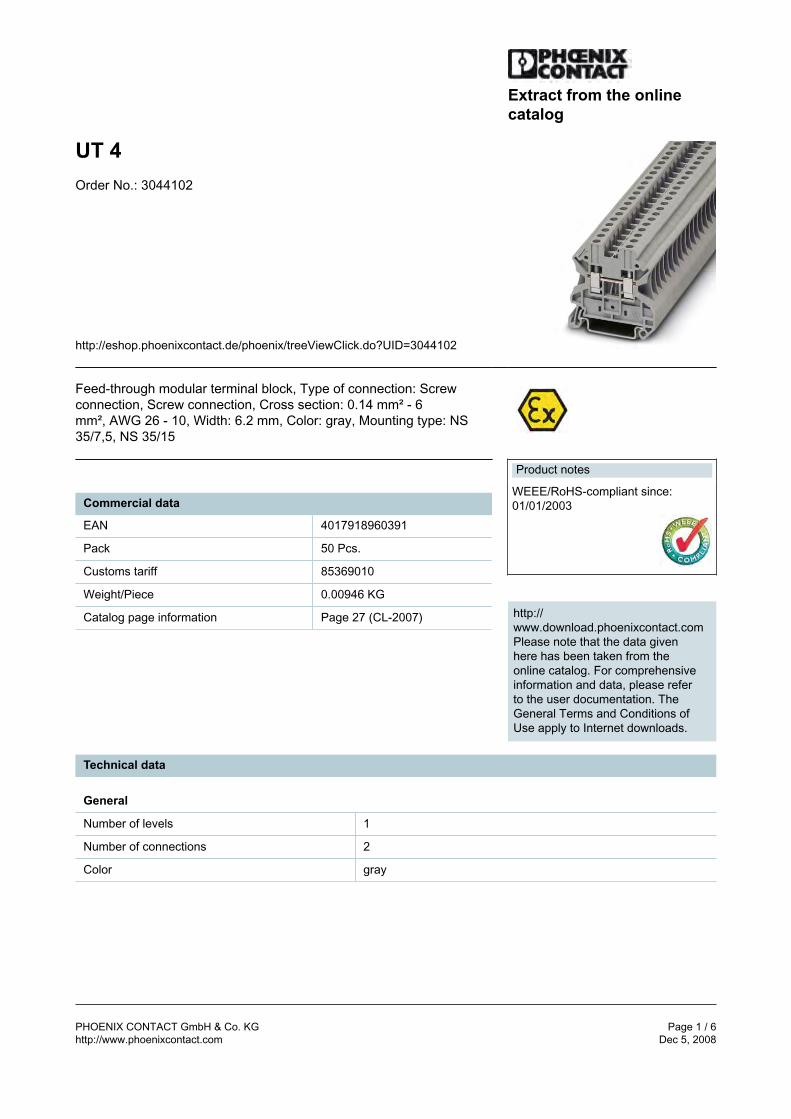
PHOENIX CONTACT GmbH & Co. KG Page 1 / 6http://www.phoenixcontact.com Dec 5, 2008
Extract from the onlinecatalog
UT 4Order No.: 3044102
http://eshop.phoenixcontact.de/phoenix/treeViewClick.do?UID=3044102
Feed-through modular terminal block, Type of connection: Screwconnection, Screw connection, Cross section: 0.14 mm² - 6mm², AWG 26 - 10, Width: 6.2 mm, Color: gray, Mounting type: NS35/7,5, NS 35/15
Commercial data
EAN 4017918960391
Pack 50 Pcs.
Customs tariff 85369010
Weight/Piece 0.00946 KG
Catalog page information Page 27 (CL-2007)
Product notes
WEEE/RoHS-compliant since:01/01/2003
http://www.download.phoenixcontact.comPlease note that the data givenhere has been taken from theonline catalog. For comprehensiveinformation and data, please referto the user documentation. TheGeneral Terms and Conditions ofUse apply to Internet downloads.
Technical data
General
Number of levels 1
Number of connections 2
Color gray
jterrio
Rectangle
UT 4 Order No.: 3044102http://eshop.phoenixcontact.de/phoenix/treeViewClick.do?UID=3044102
PHOENIX CONTACT GmbH & Co. KG Page 2 / 6http://www.phoenixcontact.com Dec 5, 2008
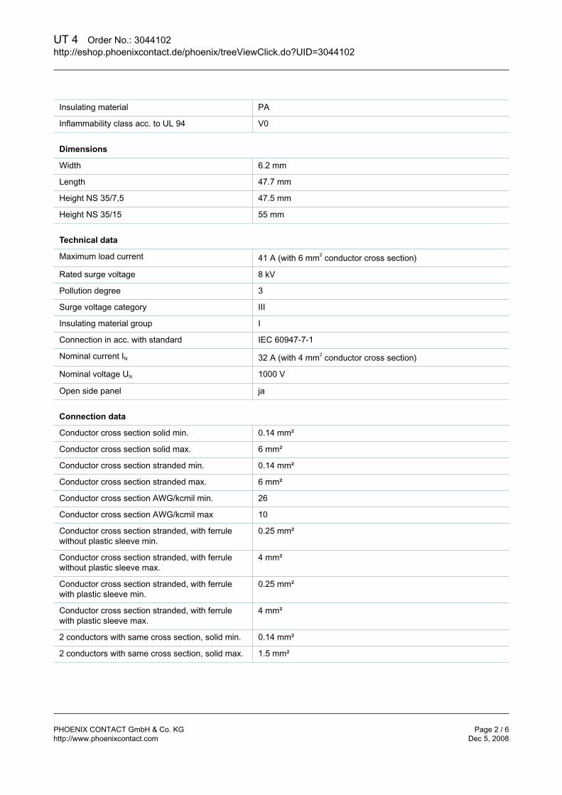
Insulating material PA
Inflammability class acc. to UL 94 V0
Dimensions
Width 6.2 mm
Length 47.7 mm
Height NS 35/7,5 47.5 mm
Height NS 35/15 55 mm
Technical data
Maximum load current 41 A (with 6 mm2 conductor cross section)
Rated surge voltage 8 kV
Pollution degree 3
Surge voltage category III
Insulating material group I
Connection in acc. with standard IEC 60947-7-1
Nominal current IN 32 A (with 4 mm2 conductor cross section)
Nominal voltage UN 1000 V
Open side panel ja
Connection data
Conductor cross section solid min. 0.14 mm²
Conductor cross section solid max. 6 mm²
Conductor cross section stranded min. 0.14 mm²
Conductor cross section stranded max. 6 mm²
Conductor cross section AWG/kcmil min. 26
Conductor cross section AWG/kcmil max 10
Conductor cross section stranded, with ferrulewithout plastic sleeve min.
0.25 mm²
Conductor cross section stranded, with ferrulewithout plastic sleeve max.
4 mm²
Conductor cross section stranded, with ferrulewith plastic sleeve min.
0.25 mm²
Conductor cross section stranded, with ferrulewith plastic sleeve max.
4 mm²
2 conductors with same cross section, solid min. 0.14 mm²
2 conductors with same cross section, solid max. 1.5 mm²
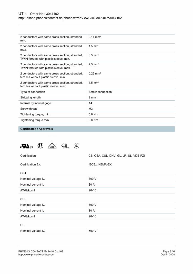
UT 4 Order No.: 3044102http://eshop.phoenixcontact.de/phoenix/treeViewClick.do?UID=3044102
PHOENIX CONTACT GmbH & Co. KG Page 3 / 6http://www.phoenixcontact.com Dec 5, 2008
2 conductors with same cross section, strandedmin.
0.14 mm²
2 conductors with same cross section, strandedmax.
1.5 mm²
2 conductors with same cross section, stranded,TWIN ferrules with plastic sleeve, min.
0.5 mm²
2 conductors with same cross section, stranded,TWIN ferrules with plastic sleeve, max.
2.5 mm²
2 conductors with same cross section, stranded,ferrules without plastic sleeve, min.
0.25 mm²
2 conductors with same cross section, stranded,ferrules without plastic sleeve, max.
1.5 mm²
Type of connection Screw connection
Stripping length 9 mm
Internal cylindrical gage A4
Screw thread M3
Tightening torque, min 0.6 Nm
Tightening torque max 0.8 Nm
Certificates / Approvals
Certification CB, CSA, CUL, DNV, GL, LR, UL, VDE-PZI
Certification Ex: IECEx, KEMA-EX
CSA
Nominal voltage UN 600 V
Nominal current IN 30 A
AWG/kcmil 26-10
CUL
Nominal voltage UN 600 V
Nominal current IN 30 A
AWG/kcmil 26-10
UL
Nominal voltage UN 600 V
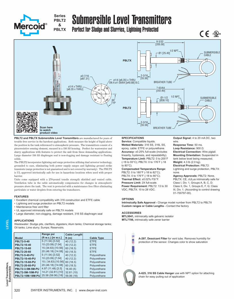
Level T
ran
sm
itte
rs,
Su
bm
ers
ible
LE
VE
L
DWYER INSTRUMENTS, INC. | www.dwyer-inst.com320
SPECIFICATIONS
Service: Compatible liquids.
Wetted Materials: 316 SS, 316L SS,
epoxy, cable: ETFE or polyurethane.
Accuracy: ±0.25% full-scale (includes
linearity, hysteresis, and repeatability).
Temperature Limit: PBLT2: 0 to 200˚F
(-18 to 93°C); PBLTX: 0 to 176˚F (-18
to 80°C).
Compensated Temperature Range:
PBLT2: 0 to 180°F (-18 to 82°C);
PBLTX: 0 to 176°F (-18 to 80°C).
Thermal Effect: ±0.02% FS/°F.
Pressure Limit: 2X full-scale.
Power Requirement: PBLT2: 13 to 30
VDC, PBLTX: 10 to 28 VDC.
Output Signal: 4 to 20 mA DC, two
wire.
Response Time: 50 ms.
Loop Resistance: 900 Ω.
Electrical Connection: Wire pigtail.
Mounting Orientation: Suspended in
tank below level being measured.
Weight: 4.3 lb (2.0 kg).
Electrical Protection: PBLT2:
Lightning and surge protection, PBLTX:
none.
Agency Approvals: PBLT2: None,
PBLTX: CE, cULus intrinsically safe for
Class I, Div. 1, Groups A, B, C, D;
Class II, Div. 1, Groups E, F, G; Class
III, Div. 1. (According to control drawing
01-700797-00).
Submersible Level TransmittersPerfect for Sludge and Slurries, Lightning Protected
Series
PBLT2
&
PBLTX
PBLT2 and PBLTX Submersible Level Transmitters are manufactured for years oftrouble free service in the harshest applications. Both measure the height of liquid abovethe position in the tank referenced to atmospheric pressure. The transmitters consist of apiezoresistive sensing element, encased in a 316 SS housing. Perfect for wastewater andslurry applications with features to protect the unit from these demanding applications.Large diameter 316 SS diaphragm seal is non-clogging and damage resistant to floatingsolids. The PBLT2 incorporates lightning and surge protection utilizing dual arrestor technology,grounded to case, eliminating both power supply surges and lightning ground striketransients (surge protection is not guaranteed and is not covered by warranty). The PBLTXis UL approved intrinsically safe for use in hazardous locations when used with properbarrier.Units come equipped with a 270-pound tensile strength shielded and vented cable.Ventilation tube in the cable automatically compensates for changes in atmosphericpressure above the tank. The vent is protected with a maintenance free filter eliminatingparticulate or water droplets from entering the transducers.
FEATURES
• Excellent chemical compatibility with 316 construction and ETFE cable
• Lightning and surge protection on PBLT2 models
• Maintenance free vent filter
• UL approved intrinsically safe on PBLTX models
• Large diameter, non-clogging, damage resistant, 316 SS diaphragm seal
APPLICATIONS
Wastewater: Sludge pits, clarifiers, digesters; Alum tanks; Chemical storage tanks;
Oil tanks; Lime slurry; Sumps; Reservoirs.
8-3/32[205.58]
2-3/16[55.56]
BREATHER TUBE
Ø1 [25.40]1/2 NPT
SUBMERSIBLECABLE
60˚TYP
ø1/4 x THRU[ø6.35 x THRU]
ø3-7/16[ø87.31] ø1/4 [ø6.35] x THRU
ON A ø1-39/64 [ø40.88] B.C.
7-63/64[202.80]
2-3/16[55.56]
Ø1-1/2[Ø38.10]
1/2 NPT
BREATHER TUBE
SUBMERSIBLECABLE
PBLTX
PBLT2
Cable Length
ft (m)
40 (12.2)
40 (12.2)
60 (18.3)
60 (18.3)
40 (12.2)
40 (12.2)
60 (18.3)
60 (18.3)
16.40 (5)
32.81 (10)
59.06 (18)
Model
PBLT2-5-40
PBLT2-10-40
PBLT2-15-60
PBLT2-20-60
PBLT2-5-40-PU
PBLT2-10-40-PU
PBLT2-15-60-PU
PBLT2-20-60-PU
PBLT2-3.5M-5M-PU
PBLT2-5M-10M-PU
PBLT2-10M-18M-PU
Range psi
(ft w.c.) [m w.c.]
5 (11.54) [3.52]
10 (23.09) [7.04]
15 (34.63) [10.56]
20 (46.18) [14.08]
5 (11.54) [3.52]
10 (23.09) [7.04]
15 ( 34.63) [10.56]
20 (46.18) [14.08]
4.97 (11.48) [3.5]
14.21 (32.81) [10]
25.58 (59.06) [18]
Scan here to watch product video
OPTIONS
Intrinsically Safe Approval - Change model number from PBLT2 to PBLTX
Custom ranges or Cable Lengths - Contact the factory
ACCESSORIES
MTL5041, intrinsically safe galvanic isolator
MTL7706, intrinsically safe zener barrier
A-297, Dessicant Filter for vent tube. Removes humidity for
protection of the sensor. Changes color to show saturation
A-625, 316 SS Cable Hanger use with NPT option for attaching
chain for easy pulling out of application
Cable Type
ETFE
ETFE
ETFE
ETFE
Polyurethane
Polyurethane
Polyurethane
Polyurethane
Polyurethane
Polyurethane
Polyurethane
awarthen
Rectangle
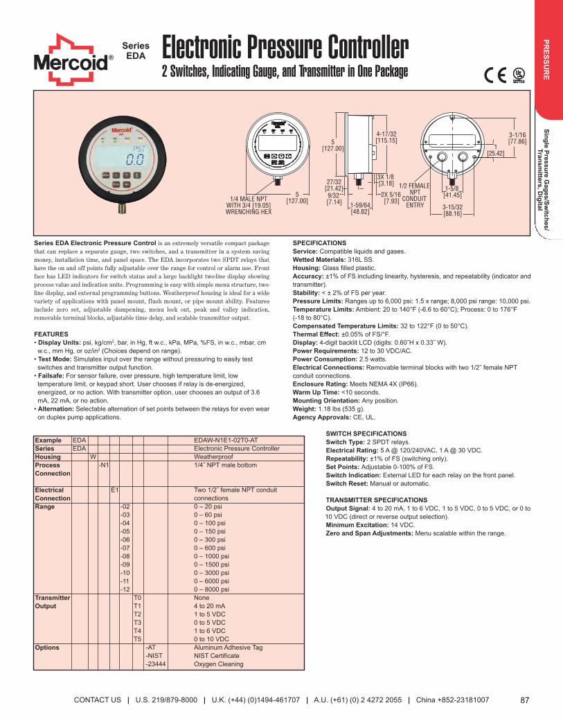
Sin
gle
Pre
ss
ure
Ga
ge
s/S
witc
he
s/
Tra
ns
mitte
rs, D
igita
lP
RE
SS
UR
E
87
Electronic Pressure Controller2 Switches, Indicating Gauge, and Transmitter in One Package
SeriesEDA
1/4 MALE NPTWITH 3/4 [19.05]WRENCHING HEX
9/32 [7.14]
5[127.00]
4-17/32[115.15]
1[25.42]
3-1/16[77.86]
1-59/64[48.82]
2X 5/16 [7.93]
3-15/32[88.16]
1-5/8 [41.45]
3X 1/8 [3.18] 1/2 FEMALE
NPTCONDUIT
ENTRY
5[127.00]
27/32[21.42]
Series EDA Electronic Pressure Control is an extremely versatile compact packagethat can replace a separate gauge, two switches, and a transmitter in a system savingmoney, installation time, and panel space. The EDA incorporates two SPDT relays thathave the on and off points fully adjustable over the range for control or alarm use. Frontface has LED indicators for switch status and a large backlight two-line display showingprocess value and indication units. Programming is easy with simple menu structure, two-line display, and external programming buttons. Weatherproof housing is ideal for a widevariety of applications with panel mount, flush mount, or pipe mount ability. Featuresinclude zero set, adjustable dampening, menu lock out, peak and valley indication,removable terminal blocks, adjustable time delay, and scalable transmitter output.
FEATURES
• Display Units: psi, kg/cm2, bar, in Hg, ft w.c., kPa, MPa, %FS, in w.c., mbar, cm
w.c., mm Hg, or oz/in2 (Choices depend on range).
• Test Mode: Simulates input over the range without pressuring to easily test
switches and transmitter output function.
• Failsafe: For sensor failure, over pressure, high temperature limit, low
temperature limit, or keypad short. User chooses if relay is de-energized,
energized, or no action. With transmitter option, user chooses an output of 3.6
mA, 22 mA, or no action.
• Alternation: Selectable alternation of set points between the relays for even wear
on duplex pump applications.
SPECIFICATIONS
Service: Compatible liquids and gases.
Wetted Materials: 316L SS.
Housing: Glass filled plastic.
Accuracy: ±1% of FS including linearity, hysteresis, and repeatability (indicator and
transmitter).
Stability: < ± 2% of FS per year.
Pressure Limits: Ranges up to 6,000 psi: 1.5 x range; 8,000 psi range: 10,000 psi.
Temperature Limits: Ambient: 20 to 140°F (-6.6 to 60°C); Process: 0 to 176°F
(-18 to 80°C).
Compensated Temperature Limits: 32 to 122°F (0 to 50°C).
Thermal Effect: ±0.05% of FS/°F.
Display: 4-digit backlit LCD (digits: 0.60˝H x 0.33˝ W).
Power Requirements: 12 to 30 VDC/AC.
Power Consumption: 2.5 watts.
Electrical Connections: Removable terminal blocks with two 1/2˝ female NPT
conduit connections.
Enclosure Rating: Meets NEMA 4X (IP66).
Warm Up Time: <10 seconds.
Mounting Orientation: Any position.
Weight: 1.18 lbs (535 g).
Agency Approvals: CE, UL.
SWITCH SPECIFICATIONS
Switch Type: 2 SPDT relays.
Electrical Rating: 5 A @ 120/240VAC, 1 A @ 30 VDC.
Repeatability: ±1% of FS (switching only).
Set Points: Adjustable 0-100% of FS.
Switch Indication: External LED for each relay on the front panel.
Switch Reset: Manual or automatic.
TRANSMITTER SPECIFICATIONS
Output Signal: 4 to 20 mA, 1 to 6 VDC, 1 to 5 VDC, 0 to 5 VDC, or 0 to
10 VDC (direct or reverse output selection).
Minimum Excitation: 14 VDC.
Zero and Span Adjustments: Menu scalable within the range.
Example
Series
Housing
Process
Connection
Electrical
Connection
Range
Transmitter
Output
Options
EDA
EDA
W
-N1
E1
-02
-03
-04
-05
-06
-07
-08
-09
-10
-11
-12
T0
T1
T2
T3
T4
T5
-AT
-NIST
-23444
CONTACT US | U.S. 219/879-8000 | U.K. (+44) (0)1494-461707 | A.U. (+61) (0) 2 4272 2055 | China +852-23181007
EDAW-N1E1-02T0-AT
Electronic Pressure Controller
Weatherproof
1/4˝ NPT male bottom
Two 1/2˝ female NPT conduit
connections
0 – 20 psi
0 – 60 psi
0 – 100 psi
0 – 150 psi
0 – 300 psi
0 – 600 psi
0 – 1000 psi
0 – 1500 psi
0 – 3000 psi
0 – 6000 psi
0 – 8000 psi
None
4 to 20 mA
1 to 5 VDC
0 to 5 VDC
1 to 6 VDC
0 to 10 VDC
Aluminum Adhesive Tag
NIST Certificate
Oxygen Cleaning
087_Layout 2 7/19/13 10:57 AM Page 87
awarthen
Rectangle
awarthen
Oval
awarthen
Oval
awarthen
Oval
awarthen
Oval
awarthen
Oval
awarthen
Oval

13005 16TH AVE. NORTH SUITE 100 PLYMOUTH MN 55441
PHONE: (763) 559-0568 FAX: (763) 559-2187www.icshealyruff.com
ENGINEERING • INSTALLATION • SERVICE
TAB 5
5/55 1/2015 The Dell Online Store: Build YoYY ur System
htttt p://// configure.us.dell.com/dellstore/ee print_summary_yy details_p__ opup.aspxpp ?~lt=print&c=us&cs=04&f&& b=1&l=en&model_id=powoo eredge-t110-2&oc=bect12bfbb sff i&refee … 1/3
PowerEdge T110 IIStarting Price $2,036.99Instant Savings $867.08
Subtotal $1,169.91
As low as $36.00 /month^
Dell Business Credit | Apply
Discount DetailsShips in 4 - 6 Business Days
PowerEdge T110 II
Date 5/1/2015 1:55:34 PM Central StandardTime
Catalog Number 4 Retail 04
Catalog Number / Description Product Code Qty SKU Id
PowerEdge T110 II:PowerEdge T110 II Chassis with Cabled 4x3.5Hard Drives
T110II 1 [225-0883] 1
Processor:Intel® Xeon® E3-1230v2 3.30 GHz, 8M Cache,Turbo, Quad Core/8T (69W)
E31230T 1 [319-0202][330-5552] 6
Memory:8GB Memory (1x8GB), 1600Mhz, Dual Ranked,Low Volt UDIMM (speed is CPU dependent)
8GBMUD 1 [317-2022][319-1758] 3
Operating System:Windows Server® 2012R2,FoundationEd,Factory Install,No MED,2SKT
WS12R2 1 [618-BBED] 11
OS Media kits:Windows Server® 2012R2, Foundation Edition,Media Kit
WINR217 1 [618-BBDX] 1203
OS Partitions:Maximum Partition Size for Microsoft OS MAXPART 1 [420-4018] 37
Hard Drive Configuration:Add-in H200 (SAS/SATA Controller), 2-6 HardDrives - RAID 0
HS4R0 1 [331-2617] 27
Internal Controller:PERC H200 Adapter Internal RAID Controllerfor 3.5 HDDs
H20035 1 [331-2398][342-0729] 9
Hard Drives (Multi-Select):
My Selections All Options
5/55 1/2015 The Dell Online Store: Build YoYY ur System
htttt p://// configure.us.dell.com/dellstore/ee print_summary_yy details_p__ opup.aspxpp ?~lt=print&c=us&cs=04&f&& b=1&l=en&model_id=powoo eredge-t110-2&oc=bect12bfbb sff i&refee … 2/22 3
500GB 7.2K RPM SATA 3Gbps 3.5in CabledHard Drive
500A7K 2 [341-9247] 1209
Network Adapter:On-Board Single Gigabit Network Adapter OBNIC 1 [430-2008] 1230
Power Cords:NEMA 5-15P to C13 Wall Plug, 125 Volt, 15AMP, 10 Feet (3m), Power Cord
125V10F 1 [310-8509] 106
Server Accessories:Keyboard and Optical Mouse, USB, Black,English
KMENG 1 [331-0846][331-2254] 154
Internal Optical Drive:DVD Drive, Internal 16XDVD 1 [313-9100][331-
2399] 16
Primary Hard Drive:HD Multi-Select HDMULTI 1 [341-4158] 8
System Documentation:Edocs and OpenManage DVD EDOCS 1 [331-2505] 21
Shipping:Shipping for PowerEdge T110 II SH110II 1 [331-2391] 2
Embedded Management:Baseboard Management Controller BMC 1 [313-7919] 14
Warranty & Service:1Yr Basic Hardware Warranty Repair: 5x10 HW-Only, 5x10 NBD Onsite
U1OS 1
[931-5387][954-9880][988-7347][994-4019][996-8029]
29
Installation Services:No Installation NOINSTL 1 [900-9997] 32
Remote Consulting Service:Declined Remote Consulting Service NORCS 1 [973-2426] 35
Dell 23 Monitor, P2314H, 23"
Date 5/1/2015 1:55:34 PM Central StandardTime
Catalog Number 4 Retail 04
Catalog Number / Description Product Code Qty SKU Id
Dell Monitors:Dell 23 Monitor - P2314H P2314H 1 [320-9799] 1
Limited Warranty:3Yr PREMIUM PANEL Ltd. Warranty, 3 yrAdvanced Exchange
P3YRAE 1 [986-4872] 161
©2015 Dell Regulatory Compliance Terms of Sale Unresolved Issues Privacy Ads & Emails
Dell Recycling Contact Site Map Visit ID Feedback
Products
Offers subject to change. Taxes, shipping, handling and other fees apply. U.S. Dell Small Business new purchases only.LIMIT 5 DISCOUNTED OR PROMOTIONAL ITEMS PER CUSTOMER. LIMIT 5 VOSTRO OR INSPIRON UNITS PER CUSTOMER. Dell
reserves right to cancel orders arising from pricing or other errors.
*Dell Business Credit: OFFER VARIES BY CREDITWORTHINESS AS DETERMINED BY LENDER. Offered by WebBank to Small andMedium Business customers with approved credit. Taxes, shipping and other charges are extra and vary. Minimum
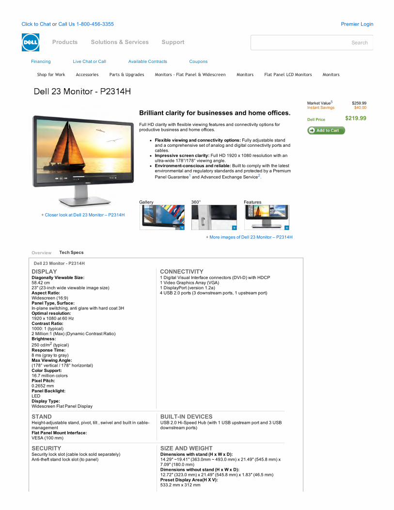
Financing Live Chat or Call Available Contracts Coupons
Shop for Work Accessories Parts & Upgrades Monitors ‐ Flat Panel & Widescreen Monitors Flat Panel LCD Monitors Monitors
+ Closer look at Dell 23 Monitor – P2314H
Brilliant clarity for businesses and home offices.Full HD clarity with flexible viewing features and connectivity options forproductive business and home offices.
Flexible viewing and connectivity options: Fully adjustable standand a comprehensive set of analog and digital connectivity ports andcables.Impressive screen clarity: Full HD 1920 x 1080 resolution with anultrawide 178°/178° viewing angle.Environmentconscious and reliable: Built to comply with the latestenvironmental and regulatory standards and protected by a PremiumPanel Guarantee1 and Advanced Exchange Service2.
Gallery 360° Features
+ More images of Dell 23 Monitor – P2314H
Dell 23 Monitor P2314H
DISPLAYDiagonally Viewable Size:58.42 cm23" (23inch wide viewable image size)Aspect Ratio:Widescreen (16:9)Panel Type, Surface:Inplane switching, anti glare with hard coat 3HOptimal resolution:1920 x 1080 at 60 HzContrast Ratio:1000: 1 (typical)2 Million:1 (Max) (Dynamic Contrast Ratio)Brightness:250 cd/m2 (typical)Response Time:8 ms (gray to gray)Max Viewing Angle:(178° vertical / 178° horizontal)Color Support:16.7 million colorsPixel Pitch:0.2652 mmPanel Backlight:LEDDisplay Type:Widescreen Flat Panel Display
CONNECTIVITY1 Digital Visual Interface connectors (DVID) with HDCP1 Video Graphics Array (VGA)1 DisplayPort (version 1.2a)4 USB 2.0 ports (3 downstream ports, 1 upstream port)
STANDHeightadjustable stand, pivot, tilt , swivel and built in cablemanagementFlat Panel Mount Interface:VESA (100 mm)
BUILTIN DEVICESUSB 2.0 HiSpeed Hub (with 1 USB upstream port and 3 USBdownstream ports)
SECURITYSecurity lock slot (cable lock sold separately)Antitheft stand lock slot (to panel)
SIZE AND WEIGHTDimensions with stand (H x W x D):14.29" ~19.41" (363.0mm ~ 493.0 mm) x 21.49" (545.8 mm) x7.09" (180.0 mm)Dimensions without stand (H x W x D):12.72" (323.0 mm) x 21.49" (545.8 mm) x 1.83" (46.5 mm)Preset Display Area(H X V):533.2 mm x 312 mm
Market Value5 $259.99Instant Savings $40.00
Dell Price $219.99
Overview Tech Specs
Click to Chat or Call Us 18004563355 Premier Login
SearchProducts Solutions & Services Support
awarthen
Rectangle
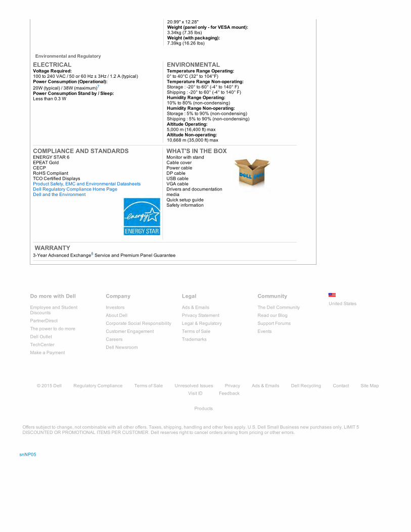
Do more with Dell
Employee and StudentDiscounts
PartnerDirect
The power to do more
Dell Outlet
TechCenter
Make a Payment
Company
Investors
About Dell
Corporate Social Responsibility
Customer Engagement
Careers
Dell Newsroom
Legal
Ads & Emails
Privacy Statement
Legal & Regulatory
Terms of Sale
Trademarks
Community
The Dell Community
Read our Blog
Support Forums
Events
20.99" x 12.28"Weight (panel only for VESA mount):3.34kg (7.35 lbs)Weight (with packaging):7.39kg (16.26 lbs)
Environmental and Regulatory
ELECTRICALVoltage Required:100 to 240 VAC / 50 or 60 Hz ± 3Hz / 1.2 A (typical)Power Consumption (Operational):20W (typical) / 38W (maximum)7Power Consumption Stand by / Sleep:Less than 0.3 W
ENVIRONMENTALTemperature Range Operating:0° to 40°C (32° to 104°F)Temperature Range Nonoperating:Storage : 20° to 60° (4° to 140° F)Shipping : 20° to 60° (4° to 140° F)Humidity Range Operating:10% to 80% (noncondensing)Humidity Range Nonoperating:Storage : 5% to 90% (noncondensing)Shipping : 5% to 90% (noncondensing)Altitude Operating:5,000 m (16,400 ft) maxAltitude Nonoperating:10,668 m (35,000 ft) max
COMPLIANCE AND STANDARDSENERGY STAR 6EPEAT GoldCECPRoHS CompliantTCO Certified DisplaysProduct Safety, EMC and Environmental DatasheetsDell Regulatory Compliance Home PageDell and the Environment
WHAT'S IN THE BOXMonitor with standCable coverPower cableDP cableUSB cableVGA cableDrivers and documentationmediaQuick setup guideSafety information
WARRANTY 3Year Advanced Exchange8 Service and Premium Panel Guarantee
© 2015 Dell Regulatory Compliance Terms of Sale Unresolved Issues Privacy Ads & Emails Dell Recycling Contact Site Map
Visit ID Feedback
Products
Offers subject to change, not combinable with all other offers. Taxes, shipping, handling and other fees apply. U.S. Dell Small Business new purchases only. LIMIT 5DISCOUNTED OR PROMOTIONAL ITEMS PER CUSTOMER. Dell reserves right to cancel orders arising from pricing or other errors.
snNP05
United States
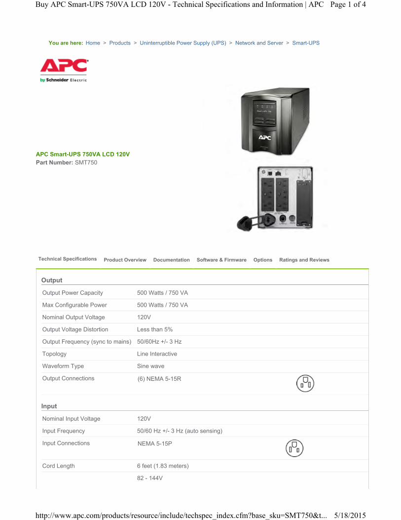
You are here:
Output Power Capacity 500 Watts / 750 VA
Max Configurable Power 500 Watts / 750 VA
Nominal Output Voltage 120V
Output Voltage Distortion Less than 5%
Output Frequency (sync to mains) 50/60Hz +/- 3 Hz
Topology Line Interactive
Waveform Type Sine wave
Output Connections (6) NEMA 5-15R
Nominal Input Voltage 120V
Input Frequency 50/60 Hz +/- 3 Hz (auto sensing)
Input Connections NEMA 5-15P
Cord Length 6 feet (1.83 meters)
82 - 144V
Home > Products > Uninterruptible Power Supply (UPS) > Network and Server > Smart-UPS
APC Smart-UPS 750VA LCD 120VPart Number: SMT750
Technical Specifications Product Overview Documentation Software & Firmware Options Ratings and Reviews
Output
Input
Page 1 of 4Buy APC Smart-UPS 750VA LCD 120V - Technical Specifications and Information | APC
5/18/2015http://www.apc.com/products/resource/include/techspec_index.cfm?base_sku=SMT750&t...
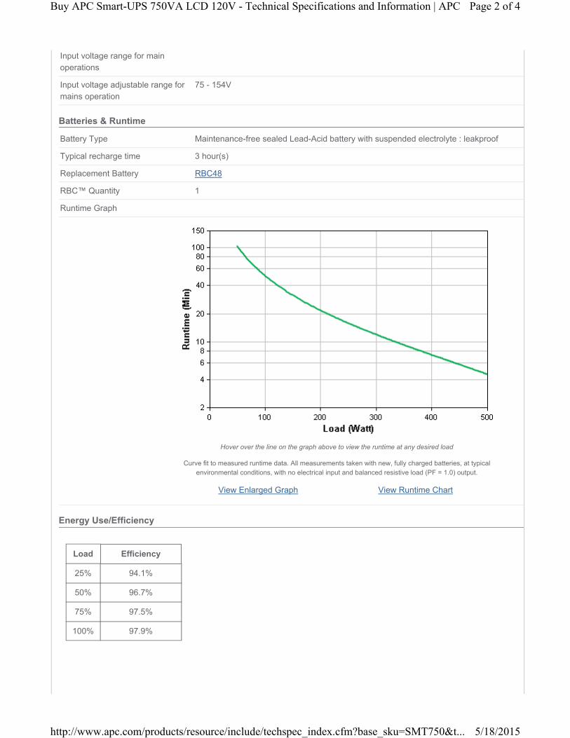
Input voltage range for main operations
Input voltage adjustable range for mains operation
75 - 154V
Battery Type Maintenance-free sealed Lead-Acid battery with suspended electrolyte : leakproof
Typical recharge time 3 hour(s)
Replacement Battery RBC48
RBC™ Quantity 1
Runtime Graph
View Enlarged Graph View Runtime Chart
Hover over the line on the graph above to view the runtime at any desired load
Curve fit to measured runtime data. All measurements taken with new, fully charged batteries, at typical environmental conditions, with no electrical input and balanced resistive load (PF = 1.0) output.
Load Efficiency
25% 94.1%
50% 96.7%
75% 97.5%
100% 97.9%
Batteries & Runtime
Energy Use/Efficiency
Page 2 of 4Buy APC Smart-UPS 750VA LCD 120V - Technical Specifications and Information | APC
5/18/2015http://www.apc.com/products/resource/include/techspec_index.cfm?base_sku=SMT750&t...
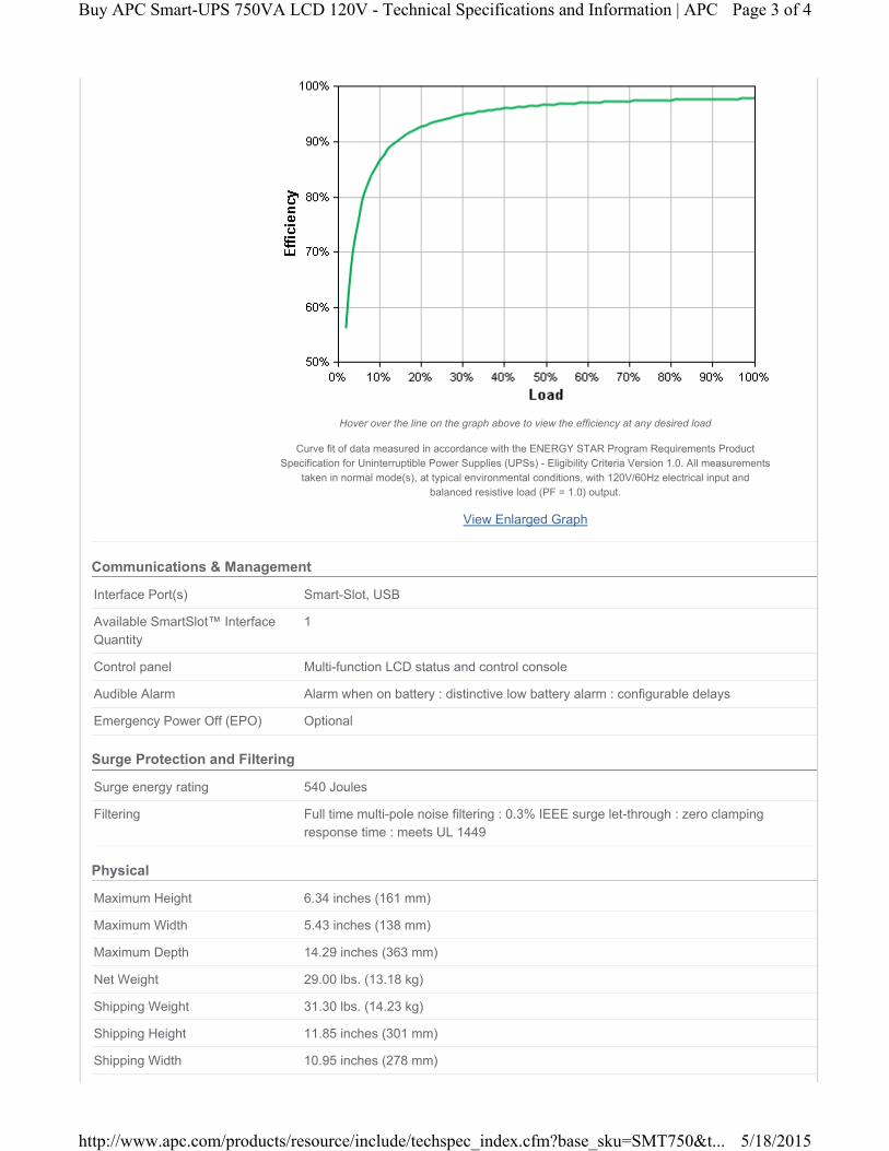
View Enlarged Graph
Hover over the line on the graph above to view the efficiency at any desired load
Curve fit of data measured in accordance with the ENERGY STAR Program Requirements Product Specification for Uninterruptible Power Supplies (UPSs) - Eligibility Criteria Version 1.0. All measurements
taken in normal mode(s), at typical environmental conditions, with 120V/60Hz electrical input and balanced resistive load (PF = 1.0) output.
Interface Port(s) Smart-Slot, USB
Available SmartSlot™ Interface Quantity
1
Control panel Multi-function LCD status and control console
Audible Alarm Alarm when on battery : distinctive low battery alarm : configurable delays
Emergency Power Off (EPO) Optional
Surge energy rating 540 Joules
Filtering Full time multi-pole noise filtering : 0.3% IEEE surge let-through : zero clamping response time : meets UL 1449
Maximum Height 6.34 inches (161 mm)
Maximum Width 5.43 inches (138 mm)
Maximum Depth 14.29 inches (363 mm)
Net Weight 29.00 lbs. (13.18 kg)
Shipping Weight 31.30 lbs. (14.23 kg)
Shipping Height 11.85 inches (301 mm)
Shipping Width 10.95 inches (278 mm)
Communications & Management
Surge Protection and Filtering
Physical
Page 3 of 4Buy APC Smart-UPS 750VA LCD 120V - Technical Specifications and Information | APC
5/18/2015http://www.apc.com/products/resource/include/techspec_index.cfm?base_sku=SMT750&t...
Shipping Depth 19.65 inches (499 mm)
Color Black
Units per Pallet 24.00
Operating Environment 32 - 104 °F (0 - 40 °C)
Operating Relative Humidity 0 - 95%
Operating Elevation 0-10000 feet (0-3000 meters)
Storage Temperature 5 - 113 °F (-15 - 45 °C)
Storage Relative Humidity 0 - 95%
Storage Elevation 0-50000 feet (0-15000 meters)
Audible noise at 1 meter from surface of unit
40.00 dBA
Online Thermal Dissipation 90.00 BTU/hr
Regulatory Approvals ENERGY STAR (USA), UL 1778
Standard Warranty 3 years repair or replace (excluding battery) and 2 year for battery
Equipment protection policy Lifetime : $150000
RoHS Compliant
REACH REACH: Contains No SVHCs
PEP Available in Documentation tab
EOLI Available in Documentation tab
Environmental
Conformance
Sustainable Offer Status
*Except where noted, all prices are Estimated Resale Price (ERP) - Without Tax/VAT. Pricing in other locations and sites may vary.
**The time to recharge to 90% of full battery capacity following a discharge to shutdown using a load rated for 1/2 the full load rating of the UPS.
Page 4 of 4Buy APC Smart-UPS 750VA LCD 120V - Technical Specifications and Information | APC
5/18/2015http://www.apc.com/products/resource/include/techspec_index.cfm?base_sku=SMT750&t...

13005 16TH AVE. NORTH SUITE 100 PLYMOUTH MN 55441
PHONE: (763) 559-0568 FAX: (763) 559-2187www.icshealyruff.com
ENGINEERING • INSTALLATION • SERVICE
TAB 6
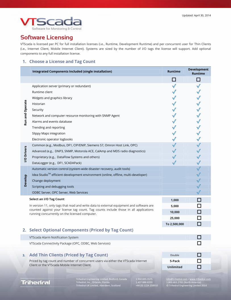
Updated: April 30, 2014
Trihedral Engineering Limited, Bedford, Canada 1.902.835.1575 [email protected] / www.trihedral.com Trihedral, Inc., Orlando, Florida 1.407.888.8203 1.800.463.2783 (North America) Trihedral UK Limited, Aberdeen, Scotland +44 (0) 1224 258910 © Trihedral Engineering Limited 2014 © Trihedral Engineering Limited 2012
Software Licensing VTScada is licensed per PC for full installation licenses (i.e., Runtime, Development Runtime) and per concurrent user for Thin Clients
(i.e., Internet Client, Mobile Internet Client). Systems are sized by the number of I/O tags the license will support. Add optional
components to any full installation license.
1. Choose a License and Tag Count
Integrated Components Included (single installation) Runtime
Development
Runtime
Ru
n a
nd
Op
era
te
Application server (primary or redundant)
Runtime client
Widgets and graphics library
Historian
Security
Network and computer resource monitoring with SNMP Agent
Alarms and events database
Trending and reporting
Slippy Maps integration
Electronic operator logbooks
I/O
Dri
ve
rs Common (e.g., Modbus, DF1, CIP/ENIP, Siemens S7, Omron Host Link, OPC)
Advanced (e.g., DNP3, SNMP, Motorola ACE, CalAmp and MDS radio diagnostics)
Proprietary (e.g., DataFlow Systems and others)
DataLogger (e.g., DF1, SCADAPack)
De
ve
lop
Automatic version control (system-wide disaster recovery, audit tools)
Idea StudioTM efficient development environment (online, offline, multi-developer)
Change deployment
Scripting and debugging tools
ODBC Server, OPC Server, Web Services
Select an I/O Tag Count
In version 11, only tags that read and write data to external equipment and software are
counted against your license tag count. Tag counts include those in all applications
running concurrently on the licensed computer.
1,000
5,000
10,000
25,000
To 2,500,000
2. Select Optional Components (Priced by Tag Count)
VTScada Alarm Notification System
VTScada Connectivity Package (OPC, ODBC, Web Services)
3. Add Thin Clients (Priced by Tag Count)
Priced by tag count and number of concurrent users via either the VTScada Internet
Client or the VTScada Mobile Internet Client.
Double 5-Pack
Unlimited
chahn
Line
chahn
Line
chahn
Line
chahn
Line

Updated May 8, 2014
What Makes VTScada Different?
Our development team created VTScada™ software to work differently from
other common monitoring and control products. After 27 years of proven
installations around the world, we believe that our approach is fundamentally
better for mission critical systems. Below are some of the obvious and not so
obvious ways that VTScada stands out.
Integrated features reduce integration time and improve reliability
All mission-critical SCADA components built into the core product.
Connections to components do not degrade over time
Upgrading software version does not require re-integration
Unlock optional components with just a license key number
Native VTScada Polling Driver replaces expensive master PLC hardware
Communicate with any combination of PLCs, RTUs, or controllers
Other HMIs require OPC® and DDE® drivers from 3rd party suppliers. In
addition to supporting these protocols, VTScada includes direct drivers for
over 100 industry standard and proprietary devices.
Direct drivers = less problems = lower integration costs
Configure without interrupting your process
Only VTScada allows you to do all this without restarting.
Make simultaneous changes from multiple workstations
Debug communications and application script code
Automatically push changes to local and remote computers
Load many changes to tags, source code, and properties
Deploy applications to all computers with a single file
VTScada ChangeSet Files help integrators simplify development, offer more
services, and provide effective offsite support.
Create and update applications offsite and offline
Instantly backup and restore configuration information
Recover quickly from unexpected effects of configuration
VTScada Application Version Control (AVC) provides access to an audit log of
all changes made on every workstation. (AVC is included with all VTScada
Development Runtime licenses.)
Instantly return to any past good version of the application
Quickly trace problems back to their source
Avoid downtime with seamless failover of servers, Internet clients,
historians, and I/O networks
Only VTScada provides this level of system-wide redundancy.
All workstations can also be backup servers (fewer servers)
Automatically synchronize restored historians and alarms
Distribute redundant historians in a variety of standard formats
Protect your valuable process data with redundant historians
VTScada includes the incredibly fast native VTScada Historian.
Log up to 4,000 tags/second
Sync historians across a WAN at 160,000 values/second
Also log to most standard SQL formats
Try It for Yourself
Download the 90-day Trial
www.trihedral.com/demo
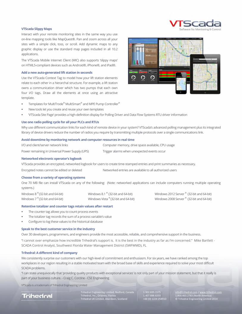
Trihedral Engineering Limited, Bedford, Canada 1.902.835.1575 [email protected] / www.trihedral.com Trihedral, Inc., Orlando, Florida 1.407.888.8203 1.800.463.2783 (North America) Trihedral UK Limited, Aberdeen, Scotland +44 (0) 1224 258910 © Trihedral Engineering Limited 2014 © Trihedral Engineering Limited 2012
VTScada Slippy Maps
Interact with your remote monitoring sites in the same way you use
on-line mapping tools like MapQuest®. Pan and zoom across all your
sites with a simple click, toss, or scroll. Add dynamic maps to any
graphic display or use the standard map pages included in all 10.2
applications.
The VTScada Mobile Internet Client (MIC) also supports ‘slippy maps’
on HTML5-compliant devices such as Android®, iPhone®, and iPad®.
Add a new auto-generated lift station in seconds
Use the VTScada Context Tag to model how your lift station elements
relate to each other in a hierarchal structure. For example, a lift station
owns a communication driver which has two pumps that each own
four I/O tags. Draw all the elements at once using an attractive
template.
Templates for MultiTrode® MultiSmart® and MPE Pump Controller®
New tools let you create and reuse your own templates
‘VTScada Site Page’ provides a high-definition display for Polling Driver and Data Flow Systems RTU driver information
Use one radio polling cycle for all your PLCs and RTUs
Why use different communication links for each kind of remote device in your system? VTScada’s advanced polling management plus its integrated
library of device drivers reduce the number of radios you require by transmitting multiple protocols over a single communications link.
Avoid downtime by monitoring network and computer resources in real time
I/O and client/server network links Computer memory, drive space available, CPU usage
Power remaining in Universal Power Supply (UPS) Trigger alarms when unexpected events occur
Networked electronic operator’s logbook
VTScada provides an encrypted, networked logbook for users to create time-stamped entries and print summaries as necessary.
Encrypted notes cannot be edited or deleted Networked entries are available to all authorized users
Choose from a variety of operating systems
One 70 MB file can install VTScada on any of the following: (Note: networked applications can include computers running multiple operating
systems.)
Windows 8 ® (32-bit and 64-bit) Windows 8.1 ® (32-bit and 64-bit) Windows 2012 Server ® (32-bit and 64-bit)
Windows 7 ® (32-bit and 64-bit) Windows Vista ® (32-bit and 64-bit) Windows 2008 Server ® (32-bit and 64-bit)
Retentive totalizer and counter tags retain values after restart
The counter tag allows you to count process events
The totalizer tag records the sum of a process variable’s value
Configure to log these values to the historical database
Speak to the best customer service in the industry
Over 30 developers, programmers, and engineers provide the most accessible, reliable, and comprehensive support in the business.
“I cannot over emphasize how incredible Trihedral’s support is. It is the best in the industry as far as I’m concerned.” Mike Bartlett -
SCADA Control Analyst, Southwest Florida Water Management District (SWFWMD), FL
Trihedral: A different kind of company
We consistently surprise our customers with our high-level of commitment and enthusiasm. For six years, we have ranked among the top
workplaces in our region resulting in a stable motivated team with the broad base of skills and experience required to solve your most difficult
SCADA problems.
“I can state unequivocally that ‘providing quality products with exceptional services’ is not only part of your mission statement, but that it really is
part of your business culture. - Craig C. Corzine - CSE Engineering
VTScada is a trademark of Trihedral Engineering Limited
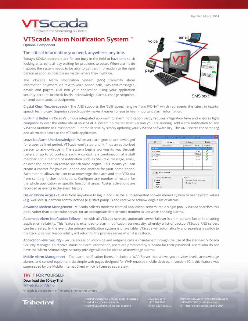
Updated May 5, 2014
Trihedral Engineering Limited, Bedford, Canada 1.902.835.1575 [email protected] / www.trihedral.com Trihedral, Inc., Orlando, Florida 1.407.888.8203 1.800.463.2783 (North America) Trihedral UK Limited, Aberdeen, Scotland +44 (0) 1224 258910 © Trihedral Engineering Limited 2014 © Trihedral Engineering Limited 2012
VTScada Alarm Notification System™ Optional Component
The critical information you need, anywhere, anytime.
Today's SCADA operators are far too busy in the field to have time to sit
looking at screens all day waiting for problems to occur. When alarms do
happen, the system needs to be able to get that information to the right
person as soon as possible no matter where they might be.
The VTScada Alarm Notification System (ANS) transmits alarm
information anywhere via text-to-voice phone calls, SMS text messages,
emails and pagers. Dial into your application using your application
security account to check levels, acknowledge alarms, change setpoints,
or send commands to equipment.
Crystal Clear Text-to-speech - The ANS supports the ‘Salli’ speech engine from IVONA® which represents the latest in text-to-
speech technology. Superior speech quality makes it easier for you to hear important alarm information.
Built-In is Better - VTScada's unique integrated approach to alarm notification vastly reduces integration time and ensures tight
compatibility over the entire life of your SCADA system no matter what version you are running. Add alarm notification to any
VTScada Runtime or Development Runtime license by simply updating your VTScada software key. The ANS shares the same tag
and alarm databases as the VTScada application.
Leave No Alarm Unacknowledged - When an alarm goes unacknowledged
for a user-defined period, VTScada won't stop until it finds an authorized
person to acknowledge it. The system begins working its way through
rosters of up to 30 contacts each. A contact is a combination of a staff
member and a method of notification such as SMS text message, email,
or over the phone via text-to-speech voice engine. This means you can
create a contact for your cell phone and another for your home phone.
Each method allows the user to acknowledge the alarm and stop VTScada
from sending further notifications. Configure any number of rosters for
the whole application or specific functional areas. Roster activations are
recorded as events in the alarm history.
Dial-In Phone Access - Dial in from anywhere to log in and use the auto-generated spoken menu’s system to hear system values
(e.g. well levels), perform control actions (e.g. start pump 1) and receive or acknowledge a list of alarms.
Advanced Modem Management - VTScada collects modems from all application servers into a single pool. VTScada searches this
pool, rather than a particular server, for an appropriate data or voice modem to use when sending alarms.
Automatic Alarm Notification Failover - As with all VTScada services, automatic server failover is an important factor in ensuring
application reliability. This feature is extended to alarm notification connectivity, whereby a list of backup VTScada ANS servers
can be created. In the event the primary notification system is unavailable, VTScada will automatically and seamlessly switch to
the backup server. Responsibility will return to the primary server when it is restored.
Application-level Security - Secure access on incoming and outgoing calls is maintained through the use of the standard VTScada
Security Manager. To receive status or alarm information, users are prompted by VTScada for their password. Users who do not
have the ‘Alarm Acknowledge’ security privilege will not be able to acknowledge alarms.
Mobile Alarm Management - The alarm notification license includes a WAP Server that allows you to view levels, acknowledge
alarms, and control equipment via simple web pages designed for WAP-enabled mobile devices. In version 10.1, this feature was
superseded by the Mobile Internet Client which is licensed separately.
TRY IT FOR YOURSELF Download the 90-day Trial
Trihedral.com/demo
VTScada is a trademark of Trihedral Engineering Limited
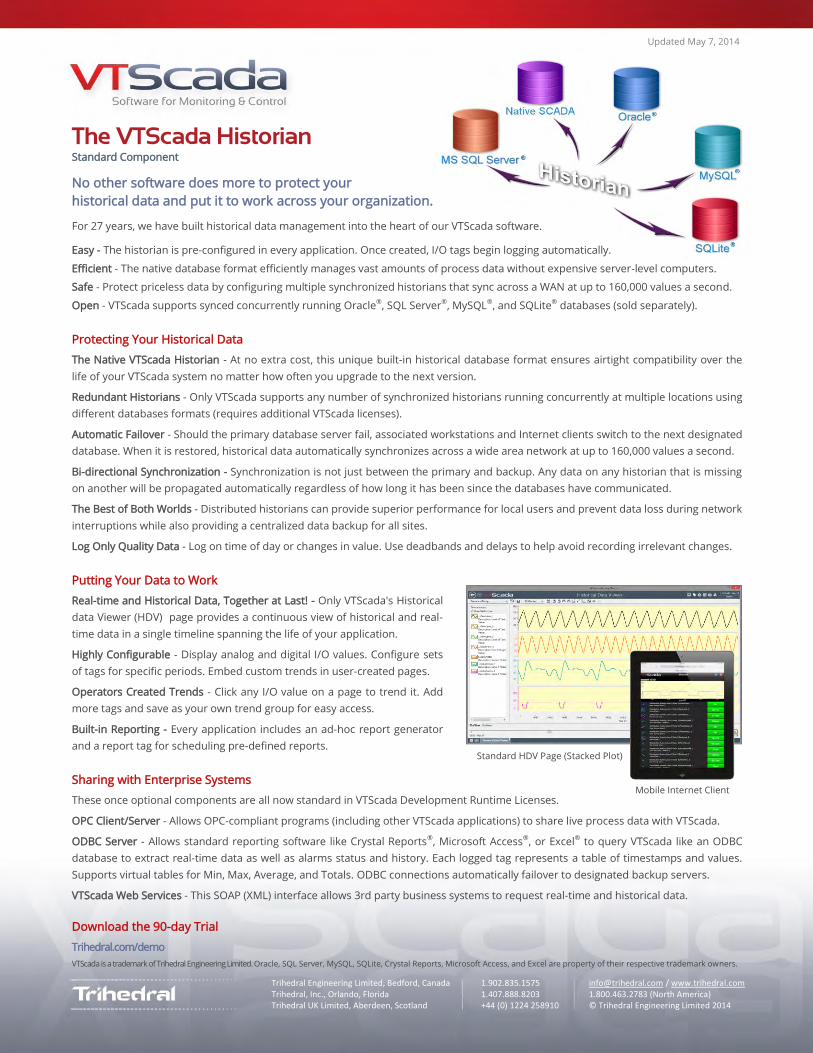
Trihedral Engineering Limited, Bedford, Canada 1.902.835.1575 [email protected] / www.trihedral.com Trihedral, Inc., Orlando, Florida 1.407.888.8203 1.800.463.2783 (North America) Trihedral UK Limited, Aberdeen, Scotland +44 (0) 1224 258910 © Trihedral Engineering Limited 2014 © Trihedral Engineering Limited 2012
Updated May 7, 2014
The VTScada Historian Standard Component
No other software does more to protect your
historical data and put it to work across your organization.
For 27 years, we have built historical data management into the heart of our VTScada software.
Easy - The historian is pre-configured in every application. Once created, I/O tags begin logging automatically.
Efficient - The native database format efficiently manages vast amounts of process data without expensive server-level computers.
Safe - Protect priceless data by configuring multiple synchronized historians that sync across a WAN at up to 160,000 values a second.
Open - VTScada supports synced concurrently running Oracle®, SQL Server®, MySQL®, and SQLite® databases (sold separately).
Protecting Your Historical Data
The Native VTScada Historian - At no extra cost, this unique built-in historical database format ensures airtight compatibility over the
life of your VTScada system no matter how often you upgrade to the next version.
Redundant Historians - Only VTScada supports any number of synchronized historians running concurrently at multiple locations using
different databases formats (requires additional VTScada licenses).
Automatic Failover - Should the primary database server fail, associated workstations and Internet clients switch to the next designated
database. When it is restored, historical data automatically synchronizes across a wide area network at up to 160,000 values a second.
Bi-directional Synchronization - Synchronization is not just between the primary and backup. Any data on any historian that is missing
on another will be propagated automatically regardless of how long it has been since the databases have communicated.
The Best of Both Worlds - Distributed historians can provide superior performance for local users and prevent data loss during network
interruptions while also providing a centralized data backup for all sites.
Log Only Quality Data - Log on time of day or changes in value. Use deadbands and delays to help avoid recording irrelevant changes.
Putting Your Data to Work
Real-time and Historical Data, Together at Last! - Only VTScada's Historical
data Viewer (HDV) page provides a continuous view of historical and real-
time data in a single timeline spanning the life of your application.
Highly Configurable - Display analog and digital I/O values. Configure sets
of tags for specific periods. Embed custom trends in user-created pages.
Operators Created Trends - Click any I/O value on a page to trend it. Add
more tags and save as your own trend group for easy access.
Built-in Reporting - Every application includes an ad-hoc report generator
and a report tag for scheduling pre-defined reports.
Sharing with Enterprise Systems
These once optional components are all now standard in VTScada Development Runtime Licenses.
OPC Client/Server - Allows OPC-compliant programs (including other VTScada applications) to share live process data with VTScada.
ODBC Server - Allows standard reporting software like Crystal Reports®, Microsoft Access®, or Excel® to query VTScada like an ODBC
database to extract real-time data as well as alarms status and history. Each logged tag represents a table of timestamps and values.
Supports virtual tables for Min, Max, Average, and Totals. ODBC connections automatically failover to designated backup servers.
VTScada Web Services - This SOAP (XML) interface allows 3rd party business systems to request real-time and historical data.
Download the 90-day Trial
Trihedral.com/demo
VTScada is a trademark of Trihedral Engineering Limited. Oracle, SQL Server, MySQL, SQLite, Crystal Reports, Microsoft Access, and Excel are property of their respective trademark owners.
Standard HDV Page (Stacked Plot)
Mobile Internet Client
January 8, 2013
0Trihedral Engineering Limited, Bedford, Canada 1.902.835.1575 [email protected] / www.trihedral.comTrihedral, Inc., Orlando, Florida 1.407.888.8203 1.800.463.2783 (North America)Trihedral UK Limited, Aberdeen, Scotland +44 (0) 1224 258910 © Trihedral Engineering Limited 2013-01-08 © Trihedral Engineering Limited 2012
VTS Mobile Internet Client (MIC) LicensingDeveloped for smart phones and tablets, the MIC is a tactile interface to your applicationthat allows you to securely view and acknowledge alarms, check equipment status, plottrends and issue commands with just a touch or pinch.
LicensingMICs can be purchased in sets of four concurrent connections under the same license as theVTS Internet Client (VIC).1
Designed for Windows desktop and laptop computers, the VIC provides an operatorinterface identical to a full VTS installation. However, the MIC was designed to include onlythe most critical features, optimized for portable devices. Therefore, each pack of fourconcurrent MIC connections is equal to one VIC connection.
For example, if you purchased two VIC Licences, you could access the following:
Two VICs or...One VIC and four MICs or...Eight MICS
Although it can be useful to know that you can use different combinations if required, youshould use caution. If you divide two licences into one VIC and four MICs, and then fivemobile users access the MIC concurrently, YOU WILL NOT BE ABLE TO CONNECT VIA THE VICUNTIL AT LEAST ONE MIC CONNECTION IS CLOSED.
Ensure Access to the VIC Using RealmsOne way to prevent accidentally blocking VIC access by using too many MICs is to set up twoVTS realms; one for VIC’s and one for MICs. Set up a different VTS Security Account andpassword for each. Logging into the MIC realm prevents mobile device users from using updedicated VIC licences. We would be happy to advise you in setting this up.
New - Mobile Mapping at Your FingertipsIn version 10.2, the MIC supports Slippy Maps. Navigate sites with a swipe and a pinch. Tap apin to see site process and alarm data.
Try for Yourself Try the VTS Internet Client (Windows Only)
http://vts.trihedral.com/waterdemo (User name: demo Password: demo) Try the Mobile Internet Client (Tablets and smart phones)
Enter the link below or scan the QR code to the right.http://vts.trihedral.com/waterdemo/mobile (User name: demo Password: demo)
Request a VTS Price Listwww.trihedral.com/purchasing/requestpricelist
VTS and VTScada are trademarks of Trihedral Engineering Limited. Apple, iPhone, iPad, MapQuest are trademarks of their respective owners.
1 Unlike the VTS WAP Browser which is part of the VTS Alarm Dialer license.
Apple iPad®
Apple iPhone®