Cisco MGX 8260 Command Line Interface Guide
588
170 West Tasman Drive San Jose, CA 95134-1706 USA http://www.cisco.com Cisco Systems, Inc. Corporate Headquarters Tel: 800 553-NETS (6387) 408 526-4000 Fax: 408 526-4100 Cisco MGX 8260 Command Line Interface Guide Software Release 1.2 September 2000 Customer Order Number: DOC-7810987= Text Part Number: 78-10987-01
-
Upload
khangminh22 -
Category
Documents
-
view
4 -
download
0
Transcript of Cisco MGX 8260 Command Line Interface Guide

Cisco MGX 8260 Command Line Interface GuideSoftware Release 1.2September 2000
170 West Tasman DriveSan Jose, CA 95134-1706USAhttp://www.cisco.com
Cisco Systems, Inc.Corporate Headquarters
Tel:800 553-NETS (6387)408 526-4000
Fax: 408 526-4100
Customer Order Number: DOC-7810987=Text Part Number: 78-10987-01

THE SPECIFICATIONS AND INFORMATION REGARDING THE PRODUCTS IN THIS MANUAL ARE SUBJECT TO CHANGE WITHOUT NOTICE. ALL STATEMENTS, INFORMATION, AND RECOMMENDATIONS IN THIS MANUAL ARE BELIEVED TO BE ACCURATE BUT ARE PRESENTED WITHOUT WARRANTY OF ANY KIND, EXPRESS OR IMPLIED. USERS MUST TAKE FULL RESPONSIBILITY FOR THEIR APPLICATION OF ANY PRODUCTS.
THE SOFTWARE LICENSE AND LIMITED WARRANTY FOR THE ACCOMPANYING PRODUCT ARE SET FORTH IN THE INFORMATION PACKET THAT SHIPPED WITH THE PRODUCT AND ARE INCORPORATED HEREIN BY THIS REFERENCE. IF YOU ARE UNABLE TO LOCATE THE SOFTWARE LICENSE OR LIMITED WARRANTY, CONTACT YOUR CISCO REPRESENTATIVE FOR A COPY.
This equipment has been tested and found to comply with the limits for a Class A digital device, pursuant to part 15 of the FCC rules. These limits are designed to provide reasonable protection against harmful interference when the equipment is operated in a commercial environment. This equipment generates, uses, and can radiate radio-frequency energy and, if not installed and used in accordance with the instruction manual, may cause harmful interference to radio communications. Operation of this equipment in a residential area is likely to cause harmful interference, in which case users will be required to correct the interference at their own expense.
Modifying the equipment without Cisco’s written authorization may result in the equipment no longer complying with FCC requirements for Class A or Class B digital devices. In that event, your right to use the equipment may be limited by FCC regulations, and you may be required to correct any interference to radio or television communications at your own expense.
You can determine whether your equipment is causing interference by turning it off. If the interference stops, it was probably caused by the Cisco equipment or one of its peripheral devices. If the equipment causes interference to radio or television reception, try to correct the interference by using one or more of the following measures:
• Turn the television or radio antenna until the interference stops.
• Move the equipment to one side or the other of the television or radio.
• Move the equipment farther away from the television or radio.
• Plug the equipment into an outlet that is on a different circuit from the television or radio. (That is, make certain the equipment and the television or radio are on circuits controlled by different circuit breakers or fuses.)
Modifications to this product not authorized by Cisco Systems, Inc. could void the FCC approval and negate your authority to operate the product.
The Cisco implementation of TCP header compression is an adaptation of a program developed by the University of California, Berkeley (UCB) as part of UCB’s public domain version of the UNIX operating system. All rights reserved. Copyright © 1981, Regents of the University of California.
NOTWITHSTANDING ANY OTHER WARRANTY HEREIN, ALL DOCUMENT FILES AND SOFTWARE OF THESE SUPPLIERS ARE PROVIDED “AS IS” WITH ALL FAULTS. CISCO AND THE ABOVE-NAMED SUPPLIERS DISCLAIM ALL WARRANTIES, EXPRESSED OR IMPLIED, INCLUDING, WITHOUT LIMITATION, THOSE OF MERCHANTABILITY, FITNESS FOR A PARTICULAR PURPOSE AND NONINFRINGEMENT OR ARISING FROM A COURSE OF DEALING, USAGE, OR TRADE PRACTICE.
IN NO EVENT SHALL CISCO OR ITS SUPPLIERS BE LIABLE FOR ANY INDIRECT, SPECIAL, CONSEQUENTIAL, OR INCIDENTAL DAMAGES, INCLUDING, WITHOUT LIMITATION, LOST PROFITS OR LOSS OR DAMAGE TO DATA ARISING OUT OF THE USE OR INABILITY TO USE THIS MANUAL, EVEN IF CISCO OR ITS SUPPLIERS HAVE BEEN ADVISED OF THE POSSIBILITY OF SUCH DAMAGES.
Access Registrar, AccessPath, Are You Ready, ATM Director, Browse with Me, CCDA, CCDE, CCDP, CCIE, CCNA, CCNP, CCSI, CD-PAC, CiscoLink, the Cisco NetWorks logo, the Cisco Powered Network logo, Cisco Systems Networking Academy, Fast Step, FireRunner, Follow Me Browsing, FormShare, GigaStack, IGX, Intelligence in the Optical Core, Internet Quotient, IP/VC, iQ Breakthrough, iQ Expertise, iQ FastTrack, iQuick Study, iQ Readiness Scorecard, The iQ Logo, Kernel Proxy, MGX, Natural Network Viewer, Network Registrar, the Networkers logo, Packet, PIX, Point and Click Internetworking, Policy Builder, RateMUX, ReyMaster, ReyView, ScriptShare, Secure Script, Shop with Me, SlideCast, SMARTnet, SVX, TrafficDirector, TransPath, VlanDirector, Voice LAN, Wavelength Router, Workgroup Director, and Workgroup Stack are trademarks of Cisco Systems, Inc.; Changing the Way We Work, Live, Play, and Learn, Empowering the Internet Generation, are service marks of Cisco Systems, Inc.; and Aironet, ASIST, BPX, Catalyst, Cisco, the Cisco Certified Internetwork Expert Logo, Cisco IOS, the Cisco IOS logo, Cisco Press, Cisco Systems, Cisco Systems Capital, the Cisco Systems logo, Collision Free, Enterprise/Solver, EtherChannel, EtherSwitch, FastHub, FastLink, FastPAD, IOS, IP/TV, IPX, LightStream, LightSwitch, MICA, NetRanger, Post-Routing, Pre-Routing, Registrar, StrataView Plus, Stratm, SwitchProbe, TeleRouter, are registered trademarks of Cisco Systems, Inc. or its affiliates in the U.S. and certain other countries.
All other brands, names, or trademarks mentioned in this document/website are the property of their respective owners. The use of the word partner does not imply a partnership relationship between Cisco and any of its resellers. (0008R)
Cisco MGX 8260 Command Line Interface GuideCopyright © 2000, Cisco Systems, Inc.All rights reserved.

C O N T E N T S
About This Guide xvii
Document Overview xvii
Who Should Use This Guide xvii
Conventions xviii
Obtaining Documentation xviii
World Wide Web xviii
Documentation CD-ROM xviii
Ordering Documentation xviii
Obtaining Technical Assistance xix
Cisco Connection Online xix
Technical Assistance Center xix
Documentation Feedback xx
C H A P T E R 1 Overview of the MGX 8260 Media Gateway 1-1
Features and Benefits 1-1
Managing the MGX 8260 Media Gateway 1-2
WebViewer Management Interface 1-3
SNMP Manager 1-3
Command Line Interface 1-4
Front Panel Controls and Indicators 1-4
System Indicators 1-5
Broadband Line Indicators 1-5
Card and Line Indicators 1-6
Front Panel Controls 1-6
C H A P T E R 2 System Management 2-1
Logging On 2-1
Configuration Tasks for System Initialization 2-1
Configuring System Security 2-2
Configuring User Accounts 2-2
Viewing Current Logins 2-4
Configuring SNMP Community Strings 2-4
iiiCisco MGX 8260 Command Line Interface Guide
Release 1.2, Part Number 78-10987-01 Rev. B0, January, 2002

Contents
Assigning a tftp Security Key 2-6
Configuring Node Parameters 2-6
Viewing Node Parameters 2-6
Setting Node Parameters 2-7
Changing the Interface Line Type 2-7
Changing the Gateway Control Protocol 2-7
Configuring the Management Interfaces 2-8
Viewing Management Port Parameters 2-8
Configuring the 10BaseT Management Port 2-8
Configuring In-Band Management Paths 2-9
Configuring IP Routes 2-10
Viewing IP Routes 2-10
Adding IP Routes 2-11
Deleting IP Routes 2-12
Synchronizing the System Clock 2-12
Setting Clock Parameters 2-12
Viewing Clock Parameters 2-13
Switching to the Secondary Clock 2-14
C H A P T E R 3 Card Management 3-1
Configuring Cards 3-1
Configuration Tasks for Cards 3-1
Configuring Card Parameters 3-2
Viewing Card Configuration and Status 3-2
Viewing Summary Information for Cards 3-7
Viewing MSM Configuration and Status 3-7
Choosing the NSC Interface Mode 3-8
Configuring the NSC Interface Mode 3-10
Setting the ATM Queue Profile 3-10
Resetting a Card 3-11
Understanding Redundancy 3-11
Understanding Physical and Logical Slot Numbers 3-11
Using 1:N NSC Redundancy 3-12
Using 1:1 BSC Redundancy 3-13
Configuring BSC or NSC Redundancy 3-15
Viewing BSC and NSC Redundancy 3-15
ivCisco MGX 8260 Command Line Interface Guide
Release 1.2, Part Number 78-10987-01 Rev. B0, January, 2002

Contents
Adding NSC Redundancy 3-16
Adding BSC Redundancy 3-17
Deleting Redundancy 3-17
Invoking a Switchback 3-18
Saving and Restoring Card Configurations 3-18
Backing Up Configurations 3-18
Uploading Configurations 3-19
Downloading Configurations 3-19
Restoring Configurations 3-20
Upgrading Software Images 3-21
System Software Upgrade Paths 3-21
Security Key Requirements 3-21
Installation Procedures 3-21
Downloading Software from CCO 3-21
Transferring Files to the MGX 8260 3-22
Upgrading Card Software 3-22
Upgrading SCC Software 3-23
Upgrading BSC Software 3-24
Upgrading NSC Software 3-26
Database Configuration Information 3-27
C H A P T E R 4 Service Management 4-1
Configuration Tasks for Lines 4-1
Viewing All MGX 8260 Lines 4-1
Viewing DS0 Lines 4-2
Viewing DS0 Configuration and Status 4-2
Viewing Summary DS0 Information 4-3
Configuring DS1 or E1 Lines 4-3
Viewing DS1/E1 Configuration and Status 4-3
Viewing Summary DS1/E1 Information 4-6
Adding DS1/E1 Lines 4-7
Changing DS1/E1 Lines 4-7
Deleting DS1/E1 Lines 4-8
Configuring DS3 Lines 4-8
Viewing DS3 Configuration and Status 4-8
Viewing Summary DS3 Information 4-10
vCisco MGX 8260 Command Line Interface Guide
Release 1.2, Part Number 78-10987-01 Rev. B0, January, 2002

Contents
Adding DS3 Lines 4-10
Changing DS3 Lines 4-10
Deleting DS3 Lines 4-11
Mapping DMC Lines 4-11
Adding Map Table Entries 4-12
Changing Map Tables 4-13
Deleting Map Table Entries 4-13
Viewing Map Tables 4-13
Configuring Fast Ethernet Lines 4-14
Viewing Fast Ethernet Configuration and Status 4-14
Adding a Fast Ethernet Line 4-15
Changing a Fast Ethernet Line 4-16
Deleting Fast Ethernet Lines 4-16
Setting the Fast Ethernet Administrative Status 4-16
Configuring Static Routes 4-17
Adding Static Routes 4-17
Deleting Static Routes 4-17
Viewing Static Routes 4-17
Configuring OC-3 Lines 4-18
Multi-chassis Considerations 4-18
Viewing OC-3 Configuration and Status 4-18
Adding OC-3 Lines 4-22
Changing OC-3 Lines 4-22
Deleting OC-3 Lines 4-22
Viewing E-RDI Configuration and Status 4-22
Understanding E-RDI and Trace Parameters 4-24
Configuration Tasks for Ports 4-26
Configuring Voice Ports 4-26
Adding Voice Ports 4-26
Changing Voice Ports 4-27
Deleting Voice Ports 4-27
Viewing Voice Port Configuration and Status 4-27
Checking All MGX 8260 ports 4-28
Viewing Active Calls 4-29
Viewing Calls by Slot/Line/Port 4-29
viCisco MGX 8260 Command Line Interface Guide
Release 1.2, Part Number 78-10987-01 Rev. B0, January, 2002

Contents
Viewing Calls by Transaction 4-31
About the Announcement Service 4-31
File Encoding 4-31
File Types 4-32
File Names 4-32
Configuration Tasks for Announcement Services 4-32
Adding and Activating an Announcement 4-32
Deactivating and Removing an Announcement 4-33
Viewing Announcement Files 4-33
C H A P T E R 5 Call Control 5-1
Primary Call Control Components 5-1
Primary MGX 8260 Call Control Interfaces 5-1
Understanding MGCP 5-2
Configuration Tasks for MGCP 5-3
Switching from IPDC to MGCP 5-3
Configuring MGCP IP Addresses 5-4
Configuring MGCP Core Parameters 5-4
Configuring MGCP Default Call Setup Parameters 5-4
Viewing MGCP Settings 5-5
Viewing MGCP Voice Parameters 5-6
Viewing Default Call Setup Parameters 5-7
Viewing MGCP Status Information 5-8
Viewing MGCP Protocol Statistics 5-9
Understanding Sessions 5-10
Configuration Tasks for Sessions 5-11
Configuring Session Sets 5-11
Viewing Session Set Information 5-11
Adding a Session Set 5-13
Deleting a Session 5-13
Configuring Session Groups 5-13
Viewing Session Groups 5-13
Adding a Session Group 5-14
Deleting a Session Group 5-14
Configuring Sessions 5-14
Viewing Session Information 5-14
viiCisco MGX 8260 Command Line Interface Guide
Release 1.2, Part Number 78-10987-01 Rev. B0, January, 2002

Contents
Adding a Session 5-16
Deleting a Session 5-16
Viewing Session Statistics 5-16
Viewing Session Group Statistics 5-16
Viewing RUDP Connection Statistics 5-17
Viewing RUDP Transport Statistics 5-17
Viewing Session Statistics 5-18
Managing ISDN D Channels 5-18
D Channel Configuration Tasks 5-19
Managing MACSAP Profiles 5-20
Adding MACSAP Profiles 5-20
Deleting MACSAP Profiles 5-20
Viewing MACSAP Profiles 5-20
Viewing MACSAP Statistics 5-21
Managing DLSAP Profiles 5-22
Adding DLSAP Profiles 5-22
Deleting DLSAP Profiles 5-22
Viewing DLSAP Profiles 5-22
Viewing DLSAP Status 5-23
Viewing DLSAP Statistics 5-24
Configuring D Channels 5-25
Adding D Channels 5-25
Changing D Channels 5-26
Deleting D Channels 5-26
Viewing D Channels 5-26
Viewing LAPD Parameters 5-30
Configuration Tasks for IPDC 5-31
Switching from MGCP to IPDC 5-31
Configuring Soft Switch IP Addresses 5-32
Configuring a Pseudo IP Address 5-32
Configuring IPDC Core Settings 5-32
Configuring IPDC Timers and Counters 5-33
Configuring COT Settings 5-33
Activating IPDC and Link Health Check 5-33
Viewing IPDC Settings 5-33
viiiCisco MGX 8260 Command Line Interface Guide
Release 1.2, Part Number 78-10987-01 Rev. B0, January, 2002

Contents
Viewing IPDC Timer and Retry Counter Information 5-35
Viewing IPDC COT Information 5-36
C H A P T E R 6 Alarm Surveillance 6-1
Surveillance Tasks for Alarms 6-1
Monitoring Shelf Alarms 6-2
Monitoring Card Alarms 6-4
Viewing Card Alarms 6-4
Monitoring DS1 Alarms 6-5
Viewing DS1/E1 Alarms 6-5
Viewing DS1 Alarm Thresholds 6-6
Setting DS1 Alarm Thresholds 6-7
Monitoring E1 Alarms 6-8
Viewing E1 Alarms 6-8
Viewing E1 Performance Alarms 6-8
Viewing E1 Alarm Thresholds 6-10
Setting E1 Alarm Thresholds 6-12
Monitoring DS3 Alarms 6-12
Viewing DS3 Alarms 6-12
Viewing DS3 Alarm Thresholds 6-13
Setting DS3 Alarm Thresholds 6-15
Monitoring Fast Ethernet Alarms 6-15
Monitoring OC-3 Alarms 6-15
Viewing OC-3 Alarms 6-15
Viewing OC-3 Alarm Thresholds 6-17
Setting OC-3 Alarm Thresholds 6-19
Monitoring Environmental Alarms 6-19
Specifying Sensors 6-20
Viewing Environmental Information 6-21
Viewing Environmental Summary Information 6-24
Configuration Tasks for Alarm Notifications 6-24
Configuring User Email Alerts 6-25
Registering the Email Server 6-25
Registering Email Alerts 6-25
Changing Email Alerts 6-26
Deleting Email Alerts 6-26
ixCisco MGX 8260 Command Line Interface Guide
Release 1.2, Part Number 78-10987-01 Rev. B0, January, 2002

Contents
Listing Email Server and Email Alert Registrations 6-26
Configuring SNMP Trap Managers 6-28
Registering SNMP Trap Managers 6-28
Changing SNMP Trap Registrations 6-29
Deleting SNMP Trap Registrations 6-29
Viewing SNMP Trap Registrations 6-30
Working With Traps 6-30
Viewing Chronological Traps 6-30
Understanding Trap Numbers 6-31
Shelf Traps 6-31
Card Traps 6-32
DS1 Traps 6-32
DS3 Traps 6-33
SONET Traps 6-34
Fast Ethernet Traps 6-34
Voice Port Events 6-35
ISDN Traps 6-35
MGCP Traps 6-35
Backhaul Traps 6-36
C H A P T E R 7 Performance Monitoring 7-1
Monitoring DS1 Performance 7-1
Viewing Current T1 Statistics 7-1
Viewing Total T1 Statistics 7-2
Viewing Interval T1 Statistics 7-2
Viewing T1 Real-Time Alarm Statistics 7-3
Clearing Real-Time T1 Statistics 7-5
Monitoring E1 Performance 7-5
Viewing Current E1 Statistics 7-5
Viewing Total E1 Statistics 7-6
Viewing Interval E1 Statistics 7-7
Viewing E1 Real-Time Alarm Statistics 7-8
Clearing Real-Time E1 Statistics 7-11
Monitoring DS3 Performance 7-11
Viewing Current DS3 Statistics 7-12
Viewing Total DS3 Statistics 7-12
xCisco MGX 8260 Command Line Interface Guide
Release 1.2, Part Number 78-10987-01 Rev. B0, January, 2002

Contents
Viewing Interval DS3 Statistics 7-13
Viewing DS3 Real-Time Alarm Statistics 7-13
Clearing Real-Time Statistics 7-13
Monitoring SONET Performance 7-13
Monitoring SONET Section Statistics 7-14
Viewing Section Current Statistics 7-14
Clearing Section Current Statistics 7-14
Viewing Section Total Statistics 7-15
Clearing Section Total Statistics 7-15
Viewing Section Interval Statistics 7-15
Monitoring SONET Line Statistics 7-17
Viewing Line Current Statistics 7-17
Clearing Line Current Statistics 7-17
Viewing Line Total Statistics 7-18
Clearing Line Total Statistics 7-18
Viewing Line Interval Statistics 7-18
Monitoring SONET Path Statistics 7-20
Viewing Path Current Statistics 7-20
Clearing Path Current Statistics 7-20
Viewing Path Total Statistics 7-21
Clearing Path Total Statistics 7-21
Viewing Path Interval Statistics 7-21
Monitoring SONET Alarm Statistics 7-23
Clearing SONET Performance Alarm Statistics 7-25
C H A P T E R 8 Troubleshooting 8-1
Performing Loopback Tests 8-1
DS1/E1 Loopback 8-2
DS3 Loopback 8-3
SONET Loopback 8-4
Performing BERT Tests 8-4
DS1/E1 BERT Test 8-5
Clearing Alarms 8-6
Clearing Chassis Alarms 8-6
Clearing Card Alarms 8-6
Clearing DS1/E1 and DS3 Alarms 8-7
xiCisco MGX 8260 Command Line Interface Guide
Release 1.2, Part Number 78-10987-01 Rev. B0, January, 2002

Contents
Clearing Fast Ethernet Alarms 8-9
Clearing SONET Alarms 8-9
Clearing Environmental Alarms 8-11
C H A P T E R 9 Command Reference 9-1
Command Line Interface Guidelines 9-1
Command Syntax 9-1
Optional Parameters 9-1
Security Levels 9-1
Understanding Bitmaps 9-2
Using Online Help 9-3
Command Syntax Help 9-3
Command Summary Help 9-3
I N D E X
xiiCisco MGX 8260 Command Line Interface Guide
Release 1.2, Part Number 78-10987-01 Rev. B0, January, 2002

F I G U R E S
Figure 1-1 MGX 8260 Management Architecture 1-3
Figure 1-2 Front Panel Indicators 1-4
Figure 2-1 10BaseT Management Connections 2-9
Figure 3-1 NSC Interface Modes 3-9
Figure 3-2 Normal Operation with 1:2 NSC Redundancy 3-12
Figure 3-3 Switchover with 1:2 NSC Redundancy 3-13
Figure 3-4 Normal Operation with 1:1 BSC Redundancy 3-14
Figure 3-5 Switchover with 1:1 BSC Redundancy 3-15
Figure 4-1 Example of DS3 to DS1 Mapping from DMC to NSC 4-11
Figure 4-2 Multi-chassis Timing 4-18
Figure 5-1 MGCP Protocol Stack 5-2
Figure 5-2 MGCP Addresses and Ports 5-3
Figure 5-3 Organization of Sessions 5-10
Figure 5-4 Logical Session Model 5-10
Figure 5-5 D Channel to Media Gateway Controller 5-19
Figure 5-6 DLSAP and MACSAP Interfaces 5-19
Figure 6-1 EMM Alarm Scale 6-20
Figure 8-1 DS1/E1 and DS3 Loopback Options 8-1
xiiiCisco MGX 8260 Command Line Interface Guide
Release 1.2, Part Number 78-10987-01 Rev. B0, January, 2002

Figures
xivCisco MGX 8260 Command Line Interface Guide
Release 1.2, Part Number 78-10987-01 Rev. B0, January, 2002

T A B L E S
Table 1-1 System Indicators 1-5
Table 1-2 Trunk Group Indicators 1-5
Table 1-3 Card and Line Indicators 1-6
Table 2-1 User Accounts and Access Privileges 2-2
Table 3-1 Response of Reset Command by Card and State 3-11
Table 3-2 Response for the Switch Card Command by Card and State 3-18
Table 4-1 DMC Map Table 4-12
Table 4-2 DMC Map Table for the addm13 Command 4-12
Table 4-3 DMC Map Table for the Modified addm13 Command 4-13
Table 6-1 DS1 Performance Alarm Thresholds 6-6
Table 6-2 E1 Performance Alarm Thresholds 6-11
Table 6-3 DS3 Performance Alarm Thresholds 6-14
Table 6-4 OC-3 Performance Alarm Thresholds 6-18
Table 6-5 SCC Sensors 6-20
Table 6-6 DMC Sensors 6-20
Table 6-7 NSC Sensors 6-20
Table 6-8 BSC Sensors 6-21
Table 6-9 Chassis Sensors 6-21
Table 6-10 Trap Subscription Bits 6-28
Table 6-11 Shelf Traps 6-31
Table 6-12 Card Traps 6-32
Table 6-13 DS1 Traps 6-32
Table 6-14 DS3 Traps 6-33
Table 6-15 SONET Traps 6-34
Table 6-16 Fast Ethernet Traps 6-34
Table 6-17 Voice Port Events 6-35
Table 6-18 ISDN Traps 6-35
Table 6-19 MGCP Traps 6-35
Table 6-20 Backhaul Traps 6-36
Table 9-1 Binary Bits versus Binary Values 9-2
Table 9-2 Bitmap Translations 9-2
xvCisco MGX 8260 Command Line Interface Guide
Release 1.2, Part Number 78-10987-01 Rev. B0, January, 2002

Tables
Table 9-3 Valid Bitmaps for Service State 9-2
Table 9-4 Time Zones 9-130
xviCisco MGX 8260 Command Line Interface Guide
Release 1.2, Part Number 78-10987-01 Rev. B0, January, 2002

About This Guide
This chapter describes the procedures for configuring, operating, and troubleshooting the MGX 8260 Media Gateway from the command line interface.
Document OverviewThis guide contains instructions for configuring, operating, and troubleshooting the MGX 8260 Media Gateway.
Chapter 1, “Overview of the MGX 8260 Media Gateway”
Chapter 2, “System Management”
Chapter 3, “Card Management”
Chapter 4, “Service Management”
Chapter 5, “Call Control”
Chapter 6, “Alarm Surveillance”
Chapter 7, “Performance Monitoring”
Chapter 8, “Troubleshooting”
Chapter 9, “Command Reference”
Who Should Use This GuideThis guide is used by the following network experts:
• Component installers, who have experience installing equipment and cables for telecommunication and data communication products.
• Network operators/administrators, who have experience configuring telecommunication and data communication networks, protocols, and equipment.
• Network designers, who plan and specify components for telecommunication and data communication networks, protocols, and equipment.
xviiCisco MGX 8260 Command Line Interface Guide
Release 1.2, Part Number 78-10987-01 Rev. B0, January, 2002

About This GuideConventions
ConventionsThis guide uses the following conventions:
Warning Means danger. You are in a situation that could cause bodily injury. Before you work on any equipment, you must be aware of the hazards involved with electrical circuitry and be familiar with standard practices for preventing accidents.
Caution Means be careful. In this situation, you might do something that could result in equipment damage or loss of data.
Note Means take note. Notes contain helpful suggestions or references to materials not covered in this manual.
Timesaver Means the described action saves time. You can save time by performing the action described in the paragraph.
Tips Means the following information contains helpful information for performing the action described in the paragraph.
Obtaining Documentation
World Wide WebYou can access the most current Cisco documentation on the World Wide Web at http://www.cisco.com, http://www-china.cisco.com, or http://www-europe.cisco.com.
Documentation CD-ROMCisco documentation and additional literature are available in a CD-ROM package, which ships with your product. The Documentation CD-ROM is updated monthly. Therefore, it is probably more current than printed documentation. The CD-ROM package is available as a single unit or as an annual subscription.
Ordering DocumentationRegistered CCO users can order the Documentation CD-ROM and other Cisco Product documentation through our online Subscription Services at http://www.cisco.com/cgi-bin/subcat/kaojump.cgi.
xviiiCisco MGX 8260 Command Line Interface Guide
Release 1.2, Part Number 78-10987-01 Rev. B0, January, 2002

About This GuideObtaining Technical Assistance
Nonregistered CCO users can order documentation through a local account representative by calling Cisco’s corporate headquarters (California, USA) at 408 526-4000 or, in North America, call 800 553-NETS (6387).
Obtaining Technical AssistanceCisco provides Cisco Connection Online (CCO) as a starting point for all technical assistance. Warranty or maintenance contract customers can use the Technical Assistance Center. All customers can submit technical feedback on Cisco documentation using the web, e-mail, a self-addressed stamped response card included in many printed docs, or by sending mail to Cisco.
Cisco Connection OnlineCisco continues to revolutionize how business is done on the Internet. Cisco Connection Online is the foundation of a suite of interactive, networked services that provides immediate, open access to Cisco information and resources at anytime, from anywhere in the world. This highly integrated Internet application is a powerful, easy-to-use tool for doing business with Cisco.
CCO’s broad range of features and services helps customers and partners to streamline business processes and improve productivity. Through CCO, you will find information about Cisco and our networking solutions, services, and programs. In addition, you can resolve technical issues with online support services, download and test software packages, and order Cisco learning materials and merchandise. Valuable online skill assessment, training, and certification programs are also available.
Customers and partners can self-register on CCO to obtain additional personalized information and services. Registered users may order products, check on the status of an order and view benefits specific to their relationships with Cisco.
You can access CCO in the following ways:
• WWW: www.cisco.com
• Telnet: cco.cisco.com
• Modem using standard connection rates and the following terminal settings: VT100 emulation; 8 data bits; no parity; and 1 stop bit.
– From North America, call 408 526-8070
– From Europe, call 33 1 64 46 40 82
You can e-mail questions about using CCO to [email protected].
Technical Assistance CenterThe Cisco Technical Assistance Center (TAC) is available to warranty or maintenance contract customers who need technical assistance with a Cisco product that is under warranty or covered by a maintenance contract.
To display the TAC web site that includes links to technical support information and software upgrades and for requesting TAC support, use www.cisco.com/techsupport.
xixCisco MGX 8260 Command Line Interface Guide
Release 1.2, Part Number 78-10987-01 Rev. B0, January, 2002

About This GuideObtaining Technical Assistance
To contact by e-mail, use one of the following:
In North America, TAC can be reached at 800 553-2447 or 408 526-7209. For other telephone numbers and TAC e-mail addresses worldwide, consult the following web site: http://www.cisco.com/warp/public/687/Directory/DirTAC.shtml.
Documentation FeedbackIf you are reading Cisco product documentation on the World Wide Web, you can submit technical comments electronically. Click Feedback in the toolbar and select Documentation. After you complete the form, click Submit to send it to Cisco.
You can e-mail your comments to [email protected].
To submit your comments by mail, for your convenience many documents contain a response card behind the front cover. Otherwise, you can mail your comments to the following address:
Cisco Systems, Inc.Document Resource Connection170 West Tasman DriveSan Jose, CA 95134-9883
We appreciate and value your comments.
Language E-mail Address
English [email protected]
Hanzi (Chinese) [email protected]
Kanji (Japanese) [email protected]
Hangul (Korean) [email protected]
Spanish [email protected]
Thai [email protected]
xxCisco MGX 8260 Command Line Interface Guide
Release 1.2, Part Number 78-10987-01 Rev. B0, January, 2002

Cisco MGX Release 1.2, Part Number 78-10987-01 Rev. B0, January, 2002
C H A P T E R 1
Overview of the MGX 8260 Media GatewayThe MGX 8260 Media Gateway is a full-scale, carrier-grade platform with high-performance, high-density termination and switching of voice, and data traffic over circuit or packet based WANs. With a modular architecture and interfaces that are compatible with a wide range of access and backbone network types, the MGX 8260 Media Gateway accommodates a diverse and changing communications network.
Features and BenefitsThe MGX 8260 incorporates multi-path switching intelligence, a speedy edge switch, and ease of operation. The following list briefly highlights the features of the MGX 8260 Media Gateway Media Gateway.
• Offload Dial Traffic and Increase Profitability
The Cisco MGX 8260 is a high-density, carrier-class gateway that intelligently switches TDM and voice over IP (VoIP) traffic across packet networks to significantly reduce costs, improve availability, and manage escalating demand. The MGX 8260 can offload TDM and VoIP traffic across a range of interfaces and backbone networks:
– Voice services across circuit-switched networks (PSTN/SS7)
– Dial traffic offloading for cost-effective wholesale delivery to Internet service providers
– TDM to VoIP gateway
By offloading dial traffic directly to network access servers, the MGX 8260 eliminates long hold-time calls from your TDM network, thereby freeing costly TDM ports for voice calls. The MGX 8260 maximizes revenue-generating TDM services, reduces total cost of ownership by improving data transport efficiency, and lays the foundation for a New World IP+ATM infrastructure that delivers tomorrow's value-added services.
• Leverage High Density and High Performance
With the highest density in the industry, the MGX 8260 media gateway scales from 384 ports to more than 70,000 TDM ports in a seven-foot telco rack. More than 20 racks of traditional circuit switching equipment would be required to provision the same number of ports as one MGX 8260 gateway. The MGX 8260 scales up as necessary, when necessary, for rapid time to revenue.
By using advanced digital signal processing (DSP) design, RISC processing, and patented technology for pipe- lining voice packets, the MGX 8260 also delivers unmatched gateway performance. Choose from 5 Gbps to 15 Gbps of switching power with the system's
1-18260 Command Line Interface Guide

Chapter 1 Overview of the MGX 8260 Media GatewayManaging the MGX 8260 Media Gateway
interchangeable switch fabrics. At the same time, ensure the lowest possible network delay. The MGX 8260 limits delay to 40 milliseconds (between two MGX 8260 gateways) for VoIP packetization/ de-packetization.
• Maximize Service Availability
The MGX 8260 provides the industry's highest availability—99.999 percent—to ensure that your customers enjoy always-on service. A redundant architecture and hot-swappable modules eliminate single points of failure. The MGX 8260 provides built-in 1:1 redundancy on all high-speed modules and interfaces, as well as 1:N redundancy for narrowband and DSP resources. The MGX 8260 platform also incorporates a redundant, high-speed hybrid bus design for switching between TDM and packet services. With no single point of failure, calls in progress are maintained even if the switch or line cards fail—a significant advantage over TDM switches.
Excellent serviceability also maximizes platform reliability. Technicians have quick and easy access to the platform via a passive rear panel where network connections attach to physical interface cards. Seamless software upgrades ensure that new features are added without downtime or service disruptions.
• Deliver New Services
Based on the Cisco Open Packet Telephony framework, the MGX 8260 interoperates with your existing technology and transitions smoothly to emerging value-added services. The Open Packet Telephony framework, an industry-standard open interface, separates the call control layer from the switching fabric. This open interface integrates the MGX 8260 with your operations support systems, service creation environments, and media gateway controllers based on the Media Gateway Control Protocol (MGCP).
The MGX 8260's open interfaces enable you to quickly and cost-effectively develop and deploy new revenue- generating services. And by moving data streams onto a packet network you not only add a revenue source, you also are positioned to support New World value-added services—the cornerstone of future profitability. As new industry-standard networking capabilities emerge, you will be able to leverage them.
Managing the MGX 8260 Media GatewayYou can manage the MGX 8260 from any of the following interfaces:
• WebViewer
• SNMP
• Command line interface
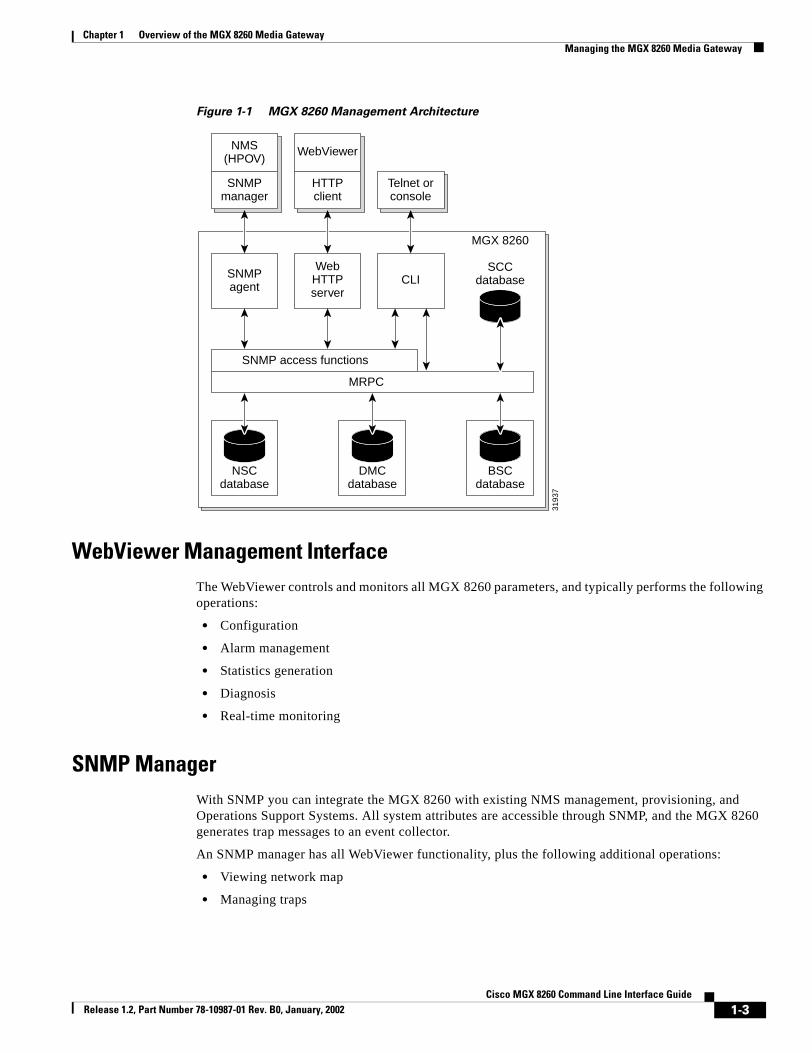
The MGX 8260 gateway offers multiple levels of security access, including viewing, configuration, system administration, and super-user control. It also supports configuration file backup and restore, as well as software upgrades. The following diagram shows the management interfaces and the internal databases they control (see Figure 1-1).
1-2Cisco MGX 8260 Command Line Interface Guide
Release 1.2, Part Number 78-10987-01 Rev. B0, January, 2002
Chapter 1 Overview of the MGX 8260 Media GatewayManaging the MGX 8260 Media Gateway
Figure 1-1 MGX 8260 Management Architecture
WebViewer Management InterfaceThe WebViewer controls and monitors all MGX 8260 parameters, and typically performs the following operations:
• Configuration
• Alarm management
• Statistics generation
• Diagnosis
• Real-time monitoring
SNMP ManagerWith SNMP you can integrate the MGX 8260 with existing NMS management, provisioning, and Operations Support Systems. All system attributes are accessible through SNMP, and the MGX 8260 generates trap messages to an event collector.
An SNMP manager has all WebViewer functionality, plus the following additional operations:
• Viewing network map
• Managing traps
3193
7
NMS(HPOV)
SNMPmanager
WebViewer
HTTPclient
Telnet orconsole
SNMPagent
SNMP access functions
MRPC
WebHTTPserver
CLISCC
database
MGX 8260
BSCdatabase
DMCdatabase
NSCdatabase
1-3Cisco MGX 8260 Command Line Interface Guide
Release 1.2, Part Number 78-10987-01 Rev. B0, January, 2002

Chapter 1 Overview of the MGX 8260 Media GatewayFront Panel Controls and Indicators
Command Line InterfaceAll MGX 8260 functions and features are available at the command line interface. During initial system configuration you can only use the command line interface via the console port. Some configuration tasks can only be performed from the command line interface.
Front Panel Controls and IndicatorsThe MGX Media Gateway has four types of cards, with the following indicator groups (see Figure 1-2).
• SCC (System Controller Card)—Displays trunk and system indicator groups
• NSC (Narrowband Service Card)—Displays DS1 line group
• BSC (Broadband Service Card)—Displays DS3 line group
• DMC (Distribution Matrix Card)—Displays DS3 line group
Figure 1-2 Front Panel Indicators
BSC
CARD
LINE
1
2
3
4
5
6
CARD
LINE
1
2
3
4
5
6
SCC
CARD
LINE
1
2
3
4
SCC
CARD
LINE
1
2
3
4
ACTFDX
1
2
3
4
ACTLINE
LAN 1
LAN 2
ALMC
ALMH
CLR
ACO
DISK
PWR A
PWR B
ACTFDX
1
2
3
4
ACTLINE
LAN 1
LAN 2
ALMC
ALMH
CLR
ACO
DISK
PWR A
PWR B
CARD
LINE
1
2
3
4
5
6
1
2
3
4
5
6
NSC
CARD
LINE
1
2
3
4
13
5
6
7
8
9
10
11
12
14
15
16
DMC
CARD CARD
LINE LINE
1
2
3
4
5
6
CARD
LINE
1
2
3
4
5
6
CARD
LINE
1
2
3
4
5
6
CARD
LINE
1
2
3
4
5
6
NSC
CARD
LINE
1
2
3
4
5
6
7
8
9
10
11
12
13
14
15
16
NSC
CARD
LINE
1
2
3
4
5
6
7
8
9
10
11
12
13
14
15
16
NSC
CARD
LINE
1
2
3
4
5
6
7
8
9
10
11
12
13
14
15
16
NSC
CARD
LINE
1
2
3
4
5
6
7
8
9
10
11
12
13
14
15
16
NSC BSC BSC BSC BSC
CARD
LINE
1
2
3
4
5
6
7
8
9
10
11
12
13
14
15
16
DMC
CARD
LINE
1
2
3
4
5
6
CISCO MGX 8260M E D I A G A T E W A Y
BSC
3172
6CARD
LINE
1
2
3
4
CARD
ACTLINE
LAN 1
LAN 2
ALMC
ALMH
CLR
ACO
DISK
PWR A
PWR B
System LEDs
Line LEDs
1-4Cisco MGX 8260 Command Line Interface Guide
Release 1.2, Part Number 78-10987-01 Rev. B0, January, 2002

Chapter 1 Overview of the MGX 8260 Media GatewayFront Panel Controls and Indicators
System IndicatorsThe SCC has the system indicators.
Broadband Line IndicatorsThe broadband line indicators consist of a pair of LEDs for each Fast Ethernet that indicate trunk configuration, activity, and status.
Table 1-1 System Indicators
LED Indication Status
LINE off management interface failure
green management Ethernet up (LAN1 or LAN2)
ACT flashing green management Ethernet data activity (LAN1 or LAN2)
ALMC green no current alarm
yellow minor alarm
red major alarm
ALMH green no alarm history
yellow minor alarm, history
red major alarm, history
DISK flashing green hard disk access
PWR A/B off power interruption
green normal power
yellow low or high voltage warning
red low or high voltage alarm
Table 1-2 Trunk Group Indicators
LED Indication Status
FDX off Half duplex operation
green Full duplex operation
ACT off Ethernet disconnected
green Ethernet signal connected and up
flashing green Ethernet data activity
1-5Cisco MGX 8260 Command Line Interface Guide
Release 1.2, Part Number 78-10987-01 Rev. B0, January, 2002

Chapter 1 Overview of the MGX 8260 Media GatewayFront Panel Controls and Indicators
Card and Line IndicatorsThe NSC, BSC, and DMC line cards have the following indicators:
Front Panel ControlsThe SCC card has two buttons:
• CLR—clears the alarm history
The ALMC and ALMH indicators display the current and historical alarm severity, respectively. Pressing this button clears the historical alarms. For example, if ALMC is yellow and ALMH is red, the CLR button changes the ALMH indication from red to yellow.
• ACO—alarm cutoff
You can configure the MGX 8260 to report alarm conditions through contact closures that activate audible or visual alarms. The ACO button stops these alarm indication by releasing the alarm relays.
Table 1-3 Card and Line Indicators
LED Card or Line Indication Status
CARD SCC green card active
yellow standby (protection mode)
flashing yellow file download
red card failure
flashing red card boot or mismatch
BSC, NSC, and DMC
green card active
yellow standby (protection mode)
red card fail
LINE DS1 and DS3
green normal operation
flashing green bert test active
yellow minor alarm
flashing yellow loopback active
red major alarm
Fast Ethernet
green link up
yellow link down in inactive mode
red link down in active mode
1-6Cisco MGX 8260 Command Line Interface Guide
Release 1.2, Part Number 78-10987-01 Rev. B0, January, 2002

Cisco MGX Release 1.2, Part Number 78-10987-01 Rev. B0, January, 2002
C H A P T E R 2
System ManagementSystem management commands configure the parameters of an MGX 8260 node that define overall operation and interactions with other nodes and servers.
Logging OnBefore you can configure the MGX 8260 Media Gateway, you must log on as a user with the privilege to change system parameters. You need SuperUser privileges to change most system-level settings. To log on, follow these steps:
Step 1 Open a telnet session with the MGX 8260 Media Gateway. You need to know the host name or IP address for the desired MGX 8260 node.
Step 2 At the User Id prompt, enter your user name. On a new system, use SuperUser.
Step 3 At the Password prompt, enter your password. On a new system, use cisco.
The MGX 8260 Media Gateway displays a command line prompt.
Configuration Tasks for System InitializationSee the following sections for configuration tasks related to managing the system:
• Configuring System Security (Required)
• Configuring Node Parameters (Required)
• Configuring the Management Interfaces (Required)
• Configuring IP Routes (Optional)
• Synchronizing the System Clock (Required)
You use the command line interface to enter system management commands.
2-18260 Command Line Interface Guide

Chapter 2 System ManagementConfiguration Tasks for System Initialization
Configuring System SecurityThe MGX 8260 controls user access two ways:
• User accounts and passwords
• SNMP communities
Configuring User Accounts
The MGX 8260 Media Gateway enforces security with user accounts and access levels. Users must log onto the MGX 8260 Media Gateway before performing any task, and authenticated users can perform only those tasks permitted by their access level. The MGX 8260 Media Gateway supports up to 20 user accounts, each with access privileges ranging from full control to guest (see Table 2-1).
A new system has a default SuperUser account. To prohibit unauthorized access to the equipment, replace the default account with a unique one.
Note The Command Line Reference lists the specific access level for each command.
Viewing User Profiles
To list existing user profiles, follow these steps:
Step 1 Log on to the MGX 8260 Media Gateway at access level 1.
Step 2 Enter the lsusps command.
The system lists the users.============================================================= User Profile Entries (lsusps)=============================================================Index User Identifier Access Level===== =============== ============ 1 William 1 2 user3 3
Table 2-1 User Accounts and Access Privileges
AccessLevel Account type Command groups
1 SuperUser Access all features
2 Administrator Configure and view all features except user profiles and community strings
3 Provisioning Configure and view system, port, lines, end points, and connections
4 Maintenance Access selected level 3 commands
5 Operator View system, port, lines, end points, and connections
6 Guest View system, common lines and ports
2-2Cisco MGX 8260 Command Line Interface Guide
Release 1.2, Part Number 78-10987-01 Rev. B0, January, 2002

Chapter 2 System ManagementConfiguration Tasks for System Initialization
Adding User Profiles
Only users with access level 1 can add new profiles to the MGX 8260 Media Gateway.
To add a new user profile, follow these steps:
Step 1 Log on to the MGX 8260 Media Gateway at access level 1.
Step 2 Enter the addusp command, specifying the user ID and access level:
The system adds a new user with a default password that matches the user id.
The following example adds a user named William with a default password of William and an access level of 1:addusp William 1
Change the default password to a unique password as described in the next section.
Changing Passwords
Every user can change their own password. If the existing password is unknown, a level 1 user must delete the account and add a new one.
To change a password, follow these steps:
Step 1 Log onto the account you want to change.
Enter the chpwd command and respond to the following prompts that appear:Rules:
1. Password length must be 4 - 10
2. First character must be alphanumeric
3. Only printable characters are allowed
4. Space not allowed
Enter Password : *****New Password : ********Verify Password: ********
The system updates the account password.
Deleting User Profiles
To delete a user profile, follow these steps:
Step 1 Log on to the MGX 8260 Media Gateway at access level 1.
Step 2 Enter the delusp command, specifying the ID of the user whose profile you want to delete:
The system removes the user profile from the database.
2-3Cisco MGX 8260 Command Line Interface Guide
Release 1.2, Part Number 78-10987-01 Rev. B0, January, 2002

Chapter 2 System ManagementConfiguration Tasks for System Initialization
For example, the following command removes the user profile for William:delusp William
Viewing Current Logins
You can view summary or detail information for current logins.
To view summary information about all active logins, use the lslogins command. The system displays the following summary information:================================================================================ User Login Session Entries (lslogins)================================================================================Index User ID AcLevel LoginTIME LoginDATE IP Address SesType===== =============== ======= ========= ========== =============== ======= 1 SuperUser 1 12:08:02 08/15/2000 172.16.252.107 telnet
To view detail information about one active logins, use the lslogin command. The system displays the following summary information:============================================================ User Session Entry (lslogin)============================================================User Session Index : 1User Identifier : SuperUserUser Access Level : 1User Login Time : 12:08:02User Login Date : 08/15/2000User Ligin IP Address : 172.16.252.107User Login Session Type : telnet
For a description of the listing, see the previous procedure for lslogins.
Configuring SNMP Community Strings
When managing the MGX 8260 Media Gateway from a SNMP manager, security is enforced with password-like community strings. SNMP communities are groupings of workstations and servers (or gateways) that can manage the MGX 8260. Community strings are important when managing the MGX 8260 Media Gateway from a Network Management System, like HP Openview. You can configure up to 15 community strings.
Displayed Information Description
Index The index number of the user account
User ID The name of the user
AcLevel The access level of the user
LoginTIME The time the user logged in
LoginDATE The date the user logged in
IP Address The IP address of the user’s host
SessType The type of login session the user is using, either telnet, console, or web
2-4Cisco MGX 8260 Command Line Interface Guide
Release 1.2, Part Number 78-10987-01 Rev. B0, January, 2002

Chapter 2 System ManagementConfiguration Tasks for System Initialization
Viewing Community Strings
To view a particular community string, enter the lscms command, specifying the community string index.
The system displays the community string information:======================================================================= Community String Entry (lscms)======================================================================= Community String Index :1 Commumity String :Public Manager IP Address :0.0.0.0 Privilege :read-write
To view all community strings, enter the lscmss command.
A list of all SNMP community strings is displayed, along with the corresponding index values, manager IP addresses, and privileges.============================================================= Community String Entries (lscmss)=============================================================Index Manager IP Address Privilege Community String===== ==================== =========== =================== 1 10.1.1.2 read-only public 2 10.1.1.3 read-write private
For a description of the output, refer to the description of the lscms command in the previous section.
Adding Community Strings
To add a community string, enter the addcms command, specifying the community, such as “public”, the IP address of the SNMP manager, and the privilege (read-only = 1 or read-write = 2). An IP address of 0.0.0.0 specifies all SNMP managers. Community strings contain up to 20 characters.
The following command adds a public community string with read-write privilege for all SNMP managers:addcms Public 10.0.0.0 2
Deleting Community Strings
To delete a community string, enter the delcms command, specifying the community string and IP address.
For example, the following command deletes the Public community string:delcms Public 0.0.0.0
Displayed Information Description
Community String Index The commStrTable index number, from 1 to 15. If you don’t know the index, list all community strings first and identify the string of interest. The following procedure shows how to list all community strings.
Community String The name of the community string.
Manager IP Address The IP address of the manager associated with this string.
Privilege The manager’s privilege, either read-write or read-only.
2-5Cisco MGX 8260 Command Line Interface Guide
Release 1.2, Part Number 78-10987-01 Rev. B0, January, 2002
Chapter 2 System ManagementConfiguration Tasks for System Initialization
Assigning a tftp Security Key
The tftp key authenticates file transfers between the MGX 8260 Media Gateway and a tftp client. If the key is not set, or if the key provided during the file transfer does not match this key, the file is not transferred.
To set the security key, enter the chkey command, specifying the security key. The system records the security key.
To view the security key, enter the lskey command. The system displays the security key.
Configuring Node ParametersSystem-wide parameters apply to the MGX 8260 node as a whole. System-wide parameters include the following settings:
• Rack number, node name, and node number
• Node type, backplane type and serial number (read/only)
• Line type
• Node number
• Gateway control protocol type
• Date, time, and time zone
Viewing Node Parameters
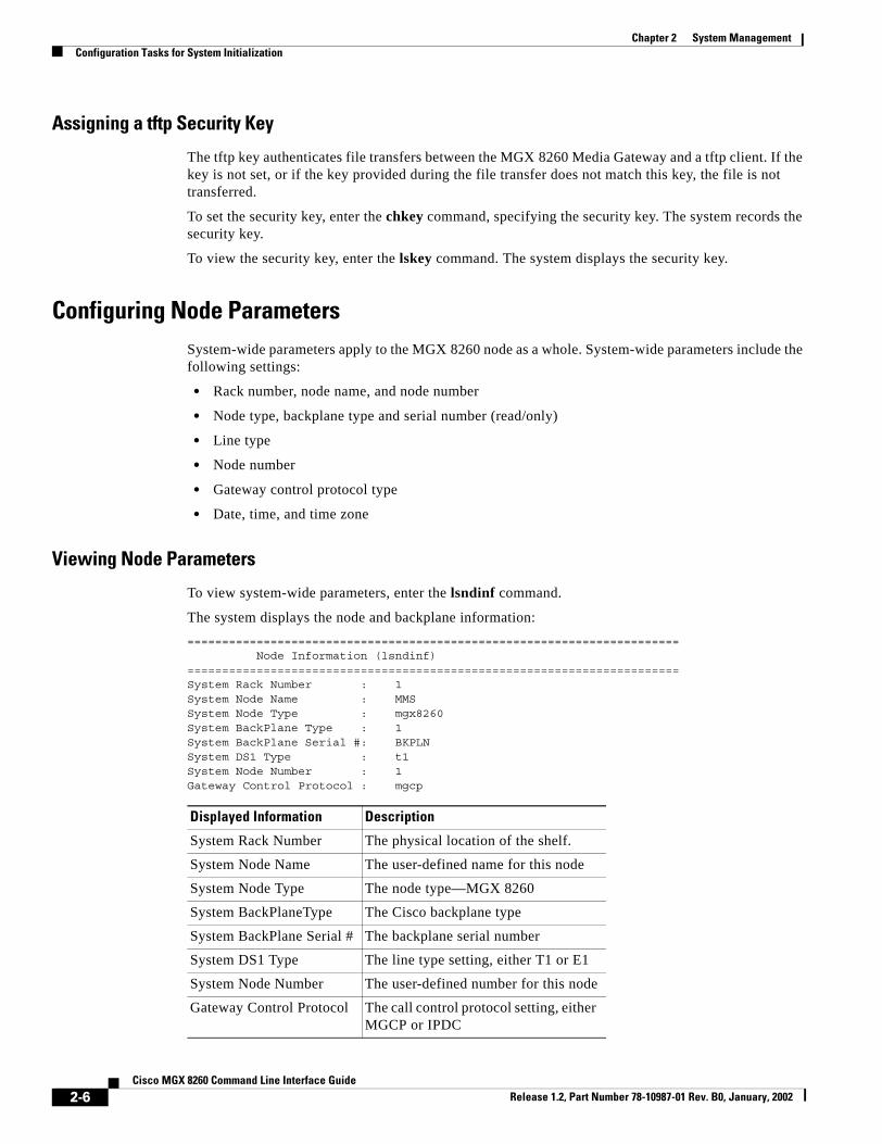
To view system-wide parameters, enter the lsndinf command.
The system displays the node and backplane information:======================================================================= Node Information (lsndinf)=======================================================================System Rack Number : 1System Node Name : MMSSystem Node Type : mgx8260System BackPlane Type : 1System BackPlane Serial #: BKPLNSystem DS1 Type : t1System Node Number : 1Gateway Control Protocol : mgcp
Displayed Information Description
System Rack Number The physical location of the shelf.
System Node Name The user-defined name for this node
System Node Type The node type—MGX 8260
System BackPlaneType The Cisco backplane type
System BackPlane Serial # The backplane serial number
System DS1 Type The line type setting, either T1 or E1
System Node Number The user-defined number for this node
Gateway Control Protocol The call control protocol setting, either MGCP or IPDC
2-6Cisco MGX 8260 Command Line Interface Guide
Release 1.2, Part Number 78-10987-01 Rev. B0, January, 2002

Chapter 2 System ManagementConfiguration Tasks for System Initialization
To view the date and time, enter the lsdate command.
The system displays the date, time, and time zone:======================================================================= System Time and Date Information (lsdate)=======================================================================Date : 03/21/1999Time : 22:14:12TimeZone : gmtplus12
Setting Node Parameters
Normally, system-wide parameters are set during installation.
To change node parameters, follow these steps:
Step 1 Configure the system rack number, node name, node number, and DS1 type using the chndinf command.
Step 2 Set the system date, time, or timezone, using the chdate and chtimezn commands.
Changing the Interface Line Type
Use this command to configure the chassis for T1 or E1 lines - you can’t mix T1 and E1 lines on a single chassis. Before switching from T1 to E1, verify the following conditions:
• The chassis has no BSCs installed
• The database contains no BSC configuration information
• The NSCs have no DS1 lines configured
When switching from E1 to T1, make sure there are no E1 lines configured.
To change the line type to DS1 or E1, use the chsyslnmd command. The chassis automatically resets and restarts with the selected line type.
Warning Changing DS1 line type interrupts service. Perform this operation during light traffic periods or in a pre-arranged maintenance window.
Changing the Gateway Control Protocol
To change the protocol to MGCP or IPDC, use the chprotocol command. The chassis automatically resets and restarts with the selected protocol.
Warning Changing the gateway protocol interrupts service. Perform this operation during light traffic periods or in a pre-arranged maintenance window.
2-7Cisco MGX 8260 Command Line Interface Guide
Release 1.2, Part Number 78-10987-01 Rev. B0, January, 2002

Chapter 2 System ManagementConfiguration Tasks for System Initialization
Configuring the Management InterfacesYou configure the MGX 8260 management interface for local or remote operation by setting the appropriate IP addresses and management paths. Assign management IP addresses for each of the following management interfaces that you plan to use:
• Ethernet 10BaseT management interface IP1 and IP2
• In-band management path
Viewing Management Port Parameters
You view all management parameters with a single command. The following management port parameters are displayed:
• Ethernet port IP addresses
• In-band IP address
• MGX 8260 MAC address
To view management port parameters, enter the lsmgips command.
The management interface configuration is displayed:========================================================================= Management Interfaces Configuration (lsmgips)=========================================================================SNMP Interface IP1 Address : 10.15.26.20SNMP Interface IP1 Mask : 255.255.255.0SNMP Interface IP2 Address : 10.15.27.20SNMP Interface IP2 Mask : 255.255.255.0SNMP Interface MAC Address : 00:50:a3:00:26:c8In-Band Interface Address : 10.15.28.20In-Band Interface Mask : 255.255.255.0
Configuring the 10BaseT Management Port
You use the SCC 10BaseT management port for http, telnet, SNMP, and TFTP sessions. Management hosts are physically connected to the 10BaseT port of the MGX 8260 Media Gateway (see Figure 2-1).
Displayed Information Description
SNMP Interface IP1 Address The IP address of the primary 10BaseT management interface
SNMP Interface IP1 Mask The IP subnet mask for the primary interface
SNMP Interface IP2 Address The IP address for the secondary 10BaseT management interface
SNMP Interface IP2 Mask The IP subnet mask for the secondary interface
SNMP Interface MAC Address The physical MAC address for the MGX 8260 Media Gateway
Inband Interface Address The IP address of the in-band management interface
Inband Interface Mask The IP subnet mask for the in-band management interface
2-8Cisco MGX 8260 Command Line Interface Guide
Release 1.2, Part Number 78-10987-01 Rev. B0, January, 2002

Chapter 2 System ManagementConfiguration Tasks for System Initialization
Figure 2-1 10BaseT Management Connections
Tips Change management IP address from the console port rather than a telnet session.
To configure the 10BaseT management port, follow these steps:
Step 1 Connect a VT100 terminal to the console port.
Step 2 Log onto the MGX 8260 Media Gateway as a SuperUser.
Step 3 Set the IP address and mask for the primary management interface using the chsysip1 command.
For example, with a system IP address of 10.15.26.20 and a 24-bit subnet mask, enter the following command:chsysip1 10.15.26.20 255.255.255.0
Step 4 Optionally, set the IP address and mask for the secondary management interface using the chsysip2 command.
For example;chsysip2 10.15.27.20 255.255.255.0
Step 5 Specify the IP address of a gateway router for management traffic using the chgw command.
For example:chgw 10.15.27.1
Note This gateway address serves both management interfaces. To add additional routes, see Adding IP Routes, page 2-11.
Configuring In-Band Management Paths
Configure an in-band management path if you want to manage the MGX 8260 Media Gateway via a Fast Ethernet channel. Before configuring an in-band management path, make sure the Fast Ethernet card is installed on the SCC.
M
MGX 8260
3192
6
IP network
10BaseTLAN
Managementports 1 and 2
NMSstations
2-9Cisco MGX 8260 Command Line Interface Guide
Release 1.2, Part Number 78-10987-01 Rev. B0, January, 2002

Chapter 2 System ManagementConfiguration Tasks for System Initialization
To configure an in-band management path, follow these steps:
Step 1 Contact your network administrator to obtain an IP address that is compatible with your in-band network.
Step 2 Verify that the chassis is configured for Fast Ethernet lines.
Step 3 Set the in-band management IP address, using the chibip command.
For example, if you assigned a IP address of 10.15.28.20 for the in-band path and you use a 24-bit subnet mask, enter the following command:chibip 10.15.28.20 255.255.255.0
Configuring IP RoutesThis section describes the process of viewing, adding, or deleting IP routes.
Viewing IP Routes
To view a specific route, use the lsiproute command, specifying the destination address. The system displays route details:======================================================================= IP Route Parameters (lsiproute)=======================================================================Destination : 192.168.41.0Gateway (Next Hop) : 192.168.41.1Interface Index : 1Mask : 255.255.255.0Type : indirectProtocol : otherAge : 153647Mib Information : 0.0Metric 1 (Primary Routing) : 1Metric 2 (Alternate Routing) : -1Metric 3 (Alternate Routing) : -1Metric 4 (Alternate Routing) : -1Metric 5 (Alternate Routing) : -1
2-10Cisco MGX 8260 Command Line Interface Guide
Release 1.2, Part Number 78-10987-01 Rev. B0, January, 2002

Chapter 2 System ManagementConfiguration Tasks for System Initialization
To view all IP routes, use the lsiproutes command.
The system displays the current route information:================================================================ IP Routes (lsiproutes)================================================================ Destination Gateway IF Mask=============== =============== ====== ================ 0.0.0.0 192.168.38.1 1 0.0.0.0 192.168.38.0 192.168.38.221 1 255.255.255.0 192.168.39.0 192.168.39.221 2 255.255.255.0 192.168.40.0 192.168.40.221 3 255.255.255.0 192.168.41.0 192.168.41.1 1 255.255.255.0 192.168.50.0 192.168.50.1 1 255.255.255.0
For a description of the output, refer to the description of the lsiproute command in the previous section.
Adding IP Routes
You can add a static route to destinations other than the default gateway.
To add an IP route, follow these steps:
Step 1 Type the addiproute command, specifying the destination address, next hop, and subnet mask.
Step 2 Verify the route addition using the lsiproutes command.
Displayed Information Description
Destination The destination IP address.
Gateway The gateway, or next hop, for the route.
IF The interface identifier:
1—Primary Ethernet port
2—Secondary Ethernet port
3—In-band path
Mask The subnet mask for the route.
Type The type of route, such as direct or indirect
Protocol The protocol type, such as local or other.
Age The age of the route is seconds.
Mib Information The version of the MIB associated with the interface.
Metric 1-5 The primary and alternate route metrics. These are specific to the protocol type, but -1 indicates not used.
2-11Cisco MGX 8260 Command Line Interface Guide
Release 1.2, Part Number 78-10987-01 Rev. B0, January, 2002

Chapter 2 System ManagementConfiguration Tasks for System Initialization
Deleting IP Routes
To delete an IP route, follow these steps:
Step 1 Type the deliproute command, specifying the destination address.
Step 2 Verify the route deletion using the lsiproutes command.
Synchronizing the System ClockThe MGX 8260 clock module has three synchronization options:
• BITS (Building Integrated Timing Source)—A high quality timing source that synchronizes all equipment in the building
• Line—A clock derived from the receive line signal
• Local—An internal MGX 8260 timing source
You assign one clock source as the primary source and another as the secondary source. When using the line clock source, specify both the line and slot associated with the source.
During normal operation, the primary clock is the active source and the secondary clock is the backup source. If the active source fails, the MGX 8260 Media Gateway switches to the backup clock and reports an alarm. You can also switch to the backup source manually. This section explains how to set primary and secondary clocks and view clock status.
Setting Clock Parameters
To set the clock synchronization, specify the primary and secondary clocks using the chpclksrc and chsclksrc commands, specifying the slot, line, source type and card type. Use the following table as a guide:
The following example selects the BITS clock as the timing source:chpclksrc 9 1 3 1
The line number doesn’t matter, but you need to specify it to execute the command.
Source Slot Line ClkSrcType ClkSrcCardType
DS3 line BSC: 11to 16DMC: 7 or 8
BSC DS3 lines: 501 to 506DMC DS3 lines: 1 to 6
1=BroadBandClk Optional
DS1 line NSC: 1 to 8, 11-16 NSC DS1 lines: 1 to 16 2=NarrowBandClk Optional
Bits input 9 Optional1
1. Optional settings are ignored, but they must be valid entries.
3=ExternalClk 1-BITS
SONET line 9 SCC, OC3 type: 1 to 4 3= ExternalClk 2-OC3
Internal 9 Optional 4=InternalClk Optional
2-12Cisco MGX 8260 Command Line Interface Guide
Release 1.2, Part Number 78-10987-01 Rev. B0, January, 2002

Chapter 2 System ManagementConfiguration Tasks for System Initialization
Viewing Clock Parameters
You view clock status with a single command. The clock parameters are:
• Status of the primary and secondary clocks
• The current clock source
• The lowest stratum level of the current clock source
To view clock status, enter the lsclksrcs command.
The system displays the clock status:======================================================================== Clock Configuration (lsclksrcs)========================================================================Primary Clock Source Type : externalClkPrimary Clock Source Slot : 9Primary Clock Source Line : 1Secondary Clock Source Type: internalClkSecondary Clock Source Slot: 9Secondary Clock Source Line: 1Primary Clock Status : okSecondary Clock Status : okClock Source Card Type : *Clock Stratum : level4Master Clock : primaryCurrent Clock : primary
Displayed Information Description
Primary (or Secondary) Clock Source Type The clock source type:
• broadBandClk
• narrowBandClk
• externalClk
• internalClk
Primary (or Secondary) Clock Source Slot The slot number for the clock source. Values: 1 to 16
Primary (or Secondary) Clock Source Line The line number for the clock source. Values:
• NSC DS1 lines: 1 to 16
• BSC DS3 lines: 501 to 506
• DMC DS3 lines: 1 to 6
• SCC, OC3 type: 1 to 4
• SCC, BITS type: 1
Primary (or Secondary) Clock Status The clock status:
• ok
• noClock
• inaccurate
Clock (or Secondary) Source Type The clock source card type:
• bits
• oc3
2-13Cisco MGX 8260 Command Line Interface Guide
Release 1.2, Part Number 78-10987-01 Rev. B0, January, 2002

Chapter 2 System ManagementConfiguration Tasks for System Initialization
Switching to the Secondary Clock
You can force the system to switch between the primary and secondary clocks. The switching direction depends on the current clock. During normal operation, the current clock is the primary clock.
To switch to the clock sources, enter the swclk command.
Clock Stratum The level of Stratum clock:
• level 3 (reserved for future use)
• level 4
Master Clock The master clock source:
• primary
• secondary
• internal
Current Clock The current clock source:
• primary
• secondary
• internal
Displayed Information Description
2-14Cisco MGX 8260 Command Line Interface Guide
Release 1.2, Part Number 78-10987-01 Rev. B0, January, 2002

Cisco MGX Release 1.2, Part Number 78-10987-01 Rev. B0, January, 2002
C H A P T E R 3
Card ManagementThis chapter explains how to configure cards and lines for service delivery.
Configuring CardsCard parameters control the operational characteristics of the card as a whole. The MGX 8260 Media Gateway supports the following cards:
• SCC (System Controller Card)
The SCC provides overall system control and database management for the shelf. In addition, the card provides optional broadband interfaces to the WAN backbone network, such as Fast Ethernet or SONET. SCCs are always in slots 9 or 10. When SCCs are installed in both slots, they operate as a redundant pair.
• NSC (Narrowband Service Card)
The NSC adapts different media types and switches signals between carrier networks and services. The NSC supports a range of service and applications for both voice and data calls. NSCs are always in slots 1-8 and 11-16.
• BSC (Broadband Service Card)
The BSC adapts different media types and switches signals between carrier networks and services. The BSC supports a range of service and applications for both voice and data calls, including DS3 circuits. BSCs are always in slots 11-16.
• DMC (Distribution Matrix Card)
The MGX 8260 Media Gateway supports full multiplexing/demultiplexing and TDM-based switching at DS3 rates through the DMC. The DMC receives DS3 signals and distributes the services across NSC modules for processing. DMCs are always in slots 7 or 8.
Configuration Tasks for CardsSee the following sections for card configuration tasks.
• Configuring Card Parameters
• Configuring BSC or NSC Redundancy
3-18260 Command Line Interface Guide

Chapter 3 Card ManagementConfiguration Tasks for Cards
Configuring Card ParametersThis sections describes how to view and set card-level parameters.
Viewing Card Configuration and Status
To list information for a single card, enter the lscd command, specifying the card location by a slot number in the MGX 8260 chassis. Slots are numbered from 1 through 16, starting at the left.
The system displays the card information.======================================================================= Physical Card Entry (lscd)=======================================================================Physical Card Number : 11Logical Card Number : 11Front Card Type : bscBack Card Type : dmcBsc6T3Daughter Card 1 Type : bim4T3E3Daughter Card 2 Type : *Card State : activeCard Service : 0Hardware Revision : 1Firmware Revision : BSC_B_r01.01.b1Software Revision : BSC_r01.01.b1Front Card Serial # : bsc-093Back Card Serial # : t3e3-141Fab Version :Failure Reason : failResonNoneReset Reason : watchDogResetMismatch Reason : noMismatchIntegrated line alarm state : ClearLine performance alarm state : ClearEMM temperature alarm state : ClearEMM voltage alarm state : ClearSW error alarm state : ClearComponent failure alarm state : ClearATM Queue Profile # : 1RAM Backup : disabledInterface Mode : bkcd
Displayed Information Description
Physical Card Number The physical slot number of the card
Logical Card Number The logical slot number of the card
Front Card Type The front card type:
• dmc—Distribution Matrix Card.
• scc—Switch Control Card.
• bsc—Broadband Service Card.
• nsc—Narrowband Service Card.
3-2Cisco MGX 8260 Command Line Interface Guide
Release 1.2, Part Number 78-10987-01 Rev. B0, January, 2002

Chapter 3 Card ManagementConfiguration Tasks for Cards
Back Card Type The back card type:
• scc-4fe—Switch Control Card with four Fast Ethernet (100 Mbps) ports
• scc4OC3—Switch Control Card with four OC-3 ports
• scc4OC3MM—Switch Control Card with four mulit-mode OC-3 ports
• bsc12T3—Broadband Service Card with 12 DS3 ports
• dmcBsc6t3—Distribution Matrix Card or BSC with six DS3 ports
• nsc-16t1e1—Narrowband Service Card with sixteen T1 ports
• rnd16-t1e1—Redundancy backcard for NSC
• blank—No back card
Daughter Card1 Type The type of daughter card installed on the NSC or SCC card:
NSC types:
• msmDSPV—Multiservice module DSP voice
SCC type:
• bim4FE—Broadband Interface Module with four Fast Ethernet ports
• bim4OC3ATM—Broadband Interface Module with 4 OC-3 ATM ports
Daughter Card 2 Type The type of secondary daughter card installed. See Dgtr Crd1 types.
Card State The status of the card:
• empty
• in-boot
• active
• standby
• mismatch
• failed
• unknown
Card Service A bitmap of the services offered by the card. When set, the card offers the service:
• bit 0: ATM
• bit 1: Frame Relay (reserved for future use)
• bit 2: Voice
• bit 3: IP Emulation (reserved for future use)
For more information, see the “Understanding Bitmaps” section on page 9-2.
Hardware Revision The hardware revision of the card.
Firmware Revision The firmware revision of the card.
Software Revision The software revision of the card.
Front Card Serial # The serial number of the front card.
Back Card Serial # The serial number of the back card.
Fab Version The fab version of the card.
Displayed Information Description
3-3Cisco MGX 8260 Command Line Interface Guide
Release 1.2, Part Number 78-10987-01 Rev. B0, January, 2002

Chapter 3 Card ManagementConfiguration Tasks for Cards
Failure Reason The reason of the last card failure, as follows:
• hwMSMFailed—One or both MSMs failed
• hwSarFailed—Sar failed
• hwPCIAErrInt—PCI-A error interrupt
• hwASXFailed—ASX failed
• hwALBMFailed—ALM or ABM switch port failed
• hwCubitFailed—Cubit failed
• hwBusCycleTmOut—Bus cycle timeout
• hwHardDrvFailed—Hard drive failed
• hwMgmtEthFailed—Management Ethernet failed
• hwDMCFailed—DMC failed
• hwSerlPtFailed—Serial port failed
• swStrvBkgdTask—Background task starvation
• swKeyTaskFailed—Critical task failed
• swFailReason—Software failed
• hwFailReason—Hardware failed
• heartBeatLost—Lost the heartbeat
• imageDownLoadFailed—Image download failed
• failedToMoveToActive—Transition to active state failed
• failedToInitApps—Application initialization failed
• configDownLoadFail—Configuration download failed
• remoteCardFailed—Remote card reported a failure
Reset Reason The reason for the mismatch for the card, as follows:
• noMismatch
• configMismatchHw—configuration file and hardware do not match
• fcAndBcMismatch—the front and back card do not match
• daughterCardBcMismatch—the daughter card and back card do not match
• peerHardWareMismatch—the two SCC cards do not match
• dmcMismatch—DMC configuration mismatch with the hardware
• noBackCard—No back card
• noDaughterCard—None or invalid daughter cards
Displayed Information Description
3-4Cisco MGX 8260 Command Line Interface Guide
Release 1.2, Part Number 78-10987-01 Rev. B0, January, 2002
Chapter 3 Card ManagementConfiguration Tasks for Cards
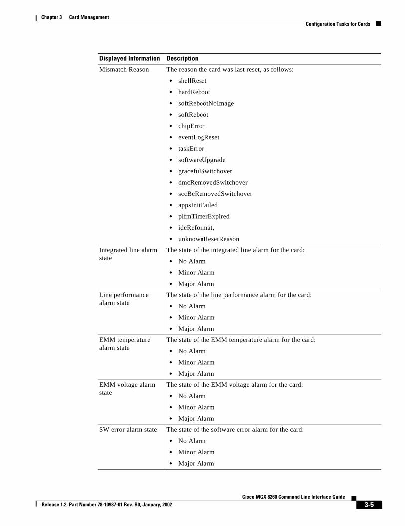
Mismatch Reason The reason the card was last reset, as follows:
• shellReset
• hardReboot
• softRebootNoImage
• softReboot
• chipError
• eventLogReset
• taskError
• softwareUpgrade
• gracefulSwitchover
• dmcRemovedSwitchover
• sccBcRemovedSwitchover
• appsInitFailed
• plfmTimerExpired
• ideReformat,
• unknownResetReason
Integrated line alarm state
The state of the integrated line alarm for the card:
• No Alarm
• Minor Alarm
• Major Alarm
Line performance alarm state
The state of the line performance alarm for the card:
• No Alarm
• Minor Alarm
• Major Alarm
EMM temperature alarm state
The state of the EMM temperature alarm for the card:
• No Alarm
• Minor Alarm
• Major Alarm
EMM voltage alarm state
The state of the EMM voltage alarm for the card:
• No Alarm
• Minor Alarm
• Major Alarm
SW error alarm state The state of the software error alarm for the card:
• No Alarm
• Minor Alarm
• Major Alarm
Displayed Information Description
3-5Cisco MGX 8260 Command Line Interface Guide
Release 1.2, Part Number 78-10987-01 Rev. B0, January, 2002
Chapter 3 Card ManagementConfiguration Tasks for Cards
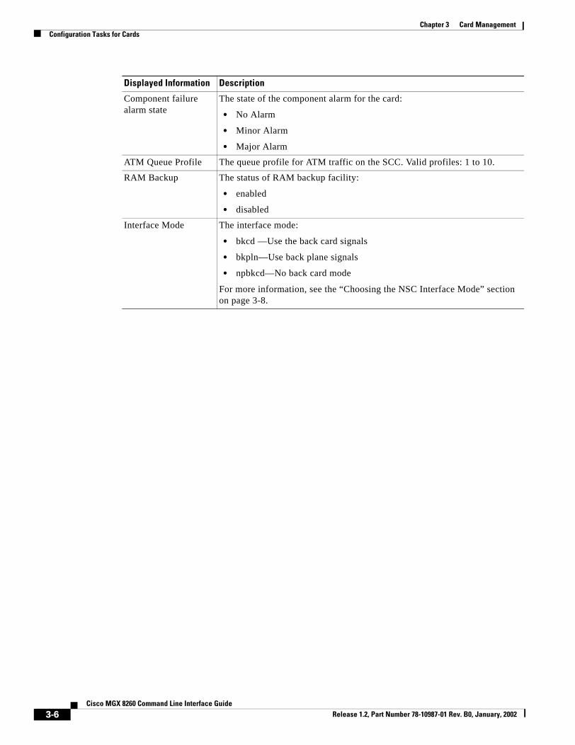
Component failure alarm state
The state of the component alarm for the card:
• No Alarm
• Minor Alarm
• Major Alarm
ATM Queue Profile The queue profile for ATM traffic on the SCC. Valid profiles: 1 to 10.
RAM Backup The status of RAM backup facility:
• enabled
• disabled
Interface Mode The interface mode:
• bkcd —Use the back card signals
• bkpln—Use back plane signals
• npbkcd—No back card mode
For more information, see the “Choosing the NSC Interface Mode” section on page 3-8.
Displayed Information Description
3-6Cisco MGX 8260 Command Line Interface Guide
Release 1.2, Part Number 78-10987-01 Rev. B0, January, 2002

Chapter 3 Card ManagementConfiguration Tasks for Cards
Viewing Summary Information for Cards
To list summary information for all cards, enter the lscds command.
The system displays information for all cards:===================================================================== Physical Card Entries (lscds)=====================================================================PhyCd LogCd FC BC Dgtr Cd1 Dgtr Cd2 Card State SW Rev===== ===== ==== ========= ========== ======== ========== ========== 1 1 nsc nmc16T1E1 msmDSPV msmDSPV active NSC_r01.01.b1 2 2 nsc nmc16T1E1 msmDSPV msmDSPV active NSC_r01.01.b1 3 3 nsc nmc16T1E1 msmDSPV msmDSPV active NSC_r01.01.b1 4 4 nsc rnd16T1E1 msmDSPV msmDSPV standby NSC_r01.01.b1 5 5 nsc nmc16T1E1 msmDSPV msmDSPV active NSC_r01.01.b1 6 6 nsc nmc16T1E1 msmDSPV msmDSPV active NSC_r01.01.b1 7 7 * * * * empty Unknown 8 8 * * * * empty Unknown 9 9 scc scc4FE bim4FE * standby SCC_r01.01.b1 10 9 scc scc4FE bim4FE * active SCC_r01.01.b1 11 11 bsc dmcBsc6T3 bim4T3E3 * active BSC_r01.01.b1 12 12 bsc dmcBsc6T3 bim4T3E3 * active BSC_r01.01.b1 13 13 bsc dmcBsc6T3 bim4T3E3 * active BSC_r01.01.b1 14 14 bsc dmcBsc6T3 bim4T3E3 * active BSC_r01.01.b1 15 15 bsc dmcBsc6T3 bim4T3E3 * active BSC_r01.01.b1 16 16 * * * * empty Unknown
Viewing MSM Configuration and Status
To view DSP information, enter the lsdsps command.
Displayed Information Description
PhyCd The physical slot number of the card
LogCd The logical slot number of the card
FC The front card type
BC The back card type
Dgtr Cd1 The type of daughter card installed on the NSC or SCC card
Dgtr Cd2 The type of secondary daughter card installed on the NSC card
Card State The status of the card
SW Rev The software release and version that is running on the card. The first letters identify the card type and the numbers identify the major release, minor release, and version.
3-7Cisco MGX 8260 Command Line Interface Guide
Release 1.2, Part Number 78-10987-01 Rev. B0, January, 2002

Chapter 3 Card ManagementConfiguration Tasks for Cards
The system lists current DSP information:====================================================================== MultiService Module (DSP) Entries (lsdsps)====================================================================== Slot Number DSP MSM Number DSP Number DSP Status=============== ================== ================ ================ 2 1 1 active 2 1 2 active 2 1 3 active 2 1 4 active 2 1 5 active 2 1 6 active 2 1 7 active 2 1 8 active
To view MSM information, enter the lsmsms command.
The system lists current MSM information:==================================================================== MultiService Module (MSM) Entries (lsmsms)==================================================================== Slot Number MSM Number MSM Type MSM Status=============== ================ =============== ================ 2 1 msmDSPV active 2 2 msmDSPV active 6 1 msmDSPV active 6 2 msmDSPV active
Choosing the NSC Interface Mode
The interface mode controls the signal source for the T1 interface of an NSC card. There are three modes (see Figure 3-1)
• Back card
• Back plane
Displayed Information Description
Slot Number The slot number of the multi-service module
DSP MSM Number The multi-service module number
DSP Number The DSP number on the multi-service module
DSP Status The status of the DSP
Displayed Information Description
Slot Number The slot number of the multi-service module
MSM Number The multi-service module number
MSM Type The type of multi-service module
MSM Status The multi-service module status
3-8Cisco MGX 8260 Command Line Interface Guide
Release 1.2, Part Number 78-10987-01 Rev. B0, January, 2002

Chapter 3 Card ManagementConfiguration Tasks for Cards
• No back card
All sixteen T1 lines operate in the same mode. The system ignores this setting for cards other than the NSC.
Figure 3-1 NSC Interface Modes
Back Card Mode
In the back card mode, the NSC transmits and receives traffic through the back card and its T1/E1 interface. The normal signal flow in this case is:NSC-BC -> NSC-FC -> Bus -> SCC-FC -> SCC-BCwhere BC = Back Card and FC = Front Card
Choose the back card mode when you are using the NSC card with a T1/E1 back card.
DMCbackcard
Back plane mode
Dummybackcard
DMCfrontcard
NSCfrontcard
SCCbackcard
SCCfrontcard
NSCbackcard
Back card mode
SCCbackcard
NSCfrontcard
SCCfrontcard
3193
3
No back card mode
NSCfrontcard
SCCbackcard
SCCfrontcard
3-9Cisco MGX 8260 Command Line Interface Guide
Release 1.2, Part Number 78-10987-01 Rev. B0, January, 2002
Chapter 3 Card ManagementConfiguration Tasks for Cards
Back Plane Mode
In the back plane mode, VoIP transmits and receives traffic from the DMC front card. The normal signal flow when using a DMC card is:DMC-BC -> DMC-FC -> Bus -> NSC-FC -> Bus -> SCC-FC -> SCC-BCwhere BC = Back Card and FC = Front Card
Use the back plane mode when you use the NSC card in conjunction with a DMC card and DS3 lines.
No Back Card Mode
In the no back card mode, the NSC transmits and receives traffic from a SCC front card. The normal signal flow in this case is:NSC-FC -> Bus -> SCC-FC -> SCC-BCwhere BC = Back Card and FC = Front Card
Use the no back card mode when using the NSC in conjunction with the SCC Fast Ethernet.
Configuring the NSC Interface Mode
You can only change the interface mode on an NSC while it’s in one of the following states:
• Active
• InBoot
• Mismatch
• Failed
To set the NSC interface mode, enter the chcdif command, specifying the card number and NSC interface mode. Valid NSC interface mode settings are:
1: back card (default)
2: back plane
3. no back card
Note Configuring the back card mode with out a back card installed results in a card mismatch.
The system sets the specified interface mode on the target NSC card. The following example sets the interface mode of card 13 to back plane:chcdif 13 2
The card resets and reboots into backplane mode.
Setting the ATM Queue Profile
The ATM queue profile defines the queue behavior for the SCC card. You can only change the ATM Queue profile on the active SCC.
To set the ATM queue profile, enter the chqprf command, specifying the slot number of the SCC card, either 9 or 10, and the queue profile, a number from 1 to 10. Profile 1 is the default.
The system sets the specified queue profile on the target SCC card.
3-10Cisco MGX 8260 Command Line Interface Guide
Release 1.2, Part Number 78-10987-01 Rev. B0, January, 2002

Chapter 3 Card ManagementConfiguration Tasks for Cards
Resetting a Card
The resetcd command restarts a card and restores its stored configuration. The following table shows response of the reset command for different card types and operating states:
Warning Resetting a card interrupts service. Perform this operation during light traffic periods or in a pre-arranged maintenance window.
To reset a card, enter the resetcd command, specifying the card to reset.
The following example resets card 13:resetcd 13
Understanding RedundancyThe MGX 8260 Media Gateway supports both redundant and non-redundant operation for all cards. The SCC and DMC don’t require user setup for redundant operation. To configure redundancy for the NSC or BSC, you define protection pairs. The Cisco MGX 8260 uses 1:N protection for NSCs and 1:1 protection for BSCs. With protection, the system switches to a protection card if an active card fails.
Understanding Physical and Logical Slot Numbers
Cards configured for redundancy may have logical numbers that are different than physical slot numbers. The physical slot number always represents the physical location of the card in the chassis. The logical slot number is an abstract concept that helps the system keep track of primary and secondary cards.
With 1:1 redundancy, the primary and secondary cards both have the same logical slot number. As such, the system treats them as a single entity for configuration operations. With 1:N redundancy, the secondary card uses logical slot number 0. During switchover, the secondary card assumes the logical number of the card it protects.
Table 3-1 Response of Reset Command by Card and State
State SCC slots 9/10 DMC slots 7/8NSC slots 1-8, 11-16 andBSC slots 11-16
active OK Service not available on DMC
OK
standby OK
empty Card does not exist. Card does not exist
inBoot OK OK
mismatch OK
failed OK
unknown Card does not exist N/A N/A
3-11Cisco MGX 8260 Command Line Interface Guide
Release 1.2, Part Number 78-10987-01 Rev. B0, January, 2002

Chapter 3 Card ManagementConfiguration Tasks for Cards
Using 1:N NSC Redundancy
A single secondary card can support multiple primary cards. In this configuration, a failure of any of the primary cards causes a switchover to the designated secondary. After a switchover, the other NSCs are unprotected until you fix the problem and restore the primary card to the active state.
For example, a 1:2 redundancy configuration with slot 3 covering slot 1 and slot 5 actually has two redundancy pairs (see Figure 3-2).
Figure 3-2 Normal Operation with 1:2 NSC Redundancy
Slot 1 is paired with slot 3, with slot 1 as the primary. Slot 5 is also paired with slot 3 with slot 5 as the primary. You can continue to add redundancy pairs to build other ratios of protection. However, you can only have one secondary slot per MGX 8260 chassis. That single secondary slot protects all primary NSC cards in the chassis.
If the primary card in slot one fails, the system switches to the secondary NSC, and the secondary NSC assumes the logical slot number of the card that failed (see Figure 3-3).
DSCSCC
CARD
LINE
1
2
3
4
SCC
CARD
LINE
1
2
3
4
ACTFDX
1
2
3
4
ACTLINE
LAN 1
LAN 2
ALMC
ALMH
CLR
ACO
DISK
PWR A
PWR B
ACTFDX
1
2
3
4
ACTLINE
LAN 1
LAN 2
ALMC
ALMH
CLR
ACO
DISK
PWR A
PWR B
NSC
CARD
LINE
1
2
3
4
13
5
6
7
8
9
10
11
12
14
15
16
DMC
CARD
LINE
1
2
3
4
5
6
NSC
CARD
LINE
1
2
3
4
5
6
7
8
9
10
11
12
13
14
15
16
NSC
CARD
LINE
1
2
3
4
5
6
7
8
9
10
11
12
13
14
15
16
NSC
CARD
LINE
1
2
3
4
5
6
7
8
9
10
11
12
13
14
15
16
NSC
CARD
LINE
1
2
3
4
5
6
7
8
9
10
11
12
13
14
15
16
NSC
CARD
LINE
1
2
3
4
5
6
7
8
9
10
11
12
13
14
15
16
DMC
CARD
LINE
1
2
3
4
5
6
32405
Secondary card (standby)
Primary cards (active)
Physical slot numbers
Logical slot numbers
1 2 3 4 5 6
1 2 0 4 5 6
3-12Cisco MGX 8260 Command Line Interface Guide
Release 1.2, Part Number 78-10987-01 Rev. B0, January, 2002

Chapter 3 Card ManagementConfiguration Tasks for Cards
Figure 3-3 Switchover with 1:2 NSC Redundancy
The logical slot number of the secondary card changes to 1, even though its physical slot number is 3. Had the slot 5 failed rather than slot 1, the logical slot number of the secondary card would have changed to 5.
Using 1:1 BSC Redundancy
You configure BSC protection using a pair of cards configured for 1:1 redundancy. After you configure a redundant pair of BSCs, both cards reboot and return to operation with the same logical slot number. The card LED displays green for the active card and yellow for the standby card.
DSCSCC
CARD
LINE
1
2
3
4
SCC
CARD
LINE
1
2
3
4
ACTFDX
1
2
3
4
ACTLINE
LAN 1
LAN 2
ALMC
ALMH
CLR
ACO
DISK
PWR A
PWR B
ACTFDX
1
2
3
4
ACTLINE
LAN 1
LAN 2
ALMC
ALMH
CLR
ACO
DISK
PWR A
PWR B
NSC
CARD
LINE
1
2
3
4
13
5
6
7
8
9
10
11
12
14
15
16
DMC
CARD
LINE
1
2
3
4
5
6
NSC
CARD
LINE
1
2
3
4
5
6
7
8
9
10
11
12
13
14
15
16
NSC
CARD
LINE
1
2
3
4
5
6
7
8
9
10
11
12
13
14
15
16
NSC
CARD
LINE
1
2
3
4
5
6
7
8
9
10
11
12
13
14
15
16
NSC
CARD
LINE
1
2
3
4
5
6
7
8
9
10
11
12
13
14
15
16
NSC
CARD
LINE
1
2
3
4
5
6
7
8
9
10
11
12
13
14
15
16
DMC
CARD
LINE
1
2
3
4
5
6
32406
Secondary card (active)
Primary card (failed)
Failed
Primary card (active)
Physical slot numbers
Logical slot numbers
1 2 3 4 5 6
1 2 1 4 5 6
3-13Cisco MGX 8260 Command Line Interface Guide
Release 1.2, Part Number 78-10987-01 Rev. B0, January, 2002

Chapter 3 Card ManagementConfiguration Tasks for Cards
For example, you can configure cards 15 and 16 for redundancy (see Figure 3-4).
Figure 3-4 Normal Operation with 1:1 BSC Redundancy
SCC
CARD
LINE
1
2
3
4
SCC
CARD
LINE
1
2
3
4
ACTFDX
1
2
3
4
ACTLINE
LAN 1
LAN 2
ALMC
ALMH
CLR
ACO
DISK
PWR A
PWR B
ACTFDX
1
2
3
4
ACTLINE
LAN 1
LAN 2
ALMC
ALMH
CLR
ACO
DISK
PWR A
PWR B
NSC
CARD
LINE
1
2
3
4
13
5
6
7
8
9
10
11
12
14
15
16
DMC
CARD
LINE
1
2
3
4
5
6
NSC
CARD
LINE
1
2
3
4
5
6
7
8
9
10
11
12
13
14
15
16
NSC
CARD
LINE
1
2
3
4
5
6
7
8
9
10
11
12
13
14
15
16
NSC
CARD
LINE
1
2
3
4
5
6
7
8
9
10
11
12
13
14
15
16
NSC
CARD
LINE
1
2
3
4
5
6
7
8
9
10
11
12
13
14
15
16
NSC
CARD
LINE
1
2
3
4
5
6
7
8
9
10
11
12
13
14
15
16
DMC
CARD
LINE
1
2
3
4
5
6
33387
Secondary card (standby)
NSC
CARD
LINE
1
2
3
4
5
6
7
8
9
10
11
12
13
14
15
16
NSC
CARD
LINE
1
2
3
4
5
6
7
8
9
10
11
12
13
14
15
16
NSC
CARD
LINE
1
2
3
4
5
6
7
8
9
10
11
12
13
14
15
16
NSC
CARD
LINE
1
2
3
4
5
6
7
8
9
10
11
12
13
14
15
16
NSC
CARD
LINE
1
2
3
4
5
6
7
8
9
10
11
12
13
14
15
16
NSC
CARD
LINE
1
2
3
4
5
6
7
8
9
10
11
12
13
14
15
16
Physical slot numbers
Logical slot numbers
11 12 13 14 15 16
11 12 13 14 15 15
Primary card (active)
3-14Cisco MGX 8260 Command Line Interface Guide
Release 1.2, Part Number 78-10987-01 Rev. B0, January, 2002

Chapter 3 Card ManagementConfiguration Tasks for Cards
A failure of the active card causes a switchover to the backup card. During the switchover, the active and standby roles are reversed (see Figure 3-5). The card that failed reboots, and the Card LED changes to either yellow or red, depending on the type of problem. After a switchover, the other BSC is unprotected until you fix the problem and restore the primary card to the active state.
Figure 3-5 Switchover with 1:1 BSC Redundancy
After repair of the failure, you restore normal operation by invoking a switchback. The system does not automatically restore the protection pair to its original state. For more information, see Invoking a Switchback, page 3-18.
Configuring BSC or NSC RedundancyThis section describes the process for configuring redundancy for BSC and NSC cards.
Viewing BSC and NSC Redundancy
To view all redundancy pairs, enter the lsreds command.
SCC
CARD
LINE
1
2
3
4
SCC
CARD
LINE
1
2
3
4
ACTFDX
1
2
3
4
ACTLINE
LAN 1
LAN 2
ALMC
ALMH
CLR
ACO
DISK
PWR A
PWR B
ACTFDX
1
2
3
4
ACTLINE
LAN 1
LAN 2
ALMC
ALMH
CLR
ACO
DISK
PWR A
PWR B
NSC
CARD
LINE
1
2
3
4
13
5
6
7
8
9
10
11
12
14
15
16
DMC
CARD
LINE
1
2
3
4
5
6
NSC
CARD
LINE
1
2
3
4
5
6
7
8
9
10
11
12
13
14
15
16
NSC
CARD
LINE
1
2
3
4
5
6
7
8
9
10
11
12
13
14
15
16
NSC
CARD
LINE
1
2
3
4
5
6
7
8
9
10
11
12
13
14
15
16
NSC
CARD
LINE
1
2
3
4
5
6
7
8
9
10
11
12
13
14
15
16
NSC
CARD
LINE
1
2
3
4
5
6
7
8
9
10
11
12
13
14
15
16
DMC
CARD
LINE
1
2
3
4
5
6
33388
Secondary card (standby)
NSC
CARD
LINE
1
2
3
4
5
6
7
8
9
10
11
12
13
14
15
16
NSC
CARD
LINE
1
2
3
4
5
6
7
8
9
10
11
12
13
14
15
16
NSC
CARD
LINE
1
2
3
4
5
6
7
8
9
10
11
12
13
14
15
16
NSC
CARD
LINE
1
2
3
4
5
6
7
8
9
10
11
12
13
14
15
16
NSC
CARD
LINE
1
2
3
4
5
6
7
8
9
10
11
12
13
14
15
16
NSC
CARD
LINE
1
2
3
4
5
6
7
8
9
10
11
12
13
14
15
16
Physical slot numbers
Logical slot numbers
11 12 13 14 15 16
11 12 13 14 15 15
Primary card (active)
Failed
3-15Cisco MGX 8260 Command Line Interface Guide
Release 1.2, Part Number 78-10987-01 Rev. B0, January, 2002

Chapter 3 Card ManagementConfiguration Tasks for Cards
The system displays all redundancy pairs:======================================================================= Card Redundancy Table (lsreds)======================================================================= Primary Slot Secondary Slot=============== ================ 1 3 5 3
Adding NSC Redundancy
There are two possible NSC redundancy scenarios: with and without DMC.
• NSC redundancy without DMC
This scenario requires a redundant back card in the secondary slot. The back card protects the primary slots in the event of a primary card failure.
• NSC redundancy with DMC
This scenario does not require, and cannot have, a redundant back card.
Both scenarios require assignment of primary and secondary slot numbers in pairs. The MGX 8260 chassis only supports one secondary slot.
Configuring NSC Redundancy without DMC
To configure NSC redundancy without DMC, follow these steps:
Step 1 Verify that the redundant NSC has a redundancy back card installed and is in the standby state. Enter the lscd command, specifying the card number, to verify the hardware and status:
Step 2 Verify that each primary, active NSC is in the back card mode and is in the active state. List the operational status of all cards using the lscds command.
Step 3 Add a redundancy pair using the addreds command, specifying the slots of the primary and secondary slots.
The primary slot is active during normal operation. The secondary slot is in standby during normal operation and protects the primary slot in the event of a primary failure.
The following example creates a redundancy pair with slot 1 as primary and slot 3 as secondary:addreds 1 3
Step 4 Repeat the previous step to assign additional primary slots to the designated secondary slot. Each MGX 8260 chassis can have only one secondary slot.
Displayed Information Description
Primary Slot The physical slot for the primary card of the redundancy pair
Secondary Slot The physical slot for the secondary card of the redundancy pair
3-16Cisco MGX 8260 Command Line Interface Guide
Release 1.2, Part Number 78-10987-01 Rev. B0, January, 2002

Chapter 3 Card ManagementConfiguration Tasks for Cards
Configuring NSC Redundancy with DMC
To configure NSC redundancy with DMC, follow these steps:
Step 1 Verify that at least one DMC and DS3 back card is installed in physical slot 7 or 8. Enter the following command to verify the hardware:lscds
Step 2 Verify that the redundant NSC does not have a redundancy back card installed. See “Viewing Summary Information for Cards” section on page 3-7.
Step 3 Verify that each primary NSC does not have a back card installed.
Step 4 Add a redundancy pair using the addreds command.
Step 5 Repeat the previous step to assign additional primary slots to the designated secondary slot. Each MGX 8260 chassis can have only one secondary slot for NSC cards.
Adding BSC Redundancy
In order to successfully configure a redundant pair, the following conditions must be true:
• The hardware configuration of the two BSCs must be identical
• The firmware version of the two BSCs must be identical
• The redundant BSC must not have any lines configured
Warning Adding BSC redundancy interrupts service. Perform this operation during light traffic periods or in a pre-arranged maintenance window.
To configure BSC redundancy, follow these steps:
Step 1 Install a redundant BSC in any available slot from 11 to 16.
Step 2 Add a redundant “Y” cable between all ports on the two cards.
Step 3 From a management session, add a redundancy pair using the addreds command.
Both cards reboot and return to operation with the same logical slot number.
Deleting Redundancy
To delete a redundancy pair, enter the delreds command specifying the primary and secondary slots. The following example deletes the redundancy pair where slot 1 is primary and slot 3 is secondary:delreds 1 3
The redundant card continues to protect other primary cards with which it is paired.
3-17Cisco MGX 8260 Command Line Interface Guide
Release 1.2, Part Number 78-10987-01 Rev. B0, January, 2002

Chapter 3 Card ManagementSaving and Restoring Card Configurations
Invoking a Switchback
The switchover from primary to secondary cards is automatic when a primary card fails. Switching back is a manual task. The following table shows the response of the switchback command as a function of card type and operational state:
To force a switchback, enter the swcd command specifying the physical number of the primary card in a protection pair.
Note To force a switchover, rather than a switch back, reset the primary card using resetcd.
Saving and Restoring Card ConfigurationsYou can save or restore system configuration from a tftp server on the management network. To use tftp, you must conform to the Cisco file-naming convention and supply a six-character security key. The security system disables tftp file transfers if the key is missing or does not match. The following procedures explain how to save and restore card configurations.
Backing Up ConfigurationsYou can back up the current MGX 8260 configuration with the dbbkup command. This command captures the configuration information for all cards and saves it to a file on the SCC hard drive. The system assigns a name for this file and reports it to the user.
To save a card configuration, follow these steps:
Step 1 Log onto the desired MGX 8260.
Step 2 At the command prompt, type dbbkup.
The system reports the result of the operation and the name of the backup file.
Table 3-2 Response for the Switch Card Command by Card and State
StateSCC slots 9/10 DMC slots 7/8 NSC slots 1-8, 11-16 and
BSC slots 11-16
active OK Service not available on DMC
Switchback from secondary to primary only.standby Illegal slot number for this
state.
empty Card does not exist.
inBoot Illegal slot number for this state.mismatch
failed
unknown N/A N/A
3-18Cisco MGX 8260 Command Line Interface Guide
Release 1.2, Part Number 78-10987-01 Rev. B0, January, 2002

Chapter 3 Card ManagementSaving and Restoring Card Configurations
Step 3 Record the file name for future reference. By default, the backup file name matches the software version name with a .cfg extension. For example, the backup file for software release R01.02.03 is SCC_R01.02.03.CFG
Uploading ConfigurationsThe MGX 8260 stores configuration information for all cards in the chassis in the SCC hard drive. You can upload this configuration information to an external server for safekeeping. Before performing this procedure, check your records to determine the name of the backup file you want to upload.
To upload a configuration file, follow these steps:
Step 1 Log onto the workstation running the tftp server.
Step 2 Initiate a tftp session with the target MGX 8260 Media Gateway using the tftp command.tftp <IP Address>
Specify the IP address of the MGX 8260 management port in standard IP dot notation.
Note tftp is an operating system command executed by the management workstation.
Step 3 Set the transfer mode to binary:mode binary
Step 4 Start the file transfer using the tftp get command.get <FileName>.<SecurityKey>
Step 5 Confirm the file transfer by checking the distribution directory.
Downloading ConfigurationsThe MGX 8260 stores configuration files on the SCC hard drive, so you generally don’t need to download a configuration file. However, if you prefer to save configuration files on an external server, you can download the file to the MGX 8260 before invoking dbrstr. Before performing this procedure, check your records to determine the name of the backup file you want to download.
Parameter Description
FileName The name of the configuration file. This name indicates the card type, major release, minor release, and version, followed by the .cfg extension. For example, SCC_R01.02.03.CFG is the database for software release 1.2.3.
SecurityKey The six-character alphanumeric security key for the target MGX 8260
3-19Cisco MGX 8260 Command Line Interface Guide
Release 1.2, Part Number 78-10987-01 Rev. B0, January, 2002

Chapter 3 Card ManagementSaving and Restoring Card Configurations
To restore a card configuration, follow these steps:
Step 1 Log onto a workstation and locate the configuration file to download.
Step 2 Initiate a tftp session with the target MGX 8260 Media Gateway using the tftp command.tftp <IP Address>
Specify the IP address of the MGX 8260 management port in standard IP dot notation.
Note tftp is an operating system command executed by the management workstation.
Step 3 Set the transfer mode to binary using the tftp mode command.mode binary
Step 4 Start the file transfer using the tftp put command.put <srcImageFileName> <destImageFileName>.<Security Key>
Step 5 Confirm the file transfer.
Restoring ConfigurationsYou can restore the MGX 8260 to a previous configuration using the dbrstr command. This command retrieves a configuration file from the SCC hard disk and restores all cards accordingly. Before performing this procedure, check your records to determine the name of the backup file you want to restore.
Warning This is a service-affecting action. Perform this task when the equipment is down or during a pre-arranged maintenance window.
To restore MGX 8260 configurations, follow these steps.
Step 1 Log onto the desired MGX 8260.
Step 2 At the command prompt, type database restore command and the configuration file name. Omit the .cfg extension from the file name.
Parameter Description
srcImageFileName The path and file name of the source file stored on your server
destImageFileName The name of the configuration file. This name indicates the card type, major release, minor release, and version, followed by the .cfg extension. For example, SCC_R01.02.03.CFG is the database for software release 1.2.3.
SecurityKey The six-character alphanumeric security key for the target MGX 8260
3-20Cisco MGX 8260 Command Line Interface Guide
Release 1.2, Part Number 78-10987-01 Rev. B0, January, 2002

Chapter 3 Card ManagementUpgrading Software Images
For example:dbrstr scc_r01.02.03
Step 3 Restart the target card using the resetcd command.
Upgrading Software ImagesThis section describes the software upgrade paths, security key requirements, installation procedures, and database configurations needed for software upgrade.
System Software Upgrade PathsRelease 1.2.5 software supports graceful upgrades from the following releases:
• 1.2.4
• 1.2.3
• 1.2.2
• 1.2.1
Security Key RequirementsA security key is required for the transfer of files to the MGX 8260 through use of the UNIX tftp function. To determine the appropriate MGX 8260 security key code, use the lskey command from the command line interface.
Installation ProceduresThe following sections describe the process you use to download MGX 8260 software from the Cisco web or ftp sites, transfer the files to the MGX 8260, and download the files to each card.
Downloading Software from CCO
To download MGX 8260 software images, refer to the Cisco software center on Cisco Connection Online (CCO), located at the following URL:
• http://www.cisco.com/public/sw-center/
For instructions on how to download software, refer to the link for “Using the Software Center”.
MGX 8260 software includes the following files:vxWorks_dnld.scc.fwvxWorks_boot.scc.fwvxWorks_dnld.nsc.fwvxWorks_boot.nsc.fwvxWorks_dnld.bsc.fwvxWorks_boot.bsc.fw
3-21Cisco MGX 8260 Command Line Interface Guide
Release 1.2, Part Number 78-10987-01 Rev. B0, January, 2002

Chapter 3 Card ManagementUpgrading Software Images
To upgrade the MGX 8260, download the new system software from CCO to a management server on your network that supports the UNIX tftp function.
Transferring Files to the MGX 8260
Using tftp, transfer the files to the MGX 8260 using the following procedure:
Step 1 Log on to the workstation running the tftp server and locate the files you downloaded in the “Downloading Software from CCO” section.
Step 2 Initiate a tftp session with the target MGX 8260 Media Gateway using the tftp command.tftp <IP Address>
Specify the IP address of the MGX 8260 management port in standard IP dot notation.
Step 3 Set the transfer mode to binary with the following command:mode binary
Step 4 Use the following tftp commands to transfer SCC software to the MGX 8260:tftp> put vxWorks_dnld.scc.fw scc_r01.02.05.img.[key]
tftp> put vxWorks_boot.scc.fw scc_r01.02.05.fls.[key]
For information about the security key [key], refer to the “Security Key Requirements” section on page 3-21.
Step 5 Use the following tftp commands to transfer BSC software to the MGX 8260:tftp> put vxWorks_dnld.bsc.fw bsc_r01.02.05.img.[key]
tftp> put vxWorks_boot.bsc.fw bsc_r01.02.05.fls.[key]
Step 6 Use the following tftp commands to transfer NSC software to the MGX 8260:tftp> put vxWorks_dnld.nsc.fw nsc_r01.02.05.img.[key]
tftp> put vxWorks_boot.nsc.fw nsc_r01.02.05.fls.[key]
Step 7 Close your tftp session.
Upgrading Card Software
Before performing an upgrade, make sure you have a current backup of the configuration database. Back up the database using the dbbkup command from the command line interface.
Caution All modules must be upgraded to the new release of software during the upgrade process. Performing a partial upgrade (For example, some, but not all BSCs, or some, but not all NSCs) could cause unexpected behavior in MGX 8260 system operation.
Note The installation procedure described here is for a graceful upgrade process from the software release indicated in the “System Software Upgrade Paths” section on page 3-21 to the current release.
The general process to upgrade software on all cards is as follows:
1. Initiate a Telnet session with the target MGX 8260 Media Gateway, specifying the IP address of the MGX 8260 management port in standard IP dot notation.
3-22Cisco MGX 8260 Command Line Interface Guide
Release 1.2, Part Number 78-10987-01 Rev. B0, January, 2002

Chapter 3 Card ManagementUpgrading Software Images
2. Log in as superuser or a user with level 1 privileges.
3. Follow the upgrade procedures for each card type.
– See the “Upgrading SCC Software” section on page 3-23 for SCC upgrade procedures.
– See the “Upgrading BSC Software” section on page 3-24 for BSC upgrade procedures.
– See the “Upgrading NSC Software” section on page 3-26 for NSC upgrade procedures.
4. Log out of your Telnet session.
Note We recommend that you use the upgrade procedures while simultaneous console connections are established to both the active and the standby SCC.
Upgrading SCC Software
The upgrade process for redundant SCCs is graceful. It does not interrupt established calls, but it can interrupt calls in the process of being established. When you invoke the upgrade process, the MGX 8260 upgrades and restarts the standby SCC. You can then commit or cancel the upgrade. When you commit the software, the MGX 8260 switches to the standby SCC and then upgrades the other SCC.
Warning Upgrading nonredundant cards interrupts service. Perform nonredundant upgrades during light traffic periods or during a prearranged maintenance window.
3-23Cisco MGX 8260 Command Line Interface Guide
Release 1.2, Part Number 78-10987-01 Rev. B0, January, 2002

Chapter 3 Card ManagementUpgrading Software Images
To upgrade SCC and software images, perform the following steps:
Step 1 Upgrade the boot Flash software on each SCC using the following command. Issue the command for each SCC, replacing the <physicalSlotNumber> with the appropriate number for your configuration.updatefls <physicalSlotNumber> IMAGE/SCC/scc_r01.02.05.fls
Step 2 Ensure that the standby SCC is in the standby state.
Step 3 Upgrade the software image on the active SCC using the following command:upgd 9 scc_r01.02.05.fw
Note Enter a 9 even if card 10 is active. This parameter refers to logical card 9. The active SCC is always logical card 9 regardless of its physical slot location.
In redundant configurations, the upgd command resets the standby SCC. Wait until the standby SCC reboots and its console session shows a standby state. At that point, the standby SCC will be running the new release of boot Flash and software images.
Step 4 You can now commit or cancel the upgrade.
a. For redundant SCCs, if you wish to cancel the upgrade, enter the upgdcancel command. Use this command only if you have not entered the upgdcmit command. You cannot cancel an upgrade for nonredundant cards.
Note Before you cancel an upgrade with the upgdcancel command, you need to to reset the previous software on the flash card using the updatefls command.
b. To commit the new software, enter the following command:
upgdcmit 9
On redundant systems, the upgdcmit command switches over the two SCCs. The SCC that was standby is placed into active state with its newly upgraded database and software image, and the previously active SCC resets and boots up to standby state.
Warning You must execute either the upgdcmit command in Step 4b. or the upgdcancel command in Step 4a. If you do not execute one of these commands, database corruption will occur.
Step 5 Ensure that the previously active SCC has completed booting and is in standby state.
Step 6 On redundant systems, force a switchback to the primary card using the swcd command:swcd 9
Upgrading BSC Software
The upgrade process for redundant BSCs is graceful. It does not interrupt established calls, but it can interrupt calls in the process of being established. When you invoke the upgrade process, the MGX 8260 upgrades and restarts the standby BSC. You can then commit or cancel the upgrade. When you commit the upgrade, the MGX 8260 switches to the standby BSC and then upgrades the other BSC.
3-24Cisco MGX 8260 Command Line Interface Guide
Release 1.2, Part Number 78-10987-01 Rev. B0, January, 2002

Chapter 3 Card ManagementUpgrading Software Images
Warning Upgrading nonredundant cards interrupts service. Perform nonredundant upgrades during light traffic periods or during a prearranged maintenance window.
If your MGX 8260 includes BSCs, perform the following steps to upgrade BSC Flash and software images:
Step 1 Upgrade the boot Flash software on each BSC using the following command. Issue the command for each BSC, replacing the <physicalSlotNumber> with the appropriate number for your configuration.updatefls <physicalSlotNumber> IMAGE/BSC/bsc_r01.02.05.fls
Step 2 Ensure that the standby BSC is in the standby state.
Step 3 Upgrade the BSC software image using the following command. Issue the command for the first primary BSC in your system, replacing the <logicalSlotNumber> with the appropriate number for your configuration.upgd <logicalSlotNumber> bsc_r01.02.05.fw
Answer Y to the “Are you sure?” warning message.
In redundant configurations, the upgd command resets the secondary BSC matched with the primary BSC you specified in <logicalSlotNumber>. The secondary is now running the new release of boot Flash and the software images.
Step 4 Ensure that the standby BSC has finished booting and is in the standby state.
Step 5 You can now commit or cancel the upgrade.
a. For redundant BSCs, if you wish to cancel the upgrade, enter the upgdcancel command. This command can be used only if you have not entered the upgdcmit command. You cannot cancel an upgrade for nonredundant cards.
Note Before you cancel an upgrade with the upgdcancel command, you need to to reset the previous software on the flash card using the updatefls command.
b. To commit the new software, use the following command. Issue the command for the first primary BSC in your system, replacing the <logicalSlotNumber> with the appropriate number for your configuration.
upgdcmit <logicalSlotNumber>
If you have redundant BSCs installed, the upgdcmit command switches over the two BSCs. The BSC that was secondary (with its newly upgraded database and software image) becomes the primary BSC, and the previously primary BSC becomes the secondary BSC.
Warning You must execute either the upgdcmit command in Step 5b. or the upgdcancel command in Step 5a. If you do not execute one of these commands, database corruption occurs.
Step 6 Ensure that the previously primary BSC has finished booting and is in the standby state.
Step 7 On redundant systems, force a switchback to the original primary BSC using the swcd command:swcd <standbySlotNumber>
Where <standbySlotNumber> is the number of the original secondary BSC (the BSC that is currently in active state).
3-25Cisco MGX 8260 Command Line Interface Guide
Release 1.2, Part Number 78-10987-01 Rev. B0, January, 2002

Chapter 3 Card ManagementUpgrading Software Images
Step 8 Repeat Step 2 through Step 7 for additional BSC pairs in your system.
Upgrading NSC Software
The upgrade process for redundant NSCs is graceful. It does not interrupt established calls, but it can interrupt calls in the process of being established. When you invoke the process, the MGX 8260 upgrades and restarts the standby NSC. You can then commit or cancel the upgrade. When you commit the upgrade, the MGX 8260 switches to the standby NSC and then upgrades the other NSC.
Warning Upgrading nonredundant cards interrupts service. Perform nonredundant upgrades during light traffic periods or during a prearranged maintenance window.
NSC redundancy follows an N:1 design, with one NSC providing redundancy for all remaining NSCs.
If your MGX 8260 includes NSCs, perform the following steps to upgrade NSC Flash and software images:
Step 1 Upgrade the boot Flash software on each NSC using the following command. Issue the command for each NSC, replacing the <physicalSlotNumber> with the appropriate number for your configuration.updatefls <physicalSlotNumber> IMAGE/NSC/nsc_r01.02.05.fls
Step 2 If your system includes NSC redundancy, identify the slot number of the NSC providing redundancy.
Step 3 Enter the following command for the first NSC in your system (excluding the redundant NSC identified in Step 2). Replace the <logicalSlotNumber> with the appropriate number for your configuration.upgd <logicalSlotNumber> nsc_r01.02.05.fw
Answer Y to the “Are you sure?” warning message.
In redundant configurations, the upgd command resets the redundant NSC. The redundant NSC should now be running the new release of boot Flash and software images.
Step 4 Ensure that the standby/redundant NSC has finished rebooting and is in the standby state.
Step 5 You can now commit or cancel the upgrade.
a. If your MGX 8260 is configured for NSC redundancy, and you wish to cancel the upgrade, enter the upgdcancel command. You can use this command only if you have not entered the upgdcmit command. You cannot cancel an upgrade for nonredundant cards.
Note Before you cancel an upgrade with the upgdcancel command, you need to to reset the previous software on the flash card using the updatefls command.
b. To commit the new software, use the following command. Issue the command for the first NSC as indicated in Step 3. Replace the <logicalSlotNumber> with the appropriate number for your configuration.upgdcmit <logicalSlotNumber>
Warning You must execute either the upgdcmit command in Step 5b. or the upgdcancel command in Step 5a. If you do not execute one of these commands, database corruption occurs.
3-26Cisco MGX 8260 Command Line Interface Guide
Release 1.2, Part Number 78-10987-01 Rev. B0, January, 2002

Chapter 3 Card ManagementUpgrading Software Images
Step 6 Ensure that the previously standby NSC is now active and that the NSC in <logicalSlotNumber> is now in standby state.
Step 7 For an MGX 8260 configured for NSC redundancy, force a switchback to the NSC indicated in Step 3. Use the swcd command:swcd <standbySlotNumber>
Where <standbySlotNumber> is the number of the standby/redundant NSC (currently in active state).
Step 8 Repeat Step 3 through Step 7 for all NSCs in your system.
Note If the NSC does not have a back card, it may reboot in MISMATCH state. Fix this by entering the command chcdif <logicalSlotNumber> 3. This returns the NSC to No-Back-Card mode.
Database Configuration InformationYou do not need to clear the configuration database when performing a graceful upgrade from Release 1.2.2, 1.2.3, or 1.2.4 to Release 1.2.5. Nongraceful upgrades require a database reconfiguration.
3-27Cisco MGX 8260 Command Line Interface Guide
Release 1.2, Part Number 78-10987-01 Rev. B0, January, 2002

Chapter 3 Card ManagementUpgrading Software Images
3-28Cisco MGX 8260 Command Line Interface Guide
Release 1.2, Part Number 78-10987-01 Rev. B0, January, 2002

Cisco MGX Release 1.2, Part Number 78-10987-01 Rev. B0, January, 2002
C H A P T E R 4
Service ManagementThis chapter explains how to configure line and voice services.
Configuration Tasks for LinesSee the following sections for line configuration tasks.
• Viewing All MGX 8260 Lines
• Viewing DS0 Lines
• Configuring DS1 or E1 Lines
• Configuring DS3 Lines
• Mapping DMC Lines
• Configuring Fast Ethernet Lines
• Configuring OC-3 Lines
Viewing All MGX 8260 LinesThe MGX 8260 Media Gateway supports the following types of lines:
• DS1, E1, and DS3
• Fast Ethernet or OC-3
You can view all existing MGX 8260 lines in a single report. From this report, you see a list of lines and their logical slot and line type. Based on the line type, you proceed with line-specific commands to configure the line or obtain more information.
To view the common line listing, enter the lslns command.
4-18260 Command Line Interface Guide

Chapter 4 Service ManagementConfiguration Tasks for Lines
The system displays the common line entries:===================================================================== Common Line Entries (lslns)===================================================================== Line Number (Slot.Line) Line Type================================= ================================== 2.1 dsx1-t1 11.1 dsx1-t1 11.2 dsx1-t1 11.501 dsx3-t3
Viewing DS0 LinesFrom the command line interface, you can add, change, delete, and view DS1 lines. The MGX 8260 Media Gateway supports both T1 and E1 line types, but you must configure the entire chassis as one type or the other. Use caution when changing DS1 configurations because you may interrupt service.
Viewing DS0 Configuration and Status
To view detail information for a single DS0, enter the lsds0 command, specifying the logical number of the slot in the MGX 8260 chassis, the number of the DS1 line, and the DS0 number.
The system displays the following DS0 details:======================================================================= DS0 Entry (lsds0)=======================================================================Slot : 1Line Number : 1Ds0 Time Slot : 1Operating Status : idlePort : 3
Displayed Information Description
Line Number The logical slot and line number, expressed as Slot.Line
Line Type The type of line:
• dsx1-t1—T1 line
• dsx3-t3—T3 line
• fast-ether—Fast Ethernet line
Displayed Information Description
Slot The slot number of car.
Line Number The line with this DS0 channel
DS0 Time Slot The DS1 time slot this DS0 uses
Operating Status The current operational status for this DS0
Port The DS0 port number
4-2Cisco MGX 8260 Command Line Interface Guide
Release 1.2, Part Number 78-10987-01 Rev. B0, January, 2002

Chapter 4 Service ManagementConfiguration Tasks for Lines
Viewing Summary DS0 Information
To list summary DS1 information for all lines, enter the lsds0s command.
The system displays summary information for all DS0 lines:======================================================================= DS0 Entries (lsds0s)=======================================================================Slot Number Line Number DS0 Number DS0 Status Logical Port Num=========== =========== ========== ================ ================== 1 1 1 idle 3 1 1 2 idle 1 1 1 5 idle 4 1 1 7 idle 6
For a description of the columns, see the previous section on the lsds0 command.
Configuring DS1 or E1 LinesFrom the command line interface, you can add, change, delete, and view DS1/E1 lines. The MGX 8260 Media Gateway supports both T1 and E1 line types, but you must configure the entire chassis as one type or the other. Use caution when changing DS1/E1 configurations because you may interrupt service.
Viewing DS1/E1 Configuration and Status
To view detail information for a single DS1/E1, enter the lsds1ln command, specifying the logical number of the slot in the MGX 8260 chassis and the number of the DS1/E1 line (expressed as slot.line).
4-3Cisco MGX 8260 Command Line Interface Guide
Release 1.2, Part Number 78-10987-01 Rev. B0, January, 2002

Chapter 4 Service ManagementConfiguration Tasks for Lines
The system displays the following DS1/E1 details:======================================================================= DS1 Line Entry (lsds1ln)=======================================================================DS1 Line : 2.1E1/T1 Line Type : e1Related DS3 Line (BSC only) : 0Line Type : dsx1E1-CRC-MFLine Coding : dsx1HDB3Send Code : dsx1SendNoCodeLine Signal Mode : bitOrientedLine Signal Bits : 6Time Elapsed in Interval : 402Line Valid Intervals : 4Line Idle Code : 84Line Loopback Config : dsx1NoLoopTransmit Clock Source : localTimingCircuit Identifier : 5IPDC Echo Cancel : naAlarm : MajorFar end LOF (Yellow Alarm) : NoNear end sending LOF Indication : YesFar end sending AIS : NoNear end sending AIS : YesNear end LOF (Red Alarm) : YesNear end Loss Of Signal : YesNear end is looped : NoE1 TS16 AIS : NoFar End Sending TS16 LOMF : NoNear End Sending TS16 LOMF : NoNear End detects a test code : NoFar End sending Remote Multiframe Alarm Indication : NoNear End Sending Remote Multiframe Alarm Indication : NoFar End sending Loss of CRC Multiframe : NoOther Failure : NoLED Status : Solid REDLine Status : UP
Displayed Information Description
DS1 Line The slot number and line number.
E1/T1 Line Type The line channelization type.
Related to DS3 Line The DS3 line number. Zero indicates not applicable.
Line Type The type of framing. The T1 values are:
• dsx1ESF—Extended superframe DS1
• dsx1D4—means use AT&T D4 format
• The E1 values are:
• dsx1E1—CCITT Recommendation G.704, Table 4a
• dsx1E1-CRC—CCITT Recommendation G.704, Table 4b
• dsx1E1-MF—G.704 table 4a with TS16 multi-framing enabled
• dsx1E1-CRC-MF— G.704 table 4b with TS16 multi-framing enabled
4-4Cisco MGX 8260 Command Line Interface Guide
Release 1.2, Part Number 78-10987-01 Rev. B0, January, 2002

Chapter 4 Service ManagementConfiguration Tasks for Lines
Line Coding The line coding format. Not applicable for T1 lines on BSCs.
• dsx1B8ZS (T1 lines only)
• dsx1HDB3 (E1 lines only)
• dsx1AMI
Send Code The type of code being sent across the DS1 interface by the device:
• dsx1SendNoCode
• dsx1SendLineCode (T1 lines only)
• dsx1SendPayloadCode (reserved for future use)
• dsx1SendResetCode (T1 lines only)
• dsx1SendQRS (T1 lines only)
• dsx1Send511Pattern (T1 lines only)
• dsx1Send3in24Pattern (T1 lines only)
• dsx1Send1in16 (T1 lines only)
Line Signal Mode Signal mode for transmit direction. In the receive direction, the mode is always set to robbed bit.
• none—reserve no bits and set channel bandwidth to 64 kbps.
• robbedBit—T1 Channel Associated Signaling
• bitOriented—E1 Channel Associated Signaling
• messageOriented—Common Channel Signaling on channel 16 of an E1 line or channel 24 of a T1 line
Line Signal Bits The 4-bit signaling pattern, represented by an integer:
1—0000
2—0001
3—0010
4—0011
5—0100
6—0101
. . .
16—1111
Time Elapsed in Interval The number of seconds since the start of the near end error measurement period.
Line Valid Intervals The number of 15 minute intervals during which the system collected valid data for the near end.
Line Idle Value The code that is sent on each idle DS0 within the DS1 line.
Displayed Information Description
4-5Cisco MGX 8260 Command Line Interface Guide
Release 1.2, Part Number 78-10987-01 Rev. B0, January, 2002

Chapter 4 Service ManagementConfiguration Tasks for Lines
Viewing Summary DS1/E1 Information
To list summary DS1/E1 information for all lines, enter the lsds1lns command.
The system displays summary information for all DS1/E1 lines:======================================================================= DS1 Lines (lsds1lns)=======================================================================Slot.Line Line Type Line Coding SignalMode LED Status========= =========== ============= ============= ========== 3.1 dsx1E1-CRC-MF dsx1HDB3 bitOriented Solid GREEN 3.2 dsx1E1-CRC-MF dsx1HDB3 bitOriented Solid GREEN 3.3 dsx1E1-CRC-MF dsx1HDB3 bitOriented Solid GREEN 3.4 dsx1E1-CRC-MF dsx1HDB3 bitOriented Solid GREEN
Line Loopback Config The loopback configuration of this interface.
• dsx1NoLoop
• dsx1PayloadLoop
• dsx1LineLoop
• dsx1OtherLoop
Transmit Clock Source The clock source for the transmit signal.
• loopTiming (reserved for future use)
• localTiming
• throughTiming (reserved for future use)
Circuit Identifier The Cisco equipment circuit identifier, displayed as a text string.
IPDC Echo Cancel The state of the echo canceller for the IPDC protocol.
Alarm Alarm state, either major, minor or no.
<alarm list> The state of individual alarms. For more information, see the alarm chapter.
LED Status The front panel LED indication for this line.
Line Status The administrative status for the line, either up or down.
Displayed Information Description
Displayed Information Description
Slot.Line The logical slot number and line number for the NSC or BSC
Line Type The line mode
Line Coding The coding format
Signal Mode The signal mode for the transmit direction
LED Status The status of the front panel LED
4-6Cisco MGX 8260 Command Line Interface Guide
Release 1.2, Part Number 78-10987-01 Rev. B0, January, 2002

Chapter 4 Service ManagementConfiguration Tasks for Lines
Adding DS1/E1 Lines
This procedure explains how to add DS1/E1 lines to BSC or NSC cards. NSCs support either T1 or E1 lines, but the whole chassis must be configured for one mode or the other. DS1 channels within a DS3 line have the following mapping:
Note Before adding DS1 lines to a DS3 line, ensure the corresponding DS3 line exists.
To add DS1/E1 lines, follow these steps:
Step 1 Enter the addds1ln command and optional parameters (see “addds1ln” section on page 9-10.
The following example adds two DS1 lines with AMI line coding at slot 11 lines 6 and 7:addds1ln 11.6 2 # 5
This example assumes the chassis is configured for T1 lines and that DS3 line number 501 already exists in slot 11.
Note The system stops adding lines on the first failure, even if later additions are valid.
Step 2 Add other DS1/E1 lines, as required.
Step 3 Verify the configuration for the new lines using the lsds1ln command, specifying the logical number of the slot in the MGX 8260 chassis and the number of the DS1/E1 line, delimited by a period (slot.line). The display identifies the associated DS3 line, if appropriate.
Changing DS1/E1 Lines
Warning Changing a DS1/E1 line interrupts service. Perform this operation during light traffic periods or in a pre-arranged maintenance window.
To change the configuration of a DS1/E1 line, enter the chds1ln command and optional parameters. Unspecified parameters, designated by a # symbol, retain their current settings.
For example, the following command activates a local diagnosis loopback on line 6 of logical slot 11:chds1ln 11.6 # # # # 4
DS 3 Line Number DS1 Line Number
501 1-28
502 29-56
503 57-84
504 85-112
505 113-140
506 141-168
4-7Cisco MGX 8260 Command Line Interface Guide
Release 1.2, Part Number 78-10987-01 Rev. B0, January, 2002

Chapter 4 Service ManagementConfiguration Tasks for Lines
Deleting DS1/E1 Lines
Warning Deleting a DS1/E1 line interrupts service. Perform this operation during light traffic periods or in a pre-arranged maintenance window.
To delete a DS1/E1 line, enter the delds1ln command, specifying the slot.line and number of lines.
The system deactivates the DS1/E1 line and removes its configuration from the database.
Note The MGX 8260 inhibits deletion of a line with an active connection.
The following example deletes 2 DS1 lines beginning at line 6 of slot 11:delds1ln 11.6 2
Configuring DS3 LinesFrom the command line interface, you can add, change, delete, and view DS3 lines. These procedures apply to all DS3 lines, regardless of the card type.
Viewing DS3 Configuration and Status
To view detail information for a single DS3 line, enter the lsds3ln command, specifying the location (slot.line) of the DS3 line.
The system displays all DS3 settings for the specified line:======================================================================= DS3 Line Entry (lsds3ln)=======================================================================DS3 Line : 16.501Line Type : dsx3M23Line Coding : dsx3B3ZSSend Code : dsx3SendNoCodeLine Status : 464Time Elapsed : 12Valid Intervals : 0Cable Length : 1Transmit Clock Source : localTimingCircuit Identifier : PMC-PM8313-D3MXAlarm : YesRcv RAI Failure : NoXmit RAI Failure : YesRcv AIS : NoTransmit AIS : NoLoss of Frame : YesLoss of Signal : YesLoopback State : NoRcv Test Code : NoOther Failure : NoLED Status : Solid RED
4-8Cisco MGX 8260 Command Line Interface Guide
Release 1.2, Part Number 78-10987-01 Rev. B0, January, 2002

Chapter 4 Service ManagementConfiguration Tasks for Lines
Displayed Information Description
DS3 Line The slot and line number of the specified DS3 line
Line Type The DS3 C-bit usage:
• dsx3M23
• dsx3SYNTRAN (reserved for future use)
• dsx3CbitParity (reserved for future use)
Line Coding The line coding format, fixed at dsx3B3ZS.
Send Code The type of code sent across the DS3 interface
• dsx3SendNoCode
• dsx3SendLineCode
• dsx3SendPayloadCode
• dsx3SendResetCode
• dsx3SendDS1LoopCode
• dsx3SendTestPattern
Line Status The line status, expressed as a bitmap. The alarm list this display shows this information in text form.
Time Elapsed The number of elapsed seconds since the start of the near end error measurement period
Valid Intervals The number of 15 minute intervals during which the system collected valid data for the near end
Cable Length The approximate length of the DS3 cable:
• upto225Ft—0 to 225 feet
• bt225To300—225 to 300 feet
• bt300To450—300 to 450 feet
• bt450To900—450 to 900 feet
Transmit Clock Source The source for the transmit signal clock
• loopTiming
• localTiming
• throughTiming
Circuit Identifier The Cisco equipment circuit identifier, expressed as a text string
Alarm Alarm state, either major, minor, or off
<alarm list> The current state of specific alarms, either yes or no. For more information, see the Alarms chapter.
Rcv Test Code Receiving a test code, yes or no
Other Failure Other failure, yes or no
4-9Cisco MGX 8260 Command Line Interface Guide
Release 1.2, Part Number 78-10987-01 Rev. B0, January, 2002

Chapter 4 Service ManagementConfiguration Tasks for Lines
Viewing Summary DS3 Information
To view summary information for all DS3 lines, enter the lsds3lns command.
The system displays summary information for all DS3 lines:======================================================================= DS3 Lines (lsds3lns)=======================================================================Slot.Line Line Type Line Coding LED Status========= ========== ============ ============= 16.501 dsx3M23 dsx3B3ZS Solid RED 16.502 dsx3M23 dsx3B3ZS Solid RED 16.503 dsx3M23 dsx3B3ZS Solid RED 16.504 dsx3M23 dsx3B3ZS Solid RED
Adding DS3 Lines
When adding DS3 lines that contain DS1 channels, add the DS3 lines first.
To add DS3 lines, follow these steps:
Step 1 Enter the addds3ln command (see “addds3ln” section on page 9-14).
The following example adds two new DS3 lines with default settings to slot 11 lines 501 and 502:addds3ln 11.501 2
Note The system stops adding lines on the first failure.
Step 2 Add other DS3 lines, as necessary.
Step 3 Check the configuration, using the lsds3ln command, specifying the location (slot.line) of the new line.
Changing DS3 Lines
Warning Changing a DS3 line interrupts service. Perform this operation during light traffic periods or in a pre-arranged maintenance window.
To change the settings of a DS3 line, enter the chds3ln command as described in the “chds3ln” section on page 9-59.
Displayed Information Description
Slot.Line The slot and line number of the specified DS3 line.
Line Type The DS3 C-bit usage.
Line Coding The zero code suppression for this interface.
LED Status The LED indication on the card.
4-10Cisco MGX 8260 Command Line Interface Guide
Release 1.2, Part Number 78-10987-01 Rev. B0, January, 2002
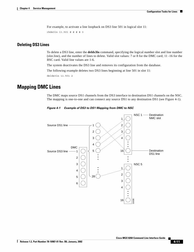
Chapter 4 Service ManagementConfiguration Tasks for Lines
For example, to activate a line loopback on DS3 line 501 in logical slot 11:chds3ln 11.501 # # # # 3
Deleting DS3 Lines
To delete a DS3 line, enter the delds3ln command, specifying the logical number slot and line number (slot.line), and the number of lines to delete. Valid slot values: 7 or 8 for the DMC card; 11 -16 for the BSC card. Valid line values are 1-6.
The system deactivates the DS3 line and removes its configuration from the database.
The following example deletes two DS3 lines beginning at line 501 in slot 11:delds3ln 11.501 2
Mapping DMC LinesThe DMC maps source DS1 channels from the DS3 interface to destination DS1 channels on the NSC. The mapping is one-to-one and can connect any source DS1 to any destination DS1 (see Figure 4-1).
Figure 4-1 Example of DS3 to DS1 Mapping from DMC to NSC
3193
8
1DMC
NSC 1 DestinationNMC slot
DestinationDS1 line
Source DS3 line
Source DS1 line
2
3
4
5
6
1
2
3
4
16
1
2
3
4
5
28
NSC 51
2
3
4
16
4-11Cisco MGX 8260 Command Line Interface Guide
Release 1.2, Part Number 78-10987-01 Rev. B0, January, 2002

Chapter 4 Service ManagementConfiguration Tasks for Lines
A single DS3 can map to multiple NSCs or multiple DS3s can map to a single NSC. Map definitions can be organized or arbitrary, but often occur in contiguous groups because you can define a range of mappings with a single command. The MGX 8260 Media Gateway stores map definitions in a map table, as follows:
You can initialize or alter the map table from any of the management interfaces or from the command line. This section describes how to add, change, or delete entries from the command line.
Adding Map Table Entries
You can add map entries individually or within a range. When adding individual map entries, the following restrictions apply:
• Map commands can’t duplicate existing entries.
• Map commands can’t specify non-existent source or destination lines. For information on adding lines, see the “Configuring DS1 or E1 Lines” section on page 4-3 and the “Configuring DS3 Lines” section on page 4-8.
You simplify the process of mapping DS3 to DS1 lines by mapping a range of DS1s rather than individual lines. A map range is added in a sequential and contiguous manner, and can cross either source or destination boundaries.
The entire range of source and destination lines must be contiguous. The system stops mapping lines if it encounters a source or destination that is already assigned, leaving map pairs before the contiguous break assigned and the rest unassigned.
To add map table entries, enter the addm13 command as described in the “addm13” section on page 9-21.
For example, in an MGX 8260 Media Gateway without any existing mapping, specify the maximum number of mappings as follows:addm13 1 1 1 1 168
To add three map entries, enter the following command:addm13 1 3 1 1 3
This example creates the following map table:
Table 4-1 DMC Map Table
Source DS3 Line Source DS1 Line Destination NSC Slot Destination DS1 Line
1 1 1 16
1 2 1 1
1 3 1 2
1 4 1 3
1 28 5 1
Table 4-2 DMC Map Table for the addm13 Command
Source DS3 Line Source DS1 Line Destination NSC Slot Destination DS1 Line
1 3 1 1
4-12Cisco MGX 8260 Command Line Interface Guide
Release 1.2, Part Number 78-10987-01 Rev. B0, January, 2002

Chapter 4 Service ManagementConfiguration Tasks for Lines
Changing Map Tables
You change map table entries one at a time. A change removes an existing mapping and replaces it with a map between the old source and new destination. To apply a change, the following must be true:
• The command must specify an existing map pair.
• The new destination must be unassigned.
Changing a map entry interrupts service to a large number of subscribers. Perform this task on inactive lines or during light traffic periods.
To change an existing map entry, enter the chm13 command. For example the following command sequence adds three map table entries and then changes one of them:addm13 1 3 1 1 3chm13 1 3 1 4
The example creates the following map table:
Deleting Map Table Entries
You can delete map table entries individually or in a range. When deleting a range of entries, the entire number of source and destination lines should be contiguous. The system stops deleting lines if it encounters a break in source range, deleting only those lines before the break.
Deleting map entries discontinues or interrupts service to a large number of subscribers. Perform this task only on lines that are out of service.
To delete map table entries, enter the delm13 command. The following example deletes three sequential map table entries, starting at DS3 line 1, DS1 line 1:delm13 1 1 3
Viewing Map Tables
You can view the map table for the system as a whole or for individual source DS1 lines.
To view map tables for a single source DS1, enter the lsm13 command, specifying the number of the source DS3 line and number of the DS1 line within the DS3 line. Valid entries are 1 through 6 for the DS3 and 1 through 28 for the DS1.The system lists map table entries for the specified line.
1 4 1 2
1 5 1 3
Table 4-2 DMC Map Table for the addm13 Command (continued)
Source DS3 Line Source DS1 Line Destination NSC Slot Destination DS1 Line
Table 4-3 DMC Map Table for the Modified addm13 Command
Source DS3 Line Source DS1 Line Destination NSC Slot Destination DS1 Line
1 3 1 4
1 4 1 2
1 5 1 3
4-13Cisco MGX 8260 Command Line Interface Guide
Release 1.2, Part Number 78-10987-01 Rev. B0, January, 2002

Chapter 4 Service ManagementConfiguration Tasks for Lines
To view all DS3 to DS1 mappings, enter the lsm13s command. The system lists all map table entries:================================================================== DMC T3-T1 Mapping Entries (lsm13s)================================================================== Src T3 Line Src T1 Line Dst Slot Dst T1 Line============= ============= ============= ================ 1 3 1 1 1 4 1 4 1 5 1 3
Configuring Fast Ethernet LinesThe SCC has four Fast Ethernet lines. This section explains how to configure and manage these lines.
Viewing Fast Ethernet Configuration and Status
To view information for a single Fast Ethernet line, enter the lsethln command, specifying the slot and line number of the SCC (slot.line).
The system displays detail information for the Fast Ethernet:======================================================================= Ether Line Entry (lsethln)=======================================================================Ether Line : 9.1MAC Address : 00.00.00.00.00.20IP Address : 10.15.26.98Subnet Mask : 255.255.255.0Primary Gateway : 10.15.26.1Router Discovery Protocol: enabledTarget State : activeOperational Status : activeDuplex Mode : full
Displayed Information Description
Ether Line The slot number and line number of the Fast Ethernet
MAC Addr The physical address of the line
IP Addr The IP address for this host
Subnet Mask The IP subnet mask for this host
Primary Gateway The primary gateway for this line
RDP The Router Discovery Protocol status
• disabled
• enabled
Target State The desired line state:
• active
• inactive
4-14Cisco MGX 8260 Command Line Interface Guide
Release 1.2, Part Number 78-10987-01 Rev. B0, January, 2002

Chapter 4 Service ManagementConfiguration Tasks for Lines
To view the information for all Fast Ethernet lines, enter the lsethlns command. The system lists summary information for all Fast Ethernet lines:======================================================================= Ether Lines (lsethlns)======================================================================= Line IP Address Subnet Mask Status Gateway Addr====== =============== =============== ================ =============== 9.1 10.15.26.97 255.255.255.0 active 10.15.26.1 9.2 10.15.26.98 255.255.255.0 active 10.15.26.1 9.3 10.15.26.99 255.255.255.0 active 10.15.26.1
Adding a Fast Ethernet Line
To add a Fast Ethernet line, follow these steps:
Step 1 Enter the addethln command as described in the “addethln” section on page 9-18.
Operational Status The operational status for the line:
• active
• inactive
• failed
• link down in active state
• link down in inactive state
Duplex Mode The duplex mode for this line
• full
• half
Displayed Information Description
Displayed Information Description
Line The slot and line number for the Fast Ethernet line
IP Address The IP address for the Fast Ethernet line
Subnet Mask The IP address mask for the Fast Ethernet line
Status The operational status for the line:
• active
• inactive
• failed
• link down in active state
• link down in inactive state
Gateway Addr The primary IP gateway for this line
4-15Cisco MGX 8260 Command Line Interface Guide
Release 1.2, Part Number 78-10987-01 Rev. B0, January, 2002

Chapter 4 Service ManagementConfiguration Tasks for Lines
The following example adds a Fast Ethernet line to slot 9 line 2 with an IP address of 10.15.26.98, a gateway of 10.15.26.1, a target state of active, RDP disabled, a subnet mask of 255.255.255.0, and full duplex mode:addethln 9.2 10.15.26.98 10.15.26.1 1 1 255.255.255.0 2
Step 2 Add other Fast Ethernet lines, as necessary.
Step 3 Verify the configuration using the lsethlns command.
The system displays the line configuration.
Changing a Fast Ethernet Line
Warning Changing a Fast Ethernet line interrupts service to a large number of users. Perform this operation during light traffic periods or in a pre-arranged maintenance window.
To change the configuration of a Fast Ethernet line, enter the chethln command as described in the “chethln” section on page 9-70. For example, the following command enables RDP but leaves other parameters unchanged on Fast Ethernet line 1 in slot 9:chethln 9.1 # 2
The system enables RDP on the specified line.
Deleting Fast Ethernet Lines
To delete Fast Ethernet lines, enter the delethln command, specifying the slot and line number of the SCC. Valid values for the slot number of the SCC are either 9 or 10. Valid values for the Fast Ethernet line is a number from 1 to 4.
The following example deletes Fast Ethernet line 1 in slot 9:delethln 9.1
Setting the Fast Ethernet Administrative Status
To enable a Fast Ethernet, enter the upethln command, specifying the slot and line number of the SCC (slot.line). The system enables the Ethernet line. The corresponding front panel ACT LED changes to green.
The following example enables Fast Ethernet line 1 in slot 9:upethln 9.1
To disable the a Fast Ethernet, enter the dnethln command, specifying the slot and line number of the SCC (slot.line). The system disables the Ethernet line. The corresponding front panel ACT LED changes to red.
The following example disables Fast Ethernet line 1 in slot 9:dnethln 9.1
4-16Cisco MGX 8260 Command Line Interface Guide
Release 1.2, Part Number 78-10987-01 Rev. B0, January, 2002

Chapter 4 Service ManagementConfiguration Tasks for Lines
Configuring Static RoutesYou can configure static routes for the MGX 8260 routing table. These routes apply to lines that utilize an IP network. You can configure static routes for empty slots or non-existing lines, but the changes have no effect without the necessary hardware.
Adding Static Routes
To add a static route, enter the addsrt command, as described in the “addsrt” section on page 9-30. The system adds the static route to the routing table.
Deleting Static Routes
To delete a static route, enter the delsrt command, specifying the IP address of the static route you want to delete and the slot and line number (slot.line) for the static route interface. The system deletes the static route from the routing table.
Viewing Static Routes
To view a specific static route, enter the lssrt command, specifying the IP address of the static route and the slot and line number (slot.line) for the static route interface. The system displays the static route information:======================================================================= Static Route Entry (lssrt)======================================================================= Dest IP Addr :10.15.26.0 Interface(Slot.Line) :9.1 Priority :1
To view all static routes, enter the lssrts command. The system displays all static routes:======================================================================= Static Route Entries (lssrts)======================================================================= Destination IP Address Interface (Slot.Line) Priority========================== ============================= ============ 127.2.4 9.1 1 127.2.4 9.2 2
Displayed Information Description
Destination IP Address The IP address of the static route
Interface Slot and line number for the static route interface
Route Priority Priority for the static route
4-17Cisco MGX 8260 Command Line Interface Guide
Release 1.2, Part Number 78-10987-01 Rev. B0, January, 2002

Chapter 4 Service ManagementConfiguration Tasks for Lines
Configuring OC-3 LinesThe OC-3 SCC and back card supports four OC-3 lines. This section explains how to configure and manage these lines.
Multi-chassis Considerations
In a multi-chassis application, each MGX8260 needs a common reference clock for all TDM lines. You can accomplish this by synchronizing the clocks of each chassis to the common ATM switch clock (See Figure 4-2).
Figure 4-2 Multi-chassis Timing
To synchronize clocks, follow these steps:
Step 1 Set the primary clock source for each chassis to an OC-3 line. Use the chpcklsrc command for this purpose.
Step 2 Set the clock source for DS3 and DS1 lines to local using the chds3ln or chds1ln commands. This is the default configuration for these lines.
Viewing OC-3 Configuration and Status
To view information for a single OC-3 line, enter the lssonetln command, specifying the slot and line number of the SCC (slot.line).
M...
MGX 8850
MGX 8260
M
MGX 8260
OC-3 OC-347
016
4-18Cisco MGX 8260 Command Line Interface Guide
Release 1.2, Part Number 78-10987-01 Rev. B0, January, 2002

Chapter 4 Service ManagementConfiguration Tasks for Lines
The system displays detail information for the SONET line:======================================================================= Sonet Line Entry (lssonetln)=======================================================================Sonet Line : 9.2Medium Type : sonetTime Elapsed in Interval : 12Line Valid Intervals : 0Line Coding : sonetMediumNRZLine Type : sonetMultiModeCircuit Identifier : PMC-PM5351-S/UNI-TETRA ver.0x00Admin Status : upLine Status(1) : 5402aLine Status(2) : 10Interface Type : oc3Frame Type : sts3cLoopback State : sonetNoLoopHCS masking : disablePayload Scrambling : enableFrame Scrambling : enableTransmit Clock Source : localTimingSupport Path ERDI : disable
Displayed Information Description
Sonet Line The slot and line number, expressed as slot.line
Medium Type The physical medium, either SONET or SDH
Time Elapsed in Interval The elapsed time of the current error-measurement period, expressed in seconds
Line Valid Intervals The number of prior intervals for which valid data was stored
Line Coding The data coding scheme this line, always NRZ.
Line Type The type of optical fiber, either single or multi-mode depending on the back card installed
Circuit Identifier The transmission vendor’s circuit identifier
Admin Status The administrative status for the line, always Up
4-19Cisco MGX 8260 Command Line Interface Guide
Release 1.2, Part Number 78-10987-01 Rev. B0, January, 2002

Chapter 4 Service ManagementConfiguration Tasks for Lines
Line Status(1) The line status, expressed as a bitmap:
Bit 0: No defect present
Bit 1: Section LOS (Loss of Signal)
Bit 2: Section LOF (Loss of frame)
Bit 3: Line AIS (Alarm Indication Signal)
Bit 4: Line RDI (Remote Defect Indication)
Bit 5: Path AIS
Bit 6: Path LOP (Loss of Pointer)
Bit 7: Path UEQ (idle)
Bit 8: Path TIM (Trace Identifier Mismatch)
Bit 9: Path SLM
Bit 10: Path RDI
Bit 11: Path ERDI server defect
Bit 12: Path ERDI connectivity defect
Bit 13: Path ERDI payload defect
Bit 14: Performance failure LOS
Bit 15: Performance failure, section LOF
Bit 16: Performance failure, line AIS
Bit 17: Performance failure, line RFI
Bit 18: Performance failure, path AIS
Bit 19: Performance failure, path LOP
Bit 20: Performance failure, path UEQ
Bit 21: Performance failure, path TIM
Bit 22: Performance failure, path SLM
Bit 23: Path ERDI server failure
Bit 24: Path ERDI connectivity failure
Bit 25: Path ERDI payload failure
Bit 26: Performance failure, path RFI
Bit 27: Line loopback (remote loop)
Bit 28: Serial loopback (local loop)
Bit 29: Parallel loopback (local loop)
Displayed Information Description
4-20Cisco MGX 8260 Command Line Interface Guide
Release 1.2, Part Number 78-10987-01 Rev. B0, January, 2002

Chapter 4 Service ManagementConfiguration Tasks for Lines
To view the information for all OC-3 lines, enter the lssonetlns command. The system lists summary information for all OC-3 lines:======================================================================= Sonet Lines (lssonetlns)=======================================================================Slot.Line Interface Type Frame Type Admin Status Line Status(2)========= ============ =========== =========== ========== 9.1 oc3 sts1 up 10 9.2 oc3 sts3c up 10
For a description of the information, see the previous table.
Line Status(2) The LED status, expressed as a bitmap:
Bit 0: Solid green
Bit 1: Blinking green
Bit 2: Solid yellow
Bit 3: Blinking yellow
Bit 4: Red
Interface Type The type of interface, either OC3 or STM-1
Frame Type The type of framing, either STS-3c or STS-1
Loopback State The loopback state:
• No loop
• Line loop
• Serial loop
• Parallel loop
HCS Masking The HCS masking state (reserved for future use)
Payload Scrambling The payload scrambling state, either enabled or disabled
Frame Scrambling The frame scrambling state, either enabled or disabled
Transmit Clock Source The clock source for the transmit signal, either loop or local timing
Support Path E-RDI The support path for enhanced remote defect indicator, either enabled or disabled
Displayed Information Description
4-21Cisco MGX 8260 Command Line Interface Guide
Release 1.2, Part Number 78-10987-01 Rev. B0, January, 2002
Chapter 4 Service ManagementConfiguration Tasks for Lines
Adding OC-3 Lines
To add OC-3 lines, follow these steps:
Step 1 Add one or more lines using the addsonetln command. Optionally, customize the line using the command line arguments. See the “addsonetln” section on page 9-28.
The following example adds one line to slot 9 line 1 with default parameters:addsonetln 9.1
Step 2 Verify the configuration using the lssonetln command.
Changing OC-3 Lines
Warning Changing an OC-3 line interrupts service to a large number of users. Perform this operation during light traffic periods or in a pre-arranged maintenance window.
To change OC-3 lines, follow these steps:
Step 1 Change SONET lines using the chsonetln command, specifying the parameters to change. See the “chsonetln” section on page 9-121.
For example, the following command enables Payload Scrambling but leaves other parameters unchanged on OC-3 line 1 in slot 9:chsonetln 9.1 # # # # # 2
Step 2 Verify the configuration using the lssonetln command.
Deleting OC-3 Lines
To delete OC-3 lines, enter the delsonetln command, specifying the slot and line number of the SCC. Valid values for the slot number of the SCC are either 9 or 10. Valid values for the OC-3 line is a number from 1 to 4.
The following example deletes OC-3 line 1 in slot 9:delsonetln 9.1
Viewing E-RDI Configuration and Status
To view E-RDI (Extended Remote Defect Indicator) information for a single OC-3 line, enter the lssonetlnerdi command, specifying the slot and line number of the SCC (slot.line).
4-22Cisco MGX 8260 Command Line Interface Guide
Release 1.2, Part Number 78-10987-01 Rev. B0, January, 2002

Chapter 4 Service ManagementConfiguration Tasks for Lines
The system displays detail E-RDI information for the line:======================================================================= Sonet Line Entry (lssonetlnerdi)=======================================================================Sonet Line : 9.1Support Path ERDI : disableTransmitted Path Signal Label : 19Expected Received Path Signal Label : 19Received Path Signal Label : 0Transmit PTID Length : 64Transmit PTID Sync. pos. : 0Transmit ID - 0 0 0 0 0 0 0 0 0 0 0 0 0 0 0 0 0 0 0 0 0 0 0 0 0 0 0 0 0 0 0 0 0 0 0 0 0 0 0 0 0 0 0 0 0 0 0 0 0 0 0 0 0 0 0 0 0 0 0 0 0 0 d aExpected Received PTID Length : 64Expected Received PTID Sync. pos. : 0Expected ID - 0 0 0 0 0 0 0 0 0 0 0 0 0 0 0 0 0 0 0 0 0 0 0 0 0 0 0 0 0 0 0 0 0 0 0 0 0 0 0 0 0 0 0 0 0 0 0 0 0 0 0 0 0 0 0 0 0 0 0 0 0 0 d aReceived ID - 2020202020202020202020202020202020202020202020202020202020202020 202020202020202020202020202020202020202020202020202020202020 d a
Displayed Information Description
Sonet Line The slot and line number, expressed as slot.line
Support Path ERDI The state of the enhanced remote defect indication for the SONET path, either disabled or enabled
Transmitted Path Signal Label The signal label to transmit in the SONET path overhead:
• No specific payload type
• ATM
• Packet on SONET
Expected Received Path Signal Label The expected signal label from the SONET path overhead:
• No specific payload type
• ATM
• Packet on SONET
Received Path Signal Label The actual label received
Transmit PTID Length The message length for the trace identifier:
• 16 bytes (SDH only)
• 64 bytes (SONET or SDH)
Transmit PTID Sync. pos. The position within a 16-byte message of the synchronization byte
Transmit ID The trace identifier to transmit in the SONET path overhead
4-23Cisco MGX 8260 Command Line Interface Guide
Release 1.2, Part Number 78-10987-01 Rev. B0, January, 2002

Chapter 4 Service ManagementConfiguration Tasks for Lines
To view the information for all OC-3 lines, enter the lssonetlnerdis command. The system lists summary E-RDI information for all OC-3 lines:======================================================================= Sonet Lines (lssonetlnerdis)=======================================================================Slot.Line Support Path SRDI================= ================= 9.1 disable 9.2 disable
For a description of the information, see the previous table.
Understanding E-RDI and Trace Parameters
Path and trace labels help identify particular SONET line. The trace label is a text string carried in a 16-byte or 32-byte message carried in the SONET overhead. The system alters or reserves some of the bytes for synchronization or other purposes.
Using 16-Byte Messages
When using 16-byte messages, consider the following points:
• This message length only applies to SDH
• The system sets the most significant bit high of one byte for synchronization purposes. The position of the altered byte in the message is defined by the trace id position parameter.
• Any printable or non-printable ASCII character is valid (00-7F hex).
• The system always sends 16 characters. If the user input is less than 16 characters, the system pads the message with null characters (00 hex).
Using 64-Byte Messages
• The user can define a message of up to 62 bytes in length; the system automatically sets the last two characters to a carriage return (OD hex) and line feed (OA hex).
• Any printable or non-printable ASCII character is valid (00-7F hex)
• The system always sends 64 characters. If the user input is less than 62 characters, the system pads the message with null characters and then adds the carriage return and line feed.
Expected Received PTID Length The expected trace identifier length for the SONET path:
• 16 bytes (SDH only)
• 64 bytes (SONET or SDH)
Expected Received Ptid Sync. pos. The position within a 16-byte message of the synchronization byte
Expected ID The expected trace identifier in the SONET path overhead
Received ID The actual trace identifier received
Displayed Information Description
4-24Cisco MGX 8260 Command Line Interface Guide
Release 1.2, Part Number 78-10987-01 Rev. B0, January, 2002

Chapter 4 Service ManagementConfiguration Tasks for Lines
Forming Hex Messages
You use two hexidecimal numbers to represent each ASCII character in a trace message. For example, you represent an ASCII space with the hex pair 20. The following table shows a few additional examples.
For 16-byte msg, the maximum input string size is 32 hex characters. For a64-byte message, you can specify up to 62 characters for a total of 124 hex characters. Refer to the following conversion table to map hex pairs to ASCII characters.
The system takes the following actions on error on bad hex strings:
• If you specify an odd number of hex characters, the last one is discarded.
• If you specify a single hex character, the process aborts with an error message.
• If the first hex number of a pair is not 0 to 7, the process aborts with an error message.
• If the second hex number of a pair is not 0 to F, the process aborts with an error message.
Trace Message Hex String
4 34
Hello World 48656c6c6f20576f726c64
Table 4-1 Hex to ASCII Conversion Table
00 NUL 01 SOH 02 STX 03 ETX 04 EOT 05 ENQ 06 ACK 07 BEL
08 BS 09 HT 0A NL 0B VT 0C NP 0D CR 0E SO 0F SI
10 DLE 11 DC1 12 DC2 13 DC3 14 DC4 15 NAK 16 SYN 17 ETB
18 CAN 19 EM 1A SUB 1B ESC 1C FS 1D GS 1E RS 1F US
20 SP 21 ! 22 dq 23 # 24 $ 25 % 26 & 27 '
28 ( 29 ) 2A * 2B + 2C , 2D - 2E . 2F /
30 0 31 1 32 2 33 3 34 4 35 5 36 6 37 7
38 8 39 9 3A : 3B ; 3C < 3D = 3E > 3F ?
40 @ 41 A 42 B 43 C 44 D 45 E 46 F 47 G
48 H 49 I 4A J 4B K 4C L 4D M 4E N 4F O
50 P 51 Q 52 R 53 S 54 T 55 U 56 V 57 W
58 X 59 Y 5A Z 5B [ 5C \ 5D ] 5E ^ 5F _
60 ` 61 a 62 b 63 c 64 d 65 e 66 f 67 g
68 h 69 i 6A j 6B k 6C l 6D m 6E n 6F o
70 p 71 q 72 r 73 s 74 t 75 u 76 v 77 w
78 x 79 y 7A z 7B { 7C | 7D } 7E ~ 7F DEL
4-25Cisco MGX 8260 Command Line Interface Guide
Release 1.2, Part Number 78-10987-01 Rev. B0, January, 2002

Chapter 4 Service ManagementConfiguration Tasks for Ports
Configuring E-RDI and SONET Trace
To change E-RDI parameters, follow these steps:
Step 1 Change extended rdi parameters for SONET lines using the chsonetperdi command, specifying the location and E-RDI parameters. See the “chsonetperdi” section on page 9-123.
Step 2 Change path trace parameters for SONET lines using the chsonettrace command, specifying the location and path trace parameters. See the “chsonettrace” section on page 9-125.
Step 3 Change expected path trace parameters for SONET lines using the chsonetexptrace command, specifying the location and path trace parameters. See the “chsonetexptrace” section on page 9-119.
Configuration Tasks for PortsSee the following sections for port configuration tasks.
• Configuring Voice Ports
• Viewing All Ports
Configuring Voice Ports Voice ports use voice over IP or ATM. The MGX 8260 Media Gateway identifies a voice port by a logical port number that is independent of the port’s physical location. The following parameters describe the physical location:
• Slot number
• Port number
• DS0 number
When you add or change a voice port, you associate a logical port number with these physical descriptors.
Adding Voice Ports
To add a voice port, enter the addvport command as described in the “addvport” section on page 9-38. For example, to add logical voice port 4 using DS0 4 of DS1 line 1 in slot 13, type the following command:addvport 13 4 1 4 1
4-26Cisco MGX 8260 Command Line Interface Guide
Release 1.2, Part Number 78-10987-01 Rev. B0, January, 2002

Chapter 4 Service ManagementConfiguration Tasks for Ports
Changing Voice Ports
You can change any of the optional parameters for an existing port. To change a voice port, use the chvport command, specifying the same parameters as required to add a voice port. For example, to change the echo tail while leaving other parameters unchanged, type the following command:
chvport 13 1 # # # # # 2
The system changes the echo tail for logical port 1 in slot 13 to tail24ms.
Deleting Voice Ports
To delete a voice port, enter the delvport command, specifying the logical slot number of an NSC and the logical port number for an existing voice port. For example, this command deletes port 4 of slot 13.delvport 13 4
Viewing Voice Port Configuration and Status
To view the information for a single voice port, enter the lsvport command, specifying the logical slot number of an NSC and the logical port number for an existing voice port. The system displays detailed information for the port:======================================================================= Voice Port Entry (lsvport)=======================================================================Slot : 13Port : 1Line Number : 1Ds0 Time Slot : 1Operating Status : idleDynamic Dejitter (enabled/diabled) : enabledInitial Dynamic Dejitter Size (x10 msecs) : 1Maximum Dynamic Dejitter Size (x10 msecs) : 50Minimum Dynamic Dejitter Size (x10 msecs) : 1Packet Loading Time (x10 msec) : 1Echo Path Tail (msec) : tail64ms
Displayed Information Description
Slot The logical slot number of the NSC associated with the port
Port The logical port number assigned to the port
Line Number The number of the DS1/E1 line associated with the DS0 voice line
DS0 Time Slot The number of the DS0 channel for the voice port
Oper Status The operating status of the voice port:
• idle
• loopback
• blocked
• disabled
Dynamic Dejitter The status of the dejitter buffer, either enabled or disabled
4-27Cisco MGX 8260 Command Line Interface Guide
Release 1.2, Part Number 78-10987-01 Rev. B0, January, 2002

Chapter 4 Service ManagementConfiguration Tasks for Ports
To list the information for all voice ports, enter the lsvports command.
The system displays the voice port settings:======================================================================= Voice Port Entries (lsvports)=======================================================================Slot Port Line Ds0 Oper Status Dejitter Buffer Pkt Load Echo Tail==== ==== ==== === =========== =============== ======== ========= 13 1 1 1 idle enabled 1 tail64ms 13 2 1 2 idle enabled 1 tail64ms 13 3 1 3 idle enabled 1 tail64ms 13 4 1 4 idle disabled 1 tail64ms
Checking All MGX 8260 portsYou can view all existing MGX 8260 ports in a single report. From this report, you see a list of ports and their slot, line, type, and DS0. Based on the line type, you proceed with port-specific commands to configure the port or obtain more information.
Initial Dynamic Dejitter Size The initial length of the dejitter buffer, specified in multiples of 10 msec.
Maximum Dynamic Dejitter Size The maximum length of the dejitter buffer, specified in multiples of 10 msec.
Minimum Dynamic Dejitter Size The minimum length of the dejitter buffer, specified in multiples of 10 msec.
Packet Loading Time The IP packet loading time for voice service, expressed in multiples of 10 msec.
Echo Path Tail The length of the echo cancel tail
Displayed Information Description
Displayed Information Description
Slot The logical slot number of the NSC associated with the port
Port The logical port number assigned to the port
Line The number of the DS1/E1 line associated with the DS0 voice line
DS0 The number of the DS0 channel for the voice port
Oper Status The operating status of the voice port
Dejitter Buffer The status of the dejitter buffer, either enabled or disabled
Pkt Load The IP packet loading time for voice service, expressed in multiples of 10 msec.
EchoTail The length of the echo cancel tail
4-28Cisco MGX 8260 Command Line Interface Guide
Release 1.2, Part Number 78-10987-01 Rev. B0, January, 2002

Chapter 4 Service ManagementViewing Active Calls
To view all ports, enter the lsports command. The system lists all ports:======================================================================= Common Port Entries (lsports)======================================================================= Slot Port Line Port Type Ds0 Bit Map============ ====== =============== =============================== 6 1 1 voice 1 6 2 1 voice 2 6 3 1 voice 4 6 4 1 voice 8
Viewing Active CallsYou view call activity and statistics by physical resource or transaction. These screens provide read-only information that is useful for audits or trouble analysis.
Viewing Calls by Slot/Line/PortTo view call information for a physical resource, enter the lsacp command, specifying the slot, line and DS0.
The system displays detail information for the active call:======================================================================= Active Call Entry (lsacp) by source=======================================================================TransactionIDCallIDSource Slot numberSource Line numberSource Ds0Source Logical Port numberDestination Slot numberDestination Line numberDestination Ds0Destination Logical Port numberNumber packets transmittedNumber packets receivedNumber packets droppedNumber of bytes transmittedNumber of bytes receivedNumber of bytes droppedCall Type: (voip/tdm)
Displayed Information Description
Slot The slot hosting the port
Port The common logical port number
Line The common physical line number for this port
Port Type The port type—voice for this release
DS0 Bit Map Common DS0 bit map for this port
4-29Cisco MGX 8260 Command Line Interface Guide
Release 1.2, Part Number 78-10987-01 Rev. B0, January, 2002

Chapter 4 Service ManagementViewing Active Calls
To view all active calls by resource, enter the lsacps command. The system displays summary call information:======================================================================= Active Call Entries (lsacps) based on source=======================================================================Src Slot Src Line Src Ds0 LogPort Type Pkts Rcd Pkts Txm======== ======== ======= ======= ==== ======== ========
Displayed Information Description
TransactionID The transaction identifier for the active call. Only the backend platform software uses this number
CallID An identifier for the active call.
Source Slot number The slot number for the active call source. The slot, line, and DS0 numbers uniquely define a call while it is active.
Source Line number The line number for the active call source.
Source Ds0 The DS0 number for the active call source.
Source Logical Port number The logical port number for the active call source.
Destination Slot number The slot number for the active call destination.
Destination Line number The line number for the active call destination.
Destination Ds0 The DS0 number for the active call destination.
Destination Logical Port number The logical port number for the active call destination.
Number packets transmitted The number of packets transmitted since call setup.
Number packets received The number of packets received since call setup.
Number packets dropped The number of packets dropped since call setup.
Number of bytes transmitted The number of bytes transmitted since call setup.
Number of bytes received The number of bytes received since call setup.
Number of bytes dropped The number of bytes dropped since call setup.
Call Type: (voip/tdm) A value that identifies the call type:
1: Voice over IP.
2: Time division multiplex.
4-30Cisco MGX 8260 Command Line Interface Guide
Release 1.2, Part Number 78-10987-01 Rev. B0, January, 2002

Chapter 4 Service ManagementAbout the Announcement Service
Viewing Calls by TransactionTo view call information for a specific transaction, enter the lsact command. The system displays detailed information for the call:======================================================================= Active Call Entry (lsact)=======================================================================TransactionIDCallIDSource Slot numberSource Line numberSource Ds0Source Logical Port numberDestination Slot numberDestination Line numberDestination Ds0Destination Logical Port numberNumber packets transmittedNumber packets receivedNumber packets droppedNumber of bytes transmittedNumber of bytes receivedNumber of bytes droppedCall Type: (voip/tdm)
To view all active calls by transaction, enter the lsacts command. The system displays summary information for active calls:======================================================================= Active Call Entries (lsacts) based on Transaction=======================================================================Xtrn Src Slot Src Line Src Ds0 LogPort Type Pkts Rcd Pkts Txd====== ======== ======== ======= ======= ==== ======== =======
About the Announcement ServiceThe MGX 8260 Media Gateway can store and play announcement messages when configured for the IPDC call control protocol. This service is useful when informing callers about a telephone number change or other voice messages. The system can store up to 100 announcement files, with a total play duration of 30 minutes.
File EncodingThe MGX 8260 Media Gateway supports the following encoding formats:
• G.711—A law and mu law
• G.726
4-31Cisco MGX 8260 Command Line Interface Guide
Release 1.2, Part Number 78-10987-01 Rev. B0, January, 2002

Chapter 4 Service ManagementConfiguration Tasks for Announcement Services
File TypesThe MGX 8260 Media Gateway supports the following file types:
• .au
• .wav
File NamesThe Announcement Service uses a file identifier that it learns from the name you assign. Construct the file name as follows:fileName_ID.ext
The file name is the alphanumeric string before the underscore and the file identifier is the number after the underscore. The id is a number from 1 to 100 and the file extension is either au or wav. The file name can contain up to 20 characters total.
Configuration Tasks for Announcement ServicesSee the following sections for Announcement Service configuration:
• Adding and Activating an Announcement
• Deactivating and Removing an Announcement
• Viewing Announcement Files
Adding and Activating an AnnouncementTo add and activate an announcement, follow this procedure:
Step 1 Download the announcement message using tftp.tftp ipAddressbinput sourceFile announceFile
Step 2 Activate the message using the acannfile command, identifying the file by ID rather than by name. You can view file IDs using the lsannfiles command.
Step 3 The system copies the file from the download location on the SCC to all NSCs in the chassis.
4-32Cisco MGX 8260 Command Line Interface Guide
Release 1.2, Part Number 78-10987-01 Rev. B0, January, 2002

Chapter 4 Service ManagementConfiguration Tasks for Announcement Services
Deactivating and Removing an AnnouncementTo deactivate and remove an announcement, follow this procedure.
Step 1 Deactivate the file using the deacannfile command, specifying the file ID. You can view file IDs using the lsannfiles command.
Step 2 Optionally, remove the file using the rmannfile command, specifying the file ID. Since the system has limited file capacity, you should remove announcements you no longer plan to use.
Viewing Announcement FilesTo view details about a single file, use the lsannfile command. Specify the file ID for which you want information.
The system displays the following information:========================================================= Announcement File (lsannfile) =========================================================File ID : 1 File Name : greeting.wav File State : inactive File Length(byte) : 80000 File Duration(second) : 10 File Encoding : g711mulaw
To view summary information about all files, use the lsannfiles command.
The system displays the following information:================================================== Announcement Files (lsannfiles) ==================================================File ID File Name File State ====== ====================== =============== 1 greeting.wav inactive 2 hello.au active
To interpret the columns, refer to the previous procedure for lsannfile.
Displayed Information Description
File ID The numeric identifier of the file. The system extracted this number from the file name when it was downloaded.
File Name The name of the file on the SCC file system
File State The activation state of the announcement
File Length The file length, in bytes
File Duration The file duration, in seconds
File Encoding The file encoding, either g711mulaw, g726encoding, or g711alaw
4-33Cisco MGX 8260 Command Line Interface Guide
Release 1.2, Part Number 78-10987-01 Rev. B0, January, 2002

Chapter 4 Service ManagementConfiguration Tasks for Announcement Services
To view resource usage for announcement files, use the lsdurationif command. The system displays the following information:===================================================Duration Information of Ann. files (lsdurationif)===================================================Maximum Duration(second) : 1800Current Duration (second) : 90Available Duration (second) : 1710
Displayed Information Description
Maximum Duration The maximum available duration in seconds
Current Duration The duration used by existing announcements, in seconds
Available Duration The duration available for new announcements, in seconds
4-34Cisco MGX 8260 Command Line Interface Guide
Release 1.2, Part Number 78-10987-01 Rev. B0, January, 2002

Cisco MGX Release 1.2, Part Number 78-10987-01 Rev. B0, January, 2002
C H A P T E R 5
Call ControlThe MGX 8260 Media Gateway works in conjunction with Media Gateway Controller (MGC) servers and the Public Switched Telephone Network (PSTN) to control voice and data calls.
Primary Call Control ComponentsThe following components of the call control system are most important:
• Signal Transfer Point (STP)
STPs are components in the Signalling System 7 (SS7) network that route management traffic between Service Switching Points (SSPs) and Service Control Points (SCPs).
• Central Office (CO)
The CO provides telephony services to subscribers and handles the associated management traffic. The CO is often a SSP in the SS7 network.
• Media Gateway Controller (MGC)
An MGC, such as the VSC2700 Media Gateway Controller, communicates with the SS7 network and MGX 8260 Media Gateways to process multimedia calls. These communications links can use backhaul channels to adapt PSTN signaling to IP/ATM signaling.
• MGX 8260 Media Gateway
The MGX 8260 Media Gateway switches voice and data traffic between PSTN circuits and a packet backbone, and it works with PSTN signaling points for voice call control and with MGCs for multimedia call control. In addition, the MGX 8260 Media Gateway adapts PSTN signaling to IP/ATM signaling so the MGC can control PSTN calls directly.
Primary MGX 8260 Call Control InterfacesThe MGX 8260 Media Gateway communicates with other media and signaling equipment through the following interfaces:
• Integrated Services Digital Network (ISDN)
The MGX 8260 Media Gateway communicates with PSTN equipment using an ISDN (Integrated Services Digital Network) D Channel of a Primary Rate Interface ISDN trunk. Within the D Channel, multiple logical links may exist, which are defined by DLSAP and MACSAP profiles.
5-18260 Command Line Interface Guide
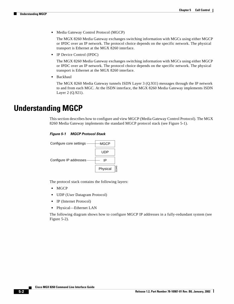
Chapter 5 Call ControlUnderstanding MGCP
• Media Gateway Control Protocol (MGCP)
The MGX 8260 Media Gateway exchanges switching information with MGCs using either MGCP or IPDC over an IP network. The protocol choice depends on the specific network. The physical transport is Ethernet at the MGX 8260 interface.
• IP Device Control (IPDC)
The MGX 8260 Media Gateway exchanges switching information with MGCs using either MGCP or IPDC over an IP network. The protocol choice depends on the specific network. The physical transport is Ethernet at the MGX 8260 interface.
• Backhaul
The MGX 8260 Media Gateway tunnels ISDN Layer 3 (Q.931) messages through the IP network to and from each MGC. At the ISDN interface, the MGX 8260 Media Gateway implements ISDN Layer 2 (Q.921).
Understanding MGCPThis section describes how to configure and view MGCP (Media Gateway Control Protocol). The MGX 8260 Media Gateway implements the standard MGCP protocol stack (see Figure 5-1).
Figure 5-1 MGCP Protocol Stack
The protocol stack contains the following layers:
• MGCP
• UDP (User Datagram Protocol)
• IP (Internet Protocol)
• Physical—Ethernet LAN
The following diagram shows how to configure MGCP IP addresses in a fully-redundant system (see Figure 5-2).
MGCPConfigure core settings
3194
5
IP
Physical
UDP
Configure IP addresses
5-2Cisco MGX 8260 Command Line Interface Guide
Release 1.2, Part Number 78-10987-01 Rev. B0, January, 2002

Chapter 5 Call ControlConfiguration Tasks for MGCP
Figure 5-2 MGCP Addresses and Ports
The minimal system consists of a primary MGC network, the MGX 8260 Media Gateway, and an IP network. You can add the secondary network and secondary MGC for more reliable operation.
Configuration Tasks for MGCPTo configure MGCP, you perform the following tasks:
• Switch from IPDC to MGCP
• Set IP addresses and ports
• Configure MGCP core parameters
• Configure default call setup parameters
• View MGCP configuration and status
Switching from IPDC to MGCPThe MGX 8260 Media Gateway supports two call control protocols, MGCP and IPDC. By default, MGCP is enabled and IPDC is disabled. This procedure explains how to switch back to MGCP from IPDC.
Warning Switching protocols interrupts service. Perform this operation during light traffic periods or in a pre-arranged maintenance window.
To switch protocols, follow these steps:
Step 1 Change the protocol type using the chprotocol command, specifying 1 for MGCP; then confirm your action. The system automatically reboots.
Step 2 After the chassis restarts, log in again.
M
PrimaryMGC
Primary MGCPaddress/port 1
Net 1
Net 2
Primary MGCPaddress/port 2
Local address 1primary/secondary/ports
Local address 2primary/secondary/ports
SecondaryMGC
Secondary MGCPaddress/port 1
Secondary MGCPaddress/port 2
3194
0
5-3Cisco MGX 8260 Command Line Interface Guide
Release 1.2, Part Number 78-10987-01 Rev. B0, January, 2002

Chapter 5 Call ControlConfiguration Tasks for MGCP
Step 3 Verify the change using the lsndinf command.
Configuring MGCP IP AddressesBefore beginning this procedure, obtain the IP addresses and ports that apply to your system. Make sure your IP and port selections do not conflict with other equipment on the networks.
Step 1 Set the local address and ports on network 1 using the chmgcplocaladdr1 command as described in the “chmgcplocaladdr1” section on page 9-97.
Step 2 If your system uses network redundancy, set the local address and ports for network 2 using the chmgcplocaladdr2 command.
Step 3 Set the primary media controller addresses and ports using the chpmgcpaddr command.
Step 4 If your system includes a redundant MGC, set the secondary media controller addresses and ports using the chsmgcpaddr command.
Step 5 Define the MGCP domain name using the chmgcpdname.
Step 6 Check your configuration using the lsmgcpdef command.
Configuring MGCP Core Parameters MGCP core settings enable and disable the protocol and control how it works.
To configure MGCP core parameters, follow these steps:
Step 1 Specify the desired parameters using the chmgcpcore command.
Step 2 Confirm the changes using the lsmgcp command.
Configuring MGCP Default Call Setup Parameters Call setup parameters define the default characteristics of a new call.
To configure default call setup parameters, follow these steps:
Step 1 Specify the default call setup parameters using the chmpc command.
Step 2 Confirm the changes using the lsmpc command.
5-4Cisco MGX 8260 Command Line Interface Guide
Release 1.2, Part Number 78-10987-01 Rev. B0, January, 2002

Chapter 5 Call ControlConfiguration Tasks for MGCP
Viewing MGCP SettingsYou can view the following MGCP information:
• IP addresses and connection status
• Voice settings
• Default call settings
• MGCP status
• Protocol statistics
To view MGCP IP settings, use the lsmgcpdef command.
The following information is displayed:=========================================================================Primary MGCP Address 1 : 10.15.26.1Primary MGCP UDP Port 1 : 2427Primary MGCP Address 2 : 10.15.27.1Primary MGCP UDP Port 2 : 2427Secondary MGCP Address 1 : 10.15.26.2Secondary MGCP UDP Port 1 : 2427Secondary MGCP Address 2 : 10.15.27.2Secondary MGCP UDP Port 2 : 2427Connection Status : unknownTime at which Connection Status changed : 02/12/2000 17:57:59Local Address 1 : 10.15.26.20Local Primary Port 1 : 2427Local Address 2 : 10.15.27.20Local Primary Port 2 : 2427MGCP domain name : mgx8260
Displayed Information Description
Primary MGCP Address 1 The IP address of the Primary Media Gateway Controller on network 1. Specify the IP address in standard dot notation.
Primary MGCP UDP Port 1 The UDP port of the Primary Media Gateway Controller on network 1.
Primary MGCP Address 2 The IP address of the Primary Media Gateway Controller on network 2. Specify the IP address in standard dot notation.
Primary MGCP UDP Port 2 The UDP port of the Primary Media Gateway Controller on network 2.
Secondary MGCP Address 1 The IP address of the Secondary Media Gateway Controller on network 1.
Secondary MGCP UDP Port 1 The UDP port of the Secondary Media Gateway Controller on network 1.
Secondary MGCP Address 2 The IP address of the Secondary Media Gateway Controller on network 2.
Secondary MGCP UDP Port 2 The UDP port of the Secondary Media Gateway Controller on network 2.
Connection Status The current status of the MGCP connection, as follows:
• unknown—undefined status
• connected—message is sent and response to it is received
• connecting—message is sent and waiting for response
• noSuchName—no domain name/IP address is found
• noResponse—timeout on message
Timestamp The time when the Connection Status last changed.
5-5Cisco MGX 8260 Command Line Interface Guide
Release 1.2, Part Number 78-10987-01 Rev. B0, January, 2002

Chapter 5 Call ControlConfiguration Tasks for MGCP
Viewing MGCP Voice Parameters
The MGX 8260 Media Gateway uses threshold levels to determine when to send alerts to the MGC. This command lists the current settings.
To view MGCP voice parameters, use the lsmgcpvoice command.============================================================= MGCP Voice parameters============================================================= Lower Bound for Packet Loss : Higher Bound for Packet Loss : Lower Bound for Jitter : Higher Bound for Jitter : Lower Bound for Latency : Higher Bound for Latency :
Local Address 1 The IP address of the MGX 8260 interface for network 1. This address is on the same subnet as the Primary MGCP IP Address.
Local Primary Port 1 The primary UDP port of the MGX 8260 interface for network 1.
Local Address 2 The IP address of the MGX 8260 interface for network 2. This address is on the same subnet as the Primary MGCP IP Address.
Local Primary Port 2 The primary UDP port of the MGX 8260 interface for network 2.
Displayed Information Description
Displayed Information Description
Lower Bound for Packet Loss The packet loss level that enables an alert.
Higher Bound for Packet Loss The packet loss level that triggers an alert message. Once triggered, alert messages are disabled until the level drops below the lower bound.
Lower Bound for Jitter The jitter level that enables an alert.
Higher Bound for Jitter The jitter level that triggers an alert message. Once triggered, alert messages are disabled until the level drops below the lower bound.
Lower Bound for Latency The latency level that enables an alert.
Higher Bound for Latency The latency level that triggers an alert message. Once triggered, alert messages are disabled until the level drops below the lower bound.
5-6Cisco MGX 8260 Command Line Interface Guide
Release 1.2, Part Number 78-10987-01 Rev. B0, January, 2002

Chapter 5 Call ControlConfiguration Tasks for MGCP
Viewing Default Call Setup Parameters
To view call control parameters, use the lsmpc command. The system displays the following information:========================================================================= MPC Parameters (lsmpc)=========================================================================Default Type of Network : voIpPacketization Period : 10Bandwidth : 64Echo Cancellation : offSilence Suppression : offType of Service : 2Resource Reservation : bestEffortDefault COT Receive Tone : co2Default COT Transmit Tone : co1Default Encoding Type : g729a
Displayed Information Description
Default Type of Network The type of network, voice-over-IP, voice-over-ATM, or local
Packetization Period Packetization Period in milliseconds. Value: fixed at 10
Bandwidth The network bandwidth in kbps. Values: 8 and 64 kbps
Echo Cancellation Enables or disables echo cancellation.
Silence Suppression Enables or disables silence suppression.
Type of Service The type of Service. Values: 1-256, where 1 indicates no service type
Resource Reservation The resource reservation type. Values:
• bestEffort
• guaranteed
• notUsed
• controlledLoad
Default COT Receive Tone The default receive tone. For transponder COT, when the media gateway controller does not supply the tones, the default tone the gateway receives is the default COT receive tone. Values:
• co1
• co2
5-7Cisco MGX 8260 Command Line Interface Guide
Release 1.2, Part Number 78-10987-01 Rev. B0, January, 2002

Chapter 5 Call ControlConfiguration Tasks for MGCP
Viewing MGCP Status Information
To view MGCP status, use the lsmgcp command. The system displays the following MGCP status information:=========================================================================Incoming messages with bad protocol version : 0Request Timeout : 5000Request Retries : 12Operational Status : downUnrecognized Packets : 0Maximum waiting delay for restart (millisecs) : 4000Restart Delay (seconds) : -1Connectivity Timeout (millisecs) : 60000Response Timeout (millisecs) : 1000Capabilities Package Name : Generic; Trunk; Line; RTP
Default COT Transmit Tone The default transmit tone. For transponder COT, when the media gateway controller does not supply the tones, the default tone the gateway transmits is the default COT transmit tone. Values:
• co1
• co2
Default Encoding Type The type of voice encoding when not specified by the MGC:
• PCMU—Mu -law encoding
• PCMA—A-law encoding
• G729A
• G726_32K
Displayed Information Description
Displayed Information Description
Incoming messages with bad protocol version The total number of incoming messages delivered to the protocol entity that were for an unsupported protocol version.
Request Timeout The time in milliseconds before retransmitting an unacknowledged message.
Request Retries The maximum number of retries for a request that times out.
Operational Status The administrative state, as follows:
• up—MGCP is up and running
• bringUpInProgress—MGCP is coming up
• shutDownInProgress—MGCP is shutting down
• down—MGCP is administratively down
Unrecognized Packets The number of unrecognized packets since the MGX 8260 Media Gateway was reset.
Maximum waiting delay for restart The maximum waiting delay, in milliseconds, before the Media Gateway interface sends the Restart In Progress message to the Media Gateway Controller
Restart Delay The delay for a graceful shutdown.
5-8Cisco MGX 8260 Command Line Interface Guide
Release 1.2, Part Number 78-10987-01 Rev. B0, January, 2002

Chapter 5 Call ControlConfiguration Tasks for MGCP
Viewing MGCP Protocol Statistics
To view MGCP statistics, use the lsmgcpstat command. The system displays the following statistical information:=============================================================Total decode errors : 0Total encode errors : 0Total Drop On Receive errors : 0Total Request Transmissions : 108Total Response Transmissions : 0Provisional Responses : 0
The MGCP protocol collects these statistics continuously after the SCC powers up or resets; you can’t reset these counters. This display is a troubleshooting tool for use by experienced technicians who understand the protocol.
Connectivity Timeout The time in milliseconds to wait for a request from MGCP before dropping the link.
Response Timeout The time in milliseconds to wait before retransmitting unacknowledged messages.
Capabilities Package Name A list of the capabilities packages:
• Generic
• DTMF
• MF
• Trunk
• Line
• Handset
• RTP
• Network Access
• Announcement
• Script
Displayed Information Description
5-9Cisco MGX 8260 Command Line Interface Guide
Release 1.2, Part Number 78-10987-01 Rev. B0, January, 2002

Chapter 5 Call ControlUnderstanding Sessions
Understanding SessionsThe session manager organizes individual sessions into groups and sets (see Figure 5-3).
Figure 5-3 Organization of Sessions
The backhaul sessions and groups include the following components:
• Session—a connection between two points, defined by a local IP address and port and a remote IP address and port. The MGX 8260 Media Gateway supports four sessions per set, two for each session group.
• Session Group—a collection of one or more sessions for a single MGC. Typically, the individual sessions implement network redundancy. The MGX 8260 Media Gateway supports two session groups per set.
• Session Set—a collection of session groups, typically used to group session groups for redundant MGCs. The MGX 8260 Media Gateway supports up to six session sets for a total of up to 24 sessions.
When adding sessions, you create a structure that supports reliable operation. The goal for a fully-redundant system is to provide multiple management sessions to multiple MGCs via multiple physical networks (see Figure 5-4).
Figure 5-4 Logical Session Model
With full redundancy, you configure the following:
• Four sessions:
– Session 1 (MGX 8260 Net 1 to Active MGC Net 1)
– Session 2 (MGX 8260 Net 1 to Standby MGC Net 1)
4636
6
Set 1
Group Group
Session Session Session Session
Set 6
M
Active MGC Standby MGC
Net 1 Net 2
Group 1 Group 2
Session 1
Session 2
Session 4
Session 3
MGX 8260 3338
9
5-10Cisco MGX 8260 Command Line Interface Guide
Release 1.2, Part Number 78-10987-01 Rev. B0, January, 2002

Chapter 5 Call ControlConfiguration Tasks for Sessions
– Session 3 (MGX 8260 Net 2 to Active MGC Net 2)
– Session 4 (MGX 8260 Net 2 to Standby MGC Net 2)
This assumes that every transport address has corresponding IP interface address and a UDP port unique for that IP address.
• Two session groups:
– Session group1 (session 1 and session 3)
– Session group2 (session 2 and session 4)
• One session set containing session group 1 and group 2.
If the MGC can’t handle all D Channels in one session set, you configure another similar set using different UDP ports and D Channels.
Configuration Tasks for SessionsTo configure ISDN backhaul signaling, perform the following tasks:
Step 1 Add session sets
Step 2 Add session groups
Step 3 Add session managers
Configuring Session SetsYou can view and change session sets.
Viewing Session Set Information
To view set details, use the lsset command. The following example lists information about session set 1. lsset 1
5-11Cisco MGX 8260 Command Line Interface Guide
Release 1.2, Part Number 78-10987-01 Rev. B0, January, 2002

Chapter 5 Call ControlConfiguration Tasks for Sessions
The system displays the following session set information:======================================================================= Session Set (lsset)=======================================================================Set Identifier : 1Set State : outOfServiceTotal Groups : 1Active Group : -1Minimum Slot Number : 11Maximum Slot Number : 11Minimum Line Number : 1Maximum Line Number : 20Redundancy Mode : nonFaultTolerantSwitchOver Failures : 0Successful Switchovers : 0Down Count : 0
To view all sets, use the lssets command. The system displays the following summary information:=========================================================================== Session Sets (lssets)=========================================================================== Set Id Set State Total Groups Active Group======== ============ ============ =============== 1 outOfService 1 -1
See the description of displayed information for the lsset command.
Displayed Information Description
Set Identifier The identification number for the set. Use this number when requesting set details
Set State The group state:
• notCreated
• outOfService
• standby
• active
• full
• switchOver
Total Groups The total number of groups in the set
Active Group The group within the set that is active
Minimum Slot Number The minimum slot number this set controls
Maximum Slot Number The maximum slot number this set controls
Minimum Line Number The minimum line number this set controls
Maximum Line Number The maximum line number this set controls
Redundancy Mode The type of fault tolerance for the set
SwitchOver Failures The number of unsuccessful switchovers from one session to another
Successful Switchovers The number of successful switchovers from one session to another
5-12Cisco MGX 8260 Command Line Interface Guide
Release 1.2, Part Number 78-10987-01 Rev. B0, January, 2002

Chapter 5 Call ControlConfiguration Tasks for Sessions
Adding a Session Set
Session sets contain a collection of session groups and managers that control a range of MGX 8260 lines. One or two session sets are adequate for a single MGX 8260 chassis.
To add a session set, use the addsset command.
For example, the following command adds session set 1 for lines 1-168 of the BSC in slot 11:addsset 1 11 1 11 168 1
Deleting a Session
To delete a session set, use the delsset command. For example, the following command deletes session set 1:delsset 1
Configuring Session GroupsYou can view and change session groups.
Viewing Session Groups
To view group details, use the lsgroup command. For example, the following command lists information for session 1 of group 1.lsgroup 1 1
The system displays the following group information:======================================================================= Session Group (lsgroup)=======================================================================Set Identifier : 1Group Identifier : 1Group State : outOfServiceGroup Use State : noneGroup Active Session : -1Group Previous Session : -1Total Sessions : 1Total Active Sessions : 0
Displayed Information Description
Set identifier The set to which this group belongs
Group Identifier The identification number for the group
Group State The group state:
• outOfService
• inService
• notCreated
Group Use State The session use state: active standby none
Group Active Session The session within this group that is active
5-13Cisco MGX 8260 Command Line Interface Guide
Release 1.2, Part Number 78-10987-01 Rev. B0, January, 2002

Chapter 5 Call ControlConfiguration Tasks for Sessions
To view all groups, use the lsgroups command. The system displays the following group information:=========================================================================== Session Groups (lsgroups)=========================================================================== Group Id Set ID Use State Active Session Group State======== ========== ============= =============== =============== 1 1 none -1 outOfService
See the description of displayed information for the lsgroup command.
Adding a Session Group
MGCP session groups organize sessions into logical groups. A session group contains a collection of sessions that communicate with the same MGC.
To add a session group, use the addsgrp command.
For example, the following command adds session group 1 to session set 1:addsgrp 1 1
Deleting a Session Group
To delete a session group, use the delsgrp command.
For example, the following command deletes session group 1 from session set 1:delsgrp 1 1
Configuring SessionsYou can view and change sessions.
Viewing Session Information
To view session details, use the lssession command. The following example lists information about session 1 of group 1 in set 1. lssession 1 1 1
Group Previous Session The previously-active session within this group
Total Sessions The total number of sessions for this group
Total Active Sessions The total number of active sessions for this group
Displayed Information Description
5-14Cisco MGX 8260 Command Line Interface Guide
Release 1.2, Part Number 78-10987-01 Rev. B0, January, 2002

Chapter 5 Call ControlConfiguration Tasks for Sessions
The system displays the following session information:======================================================================= Session Entry (lssession)=======================================================================Session Identifier : 1Group Id : 1Session Set Id : 1Session State : openWaitUse State : outOfServicePriority : 1Local Port : 7007Local Address : 10.15.38.233Remote Port : 7007Remote Address : 10.15.38.234
Displayed Information Description
Session Identifier The identification number for this session
Group Id The identification number for the group to which this session belongs
Session Set ID The identification number for the session set to which this session belongs
Session State The session state:
• notCreated
• open
• openWait
• openXfer
• close
• closeWait
• userClose
• autoReset
Use State The session use state:
• outOfService
• inService
• blocked
Priority The priority level of this session
Local Port The local UDP port number for this session
Local Address The local IP address for this session
Remote Port The remote port of a MGC for this session
Remote Address The remote IP address for this session
5-15Cisco MGX 8260 Command Line Interface Guide
Release 1.2, Part Number 78-10987-01 Rev. B0, January, 2002

Chapter 5 Call ControlConfiguration Tasks for Sessions
To view all sessions, use the lssessions command. The system displays the following summary information:=========================================================================== Sessions (lssessions)===========================================================================Set Id Group Id Session Id Session State Use State====== ======== ========== ============= ========== 1 1 1 openWait outOfService
See the description of displayed information for the lssession command.
Adding a Session
Sessions are members of session groups, which in turn, are members of session sets. To ensure reliable operation, set up two sessions to each controller through two subnets.
To add a session, use the addsess command.
For example, the following command adds session 1 to group 1 of set 1:addsess 1 1 1 10.15.38.233 7007 10.15.38.234 7007
Deleting a Session
To delete a session, use the delsess command.
For example, the following command deletes session 1 from session group 1 of set 1:delsess 1 1 1
Viewing Session StatisticsThe MGX 8260 reports the following session statistics:
• Session group statistics
• RUDP connection statistics
• RUDP transport statistics
• Session statistics
Viewing Session Group Statistics
To view session group statistics, use the lsgroupstat command.
For example, the following command lists statistics for group 1 of set 1:lsgroupstat 1 1
5-16Cisco MGX 8260 Command Line Interface Guide
Release 1.2, Part Number 78-10987-01 Rev. B0, January, 2002

Chapter 5 Call ControlConfiguration Tasks for Sessions
The system displays the group statistics:======================================================================= Session Group Statistics (lsgroupstat)=======================================================================Set Identifier : 1Group Identifier : 1Session Failures : 0Session Failover Success : 0Active Packets Received : 0Standby Packets Received : 0Total PDU Post Errors : 0
Viewing RUDP Connection Statistics
To view RUDP connection statistics, use the lsrudpconnstats command.
For example, the following command lists statistics for session 1 of group 1 in set 1:lsrudpconnstats 1 1 1
The system displays the statistics:======================================================================= RUDP statistics for a connection (lsrudpconnstats)=======================================================================Set Index : 1Group Index : 1Session Index : 1State of the Connection : synSentNumber of auto resets : 0Number of auto resets received : 0Number of packets received in Sequence : 0Number of packets received out of Sequence: 0Number of packets sent : 4Number of packets Received : 0Number of data packets sent : 0Number of data packets received : 0Number of packets discarded : 0Number of packets retransmitted : 0
Viewing RUDP Transport Statistics
To view RUDP transport statistics, use the lsrudptxstats command.
For example, the following command lists statistics for session 1 of group 1 in set 1:lsrudptxstats 1 1 1
5-17Cisco MGX 8260 Command Line Interface Guide
Release 1.2, Part Number 78-10987-01 Rev. B0, January, 2002

Chapter 5 Call ControlManaging ISDN D Channels
The system displays the statistics:======================================================================= RUDP Transport Statistics (lsrudptxstats)=======================================================================Session Identifier : 1Group Id : 1Session Set Id : 1RUDP Connections Opens : 0RUDP Connection Resets : 978RUDP Connection Refused : 0RUDP Connection Failed : 0RUDP Auto Resets : 0RUDP Open Failed : 0RUDP Not Ready : 0RUDP Connection Not Open : 0RUDP Transmit Window Full : 0RUDP Transmit Fail-No resources: 0RUDP Transmit Fail-Enque failed: 0
Viewing Session Statistics
To view session statistics, use the lssessstats command.
For example, the following command lists statistics for session 1 of group 1 in set 1:lssessstats 1 1 1
The system displays the statistics:======================================================================= Session Statistics (lssessstats)=======================================================================Session Identifier : 1Group Id : 1Session Set Id : 1Session Resets : 0Session Opens : 0Session CloseWaits : 0Session Closes : 2144Session UnExpected Transitions : 0Session Total Packets Received : 0Session Receive Errors : 0Session Total Packets Sent : 0Session PDU Transmission Fails : 0Session PDU Blocked : 0Session NonPDU Fails : 0Session NonPDU Blocked : 0
To view session statistics since the last reset, use the lssessstatslr command.
Managing ISDN D ChannelsThe MGX 8260 Media Gateway extends Primary Rate Interface ISDN D Channel signaling to a Media Gateway Controller via a backhaul channel (see Figure 5-5).
5-18Cisco MGX 8260 Command Line Interface Guide
Release 1.2, Part Number 78-10987-01 Rev. B0, January, 2002

Chapter 5 Call ControlManaging ISDN D Channels
Figure 5-5 D Channel to Media Gateway Controller
Each BSC contains 168 T1 lines, each a potential Primary Rate ISDN line. An ISDN line contains 24 channels, one of which is the D Channel that carries the signaling information for the other 23 channels. The BSC card can terminate a D Channel signaling stack and pass the payload to a Media Gateway Controller, via the SCC, using a backhaul session.
The following procedures describe how to configure a D Channel for a backhaul session. The procedures assume you already have a DS3 line and have provisioned a PRI ISDN line on one of its circuits. ISDN D Channels can be difficult to configure because they have many settings, so the MGX 8260 Media Gateway simplifies the process by grouping common settings into two types of profiles:
• Digital Link Service Access Profile
• Media Access Control Service Access Profile
The Digital Link Service Access Profile (DLSAP) and Media Access Control Service Access Profile (MACSAP) profiles define different levels of the ISDN protocol stack (see Figure 5-6).
Figure 5-6 DLSAP and MACSAP Interfaces
When adding D Channels, you simply specify suitable profiles that contain the desired configuration set. You can create profiles using default settings that accommodate the signaling requirements for common applications.
D Channel Configuration TasksThe MGX 8260 Media Gateway simplifies the process of creating D Channels with DLSAP and MACSAP profiles. These profiles provide a template of parameter settings that you apply when adding D Channels. Changes you make to the profiles only apply to lines you subsequently add, not to lines that already exist. If you want to change the configuration of a D Channel, delete it first and then recreate a new one using the new template.
The following describes the high-level procedure for configuring a D Channel on an existing DS3 trunk:
Step 1 Define a DLSAP profile.
Step 2 Define a MACSAP profile.
Step 3 Define a D Channel on a PRI ISDN line within the DS3 trunk, using the profiles you defined in Steps 1 and 2.
ChannelBank
MGCBSCDS3 Session
SCC
3193
1
3194
4
Q.931DLSAP interface
D-Channel
LAPDMACSAP interface
5-19Cisco MGX 8260 Command Line Interface Guide
Release 1.2, Part Number 78-10987-01 Rev. B0, January, 2002

Chapter 5 Call ControlManaging ISDN D Channels
The following sections present detailed procedures for each of these steps. For more information on configuring backhaul, see the “Understanding Sessions” section on page 5-10.
Managing MACSAP ProfilesMACSAP management consists of adding and deleting profiles. You need at least one profile to add D Channels.
Adding MACSAP Profiles
To add a MACSAP profile, follow these steps:
Step 1 Specify a MACSAP profile using the addmacsapprof command. For example, The following command adds MACSAP profile 1 with default settings:addmacsapprof 1
Step 2 Check the profile settings using the lsmacsapprof command.
Deleting MACSAP Profiles
To delete a MACSAP profile, use the delmacsapprof command. The following example deletes profile 1. delmacsapprof 1
Use lsmacsapprofs to discover valid profile numbers.
Viewing MACSAP Profiles
To view a MACSAP profile, use the lsmacsapprof command. The following example displays information about MAC SAP 1. lsmacsapprof 1
5-20Cisco MGX 8260 Command Line Interface Guide
Release 1.2, Part Number 78-10987-01 Rev. B0, January, 2002

Chapter 5 Call ControlManaging ISDN D Channels
The system displays a single MACSAP profile:======================================================================= MACSAP Profile (lsmacsapprof)=======================================================================MACSAP Identifier : 1MAC SAP Interface : networkLink Setup Arbitration : passiveLAPD Type : ccittMaximum Outstanding Frames : 7Timer Queue Upper Threshold : 1000Timer Queue Lower Threshold : 100Connection Timer : 500T201 Timer : 1T202 Timer : 2TEI Check Timer : 5N202 : 3Lowest Range of Automatic TEI: 64Keep MAC Up All The Time : true
See the description of displayed information in the “Viewing D Channels” section on page 5-26.
To view all MACSAP profiles, use the lsmacsapprofs command. The system displays MACSAP profile summaries:======================================================================= MACSAP Profiles (lsmacsapprofs)=======================================================================MACSAP Interface Arbitration LAPD Type N202========= =========== ============= ============= ========== 1 network passive ccitt 3
See the description of displayed information in Deleting D Channels, page 5-26 for a description of this information.
Viewing MACSAP Statistics
To view MACSAP statistics for a line, use the lsmacsapstat command. The following example displays statistics for the MACSAP at slot 7, line 3. lsmacsapstat 14.1
The system displays MACSAP statistics for the specified line:======================================================================= Statistics for a MACSAP (lsmacsapstat)=======================================================================MACSAP : 14.1MACSAP Status : inUseReceived Frames : 0Transmitted Frames : 0Received Bytes : 0Transmitted Bytes : 0Receive Queued Count : 0Transmit Queued Count : 0Receive Dropped Count : 0Transmit Failed Count : 0
5-21Cisco MGX 8260 Command Line Interface Guide
Release 1.2, Part Number 78-10987-01 Rev. B0, January, 2002

Chapter 5 Call ControlManaging ISDN D Channels
To view all MACSAP statistics, use the lsmacsapstats command. The system displays MACSAP statistic summaries:======================================================================= MACSAP Statistics (lsmacsapstats)=======================================================================Slot.Line Received Frames Transmitted Frames Received Bytes========= =============== ================== ============== 14.1 0 0 0
Managing DLSAP ProfilesDLSAP management consists of adding and deleting profiles. You need at least one profile to add D Channels.
Adding DLSAP Profiles
To add a DLSAP profile, follow these steps:
Step 1 Specify the settings that define a DLSAP profile using the adddlsp command as described in the “adddlsp” section on page 9-8. For example, the following command adds DLSAP profile 1 with default settings:adddlsp 1
Step 2 Check the profile settings using the lsdlsp command.
Deleting DLSAP Profiles
To delete a DLSAP profile, use the deldlsp command, specifying the identifier of the DLSAP profile to delete. The following example deletes profile 9. deldlsp 9
Viewing DLSAP Profiles
To view a DLSAP profile, use the lsdlsp command. The following example lists DLSAP profile 1. lsdlsp 1
5-22Cisco MGX 8260 Command Line Interface Guide
Release 1.2, Part Number 78-10987-01 Rev. B0, January, 2002

Chapter 5 Call ControlManaging ISDN D Channels
The system displays the specified DLSAP profile:======================================================================= DLSAP Entry (lsdlsp)=======================================================================DLSAP Profile Id : 1Frame Length : 1960Window Size : 7Retransmission Count : 3Congestion Timer : 200t200 Timer : 1t203 Timer : 10Modulo : 128TEI Assignment : 1Maximum DLCs for this DLSAP : 1TEI : 2
See the description of displayed information in Viewing D Channels, page 5-26.
To view all DLSAP profiles, use the lsdlsps command. The system displays DLSAP profile summaries:======================================================================= DLSAP Profiles (lsdlsps)=======================================================================Profile# Frame Len Window Size Retrans Count Modulo========= =========== ============= ============= ========== 1 1960 7 3 128
For more information, see the description of displayed information in the “Viewing D Channels” section on page 5-26.
Viewing DLSAP Status
To view DLSAP status for a line, use the lsdlsapstatus command, specifying the slot and line number delimited by a period. The following example shows how to get the status of a DLSAP in slot 14, line 1. lsdlsapstatus 14.1
The system displays DLSAP the status for the specified line:======================================================================= Status for a DLSAP (lsdlsapstatus)=======================================================================DLSAP : 14.1Number of Outstanding Frames : 0Number of Frames Dropped by MAC : 0Local Busy Status : noRemote Busy Status : noNext NS to Send : 0Next NS Expected : 0Link Level Matrix State : disconEnabledFlow Control State : offRetransmission Count : 0Queue Size : 0Number of Active SAPs : 1Number of Active DLCs : 1
Displayed Information Description
DLSAP The slot and line number for the PRI ISDN line
Number of Outstanding Frames The number of outstanding frames to the MAC
5-23Cisco MGX 8260 Command Line Interface Guide
Release 1.2, Part Number 78-10987-01 Rev. B0, January, 2002

Chapter 5 Call ControlManaging ISDN D Channels
Viewing DLSAP Statistics
To view DLSAP statistics for a line, use the lsdlsapstat command. The following example displays statistics for a DLSAP in slot 14, line 1. lsdlsapstat 14.1
Number of Frames Dropped by MAC The number of frames dropped by the MAC
Local Busy Status The local SAP busy state: no yes
Remote Busy Status The remote SAP busy state: no yes
Next NS to Send The next sequence number to send
Next NS Expected The next Sequence Number expected
Link Level Matrix State The state of the Link Level Matrix:
• disconDisabled—disconnected disabled
• connectingLL—Connecting Link Level
• dataTransfer—Data Transfer mode
• disconnectingLL—Disconnecting Link Level
• connectAwaitTEI—Connecting - awaiting TEI
• rstLLEnable—Resetting Link Level Enabled
• rstLLDisable—Resetting Link Level Disabled
• frameRejection—Frame Rejection
• disconEnabled—Disconnected Enabled
• assignAwaitTEI—Assign Awaiting TEII
Flow Control State The flow control state: off, on
Retransmission Count The count of retransmissions
Queue Size The size of the queue
Number of Active SAPs The number of active Service Access Points
Number of Active DLCs The number of active Data Link Connections
Displayed Information Description
5-24Cisco MGX 8260 Command Line Interface Guide
Release 1.2, Part Number 78-10987-01 Rev. B0, January, 2002

Chapter 5 Call ControlManaging ISDN D Channels
The system displays DLSAP statistics for the specified line:======================================================================= Statistics for a DLSAP (lsdlsapstat)=======================================================================DLSAP : 14.1Information Frames (Received): 0Information Frames (Transmitted): 0Receive Ready Frames (Received): 0Receive Ready Frames (Transmitted): 0Receive Not Ready Frames (Received): 0Receive Not Ready Frames (Transmitted): 0SABM Frames (Received): 0SABM Frames (Transmitted): 0Disconnect Frames (Received): 0Disconnect Frames (Transmitted): 0UA Frames (Received): 0UA Frames (Transmitted): 0Disconnect Mode Frames (Received): 0Disconnect Mode Frames (Transmitted): 0Frame Reject Frames (Received): 0Frame Reject Frames (Transmitted): 0Exchange ID Frames (Received): 0Exchange ID Frames (Transmitted): 0Unnumbered Info Frames (Received): 0Unnumbered Info Frames (Transmitted): 0
To view all DLSAP statistics, use the lsdlsapstats command. The system displays summary DLSAP statistics:======================================================================= DLSAP Statistics (lsdlsapstats)=======================================================================Slot.Line Received SABM Frames Received Info Frames Received Disc Frame========= ==================== ==================== =================== 14.1 0 0 0
Configuring D ChannelsThe MGX 8260 Media Gateway communicates with PSTN equipment over Primary Rate Interface (PRI) ISDN D Channels.
Adding D Channels
Adding a D Channel requires an existing DS3 line and suitable DLSAP and MACSAP profiles. To add a D Channel, follow these steps:
Step 1 Specify the D Channel parameters using the adddchan command, as described in the “adddchan” section on page 9-6.adddchan 11.1 1 1 24
Step 2 Verify the configuration using the lsdchan command.
5-25Cisco MGX 8260 Command Line Interface Guide
Release 1.2, Part Number 78-10987-01 Rev. B0, January, 2002

Chapter 5 Call ControlManaging ISDN D Channels
Changing D Channels
To change a D Channel, delete the desired D Channel and then add a new one. When creating the new channel, choose a DLSAP and MACSAP profile that contains the desired settings. If such a profile doesn’t exist, create one first before adding the new D Channel. For more information on the relationship between D Channels and profiles, see D Channel Configuration Tasks, page 5-19.
Deleting D Channels
To delete a D Channel, use the deldchan command. Specify the slot and line number, delimited by a period, of the D Channel you want to delete. The following example deletes the D Channel at slot 5, line 4. deldchan 5.4
Viewing D Channels
You can view D Channels four ways:
• Bulk capacity
• Bulk capacity and usage
• Summary for all channels
• Details for one channel
To view bulk D Channel capacity, use the lslogicalcarddchans command.
The system displays the D Channel capacity by slot:======================================================================= D-channels (lslogicalcarddchans)=======================================================================slot number max number of D channels=============== ========================= 2 16 4 16
To view bulk D Channel capacity and usage, use the lslogicalcarddchan. Specify the slot number of desired card.
The system displays the D Channel usage for the specified card:======================================================================= D-channels Entry (lslogicalcarddchan)=======================================================================Slot Number : 2Max Number of T1/E1 Lines : 16D-channel info(line 1 -16) : 4D-channel info(line 17 - 32) : 0D-channel info(line 33 - 48) : 0D-channel info(line 49 - 64) : 0D-channel info(line 65 - 80) : 0D-channel info(line 81 - 96) : 0D-channel info(line 97 - 112) : 0D-channel info(line 113 - 128) : 0D-channel info(line 129 - 144) : 0D-channel info(line 145 - 160) : 0D-channel info(line 161 - 176) : 0D-channel info(line 177 - 192) : 0
5-26Cisco MGX 8260 Command Line Interface Guide
Release 1.2, Part Number 78-10987-01 Rev. B0, January, 2002

Chapter 5 Call ControlManaging ISDN D Channels
To view D Channel information for a single line, use the lsdchan command. Specify the slot and line number, delimited by a period, of the D Channel.
The system displays D Channel information for the specified channel. This information reflects the DLSAP and MACSAP profiles used when adding the D Channel.======================================================================= D-Channel Entry (lsdchan)=======================================================================DChannel Number : 14.1DLSAP Index : 1MACSAP Index : 1DS0 : 1Frame Length : 1960Window Size : 7Retransmission Count : 3Congestion Timer : 200t200 Timer : 1t203 Timer : 10Modulo : 128TEI Assignment : 1Maximum DLCs for this DLSAP : 1TEI : 2MAC SAP Interface : networkLink Setup Arbitration : activeLAPD Type : ccittMaximum Outstanding Frames : 7Timer Queue Upper Threshold : 1000Timer Queue Lower Threshold : 100Connection Timer : 500T201 Timer : 20T202 Timer : 2TEI Check Timer : 5N202 : 3Lowest Range of Automatic TEI: 64Keep MAC Up All The Time : true
Displayed Information Description
DChannel Number The line that contains the D Channel.
DLSAP Index The DLSAP index for this D Channel.
MACSAP Index The MACSAP index for this D Channel.
DSO The DS0 number this D Channel uses.
Frame Length The frame length, which is the maximum number of octets in an information field. Values: 1 to 1960. Default: 1960
Window Size The maximum number of sequentially numbered I-frames that may be outstanding. This window-size depends on the modulo. If the modulo is 8, then this range is (1 - 8) and if the modulo is 128, then the range of the window size is (1 - 128).
Retransmission Count The maximum number of retransmissions of a frame. Values: 1 to 1023. Default: 3
Congestion Timer The time after which DLCs are dropped during periods of network congestion, in seconds. Values: 1 to 1023. Default: 200
T200 Timer The wait time before frame transmission may be initiated, in seconds. Values: 1 to 3. Default: 1
5-27Cisco MGX 8260 Command Line Interface Guide
Release 1.2, Part Number 78-10987-01 Rev. B0, January, 2002

Chapter 5 Call ControlManaging ISDN D Channels
T203 Timer The maximum time between retransmission of the TEI identity request message, in seconds. Values 20 to 60. Default: 10
Modulo Each I-frame is sequentially numbered and may have values 0 through (N-1) where N is this modulus. Values: 8 or 128. Default: 128
TEI Assignment The Terminal Endpoint Identifier Assignment setting:
1. automatic—TEI is selected by the ASP Layer Management procedure on the network side.
2. nonAutomatic—TEI is selected by the user. (default)
Maximum DLCs for this DLSAP
The maximum number of DLCs for this DLSAP. Values: 1 to 16. Default: 1
TEI The starting number for reassigning TEIs. This number is used in conjunction with the previous two parameters to number TEIs. For example, if TEI Assignment is nonAutomatic, Maximum DLCs for this DLSAP is 4, and TEI is 14. When a D Channel is added, 4 TEIs starting at 14 are preconfigured. Values: 0 to 63
MACSAP Identifier The MACSAP profile identifier. Values: 1 to 20
MACSAP Interface The logical interface. Values:
1. user
2. network
Link Setup Arbitration The link setup arbitration scheme. Values:
1. passive
2. active
Displayed Information Description
5-28Cisco MGX 8260 Command Line Interface Guide
Release 1.2, Part Number 78-10987-01 Rev. B0, January, 2002

Chapter 5 Call ControlManaging ISDN D Channels
LAPD Type The LAPD interface type:
• test—Test
• ccitt—CCITT
• att5EssBRA—AT&T 5ESS BRA
• att5EssPRA—AT&T 5ESS PRA
• att4Ess—AT&T 4ESS
• ntDMS100BRA—NT dms100 BRA ntDMS100PRA—NT dms100 PRA
• vn2or3—VN 2 or VN 3
• insNet—INS Net
• tr6MPC—tr6 MPC
• tr6PBX—tr6 PBX
• ausb—Austel Basic
• ausp—Austel Primary
• nISDN1—National ISDN-1
• etsi—ETSI
• bc303TMC—Bellcore tr303 tmc
• bc303CSC—Bellcore tr303 csc
• ntDMS250—NT dms250
• bellcore—Bellcore
Maximum Outstanding Frames
The maximum number of sequentially numbered I-frames that may be outstanding. Values: 1 to 255
Timer Queue Upper Threshold
The upper threshold for I-frame queue. When the I-frame queue size exceeds this threshold, the congestion timer is started and flow-control is turned on. Values: 1 to 32767
Timer Queue Lower Threshold
The lower threshold for I-frame queue. When the I-frame queue size falls below this threshold, the congestion timer is stopped and flow-control is turned off. Values: 1 to 32767
Connection Timer The connection timer. Values: 1 to 1024
T201 Timer The minimum time between transmissions of the TEI Identity check message, in seconds. Values: 1 to 1024
T202 Timer The minimum time between retransmission of the TEI Identity request message, in seconds. Values: 1 to 1024
TEI Check Timer The TEI check timer. The value 1025 means the TEI Check Timer is disabled. Values: 1 to 1025, where 1025 = disables
N202 Minimum time between transmissions of TEI Identity check messages.
Displayed Information Description
5-29Cisco MGX 8260 Command Line Interface Guide
Release 1.2, Part Number 78-10987-01 Rev. B0, January, 2002

Chapter 5 Call ControlManaging ISDN D Channels
To view all D Channels, use the lsdchans command. The system displays summary information for D Channels:============================================================= D Channels (lsdchans)=============================================================Slot.Line Frame Len Window Size t200 Timer TEI========= =========== ============ ========== ========== 14.1 1960 7 1 2 14.2 1960 7 1 2 14.3 1960 7 1 2 14.5 1960 7 1 2
For more information, see the description of displayed information for the lsdchan command.
Viewing LAPD ParametersTo view LAPD settings for a card, use the lslapd command. Specify the card number associated with the LAPD information. ======================================================================= LAPD General Configuration Information (lslapd)=======================================================================Physical Card Number : 14Number of Physical Links : 168Number of DLCs : 10752Number of DLCs per SAP : 168Number of ASP Links : 168
Lowest Range of Automatic TEI
The allocated TEI value. When configured for Automatic TEI Assignment, ASP can allocate TEIs greater than or equal to Lowest Automatic TEI. Values: 1 to 127
Keep MAC Up All The Time
The state of the Keep MAC Up All The Time flag. Values:
1. False
2. True
Displayed Information Description
Displayed Information Description
Physical Card Number The physical card number
Number of Physical Links The total number of physical links for this instance of LAPD on the card
Number of DLCs The total number of DLCs for this instance of LAPD on the card
Number of DLCs per SAP The total number of LAPD links for this instance of LAPD on the card
Number of ASP Links The number of Assigned Source Points
5-30Cisco MGX 8260 Command Line Interface Guide
Release 1.2, Part Number 78-10987-01 Rev. B0, January, 2002

Chapter 5 Call ControlConfiguration Tasks for IPDC
To view LAPD settings for all cards, use the lslapds command. The system displays summary information for LAPD:======================================================================= LAPD Card Entries (lslapds)=======================================================================Card Physical Links Number of DLCs LD Links ASP Links===== ============== ============== ======== ========= 14 168 10752 168 168
For more information, see the description of displayed information for the lsdchan command.
Configuration Tasks for IPDCIPDC is an alternative for MGCP for controlling voice calls through the MGX 8260 Media Gateway. When using IPDC, you don’t need to configure sessions or backhaul channels.
To configure IPDC, perform the following tasks:
• Switch from MGCP to IPDC
• Set IP addresses and ports
• Configure core settings
• Configure link timers
• Configure COT tones
• Activate the protocol
• View IPDC configuration and status
Switching from MGCP to IPDCThe MGX 8260 Media Gateway supports two call control protocols, MGCP and IPDC. By default, MGCP is enabled and IPDC is disabled. To switch to IPDC you must change the active protocol type and reset the chassis.
Warning Switching protocols interrupts service. Perform this operation during light traffic periods or in a pre-arranged maintenance window.
To switch protocols, follow these steps:
Step 1 Change the protocol type using the chprotocol command, specifying 2 for IPDC; then confirm you action.
The system automatically reboots.
Step 2 After the system restarts, log in again and verify the change using the lsndinf command.
5-31Cisco MGX 8260 Command Line Interface Guide
Release 1.2, Part Number 78-10987-01 Rev. B0, January, 2002

Chapter 5 Call ControlConfiguration Tasks for IPDC
Configuring Soft Switch IP AddressesBefore beginning this procedure, obtain the IP addresses and ports that apply to your system. Make sure your IP and port selections do not conflict with other equipment on the network.
Step 1 Set the primary Soft Switch address and port using the chipdcpssip command as described in the “chipdcpssip” section on page 9-79.
Step 2 If your system includes a redundant Soft Switch, set the secondary IP address and port using the chipdcsssip command as described in the “chipdcsssip” section on page 9-87.
Step 3 Define the IPDC gateway IP address using the chipdcgwip command as described in “chipdcgwip” section on page 9-76.
Step 4 Verify the configuration using the lsipdc command.
Configuring a Pseudo IP AddressThe MGX 8260 Media Gateway supports a single pseudo-IP address for the four broadband ports. Use this procedure to initialize this address.
To configure a pseudo-IP address, follow these steps:
Step 1 Specify a pseudo IP address for the four broadband ports using the chpseudoip command. Specify an IP address that is in the same subnet as the broadband ports.
Step 2 Verify the configuration using the lsipdc command.
Configuring IPDC Core Settings To configure IPDC core settings, follow these steps:
Step 1 Specify the system ID using the chipdcssid command.
Step 2 Specify the system type chipdcsstype.
Step 3 Limit the number of IPDC modules supported using the chipdcmaxm command.
Step 4 Set the bay number using the chipdcssbaynum command.
Step 5 Set the numbering format using the chipdcssnumfor command.
Step 6 Verify the changes using the lsipdc command.
5-32Cisco MGX 8260 Command Line Interface Guide
Release 1.2, Part Number 78-10987-01 Rev. B0, January, 2002

Chapter 5 Call ControlConfiguration Tasks for IPDC
Configuring IPDC Timers and Counters IPDC timers and counters control how the link behaves under abnormal or fault conditions. You can use the default settings, or provide a custom set.
To configure IPDC core settings, follow these steps:
Step 1 Set the IPDC link timers and retry counters using the chipdctimer command.
Step 2 Verify the changes using the lsipdctimer command.
Configuring COT SettingsTo configure IPDC COT settings, follow these steps:
Step 1 Specify the IPDC COTs using the chipdccot command.
Step 2 Verify the changes using the lsipdccot command.
Activating IPDC and Link Health CheckTo activate IPDC links, follow these steps:
Step 1 Enable the primary and secondary Soft Switch using the chipdcssadm command.
Step 2 Enable the primary and secondary health check feature using the chipdcsshlth command.
Step 3 Verify the link status using the lsipdc command.
Viewing IPDC SettingsYou can view the following IPDC information:
• IP addresses and connection status
• IPDC status
• Protocol statistics
To view IPDC IP settings, use the lsipdc command.
5-33Cisco MGX 8260 Command Line Interface Guide
Release 1.2, Part Number 78-10987-01 Rev. B0, January, 2002

Chapter 5 Call ControlConfiguration Tasks for IPDC
The following information is displayed:========================================================================= IPDC Soft Switch Configuration (lsipdc)=========================================================================Primary Soft Switch IP Address : 10.1.1.2Primary Soft Switch TCP port : 5000Secondary Soft Switch IP Address : 10.1.1.3Secondary Soft Switch TCP port : 5000Gateway IP Address : 10.1.1.1Gateway TCP port : 5000System Id : Cisco_MGX-8260System Type : TDM_XCONNPseudo IP Address : 0.0.0.0Maximum Modules : 16Bay Number : 00000001Numbering Format : zeroBasedCurrent Soft Switch : primaryOperation Status (Current Soft Switch) : downPrevious Operation Status (CSS) : downDate and time of last opst change : 07/24/2000 08:31:05Primary Soft Switch Health Check : enabledSecondary Soft Switch Health Check : enabledHealth Check Response Timer (msec) : 1000Secondary Soft Switch Admin Status : downGraceful Down Timer (sec) : 0
Displayed Information Description
Primary Soft Switch IP Address The IP address of the primary Soft Switch
Primary Soft Switch TCP port The port number of the primary Soft Switch
Secondary Soft Switch IP Address The IP address of the secondary Soft Switch
Secondary Soft Switch TCP port The port number of the secondary Soft Switch
Gateway IP Address The IP address of the gateway for IPDC traffic
Gateway TCP port The port number of the gateway for IPDC traffic
System Id The user-defined identifier for this system
System Type The user-defined identifier for this system type
Pseudo IP Address A single IP address that represents up to four broadband ports
Maximum Modules The maximum number of IPDC modules
Bay Number The number of this bay for IPDC purposes
Numbering Format Specifies zero-based or one-based numbering for communicating with the Soft Switch
Current Soft Switch The active Soft Switch
Operation Status (Current Soft Switch) The operational state of the active Soft Switch
Previous Operation Status (CSS) The previous operational state of the active Soft Switch
Date and time of last opst change A date stamp for the last operational status change
Primary Soft Switch Health Check The enable state of the primary Soft Switch health check
Secondary Soft Switch Health Check The enable state of the secondary Soft Switch health check
Health Check Response Timer (msec) The current setting for the health check response timer
5-34Cisco MGX 8260 Command Line Interface Guide
Release 1.2, Part Number 78-10987-01 Rev. B0, January, 2002

Chapter 5 Call ControlConfiguration Tasks for IPDC
Viewing IPDC Timer and Retry Counter InformationTo view IPDC timer and counter information, use the lsipdctimer command. The system displays the following information:========================================================================= IPDC Timer Configuration (lsipdctimer)=========================================================================Minimum Soft Switch Connection Retry Interval(msec) : 4000Maximum Soft Switch Connection Retry Interval(msec) : 64000TCP Connection Retry Interval(msec) : 2000NSUP Message Retry Timer(msec) : 2000Link Activity Testing Timer(msec) : 600000Maximum TCP Connection Attempts : 1Maximum NSUP Retransmission Attempts : 2Health Check Response Timer (msec) : 1000Graceful Down Timer (sec) : 0
Secondary Soft Switch Admin Status The operational state of the backup Soft Switch
Graceful Down Timer (sec) The current setting of the graceful shutdown timer
Displayed Information Description
Displayed Information Description
Minimum Soft Switch Connection Retry Interval
The minimum connection retry interval for primary or secondary Soft Switch when the link is up. The connection interval doubles with every retry attempt until the maximum value is reached.
Maximum Soft Switch Connection Retry Interval
The maximum Soft Switch connection retry interval, in milliseconds
TCP Connection Retry Interval The retry interval for a TCP connection when the link is down, in milliseconds
NSUP Message Retry Timer The retry interval for NSUP messages, in milliseconds
Link Activity Testing Timer The time this device waits for a message from the Soft Switch before declaring the link down, in milliseconds. If the health check is enabled, the link stays up until the heartbeat times out.
Maximum TCP Connection Attempts The maximum number of TCP connection attempts when the link is down.
Maximum NSUP Retransmission Attempts The maximum NSUP retransmission attempts when the link is down.
Health Check Response Timer Health check response timer in milliseconds
Graceful Down Timer Graceful down timer in seconds
5-35Cisco MGX 8260 Command Line Interface Guide
Release 1.2, Part Number 78-10987-01 Rev. B0, January, 2002

Chapter 5 Call ControlConfiguration Tasks for IPDC
Viewing IPDC COT InformationTo view IPDC COT information, use the lsipdccot command. The system displays the following statistical information:========================================================================= IPDC COT Configuration (lsipdccot)=========================================================================IPDC COT Receive Tone : co1IPDC COT Transmit Tone : co1
Displayed Information Description
IPDC COT Receive Tone The receive tone source.
IPDC COT Transmit Tone The transmit tone source.
5-36Cisco MGX 8260 Command Line Interface Guide
Release 1.2, Part Number 78-10987-01 Rev. B0, January, 2002

Cisco MGX Release 1.2, Part Number 78-10987-01 Rev. B0, January, 2002
C H A P T E R 6
Alarm SurveillanceThe MGX 8260 Media Gateway notifies maintenance or operations personnel of equipment alarms using the following features and components:
• CLI commands
• Email alerts
• SNMP trap messages
• Front panel indicators
• Relay contact closures
This chapter explains how to monitor alarms from the command line interface, and set up email and trap notifications.
Surveillance Tasks for AlarmsTo monitor alarms, you perform the following tasks:
• Monitoring Shelf Alarms
• Monitoring Card Alarms
• Monitoring DS1 Alarms
• Monitoring E1 Alarms
• Monitoring DS3 Alarms
• Monitoring Fast Ethernet Alarms
• Monitoring OC-3 Alarms
• Monitoring Environmental Alarms
For more information on front panel indicators, see the “Front Panel Controls and Indicators” section on page 1-4.
6-18260 Command Line Interface Guide

Chapter 6 Alarm SurveillanceSurveillance Tasks for Alarms
Monitoring Shelf AlarmsShelf alarms provide information on environmental, clock, and software operation. When checking alarms, start with commands that list summary information. Then use commands that provide details about the event or condition interest.
Step 1 To view shelf alarms, enter the lsalms command.
Step 2 Interpret the listing as follows:========================================================================= Shelf Alarms (lsalms)=========================================================================Shelf Card Error : falseShelf Software Error : falseShelf Integrated Alarm : majorSlot 1 : ClearSlot 2 : MajorSlot 3 : ClearSlot 4 : ClearSlot 5 : ClearSlot 6 : MajorSlot 7 : ClearSlot 8 : ClearSlot 9 : ClearSlot 10 : ClearSlot 11 : MajorSlot 12 : ClearSlot 13 : ClearSlot 14 : ClearSlot 15 : ClearSlot 16 : ClearCard : MajorChassis Temperature : ClearVoltage : ClearFan : ClearShelf Alarm History : major
Displayed Information Description
Shelf Card Error Shelf card error indication:
• true
• false
Shelf Software Error Shelf software error indication:
• true
• false
Shelf Integrated Alarm The shelf integrated alarm indicates the combined alarm condition for all shelf, card, line, and EMM alarms. Valid states:
• clear
• major
• minor
• info
6-2Cisco MGX 8260 Command Line Interface Guide
Release 1.2, Part Number 78-10987-01 Rev. B0, January, 2002

Chapter 6 Alarm SurveillanceSurveillance Tasks for Alarms
Step 3 Clear active alarms as described in the “Clearing Alarms” section on page 8-6.
Shelf Slot Alarm (Slot 1-16) The slot integrated alarm indicates the combined alarm condition for the specified card and its associated lines and EMM alarms. Valid states:
• clear
• major
• minor
• info
Card The card alarm indication:
• clear
• major
• minor
• info
Chassis Temperature The chassis temperature alarm indication:
• clear
• major
• minor
• info
Voltage The chassis voltage alarm indication:
• clear
• major
• minor
• info
Fan The fan speed alarm indication:
• clear
• major
• minor
• info
Shelf Alarm History The chassis alarm history indication:
• no alarm
• major
• minor
• info
Displayed Information Description
6-3Cisco MGX 8260 Command Line Interface Guide
Release 1.2, Part Number 78-10987-01 Rev. B0, January, 2002

Chapter 6 Alarm SurveillanceSurveillance Tasks for Alarms
Monitoring Card AlarmsCard alarms provide information on card operation and events.
Viewing Card Alarms
To view card alarms, follow these steps:
Step 1 List information for a card using the lscd command, and specifying the slot location of the card.
The system displays the card information.======================================================================= Physical Card Entry (lscd)=======================================================================Physical Card Number : 11Logical Card Number : 11Front Card Type : bscBack Card Type : dmcBsc6T3Daughter Card 1 Type : bim4T3E3Daughter Card 2 Type : *Card State : activeCard Service : 0Hardware Revision : 1Firmware Revision : BSC_B_r01.01.b1Software Revision : BSC_r01.01.b1Front Card Serial # : bsc-093Back Card Serial # : t3e3-141Fab Version :Failure Reason : failResonNoneReset Reason : watchDogResetMismatch Reason : noMismatchIntegrated line alarm state : ClearLine performance alarm state : ClearEMM temperature alarm state : ClearEMM voltage alarm state : ClearSW error alarm state : ClearComponent failure alarm state : ClearATM Queue Profile # : 1RAM Backup : disabledInterface Mode : bkcd ledInterface Mode : bkcd
Step 2 Check the alarm fields for alarm indications. The alarm types vary somewhat by card type.
Step 3 Clear any active alarms as described in the “Clearing Alarms” section on page 8-6.
6-4Cisco MGX 8260 Command Line Interface Guide
Release 1.2, Part Number 78-10987-01 Rev. B0, January, 2002

Chapter 6 Alarm SurveillanceSurveillance Tasks for Alarms
Monitoring DS1 AlarmsThis section describes viewing DS1 alarm and line status, and setting and viewing alarm thresholds.
Viewing DS1/E1 Alarms
To view DS1/E1 alarms, follow these steps:
Step 1 List alarm information using the lsds1ln command, specifying the slot and line number, delimited by a period, of the line.
The system displays the following DS1 information:======================================================================= DS1 Line Entry (lsds1ln)=======================================================================DS1 Line : 16.1E1/T1 Line Type : t1Related DS3 Line (BSC only) : 501Line Type : dsx1ESFLine Coding : dsx1B8ZSSend Code : dsx1SendNoCodeLine Signal Mode : noneLine Signal Bits : 1Time Elapsed in Interval : 439Line Valid Intervals : 0Line Idle Code : 127Line Loopback Config : dsx1NoLoopTransmit Clock Source : localTimingCircuit Identifier : PM4388 TOCTL Rev.0x1IPDC Echo Cancel : naAlarm : MajorFar end LOF (Yellow Alarm) : NoNear end sending LOF Indication : YesFar end sending AIS : NoNear end sending AIS : NoNear end LOF (Red Alarm) : YesNear end Loss Of Signal : NoNear end is looped : NoE1 TS16 AIS : NoFar End Sending TS16 LOMF : NoNear End Sending TS16 LOMF : NoNear End detects a test code : NoFar End sending Remote Multiframe Alarm Indication : NoNear End Sending Remote Multiframe Alarm Indication : NoFar End sending Loss of CRC Multiframe : NoOther Failure : NoLED Status : Solid REDLine Status : UP
Step 2 Check the alarm fields for alarm indications. The alarm types vary somewhat by card and line type.
Step 3 Clear any active alarms as described in the “Clearing Alarms” section on page 8-6.
6-5Cisco MGX 8260 Command Line Interface Guide
Release 1.2, Part Number 78-10987-01 Rev. B0, January, 2002

Chapter 6 Alarm SurveillanceSurveillance Tasks for Alarms
Viewing DS1 Alarm Thresholds
To view DS1 alarm thresholds, enter the lsds1alm command, specifying the slot and line number, delimited by a period, of the line. The system displays the alarm threshold list:======================================================================= DS1 Line Alarm Thresholds (lsds1alm)=======================================================================DS1 Line : 16.1Red Severity : majorRAI Severity : minorPerf Alarm Severity : minorLCV 15 Min Threshold: 14LCV 24 Hr Threshold: 134LES 15 Min Threshold: 12LES 24 Hr Threshold: 121LSES 15 Min Threshold: 10LSES 24 Hr Threshold: 100PCV 15 Min Threshold: 35PCV 24 Hr Threshold: 50PES 15 Min Threshold: 35PES 24 Hr Threshold: 50PSES 15 Min Threshold: 35PSES 24 Hr Threshold: 50SEFS 15 Min Threshold: 2SEFS 24 Hr Threshold: 17PSAS 15 Min Threshold: 2PSAS 24 Hr Threshold: 17UAS 15 Min Threshold: 10UAS 24 Hr Threshold: 10BES 15 Min Threshold: 35BES 24 Hr Threshold: 50PCSS 15 Min Threshold: 35PCSS 24 Hr Threshold: 50
Refer to the following table for a list of threshold counters and default values:
Displayed Information Description
DS1 Line The slot and line number of the DS1 line
Red Severity Severity of near end Loss Of Frame
RAI Severity Severity of Remote Alarm Indication
Performance Alarm Severity Severity of any performance alarms
Threshold counters (Table 6-1) The thresholds for line errors that invoke a performance alarm.
Table 6-1 DS1 Performance Alarm Thresholds
Threshold Description Default
LCV 15 15 minute line code violations 14
LCV 24 24 hour line code violations 134
LES 15 15 minute line errored seconds 12
LES 24 24 hour line errored seconds 121
LSES 15 15 minute severely errored seconds 10
6-6Cisco MGX 8260 Command Line Interface Guide
Release 1.2, Part Number 78-10987-01 Rev. B0, January, 2002

Chapter 6 Alarm SurveillanceSurveillance Tasks for Alarms
Setting DS1 Alarm Thresholds
This command changes the configuration settings for alarm severity, integration period, and thresholds for various error conditions, such as LCV, LES, and LSES. The performance alarm is set if the line errors exceed any of the threshold counts set by this command.
To change alarm threshold values, enter the chds1alm command as described in the “chds1alm” section on page 9-47.
LSES 24 24 hour severely errored seconds 100
PCV 15 15 minute path coding violations 35
PCV 24 24 hour path coding violations 50
PES 15 15 minute path errored seconds 35
PES 24 24 minute path errored seconds 50
PSES 15 15 minute path severely errored seconds 35
PSES 24 24 hour path severely errored seconds 50
SEFS 15 15 minute severely errored framing seconds 2
SEFS 24 24 hour severely errored framing seconds 17
PSAS 15 15 minute alarm indication signal seconds 2
PSAS 24 24 hour alarm indication signal seconds 17
UAS 15 15 minute unavailable seconds 10
UAS 24 24 hour unavailable seconds 10
BES 15 15 minute bursty errored seconds 35
BES 24 24 hour bursty errored seconds 50
PCSS 15 15 minute path controlled slip seconds 35
PCSS 24 24 hour path controlled slip seconds 50
Table 6-1 DS1 Performance Alarm Thresholds (continued)
Threshold Description Default
6-7Cisco MGX 8260 Command Line Interface Guide
Release 1.2, Part Number 78-10987-01 Rev. B0, January, 2002

Chapter 6 Alarm SurveillanceSurveillance Tasks for Alarms
Monitoring E1 AlarmsThis section describes the procedures for viewing E1 alarm and line status, and setting and viewing alarm thresholds.
Viewing E1 Alarms
To view E1 alarms, follow these steps:
Step 1 List alarm information using the lse1alrm command, specifying the slot and line number, delimited by a period, of the line.
The system displays the following line information:======================================================================= E1 Line Alarms (lse1alrm)=======================================================================E1 Line : 3.1Receving RAI : NoTransmitting RAI : NoReceiving AIS : NoTransmitting AIS : NoReceiving OOF : NoReceiving OOMF : NoReceiving LOS : NoNear End Local Loopback : NoNear End Remote Loopback : NoNear End Remote Payload Loopback : NoBERT in effect : NoFar End Remote Loopback : NoDetected Near End Remote Loopback: NoReceiving RMAI : NoTransmitting RMAI : NoReceiving TS16 Alarm Indication : No
Step 2 Clear any alarms using the procedures in the “Clearing Alarms” section on page 8-6.
Viewing E1 Performance Alarms
To view individual E1 performance alarms, follow these steps:
Step 1 List 15-minute alarm information using the lse1perf15 command, specifying the slot and line number, delimited by a period, of the line.
6-8Cisco MGX 8260 Command Line Interface Guide
Release 1.2, Part Number 78-10987-01 Rev. B0, January, 2002

Chapter 6 Alarm SurveillanceSurveillance Tasks for Alarms
The system displays the following line information:======================================================================= E1 15 min Performance Alarms (lse1perf15)=======================================================================E1 Line : 3.1LCV 15 minutes threshold exceeded: NoLES 15 minutes threshold exceeded: NoPCV 15 minutes threshold exceeded: NoES 15 minutes threshold exceeded: NoSES 15 minutes threshold exceeded: NoCSS 15 minutes threshold exceeded: NoBES 15 minutes threshold exceeded: NoUAS 15 minutes threshold exceeded: NoESR 15 minutes threshold exceeded: NoSESR 15 minutes threshold exceeded: NoFEESR 15 minutes threshold exceeded: NoFESESR 15 minutes threshold exceeded: NoFEBEESR 15 minutes threshold exceeded: NoFEBESESR 15 minutes threshold exceeded: NoCRCESR 15 minutes threshold exceeded: NoCRCSESR 15 minutes threshold exceeded: No
Step 2 Check the alarm fields for alarm indications.
Step 3 Clear any alarms using the procedure in the “Clearing Alarms” section on page 8-6.
Step 4 List the 24-hour alarm information using the lse1perf24 command, specifying the slot and line number, delimited by a period, of the line.
The system displays the following line information:======================================================================= E1 24 hour Performance Alarms (lse1perf24)=======================================================================E1 Line : 3.1LCV 24 Hour threshold exceeded: NoLES 24 Hour threshold exceeded: NoPCV 24 Hour threshold exceeded: NoES 24 Hour threshold exceeded: NoSES 24 Hour threshold exceeded: NoCSS 24 Hour threshold exceeded: NoBES 24 Hour threshold exceeded: NoUAS 24 Hour threshold exceeded: NoESR 24 Hour threshold exceeded: NoSESR 24 Hour threshold exceeded: NoFEESR 24 Hour threshold exceeded: NoFESESR 24 Hour threshold exceeded: NoFEBEESR 24 Hour threshold exceeded: NoFEBESESR 24 Hour threshold exceeded: NoCRCESR 24 Hour threshold exceeded: NoCRCSESR 24 Hour threshold exceeded: No
Step 5 Check the alarm fields for alarm indications.
Step 6 Clear any alarms using the procedure in the “Clearing Alarms” section on page 8-6.
6-9Cisco MGX 8260 Command Line Interface Guide
Release 1.2, Part Number 78-10987-01 Rev. B0, January, 2002

Chapter 6 Alarm SurveillanceSurveillance Tasks for Alarms
Viewing E1 Alarm Thresholds
To view E1 performance alarm thresholds, enter the lse1alm command, specifying the slot and line number, delimited by a period, of the line. The system displays the alarm thresholds:E1 Line Alarm Thresholds (lse1alm)=======================================================================E1 Line : 3.1Red Severity : majorRAI Severity : minorRMAI Severity : minorT16 Severity : minorPerf Alarm Severity : minorLCV 15 Min Threshold : 14LCV 24 Hr Threshold : 134LES 15 Min Threshold : 12LES 24 Hr Threshold : 121UAS 15 Min Threshold : 10UAS 24 Hr Threshold : 10FE ESR 15 Min Threshold : 800FE ESR 24 Hr Threshold : 800FE SESR 15 Min Threshold : 20FE SESR 24 Hr Threshold : 20FEBE ESR 15 Min Threshold : 800FEBE ESR 24 Hr Threshold : 800FEBE SESR 15 Min Threshold: 20FEBE SESR 24 Hr Threshold : 20 CRC ESR 15 Min Threshold : 800CRC ESR 24 Hr Threshold : 800CRC SESR 15 Min Threshold : 20CRC SESR 24 Hr Threshold : 20ES ESR 15 Min Threshold : 800ES ESR 24 Hr Threshold : 800SES ESR 15 Min Threshold : 20SES ESR 24 Hr Threshold : 20ES 15 Min Threshold : 35ES 24 Hr Threshold : 50SES 15 Min Threshold : 35SES 24 Hr Threshold : 50BE 15 Min Threshold : 35BE 24 Hr Threshold : 50PCV 15 Min Threshold : 35PCV 24 Hr Threshold : 50CSS 15 Min Threshold : 35CSS 24 Hr Threshold : 50
Displayed Information Description
DS1 Line The slot and line number of the DS1 line
Red Severity Severity of near end Loss Of Frame
RAI Severity Severity of Remote Alarm Indication
RMAI Severity Severity of RMAI
Performance Alarm Severity Severity of any performance alarms
Threshold counters (Table 6-2) The thresholds for line errors that invoke a performance alarm.
6-10Cisco MGX 8260 Command Line Interface Guide
Release 1.2, Part Number 78-10987-01 Rev. B0, January, 2002

Chapter 6 Alarm SurveillanceSurveillance Tasks for Alarms
Refer to the following table for a list of threshold counters:
Table 6-2 E1 Performance Alarm Thresholds
Threshold Description Default1
1. For ESR thresholds, the value shown equals 1000 time the actual ratio.
LCV 15 15 minute line code violations 14
LCV 24 24 hour line code violations 134
LES 15 15 minute line errored seconds 12
LES 24 24 hour line errored seconds 121
UAS 15 15 minute unavailable seconds 10
UAS 24 24 hour unavailable seconds 10
FE ESR 15 15 minute errored second ratio caused by frame errors 800
FE ESR 24 24 hour errored second ratio caused by frame errors 800
FE SESR 15 15 minute severely errored second ratio caused by frame errors 20
FE SESR 24 24 hour severely errored second ratio caused by frame errors 20
FEBE ESR 15 15 minute far end block error resulting from ESR 800
FEBE ESR 24 24 hour far end block error resulting from ESR 800
FEBE SESR 15 15 minute far end block error resulting from SESR 20
FEBE SESR 24 24 hour far end block error resulting from SESR 20
CRC ESR 15 15 minute errored second ratio caused by CRC errors 800
CRC ESR 24 24 hour errored second ratio caused by CRC errors 800
CRC SESR 15 15 minute severely errored second ratio caused by CRC errors 20
CRC SESR 24 24 hour severely errored second ratio caused by CRC errors 20
ESR 15 15 minute errored second ratio caused by errored seconds 800
ESR 24 24 hour errored second ratio caused by errored seconds 800
SESR 15 15 minute severely errored second ratio caused by severely errored seconds
20
SESR 24 24 hour severely errored second ratio caused by severely errored seconds 20
ES 15 15 minute errored seconds 35
ES 24 24 hour errored seconds 50
SES 15 15 minute severely errored seconds 35
SES 24 24 hour severely errored seconds 50
BE 15 15 minute burst errors 35
BE 24 24 hour burst errors 50
PCV 15 15 minute path coding violations 35
PCV 24 24 hour path coding violations 50
CSS 15 15 minute controlled slip seconds 35
CSS 24 24 hour controlled slip seconds 50
6-11Cisco MGX 8260 Command Line Interface Guide
Release 1.2, Part Number 78-10987-01 Rev. B0, January, 2002

Chapter 6 Alarm SurveillanceSurveillance Tasks for Alarms
Setting E1 Alarm Thresholds
These commands changes the thresholds for various error conditions, such as LCV, LES, and LSES. The performance alarm is set if the line errors exceed any of the threshold counts set by this command.
To change performance alarm threshold values, enter the che1alm15 or che1alm24 command.
To change alarm severity threshold values, enter the che1almsev command.
Monitoring DS3 AlarmsThis section describes viewing DS3 alarm and line status, and setting and viewing alarm thresholds.
Viewing DS3 Alarms
To view DS3 alarms, follow these steps:
Step 1 List alarm information using the lsds3ln command, specifying the slot and line number, delimited by a period, of the DS3 line.
The system displays the following DS3 information:======================================================================= DS3 Line Entry (lsds3ln)=======================================================================DS3 Line : 11.501Line Type : dsx3M23Line Coding : dsx3B3ZSSend Code : dsx3SendNoCodeLine Status : 464Time Elapsed : 559Valid Intervals : 0Cable Length : 1Transmit Clock Source : localTimingCircuit Identifier : 0Alarm : YesRcv RAI Failure : NoXmit RAI Failure : YesRcv AIS : NoTransmit AIS : NoLoss of Frame : YesLoss of Signal : YesLoopback State : NoRcv Test Code : NoOther Failure : No LED Status : Solid RED
Step 2 Check the alarm fields for alarm indications. The alarm types vary somewhat by card type.
Step 3 Clear any active alarms as described in the “Clearing Alarms” section on page 8-6.
6-12Cisco MGX 8260 Command Line Interface Guide
Release 1.2, Part Number 78-10987-01 Rev. B0, January, 2002

Chapter 6 Alarm SurveillanceSurveillance Tasks for Alarms
Viewing DS3 Alarm Thresholds
To view DS3 alarm thresholds, enter the lsds3alm command, specifying the The slot and line number, delimited by a period, of the DS3 line.
The system displays the alarm threshold list:======================================================================= DS3 Line Alarm Thresholds (lsds3alm)=======================================================================DS3 Line : 11.501Red Severity : majorRAI Severity : minorPerf Alarm Severity : minorNE Alarm UpCount : 6NE Alarm DownCount : 1NE Alarm Threshold : 14LCV 15 Min Threshold: 14LCV 24 Hr Threshold : 134LES 15 Min Threshold: 12LES 24 Hr Threshold : 121PCV 15 Min Threshold : 10PCV 24 Hr Threshold : 10PES 15 Min Threshold : 10PES 24 Hr Threshold : 10PSES 15 Min Threshold: 10PSES 24 Hr Threshold : 10SEFS 15 Min Threshold: 2SEFS 24 Hr Threshold : 17AIS 15 Min Threshold : 10AIS 24 Hr Threshold : 10UAS 15 Min Threshold: 10UAS 24 Hr Threshold : 10CCV 15 Min Threshold: 10CCV 24 Hr Threshold : 10CES 15 Min Threshold: 10CES 24 Hr Threshold : 10CSES 15 Min Threshold: 10CSES 24 Hr Threshold : 10
6-13Cisco MGX 8260 Command Line Interface Guide
Release 1.2, Part Number 78-10987-01 Rev. B0, January, 2002

Chapter 6 Alarm SurveillanceSurveillance Tasks for Alarms
Displayed Information Description
DS3 Line The slot and line number of the DS3 line.
Red Severity The near end Loss Of Frame indication severity.
RAI Severity The Remote Alarm Indication severity.
Performance Alarm Severity The performance alarm severity.
Performance Alarm Threshold The performance alarm indication. The performance alarm is set if any of the thresholds is exceeded (see Table 6-3).
NE Alarm UpCount The up counter value for NE alarms.
NE Alarm Down Count The down counter value for NE alarms.
NE Alarm Threshold The threshold for NE alarm indication.
Table 6-3 DS3 Performance Alarm Thresholds
Threshold Description Default
LCV 15 15 minute line code violations 14
LCV 24 24 hour line code violations 134
LES 15 15 minute line errored seconds 12
LES 24 24 hour line errored seconds 121
PVC 15 15 minute P-bit coding violations 10
PVC 24 24 hour P-bit coding violations 10
PES 15 15 minute P-bit errored seconds 10
PES 24 24 hour P-bit errored seconds 10
PSES 15 15 minute P-bit severely errored seconds 10
PSES 24 24 hour P-bit severely errored seconds 10
SEFS 15 15 minute severely errored framing seconds 2
SEFS 24 24 hour severely errored framing seconds 17
AISS 15 15 minute alarm indication signal seconds 10
AISS 24 24 hour alarm indication signal seconds 10
UAS 15 15 minute unavailable seconds 10
UAS 24 24 hour unavailable seconds 10
CCV 15 15 minute C-bit coding violations 10
CCV 24 24 hour C-bit coding violations 10
CES 15 15 minute C-bit errored seconds 10
CES 24 24 hour C-bit errored seconds 10
CSES 15 15 minute C-bit severely errored seconds 10
CSES 24 24 hour C-bit severely errored seconds 10
6-14Cisco MGX 8260 Command Line Interface Guide
Release 1.2, Part Number 78-10987-01 Rev. B0, January, 2002

Chapter 6 Alarm SurveillanceSurveillance Tasks for Alarms
Setting DS3 Alarm Thresholds
The chds3alm command changes the configuration settings for alarm severity, integration period, and thresholds for various error conditions, such as LCV, LES, and LSES. The performance alarm is set if the DS3 errors exceed any of the threshold counts set by this command. To change alarm threshold values, enter the chds3alm command as described in the “chds3alm” section on page 9-56.
Monitoring Fast Ethernet AlarmsFast Ethernet lines raise an alarm when an active line goes down, and invoke informational events for line configuration changes.
To view the information for configured Fast Ethernet lines, enter the lsethlns command. The system lists summary information for all Fast Ethernet lines:======================================================================= Ether Lines (lsethlns)======================================================================= Line IP Address Subnet Mask Status Gateway Addr====== =============== =============== ================ =============== 9.1 12.18.6.12 255.255.255.0 active 12.18.6.1 9.2 12.18.7.11 255.255.255.0 inactive 12.18.7.1
Monitoring OC-3 AlarmsThis section describes viewing OC-3 alarm and line status, and setting and viewing alarm thresholds.
Viewing OC-3 Alarms
To view OC-3 alarm severity, follow these steps:
Step 1 List alarm information using the lssonetalms command.
Displayed Information Description
Line The slot and line number for the Fast Ethernet line
IP Address The IP address for the Fast Ethernet line
Subnet Mask The IP address mask for the Fast Ethernet line
Status The operational status for the line, as follows:
• active
• inactive
• failed
• link down in active state
• link down in inactive state
Gateway Addr The primary IP gateway for this line
6-15Cisco MGX 8260 Command Line Interface Guide
Release 1.2, Part Number 78-10987-01 Rev. B0, January, 2002

Chapter 6 Alarm SurveillanceSurveillance Tasks for Alarms
The system displays the following alarm information:======================================================================= List alarm Severity for all SONET lines (lssonetalms)=======================================================================Slot.Line Red Severity Yellow Severity Perf Alarm Severity========= ================ ================ ================= 9.1 major minor minor 9.2 major minor minor
Step 2 Clear any active alarms as described in the “Clearing Alarms” section on page 8-6.
To view OC-3 alarms, follow these steps:
Step 1 List alarm information using the lssonetln command.
The system lists information for the OC-3 line:======================================================================= Sonet Line Entry (lssonetln)=======================================================================Sonet Line : 9.1Medium Type : sonetTime Elapsed in Interval : 69174Line Valid Intervals : 76Line Coding : sonetMediumNRZLine Type : sonetMultiModeCircuit Identifier : PMC-PM5351-S/UNI-TETRA ver.0x02Admin Status : upLine Status(1) : 5402aLine Status(2) : 10Interface Type : oc3Frame Type : sts3cLoopback State : sonetNoLoopHCS masking : disablePayload Scrambling : enableFrame Scrambling : enableTransmit Clock Source : localTimingSupport Path ERDI : disable
Step 2 Interpret the Line Status as a bitmap with the following indicators:
Bit 0: No defect present
Bit 1: Section LOS (Loss of Signal)
Bit 2: Section LOF (Loss of frame)
Bit 3: Line AIS (Alarm Indication Signal)
Bit 4: Line RDI (Remote Defect Indication)
Bit 5: Path AIS
Bit 6: Path LOP (Loss of Pointer)
Bit 7: Path UEQ (idle)
Bit 8: Path TIM (Trace Identifier Mismatch)
Bit 9: Path SLM
Bit 10: Path RDI
Bit 11: Path ERDI server defect
6-16Cisco MGX 8260 Command Line Interface Guide
Release 1.2, Part Number 78-10987-01 Rev. B0, January, 2002

Chapter 6 Alarm SurveillanceSurveillance Tasks for Alarms
Bit 12: Path ERDI connectivity defect
Bit 13: Path ERDI payload defect
Bit 14: Performance failure LOS
Bit 15: Performance failure, section LOF
Bit 16: Performance failure, line AIS
Bit 17: Performance failure, line RFI
Bit 18: Performance failure, path AIS
Bit 19: Performance failure, path LOP
Bit 20: Performance failure, path UEQ
Bit 21: Performance failure, path TIM
Bit 22: Performance failure, path SLM
Bit 23: Path ERDI server failure
Bit 24: Path ERDI connectivity failure
Bit 25: Path ERDI payload failure
Bit 26: Performance failure, path RFI
Bit 27: Line loopback (remote loop)
Bit 28: Serial loopback (local loop)
Bit 29: Parallel loopback (local loop)
Step 3 Check the alarm fields for alarm indications. The alarm types vary somewhat by card type.
Viewing OC-3 Alarm Thresholds
To view OC-3 alarm thresholds, enter the lssonetalm command, specifying the slot and line number, delimited by a period, of the OC-3 line.
6-17Cisco MGX 8260 Command Line Interface Guide
Release 1.2, Part Number 78-10987-01 Rev. B0, January, 2002

Chapter 6 Alarm SurveillanceSurveillance Tasks for Alarms
The system displays the alarm thresholds:======================================================================= Sonet Line Alarm Thresholds (lssonetalm)=======================================================================Sonet Line : 9.1Red Severity : majorYellow(RAI) Severity : minorPerf Alarm Severity : minorSection CV 15 Min Threshold : 15Section CV 24 Hr Threshold : 134Section ES 15 Min Threshold : 12Section ES 24 Hr Threshold : 120Section SES 15 Min Threshold : 10Section SES 24 Hr Threshold : 100Section SEFS 15 Min Threshold : 5Section SEFS 24 Hr Threshold : 20Line CV 15 Min Threshold : 15Line CV 24 Hr Threshold : 134Line ES 15 Min Threshold : 12Line ES 24 Hr Threshold : 120Line SES 15 Min Threshold : 10Line SES 24 Hr Threshold : 100Line UAS 15 Min Threshold : 12Line UAS 24 Hr Threshold : 20 Path CV 15 Min Threshold : 15Path CV 24 Hr Threshold : 134Path ES 15 Min Threshold : 12Path ES 24 Hr Threshold : 120Path SES 15 Min Threshold : 10Path SES 24 Hr Threshold : 100Path UAS 15 Min Threshold : 12Path UAS 24 Hr Threshold : 20
Displayed Information Description
Sonet Line The slot and line number of the line.
Red Severity The red alarm severity.
Yellow (RAI) Severity The yellow alarm severity.
Table 6-4 OC-3 Performance Alarm Thresholds
Threshold Description Default
Section CV 15 Min Threshold Section code violation threshold for 15 minutes. 15
Section CV 24 Hr Threshold Section code violation threshold for 24 hours. 134
Section ES 15 Min Threshold Section errored seconds threshold for 15 minutes. 12
Section ES 24 Hr Threshold Section errored seconds threshold for 24 hours. 120
Section SES 15 Min Threshold Section severely errored seconds threshold for 15 minutes.
10
Section SES 24 Hr Threshold Section severely errored seconds threshold for 24 hours.
100
Section SEFS 15 Min Threshold Section severely errored frame seconds threshold for 15 minutes.
5
6-18Cisco MGX 8260 Command Line Interface Guide
Release 1.2, Part Number 78-10987-01 Rev. B0, January, 2002

Chapter 6 Alarm SurveillanceSurveillance Tasks for Alarms
Setting OC-3 Alarm Thresholds
The chsonetalm command changes the configuration settings for alarm severity, integration period, and thresholds for various error counters. The performance alarm is set if the errors exceed any of the threshold counts set by this command. To change alarm threshold values, enter the chsonetalm command as described in the “chsonetalm” section on page 9-116.
Monitoring Environmental AlarmsThe MGX 8260 Media Gateway monitors three key environmental conditions:
• Temperature of the SCC, BSC, NSC, and DMC
• Voltage on the backplane and at each card
• Chassis fan rotation speed
Sensor readings translate to alarm conditions according to four fixed threshold levels (see Figure 6-1).
Section SEFS 24 Hr Threshold Section severely errored frame seconds threshold for 24 hours.
20
Line CV 15 Min Threshold Line code violation threshold for 15 minutes. 15
Line CV 24 Hr Threshold Line code violation threshold for 24 hours. 134
Line ES 15 Min Threshold Line errored seconds threshold for 15 minutes. 12
Line ES 24 Hr Threshold Line errored seconds threshold for 24 hours. 120
Line SES 15 Min Threshold Line severely errored seconds threshold for 15 minutes.
10
Line SES 24 Hr Threshold Line severely errored seconds threshold for 24 hours. 100
Line UAS 15 Min Threshold Line unavailable seconds threshold for 15 minutes. 12
Line UAS 24 Hr Threshold Line unavailable seconds threshold for 24 hours. 20
Path CV 15 Min Threshold Path code violation threshold for 15 minutes. 15
Path CV 24 Hr Threshold Path code violation threshold for 24 hours. 134
Path ES 15 Min Threshold Path errored seconds threshold for 15 minutes. 12
Path ES 24 Hr Threshold Path errored seconds threshold for 24 hours. 120
Path SES 15 Min Threshold Path severely errored seconds threshold for 15 minutes.
10
Path SES 24 Hr Threshold Path severely errored seconds threshold for 24 hours. 100
Path UAS 15 Min Threshold Path unavailable seconds threshold for 15 minutes. 12
Path UAS 24 Hr Threshold Path unavailable seconds threshold for 24 hours. 20
Table 6-4 OC-3 Performance Alarm Thresholds (continued)
Threshold Description Default
6-19Cisco MGX 8260 Command Line Interface Guide
Release 1.2, Part Number 78-10987-01 Rev. B0, January, 2002

Chapter 6 Alarm SurveillanceSurveillance Tasks for Alarms
Figure 6-1 EMM Alarm Scale
Specifying Sensors
In most cases, the MGX 8260 Media Gateway monitors environmental conditions with multiple sensors located at different physical locations. When listing environmental conditions, specify the sensor ID that corresponds to the sensor you want to view. The following tables list sensors by type and id.
Major alarm Minor alarm
Major low 3193
2
Minor low
Normal
Normal
Normal Minor alarm Major alarm
Minor hi Major hi
Table 6-5 SCC Sensors
SId emmSensorType = temp(1) emmSensorType = voltage(2)
1 Main board bottom 5 V
2 Main board top 3.3 V
3 Main board front 2.5 V
4 CSM board
5 BIM board bottom
6 BIM board top
7 Main board middle
Table 6-6 DMC Sensors
SId emmSensorType = temp(1) emmSensorType = voltage(2)
1 Main board top 5 V
2 Main board bottom 3.3 V
Table 6-7 NSC Sensors
SId emmSensorType = temp(1) emmSensorType = voltage(2)
1 Main board top 5 V
2 Main board bottom 3.3 V
3 Main board middle 2.5 V
4 MSM1 board bottom 1.8 V
5 MSM1 board top
6 MSM2 board bottom
7 MSM2 board top
8 Main board front
6-20Cisco MGX 8260 Command Line Interface Guide
Release 1.2, Part Number 78-10987-01 Rev. B0, January, 2002

Chapter 6 Alarm SurveillanceSurveillance Tasks for Alarms
Viewing Environmental Information
Use this section to view sensor details, such as the sensor reading and thresholds, for a single unit. To monitor a single sensor, enter the lsemm command, specifying the unit type, sensor type, and sensor id, as described in the “lsemm” section on page 9-249. The system displays the sensor information. The following sections show sample listings for different sensors.
Voltage Sensor Listing
To view the voltage sensor 1 information for slot 11, enter the following command:lsemm slot11 2 1
Table 6-8 BSC Sensors
SId emmSensorType = temp(1) emmSensorType = voltage(2)
1 Main board bottom 5 V
2 Main board top 3.3 V
3 Main board front 2.5 V
4 BIM board top
5 BIM board bottom
6 BIM board middle
7 Main board middle
Table 6-9 Chassis Sensors
SId emmSensorType = voltage(1) emmSensorType = fan(2)
1 1.5 Volts Bus A Fan number 1
2 1.5 Volts Bus B Fan number 2
3 -48 Volts Bus A Fan number 3
4 -48 Volts Bus B Fan number 4
5 Fan number 5
6 Fan number 6
6-21Cisco MGX 8260 Command Line Interface Guide
Release 1.2, Part Number 78-10987-01 Rev. B0, January, 2002

Chapter 6 Alarm SurveillanceSurveillance Tasks for Alarms
The system displays the following information:======================================================================= Environment Monitoring Module Reading (lsemm)=======================================================================EMM UnitId : slot11EMM SensorType : voltage-mvoltEMM SensorID : 1EMM Alarm Status : clearEMM Sensor Reading : 4970 voltage-mvoltMaj Alarm Hi Threshold : 5500Maj Alarm Lo Threshold : 4500Min Alarm Hi Threshold : 5300Min Alarm Lo Threshold : 4700
Temperature Sensor Listing
To view the temperature sensor 1 information for slot 11, enter the following command:lsemm slot11 1 1
Displayed Information Description
EMM UnitId The slot or chassis with the sensor
EMM SensorType The type of environmental sensor
EMM SensorID The number of a sensor on a unit
EMM Alarm Status The status of the environmental alarm:
• clear
• minor
• major
EMM Sensor Reading The sensor reading:
• Temperature in degrees celsius
• Chassis voltage in volts
• Fan speed in rpm
Maj Alarm Hi Threshold The threshold value separating a major alarm from a minor alarm for high readings
Maj Alarm Lo Threshold The threshold value separating a minor alarm for a high reading from normal operation
Min Alarm Hi Threshold The threshold value separating a major alarm from a minor alarm for a low reading
Min Alarm Lo Threshold The threshold value separating a minor alarm for a low reading from normal operation
6-22Cisco MGX 8260 Command Line Interface Guide
Release 1.2, Part Number 78-10987-01 Rev. B0, January, 2002

Chapter 6 Alarm SurveillanceSurveillance Tasks for Alarms
The system displays the following information:======================================================================= Environment Monitoring Module Reading (lsemm)=======================================================================EMM UnitId : slot11EMM SensorType : temp-celsiusEMM SensorID : 1EMM Alarm Status : clearEMM Sensor Reading : 30 temp-celsiusMaj Alarm Hi Threshold : 75Maj Alarm Lo Threshold : -5Min Alarm Hi Threshold : 70Min Alarm Lo Threshold : 0
See the Voltage Sensor Listing, page 6-21 for a description of the table.
Fan Sensor Listing
To view the fan sensor 1 information, enter the following command:lsemm chassis 1 1
The system displays the following information:======================================================================= Environment Monitoring Module Reading (lsemm)=======================================================================EMM UnitId : chassisEMM SensorType : fan-rpmEMM SensorID : 1EMM Alarm Status : clearEMM Sensor Reading : 3308 fan-rpmMaj Alarm Hi Threshold : 9999999Maj Alarm Lo Threshold : 2900Min Alarm Hi Threshold : 9999999Min Alarm Lo Threshold : 3100
See the Voltage Sensor Listing, page 6-21 for a description of the table.
6-23Cisco MGX 8260 Command Line Interface Guide
Release 1.2, Part Number 78-10987-01 Rev. B0, January, 2002

Chapter 6 Alarm SurveillanceConfiguration Tasks for Alarm Notifications
Viewing Environmental Summary Information
To view a summary of environmental information, enter the lsemms command.
The system displays the environmental status and readings:======================================================================= Environment Monitoring Module Readings (lsemms)======================================================================= UnitId SensorType SensorId AlmStatus SensorReading ====== ================== ======== ========= ============= slot6 temp-celsius 1 clear 28 slot6 temp-celsius 2 clear 37 slot6 temp-celsius 3 clear 30 slot6 temp-celsius 4 clear 31 slot6 temp-celsius 5 clear 35 slot6 temp-celsius 6 clear 0 slot6 temp-celsius 7 clear 0 slot6 temp-celsius 8 clear 33 slot6 voltage-mvolt 1 clear 4944 slot6 voltage-mvolt 2 clear 3271 slot6 voltage-mvolt 3 clear 2494 slot10 temp-celsius 1 clear 32 slot10 temp-celsius 2 clear 38 slot10 temp-celsius 3 clear 23 slot10 temp-celsius 4 clear 24 slot10 temp-celsius 5 clear 31 slot10 temp-celsius 6 clear 40 slot10 temp-celsius 7 clear 31 slot10 voltage-mvolt 1 clear 4970 slot10 voltage-mvolt 2 clear 3288 slot10 voltage-mvolt 3 clear 2468 slot11 temp-celsius 1 clear 30 slot11 temp-celsius 2 clear 36 slot11 temp-celsius 3 clear 31 slot11 temp-celsius 4 clear 27 slot11 temp-celsius 5 clear 36 slot11 temp-celsius 6 clear 32 slot11 temp-celsius 7 clear 39 slot11 voltage-mvolt 1 clear 4970 slot11 voltage-mvolt 2 clear 3271 slot11 voltage-mvolt 3 clear 2455chassis voltage-mvolt 2 clear 1510chassis voltage-mvolt 4 clear 47320chassis fan-rpm 1 clear 3292chassis fan-rpm 2 clear 3308chassis fan-rpm 3 clear 3409chassis fan-rpm 4 clear 3461chassis fan-rpm 5 clear 3341chassis fan-rpm 6 clear 3443
For a description of the output, see Viewing Environmental Information, page 6-21.
Configuration Tasks for Alarm NotificationsTo configure alarm notifications, you perform the following tasks:
• Configuring User Email Alerts
• Configuring SNMP Trap Managers
6-24Cisco MGX 8260 Command Line Interface Guide
Release 1.2, Part Number 78-10987-01 Rev. B0, January, 2002

Chapter 6 Alarm SurveillanceConfiguration Tasks for Alarm Notifications
Configuring User Email AlertsThe email facility works in conjunction with SNMP traps to notify registered users of alarms or significant events in the MGX 8260 Media Gateway. A system administrator can register up to ten users for email notifications and up to twenty trap events for each user. Upon occurrence of an event, the system sends an email to all registered users that contains alarm or event details and related system information.
To use email alerts, follow these steps:
Step 1 Register the domain name and IP address of your existing email server.
Step 2 Register the trap events you want users to receive. For more information, see“Working With Traps” section on page 6-30.
Registering the Email Server
To configure the email server and source email address, follow these steps:
Step 1 Enter the email server command, chem, as described in the “chem” section on page 9-68.
For example, Cisco Systems could set the email server as follows:chem cisco.com 10.1.1.1 [email protected]
Step 2 Confirm your settings using the lsem command.
The system lists the email server information.
Registering Email Alerts
To register email traps, follow these steps:
Step 1 Identify an unused index number using the lseregs command.
Step 2 Add a user and trap registrations using the addereg command as specified in the “addereg” section on page 9-17.
For more information, refer to the section in this chapter pertaining to the alarm you want to add.
The following example registers user 1 for major shelf and EMM alarms:addereg 1 [email protected] 1000 1800
Step 3 Check the entry, using the lsereg command.
The system displays registration details.
6-25Cisco MGX 8260 Command Line Interface Guide
Release 1.2, Part Number 78-10987-01 Rev. B0, January, 2002

Chapter 6 Alarm SurveillanceConfiguration Tasks for Alarm Notifications
Changing Email Alerts
This section explains how to change existing email registrations. To change optional parameters, follow the command line convention described in Chapter 1. For example, to leave a value unchanged type the # symbol as a placeholder.
To change an email trap registration, follow these steps:
Step 1 Identify the index number of the registration you want to change using the lseregs command.
Step 2 Get a complete list of the traps for the index you want to change using the lsereg command, specifying the index.
Step 3 Apply the desired changes using the chereg command. For trap values you don’t want to change, enter the # symbol as a placeholder.
The following example adds major card alarms to trap 3 of the email alerts for user 1.chereg 1 [email protected] # # 1105
Step 4 Verify the entry using the lsereg command.
The system displays registration details.
Deleting Email Alerts
To delete an email trap registration, follow these steps.
Step 1 Identify the index number of the user to delete using the lseregs command.
Step 2 Delete the desired entry using the delereg command, specifying an index.
The system deletes the registration at the specified index.
The following example deletes all email alerts for user 1:delereg 1
Listing Email Server and Email Alert Registrations
To list the email server information, enter the lsem command.
6-26Cisco MGX 8260 Command Line Interface Guide
Release 1.2, Part Number 78-10987-01 Rev. B0, January, 2002
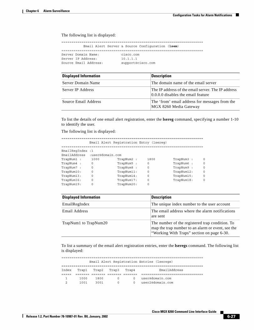
Chapter 6 Alarm SurveillanceConfiguration Tasks for Alarm Notifications
The following list is displayed:======================================================================= Email Alert Server & Source Configuration (lsem)=======================================================================Server Domain Name: cisco.comServer IP Address: 10.1.1.1Source Email Address: [email protected]
To list the details of one email alert registration, enter the lsereg command, specifying a number 1-10 to identify the user.
The following list is displayed:======================================================================= Email Alert Registration Entry (lsereg)=======================================================================EmailRegIndex :1EmailAddress :[email protected] : 1000 TrapNum2 : 1800 TrapNum3 : 0TrapNum4 : 0 TrapNum5 : 0 TrapNum6 : 0TrapNum7 : 0 TrapNum8 : 0 TrapNum9 : 0TrapNum10: 0 TrapNum11: 0 TrapNum12: 0TrapNum13: 0 TrapNum14: 0 TrapNum15: 0TrapNum16: 0 TrapNum17: 0 TrapNum18: 0TrapNum19: 0 TrapNum20: 0
To list a summary of the email alert registration entries, enter the lseregs command. The following list is displayed:======================================================================= Email Alert Registration Entries (lseregs)=======================================================================Index Trap1 Trap2 Trap3 Trap4 EmailAddress===== ======= ======= ======= ======= =============================== 1 1000 1800 0 0 [email protected] 2 1001 3001 0 0 [email protected]
Displayed Information Description
Server Domain Name The domain name of the email server
Server IP Address The IP address of the email server. The IP address 0.0.0.0 disables the email feature
Source Email Address The ‘from’ email address for messages from the MGX 8260 Media Gateway
Displayed Information Description
EmailRegIndex The unique index number to the user account
Email Address The email address where the alarm notifications are sent
TrapNum1 to TrapNum20 The number of the registered trap condition. To map the trap number to an alarm or event, see the “Working With Traps” section on page 6-30.
6-27Cisco MGX 8260 Command Line Interface Guide
Release 1.2, Part Number 78-10987-01 Rev. B0, January, 2002

Chapter 6 Alarm SurveillanceConfiguration Tasks for Alarm Notifications
Configuring SNMP Trap ManagersYou can register SNMP managers to receive SNMP trap messages on alarms or significant events in the MGX 8260 Media Gateway.
Registering SNMP Trap Managers
To register an SNMP trap manager, enter the addtmgr command as described in the “addtmgr” section on page 9-33. The bitmap parameter is a bitwise specification of trap categories to subscribe. Each bit represents a category of traps. For more information on trap numbers, see Understanding Trap Numbers, page 6-31.
The system sends the specified trap messages to registered managers as trap events occur. For more information on traps, see “Working With Traps” on page 30.
The following example subscribes the manager at address 10.1.1.10 and udp port 162 to receive trap messages for minor and informational events for cards and DS1 lines.addtmgr 10.1.1.10 162 2 public 86
Table 6-10 Trap Subscription Bits
Bit Trap Description
0 Severity Major (trap severity selection)
1 Severity Minor (trap severity selection)
2 Severity Information (trap severity selection)
3 1000-1099 Shelf
4 1100-1199 Card
5 1200-1299 SNMP
6 1300-1399 Dsx1 Line
7 1400-1499 Dsx3 Line
8 1500-1599 Sonet Line
9 1600-1699 Ether Line
10 1700-1799 Voice Port
11 N/A Ether Channel
12 N/A Voice Channel
13 1800-1899 EMM
14 1900-1999 Clock
15 2000-2099 DSP
16 2100-2199 DMCMAP
17 2200-2299 ISDN
18 2300-2399 MGCP
19 2400-2499 Backhaul Session
6-28Cisco MGX 8260 Command Line Interface Guide
Release 1.2, Part Number 78-10987-01 Rev. B0, January, 2002

Chapter 6 Alarm SurveillanceConfiguration Tasks for Alarm Notifications
You build a trap subscription argument for the addtmgr command. For example, to register for minor alarms, informational messages, card alarms, and DS1 line alarms, build the following trap subscription bitmap:
To use this bitmap, convert it to a decimal value and specify it as the last argument. Binary 1010110 is 86 decimal. The second argument (2) sets the in-band interface as the default interface for sending traps when the routing table has no trap manager.
Changing SNMP Trap Registrations
To change a SNMP trap registration, enter the chtmgr command as described in “chtmgr” section on page 9-133. The following example changes the manager at address 10.1.1.10 and udp port 162 to receive events for the traps specified by bitmap 1100110.chtmgr 10.1.1.10 162 2 public 102
Deleting SNMP Trap Registrations
To delete a SNMP trap registration, enter the deltmgr command, specifying the address of the SNMP manager who wants to discontinue notification of trap events. The system discontinues trap messages to the specified IP address.
The following example deletes the trap manager at 10.1.1.10.deltmgr 10.1.1.10
Trap: dsx1Line SNMP Card Shelf Information Minor Major
Bit Value 1 0 1 0 1 1 0
Bit Position 6 5 4 3 2 1 0
6-29Cisco MGX 8260 Command Line Interface Guide
Release 1.2, Part Number 78-10987-01 Rev. B0, January, 2002

Chapter 6 Alarm SurveillanceWorking With Traps
Viewing SNMP Trap Registrations
To view one SNMP trap registration, enter the lstmgr command. The system displays the trap registration information.======================================================================= Trap Manager Registration Entry (lstmgr)=======================================================================Trap Manager IP Address (Index) : 10.15.38.22UDP Port to Trap Manager : 162Network Interface for Trap Delivery : scc-eth-ifTrap Community String : publicTraps Subscription Bitmap : 56Manager-specific Trap Sequence Number : 0
To view all SNMP trap registrations, enter the lstmgrs command. The system displays the current trap managers. ======================================================================= Trap Manager Registration Entries (lstmgrs)======================================================================= Mgr IP Address UDP Port Interface Community String================ ========== =========== ==================== 10.15.38.22 162 scc-eth-if public
Working With TrapsThe MGX 8260 Media Gateway generates trap messages when significant changes occur in the chassis. These changes range from major alarms to informational events. While most alarms report chassis events, a few report summary information about current line state. The MGX 8260 Media Gateway sends these trap messages to SNMP managers and users registered to receive email notification. You can also view trap information from the command line interface.
Viewing Chronological TrapsTo view traps, use the lstraps command.
Displayed Information Description
Trap Manager IP Address The IP address of the registered manager.
UDP Port to Trap Manager The UDP port of the registered manager.
Network Interface for Trap Delivery The MGX 8260 interface for delivering trap messages. Fixed at scc-eth-if.
Trap Community String The name of the community string.
Trap Subscription Bitmap A bitmap of traps to send to the manager (See Table 6-10).
Manager-specific Trap Sequence Number The manager-specific trap sequence number.
6-30Cisco MGX 8260 Command Line Interface Guide
Release 1.2, Part Number 78-10987-01 Rev. B0, January, 2002

Chapter 6 Alarm SurveillanceWorking With Traps
The system displays the information such as the following:08/15/2000 18:28:21 02 02 MAJOR TRAP Line 7 is in line major alarm 0x0000004008/15/2000 18:28:19 02 02 INFO* TRAP Line 7 is modified08/15/2000 18:28:19 02 02 INFO* TRAP Line 7 is added
Understanding Trap NumbersTraps are identified by a unique number, starting with 1000. This section lists traps by function.
Shelf Traps
Shelf alarms create trap conditions that you can use for email alerts. The following table summarizes the alarm conditions and corresponding trap numbers for shelf and environmental alarms:
Column Description
Date The event dateTime The event timePhysical Slot The physical slot numberLogical Slot The logical slot numberSeverity The event severityType The type of eventDescription A text description of the trap
Table 6-11 Shelf Traps
Event Severity Trap Number
Shelf major alarm Major 1000
Shelf minor alarm Minor 1001
Shelf alarm clear Info 1002
Shelf security alert Minor 1003
Shelf cold start Major 1004
Shelf alarm history change Info 1005
Shelf DS1 type change Major 1006
Shelf configuration cleared Info 1007
EMM major alarm Major 1800
EMM minor alarm Minor 1801
EMM alarm clear Info 1802
Clock major alarm Major 1900
Clock minor alarm Minor 1901
Clock alarm cleared Info 1902
Clock switched Info 1903
6-31Cisco MGX 8260 Command Line Interface Guide
Release 1.2, Part Number 78-10987-01 Rev. B0, January, 2002

Chapter 6 Alarm SurveillanceWorking With Traps
Card Traps
The following table summarizes the alarm conditions and corresponding trap numbers for card alarms:
DS1 Traps
The following table summarizes the alarm conditions and corresponding trap numbers for DS1 alarms:
Table 6-12 Card Traps
Event Severity Trap Number
Card inserted Info 1100
Card removed Info 1101
Card failed Major 1102
Core card switchover Major 1103
Service card switchover Minor 1104
Card major alarm Major 1105
Card minor alarm Minor 1106
Card alarm cleared Info 1107
Card active Info 1108
Core redundancy failed Major 1109
Service module redundancy failed Major 1110
Multiservice Media module major alarm Major 1111
Physical card mismatched Minor 1112
Physical card configuration cleared Info 1113
Card in standby Info 1114
Physical back card inserted Info 1115
Physical back card removed Info 1116
DMC map added Info 2000
DMC map deleted Info 2001
DMC map modified Info 2002
DSP minor alarm (1 DSP down) Major 2101
DSP major alarm (all DSPs down) Major 2102
Table 6-13 DS1 Traps
Event Severity Trap Number
DS1 line added Info 1300
DS1 line deleted Info 1301
DS1 line modified Info 1302
DS1 line major alarm Major 1303
DS1 line minor alarm Minor 1304
6-32Cisco MGX 8260 Command Line Interface Guide
Release 1.2, Part Number 78-10987-01 Rev. B0, January, 2002

Chapter 6 Alarm SurveillanceWorking With Traps
DS3 Traps
The following table summarizes the alarm conditions and corresponding trap numbers for DS3 alarms:
DS1 line alarm cleared Info 1305
DS1 line performance major alarm Major 1306
DS1 line performance minor alarm Minor 1307
DS1 line performance alarm clear Info 1308
DS1 line update threshold Info 1309
DS1 line payload loopback up Info 1310
DS1 line - line loopback up Info 1311
DS1 line other loopback up Info 1312
DS1 line loopback down Info 1313
DS1 line BERT on Info 1314
DS1 line BERT off Info 1315
E1 line performance major alarm Major 1316
E1 line performance minor alarm Minor 1317
E1 line performance alarm cleared Info 1318
E1 line threshold updated Major 1319
DS1 trap update sent1 Info 1320
1. Trap sends information for all lines, not a single event.
Table 6-13 DS1 Traps (continued)
Event Severity Trap Number
Table 6-14 DS3 Traps
Event Severity Trap Number
DS3 line added Info 1400
DS3 line deleted Info 1401
DS3 line modified Info 1402
DS3 line major alarm Major 1403
DS3 line minor alarm Minor 1404
DS3 line alarm cleared Info 1405
DS3 line performance major alarm Major 1406
DS3 line performance minor alarm Minor 1407
DS3 line performance alarm clear Info 1408
DS3 line threshold update Info 1409
DS3 line payload loopback up Info 1410
DS3 line - line loopback up Info 1411
6-33Cisco MGX 8260 Command Line Interface Guide
Release 1.2, Part Number 78-10987-01 Rev. B0, January, 2002

Chapter 6 Alarm SurveillanceWorking With Traps
SONET Traps
Fast Ethernet Traps
The following table summarizes the alarm conditions and corresponding trap numbers for Fast Ethernet alarms and events:
DS3 line other loopback up Info 1412
DS3 line loopback down Info 1413
Table 6-15 SONET Traps
Event Severity Trap Number
SONET line added Info 1500
SONET line deleted Info 1501
SONET line modified Info 1502
SONET line major alarm Major 1503
SONET line minor alarm Minor 1504
SONET line alarm cleared Info 1505
SONET line performance major alarm Major 1506
SONET line performance minor alarm Minor 1507
SONET line performance alarm clear Info 1508
SONET line threshold update Info 1509
SONET line - line loopback up Info 1510
SONET line serial loopback up Info 1511
SONET line parallel loopback up Info 1512
SONET line loopback down Info 1513
Table 6-14 DS3 Traps (continued)
Event Severity Trap Number
Table 6-16 Fast Ethernet Traps
Event Severity Trap Number
Ether line active or added Info 1600
Ether line delete Info 1601
Ether line config change Info 1602
Ether line alarm while in active state Major 1603
Ether line alarm while inactive Info 1604
Ether line alarm clear Info 1605
Ether line non-recoverable failure Major 1606
6-34Cisco MGX 8260 Command Line Interface Guide
Release 1.2, Part Number 78-10987-01 Rev. B0, January, 2002

Chapter 6 Alarm SurveillanceWorking With Traps
Voice Port Events
Voice ports generate informational events for configuration changes. The only way to access these events is by using SNMP traps or email alerts. The following table summarizes the events and corresponding trap numbers for the voice ports:
ISDN Traps
The following table summarizes the ISDN conditions and corresponding trap numbers for ISDN alarms and events:
MGCP Traps
The following table summarizes the MGCP conditions and corresponding trap numbers for MGCP alarms and events:
Table 6-17 Voice Port Events
Event Severity Trap
Voice port added Info 1700
Voice port deleted Info 1701
Voice port modified Info 1702
Table 6-18 ISDN Traps
Event Severity Trap
D-Channel added to DS1 or E1 Info 2200
D-Channel deleted Info 2201
DLSAP profile added Info 2202
DLSAP profile deleted Info 2203
MACSAP profile added Info 2204
MACSAP profile deleted Info 2205
D-Channel connected Info 2206
D-Channel disconnected Info 2207
D-Channel information about a card Info 2208
Table 6-19 MGCP Traps
Event Severity Trap
MGCP core parameter changed Info 2300
MGCP IP address, port, or domain changed Info 2301
6-35Cisco MGX 8260 Command Line Interface Guide
Release 1.2, Part Number 78-10987-01 Rev. B0, January, 2002

Chapter 6 Alarm SurveillanceWorking With Traps
Backhaul Traps
The following table summarizes the Backhaul conditions and corresponding trap numbers for Backhaul alarms and events:
Table 6-20 Backhaul Traps
Event Severity Trap
Backhaul set added Info 2400
Backhaul set deleted Info 2401
Backhaul group added Info 2402
Backhaul group deleted Info 2403
Backhaul session added Info 2404
Backhaul session deleted Info 2405
6-36Cisco MGX 8260 Command Line Interface Guide
Release 1.2, Part Number 78-10987-01 Rev. B0, January, 2002

Cisco MGX Release 1.2, Part Number 78-10987-01 Rev. B0, January, 2002
C H A P T E R 7
Performance MonitoringMonitoring the performance of a communication system is part of a proactive strategy that catches problems before they affect service. The MGX 8260 Media Gateway provides performance information for DS1/E1 and DS3 lines.
Monitoring DS1 PerformanceYou can view current or historical statistics that the system collects on DS1 performance. Current statistics are performance statistics collected over the last fifteen minutes.
Viewing Current T1 StatisticsTo view current statistics for a single T1 line, enter the lsds1curst command, specifying the slot and line number, delimited by a period, of the line. The system displays current statistics:======================================================================= DS1 Line Current Statistics (lsds1curst)=======================================================================DS1 Slot.Line : 13.1Path Errored Seconds : 0Path Severely Errored Seconds : 0Path Severely Errored Framing Seconds : 0Path UnAvailable Seconds : 606Path Control Slip Seconds : 0Path Code Violations : 0Path SEF or AIS : 0Path Bursty Errored Seconds : 0Line Errored Seconds : 0Line Severely Errored Seconds : 0Line Code Violations : 0
To view current statistics for all T1 lines, enter the lsds1cursts command.
7-18260 Command Line Interface Guide

Chapter 7 Performance MonitoringMonitoring DS1 Performance
The system displays the current statistics summary:======================================================================= DS1 Current Statistics for all Lines (lsds1cursts)=======================================================================Slot.Line Error Secs SeverSecs FrameSecs UnAvailSecs========= =========== ========= ========= =========== 13.1 0 0 0 473 13.2 0 0 0 473 13.3 0 0 0 473 13.4 0 0 0 472 13.5 0 0 0 472
Viewing Total T1 StatisticsTotal statistics are performance statistics collected since the previous midnight. So just before midnight there are almost 24 hours of statistics available, at midnight the statistic counters are reset, and after midnight the system starts accumulating new data. To view total statistics for a T1 line, enter the lsds1totst command, specifying the slot and line number, delimited by a period, of the line. The system displays current statistics:======================================================================= DS1 Line Total Statistics (lsds1totst)=======================================================================DS1 Slot.Line : 13.1Path Errored Seconds : 2Path Severely Errored Seconds : 0Path Severely Errored Framing Seconds : 0Path UnAvailable Seconds : 11162Path Control Slip Seconds : 2Path Code Violations : 0Path SEF or AIS : 0Path Bursty Errored Seconds : 0Line Errored Seconds : 11Line Severely Errored Seconds : 11Line Code Violations : 0
To view 24-hour statistics for all lines, enter the lsds1totsts command.
The system displays the 24-hour statistics summary:======================================================================= DS1 Total Stats (lsds1totsts)=======================================================================Slot.Line ErrSecs SeverErrSecs FrameErrSecs UnAvailSecs LineErSecs========= ======= ============ ============ =========== ========== 13.1 2 0 0 11029 11 13.2 2 0 0 11029 11 13.3 2 0 0 11029 11 13.4 1 0 0 11028 11 13.5 2 0 0 11028 11
Viewing Interval T1 StatisticsInterval statistics are collected by each DS1 Interface for the previous 24 hours of operation. The 24 hours are broken into 96 15-minute intervals, where interval 1 is the most recent and 96 is the oldest. As time progresses, the system drops the oldest interval and adds the latest one, creating a sliding 24-hour window that moves with time.
7-2Cisco MGX 8260 Command Line Interface Guide
Release 1.2, Part Number 78-10987-01 Rev. B0, January, 2002

Chapter 7 Performance MonitoringMonitoring DS1 Performance
To list interval statistics for a T1 line, enter the lsds1intst command, specifying the slot and line number, delimited by a period, of the line and the number (1-96) of the interval of interest. The system displays the interval statistics:======================================================================= DS1 Line Interval Statistics Entry (lsds1intst)======================================================================= Slot.Line :13.1 Interval :1 Path Errored Seconds :0 Path Severely Errored Seconds :0 Path Severely Errored Framing Seconds :0 Path UnAvailable Seconds :0 Path Control Slip Seconds :0 Path Code Violations :0 Path SEF or AIS :0 Path Bursty Errored Seconds :0 Line Errored Seconds :0 Line Severely Errored Seconds :0 Line Code Violations :0
Viewing T1 Real-Time Alarm StatisticsTo view real-time statistics for a single T1 line, enter the lsds1lnst command, specifying the slot and line number, delimited by a period, of the DS1 line. The system displays the following real-time DS1 information:======================================================================= DS1 Line Real-time statistics (lsds1lnst)=======================================================================DS1 Line : 13.1Loss of Signal : 1Out Of Frame : 1Yellow Alarm : 0Frame Pattern Errors : 1Alarm State : 42Performance Alarm State: 196608
Displayed Information Description
DS1 Line The Slot.Line for these statistics
Loss of Signal The number of times Loss of Signal was detected, with or without integrating to a LOS alarm
Out of Frame The number of times Out of Frame was detected, with or without integrating to a OOF alarm
Yellow Alarm The number of times Yellow alarm was detected, with or without integrating to a RAI alarm
Frame Pattern Errors The number of framing pattern errors per second encountered by the DS1 interface
7-3Cisco MGX 8260 Command Line Interface Guide
Release 1.2, Part Number 78-10987-01 Rev. B0, January, 2002

Chapter 7 Performance MonitoringMonitoring DS1 Performance
Alarm State A bitmap of the DS1 line alarms. Zero means no alarm.
• bit 0: Receiving RAI
• bit 1: Transmitting RAI
• bit 2: Receiving AIS
• bit 3: Transmitting AIS
• bit 4: Receiving OOF
• bit 5: Receiving LOS
• bit 6: Near end local loopback in effect
• bit 7: Near end remote loopback in effect
• bit 8: Near end remote payload loopback
• bit 13: BERT in effect
• bit 14: Far end remote loopback in effect
• bit 15: Detected near end remote loopback in effect
Performance Alarm State The DS1 line performance alarms, displayed as a row of indicators.
• Indicator 0: LCV 15 minute threshold exceeded
• Indicator 1: LCV 24 hour threshold exceeded
• Indicator 2: LES 15 minute threshold exceeded
• Indicator 3: LES 24 hour threshold exceeded
• Indicator 4: LSES 15 minute threshold exceeded
• Indicator 5: LSES 24 hour threshold exceeded
• Indicator 6: PCV 15 minute threshold exceeded
• Indicator 7: PCV 24 hour threshold exceeded
• Indicator 8: PES 15 minute threshold exceeded
• Indicator 9: PES 24 hour threshold exceeded
• Indicator 10: PSES 15 minute threshold exceeded
• Indicator 11: PSES 24 hour threshold exceeded
• Indicator 12: SEFS 15 minute threshold exceeded
• Indicator 13: SEFS 24 hour threshold exceeded
• Indicator 14: AISS 15 minute threshold exceeded
• Indicator 15: AISS 24 hour threshold exceeded
• Indicator 16: UAS 15 minute threshold exceeded
• Indicator 17: UAS 24 hour threshold exceeded
• Indicator 18: BES 15 minute threshold exceeded
• Indicator 19: BES 24 hour threshold exceeded
• Indicator 20: PCSS 15 minute threshold exceeded
• Indicator 21: PCSS 24 hour threshold exceeded
Displayed Information Description
7-4Cisco MGX 8260 Command Line Interface Guide
Release 1.2, Part Number 78-10987-01 Rev. B0, January, 2002

Chapter 7 Performance MonitoringMonitoring E1 Performance
Clearing Real-Time T1 StatisticsTo clear T1 real-time statistics, enter the clrds1lnst command, specifying the slot and line number, delimited by a period, of the DS1 line and the statistic to clear.
The system clears the specified real-time statistic.
Monitoring E1 PerformanceYou can view current or historical statistics that the system collects on E1 performance. Current statistics are performance statistics collected over the last fifteen minutes.
Viewing Current E1 StatisticsTo view current statistics for a single E1 line, enter the lse1curst command, specifying the slot and line number, delimited by a period, of the line. The system displays current statistics:======================================================================= E1 Line Current Statistics (lse1curst)=======================================================================E1 Slot.Line : 2.1Path Errored Seconds : 12Path Severely Errored Seconds : 0Path UnAvailable Seconds : 0Path Control Slip Seconds : 12Path Code Violations : 0Path Bursty Errored Seconds : 0Line Errored Seconds : 0Line Code Violations : 0Errored Seconds Ratio : 158Severly Errored Seconds Ratio : 0Frame Error Errored Seconds : 0Severly Errored Frame Error Seconds : 0Unavailable Errored Frame Error Seconds : 0ESR by Frame Errors : 0SESR by Frame Errors : 0Unavailable Errored CRC Seconds : 0Errored Seconds by CRC Errors : 0Severely Errored Seconds by CRC Errors : 0Error Seconds Ratio Caused by CRC Errors : 0SESR Caused by CRC Errors : 0Error Seconds by Far End Block Errors : 0Severely Errored Seconds by Far End Block Errors : 0Unavailable Seconds by Far End Block Errors : 0ESR by Far End Block Errors : 0SESR by Far End Block Errors : 0
To view current statistics for all E1 lines, enter the lse1cursts command.
7-5Cisco MGX 8260 Command Line Interface Guide
Release 1.2, Part Number 78-10987-01 Rev. B0, January, 2002

Chapter 7 Performance MonitoringMonitoring E1 Performance
The system displays the current statistics summary:======================================================================= E1 Current Statistics for all Lines (lse1cursts)=======================================================================Slot.Line Error Secs SeverSecs SlipSecs UnAvailSecs========= =========== ========= ========= =========== 3.1 0 0 0 0 3.2 0 0 0 0 3.3 0 0 0 0 3.4 0 0 0 0
Viewing Total E1 StatisticsTotal statistics are performance statistics collected since the previous midnight. So just before midnight there are almost 24 hours of statistics available, at midnight the statistic counters are reset, and after midnight the system starts accumulating new data. To view total statistics for an E1 line, enter the lse1totst command, specifying the slot and line number, delimited by a period, of the line. The system displays current statistics:======================================================================= E1 Line Total Statistics (lse1totst)=======================================================================E1 Slot.Line : 2.1Path Errored Seconds : 572Path Severely Errored Seconds : 0Path UnAvailable Seconds : 0Path Control Slip Seconds : 572Path Code Violations : 0Path Bursty Errored Seconds : 0Line Errored Seconds : 0Line Code Violations : 0Error Seconds Ratio(ESR) : 0Severely Errored Seconds Ratio(SESR) : 0Unavailable Seconds by Frame Errors : 0Error Seconds by Frame Errors : 0Severely Errored Seconds by Frame Errors : 0ESR by Frame Errors : 0SESR by Frame Errors : 0Unavailable Seconds by CRC : 0Error Seconds by CRC : 0ESR by Frame Errors : 0SESR by Frame Errors : 0Unavailable Seconds by Far End Block Errors: 0ESR by Far End Block Errors : 0SES by Far End Block Errors : 0ESR by Far End Block Errors : 0SESR by Far End Block Errors : 0
To view 24-hour statistics for all E1 lines, enter the lse1totsts command.
7-6Cisco MGX 8260 Command Line Interface Guide
Release 1.2, Part Number 78-10987-01 Rev. B0, January, 2002

Chapter 7 Performance MonitoringMonitoring E1 Performance
The system displays the 24-hour statistics summary:============================================================================ E1 Total Stats (lse1totsts)============================================================================Slot.Line ErrSecs SeverErrSecs SlipSecs UnAvailSecs LineErSecs========= ======= ============ ============ =========== ========== 3.1 2 0 2 0 0 3.2 2 0 2 0 0 3.3 2 0 2 0 0 3.4 2 0 2 0 0
Viewing Interval E1 StatisticsInterval statistics are collected by each E1 Interface for the previous 24 hours of operation. The 24 hours are broken into 96 15-minute intervals, where interval 1 is the most recent and 96 is the oldest. As time progresses, the system drops the oldest interval and adds the latest one, creating a sliding 24-hour window that moves with time.
To list interval statistics for an E1 line, enter the lse1intst command, specifying the slot and line number, delimited by a period, of the line and the number (1-96) of the interval of interest.
The system displays the interval statistics:======================================================================= E1 Line Interval Statistics (lse1intst)=======================================================================E1 Slot.Line : 3.1Interval : 1Path Errored Seconds : 0Path Severely Errored Seconds : 0Path UnAvailable Seconds : 0Path Control Slip Seconds : 0Path Code Violations : 0Path Bursty Errored Seconds : 0Line Errored Seconds : 0Line Code Violations : 0Errored Seconds Ratio : 0Severely Errored Seconds Ratio : 0Frame Error Errored Seconds : 0Severly Errored Frame Error Seconds : 0Far End Unavailable Error Seconds : 0ESR by Far End Errors : 0SESR by Far End Errors : 0Unavailable Errored CRC Seconds : 0Errored CRC Seconds : 0Severely Errored CRC Seconds : 0 ESR Caused by CRC Errors : 0SESR Caused by CRC Errors : 0Far End Block Errors : 0Severely Errored Secs by Far End Errors : 0Unavailable Seconds by Far End Block Errors: 0ESR by Far End Block Errors : 0SESR by Far End Block Errors : 0
7-7Cisco MGX 8260 Command Line Interface Guide
Release 1.2, Part Number 78-10987-01 Rev. B0, January, 2002

Chapter 7 Performance MonitoringMonitoring E1 Performance
Viewing E1 Real-Time Alarm StatisticsTo view real-time statistics for a single E1 line, enter the lse1lnst command, specifying the slot and line number, delimited by a period, of the line. The system displays the following real-time E1 information:======================================================================= E1 Line statistics (lse1lnst)=======================================================================E1 Line : 3.1Loss of Signal : 0Out Of Frame : 0Yellow Alarm : 0Remote Multiframe Alarm: 0Frame Pattern Errors : 0Far End Block Errors : 0CRC Errors : 0Alarm State : 0Performance Alarm State: 0
Displayed Information Description
E1 Line The Slot.Line for these statistics
Loss of Signal The number of times Loss of Signal was detected, with or without integrating to a LOS alarm
Out of Frame The number of times Out of Frame was detected, with or without integrating to a OOF alarm
Yellow Alarm The number of times RAI was detected, with or without integrating to a RAI alarm
Remote Multiframe Alarm
The number of times the Remote Multiframe Alarm Indications was detected, with or without integrating to Yellow alarm
Frame Pattern Errors The number of framing pattern errors encountered by the E1 interface
Far End Block Errors The number of times the Far End Block Error was encountered by the E1 interface
CRC Errors The number of times the CRC was encountered by an E1 interface
7-8Cisco MGX 8260 Command Line Interface Guide
Release 1.2, Part Number 78-10987-01 Rev. B0, January, 2002

Chapter 7 Performance MonitoringMonitoring E1 Performance
Alarm State A bitmap of the E1 line alarms. Zero means no alarm.
• Bit 0: Receiving RAI
• Bit 1: Transmitting RAI
• Bit 2: Receiving AIS
• Bit 3: Transmitting AIS
• Bit 4: Receiving OOF
• Bit 5: Receiving LOS
• Bit 6: Near End Local Loopback
• Bit 7: Near End Remote Loopback
• Bit 8: Near End Remote Payload Loopback
• Bit 9: BERT in effect
• Bit 10: Far End Remote Loopback in effect
• Bit 11: Detected Near End Remote Loopback
• Bit 12: Receiving Out of CRC Multi-Frame
• Bit 13: Receiving Remote Multiframe Alarm Indication (RMAI)
• Bit 14: Transmitting Remote Multiframe Alarm Indication (RMAI)
• Bit 15: Receiving TS16 Alarm Indication Signal
• Bit 16: Receiving Out of Multi-Signaling Frame
Displayed Information Description
7-9Cisco MGX 8260 Command Line Interface Guide
Release 1.2, Part Number 78-10987-01 Rev. B0, January, 2002

Chapter 7 Performance MonitoringMonitoring E1 Performance
Performance Alarm State A bitmap of E1 line performance alarms. Zero means no alarm.
• Bit 0: LCV 15 minutes threshold exceeded
• Bit 1: LCV 24 hour threshold exceeded
• Bit 2: LES 15 minutes threshold exceeded
• Bit 3: LES 24 hour threshold exceeded
• Bit 4: PCV 15 minutes threshold exceeded
• Bit 5: PCV 24 hour threshold exceeded
• Bit 6: ES 15 minutes threshold exceeded
• Bit 7: ES 24 hour threshold exceeded
• Bit 8: SES 15 minutes threshold exceeded
• Bit 9: SES 24 hour threshold exceeded
• Bit 10: CSS 15 minutes threshold exceeded
• Bit 11: CSS 24 hour threshold exceeded
• Bit 12: BES 15 minutes threshold exceeded
• Bit 13: BES 24 hour threshold exceeded
• Bit 14: UAS 15 minutes threshold exceeded
• Bit 15: UAS 24 hour threshold exceeded
• Bit 16: ESR 15 minutes threshold exceeded
• Bit 17: ESR 24 hour threshold exceeded
• Bit 18: SESR 15 minutes threshold exceeded
• Bit 19: SESR 24 hour threshold exceeded
• Bit 20: FEESR 15 minutes threshold exceeded
• Bit 21: FEESR 24 hour threshold exceeded
• Bit 22: FESESR 15 minutes threshold exceeded
• Bit 23: FESESR 24 hour threshold exceeded
• Bit 24: FEBEESR 15 minutes threshold exceeded
• Bit 25: FEBEESR 24 hour threshold exceeded
• Bit 26: FEBESESR 15 minutes threshold exceeded
• Bit 27: FEBESESR 24 hour threshold exceeded
• Bit 28: CRCESR 15 minutes threshold exceeded
• Bit 29: CRCESR 24 hour threshold exceeded
• Bit 30: CRCSESR 15 minutes threshold exceeded
• Bit 31: CRCSESR 24 hour threshold exceeded
Displayed Information Description
7-10Cisco MGX 8260 Command Line Interface Guide
Release 1.2, Part Number 78-10987-01 Rev. B0, January, 2002

Chapter 7 Performance MonitoringMonitoring DS3 Performance
To view real-time statistics for all E1 lines, enter the lse1lnsts command.
The system displays the real-time statistics summary:======================================================================= E1 Statistics for all Lines (lse1lnsts)=======================================================================Slot.Line LossOfSignal OutOfFrame CRCErrs FrameErrs========= ============ ========== ========= =========== 3.1 0 0 0 0 3.2 0 0 0 91 3.3 0 0 0 84 3.4 0 0 0 90
Clearing Real-Time E1 StatisticsTo clear E1 real-time statistics, enter the clre1lnst command, specifying the slot and line number, delimited by a period, of the line and the statistic to clear.
The system clears the specified real-time statistic.
Monitoring DS3 Performance You can view current or historical statistics on DS3 performance.
Displayed Information Description
Slot.Line The Slot.Line for these statistics
LossOf Signal The number of times Loss of Signal was detected, with or without integrating to a LOS alarm
Out Of Frame The number of times Out of Frame was detected, with or without integrating to a OOF alarm
CRC Errors The number of times the CRC was encountered by an E1 interface
FrameErrs The number of framing pattern errors per second encountered by the E1 interface
7-11Cisco MGX 8260 Command Line Interface Guide
Release 1.2, Part Number 78-10987-01 Rev. B0, January, 2002

Chapter 7 Performance MonitoringMonitoring DS3 Performance
Viewing Current DS3 StatisticsCurrent statistics are performance statistics collected over the last fifteen minutes. To view current statistics for a single DS3, enter the lsds3curst command, specifying the slot and line number, delimited by a period, of the DS3 line. The system displays current statistics:======================================================================= DS3 Line Current Statistics (lsds3curst)=======================================================================DS3 Slot.Line : 14.501P-bit Errored Seconds : 0P-bit Severely Error Seconds : 0Severely Errored Framing Seconds : 0Path UnAvailable Seconds : 35Line Code Violations : 0P-bit Code Violations : 0Line Errored Seconds : 0Alarm Indication Signal Seconds : 0
Note All C-Bit counters are not increment for the M23 option.
To view current statistics for all DS3 lines, enter the lsds3cursts command. The system displays all current DS3 statistics:======================================================================= DS3 Current Statistics for all Lines (lsds3cursts)=======================================================================Slot.Line PBitErr Secs SevErrFrm Secs UAS Secs LCV Count========= ============ ============== ========== =========== 14.501 0 0 24 0 14.502 0 0 24 0
Viewing Total DS3 StatisticsTotal statistics are performance statistics collected since the previous midnight. So just before midnight there are almost 24 hours of statistics available, at midnight the statistic counters are reset, and after midnight the system starts accumulating new data. To view total statistics for a DS3, enter the lsds3totst command, specifying the slot and line number, delimited by a period, of the DS3 line. The system displays current statistics:======================================================================= DS3 Line Total Statistics (lsds3totst)=======================================================================DS3 Slot.Line : 14.501P-bit Errored Seconds : 3P-bit Severely Error Seconds : 3Severely Errored Framing Seconds : 3Path UnAvailable Seconds : 896Line Code Violations : 0P-bit Code Violations : 14966Line Errored Seconds : 0Alarm Indication Signal Seconds : 0
Note All C-Bit counters are not increment for the M23 option.
7-12Cisco MGX 8260 Command Line Interface Guide
Release 1.2, Part Number 78-10987-01 Rev. B0, January, 2002

Chapter 7 Performance MonitoringMonitoring SONET Performance
Viewing Interval DS3 StatisticsInterval statistics are collected by each DS3 Interface for the previous 24 hours of operation. The 24 hours are broken into 96 15-minute intervals, where interval 1 is the most recent and 96 is the oldest. As time progresses, the system drops the oldest interval and adds the latest one, creating a sliding 24-hour window that moves with time.
To list interval statistics for a DS3, enter the lsds3intst command, specifying the slot and line number and the interval of interest. The system displays the interval statistics:======================================================================= DS3 Line Interval Statistics Entry (lsds3intst)=======================================================================DS3 Slot.Line : 14.501Interval : 1P-bit Errored Seconds : 3P-bit Severely Errored Seconds : 3Severely Errored Framing Seconds : 3Path UnAvailable Seconds : 896Line Code Violations : 0P-bit Code Violations : 14966Line Errored Seconds : 0Alarm Indication Signal Seconds : 0
Viewing DS3 Real-Time Alarm StatisticsTo view real-time statistics for a single DS3, enter the lsds3lnst command, specifying the slot and line number, delimited by a period. The system displays the following real-time DS3 information:======================================================================= DS3 Line statistics (lsds3lnst)=======================================================================DS3 Line : 14.501Loss of Signal : 58884Out Of Frame : 58884Remote Alarm Indication : 0Framing Pattern Errors : 0PBit Parity Errors : 0Far End Block Errors : 0Excessive Zero Errors : 0
Clearing Real-Time StatisticsTo clear real-time statistics, enter the clrds3lnst command, specifying the slot and line number, delimited by a period.
The system clears the real-time statistic.
Monitoring SONET PerformanceThe system collects performance statistics at three levels:
• Section
7-13Cisco MGX 8260 Command Line Interface Guide
Release 1.2, Part Number 78-10987-01 Rev. B0, January, 2002

Chapter 7 Performance MonitoringMonitoring SONET Performance
• Line
• Path
Monitoring SONET Section Statistics
Viewing Section Current Statistics
Current statistics are performance statistics collected over the last fifteen minutes. To view current statistics for a single line, enter the lsssectioncst command, specifying the slot and line number delimited by a period. The system displays current statistics for the specified line:======================================================================= Sonet Section Current Statistics (lsssectioncst)=======================================================================Sonet section Slot.Line : 9.1Section Current Status : 6Errored Seconds : 339Severely Errored Seconds : 339Severely Errored Framing Seconds : 339Coding Voilations : 0
To view current statistics for all lines, enter the lsssectioncsts command. The system displays the current statistics for all lines:======================================================================= Sonet Section Current Statistics for all Lines (lsssectioncsts)=======================================================================Slot.Line Error Secs SeverSecs FrameSecs CodingVoilations========= =========== ========= ========= =========== 9.1 368 368 368 0 9.2 848 848 848 0
Clearing Section Current Statistics
To clear statistics, enter the clrssectioncst command, specifying the slot and line number, delimited by a period, and the statistical counter to clear. Specify the counter as follows:
1—None
2—All
3—ES
4—SES
5—SEFS
6—CV
For example, the following command clears all current section statistics for slot 9 line 1:clrssectioncst 9.1 2
7-14Cisco MGX 8260 Command Line Interface Guide
Release 1.2, Part Number 78-10987-01 Rev. B0, January, 2002
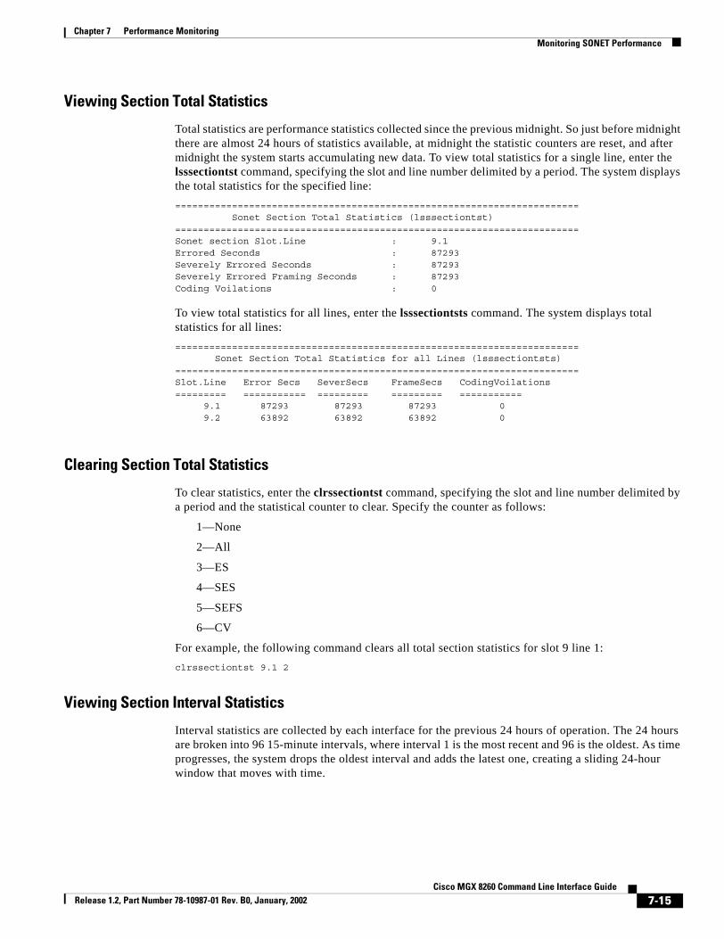
Chapter 7 Performance MonitoringMonitoring SONET Performance
Viewing Section Total Statistics
Total statistics are performance statistics collected since the previous midnight. So just before midnight there are almost 24 hours of statistics available, at midnight the statistic counters are reset, and after midnight the system starts accumulating new data. To view total statistics for a single line, enter the lsssectiontst command, specifying the slot and line number delimited by a period. The system displays the total statistics for the specified line:======================================================================= Sonet Section Total Statistics (lsssectiontst)=======================================================================Sonet section Slot.Line : 9.1Errored Seconds : 87293Severely Errored Seconds : 87293Severely Errored Framing Seconds : 87293Coding Voilations : 0
To view total statistics for all lines, enter the lsssectiontsts command. The system displays total statistics for all lines:======================================================================= Sonet Section Total Statistics for all Lines (lsssectiontsts)=======================================================================Slot.Line Error Secs SeverSecs FrameSecs CodingVoilations========= =========== ========= ========= =========== 9.1 87293 87293 87293 0 9.2 63892 63892 63892 0
Clearing Section Total Statistics
To clear statistics, enter the clrssectiontst command, specifying the slot and line number delimited by a period and the statistical counter to clear. Specify the counter as follows:
1—None
2—All
3—ES
4—SES
5—SEFS
6—CV
For example, the following command clears all total section statistics for slot 9 line 1:clrssectiontst 9.1 2
Viewing Section Interval Statistics
Interval statistics are collected by each interface for the previous 24 hours of operation. The 24 hours are broken into 96 15-minute intervals, where interval 1 is the most recent and 96 is the oldest. As time progresses, the system drops the oldest interval and adds the latest one, creating a sliding 24-hour window that moves with time.
7-15Cisco MGX 8260 Command Line Interface Guide
Release 1.2, Part Number 78-10987-01 Rev. B0, January, 2002

Chapter 7 Performance MonitoringMonitoring SONET Performance
To view interval statistics for a single line, enter the lsssectionist command, specifying the slot and line number, delimited by a period, and the desired interval. The system displays the interval statistics:======================================================================= Sonet Section Interval Statistics (lsssectionist)=======================================================================Sonet section Slot.Line : 9.1Interval : 1Errored Seconds : 900Severely Errored Seconds : 900Severely Errored Framing Seconds : 900Coding Voilations : 0
To view interval statistics for all lines, enter the lsssectionists command. The system displays interval statistics for all lines:======================================================================= Sonet Section Interval Statistics for all Lines (lsssectionists)=======================================================================Slot.Line Interval ErrSecs SeverSecs CVSecs SEFSecs========= ========= ========= ========= ========= ========= 9.1 1 900 900 0 900 9.1 2 900 900 0 900 9.1 3 900 900 0 900 9.1 4 900 900 0 900 9.1 5 900 900 0 900 9.1 6 900 900 0 900 9.1 7 900 900 0 900 9.1 8 900 900 0 900 9.1 9 900 900 0 900 9.1 10 900 900 0 900 9.1 11 900 900 0 900 9.1 12 900 900 0 900 9.1 13 900 900 0 900 9.1 14 900 900 0 900 9.1 15 900 900 0 900 9.1 16 900 900 0 900 9.1 17 900 900 0 900 9.1 18 900 900 0 900 9.1 19 900 900 0 900 9.1 20 900 900 0 900
7-16Cisco MGX 8260 Command Line Interface Guide
Release 1.2, Part Number 78-10987-01 Rev. B0, January, 2002

Chapter 7 Performance MonitoringMonitoring SONET Performance
Monitoring SONET Line Statistics
Viewing Line Current Statistics
Current statistics are performance statistics collected over the last fifteen minutes. To view current statistics for a single line, enter the lsslinecst command, specifying the slot and OC-3 line number delimited by a period. The system displays current statistics for the specified line:======================================================================= Sonet Line Current Statistics (lsslinecst)=======================================================================Sonet Line Slot.Line : 9.1Line Current Status : 2Errored Seconds : 0Severely Errored Seconds : 0Coding Voilations : 0UnAvailable Seconds : 668
To view current statistics for all lines, enter the lsslinecsts command. The system displays the current statistics for all lines:======================================================================= Sonet Line Current Statistics for all Lines (lsslinecsts)=======================================================================Slot.Line Error Secs SeverSecs CodingVoilations UnAvailSecs========= =========== ========= ============= =========== 9.1 0 0 0 689 9.2 0 0 0 269
Clearing Line Current Statistics
To clear statistics, enter the clrslinest command, specifying the slot and line number, delimited by a period, and the statistical counter to clear. Specify the counter as follows:
1—None
2—All
3—ES
4—SES
5—CV
6—UAS
For example, the following command clears all current line statistics for slot 9 line 1:clrslinest 9.1 2
7-17Cisco MGX 8260 Command Line Interface Guide
Release 1.2, Part Number 78-10987-01 Rev. B0, January, 2002

Chapter 7 Performance MonitoringMonitoring SONET Performance
Viewing Line Total Statistics
Total statistics are performance statistics collected since the previous midnight. So just before midnight there are almost 24 hours of statistics available, at midnight the statistic counters are reset, and after midnight the system starts accumulating new data. To view total statistics for a single line, enter the lsslinetst command, specifying the slot and line number delimited by a period. The system displays the total statistics for the specified line:======================================================================= Sonet Line Total Statistics (lsslinetst)=======================================================================Sonet Line Slot.Line : 9.1Errored Seconds : 0Severely Errored Seconds : 0Coding Voilations : 0UnAvailable Seconds : 8729
To view total statistics for all lines, enter the lsslinetsts command. The system displays total statistics for all lines:======================================================================= Sonet Line Total Statistics for all Lines (lsslinetsts)=======================================================================Slot.Line Error Secs SeverSecs CodingVoilations UnAvailSecs========= =========== ========= ============= =========== 9.1 0 0 0 87293 9.2 0 0 0 63892
Clearing Line Total Statistics
To clear statistics, enter the clrslinetst command, specifying the slot and line number, delimited by a period, and the statistical counter to clear. Specify the counter as follows:
1—None
2—All
3—ES
4—SES
5—CV
6—UAS
For example, the following command clears all total section statistics for slot 9 line 1:clrslinetst 9.1 2
Viewing Line Interval Statistics
Interval statistics are collected by each interface for the previous 24 hours of operation. The 24 hours are broken into 96 15-minute intervals, where interval 1 is the most recent and 96 is the oldest. As time progresses, the system drops the oldest interval and adds the latest one, creating a sliding 24-hour window that moves with time.
7-18Cisco MGX 8260 Command Line Interface Guide
Release 1.2, Part Number 78-10987-01 Rev. B0, January, 2002

Chapter 7 Performance MonitoringMonitoring SONET Performance
To view interval statistics for a single line, enter the lsslineist command, specifying the slot and line number, delimited by a period, and the desired interval. The system displays the interval statistics:======================================================================= Sonet Line Interval Statistics (lsslineist)=======================================================================Sonet Line Slot.Line : 9.1Interval : 1Errored Seconds : 0Severely Errored Seconds : 0Coding Voilations : 0UnAvailable Seconds : 900
To view interval statistics for all lines, enter the lsslineists command. The system displays interval statistics for all lines:======================================================================= Sonet Line Interval Statistics for all Lines (lsslineists)=======================================================================Slot.Line Interval ErrSecs SeverSecs CVSecs UASecs========= ========= ========= ========= ========= ========= 9.1 1 0 0 0 900 9.1 2 0 0 0 900 9.1 3 0 0 0 900 9.1 4 0 0 0 900 9.1 5 0 0 0 900 9.1 6 0 0 0 900 9.1 7 0 0 0 900 9.1 8 0 0 0 900 9.1 9 0 0 0 900 9.1 10 0 0 0 900 9.1 11 0 0 0 900 9.1 12 0 0 0 900 9.1 13 0 0 0 900 9.1 14 0 0 0 900 9.1 15 0 0 0 900 9.1 16 0 0 0 900 9.1 17 0 0 0 900 9.1 18 0 0 0 900 9.1 19 0 0 0 900 9.1 20 0 0 0 900
7-19Cisco MGX 8260 Command Line Interface Guide
Release 1.2, Part Number 78-10987-01 Rev. B0, January, 2002

Chapter 7 Performance MonitoringMonitoring SONET Performance
Monitoring SONET Path Statistics
Viewing Path Current Statistics
Current statistics are performance statistics collected over the last fifteen minutes. To view current statistics for a single line, enter the lsspathcst command, specifying the slot and OC-3 line number delimited by a period. The system displays current statistics for the specified line:======================================================================= Sonet Path Current Statistics (lsspathcst)=======================================================================Sonet Path Slot.Line : 9.1Path Current Status : cErrored Seconds : 0Severely Errored Seconds : 0Coding Voilations : 0UnAvailable Seconds : 866
To view current statistics for all lines, enter the lsspathcsts command. The system displays the current statistics for all lines:======================================================================= Sonet Path Current Statistics for all Lines (lsspathcsts)=======================================================================Slot.Line Error Secs SeverSecs CodingVoilations UnAvailSecs========= =========== ========= ============= =========== 9.1 0 0 0 896 9.2 0 0 0 477
Clearing Path Current Statistics
To clear statistics, enter the clrspathcst command, specifying the slot and line number, delimited by a period, and the statistical counter to clear. Specify the counter as follows:
1—None
2—All
3—ES
4—SES
5—CV
6—UAS
For example, the following command clears all current line statistics for slot 9 line 1:clrspathcst 9.1 2
7-20Cisco MGX 8260 Command Line Interface Guide
Release 1.2, Part Number 78-10987-01 Rev. B0, January, 2002

Chapter 7 Performance MonitoringMonitoring SONET Performance
Viewing Path Total Statistics
Total statistics are performance statistics collected since the previous midnight. So just before midnight there are almost 24 hours of statistics available, at midnight the statistic counters are reset, and after midnight the system starts accumulating new data. To view total statistics for a single line, enter the lsspathtst command, specifying the slot and line number delimited by a period. The system displays the total statistics for the specified line:======================================================================= Sonet Path Total Statistics (lsspathtst)=======================================================================Sonet Path Slot.Line : 9.1Errored Seconds : 0Severely Errored Seconds : 0Coding Voilations : 0UnAvailable Seconds : 87293
To view total statistics for all lines, enter the lsspathtsts command. The system displays total statistics for all lines:======================================================================= Sonet Path Total Statistics for all Lines (lsspathtsts)=======================================================================Slot.Line Error Secs SeverSecs CodingVoilations UnAvailSecs========= =========== ========= ============= =========== 9.1 0 0 0 87293 9.2 0 0 0 63892
Clearing Path Total Statistics
To clear statistics, enter the clrspathtst command, specifying the slot and line number, delimited by a period, and the statistical counter to clear. Specify the counter as follows:
1—None
2—All
3—ES
4—SES
5—CV
6—UAS
For example, the following command clears all total section statistics for slot 9 line 1:clrspathtst 9.1 2
Viewing Path Interval Statistics
Interval statistics are collected by each interface for the previous 24 hours of operation. The 24 hours are broken into 96 15-minute intervals, where interval 1 is the most recent and 96 is the oldest. As time progresses, the system drops the oldest interval and adds the latest one, creating a sliding 24-hour window that moves with time.
7-21Cisco MGX 8260 Command Line Interface Guide
Release 1.2, Part Number 78-10987-01 Rev. B0, January, 2002

Chapter 7 Performance MonitoringMonitoring SONET Performance
To view interval statistics for a single line, enter the lsspathist command, specifying the slot and line number, delimited by a period, and the desired interval. The system displays the interval statistics:======================================================================= Sonet Path Interval Statistics (lsspathist)=======================================================================Sonet Path Slot.Line : 9.1Interval : 1Errored Seconds : 0Severely Errored Seconds : 0Coding Voilations : 0UnAvailable Seconds : 900
To view interval statistics for all lines, enter the lsspathists command. The system displays interval statistics for all lines:======================================================================= Sonet Path Interval Statistics for all Lines (lsspathists)=======================================================================Slot.Line Interval ErrSecs SeverSecs CVSecs UASecs========= ========= ========= ========= ========= ========= 9.1 1 0 0 0 900 9.1 2 0 0 0 900 9.1 3 0 0 0 900 9.1 4 0 0 0 900 9.1 5 0 0 0 900 9.1 6 0 0 0 900 9.1 7 0 0 0 900 9.1 8 0 0 0 900 9.1 9 0 0 0 900 9.1 10 0 0 0 900 9.1 11 0 0 0 900 9.1 12 0 0 0 900 9.1 13 0 0 0 900 9.1 14 0 0 0 900 9.1 15 0 0 0 900 9.1 16 0 0 0 900 9.1 17 0 0 0 900 9.1 18 0 0 0 900 9.1 19 0 0 0 900 9.1 20 0 0 0 900
7-22Cisco MGX 8260 Command Line Interface Guide
Release 1.2, Part Number 78-10987-01 Rev. B0, January, 2002

Chapter 7 Performance MonitoringMonitoring SONET Performance
Monitoring SONET Alarm StatisticsTo view real-time statistics for a single line, enter the lssonetstat command, specifying the slot and line number, delimited by a period. The system displays the following alarm statistics:======================================================================= Sonet Line statistics (lssonetstat)=======================================================================Sonet Line : 9.1Loss of Signal : 472938Loss of Frame : 0Line AIS : 472938Line RDI : 0Path LOP : 0Path AIS : 472938Path RDI : 0Path SLM : 0Alarm State : 15Performance Alarm State : c0c03c
The Alarm State and Performance Alarm State are bitmap indicators, as follows:
Displayed Information Description
Alarm State A bitmap of the SONET line alarms. Zero means no alarm.
Bit 0: sonetStatsLOS
Bit 1: sonetStatsLOF
Bit 2: sonetStatsLineAIS
Bit 3: sonetStatsLineRFI
Bit 4: sonetStatsPathAIS
Bit 5: sonetStatsPathLOP
Bit 6: sonetStatsPathUEQ
Bit 7: sonetStatsPathTIM
Bit 8: sonetStatsPathSLM
Bit 9: sonetStatsPathRFI
Bit 10: sonetStatsPathRFIServer
Bit 11: sonetStatsPathRFIConnectivity
Bit 12: sonetStatsPathRFIPayload
7-23Cisco MGX 8260 Command Line Interface Guide
Release 1.2, Part Number 78-10987-01 Rev. B0, January, 2002
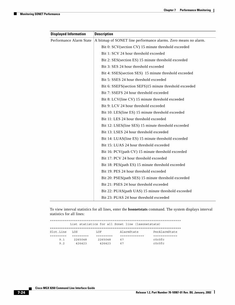
Chapter 7 Performance MonitoringMonitoring SONET Performance
To view interval statistics for all lines, enter the lssonetstats command. The system displays interval statistics for all lines:======================================================================= List statistics for all Sonet line (lssonetstats)=======================================================================Slot.Line LOS LOF AlarmState PerAlarmState========= ========= ========= ============= ============= 9.1 2265048 2265048 67 c0c0fc 9.2 426423 426423 67 c0c0fc
Performance Alarm State A bitmap of SONET line performance alarms. Zero means no alarm.
Bit 0: SCV(section CV) 15 minute threshold exceeded
Bit 1: SCV 24 hour threshold exceeded
Bit 2: SES(section ES) 15 minute threshold exceeded
Bit 3: SES 24 hour threshold exceeded
Bit 4: SSES(section SES) 15 minute threshold exceeded
Bit 5: SSES 24 hour threshold exceeded
Bit 6: SSEFS(section SEFS)15 minute threshold exceeded
Bit 7: SSEFS 24 hour threshold exceeded
Bit 8: LCV(line CV) 15 minute threshold exceeded
Bit 9: LCV 24 hour threshold exceeded
Bit 10: LES(line ES) 15 minute threshold exceeded
Bit 11: LES 24 hour threshold exceeded
Bit 12: LSES(line SES) 15 minute threshold exceeded
Bit 13: LSES 24 hour threshold exceeded
Bit 14: LUAS(line ES) 15 minute threshold exceeded
Bit 15: LUAS 24 hour threshold exceeded
Bit 16: PCV(path CV) 15 minute threshold exceeded
Bit 17: PCV 24 hour threshold exceeded
Bit 18: PES(path ES) 15 minute threshold exceeded
Bit 19: PES 24 hour threshold exceeded
Bit 20: PSES(path SES) 15 minute threshold exceeded
Bit 21: PSES 24 hour threshold exceeded
Bit 22: PUAS(path UAS) 15 minute threshold exceeded
Bit 23: PUAS 24 hour threshold exceeded
Displayed Information Description
7-24Cisco MGX 8260 Command Line Interface Guide
Release 1.2, Part Number 78-10987-01 Rev. B0, January, 2002

Chapter 7 Performance MonitoringMonitoring SONET Performance
Clearing SONET Performance Alarm StatisticsTo clear statistics, enter the clrsonetstats command, specifying the slot and line number, delimited by a period, and the statistical counter to clear. Specify the counter as follows:
1—noAction
2—clearAll
3—clearSeCV15Min
4—clearSeCV24Hr
5—clearSeES15Min
6—clearSeES24Hr
7—clearSeSES15Min
8—clearSeSES24Hr
9—clearSeSEFS15Min
10—clearSeSEFS24Hr
11—clearLCV15Min
12—clearLCV24Hr
13—clearLES15Min
14—clearLES24Hr
15—clearLSES15Min
16—clearLSES24Hr
17—clearLUAS15Min
18—clearLUAS24Hr
19—clearPCV15Min
20—clearPCV24Hr
21—clearPES15Min
22—clearPES24Hr
23—clearPSES15Min
24—clearPSES24Hr
25—clearPUAS15Min
26—clearPUAS24Hr
27—clearAll15Min
28—clearAll24Hr
For example, the following command clears all total section statistics for slot 9 line 1:clrsonetstats 9.1 2
7-25Cisco MGX 8260 Command Line Interface Guide
Release 1.2, Part Number 78-10987-01 Rev. B0, January, 2002

Chapter 7 Performance MonitoringMonitoring SONET Performance
7-26Cisco MGX 8260 Command Line Interface Guide
Release 1.2, Part Number 78-10987-01 Rev. B0, January, 2002

Cisco MGX Release 1.2, Part Number 78-10987-01 Rev. B0, January, 2002
C H A P T E R 8
TroubleshootingThe MGX 8260 Media Gateway includes diagnostic features that facilitate fault location, such as loopback and bit error rate tests. See the following sections for information on how to locate and clear trouble conditions.
• Performing Loopback Tests
• Performing BERT Tests
• Clearing Alarms
Performing Loopback TestsLoopback tests are powerful troubleshooting tools that help maintenance personnel locate faults along the transmission path. DS1/E1 and DS3 lines provide both local and line loopbacks.
Figure 8-1 DS1/E1 and DS3 Loopback Options
The local loopback option loops the DS1 signal back towards the backplane and helps isolate problems on the MGX 8260 side of the signal path. The line loopback option loops the signal back towards the DS1 or DS3 line and helps identify problems in the signal path between the MGX 8260 Media Gateway and other network equipment. A third option, payload loopback, is similar to line loopback, except that the RX signal loops through the card’s DS1 or DS3 framer logic before being returned on the TX line. Payload loopback helps determine whether the card itself is functioning properly.
3193
6
DS1 or DS3front card
DS1 or DS3back card
Fr.
Line
RX
TX
PayloadLocal
8-18260 Command Line Interface Guide

Chapter 8 TroubleshootingPerforming Loopback Tests
Warning Loopback testing interrupts service. Perform during in a pre-arranged maintenance window or when the line is down.
DS1/E1 LoopbackTo perform a DS1/E1 loopback test, follow these steps:
Step 1 Activate the loopback using the chds1ln. Specify the first and last parameters—the slot and line number, delimited by a period, of the DS1 line and the type of loopback test. Refer to the following table for loopback types:
For example, the following command loops line 2 on slot 3:chds1ln 3.2 # # # # 2
The system activates the loopback and changes the corresponding line LED to blinking yellow.
Step 2 Perform DS1/E1 signal tests, such as the BERT test. For more information, see the “Performing BERT Tests” section on page 8-4.
Step 3 Release the loopback by entering the chds1ln command again, but specify the dsx1NoLoop parameter. For example, to release the loopback on slot 3, line 2, enter the command as follows:chds1ln 3.2 # # # # 1
The system releases the loopback, changes the line LED to green, and returns the line to normal operation.
Step 4 Verify that the loopback is clear using the lsds1ln command.
Value Name
1 dsx1NoLoop
2 dsx1PayloadLoop
3 dsx1LineLoop
4 dsx1OtherLoop (local)
8-2Cisco MGX 8260 Command Line Interface Guide
Release 1.2, Part Number 78-10987-01 Rev. B0, January, 2002

Chapter 8 TroubleshootingPerforming Loopback Tests
DS3 LoopbackTo perform a DS3 loopback test, follow these steps:
Step 1 Activate the loopback using the chds3ln command. Specify the first and last parameters—the slot and line number, delimited by a period, of the DS1 line and the type of loopback test. Refer to the following table:
Note Local loopback for DS3 lines is not supported.
For example, the following command loops line 2 on slot 7:chds1ln 7.2 # # # # 2
The system activates the loopback and changes the corresponding line LED to blinking yellow.
Step 2 Perform DS3 signal tests, as appropriate.
Step 3 Release the loopback by reentering the chds3ln command, but specify the dsx3NoLoop parameter. For example, to release the loopback on slot 7, line 2, enter the command as follows:chds3ln 7.2 # # # # 1
The system releases the loopback, changes the line LED to green, and returns the line to normal operation.
Step 4 Verify that the loopback is clear using the lsds3ln command.
Value Name
1 dsx3NoLoop
2 dsx3PayloadLoop
3 dsx3LineLoop
4 dsx3OtherLoop
8-3Cisco MGX 8260 Command Line Interface Guide
Release 1.2, Part Number 78-10987-01 Rev. B0, January, 2002

Chapter 8 TroubleshootingPerforming BERT Tests
SONET LoopbackTo perform a SONET loopback test, follow these steps:
Step 1 Activate the loopback using the chsonetln command, specifying the slot, line, and loopback type. Refer to the following table for the loopback type:
Note Serial and parallel loops are both local loopback states.
For example, the following command loops line 2 on slot 9:chsonetln 9.2 # # # 2
The system activates the loopback and changes the corresponding line LED to blinking yellow.
Step 2 Perform SONET signal tests, as appropriate.
Step 3 Release the loopback by reentering the chds3ln command, but specify the dsx3NoLoop parameter. For example, to release the loopback on slot 7, line 2, enter the command as follows:chsonetln 7.2 # # # # 1
The system releases the loopback, changes the line LED to green, and returns the line to normal operation.
Step 4 Verify that the loopback is clear using the lssonetln command.
Performing BERT TestsBit Error Rate Tests (BERT) check the error performance of DS1/E1 lines. Often used in conjunction with loopback tests, this test helps isolate equipment or line segments with degraded performance. Typically, you activate loopback on one end of the communications link and activate the BERT test on the other. Do not activate loopback and BERT together on the same equipment.
Warning BERT tests interrupt service. Perform in a pre-arranged maintenance window or when the line is down.
Value Name
1 No loop
2 Line loop
3 Serial loop
4 Parallel loop
8-4Cisco MGX 8260 Command Line Interface Guide
Release 1.2, Part Number 78-10987-01 Rev. B0, January, 2002

Chapter 8 TroubleshootingPerforming BERT Tests
DS1/E1 BERT TestTo use the DS1/E1 BERT test, follow these steps:
Step 1 Activate the test signal using the onbertds1 command as described in the “onbertds1” section on page 9-357. For example, the following command activates the bert test on channel 1 of line 1 in slot 11 using a rand9Bit pattern with no error injection.onbertds1 11.1 1 1 1
Step 2 Check the test results using the lsbertds1 command, specifying the slot and line number, delimited by a period, of the DS1 line.
The system displays the BERT status:======================================================================= DS1 Bert Status (lsbertds1)=======================================================================DS1 Line : 11.1Bert Status : inSyncReceived Bit Pattern : 4050854036Receive Count : 9345256Receive Error Count : 0
Step 3 Stop the test using the offbertds1 command, specifying the slot and line number. For example:offbertds1 11.1
The system stops the bert test and resumes transport of normal traffic.
Displayed Information Description
DS1 Line The line for the test results.
Bert Status The status of the test, as follows:
1: idle
2: in-sync
3: out-of-sync
4: failed
Received Bit Pattern The bit pattern the receiver synchronized on.
Receive Count The number of bits received during the BERT test. Use this parameter with the Receive Error Count to calculate the Bit Error Rate (BER).
Receive Error Count The number of error bits received during the BERT test. Use this parameter with the Receive Count to calculate the Bit Error Rate (BER).
8-5Cisco MGX 8260 Command Line Interface Guide
Release 1.2, Part Number 78-10987-01 Rev. B0, January, 2002

Chapter 8 TroubleshootingClearing Alarms
Clearing AlarmsThe MGX 8260 Media Gateway has the following alarm categories:
• Shelf
• Card
• DS1, E1, and DS3
• Fast Ethernet
• OC-3
• Environmental
If you know the alarm source, proceed to the corresponding section of this chapter. Otherwise, start at the shelf level and work toward the cause.
Clearing Chassis AlarmsChassis alarms report the state of chassis environmental sensors, fan speed, card state, and 48 supply status.
To view chassis alarms, follow these steps:
Step 1 Enter the lsalms command.
The system displays a summary of environmental, card, and software alarms.
Step 2 Use the information to identify the most severe alarm.
Step 3 Clear the most severe alarm.
Step 4 If the system alarm identifies a card, follow instructions in “Clearing Card Alarms”.
Clearing Card AlarmsCard alarms pertain to functions that affect general card operation. To view card alarms, enter the lscd command, specifying the card number.
The system displays information about the card, including alarm and failure details. Using the integrated alarm field described in the following table, find the description that matches your problem, and follow the instructions:
Displayed Information Description
Integrated line alarm One of the lines raised an alarm. Follow the instructions in section of this chapter that describes the type of line.
Line performance alarm One of the lines raised a performance alarm. Follow the instructions in section of this chapter that describes the type of line.
Integrated port alarm One of the ports raised an alarm. Check the port configuration and make necessary changes.
8-6Cisco MGX 8260 Command Line Interface Guide
Release 1.2, Part Number 78-10987-01 Rev. B0, January, 2002

Chapter 8 TroubleshootingClearing Alarms
Clearing DS1/E1 and DS3 AlarmsThe MGX 8260 Media Gateway supports DS1 and DS3 physical layer alarm signalling. To view current DS1 alarm conditions, enter the lsds1lns command. To view current DS3 alarms, enter the lsds3lns command.
The system lists a summary of line type, code, status, and signal code for each line. Use the Line Status field and the following guidelines to clear an alarm.
EMM temperature alarm A temperature sensor raised an environmental alarm. Follow instructions in the “Clearing Environmental Alarms” section on page 8-11.
EMM voltage alarm A voltage sensor raised an environmental alarm. Follow instructions in the “Clearing Environmental Alarms” section on page 8-11.
Component failure alarm A hardware component of the card failed. Try the following possible remedies:
• Reset the card and check to see if the alarm clears.
• Remove and replace the card.
Displayed Information Description
Displayed Information Possible Cause and Corrective Action
LOF A Loss of Frame alarm occurs when the MGX 8260 cannot synchronize on frames. Try the following possible remedies:
• Verify that the framing format and clock settings for the line match the port settings.
• Check the statistics for the line and look for abnormally high error rates.
• If the line appears to have problems, use loopback tests to diagnose the condition.
LOS A Loss of Signal alarm occurs when the MGX 8260 cannot detect a signal at the line. Try the following possible remedies:
• Check for obvious physical cable damage, tight bends, or other unusual conditions.
• If the line appears to have problems, use loopback tests to diagnose the condition.
AIS An Alarm Indication Signal (0/1 pattern) occurs when the receive link encounters problems for a set number of frames.
RDI A Remote Defect Indication occurs when the remote equipment encounters problems for a set number of frames at that layer.
LOMF (E1 only) Check for framing format misconfiguration
Check for CRC bits errors in the frame
Check for line coding misconfiguration
8-7Cisco MGX 8260 Command Line Interface Guide
Release 1.2, Part Number 78-10987-01 Rev. B0, January, 2002

Chapter 8 TroubleshootingClearing Alarms
Use the following guidelines to solve general DS1/E1 configuration problems.
LOSMF (E1 only) • Check for framing format misconfiguration
• Check for TS16 alteration
• Check for bit errors in TS16
• Check for line coding misconfiguration
Yellow (RAI) • Check the transmit on the near end
• Check the physical connection
• Perform a BERT to verify the line condition
RMAI (E1 only) • Check the transmit of TS16 at the near end
• Check the physical connection
• Perform a BERT to verify the line condition
Red Alarm(LOS or LOF)
See LOS of LOF above.
Yellow Alarm(RAI or RMAI)
See RAI or RMAI above.
Displayed Information Possible Cause and Corrective Action
Problem Possible Cause
Failure to configure CAS • D-channel is enabled
• Framing format conflict
Failure to change framing type
• D-channel is enabled
• Failure to set hardware device
Failure to delete a line • Voice port exists
• Hardware failure
Failure to change system line interface mode
• BSC configured, even if not physically installed, when changing from the T1 to E1 mode
• T1 line exists when changing from the T1 to E1 mode
• E1 line exists when changing from the E1 to T1 mode
8-8Cisco MGX 8260 Command Line Interface Guide
Release 1.2, Part Number 78-10987-01 Rev. B0, January, 2002
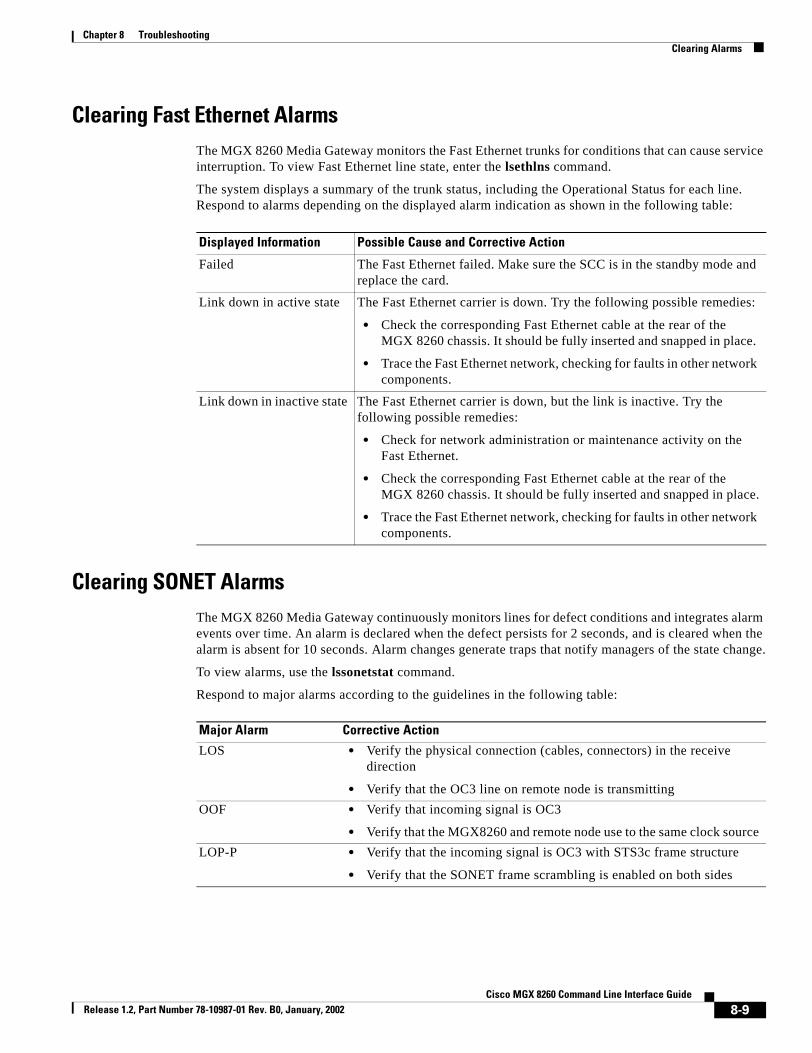
Chapter 8 TroubleshootingClearing Alarms
Clearing Fast Ethernet AlarmsThe MGX 8260 Media Gateway monitors the Fast Ethernet trunks for conditions that can cause service interruption. To view Fast Ethernet line state, enter the lsethlns command.
The system displays a summary of the trunk status, including the Operational Status for each line. Respond to alarms depending on the displayed alarm indication as shown in the following table:
Clearing SONET AlarmsThe MGX 8260 Media Gateway continuously monitors lines for defect conditions and integrates alarm events over time. An alarm is declared when the defect persists for 2 seconds, and is cleared when the alarm is absent for 10 seconds. Alarm changes generate traps that notify managers of the state change.
To view alarms, use the lssonetstat command.
Respond to major alarms according to the guidelines in the following table:
Displayed Information Possible Cause and Corrective Action
Failed The Fast Ethernet failed. Make sure the SCC is in the standby mode and replace the card.
Link down in active state The Fast Ethernet carrier is down. Try the following possible remedies:
• Check the corresponding Fast Ethernet cable at the rear of the MGX 8260 chassis. It should be fully inserted and snapped in place.
• Trace the Fast Ethernet network, checking for faults in other network components.
Link down in inactive state The Fast Ethernet carrier is down, but the link is inactive. Try the following possible remedies:
• Check for network administration or maintenance activity on the Fast Ethernet.
• Check the corresponding Fast Ethernet cable at the rear of the MGX 8260 chassis. It should be fully inserted and snapped in place.
• Trace the Fast Ethernet network, checking for faults in other network components.
Major Alarm Corrective Action
LOS • Verify the physical connection (cables, connectors) in the receive direction
• Verify that the OC3 line on remote node is transmittingOOF • Verify that incoming signal is OC3
• Verify that the MGX8260 and remote node use to the same clock sourceLOP-P • Verify that the incoming signal is OC3 with STS3c frame structure
• Verify that the SONET frame scrambling is enabled on both sides
8-9Cisco MGX 8260 Command Line Interface Guide
Release 1.2, Part Number 78-10987-01 Rev. B0, January, 2002

Chapter 8 TroubleshootingClearing Alarms
Respond to minor alarms according to the guidelines in the following table:
Respond to other card and line alarms according to the guidelines in the following table:
Minor Alarm Corrective Action1
1. Applicable only if ERDI-P is enabled
AIS-L The problem originated from an upstream node; investigate nodes in upstream direction
RFI-L • Activate a line loopback at the remote node and isolate problem by checking the looped signal
• Verify the physical connection (cables and connectors) in the MGX 8260 Media Gateway transmit direction
AIS-P The problem originated from an upstream node; investigate nodes in upstream direction
RFI-P • This is ok if MGX 8260 Media Gateway is currently transmitting AIS-P to the remote node
• Otherwise, check for conditions on MGX 8260 Media Gateway that could lead to LOP-P on the remote side
TIM-P • Verify that the expected path trace identifier (J1) is configured properly
• Investigate why the remote node is transmitting a path trace identifier that does not match the expected value
UNEQ-P • Verify that the remote node has the signal label (C2) byte configured properly
• Investigate why the remote node is transmitting a signal label that does not match the expected value
PLM-P • Verify that the remote node has the signal label (C2) byte configured properly
• Investigate why the remote node is transmitting a signal label that does not match the expected value
RFI-P server • Not a problem if MGX8260 is currently transmitting AIS-P to the remote node
• Otherwise, check for conditions on MGX8260 that could lead to LOP-P on the remote side
RFI-P connectivity • Check for conditions on MGX8260 that could lead to TIM-P or UNEQ-P on the remote side
RFI-P payload • Check for conditions on MGX8260 that could lead to PLM-P on the remote side
Symptom Corrective Action
SCC in mismatch state • Verify that both SCCs have the identical BIM and back card configuration
OC3 line in major alarm after SCC switch over
• Verify that the Y-cable set up is correct
• Prior to using a SCC as a stand by card, verify that all four OC3 lines on that SCC can function properly
8-10Cisco MGX 8260 Command Line Interface Guide
Release 1.2, Part Number 78-10987-01 Rev. B0, January, 2002

Chapter 8 TroubleshootingClearing Alarms
Clearing Environmental AlarmsThe MGX 8260 Media Gateway monitors temperature and voltage at several points in the shelf and on the cards. To view environmental alarms, enter the lsemms command.
The system displays a summary of sensor types, status, and readings. Use the sensor type field described in the following table, find the description that matches your problem, and follow the instructions.
SCC fails initialization • Use the lsevt command to check for error events logged during initialization and look for a possible OC3 hardware failure
SCC back card type not properly programmed
• escalate problem to customer support
Symptom Corrective Action
Displayed Information Description
Temperature The sensor temperature exceeds the maximum threshold value. Try the following possible remedies:
• Check the fan assembly and verify that all fans are operational.
• Make sure airflow is not blocked or inhibited.
• Remove and replace affected cards.
Voltage The voltage is over or under the threshold value. Try the following possible remedies:
• Check the front panel PWR circuit LEDs. If PWR A or PWR B is off, check the corresponding fuse.
• Check the DC power source for proper operation.
• Check interconnecting power cables and connectors.
Fan speed A fan has failed or is running too slow. Try the following possible remedies:
• Check for 6 in. clearance between the top chassis in the rack and other equipment. Remove or move any equipment that is too close.
• Physically inspect the fan assembly. Remove and replace a fan that is not rotating.
8-11Cisco MGX 8260 Command Line Interface Guide
Release 1.2, Part Number 78-10987-01 Rev. B0, January, 2002

Chapter 8 TroubleshootingClearing Alarms
8-12Cisco MGX 8260 Command Line Interface Guide
Release 1.2, Part Number 78-10987-01 Rev. B0, January, 2002

Cisco MGX Release 1.2, Part Number 78-10987-01 Rev. B0, January, 2002
C H A P T E R 9
Command ReferenceThe MGX 8260 Media Gateway Media Gateway uses a command line interface for system administration, configuration, and service provisioning. This chapter covers the security requirement, syntax, general description, example, and related topics for each command.
Command Line Interface GuidelinesThe MGX 8260 Media Gateway command line interface supports write and read commands. The MGX 8260 Media Gateway command line interface translates write commands to SNMP Set requests. You can often identify write commands by their names—add, delete (del), and change (ch). Read commands are translated into SNMP Get requests, and often have a list (ls) prefix.
Command SyntaxIn this document, the command name is shown first in bold type, followed by parameters in italics. If the parameters are optional, they are enclosed in square brackets. In the online Help, parameters are shown in angle brackets.
Optional ParametersIf you do not enter optional parameters for a command, either the default values take effect or there is no change in the optional settings. Default values take effect when you use add commands without the optional parameters. No change is made when you omit parameters for other commands, such as add and change.
You can simply omit optional parameters at the end of a command string, but you must use a # symbol if you omit optional parameters in the middle of a command string.chds1alm 1.1 # # # 15 144
Security LevelsThe MGX 8260 Media Gateway command line interface enforces security with user names, passwords, and access privileges. The Command Modes section of the command reference shows a security level for each command. See Table 2-1 on page 2-2 for a definition of these levels.
9-18260 Command Line Interface Guide

Chapter 9 Command ReferenceUnderstanding Bitmaps
Understanding BitmapsThe MGX-8260 command line interface reports some parameters as binary bitmaps. A bitmap is a compact way of representing multiple binary indicators using a single decimal value. To interpret the bitmap, you must convert it to a binary number and then interpret the individual bit positions.
For example, the MGX-8260 Media Gateway reports the card service type as a decimal value that indicates one of four possible service types. To interpret the decimal value, convert it to a binary value using a decimal to binary conversion tool such as the Microsoft Calculator in the scientific mode.
Assume the MGX-8260 command line interface reports a decimal value of 4. The binary equivalent is 0100. Each bit of the binary number is mapped to a specific card service type:
A bit position is set when it contains a one. In this case, the binary value sets bit position two. To determine the card service state, use the following service translation table:
Therefore, the service state is Voice. In this example the bit positions are mutually exclusive because you can only have one service state at a time. There following values are possible:
The values of other bitmaps, such as alarm bitmaps, are not mutually exclusive, and any value is permitted. The conversion process is the same in both cases.
Table 9-1 Binary Bits versus Binary Values
Bit Position 3 2 1 0
Binary Value 0 1 0 0
Table 9-2 Bitmap Translations
Bit position Service
Bit 0 ATM (reserved for future use)
Bit 1 Frame Relay (reserved for future use)
Bit 2 Voice
Bit 3 IP Emulation (reserved for future use)
Table 9-3 Valid Bitmaps for Service State
Decimal value Binary value Service
1 0001 ATM
2 0010 Frame Relay
4 0100 Voice
8 1000 IP Emulation
9-2Cisco MGX 8260 Command Line Interface Guide
Release 1.2, Part Number 78-10987-01 Rev. B0, January, 2002

Chapter 9 Command ReferenceUsing Online Help
Using Online HelpThe MGX-8260 command line interface includes online help.
Command Syntax HelpTo get help for a command, type the command without parameters. For example, to get help on the parameters for the command that adds community strings, type the command without parameters as follows:addcms
The system responds with a description of the command syntax and parameter definitions as follows:addcms <commStrCommString> <commStrMgrIpAddr> <commStrPrivilege> commStrCommString: <string> Community String. commStrMgrIpAddr: <string> The manager's IP address associated with this Community String. If it is set to 0.0.0.0, the managers with any IP addresses are allowed. commStrPrivilege: <num> 1: read-only, 2: read-write The manager's privilege for read-only(1) or read-write(2).
Command Summary HelpTo get a list of all commands for your user level, type help. To get a list of commands that start with a particular pattern, type help and then the characters to match. For example, the following command lists all commands that begin with add:help add
9-3Cisco MGX 8260 Command Line Interface Guide
Release 1.2, Part Number 78-10987-01 Rev. B0, January, 2002

Chapter 9 Command Referenceacannfile
acannfileActivate an announcement file.
acannfile fid
Syntax Description
Defaults No default behavior or values.
Command Modes Security level 3
Command History
Usage Guidelines You use this command to activate an announcement file. To view announcement file ID numbers, use the lsannfiles command.
Examples The following command activates announcement file 25: acannfile 25
Related Commands
fid The announcement file ID. Values: 1-100
Release Modification
1.2 This command was first introduced.
Command Description
deacannfile Deactivate an announcement filermannfile Remove an announcement filelsannfile List the given announcement filelsannfiles List all announcement fileslsdurationif List duration information about announcement files
9-4Cisco MGX 8260 Command Line Interface Guide
Release 1.2, Part Number 78-10987-01 Rev. B0, January, 2002

Chapter 9 Command Referenceaddcms
addcmsAdd the community string that applies to an SNMP manager who subscribes to receive information on traps.
addcms Comm-Str MgrAddr [Privilege]
Syntax Description
Defaults Privilege: 1
Command Modes Security level 1
Command History
Usage Guidelines You specify the access permission, read-only or read-write, to community strings. You can configure up to 15 community strings.
Examples The following command adds a public community string with read-write privilege for all SNMP managers: addcms Public 0.0.0.0 2
Related Commands
Comm-Str An SNMP community string, such as “Public”. Values: string of up to 20 characters.
MgrAddr The IP address of the SNMP manager who wants to receive trap events. If the management IP address is set to 0.0.0.0, the community string applies to all IP addresses.
Privilege Read permission. Values: 1 = read-only, 2 = read-write.
Release Modification
1.0 This command was first introduced.
Command Description
addtmgr Add trap managerdelcms Delete community stringlscms List community stringlscmss List community stringslstmgr List trap managerlstmgrs List trap managers
9-5Cisco MGX 8260 Command Line Interface Guide
Release 1.2, Part Number 78-10987-01 Rev. B0, January, 2002

Chapter 9 Command Referenceadddchan
adddchanAdd a D Channel.
adddchan Index Repetitions DlSapProfile MacSapProfile DS0 DS0format
Syntax Description
Defaults Repetitions: 1
DlSapProfile: 1
MacSapProfile: 1
DS0: 24
DS0format: 64
Command Modes Security level 3
Command History
Usage Guidelines Use this command to assign a DLSAP (Digital Link Service Access Point) and MACSAP (Media Access Service Access Point) profile to the D Channel. These profiles define the operational characteristics of the channel’s protocol stack. Before adding a D channel, you must define MACSAP and DLSAP profiles.
Examples The following example adds a 56 kpbs D Channel (DS0 = 1) of line 1 on slot 14 using DLSAP profile 2 and MACSAP profile 3: adddchan 14.1 2 3 1 56
Related Commands
Index The slot and line number, delimited by a period, of the new D Channel.Repetitions The number of sequential lines to add. Values: 1 to 1136.DlSapProfile The DLSAP profile number associated with the D Channel. Values: 1-10.MacSapProfile The MACSAP profile number associated with the D Channel. Values: 1-10.DS0 The DS0 number for this D Channel. Values: Integer 1-24.DS0format The DS0 format for this D Channel. Values: 56 or 64.
Release Modification
1.0 This command was first introduced.1.2 Added repetitions and DS0 format parameters.
Command Description
adddslp Add a DLSAP profileaddmacsapprof Add a MACSAP profile
9-6Cisco MGX 8260 Command Line Interface Guide
Release 1.2, Part Number 78-10987-01 Rev. B0, January, 2002

Chapter 9 Command Referenceadddchan
deldchan Delete a D Channellsdchan List information about a D Channellsdchans List information about D Channels
Command Description
9-7Cisco MGX 8260 Command Line Interface Guide
Release 1.2, Part Number 78-10987-01 Rev. B0, January, 2002

Chapter 9 Command Referenceadddlsp
adddlspAdd a DLSAP profile.
adddlsp dlsapProfIndex [dlsapFrameLen dlsapWinSize dlsapRetransCount dlsapCongestionTimer dlsapt200Timer dlsapt203Timer dlsapModulo dlsapTEIAssign dlsapMaxDlcs dlsapTEI]
Syntax Description
Defaults dlsapFrameLen: 1960
dlsapWinSize: 7
dlsapRetransCount: 3
dlsapCongestionTimer: 200
dlsapt200Timer: 1
dlsapt203Timer: 10
dlsapModulo: 128
dlsapTEIAssign: 2
dlsapMaxDlcs: 1
dlsapTEI: 1
dlsapProfIndex The identifier of a DLSAP Profile. Values: 1 - 20dlsapFrameLen The frame length, which is the maximum number of octets in an information
field. Values: 1 - 1960dlsapWinSize The window size, which is the maximum number of sequentially numbered
I-frames that may be outstanding. Values: 1 - 128dlsapRetransCount The maximum number of retransmissions of a frame. Values: 1 - 1023dlsapCongestionTimer The timer at the end of which DLCs are dropped if the congestion persists.
Values: 1 - 1023dlsapt200Timer The number of seconds that must expire before initiating a frame. Values:
Integer. Values: 1 to 3dlsapt203Timer The maximum time allowed without frames being exchanged. Values:
Integer.Values 20 to 60dlsapModulo The modulus that sequentially numbers each I-frame. Values: 8 or 128dlsapTEIAssign The Terminal Endpoint Identifier assignment setting:
• automatic—TEI is selected by the ASP Layer Management procedure on the network side. Default: 2, which yields a TEI of 1
• nonAutomatic—TEI is selected by the userdlsapMaxDlcs The maximum number of DLCs for this DLSAP. Values: 1 to 16dlsapTEI The starting number for reassigning TEIs. This number is used in
conjunction with the previous two parameters to number TEIs. For example, if TEI Assignment is nonAutomatic, Maximum DLCs for this DLSAP is 4, and TEI is 14. When a D Channel is added, 4 TEIs starting at 14 are preconfigured. Values: 0 to 63
9-8Cisco MGX 8260 Command Line Interface Guide
Release 1.2, Part Number 78-10987-01 Rev. B0, January, 2002

Chapter 9 Command Referenceadddlsp
Command Modes Security level 3
Command History
Usage Guidelines The DLSAP (Digital Link Service Access Point) profile defines a collection of settings for the D Channel protocol stack. These settings describe the operating characteristics of the interface between LAPD and Q.931 call control.
You assign a DLSAP profile when adding a D Channel management path. The window-size parameter, dlsapWinSize, depends on the modulo. For example, if the modulo is 8, then the range of the window size is 1 - 8. If the modulo is 128, then the range is 1 - 128.
Examples The following example adds a DLSAP profile with default settings: adddlsp 1
Related Commands
Release Modification
1.0 This command was first introduced.
Command Description
deldlsp Delete a DLSAP profilelsdlsapstat List statistics for a DLSAP lsdlsapstats List DLSAP statistics lsdlsapstatus List status for a DLSAPlsdlsp List a DLSAP profilelsdlsps List DLSAP profiles
9-9Cisco MGX 8260 Command Line Interface Guide
Release 1.2, Part Number 78-10987-01 Rev. B0, January, 2002

Chapter 9 Command Referenceaddds1ln
addds1lnAdd DS1 (T1 or E1) lines.
addds1ln Location numOfLines [LineType LineCoding SendCode LoopConfig LineSignalMode XmitClkSrc SignalBits IdleCode]
Syntax Description Location The slot and line number, delimited by a period, of the new DS1 line. For example, enter slot 3 line 2 as 3.2. Valid slot numbers:
• NSC: 1-8 and 11-16
• BSC: 11-16
Valid line numbers:
• NSC: 1-16
• BSC: 1-168 as shown by the following table of DS1 to DS3 mappings.
DS3 Line Number DS1 Line Number
501 1-28
502 29-56
503 57-84
504 85-112
505 113-140
506 141-168numOfLines Number of lines to add. The MGX 8260 stops adding lines at the first
failure. Values: 1-1136.LineType The type of framing. The T1 values are:
2=dsx1ESF, means use Extended superframe DS1
3=dsx1D4, means use AT&T D4 format
The E1 values are:
4=dsx1E1, means use CCITT Recommendation G.704, Table 4a
5=dsx1E1-CRC, means use CCITT Recommendation G.704, Table 4b
6=dsx1E1-MF, means use G.704 table 4a with TS16 multi-framing enabled
7=dsx1E1-CRC-MF, means use G.704 table 4b with TS16 multi-framing enabled
LineCoding The line coding format. Not applicable for T1 lines added to the BSC. The valid entries are:
1=dsx1JBZS (reserved for future use)
2=dsx1B8ZS (T1 lines only)
3=dsx1HDB3 (E1 lines only)
4=dsx1ZBTSI (reserved for future use)
5=dsx1AMI
6=other (reserved for future use)
9-10Cisco MGX 8260 Command Line Interface Guide
Release 1.2, Part Number 78-10987-01 Rev. B0, January, 2002

Chapter 9 Command Referenceaddds1ln
SendCode The type of code being sent across the DS1 interface by the device. Values are 1 - 8 and have the following names:
1=dsx1SendNoCode
2=dsx1SendLineCode (T1 lines only)
3=dsx1SendPayloadCode (reserved for future use)
4=dsx1SendResetCode (T1 lines only)
5=dsx1SendQRS (T1 lines only)
6=dsx1Send511Pattern (T1 or E1)
7=dsx1Send3in24Pattern (T1 or E1)
8=dsx1Send1in16 (T1 lines only)LoopConfig The loopback configuration of the DS1 interface. Values are 1 - 4 and have
the following names:
1=dsx1NoLoop
2=dsx1PayloadLoop
3=dsx1LineLoop
4=dsx1OtherLoop, means local loopback on this deviceLineSignalMode Signal mode for transmit direction. In the receive direction, the mode is
always set to robbed bit (2). Values are 1 - 4 and have the following names and meanings:
1=none, means reserve no bits and set channel bandwidth to 64 kbps.
2=robbedBit, applies to T1 Channel Associated Signaling. Use a 56 kpps channel for this mode. You can select ABCD bit encoding, but the MGX 8260 does not detect A/B signalling. Echo cancellation is enabled at set-up unless a fax tone is detected.
3=bitOriented, applies to E1 Channel Associated Signaling
4=messageOriented, means Common Channel Signaling either on channel 16 of an E1 line or channel 24 of a T1 line (reserved for future use)
XmitClkSource The clock source for the transmit signal:
1=Loop Timing, use the recovered receive clock1 (reserved for future use)
2=Local Timing, use the local clock
3=Through Timing (reserved for future use)
9-11Cisco MGX 8260 Command Line Interface Guide
Release 1.2, Part Number 78-10987-01 Rev. B0, January, 2002

Chapter 9 Command Referenceaddds1ln
Defaults numOfLines: 1
LineType: 2 for T1 or 7 for E1
LineCoding: 2 for T1 or 3 for E1
SendCode: 1
LoopConfig: 1
LineSignalMode: 1 for T1 and 3 for E1
XmitClkSrc: 2
Signal Bits: 1 for T1 and 6 for E1
IdleCode: 127
Command Modes Security level 3
Command History
Usage Guidelines Use this command to add one or more DS1 lines to NSC or BSC circuit cards. Line type affects the line data rate, the number of DS0 channels, and the interpretation of usage and error statistics. NSCs support bothT1 and E1 line types, but you must configure the entire chassis for one type or the other. BSCs support T1 lines only. The system returns an error if you attempt to apply line changes that conflict with the chassis mode. Unspecified parameters, designated by a # symbol, assume the default value
To add lines to a BSC, first add DS3 lines, then add corresponding DS1 lines.
Note When adding a range of lines, the process stops at the first error.
SignalBits The 4-bit signaling pattern, represented by an integer:
1=0000
2=0001
3=0010
4=0011
5=0100
6=0101
. . .
16=1111IdleCode The code that is sent on each idle DS0 within the DS1 line. Values: 0-255
1. Supported at the SCC through the clock source configuration
Release Modification
1.0 This command was first introduced.1.1 Added BSC1.2 Added E1 lines
9-12Cisco MGX 8260 Command Line Interface Guide
Release 1.2, Part Number 78-10987-01 Rev. B0, January, 2002

Chapter 9 Command Referenceaddds1ln
Examples The following example adds a DS1 line with AMI line coding to slot 13 line 6:addds1ln 13.6 # 5
Related Commands Command Description
chds1alm Change DS1 alarm severity and thresholdschds1ln Change DS1 lineclrds1lnst Clear DS1 line statisticsdelds1ln Delete DS1 linelsbertds1 List DS1 BERT resultslsds1alm List DS1 alarm thresholdslsds1curst List DS1 current statisticslsds1cursts List DS1 current statisticslsds1intst List DS1 interval statistics lsds1ln List DS1 line lsds1lns List DS1 lineslsds1lnst List DS1 line statistics lsds1totst List DS1 total statisticslsds1totsts List DS1 total statisticslslns List existing linesoffbertds1 Stop BERT on DS1 onbertds1 Start BERT on DS1
9-13Cisco MGX 8260 Command Line Interface Guide
Release 1.2, Part Number 78-10987-01 Rev. B0, January, 2002

Chapter 9 Command Referenceaddds3ln
addds3lnAdd a DS3 line.
addds3ln Location [RepeatLines LineType LineCoding SendCode LoopCfg XmitClkSource CableLength]
Syntax Description Location The slot and line number, delimited by a period, of the new DS3 line.
Valid slot numbers:
BSC: 11-16
DMC: 7 or 8 (reserved for future use)
Valid line numbers:
BSC: 501-506
DMC: 1-6 (reserved for future use)RepeatLines The number of lines you can add in a single request. Values are 1 - 76.LineType The type of DS3 C-bit, which affects the interpretation of the usage and
error statistics. Values are 1 - 8 and have the following names:
1=dsx3other (reserved for future use)
2=dsx3SYNTRAN (reserved for future use)
3=dsx3M23
4=dsx3CbitParity (reserved for future use)
5=dsx3ClearChannel (reserved for future use)
6=e3other (reserved for future use)
7=e3Framed (reserved for future use)
8=e3Plcp (reserved for future use)LineCoding Zero suppression used on this interface.The line coding dsx3B3ZS and
e3HDB3 refers to patterns of normal bits and bipolar violations that are used to replace sequences of zero bits of a specified length. Values are 1 - 3 and have the following names:
1=dsx3Other
2=dsx3B3ZS
3=e3HDB3 (reserved for future use)
9-14Cisco MGX 8260 Command Line Interface Guide
Release 1.2, Part Number 78-10987-01 Rev. B0, January, 2002

Chapter 9 Command Referenceaddds3ln
Defaults RepeatLines: 1
LineType: 3
LineCoding: 2
SendCode: 1
LoopConfig: 1
XmitClockSource: 2
CableLength: 1
Command Modes Security level 3
SendCode The type of code being sent across the DS3/E3 interface by the device. (Optional for E3 interfaces.) Values are 1 - 6 and have the following names and meanings:
1=dsx3SendNoCode, sending looped or normal data
2=dsx3SendLineCode, sending a request for a line loopback
3=dsx3SendPayloadCode, sending a request for a payload loopback (all DS1/E1s in a DS3/E3 frame)
4=dsx3SendResetCode, sending a loopback deactivation request
5=dsx3SendDS1LoopCode, requesting to loopback a particular DS1/E1 within a DS3/E3 frame
6=dsx3SendTestPattern, sending a test patternLoopConfig The loopback configuration of the DS3/E3 interface. Values are 1 - 4 and
have the following names:
1=dsx3NoLoop
2=dsx3PayloadLoop
3=dsx3LineLoop
4=dsx3OtherLoopXmitClockSource The transmit clock source, which is derived from the recovered receive
clock of another DS3 interface. Values are 1-3 and have the following names:
1=loopTiming
2=localTiming
3=throughTimingCableLength One of the following ranges of lengths for the cable:
1=1 to 225 ft
2=225 to 300 ft
3=300 to 450 ft
4=450 to 900 ft
9-15Cisco MGX 8260 Command Line Interface Guide
Release 1.2, Part Number 78-10987-01 Rev. B0, January, 2002

Chapter 9 Command Referenceaddds3ln
Command History
Usage Guidelines Use this command to add one or more DS3 lines to BSC or DMC circuit cards. If you do not enter optional parameters the default value is used.
Note When adding a range of lines, the process stops at the first error.
Examples The following example adds a DS3 line on the BSC at slot 11 line 501, using all the default settings.addds3ln 11.501
Related Commands
Release Modification
1.0 This command was first introduced.1.1 BSC card configuration - no functional change
Command Description
chds3alm Change DS3 alarm severity and thresholdchds3ln Change DS3 lineclrds3lnst Clear statistics for DS3 linedelds3ln Delete DS3 linelsds3alm List DS3 alarmlsds3curst List DS3 current statisticslsds3intst List DS3 interval statisticslsds3ln List DS3 linelsds3lns List DS3 lineslsds3totst List DS3 total statistics
9-16Cisco MGX 8260 Command Line Interface Guide
Release 1.2, Part Number 78-10987-01 Rev. B0, January, 2002

Chapter 9 Command Referenceaddereg
adderegAdd email registration.
addereg Index Address Trap#1 [Trap#2 ... Trap#20]
Syntax Description
Defaults No default behavior or values.
Command Modes Security level 3
Command History
Usage Guidelines Use this command to specify up to 20 traps to monitor.
Examples The following example registers user 1 for major shelf and EMM alarms:addereg 1 [email protected] 1000 1800
Related Commands
Index A unique number that identifies one of the ten users. Values: 1-10.Address The email address, up to 40 characters, of the person who wants to receive
email about traps. For example, [email protected] The number of the trap condition to register. When the trap occurs, the
system sends an email to the user. Trap numbers start at 1000 and map directly to alarms and events. You must specify at least one trap.
Values: One to twenty existing trap numbers. For more information of trap numbers, see the Chapter 6, “Alarm Surveillance.”
Release Modification
1.0 This command was first introduced.
Command Description
chem Configure email registrationchereg Change email registrationdelereg Delete email registrationlsem List email serverlsereg List entry registeredlseregs List registered email alerts
9-17Cisco MGX 8260 Command Line Interface Guide
Release 1.2, Part Number 78-10987-01 Rev. B0, January, 2002

Chapter 9 Command Referenceaddethln
addethlnAdd Ethernet line.
addethln Location Addr [Prim_IPGW_Addr AddTargetState RDP Mask Mode]
Syntax Description
Defaults AddTargetState: 1
RDP: 1
Mode: 2
Command Modes Security level 3
Command History
Usage Guidelines Use this command to add Ethernet lines to the Fast Ethernet SCC and backcard.
Examples The following example adds an Ethernet interface to the MGX 8250 Media Gateway at slot 7 line 1, address 10.1.2.10, and specifies the primary gateway to use.addethln 9.1 10.1.2.10 10.1.1.8
Related Commands
Location The slot and line number, delimited by a period, of the new Ethernet line. Slot values: 9 Line values: 1-4.
Addr IP Address in dot notation w.x.y.z.Prim_IPGW_Addr The IP address of the primary gateway for the interface.AddTargetState The state, active or inactive, of the line after the line is added. Values: 1 =
active, 2 = inactive.RDP The state of the Router Discovery Protocol. Values: 1 = disabled, 2 =
enabled.Mask The subnet mask in dotted notation a.b.c.d.Mode The mode of the line. Values: 1 = Half duplex, 2 = Full duplex.
Release Modification
1.0 This command was first introduced.
Command Description
delethln Delete Ethernet linechethln Change Fast Ethernet lineupethln Activate Ethernet linednethln DeActivate Ethernet line
9-18Cisco MGX 8260 Command Line Interface Guide
Release 1.2, Part Number 78-10987-01 Rev. B0, January, 2002

Chapter 9 Command Referenceaddethln
lsethln List Ethernet linelsethlns List Ethernet Lines
Command Description
9-19Cisco MGX 8260 Command Line Interface Guide
Release 1.2, Part Number 78-10987-01 Rev. B0, January, 2002

Chapter 9 Command Referenceaddiproute
addiprouteAdd an IP route.
addiproute IPRouteDestination nexthop IPRouteMask
Syntax Description
Defaults No default behavior or values.
Command Modes Security level 3
Command History
Usage Guidelines Use this command to add a static route to a remote destination. For systems that do not support arbitrary subnet masks, the system constructs the value mask by determining the network class:
Examples The following example adds a static route to 172.16.1.1 through 10.1.1.1: addiproute 172.16.1.1 10.1.1.1 255.0.255.0.
Related Commands
IPRouteDestination The destination IP address of this route. An entry of 0.0.0.0 is considered a default route.
nexthop The IP address of the next hop of this route. If a route is bound to an interface (through a broadcast media), the value of this field is the agent's IP address on the interface.
mask The mask to be logically ANDed with the destination address before being compared to the value in the IPRouteDest field.
Release Modification
1.2 This command was first introduced.
mask network
255.0.0.0 class-A255.255.0.0 class-B255.255.255.0 class-C
Command Description
deliproute Delete an IP routelsiproute List an IP routelsiproutes List IP routes
9-20Cisco MGX 8260 Command Line Interface Guide
Release 1.2, Part Number 78-10987-01 Rev. B0, January, 2002

Chapter 9 Command Referenceaddm13
addm13Add map to DS1 from DS3.
addm13 SrcDS3LineNum SrcDS1LineNum DestDS1SlotNum DestDS1LineNum [NoOfLines]
Syntax Description
Defaults NoOfLines: 1
Command Modes Security level 3
Command History
Usage Guidelines Use this command to add one or more DS3 to DS1 mappings from Distribution Matrix Card (DMC) to the Narrowband Service Card (NSC). To map a single point, omit the NoOfLines argument.
Examples For example, in an MGX 8260 Media Gateway without any existing mapping, specify the maximum number of mappings as follows:addm13 1 1 1 1 192
To add three map entries, enter the following command:addm13 1 3 1 1 3
Related Commands
SrcDS3LineNum The number of the source DS3 line. Values: 1 - 6.SrcDS1LineNum The number of the DS1 line, or starting DS1 line, within the DS3 line.
Values: 1 - 28.DestDS1SlotNum The logical slot number for the destination NSC card. When mapping a
range of DS1 lines, this is the starting slot. Values: 1-6 and 11-16.DestDS1LineNum The number of the DS1, or starting DS1, in the NSC. Values: 1-16NoOfLines The number of map pairs to add. Values: 1-192, depending on existing
mapping. To map a single point, omit this argument.
Release Modification
1.0 This command was first introduced.
Command Description
chm13 Change DS1 to DS3 mapdelm13 Delete DS1 to DS3 maplsm13 List DS3-to-DS1 mappinglsm13s List DS3-to-DS1 mappings
9-21Cisco MGX 8260 Command Line Interface Guide
Release 1.2, Part Number 78-10987-01 Rev. B0, January, 2002

Chapter 9 Command Referenceaddmacsapprof
addmacsapprofAdd a MACSAP profile.
addmacsapprof Index [sapIf LinkArb LapdType MaxOutStFrames TimQUpperThresh TimeQLowerThresh ConnTimer t201Timer t202Timer TEICheckTimer N202 LowAutoTei KeepL1Up]
Syntax Description Index The identifier of a MAC SAP. Values: 1 - 20.sapIf The logical Interface. Values: 1 = user, 2 = network. LinkArb Link setup arbitration scheme. Values: 1 = passive, 2 = active.LapdType The type of LAPD interface. Values: 1 - 19, which have the following
mnemonics that, in most cases,. imply their meanings:
1=test
2=ccitt
3=att5EssBRA
4=att5EssPRA
5=att4Ess
6=ntDMS100BRA
7=ntDMS100PRA
8=vn2or3
9=insNet
10=tr6MPC
11=tr6PBX
12=ausb (Austel Basic)
13=ausp (Austel Primary)
14=nISDN1 (National ISDN-1)
15=etsi
16=bc303TMC (Bellcore tr303 tmc)
17=bc303CSC
18=ntDMS250
19=bellcoreMaxOutStFrames Maximum number of sequentially numbered I-frames that may be
outstanding. Values: 1 - 255. TimQUpperThresh The timer queue upper threshold for the I-frame queue. When the
I-frame queue size exceeds this threshold, the congestion timer is started and flow-control is turned on. Values: 1 to 32767
TimeQLowerThresh The timer queue lower threshold for I-frame queue. When the I-frame queue size falls below this threshold, the congestion timer is stopped and flow-control is turned off. Values: 1 to 32767
ConnTimer The connection timer. Values: 1 -1024.
9-22Cisco MGX 8260 Command Line Interface Guide
Release 1.2, Part Number 78-10987-01 Rev. B0, January, 2002

Chapter 9 Command Referenceaddmacsapprof
Defaults sapIf: 2
LinkArb: 2
LapdType: 2
MaxOutStFrames: 7
TimQUpperThresh: 1000
TimeQLowerThresh: 100
ConnTimer: 500
t201Timer: 1
t202Timer: 2
TEICheckTimer: 5
N202: 3
LowAutoTei: 64
KeepL1Up: 2
Command Modes Security level 3
Command History
Usage Guidelines You assign a MACSAP (Media Access Service Access Point) profile when adding a D Channel management path to define a collection of settings for the D Channel protocol stack. These settings describe the operating characteristics of the interface between LAPD and the physical layer.
Examples The following example adds a MACSAP profile with default settings:addmacsapprof 1
t201Timer The T201 timer value. Values: 1 to 1024t202Timer The T202 timer value. Values: 1 to 1024TEICheckTimer The setting of the TEI check timer. Values: 1 - 1025. 1025 = disabled.N202 The maximum number of transmissions of a TEI Identity request
message.LowAutoTei The value that is greater than or equal to the lowest automatic TEI that
the ASP can allocate. Applicable only when configured for automatic TEI assignment. Values: 1 to 127
KeepL1Up A setting that keeps MAC up all the time if True. Values:
1 = False
2 = True
Release Modification
1.0 This command was first introduced.
9-23Cisco MGX 8260 Command Line Interface Guide
Release 1.2, Part Number 78-10987-01 Rev. B0, January, 2002

Chapter 9 Command Referenceaddmacsapprof
Related Commands Command Description
delmacsapprof Delete a MACSAP profilelsmacsapprof List information about a MACSAP profilelsmacsapprofs List all MACSAP profileslsmacsapstat List statistics for a MACSAP interfacelsmacsapstats List MACSAP statistics
9-24Cisco MGX 8260 Command Line Interface Guide
Release 1.2, Part Number 78-10987-01 Rev. B0, January, 2002

Chapter 9 Command Referenceaddreds
addredsAdd card redundancy.
addreds PrimarySlot SecondarySlot
Syntax Description
Defaults No default behavior or values.
Command Modes Security level 2
Command History
Usage Guidelines Adds card redundancy between the primary and secondary slot. If the primary fails, the secondary takes over.
Examples The following example makes card 3 the redundant card and card 1 the primary card.addreds 1 3
Related Commands
PrimarySlot Physical location of the primary card in the chassis. Valid settings: 1-8 and 11-16.
SecondarySlot Physical location of the secondary card in the chassis. Valid settings: 1-8 and 11-16.
Release Modification
1.0 This command was first introduced.
Command Description
delreds Delete a card redundancy pairlsreds List redundanciesswcd Switch to redundant NSC
9-25Cisco MGX 8260 Command Line Interface Guide
Release 1.2, Part Number 78-10987-01 Rev. B0, January, 2002

Chapter 9 Command Referenceaddsess
addsessAdd an MGCP session manager.
addsess SessionSetId GroupId SessionId LocalAddr LocalPort RemoteAddr RemotePort Priority
Syntax Description
Defaults Priority: 1
Command Modes Security level 3
Command History
Usage Guidelines MGCP sessions are communication links between the MGX 8260 and the primary and secondary Media Gateway Controller. Sessions are members session groups, which in turn, are members of session sets. To ensure reliable operation, set up two sessions to each controller through two networks.
Examples The following example adds session manager 1 to group 1 of set 1:addsess 1 1 1 10.15.38.233 7007 10.15.38.234 7007
Related Commands
SessionSetId The index of the session set to which the group containing the session manager belongs. Values: 1-6.
GroupId The index of the session group to which the session manager belongs. Values: 1 or 2.
SessionId The index of this session. Values: 1 or 2 LocalAddr The local IP address of the session.LocalPort Local UDP Port. Values: greater than 1024RemoteAddr Remote IP address of the session.RemotePort Remote UDP port. Values: greater than 1024Priority Session priority. Values: greater than or equal to 0
Release Modification
1.0 This command was first introduced.
Command Description
addsset Add a session setaddsgrp Add a session groupdelsess Delete a session managerdelsset Delete a session setdelsgrp Delete a session group
9-26Cisco MGX 8260 Command Line Interface Guide
Release 1.2, Part Number 78-10987-01 Rev. B0, January, 2002

Chapter 9 Command Referenceaddsgrp
addsgrpAdd an MGCP session group.
addsgrp GroupSetId GroupId
Syntax Description
Defaults No default behavior or values.
Command Modes Security level 3
Command History
Usage Guidelines MGCP session groups organize session managers into logical groups. A session group contains a collection of sessions that communicate with a single MGC.
Examples The following example adds session group 1 to session set 1:addsgrp 1 1
Related Commands
GroupSetId The index of the set to which this group belongs. Values: 1-6GroupId The index of the session group to which the session manager belongs.
Values: 1 or 2.
Release Modification
1.0 This command was first introduced.
Command Description
addsess Add a sessionaddsset Add a session setdelsess Delete a sessiondelsset Delete a session setdelsgrp Delete a session group
9-27Cisco MGX 8260 Command Line Interface Guide
Release 1.2, Part Number 78-10987-01 Rev. B0, January, 2002

Chapter 9 Command Referenceaddsonetln
addsonetlnAdd a SONET line.
addsonetln Location [numOfLines MediumType LoopConfig HCSmasking PayloadScrambling FrameScrambling TxClockSource]
Syntax Description
Defaults numOfLines: 1
MediumType: 1
LoopConfig: 1
PayloadScrambling: 1
FrameScrambling: 1
TxClockSrc: 2
Command Modes Security level 3
Location The slot and line number, delimited by a period, of the OC-3 line.Valid slot: 9. Valid lines: 1-4
numOfLines The number of lines to add. Values: 1-4.MediumType The type of circuit:
1=SONET
2=SDH (reserved for future use)LoopConfig The loopback state:
1=No loop
2=Line loop
3=Serial loop
4=Parallel loopHCSmasking The HCS masking state (reserved for future use)PayloadScrambling The payload scrambling state:
1=Disable
2=EnableFrameScrambling The frame scrambling state:
1=Disable
2=EnableTxClockSource The clock source for the transmit signal:
1=Loop Timing, use the recovered receive clock
2=Local Timing, use the local clock
3=Through Timing (reserved for future use)
9-28Cisco MGX 8260 Command Line Interface Guide
Release 1.2, Part Number 78-10987-01 Rev. B0, January, 2002

Chapter 9 Command Referenceaddsonetln
Command History
Usage Guidelines Use this command to configure optical SONET/SDH interfaces on the OC-3 SCC and back card. Although the SCC may occupy physical slots 9 or 10, you always configure logical slot 9.
You can add a single line or a range of identically-configured lines with this command. The system adds lines one at a time and aborts on the first failure, even if subsequent additions could have succeeded. The system issues an error message for partially fulfilled requests.
Examples The following example adds a SONET line with default settings:addsonetln 9.1
Related Commands
Release Modification
1.2 This command was first introduced.
Command Description
chsonetln Change a SONET linedelsonetln Delete a SONET linelssonetln List information about a SONET linelssonetlns List information about all SONET lines
9-29Cisco MGX 8260 Command Line Interface Guide
Release 1.2, Part Number 78-10987-01 Rev. B0, January, 2002

Chapter 9 Command Referenceaddsrt
addsrtAdd static route
addsrt Destination Slot.Line [RoutePriority]
Syntax Description
Defaults RoutePriority: 1
Command Modes Security level 3
Command History
Usage Guidelines Use to configure a static route from an MGX 8260 line to a network IP address. If the last byte of the destination address is not 0, the static route is not set. You can configure static routes for empty slots or non-existing lines, but the changes have no effect without the necessary hardware.
Examples The following example configures a static route from slot 1 line 1 of the MGX 8260 chassis to IP address 12.1.1.0.addesrt 12.1.1.0 9.1
Related Commands
Destination The IP address of a remote network with which you want a static route. The last byte of the IP number must be zero. For example, 127.2.4.0 is valid
Slot.Line The slot and line number, delimited by a period, of the origin of the static route. Since the outgoing interface is always an Ethernet line, valid slots are 9-10 and valid lines are 1-4
RoutePriority Priority for the route entry. Values: 1 - 10, 1 = highest
Release Modification
1.0 This command was first introduced.
Command Description
delsrt Delete static routelssrt List static routelssrts List static routes
9-30Cisco MGX 8260 Command Line Interface Guide
Release 1.2, Part Number 78-10987-01 Rev. B0, January, 2002

Chapter 9 Command Referenceaddsset
addssetAdd an MGCP session set.
addsset SessSetId MinSlot MinLine MaxSlot MaxLine RedunMode
Syntax Description
Defaults No default behavior or values.
Command Modes Security level 3
Command History
Usage Guidelines Session sets contain a collection of session groups and managers that control a range of MGX 8260 lines. One or two session sets are adequate for a single MGX 8260 chassis.
Examples The following example adds session set 1 for slots 1-168 of the BSC in slot 11:addsset 1 11 1 11 168 1
Related Commands
SessSetId Session set index. Values: 1-6.MinSlot The minimum slot number within the MGX 8260 Media Gateway chassis
assigned for this session set. Values: 1-8 and 11-16. MinLine The minimum line number assigned for this Session Set. Values: 1-168 for
the BSC; 1-16 for the NSC.MaxSlot The maximum slot number within the MGX 8260 Media Gateway chassis
assigned for this session set. Values: 1-8 and 11-16.MaxLine The maximum line number assigned for this session set. Values: 1-168 for
the BSC; 1-16 for the NSC.RedunMode The redundancy mode. Values: 1 or 2 as follows.
1=nonFaultTolerant, where the system can have one session group only to a single MGC
2=faultTolerant, where the system can have one or two session groups to redundant MGCs
Release Modification
1.0 This command was first introduced.
Command Description
addsess Add a session manageraddsset Add a session setdelsess Delete a session manager
9-31Cisco MGX 8260 Command Line Interface Guide
Release 1.2, Part Number 78-10987-01 Rev. B0, January, 2002

Chapter 9 Command Referenceaddsset
delsset Delete a session setdelsgrp Delete a session group
Command Description
9-32Cisco MGX 8260 Command Line Interface Guide
Release 1.2, Part Number 78-10987-01 Rev. B0, January, 2002

Chapter 9 Command Referenceaddtmgr
addtmgrAdd trap manager.
addtmgr Addr [Port Interface Com_String Bitmap]
Syntax Description Addr The IP address of the SNMP manager who wants to receive trap events.Port UDP number of port to which the traps are transmitted. Interface The default interface for initially sending traps if the routing table has no
trap manager. Values: 1, 2, 3. These values have the following names and meanings:
1=scc-eth-if—The default system Ethernet management interface on SCC.
2=inband-if—The in-band management interface on Fast Ethernet. Com_String SNMP community string for the trap manager.
9-33Cisco MGX 8260 Command Line Interface Guide
Release 1.2, Part Number 78-10987-01 Rev. B0, January, 2002

Chapter 9 Command Referenceaddtmgr
Defaults Port: 162
Interface: 1
Com_String: “public”
Bitmap: 0
Command Modes Security level 3
Command History
Bitmap A bitwise specification of trap categories to subscribe. Each bit represents a category of traps. Bit values: 1 = subscribe 0, = do not subscribe. Trap Subscription Bitmap specifications are:
Bit 0=Major (trap severity selection)
Bit 1=Minor (trap severity selection
Bit 2=Information (trap severity selection)
Bit 3=Shelf
Bit 4=Card
Bit 5=SNMP
Bit 6=Dsx1 Line
Bit 7=Dsx3 Line
Bit 8=Sonet Line
Bit 9=Ethernet Line
Bit 10=Voice Port
Bit 11=Ethernet Channel
Bit 12=Voice Channel
Bit 13=EMM
Bit 14=Clock
Bit 15=DSP
Bit 16=DMCMAP
Bit 17=ISDN
Bit 18=MGCP
Bit 19=Backhaul Session
The first three bit positions indicate which trap severity categories they are interested in. If you specify severity without specifying any other trap categories, managers receive traps from all categories.
Release Modification
1.0 This command was first introduced.1.2 Added new traps
9-34Cisco MGX 8260 Command Line Interface Guide
Release 1.2, Part Number 78-10987-01 Rev. B0, January, 2002

Chapter 9 Command Referenceaddtmgr
Usage Guidelines Network administrators can receive email notifications for up to 20 trap events. Use this command to subscribe a manager to receive notification about specific trap events.
Examples The following example subscribes the manager at address 10.1.1.10 and udp port 162 to receive minor and informational messages for cards and DS1 lines.
The bitmap is a binary number that represents the following settings:
To use this bitmap, convert it to a decimal value and specify it as the last argument. Binary 1100110 is 86 decimal. Therefore, you enter the command as follows:addtmgr 10.1.1.10 162 2 public 86
The 2 in the third argument sets the in-band interface as the default interface for sending traps when the routing table has no trap manager.
Related Commands
Trap dsx1line SNMP Card Shelf Information Minor Major
Bit Value 1 0 1 0 1 1 0
Bit Position 6 5 4 3 2 1 0
Command Description
addcms Add community stringchtmgr Change trap managerdeltmgr Delete trap manager lstmgr List trap managerlstmgrs List trap managers
9-35Cisco MGX 8260 Command Line Interface Guide
Release 1.2, Part Number 78-10987-01 Rev. B0, January, 2002

Chapter 9 Command Referenceaddusp
adduspAdd user profile.
addusp Name Access_Level
Syntax Description
Defaults No default behavior or values.
Command Modes Security level 1
Command History
Usage Guidelines The MGX 8260 Media Gateway enforces security with user accounts and access levels. Users must log onto the MGX 8260 Media Gateway before performing any task, and authenticated users can perform only those tasks permitted by their access level. The MGX 8260 Media Gateway supports up to 20 user accounts, each with access privileges ranging from full control to guest. Initially, the password is the same as the user name, so instruct new users to change their password to a personal one using the chpwd command. The following table summarizes access levels:
Users can use commands that have an access level equal to or greater than their account access level. For example, a user account with an access level 4 can use all commands with access levels of 4, 5, and 6.
Name The login name of the new user, expressed as a case-sensitive alphanumeric string of four to ten characters. Special characters such as @, #, and $ are allowed.
Access_Level A value associated with a user profile that determines access rights to the MGX-8260 CLI and WebViewer.
Release Modification
1.0 This command was first introduced.
AccessLevel Account Type Command Groups
1 SuperUser Access all features2 Administrator Configure and view all features except user profiles and
community strings3 Provisioning Configure and view system, port, lines, end points, and
connections4 Maintenance Access selected level 3 commands5 Operator View system, port, lines, end points, and connections6 Guest View system, common lines and ports
9-36Cisco MGX 8260 Command Line Interface Guide
Release 1.2, Part Number 78-10987-01 Rev. B0, January, 2002

Chapter 9 Command Referenceaddusp
Examples The following example adds a user named william with Administrator level privileges.addusp william 2
Related Commands Command Description
chkey Change file keydelusp Delete user profile
9-37Cisco MGX 8260 Command Line Interface Guide
Release 1.2, Part Number 78-10987-01 Rev. B0, January, 2002

Chapter 9 Command Referenceaddvport
addvportAdd voice port.
addvport SlotNum PortNum LineNum DS0Num [RepititionNum WrapNum Dejitter DejitterBufLen Maxdj Mindj PacketLoading EchoTail]
Syntax Description
Defaults ReptitionNum: 1
WrapNum: 384 for DS1, 480 for E1 (CAS on)
Dejitter: disabled
SlotNum The logical slot number of an NSC. Values: 1 to 16PortNum The logical port number for the new port. Values: 1 to 512LineNum The number of the DS1/E1 line for the voice port. Values: 1 to 16DS0Num The number of the DS0 within the DS1/E1 for the new port. Values: 1 to 24
for DS1 and 1 to 30 for E1.RepititionNum The number of ports to add. Values: 1 to 6944. This corresponds to 31 ports
per line, 16 lines per NSC, and 14 NSCs.WrapNum The DS0 number at which to wrap to the next slot. Set this to the maximum
number of DS0s the NSC in your configuration. For DS1 use 384 and for E1 use 480 with CAS or 496 without CAS. Values: 1 to 512
Dejitter The desired state, disabled or enabled, of the dejitter buffer. Values: 1 or 2 for disabled and enabled, respectively.
DejitterBufLen The initial length of the dejitter buffer, specified in multiples of 10 msec. Values: 1 through Maxdj.
Maxdj The maximum length of the dejitter buffer, specified in multiples of 10 msec. Values: 1 through 50.
Mindj The minimum length of the dejitter buffer, specified in multiples of 10 msec. Values: 1 through DejitterBufLen.
PacketLoading The IP packet loading time for voice service, expressed in multiples of 10 msec. Values: 1 - 10.
EchoTail The length of the echo cancel tail:
1 = echo disabled
2 = tail24ms—24 msecs
3 = tail32ms—32 msecs
4 = tail48ms—48 msecs
5 = tail64ms—64 msecs
6 = tail80ms—80 msecs
6 = tail96ms—96 msecs
7 = tail112ms—112 msecs
8 = tail128ms—128 msecs
9-38Cisco MGX 8260 Command Line Interface Guide
Release 1.2, Part Number 78-10987-01 Rev. B0, January, 2002

Chapter 9 Command Referenceaddvport
DejitterBufLen: 2
Maxdj: 50
Mindj: 1
PacketLoading: 1
EchoTail: 5
Command Modes Security level 3
Command History
Usage Guidelines Use this command to add one or more voice ports. The DS1/E1 line must already exist before using this command.
Examples For example, to add logical voice port 4 using DS0 4 of DS1 line 1 in slot 13, type the following command:addvport 13 4 1 4
Related Commands
Release Modification
1.0 This command was first introduced.1.2 Added repetition and wrap arguments
Command Description
chvport Change voice portdelvport Delete voice portlsvport List voice portlsvports List voice ports
9-39Cisco MGX 8260 Command Line Interface Guide
Release 1.2, Part Number 78-10987-01 Rev. B0, January, 2002

Chapter 9 Command Referencebye
byeLog out.
bye
Defaults No default behavior or values.
Command Modes Security level 6
Command History
Usage Guidelines Type this command to log out from the MGX 8260 Media Gateway
Examples The following command logs out.bye
Related Commands
Release Modification
1.0 This command was first introduced.
Command Description
exit Logs out from the MGX 8260 Media Gateway. logout Logs out from the MGX 8260 Media Gateway.
9-40Cisco MGX 8260 Command Line Interface Guide
Release 1.2, Part Number 78-10987-01 Rev. B0, January, 2002

Chapter 9 Command Referencechcdif
chcdifConfigure card interface.
chcdif Card Mode
Syntax Description
Defaults No default behavior or values.
Command Modes Security level 2
Command History
Usage Guidelines Use this command to configure the interface mode of the sixteen DS1 interfaces on an NSC. Changing the interface mode resets the card.
Examples The following example changes the interface mode of card 1 to back plane mode and consequently resets the NSC.chcdif 1 2
Related Commands
Card The number of an NSC card.Mode Indicates whether the Narrowband Service Card (NSC) transmits and
receives traffic through the back card or redirected through the backplane from the DC3 interface on the Distribution Matrix Card (DMC). Values:
1=back card
2=back plane
3=not applicable (no back card)
Release Modification
1.0 This command was first introduced.
Command Description
clrcdcnf Clear configuration of a card
9-41Cisco MGX 8260 Command Line Interface Guide
Release 1.2, Part Number 78-10987-01 Rev. B0, January, 2002

Chapter 9 Command Referencechcsbaynum
chcsbaynumChange control server bay number (reserved for future use).
chcsbaynum Number
Syntax Description
Defaults No default behavior or values.
Command Modes Security level 2
Command History
Usage Guidelines Configures the string that identifies the bay number of the MCS.
Examples The following example changes the bay number of the call server to 2.chcsbaynum 00000002
Related Commands
Number A string that represents the CS bay number. Values: a string of exactly 8 characters.
Release Modification
1.0 This command was first introduced.
Command Description
chcsid Change control server system ID
9-42Cisco MGX 8260 Command Line Interface Guide
Release 1.2, Part Number 78-10987-01 Rev. B0, January, 2002

Chapter 9 Command Referencechcsid
chcsidChange control server system ID (reserved for future use).
chcsid ID
Syntax Description
Defaults No default behavior or values.
Command Modes Security level 2
Command History
Usage Guidelines Use this command to configure a user-defined identifier for the MCS.
Examples The following example changes the bay number of the call server to 2.chcsid 1234567890
Related Commands
ID The system ID of the MCS. Value: user-defined text string, up to 24 characters
Release Modification
1.0 This command was first introduced.
Command Description
chcsbaynum Change control server bay number
9-43Cisco MGX 8260 Command Line Interface Guide
Release 1.2, Part Number 78-10987-01 Rev. B0, January, 2002

Chapter 9 Command Referencechcsnumfor
chcsnumforSpecify the MCS numbering format for modules, lines and channels (reserved for future use).
chcsnumfor format
Syntax Description
Defaults No default behavior or values.
Command Modes Security level 2
Command History
Usage Guidelines Specifies the MCS interpretation of module, line and channel numbers on an MGX 8260 Media Gateway. For example, you can specify DS0 numbers as 0-23 or 1-24
Examples The following example specifies a zero-based number format.chcsnumfor 2
Related Commands
format Specification to start module, line, and channel numbering at 0 or 1.
1 = One-based
2 = Zero-based
Release Modification
1.0 This command was first introduced.
Command Description
chcsbaynum Change control server bay number
9-44Cisco MGX 8260 Command Line Interface Guide
Release 1.2, Part Number 78-10987-01 Rev. B0, January, 2002

Chapter 9 Command Referencechcstype
chcstypeChange control server type (reserved for future use).
chcstype type
Syntax Description
Defaults No default behavior or values.
Command Modes Security level 2
Command History
Usage Guidelines Configures the string used to identify the manufacturer and model of the MCS.
Examples The following example sets the string identifier to “CiscoType”chcstype CiscoType
Related Commands
type An alphanumeric string. The string must be exactly 9 characters in length.
Release Modification
1.0 This command was first introduced.
Command Description
chcsbaynum Change control server bay number
9-45Cisco MGX 8260 Command Line Interface Guide
Release 1.2, Part Number 78-10987-01 Rev. B0, January, 2002

Chapter 9 Command Referencechdate
chdateChange date.
chdate date
Syntax Description
Defaults No default behavior or values.
Command Modes Security level 2
Command History
Usage Guidelines Use this command to configure or change the system date.
Examples The following example sets the system date to January 14, 2001.chdate 01/14/2001
Related Commands
date The system date expressed as mm/dd/yyyy. Values: 1970 - 2099
Release Modification
1.0 This command was first introduced.
Command Description
chtime Change timechtimezn Change system time zonelsdate List date
9-46Cisco MGX 8260 Command Line Interface Guide
Release 1.2, Part Number 78-10987-01 Rev. B0, January, 2002

Chapter 9 Command Referencechds1alm
chds1almChange DS1 alarm severity and thresholds.
chds1alm Location [Red_Severity RAI_Severity Perf_Alarm_Severity LCV_15 LCV_24 LES_15 LES_ 24 LESES_15 LESES_24 SEFS_15 SEFS_24 PSAS_15 PSAS_24 UAS_15 UAS_24PCV_15 PCV_24 PES_15 PES_24 SES_15 SES_24 BES_15 BES_24 PCSS_15 PCSS_24
Syntax Description Location The slot and line number, delimited by a period, of the DS1 lineRed_Severity The near end LOF indication, either minor or major. Values: 1 or 2,
respectively.RAI_Severity The remote alarm indication, either minor or major. Values: 1 or 2,
respectively. Perf_Alarm_Severity The performance alarm indication, either minor or major. The performance
alarm is set if any of the thresholds is exceeded. Values: 1 or 2, respectively.LCV_15 The line threshold for code violations in a 15-minute window or sliding
24-hour window. A code violation is either a bipolar violation or excessive zeroes event.
LCV_24
LES_15 The line threshold for errored seconds in a 15-minute window or sliding 24-hour window. An errored second is any second with at least one code violation.
LES_ 24
LESES_15 The line threshold for severely errored seconds in a 15-minute window or sliding 24-hour window. A severely errored second is any second with 15 or more code violations.
LESES_24
SEFS_15 The threshold for severely errored framing seconds in a 15-minute window or sliding 24-hour window. A severely errored framing second is a count of one-second intervals containing one or more SEF events.
SEFS_24
PSAS_15 The threshold for PSA seconds in a 15-minute window or sliding 24-hour window. An alarm indication signal second is a count of one-second intervals containing one or more incoming AISs.
PSAS_24
UAS_15 The threshold for unavailable seconds in a 15-minute window or sliding 24-hour window. Unavailable seconds represent the number of seconds that the interface is unavailable.
UAS_24
PCV_15 The threshold for path code violations in a 15-minute window or sliding 24-hour window.PCV_24
PES_15 The threshold for path errored seconds in a 15-minute window or sliding 24-hour window. PES_24
PSES_15 The threshold for path severely errored seconds in a 15-minute window or sliding 24-hour window. PSES_24
BES_15 The threshold for bursty errored seconds in a 15-minute window or sliding 24-hour window. BES_24
PCSS_15 The threshold for path controlled slip seconds in a 15-minute window or sliding 24-hour window. PCSs_24
9-47Cisco MGX 8260 Command Line Interface Guide
Release 1.2, Part Number 78-10987-01 Rev. B0, January, 2002

Chapter 9 Command Referencechds1alm
Defaults No default behavior or values. The following defaults apply to a new DS1 line:
Red_Severity: 2
RAI_Severity: 1
Perf_Alarm_Severity: 1
LCV_15: 14
LCV_24: 134
LES_15: 12
LES_24: 121
LSES_15: 10
LSES_24: 100
SEFS_15: 2
SEFS_24: 17
PSAS_15: 2
PSAS_24: 17
UAS_15: 10
UAS_24: 10
PCV_15: 35
PCV_24: 50
PES_15:35
PES_24:50
PSES_15: 35
PSES_24: 50
BES_15: 35
BES_24: 50
PCSS_15: 35
PCSS_24: 50
Command Modes Security level 2
Command History
Usage Guidelines Use this command to change the configuration settings for alarm severity, performance integration period, and thresholds for various error conditions, such as LCV, LES, and LSES. All counter thresholds are integers greater than zero. For details, refer to Table 6-1 on page 6-6. If you do not enter optional parameters for a threshold, that threshold is not changed.
Release Modification
1.0 This command was first introduced.1.2 Added new alarms
9-48Cisco MGX 8260 Command Line Interface Guide
Release 1.2, Part Number 78-10987-01 Rev. B0, January, 2002

Chapter 9 Command Referencechds1alm
Examples The following example changes the 15-minute LCV thresholds for line 1 of slot 1 from the default value to 15.chds1alm 1.1 # # # 15
Related Commands Command Description
addds1ln Add DS1 linechds1ln Change DS1 lineclrds1lnst Clear DS1 line statisticsdelds1ln Delete DS1 linelsbertds1 List DS1 BERT resultslsds1alm List DS1 alarm thresholdslsds1curst List DS1 line current statistics lsds1cursts List DS1 current statistics lsds1intst List DS1 interval statisticslsds1ln List DS1 linelsds1lns List DS1 lineslsds1lnst List DS1 line statisticslsds1totst List DS1 line total statisticslsds1totsts List DS1 total statisticslslns List existing lines
9-49Cisco MGX 8260 Command Line Interface Guide
Release 1.2, Part Number 78-10987-01 Rev. B0, January, 2002

Chapter 9 Command Referencechds1ln
chds1lnChange DS1 (T1 or E1) lines.
chds1ln Location numOfLines [LineType LineCoding SendCode LoopConfig LineSignalMode XmitClkSrc SignalBits IdleCode]
Syntax Description Location The slot and line number, delimited by a period, of the new DS1 line. For example, enter slot 3 line 2 as 3.2. Valid slot numbers:
• NSC: 1-8 and 11-16
• BSC: 11-16
Valid line numbers:
• NSC: 1-16
• BSC: 1-168 as shown by the following table of DS1 to DS3 mappings.
DS3 Line Number DS1 Line Number
501 1-28
502 29-56
503 57-84
504 85-112
505 113-140
506 141-168numOfLines Number of lines to add. The MGX 8260 stops adding lines at the first
failure. Values: 1-1136.LineType The type of framing. The T1 values are:
2=dsx1ESF—means use Extended superframe DS1
3=dsx1D4—means use AT&T D4 format
The E1 values are:
4=dsx1E1—means use CCITT Recommendation G.704, Table 4a
5=dsx1E1-CRC—means use CCITT Recommendation G.704, Table 4b
6=dsx1E1-MF—means use G.704 table 4a with TS16 multi-framing enabled
7=dsx1E1-CRC-MF—means use G.704 table 4b with TS16 multi-framing enabled
9-50Cisco MGX 8260 Command Line Interface Guide
Release 1.2, Part Number 78-10987-01 Rev. B0, January, 2002

Chapter 9 Command Referencechds1ln
LineCoding Theline coding format. Not applicable for T1 lines added to the BSC. The valid entries are:
1=dsx1JBZS (reserved for future use)
2=dsx1B8ZS (T1 lines only)
3=dsx1HDB3 (E1 lines only)
4=dsx1ZBTSI (reserved for future use)
5=dsx1AMI
6=other (reserved for future use)SendCode The type of code being sent across the DS1 interface by the device. Values
are 1 - 8 and have the following names:
1=dsx1SendNoCode
2=dsx1SendLineCode (T1 lines only)
3=dsx1SendPayloadCode (reserved for future use)
4=dsx1SendResetCode (T1 lines only)
5=dsx1SendQRS (T1 lines only)
6=dsx1Send511Pattern (T1 or E1)
7=dsx1Send3in24Pattern (T1 or E1)
8=dsx1Send1in16 (T1 lines only)LoopConfig The loopback configuration of the DS1 interface. Values are 1 - 4 and have
the following names:
1=dsx1NoLoop
2=dsx1PayloadLoop
3=dsx1LineLoop
4=dsx1OtherLoop, means local loopback on this deviceLineSignalMode Signal mode for transmit direction. In the receive direction, the mode is
always set to robbed bit (2). Values are 1 - 4 and have the following names and meanings:
1=none—means reserve no bits and set channel bandwidth to 64 kbps.
2=robbedBit—applies to Channel Associated Signaling. Use a 56 kpps channel for this mode. You can select ABCD bit encoding, but the MGX 8260 does not detect A/B signalling. Echo cancellation is enabled at set-up unless a fax tone is detected.
3=bitOriented—means E1 Channel Associated Signaling
4=messageOriented=means Common Channel Signaling either on channel 16 of an E1 link or channel 24 of a T1 (reserved for future use)
XmitClkSrc The clock source for the transmit signal:
1=Loop Timing—use the recovered receive clock (reserved for future use)
2=Local Timing—use the local clock
3=Through Timing (reserved for future use)
9-51Cisco MGX 8260 Command Line Interface Guide
Release 1.2, Part Number 78-10987-01 Rev. B0, January, 2002

Chapter 9 Command Referencechds1ln
Defaults No default behavior or values.
Command Modes Security level 3
Command History
Usage Guidelines Use this command to reconfigure one or more DS1 lines on NSC or BSC circuit cards. NSCs support both T1 and E1 lines, but you must configure the entire chassis for one type or the other. The system returns an error if you attempt to apply line changes that conflict with the chassis mode. BSCs support T1 channels only.
For example, the following command activates a local diagnosis loopback on line 1 of logical slot 1:chds1ln 1.1 # # # # 4
The following example configures 3 DS1 lines beginning at slot 1 line 1 to have a send code of dsx1SendPayloadCode.chds1ln 1.1 3 # # 3
Related Commands
SignalBits The 4-bit signaling pattern, represented by an integer:
1=0000
2=0001
3=0010
4=0011
5=0100
6=0101
. . .
16=1111IdleCode The code that is sent on each idle DS0 within the DS1 line. Values: 0-255
Release Modification
1.0 This command was first introduced.1.2 Added E1 lines
Command Description
addds1ln Add DS1 linechds1alm Change DS1 alarm severity and thresholdsclrds1lnst Clear DS1 line statisticschsyslnmd Change the DS1 line modedelds1ln Delete DS1 linelsbertds1 List DS1 BERT resultslsds1alm List DS1 alarm thresholds
9-52Cisco MGX 8260 Command Line Interface Guide
Release 1.2, Part Number 78-10987-01 Rev. B0, January, 2002

Chapter 9 Command Referencechds1ln
lsds1curst List DS1 line current statistics lsds1cursts List DS1 current statistics lsds1intst List DS1 interval statisticslsds1ln List DS1 linelsds1lns List DS1 lineslsds1lnst List DS1 line statisticslsds1totst List DS1 line total statisticslsds1totsts List DS1 total statisticslslns List existing linesoffbertds1 Stop BERT on DS1onbertds1 Start BERT on DS1
Command Description
9-53Cisco MGX 8260 Command Line Interface Guide
Release 1.2, Part Number 78-10987-01 Rev. B0, January, 2002

Chapter 9 Command Referencechds1lnecho
chds1lnechoConfigure the echo canceller for a DS1 line.
chds1lnecho Location State
Syntax Description
Defaults State: 1
Command Modes Security level 3
Command History
Usage Guidelines Use this command to enable or disable the echo canceller for the specified DS1 line. You must activate IPDC on BSC cards to enable or disable echo cancelling. Under MGCP, you can’t configure echo cancelling for BSC or NSC cards, so State is fixed at 3 (not applicable).
Location The slot and line number, delimited by a period, of the DS1 line. For example, enter slot 3 line 2 as 3.2. Valid slot numbers:
• NSC: 1-8 and 11-16
• BSC: 11-16
Valid line numbers:
• NSC: 1-16
• BSC: 1-168 as shown by the following table of DS1 to DS3 mappings.
DS3 Line Number DS1 Line Number
501 1-28
502 29-56
503 57-84
504 85-112
505 113-140
506 141-168State The enabled or disabled state of the echo canceller for each line. Values:
1 = disable
2 = enable
3 = not applicable
Release Modification
1.0 This command was first introduced.
9-54Cisco MGX 8260 Command Line Interface Guide
Release 1.2, Part Number 78-10987-01 Rev. B0, January, 2002

Chapter 9 Command Referencechds1lnecho
Examples The following example enables echo cancelling on slot 12, line 1 of the BSC card. chds1lnecho 12.1 1
Related Commands Command Description
chipdcpssip Change IPDC primary Soft Switch IP and TCP port
9-55Cisco MGX 8260 Command Line Interface Guide
Release 1.2, Part Number 78-10987-01 Rev. B0, January, 2002

Chapter 9 Command Referencechds3alm
chds3almChange DS3 alarm severities and performance alarm thresholds.
chds3alm Location RedSeverity RAISeverity PerfAlmSeverity NEAlarmUpCount NEAlarmDownCount NEAlarmThreshold LCV15MinThreshold LCV24HrThreshold LES15MinThreshold LES24HrThreshold PCV15MinThreshold PCV24HrThreshold PES15MinThreshold PES24HrThreshold PSES15MinThreshold PSES24HrThreshold SEFS15MinThreshold SEFS24HrThreshold AISS15MinThreshold AISS24HrThreshold UAS15MinThreshold UAS24HrThreshold CCV15MinThreshold CCV24HrThreshold CES15MinThreshold CES24HrThreshold CSES15MinThreshold CSES24HrThreshold
Syntax Description Location The slot and line number, delimited by a period, of the DS3 line. Valid slot numbers:
BSC: 11-16
DMC: 7 or 8 (reserved for future use)
Valid line numbers:
BSC: 501-506
DMC: 1-6 (reserved for future use)RedSeverity The RED alarm severity. Values: 1 or 0 (major or minor, respectively).RAISeverity The RAI alarm severity. Values: 1 or 0 (major or minor, respectively).PerfAlmSeverity The performance alarm severity. The performance alarm is set if any of
the thresholds is exceeded.Values: 1 or 0 (major or minor, respectively).Alarm Thresholds:
NEAlarmUpCount Increment value for the Near End alarm integration counters. The local alarms are LOS and LOF. Values: Integers > zero.
NEAlarmDownCount Decrement value for the Near End alarm integration counters. The local alarms are LOS and LOF. Values: Integers > zero.
NEAlarmThreshold Value of the alarm integration counter that raises an alarm. Values: Integers > zero.
LCV15MinThreshold The threshold for line coding violations in a 15-minute window or sliding 24-hour window.LCV24HrThreshold
LES15MinThreshold The threshold for line errored seconds in a 15-minute window or sliding 24-hour window.LES24HrThreshold
PCV15MinThreshold The threshold for P-bit coding violations in a 15-minute window or sliding 24-hour window.PCV24HrThreshold
PES15MinThreshold The threshold for P-bit errored seconds in a 15-minute window or sliding 24-hour window.PES24HrThreshold
PSES15MinThreshold The threshold for P-bit severely errored seconds in a 15-minute window or sliding 24-hour window.PSES24HrThreshold
SEFS15MinThreshold The threshold for severely errored framing seconds in a 15-minute window or sliding 24-hour window.SEFS24HrThreshold
9-56Cisco MGX 8260 Command Line Interface Guide
Release 1.2, Part Number 78-10987-01 Rev. B0, January, 2002

Chapter 9 Command Referencechds3alm
Defaults No default behavior or values. The following defaults apply to new DS3 lines:
RedSeverity: 2
RAISeverity: 1
PerfAlmSeverity: 1
NEAlarmUpCount: 6
NEAlarmDownCount: 1
NEAlarmThreshold: none
LCV15MinThreshold: 14
LCV24HrThreshold: 134
LES15MinThreshold: 12
LES24HrThreshold: 121
PCV15MinThreshold: 10
PCV24HrThreshold: 10
PES15MinThreshold: 10
PES24HrThreshold: 10
PSES15MinThreshold: 10
PSES24HrThreshold: 10
SEFS15MinThreshold: 2
SEFS24HrThreshold: 17
AISS15MinThreshold: 10
AISS24HrThreshold: 10
UAS15MinThreshold: 10
UAS24HrThreshold: 10
CCV15MinThreshold: 10
CCV24HrThreshold: 10
CES15MinThreshold: 10
CES24HrThreshold: 10
AISS15MinThreshold The threshold for alarm indication signals in a 15-minute window or sliding 24-hour window.AISS24HrThreshold
UAS15MinThreshold The threshold for unavailable seconds in a 15-minute window or sliding 24-hour window.UAS24HrThreshold
CCV15MinThreshold The threshold for C-bit coding violations in a 15-minute window or sliding 24-hour window.CCV24HrThreshold
CES15MinThreshold The threshold for C-bit errored seconds in a 15-minute window or sliding 24-hour window.CES24HrThreshold
CSES15MinThreshold The threshold for C-bit severely errored seconds in a 15-minute window or sliding 24-hour window.CSES24HrThreshold
9-57Cisco MGX 8260 Command Line Interface Guide
Release 1.2, Part Number 78-10987-01 Rev. B0, January, 2002

Chapter 9 Command Referencechds3alm
SEFS15MinThreshold: 10
CSES24HrThreshold: 10
Command Modes Security level 3
Command History
Usage Guidelines Use this command to change alarm thresholds. For details on threshold counts, refer to Table 6-3 on page 6-14.
Examples The following example changes the dsx3PerfAlmSeverity at DS3 line at slot 7 line 1 to major (2).chds3alm 7.1 # # 2
Related Commands
Release Modification
1.0 This command was first introduced.1.1 BSC card configuration - no functional change
Command Description
addds3ln Add DS3 linechds3ln Change DS3 lineclrds3lnst Clear statistics for DS3 linedelds3ln Delete DS3 linelsds3alm List DS3 alarmlsds3curst List DS3 current statisticslsds3intst List DS3 interval statisticslsds3ln List DS3 linelsds3lns List DS3 lineslsds3totst List DS3 total statistics
9-58Cisco MGX 8260 Command Line Interface Guide
Release 1.2, Part Number 78-10987-01 Rev. B0, January, 2002

Chapter 9 Command Referencechds3ln
chds3lnChange DS3 line.
chds3ln Location numOfLines [LineType LineCoding SendCode LoopConfig XmitClkSrc Cable]
Syntax Description Location The slot and line number, delimited by a period, of the DS3 line.
Valid slot numbers:
BSC: 11-16
DMC: 7 or 8 (reserved for future use)
Valid line numbers:
BSC: 501-506
DMC: 1-6 (reserved for future use)numOfLines Number of lines to change. Values: 1-76.LineType The type of DS3 C-bit, which affects the interpretation of the usage and
error statistics. Values are 1 - 8 and have the following names:
1=dsx3other (reserved for future use)
2=dsx3SYNTRAN (reserved for future use)
3=dsx3M23
4=dsx3CbitParity (reserved for future use)
5=dsx3ClearChannel (reserved for future use)
6=e3other (reserved for future use)
7=e3Framed (reserved for future use)
8=e3Plcp (reserved for future use)LineCoding Zero suppression used on this interface.The line coding dsx3B3ZS and
e3HDB3 refers to patterns of normal bits and bipolar violations that are used to replace sequences of zero bits of a specified length. Values are 1 - 3 and have the following names:
1=dsx3Other
2=dsx3B3ZS
3=e3HDB3 (reserved for future use)
9-59Cisco MGX 8260 Command Line Interface Guide
Release 1.2, Part Number 78-10987-01 Rev. B0, January, 2002

Chapter 9 Command Referencechds3ln
Defaults No default behavior or values.
Command Modes Security level 3
Command History
Usage Guidelines Use this command to configure a DS3 line. If you do not enter optional parameters, no change is made.
SendCode The type of code being sent across the DS3/E3 interface by the device. (Optional for E3 interfaces.) Values are 1 - 6 and have the following names and meanings:
1=dsx3SendNoCode, sending looped or normal data
2=dsx3SendLineCode, sending a request for a line loopback
3=dsx3SendPayloadCode, sending a request for a payload loopback (all DS1/E1s in a DS3/E3 frame)
4=dsx3SendResetCode, sending a loopback deactivation request
5=dsx3SendDS1LoopCode, requesting loopback for a particular DS1/E1 within a DS3 frame
6=dsx3SendTestPattern, sending a test patternLoopConfig The loopback configuration of the DS3/E3 interface. Values are 1 - 4 and
have the following names:
1=dsx3NoLoop
2=dsx3PayloadLoop
3=dsx3LineLoop
4=dsx3OtherLoopXmitClkSrc The transmit clock source, which is derived from the recovered receive
clock of another DS3 interface. Values are 1-3 and have the following names:
1=loopTiming
2=localTiming
3=throughTimingCable One of the following ranges of lengths for the cable:
1=1 to 225 ft
2=225 to 300 ft
3=300 to 450 ft
4=450 to 900 ft
Release Modification
1.0 This command was first introduced.1.1 BSC card configuration - no functional change
9-60Cisco MGX 8260 Command Line Interface Guide
Release 1.2, Part Number 78-10987-01 Rev. B0, January, 2002

Chapter 9 Command Referencechds3ln
Examples The following command loops line 2 on DMC slot 7:chds1ln 7.2 # # # # 2
Related Commands Command Description
addds3ln Add DS3 linechds3alm Change DS3 line alarmclrds3lnst Clear statistics for DS3 linedelds3ln Delete DS3 linelsds3alm List DS3 alarmlsds3lns List DS3 lineslsds3totst List DS3 total statistics
9-61Cisco MGX 8260 Command Line Interface Guide
Release 1.2, Part Number 78-10987-01 Rev. B0, January, 2002

Chapter 9 Command Referenceche1alm15
che1alm15Change 15-minute E1 alarm thresholds.
che1alm15 Location [LCV_15 LES_15 UAS_15 FE_ESR_15 FE_SESR_15 FEBE_ESR_15 FEBE_SESR_15 CRC_ESR_15 CRC_SESR_15 ES-ESR_15 SES_ESR_15 ES_15 SES_15 BE_15 PCV_15 CSS_15]
Syntax Description
Defaults No default behavior or values. The following defaults apply to a new E1 line:
LCV_15: 14
LES_15: 12
UAS_15: 10
FE_ESR_15: 800
FE_SESR_15: 20
FEBE_ESR_15: 800
FEBE_SESR_15: 20
CRC_ESR_15: 800
Location The slot and line number, delimited by a period, of the DS1 lineLCV_15 The threshold for LCV (Line Code Violations). A code violation is either a
bipolar violation or excessive zeroes event.LES_15 The threshold for LES (Line Errored Seconds). An errored second is any
second with at least one code violation.UAS_15 The threshold for UAS (Unavailable Seconds). UAS represents the number
of seconds that the interface is unavailable in a fixed measurement interval.FE_ESR_15 The far end threshold for ESR (Errored Seconds Ratio) due to framing
errors. ESR is the ratio of errored seconds to total seconds in a fixed measurement interval.
FE_SESR_15 The far end threshold for SESR (Severely Errored Seconds) due to framing errors. SESR is the ratio of severely errored seconds to total seconds in a fixed measurement interval.
FEBE_ESR_15 The far end block error threshold for ESR.FEBE_SESR_15 The far end block error threshold for SESR.CRC_ESR_15 The threshold for ESR resulting from CRC errors.CRC_SESR_15 The threshold for SESR resulting from CRC errors.ES-ESR_15 The threshold for ESR resulting from ES errors.SES_ESR_15 The threshold for ESR resulting from SES errors.ES_15 The threshold for ES (Errored Seconds).SES_15 The threshold for SES (Severely Errored Seconds).BE_15 The threshold for BE (Burst Errors)PCV_15 The threshold for PCV (Path Coding Violations)CSS_15 The threshold for CSS (Controlled Slip Seconds)
9-62Cisco MGX 8260 Command Line Interface Guide
Release 1.2, Part Number 78-10987-01 Rev. B0, January, 2002

Chapter 9 Command Referenceche1alm15
CRC_SESR_15: 20
ES_ESR_15:800
SES_ESR_15: 20
ES_15:35
SES_15: 35
BE_15: 35
PCV_15: 14
CSS_15: 35
Command Modes Security level 2
Command History
Usage Guidelines Use this command to change the 15-hour thresholds for various error conditions, such as LCV, LES, and LSES. All counter thresholds are integers greater than zero. If you do not enter optional parameters for a threshold, that threshold is not changed.
Examples The following example changes the threshold for LCV on line 1 of slot 1 from the default values to 150.che1alm15 1.1 # # # 150
Related Commands
Release Modification
1.2 This command was first introduced.
Command Description
addds1ln Add DS1 linechds1ln Change DS1 lineclrds1lnst Clear DS1 line statisticsche1alm24 Change E1 alarm thresholdsdelds1ln Delete DS1 linelse1alm List E1 alarm thresholdslse1curst List E1 line current statistics lse1cursts List E1 current statistics lse1intst List E1 interval statisticslsds1ln List DS1 linelsds1lns List DS1 lineslse1lnst List E1 line statisticslse1totst List E1 line total statisticslse1totsts List E1 total statisticslslns List existing lines
9-63Cisco MGX 8260 Command Line Interface Guide
Release 1.2, Part Number 78-10987-01 Rev. B0, January, 2002

Chapter 9 Command Referenceche1alm24
che1alm24Change 24-hour E1 alarm thresholds.
che1alm24 Location [LCV_24 LES_24 UAS_24 FE_ESR_24 FE_SESR_24 FEBE_ESR_24 FEBE_SESR_24 CRC_ESR_24 CRC_SESR_24 ES-ESR_24 SES_ESR_24 ES_24 SES_24 BE_24 PCV_24 CSS_24]
Syntax Description
Defaults No default behavior or values. The following defaults apply to a new E1 line:
LCV_24: 134
LES_24: 121
UAS_24: 10
FE_ESR_24: 800
FE_SESR_24: 20
FEBE_ESR_24: 800
FEBE_SESR_24: 20
CRC_ESR_24: 800
Location The slot and line number, delimited by a period, of the DS1 lineLCV_24 The threshold for LCV (Line Code Violations). A code violation is either a
bipolar violation or excessive zeroes event.LES_24 The threshold for LES (Line Errored Seconds). An errored second is any
second with at least one code violation.UAS_24 The threshold for UAS (Unavailable Seconds). UAS represents the number
of seconds that the interface is unavailable in a fixed measurement interval.FE_ESR_24 The far end threshold for ESR (Errored Seconds Ratio) due to framing
errors. ESR is the ratio of errored seconds to total seconds in a fixed measurement interval.
FE_SESR_24 The far end threshold for SESR (Severely Errored Seconds) due to framing errors. SESR is the ratio of severely errored seconds to total seconds in a fixed measurement interval.
FEBE_ESR_24 The far end block error threshold for ESR.FEBE_SESR_24 The far end block error threshold for SESR.CRC_ESR_24 The threshold for ESR resulting from CRC errors.CRC_SESR_24 The threshold for SESR resulting from CRC errors.ES-ESR_24 The threshold for ESR resulting from ES errors.SES_ESR_24 The threshold for ESR resulting from SES errors.ES_24 The threshold for ES (Errored Seconds).SES_24 The threshold for SES (Severely Errored Seconds).BE_24 The threshold for BE (Burst Errors)PCV_24 The threshold for PCV (Path Coding Violations)CSS_24 The threshold for CSS (Controlled Slip Seconds)
9-64Cisco MGX 8260 Command Line Interface Guide
Release 1.2, Part Number 78-10987-01 Rev. B0, January, 2002

Chapter 9 Command Referenceche1alm24
CRC_SESR_24: 20
ES_ESR_24:800
SES_ESR_24: 20
ES_24: 15: 50
SES_24: 50
BE_24: 50
PCV_24: 50
CSS_24: 50
Command Modes Security level 2
Command History
Usage Guidelines Use this command to change the 24-hour thresholds for various error conditions, such as LCV, LES, and LSES. All counter thresholds are integers greater than zero. If you do not enter optional parameters for a threshold, that threshold is not changed.
Examples The following example changes the threshold for LCV on line 1 of slot 1 from the default values to 150.che1alm24 1.1 # # # 150
Related Commands
Release Modification
1.2 This command was first introduced.
Command Description
addds1ln Add DS1 linechds1ln Change DS1 lineche1alm15 Change E1 alarm thresholdsclrds1lnst Clear DS1 line statisticsdelds1ln Delete DS1 linelse1alm List E1 alarm thresholdslse1curst List E1 line current statistics lse1cursts List E1 current statistics lse1intst List E1 interval statisticslsds1ln List DS1 linelsds1lns List DS1 lineslse1lnst List E1 line statisticslse1totst List E1 line total statisticslse1totsts List E1 total statisticslslns List existing lines
9-65Cisco MGX 8260 Command Line Interface Guide
Release 1.2, Part Number 78-10987-01 Rev. B0, January, 2002

Chapter 9 Command Referenceche1almsev
che1almsevChange E1 alarm severity.
che1almsev Location [Red_Severity RAI_Severity RMAI_Severity TS16_Severity Perf_Alarm_Severity ]
Syntax Description
Defaults No default behavior or values. The following defaults apply to a new DS1 line:
Red_Severity: 2
RAI_Severity: 1
RMAI_Severity: 1
TS16_Severity: 1
Perf_Alarm_Severity: 1
Command Modes Security level 2
Command History
Usage Guidelines Use this command to change the alarm severity indication for various alarm conditions, such as red alarm and performance alarm. If you do not enter optional parameters for a threshold, that threshold is not changed.
Examples The following example changes the red alarm severity on line 1 of slot 1 from the default value to minor.che1almsev 1.1 1
Location The slot and line number, delimited by a period, of the DS1 lineRed_Severity The near end LOF indication, either minor or major. Values: 1 or 2,
respectively.RAI_Severity The remote alarm indication, either minor or major. Values: 1 or 2,
respectively. RMAI_Severity The RMAI alarm indication, either minor or major. Values: 1 or 2,
respectively.TS16_Severity The TS16 alarm indication, either minor or major. Values: 1 or 2,
respectively.Perf_Alarm_Severity The performance alarm indication, either minor or major. The performance
alarm is set if any of the thresholds is exceeded. Values: 1 or 2, respectively.
Release Modification
1.2 This command was first introduced.
9-66Cisco MGX 8260 Command Line Interface Guide
Release 1.2, Part Number 78-10987-01 Rev. B0, January, 2002

Chapter 9 Command Referenceche1almsev
Related Commands Command Description
addds1ln Add DS1 linechds1ln Change DS1 lineche1alm15 Change 15-minute E1 alarm thresholdsche1alm24 Change 24-hour E1 alarm thresholdsclrds1lnst Clear DS1 line statisticsdelds1ln Delete DS1 linelse1alm List E1 alarm thresholdslse1curst List E1 line current statistics lse1cursts List E1 current statistics lse1intst List E1 interval statisticslsds1ln List DS1 linelsds1lns List DS1 lineslse1lnst List E1 line statisticslse1totst List E1 line total statisticslse1totsts List E1 total statisticslslns List existing lines
9-67Cisco MGX 8260 Command Line Interface Guide
Release 1.2, Part Number 78-10987-01 Rev. B0, January, 2002

Chapter 9 Command Referencechem
chemConfigure email registration.
chem [EmailServerDomain EmailServerIPAddr SourceEmailAddr]
Syntax Description
Defaults EmailServerIPAddr: 0.0.0.0
Command Modes Security level 3
Command History
Usage Guidelines Use this command to configure email server information and the source email address for receiving alerts about SNMP traps. You must configure the email server IP address correctly enable email alerts. If one or more fields of the IP address exceeds 255, SNMP stores the address as 255.255.255.255 and the MGX 8260 Media Gateway disables email alerts.
Examples The following example configures email from server domain WORKGROUP and server IP address 10.10.1.10 with a ‘from’ email address of [email protected]. chem WORKGROUP 10.10.1.10 [email protected]
Related Commands
EmailServerDomain The domain name of the email server on your network. Values: A text string, maximum 30 characters.
EmailServerIPAddr The IP address of the email server in standard IP dot notation. The 0.0.0.0 setting disables email notifications. Any valid IP address enables email notifications.
SourceEmailAddr The ‘from’ email address for messages from the MGX 8260 Media Gateway. Values: A text string, maximum 40 characters. For example, [email protected].
Release Modification
1.0 This command was first introduced.
Command Description
addereg Add email registrationchereg Change email registrationdelereg Delete email registrationlsem List email serverlsereg List entry registeredlseregs List registered email alerts
9-68Cisco MGX 8260 Command Line Interface Guide
Release 1.2, Part Number 78-10987-01 Rev. B0, January, 2002

Chapter 9 Command Referencechereg
cheregChange email registration.
chereg Index EmailAddress Trap#1 [Trap#2 ... Trap#20]
Syntax Description
Defaults No default behavior or values.
Command Modes Security level 3
Command History
Usage Guidelines Use this command to change email registration on as many as 20 traps, the maximum that are monitored. You change an email registration entry in the same manner as you add an email registration entry.
Examples The following example changes the email address at index 52 to johnt@hal to receive alerts when events are raised by traps 1 and 2.chereg 9 johnt@hal 1000 1001
Related Commands
Index Position of the email address in the SnmpEmailRegTable. Values: integer, 1-10.
EmailAddress The email address, up to 40 characters, of the person who wants to receive email about traps.
Trap#n One to twenty existing trap numbers.
Release Modification
1.0 This command was first introduced.
Command Description
addereg Add email registrationchem Configure email registrationdelereg Delete email registrationlsem List email serverlsereg List entry registeredlseregs List registered email alerts
9-69Cisco MGX 8260 Command Line Interface Guide
Release 1.2, Part Number 78-10987-01 Rev. B0, January, 2002

Chapter 9 Command Referencechethln
chethlnChange Fast Ethernet line.
chethln Location [Gway_Addr RDP Mask Mode]
Syntax Description
Defaults No default behavior or values.
Command Modes Security level 3
Command History
Usage Guidelines Use this command to change an Ethernet interface on the Fast Ethernet SCC and back card.
Examples Tor example, the following command enables RDP but leaves other parameters unchanged on Fast Ethernet line 1 in slot 9:chethln 9.1 # 2
Related Commands
Location The slot and line number, delimited by a period, of the Ethernet line. Values: Slot = 9, Line = 1-4.
Gway_Addr The IP address of the primary gateway for the interface.RDP The state of the Router Discovery Protocol. Values: 1 = disabled,
2 = enabled.Mask The subnet mask in dotted notation a.b.c.d.Mode The duplex mode of the line. Values: 1 = Half duplex, 2 = Full duplex.
Release Modification
1.0 This command was first introduced.
Command Description
addethln Add Ethernet linedelethln Delete Ethernet lineupethln Activate Ethernet linednethln DeActivate Ethernet linelsethln List Ethernet linelsethlns List Ethernet Lines
9-70Cisco MGX 8260 Command Line Interface Guide
Release 1.2, Part Number 78-10987-01 Rev. B0, January, 2002

Chapter 9 Command Referencechgw
chgwSpecify a gateway router.
chgw Address
Syntax Description
Defaults No default behavior or values.
Command Modes Security level 2
Command History
Usage Guidelines Use this command to configure the gateway IP address for management traffic. The system uses this gateway to route management traffic outside the local subnet.
Examples The following example configures the gateway IP address.chgw 10.2.2.1
Related Commands
Address An IP address in dotted notation w.x.y.z
Release Modification
1.2 This command was first introduced.
Command Description
chsysip1 Change system IP1 addresschsysip2 Change system IP2 addresslsmgips List management IP addresses
9-71Cisco MGX 8260 Command Line Interface Guide
Release 1.2, Part Number 78-10987-01 Rev. B0, January, 2002

Chapter 9 Command Referencechibip
chibipConfigure in-band IP.
chibip Address Mask
Syntax Description
Defaults No default behavior or values.
Command Modes Security level 2
Command History
Usage Guidelines Use this command to configure the IP address and mask of the in-band system management interface. Do not set the in-band IP address to 0.0.0.0.
Examples The following example configures the IP address, mask, and gateway of the in-band system management interface.chibip 10.2.2.5 255.255.255.0
Related Commands
Address An IP address in dotted notation w.x.y.zMask A subnet mask in dotted notation a.b.c.d
Release Modification
1.0 This command was first introduced.
Command Description
chsysip1 Change system IP1 addresschsysip2 Change system IP2 addresslsmgips List management IP addresses
9-72Cisco MGX 8260 Command Line Interface Guide
Release 1.2, Part Number 78-10987-01 Rev. B0, January, 2002

Chapter 9 Command Referencechidletm
chidletmChange idle time before session termination.
chidletm idleTime
Syntax Description
Defaults No default behavior or values.
Command Modes Security level 6
Command History
Usage Guidelines Use this command to change the amount of time allowed for no keyboard input. When the time expires, the session terminates.
Examples The following example changes the idle time to 15 minutes. chidletm 15
idleTime The idle time in minutes. Values: 0 - 2147483647. 0 = infinity.
Release Modification
1.0 This command was first introduced.
9-73Cisco MGX 8260 Command Line Interface Guide
Release 1.2, Part Number 78-10987-01 Rev. B0, January, 2002

Chapter 9 Command Referencechipdccot
chipdccotChange IPDC COTs.
chipdccot rcot tcot
Syntax Description
Defaults rcot: 1
tcot: 2
Command Modes Security level 2
Command History
Usage Guidelines Use this command to configure IPDC COTs. For the transponder COT, when the media gateway controller does not supply the tones, the default tone the gateway should receive the default COT receive tone and transmit the default COT transmit tone.
Examples The following example configures the IPDC COT to receive co2 and transmit co1.chipdccot 2 1
Related Commands
rcot IPDC COT receive tone. Values: co1 (2010 Hz) or co2 (1780 Hz)tcot IPDC COT transmit tone. Values: 1 = co1; 2 = co2
Release Modification
1.2 This command was first introduced.
Command Description
chipdcpssip Change IPDC primary Soft Switch IP and TCP portchipdcsssip Change IPDC secondary Soft Switch IP and TCP portchipdcgwip Change IPDC gateway IP and TCP portchipdcssid Change IPDC system IDchipdcsstype Change IPDC system typechipdcssbaynum Change IPDC Bay Numberchipdcmaxm Change IPDC Maximum Moduleschipdcssnumfor Change IPDC Numbering formatchipdcssadm Change IPDC Admin Statuschipdcsshlth Change IPDC Health Checkchipdctimer Change IPDC Timerschpseudoip Change pseudo IP address
9-74Cisco MGX 8260 Command Line Interface Guide
Release 1.2, Part Number 78-10987-01 Rev. B0, January, 2002

Chapter 9 Command Referencechipdccot
lsipdc List IPDC Soft Switch configurationlsipdctimer List IPDC Timer Configurationchds1lnecho Configure DS1 line echo cancelling
Command Description
9-75Cisco MGX 8260 Command Line Interface Guide
Release 1.2, Part Number 78-10987-01 Rev. B0, January, 2002

Chapter 9 Command Referencechipdcgwip
chipdcgwipChange IPDC gateway IP and TCP port.
chipdcgwip ip port
Syntax Description
Defaults port: 5000
Command Modes Security level 2
Command History
Usage Guidelines Use this command to configure.When you modify the gateway IP address, you must also change the related TCP port number.
Examples The following example configures the Soft Switch gateway IP address and TCP port.chipdcgwip 1025 6000
Related Commands
ip The IP address of gateway for MSCP link. port The TCP Port number of gateway for MSCP link. This port number cannot
be a well-known port number. Values: 1025 - 65535. Default: 5000
Release Modification
1.2 This command was first introduced.
Command Description
chipdcpssip Change IPDC primary Soft Switch IP and TCP portchipdcsssip Change IPDC secondary Soft Switch IP and TCP portchipdcssid Change IPDC system IDchipdcsstype Change IPDC system typechipdcssbaynum Change IPDC Bay Numberchipdcmaxm Change IPDC Maximum Moduleschipdcssnumfor Change IPDC Numbering formatchipdcssadm Change IPDC Admin Statuschipdcsshlth Change IPDC Health Checkchipdctimer Change IPDC Timerschipdccot Change IPDC COTschpseudoip Change pseudo IP address lsipdc List IPDC Soft Switch configuration
9-76Cisco MGX 8260 Command Line Interface Guide
Release 1.2, Part Number 78-10987-01 Rev. B0, January, 2002

Chapter 9 Command Referencechipdcgwip
lsipdctimer List IPDC Timer Configurationlsipdccot List IPDC COT Configuration
Command Description
9-77Cisco MGX 8260 Command Line Interface Guide
Release 1.2, Part Number 78-10987-01 Rev. B0, January, 2002

Chapter 9 Command Referencechipdcmaxm
chipdcmaxmChange IPDC maximum modules.
chipdcmaxm num
Syntax Description
Defaults num: 16
Command Modes Security level 2
Command History
Usage Guidelines Use this command to set the maximum number of modules.
Examples The following example sets the maximum number of modules to 10.chipdcmaxm 10
Related Commands
num Maximum number of modules (slot cards) supported. Values: integer from 1 - 16
Release Modification
1.2 This command was first introduced.
Command Description
chipdcpssip Change IPDC primary Soft Switch IP and TCP portchipdcsssip Change IPDC secondary Soft Switch IP and TCP portchipdcgwip Change IPDC gateway IP and TCP portchipdcssid Change IPDC system IDchipdcsstype Change IPDC system typechipdcssbaynum Change IPDC Bay Numberchipdcssnumfor Change IPDC Numbering formatchipdcssadm Change IPDC Admin Statuschipdcsshlth Change IPDC Health Checkchipdctimer Change IPDC Timerschipdccot Change IPDC COTschpseudoip Change pseudo IP address lsipdc List IPDC Soft Switch configurationlsipdctimer List IPDC Timer Configurationlsipdccot List IPDC COT Configuration
9-78Cisco MGX 8260 Command Line Interface Guide
Release 1.2, Part Number 78-10987-01 Rev. B0, January, 2002

Chapter 9 Command Referencechipdcpssip
chipdcpssipChange IP Device Control (IPDC) primary Soft Switch IP and TCP port.
chipdcpssip ip port
Syntax Description
Defaults port: 5000
Command Modes Security level 2
Command History
Usage Guidelines Use this command to configure the primary Soft Switch IPDC. If you the primary Soft Switch IP Address, change the related, primary TCP port also.
Examples The following example configures the primary Soft Switch IP address and TCP port.chipdcpssip 10.1.1.1 1026
Related Commands
ip The primary Soft Switch IP address. port The primary Soft Switch TCP Port. This port number cannot be a
well-known port number. Values: 1025 - 65535. Default: 5000
Release Modification
1.2 This command was first introduced.
Command Description
chipdcsssip Change IPDC secondary Soft Switch IP and TCP portchipdcgwip Change IPDC gateway IP and TCP portchipdcssid Change IPDC system IDchipdcsstype Change IPDC system typechipdcssbaynum Change IPDC Bay Numberchipdcmaxm Change IPDC Maximum Moduleschipdcssnumfor Change IPDC Numbering formatchipdcssadm Change IPDC Admin Statuschipdcsshlth Change IPDC Health Checkchipdctimer Change IPDC Timerschipdccot Change IPDC COTschpseudoip Change pseudo IP address lsipdc List IPDC Soft Switch configuration
9-79Cisco MGX 8260 Command Line Interface Guide
Release 1.2, Part Number 78-10987-01 Rev. B0, January, 2002

Chapter 9 Command Referencechipdcpssip
lsipdctimer List IPDC Timer Configurationlsipdccot List IPDC COT Configuration
Command Description
9-80Cisco MGX 8260 Command Line Interface Guide
Release 1.2, Part Number 78-10987-01 Rev. B0, January, 2002

Chapter 9 Command Referencechipdcssadm
chipdcssadmChange IPDC administrative status.
chipdcssadm primary secondary downtime
Syntax Description
Defaults primary: 1
secondary: 1
downtime: 0
Command Modes Security level 2
Command History
Usage Guidelines Use this command to connect or disconnect the primary or secondary IPDC administrative status. If the downtime is set to 0, the link is disconnected immediately. If the downtime is set to greater than 0, the Soft Switch disconnects in the time specified.
Examples The following example sets the administrative status of the primary IPDC Soft Switch down.chipdcssadm 1
primary The administrative status of link with the primary Soft Switch. Values:
1=down, disconnect the current call server
2=up, connect the current call server
3=graceful disconnect, disconnect the current call server after the time specified by downtime. (reserved for future use)
secondary The administrative status of link with the secondary Soft Switch. Values:
1=down, disconnect the current call server
2=up, connect the current call server
3=graceful disconnect, disconnect the current call server after the time specified by downtime. (reserved for future use)
downtime The graceful disconnect time for both Soft Switches. Value: 0 only (no graceful disconnect)
Release Modification
1.2 This command was first introduced.
9-81Cisco MGX 8260 Command Line Interface Guide
Release 1.2, Part Number 78-10987-01 Rev. B0, January, 2002

Chapter 9 Command Referencechipdcssbaynum
chipdcssbaynumChange IPDC bay number.
chipdcssbaynum num
Syntax Description
Defaults No default behavior or values.
Command Modes Security level 2
Command History
Usage Guidelines Use this command to assign a bay number to the IPDC.
Examples The following example configures the bay number.chipdcssbaynum NUM45678
Related Commands
num The number associated with gateway being controlled. A string of exactly 8 characters.
Release Modification
1.2 This command was first introduced.
Command Description
chipdcpssip Change IPDC primary Soft Switch IP and TCP portchipdcsssip Change IPDC secondary Soft Switch IP and TCP portchipdcgwip Change IPDC gateway IP and TCP portchipdcssid Change IPDC system IDchipdcsstype Change IPDC system typechipdcmaxm Change IPDC Maximum Moduleschipdcssnumfor Change IPDC Numbering formatchipdcssadm Change IPDC Admin Statuschipdcsshlth Change IPDC Health Checkchipdctimer Change IPDC Timerschipdccot Change IPDC COTschpseudoip Change pseudo IP address lsipdc List IPDC Soft Switch configurationlsipdctimer List IPDC Timer Configurationlsipdccot List IPDC COT Configuration
9-82Cisco MGX 8260 Command Line Interface Guide
Release 1.2, Part Number 78-10987-01 Rev. B0, January, 2002

Chapter 9 Command Referencechipdcsshlth
chipdcsshlthChange IPDC health check.
chipdcsshlth admp adms dntime
Syntax Description
Defaults admp: 1
adms: 1
dntime: 1000
Command Modes Security level 2
Command History
Usage Guidelines Use this command to enable the primary or secondary link health check.
Examples The following example enables the primary link health check in 200 msec.chipdcsshlth 1 200
Related Commands
admp Enable or disable the link health check for the primary Soft Switch.Values: 1=enable; 2=disable
adms Enable or disable the link health check for the secondary Soft Switch. Values: 1=enable; 2=disable
dntime The time to wait before disabling the link health check. Values: 400 to 10000 msec
Release Modification
1.2 This command was first introduced.
Command Description
chipdcpssip Change IPDC primary Soft Switch IP and TCP portchipdcsssip Change IPDC secondary Soft Switch IP and TCP portchipdcgwip Change IPDC gateway IP and TCP portchipdcssid Change IPDC system IDchipdcsstype Change IPDC system typechipdcssbaynum Change IPDC Bay Numberchipdcmaxm Change IPDC Maximum Moduleschipdcssnumfor Change IPDC Numbering formatchipdcssadm Change IPDC Admin Status
9-83Cisco MGX 8260 Command Line Interface Guide
Release 1.2, Part Number 78-10987-01 Rev. B0, January, 2002

Chapter 9 Command Referencechipdcsshlth
chipdctimer Change IPDC Timerschipdccot Change IPDC COTschpseudoip Change pseudo IP address lsipdc List IPDC Soft Switch configurationlsipdctimer List IPDC Timer Configurationlsipdccot List IPDC COT Configuration
Command Description
9-84Cisco MGX 8260 Command Line Interface Guide
Release 1.2, Part Number 78-10987-01 Rev. B0, January, 2002

Chapter 9 Command Referencechipdcssid
chipdcssidChange IPDC system Id.
chipdcssid ID
Syntax Description
Defaults No default behavior or values.
Command Modes Security level 2
Command History
Usage Guidelines Use this command to configure the IPDC system identifier.
Examples The following example configures the IPDC system Id to 15.chipdcssid 15
Related Commands
ID Identifier of the gateway being controlled by IPDC protocol, a string from 0 to 24 characters.
Release Modification
1.2 This command was first introduced.
Command Description
chipdcpssip Change IPDC primary Soft Switch IP and TCP portchipdcsssip Change IPDC secondary Soft Switch IP and TCP portchipdcgwip Change IPDC gateway IP and TCP portchipdcsstype Change IPDC system typechipdcssbaynum Change IPDC Bay Numberchipdcmaxm Change IPDC Maximum Moduleschipdcssnumfor Change IPDC Numbering formatchipdcssadm Change IPDC Admin Statuschipdcsshlth Change IPDC Health Checkchipdctimer Change IPDC Timerschipdccot Change IPDC COTschpseudoip Change pseudo IP address lsipdc List IPDC Soft Switch configurationlsipdctimer List IPDC Timer Configurationlsipdccot List IPDC COT Configuration
9-85Cisco MGX 8260 Command Line Interface Guide
Release 1.2, Part Number 78-10987-01 Rev. B0, January, 2002

Chapter 9 Command Referencechipdcssnumfor
chipdcssnumforChange IPDC numbering format.
chipdcssnumfor format
Syntax Description
Defaults format: 1
Command Modes Security level 2
Command History
Usage Guidelines Use this command to set the IPDC numbering format.
Examples The following example sets the IPDC numbering format to 1-base.chipdcssnumfor 2
Related Commands
format The format that determines the Soft Switch interpretation of module, line, and channel numbers on an MGX 8260. Values: 1= 0-base; 2=1-base.
Release Modification
1.2 This command was first introduced.
Command Description
chipdcpssip Change IPDC primary Soft Switch IP and TCP portchipdcsssip Change IPDC secondary Soft Switch IP and TCP portchipdcgwip Change IPDC gateway IP and TCP portchipdcssid Change IPDC system IDchipdcsstype Change IPDC system typechipdcssbaynum Change IPDC Bay Numberchipdcmaxm Change IPDC Maximum Moduleschipdcssadm Change IPDC Admin Statuschipdcsshlth Change IPDC Health Checkchipdctimer Change IPDC Timerschipdccot Change IPDC COTschpseudoip Change pseudo IP address lsipdc List IPDC Soft Switch configurationlsipdctimer List IPDC Timer Configurationlsipdccot List IPDC COT Configuration
9-86Cisco MGX 8260 Command Line Interface Guide
Release 1.2, Part Number 78-10987-01 Rev. B0, January, 2002

Chapter 9 Command Referencechipdcsssip
chipdcsssipChange IPDC secondary Soft Switch IP and TCP port.
chipdcsssip ip port
Syntax Description
Defaults port: 5000
Command Modes Security level 2
Command History
Usage Guidelines Use this command to configure the secondary Soft Switch IPDC. If you change the secondary Soft Switch IP Address, change the corresponding secondary TCP port also.
Examples The following example configures the secondary Soft Switch IP address and TCP port.chipdcsssip 10.1.1.1 1026
Related Commands
ip The secondary Soft Switch IP address.port The secondary Soft Switch TCP port. This port number cannot be a
well-known port number. Values: 1025 - 65535. Default: 5000
Release Modification
1.2 This command was first introduced.
Command Description
chipdcpssip Change IPDC primary Soft Switch IP and TCP portchipdcgwip Change IPDC gateway IP and TCP portchipdcssid Change IPDC system IDchipdcsstype Change IPDC system typechipdcssbaynum Change IPDC Bay Numberchipdcmaxm Change IPDC Maximum Moduleschipdcssnumfor Change IPDC Numbering formatchipdcssadm Change IPDC Admin Statuschipdcsshlth Change IPDC Health Checkchipdctimer Change IPDC Timerschipdccot Change IPDC COTschpseudoip Change pseudo IP address lsipdc List IPDC Soft Switch configuration
9-87Cisco MGX 8260 Command Line Interface Guide
Release 1.2, Part Number 78-10987-01 Rev. B0, January, 2002

Chapter 9 Command Referencechipdcsssip
lsipdctimer List IPDC Timer Configurationlsipdccot List IPDC COT Configuration
Command Description
9-88Cisco MGX 8260 Command Line Interface Guide
Release 1.2, Part Number 78-10987-01 Rev. B0, January, 2002

Chapter 9 Command Referencechipdcsstype
chipdcsstypeChange IPDC system type.
chipdcsstype type
Syntax Description
Defaults No default behavior or values.
Command Modes Security level 2
Command History
Usage Guidelines Use this command to configure the IPDC system type.
Examples The following example changes the IPDC system type to ID3456789.chipdcsstype ID34565789
Related Commands
type The string of exactly 9 characters that identifies the manufacturer and model of the MGX 8260 Media Gateway.
Release Modification
1.2 This command was first introduced.
Command Description
chipdcpssip Change IPDC primary Soft Switch IP and TCP portchipdcsssip Change IPDC secondary Soft Switch IP and TCP portchipdcgwip Change IPDC gateway IP and TCP portchipdcssid Change IPDC system IDchipdcssbaynum Change IPDC Bay Numberchipdcmaxm Change IPDC Maximum Moduleschipdcssnumfor Change IPDC Numbering formatchipdcssadm Change IPDC Admin Statuschipdcsshlth Change IPDC Health Checkchipdctimer Change IPDC Timerschipdccot Change IPDC COTschpseudoip Change pseudo IP address lsipdc List IPDC Soft Switch configurationlsipdctimer List IPDC Timer Configurationlsipdccot List IPDC COT Configuration
9-89Cisco MGX 8260 Command Line Interface Guide
Release 1.2, Part Number 78-10987-01 Rev. B0, January, 2002

Chapter 9 Command Referencechipdctimer
chipdctimerChange IPDC timers and retry counters.
chipdctimer ssConnRetryTimer ssConnRetryThr tcpConnRetrTimer nsupRtxTimer lnkActiveTimer maxTcpConnRetry maxNsupRetry
Syntax Description
Defaults ssConnRetryTimer: 4000
ssConnRetryThr: 64000
tcpConnRetryTimer: 2000
nsupRetrTimer: 2000
lnkActiveTimer: 60000
maxTcpConnRetry: 1
maxNsupRetry: 2
Command Modes Security level 2
Command History
Usage Guidelines Use this command to configure the IPDC timers and retry counters.
ssConnRetryTimer Minimum connection retry interval for primary or secondary Soft Switch when the link is up. The connection interval doubles with every retry attempt until the ssConnRetryThr value is reached. Values: integer 2000 to15000 msec.
ssConnRetryThr Maximum Soft Switch connection retry interval. Values: integer 16000 to 256000 msec
tcpConnRetrTimer Retry interval for a TCP connection when the link is down. Values: 1000 to 10000 msec
nsupRtxTimer Retry interval for NSUP message. The timer stops after receipt of ASUP. Values: 1000 to 10000 msec
lnkActiveTimer The time this device waits for a message from the Soft Switch before declaring the link down. If the health check is enabled, the link stays up until the heartbeat times out. Values: 1000 to 60000 msec
maxTcpConnRetry The maximum number of TCP connection attempts when the link is down. Values 0 to 10
maxNsupRetry The maximum NSUP retransmission attempts when the link is down. Values: 0 to 10
Release Modification
1.2 This command was first introduced.
9-90Cisco MGX 8260 Command Line Interface Guide
Release 1.2, Part Number 78-10987-01 Rev. B0, January, 2002

Chapter 9 Command Referencechipdctimer
Examples The following example sets the IPDC time to a minimum value of 5000 and a.maximum of 20000.chipdctimer 5000 20000 1500
Related Commands Command Description
chipdcpssip Change IPDC primary Soft Switch IP and TCP portchipdcsssip Change IPDC secondary Soft Switch IP and TCP portchipdcgwip Change IPDC gateway IP and TCP portchipdcssid Change IPDC system IDchipdcsstype Change IPDC system typechipdcssbaynum Change IPDC Bay Numberchipdcmaxm Change IPDC Maximum Moduleschipdcssnumfor Change IPDC Numbering formatchipdcssadm Change IPDC Admin Statuschipdcsshlth Change IPDC Health Checkchipdccot Change IPDC COTschpseudoip Change pseudo IP address lsipdc List IPDC Soft Switch configurationlsipdctimer List IPDC Timer Configurationlsipdccot List IPDC COT Configuration
9-91Cisco MGX 8260 Command Line Interface Guide
Release 1.2, Part Number 78-10987-01 Rev. B0, January, 2002

Chapter 9 Command Referencechkey
chkeyChange file key.
chkey key
Syntax Description
Defaults No default behavior or values.
Command Modes Security level 1
Command History
Usage Guidelines Use this command to configure the tftp security key for uploading and downloading files to prevent unauthorized file transfers.
Examples The following example changes the security key to 323bf.chkey e23bf
Related Commands
key Up to 6 alphanumeric characters
Release Modification
1.0 This command was first introduced.
Command Description
addusp Add user profilechpwd Change user passworddelusp Delete user profile
9-92Cisco MGX 8260 Command Line Interface Guide
Release 1.2, Part Number 78-10987-01 Rev. B0, January, 2002

Chapter 9 Command Referencechm13
chm13Change DS1 to DS3 map.
chm13 SrcDS3LineNum SrcDS1LineNum DestDS1SlotNum DestDS1LineNum
Syntax Description
Defaults No default behavior or values.
Command Modes Security level 3
Command History
Usage Guidelines Use this command to change a DS3 to DS1 mapping from Distribution Matrix Card (DMC) to the NSC.
Examples For example the following command sequence adds three map table entries and then changes one of them:addm13 1 3 1 1 3chm13 1 3 1 4
Related Commands
SrcDS3LineNum The number of the source DS3 line. Values: 1 - 6.SrcDS1LineNum The number of the DS1 line, or starting DS1 line, within the DS3 line.
Values: 1 - 28.DestDS1SlotNum The logical slot number for the destination NSC (Narrowband Service
Card).DestDS1LineNum The number of the DS1, or starting DS1, in the NSC. Valid entries are 1
through 16.
Release Modification
1.0 This command was first introduced.
Command Description
addm13 Add map to DS1 from DS3delm13 Delete DS1 to DS3 maplsm13 List DS3-to-DS1 mappinglsm13s List DS3-to-DS1 mappings
9-93Cisco MGX 8260 Command Line Interface Guide
Release 1.2, Part Number 78-10987-01 Rev. B0, January, 2002

Chapter 9 Command Referencechmgcpcore
chmgcpcoreChange MGCP core parameters.
chmgcpcore RequestTimeOut RequestRetries AdminStatus RestartInProgMWD RestartDelay ResponseTimeout ConnectivityTimeout
Syntax Description
Defaults No default behavior or values.
Command Modes Security level 2
Command History
Usage Guidelines Use this command to configure the core parameters for the MGCP protocol stack. It is the responsibility of the MGX 8260 Media Gateway to provide suitable timeouts for all outstanding commands, and to retry commands when timeouts occur. Setting the restart timer before sending the Restart In Progress notification to the media gateway controller avoids network congestion during the critical period of service restoration.
Examples The following example sets MGCP core parameters.chmgcpcore 600 2 2 500 -1 500 500
RequestTimeOut The time in milliseconds before retransmitting an unacknowledged message. Values: 1 - 100000.
RequestRetries The maximum number of retries for a request that times out. Values: 0 - 15.
AdminStatus The desired state of the protocol.
1=up—bring up protocol administratively
2=down—bring down protocol administratively
3=gracefulDown—gracefully shut down protocolRestartInProgMWD The maximum waiting delay, in milliseconds, before the Media Gateway
interface sends the Restart In Progress message to the Media Gateway Controller. Values: 0 - 600000
RestartDelay The delay before a graceful shutdown. Values: 0 to 600. 0 = immediate timeout, meaning shutdown.
ResponseTimeout The time in milliseconds to wait before retransmitting unacknowledged messages. Values: 1-100,000
ConnectivityTimeout The time in milliseconds to wait for a request from MGCP before dropping the link. Values: 1-100,000
Release Modification
1.0 This command was first introduced.
9-94Cisco MGX 8260 Command Line Interface Guide
Release 1.2, Part Number 78-10987-01 Rev. B0, January, 2002

Chapter 9 Command Referencechmgcpcore
Related Commands Command Description
chmgcplocaladdr1 Change the MGCP local address for network 1chmgcplocaladdr2 Change the MGCP local address for network 2chpmgcpaddr Change the primary Media Gateway Controller addresseschsmgcpaddr Change the secondary Media Gateway Controller addresseslsmgcp List MGCP core parameterslsmgcpdef List MGCP default parameterslsmgcpstat List MGCP statistics
9-95Cisco MGX 8260 Command Line Interface Guide
Release 1.2, Part Number 78-10987-01 Rev. B0, January, 2002

Chapter 9 Command Referencechmgcpdname
chmgcpdnameChange the node domain name.
chmgcpdname DomainName
Syntax Description
Defaults No default behavior or values.
Command Modes Security level 2
Command History
Usage Guidelines Use this command to define a domain name for the MGX 8260 chassis. The domain name is an alternative to IP addressing.
Examples The following assigns a domain name.chmgcpdname cisco
Related Commands
DomainName The domain name for this node. Value: 1-64 characters
Release Modification
1.0 This command was first introduced.
Command Description
chmgcplocaladdr1 Change the MGCP local address for network 1chmgcplocaladdr2 Change the MGCP local address for network 2chmgcpcore Change MGCP core parameterschpmgcpaddr Change the primary Media Gateway Controller addresses chsmgcpaddr Change the secondary Media Gateway Controller addresseslsmgcp List MGCP core parameterslsmgcpdef List MGCP default parameters
9-96Cisco MGX 8260 Command Line Interface Guide
Release 1.2, Part Number 78-10987-01 Rev. B0, January, 2002
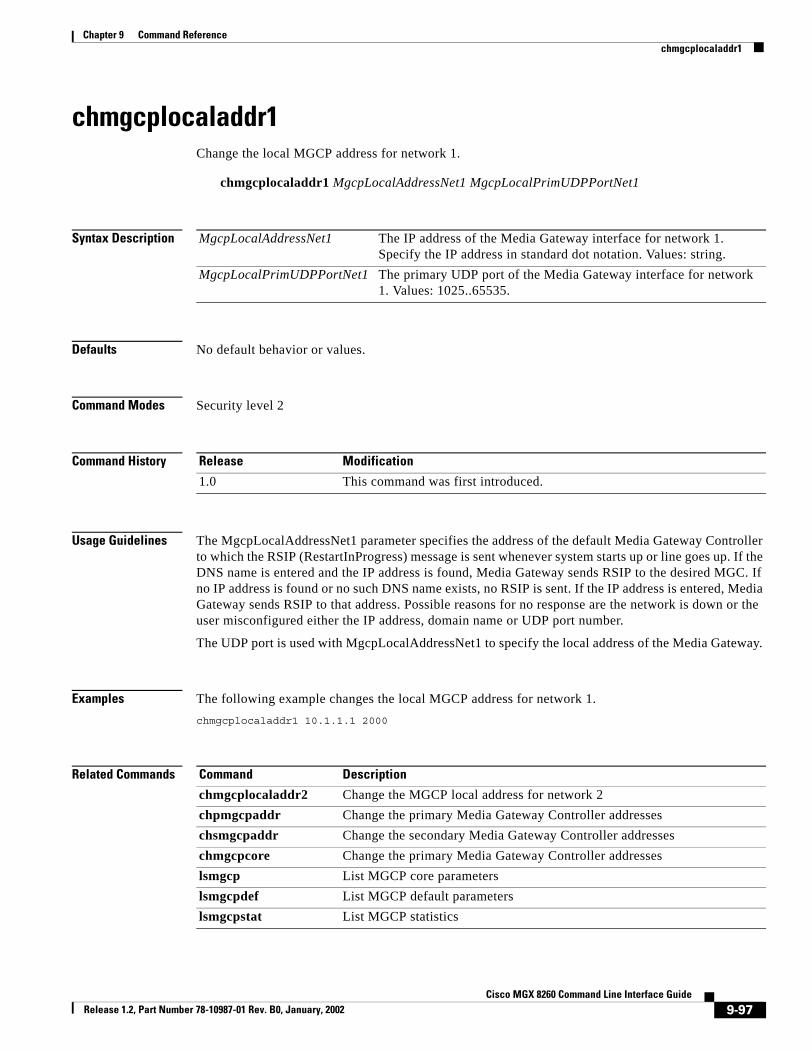
Chapter 9 Command Referencechmgcplocaladdr1
chmgcplocaladdr1Change the local MGCP address for network 1.
chmgcplocaladdr1 MgcpLocalAddressNet1 MgcpLocalPrimUDPPortNet1
Syntax Description
Defaults No default behavior or values.
Command Modes Security level 2
Command History
Usage Guidelines The MgcpLocalAddressNet1 parameter specifies the address of the default Media Gateway Controller to which the RSIP (RestartInProgress) message is sent whenever system starts up or line goes up. If the DNS name is entered and the IP address is found, Media Gateway sends RSIP to the desired MGC. If no IP address is found or no such DNS name exists, no RSIP is sent. If the IP address is entered, Media Gateway sends RSIP to that address. Possible reasons for no response are the network is down or the user misconfigured either the IP address, domain name or UDP port number.
The UDP port is used with MgcpLocalAddressNet1 to specify the local address of the Media Gateway.
Examples The following example changes the local MGCP address for network 1.chmgcplocaladdr1 10.1.1.1 2000
Related Commands
MgcpLocalAddressNet1 The IP address of the Media Gateway interface for network 1. Specify the IP address in standard dot notation. Values: string.
MgcpLocalPrimUDPPortNet1 The primary UDP port of the Media Gateway interface for network 1. Values: 1025..65535.
Release Modification
1.0 This command was first introduced.
Command Description
chmgcplocaladdr2 Change the MGCP local address for network 2chpmgcpaddr Change the primary Media Gateway Controller addresseschsmgcpaddr Change the secondary Media Gateway Controller addresseschmgcpcore Change the primary Media Gateway Controller addresseslsmgcp List MGCP core parameterslsmgcpdef List MGCP default parameterslsmgcpstat List MGCP statistics
9-97Cisco MGX 8260 Command Line Interface Guide
Release 1.2, Part Number 78-10987-01 Rev. B0, January, 2002

Chapter 9 Command Referencechmgcplocaladdr2
chmgcplocaladdr2Change the MGCP local address for network 2.
chmgcplocaladdr2 MgcpLocalAddressNet2 MgcpLocalPrimUDPPortNet2
Syntax Description
Defaults No default behavior or values.
Command Modes Security level 2
Command History
Usage Guidelines The MgcpLocalAddressNet parameter specifies the address of the default Media Gateway Controller to which the RSIP (RestartInProgress) message is sent whenever system starts up or line goes up. If the DNS name is entered and the IP address is found, Media Gateway sends RSIP to the desired MGC. If no IP address is found or no such DNS name exists, no RSIP is sent. If the IP address is entered, Media Gateway sends RSIP to that address. Possible reasons for no response are the network is down or the user misconfigured either the IP address, domain name or UDP port number.
The UDP port is used with MgcpLocalAddressNet parameter to specify the local address of the Media Gateway.
Examples The following example changes the MGCP local address for network 2.chmgcplocaladdr2 10.10.1.1 2000
Related Commands
MgcpLocalAddressNet2 The IP address of the Media Gateway interface for network 2. Specify the IP address in standard dot notation.
MgcpLocalPrimUDPPortNet2 The primary UDP port of the Media Gateway interface for network 2. Values: 1025..65535.
Release Modification
1.0 This command was first introduced.
Command Description
chmgcplocaladdr1 Change the MGCP local address for network 1chpmgcpaddr Change the primary Media Gateway Controller addresseschsmgcpaddr Change the secondary Media Gateway Controller addresseschmgcpcore Change the primary Media Gateway Controller addresseslsmgcp List MGCP core parameterslsmgcpdef List MGCP default parameterslsmgcpstat List MGCP statistics
9-98Cisco MGX 8260 Command Line Interface Guide
Release 1.2, Part Number 78-10987-01 Rev. B0, January, 2002

Chapter 9 Command Referencechmpc
chmpcConfigure default MPC parameters.
chmpc DefTypeNetwork DefPktnPeriod DefBandwidth DefEchoCancel DefSilenceSupp DefTypeOfService DefResourceRes DefCOTReceiveTone DefCOTTransmitTone Encoding
Syntax Description DefTypeNetwork The type of network.
1=voIp
2=voAtm
3=localDefPktnPeriod Packetization period in milliseconds. Value: fixed at 10DefBandwidth The network bandwidth in kbps. Values: 8 and 64 kbpsDefEchoCancel Enables or disables echo cancellation.
1=off
2=onDefSilenceSupp Enables or disables silence suppression.
1=off
2=onDefTypeOfService The type of Service. Values: 1-256, where 1 indicates no service typeDefResourceRes The resource reservation type.
1=bestEffort
2=guaranteed
3=notUsed
4=controlledLoadDefCOTReceiveTone The default receive tone. For transponder COT, when the media gateway
controller does not supply the tones, the default tone the gateway receives is the default COT receive tone.
1=co1 (2010 Hz)
2=co2 (1780 Hz)DefCOTTransmitTone The default transmit tone. For transponder COT, when the media gateway
controller does not supply the tones, the default tone the gateway transmits is the default COT transmit tone.
1=co1
2=co2Encoding The type of voice encoding when not specified by the MGC:
1=PCMA—A-law encoding
2=PCMU—Mu-law encoding
3=G729A
4=G72632K
9-99Cisco MGX 8260 Command Line Interface Guide
Release 1.2, Part Number 78-10987-01 Rev. B0, January, 2002

Chapter 9 Command Referencechmpc
Defaults DefTypeNetwork: 3
DefPktnPeriod: 10
DefBandwidth: 64
DefEchoCancel: 1
DefSilenceSupp: 1
DefTypeOfService: 2
DefResourceRes: 1
DefCOTReceiveTone: 1
DefCOTTransmitTone: 2
Command Modes Security level 2
Command History
Usage Guidelines Use this command to configure default MPC parameters.
Examples The following sets the network type to local.chmpc 3
Related Commands
Release Modification
1.1 This command was first introduced.
Command Description
lsmpc List MPC information.
9-100Cisco MGX 8260 Command Line Interface Guide
Release 1.2, Part Number 78-10987-01 Rev. B0, January, 2002

Chapter 9 Command Referencechndinf
chndinfConfigure node information.
chndinf RackNum NodeName NodeNum
Syntax Description
Defaults No default behavior or values.
Command Modes Security level 2
Command History
Usage Guidelines Use this command to configure system identification information and set the DS1 line type. You set the number of the physical rack, along with the name and number of the chassis. The rack contains the shelf, or chassis, for a node.
Examples The following example configures node information.chndinf 3 Floor3 12
Related Commands
RackNum Shelf number for node. Values: 1 - 100. NodeName Alphanumeric identifier for node. Values: up to 15 charactersNodeNum Numeric identifier for node. Values: Integer, 1 - 1000
Release Modification
1.0 This command was first introduced.
Command Description
chsyslnmd Change the line mode for the chassis.lsndinf List node information.
9-101Cisco MGX 8260 Command Line Interface Guide
Release 1.2, Part Number 78-10987-01 Rev. B0, January, 2002

Chapter 9 Command Referencechpclksrc
chpclksrcChange primary clock source.
chpclksrc SlotNum LineNum ClkSrcType CardType
Syntax Description
Defaults No default behavior or values.
Command Modes Security level 2
Command History
Usage Guidelines Use this command to configure the primary clock source. If the Type parameter is broadband or narrowband, the Slot Num and Line Num parameters are mandatory. If the Type is external or internal, do not provide this parameter.
Examples The first example configures an external clock source. The second configures a broadband clock source on slot 12, line 8.chpclksrc # # 3 #chpclksrc 12 8 1 #
SlotNum Slot number of the clock source. Values: 1 to 16LineNum Line number of clock source. Values:
NSC DS1 lines: 1 to 16
BSC DS3 lines: 501 to 506
DMC DS3 lines: 1 to 6
SCC, OC3 type: 1 to 4
SCC, BITS type: 1 ClkSrcType Type of clock source, broadband, narrowband, external, or internal. Values:
1, 2, 3, and 4 respectively.CardType Type of card, bits or OC3. Values 1 and 2, respectively.
Release Modification
1.0 This command was first introduced.1.1 Added BSC extensions1.2 Added OC-3 extensions
9-102Cisco MGX 8260 Command Line Interface Guide
Release 1.2, Part Number 78-10987-01 Rev. B0, January, 2002

Chapter 9 Command Referencechpclksrc
Related Commands Command Description
chsclksrc Change secondary clock sourceswclk Switch clocklsclksrcs List all clock sources
9-103Cisco MGX 8260 Command Line Interface Guide
Release 1.2, Part Number 78-10987-01 Rev. B0, January, 2002

Chapter 9 Command Referencechpcs
chpcsConfigure primary control server.
chpcs Address Interface Check
Syntax Description
Defaults No default behavior or values.
Command Modes Security level 2
Command History
Usage Guidelines Use this command to configure the IP address and interface of the primary MCS.
Examples The following example configures the primary CS.chpcs 10.10.10.1 5003 1
Address Primary MCS address in dotted notation w.x.y.z.Interface Default tcp port number for primary MCS. Values: Integer > 1024.Check Enables or disables the MSCP health check. Values: 1 = enabled, 2 =
disabled
Release Modification
1.0 This command was first introduced.
9-104Cisco MGX 8260 Command Line Interface Guide
Release 1.2, Part Number 78-10987-01 Rev. B0, January, 2002

Chapter 9 Command Referencechpmgcpaddr
chpmgcpaddrChange the primary Media Gateway Controller addresses.
chpmgcpaddr MgcpPMGCAddressNet1 MgcpPMGCCfgUDPPortNet1 MgcpPMGCAddressNet2 MgcpPMGCCfgUDPPortNet2
Syntax Description
Defaults No default behavior or values.
Command Modes Security level 2
Command History
Usage Guidelines The MgcpMGCCfgaddress parameter specifies the address of the default Media Gateway Controller to which the RSIP (RestartInProgress) message is sent whenever system starts up or line goes up. If the DNS name is entered and the IP address is found, Media Gateway sends RSIP to the desired MGC. If no IP address is found or no such DNS name exists, no RSIP is sent. If the IP address is entered, Media Gateway sends RSIP to that address. Possible reasons for no response are the network is down or the user misconfigured either the IP address, domain name or UDP port number.
The UDP port is used with MgcpPMGCAddress to specify the local address of the Media Gateway.
Examples The following example sets the primary MGCP controller addresses for a redundant network configuration.chpmgcpaddr 10.1.1.1 2000 10.10.1.1 2000
MgcpPMGCAddressNet1 The IP address of the Primary Media Gateway Controller on network 1. Specify the IP address in standard dot notation. Values: string.
MgcpPMGCCfgUDPPortNet1 The UDP port of the Media Gateway Controller on network 2. Values: 1025..65535.
MgcpPMGCAddressNet2 The IP address of the Primary Media Gateway Controller on network 2. Specify the IP address in standard dot notation. Values: string.
MgcpPMGCCfgUDPPortNet2 The secondary UDP port of the Media Gateway Controller on network 2. Values: 1025..65535.
Release Modification
1.0 This command was first introduced.
9-105Cisco MGX 8260 Command Line Interface Guide
Release 1.2, Part Number 78-10987-01 Rev. B0, January, 2002

Chapter 9 Command Referencechpmgcpaddr
Related Commands Command Description
chmgcplocaladdr1 Change the MGCP local address for network 1chmgcplocaladdr2 Change the MGCP local address for network 2chsmgcpaddr Change the secondary Media Gateway Controller addresseslsmgcp List MGCP core parameterslsmgcpdef List MGCP default parameterslsmgcpstat List MGCP statistics
9-106Cisco MGX 8260 Command Line Interface Guide
Release 1.2, Part Number 78-10987-01 Rev. B0, January, 2002

Chapter 9 Command Referencechprotocol
chprotocolSwitch between MGCP and IPDC protocols.
chprotocol protocol
Syntax Description
Defaults protocol: 1
Command Modes Security level 2
Command History
Usage Guidelines The MGX 8260 Media Gateway supports two protocols for voice call control, MGCP and IPDC. Use this command to switch from one protocol to the other. This command automatically resets the chassis.
Examples The following example switches from MGCP to IPDC.chprotocol 2
Related Commands
protocol The call control protocol. Values: 1 = MGCP; 2 = IPDC
Release Modification
1.2 This command was first introduced.
Command Description
chipdcpssip Change IPDC primary Soft Switch IP and TCP portchipdcsssip Change IPDC secondary Soft Switch IP and TCP portchipdcgwip Change IPDC gateway IP and TCP portchipdcssid Change IPDC system IDchipdcsstype Change IPDC system typechipdcssbaynum Change IPDC Bay Numberchipdcmaxm Change IPDC Maximum Moduleschipdcssnumfor Change IPDC Numbering formatchipdcssadm Change IPDC Admin Statuschipdcsshlth Change IPDC Health Checkchipdctimer Change IPDC Timerschpseudoip Change pseudo IP address lsipdc List IPDC Soft Switch configurationlsipdctimer List IPDC Timer Configurationlsipdccot List IPDC COT Configuration
9-107Cisco MGX 8260 Command Line Interface Guide
Release 1.2, Part Number 78-10987-01 Rev. B0, January, 2002

Chapter 9 Command Referencechpseudoip
chpseudoipChange pseudo IP address for IPDC.
chpseudoip [pseip]
Syntax Description
Defaults No default behavior or values.
Command Modes Security level
Command History
Usage Guidelines Use this command to configure a pseudo IP address that represents the four broadband ports. This IP address simplifies call control because the Soft Switch can reference one IP address rather than four. The MGX 8260 Media Gateway balances the load among the broadband interfaces. This pseudo address must be on the same subnet as the broadband ports.
Examples The following example sets the pseudo IP address at 10.1.1.1.chpseudoip 10.1.1.1
Related Commands
pseip This IP address that is used to change IP address for IPDC.
Release Modification
1.1 This command was first introduced.
Command Description
chipdcpssip Change IPDC primary Soft Switch IP and TCP portchipdcsssip Change IPDC secondary Soft Switch IP and TCP portchipdcgwip Change IPDC gateway IP and TCP portchipdcssid Change IPDC system IDchipdcsstype Change IPDC system typechipdcssbaynum Change IPDC Bay Numberchipdcmaxm Change IPDC Maximum Moduleschipdcssnumfor Change IPDC Numbering formatchipdcssadm Change IPDC Admin Statuschipdcsshlth Change IPDC Health Checkchipdctimer Change IPDC Timerschipdccot Change IPDC COTslsipdc List IPDC Soft Switch configuration
9-108Cisco MGX 8260 Command Line Interface Guide
Release 1.2, Part Number 78-10987-01 Rev. B0, January, 2002

Chapter 9 Command Referencechpseudoip
lsipdctimer List IPDC Timer Configurationlsipdccot List IPDC COT Configuration
Command Description
9-109Cisco MGX 8260 Command Line Interface Guide
Release 1.2, Part Number 78-10987-01 Rev. B0, January, 2002

Chapter 9 Command Referencechpwd
chpwdChange password.
chpwd
Syntax Description This command has no arguments or keywords.
Command Modes Security level 1-6
Command History
Usage Guidelines Use this interactive command to change the password of an existing account. To use this command, you must first log onto the account you want to change. Generally, users change their own passwords with this command.
Examples The following example shows the interactive session for a password change:MGX.9.ACTIVE-> chpwd
Rules: 1. Password length must be 4 - 10 2. First character must be alphanumeric 3. Only printable characters are allowed 4. Space not allowed
Enter Password : *****New Password : ********Verify Password: ********
Release Modification
1.0 This command was first introduced.
9-110Cisco MGX 8260 Command Line Interface Guide
Release 1.2, Part Number 78-10987-01 Rev. B0, January, 2002

Chapter 9 Command Referencechqprf
chqprfChange queue profile.
chqprf Card Queue#
Syntax Description
Defaults Queue#: 1
Command Modes Security level 2
Command History
Usage Guidelines Specifies the ATM traffic queue profile for an entire SCC card. The MGX 8260 defines 10 profiles for different traffic types. Profile 1 is recommended.
Examples The following example changes the profile of card 9 to give it an ATM queue profile of 2.chqprf 9 2
Card The number of an SCC card.Queue# The ATM queue profile number. Values: 1 - 10.
Release Modification
1.0 This command was first introduced.
9-111Cisco MGX 8260 Command Line Interface Guide
Release 1.2, Part Number 78-10987-01 Rev. B0, January, 2002

Chapter 9 Command Referencechsclksrc
chsclksrcChange secondary clock source.
chsclksrc Slot Line ClkSrcType CardType
Syntax Description
Defaults No default behavior or values.
Command Modes Security level 2
Command History
Usage Guidelines Use this command to configure the secondary clock source. If the Type parameter is broadband or narrowband, the Slot Num and Line Num parameters are mandatory. If the Type is external or internal, do not provide this parameter.
Examples The first example configures a external bits clock source. The second configures a broadband clock source on slot 1, line 2.chsclksrc # # 3 1chsclksrc 1 2 1 2
Related Commands
Slot Slot number of the clock source.Line Line number of clock source.Type Type of clock source, broadband, narrowband, external, or internal. Values:
1, 2, 3, and 4 respectively.CardType Type of card, bits or OC3. Values 1 and 2, respectively.
Release Modification
1.0 This command was first introduced.
Command Description
chpclksrc Change primary clock sourceswclk Switch clock lsclksrcs List clock sources
9-112Cisco MGX 8260 Command Line Interface Guide
Release 1.2, Part Number 78-10987-01 Rev. B0, January, 2002

Chapter 9 Command Referencechscs
chscsChange secondary control server (reserved for future use).
chscs Address Interface Check
Syntax Description
Defaults No default values or behavior.
Command Modes Security level 2
Command History
Usage Guidelines Use this command to configure the IP address and interface for the secondary MCS.
Examples The following examples configures a secondary control server at 10.10.10.1 for a PPP interface.chscs 10.10.10.1 3 5004 2
Address Secondary MCS IP address in dotted notation w.x.y.zInterface Secondary tcp port number for sending IP packets to the secondary MCSCheck Enables or disables the MSCP health check. Values: 1 = enabled, 2 =
disabled
Release Modification
1.0 This command was first introduced.
9-113Cisco MGX 8260 Command Line Interface Guide
Release 1.2, Part Number 78-10987-01 Rev. B0, January, 2002

Chapter 9 Command Referencechsmgcpaddr
chsmgcpaddrChange the secondary Media Gateway Controller addresses.
chsmgcpaddr MgcpSMGCAddressNet1 MgcpSMGCCfgUDPPortNet1 MgcpSMGCAddressNet2 MgcpSMGCCfgUDPPortNet2
Syntax Description
Defaults No default behavior or values.
Command Modes Security level 2
Command History
Usage Guidelines The MgcpSMGCAddressNet parameter specifies the address of the default Media Gateway Controller to which the RSIP (RestartInProgress) message is sent whenever system starts up or line goes up. If the DNS name is entered and the IP address is found, Media Gateway sends RSIP to the desired MGC. If no IP address is found or no such DNS name exists, no RSIP is sent. If the IP address is entered, Media Gateway sends RSIP to that address. Possible reasons for no response are the network is down or the user misconfigured either the IP address, domain name or UDP port number.
The UDP port is used with MgcpSMGCAddressNet to specify the local address of the Media Gateway.
Examples The following example sets the primary MGCP controller addresses for a redundant network configuration.chsmgcpaddr 10.1.1.3 2000 10.10.1.4 2000
Related Commands
MgcpSMGCAddressNet1 The IP address of the Secondary Media Gateway Controller on network 1. Specify the IP address in standard dot notation. Values: string.
MgcpSMGCCfgUDPPortNet1 The UDP port of the Media Gateway Controller on network 1. Values: 1025..65535.
MgcpSMGCAddressNet2 The IP address of the Secondary Media Gateway Controller on network 2. Specify the IP address in standard dot notation. Values: string.
MgcpSMGCCfgUDPPortNet2 The UDP port of the Media Gateway Controller on network 2. Values: 1025..65535.
Release Modification
1.0 This command was first introduced.
9-114Cisco MGX 8260 Command Line Interface Guide
Release 1.2, Part Number 78-10987-01 Rev. B0, January, 2002

Chapter 9 Command Referencechsmgcpaddr
Command Description
chmgcplocaladdr1 Change the MGCP local address for network 1chmgcplocaladdr2 Change the MGCP local address for network 2chpmgcpaddr Change the primary Media Gateway Controller addresseslsmgcp List MGCP core parameterslsmgcpdef List MGCP default parameterslsmgcpstat List MGCP statistics
9-115Cisco MGX 8260 Command Line Interface Guide
Release 1.2, Part Number 78-10987-01 Rev. B0, January, 2002

Chapter 9 Command Referencechsonetalm
chsonetalmChange SONET alarm thresholds.
chsonetalm Location [redSeverity yellow Severity perfSeverity SeCV15MinThresh SeCV24HrThresh SeES15MinThresh SeES24HrThresh SeSES15MinThresh SeSES24HrThresh SeSEFS15MinThresh SeSEFS24HrThresh LCV15MinThresh LCV24HrThresh LES15MinThresh LES24HrThresh LSES15MinThresh LSES24HrThresh LUAS15MinThresh LUAS24HrThresh PCV15MinThresh PCV24HrThresh PES15MinThresh PES24HrThresh PSES15MinThresh PSES24HrThresh PUAS15MinThresh PUAS24HrThresh]
Location The slot and line number, delimited by a period, of the OC-3 line.Valid slot: 9. Valid lines: 1-4
redSeverity The red alarm severity:
1=Minor (reserved for future use)
2=MajoryellowSeverity The yellow alarm severity:
1=Minor
2=Major (reserved for future use)perfSeverity The performance alarm severity:
1=Minor
2=Major (reserved for future use)SeCV15MinThresh The section threshold for code violations in a 15-minute or sliding 24-hour
window. Code violations are Bit Interleaved Parity errors detected in the incoming signal.
SeCV24HrThresh
SeES15MinThresh The section threshold for errored seconds in a 15-minute or sliding 24-hour window. An errored second is a second with one or more code violations at that layer or incoming defects.
SeES24HrThresh
SeSES15MinThresh The section threshold for severely errored seconds in a 15-minute or sliding 24-hour window. A severely errored second is one in which code violations or incoming defects occurred.
SeSES24HrThresh
SeSEFS15MinThresh The section threshold for severely errored frame seconds in a 15-minute or sliding 24-hour window. A SEFS is a second containing one or more SEF events.
SeSEFS24HrThresh
LCV15MinThresh The line threshold for code violations in a 15-minute or sliding 24-hour window. Code violations are Bit Interleaved Parity errors detected in the incoming signal.
LCV24HrThresh
LES15MinThresh The line threshold for errored seconds in a 15-minute or sliding 24-hour window. An errored second is a second with one or more code violations at that layer or incoming defects.
LES24HrThresh
LSES15MinThresh The line threshold for severely errored seconds in a 15-minute or sliding 24-hour window. A severely errored second is one in which code violations or incoming defects occurred.
LSES24HrThresh
LUAS15MinThresh The line threshold for unavailable seconds in a 15-minute or sliding 24-hour window. Unavailable seconds represent the number of seconds that the interface is unavailable.
LUAS24HrThresh
9-116Cisco MGX 8260 Command Line Interface Guide
Release 1.2, Part Number 78-10987-01 Rev. B0, January, 2002

Chapter 9 Command Referencechsonetalm
Defaults This command has no default behavior or values. The following defaults apply to a new SONET line:
redSeverity: 2
yellowSeverity: 1
perfSeverity: 1
SeCV15MinThresh: 15
SeCV24HrThresh: 134
SeES15MinThresh: 12
SeES24HrThresh: 120
SeSES15MinThresh: 10
SeSES24HrThresh: 100
SeSEFS15MinThresh: 5
SeSEFS24HrThresh: 20
LCV15MinThresh: 15
LCV24HrThresh: 134
LES15MinThresh: 12
LES24HrThresh: 120
LSES15MinThresh: 10
LSES24HrThresh: 100
LUAS15MinThresh: 12
LUAS24HrThresh: 20
PCV15MinThresh: 15
PCV24HrThresh: 134
PES15MinThresh: 12
PES24HrThresh: 120
PSES15MinThresh: 10
PSES24HrThresh: 100
PCV15MinThresh The path threshold for code violations in a 15-minute or sliding 24-hour window. Code violations are Bit Interleaved Parity errors detected in the incoming signal.
PCV24HrThresh
PES15MinThresh The path threshold for errored seconds in a 15-minute or sliding 24-hour window. An errored second is a second with one or more code violations at that layer or incoming defects.
PES24HrThresh
PSES15MinThresh The path threshold for severely errored seconds in a 15-minute or sliding 24-hour window. A severely errored second is one in which code violations or incoming defects occurred.
PSES24HrThresh
PUAS15MinThresh The path threshold for unavailable seconds in a 15-minute or sliding 24-hour window. Unavailable seconds represent the number of seconds that the interface is unavailable.
PUAS24HrThresh
9-117Cisco MGX 8260 Command Line Interface Guide
Release 1.2, Part Number 78-10987-01 Rev. B0, January, 2002

Chapter 9 Command Referencechsonetalm
PUAS15MinThresh: 12
PUAS24HrThresh: 120
Command Modes Security level 3
Command History
Usage Guidelines Use this command to enable and configure alarm thresholds for SONET lines. When a counter exceeds a threshold, the system raises the performance alarm.
Examples The following example changes the threshold for code violations in a 15-minute window:chsonetalm 9.1 # # # 30
Related Commands
Release Modification
1.2 This command was first introduced.
Command Description
chsonetperdi Change SONET E-RDI parameterschsonettrace Change SONET trace parameterschsonetexptrace Change SONET expected trace parameterslssonetlnerdi List E-RDI information for a SONET linelssonetlnerdis List summary E-RDI information for all SONET lines
9-118Cisco MGX 8260 Command Line Interface Guide
Release 1.2, Part Number 78-10987-01 Rev. B0, January, 2002

Chapter 9 Command Referencechsonetexptrace
chsonetexptraceChange expected path trace parameters for SONET lines.
chsonetexptrace Location [numOfLines expTraceIdLen expTraceId expTraceIdPosition]
Syntax Description
Defaults numOfLines: 1
Command Modes Security level 3
Command History
Usage Guidelines Use this command to configure the path trace parameters for SONET lines. This command works in conjunction with the chsonettrace and chsonetperdi commands to configure a SONET line test.
Location The slot and line number, delimited by a period, of the OC-3 line.Valid slot: 9. Valid lines: 1-4
numOfLines The number of lines to add. Values: 1-4.expTraceIdLen The expected trace identifier length for the SONET path:
16=message contains 16 bytes (SDH only)
64=message contains 64 bytes (SONET or SDH)expTraceId The expected trace identifier in the SONET path overhead. Value: ASCII
string of either 16 or 62 characters, depending on the TraceIdLen setting. You specify the ASCII characters as pairs of hexidecimal characters. For example, a you express a space as 20.
Note 1: The 16 byte message normally alters one byte for synchronization, as defined by TraceIdPosition.
Note 2: The 64 byte message uses the last two bytes for synchronization, so the maximum trace identifier length is 62 ASCII characters. Only printable ASCII characters are allowed.
expTraceIdPosition The position within a 16-byte message of the synchronization byte. The most significant bit of this byte is set high. Values: 1-16.
Alternatively, this parameter defines the following special cases:
0=No bit set
17=All most significant bits set low
Release Modification
1.2 This command was first introduced.
9-119Cisco MGX 8260 Command Line Interface Guide
Release 1.2, Part Number 78-10987-01 Rev. B0, January, 2002

Chapter 9 Command Referencechsonetexptrace
Examples The following example defines an expected trace identifier of hello world in a 64-byte message for line 1 of slot 9:chsonetexptrace 9.1 64 48656c6c6f20576f726c64
Related Commands Command Description
chsonetperdi Change SONET path e-rdi parameterschsonettrace Change SONET trace parameterslssonetlnerdi List E-RDI information for a SONET linelssonetlnerdis List summary E-RDI information for all SONET lines
9-120Cisco MGX 8260 Command Line Interface Guide
Release 1.2, Part Number 78-10987-01 Rev. B0, January, 2002
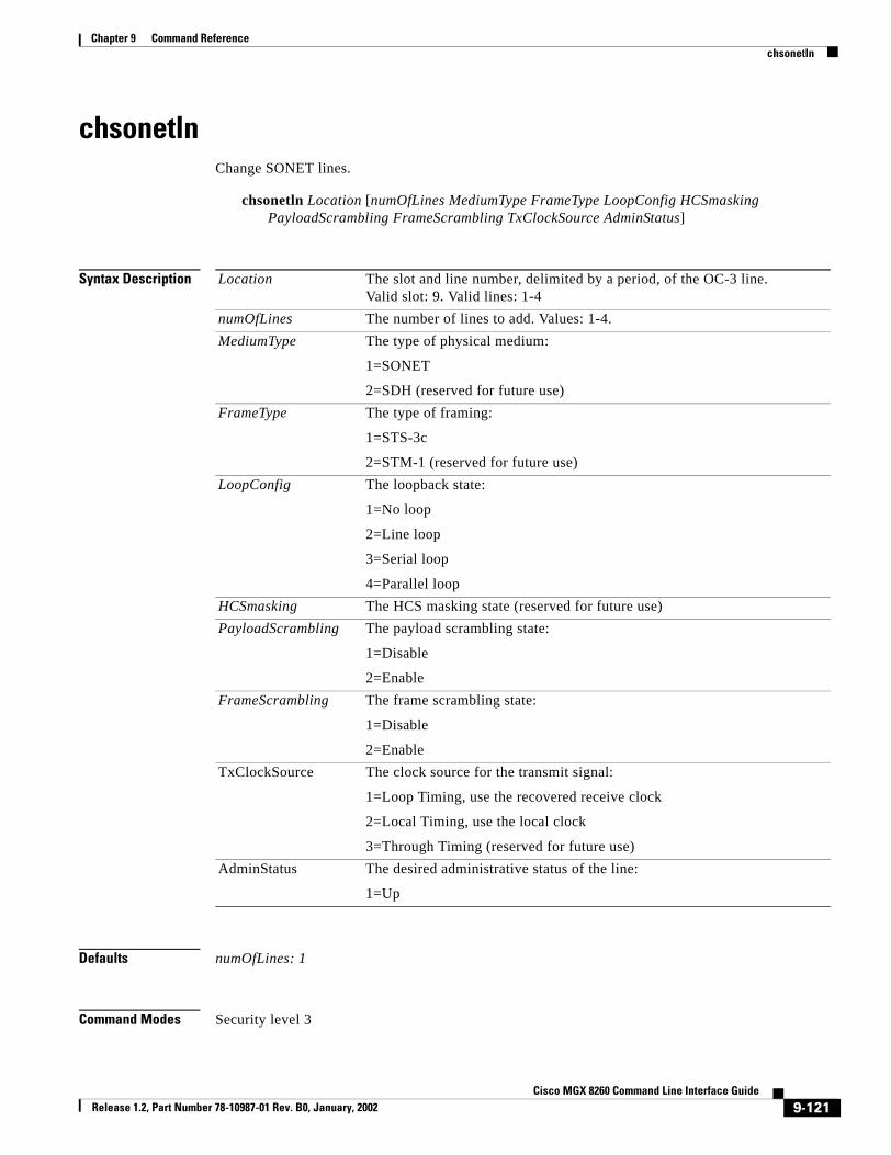
Chapter 9 Command Referencechsonetln
chsonetlnChange SONET lines.
chsonetln Location [numOfLines MediumType FrameType LoopConfig HCSmasking PayloadScrambling FrameScrambling TxClockSource AdminStatus]
Syntax Description
Defaults numOfLines: 1
Command Modes Security level 3
Location The slot and line number, delimited by a period, of the OC-3 line.Valid slot: 9. Valid lines: 1-4
numOfLines The number of lines to add. Values: 1-4.MediumType The type of physical medium:
1=SONET
2=SDH (reserved for future use)FrameType The type of framing:
1=STS-3c
2=STM-1 (reserved for future use)LoopConfig The loopback state:
1=No loop
2=Line loop
3=Serial loop
4=Parallel loopHCSmasking The HCS masking state (reserved for future use)PayloadScrambling The payload scrambling state:
1=Disable
2=EnableFrameScrambling The frame scrambling state:
1=Disable
2=EnableTxClockSource The clock source for the transmit signal:
1=Loop Timing, use the recovered receive clock
2=Local Timing, use the local clock
3=Through Timing (reserved for future use)AdminStatus The desired administrative status of the line:
1=Up
9-121Cisco MGX 8260 Command Line Interface Guide
Release 1.2, Part Number 78-10987-01 Rev. B0, January, 2002

Chapter 9 Command Referencechsonetln
Command History
Usage Guidelines Use this command to change the configuration of SONET/SDH interfaces on the OC-3 SCC and back card. Although the SCC may occupy physical slots 9 or 10, you always configure logical slot 9. This command only applies to the OC-3 SCC.
You can change a single line or a range of lines with this command. The system changes lines one at a time and aborts on the first failure, even if subsequent changes could have succeeded. The system issues an error message for partially fulfilled requests.
Examples The following example activates a line loopback on a SONET line:chsonetln 9.1 # # # 2
Related Commands
Release Modification
1.2 This command was first introduced.
Command Description
addsonetln Add a SONET linedelsonetln Delete a SONET linelssonetln List information about a SONET linelssonetlns List information about all SONET lines
9-122Cisco MGX 8260 Command Line Interface Guide
Release 1.2, Part Number 78-10987-01 Rev. B0, January, 2002

Chapter 9 Command Referencechsonetperdi
chsonetperdiChange extended rdi parameters for SONET paths.
chsonetperdi Location [numOfLines SupportPathERDI SignalLabel ExpectedSignalLabel]
Syntax Description
Defaults numOfLines: 1
SupportPathERDI: 1
SignalLabel: 19
ExpectedSignalLabel: 19
Command Modes Security level 3
Command History
Usage Guidelines Use this command to enable and configure the e-rdi feature for SONET lines. This feature is disabled by default when you add SONET lines.
Examples The following example enables e-rdi for SONET line 1 in slot 9:chsonetperdi 9.1 1 2
Location The slot and line number, delimited by a period, of the OC-3 line.Valid slot: 9. Valid lines: 1-4
numOfLines The number of lines to add. Values: 1-4.SupportPathERDI The state of the enhanced remote defect indication for the SONET path:
1=Disable
2=EnableSignalLabel The signal label to transmit in the SONET path overhead:
1=No specific payload type
19=ATM
207=Packet on SONETExpectedSignalLabel The expected signal label from the SONET path overhead:
1=No specific payload type
19=ATM
207=Packet on SONET
Release Modification
1.2 This command was first introduced.
9-123Cisco MGX 8260 Command Line Interface Guide
Release 1.2, Part Number 78-10987-01 Rev. B0, January, 2002

Chapter 9 Command Referencechsonetperdi
Related Commands Command Description
chsonettrace Change SONET trace parameterschsonetexptrace Change SONET expected trace parameterslssonetlnerdi List E-RDI information for a SONET linelssonetlnerdis List summary E-RDI information for all SONET lines
9-124Cisco MGX 8260 Command Line Interface Guide
Release 1.2, Part Number 78-10987-01 Rev. B0, January, 2002

Chapter 9 Command Referencechsonettrace
chsonettraceChange path trace parameters for SONET lines.
chsonettrace Location [numOfLines TraceIdLen TraceId TraceIdPosition]
Syntax Description
Defaults numOfLines: 1
Command Modes Security level 3
Command History
Usage Guidelines Use this command to configure the path trace parameters for SONET lines. This command works in conjunction with the chsonetexptrace and chsonetperdi commands to configure a SONET line test.
Examples The following example defines a trace identifier of hello world in a 64-byte message for line 1 of slot 9:chsonettrace 9.1 64 48656c6c6f20576f726c64
Location The slot and line number, delimited by a period, of the OC-3 line.Valid slot: 9. Valid lines: 1-4
numOfLines The number of lines to add. Values: 1-4.TraceIdLen The message length for the trace identifier:
16=message contains 16 bytes (SDH only)
64=message contains 64 bytes (SONET or SDH)TraceId The trace identifier to transmit in the SONET path overhead. Value: ASCII
string of either 16 or 62 characters, depending on the TraceIdLen setting. You specify the ASCII characters as pairs of hexidecimal characters. For example, a you express a space as 20.
Note 1: The 16 byte message normally alters one byte for synchronization, as defined by TraceIdPosition.
Note 2: The 64 byte message uses the last two bytes for synchronization, so the maximum trace identifier length is 62 characters. Only printable ASCII characters are allowed.
TraceIdPosition The position within a 16-byte message of the synchronization byte. The most significant bit of this byte is set high. Values: 1-16.
Alternatively, this parameter defines the following special cases:
0=No bit set
17=All most significant bits set low
Release Modification
1.2 This command was first introduced.
9-125Cisco MGX 8260 Command Line Interface Guide
Release 1.2, Part Number 78-10987-01 Rev. B0, January, 2002

Chapter 9 Command Referencechsonettrace
Related Commands Command Description
chsonetperdi Change SONET path e-rdi parameterschsonetexptrace Change SONET expected trace parameterslssonetlnerdi List E-RDI information for a SONET linelssonetlnerdis List summary E-RDI information for all SONET lines
9-126Cisco MGX 8260 Command Line Interface Guide
Release 1.2, Part Number 78-10987-01 Rev. B0, January, 2002

Chapter 9 Command Referencechsysip1
chsysip1Change system IP address 1.
chsysip1 Address Mask
Syntax Description
Defaults No default behavior or values.
Command Modes Security level 2
Command History
Usage Guidelines Use this command to configure the IP1 address and mask of the system management Ethernet 10BaseT interface.
Examples The following example configures the IP1 address and subnet mask of a system management interface.chsysip1 10.2.2.5 255.255.255.0
Related Commands
Address An IP1 address of the management interface in dotted notation w.x.y.z. Mask A subnet mask in dotted notation a.b.c.d.
Release Modification
1.0 This command was first introduced.
Command Description
chgw Change the gateway IP addresschibip Configure in-band IPchsysip2 Change system IP2lsmgips List management IP addresses
9-127Cisco MGX 8260 Command Line Interface Guide
Release 1.2, Part Number 78-10987-01 Rev. B0, January, 2002

Chapter 9 Command Referencechsysip2
chsysip2Change system IP address 2.
chsysip2 Address Mask
Syntax Description
Defaults No default behavior or values.
Command Modes Security level 2
Command History
Usage Guidelines Use this command to configure the IP2 address and mask of the system management Ethernet 10BaseT interface.
Examples The following example configures the IP2 address and subnet mask of a system management interface.chsysip2 10.2.2.5 255.255.255.0
Related Commands
Address An IP2 address of the management interface in dotted notation w.x.y.z. Mask A subnet mask in dotted notation a.b.c.d.
Release Modification
1.0 This command was first introduced.
Command Description
chgw Change the gateway IP addresschibip Configure in-band IPchsysip1 Change system IP1lsmgips List management IP addresses
9-128Cisco MGX 8260 Command Line Interface Guide
Release 1.2, Part Number 78-10987-01 Rev. B0, January, 2002

Chapter 9 Command Referencechsyslnmd
chsyslnmdChange the line mode to T1 or E1.
chsyslnmd Mode
Syntax Description
Defaults No default behavior or values for this command. The default mode for a new chassis is T1.
Command Modes Security level 1
Command History
Usage Guidelines Use this command to configure the chassis for T1 or E1 lines - you can’t mix T1 and E1 lines on a single chassis. Before switching from T1 to E1, verify the following conditions:
• The chassis has no BSCs installed
• The database contains no BSC configuration information
• The NSCs have no DS1 lines configured
When switching from E1 to T1, make sure there are no E1 lines configured. This command automatically resets the chassis.
Examples The following example changes the chassis to the E1 line mode.chsyslnmd 2
Related Commands
Mode The line mode for the chassis. Values:
1=T1
2=E1
Release Modification
1.2 This command was first introduced.
Command Description
chprotocol Change the call control protocol for the chassis
9-129Cisco MGX 8260 Command Line Interface Guide
Release 1.2, Part Number 78-10987-01 Rev. B0, January, 2002

Chapter 9 Command Referencechtime
chtimeChange time.
chtime H:M:S [Zone]
Syntax Description
Defaults No default behavior or values.
Command Modes Security level 2
Command History
Usage Guidelines Use this command to configure or change the system time, which may include the time zone. Set 25 integer world time zones from -12 through 0 (GMT) to +12 (see Table 9-4, which lists USA time zones values using civilian designations, such as EST).
H:M:S The system time in hours, minutes, and seconds delimited by colons. Values: 0-23 for hours and 0-60 for minutes and seconds.
Zone An integer from 1 to 25, representing a zone.
Release Modification
1.0 This command was first introduced.
Table 9-4 Time Zones
Zone Value Zone Value
gmtplus12 1 gmtminus01 14
gmtplus11 2 gmtminus02 15
gmtplus10 3 gmtminus03 16
gmtplus09 4 gmtminus04 17
gmtplus08 5 est 18
gmtplus07 6 cst 19
gmtplus06 7 pdt 20
gmtplus05 8 pst 21
gmtplus04 9 gmtminus9 22
gmtplus03 10 gmtminus10 23
gmtplus02 11 gmtminus11 24
gmtplus01 12 gmtminus12 25
gmt 13
9-130Cisco MGX 8260 Command Line Interface Guide
Release 1.2, Part Number 78-10987-01 Rev. B0, January, 2002

Chapter 9 Command Referencechtime
Examples The following example sets the system time to noon, Eastern Standard Time.chtime 12:00:00 18
Related Commands Command Description
chdate Change system datechtimezn Change system time zonelsdate List date
9-131Cisco MGX 8260 Command Line Interface Guide
Release 1.2, Part Number 78-10987-01 Rev. B0, January, 2002

Chapter 9 Command Referencechtimezn
chtimeznChange system time zone.
chtimezn number
Syntax Description
Defaults No default behavior or values.
Command Modes Security level 3
Command History
Usage Guidelines Use this command to change the system time zone. Set 25 integer world time zones from -12 through 0 (GMT) to +12 (see Table 9-4 on page 9-130, which lists USA time zones values using civilian designations, such as EST).
Examples The following example shows how to change the time zone to Pacific Standard Time. chtimezn 21
Related Commands
number The Time Zone where this MGX 8260 node is installed. Values: 1 - 25
Release Modification
1.0 This command was first introduced.
Command Description
chdate Change system datechtime Change system timelsdate List date
9-132Cisco MGX 8260 Command Line Interface Guide
Release 1.2, Part Number 78-10987-01 Rev. B0, January, 2002

Chapter 9 Command Referencechtmgr
chtmgrChange trap manager.
chtmgr Addr Port Interface Com_String Bitmap
Syntax Description Addr The address of the SNMP manager who wants to receive trap events.Port Port to which the traps are transmitted. Interface The default interface for initially sending traps if the routing table has no
trap manager. Values:
1 = scc-eth-if, the default system Ethernet management interface on SCC.
2 = inband-if, the in-band management interface.
3 = ppp-if, the PPP interface.Com_String SNMP community string for the trap manager. Bitmap A bitwise specification of trap categories to subscribe. Each bit represents
a category of traps. Bit values: 1 = subscribe 0, = do not subscribe. Trap subscription bitmap specifications are:
Bit 0=Major (trap severity selection)
Bit 1=Minor (trap severity selection
Bit 2=Information (trap severity selection)
Bit 3=Shelf
Bit 4=Card
Bit 5=SNMP
Bit 6=Dsx1 Line
Bit 7=Dsx3 Line
Bit 8=Sonet Line
Bit 9=Ethernet Line
Bit 10=Voice Port
Bit 11=Ethernet Channel
Bit 12=Voice Channel
Bit 13=EMM
Bit 14=Clock
Bit 15=DSP
Bit 16=DMCMAP
Bit 17=ISDN
Bit 18=MGCP
Bit 19=Backhaul Session
The first three bit positions indicate which trap severity categories they are interested in. If you specify severity without specifying any other trap categories, managers receive traps from all categories.
9-133Cisco MGX 8260 Command Line Interface Guide
Release 1.2, Part Number 78-10987-01 Rev. B0, January, 2002

Chapter 9 Command Referencechtmgr
Defaults Port: 162
Interface: 1
Com_String: “public”
Bitmap: 0
Command Modes Security level 3
Command History
Usage Guidelines Network administrators can receive email for up to 20 traps. Use this command to change a manager’s SNMP trap registrations.
Examples The following example changes the manager at address 10.1.1.10 and udp port 162 to receive events for the traps specified by bitmap 1100110.
The bitmap is a binary number that represents the settings.
To use this bitmap, convert it to a decimal value and specify it as the last argument. Binary 1100110 is 102 decimal. Therefore, you enter the command as follows:chtmgr 10.1.1.10 2 162 public 102
The second argument (2) sets the in-band interface as the default interface for sending traps when the routing table has no trap manager.
Related Commands
Release Modification
1.0 This command was first introduced.
Trap dsx1line SNMP Information Minor
Value 1 1 0 0 1 1 0
Bit 6 5 4 3 2 1 0
Command Description
addcms Add community stringaddtmgr Add trap managerdeltmgr Delete trap manager lstmgr List trap managerlstmgrs List trap managers
9-134Cisco MGX 8260 Command Line Interface Guide
Release 1.2, Part Number 78-10987-01 Rev. B0, January, 2002

Chapter 9 Command Referencechvport
chvportConfigure voice port.
chvport SlotNum PortNum RepitionNum WrapNum [Dejitter DejitteBufLen Maxdj Mindj PacketLoading EchoTail]
Syntax Description
Defaults ReptitionNum: 1
WrapNum: 384 for DS1, 480 for E1 (CAS on)
Command Modes Security level 3
SlotNum The logical slot number of an NSC. Values: 1 to 16PortNum The logical port number. Values 1 to 512ReptitionNum The number of ports to add. Values: 1 to 6944. This corresponds to 31 ports
per line, 16 lines per NSC, and 14 NSCs.WrapNum The DS0 number at which to wrap to the next slot. Set this to the maximum
number of DS0s the NSC in your configuration. For DS1 use 384 and for E1 use 480 with CAS or 496 without CAS. Values: 1 to 512
Dejitter The desired state, disabled or enabled, of the dejitter buffer. Values: 1 or 2, respectively.
DejitteBufLen The initial length of the dejitter buffer, specified in multiples of 10 msec. Values: 1 through Maxdj.
Maxdj The maximum length of the dejitter buffer, specified in multiples of 10 msec. Values: 1 through 50.
Mindj The minimum length of the dejitter buffer, specified in multiples of 10 msec. Values: 1 through DejitterBufLen.
PacketLoading The IP packet loading time for voice service, expressed in multiples of 10 msec. Values: 1 - 10.
EchoTail The length of the echo cancel tail:
1 = echo disabled
2 = tail24ms—24 msecs
3 = tail32ms—32 msecs
4 = tail48ms—48 msecs
5 = tail64ms—64 msecs
6 = tail80ms—80 msecs
6 = tail96ms—96 msecs
7 = tail112ms—112 msecs
8 = tail128ms—128 msecs
9-135Cisco MGX 8260 Command Line Interface Guide
Release 1.2, Part Number 78-10987-01 Rev. B0, January, 2002

Chapter 9 Command Referencechvport
Command History
Usage Guidelines Use this command to configure one or more voice ports.
Examples The following example disables the dejitter buffer for 4 lines starting slot 1 port 1.chvport 1 1 # 384 1
The system changes the packet loading for logical port one in slot one to 20 msec.
Related Commands
Release Modification
1.0 This command was first introduced.1.2 Added repetition and wrap numbers
Command Description
addvport Add voice portdelvport Delete voice portlsvport List voice portlsvports List voice ports
9-136Cisco MGX 8260 Command Line Interface Guide
Release 1.2, Part Number 78-10987-01 Rev. B0, January, 2002

Chapter 9 Command Referenceclralmhist
clralmhistClear alarm history.
clralmhist
Syntax Description The command has no arguments or keywords.
Defaults No default behavior or values.
Command Modes Security level 4
Command History
Usage Guidelines Use this command to delete alarm history.
Examples The following example clears the alarm history.clralmhist
Related Commands
Release Modification
1.0 This command was first introduced.
Command Description
lsalms List alarms
9-137Cisco MGX 8260 Command Line Interface Guide
Release 1.2, Part Number 78-10987-01 Rev. B0, January, 2002

Chapter 9 Command Referenceclrcdcnf
clrcdcnfClear configuration of a card.
clrcdcnf Num
Syntax Description
Defaults No default behavior or values.
Command Modes Security level 1
Command History
Usage Guidelines Clears the configuration of the specified card and resets it.
Examples The following example clears the configuration of the card in slot 3.clrcdcnf 3
Related Commands
Num The slot number of the card
Release Modification
1.0 This command was first introduced.
Command Description
chcdif Configure card interface
9-138Cisco MGX 8260 Command Line Interface Guide
Release 1.2, Part Number 78-10987-01 Rev. B0, January, 2002

Chapter 9 Command Referenceclrds1lnst
clrds1lnstClear T1 line statistics.
clrds1lnst Location Stat
Syntax Description
Defaults No default behavior or values.
Location The slot and line number, delimited by a period, of the DS1 line.Stat The statistic to clear: Values: one of the following integers.
1=No Action.
2=Clear all the counters in the ds1Stats Table and dsx1StatsPerfAlarmState.
3=Clear LCV 15 Minute counter in the dsx1CurrentTable.
4=Clear LCV 24 Hour counter in the dsx1TotalTable.
5=Clear LES 15 Minute counter in the dsx1CurrentTable.
6=Clear LES 24 Hour counter in the dsx1TotalTable.
7=Clear LSES 15 Minute counter in the dsx1CurrentTable.
8=Clear LSES 24 Hour counter in the dsx1TotalTable.
9=Clear PCV 15 Minute counter in the dsx1CurrentTable.
10=Clear PCV 24 Hour counter in the dsx1TotalTable.
11=Clear PES 15 Minute counter in the dsx1CurrentTable.
12=Clear PES 24 Hour counter in the dsx1TotalTable.
13=Clear PSES 15 Minute counter in the dsx1CurrentTable.
14=Clear PSES 24 Hour counter in the dsx1TotalTable.
15=Clear SEFS 15 Minute counter in the dsx1CurrentTable.
16=Clear SEFS 24 Hour counter in the dsx1TotalTable.
17=Clear PSAS 15 Minute counter in the dsx1CurrentTable.
18=Clear PSAS 24 Hour counter in the dsx1TotalTable.
19=Clear UAS 15 Minute counter in the dsx1CurrentTable.
20=Clear UAS 24 Hour counter in the dsx1TotalTable.
21=Clear all counters in the dsx1CurrentTable (15 minute counters).
22=Clear all counters in the dsx1TotalTable (24 hour counters).
23=Clear Bursty Errored Seconds in dsx1CurrentTable.
24=Clear Bursty Errored Seconds in dsx1TotalTable.
25= Clear Path Controlled Slip Seconds in the dsx1CurrentTable
26=Clear Path Controlled Slip Seconds in the dsx1TotalTable
9-139Cisco MGX 8260 Command Line Interface Guide
Release 1.2, Part Number 78-10987-01 Rev. B0, January, 2002

Chapter 9 Command Referenceclrds1lnst
Command Modes Security level 4
Command History
Usage Guidelines Use this command to clear the specified DS1 real-time statistic.
Examples The following example clears the LCV 24 Hour counter in the dsx1TotalTablefor the DS1 line at slot 1 line 1.clrds1lnst 1.1 4
Related Commands
Release Modification
1.0 This command was first introduced.
Command Description
lsbertds1 List DS1 BERT resultslsds1alm List DS1 alarm thresholdslsds1curst List DS1 current statisticslsds1cursts List DS1 current statisticslsds1intst List DS1 interval statistics lsds1ln List DS1 line lsds1lns List DS1 lineslsds1lnst List DS1 line statistics lsds1totst List DS1 total statisticslsds1totsts List DS1 total statisticslslns List existing linesoffbertds1 Stop BERT on DS1 onbertds1 Start BERT on DS1
9-140Cisco MGX 8260 Command Line Interface Guide
Release 1.2, Part Number 78-10987-01 Rev. B0, January, 2002

Chapter 9 Command Referenceclrds3lnst
clrds3lnstClear statistics for DS3 line.
clrds3lnst Index stats
Syntax Description
Defaults No default behavior or values.
Command Modes Security level 4
Command History
Usage Guidelines Clears the specified DS3 real-time statistic.
Examples The following examples clears the DS3 statistic at slot 7, line 1.clrds3lnst 7.1 2
Related Commands
Index The slot and line number, delimited by a period, of the DS3 line.
Valid slot numbers:
BSC: 11-16
DMC: 7 or 8 (reserved for future use)
Valid line numbers:
BSC: 501-506
DMC: 1-6 (reserved for future use)stats The instruction to clear or not to clear statistics.
1=Do not clear.
2=Clear
Release Modification
1.0 This command was first introduced.1.1 BSC card configuration - no functional change
Command Description
lsds3curst List DS3 current statisticslsds3cursts List all DS3 statisticslsds3intst List DS3 interval statisticslsds3ln List DS3 line
9-141Cisco MGX 8260 Command Line Interface Guide
Release 1.2, Part Number 78-10987-01 Rev. B0, January, 2002
Chapter 9 Command Referenceclrds3lnst
lsds3lns List DS3 lineslsds3totst List DS3 total statistics
Command Description
9-142Cisco MGX 8260 Command Line Interface Guide
Release 1.2, Part Number 78-10987-01 Rev. B0, January, 2002

Chapter 9 Command Referenceclre1lnst
clre1lnstClear E1 line statistics.
clrds1lnst Location Stat
Syntax Description Location The slot and line number, delimited by a period, of the line.Stat The statistic to clear: Values: one of the following integers.
1=No Action.
2=Clear all the counters in the e1Stats Table and e1StatsPerfAlarmState
3= Clear LCV 15 Minute counter in the e1CurrentTable
4=Clear LCV 24 Hour counter in the e1TotalTable
5=Clear LES 15 Minute counter in the e1CurrentTable
6=Clear LES 24 Hour counter in the e1TotalTable
7=Clear UAS 15 Minute counter in the e1CurrentTable
8=Clear UAS 24 Hour counter in the e1TotalTable
9=Clear FEESR 15 Minute counter in the e1CurrentTable
10=Clear FEESR 24 Hour counter in the e1TotalTable
11=Clear FESESR 15 Minute counter in the e1CurrentTable
12=Clear FESESR 24 Hour counter in the e1TotalTable
13=Clear FEBEESR 15 Minute counter in the e1CurrentTable
14=Clear FEBEESR 24 Hour counter in the e1TotalTable
15=Clear FEBESESR 15 Minute counter in the e1CurrentTable
16=Clear FEBESESR 24 Hour counter in the e1TotalTable
17=Clear CRCESR 15 Minute counter in the e1CurrentTable
18=Clear CRCESR 24 Hour counter in the e1TotalTable
19=Clear CRCSESR 15 Minute counter in the e1CurrentTable
20=Clear CRCSESR 24 Hour counter in the e1TotalTable
21=Clear ESR 15 Minute counter in the e1CurrentTable
22=Clear ESR 24 Hour counter in the e1TotalTable
23=Clear SESR 15 Minute counter in e1CurrentTable
24=Clear SESR 24 Hour counter in e1TotalTable
25=Clear ES in e1CurrentTable
26=Clear ES in e1TotalTable
27=Clear SES in e1CurrentTable
28=Clear SES in e1ToatlTable
29=Clear BES in e1CurrentTable
30=Clear BES in e1TotalTable
9-143Cisco MGX 8260 Command Line Interface Guide
Release 1.2, Part Number 78-10987-01 Rev. B0, January, 2002

Chapter 9 Command Referenceclre1lnst
Defaults No default behavior or values.
Command Modes Security level 4
Command History
Usage Guidelines Use this command to clear the specified E1 real-time statistic.
Examples The following example clears the LCV 24 Hour counter in the dsx1TotalTablefor the E1 line at slot 1 line 1.clre1lnst 1.1 4
Related Commands
StatCont.
31=Clear PCV in e1CurrentTable
32=Clear PCV in e1TotalTable
33=Clear Control Slip seconds in e1CurrentTable
34=Clear Control Slip seconds in e1TotalTable
35=Clear all counters in e1CurrentTable
36=Clear all counters in e1TotalTable
Release Modification
1.0 This command was first introduced.
Command Description
lsbertds1 List DS1 BERT resultslsds1alm List DS1 alarm thresholdslsds1curst List DS1 current statisticslsds1cursts List DS1 current statisticslsds1intst List DS1 interval statistics lsds1ln List DS1 line lsds1lns List DS1 lineslsds1lnst List DS1 line statistics lsds1totst List DS1 total statisticslsds1totsts List DS1 total statisticslslns List existing linesoffbertds1 Stop BERT on DS1 onbertds1 Start BERT on DS1
9-144Cisco MGX 8260 Command Line Interface Guide
Release 1.2, Part Number 78-10987-01 Rev. B0, January, 2002

Chapter 9 Command Referenceclrevt
clrevtClear event log.
clrevt
Syntax Description The command has no arguments or keywords.
Defaults No default behavior or values.
Command Modes Security level 6
Command History
Usage Guidelines Use this command to clear the event log.
Examples The following example clears the event log.clrevt
Related Commands
Release Modification
1.0 This command was first introduced.
Command Description
lsevt List events
9-145Cisco MGX 8260 Command Line Interface Guide
Release 1.2, Part Number 78-10987-01 Rev. B0, January, 2002

Chapter 9 Command Referenceclrndcnf
clrndcnfClear node configuration and restore defaults.
clrndcnf
Syntax Description The command has no arguments or keywords.
Defaults No default behavior or values.
Command Modes Security level 1
Command History
Usage Guidelines Use this command to clear configuration of a node and restore the default settings. Use with caution because this interrupts service and changes many parameters.
Examples The following example clears configuration settings of a node.clrndcnf
Related Commands
Release Modification
1.0 This command was first introduced.
Command Description
resetnd Reset node
9-146Cisco MGX 8260 Command Line Interface Guide
Release 1.2, Part Number 78-10987-01 Rev. B0, January, 2002

Chapter 9 Command Referenceclrslinecst
clrslinecstClear current statistics for a SONET line.
clrslinecst Location [Stat]
Syntax Description
Defaults Stat: 1
Command Modes Security level 4
Command History
Usage Guidelines Use this command to clear the specified statistic.
Examples The following example clears the SES counter in the sonet line at slot 9 line 1.clrds1lnst 9.1 4
Related Commands
Location The slot and line number, delimited by a period, of the OC-3 line.Valid slot: 9. Valid lines: 1-4
Stat The statistic to clear: Values: one of the following integers:
1=No Action
2=All
3=ES
4=SES
5=CV
6=UAS
Release Modification
1.2 This command was first introduced.
Command Description
clrssectioncst Clear current statistics for a SONET sectionclrssectiontst Clear total statistics for a SONET sectionclrslinetst Clear total statistics for a SONET lineclrspathcst Clear current statistics for a SONET pathclrspathtst Clear total statistics for a SONET pathclrsonetstats Clear alarm statistics for an OC-3 line
9-147Cisco MGX 8260 Command Line Interface Guide
Release 1.2, Part Number 78-10987-01 Rev. B0, January, 2002

Chapter 9 Command Referenceclrslinetst
clrslinetstClear total statistics for a SONET line.
clrslinetst Location [Stat]
Syntax Description
Defaults Stat: 1
Command Modes Security level 4
Command History
Usage Guidelines Use this command to clear the specified statistic.
Examples The following example clears the SES counter in the sonet line at slot 9 line 1.clrslinetst 9.1 4
Related Commands
Location The slot and line number, delimited by a period, of the OC-3 line.Valid slot: 9. Valid lines: 1-4
Stat The statistic to clear: Values: one of the following integers:
1=No Action
2=All
3=ES
4=SES
5=CV
6=UAS
Release Modification
1.2 This command was first introduced.
Command Description
clrssectioncst Clear current statistics for a SONET sectionclrssectiontst Clear total statistics for a SONET sectionclrslinecst Clear current statistics for a SONET lineclrspathcst Clear current statistics for a SONET pathclrspathtst Clear total statistics for a SONET pathclrsonetstats Clear alarm statistics for an OC-3 line
9-148Cisco MGX 8260 Command Line Interface Guide
Release 1.2, Part Number 78-10987-01 Rev. B0, January, 2002

Chapter 9 Command Referenceclrsonetstats
clrsonetstatsClear the SONET alarm statistics.
clrspathtst Location [Stat]
Syntax Description Location The slot and line number, delimited by a period, of the OC-3 line.Valid slot: 9. Valid lines: 1-4
Stat The statistic to clear: Values: one of the following integers:
1=noAction
2=clearAll
3=clearSeCV15Min
4=clearSeCV24Hr
5=clearSeES15Min
6=clearSeES24Hr
7=clearSeSES15Min
8=clearSeSES24Hr
9=clearSeSEFS15Min
10=clearSeSEFS24Hr
11=clearLCV15Min
12=clearLCV24Hr
13=clearLES15Min
14=clearLES24Hr
15=clearLSES15Min
16=clearLSES24Hr
17=clearLUAS15Min
18=clearLUAS24Hr
19=clearPCV15Min
20=clearPCV24Hr
21=clearPES15Min
22=clearPES24Hr
23=clearPSES15Min
24=clearPSES24Hr
25=clearPUAS15Min
26=clearPUAS24Hr
27=clearAll15Min
28=clearAll24Hr
9-149Cisco MGX 8260 Command Line Interface Guide
Release 1.2, Part Number 78-10987-01 Rev. B0, January, 2002

Chapter 9 Command Referenceclrsonetstats
Defaults Stat: 1
Command Modes Security level 4
Command History
Usage Guidelines Use this command to clear the specified alarm statistic.
Examples The following example clears all SONET alarm counters at slot 9 line 1.clrsonetstats 9.1 2
Related Commands
Release Modification
1.2 This command was first introduced.
Command Description
clrssectioncst Clear current statistics for a SONET sectionclrssectiontst Clear total statistics for a SONET sectionclrslinecst Clear current statistics for a SONET lineclrslinetst Clear total statistics for a SONET lineclrspathcst Clear current statistics for a SONET pathclrspathtst Clear total statistics for a SONET path
9-150Cisco MGX 8260 Command Line Interface Guide
Release 1.2, Part Number 78-10987-01 Rev. B0, January, 2002

Chapter 9 Command Referenceclrspathcst
clrspathcstClear current statistics for a SONET path.
clrspathcst Location [Stat]
Syntax Description
Defaults Stat: 1
Command Modes Security level 4
Command History
Usage Guidelines Use this command to clear the specified statistic.
Examples The following example clears the SES counter in the sonet path at slot 9 line 1.clrds1lnst 9.1 4
Related Commands
Location The slot and line number, delimited by a period, of the OC-3 line.Valid slot: 9. Valid lines: 1-4
Stat The statistic to clear: Values: one of the following integers:
1=No Action
2=All
3=ES
4=SES
5=CV
6=UAS
Release Modification
1.2 This command was first introduced.
Command Description
clrssectioncst Clear current statistics for a SONET sectionclrssectiontst Clear total statistics for a SONET sectionclrslinecst Clear current statistics for a SONET lineclrslinetst Clear total statistics for a SONET lineclrspathtst Clear total statistics for a SONET pathclrsonetstats Clear alarm statistics for an OC-3 line
9-151Cisco MGX 8260 Command Line Interface Guide
Release 1.2, Part Number 78-10987-01 Rev. B0, January, 2002

Chapter 9 Command Referenceclrspathtst
clrspathtstClear total statistics for a SONET path.
clrspathtst Location [Stat]
Syntax Description
Defaults Stat: 1
Command Modes Security level 4
Command History
Usage Guidelines Use this command to clear the specified statistic.
Examples The following example clears the SES counter in the sonet path at slot 9 line 1.clrspathtst 9.1 4
Related Commands
Location The slot and line number, delimited by a period, of the OC-3 line.Valid slot: 9. Valid lines: 1-4
Stat The statistic to clear: Values: one of the following integers:
1=No Action
2=All
3=ES
4=SES
5=CV
6=UAS
Release Modification
1.2 This command was first introduced.
Command Description
clrssectioncst Clear current statistics for a SONET sectionclrssectiontst Clear total statistics for a SONET sectionclrslinecst Clear current statistics for a SONET lineclrslinetst Clear total statistics for a SONET lineclrspathcst Clear current statistics for a SONET pathclrsonetstats Clear alarm statistics for an OC-3 line
9-152Cisco MGX 8260 Command Line Interface Guide
Release 1.2, Part Number 78-10987-01 Rev. B0, January, 2002

Chapter 9 Command Referenceclrssectioncst
clrssectioncstClear current statistics for a SONET section.
clrssectioncst Location [Stat]
Syntax Description
Defaults Stat: 1
Command Modes Security level 4
Command History
Usage Guidelines Use this command to clear the specified statistic.
Examples The following example clears the SES counter in the sonet section at slot 9 line 1.clrds1lnst 9.1 4
Related Commands
Location The slot and line number, delimited by a period, of the OC-3 line.Valid slot: 9. Valid lines: 1-4
Stat The statistic to clear: Values: one of the following integers:
1=No Action
2=All
3=ES
4=SES
5=SEFS
6=CV
Release Modification
1.2 This command was first introduced.
Command Description
clrssectiontst Clear total statistics for a SONET sectionclrslinecst Clear current statistics for a SONET lineclrslinetst Clear total statistics for a SONET lineclrspathcst Clear current statistics for a SONET pathclrspathtst Clear total statistics for a SONET pathclrsonetstats Clear alarm statistics for an OC-3 line
9-153Cisco MGX 8260 Command Line Interface Guide
Release 1.2, Part Number 78-10987-01 Rev. B0, January, 2002

Chapter 9 Command Referenceclrssectiontst
clrssectiontstClear total statistics for a SONET section.
clrssectiontst Location [Stat]
Syntax Description
Defaults Stat: 1
Command Modes Security level 4
Command History
Usage Guidelines Use this command to clear the specified statistic.
Examples The following example clears the SES counter in the sonet section at slot 9 line 1.clrssectiontst 9.1 4
Related Commands
Location The slot and line number, delimited by a period, of the OC-3 line.Valid slot: 9. Valid lines: 1-4
Stat The statistic to clear: Values: one of the following integers:
1=No Action
2=All
3=ES
4=SES
5=SEFS
6=CV
Release Modification
1.2 This command was first introduced.
Command Description
clrssectioncst Clear current statistics for a SONET sectionclrslinecst Clear current statistics for a SONET lineclrslinetst Clear total statistics for a SONET lineclrspathcst Clear current statistics for a SONET pathclrspathtst Clear total statistics for a SONET pathclrsonetstats Clear alarm statistics for an OC-3 line
9-154Cisco MGX 8260 Command Line Interface Guide
Release 1.2, Part Number 78-10987-01 Rev. B0, January, 2002

Chapter 9 Command Referenceclrtraps
clrtrapsClear the trap log.
clrtraps
Syntax Description The command has no arguments or keywords.
Defaults No default behavior or values.
Command Modes Security level 6
Command History
Usage Guidelines Use this command to clear the log of SNMP traps.
Examples The following example clears the trap log.clrtraps
Related Commands
Release Modification
1.0 This command was first introduced.
Command Description
lstraps List traps
9-155Cisco MGX 8260 Command Line Interface Guide
Release 1.2, Part Number 78-10987-01 Rev. B0, January, 2002

Chapter 9 Command Referencedbbkup
dbbkupBack up the configuration database.
dbbkup
Syntax Description The command has no arguments or keywords.
Defaults The system defines a backup file name.
Command Modes Security level 1
Command History
Usage Guidelines Use this command to save all configuration information, such as system and line settings, to the hard drive on the SCC. This command returns the outcome of the operation and the name assigned to the backup file. You can restore this configuration at a later time with the dbrstr command.
Examples The following example backs up the MGX 8260 database.dbbkup
The system returns the backup result and name of the backup file. For example:dbbackup: Successful back-up of configuration file [C:/scc_mms111.cfg]
Related Commands
Release Modification
1.1 This command was first introduced.
Command Description
dbrstr Database restore
9-156Cisco MGX 8260 Command Line Interface Guide
Release 1.2, Part Number 78-10987-01 Rev. B0, January, 2002

Chapter 9 Command Referencedbrstr
dbrstrRestore the configuration database.
dbrstr fileName
Syntax Description
Defaults No default behavior or values.
Command Modes Security level 1
Command History
Usage Guidelines Use this command to restore the configuration information saved by dbbkup. Use the file name assigned by dbbkup, but omit the .cfg extension.
Examples The following example restores configuration information from file scc_mms111.cfg.dbrstr scc_mms111
Related Commands
fileName The name of the backup file, without the .cfg extension.
Release Modification
1.1 This command was first introduced.
Command Description
dbbkup Database backup
9-157Cisco MGX 8260 Command Line Interface Guide
Release 1.2, Part Number 78-10987-01 Rev. B0, January, 2002

Chapter 9 Command Referencedeacannfile
deacannfileDeactivate an announcement file.
deacannfile fid
Syntax Description
Defaults No default behavior or values.
Command Modes Security level 3
Command History
Usage Guidelines You use this command to deactivate an announcement file. Before attempting to remove an announcement file, first deactivate the file; otherwise, removal fails. To view file ID numbers, use the lsannfiles command.
Examples The following command deactivates announcement file 25: deacannfile 25
Related Commands
fid The announcement file ID. Values: 1-100
Release Modification
1.2 This command was first introduced.
Command Description
acannfile Activate an announcement filermannfile Remove an announcement filelsannfile List the given announcement filelsannfiles List all announcement fileslsdurationif List duration information about announcement files
9-158Cisco MGX 8260 Command Line Interface Guide
Release 1.2, Part Number 78-10987-01 Rev. B0, January, 2002

Chapter 9 Command Referencedelcms
delcmsDelete community string.
delcms Comm_Str Addr
Syntax Description
Defaults No default behavior or values.
Command Modes Security level 3
Command History
Usage Guidelines Use this command to delete the community string for an SNMP manager who wants to discontinue receiving information on traps.
Examples For example, the following command deletes the Public community string.delcms Public 0.0.0.0
Related Commands
Comm_Str An SNMP community string, up to 20 characters.Addr The IP address of the SNMP manager who wants to discontinue receiving
trap events
Release Modification
1.0 This command was first introduced.
Command Description
addcms Add community stringdeltmgr Delete trap managerlscms List community stringlscmss List community strings
9-159Cisco MGX 8260 Command Line Interface Guide
Release 1.2, Part Number 78-10987-01 Rev. B0, January, 2002

Chapter 9 Command Referencedeldchan
deldchanDelete a D Channel.
deldchan Index Repetitions
Syntax Description
Defaults Repetitions: 1
Command Modes Security level 3
Command History
Usage Guidelines Use this command to delete a D Channel management path, freeing the resource for other uses.
Examples The following example deletes three D Channels, starting at slot 5, line 4.deldchan 5.4 3
Related Commands
Index The slot and line number, delimited by a period, of the D channelRepetitions The number of sequential D Channels to delete. Values: 1 to 1136.
Release Modification
1.0 This command was first introduced.1.2 Added number of repetitions
Command Description
adddchan Add a D Channellsdchan List information about a D Channellsdchans List information about D Channels
9-160Cisco MGX 8260 Command Line Interface Guide
Release 1.2, Part Number 78-10987-01 Rev. B0, January, 2002

Chapter 9 Command Referencedeldlsp
deldlspDelete a DLSAP profile.
deldlsp Index
Syntax Description
Defaults No default behavior or values.
Command Modes Security level 3
Command History
Usage Guidelines Use this command to deletes a DLSAP profile from the MGX 8260 Media Gateway. Profiles used by existing D Channels should not be deleted.
Examples The following example deletes profile 9.deldlsp 9
Related Commands
Index The identifier of a DLSAP Profile. Values: 1 - 10.
Release Modification
1.0 This command was first introduced.
Command Description
adddlsp Add a DLSAP profilelsdlsapstat List statistics for a DLSAP lsdlsapstats List DLSAP statistics lsdlsapstatus List status for a DLSAPlsdlsp List a DLSAP profilelsdlsps List DLSAP profiles
9-161Cisco MGX 8260 Command Line Interface Guide
Release 1.2, Part Number 78-10987-01 Rev. B0, January, 2002

Chapter 9 Command Referencedelds1ln
delds1lnDelete DS1(T1 or E1) lines.
delds1ln Index Numlines
Syntax Description
Defaults Numlines: 1
Command Modes Security level 3
Command History
Usage Guidelines Use this command to delete a one or more DS1/E1 lines. You can’t delete a DS1/E1 line if a voice port is configured for the line. When deleting a range of lines, the process stops after the last line or at the first error.
Index The slot and line number, delimited by a period, of the DS1 line. For example, enter slot 3 line 2 as 3.2. Valid slot numbers:
• NSC: 1-8 and 11-16
• BSC: 11-16
Valid line numbers:
• NSC: 1-16
• BSC: 1-168 as shown by the following table of DS1 to DS3 mappings.
DS3 Line Number DS1 Line Number
501 1-28
502 29-56
503 57-84
504 85-112
505 113-140
506 141-168
Numlines Number of lines to delete. The MGX 8260 stops deleting lines at the first failure. Values: 1-1136.
Release Modification
1.0 This command was first introduced.1.2 Added E1 lines
9-162Cisco MGX 8260 Command Line Interface Guide
Release 1.2, Part Number 78-10987-01 Rev. B0, January, 2002

Chapter 9 Command Referencedelds1ln
Examples The following example deletes 3 DS1 lines beginning at line 6 from slot 13:delds1ln 13.6 3
Related Commands Command Description
addds1ln Add DS1 linechds1alm Change DS1 alarm severity and thresholdschds1ln Change DS1 lineclrds1lnst Clear DS1 line statisticsdelds1ln Delete DS1 linelsds1alm List DS1 alarm thresholdslsds1curst List DS1 current statisticslsds1cursts List DS1 current statisticslsds1intst List DS1 interval statistics lsds1ln List DS1 line lsds1lns List DS1 lineslsds1lnst List DS1 line statistics lsds1totst List DS1 total statisticslsds1totsts List DS1 total statisticslslns List existing lines
9-163Cisco MGX 8260 Command Line Interface Guide
Release 1.2, Part Number 78-10987-01 Rev. B0, January, 2002

Chapter 9 Command Referencedelds3ln
delds3lnDelete a DS3 line.
delds3ln Index Numlines
Syntax Description
Defaults Numlines: 1
Command Modes Security level 3
Command History
Usage Guidelines Use this command to delete a one or more DS3 lines. When deleting a range of lines, the process stops after the last line or at the first error.
Examples The following example deletes three DS3 lines beginning at line 5 in slot 7:delds3ln 7.2 3
Related Commands
Index The slot and line number, delimited by a period, of the DS3 line.
Valid slot numbers:
BSC: 11-16
DMC: 7 or 8 (reserved for future use)
Valid line numbers:
BSC: 501-506
DMC: 1-6 (reserved for future use)Numlines Number of lines to delete.
Release Modification
1.0 This command was first introduced.1.1 BSC card configuration - no functional change
Command Description
addds3ln Add DS3 line.chds3alm Change DS3 alarm severity and thresholdchds3ln Change DS3 lineclrds3lnst Clear statistics for DS3 linedelds3ln Delete DS3 linelsds3alm List DS3 alarm
9-164Cisco MGX 8260 Command Line Interface Guide
Release 1.2, Part Number 78-10987-01 Rev. B0, January, 2002

Chapter 9 Command Referencedelds3ln
lsds3curst List DS3 current statisticslsds3intst List DS3 interval statisticslsds3ln List DS3 linelsds3lns List DS3 lineslsds3totst List DS3 total statistics
Command Description
9-165Cisco MGX 8260 Command Line Interface Guide
Release 1.2, Part Number 78-10987-01 Rev. B0, January, 2002

Chapter 9 Command Referencedelereg
deleregDelete email registration.
delereg Index
Syntax Description
Defaults No default behavior or values.
Command Modes Security level 3
Command History
Usage Guidelines Use this command to stop email notifications to the user.
Examples The following example deletes all email alerts for user 1:delereg 102
Related Commands
Index Position of the email address in the SnmpEmailRegTable. Values: integer.
Release Modification
1.0 This command was first introduced.
Command Description
addereg Add email registrationchem Configure email registrationchereg Change email registrationlsem List email serverlsereg List entry registeredlseregs List registered email alerts
9-166Cisco MGX 8260 Command Line Interface Guide
Release 1.2, Part Number 78-10987-01 Rev. B0, January, 2002

Chapter 9 Command Referencedelethln
delethlnDelete Ethernet line.
delethln Location
Syntax Description
Defaults No default values or behavior.
Command Modes Security level 3
Command History
Usage Guidelines Use this command to delete an Ethernet interface from the Fast Ethernet SCC and back card.
Examples The following example deletes Fast Ethernet line 4 in slot 9:delethln 9.4
Related Commands
Location The slot and line number, delimited by a period, of the Ethernet line. Values: The slot number of the SCC, either 9 or 10; the Fast Ethernet line number, from 1 to 4.
Release Modification
1.0 This command was first introduced.
Command Description
addethln Add Ethernet linechethln Change Ethernet lineupethln Activate Ethernet linednethln DeActivate Ethernet linelsethln List Ethernet linelsethlns List Ethernet Lines
9-167Cisco MGX 8260 Command Line Interface Guide
Release 1.2, Part Number 78-10987-01 Rev. B0, January, 2002

Chapter 9 Command Referencedeliproute
deliprouteDelete an IP route.
deliproute IPRouteDest
Syntax Description
Defaults No default behavior or values.
Command Modes Security level 3
Command History
Usage Guidelines Use this command to delete an IP route from the MGX 8260 Media Gateway routing table.
Examples The following example deletes indirect IP route 10.1.1.1: deliproute 10.1.1.1
Related Commands
IPRouteDest The destination IP address of this route. An entry of 0.0.0.0 is considered a default route. Multiple routes to a single destination can appear in the table, but access to them is dependent on the table-access mechanisms defined by the network management protocol.
Release Modification
1.2 This command was first introduced.
Command Description
addiproute Add an IP routelsiproute List an IP routelsiproutes List IP routes
9-168Cisco MGX 8260 Command Line Interface Guide
Release 1.2, Part Number 78-10987-01 Rev. B0, January, 2002

Chapter 9 Command Referencedelm13
delm13Delete DS1 to DS3 map.
delm13 DS3Line DS1Line NumLines
Syntax Description
Defaults No default behavior or values.
Command Modes Security level 3
Command History
Usage Guidelines Use this command to delete one or more DS3 to DS1 mappings from Distribution Matrix Card (DMC) to the Narrowband Service Card (NSC). To delete a single point, omit the NoOfLines argument.
Examples The following example deletes three sequential map table entries, starting at DS3 line 1, DS1 line 1:delm13 1 1 3
Related Commands
DS3Line The number of the source DS3 line. When deleting more than one DS1, the range may span additional DS3s. Values: 1 - 6
DS1Line The number of the DS1 line, or starting DS1 line, within the DS3 line. Values: 1 - 28
NumLines The number of map pairs to add. Values: 1 - 192, depending on the number of mappings in a contiguous sequence
Release Modification
1.0 This command was first introduced.
Command Description
addm13 Add map to DS1 from DS3chm13 Change DS1 to DS3 maplsm13 List DS3-to-DS1 mappinglsm13s List DS3-to-DS1 mappings
9-169Cisco MGX 8260 Command Line Interface Guide
Release 1.2, Part Number 78-10987-01 Rev. B0, January, 2002

Chapter 9 Command Referencedelmacsapprof
delmacsapprofDelete a MACSAP profile.
delmacsapprof Index
Syntax Description
Defaults No default behavior or values.
Command Modes Security level 3
Command History
Usage Guidelines Use this command to delete a MACSAP profile from the MGX 8260 Media Gateway. Profiles used by existing D Channels should not be deleted.
Examples The following example deletes profile 3. delmacsapprof 3
Related Commands
Index This object is the identifier of a MAC SAP. Values: 1 - 16.
Release Modification
1.0 This command was first introduced.
Command Description
addmacsapprof Add a MACSAP profilelsmacsapprof List information about a MACSAP profilelsmacsapprofs List all MACSAP profileslsmacsapstat List statistics for a MACSAP interfacelsmacsapstats List MACSAP statistics
9-170Cisco MGX 8260 Command Line Interface Guide
Release 1.2, Part Number 78-10987-01 Rev. B0, January, 2002

Chapter 9 Command Referencedelreds
delredsDelete a card redundancy pair.
delreds Slot1 Slot2
Syntax Description
Defaults No default behavior or values.
Command Modes Security level 2
Command History
Usage Guidelines Use this command to delete card redundancy between the primary and secondary slot.
Examples The following example deletes the redundancy relationship between cards 1 and 3.delreds 1 3
Related Commands
Slot1 Physical location of the primary card in the chassis. Valid settings: 1-8 and 11-16.
Slot2 Physical location of the secondary card in the chassis. Valid settings: 1-8 and 11-16.
Release Modification
1.0 This command was first introduced.
Command Description
addreds Add a card redundancy pairlsreds List card redundancy pairsswcd Switch to redundant NSC
9-171Cisco MGX 8260 Command Line Interface Guide
Release 1.2, Part Number 78-10987-01 Rev. B0, January, 2002

Chapter 9 Command Referencedelsess
delsessDelete an MGCP session manager.
delsess SessionSetId GroupId SessionId
Syntax Description
Defaults No default behavior or values.
Command Modes Security level 3
Command History
Usage Guidelines Use this command to delete a session manager from a session group.
Examples The following example deletes session manager 1 from session group 1 of set 1:delsess 1 1 1
Related Commands
SessionSetId The index of the session set to which the group containing the session manager belongs. Values: 1-6.
GroupId The index of the session group to which the session manager belongs. Values: 1 or 2.
SessionId The index of this session. Values: 1 or 2
Release Modification
1.0 This command was first introduced.
Command Description
addsess Add a session manageraddsset Add a session setaddsgrp Add a session groupdelsset Delete a session setdelsgrp Delete a session group
9-172Cisco MGX 8260 Command Line Interface Guide
Release 1.2, Part Number 78-10987-01 Rev. B0, January, 2002

Chapter 9 Command Referencedelsgrp
delsgrpDelete an MGCP session group
delsgrp SessionSetId GroupId Repetitions
Syntax Description
Defaults Repetitions: 1
Command Modes Security level 3
Command History
Usage Guidelines Use this command to delete a session group from a session set.
Examples The following example deletes session group 1 from session set 1:delsgrp 1 1
Related Commands
SessionSetId The index of this session. Values: 1 or 2 GroupId The index of the session group to which the session manager belongs.
Values: 1 or 2Repetitions The number of groups to delete
Release Modification
1.0 This command was first introduced.
Command Description
addsess Add a session manageraddsset Add a session setaddsgrp Add a session groupdelsess Delete a session managerdelsset Delete a session set
9-173Cisco MGX 8260 Command Line Interface Guide
Release 1.2, Part Number 78-10987-01 Rev. B0, January, 2002

Chapter 9 Command Referencedelsonetln
delsonetlnDelete SONET lines.
delsonetln Location [numOfLines]
Syntax Description
Defaults numOfLines: 1
Command Modes Security level 3
Command History
Usage Guidelines Use this command to delete SONET lines from the OC-3 SCC and back card. You can delete a single line or a range of lines with this command. The system deletes lines one at a time and aborts on the first failure, even if subsequent changes could have succeeded. The system issues an error message for partially fulfilled requests.
Examples The following example deletes SONET lines 3 and 4 in slot 9:delethln 9.3 2
Related Commands
Location The slot and line number, delimited by a period, of the OC-3 line.Valid slot: 9. Valid lines: 1-4
numOfLines The number of lines to delete. Values: 1-4.
Release Modification
1.2 This command was first introduced.
Command Description
addsonetln Add a SONET linechsonetln Change a SONET linelssonetln List information about a SONET linelssonetlns List information about all SONET lines
9-174Cisco MGX 8260 Command Line Interface Guide
Release 1.2, Part Number 78-10987-01 Rev. B0, January, 2002

Chapter 9 Command Referencedelsrt
delsrtDelete a static route.
delsrt Addr Location
Syntax Description
Defaults No default behavior or values.
Command Modes Security level 3
Command History
Usage Guidelines Deletes a static route from an MGX 8260 Media Gateway to a network IP address.
Examples The following example deletes a static route from slot 1 line 1 of the MGX 8260 Media Gateway to IP address 12.1.1.0.delsrt 12.1.1.0 1.1
Related Commands
Addr An address in dotted notation w.x.y.z of the destination of an existing static route
Location The slot and line number, delimited by a period, of the origin of the static route
Release Modification
1.0 This command was first introduced.
Command Description
addsrt Add static routelssrt List information about a static routelssrts List information about all static routes
9-175Cisco MGX 8260 Command Line Interface Guide
Release 1.2, Part Number 78-10987-01 Rev. B0, January, 2002

Chapter 9 Command Referencedelsset
delssetDelete an MGCP session set.
delsset SessionSetId
Syntax Description
Defaults No default behavior or values.
Command Modes Security level 3
Command History
Usage Guidelines Use this command to delete a session set.
Examples The following example deletes session set 1:delsset 1
Related Commands
SessionSetId The index of the session set to which the group containing the session manager belongs. Values: 1-6.
Release Modification
1.0 This command was first introduced.
Command Description
addsess Add a session manageraddsgrp Add a session groupdelsess Delete a session managerdelsset Delete a session setdelsgrp Delete a session group
9-176Cisco MGX 8260 Command Line Interface Guide
Release 1.2, Part Number 78-10987-01 Rev. B0, January, 2002
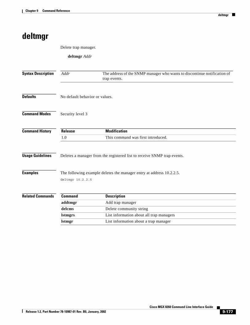
Chapter 9 Command Referencedeltmgr
deltmgrDelete trap manager.
deltmgr Addr
Syntax Description
Defaults No default behavior or values.
Command Modes Security level 3
Command History
Usage Guidelines Deletes a manager from the registered list to receive SNMP trap events.
Examples The following example deletes the manager entry at address 10.2.2.5.deltmgr 10.2.2.5
Related Commands
Addr The address of the SNMP manager who wants to discontinue notification of trap events.
Release Modification
1.0 This command was first introduced.
Command Description
addtmgr Add trap managerdelcms Delete community stringlstmgrs List information about all trap managerslstmgr List information about a trap manager
9-177Cisco MGX 8260 Command Line Interface Guide
Release 1.2, Part Number 78-10987-01 Rev. B0, January, 2002

Chapter 9 Command Referencedelusp
deluspDelete user profile.
delusp Name
Syntax Description
Defaults No default behavior or values.
Command Modes Security level 3
Command History
Usage Guidelines Use this command to remove the profile of a user from the system.
Examples The following example deletes a user profile for a user named booter. delusp booter
Related Commands
Name The login name of a user
Release Modification
1.0 This command was first introduced.
Command Description
addusp Add user profilechkey Change file key
9-178Cisco MGX 8260 Command Line Interface Guide
Release 1.2, Part Number 78-10987-01 Rev. B0, January, 2002

Chapter 9 Command Referencedelvport
delvportDelete voice port
delvport Slot Port RepetitionNum WrapNum
Syntax Description
Defaults RepetitionNum: 1
WrapNum: 384 for DS1, 480 for E1 (CAS on)
Command Modes Security level 3
Command History
Usage Guidelines Use this command to delete a voice port.
Examples The following example deletes a voice port from slot 1, line 1.delvport 1 1
Related Commands
Slot The logical slot number of an NSCPort The logical port numberRepetitionNum The number of ports to add. Values: 1 to 6944. This corresponds to 31 ports
per line, 16 lines per NSC, and 14 NSCs.WrapNum The DS0 number at which to wrap to the next slot. Set this to the maximum
number of DS0s the NSC in your configuration. For DS1 use 384 and for E1 use 480 with CAS or 496 without CAS. Values: 1 to 512
Release Modification
1.0 This command was first introduced.
Command Description
addvport Add voice portchvport Change voice portlsvport List voice portlsvports List voice ports
9-179Cisco MGX 8260 Command Line Interface Guide
Release 1.2, Part Number 78-10987-01 Rev. B0, January, 2002

Chapter 9 Command Referencednethln
dnethlnDown Ethernet line.
dnethln Location
Syntax Description
Defaults No default behavior or values.
Command Modes Security level 4
Command History
Usage Guidelines Deactivates an Ethernet interface.
Examples The following example brings down the Ethernet interface from the MGX 8250 Media Gateway at slot 7 line 1, address 10.1.2.10.dnethln 9.1
Related Commands
Location The slot and line number, delimited by a period, of the Ethernet line
Release Modification
1.0 This command was first introduced.
Command Description
addethln Add Ethernet linechethln Change Ethernet linedelethln Delete Ethernet linelsethln List Ethernet linelsethlns List Ethernet Linesupethln Activate Ethernet line
9-180Cisco MGX 8260 Command Line Interface Guide
Release 1.2, Part Number 78-10987-01 Rev. B0, January, 2002

Chapter 9 Command Referenceexit
exitLog out.
exit
Defaults No default behavior or values.
Command Modes Security level 6
Command History
Usage Guidelines Type this command to log out from the MGX 8260 Media Gateway
Examples The following command logs out.exit
Related Commands
Release Modification
1.0 This command was first introduced.
Command Description
bye Logs out from the MGX 8260 Media Gateway. logout Logs out from the MGX 8260 Media Gateway.
9-181Cisco MGX 8260 Command Line Interface Guide
Release 1.2, Part Number 78-10987-01 Rev. B0, January, 2002

Chapter 9 Command Referencehelp
helpDisplay command help.
help [command]
Syntax Description
Defaults No default behavior or values.
Command Modes Security level 6
Command History
Usage Guidelines Use this command without an argument to list the commands available at your security level. To obtain usage information for a command, specify the command name as an argument.
Examples The following example displays help for the htmlversion command.help htmlversion
command The command for which you want help.
Release Modification
1.0 This command was first introduced.
9-182Cisco MGX 8260 Command Line Interface Guide
Release 1.2, Part Number 78-10987-01 Rev. B0, January, 2002

Chapter 9 Command Referencehtmlversion
htmlversionDisplay the HTML version.
htmlversion
Syntax Description The command has no arguments or keywords.
Defaults No default behavior or values.
Command Modes Security level 6
Command History
Usage Guidelines Use this command to display version information for WebViewer HTML files.
Examples The following example displays the HTML version.htmlversion
Release Modification
1.2 This command was first introduced.
9-183Cisco MGX 8260 Command Line Interface Guide
Release 1.2, Part Number 78-10987-01 Rev. B0, January, 2002

Chapter 9 Command Referencelogout
logoutLogout of the MGX 8260 Media Gateway.
logout
Syntax Description The command has no arguments or keywords.
Defaults No default behavior or values.
Command Modes Security level 6
Command History
Usage Guidelines Use this command to end the session with the MGX 8260 Media Gateway.
Examples The following example logs out.logout
Related Commands
Release Modification
1.0 This command was first introduced.
Command Description
bye Log out
9-184Cisco MGX 8260 Command Line Interface Guide
Release 1.2, Part Number 78-10987-01 Rev. B0, January, 2002

Chapter 9 Command Referencelsacp
lsacpList information on an active call
lsacp Slot Line ID
Syntax Description
Defaults No default behavior or values.
Command Modes Security level 5
Command History
Usage Guidelines Use this command to list information about the call using a specific MGX 8260 resource. The slot, line, and DS0 is valid for a given time only, because the resource is re-used after the current active call is torn down.
Examples The following example lists information on the call on slot 1, line 1, DS0 1:lsacp 3 1 1
Related Commands
Slot The physical source (slot number) of an active call. Values: 1-16.Line The physical source (line number) of an active call. Values: 1-16.ID The DS0 used by an active call. Values: 1-24.
Release Modification
1.0 This command was first introduced.
Command Description
lsacps List all active calls by resourcelsact List an active call by transaction IDlsacts List all active calls by transaction
9-185Cisco MGX 8260 Command Line Interface Guide
Release 1.2, Part Number 78-10987-01 Rev. B0, January, 2002

Chapter 9 Command Referencelsacps
lsacpsList all active calls by resource
lsacps
Syntax Description The command has no arguments or keywords.
Defaults No default behavior or values.
Command Modes Security level 5
Command History
Usage Guidelines Use this command to lists active calls for all slots, lines, and DS0s. Output includes the log port, and packets received and transmitted.
Examples The following examples lists active calls.lsacps
Related Commands
Release Modification
1.0 This command was first introduced.
Command Description
lsacp List active call by resourcelsact List an active call by transaction IDlsacts List all active calls by transaction
9-186Cisco MGX 8260 Command Line Interface Guide
Release 1.2, Part Number 78-10987-01 Rev. B0, January, 2002

Chapter 9 Command Referencelsact
lsactList an active call by transaction ID.
lsact ID
Syntax Description
Defaults No default behavior or values.
Command Modes Security level 5
Command History
Usage Guidelines Use this command to list active call information for a specific transaction ID. The transaction ID is re-used after the current active call is torn down.
Examples The following example lists the call identified by transaction ID 2315lsact 2315
Related Commands
ID A unique identifier of an active call. Values: index number
Release Modification
1.0 This command was first introduced.
Command Description
lsacp List active call by resourcelsacps List all active calls by resourcelsacts List all active calls by transaction
9-187Cisco MGX 8260 Command Line Interface Guide
Release 1.2, Part Number 78-10987-01 Rev. B0, January, 2002

Chapter 9 Command Referencelsacts
lsactsList all active call by transaction.
lsacts
Syntax Description The command has no arguments or keywords.
Defaults No default behavior or values.
Command Modes Security level 5
Command History
Usage Guidelines Output includes the transaction number, the slot, line, and DS0 of the source, the log port, and the packets received and transmitted.
Examples The following example lists the call identified by transaction ID 2315lsacts
Related Commands
Release Modification
1.0 This command was first introduced.
Command Description
lsacp List active call by resourcelsacps List all active calls by resourcelsact List active call by transaction ID
9-188Cisco MGX 8260 Command Line Interface Guide
Release 1.2, Part Number 78-10987-01 Rev. B0, January, 2002

Chapter 9 Command Referencelsalms
lsalmsList alarms.
lsalms
Syntax Description The command has no arguments or keywords.
Defaults No default behavior or values.
Command Modes Security level 6
Command History
Usage Guidelines Displays the status of all shelf alarms and card and software errors. For more information, see Monitoring Shelf Alarms, page 6-2.
Examples The following example lists alarms.lsalms
Related Commands
Release Modification
1.0 This command was first introduced.
Command Description
clralmhist Clear alarm history
9-189Cisco MGX 8260 Command Line Interface Guide
Release 1.2, Part Number 78-10987-01 Rev. B0, January, 2002

Chapter 9 Command Referencelsannfile
lsannfileList the given announcement file.
lsannfile fid
Syntax Description
Syntax Description The command has no arguments or keywords.
Defaults No default behavior or values.
Command Modes Security level 4
Command History
Usage Guidelines You use this command to list information about the given announcement file. For more information, see Viewing Announcement Files, page 4-33.
Examples The following command lists announcement files 62. lsannfile 62
Related Commands
fid The announcement file ID. Values: 1-100
Release Modification
1.2 This command was first introduced.
Command Description
acannfile Activate an announcement filedeacannfile Deactivate an announcement filermannfile Remove an announcement filelsannfiles Lists all announcement fileslsdurationif List duration information about announcement files
9-190Cisco MGX 8260 Command Line Interface Guide
Release 1.2, Part Number 78-10987-01 Rev. B0, January, 2002

Chapter 9 Command Referencelsannfiles
lsannfilesList all announcement files.
lsannfiles
Syntax Description The command has no arguments or keywords.
Defaults No default behavior or values.
Command Modes Security level 4
Command History
Usage Guidelines You use this command to list all announcement files. For more information, see Viewing Announcement Files, page 4-33.
Examples The following command lists all announcement files. lsannfiles
Related Commands
Release Modification
1.2 This command was first introduced.
Command Description
acannfile Activate an announcement filedeacannfile Deactivate an announcement filermannfile Remove an announcement filelsannfile List the given announcement filelsdurationif List duration information about announcement files
9-191Cisco MGX 8260 Command Line Interface Guide
Release 1.2, Part Number 78-10987-01 Rev. B0, January, 2002

Chapter 9 Command Referencelsbertds1
lsbertds1List DS1 BERT results.
lsbertds1 Location
Syntax Description
Defaults No default behavior or values.
Command Modes Security level 3
Command History
Usage Guidelines Displays the bit error rate status of the specified DS1 line. Use in conjunction with onbertds1 and offbertds1 to test a DS1 line. For more information, see DS1/E1 BERT Test, page 8-5.
Examples The following example shows the BERT status of the DS1 line at slot 11 line 1.lsbertds1 11.1
Location The slot and line number, delimited by a period, of the DS1 line. For example, enter slot 3 line 2 as 3.2. Valid slot numbers:
• NSC: 1-8 and 11-16
• BSC: 11-16
Valid line numbers:
• NSC: 1-16
• BSC: 1-168 as shown by the following table of DS1 to DS3 mappings.
DS3 Line Number DS1 Line Number
501 1-28
502 29-56
503 57-84
504 85-112
505 113-140
506 141-168
Release Modification
1.0 This command was first introduced.
9-192Cisco MGX 8260 Command Line Interface Guide
Release 1.2, Part Number 78-10987-01 Rev. B0, January, 2002

Chapter 9 Command Referencelsbertds1
Related Commands Command Description
offbertds1 Stop BERT on DS1 onbertds1 Start BERT on DS1
9-193Cisco MGX 8260 Command Line Interface Guide
Release 1.2, Part Number 78-10987-01 Rev. B0, January, 2002

Chapter 9 Command Referencelscd
lscdList card details.
lscd CardNum
Syntax Description
Defaults No default behavior or values.
Command Modes Security level 6
Command History
Usage Guidelines Use this command to list the physical and logical card number, front, back, and daughter card types, the state and service of the card, revision information, serial numbers, alarm information, the ATM queue profile number, the RAM backup, interface mode, and more. For more information, see Viewing Card Configuration and Status, page 3-2.
Examples The following example lists information about card 8.lscd 8
Related Commands
CardNum The card about which you want information. Values: 1-16.
Release Modification
1.0 This command was first introduced.
Command Description
lscds Lists information about all physical cards.resetcd Resets the specified card.
9-194Cisco MGX 8260 Command Line Interface Guide
Release 1.2, Part Number 78-10987-01 Rev. B0, January, 2002

Chapter 9 Command Referencelscds
lscdsList cards.
lscds
Syntax Description The command has no arguments or keywords.
Defaults No default behavior or values.
Command Modes Security level 6
Command History
Usage Guidelines Use this command to list information on all cards. For more information, see Viewing Summary Information for Cards, page 3-7.
Examples The following example lists information about all cards.lscds
Related Commands
Release Modification
1.0 This command was first introduced.
Command Description
lscd Lists information about the specified physical card.resetcd Resets the specified card.
9-195Cisco MGX 8260 Command Line Interface Guide
Release 1.2, Part Number 78-10987-01 Rev. B0, January, 2002
Chapter 9 Command Referencelsclksrcs
lsclksrcsList all clock sources.
lsclksrcs
Syntax Description The command has no arguments or keywords.
Defaults No default behavior or values.
Command Modes Security level 5
Command History
Usage Guidelines Use this command to display all clock sources. For more information, see Viewing Clock Parameters, page 2-13.
Examples The following example lists clock sources.lsclksrcs
Related Commands
Release Modification
1.0 This command was first introduced.
Command Description
chpclksrc Change primary clock parameterschsclksrc Change secondary clock parametersswclk Switch clock
9-196Cisco MGX 8260 Command Line Interface Guide
Release 1.2, Part Number 78-10987-01 Rev. B0, January, 2002

Chapter 9 Command Referencelscms
lscmsList a community strings.
lstmgr Index
Syntax Description
Defaults No default behavior or values.
Command Modes Security level 6
Command History
Usage Guidelines Displays information about the community string and SNMP manager IP address. For more information, see Assigning a tftp Security Key, page 2-6.
Examples The following example lists information about community string 1.lscms 1
Related Commands
Index The index number of the community string
Release Modification
1.0 This command was first introduced.
Command Description
addtmgr Add trap managerclrtraps Clear trapsdelcms Delete community stringlscmss List community stringslstmgrs List trap managers
9-197Cisco MGX 8260 Command Line Interface Guide
Release 1.2, Part Number 78-10987-01 Rev. B0, January, 2002

Chapter 9 Command Referencelscmss
lscmssList trap managers.
lscmss
Syntax Description The command has no arguments or keywords.
Defaults No default behavior or values.
Command Modes Security level 6
Command History
Usage Guidelines Use this command to display summary information about all community strings. For more information, see Assigning a tftp Security Key, page 2-6.
Examples The following example lists all community strings.lscmss
Related Commands
Release Modification
1.0 This command was first introduced.
Command Description
addtmgr Add trap managerclrtraps Clear trapsdelcms Delete community stringlscms List community stringlstmgr List trap manager
9-198Cisco MGX 8260 Command Line Interface Guide
Release 1.2, Part Number 78-10987-01 Rev. B0, January, 2002

Chapter 9 Command Referencelsdate
lsdateList system date, time, and time zone.
lsdate
Syntax Description The command has no arguments or keywords.
Defaults No default behavior or values.
Command Modes Security level 1
Command History
Usage Guidelines Use this command to display the system time and date. For more information, see Viewing Node Parameters, page 2-6.
Examples The following example displays node information.lsdate
Related Commands
Release Modification
1.0 This command was first introduced.
Command Description
chdate Change the date and time
9-199Cisco MGX 8260 Command Line Interface Guide
Release 1.2, Part Number 78-10987-01 Rev. B0, January, 2002

Chapter 9 Command Referencelsdchan
lsdchanList information about a D Channel.
lsdchan Index
Syntax Description
Defaults No default behavior or values.
Command Modes Security level 5
Command History
Usage Guidelines Use this command to list information about a D Channel, such as its frame length, DS0, retransmission count, and more. For more information, see Viewing D Channels, page 5-26.
Examples The following example lists a D Channel of line 1 on slot 14: lsdchan 14.1
Related Commands
Index The slot and line number, delimited by a period, of the new D Channel.
Release Modification
1.0 This command was first introduced.
Command Description
adddslp Add a DLSAP profileaddmacsapprof Add a MACSAP profiledeldchan Delete a D Channellsdchans List information about D Channels
9-200Cisco MGX 8260 Command Line Interface Guide
Release 1.2, Part Number 78-10987-01 Rev. B0, January, 2002

Chapter 9 Command Referencelsdchans
lsdchansList information about all D Channels.
lsdchans
Syntax Description This command has no arguments or keywords.
Defaults No default behavior or values.
Command Modes Security level 5
Command History
Usage Guidelines Use this command to list information about all D Channels. For more information, see Viewing D Channels, page 5-26.
Examples The following example lists information about all D Channels: lsdchans
Related Commands
Release Modification
1.0 This command was first introduced.
Command Description
adddslp Add a DLSAP profileaddmacsapprof Add a MACSAP profiledeldchan Delete a D Channellsdchan List information about a D Channel
9-201Cisco MGX 8260 Command Line Interface Guide
Release 1.2, Part Number 78-10987-01 Rev. B0, January, 2002
Chapter 9 Command Referencelsdlsapstat
lsdlsapstatList statistics for a DLSAP.
lsdlsapstat Index
Syntax Description
Defaults No default behavior or values.
Command Modes Security level 5
Command History
Usage Guidelines Use this command to list statistics for a DLSAP, such as received and transmitted information frames, receive ready frames, disconnect frames, frame reject frames, and more. For more information, see Viewing DLSAP Statistics, page 5-24.
Examples The following example lists a D Channel of line 1 on slot 14: lsdlsapstat 2
Related Commands
Index The identifier of a DLSAP Profile. Values: 1 - 20.
Release Modification
1.0 This command was first introduced.
Command Description
adddslp Add a DLSAP profileaddmacsapprof Add a MACSAP profiledeldchan Delete a D Channellsdchans List information about D Channels
9-202Cisco MGX 8260 Command Line Interface Guide
Release 1.2, Part Number 78-10987-01 Rev. B0, January, 2002
Chapter 9 Command Referencelsdlsapstats
lsdlsapstatsList DLSAP statistics.
lsdlsapstats
Syntax Description This command has no arguments or keywords.
Defaults No default behavior or values.
Command Modes Security level 5
Command History
Usage Guidelines Use this command to list summary DLSAP statistics. For more information, see Viewing DLSAP Statistics, page 5-24.
Examples The following example lists DLSAP statistics.lsdlsapstats
Related Commands
Release Modification
1.0 This command was first introduced.
Command Description
adddslp Add a DLSAP profileaddmacsapprof Add a MACSAP profiledeldchan Delete a D Channellsdchans List information about D Channels
9-203Cisco MGX 8260 Command Line Interface Guide
Release 1.2, Part Number 78-10987-01 Rev. B0, January, 2002

Chapter 9 Command Referencelsdlsapstatus
lsdlsapstatusList status for a DLSAP.
lsdlsapstatus Location
Syntax Description
Defaults No default behavior or values.
Command Modes Security level 3
Command History
Usage Guidelines Use this command to list the DLSAP status for the DS1 line, including outstanding frames, number of frames dropped by MAC, the busy status, flow control state, retransmission count, queue size, and active SAPs and DLCs. For more information, see Viewing DLSAP Status, page 5-23.
Examples The following example lists the DLSAP status of line 1 on slot 11.lsdlsapstatus 11.1
Location The slot and line number, delimited by a period, of the DS1 line. For example, enter slot 3 line 2 as 3.2. Valid slot numbers:
• NSC: 1-8 and 11-16
• BSC: 11-16
Valid line numbers:
• NSC: 1-16
• BSC: 1-168 as shown by the following table of DS1 to DS3 mappings.
DS3 Line Number DS1 Line Number
501 1-28
502 29-56
503 57-84
504 85-112
505 113-140
506 141-168
Release Modification
1.0 This command was first introduced.
9-204Cisco MGX 8260 Command Line Interface Guide
Release 1.2, Part Number 78-10987-01 Rev. B0, January, 2002

Chapter 9 Command Referencelsdlsapstatus
Related Commands Command Description
deldlsp Delete a DLSAP profilelsdlsapstat List statistics for a DLSAP lsdlsapstats List DLSAP statistics lsdlsp List a DLSAP profilelsdlsps List DLSAP profiles
9-205Cisco MGX 8260 Command Line Interface Guide
Release 1.2, Part Number 78-10987-01 Rev. B0, January, 2002

Chapter 9 Command Referencelsdlsp
lsdlspList a DLSAP profile.
lsdlsp Num
Syntax Description
Defaults No default behavior or values.
Command Modes Security level 5
Command History
Usage Guidelines Use this command to list the DLSAP profile information, including frame length, window size, retranmission count, timer, modulo, DLC, and TEI information. For more information, see Viewing DLSAP Profiles, page 5-22.
Examples The following example lists the information for DLSAP profile 5.lsdlsp 5
Related Commands
Num The DLSAP profile number associated with the D Channel. Values: 1-20.
Release Modification
1.0 This command was first introduced.
Command Description
deldlsp Delete a DLSAP profilelsdlsapstat List statistics for a DLSAP lsdlsapstats List DLSAP statistics lsdlsapstatus List status for a DLSAPlsdlsps List DLSAP profiles
9-206Cisco MGX 8260 Command Line Interface Guide
Release 1.2, Part Number 78-10987-01 Rev. B0, January, 2002

Chapter 9 Command Referencelsdlsps
lsdlspsList summary DLSAP profile information.
lsdlsps
Syntax Description The command has no arguments or keywords.
Defaults No default behavior or values.
Command Modes Security level 5
Command History
Usage Guidelines Use this command to list summary DLSAP information for all profiles. For more information, see Viewing DLSAP Profiles, page 5-22.
Examples The following example lists the information for DLSAP profiles.lsdlsps
Related Commands
Release Modification
1.0 This command was first introduced.
Command Description
deldlsp Delete a DLSAP profilelsdlsapstat List statistics for a DLSAP lsdlsapstats List DLSAP statistics lsdlsapstatus List status for a DLSAPlsdlsp List a DLSAP profile
9-207Cisco MGX 8260 Command Line Interface Guide
Release 1.2, Part Number 78-10987-01 Rev. B0, January, 2002

Chapter 9 Command Referencelsds0
lsds0List a DS0 entry.
lsds0 Num
Syntax Description
Defaults No default behavior or values.
Command Modes Security level 5
Command History
Usage Guidelines Use this command to list information on the specified DS0.
Examples The following example lists information on channel 1 of line 1 in slot 11.lsds0 11 1 1
SlotNum The slot number of the card with the DS1 line. Valid slot numbers:
• NSC: 1-8 and 11-16
• BSC: 11-16SlotNum The DS1 line number with the DS0 channel. Valid line numbers:
• NSC: 1-16
• BSC: 1-168 as shown by the following table of DS1 to DS3 mappings.
DS3 Line Number DS1 Line Number
501 1-28
502 29-56
503 57-84
504 85-112
505 113-140
506 141-168DS0Num The number of the DS0 channel. Valid entries: 1-24 for DS1 and 1-31 for E1
Release Modification
1.0 This command was first introduced.
9-208Cisco MGX 8260 Command Line Interface Guide
Release 1.2, Part Number 78-10987-01 Rev. B0, January, 2002

Chapter 9 Command Referencelsds0s
lsds0sList all DS0 entries.
lsds0s
Syntax Description The command has no arguments or keywords.
Defaults No default behavior or values.
Command Modes Security level 5
Command History
Usage Guidelines Use this command to list all configured DS0.
Examples The following example lists all DS0 entries.lsds0s
Release Modification
1.0 This command was first introduced.
9-209Cisco MGX 8260 Command Line Interface Guide
Release 1.2, Part Number 78-10987-01 Rev. B0, January, 2002

Chapter 9 Command Referencelsds1alm
lsds1almList all alarm thresholds for a DS1 line.
lsds1alm Location
Syntax Description
Defaults No default behavior or values.
Command Modes Security level 5
Command History
Usage Guidelines Use this command to list DS1 line alarm thresholds, such as Red, RAI, and Perf Alarm Severity. For more information, see Viewing DS1 Alarm Thresholds, page 6-6.
Examples The following example lists DS1 alarm threshold levels for line 1 of slot 11.lsds1alm 11.1
Location The slot and line number, delimited by a period, of the DS1 line. For example, enter slot 3 line 2 as 3.2. Valid slot numbers:
• NSC: 1-8 and 11-16
• BSC: 11-16
Valid line numbers:
• NSC: 1-16
• BSC: 1-168 as shown by the following table of DS1 to DS3 mappings.
DS3 Line Number DS1 Line Number
501 1-28
502 29-56
503 57-84
504 85-112
505 113-140
506 141-168
Release Modification
1.0 This command was first introduced.
9-210Cisco MGX 8260 Command Line Interface Guide
Release 1.2, Part Number 78-10987-01 Rev. B0, January, 2002

Chapter 9 Command Referencelsds1curst
lsds1curstList DS1 current statistics.
lsds1cursts Location
Syntax Description
Defaults No default behavior or values.
Command Modes Security level 5
Command History
Usage Guidelines Use this command to display the performance statistics of the current 15-minute collection period for the specified DS1 line. For more information, see Viewing Current T1 Statistics, page 7-1.
Examples The following example shows the performance statistics of the DS1 line at slot 1 line 1.lsds1curst 1.1
Related Commands
Location The slot and line number, delimited by a period, of the DS1 line
Release Modification
1.0 This command was first introduced.
Command Description
addds1ln Add DS1 linechds1alm Change DS1 alarm severity and thresholdschds1ln Change DS1 lineclrds1lnst Clear DS1 line statisticsdelds1ln Delete DS1 linelsbertds1 List DS1 BERT resultslsds1alm List DS1 alarm thresholdslsds1cursts List DS1 current statisticslsds1intst List DS1 interval statistics lsds1ln List DS1 line lsds1lns List DS1 lineslsds1lnst List DS1 line statistics lsds1totst List DS1 total statisticslsds1totsts List DS1 total statisticslslns List existing lines
9-211Cisco MGX 8260 Command Line Interface Guide
Release 1.2, Part Number 78-10987-01 Rev. B0, January, 2002

Chapter 9 Command Referencelsds1cursts
lsds1curstsList DS1 current statistics.
lsds1cursts
Syntax Description The command has no arguments or keywords.
Defaults No default behavior or values.
Command Modes Security level 5
Command History
Usage Guidelines Use this command to display the performance statistics of the current 15-minute collection period for all DS1 lines. For more information, see Viewing Current T1 Statistics, page 7-1.
Examples The following example displays DS1 statistics.lsds1cursts
Related Commands
Release Modification
1.0 This command was first introduced.
Command Description
addds1ln Add DS1 linechds1alm Change DS1 alarm severity and thresholdschds1ln Change DS1 lineclrds1lnst Clear DS1 line statisticsdelds1ln Delete DS1 linelsbertds1 List DS1 BERT resultslsds1alm List DS1 alarm thresholdslsds1curst List DS1 current statisticslsds1intst List DS1 interval statistics lsds1ln List DS1 line lsds1lns List DS1 lineslsds1lnst List DS1 line statistics lsds1totst List DS1 total statisticslsds1totsts List DS1 total statisticslslns List existing lines
9-212Cisco MGX 8260 Command Line Interface Guide
Release 1.2, Part Number 78-10987-01 Rev. B0, January, 2002

Chapter 9 Command Referencelsds1intst
lsds1intstList DS1 interval statistics.
lsds1intst Location Num
Syntax Description
Defaults No default behavior or values.
Command Modes Security level 5
Command History
Usage Guidelines Displays the specified interval of DS1 line performance that were gathered every 15-minutes over the past 24 hours. Fails if the interval does not exist. For more information, see Viewing Interval T1 Statistics, page 7-2.
Examples The following example shows performance statistics for the DS1 line at slot 1 line 1.lsds1intst 1.1 5
Location The slot and line number, delimited by a period, of the DS1 line. For example, enter slot 3 line 2 as 3.2. Valid slot numbers:
• NSC: 1-8 and 11-16
• BSC: 11-16
Valid line numbers:
• NSC: 1-16
• BSC: 1-168 as shown by the following table of DS1 to DS3 mappings.
DS3 Line Number DS1 Line Number
501 1-28
502 29-56
503 57-84
504 85-112
505 113-140
506 141-168Num A number specifying an interval, where 1 is the most recently completed
15 minute interval and 96 is the least recently completed 15 minutes interval (assuming that all 96 intervals are valid). Values: 1-96.
Release Modification
1.0 This command was first introduced.
9-213Cisco MGX 8260 Command Line Interface Guide
Release 1.2, Part Number 78-10987-01 Rev. B0, January, 2002

Chapter 9 Command Referencelsds1intst
Related Commands Command Description
addds1ln Add DS1 linechds1alm Change DS1 alarm severity and thresholdschds1ln Change DS1 lineclrds1lnst Clear DS1 line statisticsdelds1ln Delete DS1 linelsbertds1 List DS1 BERT resultslsds1alm List DS1 alarm thresholdslsds1curst List DS1 current statisticslsds1cursts List all DS1current statistics lsds1ln List DS1 line lsds1lns List DS1 lineslsds1lnst List DS1 line statistics lsds1totst List DS1 total statisticslsds1totsts List DS1 total statisticslslns List existing lines
9-214Cisco MGX 8260 Command Line Interface Guide
Release 1.2, Part Number 78-10987-01 Rev. B0, January, 2002

Chapter 9 Command Referencelsds1ln
lsds1lnList DS1 line information.
lsds1ln Location
Syntax Description
Defaults No default behavior or values.
Command Modes Security level 5
Command History
Usage Guidelines Use this command to display configuration and alarm information about a DS1 lines. For more information, seeViewing DS1/E1 Configuration and Status, page 4-3.
Examples The following example lists configuration information about the DS1 line at slot 1 line 12.lsds1ln 1.12
Location The slot and line number, delimited by a period, of the DS1 line. For example, enter slot 3 line 2 as 3.2. Valid slot numbers:
• NSC: 1-8 and 11-16
• BSC: 11-16
Valid line numbers:
• NSC: 1-16
• BSC: 1-168 as shown by the following table of DS1 to DS3 mappings.
DS3 Line Number DS1 Line Number
501 1-28
502 29-56
503 57-84
504 85-112
505 113-140
506 141-168
Release Modification
1.0 This command was first introduced.
9-215Cisco MGX 8260 Command Line Interface Guide
Release 1.2, Part Number 78-10987-01 Rev. B0, January, 2002

Chapter 9 Command Referencelsds1ln
Related Commands Command Description
addds1ln Add DS1 linechds1alm Change DS1 alarm severity and thresholdschds1ln Change DS1 lineclrds1lnst Clear DS1 line statisticsdelds1ln Delete DS1 linelsbertds1 List DS1 BERT resultslsds1alm List DS1 alarm thresholdslsds1curst List DS1 current statisticslsds1cursts List all DS1current statistics lsds1intst List DS1 line interval statisticslsds1lns List DS1 lineslsds1lnst List DS1 line statistics lsds1totst List DS1 total statisticslsds1totsts List DS1 total statisticslslns List existing lines
9-216Cisco MGX 8260 Command Line Interface Guide
Release 1.2, Part Number 78-10987-01 Rev. B0, January, 2002

Chapter 9 Command Referencelsds1lns
lsds1lnsList all DS1 lines.
lsds1lns
Syntax Description The command has no arguments or keywords.
Defaults No default behavior or values.
Command Modes Security level 5
Command History
Usage Guidelines Use this command to display the configuration and alarm information for all DS1 lines. For more information, see Viewing Summary DS1/E1 Information, page 4-6.
Examples The following example displays information about all DS1 configurations and alarms.lsds1lns
Related Commands
Release Modification
1.0 This command was first introduced.
Command Description
addds1ln Add DS1 linechds1alm Change DS1 alarm severity and thresholdschds1ln Change DS1 lineclrds1lnst Clear DS1 line statisticsdelds1ln Delete DS1 linelsbertds1 List DS1 BERT resultslsds1alm List DS1 alarm thresholdslsds1curst List DS1 current statisticslsds1cursts List statistics for all DS1 lineslsds1intst List DS1 interval statistics lsds1ln List DS1 line lsds1lnst List DS1 line statistics lsds1totst List DS1 total statisticslsds1totsts List DS1 total statisticslslns List existing lines
9-217Cisco MGX 8260 Command Line Interface Guide
Release 1.2, Part Number 78-10987-01 Rev. B0, January, 2002

Chapter 9 Command Referencelsds1lnst
lsds1lnstList DS1 line statistics.
lsds1lnst Location
Syntax Description
Defaults No default behavior or values.
Command Modes Security level 5
Command History
Usage Guidelines Use this command to display the real-time statistics of the specified DS1 line. For more information, see Viewing T1 Real-Time Alarm Statistics, page 7-3.
Examples The following example displays the real-time statistics of the DS1 line at slot 1 line 1.lsds1lnst 1.1
Related Commands
Location The slot and line number, delimited by a period, of the DS1 line.
Release Modification
1.0 This command was first introduced.
Command Description
addds1ln Add DS1 linechds1alm Change DS1 alarm severity and thresholdschds1ln Change DS1 lineclrds1lnst Clear DS1 line statisticsdelds1ln Delete DS1 linelsbertds1 List DS1 BERT resultslsds1alm List DS1 alarm thresholdslsds1curst List DS1 current statisticslsds1cursts List statistics for all DS1 lineslsds1intst List DS1 interval statistics lsds1ln List DS1 line lsds1lns List DS1 lineslsds1totst List DS1 total statisticslsds1totsts List DS1 total statisticslslns List existing lines
9-218Cisco MGX 8260 Command Line Interface Guide
Release 1.2, Part Number 78-10987-01 Rev. B0, January, 2002

Chapter 9 Command Referencelsds1totst
lsds1totstList DS1 total statistics.
lsds1totst Location
Syntax Description
Defaults No default behavior or values.
Command Modes Security level 5
Command History
Usage Guidelines Use this command to display the totals of performance statistics of the specified DS1 line gathered over the past 24 hours. For more information, see Viewing Total T1 Statistics, page 7-2.
Examples The following example shows the totals of performance statistics of the DS1 line at slot 1 line 1 over the past day.lsds1totst 1.1
Related Commands
Location The slot and line number, delimited by a period, of the DS1 line.
Release Modification
1.0 This command was first introduced.
Command Description
addds1ln Add DS1 linechds1alm Change DS1 alarm severity and thresholdschds1ln Change DS1 lineclrds1lnst Clear DS1 line statisticsdelds1ln Delete DS1 linelsbertds1 List DS1 BERT resultslsds1alm List DS1 alarm thresholdslsds1curst List DS1 current statisticslsds1cursts List statistics for all DS1 lineslsds1intst List DS1 interval statistics lsds1ln List DS1 line lsds1lns List DS1 lineslsds1lnst List DS1 statistics
9-219Cisco MGX 8260 Command Line Interface Guide
Release 1.2, Part Number 78-10987-01 Rev. B0, January, 2002

Chapter 9 Command Referencelsds1totst
lsds1totsts List DS1 total statisticslslns List existing lines
Command Description
9-220Cisco MGX 8260 Command Line Interface Guide
Release 1.2, Part Number 78-10987-01 Rev. B0, January, 2002
Chapter 9 Command Referencelsds1totsts
lsds1totstsList DS1 total statistics.
lsds1totsts
Syntax Description The command has no arguments or keywords.
Defaults No default behavior or values.
Command Modes Security level 5
Command History
Usage Guidelines Displays totals of the performance statistics of the all DS1 lines over the past day. For more information, see Viewing Total T1 Statistics, page 7-2.
Examples The following example displays statistics of DS1 lines over the past day.lsds1totsts
Related Commands
Release Modification
1.0 This command was first introduced.
Command Description
addds1ln Add DS1 linechds1alm Change DS1 alarm severity and thresholdschds1ln Change DS1 lineclrds1lnst Clear DS1 line statisticsdelds1ln Delete DS1 linelsbertds1 List DS1 BERT resultslsds1alm List DS1 alarm thresholdslsds1curst List DS1 current statisticslsds1cursts List statistics for all DS1 lineslsds1intst List DS1 interval statistics lsds1ln List DS1 line lsds1lns List DS1 lineslsds1lnst List DS1 line statistics lsds1totst List DS1 total statisticslslns List existing lines
9-221Cisco MGX 8260 Command Line Interface Guide
Release 1.2, Part Number 78-10987-01 Rev. B0, January, 2002

Chapter 9 Command Referencelsds3alm
lsds3almList DS3 alarm.
lsds3alm Location
Syntax Description
Defaults No default behavior or values.
Command Modes Security level 5
Command History
Usage Guidelines Use this command to display the DS3 line alarm thresholds for a given line. For more information, see Viewing DS3 Alarm Thresholds, page 6-13.
Examples The following example shows the alarm thresholds of the DS3 line at slot 7 line 1.lsds3alm 7.1
Related Commands
Location The slot and line number, delimited by a period, of the DS3 line.
Valid slot numbers:
BSC: 11-16
DMC: 7 or 8 (reserved for future use)
Valid line numbers:
BSC: 501-506
DMC: 1-6 (reserved for future use)
Release Modification
1.0 This command was first introduced.1.1 BSC card addition - no functional change
Command Description
addds3ln Add DS3 linechds3alm Change DS3 line alarmchds3ln Change DS3 lineclrds3lnst Clear statistics for DS3 linedelds3ln Delete DS3 linelsds3curst List DS3 current statisticslsds3intst List DS3 interval statistics
9-222Cisco MGX 8260 Command Line Interface Guide
Release 1.2, Part Number 78-10987-01 Rev. B0, January, 2002

Chapter 9 Command Referencelsds3alm
lsds3lns List DS3 lineslsds3totst List DS3 total statistics
Command Description
9-223Cisco MGX 8260 Command Line Interface Guide
Release 1.2, Part Number 78-10987-01 Rev. B0, January, 2002

Chapter 9 Command Referencelsds3curst
lsds3curstList DS3 current statistics.
lsds3curst Location
Syntax Description
Defaults No default behavior or values.
Command Modes Security level 5
Command History
Usage Guidelines Displays the performance statistics of the current 15-minute collection period for the specified DS3 line. For more information, see Viewing Current DS3 Statistics, page 7-12.
Examples The following example shows the performance statistics of the DS3 line at slot 7 line 1.lsds3curst 7.1
Related Commands
Location The slot and line number, delimited by a period, of the DS3 line.
Valid slot numbers:
BSC: 11-16
DMC: 7 or 8 (reserved for future use)
Valid line numbers:
BSC: 501-506
DMC: 1-6 (reserved for future use)
Release Modification
1.0 This command was first introduced.1.1 BSC card inclusion - no functional change
Command Description
addds3ln Add DS3 linechds3alm Change DS3 line alarmchds3ln Change DS3 lineclrds3lnst Clear statistics for DS3 linedelds3ln Delete DS3 linelsds3alm List DS3 alarmlsds3cursts List all current DS3 statistics
9-224Cisco MGX 8260 Command Line Interface Guide
Release 1.2, Part Number 78-10987-01 Rev. B0, January, 2002

Chapter 9 Command Referencelsds3curst
lsds3intst List DS3 interval statisticslsds3lns List DS3 lineslsds3totst List DS3 total statistics
Command Description
9-225Cisco MGX 8260 Command Line Interface Guide
Release 1.2, Part Number 78-10987-01 Rev. B0, January, 2002

Chapter 9 Command Referencelsds3cursts
lsds3curstsList current statistics for all DS3 lines.
lsds3cursts
Syntax Description The command has no arguments or keywords.
Defaults No default behavior or values.
Command Modes Security level 5
Command History
Usage Guidelines Use this command to display the location of the DS3, errored seconds, severely errored seconds, UAS seconds, and LCV seconds. For more information, see Viewing Current DS3 Statistics, page 7-12.
Examples The following example displays DS3 statistics.lsds3cursts
Related Commands
Release Modification
1.0 This command was first introduced.1.1 BSC card inclusion - no functional change
Command Description
addds3ln Add DS3 linechds3alm Change DS3 line alarmchds3ln Change DS3 lineclrds3lnst Clear statistics for DS3 linedelds3ln Delete DS3 linelsds3alm List DS3 alarmlsds3curst List current DS3 line statisticslsds3intst List DS3 interval statisticslsds3lns List DS3 lineslsds3totst List DS3 total statistics
9-226Cisco MGX 8260 Command Line Interface Guide
Release 1.2, Part Number 78-10987-01 Rev. B0, January, 2002

Chapter 9 Command Referencelsds3intst
lsds3intstList DS3 interval statistics.
lsds3intst Location Num
Syntax Description
Defaults No default behavior or values.
Command Modes Security level 5
Command History
Usage Guidelines Use this command to display one of the 96 records of DS3 line performance that were gathered every 15-minutes over the past 24 hours. For more information, see Viewing Interval DS3 Statistics, page 7-13.
Examples The following example shows performance statistics for the DS3 line at slot 7 line 1.lsds3intst 7.1 1
Related Commands
Location The slot and line number, delimited by a period, of the DS3 line.
Valid slot numbers:
BSC: 11-16
DMC: 7 or 8 (reserved for future use)
Valid line numbers:
BSC: 501-506
DMC: 1-6 (reserved for future use)Num A number specifying an interval, where 1 is the most recently completed
15 minute interval and 96 is the least recently completed 15 minutes interval (assuming that all 96 intervals are valid). Values: 1-96.
Release Modification
1.0 This command was first introduced.1.1 BSC card inclusion - no functional change
Command Description
addds3ln Add DS3 linechds3alm Change DS3 line alarmchds3ln Change DS3 lineclrds3lnst Clear statistics for DS3 line
9-227Cisco MGX 8260 Command Line Interface Guide
Release 1.2, Part Number 78-10987-01 Rev. B0, January, 2002

Chapter 9 Command Referencelsds3intst
delds3ln Delete DS3 linelsds3alm List DS3 alarmlsds3curst List current DS3 line statisticslsds3ln List DS3 linelsds3lns List DS3 lineslsds3totst List DS3 total statistics
Command Description
9-228Cisco MGX 8260 Command Line Interface Guide
Release 1.2, Part Number 78-10987-01 Rev. B0, January, 2002

Chapter 9 Command Referencelsds3ln
lsds3lnList DS3 line and configuration.
lsds3ln Location
Syntax Description
Defaults No default behavior or values.
Command Modes Security level 5
Command History
Usage Guidelines Use this command to display configuration information about one DS3 line. For more information, see Viewing DS3 Configuration and Status, page 4-8.
Examples The following lists configuration information about the DS3 line at slot 7 line 1.lsds3ln 7.1
Related Commands
Location The slot and line number, delimited by a period, of the DS3 line.
Valid slot numbers:
BSC: 11-16
DMC: 7 or 8 (reserved for future use)
Valid line numbers:
BSC: 501-506
DMC: 1-6 (reserved for future use)
Release Modification
1.0 This command was first introduced.1.1 BSC card inclusion - no functional change
Command Description
addds3ln Add DS3 linechds3alm Change DS3 line alarmchds3ln Change DS3 lineclrds3lnst Clear statistics for DS3 linedelds3ln Delete DS3 linelsds3alm List DS3 alarmlsds3curst List current DS3 line statistics
9-229Cisco MGX 8260 Command Line Interface Guide
Release 1.2, Part Number 78-10987-01 Rev. B0, January, 2002

Chapter 9 Command Referencelsds3ln
lsds3intst List DS3interval statisticslsds3lns List DS3 lineslsds3totst List DS3 total statistics
Command Description
9-230Cisco MGX 8260 Command Line Interface Guide
Release 1.2, Part Number 78-10987-01 Rev. B0, January, 2002

Chapter 9 Command Referencelsds3lns
lsds3lnsList DS3 lines.
lsds3lns
Syntax Description The command has no arguments or keywords.
Defaults No default behavior or values.
Command Modes Security level 5
Command History
Usage Guidelines Use this command to display the configuration information for all DS3 lines. For more information, see Viewing Summary DS3 Information, page 4-10.
Examples The following example displays all DS3 line configurations.lsds3lns
Related Commands
Release Modification
1.0 This command was first introduced.1.1 BSC card inclusion - no functional change
Command Description
addds3ln Add DS3 linechds3alm Change DS3 line alarmchds3ln Change DS3 lineclrds3lnst Clear statistics for DS3 linedelds3ln Delete DS3 linelsds3alm List DS3 alarmlsds3curst List current DS3 line statisticslsds3intst List DS3 interval statisticslsds3ln List DS3 lineslsds3totst List DS3 total statistics
9-231Cisco MGX 8260 Command Line Interface Guide
Release 1.2, Part Number 78-10987-01 Rev. B0, January, 2002

Chapter 9 Command Referencelsds3lnst
lsds3lnstList real-time statistics for a DS3 line.
lsds3lnst
Syntax Description The command has no arguments or keywords.
Defaults No default behavior or values.
Command Modes Security level 5
Command History
Usage Guidelines Use this command to display Loss of Signal, Out Of Frame, RAI, CCV, Framing Pattern Errors, PBit Parity Errors, and Far End Block Errors. For more information, see Viewing DS3 Real-Time Alarm Statistics, page 7-13.
Examples The following example displays real-time statistics for slot 14 line 501.lsds3lnst 14.501
Related Commands
Release Modification
1.0 This command was first introduced.1.1 BSC card inclusion - no functional change
Command Description
addds3ln Add DS3 linechds3alm Change DS3 line alarmchds3ln Change DS3 lineclrds3lnst Clear statistics for DS3 linedelds3ln Delete DS3 linelsds3alm List DS3 alarmlsds3curst List current DS3 line statisticslsds3intst List DS3 interval statisticslsds3ln List DS3 linelsds3lns List DS3 lineslsds3totst List DS3 total statistics
9-232Cisco MGX 8260 Command Line Interface Guide
Release 1.2, Part Number 78-10987-01 Rev. B0, January, 2002
Chapter 9 Command Referencelsds3totst
lsds3totstList DS3 total statistics.
lsds3totst Location
Syntax Description
Defaults No default behavior or values.
Command Modes Security level 5
Command History
Usage Guidelines Use this command to display the totals of performance statistics of the specified DS3 line gathered over the past 24 hours. For more information, see Viewing Total DS3 Statistics, page 7-12.
Examples The following example shows the totals of performance statistics of the DS3 line at slot 7 line 1 over the past day.lsds3totst 7.1
Related Commands
Location The slot and line number, delimited by a period, of the DS3 line.
Valid slot numbers:
BSC: 11-16
DMC: 7 or 8 (reserved for future use)
Valid line numbers:
BSC: 501-506
DMC: 1-6 (reserved for future use)
Release Modification
1.0 This command was first introduced.1.1 BSC card inclusion - no functional change
Command Description
addds3ln Add DS3 linechds3alm Change DS3 line alarmchds3ln Change DS3 lineclrds3lnst Clear statistics for DS3 linedelds3ln Delete DS3 linelsds3alm List DS3 alarm
9-233Cisco MGX 8260 Command Line Interface Guide
Release 1.2, Part Number 78-10987-01 Rev. B0, January, 2002

Chapter 9 Command Referencelsds3totst
lsds3curst List current DS3 line statisticslsds3intst List DS3interval statisticslsds3lns List DS3 linelsds3ln List DS3 lines
Command Description
9-234Cisco MGX 8260 Command Line Interface Guide
Release 1.2, Part Number 78-10987-01 Rev. B0, January, 2002

Chapter 9 Command Referencelsdsps
lsdspsList DSP multiservice modules.
lsdsps
Syntax Description The command has no arguments or keywords.
Defaults No default behavior or values.
Command Modes Security level 6
Command History
Usage Guidelines Use this command to list all DSP multiservice modules (MSMs) and their operational status. For more information, see Viewing MSM Configuration and Status, page 3-7.
Examples The following example lists DSP MSMs.lsdsps
Related Commands
Release Modification
1.0 This command was first introduced.
Command Description
lsmsms List multiservice modules
9-235Cisco MGX 8260 Command Line Interface Guide
Release 1.2, Part Number 78-10987-01 Rev. B0, January, 2002

Chapter 9 Command Referencelsdurationif
lsdurationifList duration information about announcement files.
lsdurationif
Syntax Description The command has no arguments or keywords.
Defaults No default behavior or values.
Command Modes Security level 5
Command History
Usage Guidelines You use this command to list the maximum, current, and available duration of announcement files.
Examples The following command lists duration information about announcement files. lsdurationif
Related Commands
Release Modification
1.2 This command was first introduced.
Command Description
acannfile Activate an announcement filedeacannfile Deactivate an announcement filermannfile Remove an announcement filelsannfile List the given announcement filelsannfiles List all announcement files
9-236Cisco MGX 8260 Command Line Interface Guide
Release 1.2, Part Number 78-10987-01 Rev. B0, January, 2002

Chapter 9 Command Referencelse1alm
lse1almList all alarm thresholds for a E1 line.
lse1alm Location
Syntax Description
Defaults No default behavior or values.
Command Modes Security level 5
Command History
Usage Guidelines Use this command to list E1 line alarm thresholds, such as Red, RAI, and Perf Alarm Severity. This command only applies to BSC lines. For more information, see Viewing E1 Alarm Thresholds, page 6-10.
Examples The following example lists E1 alarm threshold levels for line 1 of slot 3.lse1alm 3.1
Location The slot and line number, delimited by a period, of the line. Valid slots: 1-8 and 11-16. Valid lines: 1-16
Release Modification
1.2 This command was first introduced.
9-237Cisco MGX 8260 Command Line Interface Guide
Release 1.2, Part Number 78-10987-01 Rev. B0, January, 2002

Chapter 9 Command Referencelse1alrm
lse1alrmList all alarms for a E1 line.
lse1alrm Location
Syntax Description
Defaults No default behavior or values.
Command Modes Security level 5
Command History
Usage Guidelines Use this command to list E1 line alarms, such as Red, RAI, and Perf Alarm Severity. This command only applies to BSC lines. For more information, see Viewing E1 Alarms, page 6-8.
Examples The following example lists E1 alarms for line 1 of slot 3.lse1alrm 3.1
Location The slot and line number, delimited by a period, of the line. Valid slots: 1-8 and 11-16. Valid lines: 1-16
Release Modification
1.2 This command was first introduced.
9-238Cisco MGX 8260 Command Line Interface Guide
Release 1.2, Part Number 78-10987-01 Rev. B0, January, 2002

Chapter 9 Command Referencelse1curst
lse1curstList current E1 current statistics.
lse1curst Location
Syntax Description
Defaults No default behavior or values.
Command Modes Security level 5
Command History
Usage Guidelines Use this command to display the E1 performance statistics of the current 15-minute collection period. This command only applies to BSC lines. For more information, see Viewing Current E1 Statistics, page 7-5.
Examples The following example lists E1 current statistics for line 1 of slot 3.lse1curst 3.1
Location The slot and line number, delimited by a period, of the line. Valid slots: 1-8 and 11-16. Valid lines: 1-16
Release Modification
1.2 This command was first introduced.
9-239Cisco MGX 8260 Command Line Interface Guide
Release 1.2, Part Number 78-10987-01 Rev. B0, January, 2002

Chapter 9 Command Referencelse1cursts
lse1curstsList all E1 current statistics.
lse1curst
Syntax Description The command has no arguments or keywords.
Defaults No default behavior or values.
Command Modes Security level 5
Command History
Usage Guidelines Use this command to display all E1 performance statistics for the current 15-minute collection period. This command only applies to BSC lines. For more information, see Viewing Current E1 Statistics, page 7-5.
Examples The following example lists all E1 current statistics for the chassis.lse1cursts
Release Modification
1.2 This command was first introduced.
9-240Cisco MGX 8260 Command Line Interface Guide
Release 1.2, Part Number 78-10987-01 Rev. B0, January, 2002

Chapter 9 Command Referencelse1intst
lse1intstList E1 interval statistics.
lse1intst Location Num
Syntax Description
Defaults No default behavior or values.
Command Modes Security level 5
Command History
Usage Guidelines Displays the specified interval of E1 line performance. Interval statistics are gathered every 15-minutes over the past 24 hours. The request fails if the interval does not exist (has not been collected). This command only applies to BSC lines. For more information, see Viewing Interval E1 Statistics, page 7-7.
Examples The following example lists interval 2 statistics for line 1 of slot 3.lse1intst 3.1 2
Location The slot and line number, delimited by a period, of the line. Valid slots: 1-8 and 11-16. Valid lines: 1-16
Num A number specifying an interval, where 1 is the most recently completed 15 minute interval and 96 is the oldest 15 minutes interval (assuming that all 96 intervals are valid). Values: 1-96.
Release Modification
1.2 This command was first introduced.
9-241Cisco MGX 8260 Command Line Interface Guide
Release 1.2, Part Number 78-10987-01 Rev. B0, January, 2002

Chapter 9 Command Referencelse1lnst
lse1lnstList real-time E1 line statistics.
lse1lnst Location
Syntax Description
Defaults No default behavior or values.
Command Modes Security level 5
Command History
Usage Guidelines Use this command to display the real-time statistics and alarms for the specified E1 line. This command only applies to BSC lines. For more information, see Viewing E1 Real-Time Alarm Statistics, page 7-8.
Examples The following example lists E1 line statistics for line 1 of slot 3.lse1lnst 3.1
Location The slot and line number, delimited by a period, of the line. Valid slots: 1-8 and 11-16. Valid lines: 1-16
Release Modification
1.2 This command was first introduced.
9-242Cisco MGX 8260 Command Line Interface Guide
Release 1.2, Part Number 78-10987-01 Rev. B0, January, 2002

Chapter 9 Command Referencelse1lnsts
lse1lnstsList all real-time E1 line statistics.
lse1lnsts
Syntax Description The command has no arguments or keywords.
Defaults No default behavior or values.
Command Modes Security level 5
Command History
Usage Guidelines Use this command to display the real-time statistics and alarms for the specified E1 line. This command only applies to BSC lines. For more information, see Viewing E1 Real-Time Alarm Statistics, page 7-8.
Examples The following example lists all E1 current statistics for the chassis.lse1lnsts
Release Modification
1.2 This command was first introduced.
9-243Cisco MGX 8260 Command Line Interface Guide
Release 1.2, Part Number 78-10987-01 Rev. B0, January, 2002

Chapter 9 Command Referencelse1perf15
lse1perf15List 15-minute performance alarms for an E1 line.
lse1perf15 Location
Syntax Description
Defaults No default behavior or values.
Command Modes Security level 5
Command History
Usage Guidelines Use this command to display 15-minute performance alarms for an E1 line. This command only applies to BSC lines. For more information, see Viewing E1 Performance Alarms, page 6-8.
Examples The following example lists 15-minute performance alarms for line 1 of slot 3.lse1perf15 3.1
Location The slot and line number, delimited by a period, of the line. Valid slots: 1-8 and 11-16. Valid lines: 1-16
Release Modification
1.2 This command was first introduced.
9-244Cisco MGX 8260 Command Line Interface Guide
Release 1.2, Part Number 78-10987-01 Rev. B0, January, 2002

Chapter 9 Command Referencelse1perf24
lse1perf24List 24-hour performance alarms for an E1 line.
lse1perf24 Location
Syntax Description
Defaults No default behavior or values.
Command Modes Security level 5
Command History
Usage Guidelines Use this command to display 24-hour performance alarms for an E1 line. This command only applies to BSC lines. For more information, see Viewing E1 Performance Alarms, page 6-8.
Examples The following example lists 24-hour performance alarms for line 1 of slot 3.lse1perf24 3.1
Location The slot and line number, delimited by a period, of the line. Valid slots: 1-8 and 11-16. Valid lines: 1-16
Release Modification
1.2 This command was first introduced.
9-245Cisco MGX 8260 Command Line Interface Guide
Release 1.2, Part Number 78-10987-01 Rev. B0, January, 2002

Chapter 9 Command Referencelse1totst
lse1totstList total statistics.
lse1totst Location
Syntax Description
Defaults No default behavior or values.
Command Modes Security level 5
Command History
Usage Guidelines Use this command to display the totals of performance statistics gathered over the past 24 hours for the specified line. This command only applies to BSC lines. For more information, see Viewing Total E1 Statistics, page 7-6.
Examples The following example lists E1 total statistics for line 1 of slot 3.lse1totst 3.1
Location The slot and line number, delimited by a period, of the line. Valid slots: 1-8 and 11-16. Valid lines: 1-16
Release Modification
1.2 This command was first introduced.
9-246Cisco MGX 8260 Command Line Interface Guide
Release 1.2, Part Number 78-10987-01 Rev. B0, January, 2002
Chapter 9 Command Referencelse1totsts
lse1totstsList total statistics for all E1 lines.
lse1totsts
Syntax Description The command has no arguments or keywords.
Defaults No default behavior or values.
Command Modes Security level 5
Command History
Usage Guidelines Use this command to display performance statistics totals gathered over the past 24 hours for all lines. This command only applies to BSC lines. For more information, see Viewing Total E1 Statistics, page 7-6.
Examples The following example lists all total statistics for the all E1 lines.lse1totsts
Release Modification
1.2 This command was first introduced.
9-247Cisco MGX 8260 Command Line Interface Guide
Release 1.2, Part Number 78-10987-01 Rev. B0, January, 2002

Chapter 9 Command Referencelsem
lsemList email server.
lsem
Syntax Description The command has no arguments or keywords.
Defaults No default behavior or values.
Command Modes Security level 6
Command History
Usage Guidelines Use this command to list email server information and source email addresses. For more information, see Listing Email Server and Email Alert Registrations, page 6-26.
Examples The following example lists email service information.lsem
Related Commands
Release Modification
1.0 This command was first introduced.
Command Description
addereg Add email registrationchem Configure email registrationchereg Change email registrationdelereg Delete email registrationlsereg List entry registeredlseregs List registered email alerts
9-248Cisco MGX 8260 Command Line Interface Guide
Release 1.2, Part Number 78-10987-01 Rev. B0, January, 2002

Chapter 9 Command Referencelsemm
lsemmList sensor environmental monitoring data.
lsemm UnitID SensorType SensorID
Syntax Description
Defaults No default behavior or values
Command Modes Security level 6
Command History
UnitID The unit identifier:
1=slot1
2=slot2
3=slot3
4=slot4
5=slot5
6=slot6
7=slot7
8=slot8
9=slot9
10=slot10
11=slot11
12=slot12
13=slot13
14=slot14
15=slot15
16=slot16
100=chassisSensorType Temperature, fan, or voltage sensor. Values: 1 - 3, respectively. Fan (3) is
valid only with the chassis unit ID (100). For more information, see “Monitoring Environmental Alarms” section on page 6-19
SensorID The identifier that is usually on the top or bottom of the card, or next to the CPU. Values: an integer.
Release Modification
1.0 This command was first introduced.
9-249Cisco MGX 8260 Command Line Interface Guide
Release 1.2, Part Number 78-10987-01 Rev. B0, January, 2002

Chapter 9 Command Referencelsemm
Usage Guidelines Use this command to display the specified environmental measurement taken by a single sensor. Sensors measure the following conditions: temperature of the chassis, Switch Control Card (SCC) and Narrowband Service Card (NSC); the voltage of the chassis and all cards, SCC, NSC, and Distribution Matrix Card (DMC); the fan speed of the chassis. Output is degrees Celsius for temperature, volts for chassis, percentage of voltage for card, and RPM for fan sensor. For more information, see Viewing Environmental Information, page 6-21.
Examples The following example lists the voltage of the chassis.lsemm 100 3 99923
Related Commands Command Description
lsemms List environmental monitoring sensors
9-250Cisco MGX 8260 Command Line Interface Guide
Release 1.2, Part Number 78-10987-01 Rev. B0, January, 2002

Chapter 9 Command Referencelsemms
lsemmsList environmental monitoring sensors.
lsemms
Syntax Description The command has no arguments or keywords.
Defaults No default behavior or values.
Command Modes Security level 6
Command History
Usage Guidelines Use this command to display environmental measurements taken from all sensors in the cards and chassis: the temperature of the chassis, Switch Control Card (SCC), and NSC services module; the voltage of the chassis and all cards, SCC, Narrowband Service Card (NSC), and Distribution Matrix Card (DMC); the fan speed of the chassis. For more information, see Viewing Environmental Summary Information, page 6-24.
Examples The following example lists environmental monitoring sensors.lsemms
Related Commands
Release Modification
1.0 This command was first introduced.
Command Description
lsemm List sensor environmental monitoring data
9-251Cisco MGX 8260 Command Line Interface Guide
Release 1.2, Part Number 78-10987-01 Rev. B0, January, 2002

Chapter 9 Command Referencelsereg
lseregList entry registered.
lsereg Index
Syntax Description
Defaults No default behavior or values.
Command Modes Security level 6
Command History
Usage Guidelines Lists an entry registered for email alerts. For more information, see Listing Email Server and Email Alert Registrations, page 6-26.
Examples The following example lists the email address at position 10 in the registration table.lsereg 10
Related Commands
Index Position of the email address in the SnmpEmailRegTable. Values: integer.
Release Modification
1.0 This command was first introduced.
Command Description
addereg Add email registrationchem Configure email registrationchereg Change email registrationdelereg Delete email registrationlsem List email serverlseregs List registered email alerts
9-252Cisco MGX 8260 Command Line Interface Guide
Release 1.2, Part Number 78-10987-01 Rev. B0, January, 2002

Chapter 9 Command Referencelseregs
lseregsList registered email alerts.
lseregs
Syntax Description The command has no arguments or keywords.
Defaults No default behavior or values.
Command Modes Security level 6
Command History
Usage Guidelines Use this command to display list all entries registered for email alerts. For more information, see Listing Email Server and Email Alert Registrations, page 6-26.
Examples The following example lists entries registered for email alerts.lsemms
Related Commands
Release Modification
1.0 This command was first introduced.
Command Description
addereg Add email registrationchereg Change email registrationdelereg Delete email registrationlsem List email serverlsereg List registered email alert
9-253Cisco MGX 8260 Command Line Interface Guide
Release 1.2, Part Number 78-10987-01 Rev. B0, January, 2002

Chapter 9 Command Referencelsethln
lsethlnList Ethernet line.
lsethln Location
Syntax Description
Defaults No default behavior or values.
Command Modes Security level 5
Command History
Usage Guidelines Use this command to display the configuration information for the Ethernet interface at the line specified. For more information, see Viewing Fast Ethernet Configuration and Status, page 4-14.
Examples The following example lists Ethernet configuration at slot 9 line 1.lsethln 9.1
Related Commands
Location The slot and line number, delimited by a period, of the Ethernet line. Valid slots: 9 or 10. Valid lines: 1-4.
Release Modification
1.0 This command was first introduced.
Command Description
addethln Add Ethernet linechethln Change Fast Ethernet linedelethln Delete Ethernet linednethln DeActivate Ethernet linelsethlns List Ethernet Linesupethln Activate Ethernet line
9-254Cisco MGX 8260 Command Line Interface Guide
Release 1.2, Part Number 78-10987-01 Rev. B0, January, 2002

Chapter 9 Command Referencelsethlns
lsethlnsList Ethernet lines.
lsethlns
Syntax Description The command has no arguments or keywords.
Defaults No default behavior or values.
Command Modes Security level 5
Command History
Usage Guidelines Use this command to display the configuration information for all Ethernet interfaces. For more information, see Viewing Fast Ethernet Configuration and Status, page 4-14.
Examples The following example lists Ethernet lines.lsethlns
Related Commands
Release Modification
1.0 This command was first introduced.
Command Description
addethln Add Ethernet linechethln Change Fast Ethernet linedelethln Delete Ethernet linednethln DeActivate Ethernet linelsethln List Ethernet lineupethln Activate Ethernet line
9-255Cisco MGX 8260 Command Line Interface Guide
Release 1.2, Part Number 78-10987-01 Rev. B0, January, 2002

Chapter 9 Command Referencelsevt
lsevtList event log.
lsevt
Syntax Description The command has no arguments or keywords.
Defaults No default behavior or values.
Command Modes Security level 6
Command History
Usage Guidelines Use this command to display the date and time of the event, a description of the event, and active alarms. For more information, see
Examples The following example lists the event log.lsevt
Related Commands
Release Modification
1.0 This command was first introduced.
Command Description
clrevt Clear event log
9-256Cisco MGX 8260 Command Line Interface Guide
Release 1.2, Part Number 78-10987-01 Rev. B0, January, 2002

Chapter 9 Command Referencelssgrp
lssgrpList information for an RUDP session group.
lssgrp SetID GroupID
Syntax Description
Defaults No default behavior or values.
Command Modes Security level 5
Command History
Usage Guidelines A session group consists of one or more RUDP sessions. A session represents the ‘physical’ connection between the media gateway and media gateway controller. This command lists detail configuration and status information for a single session group. For more information, see Viewing Session Groups, page 5-13.
Examples The following example lists information about session group 1.lssgrp 1 2
Related Commands
SetID Session set identifier. Value: integer.GroupID Session group identifier.
Release Modification
1.0 This command was first introduced.
Command Description
lsgroups List detailed information for all RUDP session groupslsgroupstat List statistics for an RUDP session group
9-257Cisco MGX 8260 Command Line Interface Guide
Release 1.2, Part Number 78-10987-01 Rev. B0, January, 2002

Chapter 9 Command Referencelssgrps
lssgrpsList detailed information for all RUDP session groups.
lssgrps
Syntax Description The command has no arguments or keywords.
Defaults No default behavior or values.
Command Modes Security level 5
Command History
Usage Guidelines A session group consists of one or more RUDP sessions. A session represents the ‘physical’ connection between the media gateway and media gateway controller. This command lists summary configuration and status information for all groups. For more information, see Viewing Session Groups, page 5-13.
Examples The following example lists statistics for all RUDP session groups.lssgrps
Related Commands
Release Modification
1.0 This command was first introduced.
Command Description
lsgroup List information for an RUDP session grouplsgroupstat List statistics for RUDP groups
9-258Cisco MGX 8260 Command Line Interface Guide
Release 1.2, Part Number 78-10987-01 Rev. B0, January, 2002

Chapter 9 Command Referencelsgroupstat
lsgroupstatList statistics for an RUDP session group.
lsgroupstat Index
Syntax Description
Defaults No default behavior or values.
Command Modes Security level 6
Command History
Usage Guidelines A session group consists of or more RUDP sessions. A session represents the ‘physical’ connection between the media gateway and media gateway controller. This command lists statistics for a single session group. For more information, see Viewing Session Group Statistics, page 5-16.
Examples The following example lists statistics for session group 1. lsgroupstat 17
Related Commands
Index Session group identifier. Use lsgroups to determine valid identifiers. Value: integer.
Release Modification
1.0 This command was first introduced.
Command Description
lsgroup List detailed information for an RUDP session grouplsgroups List detailed information for all RUDP session groups
9-259Cisco MGX 8260 Command Line Interface Guide
Release 1.2, Part Number 78-10987-01 Rev. B0, January, 2002

Chapter 9 Command Referencelsipdc
lsipdcList IPDC Soft Switch configuration.
lsipdc
Syntax Description The command has no arguments or keywords.
Defaults No default behavior or values.
Command Modes Security level 5
Command History
Usage Guidelines Use this command to list the IPDC Soft Switch configuration. For more information, see Viewing IPDC Settings, page 5-33.
Examples The following example lists the IPDC Soft Switch configuration.lsipdc
Related Commands
Release Modification
1.2 This command was first introduced.
Command Description
chipdcpssip Change IPDC primary Soft Switch IP and TCP portchipdcsssip Change IPDC secondary Soft Switch IP and TCP portchipdcgwip Change IPDC gateway IP and TCP portchipdcssid Change IPDC system IDchipdcsstype Change IPDC system typechipdcssbaynum Change IPDC Bay Numberchipdcmaxm Change IPDC Maximum Moduleschipdcssnumfor Change IPDC Numbering formatchipdcssadm Change IPDC Admin Statuschipdcsshlth Change IPDC Health Checkchipdctimer Change IPDC Timerschipdccot Change IPDC COTschpseudoip Change pseudo IP address lsipdctimer List IPDC Timer Configurationlsipdccot List IPDC COT Configuration
9-260Cisco MGX 8260 Command Line Interface Guide
Release 1.2, Part Number 78-10987-01 Rev. B0, January, 2002
Chapter 9 Command Referencelsipdccot
lsipdccotList IPDC COT configuration.
lsipdccot
Syntax Description The command has no arguments or keywords.
Defaults No default behavior or values.
Command Modes Security level 5
Command History
Usage Guidelines Use this command list the IPDC COT configuration. For more information, see Viewing IPDC COT Information, page 5-36.
Examples The following example lists the IPDC COT configuration.lsipdccot
Related Commands
Release Modification
1.2 This command was first introduced.
Command Description
chipdcpssip Change IPDC primary Soft Switch IP and TCP portchipdcsssip Change IPDC secondary Soft Switch IP and TCP portchipdcgwip Change IPDC gateway IP and TCP portchipdcssid Change IPDC system IDchipdcsstype Change IPDC system typechipdcssbaynum Change IPDC Bay Numberchipdcmaxm Change IPDC Maximum Moduleschipdcssnumfor Change IPDC Numbering formatchipdcssadm Change IPDC Admin Statuschipdcsshlth Change IPDC Health Checkchipdctimer Change IPDC Timerschipdccot Change IPDC COTschpseudoip Change pseudo IP address lsipdc List IPDC Soft Switch configurationlsipdctimer List IPDC Timer Configuration
9-261Cisco MGX 8260 Command Line Interface Guide
Release 1.2, Part Number 78-10987-01 Rev. B0, January, 2002

Chapter 9 Command Referencelsipdctimer
lsipdctimerList IPDC timer configuration.
lsipdctimer
Syntax Description The command has no arguments or keywords.
Defaults No default behavior or values.
Command Modes Security level 5
Command History
Usage Guidelines Use this command to list the IPDC timer configuration. For more information, see Viewing IPDC Timer and Retry Counter Information, page 5-35.
Examples The following example lists the IPDC timer configuration.lsipdctimer
Related Commands
Release Modification
1.2 This command was first introduced.
Command Description
chipdcpssip Change IPDC primary Soft Switch IP and TCP portchipdcsssip Change IPDC secondary Soft Switch IP and TCP portchipdcgwip Change IPDC gateway IP and TCP portchipdcssid Change IPDC system IDchipdcsstype Change IPDC system typechipdcssbaynum Change IPDC Bay Numberchipdcmaxm Change IPDC Maximum Moduleschipdcssnumfor Change IPDC Numbering formatchipdcssadm Change IPDC Admin Statuschipdcsshlth Change IPDC Health Checkchipdctimer Change IPDC Timerschipdccot Change IPDC COTschpseudoip Change pseudo IP address lsipdc List IPDC Soft Switch configurationlsipdccot List IPDC COT Configuration
9-262Cisco MGX 8260 Command Line Interface Guide
Release 1.2, Part Number 78-10987-01 Rev. B0, January, 2002

Chapter 9 Command Referencelsiproute
lsiprouteList IP route
lsiproute Dest
Syntax Description
Defaults No default behavior or values.
Command Modes Security level 5
Command History
Usage Guidelines Use this command to list an IP route. For more information, see Viewing IP Routes, page 2-10.
Examples The following example lists the IP route at 10.1.1.1: lsiproute 10.1.1.1
Related Commands
Dest The destination IP address of this route. An entry of 0.0.0.0 is considered a default route.
Release Modification
1.2 This command was first introduced.
Command Description
addiproute Add IP routedeliproute Delete IP routelsiproutes List IP routes
9-263Cisco MGX 8260 Command Line Interface Guide
Release 1.2, Part Number 78-10987-01 Rev. B0, January, 2002

Chapter 9 Command Referencelsiproutes
lsiproutesList IP routes
lsiproutes
Syntax Description The command has no arguments or keywords.
Defaults No default behavior or values.
Command Modes Security level 5
Command History
Usage Guidelines Use this command to list the destination, gateway (next hop), interface index, and mask of IP routes. For more information, see Viewing IP Routes, page 2-10.
Examples The following example lists IP routes: lsiproutes
Related Commands
Release Modification
1.2 This command was first introduced.
Command Description
addiproute Add IP routedeliproute Delete IP routelsiproute List IP route
9-264Cisco MGX 8260 Command Line Interface Guide
Release 1.2, Part Number 78-10987-01 Rev. B0, January, 2002

Chapter 9 Command Referencelskey
lskeyDisplay file key.
lskey
Syntax Description The command has no arguments or keywords.
Defaults No default behavior or values.
Command Modes Security level 2
Command History
Usage Guidelines Use this command to display the tftp security key. This key authenticates users when uploading and downloading files. For more information, see Assigning a tftp Security Key, page 2-6.
Examples The following example displays the current tftp key.lskey
Related Commands
Release Modification
1.0 This command was first introduced.
Command Description
chkey Change tftp key.
9-265Cisco MGX 8260 Command Line Interface Guide
Release 1.2, Part Number 78-10987-01 Rev. B0, January, 2002

Chapter 9 Command Referencelslapd
lslapdList general LAPD information for a card.
lslapd Location
Syntax Description
Defaults No default behavior or values.
Command Modes Security level 5
Command History
Usage Guidelines Use this command to display the number of physical links, DLCs, DLCs per SAP, and ASP links. For more information, see Viewing LAPD Parameters, page 5-30.
Examples The following example lists the LAPD information for the card in slot 10.lslapd 10
Related Commands
Location The slot number of the card. Values: 9-16.
Release Modification
1.0 This command was first introduced.
Command Description
lslapds List information about all LAPD cards
9-266Cisco MGX 8260 Command Line Interface Guide
Release 1.2, Part Number 78-10987-01 Rev. B0, January, 2002

Chapter 9 Command Referencelslapds
lslapdsList information about all LAPD cards.
lslapds
Syntax Description The command has no arguments or keywords.
Defaults No default behavior or values.
Command Modes Security level 6
Command History
Usage Guidelines Displays the card number, physical links, number of DLCs, LD links, and ASP links. For more information, see Viewing LAPD Parameters, page 5-30.
Examples The following example lists information about all LAPD cards in the MGX 8260 chassis.lslapds
Related Commands
Release Modification
1.0 This command was first introduced.
Command Description
lslapd List general LAPD information for a card
9-267Cisco MGX 8260 Command Line Interface Guide
Release 1.2, Part Number 78-10987-01 Rev. B0, January, 2002

Chapter 9 Command Referencelslgcd
lslgcdList upgrade information.
lslgcd upgdLogicalCardIndex
Syntax Description
Defaults No default behavior or values.
Command Modes Security level 1
Command History
Usage Guidelines Use this command to list upgrade information for a card.
Related Commands
upgdLogicalCardIndex The logical number of the card to upgrade. Values: 1-16.
Release Modification
1.1.3 This command was first introduced.
Command Description
upgd Upgrade the software imageupgdcancel Gracefully cancel an upgradeupgdcmit Commit the new software imagelslgcds List upgrade information for all cards
9-268Cisco MGX 8260 Command Line Interface Guide
Release 1.2, Part Number 78-10987-01 Rev. B0, January, 2002
Chapter 9 Command Referencelslgcds
lslgcdsList upgrade information for all cards.
lslgcd
Syntax Description The command has no arguments or keywords.
Defaults No default behavior or values.
Command Modes Security level 1
Command History
Usage Guidelines Use this command to list upgrade information for all cards.
Related Commands
Release Modification
1.1.3 This command was first introduced.
Command Description
upgd Upgrade the software imageupgdcancel Gracefully cancel an upgradeupgdcmit Commit the new software imagelslgcd List upgrade information
9-269Cisco MGX 8260 Command Line Interface Guide
Release 1.2, Part Number 78-10987-01 Rev. B0, January, 2002

Chapter 9 Command Referencelslns
lslnsList all lines.
lslns
Syntax Description The command has no arguments or keywords.
Defaults No default behavior or values.
Command Modes Security level 6
Command History
Usage Guidelines Use this command to display the slot number, line number, and line type for each DS1, DS3, and Fast Ethernet line. For more information, see Viewing All MGX 8260 Lines, page 4-1.
Examples The following example lists existing lines.lslns
Related Commands
Release Modification
1.0 This command was first introduced.
Command Description
addds1ln Add DS1 lineaddds3ln Add DS3 linechds1alm Change DS1 alarm severity and thresholdschds1ln Change DS1 linechds3ln Change DS3 lineclrds1lnst Clear DS1 line statisticsclrds3lnst Clear statistics for DS3 linedelds1ln Delete DS1 linedelds3ln Delete DS3 linelsbertds1 List DS1 BERT resultslsds1alm List DS1 alarm thresholdslsds1curst List DS1 current statisticslsds1cursts List DS1 current statisticslsds1intst List DS1 interval statistics lsds1ln List DS1 line
9-270Cisco MGX 8260 Command Line Interface Guide
Release 1.2, Part Number 78-10987-01 Rev. B0, January, 2002

Chapter 9 Command Referencelslns
lsds1lns List DS1 lineslsds1lnst List DS1 line statistics lsds1totst List DS1 total statisticslsds1totsts List DS1 total statisticslsds3ln List DS3 linelsds3lns List DS3 lines
Command Description
9-271Cisco MGX 8260 Command Line Interface Guide
Release 1.2, Part Number 78-10987-01 Rev. B0, January, 2002

Chapter 9 Command Referencelslogicalcarddchan
lslogicalcarddchanList bulk D Channel usage for a card.
lslogicalcarddchan Location
Syntax Description
Defaults No default behavior or values.
Command Modes Security level 5
Command History
Usage Guidelines Use this command to list bulk D Channel usage by card. For more information, see Viewing D Channels, page 5-26.
Examples The following example lists D Channels for card 2: lslogicalcarddchan 2
Related Commands
Location The slot and line number, delimited by a period, of the DS1 line. For example, enter slot 3 line 2 as 3.2. Valid slot numbers:
• NSC: 1-8 and 11-16
• BSC: 11-16
Release Modification
1.2 This command was first introduced.
Command Description
lsdchan List D Channel details for a linelsdchans List D Channel summaries for all lineslslogicalcarddchans List D Channel capacity for the chassis
9-272Cisco MGX 8260 Command Line Interface Guide
Release 1.2, Part Number 78-10987-01 Rev. B0, January, 2002

Chapter 9 Command Referencelslogicalcarddchans
lslogicalcarddchansList D Channel capacity for the chassis.
lslogicalcarddchans
Syntax Description The command has no arguments or keywords.
Defaults No default behavior or values.
Command Modes Security level 5
Command History
Usage Guidelines Use this command to list bulk D Channel capacity. For more information, see Viewing D Channels, page 5-26.
Examples The following example lists D Channel capacity: lslogicalcarddchans
Related Commands
Release Modification
1.2 This command was first introduced.
Command Description
lsdchan List D Channel details for a linelsdchans List D Channel summaries for all lineslslogicalcarddchan List D Channel bulk usage for a card
9-273Cisco MGX 8260 Command Line Interface Guide
Release 1.2, Part Number 78-10987-01 Rev. B0, January, 2002

Chapter 9 Command Referencelslogin
lsloginList login information.
lslogin Index
Syntax Description
Defaults No default behavior or values.
Command Modes Security level 1
Command History
Usage Guidelines Displays details about a current login, including the account name, source IP address, and the date and time the session started. For more information, see Viewing Current Logins, page 2-4.
Examples The following example information about the login with an index of 1.lslogin 1
Related Commands
Index The index number of the user account. Values: 1 - 20.
Release Modification
1.2 This command was first introduced.
Command Description
lslogins View all logins
9-274Cisco MGX 8260 Command Line Interface Guide
Release 1.2, Part Number 78-10987-01 Rev. B0, January, 2002

Chapter 9 Command Referencelslogins
lsloginsList all active logins.
lslogins
Syntax Description The command has no arguments or keywords.
Defaults No default behavior or values.
Command Modes Security level 1
Command History
Usage Guidelines Displays information about all current logins, including the account names, source IP addresses, and the date and time the sessions started. For more information, see Viewing Current Logins, page 2-4.
Examples The following example information about all current logins.lslogins
Related Commands
Release Modification
1.2 This command was first introduced.
Command Description
lslogin View login details
9-275Cisco MGX 8260 Command Line Interface Guide
Release 1.2, Part Number 78-10987-01 Rev. B0, January, 2002

Chapter 9 Command Referencelsm13
lsm13List DS3-to-DS1 mapping.
lsm13 DS3Line DS1Line
Syntax Description
Defaults No default behavior or values.
Command Modes Security level 5
Command History
Usage Guidelines Displays the DS3-to-DS1 mapping. For more information, see Viewing Map Tables, page 4-13.
Examples The following example displays mapping from DS1 line 3 within DS3 line 1.lsm13 1 3
Related Commands
DS3Line The number of the source DS3 line. Values: 1 - 6.DS1Line The number of the DS1 line, or starting DS1 line, within the DS3 line.
Values: 1 - 28.
Release Modification
1.0 This command was first introduced.
Command Description
addm13 Add DS3-to-DS1 mappingchm13 Change DS1 to DS3 mapdelm13 Delete DS1 to DS3 maplsm13s List DS3-to-DS1 mappings
9-276Cisco MGX 8260 Command Line Interface Guide
Release 1.2, Part Number 78-10987-01 Rev. B0, January, 2002

Chapter 9 Command Referencelsm13s
lsm13sList DS3-to-DS1 mappings.
lsm13s
Syntax Description The command has no arguments or keywords.
Defaults No default behavior or values.
Command Modes Security level 5
Command History
Usage Guidelines Displays all DS3-to-DS1 mapping. For more information, see Viewing Map Tables, page 4-13.
Examples The following example displays all DS3-to-DS1 mapping.lsm13s
Related Commands
Release Modification
1.0 This command was first introduced.
Command Description
addm13 Add DS3-to-DS1 mappingchm13 Change DS1 to DS3 mapdelm13 Delete DS1 to DS3 maplsm13 List a DS3-to-DS1 mapping
9-277Cisco MGX 8260 Command Line Interface Guide
Release 1.2, Part Number 78-10987-01 Rev. B0, January, 2002

Chapter 9 Command Referencelsmacsapprof
lsmacsapprofList information about a MACSAP profile.
lsmacsapprof Index
Syntax Description
Defaults No default behavior or values.
Command Modes Security level 5
Command History
Usage Guidelines Displays the interface, arbitration, LAPD type, and N202. For more information, see Viewing MACSAP Profiles, page 5-20.
Examples The following example displays information about MAC SAP 3.lsmacsapprof 3
Related Commands
Index The identifier of a MAC SAP. Values: 1 - 16.
Release Modification
1.0 This command was first introduced.
Command Description
addmacsapprof Add a MACSAP profiledelmacsapprof Delete a MACSAP profilelsmacsapprofs List all MACSAP profileslsmacsapstat List statistics for a MACSAP interfacelsmacsapstats List MACSAP statistics
9-278Cisco MGX 8260 Command Line Interface Guide
Release 1.2, Part Number 78-10987-01 Rev. B0, January, 2002

Chapter 9 Command Referencelsmacsapprofs
lsmacsapprofsList all MACSAP profiles.
lsmacsapprofs
Syntax Description The command has no arguments or keywords.
Defaults No default behavior or values.
Command Modes Security level 5
Command History
Usage Guidelines Use this command to list summary information about MACSAP interfaces, including the MACSAP profile number, the interface, arbitration, LAPD type, and N202. For more information, see Viewing MACSAP Profiles, page 5-20.
Examples The following example lists all MACSAP profiles.lsmacsapprofs
Related Commands
Release Modification
1.0 This command was first introduced.
Command Description
addmacsapprof Add a MACSAP profiledelmacsapprof Delete a MACSAP profilelsmacsapprof List information about a MACSAP profilelsmacsapstat List statistics for a MACSAP interfacelsmacsapstats List MACSAP statistics
9-279Cisco MGX 8260 Command Line Interface Guide
Release 1.2, Part Number 78-10987-01 Rev. B0, January, 2002
Chapter 9 Command Referencelsmacsapstat
lsmacsapstatList statistics for a MACSAP interface.
lsmacsapstat Index
Syntax Description
Defaults No default behavior or values.
Command Modes Security level 5
Command History
Usage Guidelines Use this command to display received frames, transmitted frames, and received bytes for a MACSAP interface. For more information, see Viewing MACSAP Statistics, page 5-21.
Examples The following example displays statistics for the MACSAP at slot 14, line 1. lsmacsapstat 14.1
Related Commands
Index The slot and line number, delimited by a period, of the MACSAP interface.
Release Modification
1.0 This command was first introduced.
Command Description
addmacsapprof Add a MACSAP profiledelmacsapprof Delete a MACSAP profilelsmacsapprof List information about a MACSAP profilelsmacsapprofs List information about all MACSAP profileslsmacsapstats List MACSAP statistics
9-280Cisco MGX 8260 Command Line Interface Guide
Release 1.2, Part Number 78-10987-01 Rev. B0, January, 2002

Chapter 9 Command Referencelsmacsapstats
lsmacsapstatsList MACSAP statistics for all interfaces.
lsmacsapstats
Syntax Description The command has no arguments or keywords.
Defaults No default behavior or values.
Command Modes Security level 5
Command History
Usage Guidelines Displays statistics for MACSAP, including the location of each MACSAP, received frames, transmitted frames, and received bytes. For more information, see Viewing MACSAP Statistics, page 5-21.
Examples The following example displays MACSAP statistics for all interfaceslsmacsapstats
Related Commands
Release Modification
1.0 This command was first introduced.
Command Description
addmacsapprof Add a MACSAP profiledelmacsapprof Delete a MACSAP profilelsmacsapprof List information about a MACSAP profilelsmacsapprofs List information about all MACSAP profileslsmacsapstat List statistics for a MACSAP interface
9-281Cisco MGX 8260 Command Line Interface Guide
Release 1.2, Part Number 78-10987-01 Rev. B0, January, 2002

Chapter 9 Command Referencelsmgcp
lsmgcpList MGCP core parameters.
lsmgcp
Syntax Description The command has no arguments or keywords.
Defaults No default behavior or values.
Command Modes Security level 5
Command History
Usage Guidelines Use this command to display the MGCP protocol parameters. For more information, see Viewing MGCP Status Information, page 5-8.
Examples The following example lists MGCP core parameters.lsmgcp
Related Commands
Release Modification
1.0 This command was first introduced.
Command Description
chmgcplocaladdr1 Change the MGCP local address for network 1chmgcplocaladdr2 Change the MGCP local address for network 2chmgcpcore Change MGCP core parameterschpmgcpaddr Change the primary Media Gateway Controller addresses chsmgcpaddr Change the secondary Media Gateway Controller addresseslsmgcpdef List MGCP default parameters
9-282Cisco MGX 8260 Command Line Interface Guide
Release 1.2, Part Number 78-10987-01 Rev. B0, January, 2002

Chapter 9 Command Referencelsmgcpdef
lsmgcpdefList MGCP default parameters.
lsmgcpdef
Syntax Description The command has no arguments or keywords.
Defaults No default behavior or values.
Command Modes Security level 5
Command History
Usage Guidelines Displays the MGCP protocol default parameters. For more information, see Viewing MGCP Settings, page 5-5.
Examples The following example displays default parameters for the MGCP protocol.lsmgcpdef
Related Commands
Release Modification
1.0 This command was first introduced.
Command Description
chmgcplocaladdr1 Change the MGCP local address for network 1chmgcplocaladdr2 Change the MGCP local address for network 2chmgcpcore Change MGCP core parameterschpmgcpaddr Change the primary Media Gateway Controller addresses chsmgcpaddr Change the secondary Media Gateway Controller addresseslsmgcp List MGCP core parameters
9-283Cisco MGX 8260 Command Line Interface Guide
Release 1.2, Part Number 78-10987-01 Rev. B0, January, 2002

Chapter 9 Command Referencelsmgcpstat
lsmgcpstatList MGCP statistics.
lsmgcpstat
Syntax Description The command has no arguments or keywords.
Defaults No default behavior or values.
Command Modes Security level 5
Command History
Usage Guidelines Use this command to display statistics for the MGCP protocol stack. For more information, see Viewing MGCP Protocol Statistics, page 5-9.
Examples The following example lists statistics for the MGCP protocol stack.lsmgcpstat
Related Commands
Release Modification
1.0 This command was first introduced.
Command Description
chmgcplocaladdr1 Change the MGCP local address for network 1chmgcplocaladdr2 Change the MGCP local address for network 2chmgcpcore Change MGCP core parameterschpmgcpaddr Change the primary Media Gateway Controller addresses chsmgcpaddr Change the secondary Media Gateway Controller addresseslsmgcp List MGCP core parameterslsmgcpdef List MGCP default parameters
9-284Cisco MGX 8260 Command Line Interface Guide
Release 1.2, Part Number 78-10987-01 Rev. B0, January, 2002

Chapter 9 Command Referencelsmgcpvoice
lsmgcpvoiceList MGCP voice parameters
lsmgcpvoice
Syntax Description The command has no arguments or keywords.
Defaults No default behavior or values.
Command Modes Security level 5
Command History
Usage Guidelines Use this command to display voice parameters for the MGCP protocol. For more information, see Viewing MGCP Settings, page 5-5
Examples The following example displays voice parameters for MGCP.lsmgcpvoice
Related Commands
Release Modification
1.0 This command was first introduced.
Command Description
chmgcplocaladdr1 Change the MGCP local address for network 1chmgcplocaladdr2 Change the MGCP local address for network 2chmgcpcore Change MGCP core parameterschmgcpvoice Change MGCP voice parameterschpmgcpaddr Change the primary Media Gateway Controller addresses chsmgcpaddr Change the secondary Media Gateway Controller addresseslsmgcp List MGCP core parameterslsmgcpdef List MGCP default parameterslsmgcpstat List MGCP statistics
9-285Cisco MGX 8260 Command Line Interface Guide
Release 1.2, Part Number 78-10987-01 Rev. B0, January, 2002

Chapter 9 Command Referencelsmgips
lsmgipsList management IP addresses.
lsmgips
Syntax Description The command has no arguments or keywords.
Defaults No default behavior or values.
Command Modes Security level 6
Command History
Usage Guidelines Use this command to display all management IP addresses and related information. For more information, see Viewing Management Port Parameters, page 2-8.
Examples The following example displays management IP addresses.lsmgips
Related Commands
Release Modification
1.0 This command was first introduced.
Command Description
chibip Change in-band IPchsysip Change system IP
9-286Cisco MGX 8260 Command Line Interface Guide
Release 1.2, Part Number 78-10987-01 Rev. B0, January, 2002

Chapter 9 Command Referencelsmpc
lsmpcList MPC parameters.
lsmpc
Syntax Description The command has no arguments or keywords.
Defaults No default behavior or values.
Command Modes Security level 5
Command History
Usage Guidelines Use this command to list MPC parameters: the default type of network, packetization period, bandwidth, echo cancellation, silence suppression, type of service, resource reservation, and COT receive and transmit tones. For more information, see Viewing Default Call Setup Parameters, page 5-7.
Examples The following example displays MPC parameters.lsmpc
Release Modification
1.2 This command was first introduced.
9-287Cisco MGX 8260 Command Line Interface Guide
Release 1.2, Part Number 78-10987-01 Rev. B0, January, 2002

Chapter 9 Command Referencelsmsms
lsmsmsList multiservice modules.
lsmsms
Syntax Description The command has no arguments or keywords.
Defaults No default behavior or values.
Command Modes Security level 6
Command History
Usage Guidelines Use this command to list all multiservice modules (MSMs) and their operational status. For more information, see Viewing MSM Configuration and Status, page 3-7.
Examples The following example displays multiservice modules.lsmsms
Related Commands
Release Modification
1.0 This command was first introduced.
Command Description
lsdsps List DSP multiservice modules
9-288Cisco MGX 8260 Command Line Interface Guide
Release 1.2, Part Number 78-10987-01 Rev. B0, January, 2002
Chapter 9 Command Referencelsndinf
lsndinfList node information.
lsndinf
Syntax Description The command has no arguments or keywords.
Defaults No default behavior or values.
Command Modes Security level 6
Command History
Usage Guidelines Use this command to display the rack number for this node, the node name and number, and the type and serial number of the back plane. For more information, see Viewing Node Parameters, page 2-6.
Examples The following example displays node information.lsndinf
Related Commands
Release Modification
1.0 This command was first introduced.
Command Description
chndinf Change node information
9-289Cisco MGX 8260 Command Line Interface Guide
Release 1.2, Part Number 78-10987-01 Rev. B0, January, 2002

Chapter 9 Command Referencelsports
lsportsList all ports.
lsports
Syntax Description The command has no arguments or keywords.
Defaults No default behavior or values.
Command Modes Security level 6
Command History
Usage Guidelines Use this command to display information about all ports.
Examples The following example displays information about ports.lsports
Release Modification
1.0 This command was first introduced.
9-290Cisco MGX 8260 Command Line Interface Guide
Release 1.2, Part Number 78-10987-01 Rev. B0, January, 2002

Chapter 9 Command Referencelsreds
lsredsList redundancy pairs.
lsreds
Syntax Description The command has no arguments or keywords.
Defaults No default behavior or values.
Command Modes Security level 6
Command History
Usage Guidelines Use this command to display card redundancy pairs. For more information, see Viewing BSC and NSC Redundancy, page 3-15.
Examples The following example lists card redundancy pairs.lsreds
Related Commands
Release Modification
1.0 This command was first introduced.
Command Description
addreds Add card redundancy pairsdelreds Delete card redundancy pairs
9-291Cisco MGX 8260 Command Line Interface Guide
Release 1.2, Part Number 78-10987-01 Rev. B0, January, 2002

Chapter 9 Command Referencelsrudpconnstats
lsrudpconnstatsList statistics for an RUDP connection.
lsrudpconnstats ID
Syntax Description
Defaults No default behavior or values.
Command Modes Security level 5
Command History
Usage Guidelines The communications link between the media gateway and media gateway controller uses a Reliable UDP connection. This command lists the connection-related statistics for one link, which includes packet transmission totals and selected connection problems. For more information, see Viewing RUDP Connection Statistics, page 5-17.
Examples The following example lists statistics for an RUDP connection.lsrudpconnstats
Related Commands
ID RUDP session identifier. Value: integer
Release Modification
1.0 This command was first introduced.
Command Description
lsgroupstat List session group statisticslsrudptxstats List RUDP transport statisticslssessstats List session statisticslssessstatslr List session statistics since last reset
9-292Cisco MGX 8260 Command Line Interface Guide
Release 1.2, Part Number 78-10987-01 Rev. B0, January, 2002

Chapter 9 Command Referencelsrudpgblstats
lsrudpgblstatsList global statistics for RUDP
lsrudpgblstats
Syntax Description The command has no arguments or keywords.
Defaults No default behavior or values.
Command Modes Security level 5
Command History
Usage Guidelines The communications link between the media gateway and media gateway controller uses Reliable UDP connections. This command lists the connection statistics for all RUDP links, which include packet totals and transmission problems.
Examples The following example lists global statistics for RUDP.lsrudpgblstats
Related Commands
Release Modification
1.0 This command was first introduced.
Command Description
lsrudpconnstats List statistics for an RUDP connectionlsrudpgblstats List global statistics for RUDPlssession List RUDP session informationlsset List session set information
9-293Cisco MGX 8260 Command Line Interface Guide
Release 1.2, Part Number 78-10987-01 Rev. B0, January, 2002

Chapter 9 Command Referencelsrudptxstats
lsrudptxstatsList RUDP transport statistics.
lsrudptxstats SessionSetId GroupId SessionId
Syntax Description
Defaults No default behavior or values.
Command Modes Security level 6
Command History
Usage Guidelines Use this command to list transport RUDP statistics, including RUDP connections events and transmit failures. For more information, see Viewing RUDP Transport Statistics, page 5-17.
Examples The following example displays RUDP parameters for session 1 of group 1 in set 1.lsrudptxstats 1 1 1
Related Commands
SessionSetId The index of the session set to which the group containing the session manager belongs. Values: 1-6.
GroupId The index of the session group to which the session manager belongs. Values: 1 or 2.
SessionId The index of this session. Values: 1 or 2
Release Modification
1.0 This command was first introduced.
Command Description
lsgroupstat List session group statisticslsrudpconnstats List RUDP connection statisticslssessstats List session statisticslssessstatslr List session statistics since last reset
9-294Cisco MGX 8260 Command Line Interface Guide
Release 1.2, Part Number 78-10987-01 Rev. B0, January, 2002

Chapter 9 Command Referencelssession
lssessionList RUDP session information.
lssession SetID GroupID SessionID
Syntax Description
Defaults No default behavior or values.
Command Modes Security level 6
Command History
Usage Guidelines A session represents a ‘physical’ connection between the media gateway and media gateway controller. This command lists detail information for a single RUDP session. For more information, see Viewing Session Information, page 5-14.
Examples The following example lists information about session 33. lssession 1 2 3
Related Commands
SetID The session set identifier. Use lssessions to determine valid identifiers. Value: integer.
GroupID The session group identifier. Value: integer.SessionID The session identifier. Value: integer
Release Modification
1.0 This command was first introduced.
Command Description
lssgrps List session group informationlssets List session set information
9-295Cisco MGX 8260 Command Line Interface Guide
Release 1.2, Part Number 78-10987-01 Rev. B0, January, 2002

Chapter 9 Command Referencelssessions
lssessionsList all RUDP sessions.
lssessions
Syntax Description The command has no arguments or keywords.
Defaults No default behavior or values.
Command Modes Security level 5
Command History
Usage Guidelines A session represents a ‘physical’ connection between the media gateway and media gateway controller. This command lists summary information for a all RUDP sessions. For more information, see Viewing Session Information, page 5-14.
Examples The following example lists all RUDP sessions.lssessions
Related Commands
Release Modification
1.0 This command was first introduced.
Command Description
lssession List all RUDP sessionlsset List session set information
9-296Cisco MGX 8260 Command Line Interface Guide
Release 1.2, Part Number 78-10987-01 Rev. B0, January, 2002

Chapter 9 Command Referencelssessstats
lssessstatsList session statistics.
lssessstats SessionSetId GroupId SessionId
Syntax Description
Defaults No default behavior or values.
Command Modes Security level 6
Command History
Usage Guidelines Use this command to list session statistics for a specific session, such as total packets and PDU information. For more information, see Viewing Session Statistics, page 5-18.
The following example displays session statistics for session 1 of group 1 in set 1.lssessstats 1 1 1
Related Commands
SessionSetId The index of the session set to which the group containing the session manager belongs. Values: 1-6.
GroupId The index of the session group to which the session manager belongs. Values: 1 or 2.
SessionId The index of this session. Values: 1 or 2
Release Modification
1.0 This command was first introduced.
Command Description
lsgroupstat List session group statisticslsrudpconnstats List RUDP connection statisticslsrudptxstats List RUDP transport statisticslssessstatslr List session statistics since last reset
9-297Cisco MGX 8260 Command Line Interface Guide
Release 1.2, Part Number 78-10987-01 Rev. B0, January, 2002

Chapter 9 Command Referencelssessstatslr
lssessstatslrList session statistics since last reset.
lssessstatslr SessionSetId GroupId SessionId
Syntax Description
Syntax Description The command has no arguments or keywords.
Defaults No default behavior or values.
Command Modes Security level 6
Command History
Usage Guidelines Use this command to list session statistics since the last reset, such as total packets and PDU information. For more information, see Viewing Session Statistics, page 5-18.
Examples The following example displays session statistics for session 1 of group 1 in set 1.lssessstatslr 1 1 1
Related Commands
SessionSetId The index of the session set to which the group containing the session manager belongs. Values: 1-6.
GroupId The index of the session group to which the session manager belongs. Values: 1 or 2.
SessionId The index of this session. Values: 1 or 2
Release Modification
1.0 This command was first introduced.
Command Description
lsgroupstat List session group statisticslsrudpconnstats List RUDP connection statisticslsrudptxstats List RUDP transport statisticslssessstats List session statistics
9-298Cisco MGX 8260 Command Line Interface Guide
Release 1.2, Part Number 78-10987-01 Rev. B0, January, 2002

Chapter 9 Command Referencelsset
lssetList RUDP session set information.
lsset Index
Syntax Description
Defaults No default behavior or values.
Command Modes Security level 5
Command History
Usage Guidelines A session set is a collection of session groups, each connecting to a different media gateway controller. Use session sets for redundant media gateway controller architectures. This command lists detail information for a single RUDP session set. For more information, see Viewing Session Set Information, page 5-11.
Examples The following example lists RUDP session set information.lsset
Related Commands
Index The session set identifier. Use lssets to determine valid identifiers. Value: integer 1-6.
Release Modification
1.0 This command was first introduced.
Command Description
lssession List RUDP sessionlssessions List all RUDP sessions
9-299Cisco MGX 8260 Command Line Interface Guide
Release 1.2, Part Number 78-10987-01 Rev. B0, January, 2002

Chapter 9 Command Referencelssets
lssetsList all RUDP session sets.
lssets
Syntax Description The command has no arguments or keywords.
Defaults No default behavior or values.
Command Modes Security level 5
Command History
Usage Guidelines A session set is a collection of session groups, each connecting to a different media gateway controller. Use session sets for redundant media gateway controller architectures. This command lists summary information for all RUDP session sets. For more information, see Viewing Session Set Information, page 5-11.
Examples The following example lists all session set information. lssets
Related Commands
Release Modification
1.0 This command was first introduced.
Command Description
lssession List RUDP sessionlssessions List all RUDP sessionslsset List RUDP session information
9-300Cisco MGX 8260 Command Line Interface Guide
Release 1.2, Part Number 78-10987-01 Rev. B0, January, 2002

Chapter 9 Command Referencelsslinecst
lsslinecstList current statistics for a SONET line.
lsslinecst Location
Syntax Description
Defaults No default behavior or values.
Command Modes Security level 5
Command History
Usage Guidelines Use this command to display current ES, SES, CV, and UAS statistics for a SONET line. For more information, see Viewing Line Current Statistics, page 7-17.
Examples The following example lists statistics for slot 9 line 1:lsslinecst 9.1
Related Commands
Location The slot and line number, delimited by a period, of the OC-3 line.Valid slot: 9. Valid lines: 1-4
Release Modification
1.2 This command was first introduced.
Command Description
clrssectioncst Clear current statistics for a SONET sectionclrssectiontst Clear total statistics for a SONET sectionclrslinecst Clear current statistics for a SONET lineclrslinetst Clear total statistics for a SONET lineclrspathcst Clear current statistics for a SONET pathclrspathtst Clear total statistics for a SONET pathclrsonetstats Clear alarm statistics for an OC-3 linelsssectioncst List current statistics for a SONET sectionlsssectioncsts List current statistics for all SONET sectionslsssectiontst List total statistics for a SONET sectionlsssectiontsts List total statistics for all SONET sectionslsssectionist List interval statistics for a SONET sectionlsssectionists List interval statistics for all SONET sectionslsslinecsts List current statistics for all SONET lines
9-301Cisco MGX 8260 Command Line Interface Guide
Release 1.2, Part Number 78-10987-01 Rev. B0, January, 2002

Chapter 9 Command Referencelsslinecst
lsslinetst List total statistics for a SONET linelsslinetsts List total statistics for all SONET lineslsslineist List interval statistics for a SONET linelsslineists List interval statistics for all SONET lineslsspathcst List current statistics for a SONET pathlsspathcsts List current statistics for all SONET pathslsspathtst List total statistics for a SONET pathlsspathtsts List total statistics for all SONET pathslsspathist List interval statistics for a SONET pathlsspathists List interval statistics for all SONET pathslssonetstat List alarm statistics for an OC-3 linelssonetstats List alarm statistics for all OC-3 lines
Command Description
9-302Cisco MGX 8260 Command Line Interface Guide
Release 1.2, Part Number 78-10987-01 Rev. B0, January, 2002

Chapter 9 Command Referencelsslinecsts
lsslinecstsList current statistics for all SONET lines.
lsslinecsts
Syntax Description The command has no arguments or keywords.
Defaults No default behavior or values.
Command Modes Security level 5
Command History
Usage Guidelines Use this command to display current ES, SES, CV, and UAS statistics for all SONET lines. For more information, see Viewing Line Current Statistics, page 7-17.
Related Commands
Release Modification
1.2 This command was first introduced.
Command Description
clrssectioncst Clear current statistics for a SONET sectionclrssectiontst Clear total statistics for a SONET sectionclrslinecst Clear current statistics for a SONET lineclrslinetst Clear total statistics for a SONET lineclrspathcst Clear current statistics for a SONET pathclrspathtst Clear total statistics for a SONET pathclrsonetstats Clear alarm statistics for an OC-3 linelsssectioncst List current statistics for a SONET sectionlsssectioncsts List current statistics for all SONET sectionslsssectiontst List total statistics for a SONET sectionlsssectiontsts List total statistics for all SONET sectionslsssectionist List interval statistics for a SONET sectionlsssectionists List interval statistics for all SONET sectionslsslinecst List current statistics for a SONET linelsslinetst List total statistics for a SONET linelsslinetsts List total statistics for all SONET lineslsslineist List interval statistics for a SONET linelsslineists List interval statistics for all SONET lineslsspathcst List current statistics for a SONET path
9-303Cisco MGX 8260 Command Line Interface Guide
Release 1.2, Part Number 78-10987-01 Rev. B0, January, 2002

Chapter 9 Command Referencelsslinecsts
lsspathcsts List current statistics for all SONET pathslsspathtst List total statistics for a SONET pathlsspathtsts List total statistics for all SONET pathslsspathist List interval statistics for a SONET pathlsspathists List interval statistics for all SONET pathslssonetstat List alarm statistics for an OC-3 linelssonetstats List alarm statistics for all OC-3 lines
Command Description
9-304Cisco MGX 8260 Command Line Interface Guide
Release 1.2, Part Number 78-10987-01 Rev. B0, January, 2002

Chapter 9 Command Referencelsslineist
lsslineistList interval statistics for a SONET line.
lsslineist Location Interval
Syntax Description
Defaults No default behavior or values.
Command Modes Security level 5
Command History
Usage Guidelines Use this command to display interval ES, SES, CV, and UAS statistics for a SONET line. For more information, see Viewing Line Interval Statistics, page 7-18.
Examples The following example lists statistics for the most recent interval of slot 9 line 1:lsslineist 9.1 1
Related Commands
Location The slot and line number, delimited by a period, of the OC-3 line.Valid slot: 9. Valid lines: 1-4
Interval The measurement interval of interest. Values: 1-96, where 1 is the most recent interval
Release Modification
1.2 This command was first introduced.
Command Description
clrssectioncst Clear current statistics for a SONET sectionclrssectiontst Clear total statistics for a SONET sectionclrslinecst Clear current statistics for a SONET lineclrslinetst Clear total statistics for a SONET lineclrspathcst Clear current statistics for a SONET pathclrspathtst Clear total statistics for a SONET pathclrsonetstats Clear alarm statistics for an OC-3 linelsssectioncst List current statistics for a SONET sectionlsssectioncsts List current statistics for all SONET sectionslsssectiontst List total statistics for a SONET sectionlsssectiontsts List total statistics for all SONET sectionslsssectionist List interval statistics for a SONET section
9-305Cisco MGX 8260 Command Line Interface Guide
Release 1.2, Part Number 78-10987-01 Rev. B0, January, 2002

Chapter 9 Command Referencelsslineist
lsssectionists List interval statistics for all SONET sectionslsslinecst List current statistics for a SONET linelsslinecsts List current statistics for all SONET lineslsslinetst List total statistics for a SONET linelsslinetsts List total statistics for all SONET lineslsslineists List interval statistics for all SONET lineslsspathcst List current statistics for a SONET pathlsspathcsts List current statistics for all SONET pathslsspathtst List total statistics for a SONET pathlsspathtsts List total statistics for all SONET pathslsspathist List interval statistics for a SONET pathlsspathists List interval statistics for all SONET pathslssonetstat List alarm statistics for an OC-3 linelssonetstats List alarm statistics for all OC-3 lines
Command Description
9-306Cisco MGX 8260 Command Line Interface Guide
Release 1.2, Part Number 78-10987-01 Rev. B0, January, 2002

Chapter 9 Command Referencelsslineists
lsslineistsList interval statistics for all SONET lines.
lsslineists
Syntax Description The command has no arguments or keywords.
Defaults No default behavior or values.
Command Modes Security level 5
Command History
Usage Guidelines Use this command to display interval ES, SES, CV, and UAS statistics for all SONET lines. For more information, see Viewing Line Interval Statistics, page 7-18.
Related Commands
Release Modification
1.2 This command was first introduced.
Command Description
clrssectioncst Clear current statistics for a SONET sectionclrssectiontst Clear total statistics for a SONET sectionclrslinecst Clear current statistics for a SONET lineclrslinetst Clear total statistics for a SONET lineclrspathcst Clear current statistics for a SONET pathclrspathtst Clear total statistics for a SONET pathclrsonetstats Clear alarm statistics for an OC-3 linelsssectioncst List current statistics for a SONET sectionlsssectioncsts List current statistics for all SONET sectionslsssectiontst List total statistics for a SONET sectionlsssectiontsts List total statistics for all SONET sectionslsssectionist List interval statistics for a SONET sectionlsssectionists List interval statistics for all SONET sectionslsslinecst List current statistics for a SONET linelsslinecsts List current statistics for all SONET lineslsslinetst List total statistics for a SONET linelsslinetsts List total statistics for all SONET lineslsslineist List interval statistics for a SONET linelsspathcst List current statistics for a SONET path
9-307Cisco MGX 8260 Command Line Interface Guide
Release 1.2, Part Number 78-10987-01 Rev. B0, January, 2002
Chapter 9 Command Referencelsslineists
lsspathcsts List current statistics for all SONET pathslsspathtst List total statistics for a SONET pathlsspathtsts List total statistics for all SONET pathslsspathist List interval statistics for a SONET pathlsspathists List interval statistics for all SONET pathslssonetstat List alarm statistics for an OC-3 linelssonetstats List alarm statistics for all OC-3 lines
Command Description
9-308Cisco MGX 8260 Command Line Interface Guide
Release 1.2, Part Number 78-10987-01 Rev. B0, January, 2002

Chapter 9 Command Referencelsslinetst
lsslinetstList total statistics for a SONET line.
lsslinetst Location
Syntax Description
Defaults No default behavior or values.
Command Modes Security level 5
Command History
Usage Guidelines Use this command to display total ES, SES, CV, and UAS statistics for a SONET line. For more information, see Viewing Line Total Statistics, page 7-18.
Examples The following example lists statistics for slot 9 line 1:lsslinetst 9.1
Related Commands
Location The slot and line number, delimited by a period, of the OC-3 line.Valid slot: 9. Valid lines: 1-4
Release Modification
1.2 This command was first introduced.
Command Description
clrssectioncst Clear current statistics for a SONET sectionclrssectiontst Clear total statistics for a SONET sectionclrslinecst Clear current statistics for a SONET lineclrslinetst Clear total statistics for a SONET lineclrspathcst Clear current statistics for a SONET pathclrspathtst Clear total statistics for a SONET pathclrsonetstats Clear alarm statistics for an OC-3 linelsssectioncst List current statistics for a SONET sectionlsssectioncsts List current statistics for all SONET sectionslsssectiontst List total statistics for a SONET sectionlsssectiontsts List total statistics for all SONET sectionslsssectionist List interval statistics for a SONET sectionlsssectionists List interval statistics for all SONET sectionslsslinecst List current statistics for a SONET line
9-309Cisco MGX 8260 Command Line Interface Guide
Release 1.2, Part Number 78-10987-01 Rev. B0, January, 2002

Chapter 9 Command Referencelsslinetst
lsslinecsts List current statistics for all SONET lineslsslinetsts List total statistics for all SONET lineslsslineist List interval statistics for a SONET linelsslineists List interval statistics for all SONET lineslsspathcst List current statistics for a SONET pathlsspathcsts List current statistics for all SONET pathslsspathtst List total statistics for a SONET pathlsspathtsts List total statistics for all SONET pathslsspathist List interval statistics for a SONET pathlsspathists List interval statistics for all SONET pathslssonetstat List alarm statistics for an OC-3 linelssonetstats List alarm statistics for all OC-3 lines
Command Description
9-310Cisco MGX 8260 Command Line Interface Guide
Release 1.2, Part Number 78-10987-01 Rev. B0, January, 2002

Chapter 9 Command Referencelsslinetsts
lsslinetstsList total statistics for all SONET lines.
lsslinetsts
Syntax Description The command has no arguments or keywords.
Defaults No default behavior or values.
Command Modes Security level 5
Command History
Usage Guidelines Use this command to display total ES, SES, CV, and UAS statistics for all SONET lines. For more information, see Viewing Line Total Statistics, page 7-18.
Related Commands
Release Modification
1.2 This command was first introduced.
Command Description
clrssectioncst Clear current statistics for a SONET sectionclrssectiontst Clear total statistics for a SONET sectionclrslinecst Clear current statistics for a SONET lineclrslinetst Clear total statistics for a SONET lineclrspathcst Clear current statistics for a SONET pathclrspathtst Clear total statistics for a SONET pathclrsonetstats Clear alarm statistics for an OC-3 linelsssectioncst List current statistics for a SONET sectionlsssectioncsts List current statistics for all SONET sectionslsssectiontst List total statistics for a SONET sectionlsssectiontsts List total statistics for all SONET sectionslsssectionist List interval statistics for a SONET sectionlsssectionists List interval statistics for all SONET sectionslsslinecst List current statistics for a SONET linelsslinecsts List current statistics for all SONET lineslsslinetst List total statistics for a SONET linelsslineist List interval statistics for a SONET linelsspathcst List current statistics for a SONET pathlsspathcsts List current statistics for all SONET paths
9-311Cisco MGX 8260 Command Line Interface Guide
Release 1.2, Part Number 78-10987-01 Rev. B0, January, 2002

Chapter 9 Command Referencelsslinetsts
lsspathtst List total statistics for a SONET pathlsspathtsts List total statistics for all SONET pathslsspathist List interval statistics for a SONET pathlsspathists List interval statistics for all SONET pathslssonetstat List alarm statistics for an OC-3 linelssonetstats List alarm statistics for all OC-3 lines
Command Description
9-312Cisco MGX 8260 Command Line Interface Guide
Release 1.2, Part Number 78-10987-01 Rev. B0, January, 2002

Chapter 9 Command Referencelssonetalm
lssonetalmList SONET alarm thresholds.
lssonetalm Location
Syntax Description
Defaults No default behavior or values.
Command Modes Security level 5
Command History
Usage Guidelines Use this command to display SONET alarm thresholds. For more information, see Viewing OC-3 Alarm Thresholds, page 6-17.
Examples The following example lists the SONET alarm thresholds for broadband line 1.lssonetalm 9.1
Related Commands
Location The slot and line number, delimited by a period, of the SONET line.Valid slot: 9. Valid lines: 1-4
Release Modification
1.2 This command was first introduced.
Command Description
addsonetln Add a SONET linechsonetln Change a SONET linedelsonetln Delete a SONET linelssonetlns List information about all SONET lineslssonetalms List alarm threshold information for all SONET lines
9-313Cisco MGX 8260 Command Line Interface Guide
Release 1.2, Part Number 78-10987-01 Rev. B0, January, 2002

Chapter 9 Command Referencelssonetalms
lssonetalmsList SONET alarms.
lssonetalms
Syntax Description The command has no arguments or keywords.
Defaults No default behavior or values.
Command Modes Security level 5
Command History
Usage Guidelines Use this command to display to view red, yellow, and performance alarms for SONET lines. For more information, see Viewing OC-3 Alarms, page 6-15.
Examples The following example lists the SONET alarms.lssonetalms
Related Commands
Release Modification
1.2 This command was first introduced.
Command Description
addsonetln Add a SONET linechsonetln Change a SONET linedelsonetln Delete a SONET linelssonetlns List information about all SONET lineslssonetalm List alarm information for all SONET lines
9-314Cisco MGX 8260 Command Line Interface Guide
Release 1.2, Part Number 78-10987-01 Rev. B0, January, 2002

Chapter 9 Command Referencelssonetln
lssonetlnList SONET line.
lssonetln Location
Syntax Description
Defaults No default behavior or values.
Command Modes Security level 5
Command History
Usage Guidelines Use this command to display the status and configuration information for the specified SONET line. For more information, see Viewing OC-3 Configuration and Status, page 4-18.
Examples The following example lists the SONET configuration at slot 9 line 1.lssonetln 9.1
Related Commands
Location The slot and line number, delimited by a period, of the OC-3 line.Valid slot: 9. Valid lines: 1-4
Release Modification
1.2 This command was first introduced.
Command Description
addsonetln Add a SONET linechsonetln Change a SONET linedelsonetln Delete a SONET linelssonetlns List information about all SONET lines
9-315Cisco MGX 8260 Command Line Interface Guide
Release 1.2, Part Number 78-10987-01 Rev. B0, January, 2002

Chapter 9 Command Referencelssonetlns
lssonetlnsList SONET lines.
lssonetlns
Syntax Description The command has no arguments or keywords.
Defaults No default behavior or values.
Command Modes Security level 5
Command History
Usage Guidelines Use this command to display status and configuration information for all SONET lines. For more information, see Viewing OC-3 Configuration and Status, page 4-18
Examples The following example lists SONET lines.lssonetlns
Related Commands
Release Modification
1.2 This command was first introduced.
Command Description
addsonetln Add a SONET linechsonetln Change a SONET linedelsonetln Delete a SONET linelssonetln List information about a SONET line
9-316Cisco MGX 8260 Command Line Interface Guide
Release 1.2, Part Number 78-10987-01 Rev. B0, January, 2002

Chapter 9 Command Referencelssonetlnerdi
lssonetlnerdiList SONET line extended remote defect indication.
lssonetlnerdi Location
Syntax Description
Defaults No default behavior or values.
Command Modes Security level 5
Command History
Usage Guidelines Use this command to display the E-RDI (Extended Remote Defect Indication) information for the specified SONET line. For more information, see Viewing E-RDI Configuration and Status, page 4-22.
Examples The following example lists the E-RDI information at slot 9 line 1.lssonetlnerdi 9.1
Related Commands
Location The slot and line number, delimited by a period, of the OC-3 line.Valid slot: 9. Valid lines: 1-4
Release Modification
1.2 This command was first introduced.
Command Description
chsonetperdi Change SONET path e-rdi parameterschsonettrace Change SONET trace parameterschsonetexptrace Change SONET expected trace parameterslssonetlnerdis List summary E-RDI information for all SONET lines
9-317Cisco MGX 8260 Command Line Interface Guide
Release 1.2, Part Number 78-10987-01 Rev. B0, January, 2002

Chapter 9 Command Referencelssonetlnerdis
lssonetlnerdisList E-RDI information for all lines.
lssonetlnerdis
Syntax Description The command has no arguments or keywords.
Defaults No default behavior or values.
Command Modes Security level 5
Command History
Usage Guidelines Use this command to display E-RDI information for all SONET lines. For more information, see Viewing E-RDI Configuration and Status, page 4-22.
Examples The following example lists summary E-RDI information for all lines:lssonetlnerdis
Related Commands
Release Modification
1.2 This command was first introduced.
Command Description
chsonetperdi Change SONET path e-rdi parameterschsonettrace Change SONET trace parameterschsonetexptrace Change SONET expected trace parameterslssonetlnerdi List E-RDI information for a SONET line
9-318Cisco MGX 8260 Command Line Interface Guide
Release 1.2, Part Number 78-10987-01 Rev. B0, January, 2002

Chapter 9 Command Referencelssonetstat
lssonetstatList SONET alarm statistics.
lssonetstat Location
Syntax Description
Defaults No default behavior or values.
Command Modes Security level 5
Command History
Usage Guidelines Use this command to display SONET alarm statistics. For more information, see Monitoring SONET Alarm Statistics, page 7-23.
Examples The following example lists statistics for slot 9 line 1:lssonetstat 9.1
Related Commands
Location The slot and line number, delimited by a period, of the OC-3 line.Valid slot: 9. Valid lines: 1-4
Release Modification
1.2 This command was first introduced.
Command Description
clrssectioncst Clear current statistics for a SONET sectionclrssectiontst Clear total statistics for a SONET sectionclrslinecst Clear current statistics for a SONET lineclrslinetst Clear total statistics for a SONET lineclrspathcst Clear current statistics for a SONET pathclrspathtst Clear total statistics for a SONET pathclrsonetstats Clear alarm statistics for an OC-3 linelsssectioncst List current statistics for a SONET sectionlsssectioncsts List current statistics for all SONET sectionslsssectiontst List total statistics for a SONET sectionlsssectiontsts List total statistics for all SONET sectionslsssectionist List interval statistics for a SONET sectionlsssectionists List interval statistics for all SONET sectionslsslinecst List current statistics for a SONET line
9-319Cisco MGX 8260 Command Line Interface Guide
Release 1.2, Part Number 78-10987-01 Rev. B0, January, 2002

Chapter 9 Command Referencelssonetstat
lsslinecsts List current statistics for all SONET lineslsslinetst List total statistics for a SONET linelsslinetsts List total statistics for all SONET lineslsslineist List interval statistics for a SONET linelsslineists List interval statistics for all SONET lineslsspathcst List current statistics for a SONET pathlsspathcsts List current statistics for all SONET pathslsspathtst List total statistics for a SONET pathlsspathtsts List total statistics for all SONET pathslsspathist List interval statistics for a SONET pathlsspathists List interval statistics for all SONET paths
Command Description
9-320Cisco MGX 8260 Command Line Interface Guide
Release 1.2, Part Number 78-10987-01 Rev. B0, January, 2002

Chapter 9 Command Referencelssonetstats
lssonetstatsList all SONET alarm statistics.
lssonetstats
Syntax Description The command has no arguments or keywords.
Defaults No default behavior or values.
Command Modes Security level 5
Command History
Usage Guidelines Use this command to display all SONET alarm statistics and states. For more information, see Monitoring SONET Alarm Statistics, page 7-23.
Related Commands
Release Modification
1.2 This command was first introduced.
Command Description
clrssectioncst Clear current statistics for a SONET sectionclrssectiontst Clear total statistics for a SONET sectionclrslinecst Clear current statistics for a SONET lineclrslinetst Clear total statistics for a SONET lineclrspathcst Clear current statistics for a SONET pathclrspathtst Clear total statistics for a SONET pathclrsonetstats Clear alarm statistics for an OC-3 linelsssectioncst List current statistics for a SONET sectionlsssectioncsts List current statistics for all SONET sectionslsssectiontst List total statistics for a SONET sectionlsssectiontsts List total statistics for all SONET sectionslsssectionist List interval statistics for a SONET sectionlsssectionists List interval statistics for all SONET sectionslsslinecst List current statistics for a SONET linelsslinecsts List current statistics for all SONET lineslsslinetst List total statistics for a SONET linelsslinetsts List total statistics for all SONET lineslsslineist List interval statistics for a SONET linelsslineists List interval statistics for all SONET lines
9-321Cisco MGX 8260 Command Line Interface Guide
Release 1.2, Part Number 78-10987-01 Rev. B0, January, 2002

Chapter 9 Command Referencelssonetstats
lsspathcst List current statistics for a SONET pathlsspathcsts List current statistics for all SONET pathslsspathtst List total statistics for a SONET pathlsspathtsts List total statistics for all SONET pathslsspathist List interval statistics for a SONET pathlsspathists List interval statistics for all SONET pathslssonetstat List alarm statistics for an OC-3 linelssonetstats List alarm statistics for all OC-3 lines
Command Description
9-322Cisco MGX 8260 Command Line Interface Guide
Release 1.2, Part Number 78-10987-01 Rev. B0, January, 2002

Chapter 9 Command Referencelsspathcst
lsspathcstList current statistics for a SONET path.
lsspathcst Location
Syntax Description
Defaults No default behavior or values.
Command Modes Security level 5
Command History
Usage Guidelines Use this command to display current ES, SES, CV, and UAS statistics for a SONET path. For more information, see Viewing Path Current Statistics, page 7-20.
Examples The following example lists statistics for slot 9 line 1:lsspathcst 9.1
Related Commands
Location The slot and line number, delimited by a period, of the OC-3 line.Valid slot: 9. Valid lines: 1-4
Release Modification
1.2 This command was first introduced.
Command Description
clrssectioncst Clear current statistics for a SONET sectionclrssectiontst Clear total statistics for a SONET sectionclrslinecst Clear current statistics for a SONET lineclrslinetst Clear total statistics for a SONET lineclrspathcst Clear current statistics for a SONET pathclrspathtst Clear total statistics for a SONET pathclrsonetstats Clear alarm statistics for an OC-3 linelsssectioncst List current statistics for a SONET sectionlsssectioncsts List current statistics for all SONET sectionslsssectiontst List total statistics for a SONET sectionlsssectiontsts List total statistics for all SONET sectionslsssectionist List interval statistics for a SONET sectionlsssectionists List interval statistics for all SONET sectionslsslinecst List current statistics for a SONET line
9-323Cisco MGX 8260 Command Line Interface Guide
Release 1.2, Part Number 78-10987-01 Rev. B0, January, 2002

Chapter 9 Command Referencelsspathcst
lsslinecsts List current statistics for all SONET lineslsslinetst List total statistics for a SONET linelsslinetsts List total statistics for all SONET lineslsslineist List interval statistics for a SONET linelsslineists List interval statistics for all SONET lineslsspathcsts List current statistics for all SONET pathslsspathtst List total statistics for a SONET pathlsspathtsts List total statistics for all SONET pathslsspathist List interval statistics for a SONET pathlsspathists List interval statistics for all SONET pathslssonetstat List alarm statistics for an OC-3 linelssonetstats List alarm statistics for all OC-3 lines
Command Description
9-324Cisco MGX 8260 Command Line Interface Guide
Release 1.2, Part Number 78-10987-01 Rev. B0, January, 2002

Chapter 9 Command Referencelsspathcsts
lsspathcstsList current statistics for all SONET paths.
lsspathcsts
Syntax Description The command has no arguments or keywords.
Defaults No default behavior or values.
Command Modes Security level 5
Command History
Usage Guidelines Use this command to display current ES, SES, CV, and UAS statistics for all SONET paths. For more information, see Viewing Path Current Statistics, page 7-20.
Related Commands
Release Modification
1.2 This command was first introduced.
Command Description
clrssectioncst Clear current statistics for a SONET sectionclrssectiontst Clear total statistics for a SONET sectionclrslinecst Clear current statistics for a SONET lineclrslinetst Clear total statistics for a SONET lineclrspathcst Clear current statistics for a SONET pathclrspathtst Clear total statistics for a SONET pathclrsonetstats Clear alarm statistics for an OC-3 linelsssectioncst List current statistics for a SONET sectionlsssectioncsts List current statistics for all SONET sectionslsssectiontst List total statistics for a SONET sectionlsssectiontsts List total statistics for all SONET sectionslsssectionist List interval statistics for a SONET sectionlsssectionists List interval statistics for all SONET sectionslsslinecst List current statistics for a SONET linelsslinecsts List current statistics for all SONET lineslsslinetst List total statistics for a SONET linelsslinetsts List total statistics for all SONET lineslsslineist List interval statistics for a SONET linelsslineists List interval statistics for all SONET lines
9-325Cisco MGX 8260 Command Line Interface Guide
Release 1.2, Part Number 78-10987-01 Rev. B0, January, 2002

Chapter 9 Command Referencelsspathcsts
lsspathcst List current statistics for a SONET pathlsspathtst List total statistics for a SONET pathlsspathtsts List total statistics for all SONET pathslsspathist List interval statistics for a SONET pathlsspathists List interval statistics for all SONET pathslssonetstat List alarm statistics for an OC-3 linelssonetstats List alarm statistics for all OC-3 lines
Command Description
9-326Cisco MGX 8260 Command Line Interface Guide
Release 1.2, Part Number 78-10987-01 Rev. B0, January, 2002

Chapter 9 Command Referencelsspathist
lsspathistList interval statistics for a SONET path.
lsspathist Location Interval
Syntax Description
Defaults No default behavior or values.
Command Modes Security level 5
Command History
Usage Guidelines Use this command to display interval ES, SES, CV, and UAS statistics for a SONET path. For more information, see Viewing Path Interval Statistics, page 7-21.
Examples The following example lists statistics for the most recent interval of slot 9 line 1:lsspathist 9.1 1
Related Commands
Location The slot and line number, delimited by a period, of the OC-3 line.Valid slot: 9. Valid lines: 1-4
Interval The measurement interval of interest. Values: 1-96, where 1 is the most recent interval
Release Modification
1.2 This command was first introduced.
Command Description
clrssectioncst Clear current statistics for a SONET sectionclrssectiontst Clear total statistics for a SONET sectionclrslinecst Clear current statistics for a SONET lineclrslinetst Clear total statistics for a SONET lineclrspathcst Clear current statistics for a SONET pathclrspathtst Clear total statistics for a SONET pathclrsonetstats Clear alarm statistics for an OC-3 linelsssectioncst List current statistics for a SONET sectionlsssectioncsts List current statistics for all SONET sectionslsssectiontst List total statistics for a SONET sectionlsssectiontsts List total statistics for all SONET sectionslsssectionist List interval statistics for a SONET section
9-327Cisco MGX 8260 Command Line Interface Guide
Release 1.2, Part Number 78-10987-01 Rev. B0, January, 2002

Chapter 9 Command Referencelsspathist
lsssectionists List interval statistics for all SONET sectionslsslinecst List current statistics for a SONET linelsslinecsts List current statistics for all SONET lineslsslinetst List total statistics for a SONET linelsslinetsts List total statistics for all SONET lineslsslineist List interval statistics for a SONET linelsslineists List interval statistics for all SONET lineslsspathcst List current statistics for a SONET pathlsspathcsts List current statistics for all SONET pathslsspathtst List total statistics for a SONET pathlsspathtsts List total statistics for all SONET pathslsspathists List interval statistics for all SONET pathslssonetstat List alarm statistics for an OC-3 linelssonetstats List alarm statistics for all OC-3 lines
Command Description
9-328Cisco MGX 8260 Command Line Interface Guide
Release 1.2, Part Number 78-10987-01 Rev. B0, January, 2002

Chapter 9 Command Referencelsspathists
lsspathistsList interval statistics for all SONET paths.
lsspathists
Syntax Description The command has no arguments or keywords.
Defaults No default behavior or values.
Command Modes Security level 5
Command History
Usage Guidelines Use this command to display interval ES, SES, CV, and UAS statistics for all SONET paths. For more information, see Viewing Path Interval Statistics, page 7-21.
Related Commands
Release Modification
1.2 This command was first introduced.
Command Description
clrssectioncst Clear current statistics for a SONET sectionclrssectiontst Clear total statistics for a SONET sectionclrslinecst Clear current statistics for a SONET lineclrslinetst Clear total statistics for a SONET lineclrspathcst Clear current statistics for a SONET pathclrspathtst Clear total statistics for a SONET pathclrsonetstats Clear alarm statistics for an OC-3 linelsssectioncst List current statistics for a SONET sectionlsssectioncsts List current statistics for all SONET sectionslsssectiontst List total statistics for a SONET sectionlsssectiontsts List total statistics for all SONET sectionslsssectionist List interval statistics for a SONET sectionlsssectionists List interval statistics for all SONET sectionslsslinecst List current statistics for a SONET linelsslinecsts List current statistics for all SONET lineslsslinetst List total statistics for a SONET linelsslinetsts List total statistics for all SONET lineslsslineist List interval statistics for a SONET linelsslineists List interval statistics for all SONET lines
9-329Cisco MGX 8260 Command Line Interface Guide
Release 1.2, Part Number 78-10987-01 Rev. B0, January, 2002

Chapter 9 Command Referencelsspathists
lsspathcst List current statistics for a SONET pathlsspathcsts List current statistics for all SONET pathslsspathtst List total statistics for a SONET pathlsspathtsts List total statistics for all SONET pathslsspathist List interval statistics for a SONET pathlssonetstat List alarm statistics for an OC-3 linelssonetstats List alarm statistics for all OC-3 lines
Command Description
9-330Cisco MGX 8260 Command Line Interface Guide
Release 1.2, Part Number 78-10987-01 Rev. B0, January, 2002

Chapter 9 Command Referencelsspathtst
lsspathtstList total statistics for a SONET path.
lsspathtst Location
Syntax Description
Defaults No default behavior or values.
Command Modes Security level 5
Command History
Usage Guidelines Use this command to display total ES, SES, CV, and UAS statistics for a SONET path. For more information, see Viewing Path Total Statistics, page 7-21.
Examples The following example lists statistics for slot 9 line 1:lsspathtst 9.1
Related Commands
Location The slot and line number, delimited by a period, of the OC-3 line.Valid slot: 9. Valid lines: 1-4
Release Modification
1.2 This command was first introduced.
Command Description
clrssectioncst Clear current statistics for a SONET sectionclrssectiontst Clear total statistics for a SONET sectionclrslinecst Clear current statistics for a SONET lineclrslinetst Clear total statistics for a SONET lineclrspathcst Clear current statistics for a SONET pathclrspathtst Clear total statistics for a SONET pathclrsonetstats Clear alarm statistics for an OC-3 linelsssectioncst List current statistics for a SONET sectionlsssectioncsts List current statistics for all SONET sectionslsssectiontst List total statistics for a SONET sectionlsssectiontsts List total statistics for all SONET sectionslsssectionist List interval statistics for a SONET sectionlsssectionists List interval statistics for all SONET sectionslsslinecst List current statistics for a SONET line
9-331Cisco MGX 8260 Command Line Interface Guide
Release 1.2, Part Number 78-10987-01 Rev. B0, January, 2002
Chapter 9 Command Referencelsspathtst
lsslinecsts List current statistics for all SONET lineslsslinetst List total statistics for a SONET linelsslinetsts List total statistics for all SONET lineslsslineist List interval statistics for a SONET linelsslineists List interval statistics for all SONET lineslsspathcst List current statistics for a SONET pathlsspathcsts List current statistics for all SONET pathslsspathtsts List total statistics for all SONET pathslsspathist List interval statistics for a SONET pathlsspathists List interval statistics for all SONET pathslssonetstat List alarm statistics for an OC-3 linelssonetstats List alarm statistics for all OC-3 lines
Command Description
9-332Cisco MGX 8260 Command Line Interface Guide
Release 1.2, Part Number 78-10987-01 Rev. B0, January, 2002

Chapter 9 Command Referencelsspathtsts
lsspathtstsList total statistics for all SONET paths.
lsspathtsts
Syntax Description The command has no arguments or keywords.
Defaults No default behavior or values.
Command Modes Security level 5
Command History
Usage Guidelines Use this command to display total ES, SES, CV, and UAS statistics for all SONET paths. For more information, see Viewing Path Total Statistics, page 7-21.
Related Commands
Release Modification
1.2 This command was first introduced.
Command Description
clrssectioncst Clear current statistics for a SONET sectionclrssectiontst Clear total statistics for a SONET sectionclrslinecst Clear current statistics for a SONET lineclrslinetst Clear total statistics for a SONET lineclrspathcst Clear current statistics for a SONET pathclrspathtst Clear total statistics for a SONET pathclrsonetstats Clear alarm statistics for an OC-3 linelsssectioncst List current statistics for a SONET sectionlsssectioncsts List current statistics for all SONET sectionslsssectiontst List total statistics for a SONET sectionlsssectiontsts List total statistics for all SONET sectionslsssectionist List interval statistics for a SONET sectionlsssectionists List interval statistics for all SONET sectionslsslinecst List current statistics for a SONET linelsslinecsts List current statistics for all SONET lineslsslinetst List total statistics for a SONET linelsslinetsts List total statistics for all SONET lineslsslineist List interval statistics for a SONET linelsslineists List interval statistics for all SONET lines
9-333Cisco MGX 8260 Command Line Interface Guide
Release 1.2, Part Number 78-10987-01 Rev. B0, January, 2002

Chapter 9 Command Referencelsspathtsts
lsspathcst List current statistics for a SONET pathlsspathcsts List current statistics for all SONET pathslsspathtst List total statistics for a SONET pathlsspathist List interval statistics for a SONET pathlsspathists List interval statistics for all SONET pathslssonetstat List alarm statistics for an OC-3 linelssonetstats List alarm statistics for all OC-3 lines
Command Description
9-334Cisco MGX 8260 Command Line Interface Guide
Release 1.2, Part Number 78-10987-01 Rev. B0, January, 2002

Chapter 9 Command Referencelssrt
lssrtList static route
lssrt Address Location
Syntax Description
Defaults No default behavior or values.
Command Modes Security level 5
Command History
Usage Guidelines Use this command to display the priority of the specified static route.
Examples The following example displays the priority of the static route from slot 1 line 1 of the MGX 8260 to IP address 12.1.1.0.lssrt 12.1.1.0 1.1
Related Commands
Address An address in dotted notation w.x.y.z that has the last byte set to 0.Location The slot and line number, delimited by a period, of the origin of the static
route.
Release Modification
1.0 This command was first introduced.
Command Description
addsrt Add static routedelsrt Delete static routelssrts List static routes
9-335Cisco MGX 8260 Command Line Interface Guide
Release 1.2, Part Number 78-10987-01 Rev. B0, January, 2002

Chapter 9 Command Referencelssrts
lssrtsList static routes.
lssrts
Syntax Description The command has no arguments or keywords.
Defaults No default behavior or values.
Command Modes Security level 5
Command History
Usage Guidelines Displays information about all static routes.
Examples The following example displays information about all static routes.lssrts
Related Commands
Release Modification
1.0 This command was first introduced.
Command Description
addsrt Add static routedelsrt Delete static routelssrt List static route
9-336Cisco MGX 8260 Command Line Interface Guide
Release 1.2, Part Number 78-10987-01 Rev. B0, January, 2002

Chapter 9 Command Referencelsssectioncst
lsssectioncstList current statistics for a SONET section.
lsssectioncst Location
Syntax Description
Defaults No default behavior or values.
Command Modes Security level 5
Command History
Usage Guidelines Use this command to display current ES, SES, SEFS, and CV statistics for a SONET section. For more information, see Viewing Section Current Statistics, page 7-14.
Examples The following example lists statistics for slot 9 line 1:lsssectioncst 9.1
Related Commands
Location The slot and line number, delimited by a period, of the OC-3 line.Valid slot: 9. Valid lines: 1-4
Release Modification
1.2 This command was first introduced.
Command Description
clrssectioncst Clear current statistics for a SONET sectionclrssectiontst Clear total statistics for a SONET sectionclrslinecst Clear current statistics for a SONET lineclrslinetst Clear total statistics for a SONET lineclrspathcst Clear current statistics for a SONET pathclrspathtst Clear total statistics for a SONET pathclrsonetstats Clear alarm statistics for an OC-3 linelsssectioncsts List current statistics for all SONET sectionslsssectiontst List total statistics for a SONET sectionlsssectiontsts List total statistics for all SONET sectionslsssectionist List interval statistics for a SONET sectionlsssectionists List interval statistics for all SONET sectionslsslinecst List current statistics for a SONET linelsslinecsts List current statistics for all SONET lines
9-337Cisco MGX 8260 Command Line Interface Guide
Release 1.2, Part Number 78-10987-01 Rev. B0, January, 2002

Chapter 9 Command Referencelsssectioncst
lsslinetst List total statistics for a SONET linelsslinetsts List total statistics for all SONET lineslsslineist List interval statistics for a SONET linelsslineists List interval statistics for all SONET lineslsspathcst List current statistics for a SONET pathlsspathcsts List current statistics for all SONET pathslsspathtst List total statistics for a SONET pathlsspathtsts List total statistics for all SONET pathslsspathist List interval statistics for a SONET pathlsspathists List interval statistics for all SONET pathslssonetstat List alarm statistics for an OC-3 linelssonetstats List alarm statistics for all OC-3 lines
Command Description
9-338Cisco MGX 8260 Command Line Interface Guide
Release 1.2, Part Number 78-10987-01 Rev. B0, January, 2002

Chapter 9 Command Referencelsssectioncsts
lsssectioncstsList current statistics for all SONET sections.
lsssectioncsts
Syntax Description The command has no arguments or keywords.
Defaults No default behavior or values.
Command Modes Security level 5
Command History
Usage Guidelines Use this command to display current ES, SES, SEFS, and CV statistics for all SONET sections. For more information, see Viewing Section Current Statistics, page 7-14.
Related Commands
Release Modification
1.2 This command was first introduced.
Command Description
clrssectioncst Clear current statistics for a SONET sectionclrssectiontst Clear total statistics for a SONET sectionclrslinecst Clear current statistics for a SONET lineclrslinetst Clear total statistics for a SONET lineclrspathcst Clear current statistics for a SONET pathclrspathtst Clear total statistics for a SONET pathclrsonetstats Clear alarm statistics for an OC-3 linelsssectioncst List current statistics for a SONET sectionlsssectiontst List total statistics for a SONET sectionlsssectiontsts List total statistics for all SONET sectionslsssectionist List interval statistics for a SONET sectionlsssectionists List interval statistics for all SONET sectionslsslinecst List current statistics for a SONET linelsslinecsts List current statistics for all SONET lineslsslinetst List total statistics for a SONET linelsslinetsts List total statistics for all SONET lineslsslineist List interval statistics for a SONET linelsslineists List interval statistics for all SONET lineslsspathcst List current statistics for a SONET path
9-339Cisco MGX 8260 Command Line Interface Guide
Release 1.2, Part Number 78-10987-01 Rev. B0, January, 2002

Chapter 9 Command Referencelsssectioncsts
lsspathcsts List current statistics for all SONET pathslsspathtst List total statistics for a SONET pathlsspathtsts List total statistics for all SONET pathslsspathist List interval statistics for a SONET pathlsspathists List interval statistics for all SONET pathslssonetstat List alarm statistics for an OC-3 linelssonetstats List alarm statistics for all OC-3 lines
Command Description
9-340Cisco MGX 8260 Command Line Interface Guide
Release 1.2, Part Number 78-10987-01 Rev. B0, January, 2002

Chapter 9 Command Referencelsssectionist
lsssectionistList interval statistics for a SONET section.
lsssectionist Location Interval
Syntax Description
Defaults No default behavior or values.
Command Modes Security level 5
Command History
Usage Guidelines Use this command to display interval ES, SES, SEFS, and CV statistics for a SONET section. For more information, see Viewing Section Interval Statistics, page 7-15.
Examples The following example lists statistics for the most recent interval of slot 9 line 1:
lsssectionist 9.1 1
Related Commands
Location The slot and line number, delimited by a period, of the OC-3 line.Valid slot: 9. Valid lines: 1-4
Interval The measurement interval of interest. Values: 1-96, where 1 is the most recent interval
Release Modification
1.2 This command was first introduced.
Command Description
clrssectioncst Clear current statistics for a SONET sectionclrssectiontst Clear total statistics for a SONET sectionclrslinecst Clear current statistics for a SONET lineclrslinetst Clear total statistics for a SONET lineclrspathcst Clear current statistics for a SONET pathclrspathtst Clear total statistics for a SONET pathclrsonetstats Clear alarm statistics for an OC-3 linelsssectioncst List current statistics for a SONET sectionlsssectioncsts List current statistics for all SONET sectionslsssectiontst List total statistics for a SONET sectionlsssectiontsts List total statistics for all SONET sectionslsssectionists List interval statistics for all SONET sections
9-341Cisco MGX 8260 Command Line Interface Guide
Release 1.2, Part Number 78-10987-01 Rev. B0, January, 2002
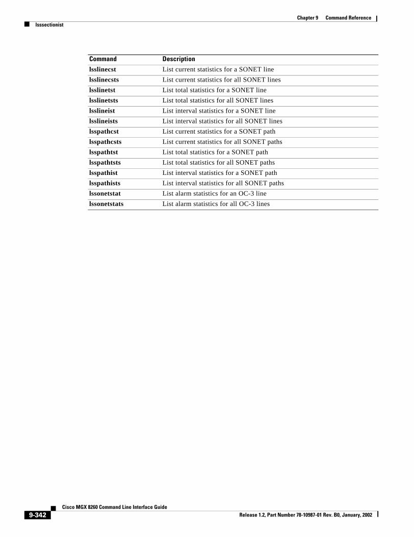
Chapter 9 Command Referencelsssectionist
lsslinecst List current statistics for a SONET linelsslinecsts List current statistics for all SONET lineslsslinetst List total statistics for a SONET linelsslinetsts List total statistics for all SONET lineslsslineist List interval statistics for a SONET linelsslineists List interval statistics for all SONET lineslsspathcst List current statistics for a SONET pathlsspathcsts List current statistics for all SONET pathslsspathtst List total statistics for a SONET pathlsspathtsts List total statistics for all SONET pathslsspathist List interval statistics for a SONET pathlsspathists List interval statistics for all SONET pathslssonetstat List alarm statistics for an OC-3 linelssonetstats List alarm statistics for all OC-3 lines
Command Description
9-342Cisco MGX 8260 Command Line Interface Guide
Release 1.2, Part Number 78-10987-01 Rev. B0, January, 2002

Chapter 9 Command Referencelsssectionists
lsssectionistsList interval statistics for all SONET sections.
lsssectionists
Syntax Description The command has no arguments or keywords.
Defaults No default behavior or values.
Command Modes Security level 5
Command History
Usage Guidelines Use this command to display interval ES, SES, SEFS, and CV statistics for all SONET sections. For more information, see Viewing Section Interval Statistics, page 7-15.
Related Commands
Release Modification
1.2 This command was first introduced.
Command Description
clrssectioncst Clear current statistics for a SONET sectionclrssectiontst Clear total statistics for a SONET sectionclrslinecst Clear current statistics for a SONET lineclrslinetst Clear total statistics for a SONET lineclrspathcst Clear current statistics for a SONET pathclrspathtst Clear total statistics for a SONET pathclrsonetstats Clear alarm statistics for an OC-3 linelsssectioncst List current statistics for a SONET sectionlsssectioncsts List current statistics for all SONET sectionslsssectiontst List total statistics for a SONET sectionlsssectiontsts List total statistics for all SONET sectionslsssectionist List interval statistics for a SONET sectionlsslinecst List current statistics for a SONET linelsslinecsts List current statistics for all SONET lineslsslinetst List total statistics for a SONET linelsslinetsts List total statistics for all SONET lineslsslineist List interval statistics for a SONET linelsslineists List interval statistics for all SONET lineslsspathcst List current statistics for a SONET path
9-343Cisco MGX 8260 Command Line Interface Guide
Release 1.2, Part Number 78-10987-01 Rev. B0, January, 2002

Chapter 9 Command Referencelsssectionists
lsspathcsts List current statistics for all SONET pathslsspathtst List total statistics for a SONET pathlsspathtsts List total statistics for all SONET pathslsspathist List interval statistics for a SONET pathlsspathists List interval statistics for all SONET pathslssonetstat List alarm statistics for an OC-3 linelssonetstats List alarm statistics for all OC-3 lines
Command Description
9-344Cisco MGX 8260 Command Line Interface Guide
Release 1.2, Part Number 78-10987-01 Rev. B0, January, 2002

Chapter 9 Command Referencelsssectiontst
lsssectiontstList total statistics for a SONET section.
lsssectiontst Location
Syntax Description
Defaults No default behavior or values.
Command Modes Security level 5
Command History
Usage Guidelines Use this command to display total ES, SES, SEFS, and CV statistics for a SONET section. For more information, see Viewing Section Total Statistics, page 7-15.
Examples The following example lists statistics for slot 9 line 1:
lsssectiontst 9.1
Related Commands
Location The slot and line number, delimited by a period, of the OC-3 line.Valid slot: 9. Valid lines: 1-4
Release Modification
1.2 This command was first introduced.
Command Description
clrssectioncst Clear current statistics for a SONET sectionclrssectiontst Clear total statistics for a SONET sectionclrslinecst Clear current statistics for a SONET lineclrslinetst Clear total statistics for a SONET lineclrspathcst Clear current statistics for a SONET pathclrspathtst Clear total statistics for a SONET pathclrsonetstats Clear alarm statistics for an OC-3 linelsssectioncst List current statistics for a SONET sectionlsssectioncsts List current statistics for all SONET sectionslsssectiontsts List total statistics for all SONET sectionslsssectionist List interval statistics for a SONET sectionlsssectionists List interval statistics for all SONET sectionslsslinecst List current statistics for a SONET linelsslinecsts List current statistics for all SONET lines
9-345Cisco MGX 8260 Command Line Interface Guide
Release 1.2, Part Number 78-10987-01 Rev. B0, January, 2002

Chapter 9 Command Referencelsssectiontst
lsslinetst List total statistics for a SONET linelsslinetsts List total statistics for all SONET lineslsslineist List interval statistics for a SONET linelsslineists List interval statistics for all SONET lineslsspathcst List current statistics for a SONET pathlsspathcsts List current statistics for all SONET pathslsspathtst List total statistics for a SONET pathlsspathtsts List total statistics for all SONET pathslsspathist List interval statistics for a SONET pathlsspathists List interval statistics for all SONET pathslssonetstat List alarm statistics for an OC-3 linelssonetstats List alarm statistics for all OC-3 lines
Command Description
9-346Cisco MGX 8260 Command Line Interface Guide
Release 1.2, Part Number 78-10987-01 Rev. B0, January, 2002

Chapter 9 Command Referencelsssectiontsts
lsssectiontstsList total statistics for all SONET sections.
lsssectiontsts
Syntax Description The command has no arguments or keywords.
Defaults No default behavior or values.
Command Modes Security level 5
Command History
Usage Guidelines Use this command to display total ES, SES, SEFS, and CV statistics for all SONET sections. For more information, see Viewing Section Total Statistics, page 7-15.
Related Commands
Release Modification
1.2 This command was first introduced.
Command Description
clrssectioncst Clear current statistics for a SONET sectionclrssectiontst Clear total statistics for a SONET sectionclrslinecst Clear current statistics for a SONET lineclrslinetst Clear total statistics for a SONET lineclrspathcst Clear current statistics for a SONET pathclrspathtst Clear total statistics for a SONET pathclrsonetstats Clear alarm statistics for an OC-3 linelsssectioncst List current statistics for a SONET sectionlsssectioncsts List current statistics for all SONET sectionslsssectiontst List total statistics for a SONET sectionlsssectionist List interval statistics for a SONET sectionlsssectionists List interval statistics for all SONET sectionslsslinecst List current statistics for a SONET linelsslinecsts List current statistics for all SONET lineslsslinetst List total statistics for a SONET linelsslinetsts List total statistics for all SONET lineslsslineist List interval statistics for a SONET linelsslineists List interval statistics for all SONET lineslsspathcst List current statistics for a SONET path
9-347Cisco MGX 8260 Command Line Interface Guide
Release 1.2, Part Number 78-10987-01 Rev. B0, January, 2002

Chapter 9 Command Referencelsssectiontsts
lsspathcsts List current statistics for all SONET pathslsspathtst List total statistics for a SONET pathlsspathtsts List total statistics for all SONET pathslsspathist List interval statistics for a SONET pathlsspathists List interval statistics for all SONET pathslssonetstat List alarm statistics for an OC-3 linelssonetstats List alarm statistics for all OC-3 lines
Command Description
9-348Cisco MGX 8260 Command Line Interface Guide
Release 1.2, Part Number 78-10987-01 Rev. B0, January, 2002

Chapter 9 Command Referencelstmgr
lstmgrList trap manager.
lstmgr Addr
Syntax Description
Defaults No default behavior or values.
Command Modes Security level 6
Command History
Usage Guidelines Displays information in the trap registration list about the manager at the specified address. For more information, see Viewing SNMP Trap Registrations, page 6-30.
Examples The following example lists information about the SNMP manager at 10.1.1.1.lstmgr 10.1.1.1
Related Commands
Addr The IP address of the manager
Release Modification
1.0 This command was first introduced.
Command Description
addtmgr Add trap managerclrtraps Clear trapsdelcms Delete community stringlscms List community stringlscmss List community stringslstmgrs List trap managers
9-349Cisco MGX 8260 Command Line Interface Guide
Release 1.2, Part Number 78-10987-01 Rev. B0, January, 2002

Chapter 9 Command Referencelstmgrs
lstmgrsList trap managers.
lstmgrs
Syntax Description The command has no arguments or keywords.
Defaults No default behavior or values.
Command Modes Security level 6
Command History
Usage Guidelines Use this command to display information about all managers in the trap registration list. For more information, see Viewing SNMP Trap Registrations, page 6-30.
Examples The following example lists trap managers.lstmgrs
Related Commands
Release Modification
1.0 This command was first introduced.
Command Description
addtmgr Add trap managerclrtraps Clear trapsdelcms Delete community stringlscms List community stringlscmss List community stringslstmgr List trap manager
9-350Cisco MGX 8260 Command Line Interface Guide
Release 1.2, Part Number 78-10987-01 Rev. B0, January, 2002

Chapter 9 Command Referencelstraps
lstrapsList the trap log.
lstraps
Syntax Description The command has no arguments or keywords.
Defaults No default behavior or values.
Command Modes Security level 6
Command History
Usage Guidelines Use this command to display the date and time of each trap and alarms associated with them.
Examples The following example displays information about all traps.lstraps
Related Commands
Release Modification
1.0 This command was first introduced.
Command Description
addtmgr Add trap managerclrtraps Clear trapsdelcms Delete community stringlscms List community stringlscmss List community stringslstmgr List trap manager
9-351Cisco MGX 8260 Command Line Interface Guide
Release 1.2, Part Number 78-10987-01 Rev. B0, January, 2002

Chapter 9 Command Referencelsusp
lsuspList a user profile.
lsusp Index
Syntax Description
Defaults No default behavior or values.
Command Modes Security level 1
Command History
Usage Guidelines Use this command to list the specified user profile by index. To determine the index, use lsusps. For more information, see Viewing User Profiles, page 2-2.
Examples The following example displays the profile for the user at index 3 in the user profile table. The profile includes the user’s security level. lsusp 3
Related Commands
Index A userProfileTable index number. Values: 1 - 20.
Release Modification
1.0 This command was first introduced.
Command Description
addusp Add user profiledelusp Delete user profilelsusps List all user profiles
9-352Cisco MGX 8260 Command Line Interface Guide
Release 1.2, Part Number 78-10987-01 Rev. B0, January, 2002

Chapter 9 Command Referencelsusps
lsuspsList all user profiles.
lsusps
Syntax Description The command has no arguments or keywords.
Defaults No default behavior or values.
Command Modes Security level 1
Command History
Usage Guidelines Use this command to list the user identifier and security level for all user profiles. For more information, see Viewing User Profiles, page 2-2.
Examples The following example lists all user profiles.lsusps
Related Commands
Release Modification
1.0 This command was first introduced.
Command Description
addusp Add user profiledelusp Delete user profilelsusp List a user profiles
9-353Cisco MGX 8260 Command Line Interface Guide
Release 1.2, Part Number 78-10987-01 Rev. B0, January, 2002

Chapter 9 Command Referencelsvport
lsvportList voice port
lsusp Slot Port
Syntax Description
Defaults No default behavior or values.
Command Modes Security level 5
Command History
Usage Guidelines Displays information about the specified voice port.
Examples The following example displays information about the voice port at slot 1, port 3. lsvport 1 3
Related Commands
Slot The logical slot number of an NSCPort The logical port number
Release Modification
1.0 This command was first introduced.
Command Description
addvport Add voice portchvport Change voice portdelvport Delete voice portlsvports List voice ports
9-354Cisco MGX 8260 Command Line Interface Guide
Release 1.2, Part Number 78-10987-01 Rev. B0, January, 2002

Chapter 9 Command Referencelsvports
lsvportsList voice ports
lsvports
Syntax Description The command has no arguments or keywords.
Defaults No default behavior or values.
Command Modes Security level 5
Command History
Usage Guidelines Use this command to list information about all voice ports.
Examples The following example lists information about all voice ports.lsvports
Related Commands
Release Modification
1.0 This command was first introduced.
Command Description
addvport Add voice portchvport Change voice portdelvport Delete voice portlsvport List voice port
9-355Cisco MGX 8260 Command Line Interface Guide
Release 1.2, Part Number 78-10987-01 Rev. B0, January, 2002

Chapter 9 Command Referenceoffbertds1
offbertds1Stop BERT on DS1.
offbertds1 Location
Syntax Description
Defaults No default behavior or values.
Command Modes Security level 3
Command History
Usage Guidelines Use this command to stop the BERT on the specified DS1 line.
Examples The following example stops a BERT that is running on the DS1 line at slot 1 line 1.offbertds1 1.1
Related Commands
Location The slot and line number, delimited by a period, of the DS1 line
Release Modification
1.0 This command was first introduced.
Command Description
lsbertds1 List DS1 BERT resultslsds1ln List DS1 line lsds1lns List DS1 linesonbertds1 Start BERT on DS1
9-356Cisco MGX 8260 Command Line Interface Guide
Release 1.2, Part Number 78-10987-01 Rev. B0, January, 2002

Chapter 9 Command Referenceonbertds1
onbertds1Start BERT on DS1.
onbertds1 Location Pattern Rate DS0 StateCtrl
Syntax Description
Defaults No default behavior or values.
Location The slot and line number, delimited by a period, of the DS1 line.Pattern One of the following patterns. Values: 1-13.
1 = Randomly-generated 29 -1 pattern
2 = Randomly-generated 211 -1 pattern
3 = Randomly-generated 215 -1 pattern
4 = Randomly-generated 220 -1 pattern with QRSS
5 = Randomly-generated 220 -1 pattern
6 = Randomly-generated 223 -1 pattern
7 = Repetitively-generated all-1 pattern
8 = Repetitively-generated all-1 pattern
9 = Repetitively-generated alternating 1 and 0 pattern
10 = Repetitively-generated alternating 11 and 00 pattern
11 = Repetitively-generated 1 in 24 pattern
12 = Repetitively-generated 1 in 16 pattern
13 = Repetitively-generated 1 in 8 patternRate The error rate to be injected into the pattern during BERT test. The value is
used as the exponent in the formula, BER 10-x. For example, if x = 1, the error rate is 10-1 or 10%. If the rate is 0, no error is injected in the BERT pattern. Values: 1-8 as follows:
1=No Error Rate Injection.
2=0.1
3=0.01
4=0.001
5=0.0001
6=0.00001
7=0.000001
8=0.0000001Ds0 A bit-mask specifying which DS0s are going to participate in the Bert test. StateCtrl A integer to control starting and stopping the Bert test. Values:
1=Start Bert test.
2=Stop Bert test.
9-357Cisco MGX 8260 Command Line Interface Guide
Release 1.2, Part Number 78-10987-01 Rev. B0, January, 2002

Chapter 9 Command Referenceonbertds1
Command Modes Security level 3
Command History
Usage Guidelines Use this command to start the BERT on the specified DS1 line. To specify which DS0s participate in a Bert test, use the Ds0 parameter. For example, 0000000000110101 specifies that the DS0 number 1, 3, 5 and 6 are participating. Convert this binary number to a decimal number and then enter that number on this option. For example, binary 0000000000110101 equals 53 decimal. Enter 53 for this option in this example
Examples The following example starts a BERT of the DS1 line at slot 1 line 1, using the 11 00 test pattern a test rate of 10%.onbertds1 1.1 10 1
Related Commands
Release Modification
1.0 This command was first introduced.
Command Description
lsbertds1 List DS1 BERT resultslsds1ln List DS1 line lsds1lns List DS1 linesoffbertds1 Stop BERT on DS1
9-358Cisco MGX 8260 Command Line Interface Guide
Release 1.2, Part Number 78-10987-01 Rev. B0, January, 2002

Chapter 9 Command Referencermannfile
rmannfileRemove an announcement file.
rmannfile fid
Syntax Description
Defaults No default behavior or values
Command Modes Security level
Command History
Usage Guidelines You use this command to remove an announcement file. Before attempting to remove an announcement file, first deactivate the file; otherwise, removal fails. To view file ID numbers, use the lsannfiles command.
Examples The first command deactivates file 25, and the next command removes the file. rmannfile 25
Related Commands
fid The announcement file ID. Values: 1-100
Release Modification
1.2 This command was first introduced.
Command Description
acannfile Activate an announcement filedeacannfile Deactivate an announcement filelsannfiles List all announcement fileslsannfile List the given announcement filelsdurationif List duration information about announcement files.
9-359Cisco MGX 8260 Command Line Interface Guide
Release 1.2, Part Number 78-10987-01 Rev. B0, January, 2002

Chapter 9 Command Referenceresetcd
resetcdReset card.
resetcd Card
Syntax Description
Defaults No default behavior or values.
Command Modes Security level 2
Command History
Usage Guidelines Use this command to specify a card to reset.
Examples The following example resets card 1.resetcd 1
Related Commands
Card The number of the card to reset
Release Modification
1.0 This command was first introduced.
Command Description
lscd List information about a cardlscds List information about all cards
9-360Cisco MGX 8260 Command Line Interface Guide
Release 1.2, Part Number 78-10987-01 Rev. B0, January, 2002

Chapter 9 Command Referenceresetnd
resetndReset node, including all processor and service modules.
resetnd
Syntax Description The command has no arguments or keywords.
Defaults No default behavior or values.
Command Modes Security level 2
Command History
Usage Guidelines Use this command to reset the node.
Examples The following example resets the node.resetnd
Related Commands
Release Modification
1.0 This command was first introduced.
Command Description
clrndcnf Clear node configuration
9-361Cisco MGX 8260 Command Line Interface Guide
Release 1.2, Part Number 78-10987-01 Rev. B0, January, 2002
Chapter 9 Command Referenceswcd
swcdSwitch to redundant NSC.
swcd Card
Syntax Description
Defaults No default behavior or values.
Command Modes Security level 4
Command History
Usage Guidelines Use this command to switch between the active and standby cards of a redundant pair.
Examples The following example makes the card in slot 1 the standby instead of the active card in a redundant pair. swcd 1
Related Commands
Card The slot number of active card to switch for the standby redundant card
Release Modification
1.0 This command was first introduced.
Command Description
addreds Add a card redundancy pairdelreds Delete a card redundancy pairlsreds List redundancies
9-362Cisco MGX 8260 Command Line Interface Guide
Release 1.2, Part Number 78-10987-01 Rev. B0, January, 2002

Chapter 9 Command Referenceswclk
swclkSwitch clock.
swclk
Syntax Description The command has no arguments or keywords.
Defaults No default behavior or values.
Command Modes Security level 2
Command History
Usage Guidelines Use this command to switch from the current clock source to the standby clock source.
Examples The following example switches to the standby clock.swclk
Related Commands
Release Modification
1.0 This command was first introduced.
Command Description
chpclksrc Change primary clock sourcechsclksrc Change secondary clock sourcelsclksrcs List clock sources
9-363Cisco MGX 8260 Command Line Interface Guide
Release 1.2, Part Number 78-10987-01 Rev. B0, January, 2002
Chapter 9 Command Referenceupethln
upethlnActivate Ethernet line.
upethln Location
Syntax Description
Defaults No default behavior or values.
Command Modes Security level 4
Command History
Usage Guidelines Use this command to bring up an Ethernet interface.
Examples The following example brings up the Ethernet interface at slot 9 line 1, address 10.1.2.10.upethln 9.1
Related Commands
Location The slot and line number, delimited by a period, of the Ethernet line
Release Modification
1.0 This command was first introduced.
Command Description
addethln Add Ethernet linechethln Change Fast Ethernet linedelethln Delete Ethernet linednethln DeActivate Ethernet linelsethln List Ethernet linelsethlns List Ethernet Lines
9-364Cisco MGX 8260 Command Line Interface Guide
Release 1.2, Part Number 78-10987-01 Rev. B0, January, 2002
Chapter 9 Command Referenceupgd
upgdUpgrade the software image.
upgd upgdLogicalCardIndex upgdFileName
Syntax Description
Defaults No default behavior or values.
Command Modes Security level 1
Command History
Usage Guidelines Use this command to upgrade the software image. The system sends a confirmation message on successful completion.
Examples The following example upgrades the software image of the SCC in logical slot 9:upgd 9 SCC_r01.01.03.fw
Related Commands
upgdLogicalCardIndex The logical number of the card to upgrade. Values: 1-16.upgdFileName The file name of the upgrade image. Values:
SCC image: SCC_<9-character string>.fw
NSC image: NSC_<9-character string>.fw
BSC image: BSC_<9-character string>.fw
Release Modification
1.1.3 This command was first introduced.
Command Description
upgdcancel Gracefully cancel an upgradeupgdcmit Commit the new software imagelslgcd List upgrade informationlslgcds List upgrade information for all cards
9-365Cisco MGX 8260 Command Line Interface Guide
Release 1.2, Part Number 78-10987-01 Rev. B0, January, 2002

Chapter 9 Command Referenceupgdcancel
upgdcancelCancel a software image upgrade.
upgdcancel upgdLogicalCardIndex
Syntax Description
Defaults No default behavior or values.
Command Modes Security level 1
Command History
Usage Guidelines Use this command to gracefully cancel a software image upgrade in a redundant system. The system sends a confirmation message on successful cancellation.
Examples The following example cancels the software upgrade of the SCC in logical slot 9:upgdcancel 9
Related Commands
upgdLogicalCardIndex The logical number of the card to upgrade. Values: 1-16.
Release Modification
1.1.3 This command was first introduced.
Command Description
upgd Upgrade the software imageupgdcmit Commit the new software imagelslgcd List upgrade informationlslgcds List upgrade information for all cards
9-366Cisco MGX 8260 Command Line Interface Guide
Release 1.2, Part Number 78-10987-01 Rev. B0, January, 2002

Chapter 9 Command Referenceupgdcmit
upgdcmitCommit the new software image.
upgdcmit upgdLogicalCardIndex
Syntax Description
Defaults No default behavior or values.
Command Modes Security level 1
Command History
Usage Guidelines Use this command to commit the new software image. The system sends a confirmation message on successful completion.
Examples The following example commits the software upgrade of the SCC in logical slot 9:upgdcmit 9
Related Commands
upgdLogicalCardIndex The logical number of the card to upgrade. Values: 1-16.
Release Modification
1.1.3 This command was first introduced.
Command Description
upgd Upgrade the software imageupgdcancel Gracefully cancel an upgradelslgcd List upgrade informationlslgcds List upgrade information for all cards
9-367Cisco MGX 8260 Command Line Interface Guide
Release 1.2, Part Number 78-10987-01 Rev. B0, January, 2002

Chapter 9 Command Referenceversion
versionShow the software version.
version
Syntax Description The command has no arguments or keywords.
Defaults No default behavior or values.
Command Modes Security level 6
Command History
Usage Guidelines Use this command to display the version information about the MGX 8260 Media Gateway.
Examples The following example displays the software version.version
Release Modification
1.0 This command was first introduced.
9-368Cisco MGX 8260 Command Line Interface Guide
Release 1.2, Part Number 78-10987-01 Rev. B0, January, 2002

Chapter 9 Command Referencewhoami
whoamiList the name of the user who is currently logged in.
whoami
Syntax Description The command has no arguments or keywords.
Defaults No default behavior or values.
Command Modes Security level 6
Command History
Usage Guidelines Use this command to determine who is logged in.
Examples The following example displays the name of the user who is logged in.whoami
Release Modification
1.0 This command was first introduced.
9-369Cisco MGX 8260 Command Line Interface Guide
Release 1.2, Part Number 78-10987-01 Rev. B0, January, 2002

Chapter 9 Command Referencewhoami
9-370Cisco MGX 8260 Command Line Interface Guide
Release 1.2, Part Number 78-10987-01 Rev. B0, January, 2002

Cisco MGX Release 1.2, Part Number 78-10987-01 Rev. B0, January, 2002
I N D E X
A
alarms
card 6-4
configuration tasks 6-24
DS1/E1 Alarms
Viewing 6-5
DS3 6-12, 6-15
E1 6-8
environmental 6-19
Fast Ethernet 6-15
OC-3c 6-15
shelf 6-2
surveillance tasks 6-1
alarm thresholds
setting DS1 6-7
setting DS3 6-19
setting E1 6-12
setting OC-3 6-19
viewing DS1 6-10
viewing DS3 6-13
viewing E1 6-10
viewing OC-3 6-17
atm queue profile, setting 3-10
C
call control
components 5-1
interfaces 5-1
call setup parameters
viewing default 5-7
card image
upgrading 3-23, 3-24
cards
configuration tasks 3-1
configuring 3-1, 3-2
resetting 3-11
viewing configuration and status 3-2
viewing summary information 3-7
clearing alarms 8-6
card 8-6
chassis 8-6
DS1/E1 and DS3 8-7
environmental 8-11
Fast Ethernet 8-9
SONET 8-9
CLI reference 9-1
configurations
backing up 3-18
downloading 3-19
restoring 3-20
uploading 3-19
controls, front panel 1-6
cot settings
configuring 5-33
D
D channels
adding 5-25
changing 5-26
configuring 5-25
deleting 5-26
viewing 5-26
DLSAP profiles
18260 Command Line Interface Guide

Index
adding 5-22
deleting 5-22
managing 5-22
viewing 5-22
DLSAP statistics
viewing 5-24
DLSAP status
viewing 5-23
dmc lines, mapping 4-11
DS0 channels, viewing information 4-3
DS1/E1 lines
adding 4-7
bert test 8-5
changing 4-7
configuring 4-3
deleting 4-8
listing summary information 4-3, 4-6
loopback 8-2
viewing configuration and status 4-2, 4-3
DS1 statistics
clearing real-Time 7-5
clearing real-time 7-5
viewing current 7-1
viewing interval 7-2
viewing real-time 7-3
viewing total 7-2
DS3 lines
adding 4-10
changing 4-10
configuring 4-8
deleting 4-11
loopback 8-3
viewing configuration and status 4-8
viewing summary information 4-10
DS3 statistics
clearing real-time 7-13, 7-25
viewing current 7-12
viewing interval 7-13
viewing real-time 7-13
viewing total 7-12
E
E1 performance Alarms 6-8
E1 statistics
clearing real-time 7-11
viewing current 7-5
Viewing Interval 7-7
Viewing Real-Time 7-8
Viewing Total 7-6
email alerts
changing 6-26
configuring 6-25
deleting 6-26
listing 6-26
registering 6-25
email server
registering 6-25
e-rdi and trace parameters 4-24
e-rdi configuration and status, viewing 4-22
F
Fast Ethernet lines
adding 4-15
administrative status 4-16
changing 4-16
configuring 4-14
deleting 4-16
viewing configuration and status 4-14
features 1-1
front panel controls and indicators 1-4
I
indicators
card and line 1-6
2Cisco MGX 8260 Command Line Interface Guide
Release 1.2, Part Number 78-10987-01 Rev. B0, January, 2002

Index
system 1-5
IPDC
activating the Link Health Check 5-33
core settings 5-32
soft switch ip addresses 5-32
timers and counters 5-33
viewing cot information 5-36
viewing settings 5-33
IPDC to MGCP, switching from 5-3
ip routes, configuring 2-10
L
lapd parameters, viewing 5-30
lines
configuration tasks 4-1
viewing all 4-1
logging on 2-1
M
MACSAP profiles
adding 5-20
deleting 5-20
managing 5-20
viewing 5-20
MACSAP statistics, viewing 5-21
management interfaces 1-2
10baset management port 2-8
command line interface 1-4
configuring 2-8
in-band management paths 2-9
SNMP 1-3
viewing 2-8
WebViewer 1-3
map table
adding entries 4-12
changing 4-13
deleting entries 4-13
viewing 4-13
MGCP
core parameters 5-4
default call setup parameters 5-4
ip addresses 5-4
settings, viewing 5-5
status information, viewing 5-8
voice parameters, viewing 5-6
MGCP to IPDC, switching from 5-31
msm
viewing configuration and status 3-7
multi-chassis considerations 4-18
N
node parameters
configuring 2-6
setting 2-7
viewing 2-6
nsc interface mode
choosing 3-8
configuring 3-10
O
OC-3 lines
adding 4-22
changing 4-22
configuring 4-18
deleting 4-22
viewing configuration and status 4-18
P
pseudo ip address
configuring 5-32
3Cisco MGX 8260 Command Line Interface Guide
Release 1.2, Part Number 78-10987-01 Rev. B0, January, 2002

Index
R
redundancy
adding bsc 3-17
adding nsc 3-16
configuring 3-15
deleting 3-17
invoking a switchback 3-18
physical and logical slot numbers 3-11
understanding 3-11
using 1 to 1 3-13
using 1 to n 3-12
viewing 3-15
rudp
connection statistics, viewing 5-17
transport statistics, viewing 5-17
S
sensors, specifying 6-20
session
adding 5-16
configuring 5-14
deleting 5-13
statistics, viewing 5-18
viewing 5-14
session group
adding 5-14
configuring 5-13
deleting 5-14
viewing 5-13
session group statistics, viewing 5-16
session set
adding 5-13
configuring 5-11
viewing 5-11
snmp communities, configuring 2-4
SNMP trap registrations
changing 6-29
configuring 6-28
deleting 6-29
registering 6-28
viewing 6-30
software
upgrading 3-21
SONET
alarm statistics 7-23
line statistics 7-17
loopback 8-4
path statistics 7-20
performance alarm statistics, clearing 7-25
section statistics 7-14
static routes
adding 4-17
deleting 4-17
viewing 4-17
system clock
setting 2-12
switching 2-14
synchronizing 2-12
viewing parameters 2-13
system initialization, configuration tasks 2-1
system security, configuring 2-2
T
tftp security key, setting 2-6
U
user accounts
adding 2-3
changing passwords 2-3
configuring 2-2
deleting 2-3
viewing 2-2
4Cisco MGX 8260 Command Line Interface Guide
Release 1.2, Part Number 78-10987-01 Rev. B0, January, 2002

Index
V
voice port
viewing configuration and status 4-27
voice ports
adding 4-26
changing 4-27
deleting 4-27
5Cisco MGX 8260 Command Line Interface Guide
Release 1.2, Part Number 78-10987-01 Rev. B0, January, 2002

Index
6Cisco MGX 8260 Command Line Interface Guide
Release 1.2, Part Number 78-10987-01 Rev. B0, January, 2002