PHV SERIES DIGITAL INTERFACE COMMAND REFERENCE
23
DIGITAL INTERFACE COMMAND REFERENCE MANUAL FOR PHV Series High Voltage POWER SUPPLY Document: 83550100 Rev C TDK-LAMBDA AMERICAS 405 Essex Road, Neptune, NJ 07753 Tel: (732) 922-9300 Fax: (732) 922-9334 Web: www.us.tdk-lambda.com/hp
-
Upload
khangminh22 -
Category
Documents
-
view
2 -
download
0
Transcript of PHV SERIES DIGITAL INTERFACE COMMAND REFERENCE
DIGITAL INTERFACE COMMAND REFERENCE MANUAL FOR
PHV Series High Voltage
POWER SUPPLY
Document: 83550100 Rev C
TDK-LAMBDA AMERICAS
405 Essex Road, Neptune, NJ 07753
Tel: (732) 922-9300
Fax: (732) 922-9334
Web: www.us.tdk-lambda.com/hp

THIS PAGE LEFT INTENTIONALLY BLANK

1
83550100 Revision C
Table of Contents 1. Overview .................................................................................................................................. 3 1.1. PHV Digital Interface ................................................................................................................ 3 1.2. User Digital Interface ................................................................................................................ 3 1.3. Available Digital Interfaces ....................................................................................................... 3 1.3.1. RS-232, Standard design ......................................................................................................... 3 1.3.2. RS-485, Standard design ......................................................................................................... 3 1.3.3. USB Interface, Standard design ............................................................................................... 3 1.3.4. Ethernet, LAN, TCP/IP, Standard design .................................................................................. 3 1.3.5. IEEE-488, Standard design ...................................................................................................... 3 1.3.6. External Fiber Optics ................................................................................................................ 3 1.4. Abbreviations ............................................................................................................................ 4 2. General Information .................................................................................................................. 5 3. Basic Programming Commands and Queries ........................................................................... 7 3.1. Turn ON the HV Output ............................................................................................................ 7 3.2. Turn OFF the HV Output .......................................................................................................... 7 3.3. Read the HV output ON/OFF state ........................................................................................... 7 3.4. Program the Output Voltage ..................................................................................................... 7 3.5. Read the Actual Output Voltage ............................................................................................... 7 3.6. Program the Output Current ..................................................................................................... 7 3.7. Read the Actual Output Current ................................................................................................ 8 3.8. Program Positive Output Polarity (reversible polarity option must be installed) ......................... 8 3.9. Program Negative Output Polarity (reversible polarity option must be installed) ....................... 8 3.10. Read the unit’s voltage rating ................................................................................................... 8 3.11. Read the unit’s current rating .................................................................................................... 8 3.12. Device Clear ............................................................................................................................. 8 3.13. Unit Identification ...................................................................................................................... 8 3.14. The Ramp Function .................................................................................................................. 8 3.14.1. Standard Ramp ........................................................................................................................ 8 3.14.2. Ramps at the Programmed Ramp Rate .................................................................................... 8 3.14.3. Ramps UP at the Programmed Ramp Rate, Down Immediately ............................................... 9 3.15. Basic Programming Examples .................................................................................................. 9 3.15.1. Turn ON HV output, program the output voltage and current .................................................... 9 3.15.2. Read Output Voltage and Current ............................................................................................ 9 3.15.3. Read back the power supply status ........................................................................................ 10 3.15.4. Using the ramp function .......................................................................................................... 10 4. PHV Digital Interface Command Set ....................................................................................... 11 4.1. Output Programming/Control Commands ............................................................................... 11 4.2. Voltage Ramp Function .......................................................................................................... 12 4.3. Current Ramp Function .......................................................................................................... 13 4.4. Analog monitors...................................................................................................................... 14 4.5. Analog Monitor A/D conversion resolution .............................................................................. 14 4.6. Power Supply Status .............................................................................................................. 15 4.7. Configuration and Status values ............................................................................................. 16 4.8. Unit build status queries ......................................................................................................... 17 4.9. Service Request, automatic transmission on status change (IEEE interface) .......................... 17 5. Error codes ............................................................................................................................. 19 6. Technical Data ........................................................................................................................ 21

2
83550100 Revision C
THIS PAGE LEFT INTENTIONALLY BLANK
3
83550100 Revision C
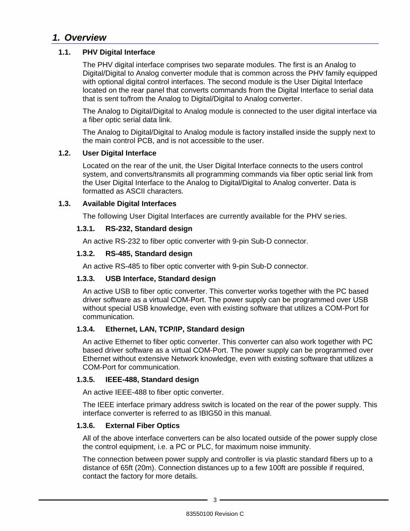
1. Overview
1.1. PHV Digital Interface
The PHV digital interface comprises two separate modules. The first is an Analog to Digital/Digital to Analog converter module that is common across the PHV family equipped with optional digital control interfaces. The second module is the User Digital Interface located on the rear panel that converts commands from the Digital Interface to serial data that is sent to/from the Analog to Digital/Digital to Analog converter.
The Analog to Digital/Digital to Analog module is connected to the user digital interface via a fiber optic serial data link.
The Analog to Digital/Digital to Analog module is factory installed inside the supply next to the main control PCB, and is not accessible to the user.
1.2. User Digital Interface
Located on the rear of the unit, the User Digital Interface connects to the users control system, and converts/transmits all programming commands via fiber optic serial link from the User Digital Interface to the Analog to Digital/Digital to Analog converter. Data is formatted as ASCII characters.
1.3. Available Digital Interfaces
The following User Digital Interfaces are currently available for the PHV series.
1.3.1. RS-232, Standard design
An active RS-232 to fiber optic converter with 9-pin Sub-D connector.
1.3.2. RS-485, Standard design
An active RS-485 to fiber optic converter with 9-pin Sub-D connector.
1.3.3. USB Interface, Standard design
An active USB to fiber optic converter. This converter works together with the PC based driver software as a virtual COM-Port. The power supply can be programmed over USB without special USB knowledge, even with existing software that utilizes a COM-Port for communication.
1.3.4. Ethernet, LAN, TCP/IP, Standard design
An active Ethernet to fiber optic converter. This converter can also work together with PC based driver software as a virtual COM-Port. The power supply can be programmed over Ethernet without extensive Network knowledge, even with existing software that utilizes a COM-Port for communication.
1.3.5. IEEE-488, Standard design
An active IEEE-488 to fiber optic converter.
The IEEE interface primary address switch is located on the rear of the power supply. This interface converter is referred to as IBIG50 in this manual.
1.3.6. External Fiber Optics
All of the above interface converters can be also located outside of the power supply close the control equipment, i.e. a PC or PLC, for maximum noise immunity.
The connection between power supply and controller is via plastic standard fibers up to a distance of 65ft (20m). Connection distances up to a few 100ft are possible if required, contact the factory for more details.

4
83550100 Revision C
1.4. Abbreviations
Abbreviations used in this manual are;
FPN – Floating Point Number
INT – Integer Number
IBIG50 – IEEE to serial User Digital Interface
1.5. Commands
A zero in a command is shown by 0, whereas an alphabetical o is shown as o or O

5
83550100 Revision C
2. General Information
Each interface command must be terminated with a Terminator Character. CR, LF or 0x00 or any combination is allowed.
The interface responds to each command with a single answer string. An "empty" command string, i.e. a string that consist only of terminator characters, is ignored and results in no response.
The interface terminates it's answer strings with the termination character(s) defined in Registers >KT and >CKT. The standard termination character is LF (Line Feed). Note that if the LAN interface is specified, the factory default terminator is CR+LF.
The command descriptions used in this manual omit the terminator character.
Any command or argument can be in upper or lower case.
Receive-Timeout:
If the interface receives no characters for more than 5000ms, all characters in the buffer are flushed.
Each command must have a string length no longer than 50 characters. The interface module has a 255 character long FiFO Receive Buffer

6
83550100 Revision C
THIS PAGE LEFT INTENTIONALLY BLANK

7
83550100 Revision C
3. Basic Programming Commands and Queries
Most functions of the PHV supply can be operated using a basic command set. This includes programming and readback of the output voltage and current, turning ON and OFF the HV output, and setting the output polarity if the polarity reversal option is installed.
Each command or query must be terminated with a Terminator Character. CR, LF or 0x00 or any combination is allowed. Commands can be uppercase or lowercase.
The PHV supply responds to each command with a single answer string. An "empty" command string, i.e. strings that consist only of terminator characters, are ignored and result in no answer string.
The supply terminates its answer strings with the default termination character (LF). The termination character can be changed if required. Note that if the LAN interface is specified, the factory default terminator is CR+LF.
In the following description of all commands, the terminator is omitted.
3.1. Turn ON the HV Output
Syntax: >BON 1
Answer: E0
3.2. Turn OFF the HV Output
Syntax: >BON 0
Answer: E0
3.3. Read the HV output ON/OFF state
Syntax: >DON?
Answer: DON:0 if the unit is OFF or DON:1 if the unit is ON
3.4. Program the Output Voltage
Syntax: >S0 x where x is a real number
Answer: E0
Example: >S0 5000 programs the output to 5,000Volts.
3.5. Read the Actual Output Voltage
Syntax: >M0?
Answer: M0:+5.00000E+3
3.6. Program the Output Current
Syntax: >S1 x where x is a real number
Answer: E0
Example: >S1 25E-3 programs the output to 25milliAmps.
8
83550100 Revision C
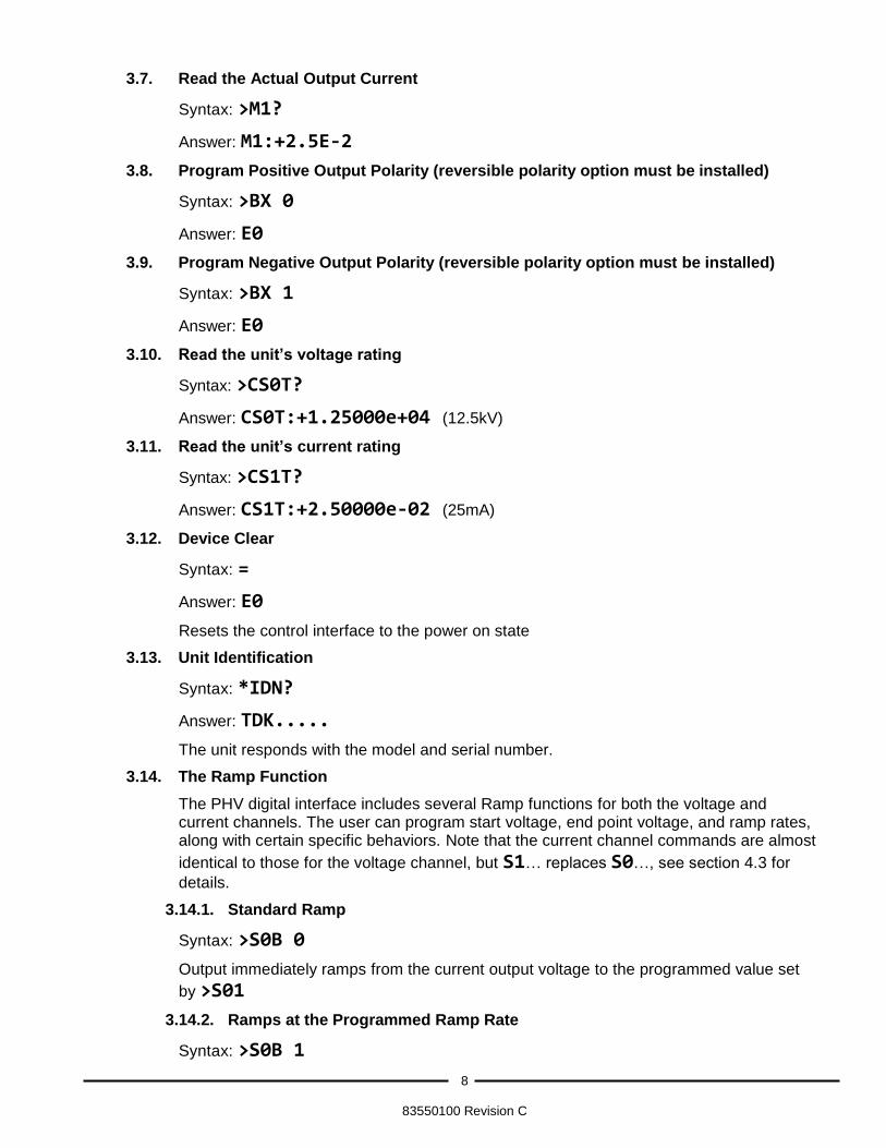
3.7. Read the Actual Output Current
Syntax: >M1?
Answer: M1:+2.5E-2
3.8. Program Positive Output Polarity (reversible polarity option must be installed)
Syntax: >BX 0
Answer: E0
3.9. Program Negative Output Polarity (reversible polarity option must be installed)
Syntax: >BX 1
Answer: E0
3.10. Read the unit’s voltage rating
Syntax: >CS0T?
Answer: CS0T:+1.25000e+04 (12.5kV)
3.11. Read the unit’s current rating
Syntax: >CS1T?
Answer: CS1T:+2.50000e-02 (25mA)
3.12. Device Clear
Syntax: =
Answer: E0
Resets the control interface to the power on state
3.13. Unit Identification
Syntax: *IDN?
Answer: TDK.....
The unit responds with the model and serial number.
3.14. The Ramp Function
The PHV digital interface includes several Ramp functions for both the voltage and current channels. The user can program start voltage, end point voltage, and ramp rates, along with certain specific behaviors. Note that the current channel commands are almost
identical to those for the voltage channel, but S1… replaces S0…, see section 4.3 for
details.
3.14.1. Standard Ramp
Syntax: >S0B 0
Output immediately ramps from the current output voltage to the programmed value set
by >S01
3.14.2. Ramps at the Programmed Ramp Rate
Syntax: >S0B 1
9
83550100 Revision C
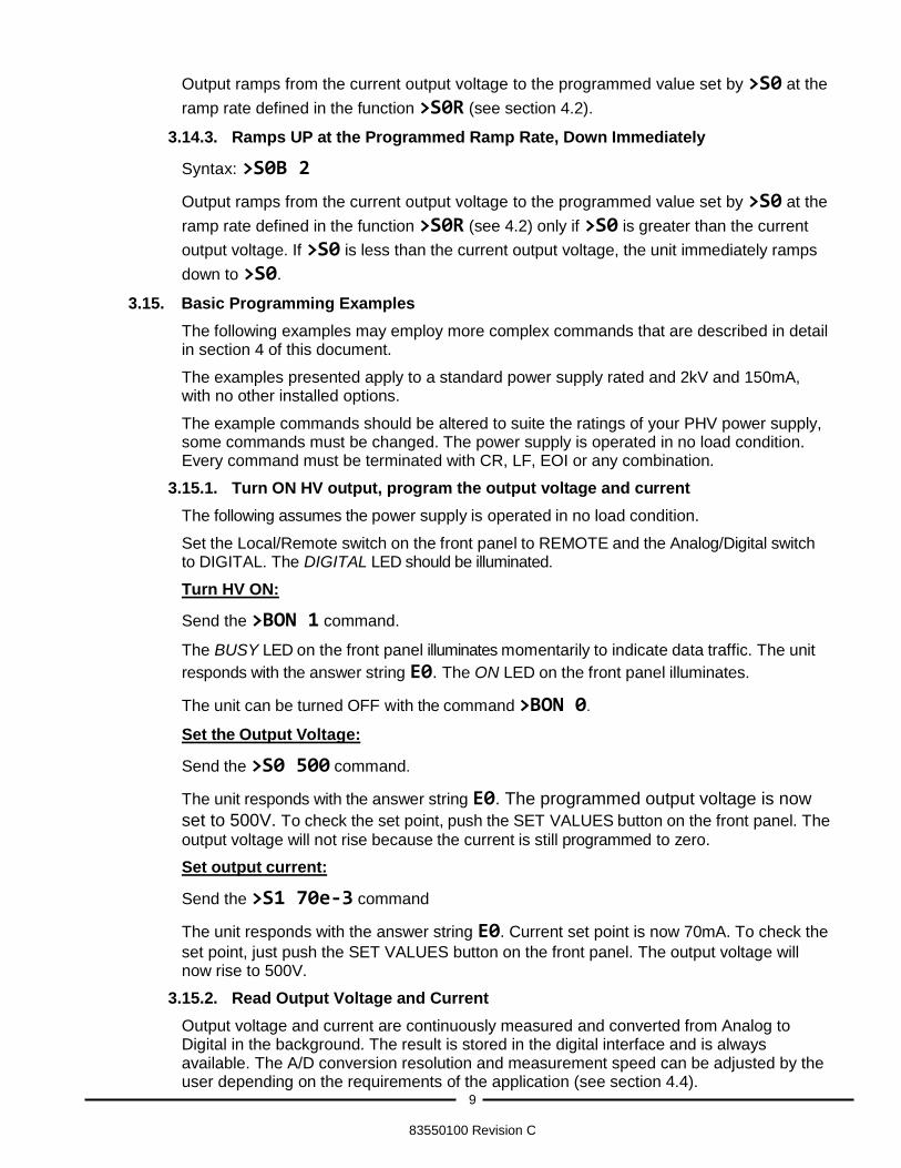
Output ramps from the current output voltage to the programmed value set by >S0 at the
ramp rate defined in the function >S0R (see section 4.2).
3.14.3. Ramps UP at the Programmed Ramp Rate, Down Immediately
Syntax: >S0B 2
Output ramps from the current output voltage to the programmed value set by >S0 at the
ramp rate defined in the function >S0R (see 4.2) only if >S0 is greater than the current
output voltage. If >S0 is less than the current output voltage, the unit immediately ramps
down to >S0.
3.15. Basic Programming Examples
The following examples may employ more complex commands that are described in detail in section 4 of this document.
The examples presented apply to a standard power supply rated and 2kV and 150mA, with no other installed options.
The example commands should be altered to suite the ratings of your PHV power supply, some commands must be changed. The power supply is operated in no load condition. Every command must be terminated with CR, LF, EOI or any combination.
3.15.1. Turn ON HV output, program the output voltage and current
The following assumes the power supply is operated in no load condition.
Set the Local/Remote switch on the front panel to REMOTE and the Analog/Digital switch to DIGITAL. The DIGITAL LED should be illuminated.
Turn HV ON:
Send the >BON 1 command.
The BUSY LED on the front panel illuminates momentarily to indicate data traffic. The unit
responds with the answer string E0. The ON LED on the front panel illuminates.
The unit can be turned OFF with the command >BON 0.
Set the Output Voltage:
Send the >S0 500 command.
The unit responds with the answer string E0. The programmed output voltage is now
set to 500V. To check the set point, push the SET VALUES button on the front panel. The
output voltage will not rise because the current is still programmed to zero.
Set output current:
Send the >S1 70e-3 command
The unit responds with the answer string E0. Current set point is now 70mA. To check the
set point, just push the SET VALUES button on the front panel. The output voltage will now rise to 500V.
3.15.2. Read Output Voltage and Current
Output voltage and current are continuously measured and converted from Analog to Digital in the background. The result is stored in the digital interface and is always available. The A/D conversion resolution and measurement speed can be adjusted by the user depending on the requirements of the application (see section 4.4).
10
83550100 Revision C
Set A/D resolution and measuring speed:
Send the >M0I 7 and >M1I 7 commands (see section 4.5). The unit responds with
the answer string E0. A/D resolution is now set to its highest level, slowest measuring
speed (long integration time).
Read back the actual Output Voltage:
Send the >M0? query.
In the ideal case, the unit responds with the answer string M0:+5.00000E+02
Actual voltage is 500.000V. Since the value comes from a true analog output voltage measurement, small deviations from the exact value are normal.
Read back the actual Output Current:
Send the >M1? query.
In the ideal case, the unit responds with the answer string M1:+0.00000E+00
Actual current is zero, because there is no load connected. Since the value comes from a true analog output voltage measurement, small deviations from the exact value are normal.
3.15.3. Read back the power supply status
All of the status bits are available by querying the D-registers (see 4.6):
The ON/OFF status can be read using the query >DON?
The unit responds with DON:1 if power is turned ON, and the HV output is ON.
3.15.4. Using the ramp function
Example: The output voltage is set to 500V and the user wants to ramp to 1000V in 20 seconds. The ramp rate is 500V/20sec or 25V/sec.
Choose the appropriate ramp function (see Section 3.14).
Send the >S0B 2 command.
The unit responds with the answer string E0. Ramp function 2 means the voltage will ramp
up at the rate defined in >S0R and ramps down immediately.
Set the ramp rate:
Send the >S0R 25 command
The unit responds with the answer string E0. The Ramp rate is now set to 25V per
second.
Set the new output voltage:
Send the >S0 1000 command. The unit responds with the answer string E0. The
output voltage will now ramp up from 500V to 1000V at a ramp rate of 25V/s.

11
83550100 Revision C
4. PHV Digital Interface Command Set
The following sections contain the complete digital interface command set including programming/readback and power supply status.
4.1. Output Programming/Control Commands
Command/Query
Read/ Write
Function Valid
Argument (x)
Response
>BON 1 W Turns ON the HV output 1 E0 >BON 0 W Turn OFF the HV output 0 E0 >DON? R Reads the HV output ON/OFF state ? DON:0 or 1 >S0 x R/W Program or query the output voltage
setpoint FPN or ?
>M0? R Reads actual output voltage ? M0:+1.00000E+01
>S1 x R/W Program or query the output current setpoint
FPN or ?
>M1? R Reads actual output current ? M1:+0.00000E+00 >BX 0 W Sets the output polarity as Positive
(reversible option must be installed) 0 0
>BX 1 W Sets the output polarity as Negative (reversible option must be installed)
1 1
= W Resets control interface to the power on state
E0
*IDN? R Query the unit identification ? TDK....

12
83550100 Revision C
4.2. Voltage Ramp Function
Command/Query
Read/ Write
Function Valid
Argument (x)
>S0A? R Calculated instantaneous ramp function programming voltage ?
>S0R x R/W Voltage ramp rate in V/sec FPN or ?
>S0B 0
R/W Output immediately ramps from the current output voltage to the
programmed value set by >S0
0 Integer 0, 1, 2, 4 or ?
>S0B 1
Output ramps from the current output voltage to the programmed
value set by >S0 at the ramp rate defined in the function >S0R only
if >S0 is greater than the current output voltage. If >S0 is less than
the current output voltage, the unit ramps down to >S0 at the ramp
rate defined in >S0R.
1
>S0B 2 Output ramps from the current output voltage to the programmed
value set by >S0 at the ramp rate defined in the function >S0R
only if >S0 is greater than the current output voltage. If >S0 is
less than the current output voltage, the unit immediately ramps
down to >S0.
In ramp mode 0, 1, and 2, the output can be programmed
before HV ON is asserted, then the ramp function starts when HV ON is asserted.
2
>S0B 4
Functions as 2, but if the HV output is set to OFF then >S0 is set
to zero. In ramp mode 4, the ramp function will not starts until HV
ON has been asserted followed by >S0 being set.
4
>S0S? R Ramp function status:
0: >S0A equals >S0
1: >S0A does not equal >S0
?
>S0H R/W High Resolution Mode PWM modulated Setvalue +/- 2 Bit, 22Bit resolution
0: normal mode
1: High Res. Mode
If one of the ramp functions is selected, and the power supply ON status is OFF, then the
calculated instantaneous ramp voltage(>S0A) is set to zero. This ensures that a ramp
event always starts at zero after the power supply was in the OFF state.
13
83550100 Revision C
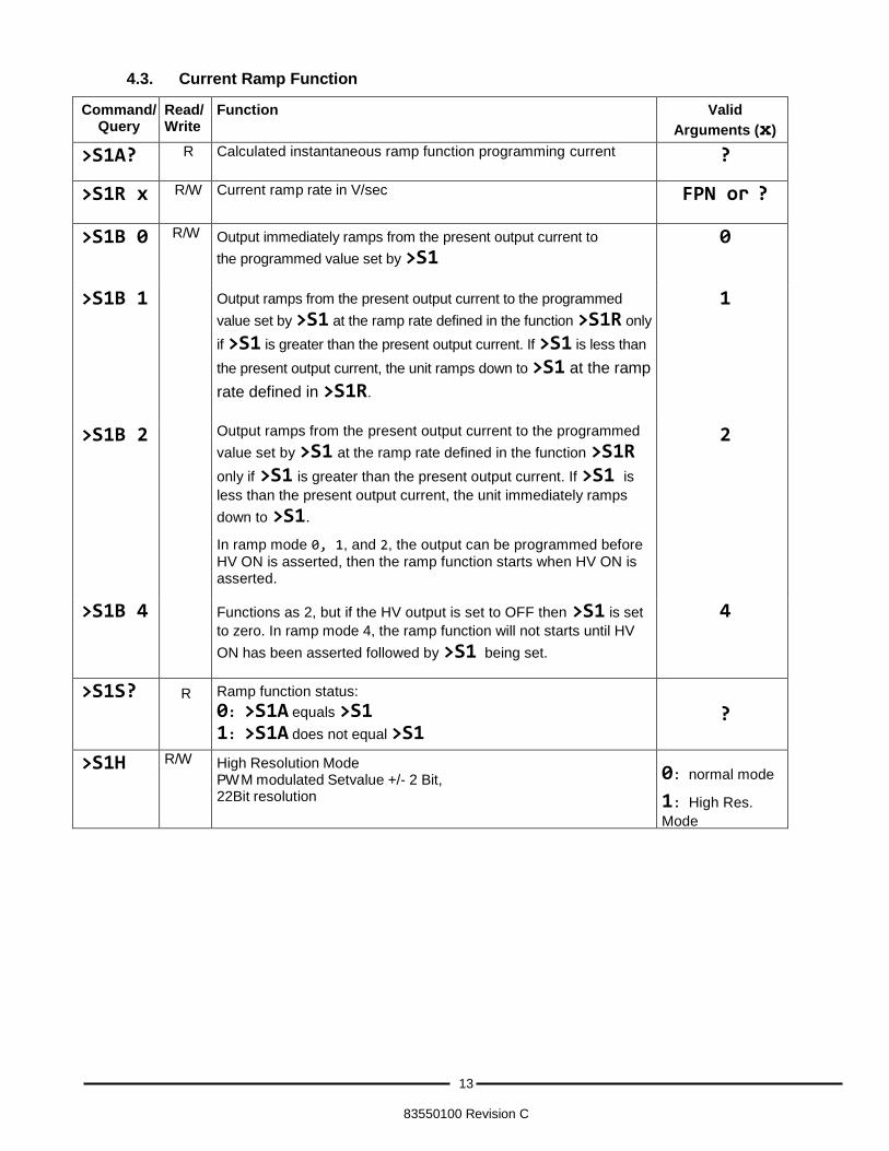
4.3. Current Ramp Function
Command/Query
Read/ Write
Function Valid
Arguments (x)
>S1A? R Calculated instantaneous ramp function programming current ?
>S1R x R/W Current ramp rate in V/sec FPN or ?
>S1B 0
R/W Output immediately ramps from the present output current to
the programmed value set by >S1
0 Integer 0, 1, 2, 4 or ?
>S1B 1
Output ramps from the present output current to the programmed
value set by >S1 at the ramp rate defined in the function >S1R only
if >S1 is greater than the present output current. If >S1 is less than
the present output current, the unit ramps down to >S1 at the ramp
rate defined in >S1R.
1
>S1B 2 Output ramps from the present output current to the programmed
value set by >S1 at the ramp rate defined in the function >S1R
only if >S1 is greater than the present output current. If >S1 is
less than the present output current, the unit immediately ramps
down to >S1.
In ramp mode 0, 1, and 2, the output can be programmed before
HV ON is asserted, then the ramp function starts when HV ON is asserted.
2
>S1B 4
Functions as 2, but if the HV output is set to OFF then >S1 is set
to zero. In ramp mode 4, the ramp function will not starts until HV
ON has been asserted followed by >S1 being set.
4
>S1S? R Ramp function status:
0: >S1A equals >S1
1: >S1A does not equal >S1
?
>S1H R/W High Resolution Mode PWM modulated Setvalue +/- 2 Bit, 22Bit resolution
0: normal mode
1: High Res.
Mode
14
83550100 Revision C
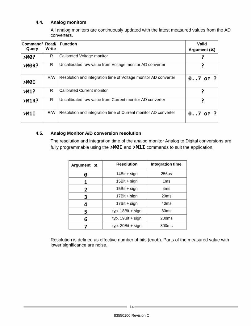
4.4. Analog monitors
All analog monitors are continuously updated with the latest measured values from the AD converters.
Command/Query
Read/ Write
Function Valid
Argument (x)
>M0? R Calibrated Voltage monitor ?
>M0R? R Uncalibrated raw value from Voltage monitor AD converter ?
>M0I
R/W Resolution and integration time of Voltage monitor AD converter 0..7 or ?
>M1? R Calibrated Current monitor ?
>M1R? R Uncalibrated raw value from Current monitor AD converter ?
>M1I R/W Resolution and integration time of Current monitor AD converter 0..7 or ?
4.5. Analog Monitor A/D conversion resolution
The resolution and integration time of the analog monitor Analog to Digital conversions are
fully programmable using the >M0I and >M1I commands to suit the application.
Argument x Resolution Integration time
0 14Bit + sign 256µs
1 15Bit + sign 1ms
2 15Bit + sign 4ms
3 17Bit + sign 20ms
4 17Bit + sign 40ms
5 typ. 18Bit + sign 80ms
6 typ. 19Bit + sign 200ms
7 typ. 20Bit + sign 800ms
Resolution is defined as effective number of bits (enob). Parts of the measured value with lower significance are noise.

15
83550100 Revision C
4.6. Power Supply Status
These queries are Read Only.
Command/Query
Read/Write Function
>DVR? R Query V-REG (responds 1 if power supply is in CV mode)
>DIR? R Query I-REG (responds 1 if power supply is in CC mode)
>DON? R Query ON-STAT (responds 1 if power supply ON)
>DSD? R Query SEL-D (responds 1 if power supply is digitally controlled)
>DSA? R Query SEL-A (responds 1 if power supply is controlled by the analog interface)
16
83550100 Revision C
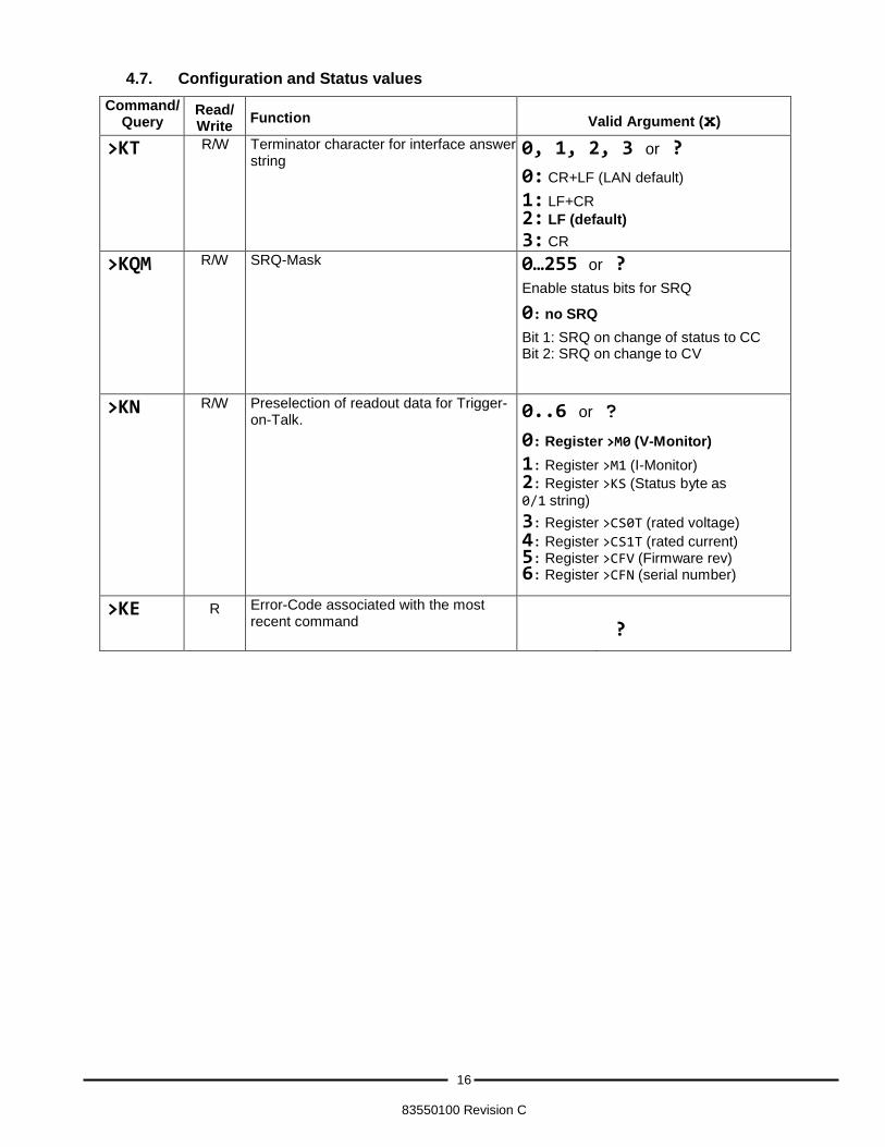
4.7. Configuration and Status values
Command/Query
Read/ Write
Function
Valid Argument (x)
>KT R/W Terminator character for interface answer string
0, 1, 2, 3 or ?
0: CR+LF (LAN default)
1: LF+CR
2: LF (default)
3: CR
>KQM R/W SRQ-Mask
0…255 or ?
Enable status bits for SRQ
0: no SRQ
Bit 1: SRQ on change of status to CC Bit 2: SRQ on change to CV
>KN R/W Preselection of readout data for Trigger-on-Talk.
0..6 or ?
0: Register >M0 (V-Monitor)
1: Register >M1 (I-Monitor)
2: Register >KS (Status byte as
0/1 string)
3: Register >CS0T (rated voltage)
4: Register >CS1T (rated current) 5: Register >CFV (Firmware rev) 6: Register >CFN (serial number)
>KE R Error-Code associated with the most recent command
?
17
83550100 Revision C
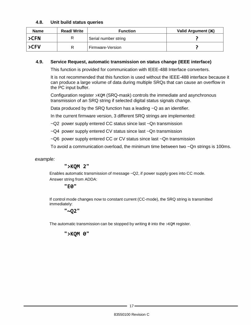
4.8. Unit build status queries
Name Read/ Write Function Valid Argument (x)
>CFN R Serial number string ?
>CFV R Firmware-Version ?
4.9. Service Request, automatic transmission on status change (IEEE interface)
This function is provided for communication with IEEE-488 Interface converters.
It is not recommended that this function is used without the IEEE-488 interface because it can produce a large volume of data during multiple SRQs that can cause an overflow in the PC input buffer.
Configuration register >KQM (SRQ-mask) controls the immediate and asynchronous
transmission of an SRQ string if selected digital status signals change.
Data produced by the SRQ function has a leading ~Q as an identifier.
In the current firmware version, 3 different SRQ strings are implemented:
~Q2 power supply entered CC status since last ~Qn transmission
~Q4 power supply entered CV status since last ~Qn transmission
~Q6 power supply entered CC or CV status since last ~Qn transmission
To avoid a communication overload, the minimum time between two ~Qn strings is 100ms.
example:
">KQM 2" Enables automatic transmission of message ~Q2, if power supply goes into CC mode.
Answer string from ADDA:
"E0"
If control mode changes now to constant current (CC-mode), the SRQ string is transmitted immediately:
"~Q2"
The automatic transmission can be stopped by writing 0 into the >KQM register.
">KQM 0"

18
83550100 Revision C
THIS PAGE LEFT INTENTIONALLY BLANK
19
83550100 Revision B
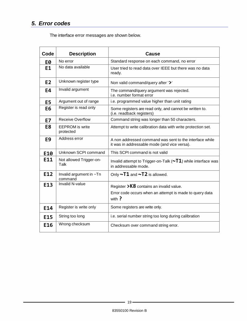
5. Error codes
The interface error messages are shown below.
Code
Description
Cause
E0 No error Standard response on each command, no error
E1 No data available User tried to read data over IEEE but there was no data ready.
E2 Unknown register type Non valid command/query after '>'
E4 Invalid argument The command/query argument was rejected. i.e. number format error
E5 Argument out of range i.e. programmed value higher than unit rating
E6 Register is read only Some registers are read only, and cannot be written to. (i.e. readback registers)
E7 Receive Overflow Command string was longer than 50 characters.
E8 EEPROM is write protected
Attempt to write calibration data with write protection set.
E9 Address error A non addressed command was sent to the interface while it was in addressable mode (and vice versa).
E10 Unknown SCPI command This SCPI command is not valid
E11 Not allowed Trigger-on- Talk
Invalid attempt to Trigger-on-Talk (~T1) while interface was
in addressable mode.
E12 Invalid argument in ~Tn command
Only ~T1 and ~T2 is allowed.
E13 Invalid N-value Register >K8 contains an invalid value.
Error code occurs when an attempt is made to query data
with ?
E14 Register is write only Some registers are write only.
E15 String too long i.e. serial number string too long during calibration
E16 Wrong checksum Checksum over command string error.

20
83550100 Revision B
THIS PAGE LEFT INTENTIONALLY BLANK
21
83550100 Revision B
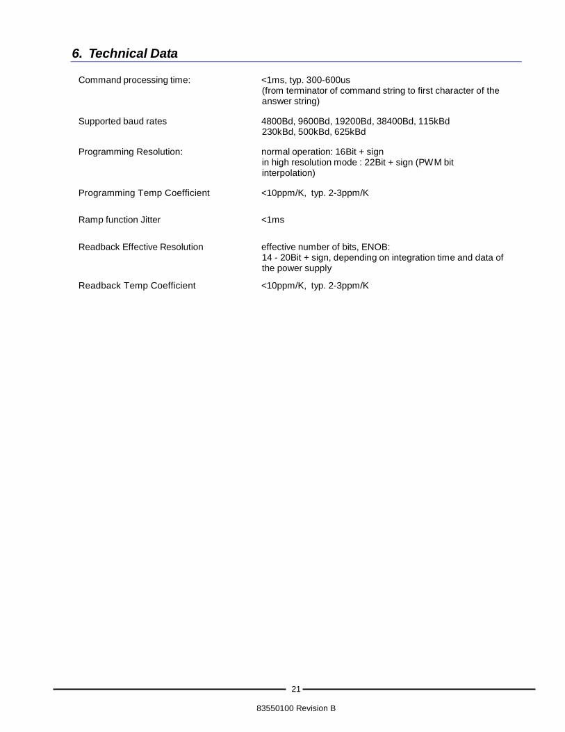
6. Technical Data
Command processing time: <1ms, typ. 300-600us (from terminator of command string to first character of the answer string)
Supported baud rates 4800Bd, 9600Bd, 19200Bd, 38400Bd, 115kBd
230kBd, 500kBd, 625kBd
Programming Resolution: normal operation: 16Bit + sign in high resolution mode : 22Bit + sign (PWM bit interpolation)
Programming Temp Coefficient <10ppm/K, typ. 2-3ppm/K
Ramp function Jitter <1ms
Readback Effective Resolution effective number of bits, ENOB: 14 - 20Bit + sign, depending on integration time and data of the power supply
Readback Temp Coefficient <10ppm/K, typ. 2-3ppm/K