DOE-HDBK-1011/1-92 DOE FUNDAMENTALS HANDBOOK ELECTRICAL SCIENCE Volume 1 of 4
Upload
khangminh22Category
view
1download
0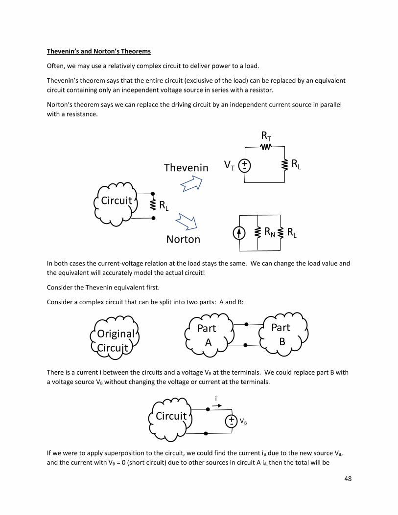
48
Thevenin’s and Norton’s Theorems
Often, we may use a relatively complex circuit to deliver power to a load.
Thevenin’s theorem says that the entire circuit (exclusive of the load) can be replaced by an equivalent
circuit containing only an independent voltage source in series with a resistor.
Norton’s theorem says we can replace the driving circuit by an independent current source in parallel
with a resistance.
In both cases the current-voltage relation at the load stays the same. We can change the load value and
the equivalent will accurately model the actual circuit!
Consider the Thevenin equivalent first.
Consider a complex circuit that can be split into two parts: A and B:
There is a current i between the circuits and a voltage VB at the terminals. We could replace part B with
a voltage source VB without changing the voltage or current at the terminals.
If we were to apply superposition to the circuit, we could find the current iB due to the new source VB,
and the current with VB = 0 (short circuit) due to other sources in circuit A iA, then the total will be
Circuit RL
Thevenin
Norton
+-VT RL
RT
RLRN
OriginalCircuit
Part A
Part B
Circuit +- VB
i

49
i = iA + iB
Setting all sources in A to zero we find:
iB = -VB/RTH
where RTH would be the resistance between the terminals of circuit A with all independent sources = 0,
therefore:
i = iA -VB/RTH
Now if we set VB =0 (we short the terminals) then we are left with:
i = isc = iA
So
i = iSC -VB/RTH (***)
Now say we open circuit the terminals, then VB = VOC and the current is equal to zero so:
i = 0 = iSC -VOC/RTH
VOC = RTH ∙ iSC
Thus, the ratio of the open circuit voltage and the short current is related by the resistance of circuit A
with all sources zeroed out! We can therefore re-write (***) as:
i = VOC/RTH -VB/RTH
Solving for VB:
VB = VOC -i∙RTH
Look at the above equation. How would you draw it as a circuit? It is a voltage source in series with a
resistor! The first term tells you the voltage when no current is drawn. The second term i∙RTH indicates
that any current drawn from the circuit will reduce the output voltage -> real circuit.
Thevenin
RTH = resistance looking into the terminals of driving circuit A with all sources = 0 -> Theven Resistance.
VOC = The voltage at the terminals of circuit A when the terminals are open circuit.
The circuit A can then be replaced by a source VOC in series with a resistor RTH:
CircuitA
CircuitB
CircuitB
+- VOC
RTH
Thevenin’s Theorem
50
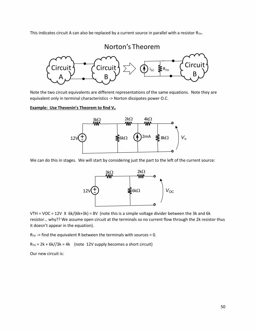
This indicates circuit A can also be replaced by a current source in parallel with a resistor RTH.
Note the two circuit equivalents are different representations of the same equations. Note they are
equivalent only in terminal characteristics -> Norton dissipates power O.C.
Example: Use Thevenin’s Theorem to find Vo
We can do this in stages. We will start by considering just the part to the left of the current source:
VTH = VOC = 12V X 6k/(6k+3k) = 8V (note this is a simple voltage divider between the 3k and 6k
resistor… why?? We assume open circuit at the terminals so no current flow through the 2k resistor thus
it doesn’t appear in the equation).
RTH -> find the equivalent R between the terminals with sources = 0.
RTH = 2k + 6k//3k = 4k (note 12V supply becomes a short circuit)
Our new circuit is:
CircuitA
CircuitB
CircuitB
iSC RTH
Norton’s Theorem
2kW
6kW
3kW
+-12V
4kW
8kW2mA Vo
2kW
6kW
3kW
+-12V VOC

51
Now break the circuit at C/D:
The new VTH = 8V + 2mA X 4k = 16V
New RTH = 4k (current source open, voltage source short)
Our equivalent is now:
And Vo = 16V X 8k/(8k+4k+4k) = 8V and
RTH = 8k//(4k+4k) = 4k (voltage source again a short circuit)
The equivalent could also be found using superposition of 2 sources.
Note:
4kW
+-8V
4kW
8kW2mA Vo
C
D
4kW
+-8V 2mA VOC
C
D
4kW
+-16V
4kW
8kW Vo
C
D
4kW
+-8V = RNIN

52
IN would be the short circuit current = 8V/4k = 2mA.
And RN would provide the same O.C. voltage:
8V = IN ∙ RN or RN = 8V/2mA = 4k
i.e. RN = RTH -> source transformation.
Thevenin:
1) Remove the load, find the open circuit voltage.
2) Find the equivalent resistance between the output terminals with independent sources set to
zero.
3) If there are dependent sources present RTH may not be obvious so a ‘test source’ is connected to
the output and RTH is found from VTEST / ITEST. (ohm’s law).
4) Re-attach the load and complete the analysis.
Thevenin Dependent and Independent Sources
Find Vo using Thevenin’s Theorem:
We will once more do this in steps. First we will remove the 6k resistor:
Using KVL:
12V –Vx – 4k∙i +Vx/2 = 0
We also note that Vx = 4k∙i, therefore:
12V –4k∙i – 4k∙i +2k∙i = 0
i = 2mA
We now note that:
4kW
4kW
+-12V 6kW Vo+-
-+
4kW
4kW
+-12V VOC+-
-+
i
53
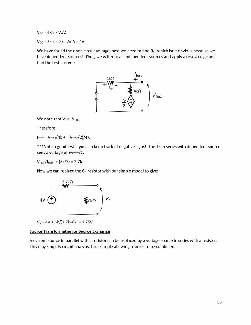
VOC = 4k∙i - Vx/2
VOC = 2k∙i = 2k ∙ 2mA = 4V
We have found the open circuit voltage, next we need to find RTH which isn’t obvious because we
have dependent sources! Thus, we will zero all independent sources and apply a test voltage and
find the test current:
We note that Vx = -VTEST
Therefore:
ITEST = VTEST/4k + (VTEST/2)/4K
***Note a good test if you can keep track of negative signs! The 4k in series with dependent source
sees a voltage of +VTEST/2.
VTEST/ITEST = (8k/3) = 2.7k
Now we can replace the 6k resistor with our simple model to give:
Vo = 4V X 6k/(2.7k+6k) = 2.75V
Source Transformation or Source Exchange
A current source in parallel with a resistor can be replaced by a voltage source in series with a resistor.
This may simplify circuit analysis, for example allowing sources to be combined.
4kW
4kW
+-
-+
ITest
VTest
6kW
2.7kW
+-4V Vo

54
The circled elements can be replaced with their Norton equivalent:
This puts two resistors directly in parallel for easy combining:
Now we can convert the two circled elements into a Thevenin equivalent:
Which means the two circled resistors can be easily combined:
2kW
6kW
3kW
+-12V
4kW
8kW2mA Vo
2kW
6kW3kW12V/3k=4mA
4kW
8kW2mA Vo
2kW
2kW4mA
4kW
8kW2mA Vo
2kW 4kW
8kW2mA Vo
2kW
+-8V
55
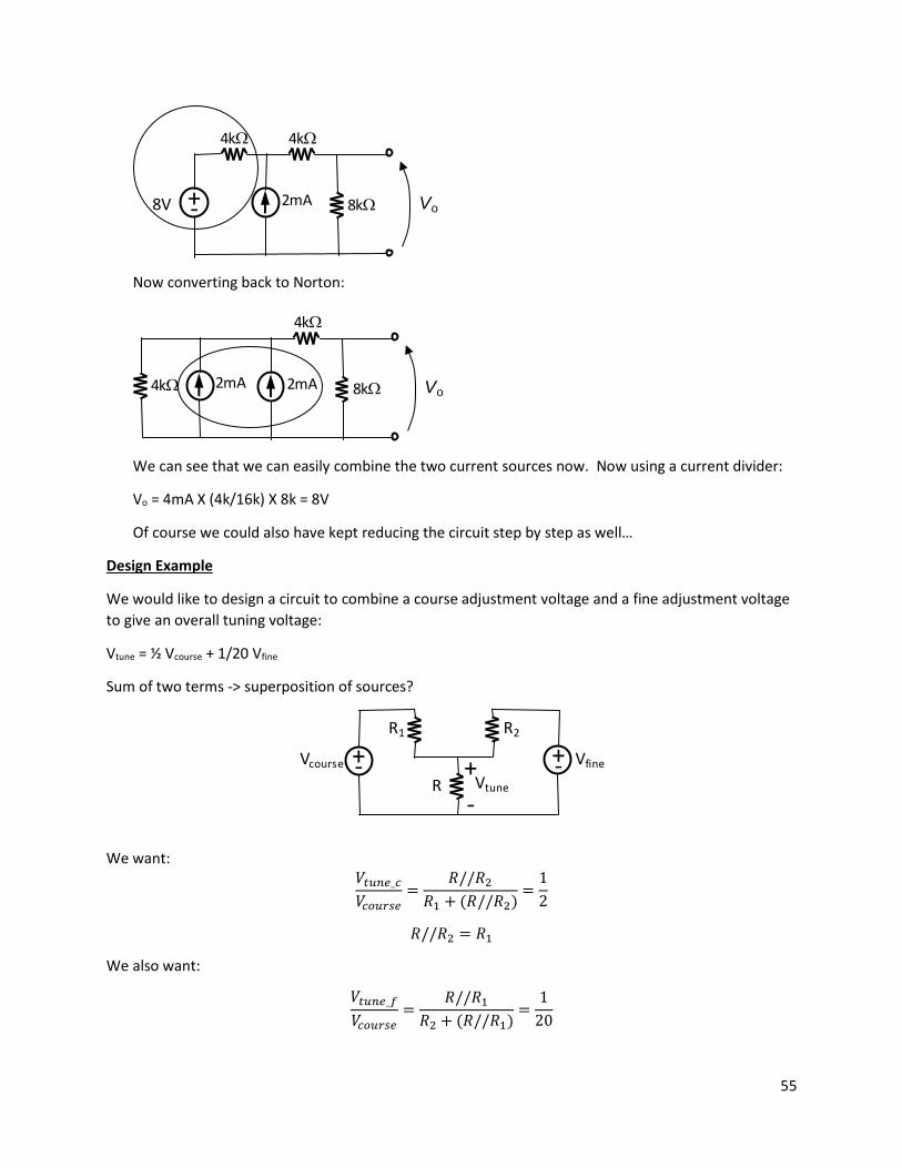
Now converting back to Norton:
We can see that we can easily combine the two current sources now. Now using a current divider:
Vo = 4mA X (4k/16k) X 8k = 8V
Of course we could also have kept reducing the circuit step by step as well…
Design Example
We would like to design a circuit to combine a course adjustment voltage and a fine adjustment voltage
to give an overall tuning voltage:
Vtune = ½ Vcourse + 1/20 Vfine
Sum of two terms -> superposition of sources?
We want: 𝑡𝑢𝑛𝑒_𝑐 𝑐𝑜𝑢𝑟𝑠𝑒
=𝑅//𝑅2
𝑅1 + (𝑅//𝑅2)=1
𝑅//𝑅2 = 𝑅1
We also want:
𝑡𝑢𝑛𝑒_𝑓
𝑐𝑜𝑢𝑟𝑠𝑒=
𝑅//𝑅1𝑅2 + (𝑅//𝑅1)
=1
0
4kW 4kW
8kW2mA Vo+-8V
4kW
8kW2mA Vo2mA4kW
+-Vcourse
R1
+- Vfine
R2
R-
+Vtune

56
𝑅//𝑅1 =1
19𝑅2
2 equations -> 3 unknowns
Another constraint? Power dissipation?
Otherwise choose ‘reasonable values’ i.e. pick at least one resistor arbitrarily.
Maximum Power Transfer
In some applications we are interested in transferring the maximum possible power to a load element or
circuit. The Thevenin equivalent circuit can aid us with this.
𝑃𝑙𝑜𝑎𝑑 = 𝑖2𝑅𝐿 = (
𝑅𝑆 + 𝑅𝐿)2
𝑅𝐿
What value of RL makes this a maximum?
𝑑𝑃𝑙𝑜𝑎𝑑𝑑𝑅𝐿
= 0 = (
𝑅𝑆 + 𝑅𝐿)2
− 𝑅𝐿 2
(𝑅𝑆 + 𝑅𝐿)3
𝑅𝐿𝑅𝑆 + 𝑅𝐿
= 1
𝑅𝐿 = 𝑅𝑆 + 𝑅𝐿
𝑅𝐿 = 𝑅𝑆
Maximum power transfer occurs when the load resistance matches the source resistance.
Example
Find RL for maximum power transfer.
RL
RS
+-V
Source of Power
Load Element
57
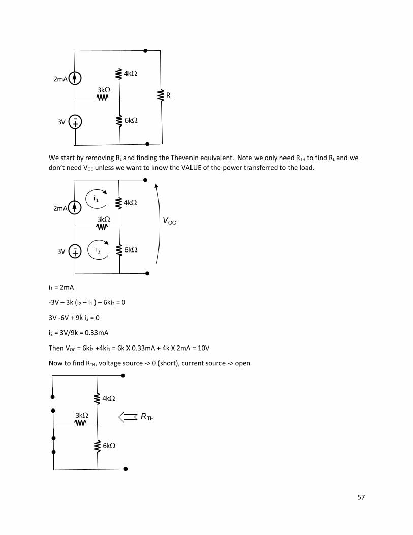
We start by removing RL and finding the Thevenin equivalent. Note we only need RTH to find RL and we
don’t need VOC unless we want to know the VALUE of the power transferred to the load.
i1 = 2mA
-3V – 3k (i2 – i1 ) – 6ki2 = 0
3V -6V + 9k i2 = 0
i2 = 3V/9k = 0.33mA
Then VOC = 6ki2 +4ki1 = 6k X 0.33mA + 4k X 2mA = 10V
Now to find RTH, voltage source -> 0 (short), current source -> open
3kW
6kW
2mA
+-3V
4kW
RL
3kW
6kW
2mA
+-3V
4kW
VOC
i1
i2
3kW
6kW
4kW
RTH

58
RTH = 4k + 6k//3k = 6k
So RL = 6k for max power.
P = i2 6k = (10V/12k)2 6k = 4.17mW
RL=6kW
RS=6kW
+-10V
59
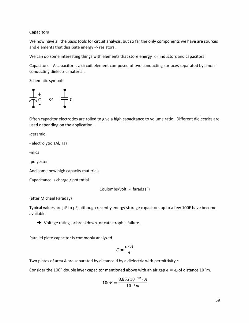
Capacitors
We now have all the basic tools for circuit analysis, but so far the only components we have are sources
and elements that dissipate energy -> resistors.
We can do some interesting things with elements that store energy -> inductors and capacitors
Capacitors - A capacitor is a circuit element composed of two conducting surfaces separated by a non-
conducting dielectric material.
Schematic symbol:
Often capacitor electrodes are rolled to give a high capacitance to volume ratio. Different dielectrics are
used depending on the application.
-ceramic
- electrolytic (Al, Ta)
-mica
-polyester
And some new high capacity materials.
Capacitance is charge / potential
Coulombs/volt = farads (F)
(after Michael Faraday)
Typical values are F to pF, although recently energy storage capacitors up to a few 100F have become
available.
➔ Voltage rating -> breakdown or catastrophic failure.
Parallel plate capacitor is commonly analyzed
𝐶 =𝜖 ∙ 𝐴
𝑑
Two plates of area A are separated by distance d by a dielectric with permittivity 𝜖.
Consider the 100F double layer capacitor mentioned above with an air gap 𝜖 = 𝜖𝑜of distance 10-4m.
100𝐹 =8.85𝑋10−12 ∙ 𝐴
10−4𝑚
-
+C Cor

60
A = 1.148X10⁹m2 or 443 square miles!
Note capacitance relates applied voltage to stored charge:
𝑞 = 𝐶 -> energy stored in electric field
And we know current
𝑖 =𝑑𝑞
𝑑𝑡=𝑑(𝐶𝑣)
𝑑𝑡
So
𝑖 = 𝐶𝑑𝑣
𝑑𝑡
For constant capacitance or turning it around:
𝑑𝑣 =1
𝐶𝑖𝑑𝑡
And
𝑣(𝑡) =1
𝐶∫ 𝑖(𝑡)𝑡
−∞
𝑑𝑡
And since we may only know a condition at some initial time
𝑣(𝑡) =1
𝐶∫ 𝑖(𝑡)𝑡𝑜
−∞
𝑑𝑡 +1
𝐶∫ 𝑖(𝑡)𝑡
𝑡𝑜
𝑑𝑡
𝑣(𝑡) = 𝑣(𝑡𝑜) +1
𝐶∫ 𝑖(𝑡)𝑡
𝑡𝑜
𝑑𝑡
Power delivered to the capacitor
𝑝(𝑡) = 𝑣(𝑡) ∙ 𝑖(𝑡)
= 𝑣(𝑡)𝐶𝑑𝑣(𝑡)
𝑑𝑡
And the energy can be found by integrating:
𝑝(𝑡)𝑑𝑡 = 𝐶𝑣(𝑡)𝑑𝑣
𝜔𝑐(𝑡) = ∫ 𝑝(𝑡)𝑡
−∞
𝑑𝑡
= 𝐶∫ 𝑣(𝑡)𝑡
−∞
𝑑𝑣(𝑡)
𝜔𝑐(𝑡) =1
𝐶𝑣2(𝑥) |
𝑣(𝑡)
𝑣(−∞)=1
𝐶𝑣2(𝑡)
61
Also from q = CV :
𝜔𝑐(𝑡) =1
𝑞2(𝑡)
𝐶
Since 𝑖 = 𝐶𝑑𝑣
𝑑𝑡 , for a constant (DC) voltage there is no capacitor current in the steady state -> a capacitor
is an open circuit to DC or ‘blocks’ DC.
****think about this for a moment…what is a capacitor physically? -> it is a broken wire!!!
Note however there is an initial transient current when DC is switched on or off. Also since
𝑝(𝑡) = 𝑣(𝑡)𝐶𝑑𝑣(𝑡)
𝑑𝑡
An instantaneous voltage change would require infinite current and power -> not physically possible. ->
capacitor voltage must be continuous.
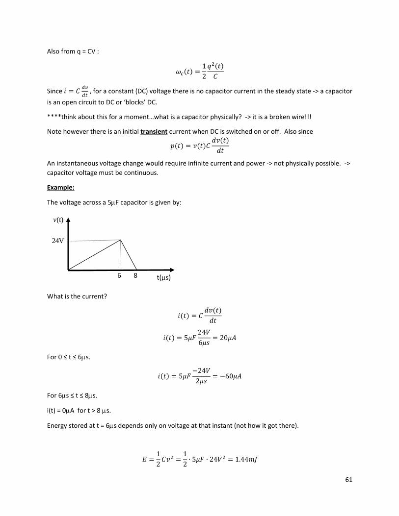
Example:
The voltage across a 5F capacitor is given by:
What is the current?
𝑖(𝑡) = 𝐶𝑑𝑣(𝑡)
𝑑𝑡
𝑖(𝑡) = 5𝜇𝐹 4
6𝜇𝑠= 0𝜇𝐴
For 0 ≤ t ≤ 6s.
𝑖(𝑡) = 5𝜇𝐹− 4
𝜇𝑠= −60𝜇𝐴
For 6s ≤ t ≤ 8s.
i(t) = 0A for t > 8 s.
Energy stored at t = 6s depends only on voltage at that instant (not how it got there).
𝐸 =1
𝐶𝑣2 =
1
∙ 5𝜇𝐹 ∙ 4 2 = 1.44𝑚𝐽
t(s)
v(t)
24V
6 8
62
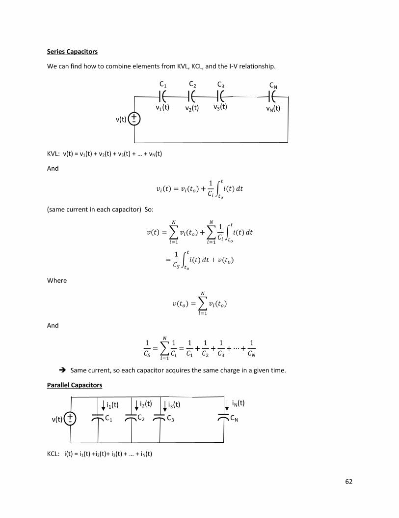
Series Capacitors
We can find how to combine elements from KVL, KCL, and the I-V relationship.
KVL: v(t) = v1(t) + v2(t) + v3(t) + … + vN(t)
And
𝑣𝑖(𝑡) = 𝑣𝑖(𝑡𝑜) +1
𝐶𝑖∫ 𝑖(𝑡)𝑡
𝑡𝑜
𝑑𝑡
(same current in each capacitor) So:
𝑣(𝑡) =∑𝑣𝑖(𝑡𝑜)
𝑁
𝑖=1
+∑1
𝐶𝑖∫ 𝑖(𝑡)𝑡
𝑡𝑜
𝑑𝑡
𝑁
𝑖=1
=1
𝐶𝑆∫ 𝑖(𝑡)𝑡
𝑡𝑜
𝑑𝑡 + 𝑣(𝑡𝑜)
Where
𝑣(𝑡𝑜) =∑𝑣𝑖(𝑡𝑜)
𝑁
𝑖=1
And
1
𝐶𝑆=∑
1
𝐶𝑖
𝑁
𝑖=1
=1
𝐶1+
1
𝐶2+
1
𝐶3+⋯+
1
𝐶𝑁
➔ Same current, so each capacitor acquires the same charge in a given time.
Parallel Capacitors
KCL: i(t) = i1(t) +i2(t)+ i3(t) + … + iN(t)
+-v(t)
v1(t) v2(t) v3(t) vN(t)
C1 C2 C3 CN
+-v(t)
i1(t) i2(t) i3(t) iN(t)
C1 C2 C3 CN

63
And
𝑖𝑖(𝑡) = 𝐶𝑖𝑑𝑣𝑖(𝑡)
𝑑𝑡
But vi(t) = v(t) for all Ci so:
𝑖(𝑡) = 𝐶1𝑑𝑣(𝑡)
𝑑𝑡+ 𝐶2
𝑑𝑣(𝑡)
𝑑𝑡+ 𝐶3
𝑑𝑣(𝑡)
𝑑𝑡+ ⋯+ 𝐶𝑁
𝑑𝑣(𝑡)
𝑑𝑡
So
𝑖(𝑡) = 𝐶𝑃𝑑𝑣(𝑡)
𝑑𝑡
Where:
𝐶𝑃 =∑𝐶𝑖
𝑁
𝑖=1
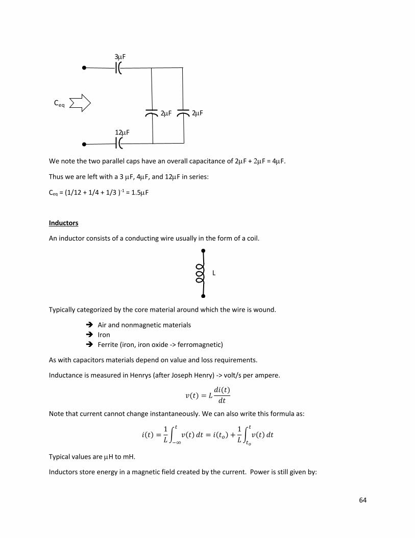
Example Find the Equivalent Capacitance
We first note that the two circled caps are in parallel Cp = 2F + 4F = 6F.
We next note that these two circled caps are in series: Cs = (1/6F +1/3F)-1=2F
This leaves us with:
Ceq
3F
2F 4F
3F
2F
12F
Ceq
3F
6F
3F
2F
12F
64
We note the two parallel caps have an overall capacitance of 2F + F = 4F.
Thus we are left with a 3 F, 4F, and 12F in series:
Ceq = (1/12 + 1/4 + 1/3 )-1 = 1.5F
Inductors
An inductor consists of a conducting wire usually in the form of a coil.
Typically categorized by the core material around which the wire is wound.
➔ Air and nonmagnetic materials
➔ Iron
➔ Ferrite (iron, iron oxide -> ferromagnetic)
As with capacitors materials depend on value and loss requirements.
Inductance is measured in Henrys (after Joseph Henry) -> volt/s per ampere.
𝑣(𝑡) = 𝐿𝑑𝑖(𝑡)
𝑑𝑡
Note that current cannot change instantaneously. We can also write this formula as:
𝑖(𝑡) =1
𝐿∫ 𝑣(𝑡)𝑡
−∞
𝑑𝑡 = 𝑖(𝑡𝑜) +1
𝐿∫ 𝑣(𝑡)𝑡
𝑡𝑜
𝑑𝑡
Typical values are H to mH.
Inductors store energy in a magnetic field created by the current. Power is still given by:
Ceq
3F
2F
12F
2F
L

65
𝑝(𝑡) = 𝑣(𝑡) ∙ 𝑖(𝑡)
= 𝐿𝑑𝑖(𝑡)
𝑑𝑡∙ 𝑖(𝑡)
Or energy is given by:
𝜔𝐿(𝑡) = ∫ 𝑝(𝑡)𝑡
−∞
𝑑𝑡
𝜔𝐿(𝑡) = ∫ 𝐿𝑑𝑖(𝑡)
𝑑𝑡∙ 𝑖(𝑡)
𝑡
−∞
𝑑𝑡 =1
𝐿𝑖2(𝑡)
Short circuit for DC (ideal, some small R). THINK about this, and inductor is just a wire!!!
Note:
𝑝(𝑡) = 𝐿𝑑𝑖(𝑡)
𝑑𝑡∙ 𝑖(𝑡)
So power is proportional to the instantaneous change in i(t). If di/dt goes to infinity power goes to
infinity which is not possible. Therefore, an inductor requires continuity of current.
Inductors are indispensable in tuned circuits and many power applications. – motors, transformers and
solenoids (actuators).
Example
The voltage measured across a 200mH is v(t) = (1-3t)e-3t mV for t ≥ 0 and zero for t < 0. What is the
current and power?
𝑖(𝑡) =1
𝐿∫ 𝑣(𝑡)𝑡
−∞
𝑑𝑡
=103
00∫ (1 − 3𝑡)𝑒−3𝑡𝑡
0
𝑑𝑡
= 5(∫ 𝑒−3𝑡𝑡
0
𝑑𝑡 − 3∫ 𝑡𝑒−3𝑡𝑡
0
𝑑𝑡)
= 5 [−1
3𝑒−3𝑡 |
𝑡
0− 3 ((−
1
3𝑡𝑒−3𝑡) − (
1
9𝑒−3𝑡)) |
𝑡
0]
= 5 [−1
3𝑒−3𝑡 +
1
3+ (𝑡𝑒−3𝑡 − 0) +
1
3𝑒−3𝑡 −
1
3]
𝑖(𝑡) = 5𝑡𝑒−3𝑡𝑚𝐴 𝑡 ≥ 0
𝑝(𝑡) = 𝑣(𝑡) ∙ 𝑖(𝑡) = 5𝑡𝑒−3𝑡 ∙ (1 − 3𝑡)𝑒−3𝑡 = 5𝑡(1 − 3𝑡)𝑒−6𝑡𝜇𝑊

66
Notice i(t) is positive for t > 0.
v(t) is positive for di/dt > 0 and negative for di/dt < 0.
i(t) positive, p(t) has the sign of v(t) starting positive (storing) and ending negative (releasing).
Series Inductors
KVL:
𝑣(𝑡) = 𝑣1(𝑡) + 𝑣2(𝑡) + 𝑣3(𝑡) + ⋯𝑣𝑁(𝑡)
time
i(t)
time
v(t)
time
p(t)
+-v(t)
v1(t) v2(t) v3(t) vN(t)
L1 L2 L3 LNi(t)

67
= 𝐿1𝑑𝑖
𝑑𝑡+ 𝐿2
𝑑𝑖
𝑑𝑡+ 𝐿3
𝑑𝑖
𝑑𝑡+ ⋯+ 𝐿𝑁
𝑑𝑖
𝑑𝑡
Since i is the same for each:
𝑣(𝑡) =∑𝐿𝑖
𝑁
𝑖=1
∙𝑑𝑖
𝑑𝑡= 𝐿𝑆 ∙
𝑑𝑖
𝑑𝑡
Where:
𝐿𝑆 =∑𝐿𝑖
𝑁
𝑖=1
Parallel Inductors
KCL: i(t) = i1(t) +i2(t)+ i3(t) + … + iN(t)
where
𝑖𝑖(𝑡) = 𝑖𝑖(𝑡𝑜) +1
𝐿𝑖∫ 𝑣(𝑡)𝑡
𝑡𝑜
𝑑𝑡
v(t) is the same across each Li so:
𝑖(𝑡) =∑𝑖𝑖(𝑡𝑜)
𝑁
𝑖=1
+∑1
𝐿𝑖∫ 𝑣(𝑡)𝑡
𝑡𝑜
𝑑𝑡
𝑁
𝑖=1
=1
𝐿𝑃∫ 𝑣(𝑡)𝑡
𝑡𝑜
𝑑𝑡 + 𝑖(𝑡𝑜)
Where
𝑖(𝑡𝑜) =∑𝑖𝑖(𝑡𝑜)
𝑁
𝑖=1
And
1
𝐿𝑃=∑
1
𝐿𝑖
𝑁
𝑖=1
=1
𝐿1+
1
𝐿2+
1
𝐿3+⋯+
1
𝐿𝑁
Similar to resistors.
+-v(t)
i1(t) i2(t) i3(t) iN(t)
L1 L2 L3 LN
i(t)
Copyright © 2022 FDOKUMEN