CIMS LAB - Jaipur Engineering College
42
LABORATORY MANUAL DEPARTMENT OF MECHANICAL ENGINEERING JEC GROUP OF COLLEGES PREFACE This lab stresses on the fundamental concepts of CAD/CIMS in mechanical engineering and stands as a cornerstone in field of engineering. This field that emerged some years ago is a promising field in engineering, research and development. In the past fifteen years the interactive computer graphics and CAD/CIMS technology have been impacting the drafting, design and manufacturing tools significantly. The purpose of this lab is to present CIMS principles and tools in generic and basic terms. These principles are supplemented with engineering and design applications as well as problems. This lab is also concerned with developing basic abilities to utilize the existing cam system CNC trainer and VMC in engineering practice. In engineering practice, CIMS has been utilized in different ways by different people. This lab enables students to develop greater interdisciplinary expertise, which will better equip them for jobs demanding the skills in the workplace. Some of the applications of this technology are: • Production of drawings and design documents • Visualization tool for generating shaded images and animated displays. • Engineering analysis of geometric models. • Process planning and generation of NC part programming. - HEAD OF DEPARTMENT
-
Upload
khangminh22 -
Category
Documents
-
view
1 -
download
0
Transcript of CIMS LAB - Jaipur Engineering College

LABORATORY MANUAL
DEPARTMENT OF MECHANICAL ENGINEERING
J E C GROUP OF COLLEGES
PREFACE
This lab stresses on the fundamental concepts of CAD/CIMS in mechanical engineering and stands as a
cornerstone in field of engineering. This field that emerged some years ago is a promising field in engineering,
research and development. In the past fifteen years the interactive computer graphics and CAD/CIMS
technology have been impacting the drafting, design and manufacturing tools significantly. The purpose of this
lab is to present CIMS principles and tools in generic and basic terms. These principles are supplemented with
engineering and design applications as well as problems. This lab is also concerned with developing basic
abilities to utilize the existing cam system CNC trainer and VMC in engineering practice. In engineering
practice, CIMS has been utilized in different ways by different people. This lab enables students to develop
greater interdisciplinary expertise, which will better equip them for jobs demanding the skills in the workplace.
Some of the applications of this technology are:
• Production of drawings and design documents
• Visualization tool for generating shaded images and animated displays.
• Engineering analysis of geometric models.
• Process planning and generation of NC part programming.
- HEAD OF DEPARTMENT

LABORATORY MANUAL
DEPARTMENT OF MECHANICAL ENGINEERING
J E C GROUP OF COLLEGES
S. No. List of Experiments Page No.
INDEX
To write the part programming and simulation them to the given lathe job.(Plane Turning)
To write the part programming and simulation them to the given lathe job.(Step Turning)
To write the part programming and simulation them to the given lathe job.(Multiple Turning)
To write the part programming and simulation them to the given lathe job.(Thread Cutting)
To write the part programming and simulation them to the given milling job(Linear & Circular Interpolation)
To write the part programming and simulation them to the given milling job(Docket Milling)
To write the part programming and simulation them to the given lathe job.(Drilling Operation)
To write the part programming and simulation them to the given milling job.(Linear Interpolation)
To write the part programming and simulation them to the given milling job.
To write the part programming and simulation them to the given lathe job
1.
2.
3.
4.
5.
6.
7.
8.
1-4
5-8
9-12
13-16
17-20
21-24
25-28
29-30
9. 31-32
10. 33-34

LABORATORY MANUAL
DEPARTMENT OF MECHANICAL ENGINEERING
J E C GROUP OF COLLEGES
01
Experiment No. 1AIMTo write the part programming and simulation them to the given lathe job.
TOOLS AND EQUIPMENTS
· CNC simulation software FANUC
· CNC trainer software
· Software Pentium IV
PROCEDURE
· To write the program for given job.
· To type G and M CODES.
· To give the tool size and stock dimensions.
· Finally to run the machine to the operation.
PROGRAMG21� G98� � ��G28� U0 W0� � �M06� T0101� � �M03� S1500 M-CODESG00� X26Z1� M06 – Tool ChangeG01� X25F50� M03 – Spindle Forward ClockwiseG01� Z-30F50� M05 – Spindle StopG01� X26F50� M30 – Program End�G01� Z1F50� �G01� X24F50� � �G01� Z-30F50� �G01� X26F50� � �G01� Z1F50� � �G01� X23F50� � � G-CODESG01� Z-30 F50 G01� X26 F50� G21– Metric� �G01� Z1 F50� G98� – Feed/MinG01� X22F50� G28� U0 W0 – Reference Point ReturnG01� Z-30 F50� G00� X Y – Positioning (Rapid Traverse)G01� X26F50� G01� X Y F – Linear Interpolation (Feed)G01� Z1F50� G03� – Circular Interpolation (CCW)G01� X18Z0F50 G90� – Cutting Cycle TurningG03� X22 Z-2 R2 F40� �G28 U0 W0M05M30

LABORATORY MANUAL
DEPARTMENT OF MECHANICAL ENGINEERING
J E C GROUP OF COLLEGES
02
RESULTThus the part program was written and simulated for given job.
VIVA- VOCE1. Explain about G codes.2. Mention few important G codes.3. What is the use M codes?4. Write about some important M codes.5. What is the difference between G00 and G01codes?

LABORATORY MANUAL
DEPARTMENT OF MECHANICAL ENGINEERING
J E C GROUP OF COLLEGES
03

LABORATORY MANUAL
DEPARTMENT OF MECHANICAL ENGINEERING
J E C GROUP OF COLLEGES
04

LABORATORY MANUAL
DEPARTMENT OF MECHANICAL ENGINEERING
J E C GROUP OF COLLEGES
05
AIM
To write the part programming and simulation them to the given lathe job
TOOLS AND EQUIPMENTS
1. CNC simulation software FANUC
2. CNC trainer software
3. Software Pentium IV
PROCEDURE
1. To write the program for given job.
2. To type G and M CODES.
3. To give the tool size and stock dimensions.
4. Finally to run the machine to the operation.
PROGRAM
G21 G98
G28 U0 W0
M06 T0101
M03 S1500
G00 X26 Z1
G90 X25 Z-40 F50
X24
X23
X22
G90 X21 Z-28 F50
X20
X19
X18
X17
X16
G90 X15 Z-10 F50
X14
X13
X12
G28 U0 W0
M05
RESULT
Thus the part program was written and simulated for given job
Experiment No. 2

LABORATORY MANUAL
DEPARTMENT OF MECHANICAL ENGINEERING
J E C GROUP OF COLLEGES
06
VIVA- VOCE
1. How to change the tool speed in CNC lathe?
2. Mention the major components of the CNC machine?
3. What is the code for Threading cycle?
4. What is use of dry run option?
5. What is the code for coolant control?

LABORATORY MANUAL
DEPARTMENT OF MECHANICAL ENGINEERING
J E C GROUP OF COLLEGES
07

LABORATORY MANUAL
DEPARTMENT OF MECHANICAL ENGINEERING
J E C GROUP OF COLLEGES
08
LABORATORY MANUAL
DEPARTMENT OF MECHANICAL ENGINEERING
J E C GROUP OF COLLEGES
09
AIM
To write the part programming and simulation them to the given lathe job.
TOOLS AND EQUIPMENTS
1. CNC simulation software FANUC
2. CNC trainer software
3. Software Pentium IV
PROCEDURE
1. To write the program for given job.
2. To type G and M CODES.
3. To give the tool size and stock dimensions.
4. Finally to run the machine to the operation.
PROGRAM
G21� G98�����G28� U0W� 0���M06� T0101���M03� S1200���G00� X26Z�� 1���G71� U0.5R� 1.0��G71� P01Q�� 02U� 0.2W� 0.2F� 50
N01� G01X�� 8���G01� Z0�����G01� X10Z�� -2���G01� X10Z�� -12���G02� X15Z�� -14.5 R2.5�G01� X15Z�� -24.5��G03� X20Z�� -27 R2.5��G01� X20Z�� -32���N02� G01X�� 25.4 Z-32�G70� P01Q�� 02F� 40��G28� U0W� 0���M05� �����M30
Experiment No. 3

LABORATORY MANUAL
DEPARTMENT OF MECHANICAL ENGINEERING
J E C GROUP OF COLLEGES
10
G71 – Multiple Turing cycle (stock remover)
G 70 – Finishing cycleG71 U RG71 P Q U W FG70 P QG71 – Multiple Turning CycleU – Depth of CutR – Retract AllowanceG71 – Multiple Turing CycleP – Starting Block (N01)Q – Ending Block (N02)U – Finishing Allowance in X-AxisW – Finishing Allowance in Z-AxisF – Feed RateG70 – Finishing CycleP – Starting BlockQ – Ending Block
RESULT
Thus the part program was written and simulated for given job.
VIVA-VOCE
1. What are the difference between CAD and CAM?
2. What is function of G00?
3. What is function of G01?
4. What is function of G02?
5. What is function of G03?

LABORATORY MANUAL
DEPARTMENT OF MECHANICAL ENGINEERING
J E C GROUP OF COLLEGES
11

LABORATORY MANUAL
DEPARTMENT OF MECHANICAL ENGINEERING
J E C GROUP OF COLLEGES
12

LABORATORY MANUAL
DEPARTMENT OF MECHANICAL ENGINEERING
J E C GROUP OF COLLEGES
13
AIM
To write the part programming and simulation them to the given lathe job.
TOOLS AND EQUIPMENTS
1. CNC simulation software FANUC
2. CNC trainer software
3. Software Pentium IV
PROCEDURE
1. To write the program for given job.
2. To type G and M CODES.
3. To give the tool size and stock dimensions.
4. Finally to run the machine to the operation.
PROGRAM
G21� G98�G28� U0W� 0
M06� T0101
M03� S1500
G00� X26Z� 1
G90� X25Z� -40 F50
X24� �X23� �X22� �G28� U0W� 0
M06� T0202
M03� S300
G00� X26Z� 1
G92� X22Z� -20 F2
X21.95
X21.90
X21.85
X21.80
X21.75
X21.70
X21.65
X21.60
X21.55
X21.50
X21.45
X21.40
Experiment No. 4

LABORATORY MANUAL
DEPARTMENT OF MECHANICAL ENGINEERING
J E C GROUP OF COLLEGES
14
X21.35
X21.3
G92 Thread Cutting Cycle
Syntax G92 X_ Z_ F_
Feed = Pitch = 2 mm
Calculation of Mirror Diameter (d) d=D-2h
=D - 2 X (0.615 X P)
=22 – 2 X (0.615 X 2)X21.25
X21.20
X21.15
X21.10
X21.05
X21
X20.95
X20.90
X20.85
X20.80
X20.75
X20.70
X20.65
X20.60
X20.55
X20.50
X20.45
X20.40
X20.35
X20.30
X20.25
X20.20
X20.15
X20.10
X20.05
X20
X19.95
X19.90
X19.85
X19.80
X19.75
X19.70
X19.65
X19.60
X19.54
G28 U0 W0

LABORATORY MANUAL
DEPARTMENT OF MECHANICAL ENGINEERING
J E C GROUP OF COLLEGES
15
M05
M30
RESULT
Thus the part program was written and simulated for given job.
VIVA-VOCE
1. What is function of G17?
2. What is function of G18?
3. What is function of G19?
4. What is function of G33?
5. What is function of G90 & G91?

LABORATORY MANUAL
DEPARTMENT OF MECHANICAL ENGINEERING
J E C GROUP OF COLLEGES
16

LABORATORY MANUAL
DEPARTMENT OF MECHANICAL ENGINEERING
J E C GROUP OF COLLEGES
17
AIM
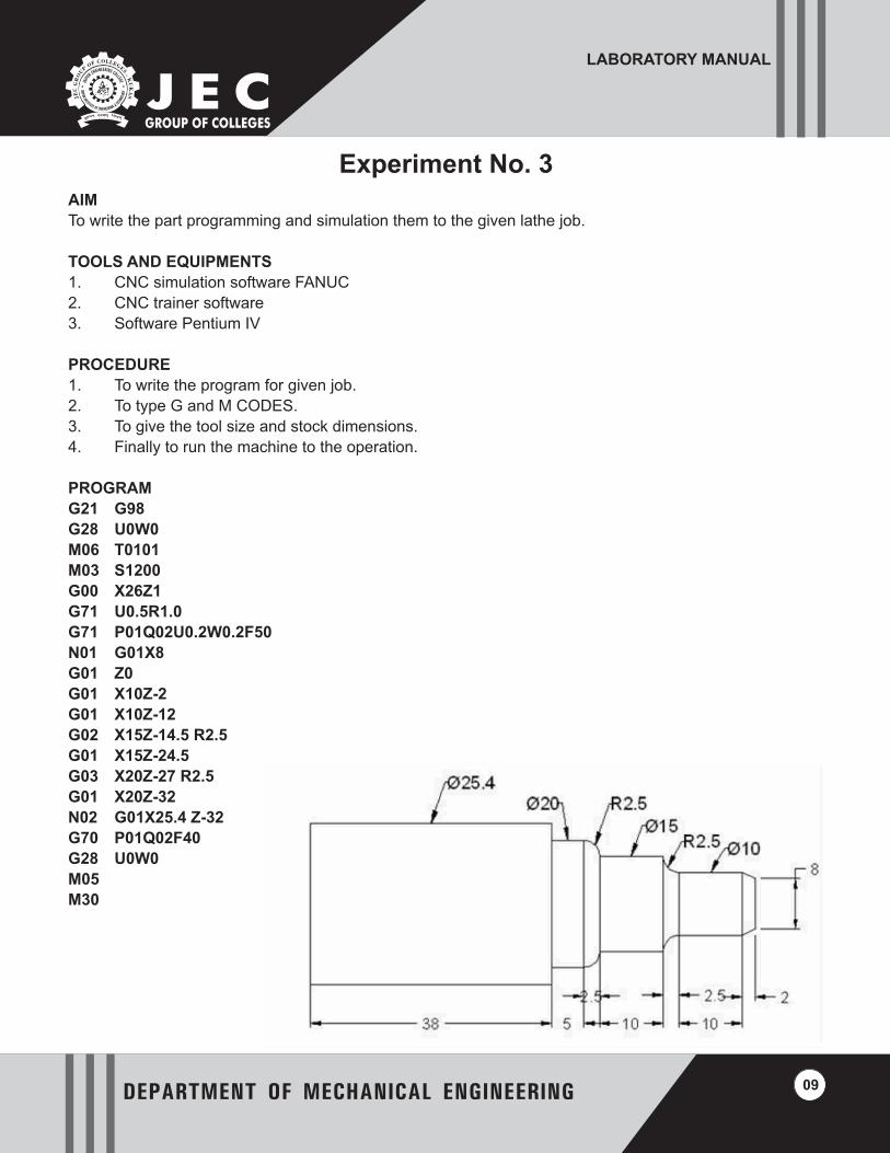
To write the part programming and simulation them to the given milling job.
TOOLS AND EQUIPMENTS
1. CNC simulation software
2. CNC milling software
3. Softaware Pentium IV
PROCEDURE
1. To write the program for given job.
2. To type G and M CODES.
3. To give the tool size and stock dimensions.
4. Finally to run the machine to the operation.
PROGRAM
G21� G94���G91� ���G28� Z0���G28� X0Y� 0��M06� T1���M03�S1500��G90� ���G00� X30Y� 20��G00� Z5���G01� Z-0.5 F30�G01� X70Y� 20F� 50�G03� X80Y� 30R� 10F� 50
G01� X80Y� 70F� 50�G01� X70Y� 80F� 50�G01� X30Y� 80F� 50�G02� X20Y� 70R� 10�G01� X20Y� 30F� 50�G01� X30Y� 20F� 50�G01� Z5F� 50��G91� ���G28� Z0���G28� X0Y� 0��M05� ���M30�
Experiment No. 5
LABORATORY MANUAL
DEPARTMENT OF MECHANICAL ENGINEERING
J E C GROUP OF COLLEGES
18
RESULT
Thus the part program was written and simulated for given job.
VIVA-VOCE
1. What is function of G94?
2. What is function of M02?
3. What is function of M03?
4. What is function of M04?
5. What is function of M05?

LABORATORY MANUAL
DEPARTMENT OF MECHANICAL ENGINEERING
J E C GROUP OF COLLEGES
19

LABORATORY MANUAL
DEPARTMENT OF MECHANICAL ENGINEERING
J E C GROUP OF COLLEGES
20

LABORATORY MANUAL
DEPARTMENT OF MECHANICAL ENGINEERING
J E C GROUP OF COLLEGES
21
AIM
To write the part programming and simulation them to the given milling job.
TOOLS AND EQUIPMENTS
1. CNC simulation software
2. CNC milling software
3. Software Pentium IV
PROCEDURE
1. To write the program for given job.
2. To type G and M CODES.
3. To give the tool size and stock dimensions.
4. Finally to run the machine to the operation.
PROGRAM
G21� G94���G91� ���G28� Z0���G28� X0Y� 0��M06� T1���M03�S1500��G90� ���G00� X30Y� 20��G00� Z5���G01� Z-0.5 F30�G01� X70Y� 20F� 50�G03� X80Y� 30R� 10F� 50
G01� X80Y� 70F� 50�G03� X70Y� 80R� 10F� 50
G01� X30Y� 80F� 50�G03� X20Y� 70R� 10F� 50
G01� X20Y� 30F� 50�G03� X30Y� 20R� 10F� 50
G91� ���G28� Z0G��� 28 X0 Y0
M05
M30
Experiment No. 6

LABORATORY MANUAL
DEPARTMENT OF MECHANICAL ENGINEERING
J E C GROUP OF COLLEGES
22
RESULT
Thus the part program was written and simulated for given job.
VIVA-VOCE
1. What is function of G28?
2. What is function of M30?
3. What is function of G21?
4. What is function of G22,G23,G24?
5. What is function of G40?

LABORATORY MANUAL
DEPARTMENT OF MECHANICAL ENGINEERING
J E C GROUP OF COLLEGES
23

LABORATORY MANUAL
DEPARTMENT OF MECHANICAL ENGINEERING
J E C GROUP OF COLLEGES
24

LABORATORY MANUAL
DEPARTMENT OF MECHANICAL ENGINEERING
J E C GROUP OF COLLEGES
25
AIM
Write an efficient CNC part program to drill 35 holes of diameter of 0.5 inch each in a machine component as
shown in the figure. The raw material to be employed is mild steel plate of 0.4 inch thickness. Explain the
important functions used in the CNC code.
TOOLS AND EQUIPMENTS
1. CNC simulation software
2. CNC trainer software
3. Software Pentium IV
Experiment No. 7

LABORATORY MANUAL
DEPARTMENT OF MECHANICAL ENGINEERING
J E C GROUP OF COLLEGES
26
Programme
RESULT
Thus the part program was written and simulated for given job.
VIVA-VOCE
1. What do you mean by block?
2. What do you mean by absolute coordinate system and incremental system?
3. What do you mean by compensatory radius in milling operation?
4. What do you mean by rapid positioning and linear translatory motion?

LABORATORY MANUAL
DEPARTMENT OF MECHANICAL ENGINEERING
J E C GROUP OF COLLEGES
27

LABORATORY MANUAL
DEPARTMENT OF MECHANICAL ENGINEERING
J E C GROUP OF COLLEGES
28

LABORATORY MANUAL
DEPARTMENT OF MECHANICAL ENGINEERING
J E C GROUP OF COLLEGES
29
AIM
To write the part programming and simulation them to the given milling job.
TOOLS AND EQUIPMENTS
1. CNC simulation software
2. CNC milling software
3. Software Pentium IV
PROCEDURE
1. To write the program for given job.
2. To type G and M CODES.
3. To give the tool size and stock dimensions.
4. Finally to run the machine to the operation.
PROGRAM
G21� G94��G91� ��G28� Z0��G28� X0Y� 0�M06� T1��M03� S1500�G90� ��G00� X20Y� 20�G00� Z5��G01� Z-0.5 F30
G01� X80Y� 20F� 50
G01� X80Y� 80F� 50
G01� X20Y� 80F� 50
G01� X20Y� 20F� 50
G91� ��G28� Z0�G28� X0Y� 0�M05� M30��
RESULT
Thus the part program was written and simulated for given job.
VIVA-VOCE
1. What do you mean by word , character in part programming?
2. What do you mean by N code?
3. What do you mean by <EOB> in part programming ?
4. Why we use jog pad in cnc?
Experiment No. 8

LABORATORY MANUAL
DEPARTMENT OF MECHANICAL ENGINEERING
J E C GROUP OF COLLEGES
30

LABORATORY MANUAL
DEPARTMENT OF MECHANICAL ENGINEERING
J E C GROUP OF COLLEGES
31
AIM
To write the part programming and simulation them to the given milling job.
TOOLS AND EQUIPMENTS
1. CNC simulation software
2. CNC milling software
3. Software Pentium IV
PROCEDURE
1. To write the program for given job.
2. To type G and M CODES.
3. To give the tool size and stock dimensions.
4. Finally to run the machine to the operation.
PROGRAM
G21G94
G91
G28Z0
G28X0Y0
M06T1
M03S1500
G90
G00X30Y20
G00Z5
G01Z-0.5 F30
G01X70Y20F50
G02X80Y30R10F50G01X80Y70F50
G02X70Y80R10F50G01X30Y80F50
G02X20Y70R10F50G01X20Y30F50
G02X30Y20R10F50
G91
G28 Z0
G28 X0 Y0
M05
M30
RESULT
Thus the part program was written and simulated for given job.
Experiment No. 9

LABORATORY MANUAL
DEPARTMENT OF MECHANICAL ENGINEERING
J E C GROUP OF COLLEGES
32
VIVA-VOCE
1. What do you mean by point to point system?
2. Give example of point to point machining tool.
3. What do you mean by pocket milling?
4. What do you mean by circular interpolation?
LABORATORY MANUAL
DEPARTMENT OF MECHANICAL ENGINEERING
J E C GROUP OF COLLEGES
33
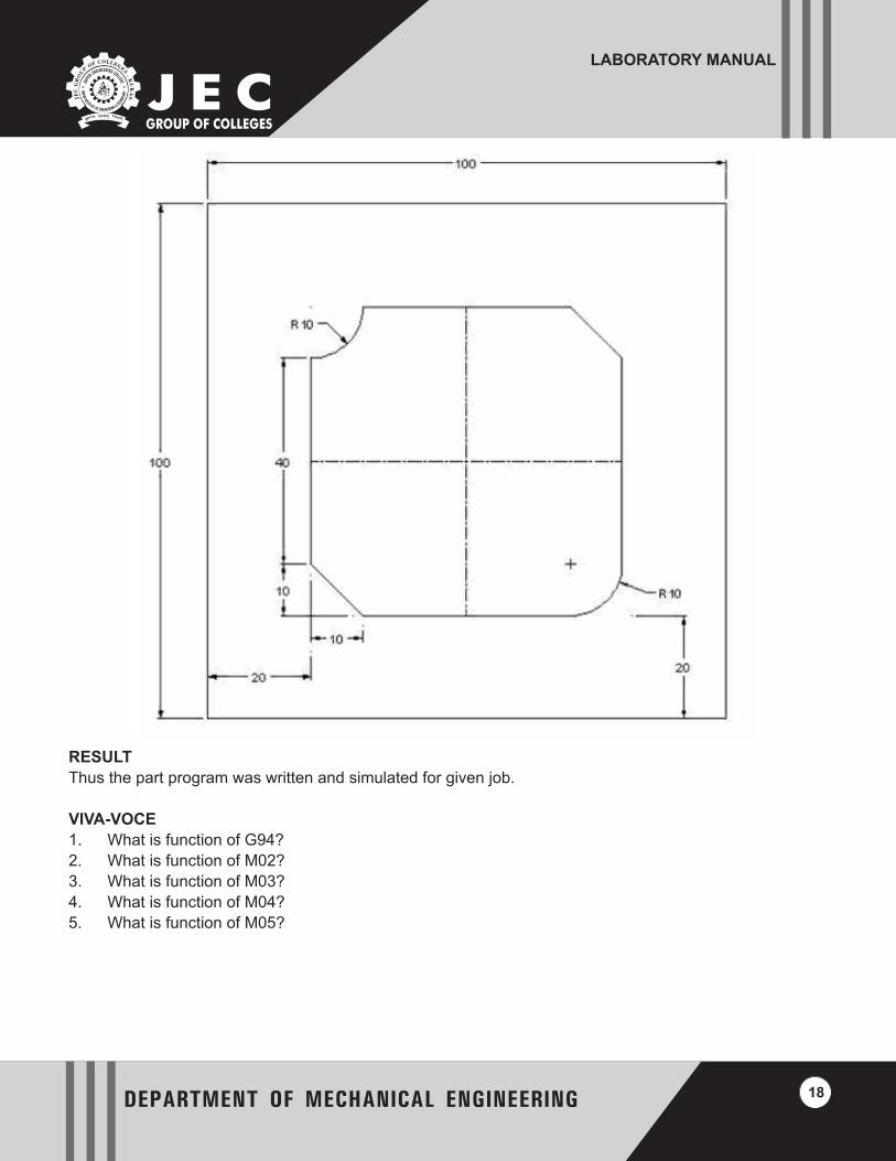
Experiment No. 10AIM
To prepare part programs using G-codes and M-codes. The following examples illustrated the part program for
different components. Example 01 (All dimensions are in mm).
TOOLS AND EQUIPMENTS
1. CNC simulation software
2. CNC trainer software
3. Software Pentium IV
Main programme
N01 G54 G90 G71 G94 M03 S800; (Parameters Setting)
N05 G01 X-12.5 Z0 F2; (Facing the job)
N10 G00 Z1; (Retrieval of tool)
N15 G00 X00; (Tool clearance)
N20 G01 Z-100; (Starting cut)
N25 G00 X1 Z1; (Clearance position)
N30 G00 X-2; (Position of cut)
N35 G01 Z-60; (Cutting length)
N40 G00 X-1 Z1; (Retrieval of tool)
N45 G00 X-3; (Position of cut)
N50 G01 Z-60; (Cutting length)
N55 G00 X-2 Z1; (Retrieval of tool)
N60 G00 X-4; (Position of cut)
N65 G01 Z-60; (Cutting length) Ø 16 Ø 35 Ø 25 60 100 (0, 0) 42 CNC Machines
N70 G00 X-3 Z1; (Retrieval of tool)
N75 G00 X-4.5; (Position of cut)

LABORATORY MANUAL
DEPARTMENT OF MECHANICAL ENGINEERING
J E C GROUP OF COLLEGES
34
N80 G01 Z-60; (Cutting length)
N85 G00 X5 Z5; (Final position of tool)
N90 M02; (End of programme)
RESULT
Thus the part program was written and simulated for given job.
VIVA-VOCE
1. What are the applications of cam?
2. What are the advantages of cnc machine?

LABORATORY MANUAL
DEPARTMENT OF MECHANICAL ENGINEERING
J E C GROUP OF COLLEGES
35
SOME IMPORTANT PREPARATORY FUNCTIONS
(G -CODES)
G00- Fast transverse
G01- Linear interpolation
G02- Circular interpolation (c.w)
G03- Circular interpolation (c.c.w)
G04-Dwell
G20-Imporial (input in inches)
G21- Metric (input in mm)
G28- Go to reference
G40- Cutter compensation cancel
G41- Cutter compensation right
G42-Cutter compensation left
G50- Co-ordinate setting
G70-Finishing cycle
G71- Stock removal in turning
G72- Multiple facing
G73-Pattern repeating
G74- drilling
G76- Multiple thread
G81- Drilling cycle
G90-Turning cycle
G94- Facing cycle
G96- Constant surface
G97- Variable surface
G98- Feed per minute
G99- Feed per revolution
MISCELLANEOUS FUNCTIONS
(M - CODES)
M00- Program stop
M02- Optional stop
M03- Program end
M04- Spindle forward
M05- Spindle stop
M06- Tool change
M08- Coolant on
M09- Coolant off
M10- Vice open
M11- Vice close
M62- Output 1ON
M63- Output 2ON
M64- Output1OFF

LABORATORY MANUAL
DEPARTMENT OF MECHANICAL ENGINEERING
J E C GROUP OF COLLEGES
36
M65- Output 2OFF
M60- Wait input 1ON
M67- Wait input 10FF
M76- Wait input 2OFF
M77-Sub program call
M98-Sub program exit
M99- Sub program exit
M30- Program and rewind

LABORATORY MANUAL
DEPARTMENT OF MECHANICAL ENGINEERING
J E C GROUP OF COLLEGES
NAME OF THE LBORATORY:____________________________________ CODE:___________________
SEMESTER:______________NAME OF STUDENT:___________________ ROLL No:________________
Note: Lab citizenship covers Discipline, Punctuality, Lab Meeting Participation, Note book Record Keeping and contribution in up keeping of the lab
Date of Allotment
LAB PERFORMANCE APPRAISAL SHEET
Marks Awarded for
Total marks as per syllabus (M)= Z / 10
Experiment No & Title of the Experiment
Full Marks (Y)
Lab Performance
Viva-Voce Lab Citizenship
Total (X) Signature of Lab In charge
with Date
Total Marks from experiment No------ to ----- (Z)

LABORATORY MANUAL
DEPARTMENT OF MECHANICAL ENGINEERING
J E C GROUP OF COLLEGES
Note

LABORATORY MANUAL
DEPARTMENT OF MECHANICAL ENGINEERING
J E C GROUP OF COLLEGES
Note

LABORATORY MANUAL
DEPARTMENT OF MECHANICAL ENGINEERING
J E C GROUP OF COLLEGES
Note