AOT LAB - Computer Engineering Group
144
Agent and Object Technology Lab Dipartimento di Ingegneria dell’Informazione AOT AOT LAB LAB Dipartimento di Ingegneria dell Informazione Università degli Studi di Parma LAB LAB Advanced Software Engineering Unified Modeling Language Unified Modeling Language P fA ti P i Prof. Agostino Poggi
-
Upload
khangminh22 -
Category
Documents
-
view
2 -
download
0
Transcript of AOT LAB - Computer Engineering Group

Agent and Object Technology LabDipartimento di Ingegneria dell’Informazione
AOTAOTLABLAB Dipartimento di Ingegneria dell Informazione
Università degli Studi di ParmaLABLAB
Advanced Software Engineering
Unified Modeling LanguageUnified Modeling Language
P f A ti P iProf. Agostino Poggi
AOTAOTLABLAB What is UML?
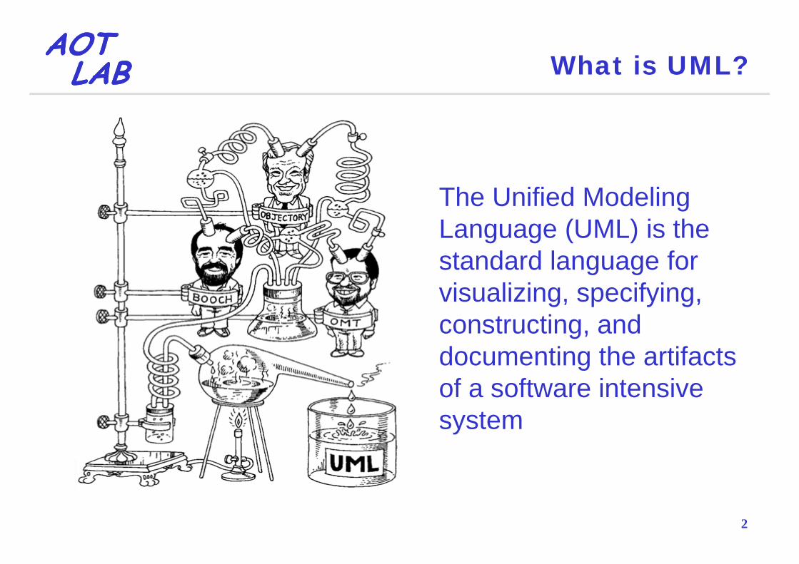
The Unified Modeling Language (UML) is the standard language for visualizing, specifying, constructing, and
fdocumenting the artifacts of a software intensive system
2

AOTAOTLABLAB What is UML?
Is a language and notation system used to specify, construct, visualize and document models of software systems
Is not a methodology (which considers the specific framework and conditions of an application domain theframework and conditions of an application domain, the organizational environment and many other things)
3

AOTAOTLABLAB Why Use UML?
Provides multiple diagrams for capturing different architectural views
Is a standard language for visualizing specifyingIs a standard language for visualizing, specifying, constructing, and documenting software systems
Tool support and interoperability improves in time, as UML, OCL, and XMI are still relatively young standards
4
y y g

AOTAOTLABLAB Why Use UML?
Improve Project Communications 69
Better Requirements … 51
Faster Development
Easier to maintain
39
40
Fewer Defects
Faster Development
25
39
0 20 40 60 80
5
Source: BZ Research, August 2004
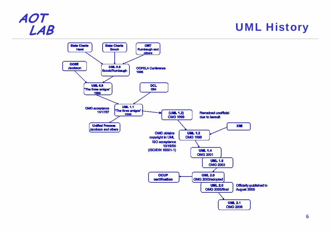
AOTAOTLABLAB UML History
6

AOTAOTLABLAB UML Notation Goals
Simple because it requires only a few concepts and symbolsExpressive because it is applicable to a wide spectrumExpressive because it is applicable to a wide spectrum of systems and life cycle methodsUsef l beca se it foc ses onl pon those necessarUseful because it focuses only upon those necessary elements to software engineeringConsistent because the same concept and symbol should be applied in the same fashion throughoutExtensible because users and tool builders should have some freedom to extend the notation
7
have some freedom to extend the notation

AOTAOTLABLAB UML Specifications
Infrastructure, the foundational language constructs
Superstructure, the user level constructs
Object Constraint Language (OCL), the formal language used to describe expressions on UML models
Diagram interchange, the means enabling a smooth g g gand seamless exchange of documents compliant to the UML standard
8

AOTAOTLABLAB UML Architecture
9

AOTAOTLABLABLABLAB
UML DiagramsUML Diagrams

AOTAOTLABLAB UML Diagram Types
Structural ViewCl
Implementation View C it t t lClass
ObjectComposite structural
Composite structuralComponent
U C ViComposite structuralPackage Use Case View
Use Case
Behavioral View Environment ViewSequenceCommunicationSt t
Deployment
StateActivityTiming
11
TimingInteraction overview

AOTAOTLABLAB Use Case View
The most important architectural viewDescribes use cases that provide value for the usersEssential use cases are used as proof of concept forEssential use cases are used as proof of concept for implementation architectureUse cases may be visualized in UML use case diagramsEach use case may have multiple possible scenariosUse case scenarios could be described:Use case scenarios could be described:
Using textual descriptions
12
Graphically, using UML activity diagrams

AOTAOTLABLAB Structural View
Represents structural elements for implementing solution for defined requirements and defines:
Object-oriented analysis and design elementsDomain and solution vocabularySystem decomposition into layers and subsystemsy p y yInterfaces of the system and its components
Is represented by static UML diagrams:Is represented by static UML diagrams:Class diagrams in multiple abstraction levelsObject diagramsComposite structural diagrams
13
Package diagrams

AOTAOTLABLAB Behavioral View
Represents dynamic interaction between system components for implementing requirementsShows distribution of responsibilities and allows to pidentify interaction and coupling bottlenecksA means for discussing non-functional requirements:A means for discussing non functional requirements: performance, maintenance, …Is represented by dynamic UML diagrams:Is represented by dynamic UML diagrams:
Sequence diagrams State diagramsCommunicationdiagrams
Interaction overview diagrams
14
Activity diagrams Timing diagrams

AOTAOTLABLAB Implementation View
Describes implementation artifacts of logical subsystems defined in structural viewMay include intermediate artifacts used in systemMay include intermediate artifacts used in system construction (code files, libraries, data files, …)Defines dependencies bet een implementationDefines dependencies between implementation components and their connections by required and provided interfacesprovided interfacesIs represented by these UML diagrams:
Component diagramsComposite structural diagrams
15
Composite structural diagrams

AOTAOTLABLAB Environment View
Represents system hardware topology
Defines how software components are deployed on hardware nodes
Useful for analyzing non-functional requirements: reliability, scalability, security, …
Provides information for system installation and fi iconfiguration
I t d b th UML d l t di16
Is represented by the UML deployment diagram

AOTAOTLABLAB Diagram Frame
The heading is a string contained in a name tag which is a rectangle with cut off cornerstag which is a rectangle with cut off corners in the upper left hand corner of the frame
E h di hEach diagram has a frame, a content area and a headingarea and a heading
The frame is a rectangle and is used to denote a border
17
is used to denote a border

AOTAOTLABLAB Use Case Diagram
18

AOTAOTLABLAB Use Case Diagram
A use case describes the proposed functionality of a system
A use case represents a discrete unit of interactionA use case represents a discrete unit of interaction between a user (human or machine) and the system
This interaction is a single unit of meaningful work, that may be include a complex interaction between parts
19
y p p

AOTAOTLABLAB Actor, System Boundary and Use Case
A user of the system i id tifi d ith th
The system b d lis identified with the
name of actorboundary usual divides what is inside or outsideinside or outside the system (use cases from actors)
A single unit of meaningful workAn actor can be also
d b l A single unit of meaningful work related to a functionality of the system is identified with the name of use case
represented by a class rectangle with the «actor» keyword
20
keyword

AOTAOTLABLAB Generalization and Composition
A use case may be used to extend the An actor can generalize another actor
behavior of another use case
An extension may
A use case may contain the functionality of
ybe conditioned
the functionality of another use case as part of their normal processing
An extension point indicates where t di i dd d
21
an extending use case is added

AOTAOTLABLAB Multiplicity
A use case diagram can contain severalcan contain several use cases and actors
The uses connector can optionally
22
have multiplicity values at each end

AOTAOTLABLAB Class Diagram
23

AOTAOTLABLAB Class Diagram
A class diagram shows the building blocks of an object-orientated systemClass diagrams depict a static view of the model, or g p ,part of the model, describing what attributes and behavior it has rather than detailing the methods for gachieving operationsClass diagrams are most useful in illustratingClass diagrams are most useful in illustrating relationships between classes and interfacesGeneralizations aggregations and associations are allGeneralizations, aggregations, and associations are all valuable in reflecting inheritance, composition or usage and connections respectively
24
usage, and connections respectively

AOTAOTLABLAB Class
A class is represented by a rectangle whichA class is represented by a rectangle which shows the name of the class and optionally the name of its operations and attributes. Compartments are used to divide the class name, attributes and operations
+ is public visibilityThe symbol that precedes the attribute, or operation name, i di t th i ibilit f th
+ is public visibility– is private visibility# is protected visibilityindicates the visibility of the
element# is protected visibility~ is package visibility
25

AOTAOTLABLAB Interface and Template
An interface is a specification of behavior that implementers agree to meet, that is, a contract
A template defines a pattern whose parameters representwhose parameters represent types and can be applied to classes, packages, operationsp g p
26

AOTAOTLABLAB Association
An association implies two model elements have amodel elements have a relationship that usually is implemented as an instance
An association is represented by a connector that may include named
variable in one class
connector that may include named roles at each end, cardinality, direction and constraints
For more than two elements aFor more than two elements, a diamond representation toolbox element can be used as well
27
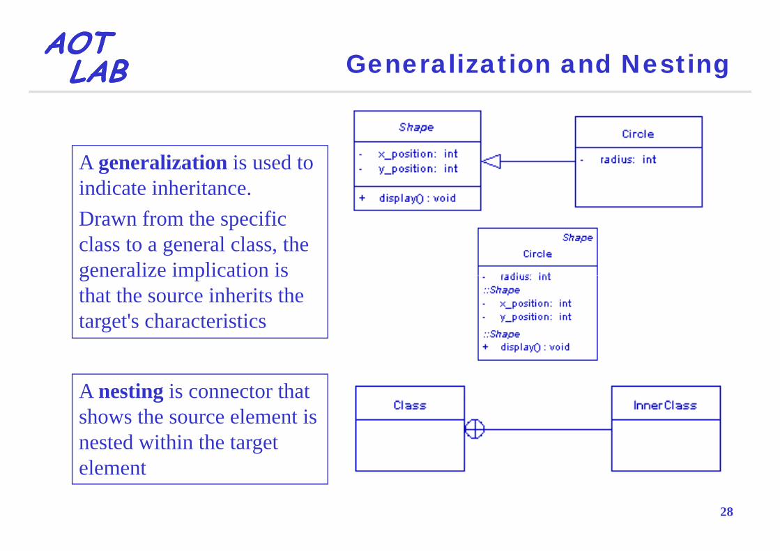
AOTAOTLABLAB Generalization and Nesting
A generalization is used to indicate inheritance.D f th ifiDrawn from the specific class to a general class, the generalize implication isgeneralize implication is that the source inherits the target's characteristics
A nesting is connector that gshows the source element is nested within the target l t
28
element

AOTAOTLABLAB Dependency and Realization
A d d i k f f A realization is a relationship between a specification and
A dependency is a weaker form of relationship showing a relationship between a client and a supplier a specification and
its implementationbetween a client and a supplier
29

AOTAOTLABLAB Aggregation and Composition
An aggregation is used to depict elements which are made up ofelements which are made up of smaller componentsAggregation relationships areAggregation relationships are shown by a white diamond-shaped arrowhead pointing towards the
A composition is a stronger form of aggregation that is shown by a black
target or parent class
A composition is a stronger form of aggregation that is shown by a black diamond-shaped arrowhead and is used where components can be included in a maximum of one composition at a timepIf the container is deleted, usually all of its parts are deleted with it, but a part can be individually removed without having to delete the container
30
Compositions are transitive and asymmetric relationships that can be recursive
AOTAOTLABLAB Association Class
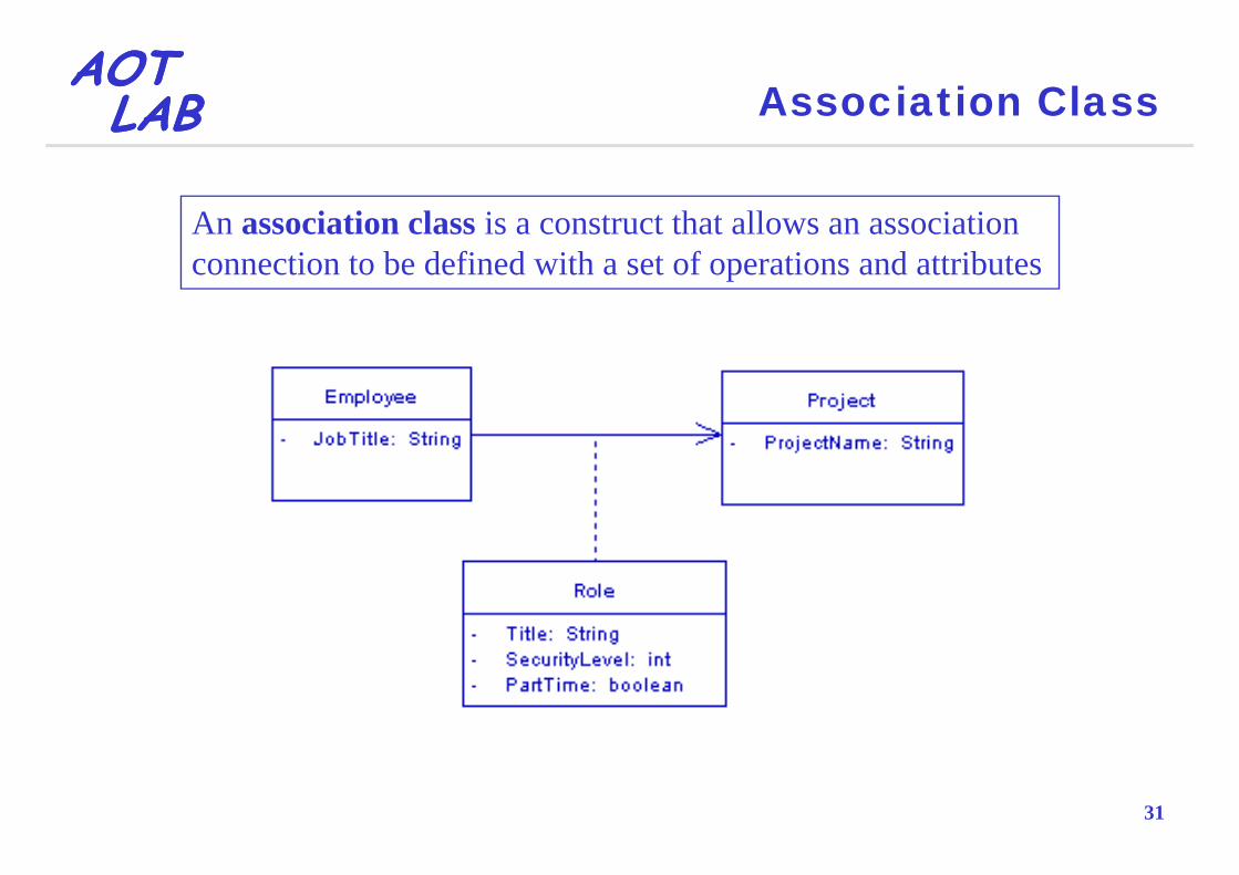
An association class is a construct that allows an association connection to be defined with a set of operations and attributes
31

AOTAOTLABLAB Object Diagram
32

AOTAOTLABLAB Object Diagram
An object diagram describes the static structure of a system at a particular time and may be considered a special case of a class diagram
Whereas a class model describes all possibleWhereas a class model describes all possible situations, an object model describes a particular situationsituation
Obj t di f l i d t di dObject diagrams are useful in understanding and validating the corresponding class diagrams
33

AOTAOTLABLAB Object
By default, object elements do not have compartments and their names are underlined and may show the name of the class fromshow the name of the class from which the object is instantiated
S i i i iblSometimes it is possible to represent an object’s run time state, showing the set values of attributesshowing the set values of attributes in the particular instance
34

AOTAOTLABLAB Composite Structure Diagram
35

AOTAOTLABLAB Composite Structure Diagram
A composite structural diagrams shows the internal structure of a classifier, including its interaction points to other parts of the system
A classifier is an UML element that is described byA classifier is an UML element that is described by attributes and/or methods (i.e., a class, an interface or a component)a component)
A it t t di i i il t lA composite structure diagram is similar to a class diagram, but it depicts individual parts instead of whole l
36
classes

AOTAOTLABLAB Structured Classifier
A structured classifier represents a class, often an abstract class or a component whose behavior can be completely orclass, or a component whose behavior can be completely or partially described through interactions between parts
A part represents a role played at runtime by one instance of a class or by a collection of instancesor by a collection of instances
A port is an interaction point that can be used to connect
An encapsulated classifier is a type of structured l ifi th t t i t
structured classifiers with their parts and with the environment
37
classifier that contains ports
AOTAOTLABLAB Port
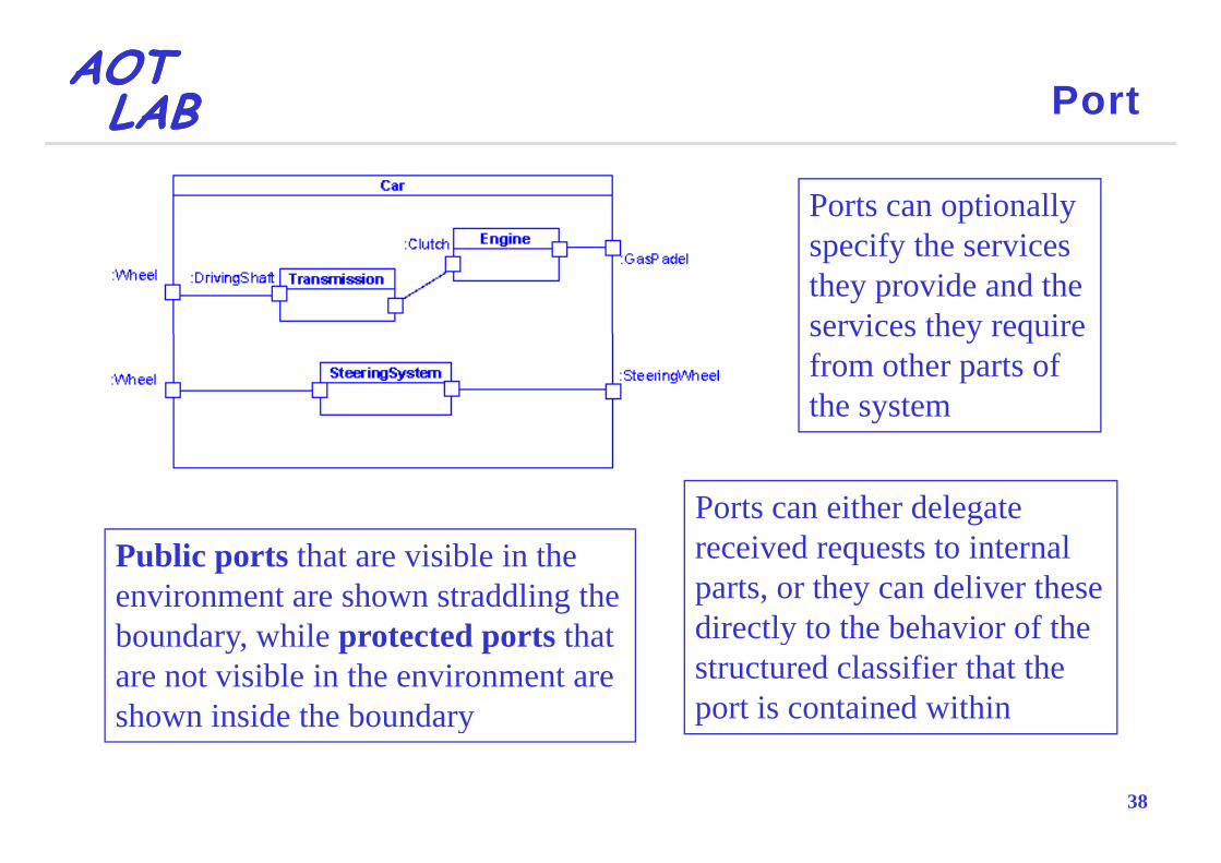
Ports can optionally if h ispecify the services
they provide and the services they requireservices they require from other parts of the system
Ports can either delegate Public ports that are visible in the environment are shown straddling the b d hil t t d t th t
received requests to internal parts, or they can deliver these directly to the behavior of theboundary, while protected ports that
are not visible in the environment are shown inside the boundary
directly to the behavior of the structured classifier that the port is contained within
38
shown inside the boundary

AOTAOTLABLAB Exposed Interfaces
A provided interface is shown "b ll i k" h das a "ball on a stick" attached to
the edge of a classifier element
A required interface is shown as a "cup on a stick" attached to the edge of a classifier elementthe edge of a classifier element.
A delegate connector is used for defining the internal workings of a component's external ports and interfaces
39
ports and interfaces

AOTAOTLABLAB Collaboration
A collaboration defines a set of cooperating roles used collectively to illustrate a specific functionality
40
AOTAOTLABLAB Collaboration
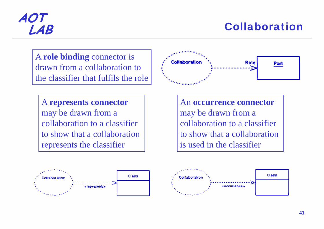
A role binding connector is drawn from a collaboration to the classifier that fulfils the role
A represents connector may be drawn from a
An occurrence connector may be drawn from amay be drawn from a
collaboration to a classifier to show that a collaboration
may be drawn from a collaboration to a classifier to show that a collaboration
represents the classifier is used in the classifier
41

AOTAOTLABLAB Component Diagram
42
AOTAOTLABLAB Component Diagram
Component diagrams illustrate the pieces of software, embedded controllers, etc., that will make up a system
A component diagram has a higher level of abstraction than a class diagram
Usually a component is implemented by one or more classes ( bj t ) t ti(or objects) at runtimes
C t t di t ib t bl h i l itComponents represent distributable physical units, including source code, object code, and executable code
43
code

AOTAOTLABLAB Component Diagram
44

AOTAOTLABLAB Package Diagram
45

AOTAOTLABLAB Package Diagram
Package diagrams are used for
Decomposing a system into logical units of work describing the dependencies between them
Providing views of a system from multiple levels of abstraction
The most common use for package diagrams is to p g gorganize use case diagrams and class diagrams, but may also be used for the other UML elements
46
y

AOTAOTLABLAB Merge, Nesting and Import
A merge connector defines an implicit generalization between elements in the source package and elements with the same name in the target packagethe source package, and elements with the same name in the target packageThe source element definitions are expanded to include the element definitions contained in the targetg
An import connectorAn import connector indicates that the elements within the target package
A nesting connector shows that the source g p g
use unqualified names when being referred to f th k
package is fully contained in the target package
47
from the source package

AOTAOTLABLAB Activity Diagram
48

AOTAOTLABLAB Activity Diagram
An activity diagram is used to display the sequence of activitiesActivity diagrams show the workflow from a start point y g pto the finish point detailing the many decision paths that exist in the progression of events contained in the p gactivityThey may be used to detail situations where parallelThey may be used to detail situations where parallel processing may occur in the execution of some activitiesactivitiesThey are useful for business modeling where they are used for detailing the processes involved in business
49
used for detailing the processes involved in business

AOTAOTLABLAB Activity and Action
An activity is shown as a round-cornered l l i ll h i l fl
Some constraintscan be attached torectangle enclosing all the actions, control flows
and other elements that make up the activitycan be attached to an action
An action represents a single step within an activity
50
single step within an activity

AOTAOTLABLAB Control Flow and Endpoint Nodes
A control flow shows the flow of control from one action to the nextcontrol from one action to the next
The activity final nodeThe activity final node denotes the end of all control flows within the activity
The initial node is depicted by a large p y gblack spot
The flow final node denotes the end of a single control flow
51
g

AOTAOTLABLAB Object and Interrupt Flows
An object flow is a path along which objects or data can pass
Exception handlers can be modeled on activity di th h thdiagrams through the use of an interrupt flow
An interruptible activityAn interruptible activity region surrounds a group of actions that can be interrupted
52

AOTAOTLABLAB Decision-Merge and Fork-Join
The control flows coming f d i i daway from a decision node
will have guard conditions which allow control to flowwhich allow control to flow if the guard condition is met
53

AOTAOTLABLAB Activity Partition
An activity partition is used for logically i h i d i id i iseparating the actions executed inside an activity
54

AOTAOTLABLAB State Diagram
55

AOTAOTLABLAB State Diagram
A state machine diagram models the behavior of a single object
It specifies the sequence of states that an object goesIt specifies the sequence of states that an object goes through during its lifetime in response to stimuli from the environmentthe environment
56

AOTAOTLABLAB State and Transition
A state is denoted by a round-cornered rectangle with the name of the state written inside itwith the name of the state written inside it
A transition from one state to the next is denoted by a line with arrowhead and may have
t i d d ff t
If the target state had many
a trigger, a guard and an effect
g ytransitions arriving at it, and each transition had the same ff t i t d ith it iteffect associated with it, it
would be better to associate the effect with the target state
57
the effect with the target state rather than the transitions

AOTAOTLABLAB Enter and Exit Points
The initial state and the final state are respectively denoted by a filled black p y ycircle and a circle with a dot inside and may also be labeled with a name
Sometimes may be possible h diff i ito have a different exit point
Sometimes may be possible to have an lt ti t t i t
58
alternative start point
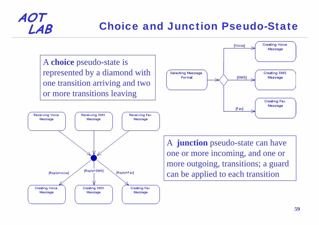
AOTAOTLABLAB Choice and Junction Pseudo-State
A choice pseudo state isA choice pseudo-state is represented by a diamond with one transition arriving and two gor more transitions leaving
A junction pseudo-state can have one or more incoming, and one or more outgoing transitions; a guardmore outgoing, transitions; a guard can be applied to each transition
59

AOTAOTLABLAB Composition
60

AOTAOTLABLAB History State and Concurrent Regions
A history state is used to remember the last state of a state machine whenstate machine when it was interrupted
A state may be divided into regions containing g gsub-states that exist and execute concurrently
61

AOTAOTLABLAB Sequence Diagram
62

AOTAOTLABLAB Sequence Diagram
Describes how a process is performed by a group of bj b i l f i iobjects by a sequential set of interactions
Facilitates assignment of responsibilities to classes and helps finding out new methods and new classesThese diagrams contain the following elements:g g
Roles, which represent roles that objects may play within the interactionLifelines, which represent the existence of an object over a period of timeActivations, which represent the time during which an object is performing an operation
63
Messages, which represent communication between objects

AOTAOTLABLAB Lifeline
A lifeline represents an individual participant in
dia sequence diagram
If lifeline name is "self", it indicates that the lifeline represents the classifier which owns the sequence didiagram
Th lif li b t t d d d d
64
The lifeline can be started and ended

AOTAOTLABLAB Message
A message is displayed as d b larrows and can be complete,
lost or found, synchronous or asynchronous, call or signalasynchronous, call or signal
A self message can represent a recursive call of an operation, or one method calling anothermethod calling another method belonging to the same object
65

AOTAOTLABLAB Fragment
A fragments allows the representation of complex procedural logic inside a sequence diagramp g q g
Alternative fragment models if then elsemodels if…then…else constructs Option fragment modelsOption fragment models switch constructsParallel fragment models gconcurrent processing Loop fragment encloses a series of messages which are repeated
66
…

AOTAOTLABLAB Communication Diagram
67

AOTAOTLABLAB Communication Diagram
A communication diagram, formerly called a collaboration diagram, is an interaction diagram that shows similar information to sequence diagrams but its primary focus is on object relationships:
Objects are shown with association connectors between themMessages are added to the associations and show as short
i ti i th di ti f th flarrows pointing in the direction of the message flowThe sequence of messages is shown through a numbering schemescheme
They provides an alternative view to the sequence di i f t b d t t th th ti
68
diagram in a format based on structure rather than time

AOTAOTLABLAB Robustness Diagram
69

AOTAOTLABLAB Robustness Diagram
A robustness diagram is basically a simplified UML communication diagram
Their purpose is to provide a means of refining the use cases:
Checking their correctness
Determining if they address all necessary alternate courses f tiof action
Discovering all the objects necessary to the design
70
Discovering all the objects necessary to the design

AOTAOTLABLAB Actor, Boundary, Control and Entity
Control elements act as the glue between boundary and entity elements, implementing the logic required y , p g g qto manage the various elements and their interactions
Boundary (interface) elements allow the communicatingcommunicating between actors and the internal parts of
Entity elements represent information unit of the system
71
pthe system
information unit of the system

AOTAOTLABLAB Logon Sequence Diagram
72

AOTAOTLABLAB Interaction Overview Diagram
73

AOTAOTLABLAB Interaction Overview Diagram
An interaction overview diagram is a form of activity diagram in which the nodes represent interaction diagrams (sequence, communication, interaction overview and timing diagrams)Most of the notation for interaction overview diagrams gis the same for activity diagrams
For example, initial, final, decision, merge, fork and join p , , , , g , jnodes are all the same
However, interaction overview diagrams introduce two , gnew elements: interaction occurrences and interaction elements
74

AOTAOTLABLAB Occurrence and Element
Occurrence
Element
75

AOTAOTLABLAB Timing Diagram
76

AOTAOTLABLAB Timing Diagram
A timing diagram is used to display the change in state or value of one or more elements over time
It can also show the interaction between timed events d th ti d d ti t i t th t thand the time and duration constraints that govern them
77
AOTAOTLABLAB Deployment Diagram
78

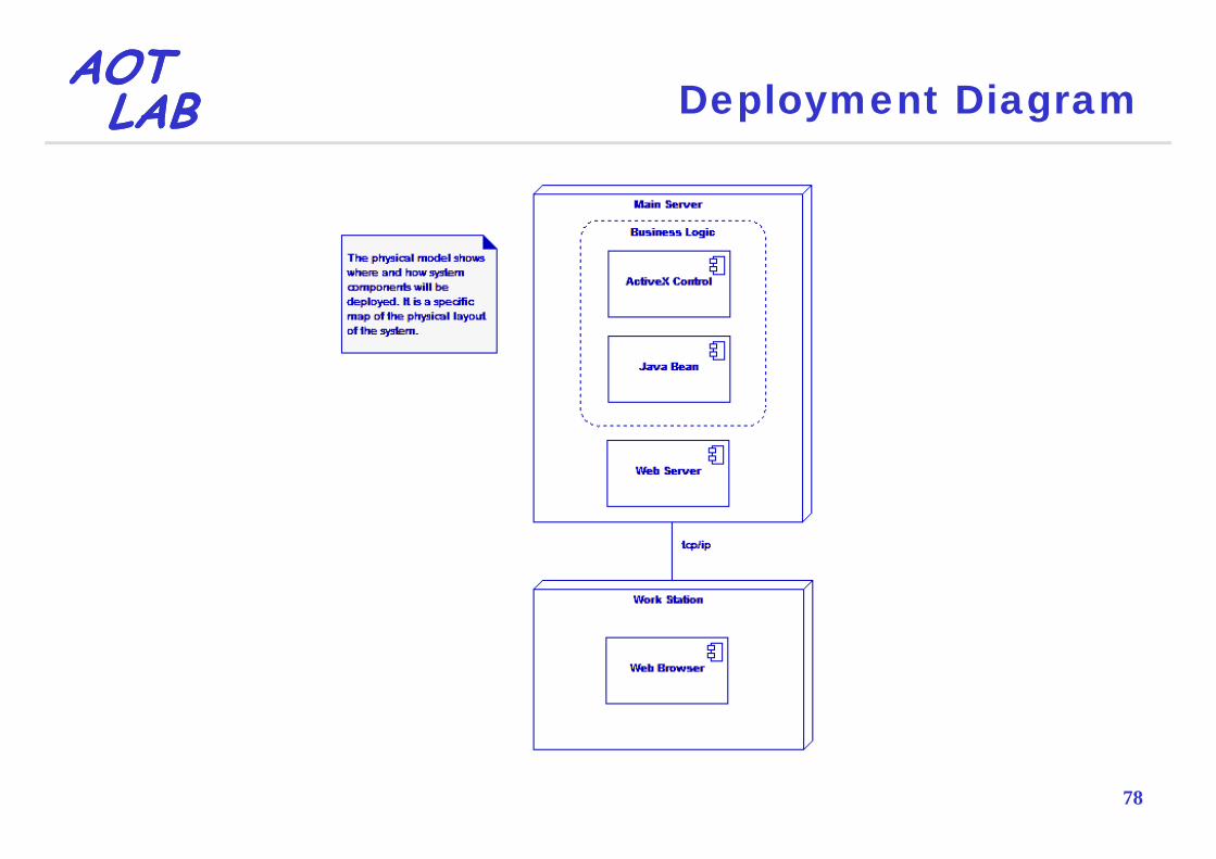
AOTAOTLABLAB Deployment Diagram
A deployment diagram models the run-time architecture of a system
Describes the configuration of hardware in a system in terms of nodes and connections
Describes the physical relationships between software and hardware
Displays how artifacts are installed and move around a distributed system
79

AOTAOTLABLAB Node and Artefact
A node is either a hardware or software element A node instancesoftware element. A node instance can be distinguished from a node by the fact that its name is underlined
An artifact is a productand has a colon before its base node type. An instance may or may not have a name before the colon
An artifact is a product of the software development process.have a name before the colon
A number of standard stereotypes are provided
p pThat may include process models (e.g. use
for nodes, namely «cd rom», «computer», «pc», «pc client», «pc server», etc.
case models, design models etc), source files, executables designexecutables, design documents, test reports, prototypes, user
80
manuals, etc.

AOTAOTLABLAB Association and Composition
In the context of a deployment diagram an associationdiagram, an association represents a communication path between nodes
A d i h l
p
A node can contain other elements, such as components or artifacts
81

AOTAOTLABLAB Use of UML Diagrams
Activity HighClass HighClass HighCommunication LowComponent MediumComponent MediumComposite Structural LowDeployment MediumDeployment MediumInteraction Overview LowObject LowjPackage LowSequence HighqState MediumTiming Low
82
Use Case Medium

AOTAOTLABLABLABLAB
Unified Modeling Language
O CObject Constraint Language

AOTAOTLABLAB What is OCL?
The Object Constraint Language (OCL) is a language th t bl th d i ti f i dthat enables the description of expressions and constraints on object-oriented
OCL is a typed formal language with a precise syntax and semanticsand semantics
OCL was developed at IBM by Jos Warmer as aOCL was developed at IBM by Jos Warmer as a language for business modeling within IBM
OCL is not a programming languageIt is not possible to write program logic or flow control in OCL
84
It is not possible to write program logic or flow control in OCL

AOTAOTLABLAB Why Use OCL in UML Models?
UML diagrams are typically not refined enough to id ll h l f ifi iprovide all the relevant aspects of a specification
For instance, there may be the need to describe additional constraints on the relationships between model entities and that can be described through:
Natural language expressions, that always result in ambiguitiesFormal language expressions, they are usable to persons with a strong mathematical background
OCL has been developed to fill this gap:It is a formal language, but remains easy to read and write for
85
all the business or system modelers

AOTAOTLABLAB OCL Constraints
OCL is based on constraintsConstraints are restrictions on one or more values of an object-oriented model or system
OCL constraints are declarativeThey specify what must be true not what must be doneThey specify what must be true not what must be done
OCL constraints have no side effectsEvaluating an OCL expression does not change the state of the system
OCL constraints have formal syntax and semanticsTheir interpretation is unambiguous
86
Their interpretation is unambiguous

AOTAOTLABLAB Advantages of Constraints
Better documentationConstraints add information about the model elements and their relationships to the visual models used in UMLIt i f d ti UML d lIt is way of documenting UML models
More precisionpOCL constraints have formal semantics, hence, can be used to reduce the ambiguity in UML models
Communication without misunderstandingUML models are sed to comm nicate bet een de elopersUML models are used to communicate between developersUsing OCL constraints modelers can communicate unambiguously
87
unambiguously

AOTAOTLABLAB Where Use OCL?
As a query languageTo specify invariants on classes and types in the class modelTo specify type invariant for stereotypesTo describe pre / post conditions on operationsTo describe pre / post conditions on operationsTo describe guardsTo specify target (sets) for messages and actionsTo specify constraints on operationsp y pTo specify derivation rules for attributes for any expression over a UML model
88
expression over a UML model

AOTAOTLABLAB Where Use OCL?
89

AOTAOTLABLAB Invariant
An invariant is a constraint that is connected to a d li l t l d i t f t d hmodeling element: class, and interface or type and has
to hold for all their instances
An invariant must be true at all times when the instance is at rest
An instance is not at rest when an operation is under execution
90

AOTAOTLABLAB Invariant
Account{ points >= 0 }
points: Integer
earn(i: Integer)burn(i: Integer)isEmpty(): Boolean
91

AOTAOTLABLAB Precondition
A precondition is a constraint that must be true when ti i i k dan operation is invoked
It is the responsibility of the caller to satisfy theIt is the responsibility of the caller to satisfy the condition
This condition is supposed to be true, and anything else is a programming errorelse is a programming error
If the condition is not satisfied, no statement can be made about the integrity of the operation or the systemabout the integrity of the operation or the system
In practice, explicitly checking preconditions by the receiver may detect many errors
92
may detect many errors

AOTAOTLABLAB Precondition
Account{ points >= 0 }
<<precondition>>
points: Integer
earn(i: Integer)
i >= 0
<<precondition>>points >= i and i >= 0
burn(i: Integer)isEmpty(): Boolean
93

AOTAOTLABLAB Postcondition
A postcondition is a constraint that must be true after th l ti f tithe completion of an operation
This condition is supposed to be true, and anything else is a programming error
It can be useful to test the postcondition after the poperation, but this is in the nature of debugging a program
94

AOTAOTLABLAB Postcondition
Account{ points >= 0 }
<<precondition>>
points: Integer
earn(i: Integer)
i >= 0
<<precondition>>points >= i and i >= 0
burn(i: Integer)isEmpty(): Boolean
<<postcondition>>points = points@pre - ipoints = points@pre i
<<postcondition>>points = points@pre + i
<< t diti >><<postcondition>>result = (points=0)
95

AOTAOTLABLAB Guard
A guard is a constraint that must be true before a transition can occur
A guard is evaluated before the transition so can beA guard is evaluated before the transition so can be thought of as a pre-condition
A guard is usually used in activity and state diagrams
96

AOTAOTLABLAB Guard
[i > 0]
Empty NotEmpty
earn(i: integer)
do/checkItem[i = 0] do/initiateDelivery
[points - i > 0]burn(i: integer)
earn(i: integer) burn(i: integer)
[p ]
[points - i = 0]
earn(i: integer)
burn(i: integer)
earn(i: integer)
97

AOTAOTLABLAB OCL Expressions and Constraints
Each OCL expression has a resultThe value that results by evaluating the expression
Each OCL expressions can contain only queryEach OCL expressions can contain only query operations
Q ti t l b t d t h thiQuery operations return a value, but do not change anythingIs not possible the activation of processes or non-query
ti ithi OCLoperations within OCL
The type of an OCL expression is the type of the result yp p ypvalue
A OCL t i t i B l OCL i98
An OCL constraint is a Boolean OCL expression

AOTAOTLABLAB OCL Types
Basic typesRealIntegergStringBooleanBoolean
Collection typesThey are the result of navigation through associations in an UML model
User-defined model typesAll classes types and interfaces in an UML model
99
All classes, types and interfaces in an UML model

AOTAOTLABLAB
Operations Defined for EveryOCL TypeOCL Type
Two model objects can be comparedo1 = o2, o1 <> o2
The type of an object can be checkedThe type of an object can be checkedoclIsTypeOf(type)
• Returns true only for the instances of typeoclIsKindOf(type)
• Returns true for the instances of type and of its subtypes
Th t f bj t b t i dThe type of an object can be retrievedoclType
100

AOTAOTLABLAB Basic Types
Realr1 + r2, r1 − r2, r1 * r2, r1 / r2, r.abs, r.floor, r.round, r1.max(r2), r1.min(r2)
r1 = r2, r1 <> r2 , r1 < r2, r1 > r2, r1 <= r2, r1 >= r2
IntegerIntegeri1 + i2, i1 − i2, i1 * i2, i1.div(i2), i1.mod(i2), i1 / i2, i.abs, i1 max(i2) i1 min(i2)i1.max(i2), i1.min(i2)
i1 = i2, i1 <> i2 , i1 < i2, i1 > i2, i1 <= i2, i1 >= i2
Note that Integer is a subclass of RealFor each parameter of type Real, an Integer can be used as
101
p yp , gthe actual parameter
AOTAOTLABLAB Basic Types
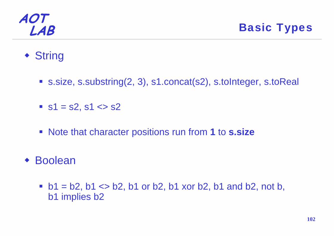
String
s.size, s.substring(2, 3), s1.concat(s2), s.toInteger, s.toReal
s1 = s2, s1 <> s2
Note that character positions run from 1 to s.size
Boolean
b1 = b2, b1 <> b2, b1 or b2, b1 xor b2, b1 and b2, not b, b1 implies b2
102
b1 implies b2
AOTAOTLABLAB Collections
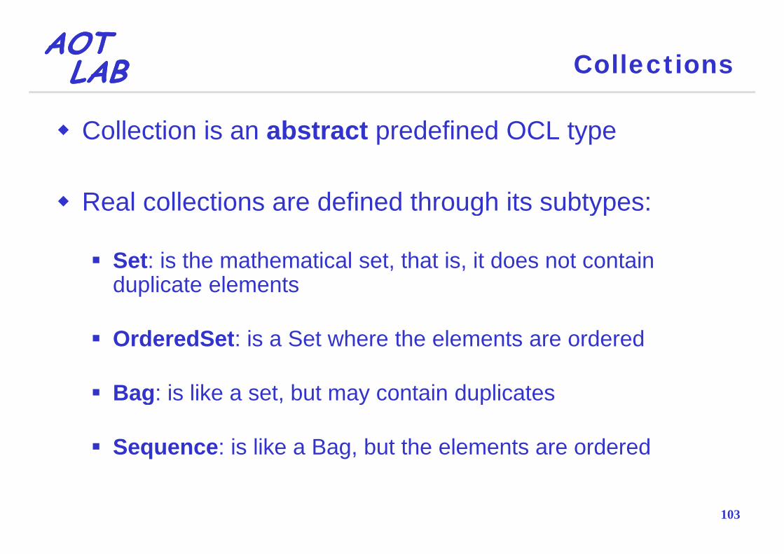
Collection is an abstract predefined OCL type
Real collections are defined through its subtypes:g yp
Set: is the mathematical set, that is, it does not contain d li t l tduplicate elements
OrderedSet: is a Set where the elements are orderedOrderedSet: is a Set where the elements are ordered
Bag: is like a set, but may contain duplicatesg , y p
Sequence: is like a Bag, but the elements are ordered
103

AOTAOTLABLAB Operation on Collections
select(b), reject(b)
This results in a collection that contains all the elements from collection for which the boolean expression, b, is true / false
self.employee->select(age > 50)
self.employee->reject(age > 50)
collect(e)
This results in a collection that contains the results of all theThis results in a collection that contains the results of all the evaluations of the expression, e
self employee >collect(person birthDate)
104
self.employee->collect(person.birthDate)

AOTAOTLABLAB Operation on Collections
forAll(b)( )
This results in a Boolean that is true if the Boolean expression b is true for all elements of the collectionexpression, b, is true for all elements of the collection
self.employee->forAll(age <= 65)self.employee forAll(age 65)
exists(b)( )
This results in a Boolean that is true if the Boolean expression b is true for at least one element of the collectionexpression, b, is true for at least one element of the collection
self.employee->exists(age <= 65)
105
self.employee exists(age 65)

AOTAOTLABLAB Operation on Collections
Set, Bag, OrderedSet and Sequencesize(), count(o), sum()c1 = c2, includes(o), excludes(o), includesAll(c), excludesAll(c), isEmpty(), notEmpty()
Set & Bag and OrderedSet & Sequenceunion(c), intersection(c), c1 – c2including(o), excluding(o)g( ) g( )
OrderedSet and Sequenceappend(o) prepend(o) insertAt(i o)append(o), prepend(o), insertAt(i, o)at(i), indexOf(o), first(), last()subOrderedSet(i1 i2) subSequence(i1 i2)
106
subOrderedSet(i1, i2), subSequence(i1, i2)
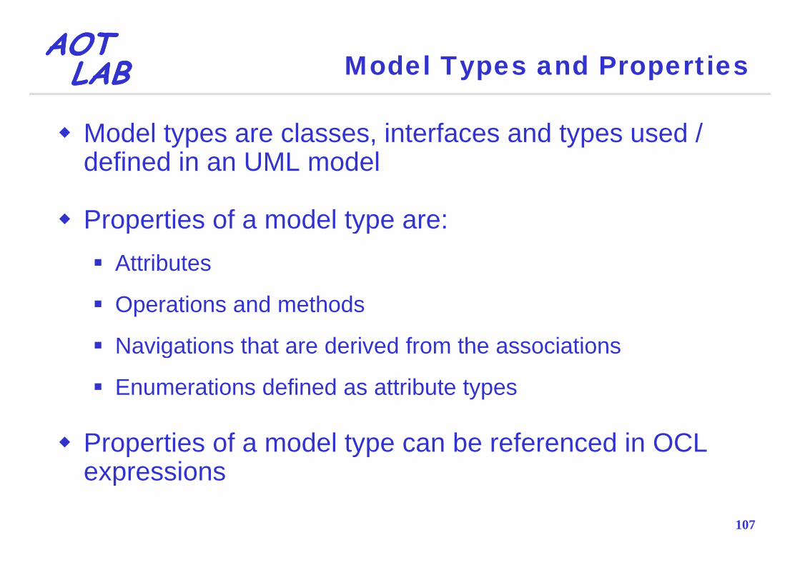
AOTAOTLABLAB Model Types and Properties
Model types are classes, interfaces and types used / d fi d i UML d ldefined in an UML model
Properties of a model type are:Properties of a model type are:Attributes
Operations and methods
Navigations that are derived from the associationsNavigations that are derived from the associations
Enumerations defined as attribute types
Properties of a model type can be referenced in OCL expressions
107
expressions

AOTAOTLABLAB Enumerations
An enumeration defines a number of enumeration literals, that are the possible values of the enumeration
Enumerations are types in UML and have a nameEnumerations are types in UML and have a name
Within OCL one can refer to the value of an enumeration
If in the UML model there is an enumeration named G d ith l 'f l ' ' l ‘ i OCL thGender with values 'female' or 'male‘, in OCL they can be referred as follows:
Gender::male
108
Gender::female

AOTAOTLABLAB Automatic Train Control System
Paul Ziemann, Martin Gogolla. Validating OCL Specifications with the USE Tool-An Example Based on the BART Case Study. 2003
109

AOTAOTLABLAB Segment Constraints
If for a segment there is a next segment, the begin of the next is equal to the end of the former
self next isDefined implies self next segBegin = self segEndself.next.isDefined implies self.next.segBegin = self.segEnd
The length of a segment has to be the difference of g gsegment end and begin
f f fself.segEnd - self.segBegin = self.length
Connected segments belong to the same trackConnected segments belong to the same track
self.next.isDefined implies self.track = self.next.track
110

AOTAOTLABLAB Train Constraints
The origin and the destination of a train have to be connected by a sequence of segments
self.orig.nextPlus()->includes(self.dest)
A train should stay below the maximum speed thatA train should stay below the maximum speed that segment of track can handle
self.trains()->forAll(t | t.v <=t.currentSeg().civilSpeed)
111

AOTAOTLABLAB Train Constraints
A train should not enter a closed gate
self.trains()->forAll(t | t.nextClosedGate().isDefinedimpliesimplies
t.nose+self.wcsd(t) < t.nextClosedGate().segment.segEnd)
A train should never get so close to a train in front that if the train in front stopped suddenly (e.g., derailed) theif the train in front stopped suddenly (e.g., derailed) the (following) train would hit it
lf t i () >f All(t | t tT i () i D fi dself.trains()->forAll(t | t.nextTrain().isDefinedimplies
t lf d(t) t tT i () t tT i () l th)
112
t.nose+self.wcsd(t) < t.nextTrain().nose - t.nextTrain().length)

AOTAOTLABLABLABLAB
Unified Modeling Language
Extending UML

AOTAOTLABLAB Why Extending UML?
UML does not contain domain specific concepts, but contains general purpose concepts for system modeling
However UML provides mechanisms to extend itselfHowever, UML provides mechanisms to extend itself
These mechanisms allow to widen the UML meta model inThese mechanisms allow to widen the UML meta model in order to embed concepts of a specific domain
Building UML models for that domain will be much easier within the extended UML meta model
114
within the extended UML meta model
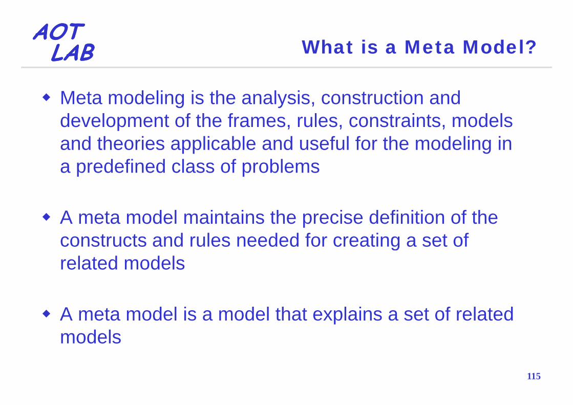
AOTAOTLABLAB What is a Meta Model?
Meta modeling is the analysis, construction and development of the frames, rules, constraints, models and theories applicable and useful for the modeling in a predefined class of problems
A meta model maintains the precise definition of the constructs and rules needed for creating a set of grelated models
A meta model is a model that explains a set of related models
115
models
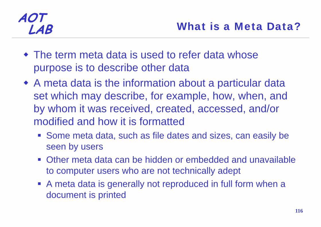
AOTAOTLABLAB What is a Meta Data?
The term meta data is used to refer data whose purpose is to describe other dataA meta data is the information about a particular data pset which may describe, for example, how, when, and by whom it was received, created, accessed, and/or y , , ,modified and how it is formatted
Some meta data, such as file dates and sizes, can easily be , , yseen by usersOther meta data can be hidden or embedded and unavailable to computer users who are not technically adeptA meta data is generally not reproduced in full form when a
116
document is printed

AOTAOTLABLAB UML Meta-Model Hierarchy
117

AOTAOTLABLAB UML Meta-Model Hierarchy
118

AOTAOTLABLAB What is MOF?
The Meta Object Facility (MOF) provides a metadata f k d f dmanagement framework, and a set of metadata
services to enable the development and interoperability f d l d t d t d i tof model and metadata driven systems
MOF provides very simple rules for modeling metadataMOF provides very simple rules for modeling metadata Meta models are defined on the basis of on simple class modeling concepts and using UML class modeling notationmodeling concepts and using UML class modeling notation
MOF decouples the modeling concepts from the desirable meta data services
Meta data interchange, Reflection, Federation, Life Cycle,
119
Versioning, Identity, Queries, …
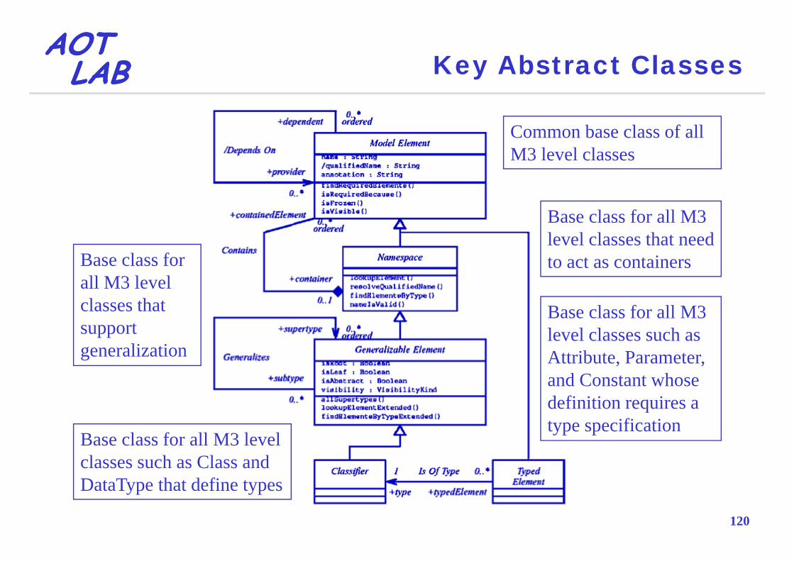
AOTAOTLABLAB Key Abstract Classes
Common base class of all M3 level classesM3 level classes
Base class for all M3Base class for all M3 level classes that need to act as containersBase class for
all M3 levelall M3 level classes that support
li i
Base class for all M3 level classes such as
generalization Attribute, Parameter, and Constant whose definition requires adefinition requires a type specification
Base class for all M3 level classes such as Class and
120
DataType that define types

AOTAOTLABLAB Concrete Classes and Associations
Class Contains
Association
ExceptionGeneralizes
AttributeI OfT
ConstantIsOfType
Constraint DependsOn
121
p

AOTAOTLABLAB UML Meta Model
122

AOTAOTLABLAB Feature
123

AOTAOTLABLAB Classifier
124
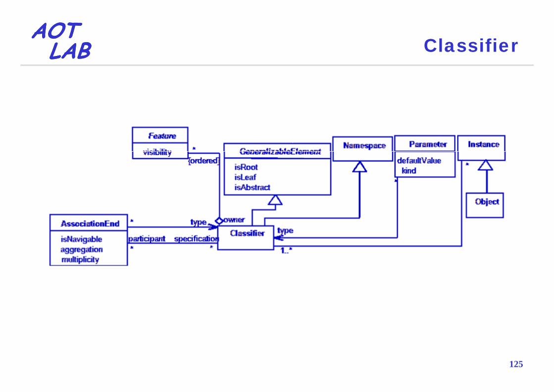
AOTAOTLABLAB Classifier
125

AOTAOTLABLAB Relationships
126
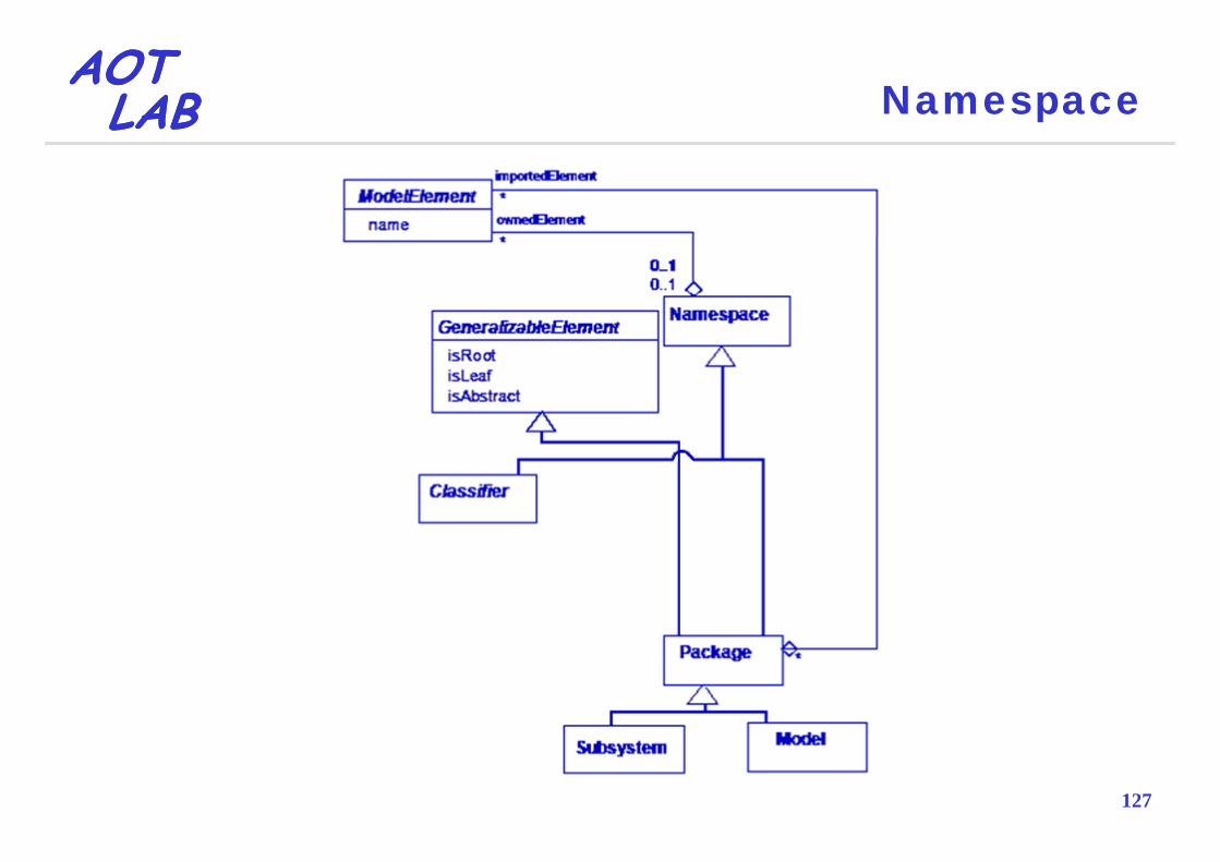
AOTAOTLABLAB Namespace
127
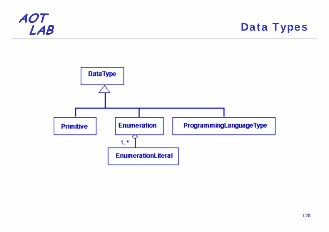
AOTAOTLABLAB Data Types
128

AOTAOTLABLAB Class Meta Model – Model Mapping
129

AOTAOTLABLAB Use Case Meta Model
130

AOTAOTLABLAB Use Case Meta Model – Model Mapping
131

AOTAOTLABLAB State Meta Model
132

AOTAOTLABLAB State Meta Model – Model Mapping
133
AOTAOTLABLAB UML Extensibility
A new dialect of UML can be defined by using profilesto customize the language for particular platforms and domains (lightweight extension)
Compliant with UML standard
A new language can be specified at the MOF level by g g p yadding new meta classes and meta relationships (heavyweight extension)( y g )
Not compliant with UML standard
134
Not compliant with UML standard

AOTAOTLABLAB UML Extension Mechanisms
135

AOTAOTLABLAB Stereotype
A stereotype denotes a variation on an existing UML modeling element with the same structure, but with a difference in meaning
A stereotype extends the UML vocabulary
A stereotype can be used to further define additional constraints and tag definitions of a model element in aconstraints and tag definitions of a model element in a UML diagram
A stereotype can vary the semantics of an existing element (it is not a new model element per se)
136
( p )

AOTAOTLABLAB Stereotype
Augment UML classification mechanism based on built-in UML meta model class hierarchy
Adds "virtual" UML meta classes with new:
SemanticsSemantics
Meta-attributes
Property lists
Constraints
G hi l t ti
137
Graphical representation
AOTAOTLABLAB Tagged Value
A tagged value allow the association of extra i f i i h d li linformation with a modeling element A tagged value is a property used for specifying a gg p p y p y gkeyword-value pair of a model element where the keyword is an attributesyA tagged value is not a class attribute, but can considered a metadata since its value applies to theconsidered a metadata, since its value applies to the element itself and not to its instancesOne of the most common uses of a tagged value is toOne of the most common uses of a tagged value is to specify properties that are relevant to code generation or configuration management
138
or configuration management

AOTAOTLABLAB Constraint
A constraint allows the specification of the semantics and/or of the condition that must be held true at all times for the elements of a model
A constraint allows the extension of the semantics of aA constraint allows the extension of the semantics of a UML building block by adding new rules, or modifying existing onesexisting ones
A t i t b d b OCL i i tA constraint can be expressed by an OCL invariant, precondition or postcondition
139

AOTAOTLABLAB Capsule Model
A capsule is a special type of concurrent object used in modeling certain real-time systems
By definition, all classes of this type:
Are active (concurrent)
Have only features (attributes and operations) with protected visibility
Have a special “language” characteristic used for code generation purposes
140
generation purposes
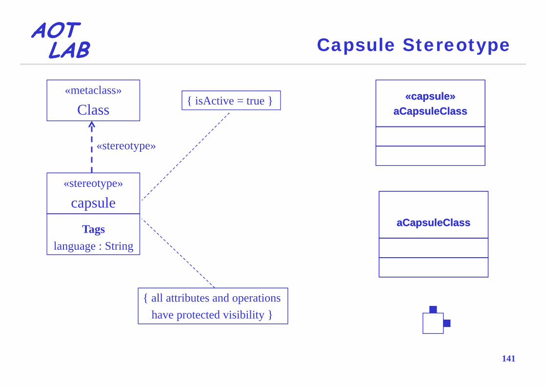
AOTAOTLABLAB Capsule Stereotype
«metaclass»
Cl«capsule»«capsule»{ isActive = true }
Class
«stereotype»
aCapsuleClassaCapsuleClass{ }
«stereotype»
«stereotype»
capsuleaCapsuleClassaCapsuleClassTags
language : String
{ all attributes and operations have protected visibility }
141

AOTAOTLABLAB Profile
A profile groups a set of extension mechanisms for building UML models in a particular domain
A profile consists of a package that contains aA profile consists of a package that contains a collection of stereotypes, tag definitions and constraints that work together to define new semantics for a modelthat work together to define new semantics for a model
142

AOTAOTLABLAB SOA Profile
143
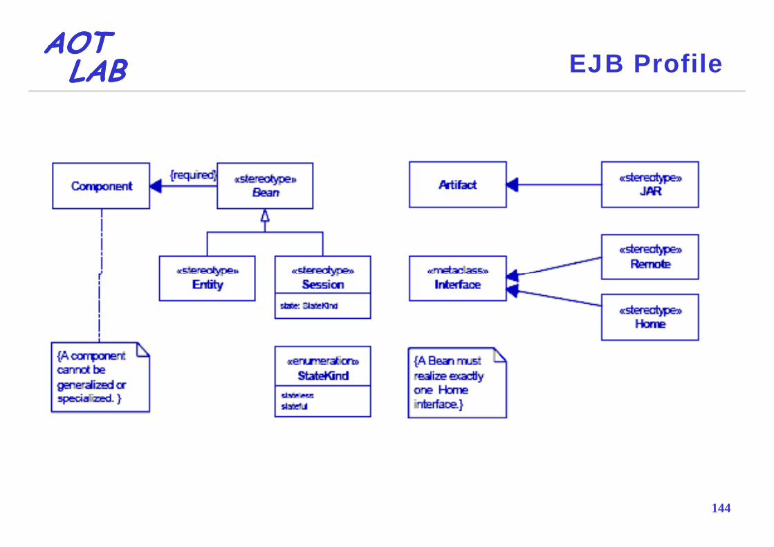
AOTAOTLABLAB EJB Profile
144