Improved Onlooker Bee Phase in Artificial Bee Colony Algorithm
Upload
khangminh22Category
view
0download
0
ELECTRICAL ENGINEERING SECTION
UNIVERSITY POLYTECHNIC
A. M. U., ALIGARH
Teacher’s Signature
BEE-293
Electrical Engineering Lab
Name: ___________________________
Class: Diploma in Architechture Asstt.ship., IInd
Sem
College No.: ____________________
En. No.: _______________________
Group No: _____________________
Partners of Group:
1. _________________________
2. _________________________
3. _________________________
4. _________________________
Date of performing Exp:____/____/____ Date of Submission of Report:____/____/____
Object:________________________________________________________________
______________________________________________________________________
Apparatus Used:
S. No. Lab No. Equipment Used Range Make
Observation Table/Circuit Diagram:
Exp. No.
Marks
ELECTRICAL ENGINEERING SECTION
UNIVERSITY POLYTECHNIC
A. M. U., ALIGARH
Teacher’s Signature
BEE-293 Electrical Engineering Lab
Name: ___________________________
Class: Diploma in LFT, IInd
Sem
College No.: ____________________
En. No.: _______________________
Group No: _____________________
Partners of Group:
1. _________________________
2. _________________________
3. _________________________
4. _________________________
Date of performing Exp:____/____/____ Date of Submission of Report:____/____/____
Object:________________________________________________________________
______________________________________________________________________
Apparatus Used:
S. No. Lab No. Equipment Used Range Make
Observation Table/Circuit Diagram:
Exp. No.
Marks
ELECTRICAL ENGINEERING SECTION
UNIVERSITY POLYTECHNIC
A. M. U., ALIGARH
Teacher’s Signature
BEE-293 Electrical Engineering Lab
Name: ___________________________
Class: Diploma in Interior Design., IInd
Sem
College No.: ____________________
En. No.: _______________________
Group No: _____________________
Partners of Group:
1. _________________________
2. _________________________
3. _________________________
4. _________________________
Date of performing Exp:____/____/____ Date of Submission of Report:____/____/____
Object:________________________________________________________________
______________________________________________________________________
Apparatus Used:
S. No. Lab No. Equipment Used Range Make
Observation Table/Circuit Diagram:
Exp. No.
Marks

DIPLOMA IN ENGINEERING ( Ist
& IInd
SEMESTER )
Mechanical, Production, RAC, Plastic, LFT, Civil, Architecture, ID
Electrical Installation Lab
BEE-192, BEE-193 & BEE-293
LIST OF EXPERIMENTS
1 (a) To control one lamp with one switch.
(b) To control two lamps (in series) with one switch.
(c) To control two lamps (in parallel) with one switch.
2 (a) Study of stair case lighting system using two-way switch.
(b) Study of Intermediate switch and its application in corridor lighting system.
3 (a) To make connection for 230 V bell and 230 V buzzer.
(b) To make connection for 6 V bell using 230/6V transformer.
(c) To make connection for bell with indicator.
4 Practice in making Plastic Casing-Capping wiring for one point.
5 Testing of following faults of electrical installation by Megger.
(a) Open circuit fault
(b) Short circuit fault.
(c) Earth leakage test.
6 a) To make connections of an Energy Meter.
b) To measure energy consumed by a 1000 watt load in given time.
c) To measure error in the meter.
7 (a) Study of various types of Multi-meters.
(b) Measurement of Resistance with the help of Analog and Digital multi-meters.
8 (a) To measure the resistance of heating element of the Kettle.
(b) To determine the efficiency of Electric Kettle.
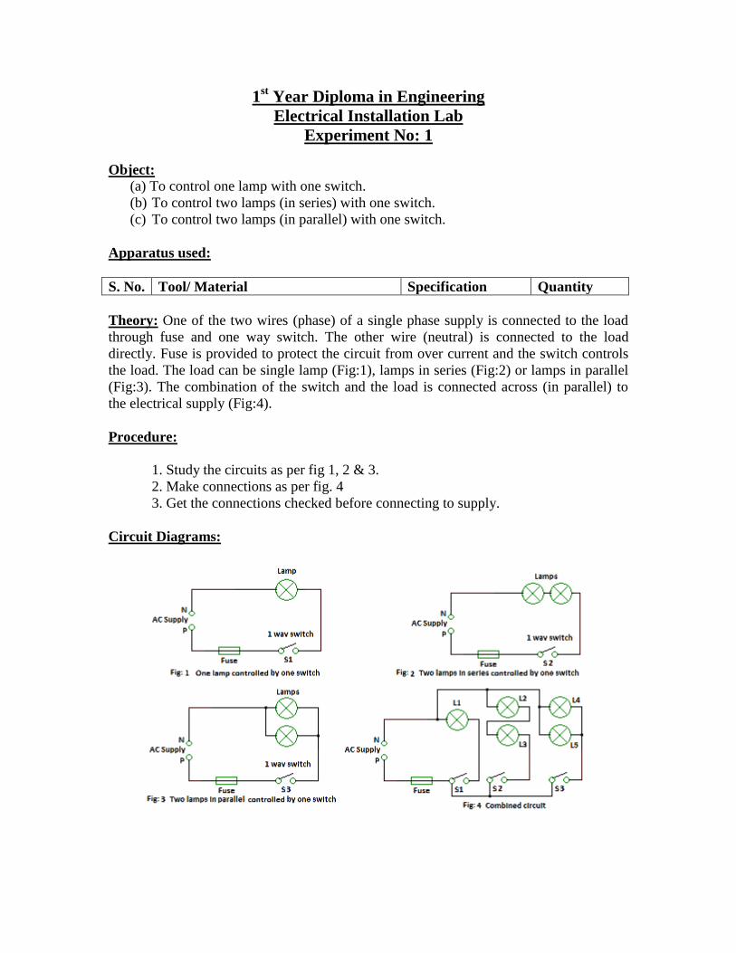
1st Year Diploma in Engineering
Electrical Installation Lab
Experiment No: 1
Object:
(a) To control one lamp with one switch.
(b) To control two lamps (in series) with one switch.
(c) To control two lamps (in parallel) with one switch.
Apparatus used:
S. No. Tool/ Material Specification Quantity
Theory: One of the two wires (phase) of a single phase supply is connected to the load
through fuse and one way switch. The other wire (neutral) is connected to the load
directly. Fuse is provided to protect the circuit from over current and the switch controls
the load. The load can be single lamp (Fig:1), lamps in series (Fig:2) or lamps in parallel
(Fig:3). The combination of the switch and the load is connected across (in parallel) to
the electrical supply (Fig:4).
Procedure:
1. Study the circuits as per fig 1, 2 & 3.
2. Make connections as per fig. 4
3. Get the connections checked before connecting to supply.
Circuit Diagrams:
1
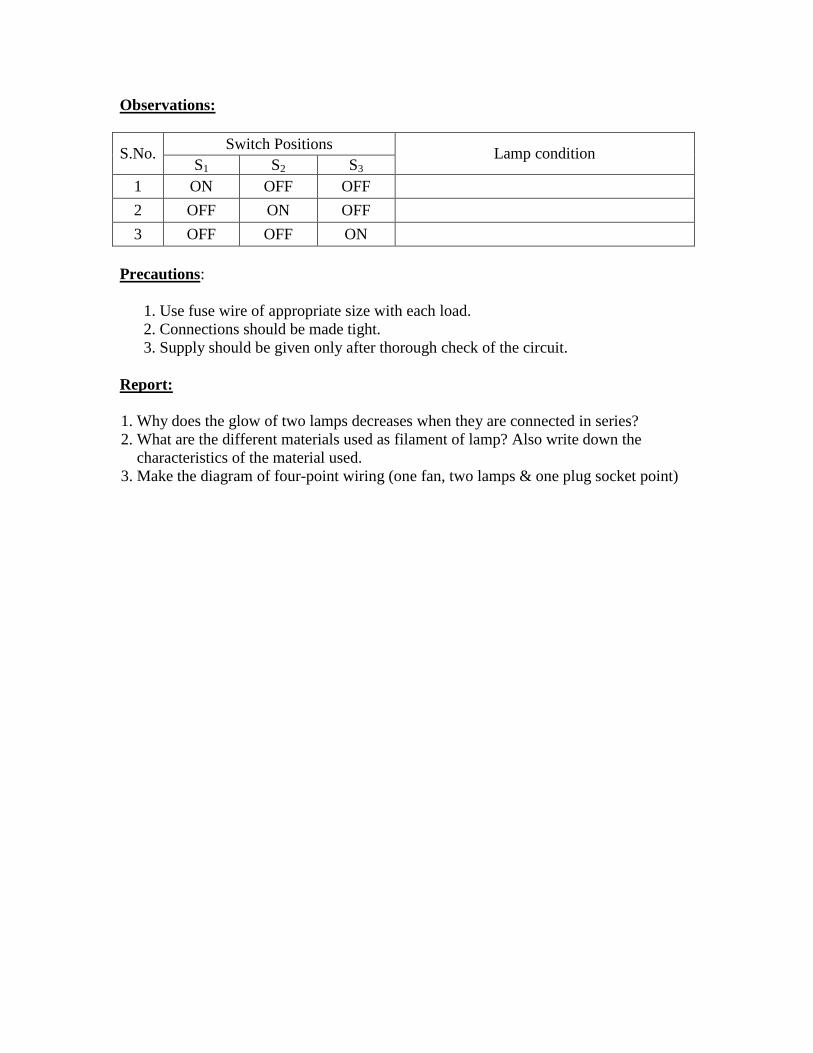
Observations:
S.No. Switch Positions
Lamp condition S1 S2 S3
1 ON OFF OFF
2 OFF ON OFF
3 OFF OFF ON
Precautions:
1. Use fuse wire of appropriate size with each load.
2. Connections should be made tight.
3. Supply should be given only after thorough check of the circuit.
Report:
1. Why does the glow of two lamps decreases when they are connected in series?
2. What are the different materials used as filament of lamp? Also write down the
characteristics of the material used.
3. Make the diagram of four-point wiring (one fan, two lamps & one plug socket point)
2

1st Year Diploma in Engineering
Electrical Installation Lab
Experiment No: 2
Object: (a) Study of stair case lighting system using two-way switch.
(b) Study of Intermediate switch and its application in corridor lighting system.
Apparatus used:
S. No. Tool/ Material Specification Quantity
Theory:
Stair case lighting: In this system, one lamp can be controlled from two different places
as shown in figure 1. For this purpose two-way switches are used. If switch S1 at ground
floor is at position A1 and switch S2 at first floor is at B2, the Lamp L will be in OFF
condition. If any of the switch is made in to another position i.e. either S1 taken to A2
position or switch S2 is taken to B1 position the lamp will be ON. So lamp can be
switched ON or OFF from ground floor or first floor.
Corridor lighting: In this system three switches placed at different places can control
one lamp. For this purpose two numbers of two-way switches and one intermediate
switch are used.
If the connections are made as shown in figure 2, the lamp will not glow. If position of
any of the three switches is changed, the lamp will glow. To bring the lamp back to its
not glow position again, change the position of any of the switches.
Intermediate Switch: The intermediate switch is used in corridor lighting. In fig 2 the
intermediate switch attains a position in which terminal A1 and B1 are connected to
terminal A2 and B2 respectively. If the position of the switch is changed, the terminals
A1 will switch over from A2 to B2 and terminal B1 will switch over from B2 to A2.
Circuit Diagrams:
3
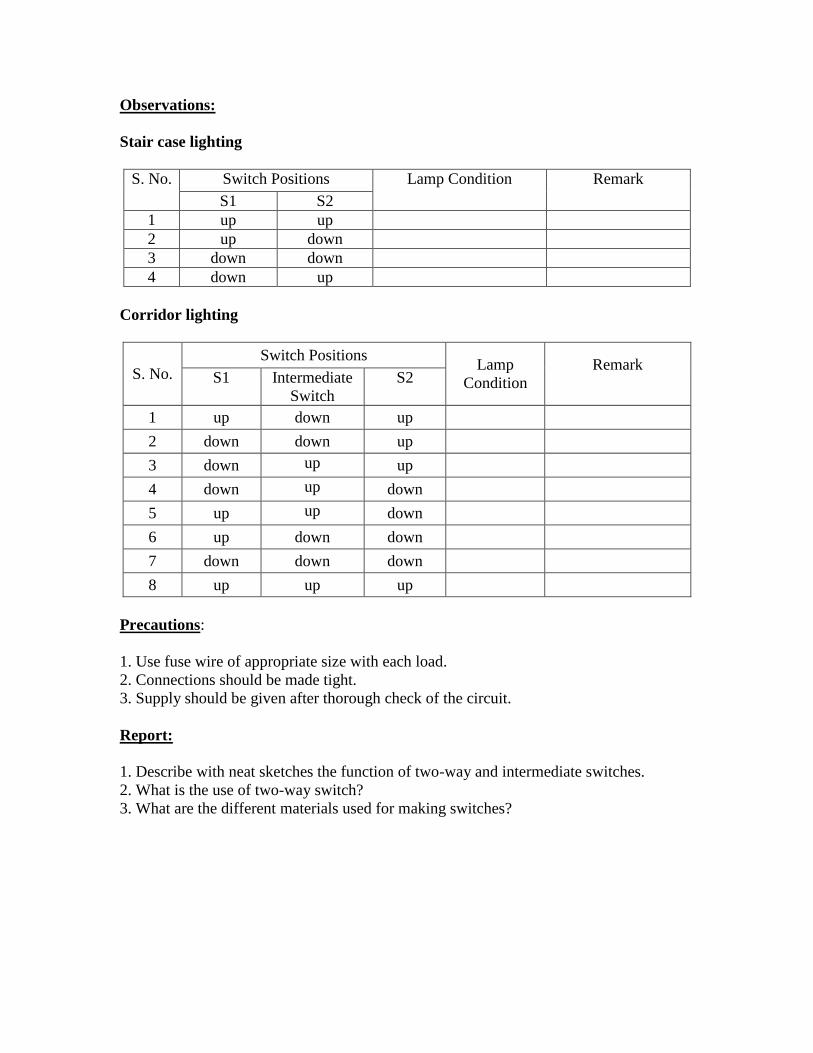
Observations:
Stair case lighting
S. No. Switch Positions Lamp Condition
Remark
S1 S2
1 up up
2 up down
3 down down
4 down up
Corridor lighting
S. No.
Switch Positions Lamp
Condition
Remark
S1 Intermediate
Switch
S2
1 up down up
2 down down up
3 down up up
4 down up down
5 up up down
6 up down down
7 down down down
8 up up up
Precautions:
1. Use fuse wire of appropriate size with each load.
2. Connections should be made tight.
3. Supply should be given after thorough check of the circuit.
Report:
1. Describe with neat sketches the function of two-way and intermediate switches.
2. What is the use of two-way switch?
3. What are the different materials used for making switches?
4

1st Year Diploma in Engineering
Electrical Installation Lab
Experiment No: 3
Object: (a) To make connection for 230V bell and 230V buzzer.
(b) To make connection for 6V bell using 230/6V transformer.
(c) To make connection for bell with indicator.
Apparatus used:
S. No. Tool/ Material Specification Quantity
Theory: In case of lighting system, lamps are required to glow continuously where as in
case of bell system, bells are required to operate intermittently (i.e. non-continuously).
The 230 V bell and 230V buzzer are connected to the supply as shown in the figure 1
figure 3 respectively. The phase wire is connected to the bell / buzzer through a fuse wire
and a push button switch. The other terminal of the bell / buzzer is connected to the
neutral wire directly. Transformer of 230 V/6 V is used in 6 V bell circuit. The purpose
of transformer here is to transform available A.C. voltage (i.e. 230 V A.C.) to the desired
voltage (i.e. 6 V A.C.). Primary winding of transformer is connected to the supply
through a push button switch. The secondary winding is connected across the two
terminal of 6 V bell.
Bell indicator is used where a number of bells are used like in hospitals and hotels. When
push button switch S1 is operated, plunger P1 operates to give the idea of a call from the
location where switch S1 is placed. Likewise number of plungers denotes different
location.
Circuit Diagram:
5

Procedure:
1. Study the circuits as per fig 1, 2 & 3.
2. Make connections as per fig. 4.
3. Study the circuits as per fig 5 and make connections.
4. Get the connections checked before connecting to supply.
Observation:
Transformer
Primary Input Voltage = volts
Secondary Output Voltage = volts
Report:
1. State the purpose of using transformer in electric bell circuit.
2. What is the purpose of iron core in a transformer?
3. Can you connect a transformer across D.C. mains?
4. Why a bell indicator is used in hotels etc ?
5. Write the difference between a bell and a buzzer?
6. What do you mean by armature of bell?
6
1st Year Diploma in Engineering
Electrical Installation Lab
Experiment No: 4
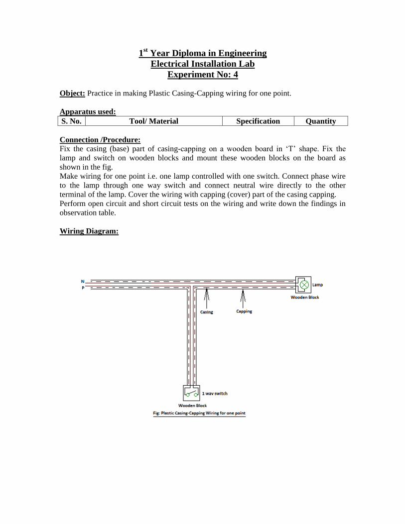
Object: Practice in making Plastic Casing-Capping wiring for one point.
Apparatus used:
S. No. Tool/ Material Specification Quantity
Connection /Procedure:
Fix the casing (base) part of casing-capping on a wooden board in „T‟ shape. Fix the
lamp and switch on wooden blocks and mount these wooden blocks on the board as
shown in the fig.
Make wiring for one point i.e. one lamp controlled with one switch. Connect phase wire
to the lamp through one way switch and connect neutral wire directly to the other
terminal of the lamp. Cover the wiring with capping (cover) part of the casing capping.
Perform open circuit and short circuit tests on the wiring and write down the findings in
observation table.
Wiring Diagram:
7
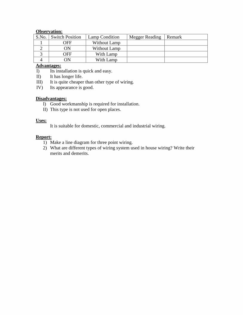
Observation:
S.No. Switch Position Lamp Condition Megger Reading Remark
1 OFF Without Lamp
2 ON Without Lamp
3 OFF With Lamp
4 ON With Lamp
Advantages:
I) Its installation is quick and easy.
II) It has longer life.
III) It is quite cheaper than other type of wiring.
IV) Its appearance is good.
Disadvantages: I) Good workmanship is required for installation.
II) This type is not used for open places.
Uses:
It is suitable for domestic, commercial and industrial wiring.
Report:
1) Make a line diagram for three point wiring.
2) What are different types of wiring system used in house wiring? Write their
merits and demerits.
8
1st Year Diploma in Engineering
Electrical Installation Lab
Experiment No: 5
Object: Testing of following faults of electrical installation by Megger.
(a) Open circuit fault
(b) Short circuit fault.
(c) Earth leakage test
Apparatus used:
S. No. Tool/ Material Specification Quantity
Theory:
A megger is a high resistance-measuring instrument. It is a hand driven small generator,
which provides voltages to the measuring circuit that causes deflection of the instrument
pointer. The reading of the instrument indicated whether there is any fault in the circuit
under test.
Open circuit test: The open circuit test indicates whether there is any break or
discontinuity in the circuit. To perform this test, the megger is connected to phase and
neutral, the load is connected and the switches are in ON position i.e. all the open points
of the circuit are closed. In this test, the megger will show zero resistance if the circuit is
complete but if there is any discontinuity in the circuit the megger will show infinity or
the infinite resistance.
Short circuit test: This test indicates whether phase and neutral wire are shorted or not.
In short circuit condition, phase and neutral wires come in contact without any load. To
perform this test, the megger is connected to phase and neutral, the load is removed from
the circuit and switches are in ON position i.e. the circuit is kept open at load to keep the
phase and neutral separate. In this test, if the megger shows zero this means that despite
the phase and neutral wires being kept separate, the resistance between them is zero and
hence there is a short circuit. If the megger indicates infinity this means that the neutral
wire has no contact with phase and hence there is no short circuit.
Earth leakage test: This test indicates whether there is any leakage between phase and
earth wire or between neutral and earth wire. This fault occurs generally due to damage
of insulation. To perform this test, the megger is connected to phase and earth, the load
from the circuit is removed and the switches are in ON position. The insulation resistance
between earth & phase and between earth & neutral is measured. If the megger shows
zero or any resistance, it means that there is an earth leakage. If it shows infinity it means
that the earth wire has no contact with phase or neutral wires and hence there is no earth
leakage.
9

Circuit Diagram of Megger:
Observation:
S.
No. Type of Test
Circuit
No.
Megger
Reading Remark
1
Open Circuit Test
1
2
3
4
5
2 Short Circuit Test
1
2
3
4
5
3 Earth Leakage Test
1
2
3
4
5
Report:
1) Discuss the purpose of earthing.
2) What are the different methods of earthing?
3) Write down the constructional details of megger.
10
1st Year Diploma in Engineering
Electrical Installation Lab
Experiment No: 6
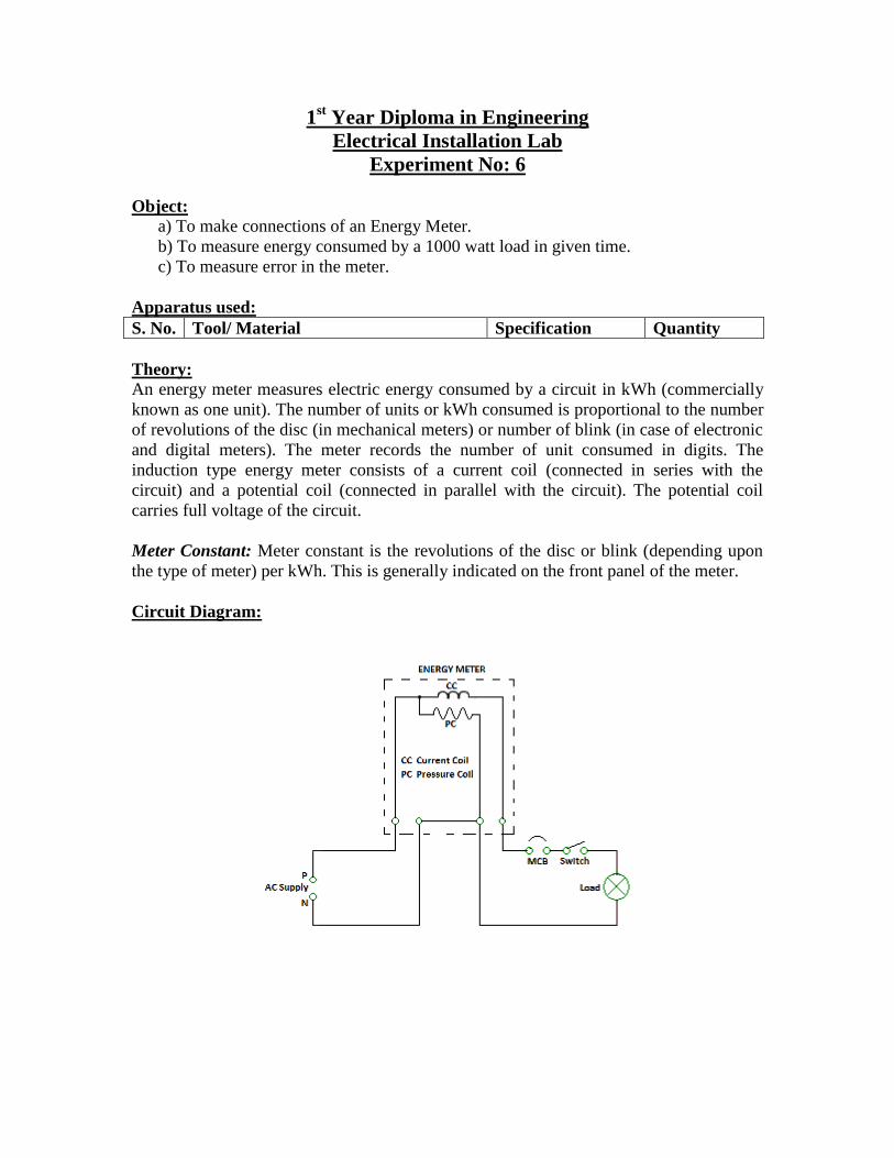
Object: a) To make connections of an Energy Meter.
b) To measure energy consumed by a 1000 watt load in given time.
c) To measure error in the meter.
Apparatus used:
S. No. Tool/ Material Specification Quantity
Theory:
An energy meter measures electric energy consumed by a circuit in kWh (commercially
known as one unit). The number of units or kWh consumed is proportional to the number
of revolutions of the disc (in mechanical meters) or number of blink (in case of electronic
and digital meters). The meter records the number of unit consumed in digits. The
induction type energy meter consists of a current coil (connected in series with the
circuit) and a potential coil (connected in parallel with the circuit). The potential coil
carries full voltage of the circuit.
Meter Constant: Meter constant is the revolutions of the disc or blink (depending upon
the type of meter) per kWh. This is generally indicated on the front panel of the meter.
Circuit Diagram:
11
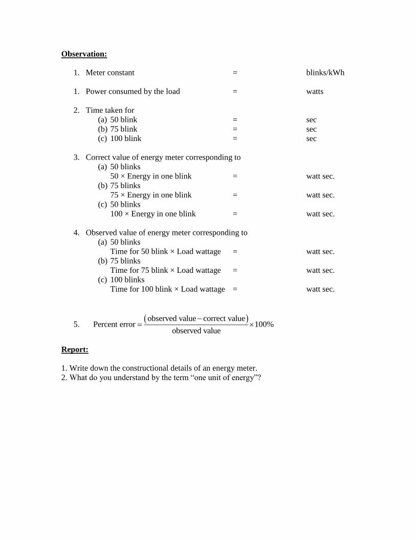
Observation:
1. Meter constant = blinks/kWh
1. Power consumed by the load = watts
2. Time taken for
(a) 50 blink = sec
(b) 75 blink = sec
(c) 100 blink = sec
3. Correct value of energy meter corresponding to
(a) 50 blinks
50 × Energy in one blink = watt sec.
(b) 75 blinks
75 × Energy in one blink = watt sec.
(c) 50 blinks
100 × Energy in one blink = watt sec.
4. Observed value of energy meter corresponding to
(a) 50 blinks
Time for 50 blink × Load wattage = watt sec.
(b) 75 blinks
Time for 75 blink × Load wattage = watt sec.
(c) 100 blinks
Time for 100 blink × Load wattage = watt sec.
5. observed value correct value
Percent errorobserved value
100%
Report:
1. Write down the constructional details of an energy meter.
2. What do you understand by the term “one unit of energy”?
12
1st Year Diploma in Engineering
Electrical Installation Lab
Experiment No: 7
Object: (a)Study of various types of Multimeters.
(b)Measurement of Resistance with the help of Analog and Digital
multimeters.
Apparatus used:
S. No. Tool/ Material Specification Quantity
Theory:
A multimeter is an instrument used to measure various electrical parameters such as
voltage, current and resistance. In analog multimeter, the measurement is indicated by the
deflection of the pointer, where as in digital multimeters the measurement is directly
shown in digits on the display screen. Since the instrument i.e. multimeter measures
circuit resistance, hence it can be used for checking the continuity of the circuit.
Analog multimeter: This is basically a galvanometer provided with suitable external
circuit to measure the desired electrical parameters. Rotary selector switch of the meter
provides resistance of appropriate value in series or in parallel to increase or decreases
the range. This selector switch also provides facility to use the meter for measuring
different electrical parameters such as voltage, current and resistance.
Digital Multimeter: It is an electronic device, which contains integrated circuits (ICs).
Before making any measurement the selector switch knob should be kept on desired
parameter to be measured. Range knob should also be kept on desired value.
Precautions:
1. Do not connect voltage source to the instrument while measuring resistance.
2. Keep the switch in OFF position while not in use.
3. In case of analog multimeter, adjust zero setting before taking any measurement.
4. Check the position of the Range selection switch before any measurement. The
range should be selected higher than the expected value of voltage/current.
13
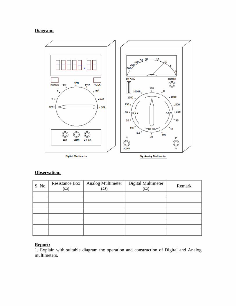
Diagram:
Observation:
S. No. Resistance Box
(Ω)
Analog Multimeter
(Ω)
Digital Multimeter
(Ω) Remark
Report:
1. Explain with suitable diagram the operation and construction of Digital and Analog
multimeters.
14

1st Year Diploma in Engineering
Electrical Installation Lab
Experiment No: 8
Object: (a) To measure the resistance of heating element of an electric kettle.
(b) To determine the efficiency of electric kettle.
Apparatus used:
S. No. Tool/ Material Specification Quantity
Theory:
(a) Resistance of the heating element
Resistance R of the heating element Voltage (volts)
(ohm, )Current (amp.)
V
I
(b) Energy Input iE V I t
Where V = Mean voltage in Volts (V)
I = Mean current in ampere (A)
t = Time taken for heating water in seconds
(c) Energy Output Eo = Mass of water in gm × Rise in temp. in °C × 4.2
(d) Efficiency of kettle (η)
100 %o
i
E
E
Procedure:
(i) Make the connections as shown in the figure below.
(ii) Take 1250 gm. of water in kettle.
(iii) Note down the initial temperature of water
(iv) Heat it up to 80 °C.
(v) Note down the reading of voltmeter and ammeter, first after switching on the
circuit (initial) and again before switching off the circuit (final).
(vi) Record the time taken for heating the water from initial temperature to 80 °C.
15
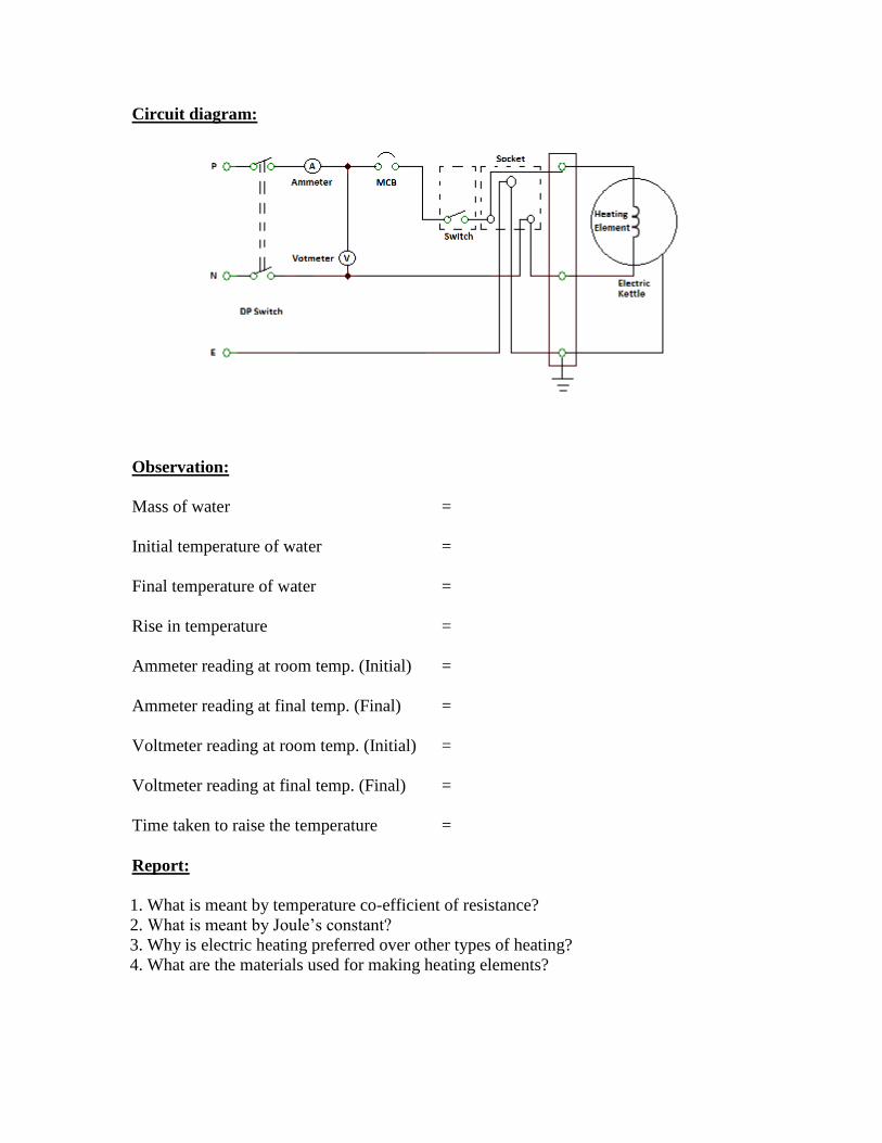
Circuit diagram:
Observation:
Mass of water =
Initial temperature of water =
Final temperature of water =
Rise in temperature =
Ammeter reading at room temp. (Initial) =
Ammeter reading at final temp. (Final) =
Voltmeter reading at room temp. (Initial) =
Voltmeter reading at final temp. (Final) =
Time taken to raise the temperature =
Report:
1. What is meant by temperature co-efficient of resistance?
2. What is meant by Joule‟s constant?
3. Why is electric heating preferred over other types of heating?
4. What are the materials used for making heating elements?
16
Copyright © 2022 FDOKUMEN