Chloride Induced Corrosion in Cracked Reinforced Strain Hardening Cement-Based Composite (R/SHCC)
10
Chloride Induced Corrosion in Cracked Reinforced Strain Hardening Cement-Based Composite (R/SHCC) S.C. Paul, A.I. Theunissen and G.P.A.G. van Zijl Department of Civil Engineering Stellenbosch University, South Africa Private Bag X1 Matieland 7602 Email: [email protected] [email protected] ABSTRACT This paper reports on corrosion of reinforcing steel bars in strain hardening cement-based composites (SHCC) under chloride attack. As part of a continued research project on durability of SHCC, the main focus here is on flexurally induced cracks in R/SHCC specimens with different cover depths. After unloading, these specimens are subjected to chloride attack, while monitoring steel corrosion. Two types of SHCC are studied, namely a fine grained SHCC, prepared with sand of maximum particle size 0.3 mm and a coarse SHCC prepared with a coarse sand of maximum particle size 1.7 mm. The crack patterns are characterized, in order to relate the crack width distribution, cover depth and corrosion. Crack widths of 50 m are found to allow chloride penetration to rebar within hours, but several weeks of accelerated chloride exposure do not cause corrosion in the steel bars. Keywords: corrosion, multiple cracks, strain hardening cement-based composite (SHCC). INTRODUCTION Structural concrete is usually specified by the slump value and compressive strength. Flexural strength, tensile strength and E-modulus are often calculated from the compressive strength by empirical relations in codes. However, this is not sufficient to guarantee the durability of concrete (Richard and Cheyrezy, 1994, Saravanan et al., 2010). The compressive strength of the concrete is a bulk property, while its durability is affected by the properties of the surface and near-surface region of the concrete in structures. Also, ingress of gas, liquid and water is controlled by the overall percolation of the pore network, while strength is usually controlled by the pore size in a concrete matrix. Durability is mostly influenced by concrete properties such as diffusivity, permeability and sorptivity. Thus, in order to design durability of concrete, it is required that properties other than compressive strength must be stipulated. In concrete structures, one of the major durability problems is the corrosion of reinforcing steel, which reduces the expected life-span of reinforced concrete. Resistance to steel corrosion is considered to be dependant on the water-cement ratio, compatibility of
-
Upload
umonash-my -
Category
Documents
-
view
0 -
download
0
Transcript of Chloride Induced Corrosion in Cracked Reinforced Strain Hardening Cement-Based Composite (R/SHCC)
Chloride Induced Corrosion in Cracked Reinforced Strain
Hardening Cement-Based Composite (R/SHCC)
S.C. Paul, A.I. Theunissen and G.P.A.G. van Zijl
Department of Civil Engineering
Stellenbosch University, South Africa
Private Bag X1 Matieland 7602
Email: [email protected]
ABSTRACT
This paper reports on corrosion of reinforcing steel bars in strain hardening cement-based
composites (SHCC) under chloride attack. As part of a continued research project on
durability of SHCC, the main focus here is on flexurally induced cracks in R/SHCC
specimens with different cover depths. After unloading, these specimens are subjected to
chloride attack, while monitoring steel corrosion. Two types of SHCC are studied, namely a
fine grained SHCC, prepared with sand of maximum particle size 0.3 mm and a coarse
SHCC prepared with a coarse sand of maximum particle size 1.7 mm. The crack patterns are
characterized, in order to relate the crack width distribution, cover depth and corrosion.
Crack widths of 50 m are found to allow chloride penetration to rebar within hours, but
several weeks of accelerated chloride exposure do not cause corrosion in the steel bars.
Keywords: corrosion, multiple cracks, strain hardening cement-based composite (SHCC).
INTRODUCTION
Structural concrete is usually specified by the slump value and compressive strength.
Flexural strength, tensile strength and E-modulus are often calculated from the compressive
strength by empirical relations in codes. However, this is not sufficient to guarantee the
durability of concrete (Richard and Cheyrezy, 1994, Saravanan et al., 2010). The
compressive strength of the concrete is a bulk property, while its durability is affected by the
properties of the surface and near-surface region of the concrete in structures. Also, ingress
of gas, liquid and water is controlled by the overall percolation of the pore network, while
strength is usually controlled by the pore size in a concrete matrix. Durability is mostly
influenced by concrete properties such as diffusivity, permeability and sorptivity. Thus, in
order to design durability of concrete, it is required that properties other than compressive
strength must be stipulated.
In concrete structures, one of the major durability problems is the corrosion of reinforcing
steel, which reduces the expected life-span of reinforced concrete. Resistance to steel
corrosion is considered to be dependant on the water-cement ratio, compatibility of
ingredients, cover thickness, and density of the cover. Depassivation of the film surrounding
the steel by ingress of deleterious gases, liquids and ions leads to the corrosion. Corrosion
increases the volume of the embedded steel, causing pressure between the steel and the cover
concrete. This imposes strain in the cover concrete which may exceed the tensile strength,
leading to cracking and eventual spalling away from the steel. This scenario is very common
for conventional concrete structures, necessitating expensive repairs or replacements. The
formation of large crack widths in conventional reinforced concrete (RC) is one of the major
problems from a structural durability point of view, as it is well known that large cracks
allow fast penetration of gases and liquids into the concrete. Cracks in RC structures are
unavoidable because of the low tensile strength and low elastic deformability of concrete.
SHCC have been introduced over the last two decades and have been found to control crack
widths. The finely cracked SHCC has been shown to reduce ingress rates, which hold
potential for a delay in corrosion initiation and reduced corrosion rate in reinforced SHCC
(R/SHCC) structures and thus an extended service life (Miyazato and Hiraishi, 2005,
Sahmaran et al., 2008, Kobayashi et al., 2010). The results reported in this paper are part of a
larger research project on SHCC at Stellenbosch University over the last number of years
and the information given here is limited to the 56 day accelerated corrosion status observed
in both fine sand (FS) and coarse sand (CS) pre-cracked R/SHCC beams.
DURABILITY OF SHCC STRUCTURES
In addition to energy dissipation by multiple crack formation, SHCC has the potential of
high durability due to the small crack widths. The typical elastic strain limit of normal
concrete (NC) ranges between 0.015% and 0.02%. This is similar for SHCC, but its
mechanical resistance as well as crack control to fine widths can be maintained to strain
levels of up to 3% or more (Sahmaran et al. 2008, Paul and van Zijl 2013b). These are
particular useful characteristics for structural repair, but also new structural elements. In its
short existence, SHCC has been applied as an overlay and repair material (bridge decks,
tunnels, retaining walls) and as seismic damping structural elements in tall buildings. Full
scale use of SHCC in structures has not yet been done and the reasons behind it may be the
high initial cost of SHCC and also that limited information on SHCC performance is
available as it is a relatively new material.
The limitation of crack widths to below 100 m is generally believed to limit water
permeability in concrete. However, cracks do act as pathways for fast penetration under
conditions of capillary absorption (Zhang et al., 2010). In contrast, cracked SHCC has been
shown to protect steel reinforcing bars against corrosion in patch-repaired reinforced
concrete beams subjected to cyclic spraying with a salt solution (Kobayashi et al. 2010). It
appears that, despite penetration of water and possibly chlorides and oxygen, the corrosion
rate is low in SHCC. Miyazato & Hiraishi (2005) reported that no or little macro-cell
corrosion could be observed in finely cracked R/SHCC, as opposed to significant macro-cell
corrosion in R/mortar specimens with a wide crack. Characterisation of crack patterns in
R/SHCC, and linking it to ingress rates and actual corrosive deterioration are required.
EXPERIMENTAL DESIGN
The research work is divided into four different parts namely direct tensile response, flexural
response, corrosion and lastly chloride penetration in SHCC. This section maps the way in
which the above-mentioned research objectives were executed.
Mix design of SHCC
To achieve the ductile behaviour of SHCC it is necessary to have a good mix design. So far
in this research, more than three trial mixes of SHCC made with FS and CS have been made
and tested and one set of their results has been shown in Paul and van Zijl (2013a & b). The
SHCC mix is sensitive to changes in ingredient materials as they are received in different
batches from industry. The mix used in this paper is a bit different than the previous mix, but
nevertheless this specific mix of SHCC also shows ductile behaviour and multiple cracking.
The mix design together with the slump flow value is shown in Table 1.
Table 1. Materials used in this study
Materials (kg/m3)
Type C FA S W F SP VA AE Flow (mm)
FS-SHCC 390 670 550 390 26 31.2 5.85 3.94 200-220
CS-SHCC 390 670 550 390 26 31.2 5.85 3.94 200-220
Note: C= cement, FA= Fly ash, S= fine or coarse sand, W=water, F= fibre, SP= super plasticizer,
VA= viscous agent, AE= air entraining agent.
Test setup for mechanical behaviour
To characterise the mechanical behaviour of SHCC, the compressive strength, direct tensile
and three-point bending (flexural) tests were performed. For determining the compressive
strength and flexural response, 100 mm cubes and 100 x 100 x 500 mm beam respectively
were used. The same specimens used in the flexural test were then used in the corrosion test.
In direct tensile tests, small dumb-bells of 30 mm width, 16 mm thickness and with a gauge
length of 80 mm were used. The cubes were tested at the age of 28 days while beams and
dumbbell specimens were tested at 14 days. Two days after mixing, all specimens were
removed from the mould and kept in a water tank (temperature 21 ± 2oC) for 7 days. After 7
days all the specimens were removed from the water tank and stored at ambient laboratory
temperature until the testing date. Details can be found in Paul and van Zijl (2013a,b).
Test setup for durability performance of SHCC
In the assessment of the durability performance of SHCC, testing of corrosion of steel and
chloride penetration into cracked SHCC was performed. Typically the corrosion process
starts in the uncracked specimen after a long time and it is fully depended on the type of
concrete, cover depth, surrounding environment, etc. However in the limited time of a
research project accelerated testing is required. In this study the cracked specimens were
subjected to chloride-induced corrosion. The specimens were cracked in flexure up to a
vertical deflection level of 3.5 mm just to form several cracks in the specimens. Single and
double steel bar reinforcements were used in both FS-SHCC and CS-SHCC at three different
cover depths (15 mm, 25 mm and 35 mm).
After applying the flexural loads in SHCC beam specimens, multiple cracks were found in
the bottom face of specimens. This face was subsequently kept in contact with NaCl solution
(3.5% wt of water) and corrosion was measured using a half cell potential (HCP) apparatus
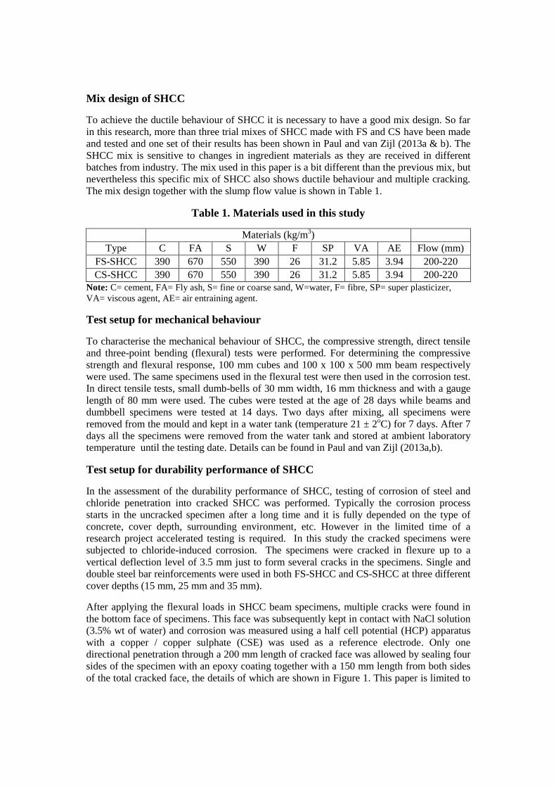
with a copper / copper sulphate (CSE) was used as a reference electrode. Only one
directional penetration through a 200 mm length of cracked face was allowed by sealing four
sides of the specimen with an epoxy coating together with a 150 mm length from both sides
of the total cracked face, the details of which are shown in Figure 1. This paper is limited to
corrosion measuring using the HCP method which does not give the corrosion rate (Icorr) in
the specimens but rather predicts the corrosion probability and gives the corrosion potential
(Ecorr). However, in future work different corrosion measuring techniques will be used from
which the corrosion rate might be determined.
Figure 1. Corrosion measuring setup for the cracked specimen
The corrosion potential was measured in a ambient laboratory conditions (temperature 21 ±
2oC and relative humidity 55 to 65%). The bottom face of all specimens was kept in contact
with NaCl solution for 21 days after which cyclic drying and wetting exposure was carried
out to accelerate the corrosion potential rate. In the first week of the corrosion test, data were
recorded every day and thereafter it was recorded randomly (at least one reading from each
drying and wetting exposure). The exposure condition used here is not a standard method
recommended by the codes because currently there is no specification for the SHCC test
method. As a result researchers follow different exposure conditions for the SHCC corrosion
test (Miyazato and Hiraishi, 2005, Sahmaran et al., 2008, Kobayashi et al., 2010) but none of
them are compared to real life structural exposures. The exposure condition used here also
needs to be compared to real life structural exposure conditions and perhaps the corrosion
modelling needs to develop a link between experimental and real exposure conditions.
In order to study the chloride penetration through the cracked SHCC specimen, unreinforced
SHCC specimens (sizes are the same as those of the reinforced SHCC specimens) were
made and pre-cracked at 28 days in three point flexure. In this case, loads were applied up to
a deflection level of 1.0 mm. After the flexural test, specimens of 150 mm long were cut
from the middle portion of the 500 mm long beam. Similar to the corrosion specimens, four
sides were sealed with epoxy coating and penetration was allowed through the cracked face
with a length of 150 mm. A total of four specimens from both the FS-SHCC and CS-SHCC
specimens were used and penetration was observed after 1, 3 and 6 hours. After these
periods, specimens were cut again along the 150 mm length into two parts (50 mm width and
150 mm length). The details of specimen preparation can be found in Paul and van Zijl
(2013b). The same NaCl solution was used here and penetration was measured by applying
0.1N AgNO3 solution. The reaction of NaCl with AgNO3 is of a different colour to that of the
concrete surface. Typically when AgNO3 is applied on the concrete surface, the presence of
NaCl shows as a white gray colour but otherwise it becomes brown (Otsuki et al 1993). A
similar trend was also found here and details of the results are shown next.
EXPERIMENTAL OUTCOME
The results from this research work are limited to the mechanical and durability performance
of SHCC made from FS and CS. For the comparison of the results, FS-SHCC is considered
to be the reference which is then compared with the results obtained from CS-SHCC. The
details of the experimental outcomes are discussed below.
Compressive and tensile strength and strain of SHCC
A total of 6 cubes from each type of SHCC were tested for determining the compressive
strength. The average 28 days compressive strengths were 24.22 MPa (coefficient of
variation (CoV) 1.43%) and 23.1 MPa (3.84%) respectively for FS-SHCC and CS-SHCC.
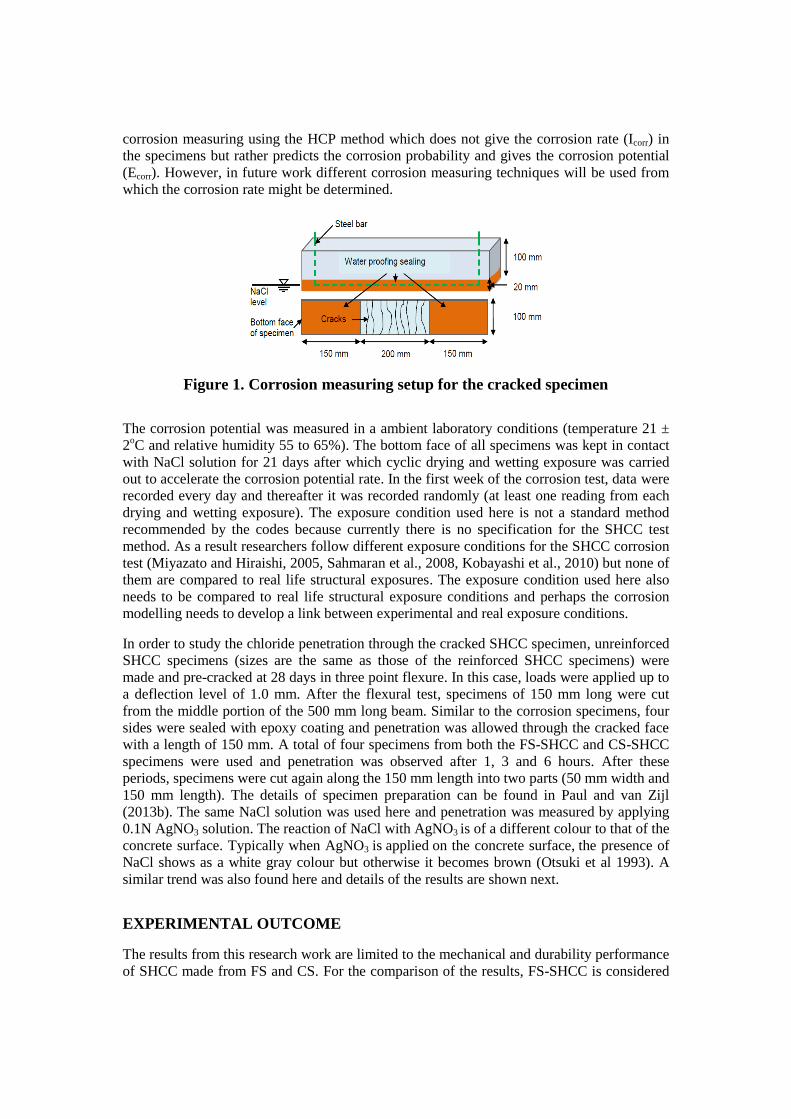
In order to confirm strain hardening behaviour of both FS-SHCC and CS-SHCC, direct
tensile tests were performed on a total of 4 dumbbell specimens of each SHCC type at 14
days and their results are shown in Figure 2. The average ultimate tensile strength of 2.76
MPa (CoV 7.54%) was obtained for CS-SHCC and of 2.67 MPa (4.85%) for FS-SHCC. The
first crack strengths were 2.46 MPa (7.03%) and 2.04 MPa (3.91%) respectively for CS-
SHCC and FS-SHCC. An average ultimate tensile strain of 2.93% (CoV 16.39%) was
obtained for FS-SHCC and 1.52% (CoV 103.7%) for CS-SHCC. Higher first crack and
ultimate strengths lead to a lower ultimate strain of CS-SHCC. In previous work an ultimate
strain of more than 3% was obtained for CS-SHCC at 14 days age (Paul and van Zijl 2013b).
Flexural deflection and cracks in SHCC
A total of 18 beams of each type of SHCC were tested for corrosion. All of them were pre-
cracked in flexure. For each cover depth of concrete, two types of reinforcement (single and
double bar) were used. For each cover depth, a total of 6 beams, 3 with a single bar and 3
with two bars were tested for both types of SHCC. Their flexural test results are shown in
Figure 3a,b for one specimen of each cover depth. C15, C25 and C35 denote different cover
depths and B1 and B2 denote a single bar and double bar specimens.
Figure 2. SHCC stress strain response in a tensile test
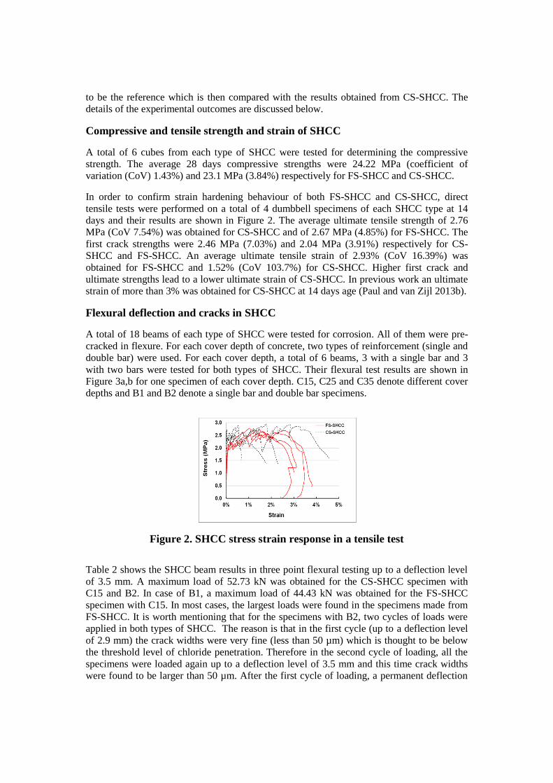
Table 2 shows the SHCC beam results in three point flexural testing up to a deflection level
of 3.5 mm. A maximum load of 52.73 kN was obtained for the CS-SHCC specimen with
C15 and B2. In case of B1, a maximum load of 44.43 kN was obtained for the FS-SHCC
specimen with C15. In most cases, the largest loads were found in the specimens made from
FS-SHCC. It is worth mentioning that for the specimens with B2, two cycles of loads were
applied in both types of SHCC. The reason is that in the first cycle (up to a deflection level
of 2.9 mm) the crack widths were very fine (less than 50 µm) which is thought to be below
the threshold level of chloride penetration. Therefore in the second cycle of loading, all the
specimens were loaded again up to a deflection level of 3.5 mm and this time crack widths
were found to be larger than 50 µm. After the first cycle of loading, a permanent deflection
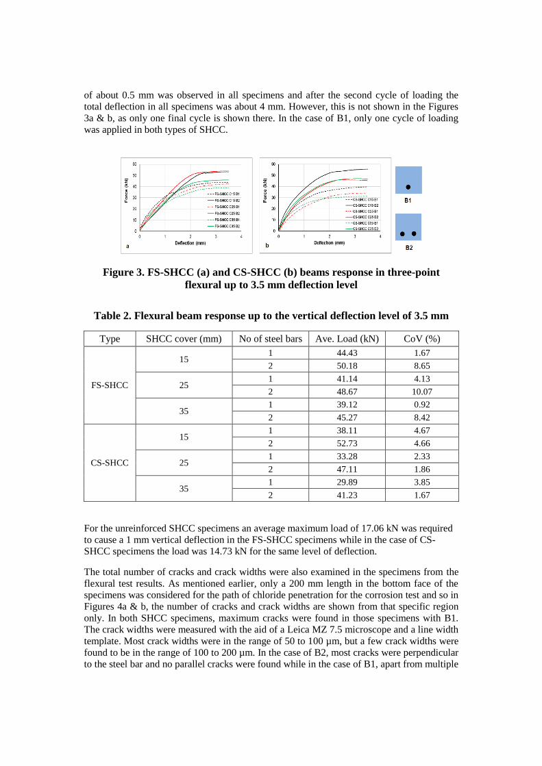
of about 0.5 mm was observed in all specimens and after the second cycle of loading the
total deflection in all specimens was about 4 mm. However, this is not shown in the Figures
3a & b, as only one final cycle is shown there. In the case of B1, only one cycle of loading
was applied in both types of SHCC.
Figure 3. FS-SHCC (a) and CS-SHCC (b) beams response in three-point
flexural up to 3.5 mm deflection level
Table 2. Flexural beam response up to the vertical deflection level of 3.5 mm
Type SHCC cover (mm) No of steel bars Ave. Load (kN) CoV (%)
FS-SHCC
15 1 44.43 1.67
2 50.18 8.65
25 1 41.14 4.13
2 48.67 10.07
35 1 39.12 0.92
2 45.27 8.42
CS-SHCC
15 1 38.11 4.67
2 52.73 4.66
25 1 33.28 2.33
2 47.11 1.86
35 1 29.89 3.85
2 41.23 1.67
For the unreinforced SHCC specimens an average maximum load of 17.06 kN was required
to cause a 1 mm vertical deflection in the FS-SHCC specimens while in the case of CS-
SHCC specimens the load was 14.73 kN for the same level of deflection.
The total number of cracks and crack widths were also examined in the specimens from the
flexural test results. As mentioned earlier, only a 200 mm length in the bottom face of the
specimens was considered for the path of chloride penetration for the corrosion test and so in
Figures 4a & b, the number of cracks and crack widths are shown from that specific region
only. In both SHCC specimens, maximum cracks were found in those specimens with B1.
The crack widths were measured with the aid of a Leica MZ 7.5 microscope and a line width
template. Most crack widths were in the range of 50 to 100 µm, but a few crack widths were
found to be in the range of 100 to 200 µm. In the case of B2, most cracks were perpendicular
to the steel bar and no parallel cracks were found while in the case of B1, apart from multiple
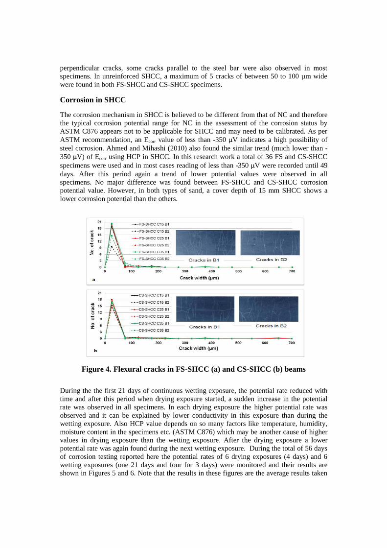
perpendicular cracks, some cracks parallel to the steel bar were also observed in most
specimens. In unreinforced SHCC, a maximum of 5 cracks of between 50 to 100 µm wide
were found in both FS-SHCC and CS-SHCC specimens.
Corrosion in SHCC
The corrosion mechanism in SHCC is believed to be different from that of NC and therefore
the typical corrosion potential range for NC in the assessment of the corrosion status by
ASTM C876 appears not to be applicable for SHCC and may need to be calibrated. As per
ASTM recommendation, an Ecorr value of less than -350 µV indicates a high possibility of
steel corrosion. Ahmed and Mihashi (2010) also found the similar trend (much lower than -
350 µV) of Ecorr using HCP in SHCC. In this research work a total of 36 FS and CS-SHCC
specimens were used and in most cases reading of less than -350 µV were recorded until 49
days. After this period again a trend of lower potential values were observed in all
specimens. No major difference was found between FS-SHCC and CS-SHCC corrosion
potential value. However, in both types of sand, a cover depth of 15 mm SHCC shows a
lower corrosion potential than the others.
Figure 4. Flexural cracks in FS-SHCC (a) and CS-SHCC (b) beams
During the the first 21 days of continuous wetting exposure, the potential rate reduced with
time and after this period when drying exposure started, a sudden increase in the potential
rate was observed in all specimens. In each drying exposure the higher potential rate was
observed and it can be explained by lower conductivity in this exposure than during the
wetting exposure. Also HCP value depends on so many factors like temperature, humidity,
moisture content in the specimens etc. (ASTM C876) which may be another cause of higher
values in drying exposure than the wetting exposure. After the drying exposure a lower
potential rate was again found during the next wetting exposure. During the total of 56 days
of corrosion testing reported here the potential rates of 6 drying exposures (4 days) and 6
wetting exposures (one 21 days and four for 3 days) were monitored and their results are
shown in Figures 5 and 6. Note that the results in these figures are the average results taken
from the middle of 3 specimens for each cover depth. So, each data point is the average of 3
and 6 readings for B1 and B2 respectively.
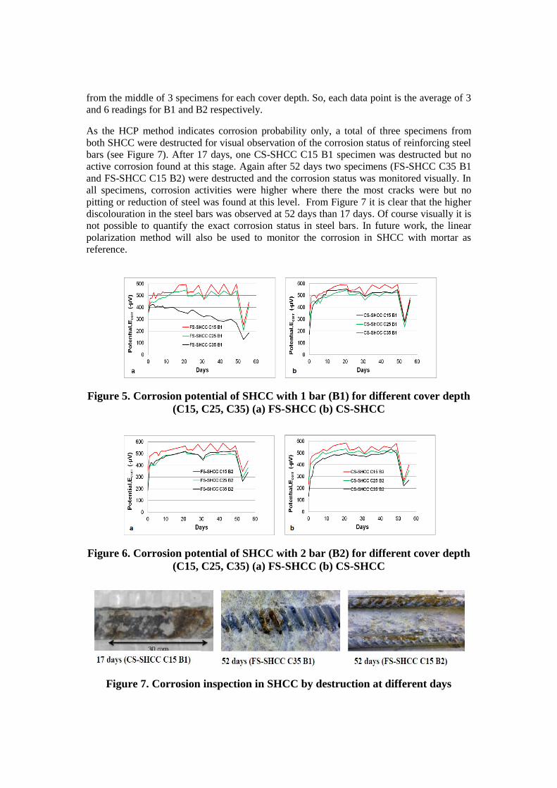
As the HCP method indicates corrosion probability only, a total of three specimens from
both SHCC were destructed for visual observation of the corrosion status of reinforcing steel
bars (see Figure 7). After 17 days, one CS-SHCC C15 B1 specimen was destructed but no
active corrosion found at this stage. Again after 52 days two specimens (FS-SHCC C35 B1
and FS-SHCC C15 B2) were destructed and the corrosion status was monitored visually. In
all specimens, corrosion activities were higher where there the most cracks were but no
pitting or reduction of steel was found at this level. From Figure 7 it is clear that the higher
discolouration in the steel bars was observed at 52 days than 17 days. Of course visually it is
not possible to quantify the exact corrosion status in steel bars. In future work, the linear
polarization method will also be used to monitor the corrosion in SHCC with mortar as
reference.
Figure 5. Corrosion potential of SHCC with 1 bar (B1) for different cover depth
(C15, C25, C35) (a) FS-SHCC (b) CS-SHCC
Figure 6. Corrosion potential of SHCC with 2 bar (B2) for different cover depth
(C15, C25, C35) (a) FS-SHCC (b) CS-SHCC
Figure 7. Corrosion inspection in SHCC by destruction at different days
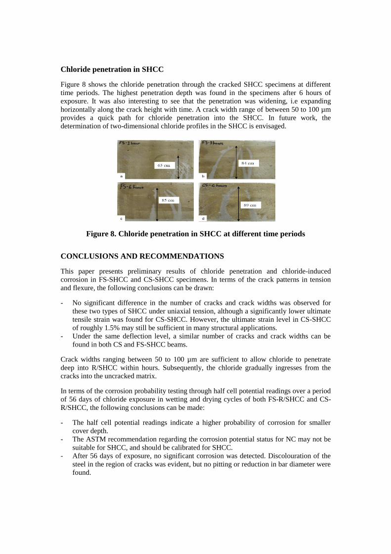
Chloride penetration in SHCC
Figure 8 shows the chloride penetration through the cracked SHCC specimens at different
time periods. The highest penetration depth was found in the specimens after 6 hours of
exposure. It was also interesting to see that the penetration was widening, i.e expanding
horizontally along the crack height with time. A crack width range of between 50 to 100 µm
provides a quick path for chloride penetration into the SHCC. In future work, the
determination of two-dimensional chloride profiles in the SHCC is envisaged.
Figure 8. Chloride penetration in SHCC at different time periods
CONCLUSIONS AND RECOMMENDATIONS
This paper presents preliminary results of chloride penetration and chloride-induced
corrosion in FS-SHCC and CS-SHCC specimens. In terms of the crack patterns in tension
and flexure, the following conclusions can be drawn:
- No significant difference in the number of cracks and crack widths was observed for
these two types of SHCC under uniaxial tension, although a significantly lower ultimate
tensile strain was found for CS-SHCC. However, the ultimate strain level in CS-SHCC
of roughly 1.5% may still be sufficient in many structural applications.
- Under the same deflection level, a similar number of cracks and crack widths can be
found in both CS and FS-SHCC beams.
Crack widths ranging between 50 to 100 µm are sufficient to allow chloride to penetrate
deep into R/SHCC within hours. Subsequently, the chloride gradually ingresses from the
cracks into the uncracked matrix.
In terms of the corrosion probability testing through half cell potential readings over a period
of 56 days of chloride exposure in wetting and drying cycles of both FS-R/SHCC and CS-
R/SHCC, the following conclusions can be made:
- The half cell potential readings indicate a higher probability of corrosion for smaller
cover depth.
- The ASTM recommendation regarding the corrosion potential status for NC may not be
suitable for SHCC, and should be calibrated for SHCC.
- After 56 days of exposure, no significant corrosion was detected. Discolouration of the
steel in the region of cracks was evident, but no pitting or reduction in bar diameter were
found.

Until now the HCP results are not showing the real corrosion status in SHCC and long term
experimental and field study may be required to understand the corrosion mechanism in
SHCC.
REFERENCES
Ahmed, S.F.U., Mihashi, H. (2010) “Corrosion durability of strain hardening fibre-
reinforced cement composites.” Australian J of Civil Engineering.
Kobayashi, K., Iizuka, T., Kurachi, H., Rokugo, K. (2010). “Corrosion protection of high
performance fiber reinforced cement composites as a repair material.” Cem and Concrete
Research 32:411-420.
Li, V.C., Wang, S., Wu, C. (2001). “Tensile strain-hardening behaviour of polyvinyl alcohol
engineered cementitious composite (PVA-ECC).” ACI materials J 98(6), 483-492.
Miyazato, S., Hiraishi, Y. (2005). “Transport properties and steel corrosion in ductile fibre
reinforced composites.” In protection of high performance fiber reinforced cement
composites as a repair material, In proceeding for ICF, vol.11, Torino.
Mihashi, H., Ahmed, S.F.U., Kobayakawa, A. (2011). “Corrosion of reinforcing steel in fibre
reinforced cementitious composites.” Journal of Advanced Concrete Technology 9(2),
159-167.
Paul, S.C., van Zijl, G.P.A.G. (2013a). “Mechanical behaviour of strain hardening cement-
based composites (SHCC) based on micromechanical design.” Advances in Cement and
Concrete Technology in Africa, January 28-30, Johannesburg, South Africa.
Paul, S.C., van Zijl, G.P.A.G. (2013, b). “Strain hardening cement based composite (SHCC)
with fine and coarse sand under tensile load and chloride attack.” In Proceedings 8th Int.
Conf. on Fracture Mechanics of Concrete and Concrete Structures, March 10-14,
Toledo, Spain.
Richard, P., Cheyrezy, M.H. (1994). “Reactive Powder Concretes with High Ductility and
200-800 MPa Compressive Strength.” Concrete Technology: Past, Present, and Future,
Proceedings of the V. Mohan Malhotra Symposium, ACI SP-144, S. Francisco, Editor
P.K. Mehta, pp. 507-518.
Sahmaran, M., Li, V.C., Andrade, C. (2008). “Corrosion resistance performance of steel-
reinforced engineered cementitious composite beams.” ACI Materials J / May-June,
105(3).
Sahmaran, M., Li, M., Li, V.C. (2007). “Transport properties of engineered cementitious
composites under chloride exposure.” ACI Materials J, November-December,104(6).
Saravanan, J., Suguna, K., Raghunath, P.N. (2010). “Confined high strength concrete
columns: An experimental study.” American J of Engng and Applied Sciences, 3(1), 133-
137, ISSN 1941-7020.
Theunissen, A.I. (2012).Corrosion of steel bar and synthetic fibre reinforced concrete in
coastal environments. Final year BEng (Civil) project, Stellenbosch University.
Zhang, P., Wittmann, F.H., Zhao, T.J., Lehmann, E.H., Tian, L., Vontobel, P. (2010).
“Observation and quantification of water penetration into strain hardening cement-based
composites (SHCC) with multiple cracks by means of neutron radiography.” Nuclear
Instruments and methods in Physics Research A 620, 414-420.