Chemistry & Materials Science Progress Report - International ...
105
UCID-20622-93-1 Chemistry & Materials Science Progress Report Weapons-Supporting Research and Laboratory Directed Research & Development First Half, FY 1993 July1993 is an informal intended external distribution. The opinions and conclusions stated are those of the authors and may ormay not be those of the Laboratory. Work performed under the auspices of the U.S. Department of Energy by the Lawrence Livermore National Laboratory under Contract W-7405-Eng-48.
-
Upload
khangminh22 -
Category
Documents
-
view
0 -
download
0
Transcript of Chemistry & Materials Science Progress Report - International ...
UCID-20622-93-1
Chemistry & Materials ScienceProgress Report
Weapons-Supporting Researchand
Laboratory Directed Research & Development
First Half, FY 1993
July1993
is an informal intended externaldistribution. The opinions and conclusions stated are those of the authors andmay or may not be those of the Laboratory.Work performed under the auspices of the U.S. Department of Energy by theLawrence Livermore National Laboratory under Contract W-7405-Eng-48.

DISCLAIMER
This document was prepared as an account of work sponsored by an agency of the United States Government.Neither the United States Government nor the University of California nor any of their employees, makes anywarranty, express or implied, or assumes any legal liability or responsibility for the accuracy, completeness,or usefulness of any information, apparatus, product, or process disclosed, or represents that its use would notinfringe privately owned rights. Reference herein to any specific commercial products, process, or service bytrade name, trademark, manufacturer, or otherwise, does not necessarily constitute or imply its endorsement,
recommendation, or favoring by the United States Government or the University of California. The views andopinions of authors expressed herein do not necessarily state or reflect those of the United States Governmentor the University of California, and shall not be used for advertising or product endorsement purposes.
This repotx has been reproduceddirectly from the best available copy.
Available to DOE and DOE contractors from theOffice of Scientific and Technical Information
P.O. Box 62, Oak Ridge, TN 37831
Prices available from (615) 576-8401, FTS 626-8401
Available to the public from theNational Technical Information Service
U.S. Department of Commerce
5285 Port Royal Rd.,Springfield, VA 22161

C&MS Progress Reportr Second Half FY92 Contents
Contents
Foreword ............................................................................................................................................................ iv
Weapons-Supporting Research
Thrust Areas ...................................................................................................................................................]
Growth, Structure, and Reactivity of Surfaces and Thin Films (L. L. Chase) ...................................... 2
Atomistic Approach to the Interaction of Surfaces with the Environment(C. A. Colmenares and T. H. Gouder) ............................................................................................. 3
Molecular Beam-Surface Reactions(A. V. Hamza, M. Moalem, M. Balooch, and W. J. Siekhaus) ...................................................... 4
Scanning Tunneling Microscopy of Nucleation and Growth of the _ Phase ofUranium on Graphite
(R. J.Tench, M. Balooch, and W. J.Siekhaus) ................................................................................ 7
Surface-Physics Research(P. Bedrossian) ..................................................................................................................................... 8
Quantum Electron Transport through Ultrathin Films(L. J. Terminello and E. Tamura) ..................................................................................................... 11
Uranium Research (L. R. Newkirk) .............................................................................................................. 12
Mechanical and Microstructural Properties of U-6Nb(G. Gallegos, P. Johnson, and A. Schwartz) .................................................................................... 13
Phase Diagrams of Uranium/Refractory Metals(F. Y. L.Gdnin) .................................................................................................................................... 14
Fundamentals of the Physics and Processing of Metals (W. H. Gourdin) ........................................... 16
Solute Segregation Behavior in Ni3A1-Based Ordered Alloys(W. H. Gourdin, P. E. Johnson, N. Kioussis, and A. Gonis) ......................................................... 17
Stability of Artificial Intermetallic Superlattices: An Experimental Study of Ti/X Multilayers(A. F. Jankowski) ................................................................................................................................. 19
Stoichiometric Interlayer Bonding of Intermetaliics(M. J. Strum and G. A. Henshall) ..................................................................................................... 20
Energetic Materials (R. L. Simpson) ............................................................................................................ 22
Experimental and Theoretical Studies of Energy-Transfer Dynamics in Energetic Materials(A. J. Ruggiero and L. E. Fried) ......................................................................................................... 22
Chemistry of High-Pressure Reactions(M. F. Foltz) ......................................................................................................................................... 24
Condensed-Phase Thermal Decomposition of Energetic Materials Investigated byAtomic Force Microscopy (AFM) and Simultaneous Thermogravimetric ModulatedBeam Mass Spectrometry (STMBMS)
(T. A. Land, R. Behrens, Jr., and W. Siekhaus) ............................................................................... 25
Synthesis of New Insensitive Materials(C. L. Coon) ......................................................................................................................................... 27
I...31S"[RfBUTtONOF THIS DOCUMENT IS UNLIMtTED:'_"-,
,Contents C&MS Progress Report r Secon d Half FY92
Groups ....................................................................................................................................................................29
Interfac_e Science and Metal/Ceramic Interfaces Prepared Using Ultrahigh-VacuumDiffusion Bonding (W. E. King, G. H. Campbell, A. W. Coombs, G. W. Johnson, B. E. Kelly,
T. C..Reitz, S. L. Stoner, and D. M. Wilson) ......................................................................................... 30
Advanced Synchrotron Radiation Study of Materials (J. Wong, P. A. Waide, and J. w. Elmer) ..... 34
Welding-Induced Solid-State Phase Transformations: Problem Definition(J. W. Elmer, J. Wong, P. A. Waide, and E. M. Larson) ................................................................. 35
First EXAFS Spectra with a YB66 Monochromator(J. Wong, T. Tanal_, Z. Rek, M. Rowen, G. George, I. Pickering, G. Via, and G. Brown, Jr.).. 36
Theory, Modeling, and Computation (A. Gonis) ...................................................................................... 39
Electronic Structure of Metallic Alloys(P. P. Singh and A. Gonis) ................................................................................................................. 39
Development of New Thermoelectric Materials with Exceptional Figures of Merit (Theory Part)(P. E. A. Turchi) .................................................................................................................................. 41
Electronic-Structure Calculations
(J. van Ek, P. A. Sterne, and A. Gonis) ............................................................................................ 43
Real-Space, Multiple-Scattering Theory(E. Sowa and A. Gonis) ..................................................................................................................... 45
Individual Projects ....................................................................................................................................47Properties of Carbon Fibers
(R. M. Christensen) .................................................................................................................................. 48
Thermoelectric Materials with Exceptional Figuzes of Merit(J. C. Farmer, G. Chapline, M. Dresselhaus, N. Eisner, R. Foreman, L. Hicks, D. Makowiecki,
D. O'Brien, M. Olsen, R. Otto, P. Turchi, R. VanKonynenburg, and J. Yee) ................................ 51
Laboratory DirectedResearch and Development
Director's Initiatives ...............................................................................................................................53
Aerogel-Based Electronic Devices(R. W. Pekala, S. T. Mayer, J. L. Kaschmitter, R. L. Morrison, L. W. Hrubesh,R.J. Contolini, and A. F. Bernhardt) ...................................................................................................... 54
Molecular-Level Studies of Energetic Materials(P. C. Souers) .............................................................................................................................................. 57
Individual Projects ....................................................................................................................................59
Nanoscale Lithography Induced Chemically or Physically by Modified Scanned Probe Microscopy(M. Balooch, W. J. Siekhaus, and A. V. Hamza) ................................................................................. 60
ii

C&MS Progress Reportr Second Half FY.92 Contents
Nanoscale Magnetics(J. G. Tobin, G. D. Waddill, A. F. Jankowski, and S. Y. Tong) .......................................................... 63
Inorganic and Organic Aerogels(L. W. I-Irubesh, T. M. Tillotson, F. M. Kong, and R. W. Pekala) ...................................................... 66
Structural Transformation and Precursor Phenomena in Advanced Materials
(P. E. A. Turchi, L. T. Reinhard, and S. C. Moss) ................................................................................ 68
Ductile-Phase Toughening of Refractory-Metal Intermetallics(G. A. Henshall and M. J. Strum) .......................................................................................................... 71
Fundamental Studies of Particle-Solid Interactions
(T. Diaz de la Rubia and M. W. Guinan) ............................................................................................. 74
Electronic-Structure Evolution _ Metal Clusters
(V. V. Kresin, M. J. Fluss, R. H. Howell, and W. D. Knight) ............................................................ 77
Osteoporosis Research(J. H. Kinney, N. Lane, and G. A. Henshall) ....................................................................................... 79
Solid-State Amorphization at a Crystalline Interface(A. F. Jankowski) ...................................................................................................................................... 83
Hydrogen Chemisorption on Diamond Surfaces(R. S. Daley and R. G. Musket) .............................................................................................................. 85
iGlenn T. Seaborg Institute for Transactinium Sc ence ............................................87Overview
(D. C. Hoffman) ........................................................................................................................................ 88
Plutonium Solubility and Speciation in Carbonate Solution(M. Neu, D. Hoffman, R. Silva, K. Roberts, and H. Nitsche) ........................................................... 89
Bacterial Remediation of Actinide-Contaminated Sites
(A. Happel and H. Nitsche) .................................................................................................................... 90
Cation-Cation Complexes of Actinides(N. Hannink, D. Hoffman, R. Silva, and R. Russo) ............................................................................ 91
Two-Photon Spectroscopy of the Actinide Ions Cm 3+ and Am 2+(J. Sytsma and N. Edelstein) .................................................................................................................... 93
Fully Relativistic Surface Green Function and Its Applications:Theoretical Study on Uranium on Pt(111) Surface
(E. Tamura and A. Gonis) ........................................................................................................................ 95
iii

Foreword C&MS Progress Report, First Half, FY93I I I IJ3 II II I I i!l ii i ii ii
Foreword
The research reported here in summary form was conducted during the first half ofFY93 under the auspices of Weapons-Supporting Research (WSR) and LaboratoryDirected Research and Development (LDRD).
WSR is the principal source of discretionary funds to support fundamental research inthe Chemistry and Materials Science (C&MS) Department. WSR provides the scientificand technological base required in the longer term for the success of the Weapons Pro-gram. This year, the major chlmges in our WSR program were to convert the plutoniumthrust to a uranium thrust, to s.o.parate the theory components of each of our WSR pro-grams, and to recombine these efforts into a new theory thrust. In this way, the theorygroup can develop more effectively the strategies and capabilities needed to address theoverall WSR program needs as requirements and individual projects change.
Administratively, work funded by WSR is organized into three categories:
• Block-funded programs ("thrust areas"), each of which typically involves severalsenior scientists in a coordinated, focused approach to a scientific or technologicalproblem.
• Research groups consisting of two or three scientists.
• A few smaller projects led by individual investigators.
LDRD-flmded work, which broadens the exploratory research base of C&MS, consistsof several categories of discretionary research activities. Of these, Exploratory Researchin the Directorates (ERD) and Director's Initiatives are included in this report. Theformer incorporates Exploratory F:esearch in the Departments (Departmental),Exploratory Research in the Institutes, and Exploratory Research in the Programs(formerly SR).
The results reported here are for work in progress; as such, they may be preliminary,fragmentary, or incomplete. Before quoting or otherwise referring to any report herein,readers should consult one of its authors to obtain current information.
J. Wadsworth
iv

Weapons-Supporting Research Thrust Areas-- i I ii _---
Weapons-Supporting Research
Thrust Areas

Surfaces and Thin Films WSRNThrust AreasI I i I i I IlL in ill i| ii ill
Growth, Structure, and Reactivity of Surfaces and Thin Films
L. L. Chase, Thrust Area Leader
Overview
The objectives of this new thrust area are to investigate the growth, structure, andchemical activity of surfaces and thin films, emphasizing actinide elements and theiralloys. These properties are important for Defense Program technologies because theyare relevant to environmental stability, containment, compatibility, fire safety, andmethods of willful destruction of nucJear weapons. There are two synergistic themes tothis research: (1) interaction of surfaces and thin films with the environment and (2)growth, structure, and electronic properties of thin films and modified surface layers.
Previously the topic of a WSR group effort, the investigation of electronic structure andsurface reactivity of thin films of uranium on various substrates continues. Uraniumoverlayers were deposited on palladium, and their mode of growth, their electronicstructure, the react_.vity of uranium with gases such as 02 and CO, the bulk diffusion ofuranium, and compounds of uranium produced by adsorption of gases wereinvestigated. Our main objectives are to evaluate the usefulness of thin layers instudying (1) the stability of actinide-containment metal interfaces subject to heat andcorrosive gases and (2) the possible use of actinides as reaction centers for catalysis.
In order to complement these investigations of surface reactions in ambient conditions,a molecular beam reactive scattering chamber (which is nearing completion) will beused to obtain kinetic information regarding thin-film formation and surface reactions.
Nucleation, growth, and structure of uranium deposited on the basal plane of highlyoriented pyrolytic graphite (HOPG) were investigated. Cluster nucleation and"ripening" behavior occur at <800 K, and a change in structure to an apparent _ phaseof uranium occurs at >900 K. This demonstrates that single-crystal films of _uraniumcan be formed on HOPG. This may prove to be a useful substrate for studying thereactivity and corrosion of uranium films because difficulties in interpretation causedby diffusion of reactants into the bulk are avoided with thin-film substrates.
A new surface-physics facility was completed that incorporates in situ samplepreparation, electron diffraction, and atomic-resolution imaging with scanningtunneling microscopy. A study of defect creation on the (100) surface of silicon by low-energy xenon irradiation was initiated, with the goal of investigating the role ofinterlayer hopping on surface and multilayer annealing.
One of the most important challenges for thin-film technology is the development ofultrasmall microelectronic devices. It is important to understand how electronspropagate through such small structures. Novel experiments involving the boron core-level photoelectron emission from delta-doped silicon:(111):boron are in progress toinvestigate this behavior.

WfiR---Thrust Areas Surfaces and Thin Filmsiiiii i.i || iiii i ,11 ii I II i i uiiiiii I I i ii ii iiii
Atomistic Approach to the Interaction of Surfaces with the Environment
C. A. Colmenares and T. H. Gouder
We continued our study of the electronic structure and surface reactivity of thin layers of
uranium on various substrates. We investigated uranium ,_verlayers on palladium at very low
coverages (below monolayer range), as opposed to our previous concentration on multilayer
systems. We characterized the mode of growth, the electronic structure, the uranium reactivity
with gas molecules (CO and 02), and the bulk diffusion of uranium and uranium compounds
formed by gas adsorption. We had two main objectives: (1) to investigate the usefulness of thin
layers in stabilizing actinide-containment metal interfaces under heat and corrosion, with a
possible application to the long-term storage of nuclear waste, and (2) to study the interaction of
dispersed uranium surface atoms with low-reactivity gas molecules (CO), with possible
application to the use of actinides as promoters and local reaction centers in catalysis. We also
resumed the study of the uranium-carbon system.
Introduction previously chemisorbed CO, whereas above thisconcentration, CO dissociates. At low uranium
The interaction of "surfaces" with the coverage, CO dissociation thus becomes an"environment" may be studied by measuring the activated process.effect of adatoms (clusters to films) on the atomic This passivation of surface uranium atoms isand electronic structures of surfaces and on their attributed to the solid-state interaction between
reactivity and how, in turn, a surface may change uranium and the substrate and provides thethe properties of the adatoms themselves. Acti- necessary condition for investigating actinides ashide elements are particularly interesting as catalytically active substances. On the other hand,adatoms or substrates because they have 5f elec- 02 adsorption always leads to the oxidation oftrons at the Fermi-level that may be delocalized surface uranium, at all coverages, which shows(as with uranium) and thus be available for reac- that uranium still retains part of its reactivity.tion or may be close to localization (as with plu- We developed a new technique for investi-tonium) and not be readily accessible. Further, gating chemical reactions and bulk diffusionthese 5f electrons may be easily probed by XPS, of uranium overlayers. The technique is time-UPS, and synchrotron radiation, and thus elec- resolved, thus allowing us to study several con-tro.r,.icchanges induced by substrates or adatoms secutive or parallel diffusion processes when theymay be measured conveniently, differ in activation energy. This will be very use-
ful for investigating heterogeneous systems such,_soverlayers of metals and reaction products on
The Uranium-Palladium System substrates.We first applied the technique to the U-Pd
At very low dosages, uranium deposits on system. Bulk diffusion and dissolution ofthe top surface of palladium. It neither agglom- uranium metal were shown to proceed in severalerates in clusters nor diffuses into the substrate, steps. First, reactive interdiffusion results in theAll uranium atoms are located in a similar chemi- formation of UPd3 below 200°C and stops oncecal environment, and the 5f electrons seem to be all surface uranium has reacted. The driving forcelocalized. In this dispersed phase, the uranium for this reaction is provided by the heat ofatoms lose their initially high chemical reactivity, formation of the intermetallic. A more detailedas shown by CO exposure studies. Below a criti- study actually allows the identification of twocal concentration of about 0.5 monolayer (ML), low-temperature reactions with very similarheating of the sample leads to the desorption of activation energies, which we tentatively
Surfaces and Thin Films WSR--Thrust AreasI i i iii III I ii
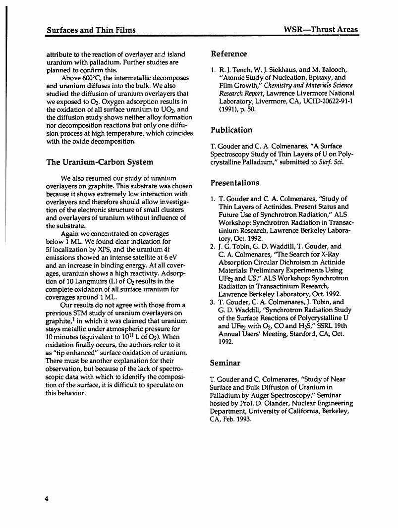
attribute to the reaction of oveflayer az.d island Referenceuranium with palladium. Further studies areplanned to confirm this. 1. R.J. Tench, W. J.Siekhaus, and M. Balooch,
Above 600°C, the intermetallic decomposes "Atomic Study of Nucleation, Epitaxy, andand uranium diffuses into the bulk. We also Film Growth," Chemistry and MateriaLsSciencestudied the diffusion of uranium overlayers that Research Report, Lawrence Livermore Nationalwe exposed to 02. Oxygen adsorption results in Laboratory, Livermore, CA, UCID-20622-91-1the oxidation of all surface uranium to U02, and (1991), p. 50.the diffusion study shows neither alloy formationnor decomposition reactions but only one diffu-sion process at high temperature, which coincides Publication
with the oxide decomposition. T. Gouder and C. A. Colmenares, "A SurfaceSpectroscopy Study of Thin Layers of U on Poly-
The Uranium-Carbon System crystalline Palladium," submitted to Surf. Sci.
We also resumed our study of uraniumoverlayers on graphite. This substrate was chosen Presentationsbecause it shows extremely low interaction withoverlayers and therefore should allow investiga- 1. T. Gouder and C. A. Colmenares, "Study oftion of the electronic structure of small clusters Thin Layers of Actinides. Present Status and
and overlayers of uranium without influence of Future Use of Synchrotron Radiation," ALSthe substrate. Workshop: Synchrotron Radiation in Transac-
tinium Research, Lawrence Berkeley Labora-Again we concelttrated on coveragesbelow 1 ML. We found clear indication for tory, Oct. 1992.5f localization by XIX3,and the uranium 4f 2. J. G. Tobin, G. D. Waddill, T. Gouder, andemissions showed an intense satellite at 6 eV C.A. Colmenares, "The Search for X-Rayand an increase in binding energy. At all cover- Absorption Circular Dichroism in Actinideages, uranium shows a high reactivity. Adsorp- Materials: Preliminary Experiments Usingtion of 10 Langmuirs (L) of 02 results in the UFe2 and US," ALS Workshop: Synchrotroncomplete oxidation of all surface uranium for Radiation in Transactinium Research,coverages around 1 ML. Lawrence Berkeley Laboratory, Oct. 1992.
C_.Jrresults do not agree with those from a 3. T. Gouder, C. A. Colmenares, J.Tobin, andG. D. Waddill, "Synchrotron Radiation Studyprevious STM study of uranium overlayers on
graphite, 1 in which it was claimed that uranium of the Surface Reactions of Polycrystalline Ustays metallic under atmospheric pressure for and UFe2 with 02, CO and H2S," SSRL19th10 minutes (equivalent to 1011L of 02). When Annual Users' Meeting, Stanford, CA, Oct.oxidation finally occurs, the authors refer to it 1992.as "tip enhanced" surface oxidation of uranium.There must be another explanation for their Seminarobservation, but because of the lack of spectro-
scopic data with which to identify the composi- T. Gouder and C. Colmenares, "Study of Neartion of the surface, it is difficult to speculate on Surface and Bulk Diffusion of Uranium in
this behavior. Palladium by Auger Spectroscopy," Seminarhosted by Prof. D. Olander, Nuclear EngineeringDepartment, University of California, Berkeley,CA, Feb. 1993.

WSR--Thrust Areas Surfaces and Thin FilmsI III II IIII III III II I i I I i I I I i I
Molecular Beam-Surface Reactions
A. V. Hamza, M. Moalem,* M. Balooch, and W. J. Siekhaus
We have completed the initial phase of construction of molecular beam-reactive scattering
apparatus.
Technical Activity to <2 x 10⁻⁷ Torr by a 5000 l/s di_tusion pump. Acollimating orifice 1 mm in diameter separates
The system consists of three differentially the source and target chambers. The targetpumped vacuum chambers (see Fig. 1).The chamber is pumped to <6 x 10⁻¹⁰ Torr by asource chamber, which houses the reactant gas cryopump.source and the modulation assembly, is pumped
Gas _ ,./inlet I I "_ _"
/ ---_---" , _ _,
Mini flanges sealed -' --
with gold loll /_"_; t_'_"" source ]25
/ \ ter /
/ \ '! 1-mm
pyromterSource
tube
/Chopper /
assembly[ )//Detectorchamber
/
Target &heater
Target Ouadrupole masschamber spectrometer (QMS)
Auger electronanalyzer
In-llne QMS
Figure 1. Top view, schematic of the modulated molecular beam apparatus.
*Postdoctoral Research Associate, University of California, Berkeley
Surfaces and Thin Films WSR---Thrust AreasI i! i I i i i iliiiil I I i ili i i i ii i I i
Samples are placed on a button heater, and 2. Constructing and installing the supersonic gasthe surface temperature is monitored by an infra- source.
red pyrometer. The molecular beam is incident 3. Adding Auger electron spectroscopy (AES)on the sample at 45° to the surface normal. The optics and an in-line-of-sight mass spectrome_detector samples reflected or desorbed molecules ter. (Both of these items are shown in Fig. 1at the specular reflection angle, -45 °. An extra- but are not yet acquired. In any surfacenuclear quadrupole mass spectrometer (detection experiment, a minimum requirement is toup to 1400 amu) is housed in the detector cham- characterize the surface composition. AES isber, which is pumped by an ion pump to a particularly useful in this respect. The in-linepressure <5 x 10-l° Tort, and views the entire mass spectrometer will allow necessarysample area. Lock-in amplification techniques are characterization of the incident beam.)used to obtain the magnitude and phase of thefirst Fourier component of the scattered signal. 4. Installing a bellows assembly (shown in Fig. 1
but not yet acquired) to vary the distance ofThe amplitude of the scattered signal is a the detector from the sample to characterizemeasure of the strength of the reaction, and thephase lag is a measure of the residence time of the energy of the scattered molecules and athe molecule on the target, after correction for rotating detector to measure angular distri-transit to and from the sample, butions of the scattered molecules.
Construction is being accomplished in fourphases: Publication1. Testing by scattering C60from a convenient
target. This phase is completed. M. Moalem, M. Balooch, A. V. Hamza, W. J.Siekhaus, and D. R. Olander, "Surface Mobility ofC60on SiO2," J. Chem. Phys. (in press).
WSR---Thrust Areas Surfaces and Thin Films_ II I I II IIII II I, IIIIIIII I II II III II Illl I Ill J
iScanning Tunneling Microscopy of Nucleation and Growth of the
[3Phase of Uranium on Graphite
R. J. Tench, M. Balooch, and W. J. Siekhaus
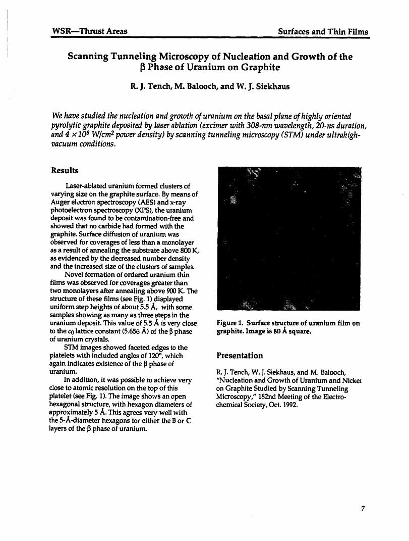
We have studied the nucleation and growth of uranium on the basalplane of highly orientedpyrolytic graphite deposited by laserablation (excimerwith 308-nm wavelength, 20-ns duration,and 4 × 10⁸ W/cm2power density) by scanning tunneling microscopy (STM) under ultrahigh-vacuum conditions.
Results
Laser-ablated uranium formed clusters of
varying size on the graphite surface. By means ofAuger d_._Tor_spectroscopy (AES) and x-rayphotoelectron spectroscopy (XlX3),the uraniumdeposit was found to be contamination-free andshowed that no carbide had formed with thegraphite. Surface diffusion of uranium wasobserved for coverages of less than a monolayeras a result of annealing the substrate above 800 K,as evidenced by the decreased number densityand the increased size of the clusters of samples.
Novel formation of ordered uranium thin
films was observed for coverages greater thantwo monolayers after annealing above 900 K. Thestructure of these films (see Fig. 1) displayeduniform step heights of about 5.5 A, with somesamples showing as many as three steps in theuranium deposit. This value of 5.5 ._ is very close Figure 1. Surface structure of uranium film onto the co lattice constant (5.656 ./_)of the [_phase graphite. Image is 80 ./_squaxe.of uranium crystals.
STM images showed faceted edges to theplatelets with included angles of 120°, which Presentationagain indicates existence of the [3phase ofuranium. R.J. Tench, W. J.Siekhaus, and M. Balooch,
In addition, it was possible to achieve very "Nucleation and Growth of Uranium and Nickelclose to atomic resolution on the top of this on Graphite Studied by Scanning Tunnelingplatelet (see Fig. 1). The image sho_vs an open Microscopy," 182nd Meeting of the Electro-hexagonal structure, with hexagon diameters of chemical Society, Oct. 1992.approximately 5 A. This agrees very well withthe 5-A-diameter hexagons for either the B or Clayers of the ]3phase of uranium.
Surfaces and Thin Films WSRmThrust AreasI iii I I iii
Surface-Physics Research
P. Bedrossian
A new surface-physics facility that incorporates in situ sample preparation, electron diffraction,and atomic-resolution imaging with scanning tunneling microscopy (STM) was commissioned
in October, 1992. A study of defect crealion on Si(lO0) by low-energy (=200-eV) xenon irradia-tion was initiated, with the goal of identifying a transition temperature for the onset of multi-layer annealing via interlayer hopping of individual silicon atoms.
Technical Activities mobile adatoms are crucial to developing modelsof ion-beam enhancement of epitaxial growth.
We previously found that ion irradiation in Figure 1 is an STM image of Si(100) thatthe low-energy regime results in damage that is resolves the individual silicon dimer rows of theconfined predominantly to the outermost atomic 2 x 1 reconstruction of that surface. Irradiationlayer of the substrate and that surface evolution by 200-eV xenon at 488°C (Fig. 2a) and 436°Cunder such sputtering is dominated by the inter- (Fig. 2b) at a fluence corresponding to removalaction of individual surface vacancies created by of one third of a monolayer (ML) results in thethe sputtering process. In order to distinguish, to formation of monolayer-deep vacancy islands.the extent possible in post mortem STM analysis, Diminished mobility of surface vacancies createdthe effects of defect creation and defect annealing, by sputtering at the lower temperature results insingular Si(100) surfaces (misorientation <1/25 °) a higher density of smaller vacancy islands. Thatwere used. Processes mediated by the creation the depressions areexactly one atomic layer deepand interaction of surface vacancies could there- is verified by Fig. 2c, a detail of Fig. 2b in which
the silicon dimer rows inside the depressions arefore be distinguished from step-mediated pro-cesses. Whereas atomic steps might be expected perpendicular to those of the outermost layer. Ato play a significant role in the annealing of ion- qualitative change in surface morphology occursinduced defects, a low step density would mini- below 370°C. The appearance of adatom islands
in Fig. 3, acquired following 200-eV xenon sput-mize the proportion of defects actually created atsteps, tering of Si(100) at 362°C, offers the first direct
Adatom generation under higher-energy experimental verification of adatom creationsputtering [5-keV argon on Cu(100)] has been during ion irradiation of a semiconductor sur-predicted from molecular-dynamics simulations. 1 face. Inhibition of interlayer hopping of silicon
adatoms below 370°C leads to the nucleation ofSimulations have also predicted adatom genera-tion by lower-energy ions (<20-eV argon) adatom islands during sputtering. This, in turn,
sets a lower bound on the temperature range inthrough individual atomic displacements onboth reconstructed Ge(100) and Si(100).2 At suffi- which 200-eV xenon sputtering of Si(100) resultsciently high substrate temperatures, adatoms in two-layer removal.generated during ion bombardment could either Further work will examineincorporate at step edges or hop between levels, * The effect of incident ion energy and mass onannihilating a mobile vacancy or filling a vacancy the creation rates for specific defects.island. At sufficiently low substrate tempera- * The identification of a displacement thresholdtures, mobile adatoms that no longer possess for surface atoms by sputtering.
sufficient kinetic energy either to overcome * The kinetics of silicon adatoms created bypotential barriers to interlayer hopping or to sputtering on surfaces roughened byreach step edges are left to nucleate adatom sputtering.islands. Experimental verification of adatom * The interaction of defects created by low-creation during low-energy irradiation of silicon energy ion irradiation with adsorbate atomsand an understanding of the kinetics of those such as germanium.

WSR--Thrust Areas Surfaces and Thin Films..... Ill I III I I I I mall I IM lilll I il
Figure 1. A 700-/_ STM image of atomically clean Si(100), showing individual silicon dimer rowsand two single atomic steps. The gray scale is keyed to vertical displacement of the STM tip.
Figure 2a. A 4200-_, STM image of singular Figure 2b. A 4200-._ STM image of singularSi(100) following removal of =1/3 ML by 200-eV Si(100) following removal of =1/3 ML by 200-eVXe ions at 488°C. Depressions are I ML deep. xenon ions at 436°C.

Surfaces and Thin Films WSR--Thrust Areasli i i II ii liliiill
Figure 2c. A 700-_ detail of Fig. 2b, showingindividual silicon dimer _ows.
Figure 3. A 2000-_ STM image of singular Si(100)following _emoval of =1/3 ML by 200-eV xenon ions at362_C, showing both monolayer-deep adatom islandsand monolayer-high vacancy islands.
References Presentations
1. D. E. Harrison, Jr., P. W. Kelly, B. J. Garrison, 1. P. Bedrossian, "Low-Energy Ion Irradiation ofand N. Winograd, "Low-Energy Ion Imp_::_: Silicon Surfaces," Physics Department Collo-Phenomena on Single Crystal Surfaces," Surf. quium, Arizona State University, Tempe, AZ,Sc/. 76, 311 (1978). Feb. 1993.
2. M.V.R. Murty and H. A. Atwater, "Defect 2. P. Bedrossian, "Adatom Generation in IonGeneration and Morphology of (001) Surfaces Irradiation of Silicon," Sandia Nationalduring Low-Energy Ar-Ion Bombardment," Laboratories, Albuquerque, NM, Feb. 1993.Phys. Rev. B 45, 1507 (1992). 3. P. Bedrossian, "Sputtering and Annealing of
Silicon Surfaces," Gordon Research Confer-ence on Frontiers of Scanning Tunneling
Publication Microscopy, Ventura, CA, Mar. 1993.4. P. Bedrossian, "Vacancy Kinetics on Silicon
P. Bedrossian and E. Kaxiras, "Symmetry and S_:rfaces," American Physical Society GeneralStability of Solitary Dimer Rows on Si(100)," Mo._ting,Seattle, WA, Mar. 1993.Phys. Rev. Lett. 70, 2589 (1993).
10

WSR---Thrust Areas Surfaces and Thin Films........ I II II IIII IIIIll Illl mm _ Ill l I II ii ill ill ,i, ==,= ,
Quantum Electron Transport through Ultrathin Films
L. J. Terminello and E. Tamura
One of the most important challenges for thin-fi'Im technology will be the fabrication of ultra-small microelectronic devices. In the limit of complete miniaturization, device materials will be
no more than a small ensemble of carefully assembled atoms. In this limit, the need will be great
to understand how electrons propagate through such small structures.
Introduction down from the silicon surface adatom. There-
fore, by photoexciting the boron ls core electron,Low-energy ('hot")-electron scattering the kinetic energy of which is selected with tun-
through atoms can be studied as a component of able and monochromatic synchrotron radiation,understanding the classical or _miclassical one can measure the electron propagationmodels of electron transport in materials. The through the silicon adatom uniquely. Thisimportance of this research will be realized when measurement was made efficiently using aquantum-effect devices (device material of only a multiple-angle electron energy analyzer. Fromfew atoms) become viable, the electron angular distribution pattern meas-
Most research in electron transport deals ured in our initial experiment, the scattering crosswith the macroscopic view of inelastic processes section for a single silicon atom can be extracted.governing electron propagation in the solid state. Our initial assessment of the experimentalMost measurements are interpreted theoretically results shows that qualitative differences existusing Monte Carlo simulation methods. Such col- between the low- and high-kinetic-energy dataculations treat the electron-electron and electron- that require a better understanding of the originphonon components of the inelastic processes, of these intensity differences, particularly at lowbut ignore the electron-core-potential interac- energy. To accomplish this, we have begun ation. Very few experiments have attempted to multiple-scattering, local-density-approximationmeasure electron-atom scattering cross sections simulation of these results. First, we will isolateat low kinetic energies, yet this component of the contribution of the single silicon forward-electron propagation will be critical to under- scattering atom to the total electron angular-standing and predicting the behavior of future distribution pattern. Second, we will identify thequantum-effect devices, origin of the off-normal fine structure present in
the low-kinetic-energy measurement.With these simulations, we will be able to
Experiment better identify the contribution of single-atom,low-kinetic-energy, electron propagation in sol-
The initial experiments that we designed to ids. Only with this combination of experimentaddress this question have measured the electron and theory can this valuable information beangular distribution pattern of the boron ls obtained. Further experimentation will measurephotoemission at 29 and 176 eV. This measure- the boron ls photoelectron angular distributionment was made using synchrotron radiation- patterns for kinetic energies below 25 eV. Thesebased photoemission and took advantage of the will be compared to the higher kinetic-energyunique geometry of the delta-doping compound patterns measured at 29 and 176 eV and calcu-of Si(111):boron. The unique surface geometry of lotions at isoenergetic kinetic energies.this system places a single boron atom two layers
11
Uranium Research WSR--Thrust Areasml I -- III I III IIII I IIII I III III II '1 --
Uranium Research
L. R. Newkirk, Thrust Area Leader
Overview
Basic research into the metallurgical properties of uranium 'alloys represents aredirection of our actinide research activities. Lawrence Livermore National Laboratorywas recently naa,,ed Lead Laboratory for Uranium Fabrication in the Nuclear WeaponsComplex Reconfiguration Program, a role that carries with it the need to support basicresearch in uranium metallurgy. This new responsibility, combined with practicallimitations on the productivity of basic plutonium research, led us to realize that ourlimited resources for basic research in actinide metallurgy would have maximumscientific and programmatic impact if redirected toward uranium alloys.
Uranium and uranium-alloy components play an important role in nuclear weapondesign and fabrication. An understanding of the basic metallurgical behavior of thesematerials is a necessary and important underpinning for developing and ensuring theirperformance within the fabrication constraints that will be associated with the modernreconfigured weapons complex. These constraints will combine the environmental con-cern associated with processing radioactive materials with the need to guarantee spe-cific aspects of performance in a weapon environment. As a result of over 40 years ofresearch on uranium and uranium alloys, both within the weapons complex and else-where, a great deal of basic information is already available; however, the metallurgicalcomplexity of these materials has left many scientifically interesting and importantquestions to be addressed.
Although not as complex as plutonium, pure uranium is a metallurgically complicatedmaterial. It exists in three solid phases: a high-temperature, bcc phase (7); an intermedi-ate, highly complex, tetragonal phase ([3);and a low-temperature, orthorhombic phase(c_).These phases have dramatically different mechanical properties, and the phasetransformation from _ to o_can be complex. As alloying elements (particularly refrac-tory metals) are added to uranium, the metastable phase behavior becomes increasinglycomplicated. Upon quenching from the 7 (bcc) region, various new phases are observed.These phases (c_', (z", yO, and y s) are various distortions of the basic c_phase,(c_'and (x'), and the 3'phase, (T° and y s), some of which form through very complexmartensitic transformations. These various phases have different and sometimesseemingly anomalous mechanical properties. In addition, the corrosion sensitivity of thealloy will be i_ighly dependent on the alloying element, its concentration, and possiblythe resulting phase structure.
The research program consists of two distinct areas of effort. The larger and moreambitious of these focuses on the mechanical properties and phase transformations
12
!
WSR---Thrust Areas Uranium ResearchJ] i iiiii iii |i i _[i 111111 ii i I ii| iiiiiii iii i iiii ii ii _ __
associated with a narrow but extremely important compositional region in theuranium/niobium system. By virtue of its stainless properties, this is a very importantalloy system, and improving our basic understanding of its constitutive relationshipswill ultimately assist our development of alternate fabrication technologies such as spin-forming. The second and smaller area of research will focus on characterizing the phaserelationships in several uranium/refractory metal alloy systems. This will provideinsight in evaluating potentially interesting binary uranium systems for either corrosionresistance or other valuable metallurgical properties.
Mechanical and Microstructural Properties of U-6Nb
G. Gallegos, P. Johnson, and A. Schwartz
Because of its unique properties, U-6Nb has important weapons applications and, because of itsunusual mechanical behavior, is also of scientific interest. At low strains, for example, a "double-knee effect" is observed in the stressstrain relationship typical of a shape-memory alloy. Thedeformation mechanism at low strains has been attributed to twinning and intertwinning(neither of which has been proven). This deformation mechanism eventually becomes exhaustedwhen the variants are aligned with respect to the imposed strain or become immobilized bycollisions with grain boundaries. At this point, it is assumed that normal plasticity bydislocation motion begins, and subsequent straining can permanently alter the structure suchthat the recoverable strain during reversion is reduced. The second yield point, corresponding tothe onset of dislocation motion, is rather soft---or gradual--in this alloy. This may indicate that acontinuously increasing fraction of fully detwinned grains contributes to wo: ' _ardening inwhat appears to be the detwinning regime. These mechanisms may operate differently in theorthorhombic or monoclinic U-Nb phases (a' and o_') than in the tetragonal phase ( y° ).
Approach We expect that the behavior during thisdeformation mode, if accomplishedby the
U-6Nb typically is used in an aged condition motion of twinboundaries, should depend onafter quenchingfrom the high-temperature y the initialvariant size and orientationsandthephase.Although evidence of dislocationsand amountof strainthatcan beaccommodatedpersubgrainshas been observed, thisis believed to unit motion of the twinboundaries. Completebe the result of the quenchingoperation. This reversion tothe initial microstructure is possi-projectfocuses on enhancingour understanding ble, in principle,by heatinginto the higher-of thedeformation behavior of U-6Nbin the ¢z" temperature_,phasefield, followed by coolingand _o phases. Specifically,we expect to better to retransformto the initialmicrostructure,understand the effectof shear stresseson both therebyrecovering the strain.the low-strain (double-kneearea)and high-straindeformation.High-straindeformationis ofinterest for formability studies,butdata are Progresslimited to studies in tension.Theapproach forthis project is to conduct torsion tests in the Most of theeffort on this l:'_o._t has beenappropriate regimes and to combine these with to optimize the torsion specimen geometry formicrostructural characterization by transmission obtaining the desired data. Torsion testing waselectron microscopy (TEM). chosen to allow the work-hardening behavior to
be studied to high strain levels, beyond the 30- to
13

Uranium Research WSR--Thrust Areas_ lUml ii IIIIN I IIII I II I Inlll I I _. -- -- I -- __ IIII III I I III [
50-percent limit caused by geometric softening in processed to obtain predominantly _", with aa tensile test. small fraction of _,o.
To obtain a sensitive measurement of the Characterization of microstructural changesdouble-yield behavior, it is necessary to maintain is off to .asolid start. Beginning with the rolledthe strain vrofile as uniformly as possible across U-6Nb plate material, 3-mm-diameter rods werethe cross section of the torsion specimen. This extracted along the three principal directions:requires a hollow specimen configuration, along the rolling direction in plane, perpendicu-
Thin-walled torsion testing requires a very lar to the rolling direction in plane, and trans-short specimen length to avoid buckling, which verse. The materials-handling procedures wereraises questions as to the influence of end and developed to obtain the 3-ram-diameter diskssurface effects. For this investigation, therefore, required for TEM.we have decided to test thick-walled, hollow, After a number of failed electropolishingtorsion bars. attempts using different solutions, a suitable
An exact solution for the stress at the outer electrolyte has been discovered that producesfiber of such a specimen exists in the form of a reasonable amounts of electron-transparentmodified Field-Backofen equation. We have tried material. Further adjustments in the electro-four different geometries of torsion specimens polishing parameters--including voltage, cur-and grips in order to optimize the geometry to rent, temperature, and electrolyte composition--meet the requirements. The most recent specimen should lead to even better thin foils.geometry appears to meet our criteria, although Preliminary TEMhas revealed a two-phasebuckling continues to present a problem. This microstructure. The matrix phase, which con-specimen design will be refined, and testing on stitutes about 99%of the thin area, has a mediumU-6Nb should begin shortly. The data acquisi- density of twins but few visible dislocations. Thetion program for these tests has been completed, second phase appears to be an ordered inter-
We have obtained a U-6Nb plate to be used metallic compound. Phase identification andfor these studies. The plate has been character- detailed microstructural characterization areized by _hemical analysis, and x-ray-diffraction beginning at this time and will provide the basisstudies are under way to determine the texture of for further study into the deformation mech-the plate. The first set of tests will be performed anisms active in this alloy.on a U-6Nb (U-14 at.%Nb) alloy sample that was
Phase Diagrams of Uranium/Refractory Metals
F. Y. L. G_nin
The goal of this study is to review selected binary phase diagrams of uraniumrefractory-metalalloys in order to identify systems with potentially interesting metallurgical or corrosion-resistant properties. The refractory metals of interest here are Cr, Hf, Mo, Nb, Ta, Ti, V, W, andZr. The study will first concentrate on Nb, V, W, and Mo.
dX dX
Progress ('_)solidus- ('dT')liquidus - A/']fusi°nRV2m . (1)
Initially, the phase diagrams were examinedfor violations of general thermodynamic rules, The results of this evaluation for the uraniumsuch as the consistency of the initial slopes of the refractory-metal systems are given in Table 1.solidus and liquidus in relation to the Van't Hoffequation:
14
WSR---Thrust Areas Uranium Research-- ] I ilfll -- iiii __ Hill III I . II1,1 IIII II I II I -- IIIII II lUII II
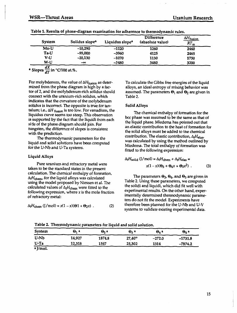
Table 1. Results o_phase-diagram examination for adherence to thermodynamic rules.
" .... .... ........ Difference - ....... _fusio._._n- -System Solidus slope" Liquidus slope a (absolu[e value) RT m.... i , ,,.
Mo-U -- -10,290..... -m0 ............. .......... 2460 - -Ta-U -99,000 -3960 4125 2465V-U -20,130 -1070 1130 1750W-U .-oo -3480 3480 3200
" Slopes _ m eC/lO0 at.%.
For molybdenum, the value of AHfusion as deter- To calculate the Gibbs free energies of the liquidmined from the phase diagram is high by a fac- alloys, an ideal entropy of mixing behavior wastor of 2, and the molybdenum-rich solidus should assumed. The parameters 01 and @2are given inconnect with the uranium-rich solidus, which Table 2.indicates that the curvature of the molybdenumsolidus is incorrect. The opposite is true for tan- Solid Alloystalum; i.e., AH fusionis tOOlOW.For vanadium, theliquidus curve seems too steep. This observation The chemical enthalpy of formation for theis supported by the fact that the liquidi from each bcc phase was assumed to be the same as that ofside of the phase diagram should join. For the liquid phase. Miedema has pointed out thatan elastic contribution to the heat of formation fortungsten, the difference of slopes is consistentwith the prediction, the solid alloys must be added to the chemical
The thermodynamic parameters for the contribution. The elastic contribution, AfHelas,was calculated by using the method outlined by
liquid and solid solutions have been computed Miedema. The total enthalpy of formation wasfor the U-Nb and U-Ta systems.fitted to the following expression:
Liquid Alloys AfHsolid(J/mol) = AfHchem+ AfHelas=
Pure uranium and refractory metal were x(1 - x)(@2+ @4x+ @5x2) • (3)taken to be the standard states in the presentcalculation. The chemical enthalpy of formation,AfHchem,for the liquid alloys was calculated The parameters @3,@4,and 05 are given inusing the model proposed by Niessen et al. The Table 2. Using these parameters, we computedcalculated values of AfHchemwere fitted to the the solidi and liquidi, which did fit well withfollowing expression, where x is the mole fraction experimental results. On the other hand, exper-of refractory metal: imentaUy determined thermodynamic parame-
ters do not fit the model. Experiments haveAfHchem(J/tool) =x(1 - x)(O1 + @2x) • (2) therefore been planned for the U-Nb and U-V
systems to validate existing experimental data.
Table 2. Thermodynamic parameters for liquid and solid solution.i, _ i ......
System - @1" .... 02 a @3" 0'4" @s_'
U-l_b - 14,927 i874.8 ..... 27,407 - -272.0 -i731.8
U-Ta !2,318 1547 ...... 25,302 .... 1314 .......-7874.2
15

WSl_---Thrust Areas Fundamentals of the Physics and Processing of MetalsIII.... -- _ -- _' -- _ "'"" " I I II - - I iiiiii ........
Fundamentals of the Physics and Processing of Metals
W. H. Gourdin, Thrust Area Leader
Overview
In the first half of FY93, the Metals Research Program has continued to shift its focus tothe properties and processing of ordered intermetallic materials. This change is part of along-range plan to gradually shift the emphasis of the program and make it moredirected. The project on the stability of metallic superlattices led by Marcel Sluiter wasterminated early in the year, but Alan Jankowski fabricated a limited number of Ti2/Cr2multilayers to verify the relative stability of (111) and (110) layer orientations. Usinggrazing-incidence x-ray diffraction, he demonstrated that multilayers with (111)orientation decay more slowly than those with (110) orientation, in qualitativeagreement with the calculations of Sluiter and Turchi.
Our efforts to understand the role of boron and other solutes in Ni3AI have made goodprogress. As stated in previous reports, our goal is to understand details of the role ofsolutes such as boron in promoting enhanced ductility in the hope that the knowledgewe gain can be applied to other, more technologically important systems. Ourtheoretical studies have shown a sharp contrast between the changes induced by aductility enhancer such as boron and an embrittling agent such as hydrogen. Differenceplots of electron density show that boron promotes a more uniform distribution ofcharge throughout the Ni3AI lattice. This distribution is of the same general character aswe found previously in pure Ni3A1, which suggests that the presence of boron mayimprove cohesion when the matrix structure is modified as it is near a grain boundary.Conversely, hydrogen tends to deplete the charge in the interstitial regions and tomodify the Ni-AI bonding. This disruption of the bond structure suggests reducedcohesion. Experimental workhas concentrated on preparing for mechanical tests ofbicrystal specimens, both natural and artificial, and at the end of March, equipment andsoftware were in place to determine the crystallographic orientation and mechanicalproperties of the specimens. We also established a collaboration with the University ofCalifornia at Irvine to study grain-boundary sliding in bicrystal specimens, which wewill provide.
If intermetallic materials are ever to have a significant impact on the gas-txtrbineindustry, methods must be developed to join them both to themselves and to othersuperalloys. Straightforward application of traditional methods, however, is frequentlyunsatisfactory because of the high melting points of these materials and the fact thatthey are brittle. Mike Strum's study of stoichiometric interlayer bonding ofintermetallics, a new project this year, is exploring one possible novel approach tojoining NiA1, an alloy of particular interest for engine applications.
16
Fundamentals of the Physics and Processing of Metals WSR---Thrust Areas-- lllIll Illll -- -- _ -- IIII llllIlllI I _- --
Solute Segregation Behavior in Ni3A1-Based Ordered Alloys
W. H. Gourdin, P. E. Johnson, N. Kioussis,* and A. Gonis
The objective of this project is to provide a fundamental understanding of the effects of ternary
solutes on intergranular cohesion and ductility in L12 ordered intermetallic alloys.
Summary orientation on the local strain accommodationand cohesive strength--with and without
Attention has focused recently on the elec- boron---of single, well-defined grain boundaries.tronic structure of highly ordered intermetallic Tests with straight bar specimens late lastcompounds containing transition metal elements year and early this year made it plain that a sim-and, in particular, on understanding the relation- pie friction grip arrangement would not be satis-ship between the electronic structure, macro- factory for these tests. Even specimens heat-scopic fracture behavior, and solute content. The treated to minimize boron segregation showed aexceptional high-temperature strengths exhibited surprising amount of ductility, and the stressesby many of these materials are thought to origi- during deformation became large enough tonate in the nature and extent of local electronic- produce significant slipping, thereby compromis-charge transfer, which is also responsible for the ing measurements of strain. We redesigned thestability of these compounds, grips to accommodate miniature shoulder ("dog-
The role of boron in polycrystalline Ni3Al bone") specimens with a 1- × 1- x 3-ram gaugehas become a paradigm for solute effects in length and had several specimens fabricated. Wewhich the appropriate selection of an interstitial also acquired, calibrated, and installed a minia-dopant can completely suppress brittle behavior, ture clip-on strain gauge to allow us to directly
The ability of low dopant levels to segregate measure the strains in the vicinity of the grainto grain boundaries and dominate the fracture boundary° Such measurements are importantmode undoubtedly depends on the local defect because we want to distinguish between thestructure itself, as well as the specific modifica- effects of boron on the boundary's cohesivetion of the electronic structure provided by the strength and the local accommodation of strainpresence of the dopant. However, recent results near the boundary. At the end of the first half ofin the literature indicate that boron may also FY93, we were ready to begil_ testing with themitigate the effects of hydrogen introduced into modified specimens and apparatus.the lattice from the ambient atmosphere. To be most informative, the orientation of
We are addressing these issues theoretically the two halves of each bicrystal must be wellwith a series of first-principles calculations on known. To accomplish the necessary measure-bulk Ni3Al, with and without boron, and experi- ments using electron backscattering patternsmentally through a set of tests that allow simul- (EBSP),we acquired and learned to operate ataneous measurements of the chemistry, struc- computer, data-acquisition hardware, and neces-ture, and plastic behavior of individual grain sary software. This equipment will be used inboundaries, conjunction with a scanning electron microscope
equipped with an EBSP camera at the University
Prol,ress of California , Santa Barbara.The ductility of the straight bar specimens,
even when treated to minimize the amount ofOn a miniature load frame, we are measur- boron present (according to conventional wisdom
ing the mechanical l:_havior of bicrystals cut found in the literature), is puzzling. To investi-from a large-grained boule. These experiments gate, we hydrogen-charged a specimen and frac-will explore the effects of crystal and boundary tured it immediately in an inert environment
(argon). Auger measurements showed little if any*CaliforniaStateUniversity, Northridge boron at the boundary, although accurate abso-
17
WSR--Thrust Areas Fundamentals of the Physics and Processing of Metals-- _ ---., --- -- -- iiiiii _ irll iiii __ ii iiiii _ [ _ _ .....
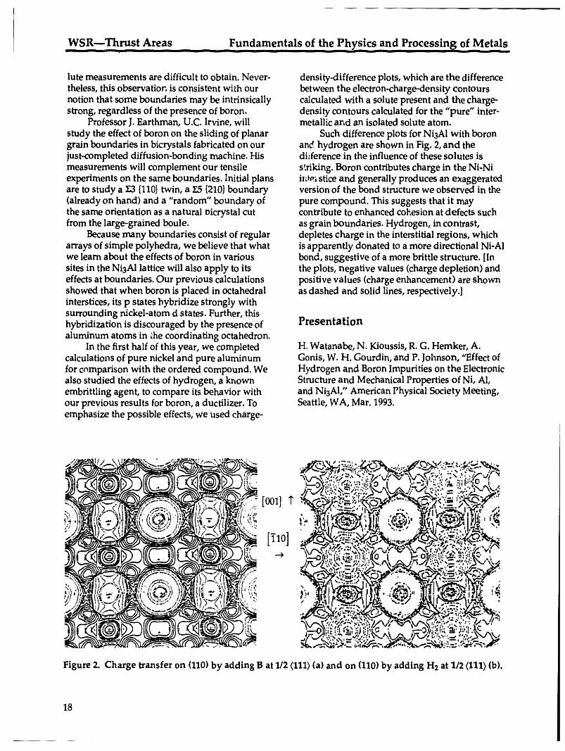
lute measurements are difficult to obtain. Never- density-difference plots, which are the differencetheless, this observation is consistent with our between the electron-charge-density contoursnotion that some boundaries may be intrinsically calculated with a solute present and the charge-strong, regardless of the presence of boron, density contours calculated for the "pure" inter-
Professor J. Earthman, U.C. Irvine, will metallic and an isolated solute atom.study the effect of boron on the sliding of planar Such difference plots for NiaAI with borongrain boundaries in bicrystals fabricated on our and hydrogen are shown in Fig. 2, and thejust-completed diffusion-bonding machine. His diiference in the influence of these solutes ismeasurements will complement our tensile s'a'iking.Boron contributes charge in the Ni-Niexperiments on the same boundaries. Initial plans in_ stice and generally produces an exaggeratedare to study a £3 {110}twin, a Y.,5{210}boundary version of the bond structure we observed in the(already on hand) and a "random" boundary of pure compound. This suggests that it maythe same orientation as a natural oicrystal cut contribute to enhanced cohesion at defects suchfrom the large-grained boule, as grain boundaries. Hydrogen, in contrast,
Because many boundaries consist of regular depletes charge in the interstitial regions, whicharrays of simple polyhedra, we believe that what is apparently donated to a more directional Ni-Alwe learn about the effects of boron in various bond, suggestive of a more brittle structure. [Insites in the Ni3Al lattice will also apply to its the plots, negative values (charge depletion) andeffects at boundaries. Our previous calculations positive values (charge enhancement) are shownshowed that when boron is placed in octahedral as dashed and solid lines, respectively.]interstices, its p states hybridize strongly withsurrounding nickel-atom d states. Further, thishybridization is discouraged by the presence of Presentationaluminum atoms in &e coordinating octahedron.
In the first half of this year, we completed H. Watanabe, N. Kioussis, R. G. Hemker, A.calculations of pure nickel and pure aluminum Gonis, W. H. Gourdin, and P. Johnson, "Effectoffor comparison with the ordered compound. We Hydrogen and Boron Impurities on the Electronicalso studied the effects of hydrogen, a known Structure and Mechanical Properties of Ni, Al,embrittling agent, to compare its behavior with and Ni3AI," American Physical Society Meeting,our previous results for boron, a ductilizer. To Seattle, WA, Mar. 1993.emphasize the possible effects, we used charge-
Figure 2. Charge transfer on (110) by adding B at 1/2 (111}(a) and on (110) by adding H2 at 1/2 (111) (b).
18
,Fundamentals,of the, Phys!cs and Processin_ of Metals WSR--Thrust Areas__ _ __ II1._ iiiiiii iiii II - _ .... _ i illli,i _ I II iii
Stability of Artificial Intermetallic Superlattices:An Experimental Study of TilX Multilayers
A. F. Jankowski
The objective of this study is to test the theory that specific artificial superlattices are thermo-dynamically stable or unstable.
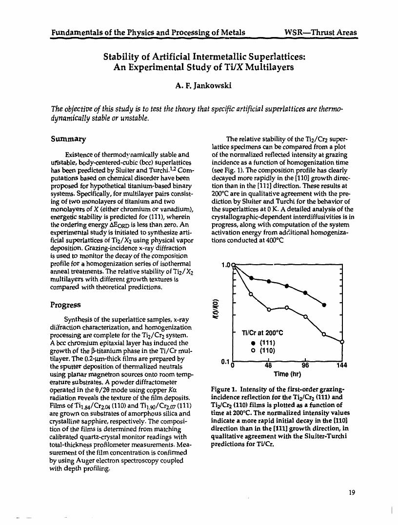
Summary The relative stability of the Ti2/Cr2 super-lattice specimens can be compared from a plot
Existence of thermodynamically stable and of the normalized reflected intensity at grazinguStable, body-centered-cubic (bcc) superlattices incidence as a function of homogenization timehas been predicted by Sluiter and Turchi.1,2Corn- (see Fig. 1). The composition profile has clearlyputations based on chemical disorder have been decayed more rapidly in the [110] growth direc-proposed for hypothetical titanium-based binary tion than in the [111] direction. These results atsystems. Specifically, for multilayer pairs consist- 200°C are in qualitative agreement with the pre-ing of two monolayers of titanium and two diction by Sluiter and Turchi for the behavior ofmonolayers of X (either chromium or vanadium), the superlattices at 0 K. A detailed analysis of theenergetic stability is predicted for (111), wherein crystallographic-dependent interdiffusivities is inthe ordering energy zXEORD is less than zero. An progress, along with computation of the systemexperimental study is initiated to synthesize arti- activation energy from add,itional homogeniza-ficial superlattices of Ti2/X2 using physical vapor tions conducted at 400°Cdeposition. Grazing-incidence x-ray diffractionis used to monitor the decay of the compositionprofile for a homogenization series of isothermal 1.0c - - - .... - - - .......................anneal treatments. The relative stability of Ti2/X2multilayers with different growth textures iscompared with theoretical predictions.
Progress _Synthesis of the superlattice samples, x-ray
diffraction characterization, and homogenizationprocessing are complete for the Ti2/Cr 2 system.A bcc chromium epitaxial layer has induced the • (111)growth of the _-titanium phase in the Ti/Cr mul- o (1"1O)tilayer. The 0.2-1am-thickfilms are prepared by 0.1 ....- ' - - ..... _ .....the sputter deposition of thermalized neutrals 0 48- -98 144using planar rnagnetron sources onto room temp- Time (hr)erature substrates. A powder diffractometeroperated in the 0/20 mode using copper K(x Figure 1. Intensity of the first-order grazing-radiation reveals the texture of the film deposits, incidence reflection for the Ti2/Cr2(111) andFilms of Til.84/Cr2.04 (110) and Til.90/Cr2.07 (111) Ti2/Cr2(110) films is plotted as a function ofare grown on substrates of amorphous silica and time at 200°C. The normalized intensity valuescrystalline sapphire, respectively. The composi- indicate a more rapid initial decay in the [110]tion of the films is determined from matching direction than in the [111] growth direction, incalibrated quartz-crystal monitor readings with qualitative agreement with the Sluiter-Turchitotal-thickness profilometer measurements. Mea- predictions for Ti/Cr.surement of the film concentration is confirmed
by using Auger electron spectroscopy coupledwith depth profiling.
19
I
WSR---Thrust Areas_ Fundarnentals of the physics an d Processing _of Metals
References Metallic Superlattices," MRS Symp. Proc. 238,623 (1992).
1. M. Sluiter and P. Turchi, "The Role of Chemi- 2. M. Slulter and P. T_'rchi, "Phase Stability ofca] Interactions in the Stability of Artificial Artificial Superlattices: Chemical-Order
Effect," Phys. Rev. B 46, 25_5 (1992).
Stoichiometric Interlayer Bonding of Intermetallics
M. J. Strum and G. A. Henshall
The objective of this study is to develop an understanding of isothermal thin-film bonding
processes and apply such methods to the joining of refractory ordered intermetallics.
Summary • Isothermal solidification and homogeniza-tion to form the parent phase by reaction
Our present goal is to develop a predictive synthesis of the pre-placed films.understanding of the isothermal bonding processin which elemental films placed at the joint inter- Both reactions are being evaluated, with empha-faces react to form a joint with the same stoichio- sis on developing a predictive model of the iso-merry as the parent material. This joining thermal solidification reactior, kinetics.method, conceived by the authors, is a modifica-
tion of conventional liquid-assisted diffusion- Progressbonciing processes but without the addition of
traditional melting-point depressants. Through In thia newly funded project, we havethis method, we expect to obtain joint composi- selected an appropriate materials system (NiAI),tions and properties approaching those of the arranged a collaboration with General Electricparent material. It is particularly suitable for Aircraft Engines to produce single crystals for thejoining high-temperature materials, including experiments, prepared aluminum-coated nickelintermetallics and ceramics, which have poor substrates for preliminary studies, initiatedweldability by conventional fusion welding metallurgical bonding experiments, completedmethods, isothermal solidification experiments on nickel
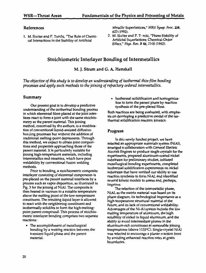
Prior to bonding, a stoichiometric composite substrates that have verified our ability to useinterlayer consisting of elemental components is reaction synthesis to form NiAl, and identifiedpre-placed on the parent material interfaces by a several kinetic models to assess and, perhaps,process such as vapor deposition, as illustrated in improve.Fig. 3 for the joining of NiAl. The composite is The selection of the intermetallic phase,then heated in vacuum to a suitable temperature NiAl, as the matrix material was based on itsabove the melting point of the low-temperature phase diagram, its technological importance as aconstituent. The resulting liquid layer is allowed high-temperature structural material of theto react with the neighboring constituent and future, and its lack of conventional weldability.isothermally solidifes to form the high-melting- Advantages of the Ni-Al system include the lowpoint parent compound. This process of stoichio- melting temperature of aluminum, the highmetric interlayer bonding comprises two separate solubility of nickel in liquid aluminum, and thereactions: ability to avoid intermediate phases in the
° The accomplishment of metallurgical aluminum-rich constituent at reasonable joiningbonding by a wetting reaction between the temperatures (above 1133°C). Single-crystal NiA1t_ansient liquid phase and the parent was selected to encourage a planar reaction frontmaterial, by avoiding enhanced reaction rates at grain
boundaries.
20
Fundamentals of the Physics and Processing of Metals WSR---Thrust Areas- ill I ililil
__ _ Whereas the 03-mm and thicker layersincrease the solidification times by increasing thetransport lengths, they are being used to facilitatemicrostructural characterization. The intermetal-
NIAI NIAI lic phases produced in these experiments weresubstrate substrale identified by EDX compositional analyses.
Completed isothermal solidification treatments_ J_J resulted in an outer layer of NiA1 separated from
__ _R N!._ the nickel substrate by a thin Ni3Al interlayer._.:_ .........,.__Al__ __':'_":_'_"___,_._,_::,._:.. or _ _ ...... The nickel substrate, unlike NiAl, provides a_'_'._,_:'.'_"-_'_"_'_':_;_ semi-infinite source of nickel and therefore'._%_._,*_',_.__'_'_ _._...:_:_..,:.:.:_,_._._.___,_,"_ ai _% I__%_ encourages Ni3A1 formation." ' .... _ _ ......... _'_'_ "' '.'._i.__.,_.,,._.,_%_ I._:_%'.!_: X a _,_'_
_:_:_.__. _:_:_ Interrupted isothermal solidification pro-I_._.':_._."._;_:_!_._.'_1_'::.::':_duced similar intermetallic layers extending from
/ i the original Ni/AI interface outward into theNiAI NIAI aluminum layer but terminating in a ,divorced
I substrate eutectic layer near the surfaceof the aluminum
coating.Defectsp;oduced during the reactionhavebeenidentified asKirkendall voidsandintermetallicstressfractures.The sensitivityofdefectformationto processingmethodswillcontinueto beevaluated in future studies.
Figure 3. Stoichiometric composite films are
pre-placed between the components to be Continuing Workjoined. In this case, films of nickel and alumi-
num on the NiAI parent material are illustrated. Upon receipt of new material, our continu-ing experiments will focus on characterizing theevolution of intermetallic formation on coated
Initial experiments of isothermal solidifica- single-crystal NiAl substrates for input into ation were conducted on commercially pure nickel kinetic model.(Ni 201) substrates coated with high-purity alu- The second concurrent task is to evaluate theminum. The coatings, applied by electron beam wettability of the mating interfaces. It is wellevaporation, adhered well and reacted with the known that wetting of a surface by aluminumnickel substrate upon heating. Complete iso- requires special consideration of the need tothermal solidification was successfully achieved disrupt the native surface oxide. In order offor a 0.3-mm-thick aluminum layer in approxi- preference, methods being evaluated for thismately 145 minutes at 1200°C. These results purpose are superheating, application ofappear promising on a technological level, pressure, and the use of thin reactive coatings.especially if one considers that thinner layers can These experiments are in progress.be used to further decrease the reaction times.
21
Energetic Materials ........................... WSR---Thrust Areas
Energetic Materials
R. L. Simpson, Thrust Area Leader
Overview
This thrust seeks to establish a fundamental understanding between the molecularstructure of energetic materials and their sensitivity and performance. The effort con-sists of four activities. The first is an experimental and theoretical effort to determineenergy-transport properties between crystal-lattice phonon modes (sudl as those gen-erated in shocked materials) and vibron modes. In the second area, reaction kinetics and
ignition sensitivity are being examined in terms of molecular structure and conforma-tion. The third activity involves determining physical and chemical solid-state decom-position processes of energetic materials and correlating them to micromorphologicalchanges caused by thermal cycling and characterized by atomic force microscopy(A.FM). This activity has direct relevance to applied programmatic activities becausematerial defects resulting from decomposition have a significant impact on sensitivityto mechanical loading. This project is a cooperative effort between the LawrenceLivermore and Sandia National Laboratories. Finally, new materials are being devel-oped as part of our synthetic effort. One of these materials, LLM-101, has producedsignificant interest in the propellant community.
Experimental and Theoretical Studies of Energy-TransferDynamics in Energetic Materials
A. J. Ruggiero and L. E. Fried
Experimental and theoretical investigations of energy-transfer dynamics in explosive crystalsand its role in determining shock and impact sensitivities continue to provide important insightsinto these complex issues.
Progress to Date vibrationalstates,the temperature,and thevibron-phononcoupling. Using this formula,we
Whena crystalreceives an impact, low- haveestimated the temperature- and frequency-frequencyvibrations (called phonons) are dependent phonon upconversionratesin widelyexcited.Typical phonon frequencies are 0 to varying materialssuch as TATB,HMX,and lead200 cm-1.Thisenergy must thenbe converted to styphanateby examiningexisting inelasticthe frequenciesof molecularvibrations (vibrons) neutron-scatteringdata. Wefind that phononin the rangeof 1000to 2000cm-1 before bond upconversion rates are strongly correlated withbreakingcan occur, sensitivity: the most sensitiveexplosives having
Wehave refineda simple formulafor the upconversion rates an order of magnitudeenergy transferrate in terms of thedensity of greater thaninsensitive explosives.
22
WSR---Thrust Areas Energetic MaterialsIll Ilil i il I I
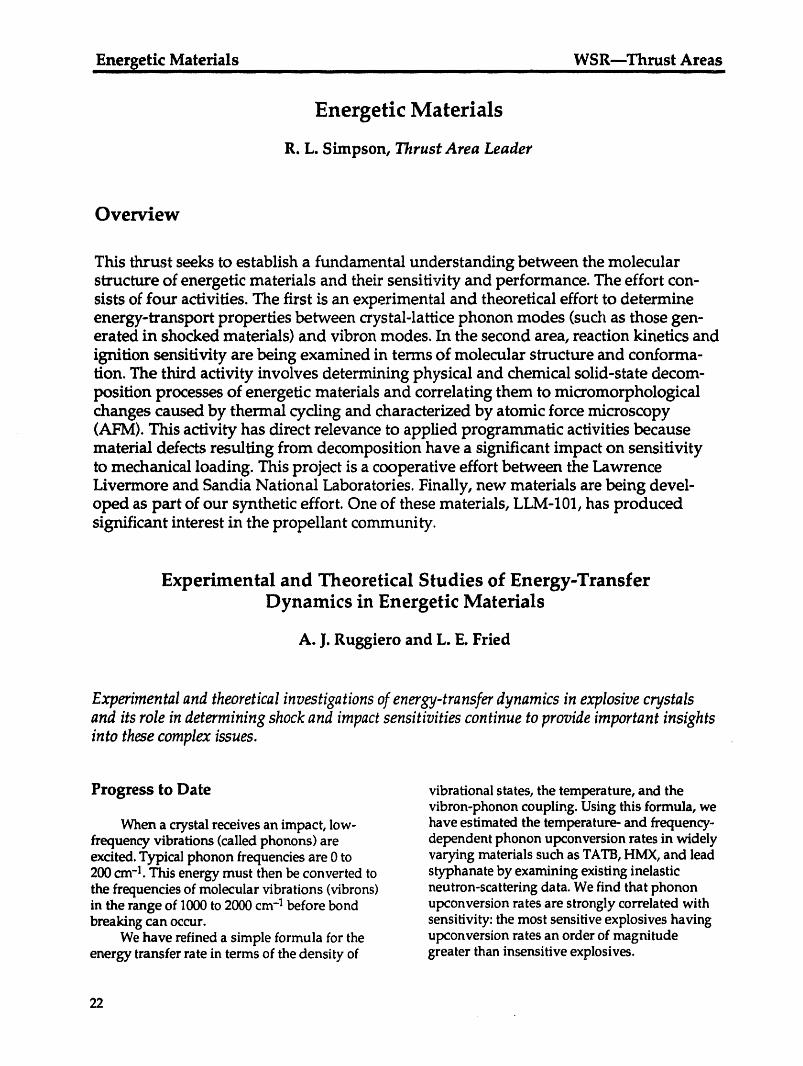
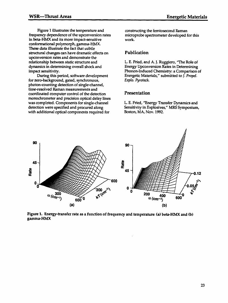
Figure I illustrates the temperature and constructing the femtosecond Ramanfrequency dependence of the upconversion rates microprobe spectrometer developed for thisin beta-HMX and its more impact-sensitive work.conformational polymorph, gamma-HMX.These data illustrate the fact that subtlestructural changes can have dramatic effects on Publicationupconversion rates and demonstrate therelationship between static structure and L.E. Fried, and A. J. Ruggiero, "The Role ofdynamics in determining overall shock and Energy Upconversion Rates in Determiningimpact sensitivity. Phonon-Induced Chemistry: a Comparison of
During this period, software development Energetic Materials," submitted to J.Propel.for zero-background, gated, synchronous, Explo. Pyrotech.photon-counting detection of single-channel,time-resolved Raman measurements andcoordinated computer control of the detection Presentationmonochrometer and precision optical delay lineswas comp!eted. Components for single-channel L.E. Fried, "Energy Transfer Dynamics anddetection were specified and procured along Sensitivity in Explosives," MRSSymposium,with additional optical components required for Boston, MA, Nov. 1992.
90 90
|n- p.12
J00 .,,"_ 03O0
400r_o?-1) 600 ) co(era-T) soo
(a) (b)
Figure 1. Energy-transfer rate as a function of _equency and temperature: (a) beta-HMX and (b)gamma-HMX
23
Energeti c Materials WSR---Thrust AreasII II I III II I II j
Chemistry of High-Pressure Reactions
M. F. Foltz
Observations of high-pressure-reaction rates are being interpreted as molecular conformationeffects.
Progress to Date C and C-O' intramolecular bonds. Asymmetricdeformation of the PETN molecules is suggested,
Work continued in the interpretation of the possibly to a lower molecular symmetryhigh-pressure bum rate of the sensitive high conformation.explosive pentaerythritol tetranitrate (PETN) that Progress has been made in setting up an_had been measured in the diamond anvil cell using a data base for studying the relationship(DAC) over the pressure range from 2 to 20 GPa. between crystallographic structural propertiesThe burn-rate data showed that PETN burns one and impact sensitivity of high explosives. Based
to two orders of magnitude faster in the DAC on sensitivity changes incurred by modifying thethan does 1,3,5-triamino-2,4,6-trinitrobenzene intermolecular hydrogen bonding of known(TATB) or nitromethane (CH3NO2), respectively, systems, new molecular composites have beenThe PETN bum-rate: curve does not show simple proposed that are expected to be more insensitivepressure-depende_t behavior like that of nitro- than the components individually. One proposedmethane, but has instead abrupt variations like material, a complex between tetranitrodibenzo-that seen in the previously measured burn-rate 1,3a,4,6a-tetraazapentalene (TACOT) andcurves of TATB and the four polymorphs of dinitrobenzotriazole, attempts in its design tohexanitrohexaazaisowurtzitane, provide a stronger intermolecular network to
In order to interpret these changes, static- produce a material that will have greater impactpressure DAC mid-IR FTIRspectra were taken of insensitivity than either material separately. Themicropellets of PETN embedded in KBr. Provi- role of bond resonance in thermally insensitivesional identification has been based on (1) pub- explosives will also be addressed by the couplinglished assignments of the fundamental vibrations of dinitrobenzotriazole with the stable TACOT.of the O'-NO2 group determined from nitro com- Work is under way to produce this and otherpounds and nitrate esters, (2) comparison of proposed materials for testing.PETN spectral features with those of pentaeryth-ritol, pentaerythritol tetrahalides, meso-erythritol,and other nitrate esters, and (3) general normal- Publicationmode identification guidelines. More definitiveidentification is planned now that deuterated M.F. Foltz, "Pressure Dependence on thePETN, provided by K.-Y. Lee of Los Alamos Reaction Propagation Rate of PETN at HighNational Laboratory, is available for infrared Pressure," Lawerence Livermore Nationalanalysis. Laboratory, Livermore, CA, UCRL-JC-111316,
Based on the preliminary spectral analysis, submitted to the lOth Int. Syrup. on Detonation,shifts and intensity changes in the infrared July 1993, Boston, MA.spectrum can be seen to suggest a pressure-induced molecular deformation in the pressureregime of the abrupt change(s) in the burn rate.Under static compression, PETN exhibits thegreatest distortion in the CH2 deformation, NO2symmetric stretch, and C-O'-N deformationmodes. Distortions other than deformation of thecore carbon skeleton that are available to relieve
pressure-induced strain are motions about the C-
24

WSR---Thrust Areas Energetic Materials
ii i I i i
Condensed-Phase Thermal Decomposition of Energetic MaterialsInvestigated by Atomic Force Microscopy (AFM) and Simultaneous
Thermogravimetric Modulated Beam Mass Spectrometry (STMBMS)
T. A. Land, R. Behrens, Jr.,* and W. Siekhaus
To gain a more detailed ,mderstanding of the issues of energetic materials decomposition
and sensitivity, a collaboration between LLNL (Land and Siekhaus) and Sandia National
Laboratories (Behrens) has commenced. The focus of our research is to gain an understanding of
the important physical and chemical parameters that affect the thermal stability of TA TB. Onearea of research is directed at understanding the physical changes that occur in the material as a
function of heating, impact, and shock. The other area of our research focuses on understandingthe chemical kinetics of the condensed-phase decomposition reactions. Since the decomposition of
TATB occurs in the solid phase, both the physical and the chemical natures of the thermal
reactions need to be understood and incorporated into any model that is developed to predict itsresponse in abnormal thermal environments.
AFM larger holes are 100 to 140 nm in diameter, andthe smaller ones are 25 to 50 nm. These holes may
In experiments done so far, atomic force be remnants of hot spots of reactions that havemicroscopy (AFM) has been used to observe the started and died out. The AFM's high-resolutionmcrphological changes that occur when TATB capability is being used to look for the beginningshas been thermally cycled. The high-resolution of these reaction centers and to predict how theycapabilities of the AFM allow us to investigate may change with time and temperature.the formation and growth of reaction centers orhot spots where reactions may have initiated andsubsequently died out. It is important to correlatethese observed physical changes with chemicalchanges in the material.
In our exper/ments, the AFM is used toinvestigate morphological changes on the surfaceand in the bulk of TATB crystals as a function ofheating. Information about the bulk was obtainedby cleaving crystals that have been heated andexamining the exposed surfaces. After cleavingTATBcrystals that were heated to 300"C andquickly recooled to room temperature, manypatches of submicron-size holes were observed.This is the first time that such holes have been
observed in the bulk of thermally cycled TATB.In contrast to holes previously observed to beconcentrated on the surface of shocked andimpacted TATB,3 these thermally produced holeshave been observed throughout the crystal.
Figure 2 is a higher-resolution, 1.1- x 1.1-proimage of typical holes that were observed. The Figure 2. 1.1- x 1.1-pro image of typical holes
created by heating a TATB crystal to 300"C.The*Energetic Materials Center, SandiaNationalLaboratories larger ones are 100 to 140 run in diameter.
25
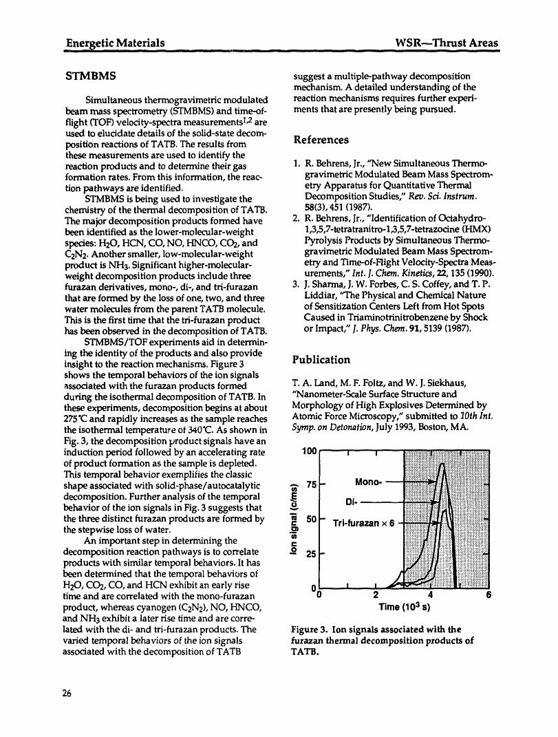
Energetic Materials WSR--Thrust Areas_l _ i i I m Ill I I I I I
STMBMS suggest a multiple-pathway decompositionmechanism. A detailed understanding of the
Simultaneous thermogravimetric modulated reaction mechanisms requires further experi-beam mass spectrometry (STMBMS)and time-of- ments that are presently being pursued.flight (TOF) velocity-spectra measurements 1,2areused to elucidate details of the solid-state decom-position reactions of TATB. The results from Referencesthese measurements are used to identify thereaction products and to determine their gas 1. R. Behrens, Jr., "New Simultaneous Thermo-formation rates. From this information, the reac- gravimetric Modulated Beam Mass Spectrom-tion pathways are identified, etry Apparatus for Quantitative Thermal
STMBMS is being used to investigate the Decomposition Studies," Rev. $ci. Instrum.chemistry of the thermal decomposition of TATB. 58(3), 451 (1987).The major decomposition products formed have 2. R. Behrens, Jr., "Identification of Octahydro-been identified as the lower-molecular-weight 1,3,5,7-tetratranitro-l,3,5,7-tetrazocine (HMX)species: H20, HCN, CO, NO, HNCO, CO2, and Pyrolysis Products by Simultaneous Thermo-C2N2.Another smaller, low-molecular-weight gravimetric Modulated Beam Mass Spectrom-product is NHs. Significant higher-molecular- etry and Time-of-Flight Velocity-Spectra Meas-weight decomposition products include three urements," Int. J.Chem. Kinetics, 22, 135 (1990).furazan derivatives, mono-, di-, and tri-furazan 3. J. Sharma, J.W. Forbes, C. S. Coffey, and T. P.that are formed by the loss of one, two, and three Liddiar, "The Physical and Chemical Naturewater molecules from the parent TATB molecule, of Sensitization Centers Left from Hot SpotsThis is the first time that the tri-furazan product Caused in Triaminotrinitrobenzene by Shockhas been observed in the decomposition of TATB. or Impact," J. Phys. Chem. 91, 5139 (1987).
STMBMS/TOF experiments aid in determin-ing the identity of the products and also provideinsight to the reaction mechanisms. Figure 3 Publicationshows the temporal behaviors of the ion signalsassociated with the furazan products formed T.A. Land, M. F. Foltz, and W. J.Siekhaus,during the isothermal decomposition of TATB. In "Nanometer-Scale Surface Structure andthese experiments, decomposition begins at about Morphology of High Explosives Determined by275°Cand rapidly increases as the sample reaches Atomic Force Microscopy," submitted to lOth Int.the isothermal temperature ot 340"C.As shown in Symp. on Detonation, July 1993, Boston, MA.Fig. 3, the decomposition product signals have aninduction period followed by an accelerating rate 100of product formation as the sample is depleted.This temporal behavior exemplifies the classicshape associated with solid-phase/autocatalytic _. 75decomposition. Further analysis of the temporalbehavior of the ion signals in Fig. 3 suggests thatthe three distinct furazan products are formed by _ 60the stepwise loss of water.
An important step in determining the "_decomposition reaction pathways is to correlate -_ 26products with similar temporal behaviors. It hasbeen determined that the temporal behaviors of 0H20, CO2, CO, and HCN exhibit an early risetime and are correlated with the mono-furazan
product, whereas cyanogen (C2N2), NO, HNCO, Timo (103 Is)and NH3 exhibit a later rise time and are corre-lated with the di- and tri-furazan products. The Figure 3. Ion signals associated with thevaried temporal behaviors of the ion signals furazan thermal decomposition products ofassociated with the decomposition of TATB TATB.
26
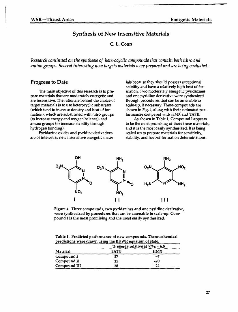
I WSR--Thrust Areas Energetic Materialsiii ii - --- _ -- i illllll ii iii IIII II II IIII IIIIIIII - IIIIII -- III IIII III I II
Synthesis of New Insensitive Materials
C. L. Coon
Researchcontinued on the synthesis of heterocycliccompounds that contain both nitro andamino groups. Several interesting new targets materials were preparedand are being evaluated.
Progress to Date ials because they should possess exceptionalstability and have a relatively high heat of for-
The main objective of this research is to pre- mation. Two moderately energetic pyridazinespare materials that are moderately energetic and and one pyridine derivative were synthesizedare insensitive. The rationale behind the choice of through procedures that can be amenable totarget materials is to use heterocyclic substrates scale-up, if necessary. These compounds are(which tend to increase density and heat of for- shown in Fig. 4, along with their estimated per-mation), which are substituted with nitro groups formances compared with HMX and TATB.(to increase energy and oxygen balance), and As shown in Table 1, Compound I appearsamino groups (to increase stability through to be the most promising of these three materials,hydrogen bonding), and it is the most easily synthesized. It is being
Pyridazine oxides and pyridine derivatives scaled up to prepare materials for sensitivity,are of interest as new insensitive energetic mater- stability, and heat-of-formation determinations.
OH NH2 NH2I "
O2N O2N O2N,= _,_ jNO2
" i1% '_0 H2N" """ "NH,
NO2 NO2
I II III
Figure 4. Three compounds, two p}_ridazines and one pyridme derivative,were synthesized by procedures that can be amenable to scale-up. Com-pound I is the most promising and the most easily synthesized.
Table 1. Predicted performance of new compounds. Thermochemical
predictions were drawn using _e BKWR equation of state.
• % energy relative a t v/v0 --6.5Material TATB HMX
,, ,, ,,, ,, _
Compound I 57 -7Compound II 35 -20Compound III 28 -24
27
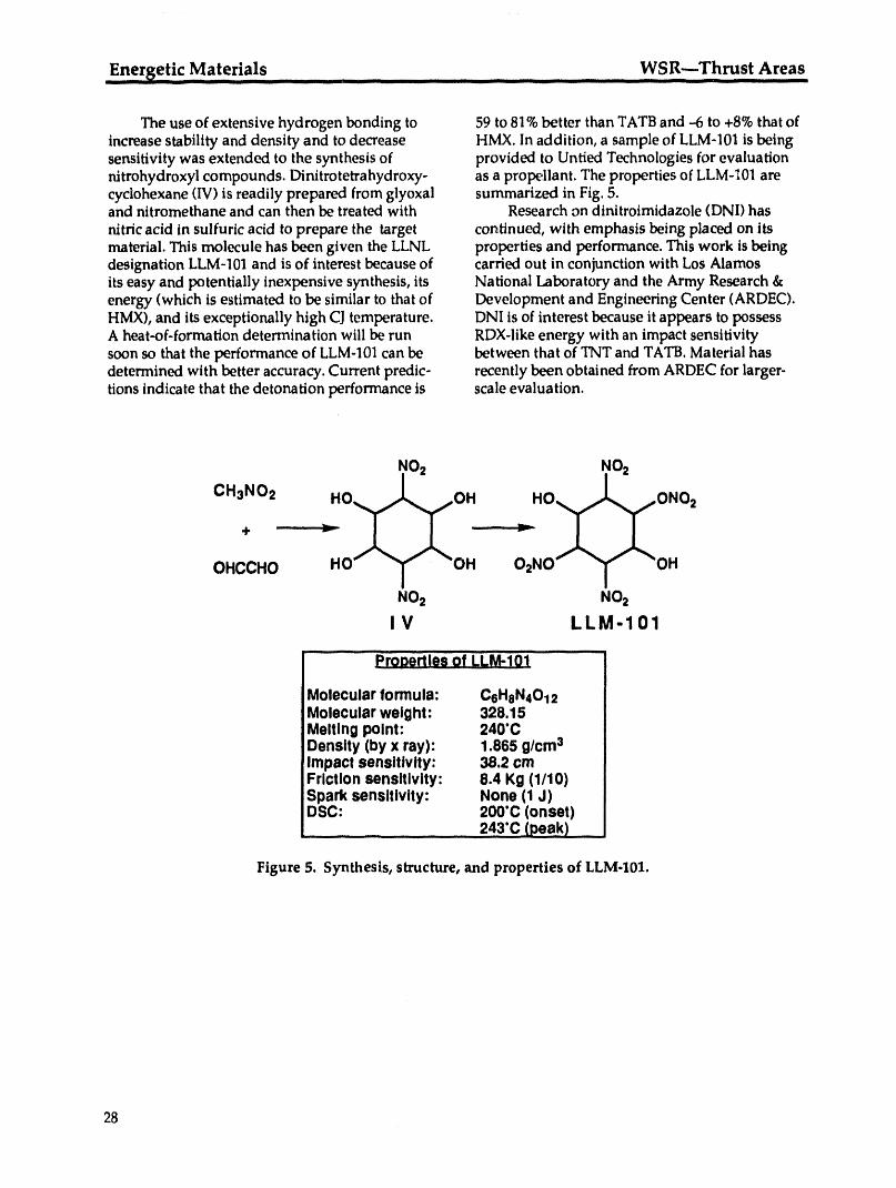
Energetic Materials WSR---Thrust Areasiiiii i iii iiiii i i II iiiii i _[ 'l Ill I III II Illlll _ I Illll'll IIIfill
The use of extensive hydrogen bonding to 59 to 81%better than TATB and -6 to +8% that ofincrease stability and density and to decrease HMX. In addition, a sample of LLM-101 is beingsensitivity was extended to the synthesis of provided to Untied Technologies for evaluationnitrohydroxyl compounds. Dinitrotetrahydroxy- as a propellant. The properties of LLM-101 arecyclohexane (IV) is readily prepared from glyoxal summarized in Fig. 5.and nitromethane and can then be treated with Research on dinitroimidazole (DNI) has
nitric acid in sulfuric acid to prepare the target continued, with emphasis being placed on itsmaterial. This molecule has been given the LLNL properties and performance. This work is beingdesignation LLM-101 and is of interest because of carried out in conjunction with Los Alamosits easy and potentially inexpensive synthesis, its National Laboratory and the Army Research &energy (which is estimated to be similar to that of Development and Engineering Center (ARDEC).HMX), and its exceptionally high CJtemperature. DNI is of interest because it appears to possessA heat-of-formation determination will be run RDX-like energy with an impact sensitivitysoon so that the performance of LLM-101can be between that of TNT and TATB. Material hasdetermined with better accuracy. Current predic- recently been obtained from ARDEC for larger-tions indicate that the detonation performance is scale evaluation.
NO2 NO2
CH3NO2 HO..__T.....OH HO_.._.,-ONO2
OHCCHO HO OH 02NO OH
NO2 NO2
IV LLM-101
......... -Properties OIi"LLM-101 '.......
Molecular formula: C6HoN4012Molecular weight: 328.15Meltlng polnt: 240"CDenslty (by x ray): 1.865 g/cm3Impact sensltlvlty: 38.2 cmFrlctlon sensltlvlty: 8.4 Kg (1/10)Spark sensltlvlty: None (1 J)DSC: 200"C(onset)
..... 243'CLoeak)
Figure 5. Synthesis, structure, and properties of LLM-101.
28

Weapons-Suppo_g Research Groupsi i _111 Iill I -- R I _ iiiiiii ii I I iiii iiiiii _ iii iiii iiiiiii IIIIIIII II _ I III _ -- iiii1[1111.__I
Weapons-Supporting Research
Groups
29
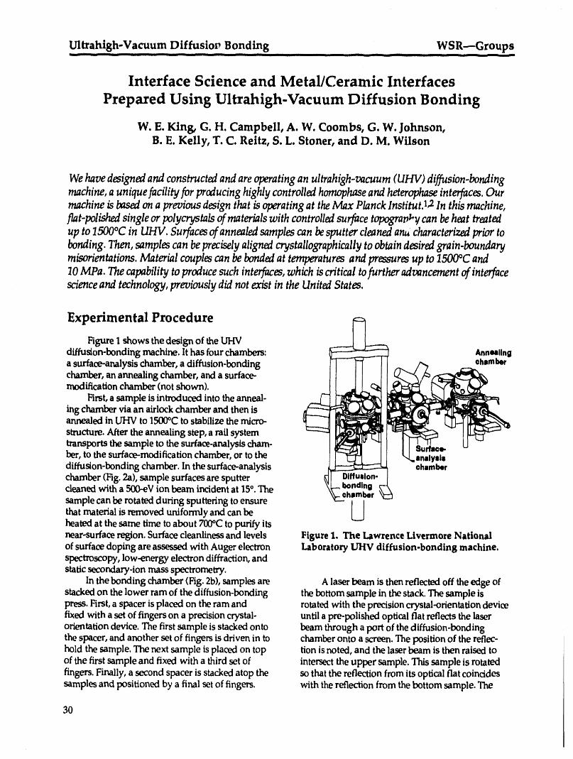
.Ultrahigh-Vacuum D!ffusio_ Bonding WSR---Groupst t ttttti t ]ttt ..... it[ tt t _ it
Interface Science and Metal/Ceramic Interfaces
Prepared Using Ultrahigh-Vacuum Diffusion Bonding
W. E. King, G. H. Campbell, A. W. Coombs, G. W. Johnson,B. E. Kelly, T. C. Reitz, S. L. Stoner, and D. M. Wilson
We have designed and constructed and are operating an ultrahigh-vacuum (UHV) diffusion-bonding
machine, a unique facility for producing highly controlled homophase and heterophase interfaces. Our
machine is basal on a previous design that is operating at the Max Planck lnstitut.l_ In this machine,flat-polished single or polycrystals of materials with controlled surface t_an_'_/ can be heat treated
up to 1500°C in UHV. Surfaces of annealed samples can be sputter cleaned an#, characterized prior to
bonding. Then, samples can be precisely aligned crystallographically to obtain desired grain.boundary
mison'entations. Material couples can be bonded at temperatures and pressures up to 1500°C and
10 MPa. The capability to produce such interfaces, which is critical to further advancement of interfacescience and technology, previously did not exist in the United States.
Experimental Procedure
Figure I shows the design of the UHVdiffusion-bonding machine. It hasfourchambers: Ann_llnga surface-analysischamber,a diffusion-bondingchamber,anannealingchamber,anda surface-modificationchamber(notshown).
First,a sampleis introducedintotheanneal-ingchamberviaanairlockchamberandthenisannealedin UHV to 1500°Cto stabilizethemicro-structure. After the annealing step, a railsystemtransports the sample to the surface-analysis cham-
ber, to the surface-modification chamber, or to the t [ _ _l I ",_.anslyslsdiffusion-bonding chamber. In the surface-analysis _ ©ham_rchamber (Fig. 2a), sample surfaces are sputtercleaned with a 5(D-eV ion beam incident at 15°. Thesample can be rotated during sputtering to ensure i/
that material is removeduniformly and can be Uheated at the same time to about 700°C to purify itsnear-surface region. Surface cleanliness and levels Figure 1. The Lawrence Livermore Nationalof surface doping areassessed with Auger electron Laboratory UItV diffusion-bonding machine.spectroscopy, low-energy electron diffraction, andstatic secondary-ion mass spectrometry.
In the bonding chamber (Fig. 2b), samples are A laser beam is then reflected off the edge ofstacked on the lower ram of the diffusion-bonding the bottom sample in the stack. The sample ispress. First, a spacer is placed on the ram and rotated with the precision crystal-orientation devicefixed with a set of fingers on a precision crystal- until a pre-polished optical fiat reflects the laserorientation device. The first sample is stacked onto beam through a port of the diffusion-bondingthe spacer, and another set of fingers is driven in to chamber onto a screen. The position of the reflec-hold the sample. The next sample is placed on top tion is noted, and the laser beam is then raised toof the first sample and fixed with a third set of intersect the upper sample. This sample is rotatedfingers. Finally, a second spacer is stacked atop the so that the reflection from its optical fiat coincidessamples and positioned by a final set of fingers, with the reflection from the bottom sample. The
3O

WSR---Groups Ultrahigh-Vacuum Diffusion Bondingml 1111 i .... I --+ 11111111 ........ iiiiii III IIi iiiiiiiii ....... __ -- LL ............. IIIf --- _ I111
_ .... i:!_i!i
t 1
+Figure 2a. Cutaway view of the surface-analysis Figure 2b. Cutaway view of the diffusion-chamber. SIMS ion gun is at top left. SIMS bonding chamber. Bonding chamber and pressquadrupole mass spectrometer is at top right, atreat top left.
rotation gears of the precision crystal-orientation tha_the applied force is distributed as an uniformdevice are locked, and the upper ram is brought to pressure on the bond area, a spherical radius ofbear on the sample stack. A small load is added, curvature was ground on one end of the top spacerand the fingers are withdrawn. The entire stack is block to allow point contact with the top ram. Thethen raised into the furnace forbonding. An airlock applied force resulted in apressure of 1 MPa at theis also incorporated in the diffusion-bonding bonding interfacein all cases studied here.chamber to facilitate removal of bonded samples. The bonding temperature and times were
variedto study their effects. The temperatureschosen were 800, 900, and 1000°C,and the times
Results and Discussion were 1,2,and 4 hr. During the diffusion-bondingheat cycle, the pressure in the bonding chamber
Bonding Kinetics of Copper with never _,cceeded 1x 10⁻⁸ Torr.The heating andSapphire cooling rates were 20 and 15°C/rain, respectively.Ck_racterization of the bonded area at the
To determine the conditions under which interface was done by optical microscopy throughcompletely dense interfaces form, we are studying the sappl_fire.With light at normal incidence, thethe evolution of bonded interfacialarea as a func- bonded areas are light in contrastbecause thetion of bonding temperature and time. The system copper ccinformsto the polished surface of theunder investigation is copper/sapphire. Insight will sapphire +rodreflects light back into the objective.be gained from this study into the appropriate The micrcgraphs were digitized and, foreachbonding conditions for copper/alumina mechanical microgral:_h,abrightness threshold was chosentestspecimens,anddatawillbeobtainedona thatcorrespondedtothebondedarea.Thenumbermodelsystemindiffusionbonding, ofpixelsabovethisbrightnesswassummed,and
h_the surface-analysis chamber, the surfaces of an area fraction was calculated.the specimens to be bonded were cleaned by Some results are shown in Figs. 3a and 3b.sputtering with Xe. ions at 1 keV. The samples The average measured bonded area is shown alongwere rotated during sputtering to maintain an even with the high and low measures, indicating thesurface finish. The cleaned surfaces were placed variability in bonded area density across the entiretogether in the bonding chamber, and high-purity interface. Tl_eresults indicate that achieving a fullyalumina spacer blocks were inserted between the dense interface in the copper/alumina system at aspecimens and the rams of the hydraulic press. To pressure of 1MPa requires lengthy bonding times,ensure proper alignment of the specimen stack so probably 6 to 12 hr, at 1000°C or higher.
31
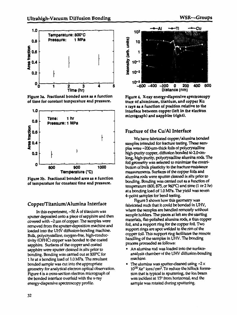
-- _ . . _ ....... _ , _ . _ _-- ..,-..__,_ ............. ,,, , -- _ , -- , iii ,11il -- __ . ............
-'-s-Al "-e--Tl _Cu1.0 .....- ;....... , ........, ..... , .... 102
Temperature: 800°0
0.8 Pressure: i MPa _ 10
0.2 _ 10"2
00 .....- , = i ..........., ........... 10-'_1 2 3 4 5 -600 -400 -200 0 200 400 600Tlme (hr) Dlstance (nm)
Figure 3a. Fractional bonded area as a function Figure 4. X-ray energy-dispersive spectroscopyof time for constant temperature and pressure, trace of aluminum, titanium, and copper Ka
x rays as a function of position relative to the1.0 .... . , ........., ....... , interface between copper (left in the electron
Time: 1 hr micrograph) and sapphire (right).0.8 Pressure: 1 MPa
0.6 Fracture of the Cu/AI Interfacet We have fabricated copper/alumina bonded
0.4 samples intended for fracturetesting. These sam-pies were -2_-thick foils of polycrystalline
0.2 _ I" hlgh-purity copper, diffusion bonded to 2.0-cm-long, high-purity, polycrystalline alumina rods. The
0 -- --_......._ ,,,_ ,,, , ...... ._, - _., _ - foilgeometrywasselectedto minimizethecontri-800 900 1000 bution of bulk plasticity to the fracture-resistance
Temperature (°C) measurements. Surfaces of thecopper foils and
Figure 3b. Fractional bonded area as a function alumina rods were sputter cleaned in situ prior toof temperature for constant time and pressure, bonding. Bonding was carriedout as a function of
temperature (800,875, or 960°C)and time (1 or 2 hr)ata bonding load of 1.0MPa. The yield was seven4--point samples for bend testing.
Figure 5 shows how this geometry wasCopper/Titanium/Alumina Interface fabricated such that it could be bonded in UHV,
In this experiment, -50 A of titanium was where the samples are handled remotely withoutsputter deposited onto a piece of sapphire and then sample holders. The pieces at left are the startingcove_d with -2 _ of copper. The samples were materials, flat-polished alumina rods, a thin copperremoved from the sputter-deposition machine and foil, and a support ring for the copper foil. Twoloaded into the UHV diffusion-bonding machine, support rings are spot welded to the rim of theBulk, polycrystalline, oxygen-free, high-conduc- copper foil. This support ring facilitates the remotetivity (OFHC) copper was bonded to the coated handling of the samples in HV. The bondingsapphire. Surfaces of the copper and coated process proceeded as follows:sapphire were sputter cleaned in situ prior to • An alumina rod was loaded into the surface-bonding. Bonding was carried out at 800°C for analysis chamber of the UHV diffusion-bonding1hr at a bonding load of 1.0 MPa. The resultant machine.bonded sample was cut into the appropriate • The alumina was sputter-cleaned using ~2 xgeometry foranalytical electron optical observation. 10TMXe+ ions/cm 2.To reduce the hillock forma-Figure 4 is a cross-section electron micrograph of tion that is typical in sputtering, the ion beamthe bonded interfaceoverlaid with the x-ray was incident at 150from horizontal, and theenergy-dispersive spectroscopy profile, sample was rotated during sputtering.
32

WSR---Groups Ultrahigh-Vacuum Diffusion Bonding...... IIIII I Illllll -- _ _ Inlll II Wj I I Ill I I IIII!111I - J _- _. -- _ Illlllllll II ...... IIIIUl _ Hill _.
i i ij' i iil
Figure 5. Fabrication of 4--point bend samples. (a) Alumina rod, copper foil, and copper ring (left); as.bonded samples (center); one of seven bend-test samples cut from a single sample (right). (b) Magni-fled image of bond line, shown with a human hair for comparison.
• After cleaning, the alumina was transferredto micrograph of the copper foil bonded between twothe diffusion-bonding chamberand loaded onto alumina bars. A human hair shown in the micro-the lower ramof the diffusion-bonding press, graph illustrate how thin the copper foil is.
• The copper foil was then sputter cleaned on With a high-speed saw, samples were notchedboth sides by means of a procedure similar to for4-point bend testing.Notches were 0.5 mm deepthat used for the alumina, except that the copper with a kerrof-87 grn. Samples were loaded on awas heated to -400°C during sputtering. 4-point bend fixture. The midpoint deflection was
• The copper foil was stacked atop the first alu- monitored by means of a spring-loaded probe fittedmina rod in the diffusion-bonding chamber, with two opposing dip gauges. Load and midpoint
• The second alumina bar was cleaned, complet- displacement were monitored as a function of timeing the sample stack, for a constant crosshead displacement rate.
• A load of 1.6 MPa was applied to'the stack,which was then raised into the radio-frequencyheater in the diffusion-bonding chamber. References
• The temperature was ramped to the set pointover25rnin,maintainedfortherequiredsoak I.H.F.Hschmeister,W. Mader,B.Gibbesch,andtime, and then ramped back to room temper- G. Elssner, "Preparation, Properties, and Struc-ature over 15 min. tureof Metal/Oxide Interfaces," in Interfacial
During the bonding process, the vacuum in Structure, Properties,and Design, M. H. Yoo,the diffusion bonding chamber typically did not W.A.T. Clark, and C. L. Briant,Eds. (MRSexceed 5 x 10⁻⁹ Tort. The samples at center in Syrnp.Proc.122, Materials Research Society,Fig.5a show the as-bonded configuration. It is Pittsburgh, PA, 1988),pp. 529--540.possible to produce one to two samples per day of 2. B.Gibbesch and G. Elssner, "Ultra High Vacuumthis type. After removal from the bonding machine, Diffusion Bonded Nb-AI203 and Cu-AI203each sample was cut into seven 3- x 3- x 40-mm Joints--TheRole of Welding Temperature andbars for 4-point bend testing. This bend-test sample Sputter Cleaning," Acta MetaU.Mater. 40configuration is shown at right. Figure 5b is a (Suppl.), $59--$66(1992).
33iiII
I

Advanced Synchrotron Radiation Study of Materials WSR--Groups_ I III IL ] IIIII _ .... _ II __ II IIII III _ - nl _ _ i .... I II -- Illlll III1[ __ II ___
Advanced Synchrotron Radiation Study of Materials
J. Wong, P. A. Waide, and J. W. Elmer
Overview
Our objective is to advance and develop state-of-the-art synchrotron radiation (SR)methods to investigate and elucidate the role of atomic and electronic structures indetermining the physicochemical properties of materials and their processing.
The activities defined in this program take advantage of the various unique charac-teristics of SR such as high intensity, high collimation, high polarization, and broad-band tunability from VUV to hard x ray in order to probe the structure of matter orLan element-selective basis in real time as well as in real space down to the second andsubsecond time scales. The research areas include an expansion of our existing SRcapabilities in material characterization using these powerful photon sources anddevelopment of new capabilities to (a) investigate the phase transformation in situ infusion welds; (b) develop and implement a novel, quick-scanning EXAFS capability onour PRT x-ray beamline at SSRLto study time-dependent phenomena; and (c) developnew soft x-ray capabilities to study low-Z materials containing silicon, aluminum, andmagnesium that are of technological importance.
Some highlights of our technical accomplishments are as follows:
• Designed and built a diffraction chamber to study phase transformation in fusionwelds.
• Achieved the first high-resolution EXAFSspectra of silicon, aluminum, andmagnesium with a YB66double-crystal monochromator.
• Defined and evaluated the critical experimental parameters in QEXAFS in both thetime and energy resolution domains.
From 6/15/92 to 11/15/92, J.Wong worked at HASYLAB in Hamburg to complete thesecortd and last five months of his Humboldt Award fellowship work on QEXAFSinvestigation and YB66characterization at the BESSYsynchrotron laboratory in Berlin.
34
i

WSR---Groups Advanced Synchrotron_ Radiation _Study of Materials
Welding-Induced Solid-State Phase Transformations:Problem Definition
J. W. Elmer, J. Wong, P. A. Waide, and E. M. Larson*
We are using time-resolved diffraction to investigate the solid-state phase transformations that
occur during the rapid thermal cycling of materials in the heat-affected zone (I-IAZ) and fusion
zone (FZ) in a fusion weld.
Introduction Discussion
Solid-state phase transformations often Figure I is a thermal profile that surroundsoccur during the rapid thermal cycle produced a quasisteady-state weld in a material that under-by a weld. Examples of such phase transforma- goes a solid-state phase transformation at a tem-tions that occur during welding include allotropic perature TT and melts at a temperature TL. If thetransformations such as bcc/hcp elemental material is titanium(which has a low-temperaturetitanium, transformations in two-phase alloys hcp phase and a high-temperature bcc phase) andsuch as fcc/bcc stainless steels, and martensitic the equilibrium phase relationships are main-transformations such as the fcc/bct transforma- tained, then the HAZ depicted in Fig. I denotestion that occurs in iron-based steel alloys. Most of regions between TTand TL. Material ila thisthe phase transformations of interest will involve region has the microstructural history hcp/bcc/deviations from equilibrium microstructures, hcp. The region depicted FZ has been heatedresulting in partial transformations and/or the above the liquidus temperature. Material in thiscreation of metastable phases. These types of region has the microstructural history hcp/bcc/phase transformations receive a considerable liquid/bcc/hcp. Regions outside the HAZ do notamount of attention in welding research, devel- reach the tcansition temperature and would notopment, and application studies, be expected to form any new phases, although
.,t I Figure 1. Thermalprofile surrounding_.., o°
. a weld moving at• a velocity V. The
.o,. region between the,,,.,._. boundaries marked
"start" and "finish"
is the region wherethe allo-tropic phasetransformation takesplace.
* University of New Mexico, Albuquerque
35
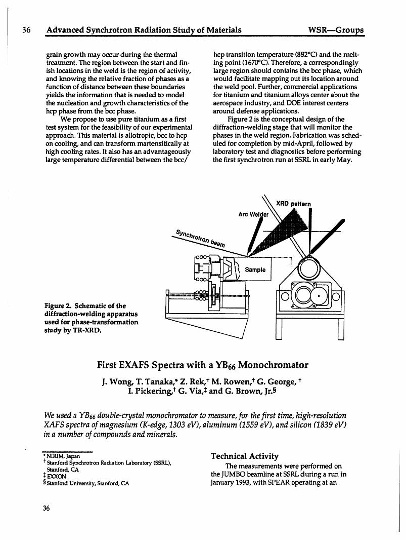
36 Advanced Synchrotron Radiation StudY of, Materials WSR--Groups
grain growth may occur during the thermal hcp transition temperature (882°0 and the melt-I treatment. The region between the start and fin- ing point (1670°C). Therefore, a correspondingly
ish locations in the weld is the region of activity, large region should contains the bcc phase, whichand knowing the relative fraction of phases as a would facilitate mapping out its location aroundfunction of distance between these boundaries the weld pool. Further, commercial applicationsyields the information that is needed to model for titanium and titanium alloys center about thethe nucleation and growth characteristics of the aerospace industry, and DOE interest centershcp phase from the bcc phase, around defense applications.
We propose to use pure titanium as a first Figure 2 is the conceptual design of thetest system for the feasibility of our experimental diffraction-welding stage that will monitor theapproach. This material is allotropic, bcc to hcp phases in the weld region. Fabrication was sched-on cooling, and can transform martensitically at uled for completion by mid-April, followed byhigh cooling rates. It also has an advantageously laboratory test and diagnostics before performinglarge temperature differential between the bcc/ the first synchrotron run at SSRLin early May.
XRDpattern
Arc Welder
Sample
r l
Figure 2. Schematic of the w
diffraction-welding apparatusused for phase-transformationstudy by TR-XRD.
First EXAFS Spectra with a YB66 Monochromator
J. Wong, T. Tanaka,* Z. Rek, t M. Rowen, t G. George, t
I. Pickering, _ G. Via,_ and G. Brown, Jr.§
We used a YB66 double-crystal monochromator to measure, for the first time, high-resolution
XAFS spectra of magnesium (K-edge, 1303 eV), aluminum (1559 eV), and silicon (1839 eV)
in a number of compounds and minerals.
,,
• NIRIM,l,wn Technical ActivityStanfordSynchrotronRadiationLaboratory(SSRL), The measurements were performed onStanford,CAEXXON the JUMBO beamline at SSRLduring a run in
§ Stanford Urdversity, Stanford, CA January 1993, with SPEAR operating at an
36

WSR__Groups Advanced Synchrotron Radiatio n StudY of Materialsiiii1_ i [ I I I I Ill I iiiiiiiiii i I I I
electron energy of 3 GeV, injection current of an upper energy limit to just below the silicon K---100 mA, and a lifetime of over 20 hr. A YB66 edge at 1839 eV. With YB6a,aluminum EXAFSboule was grown using an indirect-heating, float- spectra can now be routinely recorded to 2060 eV,zone technique. A sister pair of (400)-oriented some 500 eV above its K-edge, to give a muchcrystals (2d = 11.72 A), each 18 x 10 x 0.7 mm more useful EXAFSdata range to 11 A-1.thick, were cut and polished from this boule. Figure 4 is an experimental EXAFSscan ofAreas of high homogeneity, as revealed by white- sillimanite, an aluminosilicate mineral havinglight synchrotron radiation topography and by a a chemical composition of Al2SiOs, from 1525single peak in rocking curve measurements, were to 2060 eV. This spectrum was recorded at acarefully mapped out for each crystal. These SPEAR current of ~79 mA. A fine step size ofareas were found to be located along the growth 0.2 eV/point was used over both the aluminumaxis of the crystal closer to the zone end. The and silicon edges to register the high.-resolutioncrystal pair was configured in a nondispersive features in the XANES region. The integrationmode and with a fixed exit-beam height, sending time for each data point was 2 s. The whole spec-a monochromatic beam from the UHV mono- trum was recorded in just over an hour. Positivechromator chamber to a vacuum sample chamber chemical shifts between 5 and 6 eV from the(10-s Torr or better) through a 0.4-_-thick CVD corresponding aluminum metal and elementaldiamond window. The energy position of the silicon values were measured in this and othermonochromator was initially calibrated by means aluminosilicate minerals and compounds.of its own transmission curve from the position Figure 5 is the EXAFS spectrum of mag-of the [.3and L2 edges of yttrium at 2080 eV and nesium in MgO recorded from 1250 to 2000 eV.2156 eV, respectively, assuming no chemical shift The scanning parameters were similar to thosein YB66from the metal values. X-ray absorption used for the sillimanite sample. Note again thespectra were recorded by monitoring total elec- high-resolution features in the XANES region. Atron yield with a channeltron, positive edge shift of 3 to 4 eV with respect to
In Fig. 3, the "raw" experimental EXAFS magnesium metal (1303 eV) was observed. Withspectrum of aluminum metal is shown. This this monochromator, EXAFS data can now bespectrum, the first EXAFS scan ever made with collected to over 700 eV above the magnesiumYB66,was recorded with a SPEAR current of edge to yield a kmax,=13.5A-1, vs kmax= 8 A-1 for-50 mA. The integration time from each data a beryl monochromator, which limits data to justpoint was I s. Traditionally, aluminum K-edge below the K-edge of its aluminum constituent.EXAFSspectra have been recorded with quartz The new data clearly establish the perform-(1010) monochromator crystals, which undergo ance of YB66as both a high-resolution and syn-radiation damage in a synchrotron beam in a chrotron radiation-stable soft x-ray monochroma-matter of hours, thus degrading the resolution, for in the 1- to 2-keV region. Over a continuousThe use of a quartz monochromator would yield experimental run of two weeks on the JUMBO
'9.5 ' "', ' , 0.5 " ' ' ' ' 1.....
4/A 0.4 iAI K-edge Si K-edge0.4
o.a .o.a
0.2, 0.2 _
0.1 _ _ , , i 0.1 _ - t ,l i , i J I1.6 1.7 1.8 1.9 2.0 1.6 1.7 1.8 1.9 2.0
Energy (keV) Energy (keV)
Figure 3. Experimental EXAFSscan of alumi- Figure 4. Experimental EXAFSscan of silliman-num metal--the first ever recorded with YB66' ite (A12SiOs).
37

Advanced Synchrotron Radiation Study of Materials ........ WSR--Groups
0.5 , , , , , . ........, interest. Also, since the Bragg angle for the
_ ' " '....... ' " YB66(400)reflection varies from 80 to 20° in the 1-
_ A,,.,,,,,, l=_ to 2-keV range, this monochromator may be used
0.4 = to preserve circularly polarized light above and
' below the orbit plane to study magnetic dichro-0.3 _,v - --- _ -=* = ' A * ism in thesoftx-ray above1800eV. Finally, YB_
"Jtf +'''''' ' + t ..... mayalsohaveasignificantimpactincatalysis,
0.21 t=U ._. rnineralogy,and possiblyenvironmentaland
biolgocial, sciences.
0.1 o •= 1.1o 1_1 1Zt 1._ i.34
, , : , ,, Publications1.3 1.4 1.5 1.6 1.7 1.8 1.9
Energy(keV) I.M. Rowen,Z.Rek,J.Wong, T.Tanaka,G.N.George,I.F.Pickering,G.H.Via,andG.E.
Figure 5. An experimental XAFS spectrum of Brown, Jr.,"First XAFSSpectra with YB66MgO. Insets: normalized XANES and k- Monochromator," Synchro. Radiat. News, 6(3),weighted Fourier transform of the extracted 25 (1993).EXAFS signal showing radial structure to 8/_,. 2. Y. Kamimur, T. Tanaka, S. Otani, Y. Ishizawa,
Z. U. Rek, and J. Wong, "Floating ZoneGrowth of Monochromator Grade Crystals of
line, the energy calibration of the monochroma- YB66,J.Cryst. Growth 128, 429 (1993).tor was stable to within -13 eV. The drift may 3. Z. Rek, j. Wong, T. Tanaka, Y. Kamimura, F.largely be due to thermal effects on the first crys- Schaefers, B. Muller, "Characterization of YB(,6tal at high SPEAR current in the beginning of for Use as a Soft X-Ray Monochromator Crys-each fill. This was anticipated because YB66has a tal," SPIE 1740, 173 (1993).low thermal conductivity. More systematic char- 4. E. M. Larson, J.B. Holt, J. Wong, P. A. Waide,acterizations of the thermal load effects are being B. Rupp, and L. J.Terminello, "A Time-planned. As monitored periodically by rocking- Resolved Diffraction Study of the Ta-Ccurve measurements, the monochromator resolu- Combustion System," J.Mater. Res. (in press).tion remained essentially unchanged during the 5. M. Catalano, M. J. Kim, R. W. Carpenter, K. D.two-week run. This again had been speculated Chowdhury, and J. Wong, "The Compositionbecause YB66,being a semiconductor like silicon and Structure of SIPOS: A High Spatial Reso-and germanium, is less prone to radiation dam- lution TEMStudy," submitted to J. Mater. Res.age in a synchrotron radiation beam than are 6. A. Chaiken, L. J.Terminello, J. Wong, G. L.insulating materials such as quartz and beryl. Doll, and C. A. Taylor II, "Electronic and
Thus, besides opening up new EXAFS Atomic Structure of Metastable Phases of BNinvestigations of three relatively spectroscopic Using Core-Level Photoabsorption," submit-"silent" elements--magnesium, aluminum, and ted to Appl. Phys. Lett.silicon--which are constituents in a large varietyof important technological materials such aszeolites, silicate glasses, and high-performance Presentationsalloys, the YB66monochromator also enables L-edge spectroscopy of some 4p elements such as 1. J.Wong, "Time-Resolved Diffraction Studiesgallium to strontium and M-edge spectroscopy of o.fSolid Combustion Using SR," 12th Inter-elements from lanthanum (including all rare national Symposium on Solid Reactivity,earths) to iridium. These L-edge and M-edge Madrid,Spain, Oct. 1992.spectroscopic measurements will provide the 2. Z. Rek, "YB66:a New Monochromator fordata needed for understanding the electronic Materials Study in the Soft X-Ray Region,"structure and, hence, chemical bonding of materi- Conference on Soft X-Rays in the 21st Century,als containing these elements, because the final Provo, UT, Feb. 1993.states are associated with the valence levels of
38

WSR--Groups Theory, Modeling, and Computation
Theory, Modeling, and Computation
A. Gonis
Overview
This year a new group on theory, modeling, and computation (TMC) was created. TheTMC Group focuses on the major elements of theory, modeling, and computation thatpreviously were within other thrusts and groups. Combining all these elements into asingle group will improve focus and coordination and will make it possible to plantheoretical and computational development to address problems of increasingcomplexity.
The purpose of the Theory, Modeling, and Computation Group is to
• Investigate the electronic origins of the physical, chemical, and mechanicalproperties of materials by means of electronic structure calculations.
• Develop modeling capabilities for studying microscopic, mesoscopic, andmacroscopic properties of materials.
• Apply these models to analyze, gvide, and support related experimental activities.
These three areas of activity support ongoing experimental work in the Chemistry andMaterials Science Department. Over the last year, the Group was involved in a numberof projects, as reported in the following sections.
Electronic Structure of Metallic Alloys
P. P. Singh and A. Gonis
The aim of this project is to develop theoretical and computational frameworks for describing theelectronic structures of ordered, partially ordered,and disordered alloys. Based on our study oflight-element alloys such as AI-Li, we have modifiedour codes to include the effects of chargetransfer in disordered alloys.
to provide a better understanding of theProgress electronic origins of long-range order in Ni-Pt
alloys. Based on our calculations, we find that theWe have successfully resolved the mass-velocity and the Darwin shifts--the so-
controversy 1_ regarding the stability of ordered called scalar-relativistic terms--play anand disordered Ni-Pt alloys. Calculations done important role in stabilizing the Ni-Pt alloys.by other researchers1_ in the field indicated Figure I shows the effects of the relativistic termsconflicting origins of long-range order in these on the densities of states of ordered andalloys. Since we can treat ordered as well as disordered Ni-Pt alloys.disordered alloys on an equal footing, we are able
39
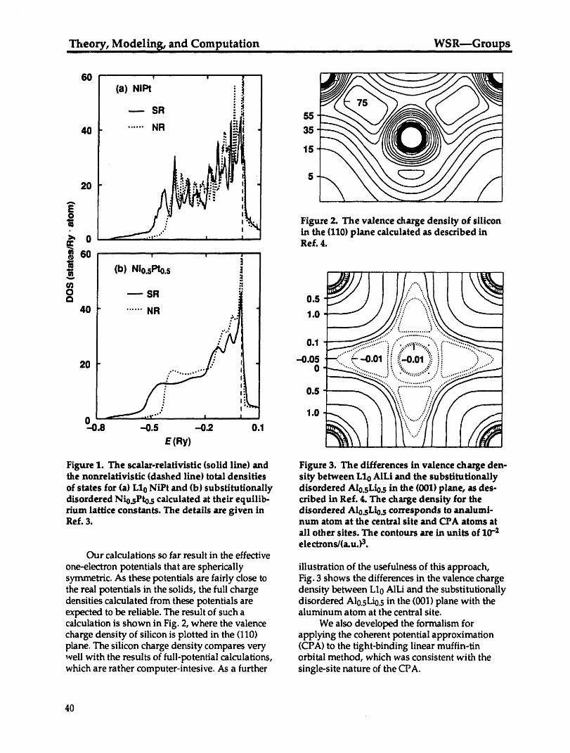
Theory, Modeling, an d Computation WSR--GroupsIIIIli__ i I I iiiiiii iiiiii I IuIIIIIIIII II IIIIIII
+ ....ill I40 ...... NR ,, - 35
t N20 !_.__. ,
i in the (1101plane calculated as described in0 Ref. 4.
6O
(b) n o.sPto.s
0 --..-- SR "
40 ...... 1.0
0.1 ' ''- +
20 -0.05 '" " +" '; " ....0
0.S
1.0
_-'0.8 "0.5 ---0.2 0.1
E (Ry)
Figure 1. The scalar-relativistic (solid line) and Figure 3. The differences in valence charge den-the nonrelativistic (dashed line) total densities sity between Llo AILi and the substitutionallyof states for (a) L10 NiPt and (b) subst/tutionally disordered Alo.sLio._in the (001) plane, as des-disordered Nio._Pto._calculated at their equilib- cribed in Ref. 4. The charge density for therium lattice constants. The details are given in disordered Alo.sLio.s corresponds to analumi-Ref. 3. num atom at the central site and CPA atoms at
all other sites. The contours are in units of 10-2electrons/(a.u.) 3.
Our calculations so far result in the effective
one-electron potentials that are spherically illustration of the usefulness of this approach,symmetric. As these potentials are fairly close to Fig. 3 shows the differences in the valence chargethe real potentials in the solids, the full charge density between L10AILi and the substitutionallydensities calculated from these potentials are disordered Al0.sLi0.s in the (001) plane with theexpected to be reliable. The result of such a aluminum atom at the central site.calculation is shown in Fig. 2, where the valence We also developed the formalism forcharge density of silicon is plotted in the (110) applying the coherent potential approximationplane. The silicon charge density compares very (CPA) to the tight-binding linear muffin-tinwell with the results of full-potential calculations, orbital method, which was consistent with thewhich are rather computer-intesive. As a further single-site nature of the CPA.
40

WSR--Groups Theory, Modeling, an d ComputationII I I ,1111I I II ,11
References 2. P. P. Singh and A. Gonis, "Real-SpaceCalculations of Non-Spherically Averaged
1. F.J. Pinski et al., "Origins of Compositional Charge Densities for SubstitutionallyOrder in NiPt Alloys," Phys. Rev. Lett. 66, 776 Disordered Alloys," Phys. Rev. B (in press).(1991). 3. P. P. Singh and A. Gonis, "Coherent Potential
2. Z. W. Lu et al., "Long-Range Order in Binary Approximation in the Tight Binding LinearLate-Transition-Metal Alloys," Phys. Rev. Lett. Muffin-Tin Orbital Method," submitted to66, 1753 (1992). Phys. Rev. B.
3. P. Singh, A. Gonis, and P. E. A. Turchi, 4. P. P. Singh and W. J. Thompson, "Exploring"Toward a Unified Approach to the Study of the Complex Plane: Green Functions, HilbertMetallic Alloys: Application to the Phase Transforms, and Analytic Continuation,"Stability of Ni-Pt," submitted to Phys. Rev. Lett. Comput. Phys., July/August 1993 (in press).
4. P. P. Singh and A. Gonis, "Real-Space Calcu-lations of Non-Spherically Averaged ChargeDensities for Substitutionally Disordered PresentationsAlloys," Phys. Rev. B (in press).
1. P. P. Singh and A. Gonis, "Real-Space Calcu-lations of Non-Spherically Averaged Charge
Publications Densities for Substitutionally DisorderedAlloys," Meeting of the American Physical
1. P. Singh, A. Gonis, and P. E. A. Turchi, Society, Seattle, WA, Mar. 1993."Toward a Unified Approach to the Study of 2. P.P. Singh, A. Gonis, and P. E. A. Turchi,Metallic Alloys: Application to the Phase "Toward a Unified Approach to the study ofStability of Ni-Pt," submitted to Phys. Rev. Lett. Metallic Alloys: Application to the Phase
Stability of Ni-Pt," Meeting of the MaterialsResearch Society, San Fransisco, CA, Apr.1993.
Development of New Thermoelectric Materials withExceptional Figures of Merit (Theory Part)
P. E. A. Turchi
A better understanding of the relationships between electronic properties and crystalline struc-ture in materials that possess interesting thermoelectric properties will be achieved by a syner-gistic effort between (1) atomistic characterization and measurements of the transport properties
and (2) modeling by state-of-the-art approaches. This acquired knowledge will support and guide
the experimental effort in designing and processing new, advanced thermoelectric materials. The
development of new theoretical tools that combine, on one hand, accurate knowledge of micro-scopic material parameters and, on the other hand, experimental determination of transport
coefficients should provide a more accurate evaluation of the figure of merit, ZT, which charac-terizes the efficiency of thermoelectric materials.
Purpose of the Work that a pr/or/exhibit interesting transport proper-ties for thermoelectric applications. The study
This work is a thorough study of structure- will be based on electronic-structure calculationsproperties relationships for a class of materials in the framework of first-principles and semi-
41
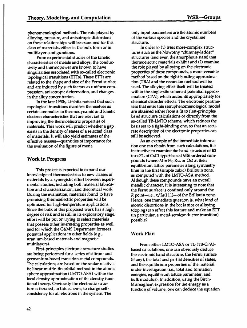
Theory, Mode!in_ and Computation WSR--GroupsI I II II I[I I I IIIII II I III I IIIIIIIIIII I I II
phenomenological methods. The role played by only input parameters are the atomic numbersalloying, pressure, and anisotropic distortions of the various species and the crystallineon these relationships will be examined for this structure.class of materials, either in the bulk form or in In order to (1) treat more-complex struc-multilayer configurations, tures such as the Nowotny "chimney-ladder"
From experimental studies of the kinetic structures (and even the amorphous state) thatcharacteristics of metals and alloys, the conduc- thermoelectric materials exhibit and (2) examinetivity and thermopower are known to have the role played by alloying on the electronicsingularities associated with so-called elec_'onic properties of these compounds, a more versatiletopological transitions (ETTs). These ETFs are method based on the tight-binding approxima-related to the shape and size of the Fermi surface tion (TBA) and the recursion method will beand are induced by such factors as uniform com- used. The alloying effect itself will be treatedpression, anisotropic deformation, and changes within the single-site coherent potential approx-in the alloy concentration, imation (CPA), which accounts appropriately for
In the late 1950s, Lifshitz noticed that such chemical disorder effects. The electronic parame-topological transitions manifest themselves as ters that enter this semiphenomenological modelcertain anomalies in thermodynamic and kinetic are obtained either from a fit to first-principleselectron characteristics that are relevant to band structure calculations or directly from theimproving the thermoelectric properties of so-called TB-LMTO scheme, which reduces thematerials. This work will predict whether a gap basis set to a tight-binding one, so that an accu-exists in the density of states of a selected class rate description of the electronic properties canof materials. It will also yield estimates of the still be achieved.effective masses--quantities of importance for As an example of the immediate informa-the evaluation of the figure of merit, tion one can obtain from such calculations, it is
instructive to examine the band structure of B2
(or cP2, of C.sCl-type)-based MSi-ordered corn-Work in Progress pounds (where M = Fe, Ru, or Os) at their
equilibrium lattice parameter along symmetryThis project is expected to expand our lines in the first (simple cubic) Brillouin zone,
knowledge of thermoelectrics to new classes of as computed with the LMTO-ASA method.materials by a synergistic effort between experi- Although these compounds have an overallmental studies, including both material fabrica- metallic character, it is interesting to note thattion and characterization, and theoretical work. the Fermi surface is confined only around theDuring the evaluation, materials found to have R point--i.e., _/2a(111)---of the Brillouin zone.promising thermoelectric properties will be Hence, one immediate question is, what kind ofoptimized for high-temperature applications, atomic distortions in the bcc lattice or alloyingSince the bulk of this proposed work has a high (doping) can affect this feature and make an ETTdegree of risk and is still in its exploratory stage, (in particular, a metal-semiconductor transition)effort will be put on trying to select materials possible?that possess other interesting properties as well,and for which the C&MS Department foreseespotential applications in oi:her fields (e g., Work Planuranium-based materials and magneticmultilayers). From either LMTO-ASA or TB (TB-CPA)-
First-principles electronic structure studies based calculations, one can obviously deduceare being performed for a series of silicon- and the electronic band structure, the Fermi surfacegermanium-based transition-metal compounds. (if any), the total and partial densities of states,The calculations are based on the scalar relativis- and the equilibrium properties of the materialtic linear muffin-tin orbital method in the atomic under investigation (i.e., total and formationsphere approximation (LMTO-ASA) within the energies, equilibrium lattice parameter, andlocal density approximation of the density func- bulk modulus). In addition, using the Birch-tional theory. Obviously the electronic struc- Mumagham expression for the energy as ature is iterated, in this scheme, to charge self- function of volume, one can deduce the equationconsistency for all electrons in the system. The
42
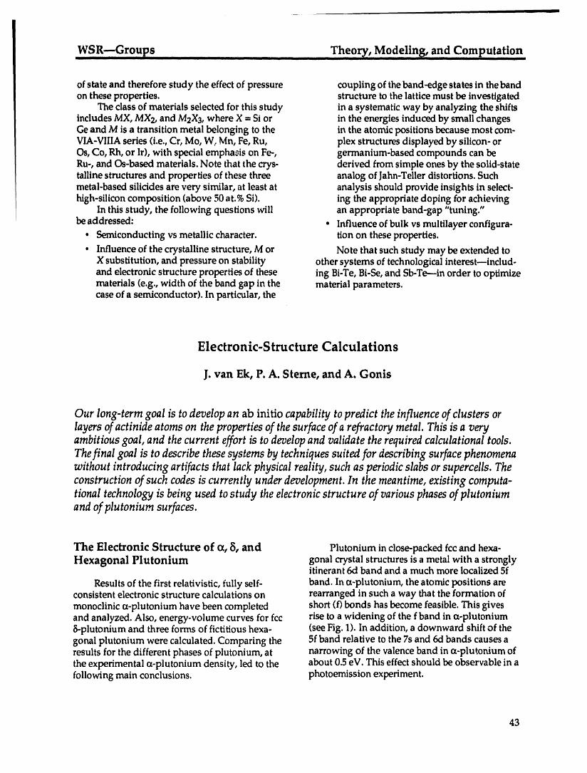
WSR---Groups Theo_.., M0de!!ng, and ComputationII I IIIIIII I _ . III III I II II III II II II iii ii i_ ii i I _ ...... _.
of state and therefore study the effect of pressure coupling of the band-edge states in thebandon these properties, structure to the lattice must be investigated
The class of materials selected for this study in a systematic way by analyzing the shiftsincludes MX, MX2, and M2X3, where X = Si or in the energies induced by small changesGe and M is a transition metal belonging to the in the atomic positions because most com-VIA-VIIIAseries (i.e., Cr, Mo, W, Mn, Fe, Ru, plex structures displayed by silicon- orOs, Co, Rh, or Ir), with special empha0is on Fe-, germanium-based compounds can beRu-, and Os-based materials. Note that the crys- derived from simple ones by the solid-statetalline structures and properties of these three analog of Jahn-Teller distortions. Suchmetal-based silicides are very similar, at least at analysis should provide insights in select-high-silicon composition (above 50 at.%Si). ing the appropriate doping for achieving
In this study, the following questions will an appropriate band-gap "tuning."
be addressed: • Influence of bulk vs multilayer configura-• Semiconducting vs metallic character, tion on these properties.
• Influence of the crystalline structure, M or Note that such study may be extended toX substitution, and pressure on stability other systems of technological interestminclud -and electronic structure properties of these ing Bi-Te, Bi-Se, and Sb-Te---in order to optimizematerials (e.g., width of the band gap in the material parameters.case of a semiconductor). In particular, the
Electronic-Structure Calculations
J. van Ek, P. A. Sterne, and A. Gonis
Our long-term goal is to develop an ab initio capability to predict the influence of clusters orlayers of actinide atoms on the properties of thesurface of a refractory metal. This is a veryambitious goal, and the current effort is to developand validate the required calculational tools.Thefinal goal is to describe thesesystems by techniques suited for describingsurface phenomenawithout introducing artifacts that lack physical reality, such as periodic slabs orsupercells. Theconstruction of such codes is currently under development. In the meantime, existing computa-tional technology is being used to study the electronicstructure of various phasesof plutoniumand of plutonium surfaces.
The Electronic Structure of oc,5, and Plutoniuminclose-packed fccand hexa-Hexagonal Plutonium gonal crystal structures is a metal with a strongly
itinerant 6d band and a much more localized 5f
Results of the first relativistic, fully self- band. In (z-plutonium, the atomic positions areconsistent electronic structure calculations on rearranged in such a way that the formation ofmonoclinic s-plutonium have been completed short (f) bonds has become feasible. This givesand analyzed. Also, energy-volume curves for fcc rise to a widening of the f band in co-plutonium5-plutonium and three forms of fictitious hexa- (see Fig. 1). In addition, a downward shift of thegonal plutonium were calculated. Comparing the 5f band relative to the 7s and 6d bands causes aresults for the different phases of plutonium, at narrowing of the valence band in oc-plutonium ofthe experimental oc-plutonium density, led to the about 0.5 eV. This effect should be observable in afollowing main conclusions, photoemission experiment.
43
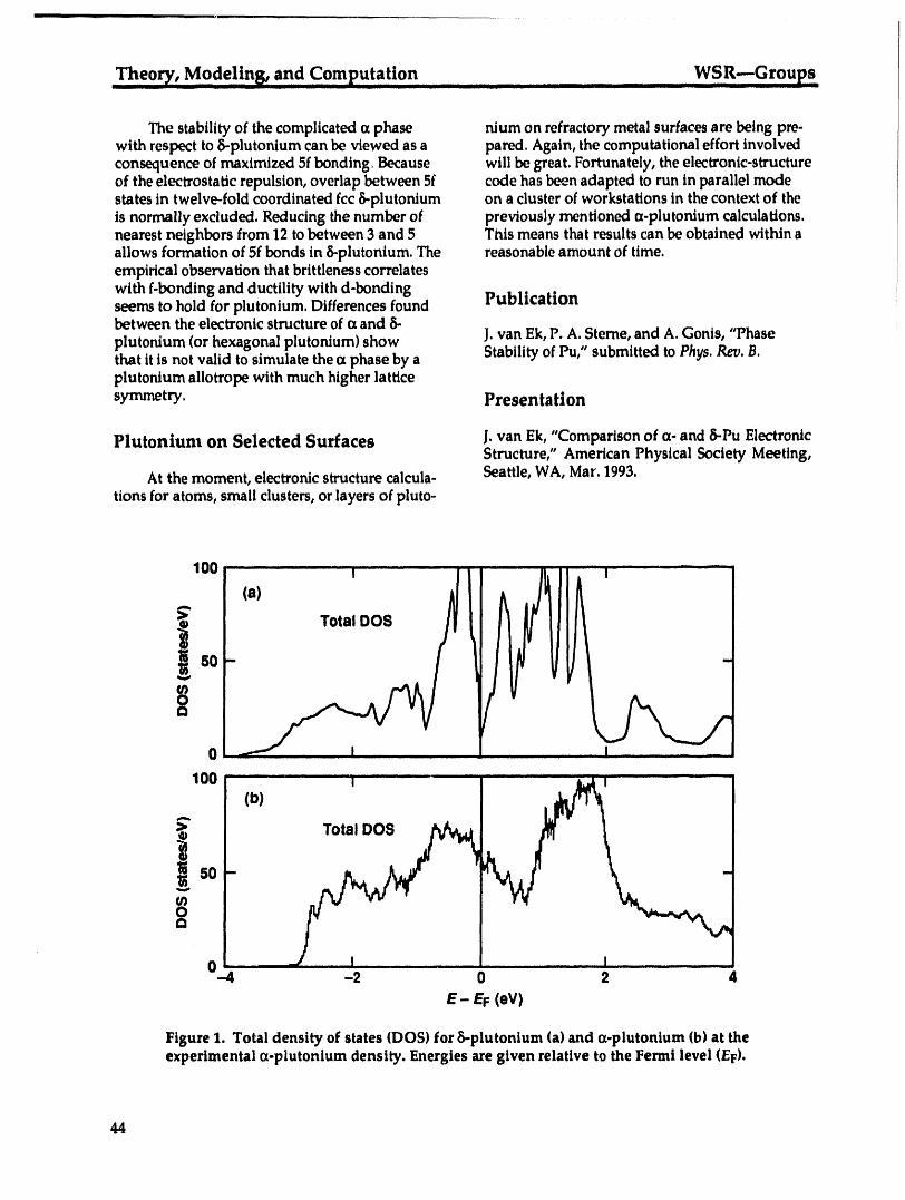
..Theory , Mode!!ng, and Computation WSR---GroupsIll I _ ._ lfllllllllllfmf _ II II/llll II fll n I I11111I iiii IiiiIIiiiJ I fie ..................
The stability of the complicated a phase nium on refractory metal surfaces are being pre-with respect to 8-plutonium can be viewed as a pared. Again, the computational effort involvedconsequence of maximized 5f bonding. Because will be great. Fortunately, the electronic-structureof the electrostatic repulsion, overlap between 5f code has bee.n adapted to run in parallel modestates in twelve-fold coordinated fcc 6-plutonium on a cluster of workstations in the context of theis normally excluded. Reducing the number of previously mentioned a-plutonium calculations.nearest neighbors from 12 to between 3 and 5 This means that results can be obtained within aallows formation of 5f bonds in 6-plutonium. The reasonable amount of time.empirical observation that brittleness correlateswith f-bonding and ductility with d-bondingseems to hold for plutonium. Differences found Publicationbetween the electronic structure of (xand 6-
plutonium (or hexagonal plutonium) show J. van Ek, P. A. Sterne, and A. Gonis, "Phasethat it is not valid to simulate the (xphase by a Stability of Pu," submitted to Phys. Rev. B.plutonium allotrope with much higher latticesymmetry. Presentation
Plutonium on Selected Surfaces j. van Ek, "Comparison of ix- and 8-Pu ElectronicStructure," American Physical Society Meeting,
At the moment, electronic structure calcula- Seattle, WA, Mar. 1993.tions for atoms, small clusters, or layers of pluto-
100 .................... I ......................I " I ...............(a)
E Total DOS
0 .......... I ........ --
100 .............. "1.......................(b)
i50 -¢/I
o.4 , J , I ......... I ...............-2 0 2 z
E- EF (eV)
Figure 1. Total density of states (DOS) for 8-plutonium (a) and (x-plutonium (b) at theexperimental (x-plutonium density. Energies are given relative to the Fermi level (EF).
44

WSR_Groups ............................ Theor__Mode!ins_ and computation.
Real-Space, Multiple-ScatterirLg Theory
E. Sowa and A. Gonis
We have developed afirst-principles method, the real-spacemultiple-scattering theory (RSMST),for charge-self-consistent total-energy calculations of the electronic structure of systems withextended defects, e.g., grain boundariesand other interface systems. We have applied this methodto selectedgrain boundaries.
Pro'pose densities of ,tates, etc., forcommensurate metalgrain boundaries. We have used this code to
We areinterestedinpredictingand explain- study7.5(310)tiltgrainboundariesincopperandingmaterialspropertiesusinga theoretical niobium,in,:ludingthecomparisonoftotalapproachbasedon condensed-matterphysics: energiesofdifferentstructures.i.e.,computationalmaterialsscience.Although Althoughthisworkdemonstratedthesuit-simulationswithclassicalinteratomicpotentials abilityofth..,RSMST approachforhandling(e.g., EAM) can treat larger systems than first., extended defects in materials, it also showed usprinciples electronic-structure calculations, there that the geometries encountered in interface workare some important unresolved issues (transfer- often involve potentials that are poorly repre-ability of interatomic potentials, directional bond- sented by si_ape-approximate methods such asing, etc.) associated with these simulations which the muffin-tin approximation (MTA) that weonly fully quantum-mechanical calculations that have used to date.explicitly treat the electrons in the material can This problem is not unique to the interfaceaddress. Ultimately, such calculations are expec- program. Many of the complex materials ofted to shed light on some of the problems interest to t:heC&MS Department share the sameencountered while simulating these systems problem, yet the MTA is still part of most of theusing interatomic potentials. To be fully under- Departmel_t's electronic-structure tools (RSMST,stood, any mechanical property that depends on LMTO, KI('.R-CPA,etc.).chemical bonding will also require a quantumtreatment of the electrons.
The presence of an interface in an otherwise Plansperfect crystal breaksthetranslationalinvarianceupon whichstandardelectronic-structuretech- Usinl_thenew TMC Group structure:niquesrely.Sinceinterfacesoftendominatethe we plantomake aconcertedefforttosolvepropertiesofrealmaterials,itisimportantto theprobh:msassociatedwithfull-potentialhavean appropriatetechniqueforstudying electronic-structuremethods,whichwillgiveustheirelectronicstructure.The RSMST issucha thetoolstotacklea widerarrayofinteresting
method.By takingadvantageoftheinvariance material_problems.We willtakefulladvantagepropertiesthatsurviveina semi-infinitesystem, ofthepr,.,senceofDr.JamesMacLarenofTulaneitprovidesa way tocomputetheelectronicstruc- University,who willbespendinghissabbaticaltureofbicrystallinematerialswithoutresorting withus.toartificialboundaryconditionssuchasslabs We alsoplantoinvestigatethepossibilityofandsupercells, deriving;interatomicpotentialsfromourfirst-
principlescalculations.We hopetoplaceonfirmerphysicalgroundsthesimulationsthatuse
Accomplishments thesek'tndsofpotentials.We requirephysicalexplan.ltions,whichmay beprovidedby aclear
Thisyear,RSMST developmentproceeded connectionbetweentheinteratomicpotentialandtothepointwherewe now havea charge-self- thefir_it-principlescalculationthatproducedit.consistentcodethatcancomputetotalenergies,
45

Theo _, Modeling, and Computation ............ ,, _, .......... WSR---Groups
Publications Conf. Computer Appl. Mater. $ci. Eng., Yoko-hama, Japan, September 22-25, 1992 (in press).
1. E.C. Sowa, A. Gonis, and X.--G. Zhang, "TheReal-Space Multiple-Scattering Theory: A First-Principles Method for the Computation of the PresentationsElectronic Structure of Extended Defects," inEquilibrium Structure and Properties ofSurfaces 1. E.C. Sowa, A. Gonis, and X.-G. Zhang, "Self-and interfaces, A. Gonis and G. M. Stocks, Eds. Consistent Electronic-Structure Calculations(Plenum Press, New York, 1992), p. 361. for Grain Boundaries," 1992 Workshop on
2. E.C. Sow& A. Gonis, and X.-G. Zhang, "Self- Computational Methods in Alloy Theory,Consistent Electronic-Structure Calculations University of Kentucky, Lexington, Jun. 1992.for Interface Geometries," MRS Proc.253, 405 2. E.C. Sowa, A. Gonis, J. M. MacLaren, and(1992). X.-G. Zhang, "First-Principles Calculations
3. E.C. Sowa, A. Gonis, and X.-G. Zhang, of the Energy of Grain-Boundary Structures"Grain-Boundary Electronic States by in Cu and Nb," American Physical SocietyMultiple-Scattering Theory," in Proc. 1992 Meeting, Seattle, WA, Mar. 1993.
46

,weap0ns-Supporting Rese_ch ...... ,,In,dividual, Pro_,ects
Weapons-Supporting Research
Individual Projects
47
Properties of Carbon Fibers WSR-.-Individual Projects
' -_" U-- -_ " ..... ITII flllll [ ............... __ Illlll lit IIlllllll [ II Ill Ill _ - -- ...... L _= . I Ill I fllflf I .........
i
Properties of Carbon Fibers
R. M. Christensen
The mechanical properties of carbonfibers are determined in terms of the elastic moduli of single-crystal graphite. This is done for the two basicfiber microstructures, radial and onionskin. Thefinal results arefound through a transformation from cylindrically orthotropic to transverselyisotropicproperties. The procedure is synthesized in a two-step process.First, a general set ofnine cylindrically orthotropic properties is transformed into a set of five equivalent transverselyisotropicproperties. Second, theseresults are specialized to the two separate casesof radial andonionskin microstructures. This process is easily accomplishedfor four of the five transverselyisotropicproperties, but the fifth property--the transverse shear modulus--is a particularlydifficult case tha' must be treatedseparately. Some consequent practical considerations forcarbonfibers may be of considerableutility in optimizing these types of materials for high-performance applications.
Description Fibers communicate behavior to an overallcomposite medium through their interfaces or by
Carbon fibers exhibit a wide spectrum integrated effects over their cross sections. In thisof properties, which are consequences of the sense, then, a nonhomogeneous fiber and aintimate details of the manufacturing process homogeneous fiber can have the same overallconditions. These properties' variations are effect on a composite medium if the properties ofprobably best viewed as being dependent on the homogeneous fiber are properly adjusted.microstructure variations, which themselves tie This is exactly the process that is developed.back to the processing conditions. The present Equivalent homogeneous and transversely iso-investigation is concerned with the two most tropic fiber properties are determined such thatcommon idealizations of microstructure because the corresponding fiber would have the same
these are probably the two most critical forms, composite material effect as would the nonhomo-Specifically, this investigation determines the geneous radial or onionskin cylindrically ortho-consequences in terms of mechanical properties tropic fiber types in Fig. 2. Thus, the properties soof the two fundamental types of microstructure determined for the equivalent homogeneous fiberfor carbon/graphite fibers, will differentiate the two basic microstructures.
The basic planar graphitic structure is Relative to the coordinate axes shown inshown in Fig. 1. Covalent bonds provide the Fig. 1, the five independent properti_ _oraatomic forces within the basal planes, whereas graphitic single crystal are taken asthe forces acting between basal planes are of C11much weaker origin, such as van der Waalsforces. These in-plane and out-of-plane forces, C22 = C33
which can differ by orders of magnitude, are the C12 = C31source of the extreme anisotropy found in graph- C23ire fibers. The two standard geometric conforma-tions of the basal planes that can exist in circular C66cylindrical fibers (see Fig. 2), radial and onion- The effective longitudinal modulus (Ez) is theskin, admit easy idealization for analysis, same for both microstructures and is given by
48

WSR---Individual Projects Properties of Carbon FibersI III I III
_ l 4_ van
B -.--_I:: cA | derA - ;_,Q-,-,_r 1 6,70 ,_ WaalsI '-' "
A
2
Figure 1. Ideal crystal graphiteCovalent structure.Basal planes.forces 1
Figure 2. Typical fiber types" radial (left) and onionskin (right) stuctures.
Three of the other propertiesalso are identicalfor microstructures,remainsquite differentin thethe two microstructuresandhave reasonably two cases. This is shown throughboth theexactsimple solutions. Thebehavior of the fifth solution andsomeasymptotic forms.property,the transverseshear modulus (_T) is In additionto theeffectof the two micro-distinctlydifferent from the other four. The structures on the properties of equivalenthomo-solution for _T,when specializedto the two geneous fibers, there are other significant
49

Properties of Carbon Fibers WSR--Individual ProjectsIlL I' I Ill I I II lllll I lllll I
differences. Failure characteristics would be Publicationsexpected to be very different for the radial andonionskin fiber types. The singularities at the 1. R. M. Christensen, "Properties of Carbonorigin are different for the two microstructures, Fibers," submitted to J.Mech. Phys. Solidsand in general, the state of stress throughout the (UCRL-JC-113786, 1993).single fiber would be drastically different in the 2. R. M. Christensen, "Effective Viscous Flowtwo cases. The solutions found here in connection Properties for Fiber Suspensions Underwith the equivalent-properties problem could Concentrated Conditions," J.Rheology 37, 103-also be used to investigate for a failure mechan- 121 (1993).ism. In general, the stress singularities occur in 3. R. M. Christensen, "Effective Properties ofthe radial microstructure case and not the Composite Materials Containing Voids," Proc.onionskin case. The exception to this is the R. Soc. Lond. A 440, 401-473 (1993).transverse shear property, in which singularities 4. R. M. Christensen, "On Compressive Failureoccur for both microstructures, of Fibrous Composites," submitted to Comp.
Eng., March, 1993.
Presentation
R. M. Christensen, "Edge Effects in CompositeLaminates," North Carolina A&T, Mar. 1993.
5O
WSR---Individual Projects Thermoelectric Materialsili i i IN'Ill I II il III II I I
Thermoelectric Materials with Exceptional Figures of Merit
J. C. Farmer, G. Chapline, M. Dresselhaus,* N. Eisner, _ R. Foreman,L. Hicks,* D. Makowiecki, D. O'Brien, M. Olsen, R. Otto, P. Turchi,
R. VanKonynenburg, and J. Yee
After a thorough review of the literature on thermoelectric materials and extensive consultation
with leading researchers in the field, we have concluded that it may be possible to achieve high
figures of merit with thermoelectric quantum wells. Such materials and devices are now being
fabricated at LLNL and will be evaluated in the foreseeable future. Bulk materials with unusual
promise, such as pseudo-binary alloys of FeSi2 and OsSi2, are also being synthesized, evaluated,and modeled. Funding sources for continuation of this effort are being pursued agressively.
Background Fabrication of NewThermoelectric Materials
The relative efficiency of a thermoelectric
material is measured in terms of the dimension- 2-D Quantum Wellsless figure of merit, ZT. The best known thermo-electric materials are heavily doped, mildly Unfortunately, molecular beam epitaxydegenerate semiconductors with ZT _<1. If is too expensive for producing practical thermo-materials with ZT < 3 could be found or devel- electric materials. We are producing thermoelec-oped, thermoelectric devices could be made that tric multilayer films (2-D quantum wells) bywould have thermodynamic efficiencies close alternately sputtering quantum-well and barrierto that of an ideal Carnot engine. In fact, such layers onto a moving substrate from dual magne-materials would make it possible to completely trons. The quantum-well layer has a very narrowreplace conventional heat engines and mechani- band gap and is sandwiched between two barriercal refrigeration systems with solid-state devices, layers made of a material with a relatively largeWe are pursuing two parallel approaches to high- band gap. Bulk materials for sputtering targetsZT thermoelectric materials: thermoelectric quan- have been produced by melting zone-refined ele-rum wells and new pseudo-binary alloys. The ments together under vacuum, grinding ingotstheoretical basis for thermoelectric quantum into powders under argon, and pressing and sin-wells has already been developed (2-D case by tering powders under vacuum or argon. TargetsMIT, 1-D case by LLNL). Quantum theory pre- also have been purchased.dicts that thermoelectric devices fabricated as 2-D Transmission electron microscopy (TEM)quantum wells or quantum wires could have ZT shows individual Bi2Te3layers that are 100 A.< 3 at relatively low temperature. We are using thick, separated by B4C layers that are 20 A thicknovel LLNL technology to make thermoelectric (see Fig. 1).We have demonstrated that we canmultilayer films (2-D quantum wells) that should produce Bi2Te3layers that are less than 30 J_have enhanced performance. From collaborative thick. Attempts have also been made to use low-work with an industrial partner, we have come to angle x-ray diffraction to determine layer thick-believe that bulk (Fe,Os)Si2 may have an excep- ness, but results were ambiguous. Crystal struc-tional figure of merit at high temperature, ture and orientation of layers have been investi-
gated with both electron diffraction and x-raydiffraction.
We have demonstrated the feasibility ofmaking alternating layers of Bi2Te3 (quantumwell) and B4C (barrier) with dual-magnetron
*MassachusettsInstituteofTechnology, Cambridge, MA sputtering. In the future, we plan to exploret Hi-Z Technology, Inc.,San Diego, CA annealing as a possible means of controlling
51
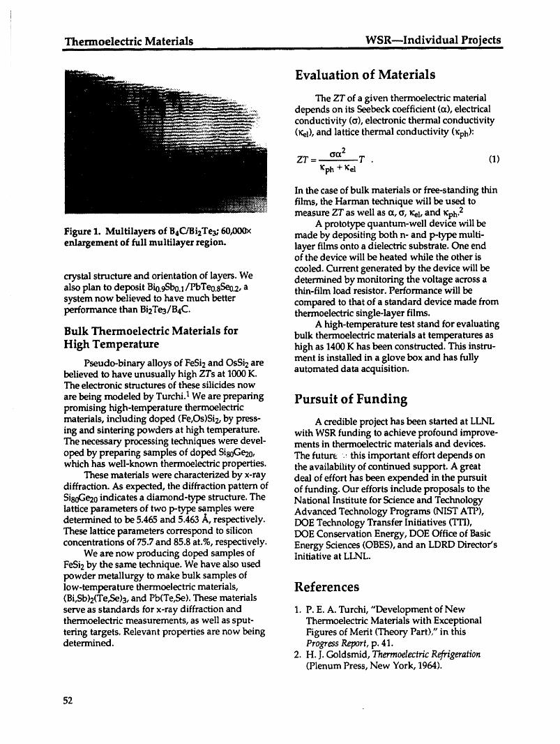
Thermoelectric Materials WSR---Individual Projects ._ I IIItl III I i
i
Evaluation of Materials
The ZT of a given thermoelectric materialdepends on its Seebeck coefficient (¢z),electrical
_ conductivity (a), electronic thermal conductivity(r,el),and lattice thermal conductivity 0¢ph):
¢_G¢2ZT = T . (1)
_ph + 1%1
In the case of bulk materials or free-standing thinfilms, the Harman technique will be used tomeasure ZT as well as o_,c, _1, and lCph.2
A prototype quantum-well device will beFigure 1. Multilayers of B4C/Bi2Te3;60,O00x made by depositing both n- and p-type multi-enlargement of full multilayer region, layer films onto a dielectric substrate. One end
of the device will be heated while the other is
cooled. Current generated by the device will becrystal structure and orientation of layers. We determined by monitoring the voltage across aalso plan to deposit Bio.gSbo.l/PbTeo.sSeo.2,a thin-film load resistor. Performance will be
system now believed to have much better compared to that of a standard device made fromperformance than Bi2Te3/B4C. thermoelectric single-layer films.
A high-temperature test stand for evaluatingBulk Thermoelectric Materials for bulk thermoelectric materials at temperatures asHigh Temperature high as 1400 Khas been constructed. This instru-
ment is installed in a glove box and has fullyPseudo-binary alloys of FeSi2and OsSi2areautomated data acquisition.believed to have unusually high ZTs at 1000 K.
The electronic structures of these silicides now
are being modeled by Turchi. 1We are preparing Pursuit of Fundingpromising high-temperature thermoelectric
materials, including doped (Fe,Os)Si2, by press- A credible project has been started at LLNLing and sintering powders at high temperature, with WSR funding to achieve profound improve-The necessary processing techniques were devel- ments in thermoelectric materials and devices.
oped by preparing samples of dopedSisoGe20, The future _ this important effort depends onwhich has well-known thermoelectric properties, the availability of continued support. A great
These materials were characterized by x-ray deal of effort has been expended in the pursuitdiffraction. As expected, the diffraction pattern of of funding. Our efforts include proposals to theSi80Ge20indicates a diamond-type structure. The National Institute for Science and Technologylattice parameters of two p-type samples were Advanced Technology Programs (NIST ATP),determined to be 5.465 and 5.463 ,/_,respectively. DOE Technology Transfer Initiatives (TTI),These lattice parameters correspond to silicon DOE Conservation Energy, DOE Office of Basicconcentrations of 75.7 and 85.8 at.%,respectively. Energy Sciences (OBES), and an LDRD Director's
We are now producing doped samples of Initiative at LLNL.FeSi2 by the same technique. We have also usedpowder metallurgy to make bulk samples oflow-temperature thermoelectric materials, References(Bi,Sb)2(Te,Se)3,and Pb(Te,Se). These materialsserve as standards for x-ray diffraction and 1. P. E. A. Turchi, "Development of Newthermoelectric measurements, as well as sput- Thermoelectric Materials with Exceptionaltering targets. Relevant properties are now being Figures of Merit (Theory Part)," in thisdetermined. Progress Report, p. 41.
2. H.J. Goldsmid, Thermoelectric Refrigeration(Plenum Press, New York, 1964).
52
Laboratory Directed Researchand Development Director's InitiativesI I III ii I I II II I I
Laboratory Directed Research andDevelopment
Director's Initiatives
53

.Aerosel-Based Electronic Devices LDRD--Director's Initiatives
Aerogel-Based Electronic Devices
R. W. Pekala, S. T. Mayer, J. L. Kaschmitter, R. L. Morrison,L. W. Hrubesh, R. J. Contolini, and A. F. Bernhardt
Aerogels have open-cell structures with interconnected colloidal-like particles (,-10 nm in
diameter), high surface area (400-1000 m2/g), and ultrafine cellpore sizes (<50 nm). Aerogels
have been synthesized from both inorganic and organic precursors. Recently, it was recognized
that silica aerogels have low dielectric constants (_ < 2) and carbon aerogels have high electrical
conductivities (,-20 S/cm) as a result of their intricate nanostructure. Our research explores the
fundamental chemistry, engineering, and physics issues involved with tailoring the structures
and properties of aerogels for applications in capacitors, batteries, and integrated circuits.
Double-Layer Capacitors compared to electrodes fabricated from activatedcarbon-black particles or fibers.
Several methods are used to produce carbon As shown in Fig. 1, two aerogel electrodesfoams or aerogels that have possible applications are separated by an electrically isolating, ionicallyas electrodes in double-layer capacitors: conductive separator (e.g., a polypropylene mem-
brane) that is flooded with electrolyte. Each elec-• Phenolic microballoons are stabilized with antrode is polarized with opposing charges when a
appropriate binder and pyrolyzed to form charging voltage is applied. For example, duringsyntactic carbon foams, charging of the Aerocapacitor, application of a
• The partial oxidation and pyrolysis of phase- bias at the positive electrode will cause migrationseparated polyacrylonitrile foams result in and electrostatic adsorption of hydroxyl anions atmicrocellular carbon foams, the carbon/electrolyte interface. All of the aero-
• Reticulated vitreous carbon (RVC) foams are gel surface area contributes to the double-layerproduced by pyrolyzing an open-cell polyure- capacitance, except where the micropores are toothane foam that has been infused with a reac- narrow (<10 ./0.
tive monomer such as furfuryl alcohol. The high usable surface area of the carbon• Replica carbon foams result from the pyrolysis aerogel accounts for demonstrated capacitances
of a phenolic resin within a sacrificial substrate up to 35 F/cm 3. The high conductivity of thethat is subsequently removed, aerogel electrodes leads to power densities
• The sol-gel polymerization of resorcinol with greater than 5 kW/kg for aqueous-based devices.formaldehyde leads to carbon aerogels after Aerocapacitors are currently being fabricated inpyrolysis, low-voltage bipolar stacks. Future efforts are
In each of these cases, processing parameters being directed at developing new potting tech-control the morphology, density, and cell size niques for packaging these devices.distribution of the final foam. Significant achievements to date:
The LLNL Aerocapacitor is an electrochem- • Evaluation of aerogel capacitance as a functionical double-layer capacitor that uses carbon of formulation, pyrolysis temperature, andaerogels as both the positive and negative elec- chemical activation.trodes. Carbon aerogels are the ideal double- • Development of casting techniques to producelayer electrode material because they have very carbon aerogels with thicknesses less thanhigh volumetric surface areas (>500 m2/cm 3) 500 j_mand diameters of 35 mm.with controllable pore sizes and density (0.1 to • Analysis of the pore-size distribution and1.0 g/cm3). Particularly important is their very surface area of carbon aerogels synthesizedlow electrical resistivity (< 25 m.Q.cm) as under different conditions.
54
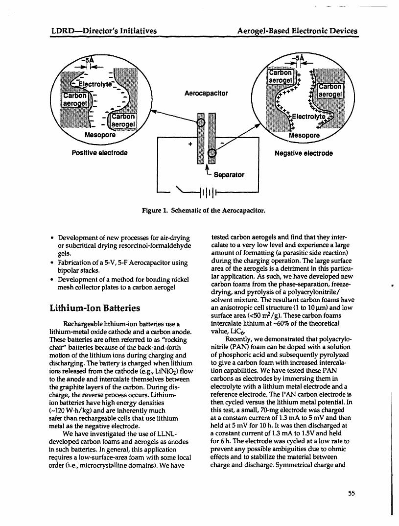
LDRD---Director's Initiatives Aer0_el-Based Electronic DevicesII II IIIIIII I II j iljlll IIIII i I iiii ii
.ooa0 oor
- Separator
-- ,1111:Figure 1. Schematic of the Aerocapacitor.
• Development of new processes for air-drying tested carbon aerogels and find that they inter-or subcritical drying resorcinol-formaldehyde calate to a very low level and experience a largegels. amount of formatting (a parasitic side reaction)
• Fabrication of a 5-V, 5-F Aerocapacitor using during the charging operation. The large surfacebipolar stacks, area of the aerogels is a detriment in this particu-
• Development of a method for bonding nickel lar application. As such, we have developed newcarbon foams from the phase-separation, freeze-
mesh collector plates to a carbon aerogel drying, and pyrolysis of a polyacrylonitrile/solvent mixture. The resultant carbon foams have
Lithium-Ion Batteries an anisotropic cell structure (1 to 10 tJm)and lowsurface area (<50 m2/g). These carbon foams
Rechargeable lithium-ion batteries use a intercalate lithium at -60% of the theoreticallithium-metal oxide cathode and a carbon anode, value, LiC6.These batteries are often referred to as "rocking Recently, we demonstrated that polyacrylo-chair" batteries because of the back-and-forth nitrile (PAN) foam can be doped with a solutionmotion of the lithium ions during charging and of phosphoric acid and subsequently pyrolyzeddischarging. The battery is charged when lithium to give a carbon foam with increased intercala-ions released from the cathode (e.g., LiNiO2) flow tion capabilities. We have tested these PANto the anode and intercalate themselves between carbons as electrodes by immersing them inthe graphite layers of the carbon. During dis- electrolyte with a lithium metal electrode and acharge, the reverse process occurs. Lithium- reference electrode. The PAN carbon electrode ision batteries have high energy densities then cycled versus the lithium metal potential. In(-120 W.h/kg) and are inherently much this test, a small, 70-rag electrode was chargedsafer than rechargeable cells that use lithium at a constant current of 1.3 mA to 5 mV and thenmetal as the negative electrode, held at 5 mV for 10 h. It was then discharged at
We have investigated the use of LLNL- a constant current of 1.3 mA to 1.5V and helddeveloped carbon foams and aerogels as anodes for 6 h. The electrode was cycled at a low rate toin such batteries. In general, this application prevent any possible ambiguities due to ohmicrequires a low-surface-area foam with some local effects and to stabilize the material betweenorder (i.e., microcrystaUine domains). We have charge and discharge. Symmetrical charge and
55
Aero_el-Based Electronic Devices LDRD---Director's Initiatives............... IIIIII I Ir Ir i ii i ill ii i ii illl i i illll i Ill i Illl Ill I I ....
discharge profiles were observed, indicating Significant achievements to date:good reversibility of the carbon. * Demonstrated the first-ever thin film (<10 _m
Significant achievements to date: thick) of silica aerogel attached to a silicon• Synthesis of PAN carbon foams with densities substrate and characterized its thickness and
ranging from 0.1 to 0.5 g/cm 3. index of refraction.• Evaluation of phosphorus doping levels on the • Demonstrated the sealing of aerogel thin film
intercalation and formatting of the resultant using a plasma-deposited polymer coatingcarbon foam. (i.e., CHF3).
• Demonstrated the improved cyclability of the • Demonstrated the comparability of liquidP-doped carbon foam photoresists with polymer-coated aerogel
films and deposited photoresist patterns onsilica aerogels.
Thin-Film Dielectrics • Demonstrated metallization of silica aerogelsurfaces by achieving coating thicknesses and
We are fabricating thin-film silica aerogels quality comparable with other dielectricfor use as an insulator with a low dielectric substrates used for this purpose.constant (_ < 1.2) in high-speed electronic circuits.We are developing processes to seal, pattern, andmetallize both bulk and thin film aerogels. Thin-film aerogels -10 _an thick recently have been Publicationsfabricated and currently are undergoing elec-
trical, optical, and mechanical tests. Qualitative S.T. Mayer, R. W. Pekala, and J. L. Kaschmitter,tests show that the aerogels can be sealed from "The Aerocapacitor: An Electrochemical Double-subsequent semiconductor process liquids so that Layer Energy Storage Device," J. Electrochem. Soc.,conventional photoresist techniques can pattern 140(2), 446 (1993).these materials. Aerogels have been patterned for
the first time with plasma etching techniques. We S.T. Mayer, R. W. Pekala, and J.L. Kaschmitter,have sputtered thin (<0.5-_an) gold metal layers "The Aerocapacitor: A Carbon Aerogel Basedonto the aerogel surfaces and electroplated Supercapacitor," in Proc. of the 2nd Int. Seminar onthicker (>l.0-_m) layers. Double Layer Capacitorsand Similar Energy Storage
Our silica thin-film aerogels are made from Dev/ces (Boca Raton: Florida Educationala silica solution (with the consistency of oil) to Seminars, Inc., 1993).which water, a solvent, and a base catalyst areadded, forming a gel. The ungelled solution isfirst spun on a silicon wafer in a manner similarto that used to spin on conventional photoresists Presentationin semiconductor processing. Then, it is allowedto gel while being exposed to an atmospheredesigned to minimize the evaporation of the sol- S.T. Mayer, R. W. Pekala, and J. L. Kaschmitter,vent from the gel. Multiple layers with controlled "The Aerocapacitor: A Carbon Aerogel Basedthicknesses are made in this manner. The gel is Supercapacitor," 2nd International Seminar onthen dried by supercritical extraction of the sol- Double Layer Capacitors and Similar Energyvent, leaving the aerogel attached to the silicon Storage Devices, Deerfield Beach, FL, Decemberwafer. The process takes only a few hours, 7-9, 1992.whereas other methods can take days.
56
LDRD---Director's Initiatives Molecular-Level Studies of Energetic MaterialsI I II II II II I|111 III II I IIIIIII Ill I[ " I 1 I ilillll II IIIII I IIIIIII
Molecular-Level Studies of Energetic Materials
P. C. Souers
This project consists of three integrated tasks dealing with high-explosive predetonation:
• Molecular hydrodynamics, J. Belak, Physics.• Doorway-mode spectroscopy, A. J. Ruggiero and L. E. Fried, C&MS.• Structure and sensitivity, M. F. Foltz, C&MS.The first two will have a large impact in about five years, with the creation of frequency-specific
initiation being the most important goal. This would be the ultimate protection device in
preventing accidental explosions. The structure program will have an immediate effect; this area
is on the verge of a major breakthrough that will result in the creation of a new, insensitive, highexplosive of potential interest to the DoD. The issues of initiation and sensitivity are foremost,and the often-used, solid, high explosive HMX (high power, moderate sensitivity) and TATB
(low power, low sensitivity) are used as baseline materials throughout.
Molecular Hydrodynamics • 3/93-9/93. Develop the framework to trackenergy flux from phonons to vibrons. Extend
Objective local environment potentials (the chemistrypotentials) using experiment and quantum-
The objective of this task is to describe mechanical calculations.
explosive predetonation using a computer model • 6/93-12/93. Simulate a weak shock in crys-running on a massively parallel system. The taUine HMX and TATB using bondedmodel is a "hydrocode"; i.e., each element is a potentials.molecule linked to the others for energy and • 12/93--3/94. Simulate a strong shock in HMXmomentum flow. The intent is to model the flow
and TATB using local environment potentials.of shock-wave energy from the lattice vibrations(phonons) to the molecular vibrations (vibrons) • 10/93-9/94. Simulate tight binding of theusing the real world of molecules instead of shock response of HMX and TATB. This isaveraged bits of matter. The goal is to discover much more of a quantum-mechanical modelwhat frequencies cause maximum energy flow than either of the previous empirical models.and start the initiation process, given the partic- • 3/94-9/95. Add defects to the best of theular structure of the solid explosive, models and rerun.
Accomplishment Doorway-Mode SpectroscopyThe point atom has been converted to
a complete molecule in the simulation code. ObjectiveBonded intramolecular potentials and localenvironment models have been obtained. Both The objective of this task is to experiment-are empirical: the first describes the excited ally measure the actual flow of predetonationsolid explosive; the second has the capacity to energy as it flows from phonons to vibrons. Adissociate into products to be determined, femtosecond laser Raman spectrometer is almost
complete that will carry out this work. Molecular-Milestones dynamics (MD) calculations show that the lattice
energy flows in two steps: a fast (femtosecond)• 1/93-6/93. Test the code and the two potential dephasing followed by the actual (picosecond)
forms on small compounds for which data are energy flow. Additional new theory has shownavailable. These include nitromethane, ben- that a likely frequency for energy flow is aboutzene, fused silica, and graphite.
57
Molecular-Level Studies of Energetic Materials LDRD---Director's Initiatives-lilllj " I ......... [ III llllIllll II " [ I ii I " TTJI II I I I IIII ....
400cm-I, ascausedby the motionof the nitro date, which will then besynthesizedand tested.groups.The fastertheenergyflowsat this The resultingexplosiveshouldbeattractivetofrequency,the moresensitivetheexplosive, theDoD, given the increasedinterestin safety.
Accomplishments Accomplishments
The laser equipment has been procured and Our entire plan is based on the recentinstalled. Production of optical-quality HMX observation that only a few graphitic structurescrystals is under way. HMX has been simulated, exist and that all are insensitive, whereas almostboth in and out of equilibrium, and phonon- all explosives have herringbone (angled) struc-vibration conversion has been obtained. A theory tures and are sensitive. This observation yieldedof energy upconversion, as related to the density the prediction that a hydrogen-bonded complexof phonon states, has been derived, of one part DNBT and two parts ANTA would
be graphitic and insensitive, although onlyMilestones ANTA,a weak explosive, is insensitive by itself.
The resulting complex proved to be one of few• 3/93-6/93. The total laser-system performance insensitive graphitic explosives with more energy
is optimized and ready for data collection. MD than ANTA by itself. A large data base has beensimulations will concentrate on obtaining started, using rare and fragmentary informationspectroscopic variables that will correspond not previously available. A computer graphingto the experiments, program illustrates the crystal structure and the
• 7/93--10/93. Properties of HMX will be meas- hydrogen bonding structure that confers insen-ured as functions of temperature, and simu- sitivity. The algorithm will be based on proper-lations will be completed. TATB's electronic ties of the hydrogen-bonding arrangement.structure will be calculated in order to developthe force field. An analytical theory directly Milestoneslinking phonon upconversion rates to a chem-ical reaction rate will be developed. Finally, • Second half, FY93. The data-base/graphingdefects will be incorporated into the existing system will be filled with data, many collectedphonon upconversion theory, from the most obscure sources. The data base
• 11/93-10/95. HMX vibrational dynamics will will be divided into categories, from whichcontinue, in collaboration with C.-S. Yoo, illustrative samples will be taken from inven-using diamond anvils to study the behavior tory and drophammer tested for sensitivity.under pressure, thereby measuring the anhar- Small-scale quantities of at least one newmonicity of the phonon-vibron interaction, explosive, built off the TATB hydrogen bondExperimental work will begin on TATB. Non- structure, will be synthesized and tested.equilibrium MD calculations on HMX and • First half, FY94. Thermal-sensitivity testing ofTATB at various shock strengths will be done. TATB will be projected to other hydrogen-
. 1/95-10/95. Infrared pump/probe spectros- bonding arrangements, with algorithm predic-copy based on a new difference-mixing tions verified by drophammer, differentialadjustment to the femtosecond source will be scanning calorimetry, and infrared spectros-used to study HMX and TATB. copy. Studies of heating in weakening the
hydrogen bond network will begin. Resultswill be used to upgrade the data base and the
Structure and Sensitivity algorithm.• Second half, FY94. The algorithm will be used
Objective to predict an insensitive explosive more pow-erful than TATB. Studies of bond-network
This task is to create an algorithm to predict weakening with temperature will continue.explosive sensitivity based on composition, • The winning material will be scaled up forwhich, in turn creates the three-dimensional performance testing. Other sensitivity testscrystal structure. The algorithm is intended to appropriate to advanced analysis will be run.search through various organic compounds to The material will enter the cycle of presenta-predict an insensitive high-performance candi- tion as a candidate for production.
58

Nanoscale Litho_aphy LDRD---Individual Pr0jects............................ II Ill[I .... II],mllll Ill Illlll Ill _ Ill I I ...... Ill I ...... ._. [11
Laboratory Directed Research andDevelopment
Individual Projects
i
59

LDRD--Individual Projects Nanosc_e Litho_aphyiiiii i iii |ll_llm]]llli ] i , i i ii [ [ i _ [_
Nanoscale Litho .graphy Induced Chemically or Physicallyby Modified Scanned Probe Microscopy
M. Balooch, W. J. Siekhaus, and A. V. Hamza
We are investigating (1) chemical reactivity on theatomic (or nanometer) scaleas it occursnaturally or as it is induced by phenomena occurring between the tip and the substrate in ascanning tunneling microscope (STM) and (2) physical modification of the substrate by the tip ofan atomic force microscope (AFM). The ultimate goal is to generate nanoscalepatterns, such asnarrow trenchesand ultrathin oxide masks, to be used in advanced electronics. The STM is anattractive instrument for nanoscale lithography becauseits characteristics (i.e., its low voltageand its high, localized electricfield) cause minimal damage to nearby structures and to thesubstrate. Moreover, it is a compactand flexible processing tool, capableof operating over a widerange of environmental conditions. In this project, various electronic-material substrates such asSi, Si02, and SiC are examined.
Introduction supply is turned off. STM data recording com-mences 2 h after surface preparation in order
To study the etching and deposition to minimize the thermal drift. The C6opowderprocesses that occur between the tip and the is placed in a gold foil envelope fastened to asubstrate in a proper environment, a reaction button heater. Many pinholes are made in thechamber capable of handling a variety of gases foil to allow uniform deposition. Deposition isof interest has been designed and constructed accomplished by heating the envelope to overto accommodate our existing STM and AFIVI. 800 K to allow C60molecules to evaporate fromThis chamber has been used to study the STM- the envelope and deposit on the silicon substrate.induced oxidation of silicon substrates with We have directly observed the "cage open-nanometer resolution, and the results were ing" of C60on Si(111)-(7 x 7) by STM and corm-reported in detail last year. Our main goals this lated the opening with global surface characteri-year are to study the thermal, ion-enhanced, and zation such as AES and TPD spectroscopy. Iso-tip-induced etching of silicon in the presence of lated C60clusters are observed on Si(111)-(7 x 7)XeF2as a reactant at atomic resolution, after annealing the surface to 620 K (see Fig. la).
Annealing the surface to 1020 K causes the C60cages to open and thereby cover more of the
Progress to Date surface (see Fig. lb). The opening of the C_ cagecorrelates with an increase in the amount of
Our main effort has been to modify the silicon-carbon bonding and with the increase inreaction chamber to perform STM imaging with the carbon-to-silicon AES peak height ratio,atomic resolution by installing vibration isolation which increases with annealing temperature. Thecomponents and lowering the base pressure of ratio increases because the opened cages coverthe system to avoid contamination. Since XeF2 is more of the substrate silicon atoms, thus reducingan extremely corrosive gas, we decided to first silicon Auger emission from the substrate. Theexamine the performance of the system by same area imaged after annealing to 1150 Kstudying C._/Si(111) interaction, reveals that most of the adsorbed molecules dis-
The silicon samples are outgassed for 12 h at appeared from the surface (see Fig. lc). Larger-about 1000 K prior to removing the surface oxide, area scans collected after annealing to 1150 KThe (7 x 7) surface is prepared by annealing the showed that no cup-like fragments remain aftersample to 1375 K for 30 s. The sample is then this high-temperature annealing.slowly cooled to 600 K, at which point the power
6O

Nan0scale Lithography LDRD--Individual Projects-- LI l II [I -- II IIIII l I IIIII I lilllllll _ ....
mechanism involved in this process has never
been determined. The site adsorption, surface
!'i: ,'i!',":' mobility, and the process involved in inducedreactions (by ions, electrons, or electric field) toremove silicon atoms are of great interest. For
..... ...i_,".:'_i'::_:,'.?':. example, the ion-enhanced reactivity reported in(a) (b) (c) the literature could be the result of the creation of
620 K 1020 K 1150 K defect siteson the surfacethat are more reactivethan therestof the surfaceatoms.On theother
Figure 1. Same-area STM images of C_ on hand, the role of ions could be mainly to assistSi(111) annealed to different temperatures, the surface intermediates to become a volatile
product.During the remainder of FY93, we will use
In silicon etching, we have been able to use STM to study in detail the adsorption, diffusion,the STM tip as a means to generate craters on sili- and reaction of XeF2 molecules on Si(111). Thecon surfaces that were cleaned from native oxide effect of a damage site (induced by ion bombard-and then hydrogen terminated. This is accom- ment) on reactivity will be studied by creatingplished by pulsing the tip to a few volts in the defect sites first, followed by adsorbing XeF2andXeF2 environment. Different crater diameters examining the site in real time as the reactionand depths can be obtained by varying the pulse proceeds.width and height. Figure 2 shows a typical crater The detailed kinetics of STM-induced etchinggenerated in a 0.3-Torr, XeF2partial pressure will be studied by applying voltage pulses to thewith a 5-V, 2-1_stip pulse, tip. The effects of the polarity and the intensity of
the field between the tip and the substrate, andthe effect of the tunneling current density will beinvestigated to find optimum conditions forenhanced etching. A model for STM-inducedetching will be proposed.
Finally, nanoscale etching of silicon bythe STM tip in XeF2reactant gas will bedemonstrated.
Proposed Work for FY94
• Modify the STM to operate at high tempera-ture. This will enhance our capabilities tostudy the reaction kinetics by imaging thesurface at different temperatures at or nearthe atomic scale.
• Explore the formation of SiC film growth byC60cage opening to investigate the possibil-ity of growing single-crystal SiC at lowertemperature and with no hydrogen incorpo-
Figure 2. STM-induced etching of silicon in ration, as opposed to the conventional CVDXeF2gas. method.
• Produce F202 (a.k.a. FOOF) as a reactant gasfor etching SiC and study the kinetics of
Milestones for FY93 etching by STM and molecular beam massspectrometry.
Even though thermal and ion-assistedetching of silicon by fluorinated gases has beenstudied for more than a decade, the detailed
61

LDRD--Individual Projects Nanoscale LithographyLJLIi_ I II Irl I II . - " II I] I l " Ill II II I II i illl[IIlIIIIIiIHH .....
Prospects for Future Funding Publications
The development of STM with the capability 1. A. V. Hamza and M. Balooch, "The Chemi-to operate over a wide temperature range and sorption of C60on Si(100)-(2 x 1),"Chem. Phys.with atomic resolution opens great opportunities Lett. 201, 404 (1992).to investigate kinetic processes that could not be 2. M. Balooch and A. V. Hamza, "Observation ofstudied before. For the first time, the reaction rate C60 Cage Opening on Si(111)-(7 x 7)," Appl.on a specific site can be measured in real time as Phys. Lett. (in press).a function of temperature. 3. M. Moalem, M. Balooch, A. V. Hamza, W. J.
Strong interest in SiC films exists, in elec- Siekhaus, and D. R. Olander, "Surface Mobil-tronics for high-temperature semiconductors, ity of C60on SiO2," J. Chem. Phys. (in press).and in mechanical engineering for hard andcorrosioa-resistant coatings.
At the end of this project, we will pursueappropriate industry connections for developingSiC coatings and for nanoscale lithography.
62

LDRD---Individual Projects Nanoscale MagneticsII III II I I iiiii III IIIII ii
Nanoscale Magnetics
J. G. Tobin, G. D. Waddill, A. F. Jankowski, and S. Y. Tong*
We are working to ascertain the structure-property relationships of reduced-dimensionality
magnetic systems. The samples are ultrathin films and multilayers, and the fundamental
measurements probe the geometric, electric, and magnetic structures on an atomic scale and with
elemental specificity. Using circularly polarized x rays, the x-ray absorption, photoelectron
spectroscopy, and photoelectron diffraction measurements give us a sensitivity to the elementally
specific magnetic moments, level-dependent exchange splittings, and local magnetic structure.These measuremems will provide us with previously unavailable details of structures and prop-erties and provide benchmarks for state-of-the-art calculations of such reduced-dimensionality
systems. These fundamental studies will ultimately impact technologically critical areas such as
magnetic information storage and chemical analysis of actinide materials.
Introduction Additionally, a new, rapid data-collection modewas introduced. Moreover, while Fourier trans-
We are moving toward spin-dependent formation of experimental data provides a directmeasurements using photoelectron diffraction, image of the surface structure, detailed multiple-By means of our new data-collection mode and scattering simulations and transformation ofanalysis method, 1 we hope to use a variant of calculated intensities are used to verify theimaging with photoelectron diffraction to ele- analysis.mentally resolve not only the source atom but The crucial results are shown in Fig. 1. Bothalso scattering atoms. This would directly the first in-plane nearest neighbors (copper) andaddress and resolve the ongoing controversy in second in-plane nearest neighbors (gold) aresuch systems as Fe/Cu(001), where it is essen- imaged with atomic resolution, without thetially impossible to differentiate surface alloys intrusion ofartifact peaks. The system studied--(copper around iron) from oveflayer clustering 1/2-monolayer, c(2 x 2) Au/Cu(001)--is a(iron and iron). The key is to use the spin-specific particularly severe test of this imaging techniquescattering calculations of S. Y. Tong and circu- because of the complexity of this system, whichlarly polarized x rays as the excitation. We would exhibits competing growth modes involvingalso be able to directly measure local magnetic surface-alloying, bulk-alloying, and overlayerordering with this technique, formation. The c(2 x 2) surface alloy is clearly
observed, and the surface alloy is easily differen-tiated from a c(2 x 2) overlayer. However, such a
Recent Progress non-model-dependent discrimination of a surfacealloy from an overlayer is impossible using more-
We present a combined experimental and conventional diffraction techniques.computational study that demonstrates direct Thus, the reconstruction formula for invert-wave-front reconstruction to obtain surface ing EDPD spectra has been applied to experi-structure with atomic resolution using spatially mental data. This direct method, based on theresolved imaging of energy-dependent photo- intersection of contour arcs associated with eachelectron diffraction (SRI-EDPD). The theory measurement direction, can provide vectorialbehind this method was presented earlier by atomic positions with atomic resolution. FirstTong et al., 2but this is the first experimental results for the c(2× 2) Au/Cu(001) system areinvestigation using this particular approach, encouraging, demonstrating two-dimensional
vectorial imaging. By achieving atomic resolution*University of Wisconsin.Milwaukee of less than 1 _, the reconstruction image shows
63
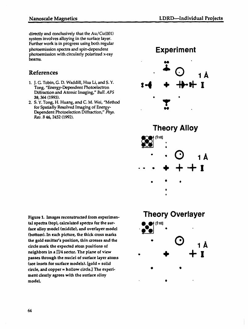
.Nanoscale Magnetics ......... LDRD---!ndividual Pr0jects
directly and conclusively that the Au/Cu(001)system involves alloying in the surface layer.Further work is in progress using both regular
photoemission spectra and spin-dependent EX pe ri m e ntphotoemission with circularly polarized x-raybeams.
References ' _ O 1 _1. J. G. Tobin, G. D. Waddill, Hua Li, and S. Y.
Tong -EnergT.Dependent Photoelectron _q_'_ + "__" IDiffraction and Atomic Imaging," Bull. APS38, 364 (1993). • •
2. S.Y. Tong, H. Huang, and C. M. Wei, "Methodfor Spatially Resolved Imaging of Energy- _ .Dependent Photoelection Diffraction," Phys.Rev. B 46, 2452 (1992).
Theory Alloy
_ [_10] .6
• .Q-- • + +-+x
• • o
o
O
Figure 1. Images reconstructed from experimen- TH nrv__e... t')csrl_v_rvV,,,._l,,"tal spectra (top), calculated spectra for the sur- O__ [_10]
face alloy model (middle), and overlayer model O_] * "(bottom). In each picture, the thick cross marks
the gold emitter's position, thin crosses and the •circle mark the expected atom positions of 1 A
neighbors in a l-[/4 sector. The plane of view • + 4,, 1[passes through the nuclei of surface layer atoms
6
(see insets for surface models). [gold = solid
circle, and copper = hollow circle.] The experi- • •
ment clearly agrees with the surface alloymodel. • •
64
iI
LDRD---Individual Projects Nanoscale Magneticsi i i iiiii i i i i I I iiii ii iiii iiii
Presentations (Invited) 4. A.F. Jankowski, G. D. Waddill, and J. G.Tobin, "Observation of X-Ray Absorption
1. J. G. Tobin, "X-Ray Circular Dichroism in Magnetic Circular Dichroism in Well-Photoemission and Photoabsorption," 1992 Characterized Iron-Platinum Multilayers,"Users Meeting of the University of Wisconsin Meeting of the American Physical Society,Synchrotron Radiation Center, Madison, WI, Seattle, WA, Mar. 1993.
i Oct. 1992. 5. J.G. Tobin, G. D. Waddill, Hua Li, and S. Y.2. J.G. Tobin, G.D. WaddiU, T. Gouder, and C. Tong, "Energy-Dependent Photoelectron
Colmenares, "The Search for X-Ray Absorp- Diffraction and Atomic Imaging," Meetingtion Magnetic Circular Dichroism in Actinide of the APS, Seattle, WA, Mar. 1993.Materials: Preliminary Experiments using
UFe2 and U-S," ALS Workshop on Synchro- Publicationstron Radiation in Transactinium Research,Berkeley, CA, Oct. 1992.
3. J. G. Tobin, G. D. Waddill, S. Y. Tong, H. 1. J.G. Tobin, "Photoemission and InversePhotoemission," in Determination of Optical
Huang, and Hua Li, "Surface-Structural Imag- Properties, Vol. VIII, Physical Methods ofing using Energy-Dependent PhotoelectronDiffraction," Fall Meeting of the Materials Chemistry, 2nd Edn., B. W. Rossiter and R. C.
Bretzold, Eds. (Wiley, New York, 1993).Research Society, Boston, MA, Nov. 1992.
4. G.D. Waddill, "Magnetic Circular Dichroism 2. D. Pappas, G. D. Waddill, and J.Tobin, "Mag-netic Dichroism in Core-Level Photoemissionin Magnetic Ultrathin Films of Fe/Cu(001),"
from Fcc Fe/Cu(001) Films," J.Appl. Phys. (inMarch Meeting of the American Physical press).Society, Seattle, WA, Mar. 1993 [Bull. APS 38,162 (1993)]. 3. J. Tobin and G. Waddill, "X-Ray Absorption
5. J. G. Tobin, G. D. Waddill, Hua Li, and S.Y. Magnetic Circular Dichroism: SimplifiedSpin-Alignment Analysis of F-Electron
Tong, "Imaging of a Surface Alloy with System," Mod. Phys. Lett. B 7, 317 (1993).Energy-Dependent Photoelectron Diffraction," 4. J.G. Tobin, G. D. Waddill, Hua Li,and S. Y.Photoelectron Diffraction Workshop, Gwatt, Tong, "Experimental Optimization for Imag-Switerzland, Mar.-Apr. 1993. ing with Photoelectron Diffraction," MRS
Syrup. Proc. (in press).Presentations (Contributed) 5. G. D. Waddill, J. G. Tobin, and A. F. Jankow-
ski, "Magnetic Circular Dichroism in X-Ray
1. G.D. Waddill, J.G. Tobin, and D. P. Pappas, Absorption for Fe/Pt Multilayers," submitted"Magnetic X-Ray Circular Dichroism of Core- to Appl. Phys. Lett.Level Photoemission of Fe/Cu(001)," Nation- 6. J. G. Tobin, G. D. Waddill, Hua Li, and S. Y.al Symposium of the American Vacuum Soci- Tong, "Imaging of a Surface Alloy withety, Chicago, IL,Nov. 1992. Energy-Dependent Photoelectron Hologra-
2. J.G. Tobin, G. D. Waddill, and D. P. Pappas, phy," Phys. Rev. Lett. (in press)."Giant X-Ray Absorption Circular Dichroism 7. J.G. Tobin, G. D. Waddill, T. H. Gouder, C. A.in Magnetic Ultrathin Films of Fe/Cu(001)," Colmenares, and D. P. Pappas, "MagneticNational Symposium of the American Circular Dichroism in X-Ray Absorption andVacuum Society, Chicago, IL,Nov. 1992. Core-Level Photoemission," submitted to MRS
3. G.D. Waddill, J.G. Tobin, and D. P. Pappas, Symp. Proc."Magnetic X-Ray Dichroism in 2p Absorption 8. A. F. Jankowski, G. D. Waddill, and J. G.Spectra of Fe/Cu(001)," 37th Annual Confer- Tobin, "Observation of X-Ray Absorptionence on Magnetics _nd Magnetic Materials, Magnetic Circular Dichroism in Well-Houston, TX, Dec. 1992. Characterized Iron-Cobalt-Platinum Multi-
layers," MRS Symp. Proc. (in press).
65

Inorganic and Organic Aerogels ...... LDRD--Indivi,'dual Project s
Inorganic and Organic Aerogels
L. W. Hrubesh, T. M. TiUotson, F. M. Kong, and R. W. Pekala
We are investigating the synthetic conditions necessary to tailor the structure and properties of
organic and inorganic aerogels at the nanometer scale. Our synthetic approach involves the sol-gel polymerizaii_n of (1) multifunctional monomers or (2) molecular building blocks in dilute
solution. The resultant aerogels have high surface areas (400 to 1000 m2/g), small pore sizes
(<50 nm), and a solid matrix composed of interconnected spherical particles or fibers with
characteristic diameters of 10 nm. We are developing a fundamental understanding of the
chemistry-structure-property relationships in these unusual porous materials.
Inorganic Aerogels at high temperature, they result in transparentmonoliths that are quite stable to atmosphericmoisture.
We have synthesized new aerogels of purezirconia and tantala at densities lower than Other significant achievements:
previously achieved for these rnid-Z metals. We • Developed a model to predict the optimummodified our formerly developed, two-step, sol- density for minimizing the thermal conduc-gel chemistry to make prehydrolyzed precursors tivity of aerogels and prepared results forfrom which we made low-density aerogels of publication.both zirconia and tantala. Our monolithic zir- • Completed measuring the thermal conduc-conia aerogels have densities as low as 38 kg/m 3, tivity of ultralow-density silica aerogels,but they are extremely weak, and tantala aerogels both pure and loaded with carbon particles.have densities as low as 60 kg/m 3, which is • Completed analyzing the frequency depen-within a factor of 4 of the theoretical limit, dence of the attenuation of sound by aero-
In addition to our synthetic efforts, we have gels and completed measurements atcompleted the characterization of new pure erbia, ultrasonic frequencies.praseodymia, and neodymia aerogels and pub-lished the results. These aerogels were madefrom sol-gel chemistry, with the meial chloride as Organic Aerogelsthe starting material. The metal chloride was dis-solved in alcohol and reacted with water. Propy- Whereas much research has been conductedlene oxide was added to scavenge the liberated on the production of large monolithic aerogelhydrochloric acid and to help induce gelation, samples, we have developed a new method forThese reactions intentionally were slowed by forming organic aerogel microspheres (0.1 tomixing at slightly above 0°C. The resulting gels 3.0 mm in diameter) in a cost-effective manner.were supercritically dried using both the high- This method involves stirring an aqueous sol inand low-temperature methods. The high- mineral oil at elevated temperature until thetemperature extracted aerogels were monolithic, dispersed phase has reacted to form nonsticky geltranslucent, hydrophobic, and very weak. The spheres. No other chemicals or surfactants arelow-temperature extracted aerogels were trans- required to stabilize the dispersion.parent and hydrophilic, but not monolithic. The size of the spheres formed depends on
Mixed aerogels were made by adding the the collision rate of the liquid droplets and therare-earth chloride-alcohol solution directly to reaction rate of the monomers. The collision rateprehydrolyzed tetramethoxysilane (condensed is governed by the volume ratio of the aqueoussilica) in a two-step gelation process. The result- solution to mineral oil and by the applied shearing solution was also partially condensed and rate. The reaction rate depends on the aerogelserved as a precursor to making gels and aero- formulation and the curing temperature. Aftergels. When these gels are supercritically extracted the crosslinked spheres have been formed, they
66

LDRD--Individual Projects Inor anic and Or anic Ae ogels
are washed with acetone, and then supercritically .... . . Idried from carbon dioxide. Density (g/cm3) I
We have produced aerogel microspheres 300 !" ,_ /_ "from both resorcinol-formaldehyde (RF)and .-.melamine-formaldehyde (MY). The RFmicro-spheres can be pyrolyzed at 1050°C to form =carbon microspheres. _"
We are continuing to characterize the struc- _ 200 r /_ _ture and transport properties of carbon aerogels,using Raman spectroscopy as a sensitive method mfor monitoring the local order. For disordered _->'carbons, two broad Raman lines are observed: fa
the line in the vicinity of 1580 cm-1 is associatedwith local crystalline order, whereas the line at " 0.6701360 cm-1 results from disorder-induced scatter-ing that is forbidden in a perfect crystal. Samplecharacterization of aerogels has involved the 012()0 1400 1600 1800measurement of central frequencies, line widths,line shapes, and integrated scattering intensities Raman shift (cm -1)for each of these lines, obtained from the fits ofthe spectra to the Breit-Wigner-Fano (BWF) Figure 1. Raman spectra for carbon aerogelsequation. From the ratios of the integrated inten- synthesized at R/C - 200.sity of the disorder-induced line to that of theRaman active line (Ils60/Ilsso), the in-planemicrocrystallite size (La)is determined according Publicationsto Knight's formula, which is valued for a laserexcitation wavelength of 4880 ._: 1. T. M. Tillotson, W. E. Sunderland, I. M.
Thomas, and L. W. Hrubesh, "Synthesis ofLa =44 (I1580/I1360) . (1) Lanthanide and Lanthanide-Silicate Aerogels,"
submitted to J. Sol-Gel Sci. Technol.Figure 1 shows Raman spectra for carbon 2. R.W. Pekala and D. W. Schaefer, "Structure of
aerogels synthesized at R/C = 200. The observed Organic Aerogels I:Scaling and Morphology,"spectra are almost identical, but a small reduction submitted to Macromols.in line width is seen with increasing density. Of 3. M. Hosoya, G. Reynolds, M. S. Dresselhaus,interest is the in-plane microcrystallite size of 25 and R. W. Pekala, "Photoconductivity ofto 30 ./_for all samples. Raman measurements are Carbon Aerogels," submitted to J.Mater. Res.not very sensitive to La in this size range, but we 4. M.S. Gebert and R. W. Pekala, "Fluorescencecan safely conclude that all La values measured and Light Scattering Studies of Colloidal andfor carbon aerogels are much smaller than the Polymeric Solutions and Gels," submitted toparticle size (--120 _). This indicates that the Chem. Mater.width and structure of the carbon ribbons withineach particle are similar and independent of thebulk density. These results agree with conclu- Presentationssions reached from TEMand BET characteriza-
tion measurements. 1. R. W. Pekala, "Aerogels: Cluster-AssembledOther significant achievements: Porous Materials," Society for the Advance-
. Measured the magnetic susceptibility and ment of Materials and Process Engineeringmagnetoresistance of carbon aerogels as a (SAMPE) Meeting, Burlingame, CA, Jan. 1993.function of temperature. 2. L.W. Hrubesh and R. W. Pekala, "Aerogel
• Measured the photoconductivity of carbon Foams for Thermal Insulation," Ninth Inter-aerogels, national Product Safety Conference on Ther-
• Completed a light-scattering and fluores- mal Insulation, Milbrae, CA, Mar. 1993.cence study of the RF polymerization.
67
LDRD.--Individual ProjectsComplex Mat, erials ...................... - .................
Structural Transformation and Precursor Phenomenain Advanced Materials
P. E. A. Turchi, L. T. Reinhard, and S. C. Moss*
Local chemical order and atomic displacements are the major precursors of alloy transformations.
Their effects on transformations are studied both theoretically, with modern electronic-structure
theory of alloy phase stability and Monte Carlo simulations, and experimentally, with scattering
and surface techniques in the case of the transformation from a simple bcc-based FeCr alloy to a
complex o"phase upon cooling.
Progress to Date time and length scales involved (ordering ismuch faster than segregation) and the evident
We have developed codes in collaboration structural differences between the competingwith A. Traiber to study the electronic-structure phases. In our previous studies on FeCr alloys,and phase-stability properties of ternary alloys in it was shown that the alloying effect (favoringorder to address the question of complex phase phase separation) and the local chemical orderformation. The methodology represents an may compete. In the case of equiatomic TiV, theextension to multicomponent alloy systems of the local order alone favors segregation, with the B32tight-binding (TB)description of the electronic ordered structure being only slightly unstablestructure, and of the generalized perturbation with respect to phase decomposition.method (GPM), which describes order-disorder The energetic quantities obtained from ourphenomena. Chemical disorder effects are taken first-principles electronic-structure calculationsinto account within the coherent potential for TiV were used in Monte Carlo simulationsapproximation (CPA). The electronic-structure based on the kinetic Ising model. This studyparameters that enter the TB model have been shows for the first time that, for such alloysfitted to results from first-principles calculations prepared in the high-temperature disorderedto accurately determine the electronic properties configuration and subsequently quenched insideand the phase diagrams of the binary alloys, the miscibility gap, an ordered B32 phase first
The first system selected was Fe-Ti-V. To spontaneously forms before evolving towardprovide an insight into the role played by atomic phase separation. A detailed analysis of thisorbital directionality in the stability of complex remarkable evolution indicates that, even in thephases, the TB approach was also used. The elec- final stage (i.e., near thermodynamic equilib-tronic parameters that enter the model were rium), the ordered phase wets the interfaceobtained from the first-principles linear muffin- between the two disordered decomposition pro-tin method, in the atomic sphere approxima- ducts. Calculations are ongoing to estimate whichtion (LMTO-ASA). The TB-LMTOparameters ternary additions would favor the experimentalobtained for the Fe-V alloy, which exhibits sta- observation of such an unusual kinetic path.bility properties similar to those of Fe-Cr, are The Monte Carlo study was also performedcurrently being tested to check their transferabil- on two-dimensional model systems to assess theity to various topological configurations and to effect of the parameters of the problem (e.g.,address the question of complex phase formation, the energy differences between the competing
Precursor phenomena are also important phases) on the time evolution and to examine thein the context of the temporal evolution of a sys- role played by extended defects such as antiphasetern. Here, the case of an energetic competition boundaries. A typical time evolution of a two-between an ordered state and phase segregation dimensional equiatomic AB system (based on ais especially interesting because of the different square lattice) is shown in Fig. 1, after an instan-
taneous quench from high temperature to a tem-*PhysicsDepartment,theUniversityof Houston(TX) perature well below the miscibility gap. Note that
68
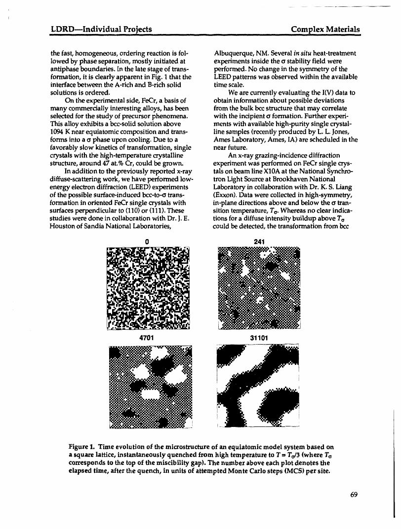
LDRD---Individual Projects Complex Materials|Ji Ii I i l il I ii B L imni I lili I Ill I ill I ill li lib
the fast, homogeneous, ordering reaction is fol- Albuquerque, NM. Several in situ heat-treatmentlowed by phase separation, mostly initiated at experiments inside the a stability field wereantiphase boundaries. [n the late stage of trans- performed. No change in the symmetry of theformation, it is clearly apparent in Fig. 1 that the LEEDpatterns was observed within the availableinterface between the A-rich and B-rich solid time scale.solutions is ordered. We are currently evaluating the I(V) data to
On the experimental side, FeCr, a basis of obtain information about possible deviationsmany commercially interesting alloys, has been from the bulk bcc structure that may correlateselected for the study of precursor phenomena, with the incipient a formation. Further experi-This alloy exhibits a bcc-solid solution above ments with available high-purity single crystal-1094 K near equiatomic composition and trans- line samples (recently produced by L. L. Jones,forms into a a phase upon cooling. Due to a Ames Laboratory, Ames, IA) are scheduled in thefavorably slow kinetics of transformation, single near future.crystals with the high-temperature crystalline An x-ray grazing-incidence diffractionstructure, around 47 at.%Cr, could be grown, experiment was performed on FeCr single crys-
In addition to the previously reported x-ray tals on beam line X10A at the National Synchro-diffuse-scattering work, we have performed low- tron Light Source at Brookhaven Nationalenergy electron diffraction (LEED) experiments Laboratory in collaboration with Dr. K. S. Liangof the possible surface-induced bcc-to-a trans- (Exxon). Data were collected in high-symmetry,formation in oriented FeCr single crystals with in-plane directions above and below the crtran-surfaces perpendicular to (110) or (111). These sition temperature, To. Whereas no clear indica-studies were done in collaboration with Dr. J.E. tions for a diffuse intensity buildup above ToHouston of Sandia National Laboratories, could be detected, the transformation from bcc
0 241
4701 31101
Figure 1. Time evolution of the microstructure of an equiatomic model system based ona square lattice, instantaneously quenched from high temperature to T--- To/3 (where Tacorresponds to the top of the miscibility gap). The number above each plot denotes theelapsed time, after the quench, in units of attempted Monte Carlo steps (MCS) per site,
69

Complex Materials LDRD--Individual ProjectsII iii II ] i iiiiiii I ii _ ] iiiiii 11111 -- -- --
to a was indeed observed below Ta. The trans- Based FeV and FeCr Alloys," Phys. Rev. B (information kinetics exhibited a pronounced press).incubation time, indicative of a strongly first- 4. J. L Robertson, D. A. Neumann, S. C. Moss,order transition, and L. Reinhard, "Inelastic Neutron Scattering
Study of Phonon Dispersion in FeCr near thea-Phase Transformation," Acta MetaU.(in press).
Future Work 5. L. Reinhard and S. C. Moss, "Recent Studies ofShort-Range Order in Alloys--The Cowley
This program provides new insights into the Theory Revisited," Ultrarnicrosc.(in press)formation and the stability of complex phases by (UCRL-JC-112438).a synergistic effort between atomistic character- 6. L. Reinhard, B.Schtnfeld, G. Kostorz, and W.ization of the early stage of transformation and B/ihrer, "Diffuse Neutron Scattering Study ofmodeling by a state-of-the-art approach. This is Local Atomic Arrangements in fcc Cu-Znincreasingly important because novel materials Alloys," submitted to Z. Metallkde.with promising properties are being synthesized.Work is now being performed to• Define accurate and transferable potentials Presentations
that can be used in molecular-dynamicssimulations to provide additional insight into 1. L. Reinhard, M. Sluiter, and P. E. A. Turchi,the formation and stability of complex phases. "Monte Carlo Study of the Formation of
• Study the effect of ternary addition on the Transient Ordered States in Phase-Separatingoccurrence and the stability of complex Systems," Meeting of the American Physical
Society, Seattle, WA, Mar. 1993 (UCRL-JC-phases. 112080 Abs).
Fundamental questions are being addressed on 2. A.J.S. Traiber, M. Sluiter, P. E. A. Turchi, and• Surface reconstruction and segregation in the S.M. Allen, "Tight-Binding Study of Elec-
bcc phase prior to the bcc-to-c_transformation, tronic Structure and Phase Stability Properties• Orientation relationships between bcc and c_ in Ternary Substitutional Alloys," Meeting of
near the surface, the American Physical Society, Seattle, WA,• Kinetics of transformation near the surface. Mar. 1993 (UCRL-JC-112081 Abs).
3. M. Sluiter, P. P. Singh, and P. E. A. Turchi,"Trends in Tight-Binding Parameters in Binary
Publications Alloys," Meeting of the American PhysicalSociety, Seattle, WA, Mar. 1993 (UCRL-JC-
1. L. Reinhard, J. L. Robertson, S. C. Moss, G.E. 112083 Abs).Ice, P. Zschack, and C. J.Sparks, "Anomalous 4. L. Reinhard and S. C. Moss, "Recent Studies ofX-Ray Scattering Study of Local Order in bcc Short-Range Order in Alloys--The CowleyFe0.ssCr0.47,"Phys. Rev. B 45, 2662-2676 (1992). Theory Revisited," John M. Cowley Sympo-
2. L. Reinhard, J. L. Robertson, S. C. Moss, G.E. sium, Phoenix, AZ, Jan. 1993 (UCRL-JC-112438Ice, P. Zschack, and C. J.Sparks, "Anomalous Abs).X-Ray Scattering Study of Local Order in bcc 5. L. Reinhard and P. E. A. Turchi, "Monte CarloFe0.53Cr0.47," in Proc. TMS Symp. on Kinetics of Simulations of Phase Transformations in Fe-CrOrdering Transformations in Metals, H. Chen Alloys," MRS Fall Meeting, Boston, MA,and V. K.Vasudevan, eds. (The Materials Nov.-Dec. 1992 (UCRL-JC-111004 Abs).Society of America, Warrendale, PA, 1992), 6. A.J.S. Traiber, M. Sluiter, P. E. A. Turchi, andpp. 37-52 (UCRL-JC-109905). S.M. Allen, "Electronic Structure and Phase
3. P. E. A. Turchi, M. Sluiter, and G. M. Stocks, Stability Properties in Ternary Substitutional"First-Principles Study of Local Order in bcc- Alloys," MRS Fall Meeting, Boston, MA,
Nov.-Dec. 1992 (UCRL-JC-111000 Abs).
70

,LDRD--Individual ,pro_ects Toughening of Refractory-Metal IntermetaUicsiilliinfl flll . II l|ii .... i • HIilli --
Ductile-Phase Toughening ofRefractory-Metal Intermetallics
G. A. Henshall and M. J. Strum
Brittle, intermetallic compounds based on refractory metals could satisfy needs for high strengthand creep resistance at extremely high temperatures if they can be toughened by the dispersion ofa ductile second phase. Beginning with the V-V3Si system, in situ synthesis methods are beingexplored as a way of producing these ductile-phase toughened intermetallic matrix composites(IMCs). Room-temperature fracture-toughness tests have been performed on specimens of vary-ing ductile-phase fraction synthesized using three methods: (1) arc melting (AM) with commer-cially pure vanadium, (2) AM with high-purity vanadium, and (3) directional solidification(DS) with high-purity vanadiu_m.m.The results show that tough.ness increases as the V(Si) frac-tion increases, from 1.3 MPa'Cm for pure V3Si to 31 MPa_/m for V(Si). For the 50% V3Sicomposite, DS improves the tou__hness over AM from 10.5 to 18.5 MPa_m, nearly the indus-trial target value of 20 MPadm. This improvement appears to be associated with greaterdebonding between the two phases, leading to improved ductility in the V(Si). In addition tothese experiments, an innovative approach is being used to study the effects of interphasedebonding on toughness using the finite-element method (FEM). Use of a parametrically variedcritical energy-,elease rate at the interface crack tip shows that higher interface toughnessincreases constraint in the ductile phase, which would decrease toughness. FEM analyses ofcreep in composites with creep-resistant matrices have shown that, because of stress redistri-bution within the material, the composite creep rate is much less than would be predicted fromsimple analytical models.
Detailed Description chemistry andmicrostructureof thecomposites.The nextobjectiveis to develop a mechanisticunderstandingof ductile-phasetoughening and,
The continuingsearch for improved light- in particular, to assess the dependenceof fractureweight structuralmaterials forhigh-temperature toughness on the distributionandproperties ofservice has led to the investigationof intermetal- the constituentphases andthe interfacebehavior.lic compoundsbased on theGroup VBand VIB The finalobjectiveis to characterizethe high-refractorymetals.The majorbarrier to theiruse is temperature creep behaviorof ductile-phasethe lack of ambient-temperaturetoughness toughenedcompositesas a functionof theirrequiredfordamage tolerance.The approachwe microstructureand to develop a micromechanicalare considering to solve thisproblem is "ductile- understandingthat provides predictive capabili-phase toughening," in whicha high-melting- ties.The majorgoal will be to identifythe micro-pointductile phase is dispersed withinthe structuresthatbest maintainthesuperiorcreepintermetaUicmatrix. The ductilephasemay properties of the intermetallicwhile providingincrease toughnessby "bridging" thecrackfaces, sufficientlow-temperature toughness.therebyinhibitingcrack opening,or by blunting Threedifferentsynthesismethods have beenthe cracktip. To produce thesecomposites, in situ used to date inpreparing theV-V3Siin situ corn-synthesis methods are being investigated in posites. Duringprevious reportingperiods, con-which the two components of thecompositeform ventional vacuum arc melting(AM)was per-by phase separationduring solidification, formed, first usingcommercial-purityvanadium
Our first objective is to develop synthesis plate andthen using high-purity vanadiumand processing techniquesthatoptimize the chips as stock.During the first halfof FY93,
71

Tou_ening of Refractor-Metal Intermetallics LDRD--Individual ProjectsIII I -- I / ............... iiii II t ] L ............................
directionally solidified (DS) ingots were made, in 40 , , , .... ,.........
collaborationwith B.P. Bewlayof GE Corporate V-VaSI composites aremelt ]R&D Lab, using the high-purity vanadium stock. 298 K ._rans ]In all cases, electronics-grade silicon was used for 30 " - [alloy preparation.
For all of the alloys studied, the V3Si was the i='"discontinuous phase. 1,2The eutectic microcon- Target _o_stituent consists of V3Si rods or ribbons with 67._20 ........ _ ......aspect ratios of up to 10. In the AM eutectic, the -.,rods form packets that are randomly oriented, _ []whereasin the DS materials,theVsSirodsare 10 - E]:]strongly aligned in the growth direction. Studies []by Bewlay et al.2 have shown that a crystallo- O O
graphic orientation relationship exists between ,I .., .... , . , ........,the two phases in the DS eutectic; the (111> 0u .... 20 40 60 80......... 100direction in V(Si) is parallel to the (001) direction
Volume fraction ductile phase (%)in the V3Si.Thisdirectionalityhasa pronouncedeffecton mechanicalproperties.Forcompositionsother than the eutectic, but in the two-phase Figure 1. The average fracture toughness, KQ, ofregime, "islands" of either V(Si) or V3Si are pres- V-VaSi composites as a function of ductile-ent in a "sea" of the eutectic microconstituent phase fraction.previously described.
To assess the influence of processing and and over only 40%of the surface in the AMductile-phase fraction on toughness, room- alloys. Cleavage of both the VaSi and the V(Si)temperature fracture toughness tests have been was observed in the other regions of the fracturePerformed on specimens of varying composition surfaces. Using an available model for toughen-that were synthesized using the three different ing by ductile bridging 3 and using the fraction oftechniques, fracture surface exhibiting ligament stretching as
As shown in Fig. 1, the V3Si has a fracture a weighting factor, we developed a model of thetoughness of only about 1.3 MPa _ (estimated effects of directional solidification on fracturefrom indentation tests), and the V(Si) phase has a toughness that is consistent with the data. 4 Moretoughness of about 31 MPa 4"_'. The industrial fundamentally, the difference in fracture behav-target for,._.advancedturbine engine materials is ior between the two eutectics suggests that cleav-20 MPaVm. The V-V3Sicomposites have inter- age in one or both of the phases is sensitive tomediate toughnesses that increase as the ductile- crystallographic orientation.phase fraction increases. (The exception is the DS Additional experiments are under way toalloy with 90%ductile phase; investigation of this improve our understanding of the effects ofanomaly is in progress.) directional solidification on the toughness of
For the eutectic--or 50%intermetallic--com- V-VaSi composites. In addition, since it may beposite (near the ratio likely to be of practical use), desirable to study a system in which the inter-the two AM tech,_.niquesresult in a toughness of metallic is the continuous phase, exploration ofabout 10 MPaVm. The DS process produces a another materials system is being considered.more optimized microstructure and/or chemistry To study the mechanisms of ductile-phaseand increases the toughness of the 50%VaSi corn- toughening, numerical crack-growth simulationsposite to 18.5 MPaqm, nearly that targeted for using the NIKE2D FEM code have begun. Onepractical use. major goal is to quantify the influence of inter-
Based on examinations of the fracture facial debonding on the stress-displacementsurface using scanning electron microscopy, behavior and, hence, the overall fracture tough-improved toughness in the DS eutectic is asso- hesS of idealized composites.ciated with greater ductility of the V(Si) and In collaboration with E. Zywicz of LLNLa greater tendency for delamination of V(Si) Engineering, an innovative approach is beingligaments from the V3Si rods. Plastic stretching implemented. Debonding between the phases isof the V(Si) was observed over approximately modeled by release of interface nodes once the85%of the fracture surface in the DS material energy-release rate at the interface cracktip
72
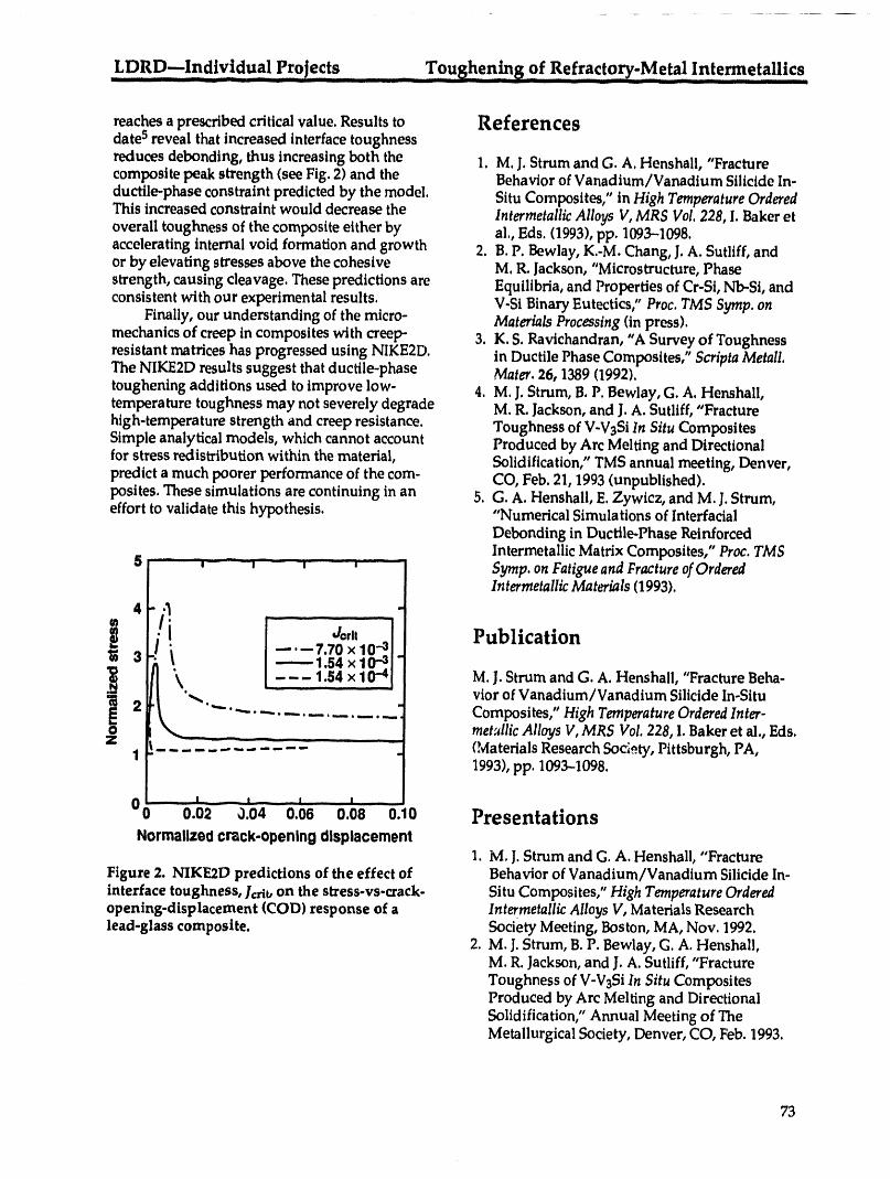
LDRD_individual Projects ................ ToughenS8 of Refracto_-Met_ In!e_etaUic s
reaches a prescribed critical value. Results to Referencesdate 5 reveal that increased interface toughness
reduces debonding, thus increasing both the 1. M.J. Strum and G. A. Henshall, "Fracturecomposite peak strength (see Fig. 2) and the Behavior of Vanadium/Vanadium Silicide In-
ductile-phase constraint predicted by the model. Situ Composites," in High Temperature OrderedThis increased constraint would decrease the Intermetallic Alloys V, MRS Vol. 228, I. Baker etoverall toughness of the composite either by al., Eds. (1993), pp. 1093-1098.accelerating internal void formation and growth 2. B.P. Bewlay, K.-M. Chang, J. A. Sutliff, andorby elevatingstressesabovethecohesive M.R. Jackson,"Microstructure,Phasestrength,causingcleavage.Thesepredictionsare Equilibria,and PropertiesofCr-Si,Nb-.Si,andconsistentwithourexperimentalresults. V-SiBinaryEutectics/'Prec.TMS Symp.on
Finally,ourunderstandingofthemicro- MaterialsProcessing(inpress).mechanicsofcreepincompositeswithcreep- 3.K.S.Ravichandran,"A SurveyofToughnessresistantmatriceshasprogressedusingNIKE2D. inDuctilePhaseComposites,"ScriptaMetall.The NIKE2D results suggest that ductile-phase Mater. 26, 1389 (1992).toughening additions used to improve low- 4. M.J. Strum, B. P. Bewlay, G. A. Henshall,temperature toughness may not severely degrade M.R. Jackson, and J. A. Sutliff, "Fracturehigh-temperature strength and creep resistance. Toughness of V-V3Si In Situ CompositesSimple analytical models, which cannot account Produced by Arc Melting and Directionalfor stress redistribution within the material, Solidification," TMS annual meeting, Denver,predict a much poorer performance of the corn- CO, Feb. 21, 1993 (unpublished).posites. These simulations are continuing in an 5. G. A. Henshall, E.Zywicz, and M. j. Strum,effort to validate this hypothesis. "Numerical Simulations of Interfacial
Debonding in Ductile-Phase ReinforcedIntermetallic Matrix Composites," Prec. TMS
5 _ Syrup. on Fatigue and Fracture ofOrderedIntermetallic Materials (1993).
4 /_. ...... ...... -
LI i I --.-7.7o xlo l_Publication
3r'k t I --------1.54 xl0-_l"
i/i L---li54 x i0-41 M.J. Strumand G. A. Henshall, "FractureBeha-
i 2 _-_ _._....... . vior of Vanadium/Vanadium Silicide In-Situ! t ............................ , Composites," High Temperature Ordered Inter-
1 (Materials Research Society, Pittsburgh, PA,1993), pp. 1093-1098.
I __ 1 I _ ,, ! .... I
Oo o.o2 o.o4 o.o6 o.o8 O.lO PresentationsNormalized crack-opening displacement
1. M.J. Strum andG. A. Hensha]l,"FractureFigure 2. NIKE2D predictions of the effect of Behavior of Vanadium/Vanadium Silicide In-interface toughness, Jcrit,on the stress-vs-crack- Situ Composites," High Temperature Orderedopening-displacement (COD) response of a Intermetallic Alloys V, Materials Researchlead-glass composite. Society Meeting, Boston, MA, Nov. 1992.
2. M.J. Strum, B. P. Bewlay, G. A. Henshal),M. R. Jackson, and J. A. Sutliff, "FractureToughness of V-V3Si In Situ CompositesProduced by Arc Melting and DirectionalSolidification," Annual Meeting of TheMetallurgical Society, Denver, CO, Feb. 1993.
73
Fundamental Studie s of Particle,Solid Interaction s .... LDRD--Individual Projects___ _ IIllllllll L1 l[ qlT]__ ll[l _.
Fundamental Studies of Particle-Solid Interactions
T. Diaz de la Rubia and M. W. Guinan
The aim of our research is to improve our understanding of nonequilibrium processing of
materials with energetic beams. Our goals are to develop models of defect production andtransport in materials in order to help industry develop improved macroscopic modeling tools
for manufacturing next-generation electronic components and other advanced materials. The
project focuses on two topics: (1) ion implantation and beam processing of semiconductors and(2) radiation effects in novel, bulk, nanophase materials.
Introduction Code and Graphics Development
As the dimensions of integrated circuits In association with the massively parallelshrink and the cost and complexity of manufac- processing (MPP) applications group at theturing increases, empirical approaches to indus- National Energy Supercomputing Centertrial process design cease to be practical. Hence, (NERSC), our code for semiconductor materialsprocess modeling of device manufacturing studies is currently being developed to use MPPbecomes critical, capabilities such as the Cray C90, the connection
However, process modeling currently is machine CMS, and networks of workstations. Thenot predictive, the main limitation being a lack of code implements the message-passing program-complete understanding of the physical processes ming paradigm on these machines and willinvolved. For example, an understanding of therefore be easily portable as new computersdefect production during ion implantation, as come on line at LLNL or elsewhere.well as dopant diffusion and activation, is vital With the help of the graphics group atto supporting shallow junction technology. NERSC, we have developed visualizationAddressing these limitations is one of the critical methods to effectively display the atomisticfactors that will determine the future success of dynamics simulated by the code. Our results ofthe serrdconductor industry. 5-keV displacement cascades in Cu3Au were
We are developing a unique capability in the shown by LLNL at the November 1992 super-area of atomistic simulation of energetic particle computing conference in Minneapolis and willinteractions with solids. Our molecular-dynamics be showcased by LLNL's National Storage(MD) codes use massively parallel computers to Laboratory to display the capabilities of theirprovide the physical insight (otherwise lacking) high-performance parallel interface (HiPPI).that will allow us to describe the defect produc-tion and diffusion processes common to beam-assisted processing of materials. Ouratomistic Semiconductor Device Processingsimulation codes---together with modem 3-D with Ion Beamsvisualization tools and continuum-transportsimulation programs--will lead the way to a We are presently carrying out MD studies ofcomprehensive total computer-aided design ion implantation in silicon at recoil energies from(TCAD) tool. This TCAD tool will provide a threshold (15 eV) up to 15 keV. The simulationspredictive process-modeling package for manu- employ crystallites with up to 216,000 atoms atfacturing the next generation of semiconductor 10 K interacting through semiempirical, three-integrated circuit components, body, interatomic potentials. The simulation cells
74
LDRD---Individual Projects Fundamental Studies of Particle-Solid Interactions.... I[ ..... I_111 I III IIIII _ II _ I IIIII " llJl Ill]l[ll ..... II IIII II .... I1[I I sue IIII I_lll ___ ' IL I
haveperiodicboundariesinallthreedimensions havenotbeenabletoidentifytheformorevenand cancontainafreesurfaceinagivendire<:- findtheinterstitial.Ab _nitioMD resultsshowt-lon.To date,allsimulationshavebeenper- thatthe(110)splitinterstitialhasno statesintheformedwiththeStiilinger-Weberpotentialfor gap andthereforedoesnotgiverisetoEPRsilicon.Comparisonsoftheresultsobtainedso signalsthatmay beusedtoidentifyit.We arefarwithsimulationsemployinga Tersoff-llke presentlytryingtodeterminethemigrationpotentialdevelopedby RockettinIllinoiswill enthaIpyofthisinterstitialconfiguration.Thisproceedinthenearfuture, willhelpustobetterunderstanddiffusionin
We haveobtaineddetailedinformationon siliconfollowingionirradiation.thethresholdenergyrequiredtoproduceastable Athigherrecoilenergies,we havesofarFrenkelpairinthesiliconlattice.Thisenergyhas obtainedresultsfordisplacementcascadesinbeenfoundtovarywithorientation,ingood siliconinitiatedby 3-and 5-keVgoldrecoilsmov-agreementwithexperimentalinformation.Along ingneara(001)direction.Fifteen-keVeventsarethe[111]direction,theminimum energyrequired currentlyunderway incrystallitescontainingatoforma stableFrenkelpairis23:i:2 eV.Inthis freesurface.Theseeventshaveshown a surpris-case,a vacancyattheoriginalrecoilsiteanda inglylargeshock-wavecomponentintheenergy-tetrahedralinterstitialareformed.Ata recoil dissipationmechanism.Suchshock-wavepro-energyof30eV,a(110)dumbbellselfinterstitial cessesarenotusuallytakenintoaccountbyisformedalongwiththevacancy.Quenchingof simplerdescriptionsoftheimplantationprocess.thesamplestonearlyzerokineticenergyreveals Significantconsequencesthatcouldhelpunder-thatthe(110)interstitialisthestableform.The standsome ofthefundamentalprocessesasso-vacancy-_110)interstitialpairhasanenergy ciatedwithbeam interactionsinsemiconductors1.25eV lowerthanthatofthevacancy-Tintersti- arebeingexplored.Forexample,thelargetialconfiguration.Moreover,we haveannealed amountofcoherentenergydissipatedby theoursamplesattemperaturesup to750K for shockwave may be partlyresponsibleforthe15ps.Theseisochronalannealingrunsrevealthat lowactivationenergyobservedduringthethetetrahedralinterstitialfirsttransformsintoa ion-inducedrecrystailizationofamorphous-(110)dumbbellbeforerecombiningwithitsown crystalline(a-c)interfacesinsilicon.A cascadeinvacancy.Theseresultsareinexcellentagreement thecrystallinesideofa pre-existinga-cinterfacewithfirst-principlesabinltioMD studiesofpoint may inducesubstantialatomicdiffusionatthedefectsinsiliconthatpredictthe(!10)splittobe interface,evenifthecascadedoesnotpreciselythelowest-energyinterstitialconfiguration, overlapit.Alongthe[111]direction,thethresholddropsto18 :t:2 eV, with the (110) split interstitial beingproduced at a recoil energy of 25 eV. Radiation Effects in Nanophase
For recoils in the [100] direction, the situa- Materialstion is very similar to that of the [111] direction
but simpler since no tetrahedral interstitial has Our collaborator, Prof. Hahn, recentlybeen found at any energy. Only the low-energy- moved from Rutgers University to theconfiguration vacancy-(110) split pair has been Technische Hochschule Darmstadt in Germany,found. The threshold for this defect to be pro- and synthesis of silver and lead nanophaseduced was found to be 23.5 ± 1eV. samples was delayed for about two months.
Along the [110] direction, the situation is Consequently, irradiation of these specimens ismore complicated. The threshold appears quite only now starting at the GSI in Darmstadt. Ourhigh (>35 eV). However, at recoil energies of ongoing plans to build a new beamline in the35 eV, we have found a closed chain of four Chemistry and Materials Science Department'sreplacements with no defect production. We are 4-MV ion accelerator for in-house irradiationspresently carrying out the simulations at 40 eV as have been put temporarily on hold. Dr. Winterer,well as along [110] to discern the mechanisms of a postdoctoral associate of Prof. Hahn, will bedefect production along these directions, spending several months in Livermore working
The observation of a (110) split as the stable on the MD simulation studies of radiation effectsinterstitial resulting from low-energy recoils in a in these materials. For this, he will be using oursilicon lattice may help explain the fact that, for MD code for metal systems that was developed30 years, electron irradiation studies of silicon
75
Fundamental Studies of Particle-Solid Interactions LDRD--Individual ProjectsIllllll II II III I -- [ ....... .... -- _1111 "_ _ _1 .L__-- __lflll m[I I II .........
during last year's LDRD funding cycle and runs optimized for performing classical, tight-bindingon the MPP platforms, and ab initio MD. This machine would be unique,
in that the architecture would be designed to bestperform the neighbor.finding algorithms that are
Summary key to the performance of MD codes. We alsoplan to submit a technology-transfer initiative
As a result of our efforts to date in the area with AT&Tto DOE _fore the end of this fiscal
of MD simulation studies of beam-solid interac- year.tions, AT&T Bell Laboratories has become veryinterested in collaborating with us to developnew computational tools for process modeling of Presentationssemiconductor devices. We have submitted a
proposal abstract to ARPA to get funds under the 1. T. Diaz de la Rubia, AT&T Bell Laboratories,NCAICM call. In addition, we plan to submit a Murray Hill, NJ, January 1993.proposal to DOE's recent HPCCI call to build, in 2. M. W. Guinan, International Conference oncollaboration with AT&T, an MPP computer Evolution of Microstructure in Metals During
Irradiation, Sep.--Oct. 1992, MineR, Canada.
76
LDRD--Groups Electronic Structure Evolution of Metal Clustersin II
Electronic-Structure Evolution of Metal Clusters
V. V. Kresin, M. J. Fluss, R. H. Howell, and W. D. Knight*
We are investigating the properties of alkali metal clusters, emphasizing electronic structure and
collisional properties. We are interested in the development of electronic energy levels with
increasing cluster size and the correlation between electronic structure and collisional propertiesof free metallic clusters. These properties can be studied as the cluster size grows atom by atom.We have been conducting a detailed study of collisions involving metal clusters. This researchhas been extended to study alkali-cluster collisions with sodium atoms and with carbon
fullerenes. This direction is of interest to both experimentalists and theorists in the field. It
represents a way to map out the step-by-step development of the interaction of a metallic system
with atoms and molecules, a question of interest in surface science and catalysis.
Technical Activities and Results Understanding the interactions involved isan important and actively discussed theoretical
After a detailed study of elastic and inelastic issue because it reflects such cluster properties ascollisions between alkali clusters and noble gas electromagnetic response, fission barrier forma-
tion, and evaporation dynamics. It is also impor-atoms and halogens completed last year, werecently performed experimental measurements rant for practical applications such as particleof collision cross sections for interactions between formation and cluster film growth.a bea_a of neutral sodium clusters and (1)sodiumatoms and (2) C60and C70clusters. The experi-ment was performed by passing a tightly colli- Referencemated beam of sodium clusters through a heatedscattering cell. By precisely controlling the tern- 1. M. Balooch, W. Siekhaus, et al., "Vaporperature of the cell (and thus the vapor pressure Pressure of Buckminsterfullerenes," Appl.of the scattering gas) and by measuring the cor- Phys. Lett. 60, 1313 (1992)]responding depletion of the cluster beam, wewere able to determine absolute scattering crosssections of the collisions. Data analysis and corn- Publicationsparison with available theoretical calculations are
now in progress. 1. V. Kresin and A. Scheidemann, "Scattering ofThis project is of considerable interest to Neutral Metal Clusters: Long-Range Interac-
researchers in the field. Collisions between alkali tions and Response Properties," J. Chem.Phys.and fullerene clusters represent a convergence of (1993).intense experimental efforts in two fields. We 2. A. Scheidemann and V. Kresin, "Elastic andwere able to take advantage of recent work car- Inelastic Collisions of Atoms and Molecules
ried out at LLNL by Abrefah, Olander, Balooch, with Neutral Alkali Clusters," Z. Phys. D (inand Siekhaus, 1who measured the temperature press) (UCRL-JC-111650).dependence of the vapor pressure of buckmin-sterfullerenes. The possibility of applying ourresults to the recently discovered alkali-cluster Presentationsdoping of bulk fullerenes is intriguing. In turn,
collisions between alkali clusters and atoms are of 1. A.Scheidemann and V. Kresin, "Scatteringconsiderable fundamental value. Experiments and Spectral Response Properties
of Metal Clusters," Meeting of the American* Physics Department, University of California, C Berkeley Physical Society, Seattle, Mar. 1993.
77

Electronic Structure Evolution of Metal Clusters LDRD---GroupsI iiiii I I
i
2. V. Kresin, "Electrons in Metal Clusters," Con- tional Symposium on Small Particles anddensed Matter Seminar, Department of Phy- Inorganic Clusters, Chicago, IL,Sep. 1992.sics, University of California, Berkeley, Feb. 4. V. Kresin, "Electron Distribution and Collec-1993. tire Resonances in Nonspherical Metal Clus-
3. V. Kresin, "Scattering of of Alkali Clusters and ters," International Workshop on ElectronicTheir Response Properties," Sixth Intema- Excitations and Magnetism in Clusters, East
Lansing, MI, Sep. 1992.
78
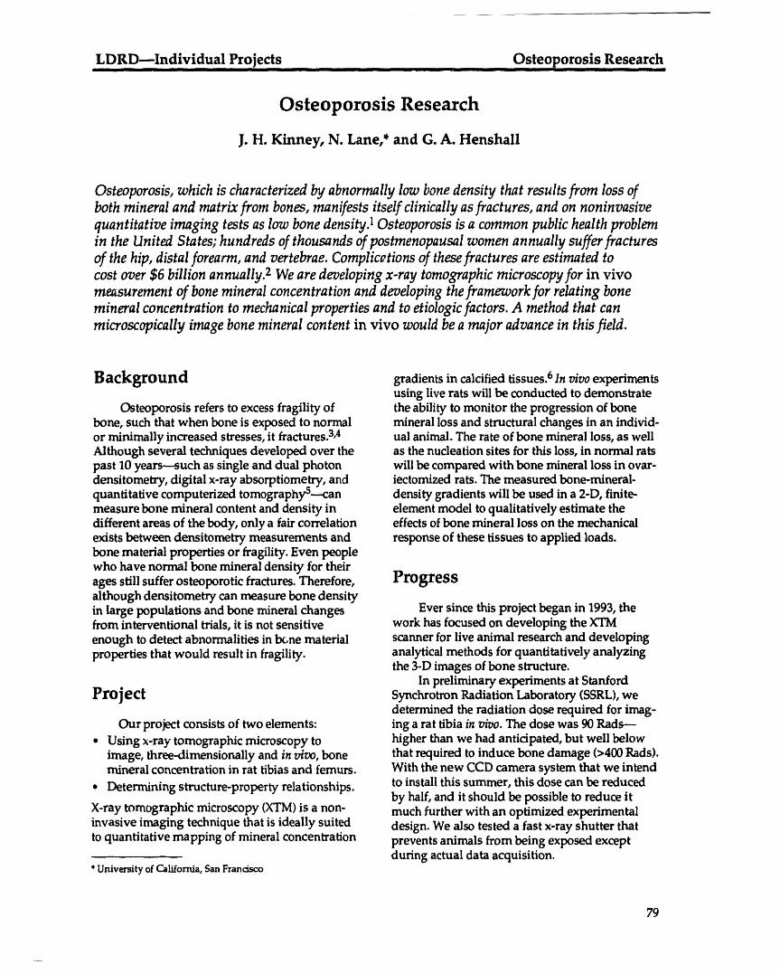
LDRD---Individual Projects Osteoporosis ResearchI i i lill iliR' I i I i il
Osteoporosis Research
J. H. Kinney, N. Lane,* and G. A. Henshall
Osteoporosis, which is characterized by abnormally low bone density that results from loss of
both mineral and matrix from bones, manifests itself clinically as fractures, and on noninvasive
quantitative imaging tests as low bone density) Osteoporosis is a common public health problemin the United States; hundreds of thousands of postmenopausal women annually suffer fractures
of the hip, distal forearm, and vertebrae. Complicotions of these fractures are estimated to
cost over $6 billion annually. 2 We are developing x-ray tomographic microscopy for in vivomeasurement of bone mineral concentration and developing the framework for relating bone
mineral concentration to mechanical properties and to etiologic factors. A method that can
microscopically image bone mineral content in vivo would be a major advance in this field.
Background gradients in calcified tissues. 6 In vivo experimentsusing live rats will be conducted to demonstrate
Osteoporosis refers to excess fragility of the ability to monitor the progression of bonebone, such that when bone is exposed to normal mineral loss and structural changes in an individ-or minimally increased stresses, it fractures.3,4 ual animal. The rate of bone mineral loss, as wellAlthough several techniques developed over the as the nucleation sites for this loss, in normal ratspast 10 years--such as single and dual photon will be compared with bone mineral loss in ovar-densitometry, digital x-ray absorptiometry, and iectomized rats. The measured bone-mineral-quantitative computerized tomography°--can density gradients will be used in a 2-D, finite-measure bone mineral content and density in element model to qualitatively estimate thedifferent areas of the body, only a fair correlation effects of bone mineral loss on the mechanicalexists between densitometry measurements and response of these tissues to applied loads.bone material properties or fragility. Even peoplewho have normal bone mineral density for theirages still suffer osteoporotic fractures. Therefore, Progressalthough densitometry can measure bone densityin large populations and bone mineral changes Ever since this project began in 1993, thefrom interventional trials, it is not sensitive work has focused on developing the XTMenough to detect abnormalities in b_ne material scanner for live animal research and developingproperties that would result in fragility, analytical methods for quantitatively analyzing
the 3-D images of bone structure.In preliminary experiments at Stanford
Project Synchrotron Radiation Laboratory (SSRL),wedetermined the radiation dose required for imag-
Our project consists of two elements: ing a rat tibia in vivo. The dose was 90 Rads--• Using x-ray tomographic microscopy to higher than we had anticipated, but well below
image, three-dimensionally and in v/vo, bone that required to induce bone damage (>400 Rads).mineral concentration in rat tibias and femurs. With the new CCD camera system that we intend
• Determining structure-property relationships, to install this summer, this dose can be reducedby hall and it should be possible to reduce it
X-ray tornographic microscopy (XTM)is a non- much further with an optimized experimentalinvasive imaging technique that is ideally suited design. We also tested a fast x-ray shutter thatto quantitative mapping of mineral concentration prevents animals from being exposed except
during actual data acquisition.*University of California, San Francisco
79
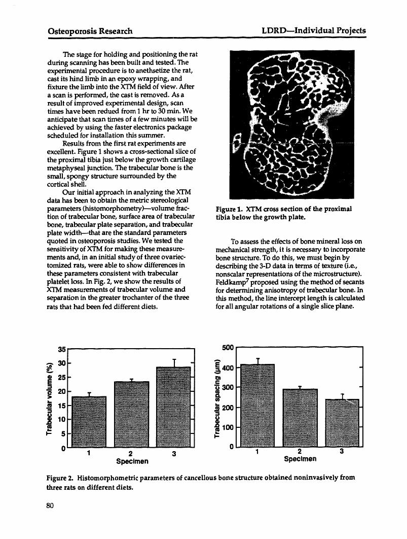
Osteoporosis Research LDRD--Individual Projectsi iil iiinl i n illll i i i I i ii i u
The stage for holding and positioning the ratduring scanning has been built and tested. Theexperimental procedure is to anethsetize the rat,cast its hind limb in an epoxy wrapping, andfixture the limb into the XTM field of view. After
a scan is performed, the cast is removed. As aresult of improved experimental design, scantimes have been redued from 1 hr to 30 rain. Weanticipate that scan times of a few minutes will beachieved by using the faster electronics packagescheduled for installation this summer.
Results from the first rat experiments areexcellent. Figure I shows a cross-sectional slice ofthe proximal tibia just below the growth cartilagemetaphyseal junction. The trabecular bone is thesmall, spongy structure surrounded by thecortical shell.
Our initial approach in analyzing the XTMdata has been to obtain the metric stereologicalparameters (histomorphometry)---volume frac- Figure 1. XTM cross section of the proximaltion of trabecular bone, surface area of trabecular tibia below the growth plate.bone, trabecular plate separation, and trabecularplate width--that are the standard parametersquoted in osteoporosis studies. We tested the To assess the effects of bone mineral loss onsensitivity of XTM for making these measure- mechanical strength, it is necessary to incorporatements and, in an initial study of three ovariec- bone structure. To do this, we must begin bytomized rats, were able to show differences in describing the 3-D data in terms of texture (i.e.,these parameters consistent with trabecular nonscalar representations of the microstructure).platelet loss. In Fig. 2, we show the results of Feldkamp 7 proposed using the method of secantsXTM measurements of trabecular volume and for determining anisotropy of trabecular bone. Inseparation in the greater trochanter of the three this method, the line intercept length is calculatedrats that had been fed different diets, for all angular rotations of a single slice plane.
:3,5 ' ' 500 .............. -
30 E4o025 a_=
15 __200
_ 100P- 5 _.
00 1 2 3 1 2 3
Specimen Specimen
Figure 2. Histomorphometric parameters of cancellous bone structure obtained noninvasively fromthree rats on different diets.
80
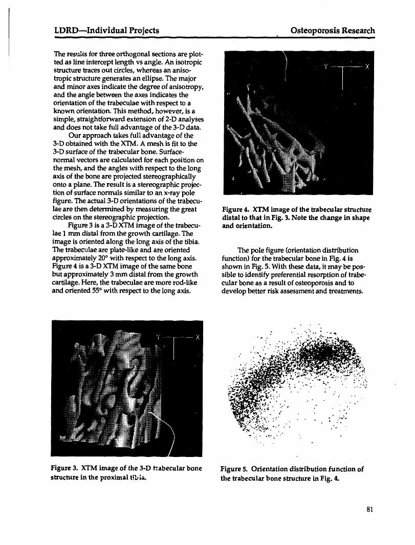
LDRD--Individual Projects Osteoporosis Researchmmll I i I I IIi i iii I _' --
The res,al_s for three orthogonal sections are plot-ted as line intercept length vs angle. An isotropicstructure traces out circles, whereas an aniso-tropic structure generates an ellipse. The majorand minor axes indicate the degree of anisotropy,and the angle between the axes indicates theorientation of the trabeculae with respect to aknown orientation. This method, however, is asimple, straightforward extension of 2-D analysesand does not take full advantage of the 3-D data.
Our approach takes full advantage of the3-D obtained with the XTM. A mesh is fit to the3-D surface of the trabecular bone. Surface-normal vectors are calculated for each position onthe mesh, and the angles with respect to the longaxis of the bone are projected stereographicallyonto a plane. The result is a stereographic projec-tion of surface normals similar to an x-ray polefigure. The actual 3-D orientations of the trabecu-lae are then determined by measuring the great Figure 4. XTM image of the trabecular structurecircles on the stereographic projection, distal to that in Fig. 3. Note the change in shape
Figure 3 is a 3-D XTM image of the trabecu- and orientation.lae 1 mm distal from the growth cartilage. Theimage is oriented along the long axis of the tibia.The trabeculae are plate-like and are oriented The pole figure (orientation distributionapproximately 20° with respect to the long axis. function) for the trabecular bone in Fig. 4 isFigure 4 is a 3-D XTM image of the same bone shown in Fig. 5. With these data, it may be pos-but approximately 3 mm distal from the growth sible to identify preferential resorption of trabe-cartilage. Here, the trabeculae are more rod-like cular bone as a result of osteoporosis and toand oriented 55° with respect to the long axis. develop better risk assessment and treatments.
,, . %,% .o • o .
' ___-" Pdr '4. #" .• • . h o . _ . ._. *" e. -s
• * • • ,i.," rf •
• ,- _3_nlk_P.- ; ," ... ,- . ",.,-:. : . -.-..
' _ _"_ ..-, -, . " '. " , '.i" ]"" ." • " .
' _,:_.:: . • . . : ,',_,_:-':'.;;;... o .- • . ""._ '._...._,,..• . . -
• o
Figure 3. XTM image of the 3-D I_.abecularbone Figure 5. Orientation distribution function ofstructure in the proximal t_.b[a, the trabecular bone structure in Fig. 4.
81
Osteoporosis Research LDRD---Individual Projects_ i! _ i i1! i iiiii i i i iiii i ill ii i iiiii iii
Another approach to 3-D analyses is taken 3. W.C. Hayes and W. C. Gerhart, "Biomech-from topology. Odgaard and Gundersen 8 have anics of Bone: Applications for Assessment ofdeveloped techniques for obtaining the Euler- Bone Strength," in Bone and Mineral Research,Poincar(_characteristic from 3-D networks. The Vol. 3, Peck, Ed. (Elsevier, Amsterdam, 1985).
weighted Euler-Poincar6 characteristic can be 4. L.J.I. Melton, E. Y. S. Chao, and J. Lane,related to the first Betti number and provides an "Biomechanical Aspects of Fractures," inindication of the degree of interconnectedness. Osteoporosis:Etiology, Diagnosis, and Manage-We intend to incorporate this approach in future ment, Riggs and Melton, Eds. (Raven Press,work. New York, 1988).
5. R. B. Mazess, H. Barden, M. Ettinger, and E.Schultz, "Bone Density of the Radius, Spine,and Proximal Femur in Osteoporosis," J. Bone
References Min. Res. 3, 13-18 (1988).6. J.H. Kinney, W. G. Marshall, and S. J.
1. W. H. Peck, A. H. Reddi, and S. L.Gordon, Marshall, "I'hree-Dimensional Mapping of"Local Mechanisms that Regulate Bone Mineral Densities in Carious Dentin: TheoryFormation: the Subject of a Recent NIH- and Method," submitted to Calc. Tissues Int.Sponsored Workshop," Calc. Tissu_ Int. 36, 7. L. A. Feldkamp, S. A. Goldstein, A. M. Parfitt,1-3 (1984). G. Jesion, and M. Kleerekoper, "The Direct
2. T.L. Holbrook, K. Grazier, J.L. Kelsey, et al., Examination of Three-Dimensional BoneThe Frequency ofOccurrence, Impact, and Cost of Architecture in vitro by Computed Tomogra-Musculoskeletal Conditions in the United States phy," J. Bone Min. Res. 4, 3-11 (1989).(American Academy of Orthopedic Surgeons, 8. A. Odgaard and H. J. G. Gunder_en, "Quan-Chicago, IL, 1985). tification of Connectivity in Cancellous Bone,
with Special Emphasis on 3-D Reconstruc-tions," Bone 14, 173--182 (1993).
82
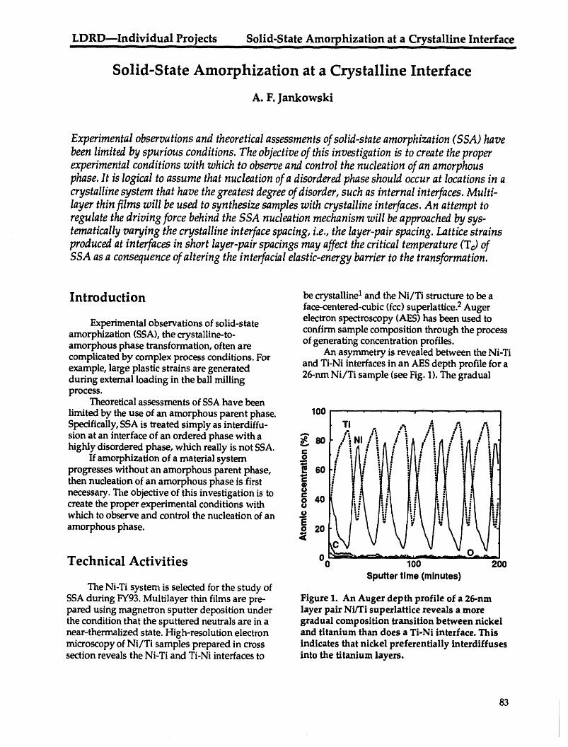
LDRD--Individual Projects Solid-State Amorphization at a Crystalline Interfacei ii i i iiiiii iiiiii i illlll i i Illllll IIII II IIIII I I
Solid-State Amorphization at a Crystalline Interface
A. F. Jankowski
Experimental observations and theoretical assessments of solid-state amorphization (SSA) have
been limited by spurious conditions. The objective of this investigation is to create the properexperimental conditions with which to observe and control the nucleation of an amorphous
phase. It is logical to assume that nucleation of a disordered phase should occur at locations in a
crystalline system that have the greatest degree of disorder, such as internal interfaces. Multi-layer thin films will be used to synthesize samples with crystalline interfaces. An attempt toregulate the driving force behind the SSA nucleation mechanism will be approached by sys-tematically varying the crystalline interface spacing, i.e., the layer-pair spacing. Lattice strains
produced at interfaces in short layer-pair spacings may affect the critical temperature (TJ of
SSA as a consequence of altering the interfacial elastic-energy barrier to the transformation.
Introduction be crystalline 1 and the Ni/Ti structure to be aface-centered-cubic (fcc) superlattice.2 Augerelectron spectroscopy (AES) has been used toExperimental observations of solid-stateconfirm sample composition through the process
amorphization (SSA), the crystalline-to- of generating concentration profiles.amorphous phase transformation, often arecomplicated by complex process conditions. For An asymmetry is revealed between the Ni-Ti
and Ti-Ni interfaces in an AES depth profile for aexample, large plastic strains are generated 26-nm Ni/Ti sample (see Fig. 1). The gradualduring extemal loading in the ball millingprocess.
Theoretical assessments of SSA have been
limited by the use of an amorphous parent phase. 100 I ...... ' ......" ....." ......Tj _. .-. _-_Specifically, SSA is treated simply as interdiffu- r ? .. ,". :, i:/i
sion at an interface of an ordered phase with a _ 80]- r :l / :, .' "A / :_1 I _ I !highly disordered phase, which really is notSSA. J: .e: : -[_a"' "!l[a" "l[;" ":llz' i
If amorphization of a material system _ .,r; t,j_ :_ s:_.-: ::,_,_z i:,1_'_r -.i" i L
L:. "1 i "l I! il ll :Ill iJ l,: i
progresses without an amorphous parent phase, _ 60 ,, ., , u _ • i" ", ,, -_,.. _ P a
then nucleation of an amorphous phase is first _ i !necessary. The objective of this investigation is to =°° :40create the proper experimental conditions with _ 'I I!
which to observe and control the nucleation of an -:° i_ |'.:amorphous phase. _ 20
Technical Activities 0_- -_ ----_, ..... , .... , ..........100 200
Sputtertime (minutes)The Ni-Ti system is selected for the study of
SSA during FY93. Multilayer thin films are pre- Figure 1. An Auger depth profile of a 26-nmpared using magnetron sputter deposition under layer pair Ni/Ti superlattice reveals a morethe condition that the sputtered neutrals are in a gradual composition transition between nickelnear-thermalized state. High-resolution electron and titanium than does a Ti-Ni interface. Thismicroscopy of Ni/Ti samples prepared in cross indicates that nickel preferentially interdiffusessection reveals the Ni-Ti and Ti-Ni interfaces to into the titanium layers.
83

.S01id-S!ate Amorphization at a Crystalline Interface LDRD---Individual ProjectsIII liil i iiiii iilil iliil _ liii in ii
change in composition at the Ni-Ti interface 0.6 t[_ - _ ' m '..... _ - -
indicates that nickel preferentially interdiffusesinto the titanium layers. X-ray diffraction is being 0.5 T©[d(n )] ofused to characterize the layer pair spacings andcomposition profile (at grazing incidence) as well
as the lattice distortions (at high angle). _ 0.4 (26.0) =306 C /
Analysis of copper Ko_scans in the 0/20 _. ___o-mode reveals a square-wave composition profile < 0.3
_T O
with strained layers of nickel (in tension) andtitanium (in compression). 3 Differential thermal
analysis (DTA) is used to measure the critical 0.2 (3.0) = 412°Ctransition temperature (Tc) of SSA. A character-istic endotherm (i.e., decrease in temperature) 0.1indicates an order-disorder transition. 280 320 360 400 440 480
DTA results show a Tc that appears to Temperature (°C)depend on the multilayer pair spacing, dNi/Ti.SSA of a 26-nm Ni/Ti sample is shown to occurat 325°C via in situ atomic imaging. 4 The DTA Figure 2. The differential thermal analysisscan (see Fig. 2) confirms this by the characteristic (DTA) trace is a plot of the difference inendotherm, measured at 308°C, and also shows temperature AT between an alumina standardan endotherm for a 3-nm Ni/Ti sample at 412°C. and the Ni/Ti multilayer as a function ofThe change in dNi/Tihas mitigated an apparent increasing temperature T. The endotherms,change in the Tc of SSA. A future explanation marked by a sudden decrease in temperature atrests in the examination of the microstructure Tc, indicate solid-state amorphization.and modeling of the nucleation mechanism.
3. J. Chaudhuri, S. M. Alyan, and A. F.References and Publications Jankowski, "X-Ray Analysis of Ni/Ti Multi-
layers," submitted to Thin Films--Stress and
1. A.F. Jankowski, "On Eliminating Deposition Mechanical PropertiesIV, P. H. Townsend, J.Induced Amorphization of Interfaces in Sanchez, C. Y. Li, and T. P. Weihs, Eds. (MRSRefractory Metal Multilayer Systems," Thin Syrup. Proc.).Solid Films 220, 166-171 (1992). 4. M. A. Wall and A. F. Jankowski, 'qn-Situ
2. A. F. Jankowski and M. A. Wall, "The Stabili- Observation of Solid-State Amorphization in azation of Face-Centered-Cubic Titanium," in Ni/Ti Multilayer," in Proc. XII Int. Congress forStructure and Propertiesof Interfaces in Materials, Electron Microscopy--Vol. 4, L. D. Peachey m_dW. A. T. Clark, U. Dahmen, and C. L. Briant, D.B. Williams, Eds. (San Francisco Press, SanEds. (MRS Symp. Proc.238, 1992), pp. 297-302. Francisco, CA, 1990), pp. 128-129.
84
LDRD--individual ,Proi,ects- _- _- H,.,Ydro_e.n Chemisorption on Diamon dSurfaces
Hydrogen Chernisorption on Diamond Surfaces
R. S. Daley and R. G. Musket
We have demonstrated the ability to measure submonolayer quantities of surface hydrogen on
insulating glasses by ion-beam techniques. We extend this ability to an analysis of the diamond
(100)-(1 × 1) and -(2 x 1) surfaces. The difference between mono- and dihydrated diamond (100)-(1 × 1) surfaces is 0.5 monolayer (ML) of hydrogen (1 ML = two hydrogen atoms per surface car-bon) and is easily resolvable by forward recoil spectroscopy (FRS), which permits measurements
of <0.05 ML. By measuring surface hydrogen concentration, the correct surface structures caneasily be deduced for the (1 x 1) and (2 × 1) surfaces. If an intermediate coverage (1 ML > _ >
0.5 ML) is found for the (1 x l) surface, then a combination of mono- and dihydrated surface
states is indicated, as predicted by theory. For the (2 × 1) surface, the absolute difference between
monohydrated and hydrogen-free surfaces is again 0.5 ML. A finding near 0.5 ML suggests that
the carbon atoms have formed dimers and are predominately monohydrated, whereas coveragesbelow 0.25 ML would indicate that most of the surface carbons are dehydrogenated and that
carbon-carbon _-bonds have formed.
Background Technical Activities and Results
The advantages of ion-beam techniques over To measure surface hydrogen coveragesother conventional surface analysis tools are under controlled conditions, an ultrahigh-
* The technique is nondestructive, vacuum (UHV) chamber attached to the• Elemental specificity is easily obtained, accelerator beamline is required. An existing
Varian-designed UPIV chamber has been• Quantitative measurements at modified and equipped with the appropriate
submonolayer coverages are possible, surface-analysis equipment required for the• Surface hydrogen can be detected, experiment. A UHV manipulator with headng
Our proposal builds on our previous work by and cooling capabilities is also required.examining hydrogen coverages on another To date, all the planning, design, and hard-insulating material: the technologically important ware purchases for the project have been made.diamond (100) surface. The information obtained The detector and other surface-analysis systemsin this study will allow us to deduce the correct have been built and installed in the UHV chain-structures for the diamond (100)-(1 x 1) and (2 x 1) ber. An existing Vacuum Generators manipulatorsurface phases as well as provide information on has been modified to handle small samples (5 x 5the kinetics of hydrogen desorption from the x 0.25 ram) and provide heating to 1200°C and(100) surface. These quantitative results are essen- cooling to -125°C. This manipulator has beential if a complete understanding of the role of tested and performs very well. The UHV chain-surface hydrogen during the chemical vapor ber (see Fig. 1) has been equipped with the fol-deposition of thin diamond films is to be corn- lowing items:pletely understood. In particular, this research • A 168° Rutherford backscatter (RBS)will help bridge a gap that has recently been detector for bulk and surface elemental
created between experiment and theory on the impurity analysis.structure of the diamond (100)-(1 x 1) and (2 x 1)surfaces. To date, hydrogen coverages have only * A detector for forward recoiled hydrogenbeen inferred by indirect measurement atoms.techniques. * An ion sputter gun for surface cleaning and
modification.
85
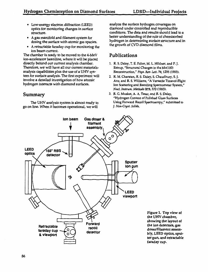
Hydrogen Chemisorption 0n Diamond Surfaces ........ LDRD--Individual Project s
• Low-energy electron diffraction (LEED) analyze the surface hydrogen coverages onoptics for monitoring changes in surface diamond under controlled and reproduciblestructure, conditions. The data and results should lead to a
• A gas manifold and filament system for better understanding of the role of chemisorbeddosing the surface with atomic gas species, hydrogen in determining surface structure and in
the growth of CVD diamond films.• A retractable faraday cup for monitoring the
ion beam current.The chamber is ready to be moved to the 4-MeV Publicationsion-accelerator beamline, where it will be placeddirectly behind our current analysis chamber. 1. R.S. Daley,T. E. Felter,M. L.Hildner, and P.J.Therefore, we will have all our current materials- Estrup,"StructuralChanges in the Mo(100)analysis capabilities plus the use of a UHV sys- Reconstruction,"Phys.Rev.Lett.70,1295 (1993).tem for surface analysis. The first experiment will 2. R. M.Charatan,R.S.Daley,S.Chaudhury,S.J.involve a detailed investigation of how atomic Anz, and R.S.Williams,"A VersatileTime-of-b"fighthydrogen interacts with diamond surfaces. Ion Scatteringand RecoilingSpectrometerSystem,"
Nucl. Instrum. MethodsB73,570(1993).
Sunlmary 3. R.G. Musket,A. A. Tesar, andR. S.Daley,'q'iydrogen Contentof PolishedGlassSurfaces
The UHV analysis system is almost ready to Using Forward RecoilSpectroscopy,"submittedtogo on line. When it becomes operational, we will J. Non-Cryst. Solids.
Ion beam Gas doser &
filamentassembly
O
LEED RB$optics detector _'
\
- - -_ Sputter
__ II "LSSDvlewport
Figure 1. Top view ofthe UHV chamber,showing the layout of
Forward the ion detectors,gasRetractable recoil doser/filament assem-faraday cup detector& vlewport bly, LEED optics,sput-
ter gun, and retractablefaraday cup.
86
LDRD Glenn T. Seaborg Institute for Transactinium Science.................... -- -- IIIIIIIII I iiiii I I I Illll' _L_ m _ m1111_. Irlllllll IIII _ -- _ --- __ - __ ..............
Laboratory Directed Research andDevelopment
Glenn T. Seaborg Institute forTransactinium Science
87
Glenn T. Seaborg institute for Transactinium Science LDRD_ -- __ -- __ III11 _ _111 I II III IIII 1hi ...... . _-_ _ I1(I II I I IIIIII ___ " .... ___ illlll I[ IIIIII I i .....
Glenn T. Seaborg Institute for Transactinium Science
D. C. Hoffman, Director
Overview
During the first half of FY93, five LDRD projects were funded under the auspices of theGlenn T. Seaborg Institute for Transactinium Science (ITS).
The largest of these involves studies of actinides in the environment and includes theongoing project entitled "Plutonium Solubility and Speciation in Carbonate Solution."These carbonate solutions are typical of the groundwater at the proposed nationalnuclear waste repository site at Yucca Mountain, Nevada, and the studies are relevantto the potential for migration of plutonium. Measurements are made in a controlled-atmosphere glove box using optical fibers to carry light from a state-of-the-art, laser-induced, photoacoustic spectrometer (LIPAS). The method is significantly more sensi-tive than conventional ultraviolet/visible spectroscopy. This research forms the basisfor graduate student M. Neu's Ph.D. dissertation, which will be completed in FY93.
Also included is a new interdisciplinary project entitled "Bacterial Remediation ofActinide-Contaminated Sites," which was initiated by ITS Senior Postdoctoral FellowA. I-Iappel in February, 1993.
Another project relevant to actinide speciation is N. Hannink's dissertation research on"Cation-Cation Complexes of Actinides," again using the LIPAS technique. The novelinteractions of actinyl (V) cations with other multiply charged cations are beinginvestigated.
The ongoing research of J. Sytsma, an ITS Postdoctoral Fellow on "Two-PhotonSpectroscopy of the Actinide Ions Cm3+and Am2," will yield valuable informationabout the electronic properties of the 5f elements, such as crystal field effects and sitesymmetries in solids. This information is not accessible by conventional, linear laserspectroscopy.
In a project to be completed in FY93, "Fully Relativistic Surface Green Function and ItsApplications: Theoretical Study of Uranium on Pt (111) Surface," Senior PostdoctoralFellow E. Tamura is comparing his theoretical results with experlimental findings forultraviolet photoemission spectra.
88
LDRD Glenn T. Seaborg Institute for Transactinium Science- • ".... _ll ............... J]......... II - ILLL i Inll ]] ......... _l -- _]L _ II _. -'- i iilll --
Plutonium Solubility and Speciation in Carbonate Solution
M. Neu, D. Hoffman, R. Silva, K. Roberts,* and H. Nitsche*
The solubility.limited speciation of 242pu as a function of time in near-neutral carbonate
solutions is being measured to better understand the chemical behavior of plutonium in
groundwater. Plutonium, in a single oxidation state, is added to an aqueous solution, and
aliquots of the resulting solution are removed over a period of weeks to measure the solubility and
investigate the nature of the soluble species. To simulate a natural groundwater, all experiments
are performed at pH = 6.0 :_ 1, T = 30.0 ..+2, Pc02 = 5.71%, with 0.100M sodium perchlorate as
an electrolyte. Laser-induced photoacoustic spectroscopy (LIPAS) and extraction methods are
used to identify and quantify the plutonium species present. Plutonium(V) is the most stable
oxidation state under these conditions, independent of the initial concentration and oxidation
state (IV, V, or VI). Plutonium(VI) exhibits the most complex solution behavior, reflecting theequilibria involving soluble and insoluble forms of both Pu(V) and Pu(VI).
Introduction state were prepared electrochemically, andseparate aliquots were added to individual pre-
In order to assess the potential for migration equilibrated carbonate solutions and monitored.of plutonium in groundwater, it is crucial to Solutions were maintained for several weeksunderstand the influences of environmental con- under an overpressure of a CO2/argon mixture.ditions on solubility, chemical speciation, and Liquid scintillation counting was performed onkinetic and thermodynamic behavior. Concentra- aliquots of the plutonium-carbonate solutions,tions of individual species are being measured as and spectral regions containing characteris0ca function of time to investigate which species absorbance bands for Pu4+,PuO[ and PuO_+may be stable in natural waters and will, there- were scanned. All experiments were performedfore, dominate the environmental chemistry, at pH = 6.0 :t:1, T = 30.0 + 2, and Pco 2= 5.71%,Plutonium solubility in solutions relatively rich wi_h 0.100M sodium perchlorate as an electrolyte.in carbonate is being measured using liquid Initial concentrations of plutonium were 4.75 xscintillation counting; the speciation is investi- 10-5, 2.51 x 10⁻⁵,and 3.68 x 10--4M,for Pu4+,+ :_+gated using extraction methods and laser- PuO2, and PuO_ , respectively.induced photoacoustic spectroscopy. This Most of the plutonium(IV) initially came outmethod yields the same information but is sig- of solution, dropping from 4.75 x 10-_M to --5 xniflcantly more sensitive than conventional 10-8M after 5 days, then appeared to resolubilizeultraviolet/visible spectroscopy, over the next 5 days. From day 10 to the end of
the experiment at day 22, the concentration ofsoluble plutonium was (1.0 ± 3) x 10-6M. Spec-
Progress troscopic identification and quantification ofthe soluble species were not possible at this low
A remote, fiber-optic, laser-induced photo- concentration; spe_c+tra over the regions of interestacoustic (LIPAS) spectroscopic system was built, for Pu4+ and PuO2 were indistinguishable fromand a small-volume cuvette was designed to background.minimize the amount of plutonium used. A The plutonium(V) solution had a solublecomputer-linked system for solution control and plutonium concentration of (2.1 _+1) x 10-5M overmonitoring provided temperature and pH con- a period of 53 days. The soluble plutonium wastrol. Plutonium solutions of a single oxidation determined to be >95% PuO[ from spectroscopic
data.*Lawrence Berkeley Laboratory, Berkeley, CA
89

Glenn T. Seaborg Institute for Transactinium Science LDRDI in i miiil ili il i I I iii mUiR i i --
which valences are bound and if microbial reten- During FY93, we will complete the microbialtion is linked to reduction. We will identify both binding assays with Tc, U(VI), Np, Pu, and Am.the cellular componentsthat are required for We will determine the valence states of theactinide binding and the corresponding genes bound elements and investigate whether micro-that encode proteins required for actinide bind- bial binding is linked to reduction. The maximaling. Our long-term goal is to use molecular gen- load (grams of actinide bound per gram dryetic techniques to engineer bacteria for high- weight of cells) will be determined, along withspecificity binding of individual actinides and the stability constants of these complexes. Bioac-for maximal actinide accumulation, cumulation of actinides will be assayed under a
variety of conditions to measure the influence of
Technical Activities Proposed pH, ionic strength, and the presence of inorganicand chemical complexing agents. We will alsodetermine the specificity of actinide-microbeThe overall goals of our research are tobinding. Other metals and anions will be
• Quantify the microbial binding and retention included in the binding assays to test for inhibi-of actinides, tion of actinide binding: Fe, Mo, Pb, Se, V, Mg,
• Determine the specificity of metal binding. Mn, Ni, Cu, Co, Zn, nitrate, and sulfate.• Identify the cell components that bind By the end of FY93, we plan to identify
actinides, bacterial components that are responsible for• Define the genes and gene products actinide binding via three separate approaches--
responsible for binding transactinium by using electron microscopy to determine whichelements, cell structures are binding the actinide, by assay-
• Bioengineer bacterial strains for maximal ing actinide binding to bacterial mutants that lackactinide binding and high-specificity metal specific cell structures, and by biochemically ..binding, analyzing cell fractions for bound actinide.
• Test these strains for remediation of watersand soils from contaminated sites.
Cation-Cation Complexes of Actinides
N. Hannink, D. Hoffman, R. Silva, and R. Russo
We are investigating the complexation of a/;tinide(V) cations with other actinide cations. The. . + Z+ . .
prevzouslydzscoveredcomplex,NpO2.UO2 , was investigatedusing laser-inducedphotoacousticspectroscopy (LIPAS), a spectroscopic technique yielding basically the same information as
absorption spectroscopy, but with greater sensitivity. Although this technique had not been
applied to the study of cation-cation complexes among the actinides, preliminary result_ indicate
that the method and equipment are working, and we are planning to look at other cation-cationcomplexes.
Introduction NpO_-UC_2., cation-cation complex. 1Since then,the cation-cation complexes of NpO_ have been
Actinyl(V) cations form complexes with a studied extensively, but these complexes of PuO_variety of other cations, including other actinides; remain virtually unstudied. The formation con-this cation-cation complex formation is unique stants for cation-cation complexes are small,to the +5 oxidation state. In 1961, Sullivan, ranging from 0.095 to 16.0. Small formation con-Hindman, and Zielen discovered the stants and radioactive species, some of which are
91

Gler m T. Seaborg Institute for Transactinium Science LDRD-- I III IIII II | L IIII IIIIIIIIII I II III I .. --
oxygen sensitive, require special handling and agrees favorably with previously reported valuessensitive techniques, of 2.45 (Ref. 2), 2.50 (Ref. 3), and 3.7 (Ref. 4), for
Laser-induced photoacoustic spectroscopy ionic strengths from 6 to 7M.(LIPAS) is a relatively new spectroscopic tech-nique that uses the nonradiative relaxation of theabsorbing species, thereby generating heat andan acoustic wave. Because LIPAS and conven-
1.5 ........ ...... .....tional absorption spectroscopy use the samephysical phenomena for the initial process(absorption of light by a species), the informationderived by each method is the same; therefore, mthe same analysis men.hods can be used. By o.1o0
analyzing the shifts in spectral absorption peaksduring complexation, formation constants can be Rcalculated.
A remote LIPAS system, set up at LLNL in 0 5an inert-atmosphere glovebox, allows contain- 1ment of the radioactive species, provides anoxygen-free environment, and uses a sensitivemeasurement technique, all of which are needed 0 i _ , . ,_ _ .... .for thisproject. 610 620 630 640 650 660 fiTOWavelength (cm)
During the course of this study,. PuO_2+,UO_2. , nO2+complexation with and will be + 2+
Nr-z Figure 1. Spectra of NpO2.UO 2 experiment atexamined. PuO_+ is important because this 0.5M ionic strength. Spectrum I is a 0.000248M
plutonium species has been shown to be present NpO_ standard, and spectrum 2 is an experi-in many environmental waters. We not only will mental solution containing 0.000248M NpO_learn more about cation-cation complexes but and 0.260M 2+UO2 Both spectraare backgroundp +also will learn more about the behavior of uO_2
o
subtracted.in the p_sence of other actinides in acidicsolutions.
Progress
By the end of FY92,various preliminary 1items were completed. For instance, the remote =_1.5LIPAS apparatuswasconstructed,installed in the _inert-atmosphere glovebox, and tested using o 1.0stable lanthanides. The spectral data analysisprogram SQUAD was tested using LIPAS data.
During the first part of FY93, preliminary Jexperiments using the previously discovered 0.5NpO_.UC_2*complex were started. This complex 4,5was chosen for the initial studies using the LIPAS 0.system and analysis using SQUAD to test the 0method and equipment for applicationto these 610 620 630 640 650 660 670typesof complexes.Thesestudieswere per- Wavelength (nm)formed at two ionic strengths,0.5and 6M. At
+ 2+0.SM,no evidencefor thecomplex wasseen;at Figure 2. Spectraof NpO 2.UO.. experiment at6M, however, evidence for complexation was 6M ionic strength. Spectrum I _sa 0.000248Mseen. Figures I and 2 show data for 0.5 and 6M NpO_ standard, spectrum 2 is an experimen-+ionic strengths, respectively. Based on the initial tal solution £ontaining 0.000248M NpO 2 and2+ Z+data, which have a fairly largeerror,an 0.0867MUO2 , spectrum 3 is a 0.0867M UO2equilibrium constantof 4 wasobtained.This standard,and spectra4 and 5 areblanks.
92

Glenn T. Seaborg Institute for Transactinium Science LDRD__ I I I I - -- I IIIIIII III I I IIII -- Illl I
Summary 3. B. Guillaume, C. M. Begun, and R. L. Hahn,Inorg. Chem. 21, 1159 (1982).
The methodology and equipment are func- 4. C. Madic, B. Guillaume, J. C. Morisseau, andtioning as expected. A preliminary result for the J.P. Moulin, J. Inorg. Nucl. Chem. 41, 1027NpO_.UO_2. complex has been obtained; how- (1979).ever, in order to obtain a more precise value forthis constant, the experiment has been repeatedand the data are currently under analysis. As a Presentationscontinuation of this project, we will look for thePuO_.UO_2+ and PuO_.NpO_ + complexes and 1. N.J. Hannink, "Use of Laser-Induced Photo-determine their equilibrium constants, acoustic Spectroscopy (LIP.aS) to Determine
Equilibrium Constants of Cation-Cation Com-plexes," Richard Diamond Symposium, Meet-
References ing of the American Chemical Society, Denver,CO, Mar. 1993.
1. J.C. Sullivan, J. C. Hindman, and A. J. Zielen, 2. N.J. Hannink, "Use of Laser-Induced Photo-I. Am. Chem. Soc. 83, 3373 (1961). acoustic Spectroscopy to Determine Equilib-
2. B.E. Stout, Ph.D. Thesis, The Florida State rium Constants of Cation-Cation Complexes,"University, Tallahassee, FL (1989). Los Alamos National Laboratory, Los Alamos,
NM, Apr. 1993.
Two-Photon Spectroscopy of the Actinide Ions Cm3+and Am2+
J. Sytsma and N. Edelstein*
We _k to better understand the electronic properties of the actinide ions Cm3+and Am 2+,especiallyin relation with Gd3+and Eu 2+. New insight into the electronic structure of theseactinide ions should comefrom comparing the two-photon excitation data with those measuredfor theanalogous lanthanides. In two-photon excitation, the energy of the excitation light is notresonant with the transition; instead, two photons provide the energy matching.
Introduction Prog:ess
Two-photon laser spectroscopy (TPS) corn- After testing the cryogenic part and elec-plements conventional linear laser spectroscopy tronic detection system on Ce3+ in LuPO4, wein solids. A significant advance has come from had to move the laser laboratory. Therefore, noexperimental and theoretical results of TIX3 experimental work could be done from earlystudies of Gd3+ and Eu2+.The enormous progress December 1992 to mid-February 1993.in understanding the intensities of intra 4f7 tran- After the move, we first performed meas-sitions of these ions led to the idea of TPS studies urements on Gd3+ in LaF3.The 8S7/2---) 6p7/2on the actinide analogues of Gd3+ and Eu2+,Cm3+, transition was observed, at room temperature asand Am2+, respectively. Important differences in well as at liquid-helium temperature, by tuningthe electronic structure of the actinide analogues the dye laser wavelength through 618 to 622 nm.(i.e., much stronger spin-orbit coupling) should Downer et al. published extensively on this sys-provide a stringent test of the "_ewtheories that tem. 1We repeated part of their measurements inhave arisen from TPS studies of the 4f7 ions. order to test our new setup and normalize our
detection sensitivity to that in Ref. 1.Linear spectroscopy of LuPO4:248Cm3+ was
*Lawrence Berkeley Laboratory, Berkeley, CA performed to measure the optical properties of
93
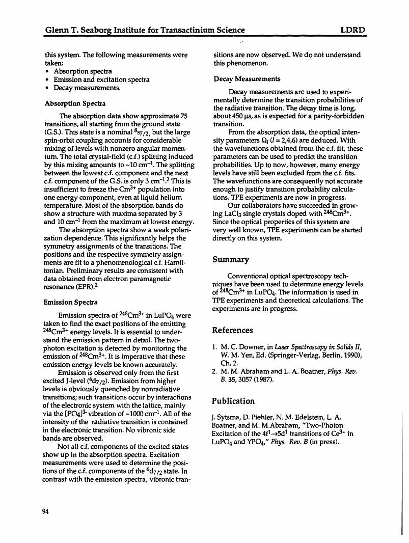
Glenn T. Seaborg Institute for Transactinium. Science .. ... LDRD
this system. The following measurements were sitions are now observed. We do not understandtaken: this phenomenon.• Absorption spectra• Emission and excitation spectra Decay Measurements
° Decay measurements. Decay measurements are used to experi-
Absorption Spectra mentally determine the transition probabilities ofthe radiative transition. The decay time is long,
The absorption data show approximate 75 about 450 tts,as is expected for a parity-forbiddentransitions, all starting from the ground state transition.(G.S.). This state is a nominal 8S7/2,but the large From the absorption data, the optical inten-spin-orbit coupling accounts for considerable sity parameters f21(t = 2,4,6) are deduced. Withmixing of levels with nonzero angular momen- the wavefunctions obtained from the c.f. fit, thesetum. The total crystal-field (c.f.) splitting induced parameters can be used to predict the transitionby this mixing amounts to -10 cm-1. The splitting probabilities. Up to now, however, many energybetween the lowest c.f. component and the next levels have still been excluded from the c.f. fits.c.f. component of the G.S. is only 3 cm-1.2This is The wavefunctions are consequently not accurateinsufficient to freeze the Cm3+population into enough to justify transition probability calcula-one energy component, even at liquid helium tions. TPE experiments are now in progress.temperature. Most of the absorption bands do Our collaborators have succeeded in grow-show a structure with maxima separated by 3 ing LaCl3 single crystals doped with 248Cm3+.and 10 cm-1 from the maximum at lowest energy. Since the optical properties of this system are
The absorption spectra show a weak polari- very well known, TPE experiments can be startedzation dependence. This significantly helps the directly on this system.symmetry assignments of the transitions. Thepositions and the respective symmetry assign-ments are fit to a phenomenological c.f. Hamil- Summarytonian. Preliminary results are consistent withdata obtained from electron paramagnetic Conventional optical spectroscopy tech-resonance (EPR).2 niques have been used to determine energy levels248 3+of Cm in LuPO4. The information is used in
TPE experiments and theoretical calculations. TheEmission Spectraexperiments are in progress.
Emission spectra of 248Cm3+ in LuPO4 weretaken to find the exact positions of the emitting248Cm3+energy levels. It is essential to under- Referencesstand the emission pattern in detail. The two-photon excitation is detected by monitoring the 1. M.C. Downer, in LaserSpectroscopy in Solids II,emission of 248C.m3+. It is imperative that these W.M. Yen, Ed. (Springer-Verlag, Berlin, 1990),emission energy levels be known accurately. Ch. 2.
Emission is observed only from the first 2. M. M. Abraham and L. A. Boatner, Phys. Rev.excited J-level (6d7/2). Emission from higher B. 35, 3057 (1987).levels is obviously quenched by nonradiative
transitions; such transitions occur by interactions Publicationof the electronic system with the lattice, mainlyvia the [PO4]3-vibration of -1000 cm-1. All of theintensity of the radiative transition is contained J. Sytsma, D. Piehler, N. M. Edelstein, L. A.Boatner, and M. M.Abraham, "Two-Photonin the electronic transition. No vibronic side Excitation of the 4fl-->5dI transitions of Ce3+ inbands are observed. LuPO4 and YPO4," Phys. Rev. B (in press).
Not all c.f. components of the excited statesshow up in the absorption spectra. Excitationmeasurements were used to determine the posi-tions of the c.f. components of the 6d7/2 state. Incontrast with the emission spectra, vibronic tran-
94
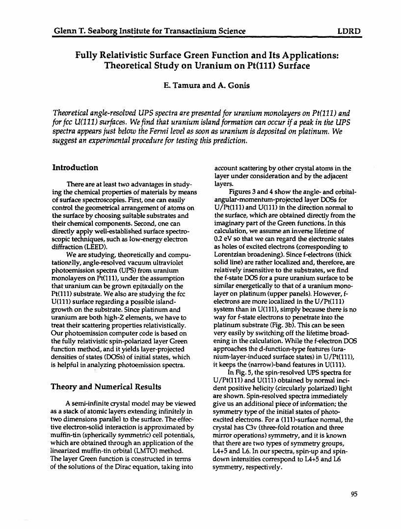
Glenn T. Seaborg Institute for Transactinium Science LDRDI I IIII Illl I I I II llr i I lllil lil
Fully Relativistic Surface Green Function and Its Applications:Theoretical Study on Uranium on Pt(111) Surface
E. Tamura and A. Gonis
Theoreticalangle-resolvedUPSspectraarepresentedfor uranium monolayersonPt(111)andfor fcc U(111)surface. Wefind that uranium islandformationcanoccur if a peakin the UPSspectraappearsjust belowtheFermilevelassoonasuranium is depositedon platinum. Wesuggest an experimentalprocedurefor testing thisprediction.
Introduction account scattering by other crystal atoms in thelayer under consideration and by the adjacent
There are at least two advantages in study- layers.ing the chemical properties of materials by means Figures 3 and 4 show the angle- and orbital-of surface spectroscopies. First, one can easily angular-momentum-projected layer D(_s forcontrol the geometrical arrangement of atoms on U/Pt(111) and U(111) in the direction normal tothe surface by choosing suitable substrates and the surface, which are obtained directly from thetheir chemical components. Second, one can imaginary part of the Green functions. In thisdirectly apply well-established surface spectro- calculation, we assume an inverse lifetime ofscopic techniques, such as low-energy electron 0.2 eV so that we can regard the electronic statesdiffraction (LEED). as holes of excited electrons (corresponding to
We are studying, theoretically and compu- Lorentzian broadening). Since f-electrons (thicktationally, angle-resolved vacuum ultraviolet solid line) are rather localized and, therefore, arephotoemission spectra (UPS) from uranium relatively insensitive to the substrates, we findmonolayers on Pt(111), under the assumption the f-state DOS for a pure uranium surface to bethat uranium can be grown epitaxially on the similar energetically to that of a uranium mono-Pt(111) substrate. We also are studying the fcc layer on platinum (upper panels). However, f-U(111) surface regarding a possible island- electrons are more localized in the U/Pt(111)growth on the substrate. Since platinum and system than in U(111), simply because there is nouranium are both high-Z elements, we have to way for f-state electrons to penetrate into thetreat their scattering properties relativisticaUy, platinum substrate (Fig. 3b). This can be seenOur photoemission computer code is based on very easily by switching off the lifetime broad-the fully relativistic spin-polarized layer Green ening in the calculation. While the f-electron DOSfunction method, and it yields layer-projected approaches the d-function-type features (ura-densities of states (DOSs) of initial states, which nium-layer-induced surface states) in U/Pt(111),
is helpful in analyzing photoemission spectra, it keeps the (narrow)-band features in U(111).In Fig. 5, the spin-resolved UPS spectra for
U/Pt(111) and U(111) obtained by normal inci-Theory and Numerical Results dent positive helicity (circularly polarized) light
are shown. Spin-resolved spectra immediatelyA semi-infinite crystal model may be viewed give us an additional piece of information; the
as a stack of atomic layers extending infinitely in symmetry type of the initial states of photo-two dimensions parallel to the surface. The effec- excited electrons. For a (111)-surface normal, therive electron-solid interaction is approximated by crystal has C3v (three-fold rotation and threemuffin-tin (spherically symmetric) cell potentials, mirror operations) symmetry, and it is knownwhich are obtained through an application of the that there are two types of symmetry groups,linearized muffin-tin orbital (LMTO) method. L4+5 and L6. In our spectra, spin-up and spin-The layer Green function is constructed in terms down intensities correspond to L4+5 and L6of the solutions of the Dirac equation, taking into symmetry, respectively.
95
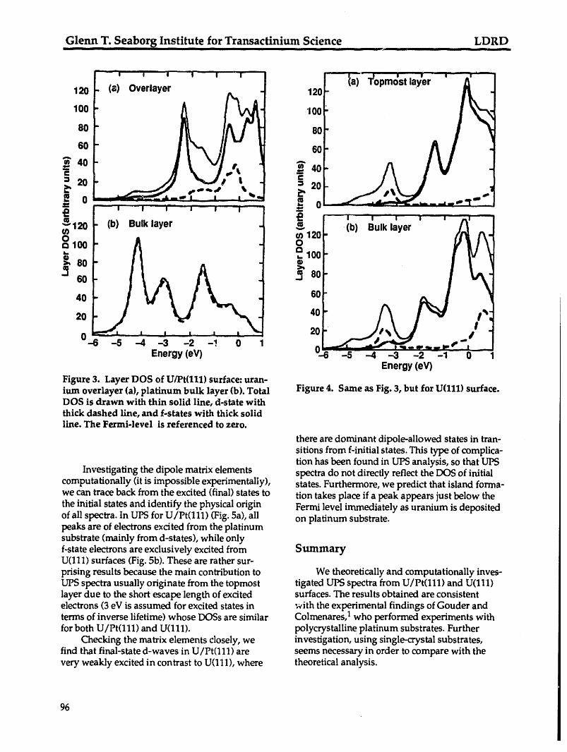
Glenn T. S.eaborg Institute fo r Transactinium Science LDRDill -- I . . i i i : i i ii ilil i ilili
120 120
100 1OO_ / _-_
.o All60
,-. 6040 4oi- A I V -I
J,,_LJ -=eo
_120 - (b) Bulk layerIi
' (b)Bulk layer
u) 1201oo o... 100
6o!
40 60
202040" __ /,_0_6 -5 -4 -3 -2 -! 0 1 _..._,___.'J"_-_.,._.p_-,
Energy(eV) 0.6 -5 --4 -3 -2 -1- 0- 1Energy(eV)
Figure 3. Layer DOS of U/Pt(111) surface:uran-ium overlayer (a), platinum bulk layer (b). Total Figure 4. Same as Fig. 3, but for U(111) surface.DOS is drawn with thin solid line, d-state withthick dashed Line,and f-states with thick solidline. The Fermi-level is referenced to zero.
there are dominant dipole-allowed states in tran-sitions from f-initial states. This type of complica-tion has been found in UPS analysis, so that Ul'X3
Investigating the dipole matrix elements spectra do not directly reflect the DOS of initialcomputationally (it is impossible experimentally), states. Furthermore, we predict that island forma-we can trace back from the excited (final) states to tion takes place if a peak appears just below thethe initial states and identify the physical origin Fermi level immediately as uranium is depositedof all spectra. In UPS for U/Pt(111) (Fig. 5a), all on platinum substrate.peaks are of electrons e×cited from the platinumsubstrate (mainly from d-states), while onlyf-state electrons are exclusively excited from SummaryU(111) surfaces (Fig. 5b). These are rather sur-prising results because the main contribution to We theoretically and computationally inves-UPS spectra usually originate from the topmost tigated UPS spectra from U/Pt(111) and U(111)layer due to the short escape length of excited surfaces. The results obtained are consistentelectrons (3 eV is assumed for excited states in with the experimental findings of Gouder andterms of inverse lifetime) whose DOSs are similar Colmenares, 1 who performed experiments withfor both U/Pt(111) and U(111). polycrystalline platinum substrates. Further
Checking the matrix elements closely, we investigation, using single-crystal substrates,find that final-state d-waves in U/Pt(111) are seems necessary in order to compare with thevery weakly excited in contrast to U(111), where theoretical analysis.
96
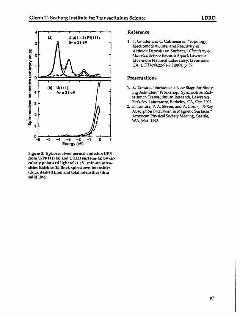
Glenn T. Seaborg Institute for Transactinium Science LDRD-- ! t t tttt tmt ttt t --
4'- , - ', ' , _, ,- , -_ Reference
(a) U-p(1 x 1) Pt(111)3 " /_' ffi21 eV . 1. T. Gouder and C. Colmenares, "Topology,
Electronic Structure, and Reactivity ofActinide Deposits on Surfaces," Chemistry &
2 ° Materials Science Research Report, Lawrence
Livermore National Laboratory, Livermore,1 CA, UCID-20622-91-2 (1992), p. 59.
0 Presentations
1. E. Tamura, "Surface as a New Stage for Study-
_4 ing Actinides," Workshop: Synchrotron Rad-iation in Transactinium Research, Lawrence
Berkeley Laboratory, Berkeley, CA,Oct. 1992.
3 2. E. Tamura, P. A. Sterne, and A. Gonis, "X-RayAbsorption Dichroism in Magnetic Surfaces,"
2 American Physical Society Meeting, Seattle,WA, Mar. 1993.
0--6 -5 -4 --3 -2 -1 0 1
Energy (eV)
Figure 5. Spin-resolved normal emission UPSfrom U/Pt(lll) (a) and U(111) surfaces (a) by cir-cularly polarized light of 21 eV: spin-up inten-sifies (thick solid line), spin-down intensities(thick dashed line) and total intensities (thinsolid line).
97

/
/"/1/,11I/ //

!