
Checking Business Process Evolution - Hal-Inria
50
HAL Id: hal-01920273 https://hal.inria.fr/hal-01920273 Submitted on 13 Nov 2018 HAL is a multi-disciplinary open access archive for the deposit and dissemination of sci- entific research documents, whether they are pub- lished or not. The documents may come from teaching and research institutions in France or abroad, or from public or private research centers. L’archive ouverte pluridisciplinaire HAL, est destinée au dépôt et à la diffusion de documents scientifiques de niveau recherche, publiés ou non, émanant des établissements d’enseignement et de recherche français ou étrangers, des laboratoires publics ou privés. Checking Business Process Evolution Ajay Krishna, Pascal Poizat, Gwen Salaün To cite this version: Ajay Krishna, Pascal Poizat, Gwen Salaün. Checking Business Process Evolution. Science of Com- puter Programming, Elsevier, 2019, 170, pp.1-26. 10.1016/j.scico.2018.09.007. hal-01920273
-
Upload
khangminh22 -
Category
Documents
-
view
7 -
download
0
Transcript of Checking Business Process Evolution - Hal-Inria
HAL Id: hal-01920273https://hal.inria.fr/hal-01920273
Submitted on 13 Nov 2018
HAL is a multi-disciplinary open accessarchive for the deposit and dissemination of sci-entific research documents, whether they are pub-lished or not. The documents may come fromteaching and research institutions in France orabroad, or from public or private research centers.
L’archive ouverte pluridisciplinaire HAL, estdestinée au dépôt et à la diffusion de documentsscientifiques de niveau recherche, publiés ou non,émanant des établissements d’enseignement et derecherche français ou étrangers, des laboratoirespublics ou privés.
Checking Business Process EvolutionAjay Krishna, Pascal Poizat, Gwen Salaün
To cite this version:Ajay Krishna, Pascal Poizat, Gwen Salaün. Checking Business Process Evolution. Science of Com-puter Programming, Elsevier, 2019, 170, pp.1-26. �10.1016/j.scico.2018.09.007�. �hal-01920273�

Checking Business Process Evolution
Ajay Krishnaa, Pascal Poizatb,c, Gwen Salaun∗,d
aUniv. Grenoble Alpes, Inria, CNRS, Grenoble INP, LIG, F-38000 Grenoble FrancebUniversite Paris Lumieres, Universite Paris Nanterre, F-92000, Nanterre, France
cSorbonne Universite, CNRS, Laboratoire d’Informatique de Paris 6, LIP6, F-75005,Paris, France
dUniv. Grenoble Alpes, CNRS, Grenoble INP, Inria, LIG, F-38000 Grenoble France
Abstract
Business processes support the design and implementation of software asworkflows of local and inter-organization activities. Tools provide the busi-ness process designer with modelling and execution facilities, but they barelyprovide formal analysis techniques. When one makes a process evolve, forexample by refactoring it or by adding new features in it, it is important tobe able to check whether, and how, this process has changed, and possiblycorrect evolution flaws. To reach this objective, we first present a modeltransformation from the BPMN standard notation to the LNT process alge-bra and LTS formal models. We then propose a set of relations for compar-ing business processes at the formal model level. With reference to relatedwork, we propose a richer set of comparison primitives supporting renaming,refinement, property and context-awareness. We also support BPMN pro-cesses containing unbalanced structures among gateways. In order to makethe checking of evolution convenient for business process designers, we haveimplemented tool support for our approach as a web application.
Key words: Business processes, evolution, model transformation,automated verification, tool, BPMN, LNT, LTS.
∗Corresponding authorEmail addresses: [email protected] (Ajay Krishna),
[email protected] (Pascal Poizat), [email protected] (Gwen Salaun)
Preprint submitted to Science of Computer Programming August 27, 2018

1. Introduction
Business processes describe the production of goods or services as a setof local tasks and inter-organization exchanges. The main business pro-cess modelling notations, BPMN 2.0, UML Activity Diagrams, and Event-driven Process Chains, have a workflow perspective of business processes.BPMN 2.0 (BPMN for short in the sequel) is an ISO standardized notationfor modelling business processes. Numerous tools support the design or exe-cution of BPMN models, e.g., Activity, Bonita BPMN, or the Eclipse BPMNDesigner. They can be used to set up the first version of a process model,and then to make it evolve by refactoring parts of it (to optimize it or bettersuit partner organizations) or by adding new features in it.
Motivations. The BPMN modelling tools support basic activities on themodels but performing formal analyses on them is barely found in these.Further, evolution needs a special treatment. It can be supported by a formof non-regression verification where the whole set of formal verifications (e.g.relative to the descriptions of expected behaviours) that has been checkedon a version of a process is checked again on its evolution. It would also beinteresting to have a more global vision of the process behaviour by beingable to specify what evolution should / should not be in terms of observablebehaviours. Our objectives are to propose to process designers a variety offormally grounded (behavioural) evolution relations between process models,and, given two process models, to support this designer with automated tech-niques for checking these evolution relations and more generally behaviouralproperties. These automated techniques should enable the designer to un-derstand the impact of evolution and, if necessary, support the refinement ofan incorrect evolution into a correct one.
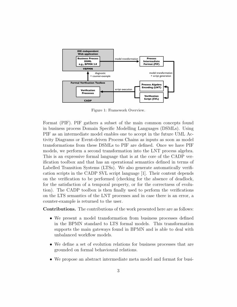
Approach. To reach these objectives we develop an approach, as shown inFigure 1, based on model transformation, and on property and behaviouralequivalence checking. We start with BPMN models that may have been de-fined in any business process IDE that can output BPMN files that conformto the standard. The process designer uses our Web application, VBPMN, toinput the (one or two depending on the verification to perform) process mod-els and the verification parameters. We then have to transform these modelsinto formal models that can support formal analysis. This is achieved inthree steps. First we transform the business processes into an intermediateprocess meta model and format that we propose, the Process Intermediate
2
IDE-independentWeb application
VBPMN
Business ProcessDSML
e.g., BPMN 2.0
ProcessIntermediateFormat (PIF)
Formal Verification Toolbox
CADP
VerificationProcesses
Process AlgebraEncoding (LNT)
Verification Script (SVL)
model transformation
script execution
model transformation+ script generation
diagnostic+ counter-example
Figure 1: Framework Overview.
Format (PIF). PIF gathers a subset of the main common concepts foundin business process Domain Specific Modelling Languages (DSMLs). UsingPIF as an intermediate model enables one to accept in the future UML Ac-tivity Diagrams or Event-driven Process Chains as inputs as soon as modeltransformations from these DSMLs to PIF are defined. Once we have PIFmodels, we perform a second transformation into the LNT process algebra.This is an expressive formal language that is at the core of the CADP ver-ification toolbox and that has an operational semantics defined in terms ofLabelled Transition Systems (LTSs). We also generate automatically verifi-cation scripts in the CADP SVL script language [1]. Their content dependson the verification to be performed (checking for the absence of deadlock,for the satisfaction of a temporal property, or for the correctness of evolu-tion). The CADP toolbox is then finally used to perform the verificationson the LTS semantics of the LNT processes and in case there is an error, acounter-example is returned to the user.
Contributions. The contributions of the work presented here are as follows:
• We present a model transformation from business processes definedin the BPMN standard to LTS formal models. This transformationsupports the main gateways found in BPMN and is able to deal withunbalanced workflow models.
• We define a set of evolution relations for business processes that aregrounded on formal behavioural relations.
• We propose an abstract intermediate meta model and format for busi-
3
ness processes, PIF. It contains common process workflow conceptsfound in different business process DSMLs, thus opening the possibil-ity to apply our approach to several of these DSMLs.
• We introduce VBPMN, a freely available tool [2] that implements themodel transformation and that enables, through a Web application, tocheck for the evolution of business process and get informative feed-back in case of an error.
Outline. Section 2 introduces the BPMN business process modelling lan-guage and the running example we will use for illustration purposes. Thetransformation from BPMN models to the formal models we use for checkingevolution is presented in Section 3, together with PIF, a business processmeta model that plays an intermediate role between business process mod-elling languages (such as BPMN) and verification models (such as LTS). InSection 4 we then formally define several behavioural relations that can beused to compare business processes and, accordingly, to check business pro-cess evolution. Section 5 addresses the implementation of the outcomes of theprevious sections. We present there VBPMN, our Web application for busi-ness process verification and some experimental data on the use of its coreverification module. Finally, Section 6 reviews related work and Section 7concludes the article.
2. BPMN
In this section, we give a short introduction on BPMN. We then presentthe running example we will use for illustration purposes in the rest of thispaper.
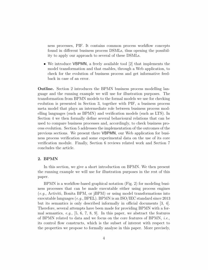
BPMN is a workflow-based graphical notation (Fig. 2) for modeling busi-ness processes that can be made executable either using process engines(e.g., Activiti, Bonita BPM, or jBPM) or using model transformations intoexecutable languages (e.g., BPEL). BPMN is an ISO/IEC standard since 2013but its semantics is only described informally in official documents [3, 4].Therefore, several attempts have been made for providing BPMN with a for-mal semantics, e.g., [5, 6, 7, 8, 9]. In this paper, we abstract the featuresof BPMN related to data and we focus on the core features of BPMN, i.e.,its control flow constructs, which is the subset of interest with respect tothe properties we propose to formally analyse in this paper. More precisely,
4
start state
end state
exclusive gatewayor
or event-based gateway
inclusive gateway
parallel gateway
sequence flow
Task 1
Task 2
Task 3split pattern
Task 1
Task 3
Task 2merge pattern
Figure 2: BPMN Notation (part of).
we consider the following categories of workflow nodes: start and end event,tasks, and gateways.
Start and end events are used to denote respectively the starting and theending point of a process. A task is an abstraction of some activity and cor-responds in practice, e.g., to manual tasks, scripted tasks, or inter-processmessage-based communication. In our context, we use a unique general con-cept of task for all these possibilities. Start (end, resp.) events must haveonly one outgoing (incoming, resp.) flow, and tasks must have exactly oneincoming and one outgoing flow.
Gateways are used, along with sequence flows, to represent the controlflow of the whole process and in particular the task execution ordering. Thereare five types of gateways in BPMN: exclusive, inclusive, parallel, event-basedand complex gateways. An exclusive gateway is used to choose one out ofa set of mutually exclusive alternative incoming or outgoing branches. Itcan also be used to represent looping behaviours. For an inclusive gate-way, any number of branches among all its incoming or outgoing branchesmay be taken. A parallel gateway creates concurrent flows for all its outgo-ing branches or synchronizes concurrent flows for all its incoming branches.For an event-based gateway, it takes one of its outgoing branches based onevents (message reception). Finally, complex gateways are used to modelcomplex synchronization behaviours especially based on data control. If agateway has one incoming branch and multiple outgoing branches, it is calleda split (gateway). Otherwise, it should have one outgoing branch and multi-
5

Table 1: Analysis of the BPMN elements found in the BIT process library, release 2009.
category element occurences present in filesflow sequence flow 35.082 825/825gateway parallel gateway 11.175 715/825task task 7.759 825/825event end event 3.533 825/825event start event 3.027 825/825gateway exclusive gateway 1.956 478/825structure sub-process 883 58/825structure definitions 825 825/825structure process 825 825/825gateway inclusive gateway 135 47/825
ple incoming branches, and it is called a merge (gateway).We support workflows that exhibit an unbalanced structure between split-
merge gateways. More precisely, this means that any merge gateway does nothave necessarily a corresponding split gateway, that is, with the same typeand with the same number of branches. We require that BPMN processesare syntactically correct, which is checked by ensuring that the BPMN modelconforms to BPMN 2.0 specification. Moreover, although specific processesare syntactically correct, they may be semantically flawed. Those erroneousmodels are usually refered as anti-patterns [10]. This is the case for instancewhen a process exhibits a looping behaviour coming back in-between a par-allel/inclusive split and merge gateway. In that case, the semantical modelwill be infinite. This problem is well-known in process algebra, which usuallyforbids recursive agent calls through parallel composition operators (referredas finite control property [11]). In our work, this case is detected by applyinga pre-processing check and then discarded before model transformation andanalysis. The pre-processing traverses the process and, for each parallel orinclusive merge gateway involved in an unbalanced structure, checks whetherthat gateway is inside a cycle.
Limitations. BPMN has three main kinds of models: processes, collabo-rations, and choreographies. In this work we deal with the first kind, andthe other two are perspectives for a future release of VBPMN (see Section 7).Different subsets of the notation, called process modeling conformance sub-
6

classes, are defined in the BPMN standard. In order to select a sufficient one,we did an analysis of the 825 BPMN processes available in the BIT processlibrary, release 2009 [12]. These processes are industrial process models takenfrom different business domains such as finance or telecommunications. Ta-ble 1 presents the outcomes of this analysis, with the number of occurrencesfor each BPMN element (in the whole set of processes) and the number ofprocesses in which at least one occurrence of the element is found. In ourapproach we are able to deal with all the BPMN elements we found in thisanalysis, but for sub-processes. This subset of BPMN that we support cor-responds to what is defined as the descriptive conformance sub-class in theBPMN standard, without sub-processes and data, but with inclusive gate-ways. Sub-processes are a structuring mechanism in BPMN and they couldpossibly be removed by flattening the processes. Supporting data is of realinterest, however, in the descriptive conformance sub-class, its role is unclear.There are no conditions on sequence flows going out of exclusive gatewaysin this sub-class for example. In the presence of conditional constructs andassignment activities, the support for data would require either to boundthe data domains (which could be done using our approach) or to rely onsymbolic approaches like in [13].
Example. We use the online shopping system depicted in Figure 3 as arunning example. This process starts by searching items, logging in, andinitiating payment (exclusive gateways, top part). Then, once the payment iscompleted, the availability of the ordered items is tackled (inclusive gateways,bottom part). Finally, items are shipped and delivered (exclusive gateways,bottom right part). If some item is unavailable or if the delivery fails (e.g.,nobody is present to receive the parcel), a refund is processed provided thepayment is made using voucher or card. We can see that this workflow isunbalanced (top right and bottom part) and includes a loop (bottom rightpart).
3. Models and Transformations
3.1. Process Intermediate Format
Business processes may be modelled using different DSMLs. BPMN ispossibly the main one but one may also consider the use of UML Activ-ity Diagrams (UML AD) or Event-driven Process Chains (EPC) for this.The formal approach for the verification of business process evolution advo-cated by our framework, could indeed apply not only to BPMN, but also to
7
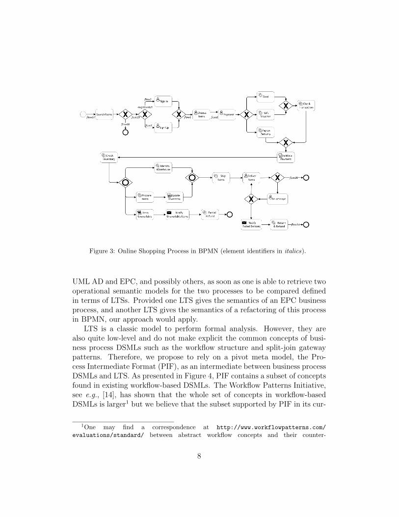
Figure 3: Online Shopping Process in BPMN (element identifiers in italics).
UML AD and EPC, and possibly others, as soon as one is able to retrieve twooperational semantic models for the two processes to be compared definedin terms of LTSs. Provided one LTS gives the semantics of an EPC businessprocess, and another LTS gives the semantics of a refactoring of this processin BPMN, our approach would apply.
LTS is a classic model to perform formal analysis. However, they arealso quite low-level and do not make explicit the common concepts of busi-ness process DSMLs such as the workflow structure and split-join gatewaypatterns. Therefore, we propose to rely on a pivot meta model, the Pro-cess Intermediate Format (PIF), as an intermediate between business processDSMLs and LTS. As presented in Figure 4, PIF contains a subset of conceptsfound in existing workflow-based DSMLs. The Workflow Patterns Initiative,see e.g., [14], has shown that the whole set of concepts in workflow-basedDSMLs is larger1 but we believe that the subset supported by PIF in its cur-
1One may find a correspondence at http://www.workflowpatterns.com/
evaluations/standard/ between abstract workflow concepts and their counter-
8

Fig
ure
4:P
IFM
eta
Mod
el(a
bst
ract
con
cep
tsare
show
nin
gre
y).
9
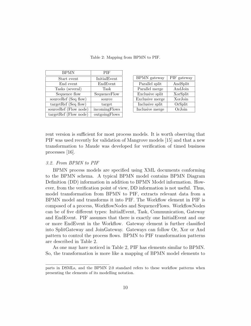
Table 2: Mapping from BPMN to PIF.
BPMN PIF
Start event InitialEventEnd event EndEvent
Tasks (several) TaskSequence flow SequenceFlow
sourceRef (Seq flow) sourcetargetRef (Seq flow) target
sourceRef (Flow node) incomingFlowstargetRef (Flow node) outgoingFlows
BPMN gateway PIF gateway
Parallel split AndSplitParallel merge AndJoinExclusive split XorSplit
Exclusive merge XorJoinInclusive split OrSplit
Inclusive merge OrJoin
rent version is sufficient for most process models. It is worth observing thatPIF was used recently for validation of Mangrove models [15] and that a newtransformation to Maude was developed for verification of timed businessprocesses [16].
3.2. From BPMN to PIF
BPMN process models are specified using XML documents conformingto the BPMN schema. A typical BPMN model contains BPMN DiagramDefinition (DD) information in addition to BPMN Model information. How-ever, from the verification point of view, DD information is not useful. Thus,model transformation from BPMN to PIF, extracts relevant data from aBPMN model and transforms it into PIF. The Workflow element in PIF iscomposed of a process, WorkflowNodes and SequenceFlows. WorkflowNodescan be of five different types: InitialEvent, Task, Communication, Gatewayand EndEvent. PIF assumes that there is exactly one InitialEvent and oneor more EndEvent in the Workflow. Gateway element is further classifiedinto SplitGateway and JoinGateway. Gateways can follow Or, Xor or Andpattern to control the process flows. BPMN to PIF transformation patternsare described in Table 2.
As one may have noticed in Table 2, PIF has elements similar to BPMN.So, the transformation is more like a mapping of BPMN model elements to
parts in DSMLs, and the BPMN 2.0 standard refers to these workflow patterns whenpresenting the elements of its modelling notation.
10

PIF elements.
3.3. From PIF to LTS
We present here our transformation from PIF to LTS, obtained througha transformation from PIF to the LNT process algebra, LNT having an LTSsemantics. We gave a semantics to each PIF construct based on the infor-mal semantics given in the standard for the corresponding BPMN construct.Hence, using our BPMN to PIF mapping and our PIF to LNT transforma-tion, one gets an LTS semantics for BPMN business processes. It is worthnoting that the generated LTS is finite (the number of states is finite) becausethe BPMN/PIF process is syntactically correct and free of flawed patternsthat may generate infinite models.
LNT. LNT [17] is an extension of LOTOS [18], an ISO standardized processalgebra, which allows the definition of data types, functions, and processes.Table 3 provides an overview of the behavioural fragment of LNT syntax andsemantics. B stands for a LNT term, G for a gate or action, E for a Booleanexpression, T for a type, and P for a process name. The syntax fragmentpresented in this table contains the termination construct (stop) and gatesor actions (G) that may come with offers (send an expression E or receive ina variable x). LNT processes are then built using several operators: sequen-tial composition (;), conditional statement (if), assignment (:=) where thevariable should be defined beforehand, hiding (hide) that hides some actionin a behaviour, nondeterministic choice (select), parallel composition (par)where the communication between the process participants is carried out byrendezvous on a list of synchronized actions, looping behaviours describedusing process calls or explicit operators (loop, while).
We also present in Table 3 some examples of rules defining the opera-tional semantics of LNT (action prefix, sequential composition, conditionalconstruct, variable assignment, hiding operator, and choice). An action orgate G can come with offers (send offer ‘!’ or receive offer ‘?’). The valuereceived in the variable x must be of the type of x (checked with the ‘type’function). Note that the received value v′ substitutes x in B. The conditionalstatement if executes when the corresponding condition is evaluated to true(expressed using [[.]]). If the condition expression evaluates to false, it resultsin termination of the block without executing the condition block. Sequen-tial composition consists of two rules. The first one corresponds to normalevolution of the B1 behaviour. The second rule executes when the first be-haviour terminates correctly (δ action). In that case, the second behaviour
11
(B2) starts executing. The operational rule for variable assignment showshow the fresh variable x is substituted by the evaluated expression E in thewhole behaviour B. There are two rules for the hiding operator. The firstone results in a normal execution if the gate does not belong to the set ofgates to be hidden. The second rule, contrarily, involves a gate that is partof the gates to be hidden and the gate transforms into an unobservable τaction. Finally, the select operator triggers nondeterministically one of thechoice branches. The reader interested in more details about the syntax andsemantics of LNT should refer to [17].
The use of LNT is preferred over the direct use of LTS since this yieldsa simpler, high-level and more declarative transformation. Thanks to theLTS semantics of LNT, one can use thereafter a rich set of existing tools forLTS-based verification. The choice of LNT over other process algebras hasbeen guided by the existence of the CADP toolbox [19], which comes witha very comprehensive set of verification tools, including ones supporting theimplementation of the various checks presented in the sequel.
Overview. The idea is to encode as LNT processes all PIF elements involvedin a process definition, that is, the nodes (tasks, gateways), which correspondto the behaviour of the business process, initial/end events, and sequenceflows, which encode the execution semantics of this process. Finally, allthese independent LNT processes are composed in parallel and synchronizedin order to respect the business process execution semantics. For instance,after execution of a node, the corresponding LNT process synchronizes withthe process encoding the outgoing flow, which then synchronizes with theprocess encoding the node appearing at the end of this flow, and so on.
The encoding patterns for the main PIF constructs are described in Ta-ble 4 except for Or gateways, which are tackled separately in Tables 5 and 6.The actions corresponding to the flows ( incf, outf, etc.) will be used as syn-chronization points between the different workflow elements. The begin andfinish actions in the initial/end events are just used to trigger and terminate,respectively, these events. The actions used in task constructs (e.g., task)will be the only ones to appear in the final LTS. All other synchronizationsactions will be hidden because they do not make sense from an observationalpoint of view. We do not present the encoding of communication/interac-tion messages in Table 4 because they are translated similarly to tasks. Andgateways are encoded using the par LNT operator, which corresponds inthis case to an interleaving of all flows. Xor gateways are encoded using the
12
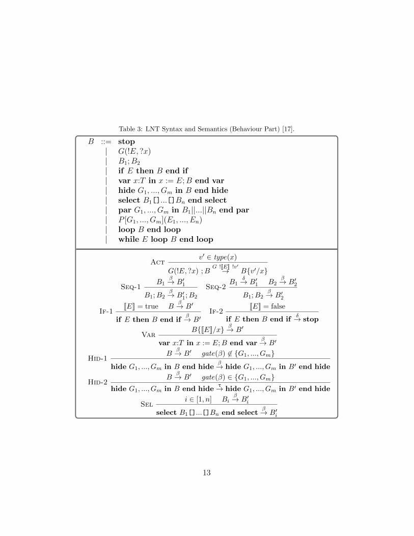
Table 3: LNT Syntax and Semantics (Behaviour Part) [17].
B ::= stop| G(!E, ?x)| B1;B2
| if E then B end if| var x:T in x := E;B end var| hide G1, ..., Gm in B end hide| select B1[]...[]Bn end select| par G1, ..., Gm in B1||...||Bn end par| P [G1, ..., Gm](E1, ..., En)| loop B end loop| while E loop B end loop
Actv′ ∈ type(x)
G(!E, ?x) ;BG ![[E]] !v′→ B{v′/x}
Seq-1B1
β→ B′1
B1;B2β→ B′1;B2
Seq-2B1
δ→ B′1 B2β→ B′2
B1;B2β→ B′2
If-1[[E]] = true B
β→ B′
if E then B end ifβ→ B′
If-2[[E]] = false
if E then B end ifδ→ stop
VarB{[[E]]/x} β→ B′
var x:T in x := E;B end varβ→ B′
Hid-1B
β→ B′ gate(β) 6∈ {G1, ..., Gm}
hide G1, ..., Gm in B end hideβ→ hide G1, ..., Gm in B′ end hide
Hid-2B
β→ B′ gate(β) ∈ {G1, ..., Gm}hide G1, ..., Gm in B end hide
τ→ hide G1, ..., Gm in B′ end hide
Seli ∈ [1, n] Bi
β→ B′i
select B1[]...[]Bn end selectβ→ B′i
13

Table 4: Encoding PIF into LNT (part of, continued below).
PIF Construct BPMN Notation LNT Encoding
InitialEvent begin ; outf
EndEvent incf ; finish
SequenceFlow loop begin ; finish end loop
Task loop incf ; task ; outf end loop
AndSplit
loop incf ;par
outf1 || outf2 || outf3end par end loop
AndJoin
loop parincf1 || incf2 || incf3
end par ;outf end loop
XorSplit
loop incf ;select
outf1 [] outf2 [] outf3end select end loop
XorJoin
loop selectincf1 [] incf2 [] incf3
end select ;outf end loop
select LNT operator, which corresponds to a nondeterministic choice amongall flows. All constructs (sequence flows, tasks, gateways) are enclosed withinan LNT loop operator since these elements can be repeated several times ifthe business process exhibits looping behaviours. However, the decision torepeat is not taken at this local level, but it depends of the overall workflowstructure whose encoding will be presented in the rest of this section.
Composition. Once all workflow elements are encoded into LNT, the nextstep is to compose them in order to obtain the behaviour of the whole busi-ness process. To do so, we compose in parallel all the flows with all theother constructs. All flows are interleaved because they do not interact onewith another. All events and nodes (start/end events, tasks, gateways) areinterleaved as well for the same reason. Then both sets are synchronized on
14

flow sequences (actions denoted by sequence flow IDs). These additional ac-tions are finally hidden because they should not appear as observable actionsand will be transformed into internal transitions in the resulting LTS. Eachprocess call is accompanied with its alphabet, that is, the list of actions usedin that process. For instance, each call of a flow process comes with a coupleof actions corresponding to the initiation and termination of the flow.
Balanced Or gateways. The Or gateways in PIF correspond to the BPMNinclusive gateways. The semantics of the inclusive gateways is quite intricatein the original version of BPMN [20]. BPMN 2.0 simplifies the semanticsof the inclusive merge gateway by allowing the merge to execute whenevera token arrives at the merge level. From the process algebra point of view,this can be simply encoded as an XorJoin gateway as already presentedbeforehand in this section. In the rest of this section, we assume that theOrJoin gateways correspond to a real synchronization point as describedin the execution semantics of the first version of BPMN. We support bothsemantics in the tool support we will present in Section 5.
As a first step, we also assume here that each OrJoin gateway has acorresponding OrSplit gateway with the same number of branches. This iswhat we call balanced gateway that can be generalized to balanced workflows/ processes if all gateways in the process exhibit a balanced structure. Theencoding of the Or gateways use the select and par operators to allowall possible combinations of the outgoing branches. Table 5 describes thetranslation patterns in LNT. Note the introduction of synchronization points(si), which are necessary to indicate to the OrJoin gateway the behaviour thatwas executed at the OrSplit level. Without such synchronization points, anOrJoin gateway does not know whether it is supposed to wait for one orseveral branches (and which branches in this second case).
Unbalanced Or gateways. In case of an unbalanced structure of theworkflow, we cannot use the synchronization points solution we used forbalanced Or gateways. Therefore, the only solution we have is to use aglobal process in charge of keeping track of all active tokens and of decidingif a certain OrJoin gateway can be triggered or not. To do so, we use anadditional process called scheduler. The scheduler runs in parallel with allthe other LNT processes encoding the aforementioned workflow constructsand synchronizes with them to keep track of active flows in the whole PIFprocess. Each time a synchronization occurs between the scheduler and a flowprocess, the scheduler updates a local set of flow identifiers corresponding to
15
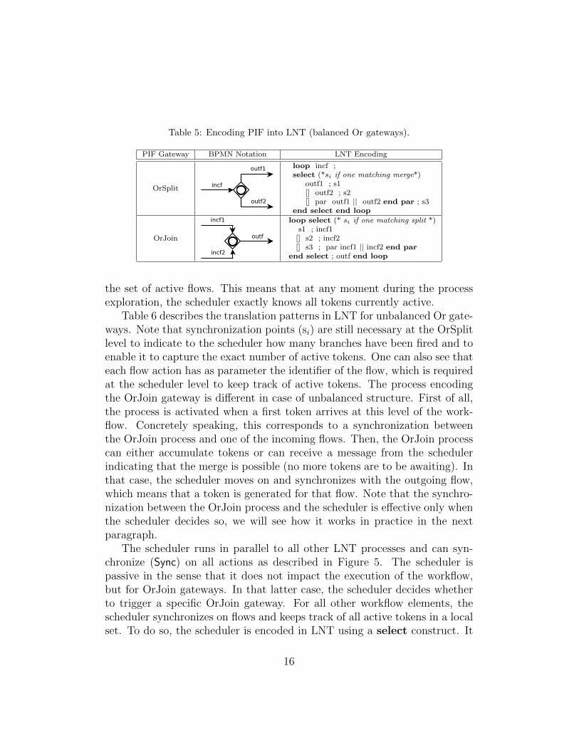
Table 5: Encoding PIF into LNT (balanced Or gateways).
PIF Gateway BPMN Notation LNT Encoding
OrSplit
loop incf ;select (*si if one matching merge*)
outf1 ; s1[] outf2 ; s2[] par outf1 || outf2 end par ; s3
end select end loop
OrJoin
loop select (* si if one matching split *)s1 ; incf1
[] s2 ; incf2[] s3 ; par incf1 || incf2 end par
end select ; outf end loop
the set of active flows. This means that at any moment during the processexploration, the scheduler exactly knows all tokens currently active.
Table 6 describes the translation patterns in LNT for unbalanced Or gate-ways. Note that synchronization points (si) are still necessary at the OrSplitlevel to indicate to the scheduler how many branches have been fired and toenable it to capture the exact number of active tokens. One can also see thateach flow action has as parameter the identifier of the flow, which is requiredat the scheduler level to keep track of active tokens. The process encodingthe OrJoin gateway is different in case of unbalanced structure. First of all,the process is activated when a first token arrives at this level of the work-flow. Concretely speaking, this corresponds to a synchronization betweenthe OrJoin process and one of the incoming flows. Then, the OrJoin processcan either accumulate tokens or can receive a message from the schedulerindicating that the merge is possible (no more tokens are to be awaiting). Inthat case, the scheduler moves on and synchronizes with the outgoing flow,which means that a token is generated for that flow. Note that the synchro-nization between the OrJoin process and the scheduler is effective only whenthe scheduler decides so, we will see how it works in practice in the nextparagraph.
The scheduler runs in parallel to all other LNT processes and can syn-chronize (Sync) on all actions as described in Figure 5. The scheduler ispassive in the sense that it does not impact the execution of the workflow,but for OrJoin gateways. In that latter case, the scheduler decides whetherto trigger a specific OrJoin gateway. For all other workflow elements, thescheduler synchronizes on flows and keeps track of all active tokens in a localset. To do so, the scheduler is encoded in LNT using a select construct. It
16
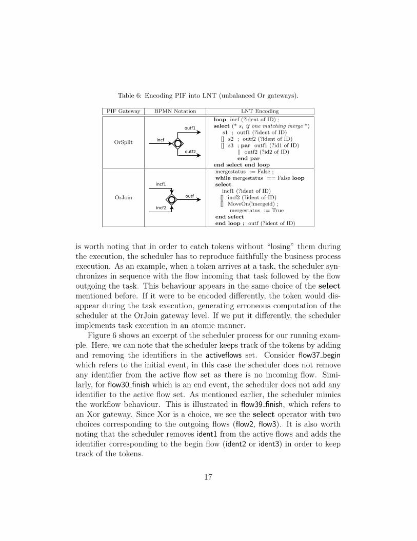
Table 6: Encoding PIF into LNT (unbalanced Or gateways).
PIF Gateway BPMN Notation LNT Encoding
OrSplit
loop incf (?ident of ID) ;select (* si if one matching merge *)
s1 ; outf1 (?ident of ID)[] s2 ; outf2 (?ident of ID)[] s3 ; par outf1 (?id1 of ID)
|| outf2 (?id2 of ID)end par
end select end loop
OrJoin
mergestatus := False ;while mergestatus == False loopselect
incf1 (?ident of ID)[] incf2 (?ident of ID)[] MoveOn(!mergeid) ;
mergestatus := Trueend selectend loop ; outf (?ident of ID)
is worth noting that in order to catch tokens without “losing” them duringthe execution, the scheduler has to reproduce faithfully the business processexecution. As an example, when a token arrives at a task, the scheduler syn-chronizes in sequence with the flow incoming that task followed by the flowoutgoing the task. This behaviour appears in the same choice of the selectmentioned before. If it were to be encoded differently, the token would dis-appear during the task execution, generating erroneous computation of thescheduler at the OrJoin gateway level. If we put it differently, the schedulerimplements task execution in an atomic manner.
Figure 6 shows an excerpt of the scheduler process for our running exam-ple. Here, we can note that the scheduler keeps track of the tokens by addingand removing the identifiers in the activeflows set. Consider flow37 beginwhich refers to the initial event, in this case the scheduler does not removeany identifier from the active flow set as there is no incoming flow. Simi-larly, for flow30 finish which is an end event, the scheduler does not add anyidentifier to the active flow set. As mentioned earlier, the scheduler mimicsthe workflow behaviour. This is illustrated in flow39 finish, which refers toan Xor gateway. Since Xor is a choice, we see the select operator with twochoices corresponding to the outgoing flows (flow2, flow3). It is also worthnoting that the scheduler removes ident1 from the active flows and adds theidentifier corresponding to the begin flow (ident2 or ident3) in order to keeptrack of the tokens.
17
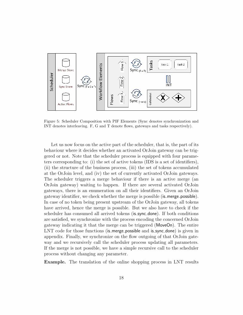
Figure 5: Scheduler Composition with PIF Elements (Sync denotes synchronization andINT denotes interleaving. F, G and T denote flows, gateways and tasks respectively).
Let us now focus on the active part of the scheduler, that is, the part of itsbehaviour where it decides whether an activated OrJoin gateway can be trig-gered or not. Note that the scheduler process is equipped with four parame-ters corresponding to: (i) the set of active tokens (IDS is a set of identifiers),(ii) the structure of the business process, (iii) the set of tokens accumulatedat the OrJoin level, and (iv) the set of currently activated OrJoin gateways.The scheduler triggers a merge behaviour if there is an active merge (anOrJoin gateway) waiting to happen. If there are several activated OrJoingateways, there is an enumeration on all their identifiers. Given an OrJoingateway identifier, we check whether the merge is possible (is merge possible).In case of no token being present upstream of the OrJoin gateway, all tokenshave arrived, hence the merge is possible. But we also have to check if thescheduler has consumed all arrived tokens (is sync done). If both conditionsare satisfied, we synchronize with the process encoding the concerned OrJoingateway indicating it that the merge can be triggered (MoveOn). The entireLNT code for those functions (is merge possible and is sync done) is given inappendix. Finally, we synchronize on the flow outgoing of that OrJoin gate-way and we recursively call the scheduler process updating all parameters.If the merge is not possible, we have a simple recursive call to the schedulerprocess without changing any parameter.
Example. The translation of the online shopping process in LNT results
18

type NODE i si ( i n i t i a l : INITIAL ) ,f ( f i n a l s : FINALS ) ,g ( gateways : GATEWAYS ) ,t ( ta sk s : TASKS )
end type
type NODES i sset of NODE
end type
type BPROCESS i sproc ( name : ID , nodes : NODES, f l ows : FLOWS )
end type
process s chedu l e r [ . . . ] ( a c t i v e f l o w s : IDS , bpmn : BPROCESS, sync s to r e : IDS ,mergestore : IDS) i s
selectf l ow37 beg in (? i dent1 of ID) ; s chedu l e r [ . . . ] ( union ({ i dent1 } ,
r emove id s f r om se t ({} , a c t i v e f l o w s ) ) , bpmn, syncstore , mergestore )[ ]
f l o w 3 9 f i n i s h (? i dent1 of ID) ;select
f l ow2 beg in (? i dent2 of ID) ; s chedu l e r [ . . . ] ( union ({ i dent2 } ,r emove id s f r om se t ({ i dent1 } , a c t i v e f l o w s ) ) , bpmn, syncs tore ,mergestore )
[ ]f l ow3 beg in (? i dent3 of ID) ; s chedu l e r . . .
end select[ ]
f l o w 3 0 f i n i s h (? i dent1 of ID) ; s chedu l e r [ . . . ] ( union ({} ,r emove id s f r om se t ({ i dent1 } , a c t i v e f l o w s ) ) , bpmn, syncs tore ,mergestore )
[ ]mergeid := any ID where member( mergeid , mergestore ) ;i f ( i s m e r g e p o s s i b l e (bpmn, a c t i v e f l o w s , mergeid ) and i s s y n c d o n e (bpmn,
a c t i v e f l o w s , syncstore , mergeid ) ) thenMoveOn( !merge id ) ;out f (? i dent1 of ID) ;s chedu l e r [ . . . ] ( union ({ i dent1 } , r emove inc f (bpmn, a c t i v e f l o w s ,
mergeid ) ) , bpmn, remove sync (bpmn, syncs tore , mergeid ) ,remove ( mergeid , mergestore ) )
elses chedu l e r [ . . . ] ( a c t i v e f l o w s , bpmn, syncstore , mergestore )
end i fend select
end process
Figure 6: Excerpt of the LNT Scheduler Process for the Online Shopping Process.
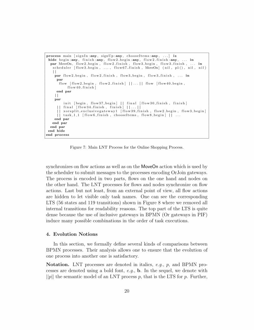
in several processes. The main process is given in Figure 7. This excerptof specification shows first how the scheduler is in parallel with the process,
19
process main [ s i gn In :any , signUp :any , chooseItems :any , . . . ] i shide begin :any , f i n i s h :any , f l ow2 beg in :any , f l o w 2 f i n i s h :any , . . . inpar MoveOn, f low2 beg in , f l o w 2 f i n i s h , f l ow3 beg in , f l o w 3 f i n i s h , . . . in
s chedu l e r [ f l ow3 beg in , . . . , f l o w 6 7 f i n i s h , MoveOn ] ( n i l , p1 ( ) , n i l , n i l )| |par f l ow2 beg in , f l o w 2 f i n i s h , f l ow3 beg in , f l o w 3 f i n i s h , . . . inpar
f l ow [ f l ow2 beg in , f l o w 2 f i n i s h ] | | . . . | | f l ow [ f low40 beg in ,f l o w 4 0 f i n i s h ]
end par| |par
i n i t [ begin , f l ow37 beg in ] | | f i n a l [ f l o w 3 0 f i n i s h , f i n i s h ]| | f i n a l [ f l o w 3 4 f i n i s h , f i n i s h ] | | . . . | || | x o r s p l i t e x c l u s i v e g a t e w a y 1 [ f l o w 3 9 f i n i s h , f l ow2 beg in , f l ow3 beg in ]| | t a s k 1 1 [ f l o w 6 f i n i s h , chooseItems , f l ow8 beg in ] | | . . .
end parend par
end parend hide
end process
Figure 7: Main LNT Process for the Online Shopping Process.
synchronizes on flow actions as well as on the MoveOn action which is used bythe scheduler to submit messages to the processes encoding OrJoin gateways.The process is encoded in two parts, flows on the one hand and nodes onthe other hand. The LNT processes for flows and nodes synchronize on flowactions. Last but not least, from an external point of view, all flow actionsare hidden to let visible only task names. One can see the correspondingLTS (56 states and 119 transitions) shown in Figure 8 where we removed allinternal transitions for readability reasons. The top part of the LTS is quitedense because the use of inclusive gateways in BPMN (Or gateways in PIF)induce many possible combinations in the order of task executions.
4. Evolution Notions
In this section, we formally define several kinds of comparisons betweenBPMN processes. Their analysis allows one to ensure that the evolution ofone process into another one is satisfactory.
Notation. LNT processes are denoted in italics, e.g., p, and BPMN pro-cesses are denoted using a bold font, e.g., b. In the sequel, we denote with||p|| the semantic model of an LNT process p, that is the LTS for p. Further,
20
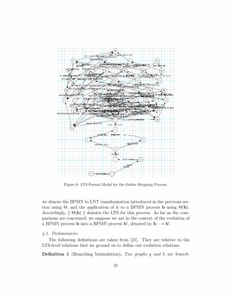
Figure 8: LTS Formal Model for the Online Shopping Process.
we denote the BPMN to LNT transformation introduced in the previous sec-tion using Θ, and the application of it to a BPMN process b using Θ(b).Accordingly, || Θ(b) || denotes the LTS for this process. As far as the com-parisons are concerned, we suppose we are in the context of the evolution ofa BPMN process b into a BPMN process b′, denoted by b 99K b′.
4.1. Preliminaries
The following definitions are taken from [21]. They are relative to theLTS-level relations that we ground on to define our evolution relations.
Definition 1 (Branching bisimulation). Two graphs g and h are branch-
21
ing bisimilar if there exists a symmetric relation R [...] (called branchingbisimulation) between the nodes of g and h such that:
(i) The roots are related by R;
(ii) If R(r, s) and r →a r′, then either a = τ and R(r′, s) or there exists apath s⇒ s1 →a s2 ⇒ s′ such that R(r, s1), R(r′, s2) and R(r′, s′).
The original definition (given above) refers to (process) graphs that are“connected, rooted, edge-labelled and direct graphs” [21]. LTSs are suchgraphs, with the roots corresponding to initial states. In the definition,r →a r′ denotes an edge (= LTS transition) from node (= LTS state) r tonode r′ labelled by a. Further, s ⇒ s1 denotes a sequence (path) of zero ormore silent (τ) transitions from s to s1 (s can be s1). In the sequel we alsorefer to branching bisimulation as branching equivalence, and when g and h
are branching bisimilar we may use gbr≡ h.
If we remove the symmetric constraint on R in the previous definition weget a branching simulation or branching preorder between g and h, denoted
with gbr< h, and we say that h simulates g.
4.2. Conservative Evolution
Our first comparison criterion is strong. Given an evolution b 99K b′, itensures that the observable behaviour of b is exactly preserved in b′. It sup-ports very constrained refactorings of BPMN processes such as grouping orsplitting parallel or exclusive branches (e.g., ( (a,b), c) 99K
L99 (a,b, c)
where (x1, . . . , xn) denotes a balanced exclusive split-merge). At the se-mantic level, several behavioural equivalences could be used. We have todeal with internal transitions introduced by hiding (see Section 3). Hence,we chose to use branching equivalence, introduced in Section 4.1, since it isthe finest equivalence notion in presence of such internal transitions.
Definition 1. (Conservative Evolution) Let b and b′ be two processes, b 99K
b′ is a conservative evolution iff || Θ(b) || br≡ || Θ(b′) ||.
4.3. Inclusive and Exclusive Evolution
In most cases, one does not want to replace a business process by anotherone having exactly the same behaviour. Rather, one wants to be able to addnew functionalities in the process, without interfering with the existing ones.
22
A typical example is adding new paths, e.g., (a,b) 99K (a,b, c), or
evolving an existing one, e.g., (a,b) 99K (a, (b, c)). So here, weground on a preorder relation rather than on an equivalence one, ensuringthat, given b 99K b′, all observable behaviours that were in b are still in b′.For this we rely on the branching preorder, introduced in Section 4.1.
Definition 2. (Inclusive Evolution) Let b and b′ be two processes, b 99K b′
is an inclusive evolution iff || Θ(b) ||br< || Θ(b′) ||.
Similarly, one may refine a process by implementing only a part of it.Here, in b 99K b′, one does not want that b′ exposes any additional behaviourthat is outside what is specified in b. This is a reversed form of inclusiveevolution.
Definition 3. (Exclusive Evolution) Let b and b′ be two processes, b 99K b′
is an exclusive evolution iff || Θ(b′) ||br< || Θ(b) ||.
The duality between inclusive and exclusive evolution is usual when oneformalizes the fact that some abstract specification a is correctly implementedinto a more concrete system c. For some people, this means that at leastall the behaviours expected from a should be available in c. Taking thewell-known “coffee machine” example, if a specification requires that themachine is able to deliver coffee, an implementation delivering either coffeeor tea (depending on the people interacting with it) is correct. For others,e.g., in the testing community, an implementation should not expose morebehaviours than what was specified.
4.4. Selective Evolution
Up to now, we have supposed that all tasks in the original process wereof interest. Still, one could choose to focus on a subset of them, called tasksof interest. This gives freedom to change parts of the processes as soon asthe behaviours stay the same for the tasks of interest. For this, we defineselective evolution up to a set of tasks T . Tasks that are not in this setwill be hidden in the comparison process. Formally, this is achieved with anoperation [T ] on LTSs, which, given an LTS l, hides any transition whose labelis not in T by changing this label to τ (it becomes an internal transition).Again, here we can rely on branching equivalence to deal with these internaltransitions.
23

Definition 4. (Selective Conservative Evolution) Let b and b′ be two pro-cesses, and T be a set of tasks, b 99K b′ is a selective conservative evolution
with reference to T iff || Θ(b′) || [T ]br≡ || Θ(b) || [T ].
A specific interesting case of selective evolution is when the set of tasksof interest corresponds exactly to the tasks of the original process. Thislets the designer add new behaviours not only in a separate way (as withinclusive evolution) but also within the behaviours of the original process.
For example, a; b 99K (a, log); b, that is a way to log some informationeach time a is done, is not an inclusive evolution but is a selective conserva-tive evolution with reference to {a,b}. Accordingly to selective conservativeevolution, we can define selective inclusive evolution (respectively selective
exclusive evolution) by using the branching preorder,br<, instead of
br≡.
4.5. Renaming and Refinement
One may also want to take into account renaming when checking anevolution b 99K b′. For this we use a relabelling relation R ⊆ Tb × Tb′ ,where Tb (respectively Tb′) denotes the set of tasks in b (respectively b′).We require that for every t in Tb, if we have (t, t′1) and (t, t′2) in R then t′1 = t′2,i.e., R is a (possibly partial) function. Applying a relabelling relation R toan LTS l, which is denoted by l / R, consists in replacing in l any transitionlabelled by some t in the domain of R by a transition labelled by R(t).
To take into account task renaming in any of the above-mentioned evolu-tions, we just have to perform the equivalence (or preorder) checking up torelabelling in the formal model for b. For example, b 99K b′ is a conservative
evolution up to a relabelling relation R for b and b′ iff || Θ(b) || /R br≡ ||Θ(b′) ||.
Sometimes renaming is not sufficient, e.g., when evolution correspondsto the refinement of a task by a workflow. We define a refinement rule as acouple (t,W ), noted t 99K W 2, where t is a task and W a workflow. A set ofrefinement rules, or refinement set, R =
⋃i∈1...n ti 99K Wi is valid if there
are no multiple refinements of the same task (∀i, j ∈ 1 . . . n, i 6= j ⇒ ti 6= tj)and if no refinement rule has in its right-hand part a task that has to berefined (∀i, j ∈ 1 . . . n, ti 6∈ Wj). These constraints enforce that refinements
2The 99K symbol is overloaded since a refinement rule is an evolution at the task level.
24

do not depend on the application ordering of refinement rules, i.e., they aredeterministic.
To take into account refinement in evolution, a pre-processing has to beperformed on the source process. For example, given that b J R denotes thereplacement in b of ti by Wi for each ti 99K Wi inR, b 99K b′ is a conservative
evolution up to a refinement set R iff || Θ(b J R) || br≡ || Θ(b′) ||.
4.6. Property-Aware Evolution
A desirable feature when checking evolution is to be able to focus on prop-erties of interest and avoid in-depth analysis of the workflows. This gives thefreedom to perform changes (including some not possible with the previousevolution relations) as long as the properties of interest are preserved. Typi-cal properties are deadlock freedom or safety and liveness properties definedover the alphabet of process tasks and focusing on the functionalities ex-pected from the process under analysis. Such properties are written in atemporal logic supporting actions and, to make the property writing easier,the developer can rely on well-known patterns as those presented in [22].
Definition 5. (Property-Aware Evolution) Let b and b′ be two processes, Tbe a set of tasks, and φ be a formula defined over T , b 99K b′ is a property-aware evolution with respect to φ iff || Θ(b) || |= φ ⇒ || Θ(b′) || |= φ.
4.7. Context-Aware Evolution
A process is often used in the context of a collaboration, which in BPMNtakes the form of a set of processes (“pool lanes”) communicating via mes-sages. When evolving a process b, one may safely make changes as soon asthey do not have an impact on the overall system made up of b and theseprocesses. To ensure this, we have to compute the semantics of b communi-cating on a set of interactions I (a subset of its tasks) with the other processesthat constitute the context of b. We support two communication modes: syn-
chronous or asynchronous. For each mode m we have an operationm×I , where
|| Θ(b) ||m×I || Θ(c) || denotes the LTS representing the communication
on a set of interactions I between b and c. For synchronous communication,m×I is the LTS synchronous product [23]. For asynchronous communication,m×I is achieved by adding a buffer to each process [24]. Here, to keep thingssimple, we will suppose without loss of generality, that a context is a singleprocess c.
25
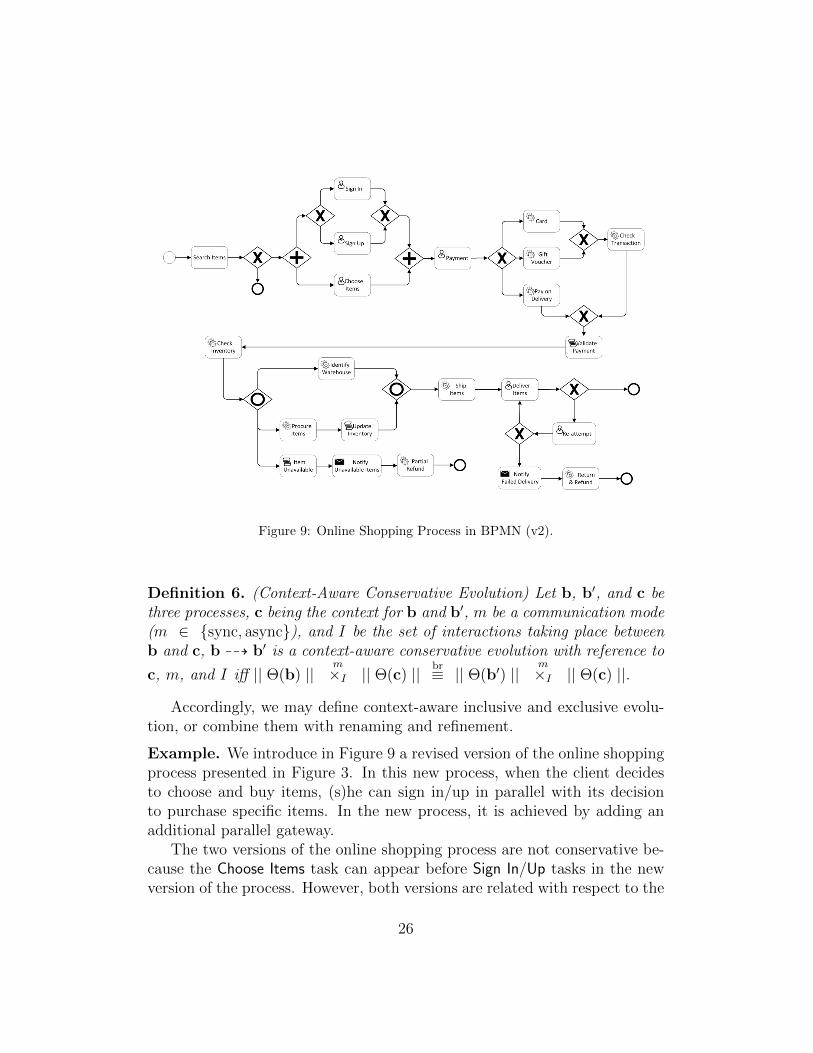
Figure 9: Online Shopping Process in BPMN (v2).
Definition 6. (Context-Aware Conservative Evolution) Let b, b′, and c bethree processes, c being the context for b and b′, m be a communication mode(m ∈ {sync, async}), and I be the set of interactions taking place betweenb and c, b 99K b′ is a context-aware conservative evolution with reference to
c, m, and I iff || Θ(b) ||m×I || Θ(c) || br≡ || Θ(b′) ||
m×I || Θ(c) ||.
Accordingly, we may define context-aware inclusive and exclusive evolu-tion, or combine them with renaming and refinement.
Example. We introduce in Figure 9 a revised version of the online shoppingprocess presented in Figure 3. In this new process, when the client decidesto choose and buy items, (s)he can sign in/up in parallel with its decisionto purchase specific items. In the new process, it is achieved by adding anadditional parallel gateway.
The two versions of the online shopping process are not conservative be-cause the Choose Items task can appear before Sign In/Up tasks in the newversion of the process. However, both versions are related with respect to the
26
inclusive/exclusive evolution notions. The new version includes all possibleexecutions of the former one (the opposite is false) while incorporating newtraces (those including Choose Items and Sign In/Up in sequence for instance).
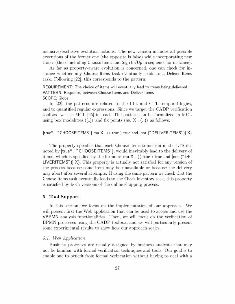
As far as property-aware evolution is concerned, one can check for in-stance whether any Choose Items task eventually leads to a Deliver Itemstask. Following [22], this corresponds to the pattern:
REQUIREMENT: The choice of items will eventually lead to items being delivered.
PATTERN: Response, between Choose Items and Deliver Items
SCOPE: Global
In [22], the patterns are related to the LTL and CTL temporal logics,and to quantified regular expressions. Since we target the CADP verificationtoolbox, we use MCL [25] instead. The pattern can be formalized in MCLusing box modalities ([..]) and fix points (mu X . (..)) as follows:
[true* . ”CHOOSEITEMS”] mu X . (〈 true 〉 true and [not (”DELIVERITEMS”)] X)
The property specifies that each Choose Items transition in the LTS de-noted by [true* . ”CHOOSEITEMS”], would inevitably lead to the delivery ofitems, which is specified by the formula: mu X . (〈 true 〉 true and [not (”DE-LIVERITEMS”)] X). This property is actually not satisfied for any version ofthe process because some item may be unavailable or because the deliverymay abort after several attempts. If using the same pattern we check that theChoose Items task eventually leads to the Check Inventory task, this propertyis satisfied by both versions of the online shopping process.
5. Tool Support
In this section, we focus on the implementation of our approach. Wewill present first the Web application that can be used to access and use theVBPMN analysis functionalities. Then, we will focus on the verification ofBPMN processes using the CADP toolbox, and we will particularly presentsome experimental results to show how our approach scales.
5.1. Web Application
Business processes are usually designed by business analysts that maynot be familiar with formal verification techniques and tools. Our goal is toenable one to benefit from formal verification without having to deal with a
27
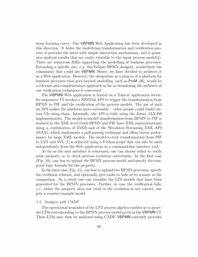
steep learning curve. The VBPMN Web Application has been developed inthis direction. It hides the underlying transformation and verification pro-cess, it provides the users with simple interaction mechanisms, and it gener-ates analysis results that are easily relatable to the input process model(s).There are numerous IDEs supporting the modelling of business processes.Extending a specific one, e.g. the Eclipse BPMN designer, would limit thecommunity that could use VBPMN. Hence, we have decided to architect itas a Web application. However, the integration as a plug-in of a platform forbusiness processes that goes beyond modelling, such as ProM [26], would bea relevant and complementary approach as far as broadening the audience ofour verification techniques is concerned.
The VBPMN Web application is hosted on a Tomcat application server.Its responsive UI invokes a RESTful API to trigger the transformation fromBPMN to PIF and the verification of the process models. The use of suchan API makes the platform more extensible – other people could build cus-tom UIs using them. Internally, the API is built using the Jersey JAX-RSimplementation. The model-to-model transformation from BPMN to PIF isrealized at the XML level (both BPMN and PIF have XML representations)using a combination of JAXB and of the Woodstox Streaming XML API(StAX), which implements a pull parsing technique and offers better perfor-mance for large XML models. The model-to-text transformation from PIFto LNT and SVL [1] is achieved using a Python script that can also be usedindependently from the Web application as a command-line interface tool.
As far as the user interface is concerned, one can choose either to verifysome property or to check process evolution correctness. In the first case(Fig. 10), one has to upload the BPMN process model and specify the tem-poral logic formula for the property.
In the later case (Fig. 11), one has to upload two BPMN processes, specifythe evolution relation, and optionally give tasks to hide or to rename in thecomparison. As a result one can visualize the LTS models that have beengenerated for the BPMN processes. Further, in case the verification fails,i.e., either the property does not yield or the evolution is not correct, onegets a counter-example model.
5.2. Analysis with CADP
The operational semantics of the LNT process algebra enables us to gener-ate LTSs corresponding to the BPMN process model given in the VBPMN UI.These LTSs may then be analyzed using CADP. VBPMN currently provides
28

Figure 10: VBPMN Web Application in Use: Property Verification.
two kinds of formal analysis: functional verification using model checkingand process comparison using equivalence checking.
Functional verification. One can for example use model checking tech-niques to search for deadlocks or livelocks. Another option is to use theCADP model checker for verifying the satisfaction of process-specific safetyand liveness properties. In this case, since the properties depend on theprocess, they have to be provided by the analyst. The use of patterns for
29

Figure 11: VBPMN Web Application in Use: Model Comparison.
properties is a perspective (see Section 7).One can also be interested in checking soundness of the process. Sound-
ness as defined in [27] requires three conditions:
• C1, from the initial state it is always possible to reach the final state,
• C2, from the moment the final state is reached, there are no remainingtokens in the process,
30

• C3, there is no dead transition from the initial state.
All three conditions can be checked using MCL formulas and model check-ing techniques. C3 can be checked using, for any task t, the following formula:
〈 true∗ . ”t” 〉 true
C1 requires to let visible (it is hidden for now, see Fig. 7) the finish actionused to encode end events in LNT (Tab. 4) and to check the reachability onall paths of those actions:
mu X . (〈 true 〉 true and [not (”finish”)] X)
C2 requires in addition to make appear as parameter to this finish actionthe number of current tokens remaining in the process, and then to checkthat when such actions are reached, the number of tokens is zero.
Process comparison. It takes as input two process models, an evolutionrelation and possibly additional parameters for the relation. Several evolutionrelations are proposed. Conservative evolution ensures that the observationalbehaviour is strictly preserved. Inclusive evolution ensures that a subset of aprocess behaviour is preserved in a new version of it. Selective evolution (thatis compatible with both conservative and inclusive evolution) allows one tofocus on a subset of the process tasks. It is also possible to have VBPMNwork up-to a renaming relation over tasks. If the two input process models donot fulfil the constraints of the chosen evolution relation, a counter-examplethat indicates the source of the violation is returned by VBPMN in the UI.This helps the process analyst in understanding the impact of evolution andsupports the refinement into a correct evolved version of a process model. Allthe evolution relations are checked using the CADP equivalence checker andSVL scripts for hiding and renaming as demonstrated with the SVL patternsin Figure 12.
5.3. Experiments
We used a Mac OS laptop running on a 2.3 GHz Intel Core i7 processorwith 16 GB of Memory. We carried out experiments on many examples takenfrom the literature or hand-crafted, and we present in Table 7 some of theseresults.
31
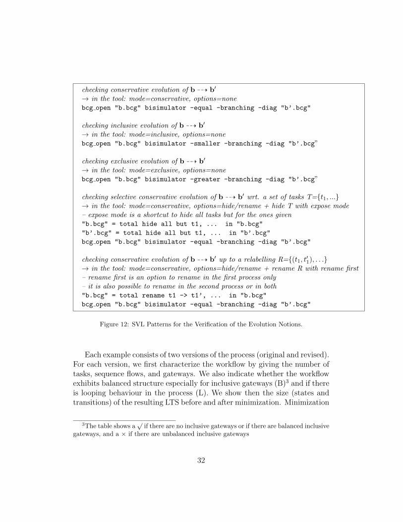
checking conservative evolution of b 99K b′
→ in the tool: mode=conservative, options=nonebcg open "b.bcg" bisimulator -equal -branching -diag "b’.bcg"
checking inclusive evolution of b 99K b′
→ in the tool: mode=inclusive, options=nonebcg open "b.bcg" bisimulator -smaller -branching -diag "b’.bcg”
checking exclusive evolution of b 99K b′
→ in the tool: mode=exclusive, options=nonebcg open "b.bcg" bisimulator -greater -branching -diag "b’.bcg”
checking selective conservative evolution of b 99K b′ wrt. a set of tasks T={t1, ...}→ in the tool: mode=conservative, options=hide/rename + hide T with expose mode– expose mode is a shortcut to hide all tasks but for the ones given"b.bcg" = total hide all but t1, ... in "b.bcg"
"b’.bcg" = total hide all but t1, ... in "b’.bcg"
bcg open "b.bcg" bisimulator -equal -branching -diag "b’.bcg"
checking conservative evolution of b 99K b′ up to a relabelling R={(t1, t′1), . . .}→ in the tool: mode=conservative, options=hide/rename + rename R with rename first– rename first is an option to rename in the first process only– it is also possible to rename in the second process or in both"b.bcg" = total rename t1 -> t1’, ... in "b.bcg"
bcg open "b.bcg" bisimulator -equal -branching -diag "b’.bcg"
Figure 12: SVL Patterns for the Verification of the Evolution Notions.
Each example consists of two versions of the process (original and revised).For each version, we first characterize the workflow by giving the number oftasks, sequence flows, and gateways. We also indicate whether the workflowexhibits balanced structure especially for inclusive gateways (B)3 and if thereis looping behaviour in the process (L). We show then the size (states andtransitions) of the resulting LTS before and after minimization. Minimization
3The table shows a√
if there are no inclusive gateways or if there are balanced inclusivegateways, and a × if there are unbalanced inclusive gateways
32
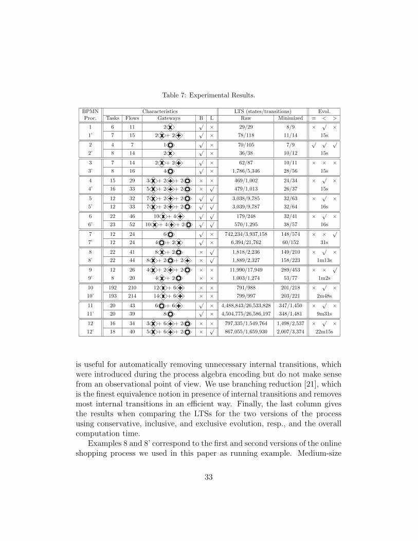
Table 7: Experimental Results.
BPMN Characteristics LTS (states/transitions) Evol.Proc. Tasks Flows Gateways B L Raw Minimized ≡ < >
1 6 11 2√× 29/29 8/9 ×
√×
1’ 7 15 2 + 2√× 78/118 11/14 15s
2 4 7 1√× 70/105 7/9
√ √ √
2’ 8 14 2√× 36/38 10/12 15s
3 7 14 2 + 2√× 62/87 10/11 × × ×
3’ 8 16 4√× 1,786/5,346 28/56 15s
4 15 29 3 + 2 + 2 × × 469/1,002 24/34 ×√×
4’ 16 33 5 + 2 + 2 ×√
479/1,013 26/37 15s
5 12 32 7 + 2 + 2√ √
3,038/9,785 32/63 ×√×
5’ 12 33 7 + 2 + 2√ √
3,039/9,787 32/64 16s
6 22 46 10 + 4√ √
179/248 32/41 ×√×
6’ 23 52 10 + 4 + 2√ √
570/1,295 38/57 16s
7 12 24 6√× 742,234/3,937,158 148/574 × ×
√
7’ 12 24 4 + 2√× 6,394/21,762 60/152 31s
8 22 41 8 + 2 ×√
1,818/2,236 149/210 ×√×
8’ 22 44 8 + 2 + 2 ×√
1,889/2,327 158/223 1m13s
9 12 26 4 + 2 + 2 × × 11,990/17,949 289/453 × ×√
9’ 8 20 4 + 2 × × 1,003/1,274 53/77 1m2s
10 192 210 12 + 6 × × 791/988 201/218 ×√×
10’ 193 214 14 + 6 × × 799/997 203/221 2m48s
11 20 43 6 + 6√× 4,488,843/26,533,828 347/1,450 ×
√×
11’ 20 39 8√× 4,504,775/26,586,197 348/1,481 9m31s
12 16 34 3 + 6 + 2 × × 797,335/1,549,764 1,498/2,537 ×√×
12’ 18 40 5 + 6 + 2 ×√
867,055/1,659,930 2,007/3,374 22m15s
is useful for automatically removing unnecessary internal transitions, whichwere introduced during the process algebra encoding but do not make sensefrom an observational point of view. We use branching reduction [21], whichis the finest equivalence notion in presence of internal transitions and removesmost internal transitions in an efficient way. Finally, the last column givesthe results when comparing the LTSs for the two versions of the processusing conservative, inclusive, and exclusive evolution, resp., and the overallcomputation time.
Examples 8 and 8’ correspond to the first and second versions of the onlineshopping process we used in this paper as running example. Medium-size
33
examples (e.g., example 7) can result in quite huge LTSs involving millionsof states and transitions. This is due to our choice to show processes in thetable containing several parallel and inclusive gateways, in most cases nested,which result in many possible interleaved executions in the correspondingLTSs. In contrast, example 10/10’ involves about 200 tasks but exhibitsa quite sequential structure, and then the generated LTSs are very small(less than a thousand states and transitions). Another comment concernsthe considerable drop in size of the LTSs before and after minimization.Example 3’ for example goes from about 2,000 states/5,000 transitions toabout 30 states/60 transitions. This drastic reduction is due to all sequenceflow actions encoded in LNT for respecting the BPMN original semantics.They do not have any special meaning per se, and are therefore hidden andremoved by reduction.
As far as computation times are concerned, we observe that the final col-umn of Table 7 gives the overall time, that is, the time for generating bothLTSs, minimizing and comparing them. The comparison time is negligible.It takes 568 seconds (9 minutes and 28 seconds) for instance for generatingand minimizing both LTSs for examples 11 and 11’, and only 3 seconds forcomparing both LTSs wrt. the three evolution notions considered in the ta-ble. Note that for processes involving unbalanced inclusive gateways, thetime importantly increases for generating corresponding LTSs compared tobalanced workflows. This is the case between example 12/12’ which takesmore than 10 minutes for generating an LTS consisting of about 1 million ofstates/transitions whereas example 11/11’ results in less than 10 minutes toobtain an LTS containing about 4 millions of states and 26 millions of tran-sitions. This drastic fall-down in performance comes from the LNT encodingfor unbalanced workflows, which induces extra-computations during the LTSgeneration process. On a wider scale, computation times remain reasonable(about half an hour for all the examples shown in Table 7) even for LTSscontaining millions of states and transitions.
6. Related Work
The absence of a single accepted modelling notation for business pro-cesses, raised the need to find ways to relate models written using differentnotations. The Workflow Pattern Initiative, see, e.g, [14], has addressed thisissue by caracterizing the atomic patterns one may find in business processes.A correspondence between these patterns and some workflow languages, in-
34

cluding BPMN, UML AD, and EPC, can be found on their Web site. Further,the BPMN standard itself refers to workflow patterns for its notational el-ements. Several general ontologies for business process modelling have alsobeen proposed, a comprehensive one being BPMO [28]4. PIF is simpler thanBPMO. It originates from a previous intermediate format we had defined,CIF [9]. Its objective is neither to be a comprehensive set of all conceptsfound in workflows, nor to support automated mapping between notationsin their whole. Rather, it is focused on a subset of common concepts foundin the three main business process notations that support a formal treatmentin order to achieve different formal analyses of business processes.
Several works have focused on providing formal semantics and verificationtechniques for business processes using Petri nets, process algebras, abstractstate machines, or rewriting logic. There was a significant effort aimed atproviding formal semantics and verification techniques for business processesusing Petri nets, see, e.g., [30, 31, 5, 32, 33]. To the best of our knowledge,none of these works focus on the formal comparison and evolution of pro-cesses. As far as rewriting logic is concerned, in [34], the authors proposea translation of BPMN into rewriting logic with a special focus on data ob-jects and data-based decision gateways. They provide new mechanisms toavoid structural issues in workflows such as flow divergence by introducingthe notion of well-formed BPMN process. Their approach aims at avoidingincorrect syntactic patterns whereas we propose automated analysis at thesemantic level. Rewriting logic is also used in [16] for analyzing BPMN pro-cesses with time using simulation, reachability analysis, and model checkingto evaluate timing properties such as degree of parallelism and minimum/-maximum processing times. We focus on behavioural and not on time anal-ysis here.
Let us now concentrate on those using process algebras for formalizingand verifying BPMN processes, which are the most related to the approachpresented in this paper. The authors of [6] present a formal semantics forBPMN by encoding it into the CSP process algebra. They show in [35] howthis semantic model can be used to verify compatibility between businessparticipants in a collaboration. This work was extended in [36] to proposea timed semantics of BPMN with delays. [37, 38] focus on the semantics
4Indeed (a quite old) one of these ontologies is named PIF [29]. We were not aware ofit when we began working on (our) PIF.
35
proposed in [6, 36] and propose an automated transformation from BPMNto timed CSP. In a previous work [9], we have proposed a first transformationfrom BPMN to LNT, targeted at checking the realizability of a BPMN chore-ography. We followed a state machine pattern for representing workflows,while we here encode them in a way close to Petri net firing semantics, whichfavours compositionality and is more natural for a workflow-based languagesuch as BPMN. In [33], the authors propose a new operational semanticsof a subset of BPMN focusing on collaboration diagrams and message ex-change. The BPMN subset is quite restricted (no support of the inclusivemerge gateway for instance) and no tool support is provided yet. Comparedto the approaches above, our encoding also gives a semantics to the consid-ered BPMN subset by translation to LNT, although it was not our primarygoal. The main difference with respect to these related works is our focus onthe evolution of processes and its automated analysis.
In the rest of this section, we present existing approaches for compar-ing several BPMN processes (or workflows). In [39], the author proposesa theoretical framework for comparing BPMN processes. His main focus issubstitutability and therefore he explores various sorts of behavioural equiv-alences in order to replace equals for equals. This work applies at the BPMNlevel and aims at detecting equivalent patterns in processes. In a relatedline of works, [40] studies BPMN behaviours from a semantic point of view.It presents several BPMN patterns and structures that are syntactically dif-ferent but semantically equivalent. This work is not theoretically groundedand is not complete in the sense that only a few patterns are tackled. Thenotion of equivalence is similar to the one used in [39]. The authors of [40]also overview best practices that can be used as guidelines by modelers foravoiding syntactic discrepancies in equivalent process models. Compared toour approach, this work only studies strong notions of equivalence where thebehaviour is preserved in an identical manner. We consider a similar no-tion here, but we also propose weaker notions because one can make deeperchanges (e.g., by introducing new tasks) and in these cases such strong equiv-alences cannot be preserved.
In Chapter 9 of [41], the authors study the evolution of processes from amigration point of view. They define several notions of evolution, migration,and refactoring. Our goal here is rather complementary since we have studiedthe impact of modifying a workflow wrt. a former version of this workflowon low-level formal models, but we do not propose any solutions for applyingthese changes on a running instance of that initial workflow. In [42], the
36

authors address the equivalence or alignment of two process models. To doso, they check whether correspondences exist between a set of activities inone model and a set of activities in the other model. They consider Petrinet systems as input and process graphs as low-level formalism for analysispurposes. Their approach resides in the identification of regions (set of activ-ities) in each graph that can coincide with respect to an equivalence notion.They particularly study two equivalence notions, namely trace and branch-ing equivalences. The main limit of this approach is that it does not workin the presence of overlapping correspondences, meaning that in some cases,the input models cannot be analyzed. This work shares similarities with ourapproach, in particular the use of low-level graph models, hiding techniquesand behavioural equivalences for comparing models. Still, our approach al-ways provides a result and considers new notions of model correspondencesuch as property-aware evolution.
It is worth mentioning another line of work aiming at measuring thedegree of similarity of business process models, see, e.g., [43, 44]. As anexample, [43] achieves this goal first using causal footprints as an abstractrepresentation of the behaviour captured by a process model. Then, giventwo footprints, the similarity is computed using the vector space model ap-proach from information filtering and retrieval. In this paper, we chose adifferent angle of this question by studying qualitative aspects of processesinstead of quantitative aspects.
This article is an extended version of a conference paper published in [45].The key additions of this journal version are as follows: (i) an improvementof our process algebra encoding to support unbalanced workflows, (ii) theextension of our tool support, and particularly of the Web application, tosupport comparison analysis as well as model checking of business processes,(iii) the extensive validation of our approach on a large set of case studies,most of them taken from the literature on this topic, and (iv) a refined reviewand comparison with related work.
7. Conclusion
We have introduced our approach for checking the evolution of BPMNprocesses. To promote its adoption by business process designers, we haveimplemented it in a tool, VBPMN [2], that can be used through a Web ap-plication. We have presented different kinds of atomic evolutions that canbe combined and formally verified. We have defined a BPMN to LNT model
37
transformation, which, using the LTS operational semantics of LNT enablesus to automate our approach using existing LTS-based verification tools. Thistranslation to LNT supports exclusive, inclusive and parallel gateways (in-cluding different semantics of inclusive merge gateways), looping behaviours,and unbalanced structure of workflows. We have applied our approach tomany examples for evaluation purposes. The experimental results shown inthis paper confirm that our tool is rather efficient since it can handle quitelarge examples within a reasonable amount of time.
As far as perspectives are concerned, let us mention the main ones.Larger subset of the BPMN standard. BPMN has three main kinds ofmodels: processes, collaborations, and choreographies. In this work we sup-port the first ones, at the descriptive conformance sub-class level, withoutsub-processes and data, but with inclusive gateways. We plan to extend oursupport to sub-processes (with boundary events to deal with errors and com-pensations) and data (to deal with conditional flows). As far as other kindsof models are concerned, collaborations where only one process evolves canbe supported using context-aware evolution, one of the evolution relationswe propose. The extension to full-fledged collaborations could be possiblethrough the transformation of each process in the collaboration and by re-lating communication tasks (synchronously or using buffers for asynchronouscommunication). The extension to choreography is possible by adding chore-ography tasks in PIF and treating them as basic observable atoms in the be-havioural equivalences and inclusion relations. However, based on our pastexperience on choreography verification [9], we believe that specific evolutionsrelations could be defined for choreographies.Patterns of properties. When the analyst wants to check model-specificproperties on the processes, they have to be input directly using the MCLtemporal logic. The reuse of well-known patterns for properties such as thosepresented in [22], and the automation of a translation from such patterns tothe MCL temporal logic would clearly help there.Enhanced feed-back. Diagnoses are returned to the designers in the formof low-level counter-examples (LTSs). This could be enhanced by presentingthis information directly on the BPMN models, e.g. using animation.New front- and back-ends. In the implementation of our BPMN toLNT transformation, we rely on an intermediate format including the mainworkflow-based constructs. This paves the way for new front-end DSLs andother back-end verification techniques. Another perspective of this work is
38

to propose quantitative analysis for comparing business processes as stud-ied in [43, 44]. Our goal is thus to consider non-functional requirements inBPMN processes, such as the throughput and latency of tasks, which canbe modelled by extending LTSs with Markovian information and computedusing steady-state analysis [46].
References
[1] H. Garavel, F. Lang, SVL: A Scripting Language for CompositionalVerification, in: Proc. of FORTE’01, 2001, pp. 377–394.
[2] VBPMN Framework., https://pascalpoizat.github.io/vbpmn-web/.
[3] OMG, Business Process Model and Notation (BPMN) – Version 2.0,january 2011.
[4] ISO/IEC, International Standard 19510, Information technology – Busi-ness Process Model and Notation, 2013.
[5] R. Dijkman, M. Dumas, C. Ouyang, Semantics and Analysis of BusinessProcess Models in BPMN, Inf. Softw. Technol. 50 (12) (2008) 1281–1294.
[6] P. Wong, J. Gibbons, A Process Semantics for BPMN, in: Proc. ofICFEM’08, 2008, pp. 355–374.
[7] F. Kossak, C. Illibauer, V. Geist, J. Kubovy, C. Natschlager, T. Zieber-mayr, T. Kopetzky, B. Freudenthaler, K. Schewe, A Rigorous Semanticsfor BPMN 2.0 Process Diagrams, Springer, 2014.
[8] R. Mateescu, G. Salaun, L. Ye, Quantifying the Parallelism in BPMNProcesses using Model Checking, in: Proc. of CBSE’14, 2014, pp. 159–168.
[9] M. Gudemann, P. Poizat, G. Salaun, L. Ye, VerChor: A Frameworkfor the Design and Verification of Choreographies, IEEE Trans. ServicesComputing 9 (4) (2016) 647–660.
[10] J. Koehler, J. Vanhatalo, Process Anti-patterns: How to Avoid the Com-mon Traps of Business Process Modeling, Tech. rep., iBM Research Re-port 3678 (2007).
39
[11] M. Dam, Model Checking Mobile Processes, in: Proc. of CONCUR’93,Vol. 715 of LNCS, Springer, 1993, pp. 22–36.
[12] D. Fahland, C. Favre, B. Jobstmann, J. Koehler, N. Lohmann,H. Volzer, K. Wolf, Instantaneous soundness checking of industrial busi-ness process models, in: Proc. of BPM’09, Vol. 5701 of LNCS, Springer,2009, pp. 278–293.
[13] H. N. Nguyen, P. Poizat, F. Zaıdi, A Symbolic Framework for the Con-formance Checking of Value-Passing Choreographies, in: Proc. of IC-SOC’12, 2012, pp. 525–532.
[14] W. van der Aalst, A. ter Hofstede, B. Kiepuszewski, A. Barros, WorkflowPatterns, Distributed and Parallel Databases 14 (3) (2003) 5–51.
[15] M. C. Cornax, A. Krishna, A. Mos, G. Salaun, Automated Analysis ofIndustrial Workflow-based Models, in: Proc. of SAC’18, ACM Press,2018.
[16] F. Duran, G. Salaun, Verifying Timed BPMN Processes using Maude,in: Proc. of COORDINATION, Vol. 10319 of LNCS, Springer, 2017, pp.219–236.
[17] D. Champelovier, X. Clerc, H. Garavel, Y. Guerte, F. Lang, C. McKinty,V. Powazny, W. Serwe, G. Smeding, Reference Manual of the LNT toLOTOS Translator, Version 6.7., Inria, 2018.
[18] ISO, LOTOS — A Formal Description Technique Based on the TemporalOrdering of Observational Behaviour, Tech. Rep. 8807, ISO (1989).
[19] H. Garavel, F. Lang, R. Mateescu, W. Serwe, CADP 2011: A Toolboxfor the Construction and Analysis of Distributed Processes, STTT 2 (15)(2013) 89–107.
[20] D. R. Christiansen, M. Carbone, T. T. Hildebrandt, Formal Semanticsand Implementation of BPMN 2.0 Inclusive Gateways, in: Proc. of WS-FM’10, Vol. 6551 of LNCS, Springer, 2011, pp. 146–160.
[21] R. J. van Glabbeek, W. P. Weijland, Branching Time and Abstractionin Bisimulation Semantics, J. ACM 43 (3) (1996) 555–600.
40

[22] M. B. Dwyer, G. S. Avrunin, J. C. Corbett, Patterns in Property Speci-fications for Finite-State Verification, in: Proc. of ICSE’99, ACM, 1999,pp. 411–420.
[23] A. Arnold, Finite Transition Systems - Semantics of CommunicatingSystems, Prentice Hall, 1994.
[24] D. Brand, P. Zafiropulo, On Communicating Finite-State Machines, J.ACM 30 (2) (1983) 323–342.
[25] R. Mateescu, D. Thivolle, A Model Checking Language for ConcurrentValue-Passing Systems, in: Proc. of FM’08, Vol. 5014 of LNCS, Springer,2008, pp. 148–164.
[26] ProM Framework, http://www.processmining.org/prom.
[27] W. M. P. van der Aalst, The Application of Petri Nets to WorkflowManagement, Journal of Circuits, Systems, and Computers 8 (1) (1998)21–66.
[28] Z. Yan, E. Cimpian, M. Zaremba, M. Mazzara, Semantic Business Pro-cess Modeling and WSMO Extension, in: Proc. of ICWS’07, 2007, pp.1185–1186.
[29] J. Lee, G. Yost, the PIF Working Group, The PIF process interchangeformat and framework, Tech. rep., MIT Center for Coordination Science(1994).
[30] A. Martens, Analyzing Web Service Based Business Processes, in: Proc.of FASE’05, Vol. 3442 of LNCS, Springer, 2005, pp. 19–33.
[31] G. Decker, M. Weske, Interaction-centric Modeling of Process Chore-ographies, Information Systems 36 (2) (2011) 292–312.
[32] I. Raedts, M. Petkovic, Y. S. Usenko, J. M. van der Werf, J. F. Groote,L. Somers, Transformation of BPMN Models for Behaviour Analysis, in:Proc. of MSVVEIS’07, 2007, pp. 126–137.
[33] F. Corradini, A. Polini, B. Re, F. Tiezzi, An Operational Semanticsof BPMN Collaboration, in: Proc. of FACS’15, Vol. 9539 of LNCS,Springer, 2015, pp. 161–180.
41

[34] N. El-Saber, A. Boronat, BPMN Formalization and Verification usingMaude, in: Proc. of BM-FA, ACM, 2014, pp. 1–8.
[35] P. Wong, J. Gibbons, Verifying Business Process Compatibility, in:Proc. of QSIC’08, 2008, pp. 126–131.
[36] P. Y. H. Wong, J. Gibbons, A Relative Timed Semantics for BPMN,Electr. Notes Theor. Comput. Sci. 229 (2) (2009) 59–75.
[37] M. I. Capel, L. E. M. Morales, Automating the Transformation fromBPMN Models to CSP+T Specifications, in: Proc. of SEW, IEEE, 2012,pp. 100–109.
[38] L. Mendoza-Morales, M. Capel, M. Perez, Conceptual Framework forBusiness Processes Compositional Verification, Inf. & Sw. Techn. 54 (2)(2012) 149–161.
[39] V. Lam, Foundation for Equivalences of BPMN Models, Theoretical andApplied Informatics 24 (1) (2012) 33–66.
[40] K. Kluza, K. Kaczor, Overview of BPMN Model Equivalences. TowardsNormalization of BPMN Diagrams, in: Proc. of KESE’12, 2012, pp.38–45.
[41] M. Reichert, B. Weber, Enabling Flexibility in Process-Aware Informa-tion Systems - Challenges, Methods, Technologies, Springer, 2012.
[42] M. Weidlich, R. M. Dijkman, M. Weske, Behaviour Equivalence andCompatibility of Business Process Models with Complex Correspon-dences, Comput. J. 55 (11) (2012) 1398–1418.
[43] B. F. van Dongen, R. M. Dijkman, J. Mendling, Measuring Similaritybetween Business Process Models, in: Proc. of CAISE’08, 2008, pp.450–464.
[44] A. K. A. de Medeiros, W. M. P. van der Aalst, A. J. M. M. Weijters,Quantifying Process Equivalence Based on Observed Behavior, DataKnowl. Eng. 64 (1) (2008) 55–74.
[45] P. Poizat, G. Salaun, A. Krishna, Checking Business Process Evolution,in: Proc. of FACS’16, Vol. 10231 of LNCS, Springer, 2016, pp. 36–53.
42

[46] N. Coste, H. Garavel, H. Hermanns, F. Lang, R. Mateescu, W. Serwe,Ten Years of Performance Evaluation for Concurrent Systems usingCADP, in: Proc. of ISoLA’10, 2010, pp. 128–142.
43
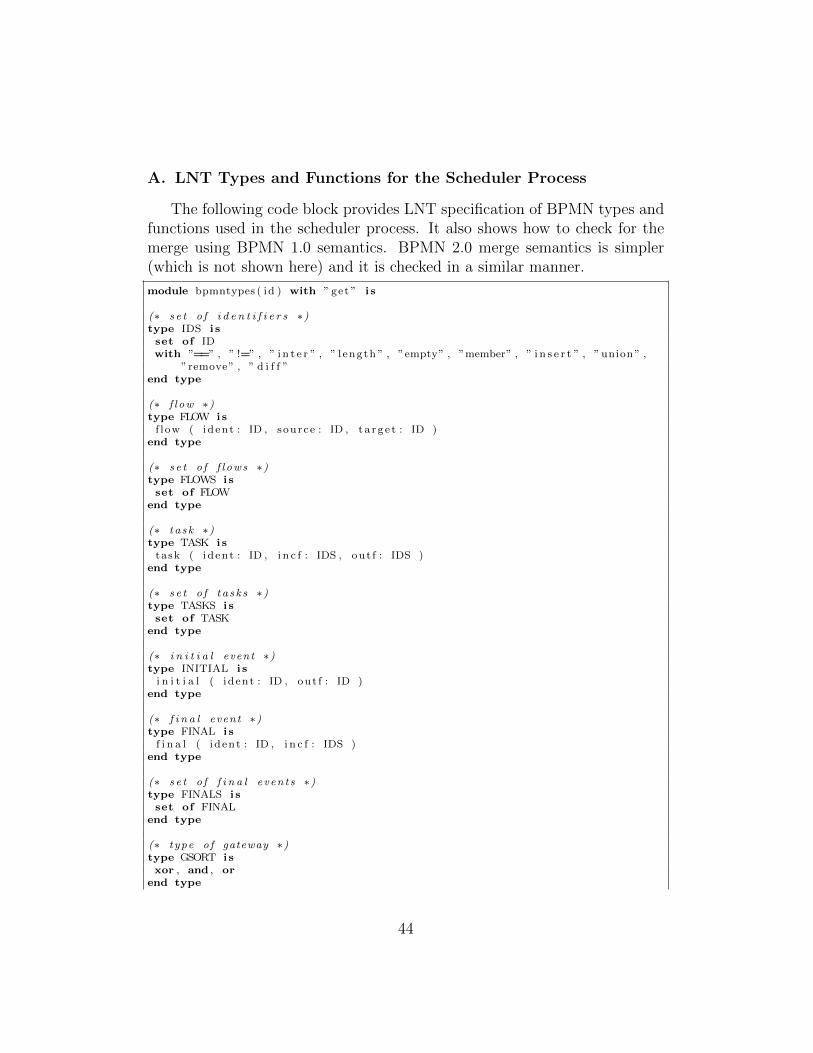
A. LNT Types and Functions for the Scheduler Process
The following code block provides LNT specification of BPMN types andfunctions used in the scheduler process. It also shows how to check for themerge using BPMN 1.0 semantics. BPMN 2.0 merge semantics is simpler(which is not shown here) and it is checked in a similar manner.
module bpmntypes ( id ) with ” get ” i s
(∗ s e t o f i d e n t i f i e r s ∗)type IDS i sset of IDwith ”==” , ” !=” , ” i n t e r ” , ” l ength ” , ”empty” , ”member” , ” i n s e r t ” , ” union ” ,
”remove” , ” d i f f ”end type
(∗ f l ow ∗)type FLOW i s
f l ow ( ident : ID , source : ID , t a r g e t : ID )end type
(∗ s e t o f f l ows ∗)type FLOWS i sset of FLOW
end type
(∗ t a s k ∗)type TASK i s
task ( ident : ID , i n c f : IDS , out f : IDS )end type
(∗ s e t o f t a s k s ∗)type TASKS i sset of TASK
end type
(∗ i n i t i a l event ∗)type INITIAL i s
i n i t i a l ( ident : ID , out f : ID )end type
(∗ f i n a l event ∗)type FINAL i s
f i n a l ( ident : ID , i n c f : IDS )end type
(∗ s e t o f f i n a l even t s ∗)type FINALS i sset of FINAL
end type
(∗ type o f gateway ∗)type GSORT i sxor , and , or
end type
44

(∗ gateway pa t t e rn ∗)type GPATTERN i s
s p l i t , mergeend type
(∗ gateway ∗)type GATEWAY i s
gateway ( ident : ID , pattern : GPATTERN, s o r t : GSORT, i n c f : IDS , out f : IDS )end type
(∗ s e t o f gateways ∗)type GATEWAYS i sset of GATEWAY
end type
(∗ node ∗)type NODE i s
i ( i n i t i a l : INITIAL ) ,f ( f i n a l s : FINALS ) ,g ( gateways : GATEWAYS ) ,t ( ta sk s : TASKS )
end type
(∗ s e t o f nodes ∗)type NODES i sset of NODE
end type
(∗ bpmn−proc ∗)type BPROCESS i s
proc ( name : ID , nodes : NODES, f l ows : FLOWS )end type
(∗ Check fo r merge with BPMN 1. x semantics ∗)function i s m e r g e p o s s i b l e (p : BPROCESS, a c t i v e f l o w s : IDS , mergeid : ID) : Bool
i svar i n c f : IDS , i n a c t i v e i n c f : IDS , ac t ive merge : Nat , v i s i t e d : IDS , r e s u l t :
Bool inv i s i t e d := n i l ;(∗ j u s t i t e r a t e through gateways ∗)i n c f := f i n d i n c f (p , mergeid ) ;act ive merge := f i n d a c t i v e t o k e n s ( a c t i v e f l o w s , i n c f ) ;(∗−−check i f a l l the i n c f have tokens−−∗)i f ( ac t ive merge == length ( i n c f ) ) thenreturn True
else(∗ f i r s t remove i n c f wi th a c t i v e tokens ∗)i n a c t i v e i n c f := r emove id s f r om se t ( a c t i v e f l o w s , i n c f ) ;(∗ then check upstream for remaining f l ows ∗)eval r e s u l t := check a f upstream ( ! ? v i s i t e d , p , a c t i v e f l o w s ,
i n a c t i v e i n c f ) ;return r e s u l t
end i fend var
end function
45
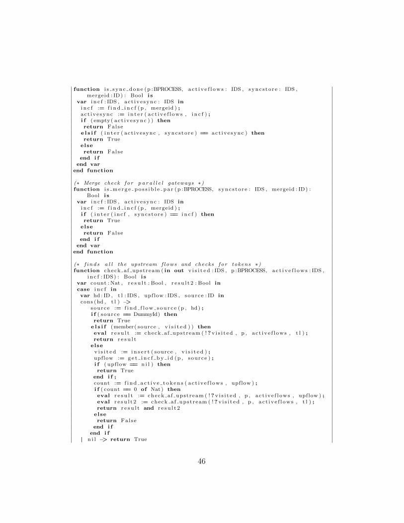
function i s s y n c d o n e (p :BPROCESS, a c t i v e f l o w s : IDS , sync s to r e : IDS ,mergeid : ID) : Bool i s
var i n c f : IDS , a c t i v e sync : IDS ini n c f := f i n d i n c f (p , mergeid ) ;ac t i v e sync := i n t e r ( a c t i v e f l o w s , i n c f ) ;i f ( empty ( ac t i v e sync ) ) thenreturn False
e l s i f ( i n t e r ( act ivesync , sync s to r e ) == ac t i v e sync ) thenreturn True
elsereturn False
end i fend var
end function
(∗ Merge check f o r p a r a l l e l gateways ∗)function i s m e r g e p o s s i b l e p a r (p :BPROCESS, sync s to r e : IDS , mergeid : ID) :
Bool i svar i n c f : IDS , a c t i v e sync : IDS in
i n c f := f i n d i n c f (p , mergeid ) ;i f ( i n t e r ( i n c f , s ync s to r e ) == i n c f ) thenreturn True
elsereturn False
end i fend var
end function
(∗ f i n d s a l l the upstream f l ows and checks f o r tokens ∗)function check a f upstream ( in out v i s i t e d : IDS , p :BPROCESS, a c t i v e f l o w s : IDS ,
i n c f : IDS) : Bool i svar count : Nat , r e s u l t : Bool , r e s u l t 2 : Bool incase i n c f invar hd : ID , t l : IDS , upflow : IDS , source : ID incons (hd , t l ) −>
source := f i n d f l o w s o u r c e (p , hd) ;i f ( source == DummyId) thenreturn True
e l s i f (member( source , v i s i t e d ) ) theneval r e s u l t := check a f upstream ( ! ? v i s i t e d , p , a c t i v e f l o w s , t l ) ;return r e s u l t
elsev i s i t e d := i n s e r t ( source , v i s i t e d ) ;upflow := g e t i n c f b y i d (p , source ) ;i f ( upflow == n i l ) thenreturn True
end i f ;count := f i n d a c t i v e t o k e n s ( a c t i v e f l o w s , upflow ) ;i f ( count == 0 of Nat ) theneval r e s u l t := check a f upstream ( ! ? v i s i t e d , p , a c t i v e f l o w s , upflow ) ;eval r e s u l t 2 := check a f upstream ( ! ? v i s i t e d , p , a c t i v e f l o w s , t l ) ;return r e s u l t and r e s u l t 2
elsereturn False
end i fend i f
| n i l −> return True
46
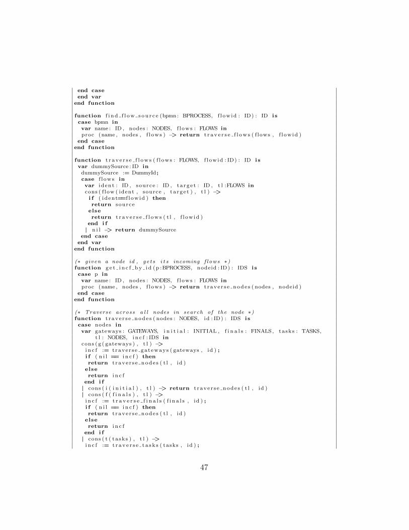
end caseend var
end function
function f i n d f l o w s o u r c e (bpmn : BPROCESS, f l ow id : ID) : ID i scase bpmn invar name : ID , nodes : NODES, f l ows : FLOWS inproc (name , nodes , f l ows ) −> return t r a v e r s e f l o w s ( f lows , f l ow id )
end caseend function
function t r a v e r s e f l o w s ( f l ows : FLOWS, f l ow id : ID) : ID i svar dummySource : ID in
dummySource := DummyId ;case f l ows invar i d ent : ID , source : ID , t a r g e t : ID , t l :FLOWS incons ( f low ( ident , source , t a r g e t ) , t l ) −>i f ( ident==f l ow id ) thenreturn source
elsereturn t r a v e r s e f l o w s ( t l , f l ow id )
end i f| n i l −> return dummySource
end caseend var
end function
(∗ g iven a node id , g e t s i t s incoming f l ows ∗)function g e t i n c f b y i d (p :BPROCESS, nodeid : ID) : IDS i scase p invar name : ID , nodes : NODES, f l ows : FLOWS inproc (name , nodes , f l ows ) −> return t r a v e r s e n o d e s ( nodes , nodeid )
end caseend function
(∗ Traverse across a l l nodes in search o f the node ∗)function t r a v e r s e n o d e s ( nodes : NODES, id : ID) : IDS i scase nodes invar gateways : GATEWAYS, i n i t i a l : INITIAL , f i n a l s : FINALS , ta sk s : TASKS,
t l : NODES, i n c f : IDS incons ( g ( gateways ) , t l ) −>
i n c f := t rave r s e ga t eways ( gateways , id ) ;i f ( n i l == i n c f ) thenreturn t r a v e r s e n o d e s ( t l , id )
elsereturn i n c f
end i f| cons ( i ( i n i t i a l ) , t l ) −> return t r a v e r s e n o d e s ( t l , id )| cons ( f ( f i n a l s ) , t l ) −>
i n c f := t r a v e r s e f i n a l s ( f i n a l s , id ) ;i f ( n i l == i n c f ) thenreturn t r a v e r s e n o d e s ( t l , id )
elsereturn i n c f
end i f| cons ( t ( ta sk s ) , t l ) −>
i n c f := t r a v e r s e t a s k s ( tasks , id ) ;
47
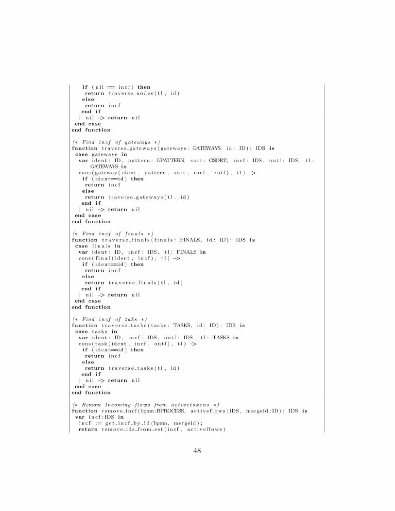
i f ( n i l == i n c f ) thenreturn t r a v e r s e n o d e s ( t l , id )
elsereturn i n c f
end i f| n i l −> return n i l
end caseend function
(∗ Find i n c f o f gateways ∗)function t rave r s e ga t eways ( gateways : GATEWAYS, id : ID) : IDS i scase gateways invar i d ent : ID , pattern : GPATTERN, s o r t : GSORT, i n c f : IDS , out f : IDS , t l :
GATEWAYS incons ( gateway ( ident , pattern , sor t , i n c f , out f ) , t l ) −>i f ( ident==id ) thenreturn i n c f
elsereturn t rave r s e ga t eways ( t l , id )
end i f| n i l −> return n i l
end caseend function
(∗ Find i n c f o f f i n a l s ∗)function t r a v e r s e f i n a l s ( f i n a l s : FINALS , id : ID) : IDS i scase f i n a l s invar i d ent : ID , i n c f : IDS , t l : FINALS incons ( f i n a l ( ident , i n c f ) , t l ) −>i f ( ident==id ) thenreturn i n c f
elsereturn t r a v e r s e f i n a l s ( t l , id )
end i f| n i l −> return n i l
end caseend function
(∗ Find i n c f o f t ak s ∗)function t r a v e r s e t a s k s ( ta sk s : TASKS, id : ID) : IDS i scase ta sk s invar i d ent : ID , i n c f : IDS , out f : IDS , t l : TASKS incons ( task ( ident , i n c f , out f ) , t l ) −>i f ( ident==id ) thenreturn i n c f
elsereturn t r a v e r s e t a s k s ( t l , id )
end i f| n i l −> return n i l
end caseend function
(∗ Remove Incoming f l ows from ac t i v e t o k en s ∗)function r emove inc f (bpmn :BPROCESS, a c t i v e f l o w s : IDS , mergeid : ID) : IDS i svar i n c f : IDS in
i n c f := g e t i n c f b y i d (bpmn, mergeid ) ;return r emove id s f r om se t ( i n c f , a c t i v e f l o w s )
48
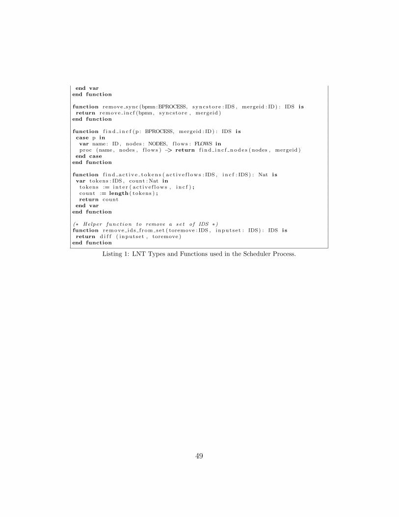
end varend function
function remove sync (bpmn :BPROCESS, sync s to r e : IDS , mergeid : ID) : IDS i sreturn r emove inc f (bpmn, syncs tore , mergeid )
end function
function f i n d i n c f (p : BPROCESS, mergeid : ID) : IDS i scase p invar name : ID , nodes : NODES, f l ows : FLOWS inproc (name , nodes , f l ows ) −> return f i n d i n c f n o d e s ( nodes , mergeid )
end caseend function
function f i n d a c t i v e t o k e n s ( a c t i v e f l o w s : IDS , i n c f : IDS) : Nat i svar tokens : IDS , count : Nat in
tokens := i n t e r ( a c t i v e f l o w s , i n c f ) ;count := length ( tokens ) ;return count
end varend function
(∗ Helper func t i on to remove a s e t o f IDS ∗)function r emove id s f r om se t ( toremove : IDS , i nput s e t : IDS) : IDS i sreturn d i f f ( inputset , toremove )
end function
Listing 1: LNT Types and Functions used in the Scheduler Process.
49