Chapter 4 Airport Capacity Assessment and Identification of ...
34
Peter O. Knight Airport Master Plan Update 1 Chapter 4 Airport Capacity Assessment and Identification of Facility Needs 4.1 Introduction The purpose of the airport capacity assessment and identification of facility needs is to evaluate the two runway airfield system and supporting landside facilities to accommodate existing and future projected aviation activity at Peter O. Knight Airport (TPF). The airport capacity assessment serves to identify annual service volume and hourly capacity, as well as aircraft operational delay for future airport operations planning. Airfield design standards will also be reviewed to identify current design standards and future needs. Facility requirements for current and future aviation demand will also be evaluated. 4.2 Quantification of Airfield Capacity 4.2.1 Approach and Methodology Airfield capacity analysis provides a numerical metric measure of the airfield’s ability to accommodate the safe and efficient movement of aircraft activities. The capacity of the airfield is primarily affected by several factors that include the physical layout of the airfield, local prevailing meteorological conditions, aircraft fleet mix, runway utilization rates, percent of aircraft arrivals to each runway, relative level of aircraft touch-and-go activity on one or more of an airport’s runways, and the location of exit taxiways relative to the approach end of the runway. An airport’s airfield capacity is expressed in terms of Annual Service Volume (ASV) and represents a reasonable estimate of the maximum level of aircraft operations that can be accommodated in a year without induced aircraft operational delay. 4.2.2 Annual Service Volume and Hourly Capacity The ability of the airport’s runway system to accommodate existing and future levels of operational demand was determined by the use of published FAA guidelines as detailed in FAA AC 150/5060-5, Airport Capacity and Delay. The aircraft fleet mix for TPF during 2013 was determined using based aircraft information provided by HCAA and Flightwise.com data from January to December 2013. Based on the data, it is estimated that Class A and Class B aircraft comprise 100 percent of aircraft operations. The FAA’s handbook methodology uses the term “Mix Index” to describe an airport’s fleet mix. The FAA defines the Mix Index as the percentage of Class C operations plus three times the percentage of Class D operations. By applying this calculation to the fleet mix percentages for the Airport, a Mix Index of 0 percent is obtained per the following equation: Class C Operations (0.00%) + (3 * Class D Operations (0.00%)) = Mix Index (0.00%)
-
Upload
khangminh22 -
Category
Documents
-
view
7 -
download
0
Transcript of Chapter 4 Airport Capacity Assessment and Identification of ...
Peter O. Knight Airport
Master Plan Update 1
Chapter 4 Airport Capacity Assessment and Identification of Facility Needs 4.1 Introduction The purpose of the airport capacity assessment and identification of facility needs is to evaluate the two runway airfield system and supporting landside facilities to accommodate existing and future projected aviation activity at Peter O. Knight Airport (TPF). The airport capacity assessment serves to identify annual service volume and hourly capacity, as well as aircraft operational delay for future airport operations planning. Airfield design standards will also be reviewed to identify current design standards and future needs. Facility requirements for current and future aviation demand will also be evaluated. 4.2 Quantification of Airfield Capacity 4.2.1 Approach and Methodology Airfield capacity analysis provides a numerical metric measure of the airfield’s ability to accommodate the safe and efficient movement of aircraft activities. The capacity of the airfield is primarily affected by several factors that include the physical layout of the airfield, local prevailing meteorological conditions, aircraft fleet mix, runway utilization rates, percent of aircraft arrivals to each runway, relative level of aircraft touch-and-go activity on one or more of an airport’s runways, and the location of exit taxiways relative to the approach end of the runway. An airport’s airfield capacity is expressed in terms of Annual Service Volume (ASV) and represents a reasonable estimate of the maximum level of aircraft operations that can be accommodated in a year without induced aircraft operational delay. 4.2.2 Annual Service Volume and Hourly Capacity The ability of the airport’s runway system to accommodate existing and future levels of operational demand was determined by the use of published FAA guidelines as detailed in FAA AC 150/5060-5, Airport Capacity and Delay. The aircraft fleet mix for TPF during 2013 was determined using based aircraft information provided by HCAA and Flightwise.com data from January to December 2013. Based on the data, it is estimated that Class A and Class B aircraft comprise 100 percent of aircraft operations. The FAA’s handbook methodology uses the term “Mix Index” to describe an airport’s fleet mix. The FAA defines the Mix Index as the percentage of Class C operations plus three times the percentage of Class D operations. By applying this calculation to the fleet mix percentages for the Airport, a Mix Index of 0 percent is obtained per the following equation: Class C Operations (0.00%) + (3 * Class D Operations (0.00%)) = Mix Index (0.00%)
Peter O. Knight Airport
Master Plan Update 2
The Annual Service Volume (ASV) is a reasonable estimate of an airport’s annual capacity. ASV takes into consideration differences in runway use, aircraft mix, weather conditions, and other factors that would be encountered over a year. For TPF, the ASV is 230,000 operations per year. TPF has an hourly capacity of 98 VFR operations per hour and 59 IFR operations per hour. 4.2.3 Aircraft Operational Delay Aircraft operational delay is the difference in time between a constrained and an unconstrained aircraft operation. As the level of aircraft operations increase as a relative proportion of the calculated ASV value, aircraft operational delay increases at an increasing rate. The level of aircraft operations at TPF for the year 2013 represented approximately 26 percent of the calculated ASV, (58,918/230,000) thus indicating virtually no associated aircraft operational delay. At the end of the 20-year forecasting period (2033), this relative percentage increases to approximately 33 percent, (76,534 /230,000) continuing to reflect little or no associated aircraft operational delay. 4.2.4 Findings The aircraft operations forecast for TPF indicates that projected aircraft operations (76,534 operations annually in 2033) through the 20-year planning period are not expected to exceed the ASV (230,000 operations annually). The capacity of the airfield system will not be exceeded and will be able to fully satisfy existing and projected future aircraft operational demand for the forecast period without induced adverse effects to aircraft operations and associated aircraft operational delay. 4.3 Runway Orientation and Wind Coverage 4.3.1 Required Wind Coverage A key meteorological factor is wind direction and speed. Ideally, runways should be aligned with the prevailing wind to reduce the effects of crosswinds on landing aircraft, especially for small aircraft. A tailwind is not a favorable condition for take-off and landing. A wind analysis is conduced to insure that the runway is properly oriented to suit both VMC and IMC. 4.3.2 Crosswind Components The crosswind component of wind direction and velocity is the resultant vector which acts at a right angle to the runway. When a runway orientation provides less than 95.0 percent wind coverage for the aircraft which are forecast to use the airport on a regular basis, a crosswind runway may be required. The 95.0 percent wind coverage is computed on the basis of the crosswind component not exceeding the allowable value, per RDC. For a RDC of B-I, the allowable crosswind component is 10.5 knots. For a Runway Design Code (RDC) of B-II, the allowable crosswind component is 13 knots. Table 4-1 shows the allowable crosswind component per RDC.
Peter O. Knight Airport
Master Plan Update 3
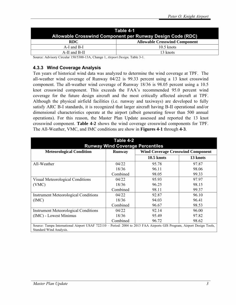
Table 4-1 Allowable Crosswind Component per Runway Design Code (RDC)
RDC Allowable Crosswind Component
A-I and B-I 10.5 knots A-II and B-II 13 knots
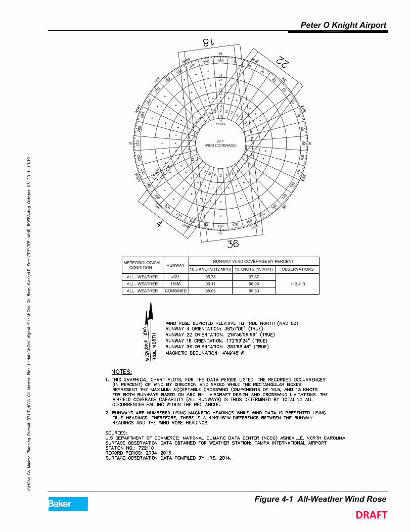
Source: Advisory Circular 150/5300-13A, Change 1, Airport Design, Table 3-1. 4.3.3 Wind Coverage Analysis Ten years of historical wind data was analyzed to determine the wind coverage at TPF. The all-weather wind coverage of Runway 04/22 is 99.33 percent using a 13 knot crosswind component. The all-weather wind coverage of Runway 18/36 is 98.05 percent using a 10.5 knot crosswind component. This exceeds the FAA’s recommended 95.0 percent wind coverage for the future design aircraft and the most critically affected aircraft at TPF. Although the physical airfield facilities (i.e. runway and taxiways) are developed to fully satisfy ARC B-I standards, it is recognized that larger aircraft having B-II operational and/or dimensional characteristics operate at the airport (albeit generating fewer than 500 annual operations). For this reason, the Master Plan Update assessed and reported the 13 knot crosswind component. Table 4-2 shows the wind coverage crosswind components for TPF. The All-Weather, VMC, and IMC conditions are show in Figures 4-1 through 4-3.
Table 4-2 Runway Wind Coverage Percentiles
Meteorological Condition Runway Wind Coverage Crosswind Component
10.5 knots 13 knots
All-Weather 04/22 18/36
Combined
95.78 96.11 98.05
97.87 98.06 99.33
Visual Meteorological Conditions (VMC)
04/22 18/36
Combined
95.93 96.25 98.11
97.97 98.15 99.37
Instrument Meteorological Conditions (IMC)
04/22 18/36
Combined
92.87 94.03 96.67
96.10 96.41 98.53
Instrument Meteorological Conditions (IMC) - Lowest Minimus
04/22 18/36
Combined
92.14 95.49 96.72
96.00 97.82 98.62
Source: Tampa International Airport USAF 722110 – Period: 2004 to 2013 FAA Airports GIS Program, Airport Design Tools, Standard Wind Analysis.


Peter O. Knight Airport
Master Plan Update 7
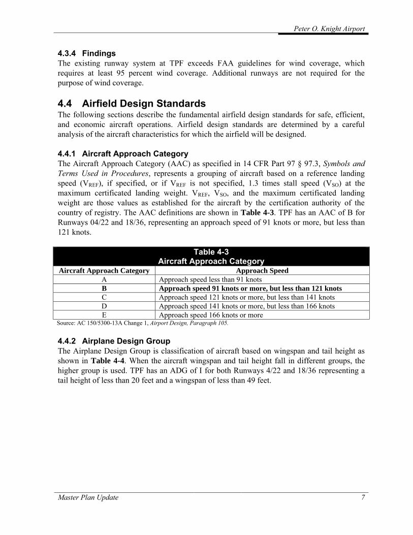
4.3.4 Findings The existing runway system at TPF exceeds FAA guidelines for wind coverage, which requires at least 95 percent wind coverage. Additional runways are not required for the purpose of wind coverage. 4.4 Airfield Design Standards The following sections describe the fundamental airfield design standards for safe, efficient, and economic aircraft operations. Airfield design standards are determined by a careful analysis of the aircraft characteristics for which the airfield will be designed. 4.4.1 Aircraft Approach Category The Aircraft Approach Category (AAC) as specified in 14 CFR Part 97 § 97.3, Symbols and Terms Used in Procedures, represents a grouping of aircraft based on a reference landing speed (VREF), if specified, or if VREF is not specified, 1.3 times stall speed (VSO) at the maximum certificated landing weight. VREF, VSO, and the maximum certificated landing weight are those values as established for the aircraft by the certification authority of the country of registry. The AAC definitions are shown in Table 4-3. TPF has an AAC of B for Runways 04/22 and 18/36, representing an approach speed of 91 knots or more, but less than 121 knots.
Table 4-3 Aircraft Approach Category
Aircraft Approach Category Approach Speed
A Approach speed less than 91 knots B Approach speed 91 knots or more, but less than 121 knots
C Approach speed 121 knots or more, but less than 141 knots D Approach speed 141 knots or more, but less than 166 knots E Approach speed 166 knots or more
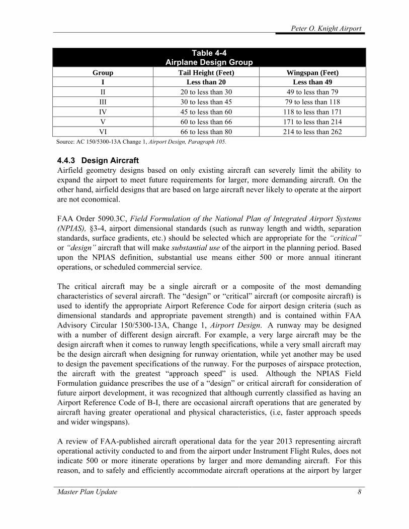
Source: AC 150/5300-13A Change 1, Airport Design, Paragraph 105. 4.4.2 Airplane Design Group The Airplane Design Group is classification of aircraft based on wingspan and tail height as shown in Table 4-4. When the aircraft wingspan and tail height fall in different groups, the higher group is used. TPF has an ADG of I for both Runways 4/22 and 18/36 representing a tail height of less than 20 feet and a wingspan of less than 49 feet.
Peter O. Knight Airport
Master Plan Update 8
Table 4-4 Airplane Design Group
Group Tail Height (Feet) Wingspan (Feet)
I Less than 20 Less than 49
II 20 to less than 30 49 to less than 79 III 30 to less than 45 79 to less than 118 IV 45 to less than 60 118 to less than 171 V 60 to less than 66 171 to less than 214 VI 66 to less than 80 214 to less than 262
Source: AC 150/5300-13A Change 1, Airport Design, Paragraph 105. 4.4.3 Design Aircraft Airfield geometry designs based on only existing aircraft can severely limit the ability to expand the airport to meet future requirements for larger, more demanding aircraft. On the other hand, airfield designs that are based on large aircraft never likely to operate at the airport are not economical. FAA Order 5090.3C, Field Formulation of the National Plan of Integrated Airport Systems (NPIAS), §3-4, airport dimensional standards (such as runway length and width, separation standards, surface gradients, etc.) should be selected which are appropriate for the “critical” or “design” aircraft that will make substantial use of the airport in the planning period. Based upon the NPIAS definition, substantial use means either 500 or more annual itinerant operations, or scheduled commercial service. The critical aircraft may be a single aircraft or a composite of the most demanding characteristics of several aircraft. The “design” or “critical” aircraft (or composite aircraft) is used to identify the appropriate Airport Reference Code for airport design criteria (such as dimensional standards and appropriate pavement strength) and is contained within FAA Advisory Circular 150/5300-13A, Change 1, Airport Design. A runway may be designed with a number of different design aircraft. For example, a very large aircraft may be the design aircraft when it comes to runway length specifications, while a very small aircraft may be the design aircraft when designing for runway orientation, while yet another may be used to design the pavement specifications of the runway. For the purposes of airspace protection, the aircraft with the greatest “approach speed” is used. Although the NPIAS Field Formulation guidance prescribes the use of a “design” or critical aircraft for consideration of future airport development, it was recognized that although currently classified as having an Airport Reference Code of B-I, there are occasional aircraft operations that are generated by aircraft having greater operational and physical characteristics, (i.e, faster approach speeds and wider wingspans). A review of FAA-published aircraft operational data for the year 2013 representing aircraft operational activity conducted to and from the airport under Instrument Flight Rules, does not indicate 500 or more itinerate operations by larger and more demanding aircraft. For this reason, and to safely and efficiently accommodate aircraft operations at the airport by larger
Peter O. Knight Airport
Master Plan Update 9
aircraft, the previously selected design aircraft as identified in the 2003 Airport Master Plan update was retained for planning purpose as part this update of the Airport Master Plan. The design aircraft for TPF are the Beechcraft Baron 58 and the Cessna Skylane 182, which both classify as B-I aircraft.
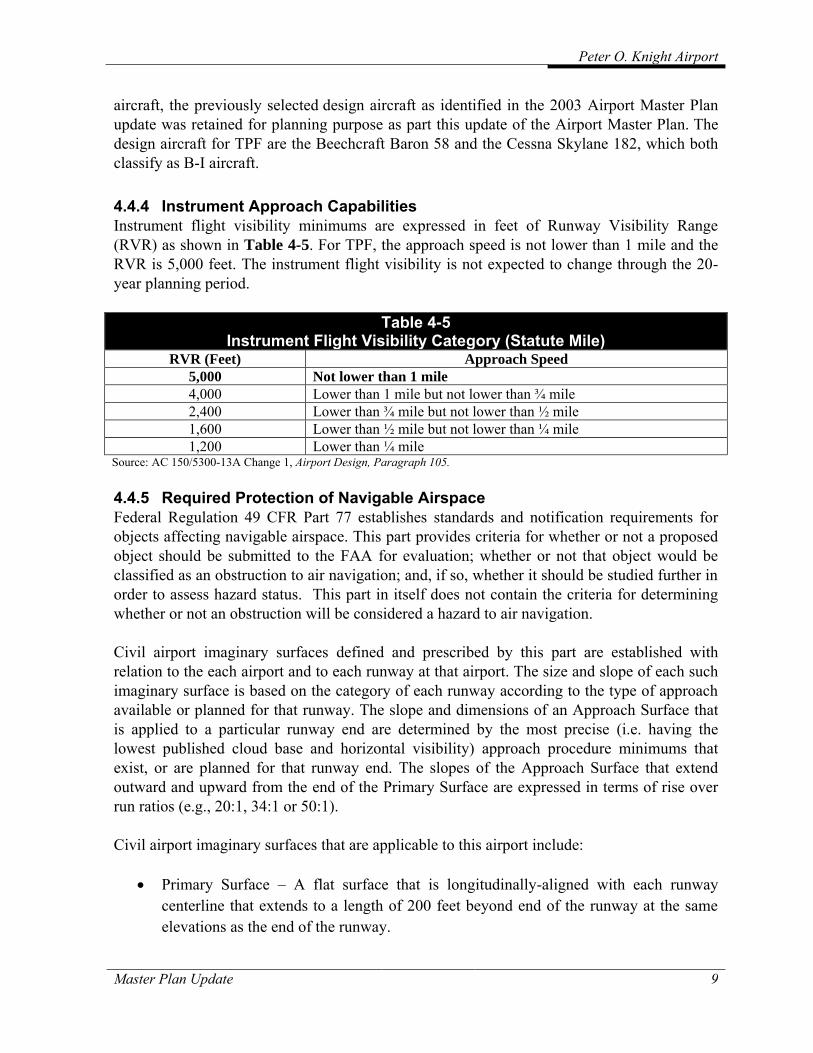
4.4.4 Instrument Approach Capabilities Instrument flight visibility minimums are expressed in feet of Runway Visibility Range (RVR) as shown in Table 4-5. For TPF, the approach speed is not lower than 1 mile and the RVR is 5,000 feet. The instrument flight visibility is not expected to change through the 20-year planning period.
Table 4-5 Instrument Flight Visibility Category (Statute Mile)
RVR (Feet) Approach Speed
5,000 Not lower than 1 mile
4,000 Lower than 1 mile but not lower than ¾ mile 2,400 Lower than ¾ mile but not lower than ½ mile 1,600 Lower than ½ mile but not lower than ¼ mile 1,200 Lower than ¼ mile
Source: AC 150/5300-13A Change 1, Airport Design, Paragraph 105. 4.4.5 Required Protection of Navigable Airspace Federal Regulation 49 CFR Part 77 establishes standards and notification requirements for objects affecting navigable airspace. This part provides criteria for whether or not a proposed object should be submitted to the FAA for evaluation; whether or not that object would be classified as an obstruction to air navigation; and, if so, whether it should be studied further in order to assess hazard status. This part in itself does not contain the criteria for determining whether or not an obstruction will be considered a hazard to air navigation. Civil airport imaginary surfaces defined and prescribed by this part are established with relation to the each airport and to each runway at that airport. The size and slope of each such imaginary surface is based on the category of each runway according to the type of approach available or planned for that runway. The slope and dimensions of an Approach Surface that is applied to a particular runway end are determined by the most precise (i.e. having the lowest published cloud base and horizontal visibility) approach procedure minimums that exist, or are planned for that runway end. The slopes of the Approach Surface that extend outward and upward from the end of the Primary Surface are expressed in terms of rise over run ratios (e.g., 20:1, 34:1 or 50:1). Civil airport imaginary surfaces that are applicable to this airport include:
Primary Surface – A flat surface that is longitudinally-aligned with each runway centerline that extends to a length of 200 feet beyond end of the runway at the same elevations as the end of the runway.
Peter O. Knight Airport
Master Plan Update 10
Approach Surface – A sloping surface that is longitudinally-aligned with each runway centerline that extends outward and upward at varying ratios (depending on type of approach) beyond from the end of the Primary Surface.
Transitional Surface – A sloping surface that extends outward and upward at right angles to the runway centerline and the runway centerline extended at a slope of 7 to 1 from the sides of the Primary Surface and from the sides of the Approach Surface. Transitional Surfaces for those portions of the precision Approach Surface which project through and beyond the limits of the Conical Surface extend to a distance of 5,000 feet measured horizontally from the edge of the Approach Surface and at right angles to the runway centerline.
Horizontal Surface – A flat surface that represents a horizontal plane established 150 feet above the highest runway elevation. The perimeter of the Horizontal Surface is constructed by swinging arcs of specified radii from the center of each end of the Primary Surface of each runway of each airport and connecting the adjacent arcs by lines tangent to those arcs.
Conical Surface – A sloping surface that extends outward and upward from the periphery of the Horizontal Surface at a slope of 20 to 1 for a horizontal distance of 4,000 feet.
Each published instrument approach procedure established for each runway end has published minima describing the lowest cloud base height expressed in feet Above Mean Sea Level and Above Ground Level, and horizontal visibility distances expressed in statute miles or Runway Visual Range (RVR) reporting values expressed in feet. The following describes each runway end having one or more published instrument procedures, the associated cloud base height and visibility distance minimums and Approach Surface slope: Three of the four runways at TPF are served by Non-precision Instrument approach procedures that are described as follows:
Runway 4 is served by a NDB Non-precision Instrument approach procedure having straight-in cloud base and horizontal visibility minimums of 580 feet and 1 statute mile. The Part 77 approach slope for this published instrument approach procedure is 20:1. Runway 22 is served by a RNAV (GPS) Non-precision Instrument approach procedure having straight-in cloud base and horizontal visibility minimums of 580 feet and 1 statute mile. The Part 77 approach slope for this published instrument approach procedure is 20:1.
Peter O. Knight Airport
Master Plan Update 11
Runway 18 has no published instrument approach procedures and is thus considered a Visual Runway. The Part 77 approach slope for this runway is 20:1. Runway 36 is served by a RNAV (GPS) Non-precision Instrument approach procedure having straight-in cloud base and horizontal visibility minimums of 440 feet and 1 statute mile. The Part 77 approach slope for this published instrument approach procedure is 20:1.
The FAA periodically reviews Instrument Approach Procedures established for each runway. Obstacles discovered and/or reported within Approach, Departure, Horizontal or Conical surfaces may result in the FAA establishing increased (i.e., “higher”) cloud base and/or visibility minima for one or more published instrument approach procedures, loss of approaches and/or loss of night operations. Development on and off an airport may potentially create adverse effects to the protection of navigable airspace at and around airports. Such adverse effects, may affect current and future airport operations when it creates obstacles to the safe and efficient use of the airspace surrounding the airport. Approach and Departure surfaces should remain clear of obstacles, including aircraft, in order to prevent operational restrictions that might affect aircraft operating weights and visibility minimums. The Civil Airport Imaginary surfaces established for this airport by CFR Part 77 were found to be appropriate and sufficient. At such time that any runway is lengthened, shortened, or upgraded to provide increased published instrument approach capabilities, these Civil Airport Imaginary surfaces should be reviewed and modeled as required. 4.4.6 Runway Design Code The RDC is a code signifying the design standards to which the runway is to be built. It is comprised of the AAC, ADG, and the runway visibility minimums. TPF has a RDC of B-I-5000 for Runway 04/22 and a RDC of B-I-5000 for Runway 18/36. Although FAA criteria are based upon the three described parameters, aircraft weight should also be considered when assessing the adequacy of pavement strength and length of haul should be considering when considering runway length requirements. 4.4.7 Airport Reference Code The Airport Reference Code (ARC) is a coded system composed of the AAC and ADG. The ARC relates airport design criteria to the operational and physical characteristics of the aircraft that will operate at the airport. TPF has an existing ARC of B-I. Existing and future aircraft operations are considered based on FAA- approved aviation demand forecasts and the airport’s existing and future role within the air transportation system. The ARC is used for planning and design only and does not limit the aircraft that may be able to operate safely on the airport.
Peter O. Knight Airport
Master Plan Update 12
4.5 Runway Design Standards Runway design standard guidance is provided by FAA Advisory Circular 150/5300-13A, Airport Design and FAA Advisory Circular 150/5325-4B, Runway Length Requirements for Airport Design. 4.5.1 Width Runway width requirement factors include approach minimums, AAC, and ADG for the runway’s design aircraft. With an RDC of B-I-5000, the runway width standard at TPF for Runway 04/22 and 18/36 is 60 feet. TPF currently has a runway width of 75 feet for all runways, meeting runway width standards. 4.5.2 Length Based on the review of the total number of aircraft operational activity by larger (i.e., more demanding) general aviation aircraft at the airport during the calendar year 2013, it was determined that the existing runway available take-off lengths at TPF are sufficient. At such time that the need for increased runway take-off lengths required to support 500 or more annual aircraft operations by one or more aircraft having similar operational characteristics is evident, it is highly recommended that HCAA and FAA initiate a Runway Improvement Justification Study to assess and document such demand. If, as part of these study actions there is a demonstrated need for increased runway take-off length, such findings should be used to formulate HCAA-sponsored planning actions and follow-on FAA funding and NEPA environmental programs that would be required to undertake such runway improvement actions. 4.5.3 Shoulders Runway shoulders provide resistance to blast erosion and accommodate the passage of maintenance and emergency equipment and the occasional passage of an aircraft veering from the runway. A stabilized surface, such as turf, normally reduces the possibility of soil erosion and engine ingestion of foreign objects. Soil not suitable for turf establishment requires a stabilized or low cost paved surface. Paved shoulders are required for runways accommodating Airplane Design Group (ADG) IV and higher aircraft, and are recommended for runways accommodating ADG-III aircraft.
Turf, aggregate-turf, soil cement, lime or bituminous stabilized soil are recommended adjacent to runways accommodating ADG I aircraft. TPF does not currently have runway shoulders. The recommended width is 10 feet. 4.5.4 Blast Pad Paved runway blast pads provide blast erosion protection beyond runway ends during jet aircraft operations. Blast pads at runway ends should extend across the full width of the runway plus the shoulders. For a RDC of B-I-5000 (Runway 36, and Runway 4/22), the standard blast pad width is 80 feet and the length is 60 feet. For a RDC of B-I-Visual (Runway 18 end), the standard blast pad width is 80 feet and the length is 100 feet. TPF does not currently have runway blast pads.
Peter O. Knight Airport
Master Plan Update 13
4.5.5 Safety Area The Runway Safety Area (RSA) is a defined surface surrounding the runway prepared or suitable for reducing the risk of damage to aircraft in the event of an undershoot, overshoot, or excursion from the runway. The current RSA requirements, for a RDC of B-I-Visual and B-I-5000 (Runways 18/36 and 4/22) are 240 feet beyond the departure end of the runway, 240 feet prior to the threshold, and a width of 120 feet. The extended portion of the RSA beyond the departure (northeast) end of Runway 4 extends approximately 140 feet beyond the land platform into Seddon Channel. The non-standard RSA condition mandates the use of declared distance criteria to provide the minimum 240-foot length. 4.5.6 Object Free Area The Object Free Area (OFA) is an area centered on the ground on a runway, taxiway, or taxilane centerline provided to enhance the safety of aircraft operations by remaining clear of objects, except for objects that need to be located in the OFA for air navigation or aircraft ground maneuvering purposes. The standard for a RDC of B-I-Visual and B-I-5000 is 240 feet beyond the runway end, 240 feet prior to the threshold, and 250 feet in width. The extended portion of the OFA beyond the south end of Runway 18/36 extends approximately 59 feet into a public roadway. Similarly, The extended portion of the OFA beyond the north end of Runway 18/36 extends approximately 42 feet into a public roadway. The non-standard OFA condition mandates the use of declared distance criteria to provide the minimum 240-foot length. 4.5.7 Object Free Zone The Object Free Zone (OFZ) is the three-dimensional airspace along the runway and extended runway centerline that is required to be clear of obstacles for protection for aircraft landing or taking off from the runway and for missed approaches. For a RDC of B-I-5000 and B-I-Visual the design standards are 200 feet in length and 250 feet in width. TPF currently satisfies OFZ requirements. 4.5.8 Runway Protection Zone The Runway Protection Zone (RPZ) in an area at ground level prior to the threshold or beyond the runway end that is designed to enhance the safety and protection of people and property on the ground. For a RDC of B-I-5000, B-I-Visual and not lower than one mile, the design standards are 1,000 feet in length, 250 feet inner width, 450 feet outer width, and an area of 8.035 acres. TPF currently satisfies RPZ requirements. 4.5.9 TERPS Approach Obstacle Clearance Surfaces The FAA’s Terminal Instrument Procedures (TERPS) final approach Obstacle Clearance Surfaces (OCS) are applicable to precision instrument approach capabilities (i.e., ILS) and non-precision approach capabilities offering vertical guidance using Localizer Performance with Vertical guidance (LPV) capabilities.

Peter O. Knight Airport
Master Plan Update 14
None of the four runways at TPF are served by Non-precision Instrument approach procedures offering LPV vertical descent procedures. 4.5.10 TERPS Departure Surfaces When a runway has an established and published instrument approach procedure, the TERPS Instrument Departure Surfaces apply. The prescribed Instrument Departure Surface begins at the departure end of the runway and extends outward and upward along the extended runway centerline with a slope of 1 unit vertically for every 40 units horizontally (40:1). When the 40:1 Instrument Departure Surface is penetrated by natural or man-made objects, the FAA may require modification of the instrument departure procedures that may potentially require the application of non-standard (increased) climb rates, and/or non-standard (increased) published instrument departure minimums. No instrument departures are allowed from the departure end of Runways 4 or 36 because of environmentally-related issues. Runway 18 is used for instrument departure activity, but, close-in obstacle penetrations of the 40:1 Instrument Departure Surface, requires a minimum aircraft climb gradient of 260 feet per nautical mile until reaching an altitude of 300 feet above sea level. Runway 22 is used for instrument departure activity and has no noted penetrations of the 40:1 Instrument Departure Surface. The existing TERPS Departure surfaces established for Runways 18 and 22 were found to be appropriate and sufficient. At such time that any runway is lengthened or shortened these surfaces should be reviewed and modeled by HCAA as required. It is highly recommended that HCAA identify and remove any future natural (trees or vegetation) other or any other man-made object that may penetrate the established and overlying 40:1 Instrument Departure Surfaces to protect and enhance the instrument departure capabilities for those runways. 4.5.11 Runway Centerline to Parallel Taxiway Centerline Separation Runway centerline to parallel taxiway centerline separation standards for a RDC of B-I-5000 and B-I-Visual is 150 feet. TPF currently meets the design standards for Runway 04/22 and 18/36. 4.5.12 Runway Pavement Strength Runway 04/22 and Runway 18/36 have a pavement strength to accommodate aircraft with a single-wheel load rating of 20,000 pounds or less. The runway is constructed of asphalt and is in fair to good condition as recorded in the FAA 5010, Airport Master Records and Reports for TPF. Based upon the Florida Department of Transportation – Aviation and Spaceports Office, 2012 Pavement Conditions Report, TPF has runway, taxiway and areas that range
Peter O. Knight Airport
Master Plan Update 15
from fair to good condition. As identified in TPF’s Inventory of Existing Conditions, Figure
2-4, there is a taxiway connector that need improvement and is in poor condition. 4.5.13 Threshold Siting Surface For any given runway, the threshold is the demarcation line that defines the beginning of useable pavement for an aircraft to land. Typically, the threshold is located at the end of the physical pavement of the runway, thereby allowing an approaching aircraft to land with the maximum amount of pavement provided. When required, a threshold can be “displaced” at a specified distance from the approach end of the runway. The displaced threshold defines a new location along the runway where an approaching aircraft may begin their touchdown on the runway. Often, the purpose of the displaced threshold is to allow an approaching aircraft ample clearance over obstacles in the approach area (i.e., those obstacles that would exceed the Threshold Siting Surfaces as defined in FAA Advisory Circular 150/5300-13A Change 1, Table 3-2, Approach/Departure Standards. Displacement of the threshold shortens the useable runway length for landing, while not adversely (i.e., shortening) affecting the length of the runway available for departing aircraft. As a basic airport design requirement, threshold siting surfaces must be kept clear of obstacles either by removing or lowering the obstacles or displacing the threshold. The dimensions of the Threshold Siting surfaces, which depend on the runway type, approach type, and other factors, include the following:
Whether or not the runway is authorized for a visual, non-precision, precision approaches, Night-time operations and the approach visibility minimums.
Whether or not there are published instrument departure procedures on the runway. Whether or not the runway is used by scheduled air carriers (those operating under
FAR Part 121), and The approach category of the runway’s design aircraft.
In many cases the requirements for maintaining airspace clear of objects depend, in part, on the type of aircraft that typically use a runway. Airport runway design standards are based, in fact, on what is known as the runway’s “critical” or “design” aircraft. When a penetration to a Threshold Siting Surface occurs, one or more of the following actions may be required by the airport owner to protect the runway Approach Surface:
Removal or lowering of the object to preclude penetration of applicable threshold siting surface;
Displacement of the threshold to preclude object penetration of applicable threshold siting surface, with a resulting shorter landing distance;
Peter O. Knight Airport
Master Plan Update 16
Modification of the approach Glide Path Angle and/or Threshold Crossing Height, or a combination of both;
Increase of published instrument approach procedure visibility minimums; or Prohibition of night-time operations unless the object is lighted or an approved Visual
Glide Slope Indicator (VGSI) is in use. The existing Threshold Siting surfaces established for each runway end were found to be appropriate and sufficient. At such time that any runway is lengthened or shortened, or a threshold is relocated or displaced on an existing runway, these siting surfaces should be reviewed and modeled by HCAA as required. HCAA should continue to monitor and review all proposals for the erection of temporary or permanent objects in proximity to the airport as filed by proponents via the FAA’s 7460-1 and OE/AAA notification process. Further, HCAA should maintain its current pro-active role within this review process with the goal of reducing or eliminating any potential penetrations to the various approach and departure surfaces to preserve the safe and efficient use of the airport. 4.5.14 Runway Design Standard Compliance Needs Summary Summarized in Table 4-6 and Table 4-7 are the runway design standards for TPF. Runway and taxiway shoulders of turf, aggregate-turf, soil cement, lime or bituminous stabilized soil are recommended adjacent to runways accommodating ADG-I aircraft. Runway blast pads are recommended, TPF does not currently have runway blast pads.
Peter O. Knight Airport
Master Plan Update 17
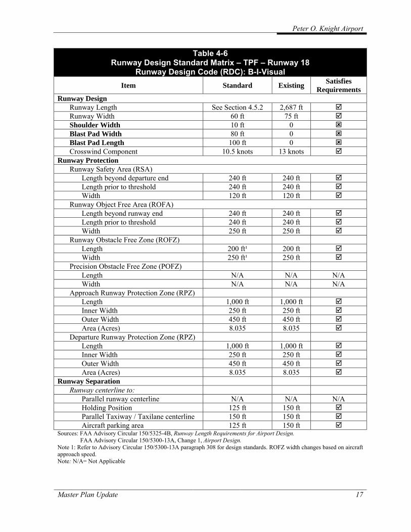
Table 4-6 Runway Design Standard Matrix – TPF – Runway 18
Runway Design Code (RDC): B-I-Visual Item Standard Existing
Satisfies
Requirements
Runway Design Runway Length See Section 4.5.2 2,687 ft Runway Width 60 ft 75 ft Shoulder Width 10 ft 0 Blast Pad Width 80 ft 0 Blast Pad Length 100 ft 0 Crosswind Component 10.5 knots 13 knots
Runway Protection Runway Safety Area (RSA)
Length beyond departure end 240 ft 240 ft Length prior to threshold 240 ft 240 ft Width 120 ft 120 ft
Runway Object Free Area (ROFA) Length beyond runway end 240 ft 240 ft Length prior to threshold 240 ft 240 ft Width 250 ft 250 ft
Runway Obstacle Free Zone (ROFZ) Length 200 ft¹ 200 ft Width 250 ft¹ 250 ft
Precision Obstacle Free Zone (POFZ) Length N/A N/A N/A Width N/A N/A N/A
Approach Runway Protection Zone (RPZ) Length 1,000 ft 1,000 ft Inner Width 250 ft 250 ft Outer Width 450 ft 450 ft Area (Acres) 8.035 8.035
Departure Runway Protection Zone (RPZ) Length 1,000 ft 1,000 ft Inner Width 250 ft 250 ft Outer Width 450 ft 450 ft Area (Acres) 8.035 8.035
Runway Separation Runway centerline to:
Parallel runway centerline N/A N/A N/A Holding Position 125 ft 150 ft Parallel Taxiway / Taxilane centerline 150 ft 150 ft Aircraft parking area 125 ft 150 ft
Sources: FAA Advisory Circular 150/5325-4B, Runway Length Requirements for Airport Design. FAA Advisory Circular 150/5300-13A, Change 1, Airport Design. Note 1: Refer to Advisory Circular 150/5300-13A paragraph 308 for design standards. ROFZ width changes based on aircraft approach speed. Note: N/A= Not Applicable

Peter O. Knight Airport
Master Plan Update 18
Table 4-7 Runway Design Standard Matrix – TPF – Runway 04, 22, 36
Runway Design Code (RDC): B-I-5000
Item Standard Existing Satisfies
Requirements
Runway Design Runway Length See Section 4.5.2 Varies Runway Width 60 ft 75 ft Shoulder Width 10 ft 0 Blast Pad Width 80 ft 0 Blast Pad Length 60 ft 0 Crosswind Component 10.5 knots 13 knots
Runway Protection Runway Safety Area (RSA)
Length beyond departure end 240 ft 240 ft Length prior to threshold 240 ft 240 ft Width 120 ft 120 ft
Runway Object Free Area (ROFA) Length beyond runway end 240 ft 240 ft Length prior to threshold 240 ft 240 ft Width 250 ft 250 ft
Runway Obstacle Free Zone (ROFZ) Length 200 ft¹ 200 ft Width 250 ft¹ 250 ft
Precision Obstacle Free Zone (POFZ) Length N/A N/A N/A Width N/A N/A N/A
Approach Runway Protection Zone (RPZ) Length 1,000 ft 1,000 ft Inner Width 250 ft 250 ft Outer Width 450 ft 450 ft Area (Acres) 8.035 8.035
Departure Runway Protection Zone (RPZ) Length 1,000 ft 1,000 ft Inner Width 250 ft 250 ft Outer Width 450 ft 450 ft Area (Acres) 8.035 8.035
Runway Separation Runway centerline to:
Parallel runway centerline N/A N/A N/A Holding Position 125 ft 150 ft Parallel Taxiway / Taxilane centerline 150 ft 150 ft Aircraft parking area 125 ft 150 ft
Sources: FAA Advisory Circular 150/5325-4B, Runway Length Requirements for Airport Design. FAA Advisory Circular 150/5300-13A, Change 1, Airport Design. Note 1: Refer to Advisory Circular 150/5300-13A paragraph 308 for design standards. ROFZ width changes based on aircraft approach speed. Note: N/A= Not Applicable
Peter O. Knight Airport
Master Plan Update 19
4.6 Declared Distance Criteria As defined in §322 of Advisory Circular 150/5300-13A, Change 1, Airport Design, declared distances represent the maximum distances available and suitable for meeting takeoff, rejected takeoff, and landing distances performance requirements for turbine powered aircraft where it is impracticable to meet the airport design standards or mitigate the environmental impacts by other means, and the use of declared distances is practical. When applicable and prudent, declared distance criteria is applied and published for each runway end where it is impracticable to meet the standard design criteria established for the Runway Safety Area (RSA), the Runway Object Free Area (ROFA), the Runway Protection Zone (RPZ), or where required to fully satisfy minimum vertical clearances over traverseways as prescribed for CFR Part 77 Approach Surfaces and/or TERPS Departure Surfaces. One or more of the any or all of the following declared distances may apply to a particular runway by direction of travel (i.e., arrival or departure).
(1) Takeoff Run Available (TORA) – the runway length declared available and suitable for the ground run of an aircraft taking off;
(2) Takeoff Distance Available (TODA) – the TORA length plus the length of any remaining runway or clearway beyond the far end of the TORA; the full length of TODA may need to be reduced because of obstacles in the departure area;
(3) Accelerate-Stop Distance Available (ASDA) – the runway length plus stopway length declared available and suitable for the acceleration and deceleration of an aircraft aborting a takeoff; and
(4) Landing Distance Available (LDA) – the runway length declared available and
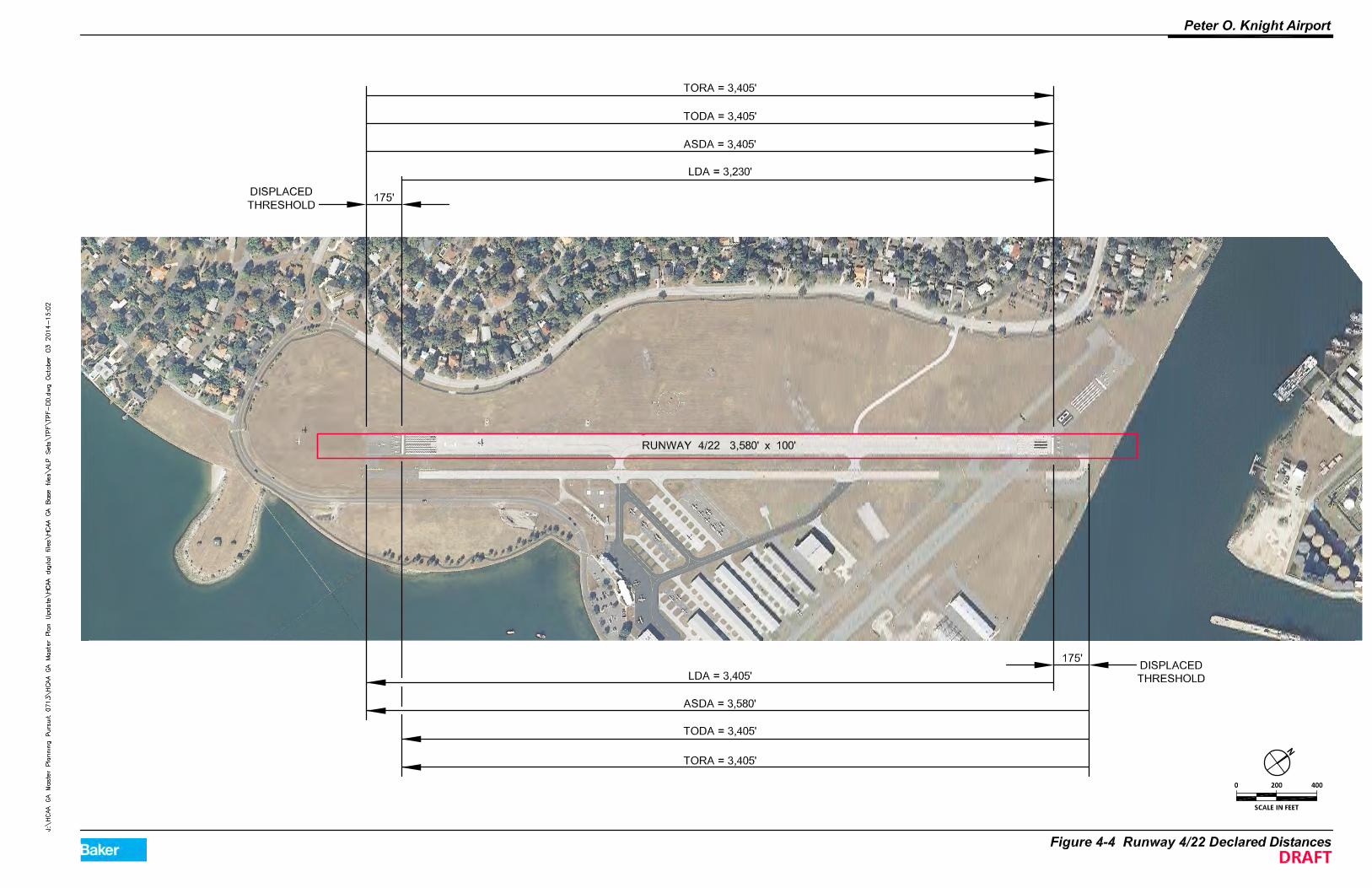
suitable for landing an aircraft. By treating these distances independently, application of declared distances is a design methodology that results in declaring and reporting the TORA, TODA ASDA and LDA for each operational direction. When applicable, declared distances limit or increase runway use. Runway 18/36 has a surveyed and published length of 2,687 feet. The threshold for Runway 18 is displaced 202 feet to provide the required CFR Part 77 Approach Surface 15-foot vertical clearances over Seddon Channel a public and navigable waterway. The threshold for Runway 36 is displaced 201 feet to provide the required CFR Part 77 Approach Surface 15-foot vertical clearance over Martinique Avenue and Severn Avenue both of which or public roads and a CFR Part 77 Approach Surface 10-foot vertical clearance over an internal non-public airport road that runs along Seddon Channel. Because the land area located beyond the north end of the runway does not fully accommodate the required extended 300-foot portion of the Runway Safety Area located beyond the end of the runway, the Runway 36 TORA, TODA, ASDA and LDA lengths are each reduced.
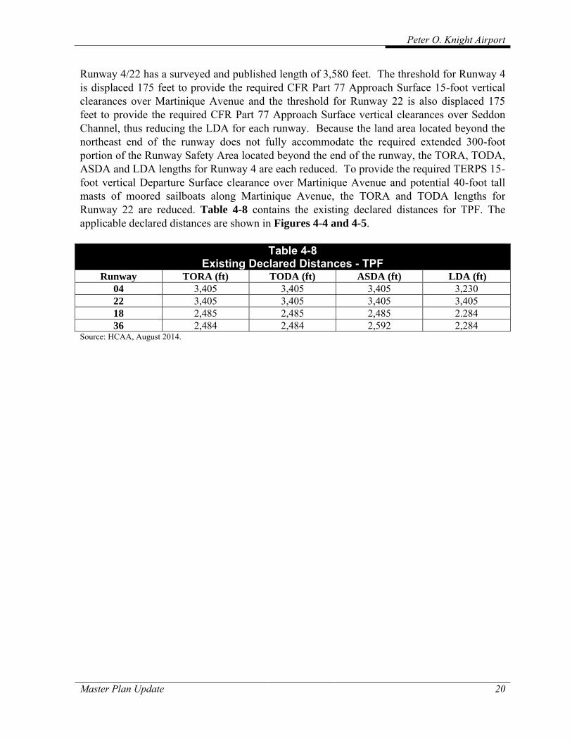
Peter O. Knight Airport
Master Plan Update 20
Runway 4/22 has a surveyed and published length of 3,580 feet. The threshold for Runway 4 is displaced 175 feet to provide the required CFR Part 77 Approach Surface 15-foot vertical clearances over Martinique Avenue and the threshold for Runway 22 is also displaced 175 feet to provide the required CFR Part 77 Approach Surface vertical clearances over Seddon Channel, thus reducing the LDA for each runway. Because the land area located beyond the northeast end of the runway does not fully accommodate the required extended 300-foot portion of the Runway Safety Area located beyond the end of the runway, the TORA, TODA, ASDA and LDA lengths for Runway 4 are each reduced. To provide the required TERPS 15-foot vertical Departure Surface clearance over Martinique Avenue and potential 40-foot tall masts of moored sailboats along Martinique Avenue, the TORA and TODA lengths for Runway 22 are reduced. Table 4-8 contains the existing declared distances for TPF. The applicable declared distances are shown in Figures 4-4 and 4-5.
Table 4-8 Existing Declared Distances - TPF
Runway TORA (ft) TODA (ft) ASDA (ft) LDA (ft)
04 3,405 3,405 3,405 3,230 22 3,405 3,405 3,405 3,405 18 2,485 2,485 2,485 2.284 36 2,484 2,484 2,592 2,284
Source: HCAA, August 2014.
Peter O. Knight Airport
Master Plan Update 23
4.7 Taxiway/Taxilane Design Standards Runway design standard guidance is provided by FAA Advisory Circular 150/5300-13A Change 1, Airport Design. TPF’s taxiway design standards are based on Taxiway Design Group (TDG) 1A, the TDG for TPF’s design aircraft. 4.7.1 Width Taxiway pavement requirements are based on Taxiway Design Group (TDG), which in turn is based on the dimensions of the airplane’s undercarriage, which includes the Main Gear Width (MGW) and Cockpit to Main Gear (CMG). For a TDG 1A taxiway, the design standard for width is 25 feet. TPF has a current taxiway width of 40 feet for Taxiway A which is a full parallel taxiway for Runway 04/22. TPF has a current taxiway width of 35 feet for Taxiway F which is a full parallel taxiway for Runway 18/36. Both runways satisfy design standards at this time. 4.7.2 Shoulders Unprotected soils adjacent to taxiways are susceptible to erosion, which can result in engine ingestion problems for jet engines that overhang the edge of the taxiway pavement. A dense, well-rooted turf cover can prevent erosion and support the occasional passage of aircraft, maintenance equipment, or emergency equipment under dry conditions. Turf, aggregate-turf, soil cement, lime or bituminous stabilized soil are recommended adjacent to paved surfaces accommodating ADG-I aircraft. For TPF, the recommended shoulder width is 10 feet. 4.7.3 Safety Area The Taxiway Safety Area (TSA) is centered on the taxilane centerline. To provide room for rescue and fire-fighting operations, the TSA width equals the maximum wingspan of the ADG. For TPF, the TSA is 49 feet for ADG I. 4.7.4 Object Free Area The Taxiway Object Free Area (TOFA) is centered on the taxiway centerline. The TOFA clearing standards prohibit service vehicle roads, parked aircraft, and other objects, except for objects that need to be located in the OFA for air navigation or aircraft ground maneuvering purposes. For TPF, the TOFA is 89 feet for ADG I. 4.7.5 Taxiway Design Group The TDG is a classification of airplanes based on outer to outer Main Gear Width (MGW) which is the distance from the outer edge to outer edge of the widest set of main gear tires, and the Cockpit to Main Gear distance (CMG) which the distance from the pilot’s eye to the main gear turn center. Unlike the Aircraft Approach Category and the Airplane Design Group, the Taxiway Design Groups do not fit in a simple table format. TDG standards can be found in Advisory Circular 150/5300-13A, Change 1, Airport Design. TPF has a TDG of 1A.
Peter O. Knight Airport
Master Plan Update 24
4.7.6 Edge Margin The Taxiway Edge Safety Margin (TESM) is the distance between the outer edge of the landing gear of an airplane with its nose gear on the taxiway centerline and the edge of the taxiway pavement. The TESM for TDG 1A is 5 feet. 4.7.7 Wingtip Clearance Wingtip clearance for TDG 1A is 20 feet for taxiways and 15 feet for taxilanes. TPF currently satisfies these requirements. 4.7.8 Centerline to Fixed or Moveable Object TDG 1A taxiway centerline to fixed or moveable object separation is 39.5 feet. TPF currently satisfies these requirements. 4.7.9 Taxiway Centerline to Parallel Taxiway Centerline Separation Taxiway centerline to parallel taxilane centerline separation is 70 feet for ADG I design standards. TPF currently satisfies requirements for ADG I. 4.7.10 Holding Bays The purpose of a holding bay is to provide space for one aircraft to pass another in order to reach the runway end. This reduces airfield delays which can result when an aircraft is conducting engine run-ups or pre-flight checks. TPF has holding bays for this purpose at the end of Runway 18 and Runway 22. 4.7.11 Taxiway Design Standard Compliance Needs Summary TPF meets TDG 1A taxiway design standards, based on the design aircraft at the Airport. The full-length parallel taxiway system provides adequate capacity and efficient flow of aircraft operations. Turf, aggregate-turf, soil cement, lime or bituminous stabilized soil are recommended adjacent to paved surfaces accommodating ADG-I aircraft. For TPF, the recommended taxiway shoulder width is 10 feet. 4.8 Airfield Facility Requirements 4.8.1 Lighting The airfield lighting at TPF consists of Medium Intensity Runway Lights (MIRLs) located along the edge of Runway 04/22 and 18/36. The Runway 22 end has Runway End Identifier Lights (REILs). Runway 04 has a 4-box Visual Approach Slope Indicator (VASI) on the left side of the runway. Runway 18 has touchdown zone lights. Runway 36 has a 2-box Precision Approach Path Indicator (PAPI) on the right side of the runway. There are no anticipated changes to the airfield lighting system and current airfield lighting satisfies requirements for non-precision approaches. 4.8.2 Marking and Signage Advisory Circular 150/5324-1K, Standards for Airport Markings, contains standards for markings used on airport runways, taxiways, and aprons. Runways 04/22 and 18/36 are
Peter O. Knight Airport
Master Plan Update 25
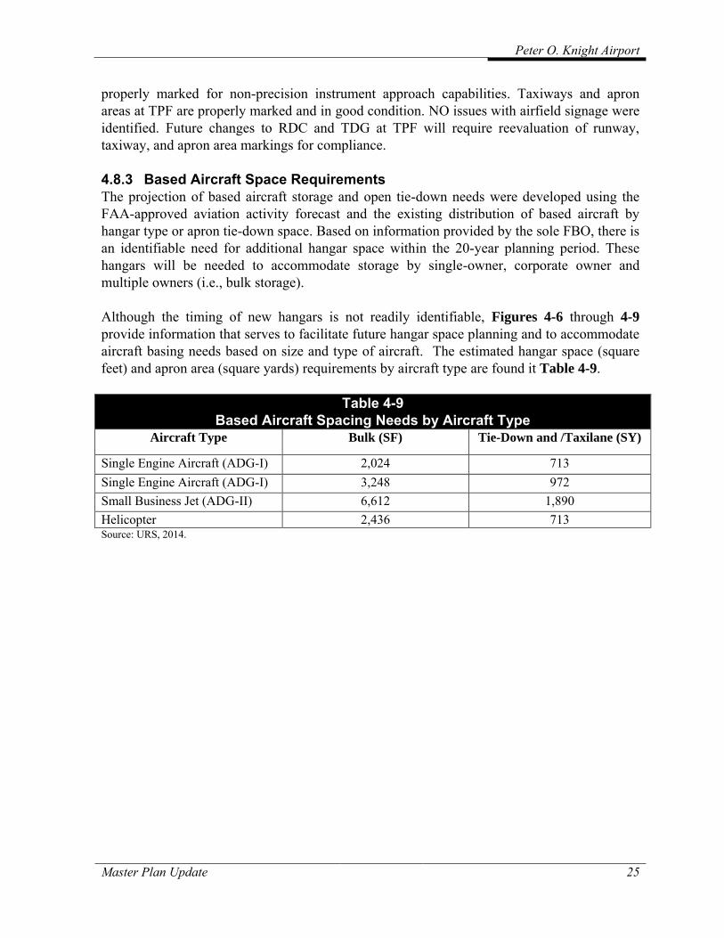
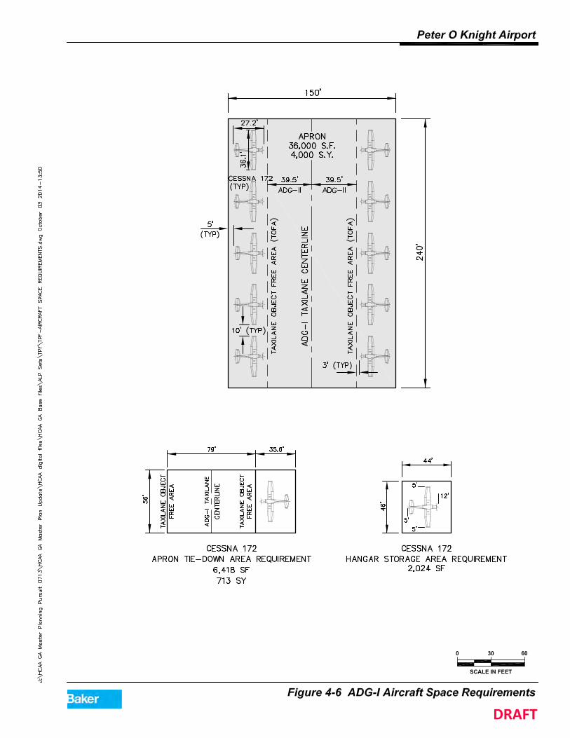
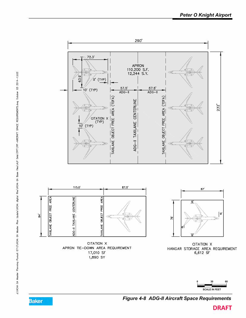
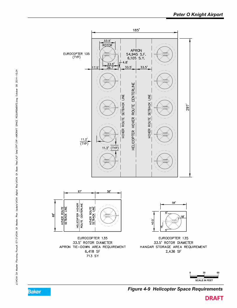
properly marked for non-precision instrument approach capabilities. Taxiways and apron areas at TPF are properly marked and in good condition. NO issues with airfield signage were identified. Future changes to RDC and TDG at TPF will require reevaluation of runway, taxiway, and apron area markings for compliance. 4.8.3 Based Aircraft Space Requirements The projection of based aircraft storage and open tie-down needs were developed using the FAA-approved aviation activity forecast and the existing distribution of based aircraft by hangar type or apron tie-down space. Based on information provided by the sole FBO, there is an identifiable need for additional hangar space within the 20-year planning period. These hangars will be needed to accommodate storage by single-owner, corporate owner and multiple owners (i.e., bulk storage). Although the timing of new hangars is not readily identifiable, Figures 4-6 through 4-9 provide information that serves to facilitate future hangar space planning and to accommodate aircraft basing needs based on size and type of aircraft. The estimated hangar space (square feet) and apron area (square yards) requirements by aircraft type are found it Table 4-9.
Table 4-9 Based Aircraft Spacing Needs by Aircraft Type
Aircraft Type Bulk (SF) Tie-Down and /Taxilane (SY)
Single Engine Aircraft (ADG-I) 2,024 713 Single Engine Aircraft (ADG-I) 3,248 972 Small Business Jet (ADG-II) 6,612 1,890 Helicopter 2,436 713 Source: URS, 2014.
Peter O. Knight Airport
Master Plan Update 26
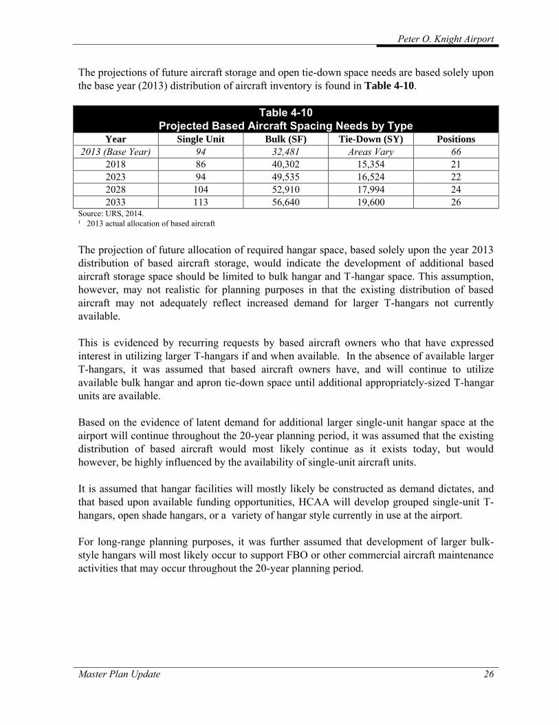
The projections of future aircraft storage and open tie-down space needs are based solely upon the base year (2013) distribution of aircraft inventory is found in Table 4-10.
Table 4-10 Projected Based Aircraft Spacing Needs by Type
Year Single Unit Bulk (SF) Tie-Down (SY) Positions
2013 (Base Year) 94 32,481 Areas Vary 66 2018 86 40,302 15,354 21 2023 94 49,535 16,524 22 2028 104 52,910 17,994 24 2033 113 56,640 19,600 26
Source: URS, 2014. ¹ 2013 actual allocation of based aircraft The projection of future allocation of required hangar space, based solely upon the year 2013 distribution of based aircraft storage, would indicate the development of additional based aircraft storage space should be limited to bulk hangar and T-hangar space. This assumption, however, may not realistic for planning purposes in that the existing distribution of based aircraft may not adequately reflect increased demand for larger T-hangars not currently available. This is evidenced by recurring requests by based aircraft owners who that have expressed interest in utilizing larger T-hangars if and when available. In the absence of available larger T-hangars, it was assumed that based aircraft owners have, and will continue to utilize available bulk hangar and apron tie-down space until additional appropriately-sized T-hangar units are available. Based on the evidence of latent demand for additional larger single-unit hangar space at the airport will continue throughout the 20-year planning period, it was assumed that the existing distribution of based aircraft would most likely continue as it exists today, but would however, be highly influenced by the availability of single-unit aircraft units. It is assumed that hangar facilities will mostly likely be constructed as demand dictates, and that based upon available funding opportunities, HCAA will develop grouped single-unit T-hangars, open shade hangars, or a variety of hangar style currently in use at the airport. For long-range planning purposes, it was further assumed that development of larger bulk-style hangars will most likely occur to support FBO or other commercial aircraft maintenance activities that may occur throughout the 20-year planning period.

Peter O. Knight Airport
Master Plan Update 31
4.8.4 NAVAIDS Navigational Aids are used for airport approaches and allow pilots to navigate to the airport and runway ends. Runway 04 has a Non-Directional Beacon (NDB) and a 4-Light Visual Approach Slope Indicator (VASI-4L) for non-precision approaches. Runway 22 has a GPS and REILs for non-precision approaches. Runway 36 has GPS and a 2-Light Precision Approach Path Indicator (PAPI-2L) for non-precision approaches. The airport has an NDB, a beacon, a lighted wind cone, and a segmented circle. Navigational aids are in good condition but should be monitored throughout the planning period for maintenance issues or if replacement is deemed necessary. 4.8.5 Windsock/Segmented Circle TPF airport management maintains a lighted windsock and segmented circle located next to Runway 04/22. The windsock and segmented circle are in fair condition and are anticipated to adequately serve the airport through the foreseeable future with routine maintenance and upkeep. 4.8.6 Security Fencing Security fencing at TPF is adequate and well maintained. Fencing should be monitored throughout the planning period. 4.9 Airport Support Facilities This section addresses the General Aviation (GA) facility requirements based on current and projected levels of local and itinerant traffic. 4.9.1 General Aviation Terminal The GA terminal at TPF is 4,000 square feet and contains office and administration, restrooms, flight planning and weather facilities, and a large conference room. There is public and employee parking located in front of the GA terminal building. Recommendations for the future development of the terminal area should be further evaluated as part of the business plan and addressed during the alternatives analysis component of this study. 4.9.2 Aircraft Fueling Based upon discussions with the sole FBO, the existing aircraft fuel storage facilities are adequate and sufficient. It is recognized, however, that although excess fuel storage capacity exists today, the need for additional storage capacity will occur as aircraft activity levels increase throughout the 20-year planning period. This existing capacity will diminish quickly as such time that the FBO fuel sales reach or exceed historical levels experienced prior to the 1997 Great Recession. The timing for the development of additional fuel storage capacity will most likely be driven by increased fuel sales, FBO-specific fuel pricing and other related business practices. 4.9.3 Airport Maintenance TPF performs aircraft maintenance activities within a 7,670 square foot hangar built before 1969 and an operations and maintenance shop that is 1,922 square feet and that was
Peter O. Knight Airport
Master Plan Update 32
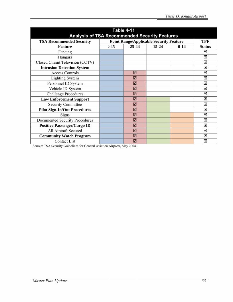
constructed between 1982 and 1994. There is also a 764 foot maintenance storage unit constructed before 1969. Recommendations for the future development of airport maintenance should be further evaluated as part of the business plan and addressed during the alternatives analysis component of this study. 4.9.4 Ground Access Severn Avenue is the entrance road for TPF and can be accessed by East Davis Boulevard or West Davis Boulevard. Access to Davis Island is gained from utilizing Davis Boulevard and involves driving through residential single- and multi-family communities. Methods to improve access to TPF, to avoid residential areas, are not cost feasible or realistic and will not be evaluated at this time. A pedestrian/bike trail is located along the northeast boundary of the airport and ends near the airport parking lot. Future plans to extend the trail to the city dog park should be considered as part of the alternatives analysis. Ground access to this airport is considered good and provides adequate Level of Service (LOS) at this time. Based on the current aeronautical role and associated trip generation associated with current airport activity, the need to modify or enhance the LOS for Severn Avenue is not anticipated at this time. 4.9.5 Automobile Parking Automobile parking at TPF is adequate for current operational needs. It is provided at the terminal building. If new Airport hangar and/or other support facilities are constructed, more parking will be required to meet anticipated increased demand. 4.10 Airport Security The Transportation Security Administration (TSA) has developed guidance, in cooperation with the General Aviation (GA) community, to provide GA airport owners, operations, and users with guidelines and recommendations that address aviation security concepts, technology, and enhancements. These guidelines and recommendations are found within Information Publication A-001, Security Guidelines for General Aviation Airports, published in May 2004. The TSA uses an airport characteristics measuring tool that includes airport location, runways, and based aircraft to assess the most appropriate security enhancements for the Airport. Each airport is assigned a certain point value that is calculated considering the airport’s location, number and types of based aircraft, runway length and surface characteristics, and number and types of aircraft operations. The airport’s value is the compared to the TSA’s recommended security features to evaluate whether additional security features may be appropriate. A point value of 32 was calculated for TPF, which means that all security features shown in the “25-44 Point Range” are recommended. Table 4-11 lists TSA recommended security features and TPF’s compliance with these features. It is recommended that TPF evaluate deficiencies in airport security to comply with all TSA recommendations.
Peter O. Knight Airport
Master Plan Update 33
Table 4-11 Analysis of TSA Recommended Security Features
TSA Recommended Security
Feature
Point Range/Applicable Security Feature TPF
Status >45 25-44 15-24 0-14
Fencing Hangars
Closed Circuit Television (CCTV) Intrusion Detection System
Access Controls Lighting System
Personnel ID System Vehicle ID System
Challenge Procedures Law Enforcement Support
Security Committee Pilot Sign-In/Out Procedures
Signs Documented Security Procedures
Positive Passenger/Cargo ID All Aircraft Secured
Community Watch Program Contact List
Source: TSA Security Guidelines for General Aviation Airports, May 2004.

Peter O. Knight Airport
Master Plan Update 34
4.11 Summary of Facility Needs Table 4-12 identifies and summaries TPF’s facility requirements. The following table presents recommendations to satisfy these facility requirements.
Table 4-12 Summary of Facility Requirements
Category Requirements
Airfield Capacity and Configuration No Improvements Recommended Design Aircraft and Airport Reference Code (ARC) Beechcraft Baron 58 and Cessna Skylane 182 –
ARC I Runway Strength No Improvements Recommended
Instrument Approaches No Improvements Recommended Runway Design Standards Runway Shoulders Recommended
Runway Blast Pads Taxiway Design Standards Taxiway Shoulders Recommended
Pavement Improvements to Taxiway Connector Airfield Lighting No Improvements Recommended Airfield Markings No Improvements Recommended Airfield Signage No Improvements Recommended
Navigational Aids No Improvements Recommended Aircraft Apron (2033) Additional Apron Space
Based Aircraft Hangars (2033) Additional Single-Unit Hangars Additional Bulk Hangars
Airport Terminal Evaluated in Alternatives Analysis Airport Maintenance Facilities Evaluated in Alternatives Analysis
Fueling Facilities No Improvements Recommended Automobile Access Evaluated in Alternatives Analysis Automobile Parking No Improvements Recommended
Airport Security Analysis Evaluate Deficiencies Based on Table 4-11 Source: URS, 2014.