Chapter 18 - Ray Optics - Lecture Presentation
209
Chapter 18 Lecture Presentation Ray Optics © 2015 Pearson Education, Inc.
-
Upload
khangminh22 -
Category
Documents
-
view
1 -
download
0
Transcript of Chapter 18 - Ray Optics - Lecture Presentation

Chapter 18
Lecture Presentation
Ray Optics
© 2015 Pearson Education, Inc.

Slide 18-2
Suggested Videos for Chapter 18
• Prelecture Videos
• Mirrors and Reflection
• Refraction
• Lenses and Images
• Class Videos
• Scattering
• Index of Refraction
• Real and Virtual Images
• Diverging Mirror
• Video Tutor Solutions
• Ray Optics
• Video Tutor Demos
• Partially Covering a Lens
© 2015 Pearson Education, Inc.

Slide 18-3
Suggested Simulations for Chapter 18
• ActivPhysics
• 15.1–15.11
• PhETs
• Geometric Optics
© 2015 Pearson Education, Inc.

Slide 18-4
Chapter 18 Ray Optics
Chapter Goal: To understand and apply the ray model of
light.
© 2015 Pearson Education, Inc.

Slide 18-5
Chapter 18 PreviewLooking Ahead: Reflection
• Light rays can bounce, or reflect, off a surface. Rays from
the bird’s head reflect from the water, forming an upside-
down image.
• You’ll learn how the law of reflection can be used to
understand image formation by mirrors.
© 2015 Pearson Education, Inc.

Slide 18-6
• The two images of the turtle are due to refraction, the
bending of light rays as they travel from one material into
another.
• You’ll learn Snell’s law for refraction and how images can
be formed by refraction.
Chapter 18 PreviewLooking Ahead: Refraction
© 2015 Pearson Education, Inc.

Slide 18-7
• Rays refracting at the surfaces of this lens form a
magnified image of the girl behind it.
• You’ll learn how to locate and characterize the images
formed by lenses and mirrors.
Chapter 18 PreviewLooking Ahead: Lenses and Mirrors
© 2015 Pearson Education, Inc.

Slide 18-8
Chapter 18 PreviewLooking Ahead
© 2015 Pearson Education, Inc.
Text p. 565

Slide 18-9
Chapter 18 PreviewLooking Back: The Ray Model of Light
• In Chapter 17, you learned that light
spreads out as it passes through a
narrow slit, but travels straight forward
through wide openings.
• In this chapter, we’ll study the behavior of light in the ray
model, applicable when light interacts with objects of
everyday size such as mirrors or lenses.
© 2015 Pearson Education, Inc.

Slide 18-10
Chapter 18 PreviewStop to Think
The dark screen has a 2-mm-diameter hole. The bulb is the
only source of light. What do you see on the viewing
screen?
© 2015 Pearson Education, Inc.

Slide 18-11
Reading Question 18.1
When an object like a tree is illuminated by the sun, and you
are looking toward the tree, light rays leave the object
A. Only from points at the top and base of the tree, but in
every direction.
B. From every point on the surface of the tree, but only
toward your eyes.
C. Only from points at the top and base of the tree, but only
toward your eyes.
D. From every point on the surface of the tree, and in every
direction.
© 2015 Pearson Education, Inc.

Slide 18-12
Reading Question 18.1
When an object like a tree is illuminated by the sun, and you
are looking toward the tree, light rays leave the object
A. Only from points at the top and base of the tree, but in
every direction.
B. From every point on the surface of the tree, but only
toward your eyes.
C. Only from points at the top and base of the tree, but only
toward your eyes.
D. From every point on the surface of the tree, and in every
direction.
© 2015 Pearson Education, Inc.

Slide 18-13
Reading Question 18.2
The image seen in a plane mirror is located
A. In front of the mirror.
B. Behind the mirror.
C. At the surface of the mirror.
D. At the position of the object.
© 2015 Pearson Education, Inc.

Slide 18-14
Reading Question 18.2
The image seen in a plane mirror is located
A. In front of the mirror.
B. Behind the mirror.
C. At the surface of the mirror.
D. At the position of the object.
© 2015 Pearson Education, Inc.

Slide 18-15
Reading Question 18.3
A light ray can change direction when going from one
material into another. That phenomenon is known as
A. Reflection.
B. Absorption.
C. Refraction.
D. Scattering.
© 2015 Pearson Education, Inc.

Slide 18-16
Reading Question 18.3
A light ray can change direction when going from one
material into another. That phenomenon is known as
A. Reflection.
B. Absorption.
C. Refraction.
D. Scattering.
© 2015 Pearson Education, Inc.

Slide 18-17
Reading Question 18.4
A virtual image is
A. The cause of optical illusions.
B. A point from which rays appear to diverge.
C. An image that only seems to exist.
D. The image that is left in space after you remove the
viewing screen.
© 2015 Pearson Education, Inc.

Slide 18-18
Reading Question 18.4
A virtual image is
A. The cause of optical illusions.
B. A point from which rays appear to diverge.
C. An image that only seems to exist.
D. The image that is left in space after you remove the
viewing screen.
© 2015 Pearson Education, Inc.

Slide 18-19
Reading Question 18.5
The focal length of a converging lens is
A. The distance at which an image is formed.
B. The distance at which an object must be placed to form
an image.
C. The distance at which parallel light rays are focused.
D. The distance from the front surface of the lens to the back
surface.
© 2015 Pearson Education, Inc.

Slide 18-20
Reading Question 18.5
The focal length of a converging lens is
A. The distance at which an image is formed.
B. The distance at which an object must be placed to form
an image.
C. The distance at which parallel light rays are focused.
D. The distance from the front surface of the lens to the back
surface.
© 2015 Pearson Education, Inc.

Section 18.1 The Ray Model of Light
© 2015 Pearson Education, Inc.

Slide 18-22
The Ray Model of Light
• The ray model of light, which ignores diffraction, is valid
as long as any apertures through which the light passes are
larger than about 1 mm.
• A light ray is a line in the direction along which energy
of light is flowing.
• A laser beam is a good approximation for light rays.
© 2015 Pearson Education, Inc.

Slide 18-23
The Ray Model of Light
© 2015 Pearson Education, Inc.
Text: p. 566

Slide 18-24
The Ray Model of Light
© 2015 Pearson Education, Inc.
Text: p. 566

Slide 18-25
The Ray Model of Light
© 2015 Pearson Education, Inc.
Text: p. 566

Slide 18-26
The Ray Model of Light
© 2015 Pearson Education, Inc.
Text: p. 566

Slide 18-27
Sources of Light Rays
• Self-luminous objects (or sources) directly create light
rays. Self-luminous objects include lightbulbs and the sun.
• Reflective objects are objects that reflect rays originating
from self-luminous objects. These objects include a piece
of paper or a tree.
© 2015 Pearson Education, Inc.

Slide 18-28
Sources of Light Rays: Self-Luminous Objects
© 2015 Pearson Education, Inc.
Text: p. 567
Since a light ray is an idealization, there are no true ray sources. Still, the thin beam of
a laser is often a good approximation of a single ray.

Slide 18-29
Sources of Light Rays: Self-Luminous Objects
© 2015 Pearson Education, Inc.
A point source is also an idealized source of light. It is infinitely small and emits
light rays in every direction. The tiny filaments of these bulbs approximate point
sources.

Slide 18-30
Sources of Light Rays: Self-Luminous Objects
© 2015 Pearson Education, Inc.
This is the most common light source. The entire surface of an extended source is
luminous, so that every point of an extended source acts as a point source.
Lightbulbs, flames, and the sun are extended sources.

Slide 18-31
Sources of Light Rays: Self-Luminous Objects
© 2015 Pearson Education, Inc.
Certain sources, such as flashlights and movie projectors, produce a bundle
of parallel rays. Rays from a very distant object, such as a star, are very
nearly parallel.

Slide 18-32
Ray Diagrams
• A ray diagram is a diagram that shows a few light rays in
order to simplify the situation.
• In reality, rays originate from every point on an object and
travel in all directions.
© 2015 Pearson Education, Inc.
Slide 18-33
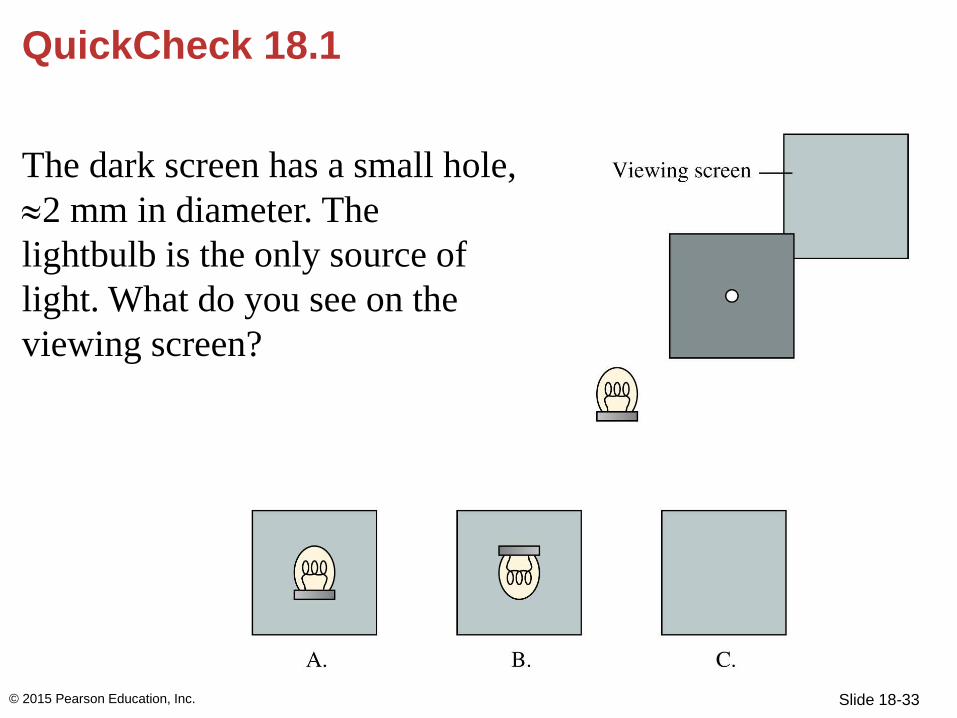
QuickCheck 18.1
The dark screen has a small hole,
2 mm in diameter. The
lightbulb is the only source of
light. What do you see on the
viewing screen?
© 2015 Pearson Education, Inc.

Slide 18-34
QuickCheck 18.1
The dark screen has a small hole,
2 mm in diameter. The
lightbulb is the only source of
light. What do you see on the
viewing screen?
© 2015 Pearson Education, Inc.
B.

Slide 18-35
QuickCheck 18.2
Two point sources of light
illuminate a narrow vertical
aperture in a dark screen.
What do you see on the
viewing screen?
© 2015 Pearson Education, Inc.

Slide 18-36
QuickCheck 18.2
Two point sources of light
illuminate a narrow vertical
aperture in a dark screen.
What do you see on the
viewing screen?
© 2015 Pearson Education, Inc.
C.

Slide 18-37
Seeing Objects
• In order for our eye to see an
object, rays from that object
must enter the eye.
• You cannot see a laser beam
traveling across the room
because no light from the laser
enters the eye. The beam is
invisible to you.
• This is the case for a ray or a parallel ray source.
© 2015 Pearson Education, Inc.
Slide 18-38
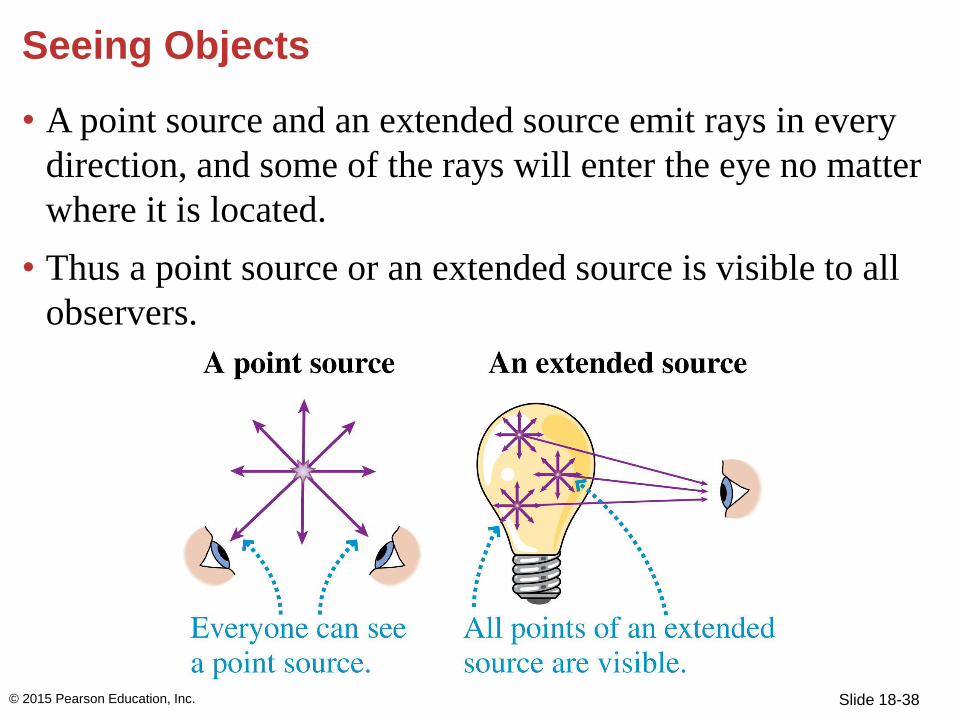
Seeing Objects
• A point source and an extended source emit rays in every
direction, and some of the rays will enter the eye no matter
where it is located.
• Thus a point source or an extended source is visible to all
observers.
© 2015 Pearson Education, Inc.

Slide 18-39
Seeing Objects
• Diffuse reflection is the process of reflecting incident
light in all directions.
• Scattering is a process in which single rays are broken
into many weaker rays that leave in all directions.
© 2015 Pearson Education, Inc.

Slide 18-40
Seeing Objects
• When reading a book, every point on the surface of the
page is struck by a ray from the lamp.
• Then, because of diffuse reflection, these rays scatter in
every direction, some of which enter your eye.
© 2015 Pearson Education, Inc.

Slide 18-41
Seeing Objects
• Lasers are visible when small particles, such as dust,
smoke, or water droplets, scatter the rays from the laser in
every direction.
• Some of the rays are scattered in the direction of your eye,
making the particles in the path of the laser visible.
© 2015 Pearson Education, Inc.

Slide 18-42
Shadows
• An opaque object can
intercept rays from a point
source, leaving a dark area,
or shadow, behind it.
• With a point source, the
shadow is completely dark
and the edges of the
shadow are sharp.
© 2015 Pearson Education, Inc.

Slide 18-43
Shadows
• An extended source is a large
number of point sources,
each of which casts a
shadow.
• The shadows overlap, so the
overall shadow is no longer
sharp.
© 2015 Pearson Education, Inc.
Slide 18-44
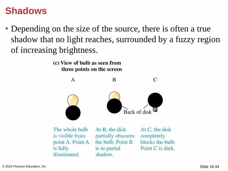
Shadows
• Depending on the size of the source, there is often a true
shadow that no light reaches, surrounded by a fuzzy region
of increasing brightness.
© 2015 Pearson Education, Inc.

Slide 18-45
If the aperture is very small, how far apart on the screen
built into the left side of the box are the images of the point-
like red and green light sources?
Example Problem
© 2015 Pearson Education, Inc.

Section 18.2 Reflection
© 2015 Pearson Education, Inc.

Slide 18-47
Reflection
• Specular reflection is the
reflection from a smooth,
shiny surface such as a
mirror or a piece of
polished metal.
• A three-dimensional
perspective shows that
the incident and reflected
rays are both in a plane that
is normal to the surface.
© 2015 Pearson Education, Inc.

Slide 18-48
• It is customary to represent
reflection with a simpler
view.
• The incident and reflected
rays are in the plane of the
page. The reflective surface
extends into and out of the page.
• A single light ray represents the entire bundle of parallel
rays. This is oversimplified, but it keeps the figure and the
analysis clear.
Reflection
© 2015 Pearson Education, Inc.

Slide 18-49
Reflection
• The angle of incidence, θi,
is the angle between the
incident ray and the line
perpendicular to the
surface.
• The angle of reflection, θr,
is the angle between the reflected
ray and the normal to the surface.
© 2015 Pearson Education, Inc.

Slide 18-50
Reflection
The law of reflection states:
1. The incident ray and the reflected ray are both in the
same plane, which is perpendicular to the surface, and
2. The angle of reflection equals the angle of incidence:
θr = θi
© 2015 Pearson Education, Inc.

Slide 18-51
Example 18.1 Light reflecting from a mirror
A full-length mirror on a closet door is 2.0 m tall. The
bottom touches the floor. A bare lightbulb hangs 1.0 m from
the closet door, 0.5 m above the top of the mirror. How long
is the streak of reflected light across the floor?
© 2015 Pearson Education, Inc.

Slide 18-52
Example 18.1 Light reflecting from a mirror (cont.)
PREPARE Treat the lightbulb as a point source and use the
ray model of light. FIGURE 18.9 is a visual overview of the
light rays. We need to consider only the two rays that strike
the edges of the mirror. All other reflected rays will fall
between these two.
© 2015 Pearson Education, Inc.

Slide 18-53
Example 18.1 Light reflecting from a mirror (cont.)
SOLVE The ray that strikes the
bottom of the mirror reflects from
it and hits the floor just where the
mirror meets the floor. For the top
ray, Figure 18.9 has used the law
of reflection to set the angle of reflection equal to the angle
of incidence; we call both . By simple geometry, the other
angles shown are also equal to . From the small triangle at
the upper right,
© 2015 Pearson Education, Inc.
Slide 18-54
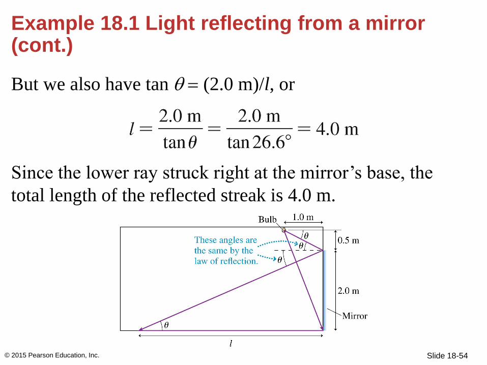
Example 18.1 Light reflecting from a mirror (cont.)
But we also have tan = (2.0 m)/l, or
Since the lower ray struck right at the mirror’s base, the
total length of the reflected streak is 4.0 m.
© 2015 Pearson Education, Inc.

Slide 18-55
QuickCheck 18.3
You are looking at the image of a pencil in a mirror.
What do you see in the mirror if the top half of the
mirror is covered with a piece of dark paper?
A. The full image of the pencil
B. The top half only of the
pencil
C. The bottom half only of
the pencil
D. No pencil, only the paper
© 2015 Pearson Education, Inc.

Slide 18-56
QuickCheck 18.3
You are looking at the image of a pencil in a mirror.
What do you see in the mirror if the top half of the
mirror is covered with a piece of dark paper?
A. The full image of the pencil
B. The top half only of the
pencil
C. The bottom half only of
the pencil
D. No pencil, only the paper
© 2015 Pearson Education, Inc.
Slide 18-57
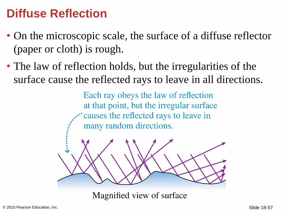
Diffuse Reflection
• On the microscopic scale, the surface of a diffuse reflector
(paper or cloth) is rough.
• The law of reflection holds, but the irregularities of the
surface cause the reflected rays to leave in all directions.
[Insert Figure 18.10]
© 2015 Pearson Education, Inc.

Slide 18-58
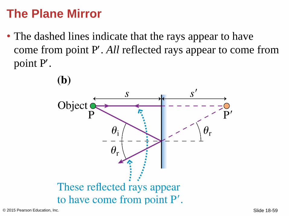
The Plane Mirror
• A plane mirror is a flat mirror.
• Rays from point P will reflect according to the law of
reflection.
[Insert Figure 18.11 (a)]
© 2015 Pearson Education, Inc.
Slide 18-59
• The dashed lines indicate that the rays appear to have
come from point P. All reflected rays appear to come from
point P.
The Plane Mirror
© 2015 Pearson Education, Inc.

Slide 18-60
The Plane Mirror
• Point P, from which the reflected rays diverge, is called
the virtual image of P.
• The image is virtual because no rays actually leave point
P, however the light waves act exactly as if they were.
© 2015 Pearson Education, Inc.

Slide 18-61
The Plane Mirror
• The image distance s is equal to the object distance s:
s = s (plane mirror)
© 2015 Pearson Education, Inc.

Slide 18-62
The Plane Mirror
• The eye captures and focuses diverging bundles of rays
from each point of the image of an extended object.
© 2015 Pearson Education, Inc.

Slide 18-63
The Plane Mirror
1. Rays from each point on
the object spread out in
all directions and strike
every point on the mirror.
Only a very few of these
rays enter your eye, but the
other rays are very real and
might be seen by other observers.
2. Rays from points P and Q enter your eye after reflecting
from different areas of the mirror. This is why you can’t
always see the full image in a very small mirror.
© 2015 Pearson Education, Inc.
Slide 18-64
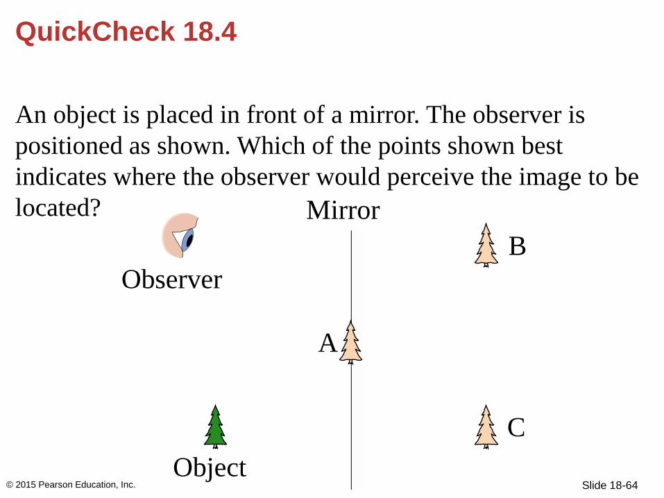
QuickCheck 18.4
An object is placed in front of a mirror. The observer is
positioned as shown. Which of the points shown best
indicates where the observer would perceive the image to be
located?
© 2015 Pearson Education, Inc.
Observer
Mirrror
Object
A
B
C
Mirror

Slide 18-65
QuickCheck 18.4
An object is placed in front of a mirror. The observer is
positioned as shown. Which of the points shown best
indicates where the observer would perceive the image to be
located?
© 2015 Pearson Education, Inc.
Observer
Mirrror
Object
A
B
C
Mirror
C

Slide 18-66
Example 18.2 How high is the mirror?
If your height is h, what is the
shortest mirror on the wall in
which you can see your full
image? Where must the top of
the mirror be hung?
PREPARE Use the ray model of
light. FIGURE 18.13 is a visual
overview of the light rays. We need to consider only the two
rays that leave the top of your head and your feet and reflect
into your eye.
© 2015 Pearson Education, Inc.
Slide 18-67
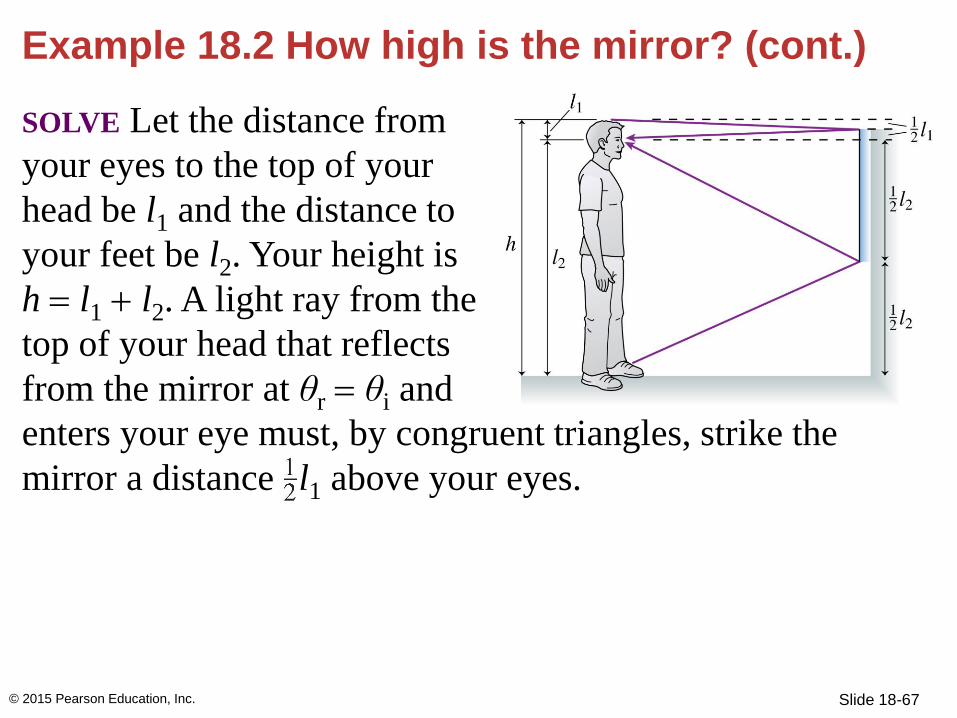
Example 18.2 How high is the mirror? (cont.)
SOLVE Let the distance from
your eyes to the top of your
head be l1 and the distance to
your feet be l2. Your height is
h = l1 + l2. A light ray from the
top of your head that reflects
from the mirror at θr = θi and
enters your eye must, by congruent triangles, strike the
mirror a distance l1 above your eyes.
© 2015 Pearson Education, Inc.

Slide 18-68
Example 18.2 How high is the mirror? (cont.)
Similarly, a ray from your foot
to your eye strikes the mirror
a distance l2 below your eyes.
The distance between these
two points on the mirror is
A ray from
anywhere else on your body
will reach your eye if it strikes the mirror between these two
points. Pieces of the mirror outside these two points are
irrelevant, not because rays don’t strike them but because
the reflected rays don’t reach your eye.
© 2015 Pearson Education, Inc.

Slide 18-69
Example 18.2 How high is the mirror? (cont.)
Thus the shortest mirror in
which you can see your full
reflection is h. But this will
work only if the top of the
mirror is hung midway
between your eyes and the top
of your head.
ASSESS It is interesting that the answer does not depend on
how far you are from the mirror.
© 2015 Pearson Education, Inc.

Section 18.3 Refraction
© 2015 Pearson Education, Inc.

Slide 18-71
Refraction
Two things happen when a
light ray crosses the boundary
between the air and the glass:
1. Part of the light reflects
from the boundary,
obeying the law of
reflection. This is how
you see the reflections from pools of water or storefront
windows, even though water and glass are transparent.
© 2015 Pearson Education, Inc.

Slide 18-72
Refraction
2. Part of the light continues
into the second medium. It
is transmitted rather than
reflected, but the transmitted
ray changes direction as it
crosses the boundary. The
transmission of light from
one medium to another, but with a change in direction, is
called refraction.
© 2015 Pearson Education, Inc.

Slide 18-73
Refraction
• This figure shows the
refraction of light rays from
a parallel beam of light, such
as a laser beam, and rays
from a source.
• An infinite number of rays
are incident on the boundary,
although for simplicity we
focus on a single light ray.
• Reflection occurs at the boundary, but is usually very
weak and is ignored here.
© 2015 Pearson Education, Inc.
Slide 18-74
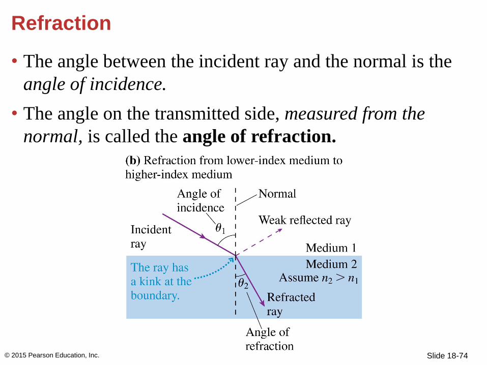
Refraction
• The angle between the incident ray and the normal is the
angle of incidence.
• The angle on the transmitted side, measured from the
normal, is called the angle of refraction.
© 2015 Pearson Education, Inc.

Slide 18-75
Refraction
• The angles are the same for the ray entering Medium 2 in
the first figure and the ray exiting Medium 2 in the second
figure.
[Insert Figure 18.15 (c ).]
© 2015 Pearson Education, Inc.

Slide 18-76
Refraction
• In 1621, Dutch scientist Willebrord Snell proposed a
mathematical statement of the “law of refraction” now
called Snell’s Law:
• The index of refraction determines how much a light ray is
bent when crossing the boundary between two different
media (a consequence of the change in the speed of light
as it crosses a boundary.)
© 2015 Pearson Education, Inc.

Slide 18-77
QuickCheck 18.5
A laser beam passing from medium 1 to medium 2 is
refracted as shown. Which is true?
A. n1 < n2
B. n1 > n2
C. There’s not enough
information to compare
n1 and n2
© 2015 Pearson Education, Inc.

Slide 18-78
QuickCheck 18.5
A laser beam passing from medium 1 to medium 2 is
refracted as shown. Which is true?
A. n1 < n2
B. n1 > n2
C. There’s not enough
information to compare
n1 and n2
© 2015 Pearson Education, Inc.
Slide 18-79
Refraction
© 2015 Pearson Education, Inc.
Slide 18-80
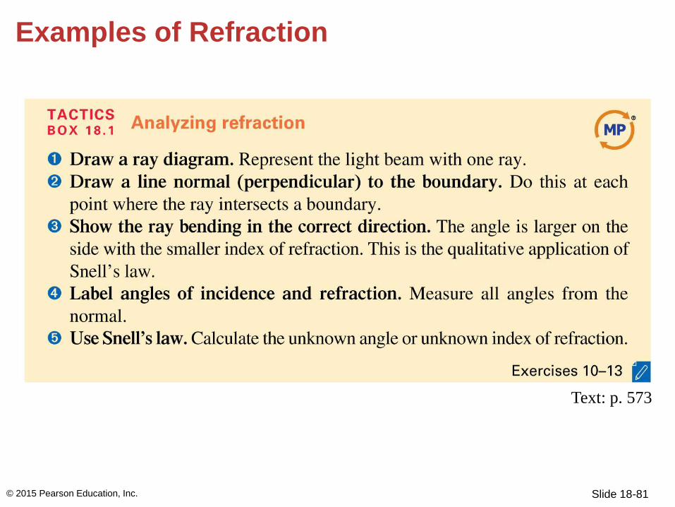
Examples of Refraction
Snell’s law shows:
• When a ray is transmitted into a material with a higher
index of refraction, it bends to make a smaller angle with
the normal.
• When a ray is transmitted into a material with a lower
index of refraction, it bends to make a larger angle with
the normal.
© 2015 Pearson Education, Inc.
Slide 18-81
Examples of Refraction
© 2015 Pearson Education, Inc.
Text: p. 573

Slide 18-82
A B
C D
QuickCheck 18.7
A light ray enters a glass prism as shown. Which is a
possible path for the ray through the prism?
© 2015 Pearson Education, Inc.

Slide 18-83
QuickCheck 18.7
A light ray enters a glass prism as shown. Which is a
possible path for the ray through the prism?
© 2015 Pearson Education, Inc.
A B
C DD

Slide 18-84
Example Problem
What is the index of refraction of the plastic if a ray is
refracted as in the figure?
© 2015 Pearson Education, Inc.

Slide 18-85
Total Internal Reflection
• Total internal reflection (TIR) occurs when a light ray is
unable to refract through a boundary. Instead, 100% of the
light reflects from the boundary.
© 2015 Pearson Education, Inc.

Slide 18-86
• Crossing a boundary into a
material with a lower index
of refraction causes the ray
to bend away from the
normal.
• As angle θ1 increases, the
refraction angle θ2
approaches 90°.
• The fraction of light energy that is transmitted decreases
while the fraction reflected increases.
Total Internal Reflection
© 2015 Pearson Education, Inc.

Slide 18-87
• A critical angle θc is reached
when θ2 = 90°.
• The refracted light vanishes at
the critical angle; there is only
reflected light.
• There is no critical angle and no total internal
reflection if n2 > n1.
Total Internal Reflection
© 2015 Pearson Education, Inc.

Slide 18-88
Total Internal Reflection
• In a pair of binoculars, the
lenses are much farther
apart than your eyes, so
the light rays need to be
brought together.
• Binoculars use a pair of
prisms, forcing the light to
undergo two TIRs before
emerging from the
eyepiece.
© 2015 Pearson Education, Inc.

Slide 18-89
QuickCheck 18.6
A laser beam undergoes two refractions plus total internal
reflection at the interface between medium 2 and medium 3.
Which is true?
A. n1 < n3
B. n1 > n3
C. There’s not enough
information to
compare n1 and n3
© 2015 Pearson Education, Inc.

Slide 18-90
QuickCheck 18.6
A laser beam undergoes two refractions plus total internal
reflection at the interface between medium 2 and medium 3.
Which is true?
A. n1 < n3
B. n1 > n3
C. There’s not enough
information to
compare n1 and n3
© 2015 Pearson Education, Inc.

Slide 18-91
Example 18.5 Seeing a submerged light
A lightbulb is set in the bottom of a 3.0-m-deep swimming
pool. What is the diameter of the circle inside which a duck
swimming on the surface could see the bulb?
© 2015 Pearson Education, Inc.

Slide 18-92
Example 18.5 Seeing a submerged light (cont.)
PREPARE Represent the lightbulb as a point source and use
the ray model of light. FIGURE 18.22 is a visual overview
of the light rays. The lightbulb emits rays at all angles, but
only some of the rays refract into the air where they can be
seen from above. Rays striking the surface at greater than
the critical angle undergo TIR back down into the water.
The diameter of the circle of light is the distance D between
the two points at which rays strike the surface at the critical
angle.
© 2015 Pearson Education, Inc.

Slide 18-93
Example 18.5 Seeing a submerged light (cont.)
SOLVE From trigonometry, the circle diameter is
D = 2h tan c, where h is the depth of the water. The
critical angle for a water-air boundary is
c = sin−1(1.00/1.33) = 48.7°. Thus
D = 2(3.0 m) tan 48.7° = 6.8 m
© 2015 Pearson Education, Inc.

Slide 18-94
Example 18.5 Seeing a submerged light (cont.)
ASSESS Light rays emerging at the edge of the circle actually
skim the surface of the water. By reversing the direction of
the rays, we can understand what a diver sees when she’s
underwater. This idea is explored further in the discussion
below.
© 2015 Pearson Education, Inc.

Slide 18-95
QuickCheck 18.8
A fish in an aquarium with flat sides looks out at a hungry
cat. To the fish, the distance to the cat appears to be
A. Less than the actual
distance.
B. Equal to the actual
distance.
C. More than the actual
distance.
© 2015 Pearson Education, Inc.

Slide 18-96
QuickCheck 18.8
A fish in an aquarium with flat sides looks out at a hungry
cat. To the fish, the distance to the cat appears to be
A. Less than the actual
distance.
B. Equal to the actual
distance.
C. More than the actual
distance.
© 2015 Pearson Education, Inc.

Slide 18-97
• Fiber optics use total internal
reflection for the transmission
of light through optical fibers.
• Light rays pass into the narrow-
diameter glass fiber, but then
strike the inside wall of the
fiber an at angle of incidence
approaching 90°. This is
larger than the critical angle,
so the light undergoes TIR
and remains inside the glass.
Fiber Optics
© 2015 Pearson Education, Inc.

Slide 18-98
Fiber Optics
• When the light rays reach the
flat end of the fiber, the angle
of incidence is lower and the
light can cross the boundary.
• To protect it from external
damage, a glass cladding
surrounds the glass core. Light
undergoes TIR at the cladding
boundary, and remains within
the core.
• Endoscopes made from optical fibers are used for
anthroscopic surgery.
© 2015 Pearson Education, Inc.

Section 18.4 Image Formation by Refraction
© 2015 Pearson Education, Inc.

Slide 18-100
Image Formation by Refraction
• The part of the ruler submerged in
water in the photograph appears
closer than the part above water.
• The rays from the submerged
portion refract at the water-air
boundary.
© 2015 Pearson Education, Inc.

Slide 18-101
Image Formation by Refraction
• To your eye, the rays appear to diverge not from the object
at point P, but instead from point P.
• The ruler appears closer than it really is because of
refraction of light at the boundary.
© 2015 Pearson Education, Inc.

Slide 18-102
Image Formation by Refraction
• The optical axis is the line
through the object and
perpendicular to the boundary.
• The distance l is common to both
the incident and refracted rays:
l = s tan θ1 = s tan θ2
Snell’s Law relates the angles:
© 2015 Pearson Education, Inc.

Slide 18-103
Image Formation by Refraction
• The small-angle approximation
shows sin θ ≈ tan θ.
Therefore
• The image distance is
© 2015 Pearson Education, Inc.

Slide 18-104
Example 18.6 An air bubble window
A fish and a sailor look at each other through a 5.0-cm-thick
glass porthole in a submarine. There happens to be a small
air bubble right in the center of the glass. How far behind
the surface of the glass does the air bubble appear to the
fish? To the sailor?
© 2015 Pearson Education, Inc.

Slide 18-105
Example 18.6 An air bubble window (cont.)
PREPARE Represent the air
bubble as a point source and
use the ray model of light.
Light rays from the bubble
refract into the air on one
side and into the water on
the other. The ray diagram
looks like Figure 18.25.
© 2015 Pearson Education, Inc.

Slide 18-106
Example 18.6 An air bubble window (cont.)
SOLVE The index of refraction of the glass is n1 = 1.50. The
bubble is in the center of the window, so the object distance
from either side of the window is s = 2.5 cm. From the
water side, the fish sees the bubble at an image distance
© 2015 Pearson Education, Inc.

Slide 18-107
Example 18.6 An air bubble window (cont.)
This is the apparent depth of the bubble. The sailor, in air,
sees the bubble at an image distance
ASSESS The image distance is shorter for the sailor because
of the larger difference between the two indices of
refraction.
© 2015 Pearson Education, Inc.

Section 18.5 Thin Lenses: Ray Tracing
© 2015 Pearson Education, Inc.

Slide 18-109
Thin Lenses: Ray Tracing
• A lens is a transparent material that uses refraction of light
rays at curved surfaces to form an image.
• Ray tracing is a pictorial method used to understand
image formation.
© 2015 Pearson Education, Inc.

Slide 18-110
Thin Lenses: Ray Tracing
• A converging lens causes the rays to refract toward the
optical axis.
• A diverging lens causes the rays to refract away from the
axis.
[Insert Figure 18.26]
© 2015 Pearson Education, Inc.

Slide 18-111
Thin Lenses: Ray Tracing
• In a converging lens, an
incoming ray refracts
toward the optical axis at
both the first (air-to-glass)
boundary and the second
(glass-to-air) boundary.
© 2015 Pearson Education, Inc.
[Insert Figure 18.27]

Slide 18-112
Thin Lenses: Ray Tracing
• The incoming rays initially
parallel to the optical axis
converge at the same point,
the focal point of the lens.
• The distance of the focal
point from the lens is called
the focal length f of the
lens.
© 2015 Pearson Education, Inc.

Slide 18-113
Thin Lenses: Ray Tracing
• There are focal points on
both sides of the lens.
• The focal point on the
side from which the light
is incident is the near
focal point; the focal
point on the other side is
the far focal point.
© 2015 Pearson Education, Inc.

Slide 18-114
Thin Lenses: Ray Tracing
• For a diverging lens,
the focal length is the
distance from the lens
to the point at which
rays parallel to the
optical axis converge
or from which they
appear to diverge.
© 2015 Pearson Education, Inc.

Slide 18-115
Converging Lenses
• A thin lens is an idealized lens whose thickness is zero
and that lies entirely in a plane called the lens plane.
• Within the thin-lens approximation, all refraction occurs
as the rays cross the lens plane, and all distances are
measured from the lens plane.
© 2015 Pearson Education, Inc.
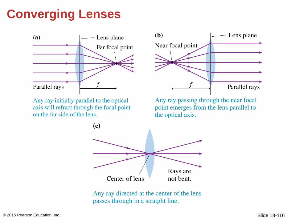
Slide 18-116
Converging Lenses
© 2015 Pearson Education, Inc.

Slide 18-117
Real Images
• If rays diverge from an object at point P and interact with a
lens such that they converge at point P, then we call P a
real image of point P.
• A virtual image is at a point from which rays appear to
diverge, but through which no rays actually pass.
© 2015 Pearson Education, Inc.

Slide 18-118
Real Images
© 2015 Pearson Education, Inc.

Slide 18-119
Real Images
• All points on the object that are in the same plane, the
object plane, converge to image points in the image
plane.
© 2015 Pearson Education, Inc.

Slide 18-120
Real Images
• The image is called an inverted image because it is upside
down with respect to the object. It is a standard
characteristic of real-image formation.
• Rays from point P fill the entire lens surface. A larger lens
“collects” more rays, and therefore makes a brighter
image.
© 2015 Pearson Education, Inc.

Slide 18-121
Real Images
• The rays don’t stop at P
unless we place a screen in
the image plane. When we
do, the image is sharp and
well-focused.
• If the screen is placed
other than in the image
plane, an image is
produced but it is blurry
and out of focus.
© 2015 Pearson Education, Inc.

Slide 18-122
Real Images
• Although you can draw many lines in a ray-tracing
diagram, only three are necessary for locating the image.
© 2015 Pearson Education, Inc. Text: p. 580

Slide 18-123
Example 18.7 Finding the image of a flower
A 4.0-cm-diameter flower is 200 cm from the 50-cm-focal-
length lens of a camera. How far should the plane of the
camera’s light detector be placed behind the lens to record a
well-focused image? What is the diameter of the image on
the detector?
© 2015 Pearson Education, Inc.

Slide 18-124
Example 18.7 Finding the image of a flower (cont.)
PREPARE The flower is in the object plane. Use ray tracing
to locate the image.
© 2015 Pearson Education, Inc.

Slide 18-125
Example 18.7 Finding the image of a flower (cont.)
SOLVE FIGURE 18.33 shows the ray-tracing diagram and
the steps of Tactics Box 18.2. The image has been drawn in
the plane where the three special rays converge. You can see
from the drawing that the image distance is s 65 cm.
© 2015 Pearson Education, Inc.

Slide 18-126
Example 18.7 Finding the image of a flower (cont.)
This is where the detector needs to be placed to record a
focused image. The heights of the object and image are
labeled h and h. The ray through the center of the lens is a
straight line; thus the object and image both subtend the
same angle .
© 2015 Pearson Education, Inc.

Slide 18-127
Example 18.7 Finding the image of a flower (cont.)
From similar triangles,
© 2015 Pearson Education, Inc.

Slide 18-128
Example 18.7 Finding the image of a flower (cont.)
Solving for h gives
The flower’s image has a diameter of 1.3 cm.
© 2015 Pearson Education, Inc.

Slide 18-129
Example 18.7 Finding the image of a flower (cont.)
ASSESS We’ve been able to learn a great deal about the
image from a simple geometric procedure.
© 2015 Pearson Education, Inc.

Slide 18-130
Magnification
• The image can be larger or smaller than the object, depending
on the location and focal length of the lens.
• The magnification m describes the orientation of the image
relative to the object and its size.
1. The absolute value of m fives the ratio of image height to
object height: h/h = |m|.
2. A positive value of m indicates that the image is upright
relative to the object. A negative value of m indicates that the
image is inverted.
© 2015 Pearson Education, Inc.

Slide 18-131
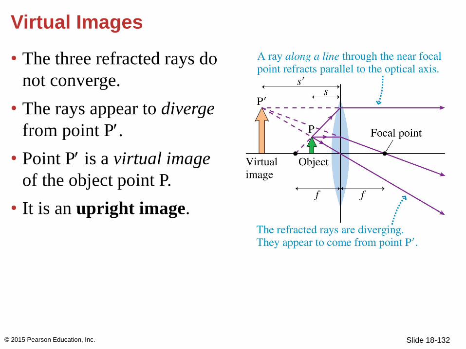
Virtual Images
• When the object is inside
the focal point, a ray passing
through the focal point (to
the left) would never reach
the lens.
• The rays emerging parallel
to the axis entered the lens
along a line passing through
the near focal point.
© 2015 Pearson Education, Inc.
Slide 18-132
Virtual Images
• The three refracted rays do
not converge.
• The rays appear to diverge
from point P.
• Point P is a virtual image
of the object point P.
• It is an upright image.
© 2015 Pearson Education, Inc.

Slide 18-133
Virtual Images
• Because no rays actually
pass through P, placing a
screen at the image plane
would not produce an
image.
• Your eye can still see a
virtual image. This is what
happens when you look
through a magnifying glass
or the eyepiece of a
microscope or binoculars.
© 2015 Pearson Education, Inc.

Slide 18-134
Virtual Images
• The magnification m = –s/s is positive since the virtual
image is upright. That means the ratio –s/s is negative.
• We define the image distance s to be negative for a
virtual image.
• This is a sign convention.
© 2015 Pearson Education, Inc.

Slide 18-135
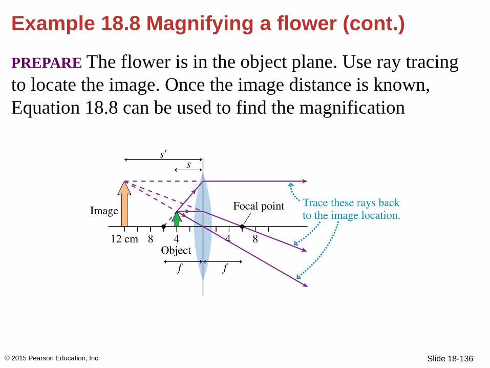
Example 18.8 Magnifying a flower
To see a flower better, you hold a 6.0-cm-focal-length
magnifying glass 4.0 cm from the flower. What is the
magnification?
© 2015 Pearson Education, Inc.
Slide 18-136
Example 18.8 Magnifying a flower (cont.)
PREPARE The flower is in the object plane. Use ray tracing
to locate the image. Once the image distance is known,
Equation 18.8 can be used to find the magnification
© 2015 Pearson Education, Inc.

Slide 18-137
Example 18.8 Magnifying a flower (cont.)
SOLVE FIGURE 18.36 shows the ray-tracing diagram. The
three special rays diverge from the lens, but we can use a
straightedge to extend the rays backward to the point from
which they diverge.
© 2015 Pearson Education, Inc.

Slide 18-138
Example 18.8 Magnifying a flower (cont.)
This point, the image point, is seen to be 12 cm to the left of
the lens. Because this is a virtual image, the image distance
is s = −12 cm. From Equation 18.8 the magnification is
© 2015 Pearson Education, Inc.

Slide 18-139
Example 18.8 Magnifying a flower (cont.)
ASSESS The image is three times as large as the object and,
as we see from the ray-tracing diagram and the fact that
m 0, upright.
© 2015 Pearson Education, Inc.

Slide 18-140
Diverging Lenses
• A diverging lens is one that is thinner at its center than at
its edge.
• Diverging lenses always make virtual images.
© 2015 Pearson Education, Inc.

Slide 18-141
Diverging Lenses
© 2015 Pearson Education, Inc.

Slide 18-142
Diverging Lenses
© 2015 Pearson Education, Inc.
Text: p. 584

Slide 18-143
QuickCheck 18.9
You can use the sun’s rays and a lens to start a fire. To do
so, you should use
A. A converging lens.
B. A diverging lens.
C. Either a converging or a diverging lens will work if you
use it correctly.
© 2015 Pearson Education, Inc.

Slide 18-144
QuickCheck 18.9
You can use the sun’s rays and a lens to start a fire. To do
so, you should use
A. A converging lens.
B. A diverging lens.
C. Either a converging or a diverging lens will work if you
use it correctly.
© 2015 Pearson Education, Inc.

Slide 18-145
QuickCheck 18.10
A lens produces a sharply focused, inverted image on a
screen. What will you see on the screen if the lens is
removed?
A. An inverted but blurry image
B. An image that is dimmer but
otherwise unchanged
C. A sharp, upright image
D. A blurry, upright image
E. No image at all
© 2015 Pearson Education, Inc.

Slide 18-146
QuickCheck 18.10
A lens produces a sharply focused, inverted image on a
screen. What will you see on the screen if the lens is
removed?
A. An inverted but blurry image
B. An image that is dimmer but
otherwise unchanged
C. A sharp, upright image
D. A blurry, upright image
E. No image at all
© 2015 Pearson Education, Inc.

Slide 18-147
QuickCheck 18.11
A lens produces a sharply focused, inverted image on a
screen. What will you see on the screen if a piece of dark
paper is lowered to cover the top half of the lens?
A. An inverted but blurry image
B. An image that is dimmer but
otherwise unchanged
C. Only the top half of the image
D. Only the bottom half of the
image
E. No image at all
© 2015 Pearson Education, Inc.

Slide 18-148
QuickCheck 18.11
A lens produces a sharply focused, inverted image on a
screen. What will you see on the screen if a piece of dark
paper is lowered to cover the top half of the lens?
A. An inverted but blurry image
B. An image that is dimmer but
otherwise unchanged
C. Only the top half of the image
D. Only the bottom half of the
image
E. No image at all
© 2015 Pearson Education, Inc.

Slide 18-149
QuickCheck 18.12
A lens produces a sharply focused, inverted image on a
screen. What will you see on the screen if the lens is
covered by a dark mask having only a small hole in the
center?
A. An inverted but blurry image
B. An image that is dimmer but
otherwise unchanged
C. Only the middle piece of the
image
D. A circular diffraction pattern
E. No image at all © 2015 Pearson Education, Inc.

Slide 18-150
QuickCheck 18.12
A lens produces a sharply focused, inverted image on a
screen. What will you see on the screen if the lens is
covered by a dark mask having only a small hole in the
center?
A. An inverted but blurry image
B. An image that is dimmer but
otherwise unchanged
C. Only the middle piece of the
image
D. A circular diffraction pattern
E. No image at all © 2015 Pearson Education, Inc.

Slide 18-151
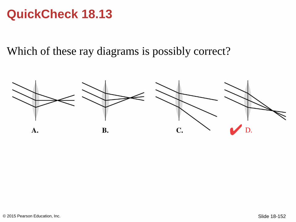
QuickCheck 18.13
Which of these ray diagrams is possibly correct?
© 2015 Pearson Education, Inc.
Slide 18-152
QuickCheck 18.13
Which of these ray diagrams is possibly correct?
© 2015 Pearson Education, Inc.
D.

Slide 18-153
Example 18.9 Demagnifying a flower
A diverging lens with a focal length of 50 cm is placed
100 cm from a flower. Where is the image? What is its
magnification?
© 2015 Pearson Education, Inc.

Slide 18-154
Example 18.9 Demagnifying a flower (cont.)
PREPARE The flower is in the object plane. Use ray tracing
to locate the image. Then Equation 18.8 can be used to find
the magnification.
© 2015 Pearson Education, Inc.

Slide 18-155
Example 18.9 Demagnifying a flower (cont.)
SOLVE FIGURE 18.38 shows the ray-tracing diagram. The
three special rays (labeled a, b, and c to match the Tactics
Box) do not converge. However, they can be traced
backward to an intersection ≈33 cm to the left of the lens.
© 2015 Pearson Education, Inc.

Slide 18-156
Example 18.9 Demagnifying a flower (cont.)
Because the rays appear to diverge from the image, this is a
virtual image and s is < 0. The magnification is
The image, which can be seen by looking through the lens,
is one-third the size of the object and upright.
© 2015 Pearson Education, Inc.

Slide 18-157
Example 18.9 Demagnifying a flower (cont.)
ASSESS Ray tracing with a diverging lens is somewhat
trickier than with a converging lens, so this example is
worth careful study.
© 2015 Pearson Education, Inc.

Section 18.6 Image Formation with Spherical Mirrors
© 2015 Pearson Education, Inc.

Slide 18-159
Image Formation with Spherical Mirrors
• Spherical mirrors are
curved mirrors and can be
used to form images.
• The mirror in the figure is a
concave mirror. Parallel
waves reflect off the mirror
and pass through the focal
point.
© 2015 Pearson Education, Inc.
Slide 18-160
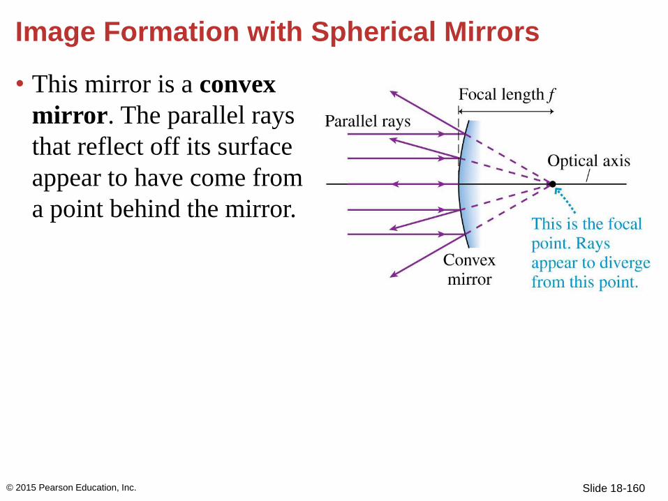
Image Formation with Spherical Mirrors
• This mirror is a convex
mirror. The parallel rays
that reflect off its surface
appear to have come from
a point behind the mirror.
© 2015 Pearson Education, Inc.
Slide 18-161
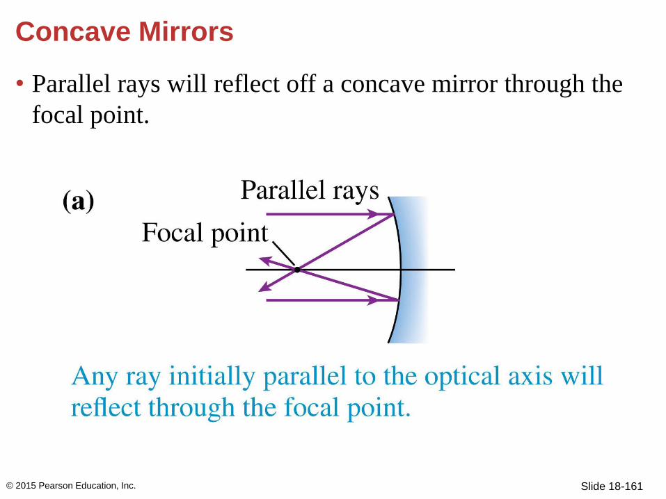
Concave Mirrors
• Parallel rays will reflect off a concave mirror through the
focal point.
© 2015 Pearson Education, Inc.

Slide 18-162
Concave Mirrors
• Rays passing through the focal point will reflect from a
concave mirror, emerging parallel to the optical axis.
© 2015 Pearson Education, Inc.

Slide 18-163
Concave Mirrors
• The law of reflection says any incoming ray will reflect at
the same angle but on the other side of the optical axis.
© 2015 Pearson Education, Inc.

Slide 18-164
Concave Mirrors
• When an object’s distance s from the mirror is greater than
the focal length, the three special rays are enough to locate
the position and size of the image.
© 2015 Pearson Education, Inc.

Slide 18-165
Concave Mirrors
• Incoming rays reflect off the mirror plane, not off the
curved surface of the mirror for the ray trace.
© 2015 Pearson Education, Inc.

Slide 18-166
Concave Mirrors
• The image is real because rays converge at the image
point P′.
• If the object is inside the focal point, the image is a virtual
image.
© 2015 Pearson Education, Inc.

Slide 18-167
Concave Mirrors
© 2015 Pearson Education, Inc.
Text: p. 585

Slide 18-168
Example 18.10 Analyzing a concave mirror
A 3.0-cm-high object is located 60 cm from a concave
mirror. The mirror’s focal length is 40 cm. Use ray tracing
to find the position, height, and magnification of the image.
PREPARE FIGURE 18.42 shows the ray-tracing diagram and
the steps of Tactics Box 18.4.
© 2015 Pearson Education, Inc.

Slide 18-169
Example 18.10 Analyzing a concave mirror (cont.)
SOLVE After preparing a careful drawing, we can use a ruler
to find that the image position is s′ ≈ 120 cm. The
magnification is thus
© 2015 Pearson Education, Inc.

Slide 18-170
Example 18.10 Analyzing a concave mirror (cont.)
The negative sign indicates that the image is inverted. The
image height is thus twice the object height, or h ≈ 6 cm.
ASSESS The image is a real image because light rays
converge at the image point.
© 2015 Pearson Education, Inc.

Slide 18-171
Convex Mirrors
© 2015 Pearson Education, Inc.

Slide 18-172
Convex Mirrors
• We use the three special rays to show that no rays
converge at the image point P.
© 2015 Pearson Education, Inc.

Slide 18-173
Convex Mirrors
• Diverging rays appear to have come from point P.
• The image is upright and much smaller than the object.
© 2015 Pearson Education, Inc.

Slide 18-174
Convex Mirrors
• Convex mirrors are used as passenger-side rearview
mirrors and in stores to keep an eye on customers. Because
the image is smaller, you can see much more of it.
© 2015 Pearson Education, Inc.
Text: p. 587

Slide 18-175
QuickCheck 18.19
You see an upright, magnified image of your face when you
look into magnifying “cosmetic mirror.” The image is
located
A. In front of the mirror’s surface.
B. On the mirror’s surface.
C. Behind the mirror’s surface.
D. Only in your mind because it’s a virtual image.
© 2015 Pearson Education, Inc.

Slide 18-176
QuickCheck 18.19
You see an upright, magnified image of your face when you
look into magnifying “cosmetic mirror.” The image is
located
A. In front of the mirror’s surface.
B. On the mirror’s surface.
C. Behind the mirror’s surface.
D. Only in your mind because it’s a virtual image.
© 2015 Pearson Education, Inc.

Slide 18-177
Conceptual Example 18.11 Driver and passenger mirrors
The rearview mirror on the driver’s side of a car is a plane
(flat) mirror, while the mirror on the passenger’s side is
convex. Why is this?
© 2015 Pearson Education, Inc.

Slide 18-178
Conceptual Example 18.11 Driver and passenger mirrors (cont.)
REASON It is important for the driver to have a wide field of
view from either mirror. He sits close to the driver-side
mirror, so it appears large and can reflect a fairly wide view
of what’s behind. The passenger-side mirror is quite far
from the driver, so it appears relatively small. If it were flat,
it would offer only a narrow view of what’s behind. Making
it convex, like the security mirror discussed above, provides
a wider field of view, but the trade-off is a smaller image.
That’s why the passenger-side mirror usually contains a
warning: Objects in mirror are closer than they appear!
© 2015 Pearson Education, Inc.

Section 18.7 The Thin-Lens Equation
© 2015 Pearson Education, Inc.
Slide 18-180
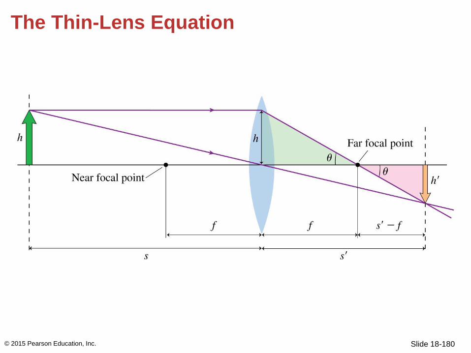
The Thin-Lens Equation
© 2015 Pearson Education, Inc.

Slide 18-181
The Thin-Lens Equation
• Because the two shaded triangles are right angles, the
angle θ must be the same for both. The triangles are
similar.
• For similar triangles, the ratios of any two similar sides are
the same:
© 2015 Pearson Education, Inc.

Slide 18-182
The Thin-Lens Equation
• We have also shown that
• Combining the equations gives
© 2015 Pearson Education, Inc.

Slide 18-183
The Thin-Lens Equation
• Finally this is written as the thin-lens equation:
© 2015 Pearson Education, Inc.

Slide 18-184
Sign Conventions for Lenses and Mirrors
• In the thin-lens equation, the sign of the focal length can
be either positive or negative, depending on the type of
lens or mirror.
© 2015 Pearson Education, Inc.

Slide 18-185
Sign Conventions for Lenses and Mirrors
© 2015 Pearson Education, Inc.
Text: p. 590

Slide 18-186
QuickCheck 18.14
A lens creates an image as shown. In this situation, the
object distance s is
A. Larger than the focal length f
B. Equal to the focal length f
C. Smaller than focal length f
© 2015 Pearson Education, Inc.

Slide 18-187
QuickCheck 18.14
A lens creates an image as shown. In this situation, the
object distance s is
A. Larger than the focal length f
B. Equal to the focal length f
C. Smaller than focal length f
© 2015 Pearson Education, Inc.

Slide 18-188
QuickCheck 18.15
A lens creates an image as shown. In this situation, the
image distance s is
A. Larger than the focal length f
B. Equal to the focal length f
C. Smaller than focal length f
© 2015 Pearson Education, Inc.

Slide 18-189
QuickCheck 18.15
A lens creates an image as shown. In this situation, the
image distance s is
A. Larger than the focal length f
B. Equal to the focal length f
C. Smaller than focal length f
© 2015 Pearson Education, Inc.

Slide 18-190
QuickCheck 18.16
Light rays are converging to point
1. The lens is inserted into the
rays with its focal point at point 1.
Which picture shows the rays
leaving the lens?
© 2015 Pearson Education, Inc.

Slide 18-191
QuickCheck 18.16
Light rays are converging to point
1. The lens is inserted into the
rays with its focal point at point 1.
Which picture shows the rays
leaving the lens?
© 2015 Pearson Education, Inc.
D.

Slide 18-192
QuickCheck 18.17
A lens creates an image as shown. In this situation,
A. s < f
B. f < s < 2f
C. s > 2f
D. There’s not enough information to compare s to f
© 2015 Pearson Education, Inc.

Slide 18-193
QuickCheck 18.17
A lens creates an image as shown. In this situation,
A. s < f
B. f < s < 2f
C. s > 2f
D. There’s not enough information to compare s to f
© 2015 Pearson Education, Inc.
The image is real, which requires s > f.
The image is taller than the object, and
s > s requires s < 2f.

Slide 18-194
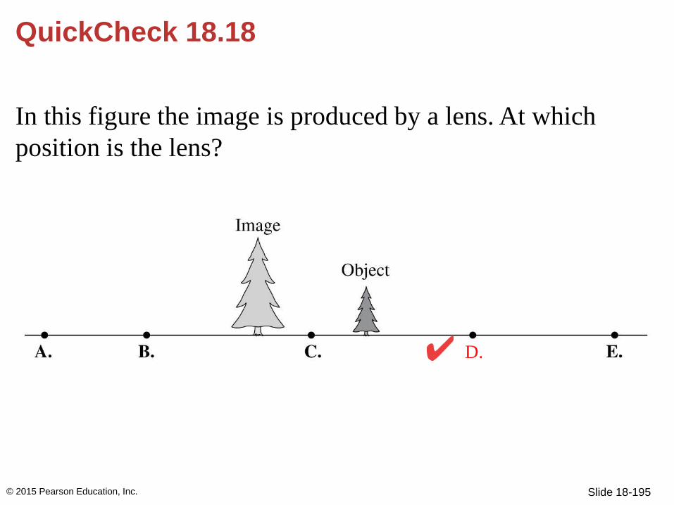
QuickCheck 18.18
In this figure the image is produced by a lens. At which
position is the lens?
© 2015 Pearson Education, Inc.
Slide 18-195
QuickCheck 18.18
In this figure the image is produced by a lens. At which
position is the lens?
© 2015 Pearson Education, Inc.
D.

Slide 18-196
Example 18.12 Analyzing a magnifying lens
A stamp collector uses a magnifying lens that sits 2.0 cm
above the stamp. The magnification is 4. What is the focal
length of the lens?
© 2015 Pearson Education, Inc.

Slide 18-197
Example 18.12 Analyzing a magnifying lens (cont.)
PREPARE A magnifying lens is a
converging lens with the object
distance less than the focal length
(s < f ). Assume it is a thin lens. The
user looks through the lens and sees
a virtual image. FIGURE 18.47
shows the lens and a ray-tracing
diagram.
© 2015 Pearson Education, Inc.

Slide 18-198
Example 18.12 Analyzing a magnifying lens (cont.)
SOLVE A virtual image is upright, so m = +4. The
magnification is m = s/s; thus
s = 4s = 4(2.0 cm) = 8.0 cm
© 2015 Pearson Education, Inc.

Slide 18-199
Example 18.12 Analyzing a magnifying lens (cont.)
We can use s and s in the thin-lens equation to find the
focal length:
© 2015 Pearson Education, Inc.

Slide 18-200
Example 18.12 Analyzing a magnifying lens (cont.)
Thus
ASSESS f 2 cm, as expected
because the object has to be inside
the focal point.
© 2015 Pearson Education, Inc.

Slide 18-201
Summary: General Principles
© 2015 Pearson Education, Inc.
Text: p. 593
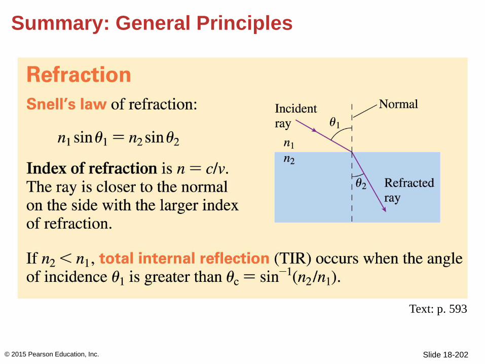
Slide 18-202
Summary: General Principles
© 2015 Pearson Education, Inc.
Text: p. 593

Slide 18-203
Summary: Important Concepts
© 2015 Pearson Education, Inc.
Text: p. 593

Slide 18-204
Summary: Important Concepts
© 2015 Pearson Education, Inc.
Text: p. 593

Slide 18-205
Summary: Applications
© 2015 Pearson Education, Inc.
Text: p. 593

Slide 18-206
Summary: Applications
© 2015 Pearson Education, Inc.
Text: p. 593

Slide 18-207
Summary
© 2015 Pearson Education, Inc.
Text: p. 593

Slide 18-208
Summary
© 2015 Pearson Education, Inc.
Text: p. 593

Slide 18-209
Summary
© 2015 Pearson Education, Inc.
Text: p. 593