Chapter 17. Stereovision Algorithm to be Executed at 100Hz ...
27
Any correspondence concerning this service should be sent to the repository administrator: [email protected] Identification number: DOI : 10.5772/14037 Official URL: http://dx.doi.org/10.5772/14037 This is an author-deposited version published in: http://oatao.univ-toulouse.fr/ Eprints ID: 12030 To cite this version: Devy, Michel and Boizard, Jean-Louis and Botero Galeano, Diego and Carrillo Lindado, Henry and Ibarra Manzano, Mario and Irki, Zohir and Naoulou, Abdelelah and Lacroix, Pierre and Fillatreau, Philippe and Fourniols, Jean-Yves and Parra, Carlos Chapter 17. Stereovision Algorithm to be Executed at 100Hz on a FPGA-Based Architecture. (2011) In: Advances in Theory and Applications of Stereo Vision. InTech, pp. 327-352. ISBN 978-953-307-516-7 Open Archive Toulouse Archive Ouverte (OATAO) OATAO is an open access repository that collects the work of Toulouse researchers and makes it freely available over the web where possible.
-
Upload
khangminh22 -
Category
Documents
-
view
1 -
download
0
Transcript of Chapter 17. Stereovision Algorithm to be Executed at 100Hz ...

Any correspondence concerning this service should be sent to the repository administrator:
Identification number: DOI : 10.5772/14037
Official URL: http://dx.doi.org/10.5772/14037
This is an author-deposited version published in: http://oatao.univ-toulouse.fr/
Eprints ID: 12030
To cite this version:
Devy, Michel and Boizard, Jean-Louis and Botero Galeano, Diego and Carrillo
Lindado, Henry and Ibarra Manzano, Mario and Irki, Zohir and Naoulou,
Abdelelah and Lacroix, Pierre and Fillatreau, Philippe and Fourniols, Jean-Yves
and Parra, Carlos Chapter 17. Stereovision Algorithm to be Executed at 100Hz
on a FPGA-Based Architecture. (2011) In: Advances in Theory and
Applications of Stereo Vision. InTech, pp. 327-352. ISBN 978-953-307-516-7
Open Archive Toulouse Archive Ouverte (OATAO) OATAO is an open access repository that collects the work of Toulouse researchers and
makes it freely available over the web where possible.
0
Stereovision Algorithm to be Executed at 100Hz ona FPGA-Based Architecture
Michel Devy1 *, Jean-Louis Boizard2, Diego Botero Galeano3, Henry CarrilloLindado4, Mario Ibarra Manzano5, Zohir Irki6, Abdelelah Naoulou7, Pierre
Lacroix8, Philippe Fillatreau9, Jean-Yves Fourniols10, Carlos Parra11
1,2,3,5,6,7,8,10CNRS; LAAS; 7 avenue du Colonel Roche, F-31077 ToulouseUniversité de Toulouse; UPS, INSA, INP, ISAE; LAAS-CNRS : F-31077 Toulouse
3,4,11Pontificia Universidad Javeriana; Carrera 7 No. 40-62; Bogotá9Delta Technologies Sud Ouest; 2 Impasse Michel Labrousse, 31036 Toulouse
1,2,3,5,6,7,8,9,10France3,4,11Columbia
1. Introduction
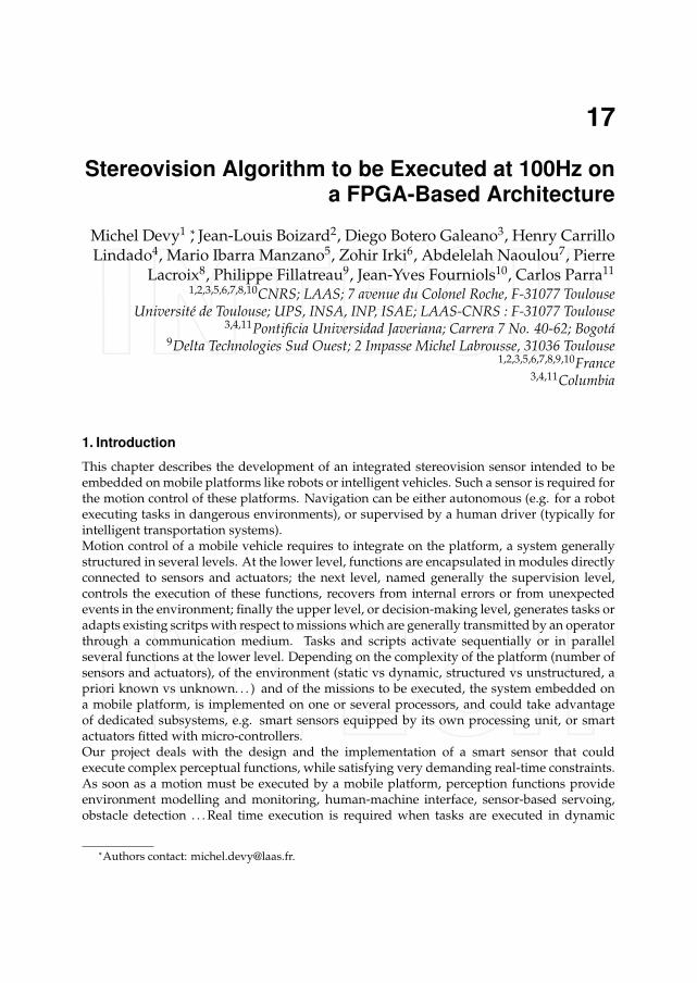
This chapter describes the development of an integrated stereovision sensor intended to beembedded on mobile platforms like robots or intelligent vehicles. Such a sensor is required forthe motion control of these platforms. Navigation can be either autonomous (e.g. for a robotexecuting tasks in dangerous environments), or supervised by a human driver (typically forintelligent transportation systems).Motion control of a mobile vehicle requires to integrate on the platform, a system generallystructured in several levels. At the lower level, functions are encapsulated in modules directlyconnected to sensors and actuators; the next level, named generally the supervision level,controls the execution of these functions, recovers from internal errors or from unexpectedevents in the environment; finally the upper level, or decision-making level, generates tasks oradapts existing scritps with respect to missions which are generally transmitted by an operatorthrough a communication medium. Tasks and scripts activate sequentially or in parallelseveral functions at the lower level. Depending on the complexity of the platform (number ofsensors and actuators), of the environment (static vs dynamic, structured vs unstructured, apriori known vs unknown. . . ) and of the missions to be executed, the system embedded ona mobile platform, is implemented on one or several processors, and could take advantageof dedicated subsystems, e.g. smart sensors equipped by its own processing unit, or smartactuators fitted with micro-controllers.Our project deals with the design and the implementation of a smart sensor that couldexecute complex perceptual functions, while satisfying very demanding real-time constraints.As soon as a motion must be executed by a mobile platform, perception functions provideenvironment modelling and monitoring, human-machine interface, sensor-based servoing,obstacle detection . . . Real time execution is required when tasks are executed in dynamic
*Authors contact: [email protected].
17
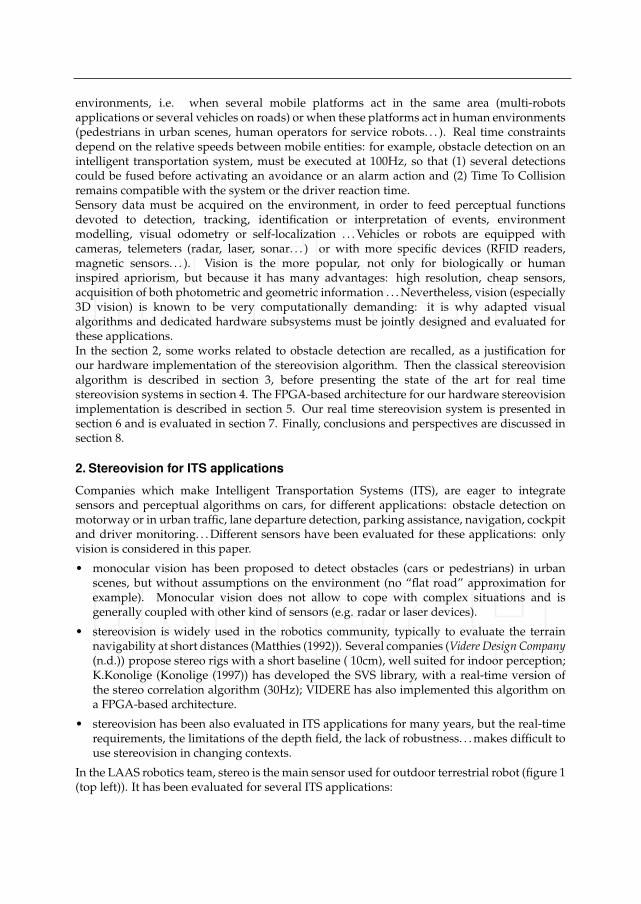
environments, i.e. when several mobile platforms act in the same area (multi-robotsapplications or several vehicles on roads) or when these platforms act in human environments(pedestrians in urban scenes, human operators for service robots. . . ). Real time constraintsdepend on the relative speeds between mobile entities: for example, obstacle detection on anintelligent transportation system, must be executed at 100Hz, so that (1) several detectionscould be fused before activating an avoidance or an alarm action and (2) Time To Collisionremains compatible with the system or the driver reaction time.Sensory data must be acquired on the environment, in order to feed perceptual functionsdevoted to detection, tracking, identification or interpretation of events, environmentmodelling, visual odometry or self-localization . . . Vehicles or robots are equipped withcameras, telemeters (radar, laser, sonar. . . ) or with more specific devices (RFID readers,magnetic sensors. . . ). Vision is the more popular, not only for biologically or humaninspired apriorism, but because it has many advantages: high resolution, cheap sensors,acquisition of both photometric and geometric information . . . Nevertheless, vision (especially3D vision) is known to be very computationally demanding: it is why adapted visualalgorithms and dedicated hardware subsystems must be jointly designed and evaluated forthese applications.In the section 2, some works related to obstacle detection are recalled, as a justification forour hardware implementation of the stereovision algorithm. Then the classical stereovisionalgorithm is described in section 3, before presenting the state of the art for real timestereovision systems in section 4. The FPGA-based architecture for our hardware stereovisionimplementation is described in section 5. Our real time stereovision system is presented insection 6 and is evaluated in section 7. Finally, conclusions and perspectives are discussed insection 8.
2. Stereovision for ITS applications
Companies which make Intelligent Transportation Systems (ITS), are eager to integratesensors and perceptual algorithms on cars, for different applications: obstacle detection onmotorway or in urban traffic, lane departure detection, parking assistance, navigation, cockpitand driver monitoring. . . Different sensors have been evaluated for these applications: onlyvision is considered in this paper.
• monocular vision has been proposed to detect obstacles (cars or pedestrians) in urbanscenes, but without assumptions on the environment (no “flat road” approximation forexample). Monocular vision does not allow to cope with complex situations and isgenerally coupled with other kind of sensors (e.g. radar or laser devices).
• stereovision is widely used in the robotics community, typically to evaluate the terrainnavigability at short distances (Matthies (1992)). Several companies (Videre Design Company(n.d.)) propose stereo rigs with a short baseline ( 10cm), well suited for indoor perception;K.Konolige (Konolige (1997)) has developed the SVS library, with a real-time version ofthe stereo correlation algorithm (30Hz); VIDERE has also implemented this algorithm ona FPGA-based architecture.
• stereovision has been also evaluated in ITS applications for many years, but the real-timerequirements, the limitations of the depth field, the lack of robustness. . . makes difficult touse stereovision in changing contexts.
In the LAAS robotics team, stereo is the main sensor used for outdoor terrestrial robot (figure 1(top left)). It has been evaluated for several ITS applications:
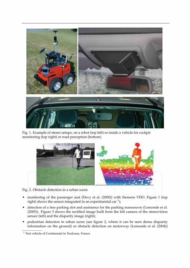
Fig. 1. Example of stereo setups, on a robot (top left) or inside a vehicle for cockpitmonitoring (top right) or road perception (bottom)
Fig. 2. Obstacle detection in a urban scene
• monitoring of the passenger seat (Devy et al. (2000)) with Siemens VDO. Figure 1 (topright) shows the sensor integrated in an experimental car 1);
• detection of a free parking slot and assistance for the parking manoeuvre (Lemonde et al.(2005)). Figure 3 shows the rectified image built from the left camera of the stereovisionsensor (left) and the disparity image (right);
• pedestrian detection in urban scene (see figure 2, where it can be seen dense disparityinformation on the ground) or obstacle detection on motorway (Lemonde et al. (2004))
1 Test vehicle of Continental in Toulouse, France
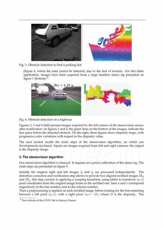
Fig. 3. Obstacle detection to find a parking slot
(figure 4, where the road cannot be detected, due to the lack of texture). For this latterapplication, images have been acquired from a large baseline stereo rig presented onfigure 1 (bottom) 2.
Fig. 4. Obstacle detection on a highway
Figures 2, 3 and 4 (left) present images acquired by the left camera of the stereovision sensor,after rectification: on figures 2 and 4, the green lines on the bottom of the images, indicate thefree space before the detected obstacle. On the right, these figures show disparity maps, withprogressive color variations with respect to the disparity value.
The next section recalls the main steps of the stereovision algorithm, on which ourdevelopments are based. Inputs are images acquired from left and right cameras; the outputis the disparity image.
3. The stereovision algorithm
Our stereovision algorithm is classical. It requires an a priori calibration of the stereo rig. Themain steps are presented on figure 5.
Initially the original right and left images Id and Ig are processed independently. Thedistortion correction and rectification step allows to provide two aligned rectified images IRd
and IRg: this step consists in applying a warping transform, using tables to transform (u, v)pixel coordinates from the original image frame to the rectified one: here u and v correspondrespectively to the line number, and to the column number.Then a preprocessing is applied on each rectified image, before looking for the best matchingbetween a left pixel (u, v), with a right pixel (u, v − D), where D is the disparity. The
2 Test vehicle of the LIVIC lab in Satory, France
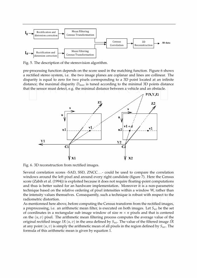
Fig. 5. The description of the stereovision algorithm.
pre-processing function depends on the score used in the matching function. Figure 6 showsa rectified stereo system, i.e. the two image planes are coplanar and lines are collinear. Thedisparity is equal to zero for two pixels corresponding to a 3D point located at an infinitedistance; the maximal disparity Dmax is tuned according to the minimal 3D points distancethat the sensor must detect, e.g. the minimal distance between a vehicle and an obstacle.
Fig. 6. 3D reconstruction from rectified images.
Several correlation scores -SAD, SSD, ZNCC. . . - could be used to compare the correlationwindows around the left pixel and around every right candidate (figure 7). Here the Censusscore (Zabih et al. (1994)) is exploited because it does not require floating-point computationsand thus is better suited for an hardware implementation. Moreover it is a non-parametrictechnique based on the relative ordering of pixel intensities within a window W, rather thanthe intensity values themselves. Consequently, such a technique is robust with respect to theradiometric distortion.As mentionned here above, before computing the Census transform from the rectified images,a preprocessing, i.e. an arithmetic mean filter, is executed on both images. Let Suv be the setof coordinates in a rectangular sub image window of size m × n pixels and that is centeredon the (u, v) pixel. The arithmetic mean filtering process computes the average value of theoriginal rectified image IR (u, v) in the area defined by Suv. The value of the filtered image ˆIRat any point (u, v) is simply the arithmetic mean of all pixels in the region defined by Suv. Theformula of this arithmetic mean is given by equation 1.
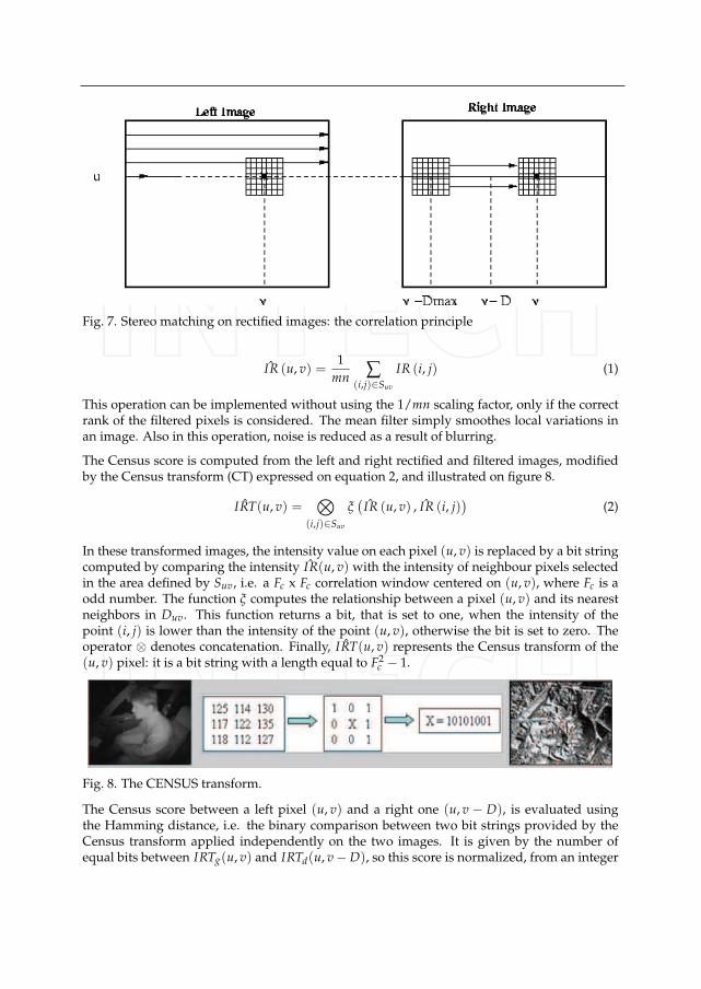
Fig. 7. Stereo matching on rectified images: the correlation principle
ˆIR (u, v) =1
mn ∑(i,j)∈Suv
IR (i, j) (1)
This operation can be implemented without using the 1/mn scaling factor, only if the correctrank of the filtered pixels is considered. The mean filter simply smoothes local variations inan image. Also in this operation, noise is reduced as a result of blurring.
The Census score is computed from the left and right rectified and filtered images, modifiedby the Census transform (CT) expressed on equation 2, and illustrated on figure 8.
ˆIRT(u, v) =⊗
(i,j)∈Suv
ξ(
ˆIR (u, v) , ˆIR (i, j))
(2)
In these transformed images, the intensity value on each pixel (u, v) is replaced by a bit stringcomputed by comparing the intensity ˆIR(u, v) with the intensity of neighbour pixels selectedin the area defined by Suv, i.e. a Fc x Fc correlation window centered on (u, v), where Fc is aodd number. The function ξ computes the relationship between a pixel (u, v) and its nearestneighbors in Duv. This function returns a bit, that is set to one, when the intensity of thepoint (i, j) is lower than the intensity of the point (u, v), otherwise the bit is set to zero. Theoperator ⊗ denotes concatenation. Finally, ˆIRT(u, v) represents the Census transform of the(u, v) pixel: it is a bit string with a length equal to F2
c − 1.
Fig. 8. The CENSUS transform.
The Census score between a left pixel (u, v) and a right one (u, v − D), is evaluated usingthe Hamming distance, i.e. the binary comparison between two bit strings provided by theCensus transform applied independently on the two images. It is given by the number ofequal bits between IRTg(u, v) and IRTd(u, v − D), so this score is normalized, from an integer
included between 0 and F2c − 1. Equation 3 shows how this score is computed: ˆIRTl and ˆIRTr
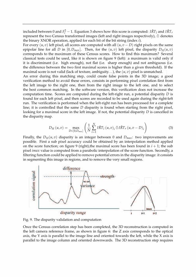
represent the two Census transformed images (left and right images respectively), ⊗ denotesthe binary XNOR operation, applied for each bit of the bit string (index i).For every (u, v) left pixel, all scores are computed with all (u, v − D) right pixels on the sameepipolar line for all D in [0, Dmax]. Then, for the (u, v) left pixel, the disparity DH(u, v)corresponds to the maximum of these Census scores. How to find this maximum? Severalclassical tests could be used, like it is shown on figure 9 (left): a maximum is valid only ifit is discriminant (i.e. high enough), not flat (i.e. sharp enough) and not ambiguous (i.e.the difference between the two first maximal scores is higher than a given threshold). If themaximal score is not valid (lack of texture, ambiguity. . . ), the (u, v) pixel is unmatched.An error during this matching step, could create false points in the 3D image; a goodverification method to avoid these errors, consists in performing pixel correlation first fromthe left image to the right one, then from the right image to the left one, and to selectthe best common matching. In the software version, this verification does not increase thecomputation time. Scores are computed during the left-right run, a potential disparity D isfound for each left pixel, and then scores are recorded to be used again during the right-leftrun. The verification is performed when the left-right run has been processed for a completeline; it is controlled that the same D disparity is found when starting from the right pixel,looking for a maximal score in the left image. If not, the potential disparity D is cancelled inthe disparity map.
DH (u, v) = maxD∈[0,Dmax ]
(
1N
N
∑i=1
ˆIRTl (u, v)i ⊗ˆIRTr (u, v − D)i
)
(3)
Finally, the DH(u, v) disparity is an integer between 0 and Dmax: two improvements arepossible. First a sub pixel accuracy could be obtained by an interpolation method appliedon the score function; on figure 9 (right),the maximal score has been found in i + 1; the subpixel imax value is computed from a parabolic interpolation of the score function. Secondly, afiltering function could be applied to remove potential errors in the disparity image: it consistsin segmenting this image in regions, and to remove the very small regions.
Fig. 9. The disparity validation and computation
Once the Census correlation step has been completed, the 3D reconstruction is computed inthe left camera reference frame, as shown in figure 6: the Z axis corresponds to the opticalaxis, the Y axis is parallel to the image line and oriented towards the left, while the X axis isparallel to the image column and oriented downwards. The 3D reconstruction step requires
the calibration data, i.e. the baseline B (distance between the two optical centers) and similarintrinsic parameters for the rectified ilatinmages (αu, αv, u0, v0). If a (u1, v1) left pixel matchedwith a (u1, v1 + D) right pixel (D negative), it corresponds to a (X, Y, Z) 3D point with thefollowing coordinates:
X =αv.B.(u1 − u0)
αu.D; Y =
B.(v1 − v0)
D; Z =
αv.BD
These equations show that (1) the disparity is constant for pixels located at a fixed depthZ with respect to the cameras, and (2) the Z error increases as Z2, so that the stereomeasurements are very noisy for long distances.
Depending on the available computation power, and on the optimization of the code, thisalgorithm could provide low resolution (320x240 or 160x120) 3D images at video rate; it couldbe sufficient for robotics application, with a weak robot speed. It does not satisfy real-timerequirements for ITS applications or for safety issues when service robots navigate in humanenvironments.
4. Real time stereovision: state of the art
In vision, the term real time is generally understood as video-rate (Brown et al. (2003)), i.e. 30frames per second or higher . Our challenge is real time stereovision at more than 100Hz, fora 640x480 resolution (nb of pixels per line W = 640). Using Camera Link connections withtwo synchronized cameras, images are transmitted with a 40MHz pixel rate (pixel period T =25ns), giving 130 images per second at this resolution. We aim at a 100Hz image rate, so pixelsmust be processed on the fly, with a possible delay between successive images if required.It is yet beyond the possibility of the software implementation, that are generally limited to avideo-rate performance with this VGA resolution; several authors proposed in the 90’s, suchimplementations, e.g. the SVS library implemented by K.Konolige (Konolige (1997)), or thestereo machine of T.Kanade (Kanade et al. (1996)).Only an FPGA implementation can reach a 100Hz performance, and can also meet cost andsize requirements. As soon as powerful enough FPGAs appeared, stereovision architectures(Corke et al. (1999)) have been proposed. A variety of architectures able to provide densedisparity maps have been reported since 1995. Most of the integrated real-time stereo system,are based on Field Programmable Gate Array (FPGA) because of the flexibility given byFPGAs at the moment to realize dedicated hardware architecture, a reasonable low cost (e.g.against ASIC) and an higher processing speed (e.g. against PC).In 2001, Arias-Estrada et al. (Arias-Estrada et al. (2001)) reported a stereo system able toprocess 320x240 images at a rate of 71 FPS using SAD scores for stereo matching. The systemdoes not perform any rectification nor distortion correction and uses a Xilinx Virtex FPGAvalued at $2,000 dollars. Darabiha et al. (Darabiha et al. (2003)) developed a four FPGAbased system with an estimate cost of $10,328 dollars able to provide 256 x360 dense disparitymap at 30 FPS. A complete stereo vision system with radial distortion correction, Laplacian ofGaussian Filtering and disparity map computation via SAD is proposed by Jia et al. Jia et al.(2004). This system can produce 640 x 480 dense disparity maps with 64 levels of disparityat 30 FPS and has an estimated cost of $2,582 dollars. Two systems able to process more than200 images per second, are presented by Georgoulas et al. (Georgoulas et al. (2008)) and Jinet al. (Jin et al. (2010)) respectively. The first system used SAD and the second is based on

Census for computing the disparity map, both system process 640 x 480 images and both ofthem have a price higher than a thousand dollars.These systems (Chonghun et al. (2004)) (Sunghwan et al. (2005)) are compared with our ownarchitecture in table 1, considering the FPGA family, the estimated cost (in $), the resolutionof input and output images (Res in pixel2), the frame rate (in Frame Per Second), the scoreused by the matching method, the maximal disparity (Max in pixels) and finally, the size ofthe neighbourhood used to compute scores (Win in pixels). The architecture presented in thispaper can produced 640 x 480 dense disparity maps at maximum rate of 491 FPS. This stereovision system performs rectification and distortion correction functions on images acquiredfrom two cameras, and then the correlation function on the transformed images, with a 3FPGAs pipeline architecture. The overall cost of the proposed hardware, is about $120, thusmaking this architecture a good choice for low cost system.
Author FPGA family Cost Resolution FPS Score Max WinArias Estrada Xilinx Virtex2 2000 320 x 240 71 SAD 16 7 x 70
Darabiha 4 Xilinx Virtex2 10328 256 x 360 30 LWPC 20 N/AJia Xilinx Virtex2 2582 640 x 480 30 SAD 64 9 X 9
Chonghun Xilinx Virtex2 2983 1024 x 1024 47 SAD 32 16 x 16Lee Xilinx Virtex2 7567 640 x 480 30 SAD 64 32 x 32
Georgulas Altera Stratix2 10797 640 X 480 275 SAD 80 7 X 7Jin Xilinx Virtex4 7261 640 x 480 230 Census 64 11 x 11
Our system 3 Altera Cyclone2 120 640 x 480 491 Census 64 7 x 7
Table 1. Comparisons between integrated stereovision algorithms.
Some authors have used FPGA platforms only as a preliminary validation for a ASIC-basedimplementation: several ones have been developed, e.g. at Zurich ETH Institute ( (Kuhnet al.(n.d.)) (50Hz for 256x192 images), (Hamette et al. (2006)) (pixel clock limited to 5MHz) orat Daejeon University in Korea (Han et al. (2009)) (30hz for 320x240 images).
5. Real time stereovision: our architecture
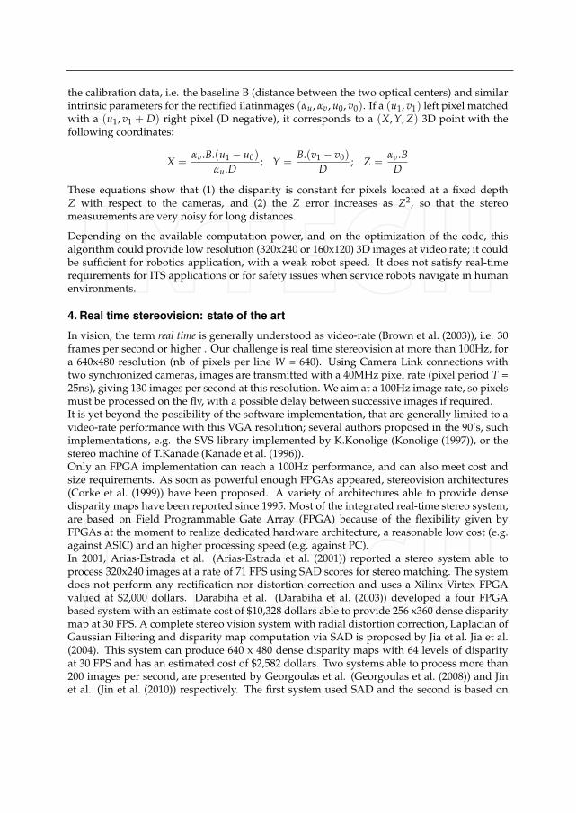
Even though its software implementation requires a lot of memory, our stereo algorithm iswell adapted for integration on a dedicated architecture: no floating-point computations,boolean operations on bit strings. . . , even if the software implementation requires a lot ofmemory. The FPGA implementation has been presented in (Boizard et al. (2005)) (Naoulouet al. (2006)) (Naoulou (2006)). In (Ibarra-Manzano et al. (2009)) and (Ibarra-Manzano et al.(2009)) it is discussed how to generate such an architecture, from tools dedicated to highlevel synthesis from C programs. Actually, these tools have been used in order to test andevaluate several possible architectures: once these preliminary choices have been done, actualarchitectures have been generated using classical tools, i.e. QUARTUS for our ALTERAimplementation.Figure 10 presents the general architecture, which is made with five main modules: theacquisition of original left and right images, the rectification, the mean operator, the Censustransformation and the Census correlation. Images are not stored completely; pixels areprocessed on the fly, with a pixel clock defined by the cameras or the communication protocolwith the cameras (here CamLink). So the pixel clock is 40MHz, i.e. every module must executeits task every 25ns.
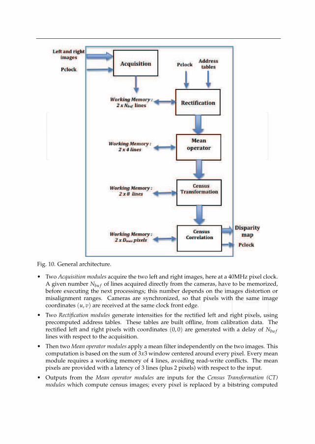
Fig. 10. General architecture.
• Two Acquisition modules acquire the two left and right images, here at a 40MHz pixel clock.A given number Nbu f of lines acquired directly from the cameras, have to be memorized,before executing the next processings; this number depends on the images distortion ormisalignment ranges. Cameras are synchronized, so that pixels with the same imagecoordinates (u, v) are received at the same clock front edge.
• Two Rectification modules generate intensities for the rectified left and right pixels, usingprecomputed address tables. These tables are built offline, from calibration data. Therectified left and right pixels with coordinates (0, 0) are generated with a delay of Nbu f
lines with respect to the acquisition.
• Then two Mean operator modules apply a mean filter independently on the two images. Thiscomputation is based on the sum of 3x3 window centered around every pixel. Every meanmodule requires a working memory of 4 lines, avoiding read-write conflicts. The meanpixels are provided with a latency of 3 lines (plus 2 pixels) with respect to the input.
• Outputs from the Mean operator modules are inputs for the Census Transformation (CT)modules which compute census images; every pixel is replaced by a bitstring computed

from comparisons with their neighbours, in a 7x7 window. So every CT module requiresa working memory of 8 lines, and provides the result as a string of 49 bits for every pixel,with a latency of 7 lines (plus 3 pixels) with respet to the input.
• Finally from these left and right CT pixels, the correlation scores are computed andmaximum scores are selected by a Census Correlation module. When starting from the leftimage, due to the configuration (see figure 6), the left pixel (u, v) can be matched with rightpixels from (u, v− Dmax) to (u, v). So scores are computed for (Dmax + 1) couples of pixels;if the maximum score is found for the position (u, v − D), then the output of the module isequal to the disparity D corresponding to the (u, v) coordinates in the disparity map.
• In our implementation, the disparity is directly sent to a CamLink output generator, so thatthe disparity map is sent at the same frequency than the original images, towards a clientsystem, here a PC only used in order to display the stereo result.
The architecture performance depends on the way scores are computed. Figure 11 presentsseveral options:
• at the top, a sequential architecture is shown. It is a software-like strategy, where (Dmax +1) scores are computed in sequence before looking for the maximum: it does not takeadvantage of the potential parallelization on an hardware implementation.
• in the middle, the scores computation is parallelized only to match left pixels with rightones; it is typically a SIMD operation, so that (Dmax + 1) identical and synchronousprocesses can provide all scores in parallel. It is the simpler strategy, because when the leftCT pixel (u, v) is available, its corresponding one in the right image is already computedin the right image. The search for the maximum, exploits a dichotomy strategy.
• on the bottom, a dual approach is proposed. Left-right scores are computed and themaximum score is looked for like in the previous case, but a verification is made usingright-left scores and right-left matchings.
The dual approach using both the right-left and the left-right stereo matching, requires morememory and more delay. In the software implementation, verifications are applied betweenevery line u; all scores are memorized when applying the left-right stereo matching for every(u, v) pixel on this line; so scores are stored in a (Dmax + 1)x640 2D table; the left-rightmatching for a (u, v) left pixel consists in finding the maximum score on the line v of thescore table; the right-left matching for a (u′, v′) right pixel consists in finding the maximumscore for a diagonal of the score table. These two maximums (on the line and the diagonal),must be the same. This approach is sequential, thus not adapted to hardware implementation;a dedicated architecture is proposed hereafter, based on parallel searching for the left-rightand the right-left matchings. Results presented in the section 7 are obtained with the parallelarchitecture, without right-left verification.At the end, the final latency between the original acquisition and the generation of thedisparity for a (u, v) pixel, can be approximated by (Nbu f + 10) lines, plus 5 pixels:
• the number of lines is given both by the distortion factor of the original images, and by thewindow size used to compute the Mean operator and the Census Transformation;
• the extra delay of 5 pixels, is given also by the window size, and also by pipeline stagerequired in order to compute the maximal score.
Each module is detailed in the following subsections.

Fig. 11. Sequential vs parallel architectures.
5.1 The rectification.
This function applies an homography to the two images, and correct distortions if they cannotbe neglected. So, it is a simple coordinate transform, using for every image, two addresstables generated off line, one for u, one for v. These tables give the correspondance betweenthe (u, v) coordinates in the original image and the (urect, vrect) ones in the rectified image.Two solutions could be implemented:
• Nbu f lines of the original image are recorded before activating the stereo algorithm onsuccessive rectified pixels; first “inverse” address tables are used to transform everyrectified pixel coordinates and to pick up its intensity in the buffer.
• Nbu f lines of the rectified image are initialized from the pixels of the original image using“direct” address tables. Some rectified pixels could remain not initialized, creating artificial“holes” in the rectified image (Irki et al. (2007)).
The two solutions have been implemented; the first one is the more efficient.The resolution of the rectified images could be reduced with respect to the original one; in ourimplementation, the pixel clock is 40MHz for the acquisition module of 640x480 images (25nsbetween two pixels of the original images). The frequency could be reduced to 10MHz (100nsbetween two pixels) if rectified images are generated with a 320x240 resolution. Here the samefrequency is used for all modules, so that the final disparity map has the same resolution thanoriginal images.Address tables are generated especially to correct image distortions. Figure 12 presentspossible configurations for the rectified images with respect to the corrected original ones.
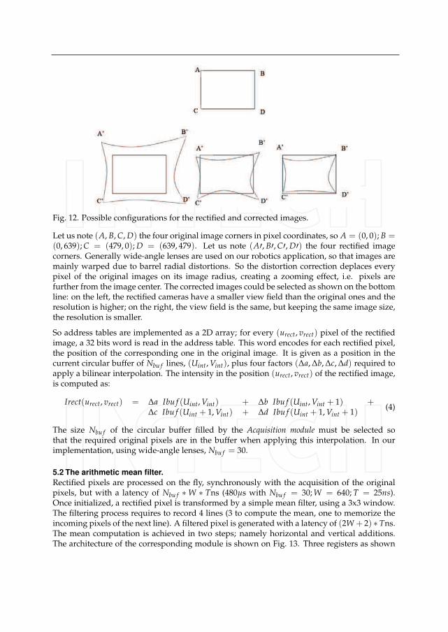
Fig. 12. Possible configurations for the rectified and corrected images.
Let us note (A, B, C, D) the four original image corners in pixel coordinates, so A = (0, 0); B =(0, 639); C = (479, 0); D = (639, 479). Let us note (A′, B′, C′, D′) the four rectified imagecorners. Generally wide-angle lenses are used on our robotics application, so that images aremainly warped due to barrel radial distortions. So the distortion correction deplaces everypixel of the original images on its image radius, creating a zooming effect, i.e. pixels arefurther from the image center. The corrected images could be selected as shown on the bottomline: on the left, the rectified cameras have a smaller view field than the original ones and theresolution is higher; on the right, the view field is the same, but keeping the same image size,the resolution is smaller.
So address tables are implemented as a 2D array; for every (urect, vrect) pixel of the rectifiedimage, a 32 bits word is read in the address table. This word encodes for each rectified pixel,the position of the corresponding one in the original image. It is given as a position in thecurrent circular buffer of Nbu f lines, (Uint, Vint), plus four factors (Δa, Δb, Δc, Δd) required toapply a bilinear interpolation. The intensity in the position (urect, vrect) of the rectified image,is computed as:
Irect(urect, vrect) = Δa Ibu f (Uint, Vint) + Δb Ibu f (Uint, Vint + 1) +Δc Ibu f (Uint + 1, Vint) + Δd Ibu f (Uint + 1, Vint + 1)
(4)
The size Nbu f of the circular buffer filled by the Acquisition module must be selected sothat the required original pixels are in the buffer when applying this interpolation. In ourimplementation, using wide-angle lenses, Nbu f = 30.
5.2 The arithmetic mean filter.
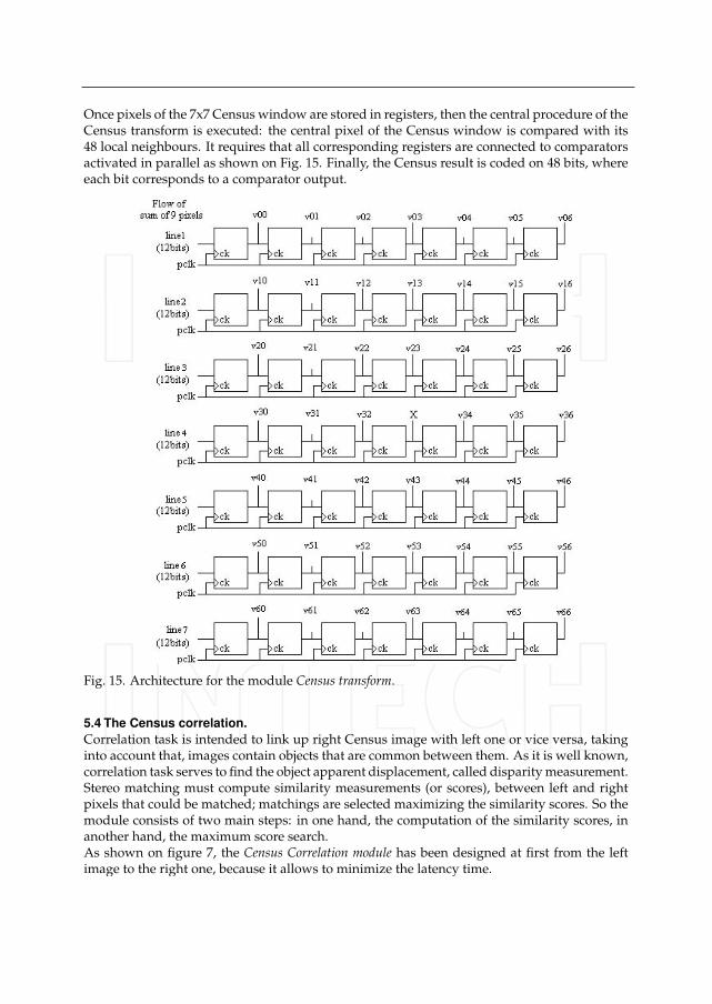
Rectified pixels are processed on the fly, synchronously with the acquisition of the originalpixels, but with a latency of Nbu f ∗ W ∗ Tns (480μs with Nbu f = 30; W = 640; T = 25ns).Once initialized, a rectified pixel is transformed by a simple mean filter, using a 3x3 window.The filtering process requires to record 4 lines (3 to compute the mean, one to memorize theincoming pixels of the next line). A filtered pixel is generated with a latency of (2W + 2) ∗ Tns.The mean computation is achieved in two steps; namely horizontal and vertical additions.The architecture of the corresponding module is shown on Fig. 13. Three registers as shown
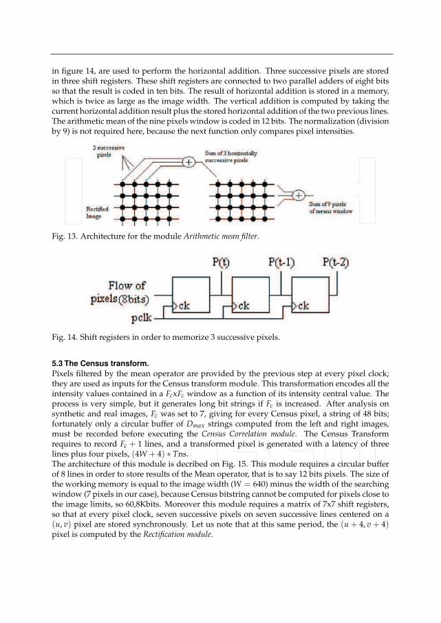
in figure 14, are used to perform the horizontal addition. Three successive pixels are storedin three shift registers. These shift registers are connected to two parallel adders of eight bitsso that the result is coded in ten bits. The result of horizontal addition is stored in a memory,which is twice as large as the image width. The vertical addition is computed by taking thecurrent horizontal addition result plus the stored horizontal addition of the two previous lines.The arithmetic mean of the nine pixels window is coded in 12 bits. The normalization (divisionby 9) is not required here, because the next function only compares pixel intensities.
Fig. 13. Architecture for the module Arithmetic mean filter.
Fig. 14. Shift registers in order to memorize 3 successive pixels.
5.3 The Census transform.
Pixels filtered by the mean operator are provided by the previous step at every pixel clock;they are used as inputs for the Census transform module. This transformation encodes all theintensity values contained in a FcxFc window as a function of its intensity central value. Theprocess is very simple, but it generates long bit strings if Fc is increased. After analysis onsynthetic and real images, Fc was set to 7, giving for every Census pixel, a string of 48 bits;fortunately only a circular buffer of Dmax strings computed from the left and right images,must be recorded before executing the Census Correlation module. The Census Transformrequires to record Fc + 1 lines, and a transformed pixel is generated with a latency of threelines plus four pixels, (4W + 4) ∗ Tns.The architecture of this module is decribed on Fig. 15. This module requires a circular bufferof 8 lines in order to store results of the Mean operator, that is to say 12 bits pixels. The size ofthe working memory is equal to the image width (W = 640) minus the width of the searchingwindow (7 pixels in our case), because Census bitstring cannot be computed for pixels close tothe image limits, so 60,8Kbits. Moreover this module requires a matrix of 7x7 shift registers,so that at every pixel clock, seven successive pixels on seven successive lines centered on a(u, v) pixel are stored synchronously. Let us note that at this same period, the (u + 4, v + 4)pixel is computed by the Rectification module.
Once pixels of the 7x7 Census window are stored in registers, then the central procedure of theCensus transform is executed: the central pixel of the Census window is compared with its48 local neighbours. It requires that all corresponding registers are connected to comparatorsactivated in parallel as shown on Fig. 15. Finally, the Census result is coded on 48 bits, whereeach bit corresponds to a comparator output.
Fig. 15. Architecture for the module Census transform.
5.4 The Census correlation.
Correlation task is intended to link up right Census image with left one or vice versa, takinginto account that, images contain objects that are common between them. As it is well known,correlation task serves to find the object apparent displacement, called disparity measurement.Stereo matching must compute similarity measurements (or scores), between left and rightpixels that could be matched; matchings are selected maximizing the similarity scores. So themodule consists of two main steps: in one hand, the computation of the similarity scores, inanother hand, the maximum score search.As shown on figure 7, the Census Correlation module has been designed at first from the leftimage to the right one, because it allows to minimize the latency time.
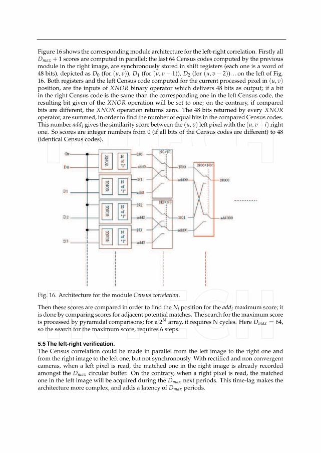
Figure 16 shows the corresponding module architecture for the left-right correlation. Firstly allDmax + 1 scores are computed in parallel; the last 64 Census codes computed by the previousmodule in the right image, are synchronously stored in shift registers (each one is a word of48 bits), depicted as D0 (for (u, v)), D1 (for (u, v − 1)), D2 (for (u, v − 2)). . . on the left of Fig.16. Both registers and the left Census code computed for the current processed pixel in (u, v)position, are the inputs of XNOR binary operator which delivers 48 bits as output; if a bitin the right Census code is the same than the corresponding one in the left Census code, theresulting bit given of the XNOR operation will be set to one; on the contrary, if comparedbits are different, the XNOR operation returns zero. The 48 bits returned by every XNORoperator, are summed, in order to find the number of equal bits in the compared Census codes.This number addi gives the similarity score between the (u, v) left pixel with the (u, v− i) rightone. So scores are integer numbers from 0 (if all bits of the Census codes are different) to 48(identical Census codes).
Fig. 16. Architecture for the module Census correlation.
Then these scores are compared in order to find the Ni position for the addi maximum score; itis done by comparing scores for adjacent potential matches. The search for the maximum scoreis processed by pyramidal comparisons; for a 2N array, it requires N cycles. Here Dmax = 64,so the search for the maximum score, requires 6 steps.
5.5 The left-right verification.
The Census correlation could be made in parallel from the left image to the right one andfrom the right image to the left one, but not synchronously. With rectified and non convergentcameras, when a left pixel is read, the matched one in the right image is already recordedamongst the Dmax circular buffer. On the contrary, when a right pixel is read, the matchedone in the left image will be acquired during the Dmax next periods. This time-lag makes thearchitecture more complex, and adds a latency of Dmax periods.

Nevertheless, the result is improved using this left-right verification. Indeed, when we searchfor the maximum scores, several scores could be identical for different disparities. In thesoftware version, basic verification tests on the found maximum, are made to filter badmatchings (see figure 9(left)). These tests are not implemented in the previous module. Soa verification step allows to eliminate these false disparities, comparing disparities providedby the left-right and right-left Correlation processes.Figure 17 presents the proposed architecture. Two Census Correlation modules are executed inparallel; the first one has been described in the previous section. The second one is identical,but a right Census code is compared with the Dmax + 1 next computed left Census codes.So this right-left search requires an extra latency (here 64 pixel periods more). All computeddisparities are stored in shift registers: so this module requires 2xDmax registers (here 6 bitsregisters, because disparity is between 0 and 63). The verification consists in comparingdisparities given by the two approaches: if disparity d is given by the left-right search, adisparity Dmax − d must be given by the right-left search. If this test is not satisfied, thedisparity is not valid.
Fig. 17. Architecture for the module left-right verification.
Finally, a disparity is generated for a given pixel with a latency of (Nbu f ∗ W + (2W + 2) +(4W + 4) + 2 ∗ Dmax) ∗ Tns with all steps. By now the filtering algorithm used in the softwareversion, is not integrated on a FPGA.
6. Real time stereovision: our FPGA-based implementation
6.1 First validations without rectification
The stereovision algorithm has been firstly implemented in VHDL on the QUARTUSdevelopment tool (Altera Quartus reference manual (n.d.)), and then loaded and executed onthe evaluation kit NIOS-DEVKIT-1S40 (Altera Stratix reference manual (n.d.)), equipped witha STRATIX 1S40 with 41250 logic elements (LEs) and 3.4Mbits of embedded RAM memory.The embedded memory was not sufficient to test the rectification function. So it was notimplemented in this first implementation. Cameras were aligned thanks to mechanicaldevices shown with our preliminary acquisition setup on figure 18 presents :
• the evaluation kit was connected to two JAI cameras, mounted on micro-actuators, so thatan expert operator could manually align the two image planes.
• Images with a 640x480 resolution, are transferred to the evaluation kit at 40MHz, usingCameraLink serial communication protocol.
• it was intended to study a multispectral version of this perceptual method, fusing sensorydata provided by classical CMOS cameras with FIR ones (far infrared, using micro
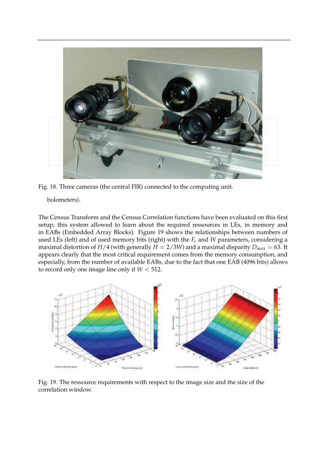
Fig. 18. Three cameras (the central FIR) connected to the computing unit.
bolometers).
The Census Transform and the Census Correlation functions have been evaluated on this firstsetup; this system allowed to learn about the required ressources in LEs, in memory andin EABs (Embedded Array Blocks). Figure 19 shows the relationships between numbers ofused LEs (left) and of used memory bits (right) with the Fc and W parameters, considering amaximal distortion of H/4 (with generally H = 2/3W) and a maximal disparity Dmax = 63. Itappears clearly that the most critical requirement comes from the memory consumption, andespecially, from the number of available EABs, due to the fact that one EAB (4096 bits) allowsto record only one image line only if W < 512.
Fig. 19. The ressource requirements with respect to the image size and the size of thecorrelation window.
This static analysis about the resources requirements, allowed us to select what could be themost well suited FPGA in the ALTERA family, in order to implement our stereo algorithm.Due to economic requirements (low cost, low power consumption), the Cyclone family wasmainly considered: the number of LEs available on the 1C20 chip (20000) could be sufficient,but not the number of EABs (64). The CycloneII family has been selected (1.1Mbits ofembedded memory, up to 64000 LEs) to design a computing unit adapted for the stereovisionalgorithm.
6.2 A multi-FPGAs computing box for stereovision
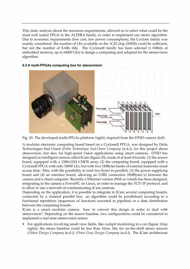
Fig. 20. The developed multi-FPGAs platform (right), inspired from the DTSO camera (left)
A modular electronic computing board based on a CycloneII FPGA, was designed by DeltaTechnologies Sud Ouest (Delta Technologie Sud-Ouest Company (n.d.)), for this project aboutstereovision, but also, for high-speed vision applications using smart cameras. DTSO hasdesigned an intelligent camera called ICam (figure 20), made of at least 4 boards: (1) the sensorboard, equipped with a 1280x1024 CMOS array, (2) the computing board, equipped with aCycloneII FPGA with only 18000 LEs, but with two 1MBytes banks of external memories (readaccess time: 50ns, with the possibility to read two bytes in parallel), (3) the power supplyingboard and (4) an interface board, allowing an USB2 connection (8MBytes/s) between thecamera and a client computer. Recently a Ethernet version (Wifi or wired) has been designed,integrating in the camera a PowerPC on Linux, in order to manage the TCP/IP protocol, andto allow to use a network of communicating iCam cameras.Depending on the application, it is possible to integrate in ICam several computing boards,connected by a chained parallel bus: an algorithm could be parallelized according to afunctional repartition (sequences of functions executed in pipeline) or a data distributionbetween the computing boards.ICam is a smart modular camera: how to convert this design in order to deal withstereovision? Depending on the sensor baseline, two configurations could be considered toimplement a real-time stereovision sensor.
• For applications involving small view fields, like cockpit monitoring in a car (figure 1(topright)), the stereo baseline could be less than 10cm, like for on-the-shelf stereo sensors(Videre Design Company (n.d.)) (Point Grey Design Company (n.d.)). The ICam architecture
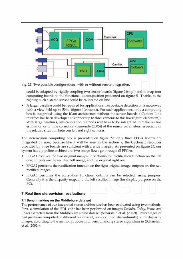
Fig. 21. Two possible configurations, with or without sensor integration.
could be adapted by rigidly coupling two sensor boards (figure 21(top)) and to map fourcomputing boards to the functional decomposition presented on figure 5. Thanks to therigidity, such a stereo sensor could be calibrated off line.
• A larger baseline could be required for applications like obstacle detection on a motorwaywith a view field up to 50m. (figure 1(bottom)). For such applications, only a computingbox is integrated using the ICam architecture without the sensor board: a Camera Linkinterface has been developed to connect up to three cameras to this box (figure 21(bottom)).With large baselines, self-calibration methods will have to be integrated to make on lineestimation or on line correction (Lemonde (2005)) of the sensor parameters, especially ofthe relative situation between left and right cameras.
The stereovision computing box is presented on figure 22; only three FPGA boards areintegrated by now, because like it will be seen in the section 7, the CycloneII resourcesprovided by three boards are sufficient with a wide margin. As presented on figure 23, oursystem has a pipeline architecture; two image flows go through all FPGAs:
• FPGA1 receives the two original images; it performs the rectification function on the leftone; outputs are the rectified left image, and the original right one.
• FPGA2 performs the rectification function on the right original image; outputs are the tworectified images.
• FPGA3 performs the correlation function; outputs can be selected, using jumpers.Generally it is the disparity map, and the left rectified image (for display purpose on thePC).
7. Real time stereovision: evaluations
7.1 Benchmarking on the Middlebury data set
The performance of our integrated stereo architecture has been evaluated using two methods.First, a simulation of the HDL code has been performed on images Tsukuba, Teddy, Venus andCones extracted from the Middlebury stereo dataset (Scharstein et al. (2002)). Percentages ofbad pixels are computed on different regions (all, non-occluded, discontinuity) of the disparityimages, according to the method proposed for benchmarking stereo algorithms in (Scharsteinet al. (2002)):
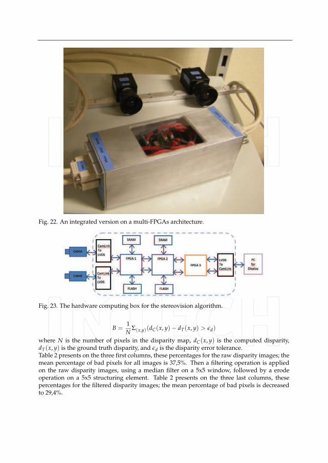
Fig. 22. An integrated version on a multi-FPGAs architecture.
Fig. 23. The hardware computing box for the stereovision algorithm.
B =1N
Σ(x,y)(dC(x, y) − dT(x, y) > εd)
where N is the number of pixels in the disparity map, dC(x, y) is the computed disparity,dT(x, y) is the ground truth disparity, and εd is the disparity error tolerance.Table 2 presents on the three first columns, these percentages for the raw disparity images; themean percentage of bad pixels for all images is 37,5%. Then a filtering operation is appliedon the raw disparity images, using a median filter on a 5x5 window, followed by a erodeoperation on a 5x5 structuring element. Table 2 presents on the three last columns, thesepercentages for the filtered disparity images; the mean percentage of bad pixels is decreasedto 29,4%.
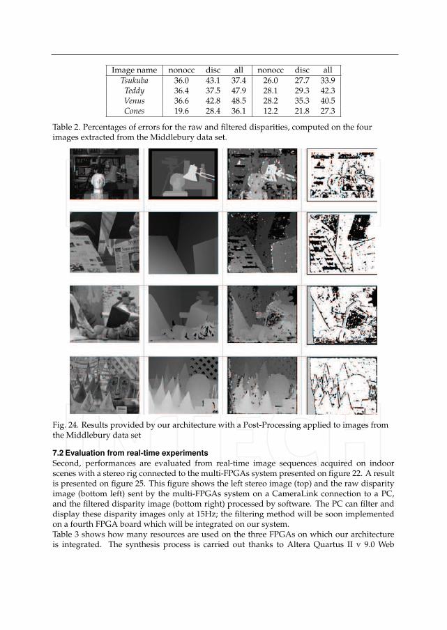
Image name nonocc disc all nonocc disc allTsukuba 36.0 43.1 37.4 26.0 27.7 33.9Teddy 36.4 37.5 47.9 28.1 29.3 42.3Venus 36.6 42.8 48.5 28.2 35.3 40.5Cones 19.6 28.4 36.1 12.2 21.8 27.3
Table 2. Percentages of errors for the raw and filtered disparities, computed on the fourimages extracted from the Middlebury data set.
Fig. 24. Results provided by our architecture with a Post-Processing applied to images fromthe Middlebury data set
7.2 Evaluation from real-time experiments
Second, performances are evaluated from real-time image sequences acquired on indoorscenes with a stereo rig connected to the multi-FPGAs system presented on figure 22. A resultis presented on figure 25. This figure shows the left stereo image (top) and the raw disparityimage (bottom left) sent by the multi-FPGAs system on a CameraLink connection to a PC,and the filtered disparity image (bottom right) processed by software. The PC can filter anddisplay these disparity images only at 15Hz; the filtering method will be soon implementedon a fourth FPGA board which will be integrated on our system.Table 3 shows how many resources are used on the three FPGAs on which our architectureis integrated. The synthesis process is carried out thanks to Altera Quartus II v 9.0 Web
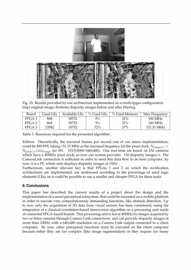
Fig. 25. Results provided by our architecture implemented on a multi-fpgas configuration:(top) original image, (bottom) disparity images before and after filtering
Board Used LEs Available LEs % Used LEs % Used Memory Max FrequencyFPGA 1 868 18752 5% 31% 160 MHzFPGA 2 868 18752 5% 31% 160 MHzFPGA 3 13582 18752 72% 37% 151.31 MHz
Table 3. Resources required for the presented algorithm.
Edition. Theoretically, the maximal frames per second rate of our stereo implementation,could be 490 FPS, taking 151.31 MHz as the maximal frequency for the pixel clock: Nimages/s =Npixels/s/sizeimage (so 491 151310000/640x480). Our real tests are based on JAI cameraswhich have a 40MHz pixel clock; so now our system provides 130 disparity images/s. TheCameraLink connection is sufficient in order to send this data flow to an host computer; bynow, it is a PC which only displays disparity images at 15Hz.Furthermore, another relevant fact is that FPGAs 1 and 2 on which the rectificationarchitectures are implemented, are underused according to the percentage of used logicelements (LEs), so it could be possible to use a smaller and cheaper FPGA for these tasks.
8. Conclusions
This paper has described the current results of a project about the design and theimplementation of a smart perceptual subsystem, that could be mounted on a mobile platformin order to execute very computationnaly demanding functions, like obstacle detection. Upto now only the acquisition of 3D data from visual sensors has been considered, using theintegration of a classical correlation-based stereovision algorithm on a processing unit madeof connected FPGA-based boards. This processing unit is fed at 40MHz by images acquired bytwo or three cameras through Camera Link connections, and can provide disparity images atmore than 100Hz with a 640x480 resolution on a Camera Link output connected to a clientcomputer. By now, other perceptual functions must be executed on the client computerbecause either they are too complex (like image segmentation) or they require too many
floating-point computations : filtering of the disparity map, 3D reconstruction, obstacledetection either directly from the disparity map or from the 3D image. . .Up to now, because of some simplifications made on the original stereovision algorithm,disparity maps acquired by our stereo sensor, are very noisy and contain too many artefacts.We are currently improving these results, by implementing on FPGA, interpolations andverifications already validated on the software version.Moreover, assuming that the ground is planar, disparity maps can be directly exploited todetect obstacles on the ground, using the v-disparity concept (Labayrade et al. (2002)), sothat a probabilistic obstacle map could be provided to the client computer. It is intended toestimate also on the smart sensor, the relative speed of the detected obstacles. Finally other
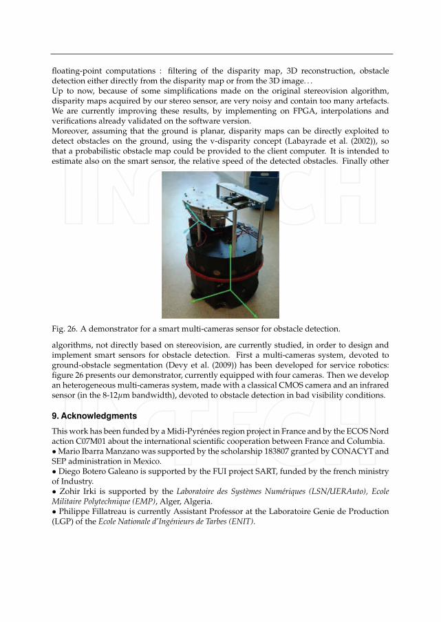
Fig. 26. A demonstrator for a smart multi-cameras sensor for obstacle detection.
algorithms, not directly based on stereovision, are currently studied, in order to design andimplement smart sensors for obstacle detection. First a multi-cameras system, devoted toground-obstacle segmentation (Devy et al. (2009)) has been developed for service robotics:figure 26 presents our demonstrator, currently equipped with four cameras. Then we developan heterogeneous multi-cameras system, made with a classical CMOS camera and an infraredsensor (in the 8-12μm bandwidth), devoted to obstacle detection in bad visibility conditions.
9. Acknowledgments
This work has been funded by a Midi-Pyrénées region project in France and by the ECOS Nordaction C07M01 about the international scientific cooperation between France and Columbia.• Mario Ibarra Manzano was supported by the scholarship 183807 granted by CONACYT andSEP administration in Mexico.• Diego Botero Galeano is supported by the FUI project SART, funded by the french ministryof Industry.• Zohir Irki is supported by the Laboratoire des Systèmes Numériques (LSN/UERAuto), EcoleMilitaire Polytechnique (EMP), Alger, Algeria.• Philippe Fillatreau is currently Assistant Professor at the Laboratoire Genie de Production(LGP) of the Ecole Nationale d’Ingénieurs de Tarbes (ENIT).
10. References
Altera Quartus reference manual (n.d.). URL: http://www.altera.com/literature/lit-qts.jsp.Altera Stratix reference manual (n.d.). URL: http://www.altera.com/products/devices/stratix /features
/stx-architecture.html.Arias-Estrada, M. & Xicotencatl, J. M. (2001). Multiple stereo matching using an extended
architecture, Proc. 11th Int. Conf. on Field-Programmable Logic and Applications (FPL), G.Brebner and R. Woods, Eds. London, UK: Springer-Verlag, pp. 203–212.
Boizard, J.L., Naoulou, A., Fourniols, J., Devy, M., Sentenac, T. & Lacroix, P. (2005). Fpgabased architectures for real time computation of the census transform and correlationin various stereovision contexts, 7th International workshop on Electronics, Control,Modelling, Measurement and Signals (ECMS’2005), 7p.
Brown, M., Burschka, D. & Hager, G. (2003). Advances in computational stereo., IEEE Trans.on Pattern Analysis and Machine Intelligence, Vol. 25(8), pp. 993–1008.
Chonghun, R., Taehyun, H., Sungsik, K. & Jaeseok, K. (2004). Symmetrical dense disparityestimation: algorithms and fpgas implementation, Consumer Electronics, 2004 IEEEInternational Symposium on . Sept. 1-3, pp. 452–456.
Corke, P. & Dunn, P. (1999). Frame-rate stereopsis using non-parametric transforms andprogrammable logic, Proc. IEEE Int. Conf. on Robotics and Automation (ICRA).
Darabiha, A., Rose, J. & MacLean, W. (2003). Video-rate stereo depth measurementon programmable hardware, Proc. IEEE Conf. on Vision and Pattern recognition(CVPR2003), Madison (USA).
Delta Technologie Sud-Ouest Company (n.d.). URL: http://www.delta-technologies.fr.Devy, M., Giralt, A. & Hernandez, A. M. (2000). Detection and classification of passager
seat occupancy using stereovision, Proc.IEEE Symp. on Intelligent Vehicles (IV2000),Dearborn (USA), pp.714-719.
Devy, M., Ibarra Manzano, M., Boizard, J.L., Lacroix, P., Filali, W. & Fourniols, J. (2009).Integrated subsystem for obstacle detection from a belt of micro-cameras, 14thInternational Conference on Advanced Robotics (ICAR 2009), Munich (Germany), 6p..
Georgoulas, C., Kotoulas, L., Sirakoulis, G., Andreadis, I. & Gasteratos, A. (2008). Real-timedisparity map computation module, Microprocessors And Microsystems, Vol. 32(3),pp. 159–170.
Hamette, P. L. & Troster, G. (2006). Fingermouse - architecture of an asic-based mobilestereovision smart camera, Wearable Computers, IEEE International Symposium, Vol. 0,pp. 121–122.
Han, S., Woo, S., Jeong, M. & You, B. (2009). Improved-quality real-time stereo visionprocessor, VLSI Design, International Conference on, Vol. 0, pp. 287–292.
Ibarra-Manzano, M., Almanza-Ojeda, D., Devy, M., Boizard, J.L. & Fourniols, J. (2009).Stereo vision algorithm implementation in fpga using census transform for effectiveresource optimization, Proc. 12th Euromicro Conference on Digital System Design,Architectures, Methods and Tools (DSD’2009), Patras (Greece), pp. 799–805.
Ibarra-Manzano, M., Devy, M., Boizard, J.L., Lacroix, P. & Fourniols, J. (2009). Anefficient reconfigurable architecture to implement dense stereo vision algorithmusing high-level synthesis, Proc. 19th Int. Conf. on Field Programmable Logic andApplications (FPL 2009), Prague (Czech Republic).
Irki, Z., Devy, M., Fillatreau, P. & Boizard, J.L. (2007). An approach for the real time correctionof stereoscopic images, 8th International Workshop on Electronics, Control, Modelling,
Measurement and Signals (ECMS 2007) & Doctoral School (EDSYS, GEET), Liberec (CzechRepublic).
Jia, Y., Zhang, X., Li, M., & An, L. (2004). A miniature stereo vision machine (msvm-iii) fordense disparity mapping, Proc. 17th Int. Conf. Pattern Recognition (ICPR), Cambridge,U.K., Vol. 1, p. 728–731.
Jin, S., Cho, J., Pham, X., Lee, K., Park, S., Kim, M. & Jeon, J. (2010). Fpga design andimplementation of a real-time stereo vision system, IEEE Trans. on circuits and systemsfor video technology Vol. 20(1), p. 15–26.
Kanade, T., Yoshida, A., Oda, K., Kano, H. & Tanaka, M. (1996). A stereo machine forvideo-rate dense depth mapping and its new applications, Proc IEEE Int. Conf. onComputer Vision and Pattern Recognition (CVPR).
Konolige, K. (1997). Small vision systems : Hardware and implementation, Proc. 8th Int.Symp.on Robotics Research (ISRR), Hayama (Japan).
Kuhn, M., Moser, S., Isler, O., Gurkaynak, F. K., Burg, A., Felber, N., Kaeslin, H. & Fichtner, W.(2003 ). Efficient asic implementation of a real-time depth mapping stereo visionsystem, Proc. IEEE Int. Symp. Micro-Nano Mechatronics and Human Science, Vol. 3,pp. 1478–1481.
Labayrade, R., Aubert, D. & Tarel, J. (2002). Real time obstacle detection in stereo vision on nonflat road geometry through v-disparity representation, Proc. IEEE Symp. on IntelligentVehicle (IV2004), Versailles (France).
Lemonde, V. (2005). Stéréovision embarquée sur véhicule : de l’auto-calibrage Ãa la détectiond’obstacles, Phd report, institut national des sciences appliquées, Toulouse (France),Laboratoire d’Architecture et d’Analyse des Systèmes (C.N.R.S.).
Lemonde, V. & Devy, M. (2004). Obstacle detection with stereovision, Mechatronics & Robotics2004 (MECHROB’04), Aachen (Allemagne), Vol.3, pp. 919–924.
Lemonde, V. & Devy, M. (2005). Obstacle detection with stereovision for parking modeling,Proc. European Congress Sensors & Actuators for Advanced Automotive Applications(SENSACT’2005), Noisy-Le-Grand (France), 10p.
Matthies, L. (1992). Stereo vision for planetary rovers: Stochastic modelling to near-real tim eimplementation, Int. Journal on Computer Vision, Vol. 8(1).
Naoulou, A. (2006). Architectures pour la stéréovision passive dense temps réel : applicationàa la stéréo-endoscopie, Phd report, Université Paul Sabatier, Toulouse (France),Laboratoire d’Architecture et d’Analyse des Systèmes (C.N.R.S.).
Naoulou, A., Boizard, J.L., Fourniols, J. & Devy, M. (2006). An alternative to sequentialarchitectures to improve the processing time of passive stereovision algorithms, Proc.16th Int. Conf. on Field Programmable Logic and Applications (FPL’2006), Madrid (Spain),4p., pp. 821–824.
Point Grey Design Company: BumbleBee2 sensor (n.d.). URL: http://www.dnai.com/mclaughl.Scharstein, D. & Szeliski, R. (2002). A taxonomy and evaluation of dense two-frame stereo
correspondence algorithms, Int. Journal on Computer Vision, Vol. 47(1-3), pp. 7–42.Sunghwan, L., Jongsu, Y. & Junseong, K. (2005). Real-time stereo vision on a reconfigurable
system, Proc. Int. Conf. SAMOS, Lecture notes in computer science, ISSN 0302-9743,pp. 299–307.
Videre Design Company (n.d.). URL: http://www.dnai.com/mclaughl.Zabih, R. & Woodfill, J. (1994). Non-parametric local transforms for computing visual
correspondence, Third European Conf. on Computer Vision (ECCV), Stockholm (Sweden).