An ACI Standard and Report Building Code Requirements for Concrete Thin Shells
Upload
khangminh22Category
view
2download
0
WWW.CONCRETE.ORG/ACI318 1
Changes to the Concrete Design Standard
ACI 318-19

WWW.CONCRETE.ORG/ACI318 2
American Concrete Institute is a Registered Provider with The American Institute of Architects Continuing Education Systems (AIA/CES). Credit(s)
earned on completion of this program will be reported to AIA/CES for AIA
members. Certificates of Completion for both AIA members and non-AIA
members will be emailed to you soon after the seminar.
This program is registered with AIA/CES for continuing professional
education. As such, it does not include content that may be deemed or
construed to be an approval or endorsement by the AIA of any material of
construction or any method or manner of handling, using, distributing, or dealing in any material or product.
Questions related to specific materials, methods, and services will be addressed at the conclusion of this presentation.
The American Institute of Architects has approved this session for
7.5 AIA/CES LU/HSW Learning Units.

WWW.CONCRETE.ORG/ACI318 3
Learning Objectives
1. Understand where higher grades of reinforcement are accepted and changes to the requirements for structural concrete to allow the higher reinforcement grades, including development lengths and phi-factors.
2. Identify the added requirements to address shotcrete as a concrete placement method.
3. Explain the expanded scope of deep foundation provisions, including seismic requirements.

WWW.CONCRETE.ORG/ACI318 4
Learning Objectives
4. Learn the new requirements for post-installed screw type anchors and shear lug
design for anchoring to concrete.
5. Describe the changes to shear design
provisions and equations.
6. Identify new tension longitudinal reinforcement requirements in special
structural walls

WWW.CONCRETE.ORG/ACI318 5
Speakers
Speaker bios are included in your handouts for the presentation

WWW.CONCRETE.ORG/ACI318 6
Changes to the Concrete Design Standard
ACI 318-19
Introduction
WWW.CONCRETE.ORG/ACI318 7
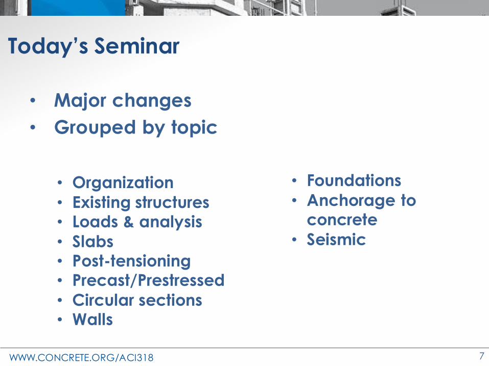
Today’s Seminar
• Major changes
• Grouped by topic
• Organization
• Existing structures• Loads & analysis
• Slabs• Post-tensioning• Precast/Prestressed
• Circular sections• Walls
• Foundations
• Anchorage to concrete
• Seismic
WWW.CONCRETE.ORG/ACI318 8
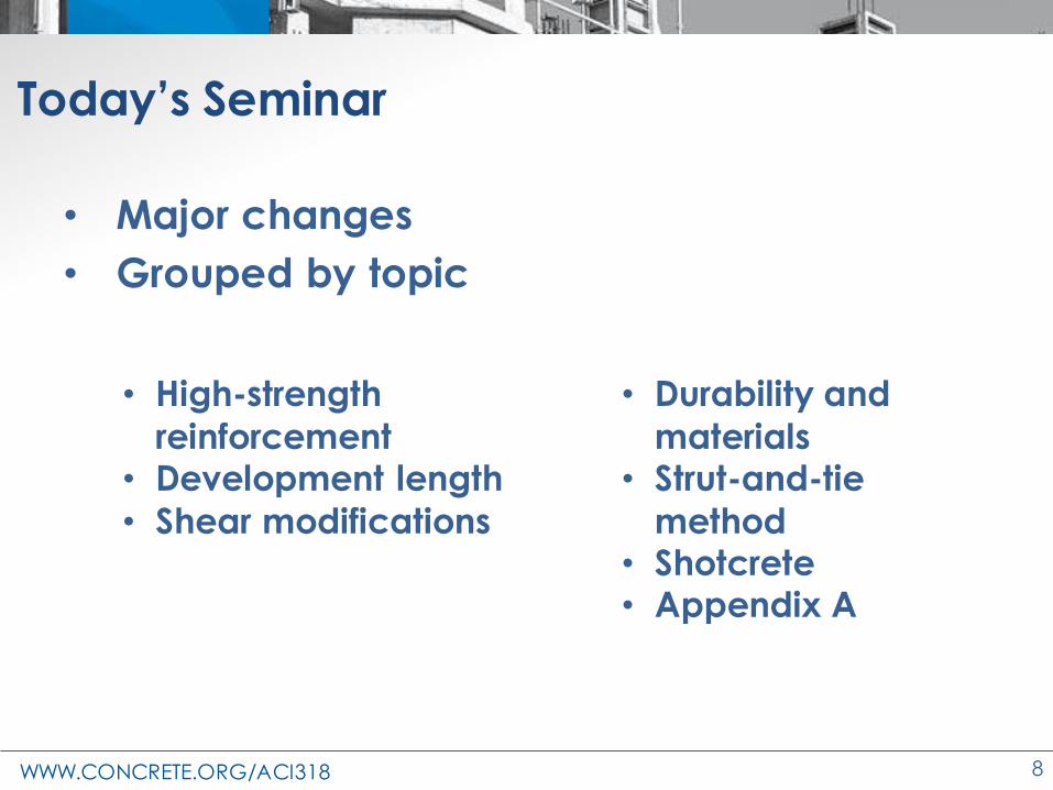
Today’s Seminar
• Major changes
• Grouped by topic
• High-strength
reinforcement• Development length
• Shear modifications
• Durability and
materials• Strut-and-tie
method• Shotcrete• Appendix A
WWW.CONCRETE.ORG/ACI318 9
• Changes from ACI 318-14 to ACI 318-19
318-14 318-19
Today’s Seminar

WWW.CONCRETE.ORG/ACI318 10
Why Do We Change ACI 318?
• Reflects new research
• Construction practices change
• Sometimes tragic events provide introspect
– Earthquakes or other natural disasters
– Collapses or construction accidents
– Observed in-service performance
• New materials
– Or better ways of making established materials
• More powerful analytical tools

WWW.CONCRETE.ORG/ACI318 11
Resources
• ACI 318
• Speaker notes
• ACI Reinforced Concrete Design Handbook
• ACI 318 Building Code Portal
WWW.CONCRETE.ORG/ACI318 12
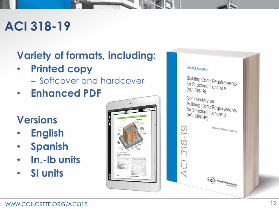
ACI 318-19
Variety of formats, including:
• Printed copy– Softcover and hardcover
• Enhanced PDF
Versions
• English
• Spanish
• In.-lb units
• SI units

WWW.CONCRETE.ORG/ACI318 13
Speaker Notes
Today’s presentation

WWW.CONCRETE.ORG/ACI318 14
ACI Design Handbook
• 15 chapters
• Explanatory text
• Design aids
• 2019 version
expected early next
year

WWW.CONCRETE.ORG/ACI318 15
ACI Design Handbook
• 1: Building Systems
• 2: Structural Systems
• 3: Structural Analysis
• 4: Durability
• 5: One-Way Slabs
• 6: Two-Way Slabs
• 7: Beams
• 8: Diaphragms
• 9: Columns
• 10: Walls
• 11: Foundations
• 12: Retaining Walls
• 13: Serviceability
• 14: Strut-and-Tie
• 15: Anchorage

WWW.CONCRETE.ORG/ACI318 16
ACI 318 Building Code Portal

WWW.CONCRETE.ORG/ACI318 17
Changes to the Concrete Design Standard
ACI 318-19
Organization

WWW.CONCRETE.ORG/ACI318 18
Major goals of ACI 318 organization
• Ease of use
• Find the information you need quickly
– Consistent organization
– Organized in the order of design
• Increase certainty that a design fully meets
the Code
– A chapter for each member type
– All member design provisions in one chapter

WWW.CONCRETE.ORG/ACI318 19
Navigation
10 Parts
• General

WWW.CONCRETE.ORG/ACI318 20
Navigation
10 Parts
• General
• Loads & Analysis
WWW.CONCRETE.ORG/ACI318 21
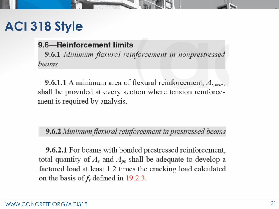
ACI 318 Style

WWW.CONCRETE.ORG/ACI318 22
Navigation
10 Parts
• General
• Loads & Analysis
• Members
• Joints/Connections/
Anchors
• Seismic
• Materials &
Durability
• Strength &
Serviceability
• Reinforcement
• Construction
• Evaluation

WWW.CONCRETE.ORG/ACI318 23
Part 1: General
• 1: General
• 2: Notation and Terminology
– dagg = nominal maximum size of coarse
aggregate, in.
– aggregate—granular material, such as sand, gravel, crushed stone, iron blast-furnace slag, or
recycled aggregates including crushed hydraulic cement concrete, used with a cementing medium to form concrete or mortar.
WWW.CONCRETE.ORG/ACI318 24
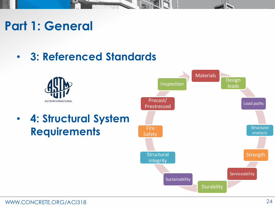
Part 1: General
• 3: Referenced Standards
• 4: Structural System
Requirements
MaterialsDesign loads
Load paths
Structural analysis
Strength
Serviceability
Durability
Sustainability
Structural integrity
Fire Safety
Precast/ Prestressed
Inspection

WWW.CONCRETE.ORG/ACI318 25
Part 2: Loads & Analysis
• 5: Loads
• 6: Structural Analysis
– Simplified, first-order, second-order
– Linear, nonlinear
– Slenderness
– Materials and section properties
WWW.CONCRETE.ORG/ACI318 26
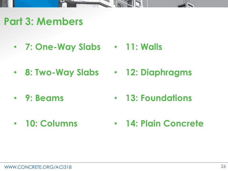
Part 3: Members
• 7: One-Way Slabs
• 8: Two-Way Slabs
• 9: Beams
• 10: Columns
• 11: Walls
• 12: Diaphragms
• 13: Foundations
• 14: Plain Concrete

WWW.CONCRETE.ORG/ACI318 27
Typical member chapter sections
• X.1 Scope
• X.2 General
• X.3 Design Limits
• X.4 Required Strength
• X.5 Design Strength
• X.6 Reinforcement Limits
• X.7 Reinforcement Detailing
• X.? ?

WWW.CONCRETE.ORG/ACI318 28
ACI 318-19
Organization
Δ
Anchorage,
Flexure,
Shear,
Deflection, Ch. 9
Ch. 11
Ch. 10
Ch. 12
Ch. 9
Ch. 9
Ch. 9
Ch. 9

WWW.CONCRETE.ORG/ACI318 29
Part 4: Joints / Connections / Anchors
• 15: Beam-column and slab-column joints
• 16: Connections
between members
• 17: Anchoring to
concrete
WWW.CONCRETE.ORG/ACI318 30
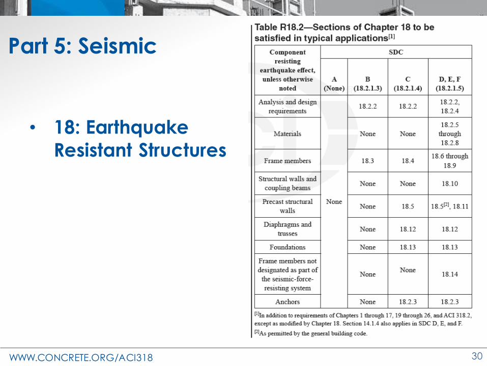
Part 5: Seismic
• 18: Earthquake
Resistant Structures

WWW.CONCRETE.ORG/ACI318 31
Part 6: Materials & Durability
• 19: Concrete: Design and Durability Properties
• 20: Steel Reinforcement Properties,
Durability, and Embedments
(Credit: PCA)
WWW.CONCRETE.ORG/ACI318 32
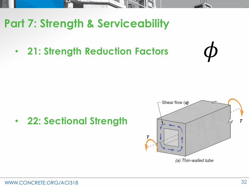
Part 7: Strength & Serviceability
• 21: Strength Reduction Factors
• 22: Sectional Strength

WWW.CONCRETE.ORG/ACI318 33
Organization
Member Chapter
9.5 — Design strength
9.5.2 — Moment
9.5.2.1 — If Pu < 0.10f’cAg, Mn shall be calculated in accordance with 22.3.
9.5.2.2 — If Pu ≥ 0.10f’cAg, Mn shall be calculated in accordance with 22.4.
Toolbox Chapter
22.3 —Flexural strength…
22.3.3.4 …
22.4 — Axial strength or combined flexural and axial
strength…
22.4.3.1 …

WWW.CONCRETE.ORG/ACI318 34
Part 7: Strength & Serviceability
• 23: Strut-and-Tie Method
• 24: Serviceability
,

WWW.CONCRETE.ORG/ACI318 35
Part 8: Reinforcement
• 25: Reinforcement Details

WWW.CONCRETE.ORG/ACI318 36
Part 9: Construction
• 26: Construction Documents and Inspection
– 318 is written to the engineer, not the contractor.
– Construction requirements must be communicated on the construction documents.
– All construction requirements are gathered
together in Chapter 26.
– Design information – job specific
– Compliance requirements – general quality
– Inspection requirements

WWW.CONCRETE.ORG/ACI318 37
Part 10: Evaluation
• 27: Strength Evaluation of Existing Structures
– Applies when strength is in doubt
– Well understood – analytical evaluation
– Not well understood – load test

WWW.CONCRETE.ORG/ACI318 38
Benefits of ACI 318 organization
• Organized from a designer’s perspective
• Easier to find specific requirements
• Intuitive location of information
• Clarified cross references
• Tables improve speed of understanding
• Consistent language in text
• Single idea for each requirement

WWW.CONCRETE.ORG/ACI318 39
Changes to the Concrete Design Standard
ACI 318-19
Existing Structures

WWW.CONCRETE.ORG/ACI318 40
1.4—Applicability
1.4.1 This Code shall apply to concrete structures designed and constructed under the
requirements of the general building code.
…
1.4.3 Applicable provisions of this Code shall
be permitted to be used for structures not
governed by the general building code.

WWW.CONCRETE.ORG/ACI318 41
307 - Chimneys
562 - Repair
216 - Fire 313 - Silos
359 – Nuclear Contain.349 – Nuclear Facilities 350 – Environmental
369 – Seismic Retrofit 376 – RLG Containment
332 – Residential
437 – Strength Evaluation
Concrete designs governed by other ACI codes

WWW.CONCRETE.ORG/ACI318 42
Design recommendations provided in guides
• Slabs-on-ground (ACI 360R)
• Blast-resistant structures (ACI 370R)
• Wire Wrapped Tanks (ACI 372R)

WWW.CONCRETE.ORG/ACI318 43
1.4.2—Repair
1.4.2 Provisions of this Code shall be permitted to be used for the assessment, repair, and
rehabilitation of existing structures.
R1.4.2 Specific provisions for assessment,
repair, and rehabilitation of existing concrete structures are provided in ACI 562-19. Existing
structures in ACI 562 are defined as structures
that are complete and permitted for use.

WWW.CONCRETE.ORG/ACI318 44
Chapter 27 – Strength Evaluation of Existing Structures
Applies when strength is in doubt
• Well understood – analytical evaluation
• Not well understood – load test
– Monotonic procedure, ACI 318
– Cyclic procedure, ACI 437.2

WWW.CONCRETE.ORG/ACI318 45
27.4.6.2—Total test load, Tt
Greatest of:
(a) Tt = 1.15D + 1.5L + 0.4(Lr or S or R)
→Tt = 1.0Dw + 1.1Ds + 1.6L + 0.5(Lr or S or R)
(b) Tt = 1.15D + 0.9L + 1.5(Lr or S or R)
→ Tt = 1.0Dw + 1.1Ds + 1.0L + 1.6(Lr or S or R)
(c) Tt = 1.3D
→Tt = 1.3(Dw + Ds)

WWW.CONCRETE.ORG/ACI318 46
Changes to the Concrete Design Standard
ACI 318-19
Loads & Analysis

WWW.CONCRETE.ORG/ACI318 47
Superposition of loads (R5.3.1)
• Added commentary– If the load effects such as internal forces and
moments are linearly related to the loads, the required strength U may be expressed in terms of load effects with the identical result. If the load effects are nonlinearly related to the loads, such as frame P-delta effects (Rogowsky et al. 2010), the loads are factored prior to determining the load effects. Typical practice for foundation design is discussed in R13.2.6.1. Nonlinear finite element analysis using factored load cases is discussed in R6.9.3.

WWW.CONCRETE.ORG/ACI318 48
Superposition of loads (R5.3.1)
In other words:
• First order, linear analysis
M1.2D+1.6L = 1.2 MD + 1.6 ML
• Second order or nonlinear analysis
M1.2D+1.6L ≠ 1.2 MD + 1.6 ML

WWW.CONCRETE.ORG/ACI318 49
Wind Loads (R5.3.5)
• Added commentary
– ASCE 7-05
• Wind = service-level wind
• Use 1.6 load factor
– ASCE 7-10 & ASCE 7-16
• Wind = strength-level wind
• Use 1.0 load factor
WWW.CONCRETE.ORG/ACI318 50
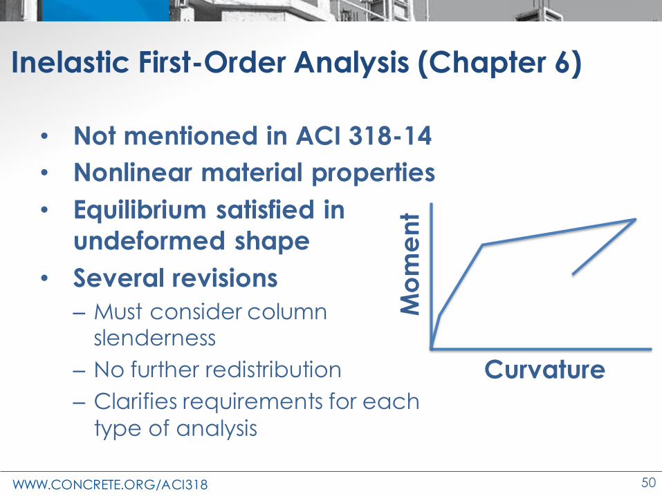
Inelastic First-Order Analysis (Chapter 6)
• Not mentioned in ACI 318-14
• Nonlinear material properties
• Equilibrium satisfied in
undeformed shape
• Several revisions
– Must consider column slenderness
– No further redistribution
– Clarifies requirements for each
type of analysisM
om
en
t
Curvature

WWW.CONCRETE.ORG/ACI318 51
Consistent Stiffness Assumptions (6.3.1.1)
• ACI 318-14 dropped “consistent throughout the analysis” language
No top steel required
No bottom steel required
No steel required

WWW.CONCRETE.ORG/ACI318 52
Torsional Stiffness (R6.3.1.1)
• Clarification in commentary
• Two factors
– Torsional vs. flexural stiffnesses
– Equilibrium requirements
GJ vs. EI

WWW.CONCRETE.ORG/ACI318 53
Torsional Stiffness
Equilibriumtorsion
• Torsion in beam
required to maintain equilibrium
• Torsion and torsional stiffness of the beam must be considered
Beam
Cantilever
slab

WWW.CONCRETE.ORG/ACI318 54
Torsional Stiffness
Compatibility torsion
• Torsion in girder not
required to maintain equilibrium
• Torsion and torsional stiffness of the beam may be neglected
BeamInterior
girder

WWW.CONCRETE.ORG/ACI318 55
Torsional Stiffness
Compatibility torsion
• Torsion in girder not
required to maintain equilibrium
• Torsion and torsional stiffness of the girder should be included
BeamExterior
girder

WWW.CONCRETE.ORG/ACI318 56
Shear Area (6.6.3.1)
Member and conditionMoment of
inertia
Cross-sectional area for axial deformations
Cross-sectional area for shear deformations
Columns 0.70Ig
1.0Ag bwhWalls
Uncracked 0.70Ig
Cracked 0.35Ig
Beams 0.35Ig
Flat plates and flat slabs 0.25Ig
Table 6.6.3.1.1(a)— Moments of Inertia and cross-sectional areas permitted for elastic analysis at factored load level
• No previous guidance

WWW.CONCRETE.ORG/ACI318 57
Floor Vibrations (R24.1)
• Typical floors
– Good performance
• Areas of concern
– Long/open spans
– High-performance (precision machinery)
– Rhythmic loading or vibrating machinery
– Precast
• Commentary references

WWW.CONCRETE.ORG/ACI318 58
Floor Vibrations
• Resources– ATC Design Guide 1, “Minimizing Floor Vibration,”
– Fanella, D.A., and Mota, M., “Design Guide for Vibrations of Reinforced Concrete Floor Systems,”
– Wilford, M.R., and Young, P., “A Design Guide for Footfall Induced Vibration of Structures,”
– PCI Design Handbook
– Mast, R.F., “Vibration of Precast Prestressed Concrete Floors
– West, J.S.; Innocenzi, M.J.; Ulloa, F.V.; and Poston, R.W., “Assessing Vibrations”
• No specific requirements
CIP
Pre
cast
P-T

WWW.CONCRETE.ORG/ACI318 59
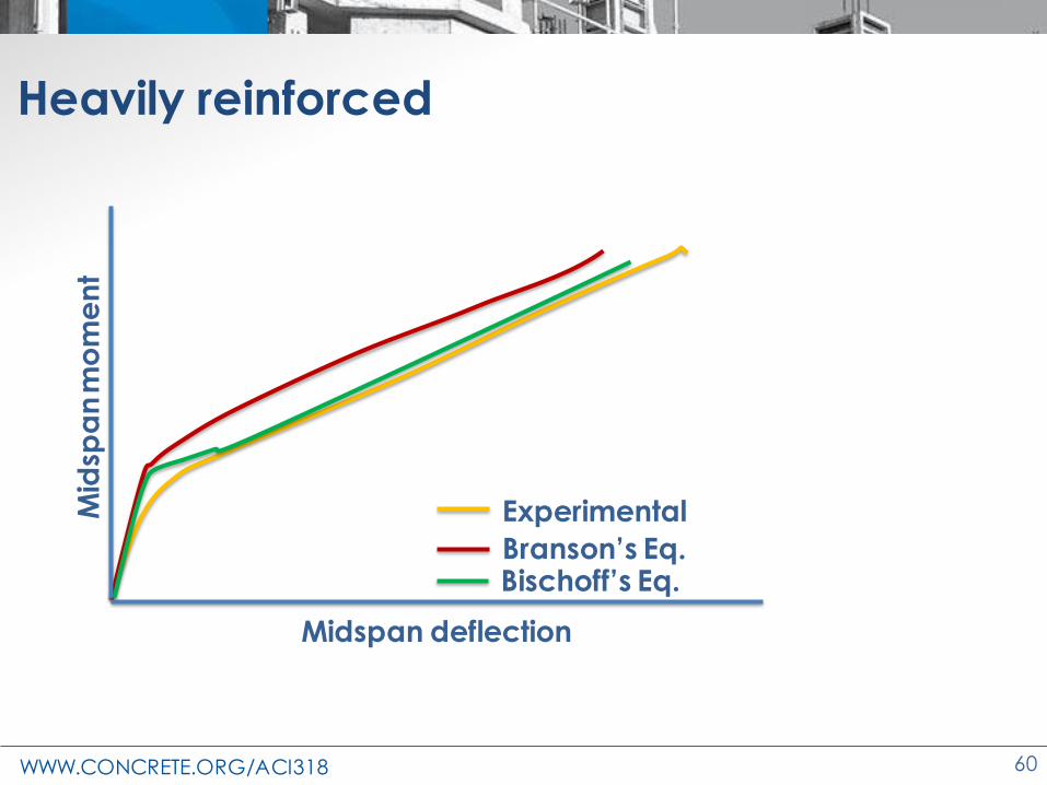
Concerns about deflection calculations
• Service level deflections based on Branson’s equation underpredicted deflections for ρ
below ≈ 0.8%
• Reports of excessive slab deflections
(Kopczynski, Stivaros)
• High-strength reinforcement may result in lower reinforcement ratios
WWW.CONCRETE.ORG/ACI318 60
Heavily reinforced
Midspan deflection
Mid
spa
nm
om
en
t
Experimental
Branson’s Eq.Bischoff’s Eq.

WWW.CONCRETE.ORG/ACI318 61
Lightly reinforced
Midspan deflection
Mid
spa
nm
om
en
t
Experimental
Branson’s Eq.Bischoff’s Eq.

WWW.CONCRETE.ORG/ACI318 62
Ie should be the average of flexibilities

WWW.CONCRETE.ORG/ACI318 63
• Branson
• Bischoff
Branson combines stiffnesses. Bischoff combines flexibilities.
Comparison of Branson’s and Bischoff’s Ie

WWW.CONCRETE.ORG/ACI318 64
• Table 24.2.3.5 ~ Inverse of Bischoff Eqn.
• 2/3 factor added to account for:
– restraint that reduces effective cracking moment
– reduced concrete tensile strength during
construction
• Prestressed concrete
Effective Moment of Inertia
𝑀𝑎 > Τ2 3 𝑀𝑐𝑟, 𝐼𝑒 =𝐼𝑐𝑟
1 −Τ2 3 𝑀𝑐𝑟𝑀𝑎
2
1 −𝐼𝑐𝑟𝐼𝑔
𝑀𝑎 ≤ Τ2 3 𝑀𝑐𝑟, 𝐼𝑒 = 𝐼𝑔

WWW.CONCRETE.ORG/ACI318 65
Changes to the Concrete Design Standard
ACI 318-19
One-Way Slabs

WWW.CONCRETE.ORG/ACI318 66
Structural Integrity Reinforcement
Structural integrity provisions have been added
• To improve structural integrity
– To ensure that failure of a portion of a slab does
not lead to disproportional collapse
• To be similar to that for beams
– bring one-way cast-in-place slab structural integrity in line with beam structural integrity provisions

WWW.CONCRETE.ORG/ACI318 67
Structural Integrity Reinforcement
• 7.7.7 Structural integrity reinforcement in cast-in-place one-way slabs
– 7.7.7.1 Longitudinal reinf. consists of at least ¼ of max. positive moment to be continuous
Beam
1/4 M+ continuous

WWW.CONCRETE.ORG/ACI318 68
Structural Integrity Reinforcement
– 7.7.7.2 Longitudinal reinf. at noncontinuous
supports to be anchored to develop fy at the face of the support
Beam

WWW.CONCRETE.ORG/ACI318 69
Structural Integrity Reinforcement
– 7.7.7.3 Splices
• Splice near supports
• mechanical or welded in accordance with 25.5.2 or 25.5.7
• or Class B tension lap splices in accordance with 25.5.2
Beam
Splice

WWW.CONCRETE.ORG/ACI318 70
Shrinkage and Temperature Reinforcement
7.6.4.1 → 24.4 Shrinkage and temperature reinforcement
24.4.3.2 : Ratio of deformed shrinkage and temperature reinforcement area to gross concrete area• 318-14: as per Table 24.4.3.2
• 318-19: Ratio ≥ 0.0018
70

WWW.CONCRETE.ORG/ACI318 71
Minimum Flexural Reinforcement in Nonprestressed Slabs – One way
7.6.1.1:
• 318-14: As,min as per Table 7.6.1.1
• 318-19: As,min = 0.0018Ag
71

WWW.CONCRETE.ORG/ACI318 72
Changes to the Concrete Design Standard
ACI 318-19
Two-Way Slabs

WWW.CONCRETE.ORG/ACI318 73
The Direct Design Method and The Equivalent Frame Method
– Removed: The direct design method (8.10) and the equivalent frame method (8.11)
– Provisions in 318-14
– 8.2.1 … The direct design method or the equivalent frame method is permitted.
– 6.2.4.1 Two-way slabs shall be permitted to be analyzed for gravity loads in accordance with (a) or (b):
(a) Direct design method for nonprestressed slabs
(b) Equivalent frame method for nonprestressed and prestressed slabs
WWW.CONCRETE.ORG/ACI318 74
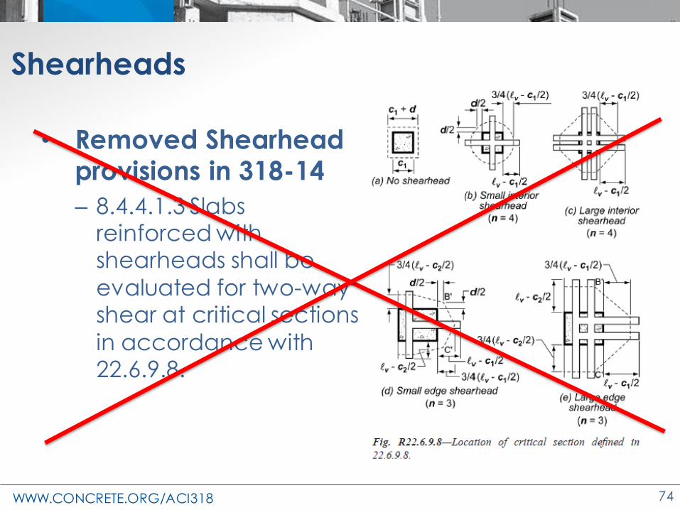
Shearheads
• Removed Shearheadprovisions in 318-14
– 8.4.4.1.3 Slabs reinforced with shearheads shall be
evaluated for two-way shear at critical sections
in accordance with 22.6.9.8.

WWW.CONCRETE.ORG/ACI318 75
Opening in Slab Systems Without Beams
Fig. R22.6.4.3—Effect of openings
and free edges (effective perimeter
shown with dashed lines)
Note: Openings shown are located
within 10h of the column periphery
ACI 318 -14: 8.5.4.2(d)
• within a column strip or closer than 10h from a concentrated load or reaction area satisfy– 22.6.4.3 for slabs without shearheads
– or 22.6.9.9 for slabs with shearheads
• 22.6.4.3: Reduced perimeter of critical section (bo)– Fig. R22.6.4.3
• 22.6.9.9: Reduction to bo is ½ of that given in 22.6.4.3

WWW.CONCRETE.ORG/ACI318 76
Opening in Slab Systems Without Beams
Fig. R22.6.4.3—Effect of openings and
free edges (effective perimeter shown
with dashed lines).
ACI 318 -19: 8.5.4.2(d)
• closer than 4h from the
periphery of a column, concentrated load or
reaction area satisfying 22.6.4.3
• 22.6.4.3: Reduced perimeter
of critical section (bo)
– Fig. R22.6.4.3

WWW.CONCRETE.ORG/ACI318 77
Minimum Flexural Reinforcement in Nonprestressed Slabs – Two way
8.6.1.1 • 318-14 : As,min as per Table 8.6.1.1.
• 318-19: As,min of 0.0018Ag, or as defined in 8.6.1.2 (discussed under two-way shear)
77

WWW.CONCRETE.ORG/ACI318 78
Reinforcement Extensions for Slabs without Beams
ACI 318-14: 8.7.4.1.3 -Column strip top bars
• Extend to at least 0.3ℓn
• May not be sufficient for thick slabs – may not intercept
critical punching shear crack
– Reduce punching shear strength Punching shear cracks in slabs
with reinforcement extensions

WWW.CONCRETE.ORG/ACI318 79
Punching shear failure - Podium Slab
• The failure crack did not intercept the top reinforcement.

WWW.CONCRETE.ORG/ACI318 80
Reinforcement Extensions for Two-Way Slabs without Beams
ACI 318-19: 8.7.4.1.3 -Column strip top bars
• Extend to at least
0.3ℓn but, not less
than 5d
Fig. R8.7.4.1.3 - Punching shear cracks in ordinary and thick slabs
d
d

WWW.CONCRETE.ORG/ACI318 81
Reinforcement Extensions for Two-Way Slabs without Beams

WWW.CONCRETE.ORG/ACI318 82
Changes to the Concrete Design Standard
ACI 318-19
Post-tensioning
WWW.CONCRETE.ORG/ACI318 83
Residential P-T Slabs (1.4.6)
• Past confusion about P-T slab foundation design on expansive soils
– Intent was for residential, but not mentioned with residential design provisions
• Commentary clarifies use of PTI DC10.5-12
for P-T residential slabs and foundations on expansive soils

WWW.CONCRETE.ORG/ACI318 84
Residential P-T Slabs (1.4.6)
• Coordinates with 2015 IBC requirements
• Adds reference to ACI 360 if not on
expansive soil

WWW.CONCRETE.ORG/ACI318 85
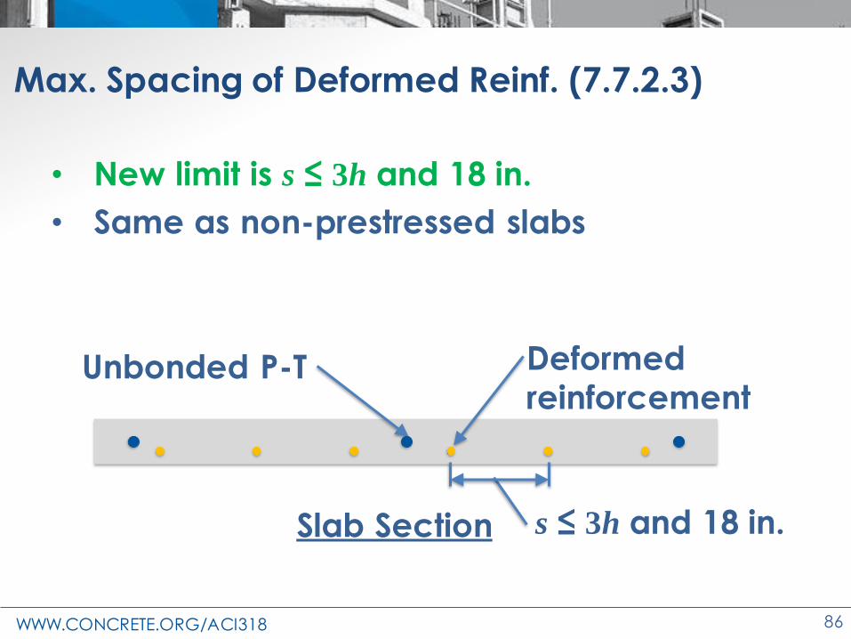
Max. Spacing of Deformed Reinf. (7.7.2.3)
• Class C (Cracked) and T (Transition) one-way slabs with unbonded tendons rely on
bonded reinforcement for crack control
• Previously no limits for spacing of deformed
reinforcement for Class C and T prestressed
slabs
• Industry feedback provided
WWW.CONCRETE.ORG/ACI318 86
Max. Spacing of Deformed Reinf. (7.7.2.3)
• New limit is s ≤ 3h and 18 in.
• Same as non-prestressed slabs
Unbonded P-T Deformed reinforcement
Slab Section s ≤ 3h and 18 in.

WWW.CONCRETE.ORG/ACI318 87
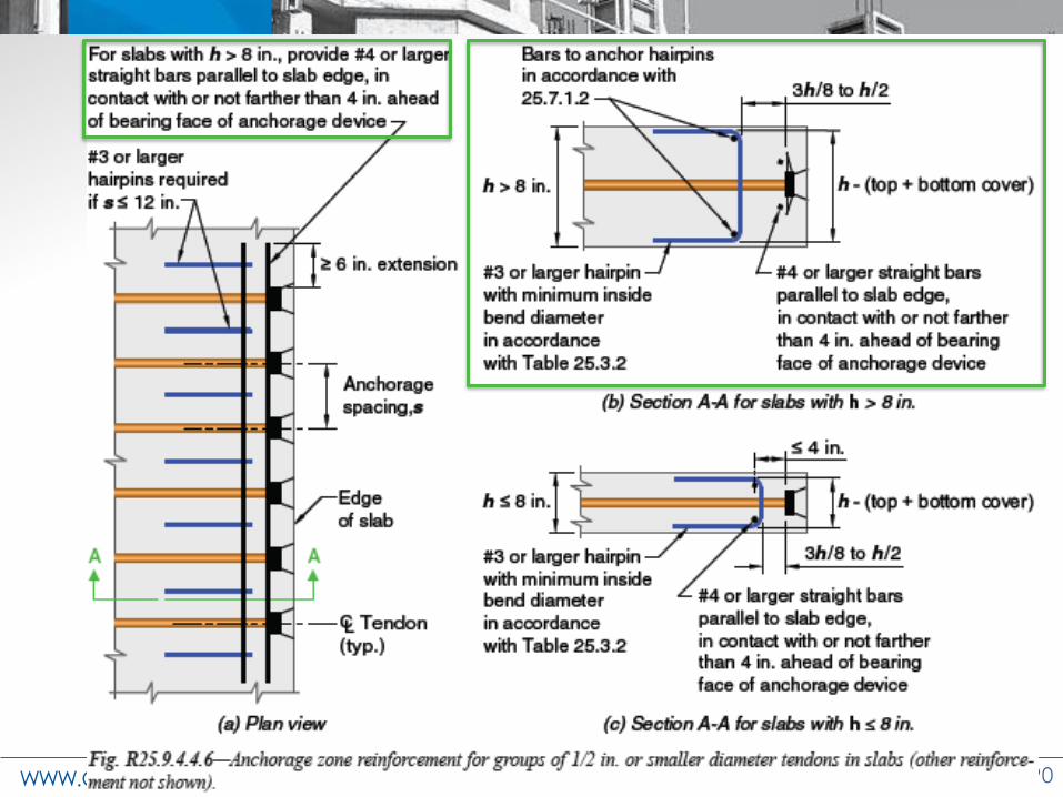
P-T Anchorage Zone Reinforcement (25.9.4.4.6)
• Referenced from slab and beam chapters
• Applies for groups of 6 or more anchors in thick slabs
• Anchorage zone requires backup bars for bearing and hairpins for bursting
• Hairpins must be anchored at the corners
Backup barsAnchor bars
Hairpins

WWW.CONCRETE.ORG/ACI318 88

WWW.CONCRETE.ORG/ACI318 89
P-T Anchorage Zone Reinforcement (25.9.4.4.6)
• Thin slabs ≤ 8 in. → Anchor bars serve as backup bars
• Thick slabs > 8 in. → Both backup bars and
anchor bars required
Backup barsAnchor bars
Hairpins
WWW.CONCRETE.ORG/ACI318 90

WWW.CONCRETE.ORG/ACI318 91

WWW.CONCRETE.ORG/ACI318 92
WWW.CONCRETE.ORG/ACI318 93
Design of Formwork for P-T (26.11.1.2 (5) and (6))
• Members may move when P-T strand is stressed
• Movement may redistribute loads
• Added requirement to allow for movement
during tensioning
• Added requirement to consider redistribution of loads on formwork from
tensioning of the prestressing reinforcement

WWW.CONCRETE.ORG/ACI318 94
Changes to the Concrete Design Standard
ACI 318-19
Precast/Prestressed
WWW.CONCRETE.ORG/ACI318 95
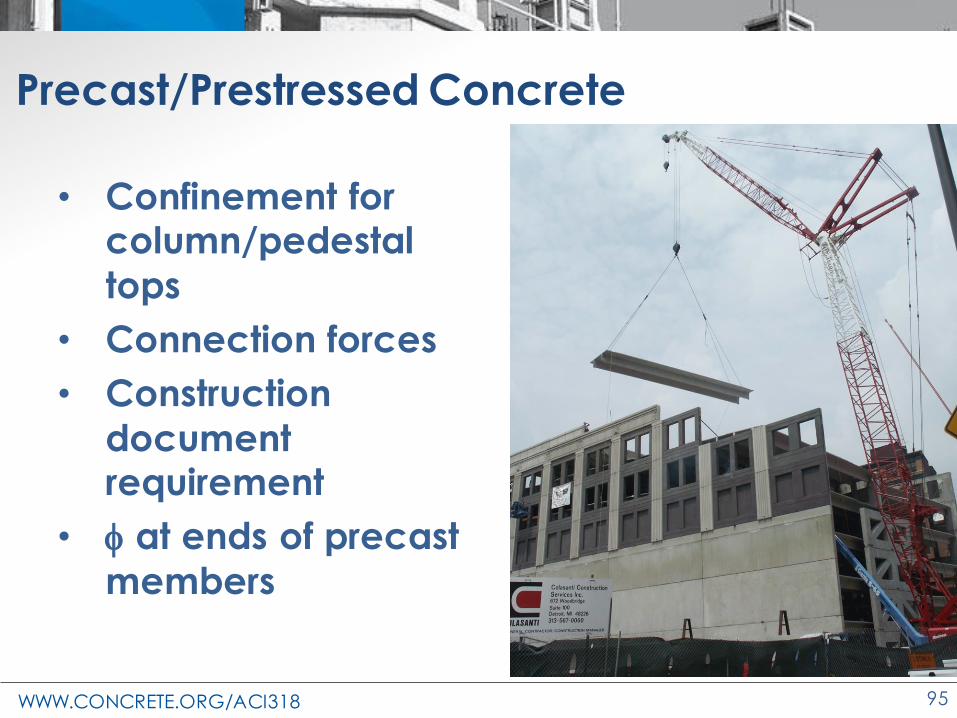
Precast/Prestressed Concrete
• Confinement for column/pedestal
tops
• Connection forces
• Construction
document requirement
• f at ends of precast
members
WWW.CONCRETE.ORG/ACI318 96
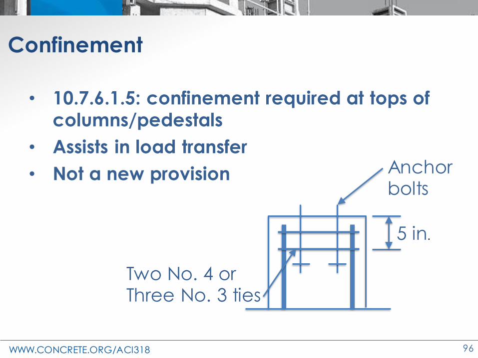
Confinement
• 10.7.6.1.5: confinement required at tops of columns/pedestals
• Assists in load transfer
• Not a new provision
5 in.
Two No. 4 orThree No. 3 ties
Anchor bolts

WWW.CONCRETE.ORG/ACI318 97
Confinement
• 10.7.6.1.6: extends confinement requirement to precast columns/pedestals
5 in.
Two No. 4 orThree No. 3 ties
Mechanical coupler
Future precast member

WWW.CONCRETE.ORG/ACI318 98
Volume Change in Precast Connections
• Volume change
– Creep
– Shrinkage
– Temperature
• May induce connection reactions if restrained

WWW.CONCRETE.ORG/ACI318 99
Volume Change in Precast Connections
• Load magnitude?
• Load factor?
• Past guidance for
brackets and corbels
– Use Nuc ≥ 0.2Vu as
restraint force
– Use a 1.6 load factor
• Approach was often
to design around
forces
WWW.CONCRETE.ORG/ACI318 100
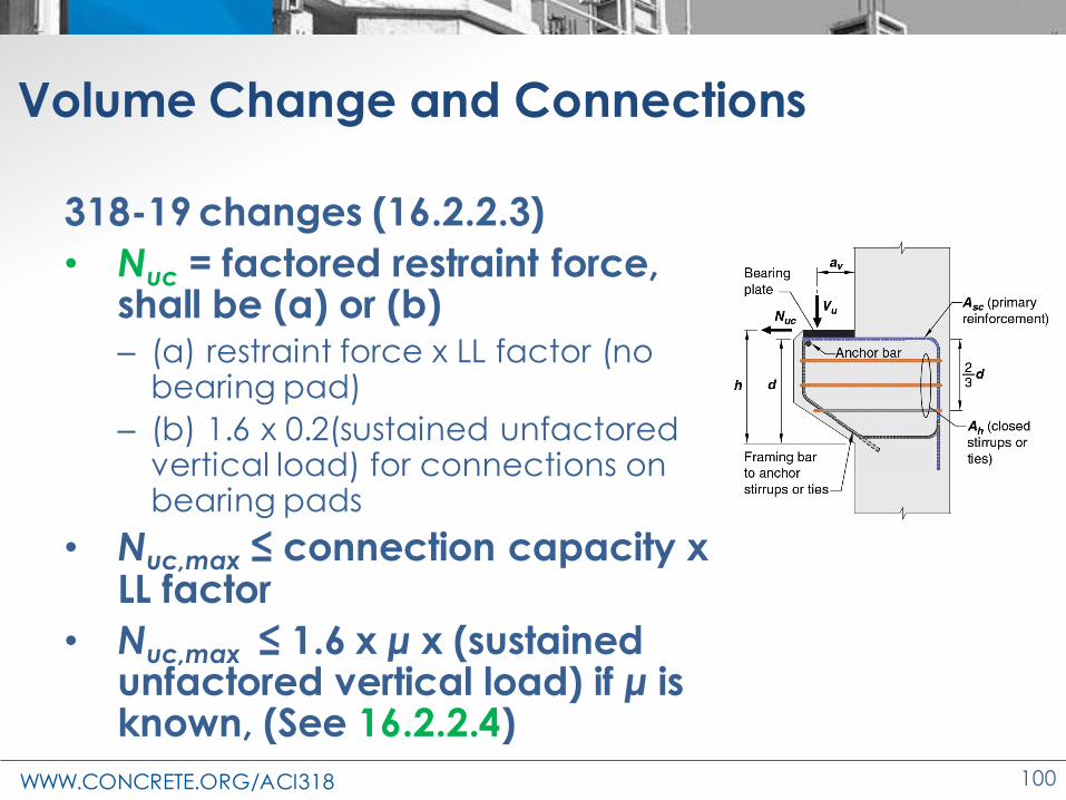
Volume Change and Connections
318-19 changes (16.2.2.3)
• Nuc = factored restraint force, shall be (a) or (b)– (a) restraint force x LL factor (no
bearing pad)
– (b) 1.6 x 0.2(sustained unfactored vertical load) for connections on bearing pads
• Nuc,max ≤ connection capacity x LL factor
• Nuc,max ≤ 1.6 x μ x (sustained unfactored vertical load) if μ is known, (See 16.2.2.4)

WWW.CONCRETE.ORG/ACI318 101
Brackets and Corbels
• 26.6.4.1(a) Details for welding of anchor bars at the front face of brackets or corbels
designed by the licensed design
professional in accordance with 16.5.6.3(a).
Fig. R16.5.6.3b Fig. R16.5.1b
WWW.CONCRETE.ORG/ACI318 102
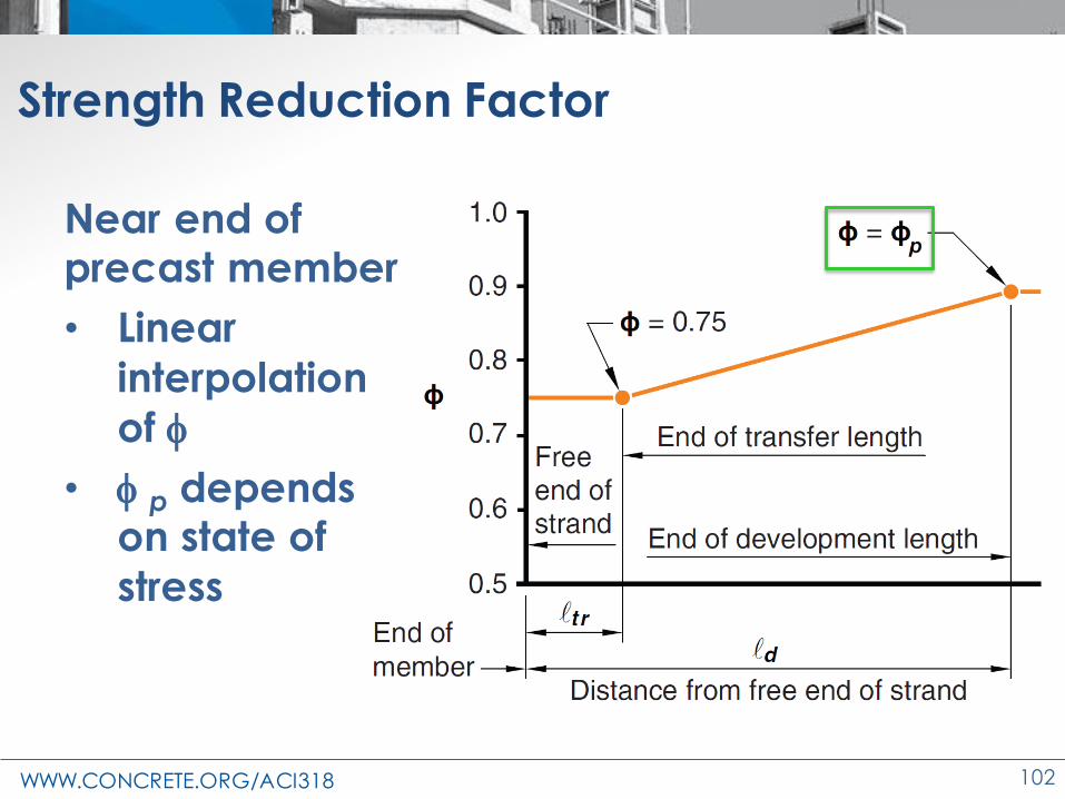
Strength Reduction Factor
Near end of precast member
• Linear
interpolation
of f
• f p depends on state of
stress

WWW.CONCRETE.ORG/ACI318 103
Strength Reduction Factor
Near end of precast member
• Similar for
debonded
strand

WWW.CONCRETE.ORG/ACI318 104
Changes to the Concrete Design Standard
ACI 318-19
Circular Sections

WWW.CONCRETE.ORG/ACI318 105
Variable definitions (22.5)
• 22.5 One-way shear
– Interpretation for hollow circular sections
d ?
bw ?ρw ?
opening

WWW.CONCRETE.ORG/ACI318 106
Variable definitions (22.5)
• 22.5.2.2 – calculation of Vc and Vs
– d = 0.8 x diameter
– bw = diameter (solid circles)
– bw = 2 x wall thickness (hollow circles)
d = 0.8D
bw = Dρw = As/bwd
bw = 2t
opening
t

WWW.CONCRETE.ORG/ACI318 107
Variable definitions (22.5)
• What about As?
(2/3)D
As

WWW.CONCRETE.ORG/ACI318 108
Torsion for circular sections (R22.7.6.1.1)
• Do ACI 318 torsion equations apply to circular cross sections?
• Code Eqns are based on thin-tube theory
• Examples added to figure
125

WWW.CONCRETE.ORG/ACI318 109
Circular Column Joints
• Based on equivalent square column
– Aj for joint shear strength (15.4.2)
– Width of transverse beams required for joint
to be considered confined (15.2.8)
– Column width ≥ 20 db for
special moment frames (18.8.2.3)
h = 0.89D

WWW.CONCRETE.ORG/ACI318 110
Changes to the Concrete Design Standard
ACI 318-19
Walls

WWW.CONCRETE.ORG/ACI318 111
Scope of walls
• Change in scope
11.1.4 - Design of cantilever retaining walls shall be in accordance with Chapter 13 (Foundations)

WWW.CONCRETE.ORG/ACI318 112
Scope of walls
• Added scope
11.1.6 - CIP walls with insulated forms shall be permitted by this code for use in one or two-story
buildings
• Design according to Chapter 11
• Guidance – ACI 560R and PCA 100-2017
• Unique construction issues
Photo courtesy Larry Novak
WWW.CONCRETE.ORG/ACI318 113
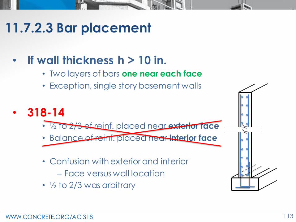
11.7.2.3 Bar placement
• If wall thickness h > 10 in.• Two layers of bars one near each face
• Exception, single story basement walls
• 318-14• ½ to 2/3 of reinf. placed near exterior face
• Balance of reinf. placed near interior face
• Confusion with exterior and interior
– Face versus wall location
• ½ to 2/3 was arbitrary

WWW.CONCRETE.ORG/ACI318 114
14.6 Plain concrete
At windows, door openings, and similarly sized openings
• At least two No. 5 bars (similar to walls
11.7.5.1)
• Extend 24 in. beyond or to develop fy
≥ 24 in.
2-No. 5 bars

WWW.CONCRETE.ORG/ACI318 115
Changes to the Concrete Design Standard
ACI 318-19
Foundations

WWW.CONCRETE.ORG/ACI318 116
Ch. 13 – Foundations – significant changes
• Added design provisions
– Cantilever retaining walls
– Deep foundation design
• Other
– Minimum concrete strengths for shallow and deep foundations
– Cover

WWW.CONCRETE.ORG/ACI318 117
Foundations and 318
• ACI 318-71 to ACI 318-11
(Ch. 15)
• Shallow footings, pile caps
• ACI 318-14 (Ch. 13)
• Shallow footings, pile caps

WWW.CONCRETE.ORG/ACI318 118
Foundations and 318
• ACI 318-71 to ACI 318-11
(Ch. 15)
• Shallow footings, pile caps
• ACI 318-14 (Ch. 13)
• Shallow footings, pile caps
• ACI 318-19 (Ch. 13)
• Shallow footings, pile caps,
deep foundations, and walls
of cantilevered retaining
walls
WWW.CONCRETE.ORG/ACI318 119
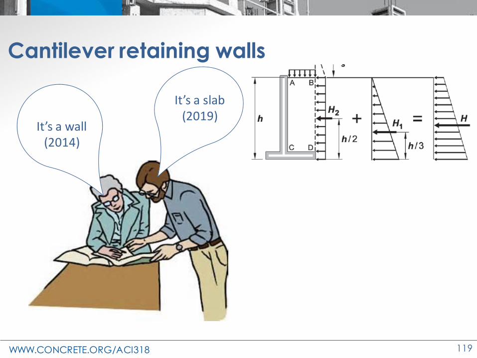
Cantilever retaining walls
It’s a wall(2014)
It’s a slab(2019)

WWW.CONCRETE.ORG/ACI318 120
13.3.6.1—Cantilever stem walls
• Design as one-way slab (Ch. 7)

WWW.CONCRETE.ORG/ACI318 121
13.3.6.2—Cantilever stem wall with counterfort
• Design as two-way slab (Ch. 8)

WWW.CONCRETE.ORG/ACI318 122
Maximum bar spacing in stem wall
Wall Slab
Stem wall reinforcement
Maximum bar
spacing (2014)
Design as wall
(2014)
Maximum bar spacing
(2019)
Design as one-way
slab (2019)
Long. (Wall) or Flexural (Slab)
3h, or 18 in.
11.7.2.1
Lesser of:
7.7.2.2(24.3)
Trans. (Wall) or S & T (Slab)
3h, or 18 in.
11.7.3.15h, or 18 in.
7.7.6.2.1
s Transverse bars
Longitudinal bars40,000
15 2.5 c
s
cf
−
40,00012
sf

WWW.CONCRETE.ORG/ACI318 123
ACI 318-14 ACI 318-19
Minimum reinforcement, ρ
Design as wall
Minimum reinforcement
As,min
Design as one-way
slab
≤ No. 5ρℓ = 0.0012
> No. 5ρℓ = 0.0015
11.6.1As,min = 0.0018 Ag 7.6.1.1
≤ No. 5ρt = 0.0020
> No. 5ρt = 0.0025
11.6.2AS+T = 0.0018 Ag 7.6.4.1
(24.4)
Minimum reinforcement in stem wall

WWW.CONCRETE.ORG/ACI318 124
1.4.7— Scope changes – deep foundations
• Scope: This code does not govern design and
installation of portions of concrete pile, drilled piers, and caissons embedded in ground, except as
provided in (a) through (c)
• (a) For portions in air or water, or in soil incapable of providing adequate lateral restraint to prevent buckling throughout their length
• (b) For precast concrete piles supporting structures assigned to SDC A and B
• (c) For deep foundation elements supporting structures assigned to SDC C, D, E, and F (SDC C is added to scope)
WWW.CONCRETE.ORG/ACI318 125
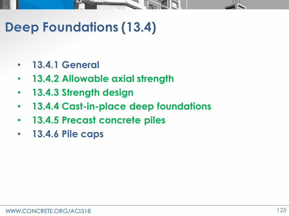
Deep Foundations (13.4)
• 13.4.1 General
• 13.4.2 Allowable axial strength
• 13.4.3 Strength design
• 13.4.4 Cast-in-place deep foundations
• 13.4.5 Precast concrete piles
• 13.4.6 Pile caps

WWW.CONCRETE.ORG/ACI318 126
Deep foundation – combine IBC & ASCE 7
• ACI 318 – 19 –
– combined IBC 2015, ASCE 7-10,
and ACI 318-14 with regards to
design of deep foundations for
earthquake resistant structures
(SDC C, D, E, and F)ACI 318 - 19
Allowable axial strength/stress
capacities
ACI 318-14
ASCE 7
IBC 2015

WWW.CONCRETE.ORG/ACI318 127
Pre- ACI 318-19 – design of deep foundations
• ACI 543 - Piles (diam. < 30 in.)
• ACI 336.3 - Design of drilled piers (diam. ≥ 30 in.)
Not code language documents
Also used deep footing provisions
from:
IBC and ASCE/SEI 7

WWW.CONCRETE.ORG/ACI318 128
Design of deep foundation members-compressive axial force (13.4.1)
• Design axial strength of members in accordance to
two methods:
– Allowable Axial Strength Design
(13.4.2)
– Strength Design (13.4.3)
Photos courtesy Larry Novak

WWW.CONCRETE.ORG/ACI318 129
Allowable axial strength method (13.4.2)
13.4.2.1 It shall be permitted to design a deep foundation
member using load combinations for allowable stress design in ASCE / SEI 7, Section 2.4, and the allowable
strength specified in Table 13.4.2.1 if (a) and (b) are satisfied
(a)Deep foundation is laterally supported for its entire
height
(b)Applied forces causing bending moments less than
moment due to an accidental eccentricity of 5 percent of the pile diameter or width.

WWW.CONCRETE.ORG/ACI318 130
13.4.2 deep foundation design

WWW.CONCRETE.ORG/ACI318 131
Confinement of metal casing (13.4.2.3):
• not used to resist axial load
• sealed tip and mandrel-driven
• seamless or welded seamless
Physical properties
• wall thickness ≥ 14 ga. (0.068 in.)
• fy ≥ 30,000 psi
• fy ≥ 6 f’c , and
• nominal diameter ≤ 16 in.
Metal casing
Sealed tip
Diam ≤ 16 in.

WWW.CONCRETE.ORG/ACI318 132
Deep foundations – strength design (13.4.3)
• Method may be used any time
• Method must be used when pile does not meet criteria for allowable axial strength design– Soils do not provide lateral support
– Moment is not negligible
• Use Section 10.5 (columns) – 𝝓 Pn ≥ Pu
– 𝝓 Mn ≥ Mu
– Combined Pn and Mn calculated by 22.4
Mu≥ 0Pu

WWW.CONCRETE.ORG/ACI318 133
Strength design (13.4.3) – axial force, no moment
Nominal axial compressive strength; Pn
𝝓 Pn,max ≥ Pu
Maximum axial strength
- For deep foundations members with ties conforming to Ch. 13 (new in Table 22.4.2.1)
Pn,max = 0.80 Po
Where:
Po = nominal axial strength at zero eccentricity
Po = 0.85f’c(Ag – Ast) + fyAst
Mu= 0Pu

WWW.CONCRETE.ORG/ACI318 134
Mu= 0
Strength design (13.4.3) – axial force, no moment
• Reduction factor – Table 13.4.3.2 Pu
0.55 to
0.70

WWW.CONCRETE.ORG/ACI318 135
Deep foundations
13.4.4.1 CIP deep foundations that are subject
to (a) uplift or (b) Mu > 0.4Mcr
shall be reinforced, unless
enclosed by a steel pipe or
tube
Confined for ductility
Reinforced for flexure
Reinforced for tension
Unreinforced

WWW.CONCRETE.ORG/ACI318 136
Table 19.2.1.1 –Additional minimum strength, f’c
Shallow foundationsMin. f’c
(psi)
Foundations in SDC A, B, or C 2500
Foundation for Residential and Utility …. 2 stories or less ….stud bearing construction …… SDC D, E, or F
2500
Foundation for Residential and Utility …. More than 2 stories….stud bearing construction …… SDC D, E, or F
3000
Deep foundations
Drilled shafts or piers 4000
Precast nonprestressed driven piles 4000
Precast prestressed driven piers 5000
WWW.CONCRETE.ORG/ACI318 137
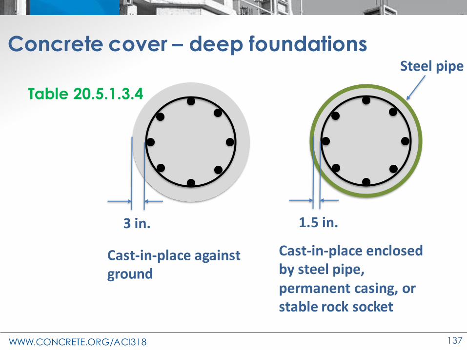
Concrete cover – deep foundations
Table 20.5.1.3.4
3 in.
Cast-in-place against ground
1.5 in.
Cast-in-place enclosed by steel pipe, permanent casing, or stable rock socket
Steel pipe

WWW.CONCRETE.ORG/ACI318 138
Concrete cover – deep foundations
In contact with ground
2.5 in. precast nonprestressed2 in. precast prestressed
Exposed to seawater
1.5 in. precast nonprestressed and precast prestressed
Table 20.5.1.3.4

WWW.CONCRETE.ORG/ACI318 139
Changes to the Concrete Design Standard
ACI 318-19
Anchorage to
Concrete

WWW.CONCRETE.ORG/ACI318 140
Chapter 17 – Anchoring to Concrete
• Reorganized
• New content/design information
– Screw anchors added
– Shear lugs added

WWW.CONCRETE.ORG/ACI318 141
Sections
• 17.1 Scope
• 17.2 General
• 17.3 Design limits
• 17.4 Required strength
• 17.5 Design strength
• 17.6 Tensile strength
• 17.7 Shear strength
• 17.8 Tension and shear interaction
• 17.9 Edge distances, spacings, and thicknesses to preclude splitting failure
• 17.10 Earthquake-resistant design requirements
• 17.11 Attachments with shear lugs

WWW.CONCRETE.ORG/ACI318 142
Ch. 17 – Anchoring to Concrete
Scope
• Headed studs and
headed bolts
• Hooked bolts
• Post-installed
undercut anchors
• Post-installed
expansion anchors
• Post-installed
adhesive anchors
WWW.CONCRETE.ORG/ACI318 143
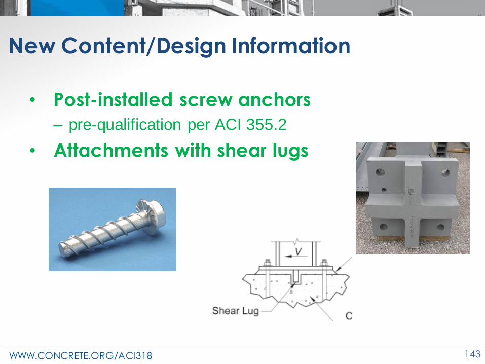
New Content/Design Information
• Post-installed screw anchors
– pre-qualification per ACI 355.2
• Attachments with shear lugs
WWW.CONCRETE.ORG/ACI318 144
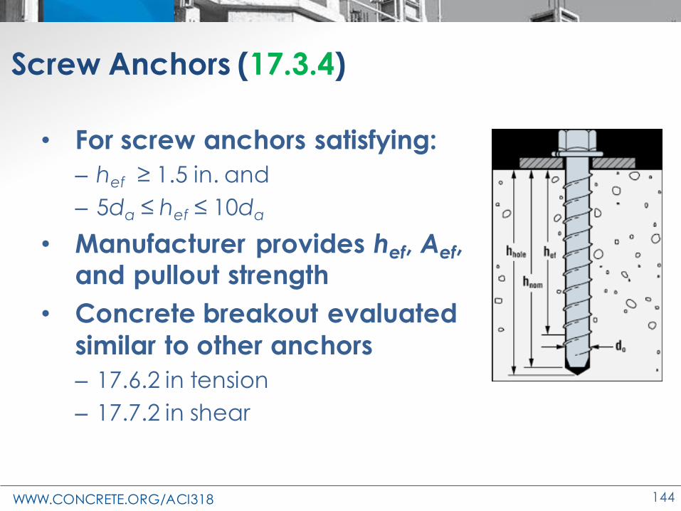
Screw Anchors (17.3.4)
• For screw anchors satisfying:
– hef ≥ 1.5 in. and
– 5da ≤ hef ≤ 10da
• Manufacturer provides hef, Aef, and pullout strength
• Concrete breakout evaluated
similar to other anchors
– 17.6.2 in tension
– 17.7.2 in shear

WWW.CONCRETE.ORG/ACI318 145
Minimum Spacing (17.9.2a)
• Screw anchor spacing limited per Table 17.9.2a
Spacing > 0.6hef
and 6da
Greatest of: (a) Cover (b) 2 x max. agg.(c) 6da or per ACI 355.2

WWW.CONCRETE.ORG/ACI318 146
17.1.6 – Reinforcement used as anchorage
Check anchorage for bars developed per Ch. 25
• Check concrete
breakout in tension (and
maybe shear)
• Greater development length should be
considered
WWW.CONCRETE.ORG/ACI318 147
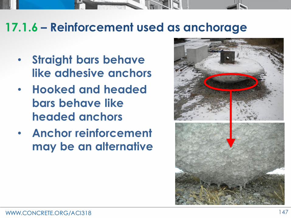
17.1.6 – Reinforcement used as anchorage
• Straight bars behave like adhesive anchors
• Hooked and headed
bars behave like
headed anchors
• Anchor reinforcement may be an alternative

WWW.CONCRETE.ORG/ACI318 148
Shear Lugs (17.11.1)
Shear lugs are fabricated from:
• Rectangular plates or
• Steel shapes composed of plate-like elements, welded to an attachment base plate

WWW.CONCRETE.ORG/ACI318 149
Shear Lugs (17.11.1)
• Minimum four anchors
• Anchors do not
need to resist shear
forces if not welded
• Anchors welded to steel plate carry
portion of total
shear load

WWW.CONCRETE.ORG/ACI318 150
Shear Lug Detailing (17.11.1.1.8)
• Anchors in tension, satisfy both (a) and (b):
(a) hef/hsl ≥ 2.5
(b) hef/csl ≥ 2.5

WWW.CONCRETE.ORG/ACI318 151
Shear Lug Detailing (17.11.1.2)
• Steel plate to have 1 in. dia. (min.) hole
• Single plate – one on each side
• Cross / cruciform plate - one each quadrant
• More vent holes are not detrimental

WWW.CONCRETE.ORG/ACI318 152
Shear Lug Overturning (17.11.1.1.9)
hef
hsl
tsl
Csl

WWW.CONCRETE.ORG/ACI318 153
Bearing (17.11.2)
• f Vbrg,sl ≥ Vu
• Where f = 0.65
Source: Peter Carrato

WWW.CONCRETE.ORG/ACI318 154
Bearing Strength (17.11.2)
• Bearing strength:
• Aef,sl is the surface perpendicular to the
applied shear:
2tsl2tsl2tsl
'
, , ,1.7brg sl c ef sl brg sl
V f A=
tsl

WWW.CONCRETE.ORG/ACI318 155
Bearing AreaDirection of shear load
Direction of shear load

WWW.CONCRETE.ORG/ACI318 156
Stiffeners
• 17.11.2.3 - If used, the length of shear lug stiffeners in the direction of the shear load
shall not be less than 0.5hsl
0.5hsl
hsl
Shear lug
Stiffener
T/Conc
WWW.CONCRETE.ORG/ACI318 157
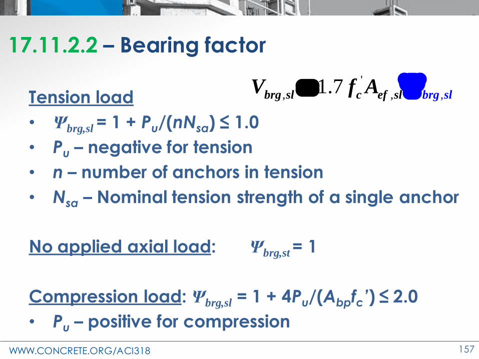
17.11.2.2 – Bearing factor
Tension load
• Ψbrg,sl = 1 + Pu/(nNsa) ≤ 1.0
• Pu – negative for tension
• n – number of anchors in tension
• Nsa – Nominal tension strength of a single anchor
No applied axial load: Ψbrg,st = 1
Compression load: Ψbrg,sl = 1 + 4Pu/(Abpfc’) ≤ 2.0
• Pu – positive for compression
'
, ,, 1.7brg slbrg sl c ef sl
V f A =

WWW.CONCRETE.ORG/ACI318 158
17.11.2.4 – Bearing for Multiple Shear Lugs
• If τ ≤ 0.2 f’c, use bearing from
both lugs
A1
A2
τ = Vu/(A1 + A2)

WWW.CONCRETE.ORG/ACI318 159
17.11.3 – Concrete breakout strength of shear lugs
• Nominal concrete breakout strength of a shear lug
– Use Anchor provisions of 17.7.2
• Where:
, , , ,Vc
cb sl ed V c V h V b
Vco
AV V
A=
' 1.5
19 ( )b a c a
V f c=
WWW.CONCRETE.ORG/ACI318 160
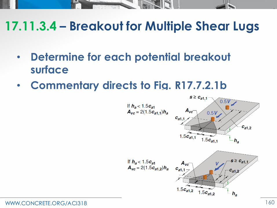
17.11.3.4 – Breakout for Multiple Shear Lugs
• Determine for each potential breakout surface
• Commentary directs to Fig. R17.7.2.1b

WWW.CONCRETE.ORG/ACI318 161
Shear Lug Example
• Reinforced Concrete Design Manual
• Anchorage example 20
• See handout
DV = 60 KipsLV = 75 KipsWV = ±170 KipsDH = ± 8 KipsLH = ± 9 KipsWH = ±12 Kips

WWW.CONCRETE.ORG/ACI318 162
Shear Lug Example
• Can we replace upper ties with shear lug?
– Remove shear from anchor rod design
– May reduce bolt size/length
– Simplify design

WWW.CONCRETE.ORG/ACI318 163
Size Shear Lug
• Size shear lug so entire lug is effective
– tsl = 1.5 in.
– Width = 1.5 in. + 4(1.5 in.)
= 7.5 in.
– Depth = 3 in. + 3 in.
= 6 in.
– Stiffeners at least 0.5 hsl or 1.5 in. wide
T/Conc
V
3 in.
1.5 in.
WWW.CONCRETE.ORG/ACI318 164
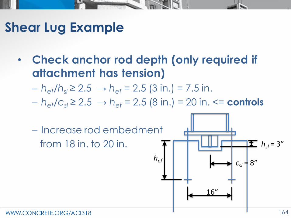
Shear Lug Example
• Check anchor rod depth (only required if attachment has tension)
– hef/hsl ≥ 2.5 → hef = 2.5 (3 in.) = 7.5 in.
– hef/csl ≥ 2.5 → hef = 2.5 (8 in.) = 20 in. <= controls
– Increase rod embedment
from 18 in. to 20 in.
16”
hsl = 3”
csl = 8”hef
WWW.CONCRETE.ORG/ACI318 165
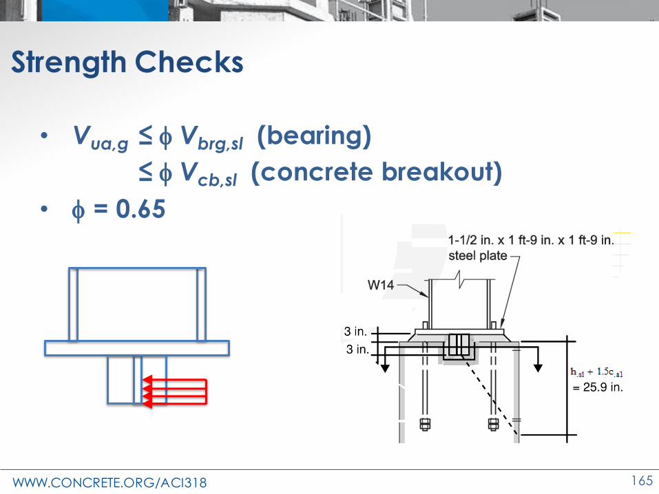
Strength Checks
• Vua,g ≤ f Vbrg,sl (bearing)
≤ f Vcb,sl (concrete breakout)
• f = 0.65

WWW.CONCRETE.ORG/ACI318 166
Bearing Strength Check
• Vua,g ≤ f Vbrg,sl (bearing)
– Vua,g = 30 kip
– Vbrg,sl = 1.7 f’c Aef,slΨbrg,sl
• For tension on attachment, bearing is reduced
– Ψbrg,sl = 1+Pu/(nNsa)
– = 1+(-116 kip)/(4 rods(72.7 kip/rod))= 0.601
– Vbrg,sl = 1.7 (4500 psi)(7.5 in.)(3 in.)(0.601) = 103 kip
• f Vbrg,sl = 0.65 (103 kip) = 67 kip > 30 kip OK
1.7 f’c
V

WWW.CONCRETE.ORG/ACI318 167
Concrete Breakout Strength Check
• Vua,g ≤ f Vcb,sl (concrete breakout)
• Vcb,sl = (AVc/AVc0) Ψed,V Ψc,V Ψh,V Vb
– AVc = [3” + 1.5 (32” -1.5”)/2](32”)-(3”)(7.5”)
= 805 in.2
32 in.32 in.
3 in.
22.9 in.
ca1 = 15.25 in.V

WWW.CONCRETE.ORG/ACI318 168
Concrete Breakout Strength Check
• Vcb,sl = (AVc/AVc0) Ψed,V Ψc,V Ψh,V Vb
– AVc0 = 4.5 ca12 = 4.5(15.25“)2 = 1047 in.2
32 in.
ca1 = 15.25 in.
1.5 ca1
1.5 ca1

WWW.CONCRETE.ORG/ACI318 169
Concrete Breakout Strength Check
• Vcb,sl = (AVc/AVc0) Ψed,V Ψc,V Ψh,V Vb
– Ψed,V = edge effect modification factor
= 0.7 + 0.3ca2/(1.5ca1)
= 0.7+0.3(12.25”)/(1.5(15.25”))=0.861
32 in.
ca1 = 15.25 in.
ca2 = 12.25 in.

WWW.CONCRETE.ORG/ACI318 170
Concrete Breakout Strength Check
• Vcb,sl = (AVc/AVc0) Ψed,V Ψc,V Ψh,V Vb
– Ψc,V = concrete cracking modification factor
– Assume cracking and No. 4 ties between lug and edge (see Table 17.7.2.5.1)
– Ψc,V = 1.2
– Ψh,V = member thickness modification factor
=1.0 (depth > 1.5 ca1)
– Vb = 9λaf’c(ca1)1.5
= 9(1)(4500 psi)(15.25”)1.5 = 36,000 lb

WWW.CONCRETE.ORG/ACI318 171
Concrete Breakout Strength Check
• Vcb,sl = (AVc/AVc0) Ψed,V Ψc,V Ψh,V Vb
= (805 in.2/1047 in.2)(0.861)(1.2)(1.0)(36 kip)
= 28.6 kip
• f Vcb,sl = 0.65(28.6 kip) = 18.6 kip < 30 kip NG
WWW.CONCRETE.ORG/ACI318 172
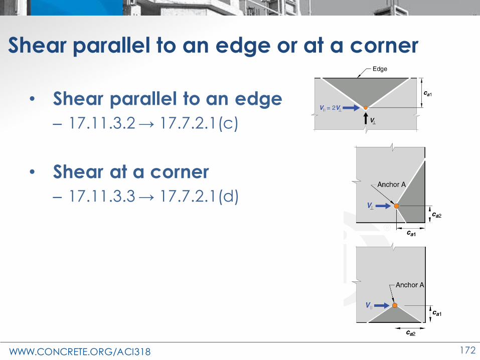
Shear parallel to an edge or at a corner
• Shear parallel to an edge
– 17.11.3.2 → 17.7.2.1(c)
• Shear at a corner
– 17.11.3.3 → 17.7.2.1(d)

WWW.CONCRETE.ORG/ACI318 173
Summary
• f Vcb,sl = 18.6 kip < 30 kip anchor reinforcement required
• From example:
– all 4 rods resisting and supplementary
reinforcement → f Vcbg = 29.4 kip
– back 2 rods resisting and supplementary reinforcement → f Vcb,sl = 21.7 kip
• Shear lugs not helpful for breakout
• Helpful when shear in rods is controlling

WWW.CONCRETE.ORG/ACI318 174
Changes to the Concrete Design Standard
ACI 318-19
Seismic Design
Philosophy

WWW.CONCRETE.ORG/ACI318 175
Seismic
• Both concrete and reinforcement are
permitted to
respond in the
inelastic range
• This is consistent with the strength
design approach
adopted throughout
the Code

WWW.CONCRETE.ORG/ACI318 176
Seismic – Ω, Cd, and R Factors (ASCE 7)

WWW.CONCRETE.ORG/ACI318 17717
Parameter in ASCE 7-16
Table 12.2-1
Example
Seismic Force Resisting
System
Special reinforced
concrete shear walls
(building frame system)
ASCE 7 Section Where
Detailing Requirements Are
Specified
ASCE 7 Section 14.2
“Concrete”
Response Modification
Coefficient, R6
Overstrength Factor, Ω0 2.5
Deflection Amplification
Factor, Cd5
Structural System
Limitations, Including
Structural Height Limits
SDC B No limit
SDC C No limit
SDC D160 ft
SDC E 160 ft
SDC F 100 ft
Seismic – Parameters

WWW.CONCRETE.ORG/ACI318 178
Seismic
• Controlled inelastic action is permitted at pre-
determined locations, called plastic hinges
• Typical plastic hinge locations are at the ends of beams in moment frames, and at the bases
of shear walls

WWW.CONCRETE.ORG/ACI318 179
Seismic
• Prescriptive rules for detailing of reinforcement are enforced, creating robust plastic hinges
• Plastic hinging reduces the stiffness of the structure, which lengthens the period; and plastic hinges dissipate earthquake energy

WWW.CONCRETE.ORG/ACI318 180
Changes to the Concrete Design Standard
ACI 318-19
Special Moment
Frames
WWW.CONCRETE.ORG/ACI318 181
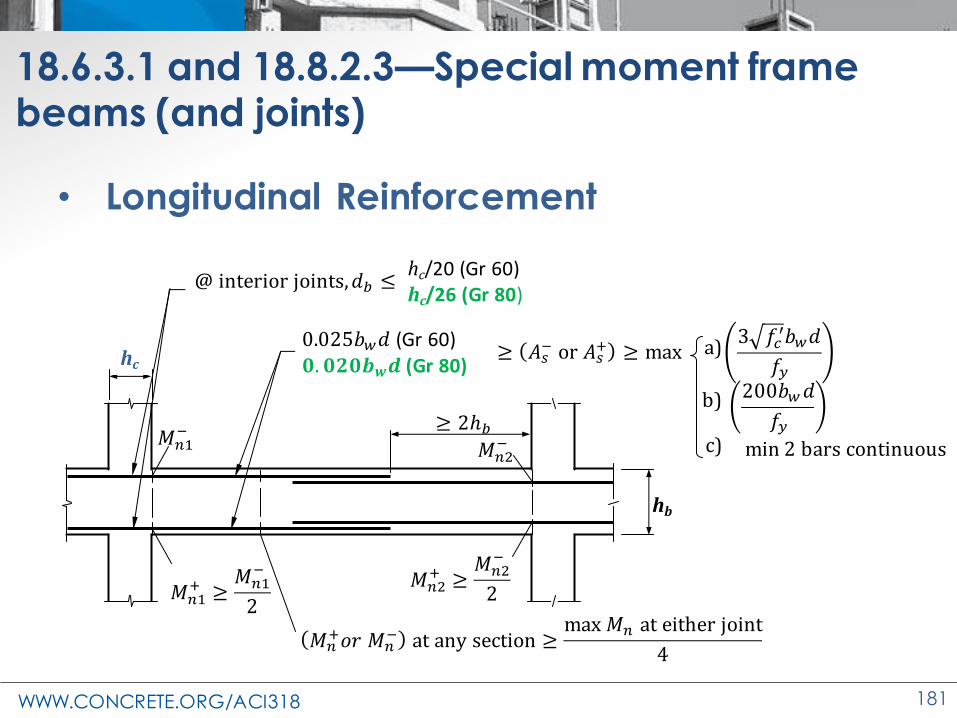
18.6.3.1 and 18.8.2.3—Special moment frame beams (and joints)
• Longitudinal Reinforcement
hc
hb
𝑀𝑛2+ ≥
𝑀𝑛2−
2
𝑀𝑛2−
≥ 2ℎ𝑏
𝑀𝑛1+ ≥
𝑀𝑛1−
2
𝑀𝑛1−
@ interior joints,𝑑𝑏 ≤
𝑀𝑛+𝑜𝑟 𝑀𝑛
− at any section ≥max 𝑀𝑛 at either joint
4
0.025𝑏𝑤𝑑 (Gr 60)
𝟎. 𝟎𝟐𝟎𝒃𝒘𝒅 (Gr 80)
hc/20 (Gr 60)hc/26 (Gr 80)
≥ 𝐴𝑠− or 𝐴𝑠
+ ≥ max
200𝑏𝑤𝑑
𝑓𝑦
3 𝑓𝑐′𝑏𝑤𝑑
𝑓𝑦
min 2 bars continuous
a)
b)
c)

WWW.CONCRETE.ORG/ACI318 182
18.6.4.4—Special moment frame beams
• Transverse reinforcement
hb
Stirrups with seismic hooksHoopsalong 2hb
Hoops @ lap splice
d/46 in.6db (Gr 60), 5db (Gr 80)
s ≤
d/44 in.s ≤
𝑠 ≤ 𝑑/2
hc
≤ 2 𝑖𝑛.

WWW.CONCRETE.ORG/ACI318 183
18.4.3.3—Columns in intermediate moment frames
• Hoops or spirals required
• First hoop at so/2 from the joint
face
o
ℓu /6 clear span[c1, c2]max
18 in.
so
ℓo
ℓo8db (Gr 60) and 8 in.6db (Gr 80) and 6 in.1/2[c1, c2]min
so ≤
ℓo ≥

WWW.CONCRETE.ORG/ACI318 184
18.7.2, 18.7.3—Columns of SMF
Strong Column/Weak Beam
• Column dimensional limits, 18.7.2– Smallest dimension ≥ 12 in.
– Short side/long side ≥ 0.4
• Flexural strength check, 18.7.3.2– ∑Mnc ≥ (6/5)∑Mnb,
– Exception, 18.7.3.1• Ignore check at top story
where 𝑷𝒖 ≤ 𝟎. 𝟏𝑨𝒈𝒇𝒄′
Beam
Column
Mnb Mnb
Mnc
Mnc

WWW.CONCRETE.ORG/ACI318 185
18.7.4.3—Bond splitting failure in columns
Splitting can be controlled by
restricting the
longitudinal bar
size to meet
1.25ℓd ≤ ℓu/2
Woodward and Jirsa (1984)Umehara and Jirsa (1982)
Sokoli and Ghannoum (2016)

WWW.CONCRETE.ORG/ACI318 186
18.7.5.3 and 18.7.5.5—Columns in special moment frames
• First hoop at so/2 from the joint face
so
ℓoℓu/6 clear span[c1, c2]max
18 in.
s
6db,min (Gr 60), 5db,min (Gr 80)6 in.
ℓoso6db,min (Gr 60), 5db,min (Gr 80)¼[c1, c2]min
4 +14−ℎ𝑥
3, ≤ 6 in.; ≥ 4 in.
ℓo ≥
s ≤
so ≤
WWW.CONCRETE.ORG/ACI318 187
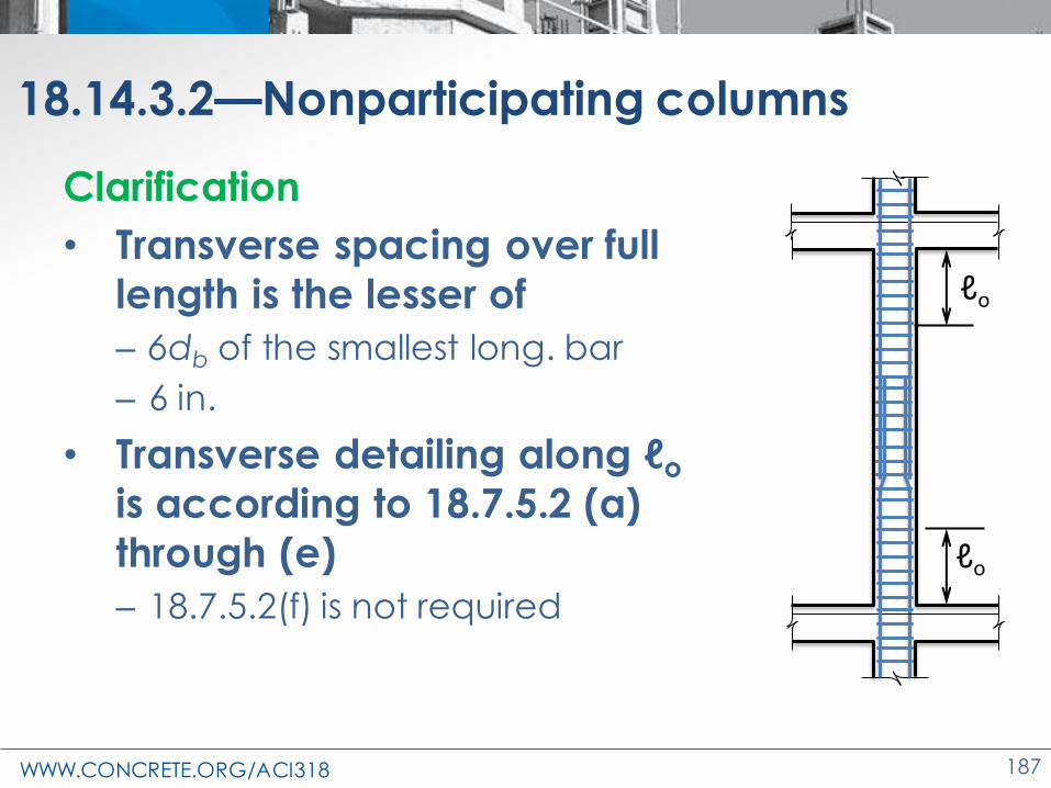
18.14.3.2—Nonparticipating columns
Clarification
• Transverse spacing over full
length is the lesser of
– 6db of the smallest long. bar
– 6 in.
• Transverse detailing along ℓo
is according to 18.7.5.2 (a)
through (e)
– 18.7.5.2(f) is not required
ℓo
ℓo

WWW.CONCRETE.ORG/ACI318 188
Changes to the Concrete Design Standard
ACI 318-19
Special Structural
Walls

WWW.CONCRETE.ORG/ACI318 189
Ch. 18.10—Special structural wall
• Cutoff of longitudinal bars in special boundary elements
• Reinforcement ratios at ends of walls
• Shear demand
• Drift capacity check
• Detailing in special boundary elements
• Ductile coupled wallsShear wall
Pu
Mu
Vu
ℓw
hw Special boundary element
δu
WWW.CONCRETE.ORG/ACI318 190
18.10.2.3(a)—Longitudinal bars
• Previously,
– tension (vertical boundary) reinforcement in special structural walls to extend 0.8ℓw beyond
the point at which it is no longer required to resist flexure
• Overly conservative
– This was an approximation of d
– Similar to beams which extend d, 12db and ℓn/16
– Actual behavior is different

WWW.CONCRETE.ORG/ACI318 191
18.10.2.3(a)—Longitudinal bars
(a) Except at the top of
a wall, longitudinal reinforcement shall
extend at least 12 ft above the point at which it is no longer
required to resist flexure but need not
extend more than ℓd
above the next floor level.
≥ 12 ft
ℓd
Bars “a” no longer required
Bars “a”
Floorlevel
Floorlevel
WWW.CONCRETE.ORG/ACI318 192
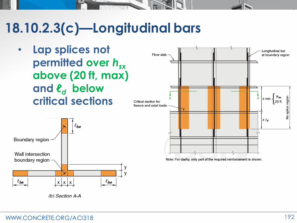
18.10.2.3(c)—Longitudinal bars
• Lap splices not
permitted over hsx
above (20 ft, max)
and ℓd below critical sections

WWW.CONCRETE.ORG/ACI318 193
18.10.2.4—Longitudinal reinforcement ratio at ends of walls
hw/ℓw ≥ 2.0
• Failures in Chile and
New Zealand
• 1 or 2 large cracks
• Minor secondary cracks
Crack patterns for walls with fixed minimum longitudinal reinforcement content of 0.25% (Lu et al. 2017)

WWW.CONCRETE.ORG/ACI318 194
18.10.2.4—Longitudinal reinforcement ratio at ends of walls
New ratio
• Many well
distributed cracks
• Flexure yielding over length
'6 c
y
f
f =
Crack patterns for walls with ρ according to equation (Lu et al. 2017)

WWW.CONCRETE.ORG/ACI318 195
18.10.2.4—Longitudinal reinforcement ratio at ends of walls
Bar Cutoff
• Mu/2Vu similar
to wall with full
reinforcement
• Mu/3Vu good
distribution
• Mu/4Vu
significant
strain above
cut off
Mu/2Vu Mu/3Vu Mu/4Vu

WWW.CONCRETE.ORG/ACI318 196
18.10.2.4—Longitudinal reinforcement ratio at ends of walls

WWW.CONCRETE.ORG/ACI318 197
18.10.2.4—Longitudinal reinforcement ratio at ends of walls
Walls or wall piers with hw/ℓw ≥ 2.0 must satisfy:
a) Long. reinf. ratio within 0.15 ℓw and minimum
b) Long. reinf. extends above and below critical section the greater of ℓw and Mu/3Vu
c) Max. 50% of reinf. terminated at one section
'6 c
y
f
f =

WWW.CONCRETE.ORG/ACI318 198
18.10.3—Shear amplification
• Similar to approach in New Zealand Standard, NZS 3101

WWW.CONCRETE.ORG/ACI318 199
18.10.3—Shear amplification
18.10.3.1 The design shear force Ve shall be calculated by: 3e v v u uV V V=
Vu = the shear force obtained from code lateral load analysis with
factored load combinations
Ωv = overstrength factor equal to the
ratio of Mpr/Mu at the wall critical section.
v = factor to account for dynamic
shear amplification.
Gogus and Wallace, 2015

WWW.CONCRETE.ORG/ACI318 200
18.10.3—Shear amplification
18.10.3.1.2 – Calculation of Ωv
Table 18.10.3.1.2—Overstrength factor Ωv at critical section
[1] For the load combination producing the largest value of Ωv.
[2] Unless a more detailed analysis demonstrated a smaller value,
but not less than 1.0.
Condition Ωv
hwcs/ℓw > 1.5 Greater ofMpr/Mu
[1]
1.5[2]
hwcs/ℓw ≤ 1.5 1.0

WWW.CONCRETE.ORG/ACI318 201
18.10.3—Shear Amplification
18.10.3.1.3 – Calculation of ωv
hwcs/ℓw < 2.0 ➔ ωv = 1.0
hwcs/ℓw ≥ 2.0 ➔ ωv = 0.9 + ns/10 for ns ≤ 6
ωv = 1.3 + ns/30 ≤ 1.8 for ns > 6
where ns ≥ 0.007hwcs
ns = number of stories above the critical section.
WWW.CONCRETE.ORG/ACI318 202
18.10.4.1—Shear strength, Vn
No Change
• The code shows change bars at this
location; rewording only
• Shear calculations for Chapters 11 and 18
were harmonized
• 11.5.4.3 is now similar to 18.10.4.1

WWW.CONCRETE.ORG/ACI318 203
18.10.4.4—Clarification of Acv
Acv = gross area of concrete section bounded by web thickness and length of section in the direction of shear force considered in the case of walls, and gross area of concrete section in the case of diaphragms. Gross area is total area of the defined section minus area of any openings.
1 2 3
Acv wall = Acw1+Acw2+Acw3
Acw2
Vertical wall segments

WWW.CONCRETE.ORG/ACI318 204
18.10.6.2—Displacement based approach
Boundary elements of special structural walls:
• Walls or wall piers
with hwcs/ℓw ≥ 2.0
• Continuous
– Uniform for full height
• Single critical (yielding) section
– Plastic hinge
Continuous
Single critical section

WWW.CONCRETE.ORG/ACI318 205
18.10.6.2—Displacement based approach
(a) Compression zone with special boundary elements required if:
• c = [Pu, fMn]max in direction of
design displacement du and
• du/hwcs ≥ 0.005
1.5
600
u w
wcsh c
d
Single critical section
hwcs
du
Extreme compression fiber

WWW.CONCRETE.ORG/ACI318 206
18.10.6.2—Displacement based approach
(b) Boundary elements req’d, then (i) and either (ii) or (iii)
i. Transv. reinf. extends above and below
critical section [ℓw, Mu/4Vu]max
ii.
iii. dc/hwcs ≥ 1.5 du / hwcs , where
'
1 14 0.015
100 50 8
c w e
wcs c cv
c V
h b b f A
d = − −
0.025 wb c
Errata

WWW.CONCRETE.ORG/ACI318 207
18.10.6.4—Special Boundary Elements
• Single perimeter hoops with 90-135 or 135-135 degree crossties, inadequate
WWW.CONCRETE.ORG/ACI318 208
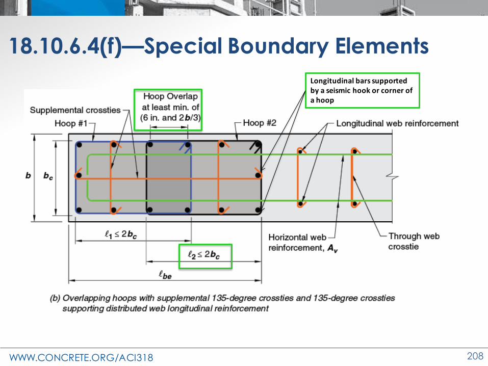
18.10.6.4(f)—Special Boundary Elements
Longitudinal bars supported by a seismic hook or corner of a hoop

WWW.CONCRETE.ORG/ACI318 209
18.10.6.4(h)—Special Boundary Elements
• Concrete within the thickness of the floor system at the special boundary element
location shall have specified compressive
strength at least 0.7 times f′c of the wall.
WWW.CONCRETE.ORG/ACI318 210
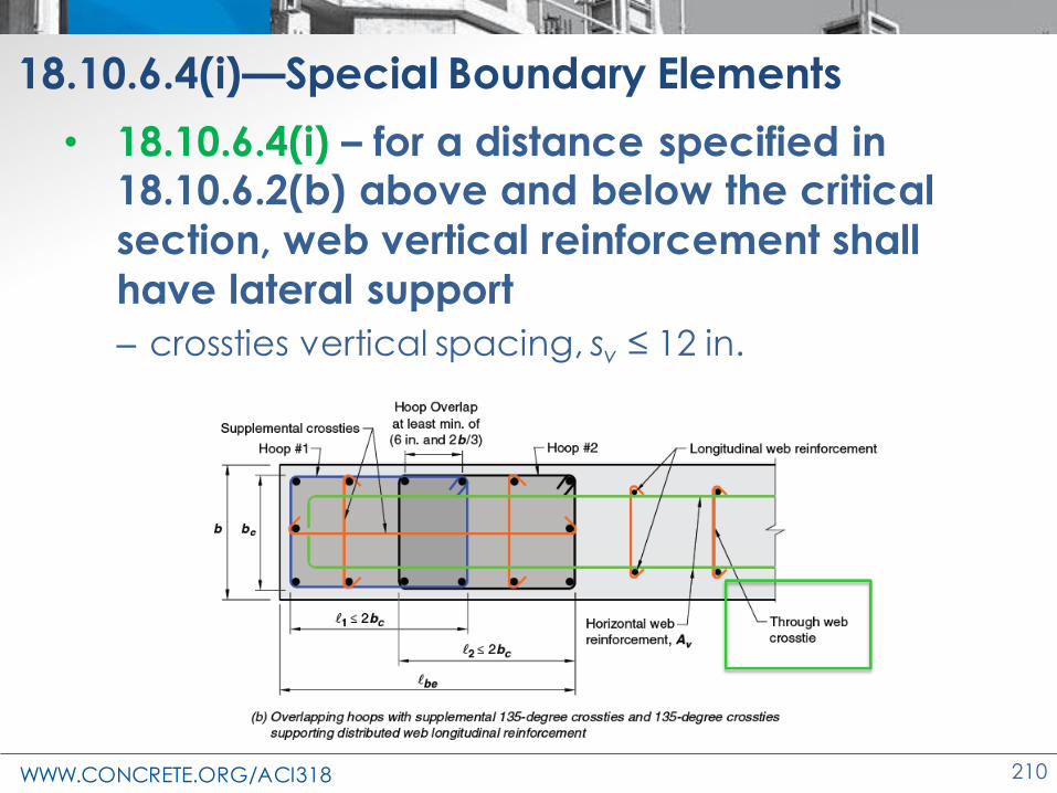
18.10.6.4(i)—Special Boundary Elements
• 18.10.6.4(i) – for a distance specified in 18.10.6.2(b) above and below the critical
section, web vertical reinforcement shall
have lateral support
– crossties vertical spacing, sv ≤ 12 in.
WWW.CONCRETE.ORG/ACI318 211
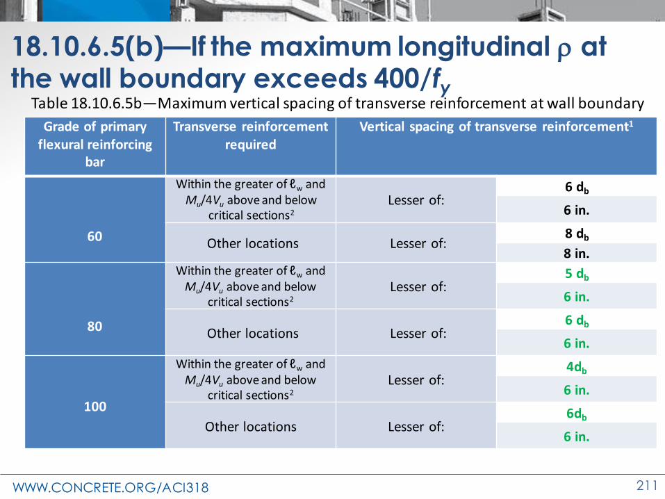
18.10.6.5(b)—If the maximum longitudinal at the wall boundary exceeds 400/fy
Grade of primary flexural reinforcing
bar
Transverse reinforcementrequired
Vertical spacing of transverse reinforcement1
60
Within the greater of ℓw and Mu/4Vu above and below
critical sections2
Lesser of:6 db
6 in.
Other locations Lesser of:8 db
8 in.
80
Within the greater of ℓw and Mu/4Vu above and below
critical sections2
Lesser of:5 db
6 in.
Other locations Lesser of:6 db
6 in.
100
Within the greater of ℓw and Mu/4Vu above and below
critical sections2
Lesser of:4db
6 in.
Other locations Lesser of:6db
6 in.
Table 18.10.6.5b—Maximum vertical spacing of transverse reinforcement at wall boundary

WWW.CONCRETE.ORG/ACI318 212
18.10.9—Ductile Coupled Walls
Issues preventing ductile behavior
• Inadequate quantity or
distribution of qualifying coupling beams
• Presence of squat walls causes
the primary mechanism to be shear and/or strut-and-tie
failure in walls
• Coupling beams are inadequately developed to
provide full energy dissipation
ℓw ℓwℓn
hwcs
h

WWW.CONCRETE.ORG/ACI318 213
18.10.9—Ductile Coupled Walls
• Individual walls satisfy
– hwcs/ℓw ≥ 2
• All coupling beams must satisfy:
– ℓn/h ≥ 2 at all levels
– ℓn/h ≤ 5 at a floor level in at least 90% of the levels of the building
– Development into adjacent
wall segments, 1.25fy (18.10.2.5)
ℓw ℓwℓn
hwcs
h

WWW.CONCRETE.ORG/ACI318 214
Changes to the Concrete Design Standard
ACI 318-19
Foundations
WWW.CONCRETE.ORG/ACI318 215
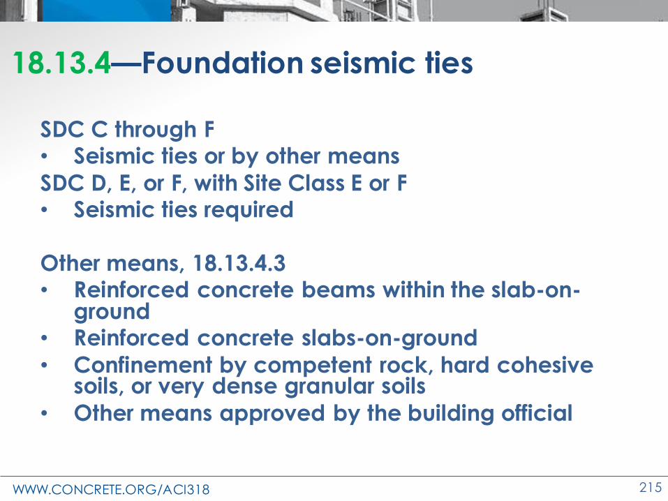
18.13.4—Foundation seismic ties
SDC C through F• Seismic ties or by other means
SDC D, E, or F, with Site Class E or F• Seismic ties required
Other means, 18.13.4.3• Reinforced concrete beams within the slab-on-
ground• Reinforced concrete slabs-on-ground
• Confinement by competent rock, hard cohesive soils, or very dense granular soils
• Other means approved by the building official
WWW.CONCRETE.ORG/ACI318 216
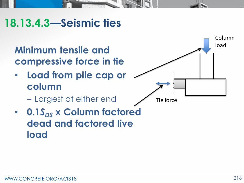
18.13.4.3—Seismic ties
Minimum tensile and compressive force in tie
• Load from pile cap or
column
– Largest at either end
• 0.1SDS x Column factored
dead and factored live load
Tie force
Columnload

WWW.CONCRETE.ORG/ACI318 217
18.13.5—Deep foundations
• (a) Uncased CIP concrete drilled or augered piles
• (b) Metal cased concrete piles
• (c) Concrete filled pipe piles
• (d) Precast concrete piles

WWW.CONCRETE.ORG/ACI318 218
18.13.5.2—Deep foundations
SDC C through F
• Resisting tension loads
→ Continuous longitudinal
reinforcement over full length to
resist design tension
Source: Ground Developments
WWW.CONCRETE.ORG/ACI318 219
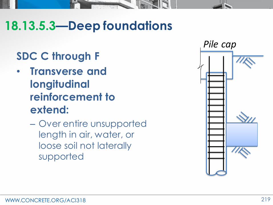
18.13.5.3—Deep foundations
SDC C through F
• Transverse and
longitudinal
reinforcement to
extend:
– Over entire unsupported length in air, water, or
loose soil not laterally supported
Pile cap
WWW.CONCRETE.ORG/ACI318 220
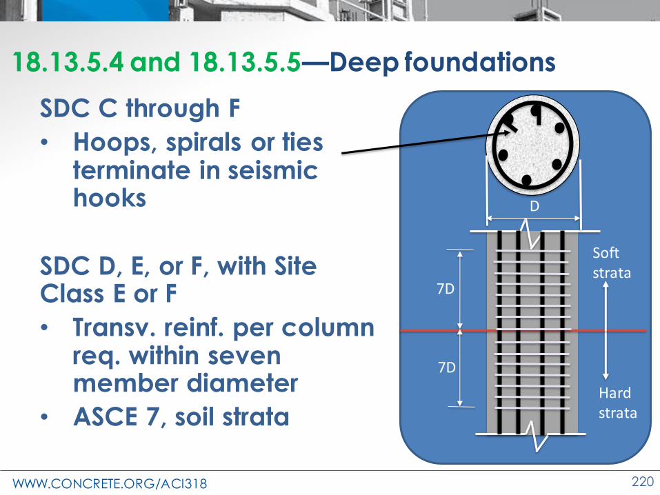
18.13.5.4 and 18.13.5.5—Deep foundations
SDC C through F
• Hoops, spirals or ties terminate in seismic hooks
SDC D, E, or F, with Site Class E or F
• Transv. reinf. per column req. within seven member diameter
• ASCE 7, soil strata
Soft strata
Hard strata
D
7D
7D

WWW.CONCRETE.ORG/ACI318 221
18.13.5.6—Deep foundations
• SDC D, E, or F
– Piles, piers, or caissons and foundation ties supporting
one- and two-story stud bearing walls
– Exempt from transv. reinf. of 18.13.5.3 through 18.13.5.5
Errata

WWW.CONCRETE.ORG/ACI318 222
18.13.5.7—Uncased cast-in place piles
Pile capSDC C1/3 ℓpile
•ℓbar ≥ 10 ft3dpile
Distance to 0.4Mcr > Mu
•Transverse confinement zone• 3 dpile from bottom of pile cap• s ≤ 6 in.; 8db long. bar
•Extended trans. reinf.• s ≤ 16db long. bar
min ≥ 0.0025
ℓ bar
Closed ties or spirals ≥ No.3
s
dpile
ℓbar = minimum reinforced pile length

WWW.CONCRETE.ORG/ACI318 223
18.13.5.7—Uncased cast-in place pilesPile cap
SDC D, E, and F with Site Class A, B, C, and D
1/2 ℓpile
• ℓbar ≥ 10 ft3dpile
Distance to 0.4Mcr > Mu
•Transverse confinement zone• 3 dpile from bottom of pile cap• s of 18.7.5.3 • min ≥ 0.06 fc′/fyt
•Extended trans. reinf.12db long. bar
s ≤ 0.5dpile
12 in.
min ≥ 0.005
ℓ bar
Closed ties or spirals ≥ No. 3 (≤ 20 in.) or No. 4 (> 20 in.); 18.7.5.2
s
dpile
ℓbar = minimum reinforced pile length

WWW.CONCRETE.ORG/ACI318 224
18.13.5.7—Uncased cast-in place pilesPile cap
SDC D, E, and F with Site Class E and F
•ℓbar Full length of pile (some exceptions)
•Transverse confinement zone• 7 dpile from bottom of pile cap• s of 18.7.5.3 • min ≥ 0.06 fc′/fyt
•Extended trans. reinf.12db long. bar
s ≤ 0.5dpile
12 in.
min ≥ 0.005
ℓ bar
Closed ties or spirals ≥ No. 3 (≤ 20 in.) or No. 4 (> 20 in.); 18.7.5.2
s
dpile
ℓbar = minimum reinforced pile length

WWW.CONCRETE.ORG/ACI318 225
18.13.5.8—Metal cased concrete pilesPile cap
SDC C through F
•Longitudinal same as
uncased piles
•Metal casing replaces
transverse reinforcement in uncased piles
•Extend casing for ℓbar
t ≥ 14 gauge
ℓ bar
dpile

WWW.CONCRETE.ORG/ACI318 226
18.13.5.9—Concrete-filled pipe pilesPile cap
SDC C through F
•min ≥ 0.01
•ℓd,pile ≥ 2ℓpilecap
ℓdt,bar
Steel pipe
2ℓ p
ile c
ap ≥
ℓd
dpile
ℓpi
le c
ap

WWW.CONCRETE.ORG/ACI318 227
18.13.5.10—Precast nonprestressed piles
Pile capSDC C
•ℓbar Full length of pile
•Transverse confinement zone• 3 dpile from bottom of pile cap• s ≤ 6 in.; 8db long. bar
•Extended trans. reinf.• s ≤ 6 in.
min ≥ 0.01
ℓ bar s
dpile
Closed ties or spirals ≥ No. 3 (≤ 20 in.) or No. 4 (> 20 in.); 18.7.5.2

WWW.CONCRETE.ORG/ACI318 228
18.13.5.10—Precast nonprestressed piles
Pile capSDC D, E, and F
•Same as SDC C
•Satisfy Table 18.13.5.7.1 for SDC D, E, and F
min ≥ 0.01
ℓ bar s
dpile
Closed ties or spirals ≥ No. 3 (≤ 20 in.) or No. 4 (> 20 in.); 18.7.5.2

WWW.CONCRETE.ORG/ACI318 229
18.13.5.10—Precast prestressed piles
Pile capSDC C through F
•Satisfy 18.13.5.10.4 through
18.13.5.10.6•Minimum amount and spacing of transverse reinforcement
ℓ bar s
dpile
WWW.CONCRETE.ORG/ACI318 230
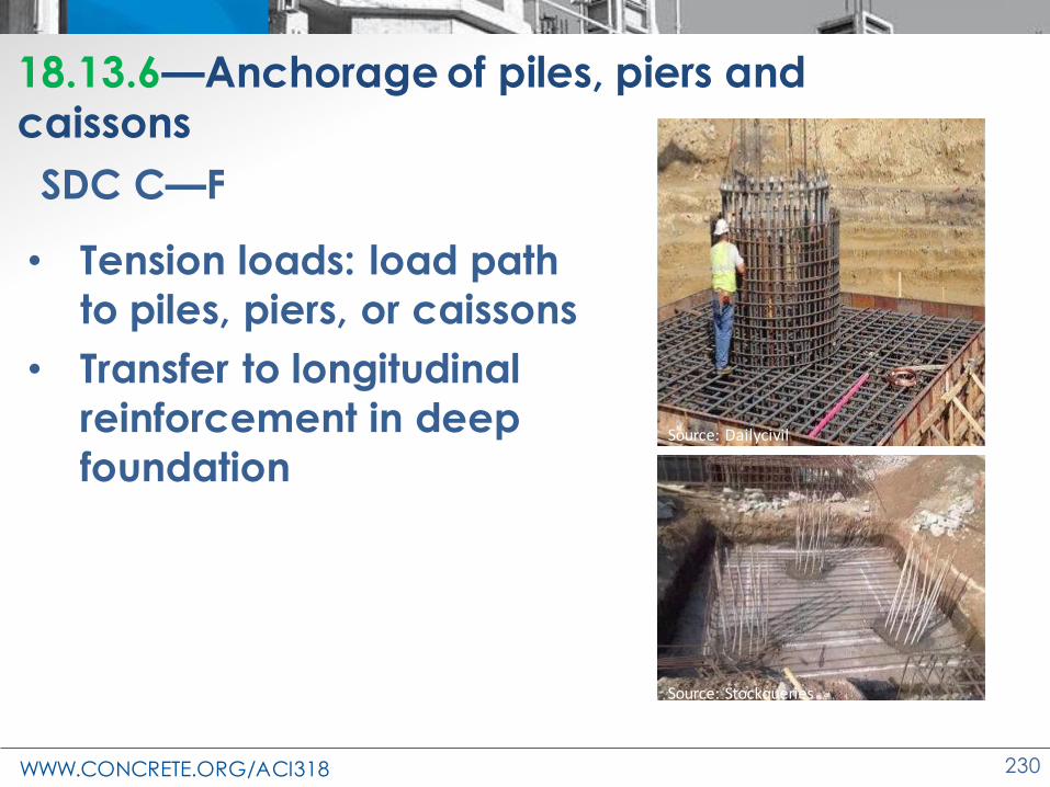
18.13.6—Anchorage of piles, piers and caissons
SDC C—F
• Tension loads: load path
to piles, piers, or caissons
• Transfer to longitudinal
reinforcement in deep
foundationSource: Dailycivil
Source: Stockqueries

WWW.CONCRETE.ORG/ACI318 231
18.13.6—Anchorage of piles, piers and caissons
ℓd compr.ℓdt tension
Dowel
1.25fy
Source: Gayle Johnson
18.13.6.2 SDC C—F
• Anchor dowel between piles and pile cap
18.13.6.3 SDC D—F
• If tension forces and dowel post-
installed in precast pile
• Grouting system to develop min. 1.25 fy (shown by test)

WWW.CONCRETE.ORG/ACI318 232
21.2.4.3—ϕ, Foundation elements
SDC C—F
• For foundation elements supporting the
primary seismic-force-resisting system
• ϕ for shear shall ≤ the least value of
– ϕ for shear used for special column
– ϕ for shear used for special wall

WWW.CONCRETE.ORG/ACI318 233
Changes to the Concrete Design Standard
ACI 318-19
High-Strength
Reinforcement

WWW.CONCRETE.ORG/ACI318 234
Ch. 20 – Yield strength determination
• 318-19, 20.2.1.2:
Nonprestressed bar yield strength
determination:
– The yield point by the
halt-of-force method
– T he offset method, using
0.2 percent offset
• 20.2.1.3
– A615 and A706
additional requirements

WWW.CONCRETE.ORG/ACI318 235
Ch. 3 – Update of ASTM A615-18e1
• Latest ASTM A615 allows:
– Gr. 100
– Bars up to No. 20
• ACI 318-19 allows
– No. 18 and smaller
– Gr. 80 & 100 with restrictions
• No. 20 not acceptable:
– Development length
– Bar bends

WWW.CONCRETE.ORG/ACI318 236
Table 20.2.2.4(a)
• Main changes
– Gr. 80
– Gr. 100
– Footnotes
– Clarifications

WWW.CONCRETE.ORG/ACI318 237
Ch. 20 – Steel Reinforcement Properties

WWW.CONCRETE.ORG/ACI318 238
Ch. 20 –Seismic Requirements for A615 Gr. 60
• Section 20.2.2.5 specifies
– ASTM A706 Gr. 60 allowed
– Requirements for ASTM A615, Gr. 60
• Section 20.2.2.5(a) permits ASTM A706
– Grade 60
– Grade 80
– Grade 100
– (as discussed previously)

WWW.CONCRETE.ORG/ACI318 239
Ch. 20 –Seismic Requirements for A615 Gr. 60
• Section 20.2.2.5(b) permits ASTM A615 Grade 60 if:
– fy,actual ≤ fy + 18,000 psi
– Provides adequate ductility (min. ft/fy ≥ 1.25)
– Min. fracture elongation in 8 in. (10-14%)
– Minimum uniform elongation (6-9%)
• Section 20.2.2.5(b) provides the A706 elongation properties

WWW.CONCRETE.ORG/ACI318 240
Ch. 20 – Seismic Requirements for A615
• For seismic design ASTM A615 GR. 80 and 100 are not permitted

WWW.CONCRETE.ORG/ACI318 241
Ch. 20 – Steel Reinforcement Properties

WWW.CONCRETE.ORG/ACI318 242
Ch. 20 – Steel Reinforcement Properties

WWW.CONCRETE.ORG/ACI318 243
Ch. 26 – Tolerances for seismic hoops26.6.2.1(c)
WWW.CONCRETE.ORG/ACI318 244
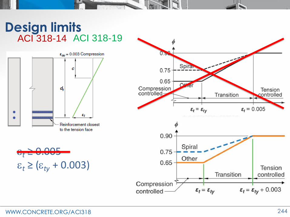
Design limits
et ≥ 0.005et ≥ (ety + 0.003)
ACI 318-14 ACI 318-19

WWW.CONCRETE.ORG/ACI318 245
Design limits
et ≥ (ety + 0.003)
ACI 318-19
ACI 318-19 Provisions 7.3.3.1,
8.3.3.1, and 9.3.3.1 require
slabs and beams be tension
controlled
y
ty
s
f
Ee =

WWW.CONCRETE.ORG/ACI318 246
Design limitsACI 318-14
WWW.CONCRETE.ORG/ACI318 247
Design limits
ACI 318-19

WWW.CONCRETE.ORG/ACI318 248
Design limits
f’c = 4000 psi f’c = 10,000 psi
GR 60 et ≥ 0.0051 1.79% 3.42%
GR 80 et ≥ 0.00575 1.24% 2.37%
GR 100 et ≥ 0.0065 0.92% 1.75%
Reinforcement ratio, tcl
y
ty
s
f
Ee =
WWW.CONCRETE.ORG/ACI318 249
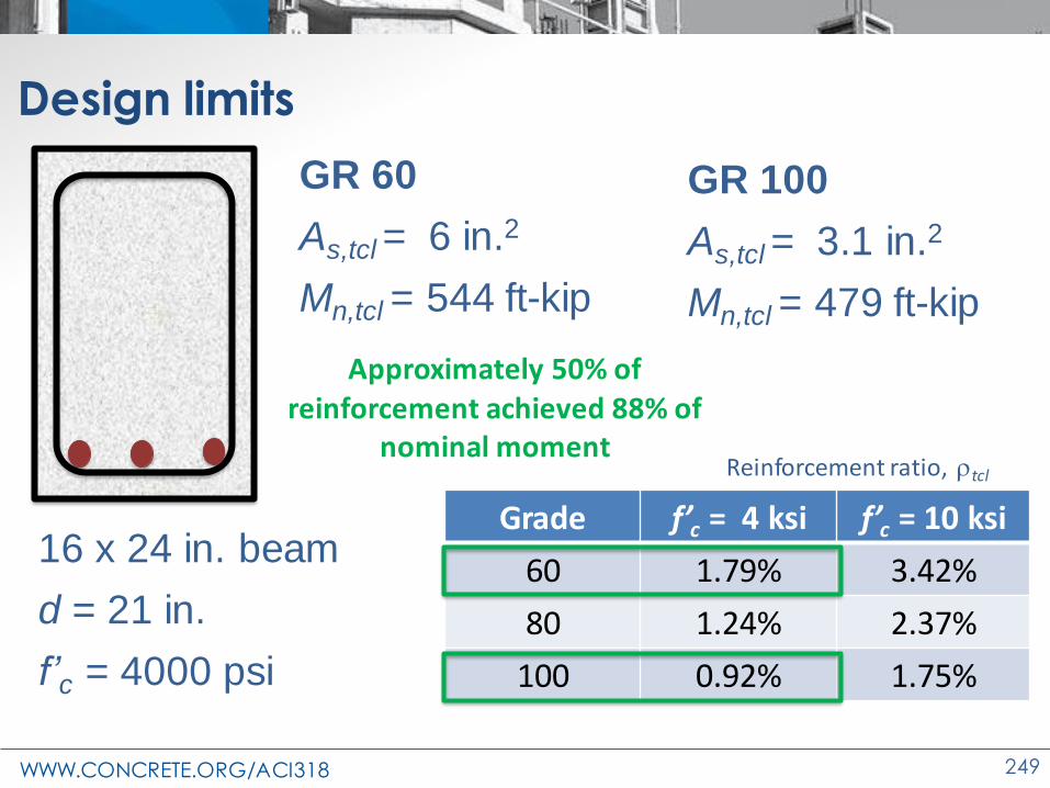
Design limits
Grade f’c = 4 ksi f’c = 10 ksi
60 1.79% 3.42%
80 1.24% 2.37%
100 0.92% 1.75%
16 x 24 in. beam
d = 21 in.
f’c = 4000 psi
GR 60
As,tcl = 6 in.2
Mn,tcl = 544 ft-kip
Reinforcement ratio, tcl
Approximately 50% of reinforcement achieved 88% of
nominal moment
GR 100
As,tcl = 3.1 in.2
Mn,tcl = 479 ft-kip

WWW.CONCRETE.ORG/ACI318 250
Changes to the Concrete Design Standard
ACI 318-19
Development Length
WWW.CONCRETE.ORG/ACI318 251
Development Length
• Deformed Bars and Deformed Wires in Tension
– Simple modification to 318-14
– Accounts for Grade 80 and 100
• Standard Hooks and Headed Deformed
Bars
– Substantial changes from 318-14

WWW.CONCRETE.ORG/ACI318 252
Development Length
• Deformed Bars and Deformed Wires in Tension
• Standard Hooks in Tension
• Headed Deformed Bars in Tension
WWW.CONCRETE.ORG/ACI318 253
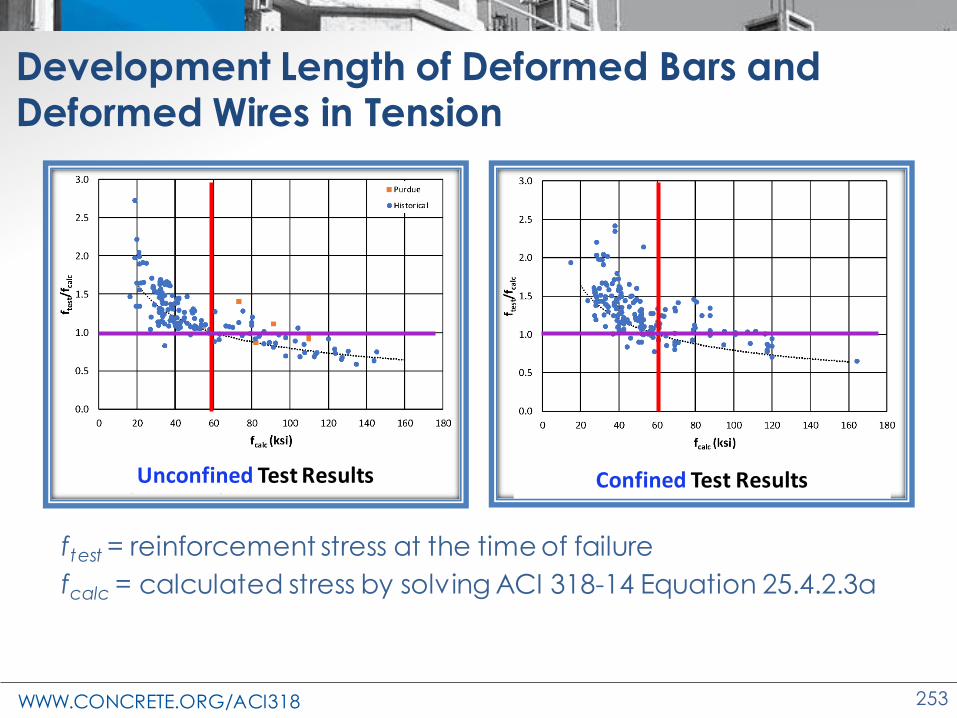
Development Length of Deformed Bars and Deformed Wires in Tension
Unconfined Test Results
ftest = reinforcement stress at the time of failure
fcalc = calculated stress by solving ACI 318-14 Equation 25.4.2.3a
Confined Test Results

WWW.CONCRETE.ORG/ACI318 254
Development Length of Deformed Bars and Deformed Wires in Tension
• Modification in simplified provisions of 25.4.2.3
• Ψg : new modification factor based on grade of reinforcement
• Modification in Table 25.4.2.3

WWW.CONCRETE.ORG/ACI318 255
Development Length of Deformed Bars and Deformed Wires in Tension
• Modification in general development length equation 25.4.2.4(a)
• Provision 25.4.2.2
Ktr ≥ 0.5db for fy ≥ 80,000 psi , if longitudinal bar spacing < 6 in.
Modification factors : Lightweightt : Casting positione : Epoxys : Sizeg : Reinforcement grade
WWW.CONCRETE.ORG/ACI318 256
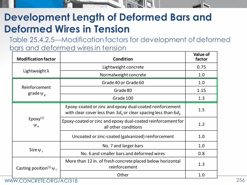
Development Length of Deformed Bars and Deformed Wires in Tension
Modification factor ConditionValue of factor
Lightweight λLightweight concrete 0.75
Normalweight concrete 1.0
Reinforcementgrade g
Grade 40 or Grade 60 1.0
Grade 80 1.15
Grade 100 1.3
Epoxy[1]
e
Epoxy-coated or zinc and epoxy dual-coated reinforcement with clear cover less than 3db or clear spacing less than 6db
1.5
Epoxy-coated or zinc and epoxy dual-coated reinforcement for all other conditions
1.2
Uncoated or zinc-coated (galvanized) reinforcement 1.0
Size s
No. 7 and larger bars 1.0
No. 6 and smaller bars and deformed wires 0.8
Casting position[1] t
More than 12 in. of fresh concrete placed below horizontal reinforcement
1.3
Other 1.0
Table 25.4.2.5—Modification factors for development of deformed bars and deformed wires in tension

WWW.CONCRETE.ORG/ACI318 257
Check development length of No. 8 longitudinal bar
in a beam. Assume f’c = 4000 psi NWC, Grade 80reinforcement, 2 in. cover and no epoxy coating.
Example—Development Length of Deformed Bars and Deformed Wires in Tension
g
Grade 40 or Grade 60 1.0
Grade 80 1.15
Grade 100 1.3
From Table 25.4.2.5
confinement term (cb + Ktr)/db = 2.5 (using the upper limit)
= 1.0e = 1.0s = 1.0t = 1.0te = 1.0 < 1.7 g = 1.15

WWW.CONCRETE.ORG/ACI318 258
Substituting in Eq. 25.4.2.4a:
Example—Development Length of Deformed Bars and Deformed Wires in Tension
ℓ𝑑 =3
40
80,000
1 4000
1 1 1 1.15
2.5(1.0) = 43.6 in.
ℓ𝑑 =3
40
60,000
1 4000
1 1 1 1
2.5(1.0) = 28.5 in.
In comparison a similar bar with Grade 60 reinforcement;
Increase of ~ 50 percent in development length for Grade 80

WWW.CONCRETE.ORG/ACI318 259
Development Length of Deformed Bars and Deformed Wires in Tension
• Differences in higher grade steel for 4000 psi concrete
Grade g ℓd,Gr#/ℓd,Gr60
60 1.0 1.0
80 1.15 1.5
100 1.3 2.2

WWW.CONCRETE.ORG/ACI318 260
Development Length
• Deformed Bars and Deformed Wires in Tension
• Standard Hooks in Tension
• Headed Deformed Bars in Tension

WWW.CONCRETE.ORG/ACI318 261
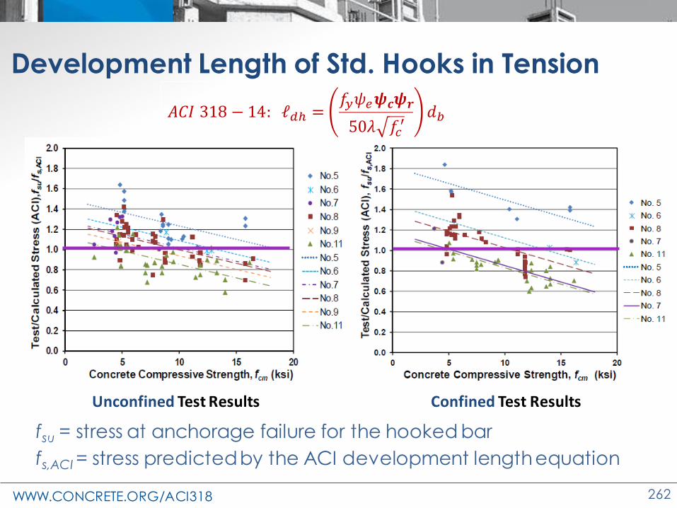
Development Length of Std. Hooks in Tension
• Failure Modes
• Mostly, front and side failures – Dominant front failure (pullout and blowout)
– Blowouts were more sudden in nature
Front Pullout Front Blowout Side splitting Tail kickoutSide blowout
WWW.CONCRETE.ORG/ACI318 262
Development Length of Std. Hooks in Tension
fsu = stress at anchorage failure for the hooked bar
fs,ACI = stress predicted by the ACI development length equation
Confined Test Results
𝐴𝐶𝐼 318 − 14: ℓ𝑑ℎ =𝑓𝑦𝜓𝑒𝝍𝒄𝝍𝒓
50𝜆 𝑓𝑐′
𝑑𝑏
Unconfined Test Results
WWW.CONCRETE.ORG/ACI318 263
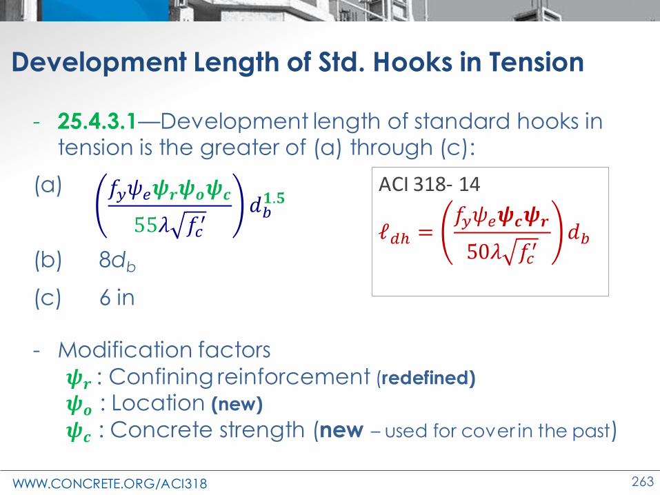
Development Length of Std. Hooks in Tension
- 25.4.3.1—Development length of standard hooks in tension is the greater of (a) through (c):
(a)
(b) 8db
(c) 6 in
- Modification factors
𝝍𝒓 : Confining reinforcement (redefined)
𝝍𝒐 : Location (new)
𝝍𝒄 : Concrete strength (new – used for cover in the past)
ACI 318- 14

WWW.CONCRETE.ORG/ACI318 264
Development Length of Std. Hooks in Tension
Modification
factor
Condition Value of
factor
318-14
Confining
reinforcement,
r
For 90-degree hooks of No. 11 and smaller
bars
(1) enclosed along ℓdh within ties or stirrups
perpendicular to ℓdh at s ≤ 3db, or
(2) enclosed along the bar extension
beyond hook including the bend within ties
or stirrups perpendicular to ℓext at s ≤ 3db
0.8
Other 1.0
318-19
Confining
reinforcement,
r
For No.11 and smaller bars with
Ath ≥ 0.4Ahs or s ≥ 6db
1.0
Other 1.6
Table 25.4.3.2: Modification factors for development of hooked bars in tension

WWW.CONCRETE.ORG/ACI318 265
Development Length of Std. Hooks in Tension
25.4.3.3:
• Confining reinforcement (Ath) shall consists of (a) or (b)– (a) Ties or stirrups that enclose
the hook and satisfy 25.3.2
– (b) Other reinf. that extends at least 0.75ℓdh from the enclosed hook in the direction of the bar in tension and in accordance with (1) or (2) • parallel or perpendicular
(Fig. R25.4.3.3a and Fig. R25.4.3.3b)
Fig. R25.4.3.3a
Fig. R25.4.3.3b

WWW.CONCRETE.ORG/ACI318 266
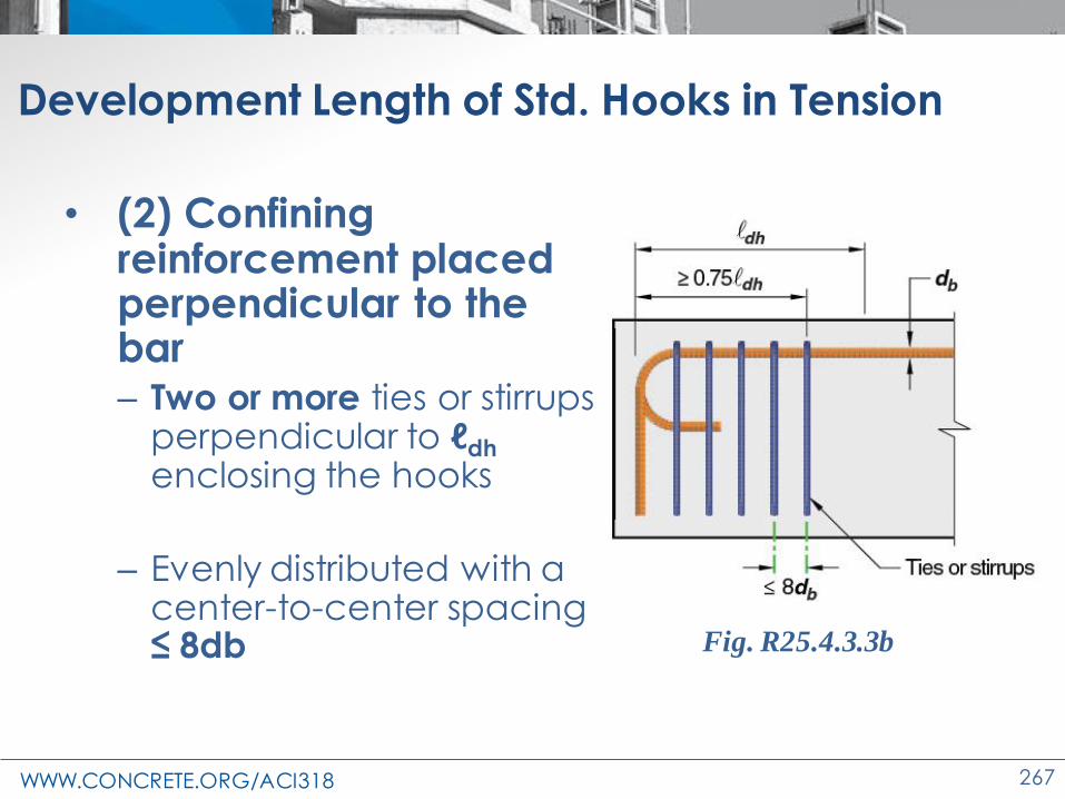
Development Length of Std. Hooks in Tension
• (1) Confining reinforcement placed parallel to the bar (Typical in beam-column joint)
– Two or more ties or stirrups parallel to ℓdh enclosing the hooks
– Evenly distributed with a center-to-center spacing ≤ 8db
– within 15db of the centerline of the straight portion of the hooked bars
Fig. R25.4.3.3a
WWW.CONCRETE.ORG/ACI318 267
Development Length of Std. Hooks in Tension
• (2) Confining reinforcement placed perpendicular to the bar – Two or more ties or stirrups
perpendicular to ℓdh
enclosing the hooks
– Evenly distributed with a center-to-center spacing ≤ 8db Fig. R25.4.3.3b

WWW.CONCRETE.ORG/ACI318 268
Development Length of Std. Hooks in Tension
Modification
factor
Condition Value of
factor
318-14
Cover
ψc
For No. 11 bar and smaller hooks with side
cover (normal to plane of hook) ≥ 2-1/2 in.
and for 90-degree hook with cover on bar
extension beyond hook ≥ 2 in.
0.7
Other 1.0
318-19
Location, o
For No.11 and smaller diameter hooked bars
(1) Terminating inside column core w/ side
cover normal to plane of hook ≥ 2.5 in., or
(2) with side cover normal to plane of hook ≥
6db
1.0
Other 1.25
Table 25.4.3.2: Modification factors for development of hooked bars in tension

WWW.CONCRETE.ORG/ACI318 269
Development Length of Std. Hooks in Tension
Modification factor
Condition Value of factor
Concrete strength, c
For f’c < 6000 psi f’c/15,000 +0.6
For f’c ≥ 6000 psi 1.0
Table 25.4.3.2: Modification factors for development of hooked bars in tension

WWW.CONCRETE.ORG/ACI318 270
Example—Development Length of Std Hook
Check hooked bar anchorage of longitudinal beam
reinforcement, 3-No. 10 bars in a 20 x 20 in. exterior
column. Assume f’c = 4000 psi NWC, Grade 60
reinforcement, 2.5 in. cover normal to plane of hook, and
no epoxy coating. Steel confinement is provided such that
Ath = 0.4 Ahs.
= 1.0
e = 1.0 r = 1.0o = 1.0c = f’c/15,000 + 0.6 = 4,000/15,000 + 0.6 = 0.87

WWW.CONCRETE.ORG/ACI318 271
Example—Development Length of Std Hook
Substituting in the equation:
ℓdh = 21.5 in. > 20 in. NG
In comparison to the equation in 318-14:
ℓdh(318-14) = 16.9 in. < 20 in. OK
ℓ𝑑ℎ =60,000 1.0 1.0 1.0 0.87
55 1.0 4,000(1.27)1.5
e = 1.0c = 0.7 (2 -1/2 in. side cover and 2 in.
back cover)r = 1.0

WWW.CONCRETE.ORG/ACI318 272
Example—Development Length of Std Hook
0
5
10
15
20
25
30
0.5 0.7 0.9 1.1 1.3 1.5
De
velo
pm
ent L
en
gth,
ℓdh
(in
.)
Bar Diameter, in.
Standard Hooked Bars; f'c = 4000 psi
318-14
318-19
0.00
5.00
10.00
15.00
20.00
25.00
0.5 0.7 0.9 1.1 1.3 1.5
De
velo
pmen
t Le
ngth
,ℓd
h(i
n.)
Bar diameter; in.
Standard Hooked Bars; f'c =6000 psi
318-14
318-19
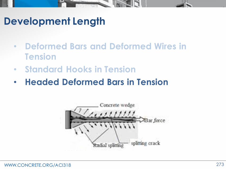
WWW.CONCRETE.ORG/ACI318 273
Development Length
• Deformed Bars and Deformed Wires in Tension
• Standard Hooks in Tension
• Headed Deformed Bars in Tension
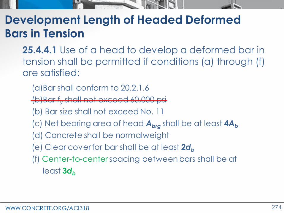
WWW.CONCRETE.ORG/ACI318 274
Development Length of Headed Deformed Bars in Tension
25.4.4.1 Use of a head to develop a deformed bar in
tension shall be permitted if conditions (a) through (f) are satisfied:
(a)Bar shall conform to 20.2.1.6
(b)Bar fy shall not exceed 60,000 psi
(b) Bar size shall not exceed No. 11
(c) Net bearing area of head Abrg shall be at least 4Ab
(d) Concrete shall be normalweight
(e) Clear cover for bar shall be at least 2db
(f) Center-to-center spacing between bars shall be at
least 3db
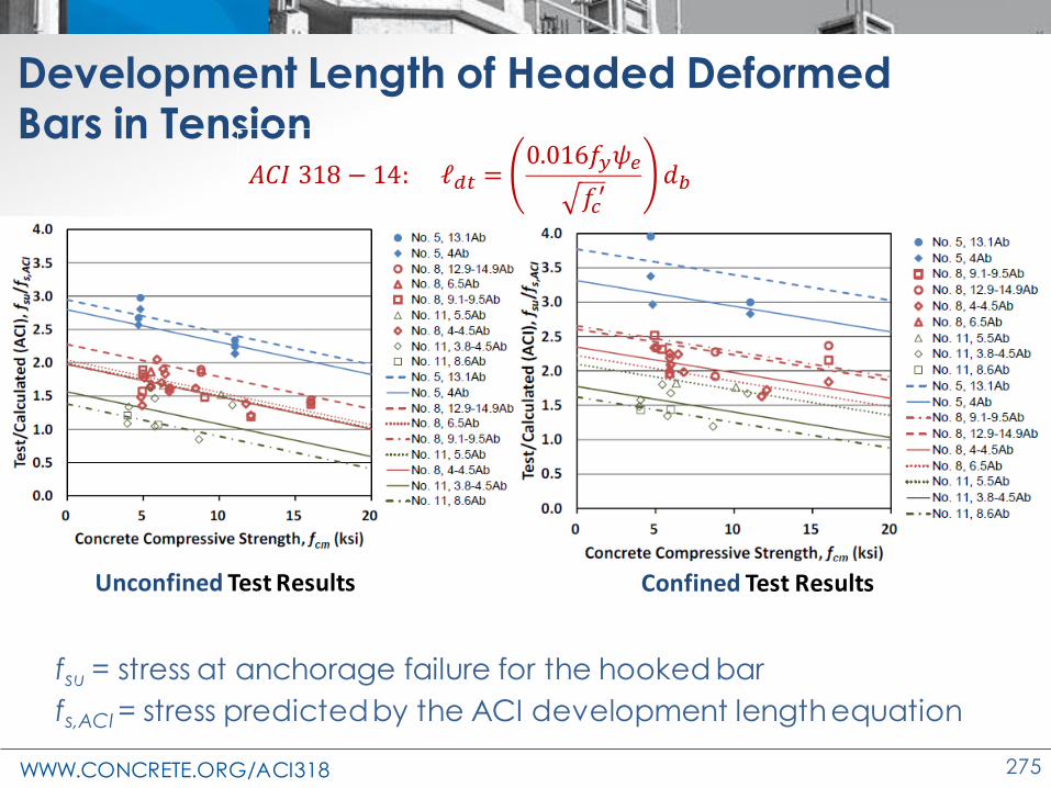
WWW.CONCRETE.ORG/ACI318 275
Development Length of Headed Deformed Bars in Tension
fsu = stress at anchorage failure for the hooked bar
fs,ACI = stress predicted by the ACI development length equation
𝐴𝐶𝐼 318 − 14: ℓ𝑑𝑡 =0.016𝑓𝑦𝜓𝑒
𝑓𝑐′
𝑑𝑏
Unconfined Test Results Confined Test Results

WWW.CONCRETE.ORG/ACI318 276
Development Length of Headed Deformed Bars in Tension
- 25.4.4.2: Development length ℓdt for headed
deformed bars in tension shall be the longest of (a) through (c):
(a)
(b) 8db
(c) 6 in.
- Modification factors𝝍𝒑 : Parallel tie reinforcement
𝝍𝒐 : Location𝝍𝒄 : Concrete strength
ACI 318- 14
f ’c ≤ 6000 psi

WWW.CONCRETE.ORG/ACI318 277
Development length of Headed Deformed Bars in Tension
Modification factor
Condition Value of factor
Parallel tie reinforcement,
p
For No.11 and smaller bars with Att ≥ 0.3Ahs or s ≥ 6db
1.0
Other 1.6
Location, o
For headed bars(1) Terminating inside column core w/ side
cover to bar ≥ 2.5 in., or(2) with side cover to bar ≥ 6db
1.0
Others 1.25
Concrete strength, c
For f’c < 6000 psi f’c/15,000+0.6
For f’c ≥ 6000 psi 1.0
Table 25.4.4.3—Modification factors for development of headed bars in
tension

WWW.CONCRETE.ORG/ACI318 278
Development Length of Headed Deformed Bars in Tension
• Parallel tie reinforcement (Att)– locate within 8db of the centerline of the headed bar
toward the middle of the joint

WWW.CONCRETE.ORG/ACI318 279
Example—Development Length of Headed Deformed Bars in Tension
Check development length of No. 9 longitudinal bar in a beam. Assume f’c = 4000 psi NWC, Grade 60
reinforcement, 2.5 in. cover, and no epoxy coating.Steel confinement is provided such that Att = 0.3 Ahs.
e = 1.0
p = 1.0
o = 1.0
c = f’c/15,000 + 0.6 = 4,000/15,000+0.6 = 0.87

WWW.CONCRETE.ORG/ACI318 280
Example—Development Length of Headed Deformed Bars in Tension
Substituting in the equation :
ℓdt = 13.2 in.
ℓ𝑑𝑡 =60,000 1.0 1.0 1.0 0.87
75 4,000(1.128)1.5
In comparison to the equation in 318-14:
ℓdt(318-14) = 17.1 in.
• Decrease in development length of headed bars in tension as per 318-19 in this example – No.11 and smaller bars with Att 0.3Ats
– bars terminating inside column core with side cover to bar ≥ 2.5 in
ℓ𝑑𝑡 =0.016 1.0 60,000
4,000(1.128)

WWW.CONCRETE.ORG/ACI318 281
Example—Development Length of Headed Deformed Bars in Tension
ℓ𝑑𝑡 =𝑓𝑦𝜓𝑒𝜓𝑝𝜓𝑜𝜓𝑐
75 𝑓𝑐′
𝑑𝑏1.5
ℓ𝑑𝑡 =0.016𝑓𝑦𝜓𝑒
𝑓𝑐′
𝑑𝑏
0
5
10
15
20
25
0.5 0.7 0.9 1.1 1.3 1.5
De
velo
pmen
t Le
ngth
, ℓdt
(in.
)
Bar diameter; in.
Headed bars, f'c = 4000 psi, confined
318-14
318-19
0
2
4
6
8
10
12
14
16
0.5 0.7 0.9 1.1 1.3 1.5
De
velo
pmen
t Le
ngth
, ℓdt
(in.
)
Bar diameter; in.
Headed bars, f'c = 10,000 psi, confined
318-14
318-19
0
5
10
15
20
25
30
35
0.5 0.7 0.9 1.1 1.3 1.5
De
velo
pmen
t Le
ngth
, ℓdt
(in
.)
Bar diameter; in.
Headed bars, f'c = 4000 psi, Unconfined
318-14
318-19

WWW.CONCRETE.ORG/ACI318 282
Changes to the Concrete Design Standard
ACI 318-19
Shear Modifications

WWW.CONCRETE.ORG/ACI318 283
Shear equations change
• One-way beam/slab shear – provision 22.5
– Size effect
– Reinforcement ratio
• Two-way slab shear – provision 22.6
– Size effect
– Reinforcement ratio

WWW.CONCRETE.ORG/ACI318 284
Why shear equations changed in 318-19
• Reasons for changes
– Evidence shows
• Size effect
• Low w effect
• More prevalent
– Deeper beams
– Deep transfer slabs
284

WWW.CONCRETE.ORG/ACI318 285
Other shear changes
• Wall shear equations
– Chapter 11 now similar to Chapter 18
• Shear leg spacing
– Section spacing requirements
• Biaxial shear
– Engineer must consider
• Hanger reinforcement
– Commentary suggestion

WWW.CONCRETE.ORG/ACI318 286
Changes to the Concrete Design Standard
ACI 318-19
One-way Shear
Equations
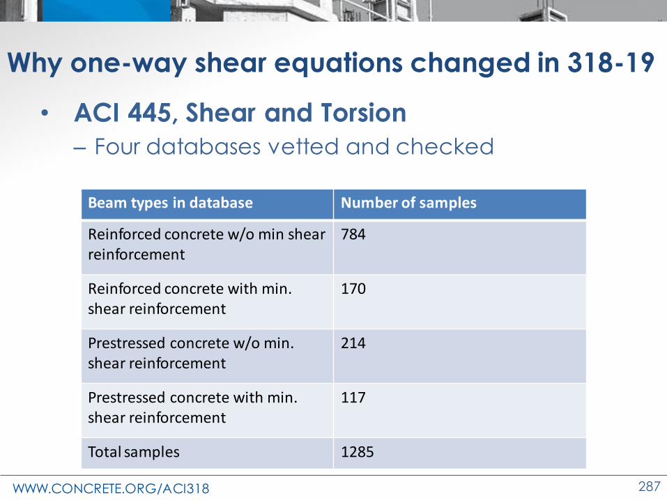
WWW.CONCRETE.ORG/ACI318 287
Why one-way shear equations changed in 318-19
• ACI 445, Shear and Torsion
– Four databases vetted and checked
287
Beam types in database Number of samples
Reinforced concrete w/o min shear reinforcement
784
Reinforced concrete with min. shear reinforcement
170
Prestressed concrete w/o min. shear reinforcement
214
Prestressed concrete with min. shear reinforcement
117
Total samples 1285

WWW.CONCRETE.ORG/ACI318 288
Why one-way shear equations changed in 318-19
288
Figure: Strength Ratio (Vtest/Vn) that was calculated by 318-14 Simplified
d = 10 in. – s, size effect factor
Vtest/Vn = 1
,minv vA A
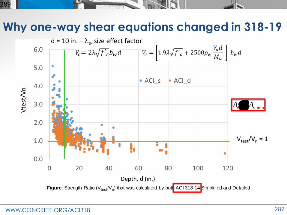
WWW.CONCRETE.ORG/ACI318 289
Why one-way shear equations changed in 318-19
289
Figure: Strength Ratio (Vtest/Vn) that was calculated by both ACI 318-14 Simplified and Detailed
d = 10 in. – s, size effect factor
Vtest/Vn = 1
,minv vA A
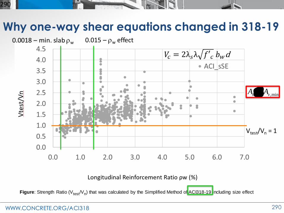
WWW.CONCRETE.ORG/ACI318 290
Why one-way shear equations changed in 318-19
290
Figure: Strength Ratio (Vtest/Vn) that was calculated by the Simplified Method of ACI318-19 including size effect
Vtest/Vn = 1
0.0018 – min. slab w
,minv vA A
0.015 – w effect
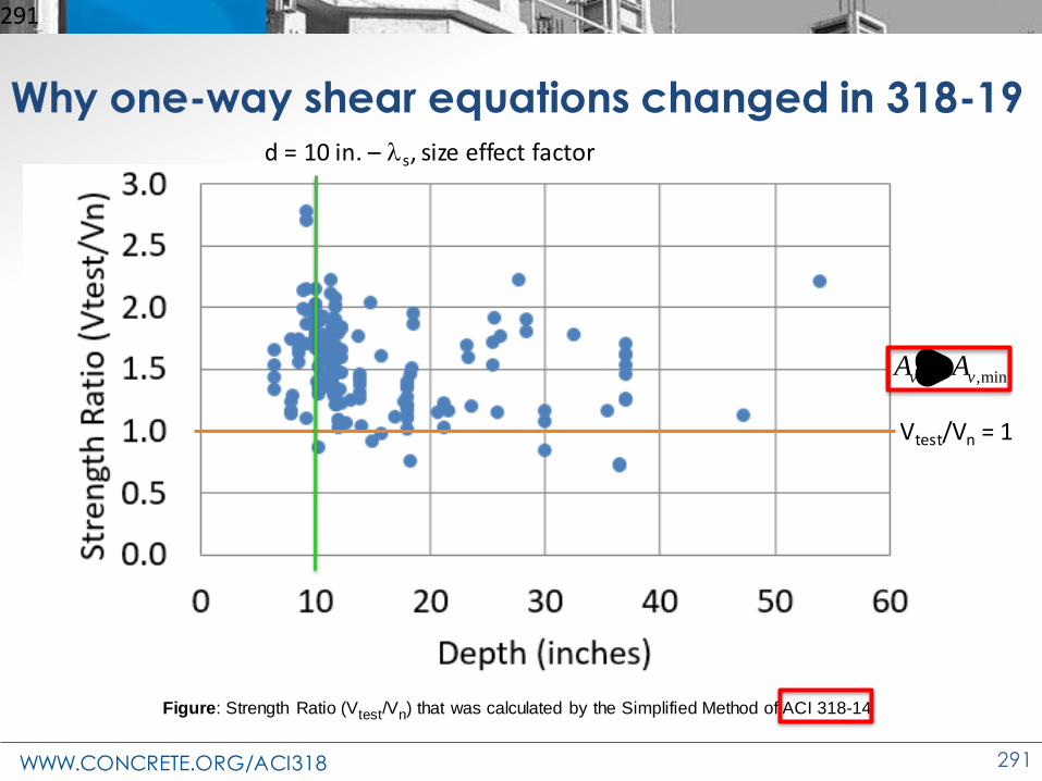
WWW.CONCRETE.ORG/ACI318 291
Why one-way shear equations changed in 318-19
291
Figure: Strength Ratio (Vtest/Vn) that was calculated by the Simplified Method of ACI 318-14
d = 10 in. – s, size effect factor
Vtest/Vn = 1
,minv vA A

WWW.CONCRETE.ORG/ACI318 292
Why one-way shear equations changed in 318-19
• Six different proposals considered
– Proposals vetted and considered by
• ACI 445
• ACI 318 Subcommittee
• Public discussion
• Concrete International articles
• ACI 318 selected one proposal

WWW.CONCRETE.ORG/ACI318 293
Initial one-way shear provision: goals
• Include nonprestressed and prestressed
• Include axial loading and size effect
• Include effect of (w)
• Continue to be proportional to √f’c
• And simple
– Reduce total number of shear equations
– Avoid increase in variables
– Easy to use
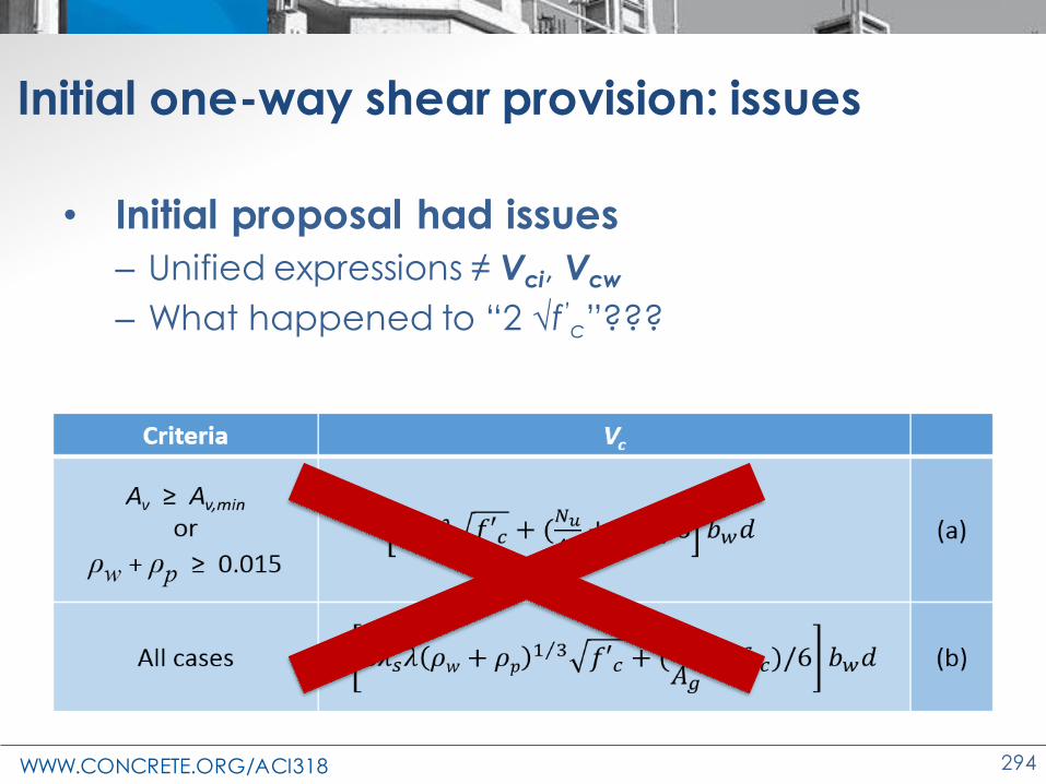
WWW.CONCRETE.ORG/ACI318 294
Initial one-way shear provision: issues
• Initial proposal had issues
– Unified expressions ≠ Vci, Vcw
– What happened to “2 √f’c”???

WWW.CONCRETE.ORG/ACI318 295
Initial one-way shear provision: goals
• Include nonprestressed and prestressed
• Include axial loading and size effect
• Include effect of ()
• Continue to be proportional to √f’c
• And simple

WWW.CONCRETE.ORG/ACI318 296
ACI 318-19 New one-way shear equations Table 22.5.5.1 - Vc for nonprestressed members
Criteria Vc
Av ≥ Av,minEither of:
(a)
(b)
Av < Av,min (c)
Notes:1. Axial load, Nu, is positive for compression and negative for tension2. Vc shall not be taken less than zero.

WWW.CONCRETE.ORG/ACI318 297
0
0.5
1
1.5
2
2.5
0.3
%
0.4
%
0.5
%
0.6
%
0.7
%
0.8
%
0.9
%
1.0
%
1.1
%
1.2
%
1.3
%
1.4
%
1.5
%
1.6
%
1.7
%
1.8
%
1.9
%
2.0
%
2.1
%
2.2
%
2.3
%
2.4
%
2.5
%
Vn
/ s
qrt
(f’c
)
Longitudinal Reinforcement Ratio (As/bd)
ACI 318-19 Shear Equation
8𝜆 𝜌𝑤Τ1 3
Effect of ρw

WWW.CONCRETE.ORG/ACI318 298
Size effect – what is s?
21.0
110
s d =
+
Provision 22.5.5.1.3 defines s as:

WWW.CONCRETE.ORG/ACI318 299
Size effect – what is s?
0
0.2
0.4
0.6
0.8
1
1.2
0 12 24 36 48 60 72 84 96 108 120
λ s
Depth in inches
21.0
110
s d =
+

WWW.CONCRETE.ORG/ACI318 300
Other limitations for Table 22.5.5.1
• Provision 22.5.5.1.1:
– Limits the maximum value of Vc
• Provision 22.5.5.1.2:
– Limits the maximum value of the Nu/6Ag term
'5c c wV f b d
'0.056
uc
g
Nf
A

WWW.CONCRETE.ORG/ACI318 301
9.6.3.1 - Minimum shear reinforcement
• ACI 318-14
– Av,min required if Vu > 0.5 fVc
• ACI 318-19
– Av,min required if Vu > fλf’c bwd
• Exceptions in Table 9.6.3.1

WWW.CONCRETE.ORG/ACI318 302
22.5.6.2.3—Prestressed members:

WWW.CONCRETE.ORG/ACI318 303
Examples: SP-17(14) 5.7 One-way slab Example 1
• Span = 14 ft
• Live load = 100 psf
• Slab = 7 in. thick
• f’c = 5000 psi
• No. 5 bars at 12 in.
• d~6 in.
• b = 12 in.
• Av = 0 in.2
• As = 0.31 in.2/ft
• Vu= 2.4 kip/ft

WWW.CONCRETE.ORG/ACI318 304
Examples: SP-17(14) 5.7 One-way slab Example 1
• SP-17(14) One-way shear calc ACI 318-14
'2
(0.75)(2)(1) 5000 (12 .)(6 .)
7.6 2.4
c c
c
c
V f bd
V psi in in
V kip kip OK
f f
f
f
=
=
=

WWW.CONCRETE.ORG/ACI318 305
Examples: SP-17(14) 5.7 One-way slab Example 1
• SP-17(14) One-way shear calc ACI 318-19
• Av ≤ Av,min, therefore use Eq. 22.5.5.1(c)
( )
1'3
13
8 ( )
0.310.0043 low
(12)(6)
(0.75)(8)(1)(1) 0.0043 5000 (12 .)(6 .)
5.0 2.4
c s w c
w w
c
c
V f bd
V psi in in
V kip kip OK
f f
f
f
=
= =
=
=

WWW.CONCRETE.ORG/ACI318 306
Examples: SP-17(14) 5.7 One-way slab Example 1
• fVc ACI 318-19 < fVc ACI 318-14
– 318-19 for the example given is ~2/3 of ACI 318-14
– Effect of low ρw
• Design impact
– Thicker slabs if depth was controlled by shear in 318-14.
– No change if one-way slab thickness was
controlled by flexure or deflections
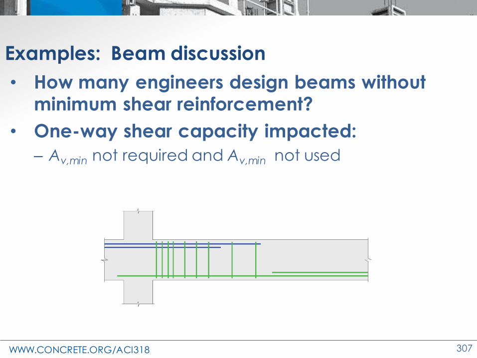
WWW.CONCRETE.ORG/ACI318 307
Examples: Beam discussion
• How many engineers design beams without minimum shear reinforcement?
• One-way shear capacity impacted:
– Av,min not required and Av,min not used

WWW.CONCRETE.ORG/ACI318 308
Examples: Beam discussion
• Where Av,min installed, Eq. 22.5.5.1(a) Vc= (2√f’c),
– ACI 318-14 ~ ACI 318-19
– Eq. 22.5.5.1(b) of Table 22.5.5.1 permitted
• fVc ↑ w > 0.015
• Provisions encourage Av,min

WWW.CONCRETE.ORG/ACI318 309
Examples: SP-17(14) 11.6 Foundation Example 1
• ℓ = 12 ft
• h = 30 in.
• d~25.5 in.
• f’c = 4000 psi
• 13-No. 8 bars
• b = 12 ft
• Av = 0 in.2
• As = 10.27 in.2
• Analysis Vu= 231 kip
3 f
t –
0 in
.
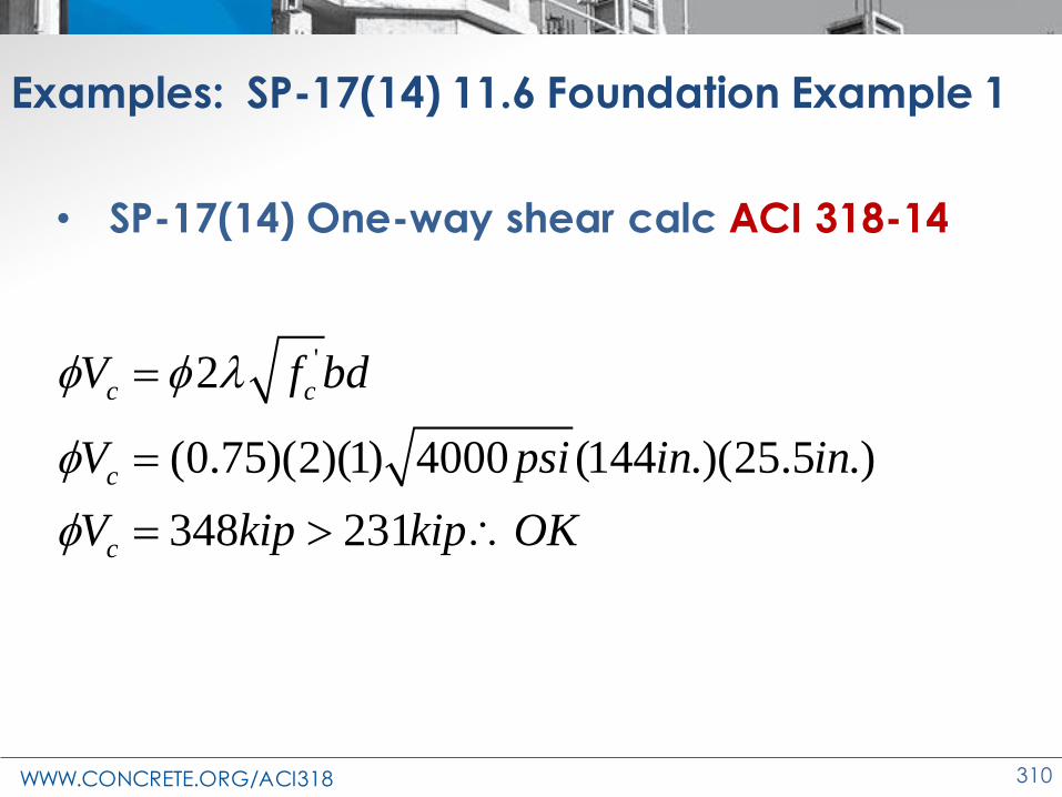
WWW.CONCRETE.ORG/ACI318 310
Examples: SP-17(14) 11.6 Foundation Example 1
• SP-17(14) One-way shear calc ACI 318-14
'2
(0.75)(2)(1) 4000 (144 .)(25.5 .)
348 231
c c
c
c
V f bd
V psi in in
V kip kip OK
f f
f
f
=
=
=

WWW.CONCRETE.ORG/ACI318 311
Examples: SP-17(14) 11.6 Foundation Example 1
• SP-17(14) One-way shear calc ACI 318-19
• Av ≤ Av,min, Eq. 22.5.5.1(c)
• Per ACI 318-19 (13.2.6.2), neglect size effect
for:
– One-way shallow foundations
– Two-way isolated footings
– Two-way combined and mat foundations
1'38 ( )c w cV f bdf f =

WWW.CONCRETE.ORG/ACI318 312
Examples: SP-17(14) 11.6 Foundation Example 1
• SP-17(14) One-way shear calc ACI 318-19
• Av ≤ Av,min, Eq. 22.5.5.1(c)
( )
1'3
2
13
8 ( )
10.27 in.0.0028
(144 in.)(25.5 in.)
(0.75)(8)(1) 0.0028 4000 (144 .)(25.5 .)
196 231
c w c
w
c
c
V f bd
V psi in in
V kip kip NG
f f
f
f
=
= =
=
=

WWW.CONCRETE.ORG/ACI318 313
Examples: SP-17(14) 11.6 Foundation Example 1
• SP-17(14) One-way shear using ACI 318-19
• Av ≤ Av,min, Eq. 22.5.5.1(c)
• Per ACI 318-19, 13.2.6.2, neglect size effect
• Add 6in. thickness
( )
1'3
2
13
8 ( )
10.27 in.0.0023
(144 in.)(31.5 in.)
(0.75)(8)(1) 0.0023 4000 psi(144 in.)(31.5 in.)
226 kip 231 kip Say OK ?
c w c
w
c
c
V f bd
V
V
f f
f
f
=
= =
=
=

WWW.CONCRETE.ORG/ACI318 314
Examples: SP-17(14) 11.6 Foundation Example 1
• Foundation fVc ACI 318-19 < fVc ACI 318-14
– 318-19 for this example given is ~1/2 of ACI 318-14
– Effect of low ρw
• Design impact
– Increased thickness; or
– Increase flexural reinforcement; or
– Increase concrete strength; or
– Combination

WWW.CONCRETE.ORG/ACI318 315
Examples: Grade beam
• Infill wall
– Vu~1 kip/ft
– Vu~8.3 kip ea. end
• Grade beam
– bw =12 in.
– d = 20 in. (h = 24 in.)
– f’c = 4000 psi
– ℓ = 20 ft
– w = 0.0033
Infill Wall
Grade BeamFtg. Ftg.

WWW.CONCRETE.ORG/ACI318 316
Examples: Grade beam
• Infill wall
– Vu~1 kip/ft
– Vu~8.3 kip ea. end
• Grade beam
– bw =12 in.
– d = 20 in. (h = 24 in.)
– f’c = 4000 psi
– ℓ = 20 ft
– w = 0.0033
• ACI 318-14
• ACI 318-19
'
,min
2
0.75(2)(1) 4000(12)(20)
22.8
(1/ 2) not required
c c w
c
c
u c v
V f b d
V
V kip OK
V V A
f f
f
f
f
=
=
=
1'3
13
'
,min
8 ( )
20.82
201
10
0.75(8)(0.82)(1)(0.0033) 4000(12)(20)
11.1
11.4 not required
c s w c w
s
c
c
u c w v
V f b d
V
V kip OK
V f b d kip A
f f
f
f
f
=
= =
+
=
=
=

WWW.CONCRETE.ORG/ACI318 317
Changes to the Concrete Design Standard
ACI 318-19
Two-way Shear
Equations

WWW.CONCRETE.ORG/ACI318 318
Why two-way shear provisions changed in 318-19
• Eqn. developed in 1963 for slabs with t < 5 in. and > 1%
• Two issues similar to one-way shear
– Size effect
– Low ρ vc
Least of (a), (b), and (c):
(a)
(b)
(c)
'4 cf
'42 cf
+
'2 sc
o
df
b
+
Table 22.6.5.2 – Calculation of vc for two-way shear

WWW.CONCRETE.ORG/ACI318 319
Two-way shear size effect
• Table 22.6.5.2—vc for two-way members without shear reinforcement
wherevc
Least of (a), (b), and (c):
(a)
(b)
(c)
'4 cs f
'42 cs f
+
'2 ss
c
o
df
b
+
21
110
s d =
+
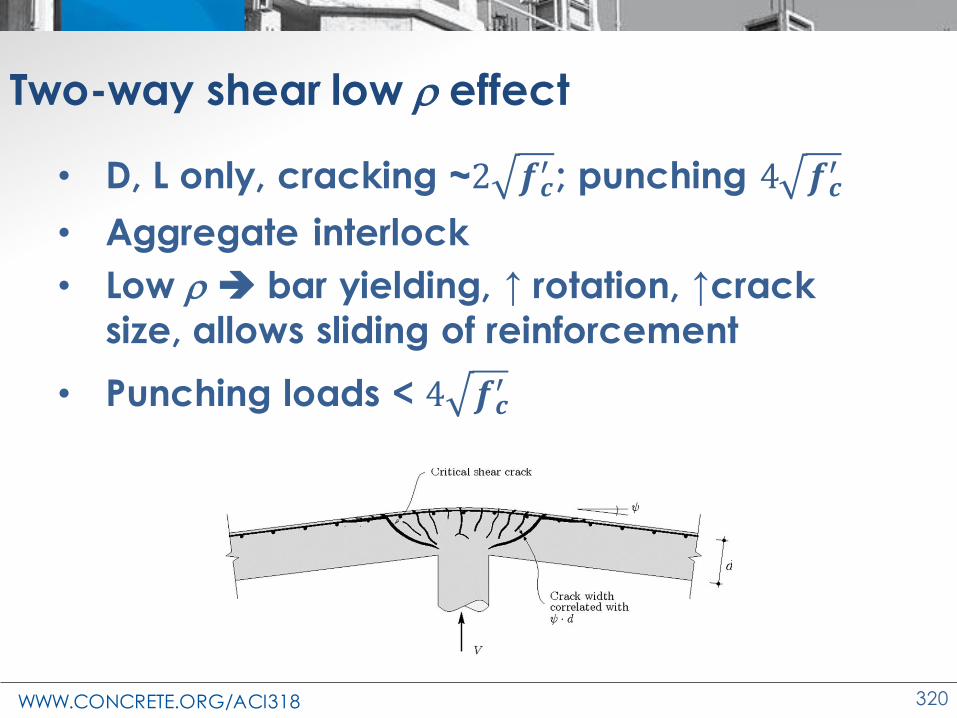
WWW.CONCRETE.ORG/ACI318 320
Two-way shear low effect
• D, L only, cracking ~2 𝒇𝒄′ ; punching 4 𝒇𝒄
′
• Aggregate interlock
• Low ➔ bar yielding, ↑ rotation, ↑crack
size, allows sliding of reinforcement
• Punching loads < 4 𝒇𝒄′
Source: Performance and design of punching –shear reinforcing system, Ruiz et al, fib 2010

WWW.CONCRETE.ORG/ACI318 321
Why two-way shear provisions changed in 318-19:
New two-way slab reinforcement limits8.6.1—Reinforcement limits
• As,min ≥ 0.0018Ag
• If on the critical section
• Then ,min
5 uv slab os
s y
v b bA
f
f
'2uv s cv f f

WWW.CONCRETE.ORG/ACI318 322
Why two-way shear provisions changed in 318-19:
8.4.2.2.3

WWW.CONCRETE.ORG/ACI318 323
h
1.5hSlab edge
bslab
h
1.5h
bslab
1.5hSlab edge
bslab is the lesser of:
Table 8.4.2.2.3

WWW.CONCRETE.ORG/ACI318 324
bslab is the lesser of:
h
1.5h
bslab
Slab edge
1.5hdrop
Table 8.4.2.2.3
h
1.5h
hcap
1.5 hcap
bslab
hdrop
1.5h
1.5 hcap

WWW.CONCRETE.ORG/ACI318 325
Changes to the Concrete Design Standard
ACI 318-19
Wall Shear Equations

WWW.CONCRETE.ORG/ACI318 326
Coordination of Chap. 11 and 18 Wall Shear Eqs.
• ACI 318-83 introduced seismic equation
– Two wall shear equation forms
• Equation forms gave similar results
• Committee 318 wanted consistency in form

WWW.CONCRETE.ORG/ACI318 327
• Chapter 11: all changes
• Chapter 18: no change
• 318-14 simplified compression eq.
(Table 11.5.4.6)
'2v yt
n c
A f dV f hd
s= +
Coordination of Chap. 11 and 18 Wall Shear Eqs.
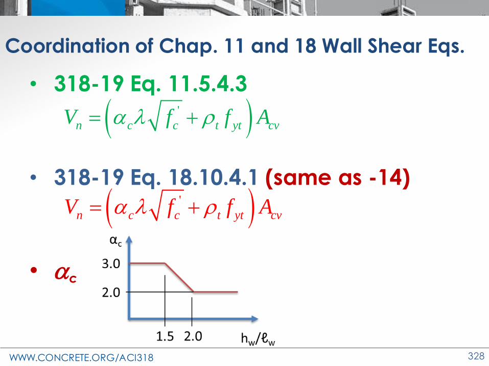
WWW.CONCRETE.ORG/ACI318 328
• 318-19 Eq. 11.5.4.3
• 318-19 Eq. 18.10.4.1 (same as -14)
• c
Coordination of Chap. 11 and 18 Wall Shear Eqs.
( )'
n c c t yt cvV f f A = +
( )'
n c c t yt cvV f f A = +
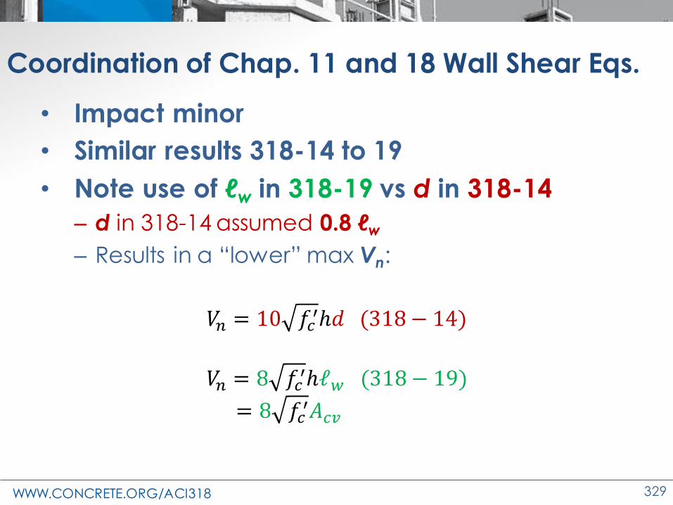
WWW.CONCRETE.ORG/ACI318 329
• Impact minor
• Similar results 318-14 to 19
• Note use of ℓw in 318-19 vs d in 318-14
– d in 318-14 assumed 0.8 ℓw
– Results in a “lower” max Vn:
𝑉𝑛 = 10 𝑓𝑐′ℎ𝑑 (318 − 14)
𝑉𝑛 = 8 𝑓𝑐′ℎℓ𝑤 (318 − 19)
= 8 𝑓𝑐′𝐴𝑐𝑣
Coordination of Chap. 11 and 18 Wall Shear Eqs.

WWW.CONCRETE.ORG/ACI318 330
Changes to the Concrete Design Standard
ACI 318-19
Spacing of Shear
Reinforcement

WWW.CONCRETE.ORG/ACI318 331
Source: Lubell et. al, “Shear Reinforcement Spacing in Wide Members, ACI Structural Journal 2009
Maximum spacing of legs of shear reinforcement
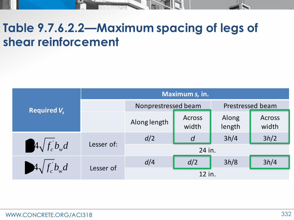
WWW.CONCRETE.ORG/ACI318 332
Table 9.7.6.2.2—Maximum spacing of legs of shear reinforcement
Required Vs
Maximum s, in.
Nonprestressed beam Prestressed beam
Along lengthAcross width
Along length
Across width
Lesser of:d/2 d 3h/4 3h/2
24 in.
Lesser ofd/4 d/2 3h/8 3h/4
12 in.
'4 c wf b d
'4 c wf b d

WWW.CONCRETE.ORG/ACI318 333
Beam stirrup configuration with three closed stirrups distributed across the beam width
Single U-stirrup (with 135-degree hooks) across the net width of the beam, two identical U-stirrups (each with 135-degree hooks) distributed across the beam interior, and a stirrup cap
Single U-stirrup across the net width of the beam, two smaller-width U-stirrups nested in the beam interior, and a stirrup cap
Maximum spacing of legs of shear reinforcement
s maximum = d or d/2 nonprestressed, 3h/2 or 3h/4 prestressed
s maximum = d or d/2 nonprestressed, 3h/2 or 3h/4 prestressed
s maximum = d or d/2 nonprestressed, 3h/2 or 3h/4 prestressed

WWW.CONCRETE.ORG/ACI318 334
Changes to the Concrete Design Standard
ACI 318-19
Bi-directional Shear

WWW.CONCRETE.ORG/ACI318 335
Interaction of shear forces
• Biaxial shear
• Symmetrical RC circular sections
– fVc equal about any axis
– Vu on 2 centroidal axes, Vu = resultant
2 2
, ,( ) ( )u u x u yv v v= +vu,x
vu,y

WWW.CONCRETE.ORG/ACI318 336
Interaction of shear forces
• Biaxial shear
• Rectangular RC sections
– fVc differs between axes
– Vu on 2 axes, fVc≠ resultant
vu,x vu
vu,y
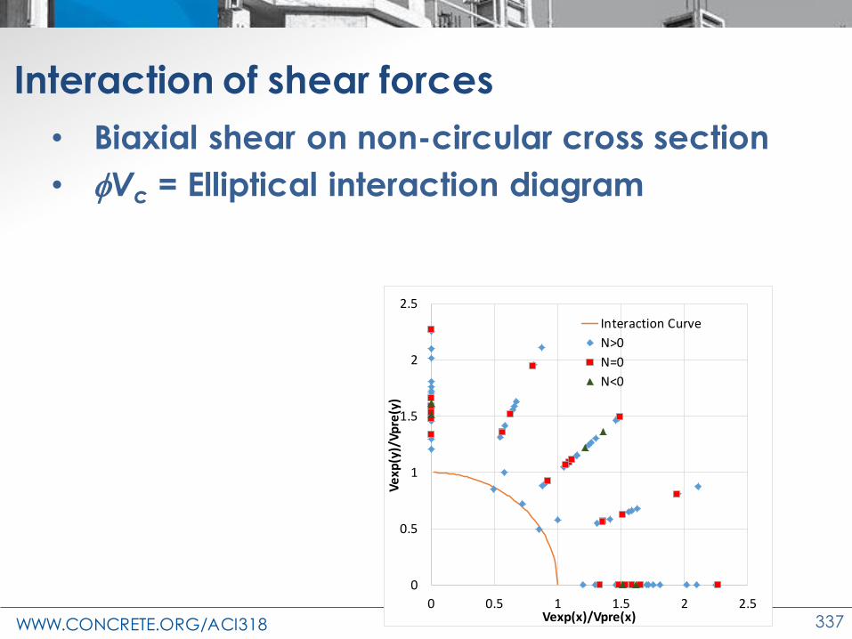
WWW.CONCRETE.ORG/ACI318 337
Interaction of shear forces
• Biaxial shear on non-circular cross section
• fVc = Elliptical interaction diagram
0
0.5
1
1.5
2
2.5
0 0.5 1 1.5 2 2.5
Ve
xp(y
)/V
pre
(y)
Vexp(x)/Vpre(x)
Interaction Curve
N>0
N=0
N<0
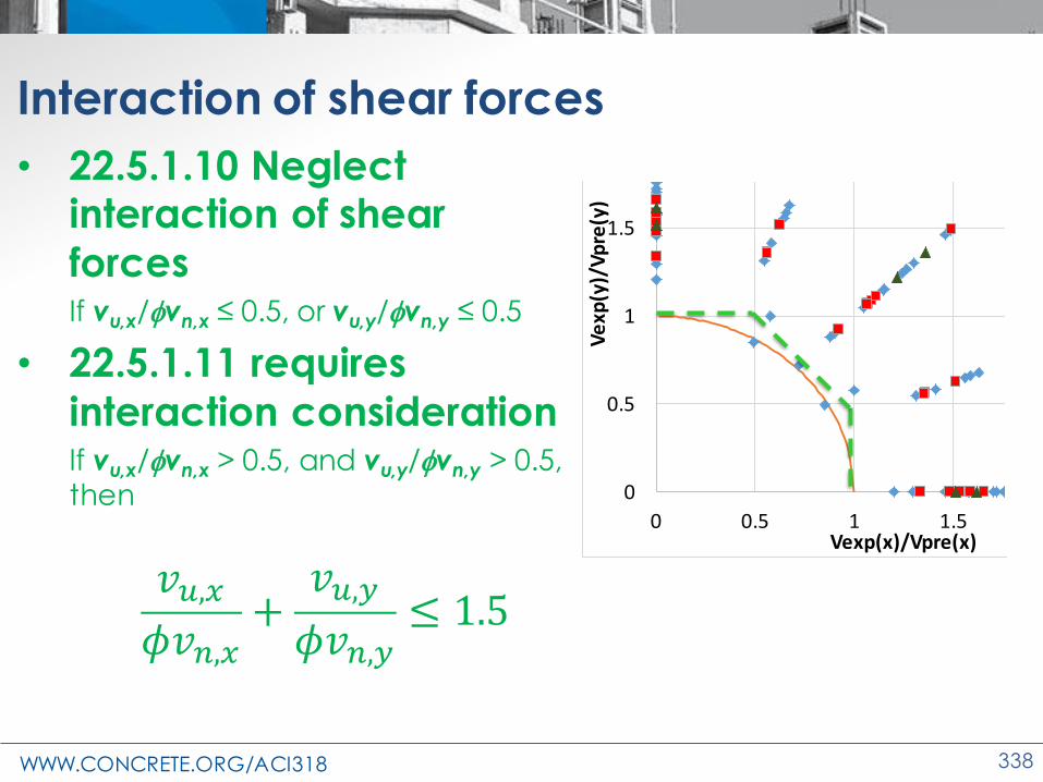
WWW.CONCRETE.ORG/ACI318 338
Interaction of shear forces
• 22.5.1.10 Neglect interaction of shear
forcesIf vu,x/fvn,x ≤ 0.5, or vu,y/fvn,y ≤ 0.5
• 22.5.1.11 requires
interaction considerationIf vu,x/fvn,x > 0.5, and vu,y/fvn,y > 0.5, then 0
0.5
1
1.5
2
2.5
0 0.5 1 1.5 2 2.5
Ve
xp(y
)/V
pre
(y)
Vexp(x)/Vpre(x)
Interaction Curve
N>0
N=0
N<0
WWW.CONCRETE.ORG/ACI318 339
Changes to the Concrete Design Standard
ACI 318-19
Hanger
Reinforcement

WWW.CONCRETE.ORG/ACI318 340
Monolithic beam-to-beam joints: Hanger steel
• Commentary added: R9.7.6.2
• Hanger reinforcement
– Suggested where both the following are true:
– Beam depth ≥ 0.5 girder depth
– Stress transmitted from beam to girder ≥ 3√f’c of the beam
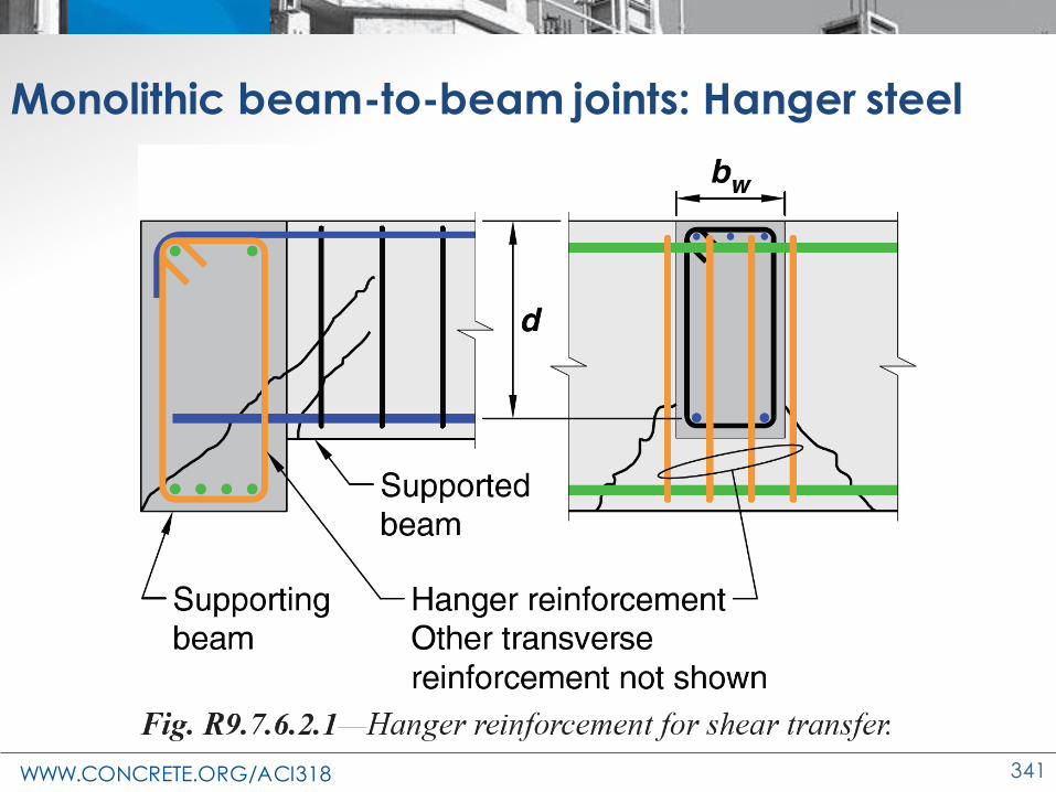
WWW.CONCRETE.ORG/ACI318 341
Monolithic beam-to-beam joints: Hanger steel

WWW.CONCRETE.ORG/ACI318 342
Changes to the Concrete Design Standard
ACI 318-19
Concrete Durability and
Materials

WWW.CONCRETE.ORG/ACI318 343
Changes in durability and materials
• Changes in material properties (19.2)– Additional minimum f’c requirements– Ec requirements
• Changes in durability (19.3)– Calculating chloride ion content– Sulfate exposure class S3– Water exposure class W– Corrosion exposure class C0
• Changes in material (26.4.1)– Alternative cements– New aggregates
• Recycled aggregates• Mineral fillers
• Evaluation and acceptance (26.12)– Strength tests
• Inspection (26.13)
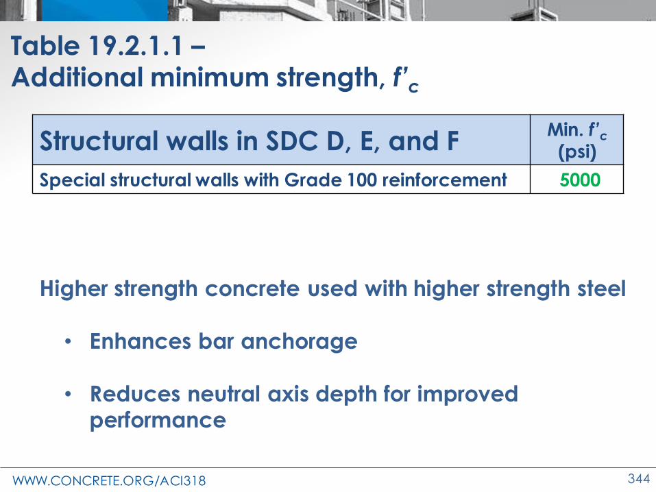
WWW.CONCRETE.ORG/ACI318 344
Table 19.2.1.1 –Additional minimum strength, f’c
Structural walls in SDC D, E, and FMin. f’c
(psi)
Special structural walls with Grade 100 reinforcement 5000
Higher strength concrete used with higher strength steel
• Enhances bar anchorage
• Reduces neutral axis depth for improved performance

WWW.CONCRETE.ORG/ACI318 345
19.2.2.1R Modulus of Elasticity
• Ec from Code equations is appropriate for most applications
• Large differences for HSC (f′c > 8000 psi),
LWC, and mixtures with low coarse of
aggregate volume

WWW.CONCRETE.ORG/ACI318 346
19.2.2.2 Modulus of Elasticity
Ec can be specified based on testing of concrete mixtures:
a) Use of specified EC for proportioning
concrete mixture
b) Test for specified EC
c) Test for EC at 28 days or as
indicated in construction
documents
Source: Engineering discoveries

WWW.CONCRETE.ORG/ACI318 347
Contract Document Information
• Members for which Ec testing of concrete mixtures is required (26.3.1(c))
• Proportioning (26.4.3.1(c))
– Ec is average of 3 cylinders
– Cylinders made and cured in the lab
– Ec ≥ specified value
Source: Engineering Discoveries

WWW.CONCRETE.ORG/ACI318 348
Changes in durability and materials
• Changes in durability (19.3)– Calculating chloride ion content– Sulfate exposure class S3– Water exposure class W– Corrosion exposure class C0
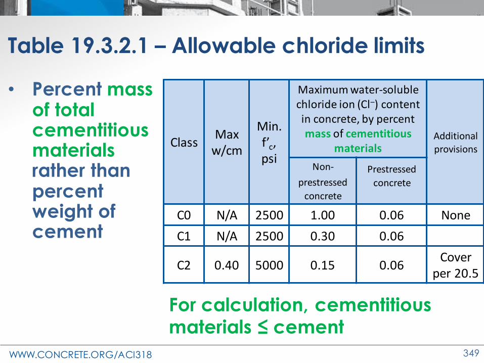
WWW.CONCRETE.ORG/ACI318 349
Table 19.3.2.1 – Allowable chloride limits
• Percent mass of total cementitious materials rather than percent weight of cement
ClassMax
w/cm
Min. f’c, psi
Maximum water-soluble chloride ion (Cl–) content in concrete, by percent mass of cementitious
materialsAdditional provisions
Non-
prestressed
concrete
Prestressed
concrete
C0 N/A 2500 1.00 0.06 None
C1 N/A 2500 0.30 0.06
C2 0.40 5000 0.15 0.06Cover
per 20.5
For calculation, cementitious materials ≤ cement

WWW.CONCRETE.ORG/ACI318 350
Determining chloride ion content
• 26.4.2.2(e) - 2 methods to calculate total chloride ion content
(1) Calculated from chloride ion content from concrete materials and concrete mixture
proportions
(2) Measured on hardened concrete in accordance with ASTM C1218 at age between 28 and 42 days
2 methods to calculate total chloride ion content

WWW.CONCRETE.ORG/ACI318 351
Sulfate Attack – Change in S3
Credit: PCA

WWW.CONCRETE.ORG/ACI318 352
Table 19.3.2.1 –Exposure Category S – ‘S3’ Options 1 and 2
Class Max. w/cm
Min. f’c (psi)
Cementitious Materials, Type Calcium chloride admixture
SO N/A 2500 No restriction
S1 0.50 4000 IIIP, IS, or IT Types with
(MS) MS No restriction
S2 0.45 4500 VIP, IS, or IT Types with
(HS) HS Not permitted
S3 Option 1
0.45 4500V + Pozzor slag
IP, IS, or IT Types with (HS) + Pozz
or slag
HS + Pozz or
SlagNot permitted
S3 Option 2
0.40 5000 VTypes with
(HS)HS Not permitted
C150 C595 C1157

WWW.CONCRETE.ORG/ACI318 353
Added advantage of sulfate exposure S3 –Option 2
• Option 1: 18 month test results
• Option 2: 6 and 12 month test results

WWW.CONCRETE.ORG/ACI318 354
Table 19.3.2.1 – Water Exposure Category W
Class Condition Example
WO Concrete dry in service Interior concrete
W1 Concrete in contact with water where low permeability is not required
Foundation member below water table
W2 Concrete in contact with water where low permeability is required
Pavement parking deck surface
Two Categories – concrete in contact with water: W1 and W2
Class Max. w/cm Min. f’c (psi) Additional requirements
WO N/A 2500 none
W1 N/A 2500 26.4.2.2(d)
W2 0.50 5000 26.4.2.2(d)

WWW.CONCRETE.ORG/ACI318 355
Exposure W1 and W2 check for reactive aggregates
• 26.4.2.2(d) – Concrete exposed to W1 and W2, concrete mixture to comply with
• ASR susceptible aggregates not permitted unless mitigated
• ACR susceptible aggregates not permitted

WWW.CONCRETE.ORG/ACI318 356
26.4.2 Concrete Mixture Requirements
26.4.2.2(g) Concrete placed on or against stay-in-place galvanized steel forms, max.
chloride ion content shall be 0.30 percent by
mass of cementitious materials unless a
more stringent limit for the member is
specified
Source: DIY Stack Exchange

WWW.CONCRETE.ORG/ACI318 357
Changes in durability and materials
• Changes in material (26.4.1)– Alternative cements– New aggregates
• Recycled aggregates• Mineral fillers

WWW.CONCRETE.ORG/ACI318 358
New materials allowed
• Alternative cements (26.4.1.1)
– Inorganic cements used as 100% replacement of PC
– Recycled glass and others in ITG-10
• Alternative aggregates and mineral fillers
(26.4.1.2 and 3)
– Recycled aggregated from crushed concrete
– Mineral fillers – finely ground recycled glass or others
Courtesy: PCA

WWW.CONCRETE.ORG/ACI318 359
New materials allowed
Permitted if:
• Documented test data confirms
mechanical properties are met for design of
structural concrete (strength, durability, fire)
• Approved by LDP and Building official
• Ongoing testing program and QC program (alternative recycled aggregates) to
achieve consistency of properties of
concrete
Courtesy: PCA

WWW.CONCRETE.ORG/ACI318 360
Changes in durability and materials
• Evaluation and acceptance (26.12)– Strength tests

WWW.CONCRETE.ORG/ACI318 361
26.12—Evaluation and acceptance of hardened concrete
• 26.12.1.1
– Added ASTMs for sampling, cylinders, and testing
– Sample taken at point of delivery
– Certified field and lab testing technicians required
– Clarified that “Strength test” is the average of at
least two 6 x 12 in. or three 4 x 8 in. cylinders

WWW.CONCRETE.ORG/ACI318 362
26.12.6 Investigation of strength tests
(d) Cores testing:
• Min. 5 days after being wetted
• Max. 7 days after coring
Unless otherwise approved by LDP or
building official
Source: The Constructor
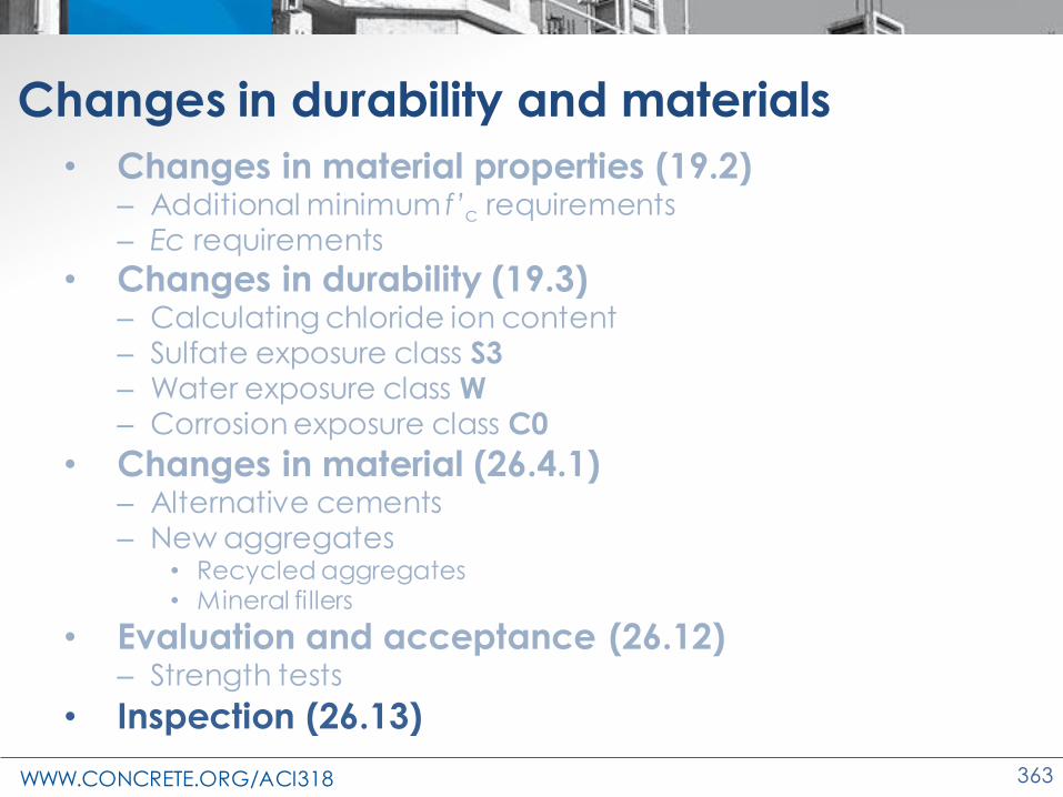
WWW.CONCRETE.ORG/ACI318 363
Changes in durability and materials
• Inspection (26.13)

WWW.CONCRETE.ORG/ACI318 364
26.13—Inspection
26.13.1.1 Concrete construction inspection per:
• General building code (GBC)
• ACI 318 in absence of GBC
Source: Galvanizeit

WWW.CONCRETE.ORG/ACI318 365
26.13—Inspection
Inspector must be certified when inspecting:
• Formwork,
• Concrete placement,
• Reinforcement,
• Embedments
Photo courtesy Larry Novak

WWW.CONCRETE.ORG/ACI318 366
Seismic Inspections (26.13.1.3)
Inspection performed by:• LDP responsible for the design• An individual under the supervision of LDP• Certified inspector
Elements to be inspected:• Placement and reinforcement for SMF• Boundary elements of SSW, • Coupling beams, and • Precast concrete diaphragms in SDC C, D,
E, or F using moderate or high-deformability connections
• Tolerances of precast concrete diaphragm connections per ACI 550.5
Source: NIST page

WWW.CONCRETE.ORG/ACI318 367
Other Inspections (26.13.1)
• Reinforcement welding → qualified welding inspector
• Expansion, screw, and undercut anchors →
inspector certified or approved by LDP and
building official
• Adhesive anchors → certified inspector

WWW.CONCRETE.ORG/ACI318 368
26.13.3.2 Items requiring continuous inspection

WWW.CONCRETE.ORG/ACI318 369
26.13.3.3 Items requiring periodic inspection
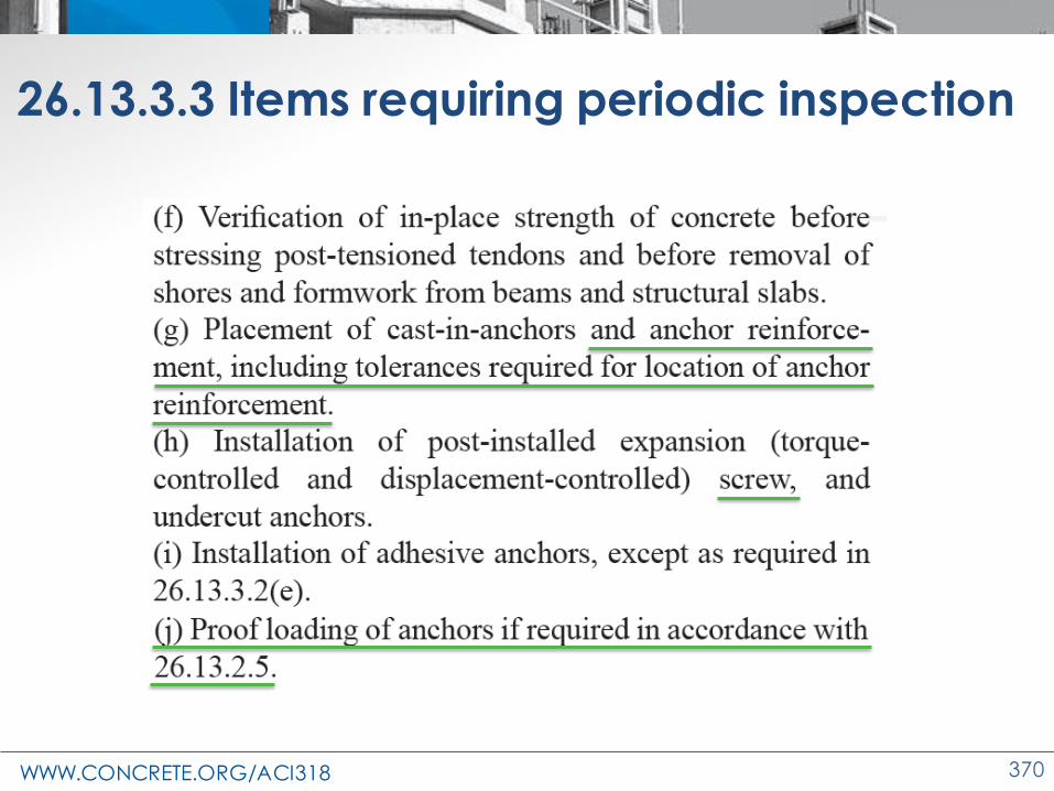
WWW.CONCRETE.ORG/ACI318 370
26.13.3.3 Items requiring periodic inspection

WWW.CONCRETE.ORG/ACI318 371
Changes to the Concrete Design Standard
ACI 318-19
Strut-and-Tie Method

WWW.CONCRETE.ORG/ACI318 372
Why strut-and-tie method?
• Valuable tool where plane-sections assumption of beam theory does not apply
• Truss analogy used to analyze concrete
structures

WWW.CONCRETE.ORG/ACI318 373
Strut and Tie Method
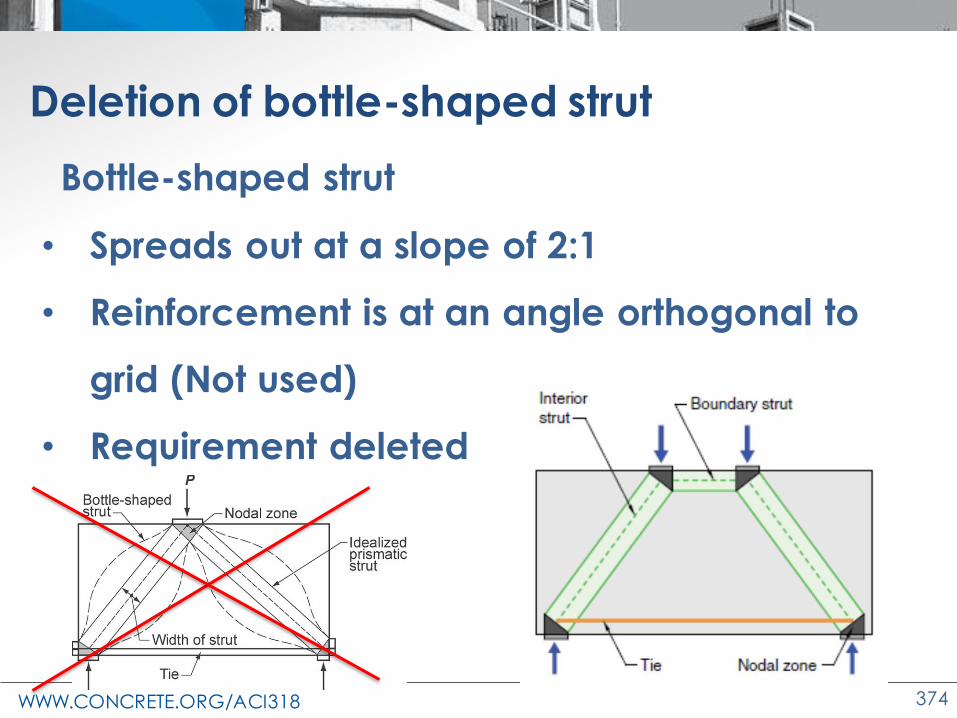
WWW.CONCRETE.ORG/ACI318 374
Bottle-shaped strut
• Spreads out at a slope of 2:1
• Reinforcement is at an angle orthogonal to
grid (Not used)
• Requirement deleted
Deletion of bottle-shaped strut

WWW.CONCRETE.ORG/ACI318 375
Code Changes—Strut-and-tie method
• Minimum angle between strut and tie
• Effect of prestressing
• Development of tie forces
• Strut strength and maximum shear stress
• Minimum reinforcement in D-region
• Curved nodes
• STM part of seismic force resisting system

WWW.CONCRETE.ORG/ACI318 376
R23.2.7 Angle between strut and tie
25° ≤ q ≤ 65°
• Mitigate cracking
• Compatibility

WWW.CONCRETE.ORG/ACI318 377
Code Changes—Strut-and-tie method
• Minimum angle between strut and tie
• Effect of prestressing
• Development of tie forces
• Strut strength and maximum shear stress
• Minimum reinforcement in D-region
• Curved nodes
• STM part of seismic force resisting system
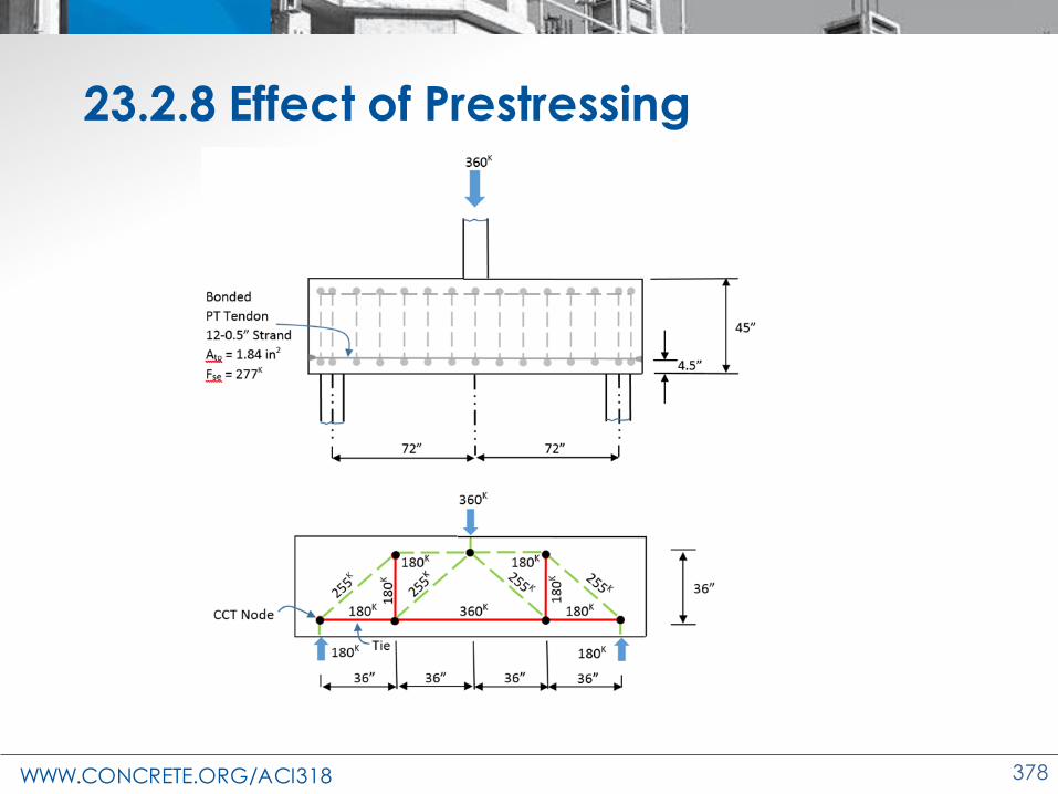
WWW.CONCRETE.ORG/ACI318 378
23.2.8 Effect of Prestressing

WWW.CONCRETE.ORG/ACI318 379
23.2.8 Effect of Prestressing
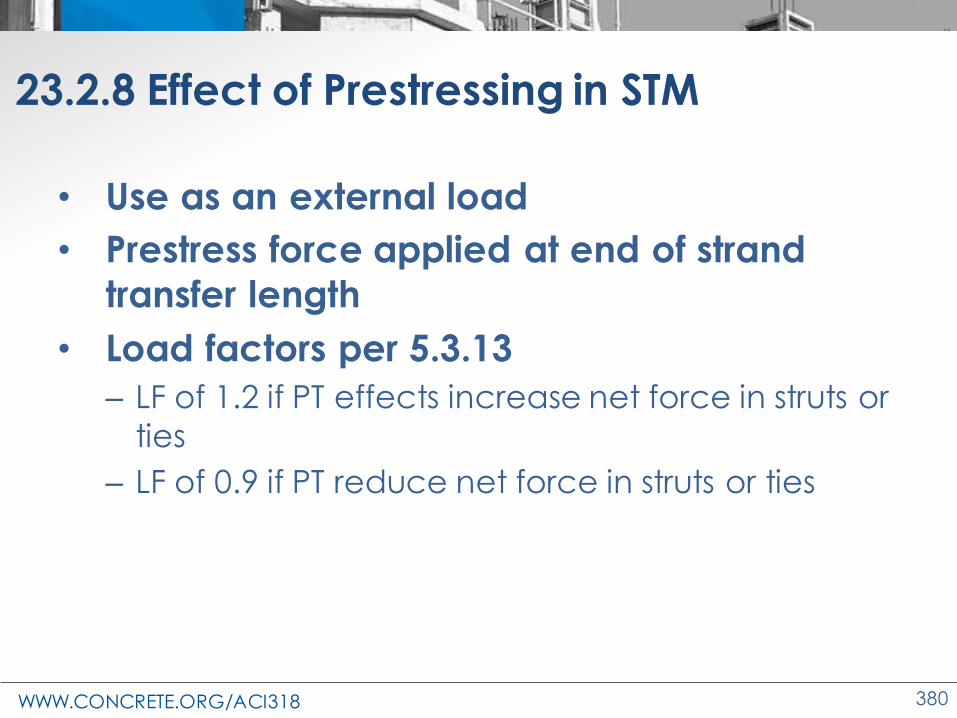
WWW.CONCRETE.ORG/ACI318 380
23.2.8 Effect of Prestressing in STM
• Use as an external load
• Prestress force applied at end of strand
transfer length
• Load factors per 5.3.13
– LF of 1.2 if PT effects increase net force in struts or
ties
– LF of 0.9 if PT reduce net force in struts or ties

WWW.CONCRETE.ORG/ACI318 381
23.7 Strength of ties
Tensile strength:
– Simple tension element
– Fnt = Atsfy +AtpDfp
– f = 0.75 for all ties
• Atp = 0 (nonprestressed)
• Δfp = 60 ksi for bonded prestressed reinf. and
10 ksi for unbonded prestressed reinf.
• T Δfp,max = fpy - fse
Note: tie centroid coincides with reinforcement centroid

WWW.CONCRETE.ORG/ACI318 382
Code Changes—Strut-and-tie method
• Minimum angle between strut and tie
• Effect of prestressing
• Development of tie forces
• Strut strength and maximum shear stress
• Minimum reinforcement in D-region
• Curved nodes
• STM part of seismic force resisting system

WWW.CONCRETE.ORG/ACI318 383
23.8.2 Strength of ties
Anchorage of tie reinforcement is accomplished by:
• Mechanical devices
• Post-tensioning anchorage devices
• Standard hooks
• Straight bar development
• Except ties extending from curved-bar nodes

WWW.CONCRETE.ORG/ACI318 384
23.8.2 Strength of ties
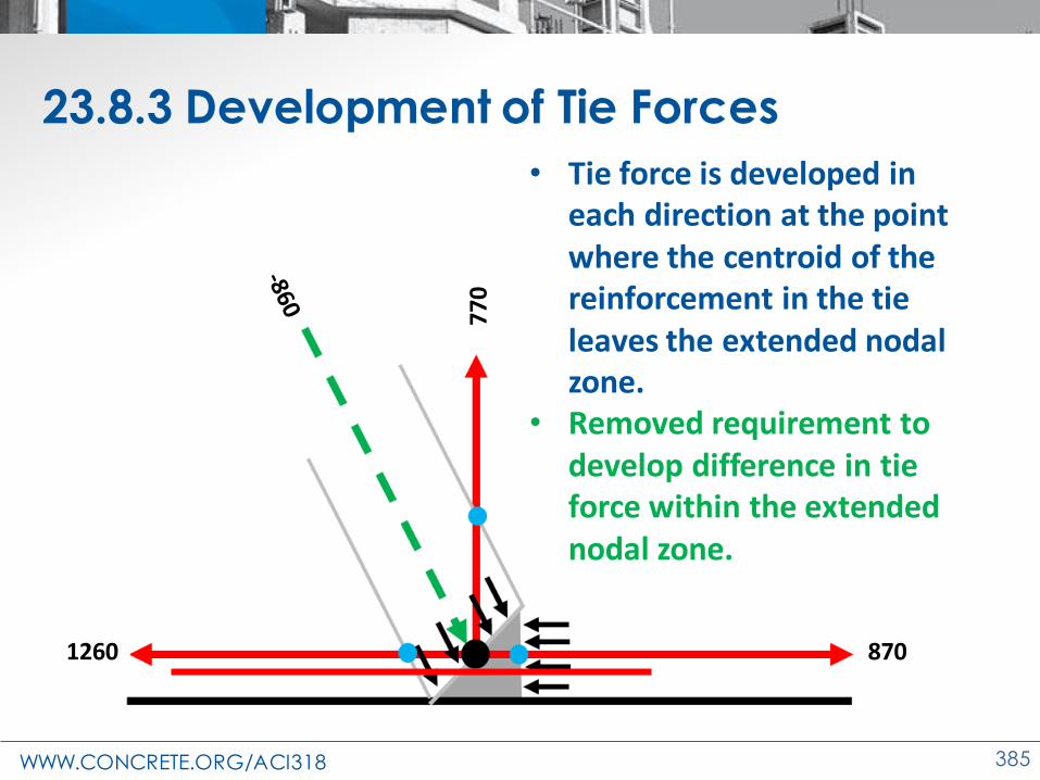
WWW.CONCRETE.ORG/ACI318 385
23.8.3 Development of Tie Forces
• Tie force is developed in each direction at the point where the centroid of the reinforcement in the tie leaves the extended nodal zone.
• Removed requirement to develop difference in tie force within the extended nodal zone.
1260 870
770

WWW.CONCRETE.ORG/ACI318 386
Code Changes—Strut-and-tie method
• Minimum angle between strut and tie
• Effect of prestressing
• Development of tie forces
• Strut strength and maximum shear stress
• Minimum reinforcement in D-region
• Curved nodes
• STM part of seismic force resisting system
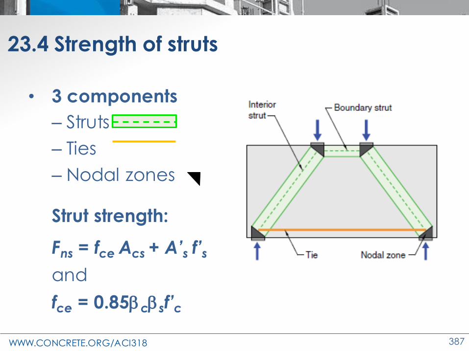
WWW.CONCRETE.ORG/ACI318 387
23.4 Strength of struts
• 3 components
– Struts
– Ties
– Nodal zones
Strut strength:
Fns = fce Acs + A’s f’s
and
fce = 0.85csf’c

WWW.CONCRETE.ORG/ACI318 388
23.4 Strength of struts
Strut coefficient, βs → Table 23.4.3
Strut location Strut type Criteria s
Tension members or tension zones of
membersAny All cases 0.4 (a)
All other cases
Boundary strut
All cases 1.0 (b)
Interior struts
Reinforcement satisfying (a) or (b) of Table 23.5.1
0.75 (c)
𝑽𝒖 ≤ 𝝓𝟓𝝀𝝀𝒔 𝒇𝒄′𝒃𝒘𝒅𝐭𝐚𝐧𝜽 0.75 (d)
Beam-column joints 0.75 (e)
All other cases 0.4 (f)

WWW.CONCRETE.ORG/ACI318 389
23.4 Strength of struts
𝑽𝒖 ≤ f𝟓𝝀𝝀𝒔 𝒇𝒄′ 𝒃𝒘𝒅 𝐭𝐚𝐧𝜃
With s:
1- s = 1 if distributed reinforcement is provided
2-2
11 / 10
sd
= +

WWW.CONCRETE.ORG/ACI318 390
23.4 Strength of struts
𝑽𝒖 ≤ f𝟓𝐭𝐚𝐧𝜃𝝀𝝀𝒔 𝒇𝒄′ 𝒃𝒘𝒅
Assume 𝝀 = 1, 𝝀𝒔 = 1, and 25° ≤ q ≤ 65°
tan 65° = 2.14
➔ 𝑽𝒖 ≤ f𝟓 𝟐. 𝟏𝟒 𝟏 𝟏 𝒇𝒄′ 𝒃𝒘𝒅
≤ f𝟏𝟎. 𝟕 𝒇𝒄′ 𝒃𝒘𝒅
Limit to 10 𝒇𝒄′ consistent with deep beam
provision 9.9.2.1
θ

WWW.CONCRETE.ORG/ACI318 391
Code Changes—Strut-and-tie method
• Minimum angle between strut and tie
• Effect of prestressing
• Development of tie forces
• Strut strength and maximum shear stress
• Minimum reinforcement in D-region
• Curved nodes
• STM part of seismic force resisting system
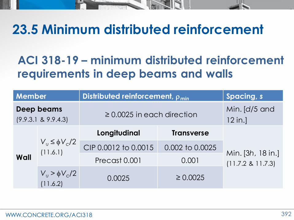
WWW.CONCRETE.ORG/ACI318 392
23.5 Minimum distributed reinforcement
Member Distributed reinforcement, min Spacing, s
Deep beams
(9.9.3.1 & 9.9.4.3)≥ 0.0025 in each direction
Min. [d/5 and
12 in.]
Wall
Vu ≤ fVc/2
(11.6.1)
Longitudinal Transverse
Min. [3h, 18 in.]
(11.7.2 & 11.7.3)
CIP 0.0012 to 0.0015 0.002 to 0.0025
Precast 0.001 0.001
Vu > fVc/2
(11.6.2)0.0025 ≥ 0.0025
ACI 318-19 – minimum distributed reinforcement requirements in deep beams and walls

WWW.CONCRETE.ORG/ACI318 393
Minimum (Vert. & Hor.) Distributed Reinforcement Ratio
Stre
ngt
h R
atio
(Vte
st/V
stm
)
0
0.5
1
1.5
2
2.5
3
3.5
0 0.002 0.004 0.006 0.008 0.01
Minimum Reinforcement of D Regions
0.25%

WWW.CONCRETE.ORG/ACI318 394
23.5 Minimum distributed reinforcement
Table 23.5.1—Minimum distributed reinforcement
Lateral restraint of strut
Reinforcement configuration
Minimum distributed reinforcement ratio
Not restrained
Orthogonal grid0.0025 in each
direction
Reinforcement in one direction crossing strut
at angle i
0.0025/(sin2i)
Restrained Distributed reinforcement not required

WWW.CONCRETE.ORG/ACI318 395
23.5 Minimum distributed reinforcement
Distributed reinforcement
must satisfy:
(a) Spacing not greater than
12 in.
(b) 1 not less than 40
degrees
Note: smaller 1 controls

WWW.CONCRETE.ORG/ACI318 396
23.5 Minimum distributed reinforcement
Struts are considered laterally restrained if:
(a)Discontinuity region is continuous ┴ to plane of
STM
Discontinuity Region

WWW.CONCRETE.ORG/ACI318 397
23.5 Minimum distributed reinforcement
Source: Yun et al. 2016
b) Concrete restraining strut
extends beyond each side
face of strut a dist. ≥ 1/2 ws
Struts are considered laterally restrained if:

WWW.CONCRETE.ORG/ACI318 398
Struts are considered laterally restrained if:
c) Strut in a joint restrained on all 4 faces (15.2.5 & 15.2.6)
23.5 Minimum distributed reinforcement

WWW.CONCRETE.ORG/ACI318 399
Code Changes—Strut-and-tie method
• Minimum angle between strut and tie
• Effect of prestressing
• Development of tie forces
• Strut strength and maximum shear stress
• Minimum reinforcement in D-region and
deletion of bottle-shaped strut
• Curved nodes
• STM part of seismic force resisting system

WWW.CONCRETE.ORG/ACI318 400
Curved Nodes
Definition
Node, curved-bar – The bend region of a
continuous reinforcing bar (or bars) that
defines a node in a strut-and-tie model
Dapped-end T-beam Column Corbel
a) column corbel
Figure 2. Strut-and-tie models with curved-bar nodes

WWW.CONCRETE.ORG/ACI318 401
23.10 Curved-bar Nodes
Why curved nodes?
Nodal zones are
generally too small to
allow development

WWW.CONCRETE.ORG/ACI318 402
23.10 Curved-bar Nodes
Two issues that need to
be addressed:
1. Slipping of bar
2. Concrete crushing
Circumferential stress
Radial stress
T1
T2

WWW.CONCRETE.ORG/ACI318 403
23.10 Curved-bar Nodes
What is the bend radius?
How long is the arc
length of the bar bend
along centerline of bar?
T
T
C
C

WWW.CONCRETE.ORG/ACI318 404
23.10 Curved-bar Nodes
1st Condition
• q < 180 degree bend
• T1 = T2 = Asfy
• Radial compression
stresses are uniform
• Bond stresses = 0
T1
T2C
C

WWW.CONCRETE.ORG/ACI318 405
23.10 Curved-bar Nodes
ts y
b '
s c
A fr
b f
2
C-T-T
T
T
C
C
but not less than half bend diameter of Table 25.3
q < 180 degree bend

WWW.CONCRETE.ORG/ACI318 406
23.10 Curved-bar Nodes
ts y
b '
t c
. A fr
w f
1 5
C-C-T
q = 180 degree bend
But not less than half bend diameter of Table 25.3
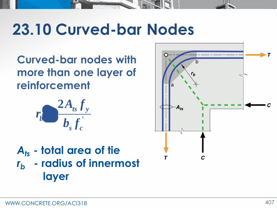
WWW.CONCRETE.ORG/ACI318 407
23.10 Curved-bar Nodes
Curved-bar nodes with more than one layer of
reinforcement
Ats - total area of tie
rb - radius of innermost
layer
'
2ts y
b
s c
A fr
b f

WWW.CONCRETE.ORG/ACI318 408
23.10 Curved-bar Nodes
23.10.2 Cover ≥ 2db
23.10.3 cover < 2db
➔ rb x (2db /cc)
23.10.5 At frame corners, joint and bars are proportioned such that center of bar curvature
is located within the joint
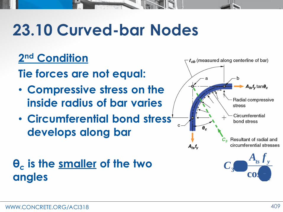
WWW.CONCRETE.ORG/ACI318 409
23.10 Curved-bar Nodes
2nd Condition
Tie forces are not equal:
• Compressive stress on the
inside radius of bar varies
• Circumferential bond stress
develops along bar
θc is the smaller of the two
angles3
cos
ts y
c
A fC =
q

WWW.CONCRETE.ORG/ACI318 410
23.10 Curved-bar Nodes
23.10.6 The curve must be sufficient to develop
difference in force
ℓcb > ℓd(1 – tan θc)
In terms of rb
2 (1 tan )
2d c b
b
dr
− q −

WWW.CONCRETE.ORG/ACI318 411
Code Changes—Strut-and-tie method
• Minimum angle between strut and tie
• Effect of prestressing
• Development of tie forces
• Strut strength and maximum shear stress
• Minimum reinforcement in D-region and
deletion of bottle-shaped strut
• Curved nodes
• STM part of seismic force resisting system

WWW.CONCRETE.ORG/ACI318 412
23.11 Earthquake-resistant design using STM
Opening
Basement wall
Wall Transfer
force
Compression strutDistributor/Collector Tension tie
Develop tension tie
beyond node
a fb
d
e
c h g

WWW.CONCRETE.ORG/ACI318 413
Earthquake-resistant design using STM
Seismic-force-resisting system assigned to
SDC D-F and designed with STM must satisfy:
1. Chapter 18
2. Strut forces are increased by overstrength
factor Ωo = 2.5 or Ωo < 2.5 if based on
rational analysis
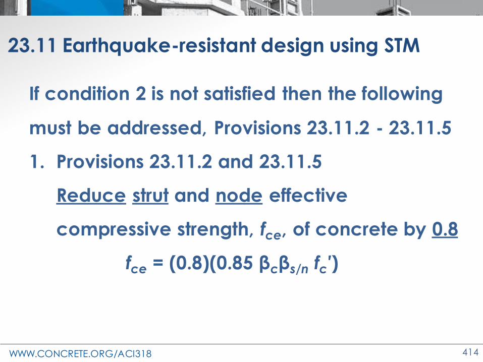
WWW.CONCRETE.ORG/ACI318 414
23.11 Earthquake-resistant design using STM
If condition 2 is not satisfied then the following
must be addressed, Provisions 23.11.2 - 23.11.5
1. Provisions 23.11.2 and 23.11.5
Reduce strut and node effective
compressive strength, fce, of concrete by 0.8
fce = (0.8)(0.85 βcβs/n fc′)
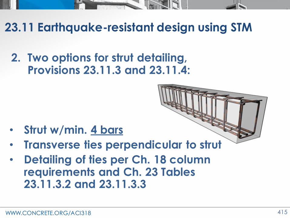
WWW.CONCRETE.ORG/ACI318 415
23.11 Earthquake-resistant design using STM
2. Two options for strut detailing, Provisions 23.11.3 and 23.11.4:
• Strut w/min. 4 bars
• Transverse ties perpendicular to strut
• Detailing of ties per Ch. 18 column requirements and Ch. 23 Tables 23.11.3.2 and 23.11.3.3 Section A-A

WWW.CONCRETE.ORG/ACI318 416
23.11 Earthquake-resistant design using STM
23.11.4 Tie development length is 1.25 ℓd (25.4)

WWW.CONCRETE.ORG/ACI318 417
Changes to the Concrete Design Standard
ACI 318-19
Shotcrete

WWW.CONCRETE.ORG/ACI318 418
Shotcrete
• Shotcrete equals regular concrete
• Placement
method
• Additional
information in ACI 506R and
ACI 506.2

WWW.CONCRETE.ORG/ACI318 419
Shotcrete
Why Shotcrete?
• Several applications – new or repair
• Economical
• Effective
• Excellent bond

WWW.CONCRETE.ORG/ACI318 420
Shotcrete
Two processes
• Wet mix
• Dry Mix

WWW.CONCRETE.ORG/ACI318 421
Shotcrete
• Requirements for freezing-and-thawing exposure
• 19.3.3.3: Air entrainment
– Wet-mix shotcrete subject to Exposure Classes F1, F2, or F3
– Dry-mix shotcrete subject to Exposure Class F3
– Air content shall conform to Table 19.3.3.3.
– Exception in 19.3.3.6 (similar to concrete)

WWW.CONCRETE.ORG/ACI318 422
Shotcrete - Minimum Spacing of Reinforcement
• 25.2.7: Parallel nonprestressedreinforcement – (a) at least the
greater of 6dband 2-1/2 in.
– (b) If two curtains of reinforcement are provided,• At least 12db in
the curtain nearer the nozzle
• remaining curtain confirm to (a)
Max (6db, 2.5in.)
Max (6db, 2.5in.)
12db
12db

WWW.CONCRETE.ORG/ACI318 423
Shotcrete - Minimum Spacing of Reinforcement
• 25.2.10
– For ties, hoops, and spiral reinforcement in columns to be placed with shotcrete, minimum clear spacing shall be 3 in.
≥ 3 in.
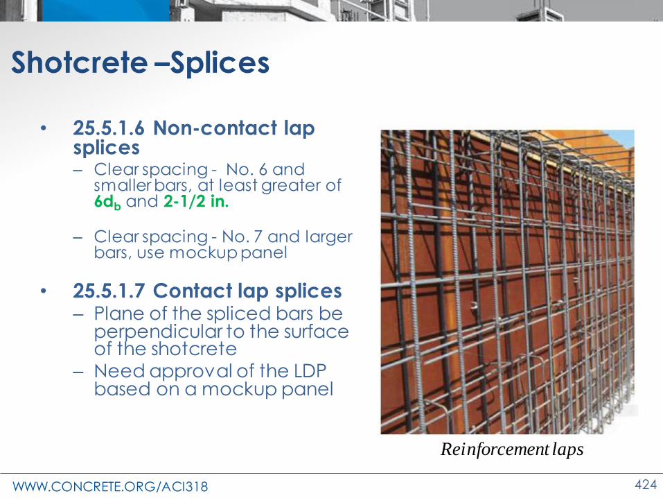
WWW.CONCRETE.ORG/ACI318 424
Shotcrete –Splices
• 25.5.1.6 Non-contact lap splices – Clear spacing - No. 6 and
smaller bars, at least greater of 6db and 2-1/2 in.
– Clear spacing - No. 7 and larger bars, use mockup panel
• 25.5.1.7 Contact lap splices – Plane of the spliced bars be
perpendicular to the surface of the shotcrete
– Need approval of the LDP based on a mockup panel
Reinforcement laps

WWW.CONCRETE.ORG/ACI318 425
Shotcrete
Mockup panels
• To demonstrate proper encasement of the
reinforcement
• Represent most complex reinforcement configurations
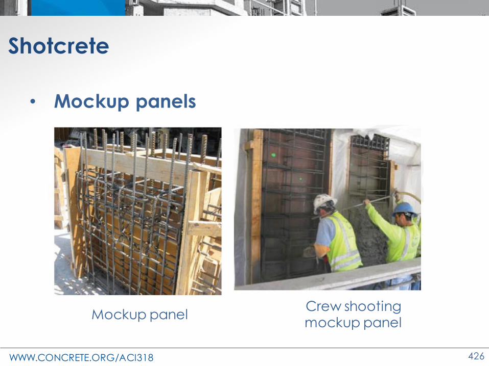
WWW.CONCRETE.ORG/ACI318 426
Shotcrete
• Mockup panels
Mockup panelCrew shooting mockup panel

WWW.CONCRETE.ORG/ACI318 427
Shotcrete
Construction Documents and Inspection
• 26.3.1-26.3.2: Where shotcrete is required
– Identify the members to be constructed using shotcrete
• 26.4.1.2 – 26.4.1.7: Materials
– Aggregate gradation - ASTM C1436.
– Admixtures – ASTM C1141.
– Packaged, preblended, dry, combined materials for shotcrete – ASTM 1480

WWW.CONCRETE.ORG/ACI318 428
Shotcrete
• 26.4.2 - Concrete mixture requirements
– Maximum coarse aggregate size ≤ 1/2 in.

WWW.CONCRETE.ORG/ACI318 429
Shotcrete
• 26.5.2.1: Placement and consolidation– Remove rebound and overspray prior to placement
of a new layer
– Cuttings and rebound shall not be incorporated into the Work
– Roughen existing surface to ¼ in. amplitude before placing subsequent shotcrete
– Before placing additional material onto hardened shotcrete,• Remove laitance
• clean joints
• dampen surface

WWW.CONCRETE.ORG/ACI318 430
Shotcrete
• 26.5.2.1: Placement and consolidation
– Remove and replace in-place fresh shotcrete that exhibits sags, sloughs, segregation,
honeycombing, and sand pockets
– Shotcrete nozzle operator
• must be certified• able to shoot an approved
mockup panel
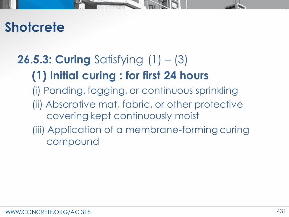
WWW.CONCRETE.ORG/ACI318 431
Shotcrete
26.5.3: Curing Satisfying (1) – (3)
(1) Initial curing : for first 24 hours
(i) Ponding, fogging, or continuous sprinkling
(ii) Absorptive mat, fabric, or other protective covering kept continuously moist
(iii) Application of a membrane-forming curing
compound

WWW.CONCRETE.ORG/ACI318 432
Shotcrete
26.5.3: Curing Satisfying (1) – (3)• (2) Final curing: After 24 hours
(i) Same method used in the initial curing process
(ii) Sheet materials
(iii) Other moisture-retaining covers kept continuously moist
• (3) Maintain final curing for a minimum duration of:
– 7 days
– 3 days if either a high-early-strength cement or an accelerating admixture is used

WWW.CONCRETE.ORG/ACI318 433
Shotcrete
26.5.6: Construction, contraction, and isolation joints
• cut at a 45° unless a square joint is
designated
• Submit locations to LDP for approval
– For joints not shown on the construction documents

WWW.CONCRETE.ORG/ACI318 434
Shotcrete
26.12—Evaluation and acceptance
• Strength test
– Average strength of
minimum three 3 in. diameter cores from a
test panel
– Tested at 28 days or at test age designated for fc′
Material test panel sketch showing where to cut five cores

WWW.CONCRETE.ORG/ACI318 435
Shotcrete
26.12.2 Frequency of testing
• Prepare a test panel
– For each mixture
– For each nozzle operator
– at least once per day or for every 50 yd3
• whichever results in the greater number of panels

WWW.CONCRETE.ORG/ACI318 436
Shotcrete
26.12.4 Acceptance criteria for shotcrete
• 26.12.4.1(a): Test specimens to satisfy (1)
and (2):
(1) Test panels shall be prepared
• in the same orientation
• by same nozzle operator
(2) Cores as per ASTM C1604

WWW.CONCRETE.ORG/ACI318 437
Shotcrete
26.12.4 Acceptance criteria
• 26.12.4.1(b): Strength to
satisfy (1) and (2):
(1) average strengths from three
consecutive test panels ≥ fc′
(2) average compressive strength of three cores from a
single test panel ≥ 0.85fc′ and no single core strength < 0.75fc′
Take steps to
increase strength if not satisfied
Investigate
if not satisfied

WWW.CONCRETE.ORG/ACI318 438
Changes to the Concrete Design Standard
ACI 318-19
Design Verification Using Nonlinear
Dynamic Analysis

WWW.CONCRETE.ORG/ACI318 439
Appendix A – Design Verification Using Nonlinear Dynamic Analysis
Why was Appendix A added to the Code?
• ASCE 7-16 = yes
• LA Tall Building Council = yes
• PEER = yes
• ACI 318-14 = no
• ACI 318-19 = yes
– Coordinates treatment of concrete

WWW.CONCRETE.ORG/ACI318 440
Appendix A – Design Verification Using Nonlinear Dynamic Analysis
What is Design Verification Using Nonlinear Dynamic Analysis?
• Design basis
• Initial design per ACI 318 (Ch. 18)
• Nonlinear software
• Behaviors in model based on
– Testing
– Estimated properties

WWW.CONCRETE.ORG/ACI318 441
Appendix A – Design Verification Using Nonlinear Dynamic Analysis
• Analysis results vs Design basis
• Peer review
• Agreement that structure meets IBC 2018
req.

WWW.CONCRETE.ORG/ACI318 442
Appendix A – Design Verification Using Nonlinear Dynamic Analysis
Why would an engineer use Design Verification Using Nonlinear Dynamic Analysis?
• Tall buildings (over 240’)
– IBC 2018 ≠ special concrete shear walls
– Forces dual system
• Nonlinear Dynamic Analysis
– Allows concrete shear walls over 240’
– Exception per IBC 2018 104.11
• NOT JUST FOR SEISMIC

WWW.CONCRETE.ORG/ACI318 443
Changes to the Concrete Design Standard
ACI 318-19
Closing Remarks

WWW.CONCRETE.ORG/ACI318 444
Certificates
• emailed to you within 1-2 weeks
• Check email and name on sign-in sheet

WWW.CONCRETE.ORG/ACI318 445
Feedback
• Survey in the email with your
certificate
• Brief, 11-question
survey

WWW.CONCRETE.ORG/ACI318 446
An Invitation to Join – ACI Membership
30,000 members form the premier community dedicated to the best use of concrete
– Free access to ACI’s 200+ guides reports
– Concrete International, Structural Journal, Materials Journal
– ACI University, discounts, Q+A opportunities, and more
Learn more and join: concrete.org/membership

WWW.CONCRETE.ORG/ACI318 447
Copyright © 2022 FDOKUMEN