CCL INTRODUCTION (i) Material CCL (ii) Welding ...
21
CCL COMPLETION OF THE FIRST TF COIL STRUCTURE OF ITER INTRODUCTION M. Nakahira, M. Iguchi, T. Sakurai, H. Ozeki, E. Fujiwara, K. Takano, Y.S. Hong, M. Ino, M. Nishino, N. Koizumi, N. Sawa*, D. Hara*, T. Inagaki*, S.Y. Kim**, J.H. Choi**, S.S. Hwang** and C. Luongo*** National Institutes for Quantum and Radiological Science and Technology, 801-1 Mukouyama, Naka-shi, Ibaraki 311-0193, Japan *Mitsubishi Heavy Industries, LTD, 1 Minamifutami, Futami-cho, Akashi 674-0093, Japan **Hyundai Heavy Industries co., LTD, 1000 Bangeojinsunhwan-doro, Dong-gu, Ulsan, 682-792, Korea ***ITER Organization (IO), Route de Vinon-sur-Verdon, CS 90 046, 13067, St. Paul-lez-Durance, France FIP1-1 / CN258 (i) Material CCL (ii) Welding Deformation CP溶接準備中 CP溶接準備中 (iii) Partial Penetration Welding (PPW) Conclusion ITER Toroidal Field Coil 18m TF Coils (18) 16m Great Stupa (16m high, Sanchi, India) ~300 ton Water in 25mx12m pool (~300ton) TF Coil Structure (TFCS) • The biggest super conducting coil structures • The procurement responsibility :100% Japan Domestic Agency (JADA). Winding Pack (WP) AU AP BP BU TFCS 65 ton 105 ton 8 ton 12 ton A1 A2 A3 B1 B2 B3 B4 Basic Segments (BS) Sub-Assembly (SA) Challenges (i) Material: Control yield strength at 4K Control fracture toughness at 4K (ii) Welding deformation Control welding deformation Control segments welding (iii) Partial Penetration Welding (PPW) PPW crack initiation PPW crack growth (iv) Ultrasonic testing (UT) Attenuation compensation method Attenuation compensation factor UT for PPW (v) Fitting test Fitting test for AU-AP and BU-BP Fitting test for AU-BU as-weld notch AU/BU AP/BP Control yield strength at 4K Special material is required with total amount about 5000 ton Ensure Huge magnetic force (Static analysis) y = 0.0106x 2 - 6.4144x + 1336.3 0 200 400 600 800 1000 1200 1400 0 50 100 150 200 250 300 TEMPERATURE (K) STRENGTH (MPa) Measured value Prediction curve (1) Prediction curve by (C+N) Figured out correlation between yield strength at 4K and C+N contents Huge amount of 4K test is needed Actual materials (total about 5000 ton) In beginning of 2018, material procurement for TFCS was completed. M14 R20 42 105 φ7±0.01 C+N contents Yield strength at RT Specimen Yield strength at 4K Predict C N Control fracture toughness at 4K In the additional work to improve control fracture toughness, JADA discovered the strong correlation between Md30 and fracture toughness at 4K. Figured out correlation between fracture toughness at 4K and Md30 Found martensite at edge of cracked area The Md30 has improved the quality of fracture toughness. ( ) ( ) ( ) 0 8 42 1 0 68 5 18 7 13 0 29 1 8 2 9 462 824 30 . . Nb . Mo . Cr . Cu Ni . Mn . Si . N C Md − ν − − − − + − − − + − = y = αx+β Low fracture toughness (ex. Glass: Hard but fragile) High fracture toughness (ex. Metals) Chemical contents (9 elements) Grain size Fracture toughness at 4K Predict Control weld deformation JADA performed 1) welding qualification using mock-ups, Mechanical properties of welding joints were confirmed, 2) Basic segment mock-ups. Control method of welding deformation was improved. ① Outer groove welding (1st) ② Inner groove welding (1st) ③ Outer groove welding (2nd) ④ Inner groove welding (2nd) Welding with monitoring welding deformation (Balance welding) B3 segment mock-up The deformation converges to 0mm. Welding qualification Improve by sequence Control segments welding Segments welding is the most difficult to control. Through trial, amount of deformation and tendency are figured out to implement to actual manufacturing. Segment-to-segment welding (A1+A2) Example of welding deformation control Welded Sub-assemblies (AU) 0 2 4 6 8 10 12 14 16 0 20 40 60 80 100 120 140 0 51 100 150 201 249 300 351 399 453 Deformation (mm) Deposit thickness (mm) Total deposit thickness of 3 plates (mm) Outer plate (outside) Outer plate (inside) Side plate Deformation + - Mark Line Controlled deformation Reference Line 4m Welding Line A2 A1 ~180mm ~80mm Side Plate Outer Plate Section at welding line Welding trial (A1+A2(3m)) Target Position The actual manufacturing, deformation is well controlled Narrow work space FPW: Invisible welding PPW: Visible welding Plate shape attachments FPW: Impractical weld joint design PPW: Practical weld joint design Full Penetration welding (FPW) is better. But… Application of PPW is necessary as-weld notch or S-N? LEFM? Fusion line Weld Metal Fusion line Base Metal Base: 316LN (N~ 0.21%) Weld: JJ1 (12Cr-12Ni-10Mn-5Mo-0.13N) Method: TIG weld Unwelded Welded Welded As-weld notch CT specimen (As-weld notch) CT specimen (EDM notch) Test condition: Load control Frequency: 10Hz Stress ratio: 0.1 a) b) 12,698 1,898 As-weld notch (no artificial treatment) EDM notch (R0.1mm is remained on edge.) => Behavior like Crack => Propagation in weld CT specimen (Weld metal/EDM notch) d)FEM analysis and assessment allowable weld joint and maximum initial defect size • FEM analysis (total 133 weld joints) • Allowable maximum initial defect size =>100mm 2 of semi-elliptical at root ① Slow crack growth ③Application of common region to assessment ① ② ③ c) Crack growth rate parameter ②Stress redistribution when sampling Method of “Design by analysis” for PPW was successfully established! CCL (iv) Ultrasonic Testing (UT) (v) Fitting Test Principle of Ultrasonic Testing Crack Echo Back surface Echo Initial pulse Attenuation of weld metal was evaluated. Transducer Crack Ultrasonic wave Weld metal Base metal Wave decreases in the weld UT attenuation compensate method DAC curves* were prepared by – Calibration block using base metal – Reference block including weld metal *: DAC curves (Distance Amplitude Characteristic curves) 1. Making DAC curve of the base metal using a calibration block Plotted point Distance 3. Calculating the sensitivities difference (A, A’, …) between each plotting point and DAC curve Sensitivities difference Calibration block 2. Plotting detected echo through the weld metal using a reference block with SDH Reference block The difference were quantified. Ultrasonic attenuation (dB) vs. Weld metal path(mm) “y = ax” (a: 0.2 ~ 0.4) Weld metal attenuation of TFCS was Properly corrected. y = 0.313x y = 0.395x y = 0.216x 0 5 10 15 20 25 0 20 40 60 80 100 Sensitivity differrence (dB) Weld Metal Path (mm) Company A Company B Company C UT for PPW Establishment inspection method for PPW Noise! • High quality weld joint ← Inside defect inspection • Weld depth& initial crack size ← weld depth Confirmation Ultrasonic Testing (UT) method • Noise near root → Low accuracy on depth measuring? • Verification test by actual size PPW mock up. UT procedure was defined. +/-1mm accuracy for depth measuring. AP/BP AU/BU Gap Mis- alignment Gap: 0.5±0.25mm Misalignment:±0.3mm Req. groove tolerances (inner) Misalignment: ±1.3mm Req. groove tolerances (outer) AU/BU AP/BP Req. 2): AU-BU Gap: 0.5±0.25mm Misalignment:±0.7mm Gap: 0.5±0.25mm Misalignment:±0.3mm Gap: 0.5±0.25mm Misalignment:±0.3mm Back plate Side plate Side plate Req. 1): AU-AP, BU-BP Upper Lower AU and AP after fit-up Nylon wedges Stainless Steel wedges Hydraulic Jack Protectio n Jig Jigs used to fit up AP to AU AU and BU after fitting up for the first EU products tested in horizontal position AU and BU after fitting up for the first JA coil tested in vertical position Note: Md30 is defined as the temperature which 50% martensitic transformation occurs when 0.3 strain is applied. Originally, it’s tendency of martensitic transformation. • Solving the difficult challenges, TFCS became feasible. • Two TFCSs has been completed in 2018, and another one will be completed soon. • The first Japan-manufacturing TF coil will be assembled TFCS and WP from the fourth quarter of 2018 as the very first TF Coil of ITER • All the TF coils will be delivered to ITER in 2021
-
Upload
khangminh22 -
Category
Documents
-
view
0 -
download
0
Transcript of CCL INTRODUCTION (i) Material CCL (ii) Welding ...

CCL
COMPLETION OF THE FIRST TF COIL STRUCTURE OF ITER
INTRODUCTION
M. Nakahira, M. Iguchi, T. Sakurai, H. Ozeki, E. Fujiwara, K. Takano, Y.S. Hong, M. Ino, M. Nishino, N. Koizumi, N. Sawa*, D. Hara*, T. Inagaki*, S.Y. Kim**, J.H. Choi**, S.S. Hwang** and C. Luongo***National Institutes for Quantum and Radiological Science and Technology, 801-1 Mukouyama, Naka-shi, Ibaraki 311-0193, Japan*Mitsubishi Heavy Industries, LTD, 1 Minamifutami, Futami-cho, Akashi 674-0093, Japan**Hyundai Heavy Industries co., LTD, 1000 Bangeojinsunhwan-doro, Dong-gu, Ulsan, 682-792, Korea***ITER Organization (IO), Route de Vinon-sur-Verdon, CS 90 046, 13067, St. Paul-lez-Durance, France
FIP1-1 / CN258
(i) Material
CCL
(ii) Welding Deformation
CP溶接準備中
CP溶接準備中
(iii) Partial Penetration Welding (PPW)
ConclusionITER Toroidal Field Coil
18m
TF Coils (18)
16m
Great Stupa (16m high, Sanchi, India)~300 ton Water in 25mx12m pool (~300ton)
TF Coil Structure (TFCS)• The biggest super conducting coil structures • The procurement responsibility :100% Japan Domestic Agency (JADA).
Winding Pack (WP)
AU
AP
BP
BU
TFCS
65 ton105 ton
8 ton
12 ton
A1
A2
A3B1
B2
B3
B4
Basic Segments (BS) Sub-Assembly (SA)
Challenges(i) Material:Control yield strength at 4KControl fracture toughness at 4K
(ii) Welding deformationControl welding deformationControl segments welding(iii) Partial Penetration Welding (PPW)PPW crack initiationPPW crack growth(iv) Ultrasonic testing (UT) Attenuation compensation methodAttenuation compensation factorUT for PPW(v) Fitting testFitting test for AU-AP and BU-BPFitting test for AU-BU
as-weld notch
AU/BU
AP/BP
Control yield strength at 4K
Special material is required with total amount about 5000 ton
Ensure Huge magnetic force(Static analysis)
y = 0.0106x2 - 6.4144x + 1336.3
y = 0.0074x2 - 4.4901x + 935.39
0
200
400
600
800
1000
1200
1400
0 50 100 150 200 250 300TEMPERATURE (K)
STR
EN
GTH
(MP
a)
��= 0.7
Measured value
Prediction curve (1)
Prediction curve by (C+N)
Figured out correlation between yield strength at 4K and C+N contentsHuge amount of 4K test is
neededActual materials
(total about 5000 ton)
In beginning of 2018, material procurement for TFCS was completed.
M14 R20
42 105
φ7±
0.01
C+N contentsYield strength at RT
SpecimenYield
strength at 4K
Predict
C
N
Control fracture toughness at 4KIn the additional work to improve control fracture toughness, JADA discovered the strong correlation between Md30 and fracture toughness at 4K.
Figured out correlation between fracture toughness at 4K and Md30
Found martensite at edge of cracked area
The Md30 has improved the quality of fracture toughness.
( )( )
( ) ( )308421068518713029182946282430
..Nb.Mo.Cr.CuNi.Mn.Si.NCMd
−ν−−−−+−−−+−=
y = αx+βLow fracture toughness
(ex. Glass: Hard but fragile)
High fracture toughness
(ex. Metals)
Chemical contents (9 elements)Grain size
Fracture toughness at 4K
Predict
Control weld deformationJADA performed 1) welding qualification using mock-ups, Mechanical properties of welding joints were confirmed, 2) Basic segment mock-ups. Control method of welding deformation was improved.
① Outer groove welding (1st)
② Inner groove welding (1st)
③ Outer groove welding (2nd)
④ Inner groove welding (2nd)
Welding with monitoring welding deformation (Balance welding)
B3 segment mock-up The deformation converges to 0mm.
Welding qualification
Improve by sequence
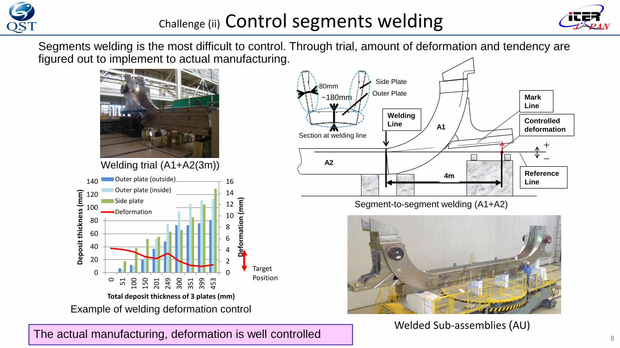
Control segments weldingSegments welding is the most difficult to control. Through trial, amount of deformation and tendency are figured out to implement to actual manufacturing.
Segment-to-segment welding (A1+A2)Example of welding deformation control
Welded Sub-assemblies (AU)
0
2
4
6
8
10
12
14
16
0
20
40
60
80
100
120
140
0 51 100 150 201 249 300 351 399 453
Defo
rmat
ion
(mm
)
Depo
sit t
hick
ness
(mm
)
Total deposit thickness of 3 plates (mm)
Outer plate (outside)
Outer plate (inside)
Side plate
Deformation
投影軸
ケガキ
+
-
変形量
MarkLine
Controlleddeformation
ReferenceLine
4m
WeldingLine
A2
A1
~180mm~80mm
Side Plate
Outer Plate
Section at welding line
Welding trial (A1+A2(3m))
TargetPosition
The actual manufacturing, deformation is well controlled
Narrow work spaceFPW: Invisible weldingPPW: Visible welding
Plate shape attachmentsFPW: Impractical weld joint designPPW: Practical weld joint design
Full Penetration welding (FPW) is better. But…
Application of PPW is necessary
as-weld notch
or
S-N? LEFM?
Fusion line
Weld Metal
Fusion lineBase Metal
Base: 316LN (N~0.21%)Weld: JJ1 (12Cr-12Ni-10Mn-5Mo-0.13N)Method: TIG weld
Unwelded
WeldedWelded
As-weld notch
CT specimen (As-weld notch)
CT specimen (EDM notch)Test condition: Load control Frequency: 10HzStress ratio: 0.1
a)
b)
12,698
1,898
As-weld notch (no artificial treatment)
EDM notch (R0.1mmis remained on edge.)
=> Behavior like Crack
=> Propagation in weld
CT specimen (Weld metal/EDM notch)
d)FEM analysis and assessment allowable weld joint and maximum initial defect size
• FEM analysis (total 133 weld joints) • Allowable maximum initial defect size =>100mm2 of semi-elliptical at root
① Slow crack growth
③Application of common region to assessment
①
②③
c) Crack growth rate parameter
②Stress redistribution when sampling
Method of “Design by analysis” for PPW was successfully established!
CCL
(iv) Ultrasonic Testing (UT)
(v) Fitting Test
Principle of Ultrasonic Testing
CrackEcho
Back surfaceEcho
Initial pulse
Attenuation of weld metal was evaluated.
Transducer
Crack
Ultrasonicwave
Weld metal
Basemetal
Wavedecreasesin the weld
UT attenuation compensate method
DAC curves* were prepared by– Calibration block using base metal– Reference block including weld
metal
*: DAC curves (Distance Amplitude Characteristic curves)
1. Making DAC curve of the base metal using a calibration block
Plotted point
Distance
3. Calculating the sensitivities difference (A, A’, …) between each plotting point and DAC curve
Sensitivities difference
Calibration block
2. Plotting detected echo through the weld metal using a reference block with SDH
Reference block
The difference were quantified.
Ultrasonic attenuation (dB) vs. Weld metal path(mm)“y = ax” (a: 0.2 ~ 0.4)
Weld metal attenuation of TFCS was Properly corrected.
y = 0.313x
y = 0.395x
y = 0.216x
0
5
10
15
20
25
0 20 40 60 80 100
Sens
itivi
ty d
iffer
renc
e (d
B)
Weld Metal Path (mm)
Company ACompany BCompany C
UT for PPWEstablishment inspection method for PPW
Noise!
• High quality weld joint ← Inside defect inspection• Weld depth& initial crack size ← weld depth
Confirmation Ultrasonic Testing (UT) method
• Noise near root → Low accuracy on depth measuring?• Verification test by actual size PPW mock up.
UT procedure was defined.
+/-1mm accuracy for depth measuring.
1
AP/BPAU/BU
Gap
Mis-alignment
Gap: 0.5±0.25mmMisalignment:±0.3mm
Req. groove tolerances (inner)
Misalignment: ±1.3mm
Req. groove tolerances (outer)
AU/BU
AP/BP
Req. 2): AU-BU
Gap: 0.5±0.25mmMisalignment:±0.7mm
Gap: 0.5±0.25mmMisalignment:±0.3mm
Gap: 0.5±0.25mmMisalignment:±0.3mm
Back plate
Side plate
Side plate
Req. 1): AU-AP, BU-BP
Upper
Lower
AU and AP after fit-up
Nylon wedges
Stainless Steelwedges
Hydraulic Jack
Protection
Jig
Jigs used to fit up AP to AU
AU and BU after fitting up for the first EU products tested in horizontal position
AU and BU after fitting upfor the first JA coil tested in vertical position
Note: Md30 is defined as the temperature which 50% martensitic transformation occurs when 0.3 strain is applied. Originally, it’s tendency of martensitic transformation.
• Solving the difficult challenges, TFCS became feasible.• Two TFCSs has been completed in 2018, and another
one will be completed soon. • The first Japan-manufacturing TF coil will be assembled
TFCS and WP from the fourth quarter of 2018 as the very first TF Coil of ITER
• All the TF coils will be delivered to ITER in 2021

1
COMPLETION OF THE FIRST TF COIL STRUCTURE OF ITER
2018.10.22 27th IAEA Fusion Energy Conference
Ahmedabad, India
M. NAKAHIRA, M. IGUCHI, T. SAKURAI, H. OZEKI, E. FUJIWARA, K. TAKANO, Y.S. HONG, M. INO, M. NISHINO, N. KOIZUMI (QST)N. SAWA, D. HARA, T. INAGAKI (MHI)S.Y. KIM, J.H. CHOI, S.S. HWANG (HHI)C. LUONGO (IO)
FIP1-1 / CN258

ITER Toroidal Field Coil
2
18m
TF Coils (18)
16m
Great Stupa (16m high, Sanchi, India)
~300 ton
Water in 25mx12m pool (~300ton)

TF Coil Structure (TFCS)• The biggest super conducting coil structures • The procurement responsibility :100% Japan Domestic Agency (JADA).
3
Winding Pack (WP)
AU
AP
BP
BU
TFCS
65 ton105 ton
8 ton
12 ton
A1
A2
A3B1
B2
B3
B4
Basic Segments (BS) Sub-Assembly (SA)

Challenges
4
(i) Material:Control yield strength at 4KControl fracture toughness at 4K
(ii) Welding deformationControl welding deformationControl segments welding
(iii) Partial Penetration Welding (PPW)PPW crack initiationPPW crack growth
(iv) Ultrasonic testing (UT) Attenuation compensation methodAttenuation compensation factorUT for PPW(v) Fitting testFitting test for AU-AP and BU-BPFitting test for AU-BU
as-weld notch
投影軸
ケガキ
+
-
変形量
MarkLine
Controlleddeformation
ReferenceLine
Section at welding line
AU/BU
AP/BP

Challenge (i) Control yield strength at 4KSpecial material is required with total amount about 5000 ton
5
Ensure Huge magnetic force(Static analysis)
y = 0.0106x2 - 6.4144x + 1336.3
y = 0.0074x2 - 4.4901x + 935.39
0
200
400
600
800
1000
1200
1400
0 50 100 150 200 250 300TEMPERATURE (K)
STR
EN
GTH
(MP
a)
��= 0.7
Measured value
Prediction curve (1)
Prediction curve by (C+N)
Figured out correlation between yield strength at 4K and C+N contents
Huge amount of 4K test is neededActual materials(total about 5000 ton)
In beginning of 2018, material procurement for TFCS was completed.
M14 R20
42 105
φ7±
0.01
C+N contentsYield strength
at RT
Specimen
Yield strength
at 4K
PredictC
N

Challenge (i) Control fracture toughness at 4KIn the work to improve control fracture toughness, JADA discovered the strong correlation between Md30 and fracture toughness at 4K.
6Figured out correlation between fracture toughness at 4K and Md30
Found martensite at edge of cracked area
The Md30 has improved the quality of fracture toughness.
( )( )
( ) ( )308421068518713029182946282430
..Nb.Mo.Cr.CuNi.Mn.Si.NCMd
−ν−−−−+−−−+−=
y = αx+β
Low fracture toughness(ex. Glass: Hard but fragile)
High fracture toughness(ex. Metals)
Chemical contents (9 elements)Grain size
Fracture toughness
at 4K
Predict

Challenge (ii) Control weld deformationJADA performed 1) welding qualification using mock-ups, Mechanical properties of welding joints were confirmed, 2) Basic segment mock-ups. Control method of welding deformation was improved.
7
① Outer groove welding (1st)
② Inner groove welding (1st)
③ Outer groove welding (2nd)
④ Inner groove welding (2nd)
Welding with monitoring welding deformation (Balance welding)
B3 segment mock-up
The deformation converges to 0mm.
Welding qualification
Improve by sequence
Challenge (ii) Control segments weldingSegments welding is the most difficult to control. Through trial, amount of deformation and tendency are figured out to implement to actual manufacturing.
8
Segment-to-segment welding (A1+A2)
Example of welding deformation controlWelded Sub-assemblies (AU)
0246810121416
0
20
40
60
80
100
120
140
0 51 100
150
201
249
300
351
399
453
Defo
rmat
ion
(mm
)
Depo
sit t
hick
ness
(mm
)
Total deposit thickness of 3 plates (mm)
Outer plate (outside)Outer plate (inside)Side plateDeformation
投影軸
ケガキ
+
-
変形量
MarkLine
Controlleddeformation
ReferenceLine
4m
WeldingLine
A2
A1
~180mm~80mm Side Plate
Outer Plate
Section at welding line
Welding trial (A1+A2(3m))
TargetPosition
The actual manufacturing, deformation is well controlled

Challenge (iii) Partial Penetration Welding (PPW)
9
Narrow work spaceFPW: Invisible weldingPPW: Visible welding
Plate shape attachmentsFPW: Impractical weld joint designPPW: Practical weld joint design
Full Penetration welding (FPW) is better. But…
Application of PPW is necessary
as-weld notchor
S-N? LEFM?

10
1: Confirmation of crack initiation behavior
Fusion line
Weld Metal
Fusion lineBase Metal
Base: 316LN (N~0.21%)Weld: JJ1 (12Cr-12Ni-10Mn-5Mo-0.13N)Method: TIG weld
Unwelded
WeldedWelded
As-weld notch
CT specimen (As-weld notch) CT specimen (EDM notch)Test condition: Load control Frequency: 10HzStress ratio: 0.1
a) b)
Challenge (iii) PPW crack initiation
12,698
1,898
As-weld notch (no artificial treatment)
EDM notch (R0.1mmis remained on edge.)
=> Behavior like Crack => Propagation in weld

11
Challenge (iii) PPW crack growth
CT specimen (Weld metal/EDM notch)
d)FEM analysis and assessment allowable weld joint and maximum initial defect size
• FEM analysis (total 133 weld joints) • Allowable maximum initial defect size =>100mm2 of semi-elliptical at root
① Slow crack growth ③Application of common region to assessment
①
②③
c) Crack growth rate parameter
②Stress redistribution when sampling
Method of “Design by analysis” for PPW was successfully established! 11

Challenge (iv) Ultrasonic Testing (UT)• Principle of Ultrasonic Testing
12
Transducer
Crack
CrackEcho
Back surfaceEcho
Initial pulse
Attenuation of weld metal was evaluated.
Ultrasonicwave
Weld metal
Basemetal
Wavedecreasesin the weld

Challenge (iv) UT attenuation compensate method• DAC curves* were prepared by
– Calibration block using base metal– Reference block including weld metal
13*: DAC curves (Distance Amplitude Characteristic curves)
1. Making DAC curve of the base metal using a calibration block
Plotted point
Distance
3. Calculating the sensitivities difference (A, A’, …) between each plotting point and DAC curve
Sensitivities difference
Calibration block
2. Plotting detected echo through the weld metal using a reference block with SDH
Reference block The difference were quantified.
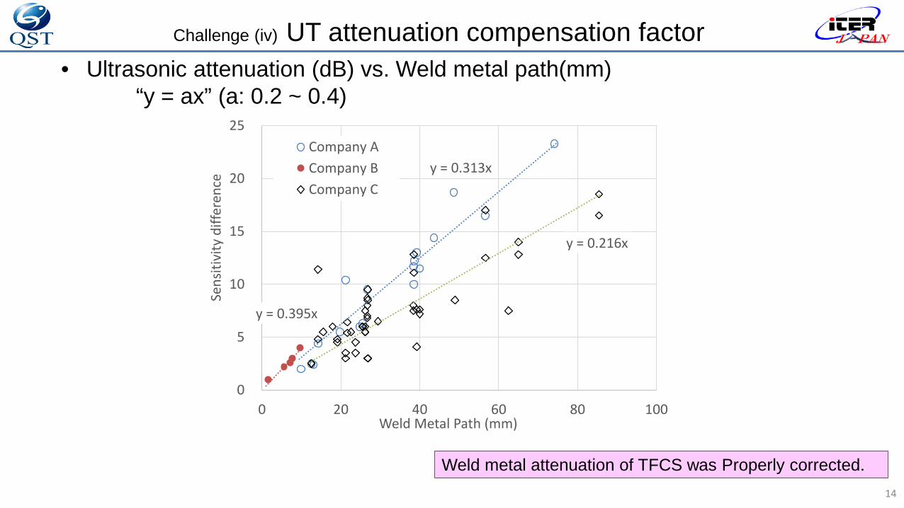
Challenge (iv) UT attenuation compensation factor• Ultrasonic attenuation (dB) vs. Weld metal path(mm)
“y = ax” (a: 0.2 ~ 0.4)
14
Weld metal attenuation of TFCS was Properly corrected.
y = 0.313x
y = 0.395x
y = 0.216x
0
5
10
15
20
25
0 20 40 60 80 100
Sens
itivi
ty d
iffer
ence
Weld Metal Path (mm)
Company ACompany BCompany C

15
Challenge (iv) UT for PPWEstablishment inspection method for PPW
Noise!
• High quality weld joint ← Inside defect inspection• Weld depth& initial crack size ← weld depth Confirmation
Ultrasonic Testing (UT) method
• Noise near root → Low accuracy on depth measuring?• Verification test by actual size PPW mock up.
UT procedure was defined.
+/-1mm accuracy for depth measuring.

Challenge (v) Fitting Test
16
AP/BPAU/BU
Gap
Mis-alignment
Gap: 0.5±0.25mmMisalignment:±0.3mm
Req. groove tolerances (inner)
Misalignment: ±1.3mmReq. groove tolerances (outer)
AU/BU
AP/BP
Req. 2): AU-BU
Gap: 0.5±0.25mmMisalignment:±0.7mm
Gap: 0.5±0.25mmMisalignment:±0.3mm
Gap: 0.5±0.25mmMisalignment:±0.3mm
Back plate
Side plate
Side plate
Req. 1): AU-AP, BU-BP
Upper
Lower
- Strict alignment accuracy requested on welding groove to assure welding quality- Actual AU, AP, BU, BP were tested

Challenge (v) Fitting Test for AU-AP/BU-BP
17
Nylon wedges
Stainless Steelwedges
Hydraulic Jack
ProtectionJig
Jigs used to fit up AP to AUAU and AP after fit-up
• Difficulty: To control the precise position of AP and BP.To control the flexibility of AP and BP shape.
• Solution: Several types of guide jigs to adjust their position.Lever hoist to control their axial flexibility
• Result: Tests were successfully completed.

Challenge (v) Fitting Test for AU-BU
18
Aligned grooves
AU and BU after fitting up for the first EU products tested in horizontal position
AU and BU after fitting upfor the first JA coil tested in vertical position
• Difficulty: To find the exact position of actual AU and BU to achieve the target criteria• Solution: Virtual fitting based on the dimension survey data by laser tracker
Find the optimum position of AU and BU• Result: Tests were successfully completed utilizing the above
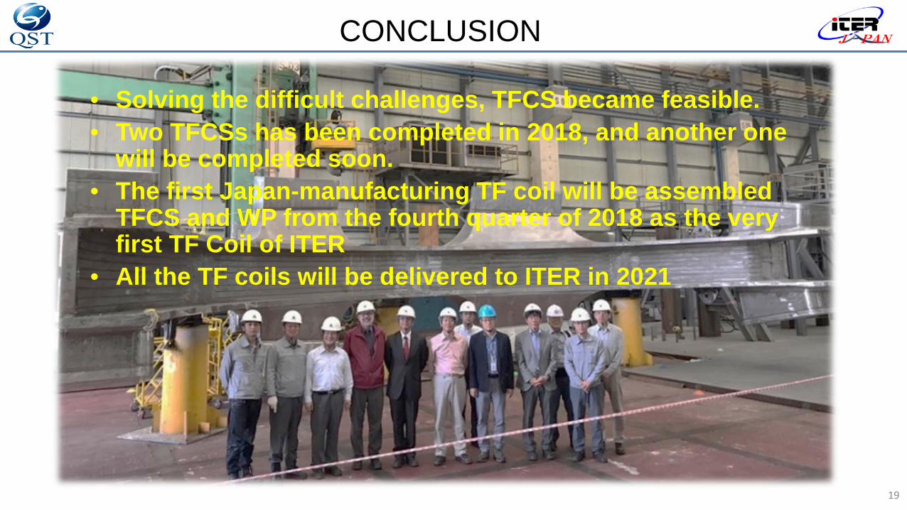
CONCLUSION
• Solving the difficult challenges, TFCS became feasible.• Two TFCSs has been completed in 2018, and another one
will be completed soon. • The first Japan-manufacturing TF coil will be assembled
TFCS and WP from the fourth quarter of 2018 as the very first TF Coil of ITER
• All the TF coils will be delivered to ITER in 2021
19

आपका ध्यान के�लए धन्यवाद
20