CATALOG NO. 1 03QJ STYLES - Diamond Needle Corp.
52
FIRST EDITION Finest Quality INDUSTRIAL SEWING EQUIPMENT CATALOG NO. 1 03QJ STYLES 39500QJ 39500RU 39500QL 39500SJ 39500QN 39500SR 39500QV 39500SX 39500QX 39500TG 39500RP 39500TV MARK IV HIGH SPEED SINGLE NEEDLE TWO AND THREE THREAD PLAIN FEED SERGING AND OVERSEAMING MACHINES From the library of: Diamond Needle Corp
-
Upload
khangminh22 -
Category
Documents
-
view
1 -
download
0
Transcript of CATALOG NO. 1 03QJ STYLES - Diamond Needle Corp.
FIRST EDITION
Finest Quality INDUSTRIAL SEWING EQUIPMENT
CATALOG NO. 1 03QJ
STYLES 39500QJ 39500RU 39500QL 39500SJ 39500QN 39500SR 39500QV 39500SX 39500QX 39500TG 39500RP 39500TV
MARK IV HIGH SPEED SINGLE NEEDLE TWO
AND THREE THREAD PLAIN FEED SERGING
AND OVERSEAMING MACHINES
From
the
libra
ry o
f: D
iam
ond
Nee
dle
Cor
p

1
·1
1
1
1
1
1
1
1
1
1
1
1
1
1
1
1
1
1
1
1
1
1
1
1
1
1
1
1
1
1
1
1
1
1
1
1
1
1
1
1
From
the
libra
ry o
f: D
iam
ond
Nee
dle
Cor
p

IDENTIFICATION OF MACHINES
Each UNION SPECIAL machine is identified by a Style number on a name plate on the machine. Style numbers are classified as standard and special. Standard Style numbers have one or more letters suffixed, but never contain the letter "Z" • Example: 11Style 39500 QJ". Special Style numbers contain the letter ttz" .. When only minor changes are made in a standard machine, a "Z" is suffixed to the standard Style number. Example: "Style 39500 QJzu.
Styles of machines similar in construction are grouped under a Class number which differs from the Style number in that it contains no letters. Example: •tclass 39500 11
•
APPLICATION OF CATALOG
This catalog applies specifically to the standard Styles of machines as listed herein. It can also be applied with discretion to some Special Styles of. machines in Class 39500. References to directions, such as right, left, front, back, etc., are given from the operator's position while seated at the machine. Operating direction of handwheel is away from operator.
STYLES OF MACITINES
MARK IV Hi-Styled High Speed, Single Curved Blade Needle, One Looper, One Spreader, Two Thread or Two Looper, Three Thread Serging Machines. Plain Feed, Trimming Mechanism with Spring Pressed Lower Knife. Automatic Lubricating System, Improved Air Cooling System.
39500 QJ Light to medium duty machine for serging light, medium and heavy weight trousers and similar garments. Two thread stitch. Seam specification 503-EFd-1; standard seam width 3/16 inch (4. 76 mm); stitch range 4-8 per inch; cam adjusted feed. Maximum recommen,ded speed 7500 R. P. M.
39500 QL Light to medium duty machine for serging light, medium and heavy weight trousers and similar garments. Three thread stitch. Seam specification 505-SSa-1; standard seam width 3/16 inch (4. 76 mm); stitch range 4-8 per inch; cam adjusted feed. Maximum recommended speed 7500 R. P. M.
39500 QN Medium to heavy duty machine for overseaming pants, jackets, snow suits, garment pockets and similar operations on medium to heavy weight materials. Three thread stitch. Seam specification 504-SSa-1; standard seam width: 3/16 inch (4. 76 mm); stitch range 8-20 per inch; cam adjusted feed. Maximum recommended speed 7500 R. P. M.
39500 QV Medium to heavy duty machine for turned edge seaming and straight overedging without cord on rayon bedspreads, bed blankets, towels, wiping cloths and other articles made from fabrics that fray readily. Three thread stitch. Seam specification 504-EFe-1 (inverted); standard seam width 3/16 inch (4. 76 mm); stitch range 7-20 per inch; cam adjusted feed. Maximum recommended spee_d 7500 R. P. M.
39500 QX Medium to heavy duty machine for simultaneously attaching right. pants flies and zipper tapes to pants fronts; also attaching zippers to right flies only and similar operations. Three thread stitch. Seam specification 504-SSa-1 or SSj-1; standard seam width 3/8 inch (9. 52 mm); stitch range 6-16 per inch;· cam adjusted feed. Maximum recommended speed 7500 R. P. M.
3
From
the
libra
ry o
f: D
iam
ond
Nee
dle
Cor
p

STYLES OF MACillNES (Continued)
39500 RP Light to medium duty machine for serging and trimming light, medium and heavy weight trousers and similar garments. Three thread stitch. Seam specification 504-EFd-1; standard seam width 3/16 inch (4 .. 76 mm); stitch range 4-10 per inch; cam adjusted feed. Maximum recommended speed 7500 R.P.M.
39500 RU Light to medium duty machine for simultaneously attaching zippers with sliders and staples already in place (and overedge the facings) to pants flies. skirts, jackets and similar garments. Three thread s titcho Seam specification 504-SSa-1; standard seam width 3/16 inch (4. 76 mm); stitch range 4-10 per inch; cam adjusted feed. Maximum recommended speed 7500 R. P. M.
39500 SJ Light to medium duty machine for serging light and medium weight trousers and similar garments of Durable Press material. Two thread stitch. Seam specification 503-EFd-1; standard seam width 3/16 inch (4. 76 mm); stitch range 4-8 per inch; cam adjusted feed. Maximum recommended speed 7500 R.P.M.
39500 SR Medium to heavy duty machine for simultaneously attaching right pant$ flies and zipper tapes to pants fronts; also attaching zippers to right flies only and similar operation of Durable Press material. Three thread stitch. Seam specification 504-SSa-1 or SSj-1; standard seam width 3/16 inch (4. 76 mm); stitch range 6 to 16 per inch; cam adjusted feed. Maximum recommended speed 7500 R. P. M.
39500 SX Medium to heavy duty machine for simultaneously attaching right pants flies and zipper tapes to pants fronts of Durable Press material; also attaching zippers to right flies only and similar operations on Durable Press material. Three thread stitch. Seam specification 504-SSa-1 or SSj-1; standard seam width 3/8 inch (9. 52 mm); stitch range 6-16 per inch; cam adjusted feed. Maximum recommended speed 7500 R. P. M.
3 9 500 TG Light to medium duty machine for serging around pants cuff before cuffs are folded and similar operations on light, medium and heavy weight trouser material. Smallest cuff that can be sewn is 2 3/8 inch ( 60. 3 2 mm) diameter or 7 1/2 inches (190. 50 mm) in circumference. Two thread stitch. Seam specification 503-EFd-1; standard seam width 3/16 inch (4. 76 mm); stitch range 4-8 per inch; cam adjusted feed. Maximum recommended speed 7500 R. P. M.
39500 TY Medium to heavy duty machine for hemming 5 to 25 pound paper, cotton orsyntheticmesh bags. Will turnupfrom 3/4 to 1 1/4inch (19.05 to 31.75 mm) of two plies of material and finish into a tight roll approximately 1/4 inch (6. 35 mm) in diameter. Three thread stitch. Seam specification 504-SSp-1 modified; stitch range, 4-20 per inch, cam adjusted feed. Maximum speed 6500 R. P. M. Maximum recommended speed 5500 R. P. M. when sewing mesh bags.
SPEED RECOMMENDATION
3 9500 MARK IV machines have been tested in their complete stitch range at their maximum rated speeds. Varied field conditions, severity and cleanliness of the sewing operation may necessitate operating at a lower speed. When operating from 50-100% machine running cycle and a longer than recommended stitch length,· it may be necessary to reduce the machine's speed by 10-15%.
The MARK IV is a precision manufactured and tested sewing machine. To obtain maximum performance, the machine should be operated at 1000 R. P. M. below maximum recommended speed for the first 20 days of field operation. This will minimize readjustment of precision mechanisms.
4
From
the
libra
ry o
f: D
iam
ond
Nee
dle
Cor
p

OILING
CAUTION! Oil was drained from machine when shipped, so reservoir must be filled before beginning to operate. Oil capacity of Class 39500 is eight ounces. A straight mineral oil of a Saybolt viscosity of 90 to 125 seconds at 100° Fahrenheit should be used.
Machine is filled with oil at spring cap in top cover. Oil level is checked at sight gauge on front of machine. Red bulb on oil level indicator should show between gauge lines when machine is stationary.
Machine is automatically lubricated. No oiling is necessary, other than keeping main reservoir filled. Check oil daily before the morning start; add oil as required.
To maintain maximumrecommended speed and serviceability of this equipment when operating continuously, the oil must be changed at least every six months. In no case should oil remain in machine for more than one year.
The drain plug screw is located at back of machine near bottom edge of base. It is a magnetic screw designed to accumulate possible foreign materials which may have entered the crank case. It should be removed and cleaned periodically.
NEEDLES
Each UNION SPECIAL needle has both type and size number. The type number denotes the kind of shank, point, length, groove, finish and oth<~r details. The size number, stamped on the needle shank, denotes largest diameter of blade, measured in thousandths of an· inch, midway between shank and eye. Collectively, type and size number represent the complete symbol which is given on the label of all needles packaged and sold by Union Special.
Class 39500 machines use a curved blade needle. The standard recommended needle for the Styles covered here is Type 154 GAS. Below is the description and sizes available of the recommended needle.
Type No.
154 GAS
Description and Sizes
Round shank, round point, curved blade, standard length, single groove, struck groove, spotted, chromium plated and is available in sizes 055/022, 065/025, 070/0'27, 075/029, 080/032, 090/036, 100/040, 110/044, 125/049, 140/054, 150/060.
To have needle orders promptly and accurately filled, an empty package, a sample needle, or the type and size number should be forwarded. Use description on label. A complete order would read: 111000 Needles, Type 154 GAS, Size 110/04411
•
Selection of the proper needle size is determined by size of thread used. Thread should pass freely through needle eye in order to produce a good stitch formation.
Success in the operation of UNION SPECIAL machines can be secured only by use of needles packaged under our brand name,~® , which is backed by a reputation for producing highestquality needles in materials and workmanship
· for more than three-quarters of a century.. ·
5
From
the
libra
ry o
f: D
iam
ond
Nee
dle
Cor
p

CHANGING NEEDLE
Release pressure on·presser foot by turning presser foot release bushing (AG, Fig. 1~ lA, lB or lC) and swing presser arm (U) out of position. Turn handwheel in operating direction until needle is at its lowest point of travel. Using hexagonal socket wrench No. 21388 A U, furnished with machine~ loosen needle clamp nut about 1/4 turn. Again turn handwheel until needle is at high position; withdraw needle.
To replace needle, leave needle holder at high position and~ with the flat to the left, insert needle in holder until it rests against stop pin. I(eeping needle in this position, turn handwheel until holder is again at its low point of travel; then tighten nut. Return presser arm (U) to position; re-lock presser foot release bushing (AG).
THREAD STAND (504 and 505 STITCH)
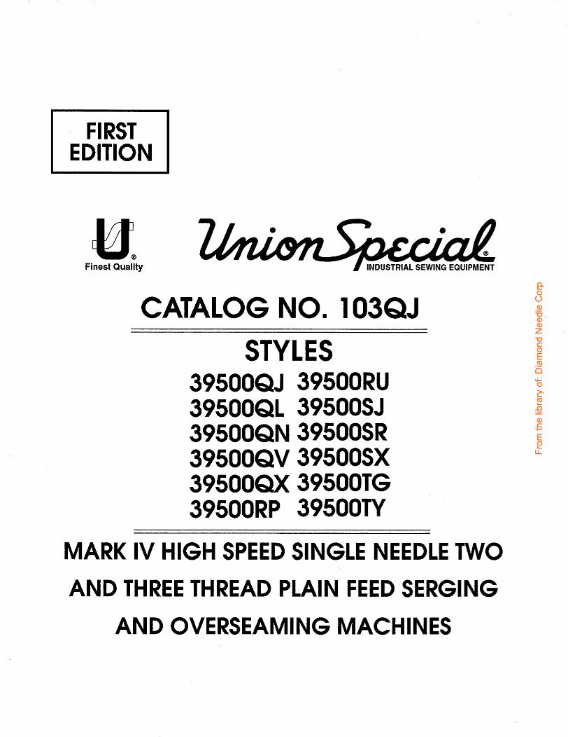
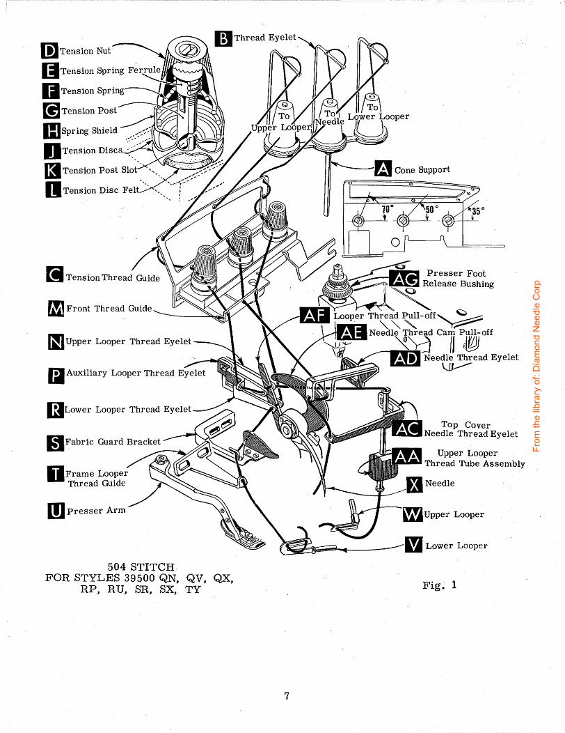
After thread comes from cones on cone support (A, Fig. 1 or lB) as applicable, it is brought up through the back hole of thread eyelet (B), then down through the front hole of thread eyelet. The needle and upper looper threads are then threaded through the upper hole of tension thread guide (C) from front to back, and then through the lower hole from back to front. The lower looper thread is threaded through the upper hole back to front, through the middle hole from front to back~ and finally through the lower hole from back to front. All three threads then continue between the tension discs (J), through tension post slot (K) in tension post (G) and on through front thr~ad guide (M).
THREAD STAND (503 STITCH, EXCEPT STYLE 39500 TY)
After thread comes from cones on cone support (A, Fig. lA) it is brought up through the back hole of thread eyelet (B), then down through the front hole of thread eyelet. The needle thread is then threaded through the upper hole of tension thread guide (C) from front to back, and then through the lower hole from back to front •. The lower looper thread is threaded through the upper hole back to front, through the middle hole from front to back, and finally through the lower hole from back to front. Both threads then continue between the tension discs (J), through . tension post slot (K) in tension post (G) and on through front thread guide (M).
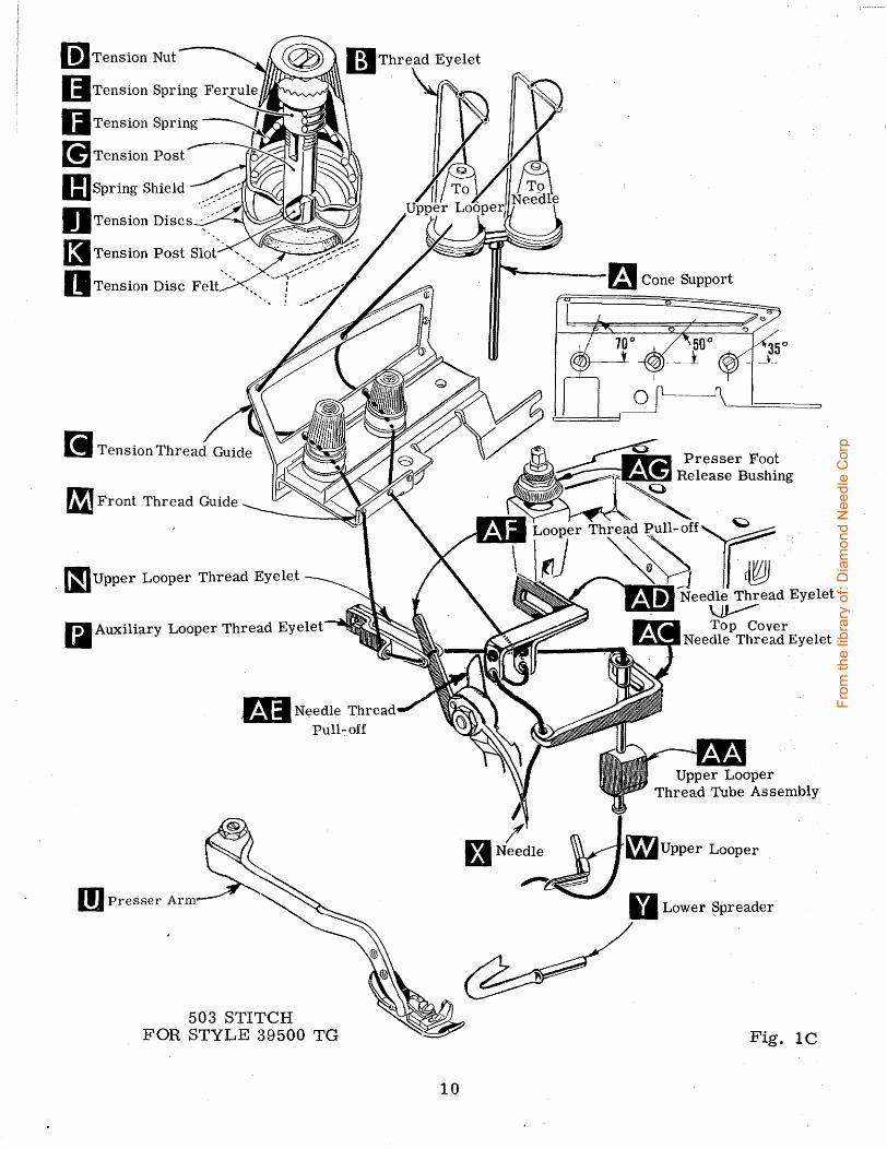
THREAD STAND (503 STITCH FOR STYLE 39500 TY)
After thread comes from cones on cone support (A, Fig. lC) it is brought up through the back hole of thread eyelet (B), then down through the front hole of thread eyelet. Next it is threaded through the upper holes of tension thread guide (C) from· front to back and then through the lower holes from back to front. Both threads then continue between tension discs (J), through tension post slot (K) in tension post (G) and on through front thread guide (M).
6
From
the
libra
ry o
f: D
iam
ond
Nee
dle
Cor
p
(;]Tension Nut
IJTension Spring F~r~
IITension Spring~~~=-"'"' [!]Tension Post~
IIJspring Shield ..,::::~~ DTension Discs :~~~/' .. · _ .
fgTension Post Slot'. ' ..... "~>-~ -~,_.;,:,;.: ~ '•. . •,,-<::>-~ 11 Tension Disc Felt · ·-. ·. j
fiJ Front Thread Guide
~~~Upper Looper Thread Eyelet
~~Lower Looper Thread Eyelet
(,1Fabric Guard Bracke_t __
DFrame Looper Thread Guide
m Presser Arm
504 STITCH-FOR STYLES 39500 QN, QV, QX,
RP, RU, SR, SX, TY
7
Top Cover IEtlil.ll.."'::ll Needle Thread Eyelet
Upper Looper Thread Tube Assembly
Fig~ 1
From
the
libra
ry o
f: D
iam
ond
Nee
dle
Cor
p

(;]Tension Nut
l'iiiTension Spring~ /~ 1.!1 Ferrule ~ IJTension Spring ~~ ... t'(,..,~..-. .. [!]Tension Post~
IIJspring Shield .--.~.--.... :::_
HTension Discs ::.::-
(1 Tension Post Slot .
11 Tension Disc Felt ·.. ·.. .. ! /..,..../,....,...
[i~ Tension Thread Guide
flJFront ~hread Guide
I9Lower Looper Thread Eyelet
mFabric Guard Bracke
DFrame Looper Thread Guide
m Presser Arm
503 STITCH FOR STYLES 39500 QJ, SJ
Cone Support
~-Upper Spreader
Fig. lA
8
From
the
libra
ry o
f: D
iam
ond
Nee
dle
Cor
p
(;]Tension Nut
.liiiTension Sprin~ /Ja""'-1!1 Ferrule ~ IITension Spring~~--~~"' [;]Tension Post~
IIJspring ·shield . _,: ... <': OTension Discs -~~~~ (I Tension Post Slot ~ n Tension Disc Felt · ..
fiJ Front Thread Guide
~Upper Looper Thread Eyelet
~~Auxiliary Looper Thread Eyelet
~~Lower Looper Threp.d Eyelet
m.Fabric Guard Bra
DFrame Looper Thread Guide
m Presser Arm
505 STITCH FOR STYLE 39500 QL
-Upper Looper Thread Tube Assembly
Upper Looper
Lower Looper
Fig. lB
9
From
the
libra
ry o
f: D
iam
ond
Nee
dle
Cor
p
I!]Tension Nut
....
OTension Discs-~-:~~-_: l3 Tension Post Slo~-- ',,_
IJ Tension Disc Felt·· ..
liJ Front Thread Guide
. ~Upper Loop er Thread Eye let
~~Auxiliary Looper Thread Eyelet
m Presser Arm
.BI N~edle Thread Pull-off
503 STITCH FOR STYLE 39500 TG
10
Upper Looper Thread Tube Assembly
£t Nee;.)jrzJupper Looper
D Lower ~preader
Fig. lC
From
the
libra
ry o
f: D
iam
ond
Nee
dle
Cor
p
THREADING
Only parts involved in threading are shown in threading diagrams (Fig. 1, lA, 1 B and 1 C). Parts are placed in their relative positions for clarity.
It will simplify the threading of these machines to follow the recommended sequence of threading the lower looper or upper looper first (as applicable) and the needle second when using the 503 stitch (Fig. lA and lC). The recommended sequence when using the 504 or 505 stitch (Fig. 1 and lB) is to thread the lower looper first, upper looper second, and the needle third.
Before beginning to thread, swing cloth plate open, turn handwheel in operating direction until needle (X) is at high position, release pressure on presser foot by turning presser foot release bushing (AG) and swing presser arm (U) out of position.
Be sure threads, as they come from the tension thread guide (C), are between tension discs (J) and in diagonal slots (K) in tension posts (G}.
TO THREAD THE LOWER LOOPER (FOR ALL STYLES EXCEPT 39500 TG)
Double end of thread and lead it through the right eyelet of front thread guide (M, Fig. 1, lA or lB). Then lead thread through both eyes of lower looper thread eyelet (R, Fig. 1, lA or lB) from right to left. NOTE: Thread must pass in front of loop er thread pull-off (AF). Lead thread behind fabric guard (S) and through frame looper thread guide (T). Turn handwheel in operating direction until heel of lower looper (V) is all the way to the left, then thread through both eyes from left to right. Left eye of lower looper can be threaded easily if tweezers are in left hand.
TO THREAD UPPER LOOPER (FOR ALL STYLES EXCEPT 39500 QJ, SJ)
Thread upper looper thread through left eyelet of front thread guide (M, Fig. 1, lB or lC). Then turn handwheel until point of upper looper (W) is all the way left. Lead thread through auxiliary looper thread eyelet (P) from back to front, then through both eyes of upper looper thread eyelet (N) from left to right. Note: thread must pass in front of looper thread pull-off (AF}. After pulling up upper looper thread tube assembly (AA), lead thread under neck of top cover casting and down through thread tube assembly (AA). Pull thread out bottom of tube; push tube down, then insert thread through upper looper eye from front to back ..
CAUTION! Be sure upper looper thread is under lower looper thread when passing from tube assembly to upper looper eye.
TO THREAD THE NEEDLE (FOR STYLES 39500 QJ" QL and SJ)
Turn handwheel in operating direction until needle (X, Fig. lA or lB) is at its highest position. Insert thread through the middle eyelet of front thread guide (M, Fig. lA or lB). then lead thread through eye of needle thread eyelet (AD) from back to front. Now lead the needle thread under the neck of top cover casting and through hole in needle thread pull-off eyelet (AB) from right to left. Thread needle from the front.
11
From
the
libra
ry o
f: D
iam
ond
Nee
dle
Cor
p
TO THREAD THE NEEDLE (FOR ALL STYLES EXCEPT 39500 QJ, QL and SJ)
Turn handwheel in operating direction until needle (X, Fig. 1 or lC) is at its highest position. Insert thread through the middle eyelet of front thread guide (M, Fig. 1 or 1 C, then insert needle thread from right to left, through both eyes of needle thread eyelet (AD), under neck of top cover casting; then down through hole in top cover needle thread eyelet (AC). Thread needle from the front.
THREAD TENSION
The amount of tension on the needle and looper threads is regulated by knurled tension nuts (D, Fig. 1, lA, lB or lC). Tension on threads should be only enough to secure proper stitch formation.
Fig. 2
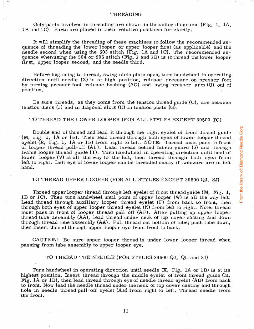
PRESSER FOOT PRESSURE
Sufficient presser foot pressure to feed work uniformly should be maintained. Should it be necessary to increase or decrease amount of pressure on presser foot, loosen lock nut (A, Fig. 2)' and turn adjusting screw (B). Adjusting screw has a right hand thread, so tightening increases pressure, loosening decreases pressure. When pressure adjusting screw (B) has been properly set, tighten lock nut (A). With presser foot resting on throat plate, position locking nut (C) so that its under surface is approximately 1/3 2 to 1/16 inch (. 79 to 1. 59 mm) from the top surface of adjusting screw {B). Set cap (D) against locking nut (C).
FEED ECCENTRICS
Feed eccentrics used in Style 39500 QJ machines have been selected to produce approximately 5 stitches per inch. It will be noted that the part number of the feed eccentric is No. 39540 B-5. Minor numbers of the part symbol indicate approximately the number of stitches obtainable when using that eccentric. Unless otherwise specified, machine Style 39500 QJ will be shipped with above eccentric. Refer to exploded views in catalog for eccentrics furnished on other Styles of machines.
The following stitch number feed eccentrics are available under No. 39540 B-4, - 5 J - 6 J - 7, - 8 J - 9 J -1 0 J -11 J -1 2 J -1 3 J -14, -1 5' -1 6' -18 J - 20 J - 2 2 J - 24 J - 2 6 J
-28, -30, -32, -34, -36, -40. Only one eccentric is supplied with each machine. Additional eccentrics may be ordered separately. To order an eccentric, use No. 39540 B with a minor number suffixed to indicate approximately the number of stitches desired. Example: "39540 B-5".
ASSEMBLING AND ADJUSTING SEWING PARTS
Before assembling and adjusting sewing parts, remove cloth plate, fabric guard, chip guard, upper knife assembly and lower knife holder assembly; then follow this suggested sequence.
NOTE: Adjusting instructions will pertain to all styles of machines covered in this catalog, unless otherwise specified.
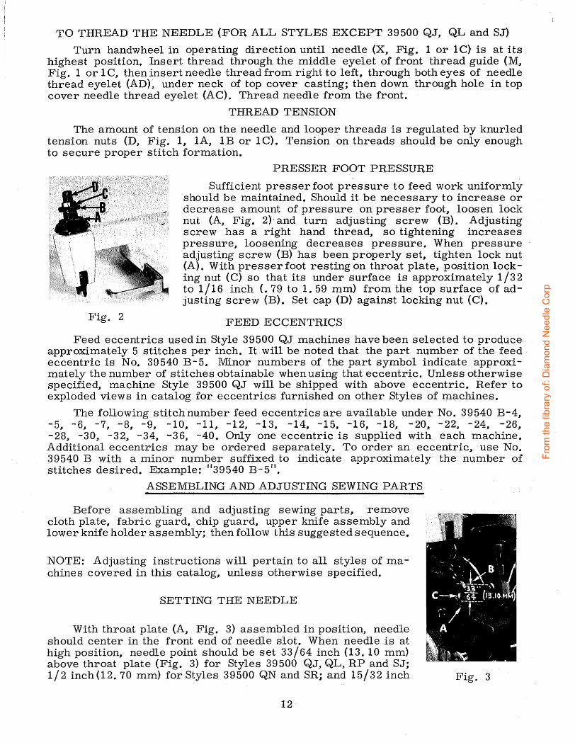
SETTING THE NEEDLE
With throat plate (A, Fig. 3) assembled in position, needle should center in the front end of needle slot. When needle is at high position, needle point should be set 33/64 inch (13. 10 mm) above throat plate (Fig. 3) for Styles 39500 QJ, QL, RP and SJ; 1/2 inch(12. 70 mm) for Styles 39500 QN and SR; and 15/32 inch
12
Fig. 3
From
the
libra
ry o
f: D
iam
ond
Nee
dle
Cor
p
SETTING THE NEEDLE (Continued)
(11. 91 mm) for Styles 39500 QV, QX, RU, SX, TG and TY. To align needle or set the height above the throat plate, move needle driving arm {B, Fig. 3) by loosening clamp screw (C). After needle has been properly set, tighten clamp screw and remove throat plate.
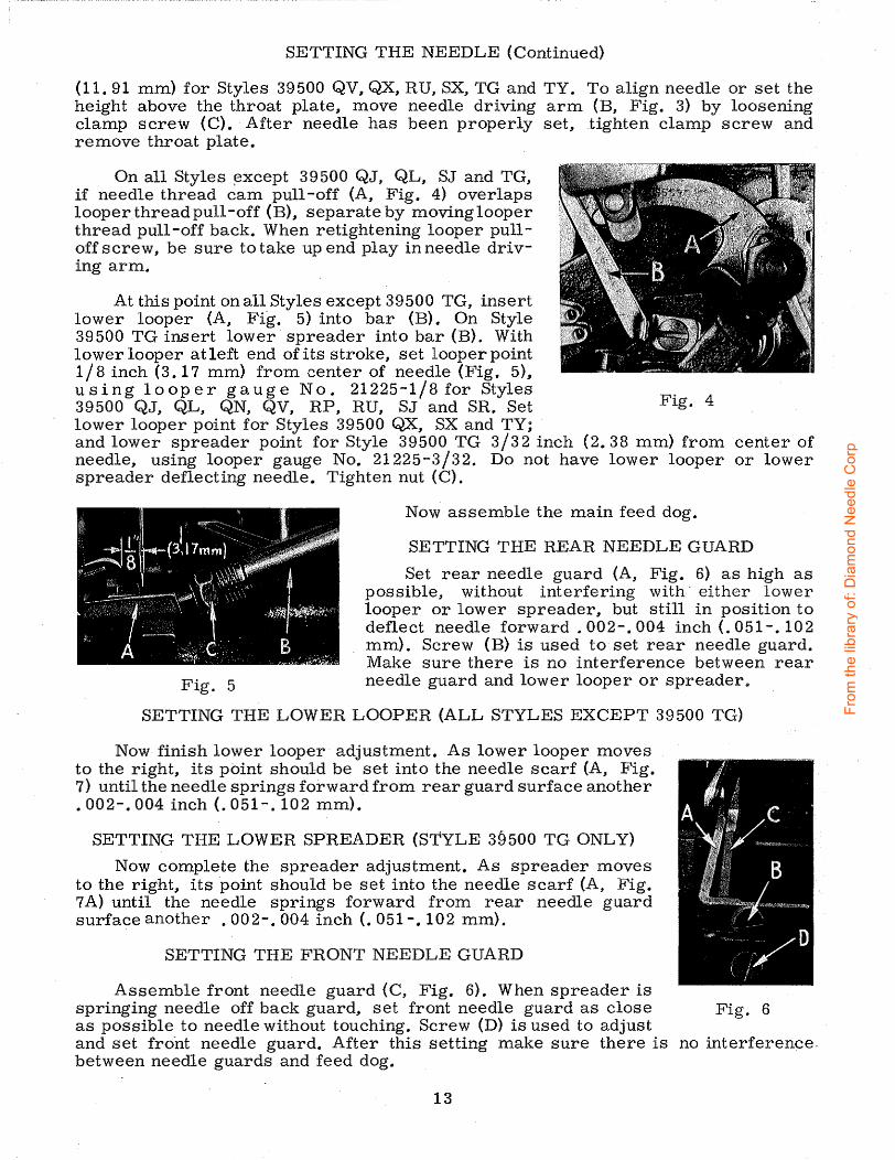
On all Styles ~xcept 39500 QJ, QL, SJ and TG, if needle thread cam pull-off (A, Fig. 4) overlaps looperthreadpull-off (B), separate by movinglooper thread pull-off back. When retightening looper pulloffscrew, be sure to take up end play in needle driving arm.
At this point on all Styles except 39500 TG, insert lower looper (A, Fig. 5) into bar (B). On Style 39500 TG insert lower spreader into bar (B). With lower loop er at left end of its stroke, set loop er point 1/8 inch (3. 17 mm) from center of needle (Fig. 5), using loop er gauge No. 21225-1/8 for Styles 39500 QJ, QL, QN, QV, RP, RU, SJ and SR. Set Fig. 4 lower looper point for Styles 39500 QX, SX and TY; and lower spreader point for Style 39500 TG 3/32 inch (2. 38 mm) from center of needle, using looper gauge No. 21225-3/32. Do not have lower looper or lower spreader deflecting needle. Tighten nut (C).
Now assemble the main feed dog.
SETTING THE REAR NEEDLE GUARD
Set rear needle guard (A, Fig. 6) as high as possible, without interfering with· either lower looper or lower spreader, but still in position to deflect needle forward. 002-.004 inch(. 051-.102 mm). Screw (B) is used to set rear needle guard. Make sure there is no interference between rear
Fig. 5 needle guard and lower loop er or spreader"
SETTING THE LOWER LOOPER (ALL STYLES EXCEPT 39500 TG)
Now finish lower looper adjustment. As lower looper moves to the right, its point should be set into the needle scarf (A, Fig. 7) until the needle springs forward from rear guard surface another • 002-.004 inch(. 051-. 102 mm).
SETTING THE LOWER SPREADER (STYLE 39500 TG ONLY)
Now complete the spreader adjustment. As spreader moves to the right, its point should be set into the needle scarf (A, Fig. 7 A) until the needle springs forward from rear needle guard surface another . 002-.004 inch(. 051-. 102 mm).
SETTING THE FRONT NEEDLE GUARD
Assemble front needle guard (C, Fig. 6). When spreader is springing needle off back guard, set front needle guard as close Fig. 6 as possible to needle without touching. Screw (D) is used to adjust and set fro"nt needle guard. After this setting make sure there is no interference. between needle guards and feed dog.
13
From
the
libra
ry o
f: D
iam
ond
Nee
dle
Cor
p

SETTING THE UPPER LOOPER (ALL STYLES EXCEPT 39500 QJ, SJ)
Insert upper looper (A, Fig. 8) in its holder. Screw (B) holds upper loop er in its holder and permits it to be pushed in or out or turned around its shank. Insert
upper looper holder into upper looper shaft, if it is not already in place. Screw ( C, Fig. 8) on clamp holds the upper loop er holder in the shaft. Locate upper looper in its holder so that the shank extends 1/16 to 3/32 inch (1. 59 to 2. 38 mm) beyond holder (Fig. 8), for Styles 39500 QL, QN, QV, QX, RU, SR, SX and TY; 1/32 to 1/16 inch (. 79 to 1. 59 mm) for Styles 39500 RP and TG.
When the upper looper is at the right end of its stroke, upper looper holder should be set to position upper looper shank about vertical on Styles 39500 QN, QV, QX, SX and TY (Fig. 8). On Styles 39500 QL, RP, RU, SR and TG the upper looper holder should be set to position the upper looper shank
Fig. 7 slightly back of vertical. Be sure, on all Styles, there is a clearance between heel
of loop er and the casting. By adjusting looper holder in or' out of upper looper shaft and by turning the looper around its shank, set upper looper point to cross lower looper to the left of the . lower looper eye with . 002 to . 004 inch (. 051 to . 102 mm) clearance (Fig. 9).
As the upper looper moves toward the top of its stroke, the heel of the upper looper should pass behind the lower looper head with 1/32 to 1/16 inch(. 79 to 1. 59 mm) clearance.
Next, turn handwheel until looper is at the left end of its Fig. 7A travel; check dimensions of upper looper point with respect to needle and throat plate (Fig. 10). If resetting is necessary, do it by moving the upper looper holder (A, Fig. 10). Figure 10 represents the dimensional setting for Styles 39500 QL and RP.
NOTE: For the dimensional settings of the other Styles refer to Fig. 11. For example, 1/ 2 inch ( 12. 7 0 mm) dim ension is increased by turning upper loop er holder counterclockwise, looking from left end of machine; 5/32 inch (3. 97 mm) dimension is increased by pulling upper looper holder to the left, out of upper looper shaft. After these changes are made it may be necessary to turn upper looper around its shank slightly to maintain the condition shown in (Fig. 9).
When the correct setting is obtained Fig. 8 for Styles 39500 QL, QN, QV, QX, RP, Fig. 9
SR, SX and TY it can be checked quickly as follows: As the upper looper is moving to the right and the upper looper eye centers on the needle, the eyes of the upper looper and needle should align exactly (Fig. 12). For Styles 39500 RU and TG when the looper eye centers on the needle, the bottom of the needle eye should be about level with the top surface of the looper.
14
From
the
libra
ry o
f: D
iam
ond
Nee
dle
Cor
p

SETTING THE UPPER LOOPER (ALL STYLES EXCEPT 39500 QJ, SJ) (Cont.)
Check setting to avoid interference between upper looper and needle on needle downstroke. If needle rubs the back of upper looper, pull looper out of its holder slightly and rotate looper a short distance counterclockwise, looking from left end of machine. Reset to maintain dimensions of Figs. 9, 10, 11, 12.
Machine Styles .
39500 QL, RP 39500 QN, TY 39500 QV, QX, SX 39500 RU 39500 SR 39500 TG
Fig. 10
Looper Point to Left Of Needle Centerline
5/32 inch (3. 97 mm) 9/64 inch (3. 57 mm) 9/64 inch (3. 57 mm) 5/32 inch (3. 97 mm) 9/64 inch (3. 57 mm) 5/32 inch (3. 97 mm)
Fig. 11
Looper Point Above Throat Plate
1/2 inch (12. 70 mm) 1/2 inch (12. 70 mm) 15/32 inch (11. 91 mm) 29/64 inch (11. 51 mm) 31/64 inch (12. 30 mm) 15/32 inch (11. 91 mm)
SETTING THE UPPER SPREADER (STYLES 39500 QJ and SJ)
Insert upper spreader (A, Fig. BA) in its holder e Screw (B) holds upper spreader in its holder, and permits it to be puahed in or out or turned around its shank. Insert spreader holder into spreader shaft, if it is not already in place. Screw (C, Fig. BA) on clamp collar holds spreader holder in the shaft, and allows holder to be rotated or adjusted laterally.
Preliminary Setting: When upper spreader is at the right end of its stroke, spreader holder should be set to position spreader shank about vertical (Fig. BA). Top end of spreader shank should extend 1/32 to 1/16 inch (.. 79 to 1 . 59 mm) above the spreader holder (Fig. BA).
Fig. 12 As spreader moves from right
to left, the Vee notch of the spreader should pass just behind the eye of the lower looper, with. 002 to . 004 inch (. 051 to . 102 mm) clearance between spreader and lower loop er (Fig. 9A).
Turn the handw heel until upper spreader is at the left end of its travel. At this position, the lower point
15
Fig. BA
From
the
libra
ry o
f: D
iam
ond
Nee
dle
Cor
p

SETTING THE ,UPPER SPREADER (STYLES 39500 QJ and SJ) (Cont.)
of the spreader should extend about 5/32 inch (3. 97 mm) to the left of the centerline of the needle and should be 31/64 inch (12. 30 mm) above the top of the throat
Fig. 9A
feed bar.
plate (Fig. lOA). If resetting is necessary, do it by moving the spreader holder (A, Fig. lOA).
Now check setting between upper spreader and needle. If needle rubs the back of spreader, pull spreader out of its holder slightly and rotate spreader holder forward a short distance. These same adjustments, in opposite movement, will reduce the clearance between spreader and needle. Reset to lower looper (Fig. 9A).
SETTING THE FEED DOOS
Assemble chaining feed dog (A, Fig. 13) to main feed dog (B). Main feed dog should be levelled with respect to the throat plate by rotating feed tilting adjusting pin (C). This pin raises or lowers the back end of the
The feed dogs should be set level at the time teeth first appear above the throat plate. Screw {D) locks feed tilting adjusting pin in place_. With the feed dogs q.t their highest point of travel, the top of the teeth on the main feed dog should be 3/64 inch ( 1. 19 rn.m) above the throat plate, on all Styles, except 39500 TY which should rise the depth of a full tooth above the throat plate. Now set chaining feed dog teeth flush with the top of throat plate, for Styles 39500 QJ, QL, QN, QX, RP, RU, SJ, SR and SX. On Style 39 500 QV, the chaining feed dog teeth should be set to the same height as the main feed dog teeth. Fig. lOA
NOTE: Styles 39500 TG or TY DO NOT have a chaining feed dog.
SETTING THE LOWER KNIFE
Replace lower knife holder assembly. Lower knife (A, Fig. 14) should be set with cutting edge flush with throat plate surface. Adjustments are made with hexagonal head screw which holds lower knife. Lower knife is spring pressed against upper knife, so no lateral adjustment is ne cessarywhen width of trim is changed.
Lower knife may be secured in any p os it ion by tightening
Fig. 13 screw (B) and locking nut (C) against support bracket. Because
screw (B) also serves as latch pin for the cloth plate latch spring, it should always be locked with nut (C) even when screw is not tightened against lower knife holder.
16
From
the
libra
ry o
f: D
iam
ond
Nee
dle
Cor
p
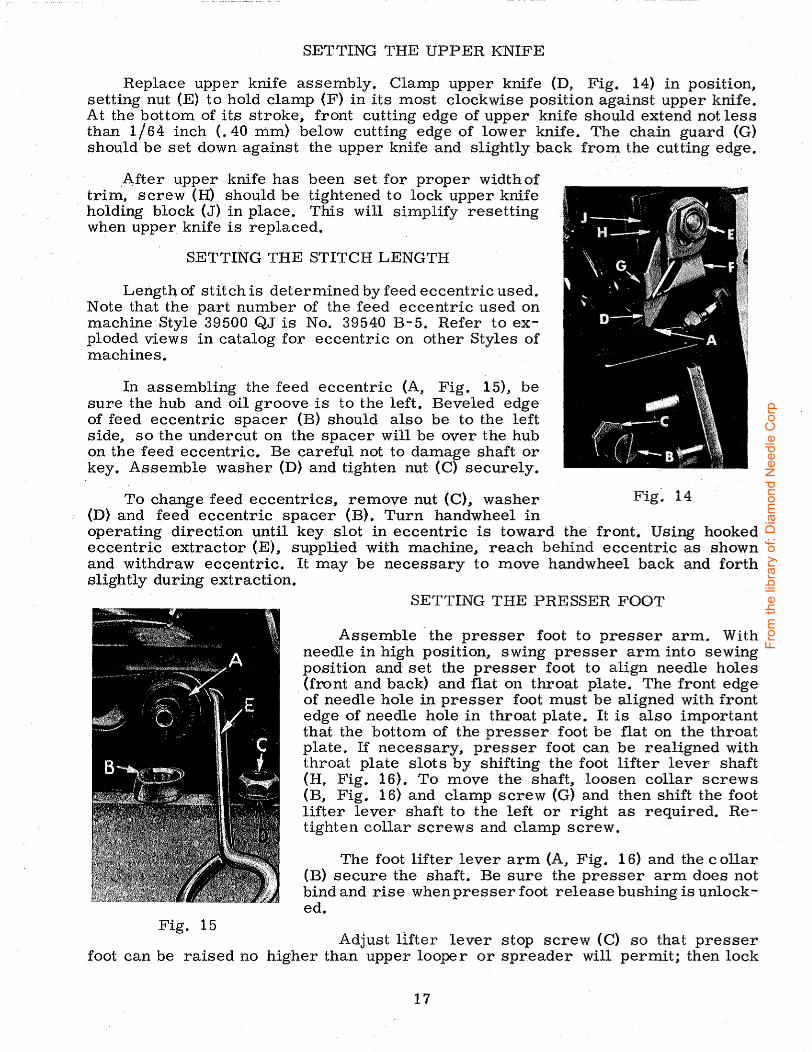
SETTING THE UPPER KNIFE
Replace upper knife assembly. Clamp upper knife (D, Fig. 14) in position, setting nut (E) to hold clamp (F) in its most clockwise position against upper knife. At the bottom of its stroke, front cutting edge of upper knife should extend not less than 1/64 inch (. 40 mm) below cutting edge of lower knife. The chain guard (G) should be set down against the upper knife and slightly back from the cutting edge.
_After upper knife has been set for proper width of trim, screw (H) should be tightened to lock upper knife holding block (J) in place. This will simplify resetting when upper knife is replaced.
SETTING THE STITCH LENGTH
Lengtb of stitch is determined by feed eccentric used. Note that the part number of the feed eccentric used on machine· Style 39500 QJ is No. 39540 B- 5. Refer to exploded views in catalog for eccentric on other Styles of machines.
In assembling the feed eccentric (A, Fig. 15), be sure the hub and oil groove is to the left. Beveled edge of feed eccentric spacer (B) should also be to the left side, so the undercut on the spacer will be over the hub on the feed eccentric. Be careful not to damage shaft or key. Assemble washer {D) and tighten nut (C) securely.
To change feed eccentrics, remove nut (C), washer Fig~ 14 (D) and feed eccentric spacer (B). Turn handwheel in operating direction until key slot in eccentric is toward the· front. Using hooked eccentric extractor (E), supplied with machine, reach behind eccentric as shown and withdraw eccentric. It may be necessary to move handwheel back and forth slightly during extraction.
SETTING THE PRESSER FOOT
Assemble -the presser foot to presser arm. With needle in high position, swing presser arm into sewing position and set the presser foot to align needle holes
_(front and back) and flat on throat plate. The front edge of needle hole in presser foot must be aligned with front edge of needle hole in throat plate. It is also important that the bottom of the presser foot be flat on the throat plate. If necessary, presser foot can be realigned with throat plate slots by shifting the foot lifter lever shaft (H, Fig. 16). To move the shaft, loosen collar screws (B, Fig. 16) and clamp screw (G) and then shift the foot lift er lever shaft to the left or right as required. Retighten collar screws and clamp screw.
The foot lifter lever arm (A, Fig. 16) and the collar (B) secure the shaft. Be sure the presser arm does not bind and rise when presser foot release bushing is unlocked.
Fig. 15 Adjust lifter lever stop screw (C) so that presser
foot can be raised no higher than upper looper or spreader will permit; then lock
17
From
the
libra
ry o
f: D
iam
ond
Nee
dle
Cor
p
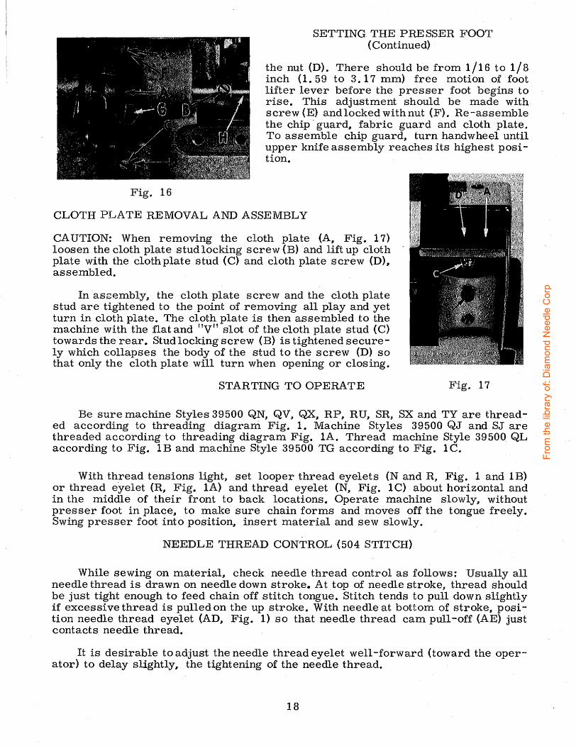
SETTING THE PRESSER FOOT (Continued)
the nut (D). There should be from 1/16 to 1/8 inch ( 1. 59 to 3. 17 mm) free motion of foot lifter lever before the presser foot begins to rise. This adjustment should be made with screw (E) and locked with nut (F). Re-assemble the chip · guard, fabric guard and cloth plate. To assemble chip guard, turn handwheel until upper knife assembly reaches its highest position.
Fig. 16
CLOTH PLATE REMOVAL AND ASSEMBLY
CAUTION: When removing the cloth plate (A, Fig. 17) loosen the cloth plate stud locking screw (B) and lift up cloth plate with the cloth plate stud (C) and cloth plate screw (D), assembled.
In aszembly, the cloth plate screw and the cloth plate stud are tightened to the point of removing all play and yet turn in cloth plate. The cloth plate is then assembled to the machine with the flat and "V" slot of the cloth plate stud (C) towards the rear. Stud locking screw (B) is tightened securely which collapses the body of the stud to the screw (D) so that only the cloth plate will turn when opening or closing.
STARTING TO OPERATE Fig. 17
Be sure machine Styles 39500 QN, QV, QX, RP, RU, SR, SX and TY are threaded according to threading diagram Fig. 1. Machine Styles 39500 QJ and SJ are threaded according to threading diagram Fig. lA. Thread machine Style 39500 QL according to Fig. 1B and machine Style 39500 TG according to Fig. lC.
With thread tensions light, set looper thread eyelets {N and R, Fig. 1 and lE) or thread eyelet (R, Fig. lA) and thread eyelet (N, Fig. lC) about horizontal and in the middle of their front to back locations. Operate machine slowly, without presser foot in place, to make sure chain forms and moves off the tongue freely. Swing presser foot into position, insert material and sew slowly.
NEEDLE THREAD CONTROL (504 STITCH)
While sewing on material, check needle thread control as follows: Usually all needle thread is drawn on needle down stroke. At top of needle stroke, thread should be just tight enough to feed chain off stitch tongue. Stitch tends to pull down slightly if excessive thread is pulled on the up stroke. With needle at bottom of stroke, position needle thread eyelet (AD, Fig. 1) so that needle thread cam pull-off (AE) just contacts needle thread.
It is desirable to adjust the needle thread eyelet well-forward (toward the oper-ator) to delay slightly, the tightening of the needle thread. ·
18
From
the
libra
ry o
f: D
iam
ond
Nee
dle
Cor
p

NEEDLE THREAD CONTROL (Styles 39500 QJ, SJ, TG- 503 STITCH)
While sewing on material, check needle thread control as follows: About 7 5% ·of needle thread required for the stitch should be drawn on needle downstroke. To increase thread drawn on downstroke, position needle thread eyelet (AD, Fig. lAand 1 C) farther to the rear.
NEEDLE THREAD CONTROL (Style 39500 QL- 505 STITCH)
While sewing on material, check needle thread control as follows: About 60% of needle thread required for the stitch should be drawn on needle downstroke.
To increase thread drawn on downstroke, position needle thread eyelet (AD, Fig. lB) farther to the rear.
LOWER LOOPER THREAD CONTROL {504 STITCH)
With material under presser foot, set lower looper thread. eyelet (R, Fig. 1) back far enough so thread is a little slack when looper thread pull-off (AF) reaches its most rearward position. Looper thread pull-off (AF) is set about l/32 inch(. 79 mm) distance behind needle thread cam pull-off (AE). Frame looper thread guide (T) should be set with its eyelet approximately 1/8 inch (3. 17 mm) to the right of lower:· looper (V) heel eyelet at the time lower looper is at extreme left end of its travel.
While sewing on material, check drawing off of looper thread as follows: A portion of lower looper thread should be drawn through the tension before lower looper thread comes off upper looper. To increase amount of thread drawn through the tension while lower looper thread is on upper loop er, move lower loop er thread eyelet (R) down, keeping the same amount of pull-off action.
LOWER LOOPER THREAD CONTROL (503 STITCH)
With material under presser foot, set lower looper thread eyelet (R, Fig. lA) back and down far enough so thread is a little slack when spreader reaches its extreme left position. Lower looper thread eyelet (R) should be about horizontal.
Frame loop er thread guide (T) should be set with its eyelet approximately 1/8 inch (3. 17 mm) to the right of heel eyelet of looper (V) at the time lower looper is at extreme left end of its travel. ·
LOWER LOOPER THREAD CONTROL (505 STITCH)
Set lower loop er thread eyelet (R, Fig. 1 B) about horizontal and all the way forward in its slot.
Frame looper thread guide (T) should be set with its eyelet approximately 1/8 inch (3. 17 mm) to the right of lower looper (V) heel eyelet, when lower looper is at the left end of its stroke.
UPPER LOOPER THREAD CONTROL (504 STITCH)
· Before proceeding to adjust upper loo per thread eyelet (N, Fig. 1) balance all three tensions to give a normal appearing stitch. Moderate change in these tensions will not markedly affect the purl.
D-uring needle downstroke, forward stroke of looper thread pull-off (AF) will draw upper looper thread through the tension. When normal amount of looper thread is drawn, upper looper thread will have almost all slack taken up as looper thread pull-off reaches its most rearward position.
19
From
the
libra
ry o
f: D
iam
ond
Nee
dle
Cor
p

UPPER LOOPER THREAD CONTROL (503 STITCH - Style 39500 TG)
With material under presser foot, set upper looper thread eyelet (N, Fig. 1C) back and down far enough so thread is a little slack when lower spreader reaches its extreme left position. Looper thread eyelet (N) should be about horizontal.
UPPER LOOPER THREAD CONTROL (505 STITCH)
With material under presser foot, set upper looper thread eyelet (N, Fig. lB) to rest on top of lower looper thread eyelet (R), and back far enough so upper looper thread is a little slack when upper looper reaches the left ~end of its stroke.
POSITIONING THE PURL (504 STITCH)
To move the purl more under the edge, both looper thread eyelets (N and R, Fig. 1) should be raised keeping the same amount of pull-off. Usually it is better to have slightly more pull-off on upper thread than on lower thread.
If it becomes necessary to move looper thread pull-off (AF), be sure to take up all end play in needle drive shaft before tightening. If upper looper is located so that it is higher over throat plate than recommended in Fig. 10, the purl will tend to form near top edge. If upper looper is too low, the purl will form nearer bottom edge.
POSITIONING THE SQUARE EI?GE (505 STITCH)
Position of lower looper thread at the edge is located by balancing needle and upper looper thread tensions.
To reduce amount of lower looper thread in the stitch, or close the edge more, increase lower looper thread tension.
THREAD TENSIONS
The needle thread tension required is a function of needle thread and material being sewn. In general, lower looper thread tension should be set as high as possible without causing needle thread to be pulled down. Upper looper thread tension should be increased as long as the elasticity of the chain increases, or until the purl is pulled too far over the top.
USE GENUINE NEEDLES AND REPAIR PARTS
Success in the operation of these machines can be secured only with genuine UNION SPECIAL Needles and Repair Parts as furnished by the Union Special Corporation, its subsidiaries and authorized distributors. They are designed according to the most approved scientific principles, and are made with utmost precision. Maximum efficiency and durability are assured.
Genuine needles are packaged with labels marked~® . Genuine repair parts are stamped with the Union Special trademark, U S Emblem. Each trademark is your guarantee of the highest quality in materials and workmanship.
TORQUE REQUIREMENTS
Torque (measured in inch -pounds) is a rotating force (inpounds) applied through a distance by a lever (in inches or feet). This is accomplished by a wrench, screw driver, etc. Many of these devices are available, which when set at the proper amount of torque will tighten the part to the correct amount and no tighter.
All straps and eccentrics should be tightened to 19-21 inch-pounds (22-24 cm/kg) unless otherwise noted. All other nuts, bolts, screws, etc. , should . be tightened by hand as tightly as possible, unless otherwise noted.
The screws requiring a specific torque, will be indicated on the picture plates.
20
From
the
libra
ry o
f: D
iam
ond
Nee
dle
Cor
p
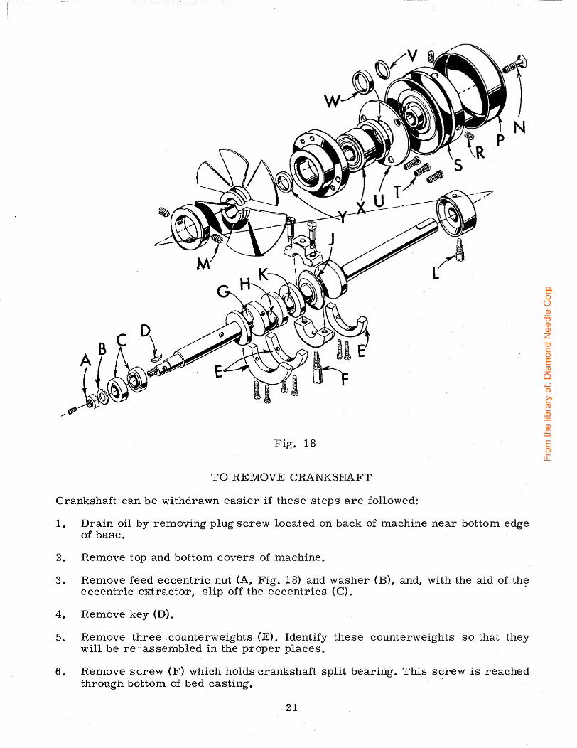
Fig. 18
TO REMOVE CRANKSHAFT
Crankshaft can be withdrawn easier if these steps are followed:
1. Drain oil by removing plug screw located on back of machine near bottom edge of base.
2. Remove top and bottom covers of machine.
3. Remove feed eccentric nut (A, Fig. 18) and washer (B), and, with the aid of the eccentric extractor, slip off the eccentrics (C). ·
4. Remove key (D).
5. Remove three counterweights (E). Identify these counterweights so that they will be re-assembled in the proper places.
6. Remove screw (F) which holds crankshaft split bearing. This screw is reached through bottom of bed casting. ·
21
From
the
libra
ry o
f: D
iam
ond
Nee
dle
Cor
p

TO REMOVE CRANKSHAFT (Continued)
7. Remove caps of bearings on crankshaft at points G, Hand J. When re-assembling bearing caps make sure they are in their original position. Trade marks are stamped on, both halves of the caps and both trade marks should be on the same side of the bearings. Also, screws should be reassembled in the same holes from which they were removed.
8. Loosen clamp nut (A, Fig. 19) which holds upper knife driving arm (B). Access to clamp nut is through top cover. Draw driving arm to the left until
Fig. 19
upper knife driving lever (C) and connecting rod (D) drop .. allowing removal of bearing cap (E). This is at bearing point (K, , Fig. 18) on crankshaft. Observe same precautions when re-assembling cap as described in 7 above.
9. Remove screw (L, Fig. 18) which holds inner right crankshaft bearing. This screw is reached through bottom of bed casting.
10. Loosen two screws (M) in fan collar; remove both halves of qpoling fan.' +
11. Remove screw (N); take off pulley cap (P).
12. Loosen two screws (R); remove pulley (S).
13. Remove three screws (T); take off bearing retaining plate (U); also, spacer collars (V) and (W) may be removed at this time.
14. Crankshaft may now be removed.
15. If necessary to replace ball bearing (X), it should be pressed off shaft on an arbor press. In replacing bearing it must be pressed on carefully until it seats against ground thrust washer (Y).
16. Carefully observing reverse of the foregoing operations should simplify reassembly of crankshaft. Checking exploded view drawings for location of various parts and constant testing for binds during re-assembly will also prove helpful.
17. Before re-assembling thoroughly clean and dry top and bottom covers and gaskets. Before re-assembling bottom cover make sure that spring pressed oil wick which lubricates left crankshaft bearing is inserted in hole in casting and that it contacts shaft. The wick stands vertically on its spring against bottom cover. Coat oil drain plug with a sealing cpmpound before re-assembling to prevent oil leakage. No. 1 Crane Lead Seal is recommended.
22
From
the
libra
ry o
f: D
iam
ond
Nee
dle
Cor
p

ORDERING REPAIR PARTS
ILLUSTRATIONS
This catalog has been arranged to simplify ordering repair parts. Exploded views of various sections of the mechanism are shown so that the parts may be seen in their actual position in the machine. On the page opposite the illustration will be found a listing of the parts with their part numbers, description and the number of pieces required in the particular view being shown.
Numbers in the first column are reference numbers only, and merely indicate the position of that part in the illustration. Reference number should never be used in ordering parts. Always use the part number listed in the second column.
Component parts of sub-assemblies which can be furnished for repairs are indicated by indenting their descriptions under the description of the main sub-assembly. Example:
23
24
25
26 27 28 29 30 31 32 33
29477 JM
29477 KE
29477 MC
22768 c
22596 H 22587 M
51-228 Elk. 39541 A
30-106 Elk. C067 E
40-46 258
Crankshaft and Needle Driving Arm Crank Assembly, for Styles 39500 QJ, QL, RP, SJ, TG -------------------- 1
Crankshaft and Needle Driving Arm Crank Assembly, for Styles_ 39500 QN, QV, QX, RU, SR, S:X, TY ------------ 1
Needle Driving Arm Crank and Connecting Rod Assembly--------------------------------------- 1
Screw, for needle driving arm connecting rod pin ------------~--------------------------- 1
Screw, for needle driving arm crank------------ 1 Screw, for needle driving arm connecting rod---- 2
Vent Plug---------------------------------------- 1 Feed Driving Eccentric Key------------------------ 1 VVood Plug --------------------------------------- 1 CorkPlug --------------------------------------- 1 VVasher ------------------------------------------ 1 Nut---------------------------------------------- 1
It will be rioted in the above example that the crankshaft, needle driving arm crank, or connecting rod are not listed. The reason is that replacement of these parts individually is not recommended, so the complete sub-assembly should be ordered.
Where the parts for all the styles covered in this catalog are not the same, the difference will be shown in the illustrations or mentioned in the descriptions. When a part is used in all machines covered by this catalog no machine style will be mentioned.
At the back of the book will be found a numerical index of all the parts shown in this book. This will facilitate locating the illustration and description when only the part number is known.
IDENTIFYING PARTS
Where the construction permits, each part is stamped with its part number. On some of the smaller parts, and on those where construction does not permit, an identification letter is stamped in to distingu~sh the part from similar ones.
PART NUMBERSREPRESENT THESAME PART, REGARDLESSOF Cfi.TALOGIN WHICH THEY APPEAR.
TERMS
'Prices are net cash and subject to change without notice. All shipments are forwarded f. o. b. shipping point. Parcel post shipments are insured unless otherwise directed. A charge is made to cover postage and insurance.
23
From
the
libra
ry o
f: D
iam
ond
Nee
dle
Cor
p

24
From
the
libra
ry o
f: D
iam
ond
Nee
dle
Cor
p

Ref. No.
1 2 3 4 5 6 7 8
9 10 11
12 13 14 15 16 17 18 19 20 21 22 23
24 25 26 27 28 29 30 31 32 33 34 35 36 37 38 39
40
41
42
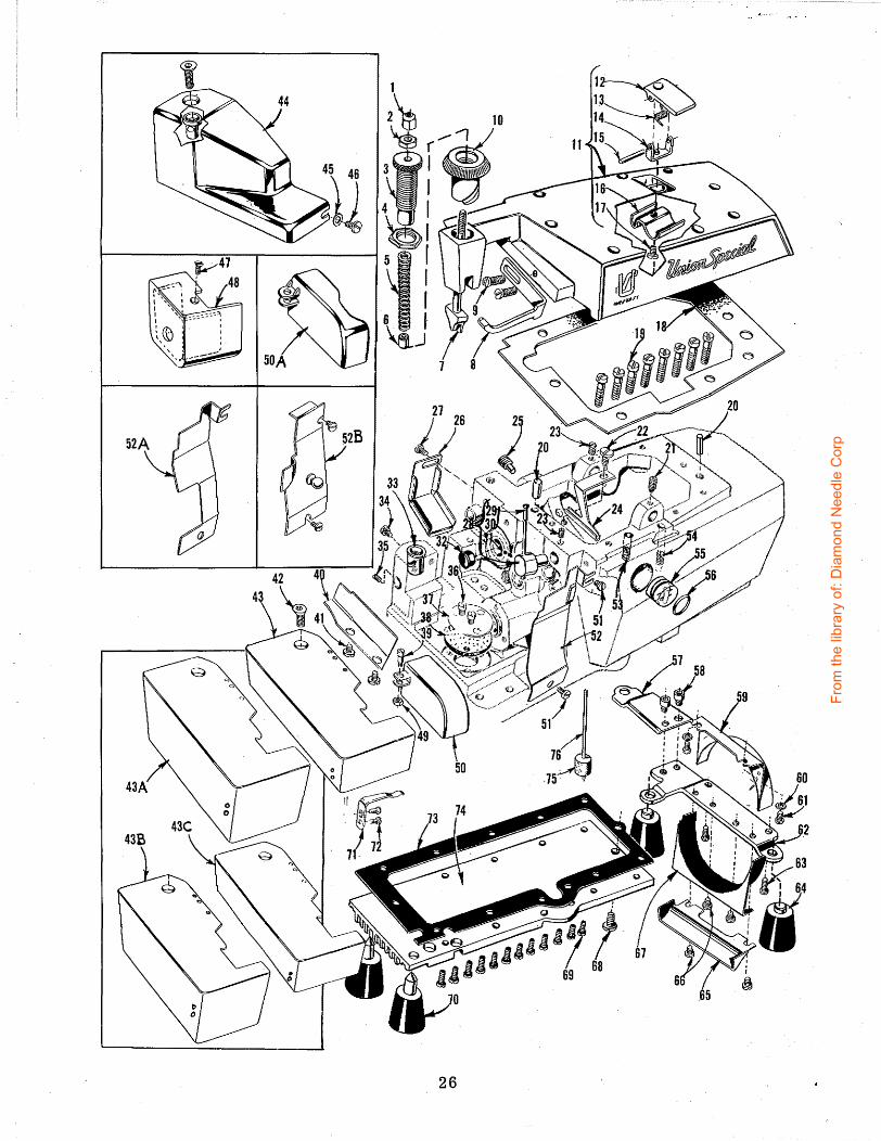
MAIN FRAME, PRESSER FOOT RELEASE PARTS, MISCELLANEOUS COVERS AND PLATES
Part No.
39557 B 39557 E 39557 c 39557 F 39557 4355-7 39557 A 39563 F
39563 T
22569 B 39556 A 39582 AD 39582 AJ 39582 AF 39582 V 39582 AG
51-103 Blk. 39582 w 22562 A 39582 AE 22541
667 D-8 22565 s 22569 D 22565
39594 R 22571 E 39534 R
90 29477 GW 39568 G 39568 J 22743
51-405 Blk. 39501 K 22569 22565 F 22569 B 39594 G 39594 H
86 X
39578 F
39578 FA 138
22657 D-12
Amt. Description Req.
Presser Spring Plunger Cap Nut ------------------ 1 Presser Spring Plunger Locking Nut -------------- 1 Presser Spring Plunger Adjusting Screw----------- 1 Lock Nut. for adjusting screw -------------------- 1 Presser Spring---------------------------------- 1 Presser Spring Spacer. for Style 39500 TY -------- 1 Presser Spring Plunger-------------------------- 1 Top Cover Needle Thread Eyelet, for all Styles
except 39500 QJ, QL, QV, SJ ------------------- 1 Top Cover Needle Thread Eyelet, for Style
39500 QV----------------------~--------------- 1 Screw, for top cover needle thread eyelet---------- 2 Presser Foot Release Bushing-------------------- 1 Top Cover, for all Styles except 39500 TY --------- 1 Top Cover, for Style 39500 TY --------- ---------- 1
Oil Filler Cover----------------------------- 1 Spring-------------------------------------- 1 Hinge Bracket ------------------------------ 1 Hinge Pin ---------------------------------- 1 Oil Guard ---------------------------------- 1 Screw, for hinge bracket--------------------- 1
Top Cover Gasket ------------------------------- 1 Screw, for top cover ---------------------------- 8 Dowel Pin -------------------------------------- 2 Spot Screw, for upper looper drive lever shaft ----- 1 Screw, for oil collector plate--------------------- 1 Set Screw, for upper looper thread tube assembly
and for upper looper drive lever shaft------------ 2 Oil Collector Plate ------------------------------ 1 Magnetic Oil Drain Plug Screw ------------------- 1 Feed Bar Oil Shield------------------------------ 1 Screw, for feed bar oil shield -------------------- 1 Upper Looper Thread Tube Assembly ------------- 1
Thread Tube-------------------------------- 1 Thread Tube Tension Spring------------------ 1 Set Screw, for thread tube tension spring------ 1
Plug, for bed on Style 39500 TY ------------------ 1 Cloth Plate Stud--------------------------------- 1 Screw. for cloth plate stud --------------~-------- 1 Screw. for feed adjusting pin --------------------- 1 Screw, for oil filter screen and strainer----------- 2 Oil Filter Screen-------------------------------- 1 Oil Strainer, felt------------------·------------- 1 Screw, for feed mechanism cover on all Styles
except 39500 TG ------------------------------- 1 Cloth Plate Fabric Guard, for all Styles except
39500 TG, TY---------------------------------- 1 Cloth Plate Fabric Guard. for Style 39500 TY ------ 1 Screw, for cloth plate fabric guard on all Styles
except 39500 TG ------------------------------- 2 Screw, for cloth plate --------------------------- f
43 thru 76 See following page
25
From
the
libra
ry o
f: D
iam
ond
Nee
dle
Cor
p
26
From
the
libra
ry o
f: D
iam
ond
Nee
dle
Cor
p
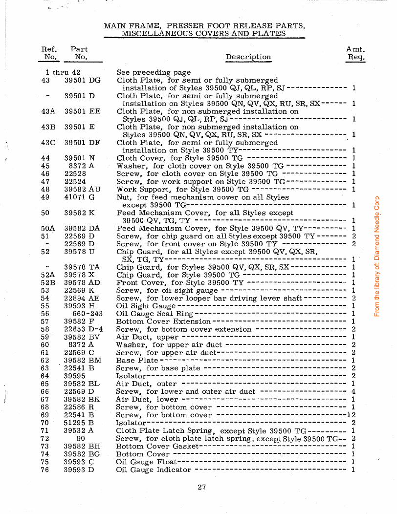
Ref. Part No. No.
· 1 thru 42 43 39501 DG
39501 D
43A 39501 EE
43B 39501 E
43C 39501 DF
44 39501 N 45 8372 A 46 22528 47 22524 48 39582 AU 49 41071 G
50 39582 K
50 A 39582 DA 51 22569 D
22569 D 52 39578 u
39578 TA 52A 39578 X 52B 39578 AD 53 22569 K 54 22894 AE 55 39593 H 56 660-243 57 39582 F 58 22653 D-4 59 39582 BV 60 8372 A 61 22569 c 62 39582 BM 63 22541 B 64 39595 65 39582 BL 66 22569 D 67 39582 BK 68 22586 R 69 22541 B 70 51295 B 71 39532 A 72 90 73 39582 BH 74 39582 BG 75 39593 c 76 39593 D
MAIN FRAME, PRESSER FOOT RELEASE PARTS, MISCELLANEOUS COVERS AND PLATES
Description
See preceding page Cloth Plate, for semi or fully submerged
Amt. Req.
installation of Styles 39500 QJ, QL, RP, SJ -------------- 1 Cloth Plate, for semi or fully submerged
installation on Styles 39500 QN, QV, QX, RU, SR, SX------ 1 Cloth Plate, for non submerged installation on
Styles· 39500 QJ, QL, RP, SJ--------------------------- 1 Cloth Plate, for non submerged installation on
Styles 39500 QN, QV, QX, RU, SR, SX ------------------- 1 Cloth Plate, for semi or fully submerged ·
installation on Style 39500 TY------------------------- 1 Cloth Cover, for Style 39500 TG ----------------------- 1 Washer .. for cloth cover on Style 39500 TG -------------- 1 Screw, for cloth cover on Style 39500 TG --------------- 1 Screw, for work support on Style 39500 TG-------------- 1 Work Support, for Style 39500 TG ---------------------- 1 Nut, for feed mechanism cover on all Styles
except 39500 TG------------------------------------- 1 Feed Mechanism Cover, for all Styles except
39500 QV, TG, TY ----------------------------------- 1 Feed Mechanism Cover, for Style 39500 QV, TY---------- 1 Screw, for chip guard on all Styles except 39500 TY ------- 2 Screw, for front cover on Style 39500 TY --------------- 2 Chip Guard, for all Styles except 39500 QV, QX, SR,
SX, TG, TY------------------------------------------ 1 -Chip Guard, for Styles 39500 QV, QX, SR, SX------------- 1 Chip Guard, for Style 39500 TG ------------------------ 1 Front Cover, for Style 39500 TY ----------------------- 1 Screw, for oil sight gauge----------------------------- 1 Screw, for lower looper bar driving lever shaft---------- 2 Oil Sight Gauge--------------------------------------- 1 Oil Gauge Seal Ring----------------------------------- 1 Bottom Cover Extension------------------------------- 1 Screw, for bottom cover extension --------------------- 2 Air Duct, upper -------------------------------------- 1 Washer, for upper air duct ---------------------------- 2 Screw, for upper air duct------------------------------ 2 Base Plate------------------------------------------- 1 Screw, for base plate --------------------------------- 2 Isolator---------------------------------------------- 2 Air Duct, outer -------------------------------------- 1 Screw, for lower and outer air duct -------------------- 4 Air Duct, lower -------------------------------------- 1 Screw, for bottom cover ------------------------------ 1 Screw, for bottom cover ------------------------------12 Isolator---------------------------------------------- 2 Cloth Plate Latch Spring; except Style 39500 TG --------- 1 Screw, for cloth plate latch spring, exceR_tStyle 39500 TG-- 2 Bottom Cover Gasket---------------------------------- 1 Bottom Cover ---------------------------------------- 1 Oil Gauge Float--------------------------------------- 1 Oil Gauge Indicator ----------------------------------- 1
27
From
the
libra
ry o
f: D
iam
ond
Nee
dle
Cor
p

A-NEEDLE DRIVE BEARING B-UPPER LOOPER DRIVE BEARING C-UPPER KNIFE DRIVE BEARING D-LOWER LOOPER DRIVE BEARING
28
From
the
libra
ry o
f: D
iam
ond
Nee
dle
Cor
p
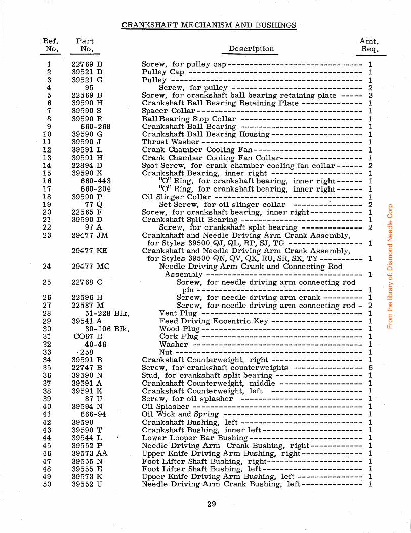
Ref. No.
1 2 3 4 5 6 7 8 9
10 11 12 13 14 15 16 17 18 19 20 21 22 23
24
25
26 27 28 29 30 31 32 33 34 35 36 37 38 39 40 41 42 43 44 45 46 47 48 49 50
CRANKSHAFT MECHANISM AND BUSHINGS
Part No.
22769 B 39521 D 39521 G
95 22569 B 39590 H 39590 s 39590 R
660-268 39590 G 39590 J 39591 L 39591 H 22894 D 39590 X
660-443 660-204
39590 p 77 Q
22565 F 39590 D
97 A 29477 JM
29477 KE
29477 MC
22768 c
22596 H 22587 M
51-228 Blk. 39541 A
30-106 Blk. C067 E
40-46 ·258
39591 B 22747 B 39590 N 39591 A 39591 K
87 u 39594 N
666-94 39590 39590 T 39544 L 39552 p 39573 AA 39555 N 39555 E 39573 K 39552 u
Amt. Description Req.
Screw, for pulley cap------------------------~------ 1 Pulley Cap ---------------------------------------- 1 Pulley ------------------------------------------~- 1
Screw, for pulley ------------------------------ 2 Screw, for crankshaft ball bearing retaining plate ----- 3 Crankshaft Ball Bearing Retaining Plate-------------- 1 Spacer Collar-----~-------------------------------- 1 BallBearing Stop Collar ---------------------------- 1 Crankshaft Ball Bearing ---------------------------- 1 Crankshaft Ball Bearing Housing--------------------- 1 Thrust Washer------------------------------------- 1 Crank Chamber Cooling Fan------------------------- 1 Crank Chamber Cooling Fan Collar------------------- 1 Spot Screw, for crank chamber cooling fan collar------ 2 Crankshaft Bearing, inner right --------------------- 1
"Ou Ring, for crankshaft bearing, inner right------ 1 "011 Ring, for crankshaft bearing, inner right------ 1
Oil Slinger Collar --- .... ------------------------------ 1 Set Screw, for oil slinger collar ________ ..:, _______ 2
Screw, for crankshaft bearing, inner right------------ 1 Crankshaft Split Bearing ---------------------------- 1
Screw, for crankshaft split beari.rig -------------- 2 Crankshaft and Needle Driving Arm Crank Assembly,
for Styles 39500 QJ, QL, RP, SJ, TG ----------------- 1 Crankshaft and Needle Driving Arm Crank-Assembly,
for Styles 39500 QN, QV, QX, RU, SR, SX, TY ---------- 1 Needle Driving Arm Crank and Connecting Rod
Assembly ------------------------------------ 1 Screw, for needle driving arm connecting rod
pin --------------------~---- ------------- 1 Screw, for needle driving arm crank --------- 1 Screw, for needle driving arm connecting rod- 2
Vent Plug ------------------------------------- 1 Feed Driving Eccentric Key --------------------- 1 Wood Plug------------------------------------- 1 Cork Plug ------------------------------------- 1 VVasher --------------------------------------- 1 Nut ------------------------------------------- 1
Crankshaft Counterweight, right --------------------- 1 Screw, for crankshaft counterweights ---------------- 6 Stud, for crankshaft split bearing -------------------- 1 Crankshaft Counterweight, middle ------------------- 1 Crankshaft Counterweight, left --------------------- 1 Screw, for oil splasher ---------------------------- 1 · Oil Splasher --------------------------------------- 1 Oil Wick and Spring -------------------------------- 1 Crankshaft Bushing, left---------------------------- 1 Crankshaft Bushing, inner left----------------------- 1 Lower Looper Bar Bushing-------------------------- 1 Needle Driving Arm Crank Bushing, right------------ 1 Upper Knife Driving Arm Bushing, right-------------- 1 Foot Lifter Shaft Bushing, right---------------------- 1 Foot Lifter Shaft Bushing, left----------------------- 1 Upper Knife Driving Arm Bushing, left---------------: 1 Needle Driving Arm Crank Bushing, left-------------- 1
29
From
the
libra
ry o
f: D
iam
ond
Nee
dle
Cor
p

30
From
the
libra
ry o
f: D
iam
ond
Nee
dle
Cor
p

Ref. Part No. No.
1 39536 E 2 39535 c 3 22565 F 4 39578 p
39578 AE 4A 39578 z 5 8372 A 6 22569 B 7 87 8 39578 M
39578 R 39578 s 39578 AC
9 22585 A 10 39578 y 11 22541 A
11A 22569 B 12 53634 c
12A 8372 A
13 39535 F
13A 39535 R 14 39580 H 14A 39680 15 93 A
16 39535 J 17 39534 G 17A 39534 J 18 39535 D 19 22569 B 20 53634 c 21 39536 B 22 39534 H 22A 39534 K 23 22569 G 24 39538 25 39536 D 26 27 28 22528 29 22 KH
22768 B
30 39536 c 31 39536 AE 32 thru 53A
NEEDLE DRIVE AND FEED MECHANISM
Amt. Description Req.
Nut, for feed bar driving stud------------------------- 1 Feed Adjusting Pin ---------------------------------- 1 Spot Screw, for feed adjusting pin--------------------- 1 Fabric Guard Mounting Bracket, for all Styles except
39500 TG, TY ------------------------------------- 1 Fabric Guard Mounting B-racket, for Style 39500 TY----- 1: Fabric Guard Mounting Bracket, for Style 39500 TG----- 1 Washer, for fabric guard mounting bracket ------------ 2 Screw, for fabric guard mounting bracket-------------- 2 Screw., for fabric guard on all Styles except 39500 TG --- 2 Fabric Guard., for Styles 39500 QJ, QL, RU, SJ -------- 1 Fabric Guard, for Styles 39500 QN, QV, RP ----------- 1 Fabric Guard, for Styles 39500 QX, SR, SX ------------ 1 Fabric Guard, for Style 39500 TY --------------------- 1 Screw, for fabric guard on Style 39500 TG ------------- 2 Fabric Guard, for Style 39500 TG --------------------- 1 Screw, for feed bar guide, left, on all Styles except
39500 TY------------------------------------------ 2 Screw, for feed bar guide, left, on Style 39500 TY ----.-- 2 Wash er, for main feed bar guide, left, on all Styles
except 39500 TY ----------------------------------- 2 Was her, for main feed bar .guide, left, on Style
39500 TY------------------------------------------ 2 Feed Bar Guide, left, for all Styles except 39500 QV,
TY ----------~-------------------------~---------- 1 Feed Bar Guide, left, for Styles 39500 QV, TY -----~--- 1 Throat Plate Support Stop, for Style 39500 QV---------- 1 Throat Plate Support Stop., for Style 39500 TY ---------- 1 Screw, for throat plate support stop on Styles 39500 QV,
TY -----------~----------------------------------- 1 Feed Bar Guide Block------------------------------- 1 Main Feed Bar, for all Styles except 39500 TG --------- 1 Main Feed Bar, for Style 39500 TG ------------------- 1 Feed Bar Guide, right ------------------------------- 1 Screw, for feed bar guide, right-------------------.--- 2 Washer, for feed 1bar guide, right--------------------- 2 Feed Bar Driving Stud ----------------------...;--------- 1 Feed Bar Thrust Washer, for all Styles except 39500 TG- 1 Feed Bar Thrust Washer, for Style 39500 TG ---------- 1 Screw, for feed bar thrust washer -------------------- 3 Feed Lift Block ----------------:..-------------------- 1 Feed Bar Spacer ------------------------------------ 1 Chaining Feed Dog (See Pages 43, 45) -------:---------- 1 Main Feed Dog (See Pages 43, 45)--------------------- 1 Screw, for main feed dog----------------------------- 1 Screw, for chaining feed dog on Styles 39500 QN, QV, QX,SR,SX~---------------------------------------- 1
Screw, for chaining feed dog for all Styles except 39500 QN, QV, QX, SR, SX, TG, TY -------------------- 1
Feed Bar Driving Connection Bushing------------------ 1 Feed Bar Driving Connection ------------------------- 1 See following page
31
From
the
libra
ry o
f: D
iam
ond
Nee
dle
Cor
p

32
From
the
libra
ry o
f: D
iam
ond
Nee
dle
Cor
p
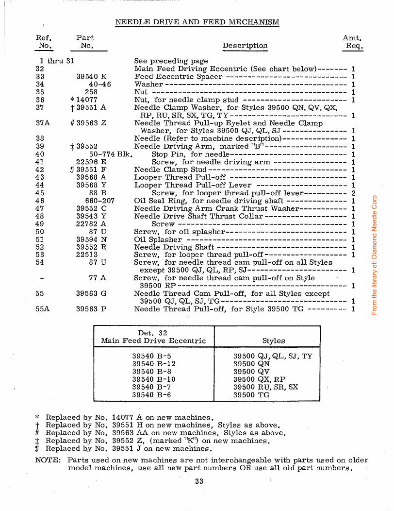
Refo No.
Part No.
NEEDLE DRIVE AND FEED MECHANISM
Amt. Description Req.
1 thru 31 32
See preceding page Main Feed Driving Eccentric (See chart below)------- 1 Feed Eccentric Spacer ---------------------------- 1 33
34 35 36 37
37A
38 39 40 41 42 43 44 45 46 47 48 49 50 51 52 53 54
55
55A
39540 K 40-46
258 * 14077 t 39551 A
# 39563 z
VVasher------------------------------------------ 1 Nut --------------------------------------------- 1 Nut, for needle clamp stud -------------...L---------- 1 Needle Clamp VVasher, for Styles 39500 QN, QV, QX,
RP, RU, SR, SX, TG, TY --------------------------- 1 Needle Thread Pull-up Eyelet and Needle Clamp · VVasher, for Styles 39500 QJ, QL, SJ --------------- 1 Needle (Refer to machine description)--------------- 1
t 39552 Needle DriVing Arm, marked "B" -------------------- 1 50-774 Blk. Stop Pin, for needle--------------------------- 1
22596 E Screw, for needle driving arm ----------------- 1 S 39551 F Needle Clamp Stud------------------------·-------- 1
39568 A Looper Thread Pull-off --------------------------- 1 39568 Y Looper Thread Pull-off Lever --------------------- 1
88 B Screw, for looper thread pull-off lever---------- 2 660-207 Oil Seal Ring, for needle driving shaft ___ ..; ________ -- 1
39552 C Needle Driving Arm Crank Thrust VVasher----------- 1 39543 Y Needle Drive Shaft Thrust Collar------------------- 1 22782 A Screw --------------------------------------- 1
87 U. Screw, for oil splasher---------------------------- 1 39594 N OilSplasher ------------------------------------- 1 39552 R Needle Driving Shaft------------------------------ 1 22513 .Screw, for looper thread pull-off------------------- 1
87 U Screw, for needle thread cam pull-off on all Styles
77 A
39563 G
39563 p
except 39500 QJ, QL, RP, SJ----------------------- 1 Screw, for needle thread cam pull-off on Style
39500 RP--------------------------------------- 1 Needle Thread Cam Pull-off, for all Styles except
39500 QJ, QL, SJ, TG ----------------------------- 1 Needle Thread Pull-off, for Style 39500 TG --------- 1
Det. 32 Main Feed Drive Eccentric Styles
39540 B-5 39500 QJ, QLJI SJ, TY 39540 B-12 39500 QN 39540 B-8 39500 QV 39540 B-10 39500 QX, RP 39540 B-7. 39500 RU, SR, SX 39540 B-6 . 39500 TG
~.c Replaced by No. 14077 A on new machines. t Replaced by No. 39551 H on new machines, Styles as above. # Replaced by No. 39563 AA on new machines, Styles as above. :t Replaced by No. 39552 Z, (marked "K'~ on new machines. S Replaced by No. 39551 J on new machines.
NOTE: Parts used on new machines are not interchangeable with parts used on older model machines, use all new part numbers OR use all old part numbers.
33
From
the
libra
ry o
f: D
iam
ond
Nee
dle
Cor
p

f I I
44~L TORQUET~-19-21 .
34
(22 -24 m. lbs. cm. kg.)
-, I I I I I
____ I
From
the
libra
ry o
f: D
iam
ond
Nee
dle
Cor
p

Ref. No.
1 2
3 4 5 6 7 7A 8
* 9 *10
11 12 13 14 15 16 . 17 18 19 20 21 22 23 24 25 26 27 28 29 30 31 32 33 34 35 36 37 38 39 39A 40 41 42 43 44
45 46 47 48 49 50 51
Part· No.
39560 A 39508 A
39508 E 39543 22564 G 39543 A
77 22565 H
1025 L 39543 T 39543 s 39543 K 22503 F 39543 E
97 39544 J
482 c 22894 c 22565 39543 X 22565 s 39543 w 39543 M 22562 A 39543 p 39543 u 22729 D
87 u 39594 N
666-255 77
39544 B 39544 D
77 22894 AE
482 c 22894 c
660-206 39544 V 39560 B 39508 B 39508 D 39151 39544 39594 N
87 u 29126 DF
22729 E 39544 N 39544 s
97 22729 D
666-255 39544 u
UPPER AND LOWER LOOPER DRIVING PARTS
Amt. Description Req.
Upper Spreader, for Styles 39500 QJ, SJ _________________ .__ 1 Upper Looper, marked "CC", for all Styles except
39500 QJ,SJ,TY-------------------~-------------------- 1 Upper Looper, marked "CK" .. for Style 39500 TY ----------- 1 Upper Looper Holder ------------------------------------ 1
Screw, for upper looper ----------------------------- 1 Upper Looper Holder Collar-----.:.------------------------ 1
Screw, for upper lo,oper holder collar _ ..... _______________ 1
Spot Screw, for bushing! and cam guide -------------------- 1 Lock Screw, for bushing and cam guide screw-------------- 1 Cam Follower---.----------.------------------------------ 1 Bushing and Cam Guide ---------------------------------- 1 Upper Looper Drive Shaft-------------------------------- 1
Screw, .for cam follower locking clamp -----------~---- 1 Cam Follower Locking Clamp------------------------- 1
Screw, for ball joint guide fork --------------------------- 2 Ball Joint Guide Fork, for upper looper drive lever--------- 1 Upper Looper Shaft Collar ------------------------------- 1
Set Screw, for upper looper rock shaft collar ---------- 2 Set Screw, for upper looper drive lever shaft--------------- 1 Upper Looper Drive Lever Shaft -------------------------- 1 Spot Screw, for upper looper drive lever shaft ------------- 1 Upper Looper Drive Lever ------------------------------- 1 Clamp Collar, for upper looper drive shaft ---------------- i
Screw, for clamp collar ----------------------------- 1 Upper Looper Drive Shaft Thrust Washer -----------------:-- 2 Upper Looper Drive Lever Connecting Rod----------------- 1
Screw, for upper looper drive lever connecting rod ----- 4 Screw, for oil splasher ---------------------------------- 1 Oil Splasher -------------------------------------------- 1 Felt, for connecting rod---------------------------------- 1 Screw, for lower looper bar connecting link pin------------- 1 Lower Looper Bar Connecting Link ----------------------- 1 Lower Looper Bar Connecting Link Pin-------------------- 2 Screw, for lower looper bar connecting link pin------------- 1 Set Screw, for lower looper driving shaft ------------------ 2 Lower Looper Driving Shaft Collar------------------------ 1
Set Screw, for lower looper driving shaft collar -------- 2 110" Ring, for lower looper driving shaft------------------- 1 Lower Looper Driving Shaft ----------------------------.-- 1 Lower Spreader, for Style 39500 TG----------------------- 1 Lower Looper, for all Styles except 39500 TG, TY --------- 1 Lower Looper, for Style 39500 TY ------------------------ 1 Nut, for lower looper bar -----------------------------~-- 1 Lower LooperBar -------------------------------------- 1 Oil Splasher -------------------------------------------- 1 Screw, for oil splasher. ---------------------------------- 1 Lower Looper Bar Driving Lever and Connecting Rod
Assembly -------------~------------------------------- 1 Screw, for connecting rod---------------------------- 2 Lower Looper Drive Lever Connecting Rod------------- 1 Ball Joint Guide Fork-------------------------------- 1 Screw, for ball jo:l.nt guide fork ----------------------- 2 Screw, for connecting rod---------------------------- 2 Felt., for connecting rod ----------------------------- 1 Lower Looper Bar Driving Lever --------------------- 1
),'< The use of assembly No. 29126 EC is recommended instead of the individual parts.
35
From
the
libra
ry o
f: D
iam
ond
Nee
dle
Cor
p

36
From
the
libra
ry o
f: D
iam
ond
Nee
dle
Cor
p
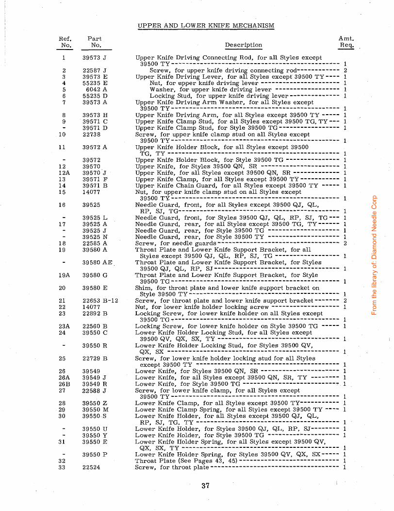
Ref. No.
1
2 3 4 5 6 7
8 9
10
11
12 12A 13 14 15
16
17
18 19
19A
20
21 22 23
23A 24
25
26 26A 26B 27
28 29 30
31
32 33
Part No.
39573 J
22587 J 39573 E 55235 E
6042 A 55235 D 39573 A
39573 H 39571 c 39571 D 22738
39572 A
39572 39570 39570.J 39571 F 39571 B 14077
39525
39525 L 39525 A 39525 J 39525 N 22585 A 39580 A
39580 AE.
39580 G
39580 E
22653 B-12 14077 22892 B
22560 B 39550 c
39550 R
22729 B
39549 39549 J 39549 R 22588 J
39550 z 39550 M 3955o.s
39550 u 39550 y 39550 E
39550 p
22524
UPPER AND LOWER KNIFE MECHANISM
Amt. Description Req.
Upper Knife Driving Connecting Rod, for all Styles except 39500 TY----------------------------------------------- 1
Screw, for upper knife driving connecting rod------------ 2 Upper Knife Driving Lever. for all Styles except 39500 TY ---- 1
Nut, for upper knife driving lever---------------------- 1 Washer, for upper knife driving lever ------------------ 1 Locking Stud, for upper knife driving lever-------------- 1
Upper Knife Driving Arm Washer, for all Styles except 39500 TY----------------------------------------------- 1
Upper Knife Driving Arm, for all Styles except 39500 TY ----- 1 Upper Knife Clamp Stud, for all Styles except 39500 TG, TY --- 1 Upper Knife Clamp Stud, for Style 39500 TG ----------------- 1 Screw. for upper knife clamp stud on all Styles except
39500 TY----------------------------------------------- 1 Upper Knife Holder Block, for all Styles except 39500
TG. TY------------------------------------------------ 1 Upper Knife Holder Block, for Style 39500 TG --------------- 1 Upper Knife, for Styles 39500 QN, SR ---------------------- 1 Upper Knife, for all Styles except 39500 QN, SR ------------- 1 Upper Knife Clamp, for all Styles except 39500 TY ----------- 1 Upper Knife Chain Guard, for all Styles except 39500 TY ----- 1 Nut, for upper knife clamp stud on all Styles except
39500 T~----------------------------------------------- 1 Needle Guard, front, for all Styles except 39500 QJ, QL,
RP, SJ, TG--------------------------------------------- 1 Needle Guard, front, for Styles 39500 QJ, QL. RP, SJ, TG --- 1 Needle Guard. rear, for all Styles except 39500 TG, TY ------ 1 Needle Guard, rear, for Style 39500 TG -------------------- 1 Needle Guard, rear, for Style 39500 TY -------------------- 1 Screw. for needle guards---------------------------------- 2 Throat Plate and Lower Knife Support Bracket, for all
Styles except 39500 QJ, QL, RP. SJ, TG ------------------ 1 Throat Plate and Lower Knife Support Bracket, for Styles
39500 QJ, QL, RP, SJ ----------------------------------- 1 Throat Plate and Lower Knife Support Bracket, for Style
39500 TG ------------------------------.----------------- 1 Shim, for throat plate and lower knife support bracket on
Style 39500 TY -------------------------.----------------- 1 Screw. for throat plate and lower knife support bracket------- 2 Nut, for lower knife holder locking screw ------------------- 1 Locking Screw, for lower knife holder on all Styles except
39500 TG 1---------------------------------------------- 1 Locking Screw, for lower knife holder on Style 39500 TG ----- 1 Lower Knife Holder Locking Stud, for all Styles except
39500 QV, QX, SX, TY ---------------------------------- 1 Lower Knife Holder Locking Stud, for Styles 39500 QV.
QX, SX ------------------------------------------------ 1 Screw, for lower knife holder locking stud for all Styles
except 39500 TY ~--------------------------------------- 1 Lower Knife, for Styles 39500 QN, SR ---------------------- 1 Lower Knife .. for all Styles except 39500 QN, SR, TY -------- 1 Lower Knife, for Style 39500 TG --------------------------~. 1 Screw, for lower knife clamp, for all Styles except
39500 TY ----------------------------------------------- 1 Lower Knife Clamp, for all Styles except 39500 TY----------- 1 Lower Knife Clamp Spring, for all Styles except 39500 TY ---- 1 Lower Knife Holder, for all Styles except 39500 QJ. QL,
RP, SJ, TG, TY ---------------------------------------- 1 Lower Knife Holder, for Styles 39500 QJ, QL, RP. SJ-------- 1 Lower Knife Holder, for Style 39500 TG _________ ,_ __________ 1 Lower Knife Holder Spring. for all Styles except 39500·Qv,
QX SX TY -------------------------------------------- 1 Low~r K~ife Holder Spring, for Styles 39500 QV. QX, SX----- 1 Throat Plate (See Pages 43, 45) ---------------------------- ~ Screw, for throat plate------------------------------------ 1
37
From
the
libra
ry o
f: D
iam
ond
Nee
dle
Cor
p
38
From
the
libra
ry o
f: D
iam
ond
Nee
dle
Cor
p
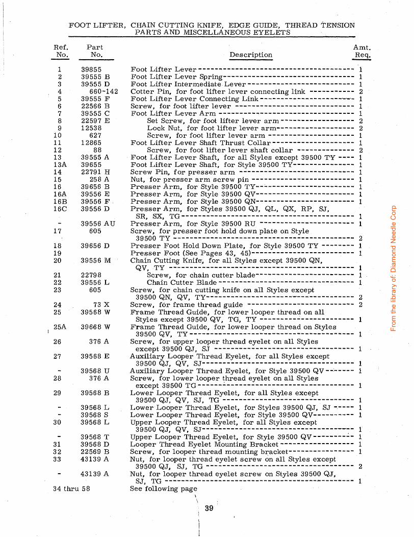
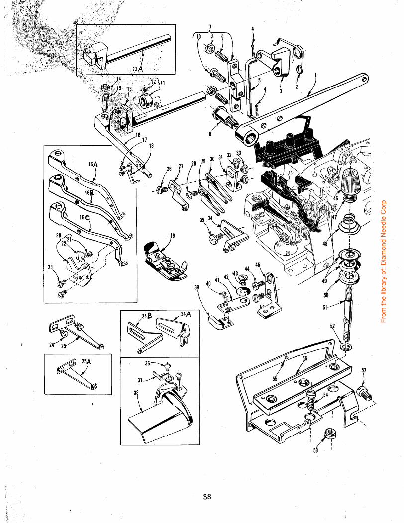
FOOT LIFTER,
Ref. Part No. No.
1 39855 2 39555 B 3 39555 D 4 660-142 5 39555 F 6 22566 B 7 39555 c 8 22597 E 9 12538
10 627 11 12865 12 88 13 39555 A 13A 39655 14 22791 H 15 258 A 16 39656 B 16A 39556 E 16B 39556 F-16C 39556 D
39556 AU 17 605
18 39656 D 19 20 39556 M
21 22798 22 39556 L 23 605
24 73 X 25 39568 w
25A 39668 w
26 376 A
27 39568 E
39568 u 28 376 A
29 39568 B
39568 L 39568 s
30 39568 L
39568 T 31 39568 D 32 22569 B 33 43139 A
43139 A
34 thru 58
CHAIN CUTTING KNIFE, EDGE GUIDE, THREAD TENSION PARTS AND MISCELLANEOUS EYELETS
Amt. Description Req. -
Foot Lifter Lever-------------------------------------- 1 Foot Lifter Lever Spring-------------------------------- 1 Foot Lifter Intermediate Lever-------------------------- 1 Cotter Pin, for foot lifter lever connecting link ----------- 2 Foot Lifter Lever Connecting Link-------------------------- 1 Screw .. for foot lifter lever ----------------------------- 1 Foot Lifter Lever Arm--------------------------------- 1
Set Screw .. for foot lifter lever arm------------------ 2 Lock Nut, for foot lifter lever arm------------------- 2 Screw, for foot lifter lever arm --------------------- 1
Foot Lifter Lever Shaft Thrust Collar ______ .;. _____________ 1
Screw, for foot lifter lever shaft collar -------------- 2 Foot Lifter Lever Shaft, for all Styles except 39500 TY ---- 1 Foot Lifter Lever Shaft, for Style 39500 TY--------------- 1 Screw Pin, for presser arm -~-------------------------- 1 Nut, for presser arm screw pin------------------------- 1 Presser Arm, for· Style 39500 TY--:...--------------------- 1 Presser Arm, for Style 39500 QV------------------------ 1 Presser Arm, for Style 39500 QN------------------------ 1 Presser Arm, for Styles· 39500 QJ, QL, QX, RP, SJ,
SR, SX, TG------------------------------------------ 1 Presser Arm.t for Style 39500 RU ----------------------- 1 Screw, for presser foot hold down plate on Style
39500 TY -------------------------------------------- 2 Presser Foot Hold Down Plate, for Style 39500 TY -------- 1 Presser Foot {See Pages 43 45)------------------------- 1 Chai!n Cutting Knife-, for all 'styles except 39500 QN ..
QV, -TY --------------------------------------------- 1 Screw, for chain cutter blade------------------------ 1 Chain Cutter Blade--------------------------------- 1
Screw, for chain cutting knife on all Styles except 39500 QN, QV, TY------------------------------------ 2
Screw, for frame thread guide -------------------------- 2 Frame Thread Guide, for lower looper thread on all
Styles except 39500 QV, TG, TY ----------------------- 1 Frame Thread Guide.. for lower looper thread on Styles
39500 QV, TY ---------------------------------------- 1 Screw, for upper looper thread eyelet on all Styles
except 39500 QJ, SJ ---------------------------------- 1 Auxiliary Loop er Thread Eyelet, for all Styles except
39500 QJ, QV, SJ------------------------------------- 1 Auxiliary Looper Thread Eyelet, for Style 39500 QV------- 1 Screw, for lower looper thread eyelet on all Styles
except 39500 TG- -----~---- --------------------------- 1 Lower Looper Thread Eyelet, for all Styles except
39500 QJ, QV, SJ, TG -------------------------------- 1 Lower Looper Thread Eyelet, for Styles 39500 QJ .. SJ ----- 1 Lower Looper Thread Eyelet, for Style 39500 QV---------- 1 Upper Looper Thread Eyelet, for all Styles except
39500 QJ .. QV~ SJ------------------------------------- l Upper Looper Thread Eyelet, for Style 39500 Qv--------..:.- 1 Looper Thread Eyelet Mounting Bracket------------------ 1 Screw, for looper thread mounting bracket---------------- 1 Nut .. for looper thread eyelet screw on all Styles except
39500 QJ, SJ, TG ------------------------------------ 2 Nut, for looper thread eyelet screw on Styles 39500 QJ,
SJ, TG ---------------------------------------------- 1 See following page
\
39.
From
the
libra
ry o
f: D
iam
ond
Nee
dle
Cor
p
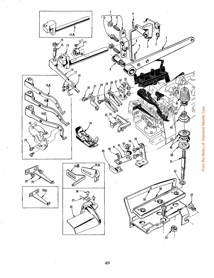
19 35~
44 45
40
From
the
libra
ry o
f: D
iam
ond
Nee
dle
Cor
p

FOOT LIFTER, CHAIN CUTTING KNIFE, EDGE GUIDE, THREAD TENSION PARTS AND MISCELLANEOUS EYELETS
Ref. No.
Part No.
1 thru 33 34 39563 H
39563 u 34A 39563 N 34B 39563 D 35 22569 D 36 22848 37 39503 N 38 23199 D 39 39503 A
40 604 41 39503 D
42 12957 E 43 22758 E 44 22569 c 45 39503 c
39503 M 46 39592 AA
39592 AB
39592 AC
.47 39592 AK 39592 AK
48 39592 AR-4
39592 AR-5 39592 AR-8 39592 AR-2 39592 AR-4 39592 AR-5 39592 AR-8
39592 AR-1 39592 AR-2 39592 AR-4 39592 AR-4
. 39592 AR-8 49 39592 AD
39592 AD 50 39592 AF
39592 AF 51 39592 AL
39592 AL 52 8372 A
8372 A 53 39592 AH
39592 AH 54 22806 A 55 39592 AG-3 56 39592 AM 57 22847 B
Amt. Description Req.
See preceding page Needle Thread Eyelet, for all Styles except 39500 QJ. QL,
QV,SJ,TG --------------------------------------------------- 1 Needle Thread Eyelet, for Style 39500 QV ------------------------ 1 Needle Thread Eyelet, for Style 39500 TG ------------------------ 1
. Needle Thread Eyelet,, for Styles 39500 QJ, QL, SJ --------------- 1 Screw, for needle thread eyelet ---------------------.;.----------- 1 Screw, for edge guide and folder on Style 39500 TY ---------------- 2 Edge Guide, for Style 39500 TY -------------------------------- 1 Folder, for Style 39500 TY-------------------------------------- 1 Edge Guide A~justable, for all Style.s except 39500 QN, QV ..
RU, TY----'-------------------------------------------------- 1 Screw, for adjustable edge guide--------------------------------- 2 Edge Guide Swinging Arm, for all Styles except 39500 QN, QV,
RU, TY------------------------------------------------------ 1 Spring Washer, for edge guide swinging arm---------------------- 1 Screw, for edg~ guide swinging arm ----------------------------- 1 Screw, for edge guide mounting bracket -------------------------- 2 Edge Guide Mounting Bracket, for all Styles except 39500 QN,
QV, RU, TY ------------------------------------------------- 1 Edge Guide Mounting Bracket, for Style 39500 TY ----------------- 1 Needle Tension Nut, green-------------------------------------- 1 Upper Looper Tension Nut, blue, for all Styles except
39500QJ, SJ------------------------------------------------- 1 Lower Looper Tension Nut, red, for all Styles except
39500 TG ---------------------------------------------------- 1 TensionSpringFerrule, for all Styles except 39500 QJ, SJ, TG------- 3 Tension Spring Ferrule, for Styles 39500 QJ, SJ, TG -------------- 2 Upper and Lower Thread Tension Spring, for Styles 39500 QX,
RP, RU, SR. SX---------------------------------------------- 2 Upper and Lower Thread Tension Spring, for Style 39500 QN ------- 2 Upper and Lower Thread Tension Spring, for Style 39500 TY ------- 2 Needle Thread Tension Spring, for Styles 39500 QJ, SJ ------------ 1 Needle Thread Tension Spring, for Styles 39500 QL, TG -----------. 1 Needle Thread Tension Spring, for Styles, 39500 QV, TY ----------- 1 Needle Thread Tension ·Spring, for Styles 39500 QN, QX, RP, RU, SR,SX-----~------------------------------------------------- 1
Upper Looper Thread Tension Spring, for Style 39500 QV---------- 1 Upper Looper Thread Tension Spring, for Style 39500 TG ---------- 1 Upper Looper Thread Tension Spring, for Style 39500 QL ----------· 1 Lower Looper Thread Tension Spring, for Styles 39500 QJ, QV,
SJ----------------------------------------------------------- 1 Lower Looper Thread Tension Spring. for Style 39500 QL ---------- 1 Thread Tension Disc, for all Styles except 39500 QJ, SJ, TG ------ 6 Thread Tension Disc, for Styles 39500 QJ, SJ, TG ---------------- 4 Tension Disc Felt, for all Styles except 39500 QJ, SJ, TG --------- 3 Tension Disc Felt, for Styles 39500 QJ, SJ, TG------------------- 2 Tension Post, for all Styles except 39500 QJ~ SJ~ TG-------------- 3 Tension Post, for Styles 39500 QJ~ SJ, TG ----------------------- 2 Washer, for tension post on all Styles except 39500 QJ, S,J, TG ---- 3 Washer~ for tension post on Styles 39500 QJ, SJ, TG-------~------ 2 Locating Nut, for tension post on all Styles except 39500 QJ, SJ, TG-------------------------------------------------------~-- 3
Locating Nut, for tension post on Styles 39500 QJ, SJ, TG --------- 2 Screw, for tension post mounting bracket------------------------- 1 Tension Post Mounting Bracket ---------:..----------------------- 1 Tension Post Bar----:------------------------------------------'- 1 Screw, for tension post mounting bracket ------------------------ 1
41
From
the
libra
ry o
f: D
iam
ond
Nee
dle
Cor
p
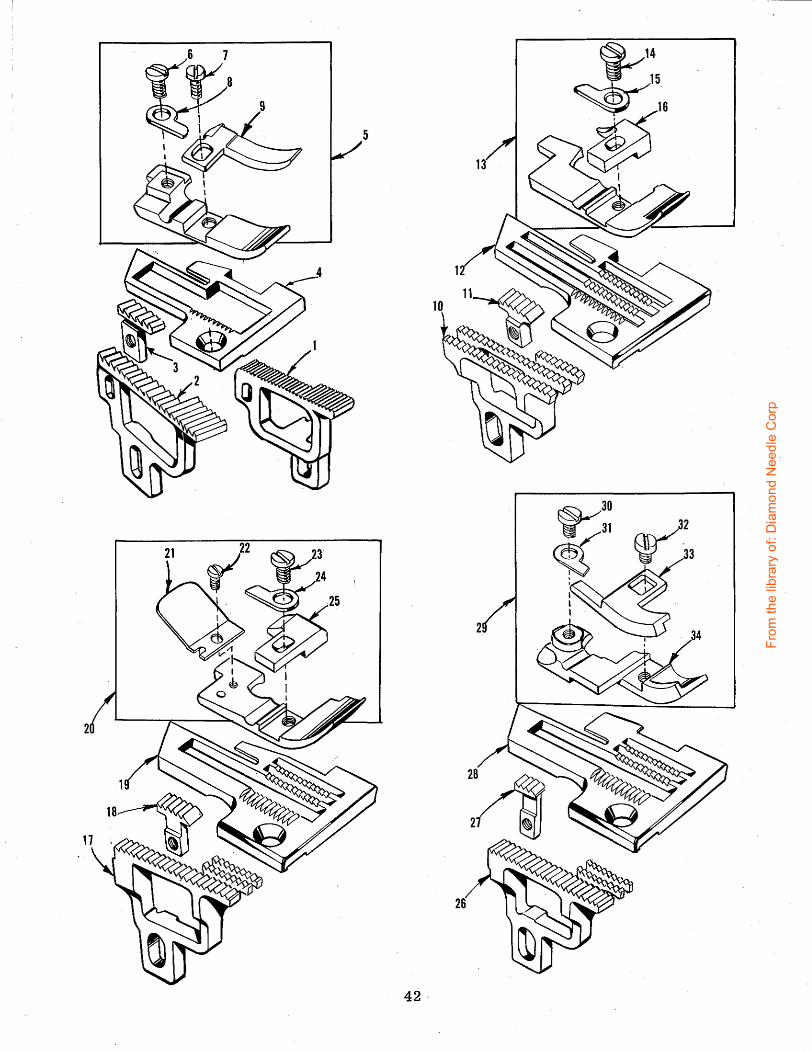
5
26
42'
From
the
libra
ry o
f: D
iam
ond
Nee
dle
Cor
p
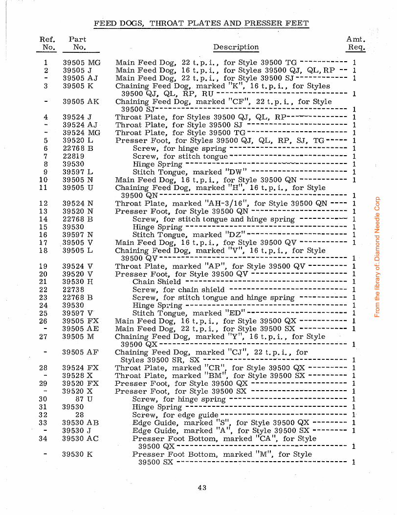
FEED DOGS, THROAT PLATES AND PRESSER FEET
Ref. No.
Part No.
1 39505 MG 2 39505 J
39505 AJ 3 39505 K
39505 AK
4 39524 J 39524 AJ · 39524 MG
5 39520 L 6 22768 B 7 22819 8 39530 9 39597 L
10 39505 N 11 39505 u
12 39524 N 13 39520 N 14 22768 B 15 39530 16 39597 N 17 . 39505 V 18 39505 L
19 39524 V 20 39520 V 21 39530 H 22 22738 23 22768 B 24 39530 25 39597 v· 26 39·505 FX
39505 AE 27 39505 M
39505 AF
28 39524 FX 39528 X
29 39520 FX 39520 X
30 87 u 31 39530 32 28 33 39530 AB
39530 ,J 34 39530 AC
39530 K
Amt. Description Req.
Main Feed Dog, 22 t. p. i., for Style 39500 TG ----------- 1 Main Feed Dog, 16 t. p. i., for Styles 39500 QJ, QL, RP -- 1 Main Feed Dog, 22 t. p. i., for Style 39500 SJ ------------ 1 Chaining Feed Dog, marked "K", 16 t. p. i., for Styles
39500 QJ, QL, RP, RU ------------------------------ 1 Chaining Feed Dog, marked "CFrr, 22 t. p. i., for Style
39500 SJ-------------------------------------------- 1 Throat Plate, for Styles 39500 QJ, QL, RP------------- 1 Throat Plate, for Style 39500 SJ ----------------------- 1 Throat Plate, for Style 39500 TG ----------------------- 1 Presser Foot, for Styles 39500 QJ, QL, RP, SJ, TG ----- 1
Screw, for hinge spring --------------------------- 1 Screw, for stitch tongue--------------------------- 1 Hinge Spring ---------------------------------------- 1 Stitch Tongue, marked uDW" ---------------------- 1
Main Feed Dog, 16 t. p. i., for Style 39500 QN ----------- 1 Chaining Feed Dog, marked "H", 16 t. p. i. , for Style
39500 QN------------------------------------------- 1 Throat Plate, marked "AH-3/16", for Style 39500 QN ---- 1 Presser Foot, for Style 39500 QN ---------------------- 1
Screw, for stitch tongue and hinge spring ---------~ 1 Hinge Spring ------------------------------------- 1 Stitch Tongue, marked 11DZ" ----------------------- 1
Main Feed Dog, 16 t. p. i., for Style 39500 QV----------- 1 Chaining Feed Dog, mark~d 11V", 16 t. p. i., for Style
395oo Qv------------------------------------------- 1 Throat Plate, marked 11AP", for Style 39500 QV--------- 1 Presser Foot, for Style 39500 QV---------------------- 1
ChainShield ------------------------------------- 1 Screw, for chain shield --------------------------- 1 Screw, for stitch tongue and hinge spring ----------- 1 Hinge Spring ------------------------------------- 1 Stitch Tongue, marked "ED" ----------------------- 1
Main Feed Dog, 16 t.p.i., for Style 39500 QX ----------- 1 Main Feed Dog, 22 t. p. i., for Style 39500 SX ----------- 1 Chaining Feed Dog, marked "Y", 16 t. p. i. , for Style ·
39500 QX------------------------------------------- 1 Chaining Feed Dog, marked "CJu, 22 t. p. i., for
Styles 39500 SR, SX --------------------------------- 1 Throat Plate, marked "CR'\ for Style 39500 QX --------- 1 Throat Plate, marked 11BM", for Style 39500 SX --------- 1 Presser Foot, for Style 39500 QX ---------------------- 1 Presser Foot, for Style 39500 SX ----------------------- 1
Screw, for hinge spring --------------------------- 1 Hinge Spring ------------------------------------- 1 Screw., for edge guide----------------------------- 1 Edge Guide, marked "S 11, for Style 39500 QX _;... ______ 1 Edge Guide, marked "A 11
, for Style 39500 SX -------- 1 Presser Foot Bottom, marked 11CA u, for Style
39500 QX--------------------------------------- 1 Presser Foot Bottom, marked "M", for Style
39500 sx --------------------------------------- 1
43
From
the
libra
ry o
f: D
iam
ond
Nee
dle
Cor
p
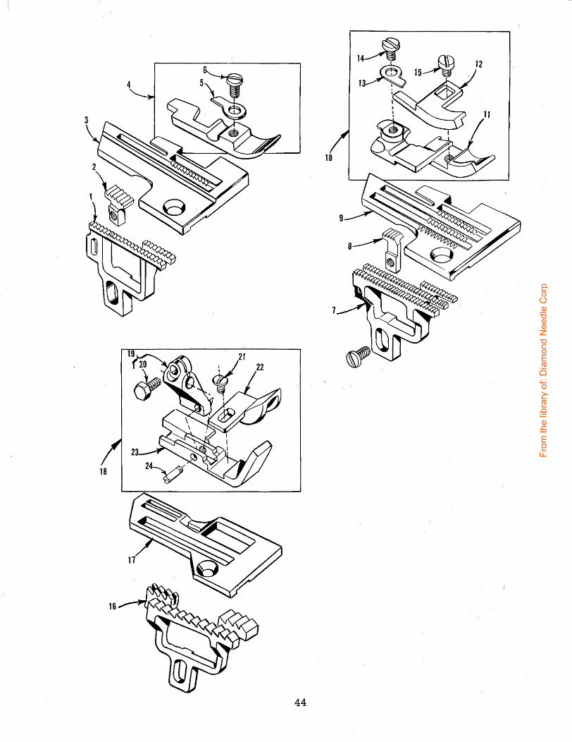
44
From
the
libra
ry o
f: D
iam
ond
Nee
dle
Cor
p

Ref. No.
1 2
3 4 5 6 7
8
9 10 11 12 13 14 15 16 17 18 19 20 21 22 23 24
FEED DOGS~ THROAT PLAT-ES AND PRESSER FEET
Part No.·
39505 AU 39505 K
39524 AU 39520 AU 39530 G 22768 B 39505 AM
39505 AF
39524 AK 39520 AJ 39530 V 39530 w 39530
87 u 28
39505 BK 39524 AZ 39520 AY 39530 y 22781
605 39530 AA 39530 z 22799 F
Amt. Description Req.
Main Feed Dog, 16 t. p. i., for Style 39500 RU ----------- 1 Chaining Feed Dog, marked "Kn ~~ 16 t. p. i. , for Styles
39500 QJ, QL~ RP~ RU ------------------------------ 1 Throat Plate, marked "BG 11
, for Style 39500 RU --------- 1 Presser Foot, for Style 39500 RU _;.. ____________________ 1
Hinge Spring ------------------------------------- 1 Screw, for hinge spring --------------------------- 1
Main Feed flog, marked "CT", 22 t. p. i., for Style 39500 SR ------------------------------------------- 1
Chaining Feed Dog, marked "CJ", 22 t. p. i. ~~ for Styles 39500 SR, SX --------------------------------------- 1
Throat Plate, marked 11BX", for Style 39500 SR --------- 1 Presser Foot, marked 11A V11~ for Style 39500 SR --------- 1
Presser Foot Bottom, marked rrAvrr ----------------- 1 Edge Guide, marked "H11
-------------------------- 1 Hinge Spring ------------------------------------- 1 Screw, for hinge spring --------------------;.. ______ 1 Screw, for edge guide----------------------------- 1
Feed Dog, 8 t. p. i., for Style 39500 TY --------------~--- 1 Throat Plate, for Style 39500 TY --------------:---------- 1 Presser Foot, for Style 39500 TY- ---------------------- 1
Presser Foot Shank, marked "K" ------------------ 1 Clamp Screw--------------------------------- 1
Screw, for cord guide------------------------------- 1 CordGuide---------------------------------------·1 Presser Foot Bottom ----------------------------- 1 Hinge Screw ------------------------------------- 1
45
From
the
libra
ry o
f: D
iam
ond
Nee
dle
Cor
p

46
From
the
libra
ry o
f: D
iam
ond
Nee
dle
Cor
p

Ref. Part No. No.
21113 F 21113 F
2 21104 V 21104 V
3 69 s 69 s
THREAD STAND AND MISCELLANEOUS TOOLS
Description Amt. Req ..
Thread Stand Eyelet, for Styles 39500 QJ,- SJ, TG---------------------------- 2 Thread Stand Eyelet, for Styles 39500 QL, QN, QV, QX, RP, RU, SR, SX, TY -- 3 Pad, for thread cone, for Styles 39500 QJ, SJ, TG --------------------------- 2 Pad, for thread cone, for Styles 39500 QL, QN, QV, QX, RP, RU, SR, SX, TY - 3 Spool Pin, for Styles 39500 QJ, SJ, TG --------------------------------,;, ____ 2
4 21130 W-2 Spool Pin, for Styles 39500 QL, QN, QV, QX, RP, RU, SR, SX, TY ----------- 3 Cone Support, for Styles 39500 QJ, SJ, TG ---------------------------------- 1 Cone Support, for Styles 39500 QL, QN, QV, QX, RP, RU, SR, SX, TY-------- 1 4A 21130 W-3
5 22650 CB-4 Screw, for thread stand eyelet --.--------------------------------------2 or 3 Screw, for cone support----------------------------------------------- 1 6 22650 CE-6
7 21104 AA Thread Stand Rod--------------------------------------------------------- 1 8 652 J-24 Washer, for thread stand rod---------------------------------------------- 1
Washer, for thread stand rod ---------------------------------------------- 1 Lock Washer, for thread stand rod ----------------------------------------- 1 Nut, for thread stand rod--------------------------------------------:------- 1
9 652 J-16 10 WA9A 11 651 A-16 12 21202 Screwdriver, 3/16 inch {4. 76 mm) diameter, 10 314 inches (273. 05 mm) long
overall (not furnished) --------------------------------------------------- 1 13 660-240 Thread Tweezers-----------------~--------------------------------------- 1 14 21227 BF Feed Eccentric Extractor Hook -------------------------------------------- 1
11Su Hook, for treadle chain------------------------------------------------ 2 15 660-264 16 421 D-34 Treadle Chain, 34 inches (863. 00 mm) long --------------------------------- 1
Socket Wrench, for 3/8 inch (9. 52 mm) nut---------------------------------- 1 17 21388AU 18
660-458 21233 HA
116
21261 M-350.
21261 M-370
21261 M-390
21377 BP 21695 u 28604 R 39598 51278 F
21371 UH
21371 PJ-48
21371 RD-48
21371 'RF-48
21371 RJ-48
21371 RL-48
21371 WL-48
21371 RC-47 314
21371 RE-47 314
21371 RH-47 314
Wrench, for 9132 inch {7. 14 mm) nut --------------------------------------- 1
Accessories Available As Extras (Not Illustrated)
Dust Cover (furnished with machine) Light Fixture Assembly, including seal beam lamp, machine mounting for machines driven by 11Electro Drive 11 which supplies the current. No. 1 11V 11 Belt, 35 inches {889. 00 mm) circumference, for fully submerged individualpower table installation. No. 1 11V 11 Belt, 37 inches (939. 80 mm) circumference, for semisubmerged individual power table installation. No. 1 11 V 11 Belt, 39 inches (990. 60 mm) circumference, for. non submerged individual power table installation. Tray, 1 314 inches (44. 45 mm) high, for semi submerged installation. Finger Protector Can of Oil, 16 fluid ounces of Spec. 174 oil (furnished with machine). Knife Grinder, complete. Chip Disposal Chute.
Individual Power Table
Table Top, 48 x 20 x 1 112 inches (1219. 20 x 508.00 x 38, 10 mm) for non-submerged power table installation, no chip chute;
Table Top, same except non-:submerged, with chip chute;
Table ~op, same except nonsubmerged, no chip chute;
Table Top, same except semisubmerged, with chip chute;
Table Top, same except semisubmerged, with chip chufe;
Table Top, same except fullysubmerged, with chip chute;
Table Top, 4 7 3 I 4 x 16 x 1 3/4 inches {1212. 85 x 406.40 x 44. 45 :rp.m) for non-submerged line shaft installation, no chip chute;
Table Top, same except nonsubmerged, with chip chute;
Table Top, same except semisubmerged, with chip chute;
Belt Slot To Right Edge
of Board
14 inch {355. 60 mm)
7 112 inch (190. 50 mm)
7 1/2 inch (190. 50 mm)
10 112 inch (266. 70 mm)
7 1/2 inch (190. 50 mm)
7 1/2 inch (190. 50 mm)
7 1/2 inch (190. 50 mm)
7 112 inch (190. 50 mm)
7 112 inch (190. 50 mm)
47
3
Cloth Plate To Front Edge
of Board
318 inch (9. 52 mm)
inch (76. 20 mm)
3/8 inch (9. 52 mm)
2 1/4 inch (57. _15 mm)
2 1 I 4 inch {57. 15 mm)
2 1/4 inch (57. 15 mm)
3/8 inch {9. 52 mm)
3 inch (76. 20 mm)
2 1/4 inch (57. 15 mm)
From
the
libra
ry o
f: D
iam
ond
Nee
dle
Cor
p

Part No,
Page No.
WA9 A., ••••••••••••• 47 22 KH •••••• , •••••• 31 28 •••••••••••••••• 43,45 30-106 Blk •••••••• 29 40-46 ••••••••••••• 29, 33 50-774 Blk •••••••• 33 51-103 Blk ........ 25 51-228 Blk •••••••• 29 51-405 Blk •••••••• 25
C067 E •••••••••••••• 29 69 s .............. 47 73 X •••••••••••••• 39 77 •••••••••••••••• 35 77 A •••••••••••••• 33 77 Q •••••••••••••• 29 86 X •••••••••••••• 25 87 ••••••••••.••••• 31 87 u .............. 29, 33, 35,
43,45 88 •••••••••••••••• 39 88 B •••.•••.••••••• 33 90 •••••••.•••••••• 25, 27 93 A •••••••••••••• 31 95 •••••••••••.•••• 29 97 .••••••••••••••• 35 97 A •••••••••••••• 29
116 •••••••••••••••• 47 138 •••••••••••••••• 25 258 •••••••••••••••• 29,33 258 A ............... 39 376A ••••••••••• · ••• 39 421 D-34 •••••••••• , 47 482 c ••••••••.••••• 35 604 ••• · ••••••••••••• 41 605 •••••••••••••••• 39,45 627 •••••••••••••••• 39 651 A-16 ••••••••••• 47 652 J-16 ••••••..••• 47 652 J-24 .•••••••••• 47 660-142 •••••••••••• 39 660-204 •••••••.•••• 29 660-206 •••••••••••• 35 660-207 ••••••.••••• 33 660-240 ••••• : •••••• 47 660-243 •••••••••••• 27 660-264 •••••••••••• 47 660-268 •••••••••••• 29 660-443 •••••••••••• 29 660-458 •••••••••••• 47 666-94 ••..••••••••• 29 666-255 •••••••••••• 35 667 D-8 ••. , •••• , ••• 25
1025L •••••••••••••• 35 6042 A •••••••••••••• 37 8372 A •••••••••••••• 27, 31, 41
12538 •••••••••••••••• 39 12865 •••••••••••••••• 39 12957 E •••••••••••••• 41 14077 •••••••••••••••• 33, 37 211o4 v •••••••••••••• 47 21104AA •••••••••••• 47 21113 F •..•••••••••• ,47 21130 W-2 ........... 47 21130 w -3 •••••••••.• 47 21202 •••••••••••••••• 47 21227 BF •••••••••••• 47 21233 HA •••••••••••• 47 21261 M-350 .. , ...... 47 21261 M-370 ......... 47 21261 M-390 ......... 47 21371 PJ-48 •••••••••• 47 21371 RC-47 3/4 ...... 47 21371 RD-48 •••••••••• 47
NUMERICAL INDEX OF PARTS
Part No.
Page No.
21371 RE-47 3/4 •••••• 47 21371 RF-48 •••••••••• 47 21371 RH-47 3/4 •••••• 47 21371 RJ-48 •••••••••• 47 21371 RL-48 •••••••••• 47 21371 UH ••••••••••••• 47 21371 WL-48 ......... 47 21377 BP ••••••••••••• 47 21388 A U •••••••••••• 47 21695U •••••••••••••• 47 22503 F •••••••••••••• 35 22513 •••••••••••••••• 33 22524 •••••••••••••••• 27,37 22528 ••••••••••• ~ •••• 27, 31 22541 •••••••••••••••• 25 22541 A •••••••••••••• 31 22541 B •••••••••••••• 27 22560 B •••• ~ ••••••••• 37 22562 A •••••••••••••• 25, 35 22564 G •••••••••••••• 35 22565 •••••••••••••••• 25, 35 22565 F •••••••••••••• 25, 29, 31 22565 H •••••••••••••• 35 22565 s .............. 25, 35 22566 B •••••••••••••• 39 22569 •••••••••••••••• 25 22569 B •••••••••••••• 25, 29, 31,
39 22569 c •••••••••••••• 27, 41 22569 D •••••••••••••• 25, 27, 41 22569 G •••••••••••••• 31 22569 K •••••••••••••• 27 22571 E •••••••••••••• 25 22585 A •••••••••••••• 31, 37 22586 R •••••••••••••• 27 22587 J •••••••••••••• 37 22587 M ••••.•••••..• 29 22588 J •.•••••••••••• 37 22596 E •••••••••••••• 33 22596 H •••••••••.•.•• 29 22597 E •••••••••••••• 39 22650 CB-4 •••••••••• 47 22650 CE-6 •••••••••• 47 22653 B-12 ••••••••••• 37 22653 D-4 •••••••••••• 27 22657 D-12 ........... 25 22729 B .•.••••••••••• 37 22729 D •••••••••••••. 35 22729 E •••••••••••••• 35 22738 •••••••••••••••• 37,43 22743 •••••••••.•••••• 25 22747 B .••••••••••••• 29 22758 E •••••••••••••• 41 22768 B .............. 31, 43,45 22768 c ••.••••••••••• 29 22769 B •••••••••••••• 29 22781 ••••••.••••••••• 45 22782 A •••••••••••••• 33 22791 H •••••••••••••• 39 22798 •••••••••••••••• 39 22799 F •••••••••••••. 45 22806 A •••••••••••••• 41 22819 •••••••••••••••• 43 22847 B •••••••••••••• 41 22848 •••••••••••••••• 41 22892 B •••••••••••••• 37 22894 c •••••••••••••• 35 22894 D •••••••••••••• 29 22894 AE .•.••••••••.• 27, 35 23199 D •.•••••••••••• 41 28604R •••••••••••••• 47 29126 DF ••••••••••••• 35 29477 GW ............ 25
48
Part No.
Page No.
29477 JM •••••••••.•.. 29 29477 KE •••.•••••••.. 29 29477 MC •.•••••••••.. 29 39151 ••••••.•••••.••• 35 39501 D .••••••••••••• 27 39501 E ••••••••••••.• 27 39501 K .............. 25 39501-N ••••••••.•.••• 27 39501 DF •••••.•••.••• 27 39501 DG •••••••.••••• 27 39501 EE ••••••..••••• 27 39503 A •.•••••..••••• 41 39503 c .............. 41 39503 D •••••••••••••• 41 39503 M .............. 41 39503 N .............. 41 39505 J ••.••••••••••• 43 39505 K •••••••••.•••• 43, 45 39505 L .............. 43 39505 M .............. 43 39505 N .............. 43 39505 u .............. 43 39505 V •••••••••••••• 43 39505 AE •.••••..••..• 43 39505 AF ............. 43, 45
-39505 AJ •••••.••••••• 43 39505 AK .•••••••••••• 43 39505 AM •••...•••.•• 45 39505 AU •••.•••••••• .45 39505 BK ............. 45 39505 FX ••.••••.••••• 43 39505 MG ............ 43 39508 A •••••.••••.••• 35 39508 B •••••••••..•• ~35 39508 D ..•.•••••.•••• 35 39508 E •.••••••.••.•. 35 39520 L •••••••••••••• 43 39520 N .............. 43 39520 V ••••••••••••.. 43 39520 X .............. 43 39520 AJ ............. 45 39520 AU ............. 45 39520 AY ......... , ... 45 39520 FX •..•••••••.•• 43 39521 D •...•••••••.•• 29 39521 G .•••.••••.•••• 29 39524 J ..•.•...••.•.• 43
39524 N •••••••••••••• 43 39524 V •••••••••••••• 43 39524 AJ ••••••••••••• 43 39524 AK ••••••••••••• 45 39524 AU ••••• , ••••••• 45 39524 AZ ••••••••••••• 45 39524 FX ••••••••••••• 43 39524 MG ••••••••••••• 43 39525 •••••••••••••••• 37 39525 A •••••••••••••• 37 39525 J ••••••••••••••• 37 39525 L •••••••••••••• 37 39525 N •••••••••••••• 37 39528 X •••••••••••••• 43 39530 ••.••••••••••••• 43, 45 39530 G •••••••••••••• 45 39530 H •••••••••••••• 43 39530 J .••••••••••••. 43 39530 K •••••••••••••• 43 39530 V •••••••••••••• 45 39530 w ...••..••..••. 45 39530 y •••••••••••••• 45 39530 z •••••••••••••• 45 39530 AA ••••••••••••• 45 39530 AB ••••••••••••• 43
From
the
libra
ry o
f: D
iam
ond
Nee
dle
Cor
p

· Part No,
Page No.
39530 AC .•••••••••••• 43 39532 A •••••••••••••• 27 39534 G •••••••••••••• 31 39534 H •••••••••••••• 31 39534 J •.••••••••••.• 31 39534 K ••••••.••••••• 31 39534 R •••••••••••••. 25 39535 c .............. 31 39535 D •••••••••••••• 31 39535 F •.•••••••••••• 31 39535 J •••••••••••••• 31 39535 R •••••••••••••• 31 39536B •••••••••••••• 31 39536 c .............. 31 39536 D •••••••••••••• 31 39536 E •••••••••••••• 31 39536 AE •••••••••••• 31 39538 .••••••••••••••• 31 39540 B-5 •• ·, ••.••••.• 33 39540 B-6 •••••••••••• 33 39540 B-7 •••••••••••• 33 39540 B-8 ••••••••••.• 33 39540 B-10 ••••••••••• 33 3 9 540 B -1 2 ••••••••••• 3 3 39540 K •••••••••••••• 33 39541 A •••••••••••••• 29 39543 ••••••.••••••••• 35 39543 A •••••••••••.•• 35 39543 E •••••••••••••• 35 39543 K ••••.••••••••• 35 39543 M ••.••.•..•••• 35 39543 p •••••••••••••• 35 39543 s .............. 35 39543 T ••.••••••••••• 35 39543 u .............. 35 39543 w ...........•.. 35 39543 X •••••••••••••• 35. 39543 y •..••.•••••••• 33 39544 •••••••••••••••• 35 39544 B •••••••••••••• 35 39544 D •••••••••••••• 35 39544 J •••••••••••••• 35 39544 L •••••••••••••• 29 39544 N •••••••••••••• 35 39544 s ............ ~ . 35 39544 u .............. 35 39544 V •••••••••••••• 35 39549 ~ ••••••••••••••• 37 39549 J •••••••••••••• 37 39549 R •••••••••••••• 37 39550 c .............. 37 39550 E •••••••••••••• 37 39550 M •••••••••••••• 37 39550 P •••••••••••••• 37 39550 R ••••••••••• , •• 37 39550 s ... 0 •••••••••• 37 39550 u .............. 37 39550 Y •••••••••••••• 37 39550 z .............. 37 39551 A •••••••••••••• 33 39551 F •••••• , ••••••• 33 39552 •••••••••••••••• 33 39552 c ........•.•... 33 39552 p ••••••••••••.•• 29 39552 R •••••••••••••• 33 39552 u .............. 29 39555 A ••••••.••••••• 39 39555 B •••••••••••••• 39 39555 c .............. 39 39555 D •.•••••••••••• 39 39555 E •••••••••••••• 29 39555 F •••••••••••••• 39 39555 N •••••••••••••• 29
NUMERICAL INDEX OF PARTS
Part No,
Page No.
39556 A •••••••••••••• 25 39556 D •••••••••••••• 39 39556 E •••••••••••••• 39 39556 F ••.•••••••••••• 39 39556 L •••••••••••••• 39 39556 M ••••••••••••• 39 39556 AU •••••••••••• 39 39557 •••••••••••••••• 25 39557 A •••••••••••••• 25 39557 B •••••. • •••••••• 25 39557 c .............. 25 39557 E ••••••••••••.• 25 39557 F •••••••••••••• 25 39560 A •••••••••••••• 35 39560 B •••••••••••••• 35 39563 D •••••••••••••• 41 39563 F •••••••••••••• 25 39563 G •••••••••••••• 33
. 39563 H •••••••••••••• 41 39563 N •••••••••••••• 41 39563 p ..•.•••••.•••• 33 39563 T •••••••••••••• 25 39563 u .............. 41 39563 z .............. 33 39568 A •••••••••••••• 33 39568 B •••••••••••••• 39 39568 D •••••••••••••• 39 39568 E •••••••••••••• 39 39568 G •••••••••••••• 25 39568 J •••••••••••••• 25 39568 L •••••••••••••• 39 39568 s .... ;. ......... 39 39568 T •••••••••••••• 39 39568 u .............. 39 39568 w ............... 39 39568 y •••••••••••••• 33
. 39570 •••••••••.•••••• 37 39570 J •••••••••••••• 37 39571B •••••••••••••• 37 39571 c .............. 37 39571 D •••••••••••••• 37 39571 F •••••••••••••• 37 39572 •••••••••••••••• 37 39572 A •••••••••••••• 37 39573 A •••••••••••••• 37 39573 E •••••••••••••• 37 39573 H •••••••••••••• 37 39573 J •••••••••••••• 37 39573 K •••••••••••••• 29 39573 AA ••••••••• ." ••• 29 39578 F ••••••• • •••••• 25 39578 M ••••••••••••• 31 3p578 P •••••••••••••• 31 39578 R •••••••••••••• 31 39578 s .............. 31 39578 u .............. 27 39578 X •••••••••••••• 27 39578 y •••••••.•••••• 31 39578 z .............. 31 39578 AC ............ 31 39578 AD •••••••••••• 27 39578 AE ............ 31 39578 FA •••••••••••• 25 39578 TA ............ 27 39580 A •••••••••••••• 37 39580 E •••••••••••••• 37 39580 G •••••••••••••• 37 39580 H •••••••••••••• 31 39580 AE ............ 37 39582 F •••••••••••••• 27 39582 K •••••••••••••• 27 39582 v ..••.•..•.•... 25 39582 w •••••••••••• •i• 25
49
Part No.
39582 AD •••••• , ••• 25 39582 AE •••••••••• 25 39582 AF ••••• , · •••• 25 39582 AG •••••••••• 25 39582 AJ •••••••••• 25 39582 AU •••••••••• 27 39582 BG •••••••••• 27 39582 BH ••••••••• ,·27 39582 BK .......... 27 39582 BL .......... 27 39582 BM .••••••• ; • 27 39582 BV •••••••••• 27 39582 DA •••••••••• 27 39590 ••••••••••••• 29 39590 D ••••••••••• 29 39590 G ........... 29 39590 H ........... 29 39590 J ••••••••••• 29 39590 N ••••••••••• 29 39590 p ........... 29 39590 R ........... 29 39590 s ........... 29 39590 T ••••••••••• 29 39590 X ••••••••••• 29 39591 A ••••••••••• 29 39591 B ••••••••••• 29 39591 H ••••••••••• 29 39591 K ••••••••••• 29 39591 L ••••••••••• 29 39592 AA .......... 41 39592 AB .......... 41 39592 AC .......... 41 39592 AD .......... 41 39592 AF .......... 41 39592 AG-3 •••••••• 41 39592 AH .......... 41 39592 AK •••••••••• 41 39592 AL •••••••••• 41 39592 AM ••••••••• 41 39592 AR-1 •••••••• 41 39592 AR-2 •••••••• 41 39592 AR-4 •••••••• 41 39592 AR-5 •••••••• 41 39592 AR-8 •••••••• 41 39593 c ........... 27 39593 D ••••••••••• 27 39593 H ••••••••••• 27 39594 G ••••••••••• 25 39594 H ••••••••••• 25
Page No.
39594 N ••••••••••• 29, 33, 35 39594 R ••••••••••• 25 39595 ••••••••••••• 27 39597 L ........... 43 39597 N •••••••••• .43 39597 V ••••••••••• 43 39598 ••••••••••••• 47 39655 ••••••••••••• 39 39656 B ••••••••••• 39 39656 D ••••••••••• 39 39668 w ........... 39 39680 ••••••••••••• 31 39855 ••••••••••••• 39 41071 G •••• · ••••••• 27 43139A ••••••••••• 39 43557 ••••••••••••• 25 51278F ••••••••••• 47 51295 B ••••••••••• 27 53634 c ........... 31 55235 D ••••••••••• 37 55235 E ••••••••••• 37
I
From
the
libra
ry o
f: D
iam
ond
Nee
dle
Cor
p
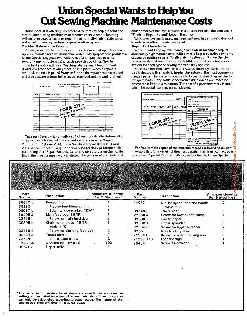
Union Special is offering two practical systems to help pinpoint and reduce your sewing machine maintenance costs: a record keeping system to help spot machines requiring abnormally high maintenance, and a parts inventory system to speed routine repairs. Machine Maintenance Records
Repair-prone machines or inexperienced competent operators can eat up your maintenance dollars in short order. To help spotthese problems, Union Special suggests two variations of a simple maintenance record keeping system using cards provided by Union Special.
The first system utilizes a "Machine Maintenance Record" card (Form 237) for each sewing machine in a plant. When a repair is required, the card is pulled frorri the file and the repair date, parts used, and their cost are entered in the spaces provided and the card is refiled.
MACHINE MAINTENANCE RECORD WA..KI:II .. MAW.I. nn.E 'TYPI:HEEOU .PUALNO. DATII:PtJIICH.
I I I I OAT& •l'WiiOL.PAIITuti:IO con OAnE !IYW-SOL-PAitTUSO con
I '2.'~1-fO~Jf\. :tenanc.e
. e fl\3\n: fl!.ac.b\~c.atd Rec.ot
----1, ---.--.afl -.......
The second system is normally used when more detailed information on repair costs is desired. Two record cards are used: a "Repair Request Card" (Form 234), and a "Machine Repair Record" (Form 233). When a machine requires service, the forelady odoreman fills out the top of a "Repair Request Card" and gives it to a mechanic. He fills in the_time the repair work is started, the parts used and their cost,
Part -Description Minimum Quantity
Number Per 5 Machines
39520 L Presser foot 1 39530 Presser foot hinge spring 2 39597 L Stitch tongue marked "DW" 1 39505 j Main feed dog, 16 TPI 1 22528 Screw for main feed dog 2 39505 K Chaining feed dog, 1 6 TPI, 1
marked "K" 22768 8 Screw for chaining feed dog 2 39524 J Throat plate 1 22524 Throat plate screw 2 154 GAS Needles {specify size) 100 39570 J Upper knife 4
• The parts and quantities listed above are intended to assist you in setting up the initial inventory of spare parts. An efficient inventory can only be established according to actual usage. The nature of the sewing operation will determine actual usage.
and the completion time. This data is then transferred to the permanent "Machine Repair Record" kept in the office.
Whichever system is used, management now has an invaluable tool to reduce needless maintenance costs. Repair Part Inventories
While record keeping tells management which machines require abnormally high maintenance, it does little to help reduce the downtime caused by routine repairs. To alleviate this situation, Union Special recommends that manufacturers establish a formal parts inventory system for each type of sewing machine they operate.
Excessive machine downtime and wasted hours by mechanics can be eliminated with an orderly in-plant inventory of the most commonly needed parts. There is no longer a need to cannibalize other machines for spare parts. Long waits for deliveries are avoided and _machine downtime is kept to a minimum. The cost of a parts inventory is small when the overall savings are considered.
MACHINE REPAIR RECORD CARD
I REPAIR REQUEST CARD
r---------------r-~-•w_"~-·~~1 ~------------ ~
r---.-.---.----''r--,--'1-1 :::; ...... Ho""-====== -DAD. "'fll.• ~~~~ ~ 1::Wit -~ ·-
PARTSUSED -
-I
t---t-----i---+---t----1---ITtM:I:STARTil := I ~:=~--,._ ____ j;.._
For free sample copies of the machine record cards and spare part inventory lists for a variety of the most popular machines, contact your local Union Special Representative or write direct to Union Special.
Part Description Minimum Quantity Number Per 5 Machines
14077 Nut for upper knife and needle 2 clamp stud
39549 J Lower knife 4 22588 .J Screw for lower knife clamp 1 39508 8 Lower looper 1 39560 A Upper spreader 1 22564 G Screw for upper spreader 2 39551 F Needle clamp stud 1 22596 E Screw for needle driving arm 2 21225 1/8 Looper gauge 1 29484 Screw assortment 1
From
the
libra
ry o
f: D
iam
ond
Nee
dle
Cor
p

From
the
libra
ry o
f: D
iam
ond
Nee
dle
Cor
p

WORLDWIDE SALES AND SERVICE
Union Special Corporation maintains sales and seNice facilities throughout the wortd. These offices will aid you in the selection of the right sewing equipment for your particular operation. -Union Special Corporation representatives and service technicians are factory trained and are able to seNe your needs promptly and efficiently. Whatever your location there is a qualified representative to seNe you.
Corporate Office:
European Distribution Center:
Finest Quality
One Union Special Plaza Huntley, IL 60142 Phone: 847•669•5101 Fax: 847•669•4454
Union Special GmbH Raiffeisenstrasse 3 D-71696 M6glingen. Germany Tef: 49•07141•247•0 Fax:49•07141•247•100
Brussels, Belgium Charlotte, N.C. Hong Kong, China Huntley, IL Leicester, England Ulle, France Miami, FL Milan, Italy M6glingen, Germany Montreal, Quebec Osaka, Japan Santa Fe Springs. CA Suwanee, GA Wayne, NJ
Other Representatives throughout all parts of the world.
From
the
libra
ry o
f: D
iam
ond
Nee
dle
Cor
p