
Installation Guide - HES SUPPLY CORP
147
Fire and Burglary Alarm System EVO192 Installation Guide
-
Upload
khangminh22 -
Category
Documents
-
view
0 -
download
0
Transcript of Installation Guide - HES SUPPLY CORP

Fire and Burglary Alarm System
EVO192
Installation Guide

Warranty
For complete warranty information on this product, please refer to the Limited Warranty Statement found on the website www.paradox.com/terms. The terns and conditions are subject to change without notice, from time to time, in Paradox’s sole discretion. We invite you to visit our website on a regular basis for the latest Limited Warranty Statement. Your use of the Paradox product signifies your acceptance of all warranty terms and conditions. Please ensure that your use of the Paradox product is in compliance with local, national, and international laws.© 2014 Paradox Security Systems Ltd. All rights reserved. Specifications may change without prior notice. US, Canadian and international patents may apply. Paradox Insight and Paradox are a trademarks or registered trademarks of Paradox Security Systems (Bahamas) Ltd. or its affiliates in Canada, the United States and/or other countries.
This product is manufactured in Canada.Paradox 780 Industrial BoulevardSt-Eustache, QuebecCanada, J7R 5V3 Tel: (450) 491-7444 Fax: (450) 491-2313
Table of ContentsTable of Contents . . . . . . . . . . . . . . . . . . . . . . . . . . . . . . . . . . . . . . . . . . . . . . . . . . . . . . . . . 3Chapter 1 Introduction . . . . . . . . . . . . . . . . . . . . . . . . . . . . . . . . . . . . . . . . . . . . 11
1.1 EVO192 – Residential Fire and Burglar Alarm and Commercial Burglar Alarm Sys-
tem 11
1.2 Features of EVO192 Controller . . . . . . . . . . . . . . . . . . . . . . . . . . . . . . . . . . . . . . . . . . . 11
1.3 Minimum Configuration . . . . . . . . . . . . . . . . . . . . . . . . . . . . . . . . . . . . . . . . . . . . . . . . . 12
1.4 System Operation . . . . . . . . . . . . . . . . . . . . . . . . . . . . . . . . . . . . . . . . . . . . . . . . . . . . . . . 12
Chapter 2 System Installation . . . . . . . . . . . . . . . . . . . . . . . . . . . . . . . . . . . . . . 13
2.1 Safety Warnings . . . . . . . . . . . . . . . . . . . . . . . . . . . . . . . . . . . . . . . . . . . . . . . . . . . . . . . . . 13
2.2 Location & Mounting . . . . . . . . . . . . . . . . . . . . . . . . . . . . . . . . . . . . . . . . . . . . . . . . . . . . 13
2.3 Recommended Installation Procedure. . . . . . . . . . . . . . . . . . . . . . . . . . . . . . . . . . . . 13
2.4 Mounting the EVO192 Controller, HUB2, ZX8, IP150. . . . . . . . . . . . . . . . . . . . . . . 14
2.5 Mounting the K641 . . . . . . . . . . . . . . . . . . . . . . . . . . . . . . . . . . . . . . . . . . . . . . . . . . . . . . 15
2.6 Mounting the TM50. . . . . . . . . . . . . . . . . . . . . . . . . . . . . . . . . . . . . . . . . . . . . . . . . . . . . . 15
2.7 Mounting the RTX3 . . . . . . . . . . . . . . . . . . . . . . . . . . . . . . . . . . . . . . . . . . . . . . . . . . . . . . 15
2.8 Wiring. . . . . . . . . . . . . . . . . . . . . . . . . . . . . . . . . . . . . . . . . . . . . . . . . . . . . . . . . . . . . . . . . . . 15
2.9 Earth Ground . . . . . . . . . . . . . . . . . . . . . . . . . . . . . . . . . . . . . . . . . . . . . . . . . . . . . . . . . . . . 17
2.10 AC Power. . . . . . . . . . . . . . . . . . . . . . . . . . . . . . . . . . . . . . . . . . . . . . . . . . . . . . . . . . . . . . . . 17
2.11 Backup Battery . . . . . . . . . . . . . . . . . . . . . . . . . . . . . . . . . . . . . . . . . . . . . . . . . . . . . . . . . . 17
2.12 Auxiliary Power Terminals. . . . . . . . . . . . . . . . . . . . . . . . . . . . . . . . . . . . . . . . . . . . . . . . 17
2.13 Bell/Siren Output . . . . . . . . . . . . . . . . . . . . . . . . . . . . . . . . . . . . . . . . . . . . . . . . . . . . . . . . 17
2.14 False Alarm Reduction . . . . . . . . . . . . . . . . . . . . . . . . . . . . . . . . . . . . . . . . . . . . . . . . . . . 18
2.15 Programmable Outputs . . . . . . . . . . . . . . . . . . . . . . . . . . . . . . . . . . . . . . . . . . . . . . . . . . 18
2.16 Keyswitch Connections . . . . . . . . . . . . . . . . . . . . . . . . . . . . . . . . . . . . . . . . . . . . . . . . . . 18
2.17 Calculating Power Requirements . . . . . . . . . . . . . . . . . . . . . . . . . . . . . . . . . . . . . . . . . 19
2.18 Keypad Zone Connections . . . . . . . . . . . . . . . . . . . . . . . . . . . . . . . . . . . . . . . . . . . . . . . 21
2.19 Addressable Zone Connections . . . . . . . . . . . . . . . . . . . . . . . . . . . . . . . . . . . . . . . . . . 22
2.20 Double Zone Connections . . . . . . . . . . . . . . . . . . . . . . . . . . . . . . . . . . . . . . . . . . . . . . . 24
2.21 Combus Connections . . . . . . . . . . . . . . . . . . . . . . . . . . . . . . . . . . . . . . . . . . . . . . . . . . . . 24
2.22 Fire Circuits. . . . . . . . . . . . . . . . . . . . . . . . . . . . . . . . . . . . . . . . . . . . . . . . . . . . . . . . . . . . . . 25
EVO Installation Guide 3
4 EVO Installation Guide
2.23 Telephone Line Connections . . . . . . . . . . . . . . . . . . . . . . . . . . . . . . . . . . . . . . . . . . . . . 26
2.24 Built-in RTC . . . . . . . . . . . . . . . . . . . . . . . . . . . . . . . . . . . . . . . . . . . . . . . . . . . . . . . . . . . . . . 27
Chapter 3 Programming Methods . . . . . . . . . . . . . . . . . . . . . . . . . . . . . . . . . . 28
3.1 Paradox Memory Key . . . . . . . . . . . . . . . . . . . . . . . . . . . . . . . . . . . . . . . . . . . . . . . . . . . . 28
3.2 Module Broadcast . . . . . . . . . . . . . . . . . . . . . . . . . . . . . . . . . . . . . . . . . . . . . . . . . . . . . . . 28
3.3 Programming Through BabyWare . . . . . . . . . . . . . . . . . . . . . . . . . . . . . . . . . . . . . . . . 29
3.4 Programming Through a Keypad. . . . . . . . . . . . . . . . . . . . . . . . . . . . . . . . . . . . . . . . . 29
3.5 Module Programming Mode . . . . . . . . . . . . . . . . . . . . . . . . . . . . . . . . . . . . . . . . . . . . . 30
Chapter 4 Zone Programming. . . . . . . . . . . . . . . . . . . . . . . . . . . . . . . . . . . . . . 31
4.1 Zone Programming . . . . . . . . . . . . . . . . . . . . . . . . . . . . . . . . . . . . . . . . . . . . . . . . . . . . . . 32
4.2 Zone Numbering . . . . . . . . . . . . . . . . . . . . . . . . . . . . . . . . . . . . . . . . . . . . . . . . . . . . . . . . 32
4.3 Zone Doubling (ATZ) . . . . . . . . . . . . . . . . . . . . . . . . . . . . . . . . . . . . . . . . . . . . . . . . . . . . 33
4.4 Zone Definitions . . . . . . . . . . . . . . . . . . . . . . . . . . . . . . . . . . . . . . . . . . . . . . . . . . . . . . . . . 33
4.5 Zone Partition Assignment. . . . . . . . . . . . . . . . . . . . . . . . . . . . . . . . . . . . . . . . . . . . . . . 35
4.6 Zone Options. . . . . . . . . . . . . . . . . . . . . . . . . . . . . . . . . . . . . . . . . . . . . . . . . . . . . . . . . . . . 35
4.7 Input Speed . . . . . . . . . . . . . . . . . . . . . . . . . . . . . . . . . . . . . . . . . . . . . . . . . . . . . . . . . . . . . 39
4.8 EOL on Hardwire Zones . . . . . . . . . . . . . . . . . . . . . . . . . . . . . . . . . . . . . . . . . . . . . . . . . . 39
4.9 Keypad Numbering . . . . . . . . . . . . . . . . . . . . . . . . . . . . . . . . . . . . . . . . . . . . . . . . . . . . . . 39
Chapter 5 Remote Control Programming . . . . . . . . . . . . . . . . . . . . . . . . . . . 40
5.1 Hardware Requirements . . . . . . . . . . . . . . . . . . . . . . . . . . . . . . . . . . . . . . . . . . . . . . . . . 40
5.2 Remote Control Template. . . . . . . . . . . . . . . . . . . . . . . . . . . . . . . . . . . . . . . . . . . . . . . . 40
Chapter 6 Keyswitch Programming . . . . . . . . . . . . . . . . . . . . . . . . . . . . . . . . . 42
6.1 Keyswitch Numbering . . . . . . . . . . . . . . . . . . . . . . . . . . . . . . . . . . . . . . . . . . . . . . . . . . . 42
6.2 Keyswitch Definitions . . . . . . . . . . . . . . . . . . . . . . . . . . . . . . . . . . . . . . . . . . . . . . . . . . . . 42
6.3 Keyswitch Partition Assignment . . . . . . . . . . . . . . . . . . . . . . . . . . . . . . . . . . . . . . . . . . 43
6.4 Keyswitch Options . . . . . . . . . . . . . . . . . . . . . . . . . . . . . . . . . . . . . . . . . . . . . . . . . . . . . . . 43
Chapter 7 Testing and Maintenance . . . . . . . . . . . . . . . . . . . . . . . . . . . . . . . . 45
7.1 ZX8 Expansion Module . . . . . . . . . . . . . . . . . . . . . . . . . . . . . . . . . . . . . . . . . . . . . . . . . . 48
7.2 Programming Locations . . . . . . . . . . . . . . . . . . . . . . . . . . . . . . . . . . . . . . . . . . . . . . . . . 48
7.3 Testing and Maintenance . . . . . . . . . . . . . . . . . . . . . . . . . . . . . . . . . . . . . . . . . . . . . . . . 48
7.4 Call Waiting Cancel. . . . . . . . . . . . . . . . . . . . . . . . . . . . . . . . . . . . . . . . . . . . . . . . . . . . . . 53
7.5 Testing and Maintenance . . . . . . . . . . . . . . . . . . . . . . . . . . . . . . . . . . . . . . . . . . . . . . . . 53
Chapter 8 Arming and Disarming Options. . . . . . . . . . . . . . . . . . . . . . . . . . . 55
8.1 Arming Follows Partition. . . . . . . . . . . . . . . . . . . . . . . . . . . . . . . . . . . . . . . . . . . . . . . . . 55
8.2 Trouble Latch. . . . . . . . . . . . . . . . . . . . . . . . . . . . . . . . . . . . . . . . . . . . . . . . . . . . . . . . . . . . 55
8.3 Restrict Arming on Supervision Loss . . . . . . . . . . . . . . . . . . . . . . . . . . . . . . . . . . . . . . 55
8.4 Restrict Arming on Tamper. . . . . . . . . . . . . . . . . . . . . . . . . . . . . . . . . . . . . . . . . . . . . . . 55
8.5 Restrict Arming on AC Failure . . . . . . . . . . . . . . . . . . . . . . . . . . . . . . . . . . . . . . . . . . . . 55
8.6 Restrict Arming on Battery Failure . . . . . . . . . . . . . . . . . . . . . . . . . . . . . . . . . . . . . . . . 55
8.7 Restrict Arming on Bell or Auxiliary Failure. . . . . . . . . . . . . . . . . . . . . . . . . . . . . . . . 56
8.8 Restrict Arming on TLM Failure . . . . . . . . . . . . . . . . . . . . . . . . . . . . . . . . . . . . . . . . . . . 56
8.9 Restrict Arming on Module Troubles . . . . . . . . . . . . . . . . . . . . . . . . . . . . . . . . . . . . . 56
8.10 Timed Auto-Arming . . . . . . . . . . . . . . . . . . . . . . . . . . . . . . . . . . . . . . . . . . . . . . . . . . . . . 56
8.11 No Movement Auto-Arming . . . . . . . . . . . . . . . . . . . . . . . . . . . . . . . . . . . . . . . . . . . . . 56
8.12 Auto-Arming Options . . . . . . . . . . . . . . . . . . . . . . . . . . . . . . . . . . . . . . . . . . . . . . . . . . . . 57
8.13 Switch To Stay Arming . . . . . . . . . . . . . . . . . . . . . . . . . . . . . . . . . . . . . . . . . . . . . . . . . . . 57
8.14 Always Force Arm when Regular Arming . . . . . . . . . . . . . . . . . . . . . . . . . . . . . . . . . 57
8.15 Auto Force on Stay Arming. . . . . . . . . . . . . . . . . . . . . . . . . . . . . . . . . . . . . . . . . . . . . . . 58
8.16 Follow Zone Switches to Entry Delay 2 . . . . . . . . . . . . . . . . . . . . . . . . . . . . . . . . . . . 58
8.17 One-Touch Features . . . . . . . . . . . . . . . . . . . . . . . . . . . . . . . . . . . . . . . . . . . . . . . . . . . . . 58
8.18 Exit Delay. . . . . . . . . . . . . . . . . . . . . . . . . . . . . . . . . . . . . . . . . . . . . . . . . . . . . . . . . . . . . . . . 58
8.19 Keypad Lock-out Feature . . . . . . . . . . . . . . . . . . . . . . . . . . . . . . . . . . . . . . . . . . . . . . . . 59
8.20 Bell Squawk . . . . . . . . . . . . . . . . . . . . . . . . . . . . . . . . . . . . . . . . . . . . . . . . . . . . . . . . . . . . . 59
8.21 Ring-back . . . . . . . . . . . . . . . . . . . . . . . . . . . . . . . . . . . . . . . . . . . . . . . . . . . . . . . . . . . . . . . 60
8.22 Maximum Bypass Entries. . . . . . . . . . . . . . . . . . . . . . . . . . . . . . . . . . . . . . . . . . . . . . . . . 60
8.23 Display “Bypass” If Armed . . . . . . . . . . . . . . . . . . . . . . . . . . . . . . . . . . . . . . . . . . . . . . . . 60
Chapter 9 Alarm Options . . . . . . . . . . . . . . . . . . . . . . . . . . . . . . . . . . . . . . . . . . 61
9.1 Bell/alarm Output . . . . . . . . . . . . . . . . . . . . . . . . . . . . . . . . . . . . . . . . . . . . . . . . . . . . . . . 61
9.2 Bell Cut-off Timer . . . . . . . . . . . . . . . . . . . . . . . . . . . . . . . . . . . . . . . . . . . . . . . . . . . . . . . . 61
9.3 Wireless Transmitter Supervision Options . . . . . . . . . . . . . . . . . . . . . . . . . . . . . . . . 61
9.4 Police Code Timer . . . . . . . . . . . . . . . . . . . . . . . . . . . . . . . . . . . . . . . . . . . . . . . . . . . . . . . 62
9.5 Tamper Recognition Options. . . . . . . . . . . . . . . . . . . . . . . . . . . . . . . . . . . . . . . . . . . . . 62
9.6 Keypad Panic Options . . . . . . . . . . . . . . . . . . . . . . . . . . . . . . . . . . . . . . . . . . . . . . . . . . . 63
EVO Installation Guide 5
6 EVO Installation Guide
Chapter 10 Event Reporting . . . . . . . . . . . . . . . . . . . . . . . . . . . . . . . . . . . . . . . . . 65
10.1 Reporting Enabled. . . . . . . . . . . . . . . . . . . . . . . . . . . . . . . . . . . . . . . . . . . . . . . . . . . . . . . 67
10.2 Report Codes . . . . . . . . . . . . . . . . . . . . . . . . . . . . . . . . . . . . . . . . . . . . . . . . . . . . . . . . . . . . 67
10.3 Report Arming and Disarming. . . . . . . . . . . . . . . . . . . . . . . . . . . . . . . . . . . . . . . . . . . . 71
10.4 Monitoring Station Phone Number . . . . . . . . . . . . . . . . . . . . . . . . . . . . . . . . . . . . . . . 72
10.5 Account Number . . . . . . . . . . . . . . . . . . . . . . . . . . . . . . . . . . . . . . . . . . . . . . . . . . . . . . . . 73
10.6 Account Number Transmission. . . . . . . . . . . . . . . . . . . . . . . . . . . . . . . . . . . . . . . . . . . 73
10.7 Reporting Formats. . . . . . . . . . . . . . . . . . . . . . . . . . . . . . . . . . . . . . . . . . . . . . . . . . . . . . . 73
10.8 Event Call Direction . . . . . . . . . . . . . . . . . . . . . . . . . . . . . . . . . . . . . . . . . . . . . . . . . . . . . . 74
10.9 Pager Delay . . . . . . . . . . . . . . . . . . . . . . . . . . . . . . . . . . . . . . . . . . . . . . . . . . . . . . . . . . . . . 75
10.10 Recent Close Delay . . . . . . . . . . . . . . . . . . . . . . . . . . . . . . . . . . . . . . . . . . . . . . . . . . . . . . 75
10.11 Power Failure Report Delay . . . . . . . . . . . . . . . . . . . . . . . . . . . . . . . . . . . . . . . . . . . . . . 75
10.12 Power Failure Restore Report Delay . . . . . . . . . . . . . . . . . . . . . . . . . . . . . . . . . . . . . . 76
10.13 Repeat Pager Report Code Transmission. . . . . . . . . . . . . . . . . . . . . . . . . . . . . . . . . . 76
10.14 Auto Test Report. . . . . . . . . . . . . . . . . . . . . . . . . . . . . . . . . . . . . . . . . . . . . . . . . . . . . . . . . 76
10.15 Disarm Reporting Options . . . . . . . . . . . . . . . . . . . . . . . . . . . . . . . . . . . . . . . . . . . . . . . 76
10.16 Zone Restore Report Options . . . . . . . . . . . . . . . . . . . . . . . . . . . . . . . . . . . . . . . . . . . . 76
10.17 Auto Report Code Programming . . . . . . . . . . . . . . . . . . . . . . . . . . . . . . . . . . . . . . . . . 77
10.18 Closing Delinquency Timer. . . . . . . . . . . . . . . . . . . . . . . . . . . . . . . . . . . . . . . . . . . . . . . 77
Chapter 11 Dialer Options. . . . . . . . . . . . . . . . . . . . . . . . . . . . . . . . . . . . . . . . . . . 78
11.1 Telephone Line Monitoring . . . . . . . . . . . . . . . . . . . . . . . . . . . . . . . . . . . . . . . . . . . . . . 78
11.2 Tone/Pulse Dialing. . . . . . . . . . . . . . . . . . . . . . . . . . . . . . . . . . . . . . . . . . . . . . . . . . . . . . . 78
11.3 Pulse Ratio . . . . . . . . . . . . . . . . . . . . . . . . . . . . . . . . . . . . . . . . . . . . . . . . . . . . . . . . . . . . . . 78
11.4 Busy Tone Detection. . . . . . . . . . . . . . . . . . . . . . . . . . . . . . . . . . . . . . . . . . . . . . . . . . . . . 78
11.5 Switch To Pulse . . . . . . . . . . . . . . . . . . . . . . . . . . . . . . . . . . . . . . . . . . . . . . . . . . . . . . . . . . 79
11.6 Bell On Communication Fail. . . . . . . . . . . . . . . . . . . . . . . . . . . . . . . . . . . . . . . . . . . . . . 79
11.7 Keypad Beep on Successful Arm or Disarm Report . . . . . . . . . . . . . . . . . . . . . . . . 79
11.8 Dial Tone Delay . . . . . . . . . . . . . . . . . . . . . . . . . . . . . . . . . . . . . . . . . . . . . . . . . . . . . . . . . . 79
11.9 Call Waiting Cancel . . . . . . . . . . . . . . . . . . . . . . . . . . . . . . . . . . . . . . . . . . . . . . . . . . . . . . 79
Chapter 12 VDMP3 Voice Module. . . . . . . . . . . . . . . . . . . . . . . . . . . . . . . . . . . . 81
12.1 VDMP3 Installation Instructions . . . . . . . . . . . . . . . . . . . . . . . . . . . . . . . . . . . . . . . . . . 81
12.2 Feature activation (PGMs) . . . . . . . . . . . . . . . . . . . . . . . . . . . . . . . . . . . . . . . . . . . . . . . . 81
12.3 VDMP3 Setup Instructions . . . . . . . . . . . . . . . . . . . . . . . . . . . . . . . . . . . . . . . . . . . . . . . 82
Chapter 13 Programmable Outputs. . . . . . . . . . . . . . . . . . . . . . . . . . . . . . . . . . 84
13.1 PGM Activation Event . . . . . . . . . . . . . . . . . . . . . . . . . . . . . . . . . . . . . . . . . . . . . . . . . . . . 84
13.2 PGM Deactivation Option . . . . . . . . . . . . . . . . . . . . . . . . . . . . . . . . . . . . . . . . . . . . . . . . 84
13.3 Flexible PGM Deactivation Option. . . . . . . . . . . . . . . . . . . . . . . . . . . . . . . . . . . . . . . . 84
13.4 PGM Deactivation Event . . . . . . . . . . . . . . . . . . . . . . . . . . . . . . . . . . . . . . . . . . . . . . . . . 85
13.5 PGM Timer . . . . . . . . . . . . . . . . . . . . . . . . . . . . . . . . . . . . . . . . . . . . . . . . . . . . . . . . . . . . . . 85
13.6 PGM1 Becomes a 2-wire Smoke Detector Input* . . . . . . . . . . . . . . . . . . . . . . . . . . 85
13.7 PGM Test Mode. . . . . . . . . . . . . . . . . . . . . . . . . . . . . . . . . . . . . . . . . . . . . . . . . . . . . . . . . . 85
13.8 PGM Initial Status . . . . . . . . . . . . . . . . . . . . . . . . . . . . . . . . . . . . . . . . . . . . . . . . . . . . . . . . 86
Chapter 14 System Settings and Commands. . . . . . . . . . . . . . . . . . . . . . . . . . 87
14.1 Hardware Reset. . . . . . . . . . . . . . . . . . . . . . . . . . . . . . . . . . . . . . . . . . . . . . . . . . . . . . . . . . 87
14.2 Software Reset . . . . . . . . . . . . . . . . . . . . . . . . . . . . . . . . . . . . . . . . . . . . . . . . . . . . . . . . . . 87
14.3 Installer Code Lock. . . . . . . . . . . . . . . . . . . . . . . . . . . . . . . . . . . . . . . . . . . . . . . . . . . . . . . 88
14.4 Daylight Savings Time . . . . . . . . . . . . . . . . . . . . . . . . . . . . . . . . . . . . . . . . . . . . . . . . . . . 88
14.5 Daylight Savings Time Schedule. . . . . . . . . . . . . . . . . . . . . . . . . . . . . . . . . . . . . . . . . . 88
14.6 Battery Charge Current . . . . . . . . . . . . . . . . . . . . . . . . . . . . . . . . . . . . . . . . . . . . . . . . . . 89
14.7 Combus Speed . . . . . . . . . . . . . . . . . . . . . . . . . . . . . . . . . . . . . . . . . . . . . . . . . . . . . . . . . . 89
14.8 Transmit Zone Status on Serial Port . . . . . . . . . . . . . . . . . . . . . . . . . . . . . . . . . . . . . . 89
14.9 Serial Port Baud Rate. . . . . . . . . . . . . . . . . . . . . . . . . . . . . . . . . . . . . . . . . . . . . . . . . . . . . 89
14.10 Partitioning. . . . . . . . . . . . . . . . . . . . . . . . . . . . . . . . . . . . . . . . . . . . . . . . . . . . . . . . . . . . . . 89
14.11 Shabbat Feature . . . . . . . . . . . . . . . . . . . . . . . . . . . . . . . . . . . . . . . . . . . . . . . . . . . . . . . . . 90
14.12 Installer Function Keys . . . . . . . . . . . . . . . . . . . . . . . . . . . . . . . . . . . . . . . . . . . . . . . . . . . 90
14.13 Module Reset. . . . . . . . . . . . . . . . . . . . . . . . . . . . . . . . . . . . . . . . . . . . . . . . . . . . . . . . . . . . 91
14.14 Locate Module . . . . . . . . . . . . . . . . . . . . . . . . . . . . . . . . . . . . . . . . . . . . . . . . . . . . . . . . . . 91
14.15 Module Programming . . . . . . . . . . . . . . . . . . . . . . . . . . . . . . . . . . . . . . . . . . . . . . . . . . . 91
14.16 Module and Label Broadcast . . . . . . . . . . . . . . . . . . . . . . . . . . . . . . . . . . . . . . . . . . . . . 91
14.17 System Date & Time . . . . . . . . . . . . . . . . . . . . . . . . . . . . . . . . . . . . . . . . . . . . . . . . . . . . . 91
14.18 Quick Module Scanning. . . . . . . . . . . . . . . . . . . . . . . . . . . . . . . . . . . . . . . . . . . . . . . . . . 91
14.19 Module Scanning . . . . . . . . . . . . . . . . . . . . . . . . . . . . . . . . . . . . . . . . . . . . . . . . . . . . . . . . 91
14.20 Serial Number Viewing. . . . . . . . . . . . . . . . . . . . . . . . . . . . . . . . . . . . . . . . . . . . . . . . . . . 92
14.21 Power Save Mode . . . . . . . . . . . . . . . . . . . . . . . . . . . . . . . . . . . . . . . . . . . . . . . . . . . . . . . 92
EVO Installation Guide 7
8 EVO Installation Guide
14.22 Auto Trouble Shutdown . . . . . . . . . . . . . . . . . . . . . . . . . . . . . . . . . . . . . . . . . . . . . . . . . 92
14.23 No AC Fail Display . . . . . . . . . . . . . . . . . . . . . . . . . . . . . . . . . . . . . . . . . . . . . . . . . . . . . . . 92
14.24 Multiple Action Feature . . . . . . . . . . . . . . . . . . . . . . . . . . . . . . . . . . . . . . . . . . . . . . . . . . 92
14.25 System Labels . . . . . . . . . . . . . . . . . . . . . . . . . . . . . . . . . . . . . . . . . . . . . . . . . . . . . . . . . . . 92
Chapter 15 Access Codes. . . . . . . . . . . . . . . . . . . . . . . . . . . . . . . . . . . . . . . . . . . . 97
15.1 Installer Code. . . . . . . . . . . . . . . . . . . . . . . . . . . . . . . . . . . . . . . . . . . . . . . . . . . . . . . . . . . . 97
15.2 Access Code Length . . . . . . . . . . . . . . . . . . . . . . . . . . . . . . . . . . . . . . . . . . . . . . . . . . . . . 97
15.3 System Master Code . . . . . . . . . . . . . . . . . . . . . . . . . . . . . . . . . . . . . . . . . . . . . . . . . . . . . 97
15.4 Programming Access Codes. . . . . . . . . . . . . . . . . . . . . . . . . . . . . . . . . . . . . . . . . . . . . . 97
15.5 User Options . . . . . . . . . . . . . . . . . . . . . . . . . . . . . . . . . . . . . . . . . . . . . . . . . . . . . . . . . . . . 98
15.6 Partition Assignment . . . . . . . . . . . . . . . . . . . . . . . . . . . . . . . . . . . . . . . . . . . . . . . . . . . 100
Automatic Report Code List . . . . . . . . . . . . . . . . . . . . . . . . . . . . . . . . . . . . . . . . . . . . . . 101 Contact ID Report Code List . . . . . . . . . . . . . . . . . . . . . . . . . . . . . . . . . . . . . . . . . . . . . . 104Keypad Installation Instructions . . . . . . . . . . . . . . . . . . . . . . . . . . . . . . . . . . . . . . . . . . . 106
Connecting the Keypads .............................................................................................................. 106
Connecting Keypad Zones........................................................................................................... 106
Programmable Output .................................................................................................................. 106
Keypad Specific Instructions ....................................................................................................... 106
K641R Access Control Connection............................................................................................ 108
Programming.................................................................................................................................... 109
Message Programming K641/K641R........................................................................................ 109
K641 Programming......................................................................................................................... 110
Programmable Output Options................................................................................................. 111
K641R Programming ...................................................................................................................... 112
Access Control Options ................................................................................................................. 114
DGP2-648BL Programming.......................................................................................................... 117
Programmable Output Options................................................................................................. 120
Guidelines for Locating Smoke Detectors and CO Detectors . . . . . . . . . . . . . . . . . . . 121Smoke Detectors ............................................................................................................................. 121
CO detectors...................................................................................................................................... 121
Fire Escape Planning . . . . . . . . . . . . . . . . . . . . . . . . . . . . . . . . . . . . . . . . . . . . . . . . . . . . 123EVO192 CP-01 Implications as of June 13th, 2014 . . . . . . . . . . . . . . . . . . . . . . . . . . . . 125
• The control unit must be installed with a local sounding device and an off-premise
transmission for SIA communication format.K641/K641+/TM50 Must be in the Installa-
tion guides ......................................................................................................................................... 127
EVO192 BOARD LABELLING......................................................................................................... 127
ADD THESE SECTIONS IN THE PROGRAMMING GUIDE, INSTALLER MANUAL AND/OR
USER MANUAL.................................................................................................................................. 128
CHANGE THESE DEFAULTS IN THE PROGRAMMING GUIDE, INSTALLER MANUAL. 128
ADD THESE NOTES TO THE INSTALLER MANUAL ................................................................ 129
ADD THESE NOTES TO THE USER MANUAL ........................................................................... 130
UNDOCUMENTED CHANGES....................................................................................................... 130
EVO192 CP-01 Installer Programming Quick Reference Chart SIA False Alarm Reduction 131Warnings . . . . . . . . . . . . . . . . . . . . . . . . . . . . . . . . . . . . . . . . . . . . . . . . . . . . . . . . . . . . . . 133Index . . . . . . . . . . . . . . . . . . . . . . . . . . . . . . . . . . . . . . . . . . . . . . . . . . . . . . . . . . . . . . . . . 141
EVO Installation Guide 9

10 EVO Installation Guide

Introduction 1
1.1 EVO192 – Residential Fire and Burglar Alarm and Commercial Burglar Alarm System
1.1.1 System DescriptionThe EVO192 is a Residential Fire and Burglar Alarm and Commercial Burglar Alarm System consisting of Controller EVO192, 8-Zone Expansion Module ZX8, HUB Module HUB2, IP Communication Module IP150, Hardwired Keypads K641and TM50, Wireless Expansion Module RTX3.
The EVO192 Controller consists of 8 on-board zone inputs (16 with zone doubling) that is expandable to a maximum of 192 zones via the 4-wire combus. The EVO Controller features up to 999 users, 8 partitions, 32 doors and can support up to 254 modules in any combination.
The EVO192 system provides the highest level of protection for use in Mercantile, high-security military and government sites, luxurious residential homes and any place where maximum security is essential. These systems are designed to be easy to use, and the modular concept of these systems provides installers with labor-saving features that make expanding, installing and servicing these systems quick and convenient.
The EVO192 Controller is connected to Detection Devices protecting different zones of the premises. These Zones can also be divided into different Partitions.
Keypads (K641 and TM50) are connected to the Control Panel in order to command, control and program the system. In addition to the Bells connected to the Control Panel, the keypads are also used for annunciation and indication of the information of the system such as events, alerts, warnings.
When required, expand the number of zones in the EVO192 system by adding ZX8 and RTX3 expansion modules1 anywhere and in any combination on the 4-wire combus. Modules are connected to the combus at the most convenient location and then their zone inputs are assigned to the desired zone and partition. Also, only a module’s used inputs are assigned to zones in the system.
EVO192 also supports 32 virtual zones in addition to its security zones. Virtual zones can be used to automate PGM (Programmable Output) activations without occupying a security zone and without affecting the system’s security functions. The EVO192 system is a logical solution to every installer’s security.
1.2 Features of EVO192 Controller• Digital combus:• Provides constant power, supervision and two-way communication between the control panel and all its
modules• Supports up to 127 modules• Connect modules up to 914m (3000ft) from the panel2
• Sabotage-proof technology without additional wiring• 8 on-board zones (16 w/ zone doubling) expandable to 192 zones via 4-wire combus• Automatic Daylight Saving Time feature• 2 on-board solid-state relays PGM outputs (+ 3 optional), negative or positive triggering• PGM1 can be used as a 2-wire smoke input3
• Built-in-real-time clock backup battery• 1 supervised bell output, auxiliary output and telephone line• Push button software reset (reset to default values and restart)• Push button to activate or deactivate the Auxiliary output1 – Connection of non ETL/UL listed component will void the ETL listing2- Connect according to the wiring requirements described in the Wiring Diagram
EVO Installation Guide 11
12 EVO Installation Guide
3 – 2-Wire Smoke Detector was not evaluated by ETL• Fits in a 28cm x 28cm x 7.6cm (11in x 11in x 3in) metal box• 5 on-board solid-state PGM outputs, negative or positive triggering• Supports up to 254 expansion bus modules• 999 user codes• 8 partitions• 2048 events buffered
ETL Note: For Mercantile installations or Residential Fire Alarm installation of the system, use only the minimum system configuration. Do not connect additional modules.
1.3 Minimum ConfigurationThe Paradox Fire and Burglary system in the minimum configuration contains:
• EVO192 and Battery inside an 11x11x3 Metal Box, • Compatible Listed Bell connected to the EVO192 Bell Output, • K641 Keypad, • RTX3 Wireless Module.
1.4 System OperationOnce the EVO192 system is set up and programmed, as described and explained in this manual, the operation of the systems is done using the Keypads for control and indication.
Once inside the premises, the users should either have the system Disarmed or Armed in Stay mode (described in details further down this manual).
While users are departing the premises it is recommended to set the system to ARM mode.
When a detection unit is activated it is sending the detection/taper/trouble signals to the controller, which processes them. The keypads communicate the status of the zones as processed by the controller.
Note: Programming, Maintenance and System Testing is done using one of the keypads, as described under the relevant parts in the manual.
Note: Connecting any non-UL/ETL components will void the UL/ETL certification.

System Installation 2
2.1 Safety Warnings 1. Before accessing the system modules for maintenance make sure the power is disconnected and the
battery is not attached
2. To prevent risk of shock, disconnect telephone line at telco jack before servicing this unit.
3. To prevent risk of electric shock, disconnect AC battery and phone cord BEFORE Servicing.
2.2 Location & MountingFor modules and detectors see the component instructions for recommendations. Also see see Guidelines for Locating Smoke Detectors and CO Detectors on page 121 and see Fire Escape Planning on page 123 for recommendations regarding smoke and fire detector locations and Fire Escape planning.
For the 11”x11” and 8” x10” boxes containing the system components, select a site that is not accessible to intruders.
Note: Before mounting the cabinet, know which components will be installed in this cabinet and place the stand-offs for each component into the proper holes in the cabinet. There are 5 stand-offs for the EVO192 panel and 4 for each of the other components. There are also stick on stand-offs packed with the components should you want to place the components elsewhere within the cabinet.
Note: Install an anti-tamper switch for each box and connect each one to 24 hour zones inputs on the EVO192 controller.
Pull all cables into the cabinet and prepare them for connection before mounting the circuit board into the back of the cabinet. Select a centralized installation site on the main floor that is not easily accessible to intruders and leave at least 5cm (2in) around the panel box to permit adequate ventilation and heat dissipation. The installation site should be dry and close to an AC source, ground connection, Ethernet connection, and telephone line connection. Avoid installation near or in the path of strong RF fields (i.e. neon lights, computers), on or near metal objects, circuit breaker boxes, air conditioner and heater ducts since they may cause interference and reduce sensitivity and may result in false alarms. Avoid installing the control panel in the basement.
Note: For recommended locations of detectors, bells, sirens etc. see specific the device installation guide.
2.3 Recommended Installation Procedure1. Connect a small group of modules, including a K641 keypad.
2. Connect the battery and AC power. Enter section [4000] (see section 14.20 on page 92). Only the Clock Loss trouble and/or Bell Absent trouble should appear. Verify the connection if a module does not appear in section [4000], or if a module trouble occurs.
3. Disconnect AC power and the battery, follow steps 2, 3 and 4 for other modules.
4. If modules were removed, enter [4005](see section 14.18 on page 91).
EVO Installation Guide 13
14 EVO Installation Guide
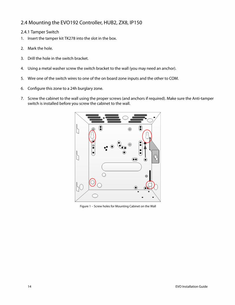
2.4 Mounting the EVO192 Controller, HUB2, ZX8, IP150
2.4.1 Tamper Switch1. Insert the tamper kit TK278 into the slot in the box.
2. Mark the hole.
3. Drill the hole in the switch bracket.
4. Using a metal washer screw the switch bracket to the wall (you may need an anchor).
5. Wire one of the switch wires to one of the on board zone inputs and the other to COM.
6. Configure this zone to a 24h burglary zone.
7. Screw the cabinet to the wall using the proper screws (and anchors if required). Make sure the Anti-tamper switch is installed before you screw the cabinet to the wall.
Figure 1 – Screw holes for Mounting Cabinet on the Wall
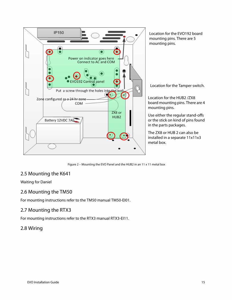
Figure 2 – Mounting the EVO Panel and the HUB2 in an 11 x 11 metal box
2.5 Mounting the K641Waiting for Daniel
2.6 Mounting the TM50For mounting instructions refer to the TM50 manual TM50-EI01.
2.7 Mounting the RTX3For mounting instructions refer to the RTX3 manual RTX3-EI11.
2.8 Wiring
Location for the EVO192 board mounting pins. There are 5 mounting pins.
Location for the Tamper switch.
Location for the HUB2 /ZX8 board mounting pins. There are 4 mounting pins.
Use either the regular stand-offs or the stick on kind of pins found in the parts packages.
The ZX8 or HUB 2 can also be installed in a separate 11x11x3 metal box.
EVO Installation Guide 15
16 EVO Installation Guide
.
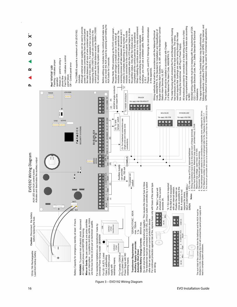
Figure 3 – EVO192 Wiring Diagram
MEM KEYSERIAL
RED BLK
COM
BELL
AC A
CAU
XRE
LAY
GRN
YEL
+BU
SZ1
Z2Z3
Z4Z5
Z6Z7
Z8R-
1T-
1RI
NG
TIP
COM
COM
COM
+–
–
PARADOX
SECURITYSYSTEMS
D I
G I
P L
E X
EV
O
DIALEREBUS
SERV
ICE
KEYP
AD
BATT
N.C
.N.O
.1
23
4PG
M
REDBLKGRNYEL
KEYPAD
PGM Z1
REDBLKGRNYEL
DETECTOR
REDBLKGRNYEL
ANY MODULE
STAT
US
AUX
AUX
COMBUS
120V
AC/
17VA
C tr
ansf
orm
er
UL
120V
AC/
17VA
C tr
ansf
orm
er
CAN
+–
TransformerRequirements:
120VAC/17VAC,40VA
AuxiliarySupplycanprovide:
max.700mA
AutomaticShutDown
1.1a
UsableBatteryChargeCurrents:
850mAmax.
Caution:Disconnectthebattery
beforereplacingthefuse.
The"BELL"outputwill
shutdownifthecurrent
exceeds3A.
*A1KUresistorisrequired
iftheBellisnotequipped
withaninternalresistor.
Positiontheresistoras
closeaspossibletothe
Bell.Aresistorisnot
requiredforsirens.
SELF-CONTAINEDBELL/
SIREN
Tometalicenclosure
Red
“ST
ATU
S” L
EDFlashing–indicatesproper
operation
Alwayson–panelisusinga
phonelilne
FastFlash–indicatesacontrol
panelfailure
Off–Controlpanelerror
TheCOMBUSsupportsamaximum
of254(EVO192)
modules.
Althoughexternalpowersuppliescanbeusedtoprovide
powertomodulesconnectedfarfromthecontrolpanel
thetotaldistanceofallrunsofwirecombinedcannot
exceed914m
(3000ft.).Forexampleiftenrunsofwire
measuring305m
(1000ft.)eachareconnectedtothe
controlpanel,thetotaldistancewouldbe3048m(10000
ft.)whichexceedsthesystem
capacity.
Beforeaddinganymodulestothecontrolpanelmakesure
youshutdowntheAUXoutputbypressingandholdingthe
AUXbuttonfor3seconds.
PleaseNote:WhenpoweringuptheEVOcontrolpanel,
thepanelwillbeginamodulescantoverifythatall
modulesconnectedtothepanelareoperational.The
scanningprocesswilltakebetween30secondsand3
minutestocompletedependingonthenumberof
modulesconnectedtothecontrolpanel.Themodule
scaniscompletewhentheLCDkeypadbeginstoshow
thepartitionstatus.Onlyafterthemodulescanis
completedwillthecontrolpanelbefullyoperational.
WhenInstallingthecombuswiresinanoisyenvironment
orwhenconnectingthecombusacrossseparate
buildings,youmustuseashieldedcable.Refertosection
2.15.1.
PleaseseeETLandETLCWarningsforandinformation
intheappendix.
Auxiliarysupply
canprovide:
Max.700mA
AWG#14singleconductor
solidcopperwire
AUXLEDandAUXcontrolbutton
Activatesanddeactivatestheauxiliaryoutput
12Vdc7AhRechargeable
Lead-Acidbackupbattery
(3) Forhardwiredconnectionssee
singlezoneanddoublezone
connections.
WiringmethodsthatshallbeinaccordancewiththeNationalElectrical
Code,ANSI/NFPA70,theStandardforInstallationandClassificationof
BurglarandHoldupAlarmSystems,UL681,andtheStandardforCentral-
StationAlarmServices,UL827.
Donotshorttheterminalsofthetransformertogether.Thiscausestheinternalfusetoblow.
Thetransformermustbeconnectedtoa230VAC,24-houroutletnotcontrolledbyaswitch
otherthananapprovedover-currentprotectiondevice.
Forcontinuedprotectionagainstriskoffire,replacefusesonlywithfusesofthesametype
andrating.
Thesystem
shouldbeinstalledinaccordancewithChapter
2oftheNationalFireAlarmCode,ANSI/NFPA72
ThemetalhousingwhichenclosedtheFireandBurglarysystem
housing
hasknockoutsonthesidesandinthebackenclosure.Thewiring
methodrequiresthatbushingsareusedforwiringthroughthemetal
box.IncludingthetransformerwithPluginPowerSupply.
WARNING:Topreventriskofelectricshock,disconnect
ACbatteryandphonecordBEFOREServicing.
Allknockoutsprovidedforconnectionofafield-wiringsystem
toafield-
wiringcompartmentshallaccommodateconduitofthetradesizeaccording
toNEC.
IntendedwiringmethodsmustbeinkeepingwiththerequirementsofCSA
C22.1,CanadianElectricalCode,PartI,SafetyStandardforElectrical
Installations.
(2)
1.ETLnote:UseanETL/ULapprovedbell/siren
2.Wiringconventionshavetobeinthesameroom
oftheseterminals
3.ZoneInputSpecifications:Maximum
loopcurrent(shortedloop):2.2mA
Maximum
loopvoltage
(openloop):5.0VDC
4.DisconnectTelecom
jackbeforeservicing
5.Theanti-tamperswitchneedstobeconnectedtoaseparatezoneconfiguredfor24hrs
6.ForMaximum
numberofdevicestobeemployedrefertotheFeaturesinsection1.1
7. T
he m
inim
um p
erm
issib
le w
ire si
ze to
be
empl
oyed
shal
l be
not s
mal
ler t
han
No.
22
AWG
(0.3
2 m
m2)
.
BELL
AC A
C+
–
BELL
AC A
CRE
LAY
COM
+–
N.C
.N.O
.1
23
4PG
MZ1
COM
Thesumtotalofthecurrentdrawfromthebell/sirenandtheAUXmustbe
llimittedto2.0A.Exceedingthislimitwilloverloadthepanelpowersupplyand
leadtocompletesystem
shutdown.
Not
es:
(4)
(1)
ForUS:UL/ETLListed
Class2wall/building
120VAC/60Hzpower
supplywith
restrainingmeans.
ForCanada:CSA/ULc/
ETLcListedClass2
PowerSupplywithNO
restrainingmeans.
Topower-on
switch
(5)Toanti-
tamperswitch
(2)
(6)
(6)
MiseenGarde:Nepasconnecteràuneprisecontrôlée
paruninterrupteur.Lesystèmedoitêtrevérifiéaumoins
unefoistouslestrois(3)ansparuntechnicienqualifié.
Forresidentialinstallationsusetransformermadeby
UniversalPowerGroupmodel:UB1640W
EVO
192
Wiri
ng D
iagr
am
ThesignaltransmissiontotheCentralStationmaybeperformedby
followingmethods:Landline(PSTN),Internet,andGPRS.OnlyInternet,and
GPRSmethodoftransmissionmaybeusedforCommercialapplications.
BatteryCapacityforemergencystandbyatleast4hours
2.9 Earth GroundConnect the ground connector to the enclosure and to a metal cold water pipe or grounding rod as per local electrical codes.
2.10 AC PowerUse a 17Vac (50/60Hz) transformer with a minimum 20VA rating. For increased power use a 40VA rating.
AC/AC transformer:
For residential installations use transformer made by Universal Power Group model: UB1640W
For US: UL/ETL LSS standard Listed Class 2 wall/building 120VAC/60Hz power supply with restraining means.
For Canada: CSA/ULc/ETLc LSS standard Listed Class 2 Power Supply with NO restraining means
Note: Do not use any switch-controlled outlets to power the transformer. The system should be connected to the building’s power source (receptacle) by an AC/AC transformer:
Do not connect the transformer or the backup battery until all wiring is completed. When powering up the EVO control panel, the panel will begin a module scan.
Do not short the terminals of the transformer together. This causes the internal fuse to blow.
The transformer must be connected to a 110 VAC, 24-hour outlet not controlled by a switch other than an approved over-current protection device.
For continued protection against risk of fire, replace fuses only with fuses of the same type and rating.
2.11 Backup BatteryConnect a 12Vdc 7Ah rechargeable acid/lead backup battery. Verify the polarity, as reversed connections will blow the battery fuse. For details on how to set the Battery Charge Current to either 350mA or 850mA, see see section 14.6 on page 89. Battery capacity for emergency standby is at least 4 hours. Using the minimum configuration of the system will provide 24 hours standby using the 7Ah battery.
2.11.1 Battery Test1. The control panel conducts a dynamic battery test under load every 60 seconds. If the battery is
disconnected, if its capacity is too low or if the battery voltage drops to 10.5 volts or less when there is no AC, the “Battery Trouble” message will appear in the Trouble Display. At 8.5 volts, the panel shuts down and all outputs close. The panel will cease to process sensor trips if the voltage is under 8.5V.
2.12 Auxiliary Power TerminalsThe auxiliary power supply can power accessories in thesecurity system. A fuseless circuit protects the auxiliary output against overload and shuts it down if the current exceeds 1.1A. Auxiliary power will resume once the overload condition has restored. Press and hold the AUX button for two seconds to turn AUX power on and off.
2.13 Bell/Siren OutputThe bell output supplies 12Vdc upon alarm and can support one 30-watt or two 20-watt sirens. The bell output will automatically shut down if the current exceeds 3A. If the load on the BELL terminals returns to normal (≤3A), the control panel will re-instate power to the BELL terminals. Please verify correct polarity.
Note: Use Wheelock 46T-12 siren.
EVO Installation Guide 17
18 EVO Installation Guide
Note:For connection of self-contained bell/siren, see Figure 7 on page 22.
When the bell output is not used, the “Bell Absent” message appears in the Trouble Display. To avoid this, connect a 1kΩ resistor across the bell output. UL Note: The keypads must be programmed to beep
with all troubles.
The metal housing which enclosed the Fire and Burglary system housing has knockouts on the sides and in the back enclosure and shall accommodate conduit of the trade size according to NEC.
WARNING: “To prevent risk of electric shock, disconnect AC battery and phone cord BEFORE Servicing”.
2.14 False Alarm Reduction In an effort to deter false alarms, the EVO192 provides various programmable features, including the following programmable features:
• double knockout, cross zoning• auto zone shutdown• auto trouble shutdown• intellizone • Audible /visual entry/exit delays• fire alarm verification• dialer delay before an alarm transmission• cancel report option• exit termination zone
2.15 Programmable OutputsPGM1 to PGM4 are 100mA (max.) solid-state relays with +/- trigger. PGM5 is a 5A/28Vdc N.O./ N.C. relay output. They can be set at either normally open or normally closed. If the current draw on PGM1 to PGM4 is to exceed the current output.
2.16 Keyswitch Connections
Connect the keyswitches to the keypad, control panel, or Zone Expansion Module's hardwired input terminals as shown in Figure 6.
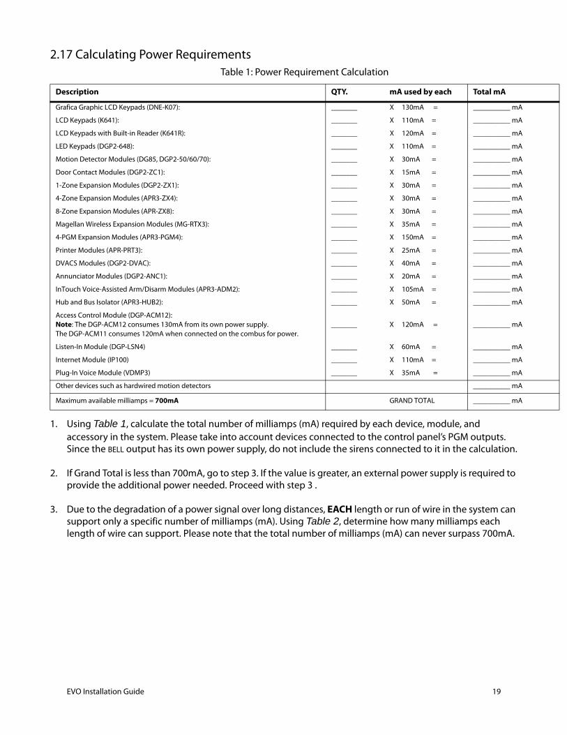
2.17 Calculating Power Requirements
1. Using Table 1, calculate the total number of milliamps (mA) required by each device, module, and accessory in the system. Please take into account devices connected to the control panel’s PGM outputs. Since the BELL output has its own power supply, do not include the sirens connected to it in the calculation.
2. If Grand Total is less than 700mA, go to step 3. If the value is greater, an external power supply is required to provide the additional power needed. Proceed with step 3 .
3. Due to the degradation of a power signal over long distances, EACH length or run of wire in the system can support only a specific number of milliamps (mA). Using Table 2, determine how many milliamps each length of wire can support. Please note that the total number of milliamps (mA) can never surpass 700mA.
Table 1: Power Requirement Calculation
Description QTY. mA used by each Total mA
Grafica Graphic LCD Keypads (DNE-K07): _______ X 130mA = __________ mA
LCD Keypads (K641): _______ X 110mA = __________ mA
LCD Keypads with Built-in Reader (K641R): _______ X 120mA = __________ mA
LED Keypads (DGP2-648): _______ X 110mA = __________ mA
Motion Detector Modules (DG85, DGP2-50/60/70): _______ X 30mA = __________ mA
Door Contact Modules (DGP2-ZC1): _______ X 15mA = __________ mA
1-Zone Expansion Modules (DGP2-ZX1): _______ X 30mA = __________ mA
4-Zone Expansion Modules (APR3-ZX4): _______ X 30mA = __________ mA
8-Zone Expansion Modules (APR-ZX8): _______ X 30mA = __________ mA
Magellan Wireless Expansion Modules (MG-RTX3): _______ X 35mA = __________ mA
4-PGM Expansion Modules (APR3-PGM4): _______ X 150mA = __________ mA
Printer Modules (APR-PRT3): _______ X 25mA = __________ mA
DVACS Modules (DGP2-DVAC): _______ X 40mA = __________ mA
Annunciator Modules (DGP2-ANC1): _______ X 20mA = __________ mA
InTouch Voice-Assisted Arm/Disarm Modules (APR3-ADM2): _______ X 105mA = __________ mA
Hub and Bus Isolator (APR3-HUB2): _______ X 50mA = __________ mA
Access Control Module (DGP-ACM12):Note: The DGP-ACM12 consumes 130mA from its own power supply.The DGP-ACM11 consumes 120mA when connected on the combus for power.
_______ X 120mA = __________ mA
Listen-In Module (DGP-LSN4) _______ X 60mA = __________ mA
Internet Module (IP100) _______ X 110mA = __________ mA
Plug-In Voice Module (VDMP3) _______ X 35mA = __________ mA
Other devices such as hardwired motion detectors __________ mA
Maximum available milliamps = 700mA GRAND TOTAL __________ mA
EVO Installation Guide 19
20 EVO Installation Guide
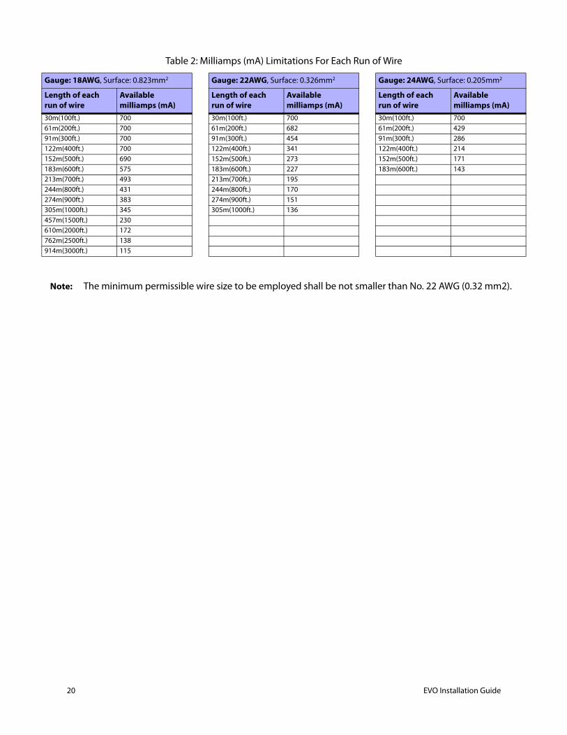
Note: The minimum permissible wire size to be employed shall be not smaller than No. 22 AWG (0.32 mm2).
Table 2: Milliamps (mA) Limitations For Each Run of Wire
Gauge: 18AWG, Surface: 0.823mm2 Gauge: 22AWG, Surface: 0.326mm2 Gauge: 24AWG, Surface: 0.205mm2
Length of each run of wire
Available milliamps (mA)
Length of each run of wire
Available milliamps (mA)
Length of each run of wire
Available milliamps (mA)
30m(100ft.) 700 30m(100ft.) 700 30m(100ft.) 70061m(200ft.) 700 61m(200ft.) 682 61m(200ft.) 42991m(300ft.) 700 91m(300ft.) 454 91m(300ft.) 286122m(400ft.) 700 122m(400ft.) 341 122m(400ft.) 214152m(500ft.) 690 152m(500ft.) 273 152m(500ft.) 171183m(600ft.) 575 183m(600ft.) 227 183m(600ft.) 143213m(700ft.) 493 213m(700ft.) 195244m(800ft.) 431 244m(800ft.) 170274m(900ft.) 383 274m(900ft.) 151305m(1000ft.) 345 305m(1000ft.) 136457m(1500ft.) 230610m(2000ft.) 172762m(2500ft.) 138914m(3000ft.) 115
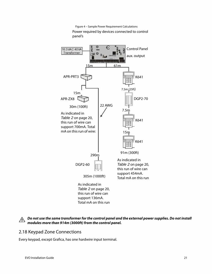
Figure 4 – Sample Power Requirement Calculations
Do not use the same transformer for the control panel and the external power supplies. Do not install modules more than 914m (3000ft) from the control panel.
2.18 Keypad Zone ConnectionsEvery keypad, except Grafica, has one hardwire input terminal.
Power required by devices connected to control panel’s
Control Panel
aux. output
61m 15m
APR-PRT3 K641
7.5m (25ft)15m
DGP2-70
7.5m
APR-ZX8
30m (100ft) 22 AWG
K641
15m
K641
91m (300ft)290m
DGP2-60
305m (1000ft)
As indicated in Table 2 on page 20, this run of wire can support 700mA. Total mA on this run of wire:
As indicated in Table 2 on page 20, this run of wire can support 454mA. Total mA on this run
As indicated in Table 2 on page 20, this run of wire can support 136mA. Total mA on this run
EVO Installation Guide 21
22 EVO Installation Guide
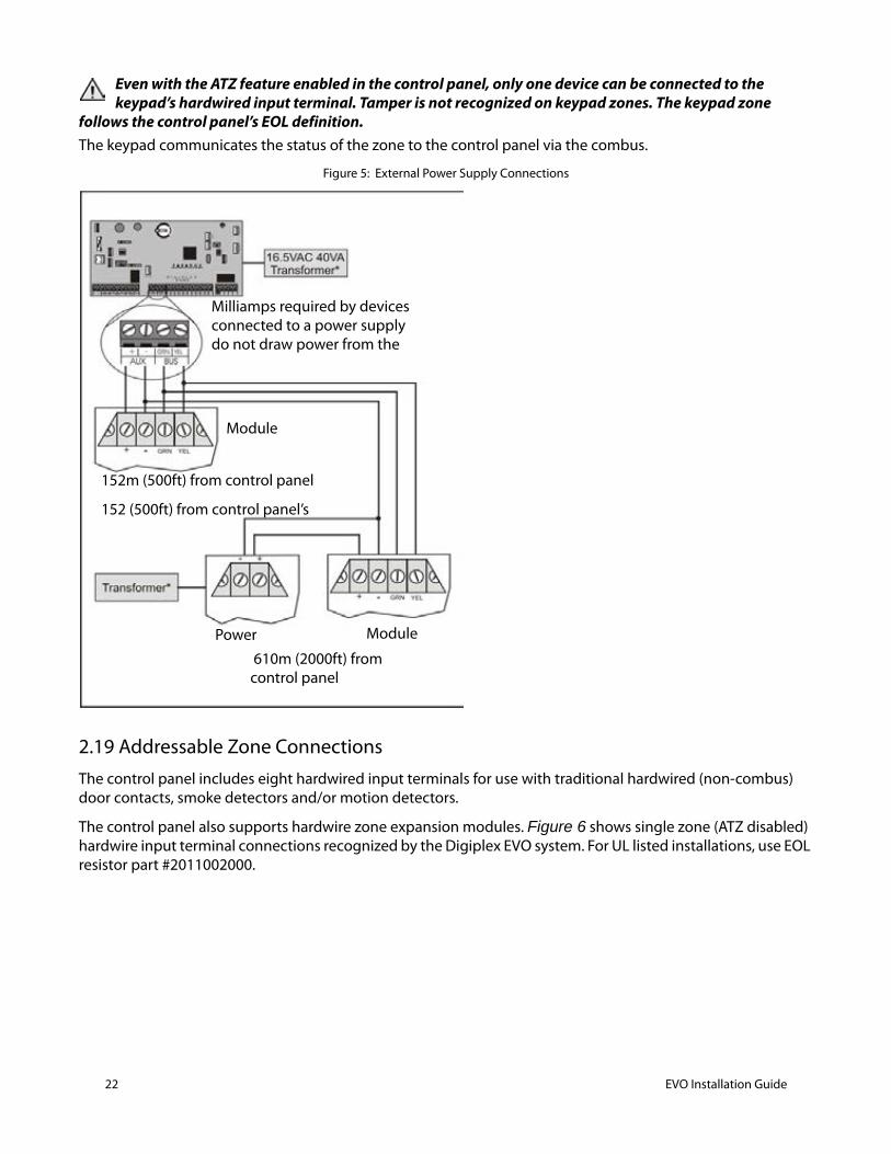
Even with the ATZ feature enabled in the control panel, only one device can be connected to the keypad’s hardwired input terminal. Tamper is not recognized on keypad zones. The keypad zone
follows the control panel’s EOL definition. The keypad communicates the status of the zone to the control panel via the combus.
Figure 5: External Power Supply Connections
2.19 Addressable Zone ConnectionsThe control panel includes eight hardwired input terminals for use with traditional hardwired (non-combus) door contacts, smoke detectors and/or motion detectors.
The control panel also supports hardwire zone expansion modules. Figure 6 shows single zone (ATZ disabled) hardwire input terminal connections recognized by the Digiplex EVO system. For UL listed installations, use EOL resistor part #2011002000.
Module
Module
Power
152m (500ft) from control panel
152 (500ft) from control panel’s
610m (2000ft) from control panel
Milliamps required by devices connected to a power supply do not draw power from the
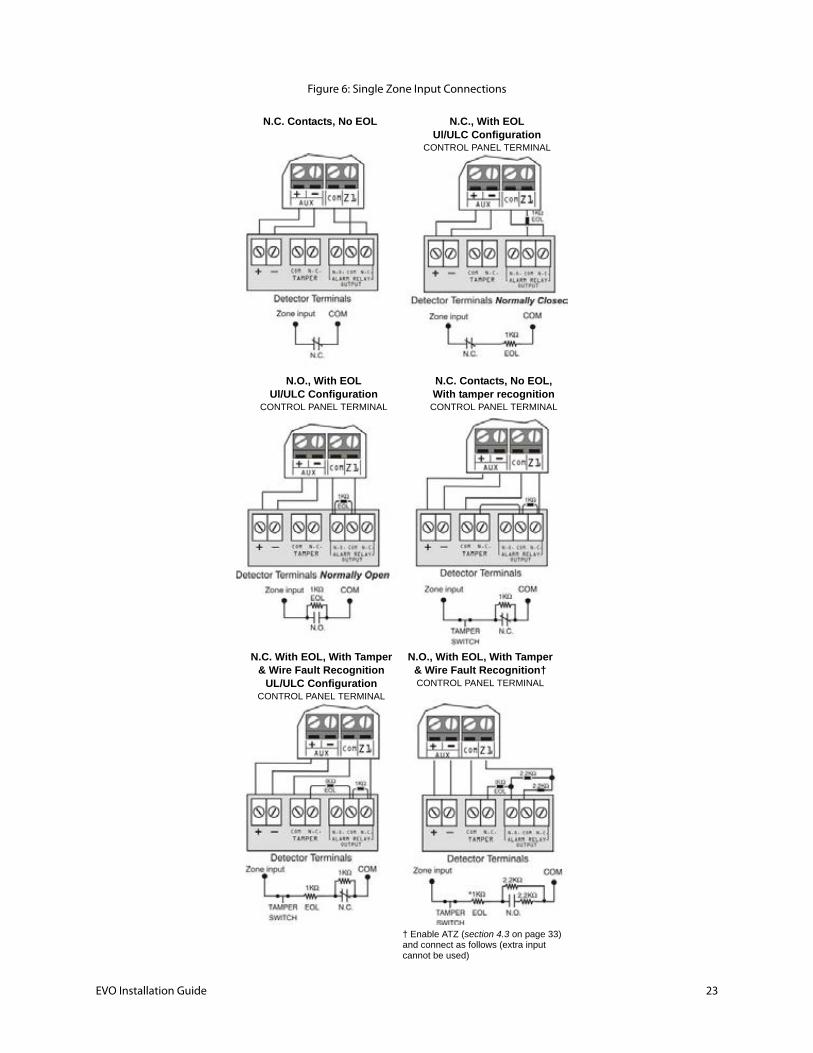
Figure 6: Single Zone Input Connections
† Enable ATZ (section 4.3 on page 33) and connect as follows (extra input cannot be used)
N.C. Contacts, No EOL N.C., With EOLUl/ULC Configuration
CONTROL PANEL TERMINAL
N.O., With EOLUl/ULC Configuration
CONTROL PANEL TERMINAL
N.C. Contacts, No EOL,With tamper recognition
CONTROL PANEL TERMINAL
N.C. With EOL, With Tamper& Wire Fault Recognition
UL/ULC ConfigurationCONTROL PANEL TERMINAL
N.O., With EOL, With Tamper& Wire Fault Recognition†CONTROL PANEL TERMINAL
EVO Installation Guide 23
24 EVO Installation Guide
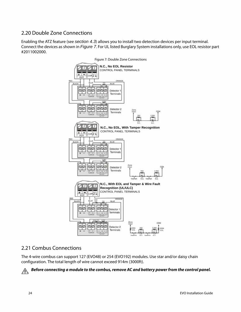
2.20 Double Zone ConnectionsEnabling the ATZ feature (see section 4.3) allows you to install two detection devices per input terminal. Connect the devices as shown in Figure 7. For UL listed Burglary System installations only, use EOL resistor part #2011002000.
Figure 7: Double Zone Connections
2.21 Combus ConnectionsThe 4-wire combus can support 127 (EVO48) or 254 (EVO192) modules. Use star and/or daisy chain configuration. The total length of wire cannot exceed 914m (3000ft).
Before connecting a module to the combus, remove AC and battery power from the control panel.
N.C., No EOL ResistorCONTROL PANEL TERMINALS
N.C., With EOL and Tamper & Wire FaultRecognition (UL/ULC)CONTROL PANEL TERMINALS
N.C., No EOL, With Tamper RecognitionCONTROL PANEL TERMINALS
2.21.1 Connecting the Combus in Noisy EnvironmentsWhen installing the combus wires in proximity to high electrical interferences or across separate buildings, use shielded cables:
Within the Same Building: Strip the outer jacket at one end of the shielded cable to expose the shield and connect the shield to the control panel ground (not the dialer ground), while leaving the shield at the other end of the cable open (floating).
Across Separate Buildings: Strip the outer jacket at one end of the shielded cable to expose the shield. In the same building as the control panel, connect the exposed shield to any earth ground available, while leaving the shield at the other end of the cable open (floating). The same configuration applies for any subsequent building.
2.22 Fire CircuitsAssign the smoke detectors connected to the control panel or zone expansion input terminals to a zone and define the zone's parameters as a Fire Zone (see section 4.4.12 and see section 4.4.13 on page 35).
2.22.1 Smoke Detector Installation (2-Wire)*PGM1 can be defined as a 2-wire smoke detector input (see ). Connect the 2-wire smoke detectors as shown in Figure 8. If a line short occurs or the smoke detector activates, whether the system is armed or disarmed, the control panel will generate an alarm. If the line is open, the “Zone Fault” trouble indication appears in the Trouble Display and the report code is sent to the monitoring station, if programmed.
* UL Note: Not to be used with UL Listed systems.
2.22.2 ESL CleanMe® InstallationConnect ESL smoke detectors like the standard smoke detectors. Avoid connecting more than 20 ESL smoke detectors. When a CleanMe signal is sent, the control panel will generate a Zone Fault trouble and may transmit the Fire Loop report code to the monitoring station. The trouble will be cleared if there is no CleanMe signal for 255 seconds. If an alarm occurs, the trouble will be cleared until it is detected again.
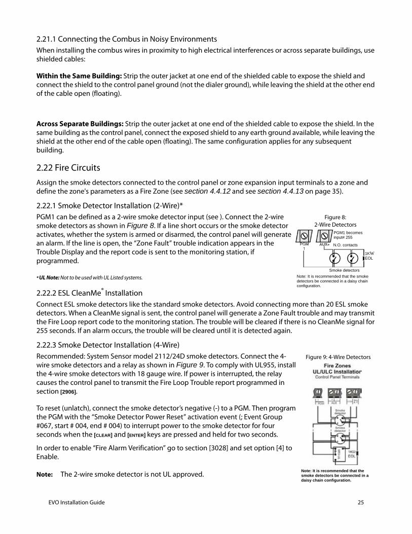
2.22.3 Smoke Detector Installation (4-Wire)Recommended: System Sensor model 2112/24D smoke detectors. Connect the 4-wire smoke detectors and a relay as shown in Figure 9. To comply with UL955, install the 4-wire smoke detectors with 18 gauge wire. If power is interrupted, the relay causes the control panel to transmit the Fire Loop Trouble report programmed in section [2906].
To reset (unlatch), connect the smoke detector’s negative (-) to a PGM. Then program the PGM with the “Smoke Detector Power Reset” activation event (; Event Group #067, start # 004, end # 004) to interrupt power to the smoke detector for four seconds when the [CLEAR] and [ENTER] keys are pressed and held for two seconds.
In order to enable “Fire Alarm Verification” go to section [3028] and set option [4] to Enable.
Note: The 2-wire smoke detector is not UL approved.
Figure 8: 2-Wire Detectors
Note: It is recommended that the smoke detectors be connected in a daisy chain configuration.
PGM1 becomesinput# 255
Smoke detectors
1KWEOL
N.O. contacts
Figure 9: 4-Wire Detectors
Note: It is recommended that the smoke detectors be connected in a daisy chain configuration.
EVO Installation Guide 25
26 EVO Installation Guide
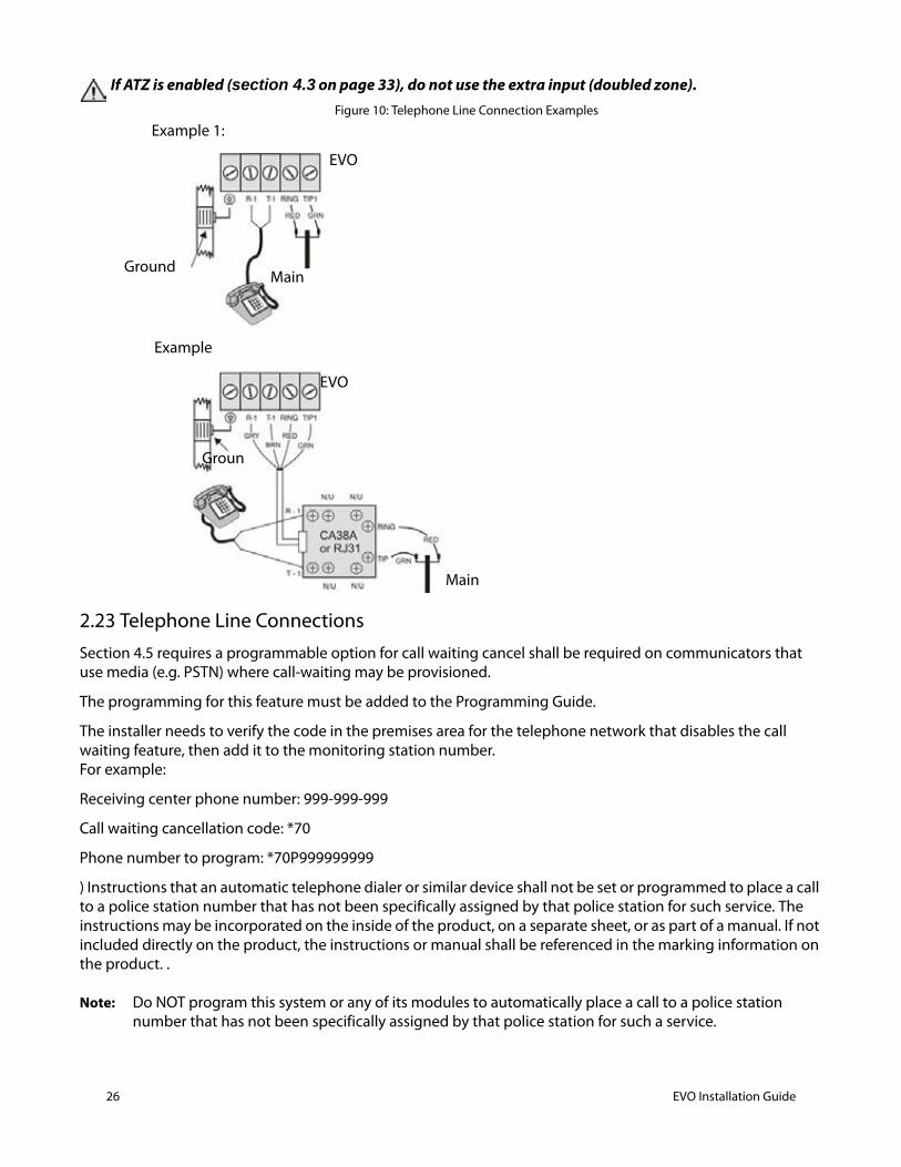
If ATZ is enabled (section 4.3 on page 33), do not use the extra input (doubled zone).Figure 10: Telephone Line Connection Examples
2.23 Telephone Line ConnectionsSection 4.5 requires a programmable option for call waiting cancel shall be required on communicators that use media (e.g. PSTN) where call-waiting may be provisioned.
The programming for this feature must be added to the Programming Guide.
The installer needs to verify the code in the premises area for the telephone network that disables the call waiting feature, then add it to the monitoring station number. For example:
Receiving center phone number: 999-999-999
Call waiting cancellation code: *70
Phone number to program: *70P999999999
) Instructions that an automatic telephone dialer or similar device shall not be set or programmed to place a call to a police station number that has not been specifically assigned by that police station for such service. The instructions may be incorporated on the inside of the product, on a separate sheet, or as part of a manual. If not included directly on the product, the instructions or manual shall be referenced in the marking information on the product. .
Note: Do NOT program this system or any of its modules to automatically place a call to a police station number that has not been specifically assigned by that police station for such a service.
EVO
Main Ground
Example
Example 1:
EVO
Groun
Main
The installation instructions shall state that the communication medium between protected property and communications service provider shall be for the exclusive use of the protected property and is not to be shared with other communications service provider subscribers
Note: The phone line between the protected property and the communications service provider shall be for the exclusive use of the protected property and is not to be shared with other communications service provider subscribers.
The telephone lines can be connected directly to the control panel or through a CA38A or RJ31 as shown in Figure 10.
Note: UL Note Installer must verify line seizure after every installation
For TBR-21 compliance, please note the following:
1. The EVO can be connected to the telephone network via an RJ-11 connector.
2. The Maximum Dialing Attempts cannot exceed 15 attempts.
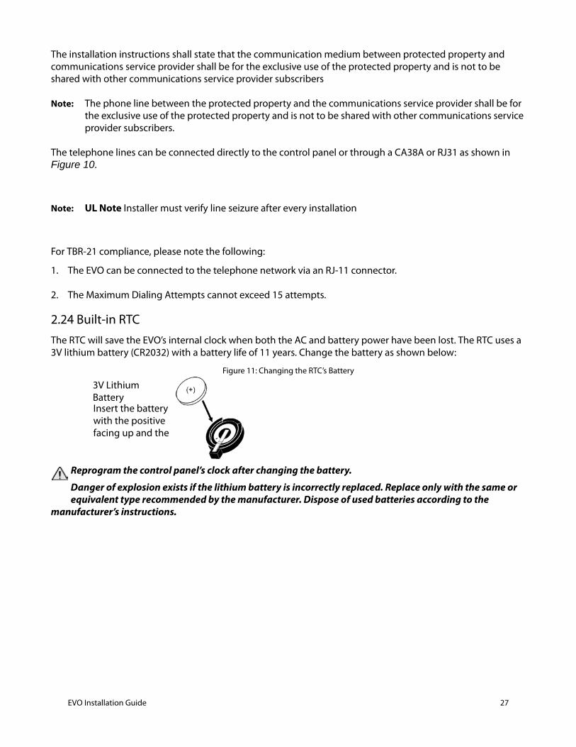
2.24 Built-in RTCThe RTC will save the EVO’s internal clock when both the AC and battery power have been lost. The RTC uses a 3V lithium battery (CR2032) with a battery life of 11 years. Change the battery as shown below:
Figure 11: Changing the RTC’s Battery
Reprogram the control panel’s clock after changing the battery.
Danger of explosion exists if the lithium battery is incorrectly replaced. Replace only with the same or equivalent type recommended by the manufacturer. Dispose of used batteries according to the
manufacturer’s instructions.
3V Lithium BatteryInsert the battery with the positive facing up and the
EVO Installation Guide 27
28 EVO Installation Guide
Programming Methods 3
3.1 Paradox Memory KeyThe Paradox Memory Key can copy the programmed contents of one control panel into as many others.
Note: Not to be used with UL Listed systems.
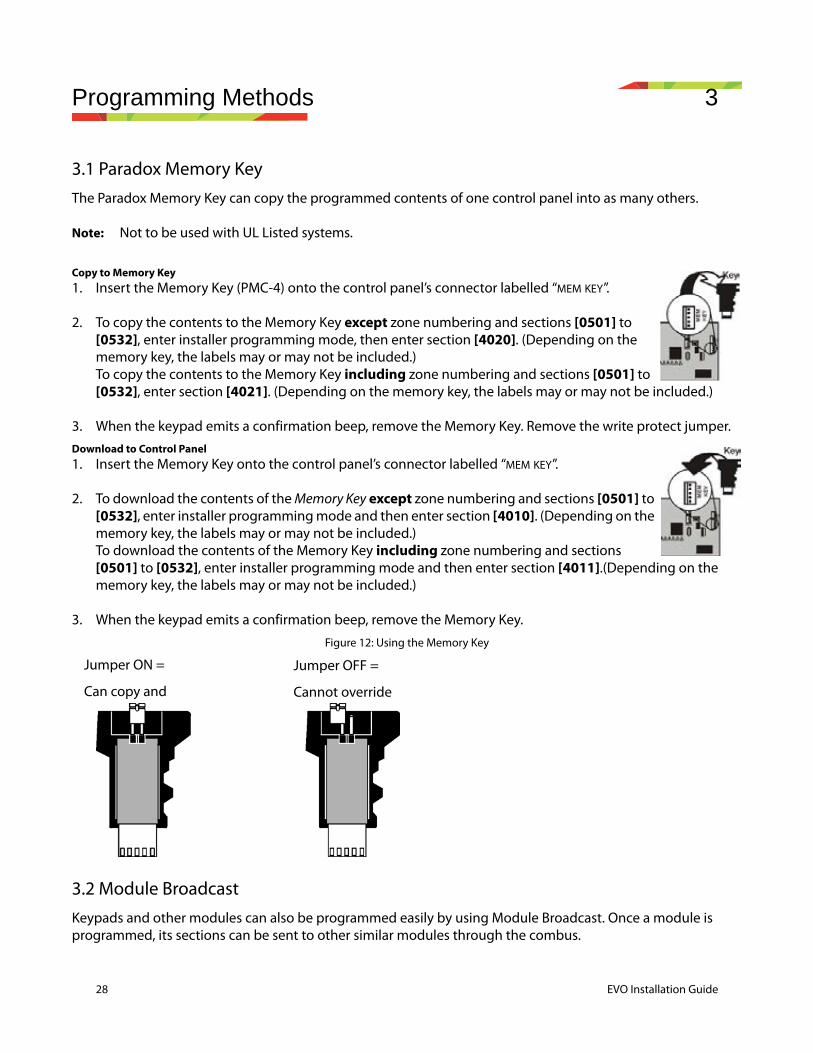
Copy to Memory Key1. Insert the Memory Key (PMC-4) onto the control panel’s connector labelled “MEM KEY”.
2. To copy the contents to the Memory Key except zone numbering and sections [0501] to [0532], enter installer programming mode, then enter section [4020]. (Depending on the memory key, the labels may or may not be included.) To copy the contents to the Memory Key including zone numbering and sections [0501] to [0532], enter section [4021]. (Depending on the memory key, the labels may or may not be included.)
3. When the keypad emits a confirmation beep, remove the Memory Key. Remove the write protect jumper.Download to Control Panel1. Insert the Memory Key onto the control panel’s connector labelled “MEM KEY”.
2. To download the contents of the Memory Key except zone numbering and sections [0501] to [0532], enter installer programming mode and then enter section [4010]. (Depending on the memory key, the labels may or may not be included.) To download the contents of the Memory Key including zone numbering and sections [0501] to [0532], enter installer programming mode and then enter section [4011].(Depending on the memory key, the labels may or may not be included.)
3. When the keypad emits a confirmation beep, remove the Memory Key.
Figure 12: Using the Memory Key
3.2 Module BroadcastKeypads and other modules can also be programmed easily by using Module Broadcast. Once a module is programmed, its sections can be sent to other similar modules through the combus.
Jumper ON =
Can copy and
Jumper OFF =
Cannot override

3.3 Programming Through BabyWareIt is recommended that system and module programming be done through BabyWare.
3.4 Programming Through a KeypadUse the “EVO Programming Guide” to record how the sections were programmed. To enter programming mode:
For LCD Keypads: The control panel will save the data and go to the next section or press the [ENTER] key to save the data and go to the next section. Press the [CLEAR] key go to the preceding step or to erase the current data entry.
For Grafica Keypads: Press Grafica’s center action key (Save) to save the data and go to the next section. Press the right action key (Exit) to go to the preceding step or press the left action key (Clear) to erase the current data.
3.4.1 Feature Select ProgrammingMost of the options are programmed using the Feature Select Method.
For LCD Keypads: The option is considered ON when the number appears within the brackets on the LCD keypad. Turn options ON and OFF by pressing the corresponding keys on the keypad and then press [ENTER] to save.
For Grafica Keypads: Select or clear the check boxes or set the options by pressing the corresponding keys on the keypad. The feature is considered ON when its check box is selected. Press the Grafica’s center action key (Save) to save.
3.4.2 Decimal ProgrammingSections may require 3-digit decimal values from 000 to 255.
3.4.3 Hexadecimal Programming Sections may require Hexadecimal values from 0 to F. Press:
For LCD Keypads:[0] to [9] = values 0 to 9 respectively[STAY] key = A [DISARM] key = D[FORCE] key = B [BYP] key = E[ARM] key = C [MEM] key = F
For Grafica Keypads:[0] to [9] = values 0 to 9 respectively[#] = A to F (press the key until the desired letter appears)
1. Press and hold the [0] key.
2. Key in the [INSTALLER CODE] (default = 000000).
3. Key in the 4-digit [SECTION].
4. Key in required [DATA]. Refer to the “EVO Programming Guide” or to the corresponding sections in this manual.
EVO Installation Guide 29
30 EVO Installation Guide
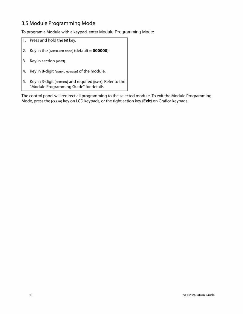
3.5 Module Programming ModeTo program a Module with a keypad, enter Module Programming Mode:
The control panel will redirect all programming to the selected module. To exit the Module Programming Mode, press the [CLEAR] key on LCD keypads, or the right action key (Exit) on Grafica keypads.
1. Press and hold the [0] key.
2. Key in the [INSTALLER CODE] (default = 000000).
3. Key in section [4003].
4. Key in 8-digit [SERIAL NUMBER] of the module.
5. Key in 3-digit [SECTION] and required [DATA]. Refer to the “Module Programming Guide” for details.
Zone Programming 4
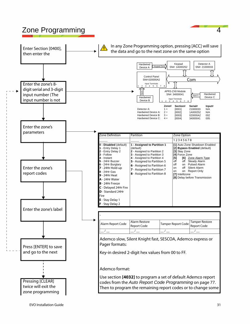
Enter Section [0400], then enter the
Enter the zone’s 8-digit serial and 3-digit input number (The input number is not
Enter the zone’s parameters
Enter the zone’s report codes
Enter the zone’s label
Press [ENTER] to save and go to the next
Pressing [CLEAR] twice will exit the zone programming
P [ENTER]
Zone Definition Partition Zone Option
_____ _____ 1 2 3 4 5 6 7 80 - Disabled (default)1 - Entry Delay 12 - Entry Delay 23 - Follow4 - Instant 5 - 24Hr Buzzer6 - 24Hr Burglary7 - 24Hr Hold-up8 - 24Hr Gas9 - 24Hr HeatA - 24Hr WaterB - 24Hr FreezeC - Delayed 24Hr FireD - Standard 24Hr FireE - Stay Delay 1F - Stay Delay 2
1 - Assigned to Partition 1 (default)2 - Assigned to Partition 23 - Assigned to Partition 34 - Assigned to Partition 45 - Assigned to Partition 56 - Assigned to Partition 67 - Assigned to Partition 78 - Assigned to Partition 8
[1] Auto Zone Shutdown Enabled[2] Bypass Enabled (default)[3] Stay Zone[4] Force Zone[5] [6] Zone Alarm Typeoff off Steady Alarmoff on Pulsed Alarmon off Silent Alarmon on Report Only[7] Intellizone[8] Delay before Transmission
.
Ademco slow, Silent Knight fast, SESCOA, Ademco express or Pager formats:
Key-in desired 2-digit hex values from 00 to FF.
Ademco format:
Use section [4032] to program a set of default Ademco report codes from the Auto Report Code Programming on page 77. Then to program the remaining report codes or to change some
Alarm Report CodeAlarm Restore Report Code
Tamper Report CodeTamper Restore Report Code
__ / __ __ / __ __ / __ __ / __
In any Zone Programming option, pressing [ACC] will save the data and go to the next zone on the same option
Inpu
t 2
HardwiredDevice B
Control PanelSN#:020000A2
APR3-ZX8 ModuleSN#: 34000041 Input 5
Detector ASN#: 21000033
COMMUNICATION NETWORK
Input Terminals1 2 3 4 5 6 7 8
Detector A:Hardwired Device A:Hardwired Device B:Hardwired Device C:
Zone#1 =2 =3 =4 =
Section#[0001][0002][0003][0004]
Serial#210000331A000252020000A234000041
Input#N/AN/A002005
KeypadSN#: 1A000252Keypad Zone
HardwiredDevice C
HardwiredDevice A
Input Terminals1 2 3 4 5 6 7 8
Com
EVO Installation Guide 31

32 EVO Installation Guide
4.1 Zone ProgrammingTwo different methods can be used to program zones:
4.1.1 Using section [0400]Allows you to program zones 001 through 192 as shown in the diagram.
In any Zone Programming option, pressing [ACC] will save the data and go to the next zone on the same option screen. Pressing [TRBL] will save the data and go to the previous zone on the same option screen.
4.1.2 Using zone serial and input numbers If you are not using an K641 or an K641R keypad, you can only program zones 1 to 96 through sections [0001] to [0096].
4.2 Zone NumberingSECTION [0400]SECTIONS [0001] TO [0096]
• To assign an addressable PIR or door contact to the combus, program the module’s serial number into the section corresponding to the zone.
• To assign a detection device connected to a module or control panel's hardwired input terminal, program the module's or control panel's serial number and the input number to the desired zone. See the “Digiplex Modules Programming Guide” for details of its input numbers (input numbers not required for keypad zones).
If PGM1 is defined as a smoke detector input, the control panel will recognize it as input # 255.
4.2.1 Clearing a Zone’s Numbering
Using section [0400]1. Enter the zone number you wish to delete.
2. Press [0] all the way through the serial/input, parameters and report codes screen.
3. Press [ENTER] to exit. Using an LCD Keypad:1. Enter a section number between [0001] to [0096].
2. Press [0] and then [ENTER] to save and exit.Using a Grafica Keypad:1. Enter a section number between [0001] to [0096].
2. Press [0] to clear the serial number.
3. Highlight the input number and then press [0] to clear the data.
Zone Number
Zone Numbering
Zone definitions
Zone Partition Assignment
Zone Options
1 [0001] [0101] [0201] [0301]
2 [0002] [0102] [0202] [0302]
+1 per zone +1 per zone +1 per zone +1 per zone
96 [0096] [0196] [0296] [0396]
4. Press Grafica’s center action key (Save) to save and exit.
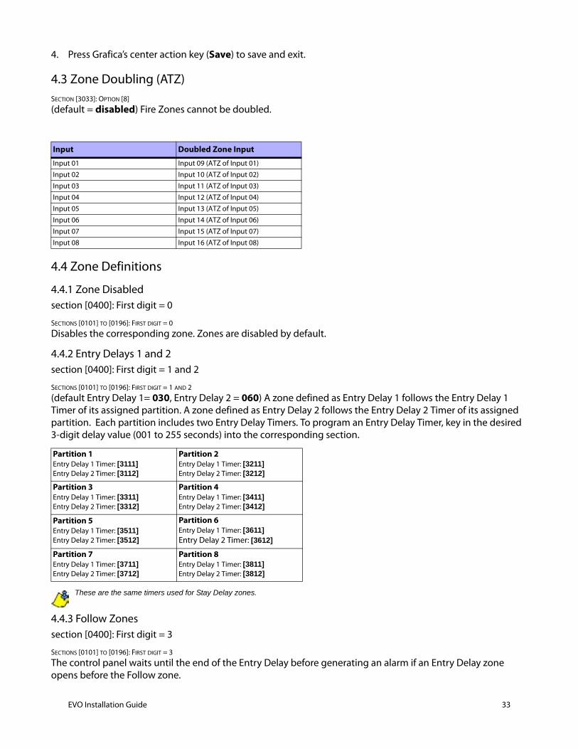
4.3 Zone Doubling (ATZ)SECTION [3033]: OPTION [8]
(default = disabled) Fire Zones cannot be doubled.
4.4 Zone Definitions
4.4.1 Zone Disabledsection [0400]: First digit = 0
SECTIONS [0101] TO [0196]: FIRST DIGIT = 0
Disables the corresponding zone. Zones are disabled by default.
4.4.2 Entry Delays 1 and 2section [0400]: First digit = 1 and 2
SECTIONS [0101] TO [0196]: FIRST DIGIT = 1 AND 2
(default Entry Delay 1= 030, Entry Delay 2 = 060) A zone defined as Entry Delay 1 follows the Entry Delay 1 Timer of its assigned partition. A zone defined as Entry Delay 2 follows the Entry Delay 2 Timer of its assigned partition. Each partition includes two Entry Delay Timers. To program an Entry Delay Timer, key in the desired 3-digit delay value (001 to 255 seconds) into the corresponding section.
These are the same timers used for Stay Delay zones.
4.4.3 Follow Zonessection [0400]: First digit = 3
SECTIONS [0101] TO [0196]: FIRST DIGIT = 3
The control panel waits until the end of the Entry Delay before generating an alarm if an Entry Delay zone opens before the Follow zone.
Input Doubled Zone Input
Input 01 Input 09 (ATZ of Input 01)
Input 02 Input 10 (ATZ of Input 02)
Input 03 Input 11 (ATZ of Input 03)
Input 04 Input 12 (ATZ of Input 04)
Input 05 Input 13 (ATZ of Input 05)
Input 06 Input 14 (ATZ of Input 06)
Input 07 Input 15 (ATZ of Input 07)
Input 08 Input 16 (ATZ of Input 08)
Partition 1Entry Delay 1 Timer: [3111]Entry Delay 2 Timer: [3112]
Partition 2Entry Delay 1 Timer: [3211]Entry Delay 2 Timer: [3212]
Partition 3Entry Delay 1 Timer: [3311]Entry Delay 2 Timer: [3312]
Partition 4Entry Delay 1 Timer: [3411]Entry Delay 2 Timer: [3412]
Partition 5Entry Delay 1 Timer: [3511]Entry Delay 2 Timer: [3512]
Partition 6Entry Delay 1 Timer: [3611]Entry Delay 2 Timer: [3612]
Partition 7Entry Delay 1 Timer: [3711]Entry Delay 2 Timer: [3712]
Partition 8Entry Delay 1 Timer: [3811]Entry Delay 2 Timer: [3812]
EVO Installation Guide 33
34 EVO Installation Guide
4.4.4 Instant ZonesSECTION [0400]: FIRST DIGIT = 4SECTIONS [0101] TO [0196]: FIRST DIGIT = 4
When an armed Instant zone opens, the control panel immediately generates an alarm.
4.4.5 24Hr Buzzer ZonesSECTION [0400]: FIRST DIGIT = 5SECTIONS [0101] TO [0196]: FIRST DIGIT = 5
Whenever a 24Hr Buzzer zone opens, the control panel activates the keypad buzzer to indicate that the zone was breached. The control panel will report the alarm, but will not enable the bell/siren output. Enter any valid access code on the keypad to stop the buzzer.
The keypads must be assigned to the same partition as the 24Hr Buzzer zone or the buzzer will not activate. UL Note: Not to be used for perimeter protection.
4.4.6 24Hr Burglary ZonesSECTION [0400]: FIRST DIGIT = 6SECTIONS [0101] TO [0196]: FIRST DIGIT = 6
When a 24Hr Burglary zone opens, the control panel will immediately generate a burglary alarm.
4.4.7 24Hr Hold-up ZonesSECTION [0400]: FIRST DIGIT = 7SECTIONS [0101] TO [0196]: FIRST DIGIT = 7
When a 24Hr Hold-up zone opens, the control panel will immediately generate an alarm.
The SIA FSK reporting format includes specific codes to identify the alarm as a Hold-up, Gas, Heat, Water, or Freeze Alarm.
4.4.8 24Hr Gas Zones*SECTION [0400]: FIRST DIGIT = 8SECTIONS [0101] TO [0196]: FIRST DIGIT = 8
When a 24Hr Gas zone opens, the control panel will immediately generate an alarm.
4.4.9 24Hr Heat Zones**SECTION [0400]: FIRST DIGIT = 9SECTIONS [0101] TO [0196]: FIRST DIGIT = 9
When a 24Hr Heat zone opens, the control panel will immediately generate an alarm.
** UL Note: UL Listed compatible devices must be used for UL systems. For UL Listed systems, this type of zone should be programmed as a pulsing Fire alarm.
4.4.10 24Hr Water Zones*SECTION [0400]: FIRST DIGIT = ASECTIONS [0101] TO [0196]: FIRST DIGIT = A
When a 24Hr Water zone opens, the control panel will immediately generate an alarm.
4.4.11 24Hr Freeze Zones*SECTION [0400]: FIRST DIGIT = BSECTIONS [0101] TO [0196]: FIRST DIGIT = B
When a 24Hr Freeze zone opens, the control panel will immediately generate an alarm.
* UL Note: UL Listed compatible devices must be used for UL systems. For UL Listed systems, this type of zone must be programmed as a silent auxiliary alarm.
4.4.12 Delayed 24Hr Fire Zone (Not to be used with UL Listed systems)
SECTION [0400]: FIRST DIGIT = CSECTIONS [0101] TO [0196]: FIRST DIGIT = C
The Delayed 24Hr Fire Zone definition from Figure 14 on page 38 is used in homes where a smoke detector often generates false alarms. A zone programmed as Fire becomes normally open and requires an EOL resistor.
The keypads must be assigned to the same partition as the Delayed 24Hr Fire zone for the buzzer to activate.
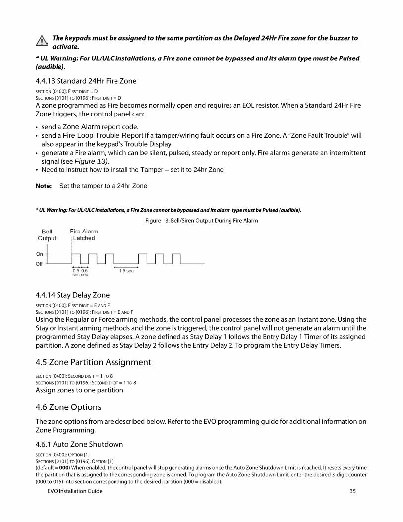
* UL Warning: For UL/ULC installations, a Fire zone cannot be bypassed and its alarm type must be Pulsed (audible).
4.4.13 Standard 24Hr Fire ZoneSECTION [0400]: FIRST DIGIT = DSECTIONS [0101] TO [0196]: FIRST DIGIT = D
A zone programmed as Fire becomes normally open and requires an EOL resistor. When a Standard 24Hr Fire Zone triggers, the control panel can:
• send a Zone Alarm report code. • send a Fire Loop Trouble Report if a tamper/wiring fault occurs on a Fire Zone. A “Zone Fault Trouble” will
also appear in the keypad's Trouble Display.• generate a Fire alarm, which can be silent, pulsed, steady or report only. Fire alarms generate an intermittent
signal (see Figure 13).• Need to instruct how to install the Tamper – set it to 24hr Zone
Note: Set the tamper to a 24hr Zone
* UL Warning: For UL/ULC installations, a Fire Zone cannot be bypassed and its alarm type must be Pulsed (audible).
Figure 13: Bell/Siren Output During Fire Alarm
4.4.14 Stay Delay ZoneSECTION [0400]: FIRST DIGIT = E AND FSECTIONS [0101] TO [0196]: FIRST DIGIT = E AND F
Using the Regular or Force arming methods, the control panel processes the zone as an Instant zone. Using the Stay or Instant arming methods and the zone is triggered, the control panel will not generate an alarm until the programmed Stay Delay elapses. A zone defined as Stay Delay 1 follows the Entry Delay 1 Timer of its assigned partition. A zone defined as Stay Delay 2 follows the Entry Delay 2. To program the Entry Delay Timers.
4.5 Zone Partition AssignmentSECTION [0400]: SECOND DIGIT = 1 TO 8SECTIONS [0101] TO [0196]: SECOND DIGIT = 1 TO 8
Assign zones to one partition.
4.6 Zone OptionsThe zone options from are described below. Refer to the EVO programming guide for additional information on Zone Programming.
4.6.1 Auto Zone ShutdownSECTION [0400]: OPTION [1]SECTIONS [0101] TO [0196]: OPTION [1](default = 000) When enabled, the control panel will stop generating alarms once the Auto Zone Shutdown Limit is reached. It resets every time the partition that is assigned to the corresponding zone is armed. To program the Auto Zone Shutdown Limit, enter the desired 3-digit counter (000 to 015) into section corresponding to the desired partition (000 = disabled):
EVO Installation Guide 35
36 EVO Installation Guide
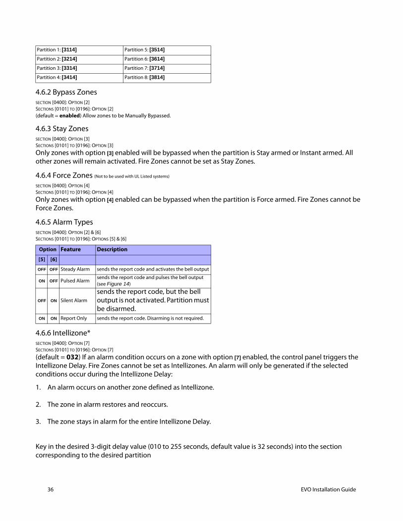
4.6.2 Bypass ZonesSECTION [0400]: OPTION [2]SECTIONS [0101] TO [0196]: OPTION [2](default = enabled) Allow zones to be Manually Bypassed.
4.6.3 Stay ZonesSECTION [0400]: OPTION [3]SECTIONS [0101] TO [0196]: OPTION [3]
Only zones with option [3] enabled will be bypassed when the partition is Stay armed or Instant armed. All other zones will remain activated. Fire Zones cannot be set as Stay Zones.
4.6.4 Force Zones (Not to be used with UL Listed systems)
SECTION [0400]: OPTION [4]SECTIONS [0101] TO [0196]: OPTION [4]
Only zones with option [4] enabled can be bypassed when the partition is Force armed. Fire Zones cannot be Force Zones.
4.6.5 Alarm TypesSECTION [0400]: OPTION [2] & [6]SECTIONS [0101] TO [0196]: OPTIONS [5] & [6]
4.6.6 Intellizone*SECTION [0400]: OPTION [7]SECTIONS [0101] TO [0196]: OPTION [7]
(default = 032) If an alarm condition occurs on a zone with option [7] enabled, the control panel triggers the Intellizone Delay. Fire Zones cannot be set as Intellizones. An alarm will only be generated if the selected conditions occur during the Intellizone Delay:
1. An alarm occurs on another zone defined as Intellizone.
2. The zone in alarm restores and reoccurs.
3. The zone stays in alarm for the entire Intellizone Delay.
Key in the desired 3-digit delay value (010 to 255 seconds, default value is 32 seconds) into the section corresponding to the desired partition
Partition 1: [3114] Partition 5: [3514]
Partition 2: [3214] Partition 6: [3614]
Partition 3: [3314] Partition 7: [3714]
Partition 4: [3414] Partition 8: [3814]
Option Feature Description
[5] [6]
OFF OFF Steady Alarm sends the report code and activates the bell output
ON OFF Pulsed Alarm sends the report code and pulses the bell output (see Figure 14)
OFF ON Silent Alarm
sends the report code, but the bell output is not activated. Partition must be disarmed.
ON ON Report Only sends the report code. Disarming is not required.

Any value less than 10 seconds will be replaced by the default value of 32 seconds.
* UL Note: For UL Listed systems, the detection pattern of both zones must be installed so that each zone has the capability of protecting the area alone.
Partition 1: [3110] Partition 3: [3310] Partition 5: [3510] Partition 7: [3710]
Partition 2: [3210] Partition 4: [3410] Partition 6: [3610] Partition 8: [3810]
EVO Installation Guide 37
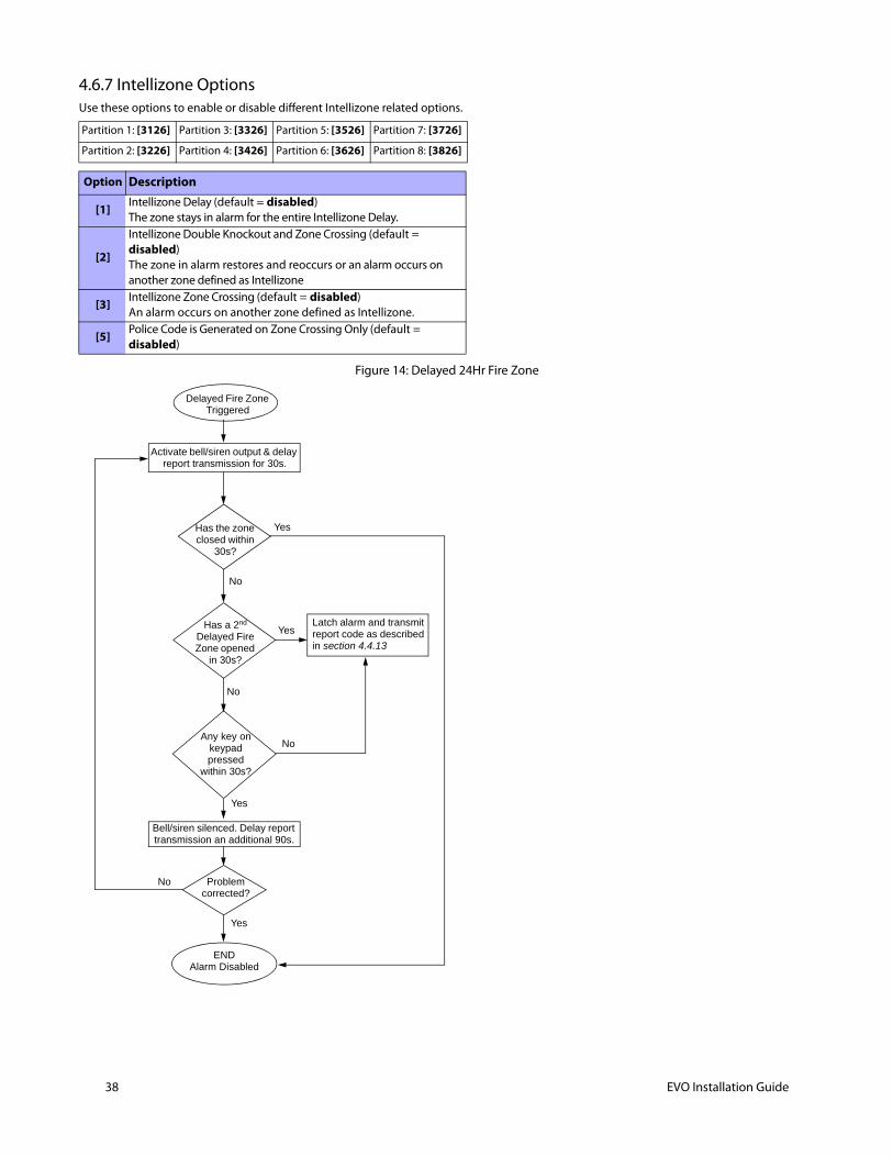
38 EVO Installation Guide
4.6.7 Intellizone OptionsUse these options to enable or disable different Intellizone related options.
Figure 14: Delayed 24Hr Fire Zone
Partition 1: [3126] Partition 3: [3326] Partition 5: [3526] Partition 7: [3726]
Partition 2: [3226] Partition 4: [3426] Partition 6: [3626] Partition 8: [3826]
Option Description
[1] Intellizone Delay (default = disabled)The zone stays in alarm for the entire Intellizone Delay.
[2]
Intellizone Double Knockout and Zone Crossing (default = disabled)The zone in alarm restores and reoccurs or an alarm occurs on another zone defined as Intellizone
[3] Intellizone Zone Crossing (default = disabled)An alarm occurs on another zone defined as Intellizone.
[5] Police Code is Generated on Zone Crossing Only (default = disabled)
Latch alarm and transmit report code as described in section 4.4.13
Delayed Fire Zone Triggered
Bell/siren silenced. Delay report transmission an additional 90s.
Activate bell/siren output & delay report transmission for 30s.
Has the zone closed within
30s?
Yes
Yes
Yes
Yes
No
No
No
No
Has a 2nd Delayed Fire Zone opened
in 30s?
Any key on keypad pressed
within 30s?
Problem corrected?
ENDAlarm Disabled
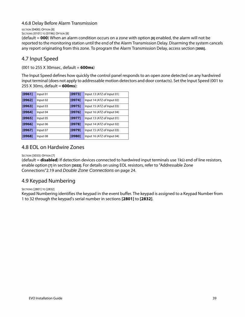
4.6.8 Delay Before Alarm Transmission SECTION [0400]: OPTION [8]SECTIONS [0101] TO [0196]: OPTION [8]
(default = 000) When an alarm condition occurs on a zone with option [8] enabled, the alarm will not be reported to the monitoring station until the end of the Alarm Transmission Delay. Disarming the system cancels any report originating from this zone. To program the Alarm Transmission Delay, access section [3055].
4.7 Input Speed(001 to 255 X 30msec, default = 600ms)
The Input Speed defines how quickly the control panel responds to an open zone detected on any hardwired input terminal (does not apply to addressable motion detectors and door contacts). Set the Input Speed (001 to 255 X 30ms, default = 600ms):
4.8 EOL on Hardwire ZonesSECTION [3033]: OPTION [7]
(default = disabled) If detection devices connected to hardwired input terminals use 1kΩ end of line resistors, enable option [7] in section [3033]. For details on using EOL resistors, refer to "Addressable Zone Connections"2.19 and Double Zone Connections on page 24.
4.9 Keypad NumberingSECTIONS [2801] TO [2832]
Keypad Numbering identifies the keypad in the event buffer. The keypad is assigned to a Keypad Number from 1 to 32 through the keypad's serial number in sections [2801] to [2832].
[0961] Input 01 [0973] Input 13 (ATZ of Input 01)
[0962] Input 02 [0974] Input 14 (ATZ of Input 02)
[0963] Input 03 [0975] Input 15 (ATZ of Input 03)
[0964] Input 04 [0976] Input 16 (ATZ of Input 04)
[0965] Input 05 [0977] Input 13 (ATZ of Input 01)
[0966] Input 06 [0978] Input 14 (ATZ of Input 02)
[0967] Input 07 [0979] Input 15 (ATZ of Input 03)
[0968] Input 08 [0980] Input 16 (ATZ of Input 04)
EVO Installation Guide 39
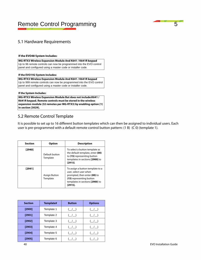
40 EVO Installation Guide
Remote Control Programming 5
5.1 Hardware Requirements
5.2 Remote Control TemplateIt is possible to set up to 16 different button templates which can then be assigned to individual users. Each user is pre-programmed with a default remote control button pattern: (1 B) (C 0) (template 1).
If the EVO48 System Includes:
MG-RTX3 Wireless Expansion Module And K641 / K641R keypadUp to 96 remote controls can now be programmed into the EVO control panel and configured using a master code or installer code.
If the EVO192 System Includes:MG-RTX3 Wireless Expansion Module And K641 / K641R keypadUp to 999 remote controls can now be programmed into the EVO control panel and configured using a master code or installer code.
If the System Includes:MG-RTX3 Wireless Expansion Module But does not include:K641 / K641R keypad. Remote controls must be stored in the wireless expansion module (32 remotes per MG-RTX3) by enabling option [1] in section [3029].
Section Option Description
[2940]
Default button Template
To select a button template as the default template, enter (00) to (15) representing button templates in sections [2900] to [2915].
[2941]
Assign Button Template
To assign a button template to a user, select user when prompted, then enter (00) to (15) representing button templates in sections [2900] to [2915].
Section Template# Button Options
[2900] Template 1 (__/__) (__/__)
[2901] Template 2 (__/__) (__/__)
[2902] Template 3 (__/__) (__/__)
[2903] Template 4 (__/__) (__/__)
[2904] Template 5 (__/__) (__/__)
[2905] Template 6 (__/__) (__/__)
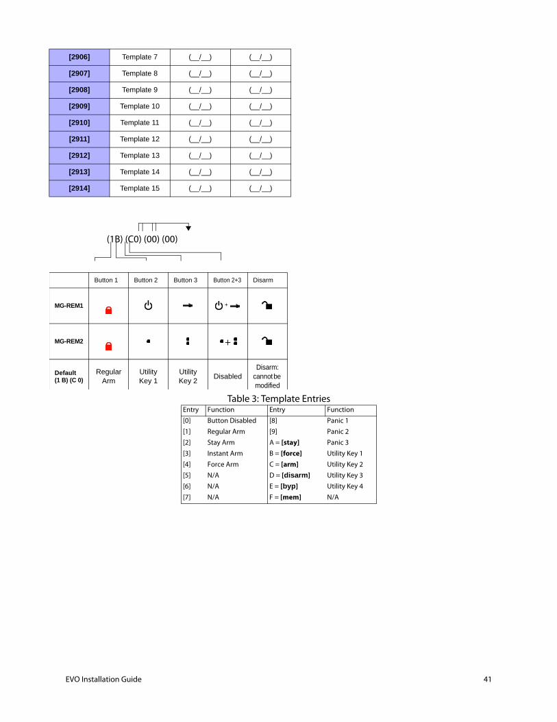
[2906] Template 7 (__/__) (__/__)
[2907] Template 8 (__/__) (__/__)
[2908] Template 9 (__/__) (__/__)
[2909] Template 10 (__/__) (__/__)
[2910] Template 11 (__/__) (__/__)
[2911] Template 12 (__/__) (__/__)
[2912] Template 13 (__/__) (__/__)
[2913] Template 14 (__/__) (__/__)
[2914] Template 15 (__/__) (__/__)
Button 1 Button 2 Button 3 Button 2+3 Disarm
MG-REM1
MG-REM2
Default(1 B) (C 0)
Regular Arm
Utility Key 1
UtilityKey 2
DisabledDisarm:
cannot be modified
+
+
(1B) (C0) (00) (00)
Table 3: Template EntriesEntry Function Entry Function
[0] Button Disabled [8] Panic 1
[1] Regular Arm [9] Panic 2
[2] Stay Arm A = [stay] Panic 3
[3] Instant Arm B = [force] Utility Key 1
[4] Force Arm C = [arm] Utility Key 2
[5] N/A D = [disarm] Utility Key 3
[6] N/A E = [byp] Utility Key 4
[7] N/A F = [mem] N/A
EVO Installation Guide 41
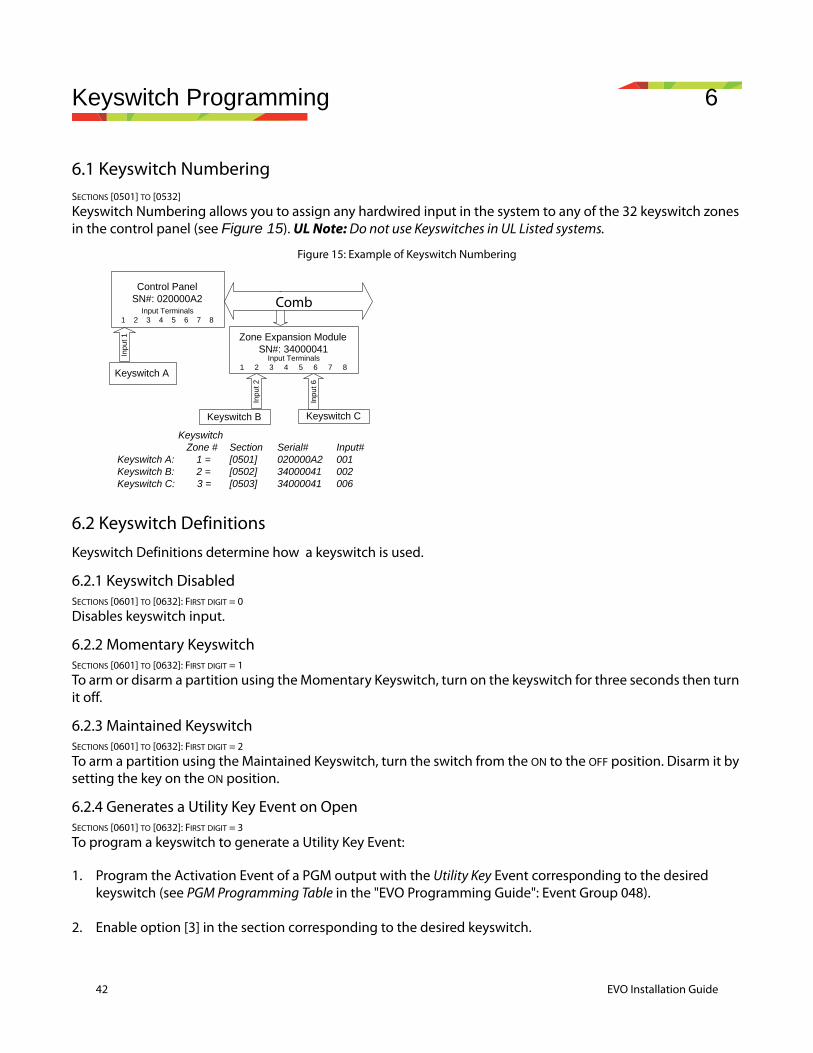
42 EVO Installation Guide
Keyswitch Programming 6
6.1 Keyswitch NumberingSECTIONS [0501] TO [0532]
Keyswitch Numbering allows you to assign any hardwired input in the system to any of the 32 keyswitch zones in the control panel (see Figure 15). UL Note: Do not use Keyswitches in UL Listed systems.
Figure 15: Example of Keyswitch Numbering
6.2 Keyswitch DefinitionsKeyswitch Definitions determine how a keyswitch is used.
6.2.1 Keyswitch DisabledSECTIONS [0601] TO [0632]: FIRST DIGIT = 0
Disables keyswitch input.
6.2.2 Momentary KeyswitchSECTIONS [0601] TO [0632]: FIRST DIGIT = 1
To arm or disarm a partition using the Momentary Keyswitch, turn on the keyswitch for three seconds then turn it off.
6.2.3 Maintained KeyswitchSECTIONS [0601] TO [0632]: FIRST DIGIT = 2
To arm a partition using the Maintained Keyswitch, turn the switch from the ON to the OFF position. Disarm it by setting the key on the ON position.
6.2.4 Generates a Utility Key Event on OpenSECTIONS [0601] TO [0632]: FIRST DIGIT = 3
To program a keyswitch to generate a Utility Key Event:
1. Program the Activation Event of a PGM output with the Utility Key Event corresponding to the desired keyswitch (see PGM Programming Table in the "EVO Programming Guide": Event Group 048).
2. Enable option [3] in the section corresponding to the desired keyswitch.
Control PanelSN#: 020000A2
Keyswitch B Keyswitch C
Keyswitch Zone # Section Serial# Input# Keyswitch A: 1 = [0501] 020000A2 001 Keyswitch B: 2 = [0502] 34000041 002 Keyswitch C: 3 = [0503] 34000041 006
Inpu
t 2
Inpu
t 6
Keyswitch A
Inpu
t 1
Input Terminals1 2 3 4 5 6 7 8
COMMUNICATION NETWORK
Zone Expansion ModuleSN#: 34000041
Input Terminals1 2 3 4 5 6 7 8
Comb
6.2.5 Generates a Utility Key Event on Open and CloseSECTIONS [0601] TO [0632]: FIRST DIGIT = 4
A Utility Key Event can be generated whenever the keyswitch input is opened or closed. The Utility Key Events increase from 32 to 64 events; one event for each state.
When a keyswitch is defined with the Generate a Utility Key Event on Open and Close option, the Keyswitch Partition Assignment and Keyswitch Options are disabled. To program a keyswitch to generate a Utility Key Event:
1. Program the Activation Event of a PGM output with the Utility Key Event corresponding to the desired keyswitch (see PGM Programming Table in the "EVO Programming Guide": Event Group 048).
2. Enable option [4] in the section corresponding to the desired keyswitch.
6.3 Keyswitch Partition AssignmentSECTIONS [0601] TO [0632]: SECOND DIGIT = 1 TO 8
Each keyswitch must be assigned to one partition.
6.4 Keyswitch OptionsEach keyswitch zone can be programmed with one or more options.
6.4.1 Disarm OnlySections [0601] to [0632]: Option [3]
When enabled, the keyswitch can only disarm assigned partitions. The type of disarming is determined by the other Keyswitch Options selected.
6.4.2 Stay/Instant Disarm Option (Keyswitch)SECTIONS [0601] TO [0632]: OPTION [4]
When enabled, the keyswitch can only disarm assigned Stay or Instant armed partitions. When option [4] is disabled, the keyswitch can disarm partitions armed using any arming method.
6.4.3 Arm Only (Keyswitch)SECTIONS [0601] TO [0632]: OPTION [5]
When enabled, the keyswitch can only arm assigned partitions. The type of arming is determined by the other Keyswitch Options selected.
6.4.4 Regular Arming (Keyswitch)SECTIONS [0601] TO [0632]: OPTION [6] TO [8]
With disabled, the arming option will be Regular arming.
6.4.5 Stay Arming (Keyswitch)SECTIONS [0601] TO [0632]: OPTION [6]
Activating the keyswitch will Stay Arm the partition.
6.4.6 Force Arming (Keyswitch)SECTIONS [0601] TO [0632]: OPTION [7]
Activating the keyswitch will force arm the selected partition.
6.4.7 Instant Arming (Keyswitch)SECTIONS [0601] TO [0632]: OPTION [8]
This option is identical to Stay arming except that all armed zones will become Instant Zones.
EVO Installation Guide 43

44 EVO Installation Guide
Only one of the arming options (Stay, Force, Instant and Regular) can be selected.

Testing and Maintenance 7
7.0.1 EVO192 PanelThe Digiplex EVO is a security and access control system with 8 on-board zone inputs (16 with zone doubling) that is expandable to 48 or 192 zones via the 4-wire combus. The EVO control panel features up to 999 users, 8 partitions, 32 doors and can support up to 254 modules in any combination.
The Digiplex EVO system provides the highest level of protection for banks, high-security military and government sites, luxurious residential homes and any place where maximum security is essential. These systems are designed to be easy to use, and the modular concept of these systems provides installers with labour-saving features that make expanding, installing and servicing these systems quick and convenient.
Expand the EVO system by adding plug-and-play expansion modules anywhere and in any combination on the 4-wire combus. Modules are connected to the combus at the most convenient location and then their zone inputs are assigned to the desired zone and partition. Also, only a module’s used inputs are assigned to zones in the system. Keyswitches, remote controls and unused module inputs do not use up zones. Once installed, all combus modules, including motion detectors, can be programmed remotely via a keypad or the WinLoad upload/download software.
EVO also supports 32 virtual zones in addition to its security zones and access control doors. Virtual zones can be used to automate PGM activations without occupying a security zone and without affecting the system’s security functions. The EVO system is a logical solution to every installer’s security, access control and home automation installation needs.
Features of EVO192 Controller
• Digital combus:• Provides constant power, supervision and two-way communication between the control panel and all its
modules• Supports up to 127 modules• Connect modules up to 914m (3000ft) from the panel2• Sabotage-proof technology without additional wiring• 8 on-board zones (16 w/ zone doubling) expandable to 192 zones via 4-wire combus• Automatic Daylight Saving Time feature• 2 on-board solid-state relays PGM outputs (+ 3 optional), negative or positive triggering• PGM1 can be used as a 2-wire smoke input3• Built-in-real-time clock backup battery• 1 supervised bell output, auxiliary output and telephone line• Push button software reset (reset to default values and restart)• Push button to activate or deactivate the Auxiliary output
Note: Connection of non ETL/UL listed component will void the ETL listing
Note: Connect according to the wiring requirements described in the Wiring Diagram
Note: 2-Wire Smoke Detector was not evaluated by ETL
• Fits in a 28cm x 28cm x 7.6cm (11in x 11in x 3in) metal box• 5 on-board solid-state PGM outputs, negative or positive triggering
EVO Installation Guide 45
46 EVO Installation Guide
• Supports up to 254 expansion bus modules• 999 user codes• 8 partitions• 2048 events buffered
Specifications
Control Panel AC Power: 17Vac, 40VA, 60HzBattery: 12Vdc, 7Ah Auxiliary Power: 11.4 to 12.5Vdc, 700mA maximum, fuseless shutdown at 1.1ABell Output: 11.4 to 12.5Vdc, 1A maximum, fuseless shutdown @ 3APGM Output: PGM1 to PGM4 100mA solid-state relays with +/- trigger, PGM5 Form C relay output rated at 5A/28Vdc N.O. / N.C.Max current/Power 40VAOperational Temperature: -20°C to +50°C (4°F to +122°F)All control panel outputs are rated to operate between 11.4Vdc and 12.5Vdc
Electrical ratings (current, power) on the product or in the installation instructions. Missing Current / Power
Specifications may change without prior notice.
See Component Installation guides at the end of this document for Installation instructions.
7.0.2 Hub Module HUB2The APR3-HUB2 is a non-addressable module that extends and divides the control panel’s bus into two completely isolated bus outputs (two for each connected APR3-HUB2). It extends the combus/communication bus by regenerating the signal between the control panel and its modules. Should one bus output experience trouble or tampering, the other will remain unaffected. The hub monitors the signal between the control panel and modules on each output. If the hub detects a loss of signal integrity it will cut off the troubled output until proper communication is reestablished.
See Component Specifications and Installation guides at the end of this document for Installation instructions.
7.0.3 Hardwired keypad K641 The K641 Keypad allows you to control your Paradox system’s functions through its keypad interface.
General Note 1Please note that only LCD and Grafica keypads can be used to program the EVO system. LED keypads cannot be used to program the system.
General Note 2Please note that the steps may differ when programming with the Grafica keypad (DNE-K07). If not indicated, refer to the complete “Grafica User Manual”, which can be downloaded for free from our website at paradox.com
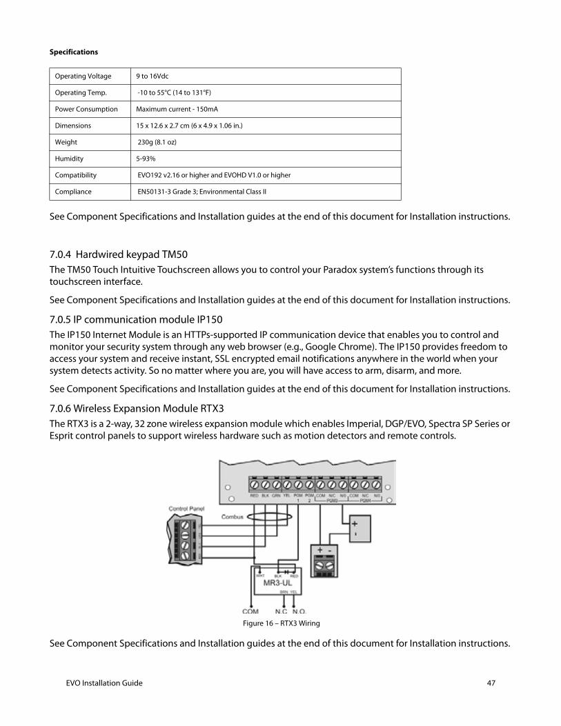
Specifications
See Component Specifications and Installation guides at the end of this document for Installation instructions.
7.0.4 Hardwired keypad TM50 The TM50 Touch Intuitive Touchscreen allows you to control your Paradox system’s functions through its touchscreen interface.
See Component Specifications and Installation guides at the end of this document for Installation instructions.
7.0.5 IP communication module IP150The IP150 Internet Module is an HTTPs-supported IP communication device that enables you to control and monitor your security system through any web browser (e.g., Google Chrome). The IP150 provides freedom to access your system and receive instant, SSL encrypted email notifications anywhere in the world when your system detects activity. So no matter where you are, you will have access to arm, disarm, and more.
See Component Specifications and Installation guides at the end of this document for Installation instructions.
7.0.6 Wireless Expansion Module RTX3The RTX3 is a 2-way, 32 zone wireless expansion module which enables Imperial, DGP/EVO, Spectra SP Series or Esprit control panels to support wireless hardware such as motion detectors and remote controls.
Figure 16 – RTX3 Wiring
See Component Specifications and Installation guides at the end of this document for Installation instructions.
Operating Voltage 9 to 16Vdc
Operating Temp. -10 to 55°C (14 to 131°F)
Power Consumption Maximum current - 150mA
Dimensions 15 x 12.6 x 2.7 cm (6 x 4.9 x 1.06 in.)
Weight 230g (8.1 oz)
Humidity 5-93%
Compatibility EVO192 v2.16 or higher and EVOHD V1.0 or higher
Compliance EN50131-3 Grade 3; Environmental Class II
EVO Installation Guide 47

48 EVO Installation Guide
7.1 ZX8 Expansion ModuleThe 8-zone Expansion Module (ZX8) is an interface between the control panels and any hardwired detection devices. The ZX8 connects to the control panel's combus to provide eight additional hardwired inputs and one 50mA on-board PGM output.
See Component Specifications and Installation guides at the end of this document for Installation instructions.
7.2 Programming LocationsThis panel can be programmed at all K641 Keypads or TM50 touchpads connected to the system.
7.3 Testing and Maintenance
Note: This system must be checked by a qualified technician at least once every three (3) years.
Note: The security system should be tested weekly by the master user or his assignee.
Note: The tester should always notify the CMS before starting a test.
Note: This system must be checked monthly with the primary ac power de-energized.
Note: Automatic Termination of System Test Mode is not supported.
Maintenance of smoke detectors must be done. To keep your equipment in excellent working order, ongoing monthly maintenance is required as outlined above and as per UL and NFPA standards. A preventative maintenance agreement should be arranged through the local manufacturer’s representative. Though smoke detectors are designed for long life, they may fail at any time. Any smoke detector, fire alarm equipment, or any component of that system which fails must be repaired or replaced as soon as possible.
7.3.1 Burglar Alarm TestingTwo people are needed to complete this test. One person will watch the screen on the keypad while the other person walks around the protected areas and opens the zones.
(i.e. opens the doors and windows that are protected, walk in the path of the motion detectors, etc.). The screen will display the opened zones, but if a zone does not register, contact your installer.
7.3.2 Fire Alarm TestingDo NOT use an open flame or burning materials to test your fire detection devices. Your installer will provide details on the best way to test your system.
Note: The smoke detector model SD360 shall be tested and maintained according to its installation guide ref. SD360-EI00.
7.3.3 System MaintenanceUnder normal use your system requires no maintenance other than regular testing. We recommend that your installer change the battery every three years.
Lamp and fuse replacement –
Battery maintenance and replacement –
Name and address of service people to contact in event of trouble –
Loss of AC power –
Low battery –
7.3.4 System TestSpeak to your installer before conducting a System Test since the system must be programmed to respond to the test instructions. It is normally recommended that you conduct the system test once a week, but contact your installer for instructions concerning your particular system.
To conduct the system test see see Installer Function Keys on page 90
The system will test all its connections and can send a report to your monitoring station.
If the system detects a problem, the Trouble Display will show on the screen (refer to section 9.0 on page 19). Call your installer for repairs if any troubles occur.
7.3.5 Beep on TroubleThis system can be configured to beep with the following trouble indications:
• System and clock trouble beep • Communicator trouble beep • Module and combus trouble beep • All zone trouble beep See the EVO programming guide for instructions on enabling audible trouble notices through the keypad or through Babyware.
7.3.6 Replacement PartsThe following parts are replaceable.
1. Main backup battery 12Vdc 7Ah rechargeable acid/lead backup battery
2. AC/AC transformer For US: UL/ETL Listed Class 2 wall/building 120VAC/60Hz power supply with restraining means. For Canada: CSA/ULc/ETLc Listed Class 2 Power Supply with NO restraining mean Must be Listed to the LSS standard or must be Surge protected Power supply For residential installations use transformer made by Universal Power Group model: UB1640W
3. Use UL Approved fuses FAST BLOW 5A/125V 5X20MM
7.3.7 End User InstructionsNeed to fill in
Normal standby –
Alarm –
Alarm test –
Alarm silence –
Trouble –
Trouble silence –
Off-normal position of switches –
Functions of lights, switches –
1. To prevent risk of shock, disconnect telephone line at telco jack before servicing this unit.
EVO Installation Guide 49

50 EVO Installation Guide
Note: For ETL and UL The minimum permissible wire size to be employed shall be not smaller than No. 22 AWG (0.32 mm2).
2. Use rubber bushings to protect the wires going through the metal housing.
3. Ground the metal box to a valid ground post or according to local electrical codes.
4. Do not use any switch-controlled outlets to power the transformer. The system should be connected to the building’s power source (grounded outlet) with an AC/AC transformer.
5. Use a UL approved transformer. Use only LSS standard or a surge protected power supply. For residential installations use transformer made by Universal Power Group model: UB1640W
6. The maximum charging current for the battery is 1amp. For UL installation 850ma charging current is required.
7. Use only Metal boxes to comply with ANSI/NFPA 72.
8. To prevent risk of electric shock, disconnect AC, battery, and phone cord BEFORE Servicing.
9. The knockouts in this box are compatible with standard conduit.
10. Main Supply Circuit – 110V, 60 Hz, with a transformer of max. power 40VA must be Listed to the LSS standard or must be Surge protected Power supply. For residential installations use transformer made by Universal Power Group model: UB1640W
11. The system should be installed in accordance with Chapter 2 of the National Fire Alarm Code, ANSI/NFPA 72
12. Installation of Residential Fire Warning Systems shall be in accordance with CAN/ULC-S540;
13. The panel will cease to process sensor trips if the voltage is under 8.5V.
14. Do no short the terminals of the transformer together. This causes the internal fuse to blow.
15. For the US and Canada: The transformer must be connected to a 110VAC/60Hz, 24-hour outlet which is not controlled by a switch other than an approved over-current protection device. Must be Listed to the LSS standard or must be Surge protected Power supply. For residential installations use transformer made by Universal Power Group model: UB1640W
16. For continued protection against risk of fire, replace fuses only with fuses of the same type and rating.
17. Install part TK278 Tamper kit in the panel metal box.
18. Wiring methods shall be in accordance with the National Electrical Code, ANSI/NFPA 70, the Standard for Installation and Classification of Burglar and Holdup Alarm Systems, UL 681, and the Standard for Central-Station Alarm Services, UL 827.
19. Wiring methods in keeping with the requirements of CSA C22.1, Canadian Electrical Code, Part I, Safety Standard for Electrical Installations.
20. Connect a power on LED that shows when there is board power visible from outside of the box. The wires need to be connected to one of the AC terminals and the other to the COM terminal.
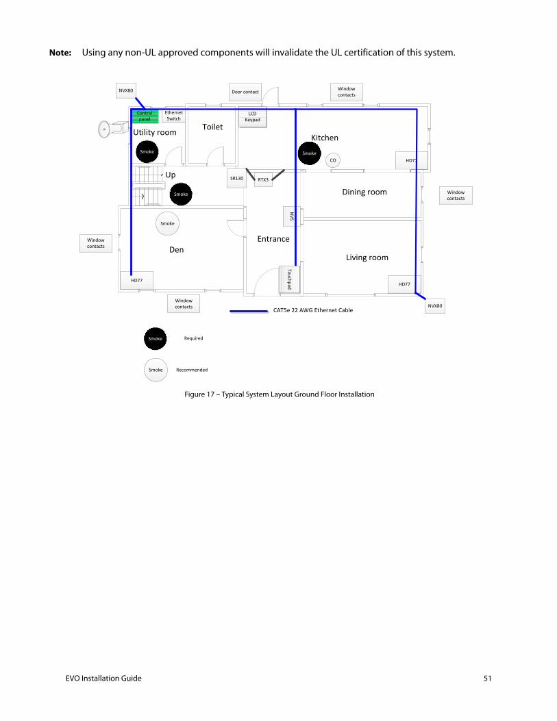
Note: Using any non-UL approved components will invalidate the UL certification of this system.
Figure 17 – Typical System Layout Ground Floor Installation
Up
DenLiving room
Dining room
KitchenToiletUtility room
Entrance
Control panel
NVX80
NVX80
HD77HD77
CO HD77
Smoke
Ethernet Switch
NV5
Door contact Window contacts
Window contacts
Window contacts
Window contacts
RTX3SR130
LCD Keypad
CAT5e 22 AWG Ethernet Cable
Touchpad
Smoke
Smoke
Required
Recommended
Smoke
Smoke Smoke
EVO Installation Guide 51
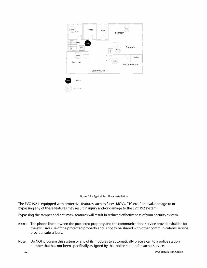
52 EVO Installation Guide
Figure 18 – Typical 2nd Floor Installation
The EVO192 is equipped with protective features such as fuses, MOVs, PTC etc. Removal, damage to or bypassing any of these features may result in injury and/or damage to the EVO192 system.
Bypassing the tamper and anti mask features will result in reduced effectiveness of your security system.
Note: The phone line between the protected property and the communications service provider shall be for the exclusive use of the protected property and is not to be shared with other communications service provider subscribers.
Note: Do NOT program this system or any of its modules to automatically place a call to a police station number that has not been specifically assigned by that police station for such a service.
Up
BedroomMaster bedroom
Bedroom
BedroomToilet
Bedroom
Smoke
Smoke
NV5
Toilet
Toilet
Laundry Area
Smoke Smoke
Smoke
Smoke
SR130
Smoke
Smoke
Required
Recommended

7.4 Call Waiting Cancel1. Section 4.5 requires a programmable option for call waiting cancel shall be required on communicators that use media (e.g. PSTN) where call-waiting may be provisioned.
The programming for this feature must be added to the Programming Guide.
The installer needs to verify the code in the premises area for the telephone network that disables the call waiting feature, then add it to the monitoring station number. For example:
Receiving center phone number: 999-999-999
Call waiting cancelation code: *70
Phone number to program: *70P999999999
) Instructions that an automatic telephone dialer or similar device shall not be set or programmed to place a call to a police station number that has not been specifically assigned by that police station for such service. The instructions may be incorporated on the inside of the product, on a separate sheet, or as part of a manual. If not included directly on the product, the instructions or manual shall be referenced in the marking information on the product. .
Note: Do NOT program this system or any of its modules to automatically place a call to a police station number that has not been specifically assigned by that police station for such a service.
7.5 Testing and Maintenance
7.5.1 Burglar Alarm TestingTwo people are needed to complete this test. One person will watch the screen on the keypad while the other person walks around the protected areas and opens the zones.
(i.e. opens the doors and windows that are protected, walk in the path of the motion detectors, etc.). The screen will display the opened zones, but if a zone does not register, contact your installer.
7.5.2 Fire Alarm TestingDo NOT use an open flame or burning materials to test your fire detection devices. Your installer will provide details on the best way to test your system.
7.5.3 System MaintenanceUnder normal use your system requires no maintenance other than regular testing. We recommend that your installer change the battery every three years.
7.5.4 System TestSpeak to your installer before conducting a System Test since the system must be programmed to respond to the test instructions. It is normally recommended that you conduct the system test once a week, but contact your installer for instructions concerning your particular system.
The system will test all its connections and can send a report to your monitoring station.
If the system detects a problem, the Trouble Display will show on the screen (refer to section 9.0 on page 19). Call your installer for repairs if any troubles occur.
7.5.5 Replacement PartsThe following parts are replaceable.
1. Main backup battery must be a12Vdc 7Ah rechargeable acid/lead battery.
EVO Installation Guide 53

54 EVO Installation Guide
2. AC/ AC transformer The transformer must be to the LSS standard or be connected to a surge protected power supply. For residential installations use transformer made by Universal Power Group model: UB1640W
3. For US: UL/ETL Listed Class 2 wall/building 120VAC/60Hz power supply with restraining means. For Canada: CSA/ULc/ETLc Listed Class 2 Power Supply with NO restraining means
4. Fuse UL Approved FUSE FAST BLOW 5A/125V 5X20MM
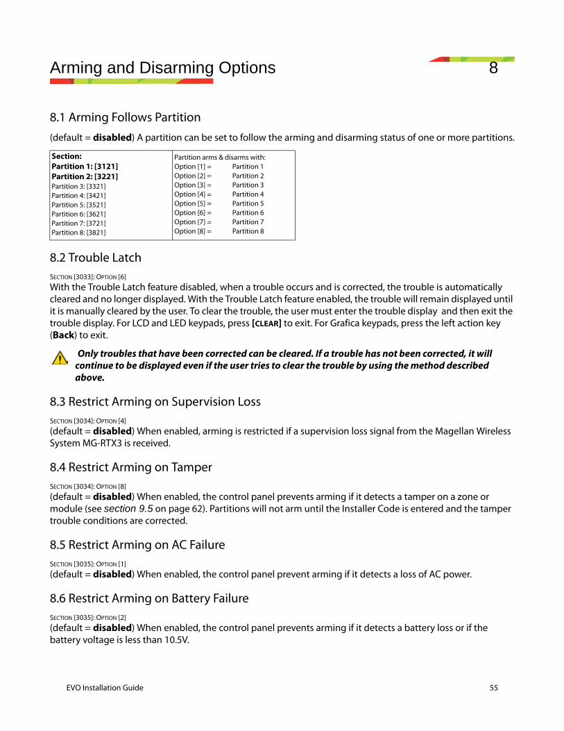
Arming and Disarming Options 8
8.1 Arming Follows Partition(default = disabled) A partition can be set to follow the arming and disarming status of one or more partitions.
8.2 Trouble LatchSECTION [3033]: OPTION [6]
With the Trouble Latch feature disabled, when a trouble occurs and is corrected, the trouble is automatically cleared and no longer displayed. With the Trouble Latch feature enabled, the trouble will remain displayed until it is manually cleared by the user. To clear the trouble, the user must enter the trouble display and then exit the trouble display. For LCD and LED keypads, press [CLEAR] to exit. For Grafica keypads, press the left action key (Back) to exit.
Only troubles that have been corrected can be cleared. If a trouble has not been corrected, it will continue to be displayed even if the user tries to clear the trouble by using the method described above.
8.3 Restrict Arming on Supervision LossSECTION [3034]: OPTION [4]
(default = disabled) When enabled, arming is restricted if a supervision loss signal from the Magellan Wireless System MG-RTX3 is received.
8.4 Restrict Arming on Tamper SECTION [3034]: OPTION [8]
(default = disabled) When enabled, the control panel prevents arming if it detects a tamper on a zone or module (see section 9.5 on page 62). Partitions will not arm until the Installer Code is entered and the tamper trouble conditions are corrected.
8.5 Restrict Arming on AC FailureSECTION [3035]: OPTION [1]
(default = disabled) When enabled, the control panel prevent arming if it detects a loss of AC power.
8.6 Restrict Arming on Battery FailureSECTION [3035]: OPTION [2]
(default = disabled) When enabled, the control panel prevents arming if it detects a battery loss or if the battery voltage is less than 10.5V.
Section:Partition 1: [3121]Partition 2: [3221]Partition 3: [3321]Partition 4: [3421]Partition 5: [3521]Partition 6: [3621]Partition 7: [3721]Partition 8: [3821]
Partition arms & disarms with:Option [1] = Partition 1Option [2] = Partition 2Option [3] = Partition 3Option [4] = Partition 4Option [5] = Partition 5Option [6] = Partition 6Option [7] = Partition 7Option [8] = Partition 8
EVO Installation Guide 55
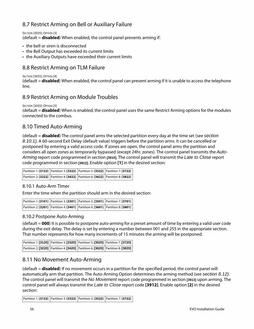
56 EVO Installation Guide
8.7 Restrict Arming on Bell or Auxiliary FailureSECTION [3035]: OPTION [3]
(default = disabled) When enabled, the control panel prevents arming if:
• the bell or siren is disconnected• the Bell Output has exceeded its current limits• the Auxiliary Outputs have exceeded their current limits
8.8 Restrict Arming on TLM FailureSECTION [3035]: OPTION [4]
(default = disabled) When enabled, the control panel can prevent arming if it is unable to access the telephone line.
8.9 Restrict Arming on Module TroublesSECTION [3035]: OPTION [5]
(default = disabled) When is enabled, the control panel uses the same Restrict Arming options for the modules connected to the combus.
8.10 Timed Auto-Arming
(default = disabled) The control panel arms the selected partition every day at the time set (see section 8.10.1). A 60-second Exit Delay (default value) triggers before the partition arms. It can be cancelled or postponed by entering a valid access code. If zones are open, the control panel arms the partition and considers all open zones as temporarily bypassed (except 24hr. zones). The control panel transmits the Auto-Arming report code programmed in section [3910]. The control panel will transmit the Late to Close report code programmed in section [3912]. Enable option [1] in the desired section:
8.10.1 Auto-Arm TimerEnter the time when the partition should arm in the desired section:
8.10.2 Postpone Auto-Arming(default = 000) It is possible to postpone auto-arming for a preset amount of time by entering a valid user code during the exit delay. The delay is set by entering a number between 001 and 255 in the appropriate section. That number represents for how many increments of 15 minutes the arming will be postponed.
8.11 No Movement Auto-Arming(default = disabled) If no movement occurs in a partition for the specified period, the control panel will automatically arm that partition. The Auto-Arming Option determines the arming method (see section 8.12). The control panel will transmit the No Movement report code programmed in section [3913] upon arming. The control panel will always transmit the Late to Close report code [3912]. Enable option [2] in the desired section:
Partition 1: [3122] Partition 3: [3322] Partition 5: [3522] Partition 7: [3722]
Partition 2: [3222] Partition 4: [3422] Partition 6: [3622] Partition 8: [3822]
Partition 1: [3101] Partition 3: [3301] Partition 5: [3501] Partition 7: [3701]
Partition 2: [3201] Partition 4: [3401] Partition 6: [3601] Partition 8: [3801]
Partition 1: [3120] Partition 3: [3320] Partition 5: [3520] Partition 7: [3720]
Partition 2: [3220] Partition 4: [3420] Partition 6: [3620] Partition 8: [3820]
Partition 1: [3122] Partition 3: [3322] Partition 5: [3522] Partition 7: [3722]
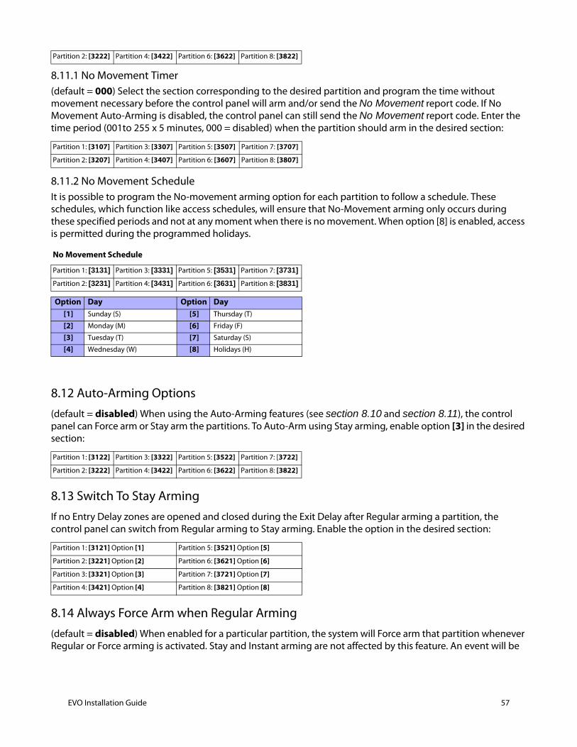
8.11.1 No Movement Timer(default = 000) Select the section corresponding to the desired partition and program the time without movement necessary before the control panel will arm and/or send the No Movement report code. If No Movement Auto-Arming is disabled, the control panel can still send the No Movement report code. Enter the time period (001to 255 x 5 minutes, 000 = disabled) when the partition should arm in the desired section:
8.11.2 No Movement ScheduleIt is possible to program the No-movement arming option for each partition to follow a schedule. These schedules, which function like access schedules, will ensure that No-Movement arming only occurs during these specified periods and not at any moment when there is no movement. When option [8] is enabled, access is permitted during the programmed holidays.
8.12 Auto-Arming Options(default = disabled) When using the Auto-Arming features (see section 8.10 and section 8.11), the control panel can Force arm or Stay arm the partitions. To Auto-Arm using Stay arming, enable option [3] in the desired section:
8.13 Switch To Stay ArmingIf no Entry Delay zones are opened and closed during the Exit Delay after Regular arming a partition, the control panel can switch from Regular arming to Stay arming. Enable the option in the desired section:
8.14 Always Force Arm when Regular Arming(default = disabled) When enabled for a particular partition, the system will Force arm that partition whenever Regular or Force arming is activated. Stay and Instant arming are not affected by this feature. An event will be
Partition 2: [3222] Partition 4: [3422] Partition 6: [3622] Partition 8: [3822]
Partition 1: [3107] Partition 3: [3307] Partition 5: [3507] Partition 7: [3707]
Partition 2: [3207] Partition 4: [3407] Partition 6: [3607] Partition 8: [3807]
No Movement Schedule
Partition 1: [3131] Partition 3: [3331] Partition 5: [3531] Partition 7: [3731]
Partition 2: [3231] Partition 4: [3431] Partition 6: [3631] Partition 8: [3831]
Option Day Option Day[1] Sunday (S) [5] Thursday (T)
[2] Monday (M) [6] Friday (F)
[3] Tuesday (T) [7] Saturday (S)
[4] Wednesday (W) [8] Holidays (H)
Partition 1: [3122] Partition 3: [3322] Partition 5: [3522] Partition 7: [3722]
Partition 2: [3222] Partition 4: [3422] Partition 6: [3622] Partition 8: [3822]
Partition 1: [3121] Option [1] Partition 5: [3521] Option [5]
Partition 2: [3221] Option [2] Partition 6: [3621] Option [6]
Partition 3: [3321] Option [3] Partition 7: [3721] Option [7]
Partition 4: [3421] Option [4] Partition 8: [3821] Option [8]
EVO Installation Guide 57
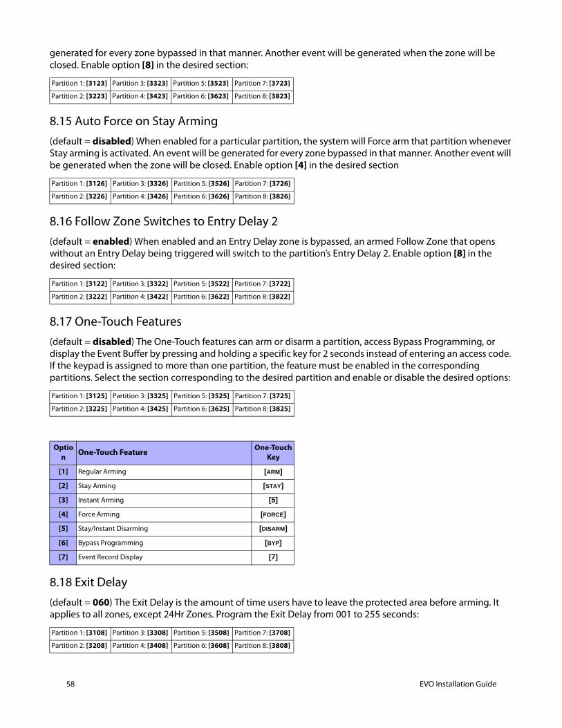
58 EVO Installation Guide
generated for every zone bypassed in that manner. Another event will be generated when the zone will be closed. Enable option [8] in the desired section:
8.15 Auto Force on Stay Arming(default = disabled) When enabled for a particular partition, the system will Force arm that partition whenever Stay arming is activated. An event will be generated for every zone bypassed in that manner. Another event will be generated when the zone will be closed. Enable option [4] in the desired section
8.16 Follow Zone Switches to Entry Delay 2(default = enabled) When enabled and an Entry Delay zone is bypassed, an armed Follow Zone that opens without an Entry Delay being triggered will switch to the partition’s Entry Delay 2. Enable option [8] in the desired section:
8.17 One-Touch Features(default = disabled) The One-Touch features can arm or disarm a partition, access Bypass Programming, or display the Event Buffer by pressing and holding a specific key for 2 seconds instead of entering an access code. If the keypad is assigned to more than one partition, the feature must be enabled in the corresponding partitions. Select the section corresponding to the desired partition and enable or disable the desired options:
8.18 Exit Delay(default = 060) The Exit Delay is the amount of time users have to leave the protected area before arming. It applies to all zones, except 24Hr Zones. Program the Exit Delay from 001 to 255 seconds:
Partition 1: [3123] Partition 3: [3323] Partition 5: [3523] Partition 7: [3723]
Partition 2: [3223] Partition 4: [3423] Partition 6: [3623] Partition 8: [3823]
Partition 1: [3126] Partition 3: [3326] Partition 5: [3526] Partition 7: [3726]
Partition 2: [3226] Partition 4: [3426] Partition 6: [3626] Partition 8: [3826]
Partition 1: [3122] Partition 3: [3322] Partition 5: [3522] Partition 7: [3722]
Partition 2: [3222] Partition 4: [3422] Partition 6: [3622] Partition 8: [3822]
Partition 1: [3125] Partition 3: [3325] Partition 5: [3525] Partition 7: [3725]
Partition 2: [3225] Partition 4: [3425] Partition 6: [3625] Partition 8: [3825]
Option One-Touch Feature One-Touch
Key
[1] Regular Arming [ARM]
[2] Stay Arming [STAY]
[3] Instant Arming [5]
[4] Force Arming [FORCE]
[5] Stay/Instant Disarming [DISARM]
[6] Bypass Programming [BYP]
[7] Event Record Display [7]
Partition 1: [3108] Partition 3: [3308] Partition 5: [3508] Partition 7: [3708]
Partition 2: [3208] Partition 4: [3408] Partition 6: [3608] Partition 8: [3808]
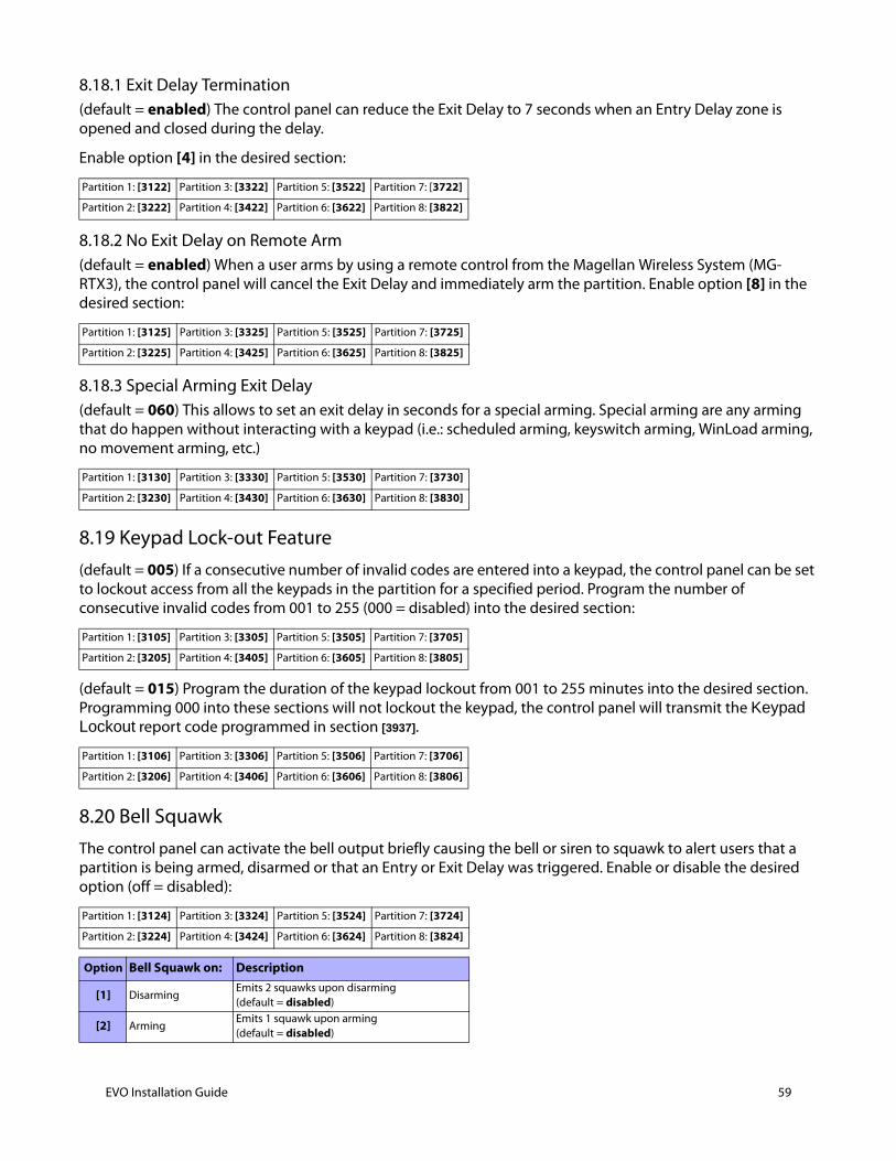
8.18.1 Exit Delay Termination(default = enabled) The control panel can reduce the Exit Delay to 7 seconds when an Entry Delay zone is opened and closed during the delay.
Enable option [4] in the desired section:
8.18.2 No Exit Delay on Remote Arm(default = enabled) When a user arms by using a remote control from the Magellan Wireless System (MG-RTX3), the control panel will cancel the Exit Delay and immediately arm the partition. Enable option [8] in the desired section:
8.18.3 Special Arming Exit Delay(default = 060) This allows to set an exit delay in seconds for a special arming. Special arming are any arming that do happen without interacting with a keypad (i.e.: scheduled arming, keyswitch arming, WinLoad arming, no movement arming, etc.)
8.19 Keypad Lock-out Feature(default = 005) If a consecutive number of invalid codes are entered into a keypad, the control panel can be set to lockout access from all the keypads in the partition for a specified period. Program the number of consecutive invalid codes from 001 to 255 (000 = disabled) into the desired section:
(default = 015) Program the duration of the keypad lockout from 001 to 255 minutes into the desired section. Programming 000 into these sections will not lockout the keypad, the control panel will transmit the Keypad Lockout report code programmed in section [3937].
8.20 Bell SquawkThe control panel can activate the bell output briefly causing the bell or siren to squawk to alert users that a partition is being armed, disarmed or that an Entry or Exit Delay was triggered. Enable or disable the desired option (off = disabled):
Partition 1: [3122] Partition 3: [3322] Partition 5: [3522] Partition 7: [3722]
Partition 2: [3222] Partition 4: [3422] Partition 6: [3622] Partition 8: [3822]
Partition 1: [3125] Partition 3: [3325] Partition 5: [3525] Partition 7: [3725]
Partition 2: [3225] Partition 4: [3425] Partition 6: [3625] Partition 8: [3825]
Partition 1: [3130] Partition 3: [3330] Partition 5: [3530] Partition 7: [3730]
Partition 2: [3230] Partition 4: [3430] Partition 6: [3630] Partition 8: [3830]
Partition 1: [3105] Partition 3: [3305] Partition 5: [3505] Partition 7: [3705]
Partition 2: [3205] Partition 4: [3405] Partition 6: [3605] Partition 8: [3805]
Partition 1: [3106] Partition 3: [3306] Partition 5: [3506] Partition 7: [3706]
Partition 2: [3206] Partition 4: [3406] Partition 6: [3606] Partition 8: [3806]
Partition 1: [3124] Partition 3: [3324] Partition 5: [3524] Partition 7: [3724]
Partition 2: [3224] Partition 4: [3424] Partition 6: [3624] Partition 8: [3824]
Option Bell Squawk on: Description
[1] DisarmingEmits 2 squawks upon disarming (default = disabled)
[2] ArmingEmits 1 squawk upon arming(default = disabled)
EVO Installation Guide 59
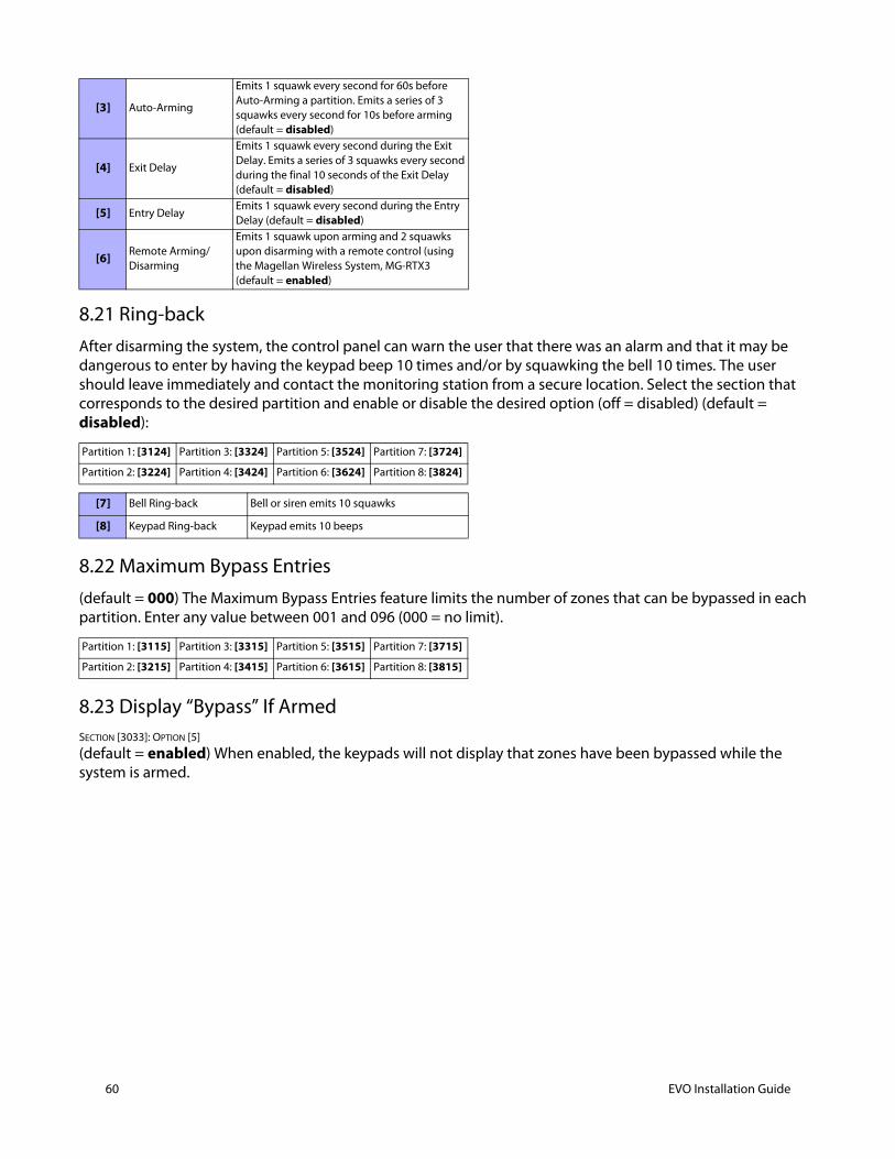
60 EVO Installation Guide
8.21 Ring-backAfter disarming the system, the control panel can warn the user that there was an alarm and that it may be dangerous to enter by having the keypad beep 10 times and/or by squawking the bell 10 times. The user should leave immediately and contact the monitoring station from a secure location. Select the section that corresponds to the desired partition and enable or disable the desired option (off = disabled) (default = disabled):
8.22 Maximum Bypass Entries(default = 000) The Maximum Bypass Entries feature limits the number of zones that can be bypassed in each partition. Enter any value between 001 and 096 (000 = no limit).
8.23 Display “Bypass” If ArmedSECTION [3033]: OPTION [5]
(default = enabled) When enabled, the keypads will not display that zones have been bypassed while the system is armed.
[3] Auto-Arming
Emits 1 squawk every second for 60s before Auto-Arming a partition. Emits a series of 3 squawks every second for 10s before arming (default = disabled)
[4] Exit Delay
Emits 1 squawk every second during the Exit Delay. Emits a series of 3 squawks every second during the final 10 seconds of the Exit Delay (default = disabled)
[5] Entry DelayEmits 1 squawk every second during the Entry Delay (default = disabled)
[6] Remote Arming/Disarming
Emits 1 squawk upon arming and 2 squawks upon disarming with a remote control (using the Magellan Wireless System, MG-RTX3(default = enabled)
Partition 1: [3124] Partition 3: [3324] Partition 5: [3524] Partition 7: [3724]
Partition 2: [3224] Partition 4: [3424] Partition 6: [3624] Partition 8: [3824]
[7] Bell Ring-back Bell or siren emits 10 squawks
[8] Keypad Ring-back Keypad emits 10 beeps
Partition 1: [3115] Partition 3: [3315] Partition 5: [3515] Partition 7: [3715]
Partition 2: [3215] Partition 4: [3415] Partition 6: [3615] Partition 8: [3815]
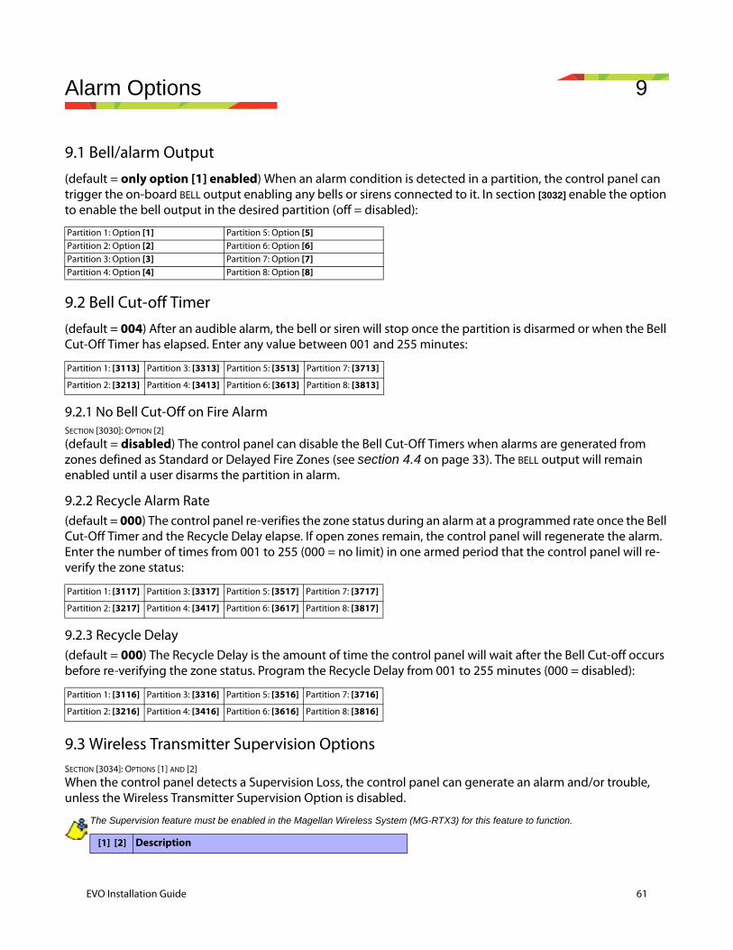
Alarm Options 9
9.1 Bell/alarm Output(default = only option [1] enabled) When an alarm condition is detected in a partition, the control panel can trigger the on-board BELL output enabling any bells or sirens connected to it. In section [3032] enable the option to enable the bell output in the desired partition (off = disabled):
9.2 Bell Cut-off Timer(default = 004) After an audible alarm, the bell or siren will stop once the partition is disarmed or when the Bell Cut-Off Timer has elapsed. Enter any value between 001 and 255 minutes:
9.2.1 No Bell Cut-Off on Fire AlarmSECTION [3030]: OPTION [2]
(default = disabled) The control panel can disable the Bell Cut-Off Timers when alarms are generated from zones defined as Standard or Delayed Fire Zones (see section 4.4 on page 33). The BELL output will remain enabled until a user disarms the partition in alarm.
9.2.2 Recycle Alarm Rate(default = 000) The control panel re-verifies the zone status during an alarm at a programmed rate once the Bell Cut-Off Timer and the Recycle Delay elapse. If open zones remain, the control panel will regenerate the alarm. Enter the number of times from 001 to 255 (000 = no limit) in one armed period that the control panel will re-verify the zone status:
9.2.3 Recycle Delay(default = 000) The Recycle Delay is the amount of time the control panel will wait after the Bell Cut-off occurs before re-verifying the zone status. Program the Recycle Delay from 001 to 255 minutes (000 = disabled):
9.3 Wireless Transmitter Supervision OptionsSECTION [3034]: OPTIONS [1] AND [2]
When the control panel detects a Supervision Loss, the control panel can generate an alarm and/or trouble, unless the Wireless Transmitter Supervision Option is disabled.
The Supervision feature must be enabled in the Magellan Wireless System (MG-RTX3) for this feature to function.
Partition 1: Option [1] Partition 5: Option [5]Partition 2: Option [2] Partition 6: Option [6]Partition 3: Option [3] Partition 7: Option [7]Partition 4: Option [4] Partition 8: Option [8]
Partition 1: [3113] Partition 3: [3313] Partition 5: [3513] Partition 7: [3713]
Partition 2: [3213] Partition 4: [3413] Partition 6: [3613] Partition 8: [3813]
Partition 1: [3117] Partition 3: [3317] Partition 5: [3517] Partition 7: [3717]
Partition 2: [3217] Partition 4: [3417] Partition 6: [3617] Partition 8: [3817]
Partition 1: [3116] Partition 3: [3316] Partition 5: [3516] Partition 7: [3716]
Partition 2: [3216] Partition 4: [3416] Partition 6: [3616] Partition 8: [3816]
[1] [2] Description
EVO Installation Guide 61
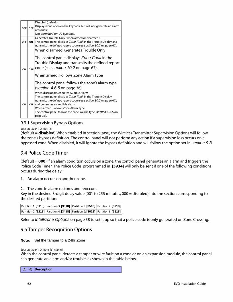
62 EVO Installation Guide
9.3.1 Supervision Bypass OptionsSECTION [3034]: OPTION [3]
(default = disabled) When enabled in section [3034], the Wireless Transmitter Supervision Options will follow the zone's bypass definition. The control panel will not perform any action if a supervision loss occurs on a bypassed zone. When disabled, it will ignore the bypass definition and will follow the option set in section 9.3.
9.4 Police Code Timer(default = 000) If an alarm condition occurs on a zone, the control panel generates an alarm and triggers the Police Code Timer. The Police Code programmed in [3934] will only be sent if one of the following conditions occurs during the delay:
1. An alarm occurs on another zone.
2. The zone in alarm restores and reoccurs.Key in the desired 3-digit delay value (001 to 255 minutes, 000 = disabled) into the section corresponding to the desired partition:
Refer to Intellizone Options on page 38 to set it up so that a police code is only generated on Zone Crossing.
9.5 Tamper Recognition Options
Note: Set the tamper to a 24hr Zone
SECTION [3034]: OPTIONS [5] AND [6]
When the control panel detects a tamper or wire fault on a zone or on an expansion module, the control panel can generate an alarm and/or trouble, as shown in the table below.
OFF OFF
Disabled (default):Displays zone open on the keypads, but will not generate an alarm or trouble. Not permitted on UL systems.
OFF ON
Generates Trouble Only (when armed or disarmed):The control panel displays Zone Fault in the Trouble Display and transmits the defined report code (see section 10.2 on page 67).
ON OFF
When disarmed: Generates Trouble Only
The control panel displays Zone Fault in the Trouble Display and transmits the defined report code (see section 10.2 on page 67).
When armed: Follows Zone Alarm Type
The control panel follows the zone’s alarm type (section 4.6.5 on page 36).
ON ON
When disarmed: Generates Audible AlarmThe control panel displays Zone Fault in the Trouble Display, transmits the defined report code (see section 10.2 on page 67), and generates an audible alarm.When armed: Follows Zone Alarm TypeThe control panel follows the zone’s alarm type (section 4.6.5 on page 36).
Partition 1: [3118] Partition 3: [3318] Partition 5: [3518] Partition 7: [3718]
Partition 2: [3218] Partition 4: [3418] Partition 6: [3618] Partition 8: [3818]
[5] [6] Description
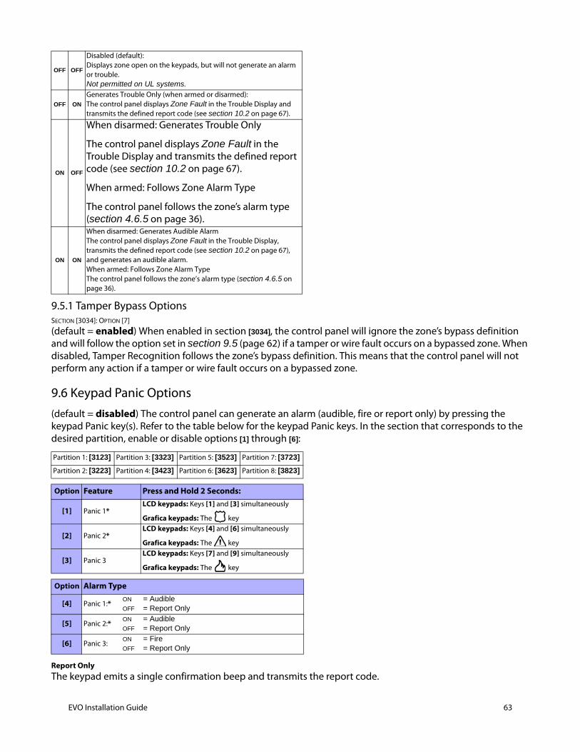
9.5.1 Tamper Bypass OptionsSECTION [3034]: OPTION [7]
(default = enabled) When enabled in section [3034], the control panel will ignore the zone’s bypass definition and will follow the option set in section 9.5 (page 62) if a tamper or wire fault occurs on a bypassed zone. When disabled, Tamper Recognition follows the zone’s bypass definition. This means that the control panel will not perform any action if a tamper or wire fault occurs on a bypassed zone.
9.6 Keypad Panic Options(default = disabled) The control panel can generate an alarm (audible, fire or report only) by pressing the keypad Panic key(s). Refer to the table below for the keypad Panic keys. In the section that corresponds to the desired partition, enable or disable options [1] through [6]:
Report OnlyThe keypad emits a single confirmation beep and transmits the report code.
OFF OFF
Disabled (default):Displays zone open on the keypads, but will not generate an alarm or trouble. Not permitted on UL systems.
OFF ON
Generates Trouble Only (when armed or disarmed):The control panel displays Zone Fault in the Trouble Display and transmits the defined report code (see section 10.2 on page 67).
ON OFF
When disarmed: Generates Trouble Only
The control panel displays Zone Fault in the Trouble Display and transmits the defined report code (see section 10.2 on page 67).
When armed: Follows Zone Alarm Type
The control panel follows the zone’s alarm type (section 4.6.5 on page 36).
ON ON
When disarmed: Generates Audible AlarmThe control panel displays Zone Fault in the Trouble Display, transmits the defined report code (see section 10.2 on page 67), and generates an audible alarm.When armed: Follows Zone Alarm TypeThe control panel follows the zone’s alarm type (section 4.6.5 on page 36).
Partition 1: [3123] Partition 3: [3323] Partition 5: [3523] Partition 7: [3723]
Partition 2: [3223] Partition 4: [3423] Partition 6: [3623] Partition 8: [3823]
Option Feature Press and Hold 2 Seconds:
[1] Panic 1*LCD keypads: Keys [1] and [3] simultaneously
Grafica keypads: The key
[2] Panic 2*LCD keypads: Keys [4] and [6] simultaneously
Grafica keypads: The key
[3] Panic 3LCD keypads: Keys [7] and [9] simultaneously
Grafica keypads: The key
Option Alarm Type
[4] Panic 1:*ON = AudibleOFF = Report Only
[5] Panic 2:*ON = AudibleOFF = Report Only
[6] Panic 3:ON = FireOFF = Report Only
EVO Installation Guide 63

64 EVO Installation Guide
Audible AlarmThe control panel activates the BELL output until a user cancels the alarm or when the Bell Cut-Off Timer elapses .
Fire AlarmSame as audible operation, except that the bell/siren output will be pulsed.
* UL Note: For UL Listed systems, all emergency non-medical and auxiliary panic alarms will be report only.

Event Reporting 10
EVO Installation Guide 65
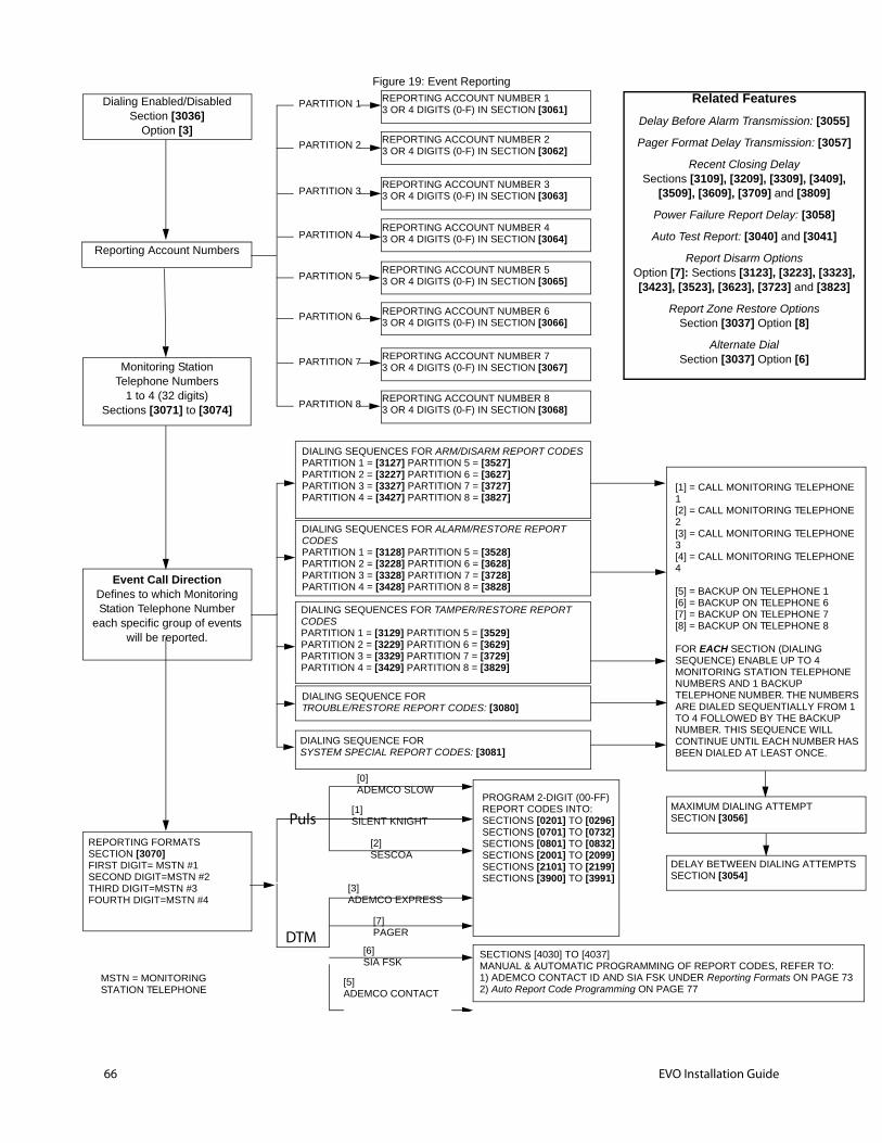
O:GE 73
PHONE
PHONE
PHONE
PHONE
1 6 7 8
HONE
MBERS ROM 1
KUP ILL ER HAS .
3055]
3057]
409], 9]
58]
41]
[3323], 3823]
EMPTS
66 EVO Installation Guide
Figure 19: Event Reporting
Dialing Enabled/DisabledSection [3036]
Option [3]
Reporting Account Numbers
Monitoring StationTelephone Numbers
1 to 4 (32 digits)Sections [3071] to [3074]
Event Call DirectionDefines to which Monitoring Station Telephone Number
each specific group of events will be reported.
REPORTING FORMATSSECTION [3070]FIRST DIGIT= MSTN #1SECOND DIGIT=MSTN #2THIRD DIGIT=MSTN #3FOURTH DIGIT=MSTN #4
PARTITION 1
PARTITION 2
PARTITION 3
PARTITION 4
PARTITION 5
PARTITION 6
PARTITION 7
PARTITION 8
REPORTING ACCOUNT NUMBER 13 OR 4 DIGITS (0-F) IN SECTION [3061]
REPORTING ACCOUNT NUMBER 23 OR 4 DIGITS (0-F) IN SECTION [3062]
REPORTING ACCOUNT NUMBER 33 OR 4 DIGITS (0-F) IN SECTION [3063]
REPORTING ACCOUNT NUMBER 43 OR 4 DIGITS (0-F) IN SECTION [3064]
REPORTING ACCOUNT NUMBER 53 OR 4 DIGITS (0-F) IN SECTION [3065]
REPORTING ACCOUNT NUMBER 63 OR 4 DIGITS (0-F) IN SECTION [3066]
REPORTING ACCOUNT NUMBER 73 OR 4 DIGITS (0-F) IN SECTION [3067]
REPORTING ACCOUNT NUMBER 83 OR 4 DIGITS (0-F) IN SECTION [3068]
MSTN = MONITORING STATION TELEPHONE
[0]ADEMCO SLOW
[1]SILENT KNIGHT
[2]SESCOA
[3]ADEMCO EXPRESS
[7]PAGER
[6]SIA FSK
[5]ADEMCO CONTACT
Puls
DTM
PROGRAM 2-DIGIT (00-FF) REPORT CODES INTO:SECTIONS [0201] TO [0296]SECTIONS [0701] TO [0732]SECTIONS [0801] TO [0832]SECTIONS [2001] TO [2099]SECTIONS [2101] TO [2199]SECTIONS [3900] TO [3991]
SECTIONS [4030] TO [4037]MANUAL & AUTOMATIC PROGRAMMING OF REPORT CODES, REFER T1) ADEMCO CONTACT ID AND SIA FSK UNDER Reporting Formats ON PA2) Auto Report Code Programming ON PAGE 77
DIALING SEQUENCES FOR ARM/DISARM REPORT CODESPARTITION 1 = [3127] PARTITION 5 = [3527]PARTITION 2 = [3227] PARTITION 6 = [3627]PARTITION 3 = [3327] PARTITION 7 = [3727]PARTITION 4 = [3427] PARTITION 8 = [3827]
DIALING SEQUENCES FOR ALARM/RESTORE REPORT CODESPARTITION 1 = [3128] PARTITION 5 = [3528]PARTITION 2 = [3228] PARTITION 6 = [3628]PARTITION 3 = [3328] PARTITION 7 = [3728]PARTITION 4 = [3428] PARTITION 8 = [3828]
DIALING SEQUENCES FOR TAMPER/RESTORE REPORT CODESPARTITION 1 = [3129] PARTITION 5 = [3529]PARTITION 2 = [3229] PARTITION 6 = [3629]PARTITION 3 = [3329] PARTITION 7 = [3729]PARTITION 4 = [3429] PARTITION 8 = [3829]
DIALING SEQUENCE FORTROUBLE/RESTORE REPORT CODES: [3080]
DIALING SEQUENCE FORSYSTEM SPECIAL REPORT CODES: [3081]
[1] = CALL MONITORING TELE1[2] = CALL MONITORING TELE2[3] = CALL MONITORING TELE3[4] = CALL MONITORING TELE4
[5] = BACKUP ON TELEPHONE[6] = BACKUP ON TELEPHONE[7] = BACKUP ON TELEPHONE[8] = BACKUP ON TELEPHONE
FOR EACH SECTION (DIALINGSEQUENCE) ENABLE UP TO 4MONITORING STATION TELEPNUMBERS AND 1 BACKUP TELEPHONE NUMBER. THE NUARE DIALED SEQUENTIALLY FTO 4 FOLLOWED BY THE BACNUMBER. THIS SEQUENCE WCONTINUE UNTIL EACH NUMBBEEN DIALED AT LEAST ONCE
Related Features
Delay Before Alarm Transmission: [
Pager Format Delay Transmission: [
Recent Closing DelaySections [3109], [3209], [3309], [3
[3509], [3609], [3709] and [380
Power Failure Report Delay: [30
Auto Test Report: [3040] and [30
Report Disarm OptionsOption [7]: Sections [3123], [3223], [3423], [3523], [3623], [3723] and [
Report Zone Restore OptionsSection [3037] Option [8]
Alternate DialSection [3037] Option [6]
MAXIMUM DIALING ATTEMPTSECTION [3056]
DELAY BETWEEN DIALING ATTSECTION [3054]
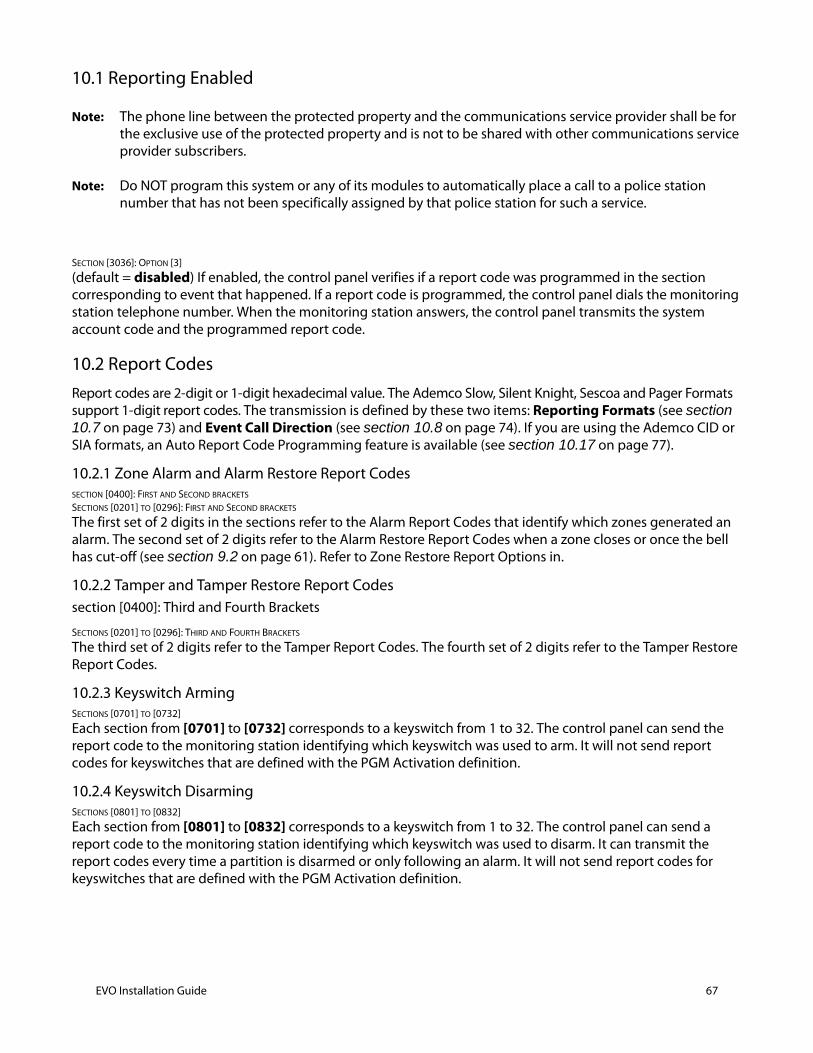
10.1 Reporting Enabled
Note: The phone line between the protected property and the communications service provider shall be for the exclusive use of the protected property and is not to be shared with other communications service provider subscribers.
Note: Do NOT program this system or any of its modules to automatically place a call to a police station number that has not been specifically assigned by that police station for such a service.
SECTION [3036]: OPTION [3]
(default = disabled) If enabled, the control panel verifies if a report code was programmed in the section corresponding to event that happened. If a report code is programmed, the control panel dials the monitoring station telephone number. When the monitoring station answers, the control panel transmits the system account code and the programmed report code.
10.2 Report Codes Report codes are 2-digit or 1-digit hexadecimal value. The Ademco Slow, Silent Knight, Sescoa and Pager Formats support 1-digit report codes. The transmission is defined by these two items: Reporting Formats (see section 10.7 on page 73) and Event Call Direction (see section 10.8 on page 74). If you are using the Ademco CID or SIA formats, an Auto Report Code Programming feature is available (see section 10.17 on page 77).
10.2.1 Zone Alarm and Alarm Restore Report Codes SECTION [0400]: FIRST AND SECOND BRACKETS
SECTIONS [0201] TO [0296]: FIRST AND SECOND BRACKETS
The first set of 2 digits in the sections refer to the Alarm Report Codes that identify which zones generated an alarm. The second set of 2 digits refer to the Alarm Restore Report Codes when a zone closes or once the bell has cut-off (see section 9.2 on page 61). Refer to Zone Restore Report Options in.
10.2.2 Tamper and Tamper Restore Report Codessection [0400]: Third and Fourth Brackets
SECTIONS [0201] TO [0296]: THIRD AND FOURTH BRACKETS
The third set of 2 digits refer to the Tamper Report Codes. The fourth set of 2 digits refer to the Tamper Restore Report Codes.
10.2.3 Keyswitch Arming SECTIONS [0701] TO [0732]
Each section from [0701] to [0732] corresponds to a keyswitch from 1 to 32. The control panel can send the report code to the monitoring station identifying which keyswitch was used to arm. It will not send report codes for keyswitches that are defined with the PGM Activation definition.
10.2.4 Keyswitch Disarming SECTIONS [0801] TO [0832]
Each section from [0801] to [0832] corresponds to a keyswitch from 1 to 32. The control panel can send a report code to the monitoring station identifying which keyswitch was used to disarm. It can transmit the report codes every time a partition is disarmed or only following an alarm. It will not send report codes for keyswitches that are defined with the PGM Activation definition.
EVO Installation Guide 67
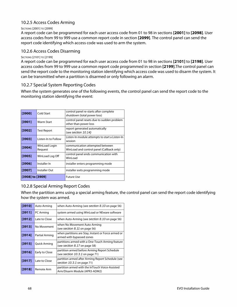
68 EVO Installation Guide
10.2.5 Access Codes Arming SECTIONS [2001] TO [2099]
A report code can be programmed for each user access code from 01 to 98 in sections [2001] to [2098]. User access codes from 99 to 999 use a common report code in section [2099]. The control panel can send the report code identifying which access code was used to arm the system.
10.2.6 Access Codes Disarming SECTIONS [2101] TO [2199]
A report code can be programmed for each user access code from 01 to 98 in sections [2101] to [2198]. User access codes from 99 to 999 use a common report code programmed in section [2199].The control panel can send the report code to the monitoring station identifying which access code was used to disarm the system. It can be transmitted when a partition is disarmed or only following an alarm.
10.2.7 Special System Reporting CodesWhen the system generates one of the following events, the control panel can send the report code to the monitoring station identifying the event:
10.2.8 Special Arming Report CodesWhen the partition arms using a special arming feature, the control panel can send the report code identifying how the system was armed.
[3900] Cold Startcontrol panel re-starts after complete shutdown (total power loss)
[3901] Warm Startcontrol panel resets due to sudden problem other than power loss
[3902] Test Reportreport generated automatically (see section 10.14)
[3903] Listen-In to FollowListen-In module attempts to start a Listen-In session
[3904] WinLoad Login Request
communication attempted between WinLoad and control panel (Callback only)
[3905] WinLoad Log Offcontrol panel ends communication with WinLoad
[3906] Installer In installer enters programming mode
[3907] Installer Out installer exits programming mode
[3908] to [3909] Future Use
[3910] Auto-Arming when Auto-Arming (see section 8.10 on page 56)
[3911] PC Arming system armed using WinLoad or NEware software
[3912] Late to Close when Auto-Arming (see section 8.10 on page 56)
[3913] No Movementwhen No Movement Auto-Arming (see section 8.11 on page 56)
[3914] Partial Armingwhen partitions are Stay, Instant or Force armed or armed with bypassed zones
[3915] Quick Armingpartitions armed with a One-Touch Arming feature (see section 8.17 on page 58)
[3916] Early to Closepartition armed before Arming Report Schedule (see section 10.3.1 on page 71)
[3917] Late to Closepartition armed after Arming Report Schedule (see section 10.3.1 on page 71)
[3918] Remote Armpartition armed with the InTouch Voice-Assisted Arm/Disarm Module (APR3-ADM2)
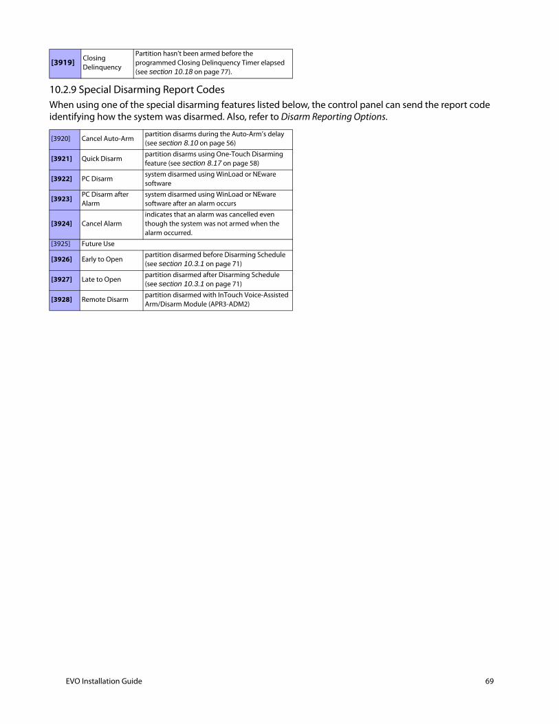
10.2.9 Special Disarming Report CodesWhen using one of the special disarming features listed below, the control panel can send the report code identifying how the system was disarmed. Also, refer to Disarm Reporting Options.
[3919] Closing Delinquency
Partition hasn’t been armed before the programmed Closing Delinquency Timer elapsed (see section 10.18 on page 77).
[3920] Cancel Auto-Armpartition disarms during the Auto-Arm’s delay (see section 8.10 on page 56)
[3921] Quick Disarmpartition disarms using One-Touch Disarming feature (see section 8.17 on page 58)
[3922] PC Disarmsystem disarmed using WinLoad or NEware software
[3923] PC Disarm after Alarm
system disarmed using WinLoad or NEware software after an alarm occurs
[3924] Cancel Alarmindicates that an alarm was cancelled even though the system was not armed when the alarm occurred.
[3925] Future Use
[3926] Early to Openpartition disarmed before Disarming Schedule (see section 10.3.1 on page 71)
[3927] Late to Openpartition disarmed after Disarming Schedule (see section 10.3.1 on page 71)
[3928] Remote Disarmpartition disarmed with InTouch Voice-Assisted Arm/Disarm Module (APR3-ADM2)
EVO Installation Guide 69
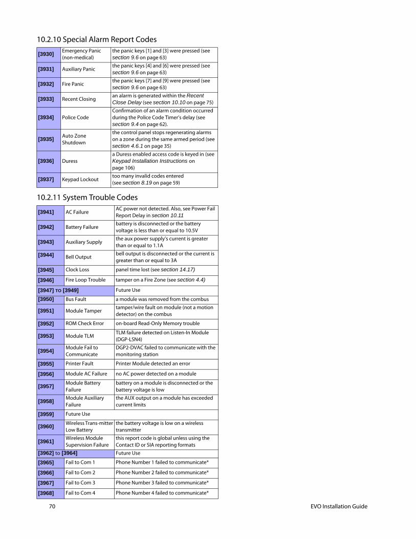
70 EVO Installation Guide
10.2.10 Special Alarm Report Codes
10.2.11 System Trouble Codes
[3930]Emergency Panic(non-medical)
the panic keys [1] and [3] were pressed (see section 9.6 on page 63)
[3931] Auxiliary Panicthe panic keys [4] and [6] were pressed (see section 9.6 on page 63)
[3932] Fire Panicthe panic keys [7] and [9] were pressed (see section 9.6 on page 63)
[3933] Recent Closingan alarm is generated within the Recent Close Delay (see section 10.10 on page 75)
[3934] Police CodeConfirmation of an alarm condition occurred during the Police Code Timer’s delay (see section 9.4 on page 62).
[3935]Auto Zone Shutdown
the control panel stops regenerating alarms on a zone during the same armed period (see section 4.6.1 on page 35)
[3936] Duressa Duress enabled access code is keyed in (see Keypad Installation Instructions on page 106)
[3937] Keypad Lockouttoo many invalid codes entered (see section 8.19 on page 59)
[3941] AC FailureAC power not detected. Also, see Power Fail Report Delay in section 10.11
[3942] Battery Failurebattery is disconnected or the battery voltage is less than or equal to 10.5V
[3943] Auxiliary Supplythe aux power supply’s current is greater than or equal to 1.1A
[3944] Bell Outputbell output is disconnected or the current is greater than or equal to 3A
[3945] Clock Loss panel time lost (see section 14.17)
[3946] Fire Loop Trouble tamper on a Fire Zone (see section 4.4)
[3947] TO [3949] Future Use
[3950] Bus Fault a module was removed from the combus
[3951] Module Tampertamper/wire fault on module (not a motion detector) on the combus
[3952] ROM Check Error on-board Read-Only Memory trouble
[3953] Module TLMTLM failure detected on Listen-In Module (DGP-LSN4)
[3954]Module Fail to Communicate
DGP2-DVAC failed to communicate with the monitoring station
[3955] Printer Fault Printer Module detected an error
[3956] Module AC Failure no AC power detected on a module
[3957]Module Battery Failure
battery on a module is disconnected or the battery voltage is low
[3958]Module Auxiliary Failure
the AUX output on a module has exceeded current limits
[3959] Future Use
[3960]Wireless Trans-mitter Low Battery
the battery voltage is low on a wireless transmitter
[3961]Wireless Module Supervision Failure
this report code is global unless using the Contact ID or SIA reporting formats
[3962] to [3964] Future Use
[3965] Fail to Com 1 Phone Number 1 failed to communicate*
[3966] Fail to Com 2 Phone Number 2 failed to communicate*
[3967] Fail to Com 3 Phone Number 3 failed to communicate*
[3968] Fail to Com 4 Phone Number 4 failed to communicate*
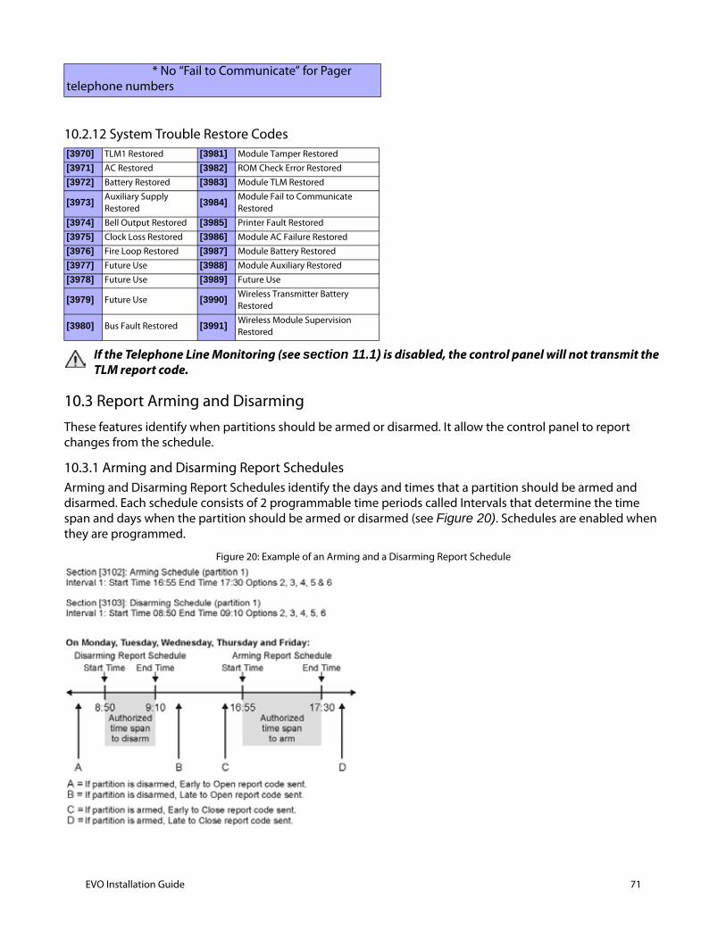
10.2.12 System Trouble Restore Codes
If the Telephone Line Monitoring (see section 11.1) is disabled, the control panel will not transmit the TLM report code.
10.3 Report Arming and DisarmingThese features identify when partitions should be armed or disarmed. It allow the control panel to report changes from the schedule.
10.3.1 Arming and Disarming Report SchedulesArming and Disarming Report Schedules identify the days and times that a partition should be armed and disarmed. Each schedule consists of 2 programmable time periods called Intervals that determine the time span and days when the partition should be armed or disarmed (see Figure 20). Schedules are enabled when they are programmed.
Figure 20: Example of an Arming and a Disarming Report Schedule
* No “Fail to Communicate” for Pager telephone numbers
[3970] TLM1 Restored [3981] Module Tamper Restored
[3971] AC Restored [3982] ROM Check Error Restored
[3972] Battery Restored [3983] Module TLM Restored
[3973] Auxiliary Supply Restored
[3984]Module Fail to Communicate Restored
[3974] Bell Output Restored [3985] Printer Fault Restored
[3975] Clock Loss Restored [3986] Module AC Failure Restored
[3976] Fire Loop Restored [3987] Module Battery Restored
[3977] Future Use [3988] Module Auxiliary Restored
[3978] Future Use [3989] Future Use
[3979] Future Use [3990]Wireless Transmitter Battery Restored
[3980] Bus Fault Restored [3991]Wireless Module Supervision Restored
EVO Installation Guide 71
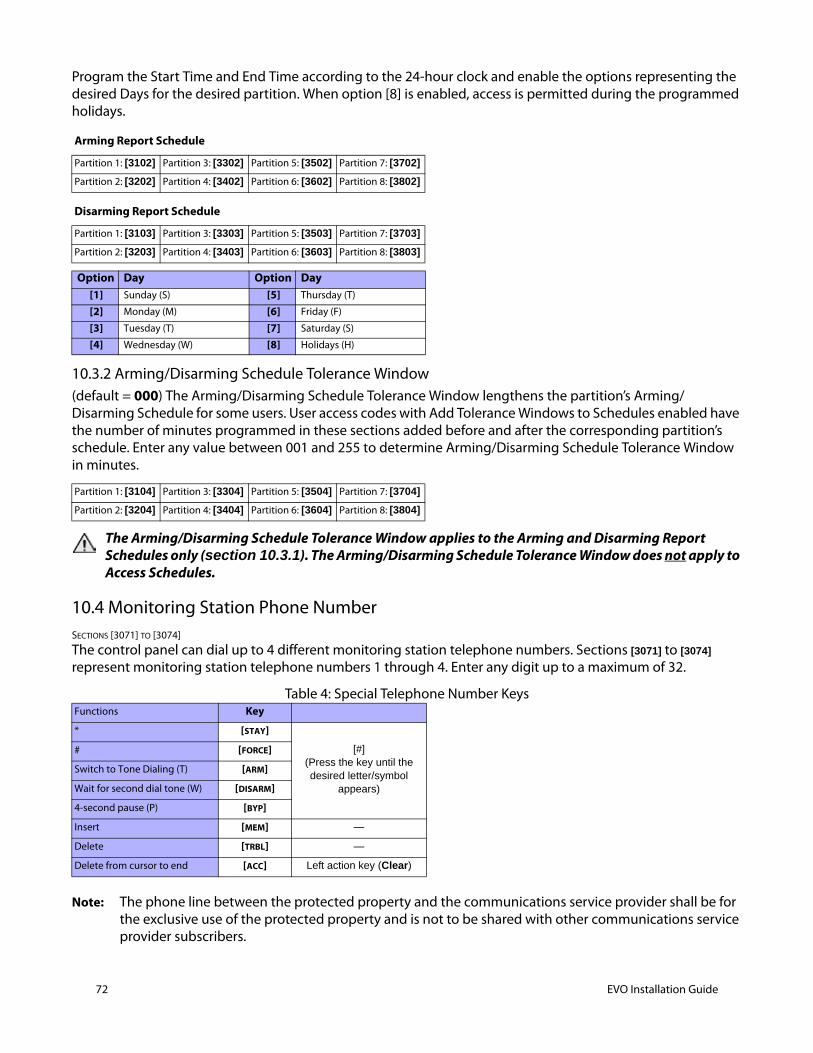
72 EVO Installation Guide
Program the Start Time and End Time according to the 24-hour clock and enable the options representing the desired Days for the desired partition. When option [8] is enabled, access is permitted during the programmed holidays.
10.3.2 Arming/Disarming Schedule Tolerance Window(default = 000) The Arming/Disarming Schedule Tolerance Window lengthens the partition’s Arming/Disarming Schedule for some users. User access codes with Add Tolerance Windows to Schedules enabled have the number of minutes programmed in these sections added before and after the corresponding partition’s schedule. Enter any value between 001 and 255 to determine Arming/Disarming Schedule Tolerance Window in minutes.
The Arming/Disarming Schedule Tolerance Window applies to the Arming and Disarming Report Schedules only (section 10.3.1). The Arming/Disarming Schedule Tolerance Window does not apply to Access Schedules.
10.4 Monitoring Station Phone NumberSECTIONS [3071] TO [3074]
The control panel can dial up to 4 different monitoring station telephone numbers. Sections [3071] to [3074] represent monitoring station telephone numbers 1 through 4. Enter any digit up to a maximum of 32.
Table 4: Special Telephone Number Keys
Note: The phone line between the protected property and the communications service provider shall be for the exclusive use of the protected property and is not to be shared with other communications service provider subscribers.
Arming Report Schedule
Partition 1: [3102] Partition 3: [3302] Partition 5: [3502] Partition 7: [3702]
Partition 2: [3202] Partition 4: [3402] Partition 6: [3602] Partition 8: [3802]
Disarming Report Schedule
Partition 1: [3103] Partition 3: [3303] Partition 5: [3503] Partition 7: [3703]
Partition 2: [3203] Partition 4: [3403] Partition 6: [3603] Partition 8: [3803]
Option Day Option Day[1] Sunday (S) [5] Thursday (T)
[2] Monday (M) [6] Friday (F)
[3] Tuesday (T) [7] Saturday (S)
[4] Wednesday (W) [8] Holidays (H)
Partition 1: [3104] Partition 3: [3304] Partition 5: [3504] Partition 7: [3704]
Partition 2: [3204] Partition 4: [3404] Partition 6: [3604] Partition 8: [3804]
Functions Key
* [STAY]
[#](Press the key until the desired letter/symbol
appears)
# [FORCE]
Switch to Tone Dialing (T) [ARM]
Wait for second dial tone (W) [DISARM]
4-second pause (P) [BYP]
Insert [MEM] —
Delete [TRBL] —
Delete from cursor to end [ACC] Left action key (Clear)
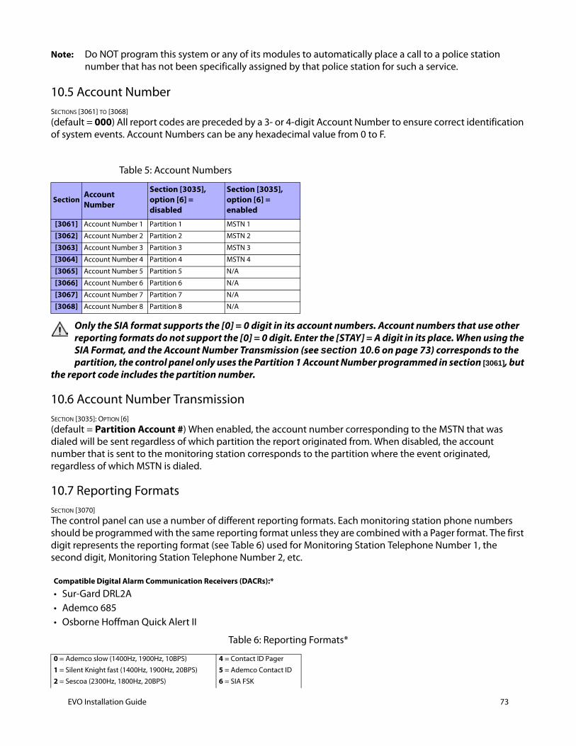
Note: Do NOT program this system or any of its modules to automatically place a call to a police station number that has not been specifically assigned by that police station for such a service.
10.5 Account NumberSECTIONS [3061] TO [3068]
(default = 000) All report codes are preceded by a 3- or 4-digit Account Number to ensure correct identification of system events. Account Numbers can be any hexadecimal value from 0 to F.
Only the SIA format supports the [0] = 0 digit in its account numbers. Account numbers that use other reporting formats do not support the [0] = 0 digit. Enter the [STAY] = A digit in its place. When using the SIA Format, and the Account Number Transmission (see section 10.6 on page 73) corresponds to the partition, the control panel only uses the Partition 1 Account Number programmed in section [3061], but
the report code includes the partition number.
10.6 Account Number TransmissionSECTION [3035]: OPTION [6]
(default = Partition Account #) When enabled, the account number corresponding to the MSTN that was dialed will be sent regardless of which partition the report originated from. When disabled, the account number that is sent to the monitoring station corresponds to the partition where the event originated, regardless of which MSTN is dialed.
10.7 Reporting FormatsSECTION [3070]
The control panel can use a number of different reporting formats. Each monitoring station phone numbers should be programmed with the same reporting format unless they are combined with a Pager format. The first digit represents the reporting format (see Table 6) used for Monitoring Station Telephone Number 1, the second digit, Monitoring Station Telephone Number 2, etc.
Table 6: Reporting Formats*
Table 5: Account Numbers
SectionAccount Number
Section [3035], option [6] = disabled
Section [3035], option [6] = enabled
[3061] Account Number 1 Partition 1 MSTN 1
[3062] Account Number 2 Partition 2 MSTN 2
[3063] Account Number 3 Partition 3 MSTN 3
[3064] Account Number 4 Partition 4 MSTN 4
[3065] Account Number 5 Partition 5 N/A
[3066] Account Number 6 Partition 6 N/A
[3067] Account Number 7 Partition 7 N/A
[3068] Account Number 8 Partition 8 N/A
Compatible Digital Alarm Communication Receivers (DACRs):*
• Sur-Gard DRL2A• Ademco 685• Osborne Hoffman Quick Alert II
0 = Ademco slow (1400Hz, 1900Hz, 10BPS) 4 = Contact ID Pager
1 = Silent Knight fast (1400Hz, 1900Hz, 20BPS) 5 = Ademco Contact ID
2 = Sescoa (2300Hz, 1800Hz, 20BPS) 6 = SIA FSK
EVO Installation Guide 73
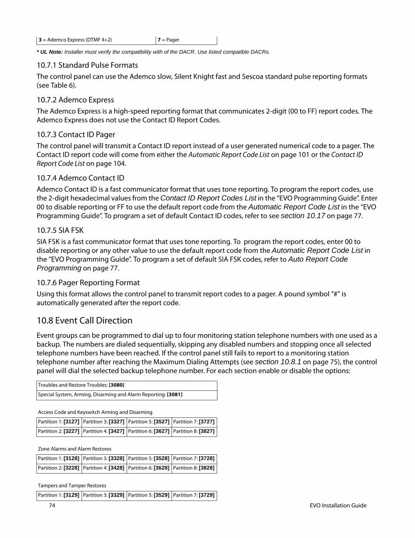
74 EVO Installation Guide
* UL Note: Installer must verify the compatibility with of the DACR. Use listed compatible DACRs.
10.7.1 Standard Pulse FormatsThe control panel can use the Ademco slow, Silent Knight fast and Sescoa standard pulse reporting formats (see Table 6).
10.7.2 Ademco ExpressThe Ademco Express is a high-speed reporting format that communicates 2-digit (00 to FF) report codes. The Ademco Express does not use the Contact ID Report Codes.
10.7.3 Contact ID PagerThe control panel will transmit a Contact ID report instead of a user generated numerical code to a pager. The Contact ID report code will come from either the Automatic Report Code List on page 101 or the Contact ID Report Code List on page 104.
10.7.4 Ademco Contact IDAdemco Contact ID is a fast communicator format that uses tone reporting. To program the report codes, use the 2-digit hexadecimal values from the Contact ID Report Codes List in the “EVO Programming Guide”. Enter 00 to disable reporting or FF to use the default report code from the Automatic Report Code List in the “EVO Programming Guide”. To program a set of default Contact ID codes, refer to see section 10.17 on page 77.
10.7.5 SIA FSKSIA FSK is a fast communicator format that uses tone reporting. To program the report codes, enter 00 to disable reporting or any other value to use the default report code from the Automatic Report Code List in the “EVO Programming Guide”. To program a set of default SIA FSK codes, refer to Auto Report Code Programming on page 77.
10.7.6 Pager Reporting FormatUsing this format allows the control panel to transmit report codes to a pager. A pound symbol “#” is automatically generated after the report code.
10.8 Event Call DirectionEvent groups can be programmed to dial up to four monitoring station telephone numbers with one used as a backup. The numbers are dialed sequentially, skipping any disabled numbers and stopping once all selected telephone numbers have been reached. If the control panel still fails to report to a monitoring station telephone number after reaching the Maximum Dialing Attempts (see section 10.8.1 on page 75), the control panel will dial the selected backup telephone number. For each section enable or disable the options:
3 = Ademco Express (DTMF 4+2) 7 = Pager
Troubles and Restore Troubles: [3080]
Special System, Arming, Disarming and Alarm Reporting: [3081]
Access Code and Keyswitch Arming and Disarming
Partition 1: [3127] Partition 3: [3327] Partition 5: [3527] Partition 7: [3727]
Partition 2: [3227] Partition 4: [3427] Partition 6: [3627] Partition 8: [3827]
Zone Alarms and Alarm Restores
Partition 1: [3128] Partition 3: [3328] Partition 5: [3528] Partition 7: [3728]
Partition 2: [3228] Partition 4: [3428] Partition 6: [3628] Partition 8: [3828]
Tampers and Tamper Restores
Partition 1: [3129] Partition 3: [3329] Partition 5: [3529] Partition 7: [3729]
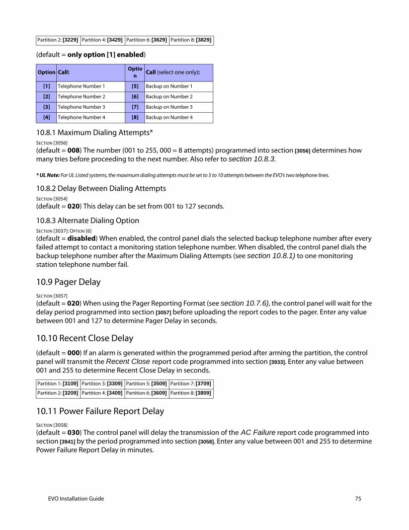
(default = only option [1] enabled)
10.8.1 Maximum Dialing Attempts*SECTION [3056]
(default = 008) The number (001 to 255, 000 = 8 attempts) programmed into section [3056] determines how many tries before proceeding to the next number. Also refer to section 10.8.3.
* UL Note: For UL Listed systems, the maximum dialing attempts must be set to 5 to 10 attempts between the EVO’s two telephone lines.
10.8.2 Delay Between Dialing AttemptsSECTION [3054]
(default = 020) This delay can be set from 001 to 127 seconds.
10.8.3 Alternate Dialing OptionSECTION [3037]: OPTION [6]
(default = disabled) When enabled, the control panel dials the selected backup telephone number after every failed attempt to contact a monitoring station telephone number. When disabled, the control panel dials the backup telephone number after the Maximum Dialing Attempts (see section 10.8.1) to one monitoring station telephone number fail.
10.9 Pager DelaySECTION [3057]
(default = 020) When using the Pager Reporting Format (see section 10.7.6), the control panel will wait for the delay period programmed into section [3057] before uploading the report codes to the pager. Enter any value between 001 and 127 to determine Pager Delay in seconds.
10.10 Recent Close Delay(default = 000) If an alarm is generated within the programmed period after arming the partition, the control panel will transmit the Recent Close report code programmed into section [3933]. Enter any value between 001 and 255 to determine Recent Close Delay in seconds.
10.11 Power Failure Report DelaySECTION [3058]
(default = 030) The control panel will delay the transmission of the AC Failure report code programmed into section [3941] by the period programmed into section [3058]. Enter any value between 001 and 255 to determine Power Failure Report Delay in minutes.
Partition 2: [3229] Partition 4: [3429] Partition 6: [3629] Partition 8: [3829]
Option Call: Option Call (select one only):
[1] Telephone Number 1 [5] Backup on Number 1
[2] Telephone Number 2 [6] Backup on Number 2
[3] Telephone Number 3 [7] Backup on Number 3
[4] Telephone Number 4 [8] Backup on Number 4
Partition 1: [3109] Partition 3: [3309] Partition 5: [3509] Partition 7: [3709]
Partition 2: [3209] Partition 4: [3409] Partition 6: [3609] Partition 8: [3809]
EVO Installation Guide 75
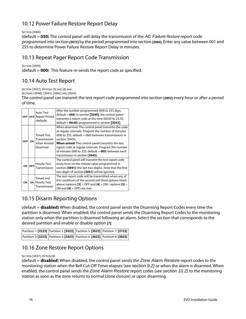
76 EVO Installation Guide
10.12 Power Failure Restore Report DelaySECTION [3060]
(default = 030) The control panel will delay the transmission of the AC Failure Restore report code programmed into section [3972] by the period programmed into section [3060]. Enter any value between 001 and 255 to determine Power Failure Restore Report Delay in minutes.
10.13 Repeat Pager Report Code TransmissionSECTION [3059]
{default = 000) This feature re-sends the report code as specified.
10.14 Auto Test ReportSECTION [3037]: OPTIONS [3] AND [4] AND
SECTIONS [3040], [3041], [3042] AND [3043]
The control panel can transmit the test report code programmed into section [3902] every hour or after a period of time.
10.15 Disarm Reporting Options (default = disabled) When disabled, the control panel sends the Disarming Report Codes every time the partition is disarmed. When enabled, the control panel sends the Disarming Report Codes to the monitoring station only when the partition is disarmed following an alarm. Select the section that corresponds to the desired partition and enable or disable option [7]:
10.16 Zone Restore Report OptionsSECTION [3037]: OPTION [8]
(default = disabled) When disabled, the control panel sends the Zone Alarm Restore report codes to the monitoring station when the Bell Cut-Off Timer elapses (see section 9.2) or when the alarm is disarmed. When enabled, the control panel sends the Zone Alarm Restore report codes (see section 10.2) to the monitoring station as soon as the zone returns to normal (zone closure) or upon disarming.
OFF OFF
Auto Test Report Period(default)
After the number programmed (000 to 255 days, default = 000) in section [3040], the control panel transmits a report code at the time (00:00 to 23:59, default = 00:00) programmed in section [3041].
OFF ON
Timed Test Transmission when Armed/Disarmed
When disarmed: The control panel transmits the code at regular intervals. Program the number of minutes (000 to 255, default = 060) between transmissions in section [3043].When armed: The control panel transmits the test report code at regular intervals. Program the number of minutes (000 to 255, default = 005) between each transmission in section [3042].
ON OFFHourly TestTransmission
The control panel will transmit the test report code every hour on the minute value programmed in section [3041] (the last two digits). Note that the first two digits of section [3041] will be ignored.
ON ON
Timed and Hourly Test Transmission
The test report code will be transmitted when any of the conditions of the second and third options listed above (options [3] = OFF and [4] = ON / options [3] = ON and [4] = OFF) are met.
Partition 1: [3123] Partition 3: [3323] Partition 5: [3523] Partition 7: [3723]
Partition 2: [3223] Partition 4: [3423] Partition 6: [3623] Partition 8: [3823]
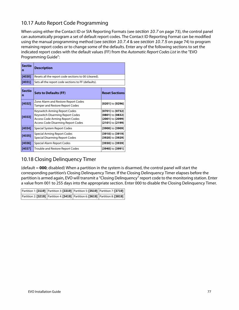
10.17 Auto Report Code ProgrammingWhen using either the Contact ID or SIA Reporting Formats (see section 10.7 on page 73), the control panel can automatically program a set of default report codes. The Contact ID Reporting Format can be modified using the manual programming method (see section 10.7.4 & see section 10.7.5 on page 74) to program remaining report codes or to change some of the defaults. Enter any of the following sections to set the indicated report codes with the default values (FF) from the Automatic Report Codes List in the "EVO Programming Guide":
10.18 Closing Delinquency Timer(default = 000; disabled) When a partition in the system is disarmed, the control panel will start the corresponding partition’s Closing Delinquency Timer. If the Closing Delinquency Timer elapses before the partition is armed again, EVO will transmit a “Closing Delinquency” report code to the monitoring station. Enter a value from 001 to 255 days into the appropriate section. Enter 000 to disable the Closing Delinquency Timer.
Section Description
[4030] Resets all the report code sections to 00 (cleared).
[4031] Sets all the report code sections to FF (defaults).
Section Sets to Defaults (FF) Reset Sections
[4032]Zone Alarm and Restore Report Codes Tamper and Restore Report Codes
[0201] to [0296]
[4033]
Keyswitch Arming Report Codes Keyswitch Disarming Report Codes Access Code Arming Report Codes Access Code Disarming Report Codes
[0701] to [0732] [0801] to [0832] [2001] to [2099] [2101] to [2199]
[4034] Special System Report Codes [3900] to [3909]
[4035]Special Arming Report Codes Special Disarming Report Codes
[3910] to [3919] [3920] to [3929]
[4036] Special Alarm Report Codes [3930] to [3939]
[4037] Trouble and Restore Report Codes [3940] to [3991]
Partition 1: [3119] Partition 3: [3319] Partition 5: [3519] Partition 7: [3719]
Partition 2: [3219] Partition 4: [3419] Partition 6: [3619] Partition 8: [3819]
EVO Installation Guide 77
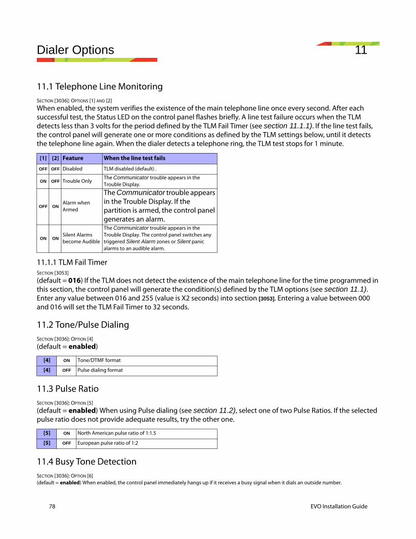
78 EVO Installation Guide
Dialer Options 11
11.1 Telephone Line MonitoringSECTION [3036]: OPTIONS [1] AND [2]
When enabled, the system verifies the existence of the main telephone line once every second. After each successful test, the Status LED on the control panel flashes briefly. A line test failure occurs when the TLM detects less than 3 volts for the period defined by the TLM Fail Timer (see section 11.1.1). If the line test fails, the control panel will generate one or more conditions as defined by the TLM settings below, until it detects the telephone line again. When the dialer detects a telephone ring, the TLM test stops for 1 minute.
11.1.1 TLM Fail TimerSECTION [3053]
(default = 016) If the TLM does not detect the existence of the main telephone line for the time programmed in this section, the control panel will generate the condition(s) defined by the TLM options (see section 11.1). Enter any value between 016 and 255 (value is X2 seconds) into section [3053]. Entering a value between 000 and 016 will set the TLM Fail Timer to 32 seconds.
11.2 Tone/Pulse DialingSECTION [3036]: OPTION [4]
(default = enabled)
11.3 Pulse RatioSECTION [3036]: OPTION [5]
(default = enabled) When using Pulse dialing (see section 11.2), select one of two Pulse Ratios. If the selected pulse ratio does not provide adequate results, try the other one.
11.4 Busy Tone DetectionSECTION [3036]: OPTION [6](default = enabled) When enabled, the control panel immediately hangs up if it receives a busy signal when it dials an outside number.
[1] [2] Feature When the line test fails
OFF OFF Disabled TLM disabled (default) .
ON OFF Trouble OnlyThe Communicator trouble appears in the Trouble Display.
OFF ONAlarm when Armed
The Communicator trouble appears in the Trouble Display. If the partition is armed, the control panel generates an alarm.
ON ONSilent Alarms become Audible
The Communicator trouble appears in the Trouble Display. The control panel switches any triggered Silent Alarm zones or Silent panic alarms to an audible alarm.
[4] ON Tone/DTMF format
[4] OFF Pulse dialing format
[5] ON North American pulse ratio of 1:1.5
[5] OFF European pulse ratio of 1:2
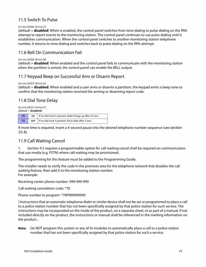
11.5 Switch To PulseSECTION [3036]: OPTION [7]
(default = disabled) When is enabled, the control panel switches from tone dialing to pulse dialing on the fifth attempt to report events to the monitoring station. The control panel continues to use pulse dialing until it establishes communication. When the control panel switches to another monitoring station telephone number, it returns to tone dialing and switches back to pulse dialing on the fifth attempt.
11.6 Bell On Communication FailSECTION [3036]: OPTION [8]
(default = disabled) When enabled and the control panel fails to communicate with the monitoring station when the partition is armed, the control panel can enable the BELL output.
11.7 Keypad Beep on Successful Arm or Disarm ReportSECTION [3037]: OPTION [5]
(default = disabled) When enabled and a user arms or disarms a partition, the keypad emits a beep tone to confirm that the monitoring station received the arming or disarming report code.
11.8 Dial Tone DelaySECTION [3037]: OPTION [7] (default = disabled)
If more time is required, insert a 4-second pause into the desired telephone number sequence (see section 10.4).
11.9 Call Waiting Cancel1. Section 4.5 requires a programmable option for call waiting cancel shall be required on communicators that use media (e.g. PSTN) where call-waiting may be provisioned.
The programming for this feature must be added to the Programming Guide.
The installer needs to verify the code in the premises area for the telephone network that disables the call waiting feature, then add it to the monitoring station number. For example:
Receiving center phone number: 999-999-999
Call waiting cancelation code: *70
Phone number to program: *70P999999999
) Instructions that an automatic telephone dialer or similar device shall not be set or programmed to place a call to a police station number that has not been specifically assigned by that police station for such service. The instructions may be incorporated on the inside of the product, on a separate sheet, or as part of a manual. If not included directly on the product, the instructions or manual shall be referenced in the marking information on the product. .
Note: Do NOT program this system or any of its modules to automatically place a call to a police station number that has not been specifically assigned by that police station for such a service.
[7] ON If no dial tone is present, dialer hangs up after 32 secs.
[7] OFF If no dial tone is present, force dials after 3 secs.
EVO Installation Guide 79

80 EVO Installation Guide
The installation instructions shall state that the communication medium between protected property and communications service provider shall be for the exclusive use of the protected property and is not to be shared with other communications service provider subscribers
Note: The phone line between the protected property and the communications service provider shall be for the exclusive use of the protected property and is not to be shared with other communications service provider subscribers.
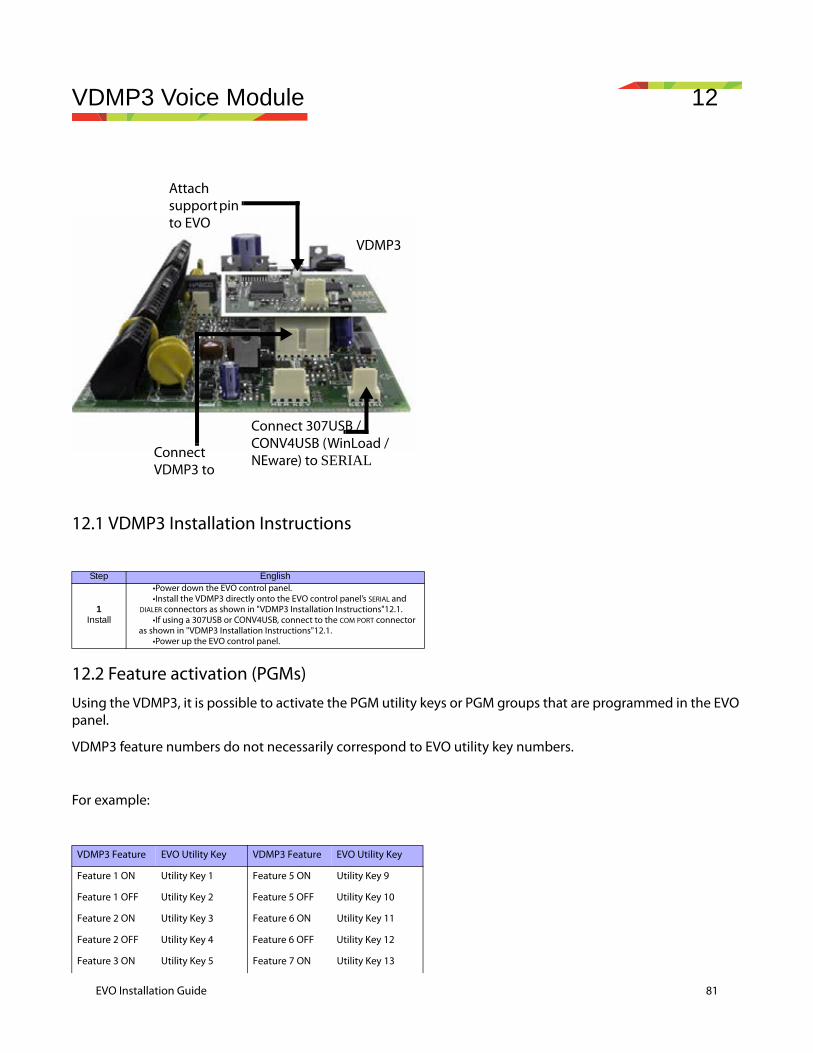
VDMP3 Voice Module 12
12.1 VDMP3 Installation Instructions
12.2 Feature activation (PGMs)Using the VDMP3, it is possible to activate the PGM utility keys or PGM groups that are programmed in the EVO panel.
VDMP3 feature numbers do not necessarily correspond to EVO utility key numbers.
For example:
Step English
1Install
•Power down the EVO control panel.•Install the VDMP3 directly onto the EVO control panel’s SERIAL and
DIALER connectors as shown in "VDMP3 Installation Instructions"12.1.•If using a 307USB or CONV4USB, connect to the COM PORT connector
as shown in "VDMP3 Installation Instructions"12.1. •Power up the EVO control panel.
VDMP3 Feature EVO Utility Key VDMP3 Feature EVO Utility Key
Feature 1 ON Utility Key 1 Feature 5 ON Utility Key 9
Feature 1 OFF Utility Key 2 Feature 5 OFF Utility Key 10
Feature 2 ON Utility Key 3 Feature 6 ON Utility Key 11
Feature 2 OFF Utility Key 4 Feature 6 OFF Utility Key 12
Feature 3 ON Utility Key 5 Feature 7 ON Utility Key 13
Attach support pin to EVO
VDMP3
Connect VDMP3 to
Connect 307USB / CONV4USB (WinLoad / NEware) to SERIAL
EVO Installation Guide 81
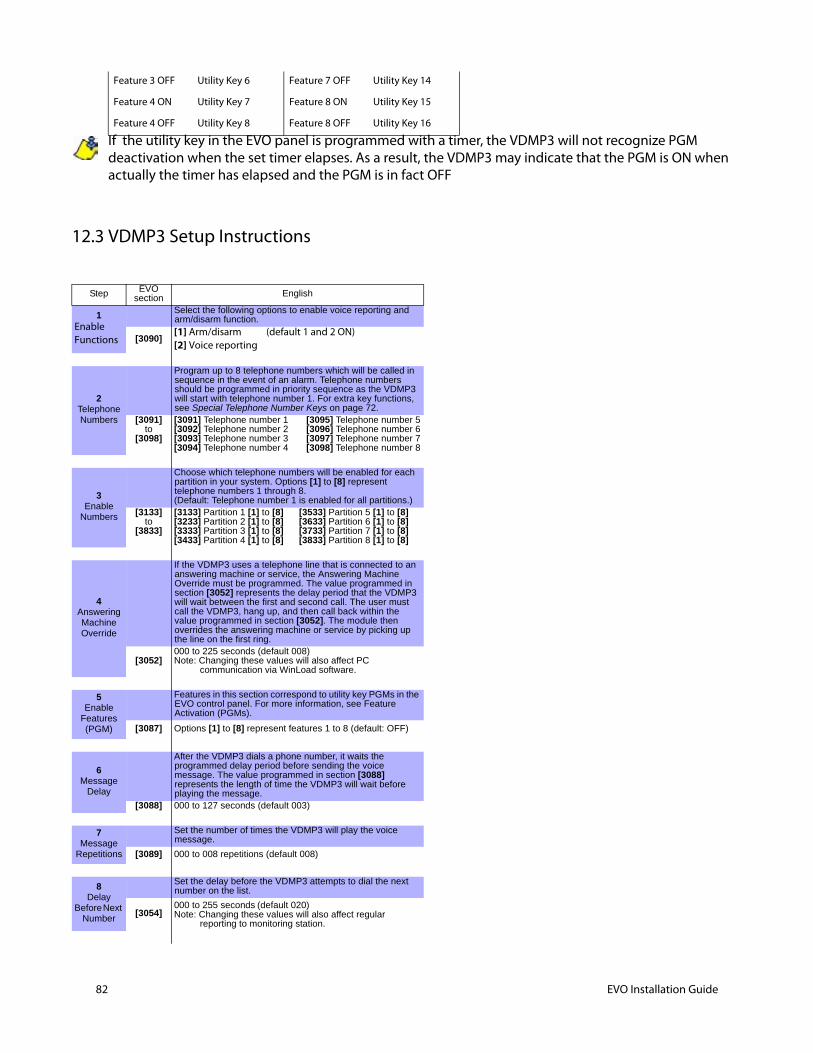
82 EVO Installation Guide
If the utility key in the EVO panel is programmed with a timer, the VDMP3 will not recognize PGM deactivation when the set timer elapses. As a result, the VDMP3 may indicate that the PGM is ON when actually the timer has elapsed and the PGM is in fact OFF
12.3 VDMP3 Setup Instructions
Feature 3 OFF Utility Key 6 Feature 7 OFF Utility Key 14
Feature 4 ON Utility Key 7 Feature 8 ON Utility Key 15
Feature 4 OFF Utility Key 8 Feature 8 OFF Utility Key 16
Step EVO section English
1Enable Functions
Select the following options to enable voice reporting and arm/disarm function.
[3090][1] Arm/disarm (default 1 and 2 ON)[2] Voice reporting
2Telephone Numbers
Program up to 8 telephone numbers which will be called in sequence in the event of an alarm. Telephone numbers should be programmed in priority sequence as the VDMP3 will start with telephone number 1. For extra key functions, see Special Telephone Number Keys on page 72.
[3091]to
[3098]
[3091] Telephone number 1 [3095] Telephone number 5[3092] Telephone number 2 [3096] Telephone number 6[3093] Telephone number 3 [3097] Telephone number 7[3094] Telephone number 4 [3098] Telephone number 8
3Enable
Numbers
Choose which telephone numbers will be enabled for each partition in your system. Options [1] to [8] represent telephone numbers 1 through 8. (Default: Telephone number 1 is enabled for all partitions.)
[3133]to
[3833]
[3133] Partition 1 [1] to [8] [3533] Partition 5 [1] to [8] [3233] Partition 2 [1] to [8] [3633] Partition 6 [1] to [8] [3333] Partition 3 [1] to [8] [3733] Partition 7 [1] to [8] [3433] Partition 4 [1] to [8] [3833] Partition 8 [1] to [8]
4Answering Machine Override
If the VDMP3 uses a telephone line that is connected to an answering machine or service, the Answering Machine Override must be programmed. The value programmed in section [3052] represents the delay period that the VDMP3 will wait between the first and second call. The user must call the VDMP3, hang up, and then call back within the value programmed in section [3052]. The module then overrides the answering machine or service by picking up the line on the first ring.
[3052]000 to 225 seconds (default 008)Note: Changing these values will also affect PC communication via WinLoad software.
5Enable
Features (PGM)
Features in this section correspond to utility key PGMs in the EVO control panel. For more information, see Feature Activation (PGMs).
[3087] Options [1] to [8] represent features 1 to 8 (default: OFF)
6Message
Delay
After the VDMP3 dials a phone number, it waits the programmed delay period before sending the voice message. The value programmed in section [3088] represents the length of time the VDMP3 will wait before playing the message.
[3088] 000 to 127 seconds (default 003)
7Message
Repetitions
Set the number of times the VDMP3 will play the voice message.
[3089] 000 to 008 repetitions (default 008)
8Delay
Before Next Number
Set the delay before the VDMP3 attempts to dial the next number on the list.
[3054]000 to 255 seconds (default 020)Note: Changing these values will also affect regular reporting to monitoring station.

9Ring
Counter
Set the number of rings the VDMP3 will wait before the call is answered.
[3051]000 to 008 rings (default 008)Note: Changing these values will also affect PC communication via WinLoad software.
EVO Installation Guide 83
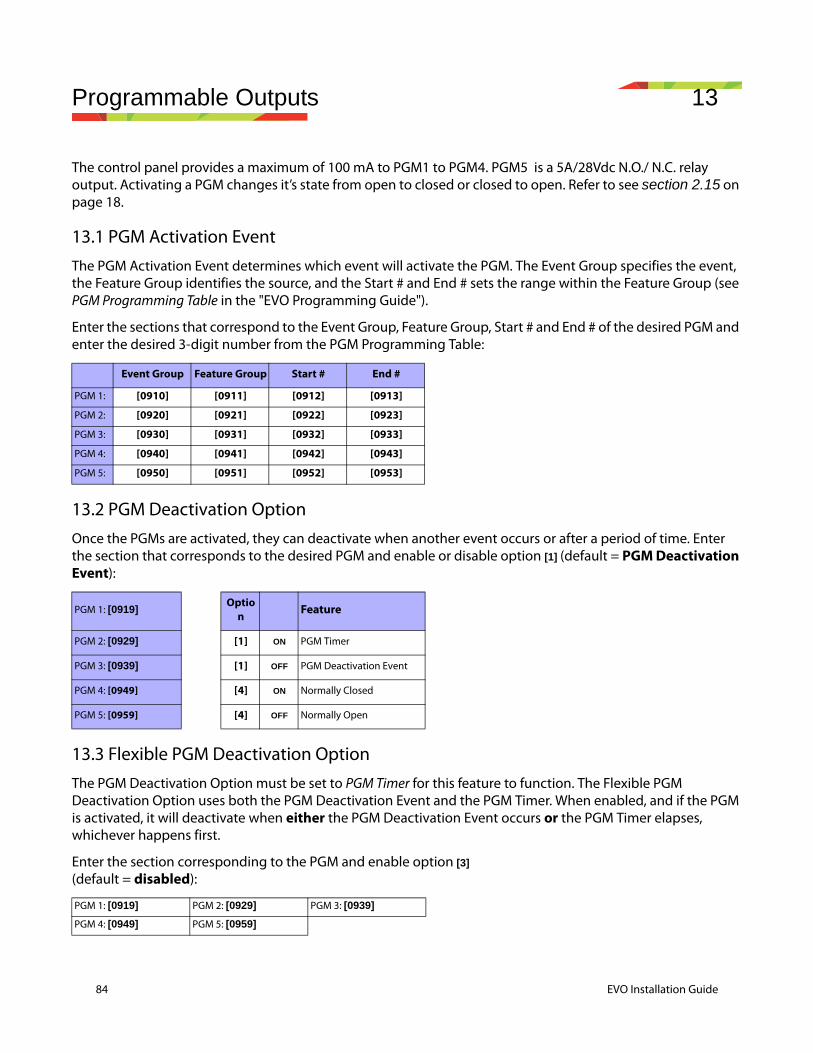
84 EVO Installation Guide
Programmable Outputs 13
The control panel provides a maximum of 100 mA to PGM1 to PGM4. PGM5 is a 5A/28Vdc N.O./ N.C. relay output. Activating a PGM changes it’s state from open to closed or closed to open. Refer to see section 2.15 on page 18.
13.1 PGM Activation EventThe PGM Activation Event determines which event will activate the PGM. The Event Group specifies the event, the Feature Group identifies the source, and the Start # and End # sets the range within the Feature Group (see PGM Programming Table in the "EVO Programming Guide").
Enter the sections that correspond to the Event Group, Feature Group, Start # and End # of the desired PGM and enter the desired 3-digit number from the PGM Programming Table:
13.2 PGM Deactivation OptionOnce the PGMs are activated, they can deactivate when another event occurs or after a period of time. Enter the section that corresponds to the desired PGM and enable or disable option [1] (default = PGM Deactivation Event):
13.3 Flexible PGM Deactivation OptionThe PGM Deactivation Option must be set to PGM Timer for this feature to function. The Flexible PGM Deactivation Option uses both the PGM Deactivation Event and the PGM Timer. When enabled, and if the PGM is activated, it will deactivate when either the PGM Deactivation Event occurs or the PGM Timer elapses, whichever happens first.
Enter the section corresponding to the PGM and enable option [3] (default = disabled):
Event Group Feature Group Start # End #
PGM 1: [0910] [0911] [0912] [0913]
PGM 2: [0920] [0921] [0922] [0923]
PGM 3: [0930] [0931] [0932] [0933]
PGM 4: [0940] [0941] [0942] [0943]
PGM 5: [0950] [0951] [0952] [0953]
PGM 1: [0919]Optio
n Feature
PGM 2: [0929] [1] ON PGM Timer
PGM 3: [0939] [1] OFF PGM Deactivation Event
PGM 4: [0949] [4] ON Normally Closed
PGM 5: [0959] [4] OFF Normally Open
PGM 1: [0919] PGM 2: [0929] PGM 3: [0939]
PGM 4: [0949] PGM 5: [0959]
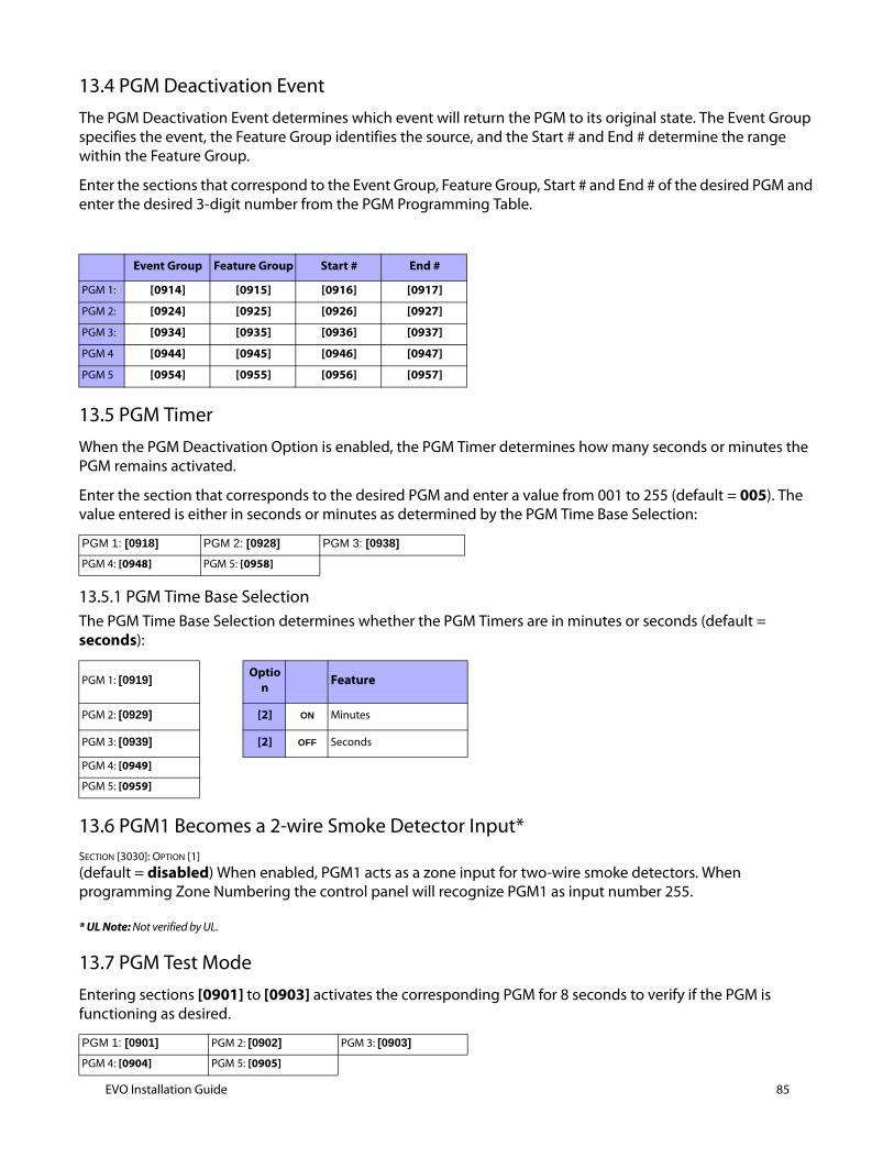
13.4 PGM Deactivation EventThe PGM Deactivation Event determines which event will return the PGM to its original state. The Event Group specifies the event, the Feature Group identifies the source, and the Start # and End # determine the range within the Feature Group.
Enter the sections that correspond to the Event Group, Feature Group, Start # and End # of the desired PGM and enter the desired 3-digit number from the PGM Programming Table.
13.5 PGM TimerWhen the PGM Deactivation Option is enabled, the PGM Timer determines how many seconds or minutes the PGM remains activated.
Enter the section that corresponds to the desired PGM and enter a value from 001 to 255 (default = 005). The value entered is either in seconds or minutes as determined by the PGM Time Base Selection:
13.5.1 PGM Time Base SelectionThe PGM Time Base Selection determines whether the PGM Timers are in minutes or seconds (default = seconds):
13.6 PGM1 Becomes a 2-wire Smoke Detector Input*SECTION [3030]: OPTION [1]
(default = disabled) When enabled, PGM1 acts as a zone input for two-wire smoke detectors. When programming Zone Numbering the control panel will recognize PGM1 as input number 255.
* UL Note: Not verified by UL.
13.7 PGM Test ModeEntering sections [0901] to [0903] activates the corresponding PGM for 8 seconds to verify if the PGM is functioning as desired.
Event Group Feature Group Start # End #
PGM 1: [0914] [0915] [0916] [0917]
PGM 2: [0924] [0925] [0926] [0927]
PGM 3: [0934] [0935] [0936] [0937]
PGM 4 [0944] [0945] [0946] [0947]
PGM 5 [0954] [0955] [0956] [0957]
PGM 1: [0918] PGM 2: [0928] PGM 3: [0938]
PGM 4: [0948] PGM 5: [0958]
PGM 1: [0919]Optio
n Feature
PGM 2: [0929] [2] ON Minutes
PGM 3: [0939] [2] OFF Seconds
PGM 4: [0949]
PGM 5: [0959]
PGM 1: [0901] PGM 2: [0902] PGM 3: [0903]
PGM 4: [0904] PGM 5: [0905]
EVO Installation Guide 85
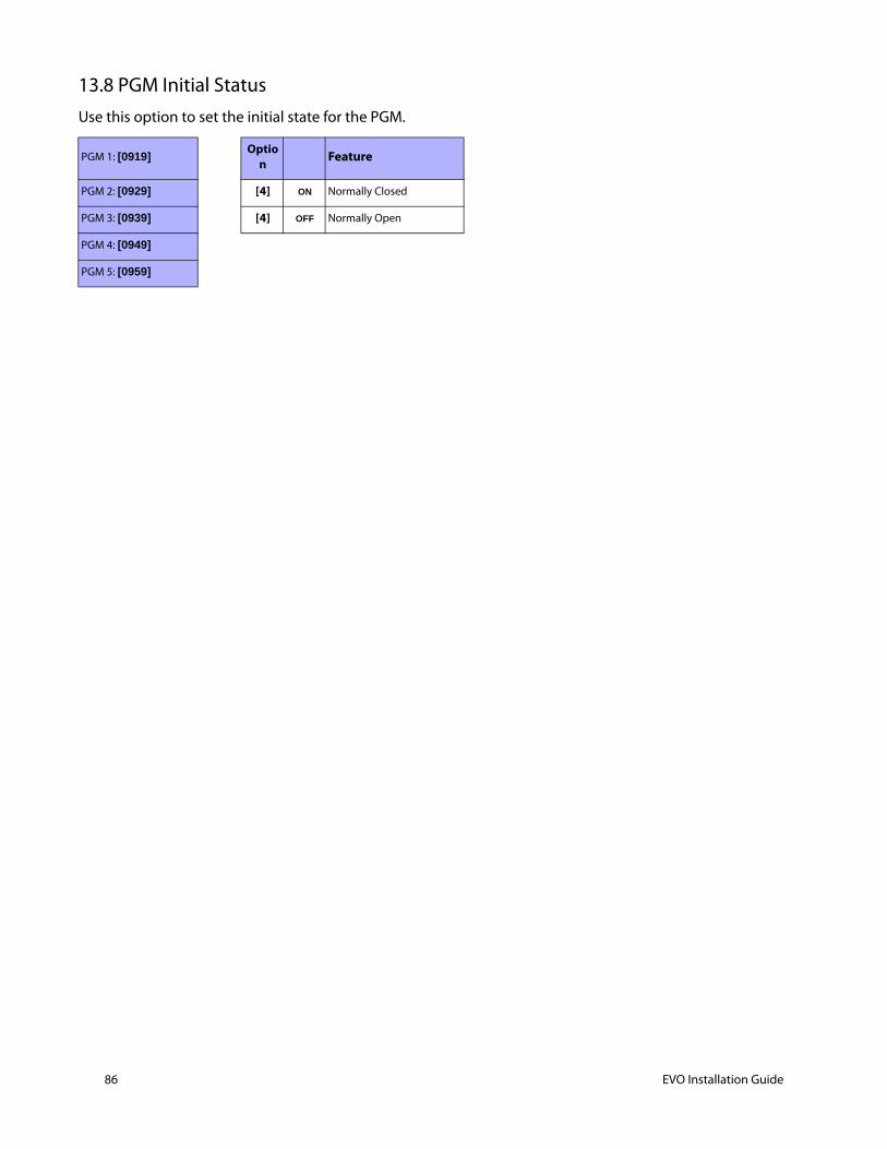
86 EVO Installation Guide
13.8 PGM Initial StatusUse this option to set the initial state for the PGM.
PGM 1: [0919]Optio
n Feature
PGM 2: [0929] [4] ON Normally Closed
PGM 3: [0939] [4] OFF Normally Open
PGM 4: [0949]
PGM 5: [0959]
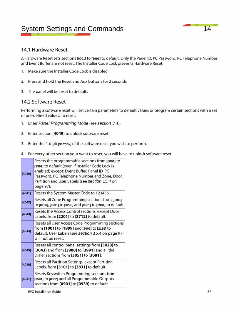
System Settings and Commands 14
14.1 Hardware ResetA Hardware Reset sets sections [0001] to [3991] to default. Only the Panel ID, PC Password, PC Telephone Number and Event Buffer are not reset. The Installer Code Lock prevents Hardware Reset.
1. Make sure the Installer Code Lock is disabled
2. Press and hold the Reset and Aux buttons for 3 seconds
3. The panel will be reset to defaults
14.2 Software ResetPerforming a software reset will set certain parameters to default values or program certain sections with a set of pre-defined values. To reset:
1. Enter Panel Programming Mode (see section 3.4).
2. Enter section [4049] to unlock software reset.
3. Enter the 4-digit [SECTION] of the software reset you wish to perform.
4. For every other section your want to reset, you will have to unlock software reset.
[4040]
Resets the programmable sections from [0001] to [3991] to default (even if Installer Code Lock is enabled) except: Event Buffer, Panel ID, PC Password, PC Telephone Number and Zone, Door, Partition and User Labels (see section 15.4 on page 97).
[4041] Resets the System Master Code to 123456.
[4042]Resets all Zone Programming sections from [0001] to [0196], [0201] to [0296] and [0961] to [0984] to default.
[4043]Resets the Access Control sections, except Door Labels, from [2201] to [2712] to default.
[4044]
Resets all User Access Code Programming sections from [1001] to [1999] and [2001] to [2199] to default. User Labels (see section 15.4 on page 97) will not be reset.
[4045]
Resets all control panel settings from [3020] to [3043] and from [3900] to [3991] and all the Dialer sections from [3051] to [3081].
[4046]Resets all Partition Settings, except Partition Labels, from [3101] to [3831] to default.
[4047]
Resets Keyswitch Programming sections from [0501] to [0832] and all Programmable Outputs sections from [0901] to [0939] to default.
EVO Installation Guide 87
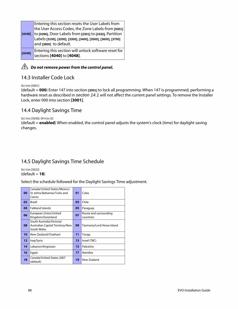
88 EVO Installation Guide
Do not remove power from the control panel.
14.3 Installer Code LockSECTION [3001]
(default = 000) Enter 147 into section [3001] to lock all programming. When 147 is programmed, performing a hardware reset as described in section 14.1 will not affect the current panel settings. To remove the Installer Lock, enter 000 into section [3001].
14.4 Daylight Savings TimeSECTION [3030]: OPTION [3]
(default = enabled) When enabled, the control panel adjusts the system's clock (time) for daylight saving changes.
14.5 Daylight Savings Time ScheduleSECTION [3022]
(default = 18)
Select the schedule followed for the Daylight Savings Time adjustment.
[4048]
Entering this section resets the User Labels from the User Access Codes, the Zone Labels from [0301] to [0396], Door Labels from [2301] to [2332], Partition Labels [3100], [3200], [3300], [3400], [3500], [3600], [3700] and [3800] to default.
[4049]Entering this section will unlock software reset for sections [4040] to [4048].
00Canada/United States/Mexico/St-Johns/Bahamas/Turks and Caicos
01 Cuba
02 Brazil 03 Chile
04 Falkland Islands 05 Paraguay
06 European Union/United Kingdom/Greenland
07 Russia and surrounding countries
08South Australia/Victoria/Australian Capital Territory/New South Wales
09 Tasmania/Lord Howe Island
10 New-Zealand/Chatham 11 Tonga
12 Iraq/Syria 13 Israel (TBC)
14 Lebanon/Kirgizstan 15 Palestine
16 Egypt 17 Namibia
18 Canada/United States 2007 (default)
19 New Zealand
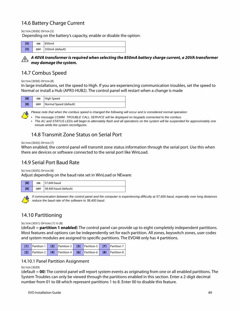
14.6 Battery Charge CurrentSECTION [3030]: OPTION [5]
Depending on the battery’s capacity, enable or disable the option:
A 40VA transformer is required when selecting the 850mA battery charge current, a 20VA transformer may damage the system.
14.7 Combus SpeedSECTION [3030]: OPTION [8]
In large installations, set the speed to High. If you are experiencing communication troubles, set the speed to Normal or install a Hub (APR3-HUB2). The control panel will restart when a change is made
Please note that when the combus speed is changed the following will occur and is considered normal operation:
• The message COMM. TROUBLE CALL SERVICE will be displayed on keypads connected to the combus.• The AC and STATUS LEDs will begin to alternately flash and all operations on the system will be suspended for approximately one
minute while the system reconfigures.
14.8 Transmit Zone Status on Serial PortSECTION [3035]: OPTION [7]
When enabled, the control panel will transmit zone status information through the serial port. Use this when there are devices or software connected to the serial port like WinLoad.
14.9 Serial Port Baud RateSECTION [3035]: OPTION [8]
Adjust depending on the baud rate set in WinLoad or NEware:
If communication between the control panel and the computer is experiencing difficulty at 57,600 baud, especially over long distances reduce the baud rate of the software to 38,400 baud.
14.10 PartitioningSECTION [3031]: OPTIONS [1] TO [8]
(default = partition 1 enabled) The control panel can provide up to eight completely independent partitions. Most features and options can be independently set for each partition. All zones, keyswitch zones, user codes and system modules are assigned to specific partitions. The EVO48 only has 4 partitions.
14.10.1 Panel Partition AssignmentSECTION [3020]
(default = 00) The control panel will report system events as originating from one or all enabled partitions. The System Troubles can only be viewed through the partitions enabled in this section. Enter a 2-digit decimal number from 01 to 08 which represent partitions 1 to 8. Enter 00 to disable this feature.
[5] ON 850mA
[5] OFF 350mA (default)
[8] ON High Speed
[8] OFF Normal Speed (default)
[8] ON 57,600 baud
[8] OFF 38,400 baud (default)
[1] Partition 1 [3] Partition 3 [5] Partition 5 [7] Partition 7
[2] Partition 2 [4] Partition 4 [6] Partition 6 [8] Partition 8
EVO Installation Guide 89
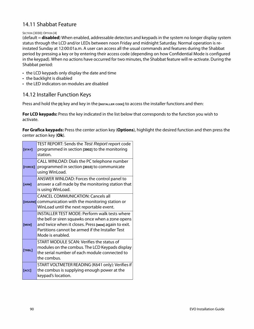
90 EVO Installation Guide
14.11 Shabbat FeatureSECTION [3030]: OPTION [4]
(default = disabled) When enabled, addressable detectors and keypads in the system no longer display system status through the LCD and/or LEDs between noon Friday and midnight Saturday. Normal operation is re-instated Sunday at 12:00:01a.m. A user can access all the usual commands and features during the Shabbat period by pressing a key or by entering their access code (depending on how Confidential Mode is configured in the keypad). When no actions have occurred for two minutes, the Shabbat feature will re-activate. During the Shabbat period:
• the LCD keypads only display the date and time• the backlight is disabled • the LED indicators on modules are disabled
14.12 Installer Function Keys Press and hold the [0] key and key in the [INSTALLER CODE] to access the installer functions and then:
For LCD keypads: Press the key indicated in the list below that corresponds to the function you wish to activate.
For Grafica keypads: Press the center action key (Options), highlight the desired function and then press the center action key (Ok).
[STAY]
TEST REPORT: Sends the Test Report report code programmed in section [3902] to the monitoring station.
[FORCE]
CALL WINLOAD: Dials the PC telephone number programmed in section [3010] to communicate using WinLoad.
[ARM]
ANSWER WINLOAD: Forces the control panel to answer a call made by the monitoring station that is using WinLoad.
[DISARM]
CANCEL COMMUNICATION: Cancels all communication with the monitoring station or WinLoad until the next reportable event.
[MEM]
INSTALLER TEST MODE: Perform walk tests where the bell or siren squawks once when a zone opens and twice when it closes. Press [MEM] again to exit. Partitions cannot be armed if the Installer Test Mode is enabled.
[TRBL]
START MODULE SCAN: Verifies the status of modules on the combus. The LCD Keypads display the serial number of each module connected to the combus.
[ACC]
START VOLTMETER READING (K641 only): Verifies if the combus is supplying enough power at the keypad’s location.

14.13 Module ResetSECTION [4001]
To reset a module connected to the combus to its default values, key in the module's serial number into section [4001].
14.14 Locate ModuleSECTION [4002]
To locate a specific module on the combus, key in the module's serial number into section [4002]. The LED on the module flashes until the serial number is entered or the module’s tamper or unlocate switch is pressed.
14.15 Module ProgrammingSECTION [4003]
To program a module, enter section [4003] to enter Module Programming Mode (see section 3.5 on page 30), and enter the module's serial number. To exit, press the [CLEAR] key until Normal Mode is displayed.
14.16 Module and Label BroadcastSECTION [4004]
Module BroadcastTo copy the contents of the programming sections from one module to another, enter the serial number of the source module in section [4004], enter the serial numbers of all the destination modules and press [ACC] or the center action key (Start).
Label BroadcastCopy the User Labels, Zone Labels (sections [0301] to [0396]), the Door Labels (sections [2301] to [2332]) and the Partition Labels (sections [3100], [3200], [3300], [3400], [3500], [3600], [3700] and [3800]) to all the modules in the system that support these labels. To transmit the labels, in section [4004], enter the control panel’s serial number. From the Destination screen, do not enter a serial number and press [ACC] if using an LCD keypad or the center action key (Start) if using a Grafica keypad.
The Module and Label Broadcast feature will only work when a module is broadcasting its data to a module or to modules of the same type and model number.
14.17 System Date & TimeThe System Date and Time is programmed through the User Menu.
14.18 Quick Module ScanningSECTION [4005]
After entering the section, the control panel will scan all addresses assigned to modules. If any missing modules are detected (i.e. detector
removed from the combus), the control panel will erase the module's serial number, removing the module from the control panel's memory.
14.19 Module ScanningSECTION [4006]
After entering the section, the control panel will scan all addresses on the combus. If any missing modules are detected (i.e. detector
removed from the combus), the control panel will erase the module's serial number, removing the module from the control panel's memory.
EVO Installation Guide 91
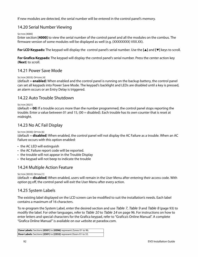
92 EVO Installation Guide
If new modules are detected, the serial number will be entered in the control panel’s memory.
14.20 Serial Number ViewingSECTION [4000]
Enter section [4000] to view the serial number of the control panel and all the modules on the combus. The firmware version of some modules will be displayed as well (e.g. (XXXXXXXX) VXX.XX).
For LCD Keypads: The keypad will display the control panel’s serial number. Use the [] and [] keys to scroll.
For Grafica Keypads: The keypad will display the control panel’s serial number. Press the center action key (Next) to scroll.
14.21 Power Save ModeSECTION [3033]: OPTIONS [4]
(default = enabled) When enabled and the control panel is running on the backup battery, the control panel can set all keypads into Power Save Mode. The keypad's backlight and LEDs are disabled until a key is pressed, an alarm occurs or an Entry Delay is triggered.
14.22 Auto Trouble ShutdownSECTION [3021]
(default = 00) If a trouble occurs more than the number programmed, the control panel stops reporting the trouble. Enter a value between 01 and 15, (00 = disabled). Each trouble has its own counter that is reset at midnight.
14.23 No AC Fail Display SECTION [3030]: OPTION [6]
(default = disabled) When enabled, the control panel will not display the AC Failure as a trouble. When an AC Failure occurs with this option enabled:
• the AC LED will extinguish • the AC Failure report code will be reported. • the trouble will not appear in the Trouble Display • the keypad will not beep to indicate the trouble
14.24 Multiple Action FeatureSECTION [3033]: OPTION [1]
(default = disabled) When enabled, users will remain in the User Menu after entering their access code. With option [1] off, the control panel will exit the User Menu after every action.
14.25 System LabelsThe existing label displayed on the LCD screen can be modified to suit the installation’s needs. Each label contains a maximum of 16 characters.
To re-program the System Label, enter the desired section and use Table 7, Table 9 and Table 8 (page 93) to modify the label. For other languages, refer to Table 10 to Table 14 on page 96. For instructions on how to enter letters and special characters for the Grafica keypad, refer to “Grafica’s Online Manual”. A complete “Grafica Online Manual” is available on our website at paradox.com.
Zone Labels: Sections [0301] to [0396] represent Zones 01 to 96.
Door Labels: Sections [2301] to [2332] represent Doors 01 to 32.
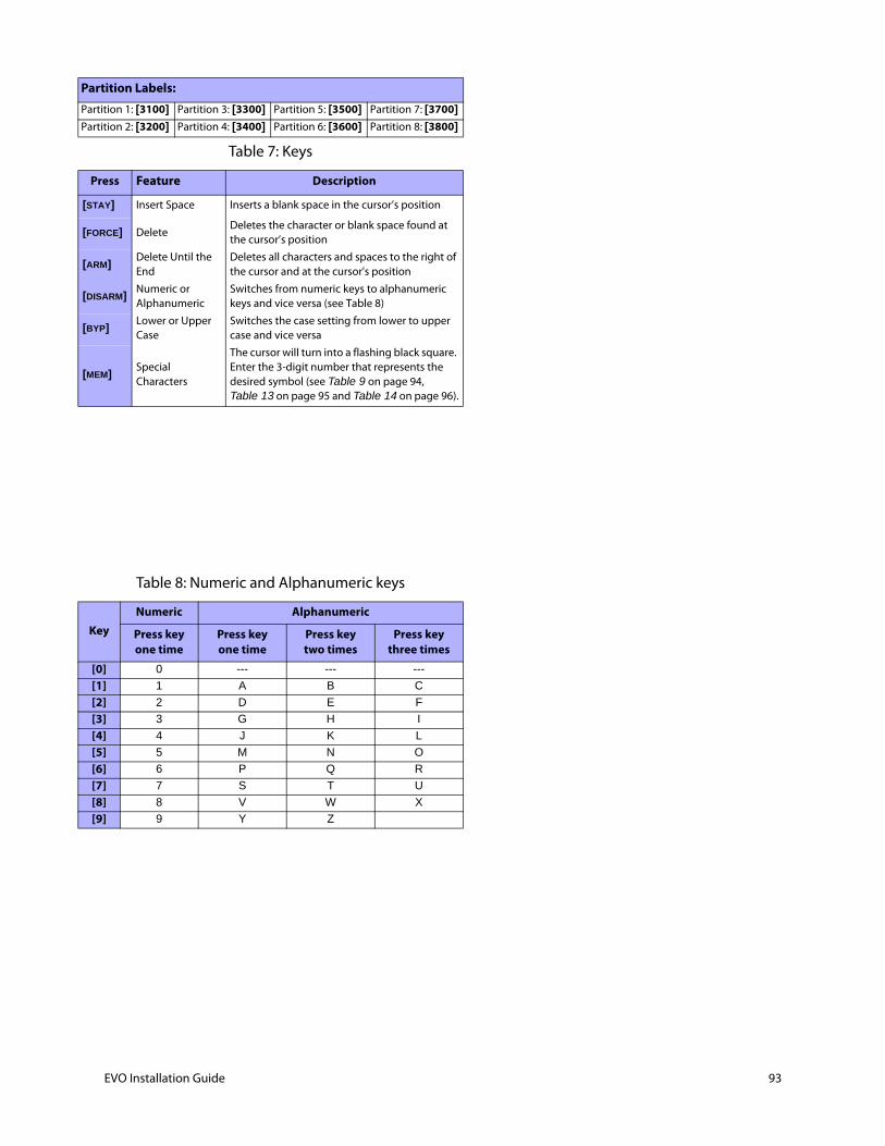
Partition Labels:
Partition 1: [3100] Partition 3: [3300] Partition 5: [3500] Partition 7: [3700]
Partition 2: [3200] Partition 4: [3400] Partition 6: [3600] Partition 8: [3800]
Table 7: Keys
Press Feature Description
[STAY] Insert Space Inserts a blank space in the cursor’s position
[FORCE] DeleteDeletes the character or blank space found at the cursor’s position
[ARM]Delete Until the End
Deletes all characters and spaces to the right of the cursor and at the cursor's position
[DISARM]Numeric or Alphanumeric
Switches from numeric keys to alphanumeric keys and vice versa (see Table 8)
[BYP]Lower or Upper Case
Switches the case setting from lower to upper case and vice versa
[MEM]Special Characters
The cursor will turn into a flashing black square. Enter the 3-digit number that represents the desired symbol (see Table 9 on page 94, Table 13 on page 95 and Table 14 on page 96).
Table 8: Numeric and Alphanumeric keys
KeyNumeric Alphanumeric
Press keyone time
Press key one time
Press key two times
Press key three times
[0] 0 --- --- ---
[1] 1 A B C
[2] 2 D E F
[3] 3 G H I
[4] 4 J K L
[5] 5 M N O
[6] 6 P Q R
[7] 7 S T U
[8] 8 V W X
[9] 9 Y Z
EVO Installation Guide 93
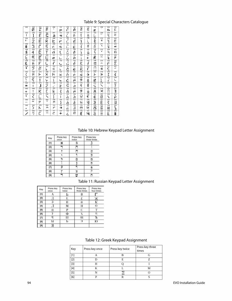
94 EVO Installation Guide
Table 9: Special Characters Catalogue
Table 10: Hebrew Keypad Letter Assignment
Table 11: Russian Keypad Letter Assignment
Table 12: Greek Keypad Assignment
Key Press key once Press key twicePress key three times
[1] A B G
[2] D E Z
[3] H Q I
[4] K L M
[5] N O
[6] P R S
032 048 064 080 096 112 128 144 160 176 192 208 224 240
033 049 065 081 097 113 129 145 161 177 193 209 225 241
034 050 066 082 098 114 130 146 162 178 194 210 226 242
035 051 067 083 099 115 131 147 163 179 195 211 227 243
036 052 068 084 100 116 132 148 164 180 196 212 228 244
037 053 A069 085 101 117 133 149 165 181 197 213 229 245
038 054 070 086 102 118 134 150 166 182 198 214 230 246
039 055 071 087 103 119 135 151 167 183 199 215 231 247
040 056 072 088 104 120 136 152 168 184 200 216 232 248
041 057 073 089 105 121 137 153 169 185 201 217 233 249
042 058 074 090 106 122 138 154 170 186 202 218 234 250
043 059 075 091 107 123 139 155 171 187 203 219 235 251
044 060 076 092 108 124 140 156 172 188 204 220 236 252
045 061 077 093 109 125 141 157 173 189 205 221 237 253
046 062 078 094 110 126 142 158 174 190 206 222 238 254
047 063 079 095 111 127 143 159 175 191 207 223 239 255
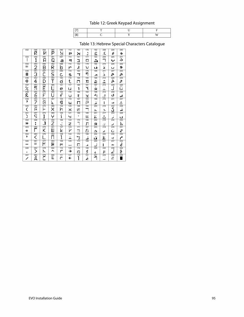
Table 13: Hebrew Special Characters Catalogue
[7] T U F
[8] C Y W
Table 12: Greek Keypad Assignment
032 048 064 080 096 112 160 176 192 208 224 240
033 049 065 081 097 113 161 177 193 209 225 241
034 050 066 082 098 114 162 178 194 210 226 242
035 051 067 083 099 115 163 179 195 211 227 243
036 052 068 084 100 116 164 180 196 212 228 244
037 053 069 085 101 117 165 181 197 213 229 245
038 054 070 086 102 118 166 182 198 214 230 246
039 055 071 087 103 119 167 183 199 215 231 247
040 056 072 088 104 120 168 184 200 216 232 248
041 057 073 089 105 121 169 185 201 217 233 249
042 058 074 090 106 122 170 186 202 218 234 250
043 059 075 091 107 123 171 187 203 219 235 251
044 060 076 092 108 124 172 188 204 220 236 252
045 061 077 093 109 125 173 189 205 221 237 253
046 062 078 094 110 126 174 190 206 222 238 254
047 063 079 095 111 127 175 191 207 223 239 255
EVO Installation Guide 95
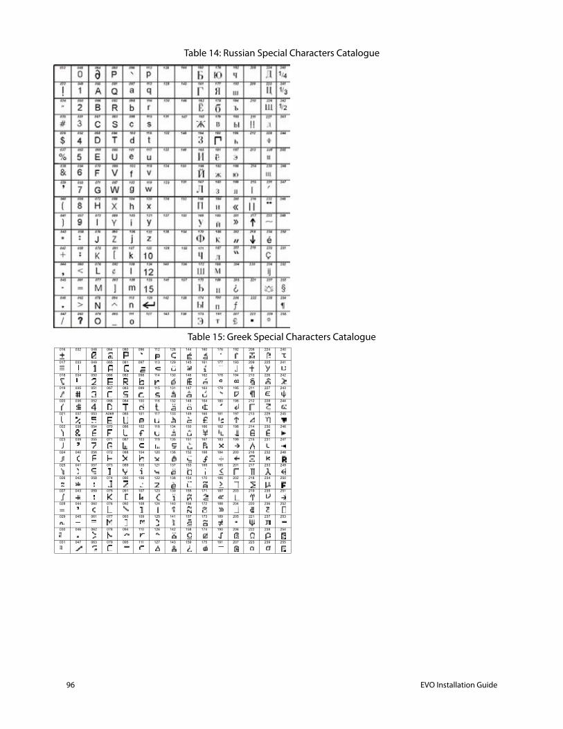
96 EVO Installation Guide
Table 14: Russian Special Characters Catalogue
Table 15: Greek Special Characters Catalogue016 032 048 064 080 096 112 128 144 160 176 192 208 224 240
017 033 049 065 081 097 113 129 145 161 177 193 209 225 241
018 034 050 066 082 098 114 130 146 162 178 194 210 226 242
019 035 051 067 083 099 115 131 147 163 179 195 211 227 243
020 036 052 068 084 100 116 132 148 164 180 196 212 228 244
021 037 053 A069 085 101 117 133 149 165 181 197 213 229 245
022 038 054 070 086 102 118 134 150 166 182 198 214 230 246
023 039 055 071 087 103 119 135 151 167 183 199 215 231 247
024 040 056 072 088 104 120 136 152 168 184 200 216 232 248
025 041 057 073 089 105 121 137 153 169 185 201 217 233 249
026 042 058 074 090 106 122 138 154 170 186 202 218 234 250
027 043 059 075 091 107 123 139 155 171 187 203 219 235 251
028 044 060 076 092 108 124 140 156 172 188 204 220 236 252
029 045 061 077 093 109 125 141 157 173 189 205 221 237 253
030 046 062 078 094 110 126 142 158 174 190 206 222 238 254
031 047 063 079 095 111 127 143 159 175 191 207 223 239 255

Access Codes 15
15.1 Installer Code SECTION [1000]
(default = 000000) The Installer Code is six digits in length where each digit can be any value from 0 to 9. To change the Installer Code:
1. Press and hold [0]
2. Enter [INSTALLER CODE]
3. Key in [1000]
4. Enter new 6-digit [INSTALLER CODE]
The Installer Code can program the User Code Options and the Partition Assignment, but cannot program the personal identification numbers.
15.2 Access Code LengthSECTION [3033]: OPTIONS [2] AND [3]
Access codes can be 1 to 6 digits in length if flexible user access code is enabled. When programming access codes with less than 6 digits, press the [ENTER] key after entering the last digit. The control panel automatically removes the last 2 digits of the user access code if the length is changed from 6 digits to 4 digits. However, if the user access code length is changed from 4 digits to 6 digits, the control panel adds 2 digits to the end by using the first 2 digits.
15.3 System Master CodeSECTION [1001]
(default = 123456) The Installer Code can change the User Code Options, Partition Assignment and Access Control Options, but cannot change the personal identification number (PIN). Each digit in the System Master Code can be any value from 0 to 9. To reset the System Master Code, refer to see section 14.2 on page 87. With the System Master Code, a user can use any of the available arming methods with access to all partitions and can program all user access codes, User Options, Partition Assignments and Access Control Options.
15.4 Programming Access CodesSECTIONS [1002] TO [1999]
(default = all options are off except bypass) The control panel supports 998 user access codes. In sections [1002] to [1999], the Installer Code can program the User Code Options, Partition Assignment and Access Control Options, but cannot program the personal identification numbers (PIN). To program the PINs, refer the users to the “System Manager’s Manual”. The System Master Code or a user with the Master feature enabled can program the User Code Options, Partition Assignment, Access Control Options and User Labels using a different method of programming.
[2] [3]
OFF OFF 4-digit User Access Code (default)
OFF ON 6-digit User Access Code
ON ON Flexible User Access Code
EVO Installation Guide 97

98 EVO Installation Guide
If no partition assignment is selected, the user access code will only be able to activate PGMs.
To program user labels, refer to the “LCD Keypad System Manager’s Manual” or to the “Grafica Graphic LCD Keypad Online Help”.
15.5 User OptionsSECTIONS [1002] TO [1999]: USER OPTIONS SCREEN, OPTIONS [1] TO [8]
The User Options define how each user access code can arm or disarm the partitions. All users can Regular arm their assigned partitions, but only those with the Arm Only option disabled can disarm an assigned partition.
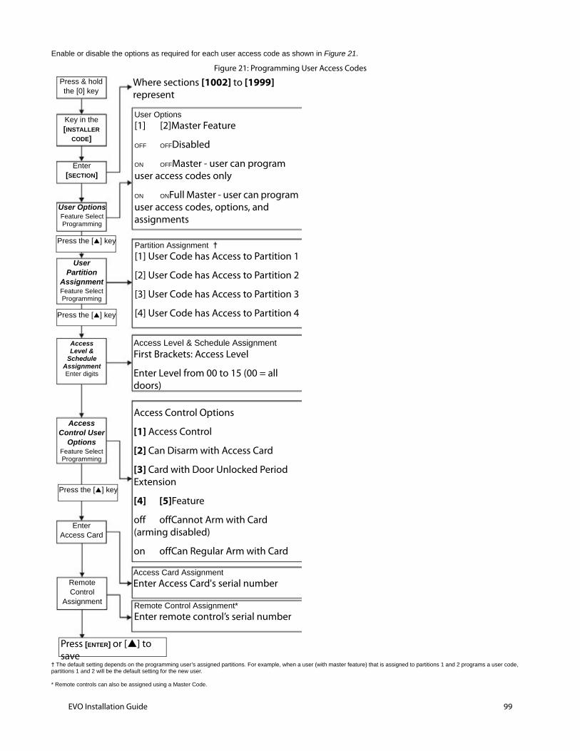
Enable or disable the options as required for each user access code as shown in Figure 21.
Figure 21: Programming User Access Codes
† The default setting depends on the programming user’s assigned partitions. For example, when a user (with master feature) that is assigned to partitions 1 and 2 programs a user code, partitions 1 and 2 will be the default setting for the new user.
* Remote controls can also be assigned using a Master Code.
Press & holdthe [0] key
Where sections [1002] to [1999] represent
Key in the[INSTALLER
CODE]
Enter[SECTION]
User OptionsFeature SelectProgramming
UserPartition
AssignmentFeature SelectProgramming
AccessLevel &
ScheduleAssignmentEnter digits
AccessControl User
OptionsFeature SelectProgramming
EnterAccess Card
User Options
[1] [2]Master Feature
OFF OFFDisabled
ON OFFMaster - user can program user access codes only
ON ONFull Master - user can program user access codes, options, and assignments
Partition Assignment †
[1] User Code has Access to Partition 1
[2] User Code has Access to Partition 2
[3] User Code has Access to Partition 3
[4] User Code has Access to Partition 4
Access Level & Schedule AssignmentFirst Brackets: Access Level
Enter Level from 00 to 15 (00 = all doors)
Access Control Options
[1] Access Control
[2] Can Disarm with Access Card
[3] Card with Door Unlocked Period Extension
[4] [5]Feature
off offCannot Arm with Card (arming disabled)
on offCan Regular Arm with Card
Access Card Assignment
Enter Access Card's serial number Remote Control
Assignment Remote Control Assignment*
Enter remote control’s serial number
Press [ENTER] or [] to save
Press the [] key
Press the [] key
Press the [] key
EVO Installation Guide 99
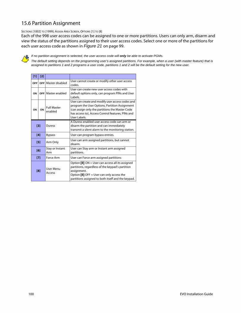
100 EVO Installation Guide
15.6 Partition AssignmentSECTIONS [1002] TO [1999]: ASSIGN AREA SCREEN, OPTIONS [1] TO [8]
Each of the 998 user access codes can be assigned to one or more partitions. Users can only arm, disarm and view the status of the partitions assigned to their user access codes. Select one or more of the partitions for each user access code as shown in Figure 21 on page 99.
If no partition assignment is selected, the user access code will only be able to activate PGMs.
The default setting depends on the programming user’s assigned partitions. For example, when a user (with master feature) that is assigned to partitions 1 and 2 programs a user code, partitions 1 and 2 will be the default setting for the new user.
[1] [2]
OFF OFF Master disabledUser cannot create or modify other user access codes.
ON OFF Master enabledUser can create new user access codes with default options only, can program PINs and User Labels.
ON ONFull Master enabled
User can create and modify user access codes and program the User Options, Partition Assignment (can assign only the partitions the Master Code has access to), Access Control features, PINs and User Labels.
[3] DuressA Duress enabled user access code can arm or disarm the partition and can immediately transmit a silent alarm to the monitoring station.
[4] Bypass User can program bypass entries.
[5] Arm OnlyUser can arm assigned partitions, but cannot disarm.
[6] Stay or Instant Arm
User can Stay arm or Instant arm assigned partitions.
[7] Force Arm User can Force arm assigned partitions
[8] User Menu Access
Option [8] ON = User can access all its assigned partitions, regardless of the keypad’s partition assignment. Option [8] OFF = User can only access the partitions assigned to both itself and the keypad.

037]
Appendix A: Automatic Report Code List
System EventDefault Contact ID Report Codewhen using sections [4032] to [4037]
Default SIA Report Codewhen using sections [4032] to [4
Arming with Master Code (##) 3 4A1 - Close by user CL - Closing Report
Arming with User Code (##) 3 4A1 - Close by user CL - Closing Report
Arming with Keyswitch (##) 3 4A9 - Keyswitch Close CS - Closing Keyswitch
Auto Arming 3 4A3 - Automatic Close CA - Automatic Closing
Arm with PC software 3 4A7 - Remote arm/disarm CQ - Remote Arming
Late To Close 3 452 - Late to Close OT - Late to Close
No Movement 3 452 - Late to Close NA - No Movement Arming
Partial arming 1 456 - Partial Arm CG - Close Area
Quick arming 3 4A8 - Quick arm CL - Closing Report
Remote Arm (voice) 3 4A7 - Remote Arm CQ - Arm with Voice Module
Delinquency Closing 1 654 - System Inactivity CD - System Inactivity
Disarm with Master Code (##) 1 4A1 - Open by user OP - Opening Report
Disarm with User Code (##) 1 4A1 - Open by user OP - Opening Report
Disarm with Keyswitch (##) 1 4A9 - Keyswitch Open OS - Opening Keyswitch
Disarm after alarm with Master Code (##) 1 4A1 - Open by user OP - Opening Report
Disarm after alarm with User Code (##) 1 4A1 - Open by user OP - Opening Report
Disarm after alarm with Keyswitch (##) 1 4A9 - Keyswitch Open OS - Opening Keyswitch
Cancel alarm with Master Code (##) 1 4A6 - Cancel OR - Disarm From Alarm
Cancel alarm with User Code (##) 1 4A6 - Cancel OR - Disarm From Alarm
Cancel alarm with Keyswitch (##) 1 4A6 - Cancel OS - Opening Keyswitch
Auto Arming Cancellation 1 464 - Auto-Arm Time Extended CE - Closing Extend
Cancel Alarm with PC Software 1 4A6 - Cancel OR - Disarm From Alarm
Voice Disarm 1 4A7 - Remote arm/disarm OQ - Remote Disarming
Disarm with PC software 1 4A7 - Remote arm/disarm OQ - Remote Disarming
Disarm after an alarm with PC software 1 4A7 - Remote arm/disarm OQ - Remote Disarming
Quick Disarm 1 4A8 - Quick Disarm OP - Opening Report
Zone Bypassed (##) 1 57A - Zone bypass UB - Untyped Zone Bypass
Zone alarm (##) 1 13A - Burglary Alarm BA - Burglary Alarm
Fire alarm (##) 1 11A - Fire alarm FA - Fire Alarm
Early to Disarm by User 1 451 - Early to Open OK - Early to Open
Late to Disarm by User 1 452 - Late to Open OJ - Late to Open
Zone alarm restore (##) 3 13A - Burglary Alarm Restore BH - Burglary Alarm Restore
Fire alarm restore (##) 3 11A - Fire alarm Restore FH - Fire Alarm Restore
24Hr Gas alarm (##) 1 13A - Burglary Alarm GA - Gas Alarm
24Hr Heat alarm (##) 1 13A - Burglary Alarm KA - Heat Alarm
24Hr Water alarm (##) 1 13A - Burglary Alarm WA - Water Alarm
24Hr Freeze alarm (##) 1 13A - Burglary Alarm ZA - Freeze Alarm
24Hr Gas alarm restore (##) 3 13A - Burglary Alarm Restore GR - Gas Alarm Restore
24Hr Heat alarm restore (##) 3 13A - Burglary Alarm Restore KR - Heat Alarm Restore
24Hr Water alarm restore (##) 3 13A - Burglary Alarm Restore WR - Water Alarm Restore
24Hr Freeze alarm restore (##) 3 13A - Burglary Alarm Restore ZR - Freeze Alarm Restore
Panic 1 - Emergency 1 12A - Panic alarm PA - Panic Alarm
Panic 2 - Medical 1 1AA - Medical alarm MA - Medical Alarm
Panic 3 - Fire 1 115 - Pull Station FA - Fire Alarm
Recent closing 3 459 - Recent Close CR - Recent Closing
Police Code 1 139 - Burglary Alarm BM - Burglary Alarm
Global zone shutdown 1 574 - Group bypass CG - Close Area
Duress alarm 1 121 - Duress HA - Hold-up Alarm
Zone shutdown (##) 1 57A - Zone bypass UB - Untyped Zone Bypass
EVO Installation Guide 101
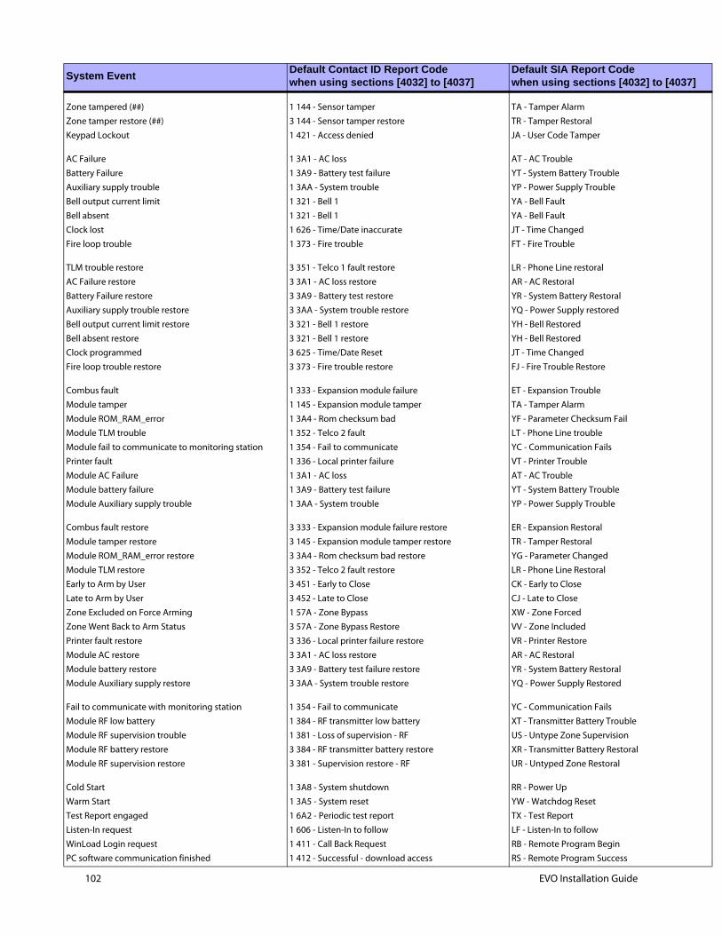
037]
102 EVO Installation Guide
Zone tampered (##) 1 144 - Sensor tamper TA - Tamper Alarm
Zone tamper restore (##) 3 144 - Sensor tamper restore TR - Tamper Restoral
Keypad Lockout 1 421 - Access denied JA - User Code Tamper
AC Failure 1 3A1 - AC loss AT - AC Trouble
Battery Failure 1 3A9 - Battery test failure YT - System Battery Trouble
Auxiliary supply trouble 1 3AA - System trouble YP - Power Supply Trouble
Bell output current limit 1 321 - Bell 1 YA - Bell Fault
Bell absent 1 321 - Bell 1 YA - Bell Fault
Clock lost 1 626 - Time/Date inaccurate JT - Time Changed
Fire loop trouble 1 373 - Fire trouble FT - Fire Trouble
TLM trouble restore 3 351 - Telco 1 fault restore LR - Phone Line restoral
AC Failure restore 3 3A1 - AC loss restore AR - AC Restoral
Battery Failure restore 3 3A9 - Battery test restore YR - System Battery Restoral
Auxiliary supply trouble restore 3 3AA - System trouble restore YQ - Power Supply restored
Bell output current limit restore 3 321 - Bell 1 restore YH - Bell Restored
Bell absent restore 3 321 - Bell 1 restore YH - Bell Restored
Clock programmed 3 625 - Time/Date Reset JT - Time Changed
Fire loop trouble restore 3 373 - Fire trouble restore FJ - Fire Trouble Restore
Combus fault 1 333 - Expansion module failure ET - Expansion Trouble
Module tamper 1 145 - Expansion module tamper TA - Tamper Alarm
Module ROM_RAM_error 1 3A4 - Rom checksum bad YF - Parameter Checksum Fail
Module TLM trouble 1 352 - Telco 2 fault LT - Phone Line trouble
Module fail to communicate to monitoring station 1 354 - Fail to communicate YC - Communication Fails
Printer fault 1 336 - Local printer failure VT - Printer Trouble
Module AC Failure 1 3A1 - AC loss AT - AC Trouble
Module battery failure 1 3A9 - Battery test failure YT - System Battery Trouble
Module Auxiliary supply trouble 1 3AA - System trouble YP - Power Supply Trouble
Combus fault restore 3 333 - Expansion module failure restore ER - Expansion Restoral
Module tamper restore 3 145 - Expansion module tamper restore TR - Tamper Restoral
Module ROM_RAM_error restore 3 3A4 - Rom checksum bad restore YG - Parameter Changed
Module TLM restore 3 352 - Telco 2 fault restore LR - Phone Line Restoral
Early to Arm by User 3 451 - Early to Close CK - Early to Close
Late to Arm by User 3 452 - Late to Close CJ - Late to Close
Zone Excluded on Force Arming 1 57A - Zone Bypass XW - Zone Forced
Zone Went Back to Arm Status 3 57A - Zone Bypass Restore VV - Zone Included
Printer fault restore 3 336 - Local printer failure restore VR - Printer Restore
Module AC restore 3 3A1 - AC loss restore AR - AC Restoral
Module battery restore 3 3A9 - Battery test failure restore YR - System Battery Restoral
Module Auxiliary supply restore 3 3AA - System trouble restore YQ - Power Supply Restored
Fail to communicate with monitoring station 1 354 - Fail to communicate YC - Communication Fails
Module RF low battery 1 384 - RF transmitter low battery XT - Transmitter Battery Trouble
Module RF supervision trouble 1 381 - Loss of supervision - RF US - Untype Zone Supervision
Module RF battery restore 3 384 - RF transmitter battery restore XR - Transmitter Battery Restoral
Module RF supervision restore 3 381 - Supervision restore - RF UR - Untyped Zone Restoral
Cold Start 1 3A8 - System shutdown RR - Power Up
Warm Start 1 3A5 - System reset YW - Watchdog Reset
Test Report engaged 1 6A2 - Periodic test report TX - Test Report
Listen-In request 1 606 - Listen-In to follow LF - Listen-In to follow
WinLoad Login request 1 411 - Call Back Request RB - Remote Program Begin
PC software communication finished 1 412 - Successful - download access RS - Remote Program Success
System EventDefault Contact ID Report Codewhen using sections [4032] to [4037]
Default SIA Report Codewhen using sections [4032] to [4

037]
Installer on site 1 627 - Program mode Entry LB - Local ProgramInstaller programming finished 1 628 - Program mode Exit LS - Local Program Success
Module Fail to Communicate Restore 3 354 - Fail to Communicate Restore YK - Communication Restore
System EventDefault Contact ID Report Codewhen using sections [4032] to [4037]
Default SIA Report Codewhen using sections [4032] to [4
EVO Installation Guide 103
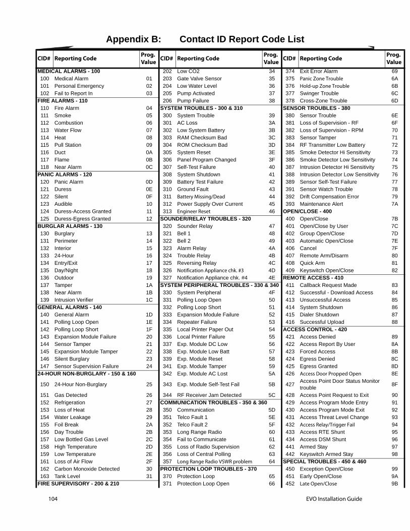
Prog.Value
696A6B6C6D
6E6F707172737475767778797A
7B7C7D7E7F808182
838485868788
898A8B8C8D8E
8F
909192939495969798
999A9B
104 EVO Installation Guide
Appendix B: Contact ID Report Code List
CID# Reporting Code Prog.Value CID# Reporting Code Prog.
Value CID# Reporting Code
MEDICAL ALARMS - 100 202 Low CO2 34 374 Exit Error Alarm100 Medical Alarm 01 203 Gate Valve Sensor 35 375 Panic Zone Trouble101 Personal Emergency 02 204 Low Water Level 36 376 Hold-up Zone Trouble102 Fail to Report In 03 205 Pump Activated 37 377 Swinger Trouble
FIRE ALARMS - 110 206 Pump Failure 38 378 Cross-Zone Trouble110 Fire Alarm 04 SYSTEM TROUBLES - 300 & 310 SENSOR TROUBLES - 380111 Smoke 05 300 System Trouble 39 380 Sensor Trouble112 Combustion 06 301 AC Loss 3A 381 Loss of Supervision - RF113 Water Flow 07 302 Low System Battery 3B 382 Loss of Supervision - RPM114 Heat 08 303 RAM Checksum Bad 3C 383 Sensor Tamper115 Pull Station 09 304 ROM Checksum Bad 3D 384 RF Transmitter Low Battery116 Duct 0A 305 System Reset 3E 385 Smoke Detector Hi Sensitivity117 Flame 0B 306 Panel Program Changed 3F 386 Smoke Detector Low Sensitivity118 Near Alarm 0C 307 Self-Test Failure 40 387 Intrusion Detector Hi Sensitivity
PANIC ALARMS - 120 308 System Shutdown 41 388 Intrusion Detector Low Sensitivity120 Panic Alarm 0D 309 Battery Test Failure 42 389 Sensor Self-Test Failure121 Duress 0E 310 Ground Fault 43 391 Sensor Watch Trouble122 Silent 0F 311 Battery Missing/Dead 44 392 Drift Compensation Error123 Audible 10 312 Power Supply Over Current 45 393 Maintenance Alert124 Duress-Access Granted 11 313 Engineer Reset 46 OPEN/CLOSE - 400125 Duress-Egress Granted 12 SOUNDER/RELAY TROUBLES - 320 400 Open/Close
BURGLAR ALARMS - 130 320 Sounder Relay 47 401 Open/Close by User130 Burglary 13 321 Bell 1 48 402 Group Open/Close131 Perimeter 14 322 Bell 2 49 403 Automatic Open/Close132 Interior 15 323 Alarm Relay 4A 406 Cancel133 24-Hour 16 324 Trouble Relay 4B 407 Remote Arm/Disarm134 Entry/Exit 17 325 Reversing Relay 4C 408 Quick Arm135 Day/Night 18 326 Notification Appliance chk. #3 4D 409 Keyswitch Open/Close136 Outdoor 19 327 Notification Appliance chk. #4 4E REMOTE ACCESS - 410137 Tamper 1A SYSTEM PERIPHERAL TROUBLES - 330 & 340 411 Callback Request Made138 Near Alarm 1B 330 System Peripheral 4F 412 Successful - Download Access139 Intrusion Verifier 1C 331 Polling Loop Open 50 413 Unsuccessful Access
GENERAL ALARMS - 140 332 Polling Loop Short 51 414 System Shutdown140 General Alarm 1D 333 Expansion Module Failure 52 415 Dialer Shutdown141 Polling Loop Open 1E 334 Repeater Failure 53 416 Successful Upload142 Polling Loop Short 1F 335 Local Printer Paper Out 54 ACCESS CONTROL - 420143 Expansion Module Failure 20 336 Local Printer Failure 55 421 Access Denied144 Sensor Tamper 21 337 Exp. Module DC Low 56 422 Access Report By User145 Expansion Module Tamper 22 338 Exp. Module Low Batt 57 423 Forced Access146 Silent Burglary 23 339 Exp. Module Reset 58 424 Egress Denied147 Sensor Supervision Failure 24 341 Exp. Module Tamper 59 425 Egress Granted
24-HOUR NON-BURGLARY - 150 & 160 342 Exp. Module AC Lost 5A 426 Access Door Propped Open
150 24-Hour Non-Burglary 25 343 Exp. Module Self-Test Fail 5B 427Access Point Door Status Monitor trouble
151 Gas Detected 26 344 RF Receiver Jam Detected 5C 428 Access Point Request to Exit152 Refrigeration 27 COMMUNICATION TROUBLES - 350 & 360 429 Access Program Mode Entry153 Loss of Heat 28 350 Communication 5D 430 Access Program Mode Exit154 Water Leakage 29 351 Telco Fault 1 5E 431 Access Threat Level Change155 Foil Break 2A 352 Telco Fault 2 5F 432 Access Relay/Trigger Fail156 Day Trouble 2B 353 Long Range Radio 60 433 Access RTE Shunt157 Low Bottled Gas Level 2C 354 Fail to Communicate 61 434 Access DSM Shunt158 High Temperature 2D 355 Loss of Radio Supervision 62 441 Armed Stay159 Low Temperature 2E 356 Loss of Central Polling 63 442 Keyswitch Armed Stay161 Loss of Air Flow 2F 357 Long Range Radio VSWR problem 64 SPECIAL TROUBLES - 450 & 460162 Carbon Monoxide Detected 30 PROTECTION LOOP TROUBLES - 370 450 Exception Open/Close163 Tank Level 31 370 Protection Loop 65 451 Early Open/Close
FIRE SUPERVISORY - 200 & 210 371 Protection Loop Open 66 452 Late Open/Close
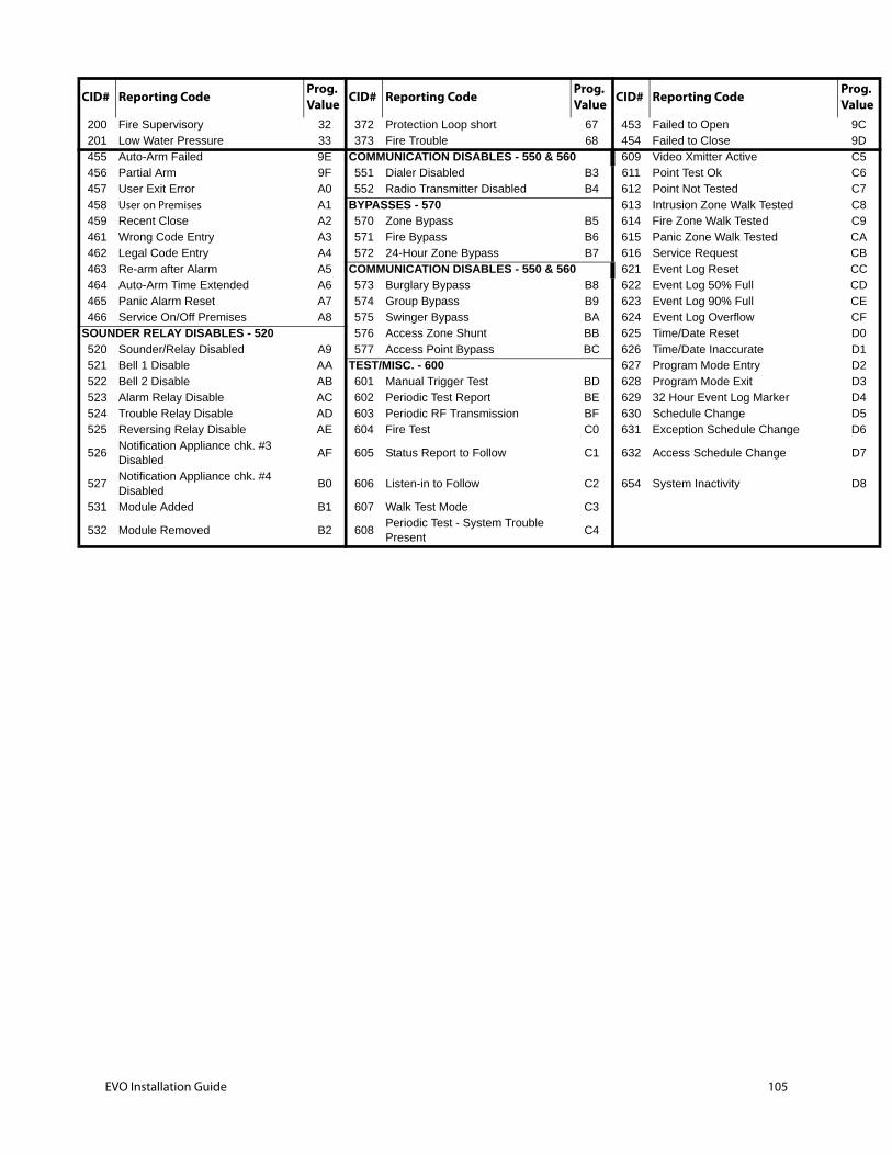
9C9DC5C6C7C8C9CACBCCCDCECFD0D1D2D3D4D5D6
D7
D8
Prog.Value
200 Fire Supervisory 32 372 Protection Loop short 67 453 Failed to Open201 Low Water Pressure 33 373 Fire Trouble 68 454 Failed to Close455 Auto-Arm Failed 9E COMMUNICATION DISABLES - 550 & 560 609 Video Xmitter Active456 Partial Arm 9F 551 Dialer Disabled B3 611 Point Test Ok457 User Exit Error A0 552 Radio Transmitter Disabled B4 612 Point Not Tested458 User on Premises A1 BYPASSES - 570 613 Intrusion Zone Walk Tested459 Recent Close A2 570 Zone Bypass B5 614 Fire Zone Walk Tested461 Wrong Code Entry A3 571 Fire Bypass B6 615 Panic Zone Walk Tested462 Legal Code Entry A4 572 24-Hour Zone Bypass B7 616 Service Request463 Re-arm after Alarm A5 COMMUNICATION DISABLES - 550 & 560 621 Event Log Reset464 Auto-Arm Time Extended A6 573 Burglary Bypass B8 622 Event Log 50% Full465 Panic Alarm Reset A7 574 Group Bypass B9 623 Event Log 90% Full466 Service On/Off Premises A8 575 Swinger Bypass BA 624 Event Log Overflow
SOUNDER RELAY DISABLES - 520 576 Access Zone Shunt BB 625 Time/Date Reset520 Sounder/Relay Disabled A9 577 Access Point Bypass BC 626 Time/Date Inaccurate521 Bell 1 Disable AA TEST/MISC. - 600 627 Program Mode Entry522 Bell 2 Disable AB 601 Manual Trigger Test BD 628 Program Mode Exit523 Alarm Relay Disable AC 602 Periodic Test Report BE 629 32 Hour Event Log Marker524 Trouble Relay Disable AD 603 Periodic RF Transmission BF 630 Schedule Change525 Reversing Relay Disable AE 604 Fire Test C0 631 Exception Schedule Change
526Notification Appliance chk. #3 Disabled
AF 605 Status Report to Follow C1 632 Access Schedule Change
527Notification Appliance chk. #4 Disabled
B0 606 Listen-in to Follow C2 654 System Inactivity
531 Module Added B1 607 Walk Test Mode C3
532 Module Removed B2 608Periodic Test - System Trouble Present
C4
CID# Reporting Code Prog.Value CID# Reporting Code Prog.
Value CID# Reporting Code
EVO Installation Guide 105

106 EVO Installation Guide
Appendix C: Keypad Installation Instructions
Connecting the KeypadsThe keypads are connected to the control panel's combus in a star and/or daisy chain configuration. Connect the four terminals labeled red, black, green and yellow of each keypad to the corresponding terminals on the control panel.
Connecting Keypad ZonesEach keypad has one hardwired input terminal, allowing you to connect one detector or door contact directly to it. Connect the device to the keypad's input terminal. In order to communicate its status to the control panel, the keypad's input must be assigned to a zone in the control panel and the zone's parameters must be defined.
Programmable OutputEach keypad has one on-board PGM. Upon activation, the PGM can provide 50mA to any device connected to it. If the current drawn is to exceed the current limit, a relay should be connected to the PGM.
Keypad Specific Instructions
C.0.1 Memory Key ConnectionA memory key can be used to download programming to the K641 and K641R keypads.
C.0.2 Memory KeySECTIONS [510] AND [520]Download information using the memory key (PMC-4).
C.0.3 Download Contents of Memory Key to KeypadSECTION [510]1. Insert the memory key into the keypad’s connector labelled “KEY.”
2. To download the contents of the memory key, enter the keypad’s programming mode and enter section [510].
3. When the keypad emits a confirmation beep, wait 5 seconds and remove the memory key after the second confirmation beep.
C.0.4 Copy the Keypad Contents to the Memory KeySECTION [520]1. Insert the memory key onto the keypad’s connector labelled “KEY.” Ensure that the write protect jumper is
ON.
2. To copy the contents to the memory key, enter the keypad’s programming mode and enter section [520].
Section [510] =Download all from the memory key (LCD keypad sections [001] to [396] and all messages) to the LCD keypad.
Section [520] =Copy the LCD keypad sections [001] to [396] and all messages to the memory key.

3. After the confirmation beep, wait 5 seconds and remove the memory key after the second confirmation beep. Set the memory key’s jumper to OFF if you do not wish to accidentally overwrite its contents.
Figure 22: PMC-4 Jumper SettingsJumper On Jumper Off
EVO Installation Guide 107
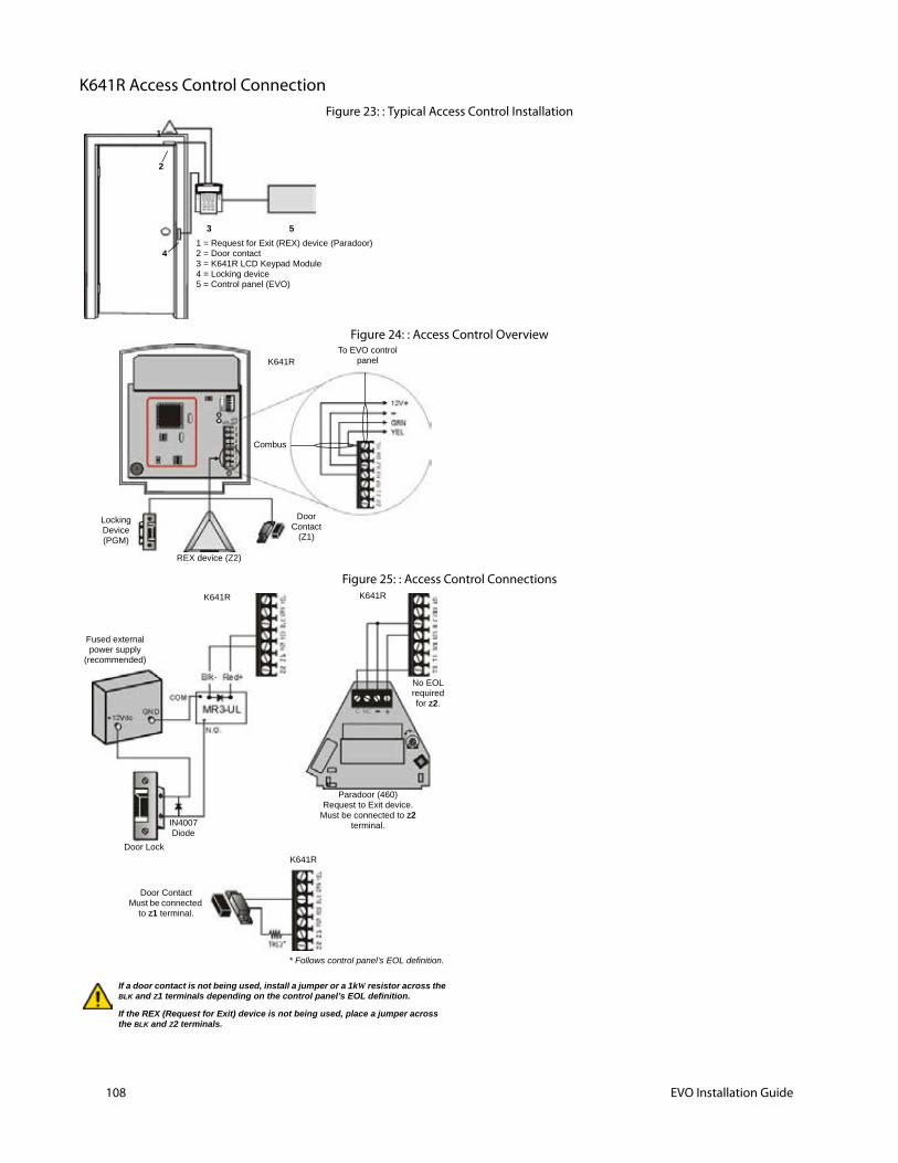
108 EVO Installation Guide
K641R Access Control ConnectionFigure 23: : Typical Access Control Installation
Figure 24: : Access Control Overview
Figure 25: : Access Control Connections
1 = Request for Exit (REX) device (Paradoor)2 = Door contact3 = K641R LCD Keypad Module4 = Locking device5 = Control panel (EVO)
5
4
3
1
2
Door Contact
(Z1)
Locking Device(PGM)
REX device (Z2)
K641R
Combus
To EVO control panel
K641R K641R
Fused external power supply
(recommended)
Door Lock
IN4007Diode
K641R
Paradoor (460)Request to Exit device.
Must be connected to Z2 terminal.
If a door contact is not being used, install a jumper or a 1kW resistor across the BLK and Z1 terminals depending on the control panel’s EOL definition.
If the REX (Request for Exit) device is not being used, place a jumper across the BLK and Z2 terminals.
Door ContactMust be connected
to Z1 terminal.
* Follows control panel’s EOL definition.
No EOL required for Z2.

Programming
C.0.5 Entering Module Programming ModeThe keypad is programmed through the control panel. To do so, you must first enter Module Programming Mode:
1. From Normal Mode press and hold the [0] key.
2. Enter the [INSTALLER CODE] (Default: 000000).
3. Enter section [4003].
4. Enter the keypad’s 8-digit [SERIAL NUMBER].
5. Enter the 3-digit [SECTION] you want to program.
6. Enter the required [DATA].
The control panel will then redirect all programming to the selected keypad. Every time the [CLEAR] key is pressed it will revert to the preceding step, unless entering in data in which case it will erase the current data entry. Please note that the serial number is located on the keypad's PC board or enter section [000] in Step 3 to view the keypad’s serial number.
C.0.6 Module BroadcastThe control panel’s Module Broadcast feature can be used to copy the contents of one keypad to one or more keypads.
1. From Normal Mode press and hold the [0] key.
2. Enter [INSTALLER CODE] (Default: 000000).
3. Enter section [4004].
4. Enter the [SERIAL #] of the source keypad. The source is the programmed keypad whose data you want to copy to other keypads.
5. Enter the [SERIAL #] of the destination keypads. The destination is the keypad(s) you want to program with the source’s data. If you want to program more than one keypad with the source’s data, enter the serial numbers of the keypads one at a time.
6. Once you have entered the serial numbers of the keypads you want to program, press the [ACC] key.
Message Programming K641/K641RSECTIONS [101] TO [148], [200] TO [204], AND [301] TO [396]Each section contains one message with a maximum of 16 characters. For more details and to record any changes, use the Digiplex Modules’ Programming Guide.
Note:The EVO control panel has up to 8 partitions, 96 zones and up to 999 user codes. The LCD keypad only allows you to program the messages for up to 4 partitions, 48 zones and 96 user codes. The rest of the messages can be programmed directly into the EVO control panel. Refer to the EVO Reference & Installation Manual and to the EVO Programming Guide for more details.
EVO Installation Guide 109
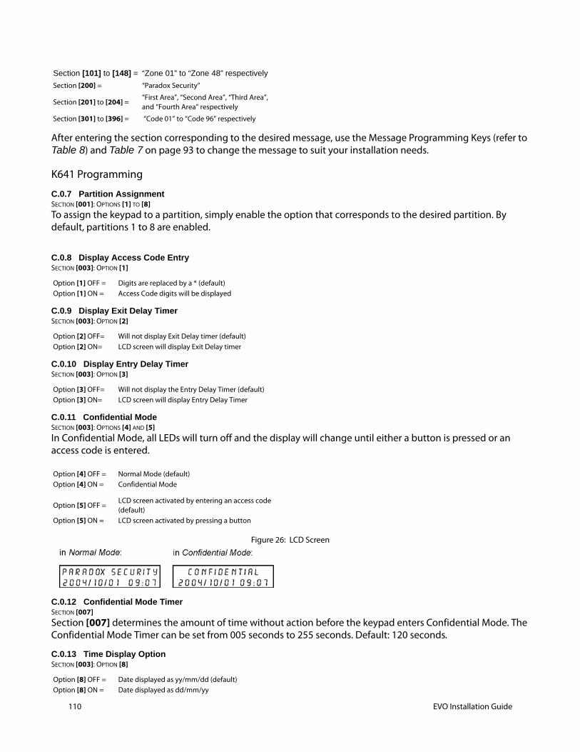
110 EVO Installation Guide
After entering the section corresponding to the desired message, use the Message Programming Keys (refer to Table 8) and Table 7 on page 93 to change the message to suit your installation needs.
K641 Programming
C.0.7 Partition AssignmentSECTION [001]: OPTIONS [1] TO [8]To assign the keypad to a partition, simply enable the option that corresponds to the desired partition. By default, partitions 1 to 8 are enabled.
C.0.8 Display Access Code EntrySECTION [003]: OPTION [1]
C.0.9 Display Exit Delay TimerSECTION [003]: OPTION [2]
C.0.10 Display Entry Delay TimerSECTION [003]: OPTION [3]
C.0.11 Confidential ModeSECTION [003]: OPTIONS [4] AND [5]In Confidential Mode, all LEDs will turn off and the display will change until either a button is pressed or an access code is entered.
Figure 26: LCD Screen
C.0.12 Confidential Mode TimerSECTION [007]Section [007] determines the amount of time without action before the keypad enters Confidential Mode. The Confidential Mode Timer can be set from 005 seconds to 255 seconds. Default: 120 seconds.
C.0.13 Time Display OptionSECTION [003]: OPTION [8]
Section [101] to [148] = “Zone 01” to “Zone 48” respectively
Section [200] = “Paradox Security”
Section [201] to [204] =“First Area”, “Second Area”, “Third Area”, and “Fourth Area” respectively
Section [301] to [396] = “Code 01” to “Code 96” respectively
Option [1] OFF = Digits are replaced by a * (default)Option [1] ON = Access Code digits will be displayed
Option [2] OFF= Will not display Exit Delay timer (default)Option [2] ON= LCD screen will display Exit Delay timer
Option [3] OFF= Will not display the Entry Delay Timer (default)Option [3] ON= LCD screen will display Entry Delay Timer
Option [4] OFF = Normal Mode (default)Option [4] ON = Confidential Mode
Option [5] OFF =LCD screen activated by entering an access code (default)
Option [5] ON = LCD screen activated by pressing a button
Option [8] OFF = Date displayed as yy/mm/dd (default)Option [8] ON = Date displayed as dd/mm/yy
C.0.14 MutingSECTION [004]: OPTION [1]
C.0.15 Beep on Exit DelaySECTION [004]: OPTION [2]
C.0.16 Chime on Zone Closure SECTION [004]: OPTION [4]
C.0.17 Beep on TroubleSECTION [005]: OPTIONS [1] TO [4]
C.0.18 Keypad Tamper EnableSECTION [006]: OPTION [5]
C.0.19 Combus Voltmeter
1. From Normal Mode press and hold the [0] key.
2. Enter the [INSTALLER CODE] (Default: 000000).
3. Press [ACC].
Note:The voltage may drop during the control panel battery test.
Programmable Output Options
C.0.20 PGM StateSECTION [006]: OPTION [1]
Note:The PGM can provide 50mA to any device connected to it.
Option [1] OFF = Audible sounds (default)Option [1] ON = Mute
Option [2] OFF= Exit Delay beep disabledOption [2] ON= Exit Delay beep enabled (default)
Option [4] OFF = Chime on Zone Closure disabled (default)Option [4] ON = Chime on Zone Closure enabled
Option [1] OFF =Beep disabled: System Troubles and Clock Loss (default)
Option [1] ON = Beep enabled: System Troubles and Clock Loss
Option [2] OFF = Beep disabled: Communicator Troubles (default)
Option [2] ON = Beep enabled: Communicator Troubles
Option [3] OFF = Beep disabled: Module and Bus Troubles (default)
Option [3] ON = Beep enabled: Module and Bus Troubles
Option [4] OFF = Beep disabled: all Zone Troubles (default)
Option [4] ON = Beep enabled: all Zone Troubles
Option [5] OFF = Keypad's tamper is disabled (default)Option [5] ON = Keypad's tamper is enabled
Option [1] OFF= PGM is Normally Open (default)Option [1] ON= PGM is Normally Closed
EVO Installation Guide 111
112 EVO Installation Guide
C.0.21 PGM Deactivation ModeSECTION [006]: OPTION [2]
C.0.22 PGM Base TimeSECTION [006]: OPTION [3]
C.0.23 PGM OverrideSECTION [006]: OPTION [4]When the PGM override is enabled, the keypad's on-board PGM will ignore PGM Activation Events (section C.0.25), PGM Deactivation Events (section C.0.26), and PGM Timers (section C.0.24). It will remain in its normal state until the PGM Override is disabled. This option may be used to test the PGM connections.
C.0.24 PGM TimerSECTION [008]The value programmed in section [008] represents how long the PGM will remain in its opposite state after being activated. To program the timer, enter a 3-digit decimal value (000 to 255) in section [008]. Default: 5 seconds.
C.0.25 PGM Activation EventSECTIONS [009] TO [012]Enter the sections that correspond to the Event Group, Feature Group, Start # and End # of the PGM and enter the required data.
C.0.26 PGM Deactivation EventSECTIONS [013] TO [016]If the PGM Deactivation Option is set to follow the PGM Deactivation event, the PGM will return to its normal state when the event programmed in sections [013] to [016] occurs.
Enter the sections that correspond to the Event Group, Feature Group, Start # and End # of the PGM and enter the required data.
K641R Programming
C.0.27 Partition AssignmentSECTION [001]: OPTIONS [1] TO [8]
To assign the keypad to a partition, enable the option that corresponds to the desired partition. By default, partitions 1 to 8 are enabled.
C.0.28 Display Access Code EntrySECTION [003]: OPTION [1]
Option [1] OFF=Digits are replaced by a “*“(default)
Option [1] ON=Access Code digits will be displayed
Option [2] OFF = Deactivates on PGM Deactivation Event (default)Option [2] ON = PGM will deactivate according to the PGM Timer
Option [3] OFF = PGM Base Time is 1 second (default)Option [3] ON = PGM Base Time is 1 minute
Option [4] OFF = PGM Override disabled (default)Option [4] ON = PGM Override enabled
Event Group Feature Group Start # End #PGM [009] [010] [011] [012]
Event Group Feature Group Start # End #PGM [013] [014] [015] [016]
C.0.29 Display Exit Delay TimerSECTION [003]: OPTION [2]
Option [2] OFF=Will not display Exit Delay timer (default)
Option [2] ON=LCD screen will display Exit Delay timer
C.0.30 Display Entry Delay TimerSECTION [003]: OPTION [3]
Option [3] OFF=Will not display the Entry Delay Timer (default)
Option [3] ON=LCD screen will display Entry Delay Timer
C.0.31 Confidential ModeSECTION [003]: OPTIONS [4] AND [5]
Section [003]:
Option [4] OFF=Normal Mode (default)
Option [4] ON=Confidential Mode
Option [5] OFF=LCD screen activated by entering an access code (default)
Option [5] ON=LCD screen activated by pressing a button
C.0.32 Confidential Mode TimerSECTION [007]
Section [007] determines the amount of time without action before the keypad enters Confidential Mode. The Confidential Mode Timer can be set from 005 seconds to 255 seconds. Default: 120 secs.
C.0.33 Time Display OptionSECTION [003]: OPTION [8]
Option [8] OFF=Date displayed as yy/mm/dd (default)
Option [8] ON=Date displayed as dd/mm/yy
C.0.34 MutingSECTION [004]: OPTION [1]
Option [1] OFF=Audible sounds (default)
Option [1] ON=Mute
C.0.35 Beep on Exit DelaySECTION [004]: OPTION [2]
Option [2] OFF=Exit Delay beep disabled
Option [2] ON=Exit Delay beep enabled (default)
C.0.36 Chime on Zone Closure SECTION [004]: OPTION [4]
Option [4] OFF=Chime on Zone Closure disabled (default)
Option [4] ON=Chime on Zone Closure enabled
C.0.37 Beep on TroubleSECTION [005]: OPTIONS [1] TO [4]
Option [1] OFF=Beep disabled: System Troubles and Clock Loss
Option [1] ON=Beep enabled: System Troubles and Clock Loss
Option [2] OFF=Beep disabled: Communicator Troubles
Option [2] ON=Beep enabled: Communicator Troubles
EVO Installation Guide 113
114 EVO Installation Guide
Option [3] OFF=Beep disabled: Module and Combus Troubles
Option [3] ON=Beep enabled: Module and Combus Troubles
Option [4] OFF=Beep disabled: all Zone Troubles
Option [4] ON=Beep enabled: all Zone Troubles
C.0.38 Keypad Tamper EnableSECTION [006]: OPTION [5]
Option [5] OFF=Keypad's tamper is disabled (default)
Option [5] ON=Keypad's tamper is enabled
C.0.39 Time FormatSECTION [005]: OPTION [7]
Option [7] OFF=Time uses the International time format (default).
Option [7] ON=Time uses the US time format.
C.0.40 Combus Voltmeter1. From Normal Mode press and hold the [0] key.
2. Enter the [INSTALLER CODE] (by default 000000).
3. Press [ACC].The voltage may drop during the control panel battery test.
Access Control Options
C.0.41 Assigning Doors To PartitionsSECTION [002]: OPTIONS [1] TO [8]
The Access Control door can be assigned to one or more partition(s) in the alarm system. This means that the actions performed with the Access Control Card will be directly linked to the partition(s) assigned to that door.
Option [1] ON =Door assigned to Partition 1(default)
Option [2] ON =Door assigned to Partition 2
Option [3] ON=Door assigned to Partition 3
Option [4] ON =Door assigned to Partition 4
Option [5] ON=Door assigned to Partition 5
Option [6] ON=Door assigned to Partition 6
Option [7] ON=Door assigned to Partition 7
Option [8] ON=Door assigned to Partition 8
OFF = Access Control Cards will not be able to arm and/or disarm partitions from the door's reader
C.0.42 Unlock on REX (Request For Exit)SECTION [006]: OPTION [8]
Option [8] OFF=Unlock on REX disabled (default)
Option [8] ON=Unlock on REX enabled
C.0.43 Door Unlocked PeriodSECTION [008]
Enter any value between 001 and 255 to determine the seconds the door can remain unlocked. Default = 5 secs.
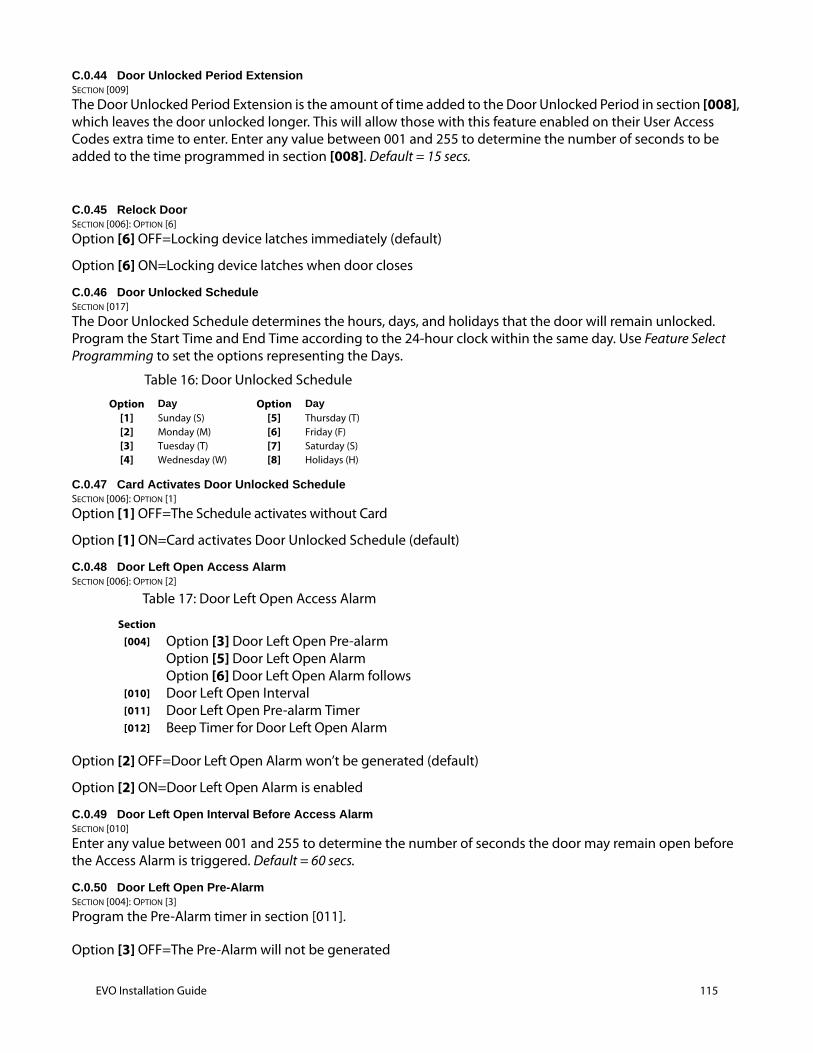
C.0.44 Door Unlocked Period ExtensionSECTION [009]
The Door Unlocked Period Extension is the amount of time added to the Door Unlocked Period in section [008], which leaves the door unlocked longer. This will allow those with this feature enabled on their User Access Codes extra time to enter. Enter any value between 001 and 255 to determine the number of seconds to be added to the time programmed in section [008]. Default = 15 secs.
C.0.45 Relock DoorSECTION [006]: OPTION [6]
Option [6] OFF=Locking device latches immediately (default)
Option [6] ON=Locking device latches when door closes
C.0.46 Door Unlocked ScheduleSECTION [017]
The Door Unlocked Schedule determines the hours, days, and holidays that the door will remain unlocked. Program the Start Time and End Time according to the 24-hour clock within the same day. Use Feature Select Programming to set the options representing the Days.
C.0.47 Card Activates Door Unlocked ScheduleSECTION [006]: OPTION [1]
Option [1] OFF=The Schedule activates without Card
Option [1] ON=Card activates Door Unlocked Schedule (default)
C.0.48 Door Left Open Access AlarmSECTION [006]: OPTION [2]
Option [2] OFF=Door Left Open Alarm won’t be generated (default)
Option [2] ON=Door Left Open Alarm is enabled
C.0.49 Door Left Open Interval Before Access AlarmSECTION [010]
Enter any value between 001 and 255 to determine the number of seconds the door may remain open before the Access Alarm is triggered. Default = 60 secs.
C.0.50 Door Left Open Pre-AlarmSECTION [004]: OPTION [3]
Program the Pre-Alarm timer in section [011].
Option [3] OFF=The Pre-Alarm will not be generated
Table 16: Door Unlocked Schedule
Option Day Option Day[1] Sunday (S) [5] Thursday (T)[2] Monday (M) [6] Friday (F)[3] Tuesday (T) [7] Saturday (S)[4] Wednesday (W) [8] Holidays (H)
Table 17: Door Left Open Access Alarm
Section[004] Option [3] Door Left Open Pre-alarm
Option [5] Door Left Open AlarmOption [6] Door Left Open Alarm follows
[010] Door Left Open Interval[011] Door Left Open Pre-alarm Timer[012] Beep Timer for Door Left Open Alarm
EVO Installation Guide 115

116 EVO Installation Guide
Option [3] ON=Pre-Alarm is enabled (default)
C.0.51 Door Left Open Pre-Alarm TimerSECTION [011]
This timer will trigger the Door Left Open Pre-Alarm before the end of the Door Left Open Interval. Enter any value between 001 and 255 to determine the seconds before the expiry of the Door Left Open Interval that the reader will beep. Default = 15 seconds.
C.0.52 Door Left Open Alarm FeedbackSECTION [004]: OPTIONS [5] AND [6]
Option [5] OFF=The Door Left Open Alarm is silent
Option [5] ON=The Door Left Open Alarm is audible (default)
If option [5] is enabled:
Option [6] OFF=Beep as long as the Door Left Open Alarm is
occurring (default)
Option [6] ON=Door Left Open Alarm follows Beep Timer (section [012])
C.0.53 Beep Timer For Door Left Open AlarmSECTION [012]
Enter any value between 001 and 255 to determine the number of seconds the Access Alarm will beep. Default = 5 seconds.
C.0.54 Door Forced Open Access AlarmSECTION [006]: OPTION [3]
When the Door Forced Open Alarm is disabled, the following sections are also disabled:
Option [3] OFF=Door Forced Open Alarm is disabled (default)
Option [3] ON=Door Forced Open Alarm is enabled
C.0.55 Door Forced Open FeedbackSECTION [004]: OPTIONS [7] AND [8]
Option [7] OFF=Door Forced Open Alarm is silent
Option [7] ON=Door Forced Open Alarm is audible (default)
If option [7] is enabled:
Option [8] OFF=Will beep as long as Door Forced Open Alarm is occurring (default)
Option [8] ON=Door Forced Open Alarm follows Beep Timer. (section [013])
C.0.56 Beep Timer For Door Forced Open AlarmSECTION [013]
Enter any value between 001 and 255 to determine the number of seconds the Door Forced Open Alarm will beep. Default = 5 seconds.
Table 18: Door Forced Open Access Alarm
Section[004] Option [7] Door Forced Open Alarm
Option [8] Door Forced Open Alarm follows[013] Beep Timer for Door Forced Open Alarm
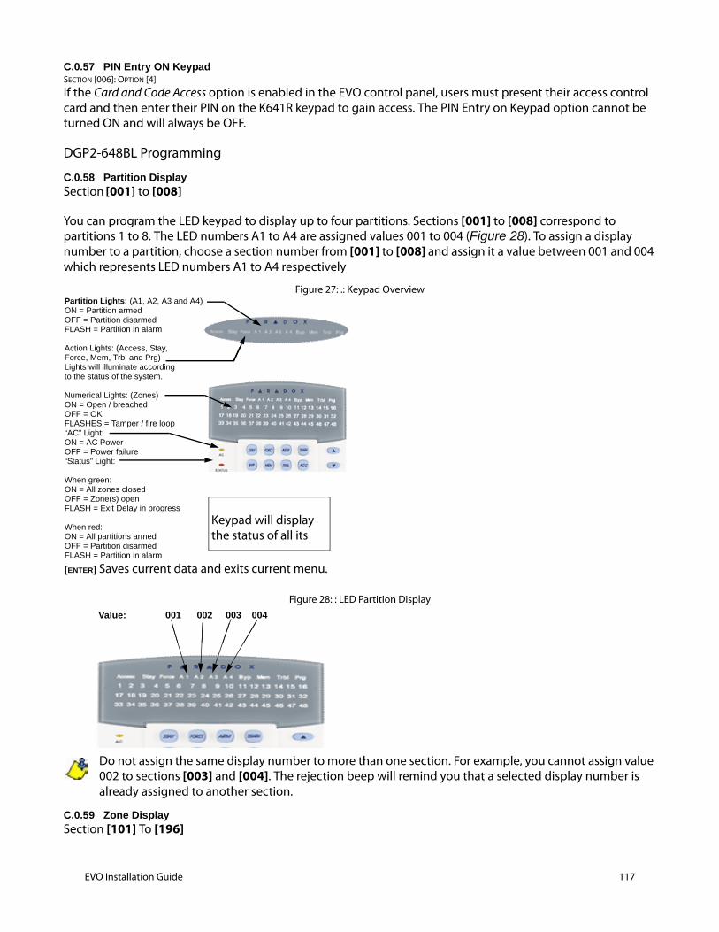
C.0.57 PIN Entry ON KeypadSECTION [006]: OPTION [4]
If the Card and Code Access option is enabled in the EVO control panel, users must present their access control card and then enter their PIN on the K641R keypad to gain access. The PIN Entry on Keypad option cannot be turned ON and will always be OFF.
DGP2-648BL Programming
C.0.58 Partition DisplaySection [001] to [008]
You can program the LED keypad to display up to four partitions. Sections [001] to [008] correspond to partitions 1 to 8. The LED numbers A1 to A4 are assigned values 001 to 004 (Figure 28). To assign a display number to a partition, choose a section number from [001] to [008] and assign it a value between 001 and 004 which represents LED numbers A1 to A4 respectively
Figure 27: .: Keypad Overview
Figure 28: : LED Partition Display
Do not assign the same display number to more than one section. For example, you cannot assign value 002 to sections [003] and [004]. The rejection beep will remind you that a selected display number is already assigned to another section.
C.0.59 Zone DisplaySection [101] To [196]
[ENTER] Saves current data and exits current menu.
Partition Lights: (A1, A2, A3 and A4)ON = Partition armedOFF = Partition disarmedFLASH = Partition in alarm
Action Lights: (Access, Stay,Force, Mem, Trbl and Prg)Lights will illuminate accordingto the status of the system.
Numerical Lights: (Zones) ON = Open / breachedOFF = OKFLASHES = Tamper / fire loop“AC” Light:ON = AC PowerOFF = Power failure“Status” Light:
When green:ON = All zones closedOFF = Zone(s) openFLASH = Exit Delay in progress
When red:ON = All partitions armedOFF = Partition disarmedFLASH = Partition in alarm
Keypad will display the status of all its
Value: 001 002 003 004
EVO Installation Guide 117
118 EVO Installation Guide
You can program the keypad to display up to a total of 48. Sections [101] to [196] correspond to zones 1 to 96 respectively. These zones are displayed on LED numbers 1 to 48 and are assigned values 001 to 048.
Do not assign more than one LED number to a zone. For example, you cannot assign LED number 33 to zones 21 and 28. The rejection beep will remind you that a selected LED number is already assigned to another section.
Every time the [CLEAR] key is pressed it will revert to the preceding step, unless entering in data in which case it will erase the current entry.
C.0.60 Section Reset Section [040]
This section resets zone display sections [101] to [196] to default settings. Enter [040] to perform the reset.
C.0.61 Confidential ModeSection [009] Option [1]
In Confidential Mode all LEDs will turn off until either a button is pressed or an access code is entered.
Option [1] OFF = Disabled (default).
Option [1] ON = Enabled.
C.0.62 Exit Confidential ModeSection [009] Option [2]
Option [2] ON = Exit Confidential Mode by entering an access code.
Option [2] OFF = Exit Confidential Mode by pressing a button (default).
Option [2] must be set to ON on UL listed systems.
Option [2] will only work if option [1] is enabled.
C.0.63 Confidential Mode TimerSection [012]
Section [012] determines the amount of time without action before the keypad enters Confidential Mode. The Confidential Mode Timer can be set from 005 seconds to 255 seconds. Default: 120 seconds
C.0.64 MutingSection [009] Option [3]
Option [3] OFF = Audible sounds (default).
Option [3] ON = Mute.
C.0.65 Beep on Exit DelaySection [009] Option [4]
Option [4] OFF = Exit Delay beep disabled.
Option [4] ON = Exit Delay beep enabled (default).
C.0.66 Chime on Zone ClosureSection [009] Option [5]
Option [5] OFF = Chime on Zone Closure disabled (default).
Option [5] ON = Chime on Zone Closure enabled.
C.0.67 Beep on TroubleSection [010] Options [1] To [4]
System Troubles / Clock Loss
Option [1] OFF = Disabled (default).
Option [1] ON = Enabled.
Communicator Troubles
Option [2] OFF = Disabled (default).
Option [2] ON = Enabled.
Module / Communication Bus Troubles
Option [3] OFF = Disabled (default).
Option [3] ON = Enabled.
Zone Troubles
Option [4] OFF = Disabled (default).
Option [4] ON = Enabled.
C.0.68 Keypad Anti-tamper EnableSection [011] Option [5]
Option [5] OFF = Keypad's anti-tamper is disabled (default).
Option [5] ON = Keypad's anti-tamper is enabled.
EVO Installation Guide 119
120 EVO Installation Guide
Programmable Output Options
C.0.69 PGM StateSECTION [011] OPTION [1]
The PGM is limited to 50mA.
Option [5] OFF = PGM is Normally Open (default).
Option [5] ON = PGM is Normally Closed.
C.0.70 PGM Activation EventSECTION [014] to [017]
Enter the sections that correspond to the EVENT GROUP, FEATURE GROUP, START # and END # of the PGM and enter the required data.
C.0.71 PGM Deactivation EventSECTION [018] to [021]
If the PGM Deactivation Option is set to follow the PGM Deactivation Event, the PGM will return to its normal state when the event programmed in sections [018] to [021] occurs. Enter the sections that correspond to the EVENT GROUP, FEATURE GROUP, START # and END # of the PGM and enter the required data.
C.0.72 PGM Deactivation ModeSECTION [011] Option [2]
Option [2] OFF = Deactivation as per PGM Deactivation Event (default).
Option [2] ON = PGM will deactivate according to the PGM Timer.
C.0.73 PGM Base TimeSECTION [011] Option [3]
Option [3] OFF = PGM Base Time is 1 second (default).
Option [3] ON = PGM Base Time is 1 minute.
C.0.74 PGM TimerSECTION [013]
To program the timer, enter a 3-digit decimal value (001 to 255) in section [013].
C.0.75 PGM TestSECTION [030]
Use this section to initiate a PGM test, which will activate the PGM for 8 seconds. Enter section [030] to activate this test.
Event group Feature group Start # End #PGM [014] [015] [016] [017]
Event group Feature group Start # End #PGM [018] [019] [020] [021]

Appendix D: Guidelines for Locating Smoke Detectors and CO Detectors
The following information is for general guidance only and it is recommended that local fire codes and regulations be consulted when locating and installing smoke and CO alarms.
Smoke DetectorsExperiments with typical fires in homes indicate that detectable quantities of smoke precede detectable levels of heat in most cases. For these reasons, smoke alarms should be installed outside of each sleeping area and on each storey of the home.
The following information is for general guidance only and it is recommended that local fire codes and regulations be consulted when locating and installing smoke alarms. It is recommended that additional smoke alarms beyond those required for minimum protection be installed.
Additional areas that should be protected include: the basement; bedrooms, especially where smokers sleep; dining rooms; furnace and utility rooms; and any hallways not protected by the required units. On smooth ceilings, detectors may be spaced 9.1m (30 feet) apart as a guide. Other spacing may be required depending on ceiling height, air movement, the presence of joists, un-insulated ceilings, etc.
Consult National Fire Alarm Code NFPA 72, CAN/ULC-S553-02 or other appropriate national standards for installation recommendations. •
Warning: Do not locate smoke detectors at the top of peaked or gabled ceilings; the dead air space in these locations may prevent the unit from detecting smoke. • Avoid areas with turbulent air flow, such as near doors, fans or windows. Rapid air movement around the detector may prevent smoke from entering the unit. • Do not locate detectors in areas of high humidity. • Do not locate detectors in areas where the temperature rises above 38 o or below 5o C
Smoke detectors should always be installed in USA in accordance with Chapter 11 of NFPA 72, the National Fire Alarm Code: 11.5.1.1.
Where required by applicable laws, codes, or standards for a specific type of occupancy, approved single- and multiple-station smoke alarms shall be installed as follows:
1. In all sleeping rooms and guest rooms.
2. Outside of each separate dwelling unit sleeping area, within 6.4 m (21 ft) of any door to a sleeping room, the distance measured along a path of travel.
3. On every level of a dwelling unit, including basements.
4. On every level of a residential board and care occupancy (small facility), including basements and excluding crawl spaces and unfinished attics.
5. In the living area(s) of a guest suite.
6. In the living area(s) of a residential board and care occupancy (small facility).
CO detectorsInstall one CO detector in each room that has a fuel burning appliance.
Make sure the alarm can be heard in the sleeping quarters of the building.
EVO Installation Guide 121
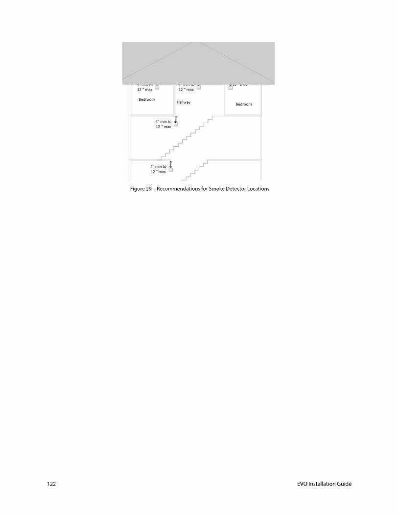
122 EVO Installation Guide
Figure 29 – Recommendations for Smoke Detector Locations
4" min to 12 “ max
4" min to 12 “ max
4" min to 12 “ max
4" min to 12 “ max
4" min to 12 “ max
BedroomBedroomHallway
Appendix E: Fire Escape Planning
The manual should include an “Emergency evacuation plan” – this can be copied or rewritten based on the instructions of NFPA in the following link:
C) Information on establishing a residential emergency evacuation plan in the event of a fire.
Pull together everyone in your household and make a plan. Walk through your home and inspect all possible exits and escape routes. Households with children should consider drawing a floor plan of your home, marking two ways out of each room, including windows and doors. Also, mark the location of each smoke alarm. For easy planning, download NFPA's escape planning grid (PDF, 1.1 MB). This is a great way to get children involved in fire safety in a non-threatening way.
•Install smoke alarms in every sleeping room, outside each sleeping area and on every level of the home. NFPA 72, National Fire Alarm Code® requires interconnected smoke alarms throughout the home. When one sounds, they all sound.
•Everyone in the household must understand the escape plan. When you walk through your plan, check to make sure the escape routes are clear and doors and windows can be opened easily.
•Choose an outside meeting place (i.e. neighbor's house, a light post, mailbox, or stop sign) a safe distance in front of your home where everyone can meet after they've escaped. Make sure to mark the location of the meeting place on your escape plan.
•Go outside to see if your street number is clearly visible from the road. If not, paint it on the curb or install house numbers to ensure that responding emergency personnel can find your home.
•Have everyone memorize the emergency phone number of the fire department. That way any member of the household can call from a neighbor's home or a cellular phone once safely outside.
•If there are infants, older adults, or family members with mobility limitations, make sure that someone is assigned to assist them in the fire drill and in the event of an emergency. Assign a backup person too, in case the designee is not home during the emergency.
•If windows or doors in your home have security bars, make sure that the bars have emergency release devices inside so that they can be opened immediately in an emergency. Emergency release devices won't compromise your security - but they will increase your chances of safely escaping a home fire.
•Tell guests or visitors to your home about your family's fire escape plan. When staying overnight at other people's homes, ask about their escape plan. If they don't have a plan in place, offer to help them make one. This is especially important when children are permitted to attend "sleepovers" at friends' homes. See NFPA's "Sleepover fire safety for kids" fact sheet.
•Be fully prepared for a real fire: when a smoke alarm sounds, get out immediately. Residents of high-rise and apartment buildings may be safer "defending in place."
•Once you're out, stay out! Under no circumstances should you ever go back into a burning building. If someone is missing, inform the fire department dispatcher when you call. Firefighters have the skills and equipment to perform rescues.
Putting your plan to the test
•Practice your home fire escape plan twice a year, making the drill as realistic as possible.
•Make arrangements in your plan for anyone in your home who has a disability.
•Allow children to master fire escape planning and practice before holding a fire drill at night when they are sleeping. The objective is to practice, not to frighten, so telling children there will be a drill before they go to bed can be as effective as a surprise drill.
EVO Installation Guide 123

124 EVO Installation Guide
•It's important to determine during the drill whether children and others can readily waken to the sound of the smoke alarm. If they fail to awaken, make sure that someone is assigned to wake them up as part of the drill and in a real emergency situation.
•If your home has two floors, every family member (including children) must be able to escape from the second floor rooms. Escape ladders can be placed in or near windows to provide an additional escape route. Review the manufacturer's instructions carefully so you'll be able to use a safety ladder in an emergency. Practice setting up the ladder from a first floor window to make sure you can do it correctly and quickly. Children should only practice with a grown-up, and only from a first-story window. Store the ladder near the window, in an easily accessible location. You don't want to have to search for it during a fire.
•Always choose the escape route that is safest – the one with the least amount of smoke and heat – but be prepared to escape under toxic smoke if necessary. When you do your fire drill, everyone in the family should practice getting low and going under the smoke to your exit.
•Closing doors on your way out slows the spread of fire, giving you more time to safely escape.
•In some cases, smoke or fire may prevent you from exiting your home or apartment building. To prepare for an emergency like this, practice "sealing yourself in for safety" as part of your home fire escape plan. Close all doors between you and the fire. Use duct tape or towels to seal the door cracks and cover air vents to keep smoke from coming in. If possible, open your windows at the top and bottom so fresh air can get in. Call the fire department to report your exact location. Wave a flashlight or light-colored cloth at the window to let the fire department know where you are located.

Appendix F: EVO192 CP-01 Implications as of June 13th, 2014
EVO Installation Guide 125

126 EVO Installation Guide
Appendix G EVO192 CP-01 Installer Programming1 Quick Reference Chart SIA False Alarm Reduction
Minimum requirement system for SIA CP-01 Installations:• 1 EVO192 CP-01 Control Panel• 2 Local Annunciation DevicesThe local annunciation devices must be of the following keypads.• K641/TM50
Caution• For SIA CP-01 installations, only use modules / devices that are listed on this page.• Fire Alarm Verification feature (Auto Verified Fire zone) is not supported for 2-wire smoke detectors zones. This feature may be enabled for 4-wire smoke detectors only.• Call Waiting Cancel feature on a non-Call Waiting line will prevent successful communication to the central station, see note 3 below.• All smoke detectors on the system must be tested annually by conducting the Installer Walk Test. Please refer to the smoke detector installation instructions on how to correctly test the detectors.
Notes1 Programming at installation may be subordinate to other UL requirements for the intended application.2 Combined Entry Delay and Abort Window should not exceed 1 minute.3 For “Call Waiting” option. The installer needs to verify the code in the premises area for the telephone network that disables the call waiting
feature, then add it to the monitoring station phone number. For example:
CP-01Paragraph
This Installation Manual (IM) Feature Range
Shipping default
Recommended Programming*
4.2.2.1section 8.18 on page 58
Exit time 45 sec – 255 sec 60 seconds 60 seconds
4.2.2.2Refer to Keypad(s) manual
Progress annunciationIndividual keypads may be disabled
All annunciators enabled
All annunciators enabled
4.2.2.3 Not programmable Exit time restart For re-entry during exit delayAlwaysEnabled
Cannot be disabled
4.2.2.5section 8.13 on page 57
Auto Stay Arm on non-evacuated Premises
If no exit after full arm Enabled Enabled
4.2.3.1section 4.4.2 on page 33
Entry delay(s) 30 sec – 255 sec 2 30 seconds At least 30 sec 2
4.2.5.1section 4.6.8 on page 39
Abort Window – for non-fire zones
May be disabled by zone Enabled Enabled (all zones)
4.2.5.1section 4.6.8 on page 39
Abort Window Time – for non-fire zones
15 sec – 45 sec 2 30 seconds At least 30 sec 2
4.2.5.1.2 Not programmable Abort annunciationAnnunciate that no alarm was transmitted
AlwaysEnabled
Cannot be disabled
4.2.5.4 Not programmable Cancel window No limits No limits No limits
4.2.5.4.1 Not programmable Cancel annunciationAnnunciate that a cancel was transmitted
AlwaysEnabled
Cannot be disabled
4.2.6.1 &4.2.6.2
section 10.2.10 on page 70 and section 15.6 on page 100
Duress featureNo 1+derivative of another user code. No duplicate with other user codes.
Disabled Disabled
4.3.1section 4.6.7 on page 38
Cross zoning Programming needed DisabledEnabled and two (or more) zones programmed
4.3.1section 4.6.6 on page 36
Programmable cross zoning May Program 48 sec.Per walk path in protected premises
4.3.2section 4.6.1 on page 35
Swinger shutdownFor all non-fire zones, shutdown at 1 or 2 trips
two trip two trip
4.3.3section 2.22.3 on page 25
Fire Alarm Verification Depends on sensors DisabledEnabled unless sensors can self- verify
4.5section 11.9 on page 79
Call waiting Cancel Depends on user phone line DisabledEnabled if user has call waiting 3
4.6.3section 7.3 on page 48
System test (test report + walk test mode + siren)
Test periodically. DisabledEnabled to test all zones, siren, communicator 4
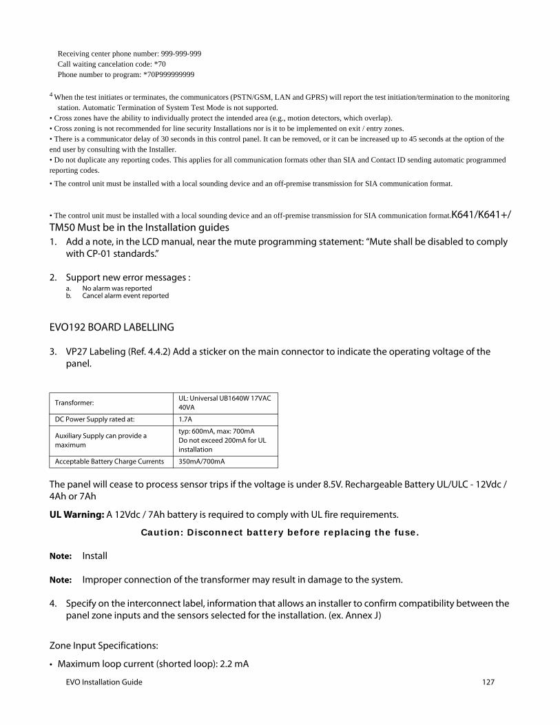
Receiving center phone number: 999-999-999Call waiting cancelation code: *70Phone number to program: *70P999999999
4 When the test initiates or terminates, the communicators (PSTN/GSM, LAN and GPRS) will report the test initiation/termination to the monitoring station. Automatic Termination of System Test Mode is not supported.
• Cross zones have the ability to individually protect the intended area (e.g., motion detectors, which overlap).• Cross zoning is not recommended for line security Installations nor is it to be implemented on exit / entry zones.• There is a communicator delay of 30 seconds in this control panel. It can be removed, or it can be increased up to 45 seconds at the option of the end user by consulting with the Installer.• Do not duplicate any reporting codes. This applies for all communication formats other than SIA and Contact ID sending automatic programmed reporting codes.
• The control unit must be installed with a local sounding device and an off-premise transmission for SIA communication format.
• The control unit must be installed with a local sounding device and an off-premise transmission for SIA communication format.K641/K641+/TM50 Must be in the Installation guides 1. Add a note, in the LCD manual, near the mute programming statement: “Mute shall be disabled to comply
with CP-01 standards.”
2. Support new error messages : a. No alarm was reportedb. Cancel alarm event reported
EVO192 BOARD LABELLING
3. VP27 Labeling (Ref. 4.4.2) Add a sticker on the main connector to indicate the operating voltage of the panel.
The panel will cease to process sensor trips if the voltage is under 8.5V. Rechargeable Battery UL/ULC - 12Vdc / 4Ah or 7Ah
UL Warning: A 12Vdc / 7Ah battery is required to comply with UL fire requirements.
Caution: Disconnect battery before replacing the fuse.
Note: Install
Note: Improper connection of the transformer may result in damage to the system.
4. Specify on the interconnect label, information that allows an installer to confirm compatibility between the panel zone inputs and the sensors selected for the installation. (ex. Annex J)
Zone Input Specifications:
• Maximum loop current (shorted loop): 2.2 mA
Transformer:UL: Universal UB1640W 17VAC 40VA
DC Power Supply rated at: 1.7A
Auxiliary Supply can provide a maximum
typ: 600mA, max: 700mA Do not exceed 200mA for UL installation
Acceptable Battery Charge Currents 350mA/700mA
EVO Installation Guide 127
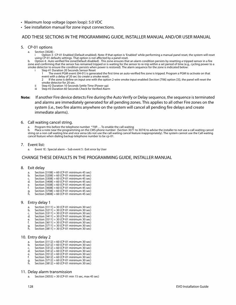
128 EVO Installation Guide
• Maximum loop voltage (open loop): 5.0 VDC• See installation manual for zone input connections.
ADD THESE SECTIONS IN THE PROGRAMMING GUIDE, INSTALLER MANUAL AND/OR USER MANUAL
5. CP-01 options a. Section [3028] :
i Option 3 : CP-01 Enabled (Default enabled). Note: If that option is ‘Enabled’ while performing a manual panel reset, the system will reset using CP-01 defaults settings. That option is not affected by a panel reset.
b. Option 4 : Auto verified fire zone(Default disabled) . This zone ensures that an alarm condition persists by resetting a tripped sensor in a fire zone and confirming that the sensor has remained tripped or is waiting for the sensor to re-trip within a set period of time (e.g., cycling power to a smoke detector to ensure the condition persists when power is restored). The alarm sequence for the zone is indicated below:
i Step #1 Duration 20 Seconds Sensor Reset1 The event PGM event (04-01) is generated the first time an auto-verified fire zone is tripped. Program a PGM to activate on that event with a delay of 20 sec (to create a smoke reset).2 If the zone is define on input one with the option 2-wire smoke input enabled (Section [706] option [3]), the panel will reset the smoke detector for 20 sec.
ii Step #2 Duration 10 Seconds Settle Time (Power-up)iii Step #3 Duration 60 Seconds Check for Verified Alarm
Note: If another Fire device detects Fire during the Auto Verify or Delay sequence, the sequence is terminated and alarms are immediately generated for all pending zones. This applies to all other Fire zones on the system (i.e., two fire alarms anywhere on the system will cancel all pending fire delays and create immediate alarms).
6. Call waiting cancel string. a. Program this before the telephone number *70P…. To enable the call waitingb. Place a note near the programming on the CMS phone number (Section 3071 to 3074) to advise the installer to not use a call waiting cancel string on a non call waiting line and vice versa (do not use the call waiting cancel feature inappropriately). The system cannot use the Call waiting cancel feature when dialing backup telephone number to be cp-01.
7. Event list: a. Event 1E : Special alarm – Sub event 5 : Exit error by User
CHANGE THESE DEFAULTS IN THE PROGRAMMING GUIDE, INSTALLER MANUAL
8. Exit delaya. Section [3108] = 60 (CP-01 minimum 45 sec)b. Section [3208] = 60 (CP-01 minimum 45 sec)c. Section [3308] = 60 (CP-01 minimum 45 sec)d. Section [3408] = 60 (CP-01 minimum 45 sec)e. Section [3508] = 60 (CP-01 minimum 45 sec)f. Section [3608] = 60 (CP-01 minimum 45 sec)g. Section [3708] = 60 (CP-01 minimum 45 sec)h. Section [3808] = 60 (CP-01 minimum 45 sec)
9. Entry delay 1a. Section [3111] = 30 (CP-01 minimum 30 sec)b. Section [3211] = 30 (CP-01 minimum 30 sec)c. Section [3311] = 30 (CP-01 minimum 30 sec)d. Section [3411] = 30 (CP-01 minimum 30 sec)e. Section [3511] = 30 (CP-01 minimum 30 sec)f. Section [3611] = 30 (CP-01 minimum 30 sec)g. Section [3711] = 30 (CP-01 minimum 30 sec)h. Section [3811] = 30 (CP-01 minimum 30 sec)
10. Entry delay 2a. Section [3112] = 60 (CP-01 minimum 30 sec)b. Section [3212] = 60 (CP-01 minimum 30 sec)c. Section [3312] = 60 (CP-01 minimum 30 sec)d. Section [3412] = 60 (CP-01 minimum 30 sec)e. Section [3512] = 60 (CP-01 minimum 30 sec)f. Section [3612] = 60 (CP-01 minimum 30 sec)g. Section [3712] = 60 (CP-01 minimum 30 sec)h. Section [3812] = 60 (CP-01 minimum 30 sec)
11. Delay alarm transmission a. Section [3055] = 30 (CP-01 min 15 sec, max 45 sec)
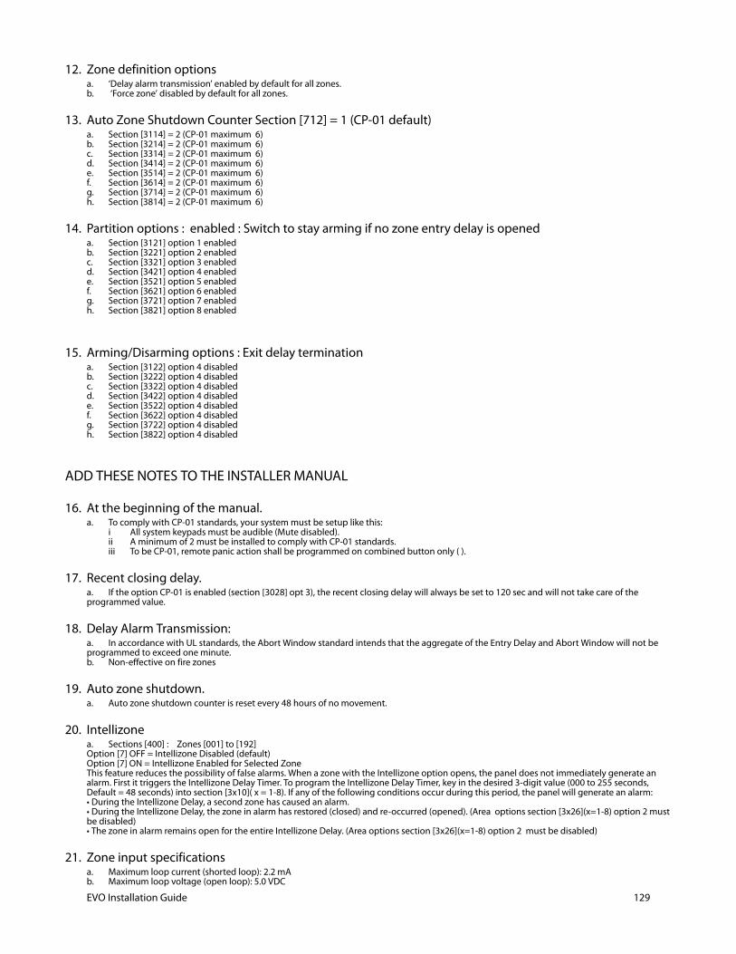
12. Zone definition optionsa. ‘Delay alarm transmission’ enabled by default for all zones.b. ‘Force zone’ disabled by default for all zones.
13. Auto Zone Shutdown Counter Section [712] = 1 (CP-01 default)a. Section [3114] = 2 (CP-01 maximum 6)b. Section [3214] = 2 (CP-01 maximum 6)c. Section [3314] = 2 (CP-01 maximum 6)d. Section [3414] = 2 (CP-01 maximum 6)e. Section [3514] = 2 (CP-01 maximum 6)f. Section [3614] = 2 (CP-01 maximum 6)g. Section [3714] = 2 (CP-01 maximum 6)h. Section [3814] = 2 (CP-01 maximum 6)
14. Partition options : enabled : Switch to stay arming if no zone entry delay is openeda. Section [3121] option 1 enabled b. Section [3221] option 2 enabled c. Section [3321] option 3 enabled d. Section [3421] option 4 enabled e. Section [3521] option 5 enabled f. Section [3621] option 6 enabled g. Section [3721] option 7 enabled h. Section [3821] option 8 enabled
15. Arming/Disarming options : Exit delay terminationa. Section [3122] option 4 disabled b. Section [3222] option 4 disabledc. Section [3322] option 4 disabled d. Section [3422] option 4 disabled e. Section [3522] option 4 disabled f. Section [3622] option 4 disabled g. Section [3722] option 4 disabled h. Section [3822] option 4 disabled
ADD THESE NOTES TO THE INSTALLER MANUAL
16. At the beginning of the manual.a. To comply with CP-01 standards, your system must be setup like this:
i All system keypads must be audible (Mute disabled).ii A minimum of 2 must be installed to comply with CP-01 standards.iii To be CP-01, remote panic action shall be programmed on combined button only ( ).
17. Recent closing delay. a. If the option CP-01 is enabled (section [3028] opt 3), the recent closing delay will always be set to 120 sec and will not take care of the programmed value.
18. Delay Alarm Transmission: a. In accordance with UL standards, the Abort Window standard intends that the aggregate of the Entry Delay and Abort Window will not be programmed to exceed one minute.b. Non-effective on fire zones
19. Auto zone shutdown. a. Auto zone shutdown counter is reset every 48 hours of no movement.
20. Intellizonea. Sections [400] : Zones [001] to [192] Option [7] OFF = Intellizone Disabled (default) Option [7] ON = Intellizone Enabled for Selected Zone This feature reduces the possibility of false alarms. When a zone with the Intellizone option opens, the panel does not immediately generate an alarm. First it triggers the Intellizone Delay Timer. To program the Intellizone Delay Timer, key in the desired 3-digit value (000 to 255 seconds, Default = 48 seconds) into section [3x10]( x = 1-8). If any of the following conditions occur during this period, the panel will generate an alarm: • During the Intellizone Delay, a second zone has caused an alarm. • During the Intellizone Delay, the zone in alarm has restored (closed) and re-occurred (opened). (Area options section [3x26](x=1-8) option 2 must be disabled) • The zone in alarm remains open for the entire Intellizone Delay. (Area options section [3x26](x=1-8) option 2 must be disabled)
21. Zone input specificationsa. Maximum loop current (shorted loop): 2.2 mAb. Maximum loop voltage (open loop): 5.0 VDC
EVO Installation Guide 129
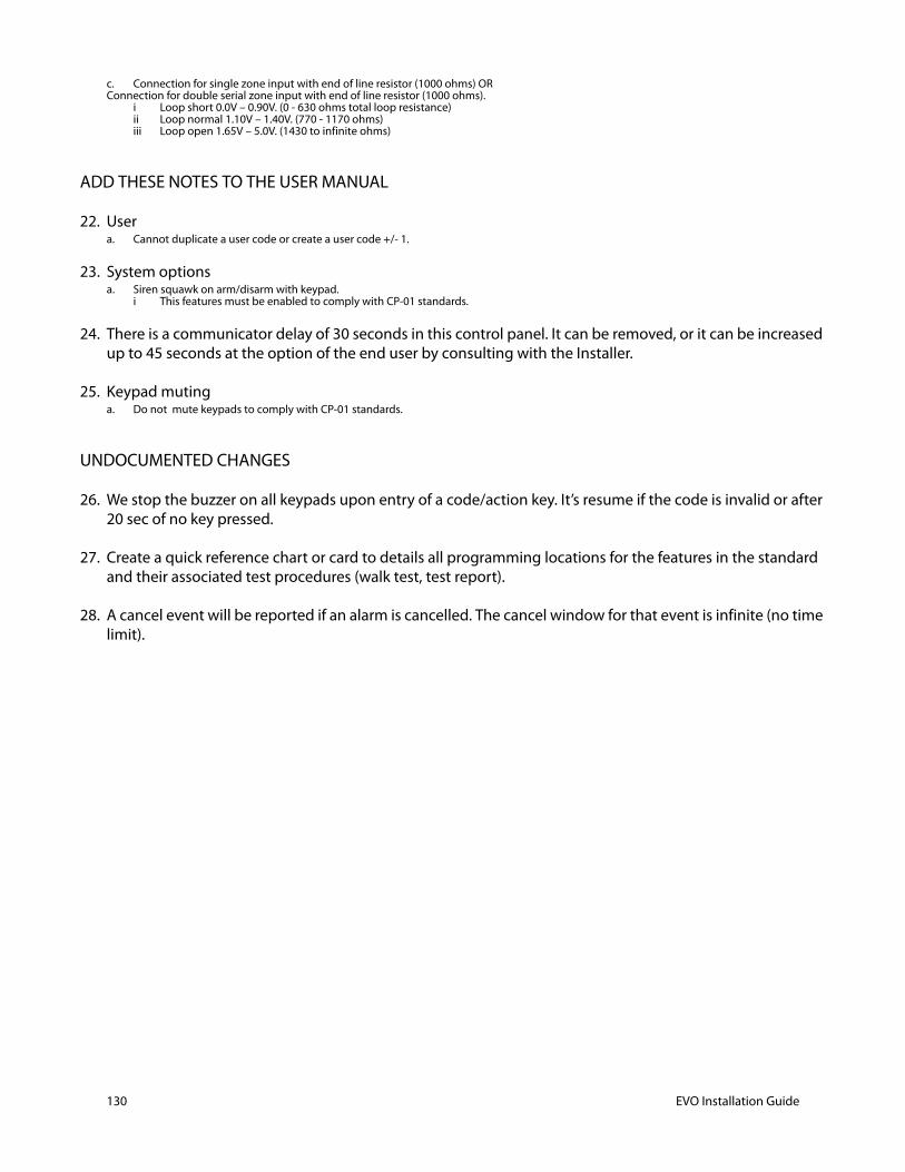
130 EVO Installation Guide
c. Connection for single zone input with end of line resistor (1000 ohms) OR Connection for double serial zone input with end of line resistor (1000 ohms).
i Loop short 0.0V – 0.90V. (0 - 630 ohms total loop resistance)ii Loop normal 1.10V – 1.40V. (770 - 1170 ohms)iii Loop open 1.65V – 5.0V. (1430 to infinite ohms)
ADD THESE NOTES TO THE USER MANUAL
22. Usera. Cannot duplicate a user code or create a user code +/- 1.
23. System optionsa. Siren squawk on arm/disarm with keypad.
i This features must be enabled to comply with CP-01 standards.
24. There is a communicator delay of 30 seconds in this control panel. It can be removed, or it can be increased up to 45 seconds at the option of the end user by consulting with the Installer.
25. Keypad mutinga. Do not mute keypads to comply with CP-01 standards.
UNDOCUMENTED CHANGES
26. We stop the buzzer on all keypads upon entry of a code/action key. It’s resume if the code is invalid or after 20 sec of no key pressed.
27. Create a quick reference chart or card to details all programming locations for the features in the standard and their associated test procedures (walk test, test report).
28. A cancel event will be reported if an alarm is cancelled. The cancel window for that event is infinite (no time limit).
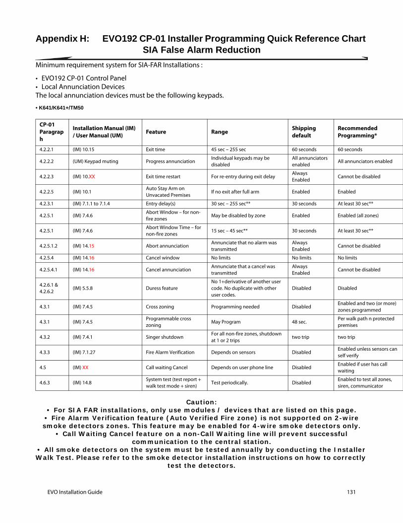
d *
enabled
ed
s)
ed
ed
(or more) ed
rotected
ensors can
as call
ll zones, ator
Appendix H: EVO192 CP-01 Installer Programming Quick Reference Chart SIA False Alarm Reduction
Minimum requirement system for SIA-FAR Installations :
• EVO192 CP-01 Control Panel• Local Annunciation DevicesThe local annunciation devices must be the following keypads.
• K641/K641+/TM50
Caution:• For SIA FAR installations, only use modules / devices that are listed on this page.
• Fire Alarm Verification feature (Auto Verified Fire zone) is not supported on 2-wire smoke detectors zones. This feature may be enabled for 4-wire smoke detectors only.
• Call Waiting Cancel feature on a non-Call Waiting line will prevent successful communication to the central station.
• All smoke detectors on the system must be tested annually by conducting the Installer Walk Test. Please refer to the smoke detector installation instructions on how to correctly
test the detectors.
CP-01Paragraph
Installation Manual (IM) / User Manual (UM) Feature Range Shipping
defaultRecommendeProgramming
4.2.2.1 (IM) 10.15 Exit time 45 sec – 255 sec 60 seconds 60 seconds
4.2.2.2 (UM) Keypad muting Progress annunciationIndividual keypads may be disabled
All annunciators enabled
All annunciators
4.2.2.3 (IM) 10.XX Exit time restart For re-entry during exit delayAlwaysEnabled
Cannot be disabl
4.2.2.5 (IM) 10.1Auto Stay Arm on Unvacated Premises
If no exit after full arm Enabled Enabled
4.2.3.1 (IM) 7.1.1 to 7.1.4 Entry delay(s) 30 sec – 255 sec** 30 seconds At least 30 sec**
4.2.5.1 (IM) 7.4.6Abort Window – for non-fire zones
May be disabled by zone Enabled Enabled (all zone
4.2.5.1 (IM) 7.4.6Abort Window Time – for non-fire zones
15 sec – 45 sec** 30 seconds At least 30 sec**
4.2.5.1.2 (IM) 14.15 Abort annunciationAnnunciate that no alarm was transmitted
AlwaysEnabled
Cannot be disabl
4.2.5.4 (IM) 14.16 Cancel window No limits No limits No limits
4.2.5.4.1 (IM) 14.16 Cancel annunciationAnnunciate that a cancel was transmitted
AlwaysEnabled
Cannot be disabl
4.2.6.1 &4.2.6.2
(IM) 5.5.8 Duress featureNo 1+derivative of another user code. No duplicate with other user codes.
Disabled Disabled
4.3.1 (IM) 7.4.5 Cross zoning Programming needed DisabledEnabled and twozones programm
4.3.1 (IM) 7.4.5Programmable cross zoning
May Program 48 sec.Per walk path n ppremises
4.3.2 (IM) 7.4.1 Singer shutdownFor all non-fire zones, shutdown at 1 or 2 trips
two trip two trip
4.3.3 (IM) 7.1.27 Fire Alarm Verification Depends on sensors DisabledEnabled unless sself verify
4.5 (IM) XX Call waiting Cancel Depends on user phone line DisabledEnabled if user hwaiting
4.6.3 (IM) 14.8System test (test report + walk test mode + siren)
Test periodically. DisabledEnabled to test asiren, communic
EVO Installation Guide 131
132 EVO Installation Guide
Note: • *Programming at installation may be subordinate to other UL requirements for the intended application. • **Combined Entry Delay and Abort Window should not exceed 1 minute. • Cross zones have the ability to individually protect the intended area (e.g., motion detectors, which overlap). • Cross zoning is not recommended for line security Installations nor is it to be implemented on exit / entry zones. • There is a communicator delay of 30 seconds in this control panel. It can be removed, or it can be increased up to 45 seconds at the option of the end user by consulting with the Installer. • Do not duplicate any reporting codes. This applies for all communication formats other than SIA and Contact ID sending automatic programmed reporting codes. • The control unit must be installed with a local sounding device and an off-premise transmission for SIA communication format.
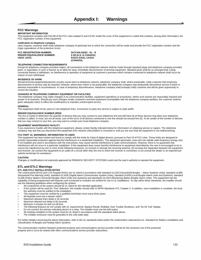
Appendix I: Warnings
FCC WarningsIMPORTANT INFORMATIONThis equipment complies with Part 68 of the FCC rules subpart D and CS-03. Inside the cover of this equipment is a label that contains, among other information, the FCC registration number of this equipment.
notification to telephone companyUpon request, customer shall notify telephone company of particular line to which the connection will be made and provide the FCC registration number and the ringer equivalence of the protective circuit.
FCC REGISTRATION NUMBER: 5A7CAN-22633 - AL - ERINGER EQUIVALENCE NUMBER: 0.1B (U.S. & CANADA)USOC JACK: RJ31X (USA), CA31A
(CANADA)
TELEPHONE CONNECTION REQUIREMENTSExcept for telephone company provided ringers, all connections to the telephone network shall be made through standard plugs and telephone company provided jacks, or equivalent, in such a manner as to allow for easy, immediate disconnection of terminal equipment. Standard jacks shall be so arranged that, if plug connected thereto is withdrawn, no interference to operation of equipment at customer's premises which remains connected to telephone network shall occur by reason of such withdrawal.
INCIDENCE OF HARMShould terminal equipment/protective circuitry cause harm to telephone network, telephone company shall, where practicable, notify customer that temporary disconnection of service may be required; however, where prior notice is not practicable, the telephone company may temporarily discontinue service if action is deemed reasonable in circumstances. In case of temporary discontinuance, telephone company shall promptly notify customer and will be given opportunity to correct the situation.
CHANGES IN TELEPHONE COMPANY EQUIPMENT OR FACILITIESThe telephone company may make changes in its communication facilities, equipment operations or procedures, where such actions are reasonably required and proper in its business. Should any such changes render customer's terminal equipment incompatible with the telephone company facilities, the customer shall be given adequate notice to effect the modifications to maintain uninterrupted service.
GENERALThis equipment shall not be used on coin telephone lines. Connection to party line service is subject to state tariffs.
RINGER EQUIVALENCE NUMBER (REN)The REN is useful to determine the quantity of devices that you may connect to your telephone line and still have all of those devices ring when your telephone number is called. In most, but not all areas, sum of the REN's of all devices connected to one line should not exceed five (5). To be certain of the number of devices that you may connect to your line, you may want to contact your local telephone company.
EQUIPMENT MAINTENANCE FACILITYIf you experience trouble with this telephone equipment, please contact facility indicated below for information on obtaining service or repairs. The telephone company may ask that you disconnect this equipment from network until problem is corrected or until you are sure that the equipment is not malfunctioning.
FCC PART 15, WARNINGS: INFORMATION TO USERThis equipment has been tested and found to comply with the limits for Class B digital devices, pursuant to Part 15 of FCC rules. These limits are designed to provide reasonable protection against harmful interference in a residential installation. This equipment generates, uses and can radiate radio frequency energy, and, if not installed and used in accordance with the instructions, may cause harmful interference to radio communications. However, there is no guarantee that interference will not occur in a particular installation. If this equipment does cause harmful interference to equipment intermittently, the user is encouraged to try to correct the interference by one or more of the following measures: (1) reorient or relocate the receiving antenna; (2) increase the separation between the equipment and receiver; (3) connect the equipment to an outlet on a circuit other than the one to which the receiver is connected, or (4) consult the dealer or an experienced radio/tv technician for assistance.
CAUTION: Changes or modifications not expressly approved by PARADOX SECURITY SYSTEMS could void the user's authority to operate the equipment.
ETL and ETLC WarningsETL AND ETLC INSTALLATION NOTESThe control panel (EVO) and LCD Keypad (K641) are UL listed in accordance with standard UL1023 (Household Burglar -- Alarm Systems Units), standard UL985 (Household Fire Warning Units), standard UL1635 (Digital Alarm Communicator System Units), standard UL609 (Local Burglar Alarm Units and Systems), standard UL365 (Police Station Connected Burglar Alarm Units and Systems) and standards UL1610 (Monitoring Station Burglar Alarm Units). This equipment has the capability of being programmed with features and connected to modules not verified for use in UL installations. To stay within these standards, the installer should use the following guidelines when configuring the system:• All components of the system should be UL listed for the intended application.• If the system will be used for “Fire” detection, the installer should refer to NFPA Standards #72, Chapter 2. In addition, once installation is complete, the local
fire authority must be notified of the installation.• This equipment must be verified by a qualified technician once every three years.• All keypads must use a tamper switch.• Maximum allowed entry delay is 45 seconds.• Maximum allowed exit delay is 60 seconds.• Minimum 4 minutes for bell cut-off time.• The following features do not comply with UL requirements: Bypass Recall, Shabbat, Auto Trouble Shutdown, and “No AC Fail” display. • Do not connect the primary indicating device to a relay. The installer must use the bell output.• All modules installed on the system must be UL listed in accordance with the standards listed above.• The metallic enclosure must be grounded to the cold water pipe.
For further details concerning the above information, refer to the UL standards listed and/or the Underwriters Laboratories Inc. Standard for Safety‘s Installation and Classification of Burglar and Holdup Alarm Systems.
The communication medium between protected property and communications service provider shall be for the exclusive use of the protectedproperty and is not to be shared with other communications service provider subscribers.
EVO Installation Guide 133
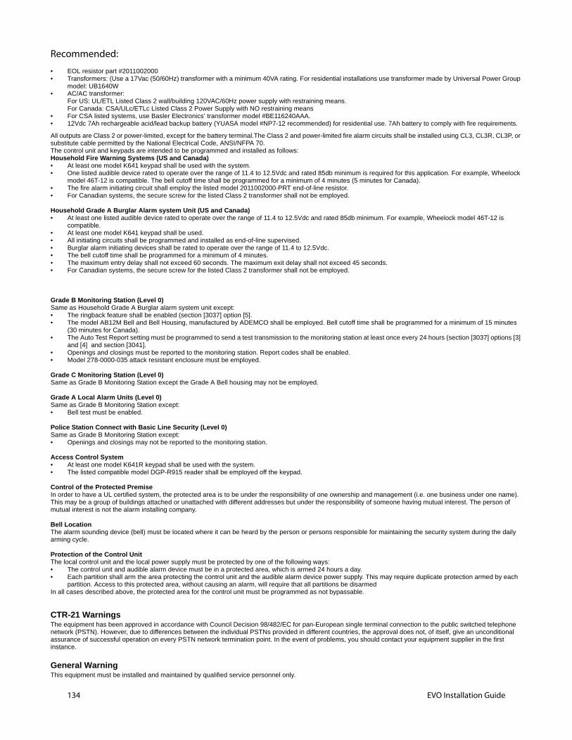
134 EVO Installation Guide
Recommended:
• EOL resistor part #2011002000• Transformers: (Use a 17Vac (50/60Hz) transformer with a minimum 40VA rating. For residential installations use transformer made by Universal Power Group
model: UB1640W • AC/AC transformer:
For US: UL/ETL Listed Class 2 wall/building 120VAC/60Hz power supply with restraining means. For Canada: CSA/ULc/ETLc Listed Class 2 Power Supply with NO restraining means
• For CSA listed systems, use Basler Electronics’ transformer model #BE116240AAA. • 12Vdc 7Ah rechargeable acid/lead backup battery (YUASA model #NP7-12 recommended) for residential use. 7Ah battery to comply with fire requirements.
All outputs are Class 2 or power-limited, except for the battery terminal.The Class 2 and power-limited fire alarm circuits shall be installed using CL3, CL3R, CL3P, or substitute cable permitted by the National Electrical Code, ANSI/NFPA 70.The control unit and keypads are intended to be programmed and installed as follows:Household Fire Warning Systems (US and Canada)• At least one model K641 keypad shall be used with the system.• One listed audible device rated to operate over the range of 11.4 to 12.5Vdc and rated 85db minimum is required for this application. For example, Wheelock
model 46T-12 is compatible. The bell cutoff time shall be programmed for a minimum of 4 minutes (5 minutes for Canada).• The fire alarm initiating circuit shall employ the listed model 2011002000-PRT end-of-line resistor.• For Canadian systems, the secure screw for the listed Class 2 transformer shall not be employed.
Household Grade A Burglar Alarm system Unit (US and Canada)• At least one listed audible device rated to operate over the range of 11.4 to 12.5Vdc and rated 85db minimum. For example, Wheelock model 46T-12 is
compatible.• At least one model K641 keypad shall be used.• All initiating circuits shall be programmed and installed as end-of-line supervised.• Burglar alarm initiating devices shall be rated to operate over the range of 11.4 to 12.5Vdc.• The bell cutoff time shall be programmed for a minimum of 4 minutes.• The maximum entry delay shall not exceed 60 seconds. The maximum exit delay shall not exceed 45 seconds.• For Canadian systems, the secure screw for the listed Class 2 transformer shall not be employed.
Grade B Monitoring Station (Level 0)Same as Household Grade A Burglar alarm system unit except:• The ringback feature shall be enabled (section [3037] option [5].• The model AB12M Bell and Bell Housing, manufactured by ADEMCO shall be employed. Bell cutoff time shall be programmed for a minimum of 15 minutes
(30 minutes for Canada).• The Auto Test Report setting must be programmed to send a test transmission to the monitoring station at least once every 24 hours (section [3037] options [3]
and [4] and section [3041]. • Openings and closings must be reported to the monitoring station. Report codes shall be enabled.• Model 278-0000-035 attack resistant enclosure must be employed.
Grade C Monitoring Station (Level 0)Same as Grade B Monitoring Station except the Grade A Bell housing may not be employed.
Grade A Local Alarm Units (Level 0)Same as Grade B Monitoring Station except:• Bell test must be enabled.
Police Station Connect with Basic Line Security (Level 0)Same as Grade B Monitoring Station except:• Openings and closings may not be reported to the monitoring station.
Access Control System• At least one model K641R keypad shall be used with the system.• The listed compatible model DGP-R915 reader shall be employed off the keypad.
Control of the Protected PremiseIn order to have a UL certified system, the protected area is to be under the responsibility of one ownership and management (i.e. one business under one name). This may be a group of buildings attached or unattached with different addresses but under the responsibility of someone having mutual interest. The person of mutual interest is not the alarm installing company.
Bell LocationThe alarm sounding device (bell) must be located where it can be heard by the person or persons responsible for maintaining the security system during the daily arming cycle.
Protection of the Control UnitThe local control unit and the local power supply must be protected by one of the following ways:• The control unit and audible alarm device must be in a protected area, which is armed 24 hours a day.• Each partition shall arm the area protecting the control unit and the audible alarm device power supply. This may require duplicate protection armed by each
partition. Access to this protected area, without causing an alarm, will require that all partitions be disarmedIn all cases described above, the protected area for the control unit must be programmed as not bypassable.
CTR-21 WarningsThe equipment has been approved in accordance with Council Decision 98/482/EC for pan-European single terminal connection to the public switched telephone network (PSTN). However, due to differences between the individual PSTNs provided in different countries, the approval does not, of itself, give an unconditional assurance of successful operation on every PSTN network termination point. In the event of problems, you should contact your equipment supplier in the first instance.
General WarningThis equipment must be installed and maintained by qualified service personnel only.
WarrantyFor complete warranty information on this product please refer to the Limited Warranty Statement found on the website www.paradox.com/terms. Your use of the Paradox product signifies your acceptance of all warranty terms and conditions.
ATTACHMENT LIMITATION NOTICEThe Industry Canada label identifies certified equipment. This certification means that the equipment meets certain telecommunications network protective, operational and safety requirements. The Department does not guarantee the equipment will operate to the user's satisfaction.
Before installing this equipment, users should ensure that it is permissible to be connected to the facilities of the local telecommunications company. The equipment must also be installed using an acceptable method of connection. The customer should be aware that compliance with the above conditions may not prevent degradation of service in some situations.
Repairs to certified equipment should be made by an authorized Canadian maintenance facility designated by the supplier. Any repairs or alterations made by the user to this equipment, or equipment malfunctions, may give the telecommunications company cause to request the user to disconnect the equipment.
Users should ensure for their own protection that the electrical ground connections of the power utility, telephone lines and internal metallic water pipe system, if present, are connected together. This precaution may be particularly important in rural areas.
CAUTION: Users should not attempt to make such connections themselves, but should contact the appropriate electrical inspection authority, or electrician, as appropriate.
The Load Number (LN) assigned to each terminal device denotes the percentage of the total load to be connected to a telephone loop which is used by the device to prevent overloading. The termination on a loop may consist of any combination of devices subject only to the requirement that the total of the Load Numbers of all of the devices does not exceed 100.
Industry Canada certification is only applicable to installation of devices which include transformers approved by the Canadian Standards Association (CSA).
© 2002-2007 Paradox Security Systems Ltd.
Digiplex EVO, WinLoad, Magellan, NEware and InTouch are trademarks or registered trademarks of Paradox Security Systems Ltd. and its affiliates in Canada, the United States and/or other countries. All rights reserved.
EVO Installation Guide 135

136 EVO Installation Guide
Notes:

EVO Installation Guide 137

138 EVO Installation Guide

EVO Installation Guide 139

140 EVO Installation Guide
Printed in Canada - 10/2007 paradox.com
IndexNumerics24Hr Zones 34AAC Failure not Displayed 92AC Power 17Access Code Length 97Access Codes 97Account Number 73Account Number Transmission 73Ademco Contact ID 73, 74Ademco Express 74Ademco slow 73Advanced Technology Zoning (ATZ) 33Alarm Transmission Delay. See Delay Alarm TransmissionAlarm Types 36Alternate Dialing Option 75Always Force Arm 57Answer WinLoad 90Arming Follows Partition 55Arming/Disarming Reporting 71Arming/Disarming Schedule Tolerance Window 72Assigning keyswitches to partitions 43Audible Alarm 64
Bell Cut-off Timer 61Pulsed 36Steady 36
Auto Force on Stay Arming 58Auto Report Code Programming 77Auto Test Report Period 76Auto Trouble Shutdown 92Auto Zone Shutdown 35Auto Zone Shutdown Limit 35Auto-Arming
Timed 56Timer 56
Auto-Arming Options 57Automatic report code list 101Auxiliary Power 17
Calculating power consumption 19Power Limitations 20Power Supply Connections 22
Away Zones. See Force ZonesBBattery 17
Battery Test 17Battery Charge Current 89Baud Rate 89Bell
Bell/siren Output 17Bell/Siren Output During Fire Alarm 35
Bell On Communication Fail 79Bell Squawk 59Bell/alarm Output 61
EVO Installation Guide 141

142 EVO Installation Guide
Broadcast 91Burglary Zones 34Bus Connection in Noisy Environments 25Bus Speed 89Busy Tone Detection 78Buzzer Zones 34Bypass Zones 36CCall Direction 74Call WinLoad 90Cancel Communication 90Closing Delinquency Timer 77Codes
Special Alarm Report Codes 69Special Arming Report Codes 68Special Disarming Report Codes 69System Trouble Codes 70System Trouble Restore Codes 71
Connecting the Bus in Noisy Environments 25Connections
Bus Connections 24Double Zone Connections 24Keypad Zone Connections 21Keyswitch Connections 18Power 17Single Zone Connections 22
Contact ID Pager 74Contact ID Report Code List 104DDaylight Savings Time 88Daylight Savings Time Schedule 88Delay Alarm Transmission 39Delay Alarm Transmission Timer 39Delay Between Dialing Attempts 75Delayed 24Hr Fire Zone 34Delinquency Timer, Closing 77Dial Tone Delay 79Digiplex Memory Key. See Paradox Memory KeyDisarm Reporting Options 76Display “Bypass” If Armed 60Door Labels 92Double Zone Connections 24Duress 100EEarth Ground 17Enable Reporting 67End # 85Entry Delay Timer 33Entry Delay Timers 33EOL Zones 39ESL CleanMeTM Installation 25Event Group 85Exit Delay 58Exit Delay cancelled on Remote Arm 59Exit Delay Termination 59

FFeature Group 85Feature Select Programming 29Fire Alarm 64Fire Circuits 25Fire Zone 25
Delayed 24Hr 34Standard 24Hr 35
Follow Zone Switches to Entry Delay 2 58Force Zones 36Freeze Zones 34Function Keys, Installer 90GGas Zones 34Ground 17HHardware Reset 87Heat Zones 34Hold-up Zones 34Hourly Test Transmission 76IInput Numbers
Keyswitch Numbering 42Input Speed 39Installation Procedure 13Installer Code 97Installer Function Keys 90Installer Lock 88Installer Test Mode 90Instant zone 34Intellizone 36Intellizone Delay 36KKeypad Beep on Successful Arm/Disarm Report 79Keypad Installation Instructions 106Keypad Lockout 59Keypad Numbering 39Keypad Zone Connections 21Keyswitch
Arm Only 43Connections 18Definitions 42Disabled 42Keyswitch Numbering 42Maintained 42Momentary 42Options 43Partition Assignment 43Stay/Instant Disarm 43
LLabel Broadcast 91Label Programming 92LCD Display
Shabbat Feature 90Locate Module 91Location & Mounting 13
EVO Installation Guide 143

144 EVO Installation Guide
Lock-out 59MMaster 100Maximum Bypass Entries 60Maximum Dialing Attempts 75Message Programming. See Label ProgrammingModule Broadcast 28, 91Module Reset 91Module Scan 90Module Scanning 91Multiple Action Feature 92NNo AC Fail Display 92No Bell Cut-Off on Fire Alarm 61No Exit Delay on Remote Arm 59No Movement Schedule 57Noisy Environments 25OOne-touch Features 58PPager Format 74Pager Reporting Format 74Panel Partition Assignment 89Panic Options 63Paradox Memory Key 28Partition Labels 93Partitioning 89PGM
PGM Activation Event 84PGM Deactivation Event 85PGM Deactivation Option 84PGM Delay Timers 85PGM Time Base Selection 85
PGM Initial Status 86Police Code Timer 62Postpone Auto-Arming 56Power Failure Report Delay 75Power Failure Restore Report Delay 76Power Save Mode 92Power Supply Connections 22Procedure to Install 13Programmable Outputs 18
As a 2-wire smoke detector 25As a 4-wire smoke detector 25Connections 18Relay 18, 84
Programming 29Decimal Programming 29Feature Select Method 29Hexadecimal Programming 29Modules 91Zone Programming 31
Pulse Dialing 79Pulse formats. See Standard Pulse FormatsPulse Ratio 78Pulsed Audible Alarm 36

QQuick Module Scanning 91RRecent Close Delay 75Recycle Alarm 61Recycle Delay 61Repeat Pager Report Code Transmission 76Report Code, Repeat Pager 76Report Only 36Reporting Formats 73Reset
Hardware 87Module 91Software 87
Restrict Arming onAC Failure 55Battery Failure 55Bell or Auxiliary Failure 56Module Troubles 56Supervision Loss 55Tamper 55TLM Failure 56
Ring-back 60RTC 27SSchedule Tolerance Window for Arming/Disarming 72Serial Port Baud Rate 89Serial Port Transmission of Zone Status 89Sescoa 73Shabbat Feature 90SIA FSK 73, 74Silent Alarm 36, 63Silent Knight fast 73Sirens 17Special Arming Exit Delay 59Special Characters 93Special Telephone Number Keys 72Speed, Bus 89Standard 24Hr Fire Zone 35Standard Pulse Formats 74Start # 85Stay Zones 36Supervision Bypass Options 62Switch To Pulse 79Switch To Stay Arming 57System Date and Time 91System Labels 92System Master Code 97TTamper Bypass Options 63Telephone Line Connection Examples 26Telephone Line Connections 26Telephone Line Monitoring (TLM) 78Test Report 90Test reports 76Timed and Hourly Test Transmission 76
EVO Installation Guide 145

146 EVO Installation Guide
Timed Test Transmission when Armed/Disarmed 76TLM Fail Timer 78Tolerance Window 72Transformer 17, 134Transmit Zone Status on Serial Port 89UUser Access Codes 97User Labels. See Access CodesUser Menu Access 100Utility Key 42WWater Zones 34WinLoad 28
Answer WinLoad 90Call WinLoad 90Cancel Communication 90
Wireless Transmitter Supervision Options 61ZZone Labels 92Zone Restore Report Options 76Zone Status Transmission to Serial Port 89Zones
24Hr Burglary zone 3424Hr Buzzer 3424Hr Freeze zone 3424Hr Gas zone 3424Hr Heat zone 3424Hr Hold-up zone 3424Hr Water zone 34Alarm Transmission Delay 39Bypass 36Connections 22Definition 33Delayed 24Hr Fire Zone 34Disabled 33Doubling 33EOL 39Force Zone 36Generates a report only 36Intellizone 36Partition Assignment 35Pulsed Audible Alarm 36Silent Alarm 36Standard 24Hr Fire Zone 35Stay Zone 36Steady Audible Alarm 36Zone Doubling (ATZ) 33Zone Options 35

paradox.com
EVO192-EI04