Depiction of a warship on gold foil (Mid 6th century BC) Sindos, Thessaloniki
Upload
independentCategory
view
3download
0
This content has been downloaded from IOPscience. Please scroll down to see the full text.
Download details:
IP Address: 198.23.188.234
This content was downloaded on 06/02/2016 at 00:26
Please note that terms and conditions apply.
Carbon ion acceleration from thin foil targets irradiated by ultrahigh-contrast, ultraintense laser
pulses
View the table of contents for this issue, or go to the journal homepage for more
2010 New J. Phys. 12 045020
(http://iopscience.iop.org/1367-2630/12/4/045020)
Home Search Collections Journals About Contact us My IOPscience

T h e o p e n – a c c e s s j o u r n a l f o r p h y s i c s
New Journal of Physics
Carbon ion acceleration from thin foil targetsirradiated by ultrahigh-contrast, ultraintense laserpulses
D C Carroll1, O Tresca1, R Prasad2, L Romagnani2, P S Foster2,3,P Gallegos1,3, S Ter-Avetisyan2, J S Green3, M J V Streeter3,4,N Dover4, C A J Palmer4, C M Brenner1,3, F H Cameron3,K E Quinn2, J Schreiber4, A P L Robinson3, T Baeva3,M N Quinn1, X H Yuan1, Z Najmudin4, M Zepf2, D Neely1,3,M Borghesi2 and P McKenna1,5
1 SUPA Department of Physics, University of Strathclyde, Glasgow G4 0NG,UK2 School of Mathematics and Physics, Queen’s University Belfast,Belfast BT7 1NN, UK3 Central Laser Facility, STFC Rutherford Appleton Laboratory, Didcot,Oxfordshire OX11 0QX, UK4 The Blackett Laboratory, Imperial College London, London SW7 2AZ, UKE-mail: [email protected]
New Journal of Physics 12 (2010) 045020 (15pp)Received 13 November 2009Published 30 April 2010Online at http://www.njp.org/doi:10.1088/1367-2630/12/4/045020
Abstract. In this study, ion acceleration from thin planar target foils irradiatedby ultrahigh-contrast (1010), ultrashort (50 fs) laser pulses focused to intensitiesof 7 × 10²⁰ W cm−2 is investigated experimentally. Target normal sheathacceleration (TNSA) is found to be the dominant ion acceleration mechanismwhen the target thickness is >50 nm and laser pulses are linearly polarized.Under these conditions, irradiation at normal incidence is found to producehigher energy ions than oblique incidence at 35◦ with respect to the target normal.Simulations using one-dimensional (1D) boosted and 2D particle-in-cell codessupport the result, showing increased energy coupling efficiency to fast electronsfor normal incidence. The effects of target composition and thickness on theacceleration of carbon ions are reported and compared to calculations usinganalytical models of ion acceleration.
5 Author to whom any correspondence should be addressed.
New Journal of Physics 12 (2010) 0450201367-2630/10/045020+15$30.00 © IOP Publishing Ltd and Deutsche Physikalische Gesellschaft

2
Contents
1. Introduction 22. The experiment 33. Ion acceleration mechanisms 54. The effect of laser incidence angle 65. Ion acceleration as a function of target thickness 76. The effects of target composition 107. Ion charge state distributions 118. Summary 12Acknowledgments 13References 13
1. Introduction
Acceleration of protons and heavier ions in interactions of intense laser pulses with thin solidtargets has received a great deal of experimental and theoretical interest since multi-MeV-energyions were first demonstrated in 2000 [1–4]. Laser-generated ion beams have been shown to havea number of desirable properties, including high brightness (up to 1013 ions in a picosecondbunch at the source) and low transverse and longitudinal emittance (about 100-fold better thanbeams produced from typical RF accelerators) [5]. The interest in laser-accelerated ions is drivenby the potential compactness and lower cost of these sources compared to more conventionalaccelerators. Among the many possible applications of laser-generated high-energy ion beamsare the fast ignition approach to inertial confinement fusion [6], ion beam radiography [7],nuclear physics [8, 9] and therapeutic medicine [10–13]. The need to optimize and control thisnovel source of high-energy ions for applications is motivating a worldwide research effort onhigh-power laser-driven ion acceleration.
Recent work in this area involves the development of techniques to produce ultrahigh-contrast laser pulses, thus enabling the acceleration from ultrathin foil targets to beinvestigated [14–17]. It has been shown that ions can be efficiently accelerated from targetswith thickness in tens of nanometres scale, using ultrashort (30–60 fs) laser pulses with energiesof the order of 1 J and peak intensities of 1–5 × 10¹⁹ W cm−2 [14, 15]. Ion acceleration fromthe rear surface of the target is attributed to the target normal sheath acceleration (TNSA)mechanism in this intensity regime. Under these conditions, protons with maximum energy up to∼5–6 MeV have been measured. Generally, the maximum ion energy increases with decreasingtarget thickness. However, there is a lower limit to the target thickness for which the TNSAmechanism works. Low-intensity prepulses and nanosecond-duration amplified spontaneousemission (ASE) can launch shock waves into the target, destroying its integrity or changingthe properties of the beam of accelerated protons [18,19]. The levels of the ASE pedestaland any prepulses effectively define the optimum target thickness and maximum ion energyobtained [19]. Ultrahigh-contrast laser pulses enable ion acceleration from ultrathin targets tobe investigated. Henig et al [16] have demonstrated enhanced laser-driven ion acceleration fromtargets that are sufficiently thin that laser energy is transmitted through the target via relativistic
New Journal of Physics 12 (2010) 045020 (http://www.njp.org/)

3
transparency [20]. Furthermore, recent numerical simulations and experiments with ultrathintargets suggest transitions to new acceleration regimes with more favourable energy scaling anda more peaked energy spectrum. These include the ‘laser breakout afterburner’ regime [21],the ‘directed Coulomb explosion’ regime [10] and the ‘radiation pressure acceleration (RPA)’regime [17], [22–29]. The ultrahigh intensities (>1021 W cm−2) required to access these newacceleration mechanisms are at the upper limit of what are achievable with present-day state-of-the-art laser systems.
In this paper, we report on an experimental investigation of carbon ion accelerationby the TNSA mechanism using one of the currently available highest power (115 TW),ultrahigh-contrast (1010), ultrashort pulse (50 fs) laser systems, operating at average intensitiesof 7 × 10²⁰ W cm−2 (on target). This is an order of magnitude higher intensity than typicallyachieved in previous ion acceleration experiments with similar laser pulse durations and iscomparable to intensities achieved using large-scale picosecond-duration laser systems [30].We chose to investigate acceleration of carbon ions because of the interest in using laser–plasmaacceleration schemes as potential future compact sources for carbon ion therapy. We comparedion acceleration for normal and oblique laser incidence angles and measured the scaling of themaximum and total ion energies with target thickness and composition. The results are discussedwith reference to one-dimensional (1D) boosted- and 2D particle-in-cell (PIC) simulations, andcalculations using the analytical models introduced by (i) Schreiber et al [31] and (ii) Andreevet al [32, 33] for ultrahigh-contrast, ultrashort laser irradiation of thin target foils.
2. The experiment
The experiment was performed using the Astra-Gemini laser at the Rutherford AppletonLaboratory. The laser-delivered pulses with duration, τL, equal to 50 fs (full-width at half-maximum (FWHM)), with energy, EL, up to 12 J, at a central wavelength, λL, equal to 800 nm.A double plasma mirror system was employed, in which one off-axis parabola (OAP) was usedto focus the laser pulses onto the plasma mirrors and a second identical OAP was used tore-collimate the expanding beam, as illustrated schematically in figure 1. Use of the doubleplasma mirror arrangement enhanced the contrast ratio between the pulse peak intensity and theASE pedestal intensity by a factor of ∼1000. The inherent intensity contrast at 20 ps prior tothe peak, for example, was measured, using a third-order scanning autocorrelator, to be ∼107.Use of the double plasma mirror system increased this to ∼1010. The overall energy throughputefficiency of the plasma mirrors was 48%, resulting in energies up to 5.8 J on the target. Thepulses were focused with an f/2 OAP onto the target at one of two fixed incidence angles, θL, 0◦
(along the target normal) and 35◦ with respect to the target normal. For θL = 0◦, the radius, rL,of the laser focal spot was 1.25 µm (the diameter at FWHM was 2.5 µm, containing 35% of thelaser energy). The calculated intensity on target was up to 7 × 10²⁰ W cm−2. A λ/4 waveplatewas placed after the plasma mirror system on a limited number of laser shots to enable targetirradiation with circularly polarized laser pulses (for θL = 0◦ only). Unless otherwise stated, thelaser pulses were linearly polarized with the electric field vector in the plane of the laser andtarget normal axes, i.e. p-polarization for θL = 35◦.
A range of target materials and thicknesses were irradiated to determine the optimumtargets for carbon ion acceleration. These include ‘uniform’ targets of C, C3H6 (polypropylene,hereafter referred to as CH), C10H10O4 (mylar, hereafter referred to as CHO), Al and Au (with
New Journal of Physics 12 (2010) 045020 (http://www.njp.org/)

4
Figure 1. Schematic of the experiment arrangement. A double plasma mirrorsystem was used to enhance the contrast of pulses from the Astra-Geminilaser. The diagnostics included a proton beam spatial intensity profile monitorconsisting of plastic scintillators, image relay optics and gated CCD camerasand an identical set of Thomson parabola ion spectrometers with MCP detectorsin the dispersion plane and EMCCD cameras.
carbon as a surface contamination layer) and ‘layered’ Au–CH targets. The target thickness, L ,was varied from 10 nm to 10 µm. The target foils were mounted on a rotating wheel to enablea range of different target types to be simultaneously loaded into the target chamber for eachparameter scan.
The charge-to-mass ratio and energy distributions of the accelerated ions were measuredusing two Thomson parabola ion spectrometers, positioned along the target normal directionfor each incident angle, as shown in figure 1. They had a line of sight to the laser focalspot in the plane of the laser beam axis and the target normal axis. The dispersed ions weredetected using micro-channel plate (MCP) detectors positioned in the dispersion plane of thespectrometers. The output signal from each MCP was measured using an intensified CCD Andorcamera (iXonEM + EMCCD 888). The arrangement was absolutely calibrated on a number oflaser shots using a CR-39 nuclear track detector, which is sensitive to ions, but insensitive toelectrons and x-rays. Slots machined into the CR-39, which was positioned directly in frontof the MCP, enabled a direct calibration of the MCP–CCD detector with respect to the CR-39 for the same laser shots. The spatial intensity distribution of the lower half (just below theplane of the spectrometers and the target normal axis) of the proton beam was measured, forprotons with energy above a lower detection limit of 5 MeV (defined by the thickness of a
New Journal of Physics 12 (2010) 045020 (http://www.njp.org/)

5
light-shield aluminium filter), using a plastic scintillator and gated CCD imaging system. Thealuminium filter stops heavier ions from reaching the scintillator and protects it from the targetdebris.
3. Ion acceleration mechanisms
As introduced above, for ion acceleration driven by ultrashort laser pulses in the intensity regimefrom 1018 to 1020 W cm−2, the TNSA mechanism dominates for targets greater than ∼50 nm inthickness [16]. In this scheme, fast electrons ponderomotively accelerated by the laser pulse atthe front irradiated surface of the target propagate through the target and exit the rear, settingup a large electrostatic field (of the order of TV m−1) due to the charge separation between theescaping electrons and the ions at the rear surface. The maximum ion energy scales as I 1/2
and the ion beam is directed along the target normal axis [4]. For higher laser intensities orultrathin targets, other ion acceleration mechanisms become feasible. If the target thickness isreduced to the order of the relativistic plasma skin depth, then the laser field can penetrate thetarget to the rear surface, enhancing the TNSA mechanism. This is termed the ‘laser break-outafterburner’ [16, 34]. The ‘Coulomb explosion’ (or ‘directed Coulomb explosion’) mechanism,in which the laser field expels all electrons from the foil, giving rise to an explosion of theions due to the repulsive Coulomb force between them, becomes important if the target isthin enough (e.g. <100 nm) [35]. The most effective mechanism for coupling laser energy toions is predicted to be RPA for which the momentum of the laser is efficiently imparted tothe ions [17], [22–28]. This mechanism, which can work both for ultrathin targets in ‘light-sail’ mode [25] and thicker targets in ‘hole-boring’ mode [26], is predicted to be particularlyeffective for circularly polarized laser pulses, which gives rise to a non-oscillating electrostaticfield and therefore a smooth pushing effect by the radiation pressure of the laser pulse. The RPAmechanism is also feasible in the intensity regime accessed in this experiment, but is likely tobecome more important at higher intensities. A peaked spectrum of ion energies is predicted,with energy scaling approximately linearly with laser intensity, which is much more favourablethan TNSA. The beam would be centred on the direction of propagation of the laser pulse.
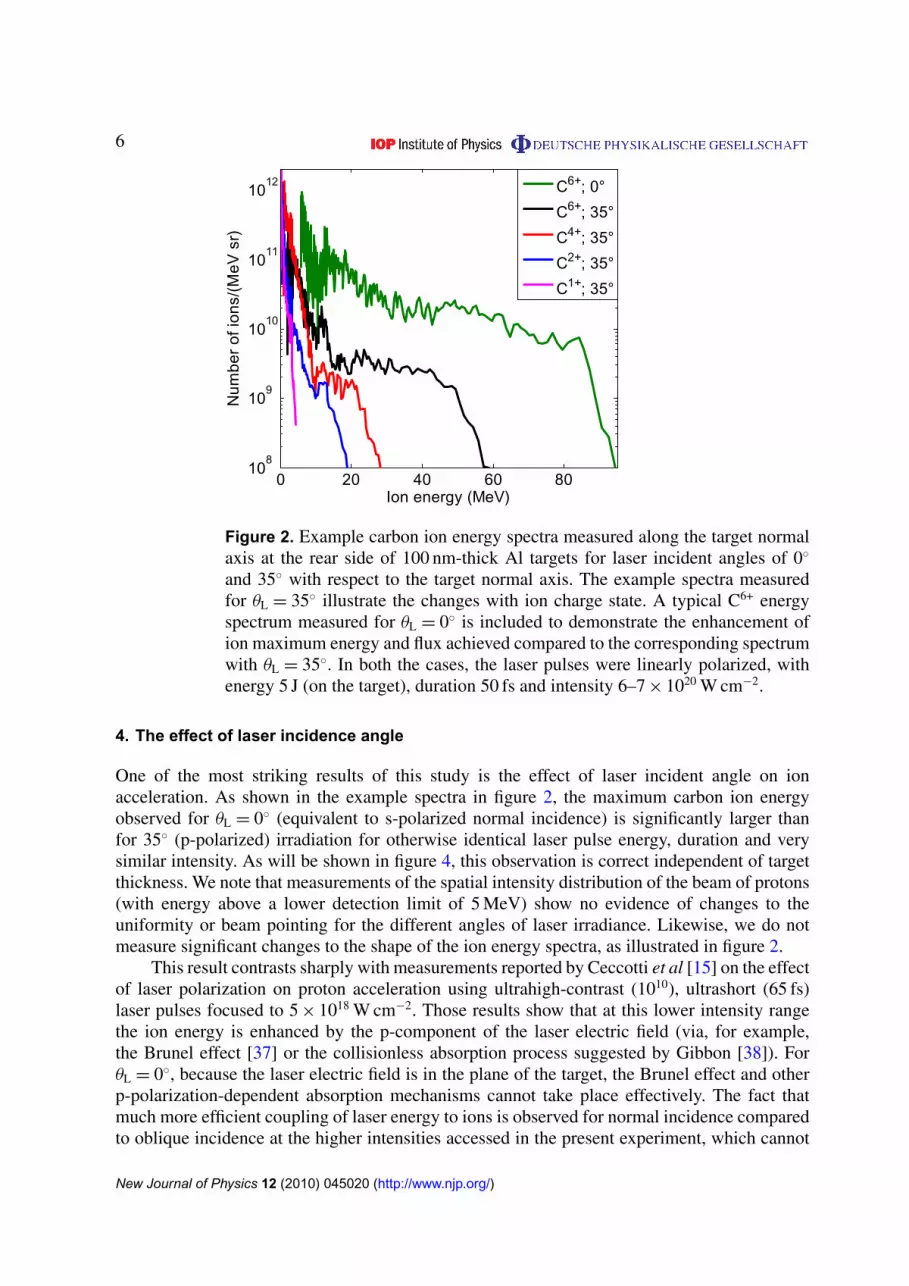
To identify the dominant ion acceleration mechanisms in this experiment, we begin byconsidering the energy spectra of the accelerated ions. Figure 2 shows representative examplecarbon ion energy spectra from Al targets irradiated with linearly polarized laser pulses focusedto average intensity equal to 6–7 × 10²⁰ W cm−2. The spectra were measured along the targetnormal axis of 100 nm-thick Al targets irradiated at θL = 35◦ and 0◦. Figure 2 is typical of theenergy spectral shape obtained for targets with thickness greater than or equal to 100 nm andis consistent with previous measurements of ions accelerated by the TNSA mechanism [3, 36].The energy distribution shifts to higher energy with increasing charge state, and higher chargestate ions exhibit more plateau-like distributions. By contrast, when targets thinner than 50 nmare irradiated, changes to the shape of the spectra at high energy, including the onset of peaksand the detection of ion species with the same maximum velocity, are measured. These spectralchanges indicate that TNSA is not the sole mechanism responsible for the ion acceleration inultrathin (<50 nm) targets and that RPA may start becoming important under these conditions.These observations, which primarily occur with circularly polarized laser pulses and for θL = 0◦,will be reported in detail in a separate article. In the remainder of the present paper, we focusour attention on carbon ion acceleration by TNSA at ultrahigh laser intensities, using linearlypolarized laser pulses.
New Journal of Physics 12 (2010) 045020 (http://www.njp.org/)
6
0 20 40 60 8010
8
109
1010
1011
1012
Ion energy (MeV)
Num
ber
of io
ns/(
MeV
sr)
C6+; 0°
C6+; 35°
C4+; 35°
C2+; 35°
C1+; 35°
Figure 2. Example carbon ion energy spectra measured along the target normalaxis at the rear side of 100 nm-thick Al targets for laser incident angles of 0◦
and 35◦ with respect to the target normal axis. The example spectra measuredfor θL = 35◦ illustrate the changes with ion charge state. A typical C6+ energyspectrum measured for θL = 0◦ is included to demonstrate the enhancement ofion maximum energy and flux achieved compared to the corresponding spectrumwith θL = 35◦. In both the cases, the laser pulses were linearly polarized, withenergy 5 J (on the target), duration 50 fs and intensity 6–7 × 10²⁰ W cm−2.
4. The effect of laser incidence angle
One of the most striking results of this study is the effect of laser incident angle on ionacceleration. As shown in the example spectra in figure 2, the maximum carbon ion energyobserved for θL = 0◦ (equivalent to s-polarized normal incidence) is significantly larger thanfor 35◦ (p-polarized) irradiation for otherwise identical laser pulse energy, duration and verysimilar intensity. As will be shown in figure 4, this observation is correct independent of targetthickness. We note that measurements of the spatial intensity distribution of the beam of protons(with energy above a lower detection limit of 5 MeV) show no evidence of changes to theuniformity or beam pointing for the different angles of laser irradiance. Likewise, we do notmeasure significant changes to the shape of the ion energy spectra, as illustrated in figure 2.
This result contrasts sharply with measurements reported by Ceccotti et al [15] on the effectof laser polarization on proton acceleration using ultrahigh-contrast (1010), ultrashort (65 fs)laser pulses focused to 5 × 10¹⁸ W cm−2. Those results show that at this lower intensity rangethe ion energy is enhanced by the p-component of the laser electric field (via, for example,the Brunel effect [37] or the collisionless absorption process suggested by Gibbon [38]). ForθL = 0◦, because the laser electric field is in the plane of the target, the Brunel effect and otherp-polarization-dependent absorption mechanisms cannot take place effectively. The fact thatmuch more efficient coupling of laser energy to ions is observed for normal incidence comparedto oblique incidence at the higher intensities accessed in the present experiment, which cannot
New Journal of Physics 12 (2010) 045020 (http://www.njp.org/)

7
0 10 20 30 40 500
200
400
600
800
1000
1200
1400
1600
Energy (MeV)
Num
ber
of p
roto
ns (
arb.
uni
ts)
a0 = 18.0 normal
a0 = 18.0 oblique (35°)
(a)
0 10 20 30 40 5010
0
101
102
103
104
Energy (MeV)
Num
ber
of h
eavy
ions
(ar
b. u
nits
)
a0 = 18.0 normal
a0= 18.0 oblique (35°)
(b)
Figure 3. (a) Proton and (b) heavier ion energy spectra from 1D-boostedPIC simulations, showing an enhancement of energy for θL = 0◦ compared toθL = 35◦ for otherwise identical laser and target parameters. The spectra areproduced at 150 fs after the start of the laser pulse.
be accounted for by the small difference in the ponderomotive potential for the two anglesinvestigated, suggests that new angle-dependent absorption processes may be accessed in theultrahigh intensity regime for ultrashort laser pulses.
To investigate the possible reasons for the higher energies achieved with θL = 0◦ comparedto θL = 35◦, 1D-boosted PIC simulations using a modified version of the code employedin [23, 26], [39–41] are performed to investigate any changes in the fast electron generation.The simulations are performed with 25 000 cells, with an individual cell size of 2 nm and 200particles per cell. The target consists of a heavier ion substrate (Z = 1; mass = 3mp, wheremp is the proton mass) at a number density of 90nc where nc is the critical density, with a20 nm proton layer (also at 90nc) on the rear surface. The acceleration of both ion speciesis simulated. The laser pulse has a ‘sin2’ profile with a pulse duration of 50 fs, a wavelengthof 0.8 µm and an a0 (dimensionless amplitude) of 18.0 (equivalent to 7 × 10²⁰ W cm−2). Twosimulations are performed, one for a laser incident angle equal to 35◦ and the other for normalincidence. The simulations reveal that higher-energy ions are produced at normal incidence, asshown in figure 3. The enhancement factors are similar to that measured experimentally forcarbon ions (see figure 2). On investigating the simulation output in more detail, it was foundthat this difference is due to higher energy fast electrons being produced in the normal incidencecase than in the oblique incidence case. 2D PIC simulations using the EPOCH code also show asimilar effect of the laser-to-fast electron momentum transfer dependence on incident angle. Weanticipate that a theoretical description of this new mechanism will be required to fully explainboth simulation and experiment. This will be the subject of a detailed investigation in the future.
5. Ion acceleration as a function of target thickness
In this section, we discuss the scaling of the maximum C6+ ion energy (the highest energycarbon ion detected) with target thickness. A summary of the measurements using Al, C and
New Journal of Physics 12 (2010) 045020 (http://www.njp.org/)

8
101
102
103
1040
20
40
60
80
100
Target thickness (nm)
Max
imum
C6+
ene
rgy
(MeV
)
C; 35°
C; 0°
Al; 35°
Al; 0°
CHO; 35°Schreiber et alAndreev et al
Figure 4. Average of the maximum C6+ ion energies measured as a functionof target thickness for given target materials and angles of incidence (symbols).Lines correspond to predictions using the analytical models of Andreev et al [32](black line) and Schreiber et al [31] (green line), as described in the main text.
CHO target foils, for both angles of incidence, is presented in figure 4. Each point correspondsto an average of the maximum C6+ ion energies obtained from a number of laser shots (typically3 or 4) on each target type and thickness and the error bars correspond to the standard deviationof the maximum energies. While we have chosen here to plot averages of short series of shotsfor nominally the same conditions, a discussion of the highest ion energies observed for eachtarget thickness is also of interest and will be included in a separate publication.
As shown in figure 4, independent of target material, a similar scaling of the maximumion energy with target thickness is measured. The rate of increase in the maximum carbon ionenergy with decreasing target thickness is very similar to that reported by Neely et al [14]for protons (for Al target thickness above 100 nm) for an order of magnitude lower intensity.The maximum ion energy increases by approximately a factor of 2 when the target thicknessis decreased by two orders of magnitude from 10 to 0.1 µm in both the cases. As the targetthickness is decreased from 10 to 0.1 µm, the ratio L/rL changes from 8 to 0.08. In the formercase, transverse spreading of the fast electron population as it propagates within the target fromthe front to the rear surface is important in defining the maximum energy of TNSA ions, whereasfor the latter case the electrons do not spread over an area much larger than the laser focal spotduring their first transit of the target. In the case of targets for which L � cτL/2 (i.e. �7.5 µm),refluxing or recirculation [42] of electrons reflected in the sheath fields formed on both sides ofthe target is believed to occur, and Mackinnon et al [43] report that transient enhancements ofthe fast electron density due to recirculating electrons can increase the maximum energy of ionsaccelerated by TNSA.
To investigate the expected scaling of the maximum ion energy with the target thickness, L ,we apply two analytical models: (i) the model presented by Schreiber et al [31] and (ii) themodel described by Andreev et al for ultrahigh-contrast laser pulse interaction with thin targetfoils [32].
New Journal of Physics 12 (2010) 045020 (http://www.njp.org/)

9
The model presented by Schreiber et al [31] is based on the surface charge set up bylaser-accelerated electrons on the target rear surface and includes consideration of the radialextent of the charge cloud. The electron density is calculated assuming that the electronsare uniformly filling a circular region at the target rear surface with radius R. This radius iscalculated assuming that the electrons are accelerated from the laser focal spot, with radius rL,and transverse the target with thickness L in an angular cone with fixed half-angle θe (set equalto 20◦), such that
R = rL + L · tan θe. (1)
The maximum observable ion energy Emax is determined from the expression
τL
τ0= X
(1 +
1
2
1
1 − X 2
)+
1
4ln
1 + X
1 − X, (2)
where τ0 = R/v∞ (v∞ is the maximum possible ion velocity), X = (Emax/E∞)1/2 and
E∞ = qi 2mec2(ηPL/PR)1/2, (3)
where PL is the laser power and PR = 8.71 GW is the relativistic power unit. qi is the chargeof the ion. η is the laser-to-fast electron energy conversion efficiency. Measurements of thelaser energy reflected from the target (in the specular direction) indicate a total laser energyabsorption of ∼30%. We therefore choose a realistic value of η = 0.2 for the total laser energyconversion to fast electrons in the calculation using the Schreiber et al model.
The Andreev et al [32] model, by contrast, is based on a self-consistent solution of thePoisson equation for the electric field responsible for ion acceleration and the equation of motionfor the ion front. The model presented in [32] uses a rectangular density profile of the target,which is made up of two layers; the bulk of the target and a thin contaminant layer. The fastelectron temperature and laser absorption are assumed to be dependent on the target thickness.The model has been calibrated against numerical simulations for angle of incidence equal to45◦ [32]. The maximum observed ion energy, Emax, is determined (in cgs units) by
Emax ≈2.4ZeE+
δ rDe√1 + (L/rDe)2
+2ZeE+
infrDe√
1 + (rDe/L)2 , (4)
where rDe =√
Te0/4πe2ne0 is the Debye radius of hot electrons, Z is the atomic numberof the target bulk or contaminant layer, e is the electronic charge and ne0 is the fastelectron number density. Te0(L ,η) is the fast electron temperature and is a function ofthe target thickness and the fraction of laser energy absorbed into the fast electrons. Theelectric fields associated with the ion front are E+
δ = 2πe(ZbnibL + ZcnicLc) and E+inf =
√4π ZbnibTe0(
√2/33/4)(Zbnib/ne0) + 2πeZcnicLc where subscripts b and c denote the target
bulk and contaminant layers, respectively, and ni denotes the ion density. The model is describedin detail by Andreev et al [32]. For the calculations shown in figure 4 the target is assumed tobe carbon with a 5 nm contaminant layer of hydrogen. The thickness of the carbon is varied.
Generally both models predict increasing ion energy with decreasing target thicknessdown to 100 nm, in qualitative agreement with the experimental measurements. An importantdifference in the models is that whilst the Schreiber et al model results in a saturation ofthe maximum ion energy as the sheath radius approaches the size of the laser focal spot, themodel by Andreev et al predicts an optimum target thickness of ∼80 nm for the parametersof the experiment. This is higher than that predicted by the scaling laws presented by
New Journal of Physics 12 (2010) 045020 (http://www.njp.org/)

10
0
2
4
6
8
10
Max
imum
ene
rgy
per n
ucle
on (M
eV u
–1)
0.1
µm A
l
0.1
µm C
H
0.1
µm C
0.8
µm A
l
0.9
µm C
HO
1.0
µm C
1.0
µm A
u
1.0
µm A
u +
0.1
µm C
H
Proton
C6+
Figure 5. Maximum proton and C6+ ion energies (averaged over several shots oneach target type) for given target compositions and thicknesses.
Esirkepov et al [20], which suggest an optimum thickness of ∼20 nm for the laser parametersused. Experimentally, we observe a slight decrease in the average of the measured maximumC6+ ion energies obtained with 50 nm Al and C targets compared to the corresponding resultsfor the 100 nm-thick targets (for θL = 0◦), as shown in figure 4. However, as discussed above,due to the fact that we observe changes to the ion energy spectra with targets thinner than 50 nm,indicative of a transition away from the purely TNSA mechanism, we cannot conclusively statewhether there is an optimum thickness for TNSA for the laser pulse parameters investigated.The results suggest that in terms of optimizing the acceleration of carbon ions, the thinnest foilsenabled by the laser prepulse conditions down to ∼100 nm should be used.
6. The effects of target composition
To investigate the extent to which the material properties and composition of the target influencethe laser energy transfer to carbon ions, we irradiate a range of targets containing carbon, eitherin the bulk material of the target (i.e. C, CH and CHO), as an uncontrolled surface contaminationlayer (on Al and Au metallic foils) or as part of a controlled deposited layer on the target rearsurface (Au–CH). This target composition scan is performed at θL = 35◦. The results for themaximum proton and C6+ energies (averaged over 3–4 shots typically) are shown in figure 5 forL = 0.1 µm and L ∼ 1 µm (0.8–1.1 µm).
We start by comparing proton and C6+ ion acceleration from the relatively low-density‘uniform’ targets C, CH and CHO. The maximum proton energy does not differ significantlyfor these targets for a given L . However, the C6+ energy is highest for C targets. The presenceof hydrogen in the composition of the target (in addition to the contamination layer) clearlyproduces a screening effect on the C6+ ion acceleration [36].
New Journal of Physics 12 (2010) 045020 (http://www.njp.org/)

11
0 0.2 0.4 0.6 0.8 1103
104
105
106
107
Charge to mass ratio (au) Charge to mass ratio (au)
Max
imum
ion
ener
gy p
er n
ucle
on (e
V u
–1)
0.1 µm CH0.1 µm C0.9 µm CHO1.0 µm C1.0 µm Au1.0 µm Au + 0.1µm CH8 TV m–1, 50 fsSchreiber et alAndreev et al
(a)
0 0.2 0.4 0.6 0.8 110–3
10–2
10–1
100
101
Inte
grat
ed e
nerg
y (J
sr–1
)
0.1 µm CH0.1 µm C0.9 µm CHO1.0 µm C1.0 µm Au1.0 µm Au 0.1 µmCH
(b)
Figure 6. (a) Maximum ion energy and (b) total integrated ion energy asa function of the ion charge-to-mass ratio. The experimental data points areaverages over several laser shots. Lines correspond to predictions using theanalytical models of Schreiber et al [31] (green line) and Andreev et al [32](black line). A simple calculation of the maximum ion energy obtained in anelectric field of magnitude 8 TV m−1 for 50 fs (blue line), as described in themain text, is also included.
For the higher-density Al and Au targets, for which the TNSA protons and carbon ionsare sourced only from hydrocarbon contamination layers on the target rear surface, a decreasein the maximum energies of both ion species is measured, particularly for the Au target. Thisis probably caused by the smaller number of those ions in the region of the acceleration field.The effect of adding a controlled ‘source’ layer (CH) of carbon and hydrogen to the targetrear surface is also shown in figure 5. The availability of more hydrogen atoms in the regionof the field enhances the acceleration of protons, producing a significant increase (from 4 to7 MeV) in the averages of the measured maximum proton energies. A small decrease, however,is measured in the maximum carbon energy. These results further demonstrate that the presenceof protons limits the maximum energies achievable for heavier ion species due to the screeningof the acceleration field.
We conclude that for a given target thickness, carbon ion energies are maximized using auniform C target and that proton energies are maximized by the use of a hydrogen-containingsource layer on the rear surface of a high-Z target. However, this target produces the lowest-energy carbon ions due to proton screening of the acceleration field.
7. Ion charge state distributions
Figure 6 shows the measured maximum and total energies, averaged over several shots, ofeach ion species as a function of ion charge-to-mass ratio (q/m) for the targets discussed inthe above section. Despite the differing target thicknesses, materials and compositions, cleartrends are observed. An increase of about 2 orders of magnitude in both the maximum ionenergy and total ion energy is measured over the range q/m = 0.1–0.5. These two parameters
New Journal of Physics 12 (2010) 045020 (http://www.njp.org/)

12
are clearly strongly correlated. In most cases, increased energy coupling efficiency into aparticular ion species results in an increase in ion number across the full energy spectrum, witha corresponding increase in the maximum ion energy detected.
Also shown in figure 6 are calculations of the maximum Cq+, q = 1–6, and proton energyscaling with q/m using the Schreiber et al [31] and Andreev et al [32] models as discussedabove. The model calculations assume that all ions are created at the target rear surface. Theinitial charge state population, which has been shown to affect the energy scaling with ionq/m [36], is not considered. Nonetheless, the Schreiber et al model is found to reproducethe measured scaling very well, albeit the predicted energies are higher than measured forirradiation at 35◦ angle of incidence. The energies predicted by the Andreev et al model arecloser to the experimental measurements. Both models predict higher energies for low-chargecarbon ions than measured, and this is likely caused by additional shielding effects that are notaccounted for in the models.
Finally, for comparison, the results of a simple calculation, in which it is assumed that allion species are subjected to the same electrostatic field of magnitude 8 TV m−1 for 50 fs (=τL),are also plotted. In this calculation, the magnitude of the electric field is a free parameter that ischosen by fitting to the measurements. At the rear surface of the target, ions can be produced byeither collisional ionization or field ionization by barrier suppression mechanisms. Assumingfield ionization to be the dominant ionization mechanism [3, 44], the minimum threshold fieldEThres.
q for the production of an ion of charge q is calculated using
EThres.q = U 2
q−1ε0π/q e, (5)
where Uq is the ionization potential in eV. EThres.q = 7 TV m−1 for C6+ ions, which are efficiently
produced in all of the laser shots considered. An electric field magnitude equal to 8 TV m−1 istherefore consistent with the ionization states measured. Despite the simplicity of this model,it reproduces the measured q/m scaling over most of the range, as shown in figure 6(a). Thedeparture observed for low q/m ions is likely to result from a screening of the acceleration fieldacting on these ions by the acceleration of ions with larger q/m, as discussed in detail in [36].We note that charge transfer can occur as the ions propagate from the source to the detector andthat this can influence the charge state distribution measured. However, we do not expect thisto have a strong influence as it would result in ions with different charge states with the samemaximum energy, which is not observed in the experiment.
8. Summary
In summary, we report on an experimental investigation of the optimization of carbon ionacceleration driven by ultrahigh-contrast (1010), ultrashort (50 fs) laser pulses focused to anaverage intensity equal to 7 × 10²⁰ W cm−2—about an order of magnitude higher intensity thanprevious ion acceleration experiments using laser pulses with tens of femtoseconds duration.
A number of conclusions are derived from our investigations of the TNSA-dominatedregime.
1. Significantly higher (a factor of between 1.5 and 2) laser energy transfer to ions is obtainedfor irradiation at normal incidence compared to oblique incidence at 35◦ (with respect tothe target normal). This result is supported by 1D-boosted PIC simulations, which showsimilar enhancement factors in the maximum ion energies. The simulations reveal that
New Journal of Physics 12 (2010) 045020 (http://www.njp.org/)

13
the difference is due to higher-energy fast electrons produced for normal incidence. Thisresult indicates that at ultrahigh intensities the p-component of the laser electric field hasa reduced role in energy absorption, contrasting sharply with measurements made at lowerintensities (5 × 10¹⁸ W cm−2) [15], and that new absorption processes may be accessed atthe ultrahigh intensity, ultrashort pulse regime explored.
2. The maximum energy of ions accelerated by TNSA increases with decreasing targetthickness down to a thickness of ∼100 nm for Al and C targets. For thinner targets, changesto the ion energy spectra suggest that the ion acceleration mechanism is not purely TNSAfor the laser pulse parameters of the experiment.
3. The highest energy carbon ions at θL = 35◦ are obtained with uniform carbon targetsand the presence of hydrogen, either distributed throughout the target or as a layer onthe rear surface, reduces the energy coupling efficiency to carbon ions. We note thatremoving the hydrogen-containing contamination layer from the target rear surface hasbeen shown previously to increase the energy coupling efficiency to ions heavier thanprotons [3], [45–47]. By contrast, a high-Z target with a hydrogen source layer on therear surface is best for optimizing proton acceleration.
4. There is a strong correlation between the measured maximum and total integrated ionenergies and the scaling with q/m can be approximated to first order by assuming allions are subjected to a constant electric field for the duration of the laser pulse. Departuresfrom the model for low q/m ions suggest partial screening of the electric field acting onthese ions by higher q/m species.
Acknowledgments
We acknowledge expert support of the staff at the Central Laser Facility. This work wassupported by the UK Engineering and Physical Sciences Research Council (grant numbersEP/E035728/1 and EP/E048668/1) and the LIBRA consortium. APLR is grateful for the useof resources provided by STFC’s e-Science facility.
References
[1] Clark E L et al 2000 Measurements of energetic proton transport through magnetized plasma from intenselaser interactions with solids Phys. Rev. Lett. 84 670–3
[2] Snavely R A et al 2000 Intense high-energy proton beams from petawatt-laser irradiation of solids Phys. Rev.Lett. 85 2945–8
[3] Hegelich M et al 2002 MeV ion jets from short-pulse-laser interaction with thin foils Phys. Rev. Lett.89 085002
[4] Borghesi M, Fuchs J, Bulanov S V, MacKinnon A J, Patel P K and Roth M 2006 Fast ion generation byhigh-intensity laser irradiation of solid targets and applications Fusion Sci. Technol. 49 412–439
[5] Cowan T et al 2004 Ultralow emittance, multi-MeV proton beams from a laser virtual-cathode plasmaaccelerator Phys. Rev. Lett. 92 204801
[6] Roth M et al 2001 Fast ignition by intense laser-accelerated proton beams Phys. Rev. Lett. 86 436–9[7] Borghesi M, Schiavi A, Campbell D H, Haines M G, Willi O, MacKinnon A J, Gizzi L A, Galimberti M,
Clarke R J and Ruhl H 2001 Proton imaging: a diagnostic for inertial confinement fusion/fast ignitor studiesPlasma Phys. Control. Fusion 43 A267–76
New Journal of Physics 12 (2010) 045020 (http://www.njp.org/)

14
[8] Ledingham K W D, McKenna P and Singhal R P 2003 Applications for nuclear phenomena generated byultra-intense lasers Science 300 1107–11
[9] McKenna P et al 2003 Demonstration of fusion-evaporation and direct-interaction nuclear reactions usinghigh-intensity laser–plasma-accelerated ion beams Phys. Rev. Lett. 91 075006
[10] Bulanov S V, Esirkepov T Z, Khoroshkov V S, Kuznetsov A V and Pegoraro F 2002 Oncologicalhadrontherapy with laser ion accelerators Phys. Lett. A 299 240–7
[11] Murakami M et al 2008 Radiotherapy using a laser proton accelerator Laser Driven Relativistic PlasmasApplied for Science, Industry, and Medicine. AIP Conf. Proc. 1024 275–300
[12] Malka V et al 2004 Practicability of protontherapy using compact laser systems Med. Phys. 31 1587–92[13] Ledingham K W D, Galster W and Sauerbrey R 2007 Laser-driven proton oncology—a unique new cancer
therapy? Br. J. Radiol. 80 855–8[14] Neely D, Foster P, Robinson A, Lindau F, Lundh O, Persson A, Wahlström C-G and McKenna P 2006
Enhanced proton beams from ultrathin targets driven by high contrast laser pulses Appl. Phys. Lett. 89021502
[15] Ceccotti T, Lévy A, Popescu H, Réau F, D’Oliveira P, Monot P, Geindre J P, Lefebvre E and Martin Ph 2007Proton acceleration with high-intensity ultrahigh-contrast laser pulses Phys. Rev. Lett. 99 185002
[16] Henig A et al 2009 Enhanced laser-driven ion acceleration in the relativistic transparency regime Phys. Rev.Lett. 103 045002
[17] Henig A et al 2009 Radiation-pressure acceleration of ion beams driven by circularly polarized laser pulsesPhys. Rev. Lett. 103 245003
[18] Lindau F, Lundh O, Persson A, McKenna P, Osvay K, Batani D and Wahlström C-G 2005 Laser-acceleratedprotons with energy-dependent beam direction Phys. Rev. Lett. 95 175002
[19] McKenna P, Lindau F, Lundh O, Neely D, Persson A and Wahlström C-G 2006 High-intensity laser-drivenproton acceleration: influence of pulse contrast Phil. Trans. R. Soc. A 364 711–23
[20] Esirkepov T, Yamagiwa M and Tajima T 2006 Laser ion-acceleration scaling laws seen in multiparametricparticle-in-cell simulations Phys. Rev. Lett. 96 105001
[21] Yin L, Albright B J, Hegelich B M, Bowers K J, Flippo K A, Kwan T J T and Fernandez J C 2007Monoenergetic and GeV ion acceleration from the laser breakout afterburner using ultrathin targets Phys.Plasmas 14 056706
[22] Zhang X, Shen B, Li X, Jin Z, Wang F and Wen M 2007 Efficient GeV ion generation by ultraintensecircularly polarized laser pulse Phys. Plasmas 14 123108
[23] Robinson A P L, Zepf M, Kar S, Evans R G and Bellei C 2008 Radiation pressure acceleration of thin foilswith circularly polarized laser pulses New J. Phys. 10 013021
[24] Liseykina T V, Borghesi M, Macchi A and Tuveri S 2008 Radiation pressure acceleration by ultraintense laserpulses Plasma Phys. Control. Fusion 50 124033
[25] Macchi A, Veghini S and Pegoraro F 2009 ‘Light Sail’ acceleration reexamined Phys. Rev. Lett. 103 085003[26] Robinson A P L, Gibbon P, Zepf M, Kar S, Evans R G and Bellei C 2009 Relativistically correct hole-boring
and ion acceleration by circularly polarized laser pulses Plasma Phys. Control. Fusion 51 024004[27] Macchi A, Liseikina T V, Tuveri S and Veghini S 2009 Theory and simulation of ion acceleration with
circularly polarized laser pulses C. R. Phys. 10 207–15[28] Qiao B, Zepf M, Borghesi M and Geissler M 2009 Stable GeV ion-beam acceleration from thin foils by
circularly polarized laser pulses Phys. Rev. Lett. 102 145002[29] Esirkepov T Z, Borghesi M, Bulanov S V, Mourou G and Tajima T 2004 Highly efficient relativistic-ion
generation in the laser-piston regime Phys. Rev. Lett. 92 175003[30] Robson L et al 2007 Scaling of proton acceleration driven by petawatt-laser–plasma interactions Nat. Phys.
3 58–62[31] Schreiber J et al 2006 Analytical model for ion acceleration by high-intensity laser pulses Phys. Rev. Lett.
97 045005
New Journal of Physics 12 (2010) 045020 (http://www.njp.org/)

15
[32] Andreev A, Levy A, Ceccotti T, Thaury C, Platonov K, Loch R A and Martin Ph 2008 Fast-ion energy-fluxenhancement from ultrathin foils irradiated by intense and high-contrast short laser pulses Phys. Rev. Lett.101 155002
[33] Andreev A A, Steinke S, Sokollik T, Schnürer M and Ter Avetsiyan S 2009 Optimal ion acceleration fromultrathin foils irradiated by a profiled laser pulse of relativistic intensity Phys. Plasmas 16 013103
[34] Yin L, Albright B J, Hegelich B M and Fernández J C 2006 GeV laser ion acceleration from ultrathin targets:the laser break-out afterburner Laser Part. Beams 24 291–8
[35] Bulanov S S et al 2008 Accelerating monoenergetic protons from ultrathin foils by flat-top laser pulses in thedirected-Coulomb-explosion regime Phys. Rev. E 78 026412
[36] McKenna P et al 2007 Low- and medium-mass ion acceleration driven by petawatt laser–plasma interactionsPlasma Phys. Control. Fusion 49 B223–31
[37] Brunel F 1987 Not-so-resonant, resonant absorption Phys. Rev. Lett. 59 52–5[38] Gibbon P 1994 Efficient production of fast electrons from femtosecond laser interaction with solid targets
Phys. Rev. Lett. 73 664–7[39] Robinson A P L, Neely D, McKenna P and Evans R G 2007 Spectral control in proton acceleration with
multiple laser pulses Plasma Phys. Control. Fusion 49 373–84[40] Gibbon P, Andreev A, Lefebvre E B, Ruhl H, Delettrez J and Bell A R 1999 Calibration of one-dimensional
boosted kinetic codes for modeling high-intensity laser–solid interactions Phys. Plasmas 6 947–53[41] Bourdier A 1983 Oblique incidence of a strong electromagnetic wave on a cold inhomogeneous electron
plasma. Relativistic effects Phys. Fluids 26 1804–7[42] Sentoku Y, Cowan T E, Kemp A and Ruhl H 2003 High energy proton acceleration in interaction of short
laser pulse with dense plasma target Phys. Plasmas 10 2009–15[43] Mackinnon A J, Sentoku Y, Patel P K, Price D W, Hatchett S, Key M H, Andersen C, Snavely R and Freeman
R R 2002 Enhancement of proton acceleration by hot-electron recirculation in thin foils irradiated byultraintense laser pulses Phys. Rev. Lett. 88 215006
[44] McKenna P et al 2007 Lateral electron transport in high-intensity laser-irradiated foils diagnosed by ionemission Phys. Rev. Lett. 98 145001
[45] McKenna P et al 2004 Characterization of proton and heavier ion acceleration in ultrahigh-intensity laserinteractions with heated target foils Phys. Rev. E 70 036405
[46] Hegelich B M et al 2005 Spectral properties of laser-accelerated mid- Z MeV/u ion beams Phys. Plasmas12 056314
[47] Hegelich B M, Albright B J, Cobble J, Flippo K, Letzring S, Paffett M, Ruhl H, Schreiber J, Schulze R K andFernandez J C 2006 Laser acceleration of quasi-monoenergetic MeV ion beams Nature 439 441–4
New Journal of Physics 12 (2010) 045020 (http://www.njp.org/)
Copyright © 2022 FDOKUMEN