
CAPSTONE PROJECT REPORT On HISTORY AND ... - ERA
78
CAPSTONE PROJECT REPORT On HISTORY AND EVOLUTION OF CLOUD NATIVE NETWORKING Prepared By Dixa Patel Guided By Dr Mike MacGregor Director, MSc in Internetworking University of Alberta
-
Upload
khangminh22 -
Category
Documents
-
view
22 -
download
0
Transcript of CAPSTONE PROJECT REPORT On HISTORY AND ... - ERA

CAPSTONE PROJECT REPORT
On
HISTORY AND EVOLUTION OF
CLOUD NATIVE NETWORKING
Prepared By
Dixa Patel
Guided By
Dr Mike MacGregor
Director, MSc in Internetworking
University of Alberta

CONTENTS
1. LITERATURE SURVEY............................................................................................................. 5
1.1. Evolution of IT Infrastructure ............................................................................................... 5
1.2. Introduction of Cloud Computing ........................................................................................ 6
1.2.1. Virtualized Networking in Cloud ................................................................................. 7
1.2.2. Benefits & challenges of Cloud computing ................................................................. 9
1.3. Cloud Computing Used Cases ............................................................................................ 10
2. CLOUD NETWORKING .......................................................................................................... 12
2.1. Data Center Network Topologies ........................................................................................... 13
2.1.1. Cloud Data centre Architecture................................................................................... 16
2.2. Server Virtualization ............................................................................................................... 17
2.2.1. Virtual Switching ......................................................................................................... 18
2.2.2. VM Migration .............................................................................................................. 20
2.3. Network Virtualization........................................................................................................ 22
2.3.1. VXLAN ........................................................................................................................ 23
2.3.2. Network Function Virtualization (NFV) .................................................................... 26
3. SOFTWARE DEFINED NETWORKING (SDN) ................................................................... 27
3.1. SDN Architecture ................................................................................................................ 28
3.2. SDN Controller .................................................................................................................... 40
3.2.1. Industry Adoption for SDN ......................................................................................... 42
3.3. SDN Benefits and Limitations ............................................................................................ 57
3.4. SDN Used Cases.................................................................................................................. 59
4. CLOUD NATIVE NETWORKING .......................................................................................... 62
4.1. Motivation for Cloud-Native Architecture ........................................................................ 63
4.1.1. Traditional vs Cloud-Native Application approach ................................................... 64
4.2. Key Concepts of Cloud-Native Architecture ..................................................................... 65
4.3. Cloud-Native Networking ................................................................................................... 67
4.4. Case Studies for Cloud-Native Architecture ..................................................................... 69
2. ASOS Making Fashion Statement with Cloud Native [4] .................................................... 69
5. CONCLUSION ........................................................................................................................... 72
BIBLIOGRAPHY............................................................................................................................... 73
ABBREVIATION .............................................................................................................................. 77

TABLE OF FIGURES
Figure 1: Stages in IT infrastructure Evolutions .................................................................................... 5
Figure 2: Cloud computing .................................................................................................................... 6
Figure 3: Virtual Network Connectivity ................................................................................................ 8
Figure 4: Data Center Evolution .......................................................................................................... 12
Figure 5: Traditional Data Center Architecture ................................................................................... 13
Figure 6: Transition in the use of ToR switch .................................................................................... 14
Figure 7: Cloud Data Center Network ................................................................................................. 16
Figure 8: Before Virtualization ............................................................................................................ 17
Figure 9: Server Virtualization ............................................................................................................ 17
Figure 10: Logical diagram of a vSphere distributed switch ............................................................... 18
Figure 11: Logical diagram of a Hyper-V server ................................................................................. 19
Figure 12: Logical Diagram of Open vSwitch ..................................................................................... 20
Figure 13: Network Utilization during & after VM Migration ............................................................ 21
Figure 14: Multitenant Data centre network ........................................................................................ 22
Figure 15: Networking in Multitenant Cloud Environment ................................................................. 22
Figure 16: VXLAN Frame Format ...................................................................................................... 23
Figure 17: VTEP forwarding table entry ............................................................................................. 24
Figure 18: VTEP Encapsulation and De-encapsulation ....................................................................... 25
Figure 19: NFV Framework ................................................................................................................. 26
Figure 20: Traditional vs SDN based Network .................................................................................... 27
Figure 21: SDN Architecture ............................................................................................................... 28
Figure 22: OpenFlow based SDN network device............................................................................... 29
Figure 23: OpenFlow Switch ............................................................................................................... 31
Figure 24: OpenFlow Table Entry Format ........................................................................................... 32
Figure 25: Packet Flow in OpenFlow Switch ...................................................................................... 34
Figure 26: Centralized vs Distributed SDN controller ......................................................................... 40
Figure 27: Classification of Distributed Controller ............................................................................. 41
Figure 28: Juniper Contrail Networking Architecture ......................................................................... 43
Figure 29 : OpenContrail Architecture ................................................................................................ 45
Figure 30: OpenContrail System Implementation with Analytics & Compute Node internal
structure................................................................................................................................................ 47
Figure 31: Internal Structure of Configuration & Control Node ......................................................... 49
Figure 32 : OpenStack Integration ....................................................................................................... 50
Figure 33: Tungsten Fabric Deployment and interaction with Orchestrator ....................................... 52
Figure 34: Tungsten Fabric vRouter functional Architecture ............................................................. 54
Figure 35: Service Chain Implementation .......................................................................................... 55
Figure 36: Evolution of Cloud Native Architecture............................................................................ 62
Figure 37: Evolution from VNF to CNF ............................................................................................. 67
Figure 38: Container networking (Port mapping) ................................................................................ 67

LIST OF TABLES
Table 1: Packet flow between virtual machines..................................................................................... 9
Table 2: Flow of data traffic within the data centre network ............................................................... 13
Table 3: SDN programming language classification .......................................................................... 38
Table 4: Traditional vs Cloud-Native Application .............................................................................. 64

5
1. LITERATURE SURVEY
1.1. Evolution of IT Infrastructure
Figure 1: Stages in IT infrastructure Evolutions [1] [2]
The excursion of IT infrastructure development throughout the last 60 years has been quite lengthy
and complicated with the steady pace of progress at each spending days. Today cloud computing
is driving the next wave of change in the world of infrastructure [3]. Cloud computing is the third
incarnation of the platform eras [4]:
The first era was the mainframe, which dominated the industry from the 1950s through the
early 1980s.
The client-server architecture was established as the dominant second platform from the
1980s right up until the second decade of the 21st century.
The "as a service" movement in IT has broadly been termed cloud computing, and it defines
the third platform era of the cloud-based, server-less world we now occupy.
Today, cloud computing has changed the way business works. With the minimal investment, high
productivity, and security, it has gained attention from 'startups' and big organization to cut the
annual cost for running a business. The software-driven nature of cloud computing has empowered
a significant number of innovations [3].

6
1.2. Introduction of Cloud Computing
Cloud computing is the on-request accessibility of computer system resources (e.g., networks,
servers, storage, applications, and services) and applications via the Internet with pay-as-you-
go pricing [5].
Figure 2 : Cloud computing [6] [7]
The main pillars of cloud computing are Software as a Service (SaaS), Platform as a Service (PaaS)
and Infrastructure as a Service (IaaS). IaaS provides only hardware infrastructure support (e.g.
servers, storage, network etc.) on a utility basis; however, the customer is responsible for its
operation & security in all aspects except physical security. In addition to IaaS, PaaS supports the
operating system and requisite core applications of the OS to provide a platform for the customer
to install & run their applications. As PaaS supports both hardware and the necessary platform to
run customer applications, users do not need to worry on weekly scheduled downtime for
maintenance. On the other hand, SaaS is a complete solution, including IaaS, PaaS, and support
for both hosted applications and its supporting hardware.

7
Based on business needs, several cloud deployment models are public, private, hybrid &
community cloud. Public cloud shares a pool of virtualized resources among multiple users on pay-
per-use or subscription basis. In contrast, the private cloud is committed to an individual user,
providing control of its security. Hybrid cloud is the blend of public and private cloud. Businesses
experiencing demand fluctuation throughout the year like financial service organizations,
companies dealing with big data can take advantage of the hybrid cloud approach to secure
sensitive applications/data using private cloud and move other applications to the public cloud.
Community cloud offers a hosted private cloud's security features and public cloud computing
benefits but restricted to a particular industry. Industry domains like automotive, energy, financial
and health care use specific applications that only apply to them and not others. Such organizations
belong to the same backgrounds and share infrastructure, resources and data using community
cloud [7].
1.2.1. Virtualized Networking in Cloud
In traditional physical networking, dedicated servers (email, web, DC, DNS etc.) are configured
for each application and connected to physical network individually. With the high dependencies
on hardware, physical infrastructure becomes very rigid and expensive to operate, introducing
specific concerns regarding the network's inefficiency, flexibility, and scalability. For example, if
a server running a particular application is not fully utilized, the resource is wasted as no other
application can acquire that server to run its own execution. On the other hand, the server
sometimes overruns due to heavy memory consumption and more processing power. In such a
scenario, infrastructure is not fully flexible enough to allocate required memory storage on demand
and release it later. The need for manufacturing-specific hardware, long standardization process
between different vendors and operators, and network complexity makes it hard to introduce new
functionalities or changes in the network for management, configuration, and control. Such a
situation demands network transformation to make much more flexible, agile and moldable
infrastructure.
Virtualization is the pioneering initiative in the network transformation and initially instigated with
the concept of VLAN. VLAN is used to divide one physical network into separate, individual
virtual networks. Network devices in the same VLAN can directly communicate with each other
however routing device (router, L3 switch, firewall) is required for communicating between
devices in different VLAN. Virtualization was further extended into hardware by consolidating
multiple segregated resources (virtual machines running various services) into a single high
computing physical server. A hypervisor is a robust software used to create a virtual environment
by allocating a certain amount of CPU, RAM & storage to each VMs as per requirement. Bare-
metal hypervisors (type 1) like VMWare vSphere/ESXi, Microsoft Hyper-V are directly installed
on hardware while hosted hypervisor (type 2) like Vmware workstation, Oracle VirtualBox is
installed on host OS.

8
Figure 3: Virtual Network Connectivity
As shown in fig.3 physical diagram, a physical server is installed with type1 hypervisor, and four
NICs are plugged into the physical switch. The virtual network consisting of virtual machines,
virtual switch and a virtual router is configured using a hypervisor. A virtual switch can be mapped
to physical NICs and play an essential role in connectivity between physical and virtual networks.
Also, each virtual machine is allocated with a certain amount of CPU, RAM and storage as per the
need of application/service running on it however total amount doesn't exceed the capacity of a
physical server. Due to such flexibility, the on-demand rise of storage or memory for a specific
virtual machine can be assigned and release later on. As shown in fig. 3 logical diagram, there are
two isolated networks. Network green includes VM1, VM3, VM5 while network blue has VM2,
VM4, VM6. Virtual machines in the same network communicate using a logical switch and
encapsulation protocol used by hypervisor host. For example, VMware uses vXLAN protocol to
encapsulate virtual packet within the frame; hence physical switch will not be aware of the virtual
network. In this case, logical switch 1 & 2 are assigned with identifier 10000 and 20000 to
differentiate between two networks. Table 1 below describes the packet flow between different
virtual machines in the same or another network.

9
Communication Virtual Machine Flow of the packet Within Network Green
VM1, VM3, VM5 From VM1 to VM3 : VM1 Logical SW1 NIC1(packet encapsulation) NIC2(packet decapsulation) Logical SW1VM3
Within Network Blue
VM2, VM4, VM6 From VM2 to VM6 : VM2 Logical SW2 NIC1(packet encapsulation) NIC3(packet decapsulation) Logical SW2VM6
Between different network but same host
VM1 & VM2, VM3 & VM4, VM5 & VM6
From VM1 to VM2 : VM1 Logical SW1 virtual router Logical SW2VM2
Between different
network and host
VM1 to VM4/VM6
VM2 to VM3/VM5 VM3 to VM2/VM6 or likewise
From VM1 to VM6:
VM1 Logical SW1 virtual router NIC1(packet encapsulation) NIC3(packet decapsulation) Logical SW2VM6
Table 1: Packet flow between virtual machines
1.2.2. Benefits & challenges of Cloud computing
1. Service Availability & Reliability: It is challenging to keep the network up at all times with
the traditional on-premise infrastructure. In contrast, most cloud service providers now
days strive for 99.99% uptime which is practically 8s per day. Hence, cloud service users
have almost 24/7 availability of resources when and wherever required. Also, with the
multi-platform service availability, cloud computing avoids device/platform dependency to
access resources.
2. Scalability & Elasticity: With virtualization, cloud service providers can provide limitless
server capacity to users as per demand. It means that business has the flexibility to scale
the number of computing resources to use. More servers can be allocated to cope with
growing business demands and release it later on when not in use.
3. Reduce Cost: With the rise in demands, companies have to invest more in purchasing or
upgrading their existing on-premise hardware resources to cope with growing networking
traffic. Also, managing high redundancy with 99.99% uptime of resources is massively
expensive for the organization. Cloud computing and virtualized networking reduce
installation, maintenance and operational cost for the organization with a pay-for-what-
you-use pricing model.
Along with many benefits, cloud computing has specific challenges like security, service outages,
compliance etc. As cloud service providers manage data centrally, any failure to secure their data
centres can result in massive data loss. Also, consumers are not aware of where their data is stored
and who has access on it, e.g. any data stored in the US could be within the US government's reach
because of the PATRIOT Act. Due to multitenancy nature of cloud computing, data belonging to
different customers reside on the same physical server, which brings the possibility that such data
could be accessed intentionally or accidentally by other customers [8].

10
1.3. Cloud Computing Used Cases
1.3.1. Services provided by Deloitte to The US Navy's Tactical Networks Program Office [9]
1.3.2. Honeywell [10]
About PMW 160 of US Navy is The Tactical Networks Program Office responsible for
robust network infrastructure and essential network information distribution
services. One of the program office's critical priorities is to train sailors who operate
and manage the CANES (consolidated afloat Networks and Enterprise Services)
network.
Existing
Approach
Physical network racks are used as training equipment at two training sites to provide
advanced CANES training
Challenges Limitation to train several sailors each year, high operational and maintenance cost,
training provided on legacy CANES systems based upon earlier technologies,
Restricted training environment to a single Hardware-Software (HW-SW) version
combination
Adapted
Approach
(SaaS)
Leveraging Amazon AWS cloud, AWS CloudFormation, Amazon Machine Images,
Amazon EC2 Bare Metal, VM Import/Export, AWS security tools, and custom
configurations, Deloitte team had re-platformed multiple variations of the CANES
shipboard network on AWS GovCloud
Result/Benefits 1. Fastest CANES installation in the Navy: More than forty instance networks
created, configured, and deployed in under 40 minutes using Cloud Formation,
APIs, and custom code.
2. Expanded training capabilities to training sites worldwide four times higher by
increasing no. of training scenarios, troubleshooting activities and conducting
real-life situation training.
3. Increase training throughput to 840 sailors a year which is four times higher
than usual.
4. Cost reduced to 50% than building and sustaining physical training equipment.
About Honeywell's Process Solutions provides the control systems for a wide range of
industrial operations like mining, refining, oil and gas, wastewater systems
Existing
Approach
Initial Physical Infrastructure with servers & clients moved to Open Virtual
Engineering Platform (VEP), virtualized environment to develop the control systems
on their own internal cloud and providing read-only access of the control system to
clients.
Challenges Clients have requested for full access and virtualized off-premise lab specific to them
for executing their own projects. However, with bandwidth limitation, it was
challenging to replicate multiple clients on existing cloud
Adapted
Approach
VMWare-based Open Virtual Engineering Platform environment has been moved
to the IBM Cloud which provides seamless VMWare portability along with the
control of stack from microchip level
Result/Benefits Improve productivity, increase efficiency and gain agility for customers

11
1.3.3. Cisco CloudLock [11]
1.3.4. Immedion, LLC [12]
1.3.5.
About CloudLock is a cloud data security company launched in 2007 and acquired by Cisco.
Existing
Approach
Initially, on-premise security solution was built using Amazon Web Services
Challenges Helping those companies facing challenges for federal & legal regulatory
requirements to move their data on the cloud, build a scalable application to
accommodate user growth, provide highly secure Google's infrastructure to protect
data, manage the app with minimal staff resources
Adapted
Approach
(PaaS)
Started to use Google App Engine in 2011 to leverage Google's highly secure,
reliable infrastructure and took advantage of crucial App Engine features like the
Datastore to accommodate growth in user data, OpenID/Single Sign-On secure
access to CloudLock's service through existing Google accounts. Also, the in-built
administration console enabled performance monitoring and error log analysis.
Result/Benefits 1. Achieved a 20-fold increment in users within a year
2. Saved almost $200,000 every year in compensation costs
3. Supported more than 200 clients with a solitary staff member
About Immedion is a cloud and managed services provider with seven data centres across
North Carolina, South Carolina and Ohio. It delivers the enterprise-level solutions
of a national data centre and cloud provider with the hands-on attention and agility
of a local business
Existing
Approach
Initially, physical servers provisioning took up to four weeks which was improved
by five days using manual VM provisioning.
Challenges 1. Speed customer onboarding and provisioning to keep up with significant
growth & customer demand
2. Enable secure multi-tenancy by isolating customers into logical security
segments
3. Meet customer demand for self-service
4. Provide resource visibility and administration to customers for making any
necessary changes
Adapted
Approach (IaaS)
Deployed VMware vCloud Director, cloud management platform to speed
provisioning, providing resource visibility and management to customers
Result/Benefits 1. Build up a new environment takes five minutes while server deployment
and configuration can be finished within a few seconds
2. Enabled greater efficiency with 80% reduction in day-to-day activities via
automation
3. Meets customer self-service and security needs
4. Speeds customer onboarding and business growth
5. Ensures workload security and automated resource control

12
2. CLOUD NETWORKING
Figure 4: Data Center Evolution [13]
Datacenter evolution has gone through a massive transformation from the dump client terminal
connected to mainframe computers in the 1960s to the latest cloud-based modular data centre. This
voyage was first started with big sized mainframe computers connected to teleprinter through
proprietary connection. With the development of chip technology and the emergence of integrated
circuits in the late 1970s, big sized expensive mainframe computers were replaced with a smaller
size, low-cost minicomputers. These minicomputers and multiple client terminals are connected
through the shared network by proprietary connection protocol. It has initiated the concept of
distributed computing to access numerous resources from different locations. In the late 1980s,
standalone workstation computers came into the picture to save minicomputers/mainframes'
computing power by accessing documentary information directly from servers and presenting it to
clients through desktop computers. As more and more business started to accommodate technology
advancement with multiple servers and desktops in LAN, no. of LAN ports and bandwidth
requirement were increasing rapidly. It has accelerated the specialized data centre's evolution from
standalone server to rack-mounted computers and blade server system. Using the new industry
initiative of Fiber Channel over Ethernet (FCoE), both data and storage traffic converge onto a
single ethernet network in the data centre. While enterprise networking has connected multiple
clients (wired and wireless) through high-bandwidth and efficient local area network, cloud
networking is another era in developing the latest data centres. Cloud networking has majorly
changed the way information is accessed, and computing resources are managed today. Cloud data
centres contain thousands of big sized specialized rack/units, including servers, storage,
networking, power, and cooling and clients are accessing these resources using the Internet from
anywhere-anytime [13].

13
2.1. Data Center Network Topologies
Initially, clients are connected to servers and storage using LAN technology in traditional data
centre architecture. However, with growing demand, business needs to increase servers and storage
capacity with high-performance network capabilities. Most traditional data centres are equipped
with high-end networking equipment from the same vendor to meet a business requirement with
ease of management and operational support.
Figure 5: Traditional Data Center Architecture [13]
As shown in fig.5, servers within the rack are connected via the top of rack (ToR) switches in a
star topology. Each server in the rack typically uses dedicated 1GbE link to ToR switch and
multiple 1GbE/10GbE/optical links between aggregation and core switch. A typical rack may
contain 40 or more servers; ToR switches contain up to 48 10GbE ports and four 40GbE uplink
ports connected to aggregation switches. Aggregation switches connect to core switch or router to
forward traffic to another aggregation switch or outside the network. Below table describes how
data travels within the datacenter and to outside network [13].
Data Traffic Path to forward traffic
From one VM to other on the same physical server Routed through vSwitch within the server
From one physical server to another on the same rack Routed through vSwitch and ToR switch
Between different racks Routed through vSwitch, ToR switch and aggregation / EoR switch
From one network to another in the same datacenter Routed through vSwitch, ToR switch,
aggregation switch and core switch
From one datacenter to other/outside network Routed through vSwitch, ToR switch, aggregation switch, core switch to the Internet
Table 2: Flow of data traffic within the data centre network

14
Figure 6: Transition in the use of ToR switch [13]
As discussed earlier, 10GbE ports can use low-cost copper cabling for a short distance between
server and ToR switch while optical fibre is used for long-distance between ToR & Aggregation
switch. Single modular chassis-based EoR switch is designed to reduce the cost of earlier topology.
EoR eliminates the need for separate power supplies, cooling fans, and CPU subsystems in every
ToR and aggregation switch. It also provides central management to manage multiple ToR
switches. However one of the drawbacks with EoR switch is additional cable cost and cable drivers
to connect all servers of the racks to EoR chassis. To eliminate the need for optical cables or
10GBase-T cables while still providing some of the cost benefits available with EoR switches,
fabric extenders were developed. Fabric Extenders are controlled and monitored through a central
controlling bridge. Fabric extenders provide a unified management model while allowing the same
cabling topologies used with ToR and aggregation switches. Standard low cost, low latency, direct
attach copper cables can be used between the fabric extender and the servers while high-bandwidth
optical cables with a much lower cable count are used between the server racks and controlling
bridge. The controlling bridge also has switch functionality. The entire configuration can be
managed through a shared CPU control plane card in the controlling bridge, acting as a single
logical EoR switch, easing configuration time and overhead [13].

15
Challenges with traditional enterprise data centre architecture:
1. High Capital and Operating expense
There are mainly two types of the expense involved in a building data centre with thousands of
servers' racks. First, capital expense includes equipment acquisition costs, cabling cost, purchasing
datacentre facilities and various software. Second, Operating expense includes electricity,
personnel to operate and maintain the equipment, hardware and software maintenance agreements.
Datacenter aggregation and core switches/routers with high-bandwidth ports are costly. Most core
switches/routers support many layer-3 features like OSPF, MPLS, BGP, IP-IP, VPLS, VPWS and
many other tunnelling protocols. Many of these features are not used, adding cost for features that
are not required. Traditional data centres may have separate software for configuring, virtualizing,
and maintaining the servers; different software for configuring and preserving storage resources
and associated storage networks; and particular software for configuring and maintaining the data
network. In many cases, they also have separate IT administrators with specialized expertise in
these different areas. Because of the cost associated with traditional enterprise data centre
architecture, the 2-tiered cloud data centre is developed [13].
2. Performance
The conventional enterprise-data centre has certain limitations which have spurred new industry
standards for bandwidth optimization, congestion control and efficient data transfer. Traditional
Ethernet workgroup based ToR switches operated at 10, 100, or 1000Mbps. Multicore-servers that
host multiple virtual machines (VMs) can rapidly immerse a 1GbE link, and at times, work at peak
data rates of up to 10Gbps. While ethernet links operate at 1Gbps, storage network using optical
fibre channel operates at 2 or 4 Gbps. Thus, the emergence of multicore processor and desire to
transmit both storage and data traffic on the same physical link has driven the ToR switch port
bandwidth requirement up to 10Gbps.
There are specific issues related to packet latency in the traditional enterprise data centre. First,
packets need to take multiple hops when travelling between servers. It increases latency and latency
variation between servers. For example, the packet may need to travel two hops between servers
in a given rack or four hops rack-to-rack. Core routers may contain switch chips that use external
buffer memory along with store and forward mechanisms where the port-to-port latency is
relatively high, and the latency varies depending on packet size. Depending on the nature of the
application, latency plays a significant impact on performance. For example, applications based on
financial trading, real-time data analytics, and cloud-based high-performance computing require
minimal latency.

16
Second, enterprise networks will drop packets during periods of high congestion. As the core
switch/router has to deal with layer-3 forwarding functions, it requires more extensive frame
header processing at very high bandwidth which adds more congestion to the network. The
traditional Ethernet workgroup based switches or aggregation switches have been designed to drop
traffic during high congestion periods. It cannot be tolerated by higher layer protocols such as Fiber
Channel over Ethernet used for storage traffic due to the long retransmission latencies involved.
Thus, data centre networks transmitting storage traffic must separate traffic classes and lossless
operation for storage traffic. Legacy enterprise networking gear cannot support this, requiring new
data centre bridging features.
2.1.1. Cloud Data centre Architecture
Figure 7: Cloud Data Center Network [13]
As the enterprise datacentre with three-tiered approaches adds cost, complexity and latency, a two-
tiered flat cloud datacentre was developed. With a large cloud data centre, service providers started
to use their networking software and custom-built networking equipment from major ODMs to
reduce cost. Most data centre networks have been designed for north-south traffic; however,
nowadays, more data centre traffic travels in the east-west direction due to server virtualization
and changing server workloads. Because of this, data centre network designers are moving towards
a flat network topology, as shown in Fig.7. With a 2-tier network, bandwidth over-provisioning
can be used to reduce the probability of congestion hot spots. By assigning 10GbE links to the rack
servers, the network can uphold storage and data traffic intermingling into one network, decreasing
expenses. ToR switches use high-bandwidth connections to the core. The core routers have been
supplanted with simple core switches having a larger number of ports permitting them to ingest
the aggregation function, making this a "flatter" network. This network type can better support all
east-west traffic in large data centres today with lower latency and lower latency variation [13].

17
2.2. Server Virtualization
Figure 8: Before Virtualization [14]
Figure 9: Server Virtualization [14]
Server virtualization is a widely adopted technology in today's cloud computing era. It allows
resource pooling where multiple customers share the standard underlying hardware. As shown in
Fig. 8, physical server hardware run one operating system and mostly one specific application
program like email, database, web hosting etc. initially. However, the only fraction of server
resources are utilized (CPU, RAM, and NIC etc.) by a single application, which is not cost-
effective considering that the organization has to invest for each server. Multiple applications can
be installed on the same host with a single OS to improve server utilization; however, any problem
with one application might affect all. Also, the OS reboot would take down all the apps running on
the same host. It led to the development of server virtualization. As shown in Fig. 9, high server
utilization can be achieved by running multiple apps on the individual guest OS sharing the same
physical hardware. Each separate instance with the guest OS running single application is called
as virtual machines. Hypervisors from the various virtualization vendors like VMware vSphere,
Microsoft Hyper-V are used to manage multiple instances on the same physical hardware [14].
Virtual machines communicate with each other using virtual switches.

18
2.2.1. Virtual Switching
2.2.1.1. VMware vSphere Virtual Switch
VMware vSphere has two main types of virtual switches: Standard & Distributed. VSphere
Standard Switch provides network connectivity for hosts and virtual machines and handles
VMKernel Traffic. The standard switch works with only one ESXi host and bridges the traffic
internally between virtual machines in the same VLAN. It does not require enterprise plus licensing
for usage. The hosts' physical NICs are connected to uplink ports on the standard switch to provide
network connectivity to hosts and virtual machines. Virtual machines have network adapters
(vNICs) that are connected to port groups on the standard switch. Every port group can utilize one
or more physical NICs to handle its network traffic. On the off chance that a port group does not
have a physical NIC associated with it, virtual machines on the similar port group can only
communicate with each other but not with the outside network.
Figure 10: Logical diagram of a vSphere distributed switch [13]
As shown in Fig. 10, vSphere Distributed Switch provides centralized management and monitoring
of all hosts' networking configuration associated with the switch. It is used to connect multiple
ESXi hosts and consists of two logical sections: the data plane and the management plane. The
data plane implements the packet switching, filtering, tagging, and so on, and management plane
is the control structure used to configure the data plane functionality. A vSphere Distributed Switch
separates the data plane and the management plane. The distributed switch's management
functionality resides on the vCenter Server system to administer the networking configuration on
a data centre level. The data plane remains locally on every host that is associated with the
distributed switch. The data plane section of the distributed switch is called a host proxy switch.
The networking configuration that is created on the vCenter Server (the management plane) is
automatically pushed down to all host proxy switches (the data plane) [15].

19
2.2.1.2. Microsoft Hyper-V Switch
As shown in Fig. 11, Hyper-V hypervisor utilizes parent partition to create and manage distinctive
VMs called child partitions. Child partitions communicate with the parent partition through a
virtual bus called the VMbus. All requests to access hardware like network interface controller
(NIC) are made through the parent partition. The parent partition also implements a virtual layer 2
switching functions to switch between local VMs and arbitrate access to the physical network. It
additionally offers a virtual NIC (vNIC) function for each VM connected to the VMbus. The vNIC
resembles a physical NIC to the VM while the parent partition converts these local VM transactions
into function calls to the physical NIC [13].
Figure 11: Logical diagram of a Hyper-V server
The Hyper-V virtual switch has three modes of operation: private, internal and public. Hyper-V
Private switch allows VMs to communicate with each other only when they are on the same host.
The Private virtual switch cannot communicate to any network outside of the host. The Hyper-V
Internal switch is slightly different in that the VMs on the switch can communicate with each other
and the Hyper-V host itself. It can commonly be used as a file exchange mechanism. The internal
mode includes virtual adapters (vNICs) within each VM. Public mode allows communication
between VMs and also to the outside physical network through vNICs. With Windows Server
2012, Microsoft has added additional functionality like Port ACL Rules, network traffic
monitoring, VLAN isolation, minimum bandwidth guarantee and traffic shaping, ARP spoofing
protection, neighbour discovery spoofing etc. [13].

20
2.2.1.3. Open vSwitch
Figure 12: Logical Diagram of Open vSwitch [16]
Open vSwitch is a software execution of a virtual multilayer network switch that enables network
automation effectively through programmatic extensions and supports standard management
interfaces and protocols such as SPAN, RSPAN, CLI, LACP, NetFlow, and 802.1ag. Open
vSwitch is also designed to support transparent distribution across multiple physical servers by
empowering the conception of cross-server switches to abstracts out the fundamental server
architecture, similar to the VMware distributed vSwitch. Open vSwitch functions both as a
software-based network switch and as the control stack for dedicated switching. Moreover, open
vSwitch has been integrated into various cloud computing software platforms and virtualization
management systems, including openQRM, OpenNebula. It is the default network switch in
the XenServer virtualization platform since its version 6.0 [16].
2.2.2. VM Migration
In some cases, a running VM must be moved from one host to another due to failure, maintenance,
a performance upgrade, or for network optimization. It is known as VM migration, live migration,
or vendor-specific names like vMotion from VMware. Most customer applications cannot tolerate
downtime while this migration happens. The migration is called "seamless" when the downtime is
not noticeable by the end-user. Low latency networking with the lossless operation is the
fundamental requirement during the migration. Besides, the network addressing and forwarding
must be updated quickly and seamlessly once the migration is complete. The first step in VM
migration is storage migration. Storage is copied from a hard drive or solid-state drive on the old
host to a new host's drive over the network. Sometimes, VM uses pooled storage, in which case a
new VM only needs to learn the address information of the network's storage location. Next step
is memory migration in which hypervisor copies pages of memory from local DRAM on the old
VM to the new VM over the network.

21
Once the storage and memory are moved over, the old VM operation can be suspended while the
CPU's execution state and register state is moved over to the new CPU. Next, the new VM is started
up. The downtime during the migration process is not usually noticeable if it's less than a second.
After the new VM is brought to life, there may still be some clean-up work to do in order to make
sure memory and storage are consistent between the old VM and the new VM. Next necessary
process is network migration to update the new location of the VM in the data centre network [13].
Figure 13: Network Utilization during & after VM Migration [13]
Fig. 13 shows an example of VM migration for network optimization. Let's assume a data centre
tenant is running applications on two VMs located on different data centre racks, and they are
accessing storage from a third rack as shown on the left side of Fig. 13. It is inefficient and
consumes unnecessary bandwidth in the data centre network. After VM migration, two VMs and
shared storage reside within the same host server within the rack. Now the VM to VM traffic runs
on the local vSwitch within the server and storage to VM traffic runs on the network within the
rack. Only client traffic runs out of the rack, reducing the load within the data centre network.
During the VM migration process, storage and server state information must be moved quickly
with minimal downtime, requiring high network bandwidth. The network administrator must
allocate the necessary bandwidth using data centre bridging mechanisms and add temporary hot
spots to the network. The high-bandwidth NIC operation on the servers hosting these VMs may
consume CPU resources, slowing down other applications running on those CPUs. Thus, network
& server administrator must have to work in coordination to ensure smooth VM migration. To
eliminate any possible human errors and maintain critical timings, the entire process can be
automated using emerging network technology called Software-Defined Networking (SDN) [13].
In conjunction with Network Function Virtualization, SDN can achieve high-level automation with
minimal time investment for providing necessary resources on the fly whenever required.

22
2.3. Network Virtualization
Figure 14: Multitenant Data centre network [13]
While server virtualization provides multiple virtual machines (virtual servers) within a single
physical server, network virtualization provides multiple virtual networks like a private network
within one physical network. It is a useful phenomenon in applications such as multitenant data
centre environments where each tenant can be allocated multiple virtual machines and a virtual
network connecting them. As shown in Fig.14, physical resources are divided up among three
different tenants. Multiple virtual machines residing on different servers are allocated to each
tenant, and virtual networks provide interconnectivity among tenant's virtual machines.
Figure 15: Networking in Multitenant Cloud Environment
Let's consider the scenario where red and blue tenant virtual machines are connected to two servers,
as shown in Fig. 15. If both tenants are using same subnets (e.g. 10.0.0.0/16) within their network,
it is challenging to differentiate traffic of two tenants travelling from one server to another. Along
with that, multitenancy cloud nature raises a few concerns related to networking as below:
Layer 2 adjacencies across layer-3 boundaries
Logical separation for virtual networks(security and overlapping addressing)
Logical separation of virtual networks from the underlay network
Requires support for large no. of VLANs for each virtual machines in the cloud however
traditional 802.1Q VLAN mechanism only supports 4096 VLAN tags
Forwarding tables on switches becoming large due to no. of VMs in the cloud

23
2.3.1. VXLAN
To alleviate such challenges, various tunnelling protocols have been developed. Tunnelling
protocols like VXLAN create overlay network/virtual tunnel on top of underlying physical
infrastructure. While the underlay network provides physical connectivity, overlay networks
provide logical connectivity to carry multitenant traffic over a single virtual network. Fig.16
represents the frame format of the VXLAN protocol.
Figure 16: VXLAN Frame Format [17]
VXLAN includes 50 bytes on top of the original Ethernet frame (with standard 1500 bytes) and
encapsulates source ethernet frame in new UDP packet. Hence, the minimum MTU for VXLAN
is 1550 bytes. VXLAN protocol encapsulates original frame containing MAC addresses and
VLAN tag using VXLAN header and a UDP header. The entire combination is then routed through
layer 3 network using IP addresses. As VXLAN protocol provides isolation between different
virtual layer 2 network domains, each tenant can use its own MAC address pool using VXLAN
network identifier (VNI). The VXLAN Network ID (VNI-24-bit value) inserted in the VXLAN
header and can identify up to 16 million unique virtual networks. As original inner TCP/IP header
within the original ethernet frame provides reliable transmission through error detection and
retransmission, VXLAN prefers UDP protocol for encapsulation. Source tunnel endpoint provides
source port in VXLAN frame while destination port is set to a well-known UDP port number 4789.
VXLAN Tunnel End Point (VTEP) is the point in the network where frame encapsulation and de-
encapsulation occurs. The outer IP addresses forward data between these VTEPs through the data
centre layer 3 networks. These endpoints can be inside the hypervisor, the NIC, or a physical switch
[13].

24
VXLAN Encapsulation & De-encapsulation:
The VXLAN Tunnel End Point (VTEP) is the VXLAN encapsulation point connected to a traffic
source that may be a standalone server or virtual machine. VTEP needs to know where VMs are
located for each tenant. For example, if virtual switch shown in Fig. 15 is considered as VTEP,
vSwitch maps MAC address to IP address through manual, push, pull or dynamic learning. Manual
is configured in the lab environment. In the push method, the SDN controller is useful to acquired
mapping at VTEP while in the pull method, VTEP requests mapping information from a central
database. The dynamic method is more analogous to the layer 2 switch learning process. Let's
discuss the dynamic learning process shown in fig.17 below where the red 1 virtual machine on
server 1 is trying to communicate the red2 virtual machine on server 2.When VMs are powered
on, both VTEP joins multicast group 239.1.1.100, and each VTEP has empty forwarding table
initially.
Figure 17: VTEP forwarding table entry
Below is the process of forwarding table entry on server 2 VTEP [18].
1. Red1 on server1 sends ARP packet with Destination MAC as "FFFFFFFFFFF"
2. VTEP on server1 encapsulates the Ethernet broadcast packet into a UDP header with a
destination IP address as "239.1.1.100"(multicast) and the source IP address as
"192.168.1.10"(VTEP address)
3. All hosts on the multicast group (with IP address "239.1.1.100" ) receive a multicast packet
sent by the physical network.
4. When VTEP on server 2 receives the encapsulated packet, it makes an entry in the
forwarding table based on the outer and inner header that shows the virtual machine's (red1)
MAC address mapping to VTEP. Here, the virtual machine MAC1 running on server 1 is
associated with VTEP IP "192.168.1.10". Based on the segment ID or VXLAN logical
network ID (5001) in the external header, VTEP decides to deliver packet further to host.
5. The de-encapsulated packet is delivered to the virtual machine (red2) connected on that
logical network VXLAN 5001.

25
As shown in Figure 18, the entry in the forwarding table of server 2 VTEP (vSwitch) is used during
the lookup process to respond with unicast ARP reply from red 2 to red1.
Figure 18: VTEP Encapsulation and De-encapsulation
Below is the process of forwarding table lookup on server 2 VTEP [18]:
1. Red 2 (MAC2) on server 2 sends a unicast packet (Destination Ethernet MAC address:
MAC1) in response to ARP request
2. VTEP on server 2 performs a lookup for the destination MAC address("MAC1" ) match in
the forwarding table. The VTEP now knows that it has to send a packet to VTEP with IP
address "192.168.1.10" in order to deliver the packet to red 1(MAC1) on server 1.
3. The VTEP on server 2 creates a unicast packet with the destination IP address as
"192.168.1.10" and sends it out.
4. When VTEP on server 1 receives the encapsulated packet, it makes an entry in the
forwarding table based on the outer and inner header that shows the mapping of the virtual
machine MAC address and the VTEP. In this example, red 2(MAC2) running on server 2
is associated with VTEP IP "192.168.2.20". Based on segment ID or VXLAN logical
network ID (5001) in the external header, VTEP decides to deliver the packet to host.
5. The de-encapsulated packet is delivered to the virtual machine (red1) connected on that
logical network VXLAN 5001.
The same mechanism is used for blue tenant also which uses the same internal network
(10.0.0.0/16) as a red tenant; however, VXLAN logical ID (VNI) for the blue tenant will be
different (e.g. 5002). Different VNI can differentiate traffic of each tenant.

26
2.3.2. Network Function Virtualization (NFV)
Traditional corporate data centres use hardware from large original equipment manufacturers
(OEMs) with proprietary software. Most network devices from the same vendors are used in data
centres to reduce management and configuration complexity. Migration to other vendor's hardware
platform resulted in significant upheaval at the application layer. Also, network devices incorporate
many features that are not needed or not utilized effectively in data centre networks. Due to vendor-
lock in, capital expense and operating expense increases. In addition to increased expenses,
network environment has to endure the dynamics of faults and adapt to load changes. The control
plane decides how to handle network traffic while data plane forwards traffic according to its
decision. Both control and data plane are bundled inside the networking device, reducing flexibility
and hindering innovation and evolution of networking infrastructure.
Network Function Virtualization (NFV) and Software-Defined Networking (SDN) are two pillars
to change the existing network infrastructure limitations. While NFV virtualizes the network,
which reduces timing for the new deployment, SDN provides network reachability for those newly
created resources. Main functions of NFV are softwarization, virtualization and orchestration. NFV
replaces costly dedicated purpose-built network hardware with generic hardware (e.g. HP and dell
blade servers). As shown in Fig. 19, three main components of NFV which ensures interoperability
and tight coupling between hardware and software are NFV infrastructure (NFVI), Virtual
Network Function (VNF) and NFV Management and orchestration (MANO). NFVI hosts all
compute, storage and network hardware (virtual and physical). VNF hosts actual applications
related to individual network services. Single VNF can be deployed over multiple VMs. VNF is
equivalent to a physical network capable of performing network functions like routing, switching,
and security provision by decoupling network services from supporting hardware. That means it is
easy to scale up or scale down capacity without affecting physical network hardware. MANO is
responsible for controlling the entire cloud or network through automation, provisioning, and
workflows coordination to VIM and VNF managers.
Figure 19: NFV Framework [19]

27
3. SOFTWARE DEFINED NETWORKING (SDN)
Figure 20: Traditional vs SDN based Network
As shown in fig. 20, the traditional network consists of a data plane, control plane and management
plane. Data plane route traffic from one device to another. The control plane is responsible for
taking routing decision. Every router has its own control logic for deciding the best path to route
the traffic. The management plane is responsible for the maintenance and operations of the
network. Alerts and various network reports are generated at a management plane. Configuration
to generate reports and alerts are done individually on each device. On the other side, software-
defined networking (SDN) is an emerging network architecture that is fully programmable,
dynamic, adaptable and cost-effective. It offers on-demand scaling by breaking vertical integration
of control and data plane. There are four fundamental principles of SDN networks [20].
1. It makes networking and IP routing flexible using software and dynamic algorithms where
forwarding decisions are based on flow-based instead of destination-based. A flow is a set
of packet field values acting as a match (filter) criterion and a set of actions (instructions).
2. Decoupling control and data plane. Data plane resides on routers while the centralized
controller handles control plane
3. It provides centralized monitoring of the entire network as control logic is moved to an
external entity, called the SDN controller or NOS.
4. Abstraction is the core of SDN. It provides a programmable network with agility for any
needs. Control plane is directly programmable while underlying infrastructure is abstracted
for applications and network services. End-user can request the SDN controller via
network application on the web portal for any changes to adjust network resources, change
configuration, provision or de-provision bandwidth.
Thus, SDN brings resilience in the network by providing a holistic decision on the entire network.
The key fundamental works for separating data and control plane between a network switch and
SDN controller is a well-defined programming interface called API. OpenFlow is one of such
prominent example of API.

28
3.1. SDN Architecture
Figure 21: SDN Architecture [20]
Fig. 21 displays SDN architecture with three fundamental planes: Data, Control and application.
(i) Data Plane
Data plane or the infrastructure layer is composed of network devices (switches, routers) to
transport and process data according to the SDN control plane's decision. As compared to
traditional network devices, network devices in SDN data plane are simple forwarding entities;
lacking embedded control or software to take an independent decision. The forwarding devices
take appropriate actions on incoming packets based on well-defined instruction sets (e.g. flow
rules). To implement SDN, there are two fundamental requirements [21]:
1. Common logical architecture for all network devices to be managed by the SDN controller.
It can be implemented differently on different vendor equipment; however, the SDN
controller sees uniform logical switch functionality.
2. The need for standard and secured protocol between the SDN controller and network device
is required to ensure communication-configuration compatibility and interoperability
among different data and control plane devices

29
The above requirements are addressed by OpenFlow, which is both a standard protocol between
SDN controllers and network devices and a specification of the logical structure of the network
switch functionality. OpenFlow was published by the Open Networking Foundation (ONF) and
defined as the OpenFlow Switch Specification [20]. The OpenFlow switch process incoming
packet based on the pipeline of flow tables. Flow tables have mainly three parts: 1) matching rules;
2) actions to execute based on matching packets; 3) counters that keep statistics of matching
packets.
Figure 22: OpenFlow based SDN network device [21]
When a packet is received, the lookup process starts with the first table of pipeline and ends with
either match or a drop (when no rule matches). As illustrated in Fig. 22, a flow rule can be defined
by combining different matching fields. In case no default rule is configured, the packet will be
discarded. If default rule is found, switch sends a packet to the controller. The precedence of the
rules follows the regular succession number of the flow table for a match. Possible actions to
perform are 1. Forward the packet to outgoing port(s) 2.Encapsulate packet and forward it to the
controller 3. drop packet 4. Send packet to the standard processing pipeline or send it to the next
flow table/special tables(group or metering tables introduced in the latest OpenFlow protocol) [20]
[22].
(ii) Control Plane
Control plane works as a bridge between data and control plane that provides a global view of an
entire network. It manages flow control of forwarding devices in data plane using southbound
interfaces while northbound APIs interact with the application plane for network management.
Control plane creates forwarding table entries using the local data set. Such data sets used to store
network topology are called a routing information base (RIB). Forwarding table entries used by
the data plane to forward traffic between ingress and egress port are called forwarding information
base (FIB). Control plane provides various functions such as shortest path forwarding, notification
manager, security mechanisms, topology manager, statistics manage and device manager [23]-
[25].

30
The brain of control plane performing all intelligent tasks is the SDN controller. It mostly contains
a set of modules that can perform a different task. The functionality provided by the SDN controller
can be viewed as Network Operation System (NOS). SDN controller has diversified properties,
including essential network services. Some controllers like NOX, POX have centralized
architecture while others like a floodlight, OpenDaylight are distributed in nature.
NOX: First OpenFlow controller is written in C++. Due to lack of proper documentation
regarding its internal working flow and other issues, it wasn't widely implemented [26].
POX: Python only version of NOX (POX) has a user-friendly API with well-prepared
documentation. It also provides a web-based graphical user interface written in python.
Compared to other implementation languages, shortening experimental and development
cycles were broadly accepted by SDN developers and engineers [27].
Floodlight: Java-based SDN controller developed by an open community of developers and
offered initially by Big Switch. It uses OpenFlow protocol to orchestrate traffic flow of
SDN environment. It was built using Apache Ant and gained lots of popularity. It has an
active community allowing for many different features to be created that can be added and
tailored to specific environments [28].
OpenDaylight: OpenDaylight is widely developed largest open source SDN controller. It
is a modular open platform for scaling and customizing network of any size. It is a Linux
Foundation collaborative project that has been highly supported by major industry players
such as Cisco and Big Switch. OpenDaylight is written in JAVA and uses REST API and
a web-based GUI. With the third release of OpenDaylight (Helium SR3), virtualization and
scalability became a reality and was chosen as the technology to create the world's first
software-defined city in Bristol, England as part of the 'Bristol is Open' project. The ODL
community is very active and leading various projects, the same as Bristol [29].
(iii) Application Plane
Application plane, also known as management plane, plays a crucial role in the SDN
implementation. SDN is implemented on a wide range of network from home to enterprise and
data centre, which uses various applications like a load balancer, policy enforcement, routing,
firewall etc. Using such applications, application-layer provides numerous services like data centre
networking, mobility & wireless, traffic engineering, information-centric networking, monitoring
and security. As an example scenario of traffic engineering, load balancer application can evenly
distribute traffic among available network paths using an abstracted view of network topology
provided by the SDN control plane. Implementation of such different applications in traditional
networks is challenging; considering each device's control plane needs to be configured
independently. Using SDN, an application plane provides a straightforward solution to implement
these applications [20][21].

31
(iv) SDN Interfaces
SDN interfaces known as Application Programmable Interfaces (API) are a key fundamental
architectural component of SDN.
A) Southbound API :
Southbound API (SBI) is a communication protocol between control and data plane. It provides a
common interface to the upper layer while pushing configuration information and install flow
entries in the data plane (lower layer). Southbound interfaces enable control plane to support
different protocols like OpenFlow, OVSDB, ForCES to manage existing or new physical/virtual
devices in the data plane. Such a mechanism is essential for backward compatibility and
heterogeneity. Therefore data plane can accommodate a mix of physical devices, virtual devices
(Open vSwitch, vRouter etc.) and various device interfaces (OpenFlow, OVSDB, NetConf,
SNMP). Amon all southbound interfaces, OpenFlow is a leader and widely used standard [21].
OpenFlow:
As shown in Fig.23, OpenFlow switch has three main components [30]:
1. Flow tables & Group tables: It performs packet lookups by
matching incoming packet to particular flow and forwards it based
on specified matching actions. Multiple flow tables work in a
pipeline fashion. A flow table may forward a flow to a group table
2. OpenFlow Protocol: The switch communicates with the
controller and controller manages switch via OpenFlow protocol
running over Transport Layer Security (TLS).
Figure 23: OpenFlow Switch [30]
3. OpenFlow Channel: Each switch connects to other OpenFlow switches, to the controller
or end-user devices (sources and destinations of packet flows) via OpenFlow ports. On the
switch side, the interface is known as an OpenFlow channel.
OpenFlow ports work as the network interfaces to pass packets between OpenFlow processing and
rest of the network. OpenFlow ports available for OpenFlow processing may or may not be
identical to the number of network interfaces provided by switch hardware. OpenFlow switch may
have OpenFlow disabled on network interfaces or can define additional OpenFlow ports. Ingress
ports are useful for matching incoming OpenFlow packets. OpenFlow pipeline process the packets
received on ingress port and forward them to output port [30].

32
There are three types of ports in OpenFlow Switch [30]:
1. Physical Ports: Corresponds to a hardware interface of the switch. For example, physical
ports map one to one to the Ethernet interfaces of the switch. If OpenFlow switch is
virtualized over the switch hardware, OpenFlow physical port represents a virtual slice of
the switch's corresponding hardware interface.
2. Logical Ports: Doesn't correspond directly to a hardware interface of the switch. Logical
ports are a higher-level abstraction that can be mapped to various physical ports. Logical
ports may be defined as non-OpenFlow methods (e.g. link aggregation groups, tunnels,
loopback interfaces) and perform packet encapsulation. Logical ports must interact
transparently with OpenFlow processing in a similar way as OpenFlow physical ports. The
only thing which differentiates logical ports from physical ports is that a packet associated
with a logical port may have an extra metadata field called Tunnel-ID associated with it.
Both logical port and its underlying physical port are reported to the controller if the packet
from the logical port is sent to the controller.
3. Reserved Ports: The OpenFlow reserved ports indicate general forwarding actions such
as flooding, sending to the controller or forwarding using non-OpenFlow methods(e.g.
"normal" switch processing). A switch might not support all reserved ports, just those
marked "Required".
Flow Table:
Figure 24: OpenFlow Table Entry Format [20]
Each packet entering into switch passes through one or more flow tables. Each flow table consists
of several rows called flow entries. Each flow entry is consisting of seven components, as shown
in Fig. 24(a).

33
Each flow table entry contains [30]: ˆ
Match fields: Selects a packet that matches values in the fields. These consist of the ingress
port, egress port, packet headers and optionally metadata specified by a previous table,
physical port, VLAN ID etc. ˆ
Priority: Defines relative priority of the flow entry. It is a 16-bit field with 0 correspondings
to the lowest priority and maximum possible 65536(216) priority levels. ˆ
Counters: Updated when packets are matched. ˆ
Instructions: Instructions to be performed if a match occurs. ˆ
Timeout: Maximum amount of time or idle time before the switch expires flow. Each flow
entry has two timeouts associated with it :
o A nonzero hard_timeout field: Flow entry is removed after the given number of
seconds configured in timeout, regardless of how many packets it has matched.
o A nonzero idle_timeout field: Flow entry is removed when it has matched no
packets in the given number of seconds.
Cookie: Controller chooses 64-bit opaque data value to filter flow statistics, flow
modification and flow deletion. It is not used during packet processing.
Flags: Flags controls the management of flow entries. As an example, the flag OFPFF_
SEND_FLOW_REM stimulates flow removed messages for that flow entry.
As shown in Fig. 24(b), the match field component of a table entry consists of the following
required fields [20]:
Ingress port: Port identifier for packet arrival. It may be a physical port or a switch-defined
virtual port. It is required in ingress tables.
Egress port: The identifier of the egress port from the action set. Required in egress tables.
Ethernet source and destination addresses: Each entry can be an exact hardware address, a
bitmasked value for which only some address bits or wildcard value are checked.
Ethernet type field: Indicates the type of the Ethernet packet payload.
IP: Version 4 or 6.
IPv4/IPv6 source address and destination address: Each entry can be an exact address, a
subnet mask value, a bitmasked value, or a wildcard value.
TCP source and destination ports: Exact match or wildcard value.
UDP source and destination ports: Exact match or wildcard value.
As shown in Fig. 24(c), the group table entry contains a list of action buckets with specific
semantics dependent on the group type.

34
Operation:
Figure 25: Packet Flow in OpenFlow Switch [30]
OpenFlow Switch implements the functions shown in Figure 25 upon arrival of the packet on the
ingress port. Firstly, the switch performs a table lookup in the first flow table (table 0) and may
perform further table lookups in other flow tables based on pipeline processing. Flow entries match
packets in precedence order with a first matching entry in each table is used. If an entry is matching,
the action associated with the specific flow entry is executed, and associated counters are updated.
For no match in a flow table, the outcome depends on the table-miss flow entry configuration.
Table-miss flow entry is the one that wildcards all fields (all fields omitted) and has priority equal
to zero. A table-miss flow entry specifies the process to follow for unmatched packets, including
dropping packets, passing packets to another table or sending them to the controller over the control
channel via packet-in messages. In case table-miss flow entry is not present, packets unmatched
by flow entries are dropped (discarded) by default. Instructions related to each flow entry either
include actions or modifies the pipeline process. Actions included in instructions defines packet
forwarding, packet modification and group table processing. Pipeline processing instructions may
be sent packets to successive tables for further processing and allow information (metadata) to be
communicated between tables. If the instruction set associated with a matching flow entry does
not specify the next table; table pipeline process stops, and the packet is usually modified and
forwarded. Additional processing may introduced if packets are directed to a group based on
actions specified in flow entries. Groups define sets of actions for flooding and more complex
forwarding semantics like fast reroute, link aggregation and multipath. Groups can also enable
multiple flow entries as a general layer of indirection to deliver to a single identifier like IP
forwarding to a common next hop. This abstraction allows common output actions to be changed
efficiently across flow entries [30].

35
B) East/Westbound API:
While SDN provides network programmability with centralized control & management, it also
faces certain challenges like scalability, security and availability at enterprise/data centre level
where network traffic flow is massive.
With the exponential increase in demand, the number of network devices required to
provide reliable services on demand also increases. A single controller cannot manage
underlying network resources beyond its capabilities which impose scalability issue.
If the SDN controller is compromised by a DDOS attack, ransomware attack or any security
breaches, the entire network is affected.
Data plane network devices need continuous involvement of the SDN controller to process
incoming packets. The overloaded controller might not be available at all the times for all
devices due to limitation of controller capability. Also, the SDN controller is the single
point of network failure.
Such issues can be addressed by implementing multiple distributed controllers. Widely adopted
approaches for such implementation are:
1. Distributed Architecture: Each controller manages its own underlying domain but
synchronized with other neighbouring controllers to share information regarding device
capability, topology changes, reachability etc.
2. Hierarchical Architecture: It has two layers of the controller. Domain/local controller and
root controller. Domain controller manages its underlying domain and updates the root
controller but doesn't communicate directly with the neighbouring controller. Root
controller manages all domain controllers.
To provide common compatibility, interoperability between multiple distributed controllers and
interoperability of new SDN domain with traditional legacy network, standard east/westbound
interfaces were developed. East represents SDN-SDN communication, while the west represents
legacy-SDN communication. East/Westbound API may require specific communication protocol
for the essential functions such as exchange reachability information to facilitate inter-SDN
routing; coordinate flow setup originated by applications, reachability update to keep the network
state consistent etc. [21]. Examples of few East/Westbound interfaces are :
ODL [27][31]: Uses SDNi to exchange reachability information across multiple domains
Onix[32]: Uses Zookeeper for easy application development by providing a Distributed
Hash Table (DHT) storage and group membership
Hyperflow [33]: Uses WheelFS as a file system for controller communication in a domain
DISCO[34]: Uses advanced message queuing protocol (AMQP) based on messenger and
agent approach responsible for the advanced distribution of data and control information

36
C) Northbound API:
Northbound interfaces play an important role as a bridge between control and application plane to
provide the network's programming abstraction for application development. Northbound API is a
software-based interface rather than hardware-dependent and lacks widely accepted
standardization like OpenFlow southbound interface. Due to variation in applications, their
requirements, application portability and interoperability among different control platforms, it is
challenging to develop open & standard northbound interface. For example, the API requirement
for security applications is different than routing, monitoring or financial applications.
To address common and standard northbound API, Open Networking Foundation (ONF) created
Northbound Interface Working Group (NBI-WG) in 2013 to define and develop the prototype for
the NBI. There is a broad range of northbound APIs used by SDN controllers and mainly divided
as 1. RESTful API, 2. Programming languages used by northbound API and 3. Specialized Ad-
hoc APIs.
1. REST(Representational state transfer) API
REST is a de-facto standard for interactive applications. It defines six constraints to restrict server-
client interaction in a way to gain desirable performance, maximum scalability and interoperability
of software interaction. Below are the six constraints every API needs to follow in order to be
RESTful [35]:
1. Client-Server Architecture
Separation of user interface concern from data storage is the key principle of client-server
constraints. It improves the scalability for server components and portability of the user interface
across multiple platforms. That means different applications; using different programming
languages can use the same function of RESTful API in SDN. Applications in the SDN serves as
"client" while SDN controller works as a "server".
2. Stateless
Client-server interaction contains intrinsic and extrinsic state. Intrinsic state, also known as
resource state, consists of information that is independent of the server's context and stored on the
server. This makes the information shareable to all clients of the server. Extrinsic state, also known
as application state, is stored on each client rather than the server, making the communication
stateless. It consists of information that is dependent on the server's context and so cannot share.
Clients are accountable for passing the application state to the server when it needs it. It also
improves reliability, scalability and simplifies implementation; however, network performance
may decrease as redundant data to be sent in a series of requests may increase.

37
3. Cache
To improve network performance and scalability by reducing client-server interaction
partially or entirely, commonly used information can be stored locally on the client-side.
Cache constraints required that data within responses are labelled implicitly or explicitly
as cacheable or non-cacheable. If the response is cacheable, data can be reused from the
cache without requesting the same information. However, it imposes trade-off on reduced
reliability if stale data on cache differs from the server's information response if the request
was made.
4. Layered System
With this constraint, REST API must be developed to not see beyond the immediate layer
with which it interacts. For example, application (client) interacts with neighbours (proxy,
load balancer, server etc.) cannot see beyond neighbour. With REST northbound API, the
application doesn't need to learn or understand southbound API languages like SNMP,
SSH. Security can also be added as a layer on top of the web services which splits business
logic from security logic. It enforces security policies on data crossing an organizational
boundary by adding security as a separate layer. Some disadvantages with this constraint
are added overhead and increased latency which ultimately affects user experience.
5. Uniform Interface
Uniform Interface between components is a fundamental architectural need of RESTful
API. Information retrieved can be in a different format; however, it is presented in the same
way. In addition to simplifying the overall system architecture, visibility of interactions is
also improved by applying generality to the component interface.
6. Code-In-Demand
Optional REST constraint as some security appliance configuration doesn't support it. It
extends the API functionality by transferring executable code into API calls to run on
server-side. Compiled components like Java applets and client-side scripts such
as JavaScript are examples of executable applets and scripts.
In SDN, an application may use REST APIs to send an HTTP/HTTPS GET message through an
SDN controller's IP address while POST requests are used to create, update, and delete data.
RESTful API is predominantly used northbound interface till the date. SDN Controllers that use
RESTful API as their Northbound API include DISCO, ElastiCon, Floodlight, HP VAN SDN,
Unified controller, OpenContrail, OpenDaylight, ONOS and sMaRtLight.

38
2. Programming Languages
Another variant of the northbound interface offered by the SDN controller is in the form of
programming languages. As computer languages are shifted from assembly level language ( x86
architectures) to high-level programming languages (Python and Java), network programming
languages are also evolved from low-level (OpenFlow) to high-level programming languages
(Frenetic, Procera, Nettle etc.). In SDN, high-level programming language enables various benefits
like a high-level abstraction to simplify programming of forwarding devices, code-reusability in
the control plane, software modularization, and productive and problem-focused environment to
speed up development and innovation of network virtualization etc. The biggest challenge
addressed by programming languages in pure OpenFlow based SDN is to ensure multiple tasks
(routing, access control, monitoring) running on a single application. Typically, each application
defines its own rules and policies without knowing rules generated by another application. In such
a case, underlying forwarding devices might have a conflicting set of rules generated and installed
by different applications, hindering regular network operation. Programing languages help to
resolve such issues using reactive or proactive flow installation mechanism. Table 3 depicts the
classification of SDN programming language[36]:
Table 3: SDN programming language classification [36]
Flow Installation defines how forwarding rules can be installed on switches.
Reactive Approach: Packet is forwarded to the controller if no flow information available
when a packet arrives. It introduces latency as each packet is sent to the controller for flow
installation.
Proactive Approach: Pre-defined rules and actions are installed on flow tables, and
programming language performs proactive installation and pre-compute forwarding tables for
the entire network. Simultaneously, the controller only modifies flow table in case of link
failure or external event. As every packet isn't sent to the controller in this approach, it
eliminates latency.

39
Programming Paradigm provides different ways of building the structure and elements of any
program. The imperative approach is traditional and specifies every step to resolve any particulate
issue; however declarative approach defines the program's nature and its result but not its
functionality or working mechanism. The declarative approach has sub-category [36]:
Logic Programming: Compiler executes an algorithm that scans all possible combinations
Event-Driven Programming: Enables program to respond to any particular event. As soon
as an event is received, automatic action is triggered. This action can either be some
computation or trigger another event.
Functional Programming: Based on evaluating some mathematical functions and reactive
programming, it enables programs to react to external events.
Policy Definition defines a set of conditions (policy rules to apply) and a respective set of actions
to perform when there is a match. Static policies are the more traditional approach for firewall
filters. They contain a pre-defined set of rules and actions while dynamic policies change according
to network situation. List of certain widely used programming languages are as below [36]:
Frenetic: Defines high-level programming abstraction with reactive flow installation
approach, dynamic policy list and function reactive programming approach
Procera: Provides extensible and computational framework using reactive flow installation
approach, dynamic policy list and function reactive programming approach and used for
policy handling.
Pyretic: Upgraded version of frenetic supports both reactive and proactive flow installation
and Imperative programming approach. Same as Procera, it is used for policy handling
FML: It supports reactive flow installation, static list of policies and declarative(logic)
programming approach, used in the enterprise network.
NetKAT: It supports both reactive and proactive flow installation with a dynamic set of
policies and functional programming paradigm, used for network mapping and traffic
isolation
3. Specialized Ad-hoc API
Many existing SDN controllers use customized northbound interface according to their needs.
SFNet is one of such high-level northbound API which translates application requirement into
lower-level service request. With limited scope, it supports congestion network status request,
bandwidth reservation, multicast etc. Yanc proposes a general control platform based on the Linux
and virtual file system (VFS) abstraction, making it easier to develop SDN applications. NOSIX,
PANE, NVP, SDMN are another example of northbound API.
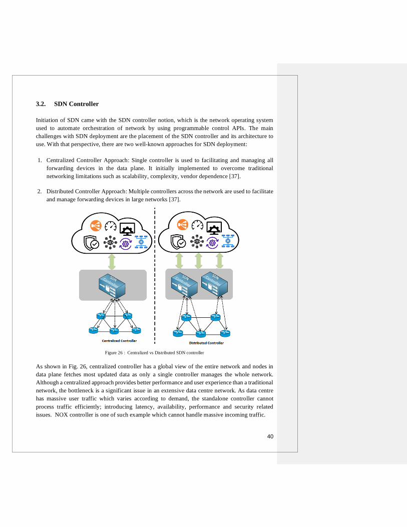
40
3.2. SDN Controller
Initiation of SDN came with the SDN controller notion, which is the network operating system
used to automate orchestration of network by using programmable control APIs. The main
challenges with SDN deployment are the placement of the SDN controller and its architecture to
use. With that perspective, there are two well-known approaches for SDN deployment:
1. Centralized Controller Approach: Single controller is used to facilitating and managing all
forwarding devices in the data plane. It initially implemented to overcome traditional
networking limitations such as scalability, complexity, vendor dependence [37].
2. Distributed Controller Approach: Multiple controllers across the network are used to facilitate
and manage forwarding devices in large networks [37].
Figure 26 : Centralized vs Distributed SDN controller
As shown in Fig. 26, centralized controller has a global view of the entire network and nodes in
data plane fetches most updated data as only a single controller manages the whole network.
Although a centralized approach provides better performance and user experience than a traditional
network, the bottleneck is a significant issue in an extensive data centre network. As data centre
has massive user traffic which varies according to demand, the standalone controller cannot
process traffic efficiently; introducing latency, availability, performance and security related
issues. NOX controller is one of such example which cannot handle massive incoming traffic.

41
Floodlight controller is another Java-based centralized controller which Big Switch Networks
developed. Trema, Medrian, Programmable flow, Rosemary, Ryu are few other examples of
centralized controller approach. The distributed controllers designed to mitigate the limitations of
a centralized controller. Distributed controller approach classified in four sub-categories:
Physically Distributed, Logically Distributed, hierarchically distributed and hybrid controller
distribution.
Figure 27 : Classification of Distributed Controller [36]
In the Physically distributed approach, a large network is divided into multiple domains. Each of
such small domains is managed and facilitated by individual local controllers. ONIX is an example
of a physically distributed controller. Each local controller updates others periodically to maintain
the same global view of the network in all controllers. Each controller has a different responsibility
in the logical distributed approach and updates other controllers whenever network state changes.
DISCO is an example of such a controller. The hierarchically distributed controller has a vertical
structure with more than one layer of controllers in the control plane. Lower/intermediate layer
controller manages a smaller network domain the same as physically distributed; however, they
don't communicate internally with each other and instead update the root/top layer controller. This
approach sidesteps a single point of failure but faces more extended path travel for traffic flow.
Kandoo controller uses a hierarchically distributed system. Hybrid controller approach is a mixture
of other techniques that impose each other's benefits while avoiding individual limitations.
SOX/DSOX is an example of a hybrid approach [38].
Distributed controller approach also faces specific challenges such as i) Number of Controllers and
its placement in control plane should improve network performance without degrading control
plane functionality ii) Inter-controller latency which varies depending on the number of controllers
in control plane iii) Controller-forwarding device (switch/router in the data plane) mapping is static
which means links and positions of controller-switch cannot be changed. Thus, it increases the
chance of a local controller being overloaded with incoming traffic [38].

42
3.2.1. Industry Adoption for SDN
With the emerging trend of network virtualization and SDN development, giant networking
vendors started to adopt SDN platform in late 2012. For example, Vmware (Dominant industry in
virtualization) acquired Nicira(Company focused on network virtualization & software-defined
networking) in August 2012[39]. Later, Cisco acquired Cariden (Organization service: Traffic
management solution, network planning & designing for telecommunication service providers ) in
November 2012[40]. In the row, Juniper acquired Contrail Systems (Company focused on SDN
& open-source network virtualization) in December 2012[41].
Vmware NSX referred to network hypervisor is the SDN solution to implement virtualized
network deployment along with zero-trust security. As server virtualization offers virtual machines
to compute, network virtualization using NSX enables programmatically provisioned virtual
networks that can be managed independently from underlying physical devices. Entire network
architecture, including L2-L7 layer network services like east-west routing, logical switching,
firewall security, network management, bridging for VMs, automation of virtual networks can be
configured and managed using NSX hypervisor. VMware offers two product variations of NSX:
NSX for vSphere and NSX for multi-hypervisor. NSX for vSphere is suitable for VMware
deployed environments, while NSX for MH is designed to support cloud environments that
leverage open standards, such as OpenStack[42].
Cisco ACI(Application Centric Infrastructure) is a new approach called spine-leaf architecture,
leveraging SDN to provide network automation with multicloud support and zero-trust security.
This 2-tiered data centre infrastructure offers Spine and leaf layer is also known as Network fabric.
Access switches in leaf layer aggregate traffic from servers (EoR or ToR) while spine switch
interconnects all leaf switches in a full-mesh topology. Once all network devices are
interconnected, the fabric can be controlled using APIC(Application Policy Infrastructure
Controller) [43].
Juniper Contrail Networking is another SDN based solution that orchestrates virtual networks and
network services to provide network automation, agility and interoperability for the heterogeneous
cloud environment. Fast, scalable and open Juniper contrail solution enables changes in virtual
networks within a second, supports open & automated cloud architecture (Openstack, Cloudstack,
Openshift, Vmware Vsphere etc. ) for seamless integration of physical and virtual assets [44].
The Linux Foundation has started open-source SDN project called "The OpenDaylight Project" on
8th April 2013 by collaborating with the IT industry leaders like Big Switch Networks, Cisco,
Citrix, Ericsson, IBM, Microsoft, Brocade, Juniper Networks, NEC, Red Hat and Vmware. The
project's main objective was to create an industry-supported & community-led open-source
platform for fast adoption and innovations of SDN & NFV [45].

43
3.2.1.1. Juniper Contrail
Contrail Networking works with any standard IP Clos architecture (type of non-blocking,
multistage circuit-switching network that was originally used as method of switching telephone
calls) in a data centre. It performs configuration operations like Day 0 operations or service
configurations using an open, adaptable and standardized protocol such as netconf/rpc. Fig. 28
presents the architecture of Juniper Contrail:
Figure 28: Juniper Contrail Networking Architecture [46]
Juniper contrail consists of the following key components :
1. Contrail Networking management Web GUI and plug-ins
Juniper contrail integrates with the service provider's operations support systems/business
support systems (OSS/BSS) and various orchestration platforms like OpenShift,
OpenStack, Kubernetes, Mesos, VMware vSphere. Such integrations are built, certified and
tested with technology coalitions like Canonical, Red Hat, Mirantis, NEC. Contrail
communicates with those orchestration platforms using the northbound REST API.
Contrail web GUI called Contrail command is used for management and configuration
purpose[46].
Commented [MOU1]: Have you defined anywhere what a Clos switching architecture is?
Commented [DP2R1]: I have not explained it explicitly as IP Clos but covered 3-tiered vs flat data center architecture in section 2.1(page no. 13-16)

44
2. Contrail Controller
A centralized controller in data centre management network provides the following
functions :
1. Network Configuration
The controller accepts a request from API for resource provisioning like adding a new
virtual network, new endpoints etc. It converts the high-level abstract request into low-
level directions at the data plane. It also provides configuration functions via
netconf/rpc, tftp/sftp for ZTP/image transfer, BGP/XMPP (evpn,ip-vpn) for route
leaking, SNMP, jflow/sflow, and gRPC (for devices) for analytics collection[46].
2. Network Control
It maintains a scalable, highly available network model and state by uniting itself with
other peer instances. It uses Extensible Messaging and Presence Protocol (XMPP) for
the Contrail Networking vRouters provisioning, and MP-BGP(open industry-standard)
to exchange network connectivity and state information with peer physical routers. MP-
BGP is the protocol used for routing the overlay networks and north-south traffic
through a high-performance cloud gateway router[46].
3. Network Monitoring
Contrail controller collects, stores, correlates and analyzes data across the network.
Such data can be analyzed with SQL style queries through Web GUI and presented to
the end-user or network applications in the form of statistics, logs, events, and errors.
Northbound REST API or Apache Kafka enables diagnostics and visualizations of
physical underlay and virtual overlay network. Users can also configure live packet
captures of traffic using built-in GUI features[46].
3. Contrail Networking vRouter
Contrail Networking vRouter is implemented on the NFV infrastructure or cloud compute
nodes in one of the two high-performance modes 1. As an Intel DPDK(Data Plane
Development Kit )-based process 2. As a Linux kernel module. Each vRouter is associated
with at least two control nodes for optimizing system resiliency. It ensures native Layer 3
services for the containers/virtual machines of the host/ Linux host by collecting VPN,
network tenancy, and reachability information from the control function nodes. In
multitenant and virtualized or containerized environments, forwarding plane provides L2
bridging & L3 routing using vRouter. Along with the load-balancing feature, vRouter's
built-in L3 & L4 firewall functionality provides security between virtual networks in a
multitenant environment[46].

45
3.2.1.2. OpenContrail
Juniper Networks has launched Apache 2.0 licensed open-source project "OpenContrail" in late
2013 to foster innovation in networking and drive SDN adoption in networks. It allows the
developer to contribute to the project and provides flexibility to service providers and businesses
to adjust contrail networking to their needs. The OpenContrail System has three basic
implementation blocks :
1. Multi-tenancy: Provides Closed User Groups (CUGs) to sets of VMs using virtual networks.
It is also known as network virtualization or network slicing.
2. Gateway functions: Connects virtual networks to physical networks and non-virtualized server
or networking service to a virtual network via a gateway router (e.g., the Internet)
3. Service chaining: Directs traffic flow from a sequence of virtual or physical network elements
such as load balancers, firewalls, Deep Packet Inspection (DPI). It is also known as Network
Function Virtualization(NFV).
Figure 29 : OpenContrail Architecture [47]

46
A. OpenContrail Architecture :
OpenContrail System consists of two parts: the SDN controller and set of vRouters. It has three
significant interfaces: a set of northbound REST APIs to communicate with Orchestration System
and the Applications, southbound interfaces to communicate with virtual network entities (XMPP
for vRouters) or physical network devices (BGP and Netconf for gateway routers and switches)
and an east-west interface (standard BGP) used to peer with other controllers [47]. As shown in
fig. 29, the controller has three main components :
1. Configuration Nodes: Responsible for storing a persistent copy of the intended
configuration state and translating the high-level data model into the low-level abstract
model in the form suitable for communicating with network entities
2. Control Nodes: Responsible for maintaining a consistent network state by propagating low-
level state information reliably to and from network entities and peer systems.
3. Analytics nodes: Responsible for capturing, abstracting and presenting real-time data from
network elements (physical or virtual) to applications in a suitable form like statistics, logs.
vRouter :
vRouter provides the same functionality as a physical router with software-based implementation.
vRouter routes packets from one virtual machine to another using set-of server-to-server tunnels.
Set of tunnels form overlay network on the top of the physical ethernet network. Each vRouter has
two major parts: User Space Agent is used to implement the control plane, and the Kernel Module
is used to implement the forwarding engine[47].
OpenContrail Forwarding Plane :
The forwarding plane is employed using an overlay network. The overlay network can be an L3(IP)
or L2 (Ethernet) overlay network. Layer-3 overlay network supports both multicast and unicast.
MPLS over GRE/UDP supports both L3 & L2 overlays while VXLAN supports layer 2 overlay.
vRouter proxies certain type of traffic (e.g. DHCP, ARP, DNS )to avoid flooding[47].
Nodes:
As shown in Fig. 30 below, the OpenContrail system works as a collaborating set of nodes running
on general-purpose x86 servers. All nodes in active-active mode can be implemented as a separate
virtual machine or physical server. Due to active-active nature of the nodes, the system provides
fully redundant and scalable architecture. Fig. 30 doesn't represent underlying physical routers,
switches and interface from every node to the analytics node. Gateway Nodes(physical routers,
switches) connects the tenant’s virtual network to physical network(e.g. Internet, Datacentre,
VPN). Service nodes are physical network elements used to provide network services like DPI,
IDS, IPS, load balancer, WAN optimizers. Service chain is a mixture of both physical and virtual
services [47].

47
Figure 30: OpenContrail System Implementation with Analytics & Compute Node internal structure [47]
Analytics Node
XMPP

48
Compute Node: Compute node is a general-purpose server that hosts tenant VMs or hosts
virtualized services. According to the standard configuration, KVM or Xen is used as the
hypervisor and Linux is the host OS. Fig. 30 above represents a Compute Node's internal structure.
There are two main building blocks of compute node: vRouter Agent and vRouter Forwarding
Plane. vRouter Agent is the user-space process running inside Linux. Each vRouter Agent is
associated with minimum two control nodes for redundancy and responsible for exchanging
control state & receiving low-level configuration state like routing instances, forwarding policies
from control plane using XMPP. It reports analytics state such as statistics, logs and events to the
analytics nodes and works with Nova Agent to discover existence and attributes of VMs. vRouter
Forwarding plane resides in the Linux Kernal and responsible for encapsulating and decapsulating
packets to & from overlay network. Forwarding plane assigns the packets received from overlay
tunnels to routing instances based on labels, VNI(virtual network identifier) or destination lookup
in FIB and applies forwarding policy using flow tables. Forwarding plane supports L3 forwarding
using LPM(Longest Prefix Match), L2 forwarding using destination MAC address, MPLS over
GRE/UDP and VXLAN encapsulation for overlay networks.
Analytics Node: As shown in Fig. 30, Analytics node uses north-bound REST API to communicate
with applications; uses distributed synchronization mechanism to interact with other analytics
nodes; and uses Sandesh (XML-Based protocol) for collecting high volumes of analytics
information from control and configuration nodes to the collector. Sandesh uses two types of
messages: Asynchronous and Synchronous. Messages received by Analytics node to report events,
logs and traces are called Asynchronous while messages exchanged for sending and receiving
requests-response to collect specific operational states are called Synchronous. All information
gathered by the collector is stored in NoSQL database. Rules Engine collects operational state
automatically when any specific events happen. REST API server provides a northbound interface
to client & analytics applications to retrieve operational state and querying the analytics database.
Query Engine is responsible for executing queries received over REST API and provides flexible
accessibility to a large amount of analytics data.
Configuration Node: Configuration Node consists of various building blocks, as shown in Fig. 31
below. REST API server provides a north-bound interface to orchestration system or other
applications and installs configuration state using the high-level data model. The Redis message
bus is used to communicate among internal components. Schema Transformer learns about high-
level data model changes over Redis message bus and transforms it into corresponding low-level
data model changes. IF-MAP server pushes those compound low-level data model changes to
control nodes using southbound interface IF-MAP. Cassandra is a scalable and fault-tolerant
database used for insistent storage of configuration while Zookeeper is used to implement
transactions and to allocate unique object identifiers. Configuration node interacts with the
Orchestration system via a REST interface, with control nodes via IF-MAP and other configuration
modes via a distributed synchronization mechanism.

49
Figure 31: Internal Structure of Configuration & Control Node [47]
Control Node: As shown in Fig.31, Control node interacts with multiple other types of nodes. It
receives configuration state from configuration nodes using IF-MAP while exchange routes with
vRouter Agents on compute nodes using XMPP. It also exchanges routes with other control nodes
using IBGP protocol to maintain the same network state in all control nodes. It proxies certain kind
of traffic using XMPP on behalf of compute nodes. Control nodes use NetConf to send
configuration and BGP to exchange routes with other Gateway nodes (switches, firewall) [47].

50
Control & Management Plane Protocol
IF-MAP(Interface for Metadata Access Points): The IF-MAP is an open standard client/server
protocol. It is developed as one of the core protocols of the Trusted Network Connect (TNC) open
architecture by the Trusted Computer Group (TCG). In OpenContrail, it provides a mechanism of
defining data model and protocol to publish, subscribe, and search datastore contents. IF-MAP
distributes configuration information from the Configuration Nodes to the Control nodes in
OpenContrail system. Control nodes can use subscribe mechanism to request an only interested set
of configuration information [47].
XMPP: The Extensible Messaging and Presence Protocol is an XML-based communication &
messaging protocol. It was named Jabber originally and used for instant messaging, contact list
maintenance, and to present information. Later, it was evolved extensively into general publish-
subscribe message bus. XMPP is used as a general-purpose message bus between the compute
nodes and the control node in OpenContrail system to exchange various information like routes,
statistics, configuration, operational state, events and logs [47].
BGP: Border Gateway Protocol in the OpenContrail system is used to exchange routing
information between control nodes and Gateway nodes among control nodes.
Sandesh: Sandesh is also an XML-based protocol used for reporting analytics information. The
XML message structure is described in published schemas. Each node has a Sandesh connection
to one analytics node to exchange information[47].
OpenStack Integration
Figure 32 : OpenStack Integration [47]
Fig.32 shows the integration between OpenContrail, OpenStack, Neutron and Nova. The Nova
Agent in the compute node creates virtual machine upon instruction receives from OpenStack Nova
and also communicates with the OpenContrail Neutron plug-in to retrieve new virtual machine’s
network attributes (e.g. the IP address). The Nova Agent informs the vRouter agent to configure
the virtual network once the virtual machine is created (e.g. new routes in the routing-instance).

51
3.2.1.3. Tungsten Fabric
Juniper based OpenContrail was migrated to The Linux Foundation in March 2018 with the
intension of making OpenContrail project more ‘open’, expanding open-source SDN developer
community for rapid development and to attract new users. In the context of providing better
separation between Juniper’s commercial product and Linux foundation’s open-source project,
“OpenContrail” was named as “Tungsten Fabric”. Tungsten Fabric provides scalable networking
platform with a single point of control, networking and security analytics and observability. It also
supports diverse multicloud environment with public, private or hybrid cloud deployment (e.g.
AWS, FCE) and integrating various cloud technology stacks including Mesos, Kubernetes,
OpenStack and Vmware. Many industry leaders including Intel, Aricent, Mellanox, AT&T, Bell,
Cavium, CertusNet, Lenovo, CloudOps, CodiLime, Juniper Networks, Mirantis, SDN Essentials,
Netronome, Orange, TechTrueUp and Yandex came forward to contribute in open-source Linux
based project enabling a vibrant community of end-users and developers.
Tungsten Fabric provides highly scalable virtual networking platform that integrates existing and
new physical-virtual networking infrastructure and works with various container orchestrators and
virtual machines. Tungsten fabric impeccably connects workloads in different orchestrator domain
using networking standards such as VXLAN overlays & BGP EVPN control plane. E.g. Containers
managed by Kubernetes and virtual machines managed by VMware vCenter.
A. Tungsten Fabric Interaction with Orchestrator:
The Tungsten Fabric controller works with cloud management systems like OpenStack or
Kubernetes to ensure network connectivity for newly created virtual machine (VM) or container
according to the security and network policies specified in the orchestrator or controller. Tungsten
Fabric consists of two primary software components [48]:
Tungsten Fabric Controller: Set of software services responsible for maintaining networks
and network policies which are running on some servers for high availability
Tungsten Fabric vRouter: Responsible to enforce network and security policies, perform
packet forwarding and installed in every host that run workloads like virtual machines or
containers
Fig. 33 below shows the deployment of tungsten fabric. Tungsten fabric uses a software plugin to
integrates with the orchestrator. For example, CNI (container network interface) and Kube-
network-manager components interact to network-related events using the Kubernetes k8s API,
OpenStack implements the Neutron API. End-user can request necessary application resources via
the portal which offers a set of services to select. The portal's requested services are translated into
API calls that trigger underlying cloud orchestrator to create virtual machine or containers with the
necessary disk, CPU, and memory as per user requirement. The various service offering includes
VM with a specific disk, CPU, memory or full application stack with multiple pre-configured
software instances[48].

52
Figure 33: Tungsten Fabric Deployment and interaction with Orchestrator[48]

53
As shown in fig. 33 above, an orchestrator interacts with tungsten fabric via plug-ins when any
event triggers, which in turn sends a request to the agent for route installation in the VRFs of virtual
networks and agent configures them the forwarder. Each interface of the virtual machines running
on the host has VRF containing L2 and L3 forwarding tables. The vRouter implements Integrated
Routing and Bridging (IRB) function the same as physical routers. Fabric VRF connects to the
physical interface of the host. Different virtual networks with overlapping IP and MAC addresses
can be configured using VRFs however, communication between them is not allowed to avoid
confusion between the same network and avoid network congestion. Packets from a VM on one
host to another VM on the different host are encapsulated in MPLS over UDP/GRE. VXLAN is
used for encapsulation if the destination is the host IP running destination VM. The controller
installs a set of routes in VRF of each vRouter according to network policy configuration. E.g.
VMs in the same network communicate with each other but forbids with VMs in different networks
by default unless network policy is explicitly configured to allow traffic. The controller
communicates with vRouters via XMPP. Below is the logical flow of network configuration on a
new VM with a single interface [48]:
1. Networks(IP addresses pool used for new VM’s interfaces) and network policies are
configured in either the Tungsten Fabric or an orchestrator using CLI, UI, or northbound
REST API.
2. The user of the orchestrator launches a VM request with the network interface.
3. The orchestrator selects a new VM host and requests the compute agent to fetch the VM
image and start it.
4. The Tungsten Fabric plugin receives API calls or events from the orchestrator’s networking
service to set up the networking for the interface of the newly started VM. Further,
Tungsten Fabric REST calls are sent to the Tungsten Fabric controller
5. Tungsten Fabric controller requests vRouter agent for connecting new VM interface to the
virtual network. The vRouter agent further instructs the vRouter Forwarder to attach the
VM interface to the virtual network VRF. In case VRF is not present, it is created.
6. The compute agent in vRotuter starts the VM, which then requests for interface ip address
using DHCP requests. The vRouter proxies them and responds with the interface IP, DNS
server addresses and default gateway.
7. The vRouter installs routes to the VM’s IP and MAC address with a next hop of the VM
virtual interface once the interface has IP address from DHCP and in an active state.
8. The vRouter installs a label route in the MPLS table and sends an XMPP message to the
controller with a route to the new VM. The route has the server’s IP address as next-hop
and encapsulation protocol specified by the label.
9. The controller distributes the new VM’s routes to the other vRouters having VMs in the
same network and in different networks with network policies that allow traffic.
10. The controller sends routes of other VMs to the vRouter of the new VM as per policy
configuration.
In the end, all the vRouters in the datacenter are updated with the same routes in the VRFs to
implement network policy configuration, considering new VM.

54
B. vRouter Architecture
Figure 34: Tungsten Fabric vRouter functional Architecture[48]
vRouter agent runs in user space of host OS and forwarder runs as a kernel module. vRouter can
be deployed in four ways: Kernal Module, DPDK, SR-IOV & Smart NIC. Kernal module is the
default deployment mode while DPDK mode provides forwarding acceleration using Intel Library.
NIC can directly access from VM in SR-IOV mode. In Smart NIC mode, vRouter forwarder is
implemented in programmable NIC. vRouter agent builds up session with controller and receives
information about routes, VRFs, ACLs. vRouter agent stores all information in its database and
uses required information to configure forwarder. Each VRFs maintains its forwarding and flow
table. MPLS labels are selected by vRoute1r when VM interface comes up and global within just
vRouter while VXLAN network identifier is global across all VRFs of different vRouter with the
same virtual network in tungsten fabric domain. Each VM or container receives default gateway
IP address in DHCP response packet. When a packet is destined to outside subnet, ARP request is
generated for MAC corresponding to the gateway IP address. vRouter provides fully
distributed default gateway by responding with its own MAC address[48].

55
C. Service Chains
Figure 35: Service Chain Implementation [48]
A service chain is created when traffic between two networks has to flow through multiple network
services (e.g. firewall, load-balancer, TCP-proxy) called Virtual Network Functions (VNF).
Tungsten Fabric supports service chains in both VMware vCenter and OpenStack environments.
When network policies with service instances(VNF) are applied to networks, the controller installs
routes in VRF with ‘left’ & ‘right’ VNF interfaces to direct traffic through VNFs. When the
controller receives encapsulation routes back from vRouter VNF, it distributes routes to other
vRouter having red & green VRF. Thus, the set of routes directs traffic between red & green
network using service instances. The left & right label identifies interfaces in the order they become
active upon VRF booting. Network services are included in network policies and are of three
types[48]:
Layer 2 Transparent – Commonly used for deep packet inspection services. Ethernet frames
sent into the service has destination MAC address of the original destination.
Layer 3 (In-Network) – Used for firewalls, TCP proxies, load balancers. Ethernet frames
sent into the service has destination MAC address of services’ ingress interface. It
terminates L2 connection and uses a new frame with egress MAC set to source MAC.
Layer 3 (NAT): It is same as L3(In-Network) type; however, service changes the source IP
address to routable one from the destination.

56
Tungsten Fabric supports the following APIs:
1. REST API for controller configuration: All configuration of tungsten fabric cluster is
accessed on port 8082 through REST API
2. REST API for access to analytics data: Used to configure & retrieve alarms for events
crossing the threshold at any time series stored in the analytics database
3. Python bindings mapping to the REST configuration API: Generated automatically while
compilation and easy to use as no usage of JSON payload
Tungsten Fabric supports various virtual networking orchestrators :
OpenStack
Kubernetes
VMware vCenter
To access external IP addresses from VMs within a data centre and to allow users from the
outside network to access some VMs in a data centre, tungsten fabric provides several ways :
BGP-enabled gateway accessible via the VPN connection
Underlay routing connection to the local gateway in vRouter
Using source-based NAT(Network address translation) in vRouter
Apart from that, tungsten fabric supports programming languages like C++, Python, Go, Node.js.
Tungsten Fabric version 5.0 & later uses microservices based on docker containers.
D. Known Limitations for Tungsten Fabric 5.0.1
ARP packets may not be handled correctly by DPDK-based compute node if only a single
CPU core is assigned to vRouter
For DPDK based vRouter used cases(SNAT, LBaaS), jumbo MTU size is not supported
Analytics services do not support Keystone V3
HA(High Availability)provisioning of Kubernetes master is not supported.
Docker restart hangs uncertainly, and Docker daemon stops running post the hang.
OpenShift deployer code cannot choose different interface names for different physical
nodes.
NTP is not installed on nodes during OpenShift deployments. It needs to be installed and
start ntpd manually after provisioning.
Dynamic mirroring for VxLAN encapsulation does not work without Juniper header
Due to scalable & flexible nature of Tungsten Fabric with virtual machines, bare metal, CNI
plugins, private & public cloud, TF is widely suitable for cloud-native platforms. The scalability
feature of Tungsten fabric makes it highly available and resilient against failure while modularity
feature enables users to customize, read, test and maintain each module separately.

57
3.3. SDN Benefits and Limitations
SDN Advantages :
1. Centralized Network Provisioning and Management
Traditional network infrastructure doesn’t allow end-to-end monitoring of network
elements. SDN eliminates that challenge by network automation, traffic programmability,
and separating data & control plane, enabling unified physical and virtual network
provision. Along with provisioning, SDN controller provides centralized and policy-driven
network management[49].
2. Greater Scalability & Agility
Compared to traditional network infrastructure, where resource purchasing, configuration,
and changes are time-consuming, SDN provides quick resource provisioning and rapid
network infrastructure changes at demand[49].
3. Granular Security
The rise of virtual machine usage in enterprise network poses a challenge for content
filtering and firewall appliances. SDN controller enables the central control point for
enforcing policy and security in the entire network[49].
4. Reliable and timely content delivery
SDN’s capability to manipulate data traffic enables quality of service for VoIP (Voice over
Internet Protocol ) and multimedia transmission. It also helps to stream high-quality video
traffic, enhancing user experience[49].
5. Hardware usage optimization
With SDN adoption, older hardware devices can be repurposed, less expensive devices can
be deployed at the optimal effect, and new devices with intelligence focused on SDN
controller can become variable ‘white box’ switches. SDN allows shared resources to use
for multiple applications at need, reducing hardware footprint noticeably compared to a
legacy-driven network where entire hardware was used for a single purpose[49].
6. Openness with Network & Cloud Abstraction
Applications and services running on SDN technology are abstracted from underlying
physical hardware using APIs in contract to the legacy network where management
interfaces are tightly coupled to physical hardware. SDN provides multi-vendor
interoperability for network & cloud resources through open-APIs like OpenFlow that
support a wide variety of applications like SaaS, OSS/BSS, cloud orchestration, business-
critical networking apps etc.

58
SDN Challenges
1. Latency
Virtualization comes at the cost of latency. Depending on the number of active virtualized
resources available on the path, interaction speed reduces. It also depends on how the
hypervisor divides or handle the traffic. With the number of IoT devices booming in the
market, it is challenging to maintain communication speed. Additionally, in a centralized
SDN approach, topology discovery produces high overload as the controller needs to
frequently update underlying switches and scan all ports linearly, which increases response
time.
2. Network Performance
While SDN provides centralized network service management, each network device in
SDN deployment must be maintained (monitor, patch, upgrade) separately. Thus, SDN
doesn’t address the maintenance requirement of individual devices. As SDN provides
network automation at a large scale, any human errors in configuration or implementation
can impact the entire network on a large scale. Every first packet of new flow must be
forwarded to the controller for inspection, and related flow entries must be programmed in
both aggregation and core switches. An increase in several new flow packets can cause
network instability or failure. Additionally, all network services and applications have to
maintain coordination with the control plane for the entire network's global vision. Failure
in maintaining the consistency of such network states among distributed functions can
cause serious performance issues.
3. Security
Cyber attacks are mostly implemented through networks via LAN or WAN. SDN controller
is the single point of failure for the entire network. There are various security threats in
SDN deployment, like DDoS attacks in data plane targeting forwarding devices and
exploiting vulnerabilities in forwarding devices. Attacks on the control plane and
deployment of malicious applications on controllers can compromise entire network
operations.
4. Additional Cost
SDN deployment requires reconfiguration of the entire network to accommodate SDN
protocols, controllers and supported network devices(routers, switches). Single vendor
SDN solution is commonly used to avoid interoperability issues. Such vendor lock-in adds
additional cost for SDN deployment. Apart from that, expertise manpower is required to
deploy and manage SDN based infrastructure, which adds cost to provide training.
5. Troubleshooting Complexity
In the case of network failure or faults in underlying devices, it is challenging to trace the
root cause or figure out the traffic flow path as traffic is encapsulated in SDN.

59
3.4. SDN Used Cases
SDN has numerous use cases ranging from video-collaboration applications, Mobile network
service orchestration to cloud and virtual multi-tenant data centre networks. Below are a few SDN
success stories from leading IT industries.
1. NANTES CHU leverages VMware for its Transformation As A “Digital Hospital”
(VMware Customer) [50]
2. Bendigo Telco & Cisco Solutions [51]
Industry Health
Company
Profile
The Nantes University Hospital Center in Nantes (France) carries excellence in
organ transplants, neurosurgery, oncology, and care for severe burn victims. It
runs a public service mission to provide local health care for the greater Nantes area in France, providing cutting-edge medical expertise.
Key
Challenges Ability to manage a large volume of resources including staff reorganization
and optimization as part of Territorial Hospital Group development
Innovation to become Digital hospital
Relocate hospital’s short-stay, including emergency department by 2026.
Solutions
Used
Software-Defined Data Center (SDDC) Implementation based on VMware NSX Data Center solution and vSAN; satisfies security, reliability, and user experience
requirements for the CHU’s digital services
Business
Benefits
Establishment Satisfaction hosted by the Territorial Hospital Group
Increased reputation and innovative image as a brand name
Increased level of security against cyber-attacks
Reduced operational & ownership cost
Industry Telecommunication Service Provider
Company
Profile
Bendigo Telco founded in 2000 is a regional B2B server provider of data, voice
and cloud solution for private businesses and government organization.
Key
Challenges
The need for an agile, flexible, and multicloud environment allows customers to
change the service anytime according to their business needs.
Solutions
Used
Implementation of the following architecture solutions :
1. Cloud Automation and Orchestration: Cisco UCS Director
2. Data Center Automation: Multi-Site ACI 3. Security and Identity Management Platforms: Cisco ISE
4. Email Security Appliance: Cisco ESA
Business
Benefits Expanded capabilities, improved scalability and compliance standards
Reduce operational cost
Secured network architecture against email or endpoint device attacks
Future
Plans
Expanding software-defined network solutions across Australia & implements
managed security solutions for managed detections and response services

60
3. Alibaba Group Optimizes Network with OpenDaylight SDN [52]
4. SURFnet builds Open, Programmable Network to Better Serve Dutch Universities and
Researchers (Juniper Customer) [53]
Industry E-Commerce
Company
Profile
Alibaba Group is a top global e-commerce company that provides electronic
payment services (Alipay), a shopping search engine (AliCloud Search), web sales
to consumers and businesses (Alibaba) and data-centric cloud computing services (Aliyun). It provides a platform for online businesses to connect with hundreds of
millions of consumers via the Internet.
Key
Challenge
Alibaba organizes the global shopping festival(the world’s biggest one-day online
sale) each year on November 11 (11/11) in honour of Singles’ Day. The Rise in
order creation volumes of up to 80,000 orders per second during the 11/11 shopping festival challenges the existing cloud computing infrastructure. It is essential to
implement scalable, flexible, open and cost-effective cloud network solution to
eliminate traditional cloud network limitations for managing substantial bandwidth
consumption and growing demand of a single day.
Solutions
Used
Integration of OpenDaylight platform avoids vendor lock-ins, decouples underlay-
overlay network and separates data and control plane by leveraging VXLAN & OpenFlow protocol. Open and hardware-agnostic SDN solution entirely supported
existing hybrid cloud environment.
Business
Benefits
The open, programmable, scalable and customizable solution effectively manages
varying amounts of traffic(peaks and lows) during every day normal operations
and on the annual festival
With more than 30,000 brands & 40,000 merchants participated in 2015, global
shopping festivals offered a high-quality shopping experience to customers that resulted in the successful festival with $14.3 billion total GMV (60% higher than
last year)
Industry Research and Education
Company
Profile
SURFnet provides network services to 1.5 million students, lecturers, and scientists
of 190 education and research institutions in the Netherlands. It aims to create fully automated service deployment with next-generation network SURFnet8 (The Dutch
national research and education network (NREN)).
Key
Challenge
Needs to build up the highly available, flexible, secure, open and programmable
network (SURFnet8) to support ‘BYOD’, research & education-specific
equipements & softwares anytime-anywhere in the learning environment
Solutions
Used
The SURFnet8 service layer runs over the optical network with multiple 40 Tbps Juniper Networks MX2008 5G Universal Routing Platform and carrier-grade router
at the core. The MX204 Universal Routing Platform is used at the edge to connect
more than 300 locations. Juniper NorthStar SDN controller is the brain of an entire
network that provides traffic engineering and granular visibility. SURFnet8 uses standard APIs at the abstraction layer to provide open architecture.
Business
Benefits
Increased flexibility and quality dramatically in a multifaceted self-service network that provides network automation and programmability

61
5. Food Passion Started a Delivery Channel in 72 Hours with Cloud Technologies (VMware
Customer) [54]
6. Gamesys streamlines Online Game Development with Private Cloud (Juniper Customer)
[55]
Industry Food and Beverage
Company
Profile
Food Passion, founded in 1987, is a leading food business operator in Asia and
handles seven brands in Thailand, Indonesia, Cambodia and Malaysia with nearly
4000 employees in 200 restaurants. Bar B Q Plaza is a Japanese and Mongolian-style barbecue flagship brand that generates considerable revenue with the dine-in
concept of ‘cook-it-yourself’: Grill vegetables & meat at your own table. It was
using a famous messaging app LINE with physical cards for a membership loyalty program
Key
Challenges Rigid traditional network infrastructure to cope up with technological changes,
business needs and market competition
The hit of COVID-19 pandemic resulted in six weeks of lockdown, and thus an exponential drop in dine-in business revenue introduced the need to expand the
LINE tool for food delivery along with the membership program. To host a new
service of food delivery on-premise, it was challenging to afford two months
period for new server procurement & deployment
Solutions
Used
Food passion decided to migrate its essential functions on cloud solution(AIS Business Cloud built on VMware technologies such as NSX Data Center, VMware
vSphere and VMware Cloud Director) for the following reasons :
Faster migration with integration support to legacy software & hardware
Cloud provides flexibility to scale up or down resources based on business
demands with minimal investment
It offers extended security and governance with reduce downtime
Business
Benefits
Reduced implementation time from two months to three days
Increase in business revenue 10 times higher than before through food delivery
during the global COVID-19 pandemic
The number of members (500,000) using a physical loyalty card increased to
more than double (1.2 million) on the digital LINE platform
Industry Media and Entertainment
Company
Profile
Gamesys, the online gaming company founded in 2001 with few developers, is now leading 19 offices worldwide with more than 1300 employees. It currently
offers various bingo and casino games like Botemania, Virgin Games and
Jackpotjoy through its subsidiaries.
Key
Challenges
Build up agile infrastructure with end-to-end efficiency while accelerating the
development and release of software into environments.
Solutions
Used
Migration to the private virtual cloud using Red hat OpenStack for cloud
computing and Juniper Contrail networking for network automation & orchestration.
Business
Benefits
Full-stack and automated infrastructure deployment with security and cloud
provisioning enable faster time-to-market for new games & features.
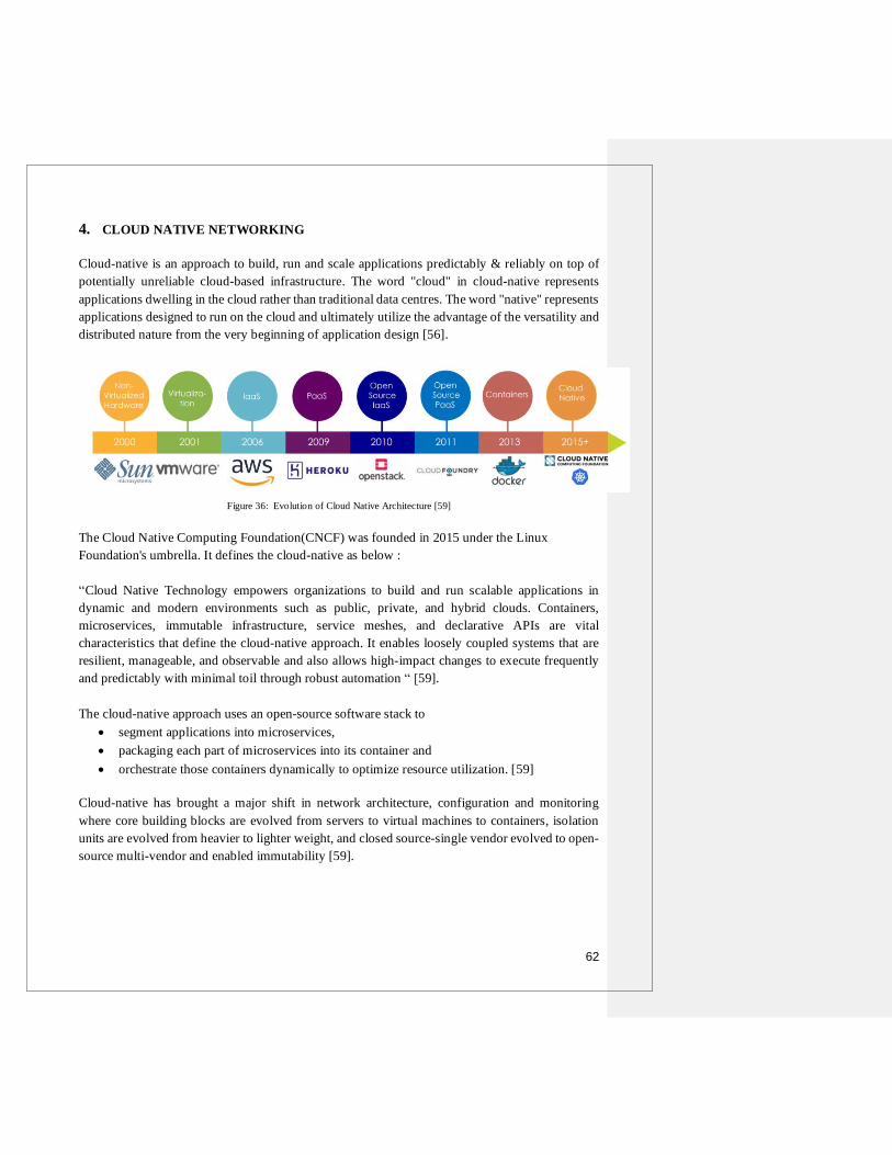
62
4. CLOUD NATIVE NETWORKING
Cloud-native is an approach to build, run and scale applications predictably & reliably on top of
potentially unreliable cloud-based infrastructure. The word "cloud" in cloud-native represents
applications dwelling in the cloud rather than traditional data centres. The word "native" represents
applications designed to run on the cloud and ultimately utilize the advantage of the versatility and
distributed nature from the very beginning of application design [56].
Figure 36: Evolution of Cloud Native Architecture [59]
The Cloud Native Computing Foundation(CNCF) was founded in 2015 under the Linux
Foundation's umbrella. It defines the cloud-native as below :
“Cloud Native Technology empowers organizations to build and run scalable applications in
dynamic and modern environments such as public, private, and hybrid clouds. Containers,
microservices, immutable infrastructure, service meshes, and declarative APIs are vital
characteristics that define the cloud-native approach. It enables loosely coupled systems that are
resilient, manageable, and observable and also allows high-impact changes to execute frequently
and predictably with minimal toil through robust automation “ [59].
The cloud-native approach uses an open-source software stack to
segment applications into microservices,
packaging each part of microservices into its container and
orchestrate those containers dynamically to optimize resource utilization. [59]
Cloud-native has brought a major shift in network architecture, configuration and monitoring
where core building blocks are evolved from servers to virtual machines to containers, isolation
units are evolved from heavier to lighter weight, and closed source-single vendor evolved to open-
source multi-vendor and enabled immutability [59].

63
4.1. Motivation for Cloud-Native Architecture
Companies like Netflix, Google, Uber, Airbnb, Tesla, Amazon are setting new benchmarks for the
IT business market by adopting new technological innovations. The common characteristics
behind this industry's success are the speed of innovation, always-available services, web-scale,
and mobile-centric user experiences. The cloud has changed the relationship between business and
infrastructure, while cloud-native changes the relationship between applications and infrastructure.
Below are certain factors motivating the development of cloud-native applications :
Speed
In today’s market, businesses that can experiment, innovate, deliver & improve quickly
become the winner. Traditional network & application architecture is not scalable to make
instantaneous changes or require days to deploy new technology. Hence, it is essential to
develop cloud-native applications that fully utilise the cloud-computing model to deliver
changes within seconds. Cloud-native applications enable rapid recovery from failure,
reduce time to market, enable quick changes, significantly lower development costs, and
run across a broad range of infrastructures [57].
Safety
Speed without direction and safety is useless. The traditional approach concentrates on
process engineering to recover from incidents. It includes detailed documentation, an
architectural review board, lengthy testing cycles; however, that alone is not enough to
prevent or mitigate the impact of failure. The cloud-native application balances the need to
move speedily with the needs of availability, stability, and durability.
o Visibility
It is necessary to enhance visibility into every component of the network and
applications to establish a profile for normal operation. Any deviations from the
normal should be reported with factors responsible for abnormal behaviour. Data
visualization frameworks, monitoring, alerting, behaviour analytics are the heart of
any cloud-native application architecture [57].
o Fault isolation & tolerance with auto-recovery
Monolithic applications possess failure mode where failure in one component fails
the entire application. Cloud-native applications limit the scope of failure by using
microservices. It is also essential to prevent cascading failure in multiple dependent
components due to failure in one of the microservices. We often follow the same
course of actions like restart system/service, redeploy part of service or application
with failure etc., to address issues. The cloud-native application performs
automated detection and recovery without manual intervention[57].

64
Scalability
The most successful businesses today require the ability to respond quickly to increasing
demands. As compared to the traditional approach where large scale servers are required to
deploy in advance, today, cloud computing and virtualization makes it possible to allocate
resources instantaneously on demand. However, applications also need to be scalable to
support modern cloud-based architecture. Cloud-native applications are stateless and so can
be created & destroyed rapidly whenever required. It also enhances the ability to respond
to changes on demand [57].
Service Integration Support
The development of mobile applications has vastly changed the client-server interaction
ration. For example, online banking enables access to banking services anytime from
anywhere by anyone. The legacy system is not architectured to support this kind of demand
with wide diversity in mobile platforms. Applications need to support requests from
different mobile vendors that use different underlying operating systems with different
versions. The cloud-native application addresses the burden of diversity and service
integration through design patterns such as API gateways [57].
4.1.1. Traditional vs Cloud-Native Application approach
Traditional Applications Cloud-Native Application
Traditional applications are developed
using programming languages C, C++,
JAVA EE, Cobol
Takes advantage of best-of-breed modern
development languages, frameworks and tools
like Go, Node.js, WebSockets, Python, gRPC
They are customized and doesn’t support
dynamic scaling. It requires redundant
resources to handle the demand peak.
Some applications are monolithic and
have strong service dependencies.
Installing updates may require downtime
Maximize resilience & portability through
predictable behaviour and microservice
architecture that decomposes applications into
small and loosely coupled independently
operating services. Thus, It supports scaling,
frequent and independent updates, failover/
restart without impacting other services.
It is OS-dependent and allows developers
to form close dependencies between
applications and hardware, storage,
backing services, underlying OS. Hence,
Application scaling and migration across
new infrastructure is complex
It supports OS abstraction by allowing
developers to use the platform to abstract away
from underlying infrastructure dependencies.
Dependant of abstract infrastructure with no
network or storage limits
Supports manual deployment and
maintenance. Network, storage and
servers are configured and maintained
manually through human operators.
Supports infrastructure & system automation,
dynamic allocation & reallocation of resources
and continuous delivery.
Table 4: Traditional vs Cloud-Native Application [4][57][58]

65
4.2. Key Concepts of Cloud-Native Architecture
A cloud-native approach to software development has various elements that are inter-related. The
key characteristics that define cloud-native architecture are DevOps, Continuous Delivery,
Containers, and Microservices[4][57]-[59].
DevOps
DevOps is a combination of ‘Development’ and ‘Operations’ that shorten the system
development life cycles through continuous development and integration. It builds a
seamless relationship between development teams and IT Operations that enables speedier
features delivery, fixes and updates. Cloud-native leverages DevOps' continuous
development features for agile and scalable software development that can be deployed
seamlessly across different cloud infrastructures [58].
Continuous Delivery
Continuous Delivery is an approach where software is developed bit by bit in short
development cycles that results in reliable software release at any time with greater speed.
Continuous delivery also provides a high level of automation. Continuous upgrades
integrate new software features or functionality and apply fixes easily according to business
requirements. Automated scalability replaces manual tasks such as software testing [58].
Microservices
Microservices represents the decomposition of monolithic applications into independently
deployable services or protocols that are lightweight by definition and deliver business
value. Applications built using microservices are considerably easy to test and improve
continuously, much faster to design and deploy. As microservices decouple monolithic
applications into individually deployable services, any changes can be made and deployed
individually without affecting the rest of the application or technology stack. Hence, it also
reduces the scope of risk with new technology adoption. As compared to monolithic
applications that scale all components, microservices offer independent & efficient scaling
of services [58][61].
Containers
Software development usually involves many overhead and dependencies on particular
hardware or libraries( prewritten code, configuration data) to run it properly. To overcome
such limitations, applications and dependant elements were bundled inside a virtual
machine; however, it came up with a massive size in multigigabytes. Later, small-sized
(megabytes) containers are developed. Containers enable to bundle software with
everything needed to run it into the single executable package. Applications hosted on
containers can be moved from one environment to another and run seamlessly within a

66
portable environment. Hence, the container is highly portable and hardware-independent
[4]. Docker is the most extensively used container engine. Kubernetes (Kube or k8) is an
open-source container orchestration framework built by Google to automate deployment,
scale and manage containerized applications [58][61].
o Docker :
The emergence of Docker in 2013 has ignited widespread container adoption.
Docker is an open-source platform to develop, ship and run applications using
containers. As docker is open source, anyone from anywhere can contribute
anytime to make it better and extend its capabilities to meet the organization’s
unique needs. Organisations can also use the thousands of programs already
designed and created to run in docker containers for their own applications [58][61].
o Kubernetes :
Kubernetes is a portable, extensible and open-source container orchestrator for
managing containerized workloads and services that facilitates both declarative
configuration and automation, allows to run distributed system resiliently with
scaling and failover for application. In a cloud-native environment, Kubernetes
provide required visibility to developers for debugging issues, support container
upgrades without downtime and provide a mechanism for communication between
different containers [58][59][61].
Resilience & Rapid Recovery
Application resilience defines an application's capability to respond to problems within any
components while providing overall service of the whole application. On the other hand,
rapid recovery defines the capability to bounce back from any system failure and protect
systems, applications and data [58].
Openstack
Openstack is an open-source, free cloud computing platform, usually deployed as
infrastructure-as-a-service in private and public clouds where virtual servers and other
cloud resources are made available to users. As OpenStack is open source, users can access
source code and apply any modifications they require without paying for it [58].
12-Factor applications & API-based collaboration
Twelve factors define the application to be cloud-native. That includes codebase,
dependencies, config, backing services, build-release-run, processes, port binding,
concurrency, disposability, dev/pro parity, logs and admin processes. All of them optimize
application design for speed, safety & scale. The services in cloud-native architecture
interact with each other via published/versioned APIs. E.g. HTTP REST-style with JSON
serialization [58].

67
4.3. Cloud-Native Networking
Network Architecture evolution can be represented in three versions as below [59] :
1.0: Separate physical devices for each service like routers, switches, firewalls
2.0: Physical devices converted into virtual machines has virtual network functions(VNF)
that runs on Vmware or OpenStack
3.0: Cloud-Native network functions(CNF) runs over Kubernetes on public, private or
hybrid clouds (Containers)
Figure 37: Evolution from VNF to CNF [59]
As represented in Fig. 37, VMWare hypervisor or open-source OpenStack were installed initially
on bare metal that handles various virtual network functions. Nowadays, various orchestration
platforms like Kubernetes, cloud foundry, OpenShift are used to manage containers. Cloud-native
network function (CNF) is a network function designed and implemented to run inside containers
representing independent services like firewall, IPSec VPN etc.
Figure 38: Container networking (Port mapping) [60]
As shown in Fig. 38, port clash arises when two container workloads want to access the same
service (eg. HTTP : port 80) and thus require port remapping at the bridge’s external network
interface. Some cookies or separate server might require to handle port mapping and service
discovery. This limitation can be addressed by assigning separate individual IP addresses for each
container. IP-per-container is now established as the best industry practice [60].

68
Cloud-Native Networking Solution mainly consists of two parts [60]:
Control Plane: Assigns IP address to containers from the pool and distribute routing
information & policy. There are certain control plane implementation options available :
o Distributed Key/value store (e.g. etcd): Key-value store can be viewed as a huge
hash table that stores some value under a unique key and runs across multiple
servers. The value can be retrieved efficiently using the key or part of the key[61].
o Routing & Gossip Protocols: Routing protocol like BGP and Gossip protocol like
weave mesh can be used for distributing reachability information across containers
o Centralized Controller: Just as used in SDN, the controller is the brain of the control
plane that controls an entire control plane network activities
Data Plane: Responsible for forwarding the packet to a destination and enforces policy.
Forwarding engine either perform kernel forwarding or packet forwarding in userspace.
Transport mechanism of data plane can be implemented either in an underlying network or
on overlay using protocols like VXLAN
Cloud-Native provides flexibility for network implementation according to individual needs;
hence, it must have a generic mechanism that supports all implementations. There are mainly two
types of plug-in models available to meet the suitability requirement.
Container Network Model(CNM/libnetwork): CNM is a standard proposed by Docker and
designed to run on a docker runtime engine only. It requires distributed-key value store like
zookeeper, consul to store network configuration and has been used in integration from
companies like Cisco Contiv, VMWare, Project Calico, Open Virtual Network “OVN”[60].
Container Network Interface (CNI): CNI is a standard proposed by CoreOS and can be
used with any container runtime. It doesn’t require a distributed-key value store as the
network configuration for CNI is in JSON format. CNI is accepted by Cloud Native
Computing Foundation (CNCF) and likely to be a de-facto standard for container
networking. It is implemented by projects like Apache Mesos, Cloud Foundry, rkt,
Rancher, Kurma [60].
As the cloud-native network is massively connected where each network entity is connected to the
other in mesh, the entire network's security is the biggest concern [60]. For example, if three
container workload is actively running across three or four different servers, then data compromise
on one container workload is likely to affect on rest all three. Hence, it is required to implement
and enforce policy on separate application tiers. Policy enforcement may limit the scope of impact
for any security threat.

69
4.4. Case Studies for Cloud-Native Architecture
The cloud-native approach is widely accepted among various industries due to its numerous
benefits. A few of them are listed below :
1. The Financial Times cuts months off deployments while nearly eliminating errors [4]
2. ASOS Making Fashion Statement with Cloud Native [4]
Industry News and Media
Company
Profile
The Financial Times of London is the first UK newspaper to report bigger
earnings from digital subscriptions versus print)
Key
Challenges Respond quickly to changes in the highly dynamic media business
Reduce time to market for business-critical applications that usually takes 3
months to deploy
Solutions
Used Adoption of virtualized infrastructure
Monolithic content platform is moved to about 150 microservices, each of
which handles a single function or component.
Use of multiple containers hosted on large AWS instances controlled by its
orchestrator build-up from open source tools
Adopted off-the-shelf Kubernetes orchestrator later on
Business
Benefits Reduced hosting costs by an impressive 75 %
Radical reduction in error rates from 20% to less than 1% which enables
their ability to release small application changes more often with
microservices
Fast deployments: From 120 days to only 15 minutes
Industry Fashion
Company
Profile
As a British online fashion and cosmetic retailer, ASOS plc was founded in
2000 in London to be the world’s top online shopping destination. The website
sells around 850 brands and their own clothes and accessories and shipped to
196 countries from the fulfilment centre in the UK, the Subcontinent, and
Europe. It holds more than 18 million active customers, 21 million social media
followers and is closing in on $3 billion in sales
Key
Challenges
Ability to provide quick response to customer requirements by significantly
increasing execution speed and involving IT staff more on strategic application
development rather than trapped them in operational responsibilities
Solutions
Used
Migration of in-house service platform to microservices that runs on the
flexible Azure cloud infrastructure
Business
Benefits Improves critical response time by allowing to make more granular choices
to store and maintain data using microservices
Boosts application-speed-to-market
Successful Black Friday Sale in 2018 that exceeded all expectations for scale
and response time across key application support

70
3. Volkswagen Hits the Development Accelerator with Cloud Native [4]
4. DISH Channels Cloud Native to Take on the Big Guys [4]
Industry Automobile
Company
Profile
Volkswagen, the world’s largest German automaker, was founded in 1937 at
Adolf Hitler's request and known for the iconic Beetle.
Key
Challenges Standardizing and automating its vast IT infrastructure
Relatively costly IT infrastructure overall
Very labour intensive and lengthy Development
New cloud platform infrastructure is required to replace the legacy
infrastructure; however, it still needs to be connected to legacy platforms that
maintain vital data.
Solutions
Used Decision to adopt a private cloud environment due to Germany’s ultra-strict
data privacy laws, which have limited Volkswagen’s public cloud options
Opted OpenStack as it eliminates the dependencies on any one vendor
Launched a DevOps culture with CI/CD toolchains for rapid testing and
deployment of new ideas.
Use of Platform-as-a-Service facilitates new tools to speed up the release
cycles further and improve overall application quality.
Business
Benefits Time to provision platform resources has dropped from months to minutes,
requiring just a few clicks
Early experience has also validated the lower infrastructure costs of the
private cloud compared with the former infrastructure.
Industry Entertainment
Company
Profile
American multichannel video service provider based in Englewood, Colorado,
is the owner of the direct-broadcast satellite provider Dish Network and holds
around 14 million subscribers and 16000 employees
Key
Challenges
Deliver desirable new services to consumers faster and more reliably than the
competition from behemoth competitors like Verizon & Comcast &
increasingly popular mobile services
Solutions
Used
Adapted open source Cloud Foundry platform from Pivotal. Initial projects on
the platform included mission-critical applications like applications to update
offer and order management, applications to streamline customer sales
interactions and applications for installation and fulfilment services
Business
Benefits Fast & frequent software release from months to weeks meaning more and
better updates and ultimately better customer-facing applications.
Developers have more time now to prototype and innovate new ideas into
new applications and no longer constrained by tedious, manual development
tasks.

71
5. The U.S. Department of Defense (DoD) is enabling DevSecOps on F-16s and battleships
with Kubernetes [62]
6. How the city of Montréal is modernizing its 30-year-old, siloed architecture with
Kubernetes [63]
Industry Government & National Security
Company
Profile
U.S Department of Defence(DoD) is the largest government agency that
coordinates and supervise all other agencies and government functions directly
related to national security and the United States Armed forces
Key
Challenges
Software delivery for big weapon systems takes around three to ten years using
the waterfall method that lacks incremental delivery, minimum viable product
and feedback loop from end-users
Solutions
Used
Created DoD enterprise DevSecOps reference design with a mandate to use
CNCF-compliant Kubernetes clusters & other open source technologies. Istio
and Envoy Kubernetes provided control and data plane. To demonstrate
Kubernetes execution on F-16 Jet’s legacy hardware, the Kubernetes cluster
on Istio was booted that launch five or six microservices within two minutes.
Kubernetes also enabled to push production on the ship while being
disconnected (at sea)
Business
Benefits Achieved great time saving estimated as 100+ years across 37 programs
Release time reduced to one week from 3-8 months
The minimum viable product to install Kubernetes on an F-16 was completed
in 45 days that might take one or two years before
Industry Government
Company
Profile
Montréal is the largest city in Canada’s Québec province. The City council is
Montréal’s primary decision-making body that adopts municipal budgets, by-
laws, programs, subsidies and governmental agreements.
Key
Challenges
A large number of legacy systems that are many years older and running over
1000 applications lack modern standardization, velocity and efficiency.
Solutions
Used
The first step was containerization that started with a small docker farm of four
to five servers, uses Rancher(open source container management platform) to
provide access to docker containers and their logs and use Jenkins(automated
software testing tool for application) for deployment. Due to a lack of self-
healing and dynamic scaling based on traffic in the docker farm, Kubernetes
opted for orchestration. Use of Prometheus for monitoring and alerting, Fluentd
for logging, and Grafana for visualization in Kubernetes environment
Business
Benefits Time to market reduce from many months to a few weeks
Deployment time reduces from months to hours
Improved efficiency to use compute resources, e.g. 200 application
components run on 8 VMs in production instead of hundreds.
Improved visibility and vendor neutrality

72
5. CONCLUSION
Computer Networks has a long and transformative evolution journey from mainframe computers
to today’s cloud-native environment. Today, cloud-native is working across a broad range of
business types as it underlies application development that is tightly coupled with business goals.
It is replacing older methodologies with roots extending back to five decades and focus on
developing high-performance, highly innovative customer-facing applications on top of the cloud-
based infrastructure that generates high revenue and profit while building customer loyalty. There
are high chances of witnessing cloud-native adoption on a large scale in the 5G development due
to its numerous benefits; however, no technology is without challenges or drawbacks, and cloud-
native is not exempt from it. Old applications have lots of infrastructure dependencies that
sometimes don’t work well with the cloud. Also, cloud-native tools and frameworks are relatively
new and under continuous improvement, so it’s challenging to decide the right tools for the right
purpose that brings better results. The best approach is slowly and safely decommission older
applications from legacy infrastructure in a way that preserves legacy data while relishing the
benefits of the cloud environment.

73
BIBLIOGRAPHY
[1] "Computer network - Vector stencils library," [Online]. Available: https :// www. conceptdraw
.com/examples/mainframe-icon-png.
[2] P. M. Veillard, "Evolution of IT Infrastructure," 9 July 2016. [Online]. Available:
https://www.linkedin.com/pulse/evolution-infrastructure-paul-m-veillard/.
[3] M. Ceppi, "The evolution of IT infrastructure – from mainframe to server-less," 29 March 2018.
[Online]. Available: https://www.itproportal.com/features/the-evolution-of-it-infrastructure-from-
mainframe-to-server-less/.
[4] D. C. E. Winn, Cloud Foundry: the cloud-native platform, First edition., Sebastopol, CA: O'Reilly
Media, 2016.
[5] "Cloud computing," Wikipedia, [Online]. Available: https://en .wikipedia. org/ wiki/ Cloud _
computing.
[6] M. R. Stephen Watts, "SaaS vs PaaS vs IaaS: What's The Difference & How To Choose," BMC
Blogs, 15 June 2019. [Online]. Available: https://www.bmc.com/blogs/saas-vs-paas-vs-iaas-whats-
the-difference-and-how-to-choose/.
[7] Types Of Cloud Computing, Cloudiofy, 24 April 2020. [Online] Available : https://cloudiofy.com/
types-of-cloud-computing/
[8] S. Srinivasan., Cloud computing basics, New York, New York: Springer Science+Business Media,
2014.
[9] "Harnessing cloud to revolutionize training of the Navy's shipboard IT network[Blog Post]," Deloitte
Consulting LLP, [Online]. Available:https://www2.deloitte.com/us/en/pages/
consulting/articles/cloud-computing-case-studies.html.
[10] D. Selby, "How cloud technology helps offer breakthrough system access[Blog Post]," IBM, 14
August 2018. [Online]. Available: https://www.ibm.com/blogs/client-voices/cloud-breakthrough-
system-access/.
[11] "Google App Engine Makes the Cloud a Safer," Google, [Online]. Available:
https://cloud.google.com/files/CloudLock.pdf.
[12] "Immedion uses VMware Cloud Director to deliver premier data center services to enterprise clients,"
VMware, [Online]. Available:https://www.vmware.com/ca/ products/cloud-director.html.
[13] G. Lee, Cloud networking: understanding cloud-based data center networks, Amsterdam: Elsevier:
Morgan Kaufmann, 2014.
[14] Neil, Director, Server Virtualization Simplified - Tutorial. [Film]. Flackbox, 2017.
[15] "vSphere Distributed Switch Architecture," VMware, 11 September 2020. [Online].
Available:https://docs.vmware.com/en/VMwarevSphere/7.0/com.vmware.vsphere.networking.doc/
GUID-B15C6A13-797E-4BCB-B9D9-5CBC5A60C3A6.html.
[16] "Open vSwitch," Wikipedia, [Online]. Available: https://en.wikipedia.org/wiki/Open_vSwitch.
[17] T. Sangha and B. Wibowo, VMware NSX Cookbook, Packt Publishing, 2018.

74
[18] V. Deshpande, "VXLAN Series – How VTEP Learns and Creates Forwarding Table – Part 5,"
VMware, 24 May 2013. [Online]. Available: https://blogs.vmware.com/vsphere/ 2013/05/vxlan-
series-how-vtep-learns-and-creates-forwarding-table-part-5.html.
[19] "What is Network Functions Virtualization?," Juniper, [Online]. Available: https://www.
juniper.net/us/en/products-services/what-is/network-functions-virtualization/.
[20] William Stallings, Foundations of Modern Networking: SDN, NFV, QoE, IoT, and Cloud, Addison-
Wesley Professional, 2015.
[21] D. Kreutz, F. M. V. Ramos, P. E. Veríssimo, C. E. Rothenberg, S. Azodolmolky and S. Uhlig,
"Software-Defined Networking: A Comprehensive Survey," Proceedings of the IEEE, vol. 103, no.
1, pp. 14 - 76, Jan 2015.
[22] P. S. Chakraborty, Lecture 44: Software Defined Networking - II (Open Flow), IIT Kharagpur, 2018.
[23] T. D. Nadeau, SDN - software-defined networks, O'Reilly, Beijing, 2013.
[24] T. Slattery, "An introduction to software defined networking (SDN)," S.l.: Pearson IT Certification,
2014.
[25] R. Chayapathi, Network functions virtualization (NFV) with a touch of SDN, Addison-Wesley,
Boston, 2017.
[26] "POX Wiki," Atlassian Confluence Open Source Project License granted to OpenFlow, [Online].
Available: https://openflow.stanford.edu/display/ONL/POX+Wiki.html. [Edited 3 Apr 2018].
[27] "OpenDaylight: A Linux Foundation Collaborative Project," [Online]. Available:
https://www.opendaylight.org/. [Edited 31 March 2020].
[28] N. Gude et al., "NOX: towards an operating system for networks," ACM SIGCOMM Computer
Communication Review, vol. 38, no. 3, pp. 105-110, July 2008.
[29] G. Barrineau, R. Izard, Q. Wang, "Floodlight Controller," Atlassian, [Online].
Available:https://floodlight.atlassian.net/wiki/spaces/floodlightcontroller/overview. [Edited 13 May,
2018].
[30] "OpenFlow Switch Specification (ONF TS-009)," The Open Networking Foundation, 25, April 2013.
[Online]. Available: https://opennetworking.org/wpcontent/uploads/2014/10/ openflow-spec-
v1.3.2.pdf.
[31]
H. Yin, H. Xie, T. Tsou, D. Lopez, P. Aranda, and R. Sidi, "SDNi: A Message Exchange Protocol for
Software Defined Networks (SDNS) across Multiple Domains," Internet-Draft, Internet Engineering
Task Force, June 2012.
[32] Teemu Koponen, Natasha Gude, Martin Casado, Jeremy Stribling, Leon Poutievski, Min Zhu, Rajiv
Ramanathan, Yuichiro Iwata, Hiroaki Inoue, Takayuki Hama, and Scott Shenker, "Onix: A
distributed control platform for large-scale production networks," in Proceedings of the 9th USENIX
Conference (Operating Systems Design and Implementation), ser. OSDI'10. Berkeley, CA, USA:
USENIX Association, 2010, pp. 351–364.
[33] A. Tootoonchian and Y. Ganjali, "Hyperflow: A distributed control plane for openflow," in
Proceedings of the 2010 Internet Network Management Conference on Research on Enterprise
Networking, ser. INM/WREN'10. Berkeley, CA, USA: USENIX Association, 2010, pp. 3–3.
Available:https://www.usenix.org/legacy/events/inmwren10/tech/full_ papers /Tootoonchian.pdf

75
[34] K. Phemius, M. Bouet and J. Leguay, "DISCO: Distributed multi-domain SDN controllers," 2014
IEEE Network Operations and Management Symposium (NOMS), Krakow, 2014, pp. 1-4, doi:
10.1109/NOMS.2014.6838330.
[35] "Representational state transfer," Wikipedia, 10 January 2021. [Online]. Available:
https://en.wikipedia.org/wiki/Representational_state_transfer.
[36] Zohaib Latif, Kashif Sharif, Fan Li, Md Monjurul Karim, and Yu Wang, "A Comprehensive Survey
of Interface Protocols for software defined networks," ELSEVIER, Journal of Network and Computer
Applications, vol. 156, 15 April 2020.
[37] Mpho Nkosi, Albert Lysko, Lusani Ravhuanzwo, Andries Engelberencht, "Classification of SDN
distributed controller approaches: A brief overview," IEEE: 2016 International Conference on
Advances in Computing and Communication Engineering (ICACCE), Durban, South Africa, 28-29
Nov. 2016.
[38] Othmane Blial, Mouad Ben Mamoun, Redouane Benaini, "An Overview on SDN Architectures with
Multiple Controllers", Journal of Computer Networks and Communications, vol. 2016, Article ID
9396525, 8 pages, 2016.https://doi.org/10.1155/2016/9396525
[39] "VMware," Wikipedia, [Last Edited] 19 January 2021. [Online]. Available:https://en.wikipedia.org
/wiki/VMware
[40] "List of acquisitions by Cisco Systems," Wikipedia, [Last Edited] 18 January 2021. [Online].
Available: https://en.wikipedia.org/wiki/List_of_acquisitions_by_Cisco_Systems.
[41] "List of acquisitions by Juniper Networks," Wikipedia, [Last Edited] 31 December 2020. [Online].
Available: https://en.wikipedia.org/wiki/List_of_acquisitions_by_Juniper_Networks
[42] "VMware NSX Data Center," VMware, [Online]. Available: https://www.vmware.com/ca/
products/nsx.html.
[43] " Cisco ACI for Data Center", Cisco Systems, [Online] Available: https://www.cisco.com/c/en/us/
solutions/data-center-virtualization/application-centric-infrastructure/index.html
[44] What Is the Juniper Contrail Controller?, SDxCentral Studios, 19 November 2014, 11:50 AM[Online]
Available:https://www.sdxcentral.com/networking/sdn/definitions/juniper-contrail-controller
[45] "OpenDaylight Project," Wikipedia, [Last Edited] 1 January 2021. [Online]. Available: https:// en.
wikipedia.org/wiki/OpenDaylight_Project
[46] "Contrail Networking Documentation," Juniper Networks, July 2020. [Online]. Available: https://
www.juniper.net/assets/us/en/local/pdf/datasheets/1000521-en.pdf.
[47] Ankur Singla, Bruno Rijsman, Day One: Understanding Opencontrail Architecture, Juniper Networks
Books, November 2013.
[48] "Tungsten Fabric Architecture, " The Linux Foundation Projects tungsten fabric, [Online]. Available:
https://tungstenfabric.github.io/website/Tungsten-Fabric-Architecture.html#vrouter-details
[49] "What is Software-Defined Networking (SDN)? " IBM, [Online]. Available: https://www.ibm.com/
services/network/sdn-versus-traditional-networking
[50] "Nantes Chu Leverages Vmware For Its Transformation as a “Digital Hospital" VMware Inc.,
November 2020. [Online]. Available: https://www.vmware.com/content/dam/digitalmarketing/
vmware/en/pdf/customers/vmware-chu-nantes-vmware-en.pdf

76
[51] "Bendigo Telco and Cisco Solutions", Cisco Systems., [Online]. Available:
https://ebooks.cisco.com/story/bendico/page/7
[52] "Alibaba Group Optimizes Network with OpenDaylight SDN", The Linux Foundation Projects
(OpenDaylight),[Online].Available: https://www.opendaylight.org/use-cases-and-users/user-stories/
alibaba-group-optimizes-network-with-opendaylight-sdn
[53] "SURFnet Builds Open, Programmable Network To Better Serve Dutch Universities and
Researchers", Juniper Networks, [Online]. Available :
https://www.juniper.net/assets/us/en/local/pdf/case-studies/3520643-en.pdf
[54] "How Food Passion Started a Delivery Channel in 72 Hours with Cloud Technologies" VMware Inc.,
[Online].Available:https://www.vmware.com/content/dam/digitalmarketing/vmware/en/pdf/custom
ers/vmware-food-passion-customer-success-story.pdf
[55] "Gamesys Streamlines Online Game Development With Private Cloud ",, Juniper Networks,
[Online]. Available: https://www.juniper.net/assets/us/en/local/pdf/case-studies/3520643-en.pdf
[56] "A Deep Dive into Cloud-Native: From Basics to Applications ", Alibaba Cloud, 2 July 2019,
[Online] Available: https://www.alibabacloud.com/blog/a-deep-dive-into-cloud-native-from-basics-
to-applications_595025
[57] Matt Stine, Migrating to Cloud-Native Application Architectures, O'Reilly Media, Inc., 2015.
[58] Bill Laberis, "What is Cloud-Native", O'Reilly Media, Inc., April 2019, ISBN 9781492055129
[59] Chris Anisczyk, "Evolving Cloud Native Landscape", Cloud Native Computing Foundation.
Container Days, Japan. December 2018.
[60] Andy Randall, Christopher Liljenstolpe, Bryan Boreham, " Cloud native networking", Presented by
Tigera, Weaveworks, Cloud Native Computing Foundation, 12 January 2017, [Online] Available :
https://www.cncf.io/webinars/cloud-native-networking/
[61] Boris Scholl; Peter Jausovec; Trent Swanson, "Cloud Native ", O'Reilly Media, Inc., August 2019,
ISBN: 9781492053828
[62] "With Kubernetes, the U.S. Department of Defense is enabling DevSecOps on F-16s and
battleships", Cloud Native Computing Foundation, 5 May 2020, [Online] Available:
https://www.cncf.io/case-studies/dod/
[63] "How the city of Montréal is modernizing its 30-year-old, siloed architecture with Kubernetes",
Cloud Native Computing Foundation, 29 January 2019, [Online] Available:
https://www.cncf.io/case-studies/montreal/

77
ABBREVIATION
ACL Access Control List
AMQP Advanced Message Queuing Protocol
API Application Programming Interface
APIC Application Policy Infrastructure Controller
ARP Address Resolution Protocol
AWS Amazon Web Service
BGP Border Gateway Protocol
CNCF Cloud Native Computing Foundation
CNF Cloud-native Network function
CNI Container Network Interface
CNM Container Network Model
CPU Central Processing Unit
CANES Consolidated Afloat Networks and Enterprise Services
DC Domain Controller
DDoS Distributed Denial of Service
DHCP Dynamic Host Configuration Protocol
DHT Distributed Hash Table
DNS Domain Name System
DPDK Data Plane Development Kit
DPI Deep Packet Inspection
EoR End of Rack
FCoE Fiber Channel over Ethernet
FIB Forwarding Information Base
HTTP Hypertext Transfer Protocol
IaaS Infrastructure as a Service
IDS Intrusion Detection System
IP Internet Protocol
IPS Intrusion Prevention System
IRB Integrated Routing and Bridging
LAN Local Area Network
MAC Media Access Control
MPLS Multiprotocol Label Switching
NAT Network Address Translation
NBI Northbound Interface
NFV Network Function Virtualization
NFVI Network Function Virtualization infrastructure
NIC Network Interface Card
NOS Network Operating System
ODM Original Design Manufacturer
OEM Original Equipment Manufacturer
ONF Open Networking Foundation
OS Operating System
PaaS Platform as a Service
RAM Random Access Memory
REST Representational state transfer

78
RIB Routing Information Base
SaaS Software as a Service
SDMN Software-Defined Mobile Network
SDN Software-Defined Networking
SNMP Simple Network Management Protocol
TCP Transmission Control Protocol
ToR Top of Rack
VFS Virtual File System
VIM Virtualized Infrastructure Manager
VLAN Virtual Local Area Network
VM Virtual Machine
VNF Virtual Network Function
VNI Virtual Network Identifier
VPN Virtual Private Network
VRF Virtual Routing and Forwarding
VTEP VXLAN Tunnel End Point
VXLAN Virtual Extensible LAN
UDP User Datagram Protocol
XMPP Extensible Messaging and Presence Protocol