Ting Zhao - ERA
221
Phosphoranimide-supported Nickel Clusters for Hydrotreatment by Ting Zhao A thesis submitted in partial fulfillment of the requirements for the degree of Doctor of Philosophy Department of Chemistry University of Alberta © Ting Zhao, 2016
-
Upload
khangminh22 -
Category
Documents
-
view
2 -
download
0
Transcript of Ting Zhao - ERA
Phosphoranimide-supported Nickel Clusters for
Hydrotreatment
by
Ting Zhao
A thesis submitted in partial fulfillment of the requirements for the degree of
Doctor of Philosophy
Department of Chemistry
University of Alberta
© Ting Zhao, 2016

ii
Abstract
Fortuitous characterization of the cationic nickel cluster [Ni4(NPtBu3)4][Li3Br4(Et2O)3] led
to the rational syntheses and characterization of the mixed-valence low-coordinate cationic
nickel cluster: [Ni4(NPtBu3)4]BPh4 and [Ni4(NPtBu3)4]PF6, and subsequently the
preparation of the anionic cluster Na[Ni4(NPtBu3)4]. The redox chemistry of the nickel
series, [Ni4(NPtBu3)4]BPh4, [Ni(NPtBu3)]4, and Na[Ni4(NPtBu3)4] was investigated, with
and without the presence of alkali metal cation. Oxidation of the cobalt analog
[Co(NPtBu3)]4 results in the formation of dimetallic mixed-valence cluster
[Co2(NPtBu3)4]PF6, which is likely due to the Na+ contamination in the starting material.
Synthesis and characterization of the pure tetrametallic [Co(NPtBu3)]4 remains a challenge.
A new preparation of the neutral cluster [Ni(NPtBu3)]4 was developed and turned out to be
a key to address the reproducibility issue previously observed. The anionic cluster
Na[Ni4(NPtBu3)4], an impurity present from the previous procedure, is the actual catalyst
for the hydrogenation of diphenylacetylene. The hydrogenation investigation of the nickel
series, [Ni4(NPtBu3)4]BPh4, [Ni(NPtBu3)]4, and Na[Ni4(NPtBu3)4] suggests that anionic
cluster is a more active catalyst than the neutral cluster, which is more active than the
cationic cluster. As the temperature increases, higher activities were observed for all three
in the series, although much of that must be attributed to the catalysts transforming from
homogeneous to heterogeneous.
iii
The hydrosilylation and hydrogenolysis of carbonyl compounds with the tetranickel series
were investigated. A preliminary study of the hydrosilylation with impure precatalyst is
mainly reproducible using the purified neutral catalyst, delivering good to excellent yields
of hydrosilylation product using diphenylsilane as a selective reductant. Complete
silylative deoxygenation of carbonyl compound was also investigated, using a more
reactive silane and higher reaction temperatures to drive the conversion. In general,
aldehydes show higher reactivity than ketones, and aromatic substrates show higher
reactivity than aliphatic substrates, at elevated temperature (60–80 C). A high conversion
(~ 90%) to deoxygenation products was achieved for cyclohexenone at 160 C, albeit at
long reaction time and with the catalyst in uncharacterized heterogeneous form.
In addition, several allyl-capped nickel clusters, [Ni(η3-allyl)(NPEt3)]2, [Ni(η3-
allyl)(NPPh3)]2, and [Ni(η3-allyl)(NPtBu3)]2, were synthesized and characterized, as the
second-generation of phosphoranimide-bridged first-row transition metal clusters. This
new set of compounds is important for developing new hydrotreatment catalysts because
they are diamagnetic, coordinatively saturated, thermally stable, and electronically tunable.
The redox investigation of [Ni(η3-allyl)(NPEt3)]2 led to the discovery of the allyl-capped
trimetallic nickel cluster, [Ni3(η3-allyl)3(µ
3-NPEt3)2]PF6, and the heterotrimetallic cluster,
[(η3-allyl)Ni]2CoCl2(μ3-NPEt3)2. These clusters provide a general method for preparing
heteropolymetallic clusters in the future, which could potentially be powerful precatalysts
for hydrotreatment.

iv
Finally, the hydrodesulfurization (HDS) activity of [Ni(NPtBu3)]4 and [Ni(η3-
allyl)(NPEt3)]2 is discussed, together with the non-innocent role of potassium hydride and
the specific promoting effect of potassium cation. The promising results obtained in these
studies validate the proposal that structurally-engineered first-row transition metal
compounds are capable of catalytic HDS under relatively mild conditions and warrant
further investigation for the rational design of new phosphoranimide-bridged first-row
transition metal clusters and the development of heterogeneous catalysts.
v
Preface
There are large deposits of bitumen, extremely heavy crude oil, located in northeastern
Alberta, comparable in magnitude to the world's total proven reserves of
conventional petroleum. The bitumen crude oil has high content of heteroatoms (S, N, and
O) and metals (Ni, V). Thus, it is imperative to develop new technology to meet the
increasingly stringent regulatory limitations on toxic gas emission, especially for
hydrodesulfurization (HDS) and hydrodenitrogenation (HDN).
The Stryker group has been focused on the fundamental research of building first-row
transition metal clusters to mimic and replace the commercial Co-MoS2 catalyst. The
exploration has been very fruitful, highlighted by two successful phosphoranimide-bridged
HDS precatalysts, [Ni(NPtBu3)]4 and [Co4(NPEt3)4]PF6.
In this thesis, further exploration of tetranickel cluster [Ni(NPtBu3)]4 will be discussed first,
introducing the cationic and anionic analog, [Ni4(NPtBu3)4]BPh4 and Na[Ni4(NPtBu3)4],
followed by the activity investigation of hydrogenation, hydrosilylation and
deoxygenation. In addition, the design, syntheses, and characterization of allyl-capped
phosphoranimide-bridged nickel cluster will be discussed. At last, the HDS activity
exploration of these nickel clusters will be included.
It should be mentioned in the beginning that Orain Brown is the main contributor of the
HDS study of neutral cluster [Ni(NPtBu3)]4 and the grafting process for heterogeneous
catalyst, and Fiona Nkala is responsible for the HDS activity of allyl-capped dimer [Ni(η3-
allyl)(NPEt3)]2.

vi
Acknowledgements
I would like to express my deepest appreciation to my supervisor, Professor Jeffrey M.
Stryker, who offered me a challenging project then guided me with wisdom, patience and
enthusiasm. It is my privilege to have him as a mentor, and this dissertation would not have
been possible without his persistent help.
In addition, I would like to thank all the past and present members of Stryker Research
Group for all their help, advice, and support through all these many years, especially Dr.
Robin Hamilton, Dr. Shaohui Yu, and Dr. Kseniya Revunova.
I would also like to acknowledge the chemistry support staffs, who are integral part of
research conducted in the department, particular Wayne Moffat, Dr. Mike Ferguson, and
Dr. Bob McDonald.
Most of all, I want to thank my wife Yan Liu and my parents for their persistent support
and trust in me.
At last, as Bruce Lee said: Don’t pray for an easy life, pray for the strength to endure a
difficult one.
vii
Table of Content
Chapter 1. Tri-tert-butylphosphoranimide-bridged Late First-row Transition Metal
Clusters
1.1 Introduction 1
1.1.1 Phosphoranimide ligands: versatile bonding mode, remote steric bulk,
and adjustable steric and electronic character
2
1.1.2 Catalyst design using trialkylphosphoranimide ligands 5
1.2 Previous work from the Stryker group 9
1.2.1 Hydrocarbon soluble coplanar two-coordinate Ni and Co clusters:
[Ni(NPtBu3)]4 and [Co(NPtBu3)]4
9
1.2.2 Heterocubane [MeCo(NPEt3)]4 and [Me4Co4(NPEt3)4]PF6 10
1.3 Results and Discussion 11
1.3.1 Synthesis and characterization of [Ni4(NPtBu3)4]BPh4 11
1.3.2 Synthesis and characterization of Na[Ni4(NPtBu3)4] 23
1.3.3 Synthesis and characterization of [Co2(μ-NPtBu3)2(NPtBu3)2]PF6 35
1.4 Conclusion 39
Chapter 2. Phosphoranimide-Bridged Nickel Catalysts for Hydrogenation of
Alkenes and Alkynes
2.1 Introduction 41
2.2 Result and discussion 42
2.2.1 Reproducibility issue with [Ni(NPtBu3)]4 42
2.2.2 Hydrogenation of alkenes and alkynes with [Ni(NPtBu3)]4 43
2.2.3 Hydrogenation of alkenes and alkynes with Na[Ni4(NPtBu3)4] 46
2.2.4 Hydrogenation of alkenes and alkynes with [Ni4(NPtBu3)4]BPh4 51
2.2.5 Proposed mechanism for hydrogenation 52
2.3 Conclusion 55

viii
Chapter 3. Phosphoranimide-bridged Nickel Clusters for Hydrosilylation and
Deoxygenation of Carbonyl Compounds
3.1 Introduction 56
3.2 Results and discussion 58
3.2.1 Hydrosilylation of carbonyl compounds using [Ni(NPtBu3)]4 59
3.2.2 Hydrosilylation of carbonyl compounds using Na[Ni4(NPtBu3)4] 62
3.2.3 Hydrosilylation of carbonyl compounds using [Ni4(NPtBu3)4]BPh4 63
3.2.4 Discussion of mechanism of hydrosilylation 64
3.2.5 Deoxygenation of carbonyl compounds using [Ni(NPtBu3)]4 65
3.3 Conclusion 70
Chapter 4 Allyl-capped First-row Transition Metal Phosphoranimide Clusters –
2nd Generation Low-valent Clusters for Catalytic Hydrotreatment
4.1 Introduction 72
4.2 Results and Discussion 75
4.2.1 Synthesis and Characterization of [Ni(η3-allyl)(NPEt3)]2 75
4.2.2 Synthesis and Characterization of [Ni(η3-allyl)(NPPh3)]2 and [Ni(η3-
allyl)(NPtBu3)]2
80
4.2.3 Trimetallic Phosphoranimide Clusters: Synthesis and
Characterization of [Ni3(η3-allyl)3(μ
3-NPEt3)2]PF6
82
4.2.4 Heterotrimetallic Transition Metal Clusters: Synthesis and
Characterization of [(η3-allyl)Ni]2CoCl2(μ3-NPEt3)2
85
4.2.5 Generalizing Allyl Precatalyst Synthesis: Preparation of [Co(η3-
allyl)(NPEt3)]n
88
4.3 Conclusion 89
ix
Chapter 5 Phosphoranimide-bridged Nickel Clusters for Catalytic
Hydrodesulfurization (HDS)
5.1 Introduction 91
5.2 Result and discussion 96
5.2.1 The role of strong base scavengers in catalytic HDS 96
5.2.2 The search for new scavengers in catalytic HDS 98
5.2.3 HDS activity of [Ni(NPtBu3)]4 101
5.2.4 HDS activity of M[Ni4(NPtBu3)4] (M = Na, K) 104
5.2.5 Preliminary hydrogenation and HDS study of [Ni(η3-allyl)(NPEt3)]2 105
5.3 Conclusion 109
Chapter 6 Experimental Section
6.1 General procedures 110
6.2 Experimental procedures for Chapter 1 113
6.3 Experimental procedures for Chapter 2 118
6.4 Experimental procedures for Chapter 3 133
6.5 Experimental procedures for Chapter 4 142
6.6 Experimental procedures for Chapter 5 146
Bibliography
Appendix Crystallography Data
x
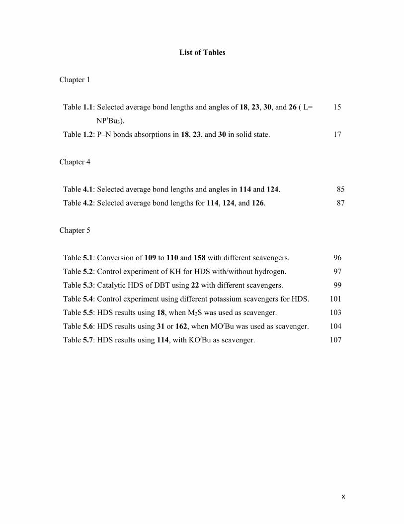
List of Tables
Chapter 1
Table 1.1: Selected average bond lengths and angles of 18, 23, 30, and 26 ( L=
NPtBu3).
15
Table 1.2: P–N bonds absorptions in 18, 23, and 30 in solid state. 17
Chapter 4
Table 4.1: Selected average bond lengths and angles in 114 and 124. 85
Table 4.2: Selected average bond lengths for 114, 124, and 126. 87
Chapter 5
Table 5.1: Conversion of 109 to 110 and 158 with different scavengers. 96
Table 5.2: Control experiment of KH for HDS with/without hydrogen. 97
Table 5.3: Catalytic HDS of DBT using 22 with different scavengers. 99
Table 5.4: Control experiment using different potassium scavengers for HDS. 101
Table 5.5: HDS results using 18, when M2S was used as scavenger. 103
Table 5.6: HDS results using 31 or 162, when MOtBu was used as scavenger. 104
Table 5.7: HDS results using 114, with KOtBu as scavenger. 107
xi
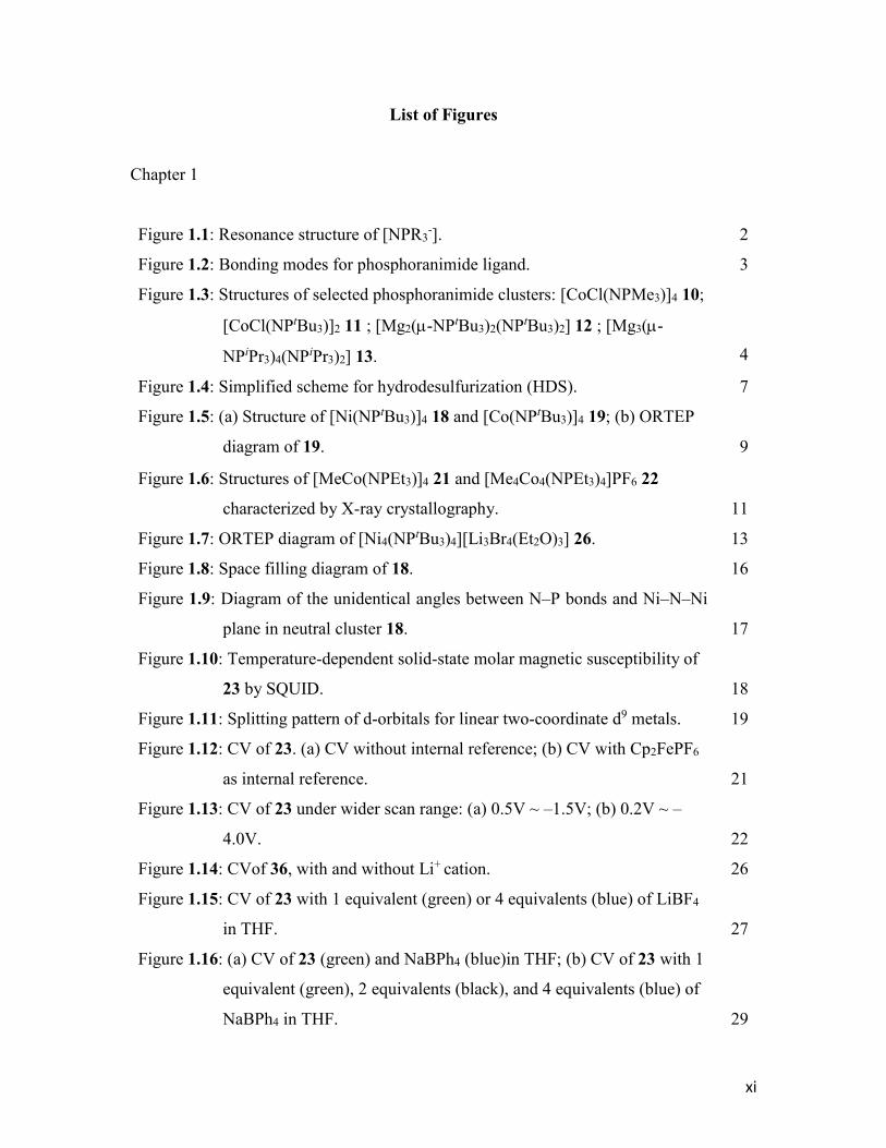
List of Figures
Chapter 1
Figure 1.1: Resonance structure of [NPR3-]. 2
Figure 1.2: Bonding modes for phosphoranimide ligand. 3
Figure 1.3: Structures of selected phosphoranimide clusters: [CoCl(NPMe3)]4 10;
[CoCl(NPtBu3)]2 11 ; [Mg2(-NPtBu3)2(NPtBu3)2] 12 ; [Mg3(-
NPiPr3)4(NPiPr3)2] 13.
4
Figure 1.4: Simplified scheme for hydrodesulfurization (HDS). 7
Figure 1.5: (a) Structure of [Ni(NPtBu3)]4 18 and [Co(NPtBu3)]4 19; (b) ORTEP
diagram of 19.
9
Figure 1.6: Structures of [MeCo(NPEt3)]4 21 and [Me4Co4(NPEt3)4]PF6 22
characterized by X-ray crystallography.
11
Figure 1.7: ORTEP diagram of [Ni4(NPtBu3)4][Li3Br4(Et2O)3] 26. 13
Figure 1.8: Space filling diagram of 18. 16
Figure 1.9: Diagram of the unidentical angles between N–P bonds and Ni–N–Ni
plane in neutral cluster 18.
17
Figure 1.10: Temperature-dependent solid-state molar magnetic susceptibility of
23 by SQUID.
18
Figure 1.11: Splitting pattern of d-orbitals for linear two-coordinate d9 metals. 19
Figure 1.12: CV of 23. (a) CV without internal reference; (b) CV with Cp2FePF6
as internal reference.
21
Figure 1.13: CV of 23 under wider scan range: (a) 0.5V ~ –1.5V; (b) 0.2V ~ –
4.0V.
22
Figure 1.14: CVof 36, with and without Li+ cation. 26
Figure 1.15: CV of 23 with 1 equivalent (green) or 4 equivalents (blue) of LiBF4
in THF.
27
Figure 1.16: (a) CV of 23 (green) and NaBPh4 (blue)in THF; (b) CV of 23 with 1
equivalent (green), 2 equivalents (black), and 4 equivalents (blue) of
NaBPh4 in THF.
29

xii
Figure 1.17: CV of 23 with 4 equivalents of KBPh4 in THF. 30
Figure 1.18: Proposed structure of [K(18-crown-6)][(-N2)Ni(NPtBu3)] 39. 32
Figure 1.19: UV-Vis spectra of 18, 23, and 31 in THF. 34
Figure 1.20: Summary of transformations among 18, 23, and 31. 35
Figure 1.21: ORTEP diagram of cationic 37. 36
Figure 1.22: ORTEP structure and bonding modes for 37. 38
Chapter 2
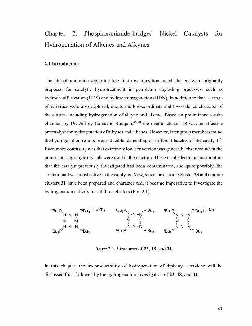
Figure 2.1: Structures of 23, 18, and 31. 41
Figure 2.2: Hydrogenation of allylbenzene 40 and diphenylacetylene 20 using 18. 42
Figure 2.3: Hydrogenation of selected alkenes with 1 mol% neutral cluster 18. 44
Figure 2.4: Hydrogenation TON of 20 using 9 at different temperatures, with and
without mercury poisoning.
45
Figure 2.5: Hydrogenation of selected alkenes with 1 mol% anionic cluster 31. 47
Figure 2.6: Hydrogenation TON of 20 using 31 at different temperatures, with
and without mercury.
48
Figure 2.7: Progress of the hydrogenation of 20 catalyzed by 1 mol% of 31 at
room temperature and 1 atm H2.
49
Figure 2.8: Hydrogenation TON of 20 using 31 in various solvents, under the
general condition.
50
Figure 2.9: TON of hydrogenation of 20 catalyzed by 1 mol% 23 under general
conditions.
51
Figure 2.10: Hydrogenation of selected alkenes with 1 mol% 23 under general
conditions.
52
Figure 2.11: Proposed mechanism for hydrogenation of 20 using 18. 53
xiii
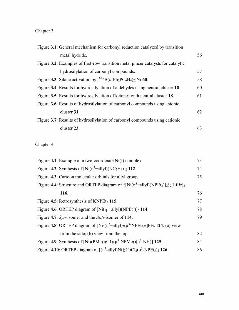
Chapter 3
Figure 3.1: General mechanism for carbonyl reduction catalyzed by transition
metal hydride.
56
Figure 3.2: Examples of first-row transition metal pincer catalysts for catalytic
hydrosilylation of carbonyl compounds.
57
Figure 3.3: Silane activation by [MesB(o-Ph2PC6H4)2]Ni 60. 58
Figure 3.4: Results for hydrosilylation of aldehydes using neutral cluster 18. 60
Figure 3.5: Results for hydrosilylation of ketones with neutral cluster 18. 61
Figure 3.6: Results of hydrosilylation of carbonyl compounds using anionic
cluster 31.
62
Figure 3.7: Results of hydrosilylation of carbonyl compounds using cationic
cluster 23.
63
Chapter 4
Figure 4.1: Example of a two-coordinate Ni(I) complex. 73
Figure 4.2: Synthesis of [Ni(η3−allyl)(NC2H4)]2 112. 74
Figure 4.3: Cartoon molecular orbitals for allyl group. 75
Figure 4.4: Structure and ORTEP diagram of {[Ni(η3−allyl)(NPEt3)]2}2[LiBr]2
116.
76
Figure 4.5: Retrosynthesis of KNPEt3 115. 77
Figure 4.6: ORTEP diagram of [Ni(η3−allyl)(NPEt3)]2 114. 78
Figure 4.7: Syn-isomer and the Anti-isomer of 114. 79
Figure 4.8: ORTEP diagram of [Ni3(η3−allyl)3(μ
3–NPEt3)2]PF6 124: (a) view
from the side; (b) view from the top.
82
Figure 4.9: Synthesis of [Ni3(PMe3)3C13(μ3-NPMe3)(μ
3-NH)] 125. 84
Figure 4.10: ORTEP diagram of [(η3-allyl)Ni]2CoCl2(μ3-NPEt3)2 126. 86
xiv
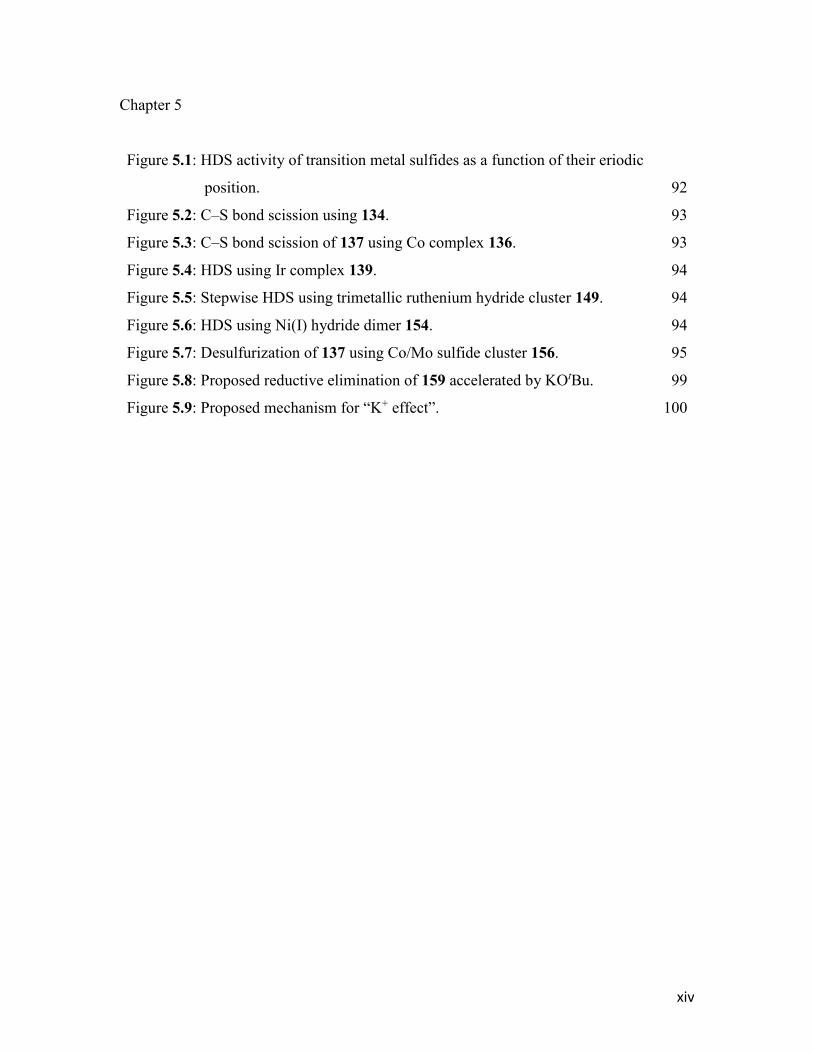
Chapter 5
Figure 5.1: HDS activity of transition metal sulfides as a function of their eriodic
position.
92
Figure 5.2: C–S bond scission using 134. 93
Figure 5.3: C–S bond scission of 137 using Co complex 136. 93
Figure 5.4: HDS using Ir complex 139. 94
Figure 5.5: Stepwise HDS using trimetallic ruthenium hydride cluster 149. 94
Figure 5.6: HDS using Ni(I) hydride dimer 154. 94
Figure 5.7: Desulfurization of 137 using Co/Mo sulfide cluster 156. 95
Figure 5.8: Proposed reductive elimination of 159 accelerated by KOtBu. 99
Figure 5.9: Proposed mechanism for “K+ effect”. 100
xv
List of Schemes
Chapter 1
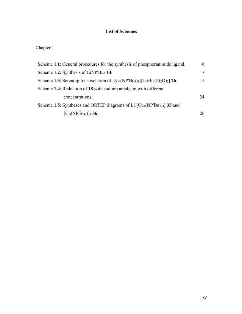
Scheme 1.1: General procedures for the synthesis of phosphoranimide ligand. 6
Scheme 1.2: Synthesis of LiNPtBu3 14. 7
Scheme 1.3: Serendipitous isolation of [Ni4(NPtBu3)4][Li3Br4(Et2O)3] 26. 12
Scheme 1.4: Reduction of 18 with sodium amalgam with different
concentrations.
24
Scheme 1.5: Syntheses and ORTEP diagrams of Li2[Cu4(NPtBu3)4] 35 and
[Cu(NPtBu3)]4 36.
26
xvi
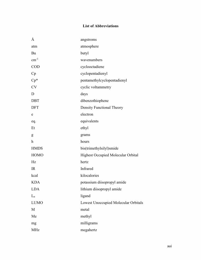
List of Abbreviations
Å angstroms
atm atmosphere
Bu butyl
cm-1 wavenumbers
COD cyclooctadiene
Cp cyclopentadienyl
Cp* pentamethylcyclopentadienyl
CV cyclic voltammetry
D days
DBT dibenzothiophene
DFT Density Functional Theory
e electron
eq. equivalents
Et ethyl
g grams
h hours
HMDS bis(trimethylsilyl)smide
HOMO Highest Occupied Molecular Orbital
Hz hertz
IR Infrared
kcal kilocalories
KDA potassium diisopropyl amide
LDA lithium diisopropyl amide
Ln ligand
LUMO Lowest Unoccupied Molecular Orbitals
M metal
Me methyl
mg milligrams
MHz megahertz
xvii
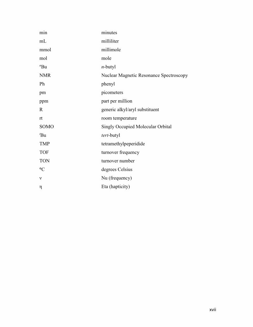
min minutes
mL milliliter
mmol millimole
mol mole
nBu n-butyl
NMR Nuclear Magnetic Resonance Spectroscopy
Ph phenyl
pm picometers
ppm part per million
R generic alkyl/aryl substituent
rt room temperature
SOMO Singly Occupied Molecular Orbital
tBu tert-butyl
TMP tetramethylpeperidide
TOF turnover frequency
TON turnover number
°C degrees Celsius
ν Nu (frequency)
η Eta (hapticity)
1
Chapter 1. Tri-tert-butylphosphoranimide-bridged Late First-row
Transition Metal Clusters
1.1 Introduction
Homogeneous catalysis is historically an area dominated by precious metals, and this is
highlighted by the Nobel prizes awarded in 2001, 2005, and 2010 for asymmetric
hydrogenation,1 olefin metathesis,2 and palladium catalyzed C–C bond formation
reactions,3 respectively. However, catalysis with precious metal such as Pd, Ir, Rh, and Ru
has obvious disadvantages, such as cost, abundance, sustainability, and toxicity, not only
for the catalyst itself but also for the whole process from production to waste treatment.4
In the last decade, catalysis with earth-abundant metals, especially first-row transition
metals has become one of the most active research fields in organometallic chemistry4 and
tremendous advances have been made in many areas, including cross coupling and
cycloaddition,5-12 hydrofunctionalization,13 hydrogenation of unsaturated species,14-17
oxidation,18 C-H functionalization5,19,20 and alkene polymerization.13,21,22
The anionic phosphoranimide ligand, also known as phosphinimide, phosphorane-iminato
or phosphorane imide, was discovered by Staudinger and Meyer23 at the beginning of the
last century and has the molecular formula [NPR3–]. Early exploration of phosphoranimide
chemistry dates back to the 1960’s by Schmidbaur et al.24,25 A large number of main group
and transition metal complexes have been characterized and reviewed since then.26-30
Phosphoranimide complexes of the late first-row transition metal (Mn, Fe, Co, Ni, Cu and
Zn) have been explored previously. For divalent metals, the core structure, an [M4N4X4]
heterocubane, prevails in most cases when the substituents on [NPR3–] are small, such as
Me or Et.26 In contrast, examples of metal complexes with sterically larger group such as
Ph and tBu are rare for late first-row transition metals.31 This chapter will mainly focus on
the synthesis, structure, and redox behavior of nickel clusters bearing the sterically large,
strong electron donating [NPtBu3–] ligand from the inorganic perspective.
2
1.1.1 Trialkylphosphoranimide ligands: versatile bonding modes, remote steric
bulk, and adjustable steric and electronic character
The phosphoranimide ligand is monoanionic and isoelectronic to [OCR3–], [OSiR3
–], and
cyclopentadienyl.32 The alkali metal salt exists as either hexamer or tetramer depending on
the steric sizes of the substituents, meanwhile the discrete anion is still unknown.28,33-38 A
qualitative description of its electronic structure was obtained in the framework of
Extended Hückel Theory (EHT).39 It indicates that the highest occupied molecular orbitals
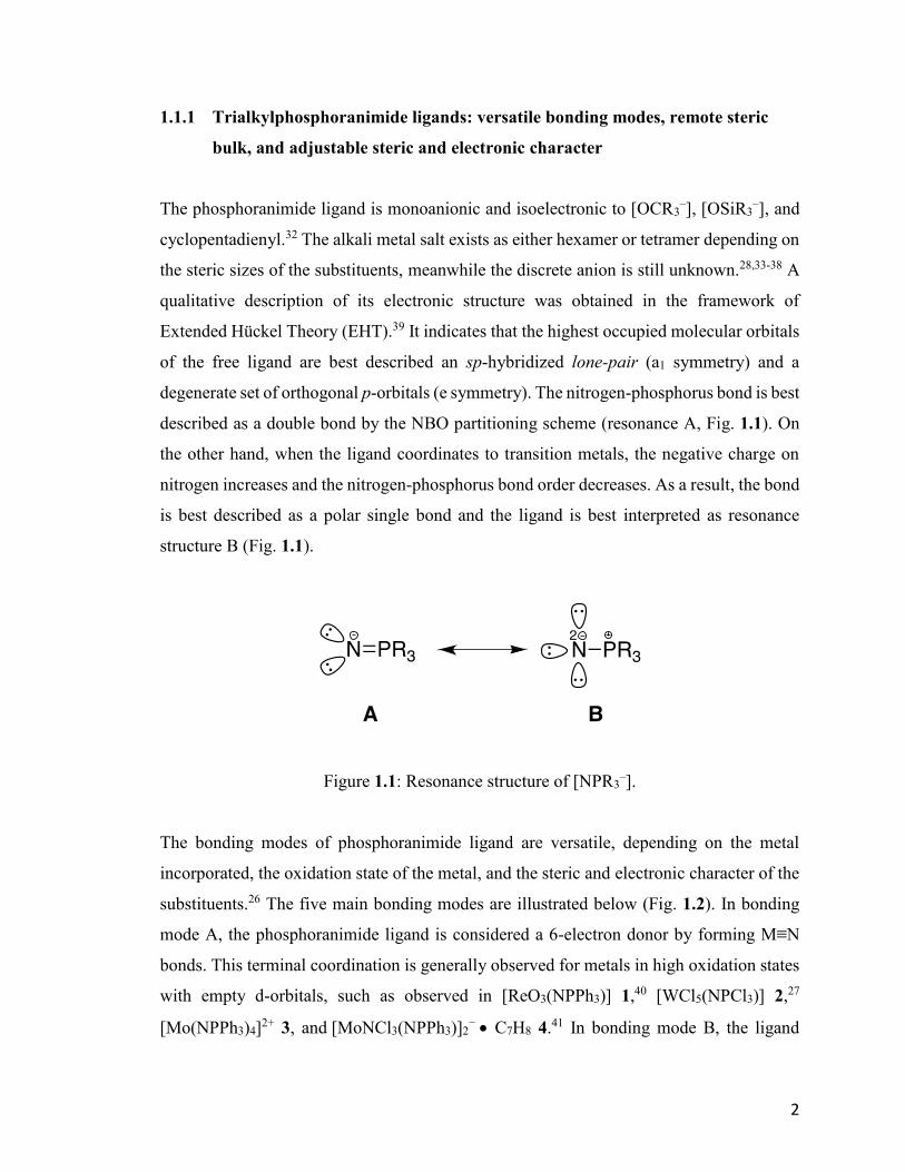
of the free ligand are best described an sp-hybridized lone-pair (a1 symmetry) and a
degenerate set of orthogonal p-orbitals (e symmetry). The nitrogen-phosphorus bond is best
described as a double bond by the NBO partitioning scheme (resonance A, Fig. 1.1). On
the other hand, when the ligand coordinates to transition metals, the negative charge on
nitrogen increases and the nitrogen-phosphorus bond order decreases. As a result, the bond
is best described as a polar single bond and the ligand is best interpreted as resonance
structure B (Fig. 1.1).
Figure 1.1: Resonance structure of [NPR3–].
The bonding modes of phosphoranimide ligand are versatile, depending on the metal
incorporated, the oxidation state of the metal, and the steric and electronic character of the
substituents.26 The five main bonding modes are illustrated below (Fig. 1.2). In bonding
mode A, the phosphoranimide ligand is considered a 6-electron donor by forming M≡N
bonds. This terminal coordination is generally observed for metals in high oxidation states
with empty d-orbitals, such as observed in [ReO3(NPPh3)] 1,40 [WCl5(NPCl3)] 2,27
[Mo(NPPh3)4]2+ 3, and [MoNCl3(NPPh3)]2
− C7H8 4.41 In bonding mode B, the ligand
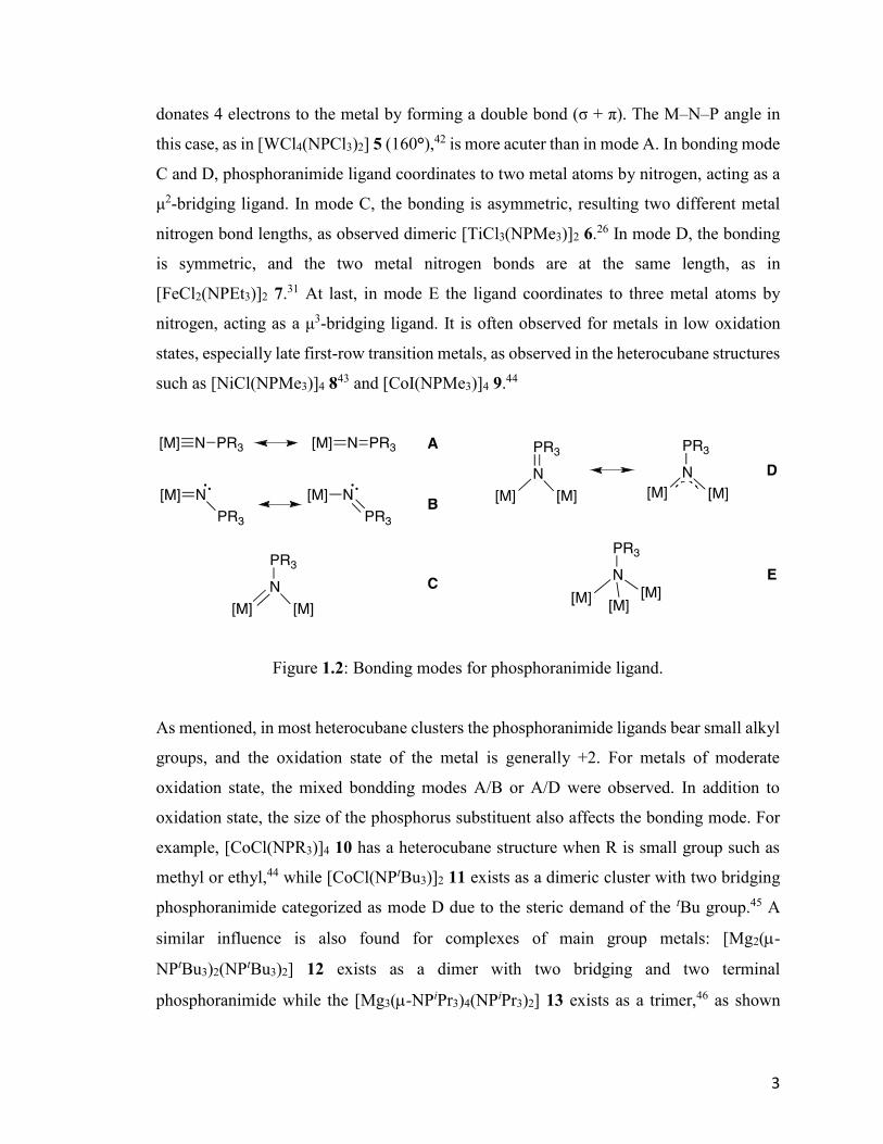
3
donates 4 electrons to the metal by forming a double bond (σ + π). The M–N–P angle in
this case, as in [WCl4(NPCl3)2] 5 (160°),42 is more acuter than in mode A. In bonding mode
C and D, phosphoranimide ligand coordinates to two metal atoms by nitrogen, acting as a
μ2-bridging ligand. In mode C, the bonding is asymmetric, resulting two different metal
nitrogen bond lengths, as observed dimeric [TiCl3(NPMe3)]2 6.26 In mode D, the bonding
is symmetric, and the two metal nitrogen bonds are at the same length, as in
[FeCl2(NPEt3)]2 7.31 At last, in mode E the ligand coordinates to three metal atoms by
nitrogen, acting as a μ3-bridging ligand. It is often observed for metals in low oxidation
states, especially late first-row transition metals, as observed in the heterocubane structures
such as [NiCl(NPMe3)]4 843 and [CoI(NPMe3)]4 9.44
Figure 1.2: Bonding modes for phosphoranimide ligand.
As mentioned, in most heterocubane clusters the phosphoranimide ligands bear small alkyl
groups, and the oxidation state of the metal is generally +2. For metals of moderate
oxidation state, the mixed bondding modes A/B or A/D were observed. In addition to
oxidation state, the size of the phosphorus substituent also affects the bonding mode. For
example, [CoCl(NPR3)]4 10 has a heterocubane structure when R is small group such as
methyl or ethyl,44 while [CoCl(NPtBu3)]2 11 exists as a dimeric cluster with two bridging
phosphoranimide categorized as mode D due to the steric demand of the tBu group.45 A
similar influence is also found for complexes of main group metals: [Mg2(-
NPtBu3)2(NPtBu3)2] 12 exists as a dimer with two bridging and two terminal
phosphoranimide while the [Mg3(-NPiPr3)4(NPiPr3)2] 13 exists as a trimer,46 as shown

4
below (Fig. 1.3). Last but not least, the bonding mode is also significantly affected by the
chemical environment at the metal center, the electronic and steric character of other
coordinated ligands.
Figure 1.3: Structures of selected phosphoranimide clusters: [CoCl(NPMe3)]4 10;
[CoCl(NPtBu3)]2 11 ; [Mg2(-NPtBu3)2(NPtBu3)2] 12 ; [Mg3(-NPiPr3)4(NPiPr3)2] 13.
The TiCp(NPR3)X2 (X = Cl or Me; R = tBu) system was well studied by Stephan, et al.,
for ethylene polymerization as an alternative to the popular metallocene system.47,48 In this
series of compounds, the phosphoranimide ligand not only mimics the Cp anion
electronically by donating as many as six electrons to the metal, but also occupies
considerable steric space due to the similarity of cone angles using Tolman’s model,49
when the R = tBu. In contrast, the Ti–P distance is much longer than the Ti–Cp-centroid
distance, 3.4Å vs 2.2Å,48 due to an extra atom in between. This suggests that even though
[NPtBu3–] occupies relative large space, the actually steric bulk is displaced far from the
metal center. Combining this character with the versatile bondding modes at nitrogen, it is
proposed that the activity of low-coordinate first-row transition metal clusters should be a
potentially valuable area for exploration.
5
Besides the versatile bondding mode and “remote steric effect”,32 the phosphoranimide
ligand also offers tunable electronic and steric character. By changing the electron-
donating ability of the substituents, it is possible to investigate electronic and steric
influences of the substituent both on the aggregation and catalytic behavior of the metal
clusters.
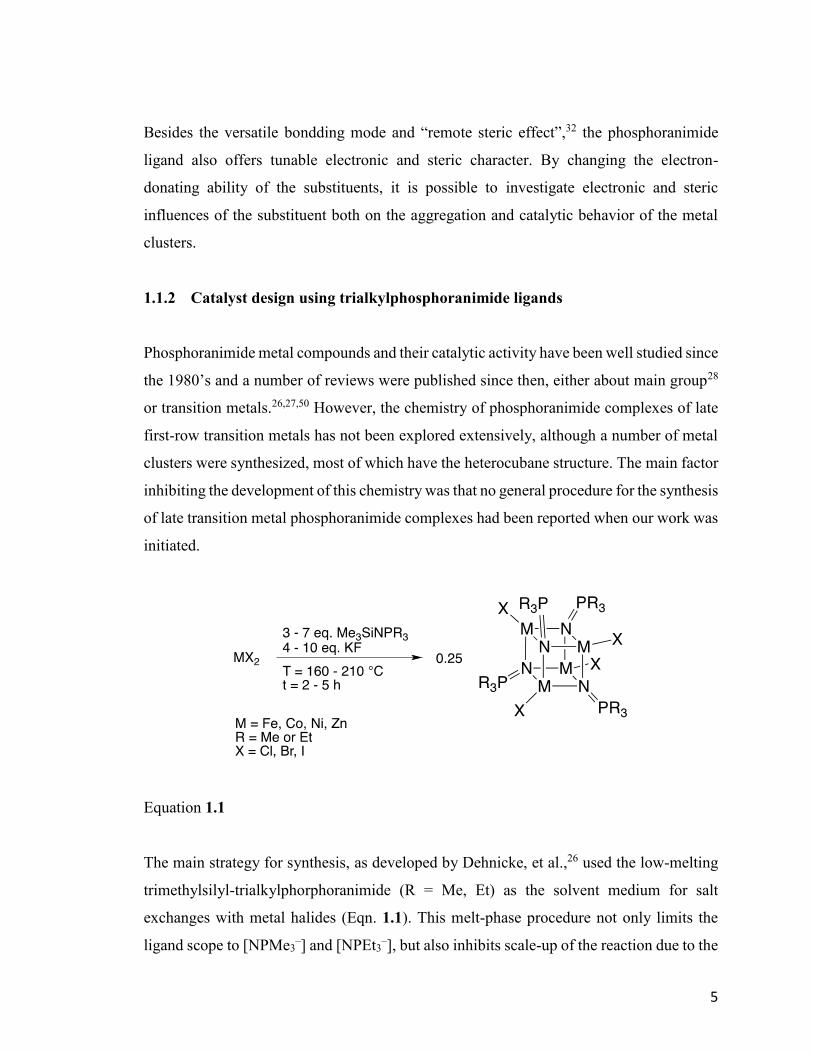
1.1.2 Catalyst design using trialkylphosphoranimide ligands
Phosphoranimide metal compounds and their catalytic activity have been well studied since
the 1980’s and a number of reviews were published since then, either about main group28
or transition metals.26,27,50 However, the chemistry of phosphoranimide complexes of late
first-row transition metals has not been explored extensively, although a number of metal
clusters were synthesized, most of which have the heterocubane structure. The main factor
inhibiting the development of this chemistry was that no general procedure for the synthesis
of late transition metal phosphoranimide complexes had been reported when our work was
initiated.
Equation 1.1
The main strategy for synthesis, as developed by Dehnicke, et al.,26 used the low-melting
trimethylsilyl-trialkylphorphoranimide (R = Me, Et) as the solvent medium for salt
exchanges with metal halides (Eqn. 1.1). This melt-phase procedure not only limits the
ligand scope to [NPMe3–] and [NPEt3
–], but also inhibits scale-up of the reaction due to the
6
inefficiency and difficulty of purification of the product. Even the ligand salts, for example
LiNPR3, are made from the trimethylsilyltrialkylphosphoranimide (TMSNPR3). It is also
difficult to apply this preparation on a large scale because trimethylsilyl azide, which is
potentially explosive at elevated temperature and acutely toxic, is not the preferred
synthetic reagent.
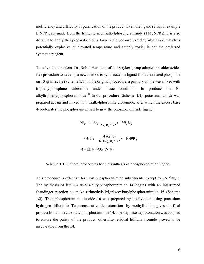
To solve this problem, Dr. Robin Hamilton of the Stryker group adapted an older azide-
free procedure to develop a new method to synthesize the ligand from the related phosphine
on 10-gram scale (Scheme 1.1). In the original procedure, a primary amine was mixed with
triphenylphosphine dibromide under basic conditions to produce the N-
alkyltriphenylphosphoranimide.51 In our procedure (Scheme 1.1), potassium amide was
prepared in situ and mixed with trialkylphosphine dibromide, after which the excess base
deprotonates the phosphoranium salt to give the phosphoranimide ligand.
Scheme 1.1: General procedures for the synthesis of phosphoranimide ligand.
This procedure is effective for most phosphoranimide substituents, except for [NPtBu3–].
The synthesis of lithium tri-tert-butylphosphoranimide 14 begins with an interrupted
Staudinger reaction to make (trimethylsilyl)tri-tert-butylphosphoranimide 15 (Scheme
1.2). Then phosphoranium fluoride 16 was prepared by desilylation using potassium
hydrogen difluoride. Two consecutive deprotonations by methyllithium gives the final
product lithium tri-tert-butylphosphoranimide 14. The stepwise deprotonation was adopted
to ensure the purity of the product; otherwise residual lithium bromide proved to be
inseparable from the 14.
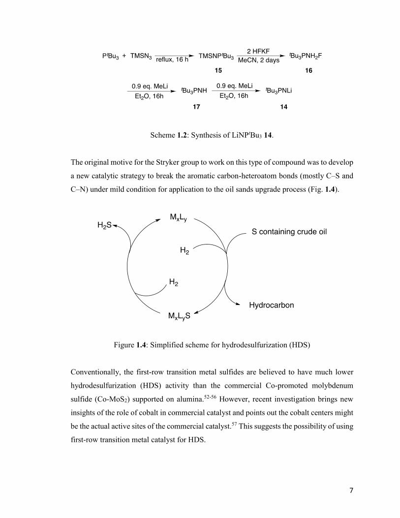
7
Scheme 1.2: Synthesis of LiNPtBu3 14.
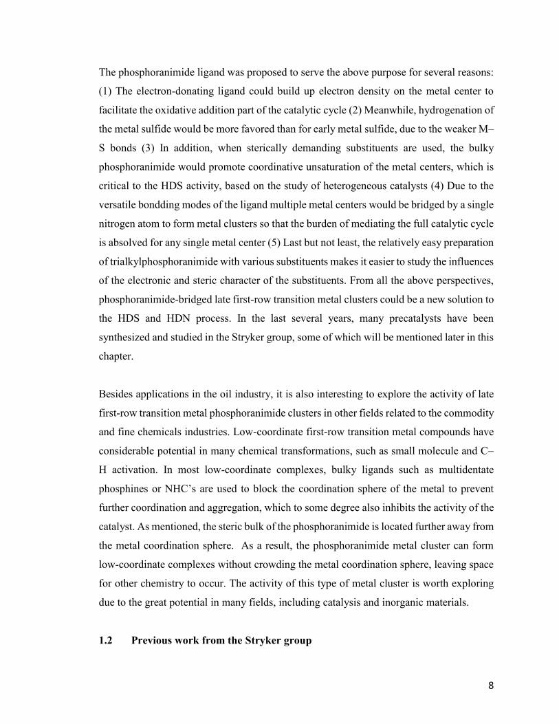
The original motive for the Stryker group to work on this type of compound was to develop
a new catalytic strategy to break the aromatic carbon-heteroatom bonds (mostly C–S and
C–N) under mild condition for application to the oil sands upgrade process (Fig. 1.4).
Figure 1.4: Simplified scheme for hydrodesulfurization (HDS)
Conventionally, the first-row transition metal sulfides are believed to have much lower
hydrodesulfurization (HDS) activity than the commercial Co-promoted molybdenum
sulfide (Co-MoS2) supported on alumina.52-56 However, recent investigation brings new
insights of the role of cobalt in commercial catalyst and points out the cobalt centers might
be the actual active sites of the commercial catalyst.57 This suggests the possibility of using
first-row transition metal catalyst for HDS.
8
The phosphoranimide ligand was proposed to serve the above purpose for several reasons:
(1) The electron-donating ligand could build up electron density on the metal center to
facilitate the oxidative addition part of the catalytic cycle (2) Meanwhile, hydrogenation of
the metal sulfide would be more favored than for early metal sulfide, due to the weaker M–
S bonds (3) In addition, when sterically demanding substituents are used, the bulky
phosphoranimide would promote coordinative unsaturation of the metal centers, which is
critical to the HDS activity, based on the study of heterogeneous catalysts (4) Due to the
versatile bondding modes of the ligand multiple metal centers would be bridged by a single
nitrogen atom to form metal clusters so that the burden of mediating the full catalytic cycle
is absolved for any single metal center (5) Last but not least, the relatively easy preparation
of trialkylphosphoranimide with various substituents makes it easier to study the influences
of the electronic and steric character of the substituents. From all the above perspectives,
phosphoranimide-bridged late first-row transition metal clusters could be a new solution to
the HDS and HDN process. In the last several years, many precatalysts have been
synthesized and studied in the Stryker group, some of which will be mentioned later in this
chapter.
Besides applications in the oil industry, it is also interesting to explore the activity of late
first-row transition metal phosphoranimide clusters in other fields related to the commodity
and fine chemicals industries. Low-coordinate first-row transition metal compounds have
considerable potential in many chemical transformations, such as small molecule and C–
H activation. In most low-coordinate complexes, bulky ligands such as multidentate
phosphines or NHC’s are used to block the coordination sphere of the metal to prevent
further coordination and aggregation, which to some degree also inhibits the activity of the
catalyst. As mentioned, the steric bulk of the phosphoranimide is located further away from
the metal coordination sphere. As a result, the phosphoranimide metal cluster can form
low-coordinate complexes without crowding the metal coordination sphere, leaving space
for other chemistry to occur. The activity of this type of metal cluster is worth exploring
due to the great potential in many fields, including catalysis and inorganic materials.
1.2 Previous work from the Stryker group
9
As the Stryker group has been focusing on the trialkylphosphoranimide-bridged first-row
transition metal clusters for several years, it is essential here to mention some previous
work briefly to bring context to this thesis. Among all the research done in the Stryker
group, the work by Dr. Jeffrey Camacho-Bunquin and Dr. Houston Brown will be
discussed here, due to the direct relevance to the content of this thesis.
1.2.1 Hydrocarbon soluble coplanar two-coordinate Ni and Co clusters:
[Ni(NPtBu3)]4 18 and [Co(NPtBu3)]4 19
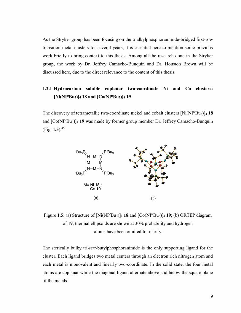
The discovery of tetrametallic two-coordinate nickel and cobalt clusters [Ni(NPtBu3)]4 18
and [Co(NPtBu3)]4 19 was made by former group member Dr. Jeffrey Camacho-Bunquin
(Fig. 1.5).45
Figure 1.5: (a) Structure of [Ni(NPtBu3)]4 18 and [Co(NPtBu3)]4 19; (b) ORTEP diagram
of 19, thermal ellipsoids are shown at 30% probability and hydrogen
atoms have been omitted for clarity.
The sterically bulky tri-tert-butylphosphoranimide is the only supporting ligand for the
cluster. Each ligand bridges two metal centers through an electron rich nitrogen atom and
each metal is monovalent and linearly two-coordinate. In the solid state, the four metal
atoms are coplanar while the diagonal ligand alternate above and below the square plane
of the metals.
10
The X-ray crystal refinement for [Co(NPtBu3)]4 19 suggested that the Co(I) centers are
partially replaced by Na cations in variable amounts in different single crystals selected for
structure refinement. Solution magnetic susceptibility, as measured by the Evans’
method,58 revealed that the cobalt cluster 19 is an 8-electron paramagnet, indicating two
unpaired electrons per metal center and no significant amount of Co–Co bonding. On the
other hand, the Ni(I) center in [Ni(NPtBu3)]4 18 is not replaced by Na cation even though
it is prepared by the same procedure. Solution magnetic susceptibility measurement for 18
reveals close to four unpaired electrons for the cluster, suggesting one unpaired electron
for each Ni(I) metal center, with d9 configuration.
Both clusters are highly unsaturated and exhibit activity for hydrogenation of alkynes and
alkenes under mild condition (room temperature, one atmosphere of hydrogen).45
However, for the nickel cluster 18, the hydrogenation activity of diphenylacetylene 20 was
irreproducible. Even more intriguing was that when the purest available single crystal was
used as the catalyst, no hydrogenation activity was observed.59 The reproducibility issue
has been addressed in the current work and will be discussed later in this thesis.
1.2.2 Heterocubane [MeCo(NPEt3)]4 21 and [Me4Co4(NPEt3)4]PF6 22
In addition to the two-coordinate tetrametallic cluster, another synthetic accomplishment
was the alkylated heterocubane cluster [MeCo(NPEt3)]4 21 and the one-electron oxidized
congener [Me4Co4(NPEt3)4]PF6 22 (Fig. 1.6) by Dr. Houston Brown.60 Neutral
[MeCo(NPEt3)]4 adopts the typical heterocubane structure, with cobalt and nitrogen atoms
positioned at alternative corners of the cube. In the cluster, each triethylphosphoranimide
ligand coordinates to three cobalt atoms and each cobalt atom binds to three ligands.
11
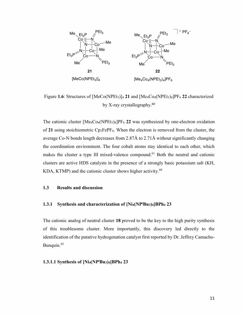
Figure 1.6: Structures of [MeCo(NPEt3)]4 21 and [Me4Co4(NPEt3)4]PF6 22 characterized
by X-ray crystallography.60
The cationic cluster [Me4Co4(NPEt3)4]PF6 22 was synthesized by one-electron oxidation
of 21 using stoichiometric Cp2FePF6. When the electron is removed from the cluster, the
average Co-N bonds length decreases from 2.87Å to 2.71Å without significantly changing
the coordination environment. The four cobalt atoms stay identical to each other, which
makes the cluster a type III mixed-valence compound.61 Both the neutral and cationic
clusters are active HDS catalysts in the presence of a strongly basic potassium salt (KH,
KDA, KTMP) and the cationic cluster shows higher activity.60
1.3 Results and discussion
1.3.1 Synthesis and characterization of [Ni4(NPtBu3)4]BPh4 23
The cationic analog of neutral cluster 18 proved to be the key to the high purity synthesis
of this troublesome cluster. More importantly, this discovery led directly to the
identification of the putative hydrogenation catalyst first reported by Dr. Jeffrey Camacho-
Bunquin.45
1.3.1.1 Synthesis of [Ni4(NPtBu3)4]BPh4 23
12
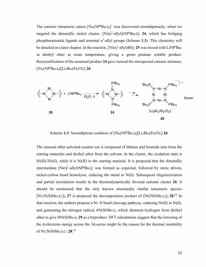
The cationic tetrameric cation [Ni4(NPtBu3)4]+ was discovered serendipitously, when we
targeted the dimetallic nickel cluster, [Ni(η3-allyl)(NPtBu3)]2 24, which has bridging
phosphoranimide ligands and terminal η3-allyl groups (Scheme 1.3). This chemistry will
be detailed in a later chapter. In the reaction, [Ni(η3-allyl)Br]2 25 was mixed with LiNPtBu3
in diethyl ether at room temperature, giving a green pentane soluble product.
Recrystallization of the assumed product 24 gave instead the unexpected cationic tetramer,
[Ni4(NPtBu3)4][Li3Br4(Et2O)3] 26.
Scheme 1.3: Serendipitous isolation of [Ni4(NPtBu3)4][Li3Br4(Et2O)3] 26.
The unusual ether-solvated counter ion is composed of lithium and bromide ions from the
starting materials and diethyl ether from the solvent. In the cluster, the oxidation state is
Ni(II)/3Ni(I), while it is Ni(II) in the starting material. It is proposed that the dimetallic
intermediate [Ni(η3-allyl)NPtBu3]2 was formed as expected, followed by steric driven,
nickel-carbon bond homolysis, reducing the metal to Ni(I). Subsequent oligomerization
and partial reoxidation results in the thermodynamically favored cationic cluster 26. It
should be mentioned that the only known structurally similar tetrameric species
[Ni{N(SiMe3)2}]4 27 is proposed the decomposition product of [Ni(NSiMe3)2]2 28.62 In
that reaction, the authors propose a Ni–N bond cleavage pathway, reducing Ni(II) to Ni(I),
and generating the nitrogen radical, N(SiMe3)2, which abstracts hydrogen from diethyl
ether to give HN(SiMe3)2 29 as a byproduct. DFT calculations suggest that the lowering of
the d-electrons energy across the 3d-series might be the reason for the thermal instability
of Ni{N(SiMe3)2}2 28.63
13
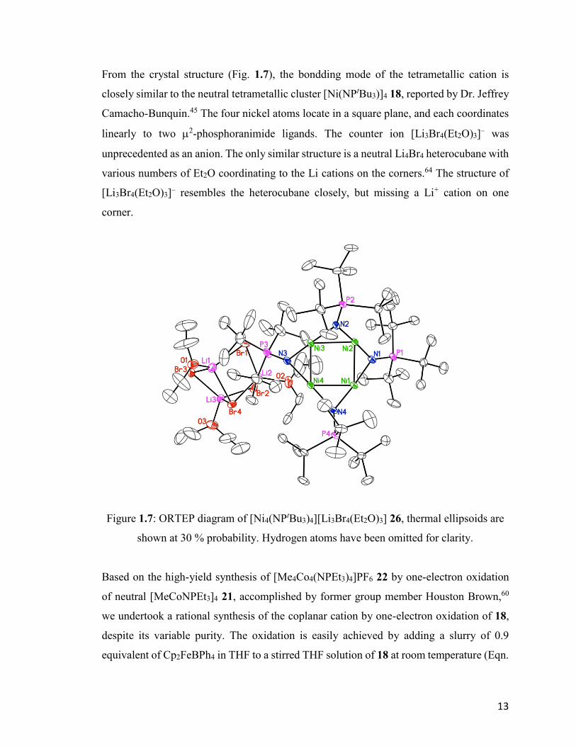
From the crystal structure (Fig. 1.7), the bondding mode of the tetrametallic cation is
closely similar to the neutral tetrametallic cluster [Ni(NPtBu3)]4 18, reported by Dr. Jeffrey
Camacho-Bunquin.45 The four nickel atoms locate in a square plane, and each coordinates
linearly to two 2-phosphoranimide ligands. The counter ion [Li3Br4(Et2O)3]– was
unprecedented as an anion. The only similar structure is a neutral Li4Br4 heterocubane with
various numbers of Et2O coordinating to the Li cations on the corners.64 The structure of
[Li3Br4(Et2O)3]– resembles the heterocubane closely, but missing a Li+ cation on one
corner.
Figure 1.7: ORTEP diagram of [Ni4(NPtBu3)4][Li3Br4(Et2O)3] 26, thermal ellipsoids are
shown at 30 % probability. Hydrogen atoms have been omitted for clarity.
Based on the high-yield synthesis of [Me4Co4(NPEt3)4]PF6 22 by one-electron oxidation
of neutral [MeCoNPEt3]4 21, accomplished by former group member Houston Brown,60
we undertook a rational synthesis of the coplanar cation by one-electron oxidation of 18,
despite its variable purity. The oxidation is easily achieved by adding a slurry of 0.9
equivalent of Cp2FeBPh4 in THF to a stirred THF solution of 18 at room temperature (Eqn.
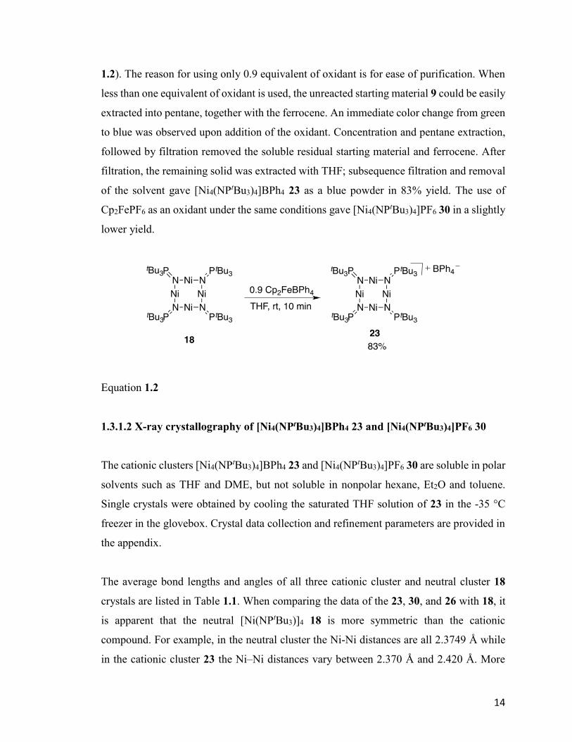
14
1.2). The reason for using only 0.9 equivalent of oxidant is for ease of purification. When
less than one equivalent of oxidant is used, the unreacted starting material 9 could be easily
extracted into pentane, together with the ferrocene. An immediate color change from green
to blue was observed upon addition of the oxidant. Concentration and pentane extraction,
followed by filtration removed the soluble residual starting material and ferrocene. After
filtration, the remaining solid was extracted with THF; subsequence filtration and removal
of the solvent gave [Ni4(NPtBu3)4]BPh4 23 as a blue powder in 83% yield. The use of
Cp2FePF6 as an oxidant under the same conditions gave [Ni4(NPtBu3)4]PF6 30 in a slightly
lower yield.
Equation 1.2
1.3.1.2 X-ray crystallography of [Ni4(NPtBu3)4]BPh4 23 and [Ni4(NPtBu3)4]PF6 30
The cationic clusters [Ni4(NPtBu3)4]BPh4 23 and [Ni4(NPtBu3)4]PF6 30 are soluble in polar
solvents such as THF and DME, but not soluble in nonpolar hexane, Et2O and toluene.
Single crystals were obtained by cooling the saturated THF solution of 23 in the -35 °C
freezer in the glovebox. Crystal data collection and refinement parameters are provided in
the appendix.
The average bond lengths and angles of all three cationic cluster and neutral cluster 18
crystals are listed in Table 1.1. When comparing the data of the 23, 30, and 26 with 18, it
is apparent that the neutral [Ni(NPtBu3)]4 18 is more symmetric than the cationic
compound. For example, in the neutral cluster the Ni-Ni distances are all 2.3749 Å while
in the cationic cluster 23 the Ni–Ni distances vary between 2.370 Å and 2.420 Å. More
15
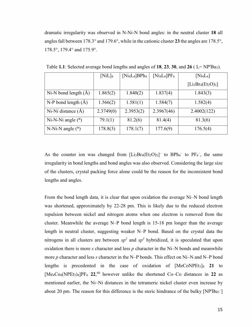
dramatic irregularity was observed in N-Ni-N bond angles: in the neutral cluster 18 all
angles fall between 178.3° and 179.6°, while in the cationic cluster 23 the angles are 178.5°,
178.5°, 179.4° and 175.9°.
Table 1.1: Selected average bond lengths and angles of 18, 23, 30, and 26 ( L= NPtBu3).
[NiL]4
[Ni4L4]BPh4 [Ni4L4]PF6 [Ni4L4]
[Li3Br4(Et2O)3]
Ni-N bond length (Å) 1.865(2) 1.840(2) 1.837(4) 1.843(3)
N-P bond length (Å) 1.566(2) 1.581(1) 1.584(7) 1.582(4)
Ni-Ni distance (Å) 2.3749(0) 2.3953(2) 2.3967(46) 2.4002(122)
Ni-N-Ni angle (°) 79.1(1) 81.2(6) 81.4(4) 81.3(6)
N-Ni-N angle (°) 178.8(3) 178.1(7) 177.6(9) 176.5(4)
As the counter ion was changed from [Li3Br4(Et2O)3]– to BPh4
– to PF6–, the same
irregularity in bond lengths and bond angles was also observed. Considering the large size
of the clusters, crystal packing force alone could be the reason for the inconsistent bond
lengths and angles.
From the bond length data, it is clear that upon oxidation the average Ni–N bond length
was shortened, approximately by 22-28 pm. This is likely due to the reduced electron
repulsion between nickel and nitrogen atoms when one electron is removed from the
cluster. Meanwhile the average N–P bond length is 15-18 pm longer than the average
length in neutral cluster, suggesting weaker N–P bond. Based on the crystal data the
nitrogens in all clusters are between sp2 and sp3 hybridized, it is speculated that upon
oxidation there is more s character and less p character in the Ni–N bonds and meanwhile
more p character and less s character in the N–P bonds. This effect on Ni–N and N–P bond
lengths is precedented in the case of oxidation of [MeCoNPEt3]4 21 to
[Me4Co4(NPEt3)4]PF6 22,60 however unlike the shortened Co–Co distances in 22 as
mentioned earlier, the Ni–Ni distances in the tetrameric nickel cluster even increase by
about 20 pm. The reason for this difference is the steric hindrance of the bulky [NPtBu3–]
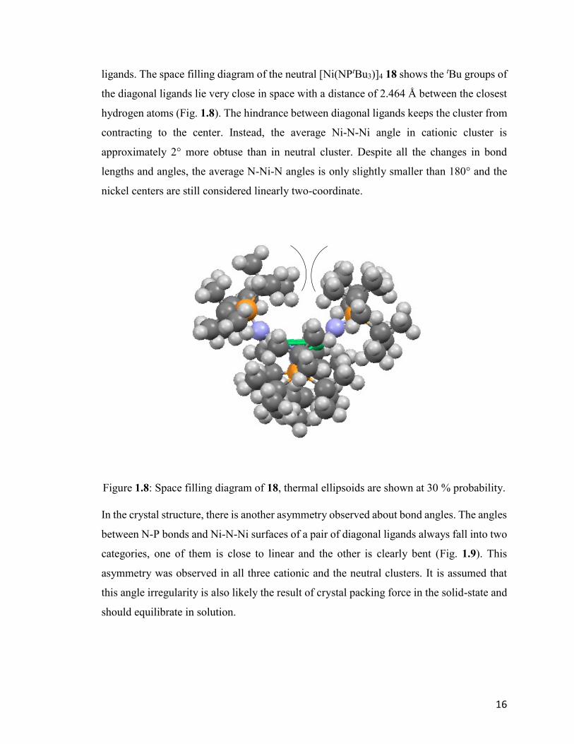
16
ligands. The space filling diagram of the neutral [Ni(NPtBu3)]4 18 shows the tBu groups of
the diagonal ligands lie very close in space with a distance of 2.464 Å between the closest
hydrogen atoms (Fig. 1.8). The hindrance between diagonal ligands keeps the cluster from
contracting to the center. Instead, the average Ni-N-Ni angle in cationic cluster is
approximately 2° more obtuse than in neutral cluster. Despite all the changes in bond
lengths and angles, the average N-Ni-N angles is only slightly smaller than 180° and the
nickel centers are still considered linearly two-coordinate.
Figure 1.8: Space filling diagram of 18, thermal ellipsoids are shown at 30 % probability.
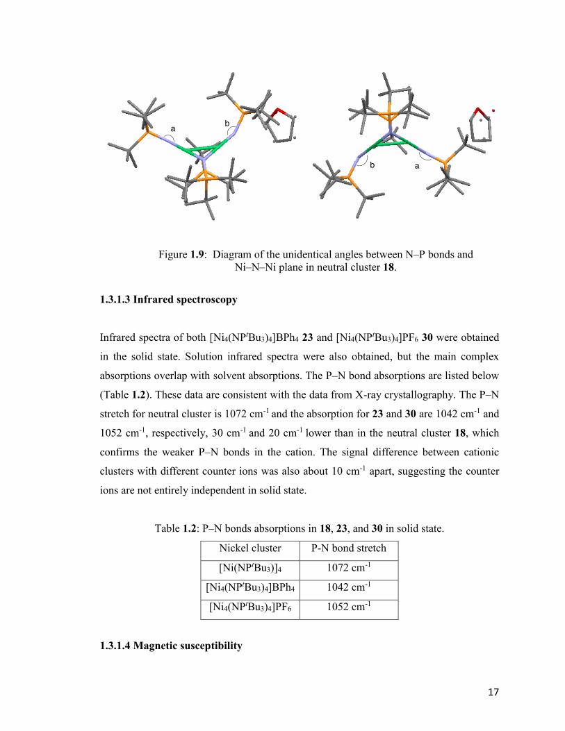
In the crystal structure, there is another asymmetry observed about bond angles. The angles
between N-P bonds and Ni-N-Ni surfaces of a pair of diagonal ligands always fall into two
categories, one of them is close to linear and the other is clearly bent (Fig. 1.9). This
asymmetry was observed in all three cationic and the neutral clusters. It is assumed that
this angle irregularity is also likely the result of crystal packing force in the solid-state and
should equilibrate in solution.
17
Figure 1.9: Diagram of the unidentical angles between N–P bonds and
Ni–N–Ni plane in neutral cluster 18.
1.3.1.3 Infrared spectroscopy
Infrared spectra of both [Ni4(NPtBu3)4]BPh4 23 and [Ni4(NPtBu3)4]PF6 30 were obtained
in the solid state. Solution infrared spectra were also obtained, but the main complex
absorptions overlap with solvent absorptions. The P–N bond absorptions are listed below
(Table 1.2). These data are consistent with the data from X-ray crystallography. The P–N
stretch for neutral cluster is 1072 cm-1 and the absorption for 23 and 30 are 1042 cm-1 and
1052 cm-1, respectively, 30 cm-1 and 20 cm-1 lower than in the neutral cluster 18, which
confirms the weaker P–N bonds in the cation. The signal difference between cationic
clusters with different counter ions was also about 10 cm-1 apart, suggesting the counter
ions are not entirely independent in solid state.
Table 1.2: P–N bonds absorptions in 18, 23, and 30 in solid state.
Nickel cluster P-N bond stretch
[Ni(NPtBu3)]4 1072 cm-1
[Ni4(NPtBu3)4]BPh4 1042 cm-1
[Ni4(NPtBu3)4]PF6 1052 cm-1
1.3.1.4 Magnetic susceptibility
18
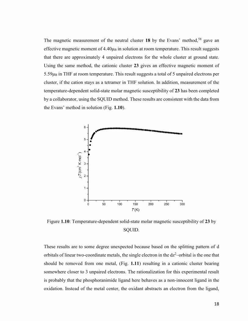
The magnetic measurement of the neutral cluster 18 by the Evans’ method,58 gave an
effective magnetic moment of 4.40μB in solution at room temperature. This result suggests
that there are approximately 4 unpaired electrons for the whole cluster at ground state.
Using the same method, the cationic cluster 23 gives an effective magnetic moment of
5.59μB in THF at room temperature. This result suggests a total of 5 unpaired electrons per
cluster, if the cation stays as a tetramer in THF solution. In addition, measurement of the
temperature-dependent solid-state molar magnetic susceptibility of 23 has been completed
by a collaborator, using the SQUID method. These results are consistent with the data from
the Evans’ method in solution (Fig. 1.10).
Figure 1.10: Temperature-dependent solid-state molar magnetic susceptibility of 23 by
SQUID.
These results are to some degree unexpected because based on the splitting pattern of d
orbitals of linear two-coordinate metals, the single electron in the dz2–orbital is the one that
should be removed from one metal, (Fig. 1.11) resulting in a cationic cluster bearing
somewhere closer to 3 unpaired electrons. The rationalization for this experimental result
is probably that the phosphoranimide ligand here behaves as a non-innocent ligand in the
oxidation. Instead of the metal center, the oxidant abstracts an electron from the ligand,

19
likely from the nitrogen atom (or, equivalent, the N=P double bond). In other words, from
the molecular orbital point of view, in the MO diagram of the cluster there is likely at least
one orbital that is nearly degenerate with the four singly occupied metal-based molecular
orbitals (SOMOs). This is likely to be a more nitrogen-based molecular orbital and the
energy gap between this orbital and the SOMO is smaller or at least close to the pairing
energy.
Figure 1.11: Splitting pattern of d-orbitals for linear two-coordinate d9 metals.
A detailed computational investigation is currently underway, again by collaborators. It is
expected that results of the FMO computation will be helpful to understand the magnetic
property and activity of the clusters.
1.3.1.5 Cyclic voltammetry
To study the redox behavior of the tetranickel cluster 18 and 23, Cyclic voltammetry was
carried out under one atmosphere of nitrogen or argon. The results were collected using
WaveNow USB potentiostat in compact voltammetry cell (starter kit) of Pine Industry
Instrumentation, using Aftermath operating software. Ceramic patterned Platinum
electrodes were used as working and counter electrodes, and pseudo silver electrode was
used as reference (for non-aqueous solutions). n-Bu4NPF6 was used as electrolyte with 0.1
20
mol/L concentration. The analyte solution is prepared in the glovebox by dissolving the
analyte in n-Bu4NPF6 solution to make 0.01mol/L solution of analyte. THF was used as
the solvent for all the CV. The general scan rate is 0.1V/s unless otherwise noticed. The
Fc+/Fc couple was used as the reference for all the CV.
The cationic cluster 23 rather than the neutral cluster 18 was used in these experiments,
given the high purity and stability of the compound. The neutral cluster 18 decomposes
slowly over a week in solution to give a precipitate that is not soluble in THF, even when
stored in the -30°C freezer of the glovebox. This is likely due to the low-coordinate nature
of Ni centers. The purity of the compound itself was also in question: the neutral cluster
prepared by Dr. Jeffrey Camacho-Bunquin was, we believe, usually contaminated with
some over-reduced component, which will be discussed later in this chapter. On the other
hand, the cationic cluster [Ni4(NPtBu3)4]BPh4 23 is kinetically much more stable, both in
solution and the solid state. There is no sign of decomposition after six months in solid
state when stored properly in the glovebox. This has resulted in self-consistent and
reproducible electrochemical measurements.
As described in the experimental section, the electrochemical cell of the CV instrument
was set up in the glovebox, sealed, and then transferred out of the glovebox for the
experiment. The Fc+/Fc couple was used as internal reference in some cases. The results
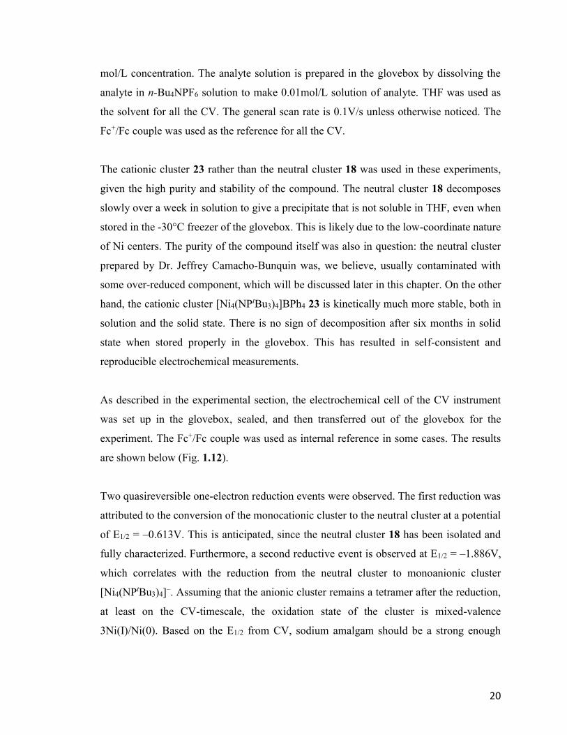
are shown below (Fig. 1.12).
Two quasireversible one-electron reduction events were observed. The first reduction was
attributed to the conversion of the monocationic cluster to the neutral cluster at a potential
of E1/2 = –0.613V. This is anticipated, since the neutral cluster 18 has been isolated and
fully characterized. Furthermore, a second reductive event is observed at E1/2 = –1.886V,
which correlates with the reduction from the neutral cluster to monoanionic cluster
[Ni4(NPtBu3)4]–. Assuming that the anionic cluster remains a tetramer after the reduction,
at least on the CV-timescale, the oxidation state of the cluster is mixed-valence
3Ni(I)/Ni(0). Based on the E1/2 from CV, sodium amalgam should be a strong enough
21
reductant to reduce the neutral cluster,65 however, this is not observed chemically, although
this possibility was not investigated, at least carefully.
(a)
(b)
Figure 1.12: CV of 23. (a) CV without internal reference; (b) CV with Cp2FePF6
as internal reference.
The electrochemistry also confirmed that both redox reactions are one-electron events. The
differences in peak potentials for each event are 0.151V and 0.165V, respectively, which
is relative broadened from the ideal 0.059V difference for a reversible one-electron redox
event. As a result, both events should be quasireversible. The wide peak differences are
likely due to slow rate of electron transfer, resulting from the high activation barrier, but
the effects of reversible cluster dissociation cannot be discounted.
22
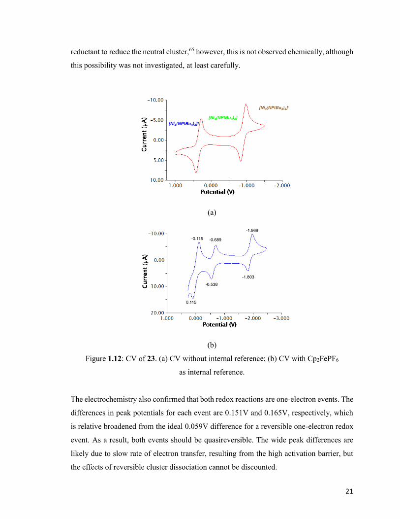
(a)
(b)
Figure 1.13: CV of 23 under wider scan range: (a) 0.5V ~ –1.5V; (b) 0.2V ~ –4.0V.
Cyclic voltammetry covering a wider scan range suggested another irreversible redox
events as shown below (Fig. 1.13). When the potential rises to around +0.3V (relative to
Fc+/0), no further oxidation of the monocationic cluster is observed other than the oxidation
of solvent. On the opposite direction, another irreversible reduction of the monoanion was
observed around -3.3V, together with the reduction of THF under such highly reductive
potential. This redox event is irreversible, implying the disassembling of the presumed
dianionic cluster. The reduction is not chemically accessible due to the extremely strong
reduction potential.

23
1.3.2 Synthesis and characterization of Na[Ni4(NPtBu3)4] 31
The insight obtained from cyclic voltammetry suggests the possibility of clean one-electron
chemical reduction of the neutral tetrameric cluster 18. Based on the data, the reduction
potential of the reducing agent has to be at least close to -2.2V, limiting us to alkali and
alkali earth metals to achieve the reduction chemically.
1.3.2.1 Direct reduction of [Ni(NPtBu3)]4 18 with alkali and alkali earth metals
Attempted reductions of 18 with lithium metal (Eqn. 1.3) and potassium graphite (KC8)
(Eqn. 1.4) were unsuccessful in delivering a single product. When lithium wire was added
to the solution of 18 in THF, the color of the solution changes gradually from green to
brown. After stirring for one hour, the major product was brown and soluble in pentane,
however there was always a variable amount of uncharacterized black precipitate as a
byproduct.
Equation 1.3
Equation 1.4
When KC8 was used as reductant, the color changed much faster, normally within one
minutes. The major product was again brown and pentane soluble, but the amount of
precipitate obtained could not be estimated due to the residual graphite in the reaction
mixture. 31P-NMR spectroscopy of each product showed the presence of the alkali metal
salt of the ligand, LiNPtBu3 (31ppm)36 or KNPtBu3 (16ppm).66 This suggests a dissociative
pathway for decomposition from the putative anionic cluster.
24
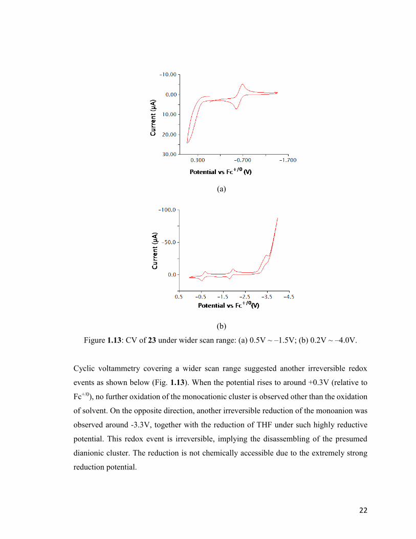
When sodium was used as reductant, more possibilities could be explored by using sodium
amalgam consisting of various percentages of sodium (Scheme 1.4). It is found that the
concentration of sodium has a clear effect on the rate of this reaction. When liquid 0.9%
Na/Hg was used, no color change was observed, and the starting material was recovered
almost quantitatively after two days at room temperature. Increasing the sodium
concentration to 2.4% led to a slow reduction of the neutral cluster 18, reaching an end
product in two days. When liquid 40% Na/Hg was used, the color of the solution changed
to brown within 15 minutes. Similar to the reduction by Li and KC8, 31P-NMR
spectroscopy detects the signal of the sodium salt of the ligand, NaNPtBu3, at 26 ppm,
which was not quantified.
Scheme 1.4: Reduction of 18 with sodium amalgam with different concentrations.
In all cases, recrystallization of the brown solid in the glovebox was attempted at low
temperature using different solvents or solvents mixtures, including pentane, hexane, THF
and DME. The only crystal that could be obtained was from the reduction using 40%
Na/Hg. The crystal proved to be NaNPtBu3 33 with a distorted heterocubane structure with
sodium and nitrogen atoms occupying alternative corners of the cube. The crystal structure
of NaNPtBu3 is similar to distorted cubic framework of LiNPtBu3, synthesized by the
Stephan et al.36 Details of this crystal structure are provided in the appendix.
25
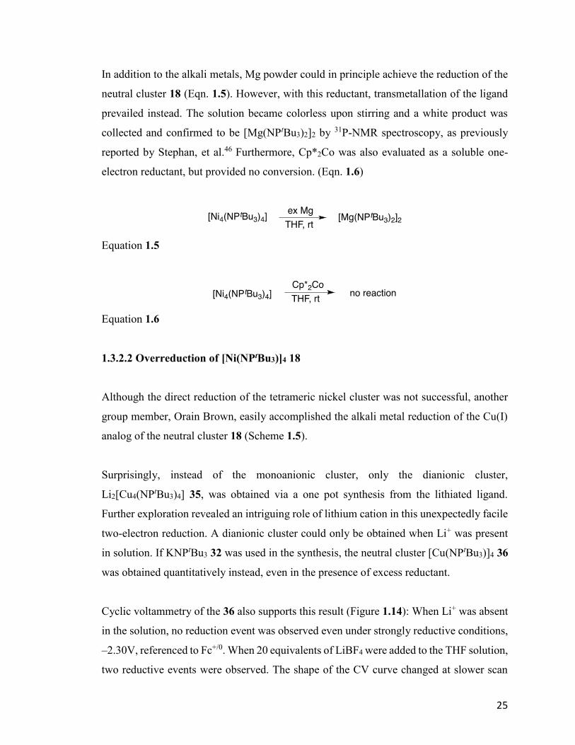
In addition to the alkali metals, Mg powder could in principle achieve the reduction of the
neutral cluster 18 (Eqn. 1.5). However, with this reductant, transmetallation of the ligand
prevailed instead. The solution became colorless upon stirring and a white product was
collected and confirmed to be [Mg(NPtBu3)2]2 by 31P-NMR spectroscopy, as previously
reported by Stephan, et al.46 Furthermore, Cp*2Co was also evaluated as a soluble one-
electron reductant, but provided no conversion. (Eqn. 1.6)
Equation 1.5
Equation 1.6
1.3.2.2 Overreduction of [Ni(NPtBu3)]4 18
Although the direct reduction of the tetrameric nickel cluster was not successful, another
group member, Orain Brown, easily accomplished the alkali metal reduction of the Cu(I)
analog of the neutral cluster 18 (Scheme 1.5).
Surprisingly, instead of the monoanionic cluster, only the dianionic cluster,
Li2[Cu4(NPtBu3)4] 35, was obtained via a one pot synthesis from the lithiated ligand.
Further exploration revealed an intriguing role of lithium cation in this unexpectedly facile
two-electron reduction. A dianionic cluster could only be obtained when Li+ was present
in solution. If KNPtBu3 32 was used in the synthesis, the neutral cluster [Cu(NPtBu3)]4 36
was obtained quantitatively instead, even in the presence of excess reductant.
Cyclic voltammetry of the 36 also supports this result (Figure 1.14): When Li+ was absent
in the solution, no reduction event was observed even under strongly reductive conditions,
–2.30V, referenced to Fc+/0. When 20 equivalents of LiBF4 were added to the THF solution,
two reductive events were observed. The shape of the CV curve changed at slower scan
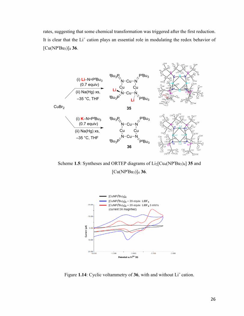
26
rates, suggesting that some chemical transformation was triggered after the first reduction.
It is clear that the Li+ cation plays an essential role in modulating the redox behavior of
[Cu(NPtBu3)]4 36.
Scheme 1.5: Syntheses and ORTEP diagrams of Li2[Cu4(NPtBu3)4] 35 and
[Cu(NPtBu3)]4 36.
Figure 1.14: Cyclic voltammetry of 36, with and without Li+ cation.
N
Cu
N Cu N
Cu
NCu
PtBu3
PtBu3tBu3P
tBu3P
N
Cu
N Cu N
Cu
NCu
PtBu3
PtBu3tBu3P
tBu3P
Li
Li
CuBr2
(i) Li–N=PtBu3
(0.7 equiv)
(ii) Na(Hg) xs,
–35 °C, THF
(i) K–N=PtBu3
(0.7 equiv)
(ii) Na(Hg) xs,
–35 °C, THF
35
36
27
Further computational study is ongoing, and is essential to provide more insight into the
unique role of the main group counter ion in this process. The details of the copper
chemistry will not be discussed in this thesis.
In combination with the decomposition observed during the chemical reduction of neutral
cluster 18, we suggest that the alkali metals were not innocent outer-sphere reductants in
the reaction. To further investigate the role of alkali metal cations in controlling this
reduction, cyclic voltammetry of 23 in the presence of various alkali metal cations was
explored.
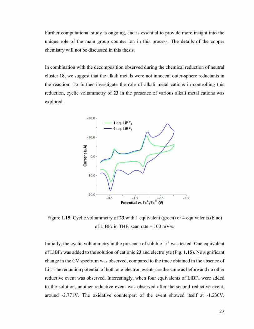
Figure 1.15: Cyclic voltammetry of 23 with 1 equivalent (green) or 4 equivalents (blue)
of LiBF4 in THF, scan rate = 100 mV/s.
Initially, the cyclic voltammetry in the presence of soluble Li+ was tested. One equivalent
of LiBF4 was added to the solution of cationic 23 and electrolyte (Fig. 1.15). No significant
change in the CV spectrum was observed, compared to the trace obtained in the absence of
Li+. The reduction potential of both one-electron events are the same as before and no other
reductive event was observed. Interestingly, when four equivalents of LiBF4 were added
to the solution, another reductive event was observed after the second reductive event,
around -2.771V. The oxidative counterpart of the event showed itself at -1.230V,
1 eq. LiBF4
4 eq. LiBF4

28
suggesting that this event is irreversible, and likely leads to cluster reorganization and/or
decomposition.
This overreduction was only observed in the presence of 4 equivalents of Li+. We propose
that the timescale for the CV is relatively short compared to the rate of the Li+ coordination
to the already anionic cluster, thus requiring an excess to be competitive. The CV of LiBF4
itself shows no such reduction peak. In summary, similar to the case of [Cu(NPtBu3)]4 36,
overreduction of the cluster was observed in the presence of Li+. However, this
overreduction leads to decomposition of the cluster, in contrast to the isolable
Li2[Cu(NPtBu3)]4 35.
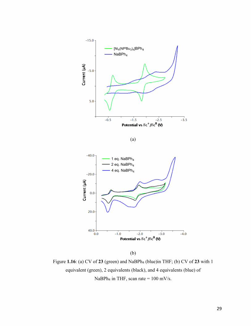
For comparison, CV spectra of 23 in the presence of various amounts of Na+ were also
obtained. In Figure 1.16 (a), the CVs of both NaBPh4 and 23 are shown on the same plot.
The background voltammagram of NaBPh4 was not entirely flat, showing a broad signal
around -2.3V. The CV of 23 in the presence of Na+ is shown below (Fig. 1.16 (b)), from
which we can conclude that the traces were basically the superimposition of the reductions
shown in Fig. 1.18 (a). In contrast to the case of Li+, no further reduction event was
observed, at least at CV-timescale. As noted earlier, liberated NaNPtBu3 33 was observed
when trying to reduce the neutral cluster 18 with Na/Hg. Based on the electrochemistry,
we can conclude that the decomposition is less the result of overreduction but the kinetic
instability of the anionic cluster itself. There is also a chance that the overreduction in the
presence of Na+ is simply much slower than the case of Li+, so it was not observed in the
CV spectra.
The CV in the presence of K+ was also investigated. The results were similar to the case of
sodium cation. The CV obtained was the overlap of cationic cluster 23 and KBPh4 (Fig.
1.17). No further redox event was observed in the presence of potassium cation.
29
(a)
(b)
Figure 1.16: (a) CV of 23 (green) and NaBPh4 (blue)in THF; (b) CV of 23 with 1
equivalent (green), 2 equivalents (black), and 4 equivalents (blue) of
NaBPh4 in THF, scan rate = 100 mV/s.
[Ni4(NPtBu3)4]BPh4
NaBPh4
1 eq. NaBPh4
2 eq. NaBPh4
4 eq. NaBPh4

30
Figure 1.17: CV of 23 with 4 equivalents of KBPh4 in THF, scan rate = 100 mV/s.
1.3.2.3 Attempt to reduce [Ni(NPtBu3)]4 18 without overreduction
Based on the cyclic voltammetry, overreduction by alkali metals probably arises from
additional reduction beyond the monoanionic cluster, triggering anionic ligand dissociation
and reorganization/decomposition of the cluster. To avoid such overreduction several
methods were evaluated. First, use of a stoichiometric amount of the reductant was posited.
Considering the high molecular weight of the neutral cluster 18, sodium and lithium
anthracenides67 and sodium naphthalenide68 were prepared in THF and used as a solution,
aiming to provide accurate stoichiometry of reductant. The radical anions are in principle
strong reductants and presumed to reduce the neutral cluster 18 to the anionic cluster.
However, this approach does not lead to substantial reduction of 18 (Eqn. 1.7).
Equation 1.7
31
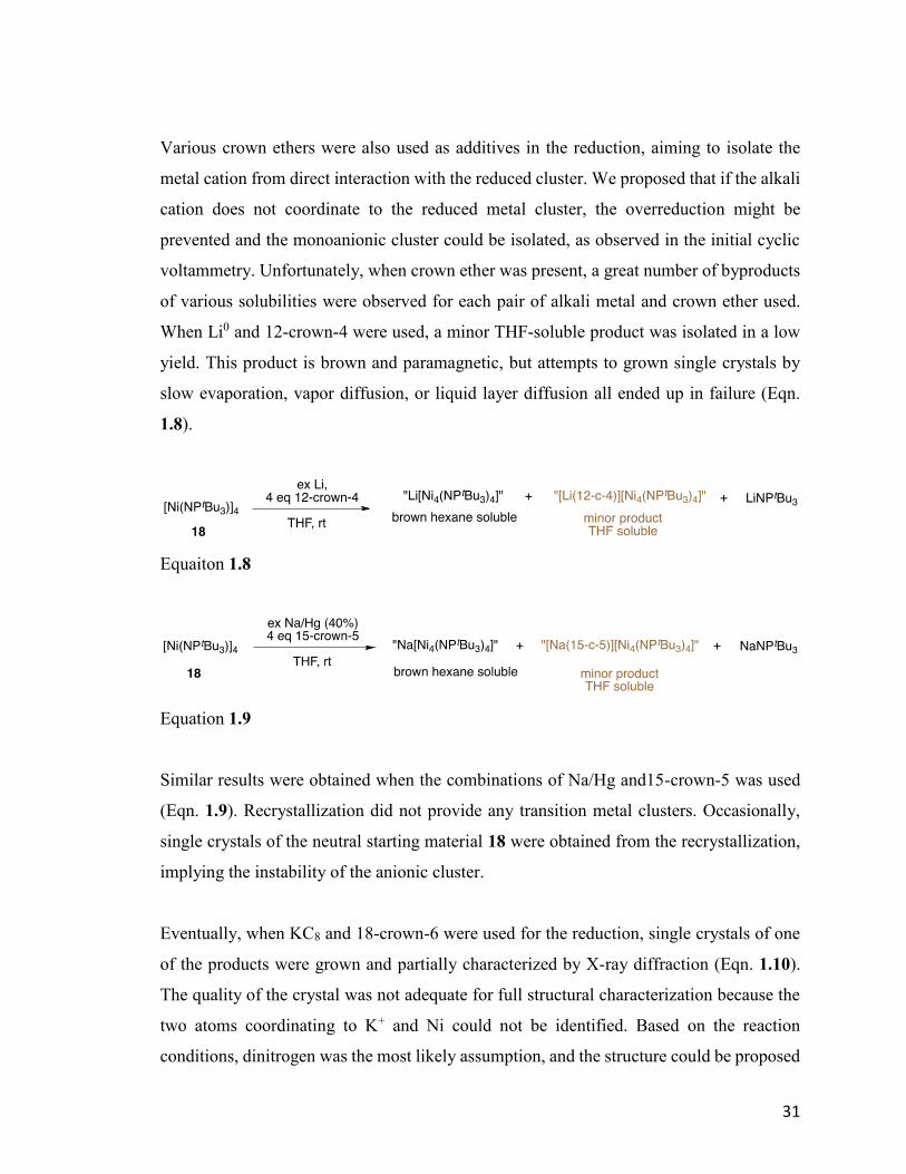
Various crown ethers were also used as additives in the reduction, aiming to isolate the
metal cation from direct interaction with the reduced cluster. We proposed that if the alkali
cation does not coordinate to the reduced metal cluster, the overreduction might be
prevented and the monoanionic cluster could be isolated, as observed in the initial cyclic
voltammetry. Unfortunately, when crown ether was present, a great number of byproducts
of various solubilities were observed for each pair of alkali metal and crown ether used.
When Li0 and 12-crown-4 were used, a minor THF-soluble product was isolated in a low
yield. This product is brown and paramagnetic, but attempts to grown single crystals by
slow evaporation, vapor diffusion, or liquid layer diffusion all ended up in failure (Eqn.
1.8).
Equaiton 1.8
Equation 1.9
Similar results were obtained when the combinations of Na/Hg and15-crown-5 was used
(Eqn. 1.9). Recrystallization did not provide any transition metal clusters. Occasionally,
single crystals of the neutral starting material 18 were obtained from the recrystallization,
implying the instability of the anionic cluster.
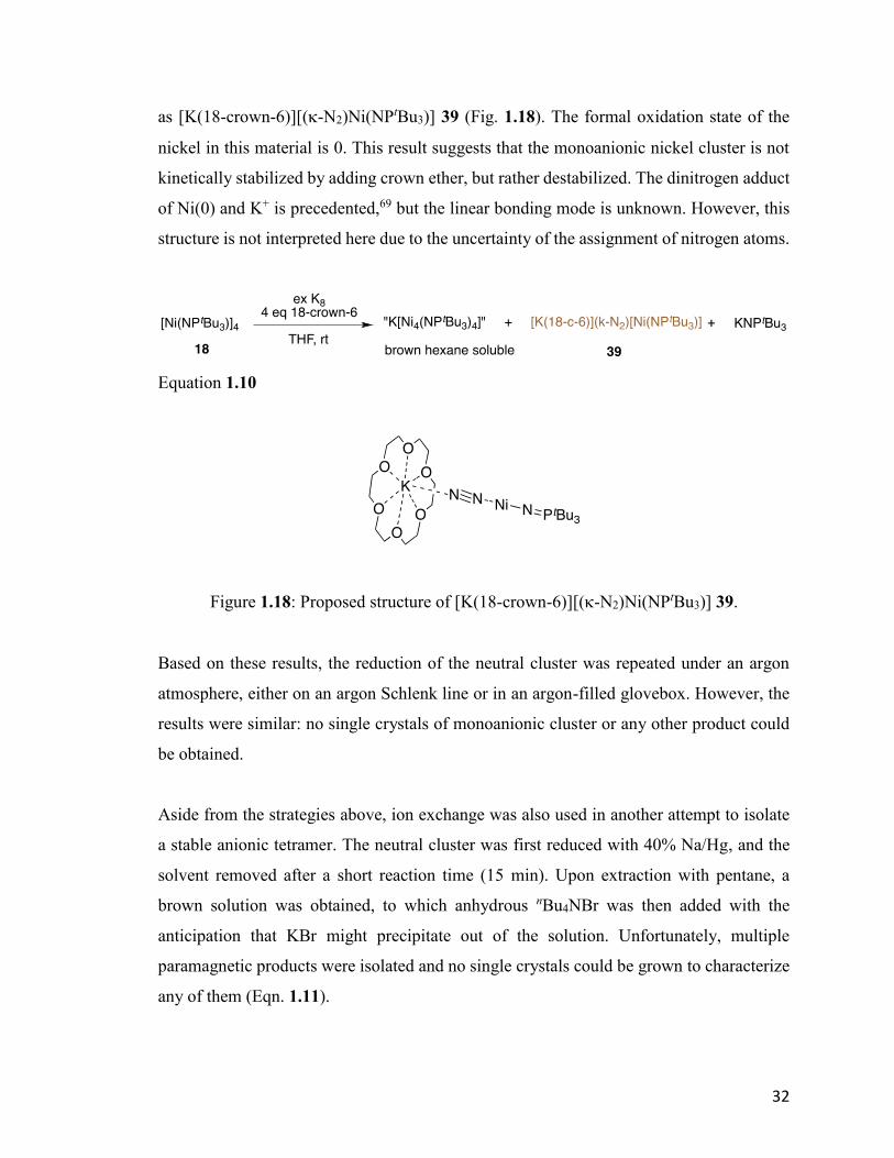
Eventually, when KC8 and 18-crown-6 were used for the reduction, single crystals of one
of the products were grown and partially characterized by X-ray diffraction (Eqn. 1.10).
The quality of the crystal was not adequate for full structural characterization because the
two atoms coordinating to K+ and Ni could not be identified. Based on the reaction
conditions, dinitrogen was the most likely assumption, and the structure could be proposed
32
as [K(18-crown-6)][(-N2)Ni(NPtBu3)] 39 (Fig. 1.18). The formal oxidation state of the
nickel in this material is 0. This result suggests that the monoanionic nickel cluster is not
kinetically stabilized by adding crown ether, but rather destabilized. The dinitrogen adduct
of Ni(0) and K+ is precedented,69 but the linear bonding mode is unknown. However, this
structure is not interpreted here due to the uncertainty of the assignment of nitrogen atoms.
Equation 1.10
Figure 1.18: Proposed structure of [K(18-crown-6)][(-N2)Ni(NPtBu3)] 39.
Based on these results, the reduction of the neutral cluster was repeated under an argon
atmosphere, either on an argon Schlenk line or in an argon-filled glovebox. However, the
results were similar: no single crystals of monoanionic cluster or any other product could
be obtained.
Aside from the strategies above, ion exchange was also used in another attempt to isolate
a stable anionic tetramer. The neutral cluster was first reduced with 40% Na/Hg, and the
solvent removed after a short reaction time (15 min). Upon extraction with pentane, a
brown solution was obtained, to which anhydrous nBu4NBr was then added with the
anticipation that KBr might precipitate out of the solution. Unfortunately, multiple
paramagnetic products were isolated and no single crystals could be grown to characterize
any of them (Eqn. 1.11).
33
Equation 1.11
1.3.2.4 Synthesis of Na[Ni4(NPtBu3)4]: a consistent procedure
Because the isolation of pure monoanionic cluster Na[Ni4(NPtBu3)4] 31 was unsuccessful,
it became crucial to develop a consistent, reproducible preparation for use of this
compound for further exploration of its activity. The priority was to determine whether the
anionic cluster is monoanionic or dianionic; either was possible and both may be present;
meanwhile, rearrangement to other oligomers remains a reasonable possibility.
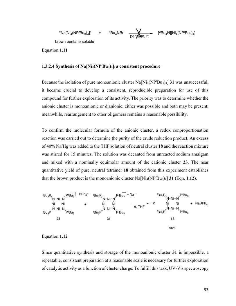
To confirm the molecular formula of the anionic cluster, a redox conproportionation
reaction was carried out to determine the purity of the crude reduction product. An excess
of 40% Na/Hg was added to the THF solution of neutral cluster 18 and the reaction mixture
was stirred for 15 minutes. The solution was decanted from unreacted sodium amalgam
and mixed with a nominally equimolar amount of the cationic cluster 23. The near
quantitative yield of pure, neutral tetramer 18 obtained from this experiment establishes
that the brown product is the monoanionic cluster Na[Ni4(NPtBu3)4] 31 (Eqn. 1.12).
Equation 1.12
Since quantitative synthesis and storage of the monoanionic cluster 31 is impossible, a
repeatable, consistent preparation at a reasonable scale is necessary for further exploration
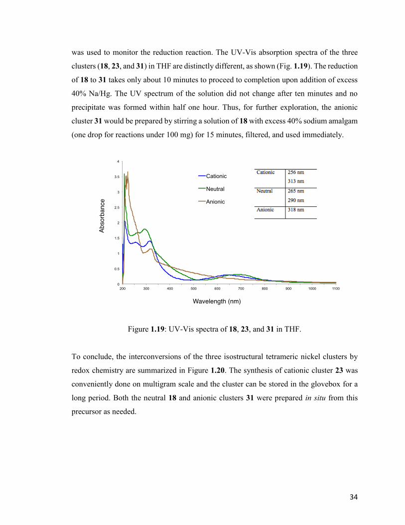
of catalytic activity as a function of cluster charge. To fulfill this task, UV-Vis spectroscopy
34
was used to monitor the reduction reaction. The UV-Vis absorption spectra of the three
clusters (18, 23, and 31) in THF are distinctly different, as shown (Fig. 1.19). The reduction
of 18 to 31 takes only about 10 minutes to proceed to completion upon addition of excess
40% Na/Hg. The UV spectrum of the solution did not change after ten minutes and no
precipitate was formed within half one hour. Thus, for further exploration, the anionic
cluster 31 would be prepared by stirring a solution of 18 with excess 40% sodium amalgam
(one drop for reactions under 100 mg) for 15 minutes, filtered, and used immediately.
Figure 1.19: UV-Vis spectra of 18, 23, and 31 in THF.
To conclude, the interconversions of the three isostructural tetrameric nickel clusters by
redox chemistry are summarized in Figure 1.20. The synthesis of cationic cluster 23 was
conveniently done on multigram scale and the cluster can be stored in the glovebox for a
long period. Both the neutral 18 and anionic clusters 31 were prepared in situ from this
precursor as needed.
35
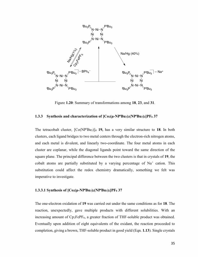
Figure 1.20: Summary of transformations among 18, 23, and 31.
1.3.3 Synthesis and characterization of [Co2(μ-NPtBu3)2(NPtBu3)2]PF6 37
The tetracobalt cluster, [Co(NPtBu3)]4 19, has a very similar structure to 18. In both
clusters, each ligand bridges to two metal centers through the electron-rich nitrogen atoms,
and each metal is divalent, and linearly two-coordinate. The four metal atoms in each
cluster are coplanar, while the diagonal ligands point toward the same direction of the
square plane. The principal difference between the two clusters is that in crystals of 19, the
cobalt atoms are partially substituted by a varying percentage of Na+ cation. This
substitution could affect the redox chemistry dramatically, something we felt was
imperative to investigate.
1.3.3.1 Synthesis of [Co2(μ-NPtBu3)2(NPtBu3)2]PF6 37
The one-electron oxidation of 19 was carried out under the same conditions as for 18. The
reaction, unexpectedly, gave multiple products with different solubilities. With an
increasing amount of Cp2FePF6, a greater fraction of THF-soluble product was obtained.
Eventually upon addition of eight equivalents of the oxidant, the reaction proceeded to
completion, giving a brown, THF-soluble product in good yield (Eqn. 1.13). Single crystals

36
of the product were grown by slowly cooling a saturated THF solution to -30°C in the
glovebox freezer. X-ray diffraction revealed the structure to be [Co2(μ-
NPtBu3)2(NPtBu3)2]PF6 37 (Fig. 1.21). The fate of the missing cobalt and sodium atoms
and the reasons for requiring excess oxidant are not known yet.
Equation 1.13
Figure 1.21: ORTEP diagram of cationic 37, thermal ellipsoids are shown at 30 %
probability. Counter ion and hydrogen atoms have been omitted for clarity.
In the crystal structure of 37, two cobalt atoms are bridged by two 2-phosphoranimide
ligands, forming a four-membered ring. Additional phosphoranimide ligand coordinates
37
terminally to each cobalt metal. The cationic bimetallic cluster 37 can be seen as the one-
electron oxidation product of the neutral dimetallic compound, Co2(μ-NPtBu3)2(NPtBu3)2
38, which was previously synthesized and characterized by Dominique Hebert in the
Stryker group.
We believe that the instability of the anticipated cationic mixed-valence cluster is at least
partly because of the substantial replacement of Na+ in the neutral cluster 19. In the case
of nickel analog 18, when the cluster is oxidized the positive charge delocalizes to all four
metals to form a type III mixed-valence Ni(II)/3Ni(I) cluster. In the case of 19 some of the
Co+ is displaced by Na+, which disrupts the symmetry and delocalization of the positive
charge. As a result, the four cobalt atoms in the square are no longer identical, leading to
the reorganization of the cluster. At that stage, further oxidation might become possible
and the product 37 is likely the highest oxidation state that could be achieved by Cp2FePF6.
This could be clarified if the pure, sodium-free cluster could be synthesized by an
alternative route, which is currently under study by another group member. Computational
investigation of redox and magnetic phenomenon is also ongoing.
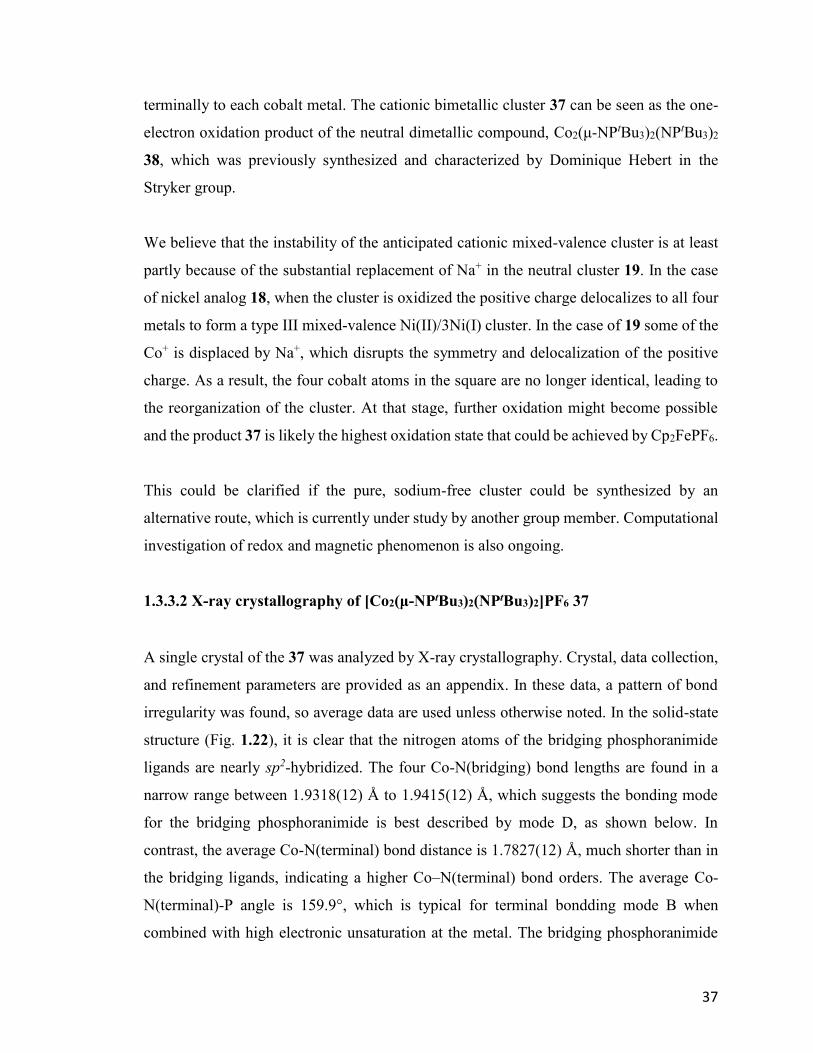
1.3.3.2 X-ray crystallography of [Co2(μ-NPtBu3)2(NPtBu3)2]PF6 37
A single crystal of the 37 was analyzed by X-ray crystallography. Crystal, data collection,
and refinement parameters are provided as an appendix. In these data, a pattern of bond
irregularity was found, so average data are used unless otherwise noted. In the solid-state
structure (Fig. 1.22), it is clear that the nitrogen atoms of the bridging phosphoranimide
ligands are nearly sp2-hybridized. The four Co-N(bridging) bond lengths are found in a
narrow range between 1.9318(12) Å to 1.9415(12) Å, which suggests the bonding mode
for the bridging phosphoranimide is best described by mode D, as shown below. In
contrast, the average Co-N(terminal) bond distance is 1.7827(12) Å, much shorter than in
the bridging ligands, indicating a higher Co–N(terminal) bond orders. The average Co-
N(terminal)-P angle is 159.9°, which is typical for terminal bondding mode B when
combined with high electronic unsaturation at the metal. The bridging phosphoranimide
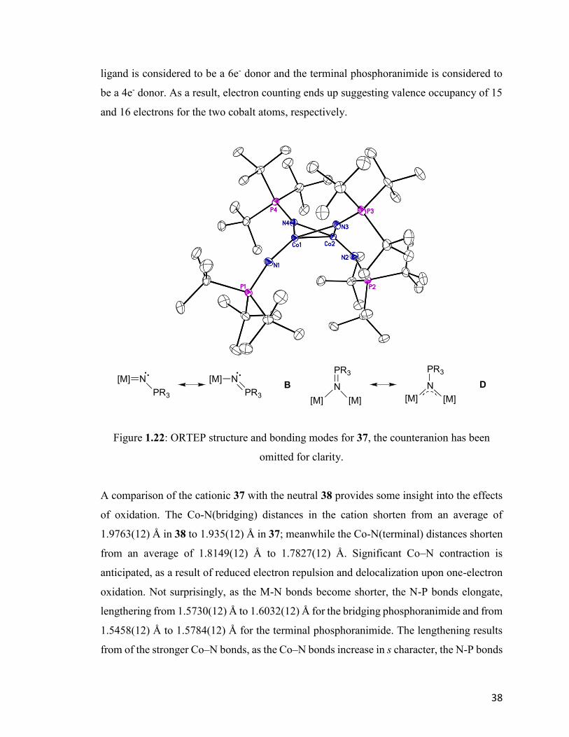
38
ligand is considered to be a 6e- donor and the terminal phosphoranimide is considered to
be a 4e- donor. As a result, electron counting ends up suggesting valence occupancy of 15
and 16 electrons for the two cobalt atoms, respectively.
Figure 1.22: ORTEP structure and bonding modes for 37, the counteranion has been
omitted for clarity.
A comparison of the cationic 37 with the neutral 38 provides some insight into the effects
of oxidation. The Co-N(bridging) distances in the cation shorten from an average of
1.9763(12) Å in 38 to 1.935(12) Å in 37; meanwhile the Co-N(terminal) distances shorten
from an average of 1.8149(12) Å to 1.7827(12) Å. Significant Co–N contraction is
anticipated, as a result of reduced electron repulsion and delocalization upon one-electron
oxidation. Not surprisingly, as the M-N bonds become shorter, the N-P bonds elongate,
lengthering from 1.5730(12) Å to 1.6032(12) Å for the bridging phosphoranimide and from
1.5458(12) Å to 1.5784(12) Å for the terminal phosphoranimide. The lengthening results
from of the stronger Co–N bonds, as the Co–N bonds increase in s character, the N-P bonds
[M]
N
PR3
[M] [M]
N
PR3
[M]
D[M] N
PR3
[M] N
PR3
B

39
assume more p character in the hybridization. The same trend is also observed upon
oxidation of nickel cluster 18.
The core Co2N2 unit adopts a butterfly shape in both cationic 37 and neutral 38. Upon
oxidation, the N-N distance remains the same as 2.8022(12) Å, but the Co-Co distances
decreases from 2.5088(12) Å to 2.3851(12) Å. The average Co-N(bridging)-Co angle
contracts from 78.84(8)° to 76.00(8)°, as the average N(bridging)-Co-N(bridging) angle
opens from 90.31(8)° to 92.64(8)°. The torsion angles of Co-N-N-Co stays almost
identical, 133.19(12)° versus 133.20(12)°.
In summary, although the core Co2N2 contracts, by shortening the Co-N(bridging) and Co-
Co distances, the Co-N-N-Co dihedral angles remain identical. No reaction chemistry of
or catalysis using 37 has been explored because this cluster and corresponding neutral
dimer 38 remain under investigation by other members in the group.
1.4 Conclusion
In this chapter, the synthesis, physical characterization and redox chemistry of the both
homoleptic phosphoranimide-bridging clusters 18 and 19 have been explored. For the
nickel analog, the oxidation products [Ni4(NPtBu3)4]BPh4 23 and [Ni4(NPtBu3)4]PF6 30
have been prepared and fully characterized. Upon oxidation, the shape of the cluster does
not change much, presumably a consequence of the steric demand of the [NPtBu3–] ligand,
even stronger Ni-N bonds and weaker N-P bonds were observed. Both 23 and 30 are type
III mixed-valence clusters.
The monoanionic reduction product Na[Ni4(NPtBu3)4] 31 has been prepared in reasonably
pure form and identified, but the cluster could not be fully characterized. Attempts to grow
single crystals failed due to the kinetic instability of the cluster. However, a consistent in
situ preparation of relatively pure 21 has been developed for further synthetic and catalysis
exploration.
40
On the other hand, one-electron oxidation of [Co(NPtBu3)]4 19 results in the formation of
the dimetallic mix-valence cluster [Co2(NPtBu3)4]PF6 37, which is probably the result of
Na+ replacement in the nominally neutral cluster 19. Synthesis and characterization of pure
19 remains an ongoing challenge by other members of the group.
41
Chapter 2. Phosphoranimide-bridged Nickel Catalysts for
Hydrogenation of Alkenes and Alkynes
2.1 Introduction
The phosphoranimide-supported late first-row transition metal clusters were originally
proposed for catalytic hydrotreatment in petroleum upgrading processes, such as
hydrodesulfurization (HDS) and hydrodenitrogenation (HDN). In addition to that, a range
of activities were also explored, due to the low-coordinate and low-valence character of
the cluster, including hydrogenation of alkyne and alkene. Based on preliminary results
obtained by Dr. Jeffrey Camacho-Bunquin,45,70 the neutral cluster 18 was an effective
precatalyst for hydrogenation of alkynes and alkenes. However, later group members found
the hydrogenation results irreproducible, depending on different batches of the catalyst.71
Even more confusing was that extremely low conversion was generally observed when the
purest-looking single crystals were used in the reaction. These results led to our assumption
that the catalyst previously investigated had been contaminated, and quite possibly, the
contaminant was most active in the catalysis. Now, since the cationic cluster 23 and anionic
clusters 31 have been prepared and characterized, it became imperative to investigate the
hydrogenation activity for all three clusters (Fig. 2.1).
Figure 2.1: Structures of 23, 18, and 31.
In this chapter, the irreproducibility of hydrogenation of diphenyl acetylene will be
discussed first, followed by the hydrogenation investigation of 23, 18, and 31.
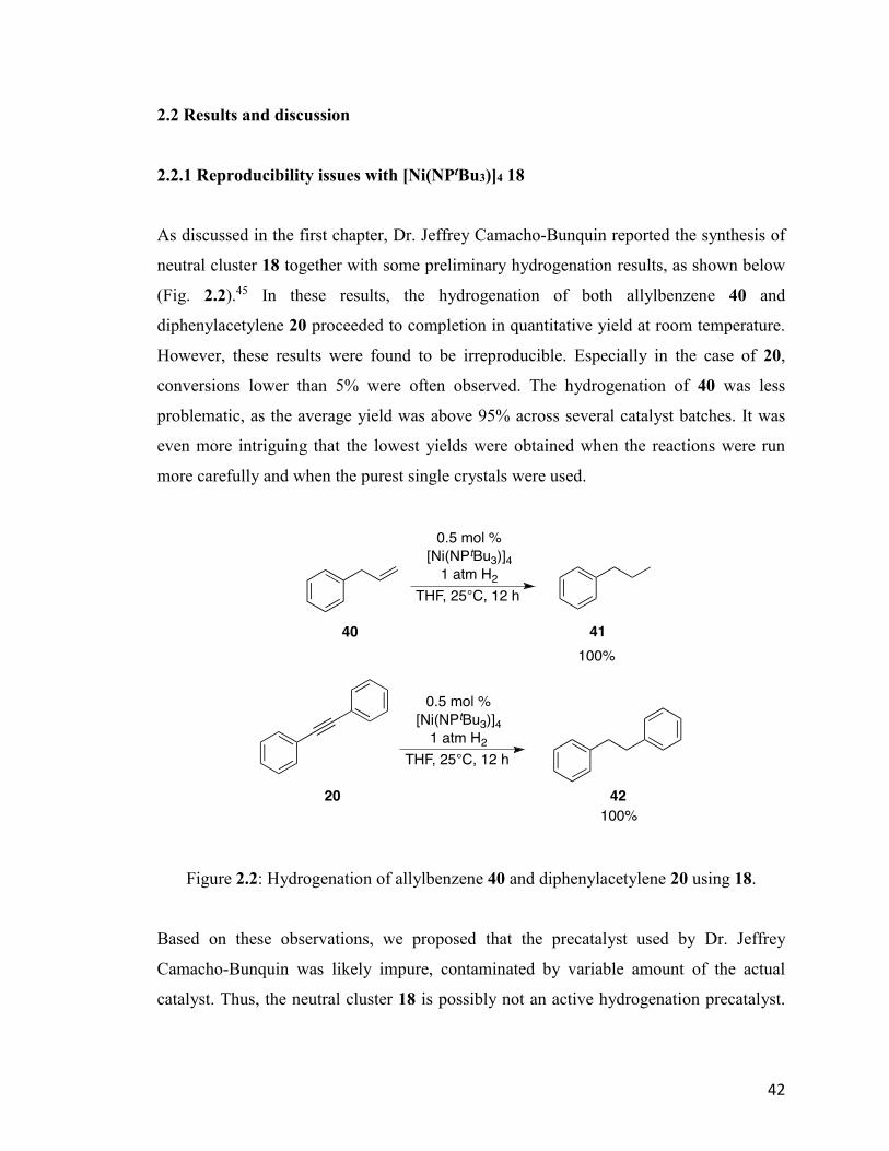
42
2.2 Results and discussion
2.2.1 Reproducibility issues with [Ni(NPtBu3)]4 18
As discussed in the first chapter, Dr. Jeffrey Camacho-Bunquin reported the synthesis of
neutral cluster 18 together with some preliminary hydrogenation results, as shown below
(Fig. 2.2).45 In these results, the hydrogenation of both allylbenzene 40 and
diphenylacetylene 20 proceeded to completion in quantitative yield at room temperature.
However, these results were found to be irreproducible. Especially in the case of 20,
conversions lower than 5% were often observed. The hydrogenation of 40 was less
problematic, as the average yield was above 95% across several catalyst batches. It was
even more intriguing that the lowest yields were obtained when the reactions were run
more carefully and when the purest single crystals were used.
Figure 2.2: Hydrogenation of allylbenzene 40 and diphenylacetylene 20 using 18.
Based on these observations, we proposed that the precatalyst used by Dr. Jeffrey
Camacho-Bunquin was likely impure, contaminated by variable amount of the actual
catalyst. Thus, the neutral cluster 18 is possibly not an active hydrogenation precatalyst.
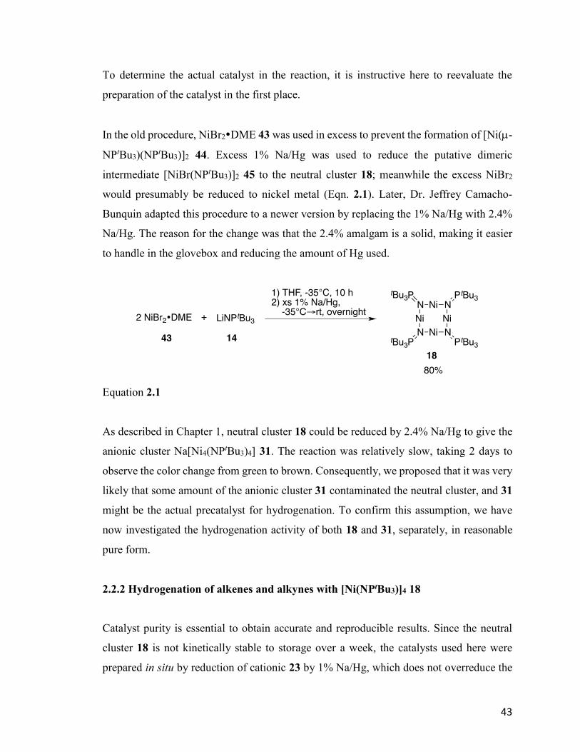
43
To determine the actual catalyst in the reaction, it is instructive here to reevaluate the
preparation of the catalyst in the first place.
In the old procedure, NiBr2DME 43 was used in excess to prevent the formation of [Ni(-
NPtBu3)(NPtBu3)]2 44. Excess 1% Na/Hg was used to reduce the putative dimeric
intermediate [NiBr(NPtBu3)]2 45 to the neutral cluster 18; meanwhile the excess NiBr2
would presumably be reduced to nickel metal (Eqn. 2.1). Later, Dr. Jeffrey Camacho-
Bunquin adapted this procedure to a newer version by replacing the 1% Na/Hg with 2.4%
Na/Hg. The reason for the change was that the 2.4% amalgam is a solid, making it easier
to handle in the glovebox and reducing the amount of Hg used.
Equation 2.1
As described in Chapter 1, neutral cluster 18 could be reduced by 2.4% Na/Hg to give the
anionic cluster Na[Ni4(NPtBu3)4] 31. The reaction was relatively slow, taking 2 days to
observe the color change from green to brown. Consequently, we proposed that it was very
likely that some amount of the anionic cluster 31 contaminated the neutral cluster, and 31
might be the actual precatalyst for hydrogenation. To confirm this assumption, we have
now investigated the hydrogenation activity of both 18 and 31, separately, in reasonable
pure form.
2.2.2 Hydrogenation of alkenes and alkynes with [Ni(NPtBu3)]4 18
Catalyst purity is essential to obtain accurate and reproducible results. Since the neutral
cluster 18 is not kinetically stable to storage over a week, the catalysts used here were
prepared in situ by reduction of cationic 23 by 1% Na/Hg, which does not overreduce the

44
18. The hydrogenation reactions were set up in middle-walled glass reactors in the glove
box with a 1 mol% loading of 18. The reactions were run for six hours and then opened to
air before work-up. The products were characterized by 1H-NMR spectroscopy and/or gas
chromatography (GC). For GC, the detector responses for all the starting materials and all
possible products were calibrated so quantitative results could be obtained. The calibration
process is included in chapter 6.
Equation 2.2
The hydrogenation of 20 was revisited, and a very low conversion to cis-stilbene 46 was
observed (Eqn. 2.2). This result confirms the assumption that the pure neutral cluster 18 is
not an effective precatalyst.
Figure 2.3: Hydrogenation of selected alkenes with 1 mol% neutral cluster 18.
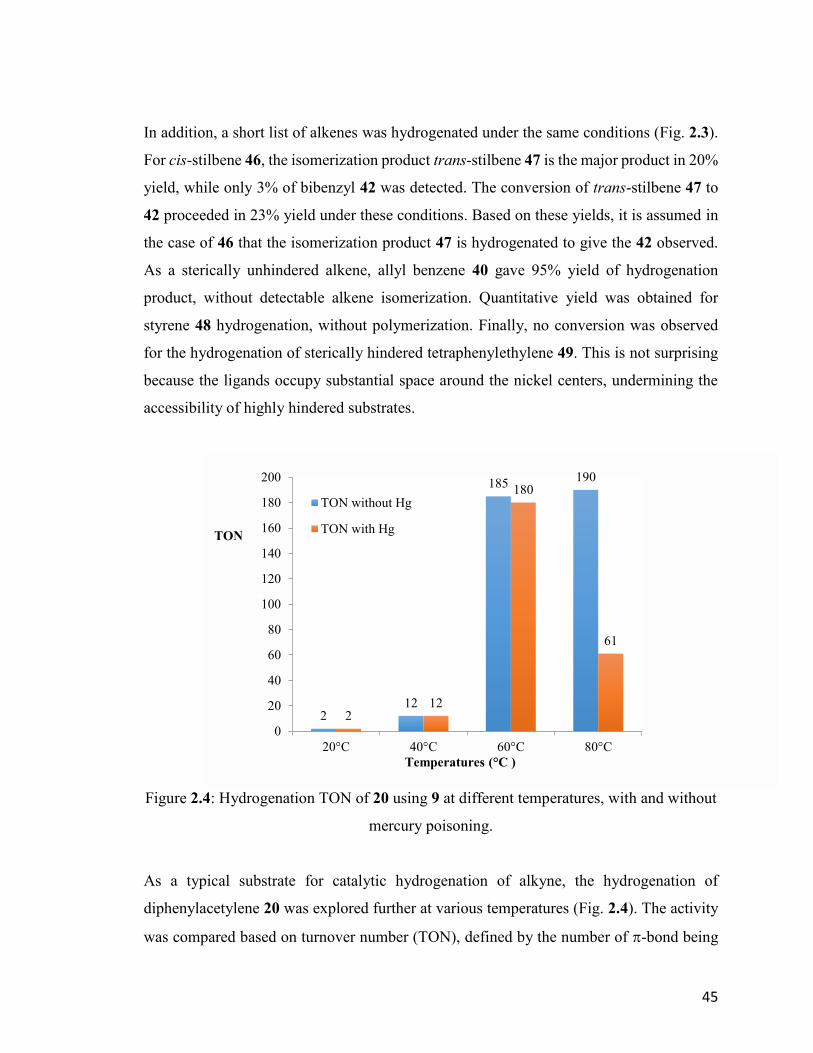
45
In addition, a short list of alkenes was hydrogenated under the same conditions (Fig. 2.3).
For cis-stilbene 46, the isomerization product trans-stilbene 47 is the major product in 20%
yield, while only 3% of bibenzyl 42 was detected. The conversion of trans-stilbene 47 to
42 proceeded in 23% yield under these conditions. Based on these yields, it is assumed in
the case of 46 that the isomerization product 47 is hydrogenated to give the 42 observed.
As a sterically unhindered alkene, allyl benzene 40 gave 95% yield of hydrogenation
product, without detectable alkene isomerization. Quantitative yield was obtained for
styrene 48 hydrogenation, without polymerization. Finally, no conversion was observed
for the hydrogenation of sterically hindered tetraphenylethylene 49. This is not surprising
because the ligands occupy substantial space around the nickel centers, undermining the
accessibility of highly hindered substrates.
Figure 2.4: Hydrogenation TON of 20 using 9 at different temperatures, with and without
mercury poisoning.
As a typical substrate for catalytic hydrogenation of alkyne, the hydrogenation of
diphenylacetylene 20 was explored further at various temperatures (Fig. 2.4). The activity
was compared based on turnover number (TON), defined by the number of -bond being
212
185190
212
180
61
0
20
40
60
80
100
120
140
160
180
200
20°C 40°C 60°C 80°C
TON
Temperatures (°C )
TON without Hg
TON with Hg
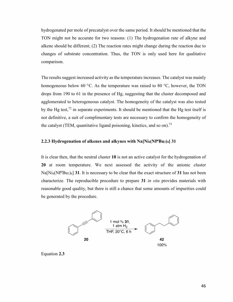
46
hydrogenated per mole of precatalyst over the same period. It should be mentioned that the
TON might not be accurate for two reasons: (1) The hydrogenation rate of alkyne and
alkene should be different; (2) The reaction rates might change during the reaction due to
changes of substrate concentration. Thus, the TON is only used here for qualitative
comparison.
The results suggest increased activity as the temperature increases. The catalyst was mainly
homogeneous below 60 C. As the temperature was raised to 80 °C, however, the TON
drops from 190 to 61 in the presence of Hg, suggesting that the cluster decomposed and
agglomerated to heterogeneous catalyst. The homogeneity of the catalyst was also tested
by the Hg test,72 in separate experiments. It should be mentioned that the Hg test itself is
not definitive, a suit of complimentary tests are necessary to confirm the homogeneity of
the catalyst (TEM, quantitative ligand poisoning, kinetics, and so on).73
2.2.3 Hydrogenation of alkenes and alkynes with Na[Ni4(NPtBu3)4] 31
It is clear then, that the neutral cluster 18 is not an active catalyst for the hydrogenation of
20 at room temperature. We next assessed the activity of the anionic cluster
Na[Ni4(NPtBu3)4] 31. It is necessary to be clear that the exact structure of 31 has not been
characterize. The reproducible procedure to prepare 31 in situ provides materials with
reasonable good quality, but there is still a chance that some amounts of impurities could
be generated by the procedure.
Equation 2.3

47
Again the hydrogenation of 20 was studied first. The result shows quantitative conversion
to 42 over the six-hour reaction (Eqn. 2.3). This result strongly supports our assumption
that the anionic cluster 31 is the actual catalyst for the hydrogenation of 20.
Furthermore, the same range of alkene substrates was explored under the same conditions
(Fig. 2.5). In most cases, the anionic cluster 31 exhibited higher activity than the neutral
cluster 18, as higher conversions were observed. Quantitative yield was obtained for
hydrogenation of 40 to give 41. About 45% of the 47 was converted to 42. For 46, the
major product with this catalyst is 42 in 85% yield, with only 15% of 47 observed after full
conversion of the starting material. In the case of 48, polymerization overrides
hydrogenation, likely initiated by one electron transfer. No conversion was again observed
for the sterically hindered 49, as obtained using neutral cluster 18.
Figure 2.5: Hydrogenation of selected alkenes with 1 mol% anionic cluster 31.
The homogeneity of the catalyst was also tested by mercury poisoning at various
temperatures. The results are shown in Figure 2.6. The catalyst was mainly heterogeneous
at room temperature, as adding excess mercury into the solution resulted in a decrease of
TON from 200 to 57. A similar result was obtained at 80 °C, which gave a TON of 64 in
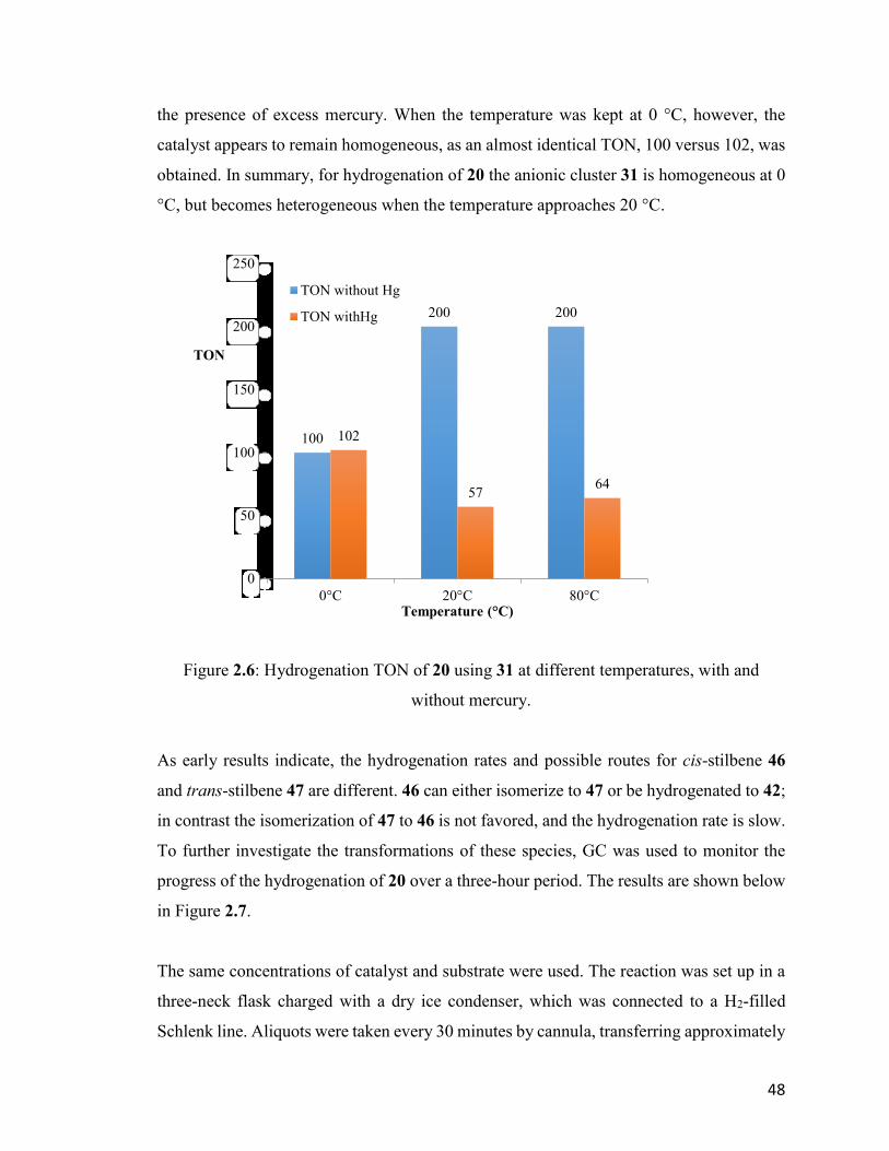
48
the presence of excess mercury. When the temperature was kept at 0 °C, however, the
catalyst appears to remain homogeneous, as an almost identical TON, 100 versus 102, was
obtained. In summary, for hydrogenation of 20 the anionic cluster 31 is homogeneous at 0
°C, but becomes heterogeneous when the temperature approaches 20 °C.
Figure 2.6: Hydrogenation TON of 20 using 31 at different temperatures, with and
without mercury.
As early results indicate, the hydrogenation rates and possible routes for cis-stilbene 46
and trans-stilbene 47 are different. 46 can either isomerize to 47 or be hydrogenated to 42;
in contrast the isomerization of 47 to 46 is not favored, and the hydrogenation rate is slow.
To further investigate the transformations of these species, GC was used to monitor the
progress of the hydrogenation of 20 over a three-hour period. The results are shown below
in Figure 2.7.
The same concentrations of catalyst and substrate were used. The reaction was set up in a
three-neck flask charged with a dry ice condenser, which was connected to a H2-filled
Schlenk line. Aliquots were taken every 30 minutes by cannula, transferring approximately
100
200 200
102
5764
0
50
100
150
200
250
0°C 20°C 80°C
TON
Temperature (°C)
TON without Hg
TON withHg
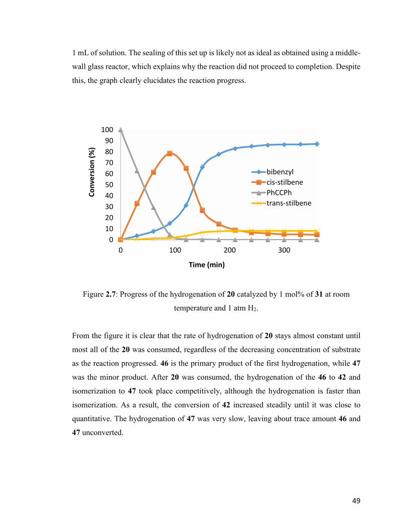
49
1 mL of solution. The sealing of this set up is likely not as ideal as obtained using a middle-
wall glass reactor, which explains why the reaction did not proceed to completion. Despite
this, the graph clearly elucidates the reaction progress.
Figure 2.7: Progress of the hydrogenation of 20 catalyzed by 1 mol% of 31 at room
temperature and 1 atm H2.
From the figure it is clear that the rate of hydrogenation of 20 stays almost constant until
most all of the 20 was consumed, regardless of the decreasing concentration of substrate
as the reaction progressed. 46 is the primary product of the first hydrogenation, while 47
was the minor product. After 20 was consumed, the hydrogenation of the 46 to 42 and
isomerization to 47 took place competitively, although the hydrogenation is faster than
isomerization. As a result, the conversion of 42 increased steadily until it was close to
quantitative. The hydrogenation of 47 was very slow, leaving about trace amount 46 and
47 unconverted.
0
10
20
30
40
50
60
70
80
90
100
0 100 200 300
Co
nve
rsio
n (
%)
Time (min)
bibenzyl
cis-stilbene
PhCCPh
trans-stilbene
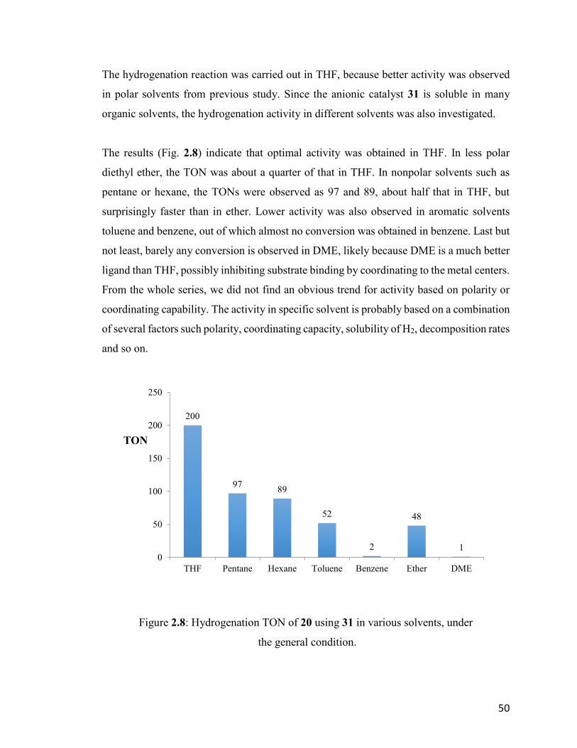
50
The hydrogenation reaction was carried out in THF, because better activity was observed
in polar solvents from previous study. Since the anionic catalyst 31 is soluble in many
organic solvents, the hydrogenation activity in different solvents was also investigated.
The results (Fig. 2.8) indicate that optimal activity was obtained in THF. In less polar
diethyl ether, the TON was about a quarter of that in THF. In nonpolar solvents such as
pentane or hexane, the TONs were observed as 97 and 89, about half that in THF, but
surprisingly faster than in ether. Lower activity was also observed in aromatic solvents
toluene and benzene, out of which almost no conversion was obtained in benzene. Last but
not least, barely any conversion is observed in DME, likely because DME is a much better
ligand than THF, possibly inhibiting substrate binding by coordinating to the metal centers.
From the whole series, we did not find an obvious trend for activity based on polarity or
coordinating capability. The activity in specific solvent is probably based on a combination
of several factors such polarity, coordinating capacity, solubility of H2, decomposition rates
and so on.
Figure 2.8: Hydrogenation TON of 20 using 31 in various solvents, under
the general condition.
200
9789
52
2
48
10
50
100
150
200
250
THF Pentane Hexane Toluene Benzene Ether DME
TON
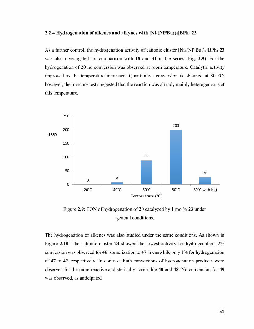
51
2.2.4 Hydrogenation of alkenes and alkynes with [Ni4(NPtBu3)4]BPh4 23
As a further control, the hydrogenation activity of cationic cluster [Ni4(NPtBu3)4]BPh4 23
was also investigated for comparison with 18 and 31 in the series (Fig. 2.9). For the
hydrogenation of 20 no conversion was observed at room temperature. Catalytic activity
improved as the temperature increased. Quantitative conversion is obtained at 80 °C;
however, the mercury test suggested that the reaction was already mainly heterogeneous at
this temperature.
Figure 2.9: TON of hydrogenation of 20 catalyzed by 1 mol% 23 under
general conditions.
The hydrogenation of alkenes was also studied under the same conditions. As shown in
Figure 2.10. The cationic cluster 23 showed the lowest activity for hydrogenation. 2%
conversion was observed for 46 isomerization to 47, meanwhile only 1% for hydrogenation
of 47 to 42, respectively. In contrast, high conversions of hydrogenation products were
observed for the more reactive and sterically accessible 40 and 48. No conversion for 49
was observed, as anticipated.
08
88
200
26
0
50
100
150
200
250
20°C 40°C 60°C 80°C 80°C(with Hg)
Temperature (°C)
TON
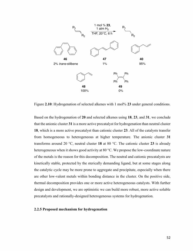
52
Figure 2.10: Hydrogenation of selected alkenes with 1 mol% 23 under general conditions.
Based on the hydrogenation of 20 and selected alkenes using 18, 23, and 31, we conclude
that the anionic cluster 31 is a more active precatalyst for hydrogenation than neutral cluster
18, which is a more active precatalyst than cationic cluster 23. All of the catalysts transfer
from homogeneous to heterogeneous at higher temperature. The anionic cluster 31
transforms around 20 °C, neutral cluster 18 at 80 °C. The cationic cluster 23 is already
heterogeneous when it shows good activity at 80 °C. We propose the low-coordinate nature
of the metals is the reason for this decomposition. The neutral and cationic precatalysts are
kinetically stable, protected by the sterically demanding ligand, but at some stages along
the catalytic cycle may be more prone to aggregate and precipitate, especially when there
are other low-valent metals within bonding distance in the cluster. On the positive side,
thermal decomposition provides one or more active heterogeneous catalysts. With further
design and development, we are optimistic we can build more robust, more active soluble
precatalysts and rationally-designed heterogeneous systems for hydrogenation.
2.2.5 Proposed mechanism for hydrogenation

53
Based on the results and observations on the hydrogenation reactions, a mechanism is
proposed (Fig. 2.11). It should be mentioned that 18, 23, and 31 have distinctive activities,
depending on the charge of the cluster. The mechanism presented here is based on the
neutral cluster 23, even though the relevancy of other clusters will be mentioned.
Figure 2.11: Proposed mechanism for hydrogenation of 20 using 18.
The mechanism is highly tentative because not much concrete information has been
collected to elucidate the details along the catalytic cycle. This is mainly due to the lack of
54
effective methods to study these paramagnetic transition metal clusters in solution.
Preliminary DFT computations suggests one equivalent of the neutral cluster reacts with
two equivalents of H2 without activation barrier, forming a mixed-valence
tetrahydridonickel cluster represented by 50. Both terminal and bridging nickel hydride is
proposed because they were both detected by IR around 2000 cm-1 and 1600 cm-1.70
The tetrahydridonickel cluster 50 then dissociates into two dimeric nickel species 51. The
dissociation is proposed here due to the similar pathway observed in HDS for tetrametallic
[Me4Co4(NPEt3)4]PF6 22. In the case of cationic 23 and anionic 31, the dissociation could
lead to dimetallic clusters with different charges, which may explain the activity difference.
The substrate 20 then coordinates to 51 to give 52 as an intermediate. Subsequent migratory
insertion delivers the hydride from the same face of nickel center to form 53, which
determines the cis geometry of the double bond in the major product. In the vinylnickel
complex 53, both nickel atoms are three-coordinate and bimetallic hydrogen activation
gives trihydridonickel(II) cluster 54. Subsequent reductive elimination releases the product
46 and regenerates the active catalyst 51. Hydrogenation of 47 is slow due to the steric
bulky phosphoranimide ligand, which hinders the coordination of the substrate. When 46
is the substrate, the migratory insertion step is reversible so the isomerization to 47 is
possible.
During the catalytic cycle, the low-valent nickel cluster could agglomerate to produce a
heterogeneous catalyst, which is possibly even more active for hydrogenation by other
related mechanisms.
In addition, the dissociation to form dimers would be entropic more favored under elevated
temperature, which explains the improved hydrogenation activity of the cationic cluster 23
and neutral cluster 18 at higher temperatures. Meanwhile, increasing the reaction
temperature also accelerates the agglomeration/decomposition to heterogeneous catalysts.
It is also possible that several oligomers are present in the system and each has its own
catalytic cycle.

55
2.3 Conclusions
In this chapter, the reproducibility problems revealed in our study of the hydrogenation of
20 with the neutral cluster 18 were raised, studied, and addressed. The root of this problem
is the overreduced, anionic impurity present in the neutral cluster when prepared by the
procedure developed by Dr. Jeffrey Camacho-Bunquin. The neutral cluster 18 was found
to be ineffective as a hydrogenation catalyst at room temperature. In contrast, the impurity,
anionic cluster 31, was the highest-activity catalyst for hydrogenation.
Due to the unstable nature of the neutral and anionic clusters, a new procedure was
developed to synthesize the cationic cluster 23 on gram scale and purify it rigorously. The
neutral cluster 18 and anionic cluster 31 can then be prepared in situ before using them.
The hydrogenation activities of three nominally isostructural tetranickel clusters were
investigated to determine electronic effects on catalysis. In general, the anionic cluster 31
forms a more active catalyst than neutral cluster 18, which is more active than cationic
cluster 23. As the temperature is increased, higher activities were observed for all three
compounds, although much of that must be attributed to the catalysts transforming from
homogeneous to heterogeneous.
The low-valent nature of the metal and the coordinatively unsaturated framework of metal
clusters are assumed to be the reason for this decomposition to heterogeneous catalyst.
Further investigation will be undertaken to understand this transformation; meanwhile, a
new generation of metal clusters have been designed rationally to prevent the uncontrolled
aggregation of metal clusters.

56
Chapter 3. Phosphoranimide-bridged Nickel Clusters for
Hydrosilylation and Deoxygenation of Carbonyl Compounds
3.1 Introduction
Catalytic hydrosilylation (hydrosilation) of carbonyl compounds is a widely applied
transformation in both the laboratory and industry (Fig. 3.1).14,74-80 In addition, the
hydrosilylation of carbonyl compounds is also related to the catalytic reduction of CO2 and
CO, for the purpose of energy storage and value-added commodities.81-87 The field has
been mainly dominated by precious metal catalysts, especially rhodium and ruthenium, at
least until the last decade, during which numerous innovations in hydrosilylation were
reported using mononuclear first-row transition metal catalysts and different ligand
scaffolds.
Figure 3.1: General mechanism for carbonyl reduction catalyzed by transition
metal hydride.
In 2007, Beller et al. reported Fe(OAc)2 catalyzed carbonyl hydrosilylation using PCy3 as
ancillary ligand at 65 °C.88 Later in the same year they published the enantioselective
version of the reaction using a chiral ligand under the same reaction conditions.89 Also in
2007, Nishiyama and coworkers published the Fe(OAc)2 catalyzed hydrosilylation using

57
both nitrogen- and sulfur-based ligands under similar conditions.90,91 In 2008, Chirik et al.
demonstrated the bis(imino)pyridine iron dialkyl system for catalytic hydrosilylation at
ambient temperature92 and subsequently the enantioselective version in 2009.78 Since then,
numerous hydrosilylation systems at have been developed with a number of first-row
transition metals and ligand scaffolds. Iron76,77,80,93-98 and cobalt77,93,99,100 are the most
popular metals adopted in this field, each with several successful ligand systems which
overturns at ambient temperature; meanwhile others metals, including nickel,75,101-103
copper104-106 and titanium107,108 have also been used.
Figure 3.2: Examples of first-row transition metal pincer catalysts for catalytic
hydrosilylation of carbonyl compounds.
The pincer architecture is the most-used ligand scaffold for hydrosilylation of carbonyl
compounds. The mechanisms generally involve metal hydride intermediates, which form
metal alkoxides after carbonyl insertion.14 Representative iron, cobalt, and nickel catalysts
are shown above (Fig. 3.2).

58
In addition to pincer complexes, several low-valent first-row transition metals catalysts
have been reported. In 2010, Tilley et al. reported the hydrosilylation of carbonyls with the
simple bivalent Fe[N(SiMe3)2]2 59 at room temperature, which remains one of the most
efficient catalysts at present.80 Peters et al. reported the hydrosilylation using chelating
phosphinoborane complexes [MesB(o-Ph2PC6H4)2]Ni 60.75 This complex can achieve H–Si
-bond activation by a frustrated Lewis pair mechanism, in which the low-valent nickel
behaves as a strong Lewis base and the labile borane behaves as the Lewis acid (Fig. 3.3).
Later they published both the cobalt and iron versions of the catalyst using similar ligands
for hydrosilylation93 and proposed the same mechanism for silane activation. Both metals
showed higher activity than the nickel analog.
Figure 3.3: Silane activation by [MesB(o-Ph2PC6H4)2]Ni 60.
In the tetrametallic clusters 18,23, and 31, the nickel atoms coordinate linearly to two
phosphoranimide ligands regardless of the oxidation state. Herein we report the evaluation
of these compounds for catalytic hydrosilylation of carbonyl compounds. Dr. Jeffrey
Camacho-Bunquin accomplished some preliminary result with the nominally neutral
cluster 18.70 However, as has been discussed, the purity of the catalyst led to irreproducible
results for hydrogenation of alkenes and alkynes. Now that all three clusters can be
prepared in reasonably pure form, it was time to revisit the catalytic hydrosilylation of
carbonyl compounds.
3.2 Results and Discussion

59
First, it is important to point out that hydrosilylation using neutral cobalt cluster
[CoNPtBu3]4 19 will not be discussed in this chapter since the partial replacement of Co(I)
by Na+ in the precatalyst is inevitable and an alternative preparation has not yet been
developed successfully.
According to previous results from our group, the hydrosilylation of cyclohexanone 61
catalyzed by nominally neutral cluster 18, in the presence of phenylsilane was not selective,
giving a product mixture of (cyclohexyloxy)phenylsilane 62 and
bis(cyclohexyloxy)phenylsilane 63 (Eqn. 3.1).
Equation 3.1
Equation 3.2
The reaction was reproducible using catalyst 18 prepared by the new method. The mixture
of products is likely due the high activity and multiple hydrogens in phenylsilane and the
lack of steric hindrance to impede further reactions. When diphenylsilane was used as
reducing reagent, the reaction becomes selective, giving 61 as a single product (Eqn. 3.2).
Thus only diphenylsilane was used as the reducing agent in this chapter.
3.2.1 Hydrosilylation of carbonyl compounds using [Ni(NPtBu3)]4 18
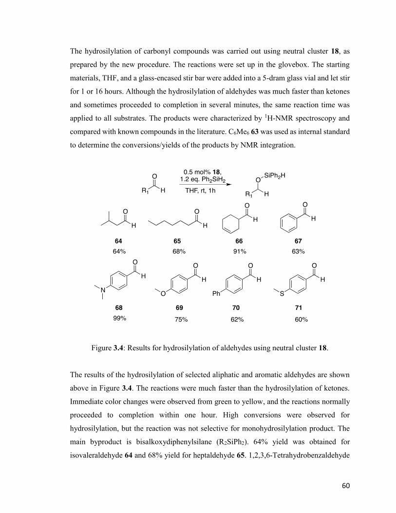
60
The hydrosilylation of carbonyl compounds was carried out using neutral cluster 18, as
prepared by the new procedure. The reactions were set up in the glovebox. The starting
materials, THF, and a glass-encased stir bar were added into a 5-dram glass vial and let stir
for 1 or 16 hours. Although the hydrosilylation of aldehydes was much faster than ketones
and sometimes proceeded to completion in several minutes, the same reaction time was
applied to all substrates. The products were characterized by 1H-NMR spectroscopy and
compared with known compounds in the literature. C6Me6 63 was used as internal standard
to determine the conversions/yields of the products by NMR integration.
Figure 3.4: Results for hydrosilylation of aldehydes using neutral cluster 18.
The results of the hydrosilylation of selected aliphatic and aromatic aldehydes are shown
above in Figure 3.4. The reactions were much faster than the hydrosilylation of ketones.
Immediate color changes were observed from green to yellow, and the reactions normally
proceeded to completion within one hour. High conversions were observed for
hydrosilylation, but the reaction was not selective for monohydrosilylation product. The
main byproduct is bisalkoxydiphenylsilane (R2SiPh2). 64% yield was obtained for
isovaleraldehyde 64 and 68% yield for heptaldehyde 65. 1,2,3,6-Tetrahydrobenzaldehyde
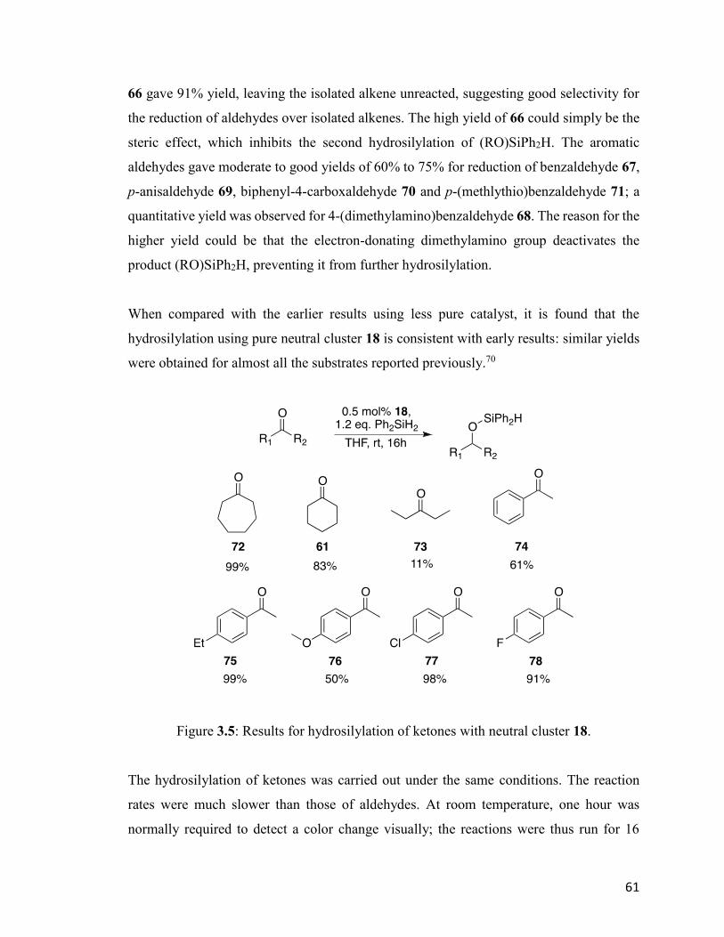
61
66 gave 91% yield, leaving the isolated alkene unreacted, suggesting good selectivity for
the reduction of aldehydes over isolated alkenes. The high yield of 66 could simply be the
steric effect, which inhibits the second hydrosilylation of (RO)SiPh2H. The aromatic
aldehydes gave moderate to good yields of 60% to 75% for reduction of benzaldehyde 67,
p-anisaldehyde 69, biphenyl-4-carboxaldehyde 70 and p-(methlythio)benzaldehyde 71; a
quantitative yield was observed for 4-(dimethylamino)benzaldehyde 68. The reason for the
higher yield could be that the electron-donating dimethylamino group deactivates the
product (RO)SiPh2H, preventing it from further hydrosilylation.
When compared with the earlier results using less pure catalyst, it is found that the
hydrosilylation using pure neutral cluster 18 is consistent with early results: similar yields
were obtained for almost all the substrates reported previously.70
Figure 3.5: Results for hydrosilylation of ketones with neutral cluster 18.
The hydrosilylation of ketones was carried out under the same conditions. The reaction
rates were much slower than those of aldehydes. At room temperature, one hour was
normally required to detect a color change visually; the reactions were thus run for 16
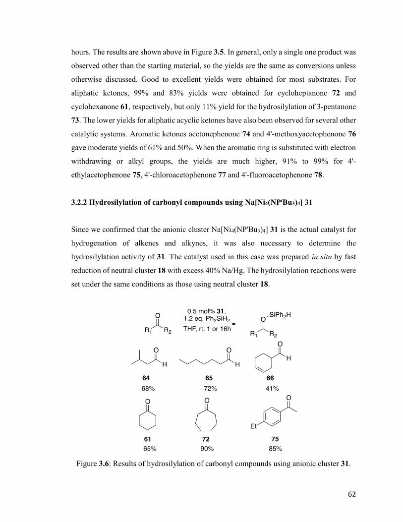
62
hours. The results are shown above in Figure 3.5. In general, only a single one product was
observed other than the starting material, so the yields are the same as conversions unless
otherwise discussed. Good to excellent yields were obtained for most substrates. For
aliphatic ketones, 99% and 83% yields were obtained for cycloheptanone 72 and
cyclohexanone 61, respectively, but only 11% yield for the hydrosilylation of 3-pentanone
73. The lower yields for aliphatic acyclic ketones have also been observed for several other
catalytic systems. Aromatic ketones acetonephenone 74 and 4'-methoxyacetophenone 76
gave moderate yields of 61% and 50%. When the aromatic ring is substituted with electron
withdrawing or alkyl groups, the yields are much higher, 91% to 99% for 4'-
ethylacetophenone 75, 4'-chloroacetophenone 77 and 4'-fluoroacetophenone 78.
3.2.2 Hydrosilylation of carbonyl compounds using Na[Ni4(NPtBu3)4] 31
Since we confirmed that the anionic cluster Na[Ni4(NPtBu3)4] 31 is the actual catalyst for
hydrogenation of alkenes and alkynes, it was also necessary to determine the
hydrosilylation activity of 31. The catalyst used in this case was prepared in situ by fast
reduction of neutral cluster 18 with excess 40% Na/Hg. The hydrosilylation reactions were
set under the same conditions as those using neutral cluster 18.
Figure 3.6: Results of hydrosilylation of carbonyl compounds using anionic cluster 31.
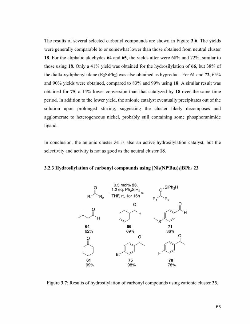
63
The results of several selected carbonyl compounds are shown in Figure 3.6. The yields
were generally comparable to or somewhat lower than those obtained from neutral cluster
18. For the aliphatic aldehydes 64 and 65, the yields after were 68% and 72%, similar to
those using 18. Only a 41% yield was obtained for the hydrosilylation of 66, but 38% of
the dialkoxydiphenylsilane (R2SiPh2) was also obtained as byproduct. For 61 and 72, 65%
and 90% yields were obtained, compared to 83% and 99% using 18. A similar result was
obtained for 75, a 14% lower conversion than that catalyzed by 18 over the same time
period. In addition to the lower yield, the anionic catalyst eventually precipitates out of the
solution upon prolonged stirring, suggesting the cluster likely decomposes and
agglomerate to heterogeneous nickel, probably still containing some phosphoranimide
ligand.
In conclusion, the anionic cluster 31 is also an active hydrosilylation catalyst, but the
selectivity and activity is not as good as the neutral cluster 18.
3.2.3 Hydrosilylation of carbonyl compounds using [Ni4(NPtBu3)4]BPh4 23
Figure 3.7: Results of hydrosilylation of carbonyl compounds using cationic cluster 23.
64
The hydrosilylation catalyzed by cationic cluster [Ni4(NPtBu3)4]BPh4 23 was also tested
for comparisons to 18 and 31. The results of the reactions of selected carbonyl compounds
are shown above (Fig. 3.7). Although a 62% yield was obtained for 64, close to that
obtained from catalyst 18, only 69% and 36% yields were obtained for 66 and 71, much
lower than those obtained from 18.
In contrast, the hydrosilylation of ketones was much more efficient than that of aldehydes
and sometimes more efficient than either precatalyst 18 or 31. Close to quantitative yields
were obtained from 64 and 75. The electron-withdrawing substituted substrate 78,
however, gave only 78% conversion, lower than that obtained with the neutral cluster 18.
3.2.4 Discussion of mechanism of hydrosilylation
As in the case of catalytic hydrogenation, the mechanism is highly tentative due to the lack
of concrete information about the intermediates along the catalytic cycle. Thus it will be
premature to propose a detailed catalytic cycle. However, some possibilities will be
discussed.
The simplest proposal is based on the neutral cluster 18, as the best yields were generally
obtained using that cluster, however the relevancy of 23 and 31 will be discussed. As we
propose the active catalyst for catalytic hydrogenation is a bimetallic cluster, a similar
dissociation is even more likely to happen in the case of hydrosilylation, due to the higher
steric bulk of the silane. As a result, we proposed the first step is the bimetallic oxidative
additions of the two equivalents of H–Si bond, likely followed by dissociation into two
equivalent of dimeric clusters.
There could be two possible pathways to reduce the C=O double bond. One is hydride
insertion into the carbonyl group to give the nickel alkoxy intermediate, the other is the
silyl-directed migratory insertion of the carbonyl.75 After this, the final product is
reductively released and the activation of another equivalent of silane regenerates the
bimetallic cluster.
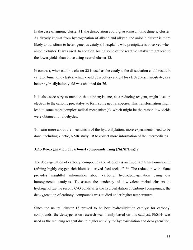
65
In the case of anionic cluster 31, the dissociation could give some anionic dimeric cluster.
As already known from hydrogenation of alkene and alkyne, the anionic cluster is more
likely to transform to heterogeneous catalyst. It explains why precipitate is observed when
anionic cluster 31 was used. In addition, losing some of the reactive catalyst might lead to
the lower yields than those using neutral cluster 18.
In contrast, when cationic cluster 23 is used as the catalyst, the dissociation could result in
cationic bimetallic cluster, which could be a better catalyst for electron-rich substrate, as a
better hydrosilylation yield was obtained for 75.
It is also necessary to mention that diphenylsilane, as a reducing reagent, might lose an
electron to the cationic precatalyst to form some neutral species. This transformation might
lead to some more complex radical mechanism(s), which might be the reason low yields
were obtained for aldehydes.
To learn more about the mechanism of the hydrosilylation, more experiments need to be
done, including kinetic, NMR study, IR to collect more information of the intermediates.
3.2.5 Deoxygenation of carbonyl compounds using [Ni(NPtBu3)]4
The deoxygenation of carbonyl compounds and alcohols is an important transformation in
refining highly oxygen-rich biomass-derived feedstocks.109-115 The reduction with silane
provides insightful information about carbonyl hydrodeoxygenation using our
homogeneous catalysts. To assess the tendency of low-valent nickel clusters to
hydrogenolyze the second C-O bonds after the hydrosilylation of carbonyl compounds, the
deoxygenation of carbonyl compounds was studied under higher temperatures.
Since the neutral cluster 18 proved to be best hydrosilylation catalyst for carbonyl
compounds, the deoxygenation research was mainly based on this catalyst. PhSiH3 was
used as the reducing reagent due to higher activity for hydrosilylation and deoxygenation,
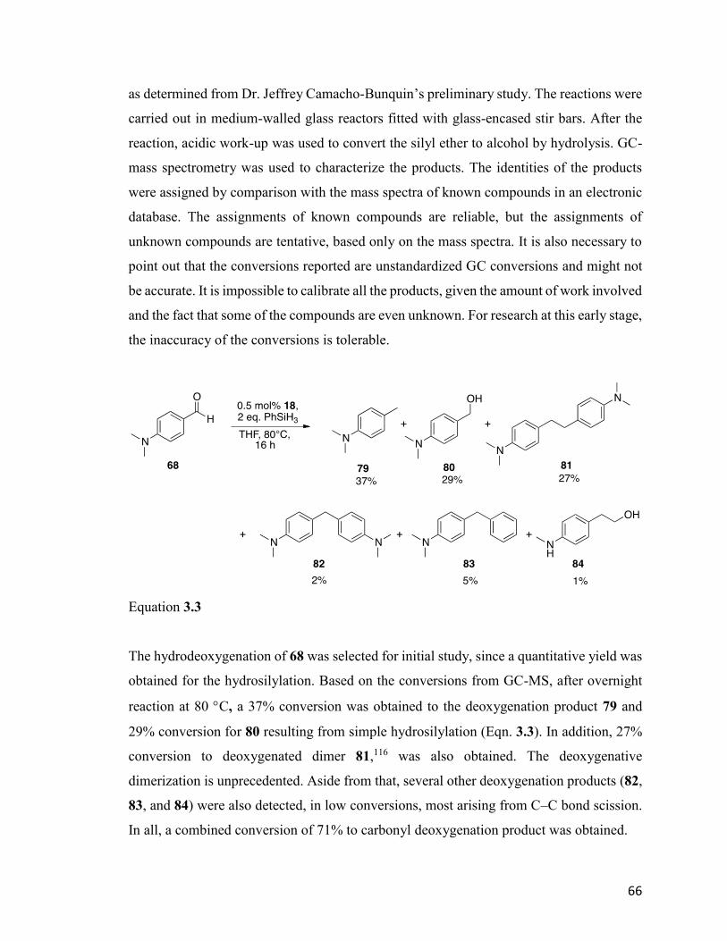
66
as determined from Dr. Jeffrey Camacho-Bunquin’s preliminary study. The reactions were
carried out in medium-walled glass reactors fitted with glass-encased stir bars. After the
reaction, acidic work-up was used to convert the silyl ether to alcohol by hydrolysis. GC-
mass spectrometry was used to characterize the products. The identities of the products
were assigned by comparison with the mass spectra of known compounds in an electronic
database. The assignments of known compounds are reliable, but the assignments of
unknown compounds are tentative, based only on the mass spectra. It is also necessary to
point out that the conversions reported are unstandardized GC conversions and might not
be accurate. It is impossible to calibrate all the products, given the amount of work involved
and the fact that some of the compounds are even unknown. For research at this early stage,
the inaccuracy of the conversions is tolerable.
Equation 3.3
The hydrodeoxygenation of 68 was selected for initial study, since a quantitative yield was
obtained for the hydrosilylation. Based on the conversions from GC-MS, after overnight
reaction at 80 C, a 37% conversion was obtained to the deoxygenation product 79 and
29% conversion for 80 resulting from simple hydrosilylation (Eqn. 3.3). In addition, 27%
conversion to deoxygenated dimer 81,116 was also obtained. The deoxygenative
dimerization is unprecedented. Aside from that, several other deoxygenation products (82,
83, and 84) were also detected, in low conversions, most arising from C–C bond scission.
In all, a combined conversion of 71% to carbonyl deoxygenation product was obtained.
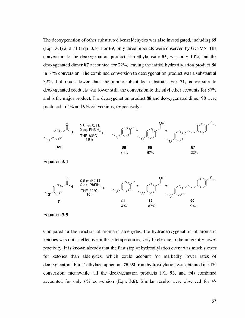
67
The deoxygenation of other substituted benzaldehydes was also investigated, including 69
(Eqn. 3.4) and 71 (Eqn. 3.5). For 69, only three products were observed by GC-MS. The
conversion to the deoxygenation product, 4-methylanisole 85, was only 10%, but the
deoxygenated dimer 87 accounted for 22%, leaving the initial hydrosilylation product 86
in 67% conversion. The combined conversion to deoxygenation product was a substantial
32%, but much lower than the amino-substituted substrate. For 71, conversion to
deoxygenated products was lower still; the conversion to the silyl ether accounts for 87%
and is the major product. The deoxygenation product 88 and deoxygenated dimer 90 were
produced in 4% and 9% conversions, respectively.
Equation 3.4
Equation 3.5
Compared to the reaction of aromatic aldehydes, the hydrodeoxygenation of aromatic
ketones was not as effective at these temperatures, very likely due to the inherently lower
reactivity. It is known already that the first step of hydrosilylation event was much slower
for ketones than aldehydes, which could account for markedly lower rates of
deoxygenation. For 4'-ethylacetophenone 75, 92 from hydrosilylation was obtained in 31%
conversion; meanwhile, all the deoxygenation products (91, 93, and 94) combined
accounted for only 6% conversion (Eqn. 3.6). Similar results were observed for 4'-
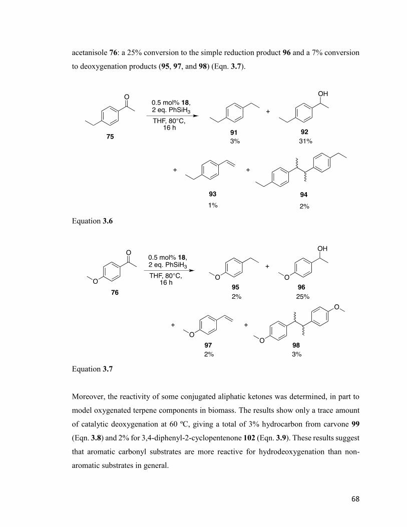
68
acetanisole 76: a 25% conversion to the simple reduction product 96 and a 7% conversion
to deoxygenation products (95, 97, and 98) (Eqn. 3.7).
Equation 3.6
Equation 3.7
Moreover, the reactivity of some conjugated aliphatic ketones was determined, in part to
model oxygenated terpene components in biomass. The results show only a trace amount
of catalytic deoxygenation at 60 ºC, giving a total of 3% hydrocarbon from carvone 99
(Eqn. 3.8) and 2% for 3,4-diphenyl-2-cyclopentenone 102 (Eqn. 3.9). These results suggest
that aromatic carbonyl substrates are more reactive for hydrodeoxygenation than non-
aromatic substrates in general.
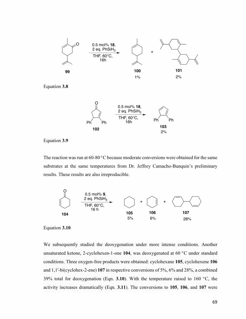
69
Equation 3.8
Equation 3.9
The reaction was run at 60-80 C because moderate conversions were obtained for the same
substrates at the same temperatures from Dr. Jeffrey Camacho-Bunquin’s preliminary
results. These results are also irreproducible.
Equation 3.10
We subsequently studied the deoxygenation under more intense conditions. Another
unsaturated ketone, 2-cyclohexen-1-one 104, was deoxygenated at 60 C under standard
conditions. Three oxygen-free products were obtained: cyclohexane 105, cyclohexene 106
and 1,1'-bi(cyclohex-2-ene) 107 in respective conversions of 5%, 6% and 28%, a combined
39% total for deoxygenation (Eqn. 3.10). With the temperature raised to 160 C, the
activity increases dramatically (Eqn. 3.11). The conversions to 105, 106, and 107 were
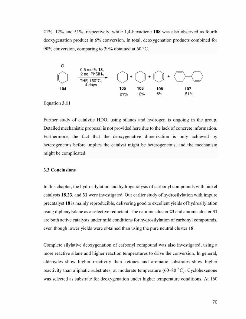
70
21%, 12% and 51%, respectively, while 1,4-hexadiene 108 was also observed as fourth
deoxygenation product in 6% conversion. In total, deoxygenation products combined for
90% conversion, comparing to 39% obtained at 60 C.
Equation 3.11
Further study of catalytic HDO, using silanes and hydrogen is ongoing in the group.
Detailed mechanistic proposal is not provided here due to the lack of concrete information.
Furthermore, the fact that the deoxygenative dimerization is only achieved by
heterogeneous before implies the catalyst might be heterogeneous, and the mechanism
might be complicated.
3.3 Conclusions
In this chapter, the hydrosilylation and hydrogenolysis of carbonyl compounds with nickel
catalysts 18,23, and 31 were investigated. Our earlier study of hydrosilylation with impure
precatalyst 18 is mainly reproducible, delivering good to excellent yields of hydrosilylation
using diphenylsilane as a selective reductant. The cationic cluster 23 and anionic cluster 31
are both active catalysts under mild conditions for hydrosilylation of carbonyl compounds,
even though lower yields were obtained than using the pure neutral cluster 18.
Complete silylative deoxygenation of carbonyl compound was also investigated, using a
more reactive silane and higher reaction temperatures to drive the conversion. In general,
aldehydes show higher reactivity than ketones and aromatic substrates show higher
reactivity than aliphatic substrates, at moderate temperature (60–80 C). Cyclohexenone
was selected as substrate for deoxygenation under higher temperature conditions. At 160
71
C, a high conversion (~ 90%) to deoxygenation products was achieved, albeit at long
reaction time.
The present investigation clarifies and resolves the reproducibility problems arising from
the early use of anion-contaminated neutral cluster 18 for hydrosilylation and
deoxygenation. These results provide enough potential to warrant further investigation and
incentive to prepare related metal cluster catalysts with higher activity. The conversions or
yields could be optimized in future. Furthermore, future development of heterogeneous
catalysts is also possible.
Catalytic HDO using hydrogen as the reductant is the ultimate objective Further study will
be continued by others in the group, completing the first comprehensive report of catalytic
deoxygenation using this unique new catalyst system.
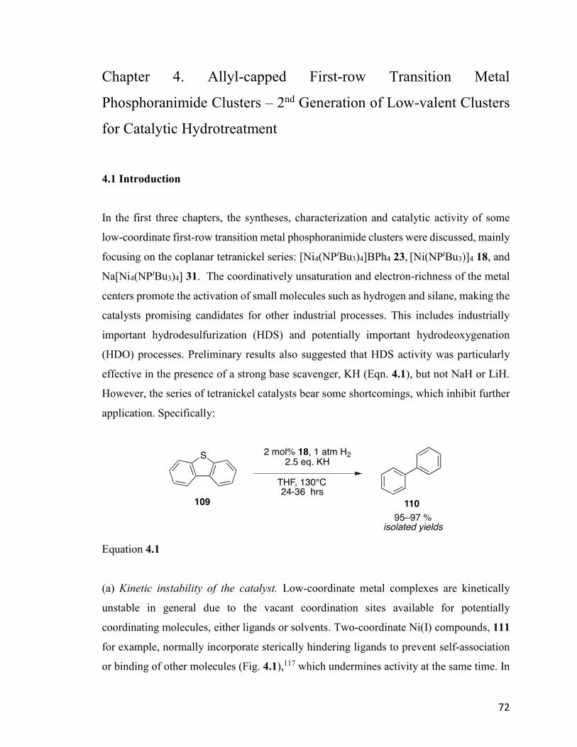
72
Chapter 4. Allyl-capped First-row Transition Metal
Phosphoranimide Clusters – 2nd Generation of Low-valent Clusters
for Catalytic Hydrotreatment
4.1 Introduction
In the first three chapters, the syntheses, characterization and catalytic activity of some
low-coordinate first-row transition metal phosphoranimide clusters were discussed, mainly
focusing on the coplanar tetranickel series: [Ni4(NPtBu3)4]BPh4 23, [Ni(NPtBu3)]4 18, and
Na[Ni4(NPtBu3)4] 31. The coordinatively unsaturation and electron-richness of the metal
centers promote the activation of small molecules such as hydrogen and silane, making the
catalysts promising candidates for other industrial processes. This includes industrially
important hydrodesulfurization (HDS) and potentially important hydrodeoxygenation
(HDO) processes. Preliminary results also suggested that HDS activity was particularly
effective in the presence of a strong base scavenger, KH (Eqn. 4.1), but not NaH or LiH.
However, the series of tetranickel catalysts bear some shortcomings, which inhibit further
application. Specifically:
Equation 4.1
(a) Kinetic instability of the catalyst. Low-coordinate metal complexes are kinetically
unstable in general due to the vacant coordination sites available for potentially
coordinating molecules, either ligands or solvents. Two-coordinate Ni(I) compounds, 111
for example, normally incorporate sterically hindering ligands to prevent self-association
or binding of other molecules (Fig. 4.1),117 which undermines activity at the same time. In
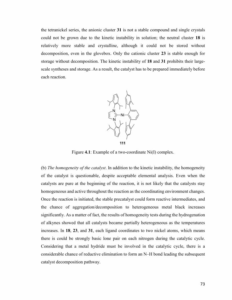
73
the tetranickel series, the anionic cluster 31 is not a stable compound and single crystals
could not be grown due to the kinetic instability in solution; the neutral cluster 18 is
relatively more stable and crystalline, although it could not be stored without
decomposition, even in the glovebox. Only the cationic cluster 23 is stable enough for
storage without decomposition. The kinetic instability of 18 and 31 prohibits their large-
scale syntheses and storage. As a result, the catalyst has to be prepared immediately before
each reaction.
Figure 4.1: Example of a two-coordinate Ni(I) complex.
(b) The homogeneity of the catalyst. In addition to the kinetic instability, the homogeneity
of the catalyst is questionable, despite acceptable elemental analysis. Even when the
catalysts are pure at the beginning of the reaction, it is not likely that the catalysts stay
homogeneous and active throughout the reaction as the coordinating environment changes.
Once the reaction is initiated, the stable precatalyst could form reactive intermediates, and
the chance of aggregation/decomposition to heterogeneous metal black increases
significantly. As a matter of fact, the results of homogeneity tests during the hydrogenation
of alkynes showed that all catalysts became partially heterogeneous as the temperatures
increases. In 18, 23, and 31, each ligand coordinates to two nickel atoms, which means
there is could be strongly basic lone pair on each nitrogen during the catalytic cycle.
Considering that a metal hydride must be involved in the catalytic cycle, there is a
considerable chance of reductive elimination to form an N–H bond leading the subsequent
catalyst decomposition pathway.
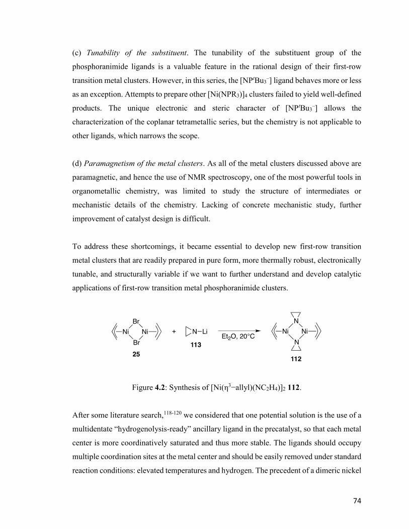
74
(c) Tunability of the substituent. The tunability of the substituent group of the
phosphoranimide ligands is a valuable feature in the rational design of their first-row
transition metal clusters. However, in this series, the [NPtBu3–] ligand behaves more or less
as an exception. Attempts to prepare other [Ni(NPR3)]4 clusters failed to yield well-defined
products. The unique electronic and steric character of [NPtBu3–] allows the
characterization of the coplanar tetrametallic series, but the chemistry is not applicable to
other ligands, which narrows the scope.
(d) Paramagnetism of the metal clusters. As all of the metal clusters discussed above are
paramagnetic, and hence the use of NMR spectroscopy, one of the most powerful tools in
organometallic chemistry, was limited to study the structure of intermediates or
mechanistic details of the chemistry. Lacking of concrete mechanistic study, further
improvement of catalyst design is difficult.
To address these shortcomings, it became essential to develop new first-row transition
metal clusters that are readily prepared in pure form, more thermally robust, electronically
tunable, and structurally variable if we want to further understand and develop catalytic
applications of first-row transition metal phosphoranimide clusters.
Figure 4.2: Synthesis of [Ni(η3−allyl)(NC2H4)]2 112.
After some literature search,118-120 we considered that one potential solution is the use of a
multidentate “hydrogenolysis-ready” ancillary ligand in the precatalyst, so that each metal
center is more coordinatively saturated and thus more stable. The ligands should occupy
multiple coordination sites at the metal center and should be easily removed under standard
reaction conditions: elevated temperatures and hydrogen. The precedent of a dimeric nickel
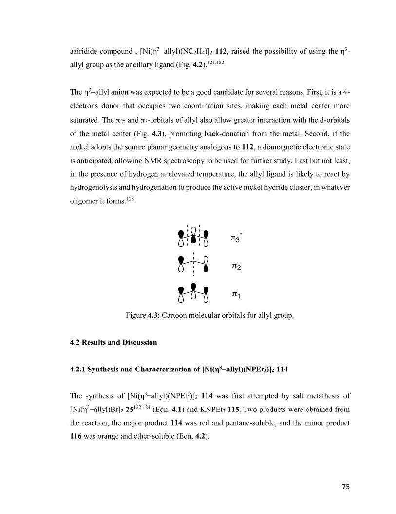
75
aziridide compound , [Ni(η3−allyl)(NC2H4)]2 112, raised the possibility of using the η3-
allyl group as the ancillary ligand (Fig. 4.2).121,122
The 3allyl anion was expected to be a good candidate for several reasons. First, it is a 4-
electrons donor that occupies two coordination sites, making each metal center more
saturated. The 2- and 3-orbitals of allyl also allow greater interaction with the d-orbitals
of the metal center (Fig. 4.3), promoting back-donation from the metal. Second, if the
nickel adopts the square planar geometry analogous to 112, a diamagnetic electronic state
is anticipated, allowing NMR spectroscopy to be used for further study. Last but not least,
in the presence of hydrogen at elevated temperature, the allyl ligand is likely to react by
hydrogenolysis and hydrogenation to produce the active nickel hydride cluster, in whatever
oligomer it forms.123
Figure 4.3: Cartoon molecular orbitals for allyl group.
4.2 Results and Discussion
4.2.1 Synthesis and Characterization of [Ni(η3−allyl)(NPEt3)]2 114
The synthesis of [Ni(η3−allyl)(NPEt3)]2 114 was first attempted by salt metathesis of
[Ni(η3−allyl)Br]2 25122,124 (Eqn. 4.1) and KNPEt3 115. Two products were obtained from
the reaction, the major product 114 was red and pentane-soluble, and the minor product
116 was orange and ether-soluble (Eqn. 4.2).
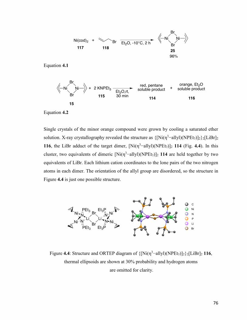
76
Equation 4.1
Equation 4.2
Single crystals of the minor orange compound were grown by cooling a saturated ether
solution. X-ray crystallography revealed the structure as {[Ni(η3−allyl)(NPEt3)]2}2[LiBr]2
116, the LiBr adduct of the target dimer, [Ni(η3−allyl)(NPEt3)]2 114 (Fig. 4.4). In this
cluster, two equivalents of dimeric [Ni(η3−allyl)(NPEt3)]2 114 are held together by two
equivalents of LiBr. Each lithium cation coordinates to the lone pairs of the two nitrogen
atoms in each dimer. The orientation of the allyl group are disordered, so the structure in
Figure 4.4 is just one possible structure.
Figure 4.4: Structure and ORTEP diagram of {[Ni(η3−allyl)(NPEt3)]2}2[LiBr]2 116,
thermal ellipsoids are shown at 30% probability and hydrogen atoms
are omitted for clarity.
C
Ni
N
P
Li
Br
LiN
Ni N
Ni
PEt3
PEt3
LiN
NiN
Ni
Et3P
Et3P
Br
Br

77
Reexamination of the KNPEt3 115 preparation revealed that some amount of LiBr came
from the reaction of LiNH2 119 and PEt3Br2 120, the first step of the ligand synthesis (Fig.
4.5). The LiBr is soluble in Et2O and slightly soluble in pentane; thus, it is carried through
all the way to the product 115.
Figure 4.5: Retrosynthesis of KNPEt3 115.
To address this issue, Dr. Robin Hamilton in our group developed a new procedure for the
synthesis of 115, in which the 120 was mixed with excess KH in liquid ammonia. In this
reaction, both the nucleophilic substitution and deprotonation happened in the one pot
reaction. 115 could be synthesized on a large scale in up to 89% yield without
contamination from LiBr (Eqn. 4.3).
Equation 4.3
Equation 4.4
The synthesis of [Ni(η3−allyl)(NPEt3)]2 114 was successful under the same reaction
conditions, but by using 115 prepared by the new procedure. The product is red and pentane
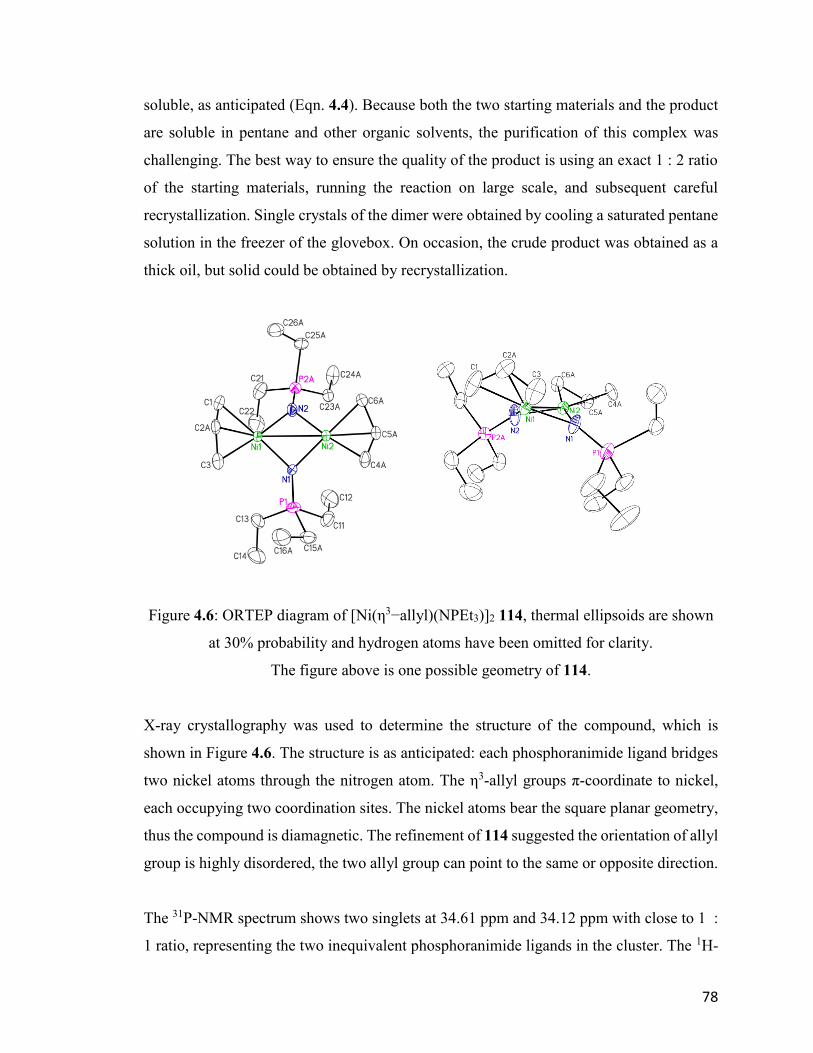
78
soluble, as anticipated (Eqn. 4.4). Because both the two starting materials and the product
are soluble in pentane and other organic solvents, the purification of this complex was
challenging. The best way to ensure the quality of the product is using an exact 1 : 2 ratio
of the starting materials, running the reaction on large scale, and subsequent careful
recrystallization. Single crystals of the dimer were obtained by cooling a saturated pentane
solution in the freezer of the glovebox. On occasion, the crude product was obtained as a
thick oil, but solid could be obtained by recrystallization.
Figure 4.6: ORTEP diagram of [Ni(η3−allyl)(NPEt3)]2 114, thermal ellipsoids are shown
at 30% probability and hydrogen atoms have been omitted for clarity.
The figure above is one possible geometry of 114.
X-ray crystallography was used to determine the structure of the compound, which is
shown in Figure 4.6. The structure is as anticipated: each phosphoranimide ligand bridges
two nickel atoms through the nitrogen atom. The η3-allyl groups π-coordinate to nickel,
each occupying two coordination sites. The nickel atoms bear the square planar geometry,
thus the compound is diamagnetic. The refinement of 114 suggested the orientation of allyl
group is highly disordered, the two allyl group can point to the same or opposite direction.
The 31P-NMR spectrum shows two singlets at 34.61 ppm and 34.12 ppm with close to 1 :
1 ratio, representing the two inequivalent phosphoranimide ligands in the cluster. The 1H-
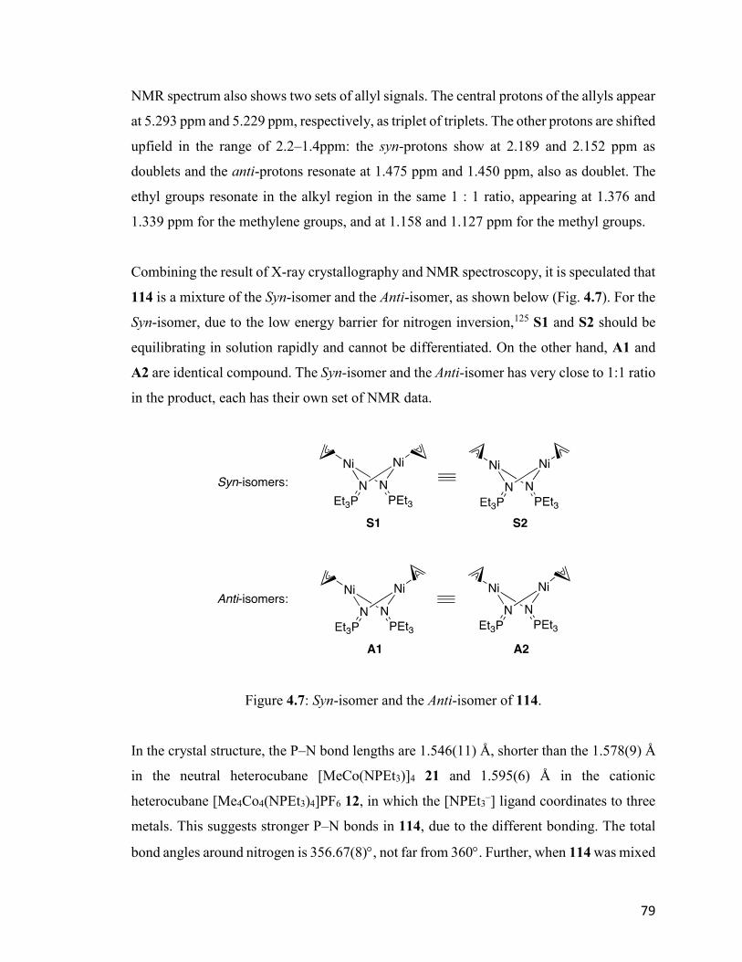
79
NMR spectrum also shows two sets of allyl signals. The central protons of the allyls appear
at 5.293 ppm and 5.229 ppm, respectively, as triplet of triplets. The other protons are shifted
upfield in the range of 2.2–1.4ppm: the syn-protons show at 2.189 and 2.152 ppm as
doublets and the anti-protons resonate at 1.475 ppm and 1.450 ppm, also as doublet. The
ethyl groups resonate in the alkyl region in the same 1 : 1 ratio, appearing at 1.376 and
1.339 ppm for the methylene groups, and at 1.158 and 1.127 ppm for the methyl groups.
Combining the result of X-ray crystallography and NMR spectroscopy, it is speculated that
114 is a mixture of the Syn-isomer and the Anti-isomer, as shown below (Fig. 4.7). For the
Syn-isomer, due to the low energy barrier for nitrogen inversion,125 S1 and S2 should be
equilibrating in solution rapidly and cannot be differentiated. On the other hand, A1 and
A2 are identical compound. The Syn-isomer and the Anti-isomer has very close to 1:1 ratio
in the product, each has their own set of NMR data.
Figure 4.7: Syn-isomer and the Anti-isomer of 114.
In the crystal structure, the P–N bond lengths are 1.546(11) Å, shorter than the 1.578(9) Å
in the neutral heterocubane [MeCo(NPEt3)]4 21 and 1.595(6) Å in the cationic
heterocubane [Me4Co4(NPEt3)4]PF6 12, in which the [NPEt3–] ligand coordinates to three
metals. This suggests stronger P–N bonds in 114, due to the different bonding. The total
bond angles around nitrogen is 356.67(8), not far from 360. Further, when 114 was mixed
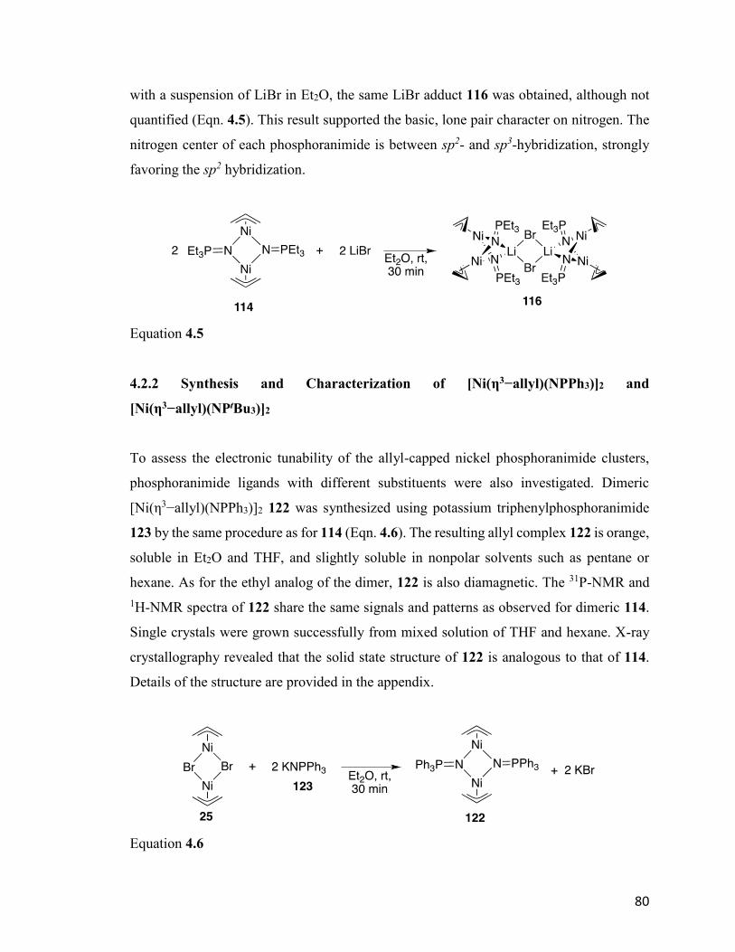
80
with a suspension of LiBr in Et2O, the same LiBr adduct 116 was obtained, although not
quantified (Eqn. 4.5). This result supported the basic, lone pair character on nitrogen. The
nitrogen center of each phosphoranimide is between sp2- and sp3-hybridization, strongly
favoring the sp2 hybridization.
Equation 4.5
4.2.2 Synthesis and Characterization of [Ni(η3−allyl)(NPPh3)]2 and
[Ni(η3−allyl)(NPtBu3)]2
To assess the electronic tunability of the allyl-capped nickel phosphoranimide clusters,
phosphoranimide ligands with different substituents were also investigated. Dimeric
[Ni(η3−allyl)(NPPh3)]2 122 was synthesized using potassium triphenylphosphoranimide
123 by the same procedure as for 114 (Eqn. 4.6). The resulting allyl complex 122 is orange,
soluble in Et2O and THF, and slightly soluble in nonpolar solvents such as pentane or
hexane. As for the ethyl analog of the dimer, 122 is also diamagnetic. The 31P-NMR and
1H-NMR spectra of 122 share the same signals and patterns as observed for dimeric 114.
Single crystals were grown successfully from mixed solution of THF and hexane. X-ray
crystallography revealed that the solid state structure of 122 is analogous to that of 114.
Details of the structure are provided in the appendix.
Equation 4.6
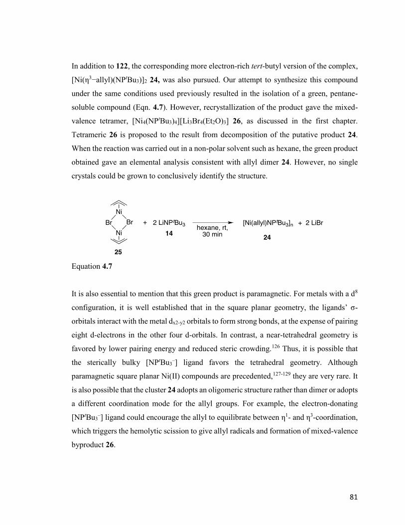
81
In addition to 122, the corresponding more electron-rich tert-butyl version of the complex,
[Ni(η3−allyl)(NPtBu3)]2 24, was also pursued. Our attempt to synthesize this compound
under the same conditions used previously resulted in the isolation of a green, pentane-
soluble compound (Eqn. 4.7). However, recrystallization of the product gave the mixed-
valence tetramer, [Ni4(NPtBu3)4][Li3Br4(Et2O)3] 26, as discussed in the first chapter.
Tetrameric 26 is proposed to the result from decomposition of the putative product 24.
When the reaction was carried out in a non-polar solvent such as hexane, the green product
obtained gave an elemental analysis consistent with allyl dimer 24. However, no single
crystals could be grown to conclusively identify the structure.
Equation 4.7
It is also essential to mention that this green product is paramagnetic. For metals with a d8
configuration, it is well established that in the square planar geometry, the ligands’ σ-
orbitals interact with the metal dx2-y2 orbitals to form strong bonds, at the expense of pairing
eight d-electrons in the other four d-orbitals. In contrast, a near-tetrahedral geometry is
favored by lower pairing energy and reduced steric crowding.126 Thus, it is possible that
the sterically bulky [NPtBu3–] ligand favors the tetrahedral geometry. Although
paramagnetic square planar Ni(II) compounds are precedented,127-129 they are very rare. It
is also possible that the cluster 24 adopts an oligomeric structure rather than dimer or adopts
a different coordination mode for the allyl groups. For example, the electron-donating
[NPtBu3–] ligand could encourage the allyl to equilibrate between η1- and η3-coordination,
which triggers the hemolytic scission to give allyl radicals and formation of mixed-valence
byproduct 26.
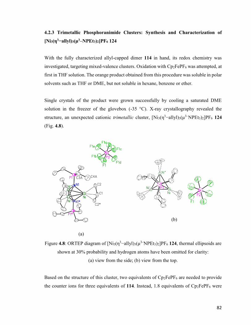
82
4.2.3 Trimetallic Phosphoranimide Clusters: Synthesis and Characterization of
[Ni3(η3−allyl)3(μ3–NPEt3)2]PF6 124
With the fully characterized allyl-capped dimer 114 in hand, its redox chemistry was
investigated, targeting mixed-valence clusters. Oxidation with Cp2FePF6 was attempted, at
first in THF solution. The orange product obtained from this procedure was soluble in polar
solvents such as THF or DME, but not soluble in hexane, benzene or ether.
Single crystals of the product were grown successfully by cooling a saturated DME
solution in the freezer of the glovebox (-35 °C). X-ray crystallography revealed the
structure, an unexpected cationic trimetallic cluster, [Ni3(η3−allyl)3(μ
3–NPEt3)2]PF6 124
(Fig. 4.8).
Figure 4.8: ORTEP diagram of [Ni3(η3−allyl)3(μ
3–NPEt3)2]PF6 124, thermal ellipsoids are
shown at 30% probability and hydrogen atoms have been omitted for clarity:
(a) view from the side; (b) view from the top.
Based on the structure of this cluster, two equivalents of Cp2FePF6 are needed to provide
the counter ions for three equivalents of 114. Instead, 1.8 equivalents of Cp2FePF6 were
(a)
(b)
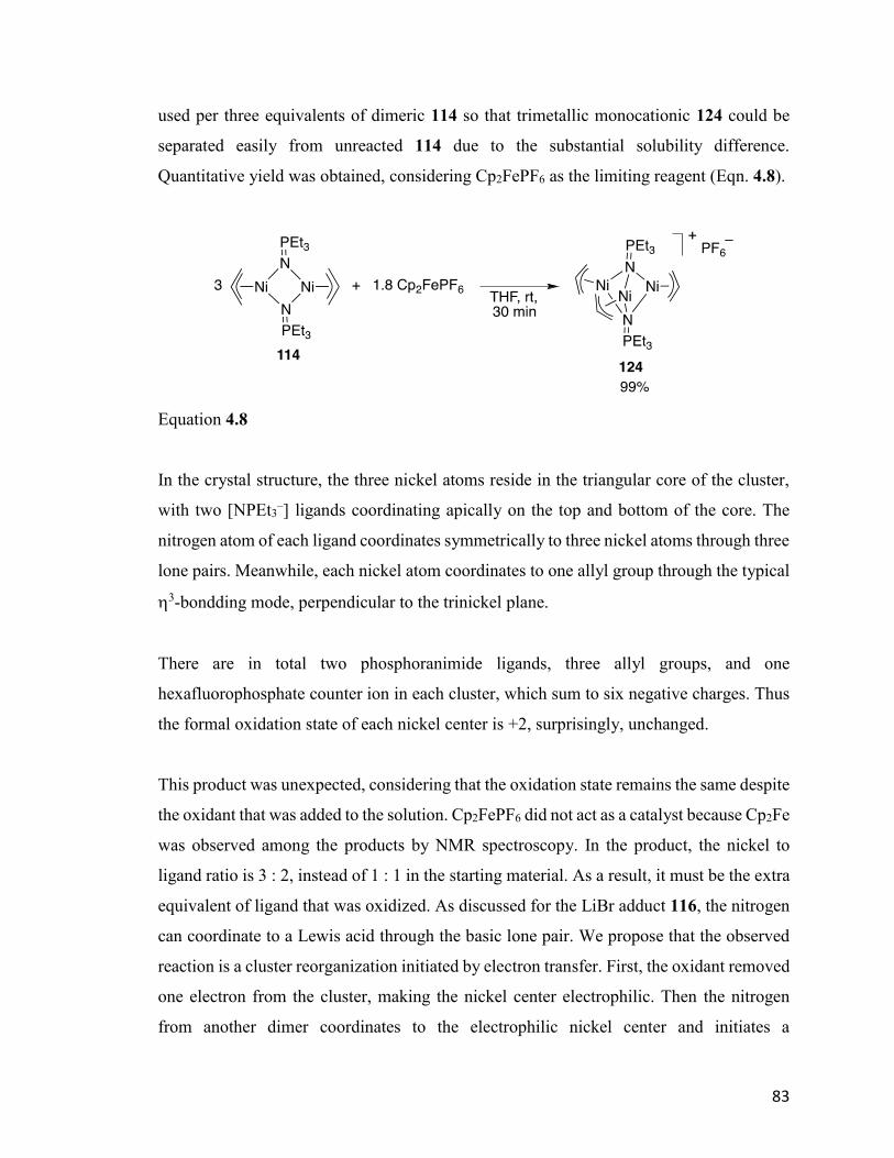
83
used per three equivalents of dimeric 114 so that trimetallic monocationic 124 could be
separated easily from unreacted 114 due to the substantial solubility difference.
Quantitative yield was obtained, considering Cp2FePF6 as the limiting reagent (Eqn. 4.8).
Equation 4.8
In the crystal structure, the three nickel atoms reside in the triangular core of the cluster,
with two [NPEt3–] ligands coordinating apically on the top and bottom of the core. The
nitrogen atom of each ligand coordinates symmetrically to three nickel atoms through three
lone pairs. Meanwhile, each nickel atom coordinates to one allyl group through the typical
3-bondding mode, perpendicular to the trinickel plane.
There are in total two phosphoranimide ligands, three allyl groups, and one
hexafluorophosphate counter ion in each cluster, which sum to six negative charges. Thus
the formal oxidation state of each nickel center is +2, surprisingly, unchanged.
This product was unexpected, considering that the oxidation state remains the same despite
the oxidant that was added to the solution. Cp2FePF6 did not act as a catalyst because Cp2Fe
was observed among the products by NMR spectroscopy. In the product, the nickel to
ligand ratio is 3 : 2, instead of 1 : 1 in the starting material. As a result, it must be the extra
equivalent of ligand that was oxidized. As discussed for the LiBr adduct 116, the nitrogen
can coordinate to a Lewis acid through the basic lone pair. We propose that the observed
reaction is a cluster reorganization initiated by electron transfer. First, the oxidant removed
one electron from the cluster, making the nickel center electrophilic. Then the nitrogen
from another dimer coordinates to the electrophilic nickel center and initiates a
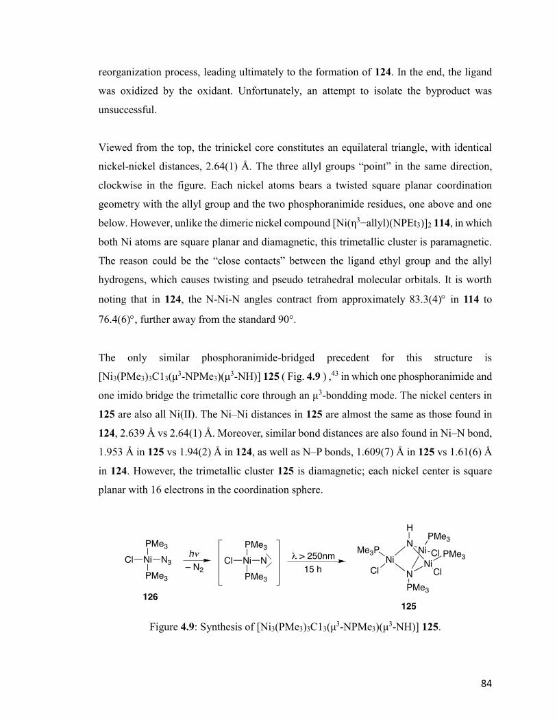
84
reorganization process, leading ultimately to the formation of 124. In the end, the ligand
was oxidized by the oxidant. Unfortunately, an attempt to isolate the byproduct was
unsuccessful.
Viewed from the top, the trinickel core constitutes an equilateral triangle, with identical
nickel-nickel distances, 2.64(1) Å. The three allyl groups “point” in the same direction,
clockwise in the figure. Each nickel atoms bears a twisted square planar coordination
geometry with the allyl group and the two phosphoranimide residues, one above and one
below. However, unlike the dimeric nickel compound [Ni(η3−allyl)(NPEt3)]2 114, in which
both Ni atoms are square planar and diamagnetic, this trimetallic cluster is paramagnetic.
The reason could be the “close contacts” between the ligand ethyl group and the allyl
hydrogens, which causes twisting and pseudo tetrahedral molecular orbitals. It is worth
noting that in 124, the N-Ni-N angles contract from approximately 83.3(4) in 114 to
76.4(6), further away from the standard 90°.
The only similar phosphoranimide-bridged precedent for this structure is
[Ni3(PMe3)3C13(μ3-NPMe3)(μ
3-NH)] 125 ( Fig. 4.9 ) ,43 in which one phosphoranimide and
one imido bridge the trimetallic core through an μ3-bondding mode. The nickel centers in
125 are also all Ni(II). The Ni–Ni distances in 125 are almost the same as those found in
124, 2.639 Å vs 2.64(1) Å. Moreover, similar bond distances are also found in Ni–N bond,
1.953 Å in 125 vs 1.94(2) Å in 124, as well as N–P bonds, 1.609(7) Å in 125 vs 1.61(6) Å
in 124. However, the trimetallic cluster 125 is diamagnetic; each nickel center is square
planar with 16 electrons in the coordination sphere.
Figure 4.9: Synthesis of [Ni3(PMe3)3C13(μ3-NPMe3)(μ
3-NH)] 125.
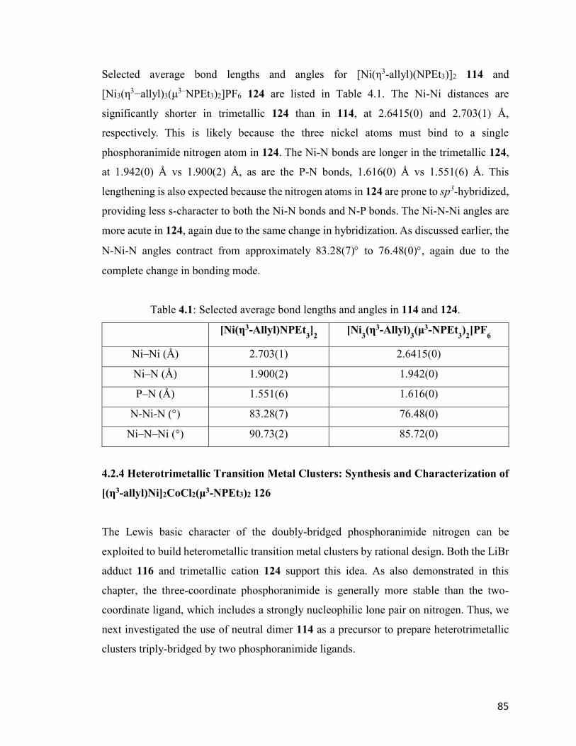
85
Selected average bond lengths and angles for [Ni(η3-allyl)(NPEt3)]2 114 and
[Ni3(η3−allyl)3(μ
3–NPEt3)2]PF6 124 are listed in Table 4.1. The Ni-Ni distances are
significantly shorter in trimetallic 124 than in 114, at 2.6415(0) and 2.703(1) Å,
respectively. This is likely because the three nickel atoms must bind to a single
phosphoranimide nitrogen atom in 124. The Ni-N bonds are longer in the trimetallic 124,
at 1.942(0) Å vs 1.900(2) Å, as are the P-N bonds, 1.616(0) Å vs 1.551(6) Å. This
lengthening is also expected because the nitrogen atoms in 124 are prone to sp3-hybridized,
providing less s-character to both the Ni-N bonds and N-P bonds. The Ni-N-Ni angles are
more acute in 124, again due to the same change in hybridization. As discussed earlier, the
N-Ni-N angles contract from approximately 83.28(7) to 76.48(0), again due to the
complete change in bonding mode.
Table 4.1: Selected average bond lengths and angles in 114 and 124.
[Ni(η3-Allyl)NPEt3]2 [Ni
3(η3-Allyl)
3(μ3-NPEt
3)2]PF
6
Ni–Ni (Å) 2.703(1) 2.6415(0)
Ni–N (Å) 1.900(2) 1.942(0)
P–N (Å) 1.551(6) 1.616(0)
N-Ni-N (°) 83.28(7) 76.48(0)
Ni–N–Ni (°) 90.73(2) 85.72(0)
4.2.4 Heterotrimetallic Transition Metal Clusters: Synthesis and Characterization of
[(η3-allyl)Ni]2CoCl2(μ3-NPEt3)2 126
The Lewis basic character of the doubly-bridged phosphoranimide nitrogen can be
exploited to build heterometallic transition metal clusters by rational design. Both the LiBr
adduct 116 and trimetallic cation 124 support this idea. As also demonstrated in this
chapter, the three-coordinate phosphoranimide is generally more stable than the two-
coordinate ligand, which includes a strongly nucleophilic lone pair on nitrogen. Thus, we
next investigated the use of neutral dimer 114 as a precursor to prepare heterotrimetallic
clusters triply-bridged by two phosphoranimide ligands.
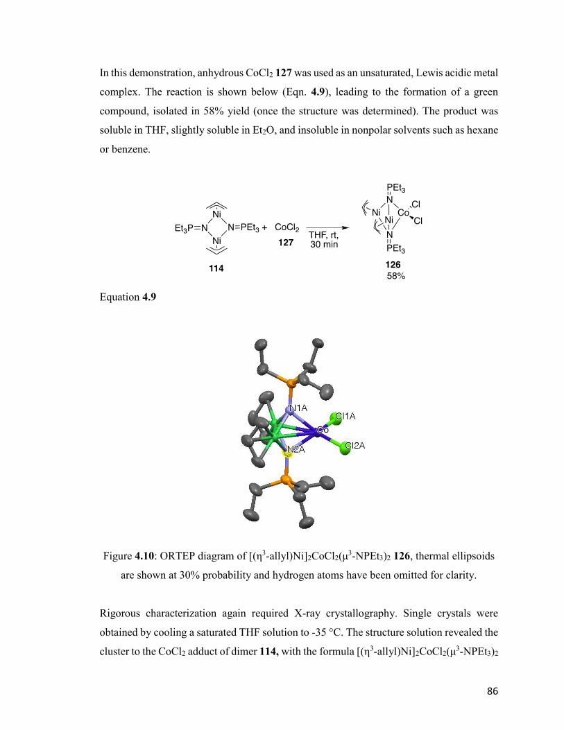
86
In this demonstration, anhydrous CoCl2 127 was used as an unsaturated, Lewis acidic metal
complex. The reaction is shown below (Eqn. 4.9), leading to the formation of a green
compound, isolated in 58% yield (once the structure was determined). The product was
soluble in THF, slightly soluble in Et2O, and insoluble in nonpolar solvents such as hexane
or benzene.
Equation 4.9
Figure 4.10: ORTEP diagram of [(η3-allyl)Ni]2CoCl2(μ3-NPEt3)2 126, thermal ellipsoids
are shown at 30% probability and hydrogen atoms have been omitted for clarity.
Rigorous characterization again required X-ray crystallography. Single crystals were
obtained by cooling a saturated THF solution to -35 °C. The structure solution revealed the
cluster to the CoCl2 adduct of dimer 114, with the formula [(η3-allyl)Ni]2CoCl2(μ3-NPEt3)2
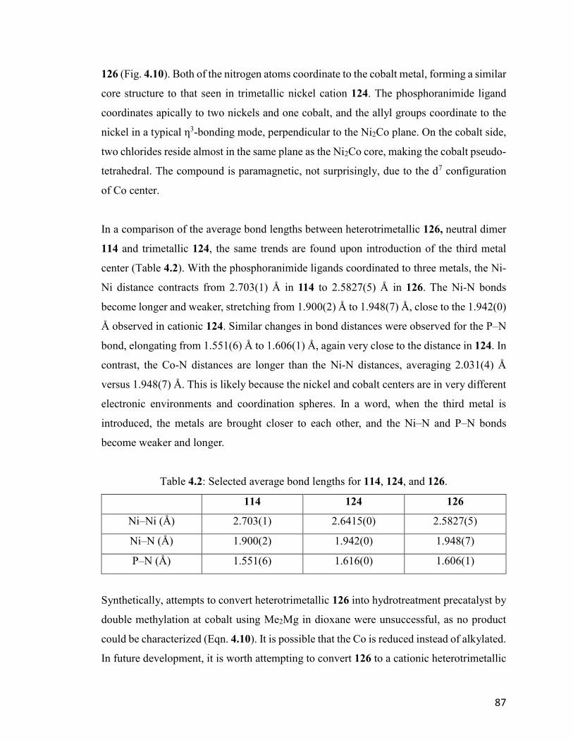
87
126 (Fig. 4.10). Both of the nitrogen atoms coordinate to the cobalt metal, forming a similar
core structure to that seen in trimetallic nickel cation 124. The phosphoranimide ligand
coordinates apically to two nickels and one cobalt, and the allyl groups coordinate to the
nickel in a typical η3-bonding mode, perpendicular to the Ni2Co plane. On the cobalt side,
two chlorides reside almost in the same plane as the Ni2Co core, making the cobalt pseudo-
tetrahedral. The compound is paramagnetic, not surprisingly, due to the d7 configuration
of Co center.
In a comparison of the average bond lengths between heterotrimetallic 126, neutral dimer
114 and trimetallic 124, the same trends are found upon introduction of the third metal
center (Table 4.2). With the phosphoranimide ligands coordinated to three metals, the Ni-
Ni distance contracts from 2.703(1) Å in 114 to 2.5827(5) Å in 126. The Ni-N bonds
become longer and weaker, stretching from 1.900(2) Å to 1.948(7) Å, close to the 1.942(0)
Å observed in cationic 124. Similar changes in bond distances were observed for the P–N
bond, elongating from 1.551(6) Å to 1.606(1) Å, again very close to the distance in 124. In
contrast, the Co-N distances are longer than the Ni-N distances, averaging 2.031(4) Å
versus 1.948(7) Å. This is likely because the nickel and cobalt centers are in very different
electronic environments and coordination spheres. In a word, when the third metal is
introduced, the metals are brought closer to each other, and the Ni–N and P–N bonds
become weaker and longer.
Table 4.2: Selected average bond lengths for 114, 124, and 126.
114 124 126
Ni–Ni (Å) 2.703(1) 2.6415(0) 2.5827(5)
Ni–N (Å) 1.900(2) 1.942(0) 1.948(7)
P–N (Å) 1.551(6) 1.616(0) 1.606(1)
Synthetically, attempts to convert heterotrimetallic 126 into hydrotreatment precatalyst by
double methylation at cobalt using Me2Mg in dioxane were unsuccessful, as no product
could be characterized (Eqn. 4.10). It is possible that the Co is reduced instead of alkylated.
In future development, it is worth attempting to convert 126 to a cationic heterotrimetallic
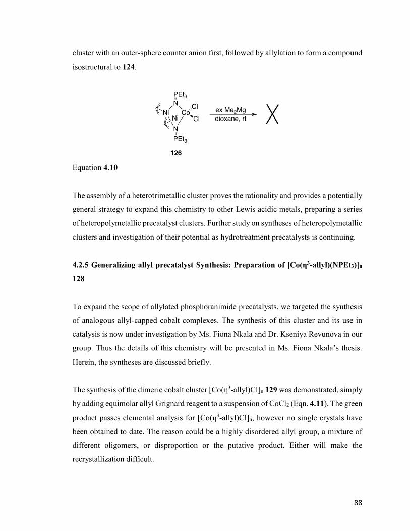
88
cluster with an outer-sphere counter anion first, followed by allylation to form a compound
isostructural to 124.
Equation 4.10
The assembly of a heterotrimetallic cluster proves the rationality and provides a potentially
general strategy to expand this chemistry to other Lewis acidic metals, preparing a series
of heteropolymetallic precatalyst clusters. Further study on syntheses of heteropolymetallic
clusters and investigation of their potential as hydrotreatment precatalysts is continuing.
4.2.5 Generalizing allyl precatalyst Synthesis: Preparation of [Co(η3-allyl)(NPEt3)]n
128
To expand the scope of allylated phosphoranimide precatalysts, we targeted the synthesis
of analogous allyl-capped cobalt complexes. The synthesis of this cluster and its use in
catalysis is now under investigation by Ms. Fiona Nkala and Dr. Kseniya Revunova in our
group. Thus the details of this chemistry will be presented in Ms. Fiona Nkala’s thesis.
Herein, the syntheses are discussed briefly.
The synthesis of the dimeric cobalt cluster [Co(η3-allyl)Cl]n 129 was demonstrated, simply
by adding equimolar allyl Grignard reagent to a suspension of CoCl2 (Eqn. 4.11). The green
product passes elemental analysis for [Co(η3-allyl)Cl]n, however no single crystals have
been obtained to date. The reason could be a highly disordered allyl group, a mixture of
different oligomers, or disproportion or the putative product. Either will make the
recrystallization difficult.
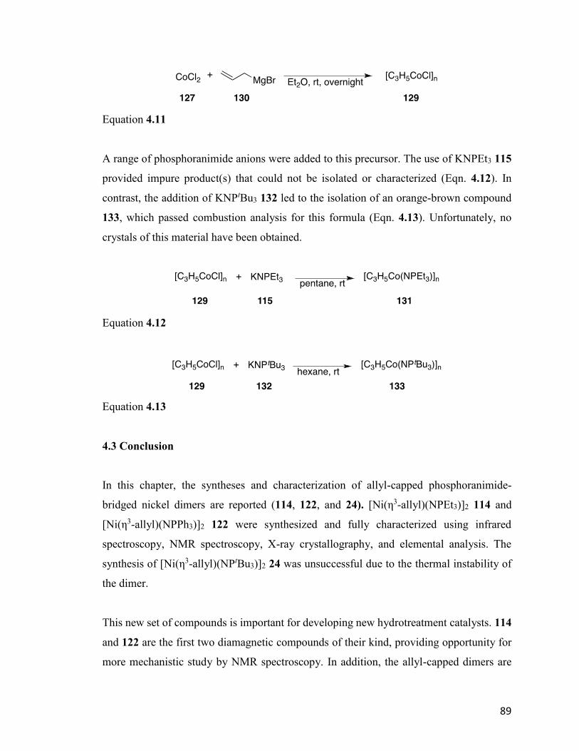
89
Equation 4.11
A range of phosphoranimide anions were added to this precursor. The use of KNPEt3 115
provided impure product(s) that could not be isolated or characterized (Eqn. 4.12). In
contrast, the addition of KNPtBu3 132 led to the isolation of an orange-brown compound
133, which passed combustion analysis for this formula (Eqn. 4.13). Unfortunately, no
crystals of this material have been obtained.
Equation 4.12
Equation 4.13
4.3 Conclusion
In this chapter, the syntheses and characterization of allyl-capped phosphoranimide-
bridged nickel dimers are reported (114, 122, and 24). [Ni(η3-allyl)(NPEt3)]2 114 and
[Ni(η3-allyl)(NPPh3)]2 122 were synthesized and fully characterized using infrared
spectroscopy, NMR spectroscopy, X-ray crystallography, and elemental analysis. The
synthesis of [Ni(η3-allyl)(NPtBu3)]2 24 was unsuccessful due to the thermal instability of
the dimer.
This new set of compounds is important for developing new hydrotreatment catalysts. 114
and 122 are the first two diamagnetic compounds of their kind, providing opportunity for
more mechanistic study by NMR spectroscopy. In addition, the allyl-capped dimers are
90
thermally more stable and tunable than the early tetrametallic series, which allows for
further substituent exploration.
The trimetallic cationic cluster, [Ni3(η3-Allyl)
3(μ3-NPEt
3)2]PF
6 124, was synthesized
fortuitously when the mixed-valent dimer was targeted. Based on 124 and the LiBr adduct
116, a rational design for the preparation of heterotrimetallic clusters was demonstrated by
the successful synthesis of [(η3-allyl)Ni]2CoCl2(μ3-NPEt3)2 126.
The syntheses and characterization of the new trimetallic clusters 124 and 126 is of great
potential for preparing heteropolymetallic clusters by rational design. By exploiting the
basicity of the nitrogen in double-bridged precursors, it should be possible to develop a
general strategy for accessing a large number of heteropolymetallic clusters.
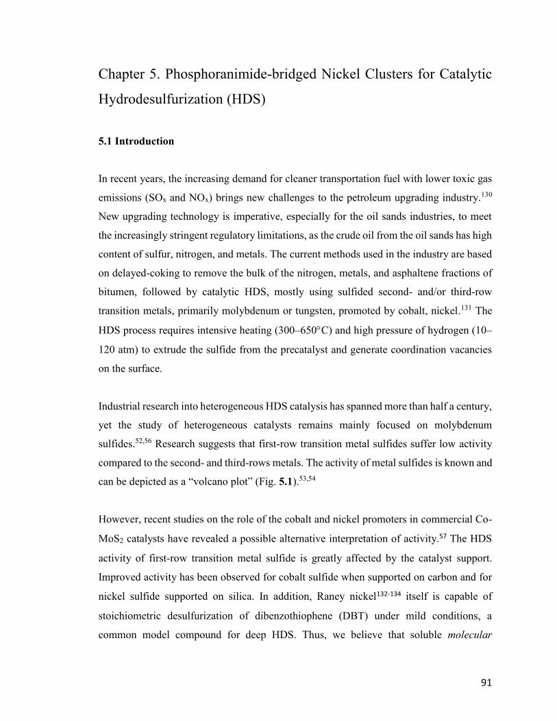
91
Chapter 5. Phosphoranimide-bridged Nickel Clusters for Catalytic
Hydrodesulfurization (HDS)
5.1 Introduction
In recent years, the increasing demand for cleaner transportation fuel with lower toxic gas
emissions (SOx and NOx) brings new challenges to the petroleum upgrading industry.130
New upgrading technology is imperative, especially for the oil sands industries, to meet
the increasingly stringent regulatory limitations, as the crude oil from the oil sands has high
content of sulfur, nitrogen, and metals. The current methods used in the industry are based
on delayed-coking to remove the bulk of the nitrogen, metals, and asphaltene fractions of
bitumen, followed by catalytic HDS, mostly using sulfided second- and/or third-row
transition metals, primarily molybdenum or tungsten, promoted by cobalt, nickel.131 The
HDS process requires intensive heating (300–650C) and high pressure of hydrogen (10–
120 atm) to extrude the sulfide from the precatalyst and generate coordination vacancies
on the surface.
Industrial research into heterogeneous HDS catalysis has spanned more than half a century,
yet the study of heterogeneous catalysts remains mainly focused on molybdenum
sulfides.52,56 Research suggests that first-row transition metal sulfides suffer low activity
compared to the second- and third-rows metals. The activity of metal sulfides is known and
can be depicted as a “volcano plot” (Fig. 5.1).53,54
However, recent studies on the role of the cobalt and nickel promoters in commercial Co-
MoS2 catalysts have revealed a possible alternative interpretation of activity.57 The HDS
activity of first-row transition metal sulfide is greatly affected by the catalyst support.
Improved activity has been observed for cobalt sulfide when supported on carbon and for
nickel sulfide supported on silica. In addition, Raney nickel132-134 itself is capable of
stoichiometric desulfurization of dibenzothiophene (DBT) under mild conditions, a
common model compound for deep HDS. Thus, we believe that soluble molecular
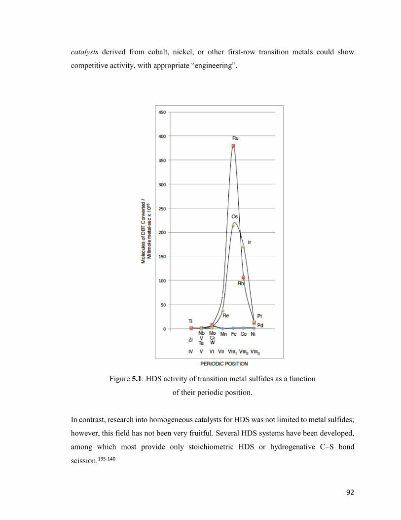
92
catalysts derived from cobalt, nickel, or other first-row transition metals could show
competitive activity, with appropriate “engineering”.
Figure 5.1: HDS activity of transition metal sulfides as a function
of their periodic position.
In contrast, research into homogeneous catalysts for HDS was not limited to metal sulfides;
however, this field has not been very fruitful. Several HDS systems have been developed,
among which most provide only stoichiometric HDS or hydrogenative C–S bond
scission.135-140
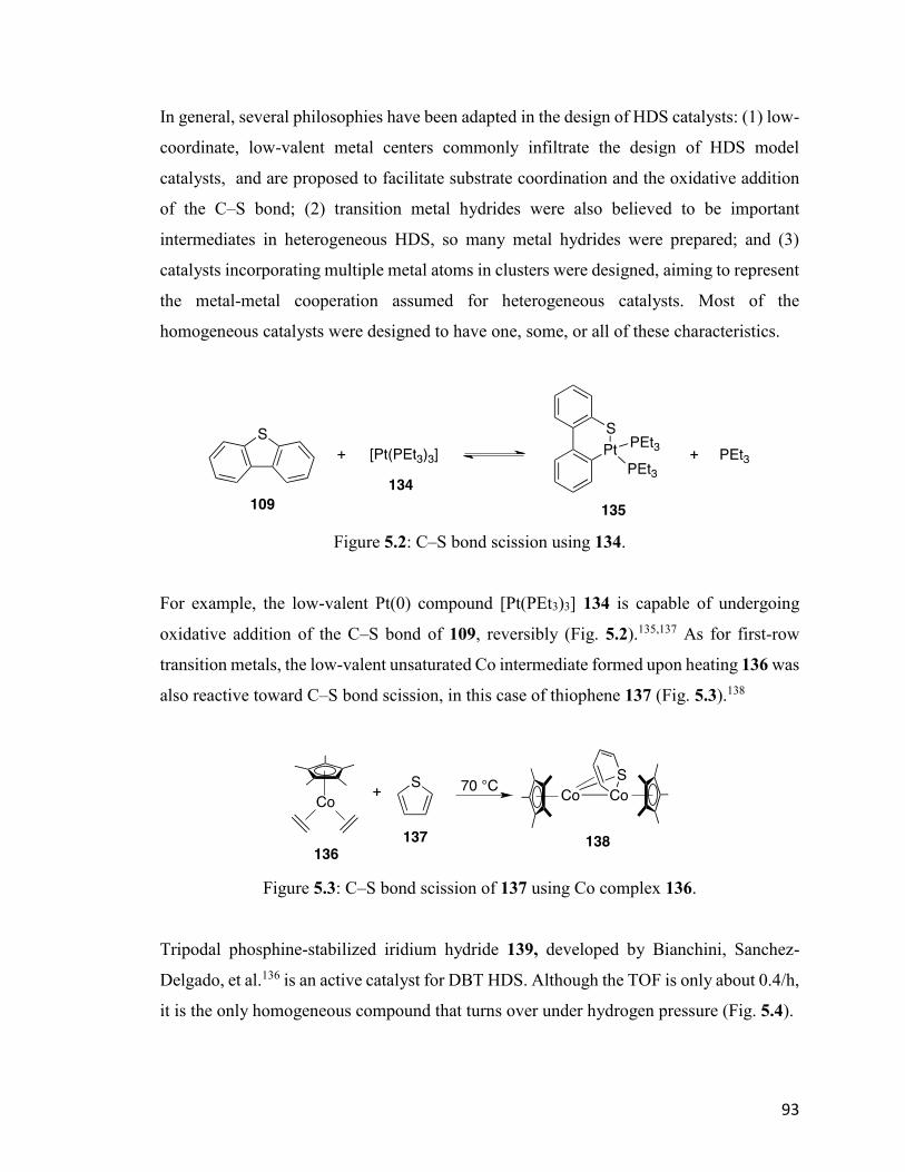
93
In general, several philosophies have been adapted in the design of HDS catalysts: (1) low-
coordinate, low-valent metal centers commonly infiltrate the design of HDS model
catalysts, and are proposed to facilitate substrate coordination and the oxidative addition
of the C–S bond; (2) transition metal hydrides were also believed to be important
intermediates in heterogeneous HDS, so many metal hydrides were prepared; and (3)
catalysts incorporating multiple metal atoms in clusters were designed, aiming to represent
the metal-metal cooperation assumed for heterogeneous catalysts. Most of the
homogeneous catalysts were designed to have one, some, or all of these characteristics.
Figure 5.2: C–S bond scission using 134.
For example, the low-valent Pt(0) compound [Pt(PEt3)3] 134 is capable of undergoing
oxidative addition of the C–S bond of 109, reversibly (Fig. 5.2).135,137 As for first-row
transition metals, the low-valent unsaturated Co intermediate formed upon heating 136 was
also reactive toward C–S bond scission, in this case of thiophene 137 (Fig. 5.3).138
Figure 5.3: C–S bond scission of 137 using Co complex 136.
Tripodal phosphine-stabilized iridium hydride 139, developed by Bianchini, Sanchez-
Delgado, et al.136 is an active catalyst for DBT HDS. Although the TOF is only about 0.4/h,
it is the only homogeneous compound that turns over under hydrogen pressure (Fig. 5.4).
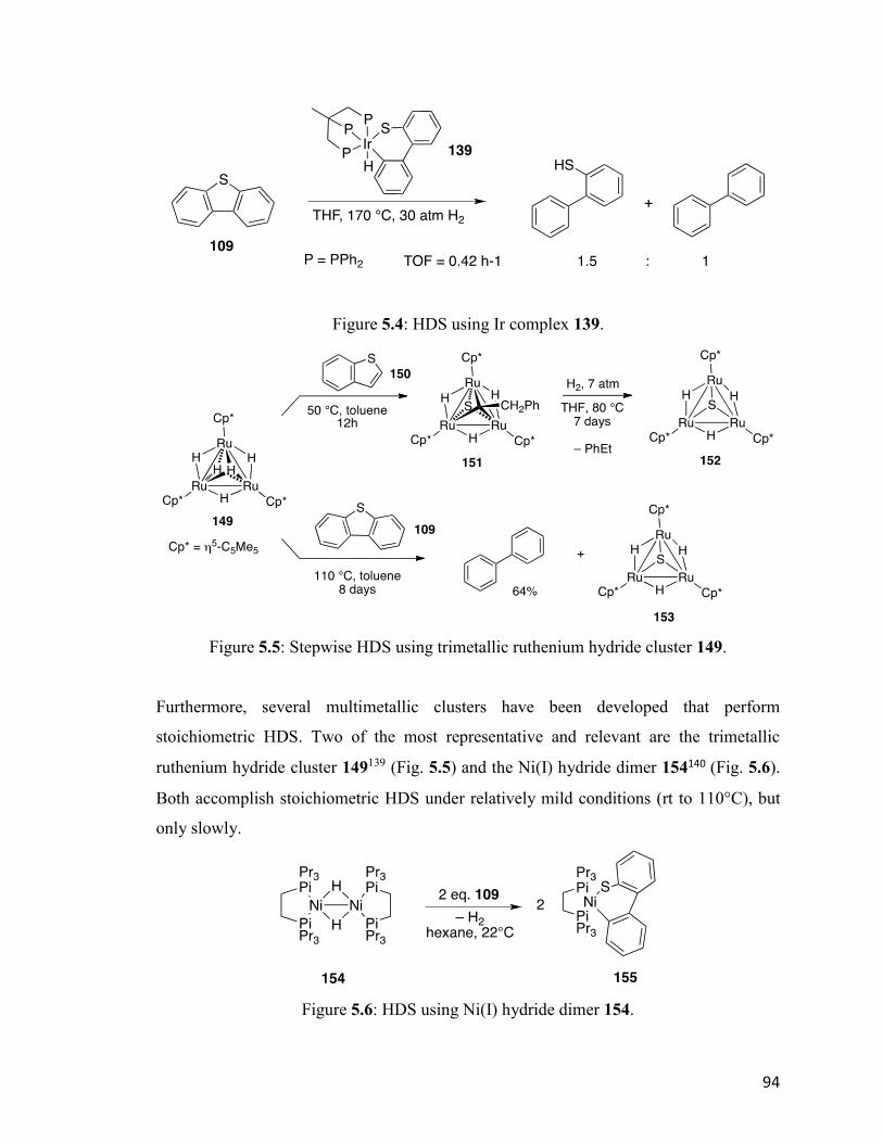
94
Figure 5.4: HDS using Ir complex 139.
Figure 5.5: Stepwise HDS using trimetallic ruthenium hydride cluster 149.
Furthermore, several multimetallic clusters have been developed that perform
stoichiometric HDS. Two of the most representative and relevant are the trimetallic
ruthenium hydride cluster 149139 (Fig. 5.5) and the Ni(I) hydride dimer 154140 (Fig. 5.6).
Both accomplish stoichiometric HDS under relatively mild conditions (rt to 110°C), but
only slowly.
Figure 5.6: HDS using Ni(I) hydride dimer 154.

95
M. David Curtis, et al., reported the tetrametallic mixed Co/Mo sulfide cluster 156,141
which is a mimic of the commercial heterogeneous catalysts (Fig. 5.7). Research into this
complex has provided valuable insight into the binding of substrate, C–S bond scission,
and metal-metal cooperation.
Figure 5.7: Desulfurization of 137 using Co/Mo sulfide cluster 156.
Our group has synthesized the phosphoranimide-bridged first-row transition metal clusters
for catalytic HDS under mild conditions, as they are coordinatively unsaturated
multimetallic clusters that could form metal hydride intermediates with appropriate
activation. According to a preliminary HDS study by Dr. Jeffrey Camacho-Bunquin, the
putative neutral nickel cluster 18 is an active HDS catalyst when using stoichiometric KH
as an irreversible scavenger for H2S (Eqn. 5.2). As the pure neutral cluster 18 is now
available, it became imperative to reinvestigate this putative HDS activity. Furthermore,
the unusually specific role of KH as a promoter for HDS will also be discussed.
Equation 5.2
Finally, the catalytic HDS activity of two allyl-capped precatalysts, [Ni(η3-allyl)(NPEt3)]2
114 and [Ni3(η3-allyl)3(μ
3-NPEt3)2]PF6 124 for hydrogenation and HDS were also studied,
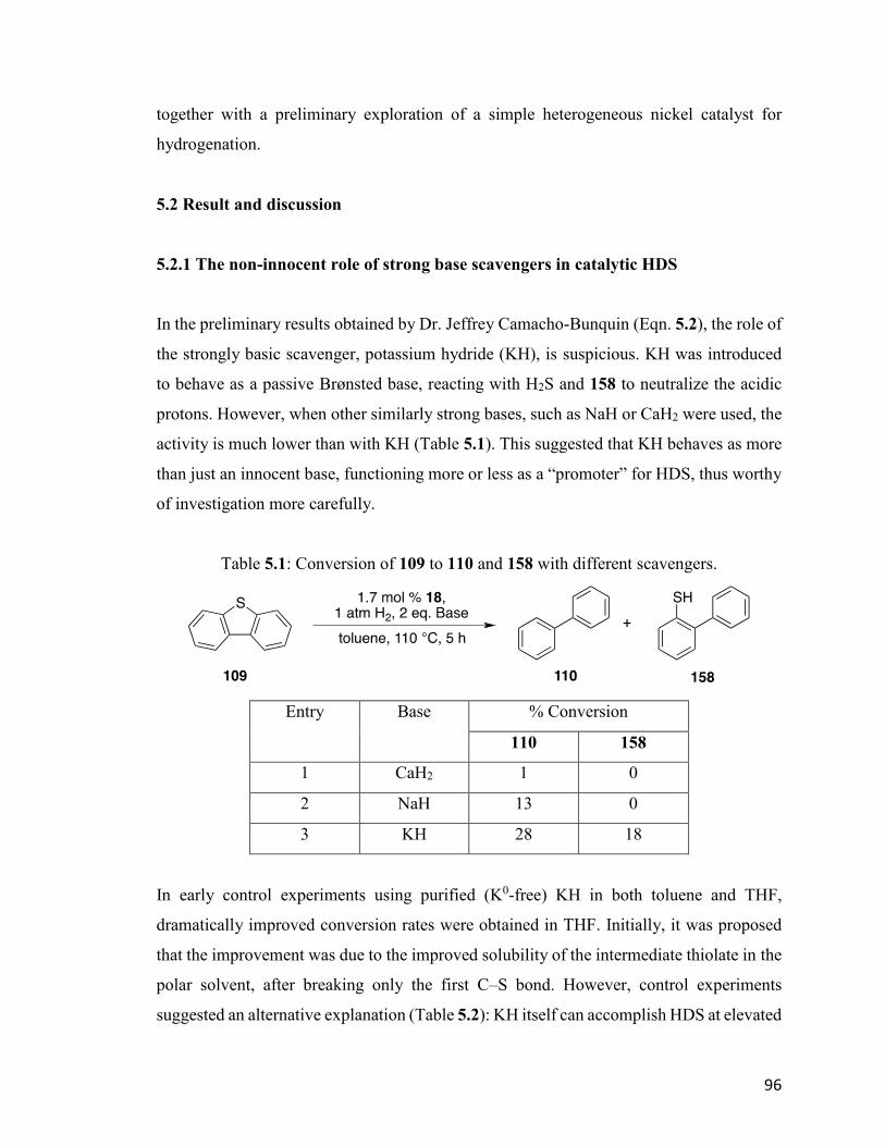
96
together with a preliminary exploration of a simple heterogeneous nickel catalyst for
hydrogenation.
5.2 Result and discussion
5.2.1 The non-innocent role of strong base scavengers in catalytic HDS
In the preliminary results obtained by Dr. Jeffrey Camacho-Bunquin (Eqn. 5.2), the role of
the strongly basic scavenger, potassium hydride (KH), is suspicious. KH was introduced
to behave as a passive Brønsted base, reacting with H2S and 158 to neutralize the acidic
protons. However, when other similarly strong bases, such as NaH or CaH2 were used, the
activity is much lower than with KH (Table 5.1). This suggested that KH behaves as more
than just an innocent base, functioning more or less as a “promoter” for HDS, thus worthy
of investigation more carefully.
Table 5.1: Conversion of 109 to 110 and 158 with different scavengers.
Entry Base % Conversion
110 158
1 CaH2 1 0
2 NaH 13 0
3 KH 28 18
In early control experiments using purified (K0-free) KH in both toluene and THF,
dramatically improved conversion rates were obtained in THF. Initially, it was proposed
that the improvement was due to the improved solubility of the intermediate thiolate in the
polar solvent, after breaking only the first C–S bond. However, control experiments
suggested an alternative explanation (Table 5.2): KH itself can accomplish HDS at elevated
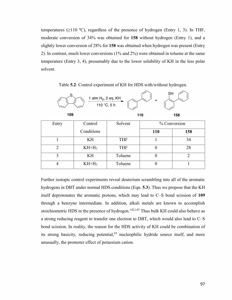
97
temperatures (≥110 ºC), regardless of the presence of hydrogen (Entry 1, 3). In THF,
moderate conversion of 34% was obtained for 158 without hydrogen (Entry 1), and a
slightly lower conversion of 28% for 158 was obtained when hydrogen was present (Entry
2). In contrast, much lower conversions (1% and 2%) were obtained in toluene at the same
temperature (Entry 3, 4), presumably due to the lower solubility of KH in the less polar
solvent.
Table 5.2: Control experiment of KH for HDS with/without hydrogen.
Entry Control
Conditions
Solvent % Conversion
110 158
1 KH THF 1 34
2 KH+H2 THF 0 28
3 KH Toluene 0 2
4 KH+H2 Toluene 0 1
Further isotopic control experiments reveal deuterium scrambling into all of the aromatic
hydrogens in DBT under normal HDS conditions (Eqn. 5.3). Thus we propose that the KH
itself deprotonates the aromatic protons, which may lead to C–S bond scission of 109
through a benzyne intermediate. In addition, alkali metals are known to accomplish
stoichiometric HDS in the presence of hydrogen.142,143 Thus bulk KH could also behave as
a strong reducing reagent to transfer one electron to DBT, which would also lead to C–S
bond scission. In reality, the reason for the HDS activity of KH could be combination of
its strong basicity, reducing potential,65 nucleophilic hydride source itself, and more
unusually, the promoter effect of potassium cation.
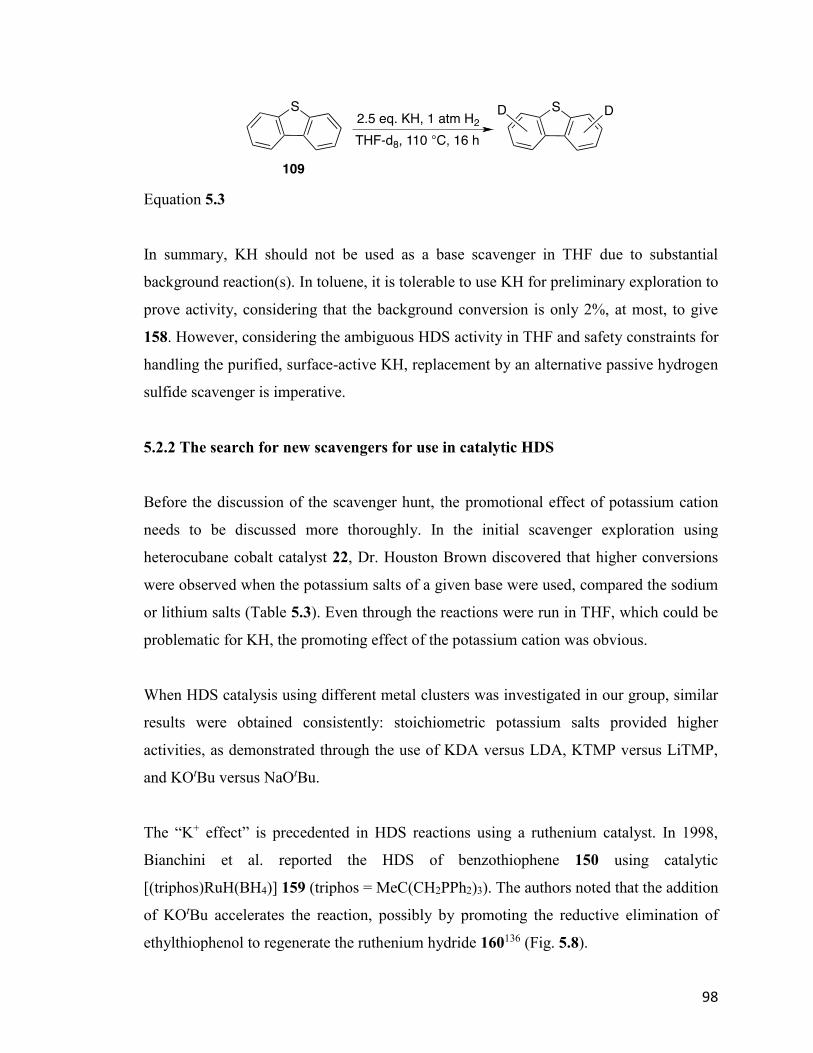
98
Equation 5.3
In summary, KH should not be used as a base scavenger in THF due to substantial
background reaction(s). In toluene, it is tolerable to use KH for preliminary exploration to
prove activity, considering that the background conversion is only 2%, at most, to give
158. However, considering the ambiguous HDS activity in THF and safety constraints for
handling the purified, surface-active KH, replacement by an alternative passive hydrogen
sulfide scavenger is imperative.
5.2.2 The search for new scavengers for use in catalytic HDS
Before the discussion of the scavenger hunt, the promotional effect of potassium cation
needs to be discussed more thoroughly. In the initial scavenger exploration using
heterocubane cobalt catalyst 22, Dr. Houston Brown discovered that higher conversions
were observed when the potassium salts of a given base were used, compared the sodium
or lithium salts (Table 5.3). Even through the reactions were run in THF, which could be
problematic for KH, the promoting effect of the potassium cation was obvious.
When HDS catalysis using different metal clusters was investigated in our group, similar
results were obtained consistently: stoichiometric potassium salts provided higher
activities, as demonstrated through the use of KDA versus LDA, KTMP versus LiTMP,
and KOtBu versus NaOtBu.
The “K+ effect” is precedented in HDS reactions using a ruthenium catalyst. In 1998,
Bianchini et al. reported the HDS of benzothiophene 150 using catalytic
[(triphos)RuH(BH4)] 159 (triphos = MeC(CH2PPh2)3). The authors noted that the addition
of KOtBu accelerates the reaction, possibly by promoting the reductive elimination of
ethylthiophenol to regenerate the ruthenium hydride 160136 (Fig. 5.8).
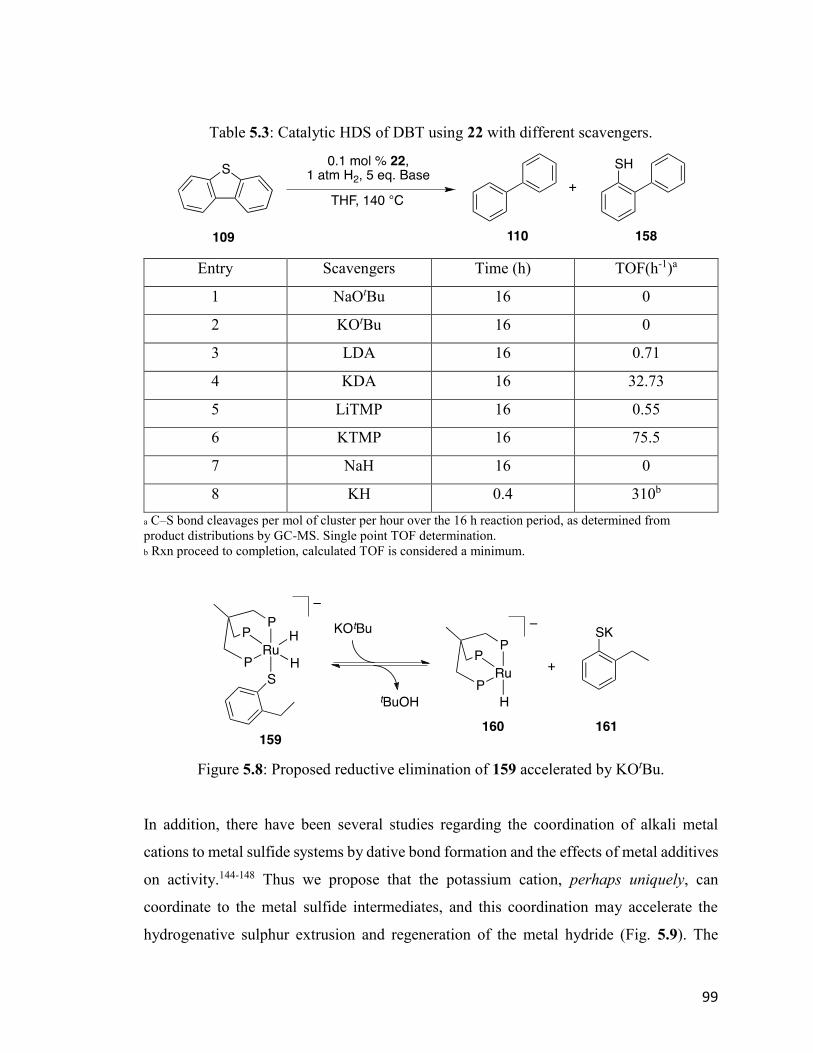
99
Table 5.3: Catalytic HDS of DBT using 22 with different scavengers.
Entry Scavengers Time (h) TOF(h-1)a
1 NaOtBu 16 0
2 KOtBu 16 0
3 LDA 16 0.71
4 KDA 16 32.73
5 LiTMP 16 0.55
6 KTMP 16 75.5
7 NaH 16 0
8 KH 0.4 310b
a C–S bond cleavages per mol of cluster per hour over the 16 h reaction period, as determined from
product distributions by GC-MS. Single point TOF determination.
b Rxn proceed to completion, calculated TOF is considered a minimum.
Figure 5.8: Proposed reductive elimination of 159 accelerated by KOtBu.
In addition, there have been several studies regarding the coordination of alkali metal
cations to metal sulfide systems by dative bond formation and the effects of metal additives
on activity.144-148 Thus we propose that the potassium cation, perhaps uniquely, can
coordinate to the metal sulfide intermediates, and this coordination may accelerate the
hydrogenative sulphur extrusion and regeneration of the metal hydride (Fig. 5.9). The
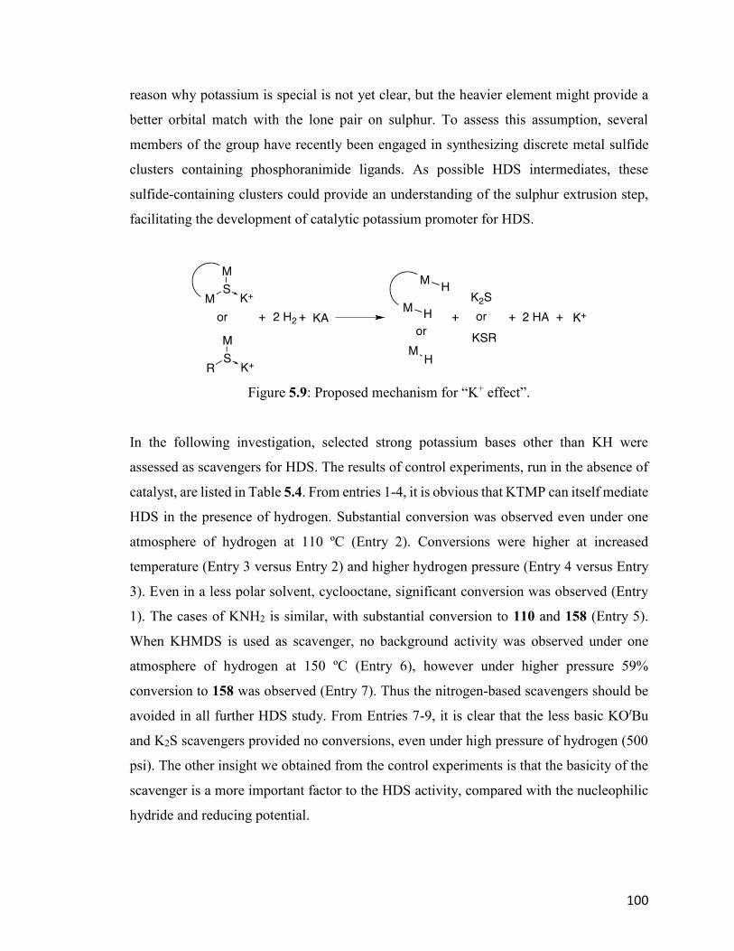
100
reason why potassium is special is not yet clear, but the heavier element might provide a
better orbital match with the lone pair on sulphur. To assess this assumption, several
members of the group have recently been engaged in synthesizing discrete metal sulfide
clusters containing phosphoranimide ligands. As possible HDS intermediates, these
sulfide-containing clusters could provide an understanding of the sulphur extrusion step,
facilitating the development of catalytic potassium promoter for HDS.
Figure 5.9: Proposed mechanism for “K+ effect”.
In the following investigation, selected strong potassium bases other than KH were
assessed as scavengers for HDS. The results of control experiments, run in the absence of
catalyst, are listed in Table 5.4. From entries 1-4, it is obvious that KTMP can itself mediate
HDS in the presence of hydrogen. Substantial conversion was observed even under one
atmosphere of hydrogen at 110 ºC (Entry 2). Conversions were higher at increased
temperature (Entry 3 versus Entry 2) and higher hydrogen pressure (Entry 4 versus Entry
3). Even in a less polar solvent, cyclooctane, significant conversion was observed (Entry
1). The cases of KNH2 is similar, with substantial conversion to 110 and 158 (Entry 5).
When KHMDS is used as scavenger, no background activity was observed under one
atmosphere of hydrogen at 150 ºC (Entry 6), however under higher pressure 59%
conversion to 158 was observed (Entry 7). Thus the nitrogen-based scavengers should be
avoided in all further HDS study. From Entries 7-9, it is clear that the less basic KOtBu
and K2S scavengers provided no conversions, even under high pressure of hydrogen (500
psi). The other insight we obtained from the control experiments is that the basicity of the
scavenger is a more important factor to the HDS activity, compared with the nucleophilic
hydride and reducing potential.
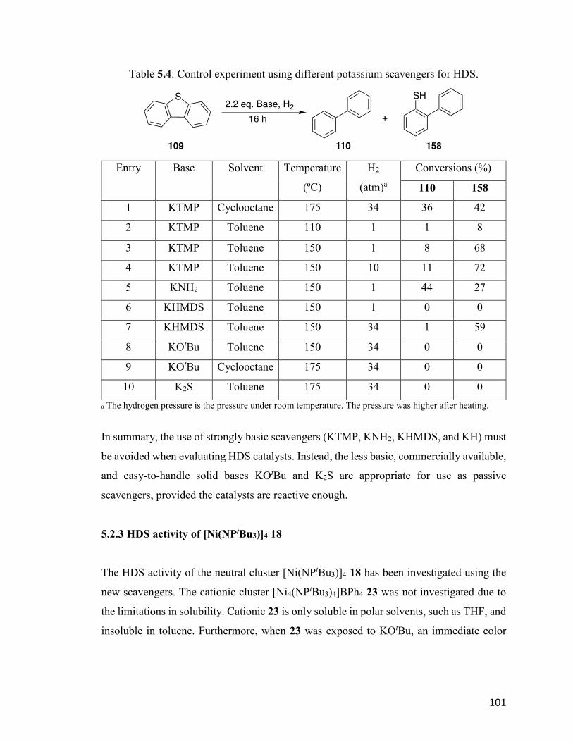
101
Table 5.4: Control experiment using different potassium scavengers for HDS.
Entry Base Solvent Temperature
(ºC)
H2
(atm)a
Conversions (%)
110 158
1 KTMP Cyclooctane 175 34 36 42
2 KTMP Toluene 110 1 1 8
3 KTMP Toluene 150 1 8 68
4 KTMP Toluene 150 10 11 72
5 KNH2 Toluene 150 1 44 27
6 KHMDS Toluene 150 1 0 0
7 KHMDS Toluene 150 34 1 59
8 KOtBu Toluene 150 34 0 0
9 KOtBu Cyclooctane 175 34 0 0
10 K2S Toluene 175 34 0 0
a The hydrogen pressure is the pressure under room temperature. The pressure was higher after heating.
In summary, the use of strongly basic scavengers (KTMP, KNH2, KHMDS, and KH) must
be avoided when evaluating HDS catalysts. Instead, the less basic, commercially available,
and easy-to-handle solid bases KOtBu and K2S are appropriate for use as passive
scavengers, provided the catalysts are reactive enough.
5.2.3 HDS activity of [Ni(NPtBu3)]4 18
The HDS activity of the neutral cluster [Ni(NPtBu3)]4 18 has been investigated using the
new scavengers. The cationic cluster [Ni4(NPtBu3)4]BPh4 23 was not investigated due to
the limitations in solubility. Cationic 23 is only soluble in polar solvents, such as THF, and
insoluble in toluene. Furthermore, when 23 was exposed to KOtBu, an immediate color
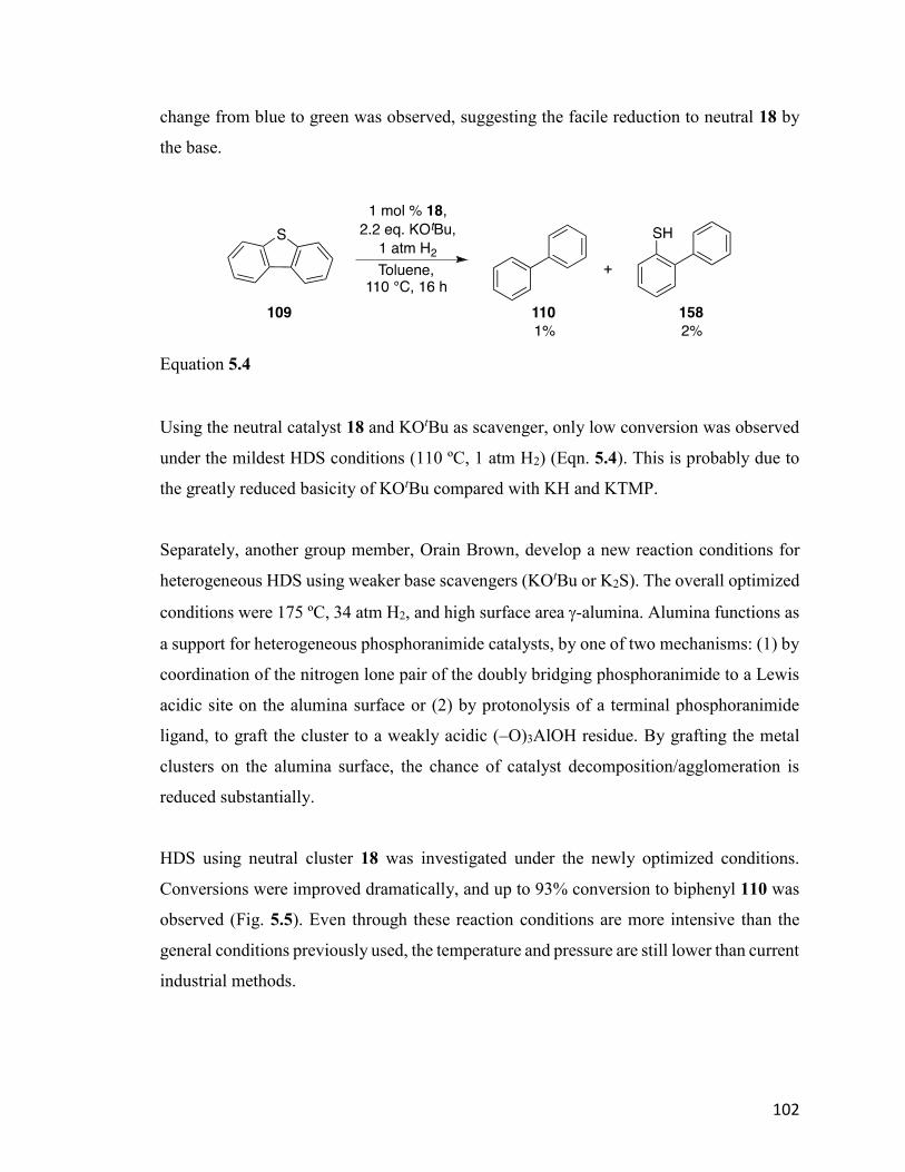
102
change from blue to green was observed, suggesting the facile reduction to neutral 18 by
the base.
Equation 5.4
Using the neutral catalyst 18 and KOtBu as scavenger, only low conversion was observed
under the mildest HDS conditions (110 ºC, 1 atm H2) (Eqn. 5.4). This is probably due to
the greatly reduced basicity of KOtBu compared with KH and KTMP.
Separately, another group member, Orain Brown, develop a new reaction conditions for
heterogeneous HDS using weaker base scavengers (KOtBu or K2S). The overall optimized
conditions were 175 ºC, 34 atm H2, and high surface area -alumina. Alumina functions as
a support for heterogeneous phosphoranimide catalysts, by one of two mechanisms: (1) by
coordination of the nitrogen lone pair of the doubly bridging phosphoranimide to a Lewis
acidic site on the alumina surface or (2) by protonolysis of a terminal phosphoranimide
ligand, to graft the cluster to a weakly acidic (–O)3AlOH residue. By grafting the metal
clusters on the alumina surface, the chance of catalyst decomposition/agglomeration is
reduced substantially.
HDS using neutral cluster 18 was investigated under the newly optimized conditions.
Conversions were improved dramatically, and up to 93% conversion to biphenyl 110 was
observed (Fig. 5.5). Even through these reaction conditions are more intensive than the
general conditions previously used, the temperature and pressure are still lower than current
industrial methods.
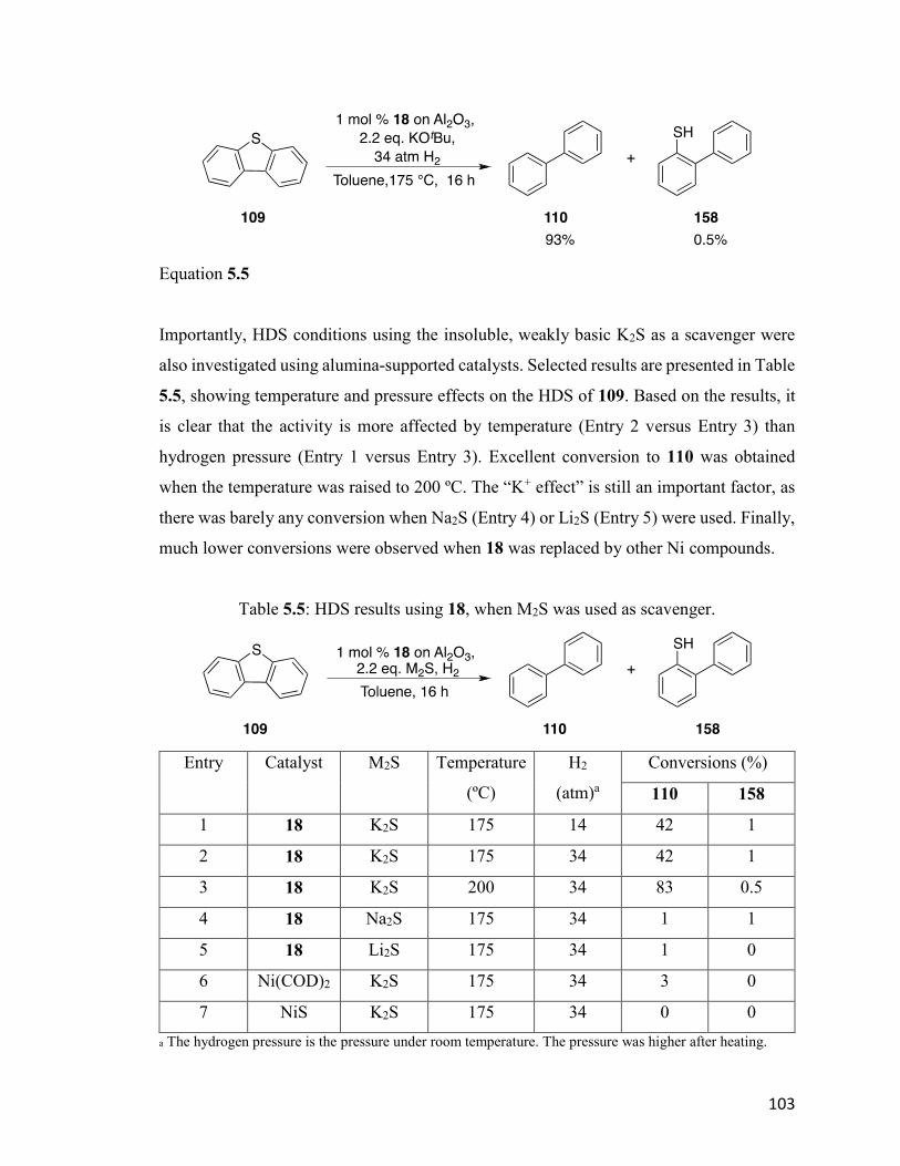
103
Equation 5.5
Importantly, HDS conditions using the insoluble, weakly basic K2S as a scavenger were
also investigated using alumina-supported catalysts. Selected results are presented in Table
5.5, showing temperature and pressure effects on the HDS of 109. Based on the results, it
is clear that the activity is more affected by temperature (Entry 2 versus Entry 3) than
hydrogen pressure (Entry 1 versus Entry 3). Excellent conversion to 110 was obtained
when the temperature was raised to 200 ºC. The “K+ effect” is still an important factor, as
there was barely any conversion when Na2S (Entry 4) or Li2S (Entry 5) were used. Finally,
much lower conversions were observed when 18 was replaced by other Ni compounds.
Table 5.5: HDS results using 18, when M2S was used as scavenger.
Entry Catalyst M2S Temperature
(ºC)
H2
(atm)a
Conversions (%)
110 158
1 18 K2S 175 14 42 1
2 18 K2S 175 34 42 1
3 18 K2S 200 34 83 0.5
4 18 Na2S 175 34 1 1
5 18 Li2S 175 34 1 0
6 Ni(COD)2 K2S 175 34 3 0
7 NiS K2S 175 34 0 0
a The hydrogen pressure is the pressure under room temperature. The pressure was higher after heating.
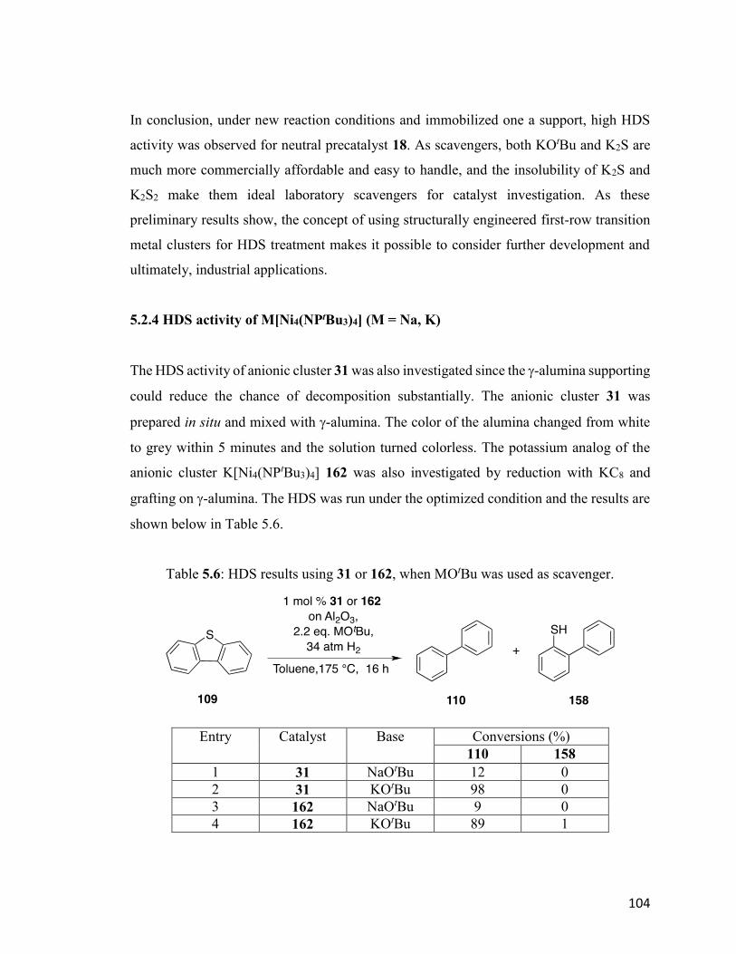
104
In conclusion, under new reaction conditions and immobilized one a support, high HDS
activity was observed for neutral precatalyst 18. As scavengers, both KOtBu and K2S are
much more commercially affordable and easy to handle, and the insolubility of K2S and
K2S2 make them ideal laboratory scavengers for catalyst investigation. As these
preliminary results show, the concept of using structurally engineered first-row transition
metal clusters for HDS treatment makes it possible to consider further development and
ultimately, industrial applications.
5.2.4 HDS activity of M[Ni4(NPtBu3)4] (M = Na, K)
The HDS activity of anionic cluster 31 was also investigated since the -alumina supporting
could reduce the chance of decomposition substantially. The anionic cluster 31 was
prepared in situ and mixed with -alumina. The color of the alumina changed from white
to grey within 5 minutes and the solution turned colorless. The potassium analog of the
anionic cluster K[Ni4(NPtBu3)4] 162 was also investigated by reduction with KC8 and
grafting on -alumina. The HDS was run under the optimized condition and the results are
shown below in Table 5.6.
Table 5.6: HDS results using 31 or 162, when MOtBu was used as scavenger.
Entry Catalyst Base Conversions (%)
110 158
1 31 NaOtBu 12 0
2 31 KOtBu 98 0
3 162 NaOtBu 9 0
4 162 KOtBu 89 1
105
Based on the results, close to quantitative conversion (98%) was obtained for 31 under
optimum conditions (Entry 2), although the accurate reaction rate was not known since the
reaction could be completed before 16 hours. A relatively close conversion, 89%, was
observed for anionic cluster 162, suggesting similar HDS activity for anionic cluster. The
comparison between Entry 1 versus 2, and Entry 3 versus 4 eatablished that the promoting
effect is substantial, and there is close to 10 times difference between NaOtBu and KOtBu
as scavengers. Moreover, a stoichiometric amount of K+ cation is necessary, comparing to
the catalytic amount present in Entry 3.
The anionic cluster 31 is the most active catalyst among all the phosphoranimide-bridged
first-row transition metal clusters. Besides the 98% conversion under optimum condition,
it is the only catalyst that turns over at all when NaOtBu is used as the scavengers. Further
study is continuing in the group.
5.2.5 Preliminary hydrogenation and HDS study of [Ni(η3-allyl)(NPEt3)]2 114
The allyl-capped nickel dimer [Ni(η3-allyl)(NPEt3)]2 114 was designed as a second-
generation nickel phosphoranimide precatalyst for HDS. For hydrogen to react with the
cluster, the allyl group must undergo 3–1 isomerization, dissociating to provide a vacant
coordination site. Thus NMR spectroscopy under elevated temperatures was studied in
deuterated toluene (C7D8). Both 1H-NMR and 31P-NMR spectra at various temperatures
were obtained. The two sets of allyl group signals become broadened at 80C and
eventually coalesced into one set of signals at higher temperatures. Thus, the rate of allyl
isomerization becomes fast on the NMR time scale above 80 C. In addition, a slight color
change from red to orange was also observed when the precatalyst was heated in the
presence of hydrogen. Since this temperature is still lower than the reaction temperatures
required for HDS, precatalyst activation should not be a limitation for 114 and other similar
allyl-capped nickel phosphoranimide clusters.
As a prerequisite for HDS, catalytic hydrogenation using [Ni(η3-allyl)(NPEt3)]2 114 was
investigated to establish the activity of the cluster. The reaction temperature was set at 100
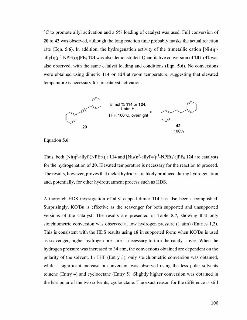
106
C to promote allyl activation and a 5% loading of catalyst was used. Full conversion of
20 to 42 was observed, although the long reaction time probably masks the actual reaction
rate (Eqn. 5.6). In addition, the hydrogenation activity of the trimetallic cation [Ni3(η3-
allyl)3(μ3-NPEt3)2]PF6 124 was also demonstrated. Quantitative conversion of 20 to 42 was
also observed, with the same catalyst loading and conditions (Eqn. 5.6). No conversions
were obtained using dimeric 114 or 124 at room temperature, suggesting that elevated
temperature is necessary for precatalyst activation.
Equation 5.6
Thus, both [Ni(η3-allyl)(NPEt3)]2 114 and [Ni3(η3-allyl)3(μ
3-NPEt3)2]PF6 124 are catalysts
for the hydrogenation of 20. Elevated temperature is necessary for the reaction to proceed.
The results, however, proves that nickel hydrides are likely produced during hydrogenation
and, potentially, for other hydrotreatment process such as HDS.
A thorough HDS investigation of allyl-capped dimer 114 has also been accomplished.
Surprisingly, KOtBu is effective as the scavenger for both supported and unsupported
versions of the catalyst. The results are presented in Table 5.7, showing that only
stoichiometric conversion was observed at low hydrogen pressure (1 atm) (Entries 1,2).
This is consistent with the HDS results using 18 in supported form: when KOtBu is used
as scavenger, higher hydrogen pressure is necessary to turn the catalyst over. When the
hydrogen pressure was increased to 34 atm, the conversions obtained are dependent on the
polarity of the solvent. In THF (Entry 3), only stoichiometric conversion was obtained,
while a significant increase in conversion was observed using the less polar solvents
toluene (Entry 4) and cyclooctane (Entry 5). Slightly higher conversion was obtained in
the less polar of the two solvents, cyclooctane. The exact reason for the difference is still
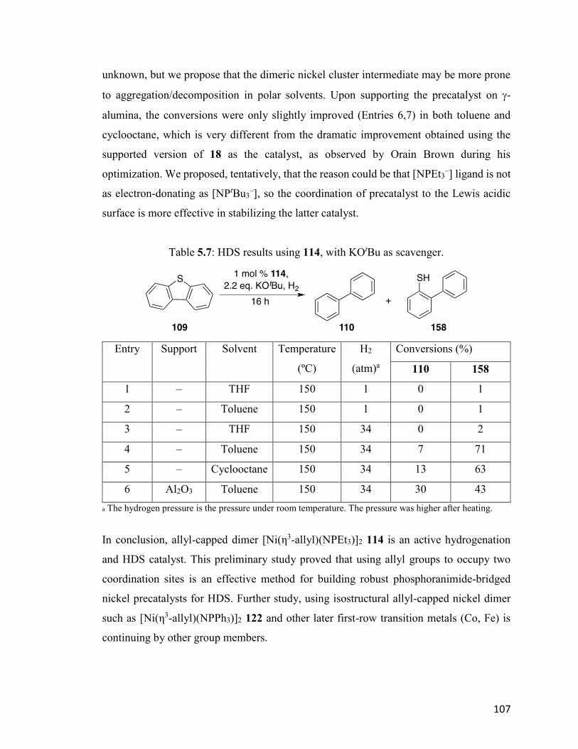
107
unknown, but we propose that the dimeric nickel cluster intermediate may be more prone
to aggregation/decomposition in polar solvents. Upon supporting the precatalyst on -
alumina, the conversions were only slightly improved (Entries 6,7) in both toluene and
cyclooctane, which is very different from the dramatic improvement obtained using the
supported version of 18 as the catalyst, as observed by Orain Brown during his
optimization. We proposed, tentatively, that the reason could be that [NPEt3–] ligand is not
as electron-donating as [NPtBu3–], so the coordination of precatalyst to the Lewis acidic
surface is more effective in stabilizing the latter catalyst.
Table 5.7: HDS results using 114, with KOtBu as scavenger.
Entry Support Solvent Temperature
(ºC)
H2
(atm)a
Conversions (%)
110 158
1 – THF 150 1 0 1
2 – Toluene 150 1 0 1
3 – THF 150 34 0 2
4 – Toluene 150 34 7 71
5 – Cyclooctane 150 34 13 63
6 Al2O3 Toluene 150 34 30 43
a The hydrogen pressure is the pressure under room temperature. The pressure was higher after heating.
In conclusion, allyl-capped dimer [Ni(η3-allyl)(NPEt3)]2 114 is an active hydrogenation
and HDS catalyst. This preliminary study proved that using allyl groups to occupy two
coordination sites is an effective method for building robust phosphoranimide-bridged
nickel precatalysts for HDS. Further study, using isostructural allyl-capped nickel dimer
such as [Ni(η3-allyl)(NPPh3)]2 122 and other later first-row transition metals (Co, Fe) is
continuing by other group members.
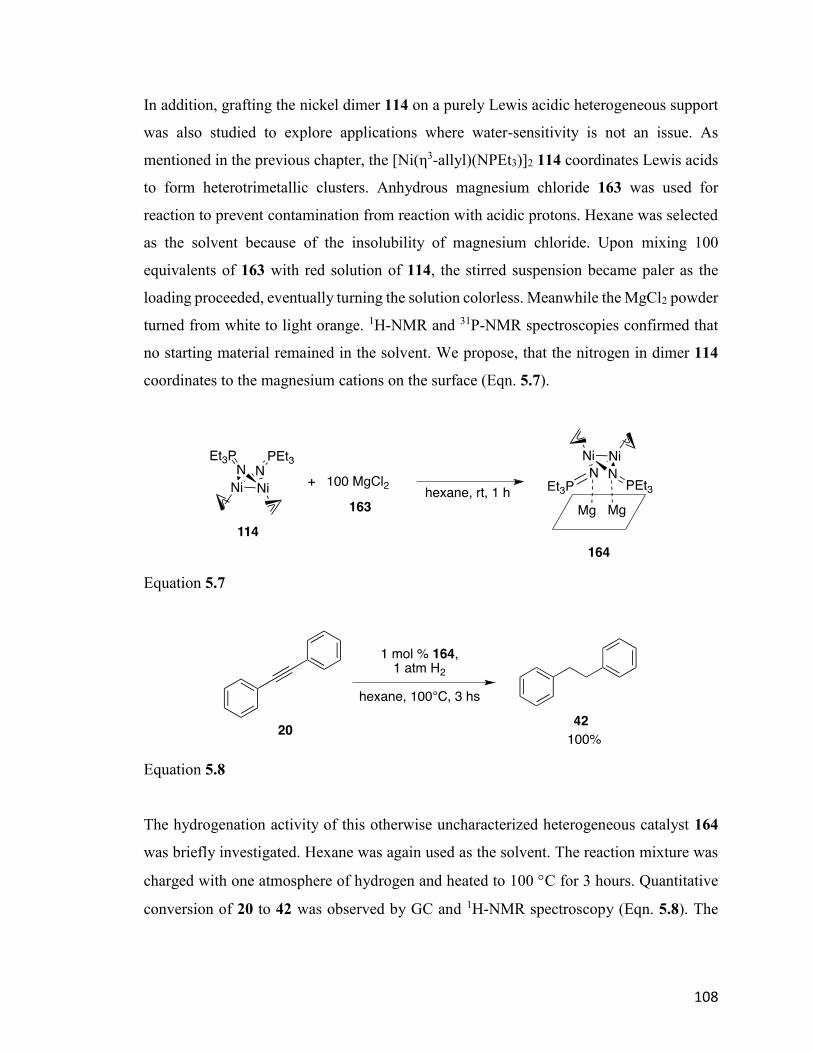
108
In addition, grafting the nickel dimer 114 on a purely Lewis acidic heterogeneous support
was also studied to explore applications where water-sensitivity is not an issue. As
mentioned in the previous chapter, the [Ni(η3-allyl)(NPEt3)]2 114 coordinates Lewis acids
to form heterotrimetallic clusters. Anhydrous magnesium chloride 163 was used for
reaction to prevent contamination from reaction with acidic protons. Hexane was selected
as the solvent because of the insolubility of magnesium chloride. Upon mixing 100
equivalents of 163 with red solution of 114, the stirred suspension became paler as the
loading proceeded, eventually turning the solution colorless. Meanwhile the MgCl2 powder
turned from white to light orange. 1H-NMR and 31P-NMR spectroscopies confirmed that
no starting material remained in the solvent. We propose, that the nitrogen in dimer 114
coordinates to the magnesium cations on the surface (Eqn. 5.7).
Equation 5.7
Equation 5.8
The hydrogenation activity of this otherwise uncharacterized heterogeneous catalyst 164
was briefly investigated. Hexane was again used as the solvent. The reaction mixture was
charged with one atmosphere of hydrogen and heated to 100 C for 3 hours. Quantitative
conversion of 20 to 42 was observed by GC and 1H-NMR spectroscopy (Eqn. 5.8). The
109
homogeneity of the catalyst is to be investigated in future. Further development of
heterogeneous catalysts is ongoing by other group members.
5.3 Conclusion
In this chapter, the non-innocent role of KH in preliminary HDS was determined,
establishing that even in non-polar solvents, KH use should be limited to preliminary
results. Strong nitrogen bases are also non-innocent and should not be used. KOtBu and
K2S, however, produce no background reaction and are appropriate scavengers for further
HDS study. Instead, more intense reaction conditions are necessary under this scenario:
150 C, 34 atm of hydrogen pressure, and alumina as support for the metal clusters. More
mechanistic study about the weak base scavenger is necessary to understand the role of
scavenger, including D-labeling control experiment.
The neutral cluster 18 and nickel dimer 114 were proved active HDS catalysts, and anionic
cluster 31 is by far the most efficient catalyst under the new optimum conditions. These
results validate the proposal that structural engineered first-row transition metal
compounds are capable of catalytic HDS.
Future improvement of the HDS catalysis could derive from understanding the effect of
oxidation state on activity (18 versus 31), and better design of heteropolymetallic clusters
to provide more efficient catalytic system. Incorporation of the K+ promoter into the cluster
design can avoid the addition of stoichiometric amount of potassium salt. In addition, easier
extrusion of sulfide and replacement of basic scavenger to passive scavengers (ZnO or
Fe2O3) can also be achieved possibly by rational design of the catalyst and appropriate
support.
110
Chapter 6. Experimental
6.1 General procedures (partially adapted from previous Stryker group theses)
6.1.1 General experimental procedures
All manipulations were performed using standard Schlenk techniques on a vacuum/N2 (or
Ar) double manifold or using a Labmaster sp MBraun glovebox under a N2 atmosphere.
Glovebox experiments were performed when the O2 level was <5 ppm as measured by a
Pb-based fuel cell Teledyne O2 sensor. Solvents were either distilled from Na (toluene),
Na/benzophenone (THF, benzene), K/benzophenone (hexane, pentane, ether, dioxane)
under nitrogen when dark blue or purple, from CaH2 (MeCN, CH2Cl2) under nitrogen or
collected from Pure Process Technology free standing solvent purification system (SPS).
Glovebox solvents were tested with a Na/benzophenone solution in THF to ensure they
were dry and degassed. Liquid reagents were either distilled under N2 (or Ar) and stored in
a glass “bomb” (a medium walled glass tube with a 14/20 sidearm that seals with a Teflon
high vacuum valve) or passed through Activity I neutral alumina into a bomb and
subsequently freeze-pump-thaw degassed three times. Hygroscopic solids were dried
overnight in a vacuum oven to remove water before bringing them into the glovebox while
hot. Non-hygroscopic solids were brought into the glovebox in vials covered with a
Kimwipes. Volatile solids were pumped into the glovebox inside of argon-filled Schlenk
flasks. All glassware was flame-dried or dried for at least 3 hours in a 150°C oven before
use. Low temperature crystallizations were done at -35 °C in the glovebox freezer. Sample
preparation for air sensitive IR spectroscopy was done in the glovebox. Solution IR cells
were sealed with Teflon stoppers and parafilm prior to data collection. Solid sample was
prepared in a special cell with KBr salt plate on top and bottom and a rubber ring between
covered with silica grease. For elemental analysis of air sensitive compounds, the samples
were prepared in the glovebox using two preweighed tin boats. Approximately 1.6 mg of
sample was placed in one boat and folded into a cube and then inserted into the second
boat, which was also folded into a cube. The cube was then sealed in a one-dram vial and
immediately submitted for analysis. Duplicate samples were run whenever possible. NMR
111
spectroscopy was done in standard NMR tubes sealed with either plastic caps or NMR-
tube sized septa. Magnetic susceptibility measurements were obtained via the Evans’
method58 in standard NMR tubes. For controlled heating of reaction mixtures, Ika stir plates
with digital temperature control were used along with heavy mineral oil (<110°C) or
silicone oil (>110°C) baths. For reactions requiring sustained low temperature, an
immersion cooler (Neslab Cryotrol cc-100) equipped with a temperature controller was
used. A high vacuum line, equipped with a three-stage diffusion pump, was used to dry
materials for elemental analysis (<10-5 Torr).
6.1.2 Method for determining magnetic susceptibility (partially adapted from
previous Stryker group theses)149
The Evans’ method58 was used to determine magnetic susceptibilities, deriving the room
temperature magnetic moment and an estimate of the number of unpaired electrons for
[Ni4(NPtBu3)4]BPh4. A reference solution of 95/5 v/v THF-d8/cyclohexane was prepared.
The solid sample (~5 mg) was dissolved in 2 mL of the reference solution. For each
determination, measurements of three separate sample solutions were made. The sample
solution was placed in a melting point capillary tube using a syringe with a 10 cm long 22-
gauge needle. This capillary was then placed into a standard NMR tube containing the
reference solution and the tube was capped. The 1H-NMR spectrum was then obtained at
room temperature for each sample.
6.1.3 Instrumentation (partially adapted from previous Stryker group theses)
X-ray crystallography was performed using either a Bruker DB diffractometer or a Bruker
PLATFORM diffractometer, both equipped with a SMART APEX II CCD area detectors.
Diffraction data collection and crystal structures determinations were done by Dr. Robert
McDonald and Dr. Michael Ferguson of the University of Alberta Department of
Chemistry X-ray Crystallography Laboratory. CHNS elemental analyses were performed
on a Carlo Erba EA1108 Elemental Analyzer. Gas chromatography-mass spectrometry was
performed using a Hewlett Packard GCD series G1800A GC-MS. The mass detectors used
112
were either HP 5870 or 5971 MSD. The column used was an Agilent DB-5 MS 25m x 0.25
mm x 0.25-micron film thickness. The MS library was the NIST/EPA/NIH 2011 Mass
Spectral Library and Software package was NIST11. IR spectroscopic analyses were
performed using a Nicolet Magna 750 FT-IR Spectrometer, or a Nicolet 8700 FT-IR
Spectrometer operating by OMNIC Spectra Software. All elemental analyses, GC-MS and
FT-IR data were obtained by staff at the University of Alberta Department of Chemistry
Analytical and Instrumentation Laboratory. 1H and 31P NMR spectra were obtained using
eitheran Agilent/Varian Inova 300 MHz spectrometer or an Agilent/Varian Inova 400 MHz
spectrometer at 27 °C unless otherwise mentioned. Chemical shifts for 1H NMR spectra
are reported in ppm and referenced against the residual proton signals of the NMR solvent.
31P NMR chemical shifts are reported in ppm, referenced to 85% phosphoric acid which is
assigned a value of 0 ppm.
6.1.4 Chemical materials (adapted from previous Stryker group theses)
All commercial reagents were purchased from Strem or Sigma-Aldrich chemical
companies were used as received. Where necessary, reagent purifications were
accomplished using standard methods. Potassium hydride150 required rigorous purification
to remove traces of potassium metal and was thus heated overnight at reflux in THF
containing 20 mol% naphthalene, then washed three times with anhydrous THF, three
times with dried hexanes and dried under vacuum before use. Materials prepared by
literature methods or modifications of such methods are noted in the appropriate
experimental sections.
6.1.5 Cyclic Voltammetry
Cyclic voltammetry was carried out using a WaveNow USB potentiostat from Pine
Industry Instrumentation and Aftermath operating software. Ceramic patterned platinum
electrodes with silver pseudo-reference (for non-aqueous solutions) were used as working
and counter electrodes. n-Bu4NPF6 was used as electrolyte with 0.1 mol/L concentration.
The analyte solution was prepared in the glovebox by dissolving the analyte in n-Bu4NPF6
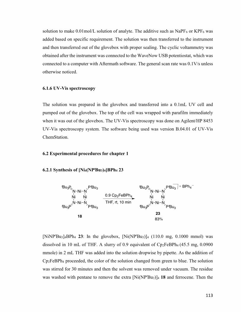
113
solution to make 0.01mol/L solution of analyte. The additive such as NaPF6 or KPF6 was
added based on specific requirement. The solution was then transferred to the instrument
and then transferred out of the glovebox with proper sealing. The cyclic voltammetry was
obtained after the instrument was connected to the WaveNow USB potentiostat, which was
connected to a computer with Aftermath software. The general scan rate was 0.1V/s unless
otherwise noticed.
6.1.6 UV-Vis spectroscopy
The solution was prepared in the glovebox and transferred into a 0.1mL UV cell and
pumped out of the glovebox. The top of the cell was wrapped with parafilm immediately
when it was out of the glovebox. The UV-Vis spectroscopy was done on Agilent/HP 8453
UV-Vis spectroscopy system. The software being used was version B.04.01 of UV-Vis
ChemStation.
6.2 Experimental procedures for chapter 1
6.2.1 Synthesis of [Ni4(NPtBu3)4]BPh4 23
[NiNPtBu3]4BPh4 23: In the glovebox, [Ni(NPtBu3)]4 (110.0 mg, 0.1000 mmol) was
dissolved in 10 mL of THF. A slurry of 0.9 equivalent of Cp2FeBPh4 (45.5 mg, 0.0900
mmole) in 2 mL THF was added into the solution dropwise by pipette. As the addition of
Cp2FeBPh4 proceeded, the color of the solution changed from green to blue. The solution
was stirred for 30 minutes and then the solvent was removed under vacuum. The residue
was washed with pentane to remove the extra [Ni(NPtBu3)]4 18 and ferrocene. Then the
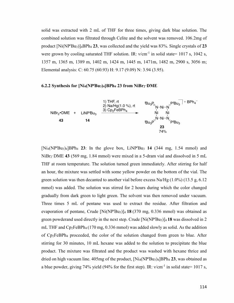
114
solid was extracted with 2 mL of THF for three times, giving dark blue solution. The
combined solution was filtrated through Celite and the solvent was removed. 106.2mg of
product [Ni(NPtBu3)]4BPh4 23, was collected and the yield was 83%. Single crystals of 23
were grown by cooling saturated THF solution. IR: ν/cm-1 in solid state= 1017 s, 1042 s,
1357 m, 1365 m, 1389 m, 1402 m, 1424 m, 1445 m, 1471m, 1482 m, 2900 s, 3056 m;
Elemental analysis: C: 60.75 (60.93) H: 9.17 (9.09) N: 3.94 (3.95).
6.2.2 Synthesis for [Ni4(NPtBu3)4]BPh4 23 from NiBr2·DME
[Ni4(NPtBu3)4]BPh4 23: In the glove box, LiNPtBu3 14 (344 mg, 1.54 mmol) and
NiBr2·DME 43 (569 mg, 1.84 mmol) were mixed in a 5-dram vial and dissolved in 5 mL
THF at room temperature. The solution turned green immediately. After stirring for half
an hour, the mixture was settled with some yellow powder on the bottom of the vial. The
green solution was then decanted to another vial before excess Na/Hg (1.0%) (13.5 g, 6.12
mmol) was added. The solution was stirred for 2 hours during which the color changed
gradually from dark green to light green. The solvent was then removed under vacuum.
Three times 5 mL of pentane was used to extract the residue. After filtration and
evaporation of pentane, Crude [Ni(NPtBu3)]4 18 (370 mg, 0.336 mmol) was obtained as
green powderand used directly in the next step. Crude [Ni(NPtBu3)]4 18 was dissolved in 2
mL THF and Cp2FeBPh4 (170 mg, 0.336 mmol) was added slowly as solid. As the addition
of Cp2FeBPh4 proceeded, the color of the solution changed from green to blue. After
stirring for 30 minutes, 10 mL hexane was added to the solution to precipitate the blue
product. The mixture was filtrated and the product was washed with hexane thrice and
dried on high vacuum line. 405mg of the product, [Ni4(NPtBu3)4]BPh4 23, was obtained as
a blue powder, giving 74% yield (94% for the first step). IR: ν/cm-1 in solid state= 1017 s,
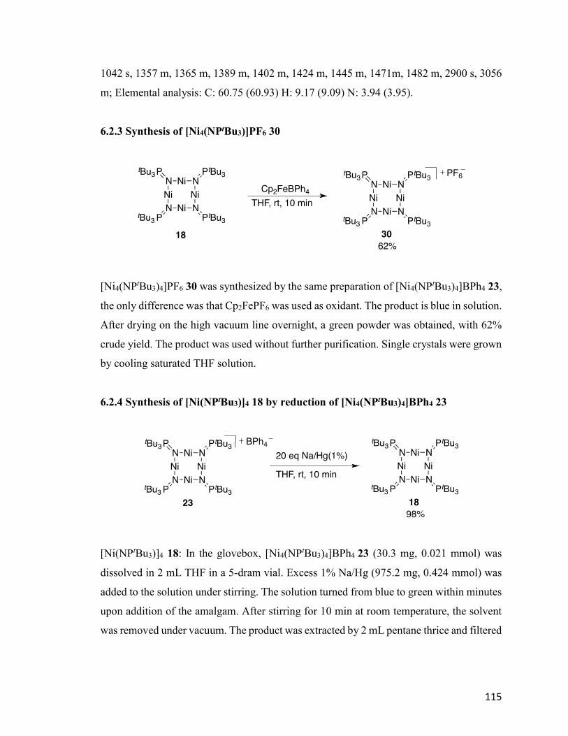
115
1042 s, 1357 m, 1365 m, 1389 m, 1402 m, 1424 m, 1445 m, 1471m, 1482 m, 2900 s, 3056
m; Elemental analysis: C: 60.75 (60.93) H: 9.17 (9.09) N: 3.94 (3.95).
6.2.3 Synthesis of [Ni4(NPtBu3)]PF6 30
[Ni4(NPtBu3)4]PF6 30 was synthesized by the same preparation of [Ni4(NPtBu3)4]BPh4 23,
the only difference was that Cp2FePF6 was used as oxidant. The product is blue in solution.
After drying on the high vacuum line overnight, a green powder was obtained, with 62%
crude yield. The product was used without further purification. Single crystals were grown
by cooling saturated THF solution.
6.2.4 Synthesis of [Ni(NPtBu3)]4 18 by reduction of [Ni4(NPtBu3)4]BPh4 23
[Ni(NPtBu3)]4 18: In the glovebox, [Ni4(NPtBu3)4]BPh4 23 (30.3 mg, 0.021 mmol) was
dissolved in 2 mL THF in a 5-dram vial. Excess 1% Na/Hg (975.2 mg, 0.424 mmol) was
added to the solution under stirring. The solution turned from blue to green within minutes
upon addition of the amalgam. After stirring for 10 min at room temperature, the solvent
was removed under vacuum. The product was extracted by 2 mL pentane thrice and filtered

116
through Celite. After evaporation of pentane under vacuum, [Ni(NPtBu3)]4 18 (23.0 mg)
was obtained in a yield of 98%.
6.2.5 Reduction of [Ni(NPtBu3)]4 18
[Ni(NPtBu3)]4 18 used in these reactions was prepared freshly from NiBr2·DME 43 and
used within two days or prepared by reduction of [Ni4(NPtBu3)4]BPh4 23 immediately
before use by 1% Na/Hg. [Ni(NPtBu3)]4 18 (40.0mg, 0.0364mmol) was dissolved in 3 mL
of THF. The reductant (Na/Hg, KC8, Li and so on) was added in excess to the solution
under stirring. After certain amount of time (noted in the content), the solvent was removed
under vacuum. The product was extracted by 2 mL of pentane thrice and filtered through
a plug of Celite. After evaporation of pentane under vacuum, the product was dissolved in
various solvents for recrystallization.
6.2.6 Ionic exchange of Na[Ni4(NPtBu3)4] 31 and nBu4NBr
[Ni(NPtBu3)]4 18 (50 mg, 0.045 mmol) was dissolved in 5 mL of THF and excess 40%
Na/Hg was added in the solution under stirring. After 30 minutes the solvent was
evaporated under vacuum. The product was extracted by 2 mL of pentane thrice and filtered
through Celite, giving a brown solution. Then nBu4NBr (14.6 mg, 0.045 mmol) was added
to the solution. After stirring for another 30 minutes, the solvent was removed under
vacuum, leaving black residue. The black powder was extracted with 3 mL of pentane,

117
ether and THF consecutively. The product was then set up for recrystallization separately.
No single crystals were obtained.
6.2.7 Comproportionation of [Ni4(NPtBu3)4]BPh4 23 and Na[Ni4(NPtBu3)4] 31
[Ni(NPtBu3)]4 18 (14.8 mg, 0.0135 mmol) was dissolved in 2 mL of THF and charged with
excess Na/Hg (40%). The solution was stirred at room temperature for 15 min, giving a
brown solution. The dark brown solution was then transferred into another vial and mixed
with a blue solution of [Ni4(NPtBu3)4]BPh4 23 (19.1 mg, 0.0135 mmol). Immediately color
change was observed from blue to green. The solvent was removed under vacuum. The
residue was extracted with 2 mL of pentane thrice. The combined pentane solution was
filtrated through Celite and concentrated to give [Ni(NPtBu3)]4 18 with 98% crude yield.
6.2.8 Consistent procedure for Na[Ni4(NPtBu3)4]
The [Ni(NPtBu3)]4 18 used in these reactions are prepared either freshly from NiBr2·DME
within three days or reduced from [Ni4(NPtBu3)4]BPh4 immediately before use by 1%
Na/Hg. [Ni(NPtBu3)]4 18 (40.0 mg, 0.0364 mmol) was dissolved in 3 mL of THF. Excess
40% Na/Hg was added to the solution. After stirring for 15 min, the solution was passed
throught Celite and the putative product Na[Ni4(NPtBu3)4] 31 was used immediately for
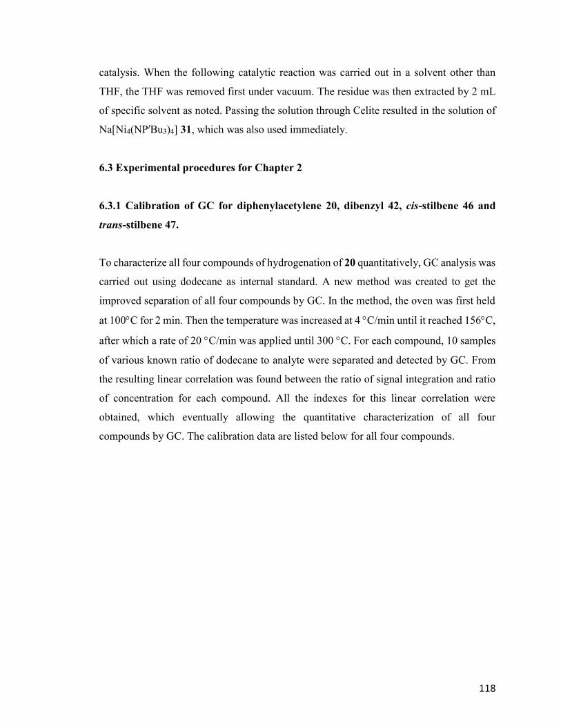
118
catalysis. When the following catalytic reaction was carried out in a solvent other than
THF, the THF was removed first under vacuum. The residue was then extracted by 2 mL
of specific solvent as noted. Passing the solution through Celite resulted in the solution of
Na[Ni4(NPtBu3)4] 31, which was also used immediately.
6.3 Experimental procedures for Chapter 2
6.3.1 Calibration of GC for diphenylacetylene 20, dibenzyl 42, cis-stilbene 46 and
trans-stilbene 47.
To characterize all four compounds of hydrogenation of 20 quantitatively, GC analysis was
carried out using dodecane as internal standard. A new method was created to get the
improved separation of all four compounds by GC. In the method, the oven was first held
at 100C for 2 min. Then the temperature was increased at 4 C/min until it reached 156C,
after which a rate of 20 C/min was applied until 300 C. For each compound, 10 samples
of various known ratio of dodecane to analyte were separated and detected by GC. From
the resulting linear correlation was found between the ratio of signal integration and ratio
of concentration for each compound. All the indexes for this linear correlation were
obtained, which eventually allowing the quantitative characterization of all four
compounds by GC. The calibration data are listed below for all four compounds.
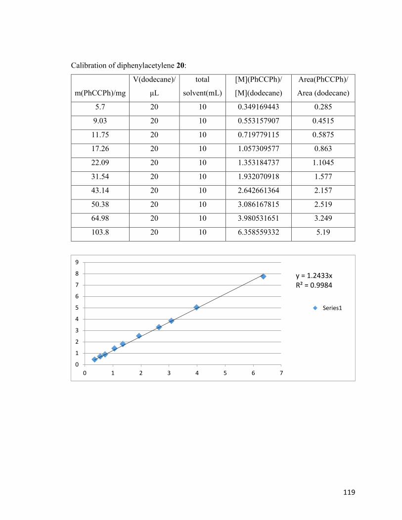
119
Calibration of diphenylacetylene 20:
m(PhCCPh)/mg
V(dodecane)/
μL
total
solvent(mL)
[M](PhCCPh)/
[M](dodecane)
Area(PhCCPh)/
Area (dodecane)
5.7 20 10 0.349169443 0.285
9.03 20 10 0.553157907 0.4515
11.75 20 10 0.719779115 0.5875
17.26 20 10 1.057309577 0.863
22.09 20 10 1.353184737 1.1045
31.54 20 10 1.932070918 1.577
43.14 20 10 2.642661364 2.157
50.38 20 10 3.086167815 2.519
64.98 20 10 3.980531651 3.249
103.8 20 10 6.358559332 5.19
y = 1.2433xR² = 0.9984
0
1
2
3
4
5
6
7
8
9
0 1 2 3 4 5 6 7
Series1
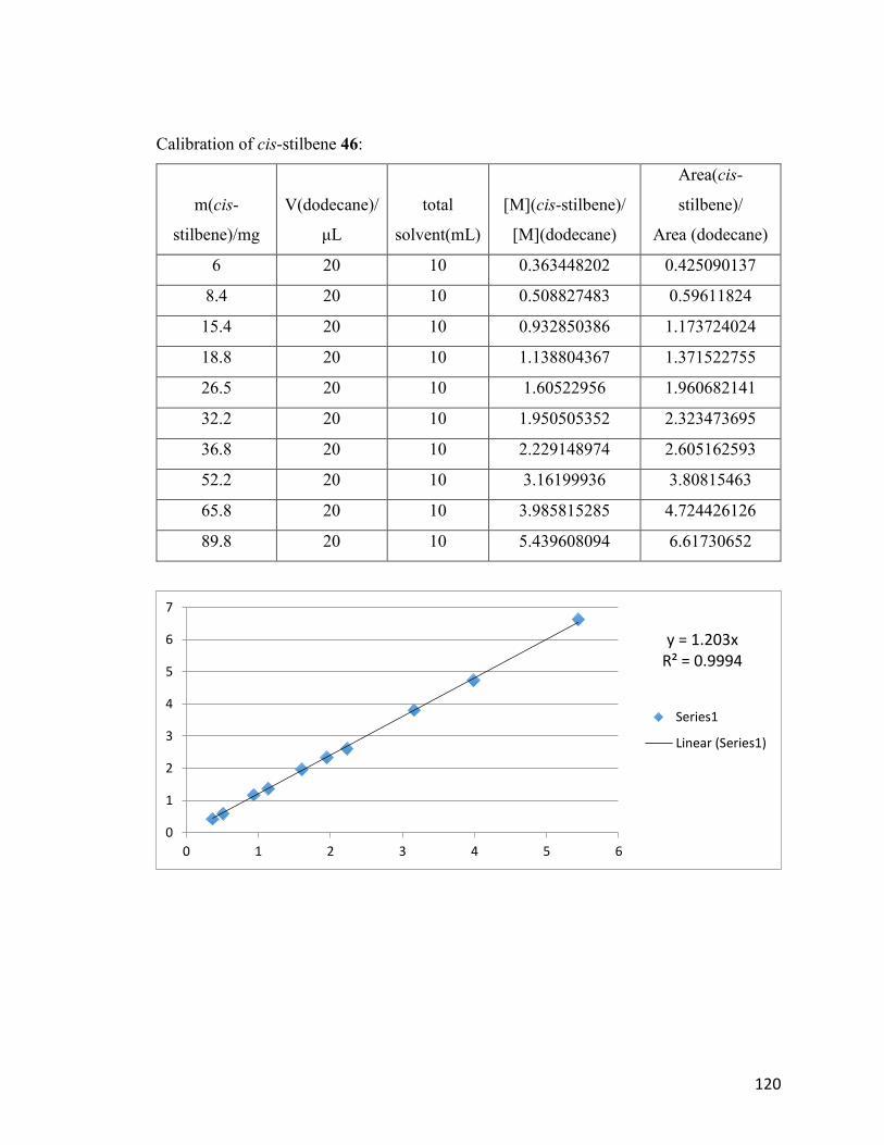
120
Calibration of cis-stilbene 46:
m(cis-
stilbene)/mg
V(dodecane)/
μL
total
solvent(mL)
[M](cis-stilbene)/
[M](dodecane)
Area(cis-
stilbene)/
Area (dodecane)
6 20 10 0.363448202 0.425090137
8.4 20 10 0.508827483 0.59611824
15.4 20 10 0.932850386 1.173724024
18.8 20 10 1.138804367 1.371522755
26.5 20 10 1.60522956 1.960682141
32.2 20 10 1.950505352 2.323473695
36.8 20 10 2.229148974 2.605162593
52.2 20 10 3.16199936 3.80815463
65.8 20 10 3.985815285 4.724426126
89.8 20 10 5.439608094 6.61730652
y = 1.203xR² = 0.9994
0
1
2
3
4
5
6
7
0 1 2 3 4 5 6
Series1
Linear (Series1)
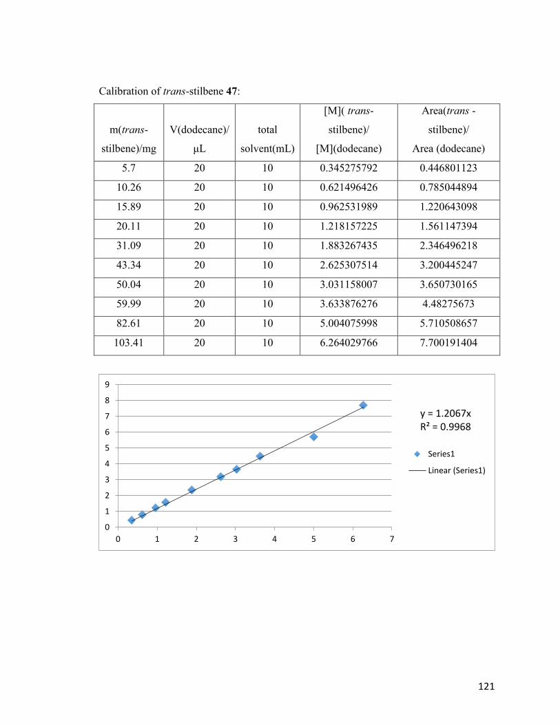
121
Calibration of trans-stilbene 47:
m(trans-
stilbene)/mg
V(dodecane)/
μL
total
solvent(mL)
[M]( trans-
stilbene)/
[M](dodecane)
Area(trans -
stilbene)/
Area (dodecane)
5.7 20 10 0.345275792 0.446801123
10.26 20 10 0.621496426 0.785044894
15.89 20 10 0.962531989 1.220643098
20.11 20 10 1.218157225 1.561147394
31.09 20 10 1.883267435 2.346496218
43.34 20 10 2.625307514 3.200445247
50.04 20 10 3.031158007 3.650730165
59.99 20 10 3.633876276 4.48275673
82.61 20 10 5.004075998 5.710508657
103.41 20 10 6.264029766 7.700191404
y = 1.2067xR² = 0.9968
0
1
2
3
4
5
6
7
8
9
0 1 2 3 4 5 6 7
Series1
Linear (Series1)
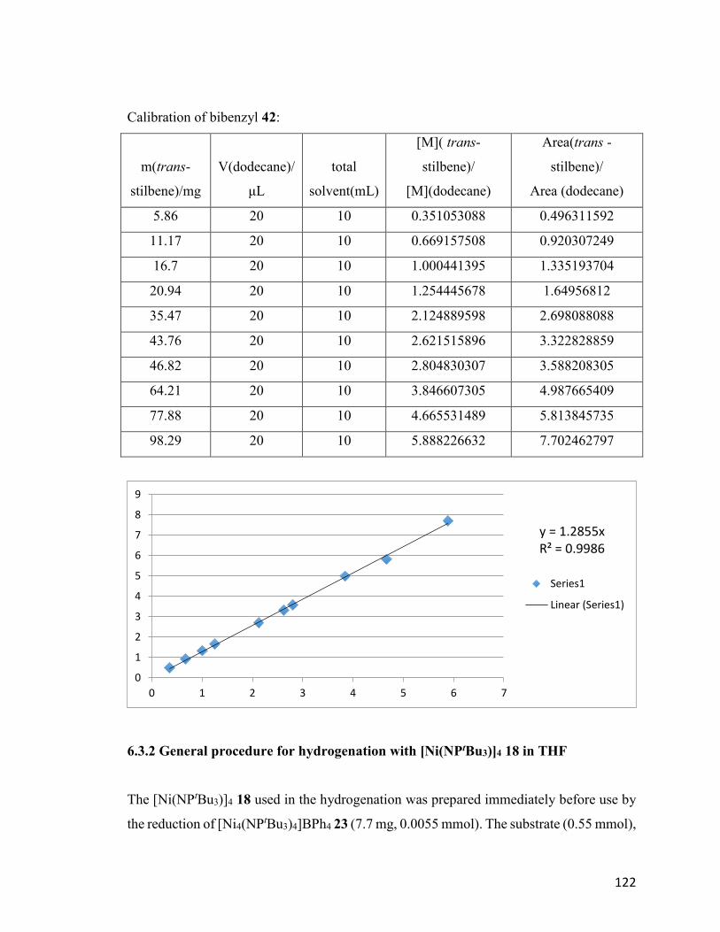
122
Calibration of bibenzyl 42:
m(trans-
stilbene)/mg
V(dodecane)/
μL
total
solvent(mL)
[M]( trans-
stilbene)/
[M](dodecane)
Area(trans -
stilbene)/
Area (dodecane)
5.86 20 10 0.351053088 0.496311592
11.17 20 10 0.669157508 0.920307249
16.7 20 10 1.000441395 1.335193704
20.94 20 10 1.254445678 1.64956812
35.47 20 10 2.124889598 2.698088088
43.76 20 10 2.621515896 3.322828859
46.82 20 10 2.804830307 3.588208305
64.21 20 10 3.846607305 4.987665409
77.88 20 10 4.665531489 5.813845735
98.29 20 10 5.888226632 7.702462797
6.3.2 General procedure for hydrogenation with [Ni(NPtBu3)]4 18 in THF
The [Ni(NPtBu3)]4 18 used in the hydrogenation was prepared immediately before use by
the reduction of [Ni4(NPtBu3)4]BPh4 23 (7.7 mg, 0.0055 mmol). The substrate (0.55 mmol),
y = 1.2855xR² = 0.9986
0
1
2
3
4
5
6
7
8
9
0 1 2 3 4 5 6 7
Series1
Linear (Series1)
123
catalyst (5.9mg, 0.00055mmol), 5 mL THF and a glass-encased stir bar were mixed in a
medium-walled glass reactor with Teflon screwed stopper. The glass reactor was
transferred out of the glovebox and connected to a hydrogen-filled schlenk line. The
solution was degassed by standard freeze-pump-thaw thrice. The reactor was then sealed
and stirred at room temperature for 6 hours unless otherwise noted. After one hour, the
reactor was open to air. Within a few minutes the nickel catalyst precipitated out. The
solution was then passed through Celite and mixed with 10 L of dodecane before
submission for GC or GC-MS analysis. If a 1H-NMR spectrum was needed, the solvent
was removed and the solid was dissolved in CDCl3 for 1H-NMR, using 2mg of C6Me6 as
internal standard.
6.3.2.1 Hydrogenation of diphenylacetylene 20 with [Ni(NPtBu3)]4 18
The general procedure was applied to [Ni(NPtBu3)]4 18 (6.0 mg, 0.0055 mmol) and
diphenylacetylene 20 (100.0 mg, 0.55 mmol). The product was characterized quantitatively
by GC. The only product is cis-stilbene 46, obtained in 2% yield. The remaining material
balance consisted of starting compound.
6.3.2.2 Hydrogenation of cis-stilbene 46 with [Ni(NPtBu3)]4 18
The general procedure was applied to [Ni(NPtBu3)]4 18 (6.0 mg, 0.0055 mmol) and cis-
stilbene 46 (102.0 mg, 0.55 mmol). The product was characterized quantitatively by GC.
The yield for trans-stilbene 47 was 20% and the yield for bibenzyl 42 was 5%. The
remaining material balance consisted of starting compound.
6.3.2.3 Hydrogenation of trans-stilbene 47 with [Ni(NPtBu3)]4 18
The general procedure was applied to [Ni(NPtBu3)]4 18 (6.0 mg, 0.0055 mmol) and trans-
stilbene 47 (102.0 mg, 0.55 mmol). The product was characterized quantitatively by GC.
The only product was bibenzyl 42 in 23% yield. The remaining material balance consisted
of starting compound.
124
6.3.2.4 Hydrogenation of allylbenzene 40 with [Ni(NPtBu3)]4 18
The general procedure was applied to [Ni(NPtBu3)]4 18 (6.0 mg, 0.0055 mmol) and
allylbenzene 40 (57.0 mg, 0.55 mmol). The product was characterized by GC-MS and 1H-
NMR. The yield of 1-phenylpropane 41 was 95%. The remaining material balance
consisted of starting compound.
6.3.2.5 Hydrogenation of styrene 48 with [Ni(NPtBu3)]4 18
The general procedure was applied to [Ni(NPtBu3)]4 18 (6.0 mg, 0.0055 mmol) and styrene
48 (65.0 mg, 0.55 mmol). The product was characterized by GC-MS and 1H-NMR. The
yield of ethylbenzene was 100%.
6.3.2.6 Hydrogenation of tetraphenylethylene 49 with [Ni(NPtBu3)]4 18
The general procedure was applied to [Ni(NPtBu3)]4 18 (6.0 mg, 0.0055 mmol) and
tetraphenylethylene 49 (182.0 mg, 0.55 mmol). The product was characterized by GC-MS
and 1H-NMR. The starting material was the only compound recovered.
6.3.2.7 Hydrogenation of diphenylacetylene 20 with [Ni(NPtBu3)]4 18 at 40 C
The general procedure was applied to [Ni(NPtBu3)]4 18 (6.0 mg, 0.0055 mmol) and
diphenylacetylene 20 (100.0 mg, 0.55 mmol). The glass reactor was immersed in 40 C
mineral oil bath after the addition of H2. The products were characterized quantitatively by
GC. The yield was 1% for bibenzyl 42, 9% for cis-stilbene 46 and 1% for trans-stilbene
47. The remaining material balance consisted of starting compound.
6.3.2.8 Hydrogenation of diphenylacetylene 20 with [Ni(NPtBu3)]4 18 at 60 C
The general procedure was applied to [Ni(NPtBu3)]4 18 (6.0 mg, 0.0055 mmol) and
125
diphenylacetylene 20 (100.0 mg, 0.55 mmol). The glass reactor was immersed in 60 C
mineral oil bath after the addition of H2. The products were characterized quantitatively by
GC. The yield was 85% for bibenzyl 42, 6% for cis-stilbene 46, and 9% for trans-stilbene
47.
6.3.2.9 Mercury test of hydrogenation of diphenylacetylene 20 with [Ni(NPtBu3)]4 18
at 60 C
The general procedure was applied to [Ni(NPtBu3)]4 18 (6.0 mg, 0.0055 mmol)
diphenylacetylene 20 (100.0 mg, 0.55 mmol). Excess mercury (5.5 mmol, 1.102 g) was
also added in the glass reactor. The glass reactor was immersed in 60 C mineral oil bath
after the addition of H2. The products were characterized quantitatively by GC. The
conversions were 73% for bibenzyl 42, 15% for cis-stilbene 46 and 13% for trans-stilbene
47.
6.3.2.10 Mercury test of hydrogenation of diphenylacetylene 20 with [Ni(NPtBu3)]4 18
at 80 C
The general procedure was applied to [Ni(NPtBu3)]4 18 (6.0 mg, 0.0055 mmol)
diphenylacetylene 20 (100.0 mg, 0.55 mmol). Excess mercury (5.5 mmol, 1.102 g) was
also added in the glass reactor. The glass reactor was immersed in 80 C mineral oil bath
after the addition of H2. The products were characterized quantitatively by GC. The
conversions were 5% for bibenzyl 42, 52% for cis-stilbene 46, and 2% for trans-stilbene
47.
6.3.3 General procedure for hydrogenation with Na[Ni4(NPtBu3)4] 31 in THF
The [Ni(NPtBu3)]4 18 used here was prepared immediately prior to use from reduction of
[Ni4(NPtBu3)4]BPh4 23 by 1% Na/Hg. The green solid [Ni(NPtBu3)]4 18 (5.9 mg, 0.00055
mmol) was dissolved in 1 mL of THF. After the solid was dissolved, one drop of 40%
Na/Hg was added to the solution and stirred for 15 min. The color changed from green to
126
brown gradually. The solution was then passed through Celite, giving a brown solution of
Na[Ni4(NPtBu3)4] 31. Then the substrate (0.055 mol), solution of Na[Ni4(NPtBu3)4] 31,
another 4 mL THF and a glass-encased stir bar were mixed in a medium-walled glass
reactor fitted with a Teflon high-vacuum valve. The glass reactor was transferred out of the
glovebox and connected to a hydrogen-filled Schlenk line. The solution was degassed by
standard freeze-pump-thaw thrice, after which the reactor was filled with 1 atm H2 as the
solution warmed to room temperature. The reactor was then sealed and stirred at room
temperature for 6 hours unless otherwise noted. After 6 hours, the reactor was open to air.
Within a few min the nickel catalyst precipitated out. The solution was then passed through
Celite and mixed with 10 µL of dodecane before submission for analysis by GC or GC-
MS. If 1H-NMR was needed, the solvent was removed, and the solid was dissolved in
CDCl3 for 1H-NMR with 2 mg of C6Me6 as internal standard.
6.3.3.1 Hydrogenation of diphenylacetylene 20 with Na[Ni4(NPtBu3)4] 31
The general procedure was applied to [Ni(NPtBu3)]4 18 (6.0 mg, 0.0055 mmol) and
diphenylacetylene 20 (100.0 mg, 0.55 mmol). The product was characterized quantitatively
by GC. The only product was bibenzyl 42 in 100% yield.
6.3.3.2 Hydrogenation of cis-stilbene 46 with Na[Ni4(NPtBu3)4] 31
The general procedure was applied to [Ni(NPtBu3)]4 18 (6.0 mg, 0.0055 mmol) and cis-
stilbene 46 (102.0 mg, 0.55 mmol). The product was characterized quantitatively by GC.
The yields were 85% for bibenzyl 42 and 15% for trans-stilbene 47.
6.3.3.3 Hydrogenation of trans-stilbene 47 with Na[Ni4(NPtBu3)4] 31
The general procedure was applied to [Ni(NPtBu3)]4 18 (6.0 mg, 0.0055 mmol) and trans-
stilbene 47 (102.0 mg, 0.55 mmol). The product was characterized quantitatively by GC.
The only product was bibenzyl in 45% yield. The remaining material balance consisted of
starting compound.
127
6.3.3.4 Hydrogenation of allylbenzene 40 with Na[Ni4(NPtBu3)4] 31
The general procedure was applied to [Ni(NPtBu3)]4 18 (6.0 mg, 0.0055 mmol) and
allylbenzene 40 (57.0 mg, 0.55 mmol). The product was characterized by GC-MS and 1H-
NMR. The yield of 1-phenylpropane 41 was 100%.
6.3.3.5 Hydrogenation of styrene 48 with Na[Ni4(NPtBu3)4] 31
The general procedure was applied to [Ni(NPtBu3)]4 18 (6.0 mg, 0.0055 mmol) and styrene
48 (65.0 mg, 0.55 mmol). The product was characterized by GC-MS and 1H-NMR. The
product was a mixture of polystyrene.
6.3.3.6 Hydrogenation of tetraphenylethylene 49 with Na[Ni4(NPtBu3)4] 31
The general procedure was applied to [Ni(NPtBu3)]4 18 (6.0 mg, 0.0055 mmol) and
tetraphenylethylene 49 (182.0 mg, 0.55 mmol). The product was characterized by GC-MS
and 1H-NMR. The starting material was the only compound recovered.
6.3.3.7 Hydrogenation of diphenylacetylene 20 with Na[Ni4(NPtBu3)4] 31 at 0 C
The general procedure was applied to [Ni(NPtBu3)]4 18 (6.0 mg, 0.0055 mmol) and
diphenylacetylene 20 (100.0 mg, 0.55 mmol). The glass reactor was immersed in ice bath
after the addition of H2. The products were characterized quantitatively by GC. The
conversions were 8% for bibenzyl 42, 66% for cis-stilbene 46, and 1% for trans-stilbene
47. The remaining material balance consisted of starting compound.
6.3.3.8 Mercury test for hydrogenation of diphenylacetylene 20 with Na[Ni4(NPtBu3)4]
31 at 0 C
128
The general procedure was applied to [Ni(NPtBu3)]4 18 (6.0 mg, 0.0055 mmol) and
diphenylacetylene 20 (100.0 mg, 0.55 mmol). Excess mercury (5.5 mmol, 1.102 g) was
also added in the glass reactor. The glass reactor was immersed in ice bath after the addition
of H2. The products were characterized quantitatively by GC. The conversions were 22%
for bibenzyl 42, 54% for cis-stilbene 46, and 4% for trans-stilbene 47. The remaining
material balance consisted of starting compound.
6.3.3.9 Mercury test for hydrogenation of diphenylacetylene 20 with Na[Ni4(NPtBu3)4]
31 at room temperature
The general procedure was applied to [Ni(NPtBu3)]4 18 (6.0 mg, 0.0055 mmol) and
diphenylacetylene 20 (100.0 mg, 0.55 mmol). Excess mercury (5.5 mmol, 1.102 g) was
also added in the glass reactor. The products were characterized quantitatively by GC. The
conversions were 8% for bibenzyl 42, 39% for cis-stilbene 46, and 4% for trans-stilbene
47.
6.3.3.10 Mercury test for hydrogenation of diphenylacetylene 20 with
Na[Ni4(NPtBu3)4] 31 at 80C
The general procedure was applied to [Ni(NPtBu3)]4 18 (6.0 mg, 0.0055 mmol) and
diphenylacetylene 20 (100.0 mg, 0.55 mmol). Excess mercury (5.5 mmol, 1.102 g) was
also added in the glass reactor. The glass reactor was immersed in 80 C mineral oil bath
after the addition of H2. The products were characterized quantitatively by GC. The
conversions were 4% for bibenzyl 42, 56% for cis-stilbene 46, and 2% for trans-stilbene
47.
6.3.4 General procedure for hydrogenation with Na[Ni4(NPtBu3)4] 31 in different
solvents
The [Ni(NPtBu3)]4 18 used here was prepared immediately from reduction of
[Ni4(NPtBu3)4]BPh4 23 by 1% Na/Hg. The green solid [Ni(NPtBu3)]4 18 (5.9 mg, 0.00055

129
mmol) was dissolved in 1 mL of THF. After the solid dissolved, one drop of 40% Na/Hg
was added. The solution was stirred 15 minutes during which the color changed from green
to brown gradually. After 15 min, the solvent was removed under vacuum. The residue was
extracted with 1 mL of the specific solvent, taking hexane for example, giving the solution
of Na[Ni4(NPtBu3)4] 31. Then the substrate (0.055 mol), solution of Na[Ni4(NPtBu3)4] 31,
another 4 mL of hexane and a glass-encased stir bar were mixed in a medium-walled glass
reactor fitted with a Teflon high-vacuum valve. The glass reactor was transferred out of the
glovebox and connected to a hydrogen-filled Schlenk line. The solution was degassed by
standard freeze-pump-thaw thrice, after which the glass reactor was filled with 1
atmosphere of H2 as the solution warmed to room temperature. The reactor was then sealed
and stirred at room temperature for one hour unless otherwise noted. After one hour, the
reactor was opened to air. Within a few minutes the nickel catalyst precipitated out. The
solution was then passed through Celite and mixed with 10 µL of dodecane before
submission for GC or GC-MS. If 1H-NMR spectroscopy was needed, the solvent was
removed, and the solid was dissolved in CDCl3 for 1H-NMR spectroscopy with 2 mg of
C6Me6 as internal standard.
6.3.4.1 Hydrogenation of diphenylacetylene 20 with Na[Ni4(NPtBu3)4] 31 in hexane
The general procedure was applied to [Ni(NPtBu3)]4 18 (6.0 mg, 0.0055 mmol) and
diphenylacetylene 20 (100.0 mg, 0.55 mmol). Hexane was used as the solvent. The
products were characterized quantitatively by GC. The yields were 21% for bibenzyl 42,
62% for cis-stilbene 46, and 7% for trans-stilbene 47. The remaining material balance
consisted of starting compound.
6.3.4.2 Hydrogenation of diphenylacetylene 20 with Na[Ni4(NPtBu3)4] 31 in toluene
The general procedure was applied to [Ni(NPtBu3)]4 18 (6.0 mg, 0.0055 mmol) and
diphenylacetylene 20 (100.0 mg, 0.55 mmol). Toluene was used as the solvent. The
products were characterized quantitatively by GC. The yields were 6% for bibenzyl 42,
130
46% for cis-stilbene 46, and 7% for trans-stilbene 47. The remaining material balance
consisted of starting compound.
6.3.4.3 Hydrogenation of diphenylacetylene 20 with Na[Ni4(NPtBu3)4] 31 in benzene
The general procedure was applied to [Ni(NPtBu3)]4 18 (6.0 mg, 0.0055 mmol) and
diphenylacetylene 20 (100.0 mg, 0.55 mmol). Benzene was used as the solvent. The
products were characterized quantitatively by GC. The yields was 1% for cis-stilbene 46
and 1% for trans-stilbene 47. The remaining material balance consisted of starting
compound.
6.3.4.4 Hydrogenation of diphenylacetylene 20 with Na[Ni4(NPtBu3)4] 31 in pentane
The general procedure was applied to [Ni(NPtBu3)]4 18 (6.0 mg, 0.0055 mmol) and
diphenylacetylene 20 (100.0 mg, 0.55 mmol). Pentane was used as the solvent. The
products were characterized quantitatively by GC. The yields were 23% for bibenzyl 42,
74% for cis-stilbene 46, and 3% for trans-stilbene 47.
6.3.4.5 Hydrogenation of diphenylacetylene 20 with Na[Ni4(NPtBu3)4] 31 in DME
The general procedure was applied to [Ni(NPtBu3)]4 18 (6.0 mg, 0.0055 mmol) and
diphenylacetylene 20 (100.0 mg, 0.55 mmol). DME was used as the solvent. The products
were characterized quantitatively by GC. The yields were 0.6% for bibenzyl 42 and 0.3%
for trans-stilbene 47. The remaining material balance consisted of starting compound.
6.3.4.6 Hydrogenation of diphenylacetylene 20 with Na[Ni4(NPtBu3)4] 31 in Et2O
The general procedure was applied to [Ni(NPtBu3)]4 18 (6.0 mg, 0.0055 mmol) and
diphenylacetylene 20 (100.0 mg, 0.55 mmol). Et2O was used as the solvent. The products
were characterized quantitatively by GC. The yields were 9% for bibenzyl 42, 34% for cis-
stilbene 46, and 10% for trans-stilbene 47.
131
6.3.5 General procedure for hydrogenation with [Ni4(NPtBu3)4]BPh4 23
The substrate (0.055 mol), [Ni4(NPtBu3)4]BPh4 23 (7.9 mg, 0.00055 mmol), 5 mL THF
and a glass-encased stir bar were mixed in a medium-walled glass reactor fitted with a
Teflon high-vacuum valve. The glass reactor was transferred out of the glovebox and
connected to a hydrogen-filled Schlenk line. The solution was degassed by standard freeze-
pump-thaw thrice, after which the bomb was filled with 1 atm H2 as the solution warmed
to room temperature. The reactor was then sealed and stirred at room temperature for 6
hours unless otherwise noted. After 6 hours, the reactor was opened to air. Within a few
min the nickel catalyst precipitated out. The solution was then passed through Celite and
mixed with 10 µL of dodecane before submission for GC or GC-MS. If 1H-NMR was
needed, the solvent was removed, and the solid was dissolved in CDCl3 for 1H-NMR with
2 mg of C6Me6 as internal standard.
6.3.5.1 Hydrogenation of diphenylacetylene 20 with [Ni4(NPtBu3)4]BPh4 23
The general procedure was applied to [Ni4(NPtBu3)4]BPh4 23 (7.9 mg, 0.00055 mmol) and
diphenylacetylene 20 (100.0 mg, 0.55 mmol). The yield was 0%, and only starting material
was recovered.
6.3.5.2 Hydrogenation of cis-stilbene 46 with [Ni4(NPtBu3)4]BPh4 23
The general procedure was applied to [Ni4(NPtBu3)4]BPh4 23 (7.9 mg, 0.00055 mmol) and
cis-stilbene 46 (102.0 mg, 0.55 mmol). The product was characterized quantitatively by
GC. The yield was 2% for trans-stilbene 47. The remaining material balance consisted of
starting compound.
6.3.5.3 Hydrogenation of trans-stilbene 47 with [Ni4(NPtBu3)4]BPh4 23
132
The general procedure was applied to [Ni4(NPtBu3)4]BPh4 23 (7.9 mg, 0.00055 mmol) and
trans-stilbene 47 (102.0 mg, 0.55 mmol). The product was characterized quantitatively by
GC. The only product was bibenzyl 42 in 1% yield. The remaining material balance
consisted of starting compound.
6.3.5.4 Hydrogenation of allylbenzene 40 with [Ni4(NPtBu3)4]BPh4 23
The general procedure was applied to [Ni4(NPtBu3)4]BPh4 23 (7.9 mg, 0.00055 mmol) and
allylbenzene 40 (57.0 mg, 0.55 mmol). The product was characterized by GC-MS and 1H-
NMR. The yield of 1-phenylpropane 41 was 95%. The remaining material balance
consisted of starting compound.
6.3.5.5 Hydrogenation of styrene 48 with [Ni4(NPtBu3)4]BPh4 23
The general procedure was applied to [Ni4(NPtBu3)4]BPh4 23 (7.9 mg, 0.00055 mmol) and
styrene 48 (65.0 mg, 0.55 mmol). The product was characterized by GC-MS and 1H-NMR.
The product was ethylbenzene in 100% yield.
6.3.5.6 Hydrogenation of tetraphenylethylene 49 with [Ni4(NPtBu3)4]BPh4 23
The general procedure was applied to [Ni4(NPtBu3)4]BPh4 23 (7.9 mg, 0.00055 mmol) and
tetraphenylethylene 49 (182.0 mg, 0.55 mmol). The product was characterized by GC-MS
and 1H-NMR. The starting material was the only compound recovered.
6.3.5.7 Hydrogenation of diphenylacetylene 20 with [Ni4(NPtBu3)4]BPh4 23 at 40 C
The general procedure was applied to [Ni4(NPtBu3)4]BPh4 23 (7.9 mg, 0.00055 mmol) and
diphenylacetylene 20 (100.0 mg, 0.55 mmol). The glass reactor was immersed in 40 C
mineral oil bath after the addition of H2. The product was characterized quantitatively by
GC. The yield was 9% for cis-stilbene. The starting material was the only compound
recovered.
133
6.3.5.8 Hydrogenation of diphenylacetylene 20 with [Ni4(NPtBu3)4]BPh4 23 at 60 C
The general procedure was applied to [Ni4(NPtBu3)4]BPh4 23 (7.9 mg, 0.00055 mmol) and
diphenylacetylene 20 (100.0 mg, 0.55 mmol). The glass reactor was immersed in 60 C
mineral oil bath after the addition of H2. The products were characterized quantitatively by
GC. The yields were 41% for bibenzyl 42, 50% for cis-stilbene 46, and 9% for trans-
stilbene 47.
6.3.5.9 Hydrogenation of diphenylacetylene 20 with [Ni4(NPtBu3)4]BPh4 23 at 80 C
The general procedure was applied to [Ni4(NPtBu3)4]BPh4 23 (7.9 mg, 0.00055 mmol) and
diphenylacetylene 20 (100.0 mg, 0.55 mmol). The glass reactor was immersed in 80 C
mineral oil bath after the addition of H2. The product was characterized quantitatively by
GC. The yield was 100% for bibenzyl 42.
6.3.5.10 Mercury test for hydrogenation of diphenylacetylene 20 with
[Ni4(NPtBu3)4]BPh4 23 at 80C
The general procedure was applied to [Ni4(NPtBu3)4]BPh4 23 (7.9 mg, 0.00055 mmol) and
diphenylacetylene 20 (100.0 mg, 0.55 mmol). Excess mercury (5.5 mmol, 1.102 g) was
also added in the glass reactor. The glass reactor was immersed in 80 C mineral oil bath
after the addition of H2. The products were characterized quantitatively by GC. The
conversions were 1% for bibenzyl 42, 28% for cis-stilbene 46, and 1% for trans-stilbene
47.
6.4 Experimental procedures for Chapter 3
6.4.1 General procedure for hydrosilylation with [Ni(NPtBu3)]4 18 in THF
The [Ni(NPtBu3)]4 18 used in the hydrosilylation was prepared immediately from the
reduction of [Ni4(NPtBu3)4]BPh4 23 (3.9 mg, 0.0025 mmol) by 1% Na/Hg. 0.5 mol% of

134
catalyst (3.0 mg, 0.0027 mmol), 1.2 eq. of Ph2SiH2 (0.0654 mmol, 120.0 mg), 0.5 mL THF
and a glass-encased stir bar were mixed in a 5-dram vial and let stir for 5 min in the
glovebox. Then a solution of the substrate (0.5 mmol) and 0.5 mL THF was added to the
vial. The solution was then set under stirring at room temperature for 1 hour or 16 hours.
Certain amount of C6Me6 was then added to the solution. A small portion of the solution
(normally 1/5) was then transferred to another vial and dried under vacuum. The residue
was then dissolved in C6D6 for 1H-NMR. The product was identified by comparing with
known compound in literature, and the yield was determined by comparing the integration
of the C6Me6 and specific peaks of the products.70,80
6.4.1.1 Hydrosilylation of isovaleraldehyde 64 with 18
The general procedure was applied to 43.0 mg isovaleraldehyde 64, 133.2 mg Ph2SiH2, and
3.0 mg 18. 64% yield was obtained for (isovaleroxy)diphenylsilane.
6.4.1.2 Hydrosilylation of n-heptaldehyde 65 with 18
The general procedure was applied to 62.9 mg n-heptaldehyde 65, 120.9 mg Ph2SiH2, and
3.0 mg 18. 68% yield was obtained for (n-heptoxy)diphenylsilane.
6.4.1.3 Hydrosilylation of 1,2,3,6-tetrahydrobenzaldehyde 66 with 18
The general procedure was applied to 59.0 mg 1,2,3,6-tetrahydrobenzaldehyde 66, 131.2
mg Ph2SiH2, and 3.0 mg 18. 91% yield was obtained for (1,2,3,6-
tetrahydrobenzoxy)diphenylsilane.
6.4.1.4 Hydrosilylation of benzaldehyde 67 with 18
The general procedure was applied to 57.0 mg benzaldehyde, 120.4 mg Ph2SiH2, and 3.0
mg 18. 63% yield was obtained for (benzoxy)diphenylsilane, and 18% yield was obtained
for bis(benzoxy)diphenylsilane.
135
6.4.1.5 Hydrosilylation of 4-(dimethylamino)benzaldehyde 68 with 18
The general procedure was applied to 80.6 mg 4-(dimethylamino)benzaldehyde 68, 122.0
mg Ph2SiH2, and 3.0 mg 18. 99% yield was obtained for 4-
(dimethylamino)benzoxydiphenylsilane.
6.4.1.6 Hydrosilylation of p-anisaldehyde 69 with 18
The general procedure was applied to 80.6 mg 4-(dimethylamino)benzaldehyde 69, 122.0
mg Ph2SiH2, and 3.0 mg 18. 99% yield was obtained for 4-
(dimethylamino)benzoxydiphenylsilane.
6.4.1.7 Hydrosilylation of biphenyl-4-carboxaldehyde 70 with 18
The general procedure was applied to 101.4 mg biphenyl-4-carboxaldehyde 70, 120.0 mg
Ph2SiH2, and 3.0 mg 18. 62% yield was obtained for biphenyl-4-carboxydiphenylsilane,
and 29% yield was obtained for bis(biphenyl-4-carboxy)diphenylsilane.
6.4.1.8 Hydrosilylation of p-(methlythio)benzaldehyde 71 with 18
The general procedure was applied to 80 mg p-(methlythio)benzaldehyde 71, 120.0 mg
Ph2SiH2, and 3.0 mg 18. 60% yield was obtained for p-(methlythio)benzoxydiphenylsilane.
6.4.1.9 Hydrosilylation of cyclohexanone 61 with 18
The general procedure was applied to 49.6 mg cyclohexanone 61, 132.0 mg Ph2SiH2, and
3.0 mg 18. 83% yield was obtained for (cyclohexoxy)diphenylsilane.
6.4.1.10 Hydrosilylation of cycloheptanone 72 with 18
136
The general procedure was applied to 59.2 mg cycloheptanone 72, 112.9 mg Ph2SiH2, and
3.0 mg 18. 99% yield was obtained for (cycloheptoxy)diphenylsilane.
6.4.1.10 Hydrosilylation of 3-pentanone 73 with 18
The general procedure was applied to 48.0 mg 3-pentanone 73, 135.0 mg Ph2SiH2, and 3.0
mg 18. 11% yield was obtained for (3-pentoxy)diphenylsilane.
6.4.1.11 Hydrosilylation of acetophenone 74 with 18
The general procedure was applied to 65.0 mg acetophenone 74, 120.0 mg Ph2SiH2, and
3.0 mg 18. 61% yield was obtained for (1-phenylethoxy)diphenylsilane.
6.4.1.12 Hydrosilylation of 4’-ethylacetophenone 75 with 18
The general procedure was applied to 83.0 mg acetophenone 75, 123.8 mg Ph2SiH2, and
3.0 mg 18. 99% yield was obtained for 1-(4’-ethylphenyl)ethoxydiphenylsilane.
6.4.1.13 Hydrosilylation of 4’-methoxyacetophenone 76 with 18
The general procedure was applied to 82.0 mg 4’-methoxyacetophenone 76, 120.0 mg
Ph2SiH2, and 3.0 mg 18. 50% yield was obtained for 1-(4’-
methoxyphenyl)ethoxydiphenylsilane.
6.4.1.14 Hydrosilylation of 4’-chloroacetophenone 77 with 18
The general procedure was applied to 84.0 mg 4’-chloroacetophenone 77, 120.0 mg
Ph2SiH2, and 3.0 mg 18. 98% yield was obtained for 1-(4’-
chloroyphenyl)ethoxydiphenylsilane.
6.4.1.15 Hydrosilylation of 4’-fluoroacetophenone 78 with 18
137
The general procedure was applied to 78.0 mg 4’-fluoroacetophenone 78, 120.0 mg
Ph2SiH2, and 3.0 mg 18. 91% yield was obtained for 1-(4’-
fluoroyphenyl)ethoxydiphenylsilane.
6.4.2 General procedure for hydrosilylation with Na[Ni(NPtBu3)]4 31 in THF
In the glovebox, [Ni4(NPtBu3)4]BPh4 23 (3.9 mg, 0.0027 mmol) was dissolved in 0.5 mL
THF and 1 drop (excess) of 40% Na/Hg was added into the solution under stirring. The
color changed from blue to green upon adding, and changed to brown gradually in 15 min.
The solution was then filtered through Celite and mixed with 1.2 eq. of Ph2SiH2 (110.4
mg) and a glass-encased stir bar in another a 5-dram vial. After 5 min of stirring, a solution
of the substrate (0.54 mmol) and 0.5 mL THF was added to the vial. The solution was then
set under stirring at room temperature for 1 hour or 16 hours. Certain amount of C6Me6
was then added to the solution. A small portion of the solution (normally 1/5) was then
transferred to another vial and dried under vacuum. The residue was dissolved in C6D6 for
1H-NMR. The product was identified by comparing with known compound in literature,
and the yields were determined by comparing the integration of the C6Me6 and specific
peaks of the products.70,80
6.4.2.1 Hydrosilylation of isovaleraldehyde 64 with 31
The general procedure was applied to 48.3 mg isovaleraldehyde 64, 133.0 mg Ph2SiH2, and
3.0 mg 31. 68% yield was obtained for (isovaleroxy)diphenylsilane.
6.4.2.2 Hydrosilylation of n-heptaldehyde 65 with 31
The general procedure was applied to 60.4 mg n-heptaldehyde 65, 130.0 mg Ph2SiH2, and
3.0 mg 31. 71% yield was obtained for (n-heptoxy)diphenylsilane.
6.4.2.3 Hydrosilylation of 1,2,3,6-tetrahydrobenzaldehyde 66 with 31
138
The general procedure was applied to 61.0 mg 1,2,3,6-tetrahydrobenzaldehyde 66, 127.0
mg Ph2SiH2, and 3.0 mg 31. 38% yield was obtained for (1,2,3,6-
tetrahydrobenzoxy)diphenylsilane, and 41% yield was obtained for bis-(1,2,3,6-
tetrahydrobenzoxy)diphenylsilane.
6.4.2.4 Hydrosilylation of cyclohexanone 61 with 31
The general procedure was applied to 49.9 mg cyclohexanone 61, 119.0 mg Ph2SiH2, and
3.0 mg 31. 65% yield was obtained for (cyclohexoxy)diphenylsilane.
6.4.2.5 Hydrosilylation of cycloheptanone 72 with 31
The general procedure was applied to 62.7 mg cycloheptanone 72, 129.0 mg Ph2SiH2, and
3.0 mg 31. 90% yield was obtained for (cycloheptoxy)diphenylsilane.
6.4.2.6 Hydrosilylation of 4’-ethylacetophenone 75 with 31
The general procedure was applied to 81.7 mg acetophenone 75, 134.4 mg Ph2SiH2, and
3.0 mg 31. 85% yield was obtained for 1-(4’-ethylphenyl)ethoxydiphenylsilane.
6.4.3 General procedure for hydrosilylation with [Ni4(NPtBu3)4]BPh4 23 in THF
The [Ni4(NPtBu3)4]BPh4 31 (3.9 mg, 0.0027 mmol), 1.2 eq. of Ph2SiH2 (0.0654 mmol,
120.0 mg), 0.5 mL THF and a glass-encased stir bar were mixed in a 5-dram vial and let
stir for 5 min in the glovebox. Then a solution of the substrate (0.5 mmol) and 0.5 mL THF
was added to the vial. The solution was then stirred at room temperature for 1 hour or 16
hours. Certain amount of C6Me6 was then added to the solution. A small portion of the
solution (normally 1/5) was then transferred to another vial and dried under vacuum. The
residue was then dissolved in C6D6 for 1H-NMR. The product was identified by comparing
with known compound in literature, and the yields were determined by comparing the

139
integration of the C6Me6 and specific peaks of the products.70,80
6.4.3.1 Hydrosilylation of isovaleraldehyde 64 with 23
The general procedure was applied to 41.9 mg isovaleraldehyde 64, 131.0 mg Ph2SiH2, and
3.9 mg 23. 62% yield was obtained for (isovaleroxy)diphenylsilane.
6.4.3.2 Hydrosilylation of 1,2,3,6-tetrahydrobenzaldehyde 66 with 23
The general procedure was applied to 55.5 mg 1,2,3,6-tetrahydrobenzaldehyde 66, 122.5
mg Ph2SiH2, and 3.6 mg 23. 69% yield was obtained for (1,2,3,6-
tetrahydrobenzoxy)diphenylsilane.
6.4.3.3 Hydrosilylation of p-(methlythio)benzaldehyde 71 with 23
The general procedure was applied to 75.7 mg p-(methlythio)benzaldehyde 71, 132.0 mg
Ph2SiH2, and 3.5 mg 23. 36% yield was obtained for p-(methlythio)benzoxydiphenylsilane.
6.4.3.4 Hydrosilylation of cyclohexanone 61 with 23
The general procedure was applied to 43.6 mg cyclohexanone 61, 108.7 mg Ph2SiH2, and
3.4 mg 23. 99% yield was obtained for (cyclohexoxy)diphenylsilane.
6.4.3.5 Hydrosilylation of 4’-ethylacetophenone 75 with 23
The general procedure was applied to 75.0 mg acetophenone 75, 125.0 mg Ph2SiH2, and
3.6 mg 23. 98% yield was obtained for 1-(4’-ethylphenyl)ethoxydiphenylsilane.
6.4.3.6 Hydrosilylation of 4’-fluoroacetophenone 78 with 23
140
The general procedure was applied to 63.4 mg 4’-fluoroacetophenone 78, 98.6 mg Ph2SiH2,
and 3.1 mg 23. 78% yield was obtained for 1-(4’-fluoroyphenyl)ethoxydiphenylsilane.
6.4.4 General procedure for deoxygenation with [Ni(NPtBu3)]4 18 in THF
The [Ni(NPtBu3)]4 18, substrate, 2 eq. of PhSiH3, 1 mL THF and a glass-encased stir bar
are mixed in a medium-walled glass reactor in the glovebox. Then the reactor was
transferred out of the glovebox and heated in silicone oil at elevated temperature for 16
hours. After heating, the reactor was opened to air and passed through neutral type I
alumina. The solution was submitted to GC-MS directly. The conversions obtained were
based on GC so it might not be as accurate as those based on NMR.
6.4.4.1 Deoxygenation of 4-(dimethylamino)benzaldehyde 68 with 18
The general procedure was applied to 5 mg of 18, 150 mg 4-(dimethylamino)benzaldehyde
68, and 160.0 mg PhSiH3. The temperature was set at 80 C. The conversions from GC-
MS were 37% for N,N,4-trimethylaniline, 29% for 4-dimethylaminobenzyl alcohol, 27%
for 4,4'-Ethane-1,2-diylbis(N,N-dimethylaniline), 2% for 4,4'-Methylenebis(N,N-
dimethylaniline), 5% for 4-Benzyl-N,N-dimethylaniline, and 1% for 4-
dimethylaminobenzyl alcohol.
6.4.4.2 Deoxygenation of p-anisaldehyde 69 with 18
The general procedure was applied to 5 mg of 18, 112 mg p-anisaldehyde 69, and 166.0
mg PhSiH3. The temperature was set at 80 C. The conversions from GC-MS were 10%
for 4-Methylanisole, 67% for p-anisyl alcohol, and 22% for 4,4'-dimethoxybibenzyl.
6.4.4.3 Deoxygenation of p-(methylthio)benzaldehyde 71 with 18
The general procedure was applied to 5 mg of 18, 108 mg p-(methylthio)benzaldehyde 71,
and 162.0 mg PhSiH3. The temperature was set at 80 C. The conversions from GC-MS
141
were 4% for 4-methylthioanisole, 87% for 4-(methylthio)phenylmethanol, and 9% for 4,4'-
bis(methylthio)bibenzyl.
6.4.4.4 Deoxygenation of 4’-ethylacetophenone 75 with 18
The general procedure was applied to 4 mg of 18, 108 mg 4’-ethylacetophenone 75, and
160.0 mg PhSiH3. The temperature was set at 80 C. The conversions from GC-MS were
3% for 1,4-diethylbenzene, 31% for 1-(4-ethylphenyl)ethanol, 1% for 4-ethylstyrene.
6.4.4.5 Deoxygenation of 4’-methoxyacetophenone 76 with 18
The general procedure was applied to 4 mg of 18, 106.1 mg 4’-methoxyacetophenone 76,
and 181.0 mg PhSiH3. The temperature was set at 80 C. The conversions from GC-MS
were 2% for 1-ethyl-4-methoxybenzene, 25% for 1-(4-methoxyphenyl)ethanol, 2% for 4-
methoxystyrene, and 3% for 1,1'-(2,3-butanediyl)bis(4-methoxybenzene).
6.4.4.6 Deoxygenation of (±)-carvone 99 with 18
The general procedure was applied to 4 mg of 18, 105.3 mg (±)-carvone 99, and 132.0 mg
PhSiH3. The temperature was set at 60 C. The conversion from GC-MS was 1% for (±)-
limonene.
6.4.4.7 Deoxygenation of 3,4-diphenyl-2-cyclopenten-1-one 102 with 18
The general procedure was applied to 4 mg of 18, 155.0 mg 3,4-diphenyl-2-cyclopenten-
1-one 102, and 200.3 mg PhSiH3. The temperature was set at 60 C. The conversion from
GC-MS was 2% for 1,1'-(2-cyclopentene-1,2-diyl)dibenzene.
6.4.4.8 Deoxygenation of 2-cyclohexen-1-one 104 with 18
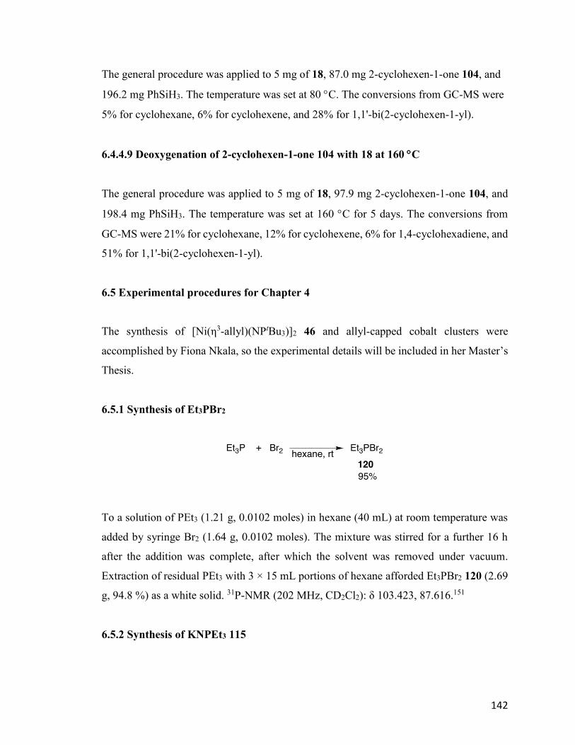
142
The general procedure was applied to 5 mg of 18, 87.0 mg 2-cyclohexen-1-one 104, and
196.2 mg PhSiH3. The temperature was set at 80 C. The conversions from GC-MS were
5% for cyclohexane, 6% for cyclohexene, and 28% for 1,1'-bi(2-cyclohexen-1-yl).
6.4.4.9 Deoxygenation of 2-cyclohexen-1-one 104 with 18 at 160 C
The general procedure was applied to 5 mg of 18, 97.9 mg 2-cyclohexen-1-one 104, and
198.4 mg PhSiH3. The temperature was set at 160 C for 5 days. The conversions from
GC-MS were 21% for cyclohexane, 12% for cyclohexene, 6% for 1,4-cyclohexadiene, and
51% for 1,1'-bi(2-cyclohexen-1-yl).
6.5 Experimental procedures for Chapter 4
The synthesis of [Ni(η3-allyl)(NPtBu3)]2 46 and allyl-capped cobalt clusters were
accomplished by Fiona Nkala, so the experimental details will be included in her Master’s
Thesis.
6.5.1 Synthesis of Et3PBr2
To a solution of PEt3 (1.21 g, 0.0102 moles) in hexane (40 mL) at room temperature was
added by syringe Br2 (1.64 g, 0.0102 moles). The mixture was stirred for a further 16 h
after the addition was complete, after which the solvent was removed under vacuum.
Extraction of residual PEt3 with 3 × 15 mL portions of hexane afforded Et3PBr2 120 (2.69
g, 94.8 %) as a white solid. 31P-NMR (202 MHz, CD2Cl2): δ 103.423, 87.616.151
6.5.2 Synthesis of KNPEt3 115
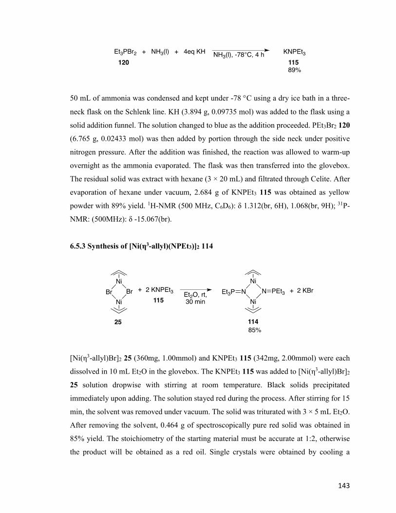
143
50 mL of ammonia was condensed and kept under -78 C using a dry ice bath in a three-
neck flask on the Schlenk line. KH (3.894 g, 0.09735 mol) was added to the flask using a
solid addition funnel. The solution changed to blue as the addition proceeded. PEt3Br2 120
(6.765 g, 0.02433 mol) was then added by portion through the side neck under positive
nitrogen pressure. After the addition was finished, the reaction was allowed to warm-up
overnight as the ammonia evaporated. The flask was then transferred into the glovebox.
The residual solid was extract with hexane (3 × 20 mL) and filtrated through Celite. After
evaporation of hexane under vacuum, 2.684 g of KNPEt3 115 was obtained as yellow
powder with 89% yield. 1H-NMR (500 MHz, C6D6): δ 1.312(br, 6H), 1.068(br, 9H); 31P-
NMR: (500MHz): δ -15.067(br).
6.5.3 Synthesis of [Ni(η3-allyl)(NPEt3)]2 114
[Ni(η3-allyl)Br]2 25 (360mg, 1.00mmol) and KNPEt3 115 (342mg, 2.00mmol) were each
dissolved in 10 mL Et2O in the glovebox. The KNPEt3 115 was added to [Ni(η3-allyl)Br]2
25 solution dropwise with stirring at room temperature. Black solids precipitated
immediately upon adding. The solution stayed red during the process. After stirring for 15
min, the solvent was removed under vacuum. The solid was triturated with 3 × 5 mL Et2O.
After removing the solvent, 0.464 g of spectroscopically pure red solid was obtained in
85% yield. The stoichiometry of the starting material must be accurate at 1:2, otherwise
the product will be obtained as a red oil. Single crystals were obtained by cooling a
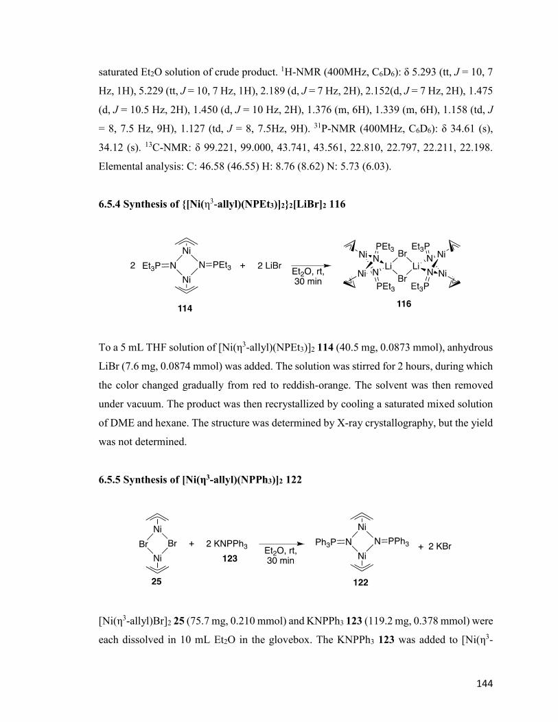
144
saturated Et2O solution of crude product. 1H-NMR (400MHz, C6D6): δ 5.293 (tt, J = 10, 7
Hz, 1H), 5.229 (tt, J = 10, 7 Hz, 1H), 2.189 (d, J = 7 Hz, 2H), 2.152(d, J = 7 Hz, 2H), 1.475
(d, J = 10.5 Hz, 2H), 1.450 (d, J = 10 Hz, 2H), 1.376 (m, 6H), 1.339 (m, 6H), 1.158 (td, J
= 8, 7.5 Hz, 9H), 1.127 (td, J = 8, 7.5Hz, 9H). 31P-NMR (400MHz, C6D6): δ 34.61 (s),
34.12 (s). 13C-NMR: δ 99.221, 99.000, 43.741, 43.561, 22.810, 22.797, 22.211, 22.198.
Elemental analysis: C: 46.58 (46.55) H: 8.76 (8.62) N: 5.73 (6.03).
6.5.4 Synthesis of {[Ni(η3-allyl)(NPEt3)]2}2[LiBr]2 116
To a 5 mL THF solution of [Ni(η3-allyl)(NPEt3)]2 114 (40.5 mg, 0.0873 mmol), anhydrous
LiBr (7.6 mg, 0.0874 mmol) was added. The solution was stirred for 2 hours, during which
the color changed gradually from red to reddish-orange. The solvent was then removed
under vacuum. The product was then recrystallized by cooling a saturated mixed solution
of DME and hexane. The structure was determined by X-ray crystallography, but the yield
was not determined.
6.5.5 Synthesis of [Ni(η3-allyl)(NPPh3)]2 122
[Ni(η3-allyl)Br]2 25 (75.7 mg, 0.210 mmol) and KNPPh3 123 (119.2 mg, 0.378 mmol) were
each dissolved in 10 mL Et2O in the glovebox. The KNPPh3 123 was added to [Ni(η3-
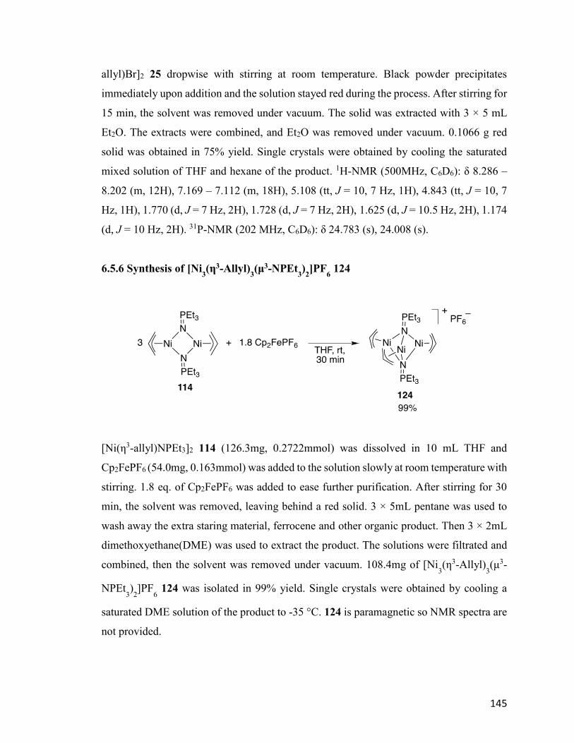
145
allyl)Br]2 25 dropwise with stirring at room temperature. Black powder precipitates
immediately upon addition and the solution stayed red during the process. After stirring for
15 min, the solvent was removed under vacuum. The solid was extracted with 3 × 5 mL
Et2O. The extracts were combined, and Et2O was removed under vacuum. 0.1066 g red
solid was obtained in 75% yield. Single crystals were obtained by cooling the saturated
mixed solution of THF and hexane of the product. 1H-NMR (500MHz, C6D6): δ 8.286 –
8.202 (m, 12H), 7.169 – 7.112 (m, 18H), 5.108 (tt, J = 10, 7 Hz, 1H), 4.843 (tt, J = 10, 7
Hz, 1H), 1.770 (d, J = 7 Hz, 2H), 1.728 (d, J = 7 Hz, 2H), 1.625 (d, J = 10.5 Hz, 2H), 1.174
(d, J = 10 Hz, 2H). 31P-NMR (202 MHz, C6D6): δ 24.783 (s), 24.008 (s).
6.5.6 Synthesis of [Ni3(η3-Allyl)
3(μ3-NPEt
3)2]PF
6 124
[Ni(η3-allyl)NPEt3]2 114 (126.3mg, 0.2722mmol) was dissolved in 10 mL THF and
Cp2FePF6 (54.0mg, 0.163mmol) was added to the solution slowly at room temperature with
stirring. 1.8 eq. of Cp2FePF6 was added to ease further purification. After stirring for 30
min, the solvent was removed, leaving behind a red solid. 3 × 5mL pentane was used to
wash away the extra staring material, ferrocene and other organic product. Then 3 × 2mL
dimethoxyethane(DME) was used to extract the product. The solutions were filtrated and
combined, then the solvent was removed under vacuum. 108.4mg of [Ni3(η3-Allyl)
3(μ3-
NPEt3)2]PF
6 124 was isolated in 99% yield. Single crystals were obtained by cooling a
saturated DME solution of the product to -35 °C. 124 is paramagnetic so NMR spectra are
not provided.
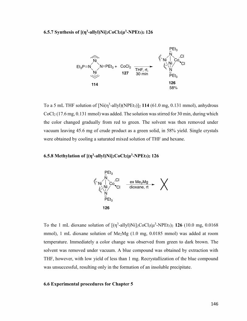
146
6.5.7 Synthesis of [(η3-allyl)Ni]2CoCl2(μ3-NPEt3)2 126
To a 5 mL THF solution of [Ni(η3-allyl)(NPEt3)]2 114 (61.0 mg, 0.131 mmol), anhydrous
CoCl2 (17.6 mg, 0.131 mmol) was added. The solution was stirred for 30 min, during which
the color changed gradually from red to green. The solvent was then removed under
vacuum leaving 45.6 mg of crude product as a green solid, in 58% yield. Single crystals
were obtained by cooling a saturated mixed solution of THF and hexane.
6.5.8 Methylation of [(η3-allyl)Ni]2CoCl2(μ3-NPEt3)2 126
To the 1 mL dioxane solution of [(η3-allyl)Ni]2CoCl2(μ3-NPEt3)2 126 (10.0 mg, 0.0168
mmol), 1 mL dioxane solution of Me2Mg (1.0 mg, 0.0185 mmol) was added at room
temperature. Immediately a color change was observed from green to dark brown. The
solvent was removed under vacuum. A blue compound was obtained by extraction with
THF, however, with low yield of less than 1 mg. Recrystallization of the blue compound
was unsuccessful, resulting only in the formation of an insoluble precipitate.
6.6 Experimental procedures for Chapter 5
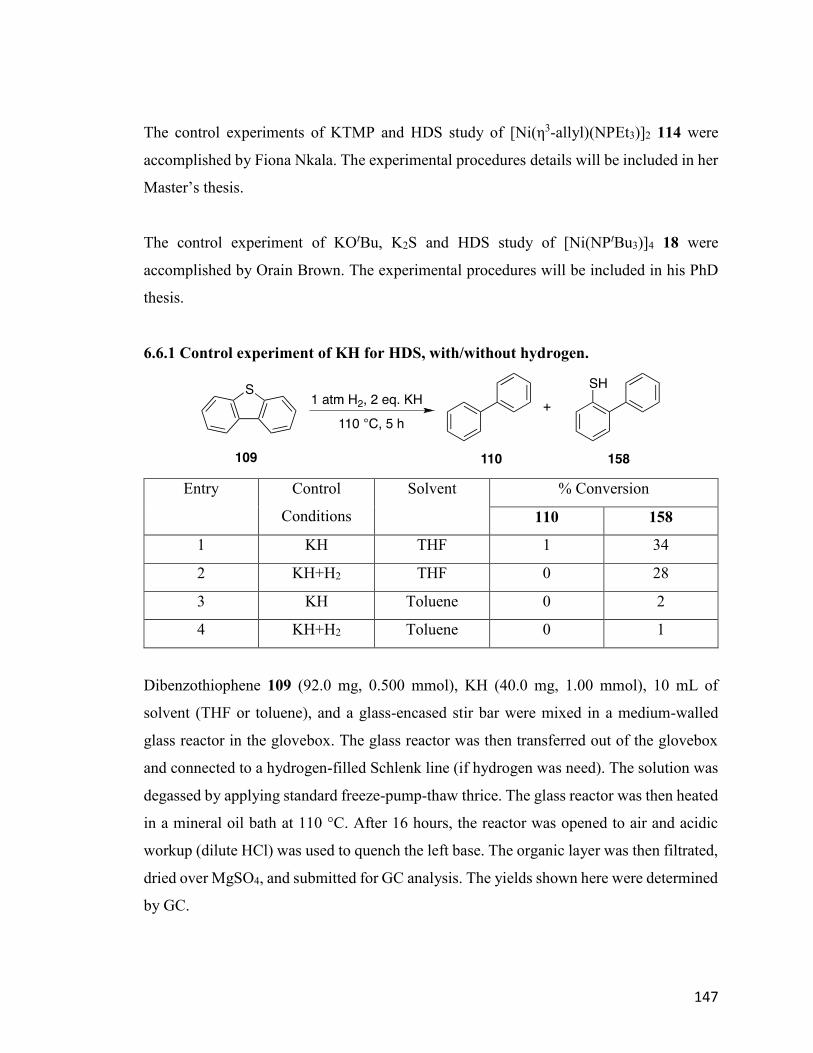
147
The control experiments of KTMP and HDS study of [Ni(η3-allyl)(NPEt3)]2 114 were
accomplished by Fiona Nkala. The experimental procedures details will be included in her
Master’s thesis.
The control experiment of KOtBu, K2S and HDS study of [Ni(NPtBu3)]4 18 were
accomplished by Orain Brown. The experimental procedures will be included in his PhD
thesis.
6.6.1 Control experiment of KH for HDS, with/without hydrogen.
Entry Control
Conditions
Solvent % Conversion
110 158
1 KH THF 1 34
2 KH+H2 THF 0 28
3 KH Toluene 0 2
4 KH+H2 Toluene 0 1
Dibenzothiophene 109 (92.0 mg, 0.500 mmol), KH (40.0 mg, 1.00 mmol), 10 mL of
solvent (THF or toluene), and a glass-encased stir bar were mixed in a medium-walled
glass reactor in the glovebox. The glass reactor was then transferred out of the glovebox
and connected to a hydrogen-filled Schlenk line (if hydrogen was need). The solution was
degassed by applying standard freeze-pump-thaw thrice. The glass reactor was then heated
in a mineral oil bath at 110 °C. After 16 hours, the reactor was opened to air and acidic
workup (dilute HCl) was used to quench the left base. The organic layer was then filtrated,
dried over MgSO4, and submitted for GC analysis. The yields shown here were determined
by GC.
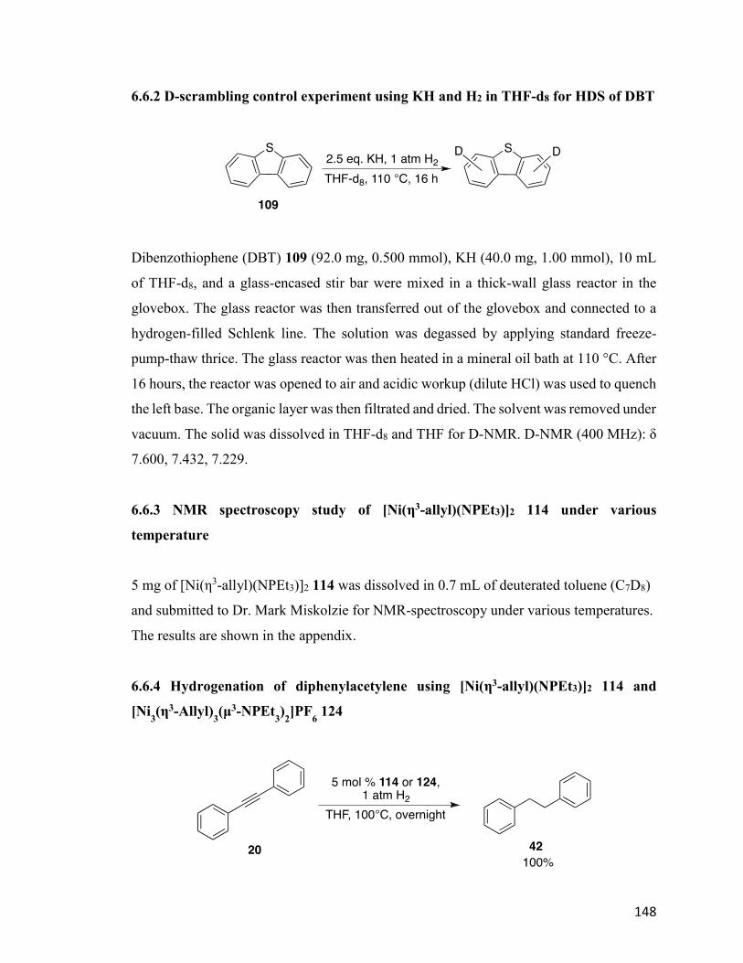
148
6.6.2 D-scrambling control experiment using KH and H2 in THF-d8 for HDS of DBT
Dibenzothiophene (DBT) 109 (92.0 mg, 0.500 mmol), KH (40.0 mg, 1.00 mmol), 10 mL
of THF-d8, and a glass-encased stir bar were mixed in a thick-wall glass reactor in the
glovebox. The glass reactor was then transferred out of the glovebox and connected to a
hydrogen-filled Schlenk line. The solution was degassed by applying standard freeze-
pump-thaw thrice. The glass reactor was then heated in a mineral oil bath at 110 °C. After
16 hours, the reactor was opened to air and acidic workup (dilute HCl) was used to quench
the left base. The organic layer was then filtrated and dried. The solvent was removed under
vacuum. The solid was dissolved in THF-d8 and THF for D-NMR. D-NMR (400 MHz): δ
7.600, 7.432, 7.229.
6.6.3 NMR spectroscopy study of [Ni(η3-allyl)(NPEt3)]2 114 under various
temperature
5 mg of [Ni(η3-allyl)(NPEt3)]2 114 was dissolved in 0.7 mL of deuterated toluene (C7D8)
and submitted to Dr. Mark Miskolzie for NMR-spectroscopy under various temperatures.
The results are shown in the appendix.
6.6.4 Hydrogenation of diphenylacetylene using [Ni(η3-allyl)(NPEt3)]2 114 and
[Ni3(η3-Allyl)
3(μ3-NPEt
3)2]PF
6 124
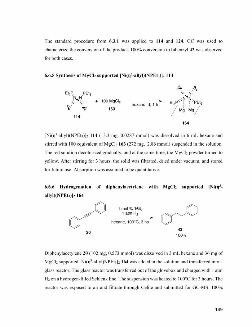
149
The standard procedure from 6.3.1 was applied to 114 and 124. GC was used to
characterize the conversion of the product. 100% conversion to bibenzyl 42 was observed
for both cases.
6.6.5 Synthesis of MgCl2 supported [Ni(η3-allyl)(NPEt3)]2 114
[Ni(η3-allyl)(NPEt3)]2 114 (13.3 mg, 0.0287 mmol) was dissolved in 6 mL hexane and
stirred with 100 equivalent of MgCl2 163 (272 mg, 2.86 mmol) suspended in the solution.
The red solution decolorized gradually, and at the same time, the MgCl2 powder turned to
yellow. After stirring for 3 hours, the solid was filtrated, dried under vacuum, and stored
for future use. Absorption was assumed to be quantitative.
6.6.6 Hydrogenation of diphenylacetylene with MgCl2 supported [Ni(η3-
allyl)(NPEt3)]2 164
Diphenylacetylene 20 (102 mg, 0.573 mmol) was dissolved in 3 mL hexane and 36 mg of
MgCl2 supported [Ni(η3-allyl)NPEt3]2 164 was added in the solution and transferred into a
glass reactor. The glass reactor was transferred out of the glovebox and charged with 1 atm
H2 on a hydrogen-filled Schlenk line. The suspension was heated to 100°C for 3 hours. The
reactor was exposed to air and filtrate through Celite and submitted for GC-MS. 100%
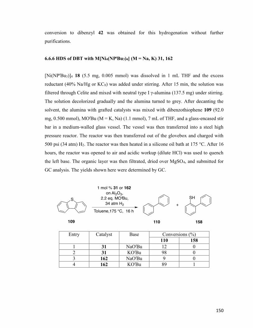
150
conversion to dibenzyl 42 was obtained for this hydrogenation without further
purifications.
6.6.6 HDS of DBT with M[Ni4(NPtBu3)4] (M = Na, K) 31, 162
[Ni(NPtBu3)]4 18 (5.5 mg, 0.005 mmol) was dissolved in 1 mL THF and the excess
reductant (40% Na/Hg or KC8) was added under stirring. After 15 min, the solution was
filtered through Celite and mixed with neutral type I γ-alumina (137.5 mg) under stirring.
The solution decolorized gradually and the alumina turned to grey. After decanting the
solvent, the alumina with grafted catalysts was mixed with dibenzothiophene 109 (92.0
mg, 0.500 mmol), MOtBu (M = K, Na) (1.1 mmol), 7 mL of THF, and a glass-encased stir
bar in a medium-walled glass vessel. The vessel was then transferred into a steel high
pressure reactor. The reactor was then transferred out of the glovebox and charged with
500 psi (34 atm) H2. The reactor was then heated in a silicone oil bath at 175 °C. After 16
hours, the reactor was opened to air and acidic workup (dilute HCl) was used to quench
the left base. The organic layer was then filtrated, dried over MgSO4, and submitted for
GC analysis. The yields shown here were determined by GC.
Entry Catalyst Base Conversions (%)
110 158
1 31 NaOtBu 12 0
2 31 KOtBu 98 0
3 162 NaOtBu 9 0
4 162 KOtBu 89 1
151
Bibliography
(1) Ault, A. J. Chem. Educ. 2002, 79, 572.
(2) Casey, C. P. J. Chem. Educ. 2006, 83, 192.
(3) Johansson Seechurn, C. C.; Kitching, M. O.; Colacot, T. J.; Snieckus, V.
Angew. Chem. Int. Ed. 2012, 51, 5062-5085.
(4) Chirik, P.; Morris, R. Acc. Chem. Res. 2015, 48, 2495-2495.
(5) Gandeepan, P.; Cheng, C.-H. Acc. Chem. Res. 2015, 48, 1194-1206.
(6) Jackson, E. P.; Malik, H. A.; Sormunen, G. J.; Baxter, R. D.; Liu, P.;
Wang, H.; Shareef, A.-R.; Montgomery, J. Acc. Chem. Res. 2015, 48, 1736-1745.
(7) Liu, C.; Liu, D.; Lei, A. Acc. Chem. Res. 2014, 47, 3459-3470.
(8) Standley, E. A.; Tasker, S. Z.; Jensen, K. L.; Jamison, T. F. Acc. Chem.
Res. 2015, 48, 1503-1514.
(9) Thakur, A.; Louie, J. Acc. Chem. Res. 2015, 48, 2354-2365.
(10) Tobisu, M.; Chatani, N. Acc. Chem. Res. 2015, 48, 1717-1726.
(11) Tollefson, E. J.; Hanna, L. E.; Jarvo, E. R. Acc. Chem. Res. 2015, 48,
2344-2353.
(12) Miao, J.; Ge, H. Eur. J. Org. Chem. 2015, 2015, 7859-7868.
(13) Ryken, S. A.; Schafer, L. L. Acc. Chem. Res. 2015, 48, 2576-2586.
(14) Chakraborty, S.; Bhattacharya, P.; Dai, H.; Guan, H. Acc. Chem. Res.
2015, 48, 1995-2003.
(15) Chirik, P. J. Acc. Chem. Res. 2015, 48, 1687-1695.
(16) Li, Y.-Y.; Yu, S.-L.; Shen, W.-Y.; Gao, J.-X. Acc. Chem. Res. 2015, 48,
2587-2598.
(17) Morris, R. H. Acc. Chem. Res. 2015, 48, 1494-1502.
(18) McCann, S. D.; Stahl, S. S. Acc. Chem. Res. 2015, 48, 1756-1766.
(19) Liu, W.; Groves, J. T. Acc. Chem. Res. 2015, 48, 1727-1735.
(20) Su, B.; Cao, Z.-C.; Shi, Z.-J. Acc. Chem. Res. 2015, 48, 886-896.
(21) Klosin, J.; Fontaine, P. P.; Figueroa, R. Acc. Chem. Res. 2015, 48, 2004-
2016.
(22) Small, B. L. Acc. Chem. Res. 2015, 48, 2599-2611.
152
(23) Staudinger, H.; Meyer, J. Helv. Chim. Acta 1919, 2, 635-646.
(24) Schmidbaur, H.; Jonas, G. Chem. Ber. 1968, 101, 1271-1285.
(25) Schmidbour, H.; Wolfsberger, W. Chem. Ber. 1967, 100, 1000-1015.
(26) Dehnicke, K.; Krieger, M.; Massa, W. Coord. Chem. Rev. 1999, 182, 19-
65.
(27) Dehnicke, K.; Strähle, J. Polyhedron 1989, 8, 707-726.
(28) Dehnicke, K.; Weller, F. Coord. Chem. Rev. 1997, 158, 103-169.
(29) Stephan, D. W. Organometallics 2005, 24, 2548-2560.
(30) Stephan, D. W. Adv. Organomet. Chem. 2006, 54, 267-291.
(31) LePichon, L.; Stephan, D. W.; Gao, X.; Wang, Q. Organometallics 2002,
21, 1362-1366.
(32) Wolczanski, P. T. Polyhedron 1995, 14, 3335-3362.
(33) Batsanov, A.; Davidson, M.; Howard, J. K.; Price, R. Chem. Commun.
1997, 1211-1212.
(34) Anfang, S.; Seybert, G.; Harms, K.; Geiseler, G.; Massa, W.; Dehnicke, K.
Z. Anorg. Allg. Chem. 1998, 624, 1187-1192.
(35) Chitsaz, S.; Neumüller, B.; Dehnicke, K. Z. Anorg. Allg. Chem. 1999, 625,
9-10.
(36) Courtenay, S.; Wei, P.; Stephan, D. W. Can. J. Chem. 2003, 81, 1471-
1476.
(37) Gröb, T.; Harms, K.; Dehnicke, K. Z. Anorg. Allg. Chem. 2000, 626,
1065-1072.
(38) Gröb, T.; Müller, C.; Massa, W.; Miekisch, T.; Seybert, G.; Harms, K.;
Dehnicke, K. Z. Anorg. Allg. Chem. 2001, 627, 2191-2197.
(39) Sundermann, A.; Schoeller, W. W. J. Am. Chem. Soc. 2000, 122, 4729-
4734.
(40) Schlecht, S.; Deubel, D. V.; Frenking, G.; Geiseler, G.; Harms, K.;
Magull, J.; Dehnicke, K. Z. Anorg. Allg. Chem. 1999, 625, 887-891.
(41) Nußhär, D.; Weller, F.; Dehnicke, K. Z. Anorg. Allg. Chem. 1993, 619,
507-512.

153
(42) Honeyman, C. H.; Lough, A. J.; Manners, I. Inorg. Chem. 1994, 33, 2988-
2993.
(43) Klein, H. F.; Haller, S.; Koenig, H.; Dartiguenave, M.; Dartiguenave, Y.;
Menu, M. J. J. Am. Chem. Soc. 1991, 113, 4673-4675.
(44) Abram, S.; Abram, U.; zu Köcker, R. M.; Dehnicke, K. Z. Anorg. Allg.
Chem. 1996, 622, 867-872.
(45) Camacho-Bunquin, J.; Ferguson, M. J.; Stryker, J. M. J. Am. Chem. Soc.
2013, 135, 5537-5540.
(46) Hollink, E.; Wei, P.; Stephan, D. W. Can. J. Chem. 2005, 83, 430-434.
(47) Stephan, D. W. In Macromolecular Symposia; Wiley Online Library:
2001; Vol. 173, p 105-116.
(48) Stephan, D. W.; Stewart, J. C.; Guérin, F.; Spence, R. E. v. H.; Xu, W.;
Harrison, D. G. Organometallics 1999, 18, 1116-1118.
(49) Tolman, C. A. J. Am. Chem. Soc. 1970, 92, 2956-2965.
(50) Dehnicke, K.; Greiner, A. Angew. Chem. Int. Ed. 2003, 42, 1340-1354.
(51) Zimmer, H.; Jayawant, M.; Gutsch, P. J. Org. Chem. 1970, 35, 2826-2828.
(52) Berhault, G.; Maugé, F.; Lavalley, J.-C.; Lacroix, M.; Breysse, M. J.
Catal. 2000, 189, 431-437.
(53) Chianelli, R.; Berhault, G.; Raybaud, P.; Kasztelan, S.; Hafner, J.;
Toulhoat, H. Appl. Catal., A 2002, 227, 83-96.
(54) Harris, S.; Chianelli, R. J. Catal. 1984, 86, 400-412.
(55) Ho, T. C. Catal. Today 2004, 98, 3-18.
(56) Pecoraro, T.; Chianelli, R. J. Catal. 1981, 67, 430-445.
(57) Prins, R.; De Beer, V.; Somorjai, G. Catal. Rev. Sci. Eng. 1989, 31, 1-41.
(58) Evans, D. J. Chem. Soc. 1959, 2003-2005.
(59) Zhao, T.; Hamilton, R.; Han, C.; Bai, T. Unpublished results. 2014.
(60) Brown, H. Doctorate, University of Alberta, 2013.
(61) Richardson, D. E.; Taube, H. Coord. Chem. Rev. 1984, 60, 107-129.
(62) Faust, M.; Bryan, A. M.; Mansikkamäki, A.; Vasko, P.; Olmstead, M. M.;
Tuononen, H. M.; Grandjean, F.; Long, G. J.; Power, P. P. Angew. Chem. Int. Ed. 2015,
54, 12914-12917.
154
(63) Mingos, D. M. P. Essential trends in inorganic chemistry; Oxford
University Press Oxford, 1998.
(64) Neumann, F.; Hampel, F.; Schleyer, P. v. R. Inorg. Chem. 1995, 34, 6553-
6555.
(65) Connelly, N. G.; Geiger, W. E. Chem. Rev. 1996, 96, 877-910.
(66) Brown, O.; Zhao, T.; Nkala, F. Unpublished results. 2015.
(67) Merrill, B. A. In Encyclopedia of Reagents for Organic Synthesis; John
Wiley & Sons, Ltd: 2001.
(68) Molander, G. A.; Harris, C. R. In Encyclopedia of Reagents for Organic
Synthesis; John Wiley & Sons, Ltd: 2001.
(69) Pfirrmann, S.; Limberg, C.; Herwig, C.; Stößer, R.; Ziemer, B. Angew.
Chem. Int. Ed. 2009, 48, 3357-3361.
(70) Bunquin, J. Unpublished results.
(71) Bergman, R. G.; Danheiser, R. L. Angew. Chem. Int. Ed. 2016, 55, 12548-
12549.
(72) Whitesides, G. M.; Hackett, M.; Brainard, R. L.; Lavalleye, J. P. P.;
Sowinski, A. F.; Izumi, A. N.; Moore, S. S.; Brown, D. W.; Staudt, E. M.
Organometallics 1985, 4, 1819-1830.
(73) Widegren, J. A.; Finke, R. G. J. Mol. Catal. A: Chem. 2003, 198, 317-341.
(74) Clarson, S. J. Silicon 2009, 1, 57-58.
(75) MacMillan, S. N.; Harman, W. H.; Peters, J. C. Chem. Sci. 2014, 5, 590-
597.
(76) Morris, R. H. Chem. Soc. Rev. 2009, 38, 2282-2291.
(77) Ruddy, A. J.; Kelly, C. M.; Crawford, S. M.; Wheaton, C. A.; Sydora, O.
L.; Small, B. L.; Stradiotto, M.; Turculet, L. Organometallics 2013, 32, 5581-5588.
(78) Tondreau, A. M.; Darmon, J. M.; Wile, B. M.; Floyd, S. K.; Lobkovsky,
E.; Chirik, P. J. Organometallics 2009, 28, 3928-3940.
(79) Trovitch, R. J. Synlett 2014, 25, 1638-1642.
(80) Yang, J.; Tilley, T. D. Angew. Chem. Int. Ed. 2010, 49, 10186-10188.
(81) Frogneux, X.; Jacquet, O.; Cantat, T. Catal. Sci. Tech. 2014, 4, 1529-
1533.
155
(82) Iglesias, M.; Fernández‐Alvarez, F. J.; Oro, L. A. ChemCatChem 2014, 6,
2486-2489.
(83) Jaseer, E.; Akhtar, M. N.; Osman, M.; Al-Shammari, A.; Oladipo, H. B.;
Garcés, K.; Fernández-Alvarez, F. J.; Al-Khattaf, S.; Oro, L. A. Catal. Sci. Tech. 2015, 5,
274-279.
(84) Riener, K.; Hogerl, M. P.; Gigler, P.; Kuhn, F. E. ACS Catal. 2012, 2,
613-621.
(85) Scheuermann, M. L.; Semproni, S. P.; Pappas, I.; Chirik, P. J. Inorg.
Chem. 2014, 53, 9463-9465.
(86) Schneider, J.; Jia, H.; Muckerman, J. T.; Fujita, E. Chem. Soc. Rev. 2012,
41, 2036-2051.
(87) Windle, C. D.; Perutz, R. N. Coord. Chem. Rev. 2012, 256, 2562-2570.
(88) Shaikh, N. S.; Junge, K.; Beller, M. Org. Lett. 2007, 9, 5429-5432.
(89) Shaikh, N. S.; Enthaler, S.; Junge, K.; Beller, M. Angew. Chem. Int. Ed.
2008, 47, 2497-2501.
(90) Nishiyama, H.; Furuta, A. Chem. Commun. 2007, 760-762.
(91) Furuta, A.; Nishiyama, H. Tetrahedron Lett. 2008, 49, 110-113.
(92) Tondreau, A. M.; Lobkovsky, E.; Chirik, P. J. Org. Lett. 2008, 10, 2789-
2792.
(93) Nesbit, M. A.; Suess, D. L.; Peters, J. C. Organometallics 2015, 34, 4741-
4752.
(94) Bleith, T.; Wadepohl, H.; Gade, L. H. J. Am. Chem. Soc. 2015, 137, 2456-
2459.
(95) Junge, K.; Schröder, K.; Beller, M. Chem. Commun. 2011, 47, 4849-4859.
(96) Zhang, M.; Zhang, A. Appl. Organomet. Chem. 2010, 24, 751-757.
(97) Zuo, Z.; Sun, H.; Wang, L.; Li, X. Dalton Trans. 2014, 43, 11716-11722.
(98) Zuo, Z.; Zhang, L.; Leng, X.; Huang, Z. Chem. Commun. 2015, 51, 5073-
5076.
(99) Zhou, H.; Sun, H.; Zhang, S.; Li, X. Organometallics 2015, 34, 1479-
1486.
156
(100) Sauer, D. s. e. C.; Wadepohl, H.; Gade, L. H. Inorg. Chem. 2012, 51,
12948-12958.
(101) Chakraborty, S.; Krause, J. A.; Guan, H. Organometallics 2008, 28, 582-
586.
(102) Kundu, S.; Brennessel, W. W.; Jones, W. D. Inorg. Chem. 2011, 50, 9443-
9453.
(103) Tran, B. L.; Pink, M.; Mindiola, D. J. Organometallics 2009, 28, 2234-
2243.
(104) Díez-González, S.; Nolan, S. P. Acc. Chem. Res. 2008, 41, 349-358.
(105) Lipshutz, B. H. Synlett 2009, 2009, 509-524.
(106) Rendler, S.; Oestreich, M. Angew. Chem. Int. Ed. 2007, 46, 498-504.
(107) Bandini, M.; Bernardi, F.; Bottoni, A.; Cozzi, P. G.; Miscione, G. P.;
Umani‐Ronchi, A. Eur. J. Org. Chem. 2003, 2003, 2972-2984.
(108) Ramón, D. J.; Yus, M. Chem. Rev. 2006, 106, 2126-2208.
(109) Alonso, D. M.; Bond, J. Q.; Dumesic, J. A. Green Chem. 2010, 12, 1493-
1513.
(110) Gallezot, P. Chem. Soc. Rev. 2012, 41, 1538-1558.
(111) Huber, G. W.; Corma, A. Angew. Chem. 2007, 119, 7320-7338.
(112) Marshall, A. L.; Alaimo, P. J. Chem. Eur. J. 2010, 16, 4970-4980.
(113) Naik, S. N.; Goud, V. V.; Rout, P. K.; Dalai, A. K. IRESR 2010, 14, 578-
597.
(114) Serrano-Ruiz, J. C.; Luque, R.; Sepulveda-Escribano, A. Chem. Soc. Rev.
2011, 40, 5266-5281.
(115) Zhang, X.; Tu, M.; Paice, M. G. Bioenergy Res 2011, 4, 246-257.
(116) Farrar, W. J. Appl. Chem. 1964, 14, 389-399.
(117) Laskowski, C. A.; Bungum, D. J.; Baldwin, S. M.; Del Ciello, S. A.; Iluc,
V. M.; Hillhouse, G. L. J. Am. Chem. Soc. 2013, 135, 18272-18275.
(118) Fontanille, M.; Guyot, A. Recent advances in mechanistic and synthetic
aspects of polymerization; Springer Science & Business Media, 2012; Vol. 215.
(119) Kurosawa, H. J. Organomet. Chem. 1987, 334, 243-253.
(120) Takagi, K.; Tomita, I.; Endo, T. Macromolecules 1997, 30, 7386-7390.
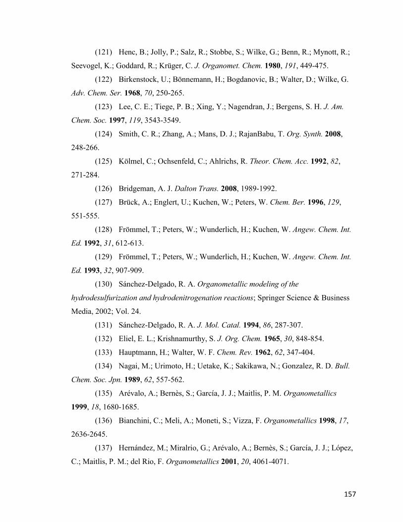
157
(121) Henc, B.; Jolly, P.; Salz, R.; Stobbe, S.; Wilke, G.; Benn, R.; Mynott, R.;
Seevogel, K.; Goddard, R.; Krüger, C. J. Organomet. Chem. 1980, 191, 449-475.
(122) Birkenstock, U.; Bönnemann, H.; Bogdanovic, B.; Walter, D.; Wilke, G.
Adv. Chem. Ser. 1968, 70, 250-265.
(123) Lee, C. E.; Tiege, P. B.; Xing, Y.; Nagendran, J.; Bergens, S. H. J. Am.
Chem. Soc. 1997, 119, 3543-3549.
(124) Smith, C. R.; Zhang, A.; Mans, D. J.; RajanBabu, T. Org. Synth. 2008,
248-266.
(125) Kölmel, C.; Ochsenfeld, C.; Ahlrichs, R. Theor. Chem. Acc. 1992, 82,
271-284.
(126) Bridgeman, A. J. Dalton Trans. 2008, 1989-1992.
(127) Brück, A.; Englert, U.; Kuchen, W.; Peters, W. Chem. Ber. 1996, 129,
551-555.
(128) Frömmel, T.; Peters, W.; Wunderlich, H.; Kuchen, W. Angew. Chem. Int.
Ed. 1992, 31, 612-613.
(129) Frömmel, T.; Peters, W.; Wunderlich, H.; Kuchen, W. Angew. Chem. Int.
Ed. 1993, 32, 907-909.
(130) Sánchez-Delgado, R. A. Organometallic modeling of the
hydrodesulfurization and hydrodenitrogenation reactions; Springer Science & Business
Media, 2002; Vol. 24.
(131) Sánchez-Delgado, R. A. J. Mol. Catal. 1994, 86, 287-307.
(132) Eliel, E. L.; Krishnamurthy, S. J. Org. Chem. 1965, 30, 848-854.
(133) Hauptmann, H.; Walter, W. F. Chem. Rev. 1962, 62, 347-404.
(134) Nagai, M.; Urimoto, H.; Uetake, K.; Sakikawa, N.; Gonzalez, R. D. Bull.
Chem. Soc. Jpn. 1989, 62, 557-562.
(135) Arévalo, A.; Bernès, S.; García, J. J.; Maitlis, P. M. Organometallics
1999, 18, 1680-1685.
(136) Bianchini, C.; Meli, A.; Moneti, S.; Vizza, F. Organometallics 1998, 17,
2636-2645.
(137) Hernández, M.; Miralrio, G.; Arévalo, A.; Bernès, S.; García, J. J.; López,
C.; Maitlis, P. M.; del Rio, F. Organometallics 2001, 20, 4061-4071.
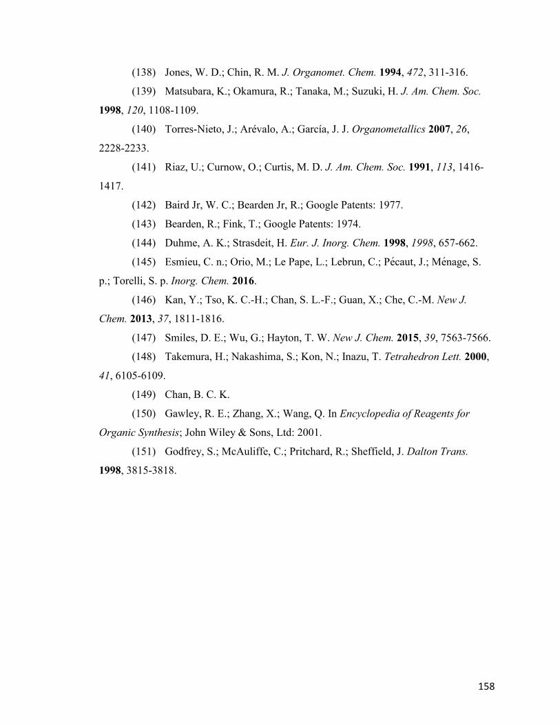
158
(138) Jones, W. D.; Chin, R. M. J. Organomet. Chem. 1994, 472, 311-316.
(139) Matsubara, K.; Okamura, R.; Tanaka, M.; Suzuki, H. J. Am. Chem. Soc.
1998, 120, 1108-1109.
(140) Torres-Nieto, J.; Arévalo, A.; García, J. J. Organometallics 2007, 26,
2228-2233.
(141) Riaz, U.; Curnow, O.; Curtis, M. D. J. Am. Chem. Soc. 1991, 113, 1416-
1417.
(142) Baird Jr, W. C.; Bearden Jr, R.; Google Patents: 1977.
(143) Bearden, R.; Fink, T.; Google Patents: 1974.
(144) Duhme, A. K.; Strasdeit, H. Eur. J. Inorg. Chem. 1998, 1998, 657-662.
(145) Esmieu, C. n.; Orio, M.; Le Pape, L.; Lebrun, C.; Pecaut, J.; Menage, S.
p.; Torelli, S. p. Inorg. Chem. 2016.
(146) Kan, Y.; Tso, K. C.-H.; Chan, S. L.-F.; Guan, X.; Che, C.-M. New J.
Chem. 2013, 37, 1811-1816.
(147) Smiles, D. E.; Wu, G.; Hayton, T. W. New J. Chem. 2015, 39, 7563-7566.
(148) Takemura, H.; Nakashima, S.; Kon, N.; Inazu, T. Tetrahedron Lett. 2000,
41, 6105-6109.
(149) Chan, B. C. K.
(150) Gawley, R. E.; Zhang, X.; Wang, Q. In Encyclopedia of Reagents for
Organic Synthesis; John Wiley & Sons, Ltd: 2001.
(151) Godfrey, S.; McAuliffe, C.; Pritchard, R.; Sheffield, J. Dalton Trans.
1998, 3815-3818.
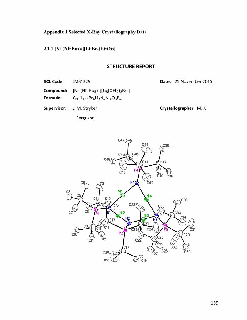
159
Appendix 1 Selected X-Ray Crystallography Data
A1.1 [Ni4(NPtBu3)4][Li3Br4(Et2O)3]
STRUCTURE REPORT
XCL Code: JMS1329 Date: 25 November 2015
Compound: [Ni4(NPtBu3)4][Li3(OEt2)3Br4]
Formula: C60H138Br4Li3N4Ni4O3P4
Supervisor: J. M. Stryker Crystallographer: M. J.
Ferguson
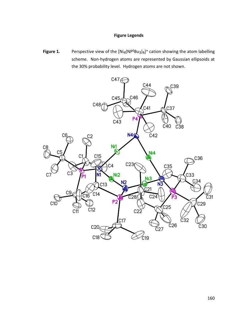
160
Figure Legends
Figure 1. Perspective view of the [Ni4(NPtBu3)4]+ cation showing the atom labelling
scheme. Non-hydrogen atoms are represented by Gaussian ellipsoids at
the 30% probability level. Hydrogen atoms are not shown.
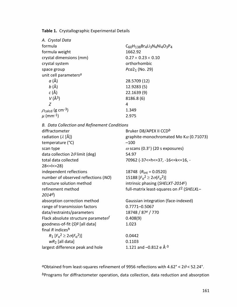
161
Table 1. Crystallographic Experimental Details
A. Crystal Data
formula C60H138Br4Li3N4Ni4O3P4 formula weight 1662.92 crystal dimensions (mm) 0.27 0.23 0.10 crystal system orthorhombic space group Pca21 (No. 29) unit cell parametersa a (Å) 28.5709 (12) b (Å) 12.9283 (5) c (Å) 22.1639 (9)
V (Å3) 8186.8 (6) Z 4 calcd (g cm-3) 1.349 µ (mm-1) 2.975
B. Data Collection and Refinement Conditions
diffractometer Bruker D8/APEX II CCDb radiation ( [Å]) graphite-monochromated Mo K (0.71073) temperature (°C) –100 scan type scans (0.3) (20 s exposures) data collection 2 limit (deg) 54.97 total data collected 70962 (-37<=h<=37, -16<=k<=16, -
28<=l<=28) independent reflections 18748 (Rint = 0.0520) number of observed reflections (NO) 15188 [Fo
2 2(Fo2)]
structure solution method intrinsic phasing (SHELXT-2014c) refinement method full-matrix least-squares on F2 (SHELXL–2014d) absorption correction method Gaussian integration (face-indexed)
range of transmission factors 0.7771–0.5067 data/restraints/parameters 18748 / 87e / 770 Flack absolute structure parameterf 0.408(9) goodness-of-fit (S)g [all data] 1.023
final R indicesh R1 [Fo
2 2(Fo2)] 0.0442
wR2 [all data] 0.1103 largest difference peak and hole 1.121 and –0.812 e Å-3
aObtained from least-squares refinement of 9956 reflections with 4.62° < 2 < 52.24°.
bPrograms for diffractometer operation, data collection, data reduction and absorption

162
correction were those supplied by Bruker.
cSheldrick, G. M. Acta Crystallogr. 2015, A71, 3–8. (SHELXT-2014)
dSheldrick, G. M. Acta Crystallogr. 2015, C71, 3–8. (SHELXL-2014)
eThe following distance restraints were applied to the diethylether molecules of the [Li3(OEt2)3Br4]– anion: O–C, 1.430(4) Å; C–C, 1.530(4) Å; O…C, 2.420(6) Å; C…C, 2.340(6) Å. Additionally, the anisotropic displacement parameters for atoms O2, C55, C56, C57 and C58 were restrained using RIGU and ISOR.
fFlack, H. D. Acta Crystallogr. 1983, A39, 876–881; Flack, H. D.; Bernardinelli, G. Acta Crystallogr. 1999, A55, 908–915; Flack, H. D.; Bernardinelli, G. J. Appl. Cryst. 2000, 33, 1143–1148. The Flack parameter will refine to a value near zero if the structure is
in the correct configuration and will refine to a value near one for the inverted configuration. The value observed herein is indicative of racemic twinning, and was accomodated during the refinement (using the SHELXL-2014 TWIN instruction [see reference d]).
gS = [w(Fo2 – Fc
2)2/(n – p)]1/2 (n = number of data; p = number of parameters varied; w = [2(Fo
2) + (0.0605P)2 + 4.5531P]-1 where P = [Max(Fo2, 0) + 2Fc
2]/3).
hR1 = ||Fo| – |Fc||/|Fo|; wR2 = [w(Fo2 – Fc
2)2/w(Fo4)]1/2.

163
A 1.2 [Ni4(NPtBu3)4][BPh4]
STRUCTURE REPORT
XCL Code: JMS1333 Date: 26 September 2013
Compound: [Ni4(NPtBu3)4][BPh4]
Formula: C72H128BN4Ni4P4
Supervisor: J. M. Stryker Crystallographer: M. J.
Ferguson
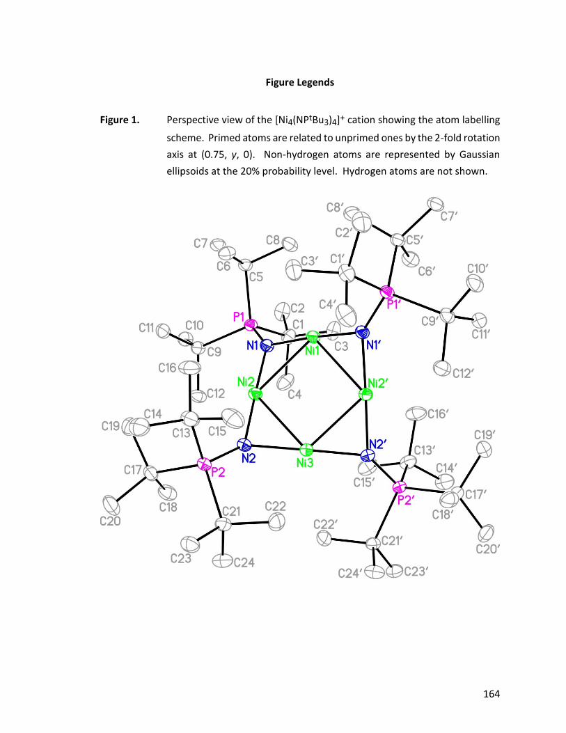
164
Figure Legends
Figure 1. Perspective view of the [Ni4(NPtBu3)4]+ cation showing the atom labelling
scheme. Primed atoms are related to unprimed ones by the 2-fold rotation
axis at (0.75, y, 0). Non-hydrogen atoms are represented by Gaussian
ellipsoids at the 20% probability level. Hydrogen atoms are not shown.
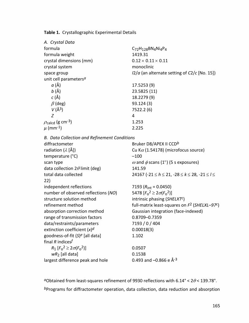
165
Table 1. Crystallographic Experimental Details
A. Crystal Data
formula C72H128BN4Ni4P4 formula weight 1419.31 crystal dimensions (mm) 0.12 0.11 0.11 crystal system monoclinic space group I2/a (an alternate setting of C2/c [No. 15]) unit cell parametersa a (Å) 17.5253 (9) b (Å) 23.5825 (11) c (Å) 18.2279 (9)
(deg) 93.124 (3) V (Å3) 7522.2 (6) Z 4 calcd (g cm-3) 1.253 µ (mm-1) 2.225
B. Data Collection and Refinement Conditions
diffractometer Bruker D8/APEX II CCDb radiation ( [Å]) Cu K (1.54178) (microfocus source) temperature (°C) –100 scan type and scans (1) (5 s exposures) data collection 2 limit (deg) 141.59
total data collected 24167 (-21 h 21, -28 k 28, -21 l 22) independent reflections 7193 (Rint = 0.0450) number of observed reflections (NO) 5478 [Fo
2 2(Fo2)]
structure solution method intrinsic phasing (SHELXTc) refinement method full-matrix least-squares on F2 (SHELXL–97c) absorption correction method Gaussian integration (face-indexed)
range of transmission factors 0.8709–0.7359 data/restraints/parameters 7193 / 0 / 404 extinction coefficient (x)d 0.00018(3) goodness-of-fit (S)e [all data] 1.102
final R indicesf R1 [Fo
2 2(Fo2)] 0.0507
wR2 [all data] 0.1538 largest difference peak and hole 0.493 and –0.866 e Å-3
aObtained from least-squares refinement of 9930 reflections with 6.14° < 2 < 139.78°.
bPrograms for diffractometer operation, data collection, data reduction and absorption
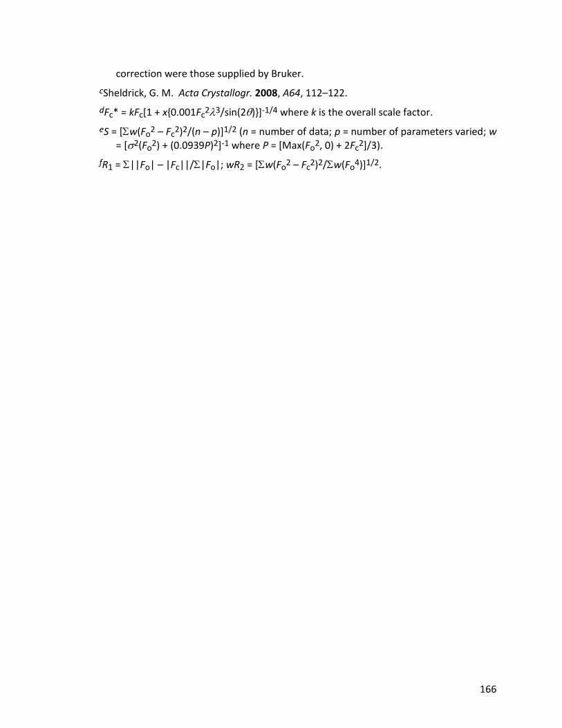
166
correction were those supplied by Bruker.
cSheldrick, G. M. Acta Crystallogr. 2008, A64, 112–122.
dFc* = kFc[1 + x{0.001Fc23/sin(2)}]-1/4 where k is the overall scale factor.
eS = [w(Fo2 – Fc
2)2/(n – p)]1/2 (n = number of data; p = number of parameters varied; w = [2(Fo
2) + (0.0939P)2]-1 where P = [Max(Fo2, 0) + 2Fc
2]/3).
fR1 = ||Fo| – |Fc||/|Fo|; wR2 = [w(Fo2 – Fc
2)2/w(Fo4)]1/2.
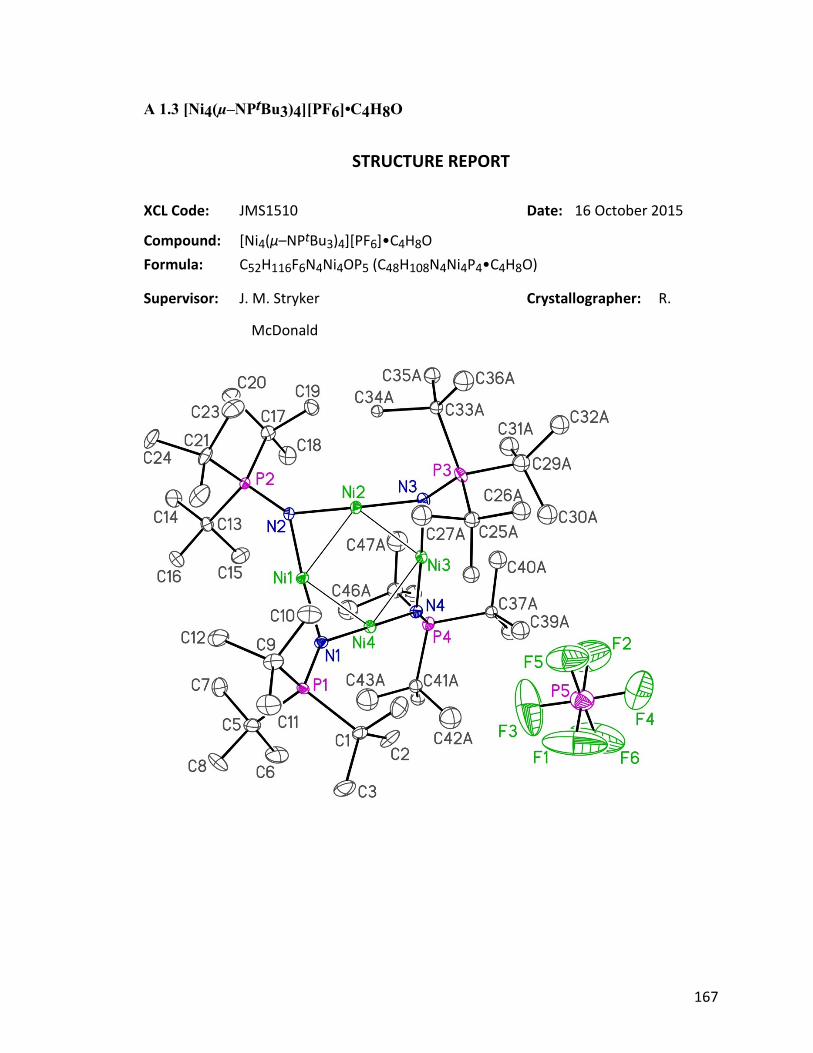
167
A 1.3 [Ni4(µ–NPtBu3)4][PF6]•C4H8O
STRUCTURE REPORT
XCL Code: JMS1510 Date: 16 October 2015
Compound: [Ni4(µ–NPtBu3)4][PF6]•C4H8O
Formula: C52H116F6N4Ni4OP5 (C48H108N4Ni4P4•C4H8O)
Supervisor: J. M. Stryker Crystallographer: R.
McDonald
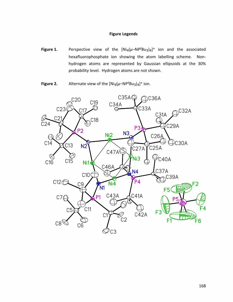
168
Figure Legends
Figure 1. Perspective view of the [Ni4(µ–NPtBu3)4]+ ion and the associated
hexafluorophosphate ion showing the atom labelling scheme. Non-
hydrogen atoms are represented by Gaussian ellipsoids at the 30%
probability level. Hydrogen atoms are not shown.
Figure 2. Alternate view of the [Ni4(µ–NPtBu3)4]+ ion.
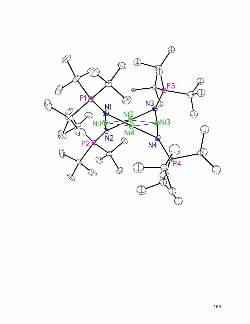
169
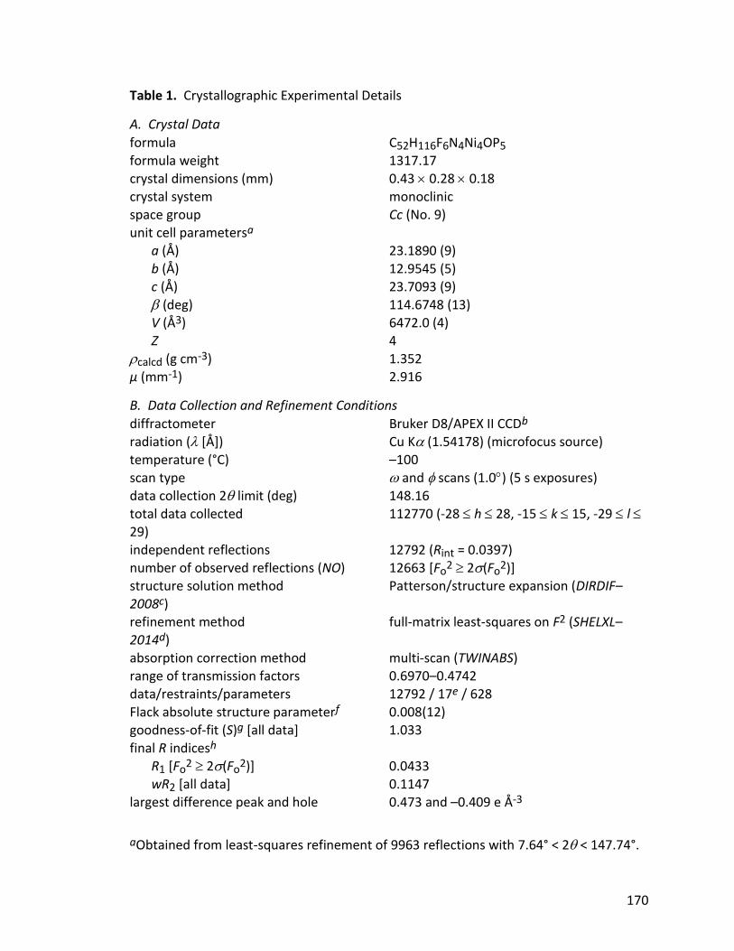
170
Table 1. Crystallographic Experimental Details
A. Crystal Data
formula C52H116F6N4Ni4OP5 formula weight 1317.17 crystal dimensions (mm) 0.43 0.28 0.18 crystal system monoclinic space group Cc (No. 9) unit cell parametersa a (Å) 23.1890 (9) b (Å) 12.9545 (5) c (Å) 23.7093 (9)
(deg) 114.6748 (13) V (Å3) 6472.0 (4) Z 4 calcd (g cm-3) 1.352 µ (mm-1) 2.916
B. Data Collection and Refinement Conditions
diffractometer Bruker D8/APEX II CCDb radiation ( [Å]) Cu K (1.54178) (microfocus source) temperature (°C) –100 scan type and scans (1.0) (5 s exposures) data collection 2 limit (deg) 148.16
total data collected 112770 (-28 h 28, -15 k 15, -29 l 29) independent reflections 12792 (Rint = 0.0397) number of observed reflections (NO) 12663 [Fo
2 2(Fo2)]
structure solution method Patterson/structure expansion (DIRDIF–2008c) refinement method full-matrix least-squares on F2 (SHELXL–
2014d) absorption correction method multi-scan (TWINABS) range of transmission factors 0.6970–0.4742 data/restraints/parameters 12792 / 17e / 628
Flack absolute structure parameterf 0.008(12) goodness-of-fit (S)g [all data] 1.033 final R indicesh R1 [Fo
2 2(Fo2)] 0.0433
wR2 [all data] 0.1147 largest difference peak and hole 0.473 and –0.409 e Å-3
aObtained from least-squares refinement of 9963 reflections with 7.64° < 2 < 147.74°.

171
bPrograms for diffractometer operation, data collection, data reduction and absorption correction were those supplied by Bruker. The crystal used for data collection was found to display non-merohedral twinning. Both components of the twin were indexed with the program CELL_NOW (Bruker AXS Inc., Madison, WI, 2004). The second twin component can be related to the first component by 180º rotation about the [0.4 0 1] axis in real space and about the [0 0 1] axis in reciprocal space. Integrated intensities for the reflections from the two components were written into a SHELXL-2014 HKLF 5 reflection file with the data integration program SAINT (version 8.34A), using all reflection data (exactly overlapped, partially overlapped and non-overlapped).
cBeurskens, P. T.; Beurskens, G.; de Gelder, R.; Smits, J. M. M.; Garcia-Granda, S.; Gould,
R. O. (2008). The DIRDIF-2008 program system. Crystallography Laboratory, Radboud University Nijmegen, The Netherlands.
dSheldrick, G. M. Acta Crystallogr. 2015, C71, 3–8.
e(a) The following P–C distances were constrained to be equal (within 0.03 Å) to a common refined value during refinement: d(P3–C33A), d(P3–C33B), d(P4–C41A), d(P4–C45A), d(P4–C41B), d(P4–C45B). (b) The following C–C distances were constrained to be equal (within 0.03 Å) to a common refined value during refinement: d(C41A–C42A), d(C41A–C43A), d(C41A–C44A), d(C45A–C46A), d(C45A–C47A), d(C45A–C48A), d(C45B–C46B), d(C45B–C47B), d(C45B–C48B).
fFlack, H. D. Acta Crystallogr. 1983, A39, 876–881; Flack, H. D.; Bernardinelli, G. Acta
Crystallogr. 1999, A55, 908–915; Flack, H. D.; Bernardinelli, G. J. Appl. Cryst. 2000, 33, 1143–1148. The Flack parameter will refine to a value near zero if the structure is in the correct configuration and will refine to a value near one for the inverted configuration.
gS = [w(Fo2 – Fc
2)2/(n – p)]1/2 (n = number of data; p = number of parameters varied; w = [2(Fo
2) + (0.0579P)2 + 20.0995P]-1 where P = [Max(Fo2, 0) + 2Fc
2]/3).
hR1 = ||Fo| – |Fc||/|Fo|; wR2 = [w(Fo2 – Fc
2)2/w(Fo4)]1/2.
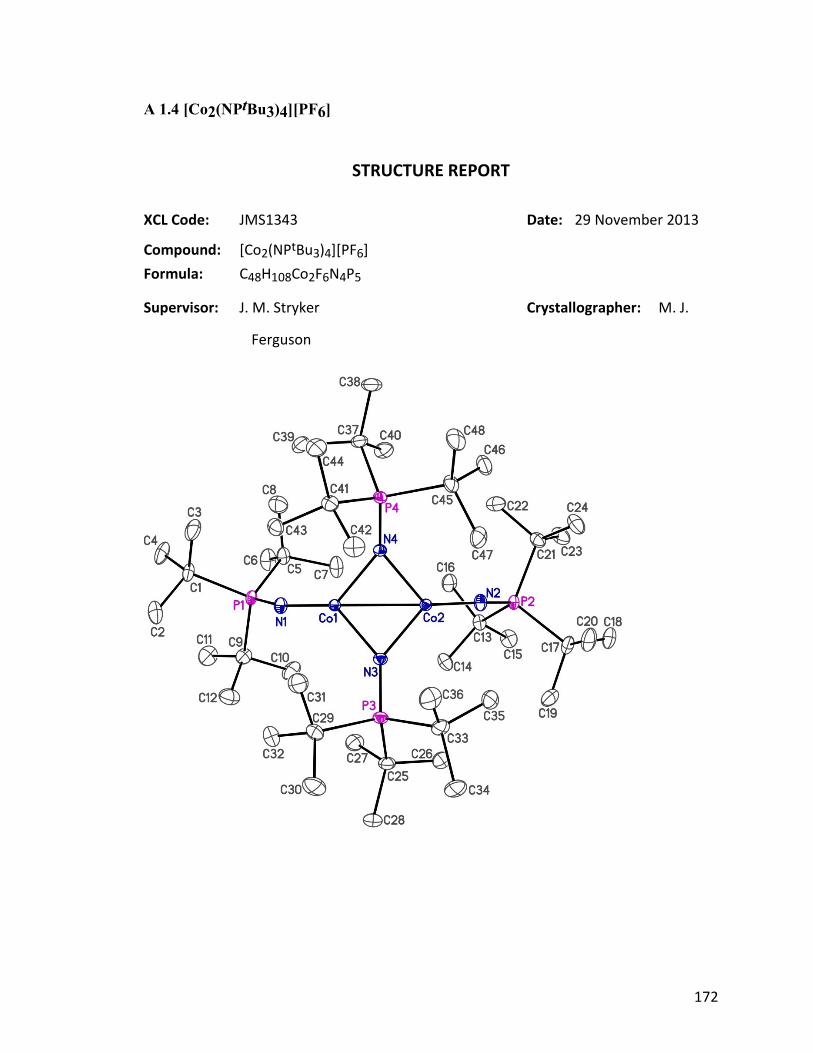
172
A 1.4 [Co2(NPtBu3)4][PF6]
STRUCTURE REPORT
XCL Code: JMS1343 Date: 29 November 2013
Compound: [Co2(NPtBu3)4][PF6]
Formula: C48H108Co2F6N4P5
Supervisor: J. M. Stryker Crystallographer: M. J.
Ferguson
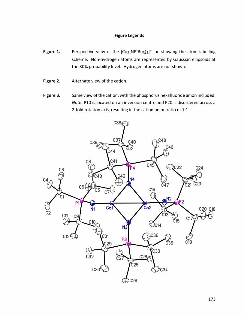
173
Figure Legends
Figure 1. Perspective view of the [Co2(NPtBu3)4]+ ion showing the atom labelling
scheme. Non-hydrogen atoms are represented by Gaussian ellipsoids at
the 30% probability level. Hydrogen atoms are not shown.
Figure 2. Alternate view of the cation.
Figure 3. Same view of the cation, with the phosphorus hexafluoride anion included.
Note: P10 is located on an inversion centre and P20 is disordered across a
2-fold rotation axis, resulting in the cation:anion ratio of 1:1.
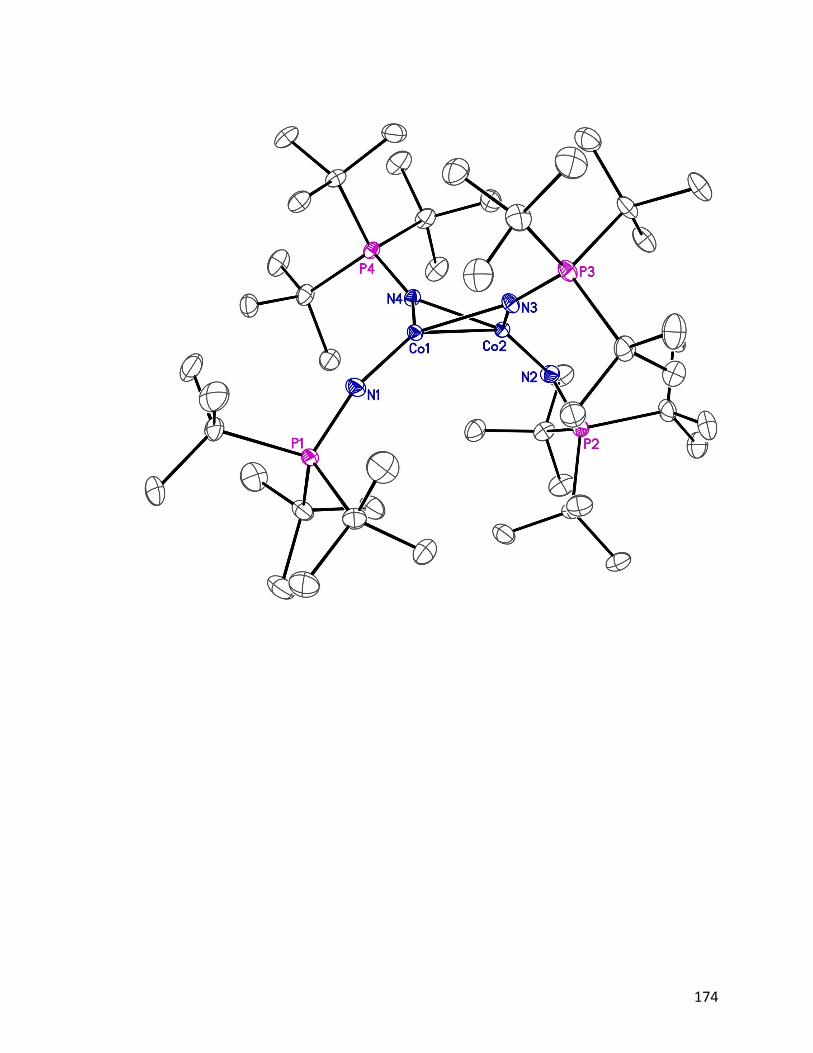
174
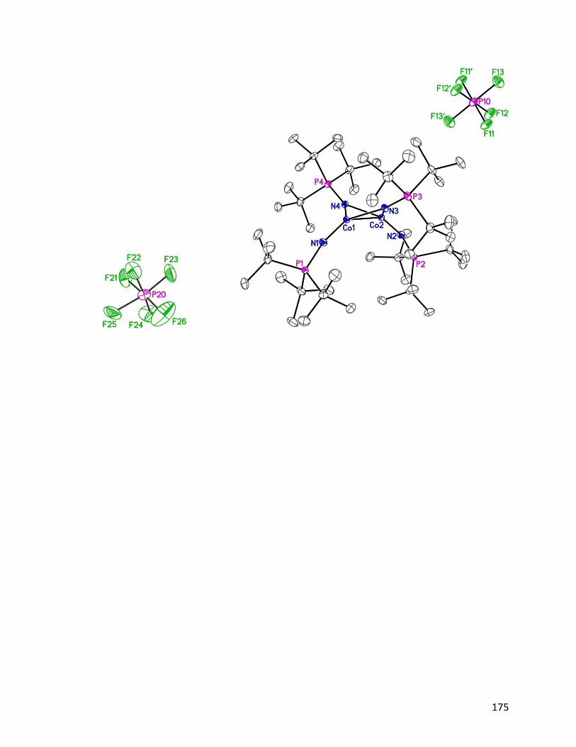
175

176
Table 1. Crystallographic Experimental Details
A. Crystal Data
formula C48H108Co2F6N4P5 formula weight 1128.09 crystal dimensions (mm) 0.44 0.42 0.32 crystal system monoclinic space group C2/c (No. 15) unit cell parametersa a (Å) 43.6858 (19) b (Å) 12.8855 (6) c (Å) 22.7021 (10)
(deg) 110.9702 (5) V (Å3) 11932.9 (9) Z 8 calcd (g cm-3) 1.256 µ (mm-1) 0.743
B. Data Collection and Refinement Conditions
diffractometer Bruker D8/APEX II CCDb radiation ( [Å]) graphite-monochromated Mo K (0.71073) temperature (°C) –100 scan type scans (0.3) (20 s exposures) data collection 2 limit (deg) 54.99
total data collected 52271 (-56 h 56, -16 k 16, -29 l 29) independent reflections 13704 (Rint = 0.0147) number of observed reflections (NO) 12477 [Fo
2 2(Fo2)]
structure solution method intrinsic phasing (SHELXTc) refinement method full-matrix least-squares on F2 (SHELXL–2013c)
absorption correction method Gaussian integration (face-indexed) range of transmission factors 0.8711–0.7837 data/restraints/parameters 13704 / 6d / 656 goodness-of-fit (S)e [all data] 1.040
final R indicesf R1 [Fo
2 2(Fo2)] 0.0287
wR2 [all data] 0.0801 largest difference peak and hole 0.989 and –0.309 e Å-3
aObtained from least-squares refinement of 9603 reflections with 4.36° < 2 < 54.98°.
bPrograms for diffractometer operation, data collection, data reduction and absorption
177
correction were those supplied by Bruker.
cSheldrick, G. M. Acta Crystallogr. 2008, A64, 112–122.
dThe P–F distances within the disordered PF6 anion were restrained to be approximately the same.
eS = [w(Fo2 – Fc
2)2/(n – p)]1/2 (n = number of data; p = number of parameters varied; w = [2(Fo
2) + (0.0420P)2 + 13.5584P]-1 where P = [Max(Fo2, 0) + 2Fc
2]/3).
fR1 = ||Fo| – |Fc||/|Fo|; wR2 = [w(Fo2 – Fc
2)2/w(Fo4)]1/2.

178
A 1.5 [Na4(NPtBu3)4]•n-pentane
STRUCTURE REPORT
XCL Code: JMS1475 Date: 4 December 2015
Compound: [Na4(NPtBu3)4]•n-pentane
Formula: C53H120N4Na4P4 (C48H108N4Na4P4•C5H12)
Supervisor: J. M. Stryker Crystallographer: R.
McDonald

179
Figure Legends
Figure 1. Perspective view of the [Na4(NPtBu3)4] molecule showing the atom
labelling scheme. Non-hydrogen atoms are represented by Gaussian
ellipsoids at the 30% probability level. Hydrogen atoms are not shown.
Primed atoms are related to unprimed ones via the crystallographic
twofold rotational axis (0, y, 1/4).
Figure 2. Illustration of the Na4(NP)4 core of the molecule.
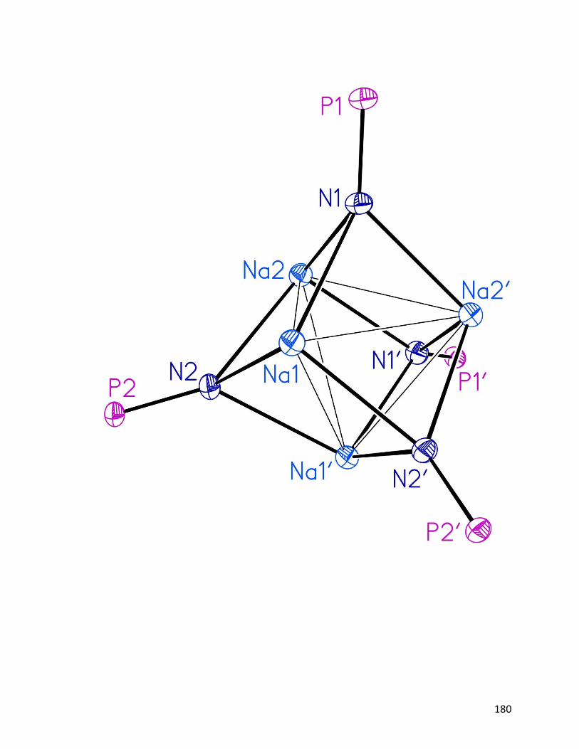
180
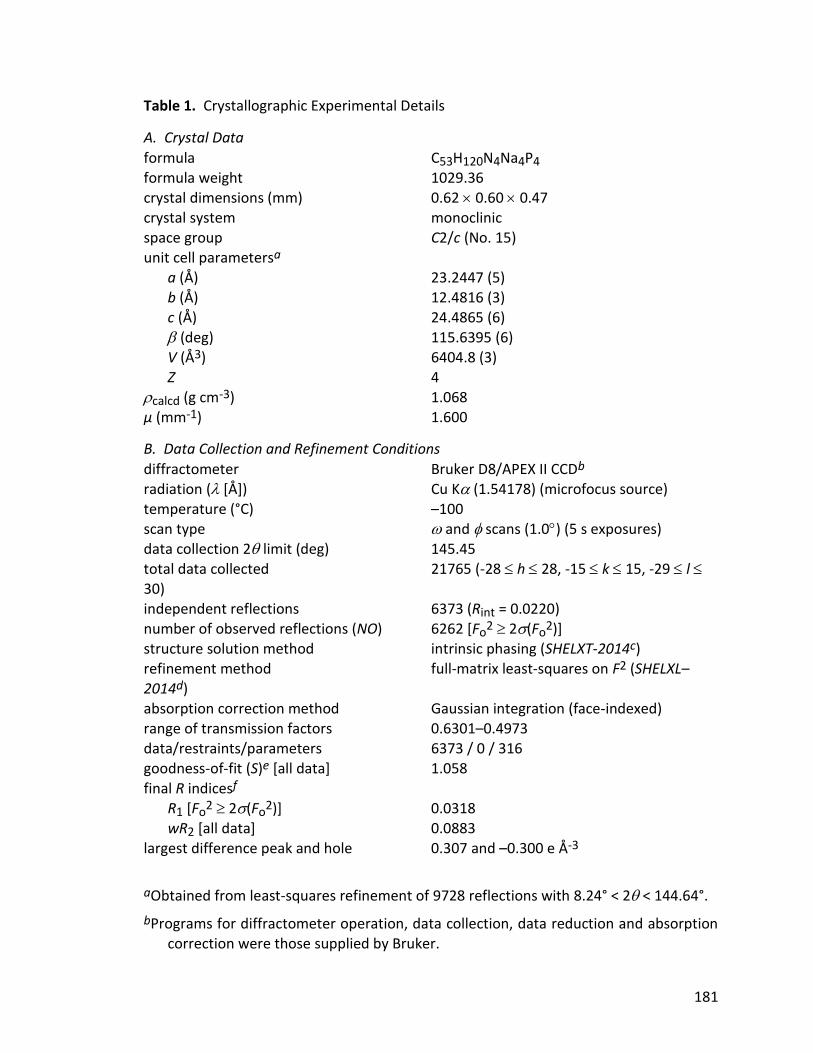
181
Table 1. Crystallographic Experimental Details
A. Crystal Data
formula C53H120N4Na4P4 formula weight 1029.36 crystal dimensions (mm) 0.62 0.60 0.47 crystal system monoclinic space group C2/c (No. 15) unit cell parametersa a (Å) 23.2447 (5) b (Å) 12.4816 (3) c (Å) 24.4865 (6)
(deg) 115.6395 (6) V (Å3) 6404.8 (3) Z 4 calcd (g cm-3) 1.068 µ (mm-1) 1.600
B. Data Collection and Refinement Conditions
diffractometer Bruker D8/APEX II CCDb radiation ( [Å]) Cu K (1.54178) (microfocus source) temperature (°C) –100 scan type and scans (1.0) (5 s exposures) data collection 2 limit (deg) 145.45
total data collected 21765 (-28 h 28, -15 k 15, -29 l 30) independent reflections 6373 (Rint = 0.0220) number of observed reflections (NO) 6262 [Fo
2 2(Fo2)]
structure solution method intrinsic phasing (SHELXT-2014c) refinement method full-matrix least-squares on F2 (SHELXL–2014d)
absorption correction method Gaussian integration (face-indexed) range of transmission factors 0.6301–0.4973 data/restraints/parameters 6373 / 0 / 316 goodness-of-fit (S)e [all data] 1.058
final R indicesf R1 [Fo
2 2(Fo2)] 0.0318
wR2 [all data] 0.0883 largest difference peak and hole 0.307 and –0.300 e Å-3
aObtained from least-squares refinement of 9728 reflections with 8.24° < 2 < 144.64°.
bPrograms for diffractometer operation, data collection, data reduction and absorption correction were those supplied by Bruker.
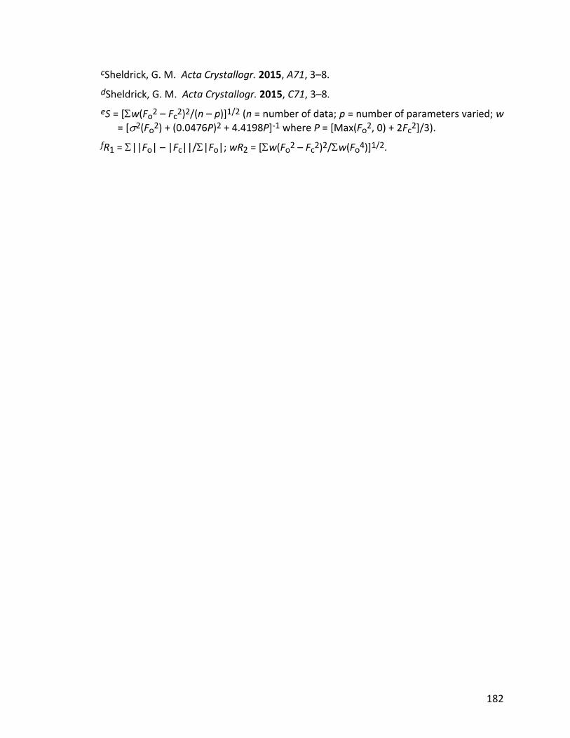
182
cSheldrick, G. M. Acta Crystallogr. 2015, A71, 3–8.
dSheldrick, G. M. Acta Crystallogr. 2015, C71, 3–8.
eS = [w(Fo2 – Fc
2)2/(n – p)]1/2 (n = number of data; p = number of parameters varied; w = [2(Fo
2) + (0.0476P)2 + 4.4198P]-1 where P = [Max(Fo2, 0) + 2Fc
2]/3).
fR1 = ||Fo| – |Fc||/|Fo|; wR2 = [w(Fo2 – Fc
2)2/w(Fo4)]1/2.
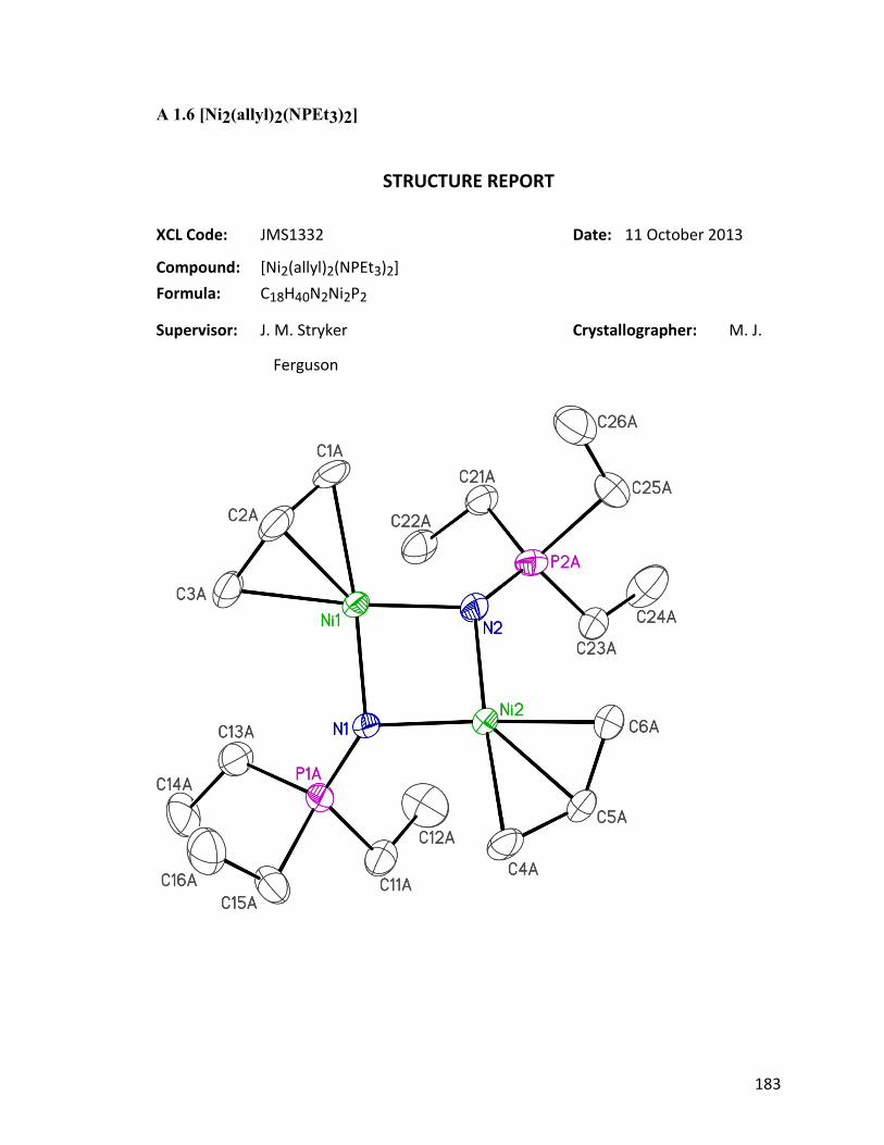
183
A 1.6 [Ni2(allyl)2(NPEt3)2]
STRUCTURE REPORT
XCL Code: JMS1332 Date: 11 October 2013
Compound: [Ni2(allyl)2(NPEt3)2]
Formula: C18H40N2Ni2P2
Supervisor: J. M. Stryker Crystallographer: M. J.
Ferguson
184
Figure Legends
Figure 1. Perspective view of the [Ni2(allyl)2(NPEt3)2] molecule showing the atom
labelling scheme. Only one orientation of the disordered groups is shown.
Non-hydrogen atoms are represented by Gaussian ellipsoids at the 30%
probability level. Hydrogen atoms are not shown.
Figure 2. Same view of the molecule showing the relative orientation of the
disordered allyl and phosphoranamido groups.
Figure 3. Alternate view of the molecule.
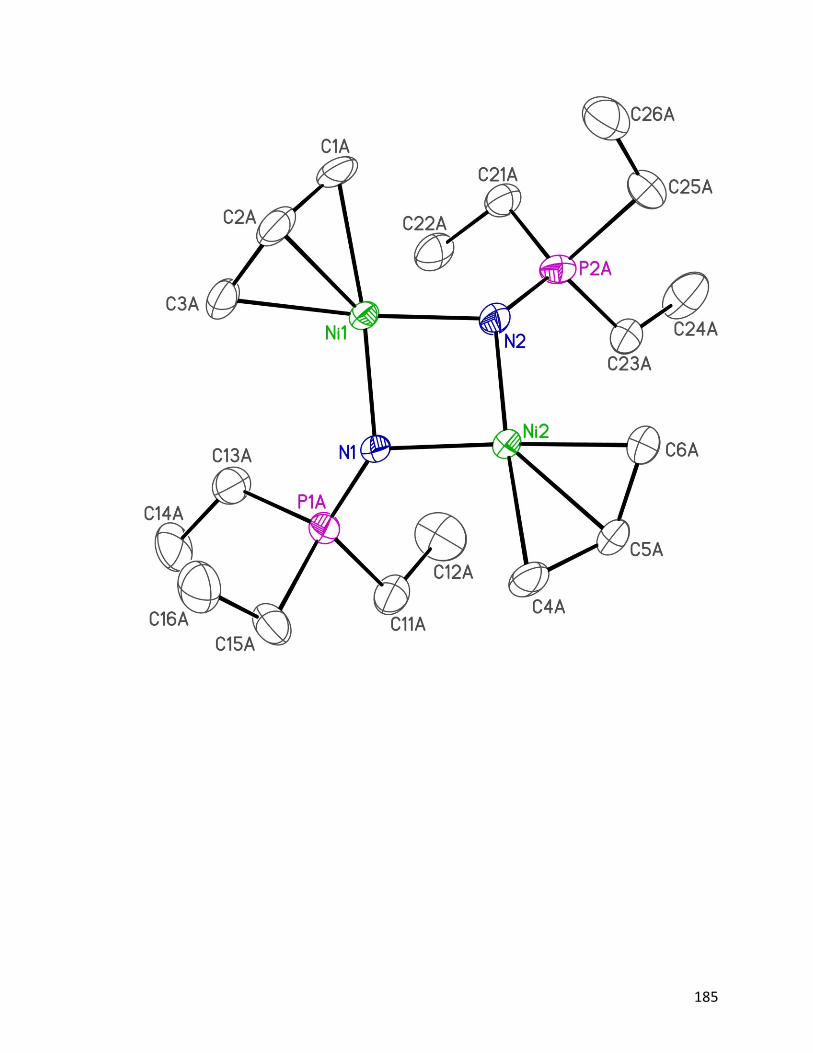
185
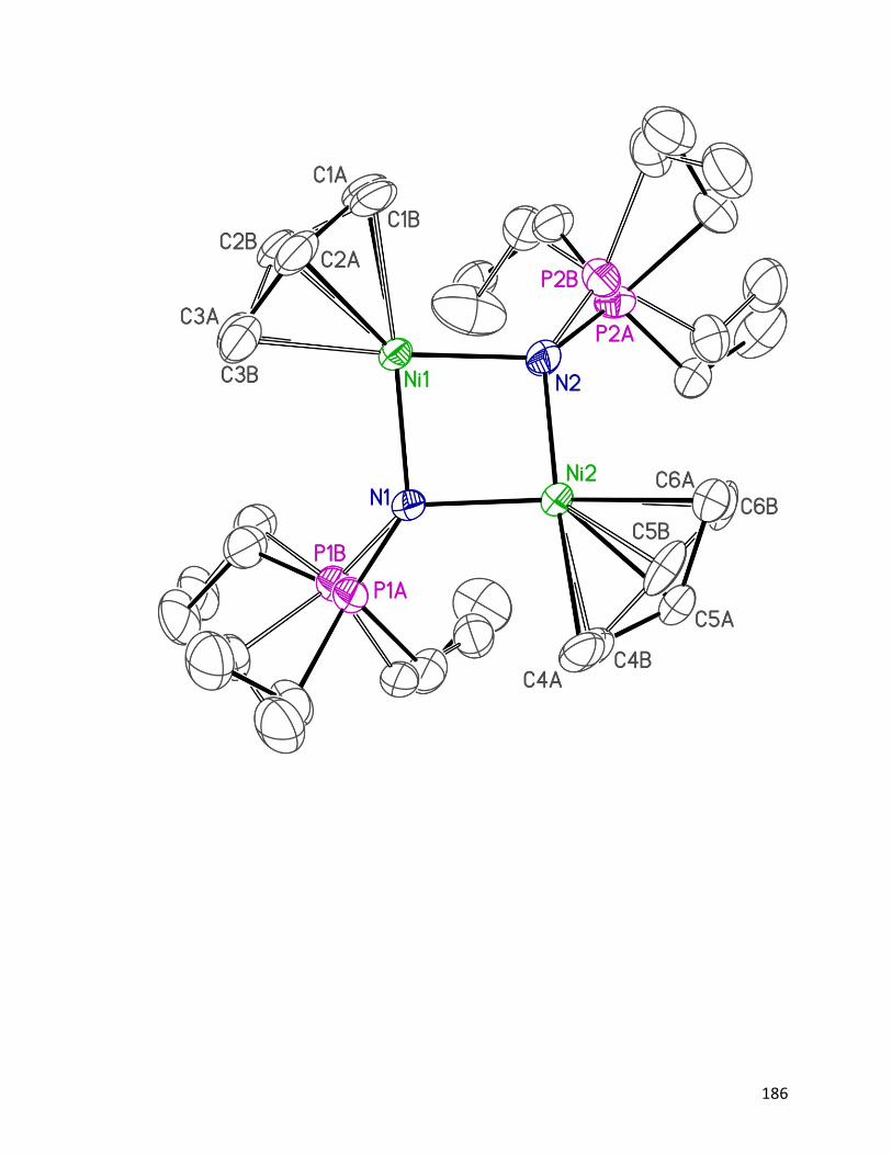
186

187
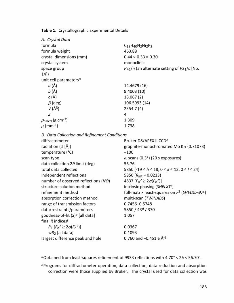
188
Table 1. Crystallographic Experimental Details
A. Crystal Data
formula C18H40N2Ni2P2 formula weight 463.88 crystal dimensions (mm) 0.44 0.33 0.30 crystal system monoclinic space group P21/n (an alternate setting of P21/c [No. 14]) unit cell parametersa a (Å) 14.4679 (16) b (Å) 9.4003 (10)
c (Å) 18.067 (2) (deg) 106.5993 (14) V (Å3) 2354.7 (4) Z 4 calcd (g cm-3) 1.309 µ (mm-1) 1.738
B. Data Collection and Refinement Conditions
diffractometer Bruker D8/APEX II CCDb radiation ( [Å]) graphite-monochromated Mo K (0.71073) temperature (°C) –100 scan type scans (0.3) (20 s exposures)
data collection 2 limit (deg) 56.76 total data collected 5850 (-19 h 18, 0 k 12, 0 l 24) independent reflections 5850 (Rint = 0.0213) number of observed reflections (NO) 4837 [Fo
2 2(Fo2)]
structure solution method intrinsic phasing (SHELXTc) refinement method full-matrix least-squares on F2 (SHELXL–97c) absorption correction method multi-scan (TWINABS)
range of transmission factors 0.7456–0.5748 data/restraints/parameters 5850 / 43d / 370 goodness-of-fit (S)e [all data] 1.057 final R indicesf
R1 [Fo2 2(Fo
2)] 0.0367 wR2 [all data] 0.1093 largest difference peak and hole 0.760 and –0.451 e Å-3
aObtained from least-squares refinement of 9933 reflections with 4.70° < 2 < 56.70°.
bPrograms for diffractometer operation, data collection, data reduction and absorption correction were those supplied by Bruker. The crystal used for data collection was
189
found to display non-merohedral twinning. Both components of the twin were indexed with the program CELL_NOW (Bruker AXS Inc., Madison, WI, 2004). The second twin component can be related to the first component by 180º rotation about the [0 0 1] axis in real space and about the [–0.23 0 1] axis in reciprocal space. Integrated intensities for the reflections from the two components were written into a SHELXL HKLF 5 reflection file with the data integration program SAINT (version 8.32B) and the scaling program TWINABS (version 2012/1), using all reflection data involving domain 1. The refined value of the twin fraction (SHELXL BASF parameter) was 0.0530(5).
cSheldrick, G. M. Acta Crystallogr. 2008, A64, 112–122.
dThe C–C distances within the disordered allyl groups were restrained to be the same by
use the SHELXL SADI instruction. Likewise, a SADI restraint was used on the C11A–C12A/C11B–C12B distances. The P–N and the P–C distances within the disordered phosphoranamido ligand were restrained by use of a DFIX instruction; the target value for the P–N bond distance refined to 1.550(11) while that for the P–C bond distance refined to 1.832(6) Å. Finally, a rigid-bond restraint was applied to the anisotropic displacement parameters for P2A, C23A, C11A, C12A, and all atoms of the disordered allyl groups, by use of the DELU instruction.
eS = [w(Fo2 – Fc
2)2/(n – p)]1/2 (n = number of data; p = number of parameters varied; w = [2(Fo
2) + (0.0724P)2 + 0.3778P]-1 where P = [Max(Fo2, 0) + 2Fc
2]/3).
fR1 = ||Fo| – |Fc||/|Fo|; wR2 = [w(Fo2 – Fc
2)2/w(Fo4)]1/2.
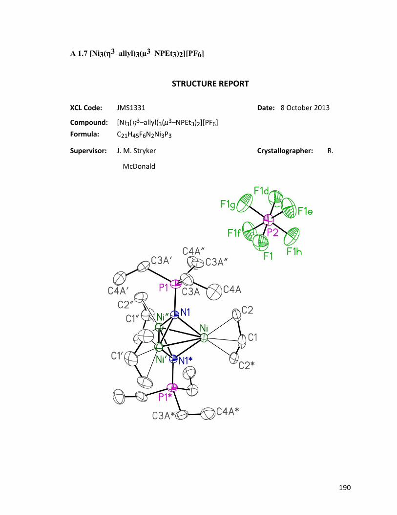
190
A 1.7 [Ni3(3–allyl)3(µ3–NPEt3)2][PF6]
STRUCTURE REPORT
XCL Code: JMS1331 Date: 8 October 2013
Compound: [Ni3(3–allyl)3(µ3–NPEt3)2][PF6]
Formula: C21H45F6N2Ni3P3
Supervisor: J. M. Stryker Crystallographer: R.
McDonald

191
Figure Legends
Figure 1. Perspective view of the [Ni3(3–allyl)3(µ3–NPEt3)2]+ ion and the associated
hexafluorophosphate ion showing the atom labelling scheme. Non-
hydrogen atoms are represented by Gaussian ellipsoids at the 30%
probability level. Hydrogen atoms are not shown. Primed atoms are
related to unprimed ones via the crystallographic symmetry operation (1–
y, 1+x–y, z) (120º rotation about the threefold axis (1/3, 2/3, z)). Double-
primed atoms are related to unprimed ones via the crystallographic
symmetry operation (y–x, 1–x, z) (the opposite-handed 120º rotation
about the threefold axis (1/3, 2/3, z)). Starred atoms are related to
unprimed ones via the crystallographic symmetry operation (x, y, 1/2–z)
(reflection across the mirror plane (x, y, 1/4) upon which the nickel atoms
are located). The hexafluorophosphate ion is located on a 3 center of
symmetry (combined inversion and threefold rotational symmetry); the
symmetry operations relating the fluorine atoms are given in the footnotes
to Tables 2 and 3.
Figure 2. Alternate view of the cation-anion pair highlighting the threefold
rotational syymetry of both ions. The view direction is approximately
parallel to the crystal unit cell’s z axis.

192
193
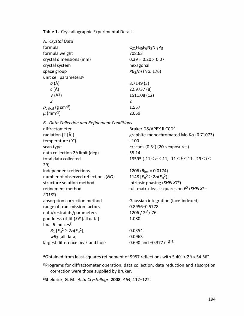
194
Table 1. Crystallographic Experimental Details
A. Crystal Data
formula C21H45F6N2Ni3P3 formula weight 708.63 crystal dimensions (mm) 0.39 0.20 0.07 crystal system hexagonal space group P63/m (No. 176) unit cell parametersa a (Å) 8.7149 (3) c (Å) 22.9737 (8) V (Å3) 1511.08 (12)
Z 2 calcd (g cm-3) 1.557 µ (mm-1) 2.059
B. Data Collection and Refinement Conditions
diffractometer Bruker D8/APEX II CCDb radiation ( [Å]) graphite-monochromated Mo K (0.71073) temperature (°C) –100 scan type scans (0.3) (20 s exposures) data collection 2 limit (deg) 55.14 total data collected 13595 (-11 h 11, -11 k 11, -29 l 29)
independent reflections 1206 (Rint = 0.0174) number of observed reflections (NO) 1148 [Fo
2 2(Fo2)]
structure solution method intrinsic phasing (SHELXTc) refinement method full-matrix least-squares on F2 (SHELXL–2013c) absorption correction method Gaussian integration (face-indexed) range of transmission factors 0.8956–0.5778
data/restraints/parameters 1206 / 2d / 76 goodness-of-fit (S)e [all data] 1.080 final R indicesf R1 [Fo
2 2(Fo2)] 0.0354
wR2 [all data] 0.0963 largest difference peak and hole 0.690 and –0.377 e Å-3
aObtained from least-squares refinement of 9957 reflections with 5.40° < 2 < 54.56°.
bPrograms for diffractometer operation, data collection, data reduction and absorption correction were those supplied by Bruker.
cSheldrick, G. M. Acta Crystallogr. 2008, A64, 112–122.
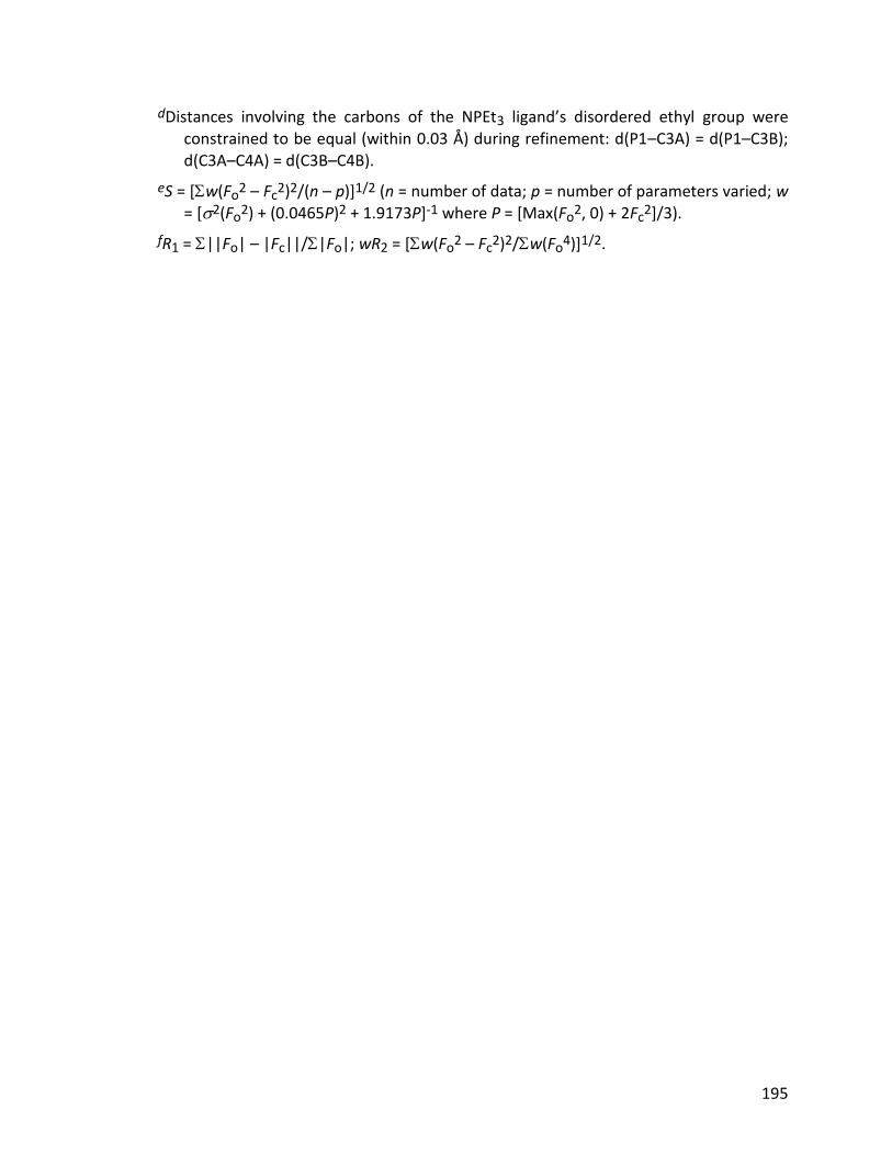
195
dDistances involving the carbons of the NPEt3 ligand’s disordered ethyl group were constrained to be equal (within 0.03 Å) during refinement: d(P1–C3A) = d(P1–C3B); d(C3A–C4A) = d(C3B–C4B).
eS = [w(Fo2 – Fc
2)2/(n – p)]1/2 (n = number of data; p = number of parameters varied; w = [2(Fo
2) + (0.0465P)2 + 1.9173P]-1 where P = [Max(Fo2, 0) + 2Fc
2]/3).
fR1 = ||Fo| – |Fc||/|Fo|; wR2 = [w(Fo2 – Fc
2)2/w(Fo4)]1/2.
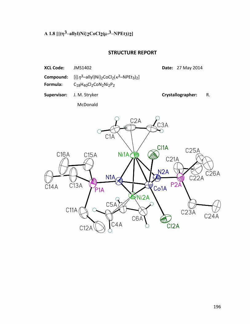
196
A 1.8 [{(3–allyl)Ni}2CoCl2(-3–NPEt3)2]
STRUCTURE REPORT
XCL Code: JMS1402 Date: 27 May 2014
Compound: [{(3–allyl)Ni}2CoCl2(3–NPEt3)2]
Formula: C18H40Cl2CoN2Ni2P2
Supervisor: J. M. Stryker Crystallographer: R.
McDonald
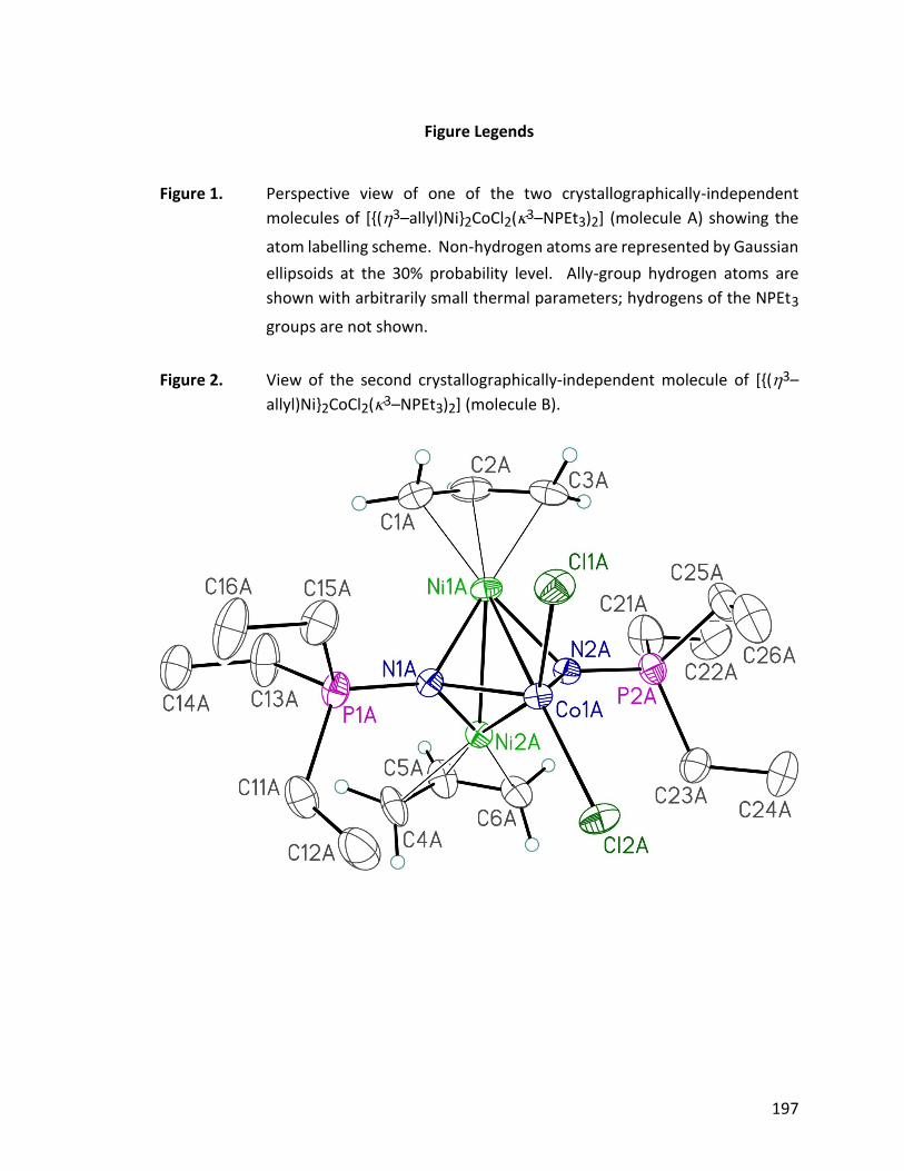
197
Figure Legends
Figure 1. Perspective view of one of the two crystallographically-independent
molecules of [{(3–allyl)Ni}2CoCl2(3–NPEt3)2] (molecule A) showing the
atom labelling scheme. Non-hydrogen atoms are represented by Gaussian
ellipsoids at the 30% probability level. Ally-group hydrogen atoms are
shown with arbitrarily small thermal parameters; hydrogens of the NPEt3
groups are not shown.
Figure 2. View of the second crystallographically-independent molecule of [{(3–
allyl)Ni}2CoCl2(3–NPEt3)2] (molecule B).

198
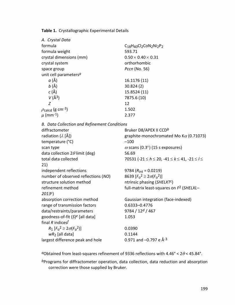
199
Table 1. Crystallographic Experimental Details
A. Crystal Data
formula C18H40Cl2CoN2Ni2P2 formula weight 593.71 crystal dimensions (mm) 0.50 0.40 0.31 crystal system orthorhombic space group Pccn (No. 56) unit cell parametersa a (Å) 16.1176 (11) b (Å) 30.824 (2) c (Å) 15.8524 (11)
V (Å3) 7875.6 (10) Z 12 calcd (g cm-3) 1.502 µ (mm-1) 2.377
B. Data Collection and Refinement Conditions
diffractometer Bruker D8/APEX II CCDb radiation ( [Å]) graphite-monochromated Mo K (0.71073) temperature (°C) –100 scan type scans (0.3) (15 s exposures) data collection 2 limit (deg) 56.69 total data collected 70531 (-21 h 20, -41 k 41, -21 l
21) independent reflections 9784 (Rint = 0.0219) number of observed reflections (NO) 8639 [Fo
2 2(Fo2)]
structure solution method ntrinsic phasing (SHELXTc) refinement method full-matrix least-squares on F2 (SHELXL–2013c) absorption correction method Gaussian integration (face-indexed)
range of transmission factors 0.6333–0.4776 data/restraints/parameters 9784 / 12d / 467 goodness-of-fit (S)e [all data] 1.053 final R indicesf
R1 [Fo2 2(Fo
2)] 0.0390 wR2 [all data] 0.1144 largest difference peak and hole 0.971 and –0.797 e Å-3
aObtained from least-squares refinement of 9336 reflections with 4.46° < 2 < 45.84°.
bPrograms for diffractometer operation, data collection, data reduction and absorption correction were those supplied by Bruker.
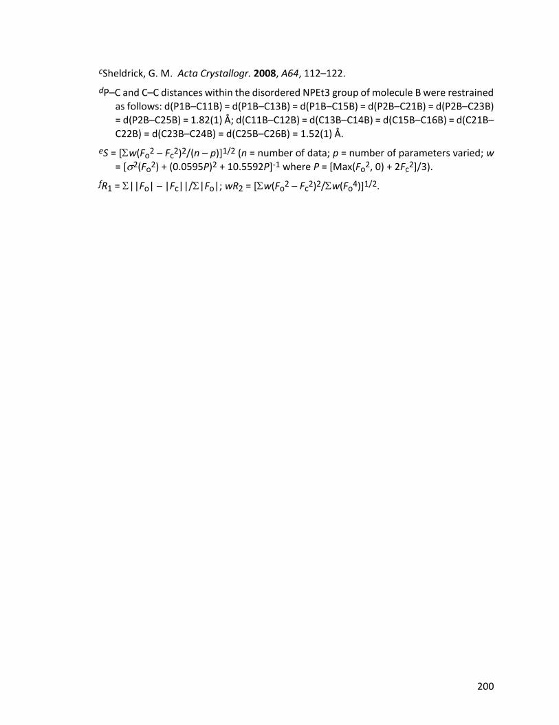
200
cSheldrick, G. M. Acta Crystallogr. 2008, A64, 112–122.
dP–C and C–C distances within the disordered NPEt3 group of molecule B were restrained as follows: d(P1B–C11B) = d(P1B–C13B) = d(P1B–C15B) = d(P2B–C21B) = d(P2B–C23B) = d(P2B–C25B) = 1.82(1) Å; d(C11B–C12B) = d(C13B–C14B) = d(C15B–C16B) = d(C21B–C22B) = d(C23B–C24B) = d(C25B–C26B) = 1.52(1) Å.
eS = [w(Fo2 – Fc
2)2/(n – p)]1/2 (n = number of data; p = number of parameters varied; w = [2(Fo
2) + (0.0595P)2 + 10.5592P]-1 where P = [Max(Fo2, 0) + 2Fc
2]/3).
fR1 = ||Fo| – |Fc||/|Fo|; wR2 = [w(Fo2 – Fc
2)2/w(Fo4)]1/2.
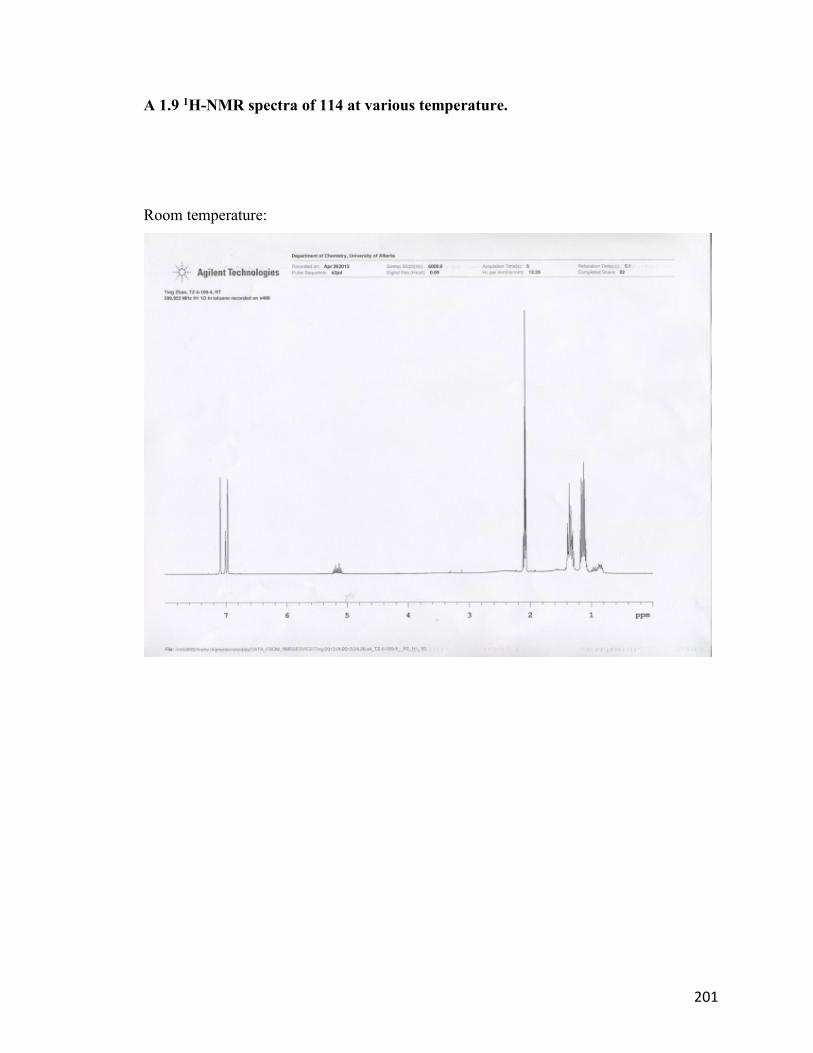
201
A 1.9 1H-NMR spectra of 114 at various temperature.
Room temperature:
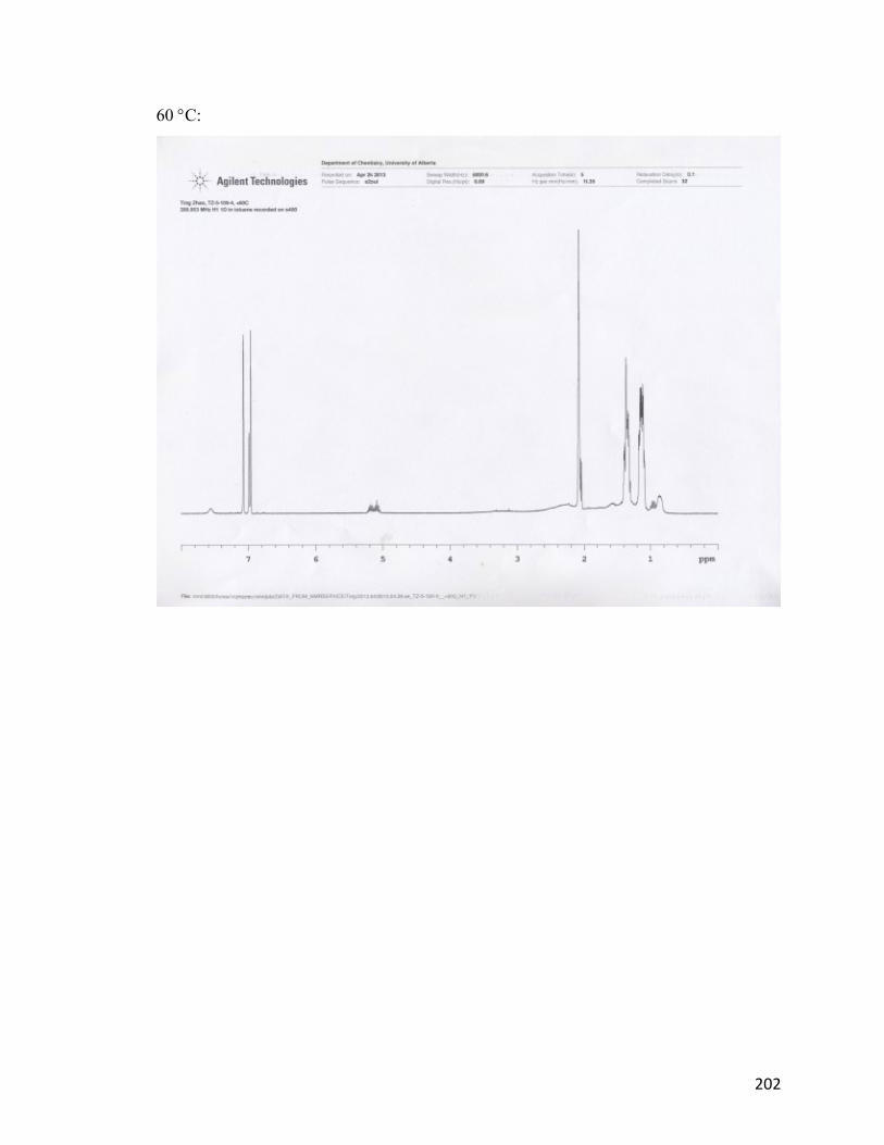
202
60 C:
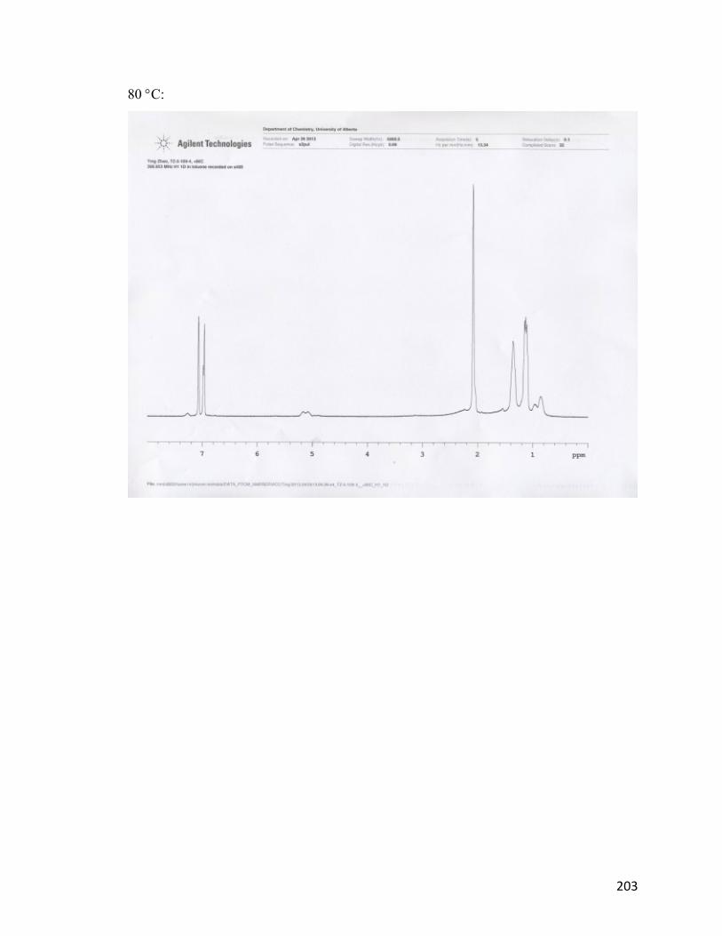
203
80 C:
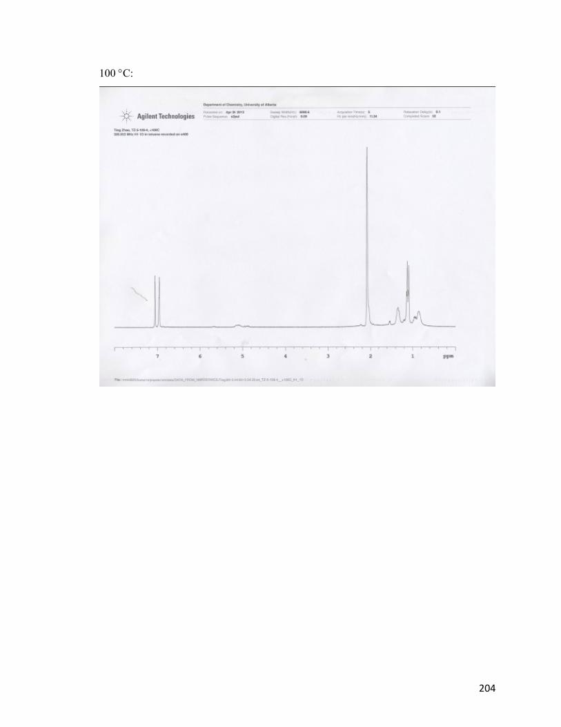
204
100 C: