
Capillary rise between parallel plates under dynamic conditions
9
Capillary rise between parallel plates under dynamic conditions Fabiano G. Wolf * , Luís O.E. dos Santos, Paulo C. Philippi Federal University of Santa Catarina, Department of Mechanical Engineering, Campus Universitário Florianópolis, Santa Catarina 88040-900, Brazil article info Article history: Received 2 February 2009 Accepted 12 December 2009 Available online 23 December 2009 Keywords: Capillary rise Lattice-Boltzmann model Long-range interactions Dynamic contact angle and capillary number abstract A Lattice-Boltzmann method based on field mediators is proposed to simulate the capillary rise between parallel plates by considering the effect of long-range interactions between the fluids and the solid walls. As a starting point, a liquid–vapor system was employed, which was modeled using a known model described in the literature. The simulations were compared with theoretical solutions of the Bosanquet equation. The results obtained are in good agreement with theoretical predictions, particularly when the dependence between the dynamic contact angle and the capillary number is taken into account. This dependence shows that on smooth and homogeneous solid surfaces, where pinning effects in the contact line are weak, the dynamic contact angle is linearly dependent on the capillary number, in good agree- ment with theoretical and experimental results available in the literature. Some discrepancies were observed in the first stages of the capillary rise when the distance between the parallel plates is large, considering the high complexity involved in predicting the initial meniscus formation. The results pre- sented in this work appear to indicate that the inclusion of long-range forces does not change signifi- cantly the fluid flow dynamics at the mesoscopic level, at least, when ideally flat and homogeneous solid surfaces are used in the simulations. Ó 2009 Elsevier Inc. All rights reserved. 1. Introduction Fluid invasion into a tube as a result of unbalanced capillary forces is a classical problem in the literature devoted to fluid dynamics. It is of great scientific interest and is important in vari- ous applications, such as ink printing, dyeing of textiles and en- hanced oil recovery. Lucas [1] and Washburn [2] published the first attempts to de- scribe the dynamic process involved in capillary rise. They verified that the process can be described using a mechanical balance be- tween the capillary, viscous and gravitational forces, leading to the well-known Lucas-Washburn equation. Their model has been verified experimentally even for very thin capillaries [3] and is gen- erally accepted as a valid approach under a laminar flow regime [4]. However, the Lucas-Washburn equation fails in the prediction of the first stages of the meniscus rising, predicting that the initial velocity is infinite at time zero, a non-physical solution, resulting from the lack of an inertial term [5]. This problem was solved by Bosanquet [6] who included an inertial term in the Lucas-Wash- burn equation, but neglected any influence from the fluid flow in the reservoir. For such a case, it was verified that the inclusion of the inertial effects avoided the non-physical initial condition, allowing the definition of an initial velocity at time zero, called the Bosanquet velocity. High resolution experiments showed that the observed initial velocities are different from those predicted by the Bosanquet equation [7]. Szekely et al. [8] carried out an analysis of the capillary rise with inertial and entrance effects by using arguments based on the balance of the mechanical energy equation. They modified the inertial term by adding an ‘‘apparent mass” related to the fluid flow from the reservoir and a ‘‘vena con- tracta” effect due to the inlet flow. Considering that the analysis by Szekely et al. considered high Reynolds number flow, while most cases of capillary rising are low Reynolds number problems, Levine et al. [9], performed a more detailed analysis of the momentum and mechanical energy balance equations, developing one of the most complete models found in the literature. The Levine et al. model presents different factors for the inertial terms and an addi- tional term, related to the inlet viscous dissipation. Dreyer et al. [10] and Stange et al. [11] carried out similar analysis, including some improvements, and obtained governing equations which are similar to those found by Levine et al. [9]. These equations were confirmed by experiments under microgravity conditions. As mentioned above, the capillary rise problem has been the subject of several discussions related to the short-time aspects of the meniscus formation and resulting flow velocity. Its complete understanding continues to be, nevertheless, an open subject, par- ticularly due to the complex physico-chemical interactions be- tween the liquid and the solid surface and the fundamental role of the triple line in the liquid displacement. In this context, useful data concerning the capillary rise phenomena have been provided 0021-9797/$ - see front matter Ó 2009 Elsevier Inc. All rights reserved. doi:10.1016/j.jcis.2009.12.023 * Corresponding author. E-mail addresses: [email protected] (F.G. Wolf), [email protected] (L.O.E. dos Santos), [email protected] (P.C. Philippi). Journal of Colloid and Interface Science 344 (2010) 171–179 Contents lists available at ScienceDirect Journal of Colloid and Interface Science www.elsevier.com/locate/jcis
Transcript of Capillary rise between parallel plates under dynamic conditions

Journal of Colloid and Interface Science 344 (2010) 171–179
Contents lists available at ScienceDirect
Journal of Colloid and Interface Science
www.elsevier .com/locate / jc is
Capillary rise between parallel plates under dynamic conditions
Fabiano G. Wolf *, Luís O.E. dos Santos, Paulo C. PhilippiFederal University of Santa Catarina, Department of Mechanical Engineering, Campus Universitário Florianópolis, Santa Catarina 88040-900, Brazil
a r t i c l e i n f o a b s t r a c t
Article history:Received 2 February 2009Accepted 12 December 2009Available online 23 December 2009
Keywords:Capillary riseLattice-Boltzmann modelLong-range interactionsDynamic contact angle and capillarynumber
0021-9797/$ - see front matter � 2009 Elsevier Inc. Adoi:10.1016/j.jcis.2009.12.023
* Corresponding author.E-mail addresses: [email protected] (F.G. Wolf),
dos Santos), [email protected] (P.C. Philippi).
A Lattice-Boltzmann method based on field mediators is proposed to simulate the capillary rise betweenparallel plates by considering the effect of long-range interactions between the fluids and the solid walls.As a starting point, a liquid–vapor system was employed, which was modeled using a known modeldescribed in the literature. The simulations were compared with theoretical solutions of the Bosanquetequation. The results obtained are in good agreement with theoretical predictions, particularly whenthe dependence between the dynamic contact angle and the capillary number is taken into account. Thisdependence shows that on smooth and homogeneous solid surfaces, where pinning effects in the contactline are weak, the dynamic contact angle is linearly dependent on the capillary number, in good agree-ment with theoretical and experimental results available in the literature. Some discrepancies wereobserved in the first stages of the capillary rise when the distance between the parallel plates is large,considering the high complexity involved in predicting the initial meniscus formation. The results pre-sented in this work appear to indicate that the inclusion of long-range forces does not change signifi-cantly the fluid flow dynamics at the mesoscopic level, at least, when ideally flat and homogeneoussolid surfaces are used in the simulations.
� 2009 Elsevier Inc. All rights reserved.
1. Introduction
Fluid invasion into a tube as a result of unbalanced capillaryforces is a classical problem in the literature devoted to fluiddynamics. It is of great scientific interest and is important in vari-ous applications, such as ink printing, dyeing of textiles and en-hanced oil recovery.
Lucas [1] and Washburn [2] published the first attempts to de-scribe the dynamic process involved in capillary rise. They verifiedthat the process can be described using a mechanical balance be-tween the capillary, viscous and gravitational forces, leading tothe well-known Lucas-Washburn equation. Their model has beenverified experimentally even for very thin capillaries [3] and is gen-erally accepted as a valid approach under a laminar flow regime[4]. However, the Lucas-Washburn equation fails in the predictionof the first stages of the meniscus rising, predicting that the initialvelocity is infinite at time zero, a non-physical solution, resultingfrom the lack of an inertial term [5]. This problem was solved byBosanquet [6] who included an inertial term in the Lucas-Wash-burn equation, but neglected any influence from the fluid flow inthe reservoir. For such a case, it was verified that the inclusion ofthe inertial effects avoided the non-physical initial condition,allowing the definition of an initial velocity at time zero, called
ll rights reserved.
[email protected] (L.O.E.
the Bosanquet velocity. High resolution experiments showed thatthe observed initial velocities are different from those predictedby the Bosanquet equation [7]. Szekely et al. [8] carried out ananalysis of the capillary rise with inertial and entrance effects byusing arguments based on the balance of the mechanical energyequation. They modified the inertial term by adding an ‘‘apparentmass” related to the fluid flow from the reservoir and a ‘‘vena con-tracta” effect due to the inlet flow. Considering that the analysis bySzekely et al. considered high Reynolds number flow, while mostcases of capillary rising are low Reynolds number problems, Levineet al. [9], performed a more detailed analysis of the momentumand mechanical energy balance equations, developing one of themost complete models found in the literature. The Levine et al.model presents different factors for the inertial terms and an addi-tional term, related to the inlet viscous dissipation. Dreyer et al.[10] and Stange et al. [11] carried out similar analysis, includingsome improvements, and obtained governing equations whichare similar to those found by Levine et al. [9]. These equations wereconfirmed by experiments under microgravity conditions.
As mentioned above, the capillary rise problem has been thesubject of several discussions related to the short-time aspects ofthe meniscus formation and resulting flow velocity. Its completeunderstanding continues to be, nevertheless, an open subject, par-ticularly due to the complex physico-chemical interactions be-tween the liquid and the solid surface and the fundamental roleof the triple line in the liquid displacement. In this context, usefuldata concerning the capillary rise phenomena have been provided
172 F.G. Wolf et al. / Journal of Colloid and Interface Science 344 (2010) 171–179
by numerical simulations based on molecular dynamics [12–15]and Lattice-Boltzman methods (LBM) [16–20]. In these frame-works, we are able to develop models with appropriate informa-tion with respect to the microscopic and mesoscopic scales in asuitable way, based on the interaction between particles and thesolid surface.
In this study, a Lattice-Boltzmann method (LBM) based on fieldmediators [21] is proposed to simulate the fluid–solid interactionand is applied in the study of the capillary rise between parallelplates under dynamic conditions in a liquid–vapor system. Themethod introduces the effect of long-range interactions betweenthe particles and solid walls. To achieve this purpose, the liquid–vapor equilibrium is required as a starting point by modeling thefluid–fluid interaction using the Shan and Chen model [22,23]. Thismodel enables the simulation of phase equilibrium retrieving anequation of state similar to the van der Waals equation. TheShan–Chen interaction model is based on nearest-neighbor inter-actions. In this paper, we use the concept of field mediators de-tailed in Santos and Philippi [24,21] to describe the long-rangeattraction between the solid surface and the fluid in a discrete lat-tice. The use of mediators allows the simulation of the effect oflong-range forces beyond a single lattice-unit, with reduced pro-cessing time. For simplicity and computational convenience, onlytwo-dimensional simulations were considered. In such a configu-ration, the capillary rise problem consists of the description ofthe liquid–vapor interface movement between two parallel plates,as illustrated in Fig. 1.
2. Theoretical background
2.1. The capillary rise problem
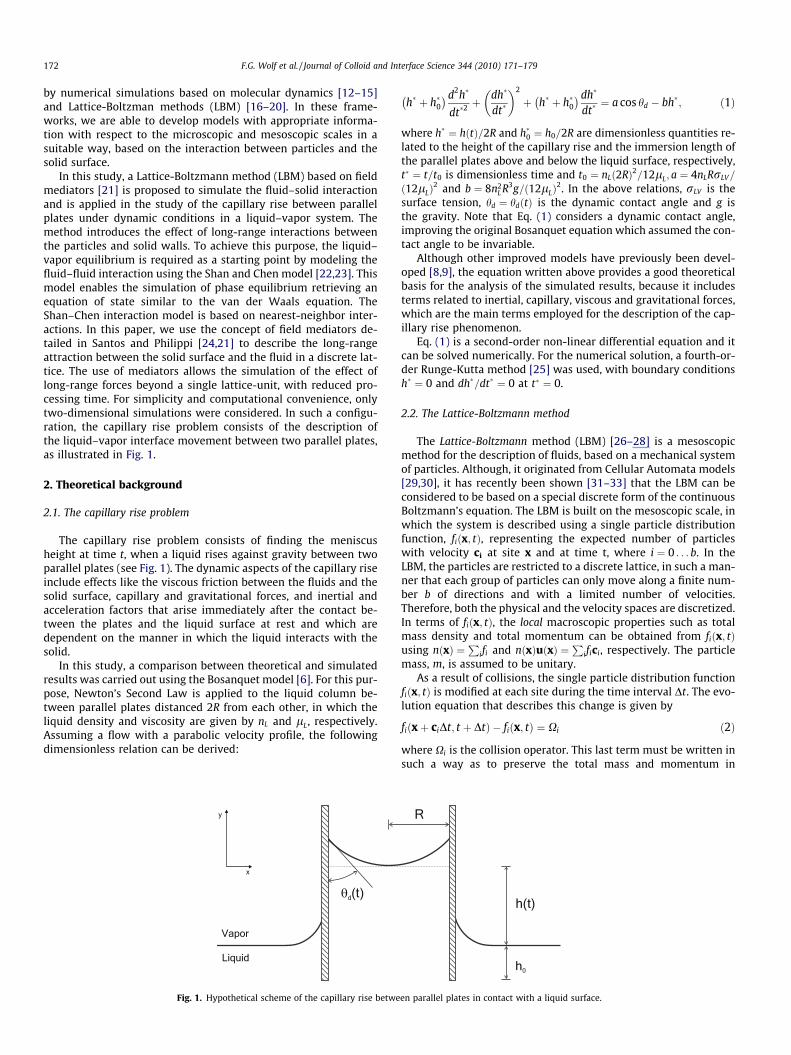
The capillary rise problem consists of finding the meniscusheight at time t, when a liquid rises against gravity between twoparallel plates (see Fig. 1). The dynamic aspects of the capillary riseinclude effects like the viscous friction between the fluids and thesolid surface, capillary and gravitational forces, and inertial andacceleration factors that arise immediately after the contact be-tween the plates and the liquid surface at rest and which aredependent on the manner in which the liquid interacts with thesolid.
In this study, a comparison between theoretical and simulatedresults was carried out using the Bosanquet model [6]. For this pur-pose, Newton’s Second Law is applied to the liquid column be-tween parallel plates distanced 2R from each other, in which theliquid density and viscosity are given by nL and lL, respectively.Assuming a flow with a parabolic velocity profile, the followingdimensionless relation can be derived:
Fig. 1. Hypothetical scheme of the capillary rise betwe
h� þ h�0� �d2h�
dt�2þ dh�
dt�
� �2
þ h� þ h�0� � dh�
dt�¼ a cos hd � bh�; ð1Þ
where h� ¼ hðtÞ=2R and h�0 ¼ h0=2R are dimensionless quantities re-lated to the height of the capillary rise and the immersion length ofthe parallel plates above and below the liquid surface, respectively,t� ¼ t=t0 is dimensionless time and t0 ¼ nLð2RÞ2=12lL; a ¼ 4nLRrLV=
ð12lLÞ2 and b ¼ 8n2
L R3g=ð12lLÞ2. In the above relations, rLV is the
surface tension, hd ¼ hdðtÞ is the dynamic contact angle and g isthe gravity. Note that Eq. (1) considers a dynamic contact angle,improving the original Bosanquet equation which assumed the con-tact angle to be invariable.
Although other improved models have previously been devel-oped [8,9], the equation written above provides a good theoreticalbasis for the analysis of the simulated results, because it includesterms related to inertial, capillary, viscous and gravitational forces,which are the main terms employed for the description of the cap-illary rise phenomenon.
Eq. (1) is a second-order non-linear differential equation and itcan be solved numerically. For the numerical solution, a fourth-or-der Runge-Kutta method [25] was used, with boundary conditionsh� ¼ 0 and dh�=dt� ¼ 0 at t� ¼ 0.
2.2. The Lattice-Boltzmann method
The Lattice-Boltzmann method (LBM) [26–28] is a mesoscopicmethod for the description of fluids, based on a mechanical systemof particles. Although, it originated from Cellular Automata models[29,30], it has recently been shown [31–33] that the LBM can beconsidered to be based on a special discrete form of the continuousBoltzmann’s equation. The LBM is built on the mesoscopic scale, inwhich the system is described using a single particle distributionfunction, fiðx; tÞ, representing the expected number of particleswith velocity ci at site x and at time t, where i ¼ 0 . . . b. In theLBM, the particles are restricted to a discrete lattice, in such a man-ner that each group of particles can only move along a finite num-ber b of directions and with a limited number of velocities.Therefore, both the physical and the velocity spaces are discretized.In terms of fiðx; tÞ, the local macroscopic properties such as totalmass density and total momentum can be obtained from fiðx; tÞusing nðxÞ ¼
Pifi and nðxÞuðxÞ ¼
Pifici, respectively. The particle
mass, m, is assumed to be unitary.As a result of collisions, the single particle distribution function
fiðx; tÞ is modified at each site during the time interval Dt. The evo-lution equation that describes this change is given by
fiðxþ ciDt; t þ DtÞ � fiðx; tÞ ¼ Xi ð2Þ
where Xi is the collision operator. This last term must be written insuch a way as to preserve the total mass and momentum in
en parallel plates in contact with a liquid surface.

F.G. Wolf et al. / Journal of Colloid and Interface Science 344 (2010) 171–179 173
collisions. In non-isothermal systems energy preservation is also re-quired. The simplest form is given by the Bhatnagar, Gross andKrook model, which describes collision as a relaxation process lead-ing to a local equilibrium state, Xi ¼ � Dt
s ðfi � f ðeqÞi Þ, where s is the
relaxation time and f ðeqÞi is a single particle local equilibrium distri-
bution. Hence, the governing LBM mesoscopic equation will be
fiðxþ ciDt; t þ DtÞ � fiðx; tÞ ¼ �Dtsðfi � f ðeqÞ
i Þ ð3Þ
After the collision step, the evolution equation, Eq. (3), requires thelocal information at x and t, fiðx; tÞ, to be transferred to the neigh-boring site xþ ciDt at time t þ Dt in the propagation step.
The macroscopic behavior of Eq. (3) is determined by a suitablechoice of the equilibrium distribution, f ðeqÞ
i ¼ f ðeqÞi ðn;uÞ. In the pres-
ent case, one needs to recover the macroscopic dynamics of fluidsruled by the Navier–Stokes equations. For this purpose, the equilib-rium distribution is chosen as [26]
f eqi ðxÞ ¼ nwi 1þ 3ðci � uÞ þ
92ðci � uÞ2 �
32
u2� �
; ð4Þ
where w0 ¼ 4=9;w1 ¼ w3 ¼ w5 ¼ w7 ¼ 1=9 and w2 ¼ w4 ¼ w6 ¼w8 ¼ 1=36 for a D2Q9 lattice [36]. The w0is are weight factors chosento guarantee macroscopic isotropy and Galilean invariance [26].
Using a multiscale method such as that of Chapman-Enskog[34], it is possible to show that the system described above recov-ers the Navier–Stokes equations at the limit of near incompressibleflows [26,27,35,28]. Next to the solid surfaces, a half-way bounce-back boundary condition [28] is imposed for the particles leavingthe fluid domain.
2.3. Interaction forces between the fluid particles
In order to take into account the physical components involvedin the microscopic interactions among the molecules of a fluid,Shan and Chen [22,23] inserted an interaction potential amongthe particles. In this way, the model is able to reproduce the li-quid–vapor phase transition and coexistence of two distinct phasesof a single component in equilibrium, in which the density distri-bution allows the identification of both phases. The authors usedthe following nearest-neighbor interaction potential between twogroups of particles located at sites x and y:
Vðx; yÞ ¼ uðxÞGiðx; yÞuðyÞ; ð5Þ
where, for a D2Q9 lattice [36], Giðx; yÞ ¼ G for jcij ¼ffiffiffi2p
;Giðx; yÞ ¼4G for jcij ¼ 1 and Giðx; yÞ ¼ 0 for two sites which are not nearest-neighbors. The function uðxÞ � u½nðxÞ� will be chosen so as toestablish a correspondence between the LBM and an isotherm ina PVT system. The strength of the interaction potential among theparticles is given by G, while its sign defines whether the potentialis attractive or repulsive. The resulting interaction force due to thispotential acting on the particles located at site x at time t is thus
Frðx; tÞ ¼ �uðxÞX
i
Giuðxþ ciDtÞci: ð6Þ
In the LBM, the local velocity, u(x), in the equilibrium distribution,Eq. (4), is modified due to the force Fr in the following way:
ueq ¼ uþ sn
Fr: ð7Þ
This type of interaction among the particles does not preserve thelocal momentum during the collision process because the force Fr
behaves as an external force acting on the site. Nevertheless, Shanand Chen [22,23] showed that the total momentum of the systemis preserved and no net momentum is inserted into the system bythe above interaction. Redefining the fluid momentum, nv, as anarithmetic average for the states before and after the collision step,
nv ¼ nuþ 12 Fr, the method of Chapman-Enskog [34] allows the
determination of the macroscopic behavior of the referred to micro-scopic system. The resulting macroscopic equation describes a non-ideal fluid whose equation of state is written for a D2Q9 lattice as:
P ¼ n3þ 6Gu2ðnÞ: ð8Þ
The correct choice of the function uðnÞ enables the modeling of awide variety of fluids, including the liquid–vapor phase transition.Supposing that the equation of state, Eq. (8), corresponds to an iso-therm in a PVT system, Shan and Chen [23] determined a specificcoexistence curve, concluding that if uðnÞ is chosen to be
uðnÞ ¼ u0 expð�n0=nÞ; ð9Þ
where n0 and u0 are arbitrary constants, the model will be consis-tent with that of an isothermal process [23]. Furthermore, theauthors showed that the model uðnÞ ¼ u0½1� expð�n=n0Þ� can alsobe used, because the resulting phase equilibrium curve exhibitsnotable discrepancies compared with that obtained when Eq. (9)is used, only when the temperature parameter goes far below itscritical value [23].
2.4. Long-range attractive forces between fluid and solid particles
When there are nðxÞ molecules located at point x of the fluidand nsðyÞ sources of attraction located at point y on the solid sur-face, and the shape and size of molecules are not considered, anapproximated form for the potential energy will be
U ¼ nðxÞnsðyÞ/ðjx� yjÞ:
where /ðjx� yjÞ is a function dependent on the distance separat-ing x and y. Therefore, the potential energy related to the inter-molecular interaction between the fluid molecules at a positionx and the solid attractive sources at a point y in the solid canbe written as,
UðfsÞðjx� yjÞ ¼ nðxÞnsðyÞxaðjx� yjÞ;
where x is a parameter related to the potential strength at the sur-face and a is a decaying function, which will be written as,
aðjx� yjÞ ¼ expð�jx� yj=jÞ ð10Þ
where j is a constant related to the potential interaction length.Since only attractive fields were considered in order to simu-
late the potential energy between any two particles, when theabove expression is used to calculate the potential energy be-tween two sites in the fluid phase, it produces a mass collapseat the sites, since LBM particles are assumed to have no volumeand each site becomes increasingly attractive as the number den-sity of the particles increases at this site. This is the main factorpreventing the use of this potential form to calculate the potentialenergy among the fluid particles described in the last section. Inthe present case, although the sites in the solid phase act asattraction points for fluid particles, the bounce-back boundarycondition used for the particles that reach the solid surface pre-vents the accumulation of these particles at the boundary. Froma physical point of view, a density increase of the liquid in theimmediate neighborhood of the solid is to be expected, but thecorrect prediction of this mass accumulation is a difficult andopen question and would require a more detailed analysis, takingthe correct fluid–solid interaction laws into account. The detaileddescription of this solid–fluid transition layer is beyond the scopeof this paper.
In a discrete space, the potential energy at x due to the interac-tion with the solid wall, S, will be
UðfsÞðxÞ ¼Xy2S
nðxÞnsðyÞxaðjx� yjÞ: ð11Þ

174 F.G. Wolf et al. / Journal of Colloid and Interface Science 344 (2010) 171–179
From a numerical point of view, the above calculation is extremelycumbersome because it requires, for each time step and for eachpoint x a search step covering all the neighborhood sites of x thatbelong to the solid phase.
In this study, a Lattice-Boltzmann method is proposed to modelthe physical phenomena related to the fluid–solid interaction. Ituses the concept of field mediators [24,21,17,37] to take the effectof attractive long-range interactions between the particles and thesolid walls into account. The role of the field mediators is to inter-mediate the long-range interactions among the particles located ona discrete lattice, in such a way that the information on the fieldfrom the neighborhood sites is found locally at each site on the lat-tice. The purpose is to avoid the time-consuming search procedurearound a given site. To obtain such an effect, some particles withnull mass, called mediators, are emitted from the solid sites at eachtime step. Each mediator is able to carry with it, the information onthe number density of attractive sources at the solid site fromwhere it was emitted. As a consequence, each fluid site next tothe wall receives this information after a few time steps and thisinformation is used to modify the local momentum of the fluid par-ticles. Since a field travels with the speed of light, this delay in thefield information was investigated by Santos, Facin and Philippi[21] in the study of capillary waves and no meaningful effectwas observed. For the simulation of the fluid–solid interactionusing field mediators, the following procedure was adopted. Ateach time step, field mediators are emitted from the solid siteswith the information on the number density of the attractivesources ns and on the potential strength xi,
MðsÞi ¼ nsxi;
where, for a D2Q9 lattice [36], xi ¼ x for jcij ¼ffiffiffi2p
;xi ¼ 4x forjcij ¼ 1 and xi ¼ 0 for two sites which are not nearest-neighbors.
In the propagation step, the mediators are moved from y to thenearest-neighbor sites y þ ciDt, undergoing an attenuation, accord-ing to the following relation:
MðsÞi ðy þ ciDt; t þ DtÞ ¼ aðrÞMðsÞ
i ðy; tÞ;
where r is unitary, because the mediators are only moved to thenearest-neighbor sites. After this step the new variable M
ðsÞi con-
tains the information: (i) the number density of attractive sourcesat point y of the solid surface; (ii) the potential strength and (iii)the distance traveled by the mediator. Fig. 2 illustrates this numer-ical scheme.
ns
ns1
.
.
.
Fig. 2. Schematic illustration of the emission and propagation steps for the mediators asthe information transported by the mediators in different time steps.
The fluid–solid interaction force, Fsðx; tÞ, on the particles locatedat site x at time t, due to the field mediators coming from the solidwall, can thus be written as
Fsðx; tÞ ¼ �nðxÞX
i
MðsÞi ðx; tÞci: ð12Þ
The fluid–solid force, Eq. (12), is imposed on the particles through achange in their momentum, in the same way as explained inSection 2.3.
In comparison with other models, the present model includesexplicitly the effect of long-range forces among the particles,allowing the interaction length to be easily controlled by onlychanging a single parameter. This attribute was not considered inprevious models, such as those by Martin and Chen [38] and Rai-skinmaki et al. [39], based on nearest-neighbor interactions. Inthe work by Zhang and Kwok [40] a distance-dependent fluid–solidpotential was considered explicitly in describing the fluid–wallinteraction. However, the methodology adopted by Zhang andKwok assumes the use of a simple wall geometry – a flat plate,for which the net force on the fluid particles at a given site is pre-viously known and is dependent only on the height z. The interac-tion field in the neighborhood of more complex solid surfaces, suchas rough surfaces, is dependent on the coordinates x and y, in addi-tion to z, requiring previous knowledge of the specific fluid–wallpotential. In the present model, it is only necessary to know the in-ter-particle potential itself, the field information being carriedfrom the solid sites to the fluid sites and among fluid sites by medi-ators, avoiding the use of simplified z-dependent decay laws. Incontrast, more complex solid surfaces require lattices with a highernumber of lattice directions, since the emission and propagationsteps are carried out according to the nearest-neighbor sites. High-er order lattices would, thus, imply a better representation of thenet force on a given site. Benzi et al. [41] discussed a generalizationof the Shan and Chen model [22,23] which includes the fluid–wallinteraction. They also presented an extension to the model withlong-range forces using a distance-dependent potential similar tothat used by Zhang and Kwok [40].
3. Results and discussion
3.1. Setting up the simulations
Unless stated otherwise, the simulations were carried out on aD2Q9 lattice with 501� 401 sites and with the parameterss ¼ 1:0 and G ¼ �0:15, resulting in a liquid–vapor density ratio
0
0
0
t
t + t
t + 2 t
t =
t =
t =
t = t + L t0
ns
nsL
.
.
.
a function of the time on a discrete lattice. The open circles above the wall represent
F.G. Wolf et al. / Journal of Colloid and Interface Science 344 (2010) 171–179 175
and surface tension given by nL=nV ’ 20 and r ’ 0:086, respec-tively, where nL = 2.235. The model parameters used in the textare in lattice units and were omitted for convenience. The constantcontrol of the fluid–solid interaction length, j, in the attenuationfunction, Eq. (10), was adjusted to 0.5. Following reference [22],for the interaction among fluid particles, the potential uðnÞ ¼u0 expð�n0=nÞ was replaced by uðnÞ ¼ u0½1� expð�n=n0Þ�, whichhas a faster convergence to the saturation potential u0 with bene-ficial effects on stability. A flat liquid–vapor interface is initializedparallel to the x-axis with the bottom space filled with liquid andthe top space with vapor. After running 2� 105 time steps the li-quid–vapor interface reaches the thermodynamic equilibrium andthe capillary rise is initialized by replacing fluid sites with solid sitesin the places where the parallel plates are to promote the liquid ris-ing. Such a scheme simulates the physical effect of positioning twoparallel plates distanced 2R from each other perpendicularly to theliquid surface, preventing any other effect associated with theimmersion of the plates and allowing the study of the capillary risephenomenon from the time when the meniscus is created.
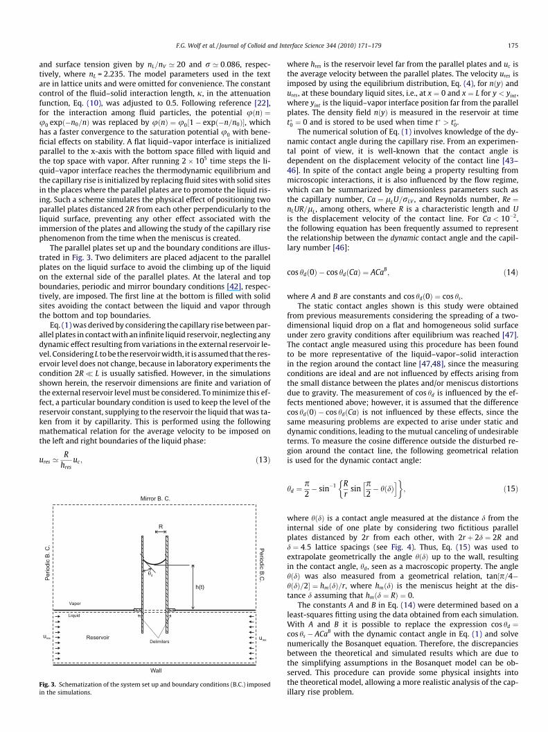
The parallel plates set up and the boundary conditions are illus-trated in Fig. 3. Two delimiters are placed adjacent to the parallelplates on the liquid surface to avoid the climbing up of the liquidon the external side of the parallel plates. At the lateral and topboundaries, periodic and mirror boundary conditions [42], respec-tively, are imposed. The first line at the bottom is filled with solidsites avoiding the contact between the liquid and vapor throughthe bottom and top boundaries.
Eq. (1) was derived by considering the capillary rise between par-allel plates in contact with an infinite liquid reservoir, neglecting anydynamic effect resulting from variations in the external reservoir le-vel. Considering L to be the reservoir width, it is assumed that the res-ervoir level does not change, because in laboratory experiments thecondition 2R� L is usually satisfied. However, in the simulationsshown herein, the reservoir dimensions are finite and variation ofthe external reservoir level must be considered. To minimize this ef-fect, a particular boundary condition is used to keep the level of thereservoir constant, supplying to the reservoir the liquid that was ta-ken from it by capillarity. This is performed using the followingmathematical relation for the average velocity to be imposed onthe left and right boundaries of the liquid phase:
ures ’R
hresuc; ð13Þ
Fig. 3. Schematization of the system set up and boundary conditions (B.C.) imposedin the simulations.
where hres is the reservoir level far from the parallel plates and uc isthe average velocity between the parallel plates. The velocity ures isimposed by using the equilibrium distribution, Eq. (4), for nðyÞ andures, at these boundary liquid sites, i.e., at x ¼ 0 and x ¼ L for y < yint ,where yint is the liquid–vapor interface position far from the parallelplates. The density field nðyÞ is measured in the reservoir at timet�0 ¼ 0 and is stored to be used when time t� > t�0.
The numerical solution of Eq. (1) involves knowledge of the dy-namic contact angle during the capillary rise. From an experimen-tal point of view, it is well-known that the contact angle isdependent on the displacement velocity of the contact line [43–46]. In spite of the contact angle being a property resulting frommicroscopic interactions, it is also influenced by the flow regime,which can be summarized by dimensionless parameters such asthe capillary number, Ca ¼ lLU=rLV , and Reynolds number, Re ¼nLUR=lL, among others, where R is a characteristic length and Uis the displacement velocity of the contact line. For Ca < 10�2,the following equation has been frequently assumed to representthe relationship between the dynamic contact angle and the capil-lary number [46]:
cos hdð0Þ � cos hdðCaÞ ¼ ACaB; ð14Þ
where A and B are constants and cos hdð0Þ ¼ cos hs.The static contact angles shown is this study were obtained
from previous measurements considering the spreading of a two-dimensional liquid drop on a flat and homogeneous solid surfaceunder zero gravity conditions after equilibrium was reached [47].The contact angle measured using this procedure has been foundto be more representative of the liquid–vapor–solid interactionin the region around the contact line [47,48], since the measuringconditions are ideal and are not influenced by effects arising fromthe small distance between the plates and/or meniscus distortionsdue to gravity. The measurement of cos hd is influenced by the ef-fects mentioned above; however, it is assumed that the differencecos hdð0Þ � cos hdðCaÞ is not influenced by these effects, since thesame measuring problems are expected to arise under static anddynamic conditions, leading to the mutual canceling of undesirableterms. To measure the cosine difference outside the disturbed re-gion around the contact line, the following geometrical relationis used for the dynamic contact angle:
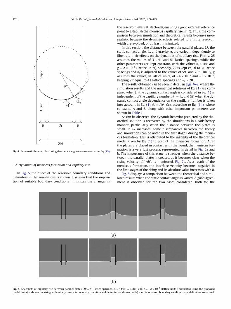
hd ¼p2� sin�1 R
rsin
p2� h dð Þ
h i ; ð15Þ
where hðdÞ is a contact angle measured at the distance d from theinternal side of one plate by considering two fictitious parallelplates distanced by 2r from each other, with 2r þ 2d ¼ 2R andd ¼ 4:5 lattice spacings (see Fig. 4). Thus, Eq. (15) was used toextrapolate geometrically the angle hðdÞ up to the wall, resultingin the contact angle, hd, seen as a macroscopic property. The anglehðdÞ was also measured from a geometrical relation, tan½p=4�hðdÞ=2� ¼ hmðdÞ=r, where hmðdÞ is the meniscus height at the dis-tance d assuming that hmðd ¼ RÞ ¼ 0.
The constants A and B in Eq. (14) were determined based on aleast-squares fitting using the data obtained from each simulation.With A and B it is possible to replace the expression cos hd ¼cos hs � ACaB with the dynamic contact angle in Eq. (1) and solvenumerically the Bosanquet equation. Therefore, the discrepanciesbetween the theoretical and simulated results which are due tothe simplifying assumptions in the Bosanquet model can be ob-served. This procedure can provide some physical insights intothe theoretical model, allowing a more realistic analysis of the cap-illary rise problem.
d
Liquid
Vapor
2R
2r
Fig. 4. Schematic drawing illustrating the contact angle measurement using Eq. (15).
176 F.G. Wolf et al. / Journal of Colloid and Interface Science 344 (2010) 171–179
3.2. Dynamics of meniscus formation and capillary rise
In Fig. 5 the effect of the reservoir boundary conditions anddelimiters in the simulations is shown. It is seen that the imposi-tion of suitable boundary conditions minimizes the changes in
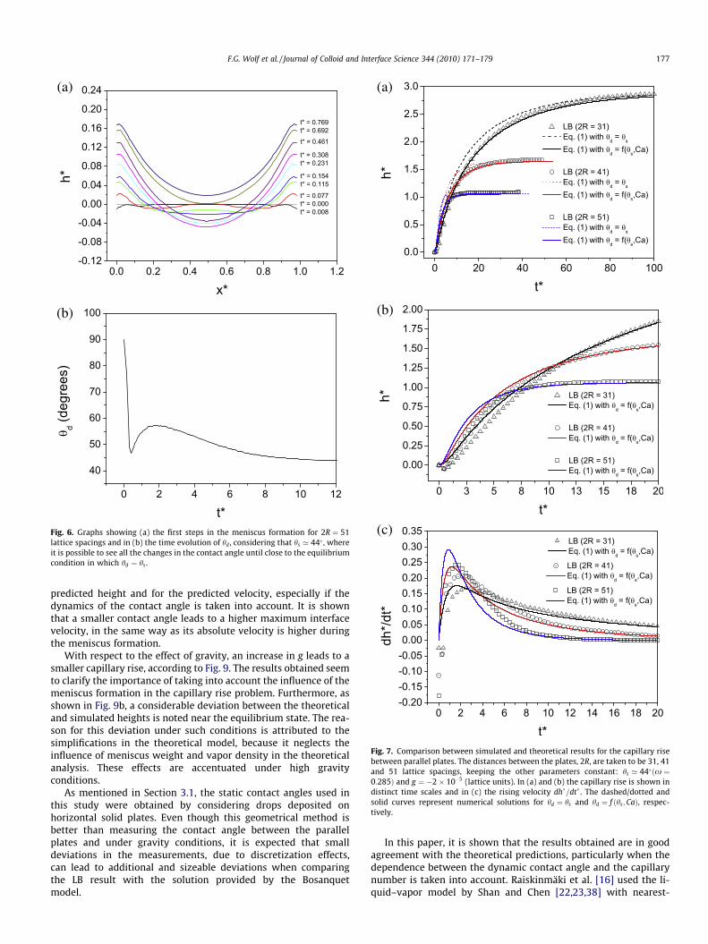
Fig. 5. Snapshots of capillary rise between parallel plates [2R ¼ 41 lattice spacings, hs
model. In (a) is shown the rising without any reservoir boundary condition and delimite
the reservoir level satisfactorily, ensuring a good external referencepoint to establish the meniscus capillary rise, h�ðtÞ. Thus, the com-parison between simulation and theoretical results becomes morerealistic because the dynamic effects related to a finite reservoirwidth are avoided, or at least, minimized.
In this section, the distance between the parallel plates, 2R, thestatic contact angle, hs, and gravity, g, are varied independently toillustrate their effects on the dynamics of capillary rise. Firstly, 2Rassumes the values of 31, 41 and 51 lattice spacings, while theother parameters are kept constant, with the values hs ’ 44 andg ¼ 2� 10�5 (lattice units). Secondly, 2R is kept equal to 31 latticespacings and hs is adjusted to the values of 59� and 20�. Finally, gassumes the values, in lattice units, of �4� 10�5 and �6� 10�5,keeping 2R equal to 41 lattice spacings and hs ’ 20.
The results obtained can be seen in detail in Figs. 6–9, where thesimulation results and the numerical solutions of Eq. (1) are com-pared when (i) the dynamic contact angle is considered in Eq. (1) asindependent of the capillary number, hd ¼ hs, and (ii) when the dy-namic contact angle dependence on the capillary number is takeninto account in Eq. (1), hd ¼ f ðhs;CaÞ, according to Eq. (14), whereconstants A and B, along with other important parameters areshown in Table 1.
As can be observed, the dynamic behavior predicted by the the-oretical solution is recovered by the simulations in a satisfactorymanner, particularly when the distance between the plates issmall. If 2R increases, some discrepancies between the theoryand simulations can be noted in the first stages, during the menis-cus formation. This is attributed to the inability of the theoreticalmodel given by Eq. (1) to predict the meniscus formation. Afterthe plates are placed in contact with the liquid, the meniscus for-mation is a very fast process, represented in detail in Fig. 6a andb. The importance of this stage is stronger when the distance be-tween the parallel plates increases, as it becomes clear when therising velocity, dh�=dt�, is monitored, Fig. 7c. As a result of themeniscus formation, the interface velocity becomes negative inthe first stages of the rising and its absolute value increases with R.
Fig. 8 displays a comparison between the theoretical and simu-lated results when the static contact angle is varied. A good agree-ment is observed for the two cases considered, both for the
’ 44ðx ¼ 0:285Þ and g ¼ �2� 10�5 (lattice units)] simulated using the proposedrs is shown; in (b) specific reservoir boundary conditions and delimiters were used.
(a)
(b)
Fig. 6. Graphs showing (a) the first steps in the meniscus formation for 2R ¼ 51lattice spacings and in (b) the time evolution of hd , considering that hs ’ 44 , whereit is possible to see all the changes in the contact angle until close to the equilibriumcondition in which hd ¼ hs .
(a)
(b)
(c)
Fig. 7. Comparison between simulated and theoretical results for the capillary risebetween parallel plates. The distances between the plates, 2R, are taken to be 31, 41and 51 lattice spacings, keeping the other parameters constant: hs ’ 44ðx ¼0:285Þ and g ¼ �2� 10�5 (lattice units). In (a) and (b) the capillary rise is shown indistinct time scales and in (c) the rising velocity dh�=dt� . The dashed/dotted andsolid curves represent numerical solutions for hd ¼ hs and hd ¼ f ðhs; CaÞ, respec-tively.
F.G. Wolf et al. / Journal of Colloid and Interface Science 344 (2010) 171–179 177
predicted height and for the predicted velocity, especially if thedynamics of the contact angle is taken into account. It is shownthat a smaller contact angle leads to a higher maximum interfacevelocity, in the same way as its absolute velocity is higher duringthe meniscus formation.
With respect to the effect of gravity, an increase in g leads to asmaller capillary rise, according to Fig. 9. The results obtained seemto clarify the importance of taking into account the influence of themeniscus formation in the capillary rise problem. Furthermore, asshown in Fig. 9b, a considerable deviation between the theoreticaland simulated heights is noted near the equilibrium state. The rea-son for this deviation under such conditions is attributed to thesimplifications in the theoretical model, because it neglects theinfluence of meniscus weight and vapor density in the theoreticalanalysis. These effects are accentuated under high gravityconditions.
As mentioned in Section 3.1, the static contact angles used inthis study were obtained by considering drops deposited onhorizontal solid plates. Even though this geometrical method isbetter than measuring the contact angle between the parallelplates and under gravity conditions, it is expected that smalldeviations in the measurements, due to discretization effects,can lead to additional and sizeable deviations when comparingthe LB result with the solution provided by the Bosanquetmodel.
In this paper, it is shown that the results obtained are in goodagreement with the theoretical predictions, particularly when thedependence between the dynamic contact angle and the capillarynumber is taken into account. Raiskinmäki et al. [16] used the li-quid–vapor model by Shan and Chen [22,23,38] with nearest-

(a)
(b)
Fig. 8. Comparison between simulated and theoretical results for the capillary risebetween parallel plates. The contact angles, hs , are taken to be approximately20ðx ¼ 0:305Þ and 59ðx ¼ 0:265Þ, keeping the other parameters constant: 2R ¼ 31lattice spacings and g ¼ �2� 10�5 (lattice units). The dashed/dotted and solid curvesrepresent numerical solutions for hd ¼ hs and hd ¼ f ðhs ;CaÞ, respectively.
(a)
(b)
Fig. 9. Comparison between simulated and theoretical results for the capillary risebetween parallel plates. The values of gravity, g, are taken to be �4� 10�5 and�6� 10�5 (lattice units), keeping the other parameters constant: 2R ¼ 41 latticespacings and hs ’ 20ðx ¼ 0:305Þ. The dashed/dotted and solid curves representnumerical solutions for hd ¼ hs and hd ¼ f ðhs ;CaÞ, respectively.
178 F.G. Wolf et al. / Journal of Colloid and Interface Science 344 (2010) 171–179
neighbor interactions for the fluid–solid interaction to simulate thecapillary rise phenomena in a tube. They compared their LB resultswith a theoretical model similar to the one used in this study. Agood agreement between the theoretical and simulated resultswas obtained even with nearest-neighbor interactions. In our sim-ulations, we considered the capillary rise problem between parallelplates under two-dimensional conditions by including the influ-ence of long-range forces on the fluid–solid interaction. In thesame way, our numerical results exhibit a good agreement be-tween theory and simulation. It indicates that the inclusion oflong-range forces does not affect the well-known behavior pre-dicted by the Lucas-Washburn model, when inertial effects, in-cluded in the Bosanquet model, are negligible. Such result is inconformity with the results reported for capillary rise in nanotubesusing molecular dynamics simulations [15], which evidences thateven in molecular scale the predicted Lucas-Washburn-typebehavior is observed, besides the presence an extra-term relatedto the slip length [15].
3.3. Contact angle versus capillary number
According to the results shown above, the dependence betweenthe dynamic contact angle and the capillary number had signifi-cant relevance in the all cases simulated in this study. From
Fig. 7a, Fig. 8a and b, it was observed that Eq. (14) seems to de-scribe properly the dependence between hd and Ca, through theconstants A and B, summarized in Table 1. These constants appearto be representative of the fluid flow dynamics resulting from thecollective behavior of the intermolecular interactions around thetriphasic contact line.
Exponent B has been connected to the movement of the contactline on solid surfaces with physical and chemical heterogeneities(for a broad review, see, e.g., Schaffer and Wong [46]). This phe-nomenon is related to the way that the occurrence of roughnessand/or chemical contaminants can affect the contact angle dynam-ics and is described by the scaling pinning exponent, b ¼ 1=B. It hasbeen established that roughness increases the dependence of thecontact angle on the capillary number (or contact line velocity)and that it produces stick-slip motion in the low capillary numberregime for systems with nonzero static contact angles [46]. Severaltheoretical results have indicated that b ¼ 1 for smooth and homo-geneous surfaces [49–51] or when the pinning effects are weak[52]. A review of the experimental results given by Schaffer andWong [46] shows a trend for the scaling exponent to be found inthe range of 1 6 b 6 5. The results of Schaffer and Wong [46]showed that b 1 in experiments which were free of pinning ef-fects within the experimental resolution.
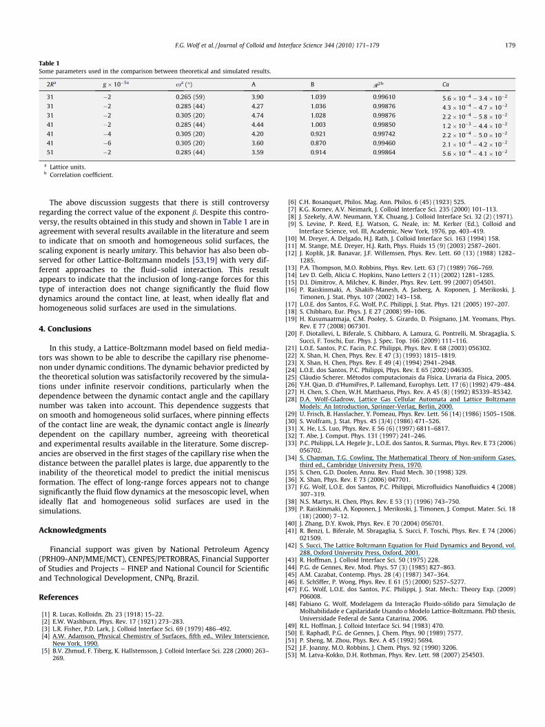
Table 1Some parameters used in the comparison between theoretical and simulated results.
2Ra g � 10�5a xa (�) A B R2b Ca
31 �2 0.265 (59) 3.90 1.039 0.99610 5:6� 10�4 � 3:4� 10�2
31 �2 0.285 (44) 4.27 1.036 0.99876 4:3� 10�4 � 4:7� 10�2
31 �2 0.305 (20) 4.74 1.028 0.99876 2:2� 10�4 � 5:8� 10�2
41 �2 0.285 (44) 4.44 1.003 0.99850 1:2� 10�3 � 4:4� 10�2
41 �4 0.305 (20) 4.20 0.921 0.99742 2:2� 10�4 � 5:0� 10�2
41 �6 0.305 (20) 3.60 0.870 0.99460 2:1� 10�4 � 4:2� 10�2
51 �2 0.285 (44) 3.59 0.914 0.99864 5:6� 10�4 � 4:1� 10�2
a Lattice units.b Correlation coefficient.
F.G. Wolf et al. / Journal of Colloid and Interface Science 344 (2010) 171–179 179
The above discussion suggests that there is still controversyregarding the correct value of the exponent b. Despite this contro-versy, the results obtained in this study and shown in Table 1 are inagreement with several results available in the literature and seemto indicate that on smooth and homogeneous solid surfaces, thescaling exponent is nearly unitary. This behavior has also been ob-served for other Lattice-Boltzmann models [53,19] with very dif-ferent approaches to the fluid–solid interaction. This resultappears to indicate that the inclusion of long-range forces for thistype of interaction does not change significantly the fluid flowdynamics around the contact line, at least, when ideally flat andhomogeneous solid surfaces are used in the simulations.
4. Conclusions
In this study, a Lattice-Boltzmann model based on field media-tors was shown to be able to describe the capillary rise phenome-non under dynamic conditions. The dynamic behavior predicted bythe theoretical solution was satisfactorily recovered by the simula-tions under infinite reservoir conditions, particularly when thedependence between the dynamic contact angle and the capillarynumber was taken into account. This dependence suggests thaton smooth and homogeneous solid surfaces, where pinning effectsof the contact line are weak, the dynamic contact angle is linearlydependent on the capillary number, agreeing with theoreticaland experimental results available in the literature. Some discrep-ancies are observed in the first stages of the capillary rise when thedistance between the parallel plates is large, due apparently to theinability of the theoretical model to predict the initial meniscusformation. The effect of long-range forces appears not to changesignificantly the fluid flow dynamics at the mesoscopic level, whenideally flat and homogeneous solid surfaces are used in thesimulations.
Acknowledgments
Financial support was given by National Petroleum Agency(PRH09-ANP/MME/MCT), CENPES/PETROBRAS, Financial Supporterof Studies and Projects – FINEP and National Council for Scientificand Technological Development, CNPq, Brazil.
References
[1] R. Lucas, Kolloidn. Zh. 23 (1918) 15–22.[2] E.W. Washburn, Phys. Rev. 17 (1921) 273–283.[3] L.R. Fisher, P.D. Lark, J. Colloid Interface Sci. 69 (1979) 486–492.[4] A.W. Adamson, Physical Chemistry of Surfaces, fifth ed., Wiley Interscience,
New York, 1990.[5] B.V. Zhmud, F. Tiberg, K. Hallstensson, J. Colloid Interface Sci. 228 (2000) 263–
269.
[6] C.H. Bosanquet, Philos. Mag. Ann. Philos. 6 (45) (1923) 525.[7] K.G. Kornev, A.V. Neimark, J. Colloid Interface Sci. 235 (2000) 101–113.[8] J. Szekely, A.W. Neumann, Y.K. Chuang, J. Colloid Interface Sci. 32 (2) (1971).[9] S. Levine, P. Reed, E.J. Watson, G. Neale, in: M. Kerker (Ed.), Colloid and
Interface Science, vol. III, Academic, New York, 1976, pp. 403–419.[10] M. Dreyer, A. Delgado, H.J. Rath, J. Colloid Interface Sci. 163 (1994) 158.[11] M. Stange, M.E. Dreyer, H.J. Rath, Phys. Fluids 15 (9) (2003) 2587–2601.[12] J. Koplik, J.R. Banavar, J.F. Willemsen, Phys. Rev. Lett. 60 (13) (1988) 1282–
1285.[13] P.A. Thompson, M.O. Robbins, Phys. Rev. Lett. 63 (7) (1989) 766–769.[14] Lev D. Gelb, Alicia C. Hopkins, Nano Letters 2 (11) (2002) 1281–1285.[15] D.I. Dimitrov, A. Milchev, K. Binder, Phys. Rev. Lett. 99 (2007) 054501.[16] P. Raiskinmaki, A. Shakib-Manesh, A. Jasberg, A. Koponen, J. Merikoski, J.
Timonen, J. Stat. Phys. 107 (2002) 143–158.[17] L.O.E. dos Santos, F.G. Wolf, P.C. Philippi, J. Stat. Phys. 121 (2005) 197–207.[18] S. Chibbaro, Eur. Phys. J. E 27 (2008) 99–106.[19] H. Kusumaatmaja, C.M. Pooley, S. Girardo, D. Pisignano, J.M. Yeomans, Phys.
Rev. E 77 (2008) 067301.[20] F. Diotallevi, L. Biferale, S. Chibbaro, A. Lamura, G. Pontrelli, M. Sbragaglia, S.
Succi, F. Toschi, Eur. Phys. J. Spec. Top. 166 (2009) 111–116.[21] L.O.E. Santos, P.C. Facin, P.C. Philippi, Phys. Rev. E 68 (2003) 056302.[22] X. Shan, H. Chen, Phys. Rev. E 47 (3) (1993) 1815–1819.[23] X. Shan, H. Chen, Phys. Rev. E 49 (4) (1994) 2941–2948.[24] L.O.E. dos Santos, P.C. Philippi, Phys. Rev. E 65 (2002) 046305.[25] Cláudio Scherer. Métodos computacionais da Física. Livraria da Física, 2005.[26] Y.H. Qian, D. d’HumiFres, P. Lallemand, Europhys. Lett. 17 (6) (1992) 479–484.[27] H. Chen, S. Chen, W.H. Matthaeus, Phys. Rev. A 45 (8) (1992) R5339–R5342.[28] D.A. Wolf-Gladrow, Lattice Gas Cellular Automata and Lattice Boltzmann
Models: An Introduction, Springer-Verlag, Berlin, 2000.[29] U. Frisch, B. Hasslacher, Y. Pomeau, Phys. Rev. Lett. 56 (14) (1986) 1505–1508.[30] S. Wolfram, J. Stat. Phys. 45 (3/4) (1986) 471–526.[31] X. He, L.S. Luo, Phys. Rev. E 56 (6) (1997) 6811–6817.[32] T. Abe, J. Comput. Phys. 131 (1997) 241–246.[33] P.C. Philippi, L.A. Hegele Jr., L.O.E. dos Santos, R. Surmas, Phys. Rev. E 73 (2006)
056702.[34] S. Chapman, T.G. Cowling, The Mathematical Theory of Non-uniform Gases,
third ed., Cambridge University Press, 1970.[35] S. Chen, G.D. Doolen, Annu. Rev. Fluid Mech. 30 (1998) 329.[36] X. Shan, Phys. Rev. E 73 (2006) 047701.[37] F.G. Wolf, L.O.E. dos Santos, P.C. Philippi, Microfluidics Nanofluidics 4 (2008)
307–319.[38] N.S. Martys, H. Chen, Phys. Rev. E 53 (1) (1996) 743–750.[39] P. Raiskinmaki, A. Koponen, J. Merikoski, J. Timonen, J. Comput. Mater. Sci. 18
(18) (2000) 7–12.[40] J. Zhang, D.Y. Kwok, Phys. Rev. E 70 (2004) 056701.[41] R. Benzi, L. Biferale, M. Sbragaglia, S. Succi, F. Toschi, Phys. Rev. E 74 (2006)
021509.[42] S. Succi, The Lattice Boltzmann Equation for Fluid Dynamics and Beyond, vol.
288, Oxford University Press, Oxford, 2001.[43] R. Hoffman, J. Colloid Interface Sci. 50 (1975) 228.[44] P.G. de Gennes, Rev. Mod. Phys. 57 (3) (1985) 827–863.[45] A.M. Cazabat, Contemp. Phys. 28 (4) (1987) 347–364.[46] E. SchSffer, P. Wong, Phys. Rev. E 61 (5) (2000) 5257–5277.[47] F.G. Wolf, L.O.E. dos Santos, P.C. Philippi, J. Stat. Mech.: Theory Exp. (2009)
P06008.[48] Fabiano G. Wolf, Modelagem da Interação Fluido-sólido para Simulação de
Molhabilidade e Capilaridade Usando o Modelo Lattice-Boltzmann. PhD thesis,Universidade Federal de Santa Catarina, 2006.
[49] R.L. Hoffman, J. Colloid Interface Sci. 94 (1983) 470.[50] E. Raphadl, P.G. de Gennes, J. Chem. Phys. 90 (1989) 7577.[51] P. Sheng, M. Zhou, Phys. Rev. A 45 (1992) 5694.[52] J.F. Joanny, M.O. Robbins, J. Chem. Phys. 92 (1990) 3206.[53] M. Latva-Kokko, D.H. Rothman, Phys. Rev. Lett. 98 (2007) 254503.