Axisymmetric edge debonding in patched plates
35
In: J. Solrds Srrucfure.~ Vol. 34, No. 18, pp. 225S2289, 1997 0 1997 Elsevier Science Ltd Pergamon PII : SOO2@-7683(96)0015%2 All rights reserved. Printed in Great Britain 0020-7683197 $17.00 + .00 AXISYMMETRIC EDGE DEBONDING IN PATCHED PLATES W. J. BOTTEGA and M. A. LOIA Department of Mechanical and Aerospace Engineering, Rutgers University, Piscataway, NJ 08855-0909, U.S.A. (Received 4 December 1995 ; in revisedform 18 July 1996) Abstract-The problem of edge debonding in patched elastic plates is considered for a variety of axisymmetric loading and support conditions. The problems are approached from a unified point of view, as a moving interior boundaries problem in the calculus of variations, incorporating a Griffith type energy criterion for debonding. This results in a selfconsistent model for the intact and debonded portions of the composite structure as well as for the primitive structures which comprise the system, and in addition yields the conditions which define equilibrium configurations of a propagating contact zone boundary and a propagating bond zone boundary. The latter yields the corresponding energy release rates for debonding. The situation of edge contact is also considered. Analytical solutions to the set of problems of interest are presented. Extensive numerical simulations based on these solutions are presented and yield results in the form of threshold curves which characterize the behavior of the evolving composite structure under load. 0 1997 Elsevier Science Ltd. 1. INTRODUCTION The configuration of a secondary structure bonded to a primary structure corresponds to a variety of contemporary structural systems. These range from bonded sensors and lap- joints (see, for example, Oplinger, 1994) to repair patches adhered to base structures (see, for example, Baker, 1993 ; Chiu et al., 1994; Chue et al., 1994; Park et al., 1992; Paul and Jones, 1992 ; Roderick, 1980 ; Sih and Hong, 1989 ; Tarn and Shek, 1991). A relatively comprehensive survey of the literature may be found in the papers by Bottega (1995) and Bottega and Loia (1996), and thus is not repeated here for brevity. We remark, however, that the problem of twin circular patches (one on each major bounding surface) bonded to a plate subjected to in-plane edge loading was considered by Sih and Hong (1989). In their study, bending effects were excluded as a result of geometrical and loading symmetry about the center plane of the plate. However, the effects of the presence of edge debonds, located in two specific regions of the structure, on the propagation of a thickness crack was assessed. As debonding alters the behavior of the composite structure formed by the adhesion of the two primitive structures, and compromises its effectiveness, the problem of edge debonding is relevant to understanding the performance and integrity of such structures. In recent studies by Bottega (1995), Bottega and Loia (1996), and Loia and Bottega (1995a, b) the issue of edge debonding was examined for a number of mathematically one- dimensional configurations. A variety of loading and support conditions were considered, for both flat and curved structures where bending effects were relevant. In the present study, we consider an analogous configuration which, though mathematically one-dimensional due to assumed azimuthal symmetry of the structure and loading, nevertheless possesses some inherent effects due to the multi-dimensional physical nature and added constraints of the structure. We thus examine edge debonding of a circular plate to which a circular patch is concentrically adhered to one of the plate’s surfaces. Several loading conditions are considered (see Fig. 1). These include : (i) applied radial (in-plane) tension, (ii) transverse 2255
Transcript of Axisymmetric edge debonding in patched plates

In: J. Solrds Srrucfure.~ Vol. 34, No. 18, pp. 225S2289, 1997 0 1997 Elsevier Science Ltd
Pergamon
PII : SOO2@-7683(96)0015%2
All rights reserved. Printed in Great Britain 0020-7683197 $17.00 + .00
AXISYMMETRIC EDGE DEBONDING IN PATCHED PLATES
W. J. BOTTEGA and M. A. LOIA Department of Mechanical and Aerospace Engineering, Rutgers University, Piscataway,
NJ 08855-0909, U.S.A.
(Received 4 December 1995 ; in revisedform 18 July 1996)
Abstract-The problem of edge debonding in patched elastic plates is considered for a variety of axisymmetric loading and support conditions. The problems are approached from a unified point of view, as a moving interior boundaries problem in the calculus of variations, incorporating a Griffith type energy criterion for debonding. This results in a selfconsistent model for the intact and debonded portions of the composite structure as well as for the primitive structures which comprise the system, and in addition yields the conditions which define equilibrium configurations of a propagating contact zone boundary and a propagating bond zone boundary. The latter yields the corresponding energy release rates for debonding. The situation of edge contact is also considered. Analytical solutions to the set of problems of interest are presented. Extensive numerical simulations based on these solutions are presented and yield results in the form of threshold curves which characterize the behavior of the evolving composite structure under load. 0 1997 Elsevier Science Ltd.
1. INTRODUCTION
The configuration of a secondary structure bonded to a primary structure corresponds to a variety of contemporary structural systems. These range from bonded sensors and lap- joints (see, for example, Oplinger, 1994) to repair patches adhered to base structures (see, for example, Baker, 1993 ; Chiu et al., 1994; Chue et al., 1994; Park et al., 1992; Paul and Jones, 1992 ; Roderick, 1980 ; Sih and Hong, 1989 ; Tarn and Shek, 1991). A relatively comprehensive survey of the literature may be found in the papers by Bottega (1995) and Bottega and Loia (1996), and thus is not repeated here for brevity. We remark, however, that the problem of twin circular patches (one on each major bounding surface) bonded to a plate subjected to in-plane edge loading was considered by Sih and Hong (1989). In their study, bending effects were excluded as a result of geometrical and loading symmetry about the center plane of the plate. However, the effects of the presence of edge debonds, located in two specific regions of the structure, on the propagation of a thickness crack was assessed.
As debonding alters the behavior of the composite structure formed by the adhesion of the two primitive structures, and compromises its effectiveness, the problem of edge debonding is relevant to understanding the performance and integrity of such structures. In recent studies by Bottega (1995), Bottega and Loia (1996), and Loia and Bottega (1995a, b) the issue of edge debonding was examined for a number of mathematically one- dimensional configurations. A variety of loading and support conditions were considered, for both flat and curved structures where bending effects were relevant. In the present study, we consider an analogous configuration which, though mathematically one-dimensional due to assumed azimuthal symmetry of the structure and loading, nevertheless possesses some inherent effects due to the multi-dimensional physical nature and added constraints of the structure. We thus examine edge debonding of a circular plate to which a circular patch is concentrically adhered to one of the plate’s surfaces. Several loading conditions are considered (see Fig. 1). These include : (i) applied radial (in-plane) tension, (ii) transverse
2255

2256
Fig. 1. Patched circular plate under various loading conditions: (a) applied radial tension. (b) transverse edgeicenterpoint loading. (c) applied transverse pressure (shown with clamped-fixed
supports).
edge loading, and (iii) applied transverse pressure. The effects of support conditions on the behavior of the evolving structure are examined as well.
The problems are approached, from a unified point of view in the spirit of Bottega. for example, (I 983 and 1995) and Bottega and Loia (1996), as moving intermediate boundaries problems in the calculus of variations, and incorporate von Karman’s plate theory as the mathematical model for the base plate and the patch individually, and a Griffith type energy criterion to govern debonding. This results in a self-consistent mathematical model of the system represented by the set of governing differential equations for the intact portion of the composite structure, for the debonded structure in a region of mutual contact between the patch and the base plate, and for the individual primitive plates. We also include the possibility of (sliding) contact of the edge of the patch with the base plate. In addition to the boundary and matching conditions, we obtain the conditions which define the locations of the variable intermediate boundaries of the “contact zone” and of the bonded region. which correspond to equilibrium configurations of the evolving structure (the transversality conditions). The latter condition yields the (self-consistent) energy release rates for the problems of interest. Closed form solutions to the problems of interest are presented. Finally, results corresponding to detailed numerical simulations based on these solutions are presented and reveal characteristic behavior of the evolving structure.
2. FORMULATION
Consider a circular elastic plate of unit (non dimensional) radius to which a circular elastic patch of normalized radius R, < 1 is centrally located and adhered over the region R, : 0 < r < a (a ,( R,,), as shown in Fig. 2, where Y is the non dimensional radial coordinate. In the preceding, and in what follows, all length scales are normalized with respect to the dimensional radius, R, of the base plate. The region 0, will be referred to as the “bond zone”. In addition, let a region of sliding contact ; Cl2 : a < r < h (h < R,,). the “contact zone”, exist adjacent to the bonded region. Finally let us designate the region a3 : h d r < I

Axisymmetric edge debonding 2251
Fig. 2. Cross section of plate showing characteristic lengths and coordinates.
as the “lift zone” or “zone of separation”. In this region, the patch and base plate do not maintain contact. Rather, the patch is considered to be lifted away from the base plate in this region. We shall also define the sub region R,,: b < Y < R, (f& c 0,) which defines the domain upon which the separated segment of the patch is defined. When referring to region Q3, it will be understood that the patch is defined on the sub region just defined. Further, the common surface between the patch and base plate and its extension (the upper surface of the base plate) shall be used as the “reference surface”. We shall examine three types of loading conditions. These include (i) applied in-plane radial tension, (ii) transverse edge/centerpoint loading (“pseudo three-point loading”) and (iii) applied transverse pres- sure. A variety of support conditions will be considered as well.
The problem shall be approached as a moving intermediate boundaries problem in the calculus of variations, incorporating von Karman’s plate theory for the mathematical models for both the base plate and the patch individually, and a Griffith’s type energy balance to govern debonding. We begin by formulating an energy functional II defined by
I-I = i {u’“+u;‘}-w-A+I-, (1) i= I
where the quantities u”’ and Ua correspond to the strain energies of the base plate and patch in region Ri (i = l-3), respectively, which, for the mathematical models employed, may be expressed in terms of the corresponding bending and membrane energies (Us], UC) and (U(Bb, Uf&). Hence ,
u(i) = uj) + u(i) M, UC0 = u(i) + u(C P BP ‘+fPY (2a,b)
where :
(3b)
(3c)
(3d)

2258 W. J. Bottega and M. A. Loia
In the above expressions, the quantities MI:’ and Mj/,i, respectively, correspond to the (normalized) resultant cross-sectional bending moments in the radial and circumferential directions about the centroid of the base plate in region R, (i = l-3), while the quantities K::’ and KI;J are the associated curvatures. Similarly, the quantities N!:’ and N&i represent the normalized resultant membrane forces in the base plate in region R, (i = l-3) for the directions indicated, while e$ and e# represent the corresponding membrane strains at the centroid of the base plate. Likewise, the quantities M$“, M#‘, IcJ~), K#‘, Nie”, Njf,“, etf” and e&” represent the counterparts of these quantities for the patch. As the class of problems under consideration are axisymmetric, the cross terms M$, ti$], N$‘, e$, M$“, K$‘). N$“, and el#’ all vanish and thus do not appear in the strain energy functionals defined by eqns (3a)-(3d). Further, the functional WA represents the work done by the applied loading, and for the problems under consideration, is given by
W = 27~nT,u,(l), or %” = -27cQ,~,(l), or ti. = 27~ 2 s;
pM;r dr, ,=I fl
where To is the normalized intensity of the applied in-plane edge load, Q. is the normalized intensity of the transverse edge load, and p is the normalized applied (transverse) pressure. The quantity A appearing in eqn (1) represents a constraint functional and is given by
a,(\$$- w,*,)rdr +2x 1 s
z(uT - u,*, )r dr, RI
(5)
where the quantities 0; (i = 1,2 ; g2 < 0) and T are Lagrange multipliers (and correspond to the interfacial stresses in the composite structure). “delamination energy” and is given by?
1- = 2y7@*2 -uo*2).
In eqn (6), the quantity y is the normalized bond energy
a* = l-a,
Finally, the functional I is the
(bond strength),
(6)
(7)
is the “conjugate bond zone radius” which is seen to locate the bond zone boundary with respect to the edge of the base plate, and a8 is some initial value of a*. The symbol 6 corresponds to the variational operator. In the above expressions, the normalized loads T,,, Q,,, and p are related to their dimensional counterparts F, Q, and p, by
where D is the dimensional bending stiffness of the base plate and R is its dimensional radius. In a similar manner, the normalized bond energy :’ is related to its dimensional counterpart 7, by y = pl?/a. The interfacial stresses, ci (i = 1,2) and z, are related to their dimensional counterparts in a manner similar to that for the applied pressure p.
In the development to this point, and in what follows, the functions u<(r) and H’,(r) (i = l-3) correspond to the normalized radial (positive outward) and transverse (positive upward) displacements, respectively, of a material particle located on the centroidal plane of the base plate in region R, (i = l-3), while z+(r) and w,,(r) (i = I-3) represent the corresponding displacements of the centroidal plane of the patch. In addition, the functions u*(r) and us(r), respectively, correspond to the radial displacements of the base plate and patch at the reference surface and are related to their individual centroidal counterparts by
t More generally, ;’ may be considered to be an implicit function of u* with r defined in terms of Its first variation, 6r, where Sr = 2~. 2m* 6a* is seen to represent the virtual work of the generalized force 2~.

Axisymmetric edge debonding 2259
U*(Y) = ui(r) - k w:(r), and US(~) = n,;(r) + $ u&(r), (ga,b)
where h and Izp correspond to the normalized thicknesses of the base plate and the patch, respectively, and primes denote differentiation with respect to r. (Within the context of von Karman’s plate theory, the transverse displacements are considered uniform through the thickness of the individual plates, i.e., IV:’ = wi, wz = wpI throughout.) Similarly, the cor- responding membrane strains at the reference surface, e,*,(‘)(r), e&“‘(r), e,*,(P’)(r), and e&@“(r) are related to their counterparts at the centroidal surfaces of the individual plates by
e*(‘)(r) = e!>(r)- i&>(r), 7, e&(‘)(r) = e&$(r) - z&(r), (90)
and
eXcp’)(r) = e?>(r) - ~IC~~‘~(~), e&(pll(r) = e@(r)- i~~hpo”(r). CW)
Further, for the present model, the constitutive relations and strain/curvature-displacement relations for the individual primitive plates in region R, (i = l-3) are given by
(lOa)
(lob)
(lla)
(12a)
N!r’ = C, (e$‘j + v,e$$‘)} = C, ((.,.+ ;w;?)+vpF} (13a)
N$PH) = C, {egH” + v,eT)) = C, {F +v,(.;,+ kw;,;)}
where the parameters C and D, respectively, correspond to the normalized membrane stiffness and bending stiffness of the base structure, while the parameters C, and 0, similarly correspond to the normalized stiffnesses of the patch. Likewise, the parameters v and v/, represent Poisson’s ratio of the base plate and the patch, respectively. The particular normalization of the stiffnesses of the primitive plates that is selected is based on the dimensional radius and bending stiffness of the base plate. We thus have

2260 W. J. Bottega and M. A. Loia
C = 12/h’, D = 1, C,, = CE,,h,, D, = E,h;,
where :
and E and E,, correspond to the (dimensional) elastic moduli of the base plate and patch, respectively.
We next invoke the Principle of Stationary Potential Energy which, in the present context, may be stated as
6rI=O (14)
where 6 is the variational operator. Upon substitution of eqns (I)-( 13) expressed in terms of the displacements at the
reference surface, performing the appropriate variations-allowing the intermediate bound- aries r = a and r = b to vary, eliminating the Lagrange multipliers, and grouping terms accordingly, we arrive at the governing differential equations for the intact segment of the composite structure, for the debonded segment of the composite structure in the contact zone, and for the primitive plates in the zone of separation. Hence,
{ mo” - (rM,T(‘))‘}‘+(rN~.“)~II,*‘)’ = -rp, (reQ,;i = 1,2) ( 15aai)
N$,“’ - (rNz(‘))’ = 0, ( 15bi)
{A&$--(rM~j’)‘}‘+ (rN~.~)w;) = -rp. (reQ,)
{Mjfi” - (rM)e”)‘) ‘+ (rN$“w~,)’ = 0.
(16a)
(16b)
Nji’ - (rN:z’)’ = 0, (r E Cl,)
N{&‘) - (rN!P”) = 0,
(17a)
(17b)
with
where the corresponding constitutive relations for the composite structure are found as
(19a)
(t9b)
(19c)
(19d)
M*(2) = D&$2’ h h rr + D,,K,T,‘~’ + ; N!,Z’ - $Nj.f’), (19e)
(19f)
(19g)

Axisymmetric edge debonding 2261
N&(2) = Nj$' +N&*'. (19h)
In eqns (19), the functions M,*,(“, M&‘“, N,*,‘” and N&@) correspond to the (normalized) resultant cross-sectional moments per unit azimuthal width of the composite structure, measured with respect to the reference surface, and the corresponding resultant membrane forces. The stiffnesses and other parameters in eqns (19a)-( 19f) are obtained as
(20b)
B” +& c 2 P P' Wd)
c* = c+c,, Poe)
c” = vc+vpcp, (2W D* = A* -p*B*, PM
p* = B*IC*, @Oh) D, = D+D,, (20i)
D, = vD+v,D,, Q?i)
where we have also introduced the parameters D* and p*, pertaining to the intact segment of the composite structure, for later use. The parameter p* may be seen to locate the neutral surface of the intact composite structure with respect to the reference surface, while the parameter D* represents the corresponding radial bending stiffness with respect to the neutral surface. The stiffnesses D, and Do are seen to, respectively, correspond to the radial and azimuthal bending stiffnesses of the debonded segment of the composite structure. The associated boundary and matching conditions are similarly found as
ruT],,o = YWT’I,=O = 0,
[AI&(‘) - (rM,*,(l))‘],,o = 0, (radial tension and transverse pressure)
or
YW:],=~ = 0, (transverse edge loading)
z&z) = u:(a) = u,:(a),
N:(l)lr=a
wx4 = wR4,
MX(‘)l,=,
[M&O” - (rM,*,“‘)‘+ rN,*,")w',],=,
G(b) = m),
N!f’L, = N!?I,=,,
= Nr*,(*)Ir=o, w:‘(a) = w?‘(u),
= M,*,‘*‘La, = [&f&‘*’ - (rM,*,‘2’)’ + rN$*'w;],_
$2 @) = $3 @I >
Ncp2)jrzb = N(P3)Jr=b, I7 rr
(21c’)
(22a,b)
(22c)
(22de)
(22f)
(22g)
(23a,b)
(2kd)

2262 W. J. Bottega and M. A. Loia
G(b) = w(b) = Wp3@),
w;‘(b) = w;(b) = M’;j(h),
(23e.f)
(230)
u?(l) = 0 or Nl:‘],-=, = r,,, (24a,a’)
M!+!‘lr=, = 0 or iv;(l) = 0, (24b.b’)
M’? (1) = 0, (radial tension and transverse pressure) (24~)
or
[M$’ -ML:’ --r(M!.J” - N~;‘Iv;)],= , = - Q,, (transverse edge loading) (24~‘)
Nl;i”‘/,.=,,, = 0, Mj,ip’IIZH,, = 0, (24d,e)
[M$’ - M;;P’ - y(M:;‘J)’ - N;;“J’II’;,,)],,K,, = 0. (24f)
The resulting transversality condition(s) for the bond zone boundary, Y = u, can be expres- sed as
+ [(#;“e!:’ +~N~f’)e~f”) -@,T(‘)e,*,(‘)],=,,
+~~~I~,:~ll~~~~l~=,,+~{[I~~lle~,)I~_=~, = 2~, (h = a) (25b)
where :
indicates the “jump” across the bond zone boundary r = a for any function F*(r). For the jumps in moment and membrane force appearing in eqn (25b) the expressions A4&‘3’ and IQoC3’ are interpreted by eqn (19f) with the first two terms replaced by eqns (10a) and (1 Ob), and by the equality (19h), respectively, with the index 2 replaced by 3 in each case. The quantities %.d{a} and g,{a}, i.e., the left hand sides of eqns (25a) and (25b), are identified as the energy release rates. The conditions (25) suggest the following delamination criterion : if, for some initial value of a = a,,, we have that 9{ao} 2 27, then debonding occurs and the system evolves (a decreases-a* increases) such that the corresponding equality (25a) or (25b) is satisfied. If %{a,,> < 27, debonding does not occur.
For a propagating contact zone boundary Y = h > a, the associated transversality condition reduces to the form
K;;7’11=h = K:;3)/,_h = K$(2)lr=h, (26a,b)
to which we add the qualification

Axisymmetric edge debonding 2263
K;,3)(,zb+ -=C K:f3)Ir=b+,
in order to prohibit penetration of the patch and base plate in the zone of separation and thus restrict the set of equilibrium configurations to consist of those corresponding to physically realizable configurations of the evolving structure. Equations (26a)-(26c) are seen to be a statement to the effect that equilibrium configurations of a propagating contact zone boundary correspond to the point at which the curvatures of the base plate and patch first become equal, when proceeding from the edge of the structure to the center of the span. If such configurations do not occur, then either b = a or b = Rp. For the latter case a “full contact zone” occurs, hence the lifted segment of the patch does not exist and the condition
K*(2ya) > 0 (reR,) ,-r (26’)
is imposed. If b = a, then the condition of “edge contact”, the situation in which only the free edge of the patch maintains sliding contact with the base plate, is possible. (For the purposes of brevity and clarity of presentation, the formulation for this case is not presented here but may be found in Appendix B.) Alternatively, b = a and no contact occurs between the debonded segments of the primitive structures.
At this point the general formulation of the set of problems of interest is established. The corresponding solution is presented in the next section.
3. ANALYTICAL SOLUTION
We next present an analytical solution corresponding to the linearized version of the equations governing the set of problems stated in the previous section.
Upon linearization, the governing differential eqns (15)-(17) simplify to the forms given by
Ya{Wi} = q;, (rEQ; i = l-3)
%{Wp3) = 0, @EQ3,)
(27a-i)
Wb)
z&4} = -P*~,(wl}, G-E%)
Q{ui} =O, (r~Q;i=2,3)
yd{Upi} = 0, (r~Ri; i = 233)
(28a)
(28b-i)
(28c-i)
where :
(29a-c)
(30a)
(30b)
(3Oc)
The coupled system (27a)-(28c) is solved to give the following forms for the transverse displacements in each region :

2264 W. J. Bottega and M. A. Loia
M’f(Y) = +& +A\“; +/lb”, (pressure or tension loading) (I.E Q, ) (3 I a)
w:(r) = G i
A’,“+ g [m(r)- I] 1
, (transverse edge loading) (Y E R, ) (3la’)
4 7 7
Wz(Y) = 64(L:n) +A~~)~[ln(r)-l]+A~~l~ +A(,“In(r)+A&“, (reR,) (31b) P
W3(r) =~[‘.‘+4~1n(r)-l]+~~~[1-r~+(1+r2)1n(r)]-~[1-~’-2q1n(r)],
(pressure or tension loading) (1. E 0,) (3 1 c)
~1~ (v) = - g [r’ - (1 + 2) In(r)] + AF [r’ + 211 In(r)] + A{>‘,
(transverse edge loading) (r E Q,) (3 1~‘)
A:“” wp3(r) = 4 __ [r2 + 2qP In(r)] + I@‘), (YE QXP) (31d)
where
x = q = - 1, (clamped supports) (32a.b)
s( =(3+v)/(l -v), q =(l +v)/(l -v), (p inned supports or transverse edge loading)
(32a’,b’)
ylP = R;(l +v/Ml -rp), (32~)
and the parameters Al” (i = l---3,j = O-3) and Aip3) and Ai”’ are constants. The corresponding forms for the associated in-plane displacements are similarly given by
u?(r) = bTr- (r E Q, ) (pressure or tension loading)
P*QO u?(r) = b+- ~ 20* r In(r), (r ER,) (transverse edge loading)
u,(r) = b&r) +cor, (rg R, ; i = 2,3)
up,(r) = b,&(r), (rEC$; i = 2.3)
where
j(r) = f +/Jr, J,(r) = i + P,r, (rER;:i= 2,3)
Q, = 7’,/( I + v) C, (in-plane radial tension loading)
.sO = 0, (pressure and transverse edge loading)
p = (I - v)/( 1+ v) = 1 /q, (edge free to translate in-plane)
/I = - 1, (edge fixed against in-plane translation)
D,> =(l -v,)/(l +v,)R; = l/l?,>,
and the parameters by, b,,, and 6, are constants.
(33a)
(33a’)
(33b)
(33c)
(34a,b)
(35)
(35’)
(36a)
(36a’)
(36b)

Axisymmetric edge debonding 2265
The sets of constants (b:, bO, &,} and (AI” (i = l-3 ;j = O-3), Ag3), Ap3’} are found from the matching conditions at r = a, and at r = a and r = b, respectively, for the particular loading and support conditions corresponding to each problem of interest.
The interfacial stress in region 51*, the contact stress Q, is found from the equation governing transverse deflections of the segment of the patch in the contact zone (not presented), and from the corresponding equation for the segment of the composite structure in the contact zone, eqn (15a-2). This gives the relation
g2 = -pD,/(D+D,) = constant 6 0 (rEC&). (37)
It is seen from eqn (37) that the contact stress vanishes when the pressure vanishes. From this it may be concluded that a contact zone will not be present for the cases of applied radial tension and transverse edge/center point loading. The issue of a contact zone, therefore, need not be considered for these loading cases. It is also seen, from eqn (37), that the contact stress will be compressive when p > 0, and thus that a contact zone may exist for the case of pressure loading. The presence of a contact zone must therefore be considered for this case.
Lastly, the expressions for the bond zone interfacial stresses, U, and r, are given in Appendix A.
The formulation and solutions presented herein provide the basis for examination of the evolution of composite structures of the class under consideration. Specific studies, in this regard, are presented in what follows. We first present an outline of the analysis to be performed.
4. ANALYSIS
In this section we present an outline of the analysis of the problems of interest, based on the analytical solution presented in Section 3.
We first define the normalized loading parameter Iz and characteristic deflection A, for each of the specific problems of interest as follows :
A= To, A = AR = u3(1), (applied in-plane tension) (3ga,b)
A= Qo, A = A, 5 - w3 (I), (transverse edge/center point loading) (3&d)
1 = p, A = A0 = w, (0), (applied pressure) (3ge,f)
where u,(r), wi(r) (i = l-3,0 < r < 1) are the normalized radial and transverse deflections, respectively, of the segment of the base plate in region i, and I is the radial coordinate, as previously defined.
We shall also define the “global stiffness” for each problem as
K 3 A/A, (39)
for each (A, A) pair defined in eqn (38). Since the analytical solutions upon which the forthcoming analysis is based correspond
to a linearization of the governing equations and conditions presented in Section 2, the response in each case will be found to be proportional to the particular loading parameter corresponding to the specific problem under consideration. Therefore, the energy release rates can be written in terms of the loading parameter explicitly, for each case under consideration. The equations for the growth paths/threshold curves il vs a (or a*) and A vs a (or a*) may then be found directly from the transversality conditions (25) and take the general forms
A* = n/Jr = llJ&-Esj, (404
A* = A/,/% = K- ’ (a, b ; S)/dm, VOb)

2266 W. J. Bottega and M. A. Loia
where g(a, b ; S) is the normalized energy release rate per square of the normalized load, S is the set of stiffnesses of the structure and (A*,A*), with labels A* - {r”, Q*,p*), A* - {A& AT, Ad}, correspond one to one with each (A, A) pair defined earlier. In this way, the evolution of the debonding structure may be characterized using the analytical solution presented in Section 3, for each particular problem of interest. Results for specific con- figurations are presented next.
5. RESULTS AND DISCUSSION
Results are presented for the following loading conditions : (1) applied (in-plane) radial tension, (2) transverse edge/center point loading, and (3) applied transverse pressure. The results presented correspond to the linear analyses outlined in the previous section. For the purposes of comparison, we shall in each case consider a system with the normalized thicknesses of the patch and base plate h, = h = 0.05, and compare results for the modulus ratios E0 = 1, 0.1, and 10. In each case, with the exception of the case of transverse edge loading, the effects of various support conditions on the behavior of the evolving structure are examined. Results corresponding to each type of loading are discussed independently.
5.1. Radial tensile loading We first consider the case where the base plate is loaded around the circumference of
its edge by a radially directed, in-plane, tensile load of intensity T,,. Results are presented for both the situation where the edge of the base plate is free to rotate (hinged), and the case where the edge of the base plate is prohibited from rotating (clamped). In each case the edge is free to translate in the plane of the undeformed plate. We recall from Section 3 that a contact zone does not occur for this type of loading. We first consider the case of hinged supports.
Hinged supports. Results for the case of hinged supports are presented in the form of threshold curves in terms of the renormed tension r* = T,,,,h$ and characteristic (radial edge) deflection AX = uj( l)/fi as functions of the conjugate bond zone boundary a*. In addition, the associated stiffness degradation curves Kvs a*, where K = P/A; are presented as well. In each case, paths are shown for each of the modulus ratios E0 = 0.1, 1, and 10. The paths for patch radii R,, = 1, 0.8, 0.6, 0.4 and 0.2 are shown, respectively, in Figs 3a-e. while a comparison of the paths corresponding to R, = 0.9, 0.6 and 0.3 is displayed in Fig. 3f. Upon examination of these figures it is seen that, for force controlled loading, debonding occurs catastrophically for each modulus ratio considered and for all relative radii of the patch. For deflection controlled loading, debonding is seen to occur in a similar fashion for the relatively compliant patch (E,, = 0.1) and for the intermediate patch (EO = 1) for all patch radii, while the relatively stiff patch (E,, = 10) is seen to debond in a moderately stable fashion for large patches, and to debond catastrophically for patches whose radii are such that R, < 0.8. In addition it may be observed that, for given EO and a*, debonding ensues at higher load levels as R,, diminishes. It is also seen that, as for related studies (Bottega, 1995; Bottega and Loia, 1996; Loia and Bottega, 1995), stiffer patches debond at lower load levels in all cases.
Clamped supports. Threshold curves, and the associated stiffness degradation curves, for the case of clamped supports are displayed in Figs 4a-f for patch radii of R,, = 1, 0.8, 0.6, 0.4, 0.2, and a comparison of R,, = 0.9, 0.6 and 0.3, respectively. On consideration of these figures, it may be seen that the predicted debonding behavior of the system is substantially influenced by the modulus ratio and also by the size of the patch. One general trend that may be observed is that decreasing the patch size tends to have a destabilizing effect on the debonding behavior for both force controlled and deflection controlled loading situations, though (as for the case of hinged supports) the load level at which debonding ensues is progressively higher. Similar trends toward destabilization are also seen for a given patch size, as the size of the bond zone diminishes (a* increases). For the case of force controlled loading, it may be seen that debonding occurs in a stable manner for

(a)
Axisymrnetric edge debonding 2261
Hlngnd Tonslon 500 0.1
. ...,, “..,
400 - “...,, 0.08 . ‘._, “...,,
“....... “‘._,.... .‘._.
300 . . . . . . . . . . . . . . . . - L ml ~...............,.,.,....,,......,,,, ,, 2oo “;#; ;““..‘,,.,..,,.
‘.---_._____
loo- -------_-____________
------------_____________- 0.02 - _______________________“__________-----------.---------~--
OO 0.2 0.4 0.6 0.8 1 a*
0 0 0.2 0.4 0.6 0.8 a*
Rp=l
Wlnged
Rp = 0.8
... Eo= 0.1
cl
- Eo= 1.0 .- Eo= 10.0
1
6000; I 0.2 04 08 0.8 1
a’
TensIon
O.‘1
0.08
t
0.06 - ‘a a
0.04 -
a’
k QOOO- ‘.
8000 *
7000 .
6OOOl I 0 0.2 0.4 0.8 0.8 1
a’ Fig. 3. Threshold curves/delamination paths and stiffness degradation curves for patched plate under applied radial tension for the case of hinged-fee supports: (a) Rp = 1.0, (b) Rp = 0.8, (c) Rp = 0.6, (d) Rp = 0.4, (e) Rp = 0.2, (f) comparison of paths for R, = 0.9 (i), 0.6 (ii). 0.3 (iii).
(Conrimed ouerleaJ)

2268 W. J. Bottega and M. A. Loia
(c)
500 Hinged
200.
loo- *----___.__
------------__.__________=
0 0 0.2 0.4 0.6 0.8 1
a*
Rp = 0.6
(d) Hinged
Ten&on
O'I------
‘..,, . . . . . . . . ..‘.....,... .,
02 0.4 0.6 0.6 a*
12000
11000-
10000-
k 9000-
6000
7000
t
\‘.A., - Ai___ . . . . . . . . . . . . . . . . ..__ -- 1
6000; I 0.2 0.4 0.6 0.6 1
a*
Tennion 0.1
0.08.
0.06. L ‘u -’ . d
‘-.j., _../ 0.04.
0.02. ----.---I___________..
0 0 0.2 0.4 0.6 0.8
a’
12000
llOOO-
10000-
k 9000-
8000-
7000. 1
a*
Rp = 0.4 I 1
_. Eo=O.l L-l - Eo= 1.0 .--- Eo = 10.0
6000' I 0 0.2 0.4 0.6 0.8 1
a’
Fig. 3-Continued.

~is~rnet~~ edge debonding
Hlngad Teneton
2269
a*
Rp = 0.2 r I ‘2000-
“’ Eo = 0.1 I I -Eo=?.O ‘--- Eo = 10.0
a’
Hinged Tension 500
., I
400. ‘,.(
” ..,,,_ ‘,..* ii I.. -I._ “. .__,, .-,.. -... Ill
. . . -.. Ly:::: . . . . . ._ 300 - “-.‘:*:.*t:,,,..
L
200 -
loo-
0t 0 0.2 0.4 0.6 0.0 1
a*
0.0; 1 .____:__._____~;-_-__i 0 0.2 0.4 0.6 0.6 1
6
12000.
IlOOO-
10000 . ‘:,
L sooo.
8ooo-
7000.
6000, 0.2 0.4 0.6 0.6 1 a'
Fig. 3-Continued.

2270 (a)
L
500
W. J. Bottega and M. A. Loia
Clamped Tension 0.1 -
400 - 0.08 -
300 - ,_,(,. ,...... .....” 0.06 -
..’ ,,,./“’ ,,,..,... ““.
200
loo:/Lc
0 0 0.2 0.4 0.6 0.6 1
a* a*
Rp= 1
60001 0 0.2 0.4 0.6 0.6 1
(b) Clamped Tension
a*
I?/J = 0.8
0.1.
0.06 -
0.06 - 2 ..“’
0.04 - ,.,,..,...,...
0.02 - ye ___________________________.______..~______________
O- 0 0.2 0.4 0.6 0.6 1
a*
12000
11000-
10000- \ \ '. L 9000- \
EOOO-
TOO0 - ~~::;~~~~.._.. - _
6000 0 0.2 0.4 0.6 0.6 1
a* Fig. 4. Threshold curves/delamination paths and stiffness degradation curves for patched plate under applied radial tension for the case of clamped-free supports : (a) Rp = 1 .O, (b) R,, = 0.8, (c) R,, = 0.6, (d) R, = 0.4, (e) R,, = 0.2, (f) comparison of paths for R, = 0.9 (i), 0.6 (ii). 0.3 (iii).
(Continued opposite and overleaf.)

k) 500
Axisymmetric edge debonding
Clrmped Tanalon
0.1
2211
0 0 0.2 0.4 0.6 0.8 1
0 0 0.2 0.4 0.6 0.8 1
a’ a’
(d)
Rp = 0.6
60001 I 0 0.2 0.4 0.6 0.8 1
a’
Chnpod Tondon
500 0.1
400 . 0.08 - -._. . . . .
300 - 0.06 - c- ??u
d -‘,) .-__._, .‘, .._.... 200. 0.04 -
100. -.-.____ ----c 0.02 - ---------__-__.
0. 0 0.2 0.4 0.6 0.8 1
0 0 0.2 0.4 0.6 0.8
a* a’
Rp = 0.4 12000-
11000~
10000 -
k 9000.
8000 -
7cmO~ ‘--..._ . . c
8000; 0.2 0.4 0.6 0.8 1
a* Fig. 4-Continued.

2212 W. J. Bottega and M. A. Loia
(e)
500. Clamped
Rp = 0.2
Tension
o’I-----l 0.06.
0.06. ‘4 -_ . . u -.._..
0.04 .
0 0 0.2 0.4 0.6 0.6 1
a’
-.____
60000 0.2 0.4 0.6 0.6 1 a*
(f) 500
Clamped Tenrlon
0.1
400 . III 0.08 . ii -.
* y ‘- I_. 300 - i
‘.’ ._ ,,,.,........ ...‘.“’ .._...,,, .*.:;i. . 0.06 - iii
L (,,,,...... “’ +u ii - . . a . . .._.._ ,,,,(,,,,,,.,,.. ::::::::::: . . . . ..I ts..
0.04. ,..I . . . . .......
0.02- &EEzz
0 0 0.2 0.4 0.6 0.6 1
0 0 0.2 0.4 0.6 0.8
a* a’
Eo= 0.1 L- -Eo= 1.0 .--- Eo = 10.0
12000 ; I : i
llOOO- ’ :
Fig. L-Continued.
60001 I 0 0.2 0.4 0.6 0.6 1
a*

Axisymmetric edge debonding 2213
relatively large patches for both the compliant and intermediate patch stiffnesses (EO = 0.1 and &, = 1) for all bond zone sizes. However, while the stiff patch (E,, = 10) is seen to first debond in a stable manner, debonding is seen to become catastrophic once the bond zone shrinks to a critical size (a* N 0.25). Debonding behavior under deflection controlled loading, for all three modulus ratios, is seen to be qualitatively similar to that for the compliant and intermediate patches under force controlled loading. It is also interesting to note that the destabilizing influence on debonding behavior associated with decreasing the patch radius is least pronounced for the intermediately stiff patch (E,, = 1). Finally, it may be observed that debonding is catastrophic for all cases once the patch radius is below half the radius of the base plate.
5.2. Transverse edgelcenterpoint loading The threshold curves and stiffness degradation curves for the case where the base plate
is subjected to a distributed transverse load of intensity Q0 applied around the circumference of the edge of the base plate and supported by a knife edge at its center (or equivalently loaded by an inverted point load of magnitude npQ,, at its center and supported by a continuous knife edge around its boundary) are displayed in Fig. 5. The paths are expressed in terms of the renormed load intensity Q* = QJ,/& and characteristic (transverse edge) deflection A: = -w,(l)/&, with the corresponding global stiffness defined as K = Q*/A:.
Upon consideration of these figures, it may be seen that debonding occurs in a catastrophic manner for all patch sizes and bond zone sizes for the case of force controlled loading. Further, debonding is seen to occur catastrophically for all patch sizes and bond zone sizes for the relatively compliant patch (EO = 0.1) for deflection controlled loading as well. For the case of deflection controlled loading for the intermediate and stiff patches (EO = 1 and 10, respectively), however, debonding is seen to occur in a catastrophic manner,
Tronrvuao Edge Loading
I : i 0.0 .
. . ii ‘. ‘. ._ . .
0.6 - '. . . '. ._ ??r ._ '_ a . . . .
_..;.. . . . -.. . . . .._ _. “1 ', :: . . ._
‘.':,,>_ " +,
%. - '\ %___.----7
0 0 0.2 0.4 0.6 0.6 1
a* a’
7oc
20-
IO. . . . . . . . . . . . . .
OO 0.2 0.4 0.6 0.6 1 a*
Fig. 5. Threshold curves/delamination paths and stiffness degradation curves for patched plate under transverse edge loading for Rp = 0.9 (i), 0.6 (ii), 0.3 (iii).

2274 W. J. Bottega and M. A. Loia
in an unstable followed by a stable manner followed by a catastrophic manner, or in a stable followed by a catastrophic manner, depending upon the initial size of the bond zone and on the relative size of the patch. In addition, the catastrophic growth for these latter two stiffnesses is seen to occur for relatively small bond zone sizes first (i.e., for smaller a*) for the intermediate patch (E, = 1) and then for the relatively stiff patch (I& = lo), during deflection controlled loading. The observed tendency toward unstable debonding as the patch size and bonded region diminish, during deflection controlled loading, differs sub- stantially from the behavior seen for the less constrained analogous case of three-point loading of a rectangular plate with through the width debonding (Bottega, 1995) and the corresponding case for a cylindrical panel (Bottega and Loia, 1996).
5.3. Applied transverse pressure The behavior of the patched circular plate subjected to transverse pressure applied to
the underside of the base plate, as depicted in Fig. 2, will be examined for both the case of hinged supports and the case of clamped supports. For each type of support pertaining to rotation we will also consider the effects of fixing or freeing the supports with regard to in-plane radial translation. We thus consider “hinged-free” and “hinged-fixed” support conditions, and “clamped-free” and “clamped-fixed” support conditions. The cor- responding threshold curves are expressed in terms of the renormed pressure p *=p& and characteristic (centerpoint) deflection A$ = w, (0)/A as functions of the conjugate bond zone radius a*, while the associated stiffness degradation curves are similarly expressed in terms of the corresponding global stiffness K = p*/A$. The case of hinged support conditions is considered first.
Hinged supports. Threshold and stiffness degradation curves for the case of hinged- free support conditions are displayed in Fig. 6, while those for the case of hinged-fixed
Hinged-Free Pressure
25
01 I I 0 0.2 0.4 0.6 0.8 1
01 0 0.2 0.4 0.6 0.8 1
a* a*
350 --.\ ‘.
300. 1 \ : 250 - : : : : * 200. : : : 150- :
:
a* Fig. 6. Threshold curves/delamination paths and stiffness degradation curves for patched plate under transverse pressure loading for the case of hinged-free support conditions for $ = 1.0 (i), 0.6
(i), 0.2 (iii).

Axisymmetric edge debonding Htngod-Fixed Prrsuro
2215
OOM a’
‘.. Eo = 0.1 El - Eo= 1.0 .--’ Eo = 10.0
OS- : -__I . ._lll
0.4 - ., ii ._ ._ *.. _ ._ -. ‘i_
.’ . .._ . ‘-. . . . ..(..,.,.,.. :;:._” :;::v**
. . . . . . . . . . ,,,...... 0.3 .
co a 0.2 -
0’ I 0 0.2 0.4 0.6 0.0 1
a*
a* Fig. 7. Threshold curves/delamination paths and stiffness degradation curves for patched plate under transverse pressure loading for the case of hinged-fixed support conditions for Rp = 1 .O (i),
0.6 (ii), 0.2 (iii).
support conditions are presented in Fig. 7. We note that, as for previous studies pertaining to analogous configurations (Bottega, 1995; Bottega and Loia, 1996) no contact of the debonded segments is found to occur for the case of hinged supports, free or fixed.
Upon consideration of the curves corresponding to the case of hinged-free supports, it may be seen that, for the case of force controlled loading, catastrophic debonding ensues once the threshold level of the pressure is achieved, for all relative patch sizes. It is seen, however, that for the case of deflection controlled loading, catastrophic debonding occurs only for the situation where the patch is the same size as the base plate and is bonded over most of its area for the stiff and intermediate patches (E,, = 10 and E0 = 1). Otherwise, debonding is seen to occur in an unstable followed by a stable manner, or in a stable manner, depending upon the relative size of the patch and the corresponding initial size of the bonded area, for these patch stiffnesses, and is generally stable for moderate and small patch areas. For the case of the compliant patch (E. = 0.1) under deflection controlled loading, however, catastrophic debonding is seen to occur for all patch sizes, when the patch is initially bonded over most of its area. Otherwise, debonding is seen to be unstable followed by stable, or stable, for the compliant patch as well. The exception being that catastrophic debonding is observed for very small patches regardless of the initial size of the corresponding bond zone for the relatively compliant patch.
The curves corresponding to the situation where the supports are fixed against in- plane translation, depicted in Fig. 7, show the same general trends and do not differ appreciably from those corresponding to the case of hinged-free supports, except for the case where the patch is of the same size as the base plate and is bonded over most of its area. For this situation, fixing the supports from translating tends to have a stabilizing effect with regard to debonding. It may be seen that the relatively stiff patch never exhibits catastrophic debonding for this case, and exhibits limited unstable debonding only for

2276 W. J. Bottega and M. A. Loia
bonded regions which cover most of the area of the base plate, subsequent debonding being stable in nature.
We next consider the effects of fixing the edges of the base plate with respect to rotation.
Clamped supports. In the remainder of this study we consider the evolution of the patched circular plate when it is subjected to transverse pressure loading, for the situation where the edges of the base plate are prohibited from rotating (i.e., are clamped). For this type of support condition, whether the edges are free to translate in-plane (clamped-free) or restricted from translating in-plane (clamped-fixed), it is found that a contact zone adjacent to the bond zone boundary does exist for patches of relatively large radius that are bonded over most of their area. As for related studies concerning analogous configurations (Bottega, 1995; Bottega and Loia, 1996), it is found that when such a contact zone is present, the entire debonded portion of the patch maintains contact with the base plate. We refer to this situation as “full contact” of the debonded segment of the patch and similarly designate the corresponding region as a “full contact zone”. In addition to the possible presence of a contact zone, we also consider the possibility of “edge contact” where the free edge of the debonded region of the patch maintains (sliding) contact with the base plate while the remainder of the debonded region of the patch is lifted away from the base plate except, of course, at the bond zone boundary. As for the presence of a contact zone, the condition of edge contact is found to occur only for relatively large patch sizes. Finally, the existence of a contact zone emanating from the free edge of the patch and terminating before reaching the bond zone boundary (“non-adjacent” contact zone), is also examined. This type of contact, however, is not found to occur for physically realizable configurations of the evolving structure. When none of the contact conditions discussed admit physically realizable solutions, it is evident that propagation of the debonded region occurs with the entire debonded segment of the patch lifted/separated away from the base plate.
Thus, equilibrium configurations are sought for the cases where : (i) no contact between the debonded segments takes place, (ii) a contact zone (adjacent to the bond zone) is present, (iii) sliding contact of the free edge (edge contact) of the debonded segment of the patch with the base plate takes place and (iv) a “non-adjacent” contact zone is present. The analysis concerning edge contact is based on a slight modification of the formulation presented in Section 2 and is given in Appendix B. We note that the analysis concerning the presence of a “non-adjacent contact zone” basically follows that presented for the contact zone adjacent to the bond zone boundary, but with regions 2 and 3p interchanged and the associated matching conditions modified accordingly. In situations where more than one physically admissible equilibrium configuration (e.g., configurations where no penetration of the debonded segments of the patch and base plate is present, etc.) may be obtained, the preferred configuration is identified as the one corresponding to the lowest total energy of the system for that specific size of the bonded region for a given load. The specific calculation, in this regard, is based on the total work per unit pressure, w*, for the particular displacement field predicted for each configuration based on the analytical solutions presented in Section 3. Thus, from eqn (4~) we have
w,r dr, (41)
where wi(r) ; i = l-3 are given by eqns (31a)-(31~). Results corresponding to clamped-fixed support conditions are presented in Figs 8-
12, while results corresponding to clamped-free support conditions are displayed in Figs 13-16. We first examine the case where the edge of the base plate is prohibited from translating.
As discussed earlier, contact of the debonded segments of the base plate and patch is found to occur for relatively large patch sizes only. That is, patches with bounding radii below certain values do not admit physically realizable contact configurations based on the

(a)
(b)
500
450
400
350
300
h 250
200
150 ,
Axisymmetric edge debonding
Clamped-fixed pressure (Rp = 1 .O, Eo = 0.1)
2211
500
450
400
350
300
??Q 250
200
150
- FC
- EC
__-___- _-
- NC
0 0.1 0.2 0.3 0.4 0.5 0.6 0.7 0.0 0.9 1
a*
Clamped-fixed pressure (Rp = 0.9, Eo = 0.1)
T
- FC
- EC
-______--
- NC
0 0.1
(cl
500
450
400
350
300
??a 250
200
150
100
50
0
0.2 0.3 0.4 0.5 0.6 0.7 0.8 0.9 1
a*
Clamped-fixed pressure (Rp = 0.8, E0 = 0.1)
- FC
- EC
_ _ _ _ _ _ _ _ _
- NC
_
;\-----_ : I ___-,
0 0.1 0.2 0.3 0.4 0.5 0.6 0.7 0.6 0.9 1
a* Fig. 8. Threshold curves for patched plate under applied pressure for the case of clamped--fixed supports with I?,, = 0.1 : (a) Rp = 1 .O, (b) Rp = 0.9, (c) RP = 0.8, (d) Rp = 0.7. (FC-“full contact”,
EC-“edge contact”, NC-“no contact”.) (Continued ooerleuf.)

2278
(d)
W. J. Bottega and M. A. Loia
Clamped-fixed pressure (f?p = 0.7, fo = 0.1)
500
450
! 400
350
300 /
h 250
200
I
I
150
100 \
- FC
II NC
50
t L+-_____ -___ _____ ___- -----.
0 _-+_~_~_ I I --i
0 0.1 0.2 0.3 0.4 0.5 0.6 0.7 0.8 0.9 1
a*
Fig. 8-Continued
present analysis. In this regard threshold curves for the case of the clamped-fixed supports are displayed in Figs Sa-8d for patch radii R,, = 1.0, 0.9, 0.8 and 0.7, for the case of a relatively compliant patch (& = 0.1). Similar results are displayed in Figs 9a-9d for the intermediate stiff patch (& = 1 .O), and in Figs lOa-10d for the relatively stiff patch (EO = 10.0). In each case it is found that, where multiple configurations are possible (full contact, edge contact and no contact), the configuration corresponding to full contact requires the least total energy of the system, followed by the configuration associated with edge contact and lastly by no contact. We thus identify this order as the order preference of the system. The corresponding work per unit pressure w** = %V*/2n is displayed as a function of the conjugate bond zone radius a* in Fig. 11, for the case where R, = 0.9 and E, = 0.1. It may be noted that the limiting value of the edge contact curve intersects the energy curve associated with no contact at that point. The work (total energy) curves corresponding to the other cases considered show similar trends but are omitted for brevity. With this in mind, the threshold curves for the case of the compliant patch may be interpreted and the corresponding debonding scenario revealed.
Upon examination of Figs 8a-8d it may be seen that the threshold curves corresponding to “full contact” (FC) possess an asymptote separating regions of stable debonding to the left of the asymptote and unstable debonding to its right. The size of the stable region is seen to diminish with the patch radius, and to disappear for the limiting patch radius permitting contact of the debonded segments (R, = 0.7). It is thus seen that, for R, = 1 .O, 0.9, and 0.8, if the bonded region covers most of the patch, then when debonding ensues it occurs in a stable manner and tends to arrest. If the initial bonded region is slightly smaller, such that a,* lies to the right of the asymptote but to the left of the “edge contact” (EC) cutoff, then when debonding occurs it occurs in an unstable fashion until the limiting value of a* corresponding to full contact is achieved. At this point the debonded segment of the patch lifts off from the base plate but maintains contact at its edge, forming a “bridge”, while debonding unstably until the limiting value of a* allowing edge contact (EC) is achieved. At this point the edge of the patch lifts away from the base plate and the structure debonds catastrophically with no contact (NC) between the debonding segments of the patch and base plate taking place. If the initial bonded area is such that ad lies to the right of the FC cutoff but to the left of the EC cutoff, debonding begins with the edge of the patch in contact with the base plate and proceeds, as for the previous case, with the patch subsequently lifting away from the base plate and catastrophic debonding ensuing with no contact of the debonded segments. The general tendencies just described are seen to occur for all patch sizes admitting contact, with the small range of values of a* where edge contact occurs following lift off seen to diminish with patch radius and to vanish for the limiting case

(a)
(b) Clamped-fixed pressure (Rp = 0.95, ECJ = 1 .O)
(c)
500 -
450 --
400 --
350 --
300 --
‘Q 250 --
200 --
- FC
- EC
_ _ _ _ _ _ _ _ _
150
100
50 _*_-----_ ,L._____ ____
0 JJ
- NC
Axisymmetric edge debonding
Clamped-fixed pressure (Rp = 1 .O, Eo = 1 .O)
2279
500
450
400
350
300
b 250
200
150
100
50
0
0 0.1 0.2 0.3 0.4 0.5 0.6 0.7 0.8 0.9 1
a’
- FC
- EC
_ _ _ _ _ _ _ _ _
- NC
0 0.1 0.2 0.3 0.4 0.5 0.6 0.7 0.8 0.9 1
a*
Clamped-fixed pressure (Rp = 0.9, Eo = 1 .O)
500 -
450 --
400 -- - FC
350 --
I\
- EC 300 -- _ _ _ _ _ _ _ _ -
b250--
200 -- - NC c ,’ :
150 -- : .,
100 -- ‘i
50 -- 07 : \----- I
0 0.1 0.2 0.3 0.4 0.5 0.6 0.7 0.8 0.9 1
a* Fig. 9. Threshold curves for patched plate under applied pressure for the case of clamped-jixed supports with E,, = 1.0: (a) Rp = 1.0, (b) Rp = 0.95, (c) R, = 0.90, (d) Rp = 0.85. (FC-“full
contact”, EC-“edge contact”, NC-“no contact”.) (Continued overleqf.)

2280
k-N
500 -
450 --
400
350 --
300 --
W. J. Bottega and M. A. Loia
Clamped-fixed pressure (Rp = 0.85, Eo = 10.0)
- FC
- NC
‘Q 250
200
150
100
50 ----_ 0
I L:;:;;, -----____ __t_-.. -------I
0 0.1 0.2 0.3 0.4 0.5 0.6 0.7 0.8 0.9 1
a’
Fig. 9-Conrinued.
(R, = 0.7). The threshold curves corresponding to the stiffnesses & = 1.0 and &, = 10.0 displayed in Figs 9 and 10 indicate similar behavior except that the conjugate bond zone radius corresponding to the asymptote occurring for the full contact paths, and the range of patch radii for which contact may occur, are seen to diminish with increasing stiffness of the patch. It is interesting to note that while edge contact does not occur for the case of the relatively stiff patch (E,, = 10.0) full contact does. The tendency of the presence of contact to diminish with increasing relative stiffness of the patch was observed for the patched plates examined by Bottega (1995) and for the similarly configured curved panels examined by Bottega and Loia (1996). However, in both of those studies contact was not observed at all for the relatively stiff patch. As mentioned earlier, patches whose radii are small enough are found not to allow any contact of the debonded segments of the structure at all. In this regard the threshold curves, and associated stiffness degradation curves, corresponding to the case of no contact are displayed in Fig. 12 for patch radii of R, = 0.7, 0.5, and 0.3. Upon consideration of these curves it may be seen that debonding occurs in a catastrophic manner for force controlled loading. Debonding for displacement controlled loading, however, is seen to occur in a stable manner, in an unstable followed by a stable manner, or in a catastrophic manner depending on the initial size of the bonded region and on the relative stiffness of the patch. It may be seen that for displacement controlled loading stiffening the patch tends to stabilize the debonding process, though the critical level is still lowered as the stiffness of the patch is increased.
Finally, we examine the effect of freeing the supports with regard to in-plane trans- lation. Paralleling the description for the case of clamped-fixed supports just presented, the paths corresponding to clamped-free supports, for patch sizes where contact occurs, are displayed in Figs 13-16. The general characteristics are seen not to differ markedly from those for the case of clamped-fixed supports, except that the critical points, i.e., the asymp- totes for the FC paths, the cutoff points for the FC and EC paths etc., are seen to shift away from the edge (i.e., the corresponding value of a* shifts slightly to the right) and the corresponding threshold pressure for the cutoff point is elevated slightly. The debonding scenarios for the case of clamped-free supports are thus seen to be qualitatively similar to those for the case of clamped-fixed supports just discussed; however, releasing the radial constraint at the support has a slight destabilizing effect.
To conclude, we remark that, by virtue of eqn A2 (Appendix A), the “large scale” interfacial normal stress is seen to be compressive for the case of pressure loading (and to vanish for the other loading types considered herein) and more importantly is independent of a*. If this is considered to be representative of some average of the “small scale” stress field, or the loading at a distance from the debonded edge for the small scale, then it may be inferred that mode-1 debonding, in the spirit.of interfaciai fracture, does not occur. In a

(a)
(b)
Axisymmetric edge debonding
Clamped-fixed pressure (Rp = 1 .O, Eo = 10.0)
2281
500 -
450 --
400 --
350 -- - FC
--------- EC
- NC
0 0.1 0.2 0.3 0.4 0.5 0.6 0.7 0.8 0.9 1
a*
500 T
450
400 --
350 --
300 --
'a 250
200
ISO - _;$y
-
100
Clamped-fixed pressure (Rp = 0.99, EO = 10.0)
- FC
--------- EC
- NC
5o ------:- _.____ 0
__-. i
0 0.1 0.2 0.3 0.4 0.5 0.6 0.7 0.8 0.9 1
a*
Clamped-fixed pressure (Rp = 0.96, Eo = 10.0)
- FC
--------- EC
-------’ NC
0 0.1 0.2 0.3 0.4 0.5 0.6 0.7 0.0 0.9 1
a* Fig. 10. Threshold curves for patched plate under applied pressure for the case of clamped-fixed supports with E,, = 10.0: (a) RP = 1.0, (b) RP = 0.99, (c) RP = 0.96. (FC-“full contact”, EC-
“edge contact”, NC-“no contact”.)

2282 W. J. Bottega and M. A. Loia
Clamped-fixed pressure (Rp = 0.9, Eo = 0.1)
0.00161
0.00179 f
3 0.00177
0.00175
0.00173
0.00171
0.00169
0 0.1 0.2 0.3 0.4 0.5 0.6
- EC
- FC
.___ _------_-. NC
0.8 0.9
Fig. 11. Total normed work per unit load vs conjugate bond zone radius for the case of clamped- j&d supports, with I$ = 0.1 and R, = 0.9. (FC-“full contact”, EC-“edge contact”. NC----“no
contact”.)
Clamped-Fixed
01 0 0.2 0.4 0.6 0.6
a*
“’ fo= 0.1 L- - Eo= 1.0 ‘--. Eo = I 0.0
NC2
Pressure 1
0.8 I-
0.6 2
0.4
0.2
a
, -
1.
: ., ii : ., ‘. ., I ., r-__/=- ‘_ ._ ._ . . ‘_ _, ., ..::,., ._ iii
,::‘::::,,,;::;::. ,..... .,
___--- .- ._.-________________.-------
'0 0.2 0.4 0.6 0.8 a*
1000,
\ ‘. 800 - \ ‘. : : :
600 - : \ :
4
400 .
2oo- G!?S+_
0 0 0.2 0.4 0.6 0.8
a* Fig. 12. Threshold and stiffness degradation curves for the case of clamped-$xed supports (and no
confact) for R, = 0.7 (i). 0.5 (ii), 0.3 (iii).

Axisymmetric edge debonding 2283
(a) Clamped-free pressure (Rp = 1 .o, Eo = 0.1)
500
450
400
350
300
‘Q 250
200
150
100
50
0
_J\ - FC
- EC
_ _ _ _ _ _ _ _ -
-------- NC _- ___-__‘< -------_ __._____- _ ___--.
I
0 0.1 0.2 0.3 0.4 0.5 0.6 0.7 0.8 0.9 1
a’
(b) Clamped-free pressure (Rp = 0.9, Eo = 0.1)
500
450
400
350
300
b 250
200
150
100
so
0
k)
500
450
400
350
300
h 250
200
150
100
50
0
- FC
- EC
_--- - ____
‘---__-- NC
0
__- _________.
0.1 0.2 0.3 0.4 0.5
a”
0.6 0.7 0.8 0.9
Clamped-free pressure (Rp = 0.8, Eo = 0.1)
- FC
- EC
_ _ _ _ _ _ _ _ _
__- ________. Nc
I__-- __---- _______ _. + I
1
0 0.1 0.2 0.3 0.4 0.5 0.6 0.7 0.8 0.9 1
a* Fig. 13. Threshold curves for patched plate under applied pressure for the case of clamped-free supports with & = 0.1: (a) R, = 1.0, (b) R, = 0.9, (c) Rp = 0.8, (d) R, = 0.7. (FC-“full contact”,
EC-“edge contact”, NC-“no contact”.) (Continued overleaf.)
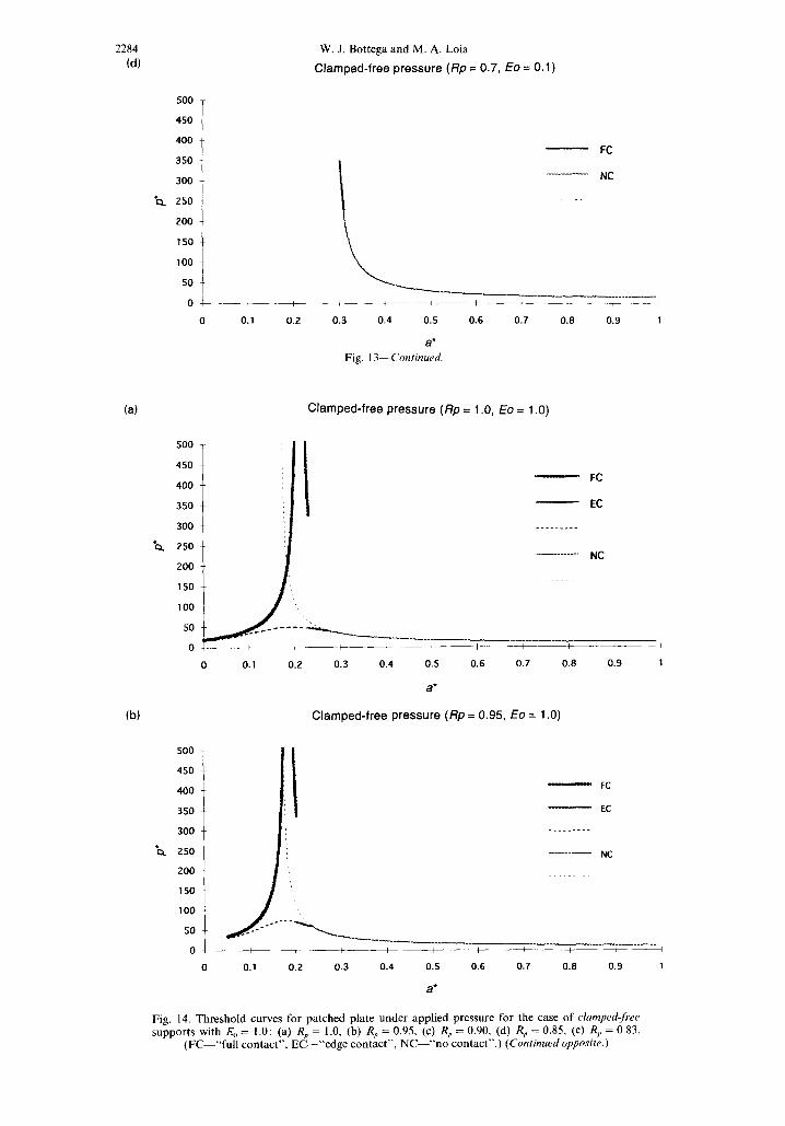
2284 (d)
W. J. Bottega and M. A. Loia
Clamped-free pressure (Rp = 0.7, ECJ = 0.1)
500 -
450 --
400
350 -~
300
‘Q 250
200 -.
150 --
100
50 --
OT
0
(a)
500 -
450 --
400 --
350 --
300 ~-
‘Q 250 --
200 --
150
100 --
- FC
- NC
,\, -- I---------____ _____________-.
+----i-----
*, ,
0.1 0.2 0.3 0.4 0.5 0.6 0.7 0.8 0.9 1
a* Fig. 13-Continued
Clamped-free pressure (Rp = 1 .O, Eo = 1 .O)
- FC
- EC
_---___--
.________ _ __-. NC
50 -----------P_____
0 ----+~_--_t- mm--t------_t- -_+------t_---_t-----A
0 0.1 0.2 0.3 0.4 0.5 0.6 0.7 0.8 0.9 1
a’
(b) Clamped-free pressure (Rp = 0.95, Eo = 1 .O)
- FC
p EC
_____----
0 0.1 0.2 0.3 0.4 0.5 0.6 0.7 0.8 0.9 1
a*
Fig. 14. Threshold curves for patched plate under applied pressure for the case of clamped-free supports with & = 1.0: (a) R,, = 1.0, (b) R,, = 0.95, (c) R,, = 0.90, (d) R,, = 0.85, (c) R,, = 0.83.
(FC-“full contact”, EC-‘&edge contact”, NC-“no contact”.) (Continued opposite.)

(c)
500
450
350
300
??Q
_I
250
200
150
100
50
0
(d) Clamped-free pressure (Rp = 0.85, Eo = 10.0)
500
450
400
350
300
'a 250
200
150
100
50
0
i
t -
1s 1: Ii :: : :
- FC : ’
! --------- EC
! ; : - NC
I
\---: I : I I I / -------______
(e) Clamped-free pressure (Rp = 0.83, Eo = 1 .O)
Axisymmetric edge debonding
Clamped-free pressure (Rp = 0.9, EO = 1 .O)
0 0.1
500 -
450 --
400 --
350 --
300 ~-
??Q 250 --
200 --
150 -'
100 -.
50 -.
0 CF 0 0.1
L; I : ; I I ( --- -__
0.2 0.3 0.4 0.5 0.6 0.7 0.8 0.9 1
a* Fig. 14-Continued.
- FC
- EC
_____ - ___-__ NC
2285
1
0.2 0.3 0.4 0.5 0.6 0.7 0.8 0.9 1
a*
0.2 0.3 0.4 0.5 0.6 0.7 0.8 0.9 1
a”
- FC
- NC

2286
(a)
??Q
500
450
400
350
300
250
200
150
100
50
Cc)
W. J. Bottega and M. A. Loia
Clamped-free pressure (Rp = 1 .O, ECJ = 10.0)
(b) Clamped-free pressure (Rp = 0.97, EO = 10.0)
0.1
450 -~
400 --
350 --
300 --
'Q 250 --
200 --
500 T
150
i /I
100
I
- FC
----_--_- EC
_I_ NC
~---____ -----___ __________ / +----~ 0.2 0.3 0.4 0.5 0.6 0.7 0.8 0.9 1
a'
i - FC
--------- EC
___ ____.__-. _ NC
50 ___-_*- 1 _s--’
‘l---____ -w__v_-_ _______.__. 0 I
0 0.1 0.2 0.3 0.4 0.5 0.6 0.7 0.8 0.9 1
a*
Clamped-free pressure (Rp = 0.94, fo = 10.0)
- FC
------*-- EC
_____________. NC
5;i I ‘y-y-17._--__. ~ ) / / -___ ____-.
0 0.1 0.2 0.3 0.4 0.5 0.6 0.7 0.8 0.9 1
a’ Fig. 15. Threshold curves for patched plate under applied pressure for the case of clamped$w supports with .EO = 10.0: (a) R, = 1.0, (b) RP = 0.97, (c) R,, = 0.94, (d) R, = 0.91, (e) R, = 0.88.
(FC-“full contact”, EC-“edge contact”, NC-“no contact”.) (Continued opposite.)

(d)
Axisymmetric edge debonding
Clamped-free pressure (Rp = 0.91, EO = 10.0)
2287
(e)
500
450
400
350
300
??Q 250
200
150
100
50
0
- FC
--------- EC
- NC
0 0.1 0.2 0.3 0.4 0.5 0.6 0.7 0.6 0.9 1
a’
Clamped-free pressure (Rp = 0.88, EO = 10.0)
1000
900
800 - FC
700
600 ----------’ NC
b 500
400
300
200
100
0
0 0.1 0.2 0.3 0.4 0.5 0.6 0.7 0.6 0.9 1
a’ Fig. 1 I-Conhued.
less restricted sense the preceding argument implies that the modal combination does not change as the structure debonds. In this sense, the scenarios discussed will not be altered by modal effects.
6. CONCLUDING REMARKS
The problem of debonding of a patched circular plate has been considered, for a variety of loading and support conditions. A self-consistent formulation in terms of the governing differential equations for the intact and debonded segments of the composite structure, as well as for the individual primitive structures has been presented. This included the conditions which define the locations of the boundaries of a region of sliding contact and the boundary of the bonded region of the structure, the latter including the cor- responding energy release rates expressed in physically interpretable expressions. In addition, the situation of (sliding) contact of the edge of the patch with the base plate was also considered. Closed form analytical solutions to the problems at hand were presented.
Extensive results corresponding to detailed numerical simulations based on the afore- mentioned formulation and analytical solutions were presented, and revealed a variety of debonding characteristics and critical parameters. These included the presence of contact (both continuous and edge point) for patches bonded over most of their area for the case

2288
15a
100
??Q
50
0
W. J. Bottega and M. A. Loia
Clamped-Free Pressure
,
0.2 0.4 0.6 0.6
1 -/3= .--- “. Eo &o = = 0.1 1.0 10.0 1
._ ii -_ ._ -. _,
“.,’ ., iii ‘...C,. :y:::;:;,,. ,...I.. ,......
0’ I 0 0.2 0.4 0.6 0.6 1
NCZ
1 01
0 0.2 0.4 0.6 08 a’
Fig. 16. Threshold and stiffness degradation curves for the case of clamped-free supports (and no contacr) for R, = 0.7 (i), 0.5 (ii), 0.3 (iii).
of pressure loading, and the existence of stable, unstable followed by stable, and catastrophic debonding behavior depending on the combinations of material and geometric parameters of the system and the type of loading. Finally, it was observed that the added constraint due to the azimuthal effects, inherent in the present case, had an effect on the stability of the debonding process when compared with results of prior investigations of the authors concerning unidirectional configurations.
Acknowledgement-The authors wish to thank D. W. Oplinger of the Federal Aviation Administration for his support and encouragement. This work was supported by the FAA through the Rutgers University Center for Computational Modeling of Aircraft Structures (CMAS).
REFERENCES
Baker, A. A. (1993). Repair efficiency in fatigue-cracked aluminum components reinforced with boron/epoxy patches. Fatigue Fracture in Engineering Material Structures 16, 753-765.
Bottega, W. J. (1983). A growth law for propagation of arbitrary shaped delaminations in layered plates. International Journal of Solids and Structures 19, 1009-l 0 17.
Bottega, W. J. (1995). Separation failure in a class of bonded plates. Computers and Structures 30, 2533269. Bottega, W. J. and Loia, M. A. (1996). Edge debonding in patched cylindrical panels. International Journal of’
Solids and Structures 33, 375553777. Chiu, W. K., Rees, D., Chalkey, P. and Jones, R. (1994). Designing for damage-tolerant composite repairs.
Computers and Structures 28, 19-37. Chue, C.-H., Chang, L.-C. and Tsai, J.-S. (1994). Bonded repair of a plate with inclined central crack under
biaxial loading. Computers and Structures 28, 3945. Loia, M. A. and Bottega, W. J. (1995a). On planar-tensile representation of edge debonding in patched panels
under pressure. International Journal qf Adhesion and Adhesives 15,21 l-217. Loia, M. A. and Bottega, W. J. (1995b). Aspects of edge debonding in patched structures. In Proc. 36th AIAA
Structures. Structural Dynamics and Materials Conf.. New Orleans, l@-12 April, pp. 272882738. Oplinger, D. W. (1994). Effects of adherend deflections in single lap joints. Internationa/ Journal of Solids and
Structures 31, 2565-2587.

Axisymmetric edge debonding 2289
Park, J. H., Ogiso, T. and Atluri, S. N. (1992). Analysis of cracks in aging aircraft structures, with and without composite-patch repairs. Computers and Mechanics 10, 169-201.
Paul, J. and Jones, R. (1992). Repair of impact damaged composites. Engineering Fracture Mechanics 41, 127- 141.
Roderick, G. L. (1980). Prediction of cyclic growth of cracks and debonds on aluminum sheets reinforced with boron/epoxy. In Fibrous Composites in Structural Design, (eds E. M. Lenoe, D. W. Oplinger and J. J. Burke) Plenum Press, New York, pp. 467-481.
Sih, G. C. and Hong, T. B. (1989). Integrity of edge-debonded patch on cracked panel. Theoretical and Applied Fracture Mechanics 12, 121-139.
Tarn, J.-Q. and Shek, K.-L. (1991). Analysis of cracked plates with a bonded patch. Engineering Fracture Mechanics 40, 1055-1065.
APPENDIX A-BOND ZONE STRESSES
The expressions for the interfacial stresses (Lagrange multipliers) t(r) and u,(r), r E R,, are found from the equations for the primitive structures in region R, (not presented) together with the corresponding equations for the intact composite structure, eqns (15a, b) for i = 1. After some manipulation, we obtain
(pressure or tension loading)
(transverse edge loading)
and
o,(r)= -${D,,+Cp(p*+%)}.
APPENDIX B-FORMULATION FOR EDGE CONTACT
For the case of edge contact, a constraint functional of the form
C.42)
is added to the functional given by eqn (5), with o2 = 0, where the quantity V0 is a Lagrange multiplier. For this case, the debonded segments of the base plate and patch in region 2 are separated, region 3p no longer exists, and the governing differential equations corresponding to each of these regions take the forms of eqns (16a)-(17b) when subscripted accordingly. The boundary and matching conditions at r = 0, r = a and r = 1 given by eqns (2la)-(22g) and (24a), (24b) retain the same general form, with the parameters corresponding to region 2 with a superscript * interpreted in the present context-with eqns (18a, b2) no longer valid.
The boundary conditions (24d) and (24e) corresponding to the membrane force and bending moment at the patch edge are maintained with the index 3p replaced by 2p. The shear balance at the boundary between regions 2 and 3 is, however, adjusted for the present case as a result of the inclusion of the functional given by eqn (Bl). It takes the form
[Mhi’ - (rM!j’)‘],=,P- [M# - (rMjt’)‘],=,g = [Mkp,” - (rM~~*‘)‘],=RP = V0 3 0
and is accompanied by the matching condition
(B3)
where the Lagrange multiplier, VO, corresponds to the normalized contact force. The inequality incorporated into eqn (B2) is imposed in order to restrict solutions to correspond to the physically realizable configurations associated with compressive contact. In addition, the conditions
w2(Rp) = wj(RJ, w;(R,) = w;(RJ, M!?l,=, = M!?L=%>
replace the conditions given by eqns (23), for the case of edge point contact. The corresponding transversality condition at r = a and the associated energy release rate, for the present
case, takes the same general form as that of g*(a) given by eqn (25b), but with the index 3 replaced by 2.