CALIFORNIA STATE UNIVERSITY, NORTHRIDGE PLANT LAYOUT ...
54
CALIFORNIA STATE UNIVERSITY, NORTHRIDGE PLANT LAYOUT I i FOR A WillNUFACTURING COMPANY A project submitted in partial satisfaction of the requirements for the degree of Master of Science in Engineering by Gurcharan S. Soni May, 1975
-
Upload
khangminh22 -
Category
Documents
-
view
0 -
download
0
Transcript of CALIFORNIA STATE UNIVERSITY, NORTHRIDGE PLANT LAYOUT ...

------------------------~------~,
CALIFORNIA STATE UNIVERSITY, NORTHRIDGE
PLANT LAYOUT I i
FOR A WillNUFACTURING COMPANY
A project submitted in partial satisfaction of the requirements for the degree of Master of Science in
Engineering
by
Gurcharan S. Soni
May, 1975

The project of Gurcharan S. Soni is approved:
California State University, Northridge
May, 1975
ii

ACKNOWlEDGEMENT
I would like to express my thanks to A. Rubendall
excecutive Vice President for providing me the oppor
tunity to work on this project; to all members who
participated in the discussion of this program, and
to the production supervisors for their valuable
suggestions and constructive ideas •
. I also wish to thank Dr. Harish Vaish, Professor
of Industrial Engineering for his guidance, and
especially to my wife, Amrit, for her patience and
encouragement throughout the time required to complete
not only this project, but the entire degree program.
iii

Acknowlegement
List of Tables
List of Figures
Abstract
1. Introduction
TABLE OF CONTENTS
2. Theory of Plant Layout
Page
iii
v
vi
vii
1
.3
2 .1 o Types of Plant Layout 3
2.2 Approach to Plant Layout 6
2.3 The factors influencing Plant Layout 7
2.4 Basic :guide to making a layout 8
3. Data Collection and Organization
3.1 Flow Process Charts
13
15 4. Developement and presentation of new Layout 23
4.1 Additional features in new layout
5. Description of the flow of work.
6. Benefits derived from New Layout
7. Bibliography
8. Appendix Building Layout First Floor
Building Layout Second Floor
Plant Layout Check List
iv
29
.30
37
42
43 44
45
46

LIST OF TABLES
Table
1. Comparison of distance travelled in the old versus new layout. {Formulation, Casting and Tape Fabrication)
2, Comparison of distance travelled in the old versus new layout.
Page
20
{Chip Manufacturing, Preheat, Firing, Silvering and Electrical Check.) 21
J. Tabulation of results 22
v

Figure
1.
2.
3· 4.
6.
7· 8.
9.
10.
11.
12.
LIST OF FIGURES
Flow Process Chart (Formulation I through Calcination)
Flow Process Chart (Calcine through Casting)
Flow Process Chart (Tape Fabrication)
Flow Process Chart of Chip Manufacturing (Screening through Cutting)
Flow Process Chart of Chip Manufacturing (Preheat through Electrical)
New Plant Layout First Floor
New Plant Layout Second Floor
New Flow:of work First ·Floor
New Flow of work Second Floor
Building Layout First Floor
Building Layout Second Floor
Plant Layout Check List
Page
15
16
17
18
19
25
26
27
28
44
45
46
--------------------------------------------------------~
vi

ABSTRACT
PLANT LAYOUT
FOR A MANUFACTURING COMPANY
by
Gurcharan S. Soni
Master of Science in Engineering
May, 1975
In this report, both the theoretical and practical
layout of a manufacturing company has been presented.
Basically, the Scientific method was used to gather,
analyze and evaluate data. This was -required for an
optimum arrangement of facilities, including personnel,
operating equipment, storage space, materials ~
handling equipment and all other supporting services.
The new layout will reduce the handling and
transportation of materials by 74%. i.e. The new
arrangement of facilities will require only 26% of
travel to accomplish the same objectives, This
represents an annual savings of 15.5 million feet
of distance that is presently travelled.
vii

I. INTRODUCTION
In order to satisfy the requirements of graduate
work in Engineering, the project Plant Layout haa been
selected for an electronic manufacturing plant in
California.
It is expected that this layout will show an
arrangement of facilities, including personnel, operating
equipment, storage space, materials handling equipment
and all other supporting services to accomplish the
following objectives:
(1) To provid~ maximum satisfaction to all
parties concerned; that is, the employees,
management, as well as the stockholders.
(2) To provide over all simplification.
(3) To minimize cost of materials handling.
(4) To provide effective space utilization •.
(5) To provide for worker convenience and
safety.
(6) To stimulate effective labor utilization.
(7) To make it flexible., so that adjustments
can be made and also to allot adequate
space so that at least 70'/o expansion can
take place within three years.
1

Due to the competitive nature of the product
confidentiality of information will be maintained.
Therefore,the name of the company will not be
disclosed. Also, comprehensive discussion of any
technical data pertaining to plant layout will not
be presented.
For simplicity sake, the cGmpany will be titled
XYZ and.the product manufactured will be referred to
as Chips.
2

2. Theory of Plant Layout
2.1 TYPES OF PLANT LAYOUT
There are three classic types of layout:
(1) Product Layout
(2) Process Layout
(3) Fixed Position ~yout
These layouts are applicable to both fabrication
and assembly operations.
1. Product Layout is one where one type of product
is produced in a given area. This layout places one
operation immediately adjacent to the next. It means
that any equipment used to make the product, regard-
less of the process it _performs, is arranged accor-
ding to the sequence of operations.
The assembly line which manufactures American
automobiles is a good example of product layout. In
this type of layout the product must be standardized
and manufactured in large quantities in order to
justify the product layout.
Advantages of this layout are:
1. Lower materials handling cost.
2. Lower Production time.
J. More effective use of labor.
4. Easier control, less supervision and allows less paperwork.
5. R.educed congestion, and less floor space required per unit of production .
....._ ___________________________ _
3

2.Process Layout: It is also referred to as functional
layout. This is one which groups together all operations
of the same type in a department. All welding is done
in one area, milling in another, plating in plating
room and all painting in paint shop.
The Process Layout is particularly useful where
low volume is required. If the product is not stand
ardized, the process layout is more desirable because
it has greater flexibility than the product layout.
Other advantages are:
1. Better machine utilization allows lower machine
investment.
2. It is adapted to a variety of products and inter
mittent demand.
3. It is easier to mainta·in continuity of production
in event of:
(a) Machine or equivalent breakdown
(b) Material shortages.
(c) Absent workers.
J. Fixed Position LaYQut: This is the layout where
material or major component remains in fixed place. It
does not move. Tools, machinery, and men as well as
other pieces of material are brought to this location.
Of the three classical types of layout, the fixed
4

position layout is the least important for today's
manufacturing process. In actual practice, most
layouts are a combination of these classic types.
They are made to utilize the advantages of all three
types.
In the case of company XYZ a combination of
process and product layout was selected due to the
following reasons:
(1) Production volume high
(2) Design of product is more or less
standardized.
(3) Demand for the product is steady.
(4) Most of the machinery is highly expensive
and not easily moved.
(5) Also, it is possible to maintain a balance
in manufacturing operations and continuity
in the flow of materials.
Most significant of all, in this company since
there is one product with hundred~ of variations, the
layout could be classified as a product layout,
although principles of process layout were utilized
in many instances.
··-·-----------....J
5

2.2 APPROACH TO LAYOUT ENGINEERING
The scientific method is appiied quite successfully
to layout engineering. Tt is similar to the procedure
applied to any management problems, because plant
layout is a management responsibility.
The procedure is as follows:
1. State the problem.
2. Get the facts.
3. Restate or clarify the problem in the light
of facts.
4. Analyze and decide on the best solution.
5. Take action for approval and the next phase.
6. Follow up.
6

2,3 FACTORS INFLUENCING PLANT LAYOUT
Richard Muther in his book Practical Plant Layout
states eight factors that influence any plant layout.
Briefly these are
(1) "The Material Factor: includes design, variety quantity, necessary operatinns and their sequence.
(2) The Machinery Factor: includes producing equipment,tools and their utilization.
(3) The Man Factor: including supervision, serv.~ce help, and direct workers.
(4) The Movement Factor: including inter and intradepartmental transport and hand handling at the various operation, storages and inspections.
(5) The Waiting Factor: including permanent and temp·orary storages and delays.
(6) The Service Factor: including employees facilities, maintenance, inspection, waste control, and production control.
(7) The Building Factor: including outside and inside building features and utility distribution and equipment.
(8) The Change Factor: including versatality, flexibility and expansion.~
Each of the eight factors brea~s down into a
number of features and considerations. These can
be found in plant layout guide lists in most
handbooks. The author found this reference extremely
helpul while making the plant layout.
7
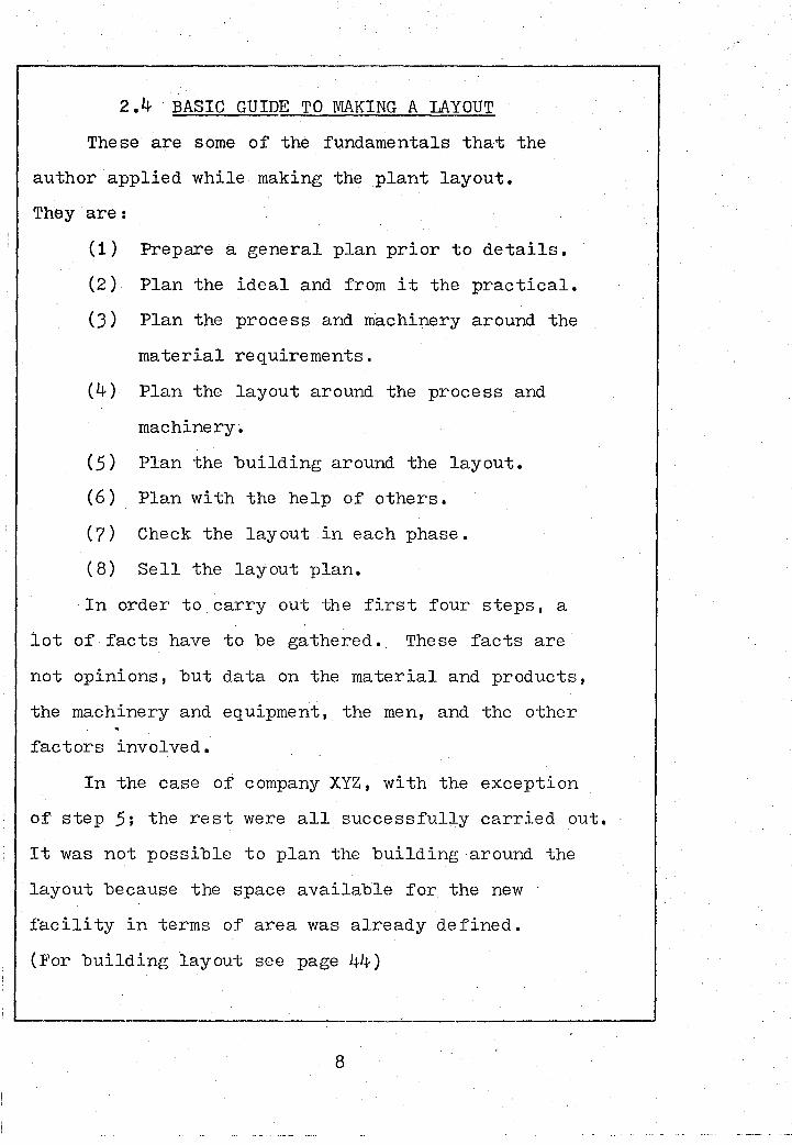
2.4 BASIC GUIDE TO MAKING A LAYOUT
These are some of the fundamentals that the
author applied while making the plant layout.
They are:
( 1)
(2)
(3)
(4)
(5)
(6)
(7)
( 8)
Prepare a general plan prior to details.
Plan the ideal and from it the practical.
Plan the process and machinery around the
material requirements.
Plan the layout around the process and
machinery.
Plan the building around the layout.
Plan with the help of others.
Check the layout in each phase.
Sell the layout plan.
In order to carry out the first four steps, a
lot of facts have to be gathered. These facts are
not opinions, but data on the material and products,
the machinery and equipment, the men, and the other
factors involved.
In the case of company XYZ, with the exception
of step 5; the rest were all successfully carried out.
It was not possible to plan the building around the
layout because the space available for the new
facility in terms of area was already defined.
(For building layout see page 44)
~-------------------------------------------------------------~
8

In an attempt to follow the guidelines established,
first the general space requirements in relation to the
volume of production anticipated was determined. This
included space requirements for not only the existing
machinery but also ne~ds for future expansion was
defined. Next, the basic pattern of flow for material
movement was considered. From this was developed
a general over all layout.
A meeting was next arranged between management
personnel to discuss this, and to further restate
the problem. At thQs meeting, it was decided to look
into the possibility of attaining an expansion
scheme of minimum 70%. Also, some detailed require
ments were spelled out like the need for cafeteria,
· to incorporate the two new departments Silvering
and Electrical Check. Also, to incorporate service
centers such as Silver Making, Jel and Ink Formulation
areas, and also to plan for at least one Conference
Room.
The overall layout was presented for approval.
It was rather conceptual at this stage, but very
clearly stated as to the type of arrangement it will
represent. (See discussion on Types of Plant Layout)
A mutual decision was made on the selection or type
of layout, and the author proceeded to work on the
...__ __________ _
9

detailed plan of integrating men, materials, machines
and supporting activities. In this endeavor, the foll
owing steps were taken to gather all the ·facts.
(1) Made up flow charts (see.page 15 through 19)
(2) Prepared a listing of equipment and their
measurements.
(3) Capacity study of each operation.
Step 2 An ideal plan was next developed without
regard for existing conditions and costs. This was
a very theoretic scheme. It depicted immediate
operations adjacent to each other and the f:low of
work unidirectional from inception to completion.
This plan carefully was analyzed. It was discovered
that the weight of certain equipment for second floor
was inappropriate. This was due to the fact that the
floor strength of the second floor made of wood
construction and 1-!" light weight concrete will not
withstand-all the loads. Therefore, a practical plan
started to take shape by confining the area
Formulation to the first floor.(Heavy equipment in
Formulation referenced are Ball Mills.) It was also
discovered that the spray drier was too high for the
second floor. An analysis made for the kiln room
that accomodated preheat and firing operations also
~------------------------------------------------------------~
10

. (. '"'·f.'·•'.' ...... ~ .....
revealed that due to several reasons, it was mo1·e
pragmatic to place the kiln department on the first
floor.
Third, the process and machinery was more clearly
defined and it was planned around the materials
requirements. After the proper production processes
were selected, the layout began. The factors influencing
the layout were all considered.
(See page 7 for factors influencing plant layout)
Once a preliminary plan was completed, a
meeting was scheduled to solicit ideas of technical
staff, management and production supervisors who
actually work in the areas and possess a detailed
working knowledge about the job. Given this chance
to participate in planning this layout, a very
harmonious and cooper,qtive atmosphere developed.
Some constructive questions were raised that did
put the author back to the drafting board for further
researchJevaluation and planning.
Since s~veral meetings were called prior to the
completion of the-project, each phase of the project
was checked to ensure that the layout is sound, or
has revealed further improvements that could be
made. Also, see plant layout check sheet in
appendix •
11

Finally, selling the plan after its completion was
accomplished without much problem. Due to several
meetings held with management the layout turned out
to be a success.
12

). DATA COLLECTION AND ORGANIZATION
An inventory of all equipment in house was first
taken. A full listing was generated by each department.
The actual physical dimensions were recorded under
length and width in feet and these converted to inches
by using the scale 1/8" to a foot.
Next, information regarding materials and
processes was gathered, analyzed and evaluated.
The production volume was explicitly defined in terms
of (1) Number of different i terns (product mix)
(2) Quantity of each item per unit time
(J) Variation in output
(4) Variation in demand
From the process analysis, machine capability
study was performed.· This is simply determining
the production rate per hour on a certain operation
given a standard and an efficiency factor. Knowing
the future volume in demand with expansion; in a
matter of seconds the total quantity of equipment
needed was established. Also, from the output rates
it was possible to compute the operating personnel
that would be needed. Similarly, the space require
ments for storage were figured out.
Other information sought was on the flow of work,
product design and building plan. The flow of work was
13

best represented by making flow charts. The flow process charts are broken down in
three categories:
(1) Formulation and Casting
(2) Tape Fabrication
(3) Chip Manufacturing
The first category entails all activities
performed in formulation and casting. For specific
breakdown see the listing below.
The second category Tape Fabrication entails
operations from Detentioning through Punching.
The third category Chip Manufacturing is the
largest. This encompasses operations from screening
through electrical check.
Formulation and Casting Tape Fabrication Chip Manufact.
Formulation(Weighing, mixing and blending)
Drying 1
Sifting,Grinding
Calcining
Sweco Milling
Spray Drying
Post Oven Drying II
Formulation 2
Ball Milling
Casting
Detentioning
Drying -~III
Candling
Stripping
Punching
Gaging
Screening
Drying IV
Lamination
Cutting
Preheating
Firing
Silvering
Electrical check

93% of Vol.
Main Stock.
5% Vol.
Kiln
Formulatin I '"IIi---# Weigh, Mix &
Blend
Grinding
Calc ining
80% Vol.
Tunnel
' Q .c.
Calcine Stor.
15% Vol.
Furnace
Fig. 1 Flow Process Chart(Formulation I through Calcination)
15

Fig. 2 Flow Process Chart (Calcine through Casting)
9.3% of volume
Calcine Stor.
Formulation II Premix
Ball Milling
Slurry Star.
7% of vol. Main Stock
Q .c. for Moisture
Test
16

Figure 3 Flow Process Chart of Tape Fabrication
Large Oven
·Punch.
Circular ..--Tape
Stor.
r1pp1ng
Detention. (I.R.)
Shrink. Test
50% vol. 50% vol. Manual Auto.
Cd'le.
Punch
Gaging
Inspection
Stk.
17

Fi • 4 Fow
Manual Auto. Screening
.Lamination
Cutting
Preheat Stor.
18

Fi . Flow Process Chart of Chi Manufacturin (Preheat through Electrical
eheat
Inspection
Manual Auto.
Silvering
Silver
'4!--.u F 1r 1 ng
Electrical check
( 1 OO%)
Final Storage
~------------------------~---------------·------------------~
19

20
TABLE I Com~arison of distance travelled in the
Old versus New la;yout
Description of Work Distance Trips ~ot. Dist.
From l To (Ft.) made travelled
Area/Oper. One Way per day (Ft.)
Area/Oper ·~ OLD NEW OLD NEW OLD NEW
Formulation and Casting
Formulation Stock(Routine) 125 5 4 4 1000 40 Formulation Stock(Special) 125 5 1 1 250 10 Form. I Blending 15 24 3 1 45 48 Blending Drying I 180 48 3 1 1080 96 Drying I Grinding 180 5 3 1 1080 10 Grinding Calcining 75 12 5 2 750 48 Calcining Calc. Stor. 75 60 2 1/5 300 24 Calc. Stor~ Sweco Mill. 16 12 2 1 64 24 Sweco Mill Oven Dry 130 48 2 1 520 96 Oven Dry Sweco Stor. 130 48 2 1 520 96 Sweco Stor. Premix 12 12 2 2 48 48 Premix Ball Milling Dis tance abou[t the same Premix Casting(Cir.) 50 36 4 2 400 144 Premix " (Vert.) 40 36 8 2 640 144 Premix II (Horiz ~ 20 36 4 2 160 144 Dirty Jars Cleaning Room 36 24 15 15 1080 720 Cleaned Jars Formulation 36 24 15 15 1080 z2o Formulation Solvent P.U. 150 50 8 4 2400 00
Ta~e Fabrication
Horiz. Cast. Detentioning 220 ;;30 6· 3 2640 180 Vert: Cast. Stripping 80 36 5 3 800 216 Circ. Cast. Stripping "30 25 2 2 _120 100 Detentioning Drying Ovens 25 36 6 2 JOO 1L!-4 Stripping .Detentioning 80 36 6 3 960 216 Detentioning I Punching 90 72 4 2 720 288 Punching Gaging 40 20 8 4 640 160 Gaging Q.C. Check 60 16 .8 4 960 128 Q.C. Stock 60 30 8 4 960 240
--------1..-..--~--l---·--'---- ------·· L-

TABLE 2 Comparison of distance travelled in the
Old versus New layout . f
--------------------------~·~-------=Y~------·~--~---pistance "" . Description of Work
From
Area/Oper.
To
Area/Oper.
CHip Manu~acturing (Scr. through Cutting)
Stock Hand Screening Stock Auro. II
Screening Drying IV Drying IV Q.C. Q.C. Stock Stock Lamination Lam. Q.C. Q.C. Lam. Lam. Cutting Cutting Q .c. (1st Art.) Cutting Q • C • ( Prod . ) Auto. Scr. Cleaning Booth
Preheat and Firing
Q.c. Setters Sto~ Setters Ld. Setters Ld. Preheat Travel Firing
Preheat Load. Area Preheat(Tunnel:::) Preheat(Boxes) Firing For paperwork Q.C.
Silvering and Electrical Check
Q.8. Q.C. Q.C. Silvering E .C.
All Depts.
E .C. (Sample) Prod . ( R e j • ) Silvering E .C. Packaging
Stock
Trips ~ot. Dist. (Ft.)
One Way
I
made !travelled per day l (Ft.)
OLD NEW OLD NEW · OLD NEW
40 60 60 50 40 25 70 70 25 75 60 56
15 wi 50 45
120 100
80
350 80
240 120 150
75
36 6 2 : 480. 144 48 8 2 960 192 24 1 1 120 48
8 1 1 . 100 16 72 1 1 *80 144 12 8 2 : 400 48 20 20 20 2800 800 20 20 20 2800 800 16 20 20 1000 640 16 15 15 2250 480 16 15 15 .1800 480 30 12 12 1320 720
4 15 15 450 120 1 be the :::arne
25 12 12 1200 600 30 15 15 1350 900 25 30 30 7200 1500 50 30 30 6000 3000 36 15 15 2400 t080
! 1
I i
32 15 15 1050( 960 24 5 5 800' 240 16 15 15 . 720d 480 48 15 15 . 360~1440 36 10 10 300C 720
30 15 15 225C' 900
* Old distance in this instance is lower. '-·-·· ·-·-------·----~---------------1-___j
21

TABIE·3
Tabulation of Results
The following table shows results summarized from pages
Dept.
Trips Made/Day Old New
A B.
Form. ~Cast. 83 55
Tape Fab. 53 27 Chip Mfg. a)Scr.
Lam. and cutting 127 111
b)Preheat and Fir. 117 117
c)Silvering and 5 Elect. Ch. 7 75
Grand Tot. 455 385
·%tage Tot.DI~st. Tot. %tage ~ot.Dist. of Trip::Trave&led Dist of dis"~. Saved Saved per ~ay SavecSaved Per Yr.
(1-B/A) Old . New E-F (1-F/E 1 Xx22x12 · x100 E F X x100 Z
" 33% 11~17 2812 8605 75% 2,271720
49% , 8100 1672 642 8 79% 1, 6961 992
13% 14110 4512 9598 6~ 2,533', 872
0 18600 7200 11400 61% 3,009,600
0 27350 4740 22610 83% 5,969,04C
15% I
79577 20936 5 864-1 74% 15 '481 '224
Note: All distances are represented by Feet •
...__ _______________________________ , ___ ___.

4. DEVELOPEMENT AND PRESENTATION OF NEW LAYOUT
After all the data had been collected, a rigorous
analysis was done. It was found from the flow process
charts that due to the inefficiency of present layout
a considerable amount of time was being spent un-
necessarily.
From the actual dimensions of the equipment a
scale of 1/8" to a f.oot was chosen so that the entire
coverage of each floor could be shown on a sheet
size 2Ft. x 3Ft. This sheet being oversize for
the report, it was reduced to 8l"x11". This .. approximately represents 33% of the original. Hence,
the new scale would be about 1/8" to 3Ft. or
1" to 24Ft.
In presenting thi's layout, the transparent
plastic templates were used as opposed to the
conventional drafting techniques. This not only .
saved hours of layout time, but it was possible
to consider more than one alternative due to its
nature of flexibility. For lines, the Chartpack
opaque pressure sensitive tapes were utilized which
were also adhesive backed similar to templates. In
a matter of seconds both tape and templates could
be pasted to represent anything desired. The paper
-------·------------------------------------~----------~
23

used was mylar grid sheet. It was cross sectioned
with l inch squares which made it excellent to
scale everything.
(For detailed plant layout see Fig. 6 & 7
For flow of work see Fig. 8 & 9)
24

~ I
• -----
I
H
RAMP
I-of.
DOWN~~ );·
ON
•
< 0
"
@
SWECO MILLING
SPRAY DRYING
FDRMU LATION
E BALL HILLING Bt. =••I --~ ..
a a~li.~1••111
:=:.___ -]
w C~LC.IN~NG_ .m
. :~=~=~~~_]!! ~-------_j
1-----------r------o
L-
§.~ '. >o "' \
\
[l
~ w ---~0 f- L _ _j
iliC~ I
25
Fig. 6
NEW PLANT LAYOUT
First Floor
• ~##ll#I#R#l+lfflff!#:
II ffifflillllllllllllllll! 11111111 fffltffittttt!=
#l##Fflffi#I#±!UIItllllllllllllllllllll • •
1!11 0 0
Ll ..
~ ,'lll'l;lllllill;;;;;;;; ,,,+l+ftffi' ' ' •••• _q F< R ST ST • ll ~. ~ ;;;;;;;;;;;~ . ~-- 1 DUMPWAITER ,
··-· ··-··
lllllllllllllHifltlllm±llmll
•

C m 1 a ~ I· -- Qil_~~ __ l -- !1J ~~ C· at
•
CAFETERIA •
----JERRY ~ON! AI'RIL I5. !975
•
•
fl -~ ~~~~~ ~~r~ ~ ~
'-, c_~ ___ jc __ ~ __ j • ~---~--~.: :---r§j--~.:
~~~e .. ;11. MANUAL SCREENING
•••• •
'\
..±±±ill±±LSCR MACH N0,3 '!!!!!!!![!!~
~~~ N0.4 .~:RJJIJ ITfTITfiEIJf{jj
AUTmiATIC SCREENING
ltiiFWI£Hiffi-j II I I IIIIi Iii I r$
-lilbmt II II lllllll Ill jlll(jj)
SCREENING
26
Fig. 7
NEW PLANT LAYOUT
Second Floor
!..=c_JII c:::::5· I! 'S" 1 c __ ~ ___ Jc_~~---1~--~---J~--~---J~--~---J'
IIBl IIBl IIBl IIBl
P-1~ l::ll 1!1!1 Ell ii!ll
I§! §i] IIBl IIBl IIBl li!llJ ... ~ Ell Ell B ~
IIBl IIBl g;) IIBl
IIP.IIP.I 1!1!1. 1!1!1 l::ll ~ B B
CUTTING
•B•"; .. :~.·.:JRiii.:_ .• _. .-e.ll •• ___ ifitw bF1ij 111 2.ECONt1 }'f.OOR PL,\.N
SCREEN
REPAIR

11
D
~ . ~ Ul ~ -1 . §
• :-, r-l rl
! i i i i i ! ! ! ! I i
·~1111-ii I I 1 LJ
·I I
I i i ___________ . ___ !
•
1-Ij I-'· 1-i til c+
1-Ij I-' 0 0 1-i
. ..
D )>
~ 1l
0 0 ~ z
/ gj/ 2.;
1-Ij f::-1 §i 1-Ij
I-'· oq
0 1-Ij
2.; co
0 ~ ?-:

•
CAFETERIA •
J~.FY ~c:ci ArRIL IS. n?5'
~
~
"
•
•
tl -~ at .. ~ ,.~,.
~~~~~
n'la·-.· ~-~" .. ~. ·c' ..
t'~ .
28
'\ Fig. 9
New Flow of Work
Second Floor
"·~>.IN t ~llfu:.;~:;:::!:;;:;:::~:~r:
~' ~~~:~~:JI ~ I
AUTN1A1'IC :;cREENI:f)
SCREENING
c;·o·oo r=~ ::.:.l:;r ~ ~~ ~1-l'lttt:J 857d .. ----- -
:.£COll'i:< io'T..OOFI Pt.o\lf

4.1 ADDITIONAL FEA':PURES PLANNED IN
NEW LAYOUT
These are some of the outstanding additional
features planned for thenew facility.
Conference Rooms
Cafeteria
Jel Making facility
Silver Making facility
Electrical Check
Cleaning Facility
Planned Storage Spaces
Lobby
Seperate Security office
Elevator
Dumbwaiter
Better rest room facilities
Better cot rooms for emergency needs
More clocks and racks for punching
Emergency safety features like eyewash and shower
29

5. DESCRIPTION OF THE FLOW OF WORK (See Fig. 8 and Fig.9)
The first department which is Formulation is set
on the first floor shown on the northeast part of the
building. There were numerous reasons for confining
this department to that locality. These are
(1) Being the first operation, it utilizes a
great number of solvents which come in standard
55 gallon drums. The storage area for drums is
located outside the building in the vacant lot close
to the elevator. There is a door between the property
line and the elevator ·just added recently. This
opening will provide an easy access to the solvents.
It is impractical to place .: this department up on the
second floor because there would be a continuous
task of conveying these solvents up. Als~ these
solvents Acetone and Trichloroethelene which are
both volatile and flammable would make it unsafe
to stor·e inside.
(2) This department contains equipment known as
ball mills which are too heavy for the second floor
to withstand this load.
(3) It has heat generating equipment which
have to be seperated from volatiles that are '
combustible. It makes it most practical to group
30

all the heat generating equipment in one location.
In order to keep the commuting distance short, they
are placed at a. minimum distance possible but yet to
comply with OSHA r~gulations.(OSHA defined as Occupa
tional Safety and Health Administration) Also, these
heat generating equipment the so called drying ovens
and calcine tunnels are located adjacent to the
formulation area which makes it readily accessible.
Above all, the proximity to the dock and the
incoming materials makes formulation location on
first floor most convenient.
The first operation in this department is pre
weighing of dry chemicals and. then mixing and blending
them together in the Sweco Milling room. After blending,
the slurry is poured in trays, and conveyed· into the
heat generating room to be dried in ovens. The drying
cycle is about 12 hours. When dried1
the white crystals
are .ground and then sifted through the vibration process ..
After the completion of grinding, the white powder is
loaded on to the saggers and placed in the calcine
tunnels for calcination (a heat process of ceramic
powders to temperatures below that required for
sintering in order to pre-react certain ingredients.)
At times calcination is also done in the furnace and
the periodic kiln on the left. This is a batch
31

handling technique and is applicable to certain
materials only. In the process of tunnel calcine the
material is fed from one end and the conveyor transports
it to the other side. Provision for in process
storage is made at the end of the tunnel. At the
end of the day the calcined powder is dumped into
the barrels and transported to the calcine storage
area.
The next operation after calcining is sweco
milling. After milling, the slurry is redried
either through means of spray drying or oven drying
depending on the moisture content specifications. As
an average, 50% of the volume is spray dried and the
rest is placed in the ovens. When drying is complete1
the ceramic powders are sealed and stored in glass
jars ready for use.
Once these swecoed powders are available, the
premix .operation takes place with the addition of
solvents and plasticizers. This solution is put
into the ball mills and milled for a least 24 hours.
When the cycle is complete, the liquid is cooled
and poured into containers. This completes major
operations of formulation. Other service activities
inspection, cleaning of jars and containers and
materials handling of solvents is done where ever
32

necessary.
The slurry from here is next conveyed up to the
casting area. Means of conveyance has not been
finalized yet. Some research is still being done
to see if pumping is the ultimate answer. The
biggest drawback is to resolve the potential danger
of contamination of materials from the residue left
in the tubes. At any rate, this slurry will be used
to cast tape by different means; horizontal, vertical,
and circular.
Upon the-completion of this operation the material ··
will be in roll form. About 65% of the ~olls will
have tape cast on the polypropolene which will be
stripped. The remaining 35% which is cast horizontally
on the belts will go directly into the area of
detentioning. The stripped material will also be
detentioned eventually. After the detentioning
pro~ess there is post drying in the ovens for few
hours. This completes the mild heat process used to
stabalize the shrinkage of tape.
After · detentioning when the tape passes
shrinkage test, most of it is ready for punching.
Some of the tape has to be candled on a bright light
to mark off any visual defects that may have occured
on the tape while casting.
33

Punching is accomplished both automatically
and manually. The manual process is used when the
tape breaks too often mainly for the thin dielectrics
that are less than 1 mil thick. After punching, the
product is in a rectangular wafer of size 3.87.5" X 1.625"
These wafers are gaged and sorted for different
thicknesses.
After grinding and sorting, the material is
placed in stock. At this point the orders that
come from the order desk through Engineering and
Production Control are given the design specifications,
and all the pertinent information required co produce
this part.
Next operation in sequence is Screening. This is
also accomplished both manually and automatically.
Manual machines are used for very small runs, and
the automatics for large volume orders. This is
essentially printing the ceramic wafers with ink,
after which parts are dried in the oven overnight, .•
When drying is complete, a pilot run is initiated.
Upon reviewing the results, the production of lots
takes place in lamination where alternate layers are
stacked and pressed together to form a fusion. These
laminates are next cut into the configuration and
size of the pattern that was originally used for
.34

screening.
At this stage, the product is known as chips
commonly referred to as greenware. These chips are
next transferred to the kiln room below situated
on the far right hand side of the building. This area
being directly located below cutting; chips are
conveyed by means of a dumbwaiter near the stairwell
where the cutting operation terminates. This means
of transport will save a considerable amount of manual
handling and it will be safe and satisfying to
employees as well. At the present, due to 100%
manual handling of chips used for conveyance, the
operation is prone to accidents.
Chips are next received in the Preheat area. They
are loaded into the· boats or saggers and put into
either the preheat tunnel or boxes. The tunnels all
have conveyors and the material is moved forward
autqmatically until the operation is complete. After
preheat, the chips go into firing tunnels or periodic
boxes. The same principle of sintering is applied
here. Note: The preheated parts do not go back.
Therefore, there is no backtracking.
After firing of chips, the units go into Silvering I
via quality control. This is a termination process
where silver is applied to the ends. Silvering
3.5

is also accomplished by several means. Two most
commonly employed techniques are(1) Hand Silvering
(2) Automatic using the rotary machines that automati
cally dips the chips in silver pots. After the
application of silver the parts are cofired in
silvering tunnels. These are again segregated from
the airconditioning area, but placed into the heat
generating room to save energy. The placement is
made such that it provides an easy access to the
silver kilns without a lot of travel.
When silvering is accomplished the parts are
subjected to elect~ical check for value and other
characteristics being sought. This final operation
completes this unit which is ready for dispatching
and shipment, except in some cases it will go to
another division for encapsulation.

6. BENEFITS DERIVED FROM NEW LAYOUT
1. Reduction in handling and transportation of
materials.
Handling and transportation of materials is
reduced by 74% See Table 3 for comparison of
distance commuted per day between the old and
new layouts. The new distance to travel has
been down to 20,936 feet per day from 79,577
feet or a net savings of 58,641 feet per day.
This represents an annual savings of 15.48
million feet. This savings in commuting will
lower the labor time considerably,. a~1d thus
would yield a lower product cost.
This savings is gained due to the following
reasons:
(1) The flow of work being methodic and
unidirectional, in most cases this type of
arrangement has eliminated backtracking and
crisscrossing. Since operations are placed
adjacent to each other in a sequential manner,
it has reduced all unnecessary travel distances.
(2) Service centers are placed near the
point of use as much as possible. e.g. The
ink making facility is located near screening
which utilizes inks; quality control inspection
--------------------------·--------------------~--·--------~
37

stations placed out on the line rather than in one
. centralized location. Also, the in process storage
centers are well planned and are situated in most
appropriate areas near the manufacturing operations.
(3) All tunnels are laid out in the direction
of work flow, thus serving the purpose of materials
handling equipment as well. e.g. All preheat tunnels
that average 30 feet in length will convey material
30 feet without the need for any additional handling.
A further reduction of materials handling is made
possible by arranging the firing tunnels just where
the preheat operations terminate. Thus an average of
32 feet per tunnel is saved again.
Similarly, the same principle has been applied
in laying out the horizontal casting machines and
the automatic screening machines whose average is
40 feet in length. Material in each case starts
at one end and goes to another and always moving
forward to the next operation in sequence. This concept
has indeed minimized the cost of materials handling.
(4) Efficient means of materials handling equip
ment utilized. e.g. The dumbwaiter for transpor
ting of chips from second floor to ,the first floor,
and also the elevator for any bulk heavy item.
38

2. Less congestion, confusion and better supervision.
Due to the improved layout, there will be less
congestion and confusion. It will make supervision
much easier as the supervisors can have more visual
contact with the employees. At present due to
seperations of each department, it makes supervision
very ineffective.
3. Will improve worker morale and worker satisfaction.
(1) There are more services provided in the
new layout as compared to the old.
(See listing of additional features incor
porated in the new layout.)
The cafeteria itself will provide
hot food for lunches and breaks. Thus it will
satisfy all those who do not like to eat out.
(2) The conference room will be an excellent
place for supeNisors to meet and discuss
daily problems.
(3) Restroom facilities are·more modern and
and updated. Drinking fountains will be
placed in several locations.
(4) Telephone services will be available ln
the cafeteria.
(5) Better lighting conditions, new tools and
fixtures and better seating arrangement
39

will be provided for all employees.
(6) By segregating and centralizing all heat genera
ting equipment in one area, better air condition
ing services will automatically result. Also,
improvement has been made for heating service
required during winter months·.
(7) Seperate punching clocks in each floor will
reduce the length of line and will save
employees 6-7 minutes prior to lunch and
working hours.
4.Flexibility of expansion possible.
The layout arranged has been planned for 100%
expansion. In most cases, a minimum of 66%
additional space and equipment are already
reflected in the new layout. It is anticipated
that 100% expansion is possible with some
improvements in process that will further
r~duce space utilization.
Other benefits that can be derived from
this improved layout are:
(1) Reduced risk to health and safety of
employees.
(2) Increased output •
. (3) Fewer production delays.
(4) Greater utilization of machines,
40

manpower and services.
(5) More efficiency will warrant deliveries in
time. This will keep the customers happy.
All the above benefits will inevitably result
in potential savings to the company.
41

1.
2.
3·
4.
5·
6.
7·
8.
9·
10.
11.
BIBLIOGRAPHY
Apple,J.M., Plant Layout and Materials Handling, The Ronald Press Company, New York, 1951.
Muther, R., Systematic Layout Planning, Industrial Educational Institute, Boston, 1961.
Muther, R., Practical Plant Layout, McGraw-Hill Book Company, Inc., New York, 195-5
Gaudreau, A.T., Mallick, R.W., Plant Layout Planning and Practice, John Wiley & Sons, Inc., New York, 1951.
Maynard, H.B. , Industrial Engineering Handbook McGraw-Hill, New York, 1963.
Moore, J.M., Plant Layout and Design, Macmillan company, New York, 19b2.
Shubin and Madeheim, Plant Layout, Prentice-Hall, Inc., 1951.
Murphy, G.H., Labor Code, State of Calif., 1973
Brennan, P.J., General Industry Standards and Interpretation, United States Dept. of Labor, OSHA 1972.
Ireson, W.G., FactoiX Planning and Plant Layout, Englewood Cliffs, N.J.: Prentice Hall, 1952.
Immer, John R., Layout Planning Technique, New York: McGraw-Hill Book Company, 1950.
42

APPENDIX
43

.. ·;. · .. :.· ....
.·· ..
~ ....
·'
,•·:·.·.
. . ~ :. : .. ~
. '.·
. ...... ~
.-.. ·,_.
•-,.
; . ~ •; .-. ~.·.1
..:·
·:.·,: .·· .· ..
.. ~ · .. · .. .' ,.
.. ' .
.... . ~ ~-; · ..... ·, >
.:. .. _ .... '. .•
··: ...
' i. l ~ • \
'. ~ ·.·
L . ..
.. ..

I I j
.,,:~·-:.
.....
. ~: ..
.~.
\ :. . . . '· . ·.·,· ,· ..
. . ~ · ... : . . ~ ·. \ _: ..... . . .· .• _:: ~. I: n II-.
i~ r.
. .... '
•· .. ·.·r
b:J ... ,.. c::. ·. v~ H · ·
t5 : It . b ,, . I,
h' IJ
.··· ; .• .
.y ..
·~ ~- .. ·
:if. . ··a·:; ~~·,:;z._· -:_' . ~ ..
: '~],; :·· ·. · · > · · ., .. :r·:. · ;_. --
• ' . ·•. . ·, -: : .l. ' • : . . ~ ' .
'. ~:. . -~. : ·. ..:
·.·.
.... '· ; .•, ~ •.·· t
: ~-.: .-~=. • .
~ . :·: ·. . _;. '." ··.
.' .· ·~ ..
:_:;· :· :.· -.'•· ....... .-
··.• ' ,':'_ ..
' ; :"
. ·.· .... .. . .
-t.:..,·
I 1
l ,~
I.
I I
• I
·- 1.
·.·

Fig.
,PLANT LAYOUT CHECK SHEET
Cpmpany. Plant I Checked By Date
Before submitting the layout for official approvals, check against the following items
INDUSTRIAL ENGINEERING
; 1. Machinery and equipment arranged to make full use of capacity?
/ 2. Machinery and equipment accessible for material supply and removal?
-' 3, Machinery and equipment located for maximum operator efficiency?
4. Line production used where practical? 5. Proper use made of mechanical handling? 6. Processing combined with transpo~tation? 7. Minimum walking required of operators? 8. Finished work ·of one operator easily accessible to
next? 9. Machinery and equipment "block in" any operators?
10. Machine overtravel extend into aisles or interfere with operat'Jr?
11. Adequate storage space at work stations? 12. Efficient work place layouts? 13, Service areas conveniently located: (tool room, tool
crib, maintenance, etc.) 14. Easy for supervisor to oversee his area? 15. Machine arrangement permit maximum flexibility in
case of product change? 16. Space allocated for foremen and production control
records? 17. Related activities located near each other? 18. All required equipment included in layout? 19. Floor area fully utilized? 20, Provisions made for expansion? 21. Provisions for. scrap removal? 22. Crowded conditions anywhere?
MATERIAL HANDLING
1. Incoming materials move directly to work area? 2. Processes involving heavy or bulky materials close
to receiving area? 3, Sub-assemblies flov. into final assembly? 4. Plans for auxiliary material flow in case of tie-up? S. Minimum of backtracking? 6. Obstacles in material flow?
not applic. OKiremarks
12 46
not OK remark a MATERIAL HA~WLING (cont'd) applic. 7, Excessively long moves? 8. Conveyors "box in" anyone? 9. Material handling equipment bring materials to
operators? 10. Material handling equipment remove materials from
operators? 11. Each material handling method integrated into
overall system? 12. Conveyors from receiving to processing areas? 13, Conveyors from assembly to shipping area? 14, Minimum of manual handling? 15, Material handling equipment carry materials in a
position to conserve space? 16, Widely separated areas connected by suitable
mechanical handling system? 17, Aisles and doors wide enough for maximum loads
and fire equiprr:ent? 18, Ramps at lowest possible grade? 19, Proper use of conveyors for efficient handling? 20. Adequate storage space for containers and material
handling equipment? . 21. Use of conveyors for floats and banks of material? 22, Adequate storage for materials in process? 23. Shipping and receiving docks covered? 24. Proper dock heights and/or levelling devices? 25. Maximum use made of building cube? 26. Aisles straight and clearly marked?
PERSONNEL AND SAFETY
1. Exits, fire doors and fire escapes ade.quate and properly located? Free of obstruction?
2. Easy exit from any location in building? 3, Plans checked by local fire, police and safety
officials? 4, Plans approved by insurance companies? 5. Lifts and hoists provided for loads over 50 lbs,? 6. Adequate work area for each operator? 7, Easy access to all safety devices.? 8, Hazardous and unpleasant operations isolated? 9, Adequate storage for inflammable materials?
10, Drinking fountains in enough lqcations? 11. Maximum use made of natural light? 12. Adequate artificial light provided for? 13, Proper ventilation provided where required?

PERSO~~EL A!'.""D SAFETY (cont'd)
14. Employee service areas provided for and conven• iently located:
a, first aid b. toilets c, locker rooms
e, coat racks ~ f, food service
g. time clocks d. smoking areas h. stretchers
15, Parking space provided for employees?
PLANT ENGINEERING
-1. Floor loads within allowable limits? 2. Overhead clearances adequate? 3. Proposed overhead loading within limits? 4. Special foundations or equipment mountings
required? 5. Floor and roof drains provided for? 6, Elevators required, located, specifie!f? 7, All possible use made of under-floor, overhead, and
on-the-roof space? 8, Layout make efficient use of building shape, size,
cube? 9, Machinery and equipment accessible for mainten•
ance? 10. Layout conducive to good housekeeping? 11. Provisions for rubbish collection, storage, and
removal? 12. Utilities provided for and properly located:
a. air g, sprinklers b. gas h. sewers c. water i. air conditioning d. electricity j, heating e, steam k. ventilation
, f, telephone 1, lighting 13, Detailed drawings of special equipment or installs•
tions? 14. Fire extinguishers and fire protection equipment
provided for? 15. Layout sati:;fy all safety codes?
PRODUCTION CONTROL
1. Inventory checking easy? 2. Adequate space and facilities for salvage opera•
tions? 3, Proper protection for material and finished goods
storage? 4. Valuable materials pro.ected from pilferage? S. Adequate space for shipping and receiving?
Fig, 12 47 not OK remark a
PRODUCTIO~ CO~TROL (cont'd) applle. not
applie. I OK I ret:~ arks
6. Adequate area for trucks waiting at shippin~ and receiving?
7, Layout pennit operations to be per(onned in logical se(J.uence?
8. Easy' adjustment to changing schedules? 9, Layout permit paced production?
10, Will equipment breakdown shut down line or plant? 11. Inspection points located at strategic points? 12. Straight flow lines?
OTHER COMMENTS OR SUGGESTIONS
.