Development of global temperature and pH calibrations based ...
Upload
khangminh22Category
view
0download
0
CALIBER Automatic calibrations of instruments
User’s Guide

MEATEST Caliber 2.51
User´s Guide Version 29 3
CONTENTS:
1. QUICK START 4
1.1. DETERMINATION 4 1.1.1. PARTS OF CALIBER PROGRAM 5
1.2. SYSTEM STRUCTURE 6 1.3. PROGRAM INSTALLATION 6 1.4. PROGRAM OPERATION 8
1.4.1. MEASURE TASK DEVELOPMENT 8 1.4.2. CALIBRATION ACCORDING TO DEVELOPED PROCEDURE 11 1.4.3. NEW CALIBRATION PROCEDURE DEVELOPMENT (CALIBRATION METHODS) 13 1.4.4. INSTRUMENT CARD DEVELOPMENT (DECADE MEATEST M109) 18 1.4.5. INSTRUMENT CARD DEVELOPMENT (RESISTANCE 10 M) 20 1.4.6. POWER CONVERTER INSTRUMENT CARD DEVELOPMENT 22 1.4.7. SWITCH INSTRUMENT CARD DEVELOPMENT 24 1.4.8. RESISTANCE METER PROCEDURE DEVELOPMENT 25 1.4.9. POWER CONVERTER PROCEDURE DEVELOPMENT 27
1.5. PRACTICAL CALIBRATION INSTRUCTIONS 29 1.5.1. MEASURING CIRCUITRY 29 1.5.2. VOLTAGE RANGE CALIBRATION 29 1.5.3. CURRENT RANGE CALIBRATION 30
2. DETAILED PROGRAM DESCRIPTION 31
2.1. “PROCEDURE“ MODULE 33 2.1.1. SCREEN DESCRIPTION OF THE “PROCEDURE“ MODULE 34 2.1.2. CALIBRATION PROCEDURE MODIFICATION 56 2.1.3. CALIBRATION PROCEDURE TEST 58
2.2. “INSTRUMENT CARD“ MODULE 59 2.2.1. ITEM DISPLAYING REGULATIONS 71 2.2.2. DEVELOPMENT OF MACROS 72 2.2.3. MACRO COMMAND SYNTAX 77
2.3. “USER FUNCTIONS” MODULE 82 2.4. “WIZARD RULES“ MODULE 86
2.4.1. DEVELOPMENT OF „WIZARD RULES“ 87 2.5. “CONFIGURATION” PANEL 89
2.5.1. GENERAL 89 2.5.2. TEST REPORT 90 2.5.3. REGIONAL 92 2.5.4. LOGS 93 2.5.5. CALIBRATION DATA 95
2.6. MEASURING PROCEDURE 96 2.7. MEASUREMENT ERROR AND UNCERTAINTY CALCULATION 98
2.6.1. USED ABBREVIATIONS 98 2.6.2. CALCULATION OF UUT DEVIATIONS 100 2.6.3. CALCULATION OF MEASUREMENT UNCERTAINTY 100 2.6.4. RELATIVE VALUE REPRESENTATION 102
2.8. TEST REPORT FORMAT 103 2.9. TESTING PROCEDURE 106 2.10. PROGRAM REGISTRATION 107 2.11. SPECIAL CALIBRATION TYPES 109
2.10.1. ANALOG METERS 109 2.10.2. CALIBRATION OF DECADES 111
3. TERMINOLOGY 112

Caliber 2.51 MEATEST
4 User´s Guide
1. Quick Start
1.1. Determination
The CALIBER program is intended for automatic calibrations of instruments by means
of a standard. Except of the unit under test and the standard unit, a computer with Windows
XP/Vista/7/8/10 Operating System is being necessary. Output of the CALIBER program
represents a physically performed calibration with a calibration record – a table with
measured and evaluated data (the test report).
Instrument Configuration for Calibration:
Measured Protocol:
The instruments can be either manually or automatically (by computer) operated. In
automatic mode the interface RS232 or GPIB can be used, eventually any other interfaces
(USB, Ethernet, RS485, …) which utilize the industry VISA standard.
Function| Range| Standard | UUT| Deviation|%spe| Allowed | Uncert.|
----------------------------------------------------------------------------------------------------
VDC-2W| 200 mV| 20.0 mV| 20.0 mV| -0 uV| 0| 200 uV| 62 uV| ok
VDC-2W| 200 mV| 180.0 mV| 180.6 mV| 620 uV| 62| 1003 uV| 71 uV| ok
VDC-2W| 200 mV| -180.0 mV| -180.7 mV| -690 uV| -69| 1003 uV| 69 uV| ok
VDC-2W| 2 V| 0.200 V| 0.200 V| -0.00 mV| 0| 2.00 mV| 0.58 mV| ok
VDC-2W| 2 V| 1.800 V| 1.807 V| 7.00 mV| 70| 10.04 mV| 0.58 mV| ok
VDC-2W| 2 V| -1.800 V| -1.807 V| -6.80 mV| -68| 10.03 mV| 0.64 mV| ok
...

MEATEST Caliber 2.51
User´s Guide 5
1.1.1. Parts of Caliber Program
The Caliber program consists of four basic units:
Procedures
Instrument Cards
User Functions
Wizard Rules
The program is based on automatic calibration of measuring instruments which shall be
performed according to before prepared calibration process or so called Calibration
Procedure. The basic module of the Caliber program called Procedures is intended for
processing of these calibration procedures. By means of this unit there is possible to develop
and modify the calibration procedures and to carry out calibrations directly. For calibration
used instruments are very important for the particular calibration procedure. In the most
simply case a procedure can be created by a list of instruments and a list of selected
functions, ranges and points of a tested instrument.
An instrument shall be specified by its instrument Card in the Caliber program. The
instrument card contains the whole instrument description. There are especially lists of
supported functions, range specifications, technical data and methods of instrument operation.
The module called Instrument Cards is intended for processing instrument cards. Existing
card can be easily used for any calibration in any configuration and the program shall
automatically know the all of instrument features.
The module User Functions allows to develop new functions and to certain extend to
modify the existing ones. The function represents a supported instrument feature category,
which is consequently being used for all the Caliber system. For example V-DC (direct
voltage) or FREQ (frequency) can be functions.
The module Wizard Rules is intended for development of regulations which shall be
used for automatic calibration procedure developments.
It can be say in simplified way that the instrument Cards are specifying features of
objects participating on a calibration, and the Calibration Procedures are specifying relations
among these objects. The Calibration Procedure stipulates which instrument shall take part in
the calibration and what function they shall perform (i.e. instruments under test, sources,
standards) and at which points the calibration shall be carried out.
A calibration procedure shall be created interactively and it does not require
programmatic knowledge of a technician. The CALIBER program can be used either
independently or as a program unit of the WinQbase database environment. If it is used
independently the program output shall be represented only by a calibration report. If it is
used with the database of WinQbase the CALIBER program results shall be transferred into
this database and a user can utilize all the WinQbase features for another operation. Below
will be described operation of the CALIBER program as independent one.

Caliber 2.51 MEATEST
6 User´s Guide
1.2. System Structure
- control unit PC 1.5 GHz and more, monitor SVGA, RAM 1 GB
- Operating System of MS Windows XP/VISTA/7/8/10
- software facility of Caliber
- to calibration necessary instruments + connecting cables
- National instruments GPIB card for communication via IEEE488 (other manufacturers are
not supported)
1.3. Program Installation
In this section installation of the Caliber program will be described if being used
independently. If being used as a part of WinQbase program its installation shall be
performed automatically during WinQbase installation. The program of Caliber is being
distributed on CD ROM disc.
Caliber program installation:
This installation shall be performed under user´s account with administrator
permissions.
The CD ROM having been inserted, a control menu shall be displayed and selection of
installation of the Caliber program is possible. If the CD ROM is not initiated automatically,
you can find the installation by means of the "Install\Software\Caliber.zip" package. Unpack
(unzip) the package and run the installation by opening the "CaliberSetup.exe" file from
newly unpacked folder.
First the program shall offer a language version and after it an installation guide shall
be initiated. Available languages are: English, German, Russian, Hungarian, Slovak and
Czech.
The installation guide consists of following points:
Assignment of a place in the computer where the installation shall be located –
we recommend to confirm the offered Caliber´s position.
Performing of the installation itself.
Computer restart.
The computer restart having performed, let the installation CD ROM in its driver and
switch on the new installed program in the „Start“ menu. The operating system may read
some other information from the installation CD. The program shall be started automatically
in a demo-mode and it can be activated after entering of the “ Registration Code “, see the
section of “ Program Registration “. Program having started, the CD ROM can be removed.

MEATEST Caliber 2.51
User´s Guide 7
If you are using the GPIB Card (National Instruments interface is required) it will be
necessary to install a particular controller by means of the installation CD delivered along
with the GPIB card.
If you are using a camera to scan measured values it will be necessary to install a
particular controller by means of the installation CD delivered along with the camera.
If you are using VISA interface it will be necessary to install VISA driver. This driver
is accessible from Caliber installation CD via start menu (it is located in “install/drivers”
directory).
Uninstall the program
The program can be removed off the computer by means of the “Installation or De-
Installation of Programs“ item in Control Panels.

Caliber 2.51 MEATEST
8 User´s Guide
1.4. Program Operation
1.4.1. Measure Task Development
To perform a calibration, we need an instrument to be calibrated and an instrument (or
instruments) for its test. It is possible to use maximally 20 instruments for one calibration
point. For the whole calibration procedure the number of instruments is not limited (each of
the points can use other instruments). The limitation given by program purposes is only one
unit under test (UUT) which shall be the same for the whole calibration procedure.
The Caliber program allows measure task development by means of five basic types of
instruments:
a) UUT (Unit Under Test) – an instrument to be calibrated, i.e. an instrument to be tested.
It is not of importance if it is a signal source or a measuring instrument. An instrument
being calibrated can be a multi-meter, a resistance decade, process calibrator, etc. A
converter can be used as UUT as well, only certain regulations shall be observed. The
UUT is always being differentiated by blue color in the program.
b) Standard – a standard instrument being connected with the UUT (it is intended for
conventionally right value estimation by the program). A standard can be a signal source
(calibrator) or a measuring instrument (multi-meter, scales). The standard is always
being differentiated by red color in the program.
c) Source – a signal source. A signal source shall be present at each measuring task. It can
be used at standard´s position (calibrator), as UUT (calibration of a decade resistance) or
can be used as a source only.
d) Converter – it converts a measured signal. It can convert physical values (a current
shunt, a frequency/voltage converter), eventually value transfer (a transformer, a current
coil with 50 turns). A converter cannot be used separately, it must be connected with a
source (a 50 turns coil behind the calibrator) or with a measuring instrument (a current
shunt). The program does not allow transducer connecting with the UUT. However such
a limitation can be avoided by another range of a measuring instrument to be calibrated
(e.g. 5 kV range for a multi-meter with a high-voltage probe). The transducer connected
with the standard is always being differentiated by red color in the program.
e) Switch – it is an instrument which can be operated along with other ones during a
calibration, but it has not any influence to calibration results (it is not any standard, any
UUT, either a source or a transducer). It can be used as an automated terminal switch etc.
The condition of any instrument usage is being represented by existing of particular
instrument Cards. There is necessary to specify a UUT, a Standard and a Source for every
measure task. The transducer cannot be used obligatory. There shall be necessary to select
particular operation method for each of the instruments, i.e. manual operation for the GPIB,
RS232, VISA buses or for a camera.

MEATEST Caliber 2.51
User´s Guide 9
Instruments are divided in terms of signal flows into following groups:
a) Source – it possess an output signal, it does not have any inputs. It is
creating a signal.
b) Meter – it possess an input signal, it does not have any outputs. It is
measuring a signal.
c) Converter – it possess both input and output signal. The signal is
being transformed.
d) Switch – it is similar as the measuring instrument, it has only input
signal, but any measured value is not expected.
Instruments scheme
All in the program used instruments shall be connected together in terms of the signal which
is demonstrated by a connecting line of grey (6) or orange (5) color. The orange line means
that the instrument is connected with the master bus, i.e. all values are set exactly as the UUT
(2) is, also as it
is determined by
the calibration
procedure. The
grey line means
that values have
been transformed by the converter (3) and they can differ from the UUT. Several converters
can be serial connected and the values can be step by step transformed in direction always
from the master bus. For better clarity it is possible after selection of a particular calibration
point to move a mouse cursor on the instrument and look at how quantity and value the
instrument shall be set on (having transformed by the converter).
Instrument displaying within a procedure
Each of instruments shall be displayed as a rectangle in the program. There is an instrument
name (1) in the upper
half of the rectangle.
The lower half is
divided in two parts. A
communication bus type
(4) is being displayed
by which the instrument is controlled eventually along which bus the value from the
instrument is counted. There is instrument index (5) in the right part. This index serves to
unique identification of each of the instruments even if they have the same name (the same
instrument can be used in one procedure many times). On the left and right part of the
instrument can be displayed a hook which determines signal connections (3) among the

Caliber 2.51 MEATEST
10 User´s Guide
instruments. The source has a hook only at its right side, the converter has a hook on both its
sides and the switch has not any hook. Rectangle´s background color symbolizes an
instrument position (2), i.e. blue stands for a UUT, red for a standard, grey for all other
instruments which value is not important in terms of calibration results. It is suitable in terms
of instrument circuitry to situate sources in left part of the surface and measuring instruments
and switches in right part of the surface, converters then among these instruments. The
instruments can be transferred on the surface by left mouse click and pulling the mouse at the
same time. Instrument transferring is possible only if the instrument circuitry is actually in
terms of a given point, a range and a procedure. The circuitry will be actually if it is displayed
in thick letters of the instruments.
Measure Task Examples:
a) Calibration of the METEX M3800 multi-meter by the MEATEST M140 calibrator
The calibrator is being used as a source and as a
standard at the same time. It is controlled through
RS232 bus (COM2 of the computer). Values from the
measuring instrument are counted by a camera.
b) Calibration of the MEATEST M612 decade by the DATRON 1281 multi-meter
The decade represents an instrument under test and a
signal source at the same time. It is controlled through
RS232 bus (COM1 of the computer). The precise
multi-meter of DATRON 1281 connected with GPIB bus of address 22 represents a standard.
c) Calibration of the multi-meter HP34401 by the multi-meter DATRON 1281 and the
calibrator MEATEST M130
HP34401A is an instrument under test. The multi-meter
DATRON 1281 is being used as a standard and the
calibrator MEATEST M130 as a signal source. All the
Instruments are connected through GPIB bus.
d) Calibration of 20A range of calibrator MEATEST M140 by the multi-meter
DATRON 1281 with shunt BURSTER 10 m
M140 is an instrument under
calibration and a signal source at the
same time. DATRON 1281 with
shunt 10 m is a standard measuring instrument. All the instruments except from the
converter are connected through GPIB bus.

MEATEST Caliber 2.51
User´s Guide 11
1.4.2. Calibration According to Developed Procedure
Start module “Procedures” (menu “Window” in upper menu bar) in “Caliber“ program.
In upper bar of the Status Window press the button “Open” and select procedure
M3800.
Connect instruments displayed in “Instrument scheme” window. If there is no camera
scanning available it will be necessary to set reading M3800 to manual mode. It will be
performed by right mouse clicking on instrument „M3800“and selecting of item “Instrument
configuration” from the menu. The field “Instrument response” shall be set to “Manual” and
then press „OK“. There is possible to select a point in the test report window, which the
calibration shall be started from. We select point 1 and press the key “Run Calibration”. The
calibration can be stop by pressing ESC key any time.
First the program shall drawn attention to change of input terminal connection (there is
an actual connections of terminals in the program´s status window), then shall open
instruments that will take part in the calibration and it shall perform every stipulated check
values step by step.
Ranges or functions having changed, an operator shall be prompted to set the
instrument.
There shall be necessary to set measured values by means of a keyboard without
camera scanning. The program requires performing a set of ten measurements for each of the
calibration points. Measurement´s number can be modified by changing of the item „No. of

Caliber 2.51 MEATEST
12 User´s Guide
UUT readings“ in the “Measurement parameters” window. The “Uncertainty” window can be
displayed after program stop (by the ESC-key) by pressing of the right mouse above the
program´s status window.
The calibration can be stopped by pressing ESC key any time. It can be started by “Run
Calibration” key from any point again. If there is a measured value recorded in a particular
point already, it shall be overwritten by a new one.
If the calibration starts from WinQbase system the output protocol shall be
automatically written down into the calibration database for particular identification sheet
after closing of “Procedure” module. Without the database superstructure the performed
calibration is to be written down into a file. Press the right mouse button above test report´s
window and select item “Export“ in order to do it. Having not saved, the measured protocol
shall be lost after closing of “Procedure” module.
MEATEST Caliber 2.51
User´s Guide 13
1.4.3. New Calibration Procedure Development (Calibration Methods)
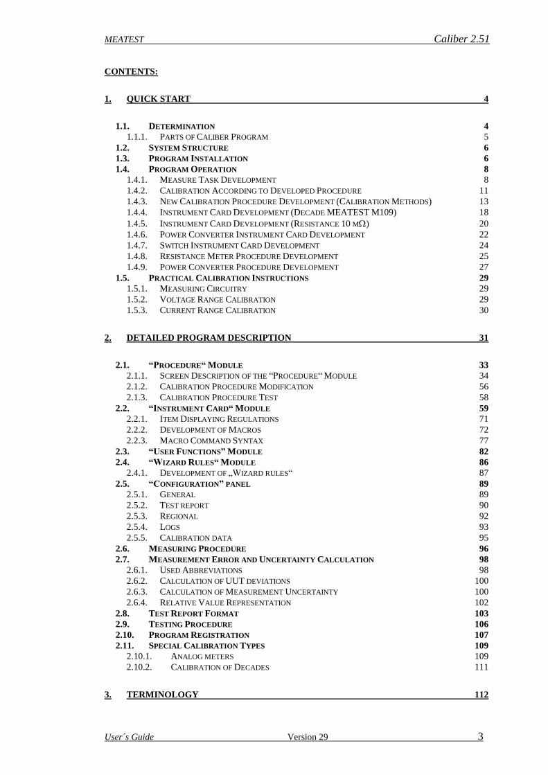
Open “Procedures” module in “Caliber“ program. Press “New” - button in the upper
bar of the status window. A Procedure wizard shall be open.
Procedure Name – a generated procedure shall be saved under this name.
Wizard Rules – a choice of rules for development of a calibration procedure. A user can
have several rule sets describing selection of calibration points for particular functions. For
details see the section “Wizard rules”.
Selected Instruments – a list of instruments for calibration performance.
To Add – it will add another item into the list of instruments.
To Remove – it will remove an item from the list of instruments.
OK – it will finish the wizard and transfer selected functions, ranges and values into the
procedure.
Cancel – operation of the wizard will be finished.
Respect the following process for procedure development:
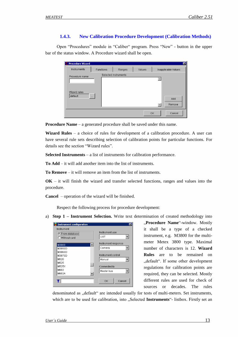
a) Step 1 – Instrument Selection. Write text determination of created methodology into
„Procedure Name“-window. Mostly
it shall be a type of a checked
instrument, e.g. M3800 for the multi-
meter Metex 3800 type. Maximal
number of characters is 12. Wizard
Rules are to be remained on
„default“. If some other development
regulations for calibration points are
required, they can be selected. Mostly
different rules are used for check of
sources or decades. The rules
denominated as „default“ are intended usually for tests of multi-meters. Set instruments,
which are to be used for calibration, into „Selected Instruments“- listbox. Firstly set an

Caliber 2.51 MEATEST
14 User´s Guide
instrument under test (UUT), select it from the database and assign a function
(“Instrument use”) and control method (“Instrument response” - Measuring by means of,
“Instrument control” - Adjustment by means of) for it. The same way is to be used for
selection of other instruments (Source, Standard). Converters, switches and instruments
to be connected behind converters cannot be written down among selected instruments,
they must be set by editing of the procedure itself. If the wizard is being used, there is no
possible to select from “Connected to” – field. There is a fixed selected item “Master
Bus” here. The master bus is a signal bus (functions, ranges and values) valid for the
UUT. For procedure development, the instrument under test (UUT) is the most important
one and it must be set as the only one. Selection of functions, ranges and calibration
points is being performed according to the UUT. At other instruments (Standards and
Sources) must be only checked if their measurement (generation) abilities are suitable for
test of the given instrument. If there is no “Instrument Card” for the required instrument,
it shall be created. For details see the section “Instrument Card Module”. “Function” –
page having activated, switch to the next step.
Note: Only instruments with their created
cards can be used for generation of a
new procedure, except for the
instrument under test for which can be
created a procedure without its
instrument card. The performed
calibration record does not contain any
evaluation and there are only deviation
and uncertainty in each of the test
report´s lines. Fields for allowed
deviation and specifications
percentages are blank. The procedure generation is not performed automatically in
such a case and checked functions, ranges and points must be set. Procedure
development without instrument cards represents only an emergency solution suitable
rather for quick check of basic functions of a unit under test but not for the calibration
itself.
If we set the instrument of “Without the instrument Card” it shall be necessary to write
down only its name and to select its position. Other steps must be performed manually
(selection of functions, ranges and points).

MEATEST Caliber 2.51
User´s Guide 15
b) Step 2 – Function Selection. The wizard shall propose functions that shall be contained
in a procedure. By means of arrows for shift of one item ( >, < ), eventually of all items (
>>, << ), number of selected functions can be reduced. Functions which are not defined
in Instrument card of the UUT cannot be used for the procedure. “Ranges” – page having
activated, switch to the next step.
c) Step 3 – Range Selection. The wizard shall propose functions that shall be contained in a
procedure. The “Range Type” shall be assigned for each of ranges (it is only for
automatic composition of calibration procedures – see below). According to the “Range
Type” and the selected “Wizard Rules”, calibration points are specified in the next step.
The “Range Type” can be modified. Press the right mouse button above the selected
range. There are following types to be selected:
Common – the range without special status (= it is neither lowest nor
highest, nor intermediate or specific).
Lowest– the lowest range.
Intermediate – the range situated in the middle. Each of the functions
contains only one range. If number of ranges is even a higher range is observed as the
intermediate one.
Highest – the highest range.
Specific – it is a range which value is situated within fix defined period of particular
magnitude (e.g. a voltage higher than 200 V, etc.).

Caliber 2.51 MEATEST
16 User´s Guide
„Common“ and „Specific“ range types can be contained many times in one function,
“Lowest” , “Intermediate” and “Highest” only once.
Point generation rules cannot be defined for every range types. If it is not defined a particular
range type for some functions it shall be suppressed in the menu (i.e. it cannot be selected).
On the contrary, for every function specific ranges can be defined (e.g. higher than 2 A, etc.).
If there is such a definition, it shall be displayed in the range type menu. Number of ranges
selected for instrument check up can be reduced by means of arrows for one item shift ( >, <
) or for all items shift ( >>, << ). The ranges not defined in the UUT instrument card cannot
be added into a procedure. Also it is not possible to add range types which are not defined in
the “Wizard Rules”. For more detail see the section “Wizard Rules Module”. “Values” –
page having activated, switch to the next step.
Note: Range types correspond with specification according to the EA 10/15
document describing the digital multi-meter test methodology.
d) Step 4 – Value Selection. The wizard shall propose calibration points for each of the
ranges and functions contained in a procedure according to the “Range Type” and
selected “Wizard Rules”. In terms of ranges there shall be possible to change particular
point sequence, change the points, reduced or added them. By means of step-by step
selection of particular “Functions” and “Ranges” it is possible to check all the points.
“Inapplicable values” – page having activated, switch to the next step.

MEATEST Caliber 2.51
User´s Guide 17
e) Step 5 – Inapplicable values (Disagreements). Finally the wizard shall write a list of
values which are not able to be set on some of the used instruments. If this list is not
blank, it will be possible to return to some of the previous steps to correct these values. If
the procedure is finished with not permitted values for some instruments, some
difficulties may occur during program run. Press the “OK” key to create a calibration
procedure for the instrument under test. This procedure can be saved by means of the
“Save” or “Save As” keys. In the WinQbase environment it will be sufficient to finish
only the Caliber program. In this way, automatic transfer of the created procedure into
database environment shall be performed.
Notes: The wizard for procedure development is the only one way how to create a
new procedure. However, if a procedure is already developed, it can be
changed interactively. We can add and remove particular functions, ranges
and calibration points.
The wizard represents a very easy and quick way of new procedure creating.
However, it doesn´t make possible to perform some special combinations, e.g.
changing of instruments during the calibration. Such changes are to be
performed additionally within the created procedure.
You can exit the wizard by pressing the OK key already in the first step after
set a procedure name and instrument selection. The particular calibration
points can be additionally written in the manual mode.
Caliber 2.51 MEATEST
18 User´s Guide
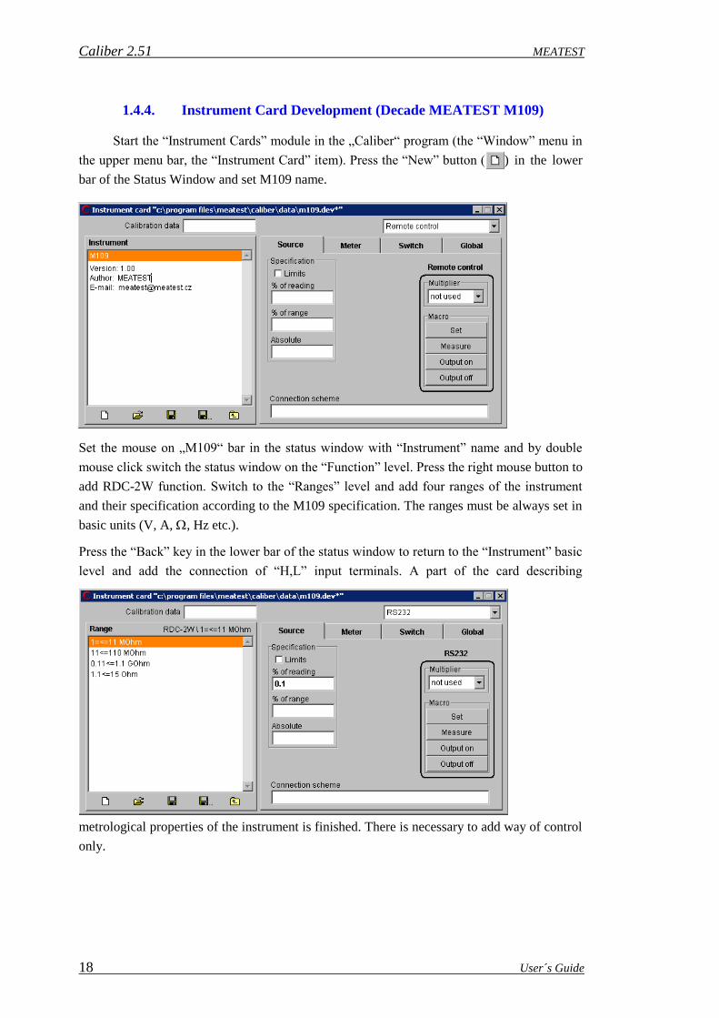
1.4.4. Instrument Card Development (Decade MEATEST M109)
Start the “Instrument Cards” module in the „Caliber“ program (the “Window” menu in
the upper menu bar, the “Instrument Card” item). Press the “New” button ( ) in the lower
bar of the Status Window and set M109 name.
Set the mouse on „M109“ bar in the status window with “Instrument” name and by double
mouse click switch the status window on the “Function” level. Press the right mouse button to
add RDC-2W function. Switch to the “Ranges” level and add four ranges of the instrument
and their specification according to the M109 specification. The ranges must be always set in
basic units (V, A, , Hz etc.).
Press the “Back” key in the lower bar of the status window to return to the “Instrument” basic
level and add the connection of “H,L” input terminals. A part of the card describing
metrological properties of the instrument is finished. There is necessary to add way of control
only.

MEATEST Caliber 2.51
User´s Guide 19
For decades without remote control, select “Manual” control mode in the upper bar.
The „Set“ option is to be in the implicit “Automatic” position. Each time
decade value is changed, an operator shall be prompted to set the
instrument.
Switch the „Measure“ option to the “Nominal value” position. The
program supposes that a value set on the decade is the required one.
Switch „Output on“ and „Output off“ options to “None” position.
The M109 can be controlled by means of the RS232 bus. Select the
“Remote control” type in the upper bar. All these settings shall be
performed on the “Instrument” basic level because they shall be valid for each of the
functions and ranges. The decade uses the M units for RS232 bus communication, because
of it set the multiplier to „mega“. The “Set” and “Measure” macros are to be filled according
to the commands for decade control. The “Set” macro consists of a value record by the “R”
command + value, counting of decade´s response. If there is the “ok” response, a 1 sec delay
shall follow for value fixation. If the response is not „ok“, the program shall interrupt with
„Communication error“ message.
The „Measure“ macro consists of the „V“ command record (value counting requirement) and
of set value counting.
Press the “Save” button ( ), in the upper bar of the status window and set the name
to the instrument card.

Caliber 2.51 MEATEST
20 User´s Guide
1.4.5. Instrument Card Development (Resistance 10 m)
Start the “Instrument Cards” module in the „Caliber“ program (the “Window” menu in
the upper menu bar, the “Instrument Card” item). Press the “New” button ( ) in the lower
bar of the Status Window and set R10MOHM name (the program doesn´t differ small and
capital letters in the name).
The resistance can be used as a source of 10 m value and also as a current/voltage converter
with 0.01 conversion constant. Both those characteristics can be described in one
instrument card. Resistance use depends on its source or transducer function.
Set the mouse on the „R10MOHM“ bar in the “Instrument” status window and switch the
status window to the “Function” level by double mouse click. Press the right mouse button to
add RDC-4W function and also RAC-4W function if alternating quantity of the resistance is
known. Switch to the “Ranges” level and add a range from 0.01 to 0.01 for both the functions.
Switch to „Frequency“ in alternating range and set a frequency range (e.g. 40 Hz - 80 Hz). Set
the Allowed deviation limit resistance in the specification window. Add terminal description
in the “Connection scheme” field (e.g. Hu,Hi,Li,Lu). Switch the control to “Manual” and the
cards to “Settings”. Switch the „Output on“ and „Output off“ to “None”, the “Measure”
panel switch to the “Fixed value” and set it into the particular field. If the value changes after
re-calibration, it can be overwritten here. Hereby the part of the card describing the 10 m
source has been finished.

MEATEST Caliber 2.51
User´s Guide 21
Now it is necessary to describe resistance´s properties for the current/voltage converter
function. Switch to “Global” page in the instrument card. Press the right mouse button in the
“Converter Conditions” listbox and select “Add”. Fill up the displayed window according to
the figure.
The converter shall convert the IDC function to VDC-2W one. It itself shall be set to the
RDC-4W function with nominal value of 0.01. The function and value, which the converter
has been set to, are significant for transfer calculation and measuring uncertainty. However
the nominal value will not be used for real calculation but the measured one (it can be
affected in the “Source” page in the “Measure” panel – there shall be set the “Fixed value” in
our case).
Press the “Save” button ( ) in the lower bar of the Status window, set a name and the
instrument card shall be saved.
Caliber 2.51 MEATEST
22 User´s Guide
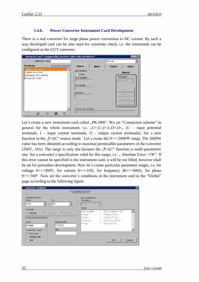
1.4.6. Power Converter Instrument Card Development
There is a real converter for singe phase power conversion to DC current. By such a
way developed card can be also used for converter check, i.e. the instrument can be
configured as the UUT converter.
Let´s create a new instrument card called „PK1000“. We set “Connection scheme” in
general for the whole instrument, i.e. „U+,U-,I+,I-,O+,O-„ (U – input potential
terminals, I – input current terminals, O – output current terminals). Set a new
function in the „P-AC“ source mode. Let´s create the 0=<=2600W range. The 2600W
value has been obtained according to maximal permissible parameters of the converter
(260V, 10A). The range is only one because the „P-AC“ function is multi-parametric
one. Set a converter´s specification valid for this range, i.e. „ Absolute Error =1W“. If
this error cannot be specified in the instrument card, it will be not filled, however shall
be set for procedure development. Now let´s create particular parameter ranges, i.e. for
voltage 0=<=260V, for current 0=<=10A, for frequency 40=<=60Hz, for phase
0=<=360°. Now set the converter´s conditions in the instrument card in the “Global”
page according to the following figure:
MEATEST Caliber 2.51
User´s Guide 23
Firstly check the “Converter as UUT” field. In that way the converter´s parameters
shall be set in order to use the converter as the UUT. The converter shall convert
power (PAC) to current (IDC) and a converting multiplying constant is to be written
down into the “Add” field. The converter value shall not be added to the formula.
The converter is to be set to the same function as the input converter function. The
converter value must stay as being set automatically by the program (the whole right
part of the panel). It is the basic condition of converter´s usage as a UUT.
The card shall be used only in the manual mode. A “Manual” panel shall be set to the
“Calibration message” and “None” options. The instrument shall not be set any way,
i.e. no setting shall be made during calibration. Herewith the instrument card is
finished.

Caliber 2.51 MEATEST
24 User´s Guide
1.4.7. Switch Instrument Card Development
There is a simple switch card for switching of terminals in the middle of a calibration
point. It can be used for calibration of resistance ranges of a checked measuring
instrument by means of an standard measuring instrument, if it is not possible to
connect both of the measuring instruments at the same time, i.e. firstly the
measurement shall be performed by means of the standard and then by the UUT
measuring instrument. The card is developed for manual control (there is not a real
instrument), but if it is a real switch with remote control ability it shall be suitable do
add a remote control. The measurement mode is to be adapted to use the card during
the procedure. A practical example for usage of the switch – see Procedure
development for a resistance meter.
- Start the “Instrument Cards” module (the “Window” menu in the upper menu bar, the
“Instrument Card” item). Press the “New” button in the lower bar of the Status Window and
set the SW_RESISTANCE name.
- Now select the “Manual” communication type.
- Select the “Switch” page in the card window.
- Set to the manual Set A option. As "Calibration message" select the “User Text”.
Write “Detach UUT, attach Standard” into the “Message” field.
- Set to the Manual Set B option. As "Calibration message" select the “User Text”.
Write “Detach Standard, attach UUT” into the “Message” field ".
- Press the “Save” button in the lower bar of the Status window to finish the card.

MEATEST Caliber 2.51
User´s Guide 25
1.4.8. Resistance Meter Procedure Development
There is a test of a resistance meter by means of a standard measuring instrument and
an auxiliary source. In such a case there is not possible to connect the checked
measuring instrument and the standard at the same time, because they themselves are
generating current and measurement results will be nonsense because it. The
measurement must be made on the standard first and then on the UUT. The
instruments shall be switched among each other. There is possible to use the “Switch”
instrument for that purpose, which has already been created. There is only a shortened
demonstrative procedure to understand the program features.
- Start the “Procedure” module in the „Caliber“ program. Press the “New” button in
the lower bar of the Status window to start the Procedure wizard.
- Write KE2000R in the “Procedure name” window. Select instruments for the
calibration. Press the “Add” key. From the list select the KE2000 instrument, an
instrument position use to „UUT“, instrument response and control set to „Manual“,
connected to the “Master bus” and press the „OK“ key. Press the “Add” key. From the
list select the DAT1281instrument, an instrument use set to „UUT“, instrument
response and control set to „Manual“, connected to the “Master bus” and press the
„OK“ key. Press the “Add” key again, select the M602 decade, a instrument use set to
„Source“, instrument response and control set to „Manual“, connected to the “Master
bus” and press the „OK“ key. If one of the instruments is available, it can be selected
way of communication along the bus.
- Start the “Functions” page to come to the next step – Function selection. Firstly shall
be removed all functions from the selection by means of the "<<" key. Then select the
RDC-2W function from the left column of “Functions available” and by means of the
">" key transfer it into the “Selected functions” list as the only one controlled function.
- Start the “Ranges” page to come to the next step – Range selection. The wizard shall
automatically propose all the ranges being defined in the KE2000 card and assign a
range type for them. The range types are defined according to “Wizard Rules”. The
1.2MOhm, 12MOhm and 120MOhm ranges shall be removed because they cannot be
set on the source.
- Start the “Values” page to come to the next step – Value selection. The wizard shall
automatically propose calibration points according to the “Wizard Rules”. The
calibration points can be added, removed, eventually adapted.
- Start the last “Inapplicable values” page to come to the next step – Inapplicable
values. There are values displayed here that cannot be set at any of the instruments. If
the list is not blank, it is possible to come back into the “Values” page and to remove
those points eventually to change them.
- Press the „OK“ key to create a calibration procedure for the UUT.

Caliber 2.51 MEATEST
26 User´s Guide
- Now we are in the procedure module again and all settings shall be performed on the
whole procedure level, i.e. there shall be selected the “Procedure” level in the Status
window.
- Let´s add a switch instrument into instrument scheme. Click with the right mouse
button on the instrument scheme window and select the “Add Instrument” item from
the menu. The “Instrument configuration” panel will appear. Select an instrument
from the "SW_RESISTANCE" database, set Instrument use to “Switch”, Instrument
response to “Manual”, Instrument control to “Manual”, Connected to “Master bus”.
Confirm it by "OK". The instrument appears in the instrument scheme. By means of
the mouse it is possible to move the instrument to any place in the scheme in order to
be well-arranged.
- Now the Measurement mode shall to be changed to exert the switch function. In the
procedure status window click by the right mouse button on the procedure name,
select the “Measurement mode” item from the menu. The “Measurement mode” panel
appears. Firstly there shall be secured that the measuring on the standard is being
performed in one step, not in two ones. Click by the right mouse button on the
“Second half measure” item by the standards and select the “Remove” item from the
menu. Click by the right mouse button on the “First half measure” item by the
standards and select the “Modify” item and change to the “Measure” item. Now add
an operation for terminal switching between the UUT and the Standard. Click by the
right mouse button on the action list, select the item “Add” from the menu. The
“Measurement mode Action” panel appears. From the instrument field select
"Switches", from the Action field select "Set B", from the condition field select
"None". Press the "OK" key to confirm. The operation appears at the end of the task
list. Transfer it among the “Measure” operations on the UUT and “Measure”
operations on the Standard. Now adjust loops for unstable measurements, it will not be
one loop but two ones, particularly for the UUT and the Standard in order not be
necessary to switch the terminals permanently if one of the measuring instruments is
unstable. Click by the right mouse button on the “Measure” action at the standard and
select the “Begin of Measure loop” item. Click by the right mouse button again and
select the “End of Measure loop” item. Click by the right mouse button on the
“Measure” action at the UUT and select the “Begin of Measure loop” item. Click by
the right mouse button again and select the “End of Measure loop” item. Press the
“OK” button to confirm.
Note: Remember that the Caliber program shall not display the “Connection scheme”
window when the switch is being used. If you want to display this window, it shall be
selected the “Enable” item in the “Connection scheme” field in the “Measurement
Mode” panel.
- Press the “Save” button in the lower bar of the procedure status window. The
procedure is herewith finished and it can be started by the “Run Calibration” button.
Since all the instruments are in manual mode, the instruments cannot be present at
calibration start, i.e. the calibration can be only “simulated”.

MEATEST Caliber 2.51
User´s Guide 27
1.4.9. Power Converter Procedure Development
There is a test of single-phase power converter to direct current. In similar way there is
possible to perform test of any converters. For that purpose (the converter represents
an UTT), two standards are necessary. One of them shall be in the converter´s input,
another one in output (direct current measurement). The value in the converter´s input
is considered as a standard value in terms of the Caliber program, the value in the
converter´s output as an UUT value. The input converter´s value is the main value, i.e.
its function, range and value is the same as a function, a range and a value in the test
report. The value in the converter´s output is direct current in our case, but for
program´s purpose is back converted into power. Despite of the fact that the value of
the standard measuring instrument in the converter´s output is being considered as the
UUT value, the uncertainty of this measuring instrument is considered as standard´s
uncertainty along with uncertainty of the standard in the converter´s input. The M140
calibrator shall be used as a source and a standard in the converter´s input at the same
time. As a standard in the converter´s output the multi-meter of Datron 1281 shall be
used. The PK1000 shall be used as a converter (creating procedure is a part of this
manual). There is a shortened demonstrative procedure to understand program´s
features.
- Start the “Procedure” module in the „Caliber“ program. Press the “New” button in
the lower bar of the Status window to start the Procedure wizard.
- Write PK1000x in the “Procedure name” window. Select instruments for the
calibration. Press the “Add” key. From the list select the PK1000 instrument, an
instrument use set to „UUT & Converter“, instrument response and control set to
„Manual“, connected to the “Master bus” and press the „OK“ key. Press the “Add”
key. Select the M140 calibrator, an instrument use set to „Standard & Source“,
instrument response and control set to „Manual“, connected to the “Master bus” and
press the „OK“ key. We don´t add any other instruments at this moment.
- Start the “Functions” page to come to the next step – Function selection. The wizard
shall automatically propose functions contained in the “Instrument card” of PK1000
which were not used in the procedure so far. The instrument contains only one P-AC
function which shall stay.
- Start the “Ranges” page to come to the next step – Range selection. The wizard shall
automatically propose all the ranges being defined in the PK1000 card and assign a
range type for them. The instrument contains only one 2.6 kW range which shall stay.
Because the power converter uses a more-parametric function (P-AC), it is only one
range in the instrument card. However number of ranges in the procedure can be
higher. There must be a condition fulfilled that any of the ranges cannot excess the
limits of the basic range (0 to 2.6 kW in our case). The ranges cannot be added in the
wizard but in the following adaptation of the procedure.

Caliber 2.51 MEATEST
28 User´s Guide
- Start the “Values” page to come to the next step – Value selection. The wizard shall
not create any values. For more-parametric functions there are no “Wizard Rules” and
the values shall be created manually. Press the “Add” button to add one calibration
point and set the power value of 0.4kW and particular parameters: Voltage=200V,
Current=2A, Frequency=50Hz, Phase=0°. Press the "OK" button to confirm.
- Inapplicable Values of calibration points cannot be checked by means of the wizard,
because it doesn´t support the more-parametric functions.
- Press the „OK“ key to finish the wizard and to come into the procedure module.
- Now add a standard measuring instrument into the converter´s output in the
“Instrument scheme”. Click by the right mouse button on any spot in the “Instrument
scheme” window to open a menu. Select the “Add Instrument” item. The instrument
configuration panel appears. Select the "Dat1281", set Instrument use to "Standard",
Instrument response and Instrument control to “Manual” (eventually GPIB or RS232 if
you have a multi-meter), connected to "PK1000". Press the "OK" button to confirm.
By means of the mouse it is possible to move the instrument to any place in the
scheme in order to be well-arranged.
- Now must be set uncertainties of the standard calibration source of M140 for each of
calibration points, because these values are not contained in the instrument card. Set
the value level in the procedure status window and select a calibration point for which
the precision shall be set. Click by the right mouse button to open a menu from which
select the “Evaluation” item. The “Evaluation” panel will appear, in which values and
uncertainties of the UUT and Standard can be changed. From the list select the
"Standard accuracy (Dmax_s) [W]" item and press the "Modify" button. The
„Evaluation formula” panel appears. By means of numeric keys set the "0.288W"
value, which is accuracy of the M140 calibrator for the 400W value (at parameters of
200V, 2A, 50Hz, PF=1). Confirm it by the "OK" button and return to the “Evaluation”
panel. Press the "OK" button again to return to the Procedure module. If the procedure
contains more calibration points, this setting shall be done for all the calibration
points.
- Press the “Save” button in the lower bar of the procedure status window to save the
procedure which can be started by the “Run Calibration” button now. Despite that we
don´t have any of the used instruments, there is possible to try the procedure if every
instruments are in the manual mode. During the calibration, the Caliber program shall
ask for value of the standard multi-meter Datron 1281 and there is expected the
0.00308A value for the 400W value, which is to be set.
MEATEST Caliber 2.51
User´s Guide 29
1.5. Practical Calibration Instructions
1.5.1. Measuring Circuitry
Correct ways of measuring circuitry are to be respected when accurate multi-meters
with accuracy more than 0.005% are being used as standard instruments, e.g. DATRON
1281, HP 3458.
Ground Connection of the Measuring Circuitry
When a calibrator and one or more multi-meters are connected among each other, there
is always a risk of “ground loops”. These lops are constituted by connections of measuring
terminals along with connections of supply cables with power networks. Through the ground
loops high currents can flow, usually the alternating and synchronous ones with the first or
second harmonic component of power supply current. Presence of these currents is being
expressed itself as data instability on the tested measuring instrument. This instability is
mainly evident in alternating ranges for frequencies of 50, 100, 200, 400 Hz, also for power
network frequency multiples. For higher frequencies of measuring signals this instability is
not practically significant. The instability will cause a comparatively slow and regular
fluctuation of signal amplitude. The beat frequency is determined by difference between the
power supply frequency and the frequency of the calibrator´s signal.
Effects of the ground loops can be eliminated by following steps:
a) All the ground outlets must be connected in one point, the best is in a Lo terminal of
calibrators (star connection). Calibration must not be performed with no-grounded
measuring circuits.
b) Main supplies of the calibrator of the control computer and both of the multi-meters must
be connected with one supply list or with a main supply socket.
c) If above mentioned measurements prove ad little sufficient ones, a low frequency toroid
choke can be connected in the main supply inlet of the calibrator or the multi-meter. The
choke can be made by winding of a few turns of a supply cord on a permalloy core of 7 –
10 cm diameter.
d) Finally, if network interferences ere too big, their effect can be reduced by calibration
performance at non-harmonic multiplies of the main supply frequency, e.g. 60, 120 Hz
(only for calibrations of alternating voltage and current ranges).
1.5.2. Voltage Range Calibration
The most practically way for the voltage range calibration is the connecting of multi-
meters directly with calibrator´s input terminals. Mainly for low voltage calibrations, when it
is necessary to perform comparison with uncertainty of hundredths of nV to units of V, it
shall be used cupper wires with gilded terminations soldered with low-thermal solders. We
neither unnecessarily touch input and output terminals nor allow local warming of some parts

Caliber 2.51 MEATEST
30 User´s Guide
of measuring circuitries (e.g. by ventilators, heat radiators, etc). Having connected them, we
will wait till a thermal voltage get stabilized and balanced. For extremely accurate
measurements of low voltages it shall be better to connect input terminals of the standard
multi-meter with input terminals of the multi-meter under test, which way is also very suitable
if the multi-meter under test possess a lower input resistance. The connection of the standard
multi-meter is being equivalent to the four-terminal connection of the calibrator.
If the 10, 100 mV range of the calibrator is used, it is necessary to take into
consideration that output resistances of some calibrators can be 50 - 100 and they cannot be
loaded.
1.5.3. Current Range Calibration
Calibration for Low Alternating Currents
For calibration of low current ranges there can be considered that each capacity
connected parallel to input terminals of a measuring instrument (and also a capacity of the
used calibrator) represents an alternating shunt. Part of the calibrated current generated by the
calibrator is running out off the connected measuring instrument and is running through this
shunt. The value of this stray current is being proportional to the load voltage and it depends
on the measuring instrument (on its input impedance) and on the measuring frequency. Free
laid shorter wires are as the most suitable for connection of both of the multi-meters and the
calibrators. Coaxial cables are completely unsuitable for this purpose.
Calibration for Heavy Currents
For calibration of the 1 and 10 A (100A at M-150S) current ranges there is necessary to
connect together a calibrator and a multi-meter under test with sufficient strong cables. At all
the connection through which currents are running is more suitable to tighten wires under
terminals in order to reduce contact resistances.
WARNING!
Most of the portable multi-meters have their maximal input current of 2 A. Their
connection with calibrators with adjusted input currents higher than 2 A can result in multi-
meter´s damage. The only way of using a standard multi-meter for a calibration consists in
usage of a precise and properly sized shunt.

MEATEST Caliber 2.51
User´s Guide 31
2. Detailed Program Description
The „Caliber“ program represents a program system to perform measuring instrument
calibrations automatically. It can be used independently or along with the WinQbase program
for registration of measuring instruments and their calibration. The program can be
incorporated into the WinQbase by setting of command and measuring file name for the
„Caliber“ – more details see the WinQbase-manual, section of „Measuring instrument
groups“. In that manual there is described program´s behavior by its independent usage
because it is the only way of describing of all its features. During program´s run under the
WinQbase system, the registration program takes over some of its functions.
The program having started, a basic screen appears:
The screen consists of three following parts:
1. The upper menu program bar (it contains menus for module selection, editing functions
and help).
2. The program desktop (it displays active windows of the program – modules – after the
start the “Procedure” module).
3. The lower information line (it displays information about a selected object, program
operation and keyboard status).

Caliber 2.51 MEATEST
32 User´s Guide
A required activity can be started by click (press the left mouse button) on a selected
object. Program control is intuitive one with common custom practice of the WINDOWS.
In the lower information line the program will automatically display the help for the
selected object. In addition to, at some objects a description shall be displayed next to the
mouse cursor. The displaying can be switched off in the menu bar from the “Help” menu (the
“Show tooltips” item).
Upper Menu Bar
Exit shall finish program operation.
Undo shall cancel the last performed activity.
Redo shall perform the last cancelled activity.
Cut shall remove the designed text and save it in
memory.
Copy shall copy the designed text in memory.
Paste shall insert the last in memory saved text in place
of the cursor.
Select all shall design the whole text as a block.
Find... allow searching in the displayed text.
Replace... allow automatic changes in the designed text.
Configuration… global program settings
Procedures It is a module for work with calibration procedures
(calibrations, modifications and creations of calibration
procedures).
Instrument cards It is a module for work with instrument
definitions (instrument features as functions, ranges,
specifications, way of controls).
User functions It is an auxiliary module for work with functions (new function development,
modifications of existing ones).
Wizard rules It is an auxiliary module for definitions of rules used for development of
calibration procedures by the program.
Caliber help F1 shall display the help content of the Caliber
program.
Show tooltips shall prohibit or permit displaying of short
prompt instructions at buttons during mouse cursor movements.
About Caliber shall display information about the program and
allows program registration.

MEATEST Caliber 2.51
User´s Guide 33
2.1. “Procedure“ Module
It is intended for calibration performances in terms of prepared calibration procedures
(methodologies). Except calibrations it makes possible developments, modifications and
testing of calibration procedures.
The calibration procedure determines functions being checked, ranges and points,
instruments used to calibrations and way of instrument connections. Features of those
instruments as way of control, specifications, allowed value ranges are determined by so
called instrument cards.
The “procedure” module performs all the control operations, measurement evaluations,
uncertainty calculations and generation of calibration protocols. During measuring of an
instrument under test there can be possible to set required information, to stop the program, to
skip check of functions, of ranges or points, eventually it is possible to insert points at which
the procedure performance shall be stopped. There is also possible to change sequences of
checked points, uncertainty calculations, numbers of measures, eventually instruments used in
the calibration.
The program shall be controlled by means of a mouse or by setting of required values
from a keyboard. The calibration can be stopped by pressing the „ESC“ key.

Caliber 2.51 MEATEST
34 User´s Guide
2.1.1. Screen Description of the “Procedure“ Module
The procedure module having opened and the M3800 methodology having loaded
(press the „Open“ key and select the M3800 methodology, which represents a
standard delivery part) the following panel shall appear:
There is a Status window in the upper corner. It displays the procedure structure
(hierarchy) – procedure -> function -> ranges -> calibration points. In the middle part of the
panel there is an Instrument scheme displayed – instruments used for the calibration and their
configuration. In a Camera window there is displayed a running video from the camera (if a
camera scanning is used), control keys for picture shift, resolution adjustment (zoom) and
external condition adjustment (brightness, contrast, etc.). There is an Information line below
the instruments which describes just performed operation during the calibration. Below the
information line there is displayed User prompt window. In the right Readings window there
are displayed particular measured values. In the upper half of the screen there is a Test report
displayed with all the calibration points which is being continuously supplemented during the
calibration. The test report contains the calibration point under the sequence of their
performance.
Open dialog – for opening documents it is used following dialog. This dialog supports
sorting by name and
by date (not supported
under WinQbase
system). There is also
possible to lookup
( ) or/and filter
( ) the document
titles.

MEATEST Caliber 2.51
User´s Guide 35
Status Window
It is intended for displaying of tested functions,
ranges or points of an instrument under calibration
according to the displayed hierarchy level. The window´s
hierarchy is: Procedure->Function->Range->Value. The
procedure has the highest hierarchy level, the value the
lowest one. Click with the mouse on the procedure name
(usually the name of an instrument under test) shall
perform switch the display to checked functions. Click on
a selected function shall display ranges of this function
and further is possible to go to particular check
points. The button with symbol is intended for back
movements. During transition to lower hierarchy level there shall be also displayed contents
of the superior level and contents of the actual level is separated by a horizontal line. If the
“Value” level is selected, there shall be a “procedure name” in the first line, a “function
name” in the second one, a “range” in the third one, after it a separator follows along with all
the values belonged to the calibration range. The actual hierarchy level is determined by an
inscription in the upper part of the window. On the right side of the inscription there is a list
of icons symbolizing the particular procedure adjustment. These icons correspond with
particular columns of the status window in which a position of this particular adjustment is
being indicated by the „*“ symbol. This setting can be changed by the right mouse click on
the selected line of the status window. The last icon ( ) symbolizes the instrument scheme
and its setting cannot be changed by means of the status window menu, but in the instrument
scheme only. One can see all the particular adjustments valid for the given calibration point
best inclusive the level for which that change has been permitted, if the status window level
of “Value” has been selected. For each of the calibration points it is valid only the adjustment
defined at the lowest level. If the adjustment is defined for a given value, it shall be used and
the superior adjustment shall be ignored. If an adjustment is not defined for a point but for a
range, an adjustment valid for the range shall be used etc. If the highest level is selected, i.e.
the procedure, the procedure´s description is displayed under the procedure´s name. This
description can be changed. There is used to be given a version, an author, e-mail or other
additional information about the procedure.

Caliber 2.51 MEATEST
36 User´s Guide
Press the right mouse button in the status window to display the following menu
according to the selected line:
Add value… It shall add another item into the calibration
procedure. The item can be a function, a range, eventually another
value. It depends on the just displayed hierarchy level “function-
range-value”. All the added values are displayed in the Test report
window at the same time.
Modify… It make possible to change a selected item (a function, a
range, a value).
Delete… It shall remove a selected item (a function, a range, a
value) from the list.
Move up… It shall shift a selected item to the first upper position.
Move down… It shall shift a selected item to the first lower
position.
Measurement parameters… It shall set an extension coefficient for calculation of
uncertainties, measured numbers add allowed specification utilization for selected items
(procedures, ranges, values). Particular uncertainty settings are being indicated by the symbol
.
Meanings of the particular items:
No. of SU readings It means how many repeated readings are being performed by the
standard measuring instrument. If a signal source represents a
standard, only one reading shall be made (test of source
adjustment). One of the uncertainty components shall be determined
from a reading set (A type).
No. of UUT readings It means how many repeated readings are being performed by the
measuring instrument under the calibration. If a UUT represents a
signal source, only one reading shall be made (test of source
adjustment). One of the uncertainty components shall be determined
from a reading set (A type).

MEATEST Caliber 2.51
User´s Guide 37
Note: 10 repeated measurements are recommended to right evaluation of the
calibration uncertainty of A type. Only in this case the uncertainty shall be
calculated accurately according to the EA-4/02 document.
% of UUT accuracy It means how is Allowed specification utilization for the UUT. E.g.,
if it is set instead of the implicit 100% value only 70%, the program
shall check if the measured deviation is smaller than 70% of the
Allowed specification.
Extension coefficient It is the extension coefficient used for calculation of a standard
extended calibration uncertainty. The implicitly adjusted value is
2.0.
Reset to default It cancels the special measurement parameter adjustment. The
measured parameters returns to that according to the implicitly
adjustment (10 readings, 100 % of specification, ku = 2.0) or to an
adjustment defined in higher level.
Additional uncertainty… set parameters of an uncertainty calculation for selected items
(functions, ranges, values). The particular uncertainty setting is indicated by the
symbol .
Pause… inserts a stop point into the program. The inserted point is indicated by the
symbol . To set a pause, an operator shall fill up a text message (a report) or select a file to be
displayed. The file can be a text document (TXT) or a figure (JPG, GIF, BMP, DIB). Press
the right mouse button on the file list to open a menu for adding, removing or displaying of
the file. The message or file shall be displayed if the program during calibration performance
met a point (a function, a range) designed as “Pause”.
Include/Exclude allows to skip a value (a range, a function). The excluding is indicated by
the symbol . The omitted item shall not be calibrated and included into the calibration
report. By excluding of functions or ranges it is possible to shorten a big calibration
procedure (i.e. to perform calibration for only one function).
Quantity prefix allows to set a prefix (micro, mili, kilo etc.), which shall be used in a test
report. The prefix can be defined only for the range level and it shall be valid for the whole
range. Changes of the implicit prefix is indicated by the symbol . The prefix is defined
only in exceptional cases because it is automatically set by the program according to the
range´s size.

Caliber 2.51 MEATEST
38 User´s Guide
Measurement mode is a list of tasks being performed by the Caliber program during the
calibration. The program has a defined measurement process to be used during the
calibration. The measurement mode allows to add and remove actions (adjustments,
measurements, terminal switch on, terminal switch off) for particular instrument categories
(sources, measuring instruments, converters, UUTs, standards) or for a particular instrument
from the instrument scheme. For mode modifications it is suitable to use instrument
categories, (if it is possible), not particular instrument types to maintain the measurement
mode valid even if the instrument scheme gets changed. Operation sequence is to be changed
easily. In addition to, a section of operations being repeated (at most 3times) can be defined if
some measurement proves to be unstable for some of the measuring instruments in the
section. This is demonstrated by red markings in the left part of the task lists. Also a few
those sections can be defined, e.g. for each of the measuring instruments separately. The
operation shall be performed during the calibration only if there is an instrument of that
category in the “Instrument scheme”, if e.g. no converter is used in the instrument scheme, if
no operation shall be performed on the converters and the program shall not report it as an
error. There is possible to “Add”, “Remove” or “Modify” any operation by pressing the right
mouse button on the required section. “Measurement mode Action” panel will be shown:
Devices – It can be selected a general category (a standard, an UUT, a source…) or a
particular instrument suitable for this operation (M3800). General categories are the
following:
Sources – an operation shall be performed on all the sources.
Meters - an operation shall be performed on all the measuring instruments.
UUT - an operation shall be performed on an instrument under test (it can be a
meter, a source or a converter).
Standards - an operation shall be performed on all the standards (it can be a
meter or a source).
Switches - an operation shall be performed on all the switches.
Converters - an operation shall be performed on all the converters.
Action – it can be selected one of the following options:

MEATEST Caliber 2.51
User´s Guide 39
Set – it shall set a function, a range, a value and parameters of the instrument
(not available for a switch).
Fine Set – for additional setting of an analog measuring instrument (only for
sources available).
Switch output on – It shall switch instrument´s terminals on (only for sources and
converters available).
Switch output off – It shall switch instrument´s terminals off (only for sources
and converters available).
Measure – It shall perform a set of measurements or one measurement in case of
a source (not available for a switch).
First half measure – It shall perform the 1st half of a set of measurements (only
for meters available).
Second half measure – It shall perform the 2nd half of a set of measurements
(only for meters available).
Set A – It shall perform A setting (only for a switch available).
Set B – It shall perform B setting (only for a switch available).
Set C – It shall perform C setting (only for a switch available).
Set D – It shall perform D setting (only for a switch available).
Conditions – It shall be a condition defined, under which an operation is to be performed:
None – an operation shall be always performed.
UUT is analog meter – an operation shall be performed if the UUT is an analog
measuring instrument.
UUT is not analog meter – an operation shall be performed if the UUT is not an
analog measuring instrument.
Evaluation… defines measured values and specifications of an UUT, a Standard and an
auxiliary standard. The program automatically assigns values for the UUT and the Standard.
Values of the auxiliary standard are in principle zeros. Only in case of converter´s test an

Caliber 2.51 MEATEST
40 User´s Guide
instrument connected behind the converter (UUT) is automatically set as an auxiliary
standard. In that case as a standard serves a measuring instrument or a source connected with
a converter´s input. A user can change any items from the list and these values shall be part of
uncertainty calculations or they can serve as values in the Test report.
UUT value (Xu) – measured value of an UUT contained in the Test report
UUT uncertainty (Uua) – uncertainty calculated from a measurement set
UUT accuracy (Dmax_u) – limit error of an UUT proven from the instrument card
UUT one digit (Dig_u) – size of one digit proven from the instrument card
Standard value (Xs) – measured value of a standard contained in the Test report
Standard uncertainty (Usa) – uncertainty calculated from a measurement set of the standard
Standard accuracy (Dmax_s) – limit error of a standard proven from the instrument card
Standard one digit (Dig_s) – size of one standard digit proven from the instrument card
Standard converter accuracy (Dmax_c) – standard uncertainty due the limit error of a
converter
Auxiliary standard uncertainty (Uta) – uncertainty calculated from a measurement set of the
auxiliary standard
Auxiliary standard accuracy (Dmax_sa) – limit error of an auxiliary standard proven from the
instrument card
Auxiliary standard one digit (Dig_sa) – limit error of an auxiliary standard proven from the
instrument card.
If the “Auto” assignment is selected, the program shall assign the values from measurements
and instrument cards as supposed. A user can change this feature according to the following
panel:
Evaluation formula - in this panel
an equation for calculation of
required values can be defined. It
can be possible to add common
mathematic functions (sin, cos,
log), numeric values (0…9),
mathematic operators (+-*/),
instrument parameters (e.g. a
measured value, an uncertainty,
an accuracy) or global
parameters (if there are any
parameters for a particular level
in a particular function, e.g. a
frequency). All these items can be combined together and create more complicated equations.
In the figure there is a calculation example for a standard value. There are three standard

MEATEST Caliber 2.51
User´s Guide 41
instruments (HP3458 as a voltmeter, DAT1281 as an ampere-meter, PHM as a phase meter)
for calculation of a resulted power P=U*I*cos(Ø).
Note: Remember that instrument parameters are in units of the particular instruments but the
result value must be always in global units, i.e. that valid for the UUT. Goniometrical
functions count an angle always in radians. If a parameter is in grades, it must be
recalculated.
Rounding… allows to change the rounding method for particular columns of the test report.
A column can be selected from a column list within also the used rounding method is
contained. There are three automatic formats:
-Mode A
UUT – according to the UUT digit numbers or the uncertainty (shorter expression), a
unit like a range
Standard – according to the UUT digit numbers or the uncertainty (shorter expression),
a unit like a range
Allowed – according to the uncertainty, a unit order lower than a range
Deviation – according to the uncertainty, a unit order lower than a range
Uncertainty – two valid digits, a unit order lower than a range
Limits – shortest possible expression, a unit like a range (the limits are placed into
"Allowed column" in test report)
-Mode B
UUT – according to the UUT digit numbers, a unit like a range
Standard – according to the standard digit numbers, a unit like a range
Allowed – two valid digits, a unit like a range
Deviation– two valid digits, a unit like a range

Caliber 2.51 MEATEST
42 User´s Guide
Uncertainty – two valid digits, exponential expression, a unit like a range
Limits – shortest possible expression, a unit like a range (the limits are placed into
"Allowed column" in test report)
-Mode C
UUT – according to the UUT digit numbers, a unit like a range
Standard – according to the UUT digit numbers, a unit like a range
Allowed – according to the uncertainty, a unit order lower than a range
Deviation – according to the uncertainty, a unit order lower than a range
Uncertainty – two valid digits, a unit order lower than a range
Limits – shortest possible expression, a unit like a range (the limits are placed into
"Allowed column" in test report)
If the “User” mode is selected for a selected column, following options shall appear:
Number expression – determines display type – Without exponent (120.5) or With exponent
(1.205e+2)
Decimals – number of digits behind the decimal point
Digits – total number of significant digits either in front of or behind the decimal point
(uncertainty is usually expressed with 2 significant digits)
Quantity prefix – it can be selected a particular prefix (mili, micro, kilo) or a prefix in relation
to the prefix used for the range. If the „mili“ prefix is selected for the range
along with the „<Like range-1>“ item, it shall be used the „micro“ prefix, if the
„< Like range -2>“ item is selected, it shall be used the „nano“ prefix.
Atto – 1e-15
Femto – 1e-12
Piko – 1e-9
Nano – 1e-6
Micro – 1e-3
None – 1e+0
Kilo – 1e+3
Mega – 1e+6
Giga – 1e+9
Tera – 1e+12
< Like range -3> - range * 1e-9
< Like range -2> - range * 1e-6
<Like range -1> - range *1e-3
< Like range > - range

MEATEST Caliber 2.51
User´s Guide 43
Test report note… allows writing additional information in an output test report. There is a
text box in upper part of window. This text box shows selected note in form the note will be
displayed in test report too. Caption of this text box is composed of column labels, so user
can create notes in accordance to this lay-out. Up to four notes can be defined in this panel for
individual placement of note. Note can consists of one or more lines.
Place – position of a note in terms of the output record. Notes for "Begin of protocol" and
"End of protocol" placement are evaluated only once per all calibration. Note specification is
marked with an icon. There are following options:
Begin of protocol – a note shall be situated at the very beginning of the test report
Before measure– a note shall be situated in front of the calibration point
After measure – a note shall be situated behind the calibration point
End of protocol – a note shall be situated at the very end of the test record
Note item – list of note items composed for given placement. Order of the items can be
changed here, items can be added, modified and removed.
Add – a new item shall be inserted into a note
Remove – a selected item shall be removed
Remove all – the whole note for particular placement shall be deleted
Export – exports the contents of the "Note item" window into the file. The file will have the
*.nte extension.
Import – imports note from the file. The note can be imported only from earlier exported files
(* .nte). Before importing you need to select "Place".
Replace calibration result by note – this checkbox allows to suppress exporting calibration
results. Instead of the calibration result this test report note is exported. Despite this
suppression all calculations are done and individual calibration columns can be placed into
note.
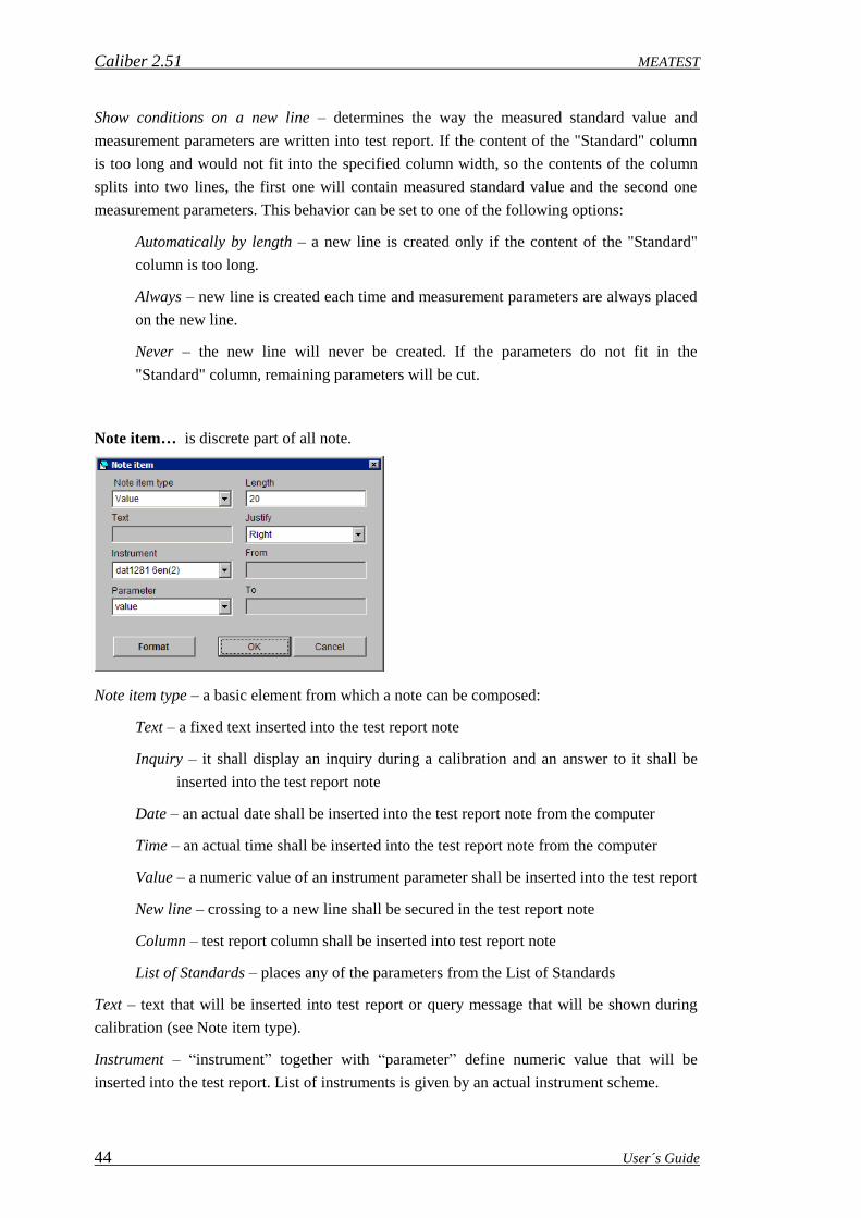
Caliber 2.51 MEATEST
44 User´s Guide
Show conditions on a new line – determines the way the measured standard value and
measurement parameters are written into test report. If the content of the "Standard" column
is too long and would not fit into the specified column width, so the contents of the column
splits into two lines, the first one will contain measured standard value and the second one
measurement parameters. This behavior can be set to one of the following options:
Automatically by length – a new line is created only if the content of the "Standard"
column is too long.
Always – new line is created each time and measurement parameters are always placed
on the new line.
Never – the new line will never be created. If the parameters do not fit in the
"Standard" column, remaining parameters will be cut.
Note item… is discrete part of all note.
Note item type – a basic element from which a note can be composed:
Text – a fixed text inserted into the test report note
Inquiry – it shall display an inquiry during a calibration and an answer to it shall be
inserted into the test report note
Date – an actual date shall be inserted into the test report note from the computer
Time – an actual time shall be inserted into the test report note from the computer
Value – a numeric value of an instrument parameter shall be inserted into the test report
New line – crossing to a new line shall be secured in the test report note
Column – test report column shall be inserted into test report note
List of Standards – places any of the parameters from the List of Standards
Text – text that will be inserted into test report or query message that will be shown during
calibration (see Note item type).
Instrument – “instrument” together with “parameter” define numeric value that will be
inserted into the test report. List of instruments is given by an actual instrument scheme.

MEATEST Caliber 2.51
User´s Guide 45
Parameter (for "Value" note item type) – parameter of an instrument:
value – average value taken from set of readings
uncertainty – uncertainty calculated from measurement set
accuracy – limit error proven from the instrument card
one digit – size of one digit proven from the instrument card
reading1-20 – individual reading made during calibration
Parameter (for "List of Standards" note item type) – parameter of a standard:
Order – one based Standard device index
Model – item is read from the calibration data file
Manufacturer – item is read from the calibration data file
Serial number – item is read from the device or from the procedure
Due date – item is read from the calibration data file
Description – item is read from the calibration data file
Column – test report calibration column inserted into note:
Function – function of UUT
Range – range of UUT
Standard – measured standard value and list of function parameters. Before calibration
it contains nominal value of calibration point.
UUT – measured UUT value
Deviation – deviation of UUT relative to Standard
%spec – "Deviation" to "Allowed" rate expressed in percentage (= Deviation / Allowed
* 100 %)
Allowed – allowed accuracy of UUT
Uncertainty – total uncertainty
Symbol – test report symbols such as "~" - unstable reading, "R" - all calculations done
relative to range or PASS vs FAILED
Length – length of the source string which shall be inserted into the note. If the source string
is shorter, it shall be completed by spaces, if it is longer, it shall be shortened.
Justify – it shall set a justification of the source string to the total length:
Left – justification to the left, spaces shall be on the right side of the string
Right – justification to the right, spaces shall be on the left side of the string
Center – justification to the middle, spaces shall be on both the sides of the string
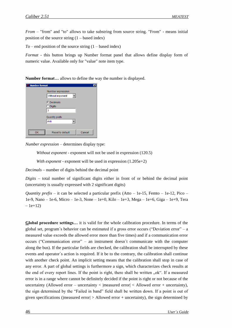
Caliber 2.51 MEATEST
46 User´s Guide
From – "from" and "to" allows to take substring from source string. "From" - means initial
position of the source string (1 – based index)
To – end position of the source string (1 – based index)
Format - this button brings up Number format panel that allows define display form of
numeric value. Available only for "value" note item type.
Number format… allows to define the way the number is displayed.
Number expression – determines display type:
Without exponent - exponent will not be used in expression (120.5)
With exponent - exponent will be used in expression (1.205e+2)
Decimals – number of digits behind the decimal point
Digits – total number of significant digits either in front of or behind the decimal point
(uncertainty is usually expressed with 2 significant digits)
Quantity prefix – it can be selected a particular prefix (Atto – 1e-15, Femto – 1e-12, Pico –
1e-9, Nano – 1e-6, Micro – 1e-3, None – 1e+0, Kilo – 1e+3, Mega – 1e+6, Giga – 1e+9, Tera
– 1e+12)
Global procedure settings… it is valid for the whole calibration procedure. In terms of the
global set, program´s behavior can be estimated if a gross error occurs (“Deviation error” – a
measured value exceeds the allowed error more than five times) and if a communication error
occurs (“Communication error” – an instrument doesn´t communicate with the computer
along the bus). If the particular fields are checked, the calibration shall be interrupted by these
events and operator´s action is required. If it be to the contrary, the calibration shall continue
with another check point. An implicit setting means that the calibration shall stop in case of
any error. A part of global settings is furthermore a sign, which characterizes check results at
the end of every report lines. If the point is right, there shall be written „ok“. If a measured
error is in a range where cannot be definitely decided if the point is right or not because of the
uncertainty (Allowed error – uncertainty < |measured error| < Allowed error + uncertainty),
the sign determined by the “Failed in band” field shall be written down. If a point is out of
given specifications (|measured error| > Allowed error + uncertainty), the sign determined by
MEATEST Caliber 2.51
User´s Guide 47
the “Failed” field shall be written down. If we don´t want to perform this evaluation, we shall
select the “not used” sign for failed.
Procedure Wizard... allows add a function under test into the calibration procedure. Detailed
description of the wizard is contained in the “New procedure development” section. A user
can by means of it add other checked functions into an existing procedure and the wizard
shall automatically generate checked ranges and values. The wizard allows add other checked
functions only. There is not possible to use it for editing of existing functions which are
already contained in the calibration procedure. The functions, which are contained in the
procedure, are no way affected. The functions added by the wizard shall be ranged always at
the procedure end.
Export… performs export of the calibration procedure structure into a text file. The file
contains a function, a range, a value and standards used for each of calibration points.
Following control keys are situated in the lower bar of the “Status window”:
New – starts a wizard for a new calibration procedure development. Details see below.
Open – opens an already created calibration procedure. The procedure has the “.pro”
prefix in the file mode.
Save – writes a performed calibration procedure.
Save as – writes a calibration procedure under a new name.
Reload instruments – renews instrument cards used in an open calibration procedure.
Namely the open calibration procedure has saved also cards of used instruments in the
computer memory. If it is anything changed in the instrument card (in the “Instrument cards”
module), an instrument update must be carried out in the calibration procedure. This update
can be performed by pressing of a described key or by new counting of the whole calibration
procedure.
Run calibration – begins performance of a calibration procedure. The procedure can be
open from any point eventually it can continue from any point.
Recalibrate point – starts executing one calibration point. This function is useful after
all calibration is done for recalibration individual calibration point.
Import – imports a calibration procedure created by means the „Export“ button. The
calibration procedure is in the „pre“ format which also contains definitions of used
instruments (instrument cards) and definitions of used functions (user functions). The format
is suitable for data transfer among users.
Export – exports a calibration procedure in the „pre“ format which also contains
definitions of used instruments (instrument cards) and definitions of used functions
(user functions). The format is suitable for data transfer among users.
Back – serves to shift one level up in hierarchy calibration procedure – function – range
– point. Nesting (shift one level down) shall be performed by mouse click on a selected
item.

Caliber 2.51 MEATEST
48 User´s Guide
Connection scheme Window
During calibration the “Status window” is being
substituted by the “Connection scheme” window. There
are described used connecting terminals for every active
instrument here. For each change of terminal
connections, a text description of a new connection
appears, the program performance stops and an operator
is prompted that the terminals are to be reconnected.
Instrument Scheme Window
It is intended for displaying of instruments used for a calibration and of their status and
control way. For each of the instrument there is given its name (according to the instrument
card), way of control (GPIB, COM, VISA, Manual, Camera), its index to be easy identified
and a graphic interpretation of signal connecting among the instruments.
Press the right mouse button on an instrument to open the following menu:
Add instrument shall add another instrument participating in the
calibration. The operation can be performed on level of procedure,
function, range or point. The required level must be preset in the
“Status window”. A new instrument is valid only for a level on
which it has been added. It can be made a quite particular instrument
configuration (e.g. for one calibration point). Instrument names
written in thick letters are valid for a just active level. Instrument
names written in thin letters are defined on higher level.
Remove instrument shall remove instrument participating in the calibration. The operation
can be again performed on level of procedure, function, range or point and it is valid for this
level only. E.g. an instrument removing on the range level shall not affect other ranges and
function any way. Removing all the instruments on the given level shall cause that they shall
be implicitly set according to the higher level.
Configure instrument shall open a menu for change of an instrument, its function and its
way of control:

MEATEST Caliber 2.51
User´s Guide 49
Instrument configuration – basic instrument configuration. Instrument can be
selected from the instrument database
(there is the “Instrument card” for it). It
is possible to filter items in the listbox
by using filter text field ( ). The
instrument under test (UUT) can be also
used without an instrument card. There
is the „*“ sign in front of a name of the
instrument without a card. These
instruments can be controlled only
manually. Instrument use describes
instrument´s function. Basic
instrument´s functions are the UUT (instrument being measured), the Source, the
Standard, the Converter and the Switch. The source function can be assigned to
functions of the standard or the measured instrument. Foe every instrument can be
selected different way of measuring (value counting) and setting (instrument control).
There are five ways of Instrument response – by means of RS232, GPIB, VISA, the
Camera and Manual; four ways of Instrument control – by means of RS232, GPIB,
VISA and Manual. At the most cases there is selected the same way of measuring and
setting; except from the camera measurement with usually manual settings. Connected
to – assigns a bus or another instrument which is an actual instrument connected to.
None – no instrument is connected either to any instrument, or to the master bus.
Master bus – an instrument is connected to the signal master bus – functions and
parameters are the same as for a measured instrument (UUT). <Converter name> - an
instrument is connected to a converter, functions and parameters are transformed by the
converter.
Copy – copies actual Instrument scheme into clipboard.
Paste – inserts Instrument scheme into actual procedure level from clipboard.
Set default Instrument scheme – a particular instrument scheme on existing level shall be
cancelled and the scheme shall be also set according to a superior definition.
List of Standards – scans all the instruments (instrument cards) used in the procedure and
determine whether any of them contains a reference to a set of calibration data. If so, it is
automatically included in the following list:
List of standards can serve as a watch list of standards, or as a tool for sharing calibration
data. The list contains the following columns:

Caliber 2.51 MEATEST
50 User´s Guide
Model - model designation. The item is read from the file * .cal and identifier is
referred as "Model" in the file.
Manufacturer - manufacturer. The item is read from the file * .cal and identifier is
referred as "Manufacturer" in the file.
Serial number - serial number. The item is read from the device or can be set by user
on the serial number panel.
Due Date - date to which the calibration certificate is valid. The item is read from the
file * .cal and identifier is referred as "CalibrationDate" in the file.
Description - brief description of the instrument, which can be used in the test report
note. The item is read from the file * .cal and identifier is referred as "Description" in
the file.
Calibration data - name of the file that contains the calibration data. Program detects
this name automatically by searching all instrument cards used in procedure.
Instrument card - list of instrument cards for the particular calibration data file (*.cal).
Export - determines whether the standard contained in the List of standards will be part
of export when used in the Test report Note. Can be changed by pressing the right
mouse button and selecting "Include / Exclude" item from the menu.
After pressing the right mouse button over the List of standards the following menu
appears:
Set serial number - displays the panel for the selection of serial
number.
Include / Exclude - includes or excludes instrument from the List
of standards during export.
Modify calibration data - opens set of calibration data (* .cal file) for editing in text
form.
Calibration data folder - file path settings can be done in the Configuration panel.
Open performs instrument opening by carrying out of the “Open” macro. This item is
especially intended for camera opening or for tuning purposes. Instrument´s opening and
closing shall be performed automatically during a calibration.
Close performs instrument closing by carrying out of the “Close” macro. This item is
especially intended for tuning purposes. Instrument´s opening and closing shall be performed
automatically during a calibration.

MEATEST Caliber 2.51
User´s Guide 51
Setup item shall be active only for automatic control ways (RS232, GPIB, VISA and the
Camera). It defines parameters for particular interface setting. According to way of control it
has following panels:
GPIB Setup - an instrument
is controlled along the GPIB
bus. The computer must be
equipped with the GPIB card
for this purpose. For GPIB
control an address of a
connected instrument can be
set. The permitted address
range is 1 to 30. The “0”
address is assigned to the
computer.
Connected devices - list of all GPIB devices found on this computer. The Port Search
Mode can be changed in the Configuration panel - the General tab.
General ports - list of all GPIB addresses from 1 to 30.
RS232 Setup - an instrument is controlled along the RS232 bus. The computer shall
have an empty RS232 port. For the RS232 control there can be set a number of the
Com port, communication speed, parity, number of data bits, number of stop bits,
communication program control (Xon/Xoff) and static status of DTR and RTS signals.
Option of static settings for those signals is necessary for communication with some
simply instruments which use the above mentioned signals for interface supply.
Available ports - list of all COM ports found on this computer. The Port Search Mode
can be changed in the Configuration panel - the General tab.
General ports - list of all COM ports from COM1 to COM256.

Caliber 2.51 MEATEST
52 User´s Guide
Camera Setup - measured values are scanned from an instrument by means of a digital
camera. The Cam-Ocr unit for camera
scanning is to be available for this purpose.
The instrument cannot be controlled this
way. Following parameters should be set for
a camera scanning:
Display type – LCD (dark signs on a light
background) or LED (light signs on dark
background)
Full scale – the highest displayed number on
the instrument display (decimal point not
included)
Minimum showed digits – minimal number of digits which can be shown on the display
Decimal point – „No“ (the instrument doesn´t use a decimal point), „Small close“
(decimal point size is approximately the same as an half of segment width), „Small far“
(a small point with distance from a segment more than an half of segment width),
„Large close“ (decimal point size is approximately the same as of segment width),
„Large far“ (a large point with distance from a segment more than segment width),
„Auto “ (the program doesn´t evaluate the decimal point from the display, but set it
automatically according the expected value – suitable for bad legible displays).
Min. trigger interval – time in seconds after its passing the instrument will display a
new value. The camera shall scan particular measurements during this time period
which can be extended for picture evaluation time (if the computer speed is not
sufficient).
Minus sign – if it is selected the “Evaluate” mode of sign evaluation, the program is
trying to read the sign from the display. If the “Auto” mode is selected, the program
shall not evaluate the sign from the display, but set it according to its expected value –
it is suitable for displays with bad legible signs, e.g. because of additional symbols
around the sign.
Camera window
It displays running video from a connected camera during opening of the instrument on
which measurement reading by means of a camera is selected. After camera opening, its
parameters can be set.
Format – camera resolution can be set
Setting – brightness, contrast and other by camera supported parameters can be set
Move left – camera window can be moved to the left

MEATEST Caliber 2.51
User´s Guide 53
Move right – camera window can be moved to the right
Move up – camera window can be moved up
Move down – camera window can be moved down
Readings window
It is intended for displaying of particular measurements from active instruments. While
the test report contains mean values calculated from sets of measurements, the particular
measurements are shown in the Readings window.
Test report window
It displays all the calibration points and measured values. This window is sequentially
filled with measured and calculated values.
Sequence of particular point performance can be changed. These changes don´t affect
the form of the resulted test report which is to be arranged according to functions, ranges and
values being adjusted in the status window. If you wish to change calibration point sequence,
move the mouse cursor on a shift field situated in the left side of every line in the test report
widow. Keep the left mouse button pressed and move the mouse up and down to transfer the
selected point. Suitable calibration point rearrangement makes the calibration itself easy
because number of output terminal reconnections can be minimized.
During procedure modification the test can be started from any point. The program
automatically supervises correct connections of output terminals and instrument adjustments.
The right mouse button having pressed on the test report, the following menu appears:
Export… exports the test report lines, which have already been checked, into a text file.
Output file form is given by column selection and their sequencing.

Caliber 2.51 MEATEST
54 User´s Guide
Columns… allows select and arrange test report columns during export. The setting made
here is valid for the current procedure. If you want to set columns for all procedures, use the
Configuration panel, the Test report tab.
Available columns – list of all unfiled columns.
Function - function of UUT
Range - range of UUT
Standard - measured standard value and list of function parameters. Before
calibration it contains nominal value of calibration point.
UUT - measured UUT value
Deviation - deviation of UUT relative to Standard
%spec - "Deviation" to "Allowed" rate expressed in percentage (= Deviation /
Allowed * 100 %)
Allowed - allowed accuracy of UUT
Uncertainty - total uncertainty
Symbol - test report symbols such as "~" - unstable reading, "R" - all calculations
done relative to range or PASS vs FAILED (see Global procedure settings)
Selected columns – list of columns that will be contained in test report. Order of
columns can be rearranged using following symbol . Double-click on any line item to
start column editing.
Column - the default column name that can not be changed.
Alias - name of the column that is exported in the test report and can be set by
user. If not set, then the default column name is used.
Width - the width of the column in the test report.

MEATEST Caliber 2.51
User´s Guide 55
Justify - alignment of the column.
- selected item from the "Available columns" listbox moves into the "Selected
columns" listbox, it means the column will be included in test report.
- removes column from the "Selected columns" listbox.
If the text does not fit in the Standard column – "Standard "column contains the
measured value and additional measurement parameters. Use this tool to select the
symbols that are used when the "Standard" column is divided into two lines due to the
long text. This behavior affects also "Show condition on a new line" setting on the Test
report Note.
Abbreviation in the Standard column – this abbreviation will fill in "Standard" column
next to the measured value of the standard. It is possible to enter the empty text.
Footnote to a new line – the text that is entered at the beginning of a new line followed
by the measurement parameters. It is possible to enter the empty text.
Remove sorting ranges test report lines according to the status window of a procedure.
Calibration run shall be performed in the same sequence as the points have been defined.
Reference zero adds special meaning to the selected point. During calibration of this marked
point the estimated deviation of an instrument under test shall be saved and it shall be
distracted from this instrument in the next calibration points. This deviation doesn´t affect
either a standard value or a tested instrument value in the test report, but it affects the
deviation and following calculations. It is intended e.g. for resistance decade tests, if it is
necessary to read zero resistance values. This point is marked by the symbol in the test report.

Caliber 2.51 MEATEST
56 User´s Guide
2.1.2. Calibration Procedure Modification
A new procedure created by means of the wizard can be straight used or modified.
The calibration procedure structure, which is shown in the left side of the status window, has
following levels: “Procedure - Function – Range – calibration point”. On all these levels there
can be modified, added and removed particular items. Modification menu appears after
pressing the right mouse button on a selected item.
Particular instruments used for calibration can be changed. The procedure wizard can namely
define only one instrument set which shall be used for the whole calibration then. It may
happen that some functions, ranges and UUT values cannot be checked by means of standard
instruments. Then other standards or signal sources (e.g. a current calibrator up to 100 A, a
resistance standard 100 MOhm etc.) can be used for the calibration of the instrument.
To use another instrument, there shall be a particular instrument card available. If we have for
example an instrument which is to be tested by means of the M140 calibrator and whose one
range of 50 A is to be tested by the current calibrator M150, first we generate the whole
methodology of testing with the M140 calibrator by means of the wizard (see the previous
section). In the created procedure the M140 calibrator (it is also used as a standard) shall be
on its 50 A range substituted by the M150 calibrator. Proceed as follows:
Find a current function (AC or DC) and the 50 A range in the status window.
Change the M140 standard instrument on this selected level. Click with the right mouse
button on the M140 calibrator to open a menu displayed at the figure.

MEATEST Caliber 2.51
User´s Guide 57
Select the “Instrument configuration” item and instead of the M140 calibrator select the
M150 calibrator from the list.
The performed change is valid only for the level on which it has been carried out. It is the
50 A range in our case.
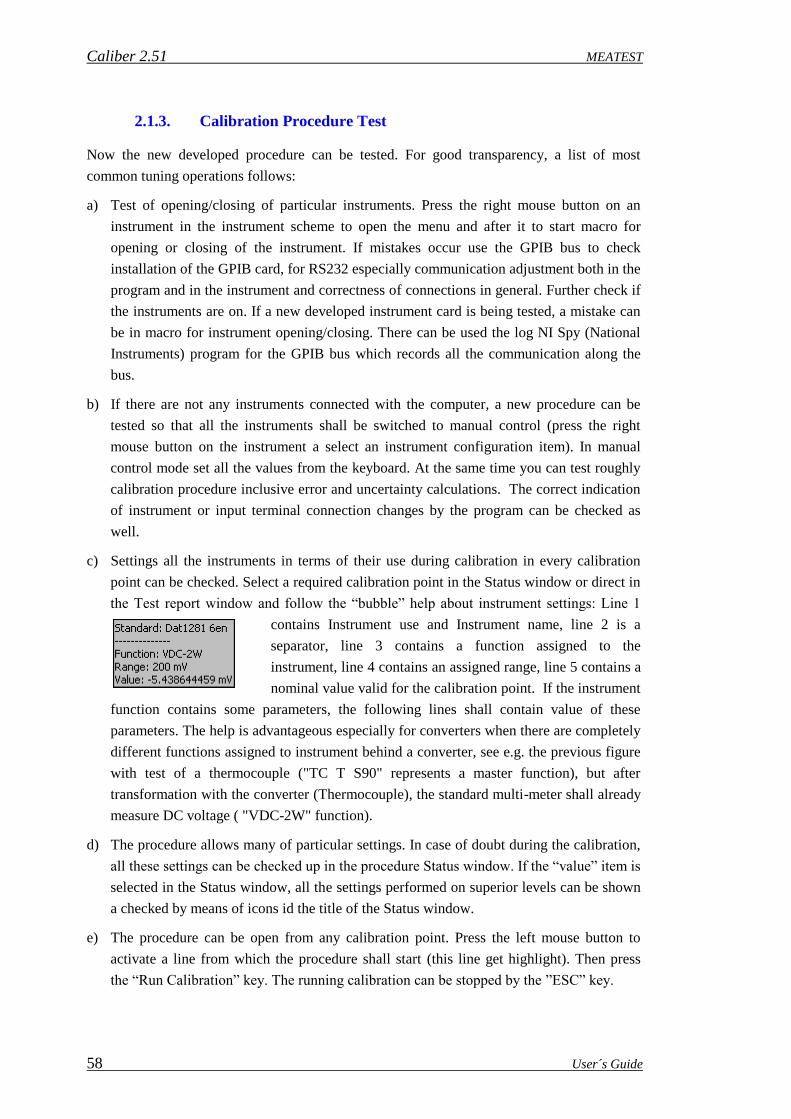
Caliber 2.51 MEATEST
58 User´s Guide
2.1.3. Calibration Procedure Test
Now the new developed procedure can be tested. For good transparency, a list of most
common tuning operations follows:
a) Test of opening/closing of particular instruments. Press the right mouse button on an
instrument in the instrument scheme to open the menu and after it to start macro for
opening or closing of the instrument. If mistakes occur use the GPIB bus to check
installation of the GPIB card, for RS232 especially communication adjustment both in the
program and in the instrument and correctness of connections in general. Further check if
the instruments are on. If a new developed instrument card is being tested, a mistake can
be in macro for instrument opening/closing. There can be used the log NI Spy (National
Instruments) program for the GPIB bus which records all the communication along the
bus.
b) If there are not any instruments connected with the computer, a new procedure can be
tested so that all the instruments shall be switched to manual control (press the right
mouse button on the instrument a select an instrument configuration item). In manual
control mode set all the values from the keyboard. At the same time you can test roughly
calibration procedure inclusive error and uncertainty calculations. The correct indication
of instrument or input terminal connection changes by the program can be checked as
well.
c) Settings all the instruments in terms of their use during calibration in every calibration
point can be checked. Select a required calibration point in the Status window or direct in
the Test report window and follow the “bubble” help about instrument settings: Line 1
contains Instrument use and Instrument name, line 2 is a
separator, line 3 contains a function assigned to the
instrument, line 4 contains an assigned range, line 5 contains a
nominal value valid for the calibration point. If the instrument
function contains some parameters, the following lines shall contain value of these
parameters. The help is advantageous especially for converters when there are completely
different functions assigned to instrument behind a converter, see e.g. the previous figure
with test of a thermocouple ("TC T S90" represents a master function), but after
transformation with the converter (Thermocouple), the standard multi-meter shall already
measure DC voltage ( "VDC-2W" function).
d) The procedure allows many of particular settings. In case of doubt during the calibration,
all these settings can be checked up in the procedure Status window. If the “value” item is
selected in the Status window, all the settings performed on superior levels can be shown
a checked by means of icons id the title of the Status window.
e) The procedure can be open from any calibration point. Press the left mouse button to
activate a line from which the procedure shall start (this line get highlight). Then press
the “Run Calibration” key. The running calibration can be stopped by the ”ESC” key.

MEATEST Caliber 2.51
User´s Guide 59
2.2. “Instrument Card“ Module
Presence of the instrument card is necessary for an instrument in a calibration procedure.
While new calibration procedure takes about 5 minutes time, the new instrument card
development takes more time. A user´s manual is necessary for that purpose, which describes
functions, ranges and specifications of an instrument. It the instrument can be controlled by a
computer, remote control command description is necessary too. You can download final
instrument card from the www.meatest.cz website free of charge.
The “Instrument card” module having started and the M140 card having count, the
following panel appears:
The upper left part of the panel contains a calibration data field. This field can contain name
of the Calibration data file without path and extension (*.cal). These are files that the system
uses as a repository of standard values or as data to create a List of Standards. The files must
be located in a shared folder for the calibration data (the path can be set in the Configuration
panel on the “Calibration data” tab). The system uses the calibration data only when the file
name is written to "Calibration data" field.
Calibration data file is a plain text file without formatting. Each such file must contain the
following items in the following order:
Model - device type. This is only a text description that can be exported in Test report Note
(List of Standards item).

Caliber 2.51 MEATEST
60 User´s Guide
Manufacturer - manufacturer. This is only a text description that can be exported in Test
report Note (List of Standards item).
Description - a short device description. This is only a text description that can be exported in
Test report Note (List of Standards item).
SerialNumber - serial number. It can be several serial numbers in one file and the system
automatically selects the data for the required serial number.
CalibrationDate - the expiry of the calibration (must be in the format YYYY-MM-DD). This
date is checked during calibration and message is displayed if the date is expired.
If calibration data file is used as a repository of standard values, the date of calibration must
be followed by the list of standard values. Here is an example of a shunt:
Each standard value must start with "@" and then continue with a short unique label for the
file. This label can be then used on the instrument card in the Manual measure:
The left part of the panel under the Calibration data field contains a status window which
displays the instrument card structure (name, functions, ranges and parameters). The proper
level is always being shown in the status window title. All other settings in the right part of
the panel (specifications, macros, terminal circuitry) are valid for actual selected level and an
item of the status window.

MEATEST Caliber 2.51
User´s Guide 61
„Instrument“ level – the highest level of the status window display the instrument name
and below this name a note (usually with instrument card version or author´s name and his e-
mail address). The note can be edited by a user any way. Its maximal size is 200 characters.
„Function“ level – perform double click by the left mouse button on the card name in the
status window to go to the function level. If the “Source” page is selected in the right part of
the panel, a source shall be created; if “Meter”, then a measuring instrument. If it is not sure
what is to be created, a rule is valid that if it is not a meter (the instrument indicates no
measured value), there is a source. The third page called "Switch" is intended for creating
switch instrument type. Press the right mouse button to display a menu and then add or
remove a function. Here can be set all the functions which shall be contained in the
instrument.
„Range“ level - perform double click by the left mouse button on the function name to go
to the range level. Here it is possible to add, change or remove ranges. If ranges are to be
created, proceed from lowest to highest range. For more parametric functions usually one
range is to be selected which covers all the options of this given instrument function. The
actual range can be set during procedure development by a user, if the instrument is used as a
UUT.
„Parameter“ level – By double mouse click on the developed range you come to the
parameter level. This is valid only if a given function contains a parameter. The program
differs if a function contains one parameter (e.g. the VAC-2W contains a frequency, i.e. one
parameter) or more parameters (PAC). At one-parameter functions the program behaves as at
ranges or functions. At more-parameter functions on parameter level there is not possible to
set specifications, terminal connections and macros except only the remote setting macro.
Macro can be set for any parameter. The Caliber program behaves a little differently during
calibration, i.e. it is executing all the macros valid for all the parameters consequentially after
each other. The macro is then signed by the symbol in the instrument card. A user also
can write down only one setting macro on the range level (it is more suitable if an instrument
can be controlled this way) or more macros for particular parameters.
On the right panel side there is a switch to select way of instrument control. One
instrument can have more control ways. For each of the switch positions another set of
control elements is assigned (on the right side of a framed field). Ways of control follow:
a) Remote control – control elements (a multiplier and macros for instrument control) are
the same for all remote buses (GPIB, RS232, VISA). If macros have been defined for that
common control way, it is no longer necessary to write macros for GPIB, RS232 or VISA
except the “Open” and “Close” macros at the „Setup“ definition. The „Remote control“ is
a recommended option for all the instruments containing even one type of these buses. In
future the instrument card can be extended about another communication type. The other
options as GPIB, RS232 or VISA are suitable only in case of different communication
along different buses but it is not so common.

Caliber 2.51 MEATEST
62 User´s Guide
b) GPIB – control elements (a multiplier and macros for instrument control) are for the
GPIB bus. It shall be used only if it is required do differentiate macros from another
communication type, e.g. from RS232, otherwise the “Remote control” item is to be used.
c) RS232 – control elements (a multiplier and macros for instrument control) are for the
RS232 bus. It shall be used only if it is required do differentiate macros from another
communication type, e.g. from GPIB, otherwise the “Remote control” item is to be used.
d) VISA – control elements (a multiplier and macros for instrument control) are for the
VISA interface. It shall be used only if it is required do differentiate macros from another
communication type, e.g. from GPIB, otherwise the “Remote control” item is to be used.
e) Camera – control elements (a multiplier) for camera scanning.
f) Manual – control elements (a multiplier and macros for instrument control) for manual
control.
There are four cards in the right panel part describing instrument features in functions
“Source”, “Meter”, “Switch” and “Global”. At sources and meters the pages contain
specifications, control commands and description of output terminal connections. The switch
setting contains only “Set” control commands. The global setting describes such features as
an instrument initialization, setting parameters of buses and a camera, transfer characteristics
of converters. For the pages there are following windows (some of them cannot be present
according to card types or control ways):
Specification allows set accuracy for the given instrument. The
specification can be set on level of instruments, ranges or parameters. It can
consist of up to four components: „% of a reading “ and „% of a range“ are
set in per cents. The “Absolute” error is set in units of a selected function
(always in basic ones, an exponential record is possible) and the “Digits
error” is set in digit numbers (only for measuring instruments). It is also
possible to use limits as specification if an instrument is used as UUT. By
checking “Limit” checkbox, two fields are shown: “Low limit” – defines
minimal possible absolute value of an instrument, “High limit” – defines
maximal value.
Full digits is set only for measuring instruments. It indicates a resolution
of digital measuring instruments (it is at most set for function with relative
evaluation). In case of an analog instrument, the „ANALOG“ text is being
used.
One digit also allows set a resolution of a digital measuring instrument. It is set in units of
measured magnitude and indicates resolution for one digit (it is at most set for function with
relative evaluation).

MEATEST Caliber 2.51
User´s Guide 63
Multiplier can be set for both a source and a meter (measuring
instrument). It allows set values during instrument readings (or during
records into the instrument) in different units as basic ones. It is implicitly
set to “not used”, but it can be selected any prefix in the „atto“ (1e-18) to
„tera“ (1e+12) ranges.
Macros are setting strings describing instrument control way by means of
GPIB, RS232 or VISA buses. The „Set“ and „Measure“ macros can be set
for sources and measures controlled by a computer. The “Output on” and
“Output off” are to be set for sources controlled by a computer only. For details see the
“Macro Development” section”.
Manual control has following elements available (there are no macros):
Manual set – allows determine a text which shall be shown during the “Instrument set”
operation if manual control is used during a
calibration. This setting can be defined for sources,
meters and switches. For sources and switches the
setting shall be performed at every point of calibration,
for measures only if ranges or functions change (it can
be changed by the “Show always” item). If the
“Manual set” is not defined the program itself shall
automatically generate necessary messages /except
from the switches). The same panel is being used also
for the “Output on” and “Output off” operations. The
“A set”, “B set”, “C set” and “D set” operations can be
defined for switches that way. Messages during
calibration are shown in the “User prompt window”.
Text during calibration provides three options:
Auto (default) – the program shall stop at every measured value and the automatic text
appears with requirement to set a source to a proper value. At a measuring instrument the
program shall stop for every change of a function or a range. The automatic text cannot be
used for a switch-instrument and there must be set the “User text”.
User text – the program shall be stop according to the same rules as for the “Automatic”
items. Program having stop, a message from the ”Message” window shall be written down.
None – the program won´t stop for this selection. An operator cannot set a function, a range
or a value. This selection is suitable for e.g. a source when terminals are switched on and off,
if the source has not terminal switching off.
Message – the user text displayed during the calibration in the “User prompt window”.

Caliber 2.51 MEATEST
64 User´s Guide
Delay – if a time it is set, the program after message displaying (if there is any) shall wait for
a set time. The delay is being count even from the moment of message confirming by a user.
Show always – allows open a message for an operator during a calibration at every calibration
point (it is valid for measuring instruments only).
Manual measure – allows define value counting way which is being set for a source during
calibration. The set shall be effective only if the value from the instrument is being count
manually. The program is trying to find
out a source value if it is used as a
Standard or a UUT. The item is only for
manual measuring of the source. For a
measuring instrument it is always
necessary to set an actual instrument´s
value.
User prompt (default) – a magnitude of a value being set for the source by the user
during a calibration.
Fixed value – a magnitude of a value being set for the source is fix given by the in the
“Fixed value” field stated value“. The value can be a reference to a calibration data file
(* .cal).
Nominal value – it is set automatically by the program as a nominal point´s value for a
magnitude of a value being set for the source.
Output on – this item is for manual source settings only. It allows define source´s behavior
during switching on of output terminals. Options are the same as for the set item.
Output off – this item is for manual source settings only. It allows define source´s behavior
during switching off of output terminals. Options are the same as for the set item.
Connection scheme represents a text which briefly characterizes active terminals. The
terminals are at most set on the function
level (different terminals are for voltages as
for currents). A short text denomination is suitable, e.g. Hu,Lu or V+,COM etc.
Note: The text itself describing the connection can be selected any way according to local
usage. But there is important that different connections shall be written by different
texts. In terms of a program text change during a calibration, a message about
terminal connection changes shall be generated.

MEATEST Caliber 2.51
User´s Guide 65
Global setup
Setup – this item shall be active only for automatic controls (RS232, GPIB, VISA and
Camera). It defines setup parameters for particular
interfaces. Macros for instrument openings and closing
and bus settings can be defined by the “Setup” key (details see in the “Macro development”
section. The bus setup has following menus according to the control way:
GPIB Setup - an instrument is
being controlled along the GPIB
bus. The computer must be
equipped with the GPIB card. For
the GPIB control, an address of a
connected instrument can be set.
The permitted address range is 1 to
30. The „0“ address is determined
for the computer.
Connected devices - list of all GPIB
devices found on this computer.
The Port Search Mode can be changed in the Configuration panel - the General tab.
General ports - list of all GPIB addresses from 1 to 30.
RS232 Setup - an instrument is being controlled along the RS232 bus. The computer must
have the RS232 port free. For the RS232 control, a number of the Com port, communication
speed, parity, data bit number, stop bit number, program communication control (Xon/Xoff)
and static status of the DTR and RTS signals can be set. Static set options for these signals is
necessary for communication with some simple instruments using the above mentioned
signals for interface supply.
Available ports - list of all COM ports found on this computer. The Port Search Mode can be
changed in the Configuration panel - the General tab.
General ports - list of all COM ports from COM1 to COM256.

Caliber 2.51 MEATEST
66 User´s Guide
VISA Setup - an instrument is being controlled along the VISA bus. The computer must have
installed the VISA driver. An identification instrument string shall be set for the VISA
control. The computer connection with an instrument can be performed along any bus (USB,
LAN, RS232), the VISA controller (not the Caliber program) shall secure this connection.
Available ports - list of all VISA ports found on this computer. The Port Search Mode can be
changed in the Configuration panel - the General tab.
Users ports - list of user defined ports. At this port, you can directly enter the name of the
VISA resource name. The identification string can be taken from instrument Remote I/O
setup screen or you can use National Instruments “VISA Interactive Control” utility.

MEATEST Caliber 2.51
User´s Guide 67
Camera Setup - measured values are being read by means of a digital camera from the
instrument. The Cam-Ocr scanning unit is to be available for this purpose. The instrument
cannot be controlled such a way. For reading of measured values the following parameters
should be set:
Display type – LCD (dark signs on a light
background) or LED (light signs on dark
background)
Full scale – the highest displayed number
on the instrument display (decimal point not
included)
Minimum showed digits – minimal number
of digits which can be shown on the display
Decimal point – „None“ (the instrument
doesn´t use a decimal point), „Small close“
(decimal point size is approximately the
same as an half of segment width), „Small far“ (a small point with distance from a
segment more than an half of segment width), „Large close“ (decimal point size is
approximately the same as of segment width), „Large far“ (a small point with distance
from a segment more than segment width), „Auto “ (the program doesn´t evaluate the
decimal point from the display, but set it automatically according the expected value –
suitable for bad legible displays).
Min. trigger interval – time in seconds after its passing the instrument will display a
new value. The camera shall scan particular measurements during this time period
which can be extended for picture evaluation time (if the computer speed is not
sufficient).
Minus sign – if it is selected the “Evaluate” mode of sign evaluation, the program is
trying to read the sign from the display. If the “Auto” mode is selected, the program
shall not evaluate the sign from the display, but set it according to its expected value –
it is suitable for displays with bad legible signs, e.g. because of additional symbols
around the sign.
Converter conditions – they are displaying overview of all the conversing conditions, which
a converter can convert. During calibration the program automatically selects an appropriate
conversion according to an input and output function.
Converter represents an instrument connected between a signal bus and another instrument. It
can change a function, a value or parameters coming into another instrument. It is possible to
arrange more converters after each other. The converter is defined by three points (functions),
by an input, by an output and by its own setting. The converter is transforming an input to an
output and it can work in both of directions. Converters are divided into two types:

Caliber 2.51 MEATEST
68 User´s Guide
Real converters represent real instruments. They are to be set to functions which is not void.
A current shunt (a resistor transferring voltages to currents) can be given as an example. The
real converters can have a defined specification (it is its accuracy) and this specification is
being counted as one of measurement uncertainty components. These converters muss have
their card filled up in the source mode.
Virtual converters are intended only for conversion of one function to another one or for
value recalculations. They are being set to the „void“ function and their instrument cards are
not be filled up either in source nor measure mode. There are no real instruments and they
have zero error because of it. A converter converting two-terminal resistors to four terminal
ones can be used as an example. We must use it if we need check a two-terminal measuring
instrument by a four-terminal standard. Namely the Caliber program requires the same
function set on all the instruments unless converter is used.
Press the right mouse button to open a menu with following items:
Modify – an editing window of the selected conversion shall be open
Converter conditions define a way of the magnitude conversion and a magnitude and a
value which the converter itself shall be set to. In the figure there is an example of a
current/voltage converter with conversion constant of 0.01 (10 m resistor).
Converter as UUT – if this field is checked, the program shall secure using of a
converter in position of the instrument under test. The as an UUT used converter is to
be set as its output function is. The value of the converter cannot be used in a formula,
only a simple formula can be used.
Convert function:
From – input value of the converter (defined by a function)
To – output value of the converter (defined by a function)

MEATEST Caliber 2.51
User´s Guide 69
Set converter to:
Function – a function which the converter is to be set to. For virtual converter
(i.e. function or value converters being not represented by a real instrument) it
shall be given „void“ here. Converter functions and ranges cannot be filled up as
for a real source or measurement instrument. For real converters their actual
function must be set. E.g. for a current shunt the RDC-4W or also RAC-4W
function is to be set, if the shunt can also be used for alternating current. In this
case the particular function (e.g. RDC-4W), range (e.g. 0.1 =<= 0.1) and
specification is to be filled up as for a real source.
Value – it is a value which the converter is to be set to. All the parameters are to
be defined here if the function contains any. A fixed value (a constant) or a
parameter being contained in the input function is assigned to particular values.
The program during its operation shall set a function, a range and parameters
which shall be set as for any other instruments. The converter card must contain
the required function and range in the source mode (a converter is being
considered as a source). Real value of the converter can be taken of the
instrument card during a calibration, in manual mode the value can be required
from a user or to be fixed set in the instrument card. The fixed set value can be
naturally changed e.g. after a new standard resistor calibration which is being
used as a current/voltage converter. If a function called ”void” is selected, it is
not necessary to set a value and fill up a specification and function in the
instrument card. Such a converter then only converts by means of a multiplying
and adding constant ant its own value won´t appear in an equation (it is
especially used for function conversion, if the converter itself is only virtual
one).
Formula – defines conversion ratio between input and output. There are three of
formula types:
Simple – a simple equation. The program is automatically performing back and
forth conversions.
Input - input value calculation form
Multiply - input value is directly used (Input = Input value)
Divide - applies the inverse of the input (Input = 1 / Input value)
Converter value – adds or removes the “Converter value” from the
formula
Not used - converter value not used in formula (Output = Input * A
+ B)
Multiply with - converter value will be multiplied (Output = Input *
A * Converter + B)
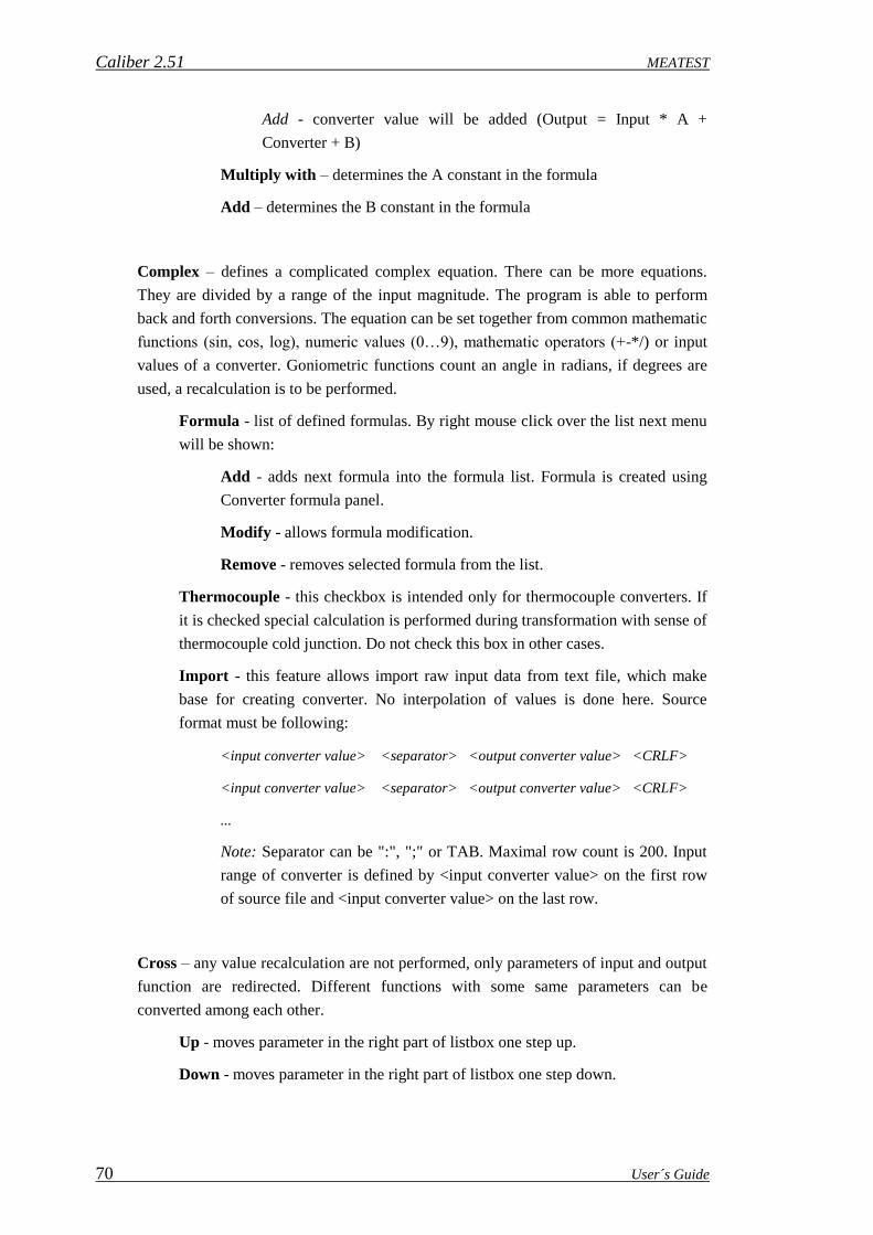
Caliber 2.51 MEATEST
70 User´s Guide
Add - converter value will be added (Output = Input * A +
Converter + B)
Multiply with – determines the A constant in the formula
Add – determines the B constant in the formula
Complex – defines a complicated complex equation. There can be more equations.
They are divided by a range of the input magnitude. The program is able to perform
back and forth conversions. The equation can be set together from common mathematic
functions (sin, cos, log), numeric values (0…9), mathematic operators (+-*/) or input
values of a converter. Goniometric functions count an angle in radians, if degrees are
used, a recalculation is to be performed.
Formula - list of defined formulas. By right mouse click over the list next menu
will be shown:
Add - adds next formula into the formula list. Formula is created using
Converter formula panel.
Modify - allows formula modification.
Remove - removes selected formula from the list.
Thermocouple - this checkbox is intended only for thermocouple converters. If
it is checked special calculation is performed during transformation with sense of
thermocouple cold junction. Do not check this box in other cases.
Import - this feature allows import raw input data from text file, which make
base for creating converter. No interpolation of values is done here. Source
format must be following:
<input converter value> <separator> <output converter value> <CRLF>
<input converter value> <separator> <output converter value> <CRLF>
...
Note: Separator can be ":", ";" or TAB. Maximal row count is 200. Input
range of converter is defined by <input converter value> on the first row
of source file and <input converter value> on the last row.
Cross – any value recalculation are not performed, only parameters of input and output
function are redirected. Different functions with some same parameters can be
converted among each other.
Up - moves parameter in the right part of listbox one step up.
Down - moves parameter in the right part of listbox one step down.

MEATEST Caliber 2.51
User´s Guide 71
Following control keys are situated in the lower bar of the “Status window”:
New – shall create a new instrument card.
Open – shall open an already created instrument card.
Save – shall write a modified instrument card in a file (database).
Save us – shall write a modified instrument card under a new name in a file
(database).
Back – is intended for move to one level up in a hierarchy: instrument – function –
range – parameter. Nesting (move to one level down) shall be performed by a mouse
click on a selected item.
2.2.1. Item Displaying Regulations
Particular items (specification, terminal circuitry and control way) can be set for any
level in a hierarchy: instrument – function – range – parameter. The item set on higher level is
implicitly valid for all lower levels. If an item is set on more levels for one point, the item set
on the lowest level shall be used for control and calculations. For easy orientation in an
instrument card the items being set are displayed in different letter types:
a) Normal – an item is not set yet.
b) Thick letters – an item is set on the just shown level.
c) Italics – an item is set on the higher level and is implicitly valid for the level displayed.
Item setting is not mandatory. However if an unset item is needed during instrument
calibration an error message appear that the requested item has not been filled up.

Caliber 2.51 MEATEST
72 User´s Guide
2.2.2. Development of Macros
Any communication with an instrument through remote control (RS232, GPIB, VISA)
in the Caliber system can be only performed by means of macros. A macro represents a
command sequence (Write and Read) for communication with an instrument completed by
some additional options as comparison of counted values etc. The program is performing
particular macros during a calibration. Macros are divided into particular categories called
actions. There can be the “Measure macro” for value reading from an instrument, the “Setup
macro” for assignment of a function and of a range, the “Output on macro”, “Output off
macro” for sources or the “Open/close macro” for instrument´s initialization. The sequence
of macro executing is given by a measuring mode during calibration. The “Open” macro shall
be performed for every instrument use in a calibration if the instrument was not open yet. The
“Close” macro shall be performed if an instrument scheme changes or a calibration completes
and the instrument was open before. Macros can be written for all the buses together (Remote
control) or particularly for each of the buses (RS232, GPIB, VISA). All macros are saved in
an instrument card. The instruction manual of the given instrument is needed to write down
remote control commands.
The program works with six basic macro types:
Open initializes an instrument connected to the computer.
Close closes the communication along the computer bus.
Setup sets an instrument to a correct function, range and value.
Measure reads a measured value on a measuring instrument and a set value on a
source.
Output on connects output terminals, it is used only for a signal source.
Output off disconnects output terminals, it is used only for a signal source.
The “Close” and “Open” macros are parts of the “Global set” of an instrument and are so
valid for the whole instrument regardless of a function, a range or a value. The “Set” and
“Measure” macros are in both the “Meter” instrument card and the “Source” card. The “Set”
macro can be also in the “Switch” card marked as the “Set A”, “Set B”, “Set C” or “Set D”.
These macros can be defined on any level (Instrument-Function-Range-Parameter). The
“Output on” and “Output off” macros are in the “Source” card only.
Macros are composed of particular commands which can be combined any way. There are
following commands:
Write sends a string into an instrument.
Read reads a string from an instrument into a program variable.
Delay inserts a delay in a macro.
Message calls up a message.
Compare allows comparison of an instrument string with a fixed one.

MEATEST Caliber 2.51
User´s Guide 73
Numeric compare allow compare a number counted from an instrument.
Every macro line (command) is being displayed in two columns in the program:
Key word determines an operation to be performed. An example: „WRITE“,
“READ“, „COMPARE“ etc.
Parameter contains texts and variables with them an operation determined by the
Key word shall be preformed
Open macro
It is defined for the GPIB, RS232 and VISA buses. There is an open macro of the M140
calibrator in the figure. The „Global write settings“ window contains a string (sign) which
shall be sent to an instrument after every “WRITE” command. An ending string for M140 is
CR (ALT13). The „Global read settings“ window contains a string (sign) which means a
message end. Reading can be also finished when a certain number of signs are received. If
both of the options are being set (finishing when a string is received and finishing after
receiving of certain sign number), a reading shall be finished if any of these conditions has
been fulfilled. The “Global read settings“ window stays unused in most of cases, except from
some instruments controlled along the RS232 bus, for some of them it is not possible to
synchronize readings. The “RS232 Setup” key is intended for bus parameter setup. A macro
can be saved by the “OK” key. Following commands are used for the macro in the picture:
WRITE – it shall send the „*IDN?“ string ended with the CR (ALT13) sign in a calibrator.
READ – it shall read a calibrator´s answer and save it into a variable called “Buffer”.
COMPARE – it shall compare the „M-140“ string with 9-13 signs saved in the buffer
variable. If they are different, a „ M-140 was not found“ message appears and a calibration
shall be finished.
The open macro is common for both the source and the measuring instrument. If the
instrument has the GPIB and also RS232 bus, the macro shall be defined separately for both
the buses. Details to particular macro commands see the “Macro Command Syntax” section”.
Note: It is possible to read serial number from the instrument in the Open macro for the
purpose of using calibration data or writing note to output test report. In such a case reading
to the variable labeled "Serial Number" must be done.

Caliber 2.51 MEATEST
74 User´s Guide
Close macro
It is defined for the GPIB, RS232 and VISA buses. There is a close macro of the M140
calibrator in the figure. The “Global write settings”, “Global read settings” windows, the
“RS232 Setup” and „OK“ keys have been described at the “Open macro”. Following
commands are used for the macro in the figure:
WRITE – it shall send the „VOLT 10;FUNC DC;VOLT 10“ string ended with the CR
(ALT13) sign in a calibrator.
WRITE – it shall send the „OUTP OFF“ string ended with the CR (ALT13) sign in a
calibrator.
The close macro is common for both the source and the meter. If the instrument has the GPIB
and also RS232 bus, the macro shall be defined separately for both the buses. Details to
particular macro commands see the “Macro Command Syntax” section”.
Macro Set
It is defined for the GPIB, RS232 and VISA buses. There is a macro set of the M140
calibrator in the figure, which shall set the calibrator to the R-2W function in source mode.
Following commands are used for the macro in the figure:
WRITE – it shall send the „RES“ string in a calibrator. Nominal value of the check point and
the report shall be ended by a sign defined in the open / close macro - CR (ALT13).
The Macro Set can be common for all the buses (Remote control). The source and the
measuring instrument have an independent macro. For the source, the macro sets a function, a
range and a value. The macro sets a function and a range for the measuring instrument.
Details to particular macro commands see the “Macro Command Syntax” section”.
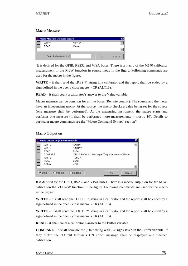
MEATEST Caliber 2.51
User´s Guide 75
Macro Measure
It is defined for the GPIB, RS232 and VISA buses. There is a macro of the M140 calibrator
measurement in the R-2W function in source mode in the figure. Following commands are
used for the macro in the figure:
WRITE – it shall send the „RES ?“ string in a calibrator and the report shall be ended by a
sign defined in the open / close macro - CR (ALT13).
READ – it shall count a calibrator´s answer to the Value variable.
Macro measure can be common for all the buses (Remote control). The source and the meter
have an independent macro. At the source, the macro checks a value being set for the source
(one measure shall be performed). At the measuring instrument, the macro starts and
performs one measure (it shall be performed more measurements – mostly 10). Details to
particular macro commands see the “Macro Command Syntax” section”.
Macro Output on
It is defined for the GPIB, RS232 and VISA buses. There is a macro Output on for the M140
calibration the VDC-2W function in the figure. Following commands are used for the macro
in the figure:
WRITE – it shall send the „OUTP 1“ string in a calibrator and the report shall be ended by a
sign defined in the open / close macro - CR (ALT13).
WRITE – it shall send the „OUTP ?“ string in a calibrator and the report shall be ended by a
sign defined in the open / close macro - CR (ALT13).
READ – it shall count a calibrator´s answer to the Buffer variable.
COMPARE – it shall compare the „ON“ string with 1-2 signs saved in the Buffer variable. If
they differ, the “Output terminals ON error” message shall be displayed and finished
calibration.

Caliber 2.51 MEATEST
76 User´s Guide
WRITE – it shall send the „*OPC?“ string in a calibrator and the report shall be ended by a
sign defined in the open / close macro - CR (ALT13).
READ – it shall count a calibrator´s answer to the Buffer variable.
DELAY – it shall wait 4 seconds to output value stabilization.
In the lower bar of the window there is the “Both”, “Positive” and “Negative” switch. If the
source has the same command for switching positive and negative polarity on, it can be
sufficient to define a macro for the “Both” switch position. Some sources have different
commands for switching positive and negative polarity on. Then one macro must be defined
for the “Positive” switch position and another one for the “Negative” switch position. The
Macro Output on can be common for all the buses (Remote control) and there it is only for
the source. Details to particular macro commands see the “Macro Command Syntax” section.
Macro Output off
It is defined for the GPIB, RS232 and VISA buses. There is a macro Output off for the M140
calibrator in the figure. Following commands are used for the macro in the figure:
WRITE – it shall send the „OUTP 0“ string in a calibrator and the report shall be ended by a
sign defined in the open / close macro - CR (ALT13).
WRITE – it shall send the „OUTP ?“ string in a calibrator and the report shall be ended by a
sign defined in the open / close macro - CR (ALT13).
READ – it shall count a calibrator´s answer to the Buffer variable.
COMPARE – it shall compare the „OFF“ string with 1-3 signs saved in the Buffer variable.
If they differ, the “Output terminals OFF error” message shall be displayed and finished
calibration.
In the lower bar of the window there is the “Both”, “Positive” and “Negative” switch. If the
source has the same command for switching positive and negative polarity on, it can be
sufficient to define a macro for the “Both” switch position. Some sources have different
commands for switching positive and negative polarity off. Then one macro must be defined
for the “Positive” switch position and another one for the “Negative” switch position. The
Macro Output off can be common for all the buses (Remote control) and there it is only for
the source. Details to particular macro commands see the “Macro Command Syntax” section.

MEATEST Caliber 2.51
User´s Guide 77
2.2.3. Macro Command Syntax
Press the right mouse key on the window for macro entry to open the following menu:
Modify – opens a window for selected macro command modifying.
Add Write – opens a window for write command adding.
Add Read – opens a window for read command adding.
Add Delay – opens a window for delay command adding..
Add Message – opens a window for message command adding.
Add Compare– opens a window for compare command adding.
Add Numeric compare – opens a window for numeric compare command adding.
Delete – removes a selected macro command.
Delete all – removes all macro commands.
Macros works with following objects:
a) Text – consists of series of the standard ASCII signs (32… 255 codes). It must not
contain control signs (0… 31codes).
b) Alternative code – one ASCII sign (0… 255). It allows records of any ASCII signs
inclusive control ones (0… 31 codes).
c) Variable – macros use numeric variables (value and parameters) and one text variable
(buffer). The “Value” variable contains a nominal value of a check point and it can be
written or read (in the read macro). The “Parameter” variables (their count and names are
determined by a selected function) contain values of next point parameters (e.g.
frequency of alternating magnitudes) and they can be written only (to be sent into
instruments). The “Buffer” text variable is intended for universal purposes and it can be
written and read. Values which are saved in it are mostly intended for comparison of two
strings (responds read from instruments and expected values). The “Serial number” text
variable is used for reading serial number from an instrument. The reading must be done
in Open macro to this variable. The Serial number can be then used for selection of the
proper Calibration data of a Standard or can be printed in output Test report.

Caliber 2.51 MEATEST
78 User´s Guide
Window for Add / Modify of WRITE Command.
It allows send a string composed of constants and variables into an instrument. The string can
be composed of “Texts”, “Alternative codes” and “Variables”. Particular parts can be entered
by its writing and pressing the particular “Add” key. By setting of “From” and “To” positions
for text variables can be selected only a part of the string. The WRITE command being
modified, a particular command part shall be selected by pressing the left mouse button in the
“Write string” field. The selected part shall be highlighted and moved into an editing field
(“Text”, “Alternative code” or “Variable”) which it has been created in. Here it can be
modified. Press the right mouse button on a selected part to open a menu for its deleting.
Window for Add / Modify of READ Command.
It allows reading of a value or a text from an instrument. Its result can be counted into the
“Value” variable, if it is a measurement result or adjusted value, into the “Buffer” variable, if
it is a text for another operation (e.g. a comparison), eventually into the “Serial number”
variable. The string can be composed of “Texts”, “Alternative codes” and “Variables”.
Particular parts can be entered by its writing and pressing the particular “Add” key. By setting
of “From” and “To” positions for text variables can be selected only a part of the string. The
“Fragment” can be selected too. The Fragment represents a part of the string separated by the
“,” comma. The Fragment which equals one means a whole string, the fragment which equals
two means a sting behind the first comma etc. The WRITE command being modified, a

MEATEST Caliber 2.51
User´s Guide 79
particular command part shall be selected by pressing the left mouse button in the “Terminate
on” field.
Window for Add / Modify of DELAY Command.
This command shall interrupt program performance for time period set in the “Delay”
window. The time can be set in 0 to 999 seconds interval. During the delay, a text written in
the “Message” field appears on the screen. The “Delay” command can be suitable used for
tuning of new written macros. Enter the “Delay” command with the next command
description in front of every macro command. If the macro operation stops with an error
message, it can be properly assessed which command was an error cause.
Window for Add / Modify of MESSAGE Command.
This command shall interrupt program performance and display a text in the “Message”
window. Press the „Enter“ key to proceed the program. The message prompts an operator to
perform an activity which cannot be performed automatically.

Caliber 2.51 MEATEST
80 User´s Guide
Window for Add / Modify of COMPARE Command.
This command shall compare two strings. If they are different, it shall interrupt program
performance and display a text in the “Message” window. In the “Jump” field, number of
macro lines can be set that shall be jumped if the condition is not fulfilled. The zero value
means that no jump shall be done. The plus value means one jump forwards, i.e. it is a
conditioned jump (can be used for macro parts jumping if a controlled instrument doesn´t
contain a function part). The negative value shall return the program back, i.e. it is a
conditioned loop (can be used for waiting on an instrument response especially if a response
long is, there shall be constantly tested if an instrument is ready). If the “Jump” field is not
zero, the field “Message” needs not be filled, if no message is to be shown. To develop a
compare command, firstly two strings are to be set, which shall be compared. A string is to be
made so that first a required string is to be selected by click on its name (“The first string” or
“The second string”) and then items “Text”, “Alternative code” or “Variable” are to be
added. Mostly a fixed text containing the “Buffer” variable with foregoing “Read” command
is being compared. In the figure there is comparing of the first two characters of the “Buffer”
variable with the “ON” text. If they are different, the program shall end with the “Output
terminals ON error” message. The same rules as for the “Read” and “Write” commands are
valid for development and modify of text strings.

MEATEST Caliber 2.51
User´s Guide 81
Window for Add / Modify of NUMERIC COMPARE Command.
This command shall compare two numeric values. If they are different of more percent than
in the “Tolerance” window has been set, it shall interrupt program performance and display a
text in the “Message” window. In the “Jump” field, number of macro lines can be set that
shall be jumped if the condition is not fulfilled. The zero value means that no jump shall be
done. The plus value means one jump forwards, i.e. it is a conditioned jump. The negative
value shall return the program back, i.e. it is a conditioned loop. If the “Jump” field is not
zero, the field “Message” needs not be filled, if no message is to be shown. To develop a
compare command, firstly two strings are to be set, which shall be compared. A string is to be
made so that first a required string is to be selected by click on its name (“The first string” or
“The second string”) and then items “Text”, “Alternative code” or “Variable” are to be
added. Mostly a fixed text containing the “Buffer” variable with foregoing “Read” command
is being compared. The program shall convert text values to numbers before comparing. The
same rules as for the “Read” and “Write” commands are valid for development and modify of
text strings.

Caliber 2.51 MEATEST
82 User´s Guide
2.3. “User Functions” Module
For a calibration of any instrument, a particular instrument card, a calibration procedure
and defined functions are necessary. The instrument card defines features of used
instruments. The calibration procedure defines relations between instruments and calibration
points. The functions are being used by the program internally and their task is to match
adjustments of particular instruments to the same function. New functions can be defined just
by this program module. The Caliber program having been installed, a set of basic functions
shall be counted.
Functions are divided into:
Absolute ones
Absolute function values begin at a fixed point (-200 o C) and end at another fixed point
(+800 o C). BMC is set in units of a measured magnitude. Examples of absolute functions
are temperature ranges of multi-meters, thermometers etc.
Relative ones
Relative function values start at zero or nearly at zero (0 V) and end at a fixed point
(1000 V). BMC is set in percents. Examples of absolute functions are voltage ranges of
multi-meters.
Evaluation method can be selected for every function regardless of this resolution. The
adjusted evaluation method affects only expression of measured and calculated values in the
calibration report. There are following functions from this point of view:
Functions with absolute evaluation
Deviations and uncertainties are expressed in values of a measured magnitude. Absolute
evaluation can be selected for both absolute and relative functions. Implicit adjustments
after installation represent the “absolute evaluation” for all the functions.
Functions with relative evaluation
Deviations and uncertainties are expressed in percents. Relative evaluation can be
selected for relative functions only.
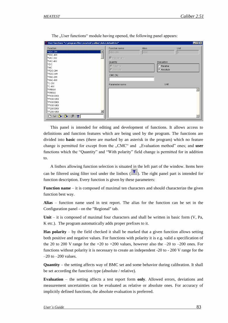
MEATEST Caliber 2.51
User´s Guide 83
The „User functions“ module having opened, the following panel appears:
This panel is intended for editing and development of functions. It allows access to
definitions and function features which are being used by the program. The functions are
divided into basic ones (there are marked by an asterisk in the program) which no feature
change is permitted for except from the „CMC“ and „Evaluation method” ones; and user
functions which the “Quantity” and “With polarity” field change is permitted for in addition
to.
A listbox allowing function selection is situated in the left part of the window. Items here
can be filtered using filter tool under the listbox ( ). The right panel part is intended for
function description. Every function is given by these parameters:
Function name – it is composed of maximal ten characters and should characterize the given
function best way.
Alias – function name used in test report. The alias for the function can be set in the
Configuration panel - on the "Regional" tab.
Unit – it is composed of maximal four characters and shall be written in basic form (V, Pa,
K etc.). The program automatically adds proper prefixes to it.
Has polarity – by the field checked it shall be marked that a given function allows setting
both positive and negative values. For functions with polarity it is e.g. valid a specification of
the 20 to 200 V range for the +20 to +200 values, however also the –20 to –200 ones. For
functions without polarity it is necessary to create an independent -20 to - 200 V range for the
–20 to –200 values.
Quantity – the setting affects way of BMC set and some behavior during calibration. It shall
be set according the function type (absolute / relative).
Evaluation – the setting affects a test report form only. Allowed errors, deviations and
measurement uncertainties can be evaluated as relative or absolute ones. For accuracy of
implicitly defined functions, the absolute evaluation is preferred.

Caliber 2.51 MEATEST
84 User´s Guide
CMC – it gives the best measurement ability of a particular laboratory. If for the given
function the better measurement uncertainty is evaluated then the CMC is, shall be the
evaluated uncertainty substituted by the here given number in the test report. This item can be
changed even for basic functions marked by asterisk. Every laboratory should fill the CMC
field for every function according its measurement ability after program´s installation. The
CMC can be set either as relative or as absolute one, it depends if the given function is a
relative or absolute one.
Parameter name – the item consists of maximal ten characters and is not mandatory one. It
is only at functions with so called next parameter (e.g. alternating voltage with its frequency
as the parameter). A function can contain more these parameters.
Following control keys are situated in the lower window edge:
New – adds a new user function.
Save – writes the modified function table into a file (database).
Import – imports functions created by means of the „Export“ button in the program. It
is checked during the import if a given function exists in the system. The list shall be
completed only by functions with a different definition.
Export – exports functions in the „fce“ format. The format is suitable to function
definition transfer among users.
The Export and Import however are not very often used keys, because a function definition is
being automatically transferred with a procedure in the „pre“ format. If it is being imported a
procedure with a new function, this function shall be added in the program automatically.
New function
This panel allows to append new function to Caliber system. This panel is accessible via the
User functions module. Every function consists of its name and unit, optionally it can contain
one or more parameters.

MEATEST Caliber 2.51
User´s Guide 85
Note: Be careful, all names and units entered here cannot be changed in future. Function
cannot be deleted, only new one can be created. Additionally, only the translation of
functions, parameters, and units into a local form can be done.
Function name - it is composed of maximal ten characters and should characterize the given
function best way. The function name should be defined in English for better compatibility
when exchanging instrument cards and procedures around the world. This name can then be
converted to a local form using the Configuration panel on the "Regional" tab, the "Function"
sub-tab.
Unit - main function unit. It is composed of maximal four characters and shall be written in
basic form (V, Pa, K etc.). The program automatically adds proper prefixes to it. The units
must first be created using the Configuration panel on the "Regional" tab and the "Units" sub-
tab.
Parameter name - the item consists of maximal ten characters and is not mandatory one. It is
only at functions with so called next parameter (e.g. alternating voltage with its frequency as
the parameter). A function can contain more these parameters. The parameters must first be
created using the Configuration panel on the "Regional" tab and the "Parameters" sub-tab.
Unit - parameter unit. It is composed of maximal four characters and shall be written in basic
form (V, Pa, K etc.). The program automatically adds proper prefixes to it. The units must
first be created using the Configuration panel on the "Regional" tab and the "Units" sub-tab.
Units are common to both functions and parameters.
Add - adds new parameter into parameter list.
Delete - removes parameter from parameter list.
OK - closes panel and saves changes. New function will added into system list of functions.
Cancel - closes panel and discards changes.

Caliber 2.51 MEATEST
86 User´s Guide
2.4. “Wizard Rules“ Module
The „Wizard rules“ module having been opened, the following panel appears:
The panel is intended for development and editing of rules according to which a
Procedure wizard shall automatically generate calibration points. The program allows create
more “Rules” and save them under their names. There is possible to determine in the wizard
according to which rule set the points shall be generated. It is suitable to have e.g. other rules
for check of sources and different ones for check of measuring instruments.
Having been installed, the program contains a basic set of “rules” for check point
generating contained in the “default.gen” file. The file contains the following rules:
VDC-2W rule for DC voltages (VDC-2W, VDC-4W functions)
VAC-2W rule for AC voltages (VAC-2W, VAC-4W functions)
IDC rule for DC currents (IDC function)
IAC rule for AC currents (IAC function)
RDC-2W rule for DC resistance, capacitance and inductance (RDC-2W, RDC-4W,
R-TRUE, R-HIGH, C-2W, C-4W, L-2W, L-4W functions)
Note: A calibration procedure cannot be automatically generated without use of the
“Rules”. The rules cannot be developed for functions having more than one
parameter. The procedure than must be put together separately.
There is a status window in the left upper corner. It displays a structure of counted rules
– rule name (function name), scale, range type and check points. On the right there are
displayed functions, which the given rule is valid for.

MEATEST Caliber 2.51
User´s Guide 87
There are control keys situated in the lower bar of the status window:
New – creates n new rule set for point generating.
Open – counts an already created rule set.
Save – shall write a modified rule set in a file (database).
Save us – shall write a modified rule set under a new name in a file (database).
Back – is intended for move to one level up in a hierarchy: instrument – scale – range
type – values. Nesting (move to one level down) shall be performed by a mouse click
on a selected item.
2.4.1. Development of „Wizard rules“
The rule set has the following structure:
Rule – its name is derived from function name. One rule can be valid for more functions. By
double mouse click on any of the rules in the status window we can move to a lower level- in
the scale.
Scale – describes length of a scale (number of digits) of an instrument under test. Sources
having not a scale length given in its instrument card are observed as having a scale of 2000
digits length. Instruments with longer scale have usually more check points than instruments
with shorter scales. A user can define a scale in any way. For every function a few scales can
be created with different rules for point generating. Recommended process for set up of
calibration points is to be found in the EA-10/15 recommendation.
Range type – characterizes a range according to its location in reference to other ranges.
There are following range types:
Highest – the highest range for a given function. The highest range for most of multi-
meters for the VDC-2W function is the 1000V range.
Lowest – the lowest range for given function.
Intermediate – the range in the middle (for voltage usually the 20V range). If number of
ranges is even, the higher range from two middle ones is observed as intermediate.
Specific – the range given by a fixed interval of a measured quantity. It is e.g. the range
higher than 100 V or the range lower than 200 Ohms. Validity for the 30V to 150V
ranges can be also given.
Common – satisfies all ranges. The lower priority must be given to this range type.
Note: Range types have been determined according to the EA-10/15 recommendation.
During procedure generating the program is going through all defined range types ant it
shall use the firstly found one satisfying the required range. It means in practice that range

Caliber 2.51 MEATEST
88 User´s Guide
priority (sequence of evaluations) is given by the sequence of range type definition. If the
range sequence needs to be changed, it can be performed in the status window. Point the
mouse cursor at a field for movement located on the left side of each of the range types. Press
the left mouse key, keep it pressed and move the mouse up or down to move the selected
range type.
Values – defines calibration points for given range types. Calibration points are inserted in
the procedure in the same sequence as they are given here. This sequence can be changed by
the left mouse button.
Ways of adding functions, ranges, points and module control are the same as at the
“Procedure” module. Press the right mouse button on a selected item to open a menu. The
item can be “Add”, “Modify” or “Delete” then.
Standard delivered „Default.gen“ rules have following definitions of point generating for the
direct voltage function:
For multi-meters up to 15,000 digits inclusive the check points of 10%, 50%, 90%, -10%, -
90% range in the middle range and for other ranges the points of 10%, 90%, -90% range are
generating.
For multi-meters from 15,000 digits to 25,000 digits inclusive the check points of 10%, 30%,
50%, 70%, 90%, -10%, -90% range in the middle range and for other ranges the points of
10%, 90%, -90% range are generating.
For multi-meters from 25,000 digits to 15,000,000 digits inclusive the check points of 10%,
50%, 90%, -90% range in the > 200V range, the 10%, 30%, 50%, 70%, 90%, -10%, -90%
range in the middle range and for other ranges the points of 10%, 90%, -90% range are
generating.
For multi-meters over 15,000,000 digits the check points of 10%, 50%, 90%, -90% range in
the > 200V range, the 10%, 30%, 50%, 70%, 90%, -10%, -90% range in the middle range and
for other ranges the points of 10%, 50%, 90%, -90% range are generating.
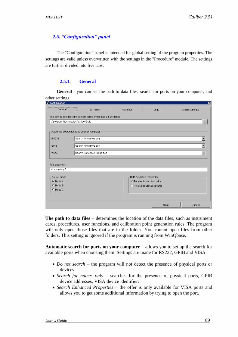
MEATEST Caliber 2.51
User´s Guide 89
2.5. “Configuration” panel
The "Configuration" panel is intended for global setting of the program properties. The
settings are valid unless overwritten with the settings in the "Procedure" module. The settings
are further divided into five tabs:
2.5.1. General
General - you can set the path to data files, search for ports on your computer, and
other settings.
The path to data files – determines the location of the data files, such as instrument
cards, procedures, user functions, and calibration point generation rules. The program
will only open those files that are in the folder. You cannot open files from other
folders. This setting is ignored if the program is running from WinQbase.
Automatic search for ports on your computer – allows you to set up the search for
available ports when choosing them. Settings are made for RS232, GPIB and VISA.
Do not search – the program will not detect the presence of physical ports or
devices.
Search for names only – searches for the presence of physical ports, GPIB
device addresses, VISA device identifier.
Search Enhanced Properties – the offer is only available for VISA ports and
allows you to get some additional information by trying to open the port.

Caliber 2.51 MEATEST
90 User´s Guide
Title appendix – allows you to enter additional text, which will then be displayed
after the program name in the top bar of the main window and in the lower Windows
bar. It serves to better identify the program.
Round mode – allows you to choose the default mode when rounding columns in the
output test report. The modes are the same as in the Rounding panel, which is
available in the Procedure module. The settings you make here will only apply if this
setting is not set in the Procedure module or the "Default Settings" in the Procedure
module is performed.
UUT Deviation calculation – determines the method of calculating the UUT
deviation for each calibration point.
Relative to nominal value – the UUT deviation is determined by the value
measured by UUT.
Relative to Standard value – the UUT deviation is determined by the value
measured by Standard.
2.5.2. Test report
Test report - allows you to set the form of the test report, the names and order of the
columns, the evaluation symbols and their comments.
Test report form – the visual form of the resulting report without measured data with all
symbols used. You can change the settings by double-clicking the left mouse button on the

MEATEST Caliber 2.51
User´s Guide 91
required test report line. If one of the rows is missing (by setting it out), you can include it
using the buttons below the test report window.
Test report columns – allows you to set the number of columns, their widths and names. To
edit, the Test report columns panel is used. This panel is the same as in the Procedure
module. The settings you make here are used only if the settings in the Procedure module is
not set or the "Default setting" is performed in the Procedure module.
Footer caption – allows you to customize the default "Symbol description" footer caption
that appears at the end of the test report.
Pass – allows you to set the symbol and comment for the result of the calibration point that it
has complied with.
Fail – allows you to set the symbol and comment for the result of the calibration point that
failed.
Pass with uncertainty – allows you to set a symbol and comment for the result of a
calibration point that has complied with the error margin + - measurement uncertainty.
Unstable reading – allows you to set a symbol and comment for a calibration point that has
been showing unstable readings.
Value relative to range – allows you to set the symbol and comment for the calibration point
that used the calculation of the deviations relative to the range and not to the value. Such a
symbol is used only when the relative evaluation of the variations (in percent) is set and the
measured value is close to zero.
Canceled by operator – allows you to set the text that appears at the end of the test report if
the calibration has not been completed and the calibration runs under WinQbase.
Comment
The "Comment" panel is used to set the protocol footer. With this panel, you can also
set the evaluation symbols that can be displayed on each line of the test report.
Comment – an edit field for writing the desired comment text. The comment appears at the
end of the test report if it is valid for actual test report. It is also possible to create multi-line
comments. The comment type can be seen in the comment title. The comment may show the

Caliber 2.51 MEATEST
92 User´s Guide
"<@>" string anywhere, which will be replaced with the selected symbol in the output test
report. The symbol can be entered in this panel or in the Global procedure settings.
Show and evaluate this comment – disables or allows the display of this type of comment in
the test report.
Symbol – allows you to enter a symbol for the selected comment type.
Reset to default – sets the default comment and symbol for that comment type, and closes
the panel.
OK – the settings will be transferred to the Configuration - Test report panel and the panel
will close.
Cancel – closes the panel and ignores the changes.
2.5.3. Regional
Regional - allows you to set localized forms of function names, parameters, and units.
These national forms will then be displayed in the exported test report. Functions, parameters,
and units are used in the User functions module and are key to Caliber system identification
and Instrument card and Procedure sharing worldwide. It is therefore necessary to use English
names for them. Therefore, the "Regional" tab is used to locate them in the locale. The
location is then divided into four additional tabs for better clarity.
Functions – a list of all Caliber functions. Functions are defined in the User functions
module. This tab can be used for translation into the national format to be used in the test
report when exporting. If the translation is not done, the original name will be used.

MEATEST Caliber 2.51
User´s Guide 93
Parameters – a list of all parameters - quantities. Parameters are defined here - both English
and National, and can then be used to create a new function in the User function module.
Parameter translation is used on all Caliber panels.
Units – a list of all units of quantities for use in the system. Units can be added and edited
here, and their English and National forms are entered if needed. Units are entered without
prefixes, because prefixes are created automatically by the system.
Prefixes – unit prefixes are pre-set for each language, but can be changed.
Save - all settings made on all tabs will be saved and set as "Default".
Cancel - closes the panel and ignores the changes.
2.5.4. Logs
Logs - logs are used to set up and view calibration log entries. This is not a regular
export of test reports, but additional calibration information. They allow you to store
individual instrument readings, or to preserve unrounded results. Records are created in the
background while calibration runs without user intervention. Recording is done in a text file
and initialized when the procedure is opened.
What will be logged – determines the contents of the record.
Disabled – logs will not be created.
Test report line – each row is saved in the same format as for test report export. The
difference is that the rows of the log are sorted according to the calibration run and
not by the Status Window.

Caliber 2.51 MEATEST
94 User´s Guide
Standard readings, UUT readings, Test report line – stores each row in the same
format as the test report export, supplemented by individual Standard and UUT
readings.
Standard readings, UUT readings, Test report line without rounding – stores each row
as when the test report is exported, but the results are not rounded, the standard and
UUT readings are filled in.
Test report line without rounding – stores each row as when the test report is exported,
but the results are not rounded.
Output file name – name of the file with logged records:
Protocol.txt – the fixed name "Protocol.txt" is used to the "Local" folder where the
program is installed.
Result.txt – the fixed name "Result.txt" is used to the "Local" folder where the program
is installed.
LogXXXXXX.txt – dynamic file name - XXXXXX is a six-digit number that is
constantly increasing from number 1 above. The path to the files is set by the "The
path to log files" setting.
The path to log files – folder to which records are stored. The settings are only available for
files with the dynamic file name "LogXXXXXX.txt".
File name – the column contains the names of the text files that are in the logs folder.
Clicking on the column heading sorts the records by filename.
Procedure - the name of the procedure that the log was made with. Clicking on the column
heading sorts the records by the procedure name.
Size - size of log in bytes. Clicking on the column heading sorts the records by file size.
Date - date the log was created. Clicking on the column heading sorts the records by date.
View - opens the selected file selected for viewing.
Save - all settings made on all tabs will be saved and set as "Default".
Cancel - closes the panel and ignores the changes.

MEATEST Caliber 2.51
User´s Guide 95
2.5.5. Calibration data
Calibration data - on this tab you can view and edit calibration data for instrument
cards. You can also see the expiration date of their calibration. A detailed description of the
calibration data can be found here.
The path to calibration data files – the folder where all instrument calibration data are
located.
File name – this column contains the file names of the calibration data that are in the
specified folder. Clicking on the column heading sorts the records by file name.
Model – list of devices found in calibration data files. Clicking on the column heading sorts
the records by model.
Serial number – serial number to the model found. Clicking on the column heading sorts the
records by serial number.
Expiration date – the date on which the instrument calibration data is valid. If the date has
already expired, an exclamation point in the yellow triangle appears before the name of the
calibration file. Clicking on the column heading sorts the records by the expiration date. This
may be appropriate for detecting instruments with expired calibration.
Refresh – reconsiders the calibration data folder and updates the list.
Modify – opens the selected file to edit. The meaning of the individual rows in the file is
described here.
Save - all settings made on all tabs will be saved and set as "Default".
Cancel - closes the panel and ignores the changes.

Caliber 2.51 MEATEST
96 User´s Guide
2.6. Measuring Procedure
For every point a measuring is being performed in these steps:
a) Adjustment of the automatic terminal switch (if it is used).
b) Adjustment of a function and range of the converters (if they are used).
c) Adjustment of a function and range of the measuring instruments.
d) Adjustment of a function and range of the sources.
e) Switch on output terminals of sources (if a source is equipped with this option).
f) Additional adjustment during an analog meter instrument test (the UUT must be used as
an analog measuring instrument).
g) Counting of all the converter values (if they are used).
h) Counting of a standard value. If a source is in standard function, one measurement shall
be performed (a value set on the source shall be counted). If a measuring instrument is a
standard, set of measurements shall be performed.
Note: If the standard measurement instrument is manually controlled, a half of
measurements written down in the “No. of SU readings” item shall be performed. If the
measurement number is odd, a half of measurements rounded up shall be performed.
If the standard measurement instrument is controlled another as manually way, one
extra measurement shall be performed before the measurement set itself. This first
measurement shall not be cont towards other evaluations.
i) Counting of a tested instrument value: If a source is instrument under test, one
measurement shall be performed (a value set on the source shall be counted). If a
measuring instrument is a standard, set of measurements shall be performed.
Note: If the instrument under test is manually controlled, number of measurements written
down in the “No. of UUT readings” item shall be performed. If the instrument is controlled
another as manually way, one extra measurement shall be performed. This first measurement
shall not be cont towards other evaluations.
j) If a meter is a standard, set of measurements by this standard instrument shall be
performed. Mean of both measurement sets (h,j points) shall be set as the standard value.
Note: By means of a standard measuring instrument a half of measurements written
down in the “No. of Standard readings” item shall be performed. If the measurement
number is odd, a half of measurements rounded down shall be performed. Measurement
number doesn´t depend on instrument´s way of control.
k) Calculations and measurement checks in terms of value scatter shall be performed (see
below). If discrepancy is found, the process shall be repeated from h point.
l) Switch off output terminals of sources (if a source is equipped with this option).

MEATEST Caliber 2.51
User´s Guide 97
Note: If a user interrupts the program in middle of described process run (by
pressing the ESC key during calibration), the output source terminals shall
go always off.
If a gross error occurs at evaluation (5 times larger deviation than the allowed error),
the program stops (implicit “Global procedure settings”) and check of this point can be
repeated. If the procedure is set that even in case of gross error it is continuing, the program is
continuing to the next calibration point.
A user can change a measuring procedure from the “Measurement mode” panel in the
procedure status window. A measuring procedure can be changed for one calibration point,
range, function or the whole procedure.

Caliber 2.51 MEATEST
98 User´s Guide
2.7. Measurement Error and Uncertainty Calculation
2.6.1. Used Abbreviations
L1
Relative accuracy from value stated in the instrument card [%] (e.g. 0.1%).
L2
Relative accuracy from range stated in the instrument card [%] (e.g. 0.05%).
L3
Absolute error in units of measured quantity stated in the instrument card (e.g. 5mV).
L4
Absolute error in digit number stated in the instrument card (e.g. 2 digits).
Rng_u
An end range value of the instrument under test in units of measured quantity stated in the
instrument card (e.g. 20V).
Dig_u
Resolution of one digit of the instrument under test in units of measured quantity. It can be
stated direct in the instrument card or it can be calculated from digit number and range (range
/ digit number), (e.g. 100mV/digit).
Dig_s
Resolution of one digit of the standard instrument in units of measured quantity (if a
converter is used, then after recalculation by this converter). It can be stated direct in the
instrument card or it can be calculated from digit number and range (range / digit number),
(e.g. 10mV/digit).
Dig_sa
Resolution of one digit of the auxiliary standard instrument in units of measured quantity (if a
converter is used, then after recalculation by this converter). It can be stated direct in the
instrument card or it can be calculated from digit number and range (range / digit number),
(e.g. 10mV/digit).
Dmax_u
Accuracy of the instrument under test in units of measured quantity. It shall be calculated
according to data stated in the instrument card (see the 2.6.2 Measurement Error Calculation
section), (e.g. 100mV).
Dmax_s
Accuracy of the standard instrument in units of measured quantity (if a converter is used, then
after recalculation by this converter). It shall be calculated according to data stated in the
instrument card (see the 2.6.2 Measurement Error Calculation section), (e.g. 10mV).
Dmax_sa
MEATEST Caliber 2.51
User´s Guide 99
Accuracy of the auxiliary standard instrument in units of measured quantity (if a converter is
used, then after recalculation by this converter). It shall be calculated according to data stated
in the instrument card (see the 2.6.2 Measurement Error Calculation section), (e.g. 10mV).
Dmax_c
Accuracy of the real converter in units of measured quantity. It shall be calculated according
to data stated in the instrument card converted to measured quantity by the converting
function itself (see the 2.6.2 Measurement Error Calculation section). This error equals zero if
the converter is under test or a virtual converter (it makes an arithmetic operation only and
doesn´t affect the measured quantity).
Xu
Value measured (adjusted) by the instrument under test. The value (Xu) equals the adjusted
value at the source under test. At the measuring instrument under test it is calculated as
measurement medium without gross errors.
Xu = aj / j
Xs
Value measured (adjusted) by the standard (if a converter is used, then after recalculation by
this converter). The value (Xs) equals the adjusted value at the standard sources. At the
standard measuring instruments it is calculated as measurement medium without gross errors.
Xs = aj / j
Xsa
Value measured (adjusted) by the auxiliary standard (if a converter is used, then after
recalculation by this converter). The value (Xsa) equals the adjusted value at the standard
sources. At the standard measuring instruments it is calculated as measurement medium
without gross errors.
Xsa = aj / j
Note: An auxiliary standard is mostly used for measurement of an output of a converter under
test.
Gross error identification is made in terms of comparison of measured values:
|aj - X| > 2.5*zaj
where the z is the mean-square deviation
zaj = ( (aj-X)2 / j )
and X are the Xu, Xs or Xsa values.
If the above mentioned condition is fulfilled for any measurement etc., the whole measuring
procedure shall be repeated at the given check point. If the measurement set fails even after
the third repetition, it shall be used and a „~“ –unstable note appears at the end of the
particular line.

Caliber 2.51 MEATEST
100 User´s Guide
2.6.2. Calculation of UUT deviations
The way of deviation calculation is fixed determined by the program. Internally the
program performs every calculation in units of a measured quantity. If a relative expression is
required, a recalculation shall be made according to rules stated in 2.6.4 Relative Value
Representation section.
Allowed deviation is determined by the following formula:
Dmax_u = |Xu| * L1 / 100% + Rng_u * L2 / 100% + L3 + Dig_u * L4
Note: In similar way limit deviations of all other instruments shall be calculated
(Dmax_s, Dmax_sa, Dmax_c). If a converter is being used, the result shall be converted to
units of the measured quantity.
Deviation of an instrument under test shall be calculated according to the following
relation:
d = Xu – Xs if a source of a meter are being tested
or
d = Xsa – Xs if a converter is being tested
2.6.3. Calculation of Measurement Uncertainty
The way of measurement uncertainty calculation is fixed determined by the program
according to EA-4/02. Internally the program performs every calculation in units of a
measured quantity. If a relative expression is required, a recalculation shall be made
according to rules stated in 2.6.4 Relative Value Representation section. If the calculated
measurement error is in the ‘limit allowed error +/- uncertainty’ interval, the particular line
shall be marked by the „?“ symbol. In terms of “Global procedure settings” of the procedure
„?“ symbol can be replaced by another symbol (adjustment can be performed in the “Failed in
band” field). In the same way a uncertainty can be removed from measurement evaluations by
selecting the “None” parameter.
For each of the points the standard extended measurement uncertainty has been
calculated.
U = ku*uc

MEATEST Caliber 2.51
User´s Guide 101
where is
ku - extension coefficient set by the control file (implicitly ku=2)
uc - combined standard uncertainty according to the formula:
uc = ua2 + ub
2 + uud2 + uua
2 + usd2 + usa
2 + usb2 + utd
2 + uta2 + utb
2 + ucb2
ua - general uncertainty of A type. It shall be used only if any of the uncertainty sources of
A type is not used in calculations by the program. It can be adjusted separately for every
function, range or point under test. In very most of cases, the implicit 0.0 value shall be
proper. A user will set this uncertainty in the “Additional uncertainty” panel. For absolute
quantities, the uncertainty equals to the by user given value. For relative quantities the
following formula is valid:
ua = by user given value * |Xs| / 100
ub - general uncertainty of B type. It shall be used only if any of the uncertainty sources of
B type is not used in calculations by the program. It can be adjusted separately for every
function, range or point under test. If this uncertainty is not defined by a user and an
instrument under test is an analog measuring instrument, the program shall automatically set a
uncertainty according to a allowed error of the measuring instrument according to the
following formula:
ub = Dmax_u / ( 3 * 10 )
If a user set a uncertainty in the “Additional uncertainty” panel, then for absolute quantities
the uncertainty shall equal to the by user given value. For relative quantities the following
formula is valid:
ub = by user given value * |Xs| / 100
uud - uncertainty caused by final resolution of the measuring instrument under test
(if a source is the measuring instrument under test, the value equals zero)
uud =0.29 * Dig_u
uua - uncertainty A type determined from j measurements aj of the measuring instrument
under test
uua = ( (aj-Xu)2 ) / ( j * ( j - 1 ) )
usd - uncertainty caused by final resolution of the standard measuring instrument
(if a source is the standard, the value equals zero)
usd = 0.29 * Dig_s
usa - uncertainty A type determined from j measurements aj of the standard measuring
instrument (if a source is the standard, the value equals zero)
usa = ( (aj-Xs)2 ) / ( j * ( j - 1 ) )

Caliber 2.51 MEATEST
102 User´s Guide
usb - uncertainty caused by the limit standard error
usb = Dmax_s / 3
utd - uncertainty caused by final resolution of the auxiliary standard measuring instrument
(if a source is the standard, the value equals zero)
utd = 0.29 * Dig_sa
uta - uncertainty A type determined from j measurements aj of the auxiliary standard
measuring instrument (if a source is the standard, the value equals zero)
uta = ( (aj-Xsa)2 ) / ( j * ( j - 1 ) )
utb - uncertainty caused by the limit auxiliary standard error
utb = Dmax_sa / 3
ucb - uncertainty caused by the limit error of the converter connected with the standard
ucb = Dmax_c / 3
2.6.4. Relative Value Representation
Internally the program performs every calculation in units of a measured quantity. If a relative
expression is required, a recalculation of absolute values to relative ones in reference to the
standard value (Xs). Conversion is made according to the following formula:
Relative = Absolute * 100% / |Xs|
If Xs is lower than one hundredth of measuring range, the program shall express the value in
reference to the range of the instrument under test (Rng_u) during relative estimations. This
fact shall be then marked by the „R“ letter at the end of a particular line in the test report:
Relative (range) = Absolute * 100% / Rng_u

MEATEST Caliber 2.51
User´s Guide 103
2.8. Test Report Format
The appearance of the Test report is preset in the program and can be individually
changed in the Configuration panel on the Test report tab. Some settings can also be changed
in the Procedure module.
For every line a measurement uncertainty is stipulated and it is given if the particular
measurement fulfills the measuring instrument specification. Accuracy of a standard
represents an essential part of the measurement uncertainty. For the accurate calculation see
the 2.5 and 2.6 sections. Following default symbols can appear at the end of every line:
* measured error is higher than the allowed one
~ measured error is unstable (see section No. 2.5)
R all errors and uncertainties are in reference to the range
? measured error is in the interval of limit error +/- measurement uncertainty
ok if a check point is ok
Test report sample:
Function| Range| Standard| UUT| Deviation|%spe| Allowed|Uncertainty|
----------------------------------------------------------------------------------------------------
VDC-2W| 200 mV| 20.0 mV| 20.0 mV| -0 uV| 0| 200 uV| 62 uV| ok
VDC-2W| 200 mV| 180.0 mV| 180.6 mV| 620 uV| 62| 1003 uV| 71 uV| ok
VDC-2W| 200 mV| -180.0 mV| -180.7 mV| -690 uV| -69| 1003 uV| 69 uV| ok
VDC-2W| 2 V| 0.200 V| 0.200 V| -0.00 mV| 0| 2.00 mV| 0.58 mV| ok
VDC-2W| 2 V| 1.800 V| 1.807 V| 7.00 mV| 70| 10.04 mV| 0.58 mV| ok
VDC-2W| 2 V| -1.800 V| -1.807 V| -6.80 mV| -68| 10.03 mV| 0.64 mV| ok
VDC-2W| 20 V| 2.00 V| 2.00 V| 0.0 mV| 0| 20.0 mV| 5.8 mV| ok
VDC-2W| 20 V| 10.00 V| 10.04 V| 40.0 mV| 66| 60.2 mV| 5.8 mV| ok
VDC-2W| 20 V| 18.00 V| 18.07 V| 70.0 mV| 70| 100.4 mV| 5.8 mV| ok
VDC-2W| 20 V| -2.00 V| -2.00 V| 0.0 mV| 0| 20.0 mV| 5.8 mV| ok
VDC-2W| 20 V| -18.00 V| -18.07 V| -71.0 mV| -71| 100.4 mV| 6.1 mV| ok
VDC-2W| 200 V| 20.0 V| 20.1 V| 100 mV| 50| 201 mV| 58 mV| ok
VDC-2W| 200 V| 180.0 V| 180.8 V| 830 mV| 83| 1004 mV| 65 mV| ok
Column meanings:
Function - function of the instrument under test (VDC-2W, VAC-2W, IDC, .....).
Range - range of the instrument under test. The program shall automatically
generate a prefix of quantity value which can be changed in the procedure
status window by means of the “Quantity prefix” panel.
Standard - calibration point (its standard value) completed by a parameter. If there
are more parameters and their values cannot be written into wide of the
„Standard“ field, the (*) reference shall be generated and the parameters
shall be written as a note in the next line of the test report. Units inclusive
prefixes are determined according to the range. Number of displayed
positions is being limited by a measurement uncertainty (if the uncertainty
is displayed with resolution of 10 mV, the standard value shall also be
displayed with this resolution). For measuring instrument is their position

Caliber 2.51 MEATEST
104 User´s Guide
number additionally limited by the display position number of the
measuring instrument under test. For resulting display there shall be used
such a rule which determines the lower resolution. Number of displayed
positions and value prefixes can be changed in the “Rounding” panel.
UUT - value having been measured by the instrument under test (an arithmetic
mean of more measurements). Units inclusive their prefixes are
determined according to their range. Number of displayed positions is
limited by a measurement uncertainty (if the uncertainty is displayed with
resolution of 10 mV, the standard value shall also be displayed with this
resolution). For measuring instrument is their position number additionally
limited by the display position number of the measuring instrument under
test. For resulting display there shall be used such a rule which determines
the lower resolution. Number of displayed positions and value prefixes
can be changed in the “Rounding” panel.
Deviation - error of the instrument under test (see section No. 2.5). Number of
displayed digits is given by a measurement uncertainty. If absolute
evaluation is being used, the used units have their prefix with lower place
value than the range. Number of displayed positions and value prefixes
can be changed in the “Rounding” panel. This column is empty if
specification of an UUT device is defined as “Limit”.
% spe - specification utilization percent (= Deviation / Allowed * 100 %). The
value is displayed with percent units. If the specification utilization is
higher than 999 %, the value of 999% shall be given. This column is
empty if specification of an UUT device is defined as “Limit”.
Allowed - allowed error of an instrument under test. There are two ways of
displaying value in this column. If allowed error of an UUT device is
specified as “Limit”:
Shortest expression of limit is applied. Evaluation of all columns is forced
to “Absolute”. Prefix and unit is determined according to UUT range. For
example expression can take form:
>100 MOhm – for low limit
<15 mOhm – for high limit
45…55 Hz – for both limits
If specification is not defined as limit:
Allowed error is calculated from four fields (% of reading, % of range,
absolute error, digit error). Number of displayed digits is given by a
measurement uncertainty. If absolute evaluation is being used, the used
units have their prefix with lower place value than the range. Number of
displayed positions and value prefixes can be changed in the “Rounding”
panel.

MEATEST Caliber 2.51
User´s Guide 105
Uncertainty - extended measurement uncertainty for ku = xxx (see section No. 2.5).
Number of displayed digits is limited to two valid positions. If absolute
evaluation is being used, the used units have their prefix with lower place
value than the range. Number of displayed positions and value prefixes
can be changed in the “Rounding” panel.

Caliber 2.51 MEATEST
106 User´s Guide
2.9. Testing Procedure
The testing procedure called „TEST” represents an integral part of program delivery.
This procedure allows check of every important functions of the „Caliber“ program as e.g.
correctness of procedure interpretation, correctness of error calculations, of measurement
uncertainties etc. The testing procedure doesn´t need any instruments.
At checking of program equipment operation we proceed as follows: Start the
calibration according to the „TEST“ procedure. If we are working in WinQbase environment,
it is suitable to create a separate identification sheet for testing purposes. Further we follow
the program instructions. If the “Write instrument value” program prompt appears, set
sequentially points from the following table:
Function, check point Entered value
V-DC, 10.0 V 10.01
A-AC, 1.0 A 0.98
O-2W, 100 100.0
The testing procedure shall run quite automatically and their result shall be a
calibration sheet with the measured values as follows:
Function| Range| Standard| UUT| Deviation|%spe| Allowed|Uncertainty|
----------------------------------------------------------------------------------------------------
VDC-2W| 20 V| 10.000 V| 10.010 V| 10 mV| 50| 20 mV| 13 mV| ?
IAC| 2 A| 1.0000 A; 60 Hz| 0.9800 A| -20.0 mA|-999| 2.0 mA| 1.3 mA| *
RDC-2W| 200 Ohm| 100.00 Ohm| 100.00 Ohm| 0 mOhm| 0| 200 mOhm| 127 mOhm| ok
----------------------------------------------------------------------------------------------------
? ... measured value is within the allowed deviation ± measurement uncertainty interval
* ... failed
ok ... ok
Let´s compare the measured report with the above shown sample. If some discrepancies
occur, check if some overwriting (failure) of the „TEST“ procedure doesn´t happen.
According to own consideration of yours, the test reports can be filed. If the test results
shall be stored regularly, you win option in terms of program correctness back-check.
Note: The testing procedure is to be imported before its first usage (the „test.pre“ file).

MEATEST Caliber 2.51
User´s Guide 107
2.10. Program Registration
The computer, which Caliber is installed on, checks the Registration code after start
and if there is not any registration code (Caliber is not registered) or it´s invalid, the program
is converted into a limited demo mode. Every registration code also contains its validity
period within which the program can be updated. If a newer version of the Caliber program
has been installed as that one supported by the registration code, the program shall be
automatically converted into the demo mode, even if the foregoing registration code was valid
for the older program version.
Demo- version
Having been installed, the Caliber program shall start automatically in the demo mode.
This mode doesn´t allow saving and printing of the calibration report. In addition to, there
cannot be used the „CamOCR“ unit for camera scanning. The program determines this mode
as “Demo mode”.
Light version
This mode requires presence of the Meatest calibrator for procedure run and at the
same time the program registration with a valid registration code in reference to a particular
calibrator type. The light mode allows full utilization of all the program features (except from
the CamOCR unit if it has not been bought). The program determines this mode as “Light
mode”.
Full version
This mode requires only set the valid registration code without reference to a particular
calibrator type. It allows full utilization of all the program features (the CamOCR unit only if
it has been bought). The program does not determine this mode.
Calibration mode
This mode is evoked, when Caliber is run from WinQbase environment and new
calibration is initiated. This mode requires the valid registration code. This mode is intended
only for calibration execution and it does not allow any procedure modification. Only
Procedure module is run in this mode and no other module can be run. The program
determines this mode as "Calibration mode".

Caliber 2.51 MEATEST
108 User´s Guide
Program registration
The program can be registered during its run by means of the “Help” menu and by the
“About Caliber” item activation. The registration consists of two steps:
Step 1 – Company identification
Set the Serial number, Company name and User name who the license is to be registered to.
Serial number you can get from “Licence agreement” which is supplied with program
package. Press the button “Send licence to validation“. Program will ask for the path where to
save the file with the information about the user. Send this file “SNXXXXXXXX
(QUERY).LCN“ as attachment to the email [email protected].
Step 2 – Licence activation
In response to the email you will receive the activation file “SNXXXXXXXX
(ACTIVE).LCN“. Use this file to complete the activation by pressing the “Activate licence“
button.

MEATEST Caliber 2.51
User´s Guide 109
2.11. Special Calibration Types
2.10.1. Analog meters
Program Caliber up its version 1.15 allows perform check of analog instruments. For
this purpose an adjustable signal source with sufficient resolution for continuous adjustment
of measuring instruments is required. E.g. check of resistance ranges cannot be done by
means of standard resistors, but by resistor decades.
For analog measurement instrument check the program allows additional continuous
adjustment for every calibration point on a signal source that a measuring pointer is in
alignment with match mark of the calibration point. Additional adjustment of the source can
be carried out by a mouse. Eleven keys situated in the “User prompt window” are intended
for that purpose. The adjusted value can be reduced by means of five keys with the left arrow
and increased by the right five keys. The keys have different sensitivity. The outer keys have
the largest step (corresponding with the tested measuring instrument class). The adjoining
keys have 4 times lower sensitivity of the step. The analog instrument having set to the check
point, an operator press the “OK” button and the program shall read the conventionally right
value of measured quantity from a standard instrument. The deviation of the measuring
instrument shall be calculated as value difference. The additional adjustment can be also
performed by means of a keyboard. The “UP” and “DOWN” keyboard arrows are intended
for adjustment step change, the “LEFT” and “RIGHT” arrows for decreasing or increasing of
the calibrator output voltage. If the analog instrument check is performed by means of a
manually adjustable source, the above shown screen shall not be displayed. The source is
being directly adjusted, not by the computer.
In uncertainty calculation, the A type uncertainty due to analog instrument reading
uncertainty shall be added to the calculated measurement uncertainty (see section No. 2.2).

Caliber 2.51 MEATEST
110 User´s Guide
The program sets this uncertainty as 10% of allowed error of the measuring instrument. If a
laboratory has determined some other uncertainty of pointer reading, the adjustment of
uncertainties can be used direct in a calibration procedure (see section No. 2.1.1).
Check points for analog measuring instruments are to be set according to instrument
types separately. The check should be done in principle in the signed scale points. It is strictly
recommended to modify the check points after automatic procedure generating according to
particular measuring instrument´s requirements.
The Caliber program considers a measuring instrument under test as analog one (it
allows continuous adjustment of the check point), if in the “Full digits” field there is the
“ANALOG” text in the particular instrument card. An analog measuring instrument is so
identified in terms of the “Instrument card”.

MEATEST Caliber 2.51
User´s Guide 111
2.10.2. Calibration of Decades
The Caliber program has a special procedure for decade calibrations by means of
which so called “Reference zero” (zero resistor of decade – R0) can be subtracted from each
of the check points.
The instrument card of a classic resistance decade must has a separate range for every
decade place value (rotary switch) plus one range for zero point check.
E.g. for the Burster decade of 1406 type withR0 < 10 m and ranges from 10 m to
100 k, the following ranges can be selected:
The calibration procedure of this decade shall have the following form:
The first procedure line is marked as the “Reference zero” ( ). The „Deviation“ value
from the first line shall be automatically distracted from the deviations measured on the next
lines. The “Reference zero” marking can be done so that we point by mouse at the line, press
the right mouse button and select the “Reference zero” from the menu.
Note: A calibration procedure for a resistance decade can be developed by means of
“Procedure Wizard”, but the particular calibration points are to be added into the
procedure. The wizard namely selects only a few points for each of the ranges.
Note: A converter labeled as CONVRTRUE is a part of above shown calibration procedure.
There is a virtual instrument only converting a function of two-terminal resistor
measurement (R2W) to four-terminal measurement of the TRUE OHM type
(DATRON1281 function). The converter allows measurement of two-terminal decades
as the four-terminal ones.

Caliber 2.51 MEATEST
112 User´s Guide
3. Terminology
This section explains meanings of some less common terms used in this User´s Guide.
Caliber – comprehensive calibration system intended for calibrations of measuring
instruments. It consists of several program modules. A program output is represented by the
“Test report” with calculated errors and uncertainties of the measurement. Instruments can be
controlled by a computer (automatically) or manually (by hand).
Standard – (SU – Standard Unit) standard instrument by means of it a conventionally right
value can be established during calibration (the instrument under test is connected with it).
The standard instrument can be both a source and a measuring instrument.
Auxiliary standard – another standard instrument. The caliber program offers another
(auxiliary) standard for check of converters by which a response of the converter under test
can be measured. In this case the auxiliary standard is being involved in calculations of
measurement deviations and uncertainties. If the auxiliary standard is not connected behind
the converter in a UUT position, its influence shall not be involved into the resulting
uncertainty.
Function – by the Caliber system checked function. A function is mostly defined by a
physical quantity (voltage, current, resistance, …), however it can defined also way of
connections (VDC-2W … direct two-terminal voltage) or way of measurement (R-TRUE …
resistors being measured for both positive and negative signal polarity). Utilizing of existing
functions represents a standard procedure. A user shall complete a new function if he is
creating an instrument card for adjustment of a new still not defined function.
Absolute and relative functions are differed by the program. The absolute functions have set
resolution of one bit and BMC in absolute value. The relative functions have set digit number
on the range and BMC in percents. Regardless of that differentiation, absolute or relative
measured values expression can be set (it determines way of error and uncertainty evaluation
in the test report).
GPIB – (General-Purpose Interface Bus) is a parallel bus for remote control of measuring
instruments. It allows parallel connection of more instruments which have different
addresses. A card for the GPIB bus control must be installed in the computer to use this bus
in the Caliber program.
Master bus– called also „Master signal bus“ is a virtual connection among an instrument
under test and other instruments. At every calibration point are function, range and value set
on this bus the main checked parameters being set in a UUT and they are also written down in
the output record (a table of both measured and calculated values).
Hierarchy – the Caliber system defines a fixed hierarchy in terms of which a user is moving
by the work with calibration procedures and instrument cards. The highest level of this
hierarchy is the “Calibration procedure” (at work in the “Procedures” module), eventually the
“Instrument card” (at work in the “Instrument cards” module), both of them being represented
through their names. The lower level consists of checked “Functions” defined in the “User

MEATEST Caliber 2.51
User´s Guide 113
functions” module. Below the functions there are checked “Ranges”. On the lowest level
there are checked “Points” in case of a calibration procedure. The lowest level in the
“Instrument card” consists of the “Ranges” and if a given function has a defined parameter,
the lowest level is represented by the “Parameter”.
Value – variable used by the program which represents a value of the measured quantity. It is
being used in macros as the variable.
Calibration procedure – set describing the methodology of calibrations. It defines
instruments used in a calibration and points at which a calibration is being performed. The
“Procedures” program module is intended for modifications and creations of calibration
procedures.
Instrument card – set describing instrument´s features. Metrologic features of an instrument
are defined here (functions, ranges, specification etc.) and way of instrument control
(commands of GPIB, RS232, VISA). Existing of an instrument card is a necessary condition
of its using in a calibration procedure.
Macro – sequence of commands defining instrument control. Detailed description of
commands, which a macro can be composed of, is contained in the “Instrument card module”
section. Opening instrument, setting instrument, reading instrument eventually switching
output terminal on/off are defined in the instrument card by means of the macros.
„Instrument card“ module – program unit of the Caliber system intended for work with
instrument cards (development and modification).
„Wizard rules“ module – program unit of the Caliber system intended for work with the
“Generating” rules files (development and modification).
„Procedures“ module– program unit of the Caliber system intended for work with the
calibration procedures (development and modification) and for calibration performances.
„User functions“ module – program unit of the Caliber system intended for work with the
function definitions (development and modification).
Parameter – describes an additional quantity of a checked function. E.g. for alternating
voltage, its frequency is the parameter, or for a thermocouple, a temperature of its remote
junction is the parameter. Parameters are never checked quantities, however they can affect
accuracy of instruments (the accuracy is defined for different parameter values) and
calibration procedure generating (according to the range of allowed parameter values for tan
instrument under test).
Wizard rules – (generating rules) set describing a way of check point development by the
Caliber system for new created calibration procedures. There can be possible to create a few
sets containing different generating rules and at creation of a new calibration procedure it can
be only selected such rules according that the procedure can be created. There can be created
other rules for calibration procedures for measuring instruments and other ones for calibrators
or decades.

Caliber 2.51 MEATEST
114 User´s Guide
Converter – converts measured signals. It allows conversation of quantities (current shunt,
voltage / frequency converter), eventually value conversation (transformer, current inductor
with 50 coils). The program doesn´t allow connect a converter to a UUT. Converters can be
divided to real ones, which convert a measured signal, or virtual ones, which performs a
mathematic operation (e.g. recalculation of a voltage to a temperature of a thermo-element)
and they doesn´t affect the measurement accuracy. A special category is represented by a
converter in position of an instrument under test. Such a converter must fulfill certain
conditions secured in the instrument card by the “Converter as UUT” denomination in the
“Converter conditions”. The converter used as a UUT must be set the same way as its input
function. Also the converter value cannot be involved in a formula. It can be used a simple
formula only.
Reference zero – denomination of a calibration point that changes way of evaluation off all
the other points belonging to the same function. At check of such denominated point, the
found deviation of an instrument under test shall be saved in a memory and it shall be
subtracted automatically from this instrument at next calibration points. This deviation
doesn´t affect either a standard value or checked instrument value in the test report, but it
shall affect a deviation and following calculations. It is intended for e.g. check of resistance
decades when the zero resistance value is to be subtracted.
RS232 – serial bus. It allows remote control of measuring instruments by the computer. Its
disadvantage is that only one instrument can be connected to the bus. A big advantage is that
practically every computer is being equipped with this bus.
Buffer – variable used for temporary data saving by the program. A typical usage example is
counting of response of an instrument controlled by the computer and its following
processing.
SU – (Standard Unit) see the STANDARD.
UUT (Unit Under Test) – instrument under calibration. A source a measuring instrument or a
converter can be the instrument under calibration.
VISA – (Virtual Instrument Software Architecture) is a standard for instrument control
through different bus types (GPIB, RS232, Ethernet, USB, …).
WinQbase – the MEATEST program equipment for identification and calibration of
measuring instruments. It can be used as a program superstructure of the Caliber system. It
provides identification of measuring instruments, of calibration sheets, record print,
measuring instrument selection according to diverse criteria etc.
Connection scheme – (terminal connection) an item (text) in an instrument card, which
describes instrument terminals being utilized. The terminal connection mostly shall change if
an instrument function changes. The text describing terminal connections shall be as short as
possible. Abbreviations named on an instrument are recommended. During calibration an
operator shall be prompted to connection change every time when a change of “Terminal
connection” happens for some of used instruments.
Copyright © 2022 FDOKUMEN