RONDA startech 4000 Caliber 4120.B – 12½'''
31
RONDA startech 4000 Multifunctions with Big Date, Alarm, 2nd Time Zone Caliber 4120.B – 12½''' Product Specifications Analog quartz movement Line startech Caliber 4120.B Size 12½''' Version Swiss Made 7 Jewels / gold plated Swiss Parts 3 Jewels / nickel plated Battery life 50 Months Hand fitting height 2 Features – Metal movement, repairable – Very long battery life – Power saving mechanism with pullled out stem: Reduction of consumption approximately 70% – Very easy handling by one pusher Date: 15.07.2013 www.ronda.ch Page: 1
-
Upload
khangminh22 -
Category
Documents
-
view
2 -
download
0
Transcript of RONDA startech 4000 Caliber 4120.B – 12½'''

RONDA startech 4000
Multifunctions with Big Date,
Alarm, 2nd Time Zone
Caliber 4120.B – 12½'''
Product Specifications
Analog quartz movement
Line startech
Caliber 4120.B
Size 12½'''
Version Swiss Made 7 Jewels / gold plated
Swiss Parts 3 Jewels / nickel plated
Battery life 50 Months
Hand fitting height 2
Features
– Metal movement, repairable
– Very long battery life
– Power saving mechanism with pullled out stem: Reduction
of consumption approximately 70%
– Very easy handling by one pusher
Date: 15.07.2013 www.ronda.ch Page: 1

RONDA startech Caliber 4120.B – 12½'''
Functions
– 2 eyes
– Multifunction
– Alarm
– Big date
– Small second
Technical Specifications
Diameter Total 28.60 mm
Case fitting 28.00 mm
Movement height 4.40 mm
Height over Battery 4.40 mm
Movement rest 0.60 mm
Height over stem 1.90 mm
Length of stem travel 0.90 mm
Stem thread 0.90 mm
Battery type 395
Battery voltage 1.5 V
Battery life 50 Months
Current consumption – typical 1.42 μA (Date
Mechanism not in
Gear)
Current consumption – maximum 1.65 μA (Date
Mechanism not in
Gear)
Useful torque second – typical 6 μNm
Useful torque minute – typical 300 μNm
Operating temperature 0 - 50 °C
Instantaneous rate -10/ +20 sec/month
Resistance to magnetic fields 18.8 Oe
Resistance against shock NIHS 91-10
Date: 15.07.2013 www.ronda.ch Page: 2

07No. 5000.322
4120.BSous réserve de modifications
Aenderungen vorbehaltenModifications reserved
Frame
UhrwerkgestellCage
RONDA
12½'''
14 Nov 2003
Modified
Scale 10 : 1 (5 : 1) (A3H)
+/- 20 µm
mkIssued
Tolerance
Released
20 Sep 2010dh
ÄA 8621
YES

b
30°
Ø Dp
30°
b
T
Ø D
e
Ø D
t
P
Ø 1.2 ±200
Ø D
p
Ø Dp
0°
a b
b
a T
Ø D
e
Ø D
t
P
30° ±2
Ø 0
.4 Ø 1
.4 +
0 -
100
Ø D
p
Ø Dp
20°
a b
b
20°
a T
Ø D
e
Ø D
t
P
Ø 0.4
Ø 1.4 +0 -100
Ø D
p
10° ±2
Ø Dp
15°
a b
b
15°
a T
Ø D
e
Ø D
t
P
Ø 0.4
15° ±2
Ø 1.4
+0 -100
Ø D
p
Ø Dp a b
10°b
10°
a T
Ø D
e
Ø D
t
P
Ø 0.4
Ø 1.4
+0 -100
Ø D
p
20° ±2
01No. 5000.345
4xxx.x, 5xxx.xSous réserve de modifications
Aenderungen vorbehaltenModifications reserved
Angle of pusher A and BWinkel der Drücker A und BAngle des poussoirs A et B
RONDA
Modified
Scale 10 : 1 (5 : 1) (A3H)
+/- 20 µm
mkIssued
Tolerance
Released
30.März 2005mk
ÄA 1784
YES
06 Sep 2004


RONDA4003.B, 4120.B, 4210.B, 4220.B
Tige (dimensions / forces)Stellwelle (Dimensionen / Kräfte)Stem (dimensions / forces)
Issued
---
Scale
Tolerance
10:1 (A3)
00
05 Sep 2012
No.
ds5222
Sous réserve de modificationsAenderungen vorbehalten
Modifications reserved
5030.018
Modified
Released YES
---
ÄA 11741ds5222
L2
L
S
L1
L3
No. d'articleArtikelnummerPart number
L L1
3000.177.CO
L2 L3 S DCouleur de la couronneKronenfarbeCrown color
20.00 10.23 24.23 10.15 1.100.90
bleu foncé
UN 5002
Tige de travail (intégrée dans le mouvement)Arbeitstellwelle (im Werk eingebaut)Working stem (implemented in the movement)
Code
dunkelblaudark blue
No. d'articleArtikelnummerPart number
L L1
3000.177
L2 L3 S D
20.00 10.23 24.23 10.15 1.100.90
Tige (normale) / Stellwelle (normal) / Stem (normal)
No. d'articleArtikelnummerPart number
L4L5
(min)
3000.040
L6 S1 S2 D1
12.00 1.90 2.45 0.90 1.350.90
Rallonge de tige / Stellwelle Verlängerung / Stem extension S2
L4
L5
S1 D1
Ø d'encageage / Gehäusepassungs-Ø / Case fitting Ø
Boîte / Gehäuse / Case
0.02 - 0.10
Couronne normaleNormale KroneNormal crown
D
L6
Force � min.Kraft � min.Force � min.
10 N
Force � max.Kraft � max.Force � max.
15 N
Couronne visséeGeschraubte KroneScrewed crown
3000.191 32.00 22.23 36.23 22.15 1.100.90

T2 Information Dokument
DOMVT080e
Seite
1 / 1
Casing instructions RONDA startech Cal. 40xx.B, 41xx.B, 42xx.B
Änd.Datum 4.5.2007
Änd.Stand 04
Geht an: RTC, RHK, RTH, ERMANO, Pine Precision, Time & Time, 5250
erstellt, bzw. geändert und geprüft überprüft und freigegeben
Datum: 21.03.2006 Visum/Initialen: Datum: 21.03.2006 Visum/Initialen:
0 3
Information & References
• Pushers and cases � case drawings
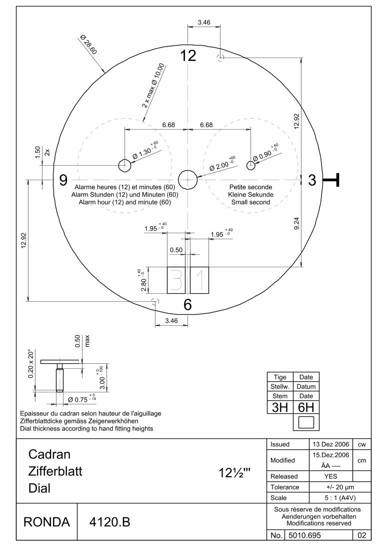
• Dials, position of date and counters � dial drawings
• Hand fitting heights & specifications for hands � hand fitting height drawings
• Setting of REFERENCE time Cal 4120.B (ALARM) � user’s manual
No pusher on Cal 40xx.B
Hand setting / Date change phases
Place the hands to 12 o’clock, after termination of the unit indicator* change from 02 to 03.
Date change phase for unit indicator* disk: approx. 1¼ hours ** * Date change phase for tens-** and unit indicator* disks together: approx. 1½ – 2 hours
Remark: During the date setting with quick mode (stem position 2), the speed may not exceed 5 days/second. .
Movement holder 4000-5999 A4 (part nr. H 5xxx.1A4) Movement holder 4000-5999 T (part nr. H 5xxx.1T) Hand setting & check of pusher function For removal of stem
Hand setting Stem removal Maximal force: For removal of the stem, the stem must be Hour and minute hands: max. 40N pushed into position 1 (pressed in) prior to All other hands: max. 30N apply pressure to the setting lever.
The movement needs to be supported for hand setting.
41xx.B (ALARM) Insert for movement holder 4000-5999 PCB ALARM (part nr. H 5xxx.1P)
By inserting this add on tool into the movement holder it is possible to check acoustically the alarm signal, generated by the movement.
Information re. BIG DATE An extreme acceleration in setting the date with quick mode (BIG DATE) can induce a false date indication. The synchronization is re-established by setting the date from 01 till 31 (stem in Pos. 2).
Setting the REFERENCE time Parallel to the current time, the reference time runs in the background. The ALARM time refers itself to this reference time. Thus, resetting the time also requires the identical correction of the reference time
Adjust the hour and the minute hand to the actual time by turning the stem
Press the pusher B for at least 2 seconds (Reference time setting mode is active)
Also adjust the REFERENCE time by pressig the pusher B to the actual time.
- short pressing (< 1 sec.) → + 1 minute
- medium pressing (1-2 sec.) → + 1 hour
- long pressing (> 2 sec.) → + continous
B
1 2 3
Pull the stem in Pos 3
Push the stem back to pos 1

Wichtig! Die Höhe der Abstützschrauben muss vor Beginn jeder Serie eingestellt werden.
Important! Veuillez ajuster l’hauteur des vis de support au préalable de chaque série.
Important! Adjust height of support screws prior to each series.
Erstellt: fb5163 Geprüft: hh5160 Freigabe IQ-Soft: ah5256 / ea5250 Seite 1/8
Werkhalter T2 Porte-pièce T2
Movement holder T2
DOMVT004
Version: 1.8
Verwendung & Übersicht Utilisation & Vue d’ensemble
Utilisation & Overview
Prozess: 3.1.3
Änd.-Dat.: 15.07.2013
� 5110, 5112, 5150, 5151, 5152, 5160, 5161, 5163, 5164, 5166, 5310, 5311, 5312, RTC, RHK � Ermano, Pine Precision � AF Switzerland SA, Horotec SA, Tschudin & Schneider
A Zeiger setzen
T Stellwelle entfernen Diverses
Poser les aiguilles Enlever la tige Divers
Hand setting Stem removal Various
Kalibergruppe Artikelnummer
Artikelnummer
Artikelnummer Groupe de calibre Numéro d’article Numéro d’article Numéro d’article
Calibre group Part number Part number Part number Z60 H 80XX.1A H 80XX.1T
Z60
8000-8499 H 80XX.1A H 80XX.1T
8040.B 8040.N
7000-7999 H 7XXX.1A H 7XXX.1T
700X.B 700X.L 700X.N 700X.P

Wichtig! Die Höhe der Abstützschrauben muss vor Beginn jeder Serie eingestellt werden.
Important! Veuillez ajuster l’hauteur des vis de support au préalable de chaque série.
Important! Adjust height of support screws prior to each series.
DOMVT004 / Version: 1.7 / Prozess: 3.1.3 / Änd.-Dat.: 06.06.2012 Seite 2/8
A Zeiger setzen
T Stellwelle entfernen
P Alarm-Check
Poser les aiguilles Enlever la tige Contrôle d’alarme
Hand setting Stem removal Alarm check
Kalibergruppe Artikelnummer
Artikelnummer
Artikelnummer Groupe de calibre Numéro d’article Numéro d’article Numéro d’article
Calibre group Part number Part number Part number 6000-6999 H 6XXX.1A H 6XXX.1T
6XXX.B 6XXX.D
Swiss Made Swiss Parts
4000-5999.B/.C/.D/.E H 5XXX.1A H 5XXX.1T H 5XXX.1P
4XXX.B 5XXX.B 5XXX.C 5XXX.D 5XXX.E
4000-5999.F H 5XXX.FA H 5XXX.1T H 5XXX.1P
5XXX.F (4XXX.B) (5XXX.B) (5XXX.C) (5XXX.D) (5XXX.E)

Wichtig! Die Höhe der Abstützschrauben muss vor Beginn jeder Serie eingestellt werden.
Important! Veuillez ajuster l’hauteur des vis de support au préalable de chaque série.
Important! Adjust height of support screws prior to each series.
DOMVT004 / Version: 1.7 / Prozess: 3.1.3 / Änd.-Dat.: 06.06.2012 Seite 3/8
A Zeiger setzen
T Stellwelle entfernen Diverses
Poser les aiguilles Enlever la tige Divers
Hand setting Stem removal Various
Kalibergruppe Artikelnummer
Artikelnummer
Artikelnummer Groupe de calibre Numéro d’article Numéro d’article Numéro d’article
Calibre group Part number Part number Part number 3500-3999 H 35XX.1A H 35XX.1T
3520.D 3540.D
1062-1069 H 106X.1A H 106X.1T
1062 1063 1064 1069
Swiss Made Swiss Parts
6h 6h
1062
- - - -
1063
-
-
1064
-
-
1069
- - - -
1042 H 1042.1A H 1042.1T
1042

Wichtig! Die Höhe der Abstützschrauben muss vor Beginn jeder Serie eingestellt werden.
Important! Veuillez ajuster l’hauteur des vis de support au préalable de chaque série.
Important! Adjust height of support screws prior to each series.
DOMVT004 / Version: 1.7 / Prozess: 3.1.3 / Änd.-Dat.: 06.06.2012 Seite 4/8
A Zeiger setzen
T Stellwelle entfernen Diverses
Poser les aiguilles Enlever la tige Divers
Hand setting Stem removal Various
Kalibergruppe Artikelnummer
Artikelnummer
Artikelnummer Groupe de calibre Numéro d’article Numéro d’article Numéro d’article
Calibre group Part number Part number Part number 1032 H 1032.1A H 1032.1T
1032
1012-1019 H 101X.1A H 101X.1T
1012 1013 1014 1015 1016 1019
1002-1009 H 100X.1A H 100X.1T
1002 1003 1004 1005 1006 1009

Wichtig! Die Höhe der Abstützschrauben muss vor Beginn jeder Serie eingestellt werden.
Important! Veuillez ajuster l’hauteur des vis de support au préalable de chaque série.
Important! Adjust height of support screws prior to each series.
DOMVT004 / Version: 1.7 / Prozess: 3.1.3 / Änd.-Dat.: 06.06.2012 Seite 5/8
A Zeiger setzen
T Stellwelle entfernen Diverses
Poser les aiguilles Enlever la tige Divers
Hand setting Stem removal Various
Kalibergruppe Artikelnummer
Artikelnummer
Artikelnummer Groupe de calibre Numéro d’article Numéro d’article Numéro d’article
Calibre group Part number Part number Part number 782-788 H 78X.1A H 78X.1T
782 783 784 785 788
Swiss Made Swiss Parts
772-775 H 77X.1A H 77X.1T
772 773 774 775
Swiss Made Swiss Parts

Wichtig! Die Höhe der Abstützschrauben muss vor Beginn jeder Serie eingestellt werden.
Important! Veuillez ajuster l’hauteur des vis de support au préalable de chaque série.
Important! Adjust height of support screws prior to each series.
DOMVT004 / Version: 1.7 / Prozess: 3.1.3 / Änd.-Dat.: 06.06.2012 Seite 6/8
A Zeiger setzen
T Stellwelle entfernen Diverses
Poser les aiguilles Enlever la tige Divers
Hand setting Stem removal Various
Kalibergruppe Artikelnummer
Artikelnummer
Artikelnummer Groupe de calibre Numéro d’article Numéro d’article Numéro d’article
Calibre group Part number Part number Part number 762-763 H 76X.1A H 76X.1T
762 762E 763 763E
Swiss Made Swiss Parts
762
- -
762E
- -
763
-
763E
751-753 H 75X.1A H 75X.1T
751 753
Swiss Made Swiss Parts
751
- -
753

Wichtig! Die Höhe der Abstützschrauben muss vor Beginn jeder Serie eingestellt werden.
Important! Veuillez ajuster l’hauteur des vis de support au préalable de chaque série.
Important! Adjust height of support screws prior to each series.
DOMVT004 / Version: 1.7 / Prozess: 3.1.3 / Änd.-Dat.: 06.06.2012 Seite 7/8
A Zeiger setzen
T Stellwelle entfernen Diverses
Poser les aiguilles Enlever la tige Divers
Hand setting Stem removal Various
Kalibergruppe Artikelnummer
Artikelnummer
Artikelnummer Groupe de calibre Numéro d’article Numéro d’article Numéro d’article
Calibre group Part number Part number Part number 712-715 H 71X.1A H 71X.1T
712 713 714 715
Swiss Made Swiss Parts
702-708 H 70X.1A H 70X.1T
702 703 704 705 708 (706)
Swiss Made Swiss Parts
706 H 706.1A H 70X.1T
706.1 706.2 706.3 706.B
Swiss Made Swiss Parts
6h 6h

Wichtig! Die Höhe der Abstützschrauben muss vor Beginn jeder Serie eingestellt werden.
Important! Veuillez ajuster l’hauteur des vis de support au préalable de chaque série.
Important! Adjust height of support screws prior to each series.
DOMVT004 / Version: 1.7 / Prozess: 3.1.3 / Änd.-Dat.: 06.06.2012 Seite 8/8
A Zeiger setzen
T Stellwelle entfernen Diverses
Poser les aiguilles Enlever la tige Divers
Hand setting Stem removal Various
Kalibergruppe Artikelnummer
Artikelnummer
Artikelnummer Groupe de calibre Numéro d’article Numéro d’article Numéro d’article
Calibre group Part number Part number Part number 582-585 H 58X.1A H 58X.1T
582 583 585
512-519 H 51X.1A H 51X.1T
512 513 515 517 519
502-509 H 50X.1A H 50X.1T
502 503 505 507 509

122
46
8
10111
3
57
9 15
60
30
45
2 3
Description of the display and control buttons
Display elements
Minute hand
Hour hand
Small minute hand
Small hour hand
Second hand
Date
Control buttons
Crown
Push-button
122
46
8
10111
3
57
9 15
60
30
45
2 3
I
Setting the alarm time
Activate the setting modePress the push-button for at least 2 seconds. As soon as the small minute hand jumps forward one minute, this mode is active.
Setting Short pressing (less than 1 second): the alarm time is moved forward by the
minute. Long pressing (longer than 2 seconds): the alarm time is moved forward until the
push-button is released.
Please note:If the push-button is not activated for 10 seconds, the setting mode of the alarm time deactivates itself. At the same time, two beeps are emitted to indicate that the alarm is switched on.
Alarm time
Push-button
122
46
8
10111
3
57
9 15
60
30
45
2 3
I
Switching the alarm on / off
The alarm is switched on / off by briefly pressing the push-button:
2 beeps alarm switched on
1 beep alarm switched off
Please note:The alarm can be set maximum 12 hours before the desired alarm time.
Once the set alarm time has been reached, a signal is emitted for 20 seconds. This signal is repeated after two minutes.Following brief pressing of the push-button, the signal is immediately switched off.
Alarm time
Push-button
65,5% = 40mm Druchmesser
I II
122
46
8
10111
3
57
9 15
60
30
45
1 7
65,5% = 40mm Druchmesser
I II III
122
46
8
10111
3
57
9 15
60
30
45
0 3
Setting the time and date
Example:– Date / time on the watch: 17 / 1:25 AM– Present date / time: 04 / 8:30 PM
Pull out the crown to position II (watch continues to run).
Turn the crown until yesterday’s date appears 03 .
Pull out the crown to position III (the second hand stops. The display changes from alarm time to reference time.)
Crown
Date
Second hand
Alarm time
Reference time
65,5% = 40mm Druchmesser
I II III
122
46
8
10111
3
57
9 15
60
30
45
0 4
65,5% = 40mm Druchmesser
I II III
122
46
8
10111
3
57
9 15
60
30
45
0 4
Turn the crown until the correct date 04
appears.
* Continue to turn the crown until the current time 8:30 PM appears.
Push the crown back into position I (the display changes from reference to alarm time.)
* Please observe the AM / PM clock rhythm.
Please note:Resetting the time also requires the identical correction of the reference time. Please refer to «setting the reference time».
Reference time
Alarm time
65,5% = 40mm Druchmesser
I II
122
46
8
10111
3
57
9 15
60
30
45
0 1
Setting the date (quick mode)
Pull out the crown to position II (the watch continues to run).
Turn the crown until the correct date 01 appears.
Push the crown back into position I.
65,5% = 40mm Druchmesser
I II
122
46
8
10111
3
57
9 15
60
30
45
3 1
Please note:The date of the following day must be set in the calendar changing phase between 9 PM and midnight.
Setting the date too quickly in quick mode can result in the incorrect date being displayed. Switching the date between 01 and 31 (position II) restores the syn-chroni-sation.
What is the reference time?
The current time is displayed by means of the hour and minute hand.
Parallel to the current time, the reference time runs in the background: the alarm time refers itself to this reference time. Thus, resetting the time also requires the identical correction of the reference time.
If the reference time is not synchronised with the current time, this results in the alarm signal being emitted at a different time to the set alarm time.
65,5% = 40mm Druchmesser
I II III
122
46
8
10111
3
57
9 15
60
30
45
0 4
65,5% = 40mm Druchmesser
I II III
122
46
8
10111
3
57
9 15
60
30
45
0 4
Setting the reference time
*Pull out the crown to position III (second hand stops. The display changes from alarm time to reference time.)
Activating the setting modePress the push-button for at least 2 seconds. As soon as the small minute hand jumps forwards one minute, this mode is active.
Short pressing (less than 1 second):the reference time is moved forwards by the minute.
Medium pressing: (1–2 seconds): the reference time is moved forwards by
the hour. Long pressing (longer than 2 seconds): the reference time is moved forwards until
the push-button is released.
Small minute hand
Reference time
Reference time
* To set your watch «to the exact second», the crown must be pulled out into position III when the second hand is in posi-tion 60. The crown must be pushed back «to the exact second» into position I (as a guideline: radio signal, radio clocks, etc.).
65,5% = 40mm Druchmesser
I II III
122
46
8
10111
3
57
9 15
60
30
45
0 4
* Push the crown back into position I
(the display changes from reference time to alarm time). A signal indicates that the alarm is switched off.
Alarm time
Please note:The reference time must display the same time as the current time. This means that resetting the current time also requires the identical correction of the reference time. Afterwards, the alarm time has to be reset.
Cal. 4120.B
EnglishUser’s Manual
122
46
8
10111
3
57
9 15
60
30
45
2 3
ALARM
ROnDA is a supplier of watch movements including their operating instructions. Please refer to the watch retailer, service centre or manufacturer, should you have any questions regarding the watch. All relevant contact information can be found in your sales and/or guarantee documents.
www.ronda.ch 05/ 2
012
Battery type: 395 (diameter 9.5mm x 2.6mm / SR 927 SW)Accuracy: +20 / -10 seconds per month

Technical Instructions 4120.B
05/2012 M RONDA AG, Lausen, Switzerland, Phone ++41 (0)61 926 50 00, www.ronda.ch, [email protected] 1
2000.574.G Main plate1.
3305.290.CO Cannon pinion with driver (Aig.2, closed)2.
3301.243 Hour wheel (counter 24h)3.
2030.017.CO Centre bridge4. Center bridge held by 1 screw 4000.250. Parts 2030.017.CO, 3004.223
and 3500.059 must be exchanged together.
4000.250 Screw 5.
3001.055.FI Sliding pinion6.
3000.177.CO Setting stem7.
3017.049 Setting lever8.
3905.049 Setting lever jumper (3 positions)9. Setting lever jumperheld by 1 screw 4000.250.
4000.250 Screw10.
3015.081 Yoke (3 positions)11. Parts 3015.081 and 3905.067 must be exchanged together.
3905.067 Yoke spring12. Tensioning the spring arm. Parts 3015.081 and 3905.067 must be
exchanged together.
3406.030 Pusher jumper B13. Put the grey jumper between the two posts on the further side.
3406.038 Pusher jumper A14. Put the yellow jumper between the two posts on the closer side.
3622.040 Stator15. Mark |Z| on stator.
3622.039 Stator (counter 6h, 9h, chrono)16.
3603.079 Plastic bracket17. Plastic bracket held by 4 screws 4000.250.
4000.250 Screw18.
3715.094.RK Rotor19.
A
B
C

Technical Instructions 4120.B
05/2012 M RONDA AG, Lausen, Switzerland, Phone ++41 (0)61 926 50 00, www.ronda.ch, [email protected] 2
3147.046.CO Intermediate wheel20.
3136.142.CO Second wheel (long)21.
3122.056.CO Third wheel22.
2020.148.G Train wheel bridge23. Train wheel bridge held by 3 screws 4000.250.
4000.250 Screw24.
3715.095.RK Rotor25.
3147.048.CO Intermediate wheel (counter)26.
3007.055.CO Minute wheel (counter 24h)27.
3402.007.CO Minute counting wheel (24h)28.
2020.149.G Counter train wheel bridge29. Counter train wheel bridge held by 3 screws 4000.250.
4000.250 Screw30.
3621.053.RK Coil31. Attention: Please hold the coil only on the grey coil core. Coil held by 1
screw 4000.250.
3621.054.RK Coil (counter 9h, chrono)32. Attention: Please hold the coil only on the grey coil core.
4000.250 Screw33.
3601.118 Contact strip34. Contact strip held by 1 screw 4000.250.
4000.250 Screw35.
3603.034 Battery insulator36.
3503.054 Tube37.
3503.054 Tube38.
D
E
F

Technical Instructions 4120.B
05/2012 M RONDA AG, Lausen, Switzerland, Phone ++41 (0)61 926 50 00, www.ronda.ch, [email protected] 3
3612.176.4120 Electronic module39. Electronic module held by 5 screws 4000.248. Electronic
measurements may be realised now.
4000.248 Screw40.
3603.069 Circuit insulator41.
3603.070 Contact insulator42.
3603.070 Contact insulator43.
3601.107.G Pusher contact spring44.
2130.160.G.M01.4120B Electronic module cover45. Electronic module held by 5 screws 4000.250.
3600.010.HGF Battery 39546.
3601.109.G Bridle +47. Bridle held by 1 screw 4000. 250.
4000.250 Screw48.
G
H

Technical Instructions 4120.B
05/2012 M RONDA AG, Lausen, Switzerland, Phone ++41 (0)61 926 50 00, www.ronda.ch, [email protected] 4
2000.574.G Main plate49.
3004.164 Setting wheel50.
3004.164 Setting wheel51.
3007.054.CO Minute wheel52.
2130.143 Minute train bridge53. Minute train bridge held by 2 screws 4000.305.
4000.305 Screw54.
3004.223 Tens indicator driving wheel55. Parts 2030.017.CO, 3004.223 and 3500.059 must be exchanged
together. The short tooth of the tens indicator driving wheel must pointto the center of the movement.
3500.059 Tens jumper56. Parts 2030.017.CO, 3004.223 and 3500.059 must be exchanged
together.
2130.142 Tens jumper maintaining plate57. Tens jumper maintaining plate held by 2 screws 4000.306. Tensioning
the spring arm.
4010.306 Screw 58.
3301.242 Hour wheel (Aig.2)59.
3315.016 Friction spring60.
3004.224.CO Date indicator driving wheel61.
3500.049 Date jumper62.
I
J

Technical Instructions 4120.B
05/2012 M RONDA AG, Lausen, Switzerland, Phone ++41 (0)61 926 50 00, www.ronda.ch, [email protected] 5
3504.214.AD.1.A Units indicator (standard)63. Nick of the indicator at 3 o`clock.
3147.054 Tens intermediate wheel64.
2130.141 Date indicator maintaining plate65. Date indicator maintaining plate held by 1 screw 4000.250.
3905.070 Date jumper spring66. Insert the date jumper spring in the provided opening.
3504.215.AD.1.A Tens indicator (standard)67. Nick of the indicator at 3 o`clock.
2130.140.G Date mechanism maintaining plate68. Date mechanism maintaining plate held by 2 screws 4000.250.
4000.250 Screw69.
3506.072.G Dial support70.
8200 Moebius 820071.
9014 Moebius 901472.
124 Jismaa 12473.
9020 Moebius 902074.
K
L

03/2012 RONDA AG, Lausen, Switzerland, Phone ++41 (0)61 926 50 00, www.ronda.ch, [email protected] EM 1
Electronic measurements 4120.B
Battery 395
Voltage 1.55 V
Setting stem in position I, calendar not in gear, 60 s measuring interval for rate and consumption:
Typical consumption Maximal consumption
1.42 µA 1.65 µA
Instantaneous rate -10s/M. .. +20s/M.
Lower working voltage limit 1.30 V
Setting stem in position III, 60 s measuring interval:
Typical consumption Maximal consumption
0.10 µA 0.30 µA

03/2012 RONDA AG, Lausen, Switzerland, Phone ++41 (0)61 926 50 00, www.ronda.ch, [email protected] EM 2
Electronic measurements 4120.B
Coil resistance M1 1.90 kΩ .. 2.10 kΩ
Coil resistance M4 2.20 kΩ .. 2.40 kΩ
Coil isolation M1/M4 ∞ kΩ
Signal generator (4.9 ms, 8 Hz):
Lower working voltage limit M4 1.30 V

Technical Instructions 4120.B
05/2012 N RONDA AG, Lausen, Switzerland, Phone ++41 (0)61 926 50 00, www.ronda.ch, [email protected] 1
2000.574.G Main plate1.
3305.290.CO Cannon pinion with driver (Aig.2, closed)2.
3301.243 Hour wheel (counter 24h)3.
2030.024.CO Centre bridge4. Center bridge held by 1 screw 4000.250.
4000.250 Screw 5.
3001.055.FI Sliding pinion6.
3000.177.CO Setting stem7.
3017.049 Setting lever8.
3905.049 Setting lever jumper (3 positions)9. Setting lever jumperheld by 1 screw 4000.250.
4000.250 Screw10.
3015.081 Yoke (3 positions)11.
3905.067 Yoke spring12. Tensioning the spring arm.
3406.030 Pusher jumper B13. Put the grey jumper between the two posts on the further side.
3406.038 Pusher jumper A14. Put the yellow jumper between the two posts on the closer side.
3622.040 Stator15. Mark |Z| on stator.
3622.039 Stator (counter 6h, 9h, chrono)16.
3603.079 Plastic bracket17. Plastic bracket held by 4 screws 4000.250.
4000.250 Screw18.
3715.094.RK Rotor19.
A
B
C

Technical Instructions 4120.B
05/2012 N RONDA AG, Lausen, Switzerland, Phone ++41 (0)61 926 50 00, www.ronda.ch, [email protected] 2
3147.046.CO Intermediate wheel20.
3136.142.CO Second wheel (long)21.
3122.056.CO Third wheel22.
2020.148.G Train wheel bridge23. Train wheel bridge held by 3 screws 4000.250.
4000.250 Screw24.
3715.095.RK Rotor25.
3147.048.CO Intermediate wheel (counter)26.
3007.055.CO Minute wheel (counter 24h)27.
3402.007.CO Minute counting wheel (24h)28.
2020.149.G Counter train wheel bridge29. Counter train wheel bridge held by 3 screws 4000.250.
4000.250 Screw30.
3621.053.RK Coil31. Attention: Please hold the coil only on the grey coil core. Coil held by 1
screw 4000.250.
3621.054.RK Coil (counter 9h, chrono)32. Attention: Please hold the coil only on the grey coil core.
4000.250 Screw33.
3601.118 Contact strip34. Contact strip held by 1 screw 4000.250.
4000.250 Screw35.
3603.034 Battery insulator36.
3503.054 Tube37.
3503.054 Tube38.
D
E
F

Technical Instructions 4120.B
05/2012 N RONDA AG, Lausen, Switzerland, Phone ++41 (0)61 926 50 00, www.ronda.ch, [email protected] 3
3612.176.4120 Electronic module39. Electronic module held by 5 screws 4000.248. Electronic
measurements may be realised now.
4000.248 Screw40.
3603.069 Circuit insulator41.
3603.070 Contact insulator42.
3603.070 Contact insulator43.
3601.107.G Pusher contact spring44.
2130.160.G.M01.4120B Electronic module cover45. Electronic module held by 5 screws 4000.248.
3600.010.HGF Battery 39546.
3601.109.G Bridle +47. Bridle held by 1 screw 4000. 250.
4000.250 Screw48.
G
H

Technical Instructions 4120.B
05/2012 N RONDA AG, Lausen, Switzerland, Phone ++41 (0)61 926 50 00, www.ronda.ch, [email protected] 4
2000.574.G Main plate49.
3004.164 Setting wheel50.
3004.164 Setting wheel51.
3007.054.CO Minute wheel52.
2130.143 Minute train bridge53. Minute train bridge held by 2 screws 4000.250.
4000.305 Screw54.
3004.227 Tens indicator driving wheel55. The short tooth of the tens indicator driving wheel must point to the
center of the movement.
3500.075 Tens jumper56.
2130.142 Tens jumper maintaining plate57. Tens jumper maintaining plate held by 2 screws 4000.306. Tensioning
the spring arm.
4010.306 Screw 58.
3301.242 Hour wheel (Aig.2)59.
3315.016 Friction spring60.
3004.224.CO Date indicator driving wheel61.
3500.049 Date jumper62.
I
J

Technical Instructions 4120.B
05/2012 N RONDA AG, Lausen, Switzerland, Phone ++41 (0)61 926 50 00, www.ronda.ch, [email protected] 5
3504.214.AD.1.A Units indicator (standard)63. Nick of the indicator at 3 o`clock.
3147.054 Tens intermediate wheel64.
2130.141 Date indicator maintaining plate65. Date indicator maintaining plate held by 1 screw 4000.250.
3905.070 Date jumper spring66. Insert the date jumper spring in the provided opening.
3504.215.AD.1.A Tens indicator (standard)67. Nick of the indicator at 3 o`clock.
2130.140.G Date mechanism maintaining plate68. Date mechanism maintaining plate held by 2 screws 4000.250.
4000.250 Screw69.
3506.072.G Dial support70.
8200 Moebius 820071.
9014 Moebius 901472.
124 Jismaa 12473.
9020 Moebius 902074.
K
L

03/2012 RONDA AG, Lausen, Switzerland, Phone ++41 (0)61 926 50 00, www.ronda.ch, [email protected] EM 1
Electronic measurements 4120.B
Battery 395
Voltage 1.55 V
Setting stem in position I, calendar not in gear, 60 s measuring interval for rate and consumption:
Typical consumption Maximal consumption
1.42 µA 1.65 µA
Instantaneous rate -10s/M. .. +20s/M.
Lower working voltage limit 1.30 V
Setting stem in position III, 60 s measuring interval:
Typical consumption Maximal consumption
0.10 µA 0.30 µA

03/2012 RONDA AG, Lausen, Switzerland, Phone ++41 (0)61 926 50 00, www.ronda.ch, [email protected] EM 2
Electronic measurements 4120.B
Coil resistance M1 1.90 kΩ .. 2.10 kΩ
Coil resistance M4 2.20 kΩ .. 2.40 kΩ
Coil isolation M1/M4 ∞ kΩ
Signal generator (4.9 ms, 8 Hz):
Lower working voltage limit M4 1.30 V
Powered by TCPDF (www.tcpdf.org)