GE - QuiXtra 4000 - Low Voltage Distribution Boards - Vitta ...
84
New GE Industrial Solutions GE imagination at work QuiXtra ™ 4000ED.02 Low Voltage Distribution Boards up to 4000A
-
Upload
khangminh22 -
Category
Documents
-
view
1 -
download
0
Transcript of GE - QuiXtra 4000 - Low Voltage Distribution Boards - Vitta ...

New
GEIndustrial Solutions
GE imagination at work
QuiXtra™4000ED.02
Low Voltage Distribution Boardsup to 4000A


A.1
QuiXtra™4000
A
B
C
X
Applications and Benefi ts
Order codes
Technical data
Numerical index
A.2 Advantages
A.4 Applications
A.5 Product description
A.6 Features and benefi ts
A.7 Full enclosure range
A.8 Kit structure
A.10 Corner enclosure
A.11 Accessories
A.12 Main technical characteristics
A.11 Range overview

A.2
QuiXtra™4000
A
B
C
X
Low VoltageDistribution Boards
QuiXtra™4000

A.3
QuiXtra™4000Advantages
A
B
C
X
Safe• Design verifi cation tested system enclosure• Certifi ed according to the new IEC 61439-2• IP55 with door and IP55 panels, IP30 with door
and IP30 panels and IP 30 without door.• Internal segregation up to Form 4• Tempered glass for transparent door
Simple and fl exible• 1 enclosures height: 12 rows of 150 mm• 3 enclosures width: 12, 24 and 36 modules• 3 enclosures depth: 450, 600 and 800 mm• Side to side and back to back coupling• 1 functional unit = 1 reference, including all
parts to mount LV devices• Modular concept: all functional units in
steps of 50 mm in height• Corner enclosure for L- or U-shape
Door ready to mount• 4 point locking system already mounted• Hinges mounted• Installation without tools• 135º open angle
Attractive design• Fits perfectly in commercial environments• Colours RAL 9006 and RAL 7024• One common line QuiXtra 630 and QuiXtra 4000
Easy and quick to assemble• Assembly by a single person• Pre-assembled captive screws for coverplates• 90º screws for cover plates• Click-in supports for functional units. No tools
needed to fi x them to the frame• Reduced number of tools
Rigid and sturdy• Rigid frame built with open profi les screwed to
corner parts• Sheet metal 1.5 and 2 mm thick• Die-cast zamak corner parts
PowerDesignNew generation of software to help customers with the confi guration, design and quotation of low voltage system enclosures: QuiXtra 630 and QuiXtra 4000
Colours RAL 9006 and RAL 7024•••• OnOnOnOnOneee e cocococommmmmmmmonononon llllinininineeee QuQuQuQuQQ iXiXiXiXtrtrtrtraaaa 6363636363000 00 anananandddd QuQuQuQuiXiXtrtraa 404 00

A.4
QuiXtra™4000In
trod
uctio
n
A
B
C
X
ApplicationsQuiXtra 4000 has been developed as a range of system enclosures, expansion of the line of QuiXtra 630. GE’s complete solution for low voltage distribution boards up to 4000A for high commercial and industrial environments.
QuiXtra 4000 is delivered as a fl at kits, to be assembled, equipped and wired by a panel builder or installer. The QuiXtra 4000 range consists of 9 fl oor standing enclosures, combination of 3 different widths and 3 depths, as well as busbars andfunctional units to easily integrate all types of low voltageelectrical devices up to 4000A.
The combination of the QuiXtra 4000 enclosure and original GE LV electrical devices are certifi ed according the new standard IEC 61439-2.
Industrial and Infrastructures• Construction materials• Water applications• Ports• Tunnels• Small factories• Waste recycling• Cement• Food and beverage• OEM• Components/parts production• Small assembly lines• Printing
Commercial• Large commercial offi ces• Shopping malls• Airports• Hospitals• Banks• Public transport• Railways• Subways• Governmental buildings• Telecommunication• Data/call centers
DescriptionQuiXtra 4000 is a range of sheet steel system enclosures delivered as fl at kit. It is GE’s solution for low voltage distribution boards up to 4000A, in commercial and industrial environments.
QuiXtra 4000 is designed to be a reliable, simple, fl exible and easy to use system enclosure, with the added value of its fresh and attractive design, expanding the benefi ts of QuiXtra 630.
The QuiXtra 4000 range consists of 9 different enclosures. There are three enclosure depths available, 450 mm, 600 mm and 800 mm, and three enclosure widths, for functions of12, 24 and 36 modules. All enclosures have the same useful height of 1800 mm. It is possible to couple enclosures of the same depth horizontally, and back to back the enclosures with the same width. Additionally, there are corner empty enclosures to allow L and U confi gurations. This huge range of enclosures provides the user total fl exibility to defi ne the layout of the LV distribution boards.
For ease of incoming and outgoing cable connection, the roofs have different types of cable entry plates available. As well, the bases are available with entry cable plates, for bottom incoming or outgoing.

A.5
QuiXtra™4000Product description
A
B
C
X
QuiXtra 4000 offers 2 types of doors, plain and transparent (tempered glass). In both cases, the 4 points locking mechanism is operated by a central handle with key. The doors are delivered with hinges and locking mechanism already mounted, to reduce assembly time.
QuiXtra 4000 introduce several features to reduce the assembly time of the panel. The functional units are fi xed to the frame by use of the “click in” supports, without the need of additional screws. The cover plates are fi xed to the frame using 90º screws and there is the possibility to fi x all of them to one functional door to make maintenance operations easier. The doors are ready to assemble to the frame without tools.
All external panels, like rear- or sidepanels as well as the roofplate, may be removed to facilitate assembly and wiring.
All GE LV electrical devices up to 4000A can be easily assembled in QuiXtra 4000 using the appropriate functional units. Each functional unit kit includes everything necessaryfor assembly:• A mounting plate or DIN-rail• A support to attach to the enclosure. For some functions, if a
depth profi le is required, they are delivered separately• A coverplate (with precise cut-outs)• The required screws and other fi xation parts. Attaching the
mounting plates or DIN-rails does not require tools: they are attached to the side mounting profi le using a “click in” support. The coverplates are attached to a functional frame using captive 90º screws.
The busbar system in QuiXtra 4000 is based on copper bars of 10 mm thickness. The horizontal main busbars is assembled at the rear of the enclosure for the ones of 450 mm in depth and at the rear, on the top or middle in the 600 mm and 800 mm depth. There are 3 possible vertical busbars, with a plain layout, assembled at the rear or in the side of the enclosure, or in staircase, assembled on the integrated cable compartment or in the enclosure 12 modules width. Several ready to install copper connection between the incomers and the main busbars are available.
QuiXtra 4000 can be confi gured with a protection degree IP30 or IP55, and a segregation form up to Form 4.
The QuiXtra 4000 colour is silver grey, RAL 9006. The external corner parts, the handle and the base are in dark grey, RAL 7024. The tempered glass of the transparent door is lightly smoked grey.

A.6
QuiXtra™4000In
trod
uctio
n
A
B
C
X
Features and benefits
Simple and fl exible• Enclosures widths for 12, 24 and 36 modules• Enclosures depths of 450 mm, 600 mm and 800 mm• Side by side and back to back coupling• Modular concept. All functions in steps of 50 mm in height• Functional kits for GE low voltage electrical devices up to
4000A• Mounting of GE devices in vertical or horizontal position• The 10 mm thickness busbars can be assembled on top,
at the rear or in vertical • Each functional unit includes all parts necessary for assembly:
mounting plate or DIN- rail, supporting brackets, cover plate (with precise cut-outs) and all required fi xation elements
• Corner enclosure with depth 450, 600 and 800 mm for L- and U-shapes.
Easy and quick to assemble• “Click in” supports for functions. Reduced number of tools
needed• 90º screws for cover plates• Pre-assembled captive screws for coverplates• Accessories to facilitate panel wiring and assembly.
Ready to assemble copper connections• Door assembly without tools. Doors delivered with locking
system and hinges pre-mounted• Generous wiring space for all functions• Optional functional door to fi x all the coverplates• Markings in the fi xation profi les to quickly position the
functional units and cover plates
Safe for users, reliable and sturdy• Verifi cation tested system enclosure, certifi ed according
to the new IEC 61439-2 standard• IP55 with door and IP55 panels• IP30 without door or with door and IP30 panels• External panels sheet steel, 1.5 mm, powder coated• Door sheet steel, 1.5 mm, powder coated• Rigid frame built with bent sheet steel profi les fi xed to
zamak corner parts• Internal segregation: Form 4• Tempered glass for the transparent door
Attractive design• One common line: QuiXtra 630 and QuiXtra 4000.
Same benefi ts, same aesthetics• Combination of two colours:
RAL 9006 (silver grey) and RAL 7024 (dark grey)

A.7
QuiXtra™4000Features and benefi ts
A
B
C
X
12 modules - external width: 447 mm
24 modules - external width: 743 mm
Corner enclosure
36 modules - external width: 959 mm
H Useful height/external heightD Useful depth/external depth
DA Useful depth behind cover plates
H 1800/2155 1800/2155 1800/2155D 375/450 525/600 725/800
DA 275 425 625
H 1800/2155 1800/2155 1800/2155D 375/450 525/600 725/800
DA 275 425 625
H 2155 2155 2155D 450 600 800
H 1800/2155 1800/2155 1800/2155D 375/450 525/600 725/800
DA 275 425 625
Full enclosure range

A.8
QuiXtra™4000
1
1
7
5
2 6
4
4
6
3
Intr
oduc
tion
A
B
C
X
1 Top/bottom framesThe kit includes the top or bottom frames, with the profi les already mounted in the zamak corner parts. There are 2 versions available, for each of the 9 enclosure dimensions, based on the protection degree IP30 or IP55. Two units of these are required per enclosure.
2 Vertical uprights4 vertical profi les to complete the frame with the top and bottom frames. One common kit for all the enclosures sizes and IP degrees.
3 BaseThe base is split in 3 types of kits: the corners, the front cover and the side covers. The front cover depends on the width of the enclosure and the side cover on the depth. When several enclosures are coupled, it’s required only to cover each side of the panel, not the intermediate positions. It’s possible to assemble one accessory in the internal sides of the panel to assure the distance between the corners. The height of the base is 100 mm, but it can be coupled in vertical to achieve 200 mm in height.
4 Top and bottom platesTop and bottom plates to fi x the roof plates with several options as cable entry plates, and the bottom entry plates. They are available in IP30 or IP55 versions.
5 Roof platesQuixtra 4000 offers different types of cable entry plates to adapt to a wide range of customer needs. Starting with a plain cover till pre punched cable entry plates. Versions in IP30 and IP55. The cable entry plates can be removed to improve the acces-sibility for the assembly and wiring of the columns.
LV distribution board in flat kits

A.9
QuiXtra™4000
9
10
8
10
8
Kit structure
A
B
C
X
6 Side panelsThe kit includes the side panel, right or left side, and all the required fi xation screws. There are version IP30 and IP55. Each reference includes just one side panel.
7 Back panelFor each width, the IP30 and IP55 versions are available.
8 Functional frameThe functional frame, the profi les where are fi xed the mounting plates and the DIN-rails for the electrical devices, and the coverplates is to assure the safety of the electrical distribution board. The functional frame depends on the width of the enclosure.
9 DoorsQuiXtra 4000 offers 2 types of doors, plain and transparent (tempered glass). In both cases, the 4 points locking mechanism is operated by a central handle with key. The doors are delivered with hinges and locking mechanism already mounted, to reduce assembly time.
10 Integrated cable compartment (CC)For the enclosures of 36 modules in width, it’s possible to split the useful width in functions of 24 modules and an integrated cable compartment, for wiring or to install a vertical busbars.
8
8

A.10
QuiXtra™4000In
trod
uctio
n
A
B
C
X
Corner enclosureTo allow the panel layout in L- or U-shape, QuiXtra 4000 offers specific corner enclosures. Each corner enclosure has to be coupled by means of 2 coupling kits 887332.
13
13
13
13
1313
13
13
12
12
11
11
1111
(8x)
11 Vertical uprightsCommon profi les for all dimensions to allow the coupling to the adjacent enclosures.
12 Back panel and baseBack panel to cover the rear part of the empty enclosure.
13 Horizontal profi les, roof and bottom platesProfi les to complete the frame of the empty corner enclosure.

A.11
QuiXtra™4000Kit structure
A
B
C
X
Accessories
QuiXtra 4000 offers a wide range of accessories to the panel builder and installer to provide a higher fl exibility and to build the distribution board easier and faster.
Mounting platesQuiXtra 4000 offers partial mounting plates and full height mounting plates, to provide higher fl exibility, especially in the control panels.
Connection kitsThe panel builder has the option to order the copper connection bars between the main breaker and the main busbar for some confi gurations, as well kits for an easy wiring to the main breaker.
Cable entry platesWide range of possible cable entry plates, options to fi t better the installer needs in each project.
Coupling kitsKits to couple the enclosures of the same depth side by side and the ones of the same width back to back.
Empty corner enclosureTo allow L and U layouts in the distribution board.
Cover platesPlain, slotted and recessed cover plates are available.

A.12
QuiXtra™4000In
trod
uctio
n
A
B
C
X
Material and colourFrame profi les Sendzimir zinc plated steel 1.5 mm
External panels Epoxy-polyester coated sheet steel 1.5 mm
Plain door Epoxy-polyester coated sheet steel 1.5 mm
Transparent doorEpoxy-polyester coated sheet steel 1.5 mm and smoked safety
glass 3 mm.
Cover plates Epoxy-polyester coated sheet steel 1 mm
External plastic ABS
Internal corners Die-cast aluminium alloy
Enclosure colour RAL 9006
Floor base colour RAL 7024
Main technical characteristics
Protection degree and segregation formProtection class I
Pollution degree 3
Segregation Form 1, Form 2b, Form 3b and Form 4a
Protection degreeWithout door IP30, IK08
With plain door and with IP55 panels IP55, IK09
With plain door and with IP30 panels IP30, IK09
With transparent door and with IP55 panels IP55, IK08
With transparent door and with IP30 panels IP30, IK08
Standards and approvalsStandards IEC 61439-2
EN 61439-2
Approval with KEMA quality testreport
Certifi cation with KEMA quality testreport
RoHS compliant YES
REACH compliant YES
Electrical characteristicsRated current (In) 4000A
Rated operational voltage (Ue) 415V, 690V
Rated insulation voltage (Ui) 1000V
Rated frequency (fn) 50/60 Hz 50/60Hz
Rated short-circuit current max (Icw) 85kA/1s
Rated current of busbar systems 4000A in IP30
Useful and external dimensions (mm)
Useful dimensions External dimensions
Mounting platewidth
Width for devices Depth Height Width Depth Height
Depth 45012 mod 238 216 (12 mod.) 375 1800 447 450 215524 mod 534 432 (24 mod.) 375 1800 743 450 215536 mod 750 648 (36 mod.) 375 1800 959 450 2155
Depth 60012 mod 238 216 (12 mod.) 525 1800 447 600 215524 mod 534 432 (24 mod.) 525 1800 743 600 215536 mod 750 648 (36 mod.) 525 1800 959 600 2155
Depth 80012 mod 238 216 (12 mod.) 725 1800 447 800 215524 mod 534 432 (24 mod.) 725 1800 743 800 215536 mod 750 648 (36 mod.) 725 1800 959 800 2155

QuiXtra™4000
A
B
C
X
Applications and Benefi ts
Order codes
Technical data
Numerical index
B.1
B.2 How to order: example 1
B.3 How to order: example 2
B.4 Enclosure kits
B.5 Corner enclosure kits
B.6 Cable entry plates
B.7 Functional units
B.16 Cover plates
B.17 Separation screens
B.18 Busbars overview
B.20 Copper bars
B.21 Busbars for 450 mm deep enclosures
B.23 Busbars for 600 mm deep enclosures
B.25 Busbars for 800 mm deep enclosures
B.27 Connectivity
B.31 Accessories

B.2
QuiXtra™4000O
rder
cod
es
A
B
C
X
= + + + + +
or or or+++ + + + +
+option
option
+7
or
+
How to order: example 1
Individual 24 modules/600mm enclosure - IP55
1 887004: top/bottom frame (2 sets/panel)
2 887027: vertical uprights
3a 887064: base corner (set of 4 pcs)
3b 887062: base front or back cover (set of 2 pcs)
3c 887059: base side cover (set of 2 pcs)
4 887013: Roof and bottom plates (open roof plate + bottom plate with premounted entry plates)
5 887071: plain roof plate or887080: cutted roof plate+ option A
6 887355: left side paneland887053: right side panel
7 887047: back panel
8 887031: functional frame or 887034: functional door
9 887041: plain door or 887044: transparent door
+ option: B
Option A 885228 ➔ 885234: cable entry plates
Option B 884122: standard lifting eyesor887339: Heavy Duty lifting eyes
1
4 5 6 7 8
2 3a 3b
9
3c
A
B
24 mod.600 mm

B.3
QuiXtra™4000H
ow to order
A
B
C
X
How to order: example 2
36 modules with integrated cable compartment (CC) coupled to 24 modules/600 mm enclosure - IP55
= + ++ + + + ++
+ +
+ +
oror
+
+
option
+
++ + + ++ + ++ +
+
++
option
+7
or
+
1
9
16
2
10
3
11
4
12
17
5 6
13
8
14
18
15
7
A
C
option A 885228 ➔ 885234: cable entry plates
option C 884122: standard lifting eyesor887339: Heavy Duty lifting eyesand887331: lifting brackets for coupled enclosures
36 mod.+24 mod.600 mm
1 887005: 24 modules + CC top/bottom frame - 600 mm (2 sets/panel)
2 887004: 24 modules top/bottom frame - 600 mm (2 sets/panel)
3 887027: vertical profi les (2x)
4 887064: base/cornerset (2x) (set of 4 pcs)
5 887063: 24 modules + CC front cover (base)
6 887062: 24 modules front cover (base) (set of 2 pcs)
7 887059: base side cover - 600 mm
8 887382: base coupling set
9 887014: 24 modules + CC top and bottom plate
10 887013: 24 modules top and bottom plate
11 887072: plain roof - 24 modules + CC / 600 mmor887081: cutted roof for cable entry plates 24 modules + CC / 600 mm
+ option A
12 887071: 24 modules plain roof - 600 mm or887080: cutted roof 600 mm + option A
13 887332: coupling kit horizontal
14 887355: left side panel - 600 mmand 887053: right side panel - 600 mm
15 887048 + 887047: 24 modules backpanels + CC
16 887038: integrated CC, can be mounted left or right in 36 modules column
17 887031: 24 modules functional frame+ 887028: 24 modules + CC functional frameor887034: 24 modules functional door+ 887029: 24 modules + CC functional door
18 887042 + 887041: plain door 24 mod. + CC and 24 mod. or887045 + 887044: transparent door 24 mod. + CC and 24 mod.
+ option: C

B.4
QuiXtra™4000O
rder
cod
es
A
B
C
X
Enclosure kitsThe QuiXtra 4000 enclosures can be offered with the protection degrees IP30 or IP55. The confi guration IP30 requires different order codes in top and bottom frames, side panels and rear panels. Additionally, in the confi guration IP55, if the door is not assembled, the protection degree drops to IP30. The order codes for each confi guration are defi ned in the table below, depending on the enclosure depth.
Enclosure basic kits
Ref. No. Ref. No.
Protection degree IP55 IP30
Width (mod.) 12 24 36 24 + CC(1) 12 32 36 24 + CC(1)
Depth (mm)(2)
1 Top/bottom frames 450 887000 x2 887001 x2 887002 x2 887002 x2 887364 x2 887365 x2 887366 x2 887366 x2 (2 sets per column) 600 887003 x2 887004 x2 887005 x2 887005 x2 887367 x2 887368 x2 887369 x2 887369 x2
800 887006 x2 887007 x2 887008 x2 887008 x2 887370 x2 887371 x2 887372 x2 887372 x2
2 Vertical uprights (set of 4 pcs) 887027 887027 887027 887027 887027 887027 887027 887027
3 Base 100 mm Corner 887064 887064 887064 887064 887064 887064 887064 887064 Front cover 887061 887062 887063 887063 887061 887062 887063 887063 Side cover 450 887058 887058 887058 887058 887058 887058 887058 887058
600 887059 887059 887059 887059 887059 887059 887059 887059800 887060 887060 887060 887060 887060 887060 887060 887060
4 Top and bottom plates 450 887009 887010 887011 887011 887018 887019 887020 887020600 887012 887013 887014 887014 887021 887022 887023 887023800 887015 887016 887017 887017 887024 887025 887026 887026
5 Roof plates Plain 450 887067 887068 887069 887069 887085 887086 887087 887087600 887070 887071 887072 887072 887088 887089 887090 887090800 887073 887074 887075 887075 887091 887092 887093 887093
+ cut-outs for cable entry plates 450 887076 887077 887078 887078 887094 887095 887096 887096600 887079 887080 887081 887081 887097 887098 887099 887099800 887082 887083 887084 887084 887100 887101 887102 887102
Ventilated 450 - - - - 887103 887104 887105 887105600 - - - - 887106 887107 887108 887108800 - - - - 887109 887110 887111 887111
6 Side panels Right 450 887052 887052 887052 887052 887055 887055 887055 887055600 887053 887053 887053 887053 887056 887056 887056 887056800 887054 887054 887054 887054 887057 887057 887057 887057
Left 450 887354 887354 887354 887354 887357 887357 887357 887357600 887355 887355 887355 887355 887358 887358 887358 887358800 887356 887356 887356 887356 887359 887359 887359 887359
7 Back panel 887046 887047 887048 887048 887049 887050 887051 887051
8 Functional frame 887030 887031 887032 887028 887030 887031 887032 887028Functional door 887033 887034 887035 887029 887033 887034 887035 887029
9 Door Plain 887040 887041 887042 887042 887040 887041 887042 887042 Transparent - 887044 887045 887045 - 887044 887045 887045
Coupling kit Horizontal 887332 887332 887332 887332 887332 887332 887332 887332 Back to back 887333 887333 887333 887333 887333 887333 887333 887333
10 Integrated cable compartment 450 - - - 887037 - - - 887037 (left or right) 600 - - - 887038 - - - 887038
800 - - - 887039 - - - 887039
(1) CC stands for Cable Compartment(2) Depth 450 mm: designed for MCCB Record Plus FK incomer
Depth 600 mm: designed for ACB EntelliGuard and M-PACT Plus frame 1 incomerDepth 800 mm: designed for ACB EntelliGuard and M-PACT Plus frame 2 incomer
1
1
7
5
2
9
6
4
4
10
8
10
8
6
3

B.5
QuiXtra™4000Basic kits
A
B
C
X
Corner enclosure kitsTo allow the panel layout in L- or U-shape, QuiXtra 4000 offers specifi c corner enclosures.Each corner enclosure has to be coupled by means of two coupling kits 887332.
13
13
13
13
1313
13
13
12
12
11
11
1111
(8x)
Corner enclosure kits
Ref. No. Ref. No. Ref. No.
Protection degree IP30
Depth (mm) 450 600 800
11 Vertical uprights (common profi les) 887363 887363 887363
12 Back panel and base 887360 887361 887362
13 Horizontal profi les, roof and bottom plates 887349 887350 887351

B.6
QuiXtra™4000O
rder
cod
es
A
B
C
X
Cable entry platesQuiXtra 4000 offers a wide range of cable entry plates as options, to allow the adaptation to different installations needs.Table with the different cable entry plate possibilities, and the number of each one per type of enclosure:
Cable entry plates types
Range IP protection Ref. No.
1 Plain metal (RAL 9006) IP40 885287
2 Plain polyester (RAL 7035)
IP55
8852283 Polyester 27xM20 8852294 Polyester 18xM25 8852305 Polyester 2xM63 + 1xM40 + 5xM25 8852316 Polyester 3xM50 + 13xM20 8852327 Polyester 4xM40 + 5xM32 8852338 Polyester 4xM40 + 8xM25 885234
21 3 4 5 6 7 8
12 mod.450 mm
12 mod.600 mm
12 mod.800 mm
24 mod.450 mm
24 mod.600 mm
24 mod.800 mm
36 mod.450 mm
36 mod.600 mm
36 mod.800 mm
Number of cable entry plates in cutted roof plates
Depth (mm) 12 modules 24 modules 36 modules450 1 2 3600 1 2 4800 2 4 6

B.7
QuiXtra™4000Functional units
A
B
C
X
Functional units for modular devicesContent• DIN-rail• Supports to fi x to the functional frame• Coverplate with cut-out• Blanking plate• Fixation elements
Modular devicesHeight(mm) Ref. No. Ref. No. Ref. No.
12 modules 24 modules 36 modules
DIN-rail for modular devices 150 887148 887149 887150DIN-rail for modular devices 200 887151 887152 887153DIN-rail for modular Fixwell devices 150 887154 887155 887156
TerminalsHeight(mm) Ref. No. Ref. No. Ref. No.
12 modules 24 modules 36 modules
1 horizontal DIN-rail for terminals 150 887142 887143 8871441 vertical DIN-rail for terminals 900 887145 - -3 vertical DIN-rails for terminals 300 - 887146 -4 vertical DIN-rails for terminals 300 - - 887147
Earth bar for vertical DIN-rails for terminals - 885264 885138 885138
Functional units for terminalsContent• DIN-rail• Supports to fi x to the functional frame• Coverplate• Fixation elements
40 mm

B.8
QuiXtra™4000O
rder
cod
es
A
B
C
X
ç CLIC
K
è
Moduclic is a secondary plug-in distribution system of 250A, 660V~ 60kA peak. Moduclic is a busbar for modular devices and this as well for MCBs as for comfort func-tions. Moduclic is mounted directly on the DIN-rail and is independent of the type of system enclosure: Quixtra or VP-System.The main advantage of Moduclic is the safety aspect (IP20): adding or removing electrical circuits in a panel board without disconnecting the power. All outgoing circuits stay in the operational function, due to the fact that all operations are done using the insulated click connection, without touching the life parts, not even when using an insulated tool.Standard connections of 6 mm2 (up to 40A) are shipped with Moduclic. The Moduclic distribution system is suitable for integration in all system enclosures conform to the standard IEC 61439-2
24 and 36 modules - 3P+2N - IP20
250 A
63 Amax.63Amax.
250A
Moduclic distribution system
Description CablesCable section
(mm²)Cable length
(mm) Ref. No. Pack
Moduclic 24 modules 3P+2N + cables 3P+N 880884 118 x black 6 1206 x blue 6 120
Moduclic 24 modules 3P+2N + cables mono 880885 112 x black 6 12012 x blue 6 120
Moduclic 24 modules 3P+2N without cables - - 880886 1
Moduclic 36 modules 3P+2N + cable 3P+N 885265 127x black 6 1209 x blue 6 120
Moduclic 36 modules 3P+2N + cables mono 885266 118 x black 6 12018 x blue 6 120
Moduclic 36 modules 3P+2N without cables - - 885267 1
Cables with end connector6 x black 6 120 880887 16 x blue 6 120 880888 16 x black 10 120 880889 16 x blue 10 120 880890 1
Stripped cables6 x black 6 320 880891 16 x blue 6 320 880892 16 x black 10 320 880893 16 x blue 10 320 880894 1
Cables for 2 x 4P MCBs6 x black + 2 x blue 6 120 880926 16 x black + 2 x blue 10 120 880928 16 x black + 2 x blue 6 320 880930 16 x black + 2 x blue 10 320 880932 1
Cables for 4 x 2P MCBs4 x black + 4 x blue 6 120 880927 14 x black + 4 x blue 10 120 880929 14 x black + 4 x blue 6 320 880931 14 x black + 4 x blue 10 320 880933 1
Plugs1.5-2.5 mm² blue - 10 plugs 880895 14-6 mm² yellow - 10 plugs 880896 1
Moduclic plug-in distribution system

B.9
QuiXtra™4000M
oduclic
A
B
C
X
Cable max. 70 mm2 - 170A Flexibar 3 x 20 x 1 - 250A
On DIN-rail (step = 200 mm)
Mounting of Moduclic
Incoming connections
60 60 60
200
200
828146
828146828145828145
828145
24 mod. 359 mm36 mod. 553 mm
4,2 x 9,5
MODUCLIC
MODUCLIC
65
65
MODUCLIC
200
Directly on busbar with 60 mm distance between(step = 200 mm)

B.10
QuiXtra™4000O
rder
cod
es
A
B
C
X
Functional units for MCCBs – Record Plus - FixedContent• Mounting plate• Supports to fi x to the functional frame• Coverplate with cut-out• Fixation elements
MCCBs - Record Plus - Manual operation - ToggleFrame size In (A) Poles RCD
positionHeigth(mm)
# MCCBs Ref. No. # MCCBs Ref. No.
Horizontal assembly24 modules 36 modules
FD 160 3/4 150 1 887157 1 887158FD+RCD 160 3 Bottom 150 1 887279 1 887166FD+RCD 160 4 Bottom 150 1 887159 1 887162FE 250 3/4 200 1 887168 1 887169FE+RCD 250 3/4 Bottom 200 1 887173 1 887174FG 630 3 300 1 887183 1 887185FG 630 4 300 1 887184 1 887186FG+RCD 630 3 Bottom 300 1 887191 1 887193FG+RCD 630 4 Bottom 300 1 887192 1 887194FK 1600 3/4 450 1 887205 - -
Vertical assembly
FD 160 3/4 250 4 887160 6 887163FD 160 3 250 5 887161 - -FD+RCD 160 3/4 Side 250 2 887160 3 887163FE 250 3/4 450 3 887170 - -FE 250 3 450 4 887171 - -FE 250 3/4 450 - - 4 887172FE+RCD 250 3/4 Bottom 600 3 887175 4 887176FG 630 3 600 1 887187 1 887189FG 630 4 600 1 887188 1 887190FG+RCD 630 3 Bottom 600 1 887195 1 887197FG+RCD 630 4 Bottom 600 1 887196 1 887198FK 1600 3/4 600 1 887206 1 887207
MCCBs - Record Plus - Manual operation - Rotary handleFrame size In (A) Poles RCD
positionHeigth(mm)
# MCCBs Ref. No.
Horizontal assembly24 modules
FD 160 3/4 150 1 887167FD+RCD 160 3/4 Bottom 150 1 887167FE 250 3/4 200 1 887181FE+RCD 250 3/4 Bottom 200 1 887181FG 630 3/4 300 1 887203FG+RCD 630 3/4 Bottom 300 1 887203FK 1600 3/4 450 1 887208
MCCBs - Record Plus - Motor operationFrame size In (A) Poles RCD
positionHeigth(mm)
# MCCBs Ref. No.
Horizontal assembly24 modules
FD 160 3/4 150 1 887167FD+RCD 160 3/4 Bottom 150 1 887167FE 250 3/4 200 1 887182FE+RCD 250 3/4 Bottom 200 1 887182FG 630 3/4 300 1 887204FG+RCD 630 3/4 Bottom 300 1 887204FK 1600 3/4 450 1 887209(1)
(1) Not every functional unit can be mounted into 450 mm depth enclosures. To know the minimum mounting depth of each functional unit, please consult our calculation software PowerDesign 2.0.
Example: horizontal assembly

B.11
QuiXtra™4000Functional units
A
B
C
X
Functional units for MCCBs – Record Plus – Plug-inContent• Mounting plate• Supports to fi x to the functional frame• Coverplate with cut-out• Fixation elements
MCCBs - Record Plus - Plug-in - Manual operation - ToggleFrame size In (A) Poles RCD
positionHeigth(mm)
# MCCBs Ref. No.
Horizontal assembly24 modules
FD 160 3/4 150 1 887164FE 250 3/4 200 1 887177FE+RDC 250 3/4 Bottom 200 1 887178FG 630 3 300 1 887199FG 630 4 300 1 887200
MCCBs - Record Plus - Plug-in - Rotary handleFrame size In (A) Poles RCD
positionHeigth(mm)
# MCCBs Ref. No.
Horizontal assembly24 modules
FD 160 3/4 150 1 887165FE 250 3/4 200 1 887179FG 630 3/4 300 1 887201
MCCBs - Record Plus - Plug-in - Motor operation(1)
Frame size In (A) Poles RCDposition
Heigth(mm)
# MCCBs Ref. No.
Horizontal assembly24 modules
FD 160 3/4 150 1 887165FE 250 3/4 200 1 887180FG 630 3/4 300 1 887202
(1) To check the minimum required depth of the enclosure, please consult PowerDesign.
Especially designed to allow the use of the moulded case circuit breaker Record Plus FE frame as a mains device with cables distributing the load over multiple outgoing circuits (or lines of multiple outgoing circuits).The terminals are available as a three or four pole set allowing the line or load side of the breaker to be equipped. The sets consist of a number of fully insulated single pole units that can be assembled into a multipole distribution block before they are mounted on the breaker.
External connectorsConnector 6 copper cable cores 2.5 mm² up to 35 mm²Set for equipping the line or load side of a breaker
External connectors for Record Plus FE
Ref. No. Pack
Set 3 pole 880954 1Set 4 pole 880955 1
Framesize Conductors
Size of conductors
Strippablelength
Max. torqueon lug bolt
FE160/250 max. 6 4 x 2.5 - 35 mm² 12 mm 6 Nm- 2 x 2.5 - 16 mm² 12 mm 3 Nm
Distribution terminals for Record Plus
-in

B.12
QuiXtra™4000O
rder
cod
es
A
B
C
X
Functional units for MCCBs – Record Plus - WithdrawableContent• Mounting plate• Supports to fi x to the functional frame• Coverplate with cut-out• Fixation elements
MCCBs - Record Plus - Withdrawable - ToggleFrame size In (A) Poles RCD
positionHeigth(mm)
# MCCBs Ref. No.
Vertical assembly24 modules
FK 1600 3/4 600 1 887210(1)
MCCBs - Record Plus - Withdrawable - Rotary handleFrame size In (A) Poles RCD
positionHeigth(mm)
# MCCBs Ref. No.
Vertical assembly24 modules
FK 1600 3/4 600 1 887211(1)
MCCBs - Record Plus - Withdrawable - Motor operationFrame size In (A) Poles RCD
positionHeigth(mm)
# MCCBs Ref. No.
Vertical assembly24 modules
FK 1600 3/4 600 1 887212(1)
(1) Two depth profi le sets required:600 mm: 887329800 mm: 887330.(min. depth 600 mm).
B.13
QuiXtra™4000Functional units
A
B
C
X
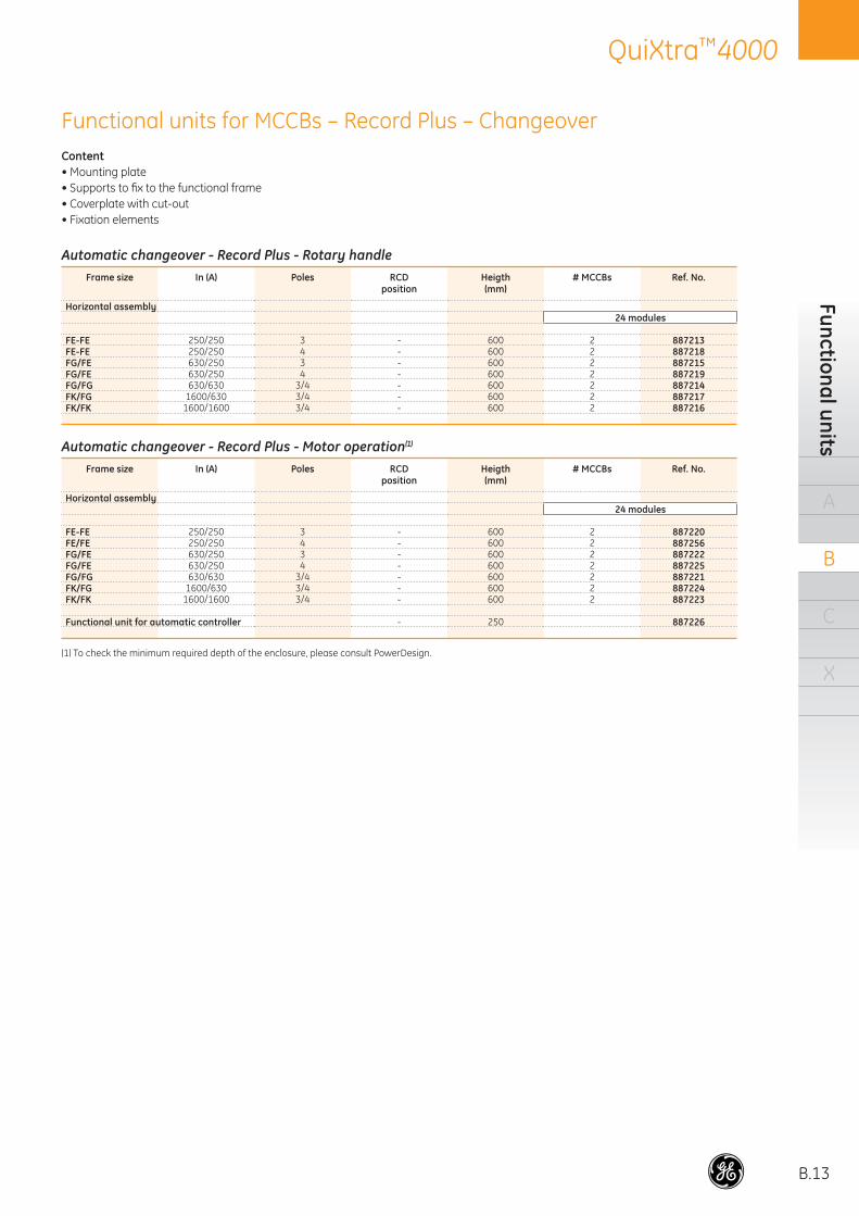
Functional units for MCCBs – Record Plus – ChangeoverContent• Mounting plate• Supports to fi x to the functional frame• Coverplate with cut-out• Fixation elements
Automatic changeover - Record Plus - Rotary handleFrame size In (A) Poles RCD
positionHeigth(mm)
# MCCBs Ref. No.
Horizontal assembly24 modules
FE-FE 250/250 3 - 600 2 887213FE-FE 250/250 4 - 600 2 887218FG/FE 630/250 3 - 600 2 887215FG/FE 630/250 4 - 600 2 887219FG/FG 630/630 3/4 - 600 2 887214FK/FG 1600/630 3/4 - 600 2 887217FK/FK 1600/1600 3/4 - 600 2 887216
Automatic changeover - Record Plus - Motor operation(1)
Frame size In (A) Poles RCDposition
Heigth(mm)
# MCCBs Ref. No.
Horizontal assembly24 modules
FE-FE 250/250 3 - 600 2 887220FE/FE 250/250 4 - 600 2 887256FG/FE 630/250 3 - 600 2 887222FG/FE 630/250 4 - 600 2 887225FG/FG 630/630 3/4 - 600 2 887221FK/FG 1600/630 3/4 - 600 2 887224FK/FK 1600/1600 3/4 - 600 2 887223
Functional unit for automatic controller - 250 887226
(1) To check the minimum required depth of the enclosure, please consult PowerDesign.

B.14
QuiXtra™4000O
rder
cod
es
A
B
C
X
Functional units for LBSs – Dilos / FulosContent• Mounting plate• Supports to fi x to the functional frame• Coverplate with cut-out• Fixation elements
Loadbreak disconnectors Frame size In (A) Poles Heigth
(mm)# LBSs Ref. No. # LBSs Ref. No.
24 modules 36 modulesHorizontal assembly
Dilos 3 160-315 3/4 300 1 887229 - -Dilos 4 400-630 3/4 450 1 887231(1) - -Dilos 6S 35 kA 800-1250 3/4 600 1 887233(1) - -Dilos 6S 50 kA 7S and 8S 800-1250 3/4 700 - - 1 887235(1)
Vertical assembly
Dilos 1-2 40-200 3/4 200 1 887227 - -Dilos 1H 40-200 3/4 300 1 887228 - -Dilos 3 160-315 3/4 300 1 887230 - -Dilos 4 400-630 3/4 450 1 887232(1) - -Dilos 6S 35 kA 800-1250 3/4 450 1 887234(1) - -Dilos 6S 50 kA 7S and 8S 800-1250 3/4 600 - - 1 887236(1)
Fused loadbreak disconnectors Frame size In (A) Poles Heigth
(mm)# LBSs Ref. No.
24 modulesHorizontal assemblyFulos 1-2 250-400 3/4 400 1 887238(1)
Fulos 3S 630 3/4 600 1 887233(1)
Vertical assembly
Fulos 0/00/000 32-160 3/4 250 1 887237Fulos 3S 630 3/4 450 1 887234(1)
Functional units for insulated fuse CosmoCosmo type In (A) Poles Heigth
(mm)# of fuse bases Ref. No.
24 modulesVertical assemblyD01/D1/D2 300 1 887239
(1) Two depth profi le sets required:600 mm: 887329 x2800 mm: 887330 x2(min. depth 600 mm).

B.15
QuiXtra™4000Functional units
A
B
C
X
Functional units for ACBs – EntelliGuard™ / M-PACT PlusContent• Support profi les to fi x to the depth profi les• Coverplate with cut-out• Fixation elements
Functional units for ACB EntelliGuard™ GFrame
sizeType Poles Heigth
(mm)# ACBs Ref. No. # ACBs Ref. No.
Vertical assembly24 modules 36 modules
Frame 1 Fixed 3/4 700 1 887240(1)
Frame 1 Withdrawable 3/4 700 1 887241(2)
Frame 1/2 Fixed 3/4 700 1 887242(1)
Frame 1/2 Withdrawable 3/4 700 1 887243(2)
Functional units for ACB M-PACT PlusFrame
sizeType Poles Heigth
(mm)# ACBs Ref. No. # ACBs Ref. No.
Vertical assembly24 modules 36 modules
Frame 1 Fixed 3/4 700 1 887244(1)
Frame 1 Withdrawable 3/4 700 1 887245(2)
Frame 1/2 Fixed 3/4 700 1 887246(1)
Frame 1/2 Withdrawable 3/4 700 1 887247(2)
(1) One depth profi le set required. Note: enclosures 600 mm depth only allow ACB Frame 1 fi xed600 mm: 887329800 mm: 887330
(2) Withdrawable only for 800 mm. One depth profi le set required: 887330Form 2 and 3: extra set depth profi les needed.
Functional units for ACB EntelliGuard™ LFrame
sizeType Poles Heigth
(mm)# ACBs Ref. No. # ACBs Ref. No.
Vertical assembly24 modules 36 modules
Frame 1 Fixed 3/4 700 1 887432(1)
Frame 1 Withdrawable 3/4 700 1 887433(1)
Frame 1/2 Fixed 3/4 700 1 887434(1)
Frame 1/2 Withdrawable 3/4 700 1 887435(1)

B.16
QuiXtra™4000O
rder
cod
es
A
B
C
X
Mounting platesQuiXtra 4000 offers the possibility of using partial mounting plates in combination with the rest of functions, or the full height mounting plate, adjustable in depth. Partial mounting plates require 2 sets of depth profi les. Full heigth mounting plate requires 3 sets of depth profi les.
Heigth (mm) Type
Width12 modules 24 modules 36 modules
50 Plain 885166 885167 885168100 Plain 887127 887132 887137150 Plain 885169 885170 885171200 Plain 885172 885173 885174250 Plain 887128 887133 887138300 Plain 885175 885176 885177400 Plain 887129 887134 887139600 Plain 885161 887135 887140750 Plain 885162 - -900 Plain 885163 - -
1050 Plain 885164 - -1200 Plain 885165 - -
150 Slot modular devices 885178 885179 885180150 Push-buttons - 885189 885190150 Meters 72x72 - 885185(1) 885186(2)
150 Meters 96x96 - 885187(3) 885188(4)
150 Recessed and pre-punched side - 885181 885182200 Ventilated 887131 887136 887141300 Recessed and pre-punched side 887130 885183 885184
(1) 4 meters(2) 6 meters(3) 3 meters(4) 5 meters
Cover plates
Heigth(mm)
Width12 modules 24 modules 36 modules
200(1) 887112 887117 887122400(1) 887113 887118 887123600(1) 887114 887119 887124
1800(2) 887115 887120 887125200 perforated(1) 887116 887121 887126
(1) 4 supports needed ref. 887328 887329 887330(2) 6 supports needed ref. 887328 887329 887330See page B.31

B.17
QuiXtra™4000Separation screen
A
B
C
X
Separation screens Form 2 and Form 3QuiXtra 4000 can be upgraded to internal segregation Form 2 or Form 3. To achieve the segregation Form 2 is required to add the separation screen for the busbars. To achieve the Form 3 additionally is required to add the separation screen between functions. There are special separation screen for the ACBs.
Form 2 and 3 separation screensDepth (mm)
Horizontal separation(metal) Width
12 modules 24 modules 36 modules450 887257 887260 887263600 887258 887261 887264800 887259 887262 887265
Side separation (length 900 mm)(polycarbonate) WIDTH
without CC with CC450 887266 887280 -600 887267 887281 -800 887268 887282 -
Vertical rear busbar separation (length 900 mm)(polycarbonate) WIDTH
12 modules 24 modules 36 modules450/600/800 - 887270 887270
ACB Entelliguard G separation screensDescription Type Depth
Width24 modules 36 modules
EG G Frame 1 Fixed 600 887271 887273EG G Frame 1 Withdrawable 800 887272 887274EG G Frame 2 Fixed 800 - 887273EG G Frame 2 Withdrawable 800 - 887274
ACB M-PACT Plus separation screensDescription Type Depth
Width24 modules 36 modules
M-Pact Frame 1 Fixed 600 887275 887277M-Pact Frame 1 Withdrawable 800 887276 887278M-Pact Frame 2 Fixed 800 - 887277M-Pact Frame 2 Withdrawable 800 - 887278
ACB Entelliguard L separation screensDescription Type Depth
Width24 modules 36 modules
EG L Frame 1 Fixed 600 887436 887438EG L Frame 1 Fixed 800 887454 887455EG L Frame 1 Withdrawable 800 887437 887439EG L Frame 2 Fixed 800 - 887440EG L Frame 2 Withdrawable 800 - 887441

B.18
QuiXtra™4000O
rder
cod
es
A
B
C
X
Busbars overviewIn a QuiXtra 4000, busbars can be fi xed horizontally and/or vertically
Horizontal busbarsDepending on where the busbar supports are fi xed, QuiXtra 4000 offers 2 kinds of horizontal busbars, both with fl at positioned bars.
• Rear fi xation A : busbar supports are fi xed on the back profi les and the phases are positioned one below the other. This is the only horizontal position possible for 450 mm deep enclosures.
• Side fi xation B : busbar supports are fi xed on the side profi les and the phases are positioned one behind the other. You can use fl oating supports in the middle. These busbars can be placed in 600 mm or 800 mm deep enclosures and are allocated at any height of the enclosure.
Maximum In (A) for busbars if ambient temperature is 35°C
IP30 without door IP55
Fixation Position Enclosure Depth (mm) 12 mod. 24 mod. 36 mod. 24 mod. + CC 12 mod. 24 mod. 36 mod. 24 mod. + CC
HORIZONTAL
Side
fl at
600 2000 2000 2000 2000 2000 2000 2000 2000800 4000 4000 4000 4000 4000 4000 4000 4000
Rear450 1600 1600 1600 1600 1600 1600 1600 1600600 1600 1600 1600 1600 1600 1600 1600 1600800 1600 1600 1600 1600 1600 1600 1600 1600
VERTICAL
Side
fl at450 670 - - 670 440 - - 440600 670/2000 - - 670/2000 440/2000 - - 440/2000800 670/4000 - - 670/2500 440/4000 - - 440/2500
staircase450 - - - 1600 - - - 1600600 630 - - 630 440 - - 440800 630 - - 630 440 - - 440
Rear
fl at450 670/1600 630/1600 630/1600 670/1600 440/1600 440/1600 440/1600 440/1600600 670/2000 630/2000 630/2000 670/2000 440/2000 440/2000 440/2000 440/2000800 670/2000 630/2000 630/2000 670/2000 440/2000 440/2000 440/2000 440/2000
staircase450 630 630 630 630 440 440 440 440600 630 630 630 630 440 440 440 440800 630 630 630 630 440 440 440 440
Maximum In (A) at IP30(1) without door if ambient temperature is 35°C
Enclosure depth (mm) 450 600 600 800 800Busbar support fi xation Rear Side Rear Side RearBusbar position Flat Flat Flat Flat fl atFigure letter A B A B A Max In (A) at IP30 without door(1) 1600 2000 1600 4000 1600Distance between busbars (mm) 125 90 125 90 125Enclosure width (mod.) all all all all allCross section 50x10 1100A 1100A 60x10 1000A 1300A 1000A 1300A 1000A 80x10 1250A 1400A 1250A 1400A 1250A 100x10 1600A 2000A 1600A 2000A 1600A 120x10 2400A 160x10 2700A (80x10) x2 2500A (100x10) x2 3000A (120x10) x2 3600A (160x10) x2 4000A
(1) Check table page C.5 for derating
BA

B.19
QuiXtra™4000Busbars
A
B
C
X
Vertical busbarsDepending on where the busbar supports are fi xed, QuiXtra 4000 offers 2 different fi xations for vertical busbars.
• Side fi xation: busbar supports are fi xed on the side of the enclosure and the phases are positioned one behind the other. These busbars can be placed in 600 mm or 800 mm deep enclosures of 12 modules width. We offer these busbars up to 4000A. Copper can be fl at or staircase.
Maximum In (A) at IP30(1) without door if ambient temperature is 35°C
Enclosure depth (mm) 450 450 450 450 600 600 600 600 800 800 800 800Busbar support fi xation Side Side Rear Rear Side Rear Rear Rear Side Rear Rear RearBusbar position fl at staircase fl at staircase fl at fl at fl at staircase fl at fl at fl at staircaseFigure letter C D E F G H I J G H I JMax In (A) at IP30 without door(1) 670 1600 670 630 2000 2000 670 630 4000 2000 670 630Distance between busbars (mm) 60 - 60 35 90 125 60 35 90 125 60 35Enclosure width (mod.) all 24 + CC all all 12/24 + CC 24/36/24 + CC all all 12/24 + CC 24/36/24 + CC all allCross section 20x5 275A - 275A 250A - - 275A 250A - - 275A 250A 30x5 425A - 425A 400A - - 425A 400A - - 425A 400A 20x10 425A - 425A 400A - - 425A 400A - - 425A 400A 30x10 670A 670A 670A 630A - - 670A 630A - - 670A 630A 40x10 - 800A - - - - - - - - - - 50x10 - 1000A - - 1100A 1000A - - 1100A 1000A - - 60x10 - - - - 1300A 1250A - - 1300A 1250A - - 80x10 - - - - 1650A 1600A - - 1650A 1600A - - 100x10 - - - - 2000A 2000A(2) - - 2000A 2000A - - (30x10) x2 - 800A - - - - - - - - - (40x10) x2 - 1250A - - - - - - - - - (50x10) x2 - 1600A - - - - - - 2000A - - - (80x10) x2 - - - - - - - - 2500A - - - (100x10) x2 - - - - - - - - 3000A - - - (120x10) x2 - - - - - - - - 3600A - - - (160x10) x2 - - - - - - - - 4000A - - -
(1) Check table page C.6 for derating (2) Not all functions can be put in front a 2000A busbar, please check with PowerDesign 2.0
• Rear fi xation: busbars supports are fi xed on the back uprights of the enclosure and the position of the phases is one next to another. We have 2 sizes: up to 630A and up to 2000A. Copper can be fl at or staircase.
C D E F
H JG I

B.20
QuiXtra™4000O
rder
cod
es
A
B
C
X
Example of a connectivity kit for ACB to busbar
Example of connecting a vertical busbar with side fi xation to a horizontal busbar with side fi xation.
Cu size Plain ThreadedPre-punchedfor vertical
busbars
Cut appropriate length for horizontal busbars450/600 and 800
mm 3 m 2 m 2 m 4x1 m holes 1.75 m 12 mod. 24 mod. 36 mod.20x5 858036 - 885207 880847 M6 - - - -30x5 885204 - 885209 - M6 - - - -
20x10 885205 - 885208 - M6 - - - -30x10 885206 - 885210 880851 M8 887398(1) - - -40x10 - - - - - 887429(1) - - -50x10 - 887306 - - - 887300 887425/887399 887422/887405 887419/88741160x10 - 887307 - - - 887301 887426/887400 887423/887406 887420/88741280x10 - 887308 - - - 887302 887427/887401 887424/887407 887421/887413
100x10 - 887309 - - - 887303 -/887402 -/887408 -/887414120x10 - 887310 - - - 887304 -/887403 -/887409 -/887415160x10 - 887311 - - - 887305 -/887404 -/887410 -/887416
(1) Ref. No. = set of 2 pcs
Flexible copper - Length = 2m
6x13x0.5 - 125A 2x20x1 - 160A 3x20x1 - 250A 4x32x1 - 400A 6x32x1 - 630A 10x32x1 -800A886530 886532 828162 828163 828164 828165
Copper bars
Earth bars
Ref. No.
Universal brackets for earth bars 887347(1)
(1) Set of 2 pcs
Earth barsThe earth continuity is assured with horizontal and vertical copper bars. The use of standard copper bars is required.

B.21
QuiXtra™4000Busbars
A
B
C
X
Side fi xation staircase, up to 1600A
In max (A)at 35°C Cu size Plain
copper barsPre-punchedcopper bars(2) Support(3) Spacer for
double busbars(4)
IP30(1) IP55 (mm) 2m 1.75 m 24 mod. with int. CC*670 440 30x10 885206 887398 887296 -800 715 40x10 - 887429 887296 -
1000 960 50x10 887306 887428 887296 -800 715 (30x10)x2 885206 x2 887398 x2 887296 887269
1250 1250 (40x10)x2 - 887429 x2 887296 8872691600 1600 (50x10)x2 887306 x2 887428 x2 887296 887269
(1) Without door, for derating see technical documentation on page C.5 and further(2) In one reference there is one busbar included, order one piece per phase(3) Set of 6 supports and 6 insulators(4) Set of 24 spacers, usable for 1 set of 6 supports
* CC = Cable Compartment
Vertical busbars for 450 mm deep enclosures
Minimum quantity of supportsSection/Icc 25kA 35kA 50kA
30x10 6 - -40x10 4 6 650x10 4 6 6(30x10)x2 6 - -(40x10)x2 4 6 6(50x10)x2 4 6 6
Connecting set for staircase busbar to main busbar
60x10 88732480x10 887323100x10 887318
Rear fi xation fl at, up to 1600A
In max (A)at 35°C Cu size Plain
copper bars Cut appropriate length copper bars(2)(3) Insulator kit+ support(4)
Extensionkit(5)
IP30(1) IP55 (mm) 2m 12 mod. 24 mod. 36 mod.1000 960 60x10 887307 887425 887422 887419 887297 8873251250 1250 80x10 887308 887426 887423 887420 887297 8873261600 1600 100x10 887309 887427 887424 887421 887297 887327
(1) Without door, for derating see technical documentation on page C.5 and further(2) In one reference there is one busbar included, order one piece per phase(3) Ready for connectivity kit to vertical staircase busbar and/or Record Plus FK(4) Order one kit per enclosure, one kit contains 2 supports and 2 insulators(5) To connect 2 horizontal busbars
Horizontal busbars for 450 mm deep enclosures
A
D

B.22
QuiXtra™4000O
rder
cod
es
A
B
C
X
Rear fi xation fl at, up to 630A
In max (A) at 35°C
Cusize
Plain copper bars
Threaded copper bars Insulator kit + support(2)
IP30(1) IP55 (mm) 3m 2m 4x1m 12 mod. 24 mod. 36 mod. 24 mod. with int. CC*275 210 20x5 858036 885207 880847 887290 887291 887292 887291425 330 30x5 885204 885209 - 887290 887291 887292 887291425 330 20x10 885205 885208 - 887290 887291 887292 887291670 440 30x10 885206 885210 880851 887290 887291 887292 887291
Side fi xation fl at, up to 630A
In max (A) at 35°C
Cusize
Plain copper bars
Threaded copper bars Insulator kit + support(2)
IP30(1) IP55 (mm) 3 m 2 m 4x1 m 24 mod. with int. CC*275 210 20x5 858036 885207 880847 887334425 330 30x5 885204 885209 - 887334425 330 20x10 885205 885208 - 887334670 440 30x10 885206 885210 880851 887334
(1) Without door, for derating see technical documentation on page C.5 and further(2) maximum distance between two supports is 300mm
* CC = Cable Compartment
Rear fi xation staircase, up to 630A
In max (A) at 35°C Cu size Plain
copper barsThreaded
copper bars Insulator kit + support(2)
IP30(1) IP55 (mm) 3m 2m 4x1m 12 mod. 24 mod. with int. CC*250 210 20x5 858036 885207 880847 887293 887294400 330 30x5 885204 885209 - 887293 887294400 330 20x10 885205 885208 - 887293 887294630 440 30x10 885206 885210 880851 887293 887294
Vertical busbars for 450 mm deep enclosures
C
F
E

B.23
QuiXtra™4000Busbars
A
B
C
X
Horizontal busbars for 600 mm deep enclosures
Rear fi xation fl at, up to 1600A
In max (A) at 35°C Cu size Plain
copper barsCut appropriate length
copper bars(2)(3)Insulator kit+ support(4)
Extensionkit(5)
IP30 IP55 (mm) 2 m 12 mod. 24 mod. 36 mod.1000A 950A 60x10 887307 887425 887422 887419 887297 8873251250A 1100A 80x10 887308 887426 887423 887420 887297 8873261600A 1400A 100x10 887309 887427 887424 887421 887297 887327
(1) Without door, for derating see technical documentation on page C.5 and further(2) In one reference there is one busbar included, order one piece per phase(3) Ready for connectivity kit to vertical staircase busbar and/or Record Plus FK(4) Order one kit per enclosure, one kit contains 2 supports and 2 insulators(5) To connect two horizontal busbars
Quantity of supports/isolators needed
Cu size 12 mod. 24 mod. 36 mod.
Icc 35 kA50x10 2/2 2/3 2/360x10 2/2 2/3 2/380x10 2/2 2/2 2/3
100x10 2/2 2/2 2/3Icc 50 kA
50x10 2/2 2/3 2/460x10 2/2 2/3 2/380x10 2/2 2/3 2/3
100x10 2/2 2/3 2/3Icc 65 kA
60x10 2/3 2/4 2/480x10 2/3 2/3 2/4
100x10 2/2 2/3 2/3Icc 80 kA and 85 kA
80x10 2/3 2/4 2/5100x10 2/3 2/4 2/4
Side fi xation fl at, up to 2000A
In max (A) at 35°C Cu size Plain
copper barsCut appropriate length
copper bars(2)(3) Support(4) Insulator(4) Extensionkit(5)
IP30(1) IP55 (mm) 2m 12 mod. 24 mod. 36 mod.1100A 950A 50x10 887306 887399 887405 887411 887287 887312 8873751300A 1100A 60x10 887307 887400 887406 887412 887287 887313 8873761650A 1400A 80x10 887308 887401 887407 887413 887287 887314 8873772000A 2000A 100x10 887309 887402 887408 887414 887287 887315 887378
B
A

B.24
QuiXtra™4000O
rder
cod
es
A
B
C
X
Vertical busbars for 600 mm deep enclosures
Side fi xation fl at, up to 2000A
In max (A)at 35°C Cu size Plain copper
barsPre-punched copper bars(2) Support(3) Insulator kit(3) Bottom
isolator(4)
IP30(1) IP55 (mm) 2 m 1.75 m1100 950 50x10 887306 887300 887287 887312 8872891300 1100 60x10 887307 887301 887287 887313 8872891650 1400 80x10 887308 887302 887287 887314 8872892000 2000 100x10 887309 887303 887287 887315 887289
Rear fi xation fl at, up to 2000A
In max (A)at 35°C Cu size Plain
copper bars(1)Pre-punched copper bars(2) Support(3) Insulator(3) Bottom
isolator(4)
IP30(1) IP55 (mm) 2m 1.75m 24 mod. 36 mod. 24 mod. with int. CC*1100 950 50x10 887306 887300 887298 887299 887298 887312 8872891300 1100 60x10 887307 887301 887298 887299 887298 887313 8872891650 1400 80x10 887308 887302 887298 887299 887298 887314 887289
2000(5) 2000(5) 100x10 887309 887303 887298 887299 887298 887315 887289
Rear fi xation fl at, up to 630A
In max (A)at 35°C Cu size Plain
copper barsThreaded
copper bars Insulator kit + support(6)
IP30(1) IP55 (mm) 3 m 2 m 4x1 m 12 mod. 24 mod. 36 mod. 24 mod. with int. CC*250 210 20x5 858036 885207 880847 887290 887291 887292 887291400 330 30x5 885204 885209 - 887290 887291 887292 887291400 330 20x10 885205 885208 - 887290 887291 887292 887291630 440 30x10 885206 885210 880851 887290 887291 887292 887291
Rear fi xation staircase, up to 630A
In max (A)at 35°C Cu size Plain
copper barsThreaded
copper bars Insulator kit + support(2)
IP30 IP55 (mm) 3 m 2 m 4x1 m 12 mod. 24 mod. with int. CC*250 210 20x5 858036 885207 880847 887293 887294400 330 30x5 885204 885209 - 887293 887294400 330 20x10 885205 885208 - 887293 887294630 440 30x10 885206 885210 880851 887293 887294
(1) Without door, for derating see technical documentation on page C.5 and further(2) In one reference there is one busbar included, order one piece per phase(3) For quantities to be ordered see table above(4) One bottom isolator needed per busbar system, order an additional support for each bottom isolator(5) Not all functions can be put in front of this busbar, please check with PowerDesign 2.0(6) Maximum distance between two supports is 300 mm
* CC = Cable Compartment
Maximum distance between supports (mm)Cu size 35kA 50kA 65kA
50x10 450 325 -60x10 500 350 27580x10 600 400 300100x10 650 450 350
H
G
I
J

B.25
QuiXtra™4000
Horizontal busbars for 800 mm deep enclosures
Side fi xation fl at, up to 4000A
In max (A)at 35°C Cu size Plain
copper bars Cut appropriate length copper bars(2)(3) Support(4) Insulator kit(4)
Extensionkit(5)
IP30(1) IP55 (mm) 2 m 12 mod. 24 mod. 36 mod.1100 950 50x10 887306 887399 887405 887411 887288 887312 8873751300 1100 60x10 887307 887400 887406 887412 887288 887313 8873761650 1400 80x10 887308 887401 887407 887413 887288 887314 8873772000 2000 100x10 887309 887402 887408 887414 887288 887315 8873782500 2500 (80x10)x2 887308 x2 887401 x2 887407 x2 887413 x2 887288 887314 8873773000 2950 (100x10)x2 887309 x2 887402 x2 887408 x2 887414 x2 887288 887315 887378 x23600 3300 (120x10)x2 887310 x2 887403 x2 887409 x2 887415 x2 887288 887316 887379 x24000 3800 (160x10)x2 887311 x2 887404 x2 887410 x2 887416 x2 887288 887317 887380 x2
Rear fi xation fl at, up to 1600A
In max (A)at 35°C Cu size Plain
copper bars Cut appropriate length copper bars(2)(3) Insulator kit(4)
Extensionkit(5)
IP30(1) IP55 (mm) 2 m 12 mod. 24 mod. 36 mod.1000A 950A 60x10 887307 887425 887422 887419 887297 8873251250A 1100A 80x10 887308 887426 887423 887420 887297 8873261600A 1400A 100x10 887309 887427 887424 887421 887297 887327
(1) Without door, for derating see technical documentation on page C.5 and further(2) In one reference there is one busbar included, order one piece per phase(3) Ready for connectivity kit to vertical staircase busbar and/or Record Plus FK(4) Order one kit per enclosure, one kit contains 2 supports and 2 insulators(5) To connect two horizontal busbars
Quantity of supports/isolators needed
Cu size 12 mod. 24 mod. 36 mod. Cu size 12 mod. 24 mod. 36 mod.
Icc 35 kA Icc 65 kA50x10 2/2 2/3 2/3 - - - -60x10 2/2 2/3 2/3 60x10 2/3 2/4 2/480x10 2/2 2/2 2/3 80x10 2/3 2/3 2/4
100x10 2/2 2/2 2/3 100x10 2/2 2/3 2/3(80x10)x2 2/2 2/2 2/3 (80x10)x2 2/2 2/3 2/3
(100x10)x2 2/2 2/2 2/3 (100x10)x2 2/2 2/3 2/3(120x10)x2 2/2 2/2 2/2 (120x10)x2 2/2 2/3 2/3(160x10)x2 2/2 2/2 2/2 (160x10)x2 2/2 2/3 2/3
Icc 50 kA Icc 80 kA and 85 kA50x10 2/2 2/3 2/4 - - - -60x10 2/2 2/3 2/3 - - - -80x10 2/2 2/3 2/3 80x10 2/3 2/4 2/5
100x10 2/2 2/3 2/3 100x10 2/3 2/4 2/4(80x10)x2 2/2 2/3 2/3 (80x10)x2 2/3 2/4 2/4
(100x10)x2 2/2 2/3 2/3 (100x10)x2 2/3 2/4 2/4(120x10)x2 2/2 2/2 2/2 (120x10)x2 2/2 2/4 2/4(160x10)x2 2/2 2/2 2/2 (160x10)x2 2/2 2/4 2/4
B
A
Busbars
A
B
C
X

B.26
QuiXtra™4000O
rder
cod
es
A
B
C
X
Side fi xation fl at, up to 4000A
In max (A)at 35°C Cu size Plain
copper bars(2)Pre-punched copper bars(2) Support(3) Insulator kit(3) Bottom
isolator(4)
IP30(1) IP55 mm 2 m 1.75 m1100 950 50x10 887306 887300 887288 887312 8872891300 1100 60x10 887307 887301 887288 887313 8872891650 1400 80x10 887308 887302 887288 887314 8872892000 2000 100x10 887309 887303 887288 887315 8872892500 2500 (80x10)x2 887308 x2 887302 x2 887288 887314 8872893600 3300 (120x10)x2 887310 x2 887304 x2 887288 887316 8872894000 3800 (160x10)x2 887311 x2 887305 x2 887288 887317 887289
Vertical busbars for 800 mm deep enclosures
Rear fi xation fl at, up to 2000A
In max (A)at 35°C Cu size Plain
copper barsPre-punched copper bars(2) Support(3) Insulator
kit(3)Bottom
isolator(4)
IP30(1) IP55 mm 2 m 1.7 m 24 mod. 36 mod. 24 mod. with int. CC*1100 950 50x10 887306 887300 887298 887299 887298 887312 8872891300 1100 60x10 887307 887301 887298 887299 887298 887313 8872891650 1400 80x10 887308 887302 887298 887299 887298 887314 8872892000 2000 100x10 887309 887303 887298 887299 887298 887315 887289
Rear fi xation fl at, up to 630A
In max (A)at 35°C Cu size Plain
copper bars Threaded copper bars Insulator kit+ support(5)
IP30(1) IP55 mm 3 m 2 m 4x1 m 12 mod. 24 mod. 36 mod. 24 mod. with int. CC*250 210 20x5 858036 885207 880847 887290 887291 887292 887291400 330 30x5 885204 885209 - 887290 887291 887292 887291400 330 20x10 885205 885208 - 887290 887291 887292 887291630 440 30x10 885206 885210 880851 887290 887291 887292 887291
Maximum distance between supports (mm)Cu size 50kA 65kA 80kA 85kA
80x10 400 300 - -100x10 450 350 250 200(120x10)x2 900 600 400 375(160x10)x2 900 600 400 375
Rear fi xation staircase, up to 630A
In max (A)at 35°C Cu size Plain
copper bars Threaded copper bars Insulator kit+ support(2)
IP30(1) IP55 mm 3 m 2 m 4x1 m 12 mod. 24 mod. with int. CC*250 210 20x5 858036 885207 880847 887293 887294400 330 30x5 885204 885209 - 887293 887294400 330 20x10 885205 885208 - 887293 887294630 440 30x10 885206 885210 880851 887293 887294
(1) Without door, for derating see technical documentation on page C.6 and further(2) In one reference there is one busbar included, order one piece per phase(3) For quantities to be ordered see table on B.25(4) One bottom isolator needed per busbar system, order an additional support for each bottom isolator(5) Maximum distance between two supports is 300 mm
* CC = Cable Compartment
G
H
I
J

B.27
QuiXtra™4000Connectivity
A
B
C
X
887322887320
887324887323887318
887325887326887327
887321887319
887296
887269887428887429887398
ConnectivityQuiXtra 4000 offers following connectivity solutions: busbar to busbar, ACB to busbar, MCCB to busbar, MCCB cable connection and connectivity accessories.

B.28
QuiXtra™4000O
rder
cod
es
A
B
C
X
Extension and connection kitsCu size Ref. No.
Extension kit horizontal busbar side fi xation (image B ) 50x10 88737560x10 88737680x10 887377
100x10 887378120x10 887379160x10 887380
Extension kit horizontal busbar rear fi xation (image A ) 60x10 88732580x10 887326
100x10 887327
Connection kit vertical staircase busbar (image D ) 60x10 887324to horizontal busbar rear fi xation (image A ) 80x10 887323
100x10 887318
Images on page. B.18 and B.19
Busbar to busbarFor connecting two busbars, there are two connectivity solutions:extension kits for connecting 2 horizontal busbars and connection kits for connecting a staircase busbar to a horizontal busbar with rear fi xation. Depending on the busbar fi xation and on the copper size, QuiXtra 4000 offers different extension kits.
Extension kit for rear fi xation busbar
Connectivity kit for Heavy Duty ACB EntelliGuard

B.29
QuiXtra™4000O
rder codes
A
B
C
XConnectivity kit EntelliGuard G to horizontal busbar with side fi xation (image B )Size Version In max Ref. No.
Frame 1 3P Fixed 2000 A 600 887248Frame 1 4P Fixed 2000 A 600 887249Frame 2 3P Fixed 4000 A 800 887250Frame 2 4P Fixed 4000 A 800 887251
Frame 1 3P Withdrawable 2000 A 800 887252Frame 1 4P Withdrawable 2000 A 800 887253Frame 2 3P Withdrawable 4000 A 800 887254Frame 2 4P Withdrawable 4000 A 800 887255Frame 2 3P Heavy Duty Withdrawable 4000 A 800 887352Frame 2 4P Heavy Duty Withdrawable 4000 A 800 887353
Connectivity kit EntelliGuard L to horizontal busbar with side fi xation (image B )Size Version In max Depth Ref. No.
Frame 1 3P Fixed 2500 A 600 887442Frame 1 4P Fixed 2500 A 600 887443Frame 2 3P Fixed 4000 A 800 887444Frame 2 4P Fixed 4000 A 800 887445Frame 1 3P Fixed 2500 A 800 887450Frame 1 4P Fixed 2500 A 800 887451
Frame 1 3P Withdrawable 2500 A 800 887446Frame 1 4P Withdrawable 2500 A 800 887447Frame 2 3P Withdrawable 3200 A 800 887448Frame 2 4P Withdrawable 3200 A 800 887449Frame 2 3P Withdrawable 4000 A 800 887452Frame 2 4P Withdrawable 4000 A 800 887453
Connectivity kit M-PACT Plus to horizontal busbar with side fi xation (image B )Size Version In max Depth Ref. No.
Frame 1 3P Fixed 2000 A 600 887248Frame 1 4P Fixed 2000 A 600 887249Frame 2 3P Fixed 4000 A 800 887250Frame 2 4P Fixed 4000 A 800 887251
Frame 1 3P Withdrawable 2000 A 800 887252Frame 1 4P Withdrawable 2000 A 800 887253Frame 2 3P Withdrawable 4000 A 800 887335Frame 2 4P Withdrawable 4000 A 800 887336
Supports for connectivity kit ACB (EntelliGuard or M-PACT Plus)Size Width In max Depth Ref. No.
Frame 1 3/4P 24 mod. 2000A - 887374Frame 1 3P 36 mod. 2000A - 887417Frame 1 4P 36 mod. 2000A - 887430Frame 2 3P 36 mod. 4000A - 887418Frame 2 4P 36 mod. 4000A - 887431Frame 2 3P Heavy Duty(1) 36 mod. 4000A - 887373Frame 2 4P Heavy Duty(1) 36 mod. 4000A - 887295
(1) Connectivity kit for Heavy Duty, see previous page.
ACB to busbarFor connecting an Air Circuit Breaker to a horizontal busbar with side fi xation, QuiXtra 4000 offers a complete range ofconnectivity solutions: M-PACT Plus frame 1 (2000A) and frame 2 (4000A); EntelliGuard frame 1 (2000A), frame 2 (4000A) and frame 2 heavy duty (for reduced heat dissipation).

B.30
QuiXtra™4000O
rder
cod
es
A
B
C
X
MCCB outgoing connection to busbar (image A )Size Ref. No.
Connectivity kit RecordPlus to horizontal busbar rear fi xation FK frame 800A 887322FK frame 1250A/1600A 887320
MCCB incoming cable connectionSize Ref. No.
Incoming connection kit, 3 cables, on RecordPlus FK frame 800A 887321FK frame 1250A/1600A 887319
MCCB to busbarFor connecting a Moulded Case Circuit Breaker to a horizontal busbar with rear fi xation, QuiXtra 4000 offers a RecordPlus FK connectivity kit.
Cable managementFor mounting a large cable duct e.g. above terminals, a function of 200 mm high has been developed. Cable ducts or other accessories can easily be mounted.
MCCB to cablesFor the easy connection of incoming or outgoing cables on a RecordPlus FK, QuiXtra 4000 offers a range of FK connection kits.
Horizontal cable managementRef. No.
Function for canalization horizontal 24 mod. 200 mm height 887340Function for canalization horizontal 36 mod. 200 mm height 887341
Cable trunk support for DIN-rail (20 pcs) 828145

B.31
QuiXtra™4000O
rder codes
A
B
C
X
Accessories
Connectivity accessoriesSize Ref. No.
Connector for fl exible copper max Cu width 32 mm 828142(1)
Connector for cable gland 20 mm or 25 mm width 20 or 25 mm 858004(1)
Connector for cable gland 25 mm, 30 mm or 40 mm width 25, 30 or 40 mm 858003(1)
Connection for cable direct on Cu-rail 1.5-16 mm² 858027(1)
10 mm thickness - Torque 4 Nm 1.5-35 mm² 858029(1)
16-70 mm² 858030(1)
16-120 mm² 858031(1)
T-bolt for 2x10 mm busbar length: 60 mm Cu-rail 20x10 85801380 mm Cu-rail 40x10 85801190 mm Cu-rail 50x10 858014120 mm Cu-rail 80x10 858016140 mm Cu-rail 100x10 858017
Fastener bolts (40 pcs) M6x16 mm 883617M8x20 mm 880852
(1) Contact block and T-bolt needed
General accessoriesDescription Ref. No.
Set depth profi les: 450 mm 887328600 mm 887329800 mm 887330
Coupling bracket for base: 450 mm 887381600 mm 887382800 mm 887383
Lighting unit 24 mod. height 50 mm 887285Lighting unit 36 mod. height 50 mm 887286
Bracket for recessed or adjustable DIN-rail 887348
Hinges for coverplate (set 2 pcs) 885285
Earthing cable for door 6 mm² 887345Universal bracket for main earth bar 887347
Lifting brackets for coupled enclosures 887331
Lifting eyes standard (set 4 pcs). Max 480 kg/column 887283Lifting eyes heavy duty (set 4 pcs). Max 1000 kg/column 887339
Note: Check lifting instructions
Set of cable support fi xations (20 pcs) 828145Set cable supports (10 supports) 828146
Height adaptor RecordPlus - ElfaPlus (1200 mm) 883997Height adaptor RecordPlus - ElfaPlus (354 mm) 617947Blanking strip for 45 mm cut-out – L 1000 mm – RAL 7035 828056Blanking strip for 45 mm cut-out – L 72 mm – RAL 7035 (set 4pcs) 610142Blanking strip for 65 mm cut-out (RecordPlus FD and FE) – L 1200 mm – RAL 7035
883970
Label holder (self adhesive) 12 mod. 885249Label holder (self adhesive) 24 mod. 885250Label holder (self adhesive) 36 mod. 885251
Drawing pocket A5 832000Drawing pocket A4 811516Paint RAL 9006 for minor touch-ups external panel 885252Paint RAL 7024 for minor touch-ups external panel 885253
Handle for half cylinder (on request) 887346Profi le half cylinder with 2 keys V2432 832030Profi le half cylinder with 1 square key 8 mm 832032Profi le half cylinder with 1 triangular key 8 mm 832033Profi le half cylinder with 2 keys A434 843248
Bolt
Contact block
Vertical rail

B.32
QuiXtra™4000O
rder
cod
es
A
B
C
X
Notes
. . . . . . . . . . . . . . . . . . . . . . . . . . . . . . . . . . . . . . . . . .
. . . . . . . . . . . . . . . . . . . . . . . . . . . . . . . . . . . . . . . . . .
. . . . . . . . . . . . . . . . . . . . . . . . . . . . . . . . . . . . . . . . . .
. . . . . . . . . . . . . . . . . . . . . . . . . . . . . . . . . . . . . . . . . .
. . . . . . . . . . . . . . . . . . . . . . . . . . . . . . . . . . . . . . . . . .
. . . . . . . . . . . . . . . . . . . . . . . . . . . . . . . . . . . . . . . . . .
. . . . . . . . . . . . . . . . . . . . . . . . . . . . . . . . . . . . . . . . . .
. . . . . . . . . . . . . . . . . . . . . . . . . . . . . . . . . . . . . . . . . .
. . . . . . . . . . . . . . . . . . . . . . . . . . . . . . . . . . . . . . . . . .
. . . . . . . . . . . . . . . . . . . . . . . . . . . . . . . . . . . . . . . . . .
. . . . . . . . . . . . . . . . . . . . . . . . . . . . . . . . . . . . . . . . . .
. . . . . . . . . . . . . . . . . . . . . . . . . . . . . . . . . . . . . . . . . .
. . . . . . . . . . . . . . . . . . . . . . . . . . . . . . . . . . . . . . . . . .
. . . . . . . . . . . . . . . . . . . . . . . . . . . . . . . . . . . . . . . . . .
. . . . . . . . . . . . . . . . . . . . . . . . . . . . . . . . . . . . . . . . . .
. . . . . . . . . . . . . . . . . . . . . . . . . . . . . . . . . . . . . . . . . .
. . . . . . . . . . . . . . . . . . . . . . . . . . . . . . . . . . . . . . . . . .
. . . . . . . . . . . . . . . . . . . . . . . . . . . . . . . . . . . . . . . . . .
. . . . . . . . . . . . . . . . . . . . . . . . . . . . . . . . . . . . . . . . . .
. . . . . . . . . . . . . . . . . . . . . . . . . . . . . . . . . . . . . . . . . .
. . . . . . . . . . . . . . . . . . . . . . . . . . . . . . . . . . . . . . . . . .
. . . . . . . . . . . . . . . . . . . . . . . . . . . . . . . . . . . . . . . . . .
. . . . . . . . . . . . . . . . . . . . . . . . . . . . . . . . . . . . . . . . . .
. . . . . . . . . . . . . . . . . . . . . . . . . . . . . . . . . . . . . . . . . .
. . . . . . . . . . . . . . . . . . . . . . . . . . . . . . . . . . . . . . . . . .
. . . . . . . . . . . . . . . . . . . . . . . . . . . . . . . . . . . . . . . . . .
. . . . . . . . . . . . . . . . . . . . . . . . . . . . . . . . . . . . . . . . . .
. . . . . . . . . . . . . . . . . . . . . . . . . . . . . . . . . . . . . . . . . .
. . . . . . . . . . . . . . . . . . . . . . . . . . . . . . . . . . . . . . . . . .
. . . . . . . . . . . . . . . . . . . . . . . . . . . . . . . . . . . . . . . . . .
. . . . . . . . . . . . . . . . . . . . . . . . . . . . . . . . . . . . . . . . . .
. . . . . . . . . . . . . . . . . . . . . . . . . . . . . . . . . . . . . . . . . .
. . . . . . . . . . . . . . . . . . . . . . . . . . . . . . . . . . . . . . . . . .
. . . . . . . . . . . . . . . . . . . . . . . . . . . . . . . . . . . . . . . . . .
. . . . . . . . . . . . . . . . . . . . . . . . . . . . . . . . . . . . . . . . . .
. . . . . . . . . . . . . . . . . . . . . . . . . . . . . . . . . . . . . . . . . .
. . . . . . . . . . . . . . . . . . . . . . . . . . . . . . . . . . . . . . . . . .
. . . . . . . . . . . . . . . . . . . . . . . . . . . . . . . . . . . . . . . . . .
. . . . . . . . . . . . . . . . . . . . . . . . . . . . . . . . . . . . . . . . . .
. . . . . . . . . . . . . . . . . . . . . . . . . . . . . . . . . . . . . . . . . .
. . . . . . . . . . . . . . . . . . . . . . . . . . . . . . . . . . . . . . . . . .
. . . . . . . . . . . . . . . . . . . . . . . . . . . . . . . . . . . . . . . . . .
. . . . . . . . . . . . . . . . . . . . . . . . . . . . . . . . . . . . . . . . . .
. . . . . . . . . . . . . . . . . . . . . . . . . . . . . . . . . . . . . . . . . .
. . . . . . . . . . . . . . . . . . . . . . . . . . . . . . . . . . . . . . . . . .
. . . . . . . . . . . . . . . . . . . . . . . . . . . . . . . . . . . . . . . . . .
. . . . . . . . . . . . . . . . . . . . . . . . . . . . . . . . . . . . . . . . . .

QuiXtra™4000
A
B
C
X
Applications and Benefi ts
Order codes
Technical data
Numerical index
C.1
C.2 General characteristics
C.3 Mechanical and electrical characteristics
C.4 Enclosure
Door
Functional units
Coupling
C.5 Corrosion protection
Painting / coating
Degree of protection
Earthing concept
C.6 Busbars
C.7 Form of internal separation
C.8 Derating tables
C.12 Watt losses
C.14 Power losses
C.22 Heat dissipation tables
C.30 Dimensional drawings
C.32 Specifi cations for tender documents
C.33 Appendix: IEC 61.439 versus IEC 60.439 for assemblies up to 4000A

C.2
QuiXtra™4000Te
chni
cal d
ata
A
B
C
X
QuiXtra 4000 is a range of sheet steel system enclosures, delivered as a fl at kit: the GE solution for low voltage distribution boards up to 4000A, in high commercial and industrial environments.
QuiXtra 4000 is designed to be a reliable, simple, fl exible and easy to use system enclosure, expanding the QuiXtra 630 line, with the same benefi ts and the same fresh and attractive design.
The QuiXtra 4000 range consists of 9 different enclosures. There are three enclosure depths available, from 450 mm up to 800 mm, and three enclosure widths, for functions of 12, 24 or 36 modules. All enclosures have the same height (1800 mm useful), allowing side to side coupling for the enclosures with same depth, and back to back coupling for the enclosures with the same width, providing the user total fl exibility to defi ne the layout of the LV distribution boards, even L and U layouts using the corner enclosures.
The kit form design allows the optimization of number of references versus the range of enclosures configurations. Basically the panels can be built with 2 protection degrees IP30 or IP55. Once the frame are assembled, the busbar system, mounting plates, supports for electrical devices and the DIN-rails are easily fixed to the frame, with accessibility from all sides. After wiring, the enclosure can be closed by the rear, top and side panels and cover plates. Thanks to the QuiXtra intelligent design, the labor time required to build a distribution panel is minimal, with higher flexibility in the panel layout
The attractive design of QuiXtra 4000, the same as QuiXtra 630, makes the line suitable for commercial environments. The QuiXtra 4000 colour is metallic silver, RAL9006; the external corner parts, the handle and the base are in dark grey, RAL7024. The tempered glass of the transparent door is lightly smoked in grey.

C.3
QuiXtra™4000Technical data
A
B
C
X
Material and colourFrame profi les Sendzimir zinc plated steel 1.5 mm
External panels Epoxy-polyester coated sheet steel 1.5 mm
Plain door Epoxy-polyester coated sheet steel 1.5 mm
Transparent doorEpoxy-polyester coated sheet steel 1.5 mm and smoked safety
glass 3 mm.
Cover plates Epoxy-polyester coated sheet steel 1 mm
External plastic ABS
Internal corners Die-cast aluminium alloy
Enclosure colour RAL 9006
Floor base colour RAL 7024
Main technical characteristics
Protection degree and segregation formProtection class I
Pollution degree 3
Segregation Form 1, Form 2b, Form 3b and Form 4a
Protection degreeWithout door IP30, IK08
With plain door and with IP55 panels IP55, IK09
With plain door and with IP30 panels IP30, IK09
With transparent door and with IP55 panels IP55, IK08
With transparent door and with IP30 panels IP30, IK08
Standards and approvalsStandards IEC 61439-2
EN 61439-2
Approval with KEMA quality testreport
Certifi cation with KEMA quality testreport
RoHS compliant YES
REACH compliant YES
Electrical characteristicsRated current (In) 4000A
Rated operational voltage (Ue) 415V, 690V
Rated insulation voltage (Ui) 1000V
Rated frequency (fn) 50/60 Hz 50/60Hz
Rated short-circuit current max (Icw) 85kA/1s
Rated current of busbar systems 4000A in IP30
Useful and external dimensions (mm)
Useful dimensions External dimensions
Mounting platewidth
Width for devices Depth Height Width Depth Height
Depth 45012 mod 238 216 (12 mod.) 375 1800 447 450 215524 mod 534 432 (24 mod.) 375 1800 743 450 215536 mod 750 648 (36 mod.) 375 1800 959 450 2155
Depth 60012 mod 238 216 (12 mod.) 525 1800 447 600 215524 mod 534 432 (24 mod.) 525 1800 743 600 215536 mod 750 648 (36 mod.) 525 1800 959 600 2155
Depth 80012 mod 238 216 (12 mod.) 725 1800 447 800 215524 mod 534 432 (24 mod.) 725 1800 743 800 215536 mod 750 648 (36 mod.) 725 1800 959 800 2155

C.4
QuiXtra™4000Te
chni
cal d
ata
A
B
C
X
EnclosureThe basic QuiXtra 4000 frame enclosure is built by ordering 4 kits:
• Top/bottom frames, depending on the dimensions width and depth, and on the IP degree
• Vertical profi les. Common for all the enclosures dimensions• Top panels, depending on the cable entry plates options
desired• Functional frame. With or without integrated cable com-
partment in the enclosures 36 modules wide and with or without functional door
The vertical profi les are fi xed to the top and bottom frames mean 2 screws in each corner, achieving a rigid and reliable frame. The die-cast aluminium corner parts, with the profi les 1.5 mm thick, provide the required rigidity to the frame.
The external covers; rear, side and doors are made of epoxy-polyester coated sheet steel, with a thickness of 1.5 mm. The top cover, rear and side panels can be delivered in 2 versions, including or not a PUR gasket, to achieve the IP30 or IP55.The external panels can be assembled by a single person. In both cases the panels are supported by the top frame, allowing the easy fi xation of the external cover screws to the frame.
DoorQuiXtra 4000 offers plain and transparent (tempered glass) doors. The doors are equipped with a centrally operated four point locking mechanism. The handle is delivered with a standard lock insert for key 2432E. The opening angle is 135 degrees, for both types of doors. Mounting the doors to the enclosure is done without tools, using the simple pin-hinges. The doors are delivered with hinges and the locking mechanism mounted, to reduce assembly time. The door is standard delivered right hinging. Changing to left hinging is done easily.
Functional unitsAll GE LV electrical devices up to 4000A can be easily assembled in QuiXtra 4000 using the appropriate functional units. Each functional kit includes all parts necessary for assembly:• A mounting plate, support or DIN-rail. Some supports
requires depth profi les for its fi xation• A cover plate (with precise cut-outs)• Fixation parts
Attaching the mounting plates or DIN-rails does not require tools: they are attached to the functional frame using a “click in” support. The cover plates are attached to two profi les using captive 90º screws. it’s possible to fi x all the cover plates to a functional door, allowing to open all the cover plates in one shot. It’s the perfect solution for maintenance purposes.QuiXtra 4000 has suffi cient wiring space for all possiblelayouts. Several ready-to-install copper connections between the main breaker and the main busbar are available, to make
the panel constructions easier and more reliable.The mounting plates of the functional units are made of sendzimir zinc plated steel 1.5 mm, and the cover plates of epoxy-polyester coated sheet steel 1 mm.
Coupling of enclosuresThe QuiXtra 4000 allows unlimited side to side horizontal coupling for enclosures of same depth, and it can be assembled back to back for the enclosures with the same width. Coupling is done just adding a gasket between the enclosures, and with screws that fi x directly the 2 adjacent vertical profi les. The same coupling concept is used in both directions, side to side and back to back.

C.5
QuiXtra™4000Enclosures
A
B
C
X
Corrosion protectionThe enclosure is protected against corrosion by epoxy polyester coating of the external panels. The unpainted parts (the rear panel, vertical profi les, mounting plates and functional supports) are made of sendzimir zinc plated steel.
Painting and coatingAll external panels and cover plates are powder coated. The colour is RAL 9006, with a minimum thickness of 75 μm. The painting procedure is as follows:
Phase 1: Degreasing in simultaneous degreasing and iron phosphating bath. Temp. 45-55°C
Phase 2: Degreasing in the same bath. Temp. 15-26°CPhase 3: Degreasing in the same bath. Temp. 15-26°CPhase 4: Iron phosphating in the same bath. Temp. 25-35°CPhase 5: RinsingPhase 6: Passivation process in bath without chromium 6+.
Temp. 15-26°CPhase 7: Rinsing with demineralised waterPhase 8: Heat drying in oven. Temp. 120°CPhase 9: Manual electrostatic powder coating in required
colourPhase 10: Curing in oven. Temp. 180°CPhase 11: Quality control of random samples
• visual inspection• control of coating thickness• cross cut test
Protection degreeThe QuiXtra 4000 protection degree is either IP30 or IP55. IP30 is achieved simply using the top and bottom frame and external covers in IP30, or using the IP55 version without door. To achieve the IP55 protection degree is required to use the top and bottom frame and external covers IP55 and adding the door.
Earthing conceptThe earth continuity in QuiXtra 4000 is assured via the screws that fi x the panels to the frame parts. Each special screw removes the paint in the contact area. The earth continuity of the cover plates is guaranteed by removing the paint in the contact area with the enclosure. Supports for main earth bars, in standard copper dimensions, are available.
The following table provides the required information to select the cross section of each busbar system
Derating tableRated current Ambient temp 35°C Cu bars/
phaseCu bar
dimensions (mm)Enclosure
depth (mm)
In IP30 (without door) IP30 (with door) IP55 L1-L2-L3-N Height x thickness
Supports for side fi xation Vert. Horz. Vert. Horz. Vert. Horz.250A 275A 275A 210A 210A 210A 210A 1 20x5400A 425A 425A 330A 330A 330A 330A 1 20x10630A 670A 670A 440A 440A 440A 440A 1 30x101000A 1100A 1100A 950A 950A 950A 950A 1 50x101250A 1300A 1300A 1100A 1100A 1100A 1100A 1 60x101600A 1650A 1650A 1400A 1400A 1400A 1400A 1 80x102000A 2000A 2000A 2000A 2000A 2000A 2000A 1 100x102500A 2500A 2500A 2500A 2500A 2500A 2500A 2 80x103200A 3600A 3600A 3300A 3300A 3300A 3300A 2 120x104000A 4000A 4000A 3800A 4000A 3800A 4000A 2 160x10
Supports for rear fi xation1600A - 1600A - 1600A - 1600A 1 100x10
Staircase supports1600A 1600A - 1600A - 1600A - 2 50x10630A 630A - 630A - 630A - 1 30x10
IncomersRecord Plus K Frame 1600A 1150A - 1000A - 1000A - 450EntelliGuard Frame 1 fi xed 2000A 2000A - 1800A - 1800A - 600M-PACT Plus Frame 1 fi xed 2500A 2000A - 1650A - 1650A - 600EntelliGuard Frame 2 withdrawable 4000A 2850A - 2400A - 2400A - 800M-PACT Plus Frame 2 withdrawable 4000A 2900A - 2900A - 2500A - 800EntelliGuard Frame 2 withdrawable 100% 4000A 3450A - 2800A - 2800A - 800EntelliGuard L Frame 1 fi xed 2500A 2350A - 1600A - 1600A - -EntelliGuard L Frame 2 withdrawable 4000A(1) 2950A - 2450A - 2450A - -
(1) With horizontal universal connection kit
Copper bar and support selections

C.6
QuiXtra™4000Te
chni
cal d
ata
A
B
C
X
BusbarsThe busbar system for QuiXtra 4000 is developed to ensure easy installation of the copper bars, easy and quick wiring of electrical devices and the most compact solution possible. The busbar system is based in standard copper dimensions of 10 mm thickness.
QuiXtra 4000 offers several types of busbar systems. The possible busbar types depend on the depth of the enclosures.
Possible busbars system for 450 mm deep enclosures• Main horizontal busbars up to 1600A. Located at the rear of
the enclosure. One phase over the other.• Vertical busbar system. Staircase busbars up to 630A,
and staircase busbar up to 1600A in integrated cable compartment. Side busbar up to 630A. Rear busbar up to 630A.
Possible busbars system for 600 mm deep enclosures• Main horizontal busbar up to 2000A. Located on the top
or middle height position. The phases are assembled one behind the other.
• Vertical busbar system. 2 rear busbar system solutions, up to 630A and up to 1600A. One staircase busbars, up to 630A, for 12 modules enclosures and integrated cable compartment. One side busbar system up to 2000A, for 12 modules enclosures and integrated cable compartment. And fi nally one vertical busbar up to 2000A to install in the enclosure 12 module wide.
Possible busbars system for 800 mm deep enclosures• Main horizontal busbar up to 4000A. Located on the top
or middle height position. The phases are assembled one behind the other.
• Vertical busbar system. 2 rear busbar system solutions, up to 630A and up to 1600A. One staircase busbar, up to 630A, for 12 modules enclosures and integrated cable compartment. One side busbar system up to 2000A, for 12 modules enclosures and integrated cable compartment. And fi nally one verticalbusbar up to 4000A to install in the enclosure 12 module wide.
C D E F
H JG I

C.7
QuiXtra™4000H
eat dissipation
A
B
C
X
Form of internal separationQuiXtra 4000 is available with internal separation up to Form 4.
Form 1: Functional units, busbars and terminals are protected against outside contact within the QuiXtra enclosure, but are internally not separated from each other.Form 2: Same as Form 1, but an insulating screen separates the busbars from the functional units and terminals.
Form 3: Additionally to the Form 2, there are separation screens between the functions to avoid that any issue in one functional unit will be transmitted to another one. There are separation screens available to achieve the Form 2 and 3, and special references to assure the Form 3 in the functional units for the ACBs.Form 4: Additionally to the Form 3, QuiXtra 4000 can be confi gured as Form 4a, connecting directly the cables to the breakers in the same functional unit
The verifi cation of the acceptable temperature rises in QuiXtra 4000 may be made by calculation if all of the following conditions are fulfi lled.
1. There is an approximately even distribution of power losses inside the enclosure
2. The load current of the circuits of QuiXtra 4000 shall not exceed 80% of the rated current mentioned on the switch-ing device and electrical components included in the circuit . Circuit breakers and thermal motor protection shall be selected to ensure adequate protection to outgoing circuits at the calculated temperature in the assembly. Infl uence of temperature on the tripping times is available in the appropriate product catalogue.
3. The mechanical parts and the installed equipment are so arranged that air circulation is not signifi cantly impeded.
4. Conductor carrying currents in excess of 200A, and the adjacent metal structural parts are so arranged that eddy-currents and hysteresis losses are minimized
5. All conductors shall have a minimum cross-sectional based on the current rating of the device according to IEC 60364-5-52.Minimum sections as defi ned in table 5 and 6 (page C.19), unless larger conductors are specifi ed in the QuiXtra 4000 assembling instructions.
Examples on how to adapt the conductor sections for conditionsinside QuiXtra 4000 are given in table 1 and 2 (page C.17)
6. Calculate the total power losses in the QuiXtra:a. Power losses of the components (Record Plus, Dilos,
Fulos, Redline/ElfaPlus) b. Power losses of the conductors and busbarsc. Power losses of other auxiliariesd. Add all the power losses
7. Choose the appropriate size of QuiXtra 4000 enclosure:a. Look for the appropriate table power dissipation/
temperature rise: tables are available for different positioning of the enclosure
b. Maximum allowed temperature rise at the top of the enclosure: 40KLimit accessible parts during normal operation to max +30K
c. The temperature in °C in the enclosure is the sum of the ambient temperature outside the QuiXtra and the temperature rise in K found in the tables.
Record Plus can be used up to 70°CEntelliGuard up to 70°CM-PACT Plus up to 70°CDilos/Fulos up to 60°CRedline/ElfaPlus can be used up to 50°CApply the appropriate current derating of these components (see page C.10 - C.16).
Verification of acceptable temperature rise
Examples on page C.26 - C.29
Form 1
Form 3b
Form 4a
Form 4b Form 2b
Form 3a Form 2a

C.8
QuiXtra™4000Te
chni
cal d
ata
A
B
C
X
Infl uence of ambient air temperature on the rated current
The maximum value of the current which can fl ow through a MCB depends of the nominal current of the MCB, the conductor cross-section as well as of the ambient air temperature.
The values shown in the table below are for devices in the free air. For devices installed with other modular devices in the same switchboard a correction factor (K) shall be applied relative to the mounting situation of the MCB, the ambient temperature and the number of main circuits in the installation (according IEC 61439-2):
No. of devices Correction factor K
2 or 3 0.94 or 5 0.86 to 9 0.7> 10 0.6
Calculation exampleWithin a distribution board consisting of eight 2P MCB C16 with an operating ambient temperature of 45°C, which is the highest temperature the MCB can operate without unwanted tripping.
CalculationThe correction factor is K=0.7 for use in a eight circuit installation: 16A x 0.7= 11.2AAs the MCB is working at 45°C it shall be applied another factor (90% = 0.9):In at 45°C = In at 30°C x 0.9 = 11.2A x 0.9 = 10.1A
The thermal calibration of the MCBs was carried out atambient temperature of 30°C. Ambient temperaturesdifferent from 30°C infl uence the bimetal and this resultsin earlier or later thermal tripping.
: 1P (single pole) : mP (multipole)
0.5 - 6A
10A
16 - 40A
50 - 63A
Derating tables for ElfaPlus MCBs

C.9
QuiXtra™4000D
erating tables
A
B
C
X
Infl uence of air ambient temperature on the rated current
Infl uence of temperature on RCCBsThe maximum value of the current which can fl ow through an RCCB depends of the nominal current as well as the ambient air temperature. The protective device placed up-stream of the RCCB must ensure the disconnectionat the values in the following table:
In 25°C 30°C 40°C 50°C 60°C
16A 19 18 16 14 1325A 31 28 25 23 2540A 48 44 40 36 3263A 76 69 63 57 5180A 97 88 80 72 65
100A 121 110 100 90 81125A 151 137 125 112 101
The above mentioned values are for devices in the free air. For devices installed with other modular devices in the same switchboard, a correction coeffi cient (K) shall be applied in relation to the number of main circuits in the installation(according IEC 61439-2):
No. of devices K
2 or 3 0.94 or 5 0.86 to 9 0.7> 10 0.6
Calculation exampleWithin a distribution panel consisting in eight 2P MCB C16 and with an operating ambient temperature of 45°C, which is the highest temperature the MCB can operate at without unwanted tripping.
CalculationThe correction factor is K=0.7 for use in an eight circuit installation: 16A x 0.7= 11.2AAs the MCB is working at 45°C another factor is applied (90% = 0.9):At 45°C = In at 30°C x 0.9 = 11.2A x 0.9 = 10.1A
Infl uence of temperature on RCBOs Series DP and DPEThe thermal calibration of the RCBO was carried out at an ambient temperature of 30°C. Ambient temperatures different from 30°C infl uence the bimetal and this results in earlier or later thermal tripping.
0.5 - 6A
10A
16 - 40A
Derating tables for ElfaPlus RCDs

C.10
QuiXtra™4000Te
chni
cal d
ata
A
B
C
X
Thermal magnetic trip unitsThe ambient temperature in the direct vicinity of a protective device has an infl uence on its current carrying properties. The Record Plus™ breakers with thermal magnetic and
magnetic only protection units as the MO, LTM and LTMD types can be used at currents and temperatures as indicated in the table.
Electronic trip unitsElectronic trip units are less sensitive to fl uctuations in ambient temperature than thermal magnetic trip units. However, to prevent the device and its environment from exceeding their design values, certain limits must be taken into account.
The table indicates the maximum values to which the LT or overload protection of the electronic trip unit of the Record Plus™ breaker can be set. This at ambient temperatures from 40 to 70°C.
Maximum permissible current at an ambient temperatureType Fixed breaker Plug-in or drawout breaker
In (A) 40°C 45° 50°C 55°C 60°C 65°C 70°C 40°C 45°C 50°C 55°C 60°C 65°C 70°CFD63. FD160. 16 16.0 15.5 15.0 14.6 14.1 13.6 13.1 15.0 14.6 14.1 13.7 13.2 12.8 12.3FE160 and FE250 25 25.0 24.3 23.5 22.8 22.0 21.3 20.5 23.5 22.8 22.1 21.4 20.7 20.0 19.3
32 32.0 31.0 30.1 29.1 28.2 27.2 26.2 30.1 29.2 28.3 27.4 26.5 25.6 24.740 40.0 38.8 37.6 36.4 35.2 34.0 32.8 37.6 36.5 35.3 34.2 33.1 32.0 30.850 50.0 48.5 47.0 45.5 44.0 42.5 41.0 47.0 45.6 44.2 42.8 41.4 40.0 38.563 63.0 61.1 59.2 57.3 55.4 53.6 51.7 59.2 57.4 55.7 53.9 52.1 50.3 48.680 80.0 77.6 75.2 72.8 70.4 68.0 65.6 75.2 72.9 70.7 68.4 66.2 63.9 61.7
100 100 97.0 94.0 91.0 88.0 85.0 82.0 94.0 91.2 88.4 85.5 82.7 79.9 77.1FD160 125 125 121 118 114 110 106 103 118 114 110 107 103 100 96
160 160 155 150 146 141 136 131 - - - - - - -FE160 and FE250 125 125 121 118 114 110 106 103 118 114 110 107 103 100 96
160 160 155 150 146 141 136 131 150 146 141 137 132 128 123200 200 194 188 182 176 170 164 188 182 177 171 165 160 154250 250 243 235 228 220 213 205 235 228 221 214 207 200 193
FK800 and FK1250 630 630 611 592 573 554 536 517 630 611 563 545 527 509 491800 800 776 752 728 704 680 656 800 760 714 692 669 646 623
1000 1000 970 940 910 880 850 820 1000 950 893 865 836 808 7791250 1250 1213 1175 1138 1100 1063 1025 1250 1188 1116 1081 1045 1009 974
FD63 and FD160 16 16.0 15.5 15.0 14.6 14.1 13.6 13.1 15.0 14.6 14.1 13.7 13.2 12.8 12.3FE160 and FE250 25 25.0 24.3 23.5 22.8 22.0 21.3 20.5 23.5 22.8 22.1 21.4 20.7 20.0 19.3with RCD 32 32.0 31.0 30.1 29.1 28.2 27.2 26.2 30.1 29.2 28.3 27.4 26.5 25.6 24.7
40 40.0 38.8 37.6 36.4 35.2 34.0 32.8 37.6 36.5 35.3 34.2 33.1 32.0 30.850 50.0 48.5 47.0 45.5 44.0 42.5 41.0 47.0 45.6 44.2 42.8 41.4 40.0 38.563 63.0 61.1 59.2 57.3 55.4 53.6 51.7 59.2 57.4 55.7 53.9 52.1 50.3 48.680 80.0 77.6 75.2 72.8 70.4 68.0 65.6 75.2 72.9 70.7 68.4 66.2 63.9 61.7
100 100 97.0 94.0 91.0 88.0 85.0 82.0 94.0 91.2 88.4 85.5 82.7 79.9 77.1FD160 with RCD 125 119 115 110 108 97 101 97 110 107 104 101 97 94 91
160 152 147 141 138 125 129 125 141 137 133 129 124 120 116FE160 and FE250 with RCD 125 125 121 118 114 110 106 103 118 114 110 107 103 100 96
160 152 147 141 138 125 129 125 141 137 133 129 124 120 116200 190 184 177 173 156 162 156 177 171 166 161 156 150 145250 238 230 221 216 195 202 195 221 214 208 201 194 188 181
Maximum permissible current at an ambient temperatureType Fixed breaker Plug-in or drawout breaker
Is(1)(A) 40°C 45° 50°C 55°C 60°C 65°C 70°C 40°C 45°C 50°C 55°C 60°C 65°C 70°CFE160 25 25 25 25 25 25 25 25 25 25 25 25 25 25 25
63 63 63 63 63 63 63 63 63 63 63 63 63 63 63125 125 125 125 125 125 125 125 125 125 125 125 125 125 125160 160 160 160 156 152 148 144 160 156 152 148 144 140 136
FE250 125 125 125 125 125 125 125 125 125 125 125 125 125 125 125160 160 160 160 160 160 160 160 160 156 152 148 144 140 136250 250 250 250 244 238 231 225 250 244 238 231 225 219 213
FG400 250 250 250 250 250 250 250 250 250 250 250 250 250 250 250350 350 350 350 350 350 350 350 350 350 350 350 350 350 340400 400 400 400 390 380 370 360 400 390 380 370 360 350 340
FG630 400 400 400 400 400 400 400 400 400 400 400 400 400 400 400500 500 500 500 500 500 500 500 500 500 500 500 500 500 481630 630 614 599 583 567 551 536 583 568 554 539 524 510 481
FK800 800 800 800 760 760 760 680 - 760 741 722 703 722 646 -FK1250 1000 1000 1000 950 950 900 850 - 950 950 903 879 855 808 -
1250 1250 1250 1188 1188 1125 1000 - 1188 1158 1128 1098 1069 950 -FK1600 1600 1600 1600 1520 1440 1408 1280 - 1600 1536 1444 1408 1368 1216 -FE160 25 25 25 25 25 25 25 25 25 25 25 25 25 25 25with RCD 63 63 63 63 63 63 63 63 63 63 63 63 63 63 63
125 125 125 125 125 125 125 125 125 125 125 125 125 125 106160 160 156 152 148 144 141 137 152 148 144 141 137 133 129
FE250 125 125 125 125 125 125 125 125 125 125 125 125 125 125 125with RCD 160 160 160 160 160 160 160 160 160 160 160 160 160 160 160
250 250 244 238 244 238 231 225 238 232 226 220 214 208 202FG400 250 250 250 250 250 250 250 250 250 250 250 250 250 250 250with RCD 350 350 350 350 341 333 324 315 350 351 342 333 324 315 306
400 400 370 360 350 340 330 320 360 351 342 333 324 315 306FG630 400 400 400 400 400 400 400 400 400 400 400 400 400 400 400with RCD 500 500 500 500 500 500 500 488 500 500 494 481 468 455 442
630 630 567 551 536 520 504 488 520 507 494 481 468 455 442
Derating tables for MCCBs Record Plus™

C.11
QuiXtra™4000D
erating tables
A
B
C
X
Derating tables for Dilos
Dilos 00 Dilos 00 Dilos 00 Dilos 00 Dilos 0 Dilos 0 Dilos 0
Conventional enclosed thermal current Ithe = Ith (A) 16 25 32 40 32 40 63Number of poles 3 3 3 3 2/3/4 2/3/4 2/3/4
Frequency (Hz) 50/60 50/60 50/60 50/60 50/60 50/60 50/60
Rated thermal current at 40°C (A) 16 25 32 40 32 40 63
50°C (A) 16 25 32 40 32 40 63
60°C (A) 16 25 32 40 32 40 63
Power loss per pole (W) 0.12 0.35 0.6 1 0.6 1 1.6
Terminal capacity (Cu) minimum (mm²) 1.5 1.5 1.5 1.5 2.5 2.5 2.5
maximum (mm²) 16 16 16 16 25 25 25
Dilos 1 Dilos 1 Dilos 1 Dilos 1 Dilos 1
Conventional enclosed thermal current Ithe = Ith (A) 40 63 80 100 125Number of poles 2/3/4 2/3/4 2/3/4 2/3/4 2/3/4
Frequency (Hz) 50/60 50/60 50/60 50/60 50/60
Rated thermal current at 40°C (A) 40 63 80 100 125
50°C (A) 40 63 80 100 125
60°C (A) 40 63 80 100 125
Power loss per pole (W) 0.48 1.2 1.84 2.9 4.5
Terminal capacity (Cu) minimum (mm²) 6 6 6 6 6
maximum (mm²) 50 50 50 50 50
Dilos 2 Dilos 2 Dilos 1H Dilos 1H Dilos 1H
Conventional enclosed thermal current Ithe = Ith (A) 160 200 40 63 125Number of poles 2/3/4 2/3/4 3/4 3/4 3/4
Frequency (Hz) 50/60 50/60 50/60 50/60 50/60
Rated thermal current at 40°C (A) 160 200 40 63 125
50°C (A) 160 200 40 63 125
60°C (A) 160 200 40 63 125
Power loss per pole (W) 6.5 10 0.9 2.2 8.5
Terminal capacity (Cu) minimum (mm²) Cu-rail Cu-rail 6 6 6
maximum (mm²) 20x6 20x6 50 50 50
Dilos 3 Dilos 3 Dilos 3 Dilos 3 Dilos 4 Dilos 4 Dilos 4
Conventional enclosed thermal current Ithe = Ith (A) 160 200 250 315 400 500 630Number of poles 3/4 3/4 3/4 3/4 3/4 3/4 3/4
Frequency (Hz) 50/60 50/60 50/60 50/60 50/60 50/60 50/60
Rated thermal current at 40°C (A) 160 200 250 315 400 500 630
50°C (A) 160 200 250 315 400 500 630
60°C (A) 160 200 250 315 400 500 630
Power loss per pole (W) 3 4.8 7.5 12 10.5 16 26
Terminal capacity (Cu) minimum (mm²) Cu-rail Cu-rail Cu-rail Cu-rail Cu-rail Cu-rail Cu-rail
maximum (mm²) 30x6 30x6 30x6 30x6 40x6 40x6 40x6
Derating tables for disconnectors Dilos

C.12
QuiXtra™4000Te
chni
cal d
ata
A
B
C
X
Breaker type ‘Automatic’
Switch type ‘Non Automatic’
Envelope In in A Power loss at In per pole (W)
≤50°C 55°C 60°C 65°C 70°C
GG04 S, N and H GJ04S and GW04N 1 400 2.29 400 400 400 400 400GG04 E and M GJ04H 2 400 1.66 400 400 400 400 400GG07 S, N and H GJ07S and GW07N 1 630 5.68 630 630 630 630 630GG07 E and M GJ07H 2 630 4.13 630 630 630 630 630GG08 S, N and H GJ08S and GW08N 1 800 9.15 800 800 800 800 800GG08 E and M GJ08H 2 800 6.66 800 800 800 800 800GG10 S, N and H GJ10S and GW10N 1 1000 14.3 1000 1000 1000 1000 1000GG10 E and M GJ10H 2 1000 10.4 1000 1000 1000 1000 1000GG13 S, N and H GJ13S and GW13N 1 1250 22.3 1250 1250 1250 1250 1250GG13 E and M GJ13H 2 1250 16.3 1250 1250 1250 1250 1250GG16 S, N and H GJ16S and GW16N 1 1600 36.6 1600 1600 1600 1600 1600GG16 E and M GJ16H 2 1600 26.6 1600 1600 1600 1600 1600GG20 S, N and H GJ20S and GW20N 1 2000 57.2 2000 2000 2000 2000 2000GG20 E and M GJ20H 2 2000 41.6 2000 2000 2000 2000 2000GG25 N, H, and M GJ25N and GW25H 2 2500 65.0 2500 2500 2500 2500 2500GG32 N, H, and M GJ32N and GW32H 2 3200 106 3200 3200 3200 3150 3100GG32 G and L GJ32G 3 3200 66.6 3200 3200 3200 3200 3200GG40 N, H, and M GJ40N and GW40H 2 4000 166 4000 3750 3600 3500 3400GG40 G and L GJ40G 3 4000 104 4000 4000 4000 4000 4000GG50 M and L GJ50L 3 5000 163 5000 5000 5000 4900 4800GG64 M and L GJ64L 3 6400 266 6400 6300 6200 6100 6000
GG04 S, N and H GJ04S and GW04N 1 400 4.78 400 400 400 400 400GG04 E and M GJ04H 2 400 3.74 400 400 400 400 400GG07 S, N and H GJ07S and GW07N 1 630 11.9 630 630 630 630 630GG07 E and M GJ07H 2 630 9.29 630 630 630 630 630GG08 S, N and H GJ08S and GW08N 1 800 19.1 800 800 800 800 800GG08 E and M GJ08H 2 800 15.0 800 800 800 800 800GG10 S, N and H GJ10S and GW10N 1 1000 29.9 1000 1000 1000 1000 1000GG10 E and M GJ10H 2 1000 23.4 1000 1000 1000 1000 1000GG13 S, N and H GJ13S and GW13N 1 1250 46.7 1250 1250 1250 1250 1250GG13 E and M GJ13H 2 1250 36.6 1250 1250 1250 1250 1250GG16 S, N and H GJ16S and GW16N 1 1600 76.5 1600 1600 1600 1600 1600GG16 E and M GJ16H 2 1600 59.9 1600 1600 1600 1600 1600GG20 S, N and H GJ20S and GW20N 1 2000 120 2000 2000 2000 2000 2000GG20 E and M GJ20H 2 2000 93.6 2000 2000 2000 2000 2000GG25 N H and M GJ25N and GW25H 2 2500 146 2500 2500 2500 2500 2500GG32 N, H and M GJ32N and GW32H 2 3200 240 3200 3200 3200 3100 3000GH32 N, H and M GK32N and GZ32H 2 3200 186 3200 3200 3200 3200 3200GG32 G and L GJ32G 3 3200 106 3200 3200 3200 3200 3200GG40 N, H and M GJ40N and GW40H 2 4000 374 3800 3700 3600 3500 3400GH40 N, H and M GK40N and GZ40H 2 4000 291 4000 3950 3900 3835 3750GG40 G and L GJ40G 3 4000 166 4000 4000 4000 4000 4000GG50 M and L GJ50L 3 5000 260 5000 5000 5000 4900 4800GG64 M and L GJ64L 3 6400 426 6400 6300 6200 6100 6000
Temperature in the direct environment of the ACB EntelliGuard
StandardsThe standard for low voltage equipment is defined in the IEC 61439-2, the EN 50298 and the IEC 60890. These providea theoretical method to calculate the temperature rise within an enclosure. The main element in these calculations is the power dissipation of the equipment installed. By totalizing this value for all the installed devices, connections, cables and busbars it is possible to calculate the temperature rise within the enclosure. For normal applications a temperature rise within the enclosure of 50 Kelvin is assumed.
UseAn enclosure manufacturer can provide the exact data on the allowable power dissipation within a certain enclosure. The values depend on the enclosure type, the ventilation it offers and where the components are located within this enclosure.
EntelliGuard™ Power Circuit breakersThe devices have been designed to offer the lowest, feasible heat dissipation value and the highest possible current ratings when enclosed. The tables here indicate the heat dissipation values and current ratings at temperatures within the direct vicinty of the breaker in free air. The values apply for breakers used with rear connections and the preferred vertical busbars. The recommended connection cross sections and busbar sizes can be found on page D.2 of the EntelliGuard catalogue.
Maximum user current Ie in AVertical connection mode: Drawout pattern
Maximum user current Ie in AVertical connection mode: Fixed pattern
Heat development, Watt loss and current ratingsEntelliGuard™ at temperatures >50°C

C.13
QuiXtra™4000W
att loss
A
B
C
X
Breaker type ‘Automatic’
Switch type ‘Non Automatic’
Envelope In in A Power loss at In per pole (W) ≤50°C 55°C 60°C 65°C 70°C
GG04 S, N and H GJ04S and GW04N 1 400 2.29 400 400 400 400 400GG04 E and M GJ04H 2 400 1.66 400 400 400 400 400GG07 S, N and H GJ07S and GW07N 1 630 5.68 630 630 630 630 630GG07 E and M GJ07H 2 630 4.13 630 630 630 630 630GG08 S, N and H GJ08S and GW08N 1 800 9.15 800 800 800 800 800GG08 E and M GJ08H 2 800 6.66 800 800 800 800 800GG10 S, N and H GJ10S and GW10N 1 1000 14.3 1000 1000 1000 1000 1000GG10 E and M GJ10H 2 1000 10.4 1000 1000 1000 1000 1000GG13 S, N and H GJ13S and GW13N 1 1250 22.3 1250 1250 1250 1250 1250GG13 E and M GJ13H 2 1250 16.3 1250 1250 1250 1250 1250GG16 S, N and H GJ16S and GW16N 1 1600 36.6 1600 1600 1600 1600 1600GG16 E and M GJ16H 2 1600 26.6 1600 1600 1600 1600 1600GG20 S, N and H GJ20S and GW20N 1 2000 57.2 2000 2000 2000 2000 2000GG20 E and M GJ20H 2 2000 41.6 2000 2000 2000 2000 2000GG25 N, H and M GJ25N and GW25H 2 2500 65.0 2500 2500 2500 2500 2500GG32 N, H and M GJ32N and GW32H 2 3200 106 3200 3200 3100 3050 3000GG32 G and L GJ32G 3 3200 66.6 3200 3200 3200 3200 3200GG40 N, H and M-RH GJ40N and GW40H-RH 2 (1) (1) (1) (1) (1) (1) (1)
GG40 N, H and M-FC GJ40N and GW40H-FC 2 4000 166 4000 3700 3400 3200 3000GG40 G and L GJ40G 3 4000 104 4000 4000 4000 4000 4000GG50 M and L GJ50L 3 5000 163 5000 5000 5000 4875 4750GG64 M and L GJ64L 3 (1) (1) (1) (1) (1) (1) (1)
GG04 S, N and H GJ04S and GW04N 1 400 4.8 400 400 400 400 400GG04 E and M GJ04H 2 400 3.74 400 400 400 400 400GG07 S, N and H GJ07S and GW07N 1 630 11.9 630 630 630 630 630GG07 E and M GJ07H 2 630 9.3 630 630 630 630 630GG08 S, N and H GJ08S and GW08N 1 800 19.1 800 800 800 800 800GG08 E and M GJ08H 2 800 15.0 800 800 800 800 800GG10 S, N and H GJ10S and GW10N 1 1000 29.9 1000 1000 1000 1000 1000GG10 E and M GJ10H 2 1000 23.4 1000 1000 1000 1000 1000GG13 S, N and H GJ13S and GW13N 1 1250 47 1250 1250 1250 1250 1250GG13 E and M GJ13H 2 1250 36.6 1250 1250 1250 1250 1250GG16 S, N and H GJ16S and GW16N 1 1600 77 1600 1600 1600 1600 1600GG16 E and M GJ16H 2 1600 60 1600 1600 1600 1600 1600GG20 S, N and H GJ20S and GW20N 1 2000 120 2000 2000 2000 2000 2000GG20 E and M GJ20H 2 2000 94 2000 2000 2000 2000 2000GG25 N, H and M GJ25N and GW25H 2 2500 146 2500 2500 2500 2500 2500GG32 N, H and M GJ32N and GW32H 2 3200 240 3200 3200 3200 3200 2900GH32 N, H and M GK32N and GZ32H 2 3200 186 3200 3200 3200 3200 3000GG32 G and L GJ32G 3 3200 106 3200 3200 3200 3200 3200GG40 N, H and M-RH GJ40N and GW40H-RH 2 (1) (1) (1) (1) (1) (1) (1)
GG40 N, H and M-FC GJ40N and GW40H-FC 2 4000 374 4000 3700 3400 3200 3000GH40 N, H and M GK40N and GZ40H 2 (1) (1) (1) (1) (1) (1) (1)
GG40 G and L GJ40G 3 4000 166 4000 4000 4000 4000 4000GG50 M and L GJ50L 3 5000 260 5000 5000 5000 4850 4700GG64 M and L GJ64L 3 (1) (1) (1) (1) (1) (1) (1)
Temperature in the direct environment of the ACB EntelliGuard
Maximum user current Ie in AHorizontal or Front(2) connection mode: Fixed pattern
Maximum user current Ie in AHorizontal or Front(2) connection mode: Drawout pattern
EntelliGuard™ Power Circuit breakers Other connection modes as rear connection with horizontal busbars and connection from the breaker front are possible. The tables here indicate the heat dissipation values and current ratings at temperatures within the direct vicinty of the breaker in free air.The values apply for breakers used in rear connection mode with horizontal busbar connection and for devices with front connection.The recommended connection cross sections and busbar sizes can be found on page D.2 of the EntelliGuard catalogue.
(1) Rear horizontal connections cannot be used at this current rating(2) Front connections are available for the standard envelope 1 and envelope 2 types (not available for GH, GK and GZ types)
Heat development, Watt loss and current ratings EntelliGuard™ at temperatures >50°C

C.14
QuiXtra™4000Te
chni
cal d
ata
A
B
C
X
The power losses are calculated by measuring the voltage drop between the incoming and the outgoing terminals of the device at rated current.
Power losses
Z Power losses in WattIn (A) (mOhm) 1P 2P 3P 3P+N
0.5 4458.00 1.12 2.23 3.35 3.351 1272.00 1.27 2.54 3.82 3.822 310.00 1.24 2.48 3.72 3.723 173.00 1.56 3.11 4.67 4.674 93.00 1.49 2.98 4.46 4.466 43.60 1.57 3.14 4.71 4.718 19.40 1.24 2.48 3.73 3.73
10 15.60 1.56 3.12 4.68 4.6813 11.90 2.01 4.02 6.03 6.0316 10.10 2.59 5.17 7.76 7.7620 6.90 2.76 5.52 8.28 8.2825 5.10 3.19 6.38 9.56 9.5632 3.00 3.07 6.14 9.22 9.2240 2.50 4.00 8.00 12.00 12.0050 1.80 4.50 9.00 13.50 13.5063 1.30 5.16 10.32 15.48 15.4880 0.90 6.00 12.00 18.00 18.00
100 0.75 7.50 15.00 22.50 22.50125 0.60 9.50 19.00 28.50 28.50
RCCB - Series FP
RCCB Power losses in WattIn (A) Z (mOhm) 2P 3P+N
16 9.95 5.10 7.6525 3.75 4.66 6.9940 2.15 6.86 10.2963 1.30 10.32 15.4880 1.3 16.60 24.90
100 0.9 17.40 26.10
RCBO - Series DP
RCBO Z (mOhm) Power losses in WattIn (A) 2P
4 125 4.006 53 3.80
10 16.5 3.2013 11.9 4.0016 9.8 5.0020 7.1 5.6025 5.6 7.0032 4.7 9.6040 3.6 11.60
e-RCBO - Series DPE
RCBO Z (mOhm) Power losses in WattIn (A)
6 45.8 1.6510 16.4 1.7013 12.5 2.1016 10.6 2.7020 7.3 2.9025 5.4 3.3032 3.2. 3.4040 2.6 4.2050 1.9 4.8063 1.4 5.60
Coupled MCB Series EP with add-on RCD
RCBO Z (mOhm) Power losses in WattIn (A) 2P 3P 3P+N
6 45.4 3.20 4.80 4.8010 17.4 3.40 5.10 5.1013 13.7 4.60 6.90 6.9016 11.9 6.00 9.00 9.0020 8.7 7.00 10.50 10.5025 6.9 8.60 12.90 12.9032 4.8 9.80 14.70 14.7040 3.6 11.60 17.40 17.4050 2.9 14.60 21.90 21.9063 2.4 19.20 28.80 28.80
Power losses RCCBs and RCBOs Series ElfaPlus

C.15
QuiXtra™4000Pow
er dissipation
A
B
C
X
Notes
. . . . . . . . . . . . . . . . . . . . . . . . . . . . . . . . . . . . . . . . . .
. . . . . . . . . . . . . . . . . . . . . . . . . . . . . . . . . . . . . . . . . .
. . . . . . . . . . . . . . . . . . . . . . . . . . . . . . . . . . . . . . . . . .
. . . . . . . . . . . . . . . . . . . . . . . . . . . . . . . . . . . . . . . . . .
. . . . . . . . . . . . . . . . . . . . . . . . . . . . . . . . . . . . . . . . . .
. . . . . . . . . . . . . . . . . . . . . . . . . . . . . . . . . . . . . . . . . .
. . . . . . . . . . . . . . . . . . . . . . . . . . . . . . . . . . . . . . . . . .
. . . . . . . . . . . . . . . . . . . . . . . . . . . . . . . . . . . . . . . . . .
. . . . . . . . . . . . . . . . . . . . . . . . . . . . . . . . . . . . . . . . . .
. . . . . . . . . . . . . . . . . . . . . . . . . . . . . . . . . . . . . . . . . .
. . . . . . . . . . . . . . . . . . . . . . . . . . . . . . . . . . . . . . . . . .
. . . . . . . . . . . . . . . . . . . . . . . . . . . . . . . . . . . . . . . . . .
. . . . . . . . . . . . . . . . . . . . . . . . . . . . . . . . . . . . . . . . . .
. . . . . . . . . . . . . . . . . . . . . . . . . . . . . . . . . . . . . . . . . .
. . . . . . . . . . . . . . . . . . . . . . . . . . . . . . . . . . . . . . . . . .
. . . . . . . . . . . . . . . . . . . . . . . . . . . . . . . . . . . . . . . . . .
. . . . . . . . . . . . . . . . . . . . . . . . . . . . . . . . . . . . . . . . . .
. . . . . . . . . . . . . . . . . . . . . . . . . . . . . . . . . . . . . . . . . .
. . . . . . . . . . . . . . . . . . . . . . . . . . . . . . . . . . . . . . . . . .
. . . . . . . . . . . . . . . . . . . . . . . . . . . . . . . . . . . . . . . . . .
. . . . . . . . . . . . . . . . . . . . . . . . . . . . . . . . . . . . . . . . . .
. . . . . . . . . . . . . . . . . . . . . . . . . . . . . . . . . . . . . . . . . .
. . . . . . . . . . . . . . . . . . . . . . . . . . . . . . . . . . . . . . . . . .
. . . . . . . . . . . . . . . . . . . . . . . . . . . . . . . . . . . . . . . . . .
. . . . . . . . . . . . . . . . . . . . . . . . . . . . . . . . . . . . . . . . . .
. . . . . . . . . . . . . . . . . . . . . . . . . . . . . . . . . . . . . . . . . .
. . . . . . . . . . . . . . . . . . . . . . . . . . . . . . . . . . . . . . . . . .
. . . . . . . . . . . . . . . . . . . . . . . . . . . . . . . . . . . . . . . . . .
. . . . . . . . . . . . . . . . . . . . . . . . . . . . . . . . . . . . . . . . . .
. . . . . . . . . . . . . . . . . . . . . . . . . . . . . . . . . . . . . . . . . .
. . . . . . . . . . . . . . . . . . . . . . . . . . . . . . . . . . . . . . . . . .
. . . . . . . . . . . . . . . . . . . . . . . . . . . . . . . . . . . . . . . . . .
. . . . . . . . . . . . . . . . . . . . . . . . . . . . . . . . . . . . . . . . . .
. . . . . . . . . . . . . . . . . . . . . . . . . . . . . . . . . . . . . . . . . .
. . . . . . . . . . . . . . . . . . . . . . . . . . . . . . . . . . . . . . . . . .
. . . . . . . . . . . . . . . . . . . . . . . . . . . . . . . . . . . . . . . . . .
. . . . . . . . . . . . . . . . . . . . . . . . . . . . . . . . . . . . . . . . . .
. . . . . . . . . . . . . . . . . . . . . . . . . . . . . . . . . . . . . . . . . .
. . . . . . . . . . . . . . . . . . . . . . . . . . . . . . . . . . . . . . . . . .
. . . . . . . . . . . . . . . . . . . . . . . . . . . . . . . . . . . . . . . . . .
. . . . . . . . . . . . . . . . . . . . . . . . . . . . . . . . . . . . . . . . . .
. . . . . . . . . . . . . . . . . . . . . . . . . . . . . . . . . . . . . . . . . .
. . . . . . . . . . . . . . . . . . . . . . . . . . . . . . . . . . . . . . . . . .
. . . . . . . . . . . . . . . . . . . . . . . . . . . . . . . . . . . . . . . . . .
. . . . . . . . . . . . . . . . . . . . . . . . . . . . . . . . . . . . . . . . . .
. . . . . . . . . . . . . . . . . . . . . . . . . . . . . . . . . . . . . . . . . .
. . . . . . . . . . . . . . . . . . . . . . . . . . . . . . . . . . . . . . . . . .

C.16
QuiXtra™4000Te
chni
cal d
ata
A
B
C
X
Power dissipation - FD160 frame ≤ 63ASwitch
(Y)Thermal magn. type (LTM, LTMD, GTM) Mag Break™ (MO)In (A)(1) 16 20 25 32 40 50 63 3 7 13 20 30 50 63
Fixed version R in mΩ per pole 10.00 6.50 4.00 2.50 2.00 1.60 1.40 200.00 55.00 18.00 1.20 1.20 0.53 0.50Dissipation Watt single pole 2.56 2.60 2.50 2.56 3.20 4.00 5.56 1.80 2.70 2.81 0.48 1.08 1.33 1.98Dissipation Watt three poles 7.68 7.80 7.50 7.68 9.60 12.00 16.67 5.40 8.09 8.44 1.44 3.24 3.98 5.95
Plug-in version R in mΩ per pole 10.07 6.57 4.07 2.57 2.07 1.67 1.47 200.07 55.07 18.07 1.27 1.27 0.60 0.57Dissipation Watt single pole 2.58 2.63 2.54 2.63 3.31 4.18 5.83 1.80 2.70 2.82 0.51 1.14 1.50 2.26Dissipation Watt three poles 7.73 7.88 7.63 7.90 9.94 12.53 17.50 5.40 8.10 8.47 1.52 3.43 4.50 6.79
Fixed version R in mΩ per pole 10.08 6.58 4.08 2.58 2.08 1.68 1.48 200.08 55.08 18.08 1.28 1.28 0.61 0.58with RCD Dissipation Watt single pole 2.58 2.63 2.55 2.64 3.33 4.20 5.87 1.80 2.70 2.83 0.51 1.15 1.53 2.30
Dissipation Watt three poles 7.74 7.90 7.65 7.93 9.98 12.60 17.62 5.40 8.10 8.48 1.54 3.46 4.58 6.91Plug-in version R in mΩ per pole 10.15 6.65 4.15 2.65 2.15 1.75 1.55 200.15 55.15 18.15 1.35 1.35 0.68 0.65
with RCD Dissipation Watt single pole 2.60 2.66 2.59 2.71 3.44 4.38 6.15 1.80 2.70 2.84 0.54 1.22 1.70 2.58Dissipation Watt three poles 7.80 7.98 7.78 8.14 10.32 13.13 18.46 5.40 8.11 8.51 1.62 3.65 5.10 7.74
Power dissipation - FD160 frame > 63ASwitch
(Y)Thermal magn. type (LTM, LTMD, GTM) Mag Break™ (MO)In (A) 80 100 125 160 80 100 160
Fixed version R in mΩ per pole 0.85 0.75 0.53 0.53 0.53 0.53 0.50Dissipation Watt single pole 5.44 7.50 8.28 13.57 3.39 5.30 12.80Dissipation Watt three poles 16.32 22.50 24.84 40.70 10.18 15.90 38.40
Plug-in version R in mΩ per pole 0.92 0.82 0.60 0.60 0.60 0.60 0.57Dissipation Watt single pole 5.89 8.20 9.38 15.36 3.84 6.00 14.59Dissipation Watt three poles 17.66 24.60 28.13 46.08 11.52 18.00 43.78
Fixed version R in mΩ per pole 0.93 0.83 0.61 0.61 0.61 0.61 0.58with RCD Dissipation Watt single pole 5.95 8.30 9.53 15.62 3.90 6.10 14.85
Dissipation Watt three poles 17.86 24.90 28.59 46.85 11.71 18.30 44.54Plug-in version R in mΩ per pole 1.00 0.90 0.68 0.68 0.68 0.68 0.65
with RCD Dissipation Watt single pole 6.40 9.00 10.63 17.41 4.35 6.80 16.64Dissipation Watt three poles 19.20 27.00 31.88 52.22 13.06 20.40 49.92
Power dissipation - FE160 frameSwitch
(Y)Thermal magn. type (LTMD, GTM)In (A) 25 32 40 50 63 80 100 125 160 160
Fixed version R in mΩ per pole 6.30 2.80 2.80 2.10 1.45 1.20 0.81 0.77 0.63 0.40Dissipation Watt single pole 3.94 2.87 4.48 5.25 5.76 7.68 8.10 12.03 16.00 10.24Dissipation Watt three poles 11.81 8.60 13.44 15.75 17.27 23.04 24.30 36.09 48.00 30.72
Plug-in version R in mΩ per pole 6.37 2.87 2.87 2.17 1.52 1.27 0.88 0.84 0.70 0.47Dissipation Watt single pole 3.98 2.94 4.59 5.43 6.03 8.13 8.80 13.13 17.79 12.03Dissipation Watt three poles 11.94 8.82 13.78 16.28 18.10 24.38 26.40 39.38 53.38 36.10
Fixed version R in mΩ per pole 6.38 2.88 2.88 2.18 1.53 1.28 0.89 0.85 0.71 0.48with RCD Dissipation Watt single pole 3.99 2.95 4.61 5.45 6.07 8.19 8.90 13.28 18.05 12.29
Dissipation Watt three poles 11.96 8.85 13.82 16.35 18.22 24.58 26.70 39.84 54.14 36.86Plug-in version R in mΩ per pole 6.45 2.95 2.95 2.25 1.60 1.35 0.96 0.92 0.78 0.55
with RCD Dissipation Watt single pole 4.03 3.02 4.72 5.63 6.35 8.64 9.60 14.38 19.84 14.08Dissipation Watt three poles 12.09 9.06 14.16 16.88 19.05 25.92 28.80 43.13 59.52 42.24
Mag BreakTM (MO) FE160 frameelectronic type (SMR1)
In (A)(1) 3 7 13 20 30 50 80 100 125 160 25 63 125 160Fixed version R in mΩ per pole 410.00 110.00 13.30 13.20 3.60 1.70 0.60 0.60 0.40 0.40 0.40 0.40 0.40 0.40
Dissipation Watt single pole 3.69 5.39 2.08 5.28 3.24 4.25 3.84 6.00 6.25 6.25 0.25 0.25 1.59 6.25Dissipation Watt three poles 11.07 16.17 6.23 15.84 9.72 12.75 11.52 18.00 18.75 18.75 0.75 0.75 4.76 18.75
Plug-in version R in mΩ per pole 410.07 110.07 13.37 13.27 3.67 1.77 0.67 0.67 0.47 0.47 0.47 0.47 0.47 0.47Dissipation Watt single pole 3.69 5.39 2.09 5.31 3.30 4.43 4.29 6.70 7.34 7.34 0.29 0.29 1.87 7.34Dissipation Watt three poles 11.07 16.18 6.27 15.92 9.91 13.28 12.86 20.10 22.03 22.03 0.88 0.88 5.60 22.03
Fixed version R in mΩ per pole 410.08 110.08 13.38 13.28 3.68 1.78 0.68 0.68 0.48 0.48 0.48 0.48 0.48 0.48with RCD Dissipation Watt single pole 3.69 5.39 2.09 5.31 3.31 4.45 4.35 6.80 7.50 7.50 0.30 0.30 1.91 7.50
Dissipation Watt three poles 11.07 16.18 6.27 15.94 9.94 13.35 13.06 20.40 22.50 22.50 0.90 0.90 5.72 22.50Plug-in version R in mΩ per pole 410.15 110.15 13.45 13.35 3.75 1.85 0.75 0.75 0.55 0.55 0.55 0.55 0.55 0.55
with RCD Dissipation Watt single pole 3.69 5.40 2.10 5.34 3.38 4.63 4.80 7.50 8.59 8.59 0.34 0.34 2.18 8.59Dissipation Watt three poles 11.07 16.19 6.30 16.02 10.13 13.88 14.40 22.50 25.7 25.78 1.03 1.03 6.55 25.78
(1) All 3A magnetic only ratings can be used at 3.5A
Power dissipationThe power dissipation tables included here indicate the DC resis-tance of the Record Plus™ breakers in cold condition. The power dissipation per pole can be calculated with this value and the average current fl owing within the circuit (formula I2R). The tables
indicate the Watt loss per pole based on the maximum current load of the breaker. To calculate the total Watt loss for a three or four pole breaker these values are multiplied by three.*
* for circuits with a high 3rd harmonic content, please contact us
Power losses Record Plus™

C.17
QuiXtra™4000Pow
er losses
A
B
C
X
Power dissipation - FE250 frameSwitch
(Y)Thermal magn. type (LTMD, GTM)In (A) 125 160 200 250 250
Fixed version R in mΩ per pole 0.67 0.53 0.40 0.33 0.30Dissipation Watt single pole 10.47 13.57 16.00 20.63 18.75Dissipation Watt three poles 31.41 40.70 48.00 61.88 56.25
Plug-in version R in mΩ per pole 0.73 0.59 0.46 0.39 0.36Dissipation Watt single pole 11.41 15.10 18.40 24.38 22.50Dissipation Watt three poles 34.22 45.31 55.20 73.13 67.50
Fixed version R in mΩ per pole 0.74 0.60 0.47 0.40 0.37with RCD Dissipation Watt single pole 11.56 15.36 18.80 25.00 23.13
Dissipation Watt three poles 34.69 46.08 56.40 75.00 69.38Plug-in version R in mΩ per pole 0.80 0.66 0.53 0.46 0.43
with RCD Dissipation Watt single pole 12.50 16.90 21.20 28.75 26.88Dissipation Watt three poles 37.50 50.69 63.60 86.25 80.63
Mag BreakTM(MO) FE250 frameElectronic type (SMR1)
In (A) 160 200 250 125 160 250Fixed version R in mΩ per pole 0.33 0.33 0.33 0.30 0.30 0.30
Dissipation Watt single pole 8.45 13.20 20.63 4.69 7.68 18.75Dissipation Watt three poles 25.34 39.60 61.88 14.06 23.04 56.25
Plug-in version R in mΩ per pole 0.39 0.39 0.39 0.36 0.36 0.36Dissipation Watt single pole 9.98 15.60 24.38 5.63 9.22 22.50Dissipation Watt three poles 29.95 46.80 73.13 16.88 27.65 67.50
Fixed version R in mΩ per pole 0.40 0.40 0.40 0.37 0.37 0.37with RCD Dissipation Watt single pole 10.24 16.00 25.00 5.78 9.47 23.13
Dissipation Watt three poles 30.72 48.00 75.00 17.34 28.42 69.38Plug-in version R in mΩ per pole 0.46 0.46 0.46 0.43 0.43 0.43
with RCD Dissipation Watt single pole 11.78 18.40 28.75 6.72 11.01 26.88Dissipation Watt three poles 35.33 55.20 86.25 20.16 33.02 80.63
Power dissipation - FG400 and FG 630 frameFG400/630 frame electronic
type (SMR1 and 2)Mag Break™
(MO)Switch
(Y)
In (A) 250 400 500 630 400 500 400 630Fixed version R in mΩ per pole 0.11 0.11 0.10 0.10 0.10 0.10 0.11 0.10
Dissipation Watt single pole 6.88 17.60 25.00 39.69 39.69 23.75 17.60 39.69Dissipation Watt three poles 20.63 52.80 75.00 119.07 119.07 71.25 52.80 119.07
Plug-in/Drawout R in mΩ per pole 0.13 0.13 0.12 0.12 0.12 0.12 0.13 0.12version Dissipation Watt single pole 8.13 20.80 30.00 47.63 47.63 30.00 20.80 47.63
Dissipation Watt three poles 24.38 62.40 90.00 142.88 142.88 90.00 62.40 142.88Fixed version R in mΩ per pole 0.16 0.16 0.15 0.15 0.15 0.15 0.16 0.15
with RCD Dissipation Watt single pole 10.00 25.60 37.50 59.54 59.54 37.50 25.60 59.54Dissipation Watt three poles 30.00 76.80 112.50 178.61 178.61 112.50 76.80 178.61
Plug-in/Drawout R in mΩ per pole 0.17 0.17 0.17 0.17 0.17 0.17 0.17 0.17version Dissipation Watt single pole 10.31 26.40 41.25 65.49 65.49 41.25 26.40 65.49
with RCD Dissipation Watt three poles 30.94 79.20 123.75 196.47 196.47 123.75 79.20 196.47
Power dissipation - FK800, FK1250 and FK1600 frameThermal magn. type (LTM) Mag Break™
(MO)Switch
(Y)
In (A) 630 800 1000 1250 800 1250 800 1250 1600Fixed version R in mΩ per pole 0.04 0.04 0.04 0.04 0.02 0.02 0.02 0.02 0.01
Dissipation Watt single pole 15.88 25.60 35.00 54.69 12.80 23.44 12.80 31.25 25.60Dissipation Watt three poles 47.63 76.80 105.00 164.06 38.40 70.31 38.40 93.75 76.80
Drawout R in mΩ per pole 0.07 0.07 0.07 0.07 0.05 0.05 0.05 0.05 0.04version Dissipation Watt single pole 27.78 44.80 65.00 101.56 32.00 70.31 32.00 78.13 102.40
Dissipation Watt three poles 83.35 134.40 195.00 304.69 96.00 210.94 96.00 234.38 307.20
FK800,1250-1600 frame electronic type (SMR1e, s and g)
In (A) 800 1000 1250 1600Fixed version R in mΩ per pole 0.04 0.04 0.04 0.03
Dissipation Watt single pole 25.60 35.00 54.69 76.80Dissipation Watt three poles 76.80 105.00 164.06 230.40
Drawout R in mΩ per pole 0.07 0.07 0.07 0.06version Dissipation Watt single pole 25.60 35.00 54.69 76.80
Dissipation Watt three poles 76.80 105.00 164.06 230.40

C.18
QuiXtra™4000Te
chni
cal d
ata
A
B
C
X
Power losses M-PACT Plus and EntelliGuard™
M-PACT Plus EntelliGuard™
Current Breaker type Power loss in Watt Breaker type Power loss in Watt
In (A) Frame Type Fixed Withdrawable Frame Type Fixed Withdrawable
400 1 S 16 33 1 S/N/H 7 14400 1 N 11 22 2 E 5 11630 1 S 39 75 1 S/N/H 17 36630 1 N 27 53 2 E 12 28800 1 S 63 127 1 S/N/H 27 57800 1 N 43 86 - - - -800 2 H 23 49 2 E 20 45
1000 1 S 106 211 1 S/N/H 43 901000 1 N 68 135 - - - -1000 2 H 36 77 2 E 31 701250 1 S 175 351 1 S/N/H 67 1411250 1 N 105 211 - - - -1250 2 H 60 128 2 E 49 1101600 1 S 287 574 1 S/N/H 110 2311600 1 N 196 392 - - - -1600 2 H 98 209 2 E 80 1802000 1 S/N 224 490 1 S/N/H 172 3602000 2 S/N 224 490 - - - -2000 2 H 163 347 2 E 125 2822500 1 S/N 224 490 - - - -2500 2 S/N 224 490 2 N/H 195 4382500 2 H 163 347 - - - -3200 2 S/N/H 418 888 2 N/H 318 7203200 - - - - 2 N/H - 5584000 2 S/N/H 571 1224 2 N/H 498 11224000 - - - - 2 N/H - 873
Power dissipationThe power dissipation tables included here indicate the DC resistance of the M-PACT Plus™ and EntelliGuard™ breakers in cold condition.
The power dissipation per pole can be calculated with this value and the average current fl owing within the circuit (formula I2R). The tables indicate the Watt loss per pole based on the maximum current load of the breaker.
Power losses ACBs M-PACT Plus and EntelliGuard™

C.19
QuiXtra™4000Pow
er losses
A
B
C
X
Table 2 – Reduction factor k1 for cables with a permissible conductor temperature of 70°C (extract from IEC 60364-5-52, Table A.52-14)
Note: If the operating current in Table 2 is converted for other air temperatures using the reduction factor k1,then also the corresponding power losses must be calculated using the formula given above.
The following tables provide guidance values for conductor operating currents and power losses under ideal conditions within an ASSEMBLY. The calculation methods used to estab-lish these values are given to enable values to be calculated for other conditions.
Table 1 - Operating current and power loss of single-core copper cables with a permissible conductor temperature of 70°C (ambient temperature inside the ASSEMBLY: 55°C)
Table 2: Reduction factor k1Air temperature °C(1) Reduction factor k1
20 1.1225 1.0630 1.0035 0.9440 0.8745 0.7950 0.7155 0.6160 0.50
(1) inside the enclosure around the conductors °C
Table 1: Conductor currents and power losses according IEC 61439-1
Conductorarrangement
Spacing at least onecable diameter
Single-core cables in a cable trunking on a wall, run horizontally.
6 of the cables (2 three-phase circuits) continuously loaded
Single-core cables, touching free in air or on a perforated tray.
6 cables (2 three-phase circuits) continuously loaded
Single-core cables,spaced horizontally
in free air
Crosssectionalarea of
conductor
(mm²)
Resistance of conductor at20°C, R20a)
(mΩ/m)
Max.operating
currentImaxb)
(A)
Power lossesper conductor
Pv
(W/m)
Max.operating
currentImaxc)
(A)
Power lossesper conductor
Pv
(W/m)
Max.operating
currentImaxd)
(A)
Power lossesper conductor
Pv
(W/m)
1.5 12.1 8 0.8 9 1.3 15 3.22.5 7.41 10 0.9 13 1.5 21 3.74 4.61 14 1.0 18 1.7 28 4.26 3.08 18 1.1 23 2.0 36 4.7
10 1.83 24 1.3 32 2.3 50 5.416 1.15 33 1.5 44 2.7 67 6.225 0.727 43 1.6 59 3.0 89 6.935 0.524 54 1.8 74 3.4 110 7.750 0.387 65 2.0 90 3.7 134 8.370 0.268 83 2.2 116 4.3 171 9.495 0.193 101 2.4 142 4.7 208 10.0
120 0.153 117 2.5 165 5.0 242 10.7150 0.124 191 5.4 278 11.5185 0.0991 220 5.7 318 12.0240 0.0754 260 6.1 375 12.7
Imax = I30 × k1 × k2 Pv = I2max × R20 ×[1 +α × (Tc −20°)]
k1 Reduction factor for air temperature inside the enclosure around the conductors (IEC 60364-5-52, Table A.52-14).k1 = 0.61 for conductor temperature 70°C, ambient temperature 55°C.k1 for other air temperatures: See Table H.2.k2 Reduction factor for groups of more than one circuit (IEC 60364-5-52, Table A.52-17).α Temperature coeffi cient of resistance, α = 0.004 K-1
Tc Conductor temperaturea) Values from IEC 60228, Table 2 (stranded conductors)b) Current carrying capacity I30 for one three-phase circuit from IEC 60364-5-52, Table A.52-4, col. 4
(Method of installation: Item 6 in table 52-3). k2=0.8 (item 1 in Table A.52-17, two circuits)c) Current carrying capacity I30 for one three-phase circuit from IEC 60364-5-52, Table A.52-10, col. 5
(Method of installation: Item F in table A.52-1). Values for cross-sections less than 25 mm² calculated following Annex C of IEC 60364-5-52. k2=0.88 (item 4 in Table A.52-17, two circuits)
d) Current carrying capacity I30 for one three-phase circuit from IEC 60364-5-52, Table A.52-10, col. 7 (Method of installation: Item G in Table A.52-1). Values for cross-sections less than 25 mm² calculated following Annex C of IEC 60364-5-52. (k2=1)
Operating current and power loss of copper conductors

C.20
QuiXtra™4000Te
chni
cal d
ata
A
B
C
X
Table 3: Power losses of conductors according IEC 61439-1
Height xthickness
of bars
Cross sectionalarea of bar
One bar per phaseTwo bars per phase
(spacing = thickness of bars)
K3Operating
current
Powerlossesper phaseconductor
Pv
K3Operating
current
Powerlossesper phaseconductor
Pv
(mm × mm) (mm²) (A) (W/m) (A) (W/m)
12 × 2 23.5 1.00 70 4.5 1.01 118 6.415 × 2 29.5 1.00 83 5.0 1.01 138 7.015 × 3 44.5 1.01 105 5.4 1.02 183 8.320 × 2 39.5 1.01 105 6.1 1.01 172 8.120 × 3 59.5 1.01 133 6.4 1.02 226 9.420 × 5 99.1 1.02 178 7.0 1.04 325 11.920 × 10 199 1.03 278 8.5 1.07 536 16.625 × 5 124 1.02 213 8.0 1.05 381 13.230 × 5 149 1.03 246 9.0 1.06 437 14.530 × 10 299 1.05 372 10.4 1.11 689 18.940 × 5 199 1.03 313 10.9 1.07 543 17.040 × 10 399 1.07 465 12.4 1.15 839 21.750 × 5 249 1.04 379 12.9 1.09 646 19.650 × 10 499 1.08 554 14.2 1.18 982 24.460 × 5 299 1.05 447 15.0 1.10 748 22.060 × 10 599 1.10 640 16.1 1.21 1 118 27.180 × 5 399 1.07 575 19.0 1.13 943 27.080 × 10 799 1.13 806 19.7 1.27 1 372 32.0100 × 5 499 1.10 702 23.3 1.17 1 125 31.8100 × 10 999 1.17 969 23.5 1.33 1 612 37.1120 × 10 1 200 1.21 1 131 27.6 1.41 1 859 43.5
Pv = I2 × k3α × κ
×[1 +α × (Tc −20°)]
wherePv is the power loss per metre;I is the operating current;k3 is the current displacement factor;κ is the conductivity of copper, κ = 56
m
Ω × mm²:A is the cross-sectional area of bar;α is the temperature coeffi cient of resistance, α = 0.004 K-1;Tc is the temperature of the conductor.The operating currents can be converted for other ambient air temperatures inside the ASSEMBLY and/or for a conductor tem-perature of 90°C by multiplying the values of Table 3 by the corresponding factor k4 from Table 4. Then the power losses must be calculated using the formula given above accordingly.
Table 4 – Factor k4 for different temperatures of the air insidethe ASSEMBLY and / or for the conductors
Table 3 – Operating current and power loss of bare copper busbars with rectangular cross-section, run horizontally and arranged with their largest face vertical, frequency 50 Hz
to 60 Hz (ambient temperature inside the ASSEMBLY: 55°C, temperature of the conductor 70°C).
Table 4: Reduction factor k4Factor k4
Air temperature inside the enclosure around
the conductors °C
Conductortemperature of
70°C
Conductortemperature of
90°C
20 2.08 2.4925 1.94 2.3730 1.82 2.2635 1.69 2.1440 1.54 2.0345 1.35 1.9150 1.18 1.7755 1.00 1.6260 0.77 1.48
It shall be considered that, dependent upon the design of the assembly, quite different ambient and busbar temperatures can occur, especially with higher operating currents. Verifi ca-tion of the actual temperature rise under these conditions shall be determined by test. The power losses can then be calculated by the same method as used for this Table 4. At higher currents additional eddy current losses may be sig-nifi cant which are not included in the values of the table.

C.21
QuiXtra™4000Pow
er losses
A
B
C
X
Table 5 – Copper test conductors for rated currents up to 400A inclusive.
Table 5: according IEC 61439-1 (§ 10.10.2.3.2)
Range of rated current(1) Conductor cross-sectional area (2)(3)A mm² AWG/MCM
0 8 1.0 188 12 1.5 16
12 15 2.5 1415 20 2.5 1220 25 4.0 1025 32 6.0 1032 50 10 850 65 16 665 85 25 485 100 35 3
100 115 35 2115 130 50 1130 150 50 0150 175 70 0175 200 95 0200 225 95 0225 250 120 250250 275 150 300275 300 185 350300 350 185 400350 400 240 500
(1) The value of the rated current shall be greater than the fi rst value in the fi rst column and less than or equal to the second value in that column.
(2) For convenience of testing and with the Manufacturer’s consent, smaller test conductors than those given for a stated rated current may be used.
(3) Either of the two conductors specifi ed may be used.
Table 6 – Copper test conductors for rated currents from 400A to 4000A.
Table 6: according IEC 61439-1 (§ 10.10.2.3.2)
Range of rated current (1) Test conductorsA Cables Copper bars (2)
# Cross-sectional area mm²
# Dimensions mm
(W × D)
400 to 500 2 150 2 30 × 5500 to 630 2 185 2 40 × 5630 to 800 2 240 2 50 × 5
800 to 1000 - - 2 60 x 51000 to 1250 - - 2 80 x 51250 to 1600 - - 2 100 x 51600 to 2000 - - 2 100 x 52000 to 2500 - - 2 100 x 52500 to 3150 - - 2 100 x 103150 to 4000 - - 2 100 x 10
(1) The value of the rated current shall be greater than the fi rst value and less than or equal to the second value.
(2) Bars are assumed to be arranged with their long faces (W) vertical. Arrangements with long faces horizontal may be used if specifi ed by the manufacturer.
Device Nm
Miniature Circuit Breakers (MCBs) ElfaPlus 3Residual Current Devices (RCDs) ElfaPlus 4Moulded Case Circuit Breakers (MCCBs) Record Plus FD frame 8Moulded Case Circuit Breakers (MCCBs) Record Plus FE frame 15Moulded Case Circuit Breakers (MCCBs) Record Plus FG frame 20Loadbreak disconnectors Dilos 00 2.2Loadbreak disconnectors Dilos 1 12Loadbreak disconnectors Dilos 2 and 3 12Loadbreak disconnectors Dilos 4 60Wiring to copper bar 20x5 M6 4.5Wiring to copper bar 20x10 M6 6Wiring to copper bar 30x5 M6 4.5Wiring to copper bar 30x10 M8 8Copper to copper connections with M6(1) 8Copper to copper connections with M8(1) 20Copper to copper connections with M10(1) 40Copper to copper connections with M12(1) 70Copper to copper connections with M16(1) 140
(1) Bolts 8.8
Minimum fixation torque

C.22
QuiXtra™4000Te
chni
cal d
ata
A
B
C
X
Free standing enclosure - external dimensions
447x450x2155 743x450x2155 959x450x2155 447x600x2155 743x600x2155 959x600x2155 447x800x2155 743x800x2155 959x800x2155Watt 12 Mod 24 Mod 36 Mod 12 Mod 24 Mod 36 Mod 12 Mod 24 Mod 36 Mod
Half Top Half Top Half Top Half Top Half Top Half Top Half Top Half Top Half Top25 - - 2 4 2 3 2 4 2 3 2 3 2 3 2 3 2 250 - - 4 6 4 5 4 7 4 5 3 5 4 6 3 5 3 475 - - 6 9 5 7 6 9 5 8 5 6 5 8 5 6 4 6
100 - - 7 11 6 9 7 12 6 9 6 8 7 10 6 8 5 7125 - - 8 13 7 11 9 14 8 11 7 10 8 12 7 10 6 9150 - - 10 15 9 13 10 16 9 13 8 11 9 14 8 11 7 10175 - - 11 17 10 15 12 19 10 15 9 13 11 16 9 13 8 11200 - - 12 19 11 16 13 21 11 17 10 14 12 18 10 14 9 12225 - - 14 21 12 18 14 23 12 18 11 16 13 20 11 15 10 14250 - - 15 23 13 20 16 25 13 20 12 17 14 22 12 17 11 15275 - - 16 25 14 21 17 27 14 21 13 18 15 23 13 18 12 16300 - - 17 27 15 23 18 29 16 23 14 20 16 25 14 19 13 17325 - - 18 28 16 24 19 31 17 24 15 21 18 27 15 21 13 18350 - - 19 30 17 26 21 33 18 26 16 22 19 28 16 22 14 20375 - - 21 32 18 27 22 34 19 27 17 24 20 30 17 23 15 21400 - - 22 34 19 29 23 36 20 29 17 25 21 31 17 25 16 22425 - - 23 35 20 30 24 38 21 30 18 26 22 33 18 26 17 23450 - - 24 37 21 31 25 40 22 32 19 27 23 35 19 27 18 24475 - - 25 39 22 33 26 42 22 33 20 29 24 36 20 28 18 25500 - - 26 40 23 34 27 43 23 35 21 30 25 38 21 29 19 26525 - - 27 42 24 36 28 45 24 36 22 31 26 39 22 31 20 27550 - - 28 43 25 37 30 47 25 37 23 32 27 41 23 32 21 28575 - - 29 45 26 38 31 48 26 39 23 33 28 42 23 33 21 29600 - - 30 47 26 40 32 50 27 40 24 34 29 44 24 34 22 30625 - - 31 48 27 41 33 52 28 41 25 36 30 45 25 35 23 31650 - - 32 50 28 42 34 53 29 43 26 37 31 46 26 36 24 32675 - - 33 51 29 44 35 55 30 44 27 38 32 48 27 37 24 33700 - - 34 53 30 45 36 57 31 45 27 39 33 49 27 39 25 34725 - - 35 54 31 46 37 58 32 47 28 40 33 51 28 40 26 35750 - - 36 56 32 47 38 60 32 48 29 41 34 52 29 41 26 36775 - - 37 57 32 49 39 62 33 49 30 42 35 54 30 42 27 37800 - - 38 59 33 50 40 63 34 50 30 43 36 55 30 43 28 38825 - - 39 60 34 51 41 65 35 52 31 44 37 56 31 44 28 39850 - - 40 62 35 53 42 66 36 53 32 46 38 58 32 45 29 40875 - - 41 63 36 54 43 68 37 54 33 47 39 59 33 46 30 41900 - - 41 65 37 55 44 69 38 55 33 48 40 60 33 47 31 42925 - - 42 66 37 56 45 71 38 57 34 49 41 62 34 48 31 43950 - - 43 67 38 57 - - 39 58 35 50 42 63 35 49 32 44975 - - 44 69 39 59 - - 40 59 36 51 42 64 36 50 33 44
1000 - - 45 70 40 60 - - 41 60 36 52 43 66 36 51 33 451025 - - - - 41 61 - - 42 62 37 53 44 67 37 52 34 461050 - - - - 41 62 - - 42 63 38 54 45 68 38 53 35 471075 - - - - 42 63 - - 43 64 39 55 46 70 39 54 35 481100 - - - - 43 65 - - 44 65 39 56 - - 39 55 36 491125 - - - - 44 66 - - 45 66 40 57 - - 40 56 37 501150 - - - - 45 67 - - 46 68 41 58 - - 41 57 37 511175 - - - - 45 68 - - 47 69 41 59 - - 41 58 38 521200 - - - - 46 69 - - 47 70 42 60 - - 42 59 39 531225 - - - - 47 70 - - - - 43 61 - - 43 60 39 531250 - - - - - - - - - - 44 62 - - 44 61 40 541275 - - - - - - - - - - 44 63 - - 44 62 40 551300 - - - - - - - - - - 45 64 - - 45 63 41 561325 - - - - - - - - - - 46 65 - - 46 64 42 571350 - - - - - - - - - - 46 66 - - 46 65 42 581375 - - - - - - - - - - 47 67 - - 47 66 43 591400 - - - - - - - - - - 48 68 - - 48 67 44 591425 - - - - - - - - - - 48 69 - - 48 68 44 601450 - - - - - - - - - - 49 70 - - 49 69 45 611475 - - - - - - - - - - - - - - 50 70 45 621500 - - - - - - - - - - - - - - - - 46 631525 - - - - - - - - - - - - - - - - 47 641550 - - - - - - - - - - - - - - - - 47 651575 - - - - - - - - - - - - - - - - 48 651600 - - - - - - - - - - - - - - - - 49 661625 - - - - - - - - - - - - - - - - 49 671650 - - - - - - - - - - - - - - - - 50 681675 - - - - - - - - - - - - - - - - 50 691700 - - - - - - - - - - - - - - - - 51 701725 - - - - - - - - - - - - - - - - 52 701750 - - - - - - - - - - - - - - - - - -
Heat dissipation tables - Only valid for FORM 1According IEC 60890, temperature rise in Kelvin

C.23
QuiXtra™4000H
eat dissipation
A
B
C
X
Back against the wall - external dimensions
447x450x2155 743x450x2155 959x450x2155 447x600x2155 743x600x2155 959x600x2155 447x800x2155 743x800x2155 959x800x2155Watt 12 Mod 24 Mod 36 Mod 12 Mod 24 Mod 36 Mod 12 Mod 24 Mod 36 Mod
Half Top Half Top Half Top Half Top Half Top Half Top Half Top Half Top Half Top25 - - 2 4 2 3 3 4 2 3 2 3 2 4 2 3 2 250 - - 4 7 4 6 5 7 4 6 4 5 4 6 4 5 3 475 - - 6 9 6 8 6 10 6 8 5 7 6 8 5 7 4 6
100 - - 8 11 7 10 8 13 7 10 6 9 7 11 6 8 6 7125 - - 9 14 8 12 10 15 8 12 8 10 9 13 7 10 7 9150 - - 10 16 10 14 11 17 10 14 9 12 10 15 9 12 8 10175 - - 12 18 11 16 13 20 11 16 10 14 11 17 10 13 9 12200 - - 13 20 12 18 14 22 12 18 11 15 13 19 11 15 10 13225 - - 14 22 13 20 16 24 13 19 12 17 14 20 12 16 11 14250 - - 16 24 15 21 17 26 15 21 13 18 15 22 13 18 12 16275 - - 17 26 16 23 18 28 16 23 14 20 16 24 14 19 13 17300 - - 18 28 17 25 20 30 17 24 15 21 17 26 15 20 14 18325 - - 19 30 18 26 21 32 18 26 16 23 19 28 16 22 14 19350 - - 21 31 19 28 22 34 19 28 17 24 20 29 17 23 15 20375 - - 22 33 20 30 23 36 20 29 18 25 21 31 18 25 16 22400 - - 23 35 21 31 25 38 21 31 19 27 22 33 19 26 17 23425 - - 24 37 22 33 26 40 22 32 20 28 23 34 20 27 18 24450 - - 25 39 23 34 27 42 23 34 21 29 24 36 21 28 19 25475 - - 26 40 24 36 28 44 24 35 22 31 25 37 21 30 20 26500 - - 27 42 25 37 29 46 25 37 23 32 26 39 22 31 20 27525 - - 29 44 26 39 31 48 26 38 24 33 27 40 23 32 21 28550 - - 30 45 27 40 32 50 27 40 25 35 28 42 24 33 22 29575 - - 31 47 28 42 33 51 28 41 26 36 29 44 25 35 23 30600 - - 32 49 29 43 34 53 29 43 27 37 30 45 26 36 24 31625 - - 33 50 30 45 35 55 30 44 27 38 31 47 27 37 24 33650 - - 34 52 31 46 36 57 31 46 28 39 32 48 28 38 25 34675 - - 35 53 32 48 38 58 32 47 29 41 33 50 29 39 26 35700 - - 36 55 33 49 39 60 33 48 30 42 34 51 29 40 27 36725 - - 37 57 34 50 40 62 34 50 31 43 35 52 30 42 27 37750 - - 38 58 35 52 41 64 35 51 32 44 36 54 31 43 28 38775 - - 39 60 36 53 42 65 36 52 33 45 37 55 32 44 29 39800 - - 40 61 37 55 43 67 37 54 33 47 38 57 33 45 30 40825 - - 41 63 38 56 44 69 38 55 34 48 39 58 34 46 30 41850 - - 42 64 39 57 45 70 39 57 35 49 40 60 34 47 31 42875 - - 43 66 40 59 - - 40 58 36 50 41 61 35 48 32 43900 - - 44 67 41 60 - - 41 59 37 51 42 62 36 50 33 44925 - - 45 69 42 61 - - 42 61 38 52 43 64 37 51 33 45950 - - 46 70 43 63 - - 43 62 38 54 44 65 38 52 34 46975 - - - - 43 64 - - 44 63 39 55 45 67 38 53 35 46
1000 - - - - 44 65 - - 44 64 40 56 46 68 39 54 36 471025 - - - - 45 67 - - 45 66 41 57 47 69 40 55 36 481050 - - - - 46 68 - - 46 67 42 58 48 71 41 56 37 491075 - - - - 47 69 - - 47 68 42 59 - - 41 57 38 501100 - - - - 48 71 - - 48 70 43 60 - - 42 58 38 511125 - - - - - - - - - - 44 61 - - 43 59 39 521150 - - - - - - - - - - 45 62 - - 44 60 40 531175 - - - - - - - - - - 46 64 - - 45 61 41 541200 - - - - - - - - - - 46 65 - - 45 62 41 551225 - - - - - - - - - - 47 66 - - 46 63 42 561250 - - - - - - - - - - 48 67 - - 47 65 43 571275 - - - - - - - - - - 49 68 - - 48 66 43 581300 - - - - - - - - - - 49 69 - - 48 67 44 591325 - - - - - - - - - - 50 70 - - 49 68 45 601350 - - - - - - - - - - - - - - 50 69 46 611375 - - - - - - - - - - - - - - 51 70 47 621400 - - - - - - - - - - - - - - - - 47 631425 - - - - - - - - - - - - - - - - 48 641450 - - - - - - - - - - - - - - - - 49 651475 - - - - - - - - - - - - - - - - 49 661500 - - - - - - - - - - - - - - - - 50 671525 - - - - - - - - - - - - - - - - 51 671550 - - - - - - - - - - - - - - - - 51 681575 - - - - - - - - - - - - - - - - 52 691600 - - - - - - - - - - - - - - - - 53 701625 - - - - - - - - - - - - - - - - - -1650 - - - - - - - - - - - - - - - - - -1675 - - - - - - - - - - - - - - - - - -1700 - - - - - - - - - - - - - - - - - -1725 - - - - - - - - - - - - - - - - - -1750 - - - - - - - - - - - - - - - - - -
Heat dissipation tables - Only valid for FORM 1According IEC 60890, temperature rise in Kelvin

C.24
QuiXtra™4000Te
chni
cal d
ata
A
B
C
X
Back against the wall and one side covered - external dimensions or
447x450x2155 743x450x2155 959x450x2155 447x600x2155 743x600x2155 959x600x2155 447x800x2155 743x800x2155 959x800x2155Watt 12 Mod 24 Mod 36 Mod 12 Mod 24 Mod 36 Mod 12 Mod 24 Mod 36 Mod
Half Top Half Top Half Top Half Top Half Top Half Top Half Top Half Top Half Top25 - - 3 4 2 3 3 5 2 3 2 3 2 4 2 3 2 350 - - 5 7 4 6 5 8 4 6 4 5 4 6 4 5 3 475 - - 6 9 6 8 7 11 6 8 5 7 6 9 5 7 5 6
100 - - 8 12 7 11 9 14 7 11 7 9 8 11 7 9 6 8125 - - 10 14 9 13 11 17 9 13 8 11 9 13 8 11 7 9150 - - 11 17 10 15 13 19 10 15 9 13 11 15 9 12 8 11175 - - 12 19 11 16 14 22 12 17 10 14 12 17 10 14 9 12200 - - 14 21 13 18 16 24 13 18 12 16 13 19 12 16 10 14225 - - 15 23 14 20 18 27 14 20 13 17 15 21 13 17 11 15250 - - 17 25 15 22 19 29 15 22 14 19 16 23 14 19 12 16275 - - 18 27 16 24 21 32 17 24 15 21 17 25 15 20 13 18300 - - 19 29 18 25 22 34 18 26 16 22 18 27 16 22 14 19325 - - 21 31 19 27 24 36 19 27 17 23 20 29 17 23 15 20350 - - 22 33 20 29 25 38 20 29 18 25 21 30 18 25 16 21375 - - 23 35 21 30 27 40 21 31 19 26 22 32 19 26 17 23400 - - 24 36 22 32 28 43 23 32 20 28 23 34 20 27 18 24425 - - 25 38 23 34 29 45 24 34 21 29 24 35 21 29 19 25450 - - 27 40 24 35 31 47 25 35 22 30 25 37 22 30 20 26475 - - 28 42 25 37 32 49 26 37 23 32 27 39 23 31 21 27500 - - 29 44 26 38 33 51 27 39 24 33 28 40 24 33 22 28525 - - 30 45 28 40 35 53 28 40 25 35 29 42 25 34 23 30550 - - 31 47 29 41 36 55 29 42 26 36 30 44 26 35 23 31575 - - 32 49 30 43 37 57 30 43 27 37 31 45 27 37 24 32600 - - 34 50 31 44 39 59 31 45 28 38 32 47 28 38 25 33625 - - 35 52 32 46 40 61 32 46 29 40 33 48 29 39 26 34650 - - 36 54 33 47 41 63 33 48 30 41 34 50 30 40 27 35675 - - 37 55 34 49 43 65 34 49 31 42 35 51 31 42 28 36700 - - 38 57 35 50 44 67 35 50 32 43 36 53 32 43 28 37725 - - 39 59 36 52 45 69 36 52 33 45 37 55 33 44 29 38750 - - 40 60 37 53 46 71 37 53 34 46 38 56 33 45 30 39775 - - 41 62 38 55 - - 38 55 34 47 39 58 34 47 31 40800 - - 42 64 39 56 - - 39 56 35 48 40 59 35 48 32 41825 - - 43 65 40 57 - - 40 58 36 50 41 60 36 49 32 43850 - - 44 67 41 59 - - 41 59 37 51 42 62 37 50 33 44875 - - 46 68 42 60 - - 42 60 38 52 43 63 38 51 34 45900 - - 47 70 42 61 - - 43 62 39 53 44 65 39 52 35 46925 - - - - 43 63 - - 44 63 40 54 45 66 40 54 36 47950 - - - - 44 64 - - 45 65 41 56 46 68 40 55 36 48975 - - - - 45 66 - - 46 66 41 57 47 69 41 56 37 49
1000 - - - - 46 67 - - 47 67 42 58 48 71 42 57 38 501025 - - - - 47 68 - - 48 69 43 59 - - 43 58 39 511050 - - - - 48 70 - - 49 70 44 60 - - 44 59 39 521075 - - - - - - - - - - 45 61 - - 45 61 40 531100 - - - - - - - - - - 46 63 - - 45 62 41 541125 - - - - - - - - - - 46 64 - - 46 63 42 551150 - - - - - - - - - - 47 65 - - 47 64 42 561175 - - - - - - - - - - 48 66 - - 48 65 43 561200 - - - - - - - - - - 49 67 - - 49 66 44 571225 - - - - - - - - - - 50 68 - - 50 67 45 581250 - - - - - - - - - - 51 69 - - 50 68 45 591275 - - - - - - - - - - 51 70 - - 51 69 46 601300 - - - - - - - - - - - - - - 52 71 47 611325 - - - - - - - - - - - - - - - - 47 621350 - - - - - - - - - - - - - - - - 48 631375 - - - - - - - - - - - - - - - - 49 641400 - - - - - - - - - - - - - - - - 50 651425 - - - - - - - - - - - - - - - - 50 661450 - - - - - - - - - - - - - - - - 51 671475 - - - - - - - - - - - - - - - - 52 681500 - - - - - - - - - - - - - - - - 52 691525 - - - - - - - - - - - - - - - - 53 701550 - - - - - - - - - - - - - - - - - -1575 - - - - - - - - - - - - - - - - - -1600 - - - - - - - - - - - - - - - - - -1625 - - - - - - - - - - - - - - - - - -1650 - - - - - - - - - - - - - - - - - -1675 - - - - - - - - - - - - - - - - - -1700 - - - - - - - - - - - - - - - - - -1725 - - - - - - - - - - - - - - - - - -1750 - - - - - - - - - - - - - - - - - -
Heat dissipation tables - Only valid for FORM 1According IEC 60890, temperature rise in Kelvin

C.25
QuiXtra™4000H
eat dissipation
A
B
C
X
Back against the wall and both sides covered - external dimensions
447x450x2155 743x450x2155 959x450x2155 447x600x2155 743x600x2155 959x600x2155 447x800x2155 743x800x2155 959x800x2155Watt 12 Mod 24 Mod 36 Mod 12 Mod 24 Mod 36 Mod 12 Mod 24 Mod 36 Mod
Half Top Half Top Half Top Half Top Half Top Half Top Half Top Half Top Half Top25 - - 3 4 2 3 4 5 3 3 2 3 3 4 2 3 2 350 - - 5 7 4 6 6 9 4 6 4 5 5 7 4 5 4 575 - - 7 10 6 8 8 13 6 8 6 7 7 10 6 7 5 6
100 - - 9 13 8 11 11 16 8 11 7 9 9 12 7 9 6 8125 - - 10 15 9 13 13 19 9 13 8 11 10 15 9 11 8 10150 - - 12 17 10 15 15 22 11 15 10 13 12 17 10 13 9 11175 - - 14 20 12 17 17 25 12 17 11 15 14 20 11 15 10 13200 - - 15 22 13 19 19 28 13 19 12 16 15 22 13 16 11 14225 - - 17 24 15 20 21 31 15 20 13 18 17 24 14 18 12 16250 - - 18 26 16 22 22 33 16 22 15 20 18 26 15 20 13 17275 - - 19 28 17 24 24 36 17 24 16 21 20 28 16 21 14 18300 - - 21 30 18 26 26 39 19 26 17 23 21 30 17 23 15 20325 - - 22 32 20 27 28 41 20 27 18 24 23 32 19 24 16 21350 - - 24 34 21 29 29 44 21 29 19 26 24 34 20 26 17 22375 - - 25 36 22 31 31 46 22 31 20 27 25 36 21 27 18 23400 - - 26 38 23 32 33 49 23 32 21 28 27 38 22 29 19 25425 - - 28 40 24 34 34 51 24 34 22 30 28 40 23 30 20 26450 - - 29 42 25 36 36 53 26 36 24 31 29 42 24 32 21 27475 - - 30 44 26 37 37 56 27 37 25 33 31 44 25 33 22 28500 - - 31 46 28 39 39 58 28 39 26 34 32 45 26 34 23 30525 - - 33 48 29 40 41 61 29 40 27 35 33 47 27 36 24 31550 - - 34 50 30 42 42 63 30 42 28 37 35 49 28 37 25 32575 - - 35 51 31 44 44 65 31 43 29 38 36 51 29 38 26 33600 - - 36 53 32 45 45 67 32 45 30 39 37 53 30 40 27 34625 - - 38 55 33 47 47 70 33 46 31 41 38 54 31 41 28 35650 - - 39 57 34 48 - - 34 48 32 42 39 56 32 42 29 36675 - - 40 58 35 49 - - 36 49 33 43 41 58 33 44 30 38700 - - 41 60 36 51 - - 37 51 34 45 42 60 34 45 31 39725 - - 42 62 37 52 - - 38 52 35 46 43 61 35 46 31 40750 - - 44 64 38 54 - - 39 54 35 47 44 63 36 48 32 41775 - - 45 65 39 55 - - 40 55 36 48 45 65 37 49 33 42800 - - 46 67 40 57 - - 41 56 37 50 47 66 38 50 34 43825 - - 47 69 41 58 - - 42 58 38 51 48 68 39 51 35 44850 - - 48 70 42 60 - - 43 59 39 52 49 70 40 53 36 45875 - - - - 43 61 - - 44 61 40 53 - - 41 54 37 46900 - - - - 44 62 - - 45 62 41 55 - - 42 55 37 47925 - - - - 45 64 - - 46 63 42 56 - - 43 56 38 48950 - - - - 46 65 - - 47 65 43 57 - - 44 58 39 49975 - - - - 47 67 - - 48 66 44 58 - - 45 59 40 51
1000 - - - - 48 68 - - 49 68 45 60 - - 46 60 41 521025 - - - - 49 69 - - 50 69 46 61 - - 47 61 41 531050 - - - - 50 71 - - 51 70 46 62 - - 48 62 42 541075 - - - - - - - - - - 47 63 - - 48 64 43 551100 - - - - - - - - - - 48 64 - - 49 65 44 561125 - - - - - - - - - - 49 65 - - 50 66 45 571150 - - - - - - - - - - 50 67 - - 51 67 46 581175 - - - - - - - - - - 51 68 - - 52 68 46 591200 - - - - - - - - - - 52 69 - - 53 70 47 601225 - - - - - - - - - - 53 70 - - - - 48 611250 - - - - - - - - - - - - - - - - 49 621275 - - - - - - - - - - - - - - - - 49 631300 - - - - - - - - - - - - - - - - 50 641325 - - - - - - - - - - - - - - - - 51 651350 - - - - - - - - - - - - - - - - 52 661375 - - - - - - - - - - - - - - - - 53 671400 - - - - - - - - - - - - - - - - 53 681425 - - - - - - - - - - - - - - - - 54 691450 - - - - - - - - - - - - - - - - 55 701475 - - - - - - - - - - - - - - - - 56 701500 - - - - - - - - - - - - - - - - - -1525 - - - - - - - - - - - - - - - - - -1550 - - - - - - - - - - - - - - - - - -1575 - - - - - - - - - - - - - - - - - -1600 - - - - - - - - - - - - - - - - - -1625 - - - - - - - - - - - - - - - - - -1650 - - - - - - - - - - - - - - - - - -1675 - - - - - - - - - - - - - - - - - -1700 - - - - - - - - - - - - - - - - - -1725 - - - - - - - - - - - - - - - - - -1750 - - - - - - - - - - - - - - - - - -
Heat dissipation tables - Only valid for FORM 1According IEC 60890, temperature rise in Kelvin

C.26
QuiXtra™4000Te
chni
cal d
ata
A
B
C
X
According to EN 62208, IEC 62208 and IEC 60890
For each enclosures range (12, 24, 36 mod):1. The 3 different matrix tables contain all the enclosure
dimensions.2. The tables are created according to the positioning of the
enclosure.3. Two different values of temperature rise are given depending
on the measuring point in the cabinet: half way or on top.
What is acceptable acc. to EN 62208, IEC 62208 and IEC 60890- For common electrical applications, a temperature rise
of 50K is generally accepted. If the rise is above 50K, a larger enclosure should be chosen. More volume results in a decrease of the temperature rise.
- The absolute temperature in °C in the enclosure is the sum of the ambient temperature in °C and the temperature rise in K. According to the standards, the absolute temperature is max. 70°C
Enclosure 24 modules / depth 600 mm. Dimensions 743x600x2155 mm (see table page C.27).Placed against the wall.Installed components:1 MCCB Record Plus FK 1250A, thermal magnetic type.3 MCCB Record Plus FG 400A, electronic type.Vertical busbar system in the rear 60x10 mm.
The components are equally distributed in the enclosure.
The calculated effective power loss of the installed components is 547 W*.In the table ‘Back against wall’ (see table page C.27) read for 650 W(dissipation) and column ‘24 mod 743x600x2155 mm’ thetemperature rise (K).‘Half’ is the temperature rise (K) in the middle of the enclosure.‘Top’ is the temperature rise (K) on top of the enclosure.
* Calculation of the power loss (at nominal current)- 1 MCCB Record Plus FK 1250A, thermal magn. type 164 W- 3 MCCB Record Plus FG 400A, electronic type 3x53 W- Vertical busbar system in the rear 60x10 mm 174 W- 10% additional for wiring and connections 50 W Total: 547 W
With an ambient temperature of 20°C, the absolute temperaturearound the components will be approximately :20°C+27°C = 47°C in the middle of the enclosure20°C+40°C = 60°C on top of the enclosureIf the temperature is too high for the components, then choose a larger enclosure to allow air ventilation. For the max. ambient temperature for the devices, read the technical documentation from the manufacturer or contact the customer service.According the standards, the absolute temperature is max. 70°C.
Heat dissipation values
Example 1: Individual enclosure
How to use a matrix?First choose the right matrix according to the position and the size of the enclosure.Second calculate the effective power loss in Watt (left column). Add 10-20% to the total effective power loss of the components in order to compensate the small wiring and connections.Third read in the matrix the temperature rise in the cabinetdue to the thermal power dissipation.
Q4000 24M_600
FG40
0
4P
FG40
0
4P
FG40
0
4P
FK 1250
3P/4P
Q4000 24M_600

C.27
QuiXtra™4000H
eat dissipation
A
B
C
X
Back against the wall - external dimensions
447x450x2155 743x450x2155 959x450x2155 447x600x2155 743x600x2155 959x600x2155 447x800x2155 743x800x2155 959x800x2155Watt 12 Mod 24 Mod 36 Mod 12 Mod 24 Mod 36 Mod 12 Mod 24 Mod 36 Mod
Half Topp Half Topp Half Topp Half Topp Half Topp Half Topp Half Topp Half Topp Half Topp25 - - 2 4 2 3 3 4 2 3 2 3 2 4 2 3 2 250 - - 4 7 4 6 5 7 4 6 4 5 4 6 4 5 3 475 - - 6 9 6 8 6 10 6 8 5 7 6 8 5 7 4 6
100 - - 8 11 7 10 8 13 7 10 6 9 7 11 6 8 6 7125 - - 9 14 8 12 10 15 8 12 8 10 9 13 7 10 7 9150 - - 10 16 10 14 11 17 10 14 9 12 10 15 9 12 8 10175 - - 12 18 11 16 13 20 11 16 10 14 11 17 10 13 9 12200 - - 13 20 12 18 14 22 12 18 11 15 13 19 11 15 10 13225 - - 14 22 13 20 16 24 13 19 12 17 14 20 12 16 11 14250 - - 16 24 15 21 17 26 15 21 13 18 15 22 13 18 12 16275 - - 17 26 16 23 18 28 16 23 14 20 16 24 14 19 13 17300 - - 18 28 17 25 20 30 17 24 15 21 17 26 15 20 14 18325 - - 19 30 18 26 21 32 18 26 16 23 19 28 16 22 14 19350 - - 21 31 19 28 22 34 19 28 17 24 20 29 17 23 15 20375 - - 22 33 20 30 23 36 20 29 18 25 21 31 18 25 16 22400 - - 23 35 21 31 25 38 21 31 19 27 22 33 19 26 17 23425 - - 24 37 22 33 26 40 22 32 20 28 23 34 20 27 18 24450 - - 25 39 23 34 27 42 23 34 21 29 24 36 21 28 19 25475 - - 26 40 24 36 28 44 24 35 22 31 25 37 21 30 20 26500 - - 27 42 25 37 29 46 25 37 23 32 26 39 22 31 20 27525 - - 29 44 26 39 31 48 26 38 24 33 27 40 23 32 21 28550550 - - 30 45 27 40 32 50 27 40 25 35 28 42 24 33 22 29575 - - 31 47 28 42 33 51 28 41 26 36 29 44 25 35 23 30600 - - 32 49 29 43 34 53 29 43 27 37 30 45 26 36 24 31625 - - 33 50 30 45 35 55 30 44 27 38 31 47 27 37 24 33650 - - 34 52 31 46 36 57 31 46 28 39 32 48 28 38 25 34675 - - 35 53 32 48 38 58 32 47 29 41 33 50 29 39 26 35700 - - 36 55 33 49 39 60 33 48 30 42 34 51 29 40 27 36725 - - 37 57 34 50 40 62 34 50 31 43 35 52 30 42 27 37750 - - 38 58 35 52 41 64 35 51 32 44 36 54 31 43 28 38775 - - 39 60 36 53 42 65 36 52 33 45 37 55 32 44 29 39800 - - 40 61 37 55 43 67 37 54 33 47 38 57 33 45 30 40825 - - 41 63 38 56 44 69 38 55 34 48 39 58 34 46 30 41850 - - 42 64 39 57 45 70 39 57 35 49 40 60 34 47 31 42875 - - 43 66 40 59 - - 40 58 36 50 41 61 35 48 32 43900 - - 44 67 41 60 - - 41 59 37 51 42 62 36 50 33 44925 - - 45 69 42 61 - - 42 61 38 52 43 64 37 51 33 45950 - - 46 70 43 63 - - 43 62 38 54 44 65 38 52 34 46975 - - - - 43 64 - - 44 63 39 55 45 67 38 53 35 46
1000 - - - - 44 65 - - 44 64 40 56 46 68 39 54 36 4710210255 - - - - 4545 6767 - - 4545 6666 4141 5757 4747 6969 4040 5555 3636 48481050 - - - - 46 68 - - 46 67 42 58 48 71 41 56 37 491075 - - - - 47 69 - - 47 68 42 59 - - 41 57 38 501100 - - - - 48 71 - - 48 70 43 60 - - 42 58 38 511125 - - - - - - - - - - 44 61 - - 43 59 39 5211511500 - - - - - - - - - - 4545 6262 - - 4444 6060 4040 53531175 - - - - - - - - - - 46 64 - - 45 61 41 541200 - - - - - - - - - - 46 65 - - 45 62 41 551225 - - - - - - - - - - 47 66 - - 46 63 42 561250 - - - - - - - - - - 48 67 - - 47 65 43 5712712755 - - - - - - - - - - 4949 6868 - - 4848 6666 4343 58581300 - - - - - - - - - - 49 69 - - 48 67 44 591325 - - - - - - - - - - 50 70 - - 49 68 45 601350 - - - - - - - - - - - - - - 50 69 46 611375 - - - - - - - - - - - - - - 51 70 47 6214014000 - - - - - - - - - - - - - - - - 4747 63631425 - - - - - - - - - - - - - - - - 48 641450 - - - - - - - - - - - - - - - - 49 651475 - - - - - - - - - - - - - - - - 49 661500 - - - - - - - - - - - - - - - - 50 6715215255 -- -- -- -- -- -- -- -- -- -- -- -- -- -- -- -- 5151 67671550 - - - - - - - - - - - - - - - - 51 681575 - - - - - - - - - - - - - - - - 52 691600 - - - - - - - - - - - - - - - - 53 701625 - - - - - - - - - - - - - - - - - -1650 - - - - - - - - - - - - - - - - - -1675 - - - - - - - - - - - - - - - - - -1700 - - - - - - - - - - - - - - - - - -1725 - - - - - - - - - - - - - - - - - -1750 - - - - - - - - - - - - - - - - - -

C.28
QuiXtra™4000Te
chni
cal d
ata
A
B
C
X
Example 2: coupled enclosuresEnclosure 1: 24 modules / depth 600 mm. Enclosure 2: 12 modules / depth 600 mm. Enclosure 3: 24 modules / depth 600 mm. (Dimensions see tables page C.29)
Placed against the wall, 12 module enclosure in the middle.Installed components in enclosure 1:1 ACB EntelliGuard frame 1 fi xed 2000AInstalled components in enclosure 2:Vertical busbar system in the side 100x10 mm. Installed components in enclosure 3:5 MCCB Record Plus FG 400A, electronic type.The components are equally distributed in the enclosure.
The calculated effective power loss of the installed components in each enclosure.Choose the right matrix!Enclosure 1: 485 W*Enclosure 2: 383 W*Enclosure 3: 292 W*
* Calculation of the power loss (at nominal current) Enclosure 1- 1 ACB EntelliGuard frame 1 fi xed 2000A 171W- Horizontal busbar 100x10 84W- In and outgoing connections 186W- 10% additional for wiring and connections 44W Total: 485W
Enclosure 2- Horizontal busbar 100x10 mm 84W- Vertical busbar system 100x10 mm 264W- 10% additional for wiring and connections 35W Total: 383W
Enclosure 3- 5 MCCB Record Plus FG 400A, electronic type 5x53 W- 10% additional for wiring and connections 27 W Total: 292 W
In the table (see tables page C.29) read for the calculated dissipation (W) and corresponding dimensions the temperature rise (K) ‘Half’ is the temperature rise (K) in the middle of the enclosure. ‘Top’ is the temperature rise (K) on top of the enclosure. With an ambient temperature of 20°C, the absolute temperature around the components will be approximately:
20°C+27°C = 47°C in the middle of the enclosure 120°C+39°C = 59°C on top of the enclosure 1
20°C+33°C = 55°C in the middle of the enclosure 220°C+49°C = 69°C on top of the enclosure 2
20°C+18°C = 38°C in the middle of the enclosure 320°C+26°C = 46°C on top of the enclosure 3
If the temperature is too high for the components, then choose a larger enclosure to allow air ventilation. For the max. ambient temperature for the devices, read the technical documentation from the manufacturer or contact the customer service. According the standards, the absolute temperature is max. 70°C.
Q4000 24M_600 Q4000 24M_600 Q4000 12M_600 Q4000 24M_600 Q4000 24M_600 Q4000 12M_600
FG40
0
4P
FG40
0
4P
FG40
0
4P
FG40
0
4P
FG40
0
4P
ENTG

C.29
QuiXtra™4000H
eat dissipation
A
B
C
X
Enclosure 1
Enclosure 2
Enclosure 3
Back against the wall and one side covered - external dimensions or
447x450x2155 743x450x2155 959x450x2155 447x600x2155 743x600x2155 959x600x2155 447x800x2155 743x800x2155 959x800x2155Watt 12 Mod 24 Mod 36 Mod 12 Mod 24 Mod 36 Mod 12 Mod 24 Mod 36 Mod
Half Topp Half Topp Half Topp Half Topp Half Topp Half Topp Half Topp Half Topp Half Topp25 - - 3 4 2 3 3 5 2 3 2 3 2 4 2 3 2 350 - - 5 7 4 6 5 8 4 6 4 5 4 6 4 5 3 475 - - 6 9 6 8 7 11 6 8 5 7 6 9 5 7 5 6
100 - - 8 12 7 11 9 14 7 11 7 9 8 11 7 9 6 8125 - - 10 14 9 13 11 17 9 13 8 11 9 13 8 11 7 9150 - - 11 17 10 15 13 19 10 15 9 13 11 15 9 12 8 11175 - - 12 19 11 16 14 22 12 17 10 14 12 17 10 14 9 12200 - - 14 21 13 18 16 24 13 18 12 16 13 19 12 16 10 14225 - - 15 23 14 20 18 27 14 20 13 17 15 21 13 17 11 15250 - - 17 25 15 22 19 29 15 22 14 19 16 23 14 19 12 16275 - - 18 27 16 24 21 32 17 24 15 21 17 25 15 20 13 18300 - - 19 29 18 25 22 34 18 26 16 22 18 27 16 22 14 19325 - - 21 31 19 27 24 36 19 27 17 23 20 29 17 23 15 20350 - - 22 33 20 29 25 38 20 29 18 25 21 30 18 25 16 21375 - - 23 35 21 30 27 40 21 31 19 26 22 32 19 26 17 23400 - - 24 36 22 32 28 43 23 32 20 28 23 34 20 27 18 24425 - - 25 38 23 34 29 45 24 34 21 29 24 35 21 29 19 25450 - - 27 40 24 35 31 47 25 35 22 30 25 37 22 30 20 26475 - - 28 42 25 37 32 49 26 37 23 32 27 39 23 31 21 27500500 - - 29 44 26 38 33 51 27 39 24 33 28 40 24 33 22 28525 - - 30 45 28 40 35 53 28 40 25 35 29 42 25 34 23 30550550 - - 3131 4747 2929 4141 3636 5555 2929 4242 2626 3636 3030 4444 2626 3535 2323 3131575575 - - 3232 4949 3030 4343 3737 5757 3030 4343 2727 3737 3131 4545 2727 3737 2424 3232600600 - - 3434 5050 3131 4444 3939 5959 3131 4545 2828 3838 3232 4747 2828 3838 2525 3333625625 - - 3535 5252 3232 4646 4040 6161 3232 4646 2929 4040 3333 4848 2929 3939 2626 3434650650 - - 3636 5454 3333 4747 4141 6363 3333 4848 3030 4141 3434 5050 3030 4040 2727 3535675675 - - 3737 5555 3434 4949 4343 6565 3434 4949 3131 4242 3535 5151 3131 4242 2828 3636700700 - - 3838 5757 3535 5050 4444 6767 3535 5050 3232 4343 3636 5353 3232 4343 2828 3737800 - - 42 64 39 56 - - 39 56 35 48 40 59 35 48 32 41
Back against the wall and one side covered - external dimensions or
447x450x2155 743x450x2155 959x450x2155 447x600x2155 743x600x2155 959x600x2155 447x800x2155 743x800x2155 959x800x2155Watt 12 Mod 24 Mod 36 Mod 12 Mod 24 Mod 36 Mod 12 Mod 24 Mod 36 Mod
Half Topp Half Topp Half Topp Half Topp Half Topp Half Topp Half Topp Half Topp Half Topp25 - - 3 4 2 3 3 5 2 3 2 3 2 4 2 3 2 350 - - 5 7 4 6 5 8 4 6 4 5 4 6 4 5 3 475 - - 6 9 6 8 7 11 6 8 5 7 6 9 5 7 5 6
100 - - 8 12 7 11 9 14 7 11 7 9 8 11 7 9 6 8125 - - 10 14 9 13 11 17 9 13 8 11 9 13 8 11 7 9150 - - 11 17 10 15 13 19 10 15 9 13 11 15 9 12 8 11175 - - 12 19 11 16 14 22 12 17 10 14 12 17 10 14 9 12200 - - 14 21 13 18 16 24 13 18 12 16 13 19 12 16 10 14225 - - 15 23 14 20 18 27 14 20 13 17 15 21 13 17 11 15250 - - 17 25 15 22 19 29 15 22 14 19 16 23 14 19 12 16275 - - 18 27 16 24 21 32 17 24 15 21 17 25 15 20 13 18300300 - - 19 29 18 25 22 34 18 26 16 22 18 27 16 22 14 19325 - - 21 31 19 27 24 36 19 27 17 23 20 29 17 23 15 20350350 - - 2222 3333 2020 2929 2525 3838 2020 2929 1818 2525 2121 3030 1818 2525 1616 2121375375375 - - 223 35 2121 030 227 040 2121 131 1919 2626 2222 232 1919 2626 117 223400400 - - 2424 3636 2222 3232 2828 4343 2323 3232 2020 2828 2323 3434 2020 2727 1818 2424425425425 - - 2525 3838 2323 3434 2929 4545 2424 3434 2121 2929 2424 3535 2121 2929 1919 2525450450 -- -- 2727 4040 2424 3535 3131 4747 2525 3535 2222 3030 2525 3737 2222 3030 2020 2626475475 - - 2828 4242 2525 3737 3232 4949 2626 3737 2323 3232 2727 3939 2323 3131 2121 2727500500 -- -- 2929 4444 2626 3838 3333 5151 2727 3939 2424 3333 2828 4040 2424 3333 2222 2828800800 - - 4242 6464 3939 5656 - - 3939 5656 3535 4848 4040 5959 3535 4848 3232 4141
Back against the wall and both sides covered - external dimensions
447x450x2155 743x450x2155 959x450x2155 447x600x2155 743x600x2155 959x600x2155 447x800x2155 743x800x2155 959x800x2155Watt 12 Mod 24 Mod 36 Mod 12 Mod 24 Mod 36 Mod 12 Mod 24 Mod 36 Mod
Half Topp Half Topp Half Topp Half Topp Half Topp Half Topp Half Topp Half Topp Half Topp25 - - 3 4 2 3 4 5 3 3 2 3 3 4 2 3 2 350 - - 5 7 4 6 6 9 4 6 4 5 5 7 4 5 4 575 - - 7 10 6 8 8 13 6 8 6 7 7 10 6 7 5 6
100 - - 9 13 8 11 11 16 8 11 7 9 9 12 7 9 6 8125 - - 10 15 9 13 13 19 9 13 8 11 10 15 9 11 8 10150 - - 12 17 10 15 15 22 11 15 10 13 12 17 10 13 9 11175 - - 14 20 12 17 17 25 12 17 11 15 14 20 11 15 10 13200 - - 15 22 13 19 19 28 13 19 12 16 15 22 13 16 11 14225 - - 17 24 15 20 21 31 15 20 13 18 17 24 14 18 12 16250 - - 18 26 16 22 22 33 16 22 15 20 18 26 15 20 13 17275 - - 19 28 17 24 24 36 17 24 16 21 20 28 16 21 14 18300 - - 21 30 18 26 26 39 19 26 17 23 21 30 17 23 15 20325 - - 22 32 20 27 28 41 20 27 18 24 23 32 19 24 16 21350 - - 24 34 21 29 29 44 21 29 19 26 24 34 20 26 17 22375 - - 25 36 22 31 31 46 22 31 20 27 25 36 21 27 18 23400400 - - 26 38 23 32 33 49 23 32 21 28 27 38 22 29 19 25425 - - 28 40 24 34 34 51 24 34 22 30 28 40 23 30 20 26450450 - - 2929 4242 2525 3636 3636 5353 2626 3636 2424 3131 2929 4242 2424 3232 2121 2727475475 - - 3030 4444 2626 3737 3737 5656 2727 3737 2525 3333 3131 4444 2525 3333 2222 2828
00500500 - - 3131 4646 2828 3939 3939 5858 2828 3939 2626 3434 3232 4545 2626 3434 2323 3030525525 - - 3333 4848 2929 4040 4141 6161 2929 4040 2727 3535 3333 4747 2727 3636 2424 3131550550 - - 3434 5050 3030 4242 4242 6363 3030 4242 2828 3737 3535 4949 2828 3737 2525 3232575575 - - 3535 5151 3131 4444 4444 6565 3131 4343 2929 3838 3636 5151 2929 3838 2626 3333600600600 -- -- 363636 535353 323232 454545 454545 676767 323232 454545 303030 393939 373737 535353 303030 404040 272727 343434

C.30
QuiXtra™4000Te
chni
cal d
ata
A
B
C
X
Dimensional drawings
238
447
2155
105
1800
Use
full
dim
ensi
on
Usefulldimension
743
534
1800
105
2155
Usefull dimension
Use
full
dim
ensi
on
105
959
750
1800
2155
Usefull dimension
Use
full
dim
ensi
on
450 600 800
Frontview (in mm)
Sideview (in mm)

C.31
QuiXtra™4000D
imensions
A
B
C
X
Dimensions in mm
Usefull dimensions External dimensions
Width(E) Width for devices
(F)Depth behind the
coverplate (B)Depth behind the
door (C)Height Width
(D)Depth
(A)Height(1)
238 216 (12 mod.) 275 375 1800 447 450 2155534 432 (24 mod.) 275 375 1800 743 450 2155750 648 (36 mod.) 275 375 1800 959 450 2155238 216 (12 mod.) 425 525 1800 447 600 2155534 432 (24 mod.) 425 525 1800 743 600 2155750 648 (36 mod.) 425 525 1800 959 600 2155238 216 (12 mod.) 625 725 1800 447 800 2155534 432 (24 mod.) 625 725 1800 743 800 2155750 648 (36 mod.) 625 725 1800 959 800 2155
(1) With base
Width 12 24 36A 374 670 886
Depth 450 mm 600 mm 800 mmB 370 520 720
Width 12 24 36F1 - F4 94 242 350F2 - F3 162 310 418
B 370 520 720Depth 450 mm 600 mm 800 mm
D1 - D3 160 235 335D2 - D4 92 167 267
BA
100
E
C
D
F
Cross-section
Floor drilling plan
A
123
D3
D4
B
D2
D1
55
F3
13
option 2
option 1
22
123 F1 F2 5530
30
F4

C.32
QuiXtra™4000Te
chni
cal d
ata
A
B
C
X
System Enclosure for Low Voltage distribution boardsup to 4000A.
Conformity to standardsThe panels are certifi ed according to the IEC 61439-2 standard. All verifi cation tests and individual tests required by the standard have been passed, and certifi ed by the independent certifi cation body DEKRA. Internal separation is Form 1. Form 2 and Form 3 can be achieved, as option.
Technical characteristicsThe panel is designed of kit-form enclosures made from sheet steel for indoor use. The enclosures can be stand alone or coupled side to side or back to back, as fl oor standing disposal. Each enclosure consists of a rigid frame built with open profi les made of galvanized sheet steel 1.5 mm thick and four die-cast aluminum corner parts. The profi les are bolted in each corner. The external panels and the doors are made in epoxy polyester power coating sheet steel 1.5 mm thick. All the external panels (top, rear and side panels) are fi xed, using screws, to the basic frame. Each one can be disassembled independently from the rest of the external panels. The sheet steel parts are pre-treated with iron phosphate and protected with epoxy polyester powdercoating RAL9006, giving a smooth fi nish. The colour for the external corner plastic parts, the handle and the base is RAL 7024.The range of QuiXtra 4000 consists of 9 different sizes:• Three external widths: 447, 743 and 959 mm• One height: external dimensions, including the base of 100 mm:
2155 mm• Three depths: 450 mm, 600 mm and 800 mm• Useful dimensions:
- Widths for 12, 24 and 36 modules 18 mm- Height of 1800 mm- Depth behind the coverplates: 275, 425 and 625 mm- Depth behind the door: 375, 525 and 725 mm
The DIN-rails, mounting plates or support on depth profi les of the functional units, and the busbar holders are fi xed with special “click-in” support, attaching to the vertical profi les which are fi xed to the front vertical profi les. QuiXtra 4000 allows free accessibility from all sides for the wiring and connection of electrical devices mounted on the DIN-rails, mounting plates or on supports on depth profi les.
The functional units, based on a modular concept with a height in steps of 50 mm are available for:• Modular devices, for 12, 24 and 36 modules of 18 mm.
In two different heights, 150 and 200 mm. One special function for screwless MCBs is available.
• Meters• Push-buttons• Moulded case circuit breakers. Up to 1600A. For fi xed,
plug-in and withdrawable execution when it’s available. To mount in horizontal or in vertical position
• Changeover functions with MCCBs• Load break switches. Up to 1250A. To mount in horizontal or
in vertical position.• Air Circuit Breakers. Up to 4000A. Fixed or withdrawable
execution• Terminals• Plain mounting plates. Partial and full height
Several busbars system can be mounted in the enclosure.• Enclosure depth 450 mm - Rear horizontal busbar. Up to 1600A. The main horizontal
busbar for the enclosures 450 mm deep is assembled on the rear part , one phase over the other.
- Vertical staircase busbar. 2 solutions, up to 630A and up to 1600A, using different isolators. It’s possible to assemble in the enclosures 12 modules wide and in the integrated cable compartment.
- Rear vertical busbar. 2 solutions. Up to 630A and up to 2000A, using different isolators. In the enclosures 12 modules wide only is possible the rear vertical busbar up to 630A
• Enclosures depth 600 and 800 mm - Top and middle horizontal busbar. Up to 2000A for 600 mm
deep enclosures and up to 4000A for 800 mm deep. - Vertical staircase busbar. 2 solutions, up to 630A and up
to 1600A, using different isolators. It’s possible to assemble in the enclosures 12 modules wide and in the integrated cable compartment.
- Vertical side busbar. Up to 2000A in the integrated cable compartment, and up to 4000A in the 12 modules wide enclosure.
- Rear vertical busbar. 2 solutions. Up to 630A and up to 2000A, using different isolators. In the enclosures 12 modules wide only is possible the rear vertical busbar up to 630A.
• Vertical and horizontal separation screens allow the upgrade of the internal segregation Form to Form 2 or Form 3,according the IEC 61439-2
The enclosures can be closed with two types of doors, plain and transparent. The plain door is available for the three enclosure widths and the transparent door is available for the 24 and 36 modules wide enclosures. The locking system is operated by a central handle and consists of a four point locking mechanism. The doors are equipped with a lock insert for a 2432E key. The door can be assembled and disassembled without any tools, and can be opened from the right or the left side of the enclosure. The opening angle is 135º.
The enclosure offers maximum protection to the users and equipment thanks to an IP55 protection degree with door and the IP55 external panels, following IEC 60529 and the IEC 62262. The enclosure can be assembled as IP30, is the external panels assembled are the IP30 ones available. Without the doors, the distribution panel would be IP30, with the external panels IP30 or IP55.The enclosure has the DEKRA approval.
Electrical characteristicsRated operational voltage: 415V, 690VRated insulation voltage: 1000VRated short-circuit current: 85kA /1sRated busbar current system: up to 4000A in IP30Protection degree: IP55 with door and IP55 panels, IP30 with IP30 external panels, and with or without doorsThe panel is designed for indoor use onlyAmbient temperature: 35°C
Specifications for tender documents

C.33
QuiXtra™4000Specifi cations
A
B
C
X
IEC 60439 vs IEC 61439 for Assemblies up to 4000A
The QuiXtra is designed according the recently published norm IEC 61439-1 and IEC 61439-2, pertaining to this type of system enclosure, in mind.
The new IEC 61439-2 supersedes the IEC 60439-1 norm. IEC 60439 was the norm that introduced the world to “type tested” and “partially type tested” assemblies. Because this terminology in the norm was open to gray zones and subjective interpretations, and therefore safety risks, they cease to exist in the new norm. The new standard IEC 61439 introduce the “Design verifi cation” approach. The Design verifi cation is achieved by testing, calculation or measurement and satisfying the design rules defi ned by the original manufacturer (OEM).The structure of the new IEC 61439 evolves from the IEC 60439. The structure for the new standard is:- IEC 61439-1. General rules- IEC 61439-2. Power Switchgear and Controlgear assemblies
(PSC-Assemblies)
IEC 61439-1 introduces a few new terms.
- Original Equipment Manufacturer (OEM): company producing enclosures and electrical switchgear: Here: GE
- Assembly Manufacturer: company assembling enclosures and equipping them with electrical switchgear. Responsible of the complete Assembly. Here: Panel Builder
- Verifi cation test: test performed by the original manufacturer to ensure that its enclosures and electrical switchgear are compliant with the norms.
In order for an assembly to comply to the new IEC 61439-2 norm, the original manufacturer needs to have conducted and passed verifi cation tests for its enclosures and components. For those enclosures and components, the OEM needs to provide documentation (typically in the form of Tables),enabling calculation of the critical parameters (heat dissipation, cable cross-sections) of an assembly, as well as clear instructions for its assembly and use.
The Assembly Manufacturer then makes this calculation for each assembly, and builds the assembly, strictly adhering to the instructions of the OEM.
If an assembly manufacturer uses a component not tested by the OEM of the enclosure, or if he makes modifi cations to the assembly not following the OEM’s use instructions, it becomes his responsibility to ensure compliance with IEC 61439-2. That compliance must then be tested via a comprehensive test, to be performed by the assembly manufacturer.
GE has taken care to design the QuiXtra, together with original EntelliGuard, M-PACT Plus Record Plus, Dilos, Fulos and Redline/ElfaPlus equipment, to be fully compliant to IEC 61439-2. When building an assembly with GE components, and using the tables and calculation methods provided by GE, the assembly manufacturer can rest assured that his end product is fully IEC 61439-2 compliant.
Appendix

X.2
QuiXtra™4000N
umer
ical
inde
x
A
B
C
X
Ref. No. Page610000610142 B.31617000617947 B.31811000811516 B.31828000828056 B.31828142 B.31828145 B.30828162 B.20828163 B.20828164 B.20828165 B.20832000832000 B.31832030 B.31832032 B.31832033 B.31843000843248 B.31858003858003 B.31858004 B.31858006 B.31858011 B.31858013 B.31858014 B.31858016 B.31858017 B.31858026 B.31858028 B.31858032 B.31858033 B.31858036 B.20880000880847 B.20880851 B.20880852 B.31880884 B.8880885 B.8880886 B.8880887 B.8880888 B.8880889 B.8880890 B.8880891 B.8880892 B.8880893 B.8880894 B.8880895 B.8880896 B.8880926 B.8880927 B.8880928 B.8880929 B.8880930 B.8880931 B.8880932 B.8880933 B.8880954 B.11880955 B.11883000883617 B.31883970 B.31883997 B.31885000885138 B.7885161 B.16885162 B.16885163 B.16885164 B.16885165 B.16885166 B.16885167 B.16885168 B.16885169 B.16885170 B.16885171 B.16885172 B.16885173 B.16
Ref. No. Page885174 B.16885175 B.16885176 B.16885177 B.16885178 B.16885179 B.16885180 B.16885181 B.16885182 B.16885183 B.16885184 B.16885185 B.16885186 B.16885187 B.16885188 B.16885189 B.16885190 B.16885204 B.20885205 B.20885206 B.20885207 B.20885208 B.20885209 B.20885210 B.20885228 B.6885229 B.6885230 B.6885231 B.6885232 B.6885233 B.6885234 B.6885249 B.31885250 B.31885251 B.31885252 B.31885253 B.31885264 B.7885265 B.8885266 B.8885267 B.8885285 B.31885287 B.6886000886530 B.20886532 B.20887000887000 B.4887001 B.4887002 B.4887003 B.4887004 B.4887005 B.4887006 B.4887007 B.4887008 B.4887009 B.4887010 B.4887011 B.4887012 B.4887013 B.4887014 B.4887015 B.4887016 B.4887017 B.4887018 B.4887019 B.4887020 B.4887021 B.4887022 B.4887023 B.4887024 B.4887025 B.4887026 B.4887027 B.4887028 B.4887029 B.4887030 B.4887031 B.4887032 B.4887033 B.4887034 B.4
Ref. No. Page887035 B.4887037 B.4887038 B.4887039 B.4887040 B.4887041 B.4887042 B.4887044 B.4887045 B.4887046 B.4887047 B.4887048 B.4887049 B.4887050 B.4887051 B.4887052 B.4887053 B.4887054 B.4887055 B.4887056 B.4887057 B.4887058 B.4887059 B.4887060 B.4887061 B.4887062 B.4887063 B.4887064 B.4887067 B.4887068 B.4887069 B.4887070 B.4887071 B.4887072 B.4887073 B.4887074 B.4887075 B.4887076 B.4887077 B.4887078 B.4887079 B.4887080 B.4887081 B.4887082 B.4887083 B.4887084 B.4887085 B.4887086 B.4887087 B.4887088 B.4887089 B.4887090 B.4887091 B.4887092 B.4887093 B.4887094 B.4887095 B.4887096 B.4887097 B.4887098 B.4887099 B.4887100 B.4887101 B.4887102 B.4887103 B.4887104 B.4887105 B.4887106 B.4887107 B.4887108 B.4887109 B.4887110 B.4887111 B.4887112 B.16887113 B.16887114 B.16887115 B.16887116 B.16887117 B.16887118 B.16887119 B.16
Ref. No. Page887120 B.16887121 B.16887122 B.16887123 B.16887124 B.16887125 B.16887126 B.16887127 B.16887128 B.16887129 B.16887130 B.16887131 B.16887132 B.16887133 B.16887134 B.16887135 B.16887136 B.16887137 B.16887138 B.16887139 B.16887140 B.16887141 B.16887142 B.7887143 B.7887144 B.7887145 B.7887146 B.7887147 B.7887148 B.7887149 B.7887150 B.7887151 B.7887152 B.7887153 B.7887154 B.7887155 B.7887156 B.7887157 B.10887158 B.10887159 B.10887160 B.10887161 B.10887162 B.10887163 B.10887164 B.11887165 B.11887166 B.10887167 B.10887168 B.10887169 B.10887170 B.10887171 B.10887172 B.10887173 B.10887174 B.10887175 B.10887176 B.10887177 B.11887178 B.11887179 B.11887180 B.11887181 B.10887182 B.10887183 B.10887184 B.10887185 B.10887186 B.10887187 B.10887188 B.10887189 B.10887190 B.10887191 B.10887192 B.10887193 B.10887194 B.10887195 B.10887196 B.10887197 B.10887198 B.10887199 B.11887200 B.11
Ref. No. Page887201 B.11887202 B.11887203 B.10887204 B.10887205 B.10887206 B.10887207 B.10887208 B.10887209 B.10887210 B.12887211 B.12887212 B.12887213 B.13887214 B.13887215 B.13887216 B.13887217 B.13887218 B.13887219 B.13887220 B.13887221 B.13887222 B.13887223 B.13887224 B.13887225 B.13887226 B.13887227 B.14887228 B.14887229 B.14887230 B.14887231 B.14887232 B.14887233 B.14887234 B.14887235 B.14887236 B.14887237 B.14887238 B.14887239 B.14887240 B.15887241 B.15887242 B.15887243 B.15887244 B.15887245 B.15887246 B.15887247 B.15887248 B.29887249 B.29887250 B.29887251 B.29887252 B.29887253 B.29887254 B.29887255 B.29887256 B.13887257 B.17887258 B.17887259 B.17887260 B.17887261 B.17887262 B.17887263 B.17887264 B.17887265 B.17887266 B.17887267 B.17887268 B.17887269 B.21887270 B.17887271 B.17887272 B.17887273 B.17887274 B.17887275 B.17887276 B.17887277 B.17887278 B.17887279 B.10887280 B.17887281 B.17
By reference number

X.3
QuiXtra™4000N
umerical index
A
B
C
X
Ref. No. Page887282 B.17887283 B.31887285 B.31887286 B.31887287 B.23887288 B.25887289 B.24887290 B.22887291 B.22887292 B.22887293 B.22887294 B.22887295 B.29887296 B.21887297 B.21887298 B.24887299 B.24887300 B.20887301 B.20887302 B.20887303 B.20887304 B.20887305 B.20887306 B.20887307 B.20887308 B.20887309 B.20887310 B.20887311 B.20887312 B.23887313 B.23887314 B.23887315 B.23887316 B.25887317 B.25887318 B.21887319 B.27887320 B.27887321 B.27887322 B.27887323 B.21887324 B.21887325 B.21887326 B.21887327 B.21887328 B.31887329 B.31887330 B.31887331 B.31887332 B.4887333 B.4887334 B.22887335 B.29887336 B.29887339 B.31887340 B.30887341 B.30887345 B.31887346 B.31887347 B.20887348 B.31887349 B.5887350 B.5887351 B.5887352 B.29887353 B.29887354 B.4887355 B.4887356 B.4887357 B.4887358 B.4887359 B.4887360 B.5887361 B.5887362 B.5887363 B.5887364 B.4887365 B.4887366 B.4887367 B.4887368 B.4
Ref. No. Page887369 B.4887370 B.4887371 B.4887372 B.4887373 B.29887374 B.29887375 B.23887376 B.23887377 B.23887378 B.23887379 B.25887380 B.25887381 B.31887382 B.31887383 B.31887398 B.20887399 B.20887400 B.20887401 B.20887402 B.20887403 B.20887404 B.20887405 B.20887406 B.20887407 B.20887408 B.20887409 B.20887410 B.20887411 B.20887412 B.20887413 B.20887414 B.20887415 B.20887416 B.20887417 B.29887418 B.29887419 B.20887420 B.20887421 B.20887422 B.20887423 B.20887424 B.20887425 B.20887426 B.20887427 B.20887428 B.21887429 B.20887430 B.29887431 B.29887432 B.15887433 B.15887434 B.15887435 B.15887436 B.17887437 B.17887438 B.17887439 B.17887440 B.17887441 B.17887442 B.29887443 B.29887444 B.29887445 B.29887446 B.29887447 B.29887448 B.29887449 B.29887450 B.29887451 B.29887452 B.29887453 B.29887454 B.17887455 B.17
The policy of GE is one of continuous improvement.The right is reserved to alter the design or any structural details of the products at any time without giving notice.
March 2014GE Industrial Solutions

X.4
QuiXtra™4000N
umer
ical
inde
x
A
B
C
X
GEIndustrial Solutions
GE imagination at work
QuiXtra™630 Low Voltage Distribution Boards
up to 630A
QuiXtra™ 630
QuiXtra 4000 and QuiXtra 630 form a complete package ofLow Voltage Distribution Boards up to 4000A.
ALSOAVAILABLE


1101
64
680817Ref. E/5462/E/EX 2.0 Ed. 03/14
© Copyright GE Industrial Solutions 2014
GE imagination at work
GEIndustrial Solutions
GE Industrial Solutions is a fi rst class global supplier of low and medium voltage products including wiring devices, residential and industrial electrical distribution components, automation products, enclosures and switchboards. Demand for the company’s products comes from wholesalers, installers, panelboard builders, contractors,OEMs and utilities worldwide.
www.ge.com/ex/industrialsolutionswww.ge.com/uk/industrialsolutions
BelgiumGE Industrial BelgiumNieuwevaart 51B-9000 GentTel. +32 (0)9 265 21 11
FinlandGE Industrial SolutionsKuortaneenkatu 2FI-00510 HelsinkiTel. +358 (0)10 394 3760
FranceGE Industrial SolutionsParis Nord 213, rue de la PerdrixF-95958 Roissy CDG CédexTel. +33 (0)800 912 816
GermanyGE Industrial SolutionsRobert-Bosch Str. 2aD-50354 Hürth-EfferenTel. +49 (0) 2233/ 9719-0
HungaryGE Hungary Kft .Vaci ut 81-83.H-1139 BudapestTel. +36 1 447 6050
South AfricaGE Industrial SolutionsUnit 4, 130 Gazelle AvenueCorporate Park Midrand 1685P.O. Box 76672 Wendywood 2144 Tel. +27 11 238 3000
SpainGE POWER CONTROLS IBÉRICA, S.L.Calle Miño 122 Naves E-FPolígono Industrial Santa Margarita08223 Terrassa (Barcelona)Tel. +34 900 993 625
United Arab EmiratesGE Industrial SolutionsInjaz Building, 3rd FloorDubai Internet CityPO Box 11549, DubaiTel. +971 4 4546912
United KingdomGE Industrial Solutions2 The Arena, Downshire WayBracknell, BerkshireRG12 1PUTel. +44 (0)800 587 1239
ItalyGE Industrial SolutionsCentro Direzionale ColleoniVia Paracelso 16Palazzo Andromeda B1I-20864 Agrate Brianza (MB)Tel. +39 039 637 371
NetherlandsGE Industrial SolutionsParallelweg 10Nl-7482 CA HaaksbergenTel. +31 (0)53 573 03 03
PolandGE Power ControlsUl. Odrowaza 1503-310 WarszawaTel. +48 22 519 76 00
Ul. Leszczyńska 643-300 Bielsko-Biała Tel. +48 33 828 62 33
RussiaGE Industrial Solutions27/8, Electrozavodskaya streetMoscow, 107023Tel. +7 495 937 11 11