Calculation No. 050-PSA-WH00-00200-000-00B, "Wet Handling ...
50
Wet Handling Facility Reliability 050-PSA-WHOO-00200-000-00B and Event Sequence Categorization Analysis To guide the reader through the analysis, Section E6.0.1 explains how the HRA write-up is structured and how it interfaces with other parts of the PCSA, including a simplified diagram of the facility operations (which defines analysis sections) and a map that links this analysis back to the MLD, the ESD, and the HAZOP evaluation. E2 SCOPE AND BOUNDARY CONDITIONS E2.1 SCOPE The scope of the HRA is established in order to focus the analysis on the issues pertinent to the goals of the overall PCSA. Thus, the scope is as follows: 1. HFEs are only considered if they contribute to a scenario that has the potential to result in a release of radioactivity, a criticality event, or a radiation exposure to workers. 2. Pursuant to the above, the following types ofHFEs are excluded: A. HFEs resulting in standard industrial injuries (e.g., falls) B. HFEs resulting in the release of hazardous nonradioactive materials, regardless of amount C. HFEs resulting solely in delays to or losses of process availability, capacity, or efficiency. 3. The identification of HFEs is restricted to those areas of the facility that handle waste forms and only during the times that waste forms are being handled (e.g., HFEs are not identified for the Cask Preparation Area during the export of empty transportation casks). 4. The exception to #3 is that system-level HFEs are considered for support systems when those HFEs could result in a loss of a safety function related to the occurrence or consequences associated with the events specified in #1. 5. Recovery post-initiator actions (as defined in Section E5.1.1.l) are not credited in the analysis; therefore, HFEs associated with them are not considered. 6. In accordance with Section 4.3.10.1 (boundary conditions of the PCSA), initiating events associated with conditions introduced in structures, systems, and components (SSCs) before they reach the site are not, by definition of 10 CFR 63.2 (Ref. E8.2.1), within the scope of the PCSA nor, by extension, within the scope of the HRA. E-20 November 2008
-
Upload
khangminh22 -
Category
Documents
-
view
1 -
download
0
Transcript of Calculation No. 050-PSA-WH00-00200-000-00B, "Wet Handling ...

Wet Handling Facility Reliability 050-PSA-WHOO-00200-000-00B and Event Sequence Categorization Analysis
To guide the reader through the analysis, Section E6.0.1 explains how the HRA write-up is structured and how it interfaces with other parts of the PCSA, including a simplified diagram of the facility operations (which defines analysis sections) and a map that links this analysis back to the MLD, the ESD, and the HAZOP evaluation.
E2 SCOPE AND BOUNDARY CONDITIONS
E2.1 SCOPE
The scope of the HRA is established in order to focus the analysis on the issues pertinent to the goals of the overall PCSA. Thus, the scope is as follows:
1. HFEs are only considered if they contribute to a scenario that has the potential to result in a release of radioactivity, a criticality event, or a radiation exposure to workers.
2. Pursuant to the above, the following types ofHFEs are excluded:
A. HFEs resulting in standard industrial injuries (e.g., falls)
B. HFEs resulting in the release of hazardous nonradioactive materials, regardless of amount
C. HFEs resulting solely in delays to or losses of process availability, capacity, or efficiency.
3. The identification of HFEs is restricted to those areas of the facility that handle waste forms and only during the times that waste forms are being handled (e.g., HFEs are not identified for the Cask Preparation Area during the export of empty transportation casks).
4. The exception to #3 is that system-level HFEs are considered for support systems when those HFEs could result in a loss of a safety function related to the occurrence or consequences associated with the events specified in #1.
5. Recovery post-initiator actions (as defined in Section E5.1.1.l) are not credited in the analysis; therefore, HFEs associated with them are not considered.
6. In accordance with Section 4.3.10.1 (boundary conditions of the PCSA), initiating events associated with conditions introduced in structures, systems, and components (SSCs) before they reach the site are not, by definition of 10 CFR 63.2 (Ref. E8.2.1), within the scope of the PCSA nor, by extension, within the scope of the HRA.
E-20 November 2008
Wet Handling Facility Reliability 050-PSA-WHOO-00200-000-00B and Event Sequence Categorization Analysis
E2.2 BOUNDARY CONDITIONS
Unless specifically stated otherwise, the following general conditions and limitations are applied throughout the HRA task. The first two conditions always apply. The remaining conditions apply unless the HRA analyst determines that they are inappropriate. This judgment is made for each individual action considered:
• Only HFEs made in the performance of assigned tasks are considered. Malevolent behavior (i.e., deliberate acts of sabotage and the like) are not considered in this task.
• All facility personnel act in a manner they believe to be in the best interests of operation and safety. Any intentional deviation from standard operating procedures is made because employees believe their actions to be more efficient or because they believe the action as stated in the procedure to be unnecessary.
• Since the YMP is currently in the design phase, facility-specific information and operating experience is generally not available. Instead, similar operations involving similar hazards and equipment are reviewed to establish surrogate operating experience to use in the qualitative analysis. Examples of reviewed information would include spent nuclear fuel (SNF) handling at reactor sites having independent spent fuel storage installations (ISFSIs), chemical munitions handling at U.S. Army chemical demilitarization facilities, and any other facilities whose primary function includes handling and disposal of very large containers of extremely hazardous material. Equipment design and operational characteristics at the geologic repository operations area facilities, once they are built and operating (including crew structures, training, and interactions), are adequately represented by these currently operating facilities.
• The facility is initially operating under normal conditions and is designed to the highest quality human factors specifications. The level of operator stress is optimal unless otherwise noted in the analysis.
• In performing the operations, the operator does not need to wear protective clothing unless the operation is similar to those performed in other comparable facilities where protective clothing is required.
• The tasks are performed by qualified personnel, such as operators, maintenance workers, or technicians. All personnel are certified in accordance with the training and certification program stipulated in the license. They are experienced and have functioned in their present positions for a sufficient amount of time to be proficient.
• The environment in the facility is not adverse. The levels of illumination and sound and the provisions for physical comfort are optimal. Judgment is required to determine what constitutes optimal environmental conditions. The analyst makes this determination and documents, as part of the assessment of performance influencing factors, when there is a belief that the action is likely to take place in a suboptimal environment.
E-21 November 2008

Wet Handling Facility Reliability 050-PSA-WHOO-00200-000-00B and Event Sequence Categorization Analysis
• Personnel involved with the facility operations are expected to have the proper training commensurate with nuclear industry standards. As appropriate, this training is followed by a period of observation until the operator is proficient.
• While all personnel are trained to procedures, and procedures exist for all work required, the direct presence and use of procedures (including checklists) during operation is generally restricted to actions performed in the control room. Workers performing skill-of-craft operations do not carry written procedures on their person while performing their activities.
These factors are evaluated qualitatively for each situation being analyzed.
E3 METHODOLOGY
E3.1 METHODOLOGY BASES
The HRA task is performed in a manner that implements the intent of the high-level requirements for HRA in the American Society of Mechanical Engineers (ASME) RA-S-2002 Standard for Probabilistic Risk Assessment for Nuclear Power Plant Applications (Ref. E8.l.4) and incorporates the guidance provided by the U.S. Nuclear Regulatory Commission (NRC) in Preclosure Safety Analysis - Human Reliability Analysis (Ref. E8.l.23).
E3.2 GENERAL APPROACH
The HRA consists of several steps, that follow the intent of ASME RA-S-2002 (Ref. E8.l.4) and the process guidance provided in NUREG-1624 (Ref. E8.1.22). Detailed descriptions of each HRA step are provided in the following subsections to summarize the processes used by the analysts. The step descriptions are based on the ATHEANA documentation, with some passages taken essentially verbatim and others paraphrased to adapt the material based on NPPs to the YMP facilities. Additional information is available in the ATHEANA documentation (Ref. E8.l.22). Further discussion on information collection and use of expert judgment in this process can be found in Section E4.
HFE probabilities produced in this analysis are mean values. The HEPs are modeled as a lognormal distribution, where the error factors are defined based on the method presented in Section E3.4.
E3.2.1 Step 1: Define the Scope of the Analysis
The objective of the YMP HRA is to provide a comprehensive quantitative assessment of the HFEs that can contribute to the facility's event sequences resulting in radiological release, criticality, or direct exposure. Any aspects of the work that provide a basis for bounding the analysis are identified in this step. In the case of the YMP, the scope is bounded by the design state of the facilities and equipment.
E-22 November 2008
Wet Handling Facility Reliability 050-PSA-WHOO-00200-000-00B and Event Sequence Categorization Analysis
E3.2.2 Step 2: Describe Base Case Scenarios
In this step, the base case scenarios are defined and characterized for the operations being evaluated. In general, there is one base case scenario for each operation included in the model. The base case scenario:
• Represents the most realistic description of expected facility, equipment, and operator behavior for the selected operation.
• Provides a basis from which to identify and define deviations from such expectations (Step 6).
In the ideal situation (which is seldom achieved), the base case scenario:
• Has a consensus operator mode11
• Is well-defined operationally • Has well-defined physics • Is well-documented in public or proprietary references • Is realistic.
Since operators and "as built, as operated" information are not currently available for YMP, this information is sought from comparable facilities with comparable operations. Documented reference analyses (e.g., engineering analyses) can assist in defining the scenario from the standpoint of physics and operations. The reference analyses may need to be modified to be more realistic. Expert judgment, engineering documents and applicable industry experience are the keys to defining realistic base case scenarios for YMP operations; Section E4 provides greater detail on how information was collected and the role of subject matter experts in this process.
E3.2.3 Step 3: Identify and Define HFEs of Concern
Possible HFEs and/or unsafe actions (i.e., actions inappropriately taken, or actions not taken when needed) that result in a degraded state are generally identified and defined in this step. After HFEs are identified they must be classified to support subsequent steps in the process. The classification process is described further in Section E5.1.1. The analyses performed in later steps (i.e., Steps 4 through 7) may identifY the need to define an HFE or unsafe action not previously identified in Step 3.
Human errors were identified based upon the three temporal parts generally analyzed by probabilistic risk assessment (PRA) and are categorized as follows:
• Pre-initiator HFEs • Human-induced initiator HFEs
lATHEANA (Ref. E8.1.22, Section 9.3.1) defines a consensus operator model in the following manner: "Operators develop mental models of plant responses to various PRA initiating events through training and experience. If a scenario is well defined and consistently understood among all operators (i.e., there is a consensus among the operators), then there is a consensus operator model."
E-23 November 2008
Wet Handling Facility Reliability 050-PSA-WHOO-00200-000-00B and Event Sequence Categorization Analysis
• Post-initiator HFEs2:
Non-recovery Recovery.
Each of these types of HFEs is defined in Section E5 .1.1.1; identification of the HFEs for each temporal phase is described in the following sections.
The result of this identification process is a list of HFEs and a description of each HFE scenario, including system and equipment conditions and any resident or triggered human factor concerns (e.g., PSFs). This combination of conditions and human factor concerns then becomes the EFC for a specific HFE. Additions to and refinements of these initial EFCs are made during the preliminary and detailed analyses.
E3.2.3.1 Identifying Pre-initiator HFEs
Pre-initiators are identified by the system analysts when modeling fault trees, while performing the system analysis task. Special attention is paid to the possibility that an error can be repeated in similar redundant components or trains, leading to a human common-cause failure.
E3.2.3.2 Identifying Human-Induced Initiator HFEs
Human-induced initiator HFEs are identified through an iterative process whereby the human reliability analysts, in conjunction with other PCSA analysts and engineering and operations personnel, meet and discuss the design and operations of the facility and SSCs in order to appropriately model the human interface. This iterative process begins with the HAZOP evaluation and MLD development, described and documented in Wet Handling Facility Event Sequence Development Analysis (Ref. E8.1.IO), followed by a second iteration during the initial fault tree and event tree modeling, and ending with a third iteration through the preliminary analysis and incorporation of HFEs into the model. Included in this process is an extensive information collection process where industry data was reviewed (Section E4.I) and subject matter experts were interviewed (Section E4.2) to identifY potential vulnerabilities and HFE scenarios. HFEs identified include both EOOs and EOCs.
E3.2.3.3 Identifying Non-recovery Post-initiator HFEs
Non-recovery post-initiator HFEs are identified by examining the human contribution to pivotal events in the event tree analysis. The event sequence analysts, with support from the human reliability analysts, identify HFEs that represent the operator's failure to perform the proper action to mitigate the initiating event and/or the unavailability of automatic mitigation functions as called for in the emergency operating procedures or in accordance with their emergency response training. This identification includes all actions required, whether in a control room or locally. Post-initiator EOCs and EOOs are also considered. It should be emphasized that this section presents the methodology that is used to identify non-recovery post-initiator events. However, as shown in Section E6, none of these types of errors have been identified for the
2Terminology common to NPPs refer to non-recovery post-initiator events as Type C events and recovery events as Type CR events.
E-24 November 2008
Wet Handling Facility Reliability 050-PSA-WHOO-00200-000-00B and Event Sequence Categorization Analysis
WHF event sequence and categorization analysis. During the qualitative evaluation, non-recovery post-initiator events were considered and ruled out because it was unnecessary to credit non-recovery actions to demonstrate compliance with the performance objectives stated in 10 CFR 63.111 (Ref. E8.2.1).
E3.2.3.4 Identifying Recovery Post-initiator HFEs
Recovery actions are of limited relevance to YMP operations and, for conservatism, were not credited in this analysis. Recovery post-initiator HFEs are outside the scope of this analysis (Section E2.1).
E3.2.4 Step 4: Perform Preliminary Analysis and Identify HFEs for Detailed Analysis
The preliminary analysis is a type of screening analysis used to identify HFEs of concern. A screening analysis is commonly performed in HRA to conserve resources and focus the effort on the subsequent detailed analysis of those HFEs that are involved in the important event sequences. Preliminary values are assigned for the probabilities of HFEs based upon predetermined characteristics of each HFE. This analysis involves the following steps:
• Verification of the validity of HFEs included in the initial PCSA model
• Assignment of conservative preliminary values to all HFEs included in the initial PCSA model
• Verification of assigned preliminary probabilities to all HFEs in the PCSA
• Quantification of the initial PCSA model using preliminary values (i.e., the "initial quantification")
• Identification of HFEs for detailed analysis.
The human reliability analyst performs the first three of these steps with the assistance of the PCSA quantification task leader, who also performs the last two steps. While most of the activities associated with this preliminary analysis are time-consuming, it is important to perform these tasks conscientiously since the results of the initial quantification are used to identifY those HFEs requiring detailed analysis.
Analysts must strike a balance between conservatism and too much conservatism. Using too conservative a value for an HEP can overemphasize the importance of an HFE in the sequence quantification, perhaps masking a significant component failure event. By contrast, using a less conservative preliminary HEP may lead to inappropriately screening out a potentially significant event sequence. Instead of the usual screening process used in PRA, where relatively high screening values of 1.0 or 0.1 for an HEP are often inserted in initial fault tree and event sequence quantification, the PCSA applies an intermediate process where conservative preliminary values are assigned based on the context and failure modes of the HFE. Appendix E.IlI of this analysis provides specific details on guidelines for preliminary quantification.
E-25 November 2008
Wet Handling Facility Reliability 050-PSA-WHOO-00200-000-00B and Event Sequence Categorization Analysis
Depending on the results obtained with the preliminary quantification, the event sequence and human reliability analysts may conclude that the preliminary results are sufficient for event sequence quantification and that a detailed analysis would not provide a better basis for event sequence categorization or more insights into the human factors issue for a particular waste handling operation. The preliminary quantification process is based on a characterization of each human action with respect to complexity and operational context using a judgment-based approach consisting of the following subtasks:
1. Complete the initial conditions required for quantification.
2. Identify the key or driving factors of the scenario context.
3. Generalize the context by matching it with generic, contextually anchored rankings or ratings.
4. Discuss and justify the judgments made in subtask 3.
5. Refine HFEs, associated contexts, and assigned HEPs.
6. Determine final preliminary HEPs for each HFE and associated context. These HEPs are then entered into the PRA logic structure to see which HFEs call for more detailed evaluation. HFEs are identified for a detailed analysis if (1) the HFE is a risk-driver for a given sequence, and (2) using the preliminary values, that sequence falls in a category (i.e., a Category 1 or Category 2) such that it does not meet 10 CFR 63.111 (Ref. E8.2.l) performance objectives.
Appendix E.IlI of this analysis defines and provides technical bases for the HEP preliminary values recommended to be used in the YMP PRA for different categories of HFEs, depending on the general HFE characteristics. Section E4.2 provides a list of experts used in this process.
E3.2.5 Step 5: Identify Potential Vulnerabilities
This information collection step defines the context for Step 6 in which scenarios that deviate from the base case are identified. In particular, analysts search for potential vulnerabilities in the operators' knowledge and information base for the initiating event or base case scenario(s) under study that might result in the HFEs and/or unsafe actions identified in Step 4. Potential traps3 inherent in the ways operators may respond to the initiating event or base case scenario are identified through the following:
• Investigation of potential vulnerabilities in operator expectations for the scenario
• Understanding of the base case scenario time line and any inherent difficulties associated with the required response
3A "trap" is a human failure that is encouraged or enabled by the existence of a specific vulnerability. That is, vulnerabilities influence operators to fall into particular traps.
E-26 November 2008

Wet Handling Facility Reliability 050-PSA-WHOO-00200-000-00B and Event Sequence Categorization Analysis
• Identification of operator action tendencies and informal rules
• Evaluation of formal rules and operating procedures expected to be used in the scenario.
The knowledge and information base is taken in the context of the specific HFE being evaluated. It includes not only the internal state of knowledge of the operator (i.e., what the operator inherently knows), but also the state of the information provided (e.g., available instrumentation, plant equipment status). Section E4 provides a description of the information types that comprise this knowledge base.
E3.2.6 Step 6: Search for HFE Scenarios
In this step, the analyst must identify deviations from the base case scenario that are likely to result in risk-significant unsafe action(s). These deviations are referred to as HFE scenarios. In serious accidents, these HFE scenarios are usually combinations of various types of unexpected conditions (which form the EFC).
The principal method for identifying HFE scenarios is a HAZOP evaluation-like search scheme, coupled with a means for relating scenario characteristics with error mechanisms for each stage in the information processing model (Ref. E8 .1.1). The result of such a search is a description of the HFE scenarios, including system and equipment conditions, along with any resident or triggered human factor concerns (e.g., PSFs). Again, this combination of conditions and human factor concerns then becomes the EFC for a specific HFE. As defined by the ATHEANA document (Ref. E8.1.22), an EFC is the situation that arises when particular combinations of PSFs and plant conditions create an environment in which unsafe actions are more likely to occur. (Additions and refinements to this initial EFC are likely in later steps of the process).
E3.2.7 Step 7: Quantify Probabilities ofHFEs
Detailed HRA quantification is performed for those HFEs that appear in dominant cut sets for event sequences that do not comply with 10 CFR 63.111 (Ref. E8.2.1) performance objectives after initial fault tree or event sequence quantification. The goal of the detailed analysis is to determine whether or not the preliminary HFE quantification is too conservative such that event sequences can be brought into compliance by a more realistic HRA. However, the detailed analysis may result in a requirement for additional design features or specification of a procedural control (Step 9, Section E3.2.9) that reduces the likelihood of a given HFE in order to achieve compliance with 10 CFR 63.111 (Ref. E8.2.1) performance objectives. The qualitative analysis in steps 3, 5, and 6 sets the stage for the detailed quantification by providing the accident progression(s) for a given HFE and its context. Specifically, the qualitative analysis provides a list of unsafe actions, along with their context, characteristics, and classification (i.e., EOO or EOC). For each unsafe action, the following steps are performed:
1. Qualitative analysis (e.g., identification of PSFs, definitions of important characteristics of the given unsafe action, assessment of dependencies)
2. Selection of a quantification model
E-27 November 2008
Wet Handling Facility Reliability 050-PSA-WHOO-00200-000-00B and Event Sequence Categorization Analysis
3. Quantification
4. Verification that HFE probabilities are appropriately updated in the PCSA database.
The detailed quantification process relies on expert judgment to choose the most applicable HRA method or failure mode and identifY the relevant PSFs. Section E4.2 provides detail on the experts used in this process and their qualifications.
E3.2.7.1 Qualitative Analysis
Before a given HFE can be quantified, a qualitative HRA analysis must be performed to fully describe each unsafe action for an HFE and to capture the dependencies between the unsafe actions. Much of this information was gathered in steps 3, 5, and 6 and is applied here. Qualitative analyses are also used to validate HRA approximations and required procedural controls, if any, for each HFE and associated event sequence to:
• Ensure that the general flow of the operator's response to dominant sequences is clearly understood from other information sources
• Confirm that the HFEs identified in the PRA models make sense relative to the actual experience and operating practice
• Identify potential influences or difficulties in implementing the procedures and making the decisions required in each event sequence
• Confirm that the cues for operator action are as identified in the HRA
• Qualitatively assess performance-influencing factors (PSFs) and other influences that might affect the reliability of responses.
E3.2.7.2 Selection of Quantification Model
Based on the characteristics and context of the unsafe action, expert judgment is used to pick the most applicable failure mode from the appropriate HRA method. There are four HRA methods that have been selected for this quantification:
1. CREAM (Basic and Extended) (Ref. E8.1.18)4
2. HEART (Ref. E8.1.28)/NARA (Ref. E8.1.11)
3. THERP (with some modifications) (Ref. E8.1.26)
When an applicable failure mode cannot be reasonably found in one of the above methods, then the following HRA method is used:
4. ATHEANA's expert elicitation approach (Ref. E8.1.22).
4Extended CREAM (Ref. E8.1.18) creates a link between CREAM and HEART (Ref. E8.1.28), and enhances the ability of CREAM to quantify skill-based HFEs.
E-28 November 2008
Wet Handling Facility Reliability 050-PSA-WHOO-00200-000-00B and Event Sequence Categorization Analysis
The selection of a specific quantification method for the failure probability of an unsafe action(s) is based upon the characteristics of the HFE quantified. The characteristics considered in the selection of the quantification method for each HFE include those discussed in Section E5.l.l.
Appendix E.IV of this analysis provides a discussion why these specific methods were selected for quantification, as well as a discussion of why some methods, deemed appropriate for HRA of NPPs, are not suitable for application in the PCSA. This discussion summarizes the main differences between NPPs and repository operations with respect to contexts and failure modes that affect potential HFEs. It also gives some background about when a given method is applicable based on the focus and characteristic of the method.
E3.2.7.3 Quantification
When the information collected is sufficient to allow the human reliability analyst to estimate the input parameters (i.e., failure mode and PSFs), these parameters are used in the selected quantification model to estimate the HEP for each unsafe action. The mean occurrence probability of the HFE is then obtained by combining the unsafe action HEPs with mechanical failure rates (as applicable) in a Boolean expression that expresses the logic of the HFE scenario. Dependencies are accounted for in this quantification process according to the method presented in Section E3.3, and uncertainties are accounted for by applying an error factor to the mean value of the overall HFE according to the guidelines presented in Section E3.4.
It should be noted, that when using NARA to calculate the HEP of a given unsafe action, the NARA HEP equation used is from A User Manual for the Nuclear Action Reliability Assessment (NARA) Human Error Quantification Technique (Ref. E8.1.11, p. 14).
In addition, it should also be noted that in CREAM there is a discrepancy in the values quoted for observation errors 02 and 03 (Ref. E8.1.18 Table 9, Chapter 9, p. 252). The National Aeronautics and Space Administration (NASA) shuttle PRA study (Ref. E8.1.16) cites a mean value of 3E-03 for these failure modes, which is consistent with the value found in the CREAM example (Ref. E8.1.18, Table 16, Chapter 9, p. 258) for 03. The changes to the original CREAM values for observation errors 02 and 03 made in the NASA shuttle PRA study reflect the correction of a typographical error in the original CREAM value. These changes were made based on a conversation with the CREAM author (Ref. E8.1.27). The HRA team in the current analysis therefore judged that the correct mean value for these failure modes to be 3E-03, as cited in the shuttle PRA.
E3.2.7.4 Verification of Human Error Probabilities
After estimates for HFE probabilities are generated, these results are reviewed by the HRA analyst and operations personnel (whenever available) for a "sanity check." Such checks can be used, for example, to compare the probabilities of different HFEs and to determine whether or not these probabilities are reasonable with respect to the associated operator actions. A review of this type is particularly important for HFE probabilities that are generated using data from the THERP (Ref. E8.1.26) method since it is difficult to identify all important PSFs.
In addition, the HFE probability estimates are reviewed to ensure that the combinations of unsafe actions within an HFE do not exceed the lower limit of credible human performance. In this
E-29 November 2008
Wet Handling Facility Reliability 050-PSA-WHOO-00200-000-00B and Event Sequence Categorization Analysis
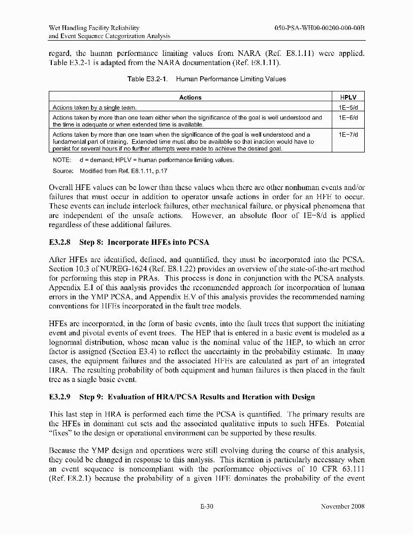
regard, the human performance limiting values from NARA (Ref. E8 .1.11) were applied. Table E3.2-1 is adapted from the NARA documentation (Ref. E8.1.II).
Table E3.2-1. Human Performance Limiting Values
Actions HPLV
Actions taken by a sinqle team. 1E-5/d
Actions taken by more than one team either when the significance of the goal is well understood and the time is adequate or when extended time is available.
1E-6/d
Actions taken by more than one team when the significance of the goal is well understood and a fundamental part of training. Extended time must also be available so that inaction would have to persist for several hours if no further attempts were made to achieve the desired goal.
1E-7/d
NOTE: d = demand; HPLV = human performance limiting values.
Source: Modified from Ref. E8.1.11, p.17
Overall HFE values can be lower than these values when there are other nonhuman events andlor failures that must occur in addition to operator unsafe actions in order for an HFE to occur. These events can include interlock failures, other mechanical failure, or physical phenomena that are independent of the unsafe actions. However, an absolute floor of IE-8/d is applied regardless of these additional failures.
E3.2.8 Step 8: Incorporate HFEs into PCSA
After HFEs are identified, defined, and quantified, they must be incorporated into the PCSA. Section 10.3 ofNUREG-1624 (Ref. E8.1.22) provides an overview of the state-of-the-art method for performing this step in PRAs. This process is done in conjunction with the PCSA analysts. Appendix EJ of this analysis provides the recommended approach for incorporation of human errors in the YMP PCSA, and Appendix E.V of this analysis provides the recommended naming conventions for HFEs incorporated in the fault tree models.
HFEs are incorporated, in the form of basic events, into the fault trees that support the initiating event and pivotal events of event trees. The HEP that is entered in a basic event is modeled as a lognormal distribution, whose mean value is the nominal value of the HEP, to which an error factor is assigned (Section E3.4) to reflect the uncertainty in the probability estimate. In many cases, the equipment failures and the associated HFEs are calculated as part of an integrated HRA. The resulting probability of both equipment and human failures is then placed in the fault tree as a single basic event.
E3.2.9 Step 9: Evaluation of HRAlPCSA Results and Iteration with Design
This last step in HRA is performed each time the PCSA is quantified. The primary results are the HFEs in dominant cut sets and the associated qualitative inputs to such HFEs. Potential "fixes" to the design or operational environment can be supported by these results.
Because the YMP design and operations were still evolving during the course of this analysis, they could be changed in response to this analysis. This iteration is particularly necessary when an event sequence is noncompliant with the performance objectives of 10 CFR 63.111 (Ref. E8.2.1) because the probability of a given HFE dominates the probability of the event
E-30 November 2008
Wet Handling Facility Reliability 050-PSA-WHOO-00200-000-00B and Event Sequence Categorization Analysis
sequence. In those cases, a design feature or procedural safety control could be added to reduce the probability or to completely eliminate the HFE. In such cases, the modification is analyzed for potential new HFEs, and the applicable HFEs are requantified, along with the event sequences.
E3.3 DEPENDENCY
Dependency between human actions is defined to exist when the outcome of a particular human action is related to the outcome of a prior human action or actions. According to THERP (Ref. E8.1.26), the joint probability of human error for a set of dependent human actions is higher than if they were independent.
The possibility of dependencies between human actions and defined HFEs is recognized throughout the HRA task. The concern with respect to dependencies is that the joint probabilities separately assigned to a set of dependent HFEs treated as independent actions can result in a lower event sequence frequency than would result if dependencies among the HFEs were appropriately recognized and treated. This situation is especially important in the HRA activities leading up to and including preliminary analysis where an inappropriately low HEP might lead to an inappropriate screening out of a potentially significant cut set or event sequence. If dependence were properly identified and treated, the resulting HEP might then appear in dominant cut sets and, therefore, be identified for detailed analysis.
E3.3.1 Capturing Dependency
Dependencies between defined HFEs can exist for two reasons:
• Due to the characteristics of the event sequence in which the HFEs are modeled • Due to the modeling style, especially the degree of decomposition, in HFE definition.
In the first case, dependencies are unavoidable due to the inherent characteristics of the initiator type or event sequence. In the second case, dependencies can be avoided by redefining dependent HFEs into a single HFE. In either case, dependencies can be treated by using a structured method for adjusting probabilities to account for dependencies. However, some HRA quantification methods (e.g., ATHEANA (Ref. E8.1.22» account for certain types of dependencies within their formulation by combining dependent events as part of the normal process of addressing the accident scenario as a whole. These methods do not require additional treatment.
All event sequences that contain multiple HFEs are examined for possible dependencies. If practical, HFEs that are completely dependent may be redefined and modeled as a single event.
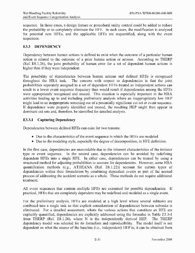
For the preliminary analysis, HFEs are modeled at a high level where several subtasks are combined into a single task so that explicit consideration of dependencies between subtasks is eliminated. For a detailed assessment, where the various actions that constitute an HFE are explicitly quantified, dependencies are explicitly addressed using the formulae in Table E3.3-1 from THERP (Ref. E8.1.26), where N is the independently derived HEP. The THERP dependency model was selected for its formalism and reproducibility. The model itself is not dependent on what the source of the baseline (i.e., independent) HEP is; it can be obtained from
E-31 November 2008
Wet Handling Facility Reliability 050-PSA-WHOO-00200-000-00B and Event Sequence Categorization Analysis
any existing model or from expert elicitation. None of the other "objective" quantification approaches used (i.e., HEART (Ref. E8.1.28)/NARA (Ref. E8.1.11), or CREAM (Basic and Extended) (Ref. E8 .1.18» has its own dependency model, and NARA (Ref. E8 .1.11) specifically endorses the use of the THERP (Ref. E8.l.26) approach.
Table E3.3-1. Formulae for Addressing HFE Dependencies
Level of Dependence Zero Low Medium High Complete Conditional Probability N 1 + 19N
20
1 + 6N
7
1 + N
2
1.0
Source: Modified from Ref. E8.1.26, Table 20-17, p. 20-33
E3.3.2 Sources of Dependency
The determination of the level of dependence between HFEs is left to the judgment of the HRA analyst. Certain factors typically are recognized as indicators of dependency. Examples of such factors are:
• Common time constraints for task performance • Common cues or indicators for task performance • Common diagnosis of situation • Common facility function or system operation involved in task performance • Common procedure steps for task performance • Common personnel and location for task performance • Common PSFs.
In addition, any human-induced failures of equipment that can directly or indirectly cause other equipment to fail through equipment dependencies are also identified as human dependencies.
E3.4 UNCERTAINTY
As with the values of failure probabilities used for active and passive components used in other parts of the PCSA, it is important that HFE quantification accounts for uncertainty. The HRA quantification, therefore, provides a mean HEP and an expression of the uncertainty. There are a number of ways to approach this task, as each of the HRA methods discussed in Section E3.2.7.2 provides recommendations on uncertainty parameters or bounds for HEPs. These recommendations run from the specific to the general and are often inconsistent. After a review of various recommendations, the HRA team has determined that to use any of them in their specific applications is both impractical and questionable. Rather, it was decided to develop a simple set of generic error factors developed through the use of the judgment by the HRA team, based on a holistic overview of the various recommendations presented in the following sources:
• Section 6 ofNARA (Ref. E8.1.11)
• HEART (Ref. E8.1.28)
E-32 November 2008
Wet Handling Facility Reliability 050-PSA-WHOO-00200-000-00B and Event Sequence Categorization Analysis
• Chapter 9 of CREAM (Ref. E8.1.18)
• Chapter 20 ofTHERP (Ref. E8.1.26).
Although ATHEANA (Ref. E8.1.22) does not provide specific recommendations regarding uncertainty estimation, it stresses that it is important to consider uncertainty in HRAs and that one way to approach it is through the use of expert judgment. To this extent, it can be said that the approach follows the guidance established in ATHEANA.
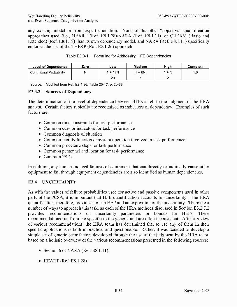
After review and due consideration of the uncertainty recommendations, the HRA team determined that for the purposes of this study it would be both reasonable and acceptable to establish a generic set of uncertainty parameters based on the calculated (total) HEP for any given HFE. The HRA team reached a consensus on the following error factor values to be applied to a lognormal distribution based on the mean HEP, as shown in Table E3.4-1. For each HEP range, the error factor reflects the HRA team's degree of confidence in the probability estimate.
Table E3.4-1. Lognormal Error Factor Values
Calculated Mean HEP Lo~normal Error Factor ~ 0.05 3
>0.0005-<0.05 5
::;;0.0005 10
NOTE: HEP = human error probability.
Source: Original
The same error factors are applied to both preliminary values and results of detailed HRAs. Therefore, after the HRA team has decided on an appropriate mean value, the corresponding generic error factor is assigned unless there is a basis from the detailed analysis to do otherwise.
E3.5 DOCUMENTATION OF RESULTS
The following information is included in the documentation of the results for the YMP PCSA HRA:
• General discussion of the overall set of PSFs (e.g., error-producing conditions (EPCs), common performance condition (CPCs» on human performance that are applicable to or especially important for the YMP PCSA and how they apply to the operations of the facility in question
• A list of all HFEs (by basic event name and category, along with a brief description of the HFE) included in the PCSA model, with their final assigned HFE probabilities
• Identification of preliminary values used for these HFEs
• Identification of the HFEs analyzed in detail
E-33 November 2008

Wet Handling Facility Reliability 050-PSA-WHOO-00200-000-00B and Event Sequence Categorization Analysis
• A more detailed description of each HFE analyzed in detail
• Identification of all expected pertinent procedures or, if no procedures are expected to exist, alternative evidence that supports the identification and quantification of HFEs and recoveries or substantiates the likelihood of human actions (e.g., normal operating practices, formal training)
• For each HFE analyzed in detail, identification of the quantification method, associated input parameters (e.g., PSFs), and any approximations or required procedural controls used to determine probabilities for that HFE
• References to sources of input information (e.g., thermal-hydraulic calculations) used in detailed quantification
• Results of qualitative and preliminary analysis
• Results of detailed quantitative analysis.
E4 INFORMATION COLLECTION AND USE OF EXPERT JUDGMENT
This section addresses how and what information was collected to support the HRA analysis and how expert judgment was used in the identification and quantification of HFEs.
E4.1 FACILITY FAMILIARIZATION AND INFORMATION COLLECTION
E4.1.1 General Information Sources
As with all of the tasks in the PCSA, facility information is required to support the HRA. In addition to the information that is gathered to support the other modeling tasks (e.g., initiating events, systems), the analysts obtain specific additional information that is needed to support the HRA task.
Since the YMP is in the design phase, there are limits on facility-specific information available to support the HRA. Sources utilized in this analysis include the following:
• Design drawings and design studies • Concept of operations documents • Engineering calculations • Discussions of event sequences with knowledgeable individuals • Event trees and supporting documentation • Fault trees and supporting documentation.
Information from similar facilities is used, including NPPs (particularly those with ISFSIs), chemical agent disposal facilities, and any other facilities whose primary function includes handling and disposal of very large containers of hazardous material. This was conducted primarily for ISFSI activities at NPPs. The use of this information in place of YMP plant-specific information is pursuant to the third analytical boundary condition specified in
E-34 November 2008

Wet Handling Facility Reliability 050-PSA-WHOO-00200-000-00B and Event Sequence Categorization Analysis
Section E2.2. Following are sources of information from ISFSI that are applied to support the YMPPCSA:
• Interviews with plant operators, operations personnel, and/or other ISFSI knowledgeable personnel
• Pertinent ISFSI procedures (e.g., operating procedures, test and maintenance procedures)
• Plant walk-downs (e.g., at locations where operations similar to those at repository may be performed) and operations reviews
• Studies, including PRAs and HRAs, conducted at these facilities that would substitute for the previously mentioned sources.
This information was acquired from two sources. First, information was obtained by the HRA team from outside sources specifically for use on the YMP, such as from NPPs, industry organizations, and governmental sources. Some of this information may have been obtained directly by the HRA team or may have been provided to the HRA team by members of the Licensing and Nuclear Safety, Engineering, or Operations departments who had obtained the information as a part of their regular duties on the YMP (Section E4.2.2). Second, information was obtained by the HRA team directly from internal sources, including members of the aforementioned departments who had past experience and information on ISFSIs from prior employment and projects before joining the YMP (Section E4.2.l).
Initially, information is gathered to support the identification of pre-initiator, human-induced initiator, and non-recovery post-initiator HFEs. This information is needed to:
• Identify test and maintenance activities performed for equipment included in the PCSA model
• Determine the frequency of test and maintenance activities
• Identify the procedures used to perform test and maintenance activities
• Determine what equipment is impacted by test and maintenance activities.
For human-induced initiator and post-initiator HFEs, such information is needed to:
• Identify important operator tasks
• Identify the specific actions required for each operator task
• Identify the procedures (e.g., normal operating and emergency operating procedures) and procedure steps associated with each operator task
• Identify the cues (e.g., procedure steps, alarms) for operator tasks
E-35 November 2008
Wet Handling Facility Reliability 050-PSA-WHOO-00200-000-00B and Event Sequence Categorization Analysis
• Assess the procedures that support operator tasks as PSFs
• Assess the training that supports operator tasks as PSFs.
E4.1.2 Industry Data Reviewed by the HRA Team
The following sources of industry data were reviewed by the HRA team for potential vulnerabilities and HFE scenarios applicable to the YMP:
• A Survey of Crane Operating Experience at Us. Nuclear Power Plants from 1968 through 2002. NUREG-1774 (Ref. E8.1.19)
• Control ofHeavy Loads at Nuclear Power Plants. NUREG-0612 (Ref. E8.1.20)
• Navy Crane Center, Naval Facilities Engineering Command Internet Web Site. The database includes the following information:
- Navy Crane Center Quarterly Reports ("Crane Comer") 2001 through 2007 - Fiscal Year 06 Crane Safety Report (covers fiscal years 2001 through 2006) - Fiscal Year 06 Audit Report.
• U.S. Department of Energy (DOE) Operational Experience Summary (2002 through 2007) (http://www.hss.energy.gov/CSA/analysis/orps/orps.html)
• Institute of Nuclear Power Operations database (https://www.inpo.org). The database I contains the following information:
- Licensee Event Reports - Equipment Performance and Information Exchange System - Nuclear Plant Reliability Data System.
• Savannah River Site Human Error Data Base Development for Nonreactor Nuclear Facilities (U) (Ref. E8.1.5)
• All Scientech/Licensing Information Service data on ISFSI events (1994 through 2007) Scientech Licensing Information Service Database and Dry Storage Information Forum (New Orleans, LA, May 2-3,2001). This database includes the following information:
- Inspection reports - Trip reports - Letters, etc.
E4.2 USE OF EXPERTS AND ENGINEERING JUDGMENT IN THE HRA
Subject matter experts were employed in the identification, verification, preliminary analysis, and detailed analysis ofHFEs. Identification ofHFEs, of which a HAZOP evaluation was a part, was performed as a combined effort by experts from a wide range of areas. This identification
E-36 November 2008
Wet Handling Facility Reliability 050-PSA-WHOO-00200-000-00B and Event Sequence Categorization Analysis
was not specifically a part of the HRA task, but it was used by the HRA team in the process of identifYing HFEs. A description of the HAZOP evaluation process and a list of experts who specifically participated in the HAZOP evaluation is provided in the Wet Handling Facility Event Sequence Development Analysis (Ref. E8.1.10).
E4.2.1 Role of HRA Team Judgment
Preliminary and detailed analyses were primarily performed by the HRA team in a consensus-based process. For the preliminary analysis, the judgment process can be summarized in the following fashion:
• Each HFE that was identified during the HAZOP evaluation and the operational experience review was characterized with input from the Engineering and Operations departments, including the context under which the HFE would occur.
• Once the individual members of the HRA team were confident that they understood the HFE and the context, they each independently assigned an HEP to the HFE and briefly documented the rationale relative to a set of anchor points established for the HRA (the basic anchor points can be found in Appendix E.IlI of this analysis).
• The values and rationales were combined into a single spreadsheet, and the team then met to discuss their values.
• The HRA team used their knowledge of the preclosure process and design to develop a consensus on the factors affecting the HFE and a resulting conservative estimate of the HEP. In most cases, the team ultimately reached a consensus on a value and a rationale. In a few cases a consensus could not be reached, and the most conservative value and rationale from that team member was used. The value and rationale applied was then documented.
This process is explained in much greater detail in Appendix E.IlI of this analysis.
The detailed analyses were performed by individual members of the HRA team and were reviewed by the rest of the HRA team. Judgment was used to identify the details of the scenarios that could lead to the HFE, the appropriate quantification methodology to apply to each unsafe action, the actual quantification of the unsafe action, and any probabilities for other key failures within the HFE for which probabilities were not available in the active or passive failure database. However, in no instance was expert judgment used to quantify an entire HFE, so in the context of the ATHEANA concept of an expert elicitation approach to quantification, it was not necessary to utilize the strict formalism. Each HFE was broken down into various combinations of unsafe actions and mechanical failures. In all but one case, every unsafe action was quantified using one of the "structured" HRA quantification techniques (i.e., HEART (Ref. E8.1.28)/NARA (Ref. E8.1.11), CREAM (Ref. E8.1.18), or THERP (Ref. E8.1.26», and so expert elicitation was not required. In the one exception, the process that was followed is that the team member who performed the detailed quantification of the HFE provided a detailed rationale for the selection of a value based on judgment. The entire HFE quantification, including the judgment value, was provided to the other team members for review and concurrence, and the resultant value and
E-37 November 2008
Wet Handling Facility Reliability 050-PSA-WHOO-00200-000-00B and Event Sequence Categorization Analysis
rationale were included in the final HFE quantification. In addition, there were cases where some of the mechanical failures within the HFE also required the use of judgment in selecting a probability of occurrence. These values were selected in accordance with the engineering judgment approach used throughout the PCSA for selection of such values. This approach anchors the selection of failure probability based on the level of understanding of the physical phenomena involved, rather than the use of anchors based on the context of the HFE. This approach is documented in Section 4.3.10.2.
The members of the HRA team are listed in the following section.
E4.2.1.1 HRA Team
Paul J. Amico-Mr. Amico is a nuclear engineer with 30 years of experience in risk, safety, regulation, and operation of NPPs, nuclear material production reactors, nuclear weapons research, production and storage facilities, nuclear fuel cycle facilities, chemical demilitarization facilities, and industrial chemical plants. He has been involved in the conduct and review of HRA since 1979. His experience includes the use of THERP, Time-Reliability Correlation (TRC), Systematic Human Action Reliability Procedure (SHARP), Human Cognitive Reliability (HCR), HEART, ATHEANA, CREAM and NARA, and he has been involved in projects related to methodology enhancements to some of these techniques. Prior to joining the YMP, he was involved in HRA for a number of NPP PRAs in the United States and overseas; for chemical process plants; and for SNF handling and storage at NPPs, including the development of project procedures for HRA. He developed a phased approach to the use of HRA during the design process of advanced NPPs and supported a project to expand HRA techniques for SNF handling operations.
Erin P. Collins-Ms. Collins is a risk analyst with over 20 years of experience in safety, reliability, and risk analysis for the U.S. Army chemical weapons destruction program, NASA, the Federal Aviation Administration, NPPs, and the chemical process industry. Her specialties are equipment reliability database development and HRA. Ms. Collins was a prime participant in a safety hazard analysis of an acrylic fiber spinning facility in northeastern Italy. This analysis evaluated worker risk in various areas of the facility through the use of hazard analysis techniques, including a HAZOP evaluation, and resulted in the recommendation of economical risk reduction measures. Her project experience in Spain includes technical review and support of the HRAs for the Asco and the Santa Maria de Garofia nuclear plant PRAs. She also supported the review of the Kola and Novovoronesh Russian nuclear reactor HRAs for the DOE. In the United States, Ms. Collins has participated in PRA-re1ated HRAs of the Hanford N Reactor and the Robinson (using simulator exercises), Crystal River 3, and Catawba NPPs. Throughout these efforts, she has applied the HEART, CREAM, THERP, and TRC methods of quantification.
Douglas D. Orvis, Ph.D.-Dr. Orvis is a registered professional engineer (California, Nuclear No. 0925) with over 35 years of experience in nuclear engineering, regulation, and risk analysis ofNPPs, alternative concepts for interim storage of SNF, and aerospace applications. Dr. Orvis has participated in the development of HRA techniques (e.g., SHARP for Electric Power Research Institute (EPRl), effects of organizational factors for the NRC) and has measured and analyzed data for evaluating the reliability of NPP control room operators during simulated
E-38 November 2008
Wet Handling Facility Reliability 050-PSA-WHOO-00200-000-00B and Event Sequence Categorization Analysis
accidents. These data-based analyses included the EPRI-sponsored Operator Reliability Experiments (ORE) (e.g., measurements performed at the Diablo Canyon, Kewaunee, and LaSalle simulators) and the follow-on programs performed at the Maanshan (Taiwan) simulator. Data collection and analysis included observing operator behavior, variability between crews, developing time-response correlations for key operator actions, and evaluating the numbers and kinds of errors and deviations committed. Postsimulation interviews with crew members and trainers were conducted to elicit information on conditions and factors that contributed to crew performance. The data analysis included comparisons of data to the HCR model and a statistical evaluation of the types and causes of errors and deviations. A similar data collection evaluated the efficacy of an expert system called the Emergency Operating Procedures Tracking System.
Dr. Orvis participated in a comprehensive review of HRA methods for a Swiss agency and was a consultant to the International Atomic Energy Agency to incorporate concepts of HRA and organizational factors into (Assessment of the Safety Culture in Organizations Team) guidelines for plant self-assessment of safety culture. Dr. Orvis has performed event tree and fault tree analyses of hazardous systems for both internal events and seismic initiators that included consideration of HRA. Dr. Orvis has participated in HAZOP evaluation sessions for repository operations.
Mary R. Presley-Ms. Presley is an engineer with 3 years of experience in risk analysis for NPPs, specializing in human reliability. Ms. Presley graduated in 2006 from the Massachusetts Institute of Technology with her M.S. in nuclear engineering, where she wrote her thesis On the Assessment ofHuman Error Probabilities for Post Initiating Events, which included an extensive review of current HRA methods. While her work focused on the EPRI HRA calculator and the NRC ATHEANA framework, she is also familiar with other HRA methods, including THERP, Accident Sequence Evaluation Program, HEART, NARA, Failure Likelihood Index Methodology, Success Likelihood Index Method/Multi-Attribute Utility Decomposition, Standardized Plant Analysis Risk Human Reliability Analysis (SPAR-H), CREAM, Methode d'Evaluation de la Relisation des Missions Operateur pour la Surete, Cause-Based Decision Tree, and HCR/ORE.
E4.2.2 Role of Subject Matter Expert Judgment
Subject matter experts were also consulted during the compilation of the base case scenarios. The outline of the base case scenarios came from the mechanical handling block flow diagram. The details of human interaction with the mechanical systems were derived from expected operations inferred directly from the design by the subject matter experts. Where a detailed design was not available, the experts extrapolated these details from common industry practice for similar operations. These experts come from the YMP Engineering, Operations, and PCSA groups, as well as from outside the YMP project.
In addition to the development of base case scenarios, subject matter experts were regularly consulted during the analysis to provide clarification of design, clarification of expected operations, and insight into expected operating conditions and failure modes. These experts provided details about the design of systems that were relevant to human performance, such as the presence of job aids and interlocks and the intended design of control system interfaces. They also provided details regarding the concept of operations for the processes, such as the role
E-39 November 2008

Wet Handling Facility Reliability 050-PSA-WHOO-00200-000-00B and Event Sequence Categorization Analysis
of the humans versus the use of automatic systems, the operational controls, and the use of procedures. These experts would also review specific parts of the analysis for technical accuracy.
Below is a list of some areas where subject matter experts were consulted during the HRA for their expertise:
• PCSA models (i.e., facility or system fault trees)
• Site prime mover (SPM), railcar, truck trailer, cask transfer trolley (CTT), cask tractor and cask transfer trailer (HCTT), and site transporter design and operation
• Crane operations (critical lifts)
• Crane design - Single-failure proof cranes (i.e., gantry cranes designed to NOG-l level 1 standards (Ref. E8.1.2) or jib cranes designed to NUM-l Type lA (Ref. E8.1.3»
• Crane design - Non-single failure proof cranes (i.e., gantry cranes designed to NOG-l level 2 standards (Ref. E8.1.2) or jib cranes designed to NUM-l Type lB (Ref. E8.1.3»
• Platform operations (shield plate and non-shield plate)
• Gas sampling process
• Canister transfer machine (CTM) design and operations
- Adjustable speed drive (ASD) features and operations - Grapple interfaces - Interlocks
• Radiation protection (e.g., cask shielding/shield rings; locks, interlocks, and procedural controls for entering high radiation areas; personal protective equipment (PPE»
• General facility layout and time line of operations
• Interlocks (general)
• Dual-purpose canister (DPC) cutting equipment and process
• Pressure relief system for DPC filling/cooling
• Pool maintenance (i.e., maintaining boration)
• SNF handling operations (i.e., pool operations, spent fuel transfer machine)
• Transportation, aging, and disposal (TAD) canister welding equipment and process
E-40 November 2008

Wet Handling Facility Reliability 050-PSA-WHOO-00200-000-00B and Event Sequence Categorization Analysis
• TAD canister drying system
• Aging overpack, horizontal shielded transfer cask (HSTC), shielded transportation cask (STC), a transportation cask that is upended using a tilt frame (TTC), and a transportation cask that is upended on a railcar (VTC) design and handling
• Other systems.
ES TERMINOLOGY AND OVERVIEW OF HUMAN PERFORMANCE ISSUES
Over the history of performance of HRAs, certain terminology has become commonplace and different classification schemes for human error has been developed. This section provides a background of this terminology and associates it to the YMP PCSA HRA. In addition, the description of operations includes references to different types of personnel. The functions of each classification of personnel are described in this section. Finally, a discussion is provided of the specific issues that relate to human performance at the YMP.
ES.l TERMINOLOGY
ES.l.l Classification of HFEs
As noted in the methodology (Section E3.2), HFEs are classified to support the HRA preliminary analysis, selection of HRA quantification methods, and detailed quantification. A combination of four classification schemes is used in the YMP HRA. The first three schemes are familiar standards in HRA. The fourth scheme has its basis in behavioral science and has been used in some second-generation HRA methods.5
The four classification schemes are based on the following:
1. The three temporal phases used in PRA modeling:
A. Pre-initiator B. Human-induced initiator C. Post-initiator
2. Error modes:
A. EOOs B. EOCs
5There is another classification not included here that has been often used in nuclear power plant PRAs: the behavior type taxonomy. This category classifies HFEs into skill-, rule-, or knowledge-type behavior. While this taxonomy has limited usefulness in addressing HFEs that take place in an NPP control room under time constraints, this distinction is not particularly useful for other types of actions. As a result, it is generally not used for HRAs in such applications as chemical process facilities, chemical demilitarization facilities, or NASA manned-mission risk assessments. Given the type of human actions and HFEs that are important at the YMP, use of this approach for the YMP PCSA HRA is not recommended.
E-41 November 2008
Wet Handling Facility Reliability 050-PSA-WHOO-00200-000-00B and Event Sequence Categorization Analysis
3. Human failure types:
A. Slips/lapses B. Mistakes
4. Informational processing failures:
A. Monitoring and detection B. Situation awareness C. Response planning D. Response implementation.
The following sections define these classification methods.
ES.l.l.l Temporal Phases of HFEs
There are three temporal phases ofHFEs:
• Pre-initiator HFE-An HFE that represents actions taken before the initiating event that causes systems or equipment to be unavailable. Examples of such HFEs are miscalibration of equipment or failure to restore equipment to an operable state after testing or maintenance activities.
• Human-Induced Initiator-An HFE that represents actions that cause or lead to an initiating event.
• Post-initiator HFE6-A post-initiator HFE represents those operator failures to manually actuate or manipulate systems or equipment, as required for accident response. Post-initiator HFEs can be further divided into recovery and non-recovery events.
A non-recovery post-initiator HFE (i.e., failure during response to an initiator) is when an operator does not operate frontline equipment in accordance with required procedural actions due to errors in diagnosis or implementation. For quantification purposes, these HFEs are usually decomposed into cognitive and implementation parts, as shown in Appendix E.1I of this analysis. In general, post-initiator HFEs associated with such actions are incorporated directly in the model prior to initial PRA quantification using preliminary values. The results of the initial event sequence quantification are used to determine if detailed modeling of these HFEs is needed.
A recovery post-lmtlator HFE represents operator failure to manually actuate or manipulate frontline equipment (or alternatives to frontline equipmene) that has failed to automatically actuate as required. In general, post-initiator HFEs associated with correction or recovery of failed frontline systems from either equipment or
6 The HRA did not take credit for post-initiator human actions and no post-initiator HFEs were identified. 7Alternatives to frontline equipment, include equipment that operators can use for performing the functions of frontline equipment in case of an impossibility to recover the failed frontline equipment in a timely manner.
E-42 November 2008
Wet Handling Facility Reliability 050-PSA-WHOO-00200-000-00B and Event Sequence Categorization Analysis
human failures are not modeled until after initial PRA quantification. The results of initial event sequence quantification are used to determine if modeling of such recovery HFEs is needed.
ES.1.1.2 Error Modes
HFEs can be classified by error mode as either an EOO or EOC. EOOs and EOCs can occur in any temporal phase (i.e., pre-initiator, initiator, or post-initiator). This classification is highly dependent upon the specific event tree or fault tree model. In other words, the same operator action could be modeled as either an EOO (e.g., failed to actuate system x) or an EOC (e.g., actuated system y instead of x). The error mode model is chosen based on consistency with the PCSA model and at the discretion of the HRA analyst. In early PRAs, EOCs were often excluded. Current PRAs, however, address both EOOs and EOCs, although there are still few methods for identifying and quantifying EOCs. In the current analysis, EOO and EOC are defined as follows:
• EOO-An HFE that represents the failure to perform one or more actions that should have been taken and that then leads to an unchanged or inappropriately changed configuration with the consequences of a degraded state. Examples include the failure of a radiation protection worker to perform the radiologic survey before a cask is released from the facility.
• EOC-An HFE that represents one or more actions that are performed incorrectly or some other action(s) that is performed instead. It results from an overt, unsafe action that, when taken, leads to a change in configuration with the consequence of a degraded state. Examples include commanding a crane to lift when it should be lowered.
ES.1.1.3 Human Failure Type
Human failure types include the following:
• Slip/lapses-An action performed where the outcome of the action was not as intended due to some failure in execution. Slips are errors that result from attention failures, while lapses are errors that result from failures in memory recall.
• Mistake-An action performed as intended, but the intention is wrong. Mistakes are typically failures associated with monitoring (especially deciding what to monitor and how frequently to monitor), situation awareness, and response planning. Section E5.1.I.4 provides definitions of these terms.
E-43 November 2008
Wet Handling Facility Reliability 050-PSA-WHOO-00200-000-00B and Event Sequence Categorization Analysis
ES.1.1.4 Informational Processing Failures
Assessment of HFEs can be guided by a model of higher-level cognitive activities, such as an information processing model. Several such models have been proposed and used in discussing pilot performance for aviation. The model that is recommended for the YMP HRA is based on the discussion in Chapter 4 of ATHEANA (Ref. E8.1.22) and consists of the following elements:
• Monitoring and detection-Both of these activities are involved with extracting information from the environment. Also, both are influenced by the characteristics of the environment and the person's knowledge and expectations. Monitoring that is driven by the characteristics of the environment is called data-driven monitoring. Monitoring initiated by a person's knowledge or expectations is called knowledge-driven monitoring. Detection can be defined as the onset of realization by operators that an abnormal event is happening.
• Situation awareness-This term is defined as the process by which operators construct an explanation to account for their observations. The result of this process is a mental model, called a situation model that represents the operator's understanding of the present situation and their expectations for future conditions and consequences.
• Response planning-This term is defined as the process operators use to decide on a course of action, given their awareness of a particular situation. Often (but not always) these actions are specified in procedures.
• Response implementation-This term is defined as the actIvItIes involved with physically carrying out the actions identified in response planning.
When there are short time frames for response and the possibility of severely challenging operating conditions (e.g., environmental conditions) exists, then failures in all information processing stages must be considered. Also, slips/lapses and mistakes are considered for each information processing stage. Response implementation failures are expected to dominate the pre-initiator failures that are modeled. Post-initiator failures and failures that initiate event sequences can occur for all information processing stages, although detection failures are likely to be important only for events requiring response in very short time frames.
ES.1.2 Personnel Involved in WHF Operations
A list of personnel involved in WHF operations with a brief description of their duties IS provided below:
Crane operator-The person who is designated to operate the crane for a given operation (i.e., the cask handling crane, the auxiliary crane, or the jib cranes).
Crew member-A generic term for personnel (not including crane operators, radiation protection workers, or supervisors) involved in the facility operations.
CTM operator-The person who is designated to operate the CTM for canister transfer activities. This person is located in the WHF Control Room and controls the CTM remotely.
E-44 November 2008
Wet Handling Facility Reliability 050-PSA-WHOO-00200-000-00B and Event Sequence Categorization Analysis
DPC cutter-The person who is designated to operate the DPC cutting machine to cut open the DPC.
Engineer-The person from Nuclear Engineering who is in charge of performing the nuclear engineering calculations, including developing and/or checking the TAD canister loading plan.
Gas sampling operator-The person who is designated to perform gas sampling of the cask and gas sampling and venting of the canister.
HCTT operator-The person who is designated to operate the cask tractor to move a HCTT unit into or out of the facility.
Level 2 and 3 NDE personnel-The person(s) who is certified to inspect the TAD canister welds and sign off on the process. This person(s) must have a Level 2 or Level 3 nondestructive examination (NDE) certification.
Person in charge (PIC)-The certified crew member who is in charge of coordinating and overseeing the facility operation. This is the person who is notified when a waste form is coming to the facility and who coordinates, according to this information, the appropriate personnel, procedures, and equipment to be used to process this cask type. This person is in charge of communicating this information to all the crew members involved in the processing of this cask and ensuring that the relevant equipment is properly staged and in proper operational condition.
Quality control-The certified crew member in charge of quality control. This person is involved in supervising critical operations and tracking the appropriate documentation (i.e., checking off on the fuel assembly serial numbers and TAD canister loading plan).
Radiation protection worker-The certified health physics technician, whose job is to monitor radiation during cask-related activities. This person is responsible for stopping operations if high radiation levels are detected.
Signaling crew member-The person who is designated to provide signals to the crane operator. This person is predesignated and is distinguished from the verification crew member (most likely through an orange hard hat, orange gloves, or an orange vest as per the high-level radioactive waste Hoisting and Rigging (Ref. E8.1.12).
Spent fuel transfer machine operator-The person who is designated to operate the spent fuel transfer machine to move fuel assemblies. This person has special training on how to read and track TAD canister loading plans.
SPM operator-The person who is designated to operate the SPM to bring a railcar or truck trailer into the facility.
Site transporter operator-The person who is designated to operate the site transporter to move an aging overpack into and around the facility.
Supervisor-The person who is in charge of the given operation and who supervises and checks off critical operations in a given step. For steps requiring independent verification, this analysis
E-45 November 2008
Wet Handling Facility Reliability 050-PSA-WHOO-00200-000-00B and Event Sequence Categorization Analysis
uses the term supervisor as the person who provides the independent check. This analysis does not rely upon the fact that this check is performed by the actual supervisor, only that an independent check is done by someone with the appropriate training and qualifications (i.e., the supervisor).
Verification crew member-The person who is designated to assist with crane operations that require a second spotter. This person can only give the stop signal to the crane operator.
Welding operator-The person who is designated to operate the welding machine to weld close the TAD canister.
ES.2 OVERVIEW OF HUMAN PERFORMANCE ISSUES
This section discusses the general human performance issues that characterize the human interaction with the YMP facilities.
Limited Automation (Significant Human Interaction)-The types of operations being performed in the WHF are not always conducive to automation. In particular, crane and transport operations are generally performed both manually and locally. Even those that are performed remotely require significant interaction by the operators. The dependence on human performance is quite high, and that dependence provides many opportunities for unsafe actions.
Limited Nature of Procedures-Other than those operations that are performed remotely from a control room, YMP operations are not highly proceduralized, but rather they depend primarily on skills learned and training. That is, while written procedures exist for all activities and training of all personnel is thorough, the actual use of procedures and checklists during operation (i.e., the step-by-step following of written procedures) generally occurs only during operations in a control room. The vast majority of local operations (e.g., skill-of-craft activities performed outside the control room) does not use written procedures at all during the actual performance of the tasks and does not have formal checklists or verbal confirmation requirements spelled out in procedures physically in the possession of the crew performing the operation. This circumstance is consistent with observations of activities at NPPs during ISFSI operations.
Communication Difficulties-There are significant challenges in communication between the team members performing WHF operations. The environment contains a not insignificant amount of background noise, predominantly machine noise. Although headsets may be used by key participants for communication, they do not eliminate the potential for misunderstanding. Garbled communication (due to system interference or background noise) is clearly possible, and in some cases it may not even be possible to clearly determine who is speaking. A belief that a particular individual is speaking, even if they are not, can bias the listeners into hearing what they expect to hear.
Visual Challenges-For most of the remote operations, successful completion of the operation requires a certain amount of visual acuity both for the performance of the operation and the confirmation of the status. Safety concerns require that visual observation be performed using cameras that provide images to screens in the control room. Even local crane operations create visual challenges. The crane operator can only be at one given distance and orientation with relation to the operation, and therefore cannot be viewed on all three axes. In addition, views
E-46 November 2008
Wet Handling Facility Reliability 050-PSA-WHOO-00200-000-00B and Event Sequence Categorization Analysis
may be obstructed, such as by the yoke, the load being moved, or some other structure or equipment. Thus, the operator is often put in the position of being the hands for someone else's eyes, which make the operations vulnerable to the communication vulnerabilities discussed previously.
Unchallenging Activities-The activities involved in WHF operations are, in general, quite simple in nature. In addition, the speed of the movements is quite slow, so each action takes a long time to complete. Basically, this is mostly boring work, with a significant amount of downtime between actions for some individuals. There is ample opportunity for diversion and distraction, and an air of informality and complacency can easily exist within and amongst the crew members. From a psychological perspective, there is insufficient dynamic activity to generate an optimum stress level for performance.
E6 ANALYSIS
E6.0 BACKGROUND
E6.0.1 Reader's Guide to the HRA Analysis
Section E3.2 describes nine steps that comprise the HRA process. This section describes the implementation of Steps 2 through 8.
The HFEs were analyzed in logical groups that relate to the various phases of WHF operations. For each group of operations, the following is presented:
• A base case scenario describing the normal operations for that group of operations (Step 2)
• Descriptions of the HFEs of concern identified for the group (Step 3)
• Preliminary values for each HFE identified (Steps 4 and preliminary Step 8)
• Detailed analysis for significant HFEs (Steps 5 through 7 and final Step 8).
Figure E6.0-1 is an overview of how the facility operations were grouped. For the WHF, there are ten HFE groups analyzed, with each presented in a separate subsection of Section E6.
E-47 November 2008
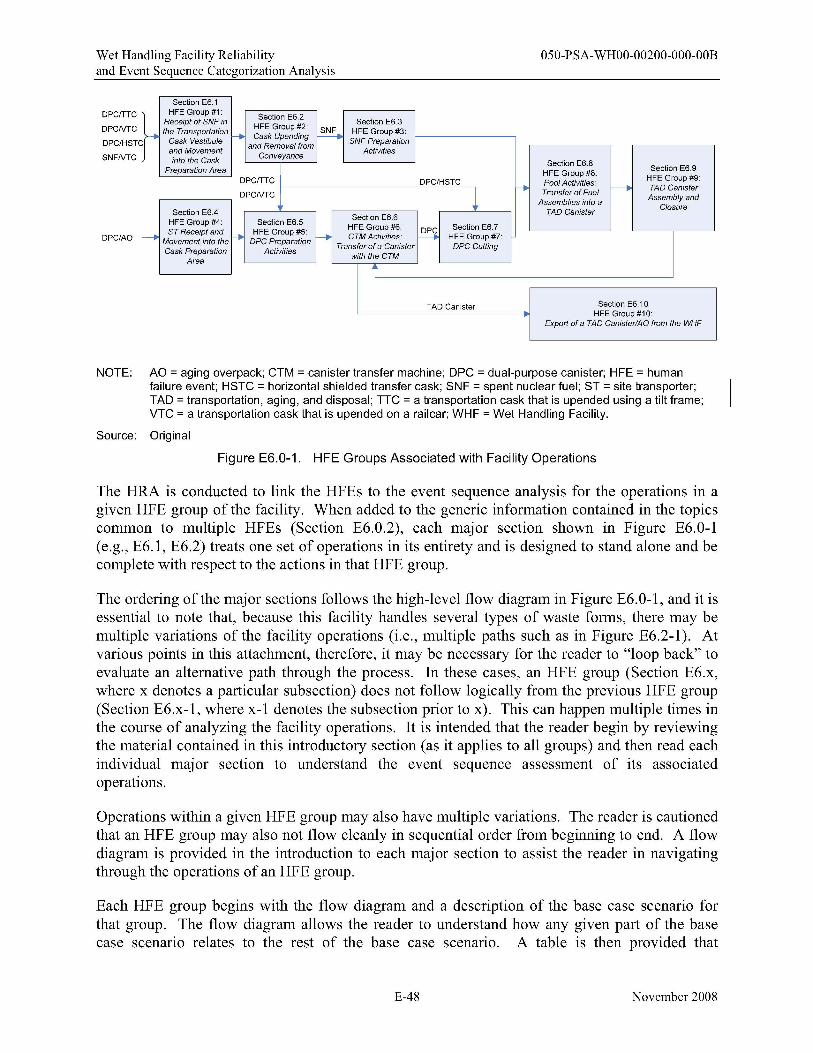
Wet Handling Facility Reliability 050-PSA-WHOO-00200-000-00B and Event Sequence Categorization Analysis
Section E6.1 DPCfTTC
DPCNTC
DPC/HSTC
SNFNTC
DPC/AO
DPCfTTC
DPCNTC
Section E6.5 HFE Group #5:
OPC Preparation Activities
HFE Group #1 : Section E6.2 Receipt of SNF in HFE Group #2: Section E6.3
~ the Transportation
---Cask Upending ~ HFE Group #3:
Cask Vestibule and Removal from SNF Preparation and Movement
Conveyance Activities
into the Cask Section E6.8 PreparaNon Area HFE Group #8: Section E6.9
DPC/HSTC Pool Activities: HFE Group #9:
1 --- Transfer of Fuel f------. TAO Canister AssembtyandAssemblies into a
ClosureSection E6.4 Section E6.6 TAO Canister
HFE Group #4: ST Receipt and HFE Group #6:
~ Section E6.7
--- Movement into the ---. f---. CTM Activities: HFE Group #7:
Cask Preparation Transfer of a Canister oPCCutting
Area with the CTM
i
TAD Canister Section E6. 10 HFE Group #10:
Export of a TAO Canister/AO from the WHF
NOTE: AO = aging overpack; CTM = canister transfer machine; DPC = dual-purpose canister; HFE = human failure event; HSTC = horizontal shielded transfer cask; SNF = spent nuclear fuel; ST = site transporter; TAD = transportation, aging, and disposal; TTC = a transportation cask that is upended using a tilt frame; VTC = a transportation cask that is upended on a railcar; WHF = Wet Handling Facility.
Source: Original
Figure E6.0-1. HFE Groups Associated with Facility Operations
The HRA is conducted to link the HFEs to the event sequence analysis for the operations in a given HFE group of the facility. When added to the generic information contained in the topics common to multiple HFEs (Section E6.0.2), each major section shown in Figure E6.0-I (e.g., E6.I, E6.2) treats one set of operations in its entirety and is designed to stand alone and be complete with respect to the actions in that HFE group.
The ordering of the major sections follows the high-level flow diagram in Figure E6.0-I, and it is essential to note that, because this facility handles several types of waste forms, there may be multiple variations of the facility operations (i.e., multiple paths such as in Figure E6.2-I). At various points in this attachment, therefore, it may be necessary for the reader to "loop back" to evaluate an alternative path through the process. In these cases, an HFE group (Section E6.x, where x denotes a particular subsection) does not follow logically from the previous HFE group (Section E6.x-I, where x-I denotes the subsection prior to x). This can happen multiple times in the course of analyzing the facility operations. It is intended that the reader begin by reviewing the material contained in this introductory section (as it applies to all groups) and then read each individual major section to understand the event sequence assessment of its associated operations.
Operations within a given HFE group may also have multiple variations. The reader is cautioned that an HFE group may also not flow cleanly in sequential order from beginning to end. A flow diagram is provided in the introduction to each major section to assist the reader in navigating through the operations of an HFE group.
Each HFE group begins with the flow diagram and a description of the base case scenario for that group. The flow diagram allows the reader to understand how any given part of the base case scenario relates to the rest of the base case scenario. A table is then provided that
E-48 November 2008
Wet Handling Facility Reliability 050-PSA-WHOO-00200-000-00B and Event Sequence Categorization Analysis
summarizes the HFE descriptions and the preliminary values assigned. Detailed analyses, where appropriate, are then explained in terms of the HFE scenarios (identified by a basic event name) and the unsafe actions within these scenarios. For these detailed analyses, an explanation of how each action was quantified is provided, indicating the specific quantification method and task type identifier used for the quantification. Each HFE group subsection concludes with a table summarizing the final HEP values for the relevant HFE scenarios. Where no detailed analyses were performed, the HFE description and preliminary value table provides this information. By associating each scenario with a basic event name, the link between the HRA results and the PCSA models is clearly established because the HFE can be traced directly to its position(s) in the fault tree(s).
The HFEs listed in each HFE group were identified through an iterative process involving the HAZOP evaluation, development of the MLD, ESDs and initial event trees/fault tree models, and extensive conversations between subject matter experts (Section E4.2.2) and the HRA team (Section E4.2.l). Because the HRA was performed as part of an integrated process with the rest of the PCSA, to put this analysis in context, the reader must have an understanding of the other components of the PCSA, including:
• The process flow diagram • HAZOP evaluation • MLD • Event trees • Faults trees (including the pivotal event fault trees) • ESDs.
To provide traceability between the HRA and the rest of the PCSA, Table E6.0-l, provides a cross-reference between the HFE groups and the ESD and HAZOP evaluation node(s)8 applicable to a given group.
Each HFE group represented in Figure E6.0-l corresponds to a HAZOP evaluation node(s) addressing that group and the ESDs and event trees that represent the event sequences covering that group. In this way, a reader looking to understand how human failures affect the results of the event sequence quantification for the event tree in any specific event tree group need not move back and forth between the major sections of E6, but can find everything related to all HFEs within each set of operations for an HFE group in a single major section. There is some necessary repetition of similar information used in more than one major section when the operations performed in their respective groups are similar (or identical). Material on HRA methodology that is common to all HFE analyses is not repeated; however, cross-references to applicable sections and appendices are provided, as appropriate.
8 HAZOP nodes are defined by the PFD in Volume I of the PCSA Wet Handling Facility Event Sequence Development Analysis (Ref. E8.1.1O).
E-49 November 2008
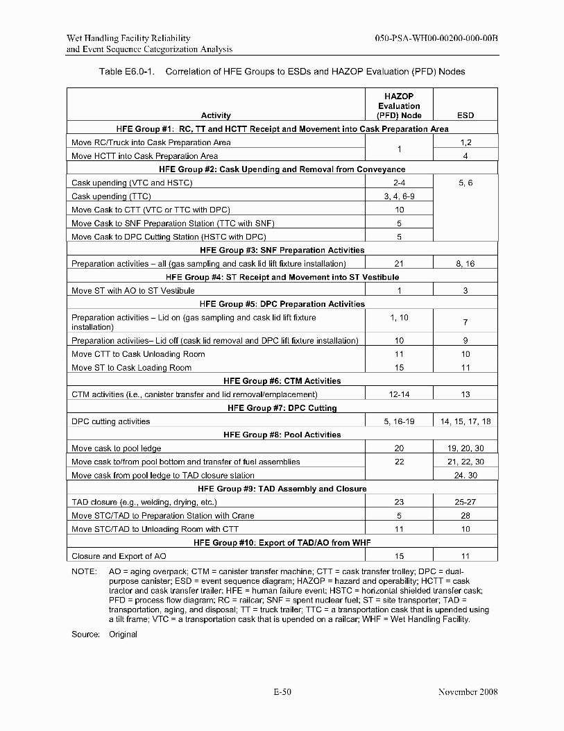
Wet Handling Facility Reliability 050-PSA-WHOO-00200-000-00B and Event Sequence Categorization Analysis
Table E6.0-1. Correlation of HFE Groups to ESDs and HAZOP Evaluation (PFD) Nodes
HAZOP Evaluation
Activity (PFO) Node ESO
HFE Group #1: RC, TT and HCTT Receipt and Movement into Cask Preparation Area
Move RClTruck into Cask Preparation Area 1,21
Move HCn into Cask Preparation Area 4
HFE Group #2: Cask Upending and Removal from Conveyance
Cask upendinQ (VTC and HSTC) 2-4 5,6
Cask upendinQ (TTC) 3,4,6-9
Move Cask to cn (VTC or nc with OPC) 10
Move Cask to SNF Preparation Station (TTC with SNF) 5
Move Cask to OPC CuttinQ Station (HSTC with OPC) 5
HFE Group #3: SNF Preparation Activities
Preparation activities - all (Qas samplinQ and cask lid lift fixture installation) 21 8,16
HFE Group #4: ST Receipt and Movement into ST Vestibule
Move ST with AO to ST Vestibule 1 3
HFE Group #5: OPC Preparation Activities
Preparation activities - Lid on (gas sampling and cask lid lift fixture 1, 10 7installation)
Preparation activities- Lid off (cask lid removal and OPC lift fixture installation) 10 9
Move CTT to Cask UnloadinQ Room 11 10
Move ST to Cask Loadinq Room 15 11
HFE Group #6: CTM Activities
CTM activities (i.e., canister transfer and lid removal/emplacement) 12-14 13
HFE Group #7: OPC Cutting
OPC cuttinQ activities 5,16-19 14,15,17,18
HFE Group #8: Pool Activities
Move cask to pool ledqe 20 19,20,30
Move cask to/from pool bottom and transfer of fuel assemblies 22 21,22,30
Move cask from pool ledQe to TAO closure station 24, 30
HFE Group #9: TAO Assembly and Closure
TAO closure (e.Q., weldinQ, dryinQ, etc.) 25-27
Move STCITAO to Preparation Station with Crane
23
5 28
Move STCITAO to Unloading Room with CTT 11 10
HFE Group #10: Export of TAO/AO from WHF
Closure and Export of AO 15 11
NOTE: AO = aging overpack; CTM = canister transfer machine; CTT = cask transfer trolley; OPC = dualpurpose canister; ESO = event sequence diagram; HAZOP = hazard and operability; HCTT = cask tractor and cask transfer trailer; HFE = human failure event; HSTC = horizontal shielded transfer cask; PFO = process flow diagram; RC = railcar; SNF = spent nuclear fuel; ST = site transporter; TAO = transportation, aging, and disposal; TT = truck trailer; TTC = a transportation cask that is upended using a tilt frame; VTC = a transportation cask that is upended on a railcar; WHF = Wet Handling Facility.
Source: Original
E-50 November 2008
Wet Handling Facility Reliability 050-PSA-WHOO-00200-000-00B and Event Sequence Categorization Analysis
The following ESDs refer to actions that fall under several HFE groups and process flow diagram nodes:
• ESD 12: Event Sequences Associated with Aging Overpack (DPC or TAD Canister) on Site Transporter or STC/TAD Canister on CTT Colliding with Cask Loading Shield Door (HFE groups 5, 7, 9 and 10).
• ESD 23: Event Sequences for Activities Associated with Low-Level Liquid Waste (No HFEs associated with this ESD, see Section E6.0.2.3.6).
• ESD 29: Direct Exposure Event Sequences for Activities Associated with Cask Preparation or CTM Movement (HFE groups 2,5,6,7,9, and 10).
• ESD 31: Event Sequences for Fires Occurring in the WHF (Fire analysis is treated separately in Attachment F).
HFEs that are generic to several HFE groups can be found in Section E6.0.2; otherwise the HFEs that correspond to these ESDs are located in the appropriate HFE group. Section E7 provides a cross-reference linking these ESDs to their corresponding HFEs.
E6.0.2 Topics Common to Multiple HFE Groups
There are a number of cross-group generic issues and HFEs that were evaluated at the facility level and determined to be conducive to establishing ground rules (i.e., how the combination of interlocks and unsafe actions are modeled in the facility) for use throughout the analysis.
E6.0.2.1 Interlocks
For the HRA, interlocks were generally modeled explicitly in the fault tree instead of being embedded in the HRA for the preliminary analysis. The approach chose by the team to assign preliminary HEPs when interlocks were present was simplified. Since the interlock would prevent the operator from completing an unsafe action (even if the operator tried to) it was conservatively analyzed as if the operator would always take the unsafe action (i.e., the HEP for the HFE containing the unsafe action was conservatively set to 1.0 as a first approximation of the HEP). Unless otherwise specified, this was done for all cases where the human cannot easily defeat the interlock that protects against the associated unsafe action and HFE. Therefore, the analysis is relying entirely upon the interlock to prevent the failure. The interlock failure probability is taken from the active component failure database (Attachment C), which gives a value of 2.7E-5 per demand (approximately 3E-5/demand). It is recognized in using this approach that, despite the interlock not being easy to defeat, there is always a possibility that it could be defeated (either by the operator or by the maintenance crew and then not restored). However, if this were the case then it would still be necessary for the operator to erroneously conduct the unsafe action. The team considered that it was very unlikely that the screening combination of the bypass error and the unsafe action would approach or exceed the 3E-5 value for the random failure of the interlock. The team judged that this preliminary value would implicitly account for the failure to restore an interlock after maintenance if that interlock is difficult to bypass and is not bypassed during normal maintenance. If this conservative approach
E-51 November 2008
Wet Handling Facility Reliability 050-PSA-WHOO-00200-000-00B and Event Sequence Categorization Analysis
was not adequate to demonstrate compliance with the performance objectives of 10 CFR 63.111 (Ref. E8.2.1), a more realistic preliminary value was applied and justified. That is, the team went back and took a further look at the unsafe action and its associated interlock, and determined whether a lower preliminary HEP for the unsafe action could be justified. If so, this is clearly discussed and documented in the preliminary analysis. Interlocks that humans can reasonably defeat were generally not explicitly modeled in the fault tree, but rather included in the HEP for the HFE since they are not independent of operator actions. Regardless of this approach, in any case where the preliminary HEP was not sufficient to demonstrate compliance with 10 CFR Part 63 (Ref. E8.2.1) and a detailed analysis was needed, all interlocks and other mechanical failures or physical phenomena that contribute to the overall HFE were integrated into the HRA along with the contributing unsafe actions and evaluated within the overall HFE quantification as part of the context of the HFE and fully discussed and documented in the detailed analysis. In all cases, interlocks that rely on programmable logic controller (PLCs) were not credited in this analysis since they won't be declared important to safety.
E6.0.2.2 Crane Drops-Drop of Cask or Drop of Object onto Cask
There are several lifts in the WHF operations, including lifts with the cask handling crane, the auxiliary hook, the CTM, and several jib cranes. These lifts of canisters, casks and heavy objects can potentially result in a drop. Crane-drop-related HFEs were not explicitly quantified because the probability of a crane drop due to human failure is incorporated in the historical data used to provide general failure probabilities for drops involving various crane/rigging types. Documentation for this failure can be found in Attachment C (active component failure data). The only exception to this is drops from the CTM; these were explicitly modeled because the CTM is sufficiently different from standard industry cranes to warrant a separate analysis.
E6.0.2.3 Preliminary Analysis of Cross-Cutting HFEs
E6.0.2.3.1 Operator Introduces Moderator Source in to Moderator-Controlled Areas of theWHF
The analysts have not found any way for operators to introduce significant quantItIes of moderator in the moderator-controlled areas of the WHF; therefore, this failure was omitted from analysis.
E6.0.2.3.2 Load Lifted too Heavy for Crane
There are several lifts in the WHF operations that may potentially result in the operator attempting to lift a load which is too heavy for the crane. Some of these opportunities include:
• Attempting to remove the cask lid with the CTM or auxiliary hook of the cask handling crane when all the lid bolts have not been removed
• Attempting to remove the impact limiters with the auxiliary hook of the cask handling crane when all the bolts have not been removed
E-52 November 2008
Wet Handling Facility Reliability 050-PSA-WHOO-00200-000-00B and Event Sequence Categorization Analysis
• Attempting to lift the cask from the conveyance with the cask handling crane when the tie downs have not been removed
• Attempting to lift the cask from the tilting frame before disengaging the cask from the frame.
Of this set of HFEs, only the failure involving cask lid removal with the CTM was modeled explicitly in the fault trees because it is different than a typical crane. All other drops due to attempting to lift a load that is too heavy for the crane have been omitted from analysis because they would require a combination of multiple human errors and mechanical errors. All cranes that handle casks are designed to a single-failure proof standard; in this case, there are at least two interlocks which prevent an overload (i.e., load cell and temperature interlock). In addition to the failure of the crane, the crew would have to fail to disconnect the cask/lid from what it is attached to, and then fail to notice that what is being lifted is not correct (i.e., that the railcar is being lifted with the cask); there are at least three crew members involved in all these operations that should be actively observing the lift.
E6.0.2.3.3 Operator Causes Collision between Shield Door and Waste Conveyance
There are several instances where a conveyance, containing a waste form, travels through a shield door. Shield doors are involved in the following transfers:
• The CTT carrying a transportation cask moves from the Cask Preparation Area into the Canister Unloading Room
• The CTT carrying a STC cask moves between the Cask Preparation Area and the Canister Unloading Room
• The site transporter carrying an aging overpack moves between the Cask Loading Room and the Site Transporter Vestibule.
Each time a conveyance moves through a set of shield doors, two HFEs are possible: an operator can cause the conveyance to collide into the shield door or an operator can close the shield door on the conveyance. These collisions were considered separately from collision of the conveyance into other SSCs because if a conveyance impacts a shield door, the shield door itself can fall back onto the conveyance; these failures are encompassed in ESD 12. Collision into a shield door, as dictated by the nuclear safety design basis, does not result in the shield door falling onto the conveyance; therefore, the only failure considered for ESD 12 is operator closes shield door on conveyance. The collision into a shield door is accounted for in the generic collision value for a given conveyance. Each transfer was assessed separately for these failures, but the operations were considered sufficiently similar to allow for one common preliminary value to be applied to all transfers. This preliminary value is described below:
OSO-OpSDCloseOOl-HFI-NOD: Operator Closes Shield Door on Conveyance
Preliminary Value: 1.0
E-53 November 2008
Wet Handling Facility Reliability 050-PSA-WHOO-00200-000-00B and Event Sequence Categorization Analysis
Justification: The operator can inadvertently close the shield door on the conveyance as it travels through the door. In order to accomplish this, the anticollision interlock on the shield door must fail. To be conservative, a preliminary HEP value of 1.0 has been assigned to all unsafe actions that require an equipment failure in addition to one or more unsafe actions to cause an initiating event.
E6.0.2.3.4 HVAC System
The heating, ventilation, and air conditioning (HVAC) system is a universal part of WHF operations, and HFEs contributing to failure of the HVAC system are thus applicable to all WHF operational groups. The following pre-initiating HFEs were identified and assigned preliminary values:
OSO-VCSO-DROOOOI-HFI-NOD: Operators Open Two or More Vestibule Doors inWHF
Preliminary Value: IE-02
Justification: Failure to properly restore an operating system to service when the degraded state is not easily detectable.
OSO-VCSO-HFIAOOO-HFI-NOM: Human Error Exhaust Fan Switch Wrong Position
Preliminary Value: IE-OI
Justification: Failure to properly restore a standby system to service.
OSO-VCSO-HEPALK-HFI-NOD: Operator Fails to Notice HEPA Filter Leak in Train B
Preliminary Value: 1.0
Justification: To be conservative, credit was not given for the operator noticing high-efficiency particulate air filter leaks.
E6.0.2.3.S Electrical System
The electrical system is a universal part of WHF operations, and HFEs contributing to failure of the electrical system are thus applicable to all WHF operational groups. The following pre- and post-initiating HFEs were identified and assigned preliminary values:
OSO-#EEE-LDCNTRA-BUA-ROE and OSO-#EEE-LDCNTRB-BUA-ROE: Operator Fails to restore ITS Load Center (Trains A and B) Post Maintenance
CTT 26D-#EEY-ITSDG-A-#DG-RSS and 26D-#EEY-ITSDG-B-#DG-RSS: Operator Fails to Restore Diesel Generator to Service
E-54 November 2008
Wet Handling Facility Reliability 050-PSA-WHOO-00200-000-00B and Event Sequence Categorization Analysis
Preliminary Values and Justification: For electrical systems, the HFE assigned to operator failure to restore a system (i.e., load center or diesel generator) to service was assigned a conservative value of 0.1. The overall failure probability for load centers (050-#EEE-LDCNTRA-BUA-ROE and 050-#EEE-LDCNTRBBUA-ROE) is 1.03E-05 and for diesel generators (26D-#EEY-ITSDG-A-#DGRSS and 26D-#EEY-ITSDG-B-#DG-RSS) is 1.95E-04. These failure probabilities reflect the probability that the load center or diesel generator require service, and are further discussed in Attachment B (Sections B8.4.1.5 and B8.4.2.5).
E6.0.2.3.6 Contamination Events
There are several possible contamination events associated with handling low-level radioactive waste (LLW) which were screened out by the WHF analysts because they are part of normal operations. Therefore, these events are not part of this HRA. Section 6.0 of the main PCSA report provides the screening justification. These events include:
050-LLW-Cleanup: Operator Exposed during LLW cleanup
050-LLW-Collision: Operator Causes Collision with LLW Container
050-LLW-Decon-Fail: Operator Improperly Performs Decontamination Procedures
050-0p-Filter-Expose: Operator Exposed During Filter Change out
050-0pExpose-Decon: Operator Exposed During Decontamination.
E-55 November 2008
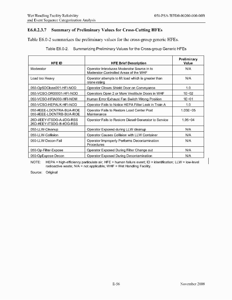
Wet Handling Facility Reliability 050-PSA-WHOO-00200-000-00B and Event Sequence Categorization Analysis
E6.0.2.3.7 Summary of Preliminary Values for Cross-Cutting HFEs
Table E6.0-2 summarizes the preliminary values for the cross-group generic HFEs.
Table E6.0-2. Summarizing Preliminary Values for the Cross-group Generic HFEs
HFEID HFE Brief Description Preliminary
Value
Moderator Operator Introduces Moderator Source in to Moderator-Controlled Areas of the WHF
N/A
Load too Heavy Operator attempts to lift load which is greater than crane rating
N/A
050-0pSDClose001-HFI-NOD Operator Closes Shield Door on Conveyance 1.0
050-VCSO-DROOO01-HFI-NOD Operators Open 2 or More Vestibule Doors in WHF 1E-02
050-VCSO-HFIAOOO-HFI-NOM Human Error Exhaust Fan Switch WronQ Position 1E-01
050-VCSO-HEPALK-HFI-NOD Operator Fails to Notice HEPA Filter Leak in Train A 1.0
050-#EEE-LDCNTRA-BUA-ROE 050-#EEE-LDCNTRB-BUA-ROE
Operator Fails to Restore Load Center Post Maintenance
1.03E-05
26D-#EEY-ITSDG-A-#DG-RSS 26D-#EEY-ITSDG-B-#DG-RSS
Operator Fails to Restore Diesel Generator to Service 1.95-04
050-LLW-Cleanup Operator Exposed durinq LLW cleanup N/A
050-LLW-Collision Operator Causes Collision with LLW Container N/A
050-LLW-Decon-Fail Operator Improperly Performs Decontamination Procedures
N/A
050-0p-Filter-Expose Operator Exposed Durinq Filter Chanqe out N/A
050-0pExpose-Decon Operator Exposed DurinQ Decontamination N/A
NOTE: HEPA = high-efficiency particulate air; HFE = human failure event; ID = identification; LLW = low-level radioactive waste; N/A = not applicable; WHF = Wet Handling Facility.
Source: Original
E-56 November 2008
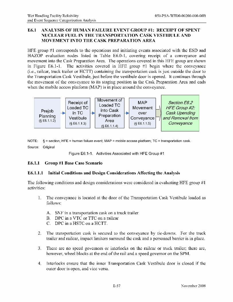
Wet Handling Facility Reliability 050-PSA-WHOO-00200-000-00B and Event Sequence Categorization Analysis
E6.1 ANALYSIS OF HUMAN FAILURE EVENT GROUP #1: RECEIPT OF SPENT NUCLEAR FUEL IN THE TRANSPORTATION CASK VESTIBULE AND MOVEMENT INTO THE CASK PREPARATION AREA
HFE group #1 corresponds to the operations and initiating events associated with the ESD and HAZOP evaluation nodes listed in Table E6.0-1, covering receipt of a conveyance and movement into the Cask Preparation Area. The operations covered in this HFE group are shown in Figure E6.1-1. The activities covered in HFE group #1 begin where the conveyance (i.e., railcar, truck trailer or HCTT) containing the transportation cask is just outside the door to the Transportation Cask Vestibule, just before the vestibule door is opened. It continues through the movement of the conveyance to its staging position in the Cask Preparation Area and ends when the mobile access platform (MAP) is in place around the conveyance.
Prejob Planning (§ E6.1.1.2)
Receipt of Loaded TC -. in TC Vestibule (§ E6.1.1.3)
f--.
Movement of Loaded TC into Cask
Preparation Area
(§ E6.1.1.4)
MAP Movement W\
over Conveyance l-yf--.
(§ E6.1.1.5)
Section £6.2 HF£ Group #2: Cask Upending
and Removal from Conveyance
NOTE: § = section; HFE = human failure event; MAP = mobile access platform; TC = transportation cask.
Source: Original
Figure E6.1-1. Activities Associated with HFE Group #1
E6.1.1 Group #1 Base Case Scenario
E6.1.1.1 Initial Conditions and Design Considerations Affecting the Analysis
The following conditions and design considerations were considered in evaluating HFE group #1 activities:
1. The conveyance is located at the door of the Transportation Cask Vestibule loaded as follows:
A. SNF in a transportation cask on a truck trailer B. DPC in a VTC or TTC on a railcar C. DPC in a HSTC on a HCTT.
2. The transportation cask is secured to the conveyance by tie-downs. For the truck trailer and railcar, impact limiters surround the cask and a personnel barrier is in place.
3. There are no speed governors or interlocks on the railcar or truck trailer; there are, however, wheel blocks at the end of the rail and a speed governor on the SPM.
4. Interlocks ensure that the inner Transportation Cask Vestibule door is closed if the outer door is open, and vice versa.
E-57 November 2008

Wet Handling Facility Reliability 050-PSA-WHOO-00200-000-00B and Event Sequence Categorization Analysis
The following personnel are involved in this set of operations:
• Crew member (twO) • PIC • SPM operator • HCTT operator.
Section E5.l.2 provides a more detailed description of the duties performed by each of these personnel.
E6.1.1.2 Prejob Plan
Before the transportation cask and conveyance reach the WHF, a PIC is notified of the type of cask/conveyance to expect and how to process it. According to this information, the PIC determines the appropriate procedures and equipment to be used to handle this cask type, and communicates this information to all the crew members involved in the handling of this cask. The PIC also fills out a pre-lift safety checklist (Ref. E8.1.12) verifying that the equipment is properly staged and in proper operational condition. All crane operators are properly trained and abide by the procedures of the facility.
The prejob plan includes "campaign" information and a TAD canister loading plan as described here. Configuration and placement of the fuel assemblies (i.e., pressurized water reactor (PWR) assemblies or boiling water reactor (BWR) assemblies) into a TAD canister is predetermined by Engineering. The TAD canister loading plan includes a map of the TAD canister grid, with the serial numbers of the fuel assemblies appropriately mapped on the grid. The TAD canister fits 21 PWR assemblies or 44 BWR assemblies. All the assemblies needed to fill a TAD canister must be in the pool before the TAD canister loading begins. Truck casks hold 4 PWR assemblies or 9 BWR assemblies, so a "campaign" would include prestaging six truck casks worth of PWR fuel assemblies or 5 of BWR fuel assemblies in the staging racks before bringing the TAD canister into the pool.
DPCs can fit more than 21 PWR fuel assemblies or more than 44 BWR fuel assemblies (in comparison to a TAD canister). After filling a TAD canister with PWR or BWR fuel from a DPC, there are left over assemblies. The extra assemblies are staged in the staging rack. In this case, a "campaign" likely includes filling several TAD canisters until there are no PWR assemblies left in the pool. However, there is some likelihood that PWR and BWR fuel assemblies to be in the pool at the same time. It should be noted that the BWR assemblies are significantly shorter than the PWR assemblies (and, thus, the BWR staging rack is significantly shorter than the PWR staging rack), and therefore are not easily confused.
E6.1.1.3 Receipt of a Loaded Transportation Cask in the Transportation Cask Vestibule
Two crew members are in attendance at the Transportation Cask Vestibule to deal with the reception of loaded casks. The loaded railcar or truck trailer is pushed by a SPM (a diesel/electric vehicle with on-board controls), and is driven by the SPM operator who is located in the cab of the SPM. The cask transfer trailer is pulled by the cask tractor (together they make
E-58 November 2008
Wet Handling Facility Reliability 050-PSA-WHOO-00200-000-00B and Event Sequence Categorization Analysis
up a HCTT unit). When the conveyance approaches the WHF, it is visually inspected and one crew member opens the outside overhead door and the other crew member uses hand signals to direct the conveyance into the Transportation Cask Vestibule after ensuring there are no vehicles or obstructions in the path. The crew members follow all relevant restrictions and procedures regarding conveyance speed and direction of travel. Once the railcar or truck trailer has cleared the door, the first crew member closes the outside door.
E6.1.1.4 Movement of Loaded Cask into Cask Preparation Area
Once the conveyance is in the Transportation Cask Vestibule, the inside overhead door is opened and the conveyance proceeds to the Cask Preparation Area and stops. A crew member sets the conveyance brakes and chocks the wheels. The cask tractor engine is turned off at this time. For a railcar or truck trailer, the SPM detaches from the railcar/truck trailer and proceeds back to the Transportation Cask Entrance Vestibule. The inside overhead door is closed by a crew member. A checklist is signed to indicate that the inside door has been closed and the brakes set.
The inner and outer doors have an interlock that normally prevents both doors from being opened simultaneously; however, this interlock can be bypassed.
E6.1.1.5 Move Mobile Access Platform over Conveyance
A crew member raises the MAP and moves it over the conveyance, positioning it for conveyance unloading activities.
E6.1.2 HFE Descriptions and Preliminary Analysis
This section defines and screens the HFEs that are identified for the base case scenario that can affect the probability of initiating events occurring, and that could lead to undesired consequences. Descriptions and preliminary analysis for the HFEs of concern during receipt of the railcar, truck trailer or HCTT are summarized in Table E6.1-1. The analysis presented here includes the assignment of preliminary HEPs in accordance with the methodology described in Section E3.2 and Appendix E.IlI of this analysis. Section E4.2 provides details on the use of expert judgment in this preliminary analysis.
E-59 November 2008

Wet Handling Facility Reliability 050-PSA-WHOO-00200-000-00B and Event Sequence Categorization Analysis
INTENTIONALLY LEFT BLANK
E-60 November 2008
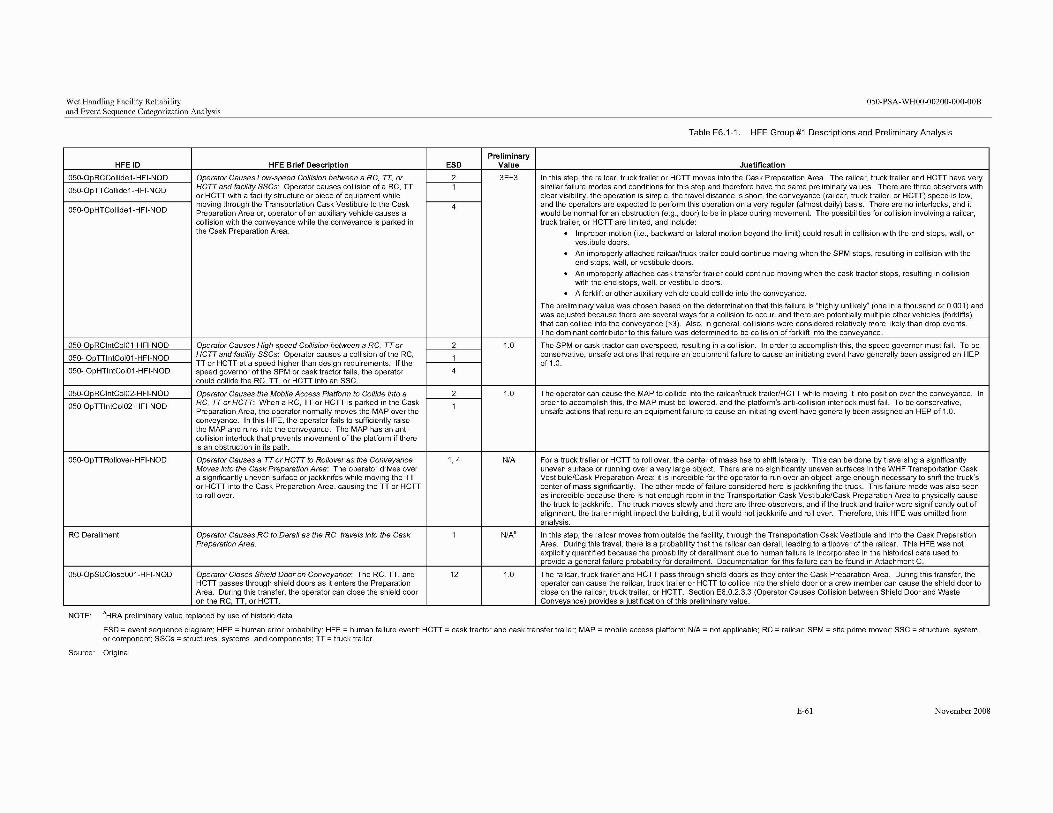
Wet Handling Facility Reliability 050-PSA-WHOO-00200-000-00B and Event Sequence Categorization Analysis
Table E6.1-1. HFE Group #1 Descriptions and Preliminary Analysis
HFEID HFE Brief Description ESD Preliminary
Value Justification
In this step, the railcar, truck trailer or Hell moves into the Cask Preparation Area. The railcar, truck trailer and Hell have very similar failure modes and conditions for this step and therefore have the same preliminary values. There are three observers with clear visibility, the operation is simple, the travel distance is short, the conveyance (railcar, truck trailer, or Hell) speed is low, and the operators are expected to perform this operation on a very regular (almost daily) basis. There are no interlocks, and it would be normal for an obstruction (e.g., door) to be in place during movement. The possibilities for collision involving a railcar, truck trailer, or HCTT are limited, and include:
· Improper motion (i.e., backward or lateral motion beyond the limit) could result in collision with the end stops, wall, or vestibule doors.
· An improperly attached railcar/truck trailer could continue moving when the SPM stops, resulting in collision with the end stops, wall, or vestibule doors.
· An improperly attached cask transfer trailer could continue moving when the cask tractor stops, resulting in collision with the end stops, wall, or vestibule doors. · A forklift or other auxiliary vehicle could collide into the conveyance.
The preliminary value was chosen based on the determination that this failure is "highly unlikely" (one in a thousand or 0.001) and was adjusted because there are several ways for a collision to occur, and there are potentially multiple other vehicles (forklifts) that can collide into the conveyance (x3). Also, in general, collisions were considered relatively more likely than drop events. The dominant contributor to this failure was determined to be collision of forklift into the convevance.
050-00RCCollide1-HFI-NOD Operator Causes Low-speed Collision between a RC, IT, or 2 3E-3
050-0pTTCollide 1-HFI-NOD HCTT and facility SSCs: Operator causes collision of aRC, TT or Hell with a facility structure or piece of equipment while
1
050-0pHTCollide1-HFI-NOD moving through the Transportation Cask Vestibule to the Cask Preparation Area or, operator of an auxiliary vehicle causes a collision with the conveyance while the conveyance is parked in the Cask Preparation Area.
4
050-0oRClntCo10 1-HFI-NOD Operator Causes High-speed Collision between aRC, TT or 2 1.0 The SPM or cask tractor can overspeed, resulting in a collision. In order to accomplish this, the speed governor must fail. To be conservative, unsafe actions that require an equipment failure to cause an initiating event have generally been assigned an HEP of 1.0.
The operator can cause the MAP to collide into the railcar/truck trailer/HCTT while moving it into position over the conveyance. In order to accomplish this, the MAP must be lowered, and the platform's anti-collision interlock must fail. To be conservative, unsafe actions that require an equipment failure to cause an initiating event have generally been assigned an HEP of 1.0.
For a truck trailer or HCTT to roll over, the center of mass has to shift laterally. This can be done by traversing a significantly uneven surface or running over a very large object. There are no significantly uneven surfaces in the WHF Transportation Cask Vestibule/Cask Preparation Area; it is incredible for the operator to run over an object large enough necessary to shift the truck's center of mass significantly. The other mode of failure considered here is jackknifing the truck. This failure mode was also seen as incredible because there is not enough room in the Transportation Cask Vestibule/Cask Preparation Area to physically cause the truck to jackknife. The truck moves slowly and there are three observers, and if the truck and trailer were significantly out of alignment, the trailer might impact the building, but it would not jackknife and roll over. Therefore, this HFE was omitted from analysis.
In this step, the railcar moves from outside the facility, through the Transportation Cask Vestibule and into the Cask Preparation Area. During this travel, there is a probability that the railcar can derail, leading to a tipover of the railcar. This HFE was not explicitly quantified because the probability of derailment due to human failure is incorporated in the historical data used to orovide a aeneral failure orobabilitv for derailment. Documentation for this failure can be found in Attachment C.
050- OoTTlntCoI01-HFI-NOD HCTT and facility SSCs: Operator causes a collision of the RC, TT or HCTT at a speed higher than design requirements. If the speed governor of the SPM or cask tractor fails, the operator could collide the RC, TT, or HCTT into an SSC.
1
050- OpHTlntCoI01-HFI-NOD 4
050-0oRClntCoI02-HFI-NOD Operator Causes the Mobile Access Platform to Collide into a 2 1.0
050-0pTTlntCoI02-HFI-NOD RC, IT or HCTT: When aRC, TT or HCTT is parked in the Cask Preparation Area, the operator normally moves the MAP over the conveyance. In this HFE, the operator fails to sufficiently raise the MAP and runs into the conveyance. The MAP has an anticollision interlock that prevents movement of the platform if there is an obstruction in its path.
1
050-0pTTRoliover-HFI-NOD Operator Causes a TT or HCTT to Rollover as the Conveyance Moves into the Cask Preparation Area: The operator drives over a significantly uneven surface or jackknifes while moving the TT or HCTT into the Cask Preparation Area, causing the TT or HCTT to roll over.
1,4 N/A
RC Derailment Operator Causes RC to Derail as the RC travels into the Cask Preparation Area.
1 N/A'
050-0pSDCloseOO 1-HFI-NOD Operator Closes Shield Door on Conveyance: The RC, TT, and HCTT passes through shield doors as it enters the Preparation Area. During this transfer, the operator can close the shield door on the RC, TT, or HCTT.
12 1.0 The railcar, truck trailer and HCTT pass through shield doors as they enter the Cask Preparation Area. During this transfer, the operator can cause the railcar, truck trailer or HCTT to collide into the shield door or a crew member can cause the shield door to close on the railcar, truck trailer, or HCTT. Section E6.0.2.3.3 (Operator Causes Collision between Shield Door and Waste Convevance) orovides a ·ustification of this oreliminarv value.
NOTE: aHRA preliminary value replaced by use of historic data.
ESD =event sequence diagram; HEP =human error probability; HFE =human failure event; HCTT =cask tractor and cask transfer trailer; MAP =mobile access platform; N/A =not applicable; RC = railcar; SPM =site prime mover; SSC =structure, system, or component; SSCs =structures, systems, and components; TT =truck trailer.
Source: Original
E-61 November 2008

Wet Handling Facility Reliability 050-PSA-WHOO-00200-000-00B and Event Sequence Categorization Analysis
INTENTIONALLY LEFT BLANK
E-62 November 2008

Wet Handling Facility Reliability 050-PSA-WHOO-00200-000-00B and Event Sequence Categorization Analysis
E6.1.3 Detailed Analysis
There are no HFEs in this group that require detailed analysis; the preliminary values in the facility model do not result in any Category 1 or Category 2 event sequences that fail to comply with the 10 CFR 63.111 (Ref. E8.2.1) performance objectives; therefore, the preliminary values were sufficient to demonstrate compliance with 10 CFR Part 63 (Ref. E8.2.1).
E-63 November 2008
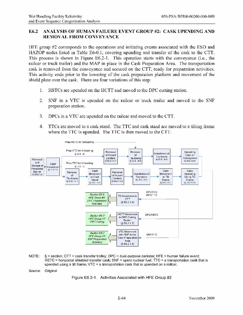
Wet Handling Facility Reliability 050-PSA-WHOO-00200-000-00B and Event Sequence Categorization Analysis
E6.2 ANALYSIS OF HUMAN FAILURE EVENT GROUP #2: CASK UPENDING AND REMOVAL FROM CONVEYANCE
HFE group #2 corresponds to the operations and initiating events associated with the ESD and HAZOP nodes listed in Table E6-0.1, covering upending and transfer of the cask to the CTT. This process is shown in Figure E6.2-1. This operation starts with the conveyance (i.e., the railcar or truck trailer) and the MAP in place in the Cask Preparation Area. The transportation cask is removed from the conveyance and secured on the CTT, ready for preparation activities. This activity ends prior to the lowering of the cask preparation platform and movement of the shield plate over the cask. There are four variations of this step:
1. HSTCs are upended on the HCTT and moved to the DPC cutting station.
2. SNF in a VTC is upended on the railcar or truck trailer and moved to the SNF preparation station.
3. DPCs in a VTC are upended on the railcar and moved to the CTT.
4. TTCs are moved to a cask stand. The TTC and cask stand are moved to a tilting frame where the TTC is upended. The TTC is then moved to the CTT.
Prep HSTC for Unloading
~ Prep VTC for Unloading Removal Removal Upending
(§ E6.2.1.4) Installation ofof Impact -------. of -------. Trunnions -------. Cask on -Limiters Tie-downs ConveyanceRemoval (§ E6.2.1.4.1) (§ E6.2.1.4.2)
(§ E6 2 1 43) (§ E6.2.1.4.4)
and Cask Prep TTC for UnloadingStorage of • Inspection (§ E6.2.1.5) Personnel (§ E6.2.1.3) Cask Cask Cask r---Barrier Removal Removal (§ E6.2.1.2) of Movement of Impact Installation of Movement Upending
4 -------. to Cask f----------. f----------. Trunnions -------. to Tilt -------. Using Tilt -Tie-downs
Stand Limiters (§ E6.2.1.5.4) Frame Frame(§ E6.2.1.5.1) (§ E6.2.1.5.2)
(§ E6.2.1.5.3) (§ E6.2.1.5.5) (§ E6.2.1.5.6)
DPCNTC Section E6.5 ;L- TC Movement to DPC/TTC
HFE Group #5' CTTDPC Preparation v-- (§ E6.2.1.6) Activities
Section E6.7 II-- HCTT Movement DPC/HSTC HFE Group #7: to DPC Cutting
I\r- StationDPCCutting (§ E6.2.1.7)
VTC Movement SectionE6.3 II-- with SNF to the SNFNTCHFE Group #3:
SNF Preparation IV--- Cask Preparation
Activities Area (§ E6.2.1.8)
NOTE: § = section; CTT = cask transfer trolley; DPC = dual-purpose canister; HFE = human failure event; HSTC = horizontal shielded transfer cask; SNF = spent nuclear fuel; TTC = a transportation cask that is upended using a tilt frame; VTC = a transportation cask that is upended on a railcar.
Source: Original
Figure E6.2-1. Activities Associated with HFE Group #2
E-64 November 2008
Wet Handling Facility Reliability 050-PSA-WHOO-00200-000-00B and Event Sequence Categorization Analysis
E6.2.1 Group #2 Base Case Scenario
E6.2.1.1 Initial Conditions and Design Considerations Affecting the Analysis
The following conditions and design considerations were considered in evaluating HFE group #2 activities:
1. The railcar, truck trailer, or HCTT is parked in the Cask Preparation Area with its brakes set and the transportation cask secure in the conveyance.
2. For DOE (short) casks, a cask pedestal is pre-staged in the CTT.
3. The MAP has an anti-collision interlock.
4. The cask handling crane (200-ton crane with 20-ton auxiliary hook) has the following safety features:
A. Upper limits-There are two upper limit marks: the initial is an indicator, and the final (which is set higher than the upper limit indicator) cuts off the power to the hoist. There is no bypass for the final limit interlock.
B. There are end-of-travel interlocks on the trolley and bridge.
C. There are speed limiters built into the motors.
D. There is a weight interlock that cuts off power to the crane when the crane capacity is exceeded.
E. There is a temperature interlock that cuts off power to the hoist when the temperature is too high; an indicator comes on before this temperature is reached.
F. There is an indicator to signal the operators that the cask handling yoke is fully engaged, and an interlock (yoke engagement) that prevents the crane from moving unless and the yoke is either fully engaged or disengaged.
Crane operations in this activity are not part of a specific procedure outlined in the YMP documentation, but rather reflect critical lift crane operations that are standard in the nuclear industry.
The following equipment is available for upending and transferring the cask:
1. Crane:
A. 200-ton cask handling crane B. 20-ton auxiliary hook.
2. Lift fixtures:
a. Impact limiter lifting device (uneven slings) b. Personnel barrier lifting device (sling)
E-65 November 2008
Wet Handling Facility Reliability 050-PSA-WHOO-00200-000-00B and Event Sequence Categorization Analysis
c. Cask sling (for TTCs) d. Yoke (adjustable, for all casks).
3. Common tools and platform.
The following personnel are involved in this set of operations:
• Crane operator • Signaling crew member • Verification crew member • Radiation protection worker9
• Supervisor.
Section E5.1.2 provides a more detailed description of the duties performed by each of these personnel.
E6.2.1.2 Removal and Storage of Personnel Barrier (if required)
Most personnel barriers are removed at the geologic repository operations entrance; however, this facility retains the capacity to remove personnel barriers if necessary. HSTCs do not have a personnel barrier. In order to remove the personnel barrier from the transportation cask, the crew members must first unbolt the barrier from the cask. The crane operator retrieves the crane and removes the personnel barriers as follows:
Alignment of Crane to Personnel Barrier-The crane operator lowers the 20-ton auxiliary hook into position over the personnel barrier. The operator is positioned on the floor in view of the crew members on either side of the personnel barrier. A signaling crew member next to the personnel barrier uses hand signals to guide the crane operator (no hardwired or wireless communication system is used). A verification crew member on the opposite side of the personnel barrier checks the alignment of the crane. The verification crew member can only signal to stop the crane. Once positioned, a crew member connects the crane to the personnel barrier using the personnel barrier lifting device, which is expected to be a sling. In order to use a sling, a crew member must secure the sling around the personnel barrier, attach the sling to the crane, and ensure that, when lifted, the load is level. If the sling is not positioned and the load is not level, the signaling crew member signals the crane operator to stop and lower the personnel barrier so that the sling can be repositioned.
Vertical Lifting of the Personnel Barrier-Upon signal from the signaling crew member that all is well, the crane operator begins to raise the personnel barrier. Once the personnel barrier has been raised (i.e., is hanging free) to the proper height (based on visual inspection), the crane operator stops raising the personnel barrier. The crane operator clears the railcar, truck trailer, or HCTT and then lowers the personnel barrier to the movement height. This action is confirmed by hand signals from the signaling crew member. The proper height for movement is roughly 6 in. above the highest obstacle in the movement path.
9The radiation protection worker, or health physicist, is not mentioned specifically in each step of this operation; however, there is always at least one radiation protection worker present during this step.
E-66 November 2008
Wet Handling Facility Reliability 050-PSA-WHOO-00200-000-00B and Event Sequence Categorization Analysis
Movement of Personnel Barrier to Staging Location-The crane operator moves the 20-ton auxiliary hook to locate the personnel barrier over the position where it is lowered in the staging area, following the indicated safe load path marked on the floor. The crane operator performs this task visually and also receives confirmatory hand signals from the signaling crew member. The crane operator can roughly align the crane, but final alignment is directed by the signaling crew member.
Lowering of Personnel Barrier and Disengagement of the Sling-When properly positioned in the staging area and the placement area is clear, the signaling crew member signals the crane operator to lower the personnel barrier. The crane operator then proceeds to lower the personnel barrier at or below the maximum allowable speed. Once the personnel barrier is stable on the floor of staging area, a crew member disengages the sling and the crane operator lifts the crane in preparation for the next operation.
E6.2.1.3 Cask Inspection
Once the conveyance is parked in the facility and the personnel barriers have been removed, the crew visually inspects and conducts radiological surveys of the exterior of the cask.
E6.2.1.4 Preparation ofVTC and HSTC for Unloading
As illustrated in Figure E6.2-I, the upending processes for the three cask types are very similar, but not identical. At this point the processes for preparing the three types of casks for upending diverge. The VTC and HSTC are discussed first, followed by a similar discussion for the TTC in Section E6.2.1.5.
E6.2.1.4.1 Removal and Storage of Impact Limiters (VTC only)
This section describes the removal and staging of impact limiters using the 20-ton auxiliary hook with standard rigging, common tools, and the MAP. This step is performed twice, as each cask has two impact limiters.
Crew members, working with the crane operator, attach the impact limiter lifting device (uneven slings) to the 20-ton auxiliary hook.
After the personnel barrier is removed and the cask is inspected, the crew removes and stores the impact limiters. HSTCs do not have impact limiters, so this step is only applicable to VTCs. This operation is performed on the conveyance with training and procedures. The first step is to remove the restraining bolts on the impact limiters. Depending on the cask type, there can be anywhere from 24 to 36 bolts to remove, with several crew members removing the bolts simultaneously. Once removed, the bolts are counted, and the crew supervisor uses a checklist to verifY and document bolt removal. Once bolt removal is verified, the crane operator removes and stores the impact limiters using the 20-ton auxiliary hook as follows:
Movement of Crane to Impact Limiter Position-The crane operator positions the crane over the impact limiter, following the indicated safe load path marked on the floor. The crane operator performs this task visually and also receives confirmatory hand signals from the
E-67 November 2008
Wet Handling Facility Reliability 050-PSA-WHOO-00200-000-00B and Event Sequence Categorization Analysis
signaling crew member. The crane operator can roughly align the crane, but final alignment is directed by the signaling crew member.
Alignment of Crane to Impact Limiter-The crane operator lowers the crane into position over the impact limiter. The crane operator is positioned on the floor in view of the crew members on either side of the impact limiter. A signaling crew member, next to the impact limiter, uses hand signals to guide the movement of the crane operator (no hardwired or wireless communication system is used). There is a verification crew member on the opposite side of the impact limiter, checking alignment of the crane. The verification crew member can only signal the crane operator to stop. Once positioned, a crew member connects the crane to the impact limiter using the uneven sling and integral lift points.
Vertical Lifting of the Impact Limiter-Upon signal from the signaling crew member, the crane operator ensures the impact limiter is free of the transportation cask (this may include moving the impact limiters horizontally to free them) and then begins to raise the impact limiter. Once the impact limiter has been raised (i.e., is hanging free) such that it has cleared the conveyance, the crane operator stops raising the impact limiters. The crane operator bases this on a visual inspection and is confirmed by hand signals from the signaling crew member. Once past the conveyance, the crane operator lowers the impact limiter to the proper height for movement. The proper height for movement is roughly 6 in. above the highest obstacle in the movement path. The crane operator bases this height estimation on a visual inspection, confirmed by hand signals from the signaling crew member.
Movement of Impact Limiter to Staging Area-The crane operator moves the crane so as to locate the impact limiter over the position where it should be lowered in the staging area, following the indicated safe load path marked on the floor. The crane operator performs this task visually and also receives confirmatory hand signals from the signaling crew member. The crane operator can roughly align the crane, but final alignment is directed by the signaling crew member.
Lowering of Impact Limiter and Disengagement of the Sling-When properly positioned and the placement area is clear, the signaling crew member signals the crane operator to lower the impact limiter to the ground or staging rack. The crane operator then proceeds to lower the impact limiter at or below the maximum allowable speed. Once the impact limiter is lowered, a crew member disengages the sling, and the crane operator lifts the crane to the maximum height in preparation for the next operation.
E6.2.1.4.2 Removal of Tie -downs
Tie-downs that secure the transportation cask to the conveyance are removed using the MAP for access. Once the impact limiters are removed, the crew removes the cask tie-downs in preparation to lift the transportation cask off the conveyance. This operation is done on the conveyance according to written procedures. The crew removes all the bolts of the tie-down, with four crew members removing the bolts simultaneously. Once removed, the bolts are counted, and the crew supervisor checks off bolt removal. Once bolt removal is verified, the crane operator (using a 200-ton crane with yoke) can proceed to lift the cask if there are trunnions on the cask; if not, then the crew must install trunnions on the cask.
E-68 November 2008
Wet Handling Facility Reliability 050-PSA-WHOO-00200-000-00B and Event Sequence Categorization Analysis
E6.2.1.4.3 Installation of Trunnions (if required)
Trunnions are installed onto the cask by using common tools, standard rigging, cask handling crane (auxiliary hook), and the MAP.
Crew members retrieve the trunnions to be installed. Trunnions are located in a package on the conveyance. If required, the 20-ton auxiliary hook is used to place the trunnions in the proper position. Crew members secure the trunnions according to training.
E6.2.1.4.4 Upending Transportation Cask on the Conveyance
The transportation is upended cask using the 200-ton cask handling crane with yoke.
Prior to attempting to upend the transportation cask on the conveyance, the crew members must properly attach the yoke to the 200-ton cask handling crane. Once that is done, the crew can proceed to initiate upending of the cask.
Movement of Crane to Transportation Cask-The operator posItIOns the crane over the transportation cask. The crane movement follows the indicated safe load path marked on the floor. The operator performs a visual check, and also receives confirmatory hand signals from the signaling crew member. The crane operator can roughly align the crane, but final alignment is directed by the signaling crew member.
Alignment of Crane to Cask-The crane operator lowers the yoke into position so that the yoke arms are lined up with the trunnion. The crane operator is positioned on the floor in view of the crew members on either side of the cask. There is a signaling crew member next to the cask using hand signals to guide the operator's movement (no hardwired or wireless communication system is used). There is a verification crew member on the opposite side of the cask, checking alignment of the second trunnion. This worker can only signal the crane operator to stop.
Yoke Arms Engaged on Trunnions-Once the yoke is aligned, the signaling crew member signals the operator to close the yoke arms. The crew members check to see that the yoke arms have attained at least the minimum amount of engagement (minimum distance from edge of trunnion to edge of yoke arm). If the arms are sufficiently engaged on both sides, the crane operator knows by an indicator on the controller, and the signaling crew member signals the operator to raise the yoke a slight amount to put pressure on the arms. The crane operator sees on the controller that the crane is bearing weight. Both crew members verifY that the yoke remains level. If the arms do not engage on the initial attempt, either crew member signals to the operator to stop, and the crane operator sets the cask down and opens the yoke arms to disengage. The signaling crew member then directs movement of the crane (again with hand signals) to compensate and then signals the operator to close the yoke arms.
Vertical Positioning of Cask-Upon receiving a signal from the signaling crew member, the crane operator begins to raise the cask. Since the bottom of the cask remains stationary because of the cask restraints, the operator moves the crane to remain directly above the upper trunnions (i.e., to keep the cables straight). The operator performs this task visually. The operator also gets hand signals from the signaling crew member to ensure that the cask is "upending" properly.
E-69 November 2008