ca no cejz/ jodh/ of 2017-18 serial page no. 1 - EQMagPro
243
CA NO CEJZ/ JODH/ OF 2017-18 SERIAL PAGE NO. 1 MILITARY ENGINEER SERVICES NAME OF WORK: PROVISION OF 2MW SOLAR POWER PLANT UNDER GE(A) UTILITY AT JODHPUR. (JOB NO: SC/MW/1251) CONTENTS S. No Description Page From To 01. Contents 01 To 01 02 Forwarding letter including instructions for filling and submission of tender documents 2 To 7 03. Notice of tender including Appendix ‘A’ 8 To 14 04. Lump Sum Tender and contracts for works on tender form IAFW-2159 (Revised 1947) 15 To 66 05. General Conditions of Contract (IAFW – 2249) including Errata & amendments thereto and Schedule of Minimum Wages 67 To 125 06. Special Conditions 126 To 142 07. Particular specifications including list of drawings and Appendix ‘A’, ‘B’, ‘C’ 143 To 238 08 Amendments to tender documents To 09 Relevant correspondence 10 Acceptance letter Total No of Pages Drgs _______________ _______________ _______________ Signature of Contractor Dy Dir (Contracts) For Accepting Officer
-
Upload
khangminh22 -
Category
Documents
-
view
0 -
download
0
Transcript of ca no cejz/ jodh/ of 2017-18 serial page no. 1 - EQMagPro

CA NO CEJZ/ JODH/ OF 2017-18 SERIAL PAGE NO. 1
MILITARY ENGINEER SERVICES
NAME OF WORK: PROVISION OF 2MW SOLAR POWER PLANT UNDER GE(A) UTILITY AT JODHPUR. (JOB NO: SC/MW/1251)
CONTENTS S. No
Description Page From To
01.
Contents
01
To
01
02 Forwarding letter including instructions for filling and submission of tender documents
2 To 7
03. Notice of tender including Appendix ‘A’ 8 To 14
04. Lump Sum Tender and contracts for works on tender form IAFW-2159 (Revised 1947)
15 To 66
05.
General Conditions of Contract (IAFW – 2249) including Errata & amendments thereto and Schedule of Minimum Wages
67 To 125
06. Special Conditions
126 To 142
07. Particular specifications including list of drawings and Appendix ‘A’, ‘B’, ‘C’
143 To 238
08 Amendments to tender documents
To
09 Relevant correspondence
10 Acceptance letter
Total No of Pages
Drgs
______________________________ _______________
Signature of Contractor Dy Dir (Contracts) For Accepting Officer

CA NO CEJZ/ JODH/ OF 2017-18 SERIAL PAGE NO. 2
Tele: (0291) – 2515113/2511518 Military Engineer Services (Email id : [email protected]) Headquarters Chief Engineer Jodhpur Zone ECHS Complex Jodhpur Jodhpur - 342010 800410/ 12 /E8 25 July 2017 M/S ------------------------------------- ------------------------------------------- ------------------------------------------- --------------------------------------------
PROVISION OF 2MW SOLAR POWER PLANT UNDER GE(A) UTILITY AT JODHPUR. (JOB
NO: SC/MW/1251) Dear Sir, 1. Tender documents in respect of above works are forwarded herewith as uploaded on the site www.eprocuremes.gov.in. Tender documents are uploaded in two parts, one being in BOQ format and another in pdf format. 2. Tender/bids will be received online by ACCEPTING OFFICER upto the date and time mentioned on the site. No tender will be received in physical form and any tender received in such manner will be treated as non bonafide tender. 3. Tender/bids will be opened on due date and time fixed for receipt of tender in the presence of tenderers or their authorised representatives, who have uploaded their quotation bid and who wish to be present at the time of opening the tenders. 4. Your attention is also drawn to instruction on filling and submission of attached herewith. You may forward your points on tender documents and/or depute your technical representative for discussion on tender/ drawings and to clarify doubts, if any, on or before date mentioned. You are requested not to write piece meal points and forward your points duly consolidated before due date as per NOT. 5. Unenlisted contractors are required to submit the scanned copies (in pdf file) of documents required as per eligibility criteria mentioned in instructions for filling the tender documents along with EMD and tender fee on e-procurement portal and submit the physical documents in the office of Chief Engineer Jodhpur Zone, ECHS Polyclinic Complex, Opp MH, Jodhpur -342010 within time limit specified in NIT. Inadequacy/deficiency of documents shall make the bid liable for rejection and in such event BOQ shall not be opened. 6. Tender/bid from contractor having not executed standing security bond and standing security deposit in any MES formation shall be accompanied with EARNEST MONEY mentioned in Notice of Tender, failing which the tender will be treated as non-bonafide. Such contractor would be required to deposit individual security deposit on acceptance of tender which will be calculated with reference to the tendered cost as per scales laid down by MES for calculation of “EARNEST MONEY” enhanced by 25% subject to maximum of Rs. 1875000/- (Rupees Eighteen Lakhs seventy five thousand Only).
CA NO CEJZ/ JODH/ OF 2017-18 SERIAL PAGE NO. 3
7. Enlisted contractors of MES shall submit the scanned copies (pdf file) of enlistment letter and tender fee on e-procurement portal and submit physical documents in the office of CE Jodhpur Zone. 8. The contractor must ensure that the tender/bid on the proper form is uploaded in time as the Accepting Officer will take no cognizance of any quotations/offer received on fax and/or email from tenderer even if they are received in time. 9. In view of delays due to system failure or other communication related failures, it is suggested that the tender (Cover–I and Cover –II) be uploaded, if necessary, sufficiently in advance of the last due date and time fixed for receipt of the tender. 10. General Conditions of Contracts (IAFW-2249) (1989 Print) and errata and amendments thereto, Schedule of minimum fair wages and MES SSR (Part –I and Part –II) are not enclosed with these documents. These are available for perusal in the Office of GE concerned and this office. 11. ANY TENDERER, WHICH PROPOSES ALTERATIONS TO ANY OF THE CONDITION, SPECIFICATIONS LAID DOWN IN THE TENDER DOCUMENTS OR ANY NEW CONDITION, WHATSOEVER, IS LIABLE TO BE REJECTED. 12. Tenderer is advised to cross check his quotation in BOQ after uploading and before the Bid closing time and date. If he fails to quote the rate for any item, in terms of amendment 21(c)(ii) to condition 6-A(A) of IAFW-2249, his overall quotation shall deem to include cost of execution of these items for the quantity mentioned in BOQ. No representation on this account shall be entertained.
Yours faithfully, (T R Chourasia) EE (QS&C) Dy Dir (Contracts) Signature of Contractor For Accepting Officer Encls :- (As above)

CA NO CEJZ/ JODH/ OF 2017-18 SERIAL PAGE NO. 4
INSTRUCTIONS ON FILLING AND SUBMISSION OF TENDER
1. EARNEST MONEY Contractor(s) who are not enlisted with MES/who are enlisted but have not executed the Standing Security Bond shall submit Earnest Money Deposit as detailed in Notice of Tender in one of the following forms, along with their tender :-
(a) Deposit at Call Receipt from a Scheduled Bank in favour of Garrison Engineer concerned
(b) Receipted Treasury Challan, the amount being credited to the Revenue Deposi of Garrison Engineer.
It is advisable that Earnest Money is deposited in the form of deposit call receipt from an approved Schedule Bank for easy refund. In case the tenderer wants to lodge `EARNEST MONEY' in any other form allowed by MES, a confirmation about its acceptability will be obtained from the Accepting Officer well in advance of the date and time of receipt of the tender. Earnest Money shall be submitted in the name of concerned GE. NOTES : Earnest Money in the form of cheque/Bank Guarantee etc will not be accepted. NON-SUBMISSION OF EARNEST MONEY WILL RENDER THE TENDER AS NON-BONAFIDE AND CONSEQUENTLY LIABLE TO BE IGNORED. 2. SECURITY DEPOSIT In case the tender submitted by such contractor who is not enlisted with MES is accepted, the contractor will be required to lodge with the Controller of Defence Accounts INDIVIDUAL SECURITY DEPOSIT calculated with reference to TENDERED COST as notified by the Accepting Officer subject to a maximum of Rs. 18,75,000/-. The amount is required to be lodged within 30(Thirty) days of the receipt by the contractor of notification of acceptance of tender, failing which the sum shall be recovered from the 1st RAR payment or from the Final bill (See Condition 22 of GCC (IAFW-2249)). 3. CONTRACTORS ENLISTED WITH CHIEF ENGINEER SOUTHERN COMMAND AND WHO HAVE EXECUTED STANDING SECURITY BOND AND DEPOSITED STANDING SECURITY DEPOSIT BUT OF LOWER CLASS In case the tender is accepted, the amount of Additional Security Deposit will be as notified by the Accepting Officer. The amount will be the difference between the “Individual Security Deposit” calculated with reference to the “TENDERED COST” and ‘Standing Security Deposit’ lodged. The amount is required to be lodged within 30(Thirty) days of the receipt by the contractor of notification of acceptance of tender, failing which the sum shall be recovered from the 1st RAR payment or from the Final bill (Refer Condition 22 of GCC (IAFW-2249)). 4. CONTRACTORS ENLISTED IN MES FORMATIONS OTHER THAN CE SOUTHERN COMMAND Contractors whose names are on the approved list of any MES formation i.e. other than CE Southern Command and who have deposited Standing Security and have executed Standing Security Bond may tender without depositing Earnest Money with the tender and if the Accepting Officer decides to accept the tender, such tenderers will be required to lodge Security Deposit as notified by the Accepting Officer. The amount is required to be lodged within 30(Thirty) days of the receipt by the contractor of notification of acceptance of tender, failing which the sum shall be recovered from the 1st RAR payment or from the Final bill.

CA NO CEJZ/ JODH/ OF 2017-18 SERIAL PAGE NO. 5
INSTRUCTIONS ON FILLING AND SUBMISSION OF TENDER (Contd…) 5. GENERAL INSTRUCTIONS FOR COMPLIANCE 5.1 The tender will only be accepted in the electronic form. All bids shall be submitted on ‘eprocuremes.gov.in’ portal. Documents should be scanned and forwarded in ‘pdf’ form and ‘xls’ form as indicated. Any tender, which proposes alterations to any of the conditions whatsoever, is liable to be rejected. 5.2 Tender shall be forwarded on ‘eprocuremes.gov.in’ portal on or before the bid closing date mentioned in the tender. No tender in physical form or any other form like email / fax /by hand/ through post will be considered. 5.3. Tender should be DIGITALLY signed using valid DSC . Contractor shall sign all drawings forming part of the tender. 5.4 BLANK 5.5 The tender shall be signed, dated and witnessed at all places provided for in the documents after acceptance. All pages of tender documents, corrections/ alterations and amendments issued and uploaded as corrigendum shall be signed /initialled by the tenderer after acceptance. Contractor shall also sign all drawings forming part of the tender. 5.6 The tender shall be accompanied by a scanned copy of Power of Attorney in favour of the signatory to the tender documents. In case the signatory himself is the sole proprietor, an affidavit on stamp paper of appropriate value to this effect stating that he has authority to bind the firm in all matters pertaining to contract including the Arbitration Clause, shall be attached in ‘pdf’ form. In case of partnership concern or a limited company, signatory of the bid/tender shall ensure that he is competent to bind the contractor (through partnership deed, general power of attorney or Memorandum and Articles of Association of the Company) in all the matters pertaining to the contracts with Union of India including arbitration clause. An scanned copy of the documents confirming of such authority shall be attached with the tender/bid in ‘pdf’ form, if not submitted earlier. The person signing the tender on behalf of another partner(s) or on behalf of a firm or company shall attach with the tender/bid a scanned copy (in ‘pdf’ form) of Power of Attorney duly executed in his favour by such other or all of by the Partner(s) or in accordance with constitution of the company in case of company, stating that he has authority to bind such other person of the firm or the Company as the case may be, in all matters pertaining to the contract including the Arbitration Clause.
5.7 Even in case of Firms or Companies which have alreaJt given Power of Attorney to an individual authorizing his to sign tender in pursuance of which tenders are being signed by such person as a routine, fresh Power of Attorney duly executed in his favor stating specifically that the said person has authority to bind such partners of the Firm, or the Company as the case may be, including the condition relating to Arbitration Clause, should be submitted in ‘pdf’ form with the tender/bid; unless such authority has alreaJt been given to him by the Firm or the Company. It shall be ensured that power of attorney shall be executed in accordance with the constitution of the company as laid down in its Memorandum & Article of Association. 5.8 Hard copies of all above documents should be sent by the contractor to the Tender issuing authority well in advance to be received before the date & time fixed for the opening of bids. 5.9 Bid shall be submitted online well in time.

CA NO CEJZ/ JODH/ OF 2017-18 SERIAL PAGE NO. 6
INSTRUCTIONS ON FILLING AND SUBMISSION OF TENDER (Contd…) 5.10 The contractor shall employ Indian Nationals after verifying their antecedents and loyalty. Attention is also drawn to special condition 3 referred hereinafter and also conditions 24 & 25 of IAFW 2249 (General conditions of contract). 5.11 The tenderer shall quote his rate on the BOQ file only. No alteration to the format will be accepted and the bid with any alteration will be summarily disqualified. 5.12 In case the tender has to revise / modify the rates quoted in the BOQ (excel sheet) he can do so only in the BOQ, through eprocuremes.gov.in site only before the bid closing date & time. 5.13 Tenderer is advised to cross check his quotation in the BOQ, after uploading and before the Bid closing time & date. If he fails to quote his rate for any item, in terms of amendment No 21(c)(ii) to condition 6-A(A) of IAFW-2249, his overall quotation shall deem to include cost of execution of these items for the quantity mentioned in the BOQ. No representation on this account shall be entertained. 6. C P M (Critical Path Method) : 6.1 The project planning for work covered in the scope of tender is based on CPM. 6.2 The tenderer is expected to be fully conversant with the CPM technique and employ technical staff who can use the technique in sufficient details. Sufficient books and other literature on the subject are widely available in the market which the tenderer may make use of. 6.3 The tenderer’s attention is drawn to special condition of the tender regarding preparation of the detailed network analysis and time schedule for the work and his liability for employing sufficient resources to adhere to this schedule. Any inability on the part of the tenderer in using the technique will be taken as his technical inefficiency and will affect his class of enlistment and future prospect/invitation to tenders for future works. 7. Department may issue amendments/errata in form of corrigendum to tender /revised BOQ to the tender documents before due date & time of submission of tender. The tenderer is requested to read the tender documents in conjunction with the errata/ amendments, if any, issued by the department. 8. The tenderer will not make, of the own, any alteration in tender documents issued to him by the Department. In this connection tenderers special attention is drawn to Para 14 of notice of tender. It is expressly brought to the notice of the tenderers that if he makes any alteration in tender documents and does not specifically bring out the alteration to the notice of the Accepting Officer, through a letter along with the tender and his tender is accepted by the Accepting Officer, the alteration(s) made by the tenderer shall be deemed to become null and void and the original provisions in the tender documents as originally made by the department or amended subsequently through amendments to tender documents issued by the department shall hold good and the contractor will not have any claim on this account.

CA NO CEJZ/ JODH/ OF 2017-18 SERIAL PAGE NO. 7
INSTRUCTIONS ON FILLING AND SUBMISSION OF TENDER (Contd…) 9. In the event of any bidder/tenderer revoking his offer or revising his rates upward/ offering voluntary reduction, after opening of tenders, his offer will be treated as revoked and the Earnest Money deposited by him shall be forfeited. In case of MES enlisted Contractors, the amount equal to the Earnest Money stipulated in the Notice of tender, shall be notified to the tenderer for depositing the amount through MRO. Issue of tender to such Contractors shall remain suspended till the aforesaid amount equal to the earnest money is deposited in Govt Treasury. In addition, such tenderer and his related firm shall not be issued the tender in second call or subsequent calls. Reduction offered by the tenderer on the freak high rates referred for review shall not be treated as voluntary reduction. 10. These instructions shall form part of the contract documents and shall be signed and returned along with the tender. Signature of Contractor Dy Dir (Contracts) For Accepting Officer

CA NO .CEJZ/JODH/ OF 2017-18 SERIAL PAGE NO.
MILITARY ENGINEER SERVICES NOTICE OF TENDER (NOT)
1. A tender is invited for the work as mentioned in Appendix ‘A’ to this NOTICE INVITING
TENDER (NIT).
2. The work is estimated to cost as indicated in aforesaid Appendix ‘A’. This estimate, however, is not a guarantee and is merely given as a rough guide and if the work cost more or less, a tenderer/bidder will have no claim on that account. The tender shall be based on as mentioned in aforesaid Appendix ‘A’. 3. The work is to be completed within the period as indicated in aforesaid Appendix ‘A’ in accordance with the phasing, if any, indicated in the tender from the date of handing over site, which will be on or about two weeks after the date of Acceptance of tender. 4. Normally contractors whose names are on the MES approved list for the area in which the work lies, and within whose financial category the estimated amount would fall, may tender but in case of term contracts, contractors of categories SS to E may tender. In case, where the tender amount is in excess of the financial limit of the contractor and the Accepting officer decides to accept the tender, in which event the tenderer would be required to lodge additional security deposit as notified by the accepting officer in term of conditions of contract. Contractors whose names are on the MES approved list of any MES Formation and who have deposited standing security and have executed standing security bond may also tender without depositing Earnest money along with the tender and if the tender submitted by such a tenderer is accepted, the contractor will be required to lodge with the Controller of Defence Accounts concerned the amount of ‘Individual security deposit’ within thirty days of the receipt by him of notification of acceptance of his tender, failing which this sum will be recovered from 1st RAR payment or from the first final bill. In the case of term/running contracts, remaining sum shall be recovered from subsequent bill(s) of the contractor. Not more than one tender shall be submitted by one contractor or one firm of contractors. Under no circumstances will a father and his son(s) or other close relations who have business dealing with one another be allowed to tender for the same contract as separate competitors. A breach of this condition will render the tenders of both parties liable for rejection. 5. The Office of Chief Engineer Jodhpur Zone, Jodhpur will be the Accepting Officer here in after referred to as such for purpose of the contract. 5.1 The Tenders/bids shall be uploaded on the eprocuremes.gov.in site in two packets i.e. the Technical Bid and Financial Bid upto the last date & time of submission of bids indicated in NOT therein. Bids shall be opened at time & date mentioned on www.eprocuremes.gov.in. 6. The Technical Bid and Financial Bid (Cover-1 and Cover-2) shall be uploaded by the tenderer/bidder on or before the date & time mentioned in NIT. A scanned copy of DO with enlistment details/documents shall be uploaded as packet 1/cover-1 (T-Bid) of the tender/bid on e-tendering portal. DO is refundable in case T Bid is not accepted resulting in Non-opening of bid. The applicant contractor shall bear the cost of bank charges for Procuring and encasing the DO and shall not have any claim from Government whatsoever on this account. 6.1. Tender form and conditions of contract and other necessary documents shall be available on eprocuremes.gov.in/eprocure.gov.in site for download and shall from part of contract agreement in case the tender/bid is accepted. 6.2. In Case of contractor who has not executed the Standing Security Bond, the Cover-1 shall be accompanied with by Earnest Money of amount as mentioned in Appendix ‘A’ in the form of deposit at call receipt in favour of concerned CE/GE/AGE(I) (see Appendix ‘A’) by a scheduled Bank or in receipted treasury Challan the amount being credited to the revenue deposit of the concerned CE/GE/AGE(I) (see Appendix ‘A’) 6.3. A contractor who is not enlisted for the area in which the work lies nut whose name is in the MES approved list of any MES formation and who has deposited standing security and executed standing security Bond may bid without depositing earnest money along with the tender; but if the Accepting officer accepts the tender/bid, the contractor will be required to lodge with the Controller

CA NO .CEJZ/JODH/ OF 2017-18 SERIAL PAGE NO.
of Defence Accounts concerned the amount of ‘Individual sec unity deposit’ within thirty days of the receipt by him of notification of acceptance of his tender/bid, failing which this sum will be recovered from 1st RAR payment or from the first final bill. In the case of term/running contracts, remaining sum shall be recovered from subsequent bill(s) of the contractor. 6.4 A contractor who has executed standing security Bond but not corresponding to the appropriate e c lass as mentioned above, shall lodge with the Accepting Officer, Additional Security Depos it as notified by the Accepting Officer within thirty days of the receipt of his notification of acceptance of his tender/bid, failing which this sum will be recovered from the first RAR payment or from the first final bill. In the case of term/running contracts, remaining sum shall be recovered from subsequent bill(s) of the contractor. However, in case where any payment is made to the contractor within thirty days of the receipt by him of notification of acceptance of tender/bid, the amount of additional security deposit shall be recovered from such payment. 6.5 The CE JODHPUR ZONE will return the Earnest Money whatever applicable to all unsuccessful tenderers/bidders by endorsing an authority on the deposit-at-call receipt for its refund. On production by the tenderer, bidder a certificate of the Accepting Officer that a bonafide tender/bid was received and all documents were returned. 6.6 The CE/GE/AGE(I) will either return the Earnest Money to the successful tenderer/bidder by endorsing an authority on the deposit-at-call Receipt/CDR/FDR for its refund on receipt of an appropriate amount of Security Deposit or will retain the same in part or full on account of security deposit if such a transaction is feasible. 6.7 Copies of the drawings and other document pertaining to the work signed for the purpose of identification by the Accepting Officer or his accredited representative, sample of materials and stores to be supplied by the contractor will also be available for inspection by the tenderer/bidder at the office of Accepting Officer and concerned GE/AGE (I) during working hours. 7. The tenderers/ bidders are advised to visit the site of work by making prior appointment with GE/AGE(I) who is also the Executing Agency of the work (see appendix 'A). The tenderers/bidders are deemed to have full knowledge of all relevant documents, samples, site etc., whether they have inspected them or not. 8. Any tender/bid which proposes any alteration to any of the conditions laid down or which proposes any other condition or prescription whatsoever, is liable to be rejected. 9. The uploading of bid implies that bidder has read this notice and the Conditions of Contract and has made himself aware of the scope and specification of work to be done and of the conditions and rates at which stores, tools and plants etc. will be issued to him and local conditions and other factors having bearing on the execution of the work.
10. Tenderers/bidders must be in possession of a copy of the MES Standard Schedule of Rates (see appendix 'A') including amendments and errata thereto. 11. Invitation for e- tender does not constitute any guarantee for validation of 'T' bid and subsequent opening of finance bid of any applicant/bidder, even of enlisted contractors of appropriate class, merely by virtue of enclosing DO. Accepting Officer reserves the right to reject the 'T' bid and not open the finance bid of any applicant/bidder. 'T' bid validation shall be decided by the Accepting Officer based on, inter alia, capability of the firm as per criteria given in Appx 'A' to this NIT. The applicant contractor/bidder will be informed regarding non-- validation of his 'T' bid assigning reasons thereof through the eprocuremes website. The applicant contractor/bidder if he so desires may appeal to the next higher Engineer authority viz CE SOUTHERN COMMAND PUNE on email id [email protected] and [email protected] copy to the Accepting Officer on email [email protected] before the scheduled date of opening of Finance Bid. The contractor/bidder shall not be entitled for any compensation whatsoever for rejection of his bid.

CA NO .CEJZ/JODH/ OF 2017-18 SERIAL PAGE NO. 12. The Accepting Officer reserves the right to accept a tender submitted by a Public Undertaking, giving a price preference over other Tender(s)/bids which may be lower, as are admissible under the Government Policy. No claim for any compensation or otherwise shall be admissible from such tenderer/bidder whose tender/bid is rejected. 13. Accepting Officer does not bind himself to accept the lowest or any tender/bid or to give any reason for not doing so. 14. This Notice Inviting Tender (NIT) including Appendix 'A' shall form part of the contract.
(T R Chourasia) Dy Dir (Contracts) Signature of contractor For Accepting Officer

CA NO .CEJZ/JODH/ OF 2017-18 SERIAL PAGE NO.
APPENDIX ‘A’ TO NOTICE OF TENDER 1 Name of work
PROVISION OF 2 MW SOLAR POWER PLANT (JOB No. SC/MW/1251) UNDER GE (A) UTILITY AT JODHPUR.
2 Estimated Cost Rs. 1300.00 Lakh (At Par Market rate) 3 Period of completion For Phase I - 365 days
For Phase-II- 5 years after completion of Phase-I. 4 Cost of tender documents Rs 3000.00 in the shape of DD/Bankers cheque from any
schedule Bank in favour of GE (A) Utility, Jodhpur and payable at Jodhpur.
5 Website/portal address www.eprocuremes.gov.in and www.mes.gov.in 6 Type of contract The tender shall be based on drawings and specifications
(IAFW-2159) and GCC (IAFW-2249) with Schedule ‘A’ (list of items of work) to be priced by tenderer. The tenderers are required to quote their lump sum amounts for pre-priced parts of Schedule ‘A’ and quote rates against items of other parts of Schedule ‘A’.
7 Information & Details : (a) Bid submission start date
Refer critical dates (b) Bid submission end date (c) Date/time for opening of ‘T’ Bid
8
Eligibility Criteria (A) For MES enlisted contractors
(i) Contractor of enlisted in Class ‘S’ shall be considered eligible. (ii) Firm should have irrevocable MOU on affidavit with MNRE approved channel partners of rating 1A/ 1B/ 1C/ 2A/ 2B/ 2C having experience as given at 8 (D) (i) (iii) They should not have any adverse remark in work load return of competent engineer authority.
(B) MNRE approved Channel Partners, MNRE approved Government Agencies.
(i) MNRE approved channel partners of rating 1A/ 1B/ 2A/ 2B. and MNRE approved Government Agencies having experience as given at 8 (D) (i) and meeting the criteria of annual turnover, financial criteria solvency, working capital, fixed assets commensurate with enlistment criteria of class ‘S’ contractor specified in MES Contract Manual-2007 (reprint 2012). (ii) No recovery outstanding in Government Department. (iii) They should not have any adverse remark in work load return of competent engineer authority.
Meeting engineering establishment criteria of class ‘S’ contractor of MES is not required.
(C) For Un-enlisted contractors other than MNRE approved Channel Partners.
(i) Contractors (other than approved channel partners) meeting the criteria of annual turnover, financial criteria, solvency, working capital, fixed assets, criteria of class ‘S’ contractor in MES.
(ii) Firms should have irrevocable MOU on affidavit with MNRE approved channel partners of rating 1A/ 1B/ 1C/ 2A/ 2B/ 2C having experience as given at 8 (D) (i)
(iii) No recovery outstanding in Government Department.
(iv)They should not have any adverse remark in work load return of competent engineer authority.

CA NO .CEJZ/JODH/ OF 2017-18 SERIAL PAGE NO. Meeting engineering establishment criteria of class ‘S’ contractor of MES is not required.
(D) For all contractors (i) Experience of having successfully completed Solar Power Plants in GOVERNMENT DEPARTMENT/ PSU during last seven years ending last day of the month previous to the one in which applications are invited should be any of the following:- One work of capacity > 80% of capacity of plant specified in NIT i.e. 1.6 MW Or Two works of capacity > 50 % of capacity of plant specified in NIT i.e. 1.0 MW Or Three works of capacity > 40% of capacity of plant specified in NIT i.e. 0.8 MW (ii) Contractor will not be allowed to execute the work by subletting or through power of attorney holder on his behalf to a third party/another firm except sons/ daughters of proprietor/ partner/ Director, Project Manager as per contract conditions.
9 Tender issuing and Accepting Officer
CE Jodhpur Zone, Jodhpur
10 Executing agency GE (A) Utility, Jodhpur
11 Earnest Money Rs 9,75,000.00 in favour of GE (A) Utility, Jodhpur.
NOTES:- (A) MES Enlisted Contractors:-
(a) The contractor enlisted up to one class below the eligible class may also apply/bid. Application/bids from one class below eligible class applicants may be considered in the event of receipt of less than 7 (Seven) Nos of bids from the applicants of eligible class and above including other qualified bidders.
(b) BLANK (c) Contractors shall upload following documents (scanned copy in pdf format) as specified above for checking eligibility:-
(i) Application for the tender on Tenderer’s Letter Head.
(ii) DD towards cost of tender
(iii) EPFO Registration No. and GST Registration No.
(iv) List of successfully completed Solar power plant work in GOVT DEPARTMENT/PSU in during last seven years by the MNRE approved firm with whom contractor entered into MOU. Works showing value of CA, completed value of work in a self-explanatory tabular form as mentioned below. This shall be submitted duly signed by proprietor / any partners / authorized Director of Pvt / Public Ltd as applicable.
Sl No
Name of work
CA No
Value of work
Date of Acceptan
ce
Date of commencem
ent
Date of completi
on
Actual date of
completion
Capacity of solar power plant
completed*
Acceptance office
detail
1 2 3 4 5 6 7 8 9 10
*The firm shall submit documentary evidence in support
CA NO .CEJZ/JODH/ OF 2017-18 SERIAL PAGE NO.
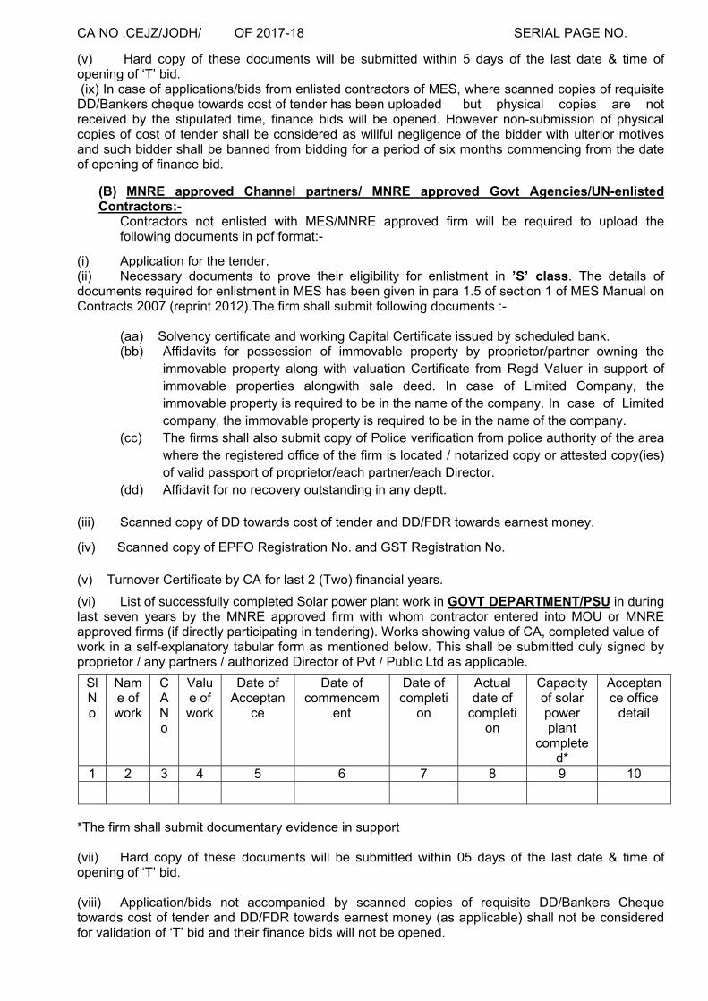
(v) Hard copy of these documents will be submitted within 5 days of the last date & time of opening of ‘T’ bid. (ix) In case of applications/bids from enlisted contractors of MES, where scanned copies of requisite DD/Bankers cheque towards cost of tender has been uploaded but physical copies are not received by the stipulated time, finance bids will be opened. However non-submission of physical copies of cost of tender shall be considered as willful negligence of the bidder with ulterior motives and such bidder shall be banned from bidding for a period of six months commencing from the date of opening of finance bid.
(B) MNRE approved Channel partners/ MNRE approved Govt Agencies/UN-enlisted Contractors:-
Contractors not enlisted with MES/MNRE approved firm will be required to upload the following documents in pdf format:-
(i) Application for the tender. (ii) Necessary documents to prove their eligibility for enlistment in ’S’ class. The details of documents required for enlistment in MES has been given in para 1.5 of section 1 of MES Manual on Contracts 2007 (reprint 2012).The firm shall submit following documents :-
(aa) Solvency certificate and working Capital Certificate issued by scheduled bank. (bb) Affidavits for possession of immovable property by proprietor/partner owning the
immovable property along with valuation Certificate from Regd Valuer in support of immovable properties alongwith sale deed. In case of Limited Company, the immovable property is required to be in the name of the company. In case of Limited company, the immovable property is required to be in the name of the company.
(cc) The firms shall also submit copy of Police verification from police authority of the area where the registered office of the firm is located / notarized copy or attested copy(ies) of valid passport of proprietor/each partner/each Director.
(dd) Affidavit for no recovery outstanding in any deptt.
(iii) Scanned copy of DD towards cost of tender and DD/FDR towards earnest money.
(iv) Scanned copy of EPFO Registration No. and GST Registration No. (v) Turnover Certificate by CA for last 2 (Two) financial years.
(vi) List of successfully completed Solar power plant work in GOVT DEPARTMENT/PSU in during last seven years by the MNRE approved firm with whom contractor entered into MOU or MNRE approved firms (if directly participating in tendering). Works showing value of CA, completed value of work in a self-explanatory tabular form as mentioned below. This shall be submitted duly signed by proprietor / any partners / authorized Director of Pvt / Public Ltd as applicable.
Sl No
Name of work
CA No
Value of work
Date of Acceptan
ce
Date of commencem
ent
Date of completi
on
Actual date of
completion
Capacity of solar power plant
completed*
Acceptance office
detail
1 2 3 4 5 6 7 8 9 10
*The firm shall submit documentary evidence in support (vii) Hard copy of these documents will be submitted within 05 days of the last date & time of opening of ‘T’ bid. (viii) Application/bids not accompanied by scanned copies of requisite DD/Bankers Cheque towards cost of tender and DD/FDR towards earnest money (as applicable) shall not be considered for validation of ‘T’ bid and their finance bids will not be opened.

CA NO .CEJZ/JODH/ OF 2017-18 SERIAL PAGE NO. (ix) Tenderers/bidders to note that they should ensure that their original DDs and earnest money (as applicable) are received within 05 days of bid submission end date. (x) In case of application/bids where scanned copies of requisite Earnest money (as applicable) were uploaded but the same are not received in physical form within stipulated time, such bids shall not qualify for opening of finance bid. (C) In case of rejection of technical/prequalification bid, contractor may appeal to next higher Engineer authority i.e. CESC Pune on email [email protected] against rejection, whose decision shall be final and binding. However contractor/bidder shall not be entitled to any compensation whatsoever for rejection of technical/prequalification bid.
(D) Jurisdiction of courts: Irrespective of the place of submission of e-bid by the bidder the courts of Jodhpur/High Court at Jodhpur (Rajasthan) only shall have jurisdiction with reference to any matter pertaining to issue/opening this tender. After acceptance of tender, condition 72-Jurisdiction of Courts of IAFW-2249 shall be applicable.
___________________ _______________ Signature of contractor (T R Chourasia) Dy Dir (Contracts) For Accepting Officer File No 800410/10 /E8
Dated : 20 July 2017
Chief Engineer Jodhpur Zone ECHS Polyclinic Complex, Opp MH Jodhpur-342010 Email: [email protected]
DISTRIBUTION SERIAL NO.1 TO 2 BY REGISTERED POST 1. The Hony, Secretary MES BAI (Regd) Raj,
Branch Defence lab, Ratanada, Jodhpur. 14. AGE (I) Nagtalao
2. MES Builders Association of India, 807, Sahyog, 58, Nehru Place, New Delhi-19
15. GE Nasirabad
3. HQ Chief Engineer Bhopal Zone, Bhopal. 16. GE Banar 4. HQ Chief Engineer Jaipur Zone, Jaipur. 17. GE (AF) Utterlai 5. Chief Engineer (AF), Gandhinagar 18. GE (AF) Jaisalmer 6. CWE (A) Jodhpur 19. GE (A) Central, Jodhpur 7. CWE (AF) Jodhpur 20. GE (A) Barmer 8. CWE Jaisalmer 21. GE (A) Jaisalmer 9. GE (A) Central, Jodhpur 22. GE (A) (P) NO 1 Jaisalmer 10. GE (A) Utility, Jodhpur 23. GE (A) (P) NO 2 Jaisalmer 11. GE Shikargarh 24. Executive Engineer CPWD, Jodhpur 12. AGE (I) R&D, Jodhpur 25. S E CPWD Jodhpur Circle 13. AGE (I) Udaipur
Internal E2 Sec, E4 Sec and Case File: 800410/C/E8

CA NO CEJZ/JODH/ OF 2017-18 SERIAL PAGE NO 15 IN LIEU OF IAFW-2159 (REVISED-1947)
(TO BE USED IN CONJUNCTION WITH GENERAL CONDITION OF CONTRACTS
IAFW-2249)
MILITARY ENGINEER SERVICES Tele Civil: (0291) 2515113 Headquarters Chief Engineer Jodhpur Zone ECHS Complex Jodhpur Jodhpur – 342010 (Email id: [email protected]) 800410/ 12 /E8 25 July 2017
LUMP SUM TENDER AND CONTRACT FOR PROVISION OF 2MW SOLAR POWER PLANT UNDER GE(A) UTILITY AT JODHPUR. (JOB NO: SC/MW/1251)
1. Shri / S’ Shri ………………………………….………..……… of …………………….. is / are hereby authorized to tender for the above work. The tender is to be forwarded on eprocuremes.gov.in portal on or before the scheduled date and time for bid closing mentioned in the tender details on the portal. 2. All documents must be uploaded while forwarding the bid on abovementioned portal. 3. Any correspondence on clarification concerning this tender shall be communicated as per information available on the e-portal mentioned above by due date. 4. THE PRESIDENT OF INDIA DOES NOT BIND HIMSELF TO ACCEPT THE LOWEST OR ANY TENDER. Signature of contractor Signature of Officer
Issuing the documents Appointment
Dy Director(Contracts)
CA NO CEJZ/JODH/ OF 2017-18 SERIAL PAGE NO 16
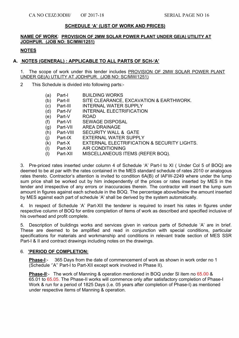
SCHEDULE ‘A’ (LIST OF WORK AND PRICES)
NAME OF WORK: PROVISION OF 2MW SOLAR POWER PLANT UNDER GE(A) UTILITY AT JODHPUR. (JOB NO: SC/MW/1251)
NOTES
A. NOTES (GENERAL) : APPLICABLE TO ALL PARTS OF SCH-‘A’
1. The scope of work under this tender includes PROVISION OF 2MW SOLAR POWER PLANT UNDER GE(A) UTILITY AT JODHPUR. (JOB NO: SC/MW/1251)
2 This Schedule is divided into following parts:-
(a) Part-I BUILDING WORKS (b) Part-II SITE CLEARANCE, EXCAVATION & EARTHWORK. (c) Part-III INTERNAL WATER SUPPLY (d) Part-IV INTERNAL ELECTRIFICATION (e) Part-V ROAD (f) Part-VI SEWAGE DISPOSAL (g) Part-VII AREA DRAINAGE (h) Part-VIII SECURITY WALL & GATE (j) Part-IX EXTERNAL WATER SUPPLY (k) Part-X EXTERNAL ELECTRIFICATION & SECURITY LIGHTS. (l) Part-XI AIR CONDITIONING (l) Part-XII MISCELLANEOUS ITEMS (REFER BOQ).
3. Pre-priced rates inserted under column 4 of Schedule ‘A’ Part-I to XI ( Under Col 5 of BOQ) are deemed to be at par with the rates contained in the MES standard schedule of rates 2010 or analogous rates thereto. Contractor’s attention is invited to condition 6A(B) of IAFW-2249 where under the lump sum price shall be worked out by him independently of the prices or rates inserted by MES in the tender and irrespective of any errors or inaccuracies therein. The contractor will insert the lump sum amount in figures against each schedule in the BOQ. The percentage above/below the amount inserted by MES against each part of schedule ‘A' shall be derived by the system automatically.
4. In respect of Schedule ‘A’ Part-XII the tenderer is required to insert his rates in figures under respective column of BOQ for entire completion of items of work as described and specified inclusive of his overhead and profit complete.
5. Description of buildings works and services given in various parts of Schedule ‘A’ are in brief. These are deemed to be amplified and read in conjunction with special conditions, particular specifications for materials and workmanship and conditions in relevant trade section of MES SSR Part-I & II and contract drawings including notes on the drawings. 6. ’PERIOD OF COMPLETION:
Phase-I:- 365 Days from the date of commencement of work as shown in work order no 1 (Schedule ‘’A’’ Part-I to Part-XII except work involved in Phase II).
Phase-II:- The work of Manning & operation mentioned in BOQ under Sl item no 65.00 & 65.01 to 65.05. The Phase-II works will commence only after satisfactory completion of Phase-I Work & run for a period of 1825 Days (i.e. 05 years after completion of Phase-I) as mentioned under respective items of Manning & operation.

CA NO CEJZ/JODH/ OF 2017-18 SERIAL PAGE NO 17 Notes: Separate completion certificate shall be issued for both Phases. Defect & Liability Period as per Condition 46 of IAFW-2249 (General Conditions of Contracts) shall start only after completion of Phase-I Work. The whole work shall be deemed to complete only after completion of Phase-II Work. Two final bills shall be progressed separately (One Final Bill for Phase-I Work & other Final Bill for Phase-II Work). Preparatory works, collection of materials & all such preliminary works & site clearance after completion shall be deemed to be included in the period of completion stated above.’’
7. In case details in respect of items shown on main drawings are not given in the drawings referred to in the main drawing, then the same shall be followed from any other drawings included in the list of drawings. Any drawing mentioned in the contract/contract drawings but not included in the list of drawings shall also be deemed to form part of contract.
8. Layout of internal/external services is tentative and may be changed as per the site requirement at the discretion of the GE. No claim on this account shall be entertained and contractor quoted rates shall be deemed to cater for the same.
9. Layout of buildings indicated in the site plan is tentative and may be changed as per the site requirement at the discretion of the GE while doing layout of buildings on ground within site plan. No claim on this account shall be entertained and contract rates shall be deemed to cater for the same.
10. The lump sum quoted by the tenderer against each part of Schedule ‘A’ in BOQ, shall be deemed to include all minor extras and constructional details, which are not specifically shown on drawings and specified in particular specifications but are essential for execution of work services in workman like manner and sound construction practices. In case of difference of opinion as to whether or not a certain item of work constitute minor extras and constructional details in the contract prices, the decision of the Accepting Officer in this regard shall be final, conclusive and binding.
11. Wooden gutties as specified in SSR shall not be used in this work. In lieu of wooden gutties, PVC sleeves of appropriate sizes shall be provided for fixing of fittings/fixtures to the entire satisfaction of GE.
12. Where specifications for any item of work are not given in MES schedule or in particular specifications, specification given in relevant Indian Standard or code of practice shall be followed.
13. The under mentioned remarks shall be deemed to have been inserted in respective columns of Schedule ‘A’ Part-I to XI against each item:-
(a) Under column 3 Refer list of drawings (b) Under column 7 (Period of Refer Note No 6 of
completion for individual item Schedule ‘A’ Notes from date of handing over the site)
(c) Under column 8 (Remarks) Refer Notes of the Schedule ‘A
And for Schedule ‘A’ Part- XII, following shall be inserted:- (a) Under column 3 Refer list of drawings (b) Under column 8 (Period of Refer Note No 7 of
completion for individual item Schedule ‘A’ Notes from date of handing over the site)
(c) Under column 9 (Remarks) Refer Notes of the Schedule ‘A

CA NO CEJZ/JODH/ OF 2017-18 SERIAL PAGE NO 18
SCHEDULE ‘A’ (LIST OF WORK AND PRICES) CONTD…
B. NOTES: (APPLICABLE TO SCHEDULE ‘A’ PART I)
14. The lump sum quoted against items of Schedule “A” Part-I shall include all works as shown on drawings and/or mentioned in notes thereon and/or specified in Schedule “A” and/or particular specifications except for items of works catered for in Schedule ‘A’ Part-II to Part-XII and provisional lump sum, complete for entire completion of work unless any item of work is specifically/ categorically excluded from scope of work. For illustration purpose, following items which are deemed to be included in the unit rate of building items in Schedule “A” Part-I are mentioned. The list is an illustration for guidance purpose and is not meant to be exclusive list of items included in the lump sum rate quoted. No claim shall be entertained on the reason that other items shown on drawings and/or specified in particular specifications, merely because these have not been included in this list, are not covered in the unit rate of the item.
(i) All cable ducts as shown in drawings.
(ii) All fittings and fixtures shown in drawings.
(iii) Plinth protection, Steps etc wherever shown in drawings.
(iv) Pre-construction anti-termite treatment at serial No 1 & 2 of Sch ‘’A’’ Part I.
(v) All internal sanitary appliances, fittings including Nahani traps, gully traps, soil, waste and vent pipes with fittings and vent cowls (soil and waste pipes from building up to first manhole which shall be at a distance not exceeding 2 meter from outer face of building wall).
(vi) Overhead service water tank of capacity as & wherever shown in drawing including pipes and fittings to the extent specified.
(vii) All soil/waste/vent pipes and rain water pipe, fittings as required up to and including gully traps and inspection chambers/first manhole all as shown in drawings. Exact location and position of GT (Gully Trap) and IC (Inspection Chamber/first manhole) if not shown on drawings, shall be considered as 30cm and 200cm respectively from the external face of buildings.
(ix) All strengthening measures as per the details shown on drawings for seismic Zone-III.
15. The unit rates of buildings of Schedule ‘A’ Part-I shall also deemed to include the cost of the following items/ works whether specifically specified and shown on drawing or not.
(a) All excavation and earth work as required unless mentioned otherwise in description of item.
(b) Any cutting, leaving / forming holes, chases, etc through/in walls, as required and making good to match with the adjoining surfaces, required in connection with the works included in various parts of Schedule ‘A’. No adjustment shall however, be made in the quoted lump sum on this account while pricing any deviation for items in respect of Schedule ‘A’ Part-I & also due to any variation in quantities indicated as provisional in the tender documents.
C. NOTES: (APPLICABLE TO SCHEDULE ‘A’ PART- II TO XI)
16. All items/quantities are “Provisional”.
17. Unless specifically specified otherwise the unit rate of each items of work shall be deemed to be inclusive of supply of all material and labour or fixing etc complete. All
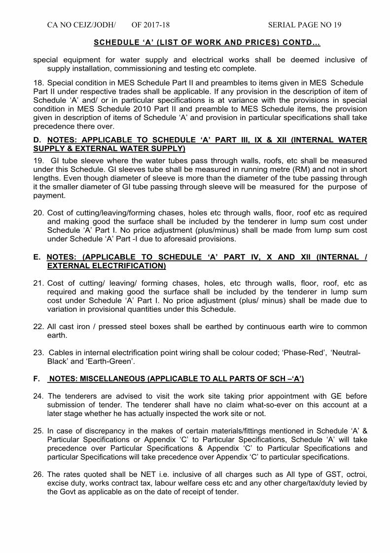
CA NO CEJZ/JODH/ OF 2017-18 SERIAL PAGE NO 19
SCHEDULE ‘A’ (LIST OF WORK AND PRICES) CONTD… special equipment for water supply and electrical works shall be deemed inclusive of supply installation, commissioning and testing etc complete.
18. Special condition in MES Schedule Part II and preambles to items given in MES Schedule Part II under respective trades shall be applicable. If any provision in the description of item of Schedule ‘A’ and/ or in particular specifications is at variance with the provisions in special condition in MES Schedule 2010 Part II and preamble to MES Schedule items, the provision given in description of items of Schedule ‘A’ and provision in particular specifications shall take precedence there over.
D. NOTES: APPLICABLE TO SCHEDULE ‘A’ PART III, IX & XII (INTERNAL WATER SUPPLY & EXTERNAL WATER SUPPLY)
19. GI tube sleeve where the water tubes pass through walls, roofs, etc shall be measured under this Schedule. GI sleeves tube shall be measured in running metre (RM) and not in short lengths. Even though diameter of sleeve is more than the diameter of the tube passing through it the smaller diameter of GI tube passing through sleeve will be measured for the purpose of payment.
20. Cost of cutting/leaving/forming chases, holes etc through walls, floor, roof etc as required and making good the surface shall be included by the tenderer in lump sum cost under Schedule ‘A’ Part I. No price adjustment (plus/minus) shall be made from lump sum cost under Schedule ‘A’ Part -I due to aforesaid provisions.
E. NOTES: (APPLICABLE TO SCHEDULE ‘A’ PART IV, X AND XII (INTERNAL / EXTERNAL ELECTRIFICATION)
21. Cost of cutting/ leaving/ forming chases, holes, etc through walls, floor, roof, etc as required and making good the surface shall be included by the tenderer in lump sum cost under Schedule ‘A’ Part I. No price adjustment (plus/ minus) shall be made due to variation in provisional quantities under this Schedule.
22. All cast iron / pressed steel boxes shall be earthed by continuous earth wire to common earth.
23. Cables in internal electrification point wiring shall be colour coded; ‘Phase-Red’, ‘Neutral- Black’ and ‘Earth-Green’.
F. NOTES: MISCELLANEOUS (APPLICABLE TO ALL PARTS OF SCH –‘A’)
24. The tenderers are advised to visit the work site taking prior appointment with GE before submission of tender. The tenderer shall have no claim what-so-ever on this account at a later stage whether he has actually inspected the work site or not.
25. In case of discrepancy in the makes of certain materials/fittings mentioned in Schedule ‘A’ & Particular Specifications or Appendix ‘C’ to Particular Specifications, Schedule ‘A’ will take precedence over Particular Specifications & Appendix ‘C’ to Particular Specifications and particular Specifications will take precedence over Appendix ‘C’ to particular specifications.
26. The rates quoted shall be NET i.e. inclusive of all charges such as All type of GST, octroi,
excise duty, works contract tax, labour welfare cess etc and any other charge/tax/duty levied by the Govt as applicable as on the date of receipt of tender.

CA NO CEJZ/JODH/ OF 2017-18 SERIAL PAGE NO 20
SCHEDULE ‘A’ (LIST OF WORK AND PRICES) CONTD…
27. MACHINE FOUNDATIONS:
Foundations of panels shall be provided all as per manufacturer’s instructions and shall be deemed to be included in rates quoted by the tenderer for these items.
28. PERIODIC PERFORMANCE EVALUATION:
Tenderer to note that Periodic Performance Evaluation of the contract shall be done as stipulated by E-in C Branch vide their letter No A/37696/05 DPL/Pol/E2W(PPC) dated 13 Aug 2014. This policy letter can be seen in office of any MES formation, the same is also available in MES website.
29. IS wherever mentioned in the tender documents shall be with Latest revisions & number upto date of receipt of tender documents. No extra shall be admissible on this account.
30. The contractor shall submit following documents before completion of work:- (i) PSMBs for all the bldgs constructed under this work. (ii) Record drawings for all the bldgs constructed under this work. (iii) Road Record with drawings for roads constructed under this work. (iv) Electrical drawings for internal electrification and External Electrification layout. (v) External and internal water supply layout (vi) sewage disposal layout
31. The layout of all bldgs, roads & ground levels shall be carried out with “Total station” latest surveying instruments.
Signature of Contractor Dy Dir (Contracts) Dated: _____________ For Accepting Officer

CA NO : CEJZ/JODH/ OF 2017-18 Serial Page No.21
S
/No
Description of item of works Rate per Unit
(Rs)
No of
units
require
d
Amount (Rs)
1 2 4 5 6
1 720000.00 1 720000.00 EACH
BLOCK
2 960000.00 1 960000.00 EACH
BLOCK
1680000.00
Signature of contractor
Date :
Dy Director (Contracts)
For Accepting Officer
TOTAL AMOUNT OF SCHEDULE "A" PART-I C/O TO BOQ
Construction of block of one Control Room complete all
as specified and shown on drawings.
SCHEDULE ‘A’ PART- I
(BUILDING WORKS)
NAME OF WORK : PROVISION OF 2MW SOLAR POWER PLANT UNDER GE(A) UTILITY AT
JODHPUR. (JOB NO: SC/MW/1251)
Refer Note 13 on page No 17 for column 3, 7 and 8
Construction of Semi Under Ground Sump of Capacity
(20000 Gallon) with all fittings and fixtures etc. complete
all as specified and shown on drawings.

CA NO : CEJZ/JODH/ OF 2017-18 Serial Page No.22
Sr
/NoDescription of item of works
Rate per
Unit (Rs) No of units
requiredAmount (Rs)
1 2 4 5 6
5.30 40470 214491.00
SQM
27.80 675 18765.00
SQM
3 115.20 990 114048.00
CUM
4 202.50 1680 340200.00
CUM
114.60 3250 372450.00
EACH
6 41.70 1075 44827.50
CUM
96.10 410 39401.00
CUM
149.40 1643 245464.20
CUM
161.40 40 6456.00
CUM
1396102.70
Signature of contractor
Date :
Total amount of Schedule ‘A’ Part-II c/o to BOQ
9 Removing excavated material (Soil) to a distance exc 500mtr but
n.exc 1 KM and depositing where directed at a level n.exc 1.5m
above the starting point complete all as specified and directed.
Dy Director (Contracts)
for Accepting Officer
5 Excavation in post holes (or similar holes) in hard dense soil each
not exc 0.50 cum, getting out, returning, filling in and ramming earth
or broken rubble mixed with earth around in layers not exc 25 cm
watering and removing surplus soil/rock to a distance not exc 50 m
and making good surface complete all as specified and directed.
8 Removing excavated material (Soil) to a distance exc 250mtr but
n.exc 500 mtr and depositing where directed at a level n.exc 1.5m
above the starting point complete all as specified and directed.
1 Site Clearance in soft/loose soil complete all as specified & directed.
Excavation in trenches, n.exc 1.5 m wide and n.exc 1.5 m in depth
for foundation/cable etc and getting out in soft/loose soil complete
all as specified and directed.
2 Surface excavation n.exc 30 cm deep and averaging 15 cm deep
and getting out in hard/dense soil complete all as specified &
directed.
Returning, filling in including spreading, leveling, watering and well
ramming in layers n. exc 25 cm thick in soil complete all as specified
and directed.
Excavation in trenches, n.exc 1.5 m wide and n.exc 1.5 m in depth
for foundation and getting out in hard/dense soil complete all as
specified and directed.
7 Removing excavated material (Soil) to a distance n.exc 50 mtr and
depositing where directed at a level n.exc 1.5m above the starting
point complete all as specified and directed.
SCHEDULE ‘A’ PART -II
( SITE CLEARANCE & EXCAVATION & EARTH WORK )
Refer Note 13 on page No 17 for column 3, 7 and 8

CA NO : CEJZ/JODH/ OF 2017-18 Serial Page No. 23
S/N
o
Description of item of works Rate per
Unit (Rs)No of
units
requir
ed
Amount
(Rs)
1 2 4 5 6
1 S&F mild steel tubes, medium grade (ISI Marked), galvanised with all
fitting (ISI Marked) and concealed or fixed complete to wall, ceiling or
laid in floors complete all as specified & directed of following sizes :-
227.50 10 2275.00
RM
153.80 10 1538.00
RM
116.60 5 583.00
RM
215.00 1 215.00
EACH
301.00 1 301.00
EACH
180.30 2 360.60
EACH
271.00 2 542.00
EACH
Signature of contractor
Date : for Accepting Officer
TOTAL AMOUNT OF SCHEDULE "A" PART-III C/O TO BOQ 5814.60
3 S&F bib taps, cast copper alloy, fancy type, chromium plated (ISI
Marked), with crutch or butter fly handle, screwed down, screwed for
iron pipe or for brass ferrule and fixed to 15mm bore pipe complete all
as specified & directed.
4 S&F stop valve, cast copper alloy (ISI marked) fancy type, chromium
plated with long shank & cup (concealed type) screwed down, high
presuure with crutch or butterfly handle, screwed both ends for iron
pipe or for unions of 15mm bore complete all as specified & directed.
SCHEDULE ‘A’ PART -III
( INTERNAL WATER SUPPLY )
Refer Note 13 on page No 17 for column 3, 7 and 8
(a) 25mm bore.
Dy Director (Contracts)
2 Supply and fixing Stop valves, cast copper alloy, screwed down, high
pressure,with crutch or butterfly handle, screwed both ends for iron
pipe or for unions and fixed complete of following sizes:-
(b) 25mm bore.
(a) 20mm bore.
(b) 20mm bore.
(c) 15mm bore.

CA NO : CEJZ/JODH/ OF 2017-18 Serial Page No.24
S/N
o
Description of item of works Rate per
Unit (Rs)
No of
units
requir
ed
Amount (Rs)
1 2 4 5 6
NOTE:-
1 Point wiring using approved colour coding as per IS (Red, Black and
Green for single phase circuits), with multi-stranded copper
conductor 1.5 Sq. mm nominal cross-sectional area, single core,
PVC insulated and unsheathed FRLS cable 1100 volts grade, ISI-
694 marked with valid CML No. in and including medium grade, PVC
concealed conduit of dia not less than 20mm and conduit
accessories, ISI marked with valid CML No.(IS-9537-1983 for
conduits and IS:3419:1976 for conduit accessories) concealed in
wall/roof/floor etc with mild steel/pressed steel sunken boxes (with
earth dolly) duly painted with two coats of anti corrosive
paint/aluminium paint over a coat of red oxide primer internally and
two coats of black bituminous paint over a coat of red oxide primer
externally, covered with 3mm thick plastic laminated sheet cover for
fixing of switches, sockets etc including PVC insulated multi-
stranded copper conductor 1.5 Sqmm nominal cross sectional area
single core FRLS cable as earth continuity conductor to common
earth and connecting to earth dolly complete all as specified and
directed for the following :-
NOTE: - Switch and socket to be measured and paid for separately.
(a) 509.10 11 5600.10
POINT
(b) 84.00 1 84.00
POINT
(c) 509.10 1 509.10
POINT
Rs 6193.20
One socket out let, 5 pin, 5/6 Amp on same board
One switch socket out let 5 pin, 5/6 Amp on independent board
Total amount of Schedule ‘A’ Part-IV c/o to Summary
One light /fan point controlled by one, one way SP switch
SCHEDULE ‘A’ PART -IV
(INTERNAL ELECTRIFICATION)
Refer Note 13 on page No 17 for column 3, 7 and 8
(i) The complete wiring installation shall be carried out in accordance and conformity with IS: 732
:1989 "Code of practise for electrical wiring(latest version)"
(ii) The unit rate against item of PVC concealed conduit point wiring includes for MS pressed steel
sunken boxes conforming to IS: 5139 (Part 1):1969, duly painted with two coats of anti corrosive paint
/ black bituminous paint externally and two coats of aluminium paint over a coat of red oxide primer
internally, for fixing switches, regulators, socket outlets etc with 3 mm thick plastic laminated sheet ISI
marked.
(iii) All screws, fasteners, bolts, nuts & washers etc shall be of cadmium plated, the cost of which is
deemed to be included in the unit rate.
(iv) The complete wiring installation shall be tested on completion as specified in particular
specifications.
(v) The cutting/leaving, forming chases shall be done with electric cutter and not by chiselling.

CA NO : CEJZ/JODH/ OF 2017-18 Serial Page No.25
1 2 4 5 6
2 990.00 2 1980.00
POINT
34.30 445.90
EACH
4 86.50 173.00
EACH
5 51.50 103.00
EACH
6 95.20 190.40
EACH
7 219.80 439.60
EACH
8 22.80 228.00
EACH
9 2536.80 2536.80
EACH
Rs 6096.70
Supply and fixing ceiling rose, three brass terminal, ISI marked,
PVC/polycarbonate, isolated body complete all as specified and
directed.
10
Material and labour for plate earthing complete with galvanized mild
steel plate electrode 60 cm x 60 cm x 6.0 mm thick buried directly in
ground vertically (in earth pit not less than 2.25 metre deep below
ground level) with the top edge of earth plate at a depth not less than
1.5 metre below normal ground level, the earth electrode
surrounded by adequate quantity of charcoal dust and salt to a
packed thickness of 15 cm on all sides and including GI earth wire 4
mm dia bolted (with GI nuts, bolts & check nuts) and rivetted to
earth (Plate) electrode at one end and connected to main switch
board / DB at the other, earth wire protected by and including GI pipe
15 mm dia (medium grade) from top of electrode to main switch
board and also including watering pipe GI pipe (medium grade) 20
mm bore from bottom of earth pit to top of electrode complete with
earth pit in PCC 1:2:4 type B0 using 12 mm graded crushed stone
aggregate, RCC cover, funnel, wire mesh including necessary
excavation & earth work, etc as shown on electrical plate No 3 of
SSR Part I.
1
Total amount of Schedule ‘A’ Part-IV c/o to Summary
Supply and fixing socket outlet multipurpose having provision for 3
pin, 5 Amp and 2 pin, 5 Amp, piano flush type IS: 1293-2005 marked
with valid CML No complete all as specified and directed.
2
Supply and fixing socket outlet multipurpose having provision for 3
pin, 15/16 Amp and 3 pin, 5/6 Amp, piano flush type IS: 1293-2005
marked with valid CML No complete all as specified and directed.
2
Supply and fixing, ceiling fan regulator electronic stepped flush type
230 Volts, ISI marked with valid CML No and connecting up
complete all as specified and directed.
2
Supply and fixing switch piano; flush type, single pole, one way, and
15/16 Amps IS: 3854 marked with valid CML No. complete all as
specified and directed.
2
SCHEDULE 'A' PART - IV (CONTD….)
(INTERNAL ELECTRIFICATION)
Refer Note 13 on page No 17 for column 3, 7 and 8
All as per item No 1 here in before but point wiring with 4.00 sqmm
single core multi stranded copper conductor PVC insulated and
unsheathed (FRLS) cable 1100 volts grade and 4.00 Sqmm PVC
insulated and unsheathed (FRLS) cable 1100 volts grade with multi-
stranded copper conductor as earth wire for 15/16 Amps multi
purpose socket combination point on independent board.
3 Supply and fixing switch piano; flush type, single pole, one way and
5/6 Amp, ISI marked with IS: 3854 with valid CML No. complete all
as specified and directed.
13

CA NO : CEJZ/JODH/ OF 2017-18 Serial Page No.26
1 2 4 5 6
10 Supply and fixing MCB/MCCB Distribution board (concealed flush to
wall), , for mounting MCBs, factory made, confirming to IS : 13032
fabricated out of CRCA sheet not less than 1.20 mm thick fitted with
DIN channel, neutral link and 200 Amps rated bus bar DBs shall be
semi glossy finished with epoxy polyester based powder paint
sprayed and backed at high temperature, between powder paint
process to ensure smooth finish and protection against corrosion
atmosphere. The DBs shall be double door type with hinged door
with locking arrangerment. The DBs shall be of same make as
MCBs. DB shall also be provided with lable marking indicating the
incoming and outgoing circuits on all ways as specified.The DBs
shall be of IP 42 procteciton class for the following:-
1232.90 1 1232.90
EACH
11 157.00 20 3140.00
RM
12 213.00 20 4260.00
RM
13 307.40 1 307.40
Each
Rs 8940.30
Total amount brought forward from Sl page No 24 Rs 6193.20
Total amount brought forward from Sl page No 25 Rs 6096.70
Total amount brought forward from Sl page No 26 Rs 8940.30
Rs 21230.20
Signature of contractor
Date :
Total amount of Schedule ‘A’ Part-IV c/o to Summary
SUMMARY OF SCHEDULE "A" PART-IV
TOTAL AMOUNT OF SCHEDULE "A" PART-IV C/O TO BOQ
Jt Director (Contracts)
For Accepting Officer
S & F MCB, 32 Amp DP isolator,240 volts, 10 kA, "C" Series curve
complete all as specified and directed.
SCHEDULE 'A' PART - IV (CONTD….)
(INTERNAL ELECTRIFICATION)
Refer Note 13 on page No 17 for column 3, 7 and 8
(a) SPN, 8 way, 230 volts, double door
Supply and fixing sub main wiring with Two runs of 4.0 Sqmm size
main cable and one run of 4.0 Sqmm size earth continuty conductor
of single core PVC insulated but unsheathed FRLS cable multi
standed copper conductors, 1100 volts grade, IS-694 marked all
drawn through and including suitable size rigid PVC conduit pipe
medium grade ISI marked & fittings/ accessories all fixed to the
surface of wall/ceiling complete all as specefied.
Note : The under mentioned specefied runs of single core cables
and specefied runs of earth continuity conductors and the relevant
conduit with accessories shall be measured as one runs length. The
small extra lengths required for loops etc for connection in DBs are
deemed to the included and only the cable covered in conduit shall
be measured.
All as per item No 11 above but sub main wiring with two runs of 6.0
Sqmm size main cable and one run of 6.0 Sqmm size earth
continuty conductor.

CA NO : CEJZ/JODH/ OF 2017-18 Serial Page No. 27
S/N
o
Description of item of works Rate per
Unit (Rs)
No of
units
required
Amount (Rs)
1 2 4 5 6
8.00 67.50 540.00
X SQM
1675.70 67.50 113109.75
X SQM
1645.00 67.50 111037.50
X SQM
109.20 67.50 7371.00
X SQM
429.50 67.50 28991.25
X SQM
2361.40
325.30 360.00 117108.00
RM
1204.80 6.00 7228.80
RM
523.90 36.00 18860.40
X SQM
Total 563641.20
Signature of contractor
Date :
5 M&L for applying evenly priming tack coat on WBM with bituminous primer
using paving bitumen at VG 10 @ 10 Kg per 10 Sqm complete all as
specified and as directed.
For Accepting Officer
Dy Director (Contracts)
7 M & L for stone kerbs roughly squared stone of size 20cmX30cm, all
surface hammered dresed so that the maximum depression from the
straight edge held against the dressed surface shall not exceed 20mm
jointed in CM 1:6 and stuck flush complete all as specified and directed.
159394.50
X SQM
9 M & L for morrum as in berms rolled and consolkidated to gradient and
camber all as specified for 100mm thick complete all as specified and
directed.
Total amount of Schedule ‘A’ Part- V carried over to BOQ
8 M & L for reinforced concrete pipes class NP-2 laid and jointed complete
collar with bore of pipe 600 mm dia complete all as specified and directed.
6 Material and labour for bituminous premix semi dense asphatic concrete
40 mm consoildated/ compacted thickness using hot mix plant and
mechnical paver with 5.5%(paving bitumin VG -30 grade ) binder content
by weight of total mix ,rolled and compacted using 8 to 10 tone power
roller to required camber and gradient complete all as pecified and directed
by Engr in charge .
67.50
SCHEDULE ‘A’ PART-V
( ROAD)
Refer Note 13 on page No 17 for column 3, 7 and 8
1 Rolling and consolidating to required gradient and camber of formation
surface (cutting or filling) of roads with 8 to 12 tonne power roller including
filling in depressions which occur during rolling complete all as specified &
directed.
M&L for soling (or sub base) 200mm thick (spread thickness) with broken
boulders or quarried stone (granite, trap, basalt) broken to size ranging
100mm to 50mm interstices filled, surfaces formed and rolled and
consolidate to required gradient and camber with 8 to 12 tone power roller
complete all as specified.
2
3 M&L for 150mm thick (compacted thickness) WBM in two layers, each
layer 75mm thick (compacted thickness) with coarse stone aggregate
(granite, trap or basalt) of grading 2 (63 to 40mm size spread & rolled with
8 to12 tonne power roller, rolled and consolidated to required gradient and
camber all as specified. Note: The unit rate inserted is for two layers of
WBM (75mm compacted thick each layer) measured as one unit, each
layer laid and compacted separately. The SSR provisions shall be deemed
to have modified accordingly.
4 Preparation of WBM surfaces by brushing with wire brushes for removing
caked mud etc sweeping with brooms and finally fanning the cleaned
surfaces with gunny bags to remove all loose dirt etc complete all as
specified and as directed.

CA NO : CEJZ/JODH/ OF 2017-18 Serial Page No. 28
S/No Description of item of works Rate per
Unit (Rs)
No of
units
require
d
Amount (Rs)
1 2 4 5 6
2303.30 3.00 6909.90
CUM
1524.70 15 22870.50
CUM
79.30 30 2379.00
SQM
194.40 245 47628.00
RM
283.30 250 70825.00
RM
3161.20 1.00 3161.20
CUM
14.90 10 149.00
RM
1.90
RM
147.30 25 3682.50
SQM
Total 157605.10
2 M&L for squared rubble walling jodhpur type brought upto course
well bonded, bedded and solidly hearted built in cement mortar (1:6)
complete all as specified and directed.
3 M&L for extra of hammer dressing to face stone with maximum
depression on face from straight edge not exc 20mm and dressing
face bed and joints as specified to squared rubble walling jodhpur
type brought upto cources as directed
M&L for 150 mm bore Reinforced concrete pipes, class NP2, laid
and jointed complete with collars complete all as specified and
directed.
5
4 M&L for PCC (1:3:6) type C-2 using 40 mm graded crushed stone
aggregate in concrete bedding to drain pipes including packing
under hauching against the sides of pipes after they are laid and
tested for 150 mm bore pipe complete all as specified and directed.
Total amount C/O to summary of Schedule `A` Part VI
6 M&L for providing cement concrete (1:2:4) type B0 (using 12.5mm
graded stone aggregate) in surfaces channels drains and benching
including form work and finishing fair and smooth using extra
cement complete all as specified and directed.
Note: - Forming fair finished channel shall be measured and
paid separately.
7 Extra for forming fair finished drain or channel 30 cm inner girth in
cement concrete using extra cement including forms, moulds,
mitred/stopped ends etc. complete all as specified and directed.
8 Add to or deduct from item No 7 for forming fair finished channels or
drains for each 25 mm girth or part thereof over or under 30 cm
complete all as specified and directed.
NOTE: - This item is only for adjustment of rate if applicable.
9 M&L for 15mm thick rendering in CM (1:4) mixed with water proofing
compound as per manufacturer's instructions on fair faces of
brick/concrete surfaces, finished even and smooth without using
extra cement complete all as specified.
For
adjust
ment
only
1 M&L for PCC (1:4:8) type D-2 using 40 mm graded crushed stone
aggregate in foundation, filling and mass concrete complete all as
specified and directed.
SCHEDULE ‘A’ PART-VI
( SEWAGE DISPOSAL )
Refer Note 13 on page No 17 for column 3, 7 and 8

CA NO : CEJZ/JODH/ OF 2017-18 Serial Page No. 29
1 2 4 5 6
35.30 10 353.00
KG
19.50 100.00 1950.00
RM
640.50 1.00 640.50
Each
4817.60 1.00 4817.60
CUM
49.10 50 2455.00
KG
Total 10216.10
167821.20
Signature of contractor
Date :
Form work to edges of concrete flats exc 5cm and n.exc 10cm wide
for rough finished surfaces of concrete complete all as specified and
directed by Engineer-in-charge.
10 Supply only integral water proofing compound complete all as
specified.
Total brought forward from Ser Page No 28157605.10
SCHEDULE ‘A’ PART-VI (Contd….)
(SEWAGE DISPOSAL)
Total amount carried over to summary of Schedule `A` Part VI
SUMMARY OF SCHEDULE ‘A’ PART- VI
14 M&L for mild steel TMT bars 6 to 8mm dia Grade 500D in
reinforcement cut to length bent to shape required including
cranking , bending spirally for hooping for columns, hooking ends
and binding with and including MS wire (annealed) not less than
0.9mm dia or securing with clips complete all as specified and
directed.
Refer Note 13 on page No 17 for column 3, 7 and 8
13 M&L for precast cement concrete (1:2:4) type B1 (using 20mm
graded stone agg) as in cover slabs for man holes and set in CM
1:4 including necessary from work all as specified.
Note :- Reinforcement work shall be measured and paid
separately under respective items of this schedule.
12 Cutting in to existing manholes for connecting new drains, internal
dia of pipe 150mm making good to pipe and rendering cutting out
existing benching for and forming branch channel (1/2 round or ¾
section) in cement concrete 1:2:4 type B1 smooth finished even
using without extra cement and reforming benching as required.
11
Dy Director (Contracts)
For Accepting Officer
Total amount of Schedule ‘A’ Part- VI carried over to BOQ
Total brought forward from Ser Page No 29
10216.10

CA NO : CEJZ/JODH/ OF 2017-18 Serial Page NO. 30
S/No Description of item of works Rate per
Unit (Rs)
No of
units
requir
ed
Amount
(Rs)
1 2 4 5 6
2303.30 87 200387.10
CUM
1524.70 625 952937.50
CUM
79.30 2030 160979.00
332.70 203 67538.10
X SQM
147.30 390 57447.00
SQM
3656.70 30 109701.00
CUM
3136.50 55.00 172507.50
CUM
14.90 780 11622.00
RM
1.90
RM
Total 1733119.20
Signature of contractor
Date :
5 M&L for rendering 15mm thick in CM (1:4) on stone masonry to
external surfaces to with out using extra cement complete all as
specified and directed.
Total amount of Schedule ‘A’ Part- VII carried over to BOQ
9 Add to or deduct from item No 8 for forming fair finished channels or
drains for each 25 mm girth or part thereof over or under 30 cm
complete all as specified and directed.
NOTE: - This item is only for adjustment of rate if applicable.
For
adjust
ment
only
7 M&L for PCC (1:2:4) type B-1 using 20mm graded stone aggregate
as in surface channels / drains, and benching including finishing top
of benching even and smooth using extra cement complete all as
specified and directed.
Note: - Forming fair finished channel shall be measured and
paid separately.
8 Extra for forming fair finished drain or channel 30 cm inner girth in
cement concrete using extra cement including forms, moulds,
mitred/stopped ends etc. complete all as specified and directed.
Jt Director (Contracts)
2 M&L for squared rubble walling jodhpur type brought upto course
well bonded, bedded and solidly hearted built in cement mortar (1:6)
complete all as specified and directed.
For Accepting Officer
SCHEDULE ‘A’ PART-VII
( AREA DRAINAGE )
Refer Note 13 on page No 17 for column 3, 7 and 8
1 M & L for Cement concrete (1:4:8) type D-2 using 40mm graded
stone aggregate as in foundation / bed concerete for drain complete
all as specified and directed.
3 Extra over stone masonry for hammer dressing to face stones with
maximum depression on face from a straight edge held against the
dressed surfaces not exc 20 mm and dressing face beds and joints
as specified to squared rubble walling, Jodhpur type,brought upto
courses complete all as specified and directed.
SQM
4 M&L for flush pointing in CM (1:4) to squared rubble coursed or
uncoursed wall in complete all as specified and directed.
6 M&L for PCC 1:3:6 type C-1 using 20mm graded aggregate copings,
kneelers, apex stones, bed plates, water throughs and like including
weathering, slightly rounded or chamfered angles and throating
including necessary form work complete all as specified and directed.

CA NO : CEJZ/JODH/ OF 2017-18 Serial Page No. 31
S/No Description of item of works Rate per
Unit (Rs)
No of
units
require
d
Amount (Rs)
1 2 4 5 6
2303.30 85 195780.50
CUM
1524.70 1135 1730534.50
CUM
79.30 3665 290634.50
SQM
436.40 367 160158.80
X SQM
36.40 3665 133406.00
SQM
48.20 2115 101943.00
KG
810.00 47 38070.00
100 RM
58.20 75 4365.00
SQM
9 4144.40 16 66310.40
CUM
Rs 2721202.70
3 M&L for extra of hammer dressing to face stone with maximum
depression on face from straight edge not exc 20mm and dressing
face bed and joints as specified to squared rubble walling jodhpur
type brought upto cources as directed
7 S&F galvanised 2 strand, steel barbed wire 2.24mm dia barbed
with 2mm dia barbs at 75mm spacings and straining and fixing to
any type of standard rails straining bolts, including, securing or
tying at crossings with and provision of galvanised mild steel wire,
staples or steel pins etc (each line wire to be measured) complete
all as specified & directed.
M & L for preparing new steel surfaces of any description
exceeding 10 cm width or girth and applying two coats of
synthetic enamel paint over a coat of red oxide primer complete
all as specified & directed.
5 M&L for of newly plastered / pointing surfaces of walls and
applying two coats of cement base paint over a coat of primer
complete all as specified and directed.
4 M&L for keyed pointing in CM (1:4) to squareed rubble course or
uncoursed wall in complete all as specified and directed.
6 S&F rolled mild steel in Joist, channel, angle, or tee sections, fixed
independently, without connecting plates, etc. (cut to ordinary
lengths i.e. within 20mm of the length indicated conforming to Fe-
290 Gde-165 ) complete all as specified & directed.
M&L for cement concrete (1:2:4) type B-1 using 20 mm graded
stone aggregate weathering /slighlty rounded or chamferd angles
and throating as coping as directed.
8
Total amount of Schedule ‘A’ Part- VIII C/O to Summary
2 M&L for squared rubble walling jodhpur type brought upto course
well bonded, bedded and solidly hearted built in cement mortar
(1:6) complete all as specified and directed.
SCHEDULE ‘A’ PART-VIII
( SECURITY WALL & GATE )
Refer Note 13 on page No 17 for column 3, 7 and 8
1 M&L for PCC (1:4:8) type D-2 using 40 mm graded crushed stone
aggregate in foundation, filling and mass concrete complete all as
specified and directed.

CA NO : CEJZ/JODH/ OF 2017-18 Serial Page No. 32
1 2 4 5 6
132.20 156 20623.20
RM
11 96500.00 1 96500.00
EACH
JOB
Rs 117123.20
2838325.90
Signature of contractor
Date : For Accepting Officer
Total brought forward from Ser Page No 32 117123.20
2721202.70
SUMMARY OF SCHEDULE ‘A’ PART- VIII
Total amount of Schedule ‘A’ Part- VIII C/O to BOQ
Dy Director (Contracts)
Total amount of Schedule ‘A’ Part- VIII C/O to Summary
M&L Steel gate 6.0 meter wide including RCC M-25 (Design mix)
pillars, execavation and earthwork in any type of soil,formwork,
reinforcement steel, painting to steel work with two coat of
synthetic enamel paint over a coat of red oxide primer, two coats
of cement paint to pillars etc. complete all as specified and shown
on drawing no CEJZ/TD/13 Sheet no 1/2 & 2/2.
10 S&F 75mm dia PVC (SWR) pipes single socketed, in any length
with rubber ring joints, laid in trenches or in floors for drain out
water complete all as specified and directed.
Total brought forward from Ser Page No 31
( SECURITY WALL & GATE )
Refer Note 13 on page No 17 for column 3, 7 and 8
SCHEDULE ‘A’ PART-VIII
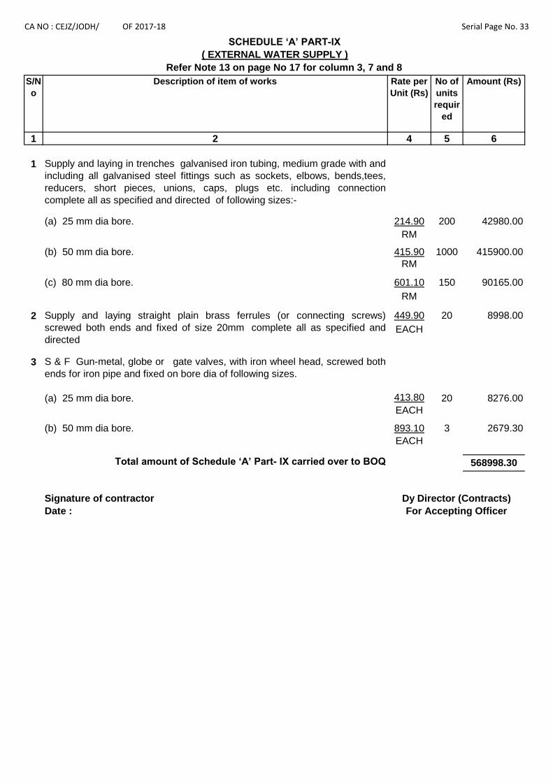
CA NO : CEJZ/JODH/ OF 2017-18 Serial Page No. 33
S/N
o
Description of item of works Rate per
Unit (Rs)
No of
units
requir
ed
Amount (Rs)
1 2 4 5 6
214.90 200 42980.00
RM
415.90 1000 415900.00
RM
601.10 150 90165.00
RM
2 449.90 20 8998.00
EACH
3
413.80 20 8276.00
EACH
893.10 3 2679.30
EACH
Signature of contractor
Date :
568998.30
(b) 50 mm dia bore.
(a) 25 mm dia bore.
(c) 80 mm dia bore.
SCHEDULE ‘A’ PART-IX
( EXTERNAL WATER SUPPLY )
For Accepting Officer
Dy Director (Contracts)
Refer Note 13 on page No 17 for column 3, 7 and 8
(a) 25 mm dia bore.
Supply and laying straight plain brass ferrules (or connecting screws)
screwed both ends and fixed of size 20mm complete all as specified and
directed
(b) 50 mm dia bore.
1 Supply and laying in trenches galvanised iron tubing, medium grade with and
including all galvanised steel fittings such as sockets, elbows, bends,tees,
reducers, short pieces, unions, caps, plugs etc. including connection
complete all as specified and directed of following sizes:-
S & F Gun-metal, globe or gate valves, with iron wheel head, screwed both
ends for iron pipe and fixed on bore dia of following sizes.
Total amount of Schedule ‘A’ Part- IX carried over to BOQ

CA NO : CEJZ/JODH/ OF 2017-18 Serial Page No. 34
S/No Description of item of works Rate per
Unit (Rs)
No of
units
require
d
Amount (Rs)
1 2 4 5 6
1 678.20 175 118685.00
CUM
2 8584.00 2 17168.00
QTL
3 5437.00 6 32622.00
EACH
4 3277.50 4 13110.00
EACH
601.10 12 7213.20
RM
798.50 10 7985.00
RM
1046.50 10 10465.00
RM
Rs 207248.20
5 M&L for GI tubing medium grade (ISI marked) with all
fitting/acessories for protection of cable on pole/wall and under
road crosing including claps, nut bolt etc all as specified and
directed of following sizes:-
(a) 80 mm dia bore.
Supplying, install and erect in true vertical position pre-stressed
cement concrete pole 11 metre long, 152 x 152 mm at top and
152 x260 mm at bottom (or nearest higher size as approved by
State Electricity Board), Class-9 conforming to IS- 1678 for
erection of 2 pole structure including painting alternate white &
black strips 30cm high & 5 No with two coats of synthetic enamel
paint over a coat of primer complete all as specified and
directed.
(b) 100 mm dia bore.
(c) 150 mm dia bore.
M&L for Earthing complete with galvanized steel earth plate
electrodes 600x600x6 mm thick buried directly in ground earth
(earth pit not less 2.25 m deep below ground level) with top edge
of the plate not less then 1.5 mtr below normal ground level
connected to galvanised iron earthing strip 32mm x6mm thick by
means of bolt nuts check nuts and washers of galvanized iron or
steel all as specified & shown in electrical plate No.3 of MES
SSR part-I 2009 connected to earth test point as specified and
testing on completion including watering pipe shall be 20 mm
bore medium grade including all excavation & earth work in any
type of soil incl PCC pit (1:3:6) type C-1 with RCC cover including
charcoal , salt, funnel, all as directed at site. NOTE:- Rate
included for excavation & earth work in any type of strata as
shown in electrical plate No 3.
Total amount of Schedule ‘A’ Part-X carried over to Summary
SCHEDULE ‘A’ PART-X
( EXTERNAL ELECTRIFICATION )
Refer Note 13 on page No 17 for column 3, 7 and 8
M&L for sand cushioning to under ground cable using sand and
gently punning to cushioning to cable complete all as specified
and directed. Note:- For the purpose of payment only punned
thickness will be measured.
Material and labour for steel structure, cross arms bracing
supports ,clamps, back plates of any type, section incl. nuts,
bolts, washers, welding ,bending cold or hot in any size and
shape all as directed Including two coats of aluminium paints
over a coat of red oxide primer including preparation of surface
all as directed by Engr-in-charge.

CA NO : CEJZ/JODH/ OF 2017-18 Serial Page No. 35
1 2 4 5 6
6 3656.70 2.0 7313.40
Cum
7 2579.00 2.16 5570.64
Cum
8 3912.00 30 117360.00
EACH
9 3482.20 293 1020284.60
Cum
10 285.10 300 85530.00
RM
11 132.10 4000 528400.00
RM
Rs 1764458.64
= Rs. 207248.20
= Rs. 1764458.64
= Rs. 1971706.84
Signature of contractor
Date :
( EXTERNAL ELECTRIFICATION )
Material and labour for Cement concrete (1:3:6) type C -2 using
40 mm graded stone aggregate for foundation of pole /struts/stay
assembly etc complete complete all as specified and directed.
Refer Note 13 on page No 17 for column 3, 7 and 8
M & L Cement concrete (1:3:6) type C-1 using 20 mm graded
stone aggregate for pedestal of poles/copping including
necessary form work, fair finishing to exposed surfaces using
extra cement complete all as specified and directed.
SCHEDULE ‘A’ PART-X
For Accepting Officer
Dy Director (Contracts)
Total amount of Schedule ‘A’ Part-X carried over to Summary
Total Amount brought forward from Sl Page No.34
Total Amount brought forward from Sl Page No.35
Total Amount of Schedule 'A' Part-X carried over to BOQ
COLLECTION OF SCHEDULE 'A' PART -X
Design, supply, laying, testing and commissioning of of 32 mm X
6 mm GI earth strip as per applicable standards complete all as
specified and directed.
Design, Supply, laying, testing and commissioning of 20 mm X 3
mm flat copper earthing strip as per applicable standards
complete all as specified and directed by Engineer-in-charge.
Material and labour for prestressed cement concrete poles 9 M
long of size 102mm x172 mm at top and 102mm x 279 mm at
bottom class-10, conforming to relavent latest IS complete all as
specified and directed by Engineer-in-charge.
Material and labour for PCC M-25(Design Mix) using (20 mm
graded aggregate) in foundation filling and mass concrete
including necessary formwork complete all as specified and
directed.

CA NO : CEJZ/JODH/ OF 2017-18 Serial Page No. 36
S/No Description of item of works Rate per
Unit (Rs)
No of
units
require
d
Amount (Rs)
1 2 4 5 6
1 58040.00 2 116080.00
EACH
2 157.00 50 7850.00
RM
3 828.10 2 1656.20
EACH
Rs 125586.20
Signature of contractor
Date :
SCHEDULE ‘A’ PART-XI
( AIR CONDITIONING)
Refer Note 13 on page No 17 for column 3, 7 and 8
Supply and install hi wall air cooled split unit indoor/outdoor air
conditioner, electric driven, single phase 230 volts, star rated, AC
of capacity 1.5 TR complete with cordless remote control unit and
with in built air ioniser and Plasma filter for better indoor air
quality with minimum 5 star rating and EEF 3.2 capacity including
fixing arrangements at various location and any hight etc with
fixing /grouting nut bolts and making connection of Gas pipe line
from blower unit O condenser unit by providing proper insulating
materials, welding / brazing of Gas line complete and providing
aluminium sheet cover 0.64 mm thickness on insulator of pipe for
protection from monkey menance and weather complete all as
specified and directed at site by the Engr-in-Charge.
S & F industrial type metal clad plug top & socket single pole and
a natural link earth enclosure with MCB Sp 20 Amp complete all
as specified and directed.
Total Amount of Schedule 'A' Part-XI carried over to BOQ
Dy Director (Contracts)
For Accepting Officer
M&L for sub main wiring with two runs of single core 4 Sqmm
(nominal area) PVC insulated and unsheathed multi stranded
copper conductor cable LT 1100 grade drawn and PVC rigid
conduit 20 mm dia with all necessary fittings and accessories and
run of PVC insulated and unsheathed single core cable with
copper conductor of size 2.5 Sqmm as earth wire (green in colour
) run through PVC rigid conduit and connected to common earth
dolly complete all as specified and directed.

CA NO : CEJZ/JODH/ OF 2017-18 Serial Page No. 37
S/No Description of item of works Unit Rate per Unit
in figure and
words (Rs)
No of
units
required
Amount
(Rs)
1 2 3 4 5 6
Signature of contractor
Date :
(ii) Quotation shall be done for these items in BOQ
Dy Director (Contracts)
For Accepting Officer
SCHEDULE ‘A’ PART-XII
( MISC. ITEMS ) (REFER BOQ)
Refer Note 13 on page No 17 for column 3, 8 and 9
Note: (i) The items under this schedule will be refered under item No. 12.00 to 65.00 of BOQ.

Srl Particulars Rate at which materials will Place of issue Remarks
No be supplied to the Contractor ( by Name )
Unit Unit Rate
1 2 3 4 5 6
SCHEDULE ' C '
LIST OF TOOLS & PLANTS ( OTHER THAN TRANSPORT )WHICH WILL BE HIRED TO THE CONTRACTOR
(See condition 15,34 & 35 of IAFW-2249 of 1989 Prints )Ser Qty Particulars Details of Hire Charges Stand by Place of RemarksNo MES crew per unit per charges per issue ( by
supplied working day Unit/off day name)Rs Rs
1 2 3 4 5 6 7 8
SCHEDULE ' D '
TRANSPORT TO BE HIRED TO THE CONTRACTOR(SEE CONDITION 16 & 35 OF IAFW-2249)
Ser Quantity Particulars Rates per Unit Place of issue RemarksNo per working day ( By Name )
--------------------------------------------- N I L -----------------------------------
SIGNATURE OF CONTRACTOR Dy DIRECTOR (CONTRACTS)DATED : ____________________ FOR ACCEPTING OFFICER
CANO: CEJZ/JODH/ OF 2017-18 SERIAL PAGE NO. 38
-----------------------------------------------NIL.-------------------------------------------------.
SCHEDULE 'B'
ISSUE OF MATERIALS TO THE CONTRACTOR
( SEE CONDITION 10 OF IAFW - 2249 )
-----------------------------------------------NIL.-------------------------------------------------.

To
The President of India
Having examined and perused the following documents: -
1 Specifications signed by Dy Director (Contracts).
2 Drawings detailed in specifications.
3 Schedule ‘A’, ‘B’, ‘C’ and ‘D’ attached hereto.
4
5
6
7
* (a)
(b)
* To be deleted where NOT APPLICABLE.Contd………
That the sum of Rs._____________________ (Rupees ________________________________________________________________________________ only) forwarded as Earnest Money shall either be retained on account of securitydeposit or be refunded by the Govt on receipt of the appropriate amount of securitydeposit within the time specified in condition 22 of IAFW-2249.
To execute all the works referred to in the said documents upon the terms andconditions contained or referred to therein and detailed in the General Summary belowor at such other rates as may be fixed under provisions of conditions 62 and to carryout such deviations as may be ordered vide condition 7 of IAFW-2249 up to maximumof 10% (Ten percent) and further agree to refer all disputes, as required by condition70 of IAFW-2249 to the Sole Arbitration of a serving officer having degree inEngineering or equivalent or having passed final/direct final Examination of Sub -Division II of Institution of Surveyors ( India ) recognized by the Govt of India to beappointed by the Engineer-in-Chief or in his absence the officer officiating asENGINEER-IN CHIEF or DIRECTOR GENERAL OF WORKS, if specifically delegatedin writing by ENGINEER-IN-CHIEF, Army Headquarters, New Delhi, whose decisionshall be final, conclusive and binding.
CANO: CEJZ/JODH/ OF 2017-18 SERIAL PAGE NO. 39
Should this tender be accepted I/We agree: -
TENDER
MES Standard Schedule of Rates Part I – 2009 (Specifications) & Part II - 2010(Rates) here-in-after and in IAFW - 2249 referred to as the MES Schedule togetherwith amendment 1 to 3 for Part-I and amendments No.1 to 59 for SSR Part-II.
General conditions of contracts IAFW -2249 (1989 Print) together with Errata Nos 1 to20 and amendments No. 1 to 40.
Water: Condition 31 of IAFW-2249 (General Conditions of Contracts) –Water will besupplied by MES & shall be metered & recovery shall be made @ Rs 23.00 perKilolitre of water.

CA.NO : CEJZ/JODH/ OF 2017-18 SERIAL PAGE NO : 66
TENDER (CONTD........)
Brought forward the lump sum from BOQ of Rs __________________________Rupees
Signature ________________________
in the capacity___________________________________________________________
For and on behalf of M/s__________________________________________________________
(IN BLOCK LETTERS)
Dated :_____________________________ ADDRESS ______________________
TELEPHONE NO ______________
TELEGRAPHIC ADDRESS ________
WITNESS :-
Address : _________________________
_________________________
ACCEPTANCE
____________alterations have been made in these documents and as evidence that these
alterations were made before the execution of the Contract Agreement, they have been initialled
by the Contractor and T R Chourasia, Dy Dir (Contracts).
The said officer is hereby authorised to sign and initial on my behalf the documents forming part of this Contract.
The above tender was accepted by me on behalf of the President of India, for the lump-sum of
Rs _________________________________(Rupees ___________________________________
_____________________________________________________________________________)
on the __________________________________ day of __________________________
Signature ___________________________ Dated ____________________________
APPOINTMENT: - CHIEF ENGINEER JODHPUR ZONE, JODHPUR ACCEPTING OFFICER (FOR AND ON BEHALF OF THE PRESIDENT OF INDIA)

CA.NO: CEJZ/JODH/ OF 2017-18 SERIAL PAGE NO: 67 to 125
GENERAL CONDITIONS OF CONTRACTS (IAFW-2249)
FOR
(LUMP SUM CONTRACTS IAFW -2159)
AND
MEASUREMENT CONTRACTS (IAFW-1779 & 1779-A)
AND
MINIMUM WAGES
1. It is hereby agreed by me/us that the following documents shall form an integral part of the tender documents:
(a) General Conditions of Contracts including condition 70 pertaining to the settlement of disputes by Arbitration (IAFW-2249, 1989 Print) containing 33 pages (Serial Page No. 67 to 99) (b) Errata 1 to 20 (IAFW-2249) (1989 Print) and amendment 1 to 40 (IAFW-2249) (1989 Print) in 20 pages (Serial Page No. 100 to 119).
(c) Schedule of minimum rates of wages (Revised UPTODATE) in 6 pages (Serial Page No. 120 to 125).
2. This tender submitted by me/us is/are subject to the aforesaid documents and copy of which is in my/our possession and which I/We have read fully and understood before submission of this tender.
3. My/our signature here under is in token of my/our having accepted the aforesaid documents as forming an integral part of this tender.
NOTE:-
(i) The documents mentioned above can be seen in the office of the Chief Engineer, Jodhpur Zone, Jodhpur or in any other MES (CWE/GE) office during working hours.
(ii) In case of difference in interpretation due to wordings of English and Hindi versions, the English version will prevail as per Article 348 of Constitution of India
SIGNATURE OF CONTRACTOR Dy. DIR (CONTRACTS) FOR ACCEPTING OFFICER

CA.NO :CEJZ/JODH/ OF 2017-18 SERIAL PAGE NO .126
SPECIAL CONDITIONS
1. GENERAL These special conditions shall be read in conjunction with the General Conditions of Contracts
(IAFW-2249) and IAFW-2159 including errata and amendments thereto. Any provisions in these special conditions if at variance with the provision in the above mentioned documents shall be deemed to take precedence there over.
2. VISIT TO SITE OF WORK (a) Tenderers shall contact the Garrison Engineer for the purpose of inspection of site(s) and relevant documents other than those sent herewith, who will give reasonable facilities for this purpose. The tenderers shall also make themselves familiar with working conditions, accessibility of site(s) availability of materials and other cogent conditions, which may affect the entire completion of work under this contract.
(b) Reference Para 8 and 11 of notice of tender (IAFW-2162) and condition 4 of IAFW-2249. The tenderer shall be deemed to have satisfied himself before submitting his tender, as to the nature of the ground and substrata soil (as far as practicable), the climatic conditions, the form and nature of the site, nature of work and means of access to the site, the accommodation he may require, and in general shall be deemed to have himself obtained all necessary information on inspection of site as to risks, contingencies and other circumstances which may alter his tender. The tenderers shall be deemed to have visited the site(s) and made themselves familiar with the working conditions, whether they actually inspect the site(s) or not. No extra payment consequent to any mistake, or misunderstanding or otherwise on this account will be allowed.
3. OTHER AGENCIES Contractor’s attention is invited to the fact that during the currency of this contract, works on other
services which are outside the scope of work of this contract may be entrusted for execution to other agencies. The contractor shall permit full access and afford all facilities for such other agencies or departmental workman, if any, engaged by Govt to carry out their part of work in the area. No extra payment shall, however, be made to the contractor on this account whatsoever.
4. WORKING CONDITION IN UNRESTRICTED AREA. Work lies in Unrestricted area, working condition for the unrestricted area will be as follows:- (a) However, the contractor, his agent’s employees, work people and vehicles may pass through the unit lines in which case the Engineer-in-Charge shall at his discretion have the right to issue passes, control their admission to the site of work or any part thereof. The contractor shall on demand by the Engineer-m-Charge submit a list of personnel, etc concerned and shall satisfy the Engineer-in-Charge as to the bona-fide of such people. Passes shall be returned at any time on deemed by the Engineer-in-Charge and in any case on completion of work. (b) The contractor and his agents, employees and work people shall observe all the rules promulgated by the authority controlling the area in which the work is to be carried out e.g. prohibition of smoking lighting and fire precaution, search of persons at entry and exit, keeping to specified routes, restricted hours of working etc. Any person found violating the security rules laid down by the authority, shall be immediately expelled from the area without assigning any reason whatsoever and the contractor shall have no claim on this account. Nothing shall be admissible for any man hours lost on this account.
5. SECURITY OF CLASSIFIED DOCUMENTS Contractor’s special attention is drawn to condition 2-A and 3 of General Conditions of Contracts
(IAFW-2249). The contractor shall not communicate any classified information regarding works either to sub contractor or others without prior approval of the Engineer-in-Charge. The contractor shall also not make copies of the design/drawings and other documents furnished to him in respect of works and he shall return all documents on completion of the works or on earlier termination of the contract. The contractor shall along with final bill attach a receipt from the Engineer-in-Charge in respect of his having returned the classified documents as per condition 3 of General Conditions of Contracts (IAFW-2249)

CA.NO :CEJZ/JODH/ OF 2017-18 SERIAL PAGE NO .127
SPECIAL CONDITIONS
6. ACCEPTANCE OF TENDER The tender shall remain open for acceptance for a period of 60 days from the date specified for its
submission. For this purpose the validity period of 60 days shall commence from the date of opening of Q-bid.
7. NETWORK ANALYSIS : CRITICAL PATH METHOD (CPM) NETWORK 7.1 The time and progress chart to be prepared as per condition 11 of General Conditions of Contracts (IAFW-2249) shall consist of detailed network analysis and a time schedule. The critical path network will be drawn jointly by the GE and contractor soon after acceptance of tender. The time scheduling of the activities will be done by the contractor so as to finish the work within the stipulated time. On completion of the time schedule the contractor will submit to GE, who will approve it after due scrutiny. The schedule will be submitted in four copies within two weeks from the date of handing over site.
7.2 During currency of the work the contractor is expected to adhere to the time schedule and this adherence will be a part of the contractor’s performance under the contract. During the execution of work contractor is expected to participate in the review and updating of the network, undertaken by the GE. These reviews may be undertaken at the discretion of the GE either as a periodic appraisal measure or when the quantum of work ordered on the contractor is substantially changed through deviation orders or amendments. Any revision of the schedule as a result of the review, will be submitted by the contractor to GE within a week who will approve it after due scrutiny. The contractor will adhere to the revised schedule thereafter. In case of contractor disagreeing with the revised schedule the same will be referred to the Accepting Officer whose decision will be final, conclusive and binding. GEs approval to the revised schedule resulting in a completion date beyond the stipulated date of completion shall not automatically amount to a grant of extension of time. Extension of time shall be considered and decided by the appropriate authority mentioned in condition 11 of (IAFW-2249) and separately regulated. 7.3 Contractor shall mobilise and employ sufficient resources to achieve the detailed schedule within the broad framework of the accepted methods of working and safety 7.4 No additional payment will be made to the contractor for any multiple shift work or other incentive method contemplated by him in his work schedule even though the time schedule is approved by the Department. 8. SCHEDULE OF FINISHES In the event of a discrepancy between schedule of finishes and other drawings forming part of the tender, the provisions in the schedule of finishes shall take precedence over the provisions in the other drawings. 9. CONTRACTOR’S REPRESENTATIVES, AGENTS & WORKMEN 9.1 Refer condition 25 of IAFW-2249. The contractor shall employ only Indian Nationals as his representative, servants and workmen and verify their antecedents and loyalty before employing them for the work. He shall ensure that no person of doubtful antecedents and nationality is, in any way associated with the work. If for the reasons of technical collaboration or other consideration the employment of foreign national is unavoidable, the contractor shall furnish the particulars to this effect, to the Accepting Officer at the time of submission of tender. 9.2 The GE shall have full powers and without giving any reason to order the contractor immediately to cease to employ, in connection with this contract any representative, any agents, servants and workmen or employees whose continued employment is, in his opinion undesirable. The contractor shall not be allowed any compensation on this account.

CA.NO :CEJZ/JODH/ OF 2017-18 SERIAL PAGE NO .128
SPECIAL CONDITIONS 10. SAMPLES OF MATERIALS AND INDIAN STANDARDS 10.1 In case where materials are specified to conform to samples the tenderer is advised to inspect samples of the materials which are displayed in the office of the GE before submitting his tender. The tenderer shall be deemed to have inspected the samples and satisfied himself so as to the nature and quality of materials he is required to incorporate in the work irrespective of whether he has actually inspected them or not. The materials to be incorporated in the work by the contractor, shall conform to or shall be superior in quality to the sample displayed and shall comply with the specifications given herein after. 10.2 Materials provided by the contractor for incorporation in the works shall, unless otherwise specified in the particular specifications, be ISI marked. IS means Indian Standards as issued by the Bureau of Indian Standards. Wherever in the specifications I.S. is referred to, it means the edition with all amendments, current as on the due date of receipt of the tender documents. The materials listed in Appx ‘B’ shall be of the makes as specified therein.
10.3 The contractor shall produce sample of materials and get them approved by the GE before commencement/incorporation in the work.
10.4 Contractor shall provide items/articles from the sources/firms mentioned in particular specifications i.e Appendix `B’ and `C’. Where a firm listed in particular specification is manufacturing both ISI/non ISI marked materials, only ISI marked items/ articles shall be provided. Where IS number is mentioned in the tender documents the year of IS shall be the latest including all amendments issued to the IS up to and including the date of receipt of tender.
11. RECORD OF MATERIALS 11.1 The quantity of materials such as paints, waterproofing compound, chemicals for anti-termite treatment and the like as directed by the Engineer in charge (the quantity of which cannot be checked after incorporation in the works), shall be recorded in measurement Books and signed by the contractor and the Engineer in charge as a check to ensure that the required quantity has been brought to site for incorporation in the work.
11.2 Materials brought to site shall be stored as directed by the Engineer in charge and those already recorded in measurement books shall be suitably marked for identification.
11.3 The contractor shall produce to the GE, original receipted vouchers/invoices from the manufacturers and/or their authorized agents in respect of the items for which payment is claimed in RAR as “Materials lying at site”. The vouchers/invoices shall be defaced and stamped by Engineer-in-Charge indicating contract number, name of the work, under his dated signature. The contractor shall ensure that the materials are brought to site, in original sealed containers/packing, bearing manufacturer’s marking. Purchase vouchers in respect of balance items will not required to be submitted. However, contractor shall produce original purchase voucher of Cement & Steel as specified in particular specification here-in-after as well as following major materials required to be incorporated in the work :-
(a) CI & DI pipes of all sizes. (b) LT/HT cable
(c) Transformer (d) solar water heater. (e) LT panel boards.
(f) steel windows/vent& pressed steel frames. (g) Fy made shutters. (h) App membrane
(i) Flooring tiles

CA.NO :CEJZ/JODH/ OF 2017-18 SERIAL PAGE NO .129
SPECIAL CONDITIONS (j) LED light fittings. (k) FLY ash bricks
12. QUARRIES Reference is invited to condition 14 of IAFW-2249. Quarries are not available on Defence land for use by the contractor.
13. BLANK
14. BLANK
15. RELEASE OF ADDITIONAL SECURITY DEPOS (Refer condition 22 and 68 of IAFW-2249)
The contractor in case he has to deposit additional security for the contract, is advised to deposit the additional security in two equal parts so as to facilitate release of additional security in accordance with condition 68 of IAFW-2249
16. ADVANCE ON ACCOUNTS APPLICABLE TO CONTRACTS OF VALUE RS 50 LAKHS AND ABOVE
Refer condition 64 of the General Condition of contract (IAFW-2249) Advance on Account. The said condition shall be deemed to be modified to the extent mentioned here-in-after.
Add the following in continuation to Para 8 of condition 64 of IAFW-2249 : ‘Provided further the contractor may be paid advance on account to the full value of under mentioned materialsonly brought on site on his furnishing guarantee bonds from schedule bank for the amount of the retention money which should otherwise be recoverable from him under the contract.
(a) Sanitary fittings (b) Water supply pipes and fittings (c) Electric fittings (d) CI manhole covers (e) Iron mongery/fittings (f) Factory made panelled/flush doors (g) Steel windows, rolling shutters (h) Electric cables, conductors (j) DI pipes, SGSW pipes, CI soil, waste, vent and RW pipes (k) Steel
The Bank Guarantee bonds shall be executed for a period and on a form as directed by the Accepting Officer. The contractor shall further arrange to extend the period of guarantee bond (s) as and when necessary as directed by the Accepting Officer or shall furnish fresh guarantee bond for similar value in lieu. It shall be noted that advance on account to the full value of materials brought on the site is permissible only in respect of fittings and fixtures and other manufactured items which do not lose their identity materials.
17. AVAILABILITY OF LAND FOR STORAGE OF MATERIALS/ TEMPORARY WORKSHOP OFFICE:
Delete the following from lines 5 to 9 of Sub Para 1 of Condition 24 of IAFW-2249 reading “ In the event of area of land……………..land allotted to him” and insert as under :-
“(a) The contractor shall be allotted free of charge, the area as marked on the layout plan for purpose of errection of temporary workshop, stores etc. No M of D land is available for accommodation of labour and canteen in restricted area for which the contractor shall make his own arrangement at his own expense. However, land for accommodation of Labour and Canteen in unrestricted area may be allotted to him.”

CA.NO :CEJZ/JODH/ OF 2017-18 SERIAL PAGE NO .130
SPECIAL CONDITIONS (b) Separate land will be allotted to the contractor for the storage of materials, temporary workshop and offices, for which he shall pay the nominal rent of Rs.1/- per year or part of a year as mentioned in condition 24 of IAFW-2249. The land/open space available within vicinity of site of work as directed by GE may also be used by the contractor for these purposes but free of charge.” 18. AVAILABILITY OF LAND FOR ACCOMMODATION OF LABOUR AND CANTEEN
(Refer condition 24 of IAFW-2249. No land will be allotted for labour camp and canteen.
19. FAIR WAGES 19.1 Refer condition 58 of IAFW-2249. The contractor shall not pay wages lower than minimum wages for labour as fixed, time t time, by the Govt of India/State Govt./Union Territory under Minimum Wages Act or Contract Labour (Abolition and Regulations Act) whichever is higher.
19.2 It is the responsibility of the contractor to ensure payment of wages complying with Govt. notification in vogue along with taxes, if any. Prices quoted by contractor shall be deemed to be inclusive of all such wages and taxes.
19.3 The fair wage referred to in condit ion 58 of IAFW-2249 wil l be deemed to be the same as the minimum wages payable as referred to above.
19.4 The contractor shall have no claim what so ever if, for any reason other than those mentioned in condition 63 of IAFW-2249 and condition 13 herein before, he is required to pay wages in excess of minimum wages as laid down by Govt of India (shown in the schedule of minimum rate of wages or the minimum wages as fixed by the State Govt whichever is higher.
20. PRECAUTION AGAINST RISKS 20.1 The Contractor shall be responsible at his own expense in taking precaution to prevent any damage from what so ever cause arising, other than out of accepted risks and to minimise the amount of any such loss or damage and for adoption of necessary protective measures required for the purpose in compliance with Condition 38 of IAFW-2249 and Rule 5 of the MES SAFETY CODE code vide (Annexure `B’) of IAFW-2249 until the works have been handed over duly completed to the Engineer-in-charge.
21. OFFICIAL SECRET ACT : The contractor shall be bound by the Official Secret Act 1923.
21.1 RECORD OF CONSUMPTION OF CEMENT :
21.1.1 For the purpose of keeping a record of cement consumed in the works, the Contractor shall maintain a pucca bound register with serially numbered pages duly initialled by Engineer-in-Charge, showing daily receipt, quantity used in works and balance in hand at the end of each day. This register shall be signed daily by the Contractors representative and MES representative in token of their verification of its correctness. This register shall be checked by Engineer-in-Charge at least once a week and on the day, cement is brought by the contractor.
21.1.2 The register shall be kept at site in the safe custody of the Contractor during progress of the work and he shall on demand produce the same for verification of inspecting Officer. On the completion of the work, cement register shall be handed over to the Engineer-in-Charge for record with MES.
22. OUTPUT OF ROAD ROLLERS 22.1 Refer condition 15 of IAFW-2249. Where road rollers are hired by the Department to the contractor, a logbook for each road roller shall be maintained by the Department for recording working hours of the road roller. In case, however, when the contractor purchases road roller from, sources other than the Department, a logbook for each road roller shall be maintained by him for recording hours of work of road roller. Entries in the log book shall be signed by the contractor or his authorised representative and by the Engineer-in-Charge.

CA.NO :CEJZ/JODH/ OF 2017-18 SERIAL PAGE NO .131
SPECIAL CONDITIONS 22.2 To ensure proper consolidation roller must work for at least number of days assessed on the basis of out put given hereunder. If the roller has not worked for the number of days so assessed, recovery shall be effected from the contractor for the number of days falling short of the days assessed on the basis of output stipulated. The recovery shall be effected as under:-
(i) Where road roller is hired out only by the Department to the contractor at rates given in Schedule ‘C’.
(ii) Where road roller is hired by the contractor only from sources other than the Department at rate of Rs 1200/- per working day of 8 hours.
(iii) Where road roller is hired by the contractor from the Department and also from sources other than the Department, at higher of the two rates given in Schedule ‘C’ of the contract and para (ii) above.
22.3 The above provisions shall not, however, absolve the contractor of his responsibility of properly consolidating surface as required under the provisions of contract. OUTPUT PER DAY OF 8 HOURS WORK
(a) Consolidation of formation surface/sub grade 1850 Sqm (b) Consolidation of stone soling/hard core (c) 10 cm thick (spread thickness) 1000 Sqm (d) 15 cm thick (spread thickness) 800 Sqm (e) 23/20 cm thick (spread thickness) 518 Sqm (f) Consolidation of water bound macadam (stone metal)
including spreading and consolidation with binding material
(g) 7.5 cm (compacted thickness) 248 Sqm (h) 10 cm (compacted thickness) 175 Sqm (j) 11.5 cm (compacted thickness) 160 Sqm (k) Consolidation of premixed carpet including seal coat (l) 2 cm thick (compacted thickness) 744 Sqm (m) 2.5 cm thick (compacted thickness) 600 Sqm (n) 40 mm thick semi dense asphaltic concrete 500 Sqm
23. ELECTRIC SUPPLY 23.1 In the case the contractor desires to buy electricity from MES, he shall be charged for the electric energy consumed at Rs 11.00 per kilowatt hours for KWH lighting and power each.
23.2 The above rates are exclusive of duty /tax, if any levied by the local state Govt on the electric energy. Duty and taxes, if any levied by the state Govt and/or electricity under taking and the like on the electricity charges, will be borne by the contractor.
23.3 Electric supply required for works shall be made available by MES. However exact location shall be shown by the GE. The main switch and KWH meter to register the electric energy supply shall be provided and installed by the contractor. Contractor shall provide all necessary connections, cables, fittings etc from the main switch in order to ensure a proper and suitable supply of electricity for the execution of work.
23.4 MES do not guarantee continuity of supply and no compensation whatsoever shall be allowed for supply becoming intermittent or for breakdown in the system.
23.4 The supply shall be AC 3 phase, 3 wire,400 to 440 volts (within permissible limits) 50 cycles up to 10 KW at point of supply.

CA.NO :CEJZ/JODH/ OF 2017-18 SERIAL PAGE NO .132
SPECIAL CONDITIONS 24 WATER
(Refer condition 31 of IAFW -2249). 24.1 Water will be supplied by MES metered. Meter shall be provided by the department. Water shall be charged @ Rs _______ per kilolitre of water. The water shall be supplied at the point shown by GE / AGE (E/M). The contractor shall make arrangement for further conveyance of the water from this point to site of work at no extra cost to the department. Tenderer to note that MES does not guarantee uninterrupted continuous supply of water , water may be supplied by MES even earlier / later than working hours observed by the contractor. The contractor shall be required to make his own arrangement for adequate storage of water. No claim however, shall be admissible, if there is break down of water supply in MES or supply becomes intermittent of the water supply timing is changed.” 24.2 The tenderer to note that if he does not desire to by water from MES , he is required to indicate his intention in a covering letter to his quotation , failing which it will be deemed that he will by water from MES. In case contractor desires not to by water from MES he can arrange water from outside at his own cost or he can drill bore well (s) at the locations permitted by GE based on report of recognized Geologist. The contractor shall also be permitted to drill bore well (s) to augment MES water supply, if he desires so. This aspect is deemed included in the quotation of contractor and no claim whatsoever on this account shall be admissible. Contractor will be allowed the use of water for work from bore well (s) only after the water is tested and found satisfactory for drinking and for use in the work. If the water obtained from such bore well (s) is not found suitable / sufficient for drinking and for use in the works, the contractor shall make his own alternative arrangement for water required for the work without any extra cost to the Department. Cost of testing of water obtained from bore well (s) or as procured by alternate arrangement shall be borne by the contractor. On completion of the work, bore shall be capped and same shall become property of the Government Department. 25. QUALIFIED TRADESMEN (APPLICABLE FOR WORKS COSTING RUPEES ONE CRORE OR MORE) In compliance with the condition 26 of IAFW-2249 (General Conditions of Contracts), the contractor shall employ skilled / semi skilled tradesmen who are qualified and possessing certificate in particular trade from Industrial Training Institute (ITI) / National Institute of Construction Management and research (NICMAR) / National Academy of Construction (NAC) Hyderabad / CIDC Hyderabad / Similar reputed and recognized Institutes by State / Central Government, to execute the works of their respective trade. The number of such qualified tradesmen shall not be less then 25% of total skilled/semi skilled tradesmen required in each trade. The contractor shall submit the list of such tradesmen along with requisite certificates to Garrison Engineer for verification and approval. Notwithstanding the approval of such tradesmen by GE, if the tradesmen are found to have inadequate skill to execute the work of their trades, leading to un-satisfactory workmanship, the contractor shall remove such tradesmen within a week after written notice to this effect by the GE and shall engage other qualified tradesmen after prior approval of GE. GE’s decision whether a particular tradesmen possess requisite qualification, skill and expertise commensurate with nature of work shall be final and binding. No compensation whatsoever on this account shall be admissible.
26. TESTING The cost of all tests shall be borne by the contractor. In case any implement and equipments for the
testing at site of work are required, the same shall also be provided by the contractor without any extra cost to the Govt.
27. RETENTION MONEY/COMPENSATION FOR DELAY
Refer condition 64 and 50 of IAFW-2249. For the purpose of calculating retention money under condition 64 of IAFW-2249, and compensation
for delay under condition 50 of IAFW-2249, the value of contract as revised by price variation in terms of condition 13 and 14 herein before under modified condition 63 of IAFW-2249 shall be taken into account.
28. CONCILIATION

CA.NO :CEJZ/JODH/ OF 2017-18 SERIAL PAGE NO .133
SPECIAL CONDITIONS
28.1 SCOPE OF CONCILIATION The scope of conciliation shall be restricted to the following types of disputes with financial limits as
indicated therein :- (a) Dispute relating to levy of compensation for delay in completion-actual amount of
compensation. (b) Disputes relating to technical examination of works. (c) Disputes relating to interpretation of the provisions of the contract with reference to
their application to parties. (d) Dispute relating to non-return of Schedule `B’ stores over-issued to contractor. (e) Any other dispute having fair chances of being resolved by conciliation and
considered fit to be referred to conciliation by the parties.
For item (b), (c), (d) and (e) each as stated above the financial limit shall be Rupees two lakhs or one percent of the contract amount whichever is less.
28.2 COMMENCEMENT OF CONCILIATION PROCEEDINGS
28.2.1 The party initiating conciliation shall send to the other party a written invitation to conciliate, briefly identifying the subject of the dispute.
28.2.2 Conciliation proceedings shall commence when the other party accepts in writing the invitation to conciliate.
28.2.3 If the other party rejects the invitation, there will be no conciliation proceedings. If the party initiating conciliation does not receive a reply within 30 days from the date on which he sends or within such other periods of time as specified in the invitation, he may elect to treat this as a rejection of the invitation to conciliate and if he so elects, he shall inform in writing the other party accordingly.
28.3 NUMBER OF CONCILIATORS There shall be a Sole conciliator.
28.4 APPOINTMENT OF CONCILIATOR
All disputes brought out in Para 29.1(a) to (e) hereinbefore shall be referred to the sole conciliator viz Serving Officer not below the rank of Superintending Engineer/ Superintending Engineer (QS&C) having degree in Engineer or equivalent or having passed final/direct final examination of sub division-II of Institution of Surveyors (India) to be appointed by the Engineer-in-Chief, Army HQ, New Delhi or in his absence the officer officiating as Engineer-in-Chief or Director General of Works specifically delegated by the Engineer-in-Chief in writing.
28.5 STATUS OF EFFECT OF SETTLEMENT AGREEMENT
The settlement agreement signed by the parties as a result of conciliation proceedings shall have the same status and effect as it is an arbitral award on agreed terms.
29. LOSS OR DAMAGE ON ACCOUNT OF ENEMY ACTION:-
29.1 CONTRACTOR’S PLANT/EQUIPMENT AT SITE:- (a) The contractor shall furnish to the Engineer-in-Charge every morning a distribution return of his plant/ equipment on the site of work, stating the following particulars:-
(i) Particulars of plant/equipment, its make, manufacture No, model No if any, registration No, if any, capacity, year of manufacture, year of purchase etc. (ii) Total No (Quantity) on site of work. (iii) Location, indicating No (quantity) at each location of site of work. (iv) Purchase value on the date of purchase. For the purpose of this condition, plant/equipment shall include vehicles i.e. trucks and lorries but neither the workmen’s tools nor any manually operated tools/equipments.
CA.NO :CEJZ/JODH/ OF 2017-18 SERIAL PAGE NO .134
SPECIAL CONDITIONS
(b) The Engineer-in-Charge shall record the particulars, supplied by the contractor in the work diary and send the return to the GE for record in his office.
29.2 REIMBURSEMENT IN CASE OF ENEMY ACTION:- If as a result of enemy action, the contractor suffers any loss or damage, the Government shall reimburse to the contractor such loss or damage to the extent and in the manner hereinafter provided:-
(i) The loss suffered by him on account of any damage or destruction of his plan/equipment (as defined in special condition) here in before or materials or any part of parts thereof. (The amount of loss assessed by the Accepting Officer of the contract or the CWE in case of contracts by GE, on this account shall be final and binding).
(ii) The compensation paid by him under any law for the time being in force, to any workmen employed by him for any injury caused to him or to the workmen’s legal successors for loss of the workman’s life.
(iii) Payment of compensation for loss or damage to any work or part of work carried out (the amount of compensation shall be determined in accordance with condition 48 of General Condition of Contracts (IAFW-2249).
No reimbursement shall be made nor shall any compensation be payable under the above provision unless the contractor had taken Air Defence precautions ordered in writing by the GE/OC concerned or in the absence of such orders, reasonable precautions. No reimbursement shall be payable nor any compensation be payable for any plant/equipment or materials not lying on site of work at the time of happening of enemy action.
30. RE-IMBURSEMENT/REFUND ON VARIATION IN TAXES DIRECTLY RELATED TO CONTRACT VALUE 30.1 The rates quoted by the Contractor shall be deemed to be inclusive of all taxes (including All type of GST on materials, All type of GST on Works Contracts, Turnover Tax, Labour Welfare Cess/tax etc.) duties, Royalties, Octroi & other levies payable under the respective Statutes. No reimbursement/refund for variation in rates of taxes, duties, Royalties, Octroi & other lavies, and/or imposition/abolition of any new/existing taxes, duties, Royalties, Octroi & other levies shall be made except as provided in sub para (b) here-in-below.
30.2 The taxes which are levied by Govt at certain percentage rates of Contract Sum/Amount shall be termed as “taxes directly related to Contract value” such as All type of GST on Work Contracts, Turnover Tax, Labour Welfare Cess/tax and like but excluding Income Tax. The tendered rates shall be deemed to be inclusive of all “taxes directly related to Contract value” with existing percentage rates as prevailing on last due date for receipt of tenders. Any increase in percentage rates of “taxes directly related to Contract value” with reference to prevailing rates on last due date for receipt of tenders shall be reimbursed to the Contractor and any decrease in percentage rates of “taxes directly related to Contract value” with reference to prevailing rates on last due date for receipt of tenders shall be refunded by the Contractor to the Govt/deducted by the Govt from any payments due to the Contractor. Similarly imposition of any new “taxes directly related to Contract value” after the last due date for receipt of tenders shall be reimbursed to the Contractor and abolition of any “taxes directly related to Contract value” prevailing on last due date for receipt of tenders shall be refunded by the Contractor to the Govt/deducted by the Govt from the payments due to the Contractor.
30.3 The contractor shall, within a reasonable time of his becoming aware of variation in percentage rates and/or imposition of any further “taxes directly related to Contract value”, give written notice thereof to the GE stating that the same is given pursuant to this Special Condition, together with all information relating there to which he may be in a position to supply. The Contractors shall submit the other documentary proof/informations as the GE may require.
CA.NO :CEJZ/JODH/ OF 2017-18 SERIAL PAGE NO .135
SPECIAL CONDITIONS 30.4 The Contractor shall, for the purpose of this condition keep such books of account and other documents as are necessary and shall allow inspection of the same by a duly authorized representative of Govt, and shall further, at the request of the GE furnish, verified in such a manner as the GE may require, any documents so kept and such other informations as the GE may require.
30.5 Reimbursement for increase in percentage rates/imposition of “taxes directly related to Contract value” shall be made only if the Contractor necessarily & properly pays additional “taxes directly related to Contract value” to the Govt, without getting the same adjusted against any other tax liability or without getting the same refunded from the concerned Govt Authority and submits documentary proof for the same as the GE may require.”
31. TESTING OF MATERIALS 31.1 It will be mandatory for the contractor to carry out all the tests specified in the Annexure I to III in addition to other tests specified else where such as cement, steel etc in the tender documents. The cost of material and transportation to different laboratories will be borne by the contractor in addition to testing charges unless specified otherwise elsewhere.
31.2 TESTS UNDER ANNEXURE-I 31.2.1 It will be mandatory for the contractor to establish his own laboratory, at his own cost at site on commencement of work for carrying out the tests of materials specified in Annexure ‘I’ herein after for the works costing Rs 1 crore and above. The contractor will be permitted to set up a site laboratory at his own cost for the works costing less than Rs 1 crore at his option. All equipment of the laboratory will be got calibrated by the contractor from the authorised test house at commencement of work and thereafter on yearly basis and tests certificate produced to the GE. The contractor shall employ a competent technical representative having minimum qualification of Diploma in Civil Engineering for carrying out tests in site laboratory. This will be in addition to Engineers(s) required to be employed for supervision of works as required vide condition 25 of IAFW-2249. All tests shall be carried out in the presence of Engineer-in-Charge.
31.2.2 There will be no recovery by the department for the tests carried out in site laboratory established by the contractor as per Annexure-‘I’.
31.2.4 If the GE decides to carryout some tests under Annexure-I in MES lab, notwithstanding facilities for the same being available in the site lab of the contractor, the recovery shall be made as per rates given in Annexure-I.
However if testing is done in other than MES lab (Govt Approved laboratory/Engg Collage/SEMT Pune/National Test House) due to contractor not having facilities in his own site lab, the testing charges as actually charged by these agencies shall be paid by the contractor directly to the testing agencies.
31.2.5 A percentage/selective checks as desired by the Accepting Officer shall be got done independently in the Zonal/Govt Approved laboratory/Engg Collage/SEMT Pune/National Test House, the expenditure for such tests shall be borne by the Department. However, the cost of material and transportation charges shall be borne by the contractor. In case the test results are found at variance from the site laboratory, then the results obtained from the Zonal/Govt approved laboratory/Engg Collage/SEMT Pune/National Test House will be final and binding.
31.2.6 For works costing less than Rs 1 crore, if the contractor does not opt to establish site laboratory, the materials required to be tested in site laboratory as indicated in Annexure ‘I’ shall be got tested by the contractor in site laboratory if established by the Department or in the Zonal laboratory and the recovery as specified in Annexure ‘I’ shall be effected from the contractor.
If facility for these tests is not there in the site lab established by the Deptt or Zonal lab, the tests shall be carried out in Govt approved lab/ Engg Collage/SEMT Pune/National Test House and cost of testing as charged by these agencies shall be borne by the contractor and no additional reimbursement shall be made to the contractor.
CA.NO :CEJZ/JODH/ OF 2017-18 SERIAL PAGE NO .136
SPECIAL CONDITIONS 31.3 TESTS UNDER ANNEXURE-II 31.3.1 Zonal lab means lab at Zonal HQ or lab with concerned CWE/GE.
31.3.2 The tests listed in annexure II shall be carried out in Zonal laboratory and recovery shall be made as per rates mentioned in Annexure ‘II’. In case facilities is not available in Zonal lab, these tests shall be carried out in Govt approved lab/Engg Collage/SEMT Pune/National Test House and the cost as charged by these agencies shall be born by the contractor. No reimbursement for difference in rates between Zonal lab and charged by the Govt approved lab/ Engg Collage/SEMT Pune/National Test House shall be allowed.
31.4 TESTS UNDER ANNEXURE-III The tests listed in annexure III shall be carried out in National Test House/Engineering College/Govt
approved lab. The cost of these tests shall be paid directly by the contractor to these Institutions and no reimbursement thereof shall be made. The rates of testing given in Annexure-III are applicable for recovery only if:-
(a) these tests are done in MES lab (if facilities available) (b) some of the tests are not done and non testing of these tests is accepted by the
Accepting Officer from technical point of view. NOTE:-
(a) IS referred in these Annexures, if found at variance due to any reason, IS as applicable shall be considered and no claim/correspondence on this account will be entertained. Decision of the GE on this account shall be final, conclusive and binding. (b) Latest revisions and number of IS up to the date of receipt of tender will be
applicable. 32. CLEANING DOWN : Refer condition 49 of IAFW-2249, General Conditions of Contracts. The contractor shall clean all floors, walls, remove cement/lime/paint marks/drops, etc clean the joinery glass panes etc, touch up all painters work and carry out all other necessary items of works in connection therewith and leave the whole premises clean and before handing over the building.
33 . QUALITY OF WORK IN PROJECT 33.1 Quoted rate of buildings as listed in sch. A part-I shall also include provision of two Nos white marble slabs each of size not less than 45cm x 30cm x 18mm thick duly embedded in locations as directed by GE. The following information shall be engraved and painted with black paint:-
(a) Job No (b) CANo & Year (c)Name of Work (d) Name of Contractor (e) Name of GE (f) Name of Engineer-in-Charge (g) Date of Commencement. (h) Details of completion phase –wise (j) Date of expiry of defects liability period Dates of expiry of guarantee period given against ATT, water proofing treatment etc. ( Note : The contractor’s rate shall be deemed to include for the above item)
34. FEES CHARGEABLE BY POLICE AUTHORITIES FOR VERIFICATION OF
ANTECEDENTS 34.1 Verification of antecedents of Proprietor/partner/Directors of the firm in connection with issue of tender and of Enlistment shall be Govt responsibility and accordingly payment to police authorities towards verification of antecedents shall be borne by Govt.
34.2 Verification of antecedents of Contractor’s representatives/labour deployed at site in connection with execution of work under the contract, as per security requirement of User Unit/Installation shall be the responsibility of the contractor and all expenses in connection with verification of antecedents by Police Authority/Security Agency shall be borne by the contractor.
35. Reference Condition No 25 of IAFW-2249

CA.NO :CEJZ/JODH/ OF 2017-18 SERIAL PAGE NO .137
SPECIAL CONDITIONS
35.1 The requirement of Engineering Staff for this tender shall be as under :- (A) COST OF WORK UPTO 10 CRORE One degree holder in Civil Engineering from Govt recognized Institution or equivalent with at least 5 years practicable experience of works. AND One diploma holders in Civil Engineering from Govt recognized Institution or equivalent with adequate practical experience of works. AND One diploma holder in Electrical Engineering from Govt recognized Institution or equivalent with adequate practical experience of works. (B) COST OF WORK MORE THAN 10 CRORE & UPTO 25 CRORE Two degree holder in Civil Engineering from Govt recognized Institution or equivalent with at least 5 years practicable experience of works. AND Two diploma holders in Civil Engineering from Govt recognized Institution or equivalent with adequate practical experience of works. AND One diploma holder in Electrical Engineering from Govt recognized Institution or equivalent with adequate practical experience of works. (C) COST OF WORK MORE THAN 25 CRORE Two degree holder in Civil Engineering from Govt recognized Institution or equivalent with at least 5 years practicable experience of works.
AND
One degree holder in Electrical Engineering from Govt recognized Institution or equivalent with at least 5 years practicable experience of works.
AND Four diploma / degree holders in Civil Engineering from Govt recognized Institution or equivalent with adequate practical experience of works.
AND One diploma / degree holder in Electrical Engineering from Govt recognized Institution or equivalent with adequate practical experience of works. 35.2 The provision above shall be applicable irrespective of the fact whether contractor himself is a Qualified Engineer or not. 35.3 Contractor shall employ additional Engineers as directed by GE where there are scattered sites.
Signature of Contractor Dy Dir (Contracts) For Accepting Officer

CA.NO :CEJZ/JODH/ OF 2017-18 SERIAL PAGE NO .138
SPECIAL CONDITIONS
ANNEXURE-I MATERIALS AND THEIR TESTS SITE LAB
SN Material Test Method
of testing Frequency of tests Rate
(in Rs)
Remarks
1 2 3 4 5 6 7 1 Bricks (i) Compressive
strength IS-3495 (Part-I)
As per IS 5454 as given under 180 Checks for visual and dimensional characteristics
(ii) Water absorption
IS-3495 (Part-II)
Lot size
Sample size
Permissible %age of defective bricks
150 Shall also be carried out as per IS5454
(iii) Efflore- scence
IS-3495 (Part-III)
2001 to 10000
6 0 180
10001 to 35000
10 0
35001 to 50000
15 1
2 Coarse aggregate
(i) Sieve analysis IS-2386 (Part-I)
One test for every 100 Cum of aggregate or part thereof brought to site
120
(ii)Flakiness Index
--DO-- --DO-- 90
(iii)Estimation of deleterious materials
IS-2386 (Part-II)
One test for every 100 Cum of aggregate or part thereof
120
(iv) Moisture content
IS-2386 (Part-III)
Regularly as required 120
3 Fine aggregate
(i) Sieve analysis IS-2386 (Part-I)
One test for every 100 Cum of FA or part when brought to site
180
(ii) Test for clay silt and impurity
IS-2386 (Part-II)
--DO-- 90
(iii) Moisture content
IS-2386 (Part-III)
Regularly as required subject to 2 tests/day when being used
180
4 Structural concrete (M-20 Grade and above) or quality concrete design for flexural concrete
(i) Slump test or compacting factor test or Vee-Bee time
IS-1199 The minimum frequency of sampling of concrete of each grade shall be as under
180 For number of cubes, samples etc., please refer Particular Specifications.
(ii) Compressive strength
IS-516 Qty of concrete in the work (Cum)
No of sample
120
1-5 1 6-15 2 16-30 3 31-50 4 51 and above 4+1 for each additional 50 Cum or part thereof
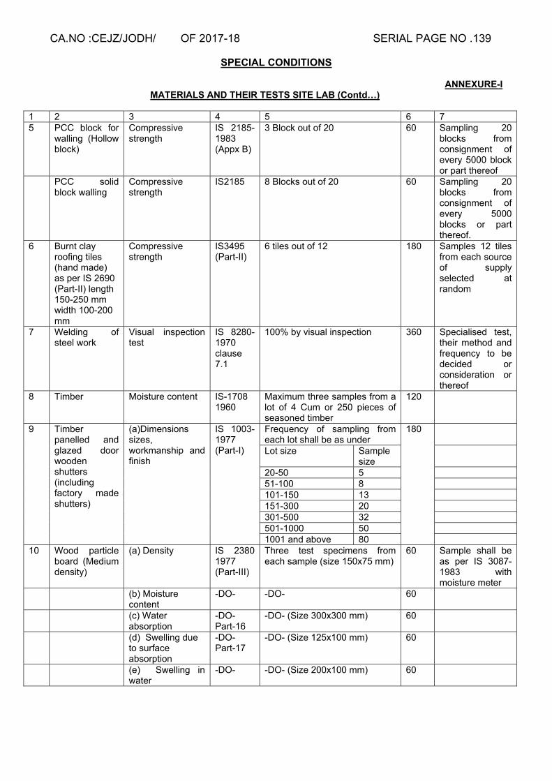
CA.NO :CEJZ/JODH/ OF 2017-18 SERIAL PAGE NO .139
SPECIAL CONDITIONS
ANNEXURE-I MATERIALS AND THEIR TESTS SITE LAB (Contd…)
1 2 3 4 5 6 7 5 PCC block for
walling (Hollow block)
Compressive strength
IS 2185-1983 (Appx B)
3 Block out of 20 60 Sampling 20 blocks from consignment of every 5000 block or part thereof
PCC solid block walling
Compressive strength
IS2185 8 Blocks out of 20 60 Sampling 20 blocks from consignment of every 5000 blocks or part thereof.
6 Burnt clay roofing tiles (hand made) as per IS 2690 (Part-II) length 150-250 mm width 100-200 mm
Compressive strength
IS3495 (Part-II)
6 tiles out of 12 180 Samples 12 tiles from each source of supply selected at random
7 Welding of steel work
Visual inspection test
IS 8280-1970 clause 7.1
100% by visual inspection 360 Specialised test, their method and frequency to be decided or consideration or thereof
8 Timber Moisture content IS-1708 1960
Maximum three samples from a lot of 4 Cum or 250 pieces of seasoned timber
120
9 Timber panelled and glazed door wooden shutters (including factory made shutters)
(a)Dimensions sizes, workmanship and finish
IS 1003-1977 (Part-I)
Frequency of sampling from each lot shall be as under
180
Lot size Sample size
20-50 5 51-100 8 101-150 13 151-300 20 301-500 32 501-1000 50 1001 and above 80
10 Wood particle board (Medium density)
(a) Density IS 2380 1977 (Part-III)
Three test specimens from each sample (size 150x75 mm)
60 Sample shall be as per IS 3087-1983 with moisture meter
(b) Moisture content
-DO- -DO- 60
(c) Water absorption
-DO- Part-16
-DO- (Size 300x300 mm) 60
(d) Swelling due to surface absorption
-DO- Part-17
-DO- (Size 125x100 mm) 60
(e) Swelling in water
-DO- -DO- (Size 200x100 mm) 60

CA.NO :CEJZ/JODH/ OF 2017-18 SERIAL PAGE NO .140
SPECIAL CONDITIONS
ANNEXURE-II MATERIALS AND THEIR TESTS ZONAL LAB
Ser No
Material Test Method of testing
Frequency of tests Rate (in Rs)
Remarks
1 2 3 4 5 6 7 1 Coarse aggregate Specific gravity IS- 2386
(Part-II) One test for each source of supply
120
2 Fine aggregate Specific gravity IS- 2386 (Part-III)
One test for each source of supply
180
3 Cement (a) Setting time IS 4031 –63 Reaffirms 1988
One for each consignment or as and when required
180
(b) Compressive strength
--DO-- --DO-- 360
(c) Soundness IS 4031-63 Reaffirms 1988
One for each consignment as and when required
120
(d) Fineness --DO-- --DO-- 120 4 (i) PCC block for
walling (Hollow) (a) Water absorption
IS 2186-1983 (Appx B)
3 block out of 20 120 Sample 20 blocks from consignment of every 5000 blocks or part thereof. These blocks to be checked for dimensions & weight
(b) Density IS 2185-1983
3 block out of 20 90 Sampling 20 blocks from consignment of 5000 blocks or part thereof. These blocks to be checked for dimensions & weight
(ii) PCC solid block for wall
(a) Density IS 2185-1983
3 block out of 20 120
(b) Water absorption
IS 2185-1983
3 block out of 20 120
5 Cement flooring tiles/terrazzo tiles
(a) Water absorption
IS 1237 1980 (Appx E)
6 tiles out of 18 180 Sample 18 tiles from each sourceof supply selectedat random
(b) Wet transverse strength
IS1237-1980 (Appx E)
6 tiles out of 18 144
6 Brunt clay roofing (Hand made) as per IS 2690 (Part-II) break line length 150 to 250 mm width 100 to 200 mm thickness 35 to 50 mm
Water absorption IS 3495 (Part-II)
6 tiles out of 12 216 Sample 12 tiles from each source of supply selected at random
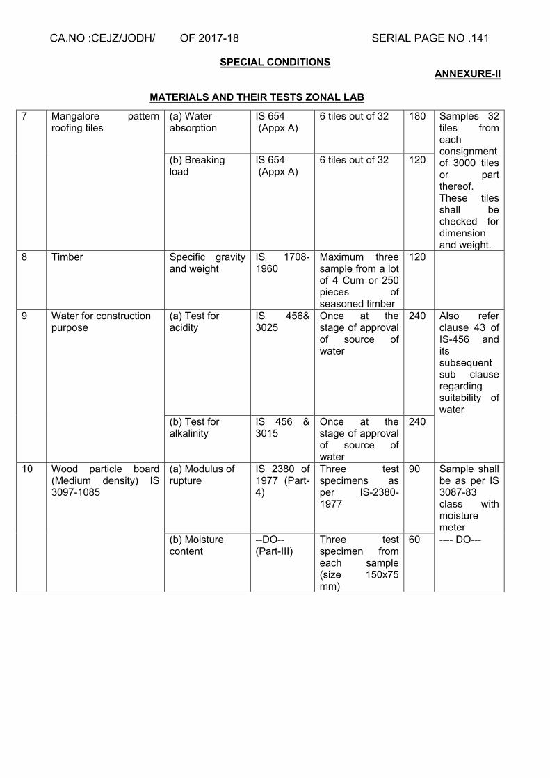
CA.NO :CEJZ/JODH/ OF 2017-18 SERIAL PAGE NO .141
SPECIAL CONDITIONS ANNEXURE-II
MATERIALS AND THEIR TESTS ZONAL LAB
7 Mangalore pattern roofing tiles
(a) Water absorption
IS 654 (Appx A)
6 tiles out of 32 180 Samples 32 tiles from each consignment of 3000 tiles or part thereof. These tiles shall be checked for dimension and weight.
(b) Breaking load
IS 654 (Appx A)
6 tiles out of 32 120
8 Timber Specific gravity and weight
IS 1708-1960
Maximum three sample from a lot of 4 Cum or 250 pieces of seasoned timber
120
9 Water for construction purpose
(a) Test for acidity
IS 456& 3025
Once at the stage of approval of source of water
240 Also refer clause 43 of IS-456 and its subsequent sub clause regarding suitability of water
(b) Test for alkalinity
IS 456 & 3015
Once at the stage of approval of source of water
240
10 Wood particle board (Medium density) IS 3097-1085
(a) Modulus of rupture
IS 2380 of 1977 (Part-4)
Three test specimens as per IS-2380-1977
90 Sample shall be as per IS 3087-83 class with moisture meter
(b) Moisture content
--DO-- (Part-III)
Three test specimen from each sample (size 150x75 mm)
60 ---- DO---

CA.NO :CEJZ/JODH/ OF 2017-18 SERIAL PAGE NO .142
SPECIAL CONDITIONS ANNEXURE-III
MATERIALS AND THEIR TESTS NATIONAL TEST
HOUSE/SEMT WING/ENGG COLLEGE Ser No
Material Test Method of testing
Frequency of tests Rate (in Rs)
Remarks
1 2 3 4 5 6 7 1 Coarse
aggregate Organic impurities
IS- 2386 (Part-II)
One test for each source of supply
120
2 Fine aggregate Test for organic impurities
IS- 2386 (Part-II)
One test for each source of supply
180
3 Cement flooring tiles/terrazzo tiles
Resistance to wear
IS 1237-1980 (Appx F)
6 tiles out of 18 540 Sample 18 tiles from each source of material selected at random
4 Water for construction purpose
Test for solid content
IS 456 & 3025
Once at the stage of approval of source of water
300 Also refer clause 43 of IS-456 and sub clause regarding suitability of water
5 Plywood (IS 303-1989)
Moisture content
IS 1734-1983 (Part-6)
Six test pieces cut from each of the boards selected as per 1shall be subject to tests
240 Sampling shall be as per IS 7533 (1975) tables
6 Wood particle board (medium density) IS 3097-1985
Screw withdrawal strength
IS 2309 (Part-14)
Three test specimens as per IS 2380
120
7 Timber panelled and glazed door wooden shutters (including factory made shutters)
Strength test 180
(i) Slamming IS 1303-1990
From each lot 5% of the factory made shutters shall be tested for strength tests
(ii) Impact indentation
-DO- -DO-
(iii) Shock resistance
-DO- -DO-
(iv) Edge loading
-DO- -DO-
Signature of Contractor Dy Dir (Contracts) For Accepting Officer

CA.NO: CEJZ/JODH/ OF 2017-18 SERIAL PAGE NO: 143
PARTICULAR SPECIFICATIONS
1. GENERAL
1.1 The following specifications shall be read in conjunction with the General Conditions of Contract (IAFW-2249) and IAFW-2159 including Errata/Amendments thereto. If any provision in the Specifications is at variance with that of the aforesaid documents, the former shall be deemed to take precedence there over.
1.2 The work under this contract shall be carried out in accordance with Schedule ‘A’, the Particular
pacifications, drawings, General specifications & other provisions in MES SSR Part-I of 2009 & Part-II of 2010 (herein after called MES Schedule) read in conjunction with each other.
1.3 The term ‘General Specifications’ referred to herein before as well as referred to in IAFW-2249
(General conditions of contracts) shall mean the specifications contained in the MES Schedule.
1.4 General Rules, specifications, special conditions and all preambles in the MES Schedule shall be deemed to apply to the work under this contract, unless mentioned otherwise in these documents, in which case, the provision in these documents shall take precedence over the aforesaid provisions in the MES Schedule. Where specifications for any item of work are not given in MES Schedule or in these particular specification, specifications as given in relevant Indian standard or code of practice shall be followed.
1.5 (a) Rate quoted for a particular item and/or lump sum quoted by the tenderer shall be deemed to include for any minor details/ items of work and /or construction which are obviously and fairly intended and which may not have been included in these documents but which are essential for the execution and entire completion of the work.
(b) Decision of the Accepting Officer as to whether any minor details of work and/or construction is obviously and fairly intended to be included in the contract or not shall be final, conclusive and binding. However, some minor details, items which shall be deemed to be essential for execution and entire completion of work are detailed as under:-
(i) Reinforcement for any RCC member not indicated in the drawings but required as per structural or code requirement. (ii) Dwarf wall in situations like verandah, passage, ramp, platform etc not indicated in drawings. (iii) Lintels over doors, windows ward robes/cup board and opening not indicated in drawings.
(iv) Fittings to doors, windows, ward robe/cup board and such other built-in furniture items not shown.
(v) PCC benching at the junction of chajjas and walls not shown in drawings. (vi) Coving at junctions of wall plaster with dado/skirting.
(c) In all the above and similar cases, the details indicated else where in the drawings which are similar or near to the missed out item of work shall be followed. In the absence of any other similar or near similar details, minimum essential requirement for completion of the work from structural and utility point of view shall be deemed to be included in the lump sum quoted. In the event of any dispute, decision of the Accepting Officer thereon shall be final, conclusive and binding.
2. SCOPE OF WORK
(a) The contract includes for the full, final and entire completion of all works described in Schedule ‘A’ included in the General Summary specified in these particular specifications and shown in the drawings forming part of this tender.

CA.NO: CEJZ/JODH/ OF 2017-18 SERIAL PAGE NO: 144
PARTICULAR SPECIFICATIONS
(b) Probable sources of local materials are given in Appendix ‘A’ to the particular specifications. However, the samples shall be got approved by the contractor from the GE before bulk procurement of the material. The contractor may bring material conforming to the specifications from other sources without price adjustment. If the contractor proposes to use materials from such other sources sample thereof shall be submitted to the GE and the same shall be got approved in writing from the GE before procurement in bulk and incorporation in the work.
(c) In appendices/Annexure to particular specifications, list of manufacturers of items have been given. Contractor shall obtain these items from one of the approved manufacturer only. However, it will not absolve the contractor from ensuring that the products supplied are conforming to the relevant IS in all respects before procuring the same for approval by the GE and before procuring bulk product for incorporation in work.
3 EXCAVATION AND EARTH WORK
3.1 EXCAVATION IN GENERAL
3.1.1 The amount quoted by the Contractor for all building works shall be deemed to include for all excavation and earthwork in ANY TYPE OF SOIL. In case during excavation variation in character of strata from above and variation in type of soil/rock is met with, the same shall be ordered through deviation. In case of omit portion of deviations involving excavation the pricing shall be based on the mean of MES schedule rates for soft /loose soil or hard/dense soil.
3.1.2 In case hard rock is met with, the contractor shall immediately notify the same to GE under intimation to Accepting Officer and prior approval of Accepting Officer shall be obtained by the GE before ordering work of excavation in hard rock on the contractor. Blasting for excavation in hard rock shall not be permitted. Excavation in hard rock shall only be done by mechanical means. Where hard rock is met with during the excavation, foundation design is likely to be changed which may entail delay in finalisation of drawings. The contractor shall mobilise his resources accordingly in consultation with GE and no claims of what so ever nature for delay in finalisation of revised details shall be entertained. Decision of the Accepting Officer in this regard will be final and binding.
3.1.3 Hard rock met with during excavation shall be entered in the measurement book duly signed by the GE and the contractor and the same shall become the property of contractor for which recovery at the rate of Rs 646.20 per cubic metre (useful solid contents) shall be made from contractor’s advance on account payment. The quantity of usable & unusable material retrieved during excavation shall be ascertain by the BOO as ordered by CWE.
3.1.4 The hard rock so obtained may be allowed to be used in the work by the GE provided it meets the specified requirements (even though the source not mentioned in Appendix ‘A’). Location (s) etc where it is to be used (if allowed to be used) shall also be as decided by the GE whose decision shall be final and binding. If hard rock obtained from excavation is not fit to be used in the work the contractor shall remove the same outside the MD land without any extra cost to the Government.
3.1.5 Surplus excavated soil if any (i.e. Unused soil left over after filing in trenches, plinth and under floors shall be removed to a distance exceeding 250 metres but not exceeding 500 metres deposited, spread and levelled as directed. Lump sum tendered by the contractor shall include for above lead for removal of surplus soil. 3.1.6 The rates quoted shall also include for bailing/pumping of water in case if water/mud is met with during excavation as specified under clause 3.17of SSR part-I.no extra payment shall be made on this account.
3.2 SITE CLEARANCE AND SURFACE DRESSING
Site clearance and surface dressing for the area covered up to 3 metres around the building from the outer edge of hard standing/ramp/wall/plinth protection shall be included in lump sum in Sch

CA.NO: CEJZ/JODH/ OF 2017-18 SERIAL PAGE NO: 145
PARTICULAR SPECIFICATIONS
`A’ Part-I shall be carried out as per clause 3.6 and 3.10 of SSR Part-I. The extent of 3 metres shall be considered from the outer most point of the structure covered under Sch ‘A’ Part –I. All rubbish obtained from site clearance and surplus soil obtained from surface dressing shall be removed, spread and levelled as directed by Engineer-in-Charge to a distance exc. 250 metres but n. exc 500 metres from external face of building.
3.3 EXCAVATION IN TRENCHES AND OVER AREAS
3.3.1 Excavation in trenches and over areas shall be carried out as described in Para 3.13 of MES SSR Part-I. Bailing and pumping of water, if required will be done as described in Para 3.17 of MES SSR Part-I. No extra payment shall be admissible for the above-mentioned operation. If however, an inflow of water in to excavation is caused by powerful springs or river seepage, broken water mains or drains and the like (other than those broken through the contractor’s negligence) the contractor shall inform the GE. If in the opinion of the GE the inflow is due to any of these causes, he shall issue instructions in writing as to the method to be employed in clearing the excavation of water and additional payment shall be allowed as deviation order.
3.3.2 Depth of foundation shown on drawing is after surface dressing.
3.4 FILLING IN TRENCHES, PLINTH AND UNDER FLOORS
3.4.1 Filling in foundation trenches, plinth, under floors, and in other situations shall be done with approved earth/soft disintegrated rock. It shall be ensured that turf, peat vegetable and other organic and deleterious matter is removed from the soil used for filing. Black cotton soil shall not be used for filling. Filling in general shall be done as specified in clause 3.19 & 3.21 of SSR Part-I, and filling in trenches for pipes, drains, cables etc shall be done as per clause 3.20 of MES SSR Part-I and shall be all as specified in drawings.
3.4.2 Earth/soft disintegrated rock obtained from excavation (Except soil obtained from surface dressing) shall be used for filling only after approval of engineer in charge. Soil/soft disintegrated rock not approved for filling or surplus to the requirement shall be removed to a distance exceeding 250 metres and not exceeding 500 metres spread & levelled.
3.4.3 No charge shall be levied against contractor for use of approved soil/soft disintegrated rock obtained from excavation.
3.4.4 If the soil/soft disintegrated rock obtained is not adequate for filling in trenches, plinth, under floor, etc, additional approved earth required for filling shall be obtained by the contractor from outside the MOD land at his own cost and no extra payment on this account shall be admissible. The entire quantity of soil/soft rocks obtained from excavation shall be considered suitable for filling for pricing omit portion of DO.
3.4.5 TIMBERING/PLANKING AND STRUTTING
The work shall be executed as per clause 3.24 of SSR Part-I.
3.5 HARD CORE: - Refer Para 3.27 of MES SSR Part-I.
3.5.1 The material for hard core shall be of broken stone or boulders as per Appendix ‘A’.
3.5.2 The hard core shall be watered and rammed. The thickness of hard core shown in drawings or specified in particular specifications is the consolidated thickness.
4 PRECONSTRUCTION ANTITERMITE CHEMICAL TREATMENT
Anti termite treatment shall be provided all as specified in clause 3.26 of MES SSR Part-I in buildings as specified in Sch ‘’A’’ Notes except that termite mound treatment if required to be provided shall be ordered as deviation.

CA.NO: CEJZ/JODH/ OF 2017-18 SERIAL PAGE NO: 146
PARTICULAR SPECIFICATIONS
4.1 The work of A.T.T. shall be carried out through a specialist firm. The firm shall meet the following requirements to be approved by the GE before anti termite treatment work is taken in hand.
(a) The firm executing the work shall have valid licence for carrying anti termite treatment as per insecticide Act 1962 (as amended from time to time).
(b) The firm shall be a member of IPCA and PCAI. (c) The person carrying out anti termite treatment shall be qualified as per rule 10 promulgated
under insecticide rule 1971. (d) However, if the contractor himself is enlisted for anti termite treatment in category g (x), he
may carryout work himself with prior approval of GE.
4.2 Daily record shall be maintained duly signed by the contractor and Engineer-in-Charge giving the following details:-
(i) Location of work done.
(ii) Name of chemical and its concentration used.
(iii) Items of the treatment work done (bottom and sides of excavation of masonry wall), back fill, under plinth protection, top of filling and along external perimeter of building/plinth protection) and area covered under each item.
(iv) Quantity of chemical required for work done during the day and quantity of chemical actually used.
4.3 The contractor shall give a service guarantee of 10 years for the anti termite treatment. The aforesaid guarantee period of 10 year shall reckon from the certificate date of completion of work.
4.4 The amount calculated as per table given below shall be retained out of the contractor’s bill as security deposit for the guarantee period of 10 years which shall be refunded to him after expiry of the guarantee period satisfactorily. Alternatively, contractor may give a separate interest bearing security deposit or bank guarantee bond to GE valid for 10 years for the sum mentioned above. Security deposit/bank guarantee shall be released after expiry of defect liability period of 10 years as specified. The contractor may at his discretion furnish fixed deposit receipt for the above amount in lieu of the security for guarantee period mentioned:-
Amount of anti-termite at contract rate
Amount to be retained from contractor’s dues rounded to nearest thousand rupees
(i) Up to Rs 50.00 lakh 2% of amount subject to minimum of Rs 5000/- and enhanced by 25%
(ii) Over Rs 50.00 lakh and up to Rs 100.00 lakh
Rs 1.00 lakh + 1.50% of amount exceeding Rs 50.00 lakh and enhanced by 25%
(iii) Over Rs 100.00 lakh and up to Rs 500 lakh
Rs 1.75 lakh + 1% of amount exceeding Rs 100.00 lakh and enhanced by 25%
4.5 Should the GE at any time during construction or prior to the expiration of the guarantee period of
10 years find that the buildings have been infected with termites, the contractor shall on demand in writing from GE, specifying the building(s) complained of, notwithstanding that same may have been inadvertently passed, certified and paid for, forthwith undertake to carry out such treatment as may be necessary to render the said building(s) free from termite infection at his own expenses for the guarantee period of 10 years and in event of his failing to do so within a period to be specified by the GE in his demand aforesaid, the GE may undertake such treatment at the risk and expense, in all respect, of the contractor. The liability of the contractor under this condition shall not extend beyond the guarantee period of 10 years unless the GE had previously given notice to the contractor. The security deposit referred to in condition 4.4 herein before may be refunded to the contractor after the expiry of the period of ten years from the certified date of completion by the GE

CA.NO: CEJZ/JODH/ OF 2017-18 SERIAL PAGE NO: 147
PARTICULAR SPECIFICATIONS
provided always that the contractor shall first have been paid the final bill and have rendered a no demand certificate (IAFW-451). Condition 10.46 and 68 of the General Conditions of Contracts (IAFW-2249) shall be deemed to be amended to the extent mentioned above.
4.6 Chemicals for anti termite treatment shall be purchased by the contractor from the manufacturers or
their authorised agents only and brought to site in manufacturers temper proof sealed containers of standard make as approved by the GE. Name of the authorised agent shall be verified from the manufacturer by the GE before approval. Only ISI marked chemicals shall be approved for use.
4.7 Regarding chemical for anti termite treatment, provisions of special condition No 11 (Record of materials) shall be strictly complied with.
4.8 The anti termite treatment chemical when brought to site shall be inspected by the Engineer-in-Charge and the quantity brought to site shall be recorded in the measurement book and signed by the contractor and the Engineer-in-Charge as a check to ensure that the required quantity has been brought to site for incorporation in the work.
4.9 The chemical brought to site shall be stored as directed by the Engineer-in-Charge and those already recorded in the MBs shall be marked for identification.
4.10 Reference clause 3.26.1 of MES SSR Part-I. Chemical for anti termite treatment shall be Chloropyriphos (20% EC).
5. CEMENT
5.1 Type of Cement :- The Cement used shall be of 43 grade ordinary Portland cement conforming to IS : 8112 – 1989 or Portland Pozzolana cement conforming to IS : 1489 –Part –I:1991 Specification for Portland Pozzolana cement ,Part-I fly ash based.Cement bags shall bear ISI certification mark and date of manufacture.
5.2 The following checks and procedure shall be followed before the cement supplied by the contractor is accepted and is approved for incorporation in the work:-
5.2.1 PROCUREMENT : Cement shall be procured from the following manufacturers/main producers:- (i) The Associated Cement Companies Ltd (Brand : ACC) (ii) Grasim Industries Ltd (Brand : GRASIM) (iii) Ultra Tech cement Ltd (Brand : ULTRATECH) (iv) The India Cement (v) Dhruv Industrial Company Limited (OPC only) (Brand : DHRUV) (vi) Andhra Cement Ltd (vii) Century Cements (Brand : CENTURY) (viii) Saurashtra Cement (Brand : SAURASHTRA) (ix) Binani Cement Ltd (Brand : BINANI) (x) Madras Cement (Brand : MADRAS) (xi) Mangalam Cement Ltd (Brand : MANGALAM) (xii) Birla Corporation Ltd (Brand : BIRLA) (xiii) Orient Cement (Brand : ORIENT) (xiv) Lafarge Cement (Brand : LAFARAGE) (xv) Shree Cement (Brand : SHREE) (xvi) JK Cement (Brand : JK) (xvii) Jaypee Rewa cement (Brand : JAYPEE) (xviii) Ambuja Cement Ltd (Brand : AMBUJA) (xix) JK Lakshmi Cement (Brand : JK LAKSHMI) (xx) Sanghi Industries Ltd (Brand : SANGHI) (xxi) Dalmia Cement (Bharat) Ltd (Brand : DALMIA CEMENT) (xxii) Zuari cement Ltd (Brand : ZUARI) (xxiii) Prism Cement Ltd (Brand : PRISM)
CA.NO: CEJZ/JODH/ OF 2017-18 SERIAL PAGE NO: 148
PARTICULAR SPECIFICATIONS
(xxiv) Cement Manufacturing Company Ltd (Brand : STAR) (xxv) OCL India Ltd (Brand : KONARK) (xxvi) Chettinad Cement Corporation Ltd (Brand : CHETTINAD) (xxvii) Heidelberg Cement India Ltd (PPC only) (Brand : MYCEM) (xxviii) Parasakti Cements Ltd (Brand : PARASAKTI) (xxix) Toshali Cements Pvt Ltd (Brand : GAJAPATI) (xxx) Saifco Cement Pvt Ltd (OPC only) (Brand : SAIFCO) (xxxi) Shree Guru Kripa Cement (Pvt) Ltd (Brand : SARTAJ) (xxxii) Barak Valley Cements Ltd (OPC only) (Brand : BVCL) (xxxiii) My Home Industries Ltd (Brand : MAHA for OPC43 & MAHASHAKTI for PPC)
The contractor shall furnish the particulars of the manufacturers of cement along with the date of manufacture to the GE for every lot of cement separately. The documents in support of the purchases of cement shall be verified by the site staff and GE. The cement so brought shall be fresh and in no case older than 60 days from the date of manufacture. Before placing the order for cement by the contractor, he shall obtain written approval from the GE regarding name of manufacture, quantity of cement etc. Based on the CPM Chart finalized, monthly requirement of cement and the proposed date wise Schedule of deliveries for bringing the cement at site shall be worked out by the contractor and the same shall be submitted to the GE for information and approval. Cement shall be procured for requirement of not more than two months at a time. The cement shall be consumed in the work within three months after receipt. Cement shall confirm to the requirements of IS specification and each bag of cement shall bear relevant ISI Mark. The weight of each consignment shall be verified by the GE and recorded. The content of cement shall be checked at random to verify the actual weight of cement per bag.
5.2.2 USE OF PPC
For using PPC, the following requirements should be met:-
(a) PPC should meet the strength criteria of 43 Grade OPC as laid down in IS-8112-1989.
(b) The minimum period for curing and striking off form work shall be as under in lieu of that specified in clause 4.11.6.3 of MES Schedule Pt-I :-
(i) Curing: - Structural RCC work, PCC work, Plastering etc. :14 days
(ii) Striking off Formwork from Walls, columns and vertical : 3 to 4 days sides of beams.
(iii) Slabs (Props left under) :14 days
(iv) Beams soffits (Props left under) :14 days
(v) Removal of props to slab/beam
(aa) Spanning upto 6 M span : 16 days (ab) Spanning beyond 6 M span : 22 days
(vi) For cantilever portion of slab form work with support shall be retained until the completion of the casting of the entire frame work of the building.
(c) Mixing of OPC & PPC shall not be permitted in the same buildings except for plaster and mortar.
(d) While procuring PPC, the following requirements are to be ensured and certificate to the effect is to be obtained by the contractor for each batch from the manufacturer and the same shall be submitted to the GE for approval to procure PPC.

CA.NO: CEJZ/JODH/ OF 2017-18 SERIAL PAGE NO: 149
PARTICULAR SPECIFICATIONS
(i) The quality of fly ash is strictly as per IS-1489 (Part-I) 1991 and as amended up to date.
(ii) Fly ash is inter-ground with clinker not mixed with clinker. (iii) The fly ash content in PPC does not exceed the limits laid down in IS-1489 (Part-I)-1991 and as amended up to date.
5.2.3. TESTING OF CEMENT: The manufacturer/ main producer shall carry out inspections and testing of cement in accordance with the relevant BIS provisions. The Contractor shall submit the Manufacturer’s Test Certificate in original along with the Test Sheet giving the result of each physical test as applicable and the chemical composition of the cement or authenticated copy thereof, duly signed by the manufacturer with each consignment. The Engineer-in-Charge shall record these details in the Cement Acceptance Register (Annexure`IV’) given here in after, after due verification. The GE shall also organize independent physical testing of random samples of cement drawn from each lot from NABL laboratories as NATIONAL TEST HOUSE, SEMT WING CME, REGIONAL RESEARCH LABORATORIES, IITs, MES ZONAL LABORATORIES, GOVT ENGINEERING COLLEGES, and NATIONAL INSTITUTE & TECHNOLOGY as per relevant BIS and record the results in the relevant portion of Cement Acceptance Register (Annexure `IV`). The random samples of cement to be tested shall be drawn as per Quality Assurance Manual. The cost of materials for testing, samples, conveyance etc shall be borne by the contractor irrespective of the test result. However the cost of testing charges shall be governed in terms of condition 10(A) of IAFW 2249. In case as per the result of independent test, the cement is found to be not of requisite standard despite manufacturer’s test certificate, the contractor shall remove the total consignment from the site within 24 hrs at his own cost after written rejection order of consignment by the GE.
5.2.3.1 The record of random samples selected by the GE for testing shall be properly maintained in the cement testing register giving cross reference to relevant consignment of cement and quantity received etc
5.2.3.2 The contractor shall be required to set up adequate testing facilities at site to the entire satisfaction of GE for conducting setting time test and compressive strength test as per BIS for the samples collected from the lot brought at site. These tests shall be carried out within 7 days of receipt of cement at site. The test can alternatively be carried out at the Zonal laboratory, or any other recognized laboratory so designated by GE. The contractor shall be allowed to use the cement only after satisfactory compressive strength of 7 days. 7 days strength will be relied upon to accept the lot of cement; 28 days compressive strength test will be final criteria to accept/reject the lot.
5.2.4 STORAGE :
A temporary cement storage shed of appropriate capacity shall be constructed by the contractor at the site for keeping the consignments of cement as and when brought at site. The cement shed shall meet the following requirement:-
[a] The roof, walls, doors, windows, ventilators of Storage accommodation shall not allow any leakage, seepage and dampness.
[b] Suitable dunnage of height not less than 200mm shall be provided to prevent deterioration due to moisture or intrusion of foreign matters.
[c] Each cement consignment shall be staked separately, similarly the tested and untested cement shall be segregated and stored separately with distinct identification.
[d] Cement bags shall be stacked at least 200mm away from the walls and adequate protective top cover shall also be provided.
CA.NO: CEJZ/JODH/ OF 2017-18 SERIAL PAGE NO: 150
PARTICULAR SPECIFICATIONS
[e] Stacks in no case shall be higher than 10 bags and the stacks shall be arranged in header & stretcher fashion.
[f] The cement godown shall be provided with two locks at each door. The key of one lock at each door shall remain with Engineer-in-Charge and the key of the other lock with contractor or his authorized agent at site of works so that cement is removed from the go down as and when required with the knowledge of both the parties.
[g] The store shed shall be inspected once a day for ensuring proper preservation of cement bags & also for the purpose of taking out cement as per daily requirement.
5.2.5 DOCUMENTATION:
The contractor shall submit original vouchers from the manufacturer for the total quantity of cement supplied under each consignment to be incorporated in the work. All consignments received at the work site shall be inspected by GE and documents verified before acceptance. The original vouchers and the Test Certificates shall be defaced by the Engineer-in-Charge, signed by contractor and kept on record in the Office of GE duly authenticated and with cross reference to the Control Number recorded in the Cement Acceptance Register. This register will be signed by JE, Engineer-in-Charge, GE and the Contractor. The Accepting Officer may order a Board of Officers for random check of cement and verification of connected documents. The entire quantity of cement shall also be suitably recorded in the Measurement Book (Not to abstracted) for record purposes before incorporation in the work and shall be signed by the Engineer-in-Charge and the Contractor.
5.2.6 Identification of cement bags by the manufacturer shall be as per relevant BIS codes.
5.2.7 The entire lot of cement brought by Contractor to the site shall be removed by contractor under his own arrangements and at his own cost, whenever the test results are not found within the prescribed acceptable limits. Decision of GE in this respect shall be final and binding.
5.2.8 The proper accommodation for storage, preservation and maintenance of cement shall be provided by the contractor at his own cost till consumption of cement in the work at the place (s) decided by GE. All arrangement for proper storage and safely of cement as indicated here-in-before shall be made by Contractor at his own cost. The cement storage accommodation shall be provided with two locks at each door. The key of one lock at each door shall remain with the Engineer-in-Charge or his representative and that of other lock shall remain with the contractor’s authorized agent at site of works so that cement is removed from the godown/storage accommodation according to daily requirement with the knowledge of both the parties.
5.2.9 Schedule of supply of cement shall be worked out by Contractor in consultation with GE so as to match with the progress contemplated in CPM Chart prepared for this Project.
5.3 WEIGHING AND PAYMENT FOR CEMENT
5.3.1 Random samples of 5 bags per 100 bags shall be got weighed by Engineer-in-Charge in presence of representative of Contractor from each consignment to arrive at average weight per bag for calculating total quantity of cement brought at site for incorporation in the work. All arrangement for weighing of cement bags including labouretc shall be provided by the contractor at his own cost.
5.3.2 The quantity of cement arrived at as aforesaid shall be considered for payment as applicable in accordance with IAFW-2249, General Conditions of Contracts.
5.3.3 Payment for cement shall only be allowed after production of original purchase vouchers, manufacturer’s test certificates for each consignment of cement brought by contractor and after the results of random testing carried out by GE are found satisfactory as specified here-in-before.
CA.NO: CEJZ/JODH/ OF 2017-18 SERIAL PAGE NO: 151
PARTICULAR SPECIFICATIONS
5.4 SCHEDULE OF SUPPLY The contractor shall procure the cement timely as required in accordance with CPM network agreed between GE and the contractor. The contractor will forfeit his right to demand extension of time if the supply of cement got delayed due to his failure in placing order in time to the manufacturer.
5.5 MEASUREMENT AND PAYMENT OF CEMENT
5.5.1 The entire quantity of cement as brought at site, from time to time shall also be suitably recorded in the Measurement book for record purposes as `Not to be abstracted’ before incorporation in the work and shall be signed by the Engineer-in-Charge and the contractor.
5.5.2 The payment shall only be allowed after production of original purchase vouchers, certified copies of test certificates from manufacturer for each consignment and if results of testing carried out in laboratory on receipt of cement (7 days compressive test) are found satisfactory after testing as specified herein before. Cement shall be paid as material lying at site as per condition 64 of IAFW-2249. Rate of cement given in MES SSR shall be applicable for cement irrespective of grade of cement specified for use in the work.
5.5.3 For the purpose of pricing deviations for the items involving cement the rates given in MES SSR shall be applicable.

CA.NO: CEJZ/JODH/ OF 2017-18 SERIAL PAGE NO: 152
PARTICULAR SPECIFICATIONS
Annexure’IV’
CEMENT SUPPLY & ACCEPTANCE REGISTER 1 CA NO & Name of work
2 Control No*
3 Name of manufacture/Brand Name/Gde of cement (A) Manufacture_______(b Brand _______( c) Grade
4 Qty of cement & Lot No/Week No (in Bags) : Qty ________ (b) Lot No/Week No __________
5 Manufacture's test certificates No _________________
6 Random test Details (a) Physical test report from _________ vide their letter No ______(Name of Approved NABL Lab/Engg College)
(b) Chemical test report from _________ vide their letter No _______ ((Name of approved NABL Lab/Engg College)
7 Details of physical & chemical properties :-
Physical Requirements (As per IS 4031) Chemical Requirements (As per IS 4031)
Spe
cific
Ser
face
s A
rea
(Sqm
/Kg)
Sou
ndne
ss b
y Le
C
hate
liar
Sou
ndne
ss b
y A
uto
Cla
ve
Initi
al S
ettin
g T
ime
(Min
ute)
Fin
al s
ettin
gs T
ime
(M
inut
e)
Compressive strengths ( Mpa)
Tem
p du
ring
test
ingO
C
Sta
ndar
d co
nsis
tenc
y (%
)
Lim
e sa
tura
tion
fact
or (
Rat
io)
Alu
min
a Ir
on R
atio
(R
atio
)
Inso
lubl
e R
esid
ue
(%)
Mag
nesi
um (
%)
Sul
phur
ic
Anh
ydrid
e (%
)
Loss
on
igni
tion(
%)
Alk
alie
s (%
)
Chl
orid
es (
%)
03 d
ays
07 d
ays
28 d
ays
1 2 3 4 5 6 7 8 9 10 11 12 13 14 15 16 17 18 19 As per relevant IS As per manufacture's test certificate As per random test Remarks with Signature Accepted/Rejected
Contractor Junior Engineer Engineer-in-Charge GE
Remarks of BOO/Inspecting Officer/CWE
* To be alloted serially by the GE consignment wise

CA.NO : CEJZ/JODH/ OF 2017-18 SERIAL PAGE NO :153
PARTICULAR SPECIFICATIONS (CONTD....)
6. CONCRETE 6.1 All plain and reinforced cement concrete shall be as per IS-456 (2000) as amended upto
date. 6.2 AGGREGATE
Coarse aggregate for all cement concrete work, unless otherwise specified shall be crushed and graded hard stone. Coarse aggregate and fine aggregate (sand) shall be from the source as mentioned in Appendix ‘A’ and approved by the GE and shall conform to IS-383 and to the sample kept in GEs office.
6.3 WATER Quality of water to be used for mixing and curing of concrete work shall conform to the requirement of clause No 5.4 of IS-456 (2000). GE and contractor will ensure that testing of water is carried out at three months intervals to comply with the requirement. Cost of testing of water will be borne by the contractor. The CWE will monitor the quality of water through test results to ensure that the water used for making concrete or mortar and for curing confirm to IS-456.
6.4 CEMENT CONCRETE The proportion and type of cement concrete and its grading in any particular building/location shall be all as shown in drawings or notes thereon. In case of varied provisions as in notes on drawings and sketches, provision as in notes shall take precedence. The proportion and type of mix and its grading, if not shown/described otherwise in drawings, it shall be as under:-
LOCATION TYPE OF MIX (a) Foundation concrete for
masonry walls/pillars PCC (1:3:6) type C-2 using 40 mm graded crushed stone aggregate
(b) Lean concrete below RCC column footing/ plinth beam
PCC (1:3:6) type C-2 using 40 mm graded crushed stone aggregate
(c) Sub base to floor
PCC (1:4:8) type D-2 using 40 mm graded crushed stone aggregate. Thickness of sub base to floor shall be as given in respective schedule of finishes. However, in case where thickness is not shown, 75 mm thickness shall be provided.
(d) All RCC work shall be in concrete grade as mentioned in the structural drawings of the building / structures. In case the grade of concrete is not mentioned in the relevant structural drawings, the same shall be of grade not less than M-25 (Design mix) except for water retaining structure i.e. Static water tank where the minimum grade of concrete shall be M-30 (Design mix). For water retaining structure ie. OH tank,UG sump &static water tank, sump well STP etc minimum M-30(design mix) shall be used.
(e) PCC in floors and other plain cement concrete work shall be as follows :- (i) 40 mm thick and above PCC (1:2:4) type B-1 using 20 mm graded crushed stone
aggregate.
(ii) Thickness less than 40 mm PCC (1:2:4) type B-0 using 12.5 mm graded crushed stone aggregate.
(f) PCC bed blocks PCC (1:2:4) type B-1 using 20 mm graded crushed stone aggregate.
(g) PCC coping and benching
PCC (1:3:6) type C-1 using 20 mm graded crushed stone aggregate.
(h) Surroundings to surface of gully traps, padding under nahani traps/floor traps/ deep seal traps/surrounding of WC seats
Lean concrete PCC (1:5:10) type E-2 using 40 mm graded crushed stone aggregate

CA.NO : CEJZ/JODH/ OF 2017-18 SERIAL PAGE NO :154
PARTICULAR SPECIFICATIONS (CONTD....)
6.5 SPECIFICATION FOR DESIGN MIX CONCRETE M-25 & M-30 GRADE
6.5.1 CEMENT Cement shall be as per clause 5 herein before.
6.5.2 AGGREGATE
(a) Aggregate shall confirm to IS 383 Coarse aggregate (stone aggregate) for all cement concrete work i.e PCC/RCC, shall be out of granite/basalt/trap stone and coarse aggregate (stone aggregate) of 40 mm and above shall be of sandstone of approved quality all as specified in clause 4.4.1 to 4.4.7 (1) of MES Schedule Part I. Mixture of two types of stone shall not be permitted. Aggregate shall be non porous, hard, strong, durable, clean and free from various impurities and adherent coating and shall not contain any deleterious materials exceeding the limits specified in the above referred IS. When required by the Engineer-in-Charge, the contractor shall at his own expenses carry out any test laid down in IS383 and IS-2386 to verify that the aggregate complies with the requirements of the IS. The test will be carried out in any laboratory approved by the GE.
(b) Coarse aggregate shall consist of crushed graded stone aggregates. 40mm and below aggregate shall be machine crushed and course aggregate above 40 mm may be hand broken. (c) Fine aggregate shall consist of naturally occurring coarse sand. Fine aggregate shall conform to Zone-II of table IV of IS-383.
(d) Samples of the aggregate proposed to be used shall be approved by GE, prior to bulk delivery of the same at site of work. Field tests for determining the contents of silt, clay etc for fine aggregate shall be carried out by the Engineer-in-Charge from time to time to ensure that material brought to site are in conformity with the samples approved by the GE.
(e) GRADING OF AGGREGATE The grading of coarse and fine aggregate shall be as per MES Schedule. Fine aggregate shall have grading as per grading Zone-II. The grading of coarse and fine aggregate shall be checked as frequently as possible. The frequency for the aggregate testing shall be determined by Engineer-in-Charge to ensure that the specified grading is being maintained.
6.5.3 BATCHING
This shall be done as per clause No 4.11.3 of MES SSR Part-I. Irrespective of what is specified in MES SSR and else wherein these tender documents, weigh batching shall be carried out for all design mix concrete. Volumetric mixing of concrete will not be permitted. Weigh batching alongwith system of measured water either through calibrated pump or calibrated tank is to be adopted strictly for all design mix concrete work.
6.5.4 MIX PROPORTION AND STRENGTH
(i) Strength to be achieved As per IS-456-2000
(ii) Type of cement As per clause 5 here-in-before
(iii) Target mean strength of cement concrete
To be taken as per mix designed as per IS-10262 clause 2.2
(iv) Aggregate/cement ratio by weight
As per mix design based on IS 10262 and IS-456-2000
(v) Workability As per clause 7.1 of IS-456-2000 slump shall be 25 mm to 75 mm compacting factor 0.85 to 0.92

CA.NO : CEJZ/JODH/ OF 2017-18 SERIAL PAGE NO :155
PARTICULAR SPECIFICATIONS (CONTD....)
(vi) Max free water cement ratio As per mix design based on IS-10262 and IS-456-2000
(vii) Degree of quality control Min Good (Refer Appx `A’ of IS-10262)
(viii) Durability Exposure condition – Moderate (for M-25) / Severe (for M-30)
(ix) Minimum cement content As per IS-456-2000
(x) Type of aggregate Crushed stone aggregate
(xi) Max nominal size of aggregate 20mm or as specified (xii) Grade of concrete aggregate M-25 / M-30 (design mix) as applicable.
NOTE (i) In case there is any variation of cement content between design mix approved and minimum cement indicated here-in-before, there shall be no price adjustment for the same and contractor shall have no claim what so ever for using more quantity of cement (ii) If cement contents as per actual mix design are worked out lower than minimum cement content indicated here-in-before, the contractor shall have to provide minimum cement content indicated here-in-before and nothing extra shall be payable on this account.
(iii) Lump sum amount quoted by the contractor shall deem to include the cost for quantity of cement as per design mix and nothing extra on this account shall be admissible (iv) No element of wastage of cement shall be allowed while working out the cement consumption details for design mix concrete work. (iv) Mix design shall be prepared based on SP-23, handbook on concrete mixes and IS-
10262. Recommendations guide lines for concrete mix design. 6.5.5. APPROVAL OF DESIGN MIX
(a) Soon after commencement of work, contractor shall arrange the design mix for M-25 & M-30 grade concrete. Design mix concrete shall be got carried out from National Test House, SEMT, CME, and Regional Research Laboratories or from any Govt approved labs such as Govt Engineering Colleges and shall be got approved from CWE before implementation in the work. In case contractor fails to submit the samples of design mix soon after commencement of work, the delay shall solely be attributable to the contractor and no claim of whatsoever nature shall be admissible on this account.
(b) As soon as possible after receiving the design mix from the above agency same shall be verified at site by casting the final cubes. (c) Frequency of sampling shall be as per clause 15 of IS-456. Each sample shall consist of three numbers of preliminary test cubes (except as stated in para (d) below) of size 15x15x15 cm, and shall be made as per clause 2.8, 2.9 and 2.10 of IS-516. The concrete cube shall be tested as per IS-516 at site laboratory. The cubes will be tested after 28 days from the date of casting. (d) One sample for every design mix in the initial stage shall consist of six numbers of preliminary test cubes of size size 15x15x15 cm, and shall be made as per clause 2.8, 2.9 and 2.10 of IS-516. The concrete cube shall be tested as per IS-516 at site laboratory. Out of six cubes, three will be tested after seven days (on 8th day) from the date of casting and three will be tested after 28 days from the date of casting.

CA.NO : CEJZ/JODH/ OF 2017-18 SERIAL PAGE NO :156
PARTICULAR SPECIFICATIONS (CONTD....)
(e) The test after seven days (ie on 8th days) is intended only to give an early indication of the strength likely to be achieved. The strength thus achieved should be comparable with the above design mix report with specified design parameter. However, 28 days compressive strength shall alone be the criterion for acceptance and rejection of the concrete.
(f) GE can also carryout seven days strength test of more samples at his option. However if the test report is found satisfactory, then the cost of testing including cost of cubes shall be borne by the Deptt. But if the result is found unsatisfactory, then the cost of cubes and cost of testing shall be borne by the contractor. The cost of conveyance of test cubes shall however be borne by the contractor in all cases. (g) On the result of the above test, the mix actually to be used shall be agreed to and approved by the CWE. The approval of the CWE shall not relieve the contractor of his responsibility for obtaining the required minimum strength of quality concrete in the works. (h) All testing charges including cost of cubes, conveyance etc. shall be born by the contractor except that, the cost of optional seven days test be regulated as stipulated in Para (f) here-in-before.
6.5.6 ACCEPTANCE CRITERIA.
(a) The contractor shall be deemed to comply with the strength requirement as per clause 16 of IS-456.
(b) Whenever there is any change in the type of grading of material, the mix should be rechecked and modified suitably to the desired compressive strength.
(c) Standard deviation to be rechecked after collecting the result of actual concrete work (compressive strength actually achieved at site) to review for Design mix.
6.6 Testing of cubes shall be carried out at the site laboratory as per Annexure ‘I’
6.7 PLACING AND CURING OF CONCRETE Placing & curing of concrete shall be as specified in SSR Part-I & as per IS.
6.8 MIXING AND COMPACTION OF CEMENT CONCRETE (i) Design mix concrete at site shall be done by using semi automatic batching plant of capacity 12 to 15 Cum/hour. The contractor shall provide the batching plant with printing facilities to ensure proper quality control and maintenance of record of concreting done on each day.
(ii) All cement concrete except design mix concrete may be mixed in approved mechanical mixer. The mixer must also have a water container with a water meter for adding measured quantity of water in each batch. Mixing of concrete shall be as per clause 4.11.5 of MES SSR Part-I.
(iii) All RCC work shall be consolidated with approved mechanical vibrators except where not practicable in the opinion of the Engineer-in-Charge. RCC in slabs shall be compacted with plate/surface type vibrator and in beams/columns with needle/pin vibrator.
6.9 HOT WEATHER CONCRETING Para 14.1 of IS-459 (2000) specifies that during hot and cold weather, the concreting should be done as per the procedure set out in IS 7861 (Part-I) & IS 7861 (Part-II). Provision contained in IS 7861 (1975), reaffirmed 1990 shall be taken in to account and nothing extra on this account shall be paid by the Dept. the procedure/combination of procedures to be

CA.NO : CEJZ/JODH/ OF 2017-18 SERIAL PAGE NO :157
PARTICULAR SPECIFICATIONS (CONTD....)
followed for bringing down the temperature of concrete shall be decided by the GE as per site requirement.
6.10 WINDOW CILLS / RCC LINTELS
(a) Whether shown in drawings or not,all windows shall be provided with cills. Cills shall be polished Kota stone 20 to 25 mm thick set and bedded in 10 mm thick cement mortar in (1:3). The portion between two frames of windows shall be filled with cement mortar (1:3.). Cills shall be in single piece. Cills shall be embedded 25mm on both the sides and shall have polished of rounded edge projected exterernally & edges shall be flushed with wallsurfaces inside room all as directed by EIC. . (b) RCC lintels over door, windows and clear openings up to 1.5 metre clear span may be precast or cast in situ at the discretion of the contractor. (c) All precast articles shall be set in the cement and sand mortar (1:3). (d) In the event of deviation, pricing shall be done at SSR rates for cast in situ work, adjusted by contractor’s percentage.
6.11. FORM WORK
(a) Form work shall be as per clause 7.15 of MES SSR Part-I and shall comply with requirement of Para 4.11.6 of MES SSR Part-I and notes given in drawing No CEBZ/STD/01 sheet 1/9 to 9/9. Form work shall be steel for columns, floor slab & roof slab. For chajjas, beam soffit, sides of facia, edges of slab, soffit of chajja etc. is of plywood / steel. (b) Only steel props shall be used to support the formwork of slabs and beams. (c) Deviation with regards to form work shall however be based on fair finish surfaces of concrete. (d) Screws need not be used in the formwork except at the discretion of the contractor for his own convenience.
6.12 FINISH TO CONCRETE SURFACE
(a) Unless otherwise specified, exposed surfaces of concrete (other than in contact with casing and of precast concrete) shall be finished to a fair and even surface without using extra cement. (b) Exposed faces of RCC/concrete surfaces which are ultimately required to be finished by application of white/colour washing/ distempering/ painting shall be plastered with a thin layer of cement mortar (1:3), 5 mm thick and finished even and smooth after removal of form work (refer clause 4.11.16.2(b) of MES SSR Part-I. (c) Exposed surfaces of RCC lintels, beams, and columns etc, which are continuous with the plastered surfaces of walls, shall be finished as for adjoining walls. (d) Exposed surfaces of concrete other than those referred to in Para (b) & (c) above, shall be finished even and fair without application of any plaster after removing irregularities and protruding, form work marks and stoping air holes with cement and sand mortar (1:3) (refer clause 4.11.16.2(a) and (c) of MES SSR Part-I. (e) Top surface for PCC ramp, unless otherwise specified shall be with chequered finish achieved by making impressions of expanded metal, while concrete is green.
CA.NO : CEJZ/JODH/ OF 2017-18 SERIAL PAGE NO :158
PARTICULAR SPECIFICATIONS (CONTD....)
(f) Use of mortar/plaster shall neither be permissible for correcting levels, unevenness or elevation etc nor shall such plaster be used to incorporate the thickness.
6.13 CAST IN SITU/PRECAST ARTICLES :- (a) PCC sills, RCC shelves may be cast in situ or pre-cast at the discretion of the contractor. In the event of deviation with regard to these items, pricing shall be done at appropriate rate in SSR for cast-in-situ articles. Top of such pre-cast articles shall be distinctly marked. (b) Unless otherwise specified all pre-cast concrete articles shall be set and jointed in cement mortar (1: 4).
6.14 PRE-CAST RCC JALLIES It shall be provided wherever indicated and as shown on drawings. Pre - cast blocks shall be set in cement mortar 1:3. Thickness of jallies shall be as indicated on the drawing (s). Where thickness is not indicated, it shall be 75mm thick.
6.15 THROATING/WEATHERING
Throating to projections of RCC/PCC beyond external faces of the walls where shown on drawings and where RCC chajja are not provided with downward facia, shall be formed in the concrete while casting, by planting half round fillets /bar of 20mm diameter in the form work and finished smooth.
6.16 RCC CJAJJA
RCC chajja shall provided as per details shown on drawings.The top surface of chajjas shall be finished with 10mm thick cement plaster in cement mortar (1:3) with mixture of approved water proofing compound as per manufacturer’s instructions while the concrete is green viz before the final setting time. 75mm thick half round in PCC M-15 (Nominal mix) using 12.5mm graded stone aggregate shall be provided at the junction of wall and chajjas before external plastering10mm wide 5mm deep vertical groove shall be provided between RCC and brick wall. Chajjas shall be casted monolithic along with the casting of lintel band.
6.17 LINTEL/BAND
Continuous bands at lintel level shall be provided for all wall of buildings under this contract as per details section shown or mentioned in notes in structural drawings irrespective of whether the sections are shown or not on architectural drawings, lintel with chajja or lintel over openings wherever occurring, these shall be cast monolithic with the lintel band. The lintels over opening and along with chajja shall be provided as per TD drawing irrespective of whatsoever shown in the drawing of respective buildings.
6.18 CONCRETE FILLING
Where the required height of wall openings, is not obtained with adequate size of bricks/AAC blocks, the same shall be obtained by providing PCC (1:3:6) type C-1 using 20mm graded stone aggregate.
6.19 PCC RAMP/APRON
PCC ramp/apron shall be provided all as shown on drawings at the location marked on drawings. All exposed surfaces of masonry shall be plastered to match the finish of adjoining wall of the buildings. The top surface of ramp/apron shall be provided with chequered finish achieving by making impression of expanded metal/IRC fabric as decided by GE.
6.20 DAMP PROOF COURSE
6.20.1 The damp proof course shall consist of 40mm thick PCC of grade M-15 (Nominal mix) mixed with water proofing compound with a coat of blown bitumen of grade 85/25 at the rate of 1.5Kg/Sqm and

CA.NO : CEJZ/JODH/ OF 2017-18 SERIAL PAGE NO :159
PARTICULAR SPECIFICATIONS (CONTD....)
blinded with clean dry sand at the rate of 0.05 Cum/Sqm. Damp proof course shall be provided on external, internal, partition and dwarf wall. However, DPC shall not be provided where plinth beam is provided at plinth level.
6.20.2 Liquid water proofing compound for damp proof course and in all other locations where specified under this contract shall conform to IS-2645. It shall be mixed with cement concrete in the proportion and manner as given in manufacturer’s instruction. Deviations if any shall be priced at the rate of 3% by weight of cement.
6.20.3 Damp proof course shall be provided under door opening below floor by providing a vertical DPC along the sides of the drop (however plinth beam is not provided).
6.21 PRECAST PCC SOLID BLOCK MASONARY
6.21.1 PCC solid blocks shall conform to IS-2185.
6.21.2 TYPE OF MIX:-
The Pre cast PCC solid block shall be as per design mix irrespective of any mix shown in drawing. Aggregate shall be mixed thoroughly to achieve desired grading. PCC blocks with above mix shall be checked and verified for 28 days compressive strength as per IS 2185 at the commencement of work and whenever there is chance in source of ingredients. The block shall have minimum compressive strength of 50 Kg/cm2.
6.21.3 Trial mix shall be carried out before casting of block to ensure that the required strength and block density is achieved as per IS.
6.21.4 SIZE:- The block shall be one of the following sizes:-
Srl No
Nominal size in cm Actual size in cm Length Breadth Height Length Breadth Height
1 40 20 20 39 20 19 2 40 10 20 39 10 19 3 20 20 20 19 20 19 4 20 10 20 19 10 19
…………………………………………………………………………. Size other than those specified above may also be used with the approval of Engineer-in-Charge.
6.21.5 MATERIAL (AGGREGATE) :
(a) COARSE AGGREGATE- This shall be crushed or natural aggregate 20mm and down size of approval quality and shall conform to IS-383.
(b) FINE AGGREGATE (SAND)- This shall be free form dust and well graded. (c) A block shall be deemed to be solid if the solid material is not less than 75% of the total volume of the block calculated from the overall dimension.
6.21.6 MANUFACTURE OF BLOCKS
(a) The block shall be machine made. The mixing of concrete manufacture of block, curing and drying shall be in accordance with the paras 6 to 10 of IS-2185.
(b) Faces of the block shall be flat and rectangular.
CA.NO : CEJZ/JODH/ OF 2017-18 SERIAL PAGE NO :160
PARTICULAR SPECIFICATIONS (CONTD....)
(c) MIXING Concrete shall be mixed in mechanical mixer. Mixing shall be continued until there is uniform distribution of material and the mix is uniform in colour and consistent.
6.21.7 PLACING AND COMPACTION
(a) In case of mechanical compaction, the mould shall be filled up to over flow, vibrated or mechanically tamped and struck of level.
(b) After remolding the block shall be protected until they are sufficiently hardened to permit handling without damage.
6.21.8 CURING-
The block hardened as mentioned here in before shall then be cured in the curing water tank or in curing yard and shall be kept continuously moist for at least 14 days. Where the block are cured in an emersion tank, the water of tank shall be changed at least every 4 days.
NOTE:- Curing yard is a paved yard sub divided by shallow drains spaced at 4 to 5 metre on a square platform, which are provided with water fountain in the centre. The blocks are stacked on the platform around the fountain, which works continuously. The fountain is connected to an elevated water storage tank.
6.21.9 DRYING-
After curing the block shall be dried for a period of 4 week before being used in the work. They shall be stacked with voids horizontal to facilitate through passage of air. The dimensional stability of concrete block is greatly affected by variation in their moisture content. Since the shrinkage of the block is much greater at the time it dries for the first time than due to subsequently wetting and re drying, it is necessary to ensure that the blocks are dried so that initial shrinkage is completed before they are delivered to use. Further their moisture content should not exceed 25% of their maximum water absorption capacity, if the blocks are to be used in situation where the average relative humidity of air is more than 60% In that case the blocks can be dried to a moisture content of 40% of their maximum water absorption capacity.
6.21.10 PHYSICAL REQUIREMENT
(a) GENERAL:- All blocks shall be sound and free from cracks or other defects which interfere with proper placing of the block or impair the strength or performance of the construction. Minor chipping resulting from the customary methods handing during delivery shall not be ground for rejection.
(b) TOLERANCE- The maximum variation in the length of the units shall not be more than + 5mm for length and maximum variation in heights and width of unit, not more than + 3mm.
(c) BLOCK DENSITY:- The block density shall be as per para 4 of IS 2185 for solid PCC blocks. It shall not be less than 1800 Kg/M3.
(d) COMPRESSIVE STRENGTH:- The average compressive strength of eight blocks when determined in the manner described in IS-2185 shall not be less than 50 Kg/sq cm of gross area. The strength of lowest individual block shall be not less than 80% of the average compressive strength of eight blocks.
(e) WATER ABSORPTION:- The water absorption shall be as per IS-2185.
(f) Drying shrinkage and moisture movement shall be as per IS-2185.
6.21.11 TESTS

CA.NO : CEJZ/JODH/ OF 2017-18 SERIAL PAGE NO :161
PARTICULAR SPECIFICATIONS (CONTD....)
(a) Test as described in appendices ‘A’ to ‘F’ of IS-2185 shall be conducted on samples of blocks selected according to the samples procedure given in Para 1(c) of IS-2185 to ensure conformity with the physical requirement laid down in Para 8 of IS-2185. Cost of testing such as transportation, casting of block, testing fee and other expenses shall be borne by the contractor. The tests listed in Appendix ‘A’ to IS-2185 shall be conducted from the laboratory as approved by GE and other tests shall be carried out as listed in Annexture-1 to special condition.
(b) SAMPLING CRITERIA FOR CONFORMITY:
The blocks required for carrying out the test laid down in standard shall be taken by one of the method given in Para 10 of IS-2185 and shall be considered as conforming to the requirements of the specifications if the conditions mentioned in Para 11.2 to 11.5 of IS-2185 are satisfied.
6.21.12 PRECAST PCC SOLID BLOCK WALLING:-
(a) 20cm thick PCC solid block walling of grade D-5 shall be built in cement mortar (1:6). 10cm thick PCC solid block walling of grade D-4 shall be built in cement mortar (1:4).
(b) LAYING:- The block shall be slightly wetted before & during laying in the wall. The block shall be laid with mortar joints completely filled without any void left in the masonry. The thickness of the horizontal and vertical joints shall not exceed 1cm. The 1/2, 1/3 and 2/3 block shall be used for breaking the joints. The face joints shall be raked to a depth of 1cm by raking tool during the progress of the work, when the mortar is still green so as to provide proper key for plaster to be done later. Where plaster is not required the joints shall be struck flush and finished side by side as work proceeds with cement mortar without any extra cost to the department.
(c) CURING OF WALLING: - Masonry work shall be kept constantly moist on all the faces for a minimum period of 7 days.
(d) SCAFFOLDING : - Only double scaffolding shall be used. The scaffolding shall be strong and sound. No holes in the masonry for supporting scaffolding will be allowed.
6 .21.13 DEVIATION : In case of deviation the rates of PCC solid block masonry of grade D-5 200mm thick walling in CM (1:6) shall be RS 3100/- cum and for 100mm thick walling of grade D-4 in CM (1:4) shall be RS 466/- sqm subject to applicable percentage for Sch ‘A’ Part-I.
6.22 FLY ASH BRICKS WALL / MASONRY:-
(a) Irrespective of whatever is shown on drawings / notes on drawing and specified elsewhere, all walls above plinth level shown as 200/300mm thick & above shall be 230mm thick & all walls shown as 100mm / 115mm thick shall be 115mm thick of fly ash bricks conforming to IS 12894. Fly Ash Bricks shall have compressive strength not less than 75 kg/sqcm. Water absorption of bricks shall not exceed 10%. The size of bricks shall be 230x115x75mm as approved by GE.
(b) For partition / internal wall the provisions specified in SSR part-I shall be strictly adhered to. (c) The fly ash bricks shall be sound, compact and uniform in shape and colour. Fly ash bricks shall have smooth rectangular faces with free from organic matter. General requirement, tolerance, materials, physical characteristics, sampling & criteria for conformity etc. shall be complied as per IS 12894. Fly ash shall conform to grade 1 or grade 2 of IS 3812: Specification for fly ash for use as Pozzolana and admixture. (d) The thickness of the brick wall indicated as 115 mm shall be taken as half brick wall & 230mm thick brick wall shall be taken as one brick. The One brick walls shall be built in CM (1:6) & half bricks wall shall be built in cement mortar (1:4).

CA.NO : CEJZ/JODH/ OF 2017-18 SERIAL PAGE NO :162
PARTICULAR SPECIFICATIONS (CONTD....)
(e) The composition of the fly ash bricks shall be as below:- FLY ASH : 50-60% SAND : 30-40% CEMENT : 8-12% (f) The Chemical composition test report of fly ash bricks shall be submitted before incorporation fly ash bricks in the work. GE shall also carry out Chemical composition test form approved lab independently. The cost of transportation and test shall be borne by the contractor.
(g) The Fly ash Bricks shall be manufactured through fully automatic machine/plant.
NOTE:- In case of any deviation, fly ash brick masonry as catered in this tender, rate of fly ash brick masonry as catered in section 5 of SSR Part II (2010).
(h) The AAC block shall be allowed at the option to contractor in lieu of fly ash bricks at no extra cost basis as under:-
(i) AAC blocks shall conform to IS – 2185 PART-III and shall have following properties: S.No Location Grade Size in mm
(LXWXH) Min Density (kg/cum) Min Com Strength
(N/sqmm 1. External Wall Grade 1 600x250x200 651-750 5 2. Internal Wall Grade 2 600x150x200 551-650 4 (ii) The water absorption shall not be more than 6%.
(iii) The AAC block shall be tested with frequency as per IS code. The testing shall be carried out in approved Lab/SEMT Pune/NABL approved Lab. The contractor shall submit the manufacturer’s test certificate in original along with the test sheet giving the result of each physical test or authenticated copy thereof, duly signed by the manufacturer with each consignment. The Engineer-in-Charge shall record these details in the register after due verification. Cost of test block, conveyance for test and testing charges shall be borne by the contractor. AAC blocks shall be of Make ARICRETE/BILLTECH/SIPOREX or equivalent Make as approved by GE.
(iv) In case of external wall, if AAC blocks used in lieu of fly ash bricks, internal floor area shall be maintained. In case of internal wall, centreline dimensions shall be maintained / followed.
(v) In case of deviation the rates of AAC block masonry in CM shall be at par with SSR rate of fly ash Bricks per Cum and Subject to applicable percentage for Sch ‘A’ Part-I (vi) The option of AAC block shall be used for whole item and not in part i.e. Fly ash bricks and AAC block both shall not be used together in any individual item of Sch A Part -I but can be used separately in separate items of Sch A Part-I. NOTE: Offset due to variation in thickness of stone wall & brick/AAC block wall shall be kept on outer side of wall & inner face shall be kept flush with column.
6.22.1 EXTERNAL / INTERNAL PLASTER ON FLY ASH BRICK MASONRY / AAC BLOCK WALL:-
Irrespective of whatever specified elsewhere or shown in schedule of finishes, internal and external plaster on fly ash bricks/ AAC Block walls shall be as under:-
(i) Internal plaster shall be 10 mm thick in CM (1:6) (ii) External plaster shall be done in two coats. 1st coat shall be 10 mm thick in CM (1:6) and 2nd coat shall be 5mm thick in CM (1:4) mixed with water proofing compound. Water proofing compound

CA.NO : CEJZ/JODH/ OF 2017-18 SERIAL PAGE NO :163
PARTICULAR SPECIFICATIONS (CONTD....)
shall be added as per manufacturer’s instruction. In case of deviation WPC shall be considered as 3% by weight of cement. Rendering shall be finished even and fair.
7. STONE MASONRY
All masonry work shall be as specified here-in-after:-
(a) Stone for masonry shall be from the sources as indicated in Appendix ‘A’ and shall conform to the sample kept in the office of the GE.
(b) Sand for mortar shall be from the source as mentioned in Appendix ‘A’ and as approved by the GE and shall conform or superior to the sample kept in the office of GE.
(c) Stone masonry in foundation, shall be squared rubble walling, Jodhpur type, regular coursed, well bonded, bedded and solidly hearted all as described in clause No 6.10.2 of MES SSR Part-I built in cement mortar (1:6) except in location described in clause 7(d) herein after.
(d) Stone masonry for steps shall be squared rubble masonry, Jodhpur type, regular coursed, well bonded, bedded and solidly hearted all as described in clause 6.10.02 of MES SSR Part-I, built in cement mortar (1:4).
(e) Stone masonry in dwarf walls shall be provided as per Drgs. Stone masonry in super structure shall be squared rubble walling Jodhpur type, regular, well bonded and bedded all as described in clause No 6.10.11 of MES SSR Part-I, built in cement mortar (1:6) with following modifications :-
(i) Hearting with stone as specified in clause 6.10.5.4 of MES SSR Part-I shall not be allowed.
(ii) Tolerance in width shall be allowed on the minimum size of stone specified in clause 6.2.4 (b) of MES SSR Part-I considering the thickness of mortar in between back of stone as 20 mm.
(f) Bond, quoin and jamb stones where exposed shall be of stone only and may be either of stones or Precast solid PCC blocks in mix (1:3:6) type C-1 at other location at the option of contractor. Bond stone may be either of stone or Precast solid PCC block in PCC (1:3:6) type C-1 at the option of contractor. No price adjustment for use of PCC blocks shall be made.
(g) No facing shall be executed to surfaces covered by earth filling. Unless otherwise specified/shown in drawings, joints of masonry covered by earth filling shall be finished flush with the same mortar as the work proceeds.
(h) Leave or form holes as and where required or as directed by the Engineer-in-Charge shall be made good as per clause No 14.14.8 of MES SSR Part-I.
(j) Chases and recess in walls where required or where directed by the Engineer-in-Charge shall as far as possible, be provided during construction to avoid cutting after wards.
(k) In the event of deviation, pricing for stone masonry shall be done at the appropriate rates in MES Schedule irrespective of the change specified above.
(l) The joints of stone masonry shall be racked out and cleaned as the work proceeds as specified in clause 6.9.3 and 6.9.4 of MES SSR Part-I.
8. BLANK

CA.NO : CEJZ/JODH/ OF 2017-18 SERIAL PAGE NO :164
PARTICULAR SPECIFICATIONS (CONTD....)
9 WOOD WORK AND JOINERY
9.1 TIMBER
(a) Unless otherwise specified elsewhere in these particular specifications or indicated on drawings, timber required for all the items of work under this contract including factory made door shutters shall be Second class hard wood well seasoned and conforming to the sample kept in the GE’s office.
(b) Timber for all joinery and wood work shall be as per specifications given in clause 7.3 of MES SSR Part-I and shall be within the permissible limits of defects as defined in clause 7.4 and 7.5 of MES SSR Part-I (2009).
(c) Timber shall be well seasoned (whether air or kiln dried at the discretion of the contractor but without any price adjustment). Maximum permissible moisture content in timber for various purposes shall be as stipulated in clause 7.7 of MES SSR Part-I. For clarification of zones for the moisture content, this contract shall be deemed to fall under climatic Zone-II.
(d) PRESERVATION OF TIMBER: Preservative/ant termite treatment shall be carried out to all wood work and joinery fabricated by the contractor at site. Factory made Ply/Boards are deemed to be provided with ant termite treatment. Chemical used for ant termite treatment to wood work and joinery shall be COPPER NAPTHANATE, ASCU or any other chemical specified in IS-401, applied in any one of the manners specified in ibid IS.
9.2 TOLERANCE
(a) Unless otherwise specified all work both carpenter and joiners, shall hold full dimensions shown on drawings except that an allowance of 1.5 mm shall be allowed for each wrought face. Wooden beads and fillets shall however hold the full dimensions as shown on drawings. The contractor shall also maintain the overall size of the doors etc as shown on drawings. (b) Timber members up to 3.0 metre length shall be in one piece.
9.3 SURFACE FINISH
Surface finish of timber in contact with or buried in masonry/plaster and surfaces of timber hidden from the view shall be cleaned sawn. All other surface shall be wrought.
9.4 PELLETING
Counter sunk holes for bolts and screws on wrought surfaces shall be plugged with tightly fitting plugs and plane finished with surrounding surfaces.
9.5 PLUGGING
Plugging to walls shall be as per Para 7.29 of MES SSR Part-I.
9.6 SCREWING ETC Use of nails is prohibited to fix planks/shelves, fillets, moulding and the like with screws. The minimum length of screws and their material shall be as specified in Para 7.21 of MES SSR Part-I. The wooden screws shall be bright finished. The size and designation shall be as specified in IS/in MES SSR. Where it is not specified the same shall be as directed by the Engineer-in-Charge.
9.7 JOINERY

CA.NO : CEJZ/JODH/ OF 2017-18 SERIAL PAGE NO :165
PARTICULAR SPECIFICATIONS (CONTD....)
(a) Dimensions of various parts of joinery as shown on drawings shall supersede those stipulated in MES SSR. However, rates for joinery as given in MES SSR shall apply to the joinery as shown in drawings in the event of deviations.
(b) Use of nails in joinery work, unless otherwise specified or shown on drawings is prohibited. Wooden screws of appropriate size shall be used.
(c) Thickness of wooden door shutters where not shown on drawings or specified shall be 35 mm. 9.8 WOODEN SHUTTERS FOR DOORS
(a) Shutters shall be factory made second-class hard wood (Non coniferous) Bonsum (Phoebe
species)/ Chaplash (Artocarpus chaplash)/Hollock (Terminalia myrio capra) kiln seasoned and chemically treated.
(b) FACTORY MADE PANELLED DOORS
Factory made panelled door shutters shall be 35mm thick & made of kiln seasoned as per IS 1141 and chemically treated as per IS-401 second-class hard wood (Non coniferous) Bonsum (Phoebe species)/ Chaplash (Artocarpus chaplash)/ Hollock (Terminalia myrio-capra) for styles and rails. Panels shall be of 12 mm thick particle board veneered commercial (both faces) BWP grade bonded with liquid phenol formaldehyde synthetic resin adhesive conforming to IS-3097 (ISI marked) for all type of doors except in case of external doors directly exposed to weather. Panels for external doors directly exposed to weather shall be 9 mm thick BWP marine grade ply wood bonded with high quality liquid phenol formaldehyde conforming to IS : 710 (ISI marked)
(c) FACTORY MADE FLY PROOF DOORS
Factory made fly proof door shutters shall be 35mm thick & made of kiln seasoned and chemically treated second class hard wood (Non coniferous) Bonsum (Phoebe species)/ Chaplash (Artocarpus chaplash)/Hollock (Terminalia myrio-capra) fixed with stainless steel wire cloth of 0.36 mm average width of aperture not less than 1.40 mm nominal dia wire as stipulated in MES SSR and drawings.
(d) The overall sizes and dimensions of door shall be as indicated on drawings for wooden doors.
(e) The overall door shutters shall conform to the IS-1003 (f) Factory made wooden doors shutter shall be obtained from one of the manufacturer given in Appendix ‘C’. Contractor will produce manufacturer’s test certificate as per BIS code along with each consignment (g) Plugging to walls shall be done with wooden plugs as per clause 7.29 of MES Schedule Part-I. (h) In the event of deviation arising for fly proof factory made doors shutters, the pricing shall be done at the rate decided in terms of condition 62(G) of IAFW-2249.
9.9 PVC SOLID PANEL FOR SHUTTER
9.9.1 Factory made solid panel PVC door shutter 30mm thick (style) consisting of frame made out of MS tubes for top, sides and bottom rails. MS frame shall be covered with heat moulded plain colour PVC `C` channel having a PVC sheet strip of 20mm width stuck inside with solvent cement for stiles and plain colour PVC sheets for top rail, lock rail and bottom rail on either side and as gap insert for top rail and bottom rail; Panelling of plain colour PVC sheet to be fitted in the MS frame welded/sealed to the stiles and rails with suitable PVC sheet beading and jointed together with solvent cement, supplying and fixing in the frame at site as per specifications and drawings.

CA.NO : CEJZ/JODH/ OF 2017-18 SERIAL PAGE NO :166
PARTICULAR SPECIFICATIONS (CONTD....)
9.9.2 PVC SOLID FRAME FOR DOOR SHUTTER
PVC Solid door frame of size 50mmx47mm made out of 5mm plain colour PVC sheet reinforced with MS square tube, supplying and fixing in opening as per specification and drawing.
9.9.3 PVC frame and shutter shall be procured from manufacturer specified in Appendix `C`.
9.10 VENEERED PARTICLE BOARD : All veneered particleboard shall be ISI marked conform to the requirement of IS 12823. The board shall be BWP grade bonded with phenol formaldehyde synthetic resin. It shall comply with the requirements of IS : 3097 of 2006, specifications for veneered particle boards. The board shall be exterior grade with solid core, general purpose type (commercial type) or decorative type as specified/indicated. The decorative type boards shall have teak veneer on one or both faces of the board as indicated/ specified.
9.11.1 PLYWOOD: General purpose ply wood shall be BWP grade, type BB conforming to the requirements of IS : 303-1975. Teak veneered decorative ply wood shall be of grade-1 (with BWP type synthetic resin bonded), type-1 quality conforming to IS : 1328-1996. Teak ply wood shall have teak veneer on one or both faces as indicated/ specified. 9.12 PARTICLE BOARD : Particleboard shall conform to requirements of IS-3087. Adhesive used shall be phenol formaldehyde. Particleboard shall be of ISI marked.
9.12.1 UN-VENEERED PARTICLE BOARD : It Shall be flat pressed, three layered, medium density, phenol-formaldehyde synthetic resin bonded (BWR type adhesive) and stamped IS : 3087-2005, specification for wood particle board (medium density) for general purposes.
9.12.2 PRE-LAMINATED PARTICLE BOARD : Shall be flat pressed, three layered type wood particle board, phenol formaldehyde synthetic resin adhesive bounded (BWP type adhesive), stamped IS 12823 exterior grade,(for decorative lamination grade-1,type-1), one or both sides pre-laminated as indicated/specified. In case of one side pre-lamination the other side of the board shall have a balancing lamination. Where the thickness is indicated as 19/20mm, same shall be provided with 18mm.
9.13 TEAK WOOD EDGING
(a) Sides of the particle board shall be provided with the teak wood edging where shown on drawings. The thickness of edging shall be 4mm if not shown in drawing/specified elsewhere.
(b) Edging shall be fixed by using the synthetic resin adhesive and with appropriate size of screws @ 300mm c/c dipped in synthetic resin adhesive.
9.14 WORKMANSHIP
9.14.1 Joinery shall be wrought all over, Timber surface exposed to view shall be wrought and for
surface not exposed to view shall be clean sawn. The workmanship and fixing of joinery shall be as per Clauses 8.15 to 8.26 of MES Schedule.
9.14.2 The dimensions of the various components of joinery (other than block board shutters) shown on drawings, wherever at variance shall supercede the standard dimensions mentioned in the MES Schedule. However, for pricing deviation involving any joinery work the rates in MES Schedule for the corresponding joinery item shall be applicable without any price adjustment for variation in dimensions given in clause 8.24 of MES Schedule.Unless otherwise specified, all work both carpenter’s and joiner’s shall hold full dimensions shown on drawings except that an allowance of 1.5mm shall be allowed for each wrought face. Wooden beads and fillets shall however, hold the full dimensions as shown on drawings.

CA.NO : CEJZ/JODH/ OF 2017-18 SERIAL PAGE NO :167
PARTICULAR SPECIFICATIONS (CONTD....)
The contractor shall also maintain the overall sizes of the doors and windows etc as shown on drawings. 9.14.3 Timber upto 3M length shall be in one piece. 9.14.4 Plugging to walls, shall be done with wooden plugs as per clause 7.29 of MES Schedule and
specified here-in-before. 10 BUILDERS HARDWARE :
10.1 GENERAL : All Builders hardware shall be of Aluminum anodized except butt hinges which
shall be mild steel cold rolled medium weight. Hardware fittings shall be provided according to the scales indicated on the schedule of iron mongery on the relevant drawing and in conformity with any note that may be appearing on a particular drawing. In case the size of particular fitting is not given in the drawing, it shall be of size as directed by the GE. All articles of builder’s hardware shall bear ISI marking. In case any item/fittings with ISI mark is not manufactured then it shall conform to the relevant IS specifications and the specifications given in the MES Schedule for the relevant item.Screws used for fixing items of builders’ hardware shall as specified in clause 9.2.6 of MES Schedule. Articles of builders’ hardware for built-in-furniture, wherever specified to be of aluminium, shall be of anodised aluminium.
10.2 ARTICLES : 10.2.1 HINGES : Butt hinges shall be of cold rolled mild steel of medium weight all as specified in
clause 9.7.2 of MES Schedule. Stainless steel hinges should be heavy duty be provided in toilet/bath room of approved make.
10.2.2 TOWER BOLTS: Tower bolts shall be Aluminium anodised conforming to specifications
given in MES Schedule. Diameter of bolt shall be 10mm length of bolt 150mm for door having 2100mm & 300mm for door having height more than 2100mm (ISI Mark).
10.2.3 SLIDING DOOR BOLTS : Sliding bolts where shown on drgs, shall be of Aluminium
anodised bolt not less than 16mm dia & 300mm long (ISI mark). 10.2.4 HANDLE : Handle shall be aluminium anodised with plate 3 mm thick (ISI Marked). 10.2.5 DOOR STOPPER: Door Stopper shall be brass cast body and tongue with hard drawn steel spring confirming to IS : 1823-1981. 10.2.6 DOOR SPRINGS:
(a) DOOR SPRINGS RAT TAIL TYPE: All wire gauzed shutters shall be provided with door springs Rat Tail Type made of mild steel all as specified in clause 9.7.8 of MES Schedule. Where helical spring hinges have been shown in drawings, the same shall be amended to read as Door Springs Rat Tail Type.
(b) DOUBLE ACTION SPRING HINGES : It shall be confirm to IS-459-1973 and shall be
mild steel stove enamelled electro galvanized steel wire spring. 10.2.7 HYDRAULIC DOOR CLOSER: Hydraulic regulated door closer shall be IS-3564-1975 marked and it shall aluminium alloy of approved colour body, designation no 2, Universal type. Make: Doorking / Kelwyn or equivalent.
CA.NO : CEJZ/JODH/ OF 2017-18 SERIAL PAGE NO :168
PARTICULAR SPECIFICATIONS (CONTD....)
10.2.8 MORTICE LOCK : All aluminium doors shall be provide with Mortice lock 6 levers, brass body , brass chromium plated covering plate and knob/ handle of approved make shall be provided whatever shown on drawings Make : Link/ Harrison/ Godrej.
10.2.9 WIRE CLOTH : Wire cloth to be used for wire gauzed shutters shall be of stainless steel wire cloth of 0.36 mm average width of aperture not less than 1.40 mm nominal dia wire and shall be provided all as specified in clause 9.25.1 of MES Schedule. 10.2.10 FAN HOOKS: Fan hooks shall be provided all as shown on drgs and as directed. The
lump sum tendered by the contractor for building under Sch ‘A’ Part-I shall be deemed to include for the cost of the same.
11. STEEL AND IRON WORK
11.1 Quality of steel to be incorporated in the work shall be as follows:-
(a) For pricing deviations involving TMT bars the rates given in SSR (subject to contractor’s percentage) shall be applied irrespective of the grade of TMT bars.
(b) For pricing deviations involving steel for general structural purpose Gde Fe-410WA, the rate shall be applicable as per Gde Fe-410-W given in SSR Part II adjusted by applicable percentage for respective parts of Schedule ‘A’.
11.2 REINFORCEMENT – GENERAL
11.2.1 All laps and crossings shall be tied with mild steel wire (annealed) of size not less than 0.9 mm dia.
11.2.2 The provision of MES SSR Part-I clause 10.18 that ends of deformed bars are not bent to form hooks is not applicable to this contract. Standard hooks and bends shall be provided to all reinforcement bars all as per RCC notes on drawing.
11.2.3 For making adjustment arising out of deviation involving reinforcement bars, the length of each bar for the purpose of calculation of laps shall be taken as 10 metres.
11.2.4 Adequate numbers of chairs as per IS shall be provided in all reinforced sections to prevent top layer of reinforcement from sagging and the cost of the same shall be deemed to be included in the quoted lump sum.
(a) High strength deformed steel bars produced by Thermo Mechanical treatment process (In short called as TMT bars) for reinforcement.
Of Grade Fe 500-D/Fe 550D and meeting all requirement of IS 1786-2008.
(b) Mild steel for miscellaneous works Shall conform to IS-432(Part-I)1982 Reaffirmed-1989. Grade wherever not shown/ indicated otherwise shall be of Grade I.
(c) Structural steel Steel for general Structural purpose shall be Grade Fe-410 WA ISI marked (IS-2062-1999) for all type of steel Structures including those subject to dynamic loading. Structural steel ordinary quality shall confirm to IS-1977
(d) Galvanised steel sheets (Plain & corrugated)
Conforming to IS-277. Galvanized steel sheet shall be of Grade O (120 gm/Sqm zinc coating). The corrugation of CGI sheet shall be Grade ‘B’.
(e) Fabric reinforcement for concrete Conforming to IS-1566
CA.NO : CEJZ/JODH/ OF 2017-18 SERIAL PAGE NO :169
PARTICULAR SPECIFICATIONS (CONTD....)
11.3 REINFORCEMENT STEEL AND STRUCTURAL/NON-STRUCTURAL STEEL
11.3.1 TYPE OF STEEL
11.3.2 REINFORCEMENT STEEL
(a) Wherever mild steel bars have been shown on drawings, TMT bars of same size and grade Fe 500D/550D shall be used in lieu.
(b) Wherever deformed bar(s) have been shown in drawings, TMT bars of the same size and grade Fe 500D/550D shall be used in lieu.
(c) However 6mm bars (MS and CTD bars) wherever shown on drawings, the same shall be amended to 8mm TMT bars without changing spacing/numbers. The grade shall be as explained in (a) and (b) above,
The provisions in (a), (b) & (c) above shall be carried out by the contractor at no extra cost to the Govt.
11.4. STRUCTURAL STEEL : Unless otherwise shown in drawing / specified elsewhere, Structural Steel shall conform to IS 2062-1999, Grade Fe-410-WA for all types of steel structures including those subject to dynamic loading. 11.4.1 Steel sections in grills/guard bars, railing, flat iron, hold fast, fencing, steel chowkats, hold fasts, gates etc and in various members of steel windows and steel doors shall be of ordinary quality conforming to IS 1977-1975 Grade Fe-310-O. Test certificate for the same shall not be insisted upon from the contractor. 11.5 SOURCE OF PROCUREMENT 11.5.1 The reinforcement steel shall be procured from following main producers:- (i) SAIL (ii) Rashtriya Ispat Nigam Ltd (iii) TISCO (iv) M/S Shyam Steel Industries Ltd. Ph 033-40074007 ((v) M/S SPS Rolling Mills Ltd, Kolkata (WB). Ph 033-22894386. (vi) M/S Jai Balaji Industries Ltd, New Delhi. Ph 011-43620219, 43620220. (vii) M/S Steel Exchange India Ltd Hyderabad 500016. Ph 040-23403725 (viii) M/S Jindal Steel & power Ltd, Gurgoan -120001 HARYANA. Ph +91 1662 222471-84 (ix) M/S SRMB Srijan Ltd Kolkata.700012. Ph 033-66006600 (x) M/S Concast Steel & Power Ltd,Kolkata. Ph 91-33-22130481 (xi) M/S Adhunik Metaliks Ltd Kolkata. Ph 033-30517100 (xii) M/S Electrosteel Steels Ltd, Kolkata. Ph 033-22839990
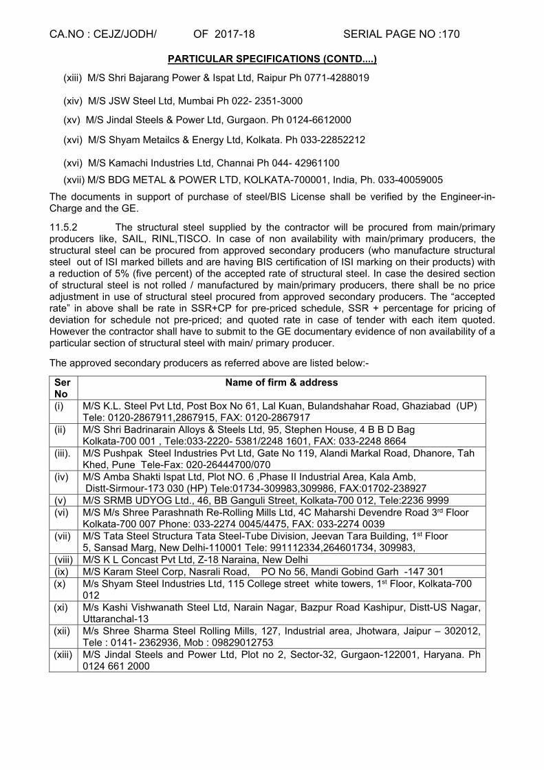
CA.NO : CEJZ/JODH/ OF 2017-18 SERIAL PAGE NO :170
PARTICULAR SPECIFICATIONS (CONTD....)
(xiii) M/S Shri Bajarang Power & Ispat Ltd, Raipur Ph 0771-4288019 (xiv) M/S JSW Steel Ltd, Mumbai Ph 022- 2351-3000
(xv) M/S Jindal Steels & Power Ltd, Gurgaon. Ph 0124-6612000
(xvi) M/S Shyam Metailcs & Energy Ltd, Kolkata. Ph 033-22852212 (xvi) M/S Kamachi Industries Ltd, Channai Ph 044- 42961100
(xvii) M/S BDG METAL & POWER LTD, KOLKATA-700001, India, Ph. 033-40059005
The documents in support of purchase of steel/BIS License shall be verified by the Engineer-in-Charge and the GE.
11.5.2 The structural steel supplied by the contractor will be procured from main/primary producers like, SAIL, RINL,TISCO. In case of non availability with main/primary producers, the structural steel can be procured from approved secondary producers (who manufacture structural steel out of ISI marked billets and are having BIS certification of ISI marking on their products) with a reduction of 5% (five percent) of the accepted rate of structural steel. In case the desired section of structural steel is not rolled / manufactured by main/primary producers, there shall be no price adjustment in use of structural steel procured from approved secondary producers. The “accepted rate” in above shall be rate in SSR+CP for pre-priced schedule, SSR + percentage for pricing of deviation for schedule not pre-priced; and quoted rate in case of tender with each item quoted. However the contractor shall have to submit to the GE documentary evidence of non availability of a particular section of structural steel with main/ primary producer.
The approved secondary producers as referred above are listed below:-
Ser No
Name of firm & address
(i) M/S K.L. Steel Pvt Ltd, Post Box No 61, Lal Kuan, Bulandshahar Road, Ghaziabad (UP) Tele: 0120-2867911,2867915, FAX: 0120-2867917
(ii) M/S Shri Badrinarain Alloys & Steels Ltd, 95, Stephen House, 4 B B D Bag Kolkata-700 001 , Tele:033-2220- 5381/2248 1601, FAX: 033-2248 8664
(iii). M/S Pushpak Steel Industries Pvt Ltd, Gate No 119, Alandi Markal Road, Dhanore, Tah Khed, Pune Tele-Fax: 020-26444700/070
(iv) M/S Amba Shakti Ispat Ltd, Plot NO. 6 ,Phase II Industrial Area, Kala Amb, Distt-Sirmour-173 030 (HP) Tele:01734-309983,309986, FAX:01702-238927
(v) M/S SRMB UDYOG Ltd., 46, BB Ganguli Street, Kolkata-700 012, Tele:2236 9999 (vi) M/S M/s Shree Parashnath Re-Rolling Mills Ltd, 4C Maharshi Devendre Road 3rd Floor
Kolkata-700 007 Phone: 033-2274 0045/4475, FAX: 033-2274 0039 (vii) M/S Tata Steel Structura Tata Steel-Tube Division, Jeevan Tara Building, 1st Floor
5, Sansad Marg, New Delhi-110001 Tele: 991112334,264601734, 309983, (viii) M/S K L Concast Pvt Ltd, Z-18 Naraina, New Delhi (ix) M/S Karam Steel Corp, Nasrali Road, PO No 56, Mandi Gobind Garh -147 301 (x) M/s Shyam Steel Industries Ltd, 115 College street white towers, 1st Floor, Kolkata-700
012 (xi) M/s Kashi Vishwanath Steel Ltd, Narain Nagar, Bazpur Road Kashipur, Distt-US Nagar,
Uttaranchal-13 (xii) M/s Shree Sharma Steel Rolling Mills, 127, Industrial area, Jhotwara, Jaipur – 302012,
Tele : 0141- 2362936, Mob : 09829012753 (xiii) M/S Jindal Steels and Power Ltd, Plot no 2, Sector-32, Gurgaon-122001, Haryana. Ph
0124 661 2000

CA.NO : CEJZ/JODH/ OF 2017-18 SERIAL PAGE NO :171
PARTICULAR SPECIFICATIONS (CONTD....)
11.5.3 Steel sections under Clause 11.4.1 can be procured from main producers / approved secondary producers / BIS marked manufacturers or their authorised dealers / authorised conversion agents at the option of the contractor without any price adjustment.
11.5.4 Galvanised Steel sheet & Fabric Reinforcement for concrete: These shall be ISI Marked and shall be procured directly from Main manufacturers.
11.5.5 The contractor shall be required to submit size wise requirement of steel directly to the Branch Sales Office of SAIL latest by 20th of previous month. The demand shall be either countersigned by GE / CWE or a separate letter signed by GE / CWE shall be attached alongwith the demand, authorizing the same for utilization in MES works. When procuring steel from other manufacturers/secondary producers, the contractor should place his demand/requisition with adequate lead time. 11.5.6 However procurement of Reinforcement Steel, structural steel, GI sheets and reinforcement fabric can be permitted from authorised dealers of main producers in case of small contracts of value not exceeding Rs 7.5 lakhs. 11.5.7 Steel, when procured from main producers/approved secondary producers (stipulated in
above paras) shall have to be procured directly from the storage depots of the main producers/approved secondary producers and not from their authorized agents/ dealers.
11.5.8 The particulars of the manufacturer/supplier of steel shall be submitted by the contractor to the Garrison Engineer prior to procurement for every lot of steel separately. The original documents in support of purchase of steel shall be verified by the site staff and Garrison Engineer and certified true copy of the result shall be retained in GE’s office. The form given here in after will be used for this purpose.

CA.NO : CEJZ/JODH/ OF 2017-18 SERIAL PAGE NO : 172
PARTICULAR SPECIFICATIONS(CONTD....)
STEEL SUPPLY & ACCEPTANCE REGISTER
1 CA NO & Name of work : 2 Control No :
3 Name of manufacture's TC No :
4 Manufacturer :
5 Random test Details (a) Physical test report from __________ vide their letter No __________(Name of NABL Approved Lab/Engg College)
(b) Chemical test report from __________ vide their letter No __________(Name of NABL approved Lab/Engg College)
6 Types of steeel, Dia & Qty (a) type : TMT / CRS (b) Dia - mm (c ) Actual Wt - MT (d) Conversion Wt - MT :-
Chemical Test Mechanical Test Remarks
Car
bon
%
Sul
phur
%
Pho
spho
rous
%
Man
gane
se
%
Sili
con
%
Cor
rosi
on R
esis
tant
E
lem
ent
Wt p
er M
eter
Str
ess
(N/m
m2 )
0.
2% p
roof
Ten
sile
Str
engt
h
(N/m
m2 )
Elo
ngat
ion
%
Ben
d T
est
Reb
end
Tes
t
1 2 3 4 5 6 7 8 9 10 11 12 13 14
As per relevant IS 1786-2008
As per manufacture's test certificate
As per independent test
Remarks with Signature Accepted/Rejected Contractor Junior
Engineer Engineer-in-Charge Garrison Engineer
Remarks of BOO/Inspecting Officer/CWE * To be alloted serially by the GE consignment wise
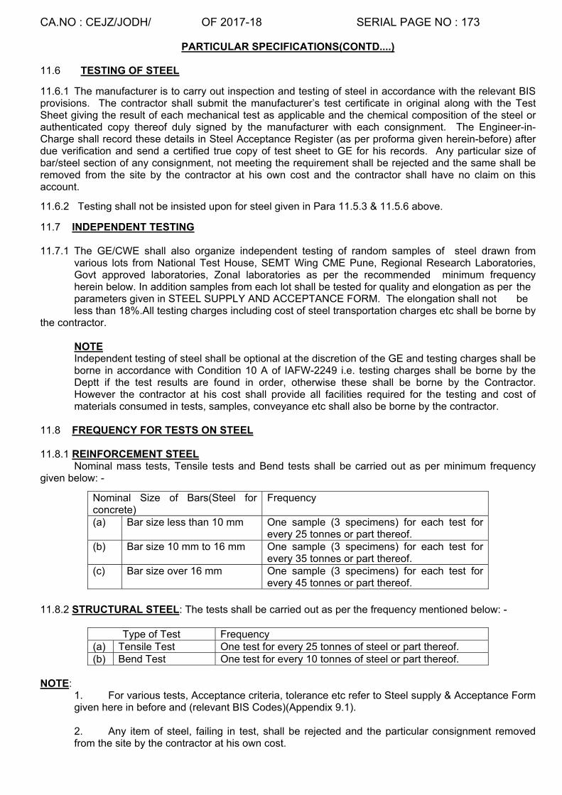
CA.NO : CEJZ/JODH/ OF 2017-18 SERIAL PAGE NO : 173
PARTICULAR SPECIFICATIONS(CONTD....)
11.6 TESTING OF STEEL
11.6.1 The manufacturer is to carry out inspection and testing of steel in accordance with the relevant BIS provisions. The contractor shall submit the manufacturer’s test certificate in original along with the Test Sheet giving the result of each mechanical test as applicable and the chemical composition of the steel or authenticated copy thereof duly signed by the manufacturer with each consignment. The Engineer-in-Charge shall record these details in Steel Acceptance Register (as per proforma given herein-before) after due verification and send a certified true copy of test sheet to GE for his records. Any particular size of bar/steel section of any consignment, not meeting the requirement shall be rejected and the same shall be removed from the site by the contractor at his own cost and the contractor shall have no claim on this account.
11.6.2 Testing shall not be insisted upon for steel given in Para 11.5.3 & 11.5.6 above.
11.7 INDEPENDENT TESTING 11.7.1 The GE/CWE shall also organize independent testing of random samples of steel drawn from various lots from National Test House, SEMT Wing CME Pune, Regional Research Laboratories, Govt approved laboratories, Zonal laboratories as per the recommended minimum frequency herein below. In addition samples from each lot shall be tested for quality and elongation as per the parameters given in STEEL SUPPLY AND ACCEPTANCE FORM. The elongation shall not be less than 18%.All testing charges including cost of steel transportation charges etc shall be borne by the contractor.
NOTE Independent testing of steel shall be optional at the discretion of the GE and testing charges shall be borne in accordance with Condition 10 A of IAFW-2249 i.e. testing charges shall be borne by the Deptt if the test results are found in order, otherwise these shall be borne by the Contractor. However the contractor at his cost shall provide all facilities required for the testing and cost of materials consumed in tests, samples, conveyance etc shall also be borne by the contractor.
11.8 FREQUENCY FOR TESTS ON STEEL 11.8.1 REINFORCEMENT STEEL
Nominal mass tests, Tensile tests and Bend tests shall be carried out as per minimum frequency given below: -
11.8.2 STRUCTURAL STEEL: The tests shall be carried out as per the frequency mentioned below: -
NOTE:
1. For various tests, Acceptance criteria, tolerance etc refer to Steel supply & Acceptance Form given here in before and (relevant BIS Codes)(Appendix 9.1). 2. Any item of steel, failing in test, shall be rejected and the particular consignment removed from the site by the contractor at his own cost.
Nominal Size of Bars(Steel for concrete)
Frequency
(a) Bar size less than 10 mm One sample (3 specimens) for each test for every 25 tonnes or part thereof.
(b) Bar size 10 mm to 16 mm One sample (3 specimens) for each test for every 35 tonnes or part thereof.
(c) Bar size over 16 mm One sample (3 specimens) for each test for every 45 tonnes or part thereof.
Type of Test Frequency (a) Tensile Test One test for every 25 tonnes of steel or part thereof. (b) Bend Test One test for every 10 tonnes of steel or part thereof.

CA.NO : CEJZ/JODH/ OF 2017-18 SERIAL PAGE NO : 174
PARTICULAR SPECIFICATIONS(CONTD....)
11.9 DOCUMENTATION:
The contractor shall submit original purchase vouchers from the manufacturer for the total quantity of steel supplied under each consignment to be incorporated in the work. All consignments received at the work site shall be inspected by the GE along with the relevant documents before acceptance. The original purchase vouchers and the test certificates shall be defaced by the Engineer-in-Charge and kept on record in the office of the Garrison Engineer duly authenticated and with cross reference to the control number recorded in the steel Acceptance Register. The Steel Acceptance Register shall be signed by the JE, Engineer-in-Charge, GE and the Contractor. The entire quantity of all steel items shall be suitably recorded in the measurement book as not to be abstracted, before incorporation in the work and shall be signed by Engineer-in-charge and the contractor. 11.10 STORAGE ACCOUNTING, PRESERVATION AND MAINTENANCE OF STEEL 11.10.1 The storage, accounting, preservation and maintenance of steel supplied by the contractor shall be done as per standard engineering practice till the same is incorporated in the work and the cost of the same shall be deemed to be included in the unit rate/amount quoted by the tenderer. The GE shall inspect at regular interval to verify that steel lying at site is stored, accounted, preserved and maintained as per the norms. The steel shall be stored so as to differentiate each consignment separately. If the GE is not satisfied with the storage / preservation of any size of bar/section of steel, he may order for any test(s) of steel as applicable for that size of bar/section of steel and as specified in tender documents /relevant IS code to recheck the acceptability criteria for the same. The contractor shall bear the cost of necessary testing(s) in this regard and no claim whatsoever shall be entertained. 11.10.2 Movement of steel shall be recorded in In/Out steel register as per following proforma. Each entry in the register shall be signed by the contractor and Engineer-in-Charge.
IN/OUT STEEL REGISTER
Sl No
Date Steel IN Steel OUT Qty Balance Qty
(Tons) Section Control
No Qty (Tons)
Section Reasons*
1 2 3 4 5 6 7 8 9 *Note:
(i) The following reasons may be mentioned for taking out steel from storage:- (a) For testing purpose. (b) For use in work. (c) Rejected steel taken out of site.
(ii) All the transaction in the register shall be signed by Contractor / his representative and Engineer-in-Charge/JE.
11.11 SCHEDULING AND SUPPLY Schedule of supply of steel will be finalised by GE in consultation with contractor and the same will be incorporated in CPM chart so that supply of steel is monitored in a way to avoid any delay in completion of the work. The schedule of supply of steel will be vetted by Accepting Officer or Officer nominated by the Accepting Officer from time to time. 11.12 MEASUREMENTS AND PAYMENT OF STEEL 11.12.1 The entire quantity of all steel items shall also be suitably recorded in the Measurement Book for record purposes as ‘Not to be abstracted’ before incorporation in the work and shall be signed by the Engineer-in-Charge and the contractor. 11.12.2 The nominal mass conversion factors for various steel Sections/ size of finished bars as given in relevant IS codes shall be considered standard for measurement.

CA.NO : CEJZ/JODH/ OF 2017-18 SERIAL PAGE NO : 175
PARTICULAR SPECIFICATIONS(CONTD....)
11.12.3 The contractor shall plan to procure steel considering the time required for approval and testing of steel well in advance. No extension of time on grounds of delay in procurement of steel or testing/retesting of steel shall be admissible.
11.12.4 The payment of steel shall only be allowed after production of original purchase vouchers, test certificates by the contractor for each consignment of steel and results of testing carried out by the department are found satisfactory after testing as specified herein before. 11.13 FABRICATION OF STEEL STRUCTURES :
The structural steel work shall be carried out all as specified in MES Schedule Part-10 and in drawings.
11.14 WELDING 11.14.1 Welding of steel and ironwork shall be done in an approved manner with electric arc welding or any
other type of welding as per structural design stipulation. 11.14.2 Electric welding shall be metal arc welding as specified in Para 10.15 of MES Schedule Part-I. 11.14.3 Welding electrodes shall be of quality suitable for welding of structural steel and shall comply with
requirement of IS-814 for covered electrodes for metal arc welding of mild steel. 11.14.4 Unless otherwise specified/shown on drawings, the fillet welds shall be of 6mm size. 11.14.5 All butt welds shall be full penetration welds. 11.15 HOLDFAST / LUGS
(i) Flat iron holdfast/lug shall be provided by welding as and where shown on drawings except those to be provided to wooden chowkhat, which shall be fixed with screws as per details shown on drawings. (ii) Flat iron holdfast shall be embedded in PCC (1:3:6) type C-1 block of size 15 cm (height of block) x30 cm (length of block) x width of masonry wall. (iii) Holdfasts/lugs shall be hot tarred and sanded before fixing (iv) Wherever doorframe and windows frame side is coming in contact with RCC column, dash fasteners shall be provided in lieu of holdfast.
11.16 STEEL WINDOWS AND VENTILATORS
(a) The term steel window use in the particular specifications shall mean ‘steel windows and ventilators’. (b) Steel windows (glazed) shall be provided with horizontal glazing bars as shown in drawings. Fixing and glazing of windows shall be in accordance with IS 1081 and shall be tennoned and riveted to the frame. (c) Glazed shutters shall be provided with box type hinges, telescopic peg stay, pressed handle open out side and gauzed shutters shall be with box type hinges with pressed handle open inside as per manufacturer’s instructions/IS specifications. (d) Steel windows shall be fixed to concrete/masonry/PCC block masonry with lugs. Lugs shall not be provided for fixing to lintels and cills even though shown in the drawings.

CA.NO : CEJZ/JODH/ OF 2017-18 SERIAL PAGE NO : 176
PARTICULAR SPECIFICATIONS(CONTD....)
(e) Peg stays and handles for steel windows shall be of steel and painted with corrosion resistant paint.
(f) Centre hung windows shall be mounted on antifriction brass pivots.
(g) Various sections for Steel windows shall be ISI marked and steel windows shall confirm to IS-1038.
(h) Handle to fly proof windows shall be pressed type
(j) Factory made steel windows and ventilators shall be procured from the firm specified in
Appendix ‘C’. 11.16A Windows/ventilators cill whether shown in the drawings or not all windows & ventilators shall be
provided with polished Udaipur green marble 15 to 20mm thick set & bedded in 10mm thick screed bed in CM (1:3). Marble for cills shall be in one piece & shall be embedded 25mm on both the sides (except RCC portion) & shall have polished & half rounded edge projected externally & edge shall flushed with wall surface inside rooms & projected 25mm outside rooms & all as directed. The portion between two frames of windows shall be filled CM (1:3).
11.17 BOX TYPE WINDOWS / VENTILATORS:- All box type windows/ventilators shall be provided as per
drawings & shall be factory made & procured from manufacturer as specified in App ‘’C’’. 11.18 GUARD BARS TO STEEL WINDOWS & VENTILATORS
(a) The term ‘window’ used in the particular specifications shall mean ‘windows/ventilators’ (b) All steel windows shall be provided with guard bars as shown on drawings. However, in case
of double windows in the same opening guard bars shall be provided to glazed windows only.
(c) Guard bars to steel windows unless otherwise shown on drawings shall be mild steel 12 mm
square. The guard bars shall be integrated during the manufacture of the windows.
11.19 FAN HOOKS Fan hook shown in drawings shall be provided wherever ceiling fan/fan hook is indicated in drawings. The lump sum tendered by the contractor for the building under schedule ‘A’ Part-I shall be deemed to include for the cost of the same.
11.20 PRESSED STEEL DOOR FRAMES
(a) Pressed steel door frames wherever shown in drawings shall be fabricated with 1.25 mm thick MS plain sheet. Pressed steel door frames shall conform to IS-4351. Tolerance over profile shall be 2 mm. (b) Pressed steel door frames shall be procured from any of the manufacturers given in
Appendix ‘C’.
(c) Space in pressed steel doorframes shall be filled with PCC (1:3:6) type C-0.
(d) Frames shall be supplied by manufacturers with a shop coat of zinc chrome primer. (e) 12 mm square mild steel bar shall be welded horizontally at the bottom of frame. The 12 mm square bar shall be embedded in floors. In case of double shutter i.e panelled door & gauzed door shutter, two nos 12 mm square bar shall be provided at bottom of frame.

CA.NO : CEJZ/JODH/ OF 2017-18 SERIAL PAGE NO : 177
PARTICULAR SPECIFICATIONS(CONTD....)
11.21 STEEL FOR REINFORCEMENT
(a) The provision of MES SSR Part-I clause 10.18 that ends of deformed bars are not bent to form hooks is not applicable to this contract. ‘L’ shaped bends shall be provided to deformed bars all as per RCC notes on drawing No.CEJZ/STR/STD/08/2016 sheet 1/29 to 29/29. However in case any conflicting provision is observed in both the above drg, provisions contained in drg. CEJZ/STR/05/2013 sheet 1/11 shall supercede. (b) The overlaps for reinforcement given in drawings No CEJZ/STR/STD/08/2016 sheet 1/29 to 29/29 (as applicable) shall take precedence over provisions given in Para 10.19 of MES Part-I. (c) For making adjustment arising out of deviation involving reinforcement bars, the length of each bar for the purpose of calculation of laps shall be taken as 10 metres. (d) Adequate numbers of chairs as given in drawing CEJZ/STR/STD/08/2016 sheet 1/29 to 29/29 shall be provided in all reinforced sections to prevent top layer of reinforcement from sagging and the cost of the same shall be deemed to be included in lump sum quoted for schedule ‘A’ Part-I (Building works).
11.22 STEEL / GARRAGE DOOR
(a) Steel door shall be manufactured and provided all as shown on drg. Various sections of steel shall be procured from sources as specified here in before.
(b) All steel surfaces embedded/in contact with concrete shall be tarred and sanded before fixing.
(c) All exposed steel surfaces shall be painted all as described here in after.
11.23 ROLLING SHUTTERS Steel rolling shutter shall confirm to IS-6248 and shall be as specified in clause No 10.23 of MES SSR Part-I. Rolling shutter shall be with 1.25 mm thick lathing and shall be gear operated type with chain wheel and hand chain.
11.24 RAILINGS
Wherever railing with GI pipes shown in drawings, the same shall be provided all as shown in drawing with medium grade GI pipes & fittings (ISI marked) railing & with square bars etc all as indicated. All exposed surface of steel/iron shall be painted with two coats of synthetic enamel paint over a coat of primer.
11.25 ANODISED ALUMINIUM DOORS, WINDOWS, VENTS AND FIXED GLAZING 11.25.1 Aluminium doors, windows, vents and fixed glazing shall be provided all as specified in MES SSR
Part-I clause 10.37 and as specified/shown on drawings. 11.25.2 Make of aluminium section for doors/windows/ventilators shall be as appendix `C`. 11.25.3 Openable aluminium windows shall be provided with aluminium grill (Type-A), aluminium wire
mesh and glass panes. 11.25.4 Thickness of glass panes for doors and windows shall be 5.5 mm thick and 4.0 mm thick
respectively. Glass shall be sheet glass selected quality. 11.25.5 Glass panes shall be provided with standard glazing clip as per manufacturer’s instructions. 11.25.6 All aluminium doors, windows and fixed galzing sections shall be powder coated in chocolate
colour. 11.25.7 Aluminium grill type A shall be provided to windows wherever indicated in the drawings/referred in
notes of the relevant drawings.

CA.NO : CEJZ/JODH/ OF 2017-18 SERIAL PAGE NO : 178
PARTICULAR SPECIFICATIONS(CONTD....)
11.25.8 Aluminium grill shall be powder coated as approved by GE and shall be fitted to windows all as per manufacturer’s instructions and as per standard Engineering practice.
11.25.8 Irrespective of whatsoever shown in drawing hydraulic door closures shall be provided to all leafs of aluminium doors of suitable capacity to match with weight of leaf.
12 ROOF COVERING 12.1 RCC ROOF SLAB
(a) Intermediate slab shall be laid to level (b) RCC roof slab shall be laid to slope as indicated in drawings (c) Roof slab shall be projected as shown in respective drawings (d) Exposed surfaces of sofit of RCC slabs shall be plastered in cement mortar (1:3), 5 mm thick and finished even and smooth (e) Irrespective of what is shown on drawings full bearing of RCC slab shall be provided on external wall
12.2 WATER PROOFING TREATMENT TO RCC ROOF : [A] WATER PROOFING TREATMENT TO NON ACCESSIBLE RCC ROOF : Water proofing treatment to non accessible RCC roof shall be carried out as follows:-
(a) Over the RCC roof slab, 10 mm thick plaster in CM (1:4) shall be provided mixed with water proofing compound, ISI marked as per manufacturer instructions. The plaster shall be provided when the concrete is green. The plaster surface shall be steel troweled to get a smooth surface.
(b) After the plaster has dried up, the membrane treatment shall be applied as under:- (i) The plastered surface shall be prepared by thoroughly wire brushing, washed, dried up and cleaned of all foreign matter and dust.
(ii) On the prepared surface, one coat of approved bituminous primer @ 0.40 Ltr per Sqm shall be applied. The primer and the membrane to be used shall be of same manufacturer.
(iii) Over the primed surface, 3 mm thick APP modified polymeric membrane with non-woven polyester reinforcement shall be laid by torch application method. Technical characteristics of the membrane shall be as under:
CHARACTERISTIC SPECIFICATIONS
(i) Thickness Minimum 3mm (ii) Weight Min 3.00 Kg per Sqm of membrane (iii) Softening point Min 150° C. (iv) Cold flexibility (-)5° C (v) Reinforcement Non-woven polyester Mat 160 gm /m2. (vi) Tensile strength:- Lengthwise Crosswise
> 750N / 5cm > 400N / 5cm
(vii) Elongation :- Lengthwise Crosswise
Min 40% Min 50%
(viii) Heat Resistance Does not Drip at 125ºC (ix) Tear Strength :- Lengthwise, N Crosswise, N
> 300 > 250
(x) Water Absorption, %
<0.15
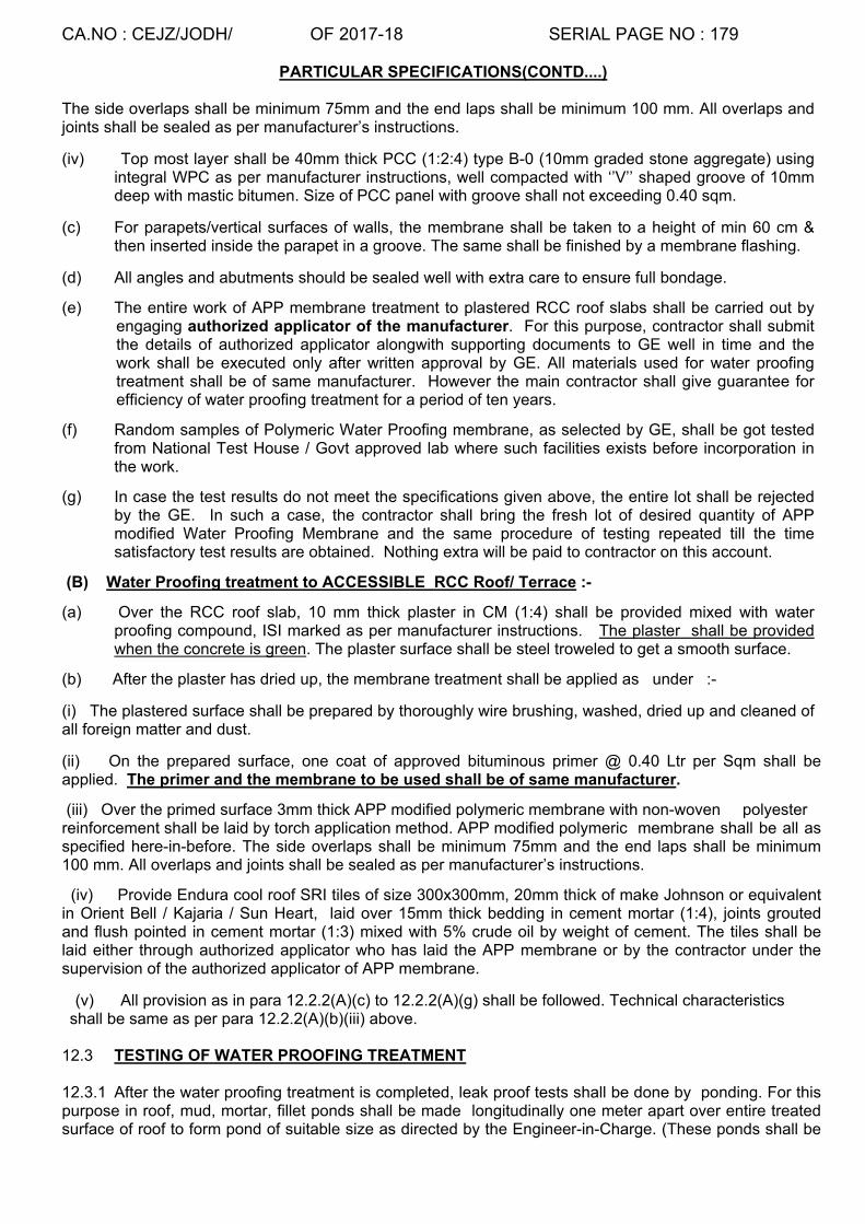
CA.NO : CEJZ/JODH/ OF 2017-18 SERIAL PAGE NO : 179
PARTICULAR SPECIFICATIONS(CONTD....)
The side overlaps shall be minimum 75mm and the end laps shall be minimum 100 mm. All overlaps and joints shall be sealed as per manufacturer’s instructions.
(iv) Top most layer shall be 40mm thick PCC (1:2:4) type B-0 (10mm graded stone aggregate) using integral WPC as per manufacturer instructions, well compacted with ‘’V’’ shaped groove of 10mm deep with mastic bitumen. Size of PCC panel with groove shall not exceeding 0.40 sqm.
(c) For parapets/vertical surfaces of walls, the membrane shall be taken to a height of min 60 cm & then inserted inside the parapet in a groove. The same shall be finished by a membrane flashing.
(d) All angles and abutments should be sealed well with extra care to ensure full bondage.
(e) The entire work of APP membrane treatment to plastered RCC roof slabs shall be carried out by engaging authorized applicator of the manufacturer. For this purpose, contractor shall submit the details of authorized applicator alongwith supporting documents to GE well in time and the work shall be executed only after written approval by GE. All materials used for water proofing treatment shall be of same manufacturer. However the main contractor shall give guarantee for efficiency of water proofing treatment for a period of ten years.
(f) Random samples of Polymeric Water Proofing membrane, as selected by GE, shall be got tested from National Test House / Govt approved lab where such facilities exists before incorporation in the work.
(g) In case the test results do not meet the specifications given above, the entire lot shall be rejected by the GE. In such a case, the contractor shall bring the fresh lot of desired quantity of APP modified Water Proofing Membrane and the same procedure of testing repeated till the time satisfactory test results are obtained. Nothing extra will be paid to contractor on this account.
(B) Water Proofing treatment to ACCESSIBLE RCC Roof/ Terrace :-
(a) Over the RCC roof slab, 10 mm thick plaster in CM (1:4) shall be provided mixed with water proofing compound, ISI marked as per manufacturer instructions. The plaster shall be provided when the concrete is green. The plaster surface shall be steel troweled to get a smooth surface.
(b) After the plaster has dried up, the membrane treatment shall be applied as under :-
(i) The plastered surface shall be prepared by thoroughly wire brushing, washed, dried up and cleaned of all foreign matter and dust.
(ii) On the prepared surface, one coat of approved bituminous primer @ 0.40 Ltr per Sqm shall be applied. The primer and the membrane to be used shall be of same manufacturer.
(iii) Over the primed surface 3mm thick APP modified polymeric membrane with non-woven polyester reinforcement shall be laid by torch application method. APP modified polymeric membrane shall be all as specified here-in-before. The side overlaps shall be minimum 75mm and the end laps shall be minimum 100 mm. All overlaps and joints shall be sealed as per manufacturer’s instructions.
(iv) Provide Endura cool roof SRI tiles of size 300x300mm, 20mm thick of make Johnson or equivalent in Orient Bell / Kajaria / Sun Heart, laid over 15mm thick bedding in cement mortar (1:4), joints grouted and flush pointed in cement mortar (1:3) mixed with 5% crude oil by weight of cement. The tiles shall be laid either through authorized applicator who has laid the APP membrane or by the contractor under the supervision of the authorized applicator of APP membrane.
(v) All provision as in para 12.2.2(A)(c) to 12.2.2(A)(g) shall be followed. Technical characteristics shall be same as per para 12.2.2(A)(b)(iii) above.
12.3 TESTING OF WATER PROOFING TREATMENT 12.3.1 After the water proofing treatment is completed, leak proof tests shall be done by ponding. For this purpose in roof, mud, mortar, fillet ponds shall be made longitudinally one meter apart over entire treated surface of roof to form pond of suitable size as directed by the Engineer-in-Charge. (These ponds shall be
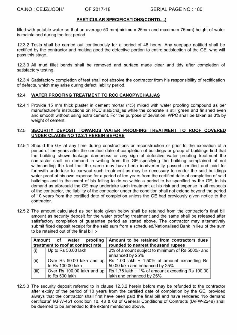
CA.NO : CEJZ/JODH/ OF 2017-18 SERIAL PAGE NO : 180
PARTICULAR SPECIFICATIONS(CONTD....)
filled with potable water so that an average 50 mm(minimum 25mm and maximum 75mm) height of water is maintained during the test period. 12.3.2 Tests shall be carried out continuously for a period of 48 hours. Any seepage notified shall be rectified by the contractor and making good the defective portion to entire satisfaction of the GE, who will pass this stage. 12.3.3 All mud fillet bends shall be removed and surface made clear and tidy after completion of satisfactory testing. 12.3.4 Satisfactory completion of test shall not absolve the contractor from his responsibility of rectification of defects, which may arise during defect liability period. 12.4. WATER PROOFING TREATMENT TO RCC CANOPY/CHAJJAS 12.4.1 Provide 15 mm thick plaster in cement mortar (1:3) mixed with water proofing compound as per
manufacturer’s instructions on RCC slab/chajjas while the concrete is still green and finished even and smooth without using extra cement. For the purpose of deviation, WPC shall be taken as 3% by weight of cement.
12.5 SECURITY DEPOSIT TOWARDS WATER PROOFING TREATMENT TO ROOF COVERED UNDER CLAUSE NO 12.2.1 HEREIN BEFORE
12.5.1 Should the GE at any time during constructions or reconstruction or prior to the expiration of a
period of ten years after the certified date of completion of buildings or group of buildings find that the building shown leakage dampness or any sign of defective water proofing treatment the contractor shall on demand in writing from the GE specifying the building complained of not withstanding the fact that the same may have been inadvertently passed certified and paid for forthwith undertake to carryout such treatment as may be necessary to render the said buildings water proof at his own expense for a period of ten years from the certified date of completion of said buildings and in the event of his failing to do so within a period to be specified by the GE, in his demand as aforesaid the GE may undertake such treatment at his risk and expense in all respects of the contractor, the liability of the contractor under the condition shall not extend beyond the period of 10 years from the certified date of completion unless the GE had previously given notice to the contractor.
12.5.2 The amount calculated as per table given below shall be retained from the contractor’s final bill
amount as security deposit for the water proofing treatment and the same shall be released after satisfactory completion of guarantee period as stated above. The contractor may alternatively submit fixed deposit receipt for the said sum from a scheduled/Nationalised Bank in lieu of the sum to be retained out of the final bill :-
Amount of water proofing treatment to roof at contract rate
Amount to be retained from contractors dues rounded to nearest thousand rupees
(i) Up to Rs 50.00 lakh 2% of amount subject to minimum of Rs 5000/- and enhanced by 25%
(ii) Over Rs 50.00 lakh and up to Rs 100.00 lakh
Rs 1.00 lakh + 1.50% of amount exceeding Rs 50.00 lakh and enhanced by 25%
(iii) Over Rs 100.00 lakh and up to Rs 500 lakh
Rs 1.75 lakh + 1% of amount exceeding Rs 100.00 lakh and enhanced by 25%
12.5.3 The security deposit referred to in clause 12.3.2 herein before may be refunded to the contractor
after expiry of the period of 10 years from the certified date of completion by the GE, provided always that the contractor shall first have been paid the final bill and have rendered ‘No demand certificate’ IAFW-451 condition 10, 48 & 68 of General Conditions of Contracts (IAFW-2249) shall be deemed to be amended to the extent mentioned above.

CA.NO : CEJZ/JODH/ OF 2017-18 SERIAL PAGE NO : 181
PARTICULAR SPECIFICATIONS(CONTD....)
12.5.4 Materials required for waterproofing shall be purchased by the contractor from the manufacturers or their authorised agent only and brought to site. The GE before approval shall verify name of authorised agent from the manufacturer.
12.5.5 TREATMENT TO SUNKEN FLOORS: Treatment to sunken floor shall be carried out as under:-
(i) Cleaning top surface of floor slab and vertical surface of wall and brushing with neat cement slurry @ 0.5 kg of cement per Sqm with acrylic based polymer modified cementitous composite @ 0.25 kg /sqm and laying 50mm thick (average) PCC of grade M-10 (Nominal Mix), mixed with WPC as per manufacturer instructing laid in slope 1:20 towards spouts including covering corners.
(ii) Rendering 15mm thick in CM (1:4) on wall/floor surfaces of sunken floor finished even and smooth with using WPC as per manufacturer’s instruction and brushing with neat cement slurry @ 0.25 kgs of cement per Sqm with acrylic based polymer modified cementitous composite at the rate of 0.13 kg/sqm complete all as specified and directed.
(iii) Applying a coat of paving bitumen 80/100 penetration @ 1.50kg/Sqm on plastered & concrete surfaces.
(iv) Laying a layer of 200 micron polythene film pasted with the help of suitable adhesive complete.
(v) Two nos 25mm bore GL medium grade 450mm long spout shall be provided through external wall to drain out accumulated water.
(vi) Sunken floor shall be tested for water tightness by filling water for 72 hrs before and after treatment work is carried out and ensure that no leakage/seepage exists.
(vii) Sunken portion shall be filled with lean cement concrete of grade M-7.5 using broken stone aggregate.
13. FLOORING
13.1 GENERAL
(a) Floors shall be laid to levels and to falls as indicated in drawings and as directed by Engineer-in-Charge. Floors shall be sunk to required depth where shown in drawings.
(b) Floors shall be carried out through threshold of all openings in walls. In case of Kota stone flooring thresholds of all openings in walls shall be finished with Kota stone floors.
(c) If type of floor at any location is not shown in drawing of schedule of finishes, the same shall be considered as under for lump sum quotation :- (i) For Ground floor 40 mm thick PCC 1:2:4 type B-1 over 75 mm thick PCC 1:4:8 type D-2 using 40 mm graded stone aggregate over rammed earth. (ii) For first floor 40 mm thick PCC 1:2:4 type B-1 using 20 mm graded stone aggregate over 10 mm thick levelling plaster in CM 1:4 over RCC slab. (d) Type of flooring shall be as per drawing of schedule of finishes and as specified. If type of flooring is not indicated for any location it shall be same as in other similar locations. No extra claim shall be admissible to the contractor on this account.
13.2 SUB BASE TO FLOOR
(a) Bay system of use of glass dividing strips not to be adopted in case of sub base. (b) Where thickness and type of sub base is not shown on drawings the same shall be 75 mm thick. PCC (1:4:8) type D-2 using 40 mm graded stone aggregate.

CA.NO : CEJZ/JODH/ OF 2017-18 SERIAL PAGE NO : 182
PARTICULAR SPECIFICATIONS(CONTD....)
(c) Where hardcore has been shown on drawings to sub base of floor, the same shall be provided as specified herein before. Thickness of sub base of hardcore where not shown shall be 150 mm compacted thickness.
13.3 CEMENT CONCRETE FLOOR (a) PCC floor up to 50 mm thick shall be laid adopting panel dimension not exceeding 1200 mm
x 1200 mm with 4 mm thick (nominal thickness) (as shown in schedule of finishes) sheet glass as dividing strips irrespective of whether shown in drg or not. The width of the glass strips shall be 2 mm less than the thickness of the floor and these strips shall be visible in the finished floor. (b) Wherever 75/100mm PCC (1:2:4) type B-1 using 20 mm graded stone aggregate in flooring is shown in schedule of finishes drawing dividing strip the panel dimension shall be not exceeding 1200 mm x 1200 mm. The panels of size 1200mm x 1200mm shall be cast in alternate panel using form work. (c) Where thickness of PCC floor is not shown on drawing the same shall be 40 mm thick PCC (1:2:4) type B-1 (d) Unless otherwise specified / shown on drawings, top of PCC floor shall be finished even and smooth with using extra cement while PCC is still green. Plaster is prohibited. (e) PCC floor except (a) & (b) here in before shall be laid in alternate bay system with panel dimension not exceeding 2mx2m. Glass dividing strips shall not be provided. (f) Sub base shall laid over rammed earth or sub base & PCC flooring shall be laid all as specified. (g) wear-resistant flooring by vaccum dewatering method and power trowelling method with skin floater:- irrespective of whatsoever shown in drawing, all concrete flooring 150mm thick and above shall be laid by vacuum dewatering process.
13.4 NON SKID CERAMIC TILES:
(a) Non-skid ceramic tiles wherever shown in schedule of finishes drawing shall be plain light shade & shall be got approved from GE before incorporation in the work. Quality of tiles shall conform to IS-15622 (2006) (Group B II). Make of tile shall be as listed in Appendix `C’ to particular specifications.
(b) In case of ground floor tiles shall be laid over 15mm thick bedding layer in cement mortar (1:4) over 75 mm thick sub base PCC (1:4:8) type D-2 using 40 mm graded stone aggregate over rammed approved earth. In case of first floor and above (except sunken portion of toilet), tiles shall be laid over 15 mm thick bedding layer in cement mortar (1:4) over 25mm thick in PCC (1:2:4) type B-0 using 12.5 mm graded stone aggregate over RCC slab. In sunken portion of toilet floor tiles shall be laid over 10 mm thick bedding layer in cement mortar (1:4) over 25mm thick in PCC (1:2:4) type B-0 using 12.5 mm graded stone aggregate over WPT all as specified.
(c) Tiles shall be provided all as specified in clause 13.40 of MES SSR Part-I. Irrespective of whatever is shown on Schedule of Finishes / drawings, Size and thickness of tile shall be 400 x 400 x 8-9 mm thick for all rooms expect toilets/bath which shall be of size 300 X300X6-7mm.
(d) Tiles shall be jointed / pointed in white cement using pigment to match the colour of tiles 13.5 POLISHED/MIRROR POLISHED KOTA STONE SLAB FLOORING
13.5.1 Polished/mirror polished Kota stone slab flooring shall be laid all as specified in clause 13.47 of MES
SSR Part-I and as directed by the Engineer-in-Charge. Thickness of stone slab shall be 20 to 25

CA.NO : CEJZ/JODH/ OF 2017-18 SERIAL PAGE NO : 183
PARTICULAR SPECIFICATIONS(CONTD....)
mm. Size of the stone slabs shall be 550 x 550mm except for area less than 2 Sqm where the size of Kota stone shall be 250 x 250mm.
13.5.2 In ground floor Kota stone slab shall be laid over 20 mm thick bedding (screed) layer in cement mortar (1:3) over 75mm thick sub base PCC (1:4:8) type D-2 using 40 mm graded stone aggregate over a layer of 150 micron polythene film over 300mm coarse sand over rammed approved earth. In first floor and above, Kota stone shall be laid over 20mm thick bedding layer in CM (1:3) over RCC slab as specified.
13.4.3 Wherever mirror polishing to Kota Stone slab have been mentioned in schedule of finishes drawings same shall be carried out as under:-
(a)1st Cutting with carborundum stone 60 Grit (b)IInd Cutting with carborundum stone 120 Grit (c)IIIrd Cutting with carborundum stone 320 Grit (d)IVth Cutting with carborundum stone 600 Grit (e)Vth Cutting with carborundum stone 1200 Grit. (f)VIth cutting with carborundum stone 0 Grit.
13.5.4 POLISHED MARBLE STONE FOR COUNTER TOPS
16mm thick machine cut marble stone slab shall be provided on counter top over 10mm thick bedding layer in cement mortar 1:4 and as specified in clause No. 13.39.6 of MES Schedule Part- I and as directed by Engineer-in-Charge
13.6 VITRIFIED TILES FLOORING
13.6.1 Vitrified tiles wherever shown in schedule of finishes drawing shall be plain light shade, stain free & got approved from GE before incorporation in the work. Quality of tiles shall be 1st class superior/ premium quality confirming to grade B-II a as per IS- 13712-1993. The tiles shall be light coloured and plain shade. Make of tile shall be as specified in Appendix ‘C’.
13.6.2 Screed bed and sub base etc for laying of tiles shall be as shown in schedule of finishes drawing in case the details are not indicated, the same shall be as under:-
In ground floor tiles shall be laid over 15mm thick bedding layer in cement mortar (1:4) over 25mm thick PCC (1:2:4) type B-O using 12.5mm graded stone aggregate over 75mm thick PCC (1:4:8) type D-2 using 40mm graded stone aggregate over rammed earth. In first floor tiles shall be laid over 15mm thick bedding layer in CM (1:4) over RCC slab as specified
13.6.3 Tiles shall be provided all as specified in clause 13.41 of MES SSR part- 1. 13.6.4 Size and thickness of tile shall be 600mm x 600mm x 9 to 10mm thick. 13.7 INTER LOCKING PRECAST BLOCK FLOORING Interlocking pre-cast coloured block shall be 50mm thick, M-35 grade (IS-15658 marked) & rubber finished as shown in schedule of finishes drawing. The make of tiles shall be as specified in Appx ‘C’. The colour / size / pattern / design of blocks shall be as approved by GE. The block shall be laid over 100mm thick sand cushioning over 100mm thick hard core over rammed earth. The joints shall be filled with sand. 13.8 PLINTH PROTECTION (a) Plinth protection shall be provided to the buildings as shown on drawings (in main plan) or any other drawing. Where indicated in drawing, plinth protection with drain shall be provided at locations shown on drawing.
(b) The plinth protection shall be with 50 mm thick PCC (1:2:4) type B-1 using 20 mm graded stone aggregate over 75 mm thick hard core over rammed earth. Plinth protection shall be laid to slope 1 in 30 in alternative bays not exceeding 3 metres in length. Exposed surfaces shall be finished even and fair without using extra cement.

CA.NO : CEJZ/JODH/ OF 2017-18 SERIAL PAGE NO : 184
PARTICULAR SPECIFICATIONS(CONTD....)
(d) Joints of plinth protection shall be filled with bitumen mastic (1:3). (e)
13.8.1 DRAIN Drain where indicated along with plinth protection shall be provided as shown on drawing. The drain shall be in PCC (1:3:6) type C-1 using 20 mm graded stone aggregate. Exposed surfaces shall be finished even and smooth using extra cement.
13.9 SKIRTING/DADO (a) Skirting shall be provided to the walls except where dado has been shown/indicated in the drawings.
Material of skirting shall be same as that of the floor except that (i) ceramic tile skirting shall be with glazed ceramic tile and (ii) Skirting for walls adjacent to chequered concrete flooring shall be with cement skirting. Materials for dado shall be as indicated/shown in drawings.
(b) The height of skirting and dado shall be as per drawings. If not shown/indicated in drawings, the
height of skirting shall be 100mm and height of dado shall be 1300mm. 13.9.1 CEMENT PLASTER IN SKIRTING Irrespective of whatever is specified in schedule of finishes, cement plaster in skirting shall be 15
mm over brick wall and 20mm over stone masonry wall. Skirting shall be provided in two coats. First coat shall be 10mm on brick wall and 15mm on stone masonry wall in cement mortar (1:4) and setting coat shall be 5mm thick in cement mortar (1:3) trowelled to a smooth and even finish using extra cement. It shall be in line with plastering and separated with groove. Junction of floor and skirting shall be rounded to minimum radius of 5mm.
13.9.2 POLISHED KOTA STONE IN SKIRTING/DADO
Polished Kota stone skirting/dado shall be provided to heights as shown in drawing. Kota stone shall be as specified here-in-before except thickness, which shall be 12 to 15 mm thick. Backing coat shall be 10mm thick in CM (1:3). Stone shall be laid bedded and jointed with neat gray cement slurry. The tiles shall be cleaned and rubbed after they are set. The joints shall match with the joints in floor. Kota Stone in skirting/dado shall be polished as specified.
13.9.3 GLAZED CERAMIC TILE DADO (a) Glazed ceramic tiles wherever shown in schedule of finishes drawing shall be got approved from GE before incorporation in the work. Quality of tiles shall be 1st class superior/premium quality confirming to grade B-III as per IS-13712-1993. Tiles shall be light coloured and plane shade. Make of tiles shall be as specified in Appendix ‘C’.
(b) Tile shall be provided over cement mortar screed as per schedule of finishes drawing and as specified in clause 13.40 of SSR Part I. Joints of dado shall match with the joints in floor tiles. (c) Colour of coloured tiles shall be as approved by GE. 13.9.4 VITRIFIED TILE SKIRTING/DADO
(a) Vitrified tiles wherever shown in schedule of finishes drawing shall be plain light shade, stain free & got approved from GE before incorporation in the work. Quality of tiles shall be 1st class superior/ premium quality conforming to grade B-III as per IS-13712-1993. Tiles shall be light coloured and plane shade. Make of tiles shall be as specified in Appendix ‘c’.
(b) Tiles shall be provided over cement mortar screed 10mm thick in CM (1:3) as per schedule of finishes drawing and as specified in clause 13.41 of SSR Part-I. Joints of skirting/ dado shall match with the joints in floor tiles.

CA.NO : CEJZ/JODH/ OF 2017-18 SERIAL PAGE NO : 185
PARTICULAR SPECIFICATIONS(CONTD....)
(c) Colour of coloured tiles if specifically shown in schedule of finishes, shall be as approved by GE. 14. PLASTERING AND POINTING 14.1 GENERAL
(a) Prepared surface to be plastered and pointed, wet the surface thoroughly.
(b) Curing of plasterwork shall be properly done. The contractor may use a spray pump or similar device without any price adjustment taking precaution against damage to plaster due to impact of splicing water. (c) The contractor shall take every precaution right from the commencement of plasterwork to prevent any craziness that may appear on the surface of plaster and shall be responsible to make good any portion of plasterwork which in the opinion of the GE require removal and redoing. (d) Unless otherwise shown on drawings/specified, external plaster surfaces shall be finished to fair and even surfaces and internal plastered surfaces shall be finished to even and smooth surface without using extra cement. (e) The thickness of plaster/dado/skirting is the finished thickness (exclusive of dubbing) over proudest portion (f) Plastering at the junction of walls and floors and to all internal and external angles shall meet at right angle as directed by Engineer-in-Charge. Plastering shall be returned in openings involved. (g) Internal plastering shall be carried out to the full width of jambs for the door, windows and openings ie up to external edge of the wall.
(h) Sand for plastering and pointing shall be from the source mentioned in Appendix ‘A’ and as approved by the GE.
(j) Where plinth protection is not provided the external plastering/pointing shall be carried out up to 150 mm below the ground level.
(k) Joint of masonry to be plastered/pointed shall be racked out as the work proceeds as specified in the MES schedule.
(l) Semi circular plaster grooves 15 mm wide 6 mm deep shall be provided internally at all the junction of RCC column/slabs/beams/lintel band with masonry and shall be filled with crack seal compound.
14.2 CEMENT PLASTER (INTERNAL)
Irrespective of what so ever shown in schedule of finishes drawing, internal plaster shall be 10 mm thick in cement mortar (1:6) on brick / AAC block masonry and 15mm thick in CM (1:6) on stone masonry surfaces and shall be finished even and smooth without using extra cement.
14.3 EXTERNAL PLASTER Irrespective of what so ever shown in schedule of finishes external plaster shall be provided to all
brick / PCC block / stone walls. Rendering shall be done in two coats. 1st coat shall be 10mm thick in CM (1:6) and 2nd coat shall be 5mm thick in CM (1:4) mixed with water proofing compound finished even and smooth without using extra cement. Water proofing compound shall be added as per manufacture’s instructions. In case of deviation WPC shall be considered as 3% by weight of cement. Rendering shall be finished even and fair.

CA.NO : CEJZ/JODH/ OF 2017-18 SERIAL PAGE NO : 186
PARTICULAR SPECIFICATIONS(CONTD....)
14.4 KEYED POINTING Irrespective of what so ever shown in schedule of finishes drawing, keyed pointing on external stone masonry surfaces shall be as specified in Para 14.29.5.3 of SSR Part-I. Keyed pointing shall be in CM (1:3) using grey cement.
15. WHITE WASHING / COLOUR WASHING / CEMENT PAINT / OIL EMULSION DISTEMPER ETC
(a) Surface finishes visualising white wash, colour wash etc shall be provided all as indicated in respective schedule of finishes drawings.
(b) Where whitewash is indicated in drawings, apply three coat of whitewash including preparation of surfaces. Where colour washing is indicated in drawings, apply two coats of colour wash over a coat of white wash. Tint of colour wash shall be approved by GE.
(c) White washing and colour washing shall be applied with proper brushes as specified in clause 15.12 of MES SSR Part-I, contractor may, at his discretion, do the same by means of spry pump without any extra cost to the Government.
(d) Where oil emulsion distemper is indicated in drawing, apply two coat of oil emulsion distemper of the tint approved by the GE. Prepare surfaces and apply primer as per clause 15.14 of MES SSR Part-I before applying two coats of distemper.
(e) Where snowcem / cement paint is indicated on drawings, apply two coats of cement paint over a coat of primer (Primer shall be with white cement). Camouflage pattern shall be as shown on drawings. The tint shall be approved by GE. Preparation, application and other instructions shall be followed as stipulated in clause 15.15 of MES SSR Part-I. (f) At places where no finish has been shown in drawings, internal plastered surfaces and ceiling shall be provided with three coats of white wash and external plastered surfaces shall be provided with two coats of cement paint.
NOTE: - Unless otherwise shown on drawings soffit and sides of lintels, shelves, parapet, cooler rest, staircase landing and waste slab shall be white washed three coats as specified.
16. GLAZING TO STEEL WINDOWS/VENTILATORS
16.1 Unless otherwise specified or indicated in the drawing, glazing shall be of plain sheet glass (ordinary glazing quality), 4mm thick (nominal thickness) except toilet/ bath/ WC windows/ vents where 4mm thick frosted glass shall be used.
16.2 Glazing to metal frames shall be with putty conforming to IS-419 and steel clips and as specified in clause 16.5 to 16.10 of MES SSR Part-I.
17 PAINTING
17.1 TARRING Prepare surface and apply two coats of tar mixture to the following:-
(a) Timber surface in contact with or buried in earth/concrete/brick work/plaster.
(b) Mild steel (except reinforced bars) surfaces in contact with or buried in earth / concrete.
17.2 PAINTING GENERAL
(a) Members specified to be painted shall first be passed by the Engineer-in-Charge and marked as such before commencement of painting work. Each coat of paint shall be passed by the Engineer-in Charge before successive coat is applied.
(b) If the under coat of paint is not executed within 06 months after applying the priming coat, the priming coat shall be redone by the contractor without any extra cost to the Government.
(c) Surface inaccessible for applying further coats shall be painted before fixing.
(d) First quality (grade) paint shall only be used. The make of the paint shall be as specified in Appendix ‘C’.

CA.NO : CEJZ/JODH/ OF 2017-18 SERIAL PAGE NO : 187
PARTICULAR SPECIFICATIONS(CONTD....)
(e) The primer and paint shall be of the same manufacturer.
17.3 CREOSOTING:- Surfaces of timber hidden from view (such as wood work below flooring/above ceiling) shall be treated with two coats of creosoting all as specified in MES SSR Part-I. 18. SUNDRIES
18.1 HDPE WATER TANK
(a) Water tanks shall be provided as shown on drawing.
(b) Water tank shall be single piece rotational moulded polyethylene, (cylindrical vertical with top closed) tripple layer, white colour.
(c) The lump sum shall also include for the following:-
(i) Galvanised steel tube medium grade 10cm long projected inside and outside of tank with bore as indicated in drawing for inlet and outlet including high pressure brass ball valve of bore as per bore of inlet with polythene float brass rod and fly nut conforming to IS-1703.
(ii) Galvanised steel tube for inlet of size shown on drawing medium grade 10 cm long projected inside and outside for wash out pipe with mosquito proof cap.
(iii) Galvanised steel water tube medium grade projecting 10 cm inside and outside the tank for over flow. (iv) Galvanised steel tube medium grade projected 10 cm above top of tank for vent. (v) 20 mm wall float valve complete.
(d) Capacity and number of water tank shall be provided as shown on drawing. Water tank shall be placed over PCC platform (1:2:4) type B-1, with minimum thickness of concrete 75mm Bottom surface of tank shall be horizontal and tank shall be fixed in position all as shown on drawing.
(e) Water tank shall be of any of make specified in Appendix ‘C’.
(f) Staging if shown on drawing for placing the tanks shall be as shown in structural drawings.
18.2 OPENING FOR EXHAUST FAN Opening for exhaust fan shall be provided all as specified and shown on drawings. In case location is not shown on drawings, the same shall be decided by Engineer-in-Charge.
18.3 NUMBER PLAQUE All buildings shall be provided with a diamond square 30 cm x 30 cm x 20 mm thick plaster plaque in cement mortar (1:2) finished smooth using extra cement duly painted in black (three coats) of synthetic enamel paint including priming coat and number letter (each of 12 cm height) as directed by Engineer-in-Charge. The number of each building on main entrance door shall also be painted as directed by Engineer-in-Charge.
18.4 INFORMATION PLAQUE (TABLET)
(a) All building/structure shall be provided with plaque (tablet) furnishing the following information in plaster engraving in and painted as directed by GE
(i) Job No, CA No, Year and name of work
(ii) Name of contractor, GE and Engineer-in-Charge
(iii) Date of commencement, completion phase wise and expiry of maintenance period
(iv) Date of expiry of warranty period against ATT and water proofing treatment
(b) Plaster shall be 20 mm thick in cement mortar (1:4)
(c) Location of plaque shall be as decided by the GE

CA.NO : CEJZ/JODH/ OF 2017-18 SERIAL PAGE NO : 188
PARTICULAR SPECIFICATIONS(CONTD....)
18.5 DRAPERY ROD (DR)
(a) ‘DR’ wherever mentioned in plan shall be power coated aluminium decorative Drapery rod. Rod shall be provided as per details given in TD drawings.
(b) Drapery rod 25mm inner dia shall be supported on the aluminium powder coated bracket fixed with rawal plug or screw on walls/beam. Drapery rod shall be provided as approved by GE. (c) Colour of Drapery rod, rings & bracket shall be as approved by GE. (d) Rings for hanging the curtain shall be as per manufacturer’s instructions and shall be provided at the rate of one ring per 100mm length of rod. (e) Make of Drapery rod, final shall be as approved by GE. 18.6 EXPANSION AND CRUMPLE JOINTS Expansion/crumple section shall be provided where indicated on drawings as per the details given
in the drawings. Irrespective of whatever is shown on drawings the expansion joints shall be filled with polysulphide sealant, PIDISEAL PS4IG (Gun grade) or equivalent as specified in BS 4254-1983. The depth of filling shall not be less than twice the width of the joint. 18mm thick bituminous jolly board shall be filled inside crumple joints & 0.50mm thick aluminium sheet 300mm wide shall be fixed over expansion/crumple joints with screws @ 300mm c/c as directed by GE.
18.7 HOOK/PEGS SET OF TWO/THREE/SIX
Hook/pegs shall be 4 mm square anodised aluminium and fixed with chromium-plated screws. The size of hook shall be 12.5 mm if not shown on drawing and shall be fixed on wooden plank as specified in respective drawing.
18.8 WARDROBE Wardrobe shall be provided as per details shown on drawings and as per the following specifications:-
(a) Frame & Shutter shall be of 1.25 mm thick pressed steel and shall conforming to IS-4351. Frame shall be of approved make.
(b) Internal surface of masonry shall be provided with 10mm thick plaster in cement mortar (1:4) finished even & smooth without extra cement.
(c) RCC shall be M-25 (Design Mix) as specified here in before.
(d) All builders hardware shall be anodised aluminium.
(e) All exposed wooden surface/wood base materials shall be treated with two coats of synthetic enamel paint over one coat of pink primer as specified here-in-before and all exposed steel and surfaces shall be treated with two coats of synthetic enamel paint over one coat of red oxide primer as specified here-in-before.
(f) All internal plastered surfaces shall be provided with two coats of synthetic enamel paint over a coat of primer including preparation of surfaces.
(g) Bottom platform shall be of PCC (1:2:4) type B-1 and finished even and smooth without using extra cement.
Note :-
(i) Make of pressed steel frame and shutters shall be as indicated in Appendix ‘C’.
(ii) Where width Wardrobe is not shown in main plan maximum width as specified in the above mentioned drawing shall be followed.

CA.NO : CEJZ/JODH/ OF 2017-18 SERIAL PAGE NO : 189
PARTICULAR SPECIFICATIONS(CONTD....)
18.9 CUP BOARD (CB)
Cup board shall be provided as per details shown on drawings and as per the following specifications:-
(a) Frame shall be plywood frame of 25 mm thick commercial ply.
(b) Shutters shall be of 19mm thick pre laminated particle board one face teak face and other side white.
(c) Shelves shall be of 19 mm thick commercial ply.
(d) Continuous piano hinges shall be provided for each shutters.
(e) Ply wood lining shall be provided with 6 mm thick commercial ply.
18.10 SPOUTS
HDPE/GI light grade/PVC spouts shall be provided all as shown on the drawings. Unless otherwise indicated on drawings, the dia of the spouts shall not be less than 40mm and shall be projected 300mm from the external face of wall/ parapet. Irr respective or what so ever shown in drawing water spout shall be of 100PP mm dia PVC pipe.
18.11 RAIN WATER PIPE (RWP)
(a) Rain water pipe and fittings shall be of UPVC (Unplastic PVC) type `A` conforming to IS: 13592- 1992 all as specified in clause 18.27A of MES SSR Part-I (1991). Size and location of RWP shall be as shown on respective drawings. Dia of pipe if not indicated on drawing, the same shall be 110mm dia. Jointing of pipe shall be carried out as per manufacturer’s instructions. Pipe & fittings shall be secured to walls at all joints with mild steel holder bat clamps all as specified in clause 11.37.5 of MES SSR Part-I.
(b) Grating and shoe shall be provided at inlet and outlet of RWP as shown on drawings.
18.12 TWO/THREE TIER RCC SHELVES
RCC shelves shall be provided at location shown on drawing and in M-25 (Design mix) as per drawing. Top and sides of shelves shall be finished even and smooth with extra cement. PCC block wall 100mm thick in support and partitions of shelf shall be as specified here-in-before and exposed surfaces shall be plastered 10mm thick in CM (1:6). Soffit of shelves shall be treated with three coats of white wash and PCC block walls shall be finished same as that of finishes for the room/location.
18.13 COOKING PLATFORM/PLATFORM/PREPARATORY TABLE/WORKING PLATFORM
(a) Platform and table shall be provided all as shown on drawing.
(b) Platform/table shall be provided with polished marble stone/kota stone/granite as shown on drawings and shall be laid over RCC slab. Thickness of screed below stone slab shall be 15 mm thick in cement mortar (1:3). Length of stone slab shall not be less than 1.50 metre. The edges of stone slab shall be rounded.
19. PLUMBING AND SANITARY FITTINGS
The lump sum tendered by the tenderer for the buildings shall include for the cost of supplying, fixing and testing as specified of the sanitary fittings/fixtures of the respective buildings including all accessories and plumbing to the extent mentioned in drawing and specified in particular specifications. All sanitary fittings shall be white glazed vitreous china, first quality, ISI marked. Make of fittings shall be as per Appendix ‘C’
19.1 WATER CLOSET (INDIAN TYPE ORISSA PATTERN)
Water closet Indian type Orissa Pattern shall comprise as under:-

CA.NO : CEJZ/JODH/ OF 2017-18 SERIAL PAGE NO : 190
PARTICULAR SPECIFICATIONS(CONTD....)
(a) Vitreous china squatting pan, water closet apparatus Orissa pattern of size 580mmx440mm white/coloured with integral foot rests conforming to IS-2556 of Part-III 1981 with CI ‘P’ trap or CI ‘S’ trap long arms 900 mm from the centre of socket, set in cement concrete irrespective of whatever shown on drawing.
(b) Low level flushing cistern 10 litre capacity body moulded from virgin polypropylene of make specified in Appendix ‘C’ with clock valve based on buoyancy principle and controlled by a water clock including brass chromium plated bend, float valve 15 mm bore with polythene ball delrin valve made from acetal and polythene connection complete including ‘Z’ type brackets. (c) 32mm bore ready made flush PVC pipe bent to shape and 1.00 to 1.25 metre long (including bent portion) complete and jointing to WC with hemp and cement. (d) The pan shall be set in lime concrete (1:3) at least 15 cm around and finished just below the rim to receive the specified thickness of floor unless shown otherwise on drawings. NOTE:- (i) Where flushing cistern cannot be fixed in wall in wall due to window lintel as per sanitary
plan, the same shall be fixed on the side wall with additional bend, the cost of which shall be deemed to be included in the lump sum cost of building in schedule ‘A’ Part-I.
(ii) Wherever Indian pattern WC shown in drawing the same shall be amended to read as Indian type Orissa pattern WC.
19.2 WATER CLOSET (PADESTAL PATTERN) 19.2.1 Pedestal pattern wash down apparatus shall be of pattern 2 of IS-2156 Part-II (1981) and shall
comprise of the following:- 19.2.2 Wash down water closet pan ISI marked complete with integral ‘P’ or ‘S’ trap, the closet screwed to
and including wooden plug embedded into the floor and made good ground. 19.2.3 Closed seat and cover shall be of thermo setting material ISI marked and hinged with chromium
plated brass hinges and rubber. 19.2.4 Low level flushing cistern 10 litre capacity body moulded from virgin polypropylene of make specified
in Appendix ‘C’ with clock valve based on buoyancy principle and controlled by a water clock including brass chromium plated bend, float valve 15 mm bore with polythene ball delrin valve made from acetal and polythene connection complete.
19.2.5 40 mm bore PVC flush pipe with necessary brass fittings 19.2.6 15 mm bore PVC connection 45 cm long with brass union at both ends. 19.2.7 TOILET PAPER HOLDER
One toilet paper holder per pedestal type WC shall be provided all as shown on drawings. Toilet paper holder shall be of vitreous china.
19.3 SOAP NICHE Provide soap niche as per details shown on drawings with same finish on all the surfaces as that for adjoining dado. In case the dado is to be of glazed tiles the soap niche shall be finished with glazed tiles with same specifications as that of dado.
19.4 NAHANI TRAPS Nahani traps shall be provided in locations as shown on drawings. Nahani trap shall be of cast iron
as per IS-3989 and shall have outlet of nominal diameter of 75 mm. Traps which are adjacent to outer wall shall be provided with long outlet so that joints falls out of buildings.

CA.NO : CEJZ/JODH/ OF 2017-18 SERIAL PAGE NO : 191
PARTICULAR SPECIFICATIONS(CONTD....)
19.5 GULLY TRAPS Gully traps shall be salt glazed stone ware quality rebated top square body size 150 mm trap type
‘P’ round mouth 100 mm bore outlet jointed to drain pipe in cement mortar (1:1) including cement concrete (1:5:10) type E-2 bedding square RCC cover with 50 mm projection on either side as shown on the drawings.
19.6 WASH HAND BASIN (a) Size of wash hand basin flat back shall be 55 cm x 40 cm (over all) and oval type 450 x 600mm wherever shown on drawing.
(b) Wash hand basin shall have flat back/oval type with the following:- (i) Chromium plated brass chain and plug and waste fittings.
(ii) The centrally fixed brass chromium plated 15 mm bore pillar tap. Pillar tap shall be fancy type conforming to IS 8934 and clause 18.16.1 of SSR Part-I (ISI marked).
(iii) Waste pipe with 32mm bore chromium plated brass coupling with check nut fixed to wash hand basin.
(iv) One pair of stout, painted cast iron brackets screwed to and including wooden plugs
(v) 32mm bore PVC heavy duty waste pipe connection from wash hand basin to NT.
(vi) 15mm bore PVC pipe connection white 45cm long with 2 Nos brass coupling for each pillar tap.
19.7 LOOKING MIRROR/FULL SIZE LOOKING MIRROR
Mirrors shall be 5.5 to 6 mm thick polished sheet glass flawless firmly mounted on 6 mm thick plywood backing in PVC frame of approved quality shape moulded and shade or aluminium anodised frame as specified in respective drawings. The edge of plywood shall be finished smooth by sand paper. Full size looking mirror shall be provided as per TD drawing. 19.8 PILLAR TAPS
Pillar taps shall be of fancy type conforming to IS-8934 (1978) and clause 18.16.1 of SSR Part-I (ISI marked) brass chromium plated.
19.9 SOIL WASTE AND VENT PIPES
(a) Unit rate for the building of Schedule ‘A’ Part-I shall be deemed to include for cost of the soil, waste and vent pipes along with requisite fittings such as bends, junctions, inspection eves and all plumbing work complete. (b) Soil, vent and waste pipe including their fittings in all location (except waste pipes), in location mentioned in clause 19.11 (c) & (d) shall be cast iron 100 mm bore with cement joint except portions embedded under floor/wall which shall be with lead joint. Soil pipe shall be extended 90 cm above roof level to serve as vent pipe and shall be provided with CI cowl at top.
(c) Waste pipe from sanitary fittings, like sinks/WHBs (without bottle trap) up to Nahani traps shall be 40 mm PVC pipe except where the pipe is embedded in the wall/floor. Waste pipe embedded in the floor/walls shall be 40 mm dia GI pipe medium grade and shall run along the walls and not across the floor.
(d) Waste pipe from Nahani trap/floor trap up to gully trap shall be CI 75 mm bore with cement joint except joints embedded under floor or masonry which shall be with lead. Drain pipe from gully trap

CA.NO : CEJZ/JODH/ OF 2017-18 SERIAL PAGE NO : 192
PARTICULAR SPECIFICATIONS(CONTD....)
shall be 100 mm bore SGSW pipe class ‘A’ duly embedded packed and haunched against the sides of pipe in PCC (1:4:8) type D-2.
(e) Soil pipe up to 2.0 metre from external face of the wall and waste pipe up to gully trap and drain pipe up to 2.0 metre length from gully trap as specified above shall be deemed to be included in the unit rate of buildings under Schedule ‘A’ Part-I. Any variation in length of pipe shall be adjusted through deviation order.
(f) (i) All cast iron pipes shall be spun centrifugally cast IS-3989 marked. (ii) All cast iron pipe fittings shall be ISI marked (IS-3989).
(g) Whether indicated on drawings or not, soil pipe to take sludge from water closets and waste pipes to take water from Nahani traps shall be provided all as specified herein before.
(h) CI accessories such as bends, pieces (single/double) etc shall be provided as required and /or as shown on drawings. All exposed accessories above ground level shall have oval access door (single pattern) to enable access to each straight section of the joints.
(j) Each and every joint of soil/waste pipe being embedded in to floor/walls shall be tested with smoke and water test as laid down in the MES SSR-2009 in presence of Engineer-in-Charge and than he will certify that the joints are satisfactory and no leakage was noticed. A copy of this certificate shall be forwarded to the GE and CWE for records.
(k) All CI pipe shall have 30 mm clearance from the finished face of wall and shall be fixed with MS clamp and as specified in SSR Part-I.
(l) All cast iron pipes shall be without ear.
20. AREA DRAINAGE The work of area drainage shall be carried out as per items of Schedule ‘A’ and as shown on drawings and as directed by Engineer-in-Charge. For general works like excavation & earthwork, concrete, masonry work, plaster, etc refer relevant clauses here-in-before for building work.
21. SECURITY FENCING & GATE
The work of security fencing & steel gate shall be carried out as per items of Schedule ‘A’ and as shown on drawings and as directed by Engineer-in-Charge. For general works like excavation & earthwork, concrete, masonry work, plaster, etc refer relevant clauses here-in-before for building work.
22.0 EXTERNAL WATER SUPPLY (PIPE LINES ETC) 22.1 The requirement pertaining to materials, conformity with National Building Code workmanship, testing , record of installations, shall be all as specified in MES Schedule Part-I Clause No.18.46 and jointing of CI pipe shall be in accordance with MES Schedule Part-I. All water supply works shall be got executed by the contractor through licensed plumber and the contractor shall produce the document to EIC in support of plumbers provided by him before commencement of work. 22.2 All pipe line & fittings work shall be laid or fixed to be completely airtight or watertight as specified.
22.3 Testing of pipe shall be carried out as specified in Clause 18.48.7 of MES Schedule Part-I. 23.1 VALVE PIT
(a) Cement concrete required for foundation shall be with PCC (1:4:8) type D-2 using 40 mm graded stone aggregate and for coping with PCC (1:2:4) type B-1 using 20 mm graded stone aggregate. (b) Walls of valve pit chamber shall be in brick work with one brick thick and above in built in cement mortar (1:6) as specified herein before.

CA.NO : CEJZ/JODH/ OF 2017-18 SERIAL PAGE NO : 193
PARTICULAR SPECIFICATIONS(CONTD....)
(c) Internal and exposed surfaces of valve pit chamber both concrete and stone masonry surfaces shall be plastered with cement mortar (1:4), 15 mm thick, finished even and smooth.
(d) Cover with angle iron frame work for valve pit chamber shall be provided all as shown on drawings. The thickness of MS sheet for cover shall be 3 mm. (e) Frame holding bolts shall be given a thick coat of bitumen/tar before embedding in concrete. (f) Cover shall be painted all as specified in Schedule ‘A’ herein-before. (g) Excavation and earth work shall be in any type of soil and removed to a distance not exceeding 50 metres all as directed by Engineer-in-Charge.
23.2 RECORD 23.3 On completion of work, the contractor shall submit one tracing cloth print and three (blue print)
copies of detailed layout plans showing (a) Actual position of pipe lines, valves etc with details (b) The following record for all buried pipelines (i) Size and type of pipe
(ii) Location of the pipes in relation to buildings, roads etc with depth
(iii) Cross section showing whether pipes are laid in culverts or ducts giving their sizes, type and depths
(iv) Location of other pipes, which run along with or across the pipe route
(v) Position and depth of all cables, sewers, ducts etc which are met as obstructions to the pipe routes.
24. SEWAGE DISPOSAL The work of Sewage Disposal shall be carried out as per items of Schedule ‘A’ and as shown on drawings and as directed by Engineer-in-Charge. For general works like excavation & earthwork, concrete, masonry work, plaster, etc refer relevant clauses here-in-before for building work. 24.1 EXCAVATION AND EARTH WORK : Irrespective of the width of trenches for the pipes excavation, the width for the purpose of payment shall be the authorized width as defined in clause 3.2 of MES Schedule (Part-II). Other requirements specified therein before and in the MES Schedule as applicable shall be compiled with. 24.2. TESTING: Drains and sewer lines shall be tested as per Clauses 18.79 and 18.79.1 to 18.79.5 of MES Schedule and its record shall be maintained.
24.3 RCC MANHOLE COVER AND FRAMES: Pre cast RCC rectangular or circular cover slab shall be of nominal mix M-15 concrete. Handle shall be painted with a coat of bituminous paint. Manhole cover slab shall be set in cement mortar (1.4)
24.4 SEPTIC TANK
(a) EXCAVATION AND EARTH WORK Excavation & earth work shall be as specified here-in-before.

CA.NO : CEJZ/JODH/ OF 2017-18 SERIAL PAGE NO : 194
PARTICULAR SPECIFICATIONS(CONTD....)
(b) CEMENT CONCRETE
(i) Cement concrete in foundation and sub base below flooring of septic tank shall be provided all as shown on drawings. The mix of concrete shall be (1:5:10) type E-2 using 40 mm graded stone aggregate.
(ii) All other plain cement concrete shall be PCC (1:2:4) type B-1 using 20 mm graded stone aggregate. Surfaces of PCC floor shall be finished even and smooth using extra cement.
(iii) All reinforced cement concrete work shall be M-25 (Design mix) as specified herein before.
(c) Stone masonry shall be all as described herein before, shall be built in cement mortar (1:4).
(d) PLASTERING
(i) All plaster shall be 12 mm thick in cement mortar (1:3).
(ii) Plaster to all internal surfaces of walls of septic tank shall be with an admixture of integral water proofing powder conforming to IS specifications and bearing ISI mark on container. Quantities of water proofing powder to be used shall be as per manufacturers instructions. Deviations, if any shall be priced taking waterproofing powder as 3% by weight of cement. All internal plastered surfaces shall be finished even and smooth without using extra cement.
(iii) Plaster to surfaces of top of slab and external faces of walls up to 15 cm below ground level all- round shall be without adding waterproofing powder to the cement.
(e) PAINTING
All steel and iron work shall be painted three coats (primer under and finishing coat). Under and finishing coat shall be of bituminous paint of the approved brand.
(f) TARRING
Portion of MS rungs etc built into wall shall be tarred and sanded before being built in.
(g) CI PIPES
Irrespective of what is indicated in the drawings, vent and air inlet pipes for septic tank shall be 100 mm dia cast iron. Pipe shall be spun centrifugally cast conforming to IS: 3989 (contractor may at his discretion provided ISI marked pipe without any price adjustment) and fittings/accessories shall be as per 3989 (ISI marked). The pipe shall project 200 cm high above top of roof slab of septic tank. Top of vent pipes shall be provided with CI cowl with cement joint and fittings shall conform to IS-3989 (ISI marked).
(h) SALT GLAZED STONE WARE PIPES
(i) SGSW pipes and fittings shall be all as specified herein after.
(ii) SGSW vertical inlet and outlet pipes in septic tank shall be fixed to walls as shown on drawing each with 2 Nos 40 mm x 6 mm MS flat iron holder bats with tails embedded 15 cm in to the walls.
(j) Manhole covers shall be 50 mm thick Precast RCC.
(k) Septic tank shall be filled with water and tested by the contractor to the entire satisfaction of the Engineer-in-Charge before handing over the work.
(l) Unit rate quoted by the contractor for septic tank shall include for 150 mm bore SWG pipe (ISI marked) inlet and outlet pipes up to and including 1 metre beyond the external face of wall. Pipe shall be bedded with PCC (1:4:8) type D-2 using 40 mm graded stone aggregate.
(m) Depth of TWL shall be 300 mm as shown in drawings. Any variation in depth of TWL as per site requirement shall be adjusted through deviation order.

CA.NO : CEJZ/JODH/ OF 2017-18 SERIAL PAGE NO : 195
PARTICULAR SPECIFICATIONS(CONTD....)
25. INTERNAL WATER SUPPLY
25.1 Sample for pipes and fittings shall be provided by the contractor for approval of GE before orders for supply.
25.2 The pipe and fittings shall be galvanised steel ISI marked (IS-1239). Make shall be as per Appendix `C’.
25.3 Screw down bib taps and stop cocks shall be of brass polished body bright finish ISI marked. Make shall be as per Appendix `C’.
25.4 The water supply installation shall be tested hydraulically at a pressure of 2.5 Kg/Sq cm in the presence of Engineer-in-Charge for at least 24 hours continuously to ensure leak proof connections. All arrangements for testing shall be made by the contractor at his own cost. Any defects noticed shall be rectified to the entire satisfaction of Engineer-in-Charge.
25.5 The mounting height of various fittings shall be as directed by Engineer-in-Charge.
25.6 As far as possible joints shall be avoided in the pipes laid under floor.
25.7 (a) As far as possible water supply pipe line shall be run exposed on external face of walls of the buildings. Water supply pipe line inside the buildings in toilets, bath, WC and kitchen for all type of accommodation shall be concealed.
(b) Necessary cuttings/leaving/ forming holes, chases etc in walls floor and ceiling and making good involved shall be deemed to have been included in the unit rate quoted by the contractor for respective buildings under Schedule ‘A’ Part-I. No adjustment shall however, be made on this account for pricing any deviation in quantities indicated as provisional items under Schedule ‘A’ Part-II (Internal water supply).
26 INTERNAL ELECTRIFICATION
26.1 GENERAL
26.1.1 All work of internal electrification shall be executed by fully qualified licensed electricians all as per the latest Engineering practice and latest IS codes/IE Rules. Certificate of qualification shall be produced on demand by Engineer-in-Charge.
26.1.2 The position of electrical fittings and fixtures shown on drawings are tentative. The exact position of these shall be as directed by Engineer-in-Charge at the time of execution without any price adjustment.
26.1.3 The runs of wires and locations of fittings shall be marked on walls and soffits of roof/floor slabs for the wiring in a sample block for the approval of Engineer-in-Charge. The contractor may have to realign the wiring and or relocate the fittings required for final approval at no extra cost to Government. The entire work shall be completed on the basis of sample block.
26.1.4 Looping in system of wiring shall invariably be used through out the installation. 26.1.5 Contractor shall produce sample of all the fittings accessories, materials etc for approval by the GE,
before incorporation in the work.
26.1.6 Notwithstanding, the fact that an equipment has passed the inspection carried out during the stage of manufacture, the contractor is not relieved from his obligations to conform to the quality, workmanship, guarantee of performance etc.
26.1.7 Any defective material, equipment or workmanship which may come to the notice of the GE or his representative after installation shall be liable for rejection and the contractor shall to replace such materials, equipments etc or rectify the defects at his own cost.
CA.NO : CEJZ/JODH/ OF 2017-18 SERIAL PAGE NO : 196
PARTICULAR SPECIFICATIONS(CONTD....)
26.2 WIRING
26.3 CONDUIT WIRING
26.3.1 The system of wiring shall consist of PVC insulated and PVC un-sheathed copper conductor/PVC insulated copper conductor in stove enamelled steel/PVC conduit as specified in Schedule ‘A’.
26.3.2 Prior to laying and fixing of conduits the contractor shall carefully examine the drawings indicating the layout, satisfy himself about the sufficiency of number and sizes of conduits, location of junction boxes, sizes and location of switch boxes and other relevant details.
26.3.3 Joint between conduits and accessories shall be securely made to ensure earth continuity.
26.3.4 RIGID PVC CONDUIT AND CONDUIT ACCESSORIES
Conduit and conduit accessories shall conform to relevant Indian Standards. Each length of rigid PVC conduit and accessories shall be marked with the following:-
(a) Manufacturers name or trademark (b) Nominal size of the conduit 26.3.5 Each length of conduit and conduit accessories may also be marked with ISI certification mark. 26.3.6 Separate conduit shall be used for normal light, fan, exhaust fan, 5 Amp socket. 26.3.7 In case of concealed wiring, conduits shall be laid before casting in the slab so as to conceal the
entire run of conduits and ceiling outlet boxes. Vertical drops shall be buried in columns or walls. 26.3.8 All wiring from FFL up to a height of 100 cm shall be drawn through welded steel conduit, concealed in walls. Contractor’s rates for the respective item of point wiring shall included for this provision. 26.3.9 All the fan boxes shall be covered with 3 mm thick phenolic laminated sheet and contractors rate for
the point wiring for fan shall included this provision. 26.3.10 Conduit pipes shall be fixed by heavy gauge saddles, secured to suitable wood plugs or other plug
with screws in an approved manner at an interval of not more than half metres. Saddles shall be fixed at a distance of 30 cm from the centre of such fittings. All necessary bends in the system including diversion shall be done by bending pipes of by inserting suitable solid or inspection type normal bends, elbows or similar fittings, or fixing cast iron inspection boxes whichever is more suitable. Conduits fittings shall be avoided as far as possible a conduit system exposed to weather, where necessary solid type fittings shall be used.
26.3.11 The conduit of each circuit or section shall be completed before conductors are drawn in the entire
system of conduit after erection shall be tested for mechanical and electrical continuity through out and permanently connected to earth wire by means of suitable earthing clamp efficiently fastened to conduit pipe in a workman like manner for perfect continuity between earth wire and conduit. Gas or water pipes shall not be used as earth medium.
26.3.12 Inspection type conduit fittings such as inspection boxes drawn boxes, bends, elbows and tees shall be so installed that they can remain accessible for such purposes as to withdrawal of existing cables or the installing or additional cables.
26.4 EARTHING 26.4.1 All the non current carrying metal parts of electrical installation shall be earthed properly. All metal
conduits, cable sheaths, switch gear, distribution board, light fittings, MS boxes and alloying parts made of metal shall be bonded together and connected by means of earthing conductors to an efficient earthing system. All earthing shall be in conformity with IE Rules.

CA.NO : CEJZ/JODH/ OF 2017-18 SERIAL PAGE NO : 197
PARTICULAR SPECIFICATIONS(CONTD....)
26.4.2 Neutral conductor, pipe conveying water, structural steel work, metallic enclosures, metallic conduits and lightening protection system conductors shall not be used as means of earthing an installation of even as a link in an earthing system. The electrical resistance measured between earth connection at the main distribution board and any other point on the completed installation shall be low enough to permit the passage of current necessary to operate circuit breakers and shall not exceed phase current. All metal clad switches and other equipment carrying single phase current, shall be connected to earth by a single connection. All metal clad switches, carrying medium voltage shall be connected with earth by two separate and distinct connections.
26.4.3 No earth pit shall be made within 2.0 metre of a wall or foundation. Effort shall be made to locate in grass lawns or near flower beds or water taps. The distance between two earthing pits shall be at least 2 metres.
26.4.4 RCC COVER FOR EARTH PIT RCC cover for earth pit shall be 40 mm thick mix of concrete for cover shall be M-25 design mix
using 20 mm graded crushed stone aggregate and reinforced with 8 mm dia high strength deformed TMT steel bars @ 100 mm c/c both ways. Handle shall be of 8 mm dia high strength deformed TMT steel bars and shall be fixed in such as way that the gap between cover and handle is at least 150 mm.
26.4.5 Concrete chamber shall be PCC (1:3:6) type C-1. All internal surfaces of the chamber shall be given
15 mm thick plaster in cement mortar (1:4). Funnel in chamber shall be made out of GI sheet. It shall be leak proof and provided with wire gauge duly soldered.
26.4.6 Charcoal dust and salt filling shall be done in layers as shown in electrical plate. Surplus soil shall be
disposed off and site left clean and tidy on completion.
26.5 TESTING
26.5.1 The installation after completion of work shall be tested for following:- (a) Insulation Resistance
(i) The insulation resistance shall be measured by applying between earth and the whole system of conductor or any section thereof with all fuses in place and all itches closed, and except in earthed concentric wiring, all lamps in position or both poles of installation other wise electrically connected together, a, DC voltage of not less than twice the working voltage, provided that it does not exceed 500 volts for medium voltage circuits. Where the supply is derived from three-wire (ac or dc) or a poly-phase system the neutral pole of which is connected to earth either direct or through added resistance the working voltage shall be deemed to be that which is maintained between the outer or phase conductor and the neutral.
(ii) The insulation resistance in megohms of an installation measured as in (i) shall be not less than 50 divided by the number of points on the circuit, provided that the whole installation need not be required to have an insulation resistance greater than one mega ohm.
(iii) Control rheostats, heating and power appliances and electric signs, may, if desired, be disconnected from the circuit during the test, but in that event the insulation resistance between the case or frame work, and all live parts of each rheostat, appliance and sign shall be not less than that specified in the relevant Indian Standard specification or where there is no such specification shall be not less than half a megohm.
(iv) The insulation resistance shall also be measured between all conductors connected to one pole or phase conductor of the supply and all the conductors connected to the middle wire or to the neutral on to the other pole of phase conductors of the supply. Such a test shall be made after removing all metallic connections between the two poles of the installation and in these circumstances the insulation resistance between conductors of the installation shall be not less than that specified in (ii) above.
(v) On completion of an electric installation (or an extension to an installation) a certificate shall be furnished by the contractor, countersigned by the certified supervisor under whose direct supervision the installation was carried out. This certificate shall be in a prescribed form as required by the Engineer in charge.

CA.NO : CEJZ/JODH/ OF 2017-18 SERIAL PAGE NO : 198
PARTICULAR SPECIFICATIONS(CONTD....)
(b) Testing of Earth Continuity Path :- The earth continuity conductor including metal conduits and metallic envelopes of cable in all cases shall be tested for electrical continuity and the electrical resistance of the same along with the earthing lead but excluding any added resistance or earth leakage circuit-breaker measured from the connection with the earth electrode to any point in the earth continuity conductor in the completed installation shall not exceed one ohm.
(c) Testing of Polarity on Non-linked, Single-Pole Switches
(i) In a two wire low voltage installation, a test shall be made to verify that all non-linked, single-pole switches have been fitted in the same conductor throughout and that such conductor has been connected to an outer or phase conductor or to the non-earthed conductor of the supply.
(ii) In a three-wire or four-wire installation, a test shall be made to verify that every non-linked, single-pole switch is fitted in a conductor connected to one of the outer or phase conductor of the supply.
26.5.2 The test shall be carried out in the presence of the Engineer-in-Charge and shall be signed by Engineer-in-Charge and the contractor. Three copies of test sheet shall be submitted by contractor. In case the earth result does not fall within the specified limit, as mentioned in IS/IE Rules, the contractor shall dig earth pit beyond 2.5 metres deep to obtain the desired earth results.
26.5.3 All testing instruments labour, materials and incidentals necessary to conduct the test shall be
arranged by the contractor at his own cost.
26.6 WIRING DIAGRAM/DRAWINGS
Wiring diagram, inventory of the buildings and test records/reports in five copies shall be submitted by the contractor after completion of work.
26.7 MAKES OF MATERIALS
Makes of materials shall be as given in Appendix ‘C’. The contractor shall provide these materials from one of the manufacturers only.
27. ROAD & CULVERT
The work of road, path & culvert shall be carried out as per items of Schedule ‘A’ and as shown on drawings and as directed by Engineer-in-Charge. For general works like excavation & earthwork, concrete, masonry work, plaster, etc refer relevant clauses here-in-before for building work.
SEMI DENSE ASPHALTIC CONCRETE (BITUMINOUS CONCRETE) :-
27.1 PREPARATION OF BASE: Before the premix is applied to the existing base, the surface shall be cleaned by removing dirt, caked earth and other foreign matter with wire brushes, sweeping with brooms and finally dusting with sacks. Where the existing base is pot holed or rutted, these irregularities shall be corrected with chippings of size 6 to 12 mm as indicated or ordered depending upon the depth of the pot hole laid after applying a tack coat of binder and well rammed thereafter. 27.2 TACK COAT:
The binder shall be heated, wherever required to the temperature appropriate to the grade of binder used and applied uniformly to the base at the rate specified by means of a sprayer. The binder shall be evenly brushed if needed. The tack coat should be applied just ahead to the spreading of the premix.
26.3 The blending of various type and size of aggregate shall be done on the basis of approved design mix (job mix) which shall be got done through labs as specified in clause no 10.6.7 and as approved by GE.

CA.NO : CEJZ/JODH/ OF 2017-18 SERIAL PAGE NO : 199
PARTICULAR SPECIFICATIONS(CONTD....)
27.3 PREPARATION OF PREMIX
27.3.1 MATERIALS
27.3.1.1 The dense asphaltic concrete shall consist of coarse aggregate, fine aggregate and filler in suitable proportions and mixed with binder as designed and specified. The combined grading of aggregate shall be as specified in clause 20.B.2.5.4 of SSR Part I for dense asphaltic concrete.
27.3.1.2 BINDER:
Paving bitumen conforming to IS: 73 of 2006 (Revised) of suitable penetration as described in Sch ‘A’ or as directed by GE shall be used as binder to be procured directly from the main manufacturers i.e. Indian Oil Corporation Ltd/Bharat Petroleum Corporation Ltd/Hindustan Petroleum Corporation Ltd or any Govt PSU.
27.3.1.3 COARSE AGGREGATE: Coarse aggregate shall be crushed material and their physical properties shall conform to clause 20.B.2.5.2 of SSR Part-I. These shall be crushed stone and shall consist of angular fragments of clean, tough and durable rock, free from disintegrated pieces and organic or other deleterious matter and adherent coatings. The aggregates shall not contain more than 6% by weight of flat/enlongated pieces. (Flat piece is one having ratio of width/thickness of more than 4, elongated piece is where the ratio length/width is more than 4). The aggregate shall be of low porosity. Hydrophilic aggregates are not to be used in any case.
27.3.1.4 FINE AGGREGATE: Fine aggregate shall be as specified hereinbefore and as per clause 20.B.2.5.3 of SSR Part-I. 27.3.1.5 FILLER: The requirement of filler in semi dense asphaltic concrete shall normally be met by the material passing 75 micron sieve in fine aggregates, if any. In case the fine aggregate is deficient in material passing 75 micron sieve, extra filler shall be added. The filler shall be an inert material the whole of which passes 600 micron sieve and at least 90% passing 75 micron sieve. The filler shall be stone dust or any other approved non plastic mineral matter as approved by GE. No price adjustment shall be entertained on this account. 27.4 DESIGN CRITERIA
Semi dense asphaltic concrete mixes should be properly designed so as to satisfy certain criteria needed to assure adequate stability and durability. The mix as designed and laid should satisfy requirement as given in clause 20.B.2.11 of MES Schedule Part-I (for dense asphaltic concrete] based on Marshall method of design.
27.5 JOB MIX FORMULA
27.5.1 Job Mix formula will be prepared in the Laboratory for use in the production of dense asphaltic concrete. The Marshall method shall be used to determine the various grading of aggregates and optimum bitumen content within the specified limits.
27.5.2 The contractor will submit their Job Mix Formula to the GE within 15 days of the commencement road work., giving the details as mentioned in preceding clauses. The GE will get this job mix formula tested either in the Zonal CE laboratory or any other recognized laboratory/institute in this field and approve the design mix for actual use. Cost towards this shall be deemed to be included in the quoted rate for this item. 27.5.3 Job Mix formula shall be based on truly representative sample of materials that will be actually used in the work. Along with the Job Mix formula proposed to be used in the work, the following details shall be recorded :-
(a) Source and location of all materials. (b) Proportions of all materials expressed as follows where each is applicable (i) Binder: As percentage of weight of total mix. (ii) Coarse Aggregates: As percentage by weight of fine aggregate and total aggregate.

CA.NO : CEJZ/JODH/ OF 2017-18 SERIAL PAGE NO : 200
PARTICULAR SPECIFICATIONS(CONTD....)
(iii) Test results of physical characteristics of the aggregates in form of parameters specified in clause 10.4.1.3 (iv) A single definite percentage passing each sieve for the mixed aggregate. (v) The results of tests for Job Mix formula in form of parameters specified in clause 10.5 above. 27.5.4 The contractor will carry out the work of asphaltic concrete only after approval of job mix formula by Garrison Engineer and by mixing various materials viz coarse aggregate, fine aggregate filler & bitumen in the proportion mentioned in job mix formula. 27.5.5 Proportion of coarse aggregate, fine aggregate and mineral filler shall be indicated as percentage by weight of total aggregate. Construction agency shall submit these mix proportions to the GE for approval on meeting the specifications mentioned here-in-before. 27.5.6 The approved job mix formula shall remain effective unless and until the same is modified and re-approved by GE. More than one job mix proportion is permissible based on the properties of actual materials available during construction of the project. 27.5.7 RECOMMENDED INSTITUTE FOR DESIGN MIX : The contractor is required to get his design mix for semi dense asphaltic concrete prepared from the following institutions under his own arrangements and cost. The unit rate quoted shall be deemed to be inclusive of cost of design mix (a) Any of the IITs (b) Any Govt Engg College in JODHPUR (c) SEMT wing of CME Pune 27.5.8 The percentage content of bitumen specified in descriptions of item in Sch ‘A’ is for guidance only. Actual percentage of bitumen by weight of mix to be followed in the work shall be as per the approved job mix formula and no adjustment for increase/decrease in binder content as per job mix formula will be done. The aggregate and its source shall be first got approved by GE before forwarding the same for necessary design of job mix formula. A particular job mix formula will be applicable for only that particular source of material. The percentage of bitumen and density of mix shall be got checked by GE regularly during the execution to ascertain their conformity with the approved job mix formula. 27.5.9 The permissible variation of the individual percentage of various in gradients in the actual mix from the specified criteria shall be within following limits.
Passing Sieve Percentage by weight of Total Mix
Size of mineral larger than 2.36 mm + 5 2.36 mm and retained on 75 micron + 3 Size of mineral finer than 75 micron + 1 Binder content + 0.3
27.6 Mixing and Transportation of Mix 27.6.1 Mix shall be prepared in an automatic, continuous-run, hot-mix plant as specified in clause 20.B.4.4 of SSR Part I of adequate capacity and conforming to specifications given here-in- after. 27.6.2 The temperature of binder at the time of mixing shall be in the range of 150-180 degrees C and of aggregates in the range of 155-163 degrees C provided also that at no time, the difference in temperature between the aggregates and binder shall exceed 14 degrees C. The mixing shall be thorough to ensure that a homogeneous mixture is obtained in which all particles of the mineral aggregates are coated uniformly and temperature of mix shall not exceed 160 degrees C. 27.6.3 The mix shall be transported from the mixing plant to the point of use in suitable tipper vehicles as specified in SSR. The vehicles employed for transport shall be clean and covered using suitable

CA.NO : CEJZ/JODH/ OF 2017-18 SERIAL PAGE NO : 201
PARTICULAR SPECIFICATIONS(CONTD....)
covers in transit to ensure that temperature of mix does not fall below 120 degrees C at the time of laying. 27.7 SPREADING OF THE MIX 27.7.1 The mix transported from the Hot Mix Plant to the site shall be spread by means of self- propelled mechanical paver and as specified in clause 20.B.4.6 of MES Schedule Part-I. 27.7.2 However for small quantities of premixed aggregate required for filling pot holes, prior to laying of bituminous mix or otherwise, this may be allowed to be mixed through mechanical mixer of approved type and laid manually with the prior approval of the GE. 27.8 ROLLING AND COMPACTION 27.8.1 The rolling and compaction shall be carried out all as specified in clause 20.B.4.7 of SSR Part I.
27.8.2 Rolling operation shall be continued till the density achieved is at least 98% of that the laboratory Marshall specimen and all roller marks are illuminated. 27.9 FINISHED SURFACE 27.9.1 The longitudinal profile of the finished surface shall be tested with a straight edge 4.5m long parallel to the center line and the transverse profile with a camber plate. Any irregularity greater than 3 mm shall be corrected. The longitudinal profile of the finished surface shall also be tested with a roughometer / profilometer and it should be ensured that the roughness shall not exceed 2000 mm per kilometer. Surface evenness requirement in respect of both the longitudinal and cross profiles shall be simultaneously satisfied. 27.9.2 As soon as the rolling is completed and the surface is finished, dry sand/stone dust at the rate of 10 kg/10 Sqm passing through 600 micron IS Sieve shall be sprinkled over thenewly laid surfaces as directed by Engineer-in-Charge. 27.9.3 The control on mix and thickness shall be achieved. 27.10 QUALITY ASSURANCE 27.10.1 Adequate quality control at every stage of work is essential and the contractor shall establish a Field Laboratory or got it tested at Hot mix plant laboratory which shall be suitably staffed and headed by a Material Engineer with sufficient experience in conducting day-to-day quality control tests as enumerated in succeeding clauses. The laboratory in-charge shall work under the direction of GE and EIC and tests are to be conducted as per their approval. This shall be in addition to any other tests which will be required by the GE and EIC through approved Laboratory/Test House. Expenses on all tests etc shall be borne by the contractor. 27.11.2 Quality control tests on the materials, the method and frequency shall be as shown in clause 20.B.4.9 of SSR Part-I. All necessary temperature measuring instruments shall be provided by the contractor to ensure production, transportation, laying and rolling of bitumen and bitumen mixes at proper temperature as required. 28. AREA DRAINAGE
The work of area drainage shall be carried out as per items of Schedule ‘A’ and as shown on drawings and as directed by Engineer-in-Charge. For general works like excavation & earthwork, concrete, masonry work, plaster, etc refer relevant clauses here-in-before for building work.
29. VALVE PIT

CA.NO : CEJZ/JODH/ OF 2017-18 SERIAL PAGE NO : 202
PARTICULAR SPECIFICATIONS(CONTD....)
(a) Cement concrete required for foundation shall be with PCC (1:4:8) type D-2 using 40 mm graded stone aggregate and for coping with PCC (1:2:4) type B-1 using 20 mm graded stone aggregate.
(b) Walls of valve pit chamber shall be in brick work with one brick thick and above in built in cement mortar (1:6) as specified herein before.
(c) Internal and exposed surfaces of valve pit chamber both concrete and stone masonry surfaces shall be plastered with cement mortar (1:4), 15 mm thick, finished even and smooth.
(d) Cover with angle iron frame work for valve pit chamber shall be provided all as shown on drawings. The thickness of MS sheet for cover shall be 3 mm.
(e) Frame holding bolts shall be given a thick coat of bitumen/tar before embedding in concrete.
(f) Cover shall be painted all as specified in Schedule ‘A’ herein-before.
(g) Excavation and earth work shall be in any type of soil and removed to a distance not exceeding 50 metres all as directed by Engineer-in-Charge.
30 EXTERNAL ELECTRIFICATION 30.1 SCOPE OF WORK
The scope of work covers external electrification to various buildings in this tender and includes all works described in various items of Schedule ‘A’ particular specifications and as shown on drawings.
30.1.1 The layout of various electrical equipments, fittings/accessories cables etc shown on various
drawings attached with this tender are tentative. The exact layout shall be as directed by Engineer-in-Charge and approved by GE in writing to suit the site requirements. Contractor is to ensure written approval before taking work in hand. No price adjustment, whatsoever, shall be admissible to the contractor on this account.
30.1.2 Specifications of materials and workmanship in these external electrification services shall be as
specified in MES SSR except where specifically mentioned in these documents. General Rules preamble to various section rates, special conditions, method of measurement etc given in MES SSR shall apply to this contract unless otherwise specified in these documents.
30.1.3 The tenderer shall be responsible for supplying, installing, laying, connection, testing and
commissioning of the items covered in the tender all as specified and directed by Engineer-in-Charge. The work shall be of high standard and executed as per sound Engineering practice as per MES SSR/IE Rules/IS/National Electrical Code.
30.1.4 During the currency of work and also on completion of work testing shall be for all items/the
installation as a whole as per MES SSR/IS to the entire satisfaction of GE and as record shall be maintained duly signed by the Engineer-in-Charge and contractor.
30.1.5 (i) The tenderer shall include all requisite components accessories like cable glands, cables,
CTs selector switches shrouds, indication lamps. Auxillary relay connectors, toggle switches, handles, cable indicating discs, brackets and clamps of all kinds instrument wiring, instrument fuses interlocks and all such other requirements for completion of the entire work though not specifically brought out in Schedule ‘A’ and in these specifications. The tendered rates shall be deemed to include all connected works required for supplying, erecting, testing and commissioning of the entire equipments, supplying and connecting cables in ducts etc.
(ii) Unless otherwise specified civil engineering works required for installation of the equipments such as grouting of poles and equipments, trench cutting and back filling in ground and in road crossings etc shall be deemed to included.
CA.NO : CEJZ/JODH/ OF 2017-18 SERIAL PAGE NO : 203
PARTICULAR SPECIFICATIONS(CONTD....)
(iii) Wherever the cable crosses the existing path/road, the contractor shall dig only half the width of path/road at a time. If required, necessary diversion shall be provided. Proper warning sings and red light shall be displayed and watchmen posted to prevent accident at crossings and diversions. After the cables are laid tested and trenches refill the road/path disturbed shall be made good to conform to the original specifications. The contractor shall be deemed to have visited site to works and made himself familiar.
30.1.6 The electrical works shall be carried out by properly skilled an licensed electricians under the
supervision of qualified electrical supervisors/engineers as per IE Rules. The contractor shall on demand by Engineer-in-Charge produce such evidence of qualifications of his workmen/supervisors/engineers at the time of commencement of work and at any time thereafter/during the currency of work.
30.1.7 The items covered in this tender and incorporated in work shall be capable of delivering
satisfactory/services/operation without detriment to its life under the climatic condition of the proposed site.
30.1.8 Before taking up any item of work of this tender in an are not belonging to Min of Defence, the
contractor shall give adequate notice to the local authorities through MES. He shall be responsible and guarding excavation which might be a source of danger to the public.
30.2 TIMELY PLANNING/PROCUREMENT ACTION BY CONTRACTORS
Tenderer shall submit detailed catalogues/pamphlets/drawings of major electrical supply items flame proof fittings, LT panels, HT & LT cables, LT & HT poles, ACSR conductors etc to the GE for approval within one month of placement of work order. The GE would convey his decision within two weeks and thereafter procurement action shall be initiated by the contractor and twelve weeks after acceptance of tender the contractor shall produce documents evidence to the effect that he has placed orders for various equipments of makes specified in the tender on the manufacturer or his authorised dealers to the GE and the Accepting Officer.
30.3 SAMPLES AND MATERIALS
(i) All materials (equipments, fittings, cables, accessories etc) to be incorporated in the works shall invariably be ISI marked and of the make specified herein after or in Appendix `C’ and approved by GE and ISI marked. In case any ISI marked items is not available in the country, this shall be BIS conforming to BIS and of the make approved by GE.
(ii) Amendments to IS issued till the date of issuing of tender are deemed to be included. (iii) In case IS does not exist for any item, it shall conform to the current BS/DIN/ASTM, specifications in which case a copy of relevant standard shall be submitted by tenderer.
(iv) The contractor after obtaining written approval of makes and samples shall obtain the materials and equipments from an approved firm or through their authorised agents and shall ensure that the materials are brought to site in the manufacturers original packing with seal intact.
(v) The contractor is required to submit the original purchase vouchers/cash memos duly machine numbered and dated in respect of purchase of the articles showing all taxes, excise duty, excise duty gate pass number, make and numbers as required. The purchase vouchers shall be produced to the Engineer-in-Charge for his verification of materials/equipments and obtaining the approval/permission of GE for release of payment/incorporation in the works. On approval the Engineer-in-Charge shall deface the purchase vouchers etc and the defaced original purchase vouchers with two zerox copies thereof shall be submitted by the contractor to the Engineer-in- Charge for reference and record. The original purchase vouchers shall be released to contractor after technical checks and payment of final bill.
(vi) No foreign exchange shall be made available by the Department.
CA.NO : CEJZ/JODH/ OF 2017-18 SERIAL PAGE NO : 204
PARTICULAR SPECIFICATIONS(CONTD....)
(vii) Manufacturers test certificate as per IS test procedures for items to be incorporated in works shall be submitted by the contractor. 30.4 RECORD DRAWINGS
On completion of work the contractor shall submit the tracing (on cloth) and three copies of detailed layout plans showing
(a) Actual position of transformers, cable runs, HT/LT poles, overhead line etc with details. (b) Detailed schematic diagram and S/S layouts, with equipments details. (c) The following record for all buried cables:-
(i) Size and type of cable and manufacturers number.
(ii) Location of the cables in relation to buildings, roads etc with depth.
(iii) Cross section showing where cables are laid in pipe or ducts giving their sizes, type and depths together with an indication of any separate available. (iv) Position and type of all joints. (v) Location of other cables which run along with or across the cable route. (vi) Accurate length from joint to joint
(d) Record of service lines as per MES SSR.
30.5 SAFETY PROCEDURE AND PARCTICES In all major electrical installations such as Sub station industrial establishments, transmission and distribution lines and cable networks safety procedures and instructions for working on low medium and high voltage mains and apparatus and safety practices listed in IS-5216 (Guide for safety procedures and practices in electrical works) shall be followed to the extent applicable. The contractor shall provide workmen with safety devices and appliance.
30.6 FIRE SAFETY All electrical equipment shall satisfy the requirements laid down in IS-1646 code of practice for fire safety of buildings (general) electrical installations and IS-3034 code of practice for fire safety of industrial buildings, electrical generating and distributing stations to the extent applicable.
30.7 PHASE SEQUENCE
Proper phase sequence will be ensured in the entire practical system during and by testing for commissioning. Proper phase sequence colour cording/marking will be maintained throughout the installation and suitable marking/painting will be provided.
30.8 CABLES (a) HT XLPE cable shall be manufactured by using sioplas and dry curing with nitrogen gas technology confirm to the requirements laid down in IS : 7098 (Part-II) issued by BIS. Contractor shall submit the acceptance test of HT XLPE cable as stipulated in clause 18.2.1 of IS-7098 Part- II. The acceptance test of cable is mandatory before approval of same by GE.
(b) LT cables shall be XLPE insulated, heavy duty armoured all as specified in Schedule ‘A’ conforming to relevant IS.
CA.NO : CEJZ/JODH/ OF 2017-18 SERIAL PAGE NO : 205
PARTICULAR SPECIFICATIONS(CONTD....)
(c) All cables shall bear ISI certification marks. These shall be brought at site wound on cable drum, ends sealed and with manufacturers test certificate.
(d) Cable shall be laid in trenches, fixed to walls/drawn in pipes/ducts and jointed and tested complete all as specified in clause 19.74 to 19.96 of MES SSR Part-I.
30.9 STEEL AND IRON WORK (i) All the structural steel shall comply with IS specifications conforming to IS-2062 (Standard quality) Fe-410WA and shall be cut to length as required and workmanship to conform as stipulated in MES SSR.
(ii) All exposed surfaces of steel/iron work shall be painted with two coats of aluminium paint over a coat of red oxide primer unless stated otherwise in the description of schedule ‘A’ items or specified here-in-before.
30.10 (a) Tripping/protection system of HTOCB i.e. relays shall be tested by secondary injection
system at site after installation before commissioning at the contractors cost which is deemed to be included in rates quoted. Relay setting would be done to provide proper discrimination downstream i.e. between SCB/MES panel main incoming all as directed by GE. (b) Suitable lugs shall be provided at all cable and terminations and these shall be crimped with hydraulic, crimping machine. Cost of this work is deemed to be included in the rates quoted.
30.11 FOUNDATION BOLTS, NUTS, INSERTS ETC (a) All foundation and other fixing bolts, nuts, brackets, cables trays and other hardware etc necessary for the erection shall be provided by the contractor and his rates shall include for the same. Adequate spacing shall be provided for lifting and handling each item of equipment.
(b) Necessary foundation pockets with channels shall be provided wherever required and / or directed by GE. 30.12 POLES, STRUTS AND STAY ASSEMBLES (a) Prestressed cement concrete poles shall conform to IS-1678. Size of the pole shall be as specified in Schedule ‘A’. The pole shall be erected as specified in clause 19.50, 19.51 & 19.52 of MES SSR Part-I.
(b) The poles shall be erected with due care so that they are truly vertical and shall be suitably stayed till the concrete in foundation is set.
(c) The contractor shall produce certificate from the manufacturer to establish that the poles conform to and have been produced as per the IS specifications.
(d) The plinth blocks/muffs shall be finished even and fair without using extra cement.
(e) Location of poles and strut shall be decided by Engineer-in-Charge but average distance between the two poles shall not exceed 40 metres in case of LT and 50 metres in case of HT. In any case the distance between the poles and strut shall not be less than 1.8 metres at ground level.
(f) The stay assembly shall be as per clause 19.8 of MES SSR part-I, and as specified in Schedule ‘A’ and shall be installed all as specified in clause 19.55 of MES SSR Part-I.
(g) The angle between the poles and the stay wire should preferably be 45 degree but in no case less
than 30 degrees, otherwise strut shall be used.
CA.NO : CEJZ/JODH/ OF 2017-18 SERIAL PAGE NO : 206
PARTICULAR SPECIFICATIONS(CONTD....)
30.13 STEEL CROSS ARMS
(a) These shall be of MS angle or channel sections all as specified in Schedule ‘A’ and in MES SSR.
(b) The rates quoted by the contractor include cutting, bending, welding and also fixing with necessary clamps made of MS flat iron, drilling holes, nuts, bolts and washers etc. The rates shall include painting with two coats of aluminium paint over a coat of red oxide primer. 30.14 TESTING: The contractor shall produce Manufacturer’s test certificate to GE in respect of routine test
enumerated in relevant IS. After installation the transformer will be tested before commissioning as per clause 19.97.8 of MES schedule by a representative nominated by the Accepting officer. The contractor shall at his own expense provide all facilities for testing including equipment.
30.15 STANDARDS: All materials and incorporated in the work shall comply with requirement of relevant
IS. The contractor shall ensure that samples of all materials to be incorporated in the work shall be got approved by the GE before commencement of work.
30.16 EXECUTION OF WORK: All works shall be carried out by skilled technicians as specified here in
before. Local regulations particularly relating to the safety men and equipment during installation and subsequent operation shall be complied with.
30.17 INSPECTION: The contractor is required to afford all facilities for inspection and examination of all
materials used and workmanship in items assembled or manufactured by them or their sub-contractors.
30.18 TESTS: The manufacturers test certificate duly signed by the authorised testing authority of the
manufacturer’s or the test certificate obtained from any recognized Govt test house shall be accepted as an evidence of the equipment / materials conforming to the relevant IS.
30.19 TESTING OF CABLES
Testing of cables shall be carried out as detailed in clauses No 19.93 and 19.94 of MES SSR Part-I except that NV test shall be made. The cable record shall be maintained all as per clause 19.95 of MES SSR Part-I.
31.0 SOLAR POWER PLANT
31.1 GENERAL SCOPE OF WORK FOR SOLAR POWER PLANT. 31.1.1 The general scope of work involves Engineering, Procurement and Construction (EPC) of the grid-
connected solar photovoltaic power plant .
31.1.2 The scope of work includes commissioning of the power plant. The Contractor shall construct and commission plant to deliver guaranteed plant performance.
31.1.3 Work includes Comprehensive Operation and Maintenance (O&M) of the plant wherein the plant shall generate at least equivalent to the Guaranteed Performance of Plant as defined in the concern schedule.
31.1.4 CIVIL WORK:
Design, fabricate, supply and installation of module mounting structures; civil footings / foundations of appropriate and anchoring of fixed tilt module mounting structure; work required for site development activities inclusive but not limited to area grading, excavation, cutting, filling and disposal of soil from site, levelling of land; RCC cable trenches & storm water drainage system, construction of room for inverter with electrical fixtures and proper air circulation, provide pipeline network with necessary control panel, pipeline, taps, flexible hoses etc. for washing of modules and gardening.
CA.NO : CEJZ/JODH/ OF 2017-18 SERIAL PAGE NO : 207
PARTICULAR SPECIFICATIONS(CONTD....)
31.1.5 ELECTRICAL WORK:
Consisting of supply, installation of solar PV modules, junction boxes, grid- tied string inverter, control panel, plant lighting system, automatic weather station; interconnection of facility through wires, cables, bus bars, etc.; comprehensive testing of all equipment’s and system and commissioning, training of client’s engineers on O&M of plant; human safety and protection equipment including danger signs, fire fighting system; etc.
31.1.6 All designs, specifications, reports etc. submitted or used by the Contractor at any point in time
shall first be approved by the GE and revised by GE, if required, prior to execution. 31.1.7 The Contractor shall submit a comprehensive project execution schedule as well as Operation
and Maintenance (O&M) schedule with resource planning in the form of Gantt chart/ CPM Chart within 15 days of the commencement of work.
31.1.8 All construction, operation and maintenance procedures shall be carried out through appropriate
relevant standards, regulations laid by MNRE / SECI / NVVN / RERC / CEI / CEA .and / or any other agency as and when applicable. Further, this shall comply to the applicable labour laws and take necessary safety measures during construction and O&M period. The Contractor shall make itself aware of such requirements and shall not solely depend on the MES Dept. to avail full information.
31.1.9 Any civil / electrical / other work, which is not mentioned or included in this tender document but
necessary for the plant shall be borne by the Contractor. 31.2 Planning and Designing. 31.2.1 The Contractor shall plan and design for the electrical / mechanical / civil requirements
including but not limited to plant configuration, space optimization, distance between rows of modules, sufficient passage for vehicle and man-power movement in the plant, mounting structures, location of inverter room, cable routing, selection of equipment’s and items, procurement plan etc. to enhance plant output.
31.2.2 The Contractor shall carry-out Shadow Analysis at the site and accordingly design strings
and arrays layout considering optimal usage of space, material and labour. 31.2.3 All designs & drawings have to be developed based on the governing standards and
requirements of the project and also keeping in mind basic design specifications. 31.2.4 GE may approve minor deviations in the same which are meant for increasing plant
performance without sacrificing quality/ workmanship norms. 31.2.5 Accepting officer may modify the specifications at any stage as per local site conditions /
requirements.
31.3 Bill of Material (Indicative Only).
31.4 Contractor shall provide all necessary facilities as mentioned in the Scope of Work.
31.5 Approval of Designs/ Drawings. 31.5.1 All designs, construction and procurement - electrical and civil, shall comply with regulations
laid by RERC/CEI(G)/MNRE/SECI/CEA and/or any other agency as and when applicable. Contractor shall make itself aware with such requirements and shall not depend on the GE to avail full information.
CA.NO : CEJZ/JODH/ OF 2017-18 SERIAL PAGE NO : 208
PARTICULAR SPECIFICATIONS(CONTD....)
31.5.2 All designs, specifications, reports, etc. submitted or used by the Contractor at any point in time shall first be approved by GE and shall be revised by Contractor as per instructions given by GE if required prior to execution.
31.5.3 The Contractor shall submit general engineering drawings of all civil work, including but not limited to, layout of the power plant at different buildings indicating rows of photovoltaic modules, SLD, location of control panels, DC and AC Distribution Boxes, MMS design, civil foundations and anchoring design / details, shading analysis and generation estimation report etc.
31.5.4 The Contractor shall submit technical specifications / Drawings / Designs and datasheets for all electrical work including but not limited to electrical component of the power plant including photovoltaic modules, cables, connectors, junction boxes, inverters, transformers, monitoring and auxiliary systems, etc.
31.5.5 The Contractor shall submit a comprehensive maintenance schedule for operation and maintenance of the photovoltaic power plant and shall be liable for abiding by the schedule. All construction, operation and maintenance procedures shall be carried out through appropriate relevant standards, regulations and labour laws.
30.6 Final Commissioning and Plant Acceptance 31.6.1 The General Scope of Work includes commissioning of the power plant and evacuation of
power corresponding to the guaranteed performance at the Evacuation Point. Contractor shall operate and maintain the facility and shall demonstrate guaranteed performance of the plant in the form of CUF as plant acceptance test.
31.6.2 Evaluation shall happen after completion of all activities mentioned hereunder and by giving
in writing to GE for witnessing and approving the same: 31.6.2.1 Obtaining written certificate of commissioning of the facility and permission to connect to the
grid from the office of the Chief Electrical Inspector of the state, if applicable. 31.6.2.2 Inspection and successful electrical commissioning certificate from the GE(A) Utility Jodhpur. 31.6.2.3 Satisfactory completion certificate towards completion of all other contractual obligations by
the Contractor from the GE(A) Utility Jodhpur. 31.7 Comprehensive Operation and Maintenance: 31.7.1 Contractors shall separately quote for manning and operation of the plant, wherein the plant
should perform at a minimum annual guaranteed performance indicated by the Contractor for the first year of installation. For subsequent years, maximum year-over-year derating in the CUF with maximum acceptable year by year fall-off in CUF proportional to the maximum derating of 3% of the first year installed DC capacity of the plant indicated by the Contractor.
31.8 Civil work
30.8.1 The Scope of work covered in this tender includes, apart from the work as per the specification and drawings, supply of all labour, technical personnel, material, fuel, water, power, laboratory testing and equipment required for proper completion of the work, it shall also include the other related works although they may not be specifically mentioned in the subsequent clauses and all such incidental items not mentioned but reasonably implied and necessary for completion of the job as a whole, all as desired and as directed by the GE. The Contractor shall give all notices, pay all taxes, fees, duties, etc. that are required for all works including temporary works.

CA.NO : CEJZ/JODH/ OF 2017-18 SERIAL PAGE NO : 209
PARTICULAR SPECIFICATIONS(CONTD....)
31.8.2 Tests & Surveys:
31.8.2.1 Topographical Survey: Topographical survey is required Contractor shall undertake Topographical survey at the proposed site at appropriate interval by with the help of Total Station or any other suitable standard method of survey if felt required.
31.8.2.2 The scope of soil investigation covers execution of complete soil exploration including boring, drilling, collection of undisturbed soil sample where possible, otherwise disturbed soil samples, conducting laboratory test of samples to find out the various parameters mainly related to load bearing capacity, ground water level, Earth Resistivity Test (ERT), settlement, and soil condition and submission of detail reports along with recommendation regarding suitable type of foundation for each bore hole along with recommendation for soil improvement where necessary.
31.8.2.3 Contractor shall obtain and study earthquake and wind velocity data for design of module
mounting structure. 31.8.2.4 The foundations shall be designed considering the weight and distribution of the structure
and assembly, and a maximum wind speed of 200 km per hour. Seismic factors for the site have to be considered while making the design of the foundation.
31.8.2.5 Contractor shall also plan for transport and storage of materials at site and shall arrange for
its own construction power and water. 31.8.2.6 Foundation / Anchoring design shall be made in accordance with the Indian Standard Codes
and structural condition of building, with the help of Registered Structural Designer having substantial experience in similar work. The Contractor shall submit the detailed structural design analysis along with calculations and bases/ standards for approval of Accepting Officer.
31.8.2.7 Contractor shall also plan for transport and storage of materials and transport of manpower
to the building terrace, arrangement for cleaning of modules, physical isolation of solar installation so as to avoid any accidental contact.
31.8.2.8 The Contractor shall carry out Shadow Analysis at the site and accordingly design strings
and arrays layout considering optimal use of space, material and man-power. 31.8.2.9 The Contractor shall estimate the water requirements for cleaning the photovoltaic modules
at least once in every week in order to operate the plant at its guaranteed performance-ratio. The Contractor shall make all provisions for water including installation of overhead storage facility, a network of GI pipes, and outlets with manual isolating valves, flexible UV resistant pipe, wipers etc. for convenient cleaning of photovoltaic modules. The overhead tank shall be of a standard make like Sintex or equivalent.
31.8.3 Site Development: 31.8.3.1 Area grading / earthen works: The Contractor shall carryout of the necessary earth works i.e.
cutting / filling, carriage of excavated material as per the direction of the Engineer in charge, for area grading. Also, the area grading with required gradient is to be done in such manner that storm water shall be naturally drained off from the plant area, through peripheral open surface drain.
31.8.3.2 Cable Trench: The Cable trench shall be excavated as per the instruction given by the
Engineer in charge, to lay necessary electrical cables, from Solar PV Module mounting structure to Inverter room. The Cable shall be laid the cable in the trench with required protection of sand / bricks at required depth. After completion of laying works, the trenches shall be backfilled with good quality of soil with required course of compaction.

CA.NO : CEJZ/JODH/ OF 2017-18 SERIAL PAGE NO : 210
PARTICULAR SPECIFICATIONS(CONTD....)
31.8.3.3 Civil Foundation for Solar PV Module Mounting Structure (MMS): The foundations shall be designed considering the weight and distribution of the structure and assembly, and a maximum wind speed of 200 kmph. Seismic factors for the site to be considered while making the foundation design Foundations shall be made in accordance with the Indian Standard Codes and soil conditions, with the help of Registered Structural Designer having substantial experience in similar work. The Contractor shall submit the detailed structural design analysis along with calculations and bases / standards.
31.8.3.4 Fire Extinguishers: Liquefied CO2 fire extinguisher shall be upright type of capacity 10 kg
having IS: 2171.7 IS: 10658 marked. The fire extinguisher shall be suitable for fighting fire of Oils, Solvents, Gases, Paints, Varnishes, Electrical Wiring, Live Machinery Fires, and All Flammable Liquid & Gas. Contractor shall provide 4 no. of portable fire extinguisher as given below.
31.8.3.5 Sand Bucket: Sand buckets shall be wall mounted made from at least 24 SWG sheet with
bracket fixing on wall conforming to IS 2546. Bucket stands with four buckets on each stand shall be provided in the Transformer Yard – 4 Nos.
31.8.3.6 Sign Boards: The sign board containing brief description of various components of the power
plant as well as the complete power plant in general shall be installed at appropriate locations of the power plant. The Signboard shall be made of steel plate of not less than 3 mm. Letters on the board shall be with appropriate illumination arrangements. The Contractor shall provide to the GE, detailed specifications of the sign boards.
31.8.4 Solar PV Module Mounting Structure (MMS): 31.8.4.1 The MMS shall be designed for an optimum tilt angle (fixed tilt) so as to meet the offered
CUF. The angle shall be systematically optimized for maximum energy generation throughout the year based on location and local weather variables for each module technology.
31.8.4.2 The MMS shall be safe, and designed to allow easy replacement of any module and easy
access to the O&M staff. It shall be designed for simple mechanical and electrical installation, shall support Solar PV modules at a given orientation, absorb and transfer the mechanical loads to the ground properly and there shall be no requirement of welding or complex machinery at site.
31.8.4.3 The array structure shall be so designed that it will occupy minimum space without sacrificing
the output from Solar PV panels at the same time it will withstand severe cyclonic storm with wind speed up to maximum 200 kmph.
31.8.4.4 The structure shall be designed for simple mechanical and electrical installation. It shall support Solar PV modules at a given orientation, absorb and transfer the mechanical loads to the ground properly. There shall be no requirement of welding or complex machinery at site and is strictly not allowed.
31.8.4.5 Seismic factors for the site to be considered while making the design of the
foundation/ramming etc. or any technology. The design of array structure shall be based on soil test report of the site and shall be approved by GE.
31.8.4.6 The frames and leg assemblies of the array structures shall be made of hot dip Galvanized
steel as per ASTM A123. 31.8.4.7 In case of galvanization of structures, thickness of galvanization shall be at least 80 microns.
Inner side shall also be galvanised.

CA.NO : CEJZ/JODH/ OF 2017-18 SERIAL PAGE NO : 211
PARTICULAR SPECIFICATIONS(CONTD....)
31.8.4.8 Modules shall be clamped / bolted with the structure properly. The material of construction shall be GI / Al / Steel. Clamps / bolts shall be designed in such a way so as not to cast any shadow on the active part of a module.
31.8.4.9 Modules shall be isolated electrically from the MMS through EPDM sheet of appropriate
thickness and all the modules shall be separately earthed through proper earthing arrangements.
31.8.4.10 Module mounting structures shall also be earthed through proper separate earthing. 31.8.4.11 Mounting structure shall also be equipped with suitably designed spikes at its high end to
avoid bird standing. 31.8.4.12 The material of construction, structural design and workmanship shall be appropriate with a
factor of safety of not less than 1.5. 31.8.4.13 The structure shall be designed for simple mechanical and electrical installation. It shall
support solar PV modules at a given orientation, absorb and transfer the mechanical loads to the ground properly. There shall be no requirement of welding or complex machinery at site.
31.8.4.14 For multiple module mounting structures located in a single row, the alignment of all modules
shall be within an error limit of 10 mm in vertical / horizontal line. 31.8.4.15 The Contractor shall provide to GE the detailed design, specifications and calculations of the
MMS. 31.8.4.16 The Contractor / manufacturer shall specify installation details of the Solar PV modules and
the support structures with appropriate diagrams and drawings. 31.8.4.17 The Module Mounting Structure design shall be certified by a chartered structural engineer. 31.8.4.18 All fasteners shall be of Stainless steel - SS 304. Nut & bolts, supporting structures including
the entire MMS shall have to be adequately protected against all climatic condition. 31.8.4.19 The Contractor shall design the structure height considering highest flood level at the site.
The minimum clearance between the lower edge of the module and the ground shall be the higher of (i) above highest flood level at the site and (ii) minimum 500 mm.
31.8.4.20 The structure shall be designed for simple mechanical and electrical installation. It shall
support solar PV modules at a given orientation, absorb and transfer the mechanical loads to the ground properly. Cable should be passes from Pipes and Cable-ties shall be used to hold and guide the Pipes (cables/wires) from the modules to inverters or junction boxes.
31.8.4.21 The Contractor shall be permitted ramming of the module mounting structure provided that
they obtain consent of the GE. The GE shall provide such consent once it is convinced that such ramming shall not in any way deteriorate the strength of the structure and shall not reduce the structure’s strength to enjoy life of more than 15 years.
31.8.4.22 Civil foundation design for Module Mounting Structures (MMS) shall be made in accordance
with the Indian Standard Codes and soil conditions. 31.9 Electrical work 31.9.1 Photovoltaic Modules 31.9.1.1 Project shall only make use of Polycrystalline Si Solar PV Modules.
CA.NO : CEJZ/JODH/ OF 2017-18 SERIAL PAGE NO : 212
PARTICULAR SPECIFICATIONS(CONTD....)
31.9.1.2 Total volume of PV Modules to be supplied is (500Kw x2) which is cumulative rated capacity of all solar PV module under supply as per relevant IEC standard under STC conditions.
31.9.1.3 The Project shall consist of poly-crystalline silicon photovoltaic modules of 72 cell
configuration. 31.9.1.4 The net rated and certified capacity of the modules at Standard Testing Conditions (STC)
shall be (2000Kw ) (with a positive tolerance of ≤ 3%). 31.9.1.5 All modules shall be certified IEC 61215 2nd Ed. (Design qualification and type approval for
Crystalline Si modules), IEC 61730 (PV module safety qualification) and IEC 61701 (Salt-Mist Corrosion Resistance).
31.9.1.6 Minimum certified module capacity shall be 315Wp for Crystalline-Si. The actual module
capacity shall not vary by more than +3% from its minimum certified module capacity. No negative tolerance in the minimum certified module capacity is acceptable.
31.9.1.7 Minimum certified module efficiency shall be 16% for crystalline. The temperature co-
efficient of the module shall not be more than 0.50% / °C. 31.9.1.8 All photovoltaic modules shall carry a performance warranty of >90% during the first 10
years, and >80% during the consecutive 15 years. Further, module shall have performance warranty of > 97.5% during the first year of installation.
31.9.1.9 The module mismatch losses for modules connected to an inverter shall be less than 2%. 31.9.1.10 SPV module shall have module safety class-II and shall be highly reliable, light weight and
must have a service life of more than 25 years. 31.9.1.11 The SPV module shall be made up of high transitivity glass & front surface shall give high
encapsulation gain and the module shall consists of impact resistance, low iron and high transmission toughened glass. The module frame shall be made of corrosion resistant material, which shall be electrically compatible with the structural material used for mounting the modules.
31.9.1.12 The SPV modules shall have suitable encapsulation and sealing arrangements to protect the
silicon cells from environment. The encapsulation arrangement shall ensure complete moisture proofing for the entire life of solar modules.
31.9.1.13 The module frame shall have been made of Aluminium or corrosion resistant material, which
shall be electrolytic ally compatible with the structural material used for mounting the modules with sufficient no. of grounding/installation.
31.9.1.14 All materials used for manufacturing solar PV module shall have a proven history of reliability
and stable operation in external applications. It shall perform satisfactorily in relative humidity up to 85%+5% with temperature between -10°C to +85°C and shall withstand adverse climatic conditions, such as high speed wind, blow with dust, sand particles, saline climatic / soil conditions and for wind 200 km/hr on the surface of the panel.
31.9.1.15 The Contractor shall provide to GE the data sheets of all modules. The exact power of the
module shall be indicated if the data sheet consists of a range of modules with varying output power.
31.9.1.16 Only those crystalline modules which are supplied for a capacity more than 5 MW and
installed for at least one year till date shall be considered for existing project. On this account, Contractor shall provide full information, to the satisfaction of the GE, before placing final order for the modules.

CA.NO : CEJZ/JODH/ OF 2017-18 SERIAL PAGE NO : 213
PARTICULAR SPECIFICATIONS(CONTD....)
31.9.1.17 GE or its authorized representative reserves the right to inspect the modules at the
manufacturer’s site prior to dispatch. 31.9.1.18 The Contractor is advised to check and ensure the availability of modules prior to submitting
the tender. All modules shall be certified IEC 61215 2nd Ed. (Design qualification and type approval for Crystalline Si modules), IEC 61730 (PV module safety qualification) and IEC 61701 (Salt-Mist Corrosion Resistance).
31.9.1.19 Modules only with the same rating and manufacturer shall be connected to any single
inverter. Modules there shall compulsorily bear following information in the form of ID encapsulated with solar cell in the manner so as not to cast shadow on the active area and to be clearly visible from the top:-
(i) Name of the manufacturer of the PV module. (ii) Name of the manufacturer of Solar Cells. (iii) Month & year of the manufacture (separate for solar cells and modules). (iv) Country of origin (separately for solar cells and module). (v) Wattage, Imp, Vmp, Isc, Voc, temperature co-efficient of power and FF for the
module. (vi) Unique Serial No. and Model No. of the module (vii) Date and year of obtaining IEC PV module qualification certificate (viii) Name of the test lab issuing IEC certificate. (ix) Other relevant information on traceability of solar cells and module as per ISO 9001
and ISO 14001.
31.9.2 Junction/ Combiner Box 31.9.2.1 All junction/ combiner boxes including the module junction box, string junction box, array
junction box and main junction box shall be equipped with appropriate functionality, safety (including fuses, grounding, etc.) and protection.
31.9.2.2 The terminals shall be connected to copper bus-bar arrangement of proper sizes to be
provided. The junction boxes shall have suitable cable entry points fitted with cable glands of appropriate sizes for both incoming and outgoing cables. Suitable markings shall be provided on the bus-bars for easy identification and cable ferrules will be fitted at the cable termination points for identification.
31.9.2.3 Each Array Junction Box shall have Suitable Reverse Blocking Diodes of maximum DC blocking
voltage of 1000 V with suitable arrangement for its connecting. The Array Junction Box shall also have suitable surge protection. The Junction Boxes shall have suitable arrangement for the followings:-
(i) Combine groups of modules into independent charging sub-arrays that will be wired into
the controller. (ii) Provide arrangement for disconnection for each of the groups. Provide a test point for
each sub-group for quick fault location. (iii) To provide group array isolation.
31.9.2.4 The current carrying rating of the Junction Boxes should be suitable with adequate safety factor
to inter connect the Solar PV array. 31.9.2.5 The junction boxes shall be dust, vermin, and waterproof and made of thermoplastic/ metallic
which should be sunlight/ UV resistive as well as fire retardant & must have minimum protection to IP 65(Outdoor)/ IP 21(indoor) and Protection Class II.

CA.NO : CEJZ/JODH/ OF 2017-18 SERIAL PAGE NO : 214
PARTICULAR SPECIFICATIONS(CONTD....)
31.9.2.6 In addition, over voltage protection shall be provided between positive and negative conductor and earth ground such as Metal Oxide Variaster (MOV).
31.9.2.7 A lightning protection coil in each sub-array line shall be provided to prevent the high current
transients from entering into the DC bus. 31.9.2.8 The bypass & reverse blocking diodes should work for temperature extremes and should have
efficiency of 99.98%, confirmed by appropriate IEC standards. 31.9.2.9 Adequate capacity solar DC fuses & isolating miniature circuit breakers shall be provided if
required. 31.9.2.10 Detailed junction box specifications and data sheet shall be provided in the Bid document. 31.9.3 Inverter and Power Conditioning Unit (PCU): 31.9.3.1 Power Conditioning Unit (PCU) shall be of string inverter type 8 Nos as described in BOQ and
consists of an electronic inverter along with associated control, protection and data logging devices.
31.9.3.2 All PCUs shall consist of associated control, protection and data logging devices and remote
monitoring hardware, software. 31.9.3.3 Contractor shall give warranty of Inverter for 05 (five) years from date of completion of Phase-I of
work.
31.9.3.4 Only those makes of PCUs/ Inverters which are commissioned for more than 5 MW cumulative capacity solar PV projects till date shall be considered for this project. Contractor shall provide sufficient information to the satisfaction of the GE before placing the final order for PCUs/Inverters.
31.9.3.5 The minimum European efficiency of the inverter shall be 94%, measured at 100% load as per
IEC 61683 standard for measuring efficiency. The Contractor shall specify the conversion efficiency of different loads i.e. 25%, 50%, 75% and 100% in its offer. The Contractor shall specify the overload capacity in the bid.
31.9.3.6 The PCU shall be tropicalized and design shall be compatible with conditions prevailing at site.
Provision of exhaust fan with proper ducting for cooling of PCU’s shall be incorporated in the PCU’s, keeping in mind the extreme climatic condition of the site.
31.9.3.7 The inverters shall have minimum protection to IP 65(Outdoor)/ IP 21(indoor) and Protection
Class II. 31.9.3.8 Nuts & bolts and the PCU enclosure shall be adequately protected taking into consideration the
atmosphere and weather prevailing in the area. 31.9.3.9 Dimension and weight of the PCU shall be indicated by the Contractor in the offer. Grid Synchronization
31.9.3.10 The system shall incorporate a uni-directional inverter and shall be designed to supply the AC power to the grid at load end. The power conditioning unit shall adjust the voltage & frequency levels to suit the Grid.

CA.NO : CEJZ/JODH/ OF 2017-18 SERIAL PAGE NO : 215
PARTICULAR SPECIFICATIONS(CONTD....)
31.9.3.11 All three phases shall be supervised with respect to rise/fall in programmable threshold values of frequency.
31.9.3.12 The inverter output shall always follow the grid in terms of voltage and frequency. This shall be
achieved by sensing the grid voltage and phase and feeding this information to the feedback loop of the inverter. Thus control variable then controls the output voltage and frequency of the inverter, so that inverter is always synchronized with the grid. The inverter shall be self-commutated with Pulse width modulation technology.
31.9.3.13 This shall be capable of synchronize maximum within 1 Minutes. Operational Requirements. 31.9.3.14 The System shall have capability of dynamic power factor adjustments. 31.9.3.15 The PCU shall have the feature to work in tandem with other similar PCU's and be able to be
successively switched "ON" and "OFF" automatically based on solar radiation variations during the day.
31.9.3.16 Maximum power point tracker shall be integrated in the power conditioner unit to maximize
energy drawn from the Solar PV array. The MPPT shall be microprocessor based to minimize power losses. The details of working mechanism of MPPT shall be mentioned by the Contractor in its offer. The MPPT must have provision for constant voltage operation. The MPPT unit shall confirm to IEC 62093 for design qualification.
31.9.3.17 The system shall automatically “wake up” in the morning and begin to export power provided
there is sufficient solar energy and the grid voltage and frequency is in range. 31.9.3.18 Sleep Mode: Automatic sleep mode shall be provided so that unnecessary losses are minimized
at night. The power conditioner must also automatically re-enter standby mode when threshold of standby mode reached.
31.9.3.19 Stand – By Mode: The control system shall continuously monitor the output of the solar power
plant until pre-set value is exceeded & that value to be indicated. 31.9.3.20 PCU shall have sinusoidal current modulation with excellent dynamic response. 31.9.3.21 Compact and weather-proof housing shall be provided. 31.9.3.22 Direct use in the outdoors with outdoor housing shall be done. 31.9.3.23 Comprehensive network management functions (including the LVRT and capability to inject
reactive power to the grid) shall be provided. 31.9.3.24 There shall be no load loss < 1% of rated power and maximum loss in sleep mode shall be less
than 0.05%. 31.9.3.25 OPTIONAL VAR CONTROL. 31.9.3.26 Unit wise & integrated Data logging shall be provided. 31.9.3.27 Dedicated Prefabs / Ethernet for networking shall be provided. 31.9.3.28 Basic System Operation (Full Auto Mode): The control system shall continuously monitor the
output of the solar power plant until pre-set value is exceeded & that value to be indicated.
CA.NO : CEJZ/JODH/ OF 2017-18 SERIAL PAGE NO : 216
PARTICULAR SPECIFICATIONS(CONTD....)
31.9.3.29 All inverters/ PCUs shall be three phase using static solid state components. DC lines shall have suitably rated isolators to allow safe start up and shut down of the system. Circuit breakers used in the DC lines shall be rated suitably.
31.9.3.30 Over current, Sync loss, Over temp., DC bus over voltage, Cooling Fan failure (If provided),
Short circuit, Protection against lightning, Protection against earth fault, Surge voltage induced at output due to external source, Power regulation in the event of thermal overloading, Set point pre-selection for VAR control, Bus communication via -interface for integration, Remote control via telephone modem or mini web server, Integrated protection in the DC and three phase system.
31.9.3.31 Insulation monitoring of the PV array with sequential fault location, Ground fault detector – which
is essential for large PV generators in view of appreciable discharge current with respect to ground.
31.9.3.32 The power conditioner shall be entirely self-managing and stable in operation. A self-diagnostic system check should occur on start up. Functions should include a test of key parameters on start up.
31.9.3.33 Over voltage protection against atmospheric lightning discharge to the PV array shall be
provided. Standards & Compliances 31.9.3.34 PCU shall confirm to IEC 60068-2 standards for Environmental Testing. 31.9.3.35 All inverters shall be IEC 61000 compliant for electromagnetic compatibility, harmonics, etc. 3.9.3.36 All inverters shall be safety rated as per IEC 62109, EN 50178 or equivalent DIN or UL standard. 31.9.3.37 Each PCU shall be compliant with IEEE standard 929-200 or equivalent. The Contractor shall
select the inverter (Central / String) as per its own system design so as to optimize the power output Display.
31.9.3.38 The PCU shall have local LCD (Liquid crystal display) and keypad for system control, monitoring
instantaneous system data, event logs, data logs and changing set points. Control and read-out shall be provided on an indicating panel integral to the Inverter. Display shall be simple and self explanatory. Display to show all the relevant parameter relating to PCU operational data and fault condition in form of front panel meters/ LEDs or two line LCD Display.
31.9.3.39 If the Contractor is not able to provide PCU with display, the same has to be made available
at the SCADA monitoring & controlling desk installed in Main Control Room. 31.9.3.40 PCU front panel shall be provided with display (LCD or equivalent) to monitor the following:-
(i) DC power input (ii) DC input voltage (iii) DC current (iv) AC power output (v) AC voltage (all the 3 phases and line) (vi) AC current (all the 3 phases and line) (vii) Power factor
31.9.3.41 Following table summarizes the general technical requirement for the PCU to be supplied. Desired Technical Specifications of Grid-Connected String Type PCU Sr. No Particulars Details. (i) PCU Mounting As per the design

CA.NO : CEJZ/JODH/ OF 2017-18 SERIAL PAGE NO : 217
PARTICULAR SPECIFICATIONS(CONTD....)
(ii) Cumulative AC Output Power 500 kW (iii) Nominal AC Output Voltage 415 Volts +15%/-10% AC / 270 V / as per design (iv) Maximum Input Voltage 800 V DC Extendable up to 1100 V (v) Wave Form Sine wave (vi) DC voltage range, MPPT 450 to 820 volts DC (vii) Minimum Efficiency at 100% load > 98% as IEC- 61683(Efficiency) (viii) Output frequency 50 Hz +/- 3 Hz or more (ix) Power Factor 0.9 leading …0.9 lagging (x) Max.THD Less than 3 % (xi) Ambient dry bulb temperature range 0 to 50˚deg C (xii) Humidity 15% to 95 % non- condensing (xiii) Enclosure IP 21 / IP 65 (Indoor/ Outdoor rated) IEC- 60068-2 (environmental) (xiv) Protection rating (as per IEC-60721-3-3) Classification of chemically active substances:
3C2 Classification of chemically active substances: 3S2 (xv) Grid Specifications (xvi) Nominal Voltage & Frequency 415 Volts & 50 Hz (xvii) Voltage Tolerance + 10% and -10% Table 8-2 Desired Technical Specifications. Documentary Requirements & Inspection.
31.9.3.42 The bill of materials associated with PCU’s shall be clearly indicated while delivering the
equipment. 31.9.3.43 The Contractor shall provide the data sheet containing detailed technical specifications of all the
inverters and PCUs. Operation & Maintenance manual shall be furnished by the Contractor before dispatch of PCU’s. Note: The GE reserves the right to inspect the PCUs/ Inverters at the manufacturer’s site prior to dispatch.
31.9.4 Cables and Wires Power and Control Cables: Cable Specifications 31.9.4.1 Wires with sufficient capacity and parameters shall be designed and used so that maximum
voltage-drop at full power from the PV modules to inverter shall be less than 1.5% (including diode voltage drop). Contractor shall provide voltage drop calculations in excel sheet.
31.9.4.2 The size of each type of cable selected shall be based on minimum voltage drop; however, the
maximum drop shall be limited to 2%. Due consideration shall be made for the de-rating of the cables with respect to the laying pattern in buried trenches / on cable trays, while sizing the cables.
31.9.4.3 All cables shall be supplied in the single largest length to restrict the straight-through joints to the minimum number.
31.9.4.4 All wires used on the LT side shall conform to IS and should be of appropriate voltage grade.
Only Copper / Aluminium conductor wires of reputed make shall be used. 31.9.4.5 PV Modules shall be connected with USE-2/RHW-2 cables array to junction box conductors and
junction box to photovoltaic disconnector with the THHN/THWN-2 sunlight resistant with 90ºC wet rated insulation cable.
31.9.4.6 Only terminal cable joints shall be accepted. No cable joint to join two cable ends shall be
accepted. All cable/wires shall be marked with good quality letter and number ferrules of proper sizes so that the cables can be identified easily.
31.9.4.7 Cable terminations shall be made with suitable cable lugs & sockets etc, crimped properly and
passed through brass compression type cable glands at the entry & exit point of the cubicles. 31.9.4.8 All high voltage cables connecting the main junction box/string inverters to the transformers shall
be PVC insulated grade conforming to IS 1554/ IS 694 standards

CA.NO : CEJZ/JODH/ OF 2017-18 SERIAL PAGE NO : 218
PARTICULAR SPECIFICATIONS(CONTD....)
31.9.4.9 The cables shall be adequately insulated for the voltage required and shall be suitably color coded for the required service. Bending radii for cables shall be as per manufacturer's recommendations and IS: 1255.
31.9.4.10 Cables inside the control room and in the switchyard shall be laid in Galvanized Cable Trays
mounted on mild steel supports duly painted, in constructed trenches with RCC raft and brick sidewalls and provided with removable RCC covers.
31.9.4.11 Data sheets of individual cable sizes (LT) shall be submitted for approval by GE. Drum numbers
and drum length details shall be submitted with each consignment. 31.9.4.12 Cable terminations shall be made with suitable cable lugs & sockets etc, crimped properly and
passed through brass compression type cable glands at the entry & exit point of the cubicles. 31.9.4.13 All cable/wires shall be provided with Aluminium tags only. The marking on tags shall be done
with good quality letter and number ferrules of proper sizes so that the cables can be identified easily.
31.9.4.14 The wiring for modules interconnection shall be in the GI pipe of approved make. Cable Ends: 31.9.4.15 Cable end terminations and joint kits shall comply with the latest version of the relevant IS
standard.
31.9.4.16 The cable ends shall be terminated with adequate size copper lugs and sockets etc, single/double compression cable glands. Cable glands shall be of robust construction capable of clamping cable and cable armour (for armoured cables) firmly without injury to insulation. The metallic glands shall be earthed at two locations. Suitable lock type crimping lugs shall be used for cable end terminations. Where cables are raising from ground, suitable PVC pipe guarding shall be provided for cable raising with sealing of the guarding PVC pipe including a suitable clamp.
31.9.5 AC BUS AND PANEL:
31.9.5.1 The Contractor shall submit the detailed specifications of the AC bus and panel.
31.9.5.2 The ACDB incomer shall be a four (4) pole MCCB with thermal over current and earth fault releases. The incomer shall be selected one size higher than the required rating as per Type 2 selection chart.
31.9.5.3 The ACDB outgoing feeders shall be provided with four (4) pole MCBs for each feeder. The outgoing MCBs shall be selected one size higher as per Type 2 selection chart. The short circuit current ratings for the incomer and the outgoing MCBs shall be 35 kA and 10 kA respectively.
31.9.5.4 The ACDB enclosure shall be IP 42 and suitable for mounting on the trenches / on wall.
31.9.5.5 Removable gland plates with gaskets shall be provided in the cable alleys for glanding the power
and control cables. The distance between the gland plate and the incomer terminals shall not be less than 450 mm.
31.9.5.6 Contractor shall submit theoretical design calculations and detailed explanations alongwith
drawings shall be provided and approved by GE.
31.9.6 Protective Relays
31.9.6.1 The Solar PV system and the associated power evacuation system interconnections shall be protected as per IEC 61727 Ed.2, norms. Over current relays, reverse power relays, differential protection relays and earth fault relays shall be essentially provided. All relay shall be numerical type & shall be remote operating and controlling facility from the control room.
31.9.6.2 The numerical relays shall have RS 485 port for communication.
CA.NO : CEJZ/JODH/ OF 2017-18 SERIAL PAGE NO : 219
PARTICULAR SPECIFICATIONS(CONTD....)
31.9.6.3 Detailed Design calculations shall be provided on fault power computations and the philosophy of protective relaying with respect to short circuit kA calculations. Design, drawing and model of protection relay shall be approved by GE.
31.9.7 Earthing for PV Array 31.9.7.1 The photovoltaic modules, BOS and other components of power plant shall be provided with
adequate earthing for protecting against any serious faults as guided by IEC 60364. 31.9.7.2 The earthing system shall be designed with consideration of the earth resistivity of the project
area. The earth resistivity values shall be measured prior to designing the earthing system. Unless otherwise specified, earthing system shall be in accordance with IS: 3043 and IEEE 80, Indian Electricity Rules, Codes of practice and regulations existing in the location where the system is being installed.
31.9.7.3 Each array structure of the PV yard, LT power system, earthing grid for switchyard, all electrical
equipment, control room, PCU, All junction boxes, ACDB & DCDB, all motors and pumps etc. shall be grounded properly as per IS 3043 - 1987. All metal casing / shielding of the plant shall be thoroughly grounded in accordance with Indian electricity act / IE Rules.
31.9.7.4 The earthing for array and LT power system shall be made with GI pipe, 3 m long 40 mm
diameter perforated GI pipe / chemical compound filled, double walled earthing electrodes including accessories, and providing masonry enclosure with cast iron cover plate having pad-locking arrangement, watering pipe using charcoal or coke and salt as required as per provisions of IS: 3043.
31.9.7.5 Necessary provision shall be made for bolted isolating joints of each earthing pit for periodic
checking of earth resistance. 31.9.7.6 Each string/ array and MMS of the plant shall be grounded properly. The array structures are to
be connected to earth pits as per IS standards. Necessary provision shall be made for bolted isolating joints of each earthing pit for periodic checking of earth resistance.
31.9.7.7 The complete earthing system shall be mechanically & electrically connected to provide
independent return to earth. 31.9.7.8 For each earth pit, a necessary test point shall be provided. 31.9.7.9 In compliance to Rule 11 and 61 of Indian Electricity Rules, 1956 (as amended up to date), all
non-current carrying metal parts shall be earthed with two separate and distinct earth continuity conductors to an efficient earth electrode.
31.9.7.10 The Contractor shall submit the earthing system design calculations along with the system
layout for GE’s approval, prior to the installation of the system. 31.9.7.11 Unless otherwise specified, the earthing system primary and secondary grid conductors,
equipment connections shall be constructed with galvanized iron flat. However the earthing of transformer neutrals, plc and inverter terminals and electronic earthing shall be provided using copper earthing conductor only.
31.9.7.12 Earthing Mesh shall be prepared and installed in entire power plant. 31.9.8 Lightning Protection for PV Array 31.9.30.1 The source of over voltage can be lightning or other atmospheric disturbance. Main aim of over
voltage protection is to reduce the over voltage to a tolerable level before it reaches the PV or
CA.NO : CEJZ/JODH/ OF 2017-18 SERIAL PAGE NO : 220
PARTICULAR SPECIFICATIONS(CONTD....)
other sub-system components as per IEC 60099 / IS:2309 – 1989 (Reaffirmed – 2005), Edition 3.1 (2006-01).
31.9.30.2 Necessary concrete foundation for holding the lightning conductor in position shall be made after
giving due consideration to shadow on PV array, maximum wind speed and maintenance requirement at site in future.
31.9.8.3 The lightning conductor shall be earthed through flats and connected to the earth mats as per
applicable Indian Standards with earth pits. Each lightning conductor shall be fitted with individual earth pit as per required Standards including accessories, and providing masonry enclosure with cast iron cover plate having locking arrangement, watering pipe using charcoal or coke and salt as required as per provisions of IS.
31.9.8.4 If necessary more numbers of lightning conductors shall be provided. 31.9.30.5 The Contractor shall submit the drawings and detailed specifications of the PV array lightning
protection equipment. 31.9.9 Lightening Arrestors 31.9.9.1 The design, manufacture, inspection, testing and performance of Lighting Arrester shall comply
with all currently applicable statutes, safety codes, provision of latest Indian Electricity Act, Indian Electricity Rules and Regulations of Statutory Authorities.
31.9.9.2 Contractor shall provide dedicated two earth pits for Lightening Arrestor as per relevant IS
standard. 31.9.10 Weather Station and Data logger (Remote Monitoring System – RMS) 31.9.10.1 Contractor shall provide the data over remote web-server with rights to control or modify the
same through appropriate arrangements. 31.9.10.2 Contractor shall provide necessary licensed software and hardware solution to offer
monitoring of electrical parameters of grid and solar generator monitored at individual string level over remote web server. Contractor shall provide all necessary accessories like power supply, connection cords, sensors, active SIM card with appropriate data plan etc. so as to make the system complete in all respect.
31.9.10.3 The cost of data plan during the project and O&M shall be borne by the Contractor. At the
end of the O&M, the same shall be transferred to the GE at no extra cost.
31.9.10.4 It shall also have local data logging and communication through Bluetooth / Wi-Fi and Ethernet port.
31.9.10.5 The Remote Monitoring System shall be capable of sustaining maximum – minimum
temperature, rainfall, wind gusts and UV radiation. The enclosure shall be IP65 for outdoor installation / IP21 for indoor installation.
31.9.10.6 The Remote Monitoring System shall have capability to log and send data from weather
sensors. 31.9.10.7 The data shall be available for every minimum 15 minutes interval.

CA.NO : CEJZ/JODH/ OF 2017-18 SERIAL PAGE NO : 221
PARTICULAR SPECIFICATIONS(CONTD....)
31.9.10.8 The system shall have sufficient internal memory storage to retain data for one complete year and shall have provision of expanding memory through external memory card / USB drive.
31.9.10.9 The system shall be able to communicate wirelessly in a close proximity 31.9.10.10 The Contractor shall provide to GE the detailed specifications, and all administrative rights/
privileges / passwords to the string monitoring system. 31.9.10.11 Contractor shall provide following measuring instruments with all necessary software &
hardware compatible with the Data logging and web based monitoring system. 31.9.10.12 Pyranometer: Contractor shall provide two no. of pyranometers for measuring incident
global solar radiation, one each on on the horizontal surface and in the same orientation (inclination and azimuth) as the photovoltaic modules. The pyranometers shall have following specifications:-
(i) Class-II (ii) Spectral Response- 0.31 to 2.8 micron. (iii) Sensitivity- Approx. 9 micro-volt/w/m2 (iv) Time response(95%): Max 15 s (v) Non linearity: ±0.5% (vi) Temperature Response: ±2% (vii) Temperature Response= Max ±2% (viii) Tilt error: ±0.5%. (ix) Zero offset thermal radiation: ±7 w/m2 (x) Zero offset temperature change ±2 w/m2 (xi) Operating temperature range: - 40 deg to +80 deg. (xii) Uncertainty (95% confidence Level): Hourly- Max-3% (xiii) Daily- Max-2% (xiv) Non stability: Max ±0.8% (xv) Resolution: Min + / - 1 W/m2 (xvi) Input Power for Instrument & Peripherals: 230 VAC (If required) (xvii) Output Signal: Analogue form which is compatible with the data.
31.9.10.13 Temperature Sensor: Contractor shall provide suitable nos. of RTD type temperature sensors
with required weather shield as per Indian Standards, so as to individually and simultaneously measure both, ambient temperature, and module temperature. To measure module temperature, the temperature sensors shall be located on the back of representative modules and on front glass surface. Care must be taken to ensure that the temperature of the cell in front of the sensor is not substantially altered due to the presence of the sensor. Instrument shall have a range of -5°C to 60°C.
31.9.10.14 Anemometer and Wind Vane: The Contractor shall provide double cup anemometer on tubular type made up of hot dipped Galvanized Iron. Velocity range upto 65 m/s, accuracy limit of 0.1 m/s. the anemometer shall have valid calibration certificates which shall be produced during one month of the installation.
31.9.10.15 Each instrument shall be supplied with necessary cables. Calibration certificate with
calibration traceability to World Radiation Reference (WRR) or World Radiation Centre (WRC) shall be furnished along with the equipment. The signal cable length shall not exceed 20m. Contractor shall provide Instrument manual in hard and soft form.
31.9.10.16 Reliable sensors for solar insolation, temperature, and other weather and electrical
parameters shall be supplied with the data logger unit. 31.9.10.17 The data acquisition system shall measure, continuously record power at PV module
ambient temperature near array field, cell temperature, wind velocity, AC and DC (string

CA.NO : CEJZ/JODH/ OF 2017-18 SERIAL PAGE NO : 222
PARTICULAR SPECIFICATIONS(CONTD....)
level) side power of each inverter, power characteristics of the HT side, fault messages, alarms etc. in Indian Standard Time.
31.9.10.18 All data shall be recorded chronologically date wise. The data file shall be MS Excel
compatible. The data logger shall have internal reliable battery backup and data storage capacity to record all sorts of data simultaneously round the clock. All data shall be stored in a common work sheet chronologically. Representation of monitored data in graphics mode or in tabulation form. All instantaneous data can be shown in the Computer Screen.
31.9.10.20 The Contractor shall submit the data sheet with technical specifications of the RMS
system. 31.9.10.21 The PC shall be of Industrial type, rugged & robust in nature to operate in a hostile
environment. The PC shall have minimum Intel Core 2 Duo processor having 2 x 150 GB HDD with 2 GB RAM. The PC shall also have 17” TFT Colour monitor, DVD Drive with Writer, Floppy Drive, USB drive, Scroll Mouse and UPS for 4 hours Power back up.
31.9.11 Control Room Electrical Wiring 31.9.11.1 Electrification of building shall be carried out as per IS 732-1989, IS 46481968 and other
relevant standards. Suitable AC Distribution Board shall be designed to Supply AC power in Control room.
31.9.11.2 Control room AC distribution Board theoretical design, calculations and detailed explanations along with drawing shall be provided and approved by the GE.
31.9.12 Danger Plates 31.9.12.1 Size of each Danger Notice plates shall be 200 mm x 150 mm made of mild steel sheet
and at least 2 mm thick, and vitreous enamelled white on both sides and with inscription in signal red colors on front side as required. The inscriptions shall be in Hindi and English.
31.9.13 Fire Extinguishing System 31.9.13.1 The installation shall meet all applicable statutory requirements, safety regulations in
terms of fire protection 31.9.13.2 Liquefied CO2 fire extinguisher shall be upright type of capacity 10 kg having IS: 2171.7
IS: 10658 marked. The fire extinguisher shall be suitable for fighting fire of Oils, Solvents, Gases, Paints, Varnishes, Electrical Wiring, Live Machinery Fires, and All Flammable Liquid & Gas. Contractor shall provide portable fire extinguisher as given below. DCP Type (ABC type) (10 kg Cap) CO2 Type Hand 9 kg Foam Type Hand 9 kg 1 1 1
31.9.13.3 The minimum 3 no. of fire extinguishers shall be provided for every installations / building. 31.9.13.4 Sand bucket shall be wall mounted made from at least 24 SWG sheet with bracket fixing
on wall conforming to IS 2546. 31.9.14 Testing Instruments for Electrical & Electronic 31.9.14.1 The Contractor shall also provide required set of onsite testing instruments/equipments
viz. earth resistance tester, rheostats, insulation tester, multimeters, clamp meters, CRO, Function Generator, Transformer oil BDV kit, Relay testing kit, infrared thermal imaging hand held temp. meter, inverter testing kit etc.

CA.NO : CEJZ/JODH/ OF 2017-18 SERIAL PAGE NO : 223
PARTICULAR SPECIFICATIONS(CONTD....)
31.9.15 General Guideline 31.9.15.1 Any civil or electrical work which is not mentioned or included in this tender document but
necessary for the plant shall be borne by the Contractor. 30.9.15.2 Contractor shall prepare all designs / drawings have based on the specifications given in
the tender and in light of relevant BIS standard. 31.9.15.3 GE reserves right to modify the design at any stage, to meet local site conditions / project
requirements. However, necessary assistance for liaison with PSEB for progress of purchase agreement/project permission for grid connection/net metering, documents support will be given by GE (A) utility Jodhpur.
31.9.15.4 All work shall be carried out in accordance with the latest edition of the Indian Electricity
Act and rules formed there under and as 32. General Terms and Conditions 32.1 Use of Contract Documents & Information 32.1.1 The Contractor shall not, disclose the Contract or any provision thereof or any
specification, plan, drawing, pattern therewith to any person other than person employed by the Contractor in performance of the Contract. Disclosure to any such employed person shall be made in confidence and shall extend strictly for purpose of performance only.
32.1.2 The Contractor shall not, make use of any document or information except for purpose of performing the Contract. Contractor shall obtain commissioning certificate from local state electricity board if mandatory.
32.1.3 Any document other than the Contract itself shall remain the property of the GE. 32.1.4 Tenderer/Bidder shall submit the design layout of panel & module for approval of GE.
32.2 Patent Rights 32.2.1 The Contractor shall indemnify the GE (A) Utility Jodhpur against third party claims of
infringement of patent, trademark or industrial design rights arising from use of goods or any part thereof in India.
32.3 Materials and Workmanship.
32.3.1 All materials shall be of the best quality and workmanship capable of satisfactory operation under the operating and climatic conditions as may be specified. Unless otherwise specified, they shall conform in all respect to the latest edition of the relevant Bureau of Indian Standard (BIS) specification wherever Indian specifications apply or British Standard (BS) or internationally accepted standard.
32.3.2 The Contractor shall supply & deliver all equipment and materials for installation at site. The Contractor shall arrange for transportation, loading & unloading and safe storage of materials at project site at his own cost & risk.
32.3.3 If the Contractor offers equipments manufactured in accordance with other international well recognized standards, he shall, in that case, supply a copy in English of the Standard Specification adopted and shall clearly mention in what respect such standard specification differs from Indian Standard Specifications. The Plant, equipment, and materials offered by the Contractor shall comply with one consistent set of Standards only as far as possible.
CA.NO : CEJZ/JODH/ OF 2017-18 SERIAL PAGE NO : 224
PARTICULAR SPECIFICATIONS(CONTD....)
32.4 Inter-changeability.
32.4.1 All the parts shall be made accurately to Standard gauges so as to facilitate replacement and repairs. All corresponding parts of similar apparatus shall be inter-changeable.
32.5 Packing and Marking.
32.5.1 The Contractor shall be responsible for securely protecting and packing the plant & equipment as per prescribed standards in force to withstand the journey and ensuring safety of materials and also arrival of materials at destination in original condition and good for contemplated use. Packing case size & weight shall take into consideration the remoteness of the goods final destination and absence of heavy material handling facilities at all points in transit.
32.5.2 Packing lists of materials shall be provided in each package to facilitate checking up of the contents at the destination.
32.5.3 In order to import any items, associated with the Solar PV Power Project, from abroad or from any other state in India, Contractor shall have to arrange any clearance, permission, if required at his own risk, from any Government (Government of State & Government of India) or any Government (Government of State &Government of India) controlled organization for transportation of materials from manufacturing shop to delivery at Site. Necessary certificates if so required shall be issued by the GE within reasonable time after getting written request from the Contractor alongwith the necessary documents substantiating necessity of such approvals. All packing material shall be the property of the GE and shall be immediately deposited by the Contractor to the GE(A) Utility Jodhpur Store at project Site.
33. MAINTENANCE:-
(a) The contractor shall be fully conversant with the daily, weekly, monthly, quarterly, half yearly checks/ maintenance need on various equipments installed. Manufacturer’s specific maintenance schedule shall be ensured in addition to the normal maintenance schedule.
(b) The operating staff shall maintain the following neatly:-
(i) Daily Log sheet.
(ii) A register of record of periodical maintenance carried out data wise and will be signed by the contractor and Engineer-in-Charge.
(iii) Necessary daily log register and periodical register shall be provided by contractor without additional cost and rates quoted against items of BOQ shall be deemed to include for the same and the register will become the property of the Govt.
(c) The contractor shall ensure by preventive maintenance occurrence of any possible breakdown to keep the plants in serviceable condition at all time.
(d) The contractor will attend on the same day any defect due to fair wear and beyond the control of operator/department. (e) The contractor shall ensure by preventive maintenance occurrence of any possible breakdown to keep the plants in serviceable condition at all time. The fault should be attended within 72 hours of reporting & if the major parts or components need to be replaced further time extension will be approved by the GE as per the requirement.
(f) Maintenance of the plant will start from date of completion
(g) Necessary cable duct to be provided for cable in plant room as per requirement cost deem to be included in building work.
(h) Any minor item required for the successful operation of the plant is deemed to be included in the overall cost of project.”

CA.NO : CEJZ/JODH/ OF 2017-18 SERIAL PAGE NO : 225
PARTICULAR SPECIFICATIONS(CONTD....)
34. PENAL RECOVERY:-
(a) In case of breakdown of plant, contractor will be given 24 Hrs to make it operational, penalty of Rs 35000/- per day or part thereof shall be charged for full duration of breakdown including initial 24 hrs also.
(b) In case of failure of contractor regarding fulfilling requirement of stores, the contractor shall bear the cost of penal recovery.
(a) Regarding penal recovery, the decision of Garrison Engineer shall be final and binding.
(b) Plant performance ratio must be more than or equal to 75%, and a penalty of Rs 150/- per hour
will be charge for every 1% drop in performance ration below 75%. 35. CLARIFICATION ON DRAWINGS:- In case any conflict / clarification in between main working drawing & TD / Structural TD drawing, provisions shown main working drawings shall supersede. 36. The, control room shall be equipped with all fire safety equipments including insulation tested rubber mats min 2mm thick, hand gloves, danger notice boards, line isolating earth rods(HT 33000 KV) etc. as per IE Rules & as directed by GE. Lump sum cost of the buildings shall be inclusive of the same & no extra shall be admissible on this account. SIGNATURE OF CONTRACTOR Dy DIR (CONTRACTS) DATE: FOR ACCEPTING OFFICER

CA.NO : CEJZ/JODH/ OF 2017-18 SERIAL PAGE NO : 226
PARTICULAR SPECIFICATIONS(CONTD....)
LIST OF DRAWINGS NOTES APPLICABLE TO DRAWINGS: - (A) The drawings forming part of these tender documents are as listed below. (B) All the TD drawings including RCC general notes, even if not referred in any of the main
architectural/structural drawing, shall be deemed to form part of tender documents. The tenderer are deemed to have referred and considered such relevant drawing/RCC Notes while quoting their rates/lump sum and no claim whatsoever shall be entertained on this account.
(C) The drawing No. referred in any of the documents or drawing shall also form part of tender documents although not listed under list of drawings. The tenderer rates are deemed to be inclusive of provision as per respective drawing. Those drawings are available in the office of CE/CWE/GE for reference. No claim whatsoever shall be entertained on this account.
(D) In case of any discrepancy in between main drawing and structural drawing, the main drawing shall be applicable for architectural details and structural details shall be applicable for structural details.
(E) The revision date of drawing shall be deemed to be amended as per the respective revised drawings uploaded alongwith the corrigendum’s from time to time.
(F) In case of discrepancy between schedule of finishes and other drawings forming part of the tender, the provisions in the sch of finishes shall take precedence over the provisions in the other drawings.
(G) The lintels over openings shall be provided as per TD drawing as per size of opening in addition to through LB as per TD Drawings.
LIST OF DRAWING
Ser No
Description of Drawing
Drawing No. Sheet No.
Date of Drawing
Date of Last revision
Remark
1 2 3 4 5 6 7 ARCH DRAWINGS CONTROL ROOM 1. PLAN, ROOF, E/M PLAN,
ELEVATIONS, SECTIONS, TOILET DETAIL & SCHEDULE OF FINISHES
CEJZ/WD/91/2017 01/01 05-07-17 - -
STRUCTUREL DRAWINGS CONTROL ROOM 2. FOUNDATION PLAN, PLINTH BEAM
PLAN, ROOF BEAM & SLAB PLAN, RCC COLUMN DETAIL & FOOTING, SCHEDULES & DETAILS
CEJZ/STR/91/2017 01/01 11-07-17 - -
TD DRAWINGS 3. PANEL DOORS WITH PRESSED
STEEL FRAME CEJZ/TD/01 01/04 21-03-13 - -
4. PANEL DOORS WITH PRESSED STEEL FRAME
CEJZ/TD/01 02/04 21-03-13 - -
5. PANEL DOORS WITH PRESSED STEEL FRAME
CEJZ/TD/01 03/04 21-03-13 - -
6. PANEL DOORS WITH PRESSED STEEL FRAME
CEJZ/TD/01 04/04 21-03-13 - -
7. PRELAMINATED PVC DOORS CEJZ/TD/03 01/02 21-03-13 - - 8. PRELAMINATED PVC DOORS CEJZ/TD/03 02/02 21-03-13 - - 9. MISC TYPICAL DETAILS 1,2,3 CEJZ/TD/04 01/03 21-03-13 - - 10. MISC TYPICAL DETAILS 1,2,3 CEJZ/TD/04 02/03 21-03-13 - - 11. MISC TYPICAL DETAILS 1,2,3 CEJZ/TD/04 03/03 21-03-13 - - 12. STEEL GATE 5.5, 6.0, 7.0, 7.5M WIDE CEJZ/TD/13 01/02 04-10-13 - - 13. STEEL GATE 5.5, 6.0, 7.0, 7.5M WIDE CEJZ/TD/13 02/02 04-10-13 - - 14. TYPICAL DETAILS OF FIXING HDPE
WATER STORAGE TANK OVER RCC ROOF SLAB
CEJZ/TD/14 01/01 04-10-13 - -
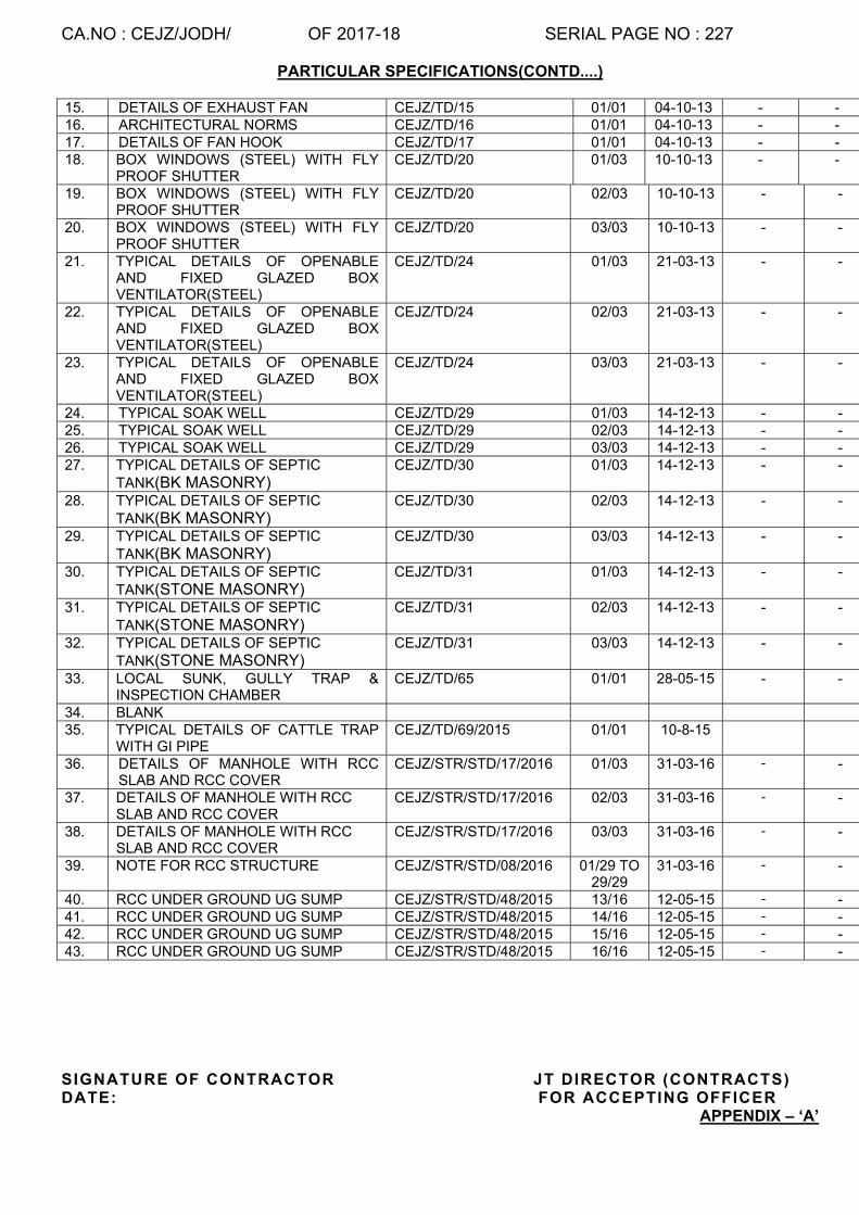
CA.NO : CEJZ/JODH/ OF 2017-18 SERIAL PAGE NO : 227
PARTICULAR SPECIFICATIONS(CONTD....)
15. DETAILS OF EXHAUST FAN CEJZ/TD/15 01/01 04-10-13 - - 16. ARCHITECTURAL NORMS CEJZ/TD/16 01/01 04-10-13 - - 17. DETAILS OF FAN HOOK CEJZ/TD/17 01/01 04-10-13 - - 18. BOX WINDOWS (STEEL) WITH FLY
PROOF SHUTTER CEJZ/TD/20 01/03 10-10-13 - -
19. BOX WINDOWS (STEEL) WITH FLY PROOF SHUTTER
CEJZ/TD/20 02/03 10-10-13 - -
20. BOX WINDOWS (STEEL) WITH FLY PROOF SHUTTER
CEJZ/TD/20 03/03 10-10-13 - -
21. TYPICAL DETAILS OF OPENABLE AND FIXED GLAZED BOX VENTILATOR(STEEL)
CEJZ/TD/24 01/03 21-03-13 - -
22. TYPICAL DETAILS OF OPENABLE AND FIXED GLAZED BOX VENTILATOR(STEEL)
CEJZ/TD/24 02/03 21-03-13 - -
23. TYPICAL DETAILS OF OPENABLE AND FIXED GLAZED BOX VENTILATOR(STEEL)
CEJZ/TD/24 03/03 21-03-13 - -
24. TYPICAL SOAK WELL CEJZ/TD/29 01/03 14-12-13 - - 25. TYPICAL SOAK WELL CEJZ/TD/29 02/03 14-12-13 - - 26. TYPICAL SOAK WELL CEJZ/TD/29 03/03 14-12-13 - - 27. TYPICAL DETAILS OF SEPTIC
TANK(BK MASONRY) CEJZ/TD/30 01/03 14-12-13 - -
28. TYPICAL DETAILS OF SEPTIC TANK(BK MASONRY)
CEJZ/TD/30 02/03 14-12-13 - -
29. TYPICAL DETAILS OF SEPTIC TANK(BK MASONRY)
CEJZ/TD/30 03/03 14-12-13 - -
30. TYPICAL DETAILS OF SEPTIC TANK(STONE MASONRY)
CEJZ/TD/31 01/03 14-12-13 - -
31. TYPICAL DETAILS OF SEPTIC TANK(STONE MASONRY)
CEJZ/TD/31 02/03 14-12-13 - -
32. TYPICAL DETAILS OF SEPTIC TANK(STONE MASONRY)
CEJZ/TD/31 03/03 14-12-13 - -
33. LOCAL SUNK, GULLY TRAP & INSPECTION CHAMBER
CEJZ/TD/65 01/01 28-05-15 - -
34. BLANK 35. TYPICAL DETAILS OF CATTLE TRAP
WITH GI PIPE CEJZ/TD/69/2015 01/01 10-8-15
36. DETAILS OF MANHOLE WITH RCC SLAB AND RCC COVER
CEJZ/STR/STD/17/2016 01/03 31-03-16 - -
37. DETAILS OF MANHOLE WITH RCC SLAB AND RCC COVER
CEJZ/STR/STD/17/2016 02/03 31-03-16 - -
38. DETAILS OF MANHOLE WITH RCC SLAB AND RCC COVER
CEJZ/STR/STD/17/2016 03/03 31-03-16 - -
39. NOTE FOR RCC STRUCTURE CEJZ/STR/STD/08/2016 01/29 TO 29/29
31-03-16 - -
40. RCC UNDER GROUND UG SUMP CEJZ/STR/STD/48/2015 13/16 12-05-15 - - 41. RCC UNDER GROUND UG SUMP CEJZ/STR/STD/48/2015 14/16 12-05-15 - - 42. RCC UNDER GROUND UG SUMP CEJZ/STR/STD/48/2015 15/16 12-05-15 - - 43. RCC UNDER GROUND UG SUMP CEJZ/STR/STD/48/2015 16/16 12-05-15 - -
SIGNATURE OF CONTRACTOR JT DIRECTOR (CONTRACTS) DATE: FOR ACCEPTING OFFICER
APPENDIX – ‘A’

CA.NO : CEJZ/JODH/ OF 2017-18 SERIAL PAGE NO : 228
PARTICULAR SPECIFICATIONS(CONTD....)
LIST OF BIS CERTIFIED PRODUCTS TO BE INCORPORATED IN WORKS Sr. No. Materials IS Nos. 1 2 3 1 Concrete a Integral Water Proof ing Compound IS : 2645 2 Joinery a Panel led Door Shut ters IS: 1003 3 Builder’s Hardware a Steel Butt Hinges IS : 1341 b Ferrous Tower Bol ts IS : 204 Part - I c Non-Ferrous Tower Bol ts IS : 204 Part - I Id Door Handles ( Non – Ferrous ) IS : 208 e Par l iament Hinges , Ferrous IS : 362 f Cont inuous piano Hinges IS : 3818 g Non- Ferrous Metal Sl id ing Door Bol ts IS : 2681 h Tee and Strap Hinges IS : 206 i Mi ld Steel Sl id ing Door Bol ts IS : 281 4 Steel and Iron Work a Steel Doors , Windows and Vent i lators IS : 1038 5 Roof Covering a Bi tumen Fel ts for water proof ing and damp proof ing b Un-reinforced corrugated or semi – corrugated asbestos
cement
6 Ceil ing and Lining a Plywood for general purposes IS : 303 b Block boards IS : 1659 c Veneered part ic le board IS : 3097 d Marine Plywood IS : 710 e Fibre Hardboard IS : 1658 f Medium Densi ty Fibre Board IS : 12406 7 Flooring a White Port land cement IS : 8042 b Cement concrete f loor ing t i les IS : 1237 8 Water supply , Plumbing , Drains and Sanitary
Appliances
a Concrete Pipes wi th or wi thout reinforcement IS : 458 b Sal t Glazed Stoneware pipes and f i t t ings IS : 651 c Centr i fugal ly cast ( spun ) i ron spigot and socket soi l ,
waste and vent i lat ing pipes , f i t t ings and accessor ies IS : 3989
d UPVC , Soi l , waste and Rain water Pipes IS : 4985 e Sand cast i ron spigot and socket soi l waste and vent i lat ing
pipes IS : 1729
f Galvanized Mi ld Steel tubes IS : 1239 g Galvanized mi ld s teel tubes f i t t ings IS : 1239 Part- I h Vi t reous china sani tary appl iances ( i ) Wash down water c losets IS : 2556 Part- I I
APPENDIX – ‘A’(contd. . . )
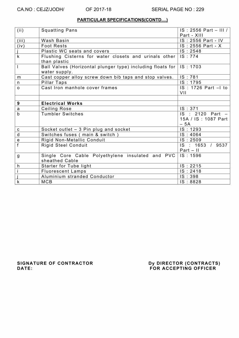
CA.NO : CEJZ/JODH/ OF 2017-18 SERIAL PAGE NO : 229
PARTICULAR SPECIFICATIONS(CONTD....)
( i i ) Squatt ing Pans IS : 2556 Part – I I I / Part - XI I I
( i i i ) Wash Basin IS : 2556 Part - IV ( iv) Foot Rests IS : 2556 Part - X j Plast ic WC seats and covers IS : 2548 k Flushing Cisterns for water c losets and ur inals other
than plast ic IS : 774
l Bal l Valves (Hor izontal p lunger type) inc luding f loats for water supply.
IS : 1703
m Cast copper al loy screw down bib taps and stop valves. IS : 781 n Pi l lar Taps IS : 1795 o Cast I ron manhole cover f rames IS : 1726 Part –I to
VII 9 Electrical Works a Cei l ing Rose IS : 371 b Tumbler Switches IS : 2120 Part –
15A / IS : 1087 Part – 5A
c Socket out let – 3 Pin plug and socket IS : 1293 d Swi tches fuses ( main & swi tch ) IS : 4064 e Rigid Non-Metal l ic Condui t IS : 2509 f Rigid Steel Conduit IS : 1653 / 9537
Part – I I g Single Core Cable Polyethylene insulated and PVC
sheathed Cable IS : 1596
h Starter for Tube l ight IS : 2215 i Fluorescent Lamps IS : 2418 j Aluminium stranded Conductor IS : 398 k MCB IS : 8828 SIGNATURE OF CONTRACTOR Dy DIRECTOR (CONTRACTS) DATE: FOR ACCEPTING OFFICER

CA.NO : CEJZ/JODH/ OF 2017-18 SERIAL PAGE NO : 230
PARTICULAR SPECIFICATIONS(CONTD....)
Appendix ‘B’
SOURCES OF MATERIALS
Sr l No
Name of mater ia ls Sources of mater ia l for works at stat ion **
1 2 3 1 (a) Stone for masonry
(b) Stone aggregate for RCC (c) Stone aggregate for PCC
a) Ganganal / Bhadasia / Soor sagar (b) Kakani / Daijar / Rinyal / Sawri Bhakari (c) Kakani / Dai jar / Rinyal / Sawri / Bhakar i / Ganganal / Bhadasia / Soor Sagar
2 Fine aggregate (sand) for cement concrete and mortar in masonry
Binawas / Luni river.
3 Sand for mortar in plaster ing and point ing
Binawas / Luni river.
4 Stone for sol ing, WBM and hard core
Ganganal / Daijar / Bhadasia / Soor Sagar / Rinya
5 Stone for kerb/edging
Balesar / Soor Sagar / Jodhpur
6 Stone chipping for road work
Kakani / Daijar / Rinya / Sawri / Polubri
**Sources indicated are for guidance only NOTES:- 1. Sources of mater ia ls shal l be as given in Sr l No 1 to 6 above or in the vic in i ty thereof. The tenderer shal l ascertain the actual posi t ion/exact locat ion of source before submit t ing his tender and no addi t ional payment shal l be made on account of misunderstanding or i ts dis tance f rom si te of works. Contractor may br ing mater ia l conforming to contract speci f icat ions f rom other sources without any pr ice adjustment af ter obtaining wri t ten approval of GE. 2. The tenderer shal l amongst other th ings also ascertain al l informat ion such as royal t ies, taxes, dut ies and other charges etc, on the mater ia ls and no addi t ional payment shal l be made on account of the foregoing.
SIGNATURE OF CONTRACTOR Dy DIRECTOR (CONTRACTS) DATE: FOR ACCEPTING OFFICER

CA.NO: CEJZ/JODH/ OF 2017-18 SERIAL PAGE NO: 231
LIST OF MAKES (07/17) APPENDIX – ‘C’
APPROVED NAMES FOR PRODUCTS TO BE INCORPORATED IN WORK
Sr. No. Materials Make / Name of the Firms1 2 3
(A) BUILDING MATERIALS 1 Factory made Wooden Paneled & Flush
door shutters/Gauged shutters/ window shutters/ frames
(i) M/S Surabhi Metal India Pvt Ltd Jodhpur (ii) M/s Doorking Industries Kolkata – 27 G.R. Block, Sector-V, Salt Lake , Kolkata (iii) Ashish (Only for flush doors) (iv) M/s Goyal Industries (v) M/s R.P. Wood Products, Ajmer (only flush doors) (vi) M/s A1, Teak Products, Indore (vii) Jain door Pvt. Ltd. (Haryana) (Viii) M/S Engco Industries, Jodhpur (Ix) M/S Egg Wood Pdts Hyderabad (X) M/S India Wood & Wood PdtsManglore (Xi) M/S Prince Timber, Jamnagar (Xii) M/S M P Wood Products, Indore (xiii) M/S Jain Wood Industries, Sonipat
2 Factory made Solid PVC/UPVC door frame/ Chowkhat and shutters
(i) M/S ENGCO INDUSTRIES, JODHPUR (ii) M/s Rajshri plastiwood INDORE (iii) Sintex (iv) Madhu Industries, Banglore (v) DuroPlast Extrusion Pvt Ltd. (vi) Polyline ExtursionPvt Ltd, Kasba Industry Road, Kolkata – 700 107 (vii) Accucell (viii) VIKASH Plastiply, AKAL GROUP
3 Factory made Steel Windows, Ventilators, Pressed Steel door/ Windows frames, Steel Lockers and Cup board
(i) M/s Chandni Industries Ghaziabad (ii) M/s Sen Harvic , Bombay (iii) M/s Godrej & Boyce Mfrs. Ltd , Bombay (iv) M/s Agew Steel Manufacturers Pvt. Ltd. , Ahmedabad (v) M/s Behar Bobbin & Engineering works , Katihar (vi) M/s Jangid Engineering, Jaipur (vii) M/S Surabhi Metal India Pvt Ltd Jodhpur (viii) M/S ENGCO INDUSTRIES, JODHPUR (ix) M/s Madhu Industries Banglore (x) M/s Shivmular, Ahmedabad (xi) M/s Kumar Arch Tech Pvt Ltd. (xi) Anoop Industries, Meerut (xii) Trisul Industries Meerut (xv) Ashwani & Sons Ghaziabad
4 Oil Bound distemper Nerolac, Shalimar, Asian, Berger, Johsons&Niecholson
5 Synthetic Enamel Paint (i)Berger- Luxol (ii) Shalimar – Superlac (iii)Johnson & Nicholson – Brolac (iv)GoodlassNerolac (v)Asian – Apcolite
6 Cement base paint (i) Super-Snow Cem (ii) Durocem (iii) BagerExtrcem (iv) Asian Paints – Gutucem (v) Johnson and Nicholson-Robbiacem
7 Plastic Emulsion Paint
Asian paint, Berger, Johnson & Nicholson, Shalimar, Nerolac
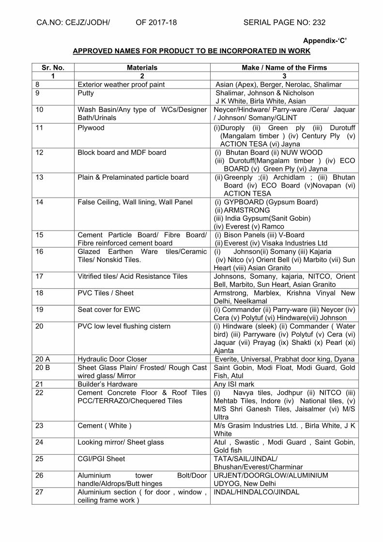
CA.NO: CEJZ/JODH/ OF 2017-18 SERIAL PAGE NO: 232
Appendix-‘C’
APPROVED NAMES FOR PRODUCT TO BE INCORPORATED IN WORK
Sr. No. Materials Make / Name of the Firms 1 2 3
8 Exterior weather proof paint Asian (Apex), Berger, Nerolac, Shalimar 9 Putty Shalimar, Johnson & Nicholson
J K White, Birla White, Asian 10 Wash Basin/Any type of WCs/Designer
Bath/Urinals Neycer/Hindware/ Parry-ware /Cera/ Jaquar / Johnson/ Somany/GLINT
11 Plywood (i) Duroply (ii) Green ply (iii) Durotuff (Mangalam timber ) (iv) Century Ply (v) ACTION TESA (vi) Jayna
12 Block board and MDF board (i) Bhutan Board (ii) NUW WOOD (iii) Durotuff(Mangalam timber ) (iv) ECO
BOARD (v) Green Ply (vi) Jayna 13 Plain & Prelaminated particle board (ii) Greenply ;(ii) Archidlam ; (iii) Bhutan
Board (iv) ECO Board (v)Novapan (vi) ACTION TESA
14 False Ceiling, Wall lining, Wall Panel (i) GYPBOARD (Gypsum Board) (ii) ARMSTRONG (iii) India Gypsum(Sanit Gobin) (iv) Everest (v) Ramco
15 Cement Particle Board/ Fibre Board/ Fibre reinforced cement board
(i) Bison Panels (iii) V-Board (ii) Everest (iv) Visaka Industries Ltd
16 Glazed Earthen Ware tiles/Ceramic Tiles/ Nonskid Tiles.
(i) Johnson(ii) Somany (iii) Kajaria (iv) Nitco (v) Orient Bell (vi) Marbito (vii) Sun Heart (viii) Asian Granito
17 Vitrified tiles/ Acid Resistance Tiles Johnsons, Somany, kajaria, NITCO, Orient Bell, Marbito, Sun Heart, Asian Granito
18 PVC Tiles / Sheet Armstrong, Marblex, Krishna Vinyal New Delhi, Neelkamal
19 Seat cover for EWC (i) Commander (ii) Parry-ware (iii) Neycer (iv) Cera (v) Polytuf (vi) Hindware(vii) Johnson
20 PVC low level flushing cistern
(i) Hindware (sleek) (ii) Commander ( Water bird) (iii) Parryware (iv) Polytuf (v) Cera (vi) Jaquar (vii) Prayag (ix) Shakti (x) Pearl (xi) Ajanta
20 A Hydraulic Door Closer Everite, Universal, Prabhat door king, Dyana 20 B Sheet Glass Plain/ Frosted/ Rough Cast
wired glass/ Mirror Saint Gobin, Modi Float, Modi Guard, Gold Fish, Atul
21 Builder’s Hardware Any ISI mark 22 Cement Concrete Floor & Roof Tiles
PCC/TERRAZO/Chequered Tiles (i) Navya tiles, Jodhpur (ii) NITCO (iii) Mehtab Tiles, Indore (iv) National tiles, (v) M/S Shri Ganesh Tiles, Jaisalmer (vi) M/S Ultra
23 Cement ( White ) M/s Grasim Industries Ltd. , Birla White, J K White
24 Looking mirror/ Sheet glass Atul , Swastic , Modi Guard , Saint Gobin, Gold fish
25 CGI/PGI Sheet TATA/SAIL/JINDAL/ Bhushan/Everest/Charminar
26 Aluminium tower Bolt/Door handle/Aldrops/Butt hinges
URJENT/DOORGLOW/ALUMINIUM UDYOG, New Delhi
27 Aluminium section ( for door , window , ceiling frame work )
INDAL/HINDALCO/JINDAL

CA.NO: CEJZ/JODH/ OF 2017-18 SERIAL PAGE NO: 233
Appendix-‘C’
APPROVED NAMES FOR PRODUCT TO BE INCORPORATED IN WORK
Sr. No. Materials Make / Name of the Firms 1 2 3
28 Inter Locking Paver Blocks/ PCC Cable cover
ULTRA tiles/ NavyaTiles Jodhpur/ M/s MEHTAB TILES, INDORE./ M/S Shri Ganesh Tiles, Jaisalmer/ M/S NITCO/ M/s Vaishnavi Developers Pune/ Sukhi Ent, Jamnagar/ Supreme Tiles, Morbi/Lucky cement Block Works,Kachchh
29 Stainless Steel Sink/plate Rack NIRALI/ PEARL /JAYANA/DIAMOND /NEELKAMAL/ANUPAM/PRAYAG/ BLUE STAR/SILVER SHINE
30 Water Proofing compound CICO/ACCRO No 1/ IMPERMO/ AQUAPROOF/ PIDILITE/ FOSROC/ SIKA/MARUTI BITUMEN
31 APP modified polymeric membrane/ Primer/ Bitumen Based Aluminum Paints
M/s TEXSA INDIA LTD./TORCHTAR MEMBRANE M/s STP LTD. M/s PIDILITE, M/s TIKITAR M/S IWL INDIA LTD, M/S BENGAL BITUMEN, M/s SHIVAM TAR PRODUCTS, SUPREME BITUCHEM, MARUTI BITUMEN,AR INDUSTRIES
31 A Admixtures SIKA, FOSROC, STP, MARUTI BITUMEN PVT Lt d.
31 B Road Marking Paints ASIAN, SHALIMAR, SN INDUSTRIES DELHI/ MARUTI REFLO MARK.
(B) WATER SUPPLY MATERIALS 32 Chromium Plated all type of Bath Room
fittings & Accessories, Sensor Tap/ Urinals
CRABTREE/ JAQUAR/ MARC/JOHNSON/ ESSC/PLAYER/PRAYAG/PRIMA/CORONET
33 PTMT taps &Accessories, bathroom cabinets
PRAYAG/ SHAKTI/POLYTUF/PEARL
34 GI Pipes & Fittings (i) Jindal(ii) Tata(iii) PRAKASH SURYA (iv) Swastik (v) BST (vi) KS
35 PVC Pipe & fittings Supreme, Prince, Kisan, Finolex 36 CI PIPES & Fittings Nico Tisco, Kesoram, Kalinga, Kapilansh 37 MS Pipe & Fittings (i) Tata (ii) Jindal (iii) Prakash Surya (iv) BST 38 HDPE Pipes & Fittings (i) Finolex (ii) Oriplast (iii)Supreme, (iv) Prince
(v) SFMC (vi) Kisan 39 CI Pipe Centrifugally cast ( spun) as per
IS 1536 (i) Kejriwal;(ii) Electrosteel (iii) Kesoram (iv) Jindal (v) JAYASWAL (vi) NECO (vii) HIF
40 Centrifugal Pumps Sets (i) Kirloskar (ii) Alstom (iii) Crompton (iv) Beacon (v) Mather & Platt (vi) KSB NOTE:- Motor should be of same make
41 Motors for pump sets (i) Kirloskar (ii) Crompton (iii) ABB (iv) Bharat Bijlee
42 Submersible pump KSB, Kirloskar, Mather & Platt, CROMPTION 43 DI Pipe and fittings (i) Electro-steel (ii) TATA (iii)LANCO (iv)
JINDAL ((v) Electrotherm (vi) AARCO PIPE (vii) SRIKALA HATHI PIPE(x)TRUE FORM
44 CI double flanged pipe TRUFORM/ KEJRIWAL 45 Sluice Valve / Foot Valves / Reflux Valve
/ Non Return valve / Air release valve / Gate valve / Globe valve
(i) Kirloskar (ii) Upadhyay (iii) Zoloto (iv) KEJRIWAL (v) LEADER (vi) AARCO PIPE
46 Rotational moulded HDPE Water storage Tank
(i) Sintex (ii) Polycon (iii) Rotex (iv) JS Polyplast
47 PVC Ball for service water tank (i) Prayag (ii) Polytuf (iii) Pearl
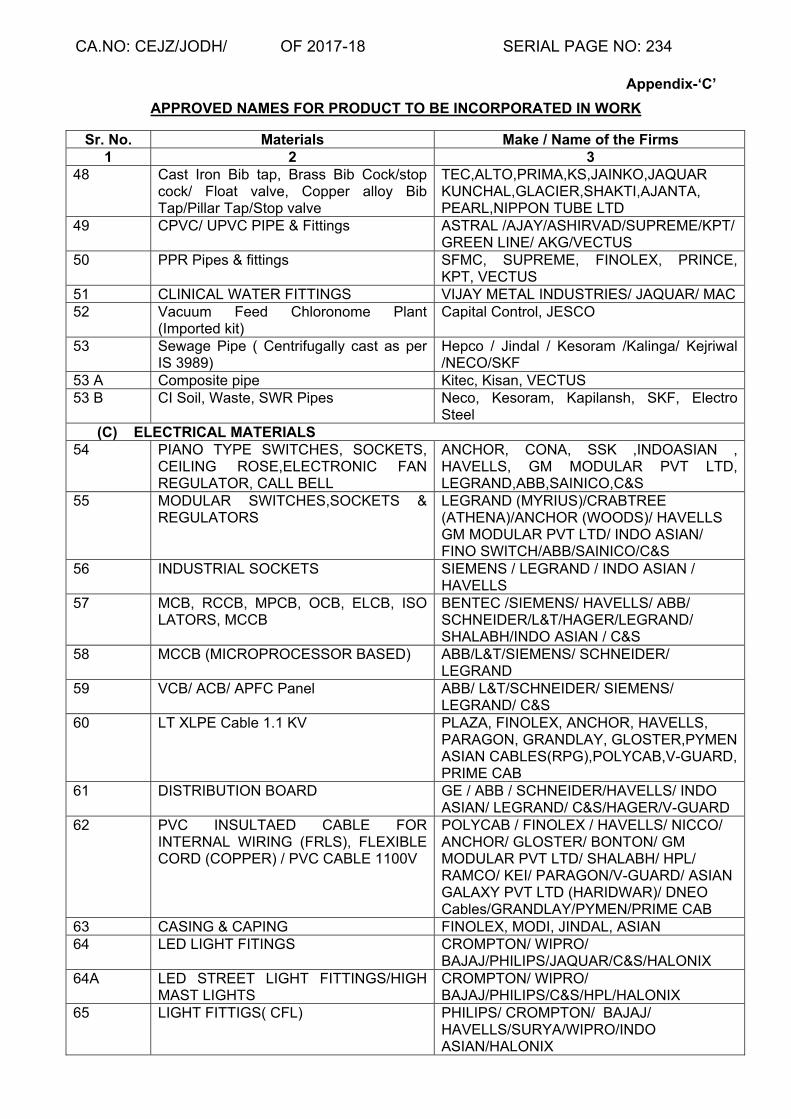
CA.NO: CEJZ/JODH/ OF 2017-18 SERIAL PAGE NO: 234
Appendix-‘C’
APPROVED NAMES FOR PRODUCT TO BE INCORPORATED IN WORK
Sr. No. Materials Make / Name of the Firms 1 2 3
48 Cast Iron Bib tap, Brass Bib Cock/stop cock/ Float valve, Copper alloy Bib Tap/Pillar Tap/Stop valve
TEC,ALTO,PRIMA,KS,JAINKO,JAQUAR KUNCHAL,GLACIER,SHAKTI,AJANTA, PEARL,NIPPON TUBE LTD
49 CPVC/ UPVC PIPE & Fittings ASTRAL /AJAY/ASHIRVAD/SUPREME/KPT/ GREEN LINE/ AKG/VECTUS
50 PPR Pipes & fittings SFMC, SUPREME, FINOLEX, PRINCE, KPT, VECTUS
51 CLINICAL WATER FITTINGS VIJAY METAL INDUSTRIES/ JAQUAR/ MAC 52 Vacuum Feed Chloronome Plant
(Imported kit) Capital Control, JESCO
53 Sewage Pipe ( Centrifugally cast as per IS 3989)
Hepco / Jindal / Kesoram /Kalinga/ Kejriwal /NECO/SKF
53 A Composite pipe Kitec, Kisan, VECTUS 53 B CI Soil, Waste, SWR Pipes Neco, Kesoram, Kapilansh, SKF, Electro
Steel (C) ELECTRICAL MATERIALS
54 PIANO TYPE SWITCHES, SOCKETS, CEILING ROSE,ELECTRONIC FAN REGULATOR, CALL BELL
ANCHOR, CONA, SSK ,INDOASIAN , HAVELLS, GM MODULAR PVT LTD, LEGRAND,ABB,SAINICO,C&S
55 MODULAR SWITCHES,SOCKETS & REGULATORS
LEGRAND (MYRIUS)/CRABTREE (ATHENA)/ANCHOR (WOODS)/ HAVELLS GM MODULAR PVT LTD/ INDO ASIAN/ FINO SWITCH/ABB/SAINICO/C&S
56 INDUSTRIAL SOCKETS SIEMENS / LEGRAND / INDO ASIAN / HAVELLS
57 MCB, RCCB, MPCB, OCB, ELCB, ISO LATORS, MCCB
BENTEC /SIEMENS/ HAVELLS/ ABB/ SCHNEIDER/L&T/HAGER/LEGRAND/ SHALABH/INDO ASIAN / C&S
58 MCCB (MICROPROCESSOR BASED) ABB/L&T/SIEMENS/ SCHNEIDER/ LEGRAND
59 VCB/ ACB/ APFC Panel ABB/ L&T/SCHNEIDER/ SIEMENS/ LEGRAND/ C&S
60 LT XLPE Cable 1.1 KV PLAZA, FINOLEX, ANCHOR, HAVELLS, PARAGON, GRANDLAY, GLOSTER,PYMEN ASIAN CABLES(RPG),POLYCAB,V-GUARD, PRIME CAB
61 DISTRIBUTION BOARD GE / ABB / SCHNEIDER/HAVELLS/ INDO ASIAN/ LEGRAND/ C&S/HAGER/V-GUARD
62 PVC INSULTAED CABLE FOR INTERNAL WIRING (FRLS), FLEXIBLE CORD (COPPER) / PVC CABLE 1100V
POLYCAB / FINOLEX / HAVELLS/ NICCO/ ANCHOR/ GLOSTER/ BONTON/ GM MODULAR PVT LTD/ SHALABH/ HPL/ RAMCO/ KEI/ PARAGON/V-GUARD/ ASIAN GALAXY PVT LTD (HARIDWAR)/ DNEO Cables/GRANDLAY/PYMEN/PRIME CAB
63 CASING & CAPING FINOLEX, MODI, JINDAL, ASIAN 64 LED LIGHT FITINGS CROMPTON/ WIPRO/
BAJAJ/PHILIPS/JAQUAR/C&S/HALONIX 64A LED STREET LIGHT FITTINGS/HIGH
MAST LIGHTS CROMPTON/ WIPRO/ BAJAJ/PHILIPS/C&S/HPL/HALONIX
65 LIGHT FITTIGS( CFL) PHILIPS/ CROMPTON/ BAJAJ/ HAVELLS/SURYA/WIPRO/INDO ASIAN/HALONIX

CA.NO: CEJZ/JODH/ OF 2017-18 SERIAL PAGE NO: 235
Appendix-‘C’
APPROVED NAMES FOR PRODUCT TO BE INCORPORATED IN WORK
Sr. No. Materials Make / Name of the Firms 1 2 3
66 FLAME PROOF ALL TYPE OF LIGHT FITTINGS/ JUNCTION BOX/ DISTRIBUTION BOX/ SWITCH/FAN/ FIRE ALARM/ STATER/HOOTER
SUDHIR/FLEXPRO/ BALIGA/ CROMPTION/VOLTECH MANUFACTURING CO LTD, CHENNAI, FORTUNE ARRT LED LIGHTING PVT LTD.
67 STREET LIGHT TIMERS L&T/ G.E./ PHILIPS/LEGRAND/HAGER
68 SOLAR LIGHT CROMPTON/ BAJAJ/ PHILIPS/WIPRO
69 H.T.XLPE CABLE CCI MUMBAI/ ASIAN CABLE(RPG) GLOSTER /HAVELLS/ NICCO/POLYCAB/ ASIAN GALAXY PVT LTD (HARIDWAR)/KEI/PRIME CAB
70 SUBMERSIBLE CABLE FINOLEX/ NICCO/POLYCAB 71 CONTROL CABLES (COPPER) POLYCAB / FINOLEX /NICCO/ GM
MODULAR PVT LTD 72 ACSR CONDUCTOR BHARAT CONDUCTORS, UJALA, INDIAN
ALUMINIUMCOMPANY/ESSAR. 73 TELEPHONE / TV CABLE DELTON / BONTON /FINOLEX 74 RIGID PVC CONDUIT ANY ISI MARK 75 MS BLACK ENAMELED / GALVANIZED
ERW CONDUIT/ STEEL CONDUIT BEC / AKG / NIC/ BST/ TATA/ JINDAL/ FINOLEX/ RMG STEEL
76 DOUBLE WALL CORRUGATED HIGH DENSITY POLYETHENE PIPE FOR CABLE PROTECTION (IS:14930)
(A) REX POLYEXTRUSIONS LTD., PLOT NO. H-5/2 MIDC KUPWAD SANGLI, MAHARASHTRA 41436 CML NO 7479797
(B) DURALINE INDIA PVT LTD, PLOT NO 24 VERNA ELECTRONICS CITY, PHASE II A, VERNA, SALCETE, GOA-403722 CML NO 7643582 & PLOT 19-22, 37-40 PHASE III A, SANOALE IND ESTATE, ZUARINAGAR GOA 403726
77 REFRIGERATOR / WATER COOLER ( Min 3 star rating, If not indicated)
SAMSUNG, LG, VOLTAS, KELVINATOR, WHIRLPOOL
78 AIRCONDITIONER(Split/Window) ( Min 4 star rating, If not indicated)
VOLTAS, CARRIER, SAMSUNG, BLUESTAR, LG
79 CELING FANS/EXHAUST FAN USHA, BAJAJ, KHAITAN, CROMPTON, HAVELLS
80 WALL MOUNTED AIR CIRCULATOR BAJAJ, KHAITAN, CROMPTON, ALMONARD, HAVELLS
80 A GEYSERS FOR KITCHEN/BATHROOM BAJAJ, USHA, HAVELLS, JAQUAR,
(D) Ext Electrical Supply Material 81 TRANSFORMER 66 KV/ 11 KV, 33 KV/
11 KV, 33/0.433 KV Copper Wound CROMPTON GREAVES/ BHEL/ VOLTAMP/ BHARAT BIJLEE/ SEIMENS/ ABB/ AREVA/ ESENNAR TRANSFORMERS PVT LTD HYDERABAD/SCHNEIDER/VOLTECH MANUFACTURING CO LTD.
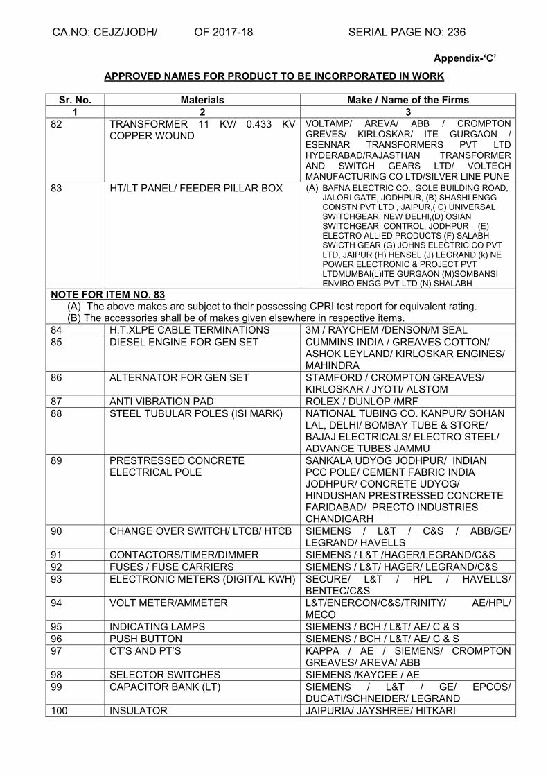
CA.NO: CEJZ/JODH/ OF 2017-18 SERIAL PAGE NO: 236
Appendix-‘C’
APPROVED NAMES FOR PRODUCT TO BE INCORPORATED IN WORK
Sr. No. Materials Make / Name of the Firms 1 2 3
82 TRANSFORMER 11 KV/ 0.433 KV COPPER WOUND
VOLTAMP/ AREVA/ ABB / CROMPTON GREVES/ KIRLOSKAR/ ITE GURGAON / ESENNAR TRANSFORMERS PVT LTD HYDERABAD/RAJASTHAN TRANSFORMER AND SWITCH GEARS LTD/ VOLTECH MANUFACTURING CO LTD/SILVER LINE PUNE
83 HT/LT PANEL/ FEEDER PILLAR BOX (A) BAFNA ELECTRIC CO., GOLE BUILDING ROAD, JALORI GATE, JODHPUR, (B) SHASHI ENGG CONSTN PVT LTD , JAIPUR,( C) UNIVERSAL SWITCHGEAR, NEW DELHI,(D) OSIAN SWITCHGEAR CONTROL, JODHPUR (E) ELECTRO ALLIED PRODUCTS (F) SALABH SWICTH GEAR (G) JOHNS ELECTRIC CO PVT LTD, JAIPUR (H) HENSEL (J) LEGRAND (k) NE POWER ELECTRONIC & PROJECT PVT LTDMUMBAI(L)ITE GURGAON (M)SOMBANSI ENVIRO ENGG PVT LTD (N) SHALABH
NOTE FOR ITEM NO. 83 (A) The above makes are subject to their possessing CPRI test report for equivalent rating. (B) The accessories shall be of makes given elsewhere in respective items.
84 H.T.XLPE CABLE TERMINATIONS 3M / RAYCHEM /DENSON/M SEAL 85 DIESEL ENGINE FOR GEN SET CUMMINS INDIA / GREAVES COTTON/
ASHOK LEYLAND/ KIRLOSKAR ENGINES/ MAHINDRA
86 ALTERNATOR FOR GEN SET STAMFORD / CROMPTON GREAVES/ KIRLOSKAR / JYOTI/ ALSTOM
87 ANTI VIBRATION PAD ROLEX / DUNLOP /MRF 88 STEEL TUBULAR POLES (ISI MARK) NATIONAL TUBING CO. KANPUR/ SOHAN
LAL, DELHI/ BOMBAY TUBE & STORE/ BAJAJ ELECTRICALS/ ELECTRO STEEL/ ADVANCE TUBES JAMMU
89 PRESTRESSED CONCRETE ELECTRICAL POLE
SANKALA UDYOG JODHPUR/ INDIAN PCC POLE/ CEMENT FABRIC INDIA JODHPUR/ CONCRETE UDYOG/ HINDUSHAN PRESTRESSED CONCRETE FARIDABAD/ PRECTO INDUSTRIES CHANDIGARH
90 CHANGE OVER SWITCH/ LTCB/ HTCB SIEMENS / L&T / C&S / ABB/GE/ LEGRAND/ HAVELLS
91 CONTACTORS/TIMER/DIMMER SIEMENS / L&T /HAGER/LEGRAND/C&S 92 FUSES / FUSE CARRIERS SIEMENS / L&T/ HAGER/ LEGRAND/C&S 93 ELECTRONIC METERS (DIGITAL KWH) SECURE/ L&T / HPL / HAVELLS/
BENTEC/C&S 94 VOLT METER/AMMETER L&T/ENERCON/C&S/TRINITY/ AE/HPL/
MECO 95 INDICATING LAMPS SIEMENS / BCH / L&T/ AE/ C & S 96 PUSH BUTTON SIEMENS / BCH / L&T/ AE/ C & S 97 CT’S AND PT’S KAPPA / AE / SIEMENS/ CROMPTON
GREAVES/ AREVA/ ABB 98 SELECTOR SWITCHES SIEMENS /KAYCEE / AE 99 CAPACITOR BANK (LT) SIEMENS / L&T / GE/ EPCOS/
DUCATI/SCHNEIDER/ LEGRAND 100 INSULATOR JAIPURIA/ JAYSHREE/ HITKARI

CA.NO: CEJZ/JODH/ OF 2017-18 SERIAL PAGE NO: 237
Appendix-‘C’
APPROVED NAMES FOR PRODUCT TO BE INCORPORATED IN WORK
Sr. No. Materials Make / Name of the Firms 1 2 3
101 GOD WITH ISOLATOR PACTIL / ECE/C&S/L&T 102 RING MAIN UNIT(RMU) ABB/ L&T/SCHNEIDER/ SIEMENS/
LEGRAND 103 GANG OPERATED AIR BREAK
SWITCHES, EXPLULSION FUSE, DROP OUT FUSE
PACTIL/ ECE/C&S/L&T
104 OVER LOAD RELAY/THERMAL RELAY SCHNEIDER/ABB / L&T / TELEMECHNIC/ LEGRAND/C&S
105 CONNECTORS SIEMENS / L&T / TELEMECHNIC/ LEGRAND/C&S
106 CONTROL SWITCHES SIEMENS / C&S /L&T/ LEGRAND 107 TERMINAL STRIP CONNECT WELL / ELMEX 108 TERMINAL BLOCKS BCH / JAINSON / INDUSTRIAL CONTROLS 109 CABLE JOINTING KIT 3M/ DENSON/ RAYCHEM 110 H.T.XLPE CABLE TERMINATIONS 3M / RAYCHEM / DENSON 111 CABLE GLANDS DOWELL / SIEMENS /L&T/ HENSEL/
LEGRAND 112 THIMBLES DOWELLS / COMET 113 CABLE TRAYS SLOTCO / MODERN CARRIERS/ LEGRAND 114 OVER HEAD BUS TRUNKING/ BUS
DUCT /RISING MAINS LEGRAND/ C&S / SIEMENS
115 FLOOR RACE WAYS SKABER/ MODERN CARRIERS 116 UPS MICROTECH, LUMINOUS, SINETRAC 117 DATA OUTLETS D-LINK / TP-LINK /LEGRAND 118 LIGHTING DIMMER PANELS LUTRON / CLIPSAL/ LEGRAND 119 MAINTENANCE FREE EARTHING
SYSTEM ERICO / ALTEC
120 LIGHTNING ARRESTORS ALTEC / INDLEC/OBLUM/BHEL/ATLAS 121 FIRE DETECTOR EDWARDS / HONEYWELL / APPOLO
122 FIRE CONTROL PANEL / DEVICES & MODULES
EDWARDS / HONEYWELL / APPOLO
123 ACCESS CONTROL SYSTEMS HONEYWELL / HID 124 LEAD ACID BATTERY EXIDE / AMRON /MICRO TECH 125 BATTERY CHARGER AE / VOLTSTAT /CALDYNE/BCH/NUCLEUS 126 SERVO CONTROLLED STABLIZER/
AUTOMATIC VOLTAGE STABLIZER (COPPER WOUND)
STABLINE / BLUE LINE / SERVOCON/ AE/ V-GUARD/VOLINA/ VOLTAMP/ MICROTECH/ VINITEC/ ITE GURGAON
127 DG SET ASSEMBLED SOUND PROOF KIRLOSKAR, MAHINDRA, SUDHIR, JACKSON, CUMMINS, GREAVES,C&S
(E) MISCELLANEOUS 128 SOLAR WATER HEATING SYSTEM TATA SOLAR, SUDARSHAN SAUR SHAKTI
Pvt Ltd,SU Solartech System(P) Ltd,Inter Solar System Pvt Ltd,Kotak Urja Pvt Ltd,Photon Energy System Ltd,Thermax
129 Pre Painted Galvalume/Galvanised Corrugated Steel sheet
METCO ROOF Pvt Ltd,Chennai/Any ISI Mark

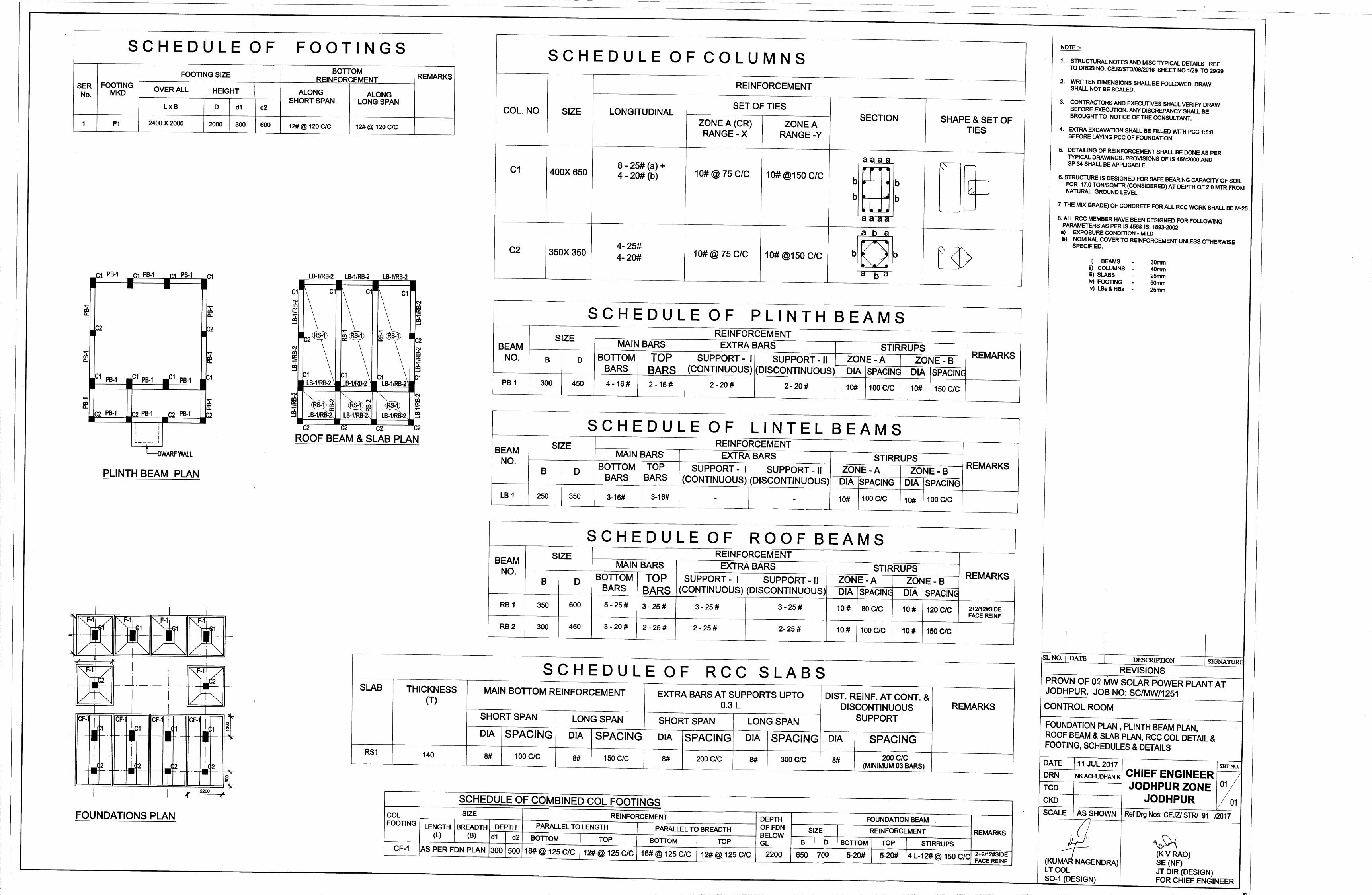


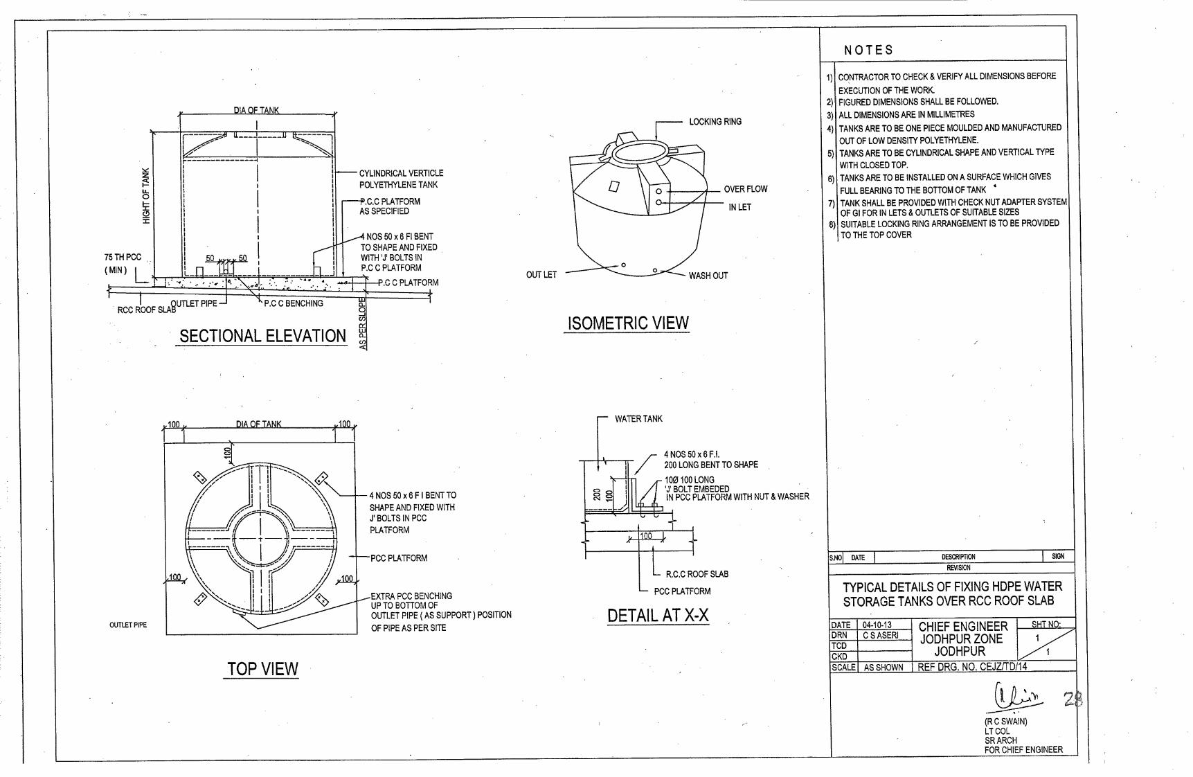
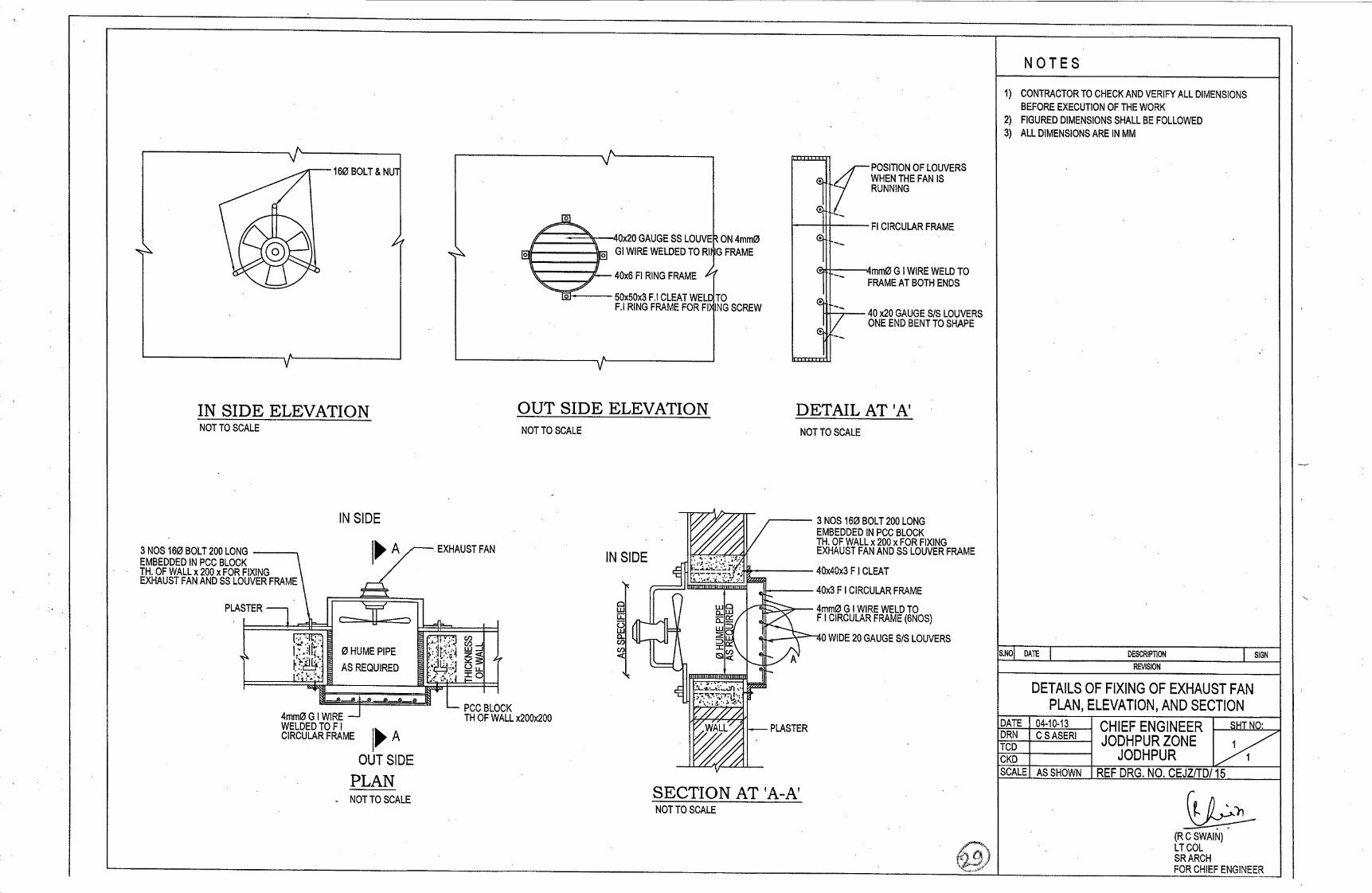

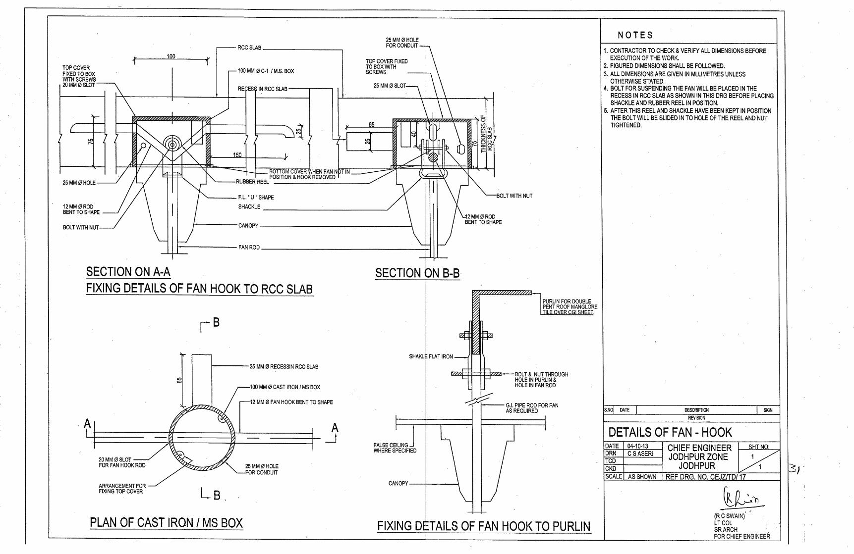


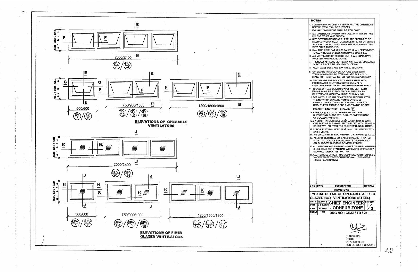
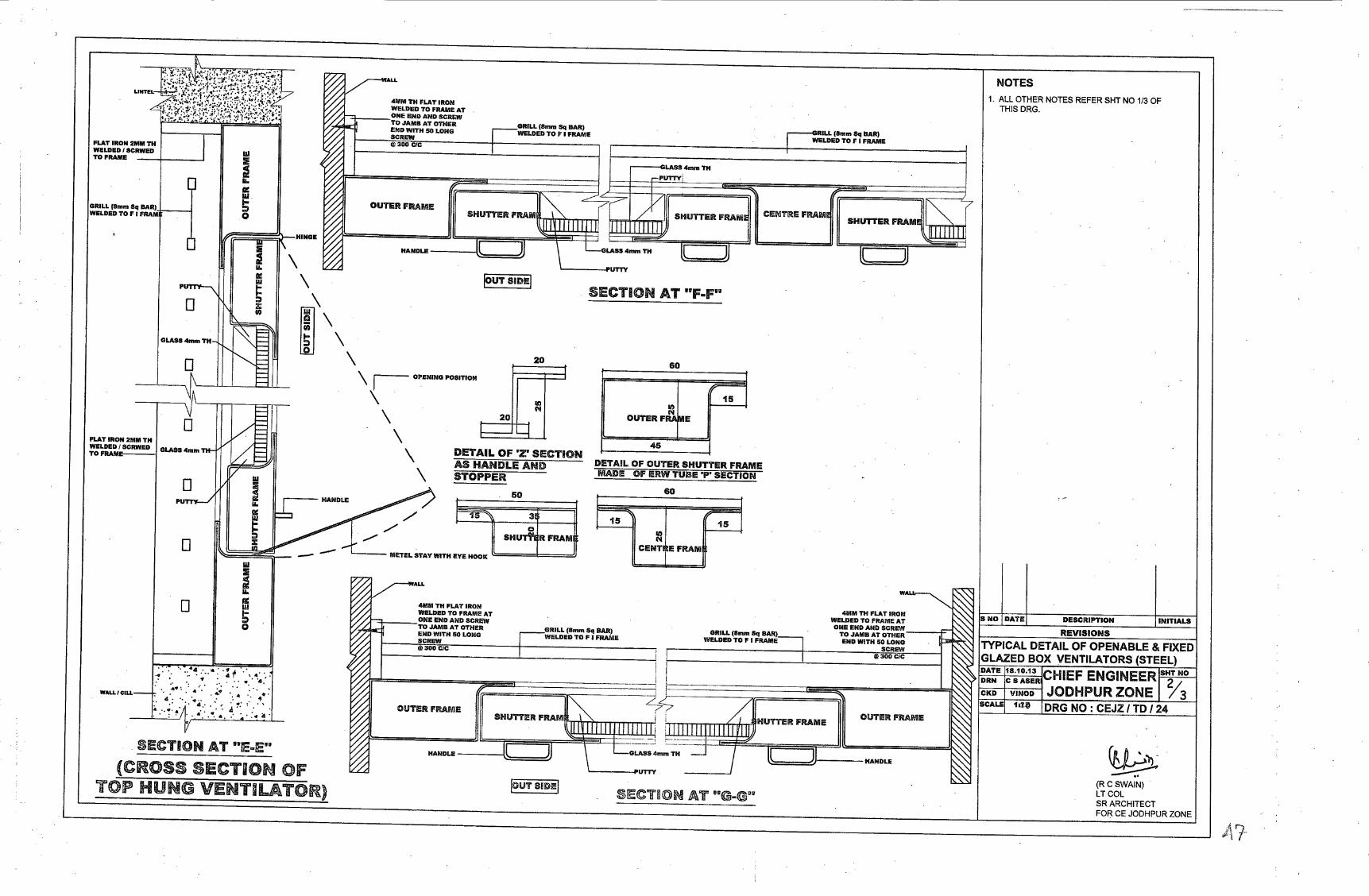


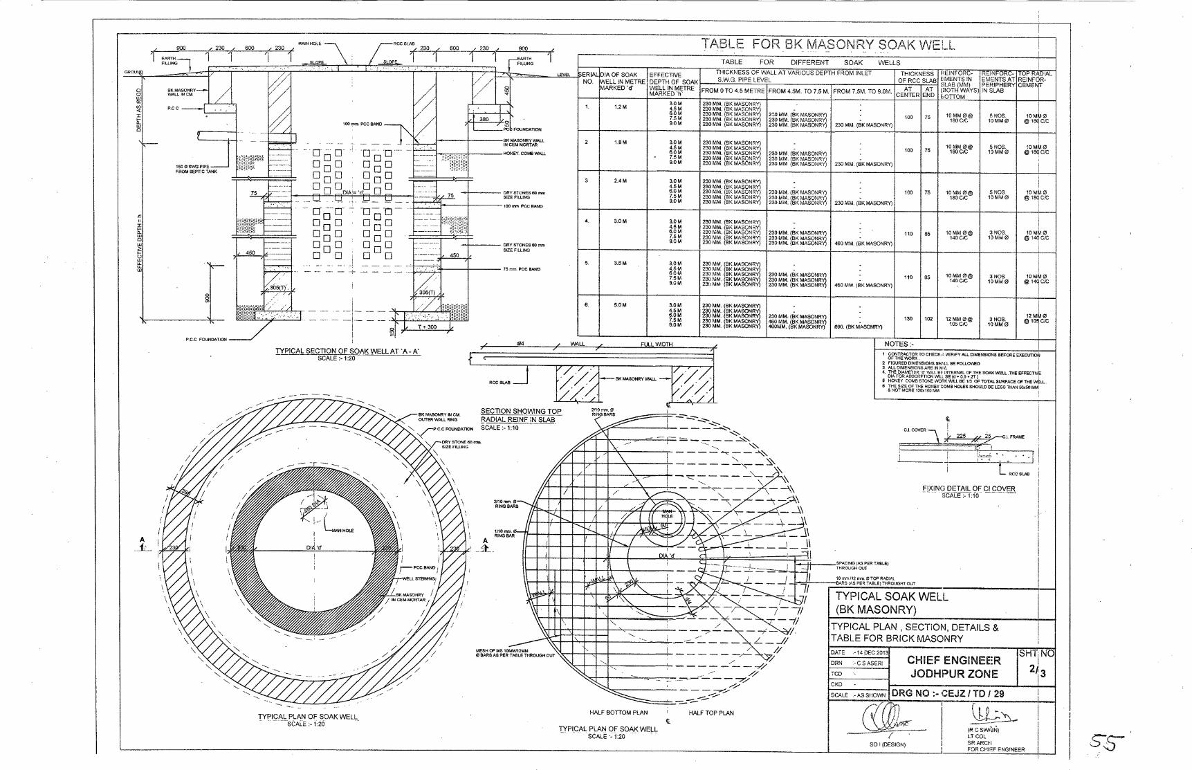

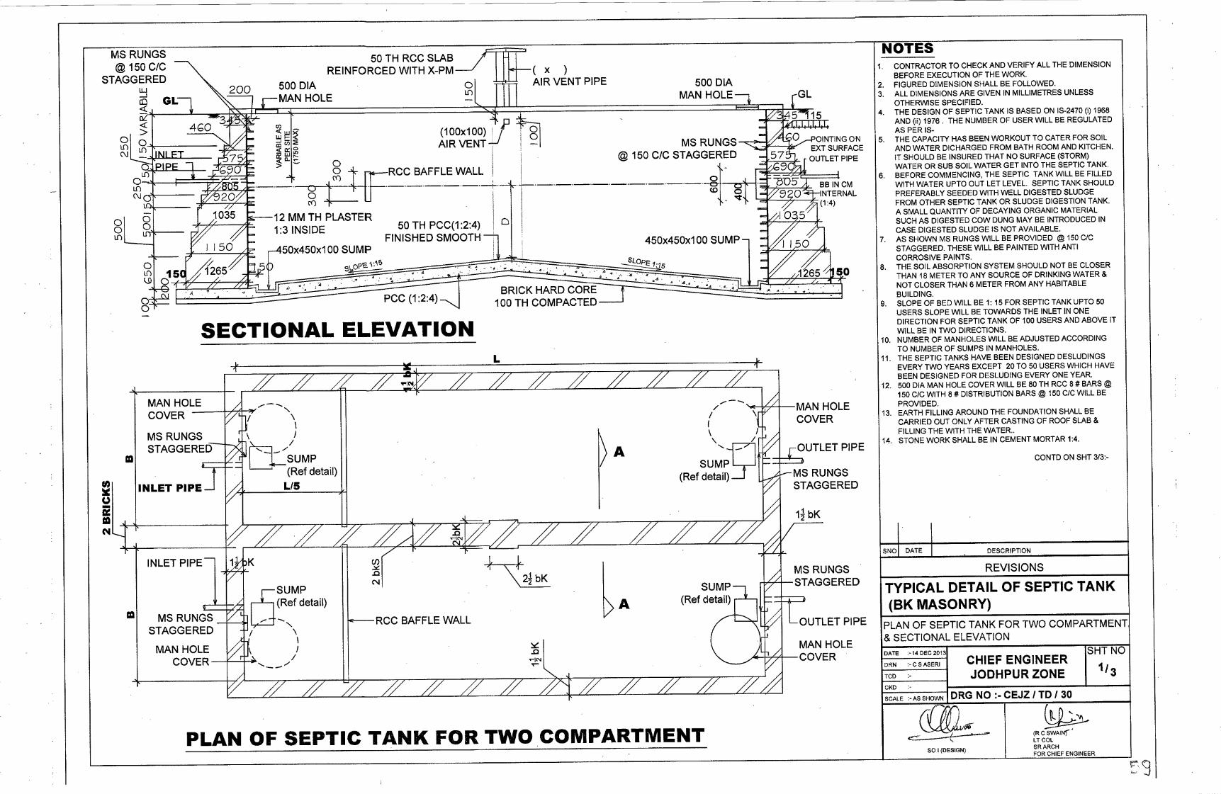


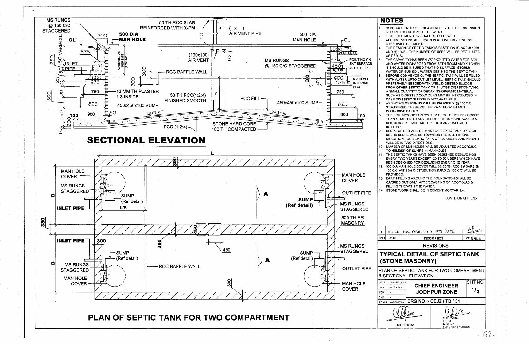
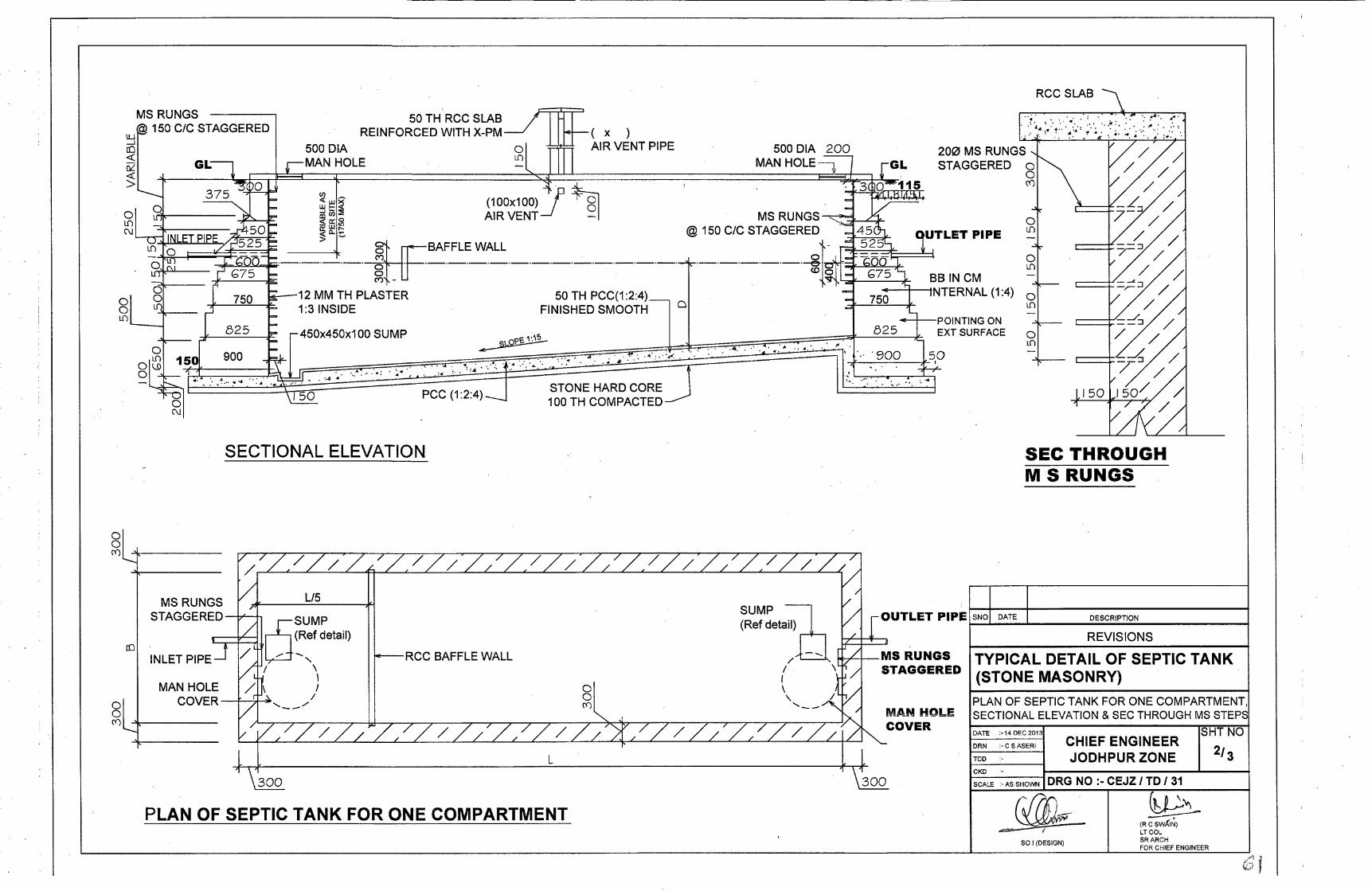


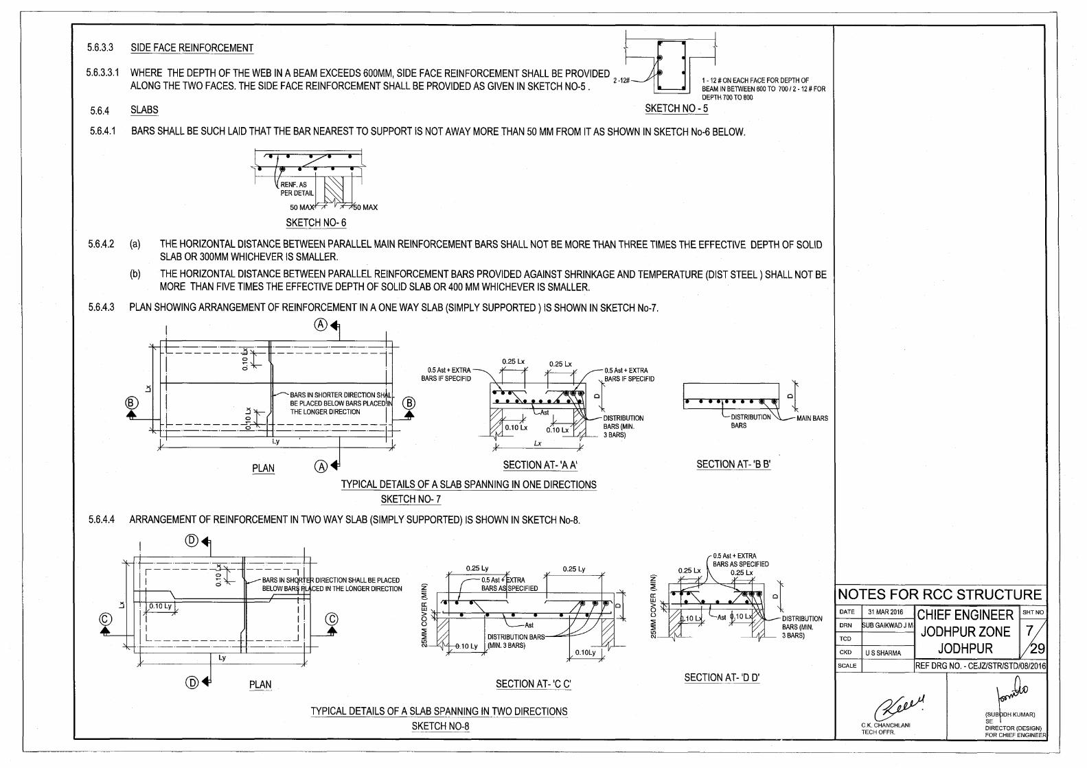


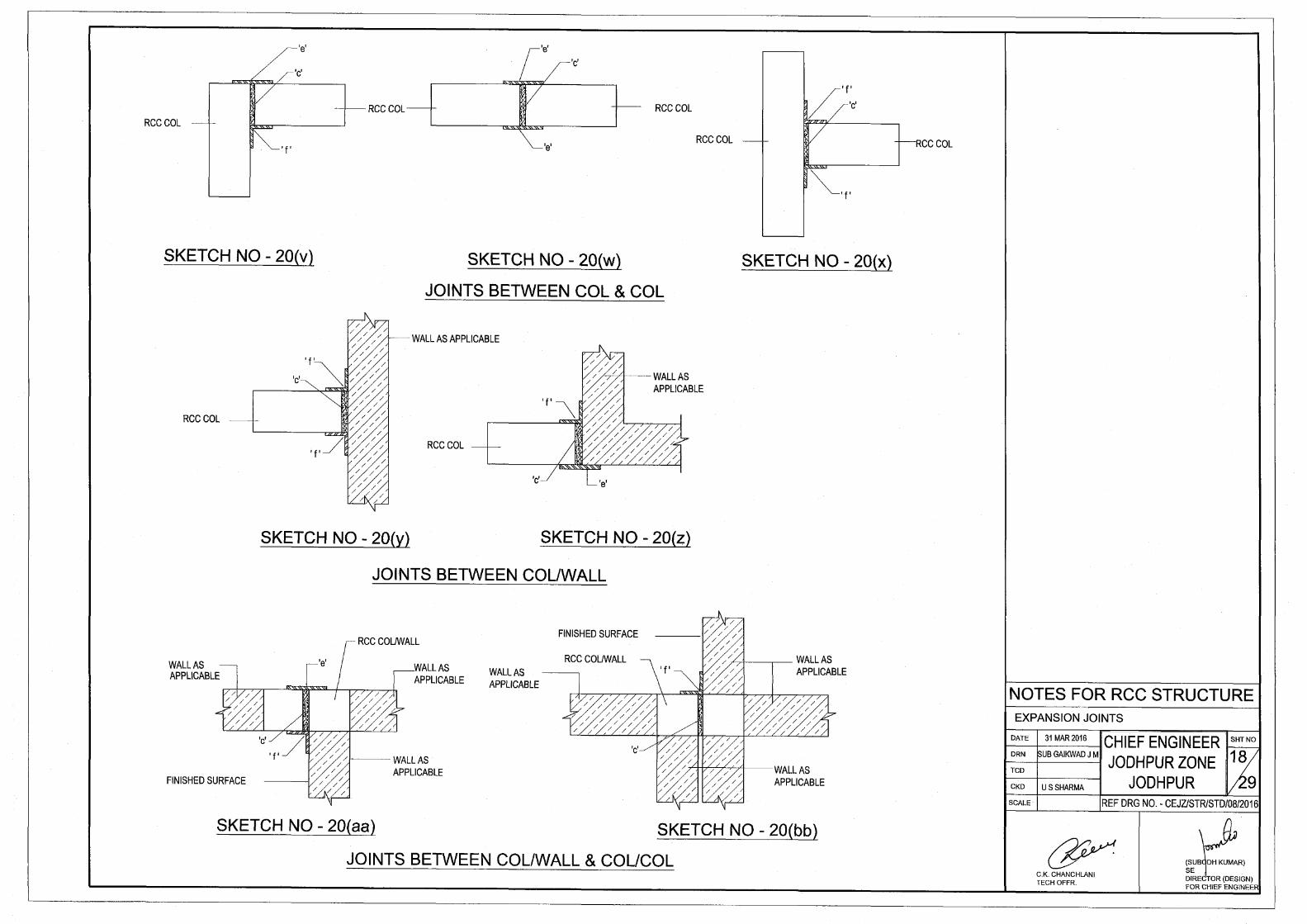
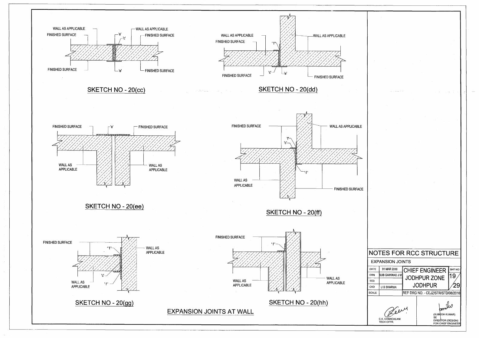


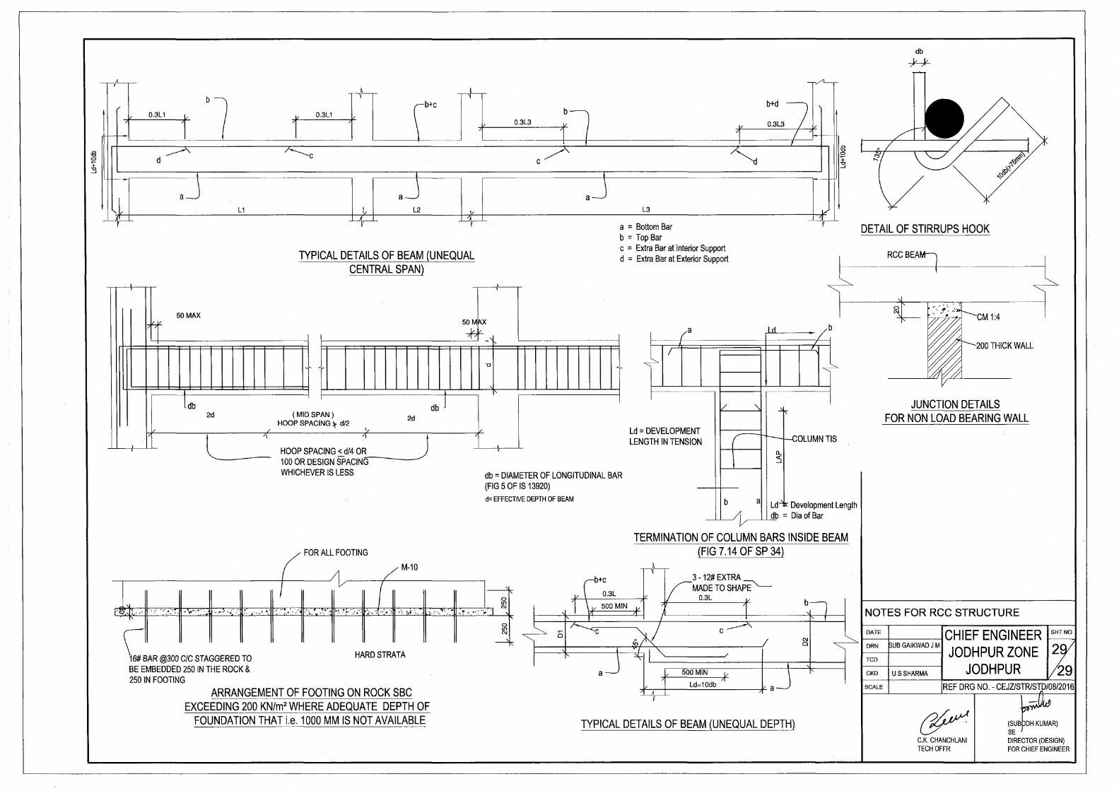


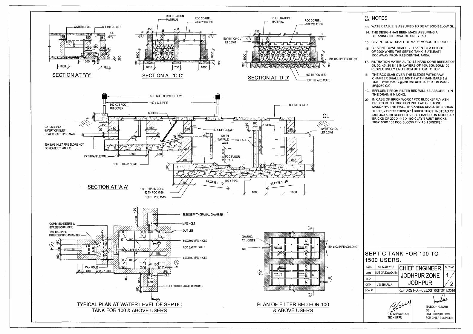

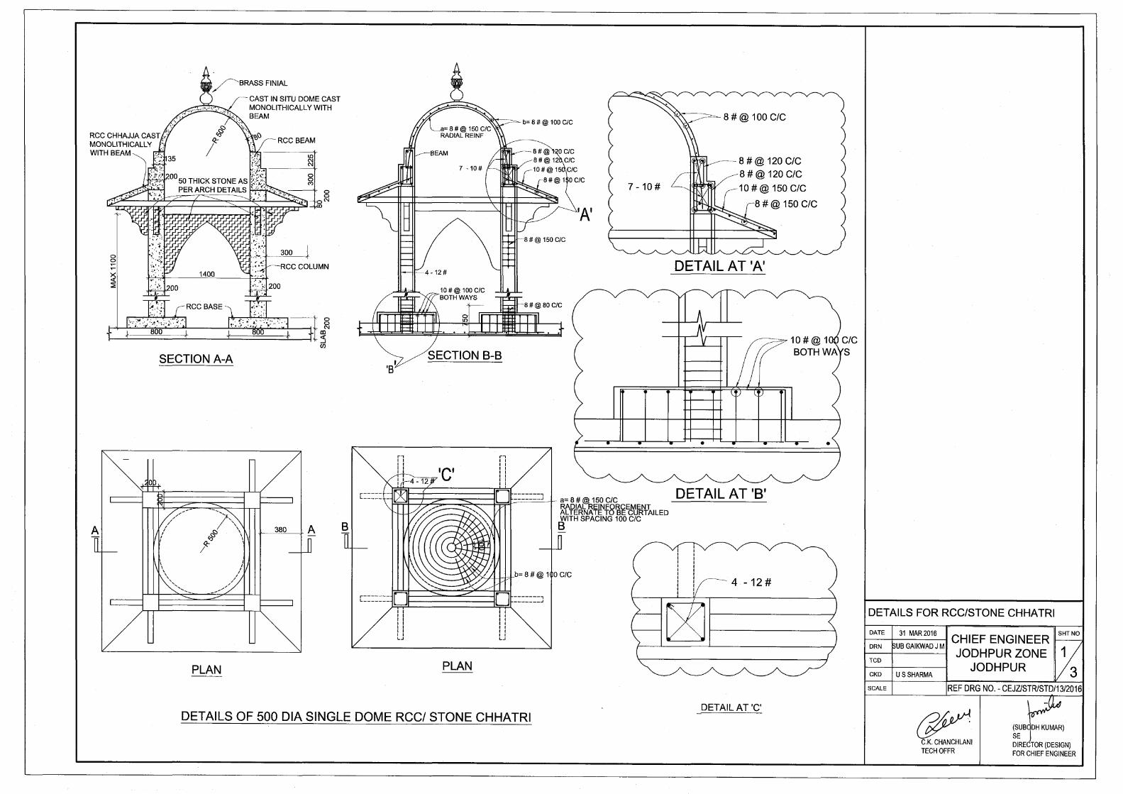


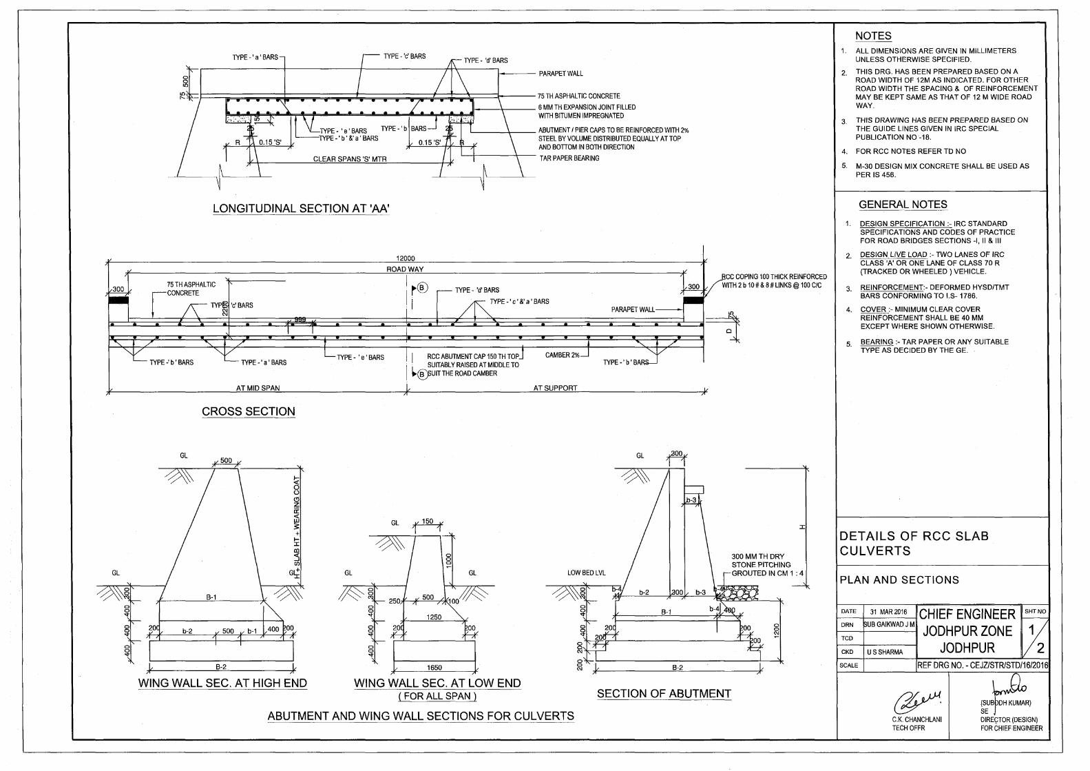

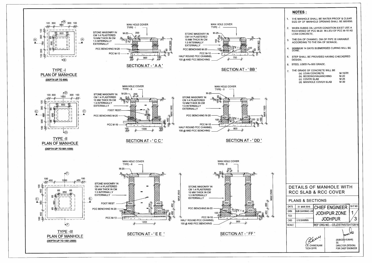
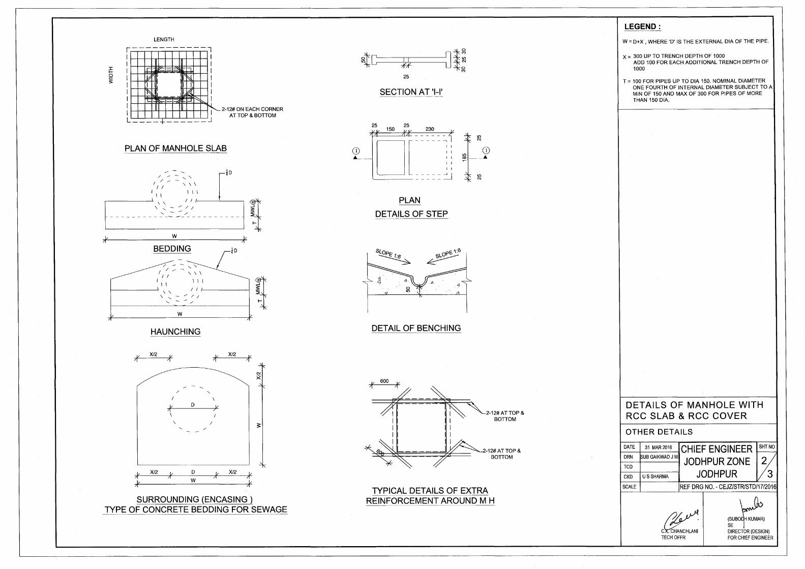


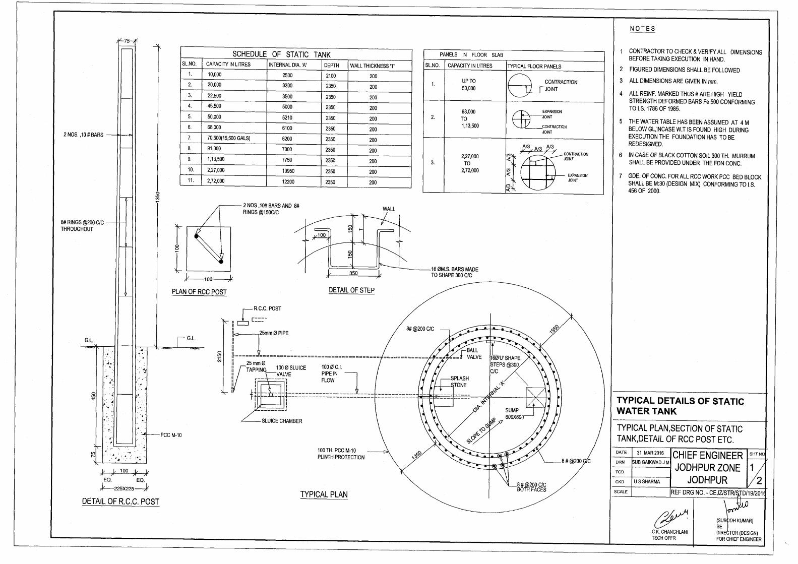


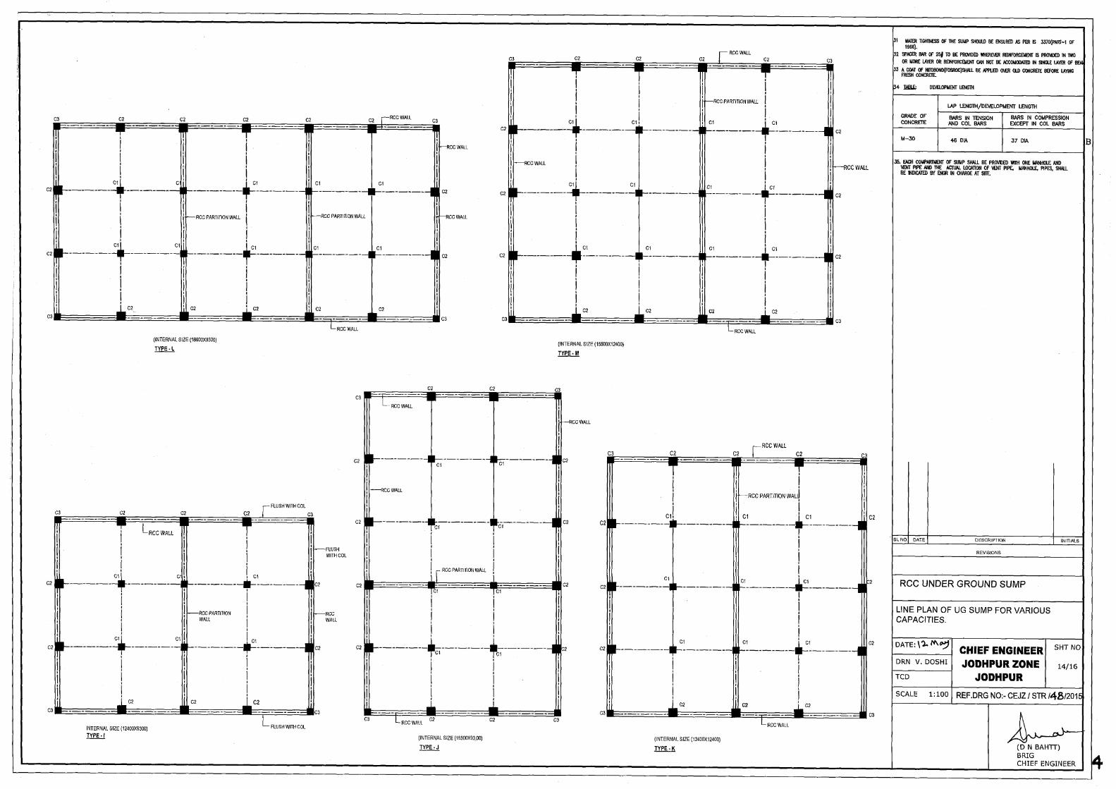
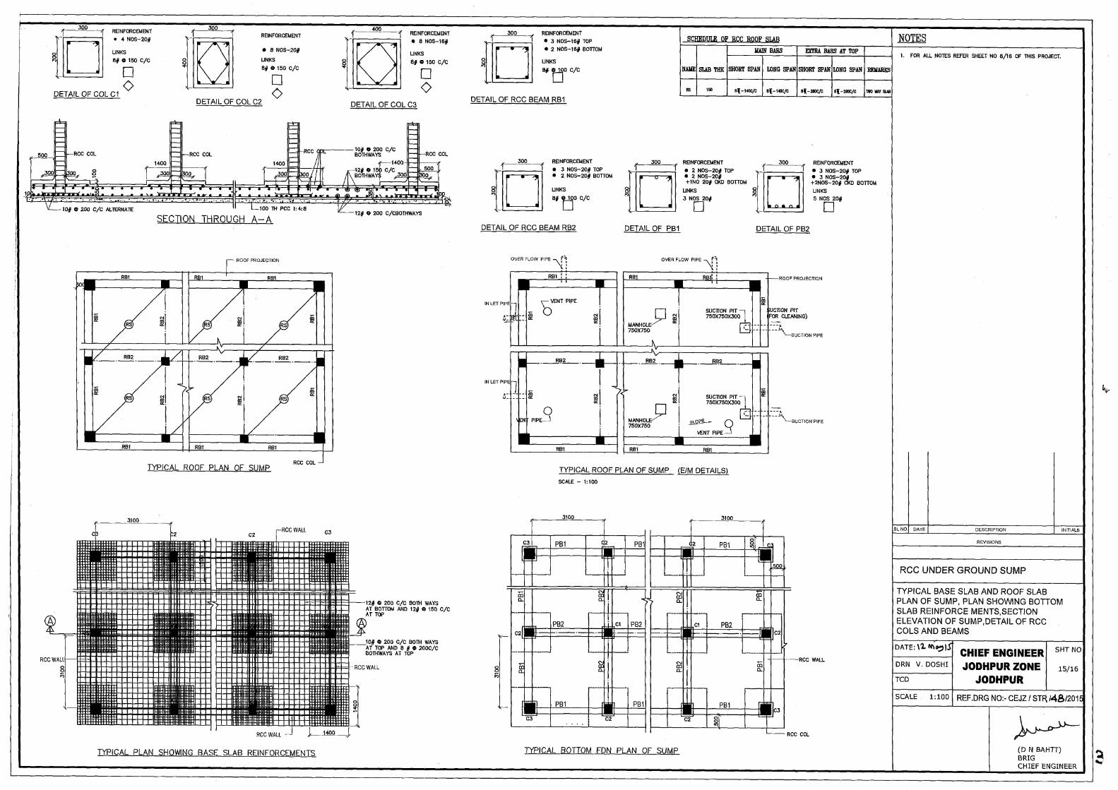

![8 THE SCHEDULE [See section 2] Serial No. National ...](https://static.fdokumen.com/doc/165x107/633d581a2bbaf1c5d906c9e0/8-the-schedule-see-section-2-serial-no-national-.jpg)

![North Carolina register [serial] - NC.gov](https://static.fdokumen.com/doc/165x107/6327f539e491bcb36c0b8a23/north-carolina-register-serial-ncgov.jpg)


![The Chanticleer [serial]](https://static.fdokumen.com/doc/165x107/632863a3051fac18490eb46f/the-chanticleer-serial.jpg)