CA NO. CEB / DDN / 24 OF 2016-2017 - EQMagPro
322
CA NO. CEB / DDN / 24 OF 2016-2017 SERIAL PAGE NO. 1 CONTD …… MILITARY ENGINEER SERVICES CHIEF ENGINEER BAREILLY ZONE NAME OF WORK: - PROVISION OF 2 MW SOLAR ENERGY PROJECT AT DEHRADUN CONTENTS Sl. No. PARTICULARS PAGES FROM TO 1. Index Sheet. 01 2. Forwarding Letter 02 To 03 3. Instructions to Tenderers 04 To 06 4. Notice of Tender IAFW-2162 including Appendix „A‟ to Notice of Tender alongwith errata / amendment thereof 07 To 5. Lump sum tender and Contract for Works required IAFW- 2159 (Revised 1947) To 6. * General Conditions of Contracts IAFW-2249 (1989-Print) To 7. * Errata and Amendments to General Conditions of Contracts IAFW-2249 (1989-Print) To 8. * Schedule of Minimum Wages 9. Special Conditions To 10. Particular Specifications including Appendix „A‟, Annexure-I to IV to Particular Specifications and List of Drawings To 11. Errata / Amendments to Tender Documents To 12. Relevant Correspondence To 13. Acceptance Letter. To Total Nos. of pages Drawings : Sheets * These documents are not attached with tender documents and can be seen in the office of CEBZ BAREILLY, CWE DEHRADUN and GE DEHRADUN during working hours. (Signature of Contractor) Astt Dir/ Dy Dir (Contracts) Dated…………………………. For Accepting Officer
-
Upload
khangminh22 -
Category
Documents
-
view
5 -
download
0
Transcript of CA NO. CEB / DDN / 24 OF 2016-2017 - EQMagPro

CA NO. CEB / DDN / 24 OF 2016-2017 SERIAL PAGE NO. 1
CONTD ……
MILITARY ENGINEER SERVICES CHIEF ENGINEER BAREILLY ZONE
NAME OF WORK: - PROVISION OF 2 MW SOLAR ENERGY PROJECT AT DEHRADUN
CONTENTS
Sl. No.
PARTICULARS PAGES FROM TO
1. Index Sheet. 01
2. Forwarding Letter 02 To 03
3. Instructions to Tenderers 04 To 06
4. Notice of Tender IAFW-2162 including Appendix „A‟ to Notice of Tender alongwith errata / amendment thereof
07 To
5. Lump sum tender and Contract for Works required IAFW-
2159 (Revised 1947) To
6. * General Conditions of Contracts IAFW-2249 (1989-Print) To
7. * Errata and Amendments to General Conditions of Contracts IAFW-2249 (1989-Print)
To
8. * Schedule of Minimum Wages
9. Special Conditions To
10. Particular Specifications including Appendix „A‟, Annexure-I to IV to Particular Specifications and List of Drawings
To
11. Errata / Amendments to Tender Documents To
12. Relevant Correspondence To
13. Acceptance Letter. To
Total Nos. of pages
Drawings : Sheets * These documents are not attached with tender documents and can be seen in the office of CEBZ BAREILLY, CWE DEHRADUN and GE DEHRADUN during working hours.
(Signature of Contractor) Astt Dir/ Dy Dir (Contracts) Dated…………………………. For Accepting Officer
CA NO. CEB / DDN / 24 OF 2016-2017 SERIAL PAGE NO. 2
CONTD ……
BY REGISTERED POST
Tele Mil : 6055 Headquarters Chief Engineer Bareilly Zone
Military Engineer Services Sarvatra Bhawan, Station Road
Bareilly Cantt Bareilly -243001
886335 / / E-8 Feb 2018 Shri / M/S ………………………………………...
………………………………………………………..
………………………………………………………..
TENDER FOR PROVISION OF 2 MW SOLAR ENERGY PROJECT AT DEHRADUN
Dear Sir (s), 1. Tender documents in respect of above work are uploaded on the site www.defproc.gov.in. The tender is on single stage two cover e-tendering system. The contents of Cover 1 & Cover II are specified in NOTICE OF TENDER. 2. Bids will be received online by ACCEPTING OFFICER (Chief Engineer, Bareilly Zone, Bareilly) up to the date and time mentioned in the NIT. No tender/bid will be received in physical form and any tender/bid received in such manner will be treated as non bonafide tender/bid. 3. Bid will be opened on due date and time fixed for opening in the presence of tenderers/bidders or their authorized representatives, who have uploaded their quotation bid and who wish to be present at the time of opening the bids. 4. Your attention is also drawn to instruction on filling and submission of tender attached herewith. You may forward your points on tender documents and/or depute your technical representative for discussion on tender/drawings and to clarify doubts, if any, on or before 20 Feb 2018. You are requested not to write piece meal points and forward your points duly consolidated before due date ie 20 Feb 2018. 5. Un-enlisted contractors are required to submit the scanned copies (in pdf file) of documents required as per eligibility criteria mentioned in instructions for filling the tender documents and Appendix „A‟ to NIT alongwith EARNEST MONEY DEPOSIT (EMD) and tender fee on e-procurement portal and submit the physical documents in the office of Chief Engineer Bareilly Zone, Bareilly within time limit specified in NIT. Inadequacy/deficiency of documents shall make the bid liable for rejection resulting in disqualification for opening of finance bid. 6. (a) Contractors having not executed standing security bond and standing security deposit in any MES formation shall upload scanned copy of EARNEST MONEY DEPOSIT (EMD) mentioned in Notice of Tender and shall ensure receipt of hard copy of EMD in the office of tender issuing authority before date and time fixed for this purpose. In case of failure to abide by any of these two requirements, the finance bid will not be opened.

CA NO. CEB / DDN / 24 OF 2016-2017 SERIAL PAGE NO. 3
CONTD ……
(b) Contractor having not executed standing security bond and standing security deposit in any MES formation would be required to deposit individual security deposit on acceptance of tender which will be calculated with reference to the tendered cost as per scales laid down by MES for calculation of “EARNEST MONEY” enhanced by 25% subject to maximum of Rs 18,75,000.00 (Rupees eighteen lakh seventy five thousand only).
7. Enlisted contractors of MES shall submit the scanned copies (pdf file) of enlistment letter, tender fee and such other documents as mentioned in Appx „A‟ to NIT on e-procurement portal and submit physical documents in the office of Chief Engineer Bareilly Zone, Bareilly before date and time fixed for this purpose. 8. The contractor must ensure that the tender/bid on the proper form is uploaded in time as the Accepting Officer will take no cognizance of any quotations/offer received in any other electronic or physical form like email/fax/by hand/through post from tenderer/bidder even if they are received in time. 9. In view of delays due to system failure or other communication related failures, it is suggested that the tender/bid be uploaded, if necessary, sufficiently in advance of the last due date and time fixed. 10. General Conditions of Contracts (IAFW-2249) (1989 print) and errata and amendments thereto, Schedule of minimum fair wages and MES SSR (Part-I and Part-II) are not enclosed with these documents. These documents are available for perusal in the office of GE concerned and this office. 11. ANY TENDERER, WHICH PROPOSES ALTERATIONS TO ANY OF THE CONDITION, SPECIFICATIONS LAID DOWN IN THE TENDER DOCUMENTS OR ANY NEW CONDITION, WHATSOEVER, IS LIABLE TO BE REJECTED. 12. (a) Contractor having not executed standing security bond and standing security deposit in any MES formation shall upload scanned copy of EARNEST MONEY DEPOSIT (EMD) mentioned in Notice of Tender (NIT) and shall ensure receipt of hard copy of EMD in the office of Chief Engineer, Bareilly Zone, Bareilly before date and time fixed for this purpose. In case of failure to abide by any of these two requirements, the finance bid will not be opened. (b) Contractor having not executed standing security bond and standing security deposit in any MES formation would be required to deposit individual security deposit on acceptance of tender which will be calculated with reference to the tendered cost as per scales laid down by MES for calculation of “EARNEST MONEY” enhanced by 25% subject to maximum of Rs 1875000.00 (Rupees eighteen lakh seventy five thousand only).
13. The work lies in UNRESTRICTED AREA.
14. This letter alongwith „Instructions to tenderers‟ shall form part of tender documents.
15. Your attention is invited to „Instruction to tenderers‟ attached herewith for strict compliance.
Yours faithfully, ______________________________ Astt Dir/ Dy Dir (Contracts) SIGNATURE OF CONTRACTOR for Accepting Officer DATED : _____________________

CA NO. CEB / DDN / 24 OF 2016-2017 SERIAL PAGE NO. 4
CONTD ……
INSTRUCTIONS TO THE TENDERER (S) (INSTRUCTIONS FOR COMPLETION OF TENDER DOCUMENTS
TO BE COMPLIED WITH BY THE TENDERER (S))
1. EARNEST MONEY DEPOSIT (EMD)
Contractor(s) who are not enlisted with MES/who are enlisted but have not executed the Standing Security Bond shall submit Earnest Money Deposit as detailed in Notice of Tender in one of the following forms, alongwith their tender/bid :-
(a) Deposit at Call Receipt from a Scheduled Bank in favour of Garrison Engineer concerned.
(b) Receipted Treasury challan, the amount being credited to the Revenue Deposit in favour of Garrison Engineer.
Note :- Earnest Money in the form of Cheque/Bank Guarantee etc. will not be accepted.
NON-SUBMISSION OF EARNEST MONEY DEPOSIT (EMD) (SCANNED COPY ALONGWITH TECHNICAL BID & HARDCOPY BEFORE THE DATE AND TIME FIXED FOR OPENING OF BOQ) WILL RENDER THE BID DISQUALIFIED FOR OPENING OF COVER II (FINANCE BID). 2. SECURITY DEPOSIT
In case the tender/bid submitted by such contractor who is not enlisted with MES is accepted, the contractor will be required to lodge with the Controller of Defence Accounts "INDIVIDUAL SECURITY DEPOSIT" calculated with reference to "TENDERED COST" as notified by the Accepting Officer subject to a maximum of Rs. 18,75,000/-. The amount is required to be lodged within 30 (Thirty) days of the receipt by the contractor of notification of acceptance of tender/bid, failing which the sum shall be recovered from the 1st RAR payment or from the Final Bill (See condition 22 of GCC (IAFW-2249)). 3. CONTRACTORS ENLISTED WITH CHIEF ENGINEER CENTRAL COMMAND AND WHO HAVE EXECUTED STANDING SECURITY BOND AND DEPOSITED STANDING SECURITY DEPOSIT BUT OF LOWER CLASS
In case the tender/bid is accepted, the amount of 'Additional Security Deposit' will be as notified
by the Accepting Officer. The amount will be the difference between the 'Individual Security Deposit' calculated with reference to the 'TENDERED COST' and 'Standing Security Deposit' lodged. The amount is required to be lodged within 30 (Thirty) days of the receipt by the contractor of notification of acceptance of tender/bid, failing which the sum shall be recovered from the 1st RAR payment or from the Final Bill (refer condition 22 of IAFW-2249). 4. CONTRACTOR(S) ENLISTED IN MES FORMATIONS OTHER THAN CE CENTRAL COMMAND
Contractors whose names are on the approved list of any MES formations i.e. other than CE
Central Command and who have deposited standing security and have executed standing security bond may tender/bid without depositing earnest money with the tender/bid and if the Accepting Officer decides to accept the tender/bid, such tenderers will be required to lodge security deposit as notified by the Accepting Officer. The amount is required to be lodged within 30 (Thirty) days of the receipt by the contractor of notification of acceptance of tender/bid, failing which the sum shall be recovered from the 1st RAR payment or from the Final Bill. 5. GENERAL INSTRUCTIONS FOR COMPLIANCE 5.1. The bids received only in the electronic form will be considered. All bids shall be submitted on „eprocuremes.gov.in‟ portal. Documents should be scanned and forwarded in „pdf‟ form and „xls‟ form as indicated.

CA NO. CEB / DDN / 24 OF 2016-2017 SERIAL PAGE NO. 5
CONTD ……
INSTRUCTIONS FOR COMPLETION OF TENDER DOCUMENTS
TO BE COMPLIED WITH BY THE TENDERER(S) (Contd…) 5.2 Bids shall be uploaded on „eprocuremes.gov.in‟ portal on or before the bid closing date mentioned in the tender. No tender/bid in any other electronic or physical form like email / fax / by hand / through post will be considered. 5.3 Bid should be DIGITALLY signed using valid DSC. All pages of tender documents, corrections/ alterations shall be signed/ initialled by the lowest bidder after acceptance. 5.4 Drawings, if issued in physical form, must be returned duly initialled by the tenderer/bidder in separate envelope indicating his name and address. 5.5 The tender shall be signed, dated and witnessed at all places provided for in the documents after acceptance. All corrections shall be initialled. The contractor shall initial every page of tender and shall sign all drawings forming part of the tender. Any tender/bid, which proposes alterations to any of the conditions whatsoever, is liable to be rejected. 5.6 In the technical bid, a scanned copy of Power of Attorney in favour of the person uploading the bid using his/her DSC shall be uploaded. In case the digital signatory himself is the sole proprietor, scanned copy of an affidavit on stamp paper of appropriate value to this effect stating that he has authority to bind the firm in all matters pertaining to contract including the Arbitration clause, shall be attached in „pdf‟ form. In case of partnership concern or a limited company, digital signatory of the bid/ tender shall ensure that he is competent to bind the contractor (through partnership deed, general power of attorney or Memorandum and Articles of Association of the Company) in all matters pertaining to the contracts with Union of India including arbitration clause. A scanned copy of the documents confirming of such authority shall be attached with the tender/bid in „pdf‟ form, if not submitted earlier. The person uploading the bid on behalf of another partner(s) or on behalf of a firm or company using his DSC shall upload with the tender/bid, a scanned copy(in „pdf‟ form) of Power of Attorney duly executed in his favour by such other or all of the Partner (s) or in accordance with constitution of the company in case of company, stating that he has authority to bind such other person or the firm or the company as the case may be, in all matters pertaining to the contract including the Arbitration Clause. 5.7 Even in case of firms or companies which have already given Power of Attorney to an individual authorizing him to sign tender and in pursuance of which tenders/bids are being uploaded by such person as a routine, fresh Power of Attorney duly executed in his favour stating specifically that the said person has authority to bind such partners of the Firm, or the Company as the case may be, including the condition relating to Arbitration Clause, should be uploaded in „pdf‟ form with the tender/bid; unless such authority has already been given to him by the Firm or the Company. It shall be ensured that power of attorney shall be executed in accordance with the constitution of the company as laid down in its Memorandum & Article of Association. 5.8 Hard copies of all above documents should be sent by the contractor to the Tender issuing authority well in advance to be received before the date & time fixed for the same. 5.9 Bid (Cover 1 & 2) shall be uploaded online well in time. 5.10 The contractor shall employ Indian Nationals after verifying their antecedents and loyalty. Attention is also drawn to special condition 3 referred hereinafter and also conditions 24 & 25 of IAFW- 2249 (General Conditions of Contract). 5.11 Tenderers/bidders who uploaded their priced tenders/bids and are desirous of being present at the time of opening of the tenders/bids, may do so at the appointed time.

CA NO. CEB / DDN / 24 OF 2016-2017 SERIAL PAGE NO. 6
CONTD ……
INSTRUCTIONS FOR COMPLETION OF TENDER DOCUMENTS
TO BE COMPLIED WITH BY THE TENDERER(S) (Contd…)
5.12 The tenderer/bidder shall quote his rate on the BOQ file only. The amount shall be filled against the items in green column provided to quote the rates only and schedule of credit if any shall be deducted manually at the time of acceptance of tender. No alteration to the format will be accepted; else the bid will be disqualified and summarily rejected.
5.13 In case the tenderer/bidder has to revise / modify the rates quoted in the BOQ (excel sheet) he can do so only in the BOQ, through eprocuremes.gov.in site only before the bid closing time and date.
5.14 Site visit by the contractor before quoting the tender is compulsory. The department, in this regard, will entertain no claim subsequently.
5.15 Uploading of documents related to Provident Fund Code number and GST/Service Tax number is essential for eligibility of quoting of bids, failing which the bid shall not be opened.
6. REVOKATION/REVISION OF OFFER UPWARD/OFFERING VOLUNTARY REDUCTION, AFTER OPENING OF FINANCIAL BIDS BY LOWEST BIDDER
In the event of lowest tenderer/bidder revoking his offer or revising his rates upward/offering voluntary reduction, after closing bid submission date and time, his offer will be treated as revoked and the Earnest Money deposited by him shall be forfeited. In case of MES enlisted contractors, the amount equal to the Earnest Money stipulated in the Notice of Tender, shall be notified to the tenderer/bidder for depositing the amount through MRO, failing which the amount shall be recovered from payment due to such Contractor or shall be adjusted from his Standing Security Deposit. In addition, such tenderer and his related firm shall not be issued the tender in second call or subsequent calls. Issue of further tenders to such tenderer shall also remain suspended till the aforesaid Earnest Money is deposited in the Govt. Treasury. Reduction offered by the tenderer/bidder on the freak high rates referred for review shall not be treated as voluntary reduction.
7. CPM (Critical Path Method)
7.1 The project planning for work covered in the scope of tender is based on CPM.
7.2 The tenderer/bidder is expected to be fully conversant with the CPM technique and employ technical staff who can use the technique in sufficient details. Sufficient books and other literature on the subject are widely available in the market which the tenderer/bidder may make use of.
7.3 The tenderer‟s/bidder‟s attention is drawn to special condition of the tender regarding preparation of the detailed network analysis and the time schedule for the work and his liability for employing sufficient resources to adhere to this schedule. Any inability on the part of the tenderer/ bidder in using the technique will be taken as his technical inefficiency and will affect his class of enlistment and future prospect/invitation to tenders for future works.
7.4 Department may issue amendments/errata in form of CORRIGENDUM to tender /revised BOQ to the tender documents. The tenderer/bidder is requested to read the tender documents in conjunction wilt all the errata/amendments / corrigendum, if any, issued by the department.
8. These instructions shall form part of the contract documents and shall be signed and returned alongwith the tender documents. ___________________________ Astt Dir/ Dy Dir (Contracts) SIGNATURE OF CONTRACTOR for Accepting Officer DATED : _____________________
CA NO. CEB / DDN / 24 OF 2016-2017 SERIAL PAGE NO. 7
CONTD ……
MILITARY ENGINEER SERVICES
NOTICE OF TENDER 1. A tender is invited for the work as mentioned in Appendix 'A' to this NOTICE INVITING TENDER (NIT). 2. The work is estimated to cost as indicated in aforesaid Appendix 'A'. This estimate, however, is not a guarantee and is merely given as a rough guide and if the work cost more or less, a tenderer/bidder will have no claim on that account even. The tender shall be based on as mentioned in aforesaid Appendix „A‟. 3. The work is to be completed within the period as indicated in aforesaid Appendix 'A'. In accordance with the phasing, if any, indicated in the tender from the date of handing over site, which will be on or about two weeks after the date of Acceptance of tender. 4. Normally contractors whose names are on the MES approved list for the area in which the work lies and within whose financial category the estimated amount would fall, may tender/bid but in case of term contracts, contractors of categories SS to E may tender/bid. In case, where the tender amount is in excess of the financial limit of the contractor and the Accepting Officer decides to accept the tender/bid in which event the tenderer/bidder would be required to lodged additional security deposit as notified by the accepting officer in term of conditions of contract. Contractors whose names are on the MES approved list of any MES formation and who have deposited standing Security and have executed Standing Security Bond, may also tender/bid without depositing Earnest Money alongwith the tender/bid and if the tender /bid submitted by such a tenderer/bidder is accepted, the contractor will be required to lodged with the Controller of Defence Account concerned the amount of „Individual security deposit‟ within the thirty days of the receipt by him of notification of acceptance of his tender/bid, failing which this sum will be recovered from 1st RAR payment or from the first final bill. In the case of term/running contracts, remaining sum shall be recovered from subsequent bill(s) of the contractor. Not more than one tender/bid shall be submitted/uploaded by one contractor or one firm of contractors. Under no circumstances will a father and his son(s) or other close relations who have business dealing with one another be allowed to tender/bid for the same contract as separate competitors. A breach of this condition will render the tenders/bids of both the parties liable for rejection. 5. The office of Chief Engineer, Bareilly Zone, Bareilly-243001 will be the Accepting Officer hereinafter referred to as such for the purpose of this contract. 6. The Technical Bid and Financial Bid (Cover-1 and Cover-2) shall be uploaded by the tenderer/bidder on or before the date & time mentioned in NIT. A scanned copy of DD with enlistment details/documents shall be uploaded as packet 1/cover-1 („T‟ bid) of the tender/bid on e-tendering portal. DD is refundable if T bid is not accepted resulting in non-opening of „Q‟ bid. The applicant contractor shall bear the cost of bank charges for procuring and encashing the DD and shall not have any claim from Government whatsoever on this account. 6.1. Tender form and conditions of contract and other necessary documents shall be available on eprocuresmes.gov.in / eprocure.gov.in site for download and shall form part of contract agreement in case the tender/bid is accepted. 6.2. In case of contractor who has not executed the "STANDING SECURITY BOND", the Cover-1 shall be accompanied with by "Earnest Money" of amount as mentioned in Appendix 'A' in the form of deposit at call receipt in favour of concerned GE (see Appendix 'A') by a Nationalized Bank / Scheduled Bank/or in receipted treasury challan, the amount being credited to the revenue deposit of the concerned GE (see Appendix 'A').

CA NO. CEB / DDN / 24 OF 2016-2017 SERIAL PAGE NO. 8
CONTD ……
NOTICE OF TENDER (Contd…)
6.3. A contractor who is not enlisted for the area in which the work lies, but whose name is in the MES approved list of any MES formation and who has deposited Standing Security and executed Standing security bond, may bid/tender without depositing earnest money alongwith the tender, but if the Accepting Officer accepts the tender/bid, the contractor will be required to lodged with the Controller of Defence Account concerned the amount of „Individual security deposit‟ within the thirty days of the receipt by him of notification of acceptance of his tender/bid, failing which this sum will be recovered from 1st RAR payment or from the first final bill. In the case of term/running contracts, remaining sum shall be recovered from subsequent bill(s) of the contractor.
6.4. A contractor who has executed the standing security bond but not corresponding to the appropriate class as mentioned above, shall lodge with the Accepting Officer, Additional Security Deposit as notified by the Accepting Officer within thirty days of receipt of his notification of acceptance of his tender/bid, failing which this sum will be recovered from first RAR payment or from the first final bill. In the case of term/running contracts, remaining sum shall be recovered from subsequent bill(s) of the contractor. However, in case where any payment is made to the contractor within thirty days of receipt by him of notification of acceptance of tender/bid, the amount of additional security deposit shall be recovered from such payment.
6.5. GE will return the Earnest Money wherever applicable to all unsuccessful tenderers/bidders by endorsing an authority on the deposit-at-call receipt for its refund, on production by the tenderer/bidder a certificate of the Accepting Officer, that a bonafide tender/bid was received and all documents were returned.
6.6. The GE will either return the Earnest Money to the successful tenderer/bidder by endorsing an authority on the deposit-at-call receipt for its refund on receipt of an appropriate amount of security deposit or will retain the same in part or full on account of security deposit if such a transaction is feasible.
6.7. Copies of the drawings and other documents pertaining to the work signed for the purpose of identification by the Accepting Officer or his accredited representative, sample of materials and stores to be supplied by the contractor will also be available for inspection by the tenderer/bidder at the office of Accepting Officer and concerned GE during office working hours.
7. The tenderers/bidders are advised to visit the site of work by making prior appointment with GE who is also the executing agency of the work (see Appendix „A‟). The tenderers/bidders are deemed to have full knowledge of all relevant documents, samples, site etc., whether they have inspected them or not.
8. Any tender/bid which proposes any alteration to any of the conditions laid down or which proposes any other condition or prescription whatsoever, is liable to be rejected.
9. The uploading of bid implies that bidder has read this notice and the conditions of contract has made himself aware of the scope and specification of work to be done and of the conditions and rates at which stores, tools and plants etc will be issued to him and local conditions and other factors heaving bearing on the execution of the work.
10. Tenderers/bidders must be in possession of copy of MES Standard Schedule of Rates Part I-2009 & Part II-2010 including errata/ amendments thereto.
CA NO. CEB / DDN / 24 OF 2016-2017 SERIAL PAGE NO. 9
CONTD ……
NOTICE OF TENDER (Contd…)
11. Invitation for e-tender does not constitute any guarantee for validation of „T‟ bid and subsequent opening of finance bid of any applicant/bidder, even of enlisted contractors of appropriate class, merely by virtue of enclosing DD. Accepting Officer reserves the right to reject the „T‟ bid and not open the financial bid of any applicant/bidder. „T‟ bid validation shall be decided by the Accepting Officer based on, inter alia, capability of the firm as per criteria given in Appendix „A‟ to this NIT. The applicant contractor/bidder will be informed regarding non-validation of his „T‟ bid assigning reasons thereof through the eprocuremes website. The applicant contractor/bidder if he so desires may appeal to the next higher Engineer authority viz Chief Engineer, Central Command Lucknow on email id ceengrll-
[email protected] with copy to the Accepting Officer on email before the scheduled date of opening of
Finance Bid. The decision of the Next Higher Engineer Authority (NHEA) shall be final and binding. The contractor/bidder shall not be entitled for any compensation whatsoever for rejection of his bid. 12. The Accepting Officer reserves the right to accept the tender submitted by a Public Undertaking, giving a price preference over other. Tender(s)/bid(s) which may as lower, as are admissible under the Government Policy. No claim for any compensation or otherwise shall be admissible from such tenderer/bidder whose tender/bid is rejected. 14. Accepting Officer does not bind himself to accept the lowest or any tender/bid or to give any reason for not doing so. 15. Court of the place from where tender has been issued shall alone have jurisdiction to decide any dispute out of or in respect of this tender. After acceptance of tender, Condition 72 – Jurisdiction of Courts of IAFW-2249 shall be applicable. 16. This Notice Inviting Tender (NIT) including Appendix „A‟ shall form part of the contract. (Signature of Contractor) Astt Dir/ Dy Dir (Contracts) Dated…………………………. For Accepting Officer

CA NO. CEB / DDN / 24 OF 2016-2017 SERIAL PAGE NO. 10
CONTD ……
APPENDIX 'A' TO NOTICE OF e-TENDER INVITING APPLICATION MILITARY ENGINEER SERVICES
1 Name of Work : PROVISION OF 2 MW SOLAR ENERGY PROJECT AT DEHRADUN
2 Estimated Cost : Rs. 1475.00 Lakhs (At Par Market)
3. Period of completion : 12 (Twelve) Months / 365 days
4. Cost of tender documents : Rs 3000.00 in the shape of DD/Bankers cheque from any schedule Bank in favour of GE Dehradun and payable at Dehradun.
5. Website/portal address : www.defproc.gov.in and www.mes.gov.in
6. Type of contract : The tender shall be based on drawings and specifications, IAFW-2159 and GCC (IAFW-2249) with Sch „A‟ (list of items of work) to be priced by the tenderer. The tenderers are required to quote their lump sum amounts for prepriced parts of Schedule „A‟ and quote rates against items of other parts of Schedule „A‟.
7. Information & Details :
(a) Bid submission start date
: As per critical dates
(b) Last date of bid submission
: As per critical dates
(c) Date of bid opening
: As per critical dates
8. Eligibility Criteria
(A) For MES enlisted contractors
: (i) Contractors of Class “S” (and below eligible class as per existing policy) shall be considered eligible. (ii) Firm should have experience as given in para 8(C)(i). (iii) They should not have any adverse remarks in WLR of competent engineer authority.

CA NO. CEB / DDN / 24 OF 2016-2017 SERIAL PAGE NO. 11
CONTD ……
APPENDIX 'A' TO NOTICE OF e-TENDER INVITING APPLICATION (Contd…)
(B) For Un-enlisted contractors
(i) Contractors meeting the criteria of annual turnover, financial criteria, solvency, working capital, fixed assets commensurate with enlistment criteria of class “S” contractor in MES. (ii) Firms should have experience as given in para 8(C)(i). (iii) No recovery outstanding in any Government Department. (iv) They should not have any adverse remarks in WLR/or any other similar report of any authority. Note: - Meeting engineering establishment criteria of Class “S” contractor of MES is not required.
(C) For All Contractors (i) Experience of having successfully completed Solar Power Plants in Government Department / PSU during last seven years ending last day of the month previous to the one in which applications are invited should be any of the following:- One work of capacity ≥ 1600 KWp
OR Two works of capacity ≥ 1000 KWp OR Three works of capacity ≥ 800 KWp
(ii) Contractor will not be allowed to execute the work by subletting or through power of attorney holder on his behalf to a third party/ another firm except sons/ daughters of proprietor/ partner/ Director, Project Manager as per contract conditions.
9. Tender issuing and Accepting Officer
: Chief Engineer, Bareilly Zone, Bareilly-243001
10. Executing agency : GE Dehradun
CA NO. CEB / DDN / 24 OF 2016-2017 SERIAL PAGE NO. 12
CONTD ……
APPENDIX 'A' TO NOTICE OF e-TENDER INVITING APPLICATION (Contd…)
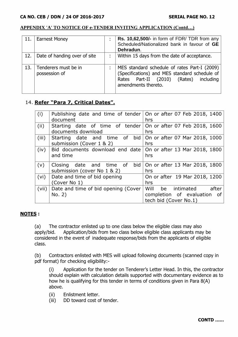
11. Earnest Money : Rs. 10,62,500/- in form of FDR/ TDR from any Scheduled/Nationalized bank in favour of GE Dehradun.
12. Date of handing over of site
: Within 15 days from the date of acceptance.
13. Tenderers must be in possession of
: MES standard schedule of rates Part-I (2009) (Specifications) and MES standard schedule of Rates Part-II (2010) (Rates) including amendments thereto.
14. Refer “Para 7, Critical Dates”.
(i) Publishing date and time of tender
document
On or after 07 Feb 2018, 1400
hrs
(ii) Starting date of time of tender documents download
On or after 07 Feb 2018, 1600 hrs
(iii) Starting date and time of bid submission (Cover 1 & 2)
On or after 07 Mar 2018, 1000 hrs
(iv) Bid documents download end date and time
On or after 13 Mar 2018, 1800 hrs
(v) Closing date and time of bid submission (cover No 1 & 2)
On or after 13 Mar 2018, 1800 hrs
(vi) Date and time of bid opening (Cover No 1)
On or after 19 Mar 2018, 1200 hrs
(vii) Date and time of bid opening (Cover
No. 2)
Will be intimated after
completion of evaluation of tech bid (Cover No.1)
NOTES :
(a) The contractor enlisted up to one class below the eligible class may also apply/bid. Application/bids from two class below eligible class applicants may be considered in the event of inadequate response/bids from the applicants of eligible class.
(b) Contractors enlisted with MES will upload following documents (scanned copy in pdf format) for checking eligibility:-
(i) Application for the tender on Tenderer‟s Letter Head. In this, the contractor should explain with calculation details supported with documentary evidence as to
how he is qualifying for this tender in terms of conditions given in Para 8(A) above.
(ii) Enlistment letter. (iii) DD toward cost of tender.

CA NO. CEB / DDN / 24 OF 2016-2017 SERIAL PAGE NO. 13
CONTD ……
APPENDIX 'A' TO NOTICE OF e-TENDER INVITING APPLICATION (Contd…)
Hard copy of these documents will be submitted within 5 (Five) days of the last
date & time of opening of „T‟ bid.
(c) Contractors not enlisted with MES will be required to upload the following :-
(i) Application for the tender : In this the contractor should explain with calculation details supported with documentary evidence, how he is qualifying for this tender in terms of conditions given in Para 8 above .
(ii) Necessary documents to prove their eligibility for enlistment in required class including Affidavit for no recovery outstanding. List of documents required
for enlistment in MES has been given Para 1.5 of section 1 of Part I MES Manual on Contracts 2007 (Reprint 2012). The work experience shall include details of
similar nature of works executed during last five years, financial year wise in tabular form giving name of work, Accepting Officer‟s details viz, Address, telephone , Fax No, e-mail ID etc, date of acceptance of tender and actual date of completion . This shall be duly signed by proprietor / all Partners / authorized Director of Pvt / Public Ltd, as applicable. It should indicate whether extension was granted or compensation was levied. Attested copy of acceptance letter and completion certificate shall be enclosed of each work. In case performance report has been given by the client same shall also be submitted duly attested.
The documents will also include the following amongst others:-
(aa) Solvency certificate and working Capital Certificate issued by scheduled bank.
(ab) Affidavits for possession of movable & immovable properties by proprietor/ partner owning the immovable property along with Valuation Certificate from Regd Valuer in support of movable & immovable properties. In case of Limited Company, the immovable property is required to be in the name of the company. In case of Limited Company, the immovable property is required to be in the name of the Company.
(iii) Scanned copy of earnest money and DD toward cost of tender.
(iv) Documents in support of residual capacity which shall include:-
(aa) Copy of turn over certificate from CA for last 5 (five) years ( FY), notarized copy of relevant pages of balance sheet of those FYs showing the turnover (gross receipts). (ab) List of works in hand for contracts with Government Department and private works, completed value thereof and residual work to be completed during completion period of subject work in a self-explanatory tabular form. This shall be submitted duly signed by proprietor/ all partners/ authorized Director of Pvt/Public Ltd as applicable.
CA NO. CEB / DDN / 24 OF 2016-2017 SERIAL PAGE NO. 14
CONTD ……
APPENDIX 'A' TO NOTICE OF e-TENDER INVITING APPLICATION (Contd…)
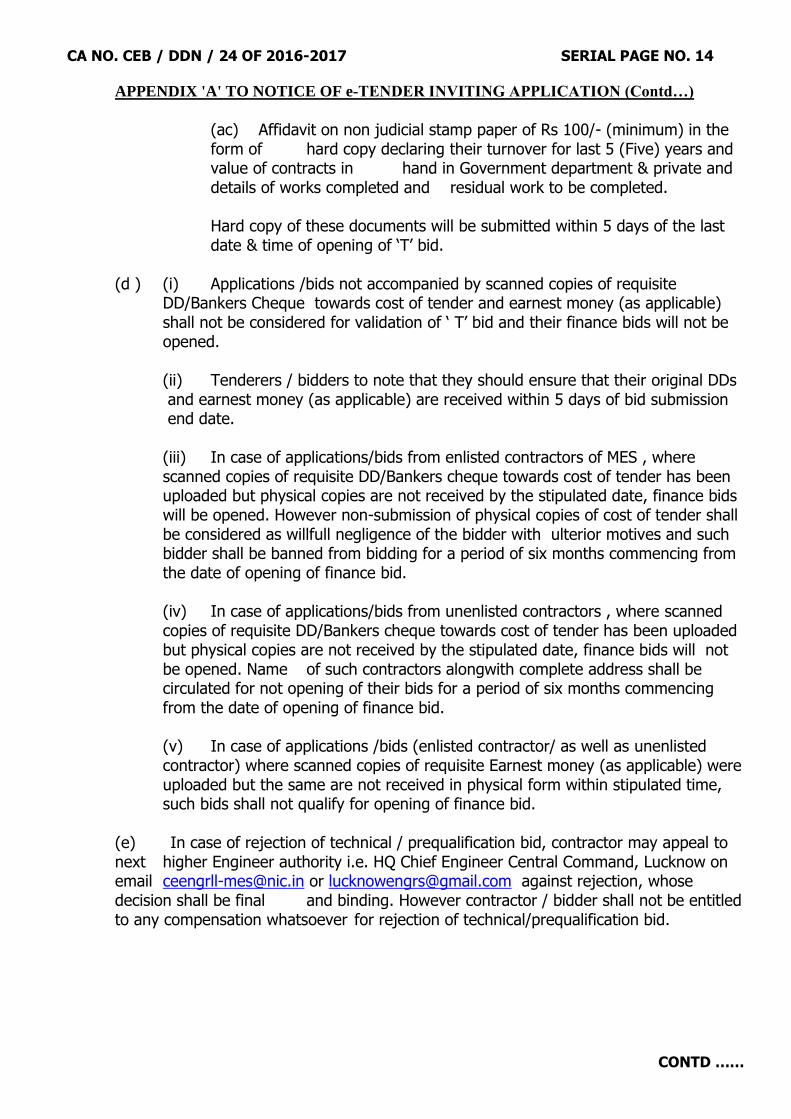
(ac) Affidavit on non judicial stamp paper of Rs 100/- (minimum) in the form of hard copy declaring their turnover for last 5 (Five) years and value of contracts in hand in Government department & private and details of works completed and residual work to be completed.
Hard copy of these documents will be submitted within 5 days of the last date & time of opening of „T‟ bid. (d ) (i) Applications /bids not accompanied by scanned copies of requisite DD/Bankers Cheque towards cost of tender and earnest money (as applicable)
shall not be considered for validation of „ T‟ bid and their finance bids will not be opened.
(ii) Tenderers / bidders to note that they should ensure that their original DDs
and earnest money (as applicable) are received within 5 days of bid submission end date.
(iii) In case of applications/bids from enlisted contractors of MES , where
scanned copies of requisite DD/Bankers cheque towards cost of tender has been uploaded but physical copies are not received by the stipulated date, finance bids will be opened. However non-submission of physical copies of cost of tender shall be considered as willfull negligence of the bidder with ulterior motives and such bidder shall be banned from bidding for a period of six months commencing from the date of opening of finance bid.
(iv) In case of applications/bids from unenlisted contractors , where scanned copies of requisite DD/Bankers cheque towards cost of tender has been uploaded but physical copies are not received by the stipulated date, finance bids will not be opened. Name of such contractors alongwith complete address shall be circulated for not opening of their bids for a period of six months commencing from the date of opening of finance bid.
(v) In case of applications /bids (enlisted contractor/ as well as unenlisted contractor) where scanned copies of requisite Earnest money (as applicable) were uploaded but the same are not received in physical form within stipulated time, such bids shall not qualify for opening of finance bid.
(e) In case of rejection of technical / prequalification bid, contractor may appeal to next higher Engineer authority i.e. HQ Chief Engineer Central Command, Lucknow on email [email protected] or [email protected] against rejection, whose decision shall be final and binding. However contractor / bidder shall not be entitled to any compensation whatsoever for rejection of technical/prequalification bid.
CA NO. CEB / DDN / 24 OF 2016-2017 SERIAL PAGE NO. 15
CONTD ……
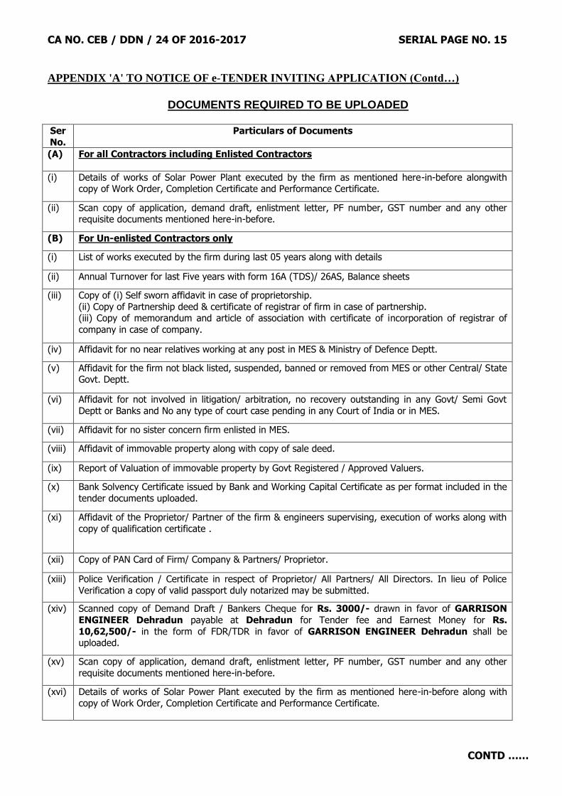
APPENDIX 'A' TO NOTICE OF e-TENDER INVITING APPLICATION (Contd…)
DOCUMENTS REQUIRED TO BE UPLOADED
Ser
No.
Particulars of Documents
(A) For all Contractors including Enlisted Contractors
(i) Details of works of Solar Power Plant executed by the firm as mentioned here-in-before alongwith copy of Work Order, Completion Certificate and Performance Certificate.
(ii) Scan copy of application, demand draft, enlistment letter, PF number, GST number and any other requisite documents mentioned here-in-before.
(B) For Un-enlisted Contractors only
(i) List of works executed by the firm during last 05 years along with details
(ii) Annual Turnover for last Five years with form 16A (TDS)/ 26AS, Balance sheets
(iii) Copy of (i) Self sworn affidavit in case of proprietorship.
(ii) Copy of Partnership deed & certificate of registrar of firm in case of partnership. (iii) Copy of memorandum and article of association with certificate of incorporation of registrar of
company in case of company.
(iv) Affidavit for no near relatives working at any post in MES & Ministry of Defence Deptt.
(v) Affidavit for the firm not black listed, suspended, banned or removed from MES or other Central/ State Govt. Deptt.
(vi) Affidavit for not involved in litigation/ arbitration, no recovery outstanding in any Govt/ Semi Govt
Deptt or Banks and No any type of court case pending in any Court of India or in MES.
(vii) Affidavit for no sister concern firm enlisted in MES.
(viii) Affidavit of immovable property along with copy of sale deed.
(ix) Report of Valuation of immovable property by Govt Registered / Approved Valuers.
(x) Bank Solvency Certificate issued by Bank and Working Capital Certificate as per format included in the
tender documents uploaded.
(xi) Affidavit of the Proprietor/ Partner of the firm & engineers supervising, execution of works along with
copy of qualification certificate .
(xii) Copy of PAN Card of Firm/ Company & Partners/ Proprietor.
(xiii) Police Verification / Certificate in respect of Proprietor/ All Partners/ All Directors. In lieu of Police
Verification a copy of valid passport duly notarized may be submitted.
(xiv) Scanned copy of Demand Draft / Bankers Cheque for Rs. 3000/- drawn in favor of GARRISON
ENGINEER Dehradun payable at Dehradun for Tender fee and Earnest Money for Rs.
10,62,500/- in the form of FDR/TDR in favor of GARRISON ENGINEER Dehradun shall be uploaded.
(xv) Scan copy of application, demand draft, enlistment letter, PF number, GST number and any other
requisite documents mentioned here-in-before.
(xvi) Details of works of Solar Power Plant executed by the firm as mentioned here-in-before along with
copy of Work Order, Completion Certificate and Performance Certificate.

CA NO. CEB / DDN / 24 OF 2016-2017 SERIAL PAGE NO. 16
CONTD ……
APPENDIX 'A' TO NOTICE OF e-TENDER INVITING APPLICATION (Contd…)
DOCUMENTS REQUIRED TO BE UPLOADED (Contd…) (xv) Though adequate care has been taken while preparing the Bidding documents, the Bidders/Applicants shall satisfy themselves that the document is complete in all respects. Intimation of any discrepancy shall be given to this
office immediately. If no intimation is received from any Bidder within twenty (20) days from the date of publication of tender, it shall be considered that the tender documents are complete in all respects has been received by the
Bidder.
(aa) Military Engineer Services (MES), Chief Engineer Bareilly Zone, Bareilly, the Employer, reserves the right to modify, amend or supplement this NIT documents including all formats and Annexures.
(ab) While this bidding documents have been prepared in good faith, neither Employer or its authorized
representatives nor their employees or advisors make any representation or warranty, express or implied, or
accept any responsibility or liability, whatsoever, in respect of any statements or omissions herein, or the accuracy, completeness or reliability of information, and shall incur no liability under any law, statute, rules
or regulations as to the accuracy, reliability or completeness of this bidding documents, even if any loss or damage is caused by any act or omission on their part.
(ac) The specification mentioned for all the equipment which include Solar modules, PCU, combiner
boxes, DC cables, module mounting structures, transformer, CT, PT, LT/ HT cables, interfacing panels,
switch gears & other associated equipment etc., to complete the power generation and interconnection at designated substation, in the present bidding documents is for the reference only. It is subject to revise/
alters as per the design/ planning/Good engineering practices etc., to be carried out by the selected bidder, to the satisfaction of the Employer or its authorized representatives. It is advised that the bidders must
satisfy himself with the prevailing site conditions before design/ plan.
The design must be optimized for the site conditions and directed to achieve the maximum output from the installed capacity at all times. Moreover, the components not separately mentioned, but are required to
complete the Plant for successful operation is also included in the scope of bidder and shall be vetted by the
Employer or its authorized representatives.
(xvi ) This NIT shall supersede the NIT already issued.
Astt Dir/Dy Dir (Contracts)
886335 / / E8 for Accepting Officer Dated : Feb 2018
Headquarters Chief Engineer Bareilly Zone Military Engineer Services Sarvatra Bhawan, Station Road Bareilly Cantt Bareilly – 243 001

CA NO. CEB / DDN / 24 OF 2016-2017 SERIAL PAGE NO. 17
CONTD ……
Copy to :-
1. CE Central Command, Lucknow 28. GE (P) Bareilly
2. CE Jabalpur Zone, Jabalpur 29. GE AF Izatnagar
3. CE Lucknow Zone, Lucknow 30. GE Lansdowne
4. CE (AF) Allahabad Zone, Allahabad 31. AGE (I) Raiwala
5. CWE Bareilly 32. Builders Association of India, G-1/G-20, Commerce Centre, 7th floor Tradeo, Mumbai-400034
6. CWE Dehradun 33. MES BAI, 807, Sahyog, 58, Nehru Place, New Delhi-110019
7. CWE (Hills) Dehradun 34. Hony Secy, MES BAI, Bareilly Branch, C/O M/S Nijhon Constructions, M-1, Neel Kanth Flats, Stadium Road, Bareilly-243005
8. CWE Meerut Cantt 35. Hony Secy, MES BAI, 119-D, Race Course, Dehradun - 248001
9. CWE (P) Meerut Cantt 36. Hony Secy, MES BAI Kanpur Branch, C/O M/s Kali Charan Pandey & Co., P.O Building, Ganga Ghat Unnao (U.P)
10. CWE (Hills) Pithoragarh 37. Hony Secy, MES BAI, Agra Branch, B-103, New Agra Colony, Agra – 282005
11. CWE (AF) Bareilly 38. MES BAI, Lucknow Branch, C/O M/S Pratap Builders, 210-Ram Das Ka Hata, Lucknow Cantt
12. GE Premnagar Dehradun 39. MES BAI, Meerut Branch, 10, Rajan Kunj, Roorkee Road, Meerut
13. GE Dehradun 40. MES BAI, Roorkee Branch, “SHALABH HOUSE”, 490, Purani Tehsil, Roorkee (U.A.)
14. GE (P) Dehradun 41. State Bank of India, Main Branch, Bareilly
15. GE Clement Town 42. Muncipal Corporation, Bareilly
16. GE (P) IMA Dehradun 43. Executive Engineer, CPWD, Bareilly
17. GE (MES) Roorkee 44. Executive Engineer, UPPWD, Bareilly
18. GE (N) Meerut 45. Station Master, Bareilly Junction
19. GE (S) Meerut 46. Construction Industry Development Council, 801 (8th floor), Hemkunt Chambers, 89, Nehru Place, New Delhi-110019
20. GE (U) E/M Meerut 47. Employment Exchange, Bareilly
21. GE(P) No 1 Meerut 48. Employment Exchange., Dehradun
22. GE(P) No 2 Meerut 49. Head Post Office Bareilly
23. GE Pithoragarh 50. Commercial Supdt., N E Railway, Izatnagar Bareilly
24. GE Ranikhet 51. Cantonment Board, Bareilly
25. GE 871 EWS, C/O 56 APO 52. Notice Board
26. GE (East) Bareilly
27. GE (West) Bareilly
Internal E-2 (Plg)/ E-2(Wks)/ E-3/ E-4/ E-2(D)/ E-6/ E-7(Adm) and C-886335/E8
CA NO. CEB / DDN / 24 OF 2016-2017 SERIAL PAGE NO. 18
CONTD … …
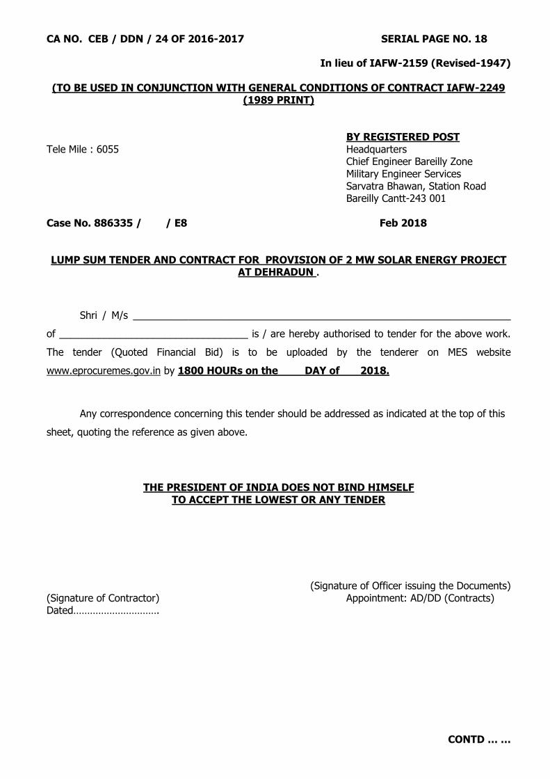
In lieu of IAFW-2159 (Revised-1947)
(TO BE USED IN CONJUNCTION WITH GENERAL CONDITIONS OF CONTRACT IAFW-2249 (1989 PRINT)
BY REGISTERED POST Tele Mile : 6055 Headquarters
Chief Engineer Bareilly Zone Military Engineer Services
Sarvatra Bhawan, Station Road Bareilly Cantt-243 001 Case No. 886335 / / E8 Feb 2018 LUMP SUM TENDER AND CONTRACT FOR PROVISION OF 2 MW SOLAR ENERGY PROJECT
AT DEHRADUN .
Shri / M/s ____________________________________________________________________
of __________________________________ is / are hereby authorised to tender for the above work.
The tender (Quoted Financial Bid) is to be uploaded by the tenderer on MES website
www.eprocuremes.gov.in by 1800 HOURs on the DAY of 2018.
Any correspondence concerning this tender should be addressed as indicated at the top of this
sheet, quoting the reference as given above.
THE PRESIDENT OF INDIA DOES NOT BIND HIMSELF TO ACCEPT THE LOWEST OR ANY TENDER
(Signature of Officer issuing the Documents) (Signature of Contractor) Appointment: AD/DD (Contracts) Dated………………………….

CA NO. CEB / DDN / 24 OF 2016-2017 SERIAL PAGE NO. 19
CONTD … …
SCHEDULE 'A' (LIST OF WORKS AND PRICES)
NAME OF WORK: - PROVISION OF 2 MW SOLAR ENERGY PROJECT AT DEHRADUN NOTES :- A. GENERAL (APPLICABLE TO ALL PARTS OF SCHEDULE ‘A’)
1. The schedule is divided into the following parts as detailed below: -
(i) Schedule „A‟ Part-I A : Solar Power Plant (To be quoted by contractor)
(ii) Schedule „A‟ Part-I B : Building Work (To be quoted by contractor)
(iii) Schedule „A‟ Part-II A : Internal Water Supply
(iv) Schedule „A‟ Part-II B : Internal Water Supply (To be quoted by contractor)
(v) Schedule „A‟ Part-III A : Internal Electrification
(vi) Schedule „A‟ Part-III B : Internal Electrification (To be quoted by contractor)
(vii) Schedule „A‟ Part-IV : Site Clearance and Earthwork
(viii) Schedule „A‟ Part-V : Road, Path and Hardstanding
(ix) Schedule „A‟ Part-VIA : Sewage Disposal
(x) Schedule „A‟ Part-VIB : Sewage Disposal (To be quoted by contractor)
(xi) Schedule „A‟ Part-VII : Area Drainage
(xii) Schedule „A‟ Part-VIII : Compound wall & Gate
(xiii) Schedule „A‟ Part-IXA : External Water Supply
(xiv) Schedule „A‟ Part-IXB : External Water Supply (To be quoted by contractor)
(xv) Schedule „A‟ Part-XA : External Electric Supply
(xvi) Schedule „A‟ Part-XB : External Electric Supply (To be quoted by contractor)
(xvii) Schedule „A‟ Part-XI : Manning and Operation of Solar Power Plant
(To be quoted by contractor)
2. Entire work under this contract shall be completed in two Phase:-
(a) Phase-I:- 12 Months from the date of commencement of work shown in work order No.1 ( All works except mentioned in Phase-II). Completion for Phase I of the contract shall be issued once solar plant is Commissioned and tested to achieve a minimum Performance Ratio of 0.78 or above.
(b) Phase-II:- The work Manning & Operation of Solar Power Plant mentioned under Schedule ‘A’ Part-XI. The Phase-II will commence only after satisfactory completion of Phase-I Works and run for a period of 60 Months as mentioned under respective items of Manning and Operation of Solar Power Plant.
Notes:- Separate completion certificate shall be issued for all phases. Maintenance period as per Condition No. 46 of IAFW -2249 shall start only after completion of Phase-I Work. The whole work shall be deemed completed only after completion of Phase-II Work. Two final bills shall be progressed separately (One Final Bill for Phase-I and one Final Bill for Phase-II Work). Preparatory works, collection of materials, and all such preliminary works and site clearance after completion shall be deemed to be included in the period of completion stated above.

CA NO. CEB / DDN / 24 OF 2016-2017 SERIAL PAGE NO. 20
CONTD … …
SCHEDULE 'A' NOTES (Contd….) (LIST OF WORKS AND PRICES)
3. Site for execution of entire work will be made available on the date of commencement of work as per W.O. No. 01. In case, however, it is not possible for the department to make the entire site available on the date of commencement of work, the contractor will have to arrange his working programme accordingly. No claim whatsoever, for not handing over the entire site on the date of commencement of the work & handing over balance site for execution gradually will be tenable. 4. Pre-priced rates inserted under column 5 of Schedule „A‟ Part-IIA, IIIA, IV, V, VIA, VII, VIII, IXA and XA shall deemed to be at par with the rates contained in the MES standard schedule of rates or analogous rates thereto. Contractor‟s attention is invited to condition 6A (B) of IAFW-2249. Accordingly, the lump sum price shall be worked out by contractor independently of the prices or rates inserted by MES in the tender and irrespective of any errors or inaccuracies therein. The percentage to be inserted by the contractor above or below the prices inserted by MES against a particular part of schedule „A‟ shall be as derived by him from the amount tendered by him against that particular part of Schedule „A‟ as compared to the amount inserted by MES against it. 5. In respect of Schedule „A‟ Part-IA, IB, IIB, IIIB, VIB, IXB, XB and XI, the tenderer is required to insert his rates under column 6 of BOQ for entire completion of concerned items of work as described and specified inclusive of his all overhead and profit complete. 6. Descriptions of building works and services given in various parts of schedule „A' are in brief. These are deemed to be amplified and read in conjunction with Special Conditions, Particular specifications, specifications for materials and workmanship and conditions in relevant trade sections of the MES Standard Schedule of Rates (Part-I 2009 Print & Part-II 2010 Print) and contract drawings, including notes thereon. 7.1 Reference to drawings as per list of drawings has been given under col. 3 of schedule `A'. In case, details in respect of items shown in the main drawings are not given in drawings referred to in the main drawings, the same shall be followed from any other drawing, included in the list of drawings. 7.2 Any drawing mentioned in the contract drawings / Particular specifications if inadvertently not included in the list of drawings, shall also be deemed to form part of the contract. Tenderer shall see such drawing in the office of Accepting Officer / concerned CWE / concerned Garrison Engineer. 7.3 Any drawing that is mentioned on the drawings forming part of the tender but not specifically mentioned in the list of drawings shall be deemed to form part of the tender. Tenderer shall see such drawings / details in the office of Accepting Officer / concerned CWE / concerned GE. 8. Probable distribution of various items of internal / external services are indicated on drawings. These are tentative and may be varied as per site requirement where necessary at the discretion of the GARRISON ENGINEER within the limits laid down in Condition 7 of IAFW-2249. The contractor shall not be entitled for any claim on account of such varied alignment and consequent variation in quantities.

CA NO. CEB / DDN / 24 OF 2016-2017 SERIAL PAGE NO. 21
CONTD … …
SCHEDULE 'A' NOTES (Contd….) (LIST OF WORKS AND PRICES)
9. The lump sum amount quoted by contractor shall be deemed to include for all minor details / items of work / extra constructional details which are obviously and fairly intended and which may not have been specifically shown on drawings or given in Particular Specifications but are essential for the execution of works and services in the workman like manner, sound construction and established engineering practice. The details of such items not specifically shown on drawings / specified shall be furnished during execution of work. In case of difference in opinion between contractor and the Garrison Engineer as to whether or not certain items of work constitute minor details / items of work / extra construction details which are deemed to have been included in the contractor‟s lump sum, the decision of the Accepting Officer shall be final, conclusive and binding. Some of the details / items which are deemed to be essential for execution and entire completion of work are given hereunder for guidance:
(a) Reinforcement for any RCC member not indicated in the drawings but which is structural or codal requirement. (b) Dwarf wall in situations like verandah, passage etc. not indicated in drawings. (c) Lintels over doors, windows and openings not shown in drawings (d) Builders hardware for doors / windows etc. though not indicated on drawings but essential for usage. In all the above and other similar cases, the details indicated elsewhere in the drawings that
are similar or near similar to the missed out items of work shall be followed. In the absence of any other similar or near similar details, minimum essential requirement for completion of the work from structural and utility point of view shall deemed to be included in the lump sum quoted. 10. The layout of buildings indicated in site plan / layout plan is tentative and may be varied where necessary at the discretion of the Garrison Engineer. The contractor shall not be entitled for any claim on account of any such variation. 10.1. Before commencement of excavation or earth filling, the Engr-in-Charge and the contractor will be required to take the levels jointly of the existing ground surfaces at intervals as decided by the GE (the decision of the GE being final and binding in this respect) but not greater than 3m x 3m grid. 11. Unless specifically mentioned otherwise such as labour only / fixing only / laying only, the unit rates for all items of works shall be deemed to include cost of all materials, labour, tools and plants, testing and commissioning work in position complete as required for entire completion of works. 12. The rates quoted by contractor shall include all taxes / duties i.e. GST, Sales Tax, Sales Tax on Works Contracts, excise duty, custom duty, octroi duty, cess, labour cess, Service Tax and any other taxes / duties as applicable. Form 3D, 31 & 32 or any other form shall not be issued by MES. This is an express condition of this contract that no claim of the contractor shall be entertained by MES on this account. 13. The whole work under this contract lies in UNRESTRICTED AREA. 14. In laying out building, the centre line dimensions, mentioned in drawings or derived there from, shall be strictly followed. 15. In case of varying provisions between drawings(s) for schedule of finishes and other drawings with regard to finishes, the drawing(s) for schedule of finishes shall take precedence over other drawings. However, in case there are varying provisions with regard to height of skirting / dado in drawings for schedule of finishes and other drawings, provisions in other drawings shall be followed.
CA NO. CEB / DDN / 24 OF 2016-2017 SERIAL PAGE NO. 22
CONTD … …
SCHEDULE 'A' NOTES (Contd….) (LIST OF WORKS AND PRICES)
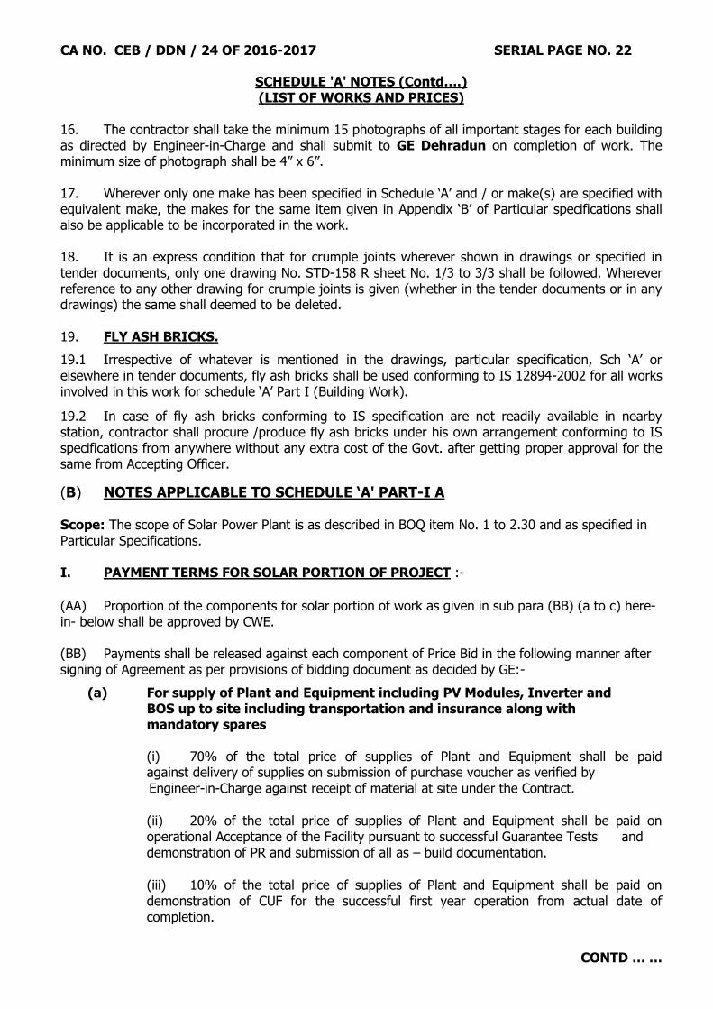
16. The contractor shall take the minimum 15 photographs of all important stages for each building as directed by Engineer-in-Charge and shall submit to GE Dehradun on completion of work. The minimum size of photograph shall be 4” x 6”. 17. Wherever only one make has been specified in Schedule „A‟ and / or make(s) are specified with equivalent make, the makes for the same item given in Appendix „B‟ of Particular specifications shall also be applicable to be incorporated in the work.
18. It is an express condition that for crumple joints wherever shown in drawings or specified in tender documents, only one drawing No. STD-158 R sheet No. 1/3 to 3/3 shall be followed. Wherever reference to any other drawing for crumple joints is given (whether in the tender documents or in any drawings) the same shall deemed to be deleted. 19. FLY ASH BRICKS.
19.1 Irrespective of whatever is mentioned in the drawings, particular specification, Sch „A‟ or elsewhere in tender documents, fly ash bricks shall be used conforming to IS 12894-2002 for all works involved in this work for schedule „A‟ Part I (Building Work).
19.2 In case of fly ash bricks conforming to IS specification are not readily available in nearby station, contractor shall procure /produce fly ash bricks under his own arrangement conforming to IS specifications from anywhere without any extra cost of the Govt. after getting proper approval for the same from Accepting Officer.
(B) NOTES APPLICABLE TO SCHEDULE ‘A' PART-I A Scope: The scope of Solar Power Plant is as described in BOQ item No. 1 to 2.30 and as specified in Particular Specifications. I. PAYMENT TERMS FOR SOLAR PORTION OF PROJECT :-
(AA) Proportion of the components for solar portion of work as given in sub para (BB) (a to c) here-in- below shall be approved by CWE. (BB) Payments shall be released against each component of Price Bid in the following manner after signing of Agreement as per provisions of bidding document as decided by GE:-
(a) For supply of Plant and Equipment including PV Modules, Inverter and BOS up to site including transportation and insurance along with mandatory spares (i) 70% of the total price of supplies of Plant and Equipment shall be paid against delivery of supplies on submission of purchase voucher as verified by Engineer-in-Charge against receipt of material at site under the Contract.
(ii) 20% of the total price of supplies of Plant and Equipment shall be paid on operational Acceptance of the Facility pursuant to successful Guarantee Tests and demonstration of PR and submission of all as – build documentation.
(iii) 10% of the total price of supplies of Plant and Equipment shall be paid on demonstration of CUF for the successful first year operation from actual date of completion.
CA NO. CEB / DDN / 24 OF 2016-2017 SERIAL PAGE NO. 23
CONTD … …
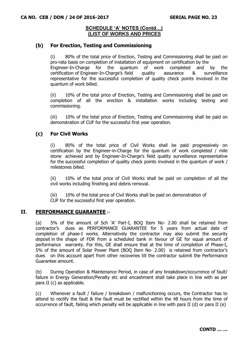
SCHEDULE ‘A’ NOTES (Contd…) (LIST OF WORKS AND PRICES
(b) For Erection, Testing and Commissioning (i) 80% of the total price of Erection, Testing and Commissioning shall be paid on pro-rata basis on completion of installation of equipment on certification by the Engineer-In-Charge for the quantum of work completed and by the certification of Engineer-In-Charge‟s field quality assurance & surveillance representative for the successful completion of quality check points involved in the quantum of work billed. (ii) 10% of the total price of Erection, Testing and Commissioning shall be paid on completion of all the erection & installation works including testing and commissioning. (iii) 10% of the total price of Erection, Testing and Commissioning shall be paid on demonstration of CUF for the successful first year operation.
(c) For Civil Works (i) 80% of the total price of Civil Works shall be paid progressively on certification by the Engineer-in-Charge for the quantum of work completed / mile stone achieved and by Engineer-In-Charge‟s field quality surveillance representative for the successful completion of quality check points involved in the quantum of work / milestones billed.
(ii) 10% of the total price of Civil Works shall be paid on completion of all the civil works including finishing and debris removal.
(iii) 10% of the total price of Civil Works shall be paid on demonstration of CUF for the successful first year operation.
II. PERFORMANCE GUARANTEE :-
(a) 5% of the amount of Sch „A‟ Part-I, BOQ Item No- 2.00 shall be retained from contractor‟s dues as PERFORMANCE GUARANTEE for 5 years from actual date of completion of phase-I works. Alternatively the contractor may also submit the security deposit in the shape of FDR from a scheduled bank in favour of GE for equal amount of performance warranty. For this, GE shall ensure that at the time of completion of Phase-I, 5% of the amount of Solar Power Plant (BOQ Item No- 2.00) is retained from contractor‟s dues on this account apart from other recoveries till the contractor submit the Performance Guarantee amount.
(b) During Operation & Maintenance Period, in case of any breakdown/occurrence of fault/ failure in Energy Generation/Penalty etc and encashment shall take place in line with as per para II (c) as applicable.
(c) Whenever a fault / failure / breakdown / malfunctioning occurs, the Contractor has to attend to rectify the fault & the fault must be rectified within the 48 hours from the time of occurrence of fault, failing which penalty will be applicable in line with para II (d) or para II (e)
CA NO. CEB / DDN / 24 OF 2016-2017 SERIAL PAGE NO. 24
CONTD … …
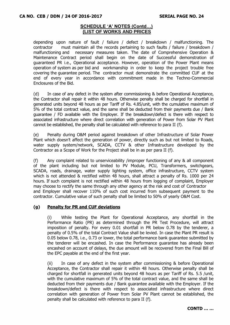
SCHEDULE ‘A’ NOTES (Contd…) (LIST OF WORKS AND PRICES
depending upon nature of fault / failure / defect / breakdown / malfunctioning. The
contractor must maintain all the records pertaining to such faults / failure / breakdown / malfunctioning and necessary measures taken. The date of Comprehensive Operation & Maintenance Contract period shall begin on the date of Successful demonstration of guaranteed PR i.e., Operational acceptance. However, operation of the Power Plant means operation of system as per bid and workmanship in order to keep the project trouble free covering the guarantee period. The contractor must demonstrate the committed CUF at the end of every year in accordance with commitment made in the Techno-Commercial Enclosures of the Bid.
(d) In case of any defect in the system after commissioning & before Operational Acceptance,
the Contractor shall repair it within 48 hours. Otherwise penalty shall be charged for shortfall in generated units beyond 48 hours as per Tariff of Rs. 4.85/unit, with the cumulative maximum of 5% of the total contract value, and the same shall be deducted from their payments due / Bank guarantee / FD available with the Employer. If the breakdown/defect is there with respect to associated infrastructure where direct correlation with generation of Power from Solar PV Plant cannot be established, the penalty shall be calculated with reference to para II (f).
(e) Penalty during O&M period against breakdown of other Infrastructure of Solar Power Plant which doesn‟t affect the generation of power, directly such as but not limited to Roads, water supply system/network, SCADA, CCTV & other Infrastructure developed by the Contractor as a Scope of Work for the Project shall be in as per para II (f).
(f) Any complaint related to unserviceability /improper functioning of any & all component of the plant including but not limited to PV Module, PCU, Transformers, switchgears, SCADA, roads, drainage, water supply lighting system, office infrastructure, CCTV system which is not attended & rectified within 48 hours, shall attract a penalty of Rs. 1000 per 24 hours. If such complaint is not rectified within 48 hours from logging of complaint, Employer may choose to rectify the same through any other agency at the risk and cost of Contractor and Employer shall recover 110% of such cost incurred from subsequent payment to the contractor. Cumulative value of such penalty shall be limited to 50% of yearly O&M Cost.
(g) Penalty for PR and CUF deviations
(i) While testing the Plant for Operational Acceptance, any shortfall in the
Performance Ratio (PR) as determined through the PR Test Procedure, will attract imposition of penalty. For every 0.01 shortfall in PR below 0.78 by the tenderer, a penalty of 0.5% of the total Contract Value shall be levied. In case the Plant PR result is 0.05 below 0.78, i.e., 0.73 or lower, the total performance bank guarantee submitted by the tenderer will be encashed. In case the Performance guarantee has already been encashed on account of delays, the due amount will be recovered from the Final Bill of the EPC payable at the end of the first year.
(ii) In case of any defect in the system after commissioning & before Operational Acceptance, the Contractor shall repair it within 48 hours. Otherwise penalty shall be charged for shortfall in generated units beyond 48 hours as per Tariff of Rs. 5.5 /unit, with the cumulative maximum of 5% of the total contract value, and the same shall be deducted from their payments due / Bank guarantee available with the Employer. If the breakdown/defect is there with respect to associated infrastructure where direct correlation with generation of Power from Solar PV Plant cannot be established, the penalty shall be calculated with reference to para II (f).

CA NO. CEB / DDN / 24 OF 2016-2017 SERIAL PAGE NO. 25
CONTD … …
SCHEDULE ‘A’ NOTES (Contd…) (LIST OF WORKS AND PRICES
(iii) Penalty for during O&M period shall be charged at a rate of difference in units derived from committed and achieved CUF x Rs. 5.5 per unit, for period after commissioning till the O&M contract closure. Penalty applicable shall be on annual basis. The CUF shall be evaluated as per the formula mentioned in tender document. During the O&M period, at any point of time, the Contractor has to ensure the
availability of BG / FD of requisite value with Employer.
(iv) Penalty during O&M period against breakdown of other Infrastructure of Solar Power Plant which doesn‟t affect the generation of power, directly such as but not limited to Roads, water supply system/network, SCADA, CCTV & other Infrastructure developed by the Contractor as a Scope of Work for the Project shall be in accordance with para II (f).
(v) In case the Project fails to generate any power continuously for 1 month any time during the O&M period, apart from the force majeure and grid outages as certified by competent authority from STU/ CTU, it shall be considered as “an event of default”. In the case of default the entire Performance Bank Guarantee will be encashed.
(vi) The penalties specified on account of delays, as specified in Condition – 50 of IAFW-2249 (General conditions of contracts) and penalty specified on account of deviations in Functional Guarantees as specified above shall be assessed independent of each other. Even penalties specified above are also independent of each other.
III. (a) Detailed design and other parameters of Solar Power Plant are given in detailed Particular Specifications in the tender documents.
(b) Lowest Bidder (Contractor) shall prepare the detailed project report & design basis report and submit a copy to Chief Engineer Bareilly Zone, Bareilly for evaluation within 4 weeks from the date of acceptance based on detailed specifications, design parameters and scope of work given in Particular Specifications for Solar Power Plant. Chief Engineer shall give approval within reasonable period after taking into consideration the recommendation of his authorized consultant. Contractor shall be liable to carryout changes as notified to him by CE or his authorized representative before approval of scheme within 07 (Seven) days of being notified such changes.
(c) Procurement action and commencement of work for Solar Power Plant shall be undertaken only after approval of scheme as well as other details by CE.
(d) Design of modules/ Array mounting steel structure with concrete foundation/ grouting work shall be duly vetted from Govt. Engg College/ IIT/ NIT.
IV. The contractor shall be liable to obtain an undertaking from the Channel Partner with regard to carrying out comprehensive maintenance for five year after completion of installation of solar plant.

CA NO. CEB / DDN / 24 OF 2016-2017 SERIAL PAGE NO. 26
CONTD … …
SCHEDULE ‘A’ NOTES (Contd…) (LIST OF WORKS AND PRICES (C) NOTES APPLICABLE TO SCHEDULE ‘A' PART-I B 1. The lump sum quoted by the tenderer for works under Schedule „A‟ Part-I B shall be deemed to include all relevant items of works shown on drawings, notes therein and as specified in Particular Specifications complete for entire completion of work except services and other works covered under Schedule `A' Part-II to XI. 2. The lump sum quoted by the tenderer for works under Schedule „A‟ Part-I B shall also be deemed to include the cost of following items of works amongst others :-
(a) Service water tanks as specified and shown on drawings including PVC ball cock of 25 mm bore of make Symet Prayag with epoxy coated aluminium rod and HD ball, over flow pipe and wash out pipe. Over flow GI pipe 25 mm nominal bore medium grade shall be extended upto 150 mm above top of plinth protection from each water tank. All inlet and outlet pipe (for supply) shall be measured and paid separately.
(b) Sanitary and toilet fittings and appliances. (c) Fittings and fixtures shown on drawings.
(d) Cost of 1st Manhole deemed to be included in cost of building. CI soil waste and vent pipe including its fixing arrangement and accessories for sanitation work upto 1st manhole i.e. upto 3.0 m beyond the face of external wall including necessary earth work, bedding, haunching of pipes, nahani trap and Gully trap with chamber . NOTE: However, gully trap shall be connected to nearby drain with SGSW pipes of suitable dia & 50 mm CI vent pipe shall be extended minimum 15 cm above the top level of water tank.
(e) Gully / Nahani traps.
(f) Seismic strengthening measures and crumple joint to be provided to the extent shown on drawing.
(g) Anti-termite treatment shall be carried out in the building covered under item No.3 to 5 of Schedule „A‟ Part-I. (h) Fan hooks/fan boxes, curtain rods including necessary clamps/ brackets etc, pelmet boxes, drapery rods including all fittings, nitches, peg sets, towel rails, MS rungs, cupboards, ward robes, electric meter boxes, water meter boxes, main switch boxes, paper holder etc. (j) Leaving / Forming / Cutting necessary chases, holes, openings, nitches etc. in walls, floors and ceilings wherever required for embedding pipes, conduits, sunken boxes, electric metre boxes and making good to match the adjoining surfaces. No price adjustment shall be made for variation in the quantities of chases, holes, nitches etc consequent to the variation in provisional quantities of items given in other schedules. Nitches shall be provided with frame and shutters all as specified here-in-after and shown in drawings.
(k) Format / plaster plate for numbering to building after completion of work to be made as directed at site during execution of work.

CA NO. CEB / DDN / 24 OF 2016-2017 SERIAL PAGE NO. 27
CONTD … …
SCHEDULE ‘A’ NOTES (Contd…) (LIST OF WORKS AND PRICES
(l) Format / plaster plate for recording details of anti termite treatment.
(m) Furniture item whether built in or otherwise shown in main plan of building such as show case, mirror, bin soiled linen, notice board, writing table, lockers, cupboard, steel wash hand basin ,chalk board etc. In case specification of any built-in-furniture shown on main drawings are not given, the specifications for the same shall be intimated by GE. (n) All other items which are not covered in notes but indicated in drgs and/or specified in Particular Specifications
(o) PCC drains along with plinth protection as shown in drawings. (p) Angle iron to be provided in each window for fitting of desert cooler as shown in drawing or as directed by Engineer-in-Charge. (r) Door shutter shall be flush door shutter irrespective of whatever shown on drawing or in tender documents elsewhere.
(s) All other items which are not covered in notes but indicated in drgs and / or specified in PS. (t) The plinth height of all buildings shall be as shown in respective drawings after surface dressing and filling under floor with approved earth. (u) Any other components left out here-in-before and covered in drawing, BOQ and other notes as given here-in-before and after shall also be followed and are deemed to be included in the rates quoted by the contractor. 3. Buildings under Sch „A‟ Part-I B shall have the foundation for soil bearing capacity of soil as shown in respective structural drawings or schedule of RCC beam / slab / column footing drawings. Variation in SBC of soil if found at site requiring redesigning of the foundation, the same shall be regularized through proper deviation order. 4. Rates quoted by the contractor for Schedule „A‟ Part-I B shall be for excavation and earth work in any type of soil. Any type of soil mentioned in Schedule „A‟ shall be soft/ loose / hard/ dense soil. Irrespective of whatever strata is met with during excavation i.e. soft/loose/hard/dense soil, the same shall be considered as any type of soil. Soft/hard rock met with during excavation shall be measured and paid separately as a deviation. Hard rock shall become the property of contractor and recovery at the rate of Rs 300.00 per cubic metre (solid contents) shall be made for hard rock. 5. Details/fittings/fixtures/furniture items/finishes shown in one part of building shall also be provided in other similar parts of buildings, though the same may have not been repeated in the drawings. 6. DEVIATIONS :- For the purpose of pricing deviation orders against Sch „A‟ Part-I B (i.e. Building Works), a deviation percentage of PLUS 20% (TWENTY PERCENT) shall be applied at par rates contained in MES Standard Schedule of Rates 2010 Part-II. (D) NOTES APPLICABLE TO SCHEDULE `A' PART-II TO IX 1. The quantities given under column 5 are provisional.

CA NO. CEB / DDN / 24 OF 2016-2017 SERIAL PAGE NO. 28
CONTD … …
SCHEDULE ‘A’ NOTES (Contd…) (LIST OF WORKS AND PRICES 2. Special Conditions in MES schedule Part-II and preamble for items given in MES schedule 2009 Part-I under respective trades shall be applicable. If any provision in the description of item of schedule 'A' and or Particular Specifications is at variance with the provisions given in special conditions in MES schedule 2010 Part-II and preamble to MES schedule, provision in Schedule „A‟ and or Particular specifications shall take precedence there over. (E) NOTES APPLICABLE TO SCHEDULE ‘A’ PART-II AND IX 1. CPVC / GI pipes and fittings, when fixed above ground shall run on surface of the walls or ceilings unless specified to be concealed. Where unavoidable, pipes may be buried for short distance provided adequate protection is given against damage. A GI tube light grade sleeve shall be fixed where the pipe is passing through a wall or floor for protection of the pipe and to allow freedom for expansion and contraction and other movements. Pipes, which are embedded in walls, ceiling or floors shall be painted with bituminous paint of approved quality.
(F) NOTES APPLICABLE TO SCHEDULE ‘A’ PART-III AND X 1. Recessed terminal boxes for housing switches, socket, outlets, power plug, regulator/electronic speed controller etc shall be provided flush with the walls. In case of half brick walls boxes may be fixed on surface of walls. The covers of these boxes shall be modular with inner and outer sheets. 2. The wiring for points, outside the building shall run on internal face of wall as far as practicable. Only at terminal points it shall be taken out by puncturing the walls to fix and connect light fittings/switches. 3. Conduit pipes embedded in RCC members shall be PVC conduit medium grade of appropriate size and the cost of the same shall deemed to be included in the unit rate inserted by MES. The contractor shall quote his lump sum accordingly. 4. Wherever in description of Sch „A‟ 5 Amps, 15 Amps, 30 Amps, 60 Amps have been mentioned, the same shall be amended to read as 5/6 Amps, 15/16 Amps, 30/32 Amps, 60/63 Amps respectively.
5. Opening of fan boxes shall be covered with laminated sheet 3 mm thick. The cost of these provisions shall deemed to be included in the lump sum cost of Schedule „A‟ Part-I (Building work). 6. Cost of flexible PVC insulated copper wire from connecting block to ceiling rose of suitable size is inclusive in the S&F/fixing only cost of fittings/fixtures/luminaries 7. Unless otherwise specifically mentioned, the unit rates for various items shall be deemed to include the cost of materials & labour complete including fixing in position & testing as required. 8. The rates for point wiring include any length of wiring. 9. The maximum No. of point wiring / fan points / light points / socket 5 amp points on an independent circuit from DB shall not exceed 8 No. in any case and for power points maximum number of points on an independent circuit from DB shall not exceed 2 power points.

CA NO. CEB / DDN / 24 OF 2016-2017 SERIAL PAGE NO. 29
CONTD … …
SCHEDULE ‘A’ NOTES (Contd…) (LIST OF WORKS AND PRICES (G) NOTES APPLICABLE TO SCHEDULE ‘A' PART-XI 1. Once the completion certificate has been issued by the Garrison Engineer for the Phase-I of the project, the work under Phase-II i.e., Manning and operation of Solar Power Plant for the period of 2 (two) years shall commence all as shown in Schedule „A‟ of BOQ from the date of issue of completion certificate for the Phase-I of the project. 2. A compensation with double the wages of the persons with respective trade as per the prevailing labour rates shall be charged on the contractor for the persons absented themselves from the duty. A shift of 08.00 hrs shall be considered as one unit for the compensation charged on the contractor. An attendance register duly bound shall be maintained by the concerned JE on daily basis endorsing the initials of contractor and Engineer-in-Charge. The attendance register shall form a part of payment of RAR and final bill. (H) NOTES APPLICABLE TO SCHEDULE ‘A' PART-I TO XI 1. The following description may please be inserted under the appropriate columns:- Column 3 : Refer list of drawing for all items . Column 7 : Refer schedule 'A' Note (A) 2 here-in-before for all items. Column 8 : Refer schedule 'A' Notes here-in-before for all items. 2. Unit RM, Cum or CUM, Sqm or SQM, 10 SQM and Quintal or Qtl, Kg or KG wherever mentioned in the tender documents denotes the unit, Running metre, cubic metre, square metre, ten square metre, Quintal and Kilogram respectively. (J) COMPLETION DRAWINGS Before one week of completion of work, a completion drawing set showing plan, sections and other details as directed by GE shall be submitted by the contractor on tracing cloth to GE for his approval. These drawings shall be got approved by the contractor from Garrison Engineer. The cost of the same shall be borne by the contractor and the lump sum quoted by contractor shall deem to be included for this provision. (K) MODEL Contractor shall provide a model made of plastic material showing all the buildings and external services in different colour codes as directed by GE and shall be displayed at site highlighting its salient / special features. The scale of model shall be 1:400. The cost of the same shall be borne by the contractor and the lump sum quoted by the contractor shall be deemed to included for this provision. (L) After completion of the work, the contractor shall submit the PSMB of entire completed building. The cost of the same shall be borne by the contractor and the Lump sum quoted by the contractor shall deemed to be included for the same. (M) All the site material testing record shall be maintained by the contractor with initials of concerned JE, Contractor, Engineer-in-Charge and countersigned by GE with date of testing. The same shall be produced at the time of submission of final bill. The cost of the material testing including material required for testing as per latest IS, transportation and maintaining record shall be borne by the contractor and the Lump sum quoted by the contractor shall be deemed to be included for the same.

CA NO. CEB / DDN / 24 OF 2016-2017 SERIAL PAGE NO. 30
CONTD … …
SCHEDULE ‘A’ NOTES (Contd…) (LIST OF WORKS AND PRICES (N) EMPLOYMENT OF ENGINEERS BY THE CONTRACTOR. The contractor at his own expense shall employ three graduate engineers from a Government recognized institution with minimum experience of 5 years and five diploma engineers from Government recognized institution with minimum experience of 8 years and one of the engineer shall have capability to use project management software like MS Project / Primavera in the project which is deemed to be included in the quoted rate. For all other notes condition No 25 of IAFW-2249 (GCC) shall be followed.
(Signature of Contractor) Astt Dir/Dy Dir (Contracts) Dated…………………………. For Accepting Officer
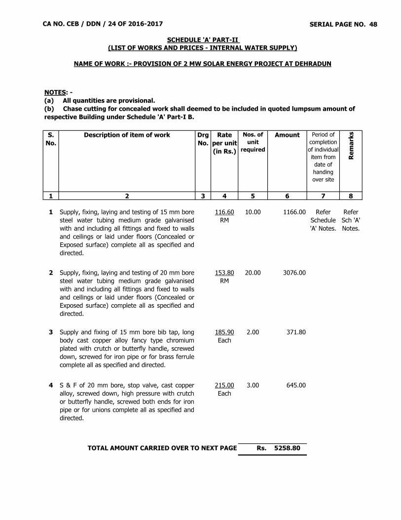
CA NO. CEB / DDN / 24 OF 2016-2017 SERIAL PAGE NO. 48
S. No.
Description of item of work Drg No.
Rate per unit(in Rs.)
Nos. of unit
required
Amount Period of completion of individual item from date of handing over site
Remar
ks
1 2 3 4 5 6 7 8
1 Supply, fixing, laying and testing of 15 mm boresteel water tubing medium grade galvanisedwith and including all fittings and fixed to wallsand ceilings or laid under floors (Concealed orExposed surface) complete all as specified anddirected.
116.60RM
10.00 1166.00 Refer Schedule 'A' Notes.
Refer Sch 'A' Notes.
2 Supply, fixing, laying and testing of 20 mm boresteel water tubing medium grade galvanisedwith and including all fittings and fixed to wallsand ceilings or laid under floors (Concealed orExposed surface) complete all as specified anddirected.
153.80RM
20.00 3076.00
3 Supply and fixing of 15 mm bore bib tap, longbody cast copper alloy fancy type chromiumplated with crutch or butterfly handle, screweddown, screwed for iron pipe or for brass ferrulecomplete all as specified and directed.
185.90Each
2.00 371.80
4 S & F of 20 mm bore, stop valve, cast copperalloy, screwed down, high pressure with crutchor butterfly handle, screwed both ends for ironpipe or for unions complete all as specified anddirected.
215.00Each
3.00 645.00
Rs. 5258.80
NOTES: - (a) All quantities are provisional.(b) Chase cutting for concealed work shall deemed to be included in quoted lumpsum amount of respective Building under Schedule 'A' Part-I B.
SCHEDULE 'A' PART-II (LIST OF WORKS AND PRICES - INTERNAL WATER SUPPLY)
NAME OF WORK :- PROVISION OF 2 MW SOLAR ENERGY PROJECT AT DEHRADUN
TOTAL AMOUNT CARRIED OVER TO NEXT PAGE
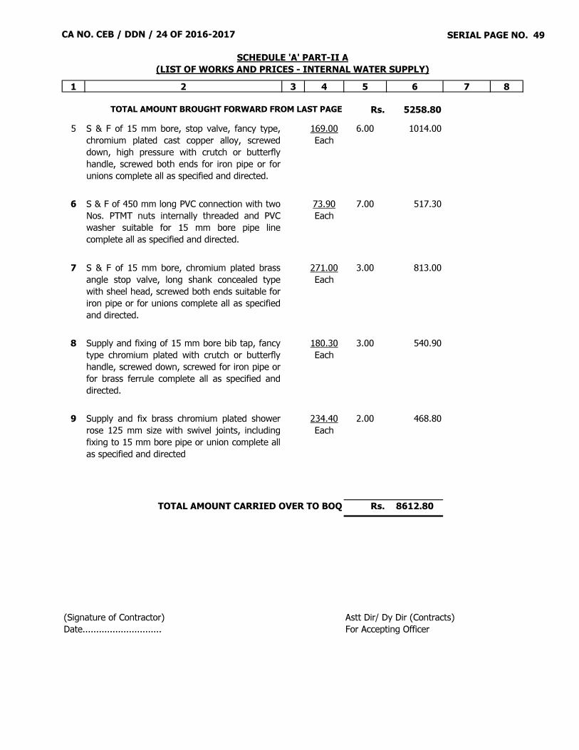
CA NO. CEB / DDN / 24 OF 2016-2017 SERIAL PAGE NO. 49
1 2 3 4 5 6 7 8
Rs. 5258.805 S & F of 15 mm bore, stop valve, fancy type,
chromium plated cast copper alloy, screweddown, high pressure with crutch or butterflyhandle, screwed both ends for iron pipe or forunions complete all as specified and directed.
169.00Each
6.00 1014.00
6 S & F of 450 mm long PVC connection with twoNos. PTMT nuts internally threaded and PVCwasher suitable for 15 mm bore pipe linecomplete all as specified and directed.
73.90Each
7.00 517.30
7 S & F of 15 mm bore, chromium plated brassangle stop valve, long shank concealed typewith sheel head, screwed both ends suitable foriron pipe or for unions complete all as specifiedand directed.
271.00Each
3.00 813.00
8 Supply and fixing of 15 mm bore bib tap, fancytype chromium plated with crutch or butterflyhandle, screwed down, screwed for iron pipe orfor brass ferrule complete all as specified anddirected.
180.30Each
3.00 540.90
9 Supply and fix brass chromium plated showerrose 125 mm size with swivel joints, includingfixing to 15 mm bore pipe or union complete allas specified and directed
234.40Each
2.00 468.80
Rs. 8612.80
(Signature of Contractor)Date.............................
TOTAL AMOUNT CARRIED OVER TO BOQ
Astt Dir/ Dy Dir (Contracts)For Accepting Officer
TOTAL AMOUNT BROUGHT FORWARD FROM LAST PAGE
SCHEDULE 'A' PART-II A(LIST OF WORKS AND PRICES - INTERNAL WATER SUPPLY)
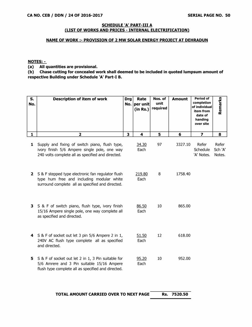
CA NO. CEB / DDN / 24 OF 2016-2017 SERIAL PAGE NO. 50
S. No.
Description of item of work Drg No.
Rate per unit(in Rs.)
Nos. of unit
required
Amount Period of completion
of individual item from
date of handing over site
Remar
ks
1 2 3 4 5 6 7 8
1 Supply and fixing of switch piano, flush type,ivory finish 5/6 Ampere single pole, one way240 volts complete all as specified and directed.
34.30Each
97 3327.10 Refer Schedule 'A' Notes.
Refer Sch 'A' Notes.
2 S & F stepped type electronic fan regulator flushtype hum free and including modular whitesurround complete all as specified and directed.
219.80Each
8 1758.40
3 S & F of switch piano, flush type, ivory finish15/16 Ampere single pole, one way complete allas specified and directed.
86.50Each
10 865.00
4 S & F of socket out let 3 pin 5/6 Ampere 2 in 1,240V AC flush type complete all as specifiedand directed.
51.50Each
12 618.00
5 S & F of socket out let 2 in 1, 3 Pin suitable for5/6 Amrere and 3 Pin suitable 15/16 Ampereflush type complete all as specified and directed.
95.20Each
10 952.00
Rs. 7520.50
NOTES: - (a) All quantities are provisional.(b) Chase cutting for concealed work shall deemed to be included in quoted lumpsum amount of respective Building under Schedule 'A' Part-I B.
SCHEDULE 'A' PART-III A(LIST OF WORKS AND PRICES - INTERNAL ELECTRIFICATION)
NAME OF WORK :- PROVISION OF 2 MW SOLAR ENERGY PROJECT AT DEHRADUN
TOTAL AMOUNT CARRIED OVER TO NEXT PAGE

CA NO. CEB / DDN / 24 OF 2016-2017 SERIAL PAGE NO. 51
1 2 3 4 5 6 7 8
Rs. 7520.506 S & F of lamp holder (angular/straight),
insulated body, with back plate for batten fittingincluding all necessary accessories complete allas specified and directed.
40.00Each
4 160.00
7 S & F of ceiling rose, surface bakelite 65 X 50mm, 3 terminals comple all as specified anddirected.
22.80Each
81 1846.80
= Rs. 9527.30
Astt Dir/ Dy Dir (Contracts)For Accepting Officer
TOTAL AMOUNT BROUGHT FORWARD FROM LAST PAGE
(Signature of Contractor)Date.............................
TOTAL AMOUNT CARRIED OVER TO BOQ
SCHEDULE 'A' PART-III A(LIST OF WORKS AND PRICES - INTERNAL ELECTRIFICATION)
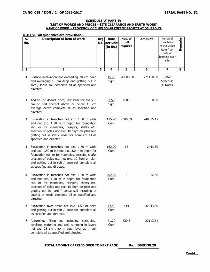
CA NO. CEB / DDN / 24 OF 2016-2017 SERIAL PAGE NO. 52
S. No.
Description of item of work Drg No.
Rate per unit(in Rs.)
Nos. of unit
required
Amount Period of completion of individual item from date of
handing over site
Remar
ks
1 2 3 4 5 6 7 8
1 Surface excavation not exceeding 30 cm deepand averaging 15 cm deep and getting out insoft / loose soil complete all as specified anddirected.
15.90Sqm
48500.00 771150.00 Refer Schedule 'A' Notes.
2 Add to (or deduct from) last item for every 3cm or part thereof above or below 15 cmaverage depth complete all as specified anddirected.
2.50Sqm
0.00 0.00
3 Excavation in trenches not exc. 1.50 m wideand not exc. 1.50 m in depth for foundationetc. or for manholes, cesspits, shafts etc.erection of poles not exc. 10 Sqm on plan andgetting out in soft / loose soil complete all asspecified and directed.
115.20Cum
2086.59 240375.17
4 Excavation in trenches not exc. 1.50 m wideand exc. 1.50 m but not exc. 3.0 m in depth forfoundation etc. or for manholes, cesspits, shaftserection of poles etc. not exc. 10 Sqm on planand getting out in soft / loose soil complete allas specified and directed.
162.90Cum
15 2443.50
5 Excavation in trenches not exc. 1.50 m wideand not exc. 1.50 m in depth for foundationetc. or for manholes, cesspits, shafts etc.erection of poles not exc. 10 Sqm on plan andgetting out in hard / dense soil including ofcutting of roads complete all as specified anddirected.
202.50Cum
5 1012.50
6 Excavation over areas not exc. 1.50 m deepand getting out in soft / loose soil complete allas specified and directed.
77.40Cum
414 32043.60
7 Returning, filling in, including spreading,levelling, watering and well ramming in layersnot exc. 25 cm thick in each layer as in soilcomplete all as specified and directed.
41.70Cum
530.3 22113.51
Rs. 1069138.28
SCHEDULE 'A' PART-IV(LIST OF WORKS AND PRICES - SITE CLEARANCE AND EARTH WORK)
NAME OF WORK :- PROVISION OF 2 MW SOLAR ENERGY PROJECT AT DEHRADUN NOTES: - All quantities are provisional.
TOTAL AMOUNT CARRIED OVER TO NEXT PAGE
Contd...
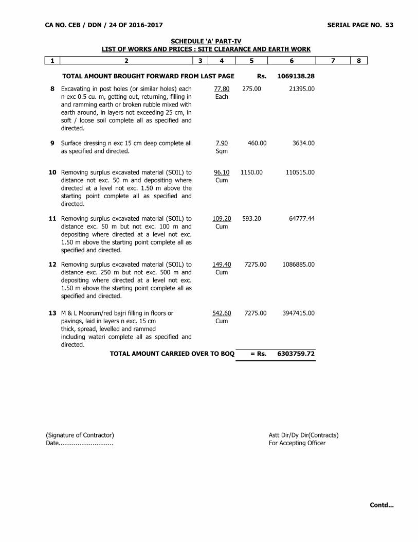
CA NO. CEB / DDN / 24 OF 2016-2017 SERIAL PAGE NO. 53
1 2 3 4 5 6 7 8
Rs. 1069138.288 Excavating in post holes (or similar holes) each
n exc 0.5 cu. m, getting out, returning, filling inand ramming earth or broken rubble mixed withearth around, in layers not exceeding 25 cm, insoft / loose soil complete all as specified anddirected.
77.80Each
275.00 21395.00
9 Surface dressing n exc 15 cm deep complete allas specified and directed.
7.90Sqm
460.00 3634.00
10 Removing surplus excavated material (SOIL) todistance not exc. 50 m and depositing wheredirected at a level not exc. 1.50 m above thestarting point complete all as specified anddirected.
96.10Cum
1150.00 110515.00
11 Removing surplus excavated material (SOIL) todistance exc. 50 m but not exc. 100 m anddepositing where directed at a level not exc.1.50 m above the starting point complete all asspecified and directed.
109.20Cum
593.20 64777.44
12 Removing surplus excavated material (SOIL) todistance exc. 250 m but not exc. 500 m anddepositing where directed at a level not exc.1.50 m above the starting point complete all asspecified and directed.
149.40Cum
7275.00 1086885.00
13 M & L Moorum/red bajri filling in floors orpavings, laid in layers n exc. 15 cmthick, spread, levelled and rammedincluding wateri complete all as specified anddirected.
542.60Cum
7275.00 3947415.00
= Rs. 6303759.72
Astt Dir/Dy Dir(Contracts)For Accepting Officer
TOTAL AMOUNT BROUGHT FORWARD FROM LAST PAGE
(Signature of Contractor)Date.............................
TOTAL AMOUNT CARRIED OVER TO BOQ
SCHEDULE 'A' PART-IVLIST OF WORKS AND PRICES : SITE CLEARANCE AND EARTH WORK
Contd...
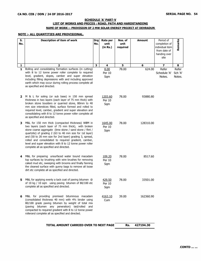
CA NO. CEB / DDN / 24 OF 2016-2017 SERIAL PAGE NO. 54
S. No.
Description of item of work Drg No.
Rate per unit
(in Rs.)
Nos. of unit
required
Amount Period of completion of individual item from date of handing over
site
Remar
ks
1 2 3 4 5 6 7 81 Rolling and consolidating formation surfaces (in cutting)
with 8 to 12 tonne power roller complete to requiredlevel, gradient, slopes, camber and super elevationincluding filling depressions with and including approvedearth which may occur during rolling process complete allas specified and directed.
8.00Per 10 Sqm
78.00 624.00 Refer Schedule 'A'
Notes.
Refer Sch 'A' Notes.
2 M & L for soling (or sub base) in 150 mm spreadthickness in two layers (each layer of 75 mm thick) withbroken stone boulders or quarried stone, 80mm to 40mm size interstices filled, surface formed and rolled torequired level, camber, gradient and super elevation andconsolidating with 8 to 12 tonne power roller complete allas specified and directed.
1203.60Per 10 Sqm
78.00 93880.80
3 M&L for 150 mm thick (compacted thickness) WBM intwo layers (each layer of 75 mm thick), with brokenstone coarse aggregate (lime stone / sand stone / flint /quartzite) of grading 2 (63 to 40 mm size for 1st layer)and (50 to 20 mm size for 2nd layer) grading 3, spread,rolled and consolidated to required gradient, camber,level and super elevation with 8 to 12 tonne power rollercomplete all as specified and directed.
1645.00Per 10 Sqm
78.00 128310.00
4 M&L for preparing unsurfaced water bound macadamtop surfaces by brushing with wire brushes for removingcaked mud etc, sweeping with brooms and finally fanningthe cleaned surface with gunny bags to remove all loosedirt etc complete all as specified and directed.
109.20Per 10 Sqm
78.00 8517.60
5 M&L for applying evenly a tack coat of paving bitumen @of 10 kg / 10 sqm using paving bitumen of 80/100 etccomplete all as specified and directed.
429.50Per 10 Sqm
78.00 33501.00
6 M&L for providing premixed bituminous macadam(consolidated thickness 40 mm) with 4% binder using80/100 grade paving bitumen by weight of total mix(paving bitumen any peneration) laid/rolled andcompacted to required gradient with 8 to 12 tonne powerrollerand complete all as specified and directed.
4163.10Cum
39.00 162360.90
Rs. 427194.30TOTAL AMOUNT CARRIED OVER TO NEXT PAGE
NAME OF WORK :- PROVISION OF 2 MW SOLAR ENERGY PROJECT AT DEHRADUN
SCHEDULE 'A' PART-VLIST OF WORKS AND PRICES : ROAD, PATH AND HARDSTANDING
NOTE :- ALL QUANTITIES ARE PROVISIONAL.
.CONTD ... ...

CA NO. CEB / DDN / 24 OF 2016-2017 SERIAL PAGE NO. 55
1 2 3 4 5 6 7 8
Rs. 427194.307 M&L for providing bituminous premix semi dense
asphaltic concrete (SDAC), 40 mm consolidated thicknesswith 5.5% binder (using paving bitumen any penetration)content by weight of total mix, rolled and compacted torequired camber and gradient with 8 to 12 tonne powerroller complete all as specified and directed.
2361.40Per 10 Sqm
78.00 184189.20
8 M & L Painting lines, dashes, arrows, letters, etc. onroads, pavements and the like exc 10cm wide with roadmarking paint, white or golden yellow complete all asspecified and directed.
37.10Sqm
52.00 1929.20
9 M & L Hardcore of gauge n exc. 63 mm, broken stone orboulders, deposited, spread and levelled in layers n exc.15cm thick, watered and rammed to a truesurfacecomplete all as specified and directed.
895.10Cum
90.00 80559.00
10 M & L for providing plain cement concrete, type D-2,1:4:8 (using 40 mm graded stone aggregate) as infoundation, filling and mass concrete complete all asspecified and directed.
2303.30Cum
60.00 138198.00
11 M & L Machine pressed precast concrete interlockingpaver block any shape and size confirming to IS 15658-2006 of 80 mm thickness M-40 Grade with grey cementand pigment set and bedded with sides are sealed withPCC 1:2:4 type B1 (using 20 mm graded stoneaggregate) complete all as specified and directed.
578.10Sqm
600.00 346860.00
12 Deduct to ser item No 06 and 08 here-in-before for eachextra kg of binder reduced
46.90Kg
0.00 0.00
NOTE: - All excavation and earthworkinvolved in this schedule shall be measuredand paid separately under Schedule 'A' Part-IV (Site clearance & earth work) exceptotherwise mentioned in the description of anyitem.
= Rs. 1178929.70TOTAL AMOUNT CARRIED OVER TO BOQ
(Signature of Contractor)Date.............................
TOTAL AMOUNT BROUGHT FORWARD FROM LAST PAGE
Astt Dir/Dy Dir (Contracts)For Accepting Officer
SCHEDULE 'A' PART-VLIST OF WORKS AND PRICES : ROAD, PATH AND HARDSTANDING
.CONTD ... ...

CA NO. CEB / DDN / 24 OF 2016-2017 SERIAL PAGE NO. 56
S. No.
Description of items of works Drg. No.
Rate per unit(Rs.)
Nos of unit reqd
Amount(Rs.)
Period of completion of individual items from date of handing over site
Remar
ks
1 2 3 4 5 6 7 8
1 M & L for providing plain cement concrete, type D-2, 1:4:8 (using 40 mm graded stone aggregate) as in foundation, filling and mass concrete complete all as specified and directed.
2303.30Cum
1.50 3454.95 Refer Schedule 'A'
Notes.
Refer Sch 'A' Notes.
2 M & L for brick work with fly ash old size bricks straightor curved on plan exc. 6.00 m mean radius built incement mortar 1:4 complete all as specified anddirected.
2421.20Cum
12.00 29054.40
3 M&L for PCC 1:2:4 type B-1 (using 20 mm graded stoneaggregate) as in coping and the like including weathering,slightly rounded or chamferred angles and throating, use offormwork straight or curved complete all as specified anddirected.
4144.40Cum
1.00 4144.40
4 M & L for 15 mm thick rendering in cement mortar 1: 4 withusing WPC @ 3 % by weight of cement on fair faces of brickswalls including finishing the surface even and smoothcomplete all as specified and directed. (NOTE: - WPC shall be measured and paid separately underrespective item as "Supply only".)
127.40 Sqm
105.00 13377.00
5 Supply only integral water proofing compound (Powder)complete all as specified.
35.30Kg
37.00 1306.10
6 M & L for cement concrete 1:4:8, type D-2 (using 40 mmgraded stone aggregate) as in bed to drain pipes of 150mm bore including packing under and haunching againstthe sides of pipe completely after they are laid andtested complete all as specified and directed.
177.20RM
50.00 8860.00
7 M&L for 150 mm internal dia, SGSW drain pipe grade 'A'in any length, jointed with cement mortar 1:1 laid intrenches and tested complete all as specified anddirected.
209.00RM
50.00 10450.00
Rs. 70646.85
SCHEDULE 'A' PART-VI ALIST OF WORKS AND PRICES : SEWAGE DISPOSAL
NAME OF WORK :- PROVISION OF 2 MW SOLAR ENERGY PROJECT AT DEHRADUN NOTE :- ALL QUANTITIES ARE PROVISIONAL
TOTAL AMOUNT CARRIED OVER TO NEXT PAGE
CONTD ... ...

CA NO. CEB / DDN / 24 OF 2016-2017 SERIAL PAGE NO. 57
1 2 3 4 5 6 7 8Rs. 70646.85
8 M & L for providing pre-cast reinforced cement concretelanding, manhole covers and similar items with plainfaces in cement concrete 1:2:4 type B-1, (using 20 mmgraded crushed stone aggregate) and setting in cementmortar 1:4 with and including necessary formworkcomplete all as specified and directed.
4817.60Cum
1.00 4817.60
9 M & L for mild steel TMT bars 10 mm dia and over, cutto length, bent to shape required including cranking,bending spirally for hooping for columns and bindingwith and including mild steel wire (annealed) not lessthan 0.9 mm dia or securing with clips complete all asspecified and directed.
48.60Kg
150.00 7290.00
NOTE: - All excavation and Earthwork involved inthis schedule shall be measured and paidseparately under schedule 'A' Part-IV.
= Rs. 82754.45
(Signature of Contractor)Date.............................
TOTAL AMOUNT CARRIED OVER TO BOQ
SCHEDULE 'A' PART-VI ALIST OF WORKS AND PRICES : SEWAGE DISPOSAL
TOTAL AMOUNT BROUGHT FORWARD FROM LAST PAGE
Astt Dir/Dy Dir (Contracts)For Accepting Officer
CONTD ... ...

CA NO. CEB / DDN / 24 OF 2016-2017 SERIAL PAGE NO. 58
S. No.
Description of items of works Drg. No.
Rate per unit(Rs.)
Nos of unit reqd
Amount(Rs.)
Period of completion of individual items from
date of handing over site
Remar
ks
1 2 3 4 5 6 7 8
1 M & L for providing plain cement concrete, type D-2, 1:4:8 (using 40 mm graded stone aggregate) as in foundation, filling and mass concrete complete all as specified and directed.
2303.30Cum
228.40 526073.72 Refer Schedule 'A' Notes.
Refer Sch 'A'
Notes.
2 M & L for brick work with fly ash old size bricksstraight or curved on plan exc. 6.00 m mean radiusbuilt in cement mortar 1:6 complete all as specifiedand directed.
2249.50Cum
283.50 637733.25
3 M & L for PCC 1:2:4 type B-1, 50mm thick (using 20mm graded stone aggregate) as in coping and the likeincluding weathering, slightly rounded or chamferredangles and throating, use of formwork straight or curvedcomplete all as specified and directed.
4144.40Cum
25.80 106925.52
4 M & L for 15 mm thick rendering in cement mortar1:6 on fair faces of bricks walls or concrete surfacesincluding finishing the surface even and smoothwithout using extra cement complete all asspecified and directed.
110.20 Sqm
1750.00 192850.00
5 M & L for providing plain cement concrete, type C-2, 1:3:6 (using 40 mm graded stone aggregate) as in surface channel and drainage complete all as specified and directed.
2648.80Cum
33.60 88999.68
6 M & L for providing Extra for forming fair finisheddrain or channel exc 45 cm and upto 60 cm innergirth in cement concrete, using ex- tra cement,including forms, moulds, mitred/stopped ends etc.complete all as specified and directed.
16.80RM
1120.00 18816.00
7 Add or deduct for each 25 mm girth or partthereof over or under 30cm ditto all as per ser itemNo 6 here-in-before.
1.90RM
8 M & L for providing pre-cast reinforced cementconcrete landing, manhole covers and similar itemswith plain faces in cement concrete 1:2:4 type B-1,(using 20 mm graded crushed stone aggregate) andsetting in cement mortar 1:4 with and includingnecessary formwork complete all as specified anddirected.
4817.60Cum
89.00 428766.40
Rs. 2000164.57
SCHEDULE 'A' PART-VIILIST OF WORKS AND PRICES : AREA DRAINAGE
NAME OF WORK :- PROVISION OF 2 MW SOLAR ENERGY PROJECT AT DEHRADUN NOTE :- ALL QUANTITIES ARE PROVISIONAL
TOTAL AMOUNT CARRIED OVER TO NEXT PAGE
CONTD ... ...

CA NO. CEB / DDN / 24 OF 2016-2017 SERIAL PAGE NO. 59
1 2 3 4 5 6 7 8Rs. 2000164.57
9 M & L for mild steel TMT bars 10 mm dia and over,cut to length, bent to shape required includingcranking, bending spirally for hooping for columnsand binding with and including mild steel wire(annealed) not less than 0.9 mm dia or securing withclips complete all as specified and directed.
48.60Kg
3940.00 191484.00
10 M & L for mild steel TMT bars 6 to 8 mm dia, cut tolength, bent to shape required including cranking,bending spirally for hooping for columns and bindingwith and including mild steel wire (annealed) not lessthan 0.9 mm dia or securing with clips complete all asspecified and directed.
49.10Kg
4920.00 241572.00
NOTE: - All excavation and Earthworkinvolved in this schedule shall be measuredand paid separately under schedule 'A' Part-IV.
= Rs. 2433220.57TOTAL AMOUNT CARRIED OVER TO BOQ
(Signature of Contractor)Date.............................
SCHEDULE 'A' PART-VIILIST OF WORKS AND PRICES : AREA DRAINAGE
TOTAL AMOUNT BROUGHT FORWARD FROM LAST PAGE
Astt Dir/Dy Dir (Contracts)For Accepting Officer
CONTD ... ...
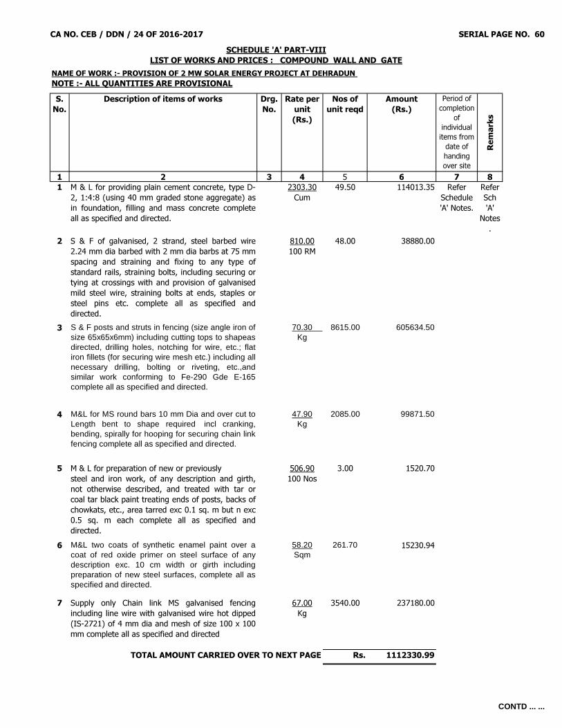
CA NO. CEB / DDN / 24 OF 2016-2017 SERIAL PAGE NO. 60
S. No.
Description of items of works Drg. No.
Rate per unit(Rs.)
Nos of unit reqd
Amount(Rs.)
Period of completion
of individual items from
date of handing over site
Remar
ks
1 2 3 4 5 6 7 81 M & L for providing plain cement concrete, type D-
2, 1:4:8 (using 40 mm graded stone aggregate) asin foundation, filling and mass concrete completeall as specified and directed.
2303.30Cum
49.50 114013.35 Refer Schedule 'A' Notes.
Refer Sch 'A'
Notes.
2 S & F of galvanised, 2 strand, steel barbed wire2.24 mm dia barbed with 2 mm dia barbs at 75 mmspacing and straining and fixing to any type ofstandard rails, straining bolts, including securing ortying at crossings with and provision of galvanisedmild steel wire, straining bolts at ends, staples orsteel pins etc. complete all as specified anddirected.
810.00100 RM
48.00 38880.00
3 S & F posts and struts in fencing (size angle iron ofsize 65x65x6mm) including cutting tops to shapeasdirected, drilling holes, notching for wire, etc.; flatiron fillets (for securing wire mesh etc.) including allnecessary drilling, bolting or riveting, etc.,andsimilar work conforming to Fe-290 Gde E-165complete all as specified and directed.
70.30 Kg
8615.00 605634.50
4 M&L for MS round bars 10 mm Dia and over cut toLength bent to shape required incl cranking,bending, spirally for hooping for securing chain linkfencing complete all as specified and directed.
47.90Kg
2085.00 99871.50
5 M & L for preparation of new or previously steel and iron work, of any description and girth,not otherwise described, and treated with tar orcoal tar black paint treating ends of posts, backs ofchowkats, etc., area tarred exc 0.1 sq. m but n exc0.5 sq. m each complete all as specified anddirected.
506.90100 Nos
3.00 1520.70
6 M&L two coats of synthetic enamel paint over acoat of red oxide primer on steel surface of anydescription exc. 10 cm width or girth includingpreparation of new steel surfaces, complete all asspecified and directed.
58.20Sqm
261.70 15230.94
7 Supply only Chain link MS galvanised fencingincluding line wire with galvanised wire hot dipped(IS-2721) of 4 mm dia and mesh of size 100 x 100mm complete all as specified and directed
67.00Kg
3540.00 237180.00
Rs. 1112330.99TOTAL AMOUNT CARRIED OVER TO NEXT PAGE
SCHEDULE 'A' PART-VIIILIST OF WORKS AND PRICES : COMPOUND WALL AND GATE
NAME OF WORK :- PROVISION OF 2 MW SOLAR ENERGY PROJECT AT DEHRADUN NOTE :- ALL QUANTITIES ARE PROVISIONAL
CONTD ... ...

CA NO. CEB / DDN / 24 OF 2016-2017 SERIAL PAGE NO. 61
1 2 3 4 5 6 7 8
Rs. 1112330.998 Fixing only chain link fencing including line wires,
any mesh, size and type to any type of standards,rails, straining bolts, etc. including provision ofbinding wire complete all as specified and directed.
4.20Sqm
1608.00 6753.60
9 S & F Mild steel nuts and bolts not less than 12 mmdia machine made with hexagonal or square headone end and screwed the other, or screwed bothends; each screwed end to be fitted with washersand one hexagonal or square nut not exceeding 6cm long @ 450 mm centre to centre complete all asspecified and directed.
91.80Kg
200.00 18360.00
10 M & L for providing plain cement concrete, type C-2, 1:3:6 (using 40 mm graded stone aggregate) asin foundation, filling and mass concrete completeall as specified and directed.
2579.00Cum
42.00 108318.00
11 M & L for brick work with fly ash old size bricksstraight or curved on plan exc. 6.00 m mean radiusbuilt in cement mortar 1:6 complete all as specifiedand directed.
2249.50Cum
295.00 663602.50
12 M&L for RCC Design mix M-25 (20 mm graded stone aggregate) in fdn, footing, plinth beam and mass concrete complete all as specified and directed.
3482.20Cum
18.63 64873.39
13 M & L for mild steel TMT bars 10 mm dia and over,cut to length, bent to shape required includingcranking, bending spirally for hooping for columnsand binding with and including mild steel wire(annealed) not less than 0.9 mm dia or securingwith clips complete all as specified and directed.
48.60Kg
1380.00 67068.00
14 M&L for MS round bars 5mm dia and over upto andincluding 10 mm dia bars as in stirrups , spacers ,binders,including cut to Length bent to shaperequired incl cranking, bending, spirally for hoopingfor collumns with an incl MS wire(annealed) notless than .90 mm dia or securing with clipscomplete all as specified and directed.
49.10 Kg
466.24 22892.38
Rs. 2064198.86
SCHEDULE 'A' PART-VIII (CONTD……)LIST OF WORKS AND PRICES : COMPOUND WALL AND GATE
TOTAL AMOUNT BROUGHT FORWARD FROM LAST PAGE
TOTAL AMOUNT CARRIED OVER TO NEXT PAGE
CONTD ... ...

CA NO. CEB / DDN / 24 OF 2016-2017 SERIAL PAGE NO. 62
1 2 3 4 5 6 7 8
Rs. 2064198.8615 Formwork to edges of concrete flats, treads, breaks
in floors, window cills, concrete railings,openings in concrete walls, floor and roofs n exc 20cm wide and sides of RCC/ PCC bands in walls,horizontal or sloping and similar work exc 10cm butn exc 20cm wide Rough finished surfaces ofconcrete complete all as specified and directed.
40.80RM
720.00 29376.00
16 M&L for PCC 1:2:4 type B-1 (using 20 mm gradedstone aggregate) as in coping and the like includingweathering, slightly rounded or chamferred anglesand throating, use of formwork straight or curvedcomplete all as specified and directed.
4144.40Cum
6.10 25280.84
17 M & L for 15 mm thick rendering on fair faces of brick work or concrete surfaces with cement mortar 1:6 finished even and smooth without using extra cement complete all as specified and directed.
114.10 Sqm
1872.00 213595.20
18 M & L for preparation of newly plastered or un-plastered surfaces of walls and applying two coatsof cement base paint over one coat of alkaliresistant primer complete all as specified anddirected.
48.10Sqm
1872.00 90043.20
19 M & L for providing reinforced cement concrete,type B-1, 1:2:4 (using 20 mm graded stoneaggregate) as in foundation, including rafts,footings, foundation beams;plinth beams; bases for columns, etc.; basementslabs, under-reamed piles and massconcrete complete all as specified and directed.
3101.50Cum
0.40 1240.60
20 M & L for providing reinforced cement concrete,type B-1, 1:2:4 (using 20 mm graded stoneaggregate) as in Columns, pillars, piers, posts andstruts complete all as specified and directed.
3793.00Cum
1.00 3793.00
21 Formwork to sides of concrete foundations,footings, bases of columns, raft and raft beams,sides and soffits (if any) offoundation and plinth beams; and similar work;vertical or to batter Rough finished surfaces ofconcrete complete all as specified and directed.
134.20Sqm
2.50 335.50
Rs. 2427863.20TOTAL AMOUNT CARRIED OVER TO NEXT PAGE
SCHEDULE 'A' PART-VIII (CONTD……)LIST OF WORKS AND PRICES : COMPOUND WALL AND GATE
TOTAL AMOUNT BROUGHT FORWARD FROM LAST PAGE
CONTD ... ...

CA NO. CEB / DDN / 24 OF 2016-2017 SERIAL PAGE NO. 63
1 2 3 4 5 6 7 8
Rs. 2427863.2022 Formwork to sides of pillars, posts, struts, piers,
columns and stanchions Rough finished surfacesflat of concrete complete all as specified anddirected.
241.10Sqm
26.00 6268.60
23 S & F Framed mild steel work as in doors or gatesof ornamental type conforming to Fe-290 gde E-165 with gusset plates, rails, braces, etc., complete,drilled for fixing of steel sheeting or other covering.Doors, etc. to be prepared for hanging or slidingwith and including either hooks, pintle and hinges,hand made sliding bolts etc or steel hanging doorfittings and hanging; also fastening and fixingcomplete all as specified and directed.
58.00Kg
1000.00 58000.00
24 M & L 20mm thick Granite (of any type) tilesmachine cut, in skirting/ dado laid over cementscreed in CM 1:4, 10 mm thick and jointed withgrey cement slurry, and pointed with white cementwith admixture of pigment to match the shade ofgranite stone including grinding and polishingcomplete all as specified and directed
2227.00Sqm
26.00 57902.00
NOTE: - All excavation and Earthworkinvolved in this schedule shall be measuredand paid separately under schedule 'A' Part-IV.
= Rs. 2550033.80
Astt Dir/Dy Dir (Contracts)For Accepting Officer
TOTAL AMOUNT CARRIED OVER TO BOQ
(Signature of Contractor)Date.............................
SCHEDULE 'A' PART-VIII (CONTD……)LIST OF WORKS AND PRICES : COMPOUND WALL AND GATE
TOTAL AMOUNT BROUGHT FORWARD FROM LAST PAGE
CONTD ... ...
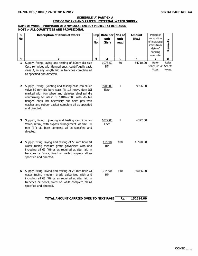
CA NO. CEB / DDN / 24 OF 2016-2017 SERIAL PAGE NO. 64
S. No.
Description of items of works Drg.
No.
Rate per unit(Rs.)
Nos of unit reqd
Amount(Rs.)
Period of completion of individual items from
date of handing over site
Remar
ks
1 2 3 4 5 6 7 81 Supply, fixing, laying and testing of 80mm dia size
Cast iron pipes with flanged ends, centrifugally cast,class A, in any length laid in trenches complete allas specified and directed.
1078.50RM
60 64710.00 Refer Schedule 'A'
Notes.
Refer Sch 'A' Notes.
2 Supply , fixing , jointing and testing cast iron sluicevalve 80 mm dia bore class PN-1.6 heavy duty ISImarked with iron wheel and stainless steel spindleconforming to latest IS 14846-2000 with doubleflanged ends incl necessary out bolts gas withwasher and rubber gasket complete all as specifiedand directed.
9906.00Each
1 9906.00
3 Supply , fixing , jointing and testing cast iron forValve, reflux, with bypass arrangement of size 80mm (3”) dia bore complete all as specified anddirected.
6322.00Each
1 6322.00
4 Supply, fixing, laying and testing of 50 mm bore GIwater tubing medium grade galvanised with andincluding all GI fittings as required at site, laid intrenches or floors, fixed on walls complete all asspecified and directed.
415.90RM
100 41590.00
5 Supply, fixing, laying and testing of 25 mm bore GIwater tubing medium grade galvanised with andincluding all GI fittings as required at site, laid intrenches or floors, fixed on walls complete all asspecified and directed.
214.90RM
140 30086.00
Rs. 152614.00
SCHEDULE 'A' PART-IX ALIST OF WORKS AND PRICES : EXTERNAL WATER SUPPLY
NAME OF WORK :- PROVISION OF 2 MW SOLAR ENERGY PROJECT AT DEHRADUN NOTE :- ALL QUANTITIES ARE PROVISIONAL
TOTAL AMOUNT CARRIED OVER TO NEXT PAGE
CONTD ... ...

CA NO. CEB / DDN / 24 OF 2016-2017 SERIAL PAGE NO. 65
1 2 3 4 5 6 7 8Rs. 152614.00
6 S & F of 50 mm bore gunmetal globe or gate valve,with iron wheel head, screwed both ends for ironpipe complete all as specified and directed.
893.10Each
3 2679.30
7 S & F of 25 mm bore gunmetal globe or gate valve,with iron wheel head, screwed both ends for ironpipe complete all as specified and directed.
413.80Each
4 1655.20
NOTE: - All excavation and Earthworkinvolved in this schedule shall be measuredand paid separately under schedule 'A' Part-IV.
= Rs. 156948.50TOTAL AMOUNT CARRIED OVER TO BOQ
(Signature of Contractor)Date.............................
SCHEDULE 'A' PART-IX ALIST OF WORKS AND PRICES : EXTERNAL WATER SUPPLY
TOTAL AMOUNT BROUGHT FORWARD FROM LAST PAGE
Astt Dir/Dy Dir(Contracts)For Accepting Officer
CONTD ... ...

CA NO. CEB / DDN / 24 OF 2016-2017 SERIAL PAGE NO. 66
S. No.
Description of items of works Drg. No.
Rate per unit(Rs.)
Nos of unit reqd
Amount(Rs.)
Period of completion of individual items from
date of handing over site
Remar
ks
1 2 3 4 5 6 7 8
1 Supply and laying in trenches / ducts, passingthrough pipe / fixing on poles 1100 volts grade, 10Sqmm 4 core, electric power cable (heavy duty),XLPE PVC insulated and PVC sheathed galvanisedsteel strip or wire armoured with strandedaluminium conductor including commissioning andtesting complete all as specified and directed.
128.00RM
900 115200.00 Refer Schedule 'A' Notes.
2 Supply, transporting, errecting steel tubular swagedpole ISI marked, type 410- SP-31, 9.00 metre long,complete with mild steel base plate, pole cap, finialtaper plug, bolts, nuts, washers etc. includingpainting two coats of aluminium paint over a coatof red oxide primer including 3 Nos. of bands /strips painted with post office red and white colour(300 mm each) in alternate layer from plinth block,marking of pole number with black syntheticenamelled paint 2.5 cm height including one coatblack bitumenous paint on steel surface embeddedin concrete foundation complete all as specified anddirected.
7891.70Each
30 236751.00
3 Supply, transporting, errecting steel tubular swagedpole ISI marked, type 410- SP-55, 11.00 metrelong, complete with cast iron base plate, pole cap,finial taper plug, bolts, nuts, washers etc. includingpainting two coats of aluminium paint over a coatof red oxide primer including 3 Nos. of bands /strips painted with post office red and white colour(300 mm each) in alternate layer from plinth block,marking of pole number with black syntheticenamelled paint 2.5 cm height and 30 cm fromplinth block including one coat black bituminouspaint on steel surface embedded in concretefoundation complete all as specified and directed.
11352.40Each
2 22704.80
Rs. 374655.80
SCHEDULE 'A' PART-X A LIST OF WORKS AND PRICES : EXTERNAL ELECTRIC SUPPLY
NAME OF WORK :- PROVISION OF 2 MW SOLAR ENERGY PROJECT AT DEHRADUNNOTE :- ALL QUANTITIES ARE PROVISIONAL
TOTAL AMOUNT CARRIED OVER TO NEXT PAGE
CONTD ... ...

CA NO. CEB / DDN / 24 OF 2016-2017 SERIAL PAGE NO. 67
1 2 3 4 5 6 7 8
Rs. 374655.804 M & L for laying fly ash brick as in protection covers
over cables using well burnt fly ash bricks completeall as specified and directed.
2.70Each
6750 18225.00
5 M & L for river sand, dry, washed, clean andscreened, fine sand free from sharp materials as infilling in trenches for cable protection includingnecessary punning and consolidation as requiredcomplete all as specified and directed.
646.30Cum
60.80 39295.04
6 M & L for providing plain cement concrete type C-2, 1:3:6, (using 40 mm graded stone aggregate),as in pole foundation, stays etc complete all asspecified and directed.
2579.00Cum
30 77370.00
7 M&L for PCC 1:2:4 type B-1 (using 20 mm gradedstone aggregate) as in coping and the like includingweathering, slightly rounded or chamferred anglesand throating, use of formwork straight or curvedcomplete all as specified and directed.
4144.40Cum
7 29010.80
8 Material and labour Earth continuity conductor ormain earthing lead fixed to wall on battenor recess or chases or buried in ground or drawn inconduit/pipe or fixed to poles or any other indicatedsituation for loop earthing etc. as required 32x6mm dia galvanised iron strip complete all asspecified and directed.
132.10RM
90 11889.00
9 Supply and fix 50 mm bore of High densitypolyethylene pipes (HDPE) of pressure rating 6kgf/cm2 laid in trenches under rood/footpath orfixed to pole with necessary clamps complete all asspecified and directed.
146.30RM
50 7315.00
10 Supply and fix 80 mm bore Unplasticised PVCpipes of pressure rating 10 kgf/cm2 laid in trenchesunder rood/footpath or fixed to pole with necessaryclamps complete all as specified and directed.
243.36RM
60 14601.60
Rs. 572362.24TOTAL AMOUNT CARRIED OVER TO NEXT PAGE
SCHEDULE 'A' PART-X A (CONTD……)LIST OF WORKS AND PRICES : EXTERNAL ELECTRIC SUPPLY
TOTAL AMOUNT BROUGHT FORWARD FROM LAST PAGE
CONTD ... ...
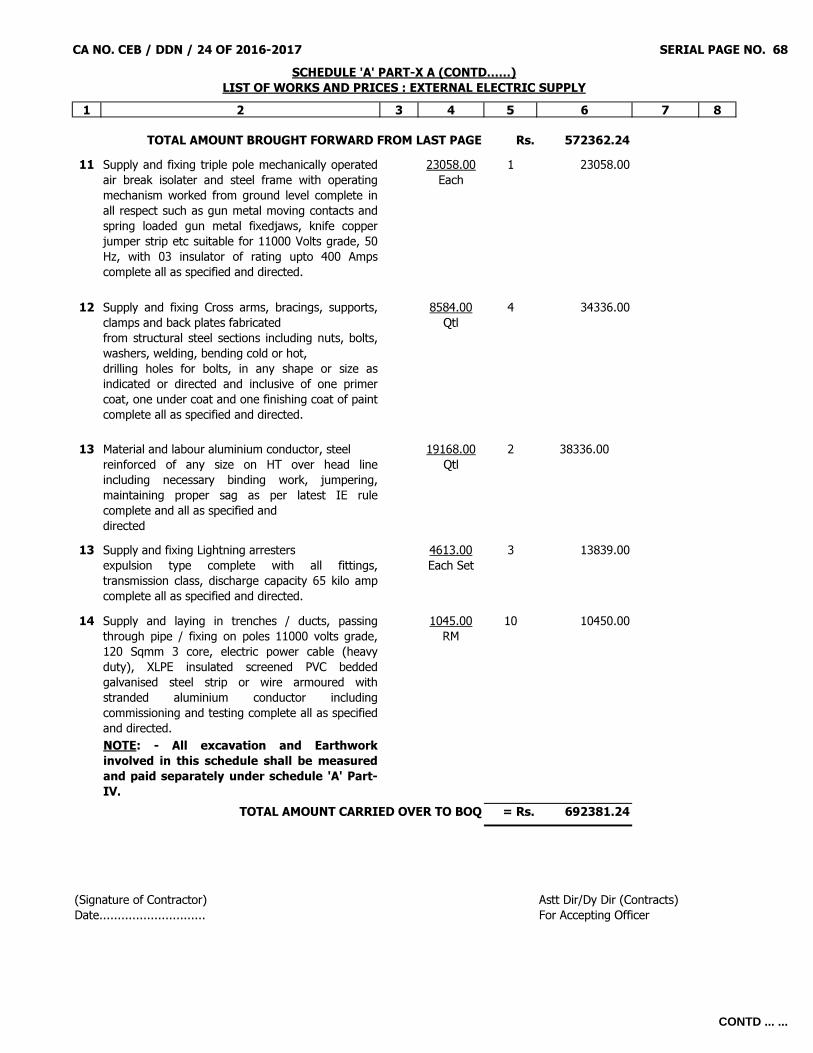
CA NO. CEB / DDN / 24 OF 2016-2017 SERIAL PAGE NO. 68
1 2 3 4 5 6 7 8
Rs. 572362.2411 Supply and fixing triple pole mechanically operated
air break isolater and steel frame with operatingmechanism worked from ground level complete inall respect such as gun metal moving contacts andspring loaded gun metal fixedjaws, knife copperjumper strip etc suitable for 11000 Volts grade, 50Hz, with 03 insulator of rating upto 400 Ampscomplete all as specified and directed.
23058.00Each
1 23058.00
12 Supply and fixing Cross arms, bracings, supports,clamps and back plates fabricatedfrom structural steel sections including nuts, bolts,washers, welding, bending cold or hot,drilling holes for bolts, in any shape or size asindicated or directed and inclusive of one primercoat, one under coat and one finishing coat of paintcomplete all as specified and directed.
8584.00Qtl
4 34336.00
13 Material and labour aluminium conductor, steelreinforced of any size on HT over head lineincluding necessary binding work, jumpering,maintaining proper sag as per latest IE rulecomplete and all as specified anddirected
19168.00Qtl
2 38336.00
13 Supply and fixing Lightning arrestersexpulsion type complete with all fittings,transmission class, discharge capacity 65 kilo ampcomplete all as specified and directed.
4613.00Each Set
3 13839.00
14 Supply and laying in trenches / ducts, passingthrough pipe / fixing on poles 11000 volts grade,120 Sqmm 3 core, electric power cable (heavyduty), XLPE insulated screened PVC beddedgalvanised steel strip or wire armoured withstranded aluminium conductor includingcommissioning and testing complete all as specifiedand directed.
1045.00RM
10 10450.00
NOTE: - All excavation and Earthworkinvolved in this schedule shall be measuredand paid separately under schedule 'A' Part-IV.
= Rs. 692381.24
SCHEDULE 'A' PART-X A (CONTD……)LIST OF WORKS AND PRICES : EXTERNAL ELECTRIC SUPPLY
TOTAL AMOUNT BROUGHT FORWARD FROM LAST PAGE
TOTAL AMOUNT CARRIED OVER TO BOQ
(Signature of Contractor)Date.............................
Astt Dir/Dy Dir (Contracts)For Accepting Officer
CONTD ... ...

CA NO. CEB / DDN / 24 OF 2016-2017 SERIAL PAGE NO. 69
SCHEDULE 'B' LIST OF MATERIAL TO BE ISSUED BY THE DEPARTMENT
(SEE CONDITION 10 OF IAFW – 2249) S. NO.
PARTICULARS RATE AT WHICH MATERIALS WILL BE ISSUED TO THE CONTRACTOR
PLACE OF ISSUE BY NAME
REMARKS
UNIT RATE 1 2 3 4 5 6
- NIL -
-------------------------------------------------------------------------------------------------------------------------------
SCHEDULE 'C' LIST OF TOOLS AND PLANTS (OTHER THAN TRANSPORT) WHICH WILL BE ISSUED
TO THE CONTRACTOR (SEE CONDITIONS 15, 34 & 35 OF IAFW-2249)
S. No.
Particulars Details of MES crew supplied
Hire charges per unit per working day
Rs.
Stand by charges per unit per Off days Rs.
Place of
issue Remarks
1 2 3 4 5 6 7 - NIL -
-------------------------------------------------------------------------------------------------------------------------------
SCHEDULE 'D'
TRANSPORT TO BE HIRED TO THE CONTRACTOR (SEE CONDITIONS 16 & 35 OF IAFW-2249)
S. No. Quantity Particulars Rate per unit
per working day Place of issue (by name)
Remarks 1 2 3 4 5 6
- NIL -
------------------------------------------------------------------------------------------------------------------------------- (Signature of Contractor) Astt Dir/Dy Dir (Contracts) Dated…………………………… For Accepting Officer

CA NO. CEB / DDN/ 24 OF 2016-2017 SERIAL PAGE NO. 70
T E N D E R To, The president of India, Having examined and perused the following documents: - 1. Specifications signed by Addl Astt Dir / Astt Dir / Dy Dir / Director (Contracts). 2. Drawings as detailed in the specifications or list of drawings. 3. Schedule ‘A’, ‘B’, ‘C’ and ‘D’ attached hereto. 4. MES Standard Schedule of rates Part-I (Specifications) 2009 Print and Part-II (Rates) 2010 Print (here-in-after and in IAFW – 2249 referred to as the ‘MES Schedule’) together with amendments Nos. 1 To 3 for SSR Part-I (2009) Print and amendments Nos. 1 To 59 for SSR Part-II (2010) Print. 5. General Conditions of Contracts IAFW – 2249 (1989 Print) together with errata No 1 To 20 and amendment No 1 To 40. 6. WATER: CONDITION 31 OF IAFW – 2249 (GENERAL CONDITIONS OF CONTRACTS): - Water will not be supplied by MES and contractor shall make his own arrangement for water supply required for construction of work and drinking water for his employees. 7. Should this tender to be accepted, I / we agree: - * (a) That the sum of Rs. ……………… (RUPEES ………………………………………………… ONLY) forwarded as earnest money shall either be retained as part of the security deposits or be refunded by the Government on receipt of the appropriate amount of security deposit all as per condition 22 of IAFW-2249. (b) To execute all the works referred to in the said documents upon the terms and conditions contained / referred to therein and at the item rates contained in the aforesaid Schedule ‘A’ (BOQ) or at such other rates as may be fixed under the provision of condition 62 of IAFW – 2249 and to carryout such deviations as may be ordered vide conditions 7 of IAFW-2249 up to maximum 10% (TEN PERCENT) and further agree to refer all disputes as required by condition 70 of IAFW-2249 to the Sole Arbitrator who shall be serving officer having degree in Engineering or equivalent or having passed final / direct final examinations of Sub-divisions – II of Institution of Surveyors (India) recognized by Govt. of India to be appointed by Engineer-in-Chief, Army Head Quarters, New Delhi-110011 or in his absence the officer officiating as Engineer-in-Chief, or Director General of works, if powers specifically delegated in writing by Engineer-in-Chief's, Army Head Quarters, New Delhi-110011, whose decision shall be final, conclusive and binding. * To be deleted where not applicable.
Contd…

CA NO. CEB / DDN/ 24 OF 2016-2017 SERIAL PAGE NO. 71
T E N D E R (CONTD....)
Brought forward Rs. ……………………………… For the lump sum of Rs. …………………………………………… (Rupees ……………………………………………………… ……………………………………………………………………………………………………………………………………………………) Signature …………………………………………………… in the capacity of……………………………………………………… Name of signatory………………………………………………………………………………………… (IN BLOCK LETTERS) duly authorised to sign the tender for and on behalf of M/S……………………………………………………………………………………………………………… (IN BLOCK LETTERS)
Postal Address………………………………………… Witness…………………………………………… ……………………………………………………………… M/S………………………………………………… ……………………………………………………………… Address…………………………………………… Telephone No ………………………………………… ……………………………………………………… Telegraphic Address ………………………………. Telephone No…………………………………
A C C E P T A N C E
1. ………… Alterations have been made to the documents and as evidence that these alterations were made before execution of the Contract Agreement; they have been initialed by the contractor and Shri Rajeshwar Prasad, Assistant Director (Contracts)/ Shri B D Pandey, Dy Dir (Contracts). The said officer is hereby authorised to sign and initial on my behalf the documents forming part of this contract.
2. The above tender was accepted by me on the ……………… day of ………………… 2018 on behalf of the President of India for the lump sum of Rs. …………………………………………………… (Rupees ………………………………………………………………………………………………………………………… ………………………………………………………………………………………………………………………………only).
Signed on…………………Day of…………………2018. Appointment: CHIEF ENGINEER BAREILLY ZONE, BAREILLY ACCEPTING OFFICER
(FOR AND ON BEHALF OF THE PRESIDENT OF INDIA)
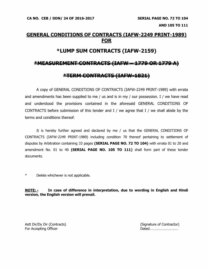
CA NO. CEB / DDN/ 24 OF 2016-2017 SERIAL PAGE NO. 72 TO 104
AND 105 TO 111
GENERAL CONDITIONS OF CONTRACTS (IAFW-2249 PRINT-1989) FOR
*LUMP SUM CONTRACTS (IAFW-2159)
*MEASUREMENT CONTRACTS (IAFW – 1779 OR 1779 A)
*TERM CONTRACTS (IAFW-1821)
A copy of GENERAL CONDITIONS OF CONTRACTS (IAFW-2249 PRINT-1989) with errata and amendments has been supplied to me / us and is in my / our possession. I / we have read and understood the provisions contained in the aforesaid GENERAL CONDITIONS OF CONTRACTS before submission of this tender and I / we agree that I / we shall abide by the terms and conditions thereof. It is hereby further agreed and declared by me / us that the GENERAL CONDITIONS OF CONTRACTS (IAFW-2249 PRINT-1989) including condition 70 thereof pertaining to settlement of disputes by Arbitration containing 33 pages (SERIAL PAGE NO. 72 TO 104) with errata 01 to 20 and amendment No. 01 to 40 (SERIAL PAGE NO. 105 TO 111) shall form part of these tender documents. * Delete whichever is not applicable. NOTE: - In case of difference in interpretation, due to wording in English and Hindi version, the English version will prevail. Astt Dir/Dy Dir (Contracts) (Signature of Contractor) For Accepting Officer Dated…………………………

CA NO. CEB / DDN/ 24 OF 2016-2017 SERIAL PAGE NO. 112
SCHEDULE OF MINIMUM WAGES It is hereby agreed that the “Schedule of Minimum Wages” as published vide Government of India / State Govt. / Govt. Local authorities, whichever is highest and which specifics minimum rates of wages for various categories of workmen as applicable on the last due date of receipt of this tender shall form part of these tender. My / Our signature here under amounts to my / our having signed the aforesaid documents forming part of these tender documents. Astt Dir/Dy Dir (Contracts) (Signature of Contractor) For Accepting Officer Dated…………………………

CA NO. CEB / DDN/ 24 OF 2016-2017 SERIAL PAGE NO. 113
SPECIAL CONDITIONS (Contd…)
CONTD … …
1. GENERAL The following Special Conditions shall be read in conjunction with the general Conditions of Contracts, IAFW-2249 and IAFW-1779-A including Errata / amendments thereto. If any provision in these Special Conditions is at variance with that of the aforesaid documents, the former shall be deemed to take precedence there over. The term General specification used in any of the documents forming part of the contract refers to the specification contained in the MES Schedule. 2. ADMISSION TO SITE BY CONTRACTOR AND RESPONSIBILITY TO ASCERTAIN HIS OWN INFORMATION. (a) The tenderers shall contact the GE for the purpose of inspection of site (s) and relevant documents other than those sent herewith, who will give reasonable facilities for this purpose. The tenderers shall also make themselves familiar with working conditions, accessibility of site(s) availability of materials and other cogent conditions which may affect the entire completion of work under this contract. (b) The tenderers shall be deemed to have visited the site(s) before quoting rate and made themselves familiar with the working conditions, whether they actually inspect the site(s) or not. 3. CONDITIONS FOR WORKING 3.1 (a) The work lies in UNRESTRICTED AREA. However, the contractor, his agents, working
people and vehicles may pass through the unit lines in which case the Engineer-in-Charge shall, at his discretion, have the right to issue passes to control their admission to the site of work or any part thereof. The contractor shall on demand by the Engineer-in-Charge submit a list of personnel’s, etc. concerned and shall satisfy the Engineer-in-Charge as to the bonafides of such people having been checked. Passes shall be returned at any time on demand by the Engineer-in Charge and in any case on completion of work. (b) The contractor and his agents, employees and work people shall observe all the rules promulgated by the authority controlling the area in which the work is to be carried out e.g. prohibition of smoking, lighting and fire precaution, search of persons at entry and exit, keeping specified routes, restricted hours of working etc. Any person found violating the security rules laid down by the authority, shall be immediately expelled from the area without assigning any reasons whatsoever and the contractor shall have no claim on this account. Nothing shall be admissible for any man hours lost on this account.
4. ACCEPTABLE QUALITY OF WORK AND FINISHES
(i) To determine the acceptable standard of materials and workmanship/final finishes and layout of fittings etc, the contractor shall execute stages of work viz excavation, foundation concrete, walling upto plinth/lintel/roof levels, roofing, flooring, joinery, built in items, finishes and the like and services i.e. internal electrification, water supply, plumbing, sanitary fittings as directed by the GE under the close supervision of Engineer-in-Charge and shall get it approved by the GE. The workmanship of various trades, finishes and fittings shall serve as guiding samples.
(ii) Approval of the stages and workmanship of sample finishes and fittings shall be separately entered and approved in stage passing register giving reference for easy identification even at a later date.

CA NO. CEB / DDN/ 24 OF 2016-2017 SERIAL PAGE NO. 114
SPECIAL CONDITIONS (Contd…)
CONTD … …
5. WORK ON HOLIDAY The contractor shall not carryout any work on gazetted holidays except when he is specially authorised in writing to do so by GE. The GE may at his sole discretion declare any day as holiday or non-working day without assigning any reason for such declaration. 6. RECORD OF CONSUMPTION OF CEMENT 6.1 The contractor shall maintain a pucca bound register with serially numbered pages with all pages initialed by Engineer-in-Charge against numbering showing quantities of cement received, used in the work and balance at the end of each day. The form of record shall be as approved by Engineer-in-Charge. The register shall be signed daily by the representatives of MES and the contractor in token of verification of its correctness and will be checked by Engineer-in-Charge, at least once a week. 6.2 The register shall be kept at site in safe custody of the contractor’s representative during the progress of the work and shall on demand, be produced for verification to the inspecting officer(s). 6.3 On completion of the work the contractor shall deposit the cement register with the Engineer-in-Charge for record. 7. MINIMUM WAGES PAYABLE (REFER CONDITION 58 OF IAFW-2249) 7.1 Refer condition 58 of IAFW-2249. The contractor shall not pay wages lower than minimum wages including allowances for labour as fixed by Govt. of India/State Govt. OR Union Territory whichever is higher. 7.2 The fair wages referred to in condition 58 of IAFW-2249 will deemed to be the same as the minimum wages payable referred to above. 8. ROYALTIES
Refer condition 14 of general condition of contracts (IAFW-2249). Quarries on defence land are not available. 9. LAND FOR TEMPORARY WORKSHOP, STORES ETC. Delete the following from lines 5 to 9 of sub para 1 of condition 24 0f IAFW-2249 reading “in the event of area of land..... land allotted to him” and insert as under : -
" Separate land will not be allotted to the contractor for the storage of materials, temporary workshop and offices. The land for these purposes shall be arranged by contractor at his own and the lump sum cost quoted in the tender shall deemed to be included for the same."
10. WATER 10.1 Refer condition 31 of General Conditions of Contracts (IAFW-2249) and clause 1.13 of MES Schedule Part I. 10.2 Water will not be supplied by MES. Contractor shall make his own arrangement for supply of water required for the work and his labour/workmen employed on the work. However, if he so desired, the contractor will be allowed to dig / bore tube well or hand pump on defence land at the site(s) of works at his own expense and without any extra cost to Govt. The pump and other connected items such as pipes etc. required for the same shall be procured by the contractor under his own arrangements in such case. No charges will be levied for allowing the contractor to dig tube well/hand pump on defence land.

CA NO. CEB / DDN/ 24 OF 2016-2017 SERIAL PAGE NO. 115
SPECIAL CONDITIONS (Contd…)
CONTD … …
10.3 Where the contractor arranges water under his own resources by way of digging/boring tube well or hand pump or otherwise, it will be ensured by him that the water is free from injurious quantities of acids, alcohol, silt, oil, organic matters or other impurities specified in the relevant IS and water is clean, potable and suitable for mixing mortar, for washing aggregate, for curing concrete and plaster etc. In such cases water shall be got tested under contractor's own arrangements from Govt approved test laboratories and the test report shall be kept on record. 10.4 Contractor may drill the bore well(s) of appropriate size and depth on Govt. land at the point approved by the GE. It is the express condition of the contract that after completion of the work such drilled bore well(s) at site shall become Government property without any cost to contractor and contractor shall not destroy / dismantle the same and shall not remove the casing pipes from bore well(s) 11. CO-OPERATION WITH OTHER AGENCIES The contractor shall permit free access and generally afford reasonable facilities to other agencies or departmental workmen engaged by the Govt. to carryout their part of the work, if any, under separate arrangements. 12. ELECTRIC SUPPLY Electric supply required for the work up to a maximum 5 KW single phase / three phase shall be made available by the MES at point(s) shown on site plan. The exact location of the electric point(s) will be shown by the GE. KWH meters to register the electric energy supplied and main switch shall be provided and installed by the MES. Contractor shall provide all necessary cables, fittings etc. from the tapping point in order to ensure a proper and suitable supply of electricity for execution of work. The contractor will be charged for the electric energy consumed for execution of work at the following rates:- (a) At Rs. 6.16 (Rupees Six and Paise Sixteen only) per unit for lighting and power. 12.1 MES do not guarantee continuity of supply and no compensation whatsoever shall be allowed for supply becoming intermittent or for break down in the system. 12.2. GE or his representative shall be free to inspect all the power consuming devices or any electric lines provided by the contractor. Any devices or electric lines provided by the contractor, which are not to the satisfaction of the GE shall be disconnected from the supply, if so directed by him. 13. NET WORK ANALYSIS 13.1. The time and progress chart to be prepared as per condition 11 of General Conditions of Contracts (IAFW-2249) shall consist of detailed net work analysis and a time Schedule. The critical path net work will be drawn jointly by the GE and the contractor soon after acceptance of tender. The time scheduling of the activities will be done by the contractor so as to finish the work with in the stipulated time. On completion of the time Schedule, a firm calendar date Schedule will be prepared and submitted by the contractor to the GE who will approve it after due scrutiny. The Schedule will be submitted in four copies within two weeks from the date of handing over of site.
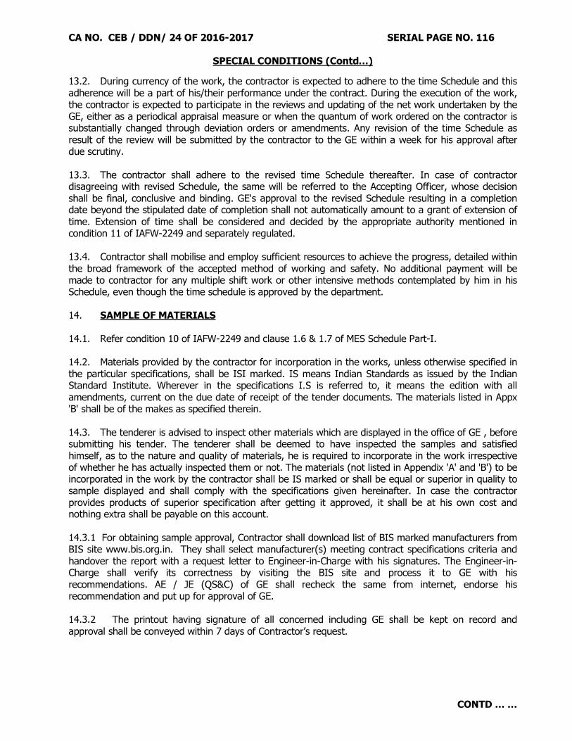
CA NO. CEB / DDN/ 24 OF 2016-2017 SERIAL PAGE NO. 116
SPECIAL CONDITIONS (Contd…)
CONTD … …
13.2. During currency of the work, the contractor is expected to adhere to the time Schedule and this adherence will be a part of his/their performance under the contract. During the execution of the work, the contractor is expected to participate in the reviews and updating of the net work undertaken by the GE, either as a periodical appraisal measure or when the quantum of work ordered on the contractor is substantially changed through deviation orders or amendments. Any revision of the time Schedule as result of the review will be submitted by the contractor to the GE within a week for his approval after due scrutiny. 13.3. The contractor shall adhere to the revised time Schedule thereafter. In case of contractor disagreeing with revised Schedule, the same will be referred to the Accepting Officer, whose decision shall be final, conclusive and binding. GE's approval to the revised Schedule resulting in a completion date beyond the stipulated date of completion shall not automatically amount to a grant of extension of time. Extension of time shall be considered and decided by the appropriate authority mentioned in condition 11 of IAFW-2249 and separately regulated. 13.4. Contractor shall mobilise and employ sufficient resources to achieve the progress, detailed within the broad framework of the accepted method of working and safety. No additional payment will be made to contractor for any multiple shift work or other intensive methods contemplated by him in his Schedule, even though the time schedule is approved by the department. 14. SAMPLE OF MATERIALS 14.1. Refer condition 10 of IAFW-2249 and clause 1.6 & 1.7 of MES Schedule Part-I. 14.2. Materials provided by the contractor for incorporation in the works, unless otherwise specified in the particular specifications, shall be ISI marked. IS means Indian Standards as issued by the Indian Standard Institute. Wherever in the specifications I.S is referred to, it means the edition with all amendments, current on the due date of receipt of the tender documents. The materials listed in Appx 'B' shall be of the makes as specified therein. 14.3. The tenderer is advised to inspect other materials which are displayed in the office of GE , before submitting his tender. The tenderer shall be deemed to have inspected the samples and satisfied himself, as to the nature and quality of materials, he is required to incorporate in the work irrespective of whether he has actually inspected them or not. The materials (not listed in Appendix 'A' and 'B') to be incorporated in the work by the contractor shall be IS marked or shall be equal or superior in quality to sample displayed and shall comply with the specifications given hereinafter. In case the contractor provides products of superior specification after getting it approved, it shall be at his own cost and nothing extra shall be payable on this account. 14.3.1 For obtaining sample approval, Contractor shall download list of BIS marked manufacturers from BIS site www.bis.org.in. They shall select manufacturer(s) meeting contract specifications criteria and handover the report with a request letter to Engineer-in-Charge with his signatures. The Engineer-in-Charge shall verify its correctness by visiting the BIS site and process it to GE with his recommendations. AE / JE (QS&C) of GE shall recheck the same from internet, endorse his recommendation and put up for approval of GE. 14.3.2 The printout having signature of all concerned including GE shall be kept on record and approval shall be conveyed within 7 days of Contractor’s request.
CA NO. CEB / DDN/ 24 OF 2016-2017 SERIAL PAGE NO. 117
SPECIAL CONDITIONS (Contd…)
CONTD … …
14.3.3 After sample approval GE shall send an e-mail to manufacturer (not the authorised dealer). Intimating him name of firm, approx quantity of materials being procured by the Contractor and request the manufacturer to ensure that his product only is purchased by the Contractor from proper authorised source. A printout of the e-mail sent to manufacturer shall be kept on record duly signed by GE and a copy thereof shall be sent by post to the manufacturer. 14.3.4 In cases involving suspected procurement of spurious material purchase vouchers shall be verified through the manufacturer and proof of payment shall be obtained from the Contractor. The payment of such doubtful material shall be allowed only after GE satisfies himself about the genuineness of materials. 14.4. The contractor shall not procure materials unless the samples are first approved by GE. 14.5 The cost of testing of all materials shall be borne by the contractor. While quoting their lump sum, this aspect should be kept in mind and nothing extra shall be admissible on this account. 15. PERIOD FOR KEEPING THE TENDER OPEN The tender shall remain open for acceptance for a period of 90 (NINETY) days from the date on which the tenders are due to be submitted. 16. ADVANCE ON ACCOUNT OF MATERIALS WHICH DO NOT LOOSE IDENTITY (APPLICABLE TO CONTRACTS OF VALUE Rs.50 LAKHS AND ABOVE)
The contractor may be paid advance on account of the full value of the under mentioned materials only, brought on the site, on his furnishing guarantee Bonds from a Scheduled Bank for the amount of retention money which should otherwise be recoverable from him under the contract.
(a) Poles (b) Transformers (c) ACSR Conductor (d) Cables (e) Factory made panelled shutters (f) Factory made pressed steel door frame (g) Factory made steel windows and ventilators (h) Sanitary, toilet fittings and appliances (j) All other equipments/accessories and fittings included in Schedule ‘A’ (k) (l) (m)
Structural Steel Solar modules Inverters
(n) VCB
The Bank Guarantee Bonds shall be executed for a period of twelve months on a form as directed by the Accepting Officer. The contractor shall further arrange to extend the period of Guarantee Bond if and when necessary, as directed by the Accepting Officer or shall furnish fresh guarantee bond of similar value. It shall be noted that advance on account to the full value of materials brought on the site is permissible only in respect of fittings and fixtures and other manufactured items which do not lose their identity. Materials like bricks, aggregate precast concrete and similar items shall not be taken in the list.
CA NO. CEB / DDN/ 24 OF 2016-2017 SERIAL PAGE NO. 118
SPECIAL CONDITIONS (Contd…)
CONTD … …
17. SECURITY OF CLASSIFIED DOCUMENTS Contractor's special attention is drawn to conditions 2-A and 3 of IAFW-2249 (General Condition of Contracts). The contractor shall not communicate any classified information regarding the work either to sub contractors or another person without the prior approval of the Engineer-in-Charge. The contractor shall not make copies of the design/drawings and other documents furnished to him in respect of the work, and shall return all documents on completion of the works or earlier on termination of the contract. The contractor shall along with the final bill, attach a receipt of his having returned the classified documents as per condition 3 of IAFW-2249(General Conditions of Contracts). 18. OFFICIAL SECRETS ACT The contractor shall be bound by the Official Secrets Act -1923. 19. RECORD OF MATERIALS 19.1 The quantity of materials such as paints, water proofing compound, chemicals for antitermite treatment and the like, as directed by the Engineer-in-Charge (the quantity of which can not be checked after incorporation in the works), shall be recorded in measurement books and signed by the contractor and the Engineer-in-Charge as a check to ensure that the required quantity has been brought to site for incorporation in the work. 19.2 Materials brought to site shall be stored as directed by the Engineer-in-Charge and those already recorded in measurement book shall be suitably marked for identification. 19.3 The contractor shall, on demand, produce to the GE, original receipted vouchers/invoices in respect of the supplies. The vouchers/invoices shall be defaced and stamped by Engineer-in-Charge indicating contract no, name of work, under his dated signature. The contractor shall ensure that the materials are brought to site, in original sealed containers/packing, bearing manufacturer's marking except in the case of the requirement of material(s) being less than smallest packing. 19.4 Contractor shall produce vouchers/invoices from the manufacturers and/or their authorised agents for the full quantity of the material, as a pre-requisite before submitting claims for payment for advances on account of the work done and/or materials collected in accordance with condition 64 of General Conditions of Contracts IAFW-2249. 20. RELEASE OF ADDITIONAL SECURITY DEPOSIT 20.1 Refer conditions 22 and 68 of IAFW-2249. 20.2 The contractor, in case he has to deposit additional security for the contract, is advised to deposit additional security in two equal parts so as to facilitate its release in accordance with condition 68 of IAFW-2249. 21. CLEANING DOWN
Refer Condition 49 of IAFW-2249, General Condition of Contracts : - The contractor shall clean all floors, walls, remove cement/ lime/paint marks/ drops, etc. clean the joinery glass panes etc, touch up all painters work and carryout all other necessary items of work in connection therewith and leave the whole premises clean and tidy before handing over the completed work.

CA NO. CEB / DDN/ 24 OF 2016-2017 SERIAL PAGE NO. 119
SPECIAL CONDITIONS (Contd…)
CONTD … …
22. SAFETY PRECAUTION 22.1 The contractor shall take every/precaution to control traffic on road keeping danger boards, necessary lighting arrangements, fencing and watchman to avoid any damage. In case due to excavation or others the road is to be blocked the contractor shall, without any extra cost to the Govt, provide separate by pass so that normal traffic is not disturbed. 22.2 Any damage to the existing road/building etc, shall be made good by the contractor with the same specifications as per existing work, without any extra cost to the Govt. In the event of contractor not fully complying with the above provisions to the satisfaction of the GE, the GE may provide the same for which the expenses incurred will be recovered from the contractor. 23. ADVANCES ON ACCOUNT 23.1 Refer condition 64 of IAFW-2249 (General Conditions of Contract). 23.2. Para 1 of condition 64 of IAFW-2249 shall be amended to read as under :-
“The contractor may at intervals of not less than 15 days submit claims on IAFW-2263 for payment of advances on account of work done and of materials delivered in connection with Measurement and Lump Sum contracts.”
All other provisions of condition 64 of IAFW-2249 as amended up to date shall remain unchanged.
24. CONTRACTOR’S SITE LABORATORY AND TESTING OF MATERIALS 24.1 Tests to be carried out in the Contract are listed in Appx ‘D’ to Particular Specification for the material to be incorporated in the contract. Any other tests mentioned in particular specification shall be in addition to the tests mentioned in Appx ‘D’ and shall be carried as per terms & condition stipulated there under. A site laboratory shall be set up by the Contractor for carrying out the tests as required under the Contract. The laboratory shall be fully equipped and shall be approved in writing by the GE. The calibration of equipment shall be periodically checked by the GE. 24.2 The types of tests and frequency of tests to be carried are given in Appendix ‘D’ to particular specification. However keeping in view nature of work, Garrison Engineer may add additional tests checks to this list or modify the list as required. 24.3 The Contractor shall be responsible for tests to be carried out. For carrying out the tests in site lab he shall employ a competent technical representative as approved by the Garrison Engineer and all such tests shall be carried out in the presence of Engineer-in-Charge. 24.4 The charges for the tests carried out in site laboratory of the contractor shall not be recovered, as the tests shall be carried out by the contractor at his own cost in his site laboratory. However, the charges for tests shall be recovered from the contractor only if does not carryout tests catered for in the contest and are got done in MES laboratory.
CA NO. CEB / DDN/ 24 OF 2016-2017 SERIAL PAGE NO. 120
SPECIAL CONDITIONS (Contd…)
CONTD … …
24.5 Where testing of contractor’s materials (level ‘B’ & ‘C’ test) is carried out in MES Zonal Lab / SEMT wing Pune, the contractor shall be liable to pay the testing charges as stated in Appx ‘D’ to the specifications and shall be recovered from the contractors running payment/final bill as the case may be. When tests (level ‘B’ & ‘C’) are carried out in Govt approved lab/National tests house/Engineering colleges, the testing charges as charged by the lab/institute shall be borne by the contractor irrespective of the testing charges mentioned in Appx ‘D’. However no recovery shall be made for those tests which are carried out in Govt approved lab/National test house/Engg Colleges by the contractor and he has paid the charges thereof. 24.6 A percentage/ selected checks as decided by the Accepting Officer, shall be got done independently in the Zonal/ Govt laboratory and charges for such tests shall be borne by the contractor only if the tests disclose that the said materials are not in accordance with the provision of the contract. The cost of materials consumed in tests and cartage to the testing laboratory shall however be borne by the contractor in all cases. 24.7 In case requisite number of applicable tests catered in Appendix ‘D’ are not carried out by the Contractor and GE is satisfied about the quality of material that same is in accordance with the Contract specification he may dispense with the test and in that event the contractor shall be liable to bear the recovery for not carrying out the tests at the penal rate which will be three times the rate given in Appendix ‘D’. In case GE is not satisfied about the quality of material, he will get the tests done in the MES Zonal Lab / SEMT Wing Pune / National test house / Govt approved lab / Engg colleges and in that event Contractor shall bear the recovery for such tests carried out at penal rate of three times, the rate given in Appendix ‘D’ or twice the actual expenditure incurred whichever is higher. 25. to 26.2. BLANK. 26.3. RE-IMBURSEMENT/REFUND ON VARIATION IN ‘TAXES DIRECTLY RELATED TO CONTRACT VALUE’ :- 26.3.1. The rates quoted by the Contractor shall be deemed to be inclusive of all taxes (including Sales Tax/ VAT on materials, Sales Tax/ VAT on Works Contracts, Turnover Tax, Service Tax, Labour Welfare Cess/ Tax etc.), duties, Royalties, Octroi & other levies payable under the respective Statutes. No re-imbursement/ refund for variation in rates of taxes, duties, Royalties, Octroi & other levies, and/or imposition/ abolition of any new/ existing taxes, duties Royalties, Octroi & other levies shall be made except as provided in sub para 26.3.2 here-in-below. 26.3.2. (i) The taxes which are levied by Govt at certain percentage rates of Contract Sum/ Amount
shall be termed as ‘taxes directly related to Contract value’ such as Sales Tax/ VAT on Works Contracts, Turnover Tax, , Service Tax, Labour Welfare Cess/ tax and like but excluding Income Tax. The tendered rates shall be deemed to be inclusive of all ‘taxes directly related to Contract value’ with existing percentage rates as prevailing on last due date for receipt of tenders. Any increase in percentage rates of ‘taxes directly related to Contract value’ with reference to prevailing rates on last due date for receipt of tenders shall be reimbursed to the Contractor and any decrease in percentage rates of ‘taxes directly related to Contract value’ with reference to prevailing rates on last due date for receipt of tenders shall be refunded by the Contractor to the Govt/ deducted by the Govt from any payments due to the Contractor. Similarly imposition of any new ‘taxes directly related to Contract value’ after the last due date for receipt of tenders
shall be reimbursed to the Contractor and abolition of any ‘taxes directly related to Contract
value’ prevailing on last due date for receipt of tenders shall be refunded by the Contractor to the Govt/ deducted by the Govt from the payments due to the Contractor.
CA NO. CEB / DDN/ 24 OF 2016-2017 SERIAL PAGE NO. 121
SPECIAL CONDITIONS (Contd…)
CONTD … …
(ii) The Contractor shall, within a reasonable time of his becoming aware of variation in percentage rates and/or imposition of any further ‘taxes directly related to Contract value’, give written notice thereof to the GE stating that the same is given pursuant to this Special Condition, together with all information relating there to which he may be in a position to supply. The Contractors shall submit the other documentary proof/ informations as the GE may require. (iii) The Contractor shall, for the purpose of this condition keep such books of account and other documents as are necessary and shall allow inspection of the same by a duly authorized representative of Govt, and shall further, at the request of the GE furnish, verified in such a manner as the GE may require, any documents so kept and such other informations as the GE may require. (iv) Re-imbursement for increase in percentage rates imposition of ‘taxes directly related to Contract value’ shall be made only if the Contractor necessary & properly pays additional ‘taxes directly related to Contract value’ to the Govt, without getting the same adjusted against any other tax liability or without getting the same refunded from the concerned Govt authority and submits documentary proof for the same as the GE may require.
27. OUTPUT OF ROAD ROLLER (REFER CONDITION 15 OF IAFW-2249) 27.1 Where road rollers are hired by the Department to contractors, a log book for each road roller shall be maintained by the Department for recording hours of working of the road roller. However, when the contractor procures road rollers from sources other than the Department a log book for each road roller shall be maintained by him for recording hours of working of the road roller. Entries in the log book shall be signed by the contractor or his authorised representative and by the EIC. 27.2 To ensure proper consolidation roller must work for at least the number of days assessed, on the basis of output given hereinafter. If the roller has not worked for the number of days so assessed, recovery shall be effected from the contractor for the number of days falling short of the days assessed on the basis of output stipulated, the recovery shall be affected as under :-
(a) Where road roller is hired out only by the department to the contractor at rates given in Schedule ‘C’.
(b) Where road roller is hired by the contractor only from sources other than the department, Rs 1400/- per working day of hours for 8 to 12 ton roller.
(c) Where road roller is hired by the contractor from the department and also from sources other than the department at higher of the two rates given in Schedule ‘C’ of contract and para 27.2 (b) above.
27.3 The above provision shall not however, absolve the contractor of his responsibility of properly consolidating surfaces as required under the provisions of the contract.
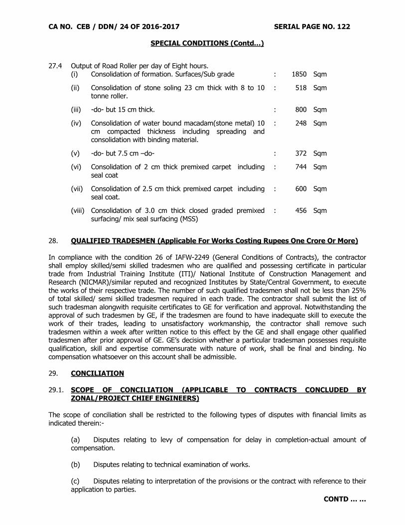
CA NO. CEB / DDN/ 24 OF 2016-2017 SERIAL PAGE NO. 122
SPECIAL CONDITIONS (Contd…)
CONTD … …
27.4 Output of Road Roller per day of Eight hours.
(i) Consolidation of formation. Surfaces/Sub grade
: 1850 Sqm (ii) Consolidation of stone soling 23 cm thick with 8 to 10
tonne roller.
: 518 Sqm
(iii) -do- but 15 cm thick.
: 800 Sqm (iv) Consolidation of water bound macadam(stone metal) 10
cm compacted thickness including spreading and consolidation with binding material.
: 248 Sqm
(v) -do- but 7.5 cm –do-
: 372 Sqm (vi) Consolidation of 2 cm thick premixed carpet including
seal coat
: 744 Sqm
(vii) Consolidation of 2.5 cm thick premixed carpet including seal coat.
: 600 Sqm
(viii) Consolidation of 3.0 cm thick closed graded premixed surfacing/ mix seal surfacing (MSS)
: 456 Sqm
28. QUALIFIED TRADESMEN (Applicable For Works Costing Rupees One Crore Or More) In compliance with the condition 26 of IAFW-2249 (General Conditions of Contracts), the contractor shall employ skilled/semi skilled tradesmen who are qualified and possessing certificate in particular trade from Industrial Training Institute (ITI)/ National Institute of Construction Management and Research (NICMAR)/similar reputed and recognized Institutes by State/Central Government, to execute the works of their respective trade. The number of such qualified tradesmen shall not be less than 25% of total skilled/ semi skilled tradesmen required in each trade. The contractor shall submit the list of such tradesman alongwith requisite certificates to GE for verification and approval. Notwithstanding the approval of such tradesmen by GE, if the tradesmen are found to have inadequate skill to execute the work of their trades, leading to unsatisfactory workmanship, the contractor shall remove such tradesmen within a week after written notice to this effect by the GE and shall engage other qualified tradesmen after prior approval of GE. GE’s decision whether a particular tradesman possesses requisite qualification, skill and expertise commensurate with nature of work, shall be final and binding. No compensation whatsoever on this account shall be admissible. 29. CONCILIATION 29.1. SCOPE OF CONCILIATION (APPLICABLE TO CONTRACTS CONCLUDED BY
ZONAL/PROJECT CHIEF ENGINEERS) The scope of conciliation shall be restricted to the following types of disputes with financial limits as indicated therein:-
(a) Disputes relating to levy of compensation for delay in completion-actual amount of compensation. (b) Disputes relating to technical examination of works. (c) Disputes relating to interpretation of the provisions or the contract with reference to their application to parties.

CA NO. CEB / DDN/ 24 OF 2016-2017 SERIAL PAGE NO. 123
SPECIAL CONDITIONS (Contd…)
CONTD … …
(d) Disputes relating to non-return of Schedule ‘B’ stores over issued to contractor (e) Any other disputes having fair chances of being resolved by conciliation and considered fit to be referred to conciliation by the parties.
For item (b), (c), (d) and (e) each as stated above the financial limit shall be Rupees two lakhs or one percent of the contract amount whichever is less. 29.2. Commencement of Conciliation Proceedings 29.2.1 The party initiating conciliation shall send to the other party a written invitation to conciliate, briefly identifying the subject of the dispute. 29.2.2 Conciliation proceedings shall commence when the other party accepts in writing the invitation to conciliate. 29.2.3 If the other party rejects the invitation, there will be no conciliation proceedings. If the party initiating conciliation does not receive a reply within 30 days from the date on which he sends or within such other periods of time as specified in the invitation, he may elect to treat this as a rejection of the invitation to conciliate and if he so elects, he shall inform in writing the other party accordingly. 29.3 Number of Conciliators: - There shall be a Sole Conciliator. 29.4 Appointment of Conciliator :- All disputes brought out in para 29.1(a) to (e) above shall be referred to the Sole Conciliator viz. Serving Officer not below the rank of Superintending Engineer/Superintending Engineering (QS&C) having degree in Engineering or equivalent or having passed final/ direct final examination of Sub division II of Institution of Surveyors (India) to be appointed by the Engineer-in-Chief, Army Headquarters, New Delhi or in his absence the Officer officiating as Engineer-in-Chief or Director General of works specifically delegated by the Engineer-in-Chief in writing. 29.5 Status of effect of Settlement Agreement: The settlement agreement signed by the parties as a result of conciliation proceedings shall have the same status and effect as it is an arbitral award on agreed terms. 30. Quality Control Plan : To ensure consolidated information in respect of work, Contractor shall submit Quality Control Plan within 30 days of commencement of work as per format as in Annexure ‘I’ given below :-

CA NO. CEB / DDN/ 24 OF 2016-2017 SERIAL PAGE NO. 124
SPECIAL CONDITIONS (Contd…)
CONTD … …
Annexure ‘I’
FORMAT FOR QUALITY CONTROL PLAN
PART-I
01.
Contract Agreement Reference No. : 02. CPM network prepared and approved by GE
:
03. Resource scheduling done based on CPM
: 04. Site Laboratory (with equipments) set up as
per Contract Agreement (CA)
:
05. Concrete mix design submitted and approved
:
06. Preliminary works completed to standard engineering practice
:
07. Arrangements for water made (including testing of water).
:
08. Arrangement for electric supply made :
09. Materials
: Srl
No. Item Source as
per CA Contractor’s
plan of sourcing
Refer to testing clause
Agency for testing
Responsibility for testing
10. List of all T&P, make and numbers that the contractor would deploy at site of work.
11. Name of person nominated by contractor for
exercising quality control. :
12. Qualifications/Experience of person at Serial No. 11 above.
:
13. Names of supervisors with their qualifications/ experience employed by contractor.
:
14. Confirmation that contract requirements relating to quality of all materials and quality standards of workmanship and finishes and acceptance criteria are explained and understood by all.
:

CA NO. CEB / DDN/ 24 OF 2016-2017 SERIAL PAGE NO. 125
SPECIAL CONDITIONS (Contd…)
CONTD … …
15. Confirmation that requirement of tests to be
conducted on materials before approval of sample and during execution, tests on workmanship, tests before acceptance including the testing procedure, sampling techniques, frequency and agencies responsible for testing are understood and shall be complied with.
:
16. Method to be adopted for maintaining records of test result.
:
17. Certificate that contractor shall maintain a log of all materials received at site as per the following format :-
Srl No.
Date Material Quantity received
Source Whether as per approved sample or
not
Tests carried out by supplier
Tests to be carried out before
incorporation
18. General remarks by contractor of his plan of actions to ensure that quality standards
Dated : ______________ (Signature of Contractor)
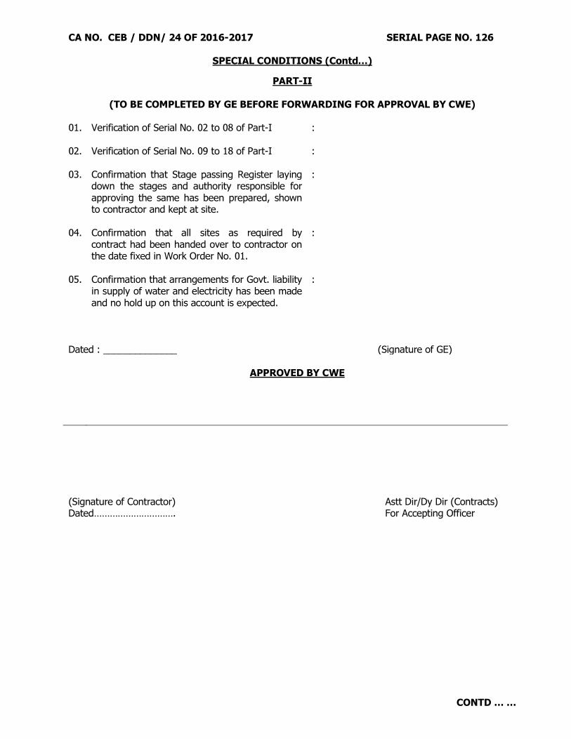
CA NO. CEB / DDN/ 24 OF 2016-2017 SERIAL PAGE NO. 126
SPECIAL CONDITIONS (Contd…)
CONTD … …
PART-II
(TO BE COMPLETED BY GE BEFORE FORWARDING FOR APPROVAL BY CWE)
01. Verification of Serial No. 02 to 08 of Part-I
: 02. Verification of Serial No. 09 to 18 of Part-I
:
03. Confirmation that Stage passing Register laying down the stages and authority responsible for approving the same has been prepared, shown to contractor and kept at site.
:
04. Confirmation that all sites as required by contract had been handed over to contractor on the date fixed in Work Order No. 01.
:
05. Confirmation that arrangements for Govt. liability in supply of water and electricity has been made and no hold up on this account is expected.
:
Dated : ______________ (Signature of GE) APPROVED BY CWE
(Signature of Contractor) Astt Dir/Dy Dir (Contracts) Dated…………………………. For Accepting Officer

CA NO. CEB / DDN / 24 OF 2016-2017 SERIAL PAGE NO. 127
PARTICULAR SPECIFICATIONS (SOLAR POWER PLANT)
Contd....
1. Introduction
1.1 Project particulars:
Particulars Description
Proposed capacity of the solar power plant 2 MW (AC)
Technology Mono/ Multi crystalline
Origin of cell manufacturer Indigenous, as per MNRE Guidelines for the Defence Scheme
O&M period 5 (Five) years
Site location and land details
Latitude 30°22‟8.3” N
Longitude 78°01‟29” E
Altitude 722 m
Village Birpur
Mandal
District Dehradun
State Uttarakhand
Type of Land Govt. land
Owner of land
Connecting Substation Details 11 kV Sub-station, Birpur
Distance to connecting substation 1 km (approx.)
Estimated life of PV Power plant 25 years
Nearest Urban Area Dehradun
Nearest Highway NH 7
Nearest Railway Station Dehradun (9 km)
Nearest Domestic Airport Dehradun (37 km)
Minimum values of PR and CUF of the plant after netting off the auxiliary consumption.
PR : 0.79 CUF : 22.3 %
Water and Power for Construction To be arranged by the Contractor

CA NO. CEB / DDN / 24 OF 2016-2017 SERIAL PAGE NO. 128
PARTICULAR SPECIFICATIONS (SOLAR POWER PLANT)
Contd....
2. Scope of Supply and Work
2.1 Brief Scope of Work
Scope of Supply & Work includes all design & engineering, procurement & supply of equipment
and materials, testing at manufacturers works, multi – level inspections, packing and forwarding,
supply, receipt, unloading and storage at site, associated civil works, services, permits, licences,
installation and incidentals, insurance at all stages, erection, testing and commissioning of 2MW
(AC) Grid Interactive Solar PV Power Plant and performance demonstration with associated
equipment and materials on turnkey basis at Dehradun, Uttarakhandand 5 (Five) years
comprehensive operation and maintenance from the date of Operational Acceptance.
2.2 Solar cells and modules both shall be made in India.
3. Design and Engineering:
3.1 The Contractor shall prepare the detailed design basis report (DBR) along with relevant
standards (with respective clause description), CPM Chart and MDL. The Contractor shall
submit a copy to Employer for evaluation.
3.2 Submission of basic design data, design documents, drawings, and engineering information
including GTP and test reports to Employer or its authorized representative for review and
approval in hard copy and soft copy from time to time as per project schedule. The
documents typically include, but not limited to, the following:
Solar insolation data and basis for generation
Detailed technical specifications of all the equipment
General arrangement and assembly drawings of all major equipment
Schematic diagram for entire electrical system
GTP & G.A. drawings for all types of structures/ components
Test reports (type, routine and acceptance tests)
Relay setting charts
Design calculations and sheets (licenced software as well as design templates)
Geo technical investigation data and Topographical survey and plan for the area
Overall plant layout
GA drawings of the entire project including main control room, roads, storm water drainage, fire
protection system, etc.
Quality assurance plan for manufacturing and field activities
Detailed site EHS plan, fire safety & evacuation plan and disaster management plan
Detailed risk assessment and mitigation plan
O&M Instruction‟s manuals for major equipment
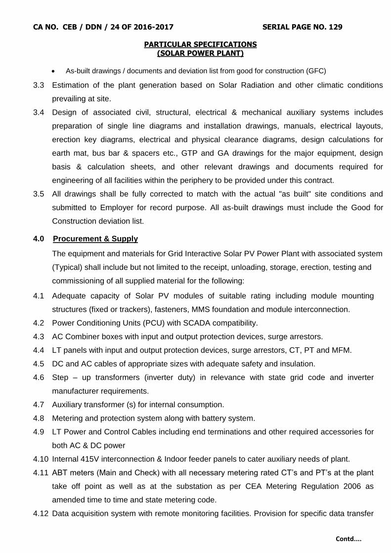
CA NO. CEB / DDN / 24 OF 2016-2017 SERIAL PAGE NO. 129
PARTICULAR SPECIFICATIONS (SOLAR POWER PLANT)
Contd....
As-built drawings / documents and deviation list from good for construction (GFC)
3.3 Estimation of the plant generation based on Solar Radiation and other climatic conditions
prevailing at site.
3.4 Design of associated civil, structural, electrical & mechanical auxiliary systems includes
preparation of single line diagrams and installation drawings, manuals, electrical layouts,
erection key diagrams, electrical and physical clearance diagrams, design calculations for
earth mat, bus bar & spacers etc., GTP and GA drawings for the major equipment, design
basis & calculation sheets, and other relevant drawings and documents required for
engineering of all facilities within the periphery to be provided under this contract.
3.5 All drawings shall be fully corrected to match with the actual "as built" site conditions and
submitted to Employer for record purpose. All as-built drawings must include the Good for
Construction deviation list.
4.0 Procurement & Supply
The equipment and materials for Grid Interactive Solar PV Power Plant with associated system
(Typical) shall include but not limited to the receipt, unloading, storage, erection, testing and
commissioning of all supplied material for the following:
4.1 Adequate capacity of Solar PV modules of suitable rating including module mounting
structures (fixed or trackers), fasteners, MMS foundation and module interconnection.
4.2 Power Conditioning Units (PCU) with SCADA compatibility.
4.3 AC Combiner boxes with input and output protection devices, surge arrestors.
4.4 LT panels with input and output protection devices, surge arrestors, CT, PT and MFM.
4.5 DC and AC cables of appropriate sizes with adequate safety and insulation.
4.6 Step – up transformers (inverter duty) in relevance with state grid code and inverter
manufacturer requirements.
4.7 Auxiliary transformer (s) for internal consumption.
4.8 Metering and protection system along with battery system.
4.9 LT Power and Control Cables including end terminations and other required accessories for
both AC & DC power
4.10 Internal 415V interconnection & Indoor feeder panels to cater auxiliary needs of plant.
4.11 ABT meters (Main and Check) with all necessary metering rated CT‟s and PT‟s at the plant
take off point as well as at the substation as per CEA Metering Regulation 2006 as
amended time to time and state metering code.
4.12 Data acquisition system with remote monitoring facilities. Provision for specific data transfer

CA NO. CEB / DDN / 24 OF 2016-2017 SERIAL PAGE NO. 130
PARTICULAR SPECIFICATIONS (SOLAR POWER PLANT)
Contd....
to the State Load Dispatch Centre (SLDC) shall also be provided.
4.13 Lightning arrestors for entire plant area.
4.14 PVC pipes, cable conduits, cable trays and accessories/trenches.
4.15 Earthing of the entire plant as per relevant standards.
4.16 Testing instruments for maintenance and monitoring of equipment.
4.17 Spares & consumables, as required or recommended, for the complete O&M period.
4.18 CCTV cameras with monitoring station for plant surveillance
4.19 Fire protection system in buildings and fire extinguishers.
4.20 Weather monitoring station shall include but not be limited to the following:
Pyranometers – for horizontal and tilted plane
Ultrasonic Anemometer (wind speed and direction)
Temperature Sensor – Ambient and module surface
Power source to the all sensors
Data Logger
4.21 Materials and accessories, which are required for satisfactory and trouble-free operation
and maintenance of the above equipment.
4.22 Any other equipment / material, not mentioned but required to complete the Solar Power
Plant facilities in all respect.
5.0 Construction and Erection Works
The items of civil design and construction work shall include all works required for solar PV
project and should be performed specifically with respect to following but not limited to:
5.1 Conducting geotechnical investigation and topographical survey of the total area.
5.2 Construction of foundation for module mounting structures.
5.3 Civil foundation work of transformers, switchgears, etc.
5.4 Construction of peripheral road with WBM base.
5.5 Permanent water supply for module cleaning and other needs of SPV power Plant during
entire O&M period.
5.6 Construction of storm water drainage including rain water harvesting mechanism.
5.7 Laying of underground / over ground Cables (all types) with proper arrangements along with
appropriate sized ferrules, lugs, glands and terminal blocks.
5.8 Suitable earthing for plant along with earth pits as per standards.

CA NO. CEB / DDN / 24 OF 2016-2017 SERIAL PAGE NO. 131
PARTICULAR SPECIFICATIONS (SOLAR POWER PLANT)
Contd....
5.9 The Contractor will construct/provide a separate temporary office with Lavatory facility/
arrangement at site(including office furniture, computer with internet facility and printer,
vehicle etc) to be used by the officials of the Employer/ Owner at the time of construction of
the Solar Power Plant. All the temporary facilities constructed for the purpose of execution
of the contract shall be removed after taking necessary permissions from the
Employer/Owner immediately after Operational Acceptance.
5.10 All approvals, for equipment, items and works, which are not otherwise specifically
mentioned in this document but are required for successful completion of the work in all
aspects, including construction, commissioning, O&M of Solar PV Power Plant and
guaranteed performance are deemed to be included in the scope of the contractor.
6.0 Statutory Approvals
6.1 Obtaining statutory approvals /clearances on behalf of the Employer from various Government
Departments, not limited to, the following.
6.1.1 Pollution control board clearance, if required
6.1.2 Mining Department, if required
6.1.3 Forest Department, if required
6.1.4 All other approvals, as necessary for setting up of a solar power plant including CEIG/ CEA,
connectivity, power evacuation, railways, PTCC etc. as per the suggested guidelines
6.1.5 All other statutory approvals and permissions, not mentioned specifically but are required to carry out
hassle free Construction and O&M of the plant prevailing at Site.
6.1.6 Adequate and seamless insurance coverage during EPC and O&M period to mitigate all risks related
to construction and O&M of the plant to indemnify the Employer.
6.2 The Contractor shall comply with the provision of all relevant acts of Central or State
Governments including payment of Wages Act 1936, Minimum Wages Act 1948, Employer's
Liability Act 1938, Workmen's Compensation Act 1923, Industrial Dispute Act 1947, Maturity
Benefit Act 1961, Mines Act 1952, Employees State Insurance Act 1948, Contract Labour
(Regulations & Abolishment) Act 1970, Electricity Act 2003, Grid Code, Metering Code,
MNRE guidelines or any modification thereof or any other law relating whereto and rules
made there under or amended from time to time.
7.0 Operation and Maintenance
7.1 Total Operation & Maintenance of the SPV Plant shall be with the Contractor, after
commissioning of the plant till final acceptance which shall include deployment of engineering
personnel, technicians and security personnel.

CA NO. CEB / DDN / 24 OF 2016-2017 SERIAL PAGE NO. 132
PARTICULAR SPECIFICATIONS (SOLAR POWER PLANT)
Contd....
7.2 To provide a detailed training plan for all O&M procedures to Employer‟s nominated staff,
which shall have prior approval from the Employer.
7.3 Employ and coordinate the training of contractors‟ personnel who will be qualified and
experienced to operate and monitor the facility and to coordinate operations of the facility with
the grid system.
7.4 Discharge obligations relating to retirement/ Superannuating benefits to employees or any
other benefit accruing to them in the nature of compensation, profit in lieu / in addition to
salary, etc. for the period of service with the contractor, irrespective continuance of employees
with the project as employees of Contractor, after conclusion of O&M period.
7.5 To maintain accurate and up-to-date operating logs, records and monthly Operation &
Maintenance reports at the facility. Contractor shall keep the measured daily data at regular
intervals and provide the same to Employer in electronic form, compatible in CSV format. The
right to use the data shall remain with the Employer.
7.6 Procurement of spare parts, overhaul parts, tools& tackles, equipment, consumables, etc.
required for smooth operation and maintenance of the plant as per prudent/ standard utility
practices, OEM recommendations and warranty clauses for the entire O&M period
7.7 To upkeep all administrative offices, roads, tool room, stores room, equipment, clean, green
and in workable conditions.
7.8 To carry out periodic overhauls or maintenance required as per the recommendations of the
original equipment manufacturer (OEM) and to furnish all such periodic maintenance
schedules at the time of plant commissioning/ start of O&M contract.
7.9 Handover the system to maintain an inventory of spare parts, tools, equipment, consumables
and supplies for the facility‟s operation along-with required details of recommended spares list
with all associated information regarding replacement records, supplier details, tentative cost,
storage details, specifications on the basis of replacement frequency and mean time between
failures and mean time to restore at the culmination of penultimate year under O&M period.
7.10 Availability of vehicles for Employer staff during construction and O&M period as per
requirement may be ensured, failing which Employer shall have full right for alternate
arrangement at the risk & cost of the contractor.
7.11 The contractor shall be responsible for all the required activities for the successful running,
committed energy generation & maintenance of the Solar Photovoltaic Power Plant covering:
Deputation of qualified and experienced engineers and technicians at the facility.
Deputation of Security personnel for the complete security of plant.

CA NO. CEB / DDN / 24 OF 2016-2017 SERIAL PAGE NO. 133
PARTICULAR SPECIFICATIONS (SOLAR POWER PLANT)
Contd....
Successful running of Solar Power Plant for committed energy generation.
Co-ordination with STU/SLDC/other statutory organizations as per the requirement on behalf of
Employer for Joint Metering Report (JMR), furnishing generations schedules as per requirement,
revising schedules as necessary and complying with grid requirements.
Monitoring, controlling, troubleshooting maintaining of logs & records, registers.
Furnishing generation data monthly to Employer by 1st week of every month for the previous month to
enable Employer raise commercial bills on consumers.
Periodic cleaning of solar modules as approved by the Employer and water quality as per the
recommendations of OEM
Replacement of Modules, Invertors/PCU‟s and other equipment as and when required during the
O&M period without additional cost to Employer
7.12 Continuous monitoring the performance of the Solar Power Plant and regular maintenance of
the whole system including Modules, PCU‟s, transformers, overhead line, outdoor/indoor
panels/ kiosks etc. are necessary for extracting and maintaining the maximum energy output
from the Solar Power Plant.
7.13 Preventive and corrective O&M of the Solar Photovoltaic Power Plant including supply of
spares, consumables, wear and tear, overhauling, replacement of damaged modules,
invertors, PCU‟s and insurance covering all risks (Fire & allied perils, earth quake, terrorists,
burglary and others) as required.
7.14 The period of Operation and Maintenance will be deemed to commence from the date of
completion of performance demonstration/Operational acceptance and successively the
complete Solar Photovoltaic Power Plant to be handed over to the O&M contractor for
operation and maintenance of the same. O&M contract shall further be extended on the
mutually agreed terms and conditions for the period of minimum 5 years.
7.15 All the equipment required for Testing, Commissioning and O&M for the healthy operation of
the Plant must be calibrated, time to time, from the NABL accredited labs and the certificate of
calibration must be provided prior to its deployment.
7.16 The Contractor shall ensure that all safety measures are taken at the site to avoid accidents to
his or his sub-contractor or Employer's Workmen. This will include procurement of all safety
gadgets during Construction and O&M period including but not limited to, rubber mats of
appropriate grade, PPE, rubber gloves and shoes etc.

CA NO. CEB / DDN / 24 OF 2016-2017 SERIAL PAGE NO. 134
PARTICULAR SPECIFICATIONS (SOLAR POWER PLANT)
Contd....
8.0 Operation and Performance Monitoring
8.1 Operation part consists of deputing necessary manpower necessary to operate the Solar
Photovoltaic Power Plant at the full capacity. Operation procedures such as preparation to
starting, running, routine operations with safety precautions, monitoring etc., shall be carried
out as per the manufacturer‟s instructions to have trouble free operation of the complete
system.
8.2 Daily work of the operation and maintenance in the Solar Photovoltaic Power Plant involves
periodic cleaning of Modules, logging the voltage, current, power factor, power and energy
output of the Plant at different levels. The operator shall also note down time/failures,
interruption in supply and tripping of different relays, reason for such tripping, duration of such
interruption etc. The other task of the operators is to check battery voltage-specific gravity and
temperature. The operator shall record monthly energy output, down time, etc.
8.3 Earth resistance of Plant as well as individual earth pit is to be measured and recorded every
month. If the earth resistance is high suitable action is to be taken to bring down the same.
8.4 A maintenance record is to be maintained by the operator/engineer-in-charge to record the
regular maintenance work carried out as well as any breakdown maintenance along with the
date of maintenance reasons for the breakdowns steps have taken to attend the breakdown
duration of the breakdown etc.
8.5 The Schedules will be drawn such that some of the jobs other than breakdown, which may
require comparatively long stoppage of the Power Plant, shall be carried out preferably during
the non-sunny days. An information shall be provided to Engineer-in-charge for such operation
prior to start.
8.6 The Contractor will attend to any breakdown jobs immediately for repair/
replacement/adjustments and complete at the earliest working round the clock. During
breakdowns (not attributable to normal wear and tear) at O&M period, the Contractor shall
immediately report the accidents, if any, to the Engineer In-charge showing the circumstances
under which it happened and the extent of damage and or injury caused.
8.7 The contractor shall at his own expense provide all amenities to his workmen as per applicable
laws and rules.
8.8 If negligence / mal operation of the contractor's operator results in failure of equipment such
equipment should be repaired replaced by contractor at free of cost.

CA NO. CEB / DDN / 24 OF 2016-2017 SERIAL PAGE NO. 135
PARTICULAR SPECIFICATIONS (SOLAR POWER PLANT)
Contd....
9.0 Security services
9.1 The contractor has to arrange proper security system including deputation of security
personnel at his own cost for the check vigil for the Solar Power Plant. The security staff may
be organized to work on suitable shift system; proper checking & recording of all incoming &
outgoing materials vehicles shall be maintained. Any occurrence of unlawful activities shall be
informed to Employer immediately. A monthly report shall be sent to Employer on the security
aspects.
9.2 All the information shown here is indicative only and may vary as per design and planning
by the bidder. The bidder must provide the BOM of the plant as per the design during the
time of bidding. The technical features of major equipment are described hereunder.
10.0 Design Philosophy
10.1 The main objective of the design philosophy is to construct the plant within-built Quality
and appropriate redundancy to achieve high availability and reliability with minimum
maintenance efforts. In order to achieve this, the following principles shall be adopted
while designing the system.
10.1.1 Adequate capacity of SPV modules, PCUs, Junction boxes etc. to ensure generation of power as
per design estimates. This will be done by applying liberal de-rating factors for the array and
recognizing the efficiency parameters of PCUs, transformers, conductor losses, system losses,
site conditions etc.
10.1.2 Use of equipment and systems with proven design and performance that have high availability
track records under similar service conditions.
10.1.3 Selection of the equipment and adoption of a plant layout to ensure ease of maintenance.
10.1.4 Strict compliance with approved and proven quality assurance (QA)systems and procedures
during different stages of the project, starting from sizing, selection of make, shipment, storage
(at site), during erection, testing and commissioning.
10.1.5 Proper monitoring of synchronization and recording, to ensure availability of power to the grid.
10.1.6 The plant instrumentation and control system should be designed to ensure high availability and
reliability of the plant to assist the operators in the safe and efficient operation of the plant with
minimum effort.
10.1.7 It should also provide the analysis of the historical data and help in the plant maintenance people
to take up the plant and equipment on predictive maintenance.
10.1.8 System design shall have intelligent protection mechanism which may include very fast
responsive microprocessor based relays etc., so that any disturbance from the grid will not cause
any damage to the equipment of the Solar Power Plant.

CA NO. CEB / DDN / 24 OF 2016-2017 SERIAL PAGE NO. 136
PARTICULAR SPECIFICATIONS (SOLAR POWER PLANT)
Contd....
10.2 The basic and detailed engineering of the plant shall aim at achieving high standards of
operational performance especially considering following:
10.2.1 SPV power plant should be designed to operate satisfactorily in synchronization with the grid
within permissible limits of high voltage and frequency fluctuation conditions. It is also extremely
important to safeguard the system during major disturbances, internal and external surge
conditions while ensuring safe operation of the plant.
10.2.2 SPV arrays are commonly fixed at an optimum tilted angle facing the equator. Trackers can also
be used for tracking the sun on daily or seasonal basis. In case of fixed tilt, the tilt angle shall be
defined in such a way that optimum generation is achieved at all times.
10.2.3 Shadow free plant layout to ensure minimum losses in generation during the day time.
10.2.4 Higher system voltage and lower current options to be followed to minimise ohmic losses.
10.2.5 Selection of PCUs with proven reliability and minimum downtime. Ready availability of requisite
spares.
10.2.6 Careful logging of operational data / historical information from the Data Monitoring Systems, and
periodical analysis of the same to identify any abnormal or slowly deteriorating conditions.
10.2.7 The designed array capacity at STC shall be suitably determined to meet the proposed
guaranteed generation output at the point of interconnection by the contractor in his bid. The
contractor shall take care of first year degradation also by installing additional DC capacity as the
CUF calculations will not factor the first year degradation of the modules.
10.2.8 Each component offered by the Contractor shall be of established reliability. The minimum target
reliability of each equipment shall be established by the Contractor considering its mean time
between failures and mean time to restore, such that the availability of complete system is
assured. The Contractor‟s recommendation of the spares shall be on the basis of established
reliability.
10.2.9 The Contractor shall design the plant and equipment in order to have sustained life of 25 years
with minimum maintenance efforts.
10.2.10 The work execution planning for supply, erection, commissioning and all other allied works for
SPV Power Plant shall be such that it is completed within stipulated time from the date of work .
10.3 The specifications provided with this bid document are functional ones; any design
provided in this document is only meant as an example. The Contractor must submit a
detailed design philosophy document for the project to meet the functional requirements
based upon their own design in-line with the above. The bidders are advised to visit the
site and satisfy themselves before bidding.
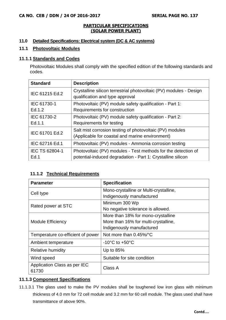
CA NO. CEB / DDN / 24 OF 2016-2017 SERIAL PAGE NO. 137
PARTICULAR SPECIFICATIONS (SOLAR POWER PLANT)
Contd....
11.0 Detailed Specifications: Electrical system (DC & AC systems)
11.1 Photovoltaic Modules
11.1.1 Standards and Codes
Photovoltaic Modules shall comply with the specified edition of the following standards and codes.
11.1.2 Technical Requirements
Parameter Specification
Cell type Mono-crystalline or Multi-crystalline,
Indigenously manufactured
Rated power at STC Minimum 300 Wp
No negative tolerance is allowed.
Module Efficiency
More than 18% for mono-crystalline
More than 16% for multi-crystalline,
Indigenously manufactured
Temperature co-efficient of power Not more than 0.45%/°C
Ambient temperature -10°C to +50°C
Relative humidity Up to 85%
Wind speed Suitable for site condition
Application Class as per IEC
61730 Class A
11.1.3 Component Specifications
11.1.3.1 The glass used to make the PV modules shall be toughened low iron glass with minimum
thickness of 4.0 mm for 72 cell module and 3.2 mm for 60 cell module. The glass used shall have
transmittance of above 90%.
Standard Description
IEC 61215 Ed.2 Crystalline silicon terrestrial photovoltaic (PV) modules - Design
qualification and type approval
IEC 61730-1
Ed.1.2
Photovoltaic (PV) module safety qualification - Part 1:
Requirements for construction
IEC 61730-2
Ed.1.1
Photovoltaic (PV) module safety qualification - Part 2:
Requirements for testing
IEC 61701 Ed.2 Salt mist corrosion testing of photovoltaic (PV) modules
(Applicable for coastal and marine environment)
IEC 62716 Ed.1 Photovoltaic (PV) modules - Ammonia corrosion testing
IEC TS 62804-1
Ed.1
Photovoltaic (PV) modules - Test methods for the detection of
potential-induced degradation - Part 1: Crystalline silicon

CA NO. CEB / DDN / 24 OF 2016-2017 SERIAL PAGE NO. 138
PARTICULAR SPECIFICATIONS (SOLAR POWER PLANT)
Contd....
11.1.3.2 The back sheet used in the PV modules shall be of three layered or mono layered structure.
The back sheet should be durable for humid – hot conditions with properties of moisture barrier,
elongation retention and UV resistance. The back sheet shall have the following properties.
Parameter Value
Material thickness ≥ 300 micron
Water vapour transmission rate < 2 g/m2/day
Partial discharge test voltage ≥ 1000 V
Elongation at break > 100%
Adhesion strength with encapsulant > 70 N/cm
Interlayer adhesion strength > 5 N/cm
The Employer reserves the right to conduct Pressure Cooker (PC) test/ Highly Accelerated Stress
Test (HAST) to confirm the durability of the back sheet in accelerated conditions.
11.1.3.3 The encapsulant used for the PV modules should be UV resistant in nature. No yellowing of the
encapsulant with prolonged exposure shall occur. The encapsulant shall have the following
properties.
Parameter Value
Gel content > 75%
Volume resistivity > 1×10¹⁵ Ω.cm
Peeling strength with glass >60 N/cm
11.1.3.4 The sealant used for edge sealing of PV modules shall have excellent moisture ingress
protection with good electrical insulation (Break down voltage >15 kV/mm) and with good
adhesion strength. Edge tapes for sealing are not allowed.
11.1.3.5 The module frame shall be made of anodized Aluminium, which shall be electrically &
chemically compatible with the structural material used for mounting the modules. It is required to
have provision for earthing to connect it to the earthing grid. The anodization thickness shall not
be less than 15 micron.
11.1.3.6 The material used for junction box shall be UV resistant to avoid degradation during module life.
The degree of protection of the junction box shall be at least IP67. Minimum three number of
bypass diodes and two number of MC4 connectors with appropriate length of TUV 2Pfg
1169/08.2007 certified 4 sq.mm Cu cable shall be provided. The cable length shall be in
accordance with the PV Module wiring strategy and adequate to ensure that the cable bending
radius standard is not exceeded.

CA NO. CEB / DDN / 24 OF 2016-2017 SERIAL PAGE NO. 139
PARTICULAR SPECIFICATIONS (SOLAR POWER PLANT)
Contd....
11.1.3.7 Each PV Module shall be provided a RFID tag which is embedded inside the module lamination
and must be able to withstand harsh environmental conditions. The RFID data base shall contain
the following information. RFID scanner and database of all the modules containing the following
information shall also be provided.
(i) Name of the manufacturer of PV Module
(ii) Name of the Manufacturer of Solar cells
(iii) Type of cell: Mono / Multi
(iv) Month and year of the manufacture (separately for solar cells and module)
(v) Country of origin (separately for solar cells and module)
(vi) I-V curve for the module
(vii) Peak Wattage, Im, Vm and FF for the module
(viii) Unique Serial No. and Model No. of the module.
(ix) Date and year of obtaining IEC PV module qualification certificate
(x) Name of the test lab issuing IEC certificate
(xi) Other relevant information on traceability of solar cells and modules as per ISO 9000 series.
11.1.4 Warranty
11.1.4.1 PV modules must be warranted with linear degradation rate of power output except for first year
and shall guarantee 80% of the initial rated power output at the end of 25 years.
11.1.4.2 The modules shall be warranted for minimum of 10 years against all material/manufacturing
defects and workmanship.
11.1.5 Approval
11.1.5.1 The Contractor shall provide commercial datasheet and Guaranteed Technical Particular
datasheet
11.1.5.2 The Contractor shall provide the Bill of Materials (BOM) of the module that is submitted for
approval along with the datasheets of each component. The component datasheet shall contain
all the information to substantiate the compliance for component specifications mentioned above.
The Contractor shall also provide complete test reports and certifications for the module
proposed as per above. The BOM proposed shall be the subset of Constructional Data Form
(CDF)‟s of all the test reports.
11.1.5.3 The Contractor shall obtain the approval of the proposed module make & model prior to
manufacturing/ inspection call.
CA NO. CEB / DDN / 24 OF 2016-2017 SERIAL PAGE NO. 140
PARTICULAR SPECIFICATIONS (SOLAR POWER PLANT)
Contd....
11.1.6 Manufacturing and Inspection
11.1.6.1 The Contractor shall inform the module manufacturing schedule to the Employer at least 7
(seven) working days before the start of proposed schedule.
11.1.6.2 The Employer shall perform material inspection at the Manufacturer‟s factory before the start of
proposed manufacturing schedule. Proof of procurement of components as per the approved
BOM mentioning manufacturer name, manufacturing date and relevant test certificate shall be
submitted during material inspection for verification.
11.1.6.3 The Manufacturing shall start only after the clearance by the Employer after the material
inspection.
11.1.6.4 The cells used for module making shall be free from all defects like edge chipping, breakages,
printing defects, discoloration of top surface etc. Only Class A solar cell shall be used.
11.1.6.5 The modules shall be uniformly laminated without any lamination defects.
11.1.6.6 Current binning of modules shall be employed so that current mismatch of modules in a pallet
does not exceed 2% of current at Maximum Power (Imp). Different colour codes shall be
provided on the modules as well as pallet for identification of different bins.
11.1.6.7 Pre-dispatch inspection of modules shall be performed as per the inspection protocol attached
in Annexure – A.
11.1.7 Transportation, Handling, Storage and Installation
11.1.7.1 Transportation, handling, storage and installation of modules shall be in accordance with the
manufacturer manual so as not to breach warranty conditions. The Standard Operating
Procedure (SOP) for the same shall be shared by the Contractor prior to dispatch.
11.1.7.2 It is required to construct a temporary platform (graded) while keeping the modules at least
above the highest flood level. If the contractor scheduled/ planned to mount the modules
immediately after the receipt at site, then the module shall be kept in common storage area with
proper arrangement.
11.1.7.3 The stacked modules, in any case, shall be stacked as per the manufacturer‟s recommendation
only and shall be covered with tarpaulin sheet.

CA NO. CEB / DDN / 24 OF 2016-2017 SERIAL PAGE NO. 141
PARTICULAR SPECIFICATIONS (SOLAR POWER PLANT)
Contd....
12 Power Conditioning Unit
12.1 Standards and Codes
Power Conditioning Unit shall comply with the specified edition of the following standards
and codes.
Standard/Code Description
IEC 61683 Ed. 1 Photovoltaic systems - Power conditioners -
Procedure for measuring efficiency
IEC 62109-1 Ed. 1 Safety of power converters for use in photovoltaic
power systems - Part 1: General requirements
IEC 62109-2 Ed. 1
Safety of power converters for use in photovoltaic
power systems - Part 2: Particular requirements for
inverters
IEC 61000-6-2 Ed. 2
Electromagnetic compatibility (EMC) - Part 6-2:
Generic standards - Immunity standard for industrial
environments
IEC 61000-6-4 Ed.
2.1
Electromagnetic compatibility (EMC) - Part 6-4:
Generic standards - Emission standard for industrial
environments
IEC 62116 Ed. 2 Utility-interconnected photovoltaic inverters - Test
procedure of islanding prevention measures
IEC 61727 Ed. 2 Photovoltaic (PV) systems - Characteristics of the
utility interface
IEC 60068-2-1:2007 Environmental testing - Part 2-1: Tests - Test A: Cold
IEC 60068-2-2:2007 Environmental testing - Part 2-2: Tests - Test B: Dry
heat
IEC 60068-2-14:2009 Environmental testing - Part 2-14: Tests - Test N:
Change of temperature
IEC 60068-2-30:2005 Environmental testing - Part 2-30: Tests - Test Db:
Damp heat, cyclic (12 h + 12 h cycle)
CEA Technical Standards for Connectivity to the Grid Regulations 2007 with
2013 Amendment

CA NO. CEB / DDN / 24 OF 2016-2017 SERIAL PAGE NO. 142
PARTICULAR SPECIFICATIONS (SOLAR POWER PLANT)
Contd....
12.2 Technical Requirements
Parameter Specification
Rated AC power at unity power
factor minimum 25 kW
Maximum input voltage 1000 V
Rated AC output voltage As per design
Tolerance on rated AC output
voltage +/-10%
Rated frequency 50 Hz
Operating frequency range 47.5 Hz to 52 Hz
Power factor control range 0.9 lag to 0.9 lead
European efficiency Minimum 98%
Maximum loss in Sleep Mode 0.05% of rated AC power
Total Harmonic Distortion Less than 3% at 100% load
Degree of protection IP 65
12.2.1 The Power Conversion Unit (PCU) shall be string inverter complying to the statutory norms / CEA
regulation requirements.
12.2.2 The rated/ name plate AC capacity of the PCU shall be AC power output of the PCU at 50°Cat
unity power factor.
12.2.3 Maximum power point tracker (MPPT) shall be integrated in the PCU to maximize energy drawn
from the Solar PV array. The MPPT voltage window shall be sufficient enough to accommodate
the output voltage of the PV array at extreme temperatures prevailing at site.
12.2.4 The PCU output shall always follow the grid in terms of voltage and frequency. The operating
voltage and frequency range of the PCU shall be sufficient enough to accommodate the
allowable grid voltage and frequency variations.
12.3 Construction
12.3.1 Power Conditioning Unit (PCU) shall consist of an electronic three phase inverter along with
associated control, protection, filtering, measurement and data logging devices.
12.3.2 In case the number of strings connected to single MPPT is more than two, „gPV‟ fuse conforming
to IEC 60296-6 shall be provided at each input of PCU. The rating of the fuses shall be selected
such that it protects the modules from reverse current overload.
12.3.3 DC disconnector switch of suitable rating shall be provided at the input of PCU to disconnect both
positive and negative side simultaneously.
12.3.4 Type-II surge protective device (SPD) conforming to IEC 61643-12 shall be provided for both DC
and AC side.

CA NO. CEB / DDN / 24 OF 2016-2017 SERIAL PAGE NO. 143
PARTICULAR SPECIFICATIONS (SOLAR POWER PLANT)
Contd....
12.3.5 The PCU shall be tropicalized and the design shall be compatible with conditions prevailing at
site. Suitable number of exhaust fan with proper ducting shall be provided for cooling keeping in
mind the extreme climatic condition of the site as per the recommendations of OEM to achieve
desired performance and life expectancy.
12.3.6 All the conducting parts of the PCU that are not intended to carry current shall be bonded
together and connected to dedicated earth pits through protective conductor of appropriate size.
DC negative terminal shall be grounded.
12.3.7 Dedicated communication interface shall be provided to monitor the PCU from SCADA.
12.3.8 PCU front panel shall be provided with LCD/ LED to display all the relevant parameters related to
PCU operation and fault conditions. It shall include, but not limited to, the following
parameters.
(i) DC input power
(ii) DC input voltage
(iii) DC input current
(iv) AC output power
(v) AC output voltage (all the 3 phases and line)
(vi) AC output current (all the 3 phases and line)
(vii) Frequency
(viii) Power Factor
12.4 Operating Modes
Operating modes of PCU shall include, but not limited to, the following modes. These operating modes and conditions for transition are indicative only. The Contractor shall provide the detailed flow chart indicating the various operating modes and conditions for transition during detailed engineering.
12.4.1 Standby Mode
The PCU shall continuously monitor the input DC voltage and remain on Standby Mode until it reaches the pre-set value.
12.4.2 MPPT Mode
When the input DC voltage is above the pre-set value and AC grid connection conditions are fulfilled, the PCU shall enter into MPPT mode.
12.4.3 Sleep Mode
When the AC output power/DC input voltage decreases below the pre-set value for pre-set time delay, the PCU shall switch into Sleep Mode.

CA NO. CEB / DDN / 24 OF 2016-2017 SERIAL PAGE NO. 144
PARTICULAR SPECIFICATIONS (SOLAR POWER PLANT)
Contd....
12.5 Protection Features
The PCU shall include appropriate self-protective and self-diagnostic feature to protect itself and the PV array from damage in the event of PCU component failure or from parameters beyond the PCU’s safe operating range due to internal or external causes. The self-protective features shall not allow signals from the PCU front panel to cause the PCU to be operated in a manner which may be unsafe or damaging. Faults due to malfunctioning within the PCU, including commutation failure, shall be cleared by the PCU protective devices.
The PCU shall provide protection against the following type of faults, among others.
(i) DC/AC over current
(ii) DC/AC over voltage
(iii) DC reverse polarity
(iv) DC earth fault
(v) AC under voltage
(vi) AC under frequency/over frequency
(vii) Islanding
(viii) Over temperature
(ix) Lightning surges
(x) Cooling fan failure
(xi) Auxiliary supply failure
12.6 Grid Support Functions
12.6.1 Active power regulation
The PCU shall be able to limit the active power exported to the grid based on the set point provided through PCU front control panel. The PCU shall also be able to automatically the limit the active power after an increase in grid frequency above a pre-set value. The ramp rate shall be adjustable during operation and start-up after fault. The applicability of the requirement shall be as per CEA regulation and compliance.
12.6.2 Reactive power control
The PCU shall be able to inject /absorb reactive power to/ from the grid based on the set point provided through PCU front control panel. The same shall be performed automatically with adjustable ramp rate based on dynamic changes in grid voltage or reactive power reference.
12.6.3 Voltage Ride Through
The PCU shall remain connected to the grid during temporary dip or rise in grid voltage as per the LVRT and HVRT requirements of CEA Technical Standards for Connectivity to the Grid Regulations. The PCU shall also be able to inject reactive power during the period of voltage dip.
12.7 Warranty
The complete Power Conditioning Unit shall be warranted for minimum of 10(ten) years against all material/ manufacturing defects and workmanship.

CA NO. CEB / DDN / 24 OF 2016-2017 SERIAL PAGE NO. 145
PARTICULAR SPECIFICATIONS (SOLAR POWER PLANT)
Contd....
12.8 Approval
12.8.1 Documents/Drawings
(i) Guaranteed Technical Particular (GTP) Datasheet.
(ii) General Arrangement (GA) drawing and Foundation details
(iii) Single Line Diagram and Bill of Materials
(iv) Transformer Requirements
(v) Quality Assurance Plan (QAP)
12.8.2 Test Certificates/Reports
All the test certificates as per the standards mentioned above shall be submitted for approval. The tests should have been conducted at a test laboratory compliant with ISO 17025 for testing and calibration and accredited by an ILAC member signatory. Laboratory accreditation certificate or weblink along with scope of accreditation shall also be submitted. It is the responsibility of the Contractor to substantiate the compliance for CEA Regulations using test reports.
12.9 Tests
Routine tests and acceptance tests shall be as per the Quality Assurance Plan (QAP) approved by the Employer.
13 Solar Cable
13.1 Standards and Codes
Cable From To Conductor/
Insulation Voltage Rating
Applicable
Standard
Solar
Cable* Module PCU Copper/XLPO 1.1 kV DC
TUV 2 PfG
1169/08.2007
* Cable used for module interconnection shall also be referred as solar cable.
13.2 Solar cable outer sheath shall be flame retardant, UV resistant and black in colour. Solar
cable with positive polarity should have marking of red line on black outer sheath.
13.3 In addition to manufacturer's identification on cables as per relevant standard, following
marking shall also be provided over outer sheath.
(i) Cable size and voltage grade
(ii) Word 'FRNC/FRLS’ (as applicable) at every metre
(iii) Sequential marking of length of the cable in metres at every metre
13.4 Cables shall be sized based on the following considerations:
(i) Rated current of module
(ii) The average voltage drop in the cables (Modules to Inverter) shall be limited to 1.5% of the rated
voltage. Contractor shall provide voltage drop calculations in excel sheet.
(iii) Short circuit withstand capability
(iv) De-rating factors according to laying pattern

CA NO. CEB / DDN / 24 OF 2016-2017 SERIAL PAGE NO. 146
PARTICULAR SPECIFICATIONS (SOLAR POWER PLANT)
Contd....
13.5 Warranty
The cables shall be warranted for minimum of 1 (one) year against all material/ manufacturing defects and workmanship.
13.6 Approval
13.6.1 Documents/Drawings
(i) Guaranteed Technical Particular (GTP) Datasheet.
(ii) Solar Cable sizing calculation
(iii) Quality Assurance Plan (QAP)
13.6.2 Test Certificates/Reports
(i) Type test certificates as perTUV 2 PfG 1169/08.2007
13.7 Tests
Routine test and acceptance tests requirements shall be as per TUV specification 2Pfg 1169/08.2007.
13.8 Installation
13.8.1 Cable installation shall be as per IS 1255.
13.8.2 Only terminal cable joints shall be accepted. No cable joint to join two cable ends shall be
accepted.
13.8.3 Solar cables shall be provided with UV resistant printed. The marking shall be done with good
quality letter and numbers of proper size so that the cables can be identified easily.
13.8.4 Cable terminations shall be made with properly crimped lugs and passed through cable glands at
the entry & exit point of the cubicles.
13.8.5 Solar cables, wherever exposed to direct sunlight and buried underground, shall be laid through
Double Wall Corrugated (DWC) HDPE conduits.
13.8.6 Solar cables shall be aesthetically tied to Module Mounting Structure using UV resistant cable-
ties suitable for outdoor application.
13.8.7 A.C and D.C cables shall be kept in different/ separate trenches.
13.8.8 The horizontal and vertical clearances between power and communication cable them shall not
be less than 300mm.

CA NO. CEB / DDN / 24 OF 2016-2017 SERIAL PAGE NO. 147
PARTICULAR SPECIFICATIONS (SOLAR POWER PLANT)
Contd....
14 AC Combiner Box
14.1 Standards and Codes
Standard/Code Description
IEC 60529 Enclosure ingress protection
IEC 62262 Enclosure impact protection
IEC 61643 Surge protection
IEC 60269 Fuse
IEC 60947-2 Circuit Breaker
14.2 Construction
14.2.1 Enclosure shall be made of UV resistant, fire retardant, thermoplastic material. Enclosure degree
of protection shall be at least IP 65 and mechanical impact resistance shall be at least IK07.
14.2.2 Bus bar shall be made of copper and of sufficient cross section to carry maximum operating
current without exceeding the allowable temperature rise. The Contractor shall submit bus bar
sizing calculation during detailed engineering.
14.2.3 Fuse/MCB/MCCB of suitable rating conforming to relevant IEC standards shall be provided at
each input of the combiner box.
14.2.4 Moulded Case Circuit Breaker (MCCB) of suitable rating conforming to IEC 60947-2 shall be
provided at the output of combiner box for protection and isolation.
14.2.5 Type-II surge protection device (SPD) conforming to IEC 61643 shall be connected between all
the three phases and Earth.
14.2.6 Double compression metallic cable gland of suitable size shall be provided for both input and
output cables.
14.3 Warranty
AC Combiner Box unit shall be warranted for minimum of 10(ten) years against all material/ manufacturing defects and workmanship.
14.4 Approval
14.4.1 Documents/Drawings
(i) Guaranteed Technical Particular (GTP) Datasheet
(ii) Bill of Materials along with the datasheet of each component
(iii) General Arrangement (GA) drawing
(iv) Bus bar sizing calculation
(v) Quality Assurance Plan (QAP)
14.4.2 Test Certificates/Reports
(i) Test certificates of fuse/MCB/MCCB and SPD
(ii) Enclosure ingress protection and impact protection test certificates

CA NO. CEB / DDN / 24 OF 2016-2017 SERIAL PAGE NO. 148
PARTICULAR SPECIFICATIONS (SOLAR POWER PLANT)
Contd....
14.5 Tests
Routine tests and acceptance tests for the assembled unit shall be as per the Quality Assurance Plan (QAP) approved by the Employer.
15 LT Switchgear Panel
15.1 Standards and Codes
All equipment provided under LT switchgear panel shall comply with latest editions and amendments of the relevant IEC standards and IS codes. In particular, the switchgear shall comply with the following standards and codes.
Standard/Code Description
IS/IEC 60947 Low-voltage Switchgear and Control gear
IEC 61439 Low-voltage switchgear and control gear assemblies
IEC 61869 Instrument Transformers
IS 9385 High voltage fuses
IEC 60099-4 Surge arresters - Part 4: Metal-oxide surge arresters without gaps
for A.C. systems
IS 3070-3 Lightning Arresters for Alternating Current Systems - Part 3: Metal
Oxide Lightning Arresters Without Gaps
IEC 62052-11 Electricity metering equipment (A.C.) - General requirements, tests
and test conditions - Part 11: Metering equipment
IEC 62053 Electricity metering equipment (A.C.) - Particular requirements
IS 694
Polyvinyl Chloride insulated unsheathed and sheathed
cables/cords with rigid and flexible conductor for rated voltages -
up to and including 450/750 V

CA NO. CEB / DDN / 24 OF 2016-2017 SERIAL PAGE NO. 149
PARTICULAR SPECIFICATIONS (SOLAR POWER PLANT)
Contd....
15.2 Technical Parameters
Parameter Specification
System Parameters
Rated voltage PCU rated output voltage
Rated frequency 50 Hz
Number of phases 3 (Three)
Power frequency withstand voltage As per PCU output voltage
Lightning impulse withstand voltage As per PCU output voltage
System fault current As per system design
Air Circuit Breaker
Type Air break
Rated Current As per system design
Rated Insulation Voltage As per PCU output voltage
Rated Impulse Withstand Voltage As per PCU output voltage
Rated Ultimate Short-Circuit Breaking
Capacity & Rated Service Short-Circuit
Breaking Capacity
As per system fault current
Rated Short-Circuit Making Capacity As per rated ultimate short-circuit breaking
capacity
Moulded Case Circuit Breaker
Rated Current As per system design
Rated Insulation Voltage As per PCU output voltage
Rated Impulse Withstand Voltage As per PCU output voltage
Utilization Category A
Rated Ultimate Short-Circuit Breaking
Capacity & Rated Service Short-Circuit
Breaking Capacity
As per system fault current
Rated Short-Circuit Making Capacity As per rated ultimate short-circuit breaking
capacity
Current Transformer
Accuracy class 0.5 for metering 5P20 for protection
Rated VA burden As per requirement
Insulation class Class E
Voltage Transformer
Accuracy class 0.5 for metering 3P for protection
Rated VA burden As per requirement
Insulation class Class E

CA NO. CEB / DDN / 24 OF 2016-2017 SERIAL PAGE NO. 150
PARTICULAR SPECIFICATIONS (SOLAR POWER PLANT)
Contd....
15.3 Construction
15.3.1 The switchgear panel shall be free standing, floor mounted, metal enclosed construction.
15.3.2 The panel enclosure shall be constructed with CRCA steel/Aluzinc sheet. The thickness of load
bearing members shall be minimum 2 mm and that of non-load bearing members shall be
minimum 1.6 mm.
15.3.3 All external surface shall be painted with two coats of epoxy based paint of colour shade as
decided by the Employer. Internal surface shall be painted with epoxy enamel white paint. The
minimum dry film thickness (DFT) shall be 100 micron.
15.3.4 The circuit breaker and auxiliary circuit compartments provided on the front side shall have
separate concealed hinged doors. Cable and bus bar compartments provided on the rear side
shall have separate bolted covers.
15.3.5 All doors and covers shall be provided with neoprene/synthetic rubber gaskets to prevent entry of
vermin and dust. Degree of protection of the complete panel shall not be less than IP 54.
15.3.6 Automatic safety shutters shall be provided to cover up the fixed high voltage contacts on when
the breaker carriage is withdrawn from SERVICE position.
15.3.7 Mechanical/Electrical interlocks shall be provided to prevent mal-operation and in particular to
ensure the following.
(i) It shall be possible to close the circuit breaker only if it is in SERVICE or TEST position.
(ii) It shall be possible to open the door only when the breaker is in TEST position.
(iii) Movement of the circuit breaker between SERVICE and TEST positions shall be possible
only if the breaker is OFF.
(iv) Racking in the circuit breaker from TEST to SERVICE position shall be possible only if door
is closed.
15.3.8 Each switchgear panel shall be provided with thermostatically controlled space heaters,
separately for breaker, cable and bus bar compartments, to prevent condensation within the
compartment. The space heater shall be connected to 230 V, 50 Hz, single phase AC supply
through suitable switch and fuse.
15.3.9 230 V, 15 A, SPN industrial socket-outlet with ON/OFF switch shall be provided in each panel.
15.3.10 Each panel shall be provided with LED lamp rated for 230 V, 50 Hz, single phase AC supply for
interior illumination controlled by door switch.
15.3.11 Gapless, metal-oxide surge arrestors shall be provided between line and earth in cable
compartment of the switchgear panel.
15.3.12 Suitable lifting hooks shall be provided for each panel.

CA NO. CEB / DDN / 24 OF 2016-2017 SERIAL PAGE NO. 151
PARTICULAR SPECIFICATIONS (SOLAR POWER PLANT)
Contd....
15.3.13 Telescopic trolley or suitable arrangement shall be provided for maintenance of circuit breaker.
The trolley shall be such that the top most breaker module can be withdrawn on the trolley and
can be lowered for maintenance purpose. The telescopic trolley shall be such that all type, size
and rating of breaker can be withdrawn/inserted.
15.4 Air Circuit Breaker
15.4.1 The circuit breaker shall be three pole, air break, horizontal draw-out type.
15.4.2 The circuit breaker shall have three positions, i.e. SERVICE, TEST and ISOLATED.
15.4.3 The circuit breaker operating mechanism shall be based on motor operated spring charging and it
shall be re-strike free, trip free both electrically and mechanically, with anti-pumping feature.
15.4.4 The rated control voltage of the spring charging motor shall be 110 VDC/230 VAC. Closing coil
shall operate at all values of voltages between 85% and 110% of rated voltage. Opening coil
shall operate correctly under all operating conditions of the circuit breaker up to the rated
breaking capacity and at all values of supply voltage between 70% and 110% of rated voltage.
15.4.5 The spring charging motor shall have adequate thermal rating such that continuous sequence of
the closing and opening operations is possible as long as power supply is available to the motor.
It shall also be possible to charge the spring manually and close the breaker in the event of
failure of motor / control supply to motor. Operating handle shall be provided for charging the
operating mechanism. After failure of control supply to the motor, one open-close-open operation
shall be possible with the energy contained in the operating mechanism.
15.4.6 The motor rating shall be such that it requires not more than 30 seconds for full charging of the
closing spring. Closing action of the circuit breaker shall compress the opening spring ready for
tripping. When closing springs are discharged after closing the breaker, they shall be
automatically charged for the next operation.
15.4.7 Mechanical indicators shall be provided to indicate OPEN/CLOSED positions of the circuit
breaker and CHARGED/ DISCHARGED positions of the closing spring. An operation counter
shall also be provided.
15.4.8 The circuit breaker shall be provided with microprocessor based front adjustable protection
release for overload, short circuit and earth fault.
15.4.9 The circuit breaker shall have suitable provision for integration with SCADA.
15.5 Instrument Transformers
15.5.1 Instrument transformers shall be completely encapsulated cast resin type, suitable for continuous
operation at the ambient temperature prevailing inside the switchgear enclosure, when the
switchgear is operating at its rated load and the outside ambient temperature is 50°C.
15.5.2 Polarity marks shall indelibly be marked on each instrument transformer and at the lead terminals
at the associated terminal block.
CA NO. CEB / DDN / 24 OF 2016-2017 SERIAL PAGE NO. 152
PARTICULAR SPECIFICATIONS (SOLAR POWER PLANT)
Contd....
15.5.3 HRC fuses of suitable rating shall be provided on primary side of voltage transformers. For
secondary side, four pole Miniature Circuit Breakers (MCB) shall be provided.
15.6 Bus bar
15.6.1 Bus bar shall be made of copper or aluminium with uniform cross section throughout their length.
They shall be adequately supported on insulators to withstand electrical and mechanical stresses
due to specified short circuit current.
15.6.2 All bus bars joints shall be thoroughly cleaned and anti-oxide grease shall be applied. Plain and
spring washers shall be provided to ensure good contacts at the joints and taps. Wherever
aluminium to copper connections are required, suitable bimetallic connectors or clamps shall be
used.
15.6.3 Bus bars shall be provided with heat shrinkable sleeves of suitable insulation class throughout
their length with proper colour coding. All bus bar joints and taps shall be shrouded.
15.6.4 Bus bar support insulators shall be made of non-hygroscopic, arc and track resistant, high
strength material suitable to withstand stresses due to over voltage and short circuit current.
15.6.5 The Contractor shall submit busbar sizing calculation for specified continuous and short time
current ratings during detailed engineering.
15.7 Earthing
15.7.1 An earth bus made of copper or aluminium shall be provided throughout the length of the panel. It
shall be bolted to the framework of each panel and brazed to each breaker earthing contact bar.
15.7.2 The earth bus shall have sufficient cross section to carry maximum fault current without
exceeding the allowable temperature rise.
15.7.3 All non-current carrying conductors of the panel shall be connected to the earth bus. All joints to
the earth bus shall be made through at least two bolts. Hinged doors shall be earthed through
flexible earthing braid of adequate cross section. Suitable provision shall be provided at each end
of the earth bus for connection with Owner‟s Earth conductor.
15.7.4 Positive earthing of the carriage and breaker frame shall be maintained when it is in the
connected position and in all other positions whilst the auxiliary circuits are not totally
disconnected.
15.7.5 All metallic cases of relays, instruments and other panel mounted equipment shall be connected
to earth bus by independent copper wires of size not less than 2.5 sq. mm with green colour
insulation.
15.7.6 Instrument transformer secondary neutral point shall be earthed at one place only on the terminal
block. Such earthing shall be made through links so that earthing of one circuit may be removed
without disturbing the earthing of other circuits.

CA NO. CEB / DDN / 24 OF 2016-2017 SERIAL PAGE NO. 153
PARTICULAR SPECIFICATIONS (SOLAR POWER PLANT)
Contd....
15.8 Multi-Function Meter
15.8.1 Digital, flush mounting type Multi-Function Meter (MFM) of 0.2 accuracy class shall be provided
for all the incoming and outgoing feeders. It shall have provision for integration with SCADA.
15.8.2 MFM shall have provision to display the following parameters.
(i) Line and phase voltages
(ii) Line and phase currents
(iii) Active power, Reactive power, Apparent power
(iv) Frequency
(v) Power factor
(vi) Total Harmonic Distortion (THD)
15.9 Wiring and Terminal blocks
15.9.1 All internal wiring shall be done with 650 V grade, 1.5 sq.mm. PVC insulated stranded flexible
copper wire. For CT secondary circuits, 2.5 sq.mm copper wire shall be used.
15.9.2 Wire terminations shall be made with solder less crimping type tinned copper lugs, which shall
firmly grip the conductor. Insulation sleeves shall be provided at all the wire terminations.
15.9.3 Printed identification ferrules, marked to correspond with panel wiring diagram shall be provided
at both ends of each wire. The ferrules shall be firmly located on each wire so that they cannot
move or turn freely on the wire. Wire identification shall be done in accordance with IS 11353.
15.9.4 The Contractor shall be solely responsible for the completeness and correctness of the internal
wiring and for the proper functioning of the connected equipment.
15.9.5 All internal wiring to be connected to the external equipment shall terminate on terminal blocks.
Terminal blocks shall be rated for 650 V, 10 A and made of non-inflammable material.
15.9.6 CT and VT secondary circuits shall be terminated on stud type, non-disconnecting terminal
blocks.
15.9.7 At least 10% spare terminals shall be provided on each panel and these spare terminals shall be
distributed on all terminal blocks.
15.10 Warranty
The HT panel unit shall be warranted for minimum of 5 (five) years against all material/ manufacturing defects and workmanship.

CA NO. CEB / DDN / 24 OF 2016-2017 SERIAL PAGE NO. 154
PARTICULAR SPECIFICATIONS (SOLAR POWER PLANT)
Contd....
15.11 Approval
15.11.1 Documents/Drawings
(i) Guaranteed Technical Particular (GTP) Datasheet
(ii) General Arrangement (GA) Drawing and Foundation details
(iii) Schematic diagram
(iv) Bus bar sizing calculation
(v) Bill of Materials
(vi) Quality Assurance Plan (QAP)
15.11.2 Test Certificates/ Reports
Type test reports as mentioned in the following clause shall be submitted for approval.
15.12 Testing and Inspection
15.12.1 Type Tests
The switchgear panel shall be of type tested design. Type test reports as per the following standards shall be submitted during detailed engineering. The tests should have been conducted on the similar equipment by NABL accredited laboratory.
Equipment Standard
Switchgear Panel Relevant parts of IEC 61439
Air Circuit Breaker IEC 60947-2
Moulded Case Circuit Breaker IEC 60947-2
Current Transformer Relevant parts of IEC 61869
Voltage Transformer Relevant parts of IEC 61869
In case the contractor is not able to submit the test reports during detailed engineering, the contractor shall submit the reports of type/special tests either conducted by NABL accredited laboratory or witnessed by Employer.
15.12.2 Routine Tests
Routine tests and acceptance tests shall be as per the Quality Assurance Plan (QAP) approved by the Employer.
16 Inverter Transformer and Auxiliary Transformer
16.1 Standards and Codes
Inverter transformer and auxiliary transformer, wherever applicable, shall comply with the latest edition of the following standards and codes including amendments.
Standard Description
IS:2026, IEC:60076 Specification of Power Transformers
IS:2099, IEC:60137 Bushings for alternate voltage above 1000 V
IS: 335, IEC 60296 Insulating oil
IS: 3639 Fittings and Accessories for Power Transformers

CA NO. CEB / DDN / 24 OF 2016-2017 SERIAL PAGE NO. 155
PARTICULAR SPECIFICATIONS (SOLAR POWER PLANT)
Contd....
16.2 Technical Requirements
Parameters Inverter Transformer Auxiliary Transformer
VA Rating As per system requirement and SLD
Voltage Ratio 11 kV/ Inverter output voltage 11 kV/0.415 kV
Duty, Service & Application Continuous Solar Inverter application and converter Duty (Outdoor)
Continuous application (Outdoor/Indoor)
Winding As per system design requirement
2
Frequency 50 Hz 50Hz
Nos. of Phase 3 3
Vector Group & Neutral earthing
As per system/inverter manufacturer requirement and SLD
Dyn11
Cooling ONAN ONAN/AN
Tap Changer OCTC, No. of steps shall be as per the SLD and system requirement
Impedance at 75°C As per Inverter Manufacturer requirement and SLD
As per system requirement and SLD
Permissible Temperature rise over an ambient of 50°C (irrespective of tap)
Top Oil 50°C 50°C
Winding 55°C 55°C
SC withstand time (thermal) 2 second 2 second
Fault Level & Bushing CT 25 kA for 3 second
Termination As per system requirement and SLD
Bushing rating, Insulation class (Winding & bushing)
HV side - 12 kV porcelain bushings LV side – 1.1 kV porcelain bushings
Noise level As per NEMA TR-1
Loading Capability Continuous operation at rated MVA on any tap with voltage variation of +/-3%, also transformer shall be capable of being loaded in accordance with IEC 60076-7
Flux density
Not to exceed 1.9 Wb/sq.m. at any tap position with combined frequency and voltage variation from rated V/f ratio by 10% corresponding to the tap. Transformer shall also withstand following over fluxing conditions due to combined voltage and frequency fluctuations: a) 110% for continuous rating b) 125% for at least one minute c) 140% for at least five seconds. Bidder shall furnish over fluxing characteristic up to 150%
Air Clearance As per CBIP
* Single Line Diagram (SLD) will be finalized during detailed engineering.

CA NO. CEB / DDN / 24 OF 2016-2017 SERIAL PAGE NO. 156
PARTICULAR SPECIFICATIONS (SOLAR POWER PLANT)
Contd....
16.3 Construction
16.3.1 The transformer shall be provided with conventional ingle compartment conservator with
prismatic toughened glass oil gauge. The top of the conservator shall be connected to the
atmosphere through indicating type cobalt free silica gel breather with transparent enclosure.
Silica gel shall be isolated from atmosphere by an oil seal .Inverter transformers shall be
provided with Magnetic Oil Gauge (MOG) with low oil level alarm contact.
16.3.2 It is the responsibility of the Contractor to ensure that the inverter transformer comply with all the
requirements of inverter provided by the inverter manufacturer.
16.3.3 Inverter Transformer shall be designed for at least 5% total harmonic distortion (THD) to
withstand distortion generated by the inverter as well as possible outside harmonics from the
network.
16.3.4 The transformer shall be suitable for continuous operation with a frequency variation of ± 2.5%
from nominal frequency of 50 Hz without exceeding the specified temperature rise.
16.3.5 Inverter Transformer shall have shield winding between LV & HV windings. Each LV winding
must be capable of handling non-sinusoidal voltage with voltage gradient as specified by the
inverter manufacturer. Also, shield winding shall be taken out from tank through shield bushing
and the same shall be brought down to the bottom of the tank using copper flat and support
insulator for independent grounding.
16.3.6 Neutral bushing of Inverter duty transformer shall be brought outside the tank for the testing
purpose. It shall be covered with MS sheet and a sticker “For testing purpose only. Do not earth”.
Neutral bushing of auxiliary transformer shall be brought outside the tank for earthing.
16.3.7 Transformer shall have 150 mm dial type Oil Temperature Indicator (OTI) and Winding
temperature Indicator (WTI) with alarm and trip contacts. All indicators shall have accuracy class
of +/-2 deg. For inverter transformers, WTI shall be provided for all the windings.
16.3.8 The radiators shall be detachable type, mounted on the tank with shut off valve at each point of
connection to the tank, lifts, along with drain plug/valve at the bottom and air release plug at the
top.
16.3.9 Marshalling Box shall be of sheet steel, dust and vermin proof provided with proper lighting and
thermostatically controlled space heaters. The degree of protection shall be IP 55. Marshalling
Box of all transformers shall be preferably Tank Mounted. One dummy terminal block in between
each trip wire terminal shall be provided. At least 10% spare terminals shall be provided on each
panel. The gasket used shall be of neoprene rubber. Wiring scheme (TB details) shall be
engraved in a stainless-steel plate with viewable font size and the same shall be fixed inside the
Marshalling Box door.
16.3.10 Buchholz relay, double float type with alarm and trip contacts, along with suitable gas collecting
arrangement shall be provided.

CA NO. CEB / DDN / 24 OF 2016-2017 SERIAL PAGE NO. 157
PARTICULAR SPECIFICATIONS (SOLAR POWER PLANT)
Contd....
16.3.11 Inverter transformer shall be provided with spring operated Pressure Relief Device (with trip
contacts) with suitable discharge arrangement for oil. For Auxiliary transformers, diaphragm type
explosion vent shall be provided.
16.3.12 Filter valve at top the tank and drain cum sampling valve at bottom of the tank shall be provided.
16.3.13 All external surface of the transformer shall be painted with two coats of epoxy based paint of
colour shade RAL 7032. Internal surface of cable boxes and marshalling box shall be painted
with epoxy enamel white paint. The minimum dry film thickness (DFT) shall be 100 micron.
16.3.14 LV and HV cable box shall be provided with disconnecting chamber to facilitate the movement of
transformer without disturbing cable box and termination.
16.3.15 Air release plug, bi-directional wheel/skids, cover lifting eyes, transformer lifting lugs, jacking
pads, towing holes, core and winding lifting lugs, inspection cover, rating plate, valve schedule
plate, accessories and terminal marking plates, two nos. of earthing terminals shall be provided.
16.3.16 Rain hoods to be provided on Buchholz, MOG & PRD. Entry points of wires shall be suitably
sealed.
16.3.17 The accessories listed above are indicative only. Accessories which are not mentioned above
but required for satisfactory operation of the transformers are deemed to be included in the
contract without extra charges.
16.4 Warranty
The transformer shall be warranted for minimum of 5 (five) years against all material/
manufacturing defects and workmanship.
16.5 Approval
16.5.1 Documents/Drawings
(i) Guaranteed Technical Particular (GTP) Datasheet.
(ii) General Arrangement (GA) Drawing of complete transformer, cable boxes, marshalling box
(iii) Foundation details
(iv) Rating plate and Valve schedule plate
(v) Marshalling box wiring diagram
(vi) Manufacturer acceptance for inverter requirements
(vii) Quality Assurance Plan (QAP)
16.5.2 Test Certificates/Reports
Type test and Special test reports as mentioned in the following clause shall be submitted for
approval.

CA NO. CEB / DDN / 24 OF 2016-2017 SERIAL PAGE NO. 158
PARTICULAR SPECIFICATIONS (SOLAR POWER PLANT)
Contd....
16.6 Testing and Inspection
16.6.1 Type Tests and Special Tests
The following type test and special test reports shall be submitted during detailed engineering. The
tests should have been conducted on the similar transformer by NABL accredited laboratory.
A. Type Tests
(i) Lightning impulse (Full & Chopped Wave) test on windings as per IEC 60076-3
(ii) Temperature Rise test at a tap corresponding to maximum losses as per IEC 60076-2
B. Special Tests
(i) Measurement of zero-sequence impedance as per IEC 60076-1
(ii) Measurement of harmonics of no-load current as per IEC 60076-1
(iii) Measurement of acoustic noise level as per NEMA TR-1
In case the contractor is not able to submit the test reports during detailed engineering, the
contractor shall submit the reports of type/special tests either conducted by NABL accredited
laboratory or witnessed by Employer.
16.6.2 Routine Tests
Each completed transformer shall be subjected to following routine tests as per the latest edition of
IEC 60076 unless specified otherwise.
(i) Measurement of winding resistance at each tap
(ii) Measurement of voltage ratio between HV and LV windings at each tap
(iii) Check of vector group
(iv) Measurement of no-load loss and no-load current
(v) Measurement of short-circuit impedance and load loss
(vi) Magnetic balance test as per CBIP manual publication no. 295
(vii) Separate source voltage withstand test
(viii) Induced over voltage withstand test
(ix) Measurement of insulation resistance
(x) Marshalling box functional test
(xi) IR Measurement on wiring of marshalling box
(xii) Breakdown voltage test on transformer oil as per IS 335
(xiii) Oil leakage test on completely assembled transformer along with radiators
CA NO. CEB / DDN / 24 OF 2016-2017 SERIAL PAGE NO. 159
PARTICULAR SPECIFICATIONS (SOLAR POWER PLANT)
Contd....
16.6.3 Tests at Site
After erection at site all transformer(s) shall be subjected to the following tests.
(i) Measurement of voltage ratio
(ii) Check of vector group
(iii) Magnetic balance test
(iv) Measurement of insulation resistance
(v) Breakdown voltage test on transformer oil
In case the equipment is not found as per the requirements of the Technical Specifications of NIT,
all expenses incurred during site testing will be to the Contractor‟s account and the equipment shall
be replaced by him at free of cost.
17 AC Cables
17.1 Standards and Codes
All AC Cables shall conform to the following standards and codes.
IS 7098 Cross linked polyethylene insulated PVC sheathed cables, Part 1: For
working voltage upto and including 1100 V
IS 7098 Cross linked Polyethylene Insulated Thermoplastics Sheathed Cables
Part 2: for Working Voltages from 3.3 kV up to and Including 33 kV
17.2 All AC cables shall be flame retardant, low smoke (FRLS) type designed to withstand all
mechanical, electrical and thermal stresses develop under steady state and transient
operating conditions.
17.3 Only terminal cable joints shall be accepted. No cable joint to join two cable ends shall be
accepted. However, cable joints may be allowed if the route length is more than maximum
available drum length subject to Employer‟s approval.
17.4 In addition to manufacturer's identification on cables as per relevant standard, following
marking shall also be provided over outer sheath.
(i) Cable size and voltage grade
(ii) Word 'FRLS’ at every metre
(iii) Sequential marking of length of the cable in metres at every metre
CA NO. CEB / DDN / 24 OF 2016-2017 SERIAL PAGE NO. 160
PARTICULAR SPECIFICATIONS (SOLAR POWER PLANT)
Contd....
17.5 Cables shall be sized based on the following considerations:
(i) Rated current the equipment
(ii) Maximum voltage drop in LT cable (from inverter to inverter transformer) shall be limited to 0.5% of the
rated voltage. For HT cables (from inverter transformer to interconnection point), maximum voltage drop
shall be limited to 0.5 % of the rated voltage. Successful Bidder shall provide voltage drop calculations in
excel sheet.
(iii) Short circuit withstand capability as per design for 1s.
(iv) De-rating factors according to laying pattern
17.6 Warranty
All cables shall be warranted for minimum of 1 (one) year against all material/
manufacturing defects and workmanship.
17.7 Approval
17.7.1 Documents/Drawings
(i) Guaranteed Technical Particular (GTP) Datasheet
(ii) Cable sizing calculation
(iii) Quality Assurance Plan (QAP)
17.7.2 Test Certificates/Reports
Type test certificates as per the standards mentioned above shall be submitted for approval.
17.8 Testing
Routine test and acceptance tests requirements shall be as per relevant standards for all
cable sizes.
17.9 Installation
17.9.1 Cable installation shall be as per IS 1255.
17.9.2 LT cable (from inverter to inverter transformer) shall laid through RCC cable trench with supports.
17.9.3 Cable terminations shall be made with properly crimped lugs and passed through cable glands at
the entry & exit point of the cubicles. Bimetallic lugs shall be used for connecting Cu busbar and
Al cables or vice-versa.
17.9.4 All AC cables shall be provided with punched/embossed aluminium tags. The marking shall be
done with good quality letter and numbers of proper size so that the cables can be identified
easily.

CA NO. CEB / DDN / 24 OF 2016-2017 SERIAL PAGE NO. 161
PARTICULAR SPECIFICATIONS (SOLAR POWER PLANT)
Contd....
18 Auxiliary supply system
18.1 Scheme for Auxiliary supply system shall be submitted by contractor during detailed
engineering for the approval by Employer.
18.2 It shall mainly comprise of auxiliary transformer, AC distribution board(s) (ACDB), Battery
& battery charger system, emergency lighting network, Uninterrupted power supply
(UPS),distribution cables and metering & protective devices.
18.3 Following consideration shall be taken into account while sizing the auxiliary transformer:
(i) 20% future load margin
(ii) 20% design margin
(iii) Total connected load at 0.8 power factor
19 Distribution Switchgear
19.1 Standards and Codes
All equipment provided under distribution switchgear shall comply with latest revisions and
amendments of the relevant IEC standards and IS codes. In particular, the switchgear
shall comply with the following standards and codes.
Standard/Code Description
IEC 61439-1 Low-voltage switchgear and control gear assemblies - Part 1: General rules
IEC 61439-2 Low-voltage switchgear and control gear assemblies - Part 2: Power
switchgear and control gear assemblies
IEC 60947-1 Low-voltage switchgear and control gear - Part 1: General rules
IEC 60947-2 Low-Voltage Switchgear and Control gear: Circuit Breakers
IEC 60947-3 Low voltage switchgear and control gear: Part 3 Switches, disconnectors,
switch-disconnectors and fuse combination units
IEC 60947-4-1 Low-voltage switchgear and control gear - Part 4-1: Contactors and motor-
starters - Electromechanical contactors and motor-starters
IEC 60947-5-1 Low-voltage switchgear and control gear - Part 5-1: Control circuit devices
and switching elements - Electromechanical control circuit devices
IEC 62052-11 Electricity metering equipment (a.c.) - General requirements, tests and test
conditions - Part 11: Metering equipment
IS 694
Polyvinyl chloride insulated unsheathed-and sheathed cables/cords with
rigid and--flexible conductor for rated voltages--up to and including
450/750V
IEC 61869 Instrument Transformers
IS 3043 Code of practice for earthing
IEC 60255 Measuring relays and protection equipment - Part 1: Common
requirements
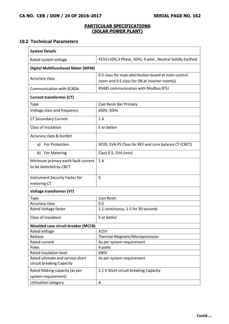
CA NO. CEB / DDN / 24 OF 2016-2017 SERIAL PAGE NO. 162
PARTICULAR SPECIFICATIONS (SOLAR POWER PLANT)
Contd....
19.2 Technical Parameters
System Details
Rated system voltage 415V+10%,3 Phase, 50Hz, 4 wire , Neutral Solidly Earthed
Digital Multifunctional Meter (MFM)
Accuracy class 0.5 class for main distribution board at main control
room and 0.5 class for DB at inverter room(s)
Communication with SCADA RS485 communication with Modbus RTU
Current transformer (CT)
Type Cast Resin Bar Primary
Voltage class and frequency 650V, 50Hz
CT Secondary Current 1 A
Class of insulation E or better
Accuracy class & burden
a) For Protection 5P20, 5VA PS Class for REF and core balance CT (CBCT)
b) For Metering Class 0.5, 5VA (min)
Minimum primary earth fault current
to be detected by CBCT
1 A
Instrument Security Factor for
metering CT
5
Voltage transformer (VT)
Type Cast Resin
Accuracy class 0.5
Rated Voltage factor 1.1 continuous, 1.5 for 30 seconds
Class of insulation E or better
Moulded case circuit breaker (MCCB)
Rated voltage 415V
Release Thermal-Magnetic/Microprocessor
Rated current As per system requirement
Poles 4 poles
Rated insulation level 690V
Rated ultimate and service short circuit breaking Capacity
As per system requirement
Rated Making capacity (as per
system requirement)
2.1 X Short circuit breaking Capacity
Utilization category A

CA NO. CEB / DDN / 24 OF 2016-2017 SERIAL PAGE NO. 163
PARTICULAR SPECIFICATIONS (SOLAR POWER PLANT)
Contd....
19.3 Constructional Details
19.3.1 The panel shall be metal enclosed, free standing, floor mounted, modular type with
compartmentalized construction having degree of protection of IP 2X (Indoor) as per IS/IEC
60529. All doors and covers shall be provided with neoprene gaskets to prevent entry of vermin
and dust.
19.3.2 All switches, push buttons etc. shall be operated front and shall be flush/semi-flush mounted.
19.3.3 The panel shall be fabricated from 2 mm CRCA sheet steel for frame & load bearing surfaces.
Partitions may be fabricated from 1.6 mm CRCA if no components are mounted on them.
19.3.4 Cable entries shall be from bottom. The opening of cable entry shall be covered by 3mm thick
gland plates with proper sealing to avoid water and rodent entry.
19.3.5 Earthing bus bar of suitable cross section shall be provided throughout the length of panel.
19.3.6 The panel shall be duly wired with suitable size of 1.1kV, PVC insulated cable and terminals shall
be brought out for cable connections. 10% spare terminals subjected to minimum one of each
rating shall be provided on each distribution switchgear. All wire shall have ferrules as per wiring
diagram.
19.3.7 The panel shall be painted with 2 coats of primer after pre-treatment and 2 coats of Polyurethane
/ epoxy paint with shade as decided by the Owner.
19.3.8 The panel shall be of dead front construction suitable for front operated and back maintained
functioning.
19.3.9 240 V, 15 A, 3 pin industrial socket-outlet with ON/OFF switch shall be provided in each panel.
19.3.10 Each panel shall be provided with LED lamp rated for 240 V, 50 Hz, single phase AC supply for
interior illumination controlled by door switch.
19.3.11 Suitable lifting hooks shall be provided for each panel.
19.3.12 Each switchgear panel shall be provided with thermostatically controlled space heaters to
prevent condensation within the enclosure. The space heater shall be connected to 240 V, 50
Hz, single phase AC supply through suitable switch and fuse.
19.3.13 Earth leakage relay with Core balance CTs (CBCT) shall be provided on main incoming feeders
having phase CT ratio more than 50/1A. CBCT's shall be circular window type with window size
based on the overall diameter of the cables, to be finalized during detailed engineering.
19.4 Warranty
Distribution panels (ACDB and DCDB) shall be warranted for minimum of 1 (one) year
against all material/ manufacturing defects and workmanship
19.5 Approval
Schematic diagram and General Arrangement (GA) drawing shall be submitted for approval.

CA NO. CEB / DDN / 24 OF 2016-2017 SERIAL PAGE NO. 164
PARTICULAR SPECIFICATIONS (SOLAR POWER PLANT)
Contd....
19.6 Testing
Routine test and acceptance tests requirements shall be as per relevant standards for all
cable sizes.
20 Uninterrupted Power Supply (UPS)
20.1 Standards and Codes
Standard/Code Description
IEC 62040-1 Uninterruptible power systems (UPS) - Part 1: General and safety
requirements for UPS
IEC 62040-2 Uninterruptible power systems (UPS) - Part 2: Electromagnetic
compatibility (EMC) requirements
IEC 62040-3 Uninterruptible power systems (UPS) - Part 3: Method of specifying the
performance and test requirements
20.2 General Requirements
20.2.1 The Uninterrupted Power Supply (UPS) system shall be designed to supply power to following
loads (but not limited to).
(i) Data logger / SCADA
(ii) Fire Detection/ Alarm Panel
(iii) HMI of SCADA
(iv) Emergency Lighting
(v) Inverter’s Auxiliary supply (if applicable)
(vi) HT panel auxiliary
(vii) CCTV
20.2.2 Sizing of UPS shall be done considering the above-mentioned load at power factor of 0.8 lagging
inclusive of 10% design margin at 50 ˚C.
20.3 System Description
20.3.1 The UPS shall automatically provide continuous, regulated AC power to critical loads under
normal and abnormal conditions, including loss of input AC power. The UPS system shall consist
of the following major equipment.
(i) UPS Module
(a) Insulated Gate Bipolar Transistor (IGBT) Converter
(b) Insulated Gate Bipolar Transistor (IGBT) Inverter
(c) Digital Signal Processor (DSP) using Pulse Width Modulation (PWM) for Direct Digital Control (DDC) of
all UPS control and monitoring functions

CA NO. CEB / DDN / 24 OF 2016-2017 SERIAL PAGE NO. 165
PARTICULAR SPECIFICATIONS (SOLAR POWER PLANT)
Contd....
(d) Static bypass switch
(ii) Battery system for 2 hours
(iii) Battery protective and disconnect device
(iv) Maintenance bypass switch
(v) LCD display panel and LED indications
(vi) Integrated UPS Communications Protocols capable of communicating with SCADA system
20.3.2 The UPS shall meet the following minimum specifications.
Parameter Specification
Topology Online double conversion UPS
Input
Voltage 415V ± 10% AC
Frequency 50 ± 5 Hz
Power factor 0.95
Output
Voltage 230V ± 1% AC
Frequency 50 Hz
Power factor 0.8
Battery
Type Sealed, Maintenance-Free (AGM) battery
Capacity 100% UPS load for 2 hours
Monitoring and communication
LED Indicators Load on Inverter, Battery operation, Load on Bypass, Overload, LCD Fault, UPS Fault
Electrical contacts
Closing contacts for each of the following conditions: 1. Unit on Battery 2. Low Battery 3. Summary Alarm 4. UPS On 5. Input Fail
Local Display LCD/ LED
SCADA
communications RS-232 & RS-485 Interface Port
Overall efficiency >90%
Electrical Protection Input/ output under voltage, over temperature, overload, Short circuit, battery low trip
20.3.3 The UPS shall be forced air cooled by internally mounted fans. The fans shall be redundant in
nature to ensure maximum reliability. The fans shall be easily replaceable without the use of
special tools.
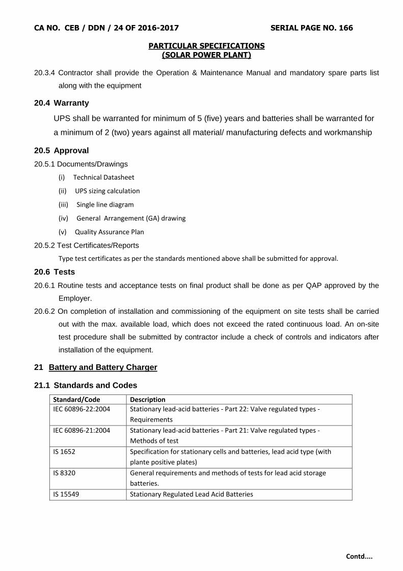
CA NO. CEB / DDN / 24 OF 2016-2017 SERIAL PAGE NO. 166
PARTICULAR SPECIFICATIONS (SOLAR POWER PLANT)
Contd....
20.3.4 Contractor shall provide the Operation & Maintenance Manual and mandatory spare parts list
along with the equipment
20.4 Warranty
UPS shall be warranted for minimum of 5 (five) years and batteries shall be warranted for
a minimum of 2 (two) years against all material/ manufacturing defects and workmanship
20.5 Approval
20.5.1 Documents/Drawings
(i) Technical Datasheet
(ii) UPS sizing calculation
(iii) Single line diagram
(iv) General Arrangement (GA) drawing
(v) Quality Assurance Plan
20.5.2 Test Certificates/Reports
Type test certificates as per the standards mentioned above shall be submitted for approval.
20.6 Tests
20.6.1 Routine tests and acceptance tests on final product shall be done as per QAP approved by the
Employer.
20.6.2 On completion of installation and commissioning of the equipment on site tests shall be carried
out with the max. available load, which does not exceed the rated continuous load. An on-site
test procedure shall be submitted by contractor include a check of controls and indicators after
installation of the equipment.
21 Battery and Battery Charger
21.1 Standards and Codes
Standard/Code Description
IEC 60896-22:2004 Stationary lead-acid batteries - Part 22: Valve regulated types -
Requirements
IEC 60896-21:2004 Stationary lead-acid batteries - Part 21: Valve regulated types -
Methods of test
IS 1652 Specification for stationary cells and batteries, lead acid type (with
plante positive plates)
IS 8320 General requirements and methods of tests for lead acid storage
batteries.
IS 15549 Stationary Regulated Lead Acid Batteries

CA NO. CEB / DDN / 24 OF 2016-2017 SERIAL PAGE NO. 167
PARTICULAR SPECIFICATIONS (SOLAR POWER PLANT)
Contd....
21.2 General
110 V DC system (Battery, Battery Charger & DCDB) in accordance with this specification
and standards stated herein, shall comprise of the following.
(i) Sealed Maintenance Free (VRLA) Battery complete with racks & accessories.
(ii) One No. Float charger.
(iii) One No. Float cum Boost charger.
(iv) DC Distribution Board (DCDB)
21.3 Battery
21.3.1 Battery shall be used to supply the following loads with back up of two hours in case of complete
power failure:
(i) Trip and closing coil of HT circuit breaker
(ii) Spring charging motors for HT circuit breaker
(iii) Annunciator and Indication circuit of HT panel
(iv) Auxiliary supply to protection relays
21.3.2 The battery sizing shall account for suitable temperature correction factors, ageing factors of
1.25, design margin of 1.25&depth of discharge of 80%.
21.3.3 The design of the battery bank and sizing calculation along with the data sheet for the battery and
battery charger shall be submitted for approval.
21.3.4 Battery voltage – 220V dc or 110V dc
21.4 Battery charger
21.4.1 The Float Charger shall be used to supply normal DC loads and float charging current of charged
battery. The Float cum Boost charger shall be designed to supply boost charging current
requirement of the associated battery as well as to supply normal DC load. After full discharge of
battery bank, the Float Cum boost charger shall be capable of charging the battery to its full
capacity in 8 hours duration while supplying normal DC load.
21.4.2 The float charger shall have both auto and manual voltage regulation arrangements with
provision of selector switch.
21.4.3 Suitable filter circuits shall be provided in all the chargers to limit the ripple content (peak to peak)
in the output voltage and current to 2 % and 5 % respectively.
21.4.4 Digital Outputs shall be configured for connection to the SCADA to monitor the outputs like
charger output current, output voltage, float/boost mode, etc.

CA NO. CEB / DDN / 24 OF 2016-2017 SERIAL PAGE NO. 168
PARTICULAR SPECIFICATIONS (SOLAR POWER PLANT)
Contd....
21.4.5 The charging equipment shall be housed in a free standing, floor mounted compartmentalized
panels. Panel shall have provision for bottom cable entry with removable undrilled cable gland
plate of 3.0 mm thickness.
21.4.6 The panel shall be of CRCA sheet steel construction having thickness of at least 2.0 mm. Degree
of protection provided by the enclosure to the internals of charger shall be IP-42.
21.4.7 The instruments, switches and indicating lamps shall be flush mounted on the front panel.
21.5 DC distribution board (DCDB)
21.5.1 DCDB shall be a separate panel, but shall form an integral part of a battery charger panel board.
21.5.2 Doors and covers shall be provided with neoprene gaskets to prevent entry of vermin and dust.
Also, door shall be provided with lock and key arrangement to prevent unauthorized access to
the board.
21.5.3 DCDB shall have adequate number of outgoing feeders with double pole, DC MCBs. At least
20% feeders shall be provided as spare.
21.6 Warranty
Batteries and battery charger shall be warranted for minimum of 2 (two) years against all
material/ manufacturing defects and workmanship.
21.7 Approval
21.7.1 Documents/Drawings
(i) Technical Datasheet
(ii) Battery sizing calculation
21.7.2 Test Certificates/Reports
Type test certificates as per the standards mentioned above shall be submitted for approval.
21.8 Tests
Routine tests and acceptance tests shall be as per the Quality Assurance Plan (QAP) approved by
the Employer.
22 Metering System
22.1 Standards and Codes
Standard/Code Description
IEC 62052-11:2003 Electricity metering equipment (AC) - General requirements,
tests and test conditions - Part 11: Metering equipment
IEC 62053-22:2003 Electricity metering equipment (AC) - Particular Requirements - Part
22: Static meters for active energy (classes 0,2 S and 0,5 S)
IS 14967 AC Static Transformer Operated Watt hour and Var-hour Meters, Class
0.2 S and 0.5 S

CA NO. CEB / DDN / 24 OF 2016-2017 SERIAL PAGE NO. 169
PARTICULAR SPECIFICATIONS (SOLAR POWER PLANT)
Contd....
22.2 ABT energy meter shall be provided as approved by state DISCOM under the metering
scheme, to measure the delivered quantum of energy to the grid for sale. The
responsibility of arranging for the meter, its inspection/calibration/testing charges etc. rests
with the Contractor. All charges incurred on Meter testing, shall be borne by the
Contractor. ABT energy metering system is to be approved by state DISCOM.
22.3 Meter must be provided with the necessary data cables.
22.4 The Contractor shall provide ABT compliant meters at the interface points.
22.5 Interface metering shall conform to the CEA(Installation and Operation Meters) Regulation
2006 and amendment thereof Commercial settlement of solar Photovoltaic Grid Interactive
based power project.
22.6 Meter shall be suitable for interfacing for synchronizing the built-in clock of the meter by
GPS time synchronization equipment existing at the station either through a
synchronization pulse received from the time synchronization equipment or through a
remote PC synchronized to GPS clock shall also be in the scope of Contractor.
22.7 All charges for testing and passing of the meter with relevant government agency shall be
borne by Contractor, the Employer will assist Contractor for necessary document as and
when required. Contractor has to intimate the required documents at least 7 days prior of
such requirements.
22.8 ABT compliant Energy Meters shall have technical specification as given below (not limited
to specified requirement, Contractor can provide Meter with latest facilities).
22.8.1 Meters shall carry out measurement of active energy (both import and export) and reactive
energy (both import and export) by 3-phase, 4-wire principle suitable for balanced/ unbalanced 3
phase load.
22.8.2 Meters shall have an accuracy of energy measurement of at least Class 0.2S for active energy
and at least Class 0.5 for reactive energy, and shall be connected to Class 0.2 CT cores and
Class 0.2 VT windings or as per state grid regulations. The active and reactive energy shall be
directly computed in CT & VT primary ratings.
22.8.3 Meters shall compute the net MWh and MVArh during each successive 15-minute block metering
interval along with a plus/minus sign, instantaneous net MWh, instantaneous net MVARh,
average frequency of each 15 minutes, net active energy at midnight, net reactive energy for
voltage low and high conditions at each midnight.

CA NO. CEB / DDN / 24 OF 2016-2017 SERIAL PAGE NO. 170
PARTICULAR SPECIFICATIONS (SOLAR POWER PLANT)
Contd....
22.8.4 Each energy meter shall have a seven digit display unit. It shall display the net MWh and MVARh
with a plus/minus sign and average frequency during the previous metering interval; peak MW
demand since the last demand reset; accumulated total (instantaneous) MWh and MVARh with a
plus/minus sign, date and time; and instantaneous current and voltage on each phase.
22.8.5 All the registers shall be stored in a non-volatile memory. Meter registers for each metering
interval, as well as accumulated totals, shall be downloadable. All the net active/reactive energy
values displayed or stored shall be with a plus /minus sign for export/import.
22.8.6 At least the following data shall be stored before being over-written for the following parameters.
S. No. Parameters Details Min. No. of days
1 Net MWh 15 min. block 90 days in meter
2 Average Frequency 15 min. block 90 days in meter
3 Net MVARh for > 103% 15 min. block 90 days in meter
4 Cumulative net MWh At every mid night 30 days in meter/ 90 days in PC
5 Cumulative net MVARh for >103%
At every mid night 30 days in meter/ 90 days in PC
6 Date & time blocks for VT failure on any phase
22.8.7 The meter shall have a built in clock and calendar with an accuracy of less than15 seconds per
month drift without assistance of external time synchronizing pulse.
22.8.8 Date/time shall be displayed on demand. The clock shall be synchronized by GPS time
synchronization equipment existing at the station provided by Contractor.
22.8.9 he meter shall be suitable to operate with power drawn from the VT supplies. The burden of the
meters shall be less than maximum 2VA.
22.8.10 The power supply to the meter shall be healthy even with a single- phase VT supply. An
automatic backup, in the event of non-availability of voltage in all the phases, shall be provided
by a built in long life battery and shall not need replacement for at least 10 years with a
continuous VT interruption of at least 2 years. Date and time of VT interruption and restoration
shall be automatically stored in a non-volatile memory.
22.8.11 Even under the absence of VT input, energy meter display shall be available and it shall be
possible to download data from the energy meters.
22.8.12 Meters shall have an optical port on the front of the meter for data collection from either a hand
held meter reading instrument (MRI) having a display for energy readings or from a notebook
computer with suitable software.
22.8.13 The meter shall have means to test MWh and MVARh accuracy and calibration at site in-situ
and test terminal blocks shall be provided for the same.

CA NO. CEB / DDN / 24 OF 2016-2017 SERIAL PAGE NO. 171
PARTICULAR SPECIFICATIONS (SOLAR POWER PLANT)
Contd....
22.8.14 The Employer/ Owner shall have the right to carry out surprise inspections of the
Metering Systems from time to time to check their accuracy.
22.8.15 The Contractor must comply with the relevant grid regulations, DISCOM‟s, State
TRANSCO‟s & CEA‟s guidelines with respect to all the works corresponding to power
evacuation, transmission, termination along with metering at DISCOM‟s substation.
23 Earthing
23.1 Standards and Codes
Earthing system shall comply with latest revisions and amendments of the relevant IEC
standards and IS codes. In particular, earthing system shall comply with the following
standards and codes.
Standard/Code Description
IS 3043 Code of Practice for Earthing
IEEE 80 IEEE Guide for Safety in AC Substation Grounding
IEEE 142 IEEE Recommended Practice for Grounding of Industrial and Commercial Power Systems
Indian Electricity Rules
23.2 General Requirements
23.2.1 Earthing system shall be designed based on system fault current and soil resistivity value
obtained from geo-technical investigation report. Earth grid shall be formed consisting of number
of earth electrodes sufficient enough to dissipate the system fault current interconnected by
earthing conductors.
23.2.2 The earth electrode shall be made of high tensile low carbon steel rod, molecularly bonded by
high conductivity copper on outer surface with coating thickness not less than 250 micron as per
relevant standards. Suitable earth enhancing material shall be filled around the electrode to lower
the resistance to earth. Inspection chamber and lid shall be provided as per IS 3043.
23.2.3 Earth conductors shall be made of copper bonded steel or galvanized steel of sufficient cross
section to carry the fault current and withstand corrosion.
23.2.4 Earth conductors buried in ground shall be laid minimum 600 mm below ground level unless
otherwise indicated in the drawing. Back filling material to be placed over buried conductors shall
be free from stones and harmful mixtures. Earthing conductor shall be buried at least 2000 mm
outside the fence of electrical installations.
23.2.5 Earth electrodes shall not be situated within 1.5m from any building whose installation system is
being earthed. Minimum distance between earth electrodes shall be the driven depth of the
electrode.

CA NO. CEB / DDN / 24 OF 2016-2017 SERIAL PAGE NO. 172
PARTICULAR SPECIFICATIONS (SOLAR POWER PLANT)
Contd....
23.2.6 Every alternate post of the transformer yard and switchyard fence shall be connected to the earth
grid by one GS flat and gates by flexible lead to the earthed post.
23.2.7 All welded connections shall be made by electric arc welding. For rust protection the welds should
be treated with red lead compound and afterwards thickly coated with bitumen compound.
23.3 Earthing of PV array field
23.3.1 All PV Modules, Module Mounting Structures (MMS) and String Monitoring Unit (SMU) structures
in the PV array field shall be bonded to the earthing system by two distinct connections.
23.3.2 Each PV Module frame shall be earthed using copper wire of sufficient cross section. The copper
wire shall be connected to the earth hole provided in the module frame using suitable
arrangement in line with the manufacturer recommendation. The earthing arrangement shall use
stainless washers to prevent galvanic corrosion between aluminium frame and copper wire. In
order to achieve effective earthing, serrated washers shall be employed to penetrate the
anodization layer of the module frame.
23.3.3 Continuous copper earthing wire shall be run to connect a group of modules and both ends of the
loop shall be bolted to the DC earth grid using bimetallic lugs and stainless-steel fasteners. The
copper earthing wire shall be routed in such a way to avoid physical contact with the module
aluminium frame.
23.3.4 The connection between MMS and DC earth grid shall be bolted or welded. Portion of the MMS
which undergoes welding at site shall be coated with two coats of cold galvanising and anti-
corrosion paint afterwards.
23.3.5 Earth electrodes of the DC earth grid shall be uniformly distributed throughout the PV array field
so that optimum earth resistance is offered to leakage current flowing from any module frame or
MMS.
23.3.6 SMU equipment earthing point shall be connected to the DC earth grid using flexible copper cable
of sufficient cross section as recommended by the manufacturer. The connection with the DC
earth grid shall be done using suitable bimetallic lugs and stainless-steel fasteners.
23.4 PCU Earthing
DC negative bus bar of the PCU shall be earthed to avoid Potential Induced Degradation
(PID). DC negative bus bar and PCU equipment earth shall be bonded to the PCU earth
bus and connected to earth electrodes through flexible copper cable of sufficient cross
section as mentioned by the manufacturer. The interconnection of PCU earth electrodes
with DC earth grid shall be as per PCU manufacturer recommendation.

CA NO. CEB / DDN / 24 OF 2016-2017 SERIAL PAGE NO. 173
PARTICULAR SPECIFICATIONS (SOLAR POWER PLANT)
Contd....
23.5 Transformer Earthing
23.5.1 Inverter transformer neutral shall be floating, not to be earthed. Transformer tank, cable box,
marshalling box and all other body earth points shall be earthed.
23.5.2 Inverter transformer shield shall be earthed separately using minimum two no. of earth
electrodes. Earthing conductor between shield bushing and earth electrodes shall be copper flat
of suitable size not less than 25 x 6 mm.
23.5.3 Neutral and body of the auxiliary transformer shall be earthed.
23.6 Inverter Room and Main Control Room Earthing
23.6.1 Metallic enclosure of all electrical equipment inside the inverter room and main control room shall
be connected to the earth grid by two separate and distinct connections.
23.6.2 Cable racks and trays shall be connected to the earth grid at minimum two places using
galvanized steel flat.
23.6.3 SCADA and other related electronic devices shall be earthed separately using minimum two no.
of earth electrodes.
23.7 Switchyard Earthing
The metallic frame work of all switchyard equipment and support structures shall be
connected to the earth grid by means of two separate and distinct connections.
23.8 Approval
23.8.1 Documents/ drawings
(i) Technical datasheet
(ii) Earthing Design calculation
23.9 Tests
On completion of installation, continuity of earth conductors and efficiency of all bonds and
joints shall be checked. Earth resistance at earth terminations shall be measured and
recorded. The earth plate shall be provided to facilitate its identification and for carrying
out periodical inspection.
24 Lightning Protection System
24.1 Lightning Protection System for entire plant against direct lighting strokes shall be provided
with Early Streamer Emission (ESE) Air Terminal as per NFC 17-102:2011.
24.2 Protection Level for the entire plant shall be level – I.

CA NO. CEB / DDN / 24 OF 2016-2017 SERIAL PAGE NO. 174
PARTICULAR SPECIFICATIONS (SOLAR POWER PLANT)
Contd....
24.3 Each ESE air terminal shall be provided with following accessories.
(i) Highly insulated poly-plastic adaptor to fix the ESE air terminal with the FRP mast
(ii) Fiber glass Reinforced Plastic (FRP) mast
(iii) Coupler to connect FRP mast with GI mast
(iv) Galvanized Iron mast with base plate and guy wire kit
(v) Down-conductor: PVC insulated flexible copper cable of suitable size complying with EN 50164-2 or equivalent
standard. It shall be routed along the mast with suitable fixings and connecters
(vi) Test joint with each down conductor
(vii) Lightning event counter complying with EN 50164-6 or equivalent standard. It shall be fixed at suitable height
in series with the down conductor.
(viii) Earth termination system in accordance with NFC 17-102. Earth electrodes shall comply with the EN 50164-2
or equivalent standard. Earth enhancing compounds complying with EN 50164-7 or equivalent standard, may
be used where soil resistivity is higher and making it impossible to achieve system resistance within specified
limit.
24.4 Accessories listed above are indicative only and any other fittings or accessories, which are usual
or necessary for satisfactory operation of the lightning protection shall be provided by the
Contractor without extra charges.
24.5 Necessary foundation/anchoring for holding the lightning mast in position to be made after giving
due consideration to shadow on PV array, maximum wind speed and maintenance requirement at
site in future.
24.6 The product shall be warranted for minimum of 2 (two) years against all material/ manufacturing
defects and workmanship.
24.7 Type test reports as per NFC 17-102:2011 shall be submitted during detailed engineering for
approval.
25 Communication Cables
25.1 Optical Fibre Cables
25.1.1 Optic Fibre cable shall be 4/8/12 core, galvanized corrugated steel taped armoured, fully water
blocked with dielectric central member for outdoor/ indoor application so as to prevent any
physical damage.
25.1.2 The cable shall have multiple single-mode or multimode fibres on as required basis so as to avoid
the usage of any repeaters.

CA NO. CEB / DDN / 24 OF 2016-2017 SERIAL PAGE NO. 175
PARTICULAR SPECIFICATIONS (SOLAR POWER PLANT)
Contd....
25.1.3 The outer sheath shall have Flame Retardant, UV resistant properties and are to be identified
with the manufacturer‟s name, year of manufacturing, progressive automatic sequential on-line
marking of length in meters at every meter on outer sheath.
25.1.4 The cable core shall have suitable characteristics and strengthening for prevention of damage
during pulling.
25.1.5 All testing of the optic fiber cable being supplied shall be as per the relevant IEC, EIA and other
international standards.
25.1.6 The Contractor shall ensure that minimum 100% cores are kept as spare in all types of optical
fibre cables.
25.1.7 Cables shall be suitable for laying in conduits, ducts, trenches, racks and underground buried
installation.
25.1.8 Spliced/ Repaired cables are not acceptable. Penetration of water resistance and impact
resistance shall be as per IEC standard.
25.2 Communication Cable (Modbus)
25.2.1 Data (Modbus) Cable to be used shall be shielded type with stranded copper conductor. Cable
shall have minimum 2 pair each with conductor size of 0.5 Sq.mm. Cable shall be flame retardant
according to IEC 60332-1-2.
25.2.2 Cable shall be tested for Peak working voltage of not less than 300 V and shall be suitable for
serial interfaces (RS 422 and RS 485).
25.2.3 Communication cable shall be laid through underground with suitable HDPE ducts.
26 SCADA
26.1 General Requirements
26.1.1 The Contractor shall provide complete SCADA system with all accessories, auxiliaries and
associated equipment and cables for the safe, efficient and reliable operation of entire solar plant
and its auxiliary systems.
26.1.2 The Contractor shall provide all the components including, but not limited to, Hardware,
Software, Panels, Power Supply, HMI, Laser Printer, Gate way, Networking equipment and
associated Cables, firewall etc. needed for the completeness.
26.1.3 SCADA System shall have the provision to perform the following functions.
(i) Real-time acquisition and display of data, status, alarms and trends.
(ii) Display of status of major equipment in Single Line Diagram(SLD) format with string level monitoring capability
(iii) Display and storage of measured values
(iv) Display and storage of derived/calculated/integrated values
(v) Generate, store and retrieve user configurable Sequence of Event (SOE) Reports
CA NO. CEB / DDN / 24 OF 2016-2017 SERIAL PAGE NO. 176
PARTICULAR SPECIFICATIONS (SOLAR POWER PLANT)
Contd....
(vi) Remote monitoring of essential parameters on the web using standard modem (Internet connection for
transferring data to web shall be taken by Contractor in the name of Employer for O&M period).
26.1.4 It shall be possible to remove/replace redundant controller or various modules (like any I/O
module, interface module, etc.) from its slot for maintenance purpose without switching off power
supply to the corresponding rack without releasing any spurious signal to controller and causing
disturbance or loss of controller functions for other controller.
26.1.5 The Control system shall be designed to operate in non-air-conditioned area. However, the
Contractor shall provide a Package/Split AC of suitable capacity decided by heat load
requirement in SCADA room at Main Control Room.
26.2 Programmable Logic based control system at Main Control Room
26.2.1 Bidder shall provide PLC based SCADA at Main Control Room. For other locations such as Sub
Pooling Switchgear Room (if applicable) bidder may offer IO modules/RTU/PLC for
completeness of SCADA.
26.2.2 PLC Processor
The processor unit shall be capable of executing the following functions.
(i) Receiving binary and analog signals from the field to server.
(ii) Implementing all logic functions for protection and annunciation of the equipment and systems.
(iii) Providing supervisory information for alarm, various types of displays, status information, trending,
historical storage of data etc.
26.2.3 The SCADA shall be OPC version 2.05a compliant and implement an OPC- DA 2.05a server as
per the specification of OPC Foundation. All data should be accessible through this OPC server.
SCADA shall have OPC connectivity for other systems.
26.3 Human Machine Interface System (HMIS)
26.3.1 Graphical interface Unit (GIU) / Operator work station (OWS) shall perform monitoring and
operation of all device sinter acting with PLC based system.
26.3.2 The system shall have built-in safety features that will allow/disallow certain functions and entry
fields with in a function to be under password control to protect against in advertent and
unauthorized use of these functions. The system security shall contain various user levels with
specific rights as finalized by the Employer during detailed engineering. However, no. of user
levels, no. of users in a level and rights for each level shall be change able by the programmer
(Administrator).
26.3.3 Bidder has to provide suitable hardware and software based fire wall for net work security to
restrict unauthorized access to HMI/Solar SCADAPCs and system.

CA NO. CEB / DDN / 24 OF 2016-2017 SERIAL PAGE NO. 177
PARTICULAR SPECIFICATIONS (SOLAR POWER PLANT)
Contd....
26.4 Programming Functionalities
Programming of the PLC Processor/controller as well as programming of HMIS shall be
user friendly with graphical user interface. All programming functionalities shall be
password protected to avoid unauthorized modification.
26.5 Software Requirements
26.5.1 All necessary software required for implementation of control logic, operator station displays/logs,
storage & retrieval and other functional requirement shall be provided.
26.5.2 Industry standard operating system like WINDOWS (latest version)etc. to ensure openness and
connectivity with other system in industry shall be provided. SCADA system shall support
following standard protocols (included but not limited to) to communicate with different sub
system/Devices:
(i) Modbus (TCP/IP, RTU, ASCII)
(ii) Sub Station Protocol like IEC-61850
(iii) IEC 60870 – 5 – 101/104
(iv) Any other protocol on which the offered equipment (by Contractor) will communicate with SCADA.
26.5.3 The Contractor shall provide software locks and passwords to Employer for all operating &
application software. Also, the Contractor shall provide sufficient documentation and program
listing so that it is possible for the Employer to carryout modification at a later date.
26.6 System Spare Capacity
26.6.1 Over and above the equipment and accessories required to meet the fully implemented system
as per specification requirements, Control System shall have spare capacity of 10% along with
the necessary hardware/equipment/accessories to meet the future expansion requirement.
26.7 Data Communication System (DCS)
The DCS shall have the following minimum features.
26.7.1 Redundant communication controllers shall be provided to handle the communication between I/
O Modules (including remote I/O) and PLCs and between PLCs and operator work station.
26.7.2 The design shall be such as to minimize interruption of signals. It shall ensure that a single failure
anywhere in the media shall cause no more than a single message to be disrupted and that
message shall automatically be retransmitted. Any failure or physical removal of any
station/module connected to the system bus shall not result in loss of any communication
function to and from any other station/module.
26.7.3 Built-in diagnostics shall be provided for easy fault detection. Communication error detection and
correction facility (ECC) shall be provided at all levels of communication. Failure of one bus and
changeover to the standby system bus shall be automatic and completely bump less and the
same shall be suitably alarmed/logged.

CA NO. CEB / DDN / 24 OF 2016-2017 SERIAL PAGE NO. 178
PARTICULAR SPECIFICATIONS (SOLAR POWER PLANT)
Contd....
26.7.4 Data transmitting speed shall be sufficient to meet the responses of the system in terms of
displays , control etc. plus 20%sparecapacity shall be available for future expansion.
26.7.5 Contractor shall employ redundant Fibre optic back bone for data communication between
Inverter rooms and main control room.
26.7.6 The Contractor shall furnish details regarding the communication system like communication
protocol, bus utilization calculations etc.
26.8 Operator Interface Displays/Logs/Reports
Suitable Operator Interface Displays/Logs/Reports for control operation & monitoring shall
be provided. The details shall be furnished and finalized during detailed engineering
stage.
26.9 Historical Storage and Retrieval System(HSRS)
26.9.1 The HSRS shall collect, store and process system data from man-machine interface system and
plant information system (MMIPIS) data base. The data shall be saved online on hard disk and
automatically transferred to erasable long-term storage media once in every 24 hours periodically
for long term storage. Provision shall be made to notify the operator when hard disk is certain
percentage full. The disk capacity shall be sufficient to store at least seven days data.
26.9.2 The data to be stored in the above system shall include alarm and event list, periodic plant data,
selected logs/reports. The data/information to be stored and frequency of storage and retrieval
shall be finalised during detail engineering stage.
26.10 Control and Power Supply Scheme
Contractor shall provide the UPS/DC Power supply of suitable rating to cater all the load
requirements of SCADA system and its auxiliaries. The power back up for the entire
system should be at least for 02 hours.
26.11 Control Cabinets/Panels/Desks at Main Control Room
26.11.1 The cabinets shall be IP-22 protection class. The Contractor shall ensure that the temperature
rise is well within the safe limits for system components even under the worst condition and
specification requirements for remote I/O cabinets.
26.11.2 The cabinets shall be totally enclosed, free standing type and shall be constructed with
minimum 2mm thick steel plate frame and1.6mm thick CRCA steel sheet or as per supplier's
standard practice for similar applications.

CA NO. CEB / DDN / 24 OF 2016-2017 SERIAL PAGE NO. 179
PARTICULAR SPECIFICATIONS (SOLAR POWER PLANT)
Contd....
26.12 Software Licences
The Contractor shall provide software license for all software being used in Contractor‟s
System. The software licenses shall be provided for the project and shall not be
hardware/machine-specific.
26.13 Hardware at Main Control Room
26.13.1 The Hardware as specified shall be based on latest state of the art Workstations and Servers
and technology suitable for industrial application & power plant environment.
26.13.2 All the peripherals shall conform to the following minimum requirement but the exact make&
model shall be as approved by Employer during detailed engineering. The LAN to be provided
shall support TCP/IP protocol (Ethernet connectivity) with OPC RDI for interface with PLCs/other
systems and shall have data communication speed of min. 100 Mbps. All network components of
LAN and Workstations shall be compatible to the LAN, without degrading its performance.
Processor 64 Bit
Hard disk 1TB -RAID 1
Memory 8 GB RAM upgradable to 16 GB
Monitor Min 22” LED Flat Monitor with non-interfaced refresh
rate min. 75 Hz. Communication port-2 Serial bus, one
parallel Dual 10/100/1000 Mbps. Ethernet Graphic
Memory=16 MB Expansion slot=3
Screen display unit Min 50” LED Flat Monitor with wall mounted arrangement for the display of SCADA screen
Removable bulk storage drive (DVD /
DAT)
6 GB (minimum)
Removable Bulk Storage Media for
above (with each server/ work-
station)
10 nos.
DVD R/W 16x or higher
Intelligent UPS (on line) with
remotemonitoring for each
workstation/ server
1 no. with 30 mins. Battery backup on machine
load
Keyboard ASCII
Pointing Device Mouse
Colour Laser Printer Heavy duty type with resolution of 600 dpi Resolution
26.14 Factory Acceptance Test (FAT)
FAT procedure shall be submitted by bidder for approval. SCADA shall communicate with
all third devices which are part of solar plant and same shall be demonstrated during the
FAT.

CA NO. CEB / DDN / 24 OF 2016-2017 SERIAL PAGE NO. 180
PARTICULAR SPECIFICATIONS (SOLAR POWER PLANT)
Contd....
27 Weather Monitoring System
As a part of weather monitoring system, the Contractor shall provide the following
measuring instruments with all necessary software and hardware required to integrate
with SCADA.
27.1 Pyranometer
27.1.1 The Contractor shall provide minimum 4 (four) number of secondary standard pyranometers (ISO
9060 classification) along with necessary accessories for measuring the incidental solar radiation
at horizontal and inclined plane of array.
27.1.2 Specification of the pyranometer shall be as follows.
Parameter Specification
Spectral Response 0.31 to 2.8 micron
Sensitivity Minimum 8micro-volt/W/m2
Time response (95%) Maximum 15s
Nonlinearity ±0.5%
Temperature Response ±2%
Tilt error <±0.5%
Zero offset thermal radiation ±7 W/m2
Zero offset temperature change ±2 W/m2
Operating temperature range 0°C to +80°C
Uncertainty (95% Confidence Level) Hourly Max-3% Daily Max-2%
Non-stability Maximum ±0.8%
Resolution Minimum +/- 1W/m2
Input Power for Instrument & Peripherals 230V AC (If required)
27.1.3 Each instrument shall be supplied with necessary cables. Calibration certificate with calibration
traceability to World Radiation Reference (WRR) or World Radiation Centre (WRC) shall be
furnished along with the equipment. The signal cable length shall not exceed 20m. The
Contractor shall provide instrument manual in hard and soft form.
27.2 Temperature Sensor
The Contractor shall provide minimum 6 (six) temperature sensors(1 (one) for ambient
temperature measurement with shielding case and 5(five)for module temperature
measurement). The temperature sensor shall be Resistance Temperature Detector
(RTD)/Semiconductor type with measurement range of 0oC to 80oC.The instrument shall
have valid calibration certificate.

CA NO. CEB / DDN / 24 OF 2016-2017 SERIAL PAGE NO. 181
PARTICULAR SPECIFICATIONS (SOLAR POWER PLANT)
Contd....
27.3 Anemometer
Contractor shall provide minimum one no. ultrasonic wind sensor (no moving parts) for
wind speed and direction monitoring.
Details Values
Velocity range with accuracy limit
0-60m/s with +/-2% accuracy @12 m/s; Resolution: 0.01m/s
Wind direction range with accuracy limit
0 to 360o (No dead band) with +/-2o accuracy @12 m/s; Resolution: 1o
Mounting Bracket Anodized Aluminium bracket to reduce corrosion, all mounting bolts of SS
Protection Class IP66
Output RS232 and RS485
27.4 Data logger and Data Acquisition System
Data logger for the weather monitoring station should have the following features:
27.4.1 Provision for analog, digital and counter type inputs for interfacing with various type of sensors:
(i) Analog Input
Adequate nos. for all analog sensors with redundancy
Provision for operation in different current and voltage ranges as per connected sensors
Accuracy of +/-0.1% of FS
(ii) Digital Inputs
Adequate no. of Digital inputs and outputs for the application
(iii) Provision for RS232 and RS485 serial outputs
(iv) Built-in battery backup
(v) Connectivity and Data transmission:
Built-in GSM/GPRS modem for wireless data transmission to SCADA/cloud server (procurement of GPRS
enabled SIM Card and connection subscription to be the responsibility of Contractor). It should be
possible to remotely communicate with the device for configuration settings.
RS485 MODBUS interface for data collection and storage on SCADA
Web interface with provision for user login to enable viewing and downloading of weather data in XLS/
CSV format
Communication protocol should support fast data transmission rates, enable operation in different
Frequency bands and have an encryption based data security layer for secure data transmission

CA NO. CEB / DDN / 24 OF 2016-2017 SERIAL PAGE NO. 182
PARTICULAR SPECIFICATIONS (SOLAR POWER PLANT)
Contd....
(vi) Display Settings: Graphic LCD screen which should be easily accessible and should display relevant details
like all sensor values, battery strength, network strength etc.
(vii) Provision of Time synchronization from telecom time or server time
(viii) Data Storage: Provision for at least 2 MB internal Flash Memory and at least 8 GB Micro SD card
(expandable)
(ix) Protection level: IP65
28 CCTV Camera
28.1 CCTV Cameras along with monitoring stations (sufficient numbers) and all other
accessories required for its proper operation must be installed to have complete coverage
of following areas.
(i) Main entry: Covering all the entry/exit 24 hours
(ii) Along the Plant Perimeter: Covering complete perimeter of Plant Area to capture all possible
intrusion
(iii) Control Rooms: Covering Entry/Exit and activities within Control Rooms
The Contractor has to propose the locations and number of cameras required for the Plant
during bidding, however Employer‟s decision on number of cameras shall be final.
28.2 Monitoring stations of the CCTV Network shall be installed in Main Control Room.
28.3 The CCTV system shall be designed as a standalone IP based network architecture.
System shall use video signals from different cameras at defined locations, process the
video signals for viewing on monitors at control room and simultaneously record all video
streams using latest compression techniques.
28.4 Camera shall be colour, suitable for day and night surveillance (even under complete
darkness) and network compatible.
28.5 It shall be possible to control all cameras i.e., PTZ auto/ manual focus, selection of pre-
sets, video tour selection etc. The software shall support flexible 1/2/4 windows split
screen display mode or scroll mode on the display monitor for live video.

CA NO. CEB / DDN / 24 OF 2016-2017 SERIAL PAGE NO. 183
PARTICULAR SPECIFICATIONS (SOLAR POWER PLANT)
Contd....
28.6 The system shall support video analytics in respect of the following:
(i) Video motion detection
(ii) Object tracking
(iii) Object classification
Camera server shall be provided with sufficient storage space to storage recordings of all
cameras at HD mode for a period of 15 days. All recordings shall have camera ID,
location, date and time of recording.
29 Fire alarm System
29.1 Standards and Codes
Standard/Code Description
IS 2189 Selection, Installation and Maintenance of Automatic Fire Detection and Alarm System Code of Practice
IS 2171 Portable Fire Extinguishers, Dry Powder (Cartridge Type)
IS 8149 Functional requirements for twin CO2 fire extinguishers (trolley mounted)
IS 2546 Galvanized mild steel fire bucket
National Building code 2005
29.2 Contractor shall ensure the compliance of fire detection and alarm system as per relevant
standards and regulations. The installation shall meet all applicable statutory requirements
and safety regulations of state/central fire department/body or any other competent
authority in terms of fire protection.
29.3 Fire fighting system for the proposed power plant for fire protection shall be consisting of
but not limited to:
(i) Sand buckets
(ii) Portable fire extinguishers (CO2 and dry powder type)
(iii) Microprocessor based fire alarm panel
(iv) Multi sensor smoke detectors
(v) Hooter cum strobe
(vi) Manual call points
(vii) Cables from sensor to fire Panel.
29.4 Minimum two numbers of fire extinguishers (CO2 and Foam type each, of capacity 10 kg
having BIS certification marking as per IS: 2171) shall be provided at every
building/encloser, transformer yard and switchyard. However, contractor must comply with
existing building code for fire protection and relevant IS codes.
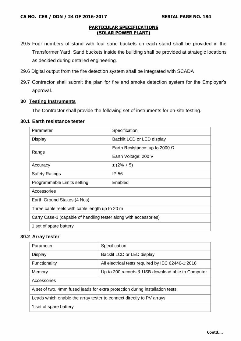
CA NO. CEB / DDN / 24 OF 2016-2017 SERIAL PAGE NO. 184
PARTICULAR SPECIFICATIONS (SOLAR POWER PLANT)
Contd....
29.5 Four numbers of stand with four sand buckets on each stand shall be provided in the
Transformer Yard. Sand buckets inside the building shall be provided at strategic locations
as decided during detailed engineering.
29.6 Digital output from the fire detection system shall be integrated with SCADA
29.7 Contractor shall submit the plan for fire and smoke detection system for the Employer‟s
approval.
30 Testing Instruments
The Contractor shall provide the following set of instruments for on-site testing.
30.1 Earth resistance tester
Parameter Specification
Display Backlit LCD or LED display
Range Earth Resistance: up to 2000 Ω
Earth Voltage: 200 V
Accuracy ± (2% + 5)
Safety Ratings IP 56
Programmable Limits setting Enabled
Accessories
Earth Ground Stakes (4 Nos)
Three cable reels with cable length up to 20 m
Carry Case-1 (capable of handling tester along with accessories)
1 set of spare battery
30.2 Array tester
Parameter Specification
Display Backlit LCD or LED display
Functionality All electrical tests required by IEC 62446-1:2016
Memory Up to 200 records & USB download able to Computer
Accessories
A set of two, 4mm fused leads for extra protection during installation tests.
Leads which enable the array tester to connect directly to PV arrays
1 set of spare battery

CA NO. CEB / DDN / 24 OF 2016-2017 SERIAL PAGE NO. 185
PARTICULAR SPECIFICATIONS (SOLAR POWER PLANT)
Contd....
30.3 Insulation tester
Parameter Specification
Display Backlit LCD or LED display
Insulation Test Range 0.1 MΩ to 10 GΩ
Test Voltage 250V, 500V, 1000V, 5000V
Test Voltage accuracy +20% on positive side only no negative variation
is allowed
Insulation Test Current 1 mA nominal
Auto Discharge Discharge time< 0.5
Second for C=1
Open Circuit test Voltage >4 V, <8 V
Accessories
Heavy duty Test Lead Set – 4 Nos.
Carry Case with sufficient space for accommodating accessories.
30.4 Digital Multimeter
Parameter Specification
Display
Backlit LCD or LED display;
Minimum resolution: 5 ¾ places for DC , 4 ¾
places for AC
Measuring Category
1000V CAT III as per IEC Standard 61010-1;
wave shape independent RMS measurement
(True RMS) suitable for operation in the site
conditions.
Additional Functions
Resistance (Ω), Temperature (oC ), Continuity,
Diode , Capacitance, Frequency, Duty cycle
measurement
Accessories
Temperature Probe
Silicon Test Lead
Alligator Clip
Carry Case with sufficient space for accommodating accessories.

CA NO. CEB / DDN / 24 OF 2016-2017 SERIAL PAGE NO. 186
PARTICULAR SPECIFICATIONS (SOLAR POWER PLANT)
Contd....
30.5 Clamp meter
Parameter Specification
Display Backlit LCD or LED display
Measuring Category
1000V CAT III as per IEC Standard 61010-1; wave shape
independent RMS measurement (True RMS) suitable for operation
in the site conditions.
Current Range AC & DC Current up to 1000A/400 A
Voltage range AC & DC Voltage up to 1000V
Additional Functions Resistance, continuity, diode and non- contact voltage detection,
Active, Reactive and Apparent Power, THD, PF
Accessories
Test leads
Battery
Alligator Clip
Carry Case with sufficient space for accommodating accessories.
30.6 Infra-red thermal imaging camera
Parameter Value
Spectral response 8 μm to 14 μm (LW)
Temperature-sensitivity and calibration range
–20 °C to +120 °C
Atmospheric air temperature -10 °C to +40 °C
Thermal sensitivity NETD ≤ 0.1 K at 30 °C
Geometric resolution 640 x 480 pixels
Photo camera resolution Approx. 30 times of IR camera resolution
Absolute error of measurement < ± 2 K
Adjustable parameters Emissivity, ambient temperature
Adjustable functions Focus, temperature level and span
Measurement functions Measuring spot, measuring area with average and maximum temperature
Calibration
The measuring system (Camera, lens, aperture and filter):
The camera has to be traceably calibrated at least every
two years. The calibration has to be documented. If the
camera is not compliant, it has to be readjusted by the
manufacturer.
Documentation Storing of the infrared picture with the radiometric data

CA NO. CEB / DDN / 24 OF 2016-2017 SERIAL PAGE NO. 187
PARTICULAR SPECIFICATIONS (SOLAR POWER PLANT)
Contd....
30.7 Digital lux meter
Parameter Specification
Range 0 – 1000 lux
Accuracy ± (2% + 5)
Resolution 1 lux
Display 3½ digits, Backlit LCD/LED
30.8 All testing equipment shall possess valid calibration certificate issued from approved NABL
labs.
30.9 Instruments of superior rating is allowed after seeking consent of the Employer.
30.10 Maintenance, calibration, up keeping, repair & replacement of these tools will be in the
scope of the Contractor during 5 years of O&M.
30.11 It is Contractor‟s responsibility to arrange for tools, tackles, logistics, test kits, manpower,
experts etc. required for trouble free operation of Plant.
31 Civil, Mechanical & Plumbing Works
31.1 General Requirement
31.1.1 This section of Technical Specifications describes detailed technical and functional
requirements of all civil, Mechanical & Plumbing works included in the scope excluding
civil works for Transmission Line towers, Tower extensions & Tower accessories.
31.2 Standards & Codes
31.2.1 All design and construction of civil works shall conform to relevant Indian standards such as BIS,
IRC, MORTH, NBC etc. In general codes are as below:
IS: 800, 801or
802
Design of steel structures with working stress method (WSD)
of design
IS: 456 Design of concrete structure
IS: 3374 Design of liquid retaining structure
31.2.2 Only in case of non-availability of Indian standard, equivalent American or British standard may
be used for design with prior approval of the Employer and the contractor shall submit proper
justification along with his request to the Employer for his review.
CA NO. CEB / DDN / 24 OF 2016-2017 SERIAL PAGE NO. 188
PARTICULAR SPECIFICATIONS (SOLAR POWER PLANT)
Contd....
31.2.3 Contractor shall either have in - house qualified and experienced engineering team to carry out
engineering or shall appoint a qualified and experienced external agency to carry out the
engineering as approved by GE.
31.2.4 The design calculations for MMS, RCC structure, steel structure, foundation system, road work,
drainage work, etc. shall be submitted for prior approval of Employer before commencement of
construction.
31.2.5 The design calculations shall be supplemented with a neat sketch showing the structure
geometry, node and member nos., lengths of various typical members, support points and type
of supports, types of materials with design properties considered, type of sections used in
analysis & design.
31.2.6 The report shall also include back-up calculations for various loads adopted in design, brief write-
up on primary load cases and load combinations considered and conclusions on design results
with supporting sketches for easy reference and clarity.
31.2.7 Where a computer program (other than STAAD Pro) is used for analysis and design, the
contractor shall also include a write-up on the computer program used along with validation
check. Input and output file shall also be given in the design report to facilitate its review and
approval by the Employer.
31.3 The construction methodology for MMS and its foundations, road works, drains and pile
load test procedure shall also be submitted for prior approval of Employer before start of
works.
31.4 Contractor has to submit the design documents, drawings, layouts, investigation reports,
test reports, calculations and analysis etc. for all works to Employer for approval prior to
the start of construction at site. The construction shall be done only as per approved
drawings
31.5 The contractor shall submit the detailed design calculations and drawings for MMS
structure, bill of materials and their specifications/ standards to the Employer for approval
before start for fabrication work.
31.6 Contractor must submit the complete quality documents i.e. test certificates for all tests
conducted starting from raw material stage, in process, final testing w.r.t structure
31.7 The Contractor shall submit the detailed foundation & structural design basis and the list of
reference standards, in this design philosophy. Depending upon the requirement, GE may
ask the contractor to get the design vetted by a Chartered engineer.

CA NO. CEB / DDN / 24 OF 2016-2017 SERIAL PAGE NO. 189
PARTICULAR SPECIFICATIONS (SOLAR POWER PLANT)
Contd....
32 Topographical Survey
32.1 The contractor shall be responsible for detailed Topographical Survey of the proposed
project site. The work shall be carried out through an agency with relevant experience and
shall have qualified survey team.
32.2 The Topographical survey shall be conducted at 20mx20m grid, or as directed by the
Engineer, with the help of digital surveying instruments like Total Station.
32.3 The Contractor shall carry the Bench Mark from nearest GTS Bench Mark, or any other
establish source like Railway station etc. as approved by the Employer, by fly-levelling and
establish two permanent bench marks (PBM) at site. All subsequent transfer of levels shall
be carried out with respect to these PBMs. The work shall also include constructing
permanent reference pillars at suitable locations as approved by the Employer. These
reference pillars shall be labelled permanently with their respective coordinates and
reduced levels for future use. The Permanent Bench Marks and reference pillars shall be
shown on the survey drawings.
32.4 While carrying bench mark to the project site, levels shall be established on the permanent
objects like culverts etc. at least on one object in every one km. if available along with
route with adequate description about the objects. These levels shall be maintained at site
& also mentioned in the survey report to facilitate locating these objects later on.
32.5 The work survey work shall be carried out in UTM grids system. The contractor shall also
establish the latitudes and longitudes of the corners of the project site. At least 50m width
of the adjoining plots and surrounding areas shall also be covered in the survey for
correlation with adjoining plots and facilities. The grids for the survey work shall be
established in N-S & E-W direction (corresponding to magnetic North) or the Plant North
as directed by the Employer. Positions, both in plan and elevation, of all natural and
artificial features in the area like waterways, railway tracks, trees, cultivation, houses,
fences, pucca and kutcha roads including culverts and crossings, foot tracks, other
permanent objects like telephone posts and transmission towers etc. are to be established
and subsequently shown on survey maps by means of conventional symbols (preferably,
symbols of survey of India Maps). All hills and valleys within the area/areas are to be surveyed
and plotted on maps by contours. Any unusual condition or formations on the ground,
locations of rock outcrops (if visible on the surface) and spring/falls, sand heap/dune,
possible aggregate deposits etc. shall also be noted and plotted on contour maps.

CA NO. CEB / DDN / 24 OF 2016-2017 SERIAL PAGE NO. 190
PARTICULAR SPECIFICATIONS (SOLAR POWER PLANT)
Contd....
32.6 The record of measurement of all Reduced Levels (RL) shall be submitted in digital format,
(in x, y z coordinate system) along with preliminary contour plan of the site, for Employer‟s
review before submission of final contour Map. The contour interval shall be as required
for proper representation of the topography however it shall not be more than 0.5m. The
Contractor shall submit survey maps of the site in 1:10,000 scale indicating grid lines and
contour lines, demarcating all permanent features like roads, railways, waterways,
buildings, power lines, natural streams, trees, sand dunes etc. Present use of the site i.e.
mining, quarrying, agriculture etc, existing drainage pattern of the site, possibility of water
logging and high flood level of the area shall also be captured in the document. The
project plot boundary with coordinates of all corner points along with coordinate grid of
50x50M interval shall be marked on the contour map
33 Geotechnical Investigations
33.1 The contractor shall be responsible for detailed soil investigations at the proposed project
site for the purpose of foundation design for various buildings, structures, HT lines, MMS
etc. and other design/ planning requirements.
33.2 The investigation work shall be carried out through any Govt. approved/ NABL
accredited/IIT‟s/NIT‟s Labs, which are authorized to carry out such tests. The contractor
shall submit the credentials of the proposed agency along with relevant certificates in
support thereof for verification/approval by the Employer.
33.3 The scope of work includes execution of complete soil exploration including boring and
drilling, standard penetration test (SPT), collecting disturbed(DS) and undisturbed
samples (UDS), collecting ground water samples, electrical resistivity tests (ERT) and
conducting laboratory tests on collected samples of soil, ground water analysis,
preparation and submission of report.
33.4 The field investigations shall mainly include drilling of min. 5 m deep boreholes (50% of
total No. of boreholes shall be 10m deep), conducting SPT and collecting Disturbed (DS)
and Undisturbed samples (UDS); conducting in-situ CBR test for internal roads &
peripheral road; ERT and Trial pits. Number and location of bore holes, CBR tests and
trial pits shall be decided as per the project layout, site topography and soil conditions in
consultation with the Employer. However, there shall be minimum 1 (one) borehole per 5
(five)acres of the area or per MW of capacity while number of samples for laboratory
investigations shall not be less than 50.
CA NO. CEB / DDN / 24 OF 2016-2017 SERIAL PAGE NO. 191
PARTICULAR SPECIFICATIONS (SOLAR POWER PLANT)
Contd....
33.5 The proposed Geotechnical investigation plan indicating proposed locations of Trial pits
(minimum 3 nos.), Bore holes and CBR tests (minimum 7 nos.) shall be submitted to the
Employer for review and approval before start of work.
33.6 Laboratory tests shall be conducted on DS & UDS samples and water samples in sufficient
no. and shall include, Soil classification, Grain size analysis including Hydrometer
analysis, determination of Bulk and dry density, Specific gravity, Natural moisture content,
Atterberg limits, Tri-axial shear tests (UU), Undrained shear test(Cu), Consolidation tests,
Unconfined compression tests, Free swell index, chemical analysis of soil and water
samples to determine the carbonates, sulphates, chlorides, nitrates, pH, Organic matter
and any other chemicals harmful to concrete and reinforcement/ steel. Laboratory tests on
rock samples shall be carried out for Hardness, Specific Gravity, Unit Weight, Uniaxial
Compressive Strength (in-situ & saturated), Slake Durability etc.
33.7 After completion of field and laboratory work, the contractor shall submit a Geotechnical
Investigation Report for Employer‟s approval. All bore log details and lab test results shall
be presented in the report as per provisions of relevant BIS standards. The report shall
include a Map showing the locations of various field tests including coordinates,
calculations and recommendations for foundation type and safe bearing capacity (SBC)
for buildings, switch yard structures, Sub-Station, Transformer foundation, HT lines, MMS
foundation etc. corresponding to settlement of 25mm
33.8 In case the contractor wishes to adopt pile foundation for MMS supports the report shall
also include the calculations for pile capacity for direct compression, lateral and pull out
capacity and recommended depth and dia. The contractor shall carry out field trials for
initial load test on pile to verify the pile design & finalize the safe load carrying capacity
under direction compression, lateral load and pull out. The no. of piles to be tested under
each category shall be finalized corresponding to geotechnical characteristics at site, plot
area etc. However, minimum 5 no. of piles shall be tested under each category of load.
The locations of test piles shall be finalized in consultation with Employer. The adequacy
of provided pile reinforcement in job (working) pile corresponding to the set of test loads
shall be reviewed by the contractor for any additional requirement of reinforcement steel
and the shall provide the same, the revised drawings for pile details, if any, shall be
submitted to Employer for his approval before casting. The load test on pile shall be
conducted after min. of 28 days from the date of casting. In case the contractor desires to
conduct the test earlier than 28 days, he may use suitable higher grade of concrete or if

CA NO. CEB / DDN / 24 OF 2016-2017 SERIAL PAGE NO. 192
PARTICULAR SPECIFICATIONS (SOLAR POWER PLANT)
Contd....
substantial evidence from earlier cube test results on design grade concrete to
demonstrate the early gain of required compressive strength prior to application of the test
load. However, no pile test shall be conducted before 7 days of casting the pile. All the dial
gauges and hydraulic jack assembly shall be properly calibrated as per the requirements
of relevant IS codes and valid calibration certificate to this effect shall be submitted to the
Employer before the equipment is used for the test. The contractor shall submit detailed
methodology for conducting the tests in line with IS: 2911 – Part 4 for Employer‟s approval
before commencement of any test. After completion of these tests the contractor shall
compile the test results and submit the report in a proper format as specified in the IS
code with recommendations/ conclusions for Employer‟s approval. The pile work shall
start only after approval of the final pile design duly verified/ confirmed with initial load test
results.
33.9 All building, switchyard and sub-station area shall have levelled ground. No foundation for
buildings, switch yard equipment & structures, sub-stations, transmission line (TL) towers
shall rest on filled up ground, except minor structures like cable trench, pipe pedestal etc.
with maximum safe bearing capacity of soil not more than 3 T/m2.
33.10 The report shall also include ground water analysis to ascertain its suitability for
construction purposes, recommendations for type of cement, grade of concrete &minimum
cement content as per prevalent soil characteristics with respect to presence of
aggressive chemicals, environment exposure conditions as per relevant BIS
specifications. The type of cement shall be decided based on the recommendations of the
soil investigation report.
34 Other Investigations
34.1 The contractor shall also obtain and study other input data at proposed project site for
design of the project. This shall include data related to earthquake and wind, rainfall,
maximum & minimum ambient temperature, humidity, high food level (HFL) etc.
34.2 The contractor shall carry out Shadow Analysis at proposed site and accordingly design
strings and array layout with optimum use of space, material and man power. In case of
large and steep variations in topography the study shall also include the effect of
topographical variations on array layout. The contractor shall submit all the details/ design
to the Employer for review/ approval.
CA NO. CEB / DDN / 24 OF 2016-2017 SERIAL PAGE NO. 193
PARTICULAR SPECIFICATIONS (SOLAR POWER PLANT)
Contd....
34.3 The contractor shall also identify potential quarry areas for coarse and fine aggregates to
be used for concrete and shall carry out the concrete mix design for different grades of
concrete to be used in the work. The concrete mix shall be designed for each source of
cement and quarry as per provisions of relevant Indian Standard. The concrete mix design
shall be carried out through NABL accredited Laboratory or any Gov. Engineering college
as directed by the Employer.
35 Peripheral Road
35.1 Suitable peripheral road along the boundary fence shall be provided for safe and easy
transportation of materials and equipment during construction and maintenance phase.
35.2 The peripheral road shall be 2.5m wide with 0.5m shoulders on either side.
35.3 The peripheral road including shoulders shall be of WBM.
35.4 The top of road (TOR) elevation shall be minimum 200 mm above FGL to avoid flooding of
roads during rains.
35.5 The roads shall be provided with alongside drains as per design requirements of storm
water drainage system.
35.6 The roads shall be designed as per IRC 37 corresponding to design vehicular traffic of 2
(two) million standard axles (msa) and critical field CBR value.
35.7 The details of minimum road section to be adopted shall be as follows:
(i) Topping: 75mm thick well compacted murrum layer.
(ii) WBM, compacted 75mm thick, Grade III.
(iii) WBM, compacted 100mm thick, Grade II.
(iv) Granular sub-base, compacted 250mm thick, Grade I.
35.8 Well compacted sub grade under road and shoulders to achieve min. 95% of standard
proctor modified dry density (MDD). CBR value of sub-grade shall not be less than 4%. In
case the CBR is less than 4% in a particular stretch, then the material shall be modified
with increase in GSB thickness as per IRC standard.
35.9 The construction of roads shall conform to relevant IRC/ MORTH standards.
35.10 Drain and other crossings shall be provided with RCC slab or precast concrete pipe
culvert. The culvert design shall conform to relevant IRC standard. However, all cable
crossings across road shall be through pipes of minimum class NP3 conforming to IS 458.
CA NO. CEB / DDN / 24 OF 2016-2017 SERIAL PAGE NO. 194
PARTICULAR SPECIFICATIONS (SOLAR POWER PLANT)
Contd....
35.11 Areas of depression, valley zones or wherever there is noticeable change in topography
shall be levelled matching surface with ground topography/ grade to avoid accumulation of
water in the region by allowing its free flow to keep the area free from mud/ sludge.
36 Surface/Area drainage
36.1 The contractor shall design and construct storm water drainage network for smooth
disposal of storm water from the Plant to the nearest available drainage outlet.
36.2 The storm water drainage system shall be designed and planned to ensure no water
stagnation in the Plant. Necessary input data for maximum hourly rainfall intensity to be
taken for drainage design shall be obtained by the contractor from Indian Metrological
department.
36.3 The drainage system shall be designed as per the provisions of relevant IRC standard and
best Industry practices.
36.4 The drainage scheme shall be designed considering the Plant plot area and the catchment
area contributing to the Plant area drainage.
36.5 The storm water drainage system shall be a network of open surface drains (with
rectangular or trapezoidal cross section) and shall generally be designed to follow the
natural flow of water and ground contours.
36.6 Suitable size drain shall be provided on either side of the road for quick disposal of water
from road and solar blocks/plant.
36.7 All the drains shall be lined with either brick or RR masonry/ concrete or stone slabs as
suitable to the site conditions. The min. thickness of the lining shall be 115mm for brick
masonry, 75mm for concrete slabs, 150mm for RR masonry and 100mm for stone slabs.
36.8 The concrete slab/ stone cladding shall have suitable CM (1:4) bedding. The lining work
shall be in CM (1:4) and the joints shall be raked and pointed with CM (1:3), however, the
joints in peripheral drain lining shall be without pointing.
36.9 The design shall be as per provisions of relevant BIS standards and good industry
practice. The drain outfall shall be connected to the nearest existing natural drain(s)/ water
body outside Plant premises and it shall be ensured that the drainage water shall not
encroach/ flood in the adjacent property/ plot.
36.10 The contractor shall provide rain water harvesting system for water conservation by
constructing suitable collection wells along the drains, detention ponds etc.

CA NO. CEB / DDN / 24 OF 2016-2017 SERIAL PAGE NO. 195
PARTICULAR SPECIFICATIONS (SOLAR POWER PLANT)
Contd....
37 Plant Layout
37.1 The contractor shall submit drawing showing proposed Project Plant Layout.
37.2 The Plant layout shall be a comprehensive drawing showing various requirements of the
project like, Reference coordinate grid, Geographical and Plant North, Boundary fence
including coordinates of all corner points, Main Entrance Gate and any other access gates
as per project needs, block wise FGL, Internal and peripheral roads, Security Room/ cabin
(s), All buildings with coordinates, temporary storage yard/ facility to be used by the
contractor during construction, proposed Array layout, Lightening Arrester etc.
37.3 The Plant Layout drawing shall be in suitable scale to have proper representation of the
information.
38 Design Loads
38.1 Unless otherwise specified elsewhere, Dead load, Live load, Wind load and Seismic load
for buildings and structures shall be considered as per provisions of relevant IS standards.
38.2 The following minimum imposed load as indicated for some of the important areas shall,
however be considered for the design. If actual expected load is more than the specified
minimum load, then actual load is to be considered.
Area Imposed Load
Roof 150 kg/ Sqm
Building floors 1000 kg/ Sq
RCC Floors (General) 500 kg/ Sqm
Outdoor platforms, Stairs, Landing
and Balconies, Walkway, Chequered
plate & Grating floor
500 kg/ Sqm
Road As per IRC Standard
Road culverts & allied structures over
drain & pipe crossings
Design for class -„AA‟ loading (Wheeled &
Tracked both) and check for Class – „A‟
loading as per IRC Standard
Underground structures such as
Sumps, Pits, Trench, Drain etc.
In addition to Earth pressure and Ground
water table at FGL, a surcharge of 1 T/Sqm
shall also be considered
Pre-cast cover over cable trench 400 kg/ Sqm
CA NO. CEB / DDN / 24 OF 2016-2017 SERIAL PAGE NO. 196
PARTICULAR SPECIFICATIONS (SOLAR POWER PLANT)
Contd....
38.2.1 Primary Loads
(i) Dead Load (DL)
(ii) Live Load (LL)
(iii) Wind Load (WL) – Both along X & Z directions
(iv) Seismic Load (EL) – Both along X & Z direction
38.2.2 WL for MMS design
(i) Load due to fair (positive pressure) wind direction on design tilt angles of MMS members
(ii) Load due to adverse (negative pressure) wind direction on design tilt angles of MMS
members
(iii) Load due to wind on side face of MMS members.
38.2.3 Design Load combinations
(i) DL+LL
(ii) DL+LL ± WLx
(iii) DL +LL± WLz
(iv) DL+LL ± ELx
(v) DL+LL ± ELz
Note - For MMS design, WL corresponding to (iii) shall be considered along with (i) & (ii),
under 38.2.2, as applicable in calculation of WL under Primary Load ((iii) under 38.2.3).
38.3 All buildings, structures and foundations shall be designed to withstand loads
corresponding to worst design load combinations. Unless otherwise specified elsewhere in
the specifications, the DL, LL, WL and EL shall be estimated as per provisions of relevant
BIS standards.
38.4 Wind Load Factors K2, K2 and K3 – As per IS 875 (Part-3). However, minimum value for
K1, K2 and K3 shall be 1.0.
38.5 Unless otherwise specified elsewhere in the specifications, the Seismic Load shall be
considered corresponding to Earth quake zone at site as per IS: 1893 – (Part- 4)
39 Foundations
39.1 Contractor shall design all foundations for buildings, equipment, HT line Towers, Switch
yard structures, Transformer, MMS & other structures as per relevant BIS standards and
recommendations of Geotechnical investigation report.
CA NO. CEB / DDN / 24 OF 2016-2017 SERIAL PAGE NO. 197
PARTICULAR SPECIFICATIONS (SOLAR POWER PLANT)
Contd....
39.2 The contractor should ensure that the minimum plinth level of all buildings shall be 450mm
above FGL. Module mounting structure foundation or any other pedestal shall be min.
250mm above FGL to avoid any damage to the MMS column/sub support due to direct
contact of rain water/ surface run-off.
39.3 In case the contractor proposes to provide pile foundation for support of module mounting
structure (MMS); the type, dia. and length of pile shall be as per recommendations of
Geotechnical Investigation Report corresponding to prevalent soil characteristics at site,
however the min. dia. and depth of the pile shall be 300 and 1800mm respectively except
when very hard strata/ rock (N>100) is encountered ata higher level, the pile shall be
extended in to the hard strata minimum 1.5 times the diameter of the pile or shall have
total minimum length of 1200 mm.
39.4 In case collapse of foundation strata during drilling of the pile bore, removal steel liner shall
be used to maintain design depth and diameter of the pile for proper concreting.
39.5 The design pile capacity under direct compression, lateral load and pull out shall be
verified through field trials by conducting initial load tests on test piles to be specially cast
for this purpose. The tests shall conform to IS 2911 – Part 4. The number and location of
such tests shall be as discussed and finalized with Engineer-in-charge. However,
minimum3(three) number of tests shall be conducted under each category. In case, the
site conditions demand for more number of tests to be performed, tests are required to be
conducted by the contractor without extra cost.
39.6 Contractor shall also carry out routine tests on 0.5 % of the total no. of working piles as per
provisions of IS: 2911 – Part 4.
40 Module Mounting Structure (MMS)
40.1 Standards and Codes
IS: 2062 Hot rolled Medium and High tensile structural steel
IS: 811 Cold formed light gauge structural steel sections
IS: 1161 Steel tubes for structural purposes
IS: 4923 Hollow steel sections for structural use
IS-2629, 4759 & 4736 Galvanization
40.2 General Requirement
40.2.1 MMS shall support SPV modules at a given orientation & tilt, absorb and transfer the
mechanical loads to the ground properly.
CA NO. CEB / DDN / 24 OF 2016-2017 SERIAL PAGE NO. 198
PARTICULAR SPECIFICATIONS (SOLAR POWER PLANT)
Contd....
40.2.2 The ground mounted module mounting structure design must follow the land profile of
project site after levelling and grading
40.2.3 The structure shall be designed to allow easy replacement of any module and shall be in
line with the site requirements.
40.2.4 The MMS stub/ column, rafter, purlin, ties and bracing members shall conform to Indian
standards as mentioned in the list of codes and standards above.
40.2.5 The primary loads and load combinations for design of MMS structure shall be as
specified under “Design Load” above.
40.2.6 The support structure design shall be as per relevant Indian standard(s) and shall be
with working stress method considering appropriate factor of safety. No increase in
permissible stress under wind/ Seismic load combination shall be permitted.
40.2.7 In case of fundamental time period of MMS table structure is more than 1 Sec, then
structure design shall be checked against dynamic effects of wind as per provisions of
IS - 875 (Part-3).
40.2.8 The array structure shall be so designed that it will occupy minimum space without
sacrificing the output from SPV panels at the same time.
40.2.9 The Contractor shall specify installation details of the PV modules and the support
structures with appropriate diagram and drawings.
40.2.10 The Contractor should design the structure height considering highest flood level at the
site and the finished grade level. The minimum clearance between the lower edge of the
module or SMU, as the case may be, and the finished grade shall be the higher of;
(i) Highest flood level (HFL) + 100mm
(ii) 500 mm.
40.2.11 Welding of structure at site shall not be allowed and only bolted connections shall be
used.
40.2.12 The maximum permissible deflection/ side sway limits for various elements of MMS
under serviceability conditions shall be as following:
(i) Lateral deflection for Column/ stub – Span/ 240
(ii) Vertical deflection for Rafter and Purlin – Span/ 180
CA NO. CEB / DDN / 24 OF 2016-2017 SERIAL PAGE NO. 199
PARTICULAR SPECIFICATIONS (SOLAR POWER PLANT)
Contd....
40.2.13 The minimum thickness (BMT) of various elements of MMS structure shall be as
following:
(i) Stub/ column – 3.15mm
(ii) Rafter – 2.5mm
(iii) Bracing/Purlin & other members – 2.0mm
(iv) Final thickness of the members shall be arrived by structural analysis considering
combination of all possible loads.
40.2.14 In case the contractor wishes to mount the string monitoring unit over the MMS, the
load of the same shall also be considered while designing the MMS. The minimum
clearance of the lowest part of the structure (either the module or the SMU) from ground
shall be adhered.
40.2.15 The contractor can also propose new light gauge structural steel or structural
aluminium sections other than specified above subject to approval of the Employer. In
this case the contractor shall submit his proposal stating the technical advantages ofthe
proposed sections for Employers review along with supporting literature.
40.3 Galvanization
40.3.1 The MMS structure shall be hot dip galvanized with minimum thickness of coating not
less than 80 microns on each side. It is to ensure that before application of this coating,
the steel surface shall be thoroughly cleaned of any paint, grease, rust, scale, acid or
alkali or such foreign material as are likely to interfere with the coating process. The
Contractor should ensure that inner side should also be coated.
40.3.2 The galvanization shall be done after fabrication of members to ensure galvanization of
all cut surfaces.
40.3.3 In case the proposed section is made up of Aluminium, anodized coating shall be Gr
AC25 and shall conform to IS: 1868. 10.13
40.4 Fasteners
40.4.1 All the fasteners and washers (packing & spring) for Module Mounting Structure and
Module shall be adequately protected from atmosphere and weather prevailing in the
area and must sustain the adverse climatic conditions to ensure the life of the structure
for at least 25 years.
40.4.2 Fasteners and washers to be used for erection of mounting structures shall be of SS
304/UNS S 20430 or equivalent.

CA NO. CEB / DDN / 24 OF 2016-2017 SERIAL PAGE NO. 200
PARTICULAR SPECIFICATIONS (SOLAR POWER PLANT)
Contd....
40.4.3 Fasteners used for the fixing of Module over MMS shall be of stainless steel grade SS
316 or equivalent.
40.4.4 In case the modules on MMS are fixed with the Clamp – bolt arrangement, the material
of clamps shall be Al / Steel having weather resistant properties. Clamp – bolt
arrangement shall use EPDM rubber and shall be designed in such a way so as not to
cast any shadow on the active part of a module.
41 Concrete Works
41.1 All RCC works shall be with design mix as per IS 456 : 2000 and the materials used viz.
Cement, coarse & fine aggregate, Reinforcement steel etc. shall confirm to relevant BIS
standards.
41.2 The contractor shall carry out concrete mix design well in advance prior to construction
through NABL accredited laboratory/ Reputed Engineering Institute (IITs/NITs/
Government Engineering Institutes) or as directed by the employer.
41.3 The minimum grade of RCC shall be M25 except forliquid retaining structures like
underground water tank etc. where the grade of concrete shall be min. M30. (However in
case of marshy land and plant near the sea coast these minimum grade of concrete shall
be read as M30 and M35 respectively.) PCC shall be of min. grade M10 (equivalent
nominal Mix – 1:3:6) unless otherwise specified.
41.4 Reinforcement steel shall be of high strength TMT bars of grade Fe500 D conforming to
IS: 1786. Ductile detailing in accordance with IS: 13920 shall be adopted for
superstructure and sub-structure of all RCC buildings and structures.
41.5 For grouting works anti shrink ready mix grout of approved make or cement mortar (CM)
grout with non-shrink additive shall be used. The grout shall be high strength grout having
min. characteristic strength of 30 N/ mm2 at 28 days.
42 Miscellaneous Steel Works
42.1 Unless otherwise specified all structural steel work shall be designed as per provisions of
IS: 800 with working stress method of design (WSD). Structural steel hot rolled sections,
flats and plates shall conform IS: 2062. Structural Pipes shall be medium (M)/high (H)
grade conforming to IS: 1161.
42.2 Chequered plate shall conform to IS: 3502 and Hollow steel sections for structural
purposes shall conform to IS: 4923.
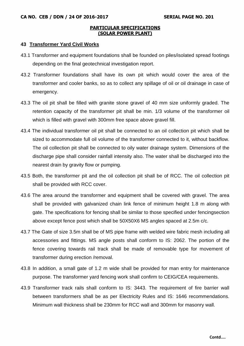
CA NO. CEB / DDN / 24 OF 2016-2017 SERIAL PAGE NO. 201
PARTICULAR SPECIFICATIONS (SOLAR POWER PLANT)
Contd....
43 Transformer Yard Civil Works
43.1 Transformer and equipment foundations shall be founded on piles/isolated spread footings
depending on the final geotechnical investigation report.
43.2 Transformer foundations shall have its own pit which would cover the area of the
transformer and cooler banks, so as to collect any spillage of oil or oil drainage in case of
emergency.
43.3 The oil pit shall be filled with granite stone gravel of 40 mm size uniformly graded. The
retention capacity of the transformer pit shall be min. 1/3 volume of the transformer oil
which is filled with gravel with 300mm free space above gravel fill.
43.4 The individual transformer oil pit shall be connected to an oil collection pit which shall be
sized to accommodate full oil volume of the transformer connected to it, without backflow.
The oil collection pit shall be connected to oily water drainage system. Dimensions of the
discharge pipe shall consider rainfall intensity also. The water shall be discharged into the
nearest drain by gravity flow or pumping.
43.5 Both, the transformer pit and the oil collection pit shall be of RCC. The oil collection pit
shall be provided with RCC cover.
43.6 The area around the transformer and equipment shall be covered with gravel. The area
shall be provided with galvanized chain link fence of minimum height 1.8 m along with
gate. The specifications for fencing shall be similar to those specified under fencingsection
above except fence post which shall be 50X50X6 MS angles spaced at 2.5m c/c.
43.7 The Gate of size 3.5m shall be of MS pipe frame with welded wire fabric mesh including all
accessories and fittings. MS angle posts shall conform to IS: 2062. The portion of the
fence covering towards rail track shall be made of removable type for movement of
transformer during erection /removal.
43.8 In addition, a small gate of 1.2 m wide shall be provided for man entry for maintenance
purpose. The transformer yard fencing work shall confirm to CEIG/CEA requirements.
43.9 Transformer track rails shall conform to IS: 3443. The requirement of fire barrier wall
between transformers shall be as per Electricity Rules and IS: 1646 recommendations.
Minimum wall thickness shall be 230mm for RCC wall and 300mm for masonry wall.

CA NO. CEB / DDN / 24 OF 2016-2017 SERIAL PAGE NO. 202
PARTICULAR SPECIFICATIONS (SOLAR POWER PLANT)
Contd....
43.10 All steel members used in preparation of yard fence shall be finished by cleaning of steel
surfaces and applying zinc chrome or zinc phosphate primer, followed by two coats of
synthetic enamel paint. All paints including primer shall be of reputed brand /
manufacturer.
44 Water Supply & Cleaning of Modules
44.1 Water used for cleaning purpose shall be fit for cleaning the PV modules, cleaning
procedure and pressure requirement shall be as per the recommendation of PV module
manufacturer.
44.2 A suitable arrangement of water shall be ensured to cater the day-to-day requirement of
drinking water and needs of Solar Photovoltaic Plant during entire O&M period.
44.3 The Contractor shall estimate the water requirements for cleaning the photovoltaic
modules as per the soiling conditions prevailing at site or mutually agreed frequency, in
order to operate the Plant at its guaranteed Plant performance. Also, Contractor is
required to plan the water storage accordingly.
44.4 Contractor has to plan and install the effective module cleaning system as per the
prevailing conditions at Site. The system may include the storage water tanks, pumps,
laying of HDPE pipes, flexible pipes, taps/ valves, pressure gauges etc. as per the
planning by the Contractor. Contractor has to submit the drawing/ plan for the proposed
module cleaning system.
44.5 All the pipes thus laid must be buried in ground at least 150mm below FGL. Road
crossings and drain crossings, the pipes must be passed through GI/ Hume pipes as
applicable.
44.6 The pipe riser with valve for the flexible pipe terminal shall be of GI only with masonry
housing.
44.7 There shall be 2 nos.(1 working+1 standby) suitably selected pumps with desired flow rate,
pressure head etc. to meet the PV module cleaning requirements, complete with all valves
and pressure gauges. The pumps and all its accessories shall be suitable for outdoor
installation with minimum IP55 protection

CA NO. CEB / DDN / 24 OF 2016-2017 SERIAL PAGE NO. 203
PARTICULAR SPECIFICATIONS (SOLAR POWER PLANT)
Contd....
45 Performance Measurement Procedure
45.1 Performance Ratio (PR)
Performance Ratio (PR) test for Operational Acceptance of the plant shall be performed
as per the procedure attached in Annexure.
46 Capacity Utilization Factor (CUF)
46.1 Capacity Utilization Factor shall be calculated as per the following formula.
118760
NDFPac
EacCUF
where,
Eac = is the number of units recorded in the ABT meter located at plant
facilities after excluding auxiliary consumption, kWh
8760 =refers to the number of hours in non-leap year. It shall be replaced by 8784
hours during leap year.
Pac = is the plant AC capacity
DF = is module degradation factor, 0.75% per year
N = is the number of years of operation after operational acceptance of the plant
46.2 CUF shall be calculated on annual basis from the date of operational acceptance of the
plant. Module degradation factor will not be considered for first year CUF calculation. It is
the Contactor‟s responsibility to envisage and install extra DC capacity to accommodate
any degradation during first year. 0.75% per year will be considered from second year of
operation.
46.3 It is the responsibility of the Contractor to build-in the expected variation of irradiance in
their design by installing additional DC capacity to meet the committed CUF. Irradiance
variation will not be considered for the calculation of CUF.
46.4 Grid outage hours shall be subtracted from total number of hours in a year. The Contractor
shall submit grid outage certification from component authority of STU/DISCOM.
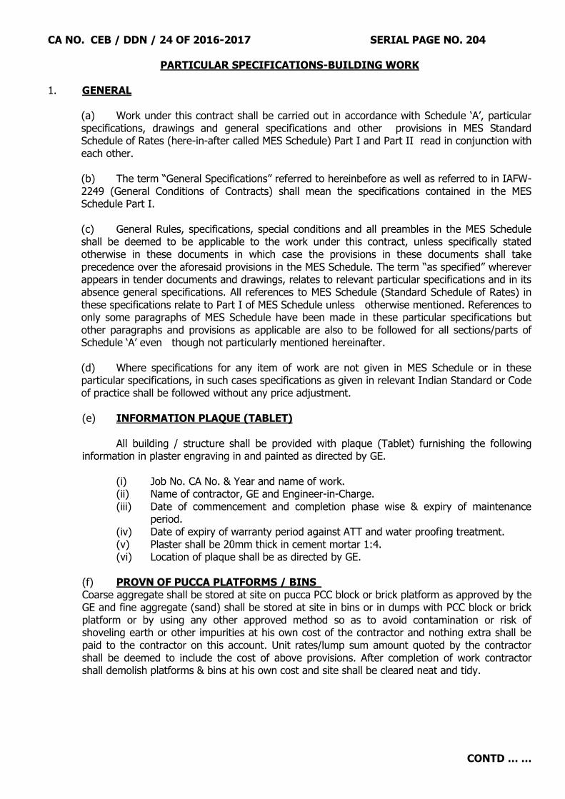
CA NO. CEB / DDN / 24 OF 2016-2017 SERIAL PAGE NO. 204
PARTICULAR SPECIFICATIONS-BUILDING WORK
CONTD … …
1. GENERAL
(a) Work under this contract shall be carried out in accordance with Schedule „A‟, particular specifications, drawings and general specifications and other provisions in MES Standard Schedule of Rates (here-in-after called MES Schedule) Part I and Part II read in conjunction with each other. (b) The term “General Specifications” referred to hereinbefore as well as referred to in IAFW-2249 (General Conditions of Contracts) shall mean the specifications contained in the MES Schedule Part I.
(c) General Rules, specifications, special conditions and all preambles in the MES Schedule shall be deemed to be applicable to the work under this contract, unless specifically stated otherwise in these documents in which case the provisions in these documents shall take precedence over the aforesaid provisions in the MES Schedule. The term “as specified” wherever appears in tender documents and drawings, relates to relevant particular specifications and in its absence general specifications. All references to MES Schedule (Standard Schedule of Rates) in these specifications relate to Part I of MES Schedule unless otherwise mentioned. References to only some paragraphs of MES Schedule have been made in these particular specifications but other paragraphs and provisions as applicable are also to be followed for all sections/parts of Schedule „A‟ even though not particularly mentioned hereinafter. (d) Where specifications for any item of work are not given in MES Schedule or in these particular specifications, in such cases specifications as given in relevant Indian Standard or Code of practice shall be followed without any price adjustment.
(e) INFORMATION PLAQUE (TABLET)
All building / structure shall be provided with plaque (Tablet) furnishing the following
information in plaster engraving in and painted as directed by GE. (i) Job No. CA No. & Year and name of work. (ii) Name of contractor, GE and Engineer-in-Charge.
(iii) Date of commencement and completion phase wise & expiry of maintenance period.
(iv) Date of expiry of warranty period against ATT and water proofing treatment. (v) Plaster shall be 20mm thick in cement mortar 1:4.
(vi) Location of plaque shall be as directed by GE.
(f) PROVN OF PUCCA PLATFORMS / BINS Coarse aggregate shall be stored at site on pucca PCC block or brick platform as approved by the GE and fine aggregate (sand) shall be stored at site in bins or in dumps with PCC block or brick platform or by using any other approved method so as to avoid contamination or risk of shoveling earth or other impurities at his own cost of the contractor and nothing extra shall be paid to the contractor on this account. Unit rates/lump sum amount quoted by the contractor shall be deemed to include the cost of above provisions. After completion of work contractor shall demolish platforms & bins at his own cost and site shall be cleared neat and tidy.

CA NO. CEB / DDN / 24 OF 2016-2017 SERIAL PAGE NO. 205
PARTICULAR SPECIFICATIONS-BUILDING WORK
CONTD … …
2. EXCAVATION AND EARTH WORK 2.1. PREPARATORY WORK Before setting out the building and commencing the construction, the contractor shall carry out the preparatory work, such as removal of grass, vegetation etc., trimming/surface dressing of the area to the entire satisfaction of Engineer-in-Charge. The „Area‟, referred to, implies the entire building plot extending upto 3 m all around the outer perimeter of the Plinth protection. The cost of such work as may be necessary shall deem to be included in the contractor‟s lump sum / item rates. 2.2 SURFACE DRESSING Before starting excavation work, the contractor shall carryout surface dressing not exceeding 15 cm deep over the entire area covered by the item of Sch `A‟ Part-I and dispose off the spoil to a distance not exceeding 500 metre, spread and levelled, as directed by the Engineer-in-Charge at no extra cost to the Govt. 2.3. DISPOSAL OF SURPLUS SOIL Surplus soil obtained from excavation shall be removed to a distance not exceeding 500 m and deposited where directed at a level not exceeding 1.5 m above the starting point at places as directed by Engineer-in-Charge including spreading and levelling. 2.4. EXCAVATION - GENERAL (a) Excavation shall be done to the depth as shown on drawings.
(b) Unit rates for buildings in Sch 'A' Part-I shall include for excavation and earth work and leveling of ground work in any type of strata. Any type of strata shall include "soft / loose soil or Hard / dense soil" and "Soft / disintegrated rock" as defined in MES Schedule Part I. In the event of deviation in Schedule 'A' Part-I for excavation and earth work the rate given in SSR Part-II for two types of strata given above shall be averaged for pricing purpose". (c) The measurements of excavation shall be as given in MES Schedule (Part-II). Decision of GE Shall be final, conclusive and binding as regard classification of soil and rocks.
(d) If hard rock is met at site, contractor shall immediately notify the fact to the GE in writing, who will after due verification, regularize the change through a proper deviation order. Blasting shall not be done without prior written permission of GE.
(e) In case of excavation in hard rock, extra depth of excavation in excess to the required depth shall be made up with PCC 1:5:10 type E-2 (using 40 mm graded stone aggregate) at no extra cost to the Govt.
(f) The stones/boulders obtained from excavation shall become Govt property and shall be properly stacked and measured. Quantity equal to the reassured equal in quantity obtained in excavation shall be issued to the contractor @ Rs 300.00 per cum. The cost of removing and stacking, if any shall be included in lump-sum quoted by contractor.
(g) In case timbering to excavation is required and specifically ordered by the GE in writing, it shall be paid as deviation.
(h) Bailing/pumping of water where required shall be carried out as described in clause 3.17 of MES Schedule. The cost of such work as may be necessary shall be deemed to be included in the contractor‟s lump sum.
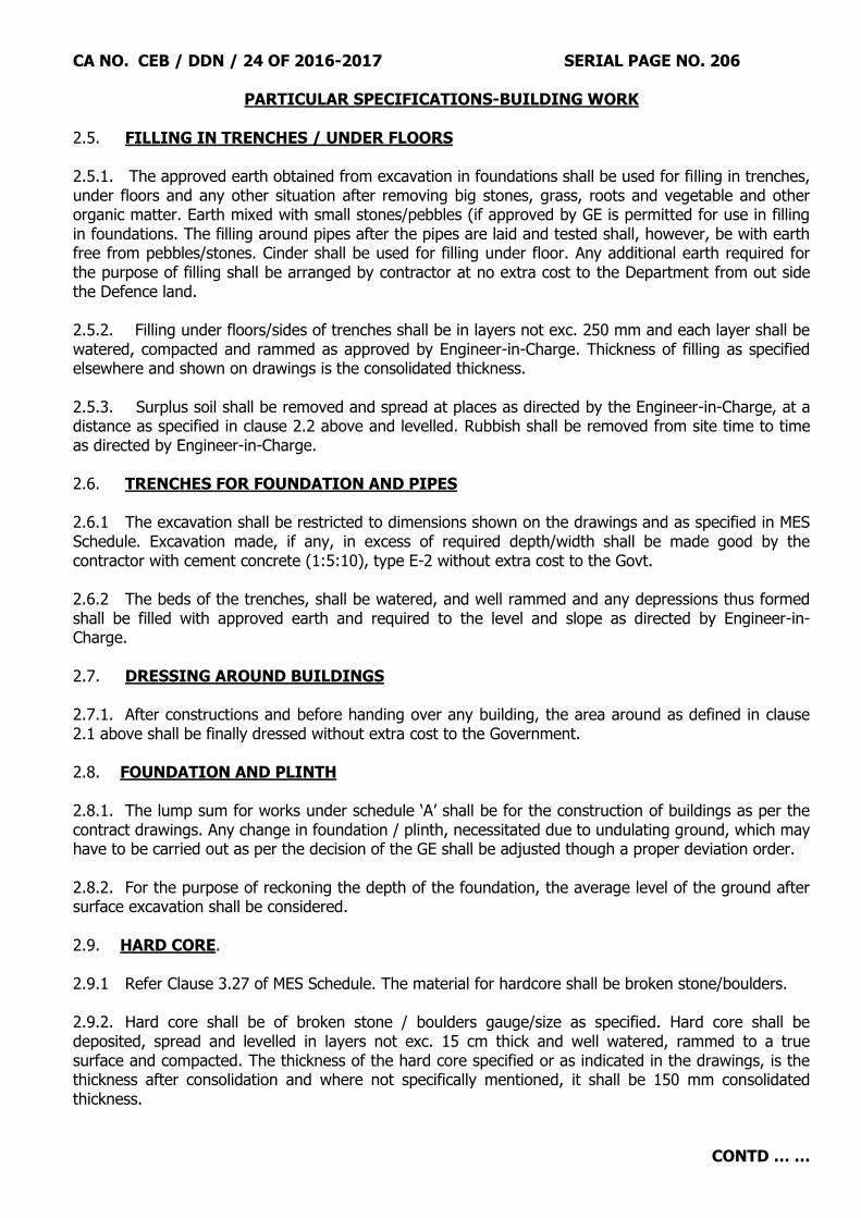
CA NO. CEB / DDN / 24 OF 2016-2017 SERIAL PAGE NO. 206
PARTICULAR SPECIFICATIONS-BUILDING WORK
CONTD … …
2.5. FILLING IN TRENCHES / UNDER FLOORS 2.5.1. The approved earth obtained from excavation in foundations shall be used for filling in trenches, under floors and any other situation after removing big stones, grass, roots and vegetable and other organic matter. Earth mixed with small stones/pebbles (if approved by GE is permitted for use in filling in foundations. The filling around pipes after the pipes are laid and tested shall, however, be with earth free from pebbles/stones. Cinder shall be used for filling under floor. Any additional earth required for the purpose of filling shall be arranged by contractor at no extra cost to the Department from out side the Defence land. 2.5.2. Filling under floors/sides of trenches shall be in layers not exc. 250 mm and each layer shall be watered, compacted and rammed as approved by Engineer-in-Charge. Thickness of filling as specified elsewhere and shown on drawings is the consolidated thickness. 2.5.3. Surplus soil shall be removed and spread at places as directed by the Engineer-in-Charge, at a distance as specified in clause 2.2 above and levelled. Rubbish shall be removed from site time to time as directed by Engineer-in-Charge. 2.6. TRENCHES FOR FOUNDATION AND PIPES 2.6.1 The excavation shall be restricted to dimensions shown on the drawings and as specified in MES Schedule. Excavation made, if any, in excess of required depth/width shall be made good by the contractor with cement concrete (1:5:10), type E-2 without extra cost to the Govt. 2.6.2 The beds of the trenches, shall be watered, and well rammed and any depressions thus formed shall be filled with approved earth and required to the level and slope as directed by Engineer-in-Charge. 2.7. DRESSING AROUND BUILDINGS 2.7.1. After constructions and before handing over any building, the area around as defined in clause 2.1 above shall be finally dressed without extra cost to the Government. 2.8. FOUNDATION AND PLINTH 2.8.1. The lump sum for works under schedule „A‟ shall be for the construction of buildings as per the contract drawings. Any change in foundation / plinth, necessitated due to undulating ground, which may have to be carried out as per the decision of the GE shall be adjusted though a proper deviation order. 2.8.2. For the purpose of reckoning the depth of the foundation, the average level of the ground after surface excavation shall be considered. 2.9. HARD CORE. 2.9.1 Refer Clause 3.27 of MES Schedule. The material for hardcore shall be broken stone/boulders. 2.9.2. Hard core shall be of broken stone / boulders gauge/size as specified. Hard core shall be deposited, spread and levelled in layers not exc. 15 cm thick and well watered, rammed to a true surface and compacted. The thickness of the hard core specified or as indicated in the drawings, is the thickness after consolidation and where not specifically mentioned, it shall be 150 mm consolidated thickness.
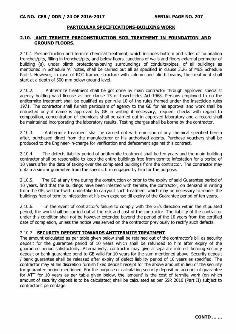
CA NO. CEB / DDN / 24 OF 2016-2017 SERIAL PAGE NO. 207
PARTICULAR SPECIFICATIONS-BUILDING WORK
CONTD … …
2.10. ANTI TERMITE PRECONSTRUCTION SOIL TREATMENT IN FOUNDATION AND GROUND FLOORS.
2.10.1 Preconstruction anti termite chemical treatment, which includes bottom and sides of foundation trenches/pits, filling in trenches/pits, and below floors, junctions of walls and floors external perimeter of building (s), under plinth protections/paving surroundings of conduits/pipes, of all buildings as mentioned in Schedule „A‟ notes, shall be carried out all as specified in clause 3.26 of MES Schedule Part-I. However, in case of RCC framed structure with column and plinth beams, the treatment shall start at a depth of 500 mm below ground level. 2.10.2. Antitermite treatment shall be got done by main contractor through approved specialist agency holding valid license as per clause 13 of Insecticides Act-1968. Persons employed to do the antitermite treatment shall be qualified as per rule 10 of the rules framed under the insecticide rules 1971. The contractor shall furnish particulars of agency to the GE for his approval and work shall be entrusted only if name is approved by GE in writing if necessary, frequent checks with regard to composition, concentration of chemicals shall be carried out in approved laboratory and a record shall be maintained incorporating the laboratory results. Testing charges shall be borne by the contractor. 2.10.3. Antitermite treatment shall be carried out with emulsion of any chemical specified herein after, purchased direct from the manufacturer or his authorised agents. Purchase vouchers shall be produced to the Engineer-in-charge for verification and defacement against this contract. 2.10.4. The defects liability period of antitermite treatment shall be ten years and the main building contractor shall be responsible to keep the entire buildings free from termite infestation for a period of 10 years after the date of taking over the completed buildings from the contractor. The contractor may obtain a similar guarantee from the specific firm engaged by him for the purpose. 2.10.5. The GE at any time during the construction or prior to the expiry of said Guarantee period of 10 years, find that the buildings have been infested with termite, the contractor, on demand in writing from the GE, will forthwith undertake to carryout such treatment which may be necessary to render the buildings free of termite infestation at his own expense till expiry of the Guarantee period of ten years. 2.10.6. In the event of contractor‟s failure to comply with the GE‟s direction within the stipulated period, the work shall be carried out at the risk and cost of the contractor. The liability of the contractor under this condition shall not be however extended beyond the period of the 10 years from the certified date of completion, unless the notice was served on the contractor previously to rectify such defects. 2.10.7 SECURITY DEPOSIT TOWARDS ANTITERMITE TREATMENT The amount calculated as per table given below shall be retained out of the contractor‟s bill as security deposit for the guarantee period of 10 years which shall be refunded to him after expiry of the guarantee period satisfactorily. Alternatively, contractor may give a separate interest bearing security deposit or bank guarantee bond to GE valid for 10 years for the sum mentioned above. Security deposit / bank guarantee shall be released after expiry of defect liability period of 10 years as specified. The contractor may at his discretion furnish fixed deposit receipt for the above amount in lieu of the security for guarantee period mentioned. For the purpose of calculating security deposit on account of guarantee for ATT for 10 years as per table given below, the 'amount' is the cost of termite work (on which amount of security deposit is to be calculated) shall be calculated as per SSR 2010 (Part II) subject to contractor‟s percentage.

CA NO. CEB / DDN / 24 OF 2016-2017 SERIAL PAGE NO. 208
PARTICULAR SPECIFICATIONS-BUILDING WORK
CONTD … …
S. No.
Amount (Cost of termite work) Amount to be retained from contractor's dues
(i) Up to Rs. 50.00 lakhs : 2% of amount subject to minimum of Rs. 5,000.00 and enhanced by 25%
(ii) Over Rs. 50.00 lakhs and upto Rs
100.00 lakhs : Rs. 1,00,000.00 + 1.5% of amount exceeding
Rs. 50 Lakhs and enhanced by 25% (iii) Over Rs. 100.00 lakhs and upto Rs
500.00 lakhs : Rs. 1,75,000.00 + 1% of amount exceeding
Rs. 100 Lakhs and enhanced by 25% (iv) Over Rs. 500.00 lakhs and upto Rs
1500.00 lakhs : Rs. 5,75,000.00 + 0.5% of amount exceeding
Rs. 500 Lakhs and enhanced by 25% (v) Over Rs. 1500.00 lakhs : Rs. 10,75,000.00 + 0.5% of amount
exceeding Rs. 1500 Lakhs subject to maximum of Rs. 15,00,000.00 and enhanced by 25%
2.10.8. The contractor shall provide a cement plaster plate of requisite size in situation as decided by the Engineer-in-Charge on the wall of each of the building. The plate shall be 10 mm thick in cement mortar (1:4) to indicate the CA No., Name of the contractor, the date of completion of the work and the date of expiry of 10 years guarantee for antitermite treatment by engraving and painting (black). The cost of plaster plates etc is deemed to be included in the unit rates of the buildings. 2.10.9. Chemical for antitermite treatment shall be brought in sealed containers. The sealed container of the chemical for use in antitermite treatment shall bear ISI mark. Chemical brought without ISI marked sealed container shall be rejected. Quantity of chemicals brought to site with manufacturer‟s name, brand, batch No. etc shall be recorded in M.B. The empty container shall be kept at site till completion of the work for inspection by GE /Engineer-in-Charge. 2.10.10. For the purpose of advance on account, the main contractor shall produce proof of payment/paid receipts and written guarantee from the nominated specialist firm/agency. 2.10.11 The antitermite treatment in foundation, back fill floor and plinth etc shall be carried out all as per clause 3.26 of MES Schedule Part-I and as specified in IS-6313 Part-II. The chemical used shall be chlorophyrifos 20% EC/ Gammax – 20 (Lindane - 20% EC). conforming to IS 8944 and as per manufacturers instructions. The concentration of chemical for antitermite treatment in different stages shall be 1.00%. 3. CONCRETE WORK 3.1 CEMENT 3.1.1 GENERAL: Cement required for the entire work under the concrete shall be procured, supplied and incorporated in the works by the contractor under his own arrangement. Cement shall be of tested quality and shall comply with the requirements mentioned in the drawings, MES Schedules, IS specification as amended and particular specifications given here-in-after.
CA NO. CEB / DDN / 24 OF 2016-2017 SERIAL PAGE NO. 209
PARTICULAR SPECIFICATIONS-BUILDING WORK
CONTD … …
3.1.2. Type of cement for the subject work shall Ordinary Portland cement of Grade 43 (Forty Three) in accordance with IS-8112 of 1989 or Portland Pozzolana Cement (IS: 1489-1991) as mentioned in notes of Structural drawings. Mixing of OPC & PPC shall not be allowed in the work. 3.1.2.1 Whatsoever elsewhere mentioned here-in-before cement to be used for overhead tank of water retaining structure shall be ordinary portland cement (OPC) 43 Grade. 3.1.3. While using the PPC, following requirement shall be met by the contractor:-
(a) PPC shall meet the strength criteria of 43 Grade OPC as laid down in IS : 8112-1989. (b) The minimum period before striking formwork given in clause 11.3.1 of IS : 456 of 2000 shall be increased at site by 03 days. The contractor shall not claim any thing extra on this account. (c) Wet curing shall be done for a period of 14 days; wet curing of columns shall be done through Hessians cloth wrapped on the columns. (d) The contractor shall submit the following certificates from the manufacturer of the cement for every batch of cement: -
(i) The quality of fly ash is strictly as per IS : 14989 (Part-I)-2002. (ii) Fly ash is inter-ground with clinker and not mixed with clinker. (iii) Dry fly ash is transported in closed containers and stored in silos. Only pneumatic pumping has been used. (iv) The fly ash received from thermal power plant using high temperature combustion above 10000C has only been used.
(e) The compressive strength of cement at 03 days, 07 days and 28 days shall not be less than 23 Mpa, 33 Mpa and 43 Mpa respectively. Each lot of cement brought at site shall be tested for compliance by the GE before acceptance. (f) In cold climate regions, where temperature is lower than 150C, OPC shall be used (However during working seasons in cold climate regions, where OPC is not available use of PPC may be permitted provided it shall be ensured that while using PPC, atmospheric temperature should be more than 150C). (g) Mixing of OPC and PPC shall not be allowed in a work. However with the strict control of the ground executives, different buildings can have different types of cement.

CA NO. CEB / DDN / 24 OF 2016-2017 SERIAL PAGE NO. 210
PARTICULAR SPECIFICATIONS-BUILDING WORK
CONTD … …
3.1.4. SOURCES OF PROCUREMENT
3.1.4. (a) Cement shall be procured by the contractor directly from any of the following main producers of
cement (for OPC & PPC) :-
(b) However, where the quantity of cement required is less than 1200 bags, same may be procured
from authorised distributors/dealers of approved manufacturer's, if so, permitted by GE in writing. Testing
of cement shall in variably be got done before incorporation in work. The contractor shall submit test certificate for each batch of cement issued by the manufacturer.
(c) The contractor shall furnish the particulars of the manufacturer of cement along with the
date of manufacture to the GE for every lot of cement separately. The cement so brought shall be fresh and in no case older than 90 days from the date of manufacture. The GE shall
verify the document in support of the purchase of cement. Before placing order for supply of cement by the contractor, he shall obtain written approval from the GE regarding name of manufacturer,
1 M/s Sanghi Industries Ltd Brand : “SANGHI”
For OPC 53 grade & PPC
2 M/s Cement mfg company Ltd. Brand : “STAR”
For OPC 43, 53 grade & PPC
3 M/s Ultra Tech Cement Ltd Brand : “ULTRATECH”
For PSC 4 M/s OCL India Ltd Brand : “KONARK”
For OPC 43 grade & PPC
5 M/s Dalmia Cement
(Bharat) Ltd. Brand:”DALMIA CEMENT”
For OPC 43
grade & PPC
6 M/s Chettinad Cement
Corporation Ltd. Brand : “CHETTINAD”
For OPC 43 grade,
PPC & PSC
7 M/s Heidelberg Cement India Ltd
Brand :”MYCEM”
For PPC 8 M/s My Home Industries Ltd. Brand : “MAHA SHAKTI”
“MAHA”
“MAHA SHAKTHI”
- For PSC
- For OPC 43 grade
- For PPC
9 M/s Parasakti Cements Ltd Brand :”PRASAKTI”
For OPC 43 grade and PPC
10 M/s Zuari Cement Ltd Brand :”ZUARI”
For OPC 43 grade & PPC
11 M/s Toshali Cements Pvt
Ltd Brand :”GAJAPATI”
OPC 43 grade,
PPC & PSC 12 M/s Saifco Cement Pvt Ltd
Brand :”SAIFCO”
For OPC 43 grade
13 M/s Prism Cement Ltd
Brand :”PRISM”
For OPC 43
grade & PPC
14 M/s Shree Guru Kripa
Cement (Pvt) Ltd Brand :”SARTAJ”
For OPC 43 grade
& PPC
15 M/s Barak Valley Cements
Ltd Brand :”BVCL”
For OPC 43
grade & PPC
16 M/s Dhruv Industrial
Company Ltd Brand :”DHRUV”
For OPC 43 grade
& PPC
17 Madras Cement
Brand :”MADRAS”
For OPC 43
grade & PPC
18 Saurashtra Cement
Brand :”SAURASHTRA”
For OPC 43 grade
& PPC
19 Lafarge Cement
(Lafarge India Pvt Ltd) Brand :”LAFARGE”
For OPC 43
grade & PPC
20 The Associated Cement
Companies Ltd. Brand :”ACC”
For OPC 43 grade
& PPC
21 Grasim Industries Ltd
Brand :”GRASIM”
For OPC 43
grade & PPC
22 The India Cement For OPC 43 grade
& PPC
23 Andhra Cement Ltd For OPC 43
grade & PPC
24 Century Cements
Brand :”CENTURY”
For OPC 43 grade
& PPC
25 Binani Cement Ltd Brand :”BINANI”
For OPC 43 grade & PPC
26 Mangalam Cement Ltd Brand :”MANGALAM”
For OPC 43 grade & PPC
27 Birla Corporation Ltd Brand :”BIRLA”
For OPC 43 grade & PPC
28 Orient Cement Brand :”ORIENT”
For OPC 43 grade & PPC
29 Shree Cement Brand :”SHREE”
For OPC 43 grade & PPC
30 J K Cement Brand :”J K”
For OPC 43 grade & PPC
31 J K Lakshmi Cement Ltd
Brand :”J K LAKSHMI”
For OPC 43
grade & PPC
32 Jaypee Rewa Cement
Brand :”JAYPEE”
For OPC 43 grade
& PPC
33 Ambuja Cement Ltd
Brand :”AMBUJA”
For OPC 43
grade & PPC
34 Any other make approved by E-in-C‟s Branch
including subsequent to receipt of tender after approval from Accepting Officer
CA NO. CEB / DDN / 24 OF 2016-2017 SERIAL PAGE NO. 211
PARTICULAR SPECIFICATIONS-BUILDING WORK
CONTD … …
quantity of cement etc. Cement shall be procured for minimum requirement of one month and not exceeding the requirements of the same for more than two months at a time. The cement shall be consumed in the work within three months after receipt. Cement shall conform to the requirement of IS specification and each bag of cement shall bear relevant ISI mark. The weight of each consignment shall be verified by the GE and recorded. The content of cement shall be checked at random to verify the actual weight of cement per bag. However, the content of cement per bag shall be 50 Kg only subject to tolerance given in Clause 9.2.1.1 and Annexure „B‟ of IS-8112 and Clause 10.2.1.1 and Annexure „B‟ of IS – 1489 for OPC and PPC respectively.
3.1.5. TESTING OF CEMENT 3.1.5. (a) The contractor shall submit the manufacturer‟s test certificate in original alongwith test
sheets giving the results of each physical test as applicable in accordance with relevant IS provision and the chemical composition of the cement or authenticated copy thereof, duly signed by the manufacturer with each consignment, as per the following IS provision :-
(i) Method of sampling hydraulic cement as per IS : 3535-1986.
(ii) Method of physical test of hydraulic cement as per IS-4031.
(iii) Method of chemical analysis of hydraulic cement as per IS-4032-1985.
(b) The test certificate and test sheet shall be furnished with each batch of cement. The Engineer-in-Charge shall record these details in cement acceptance register to be maintained by him which will be signed by JE (Civil), Engineer-in-Charge, GE and the Contractors as given in the format here-in-after for verification. (c) The contractor shall however, organize setting time and a compressive strength test of cement through designated laboratory on samples collected from the lot brought at site before incorporation in work. The contractor will be allowed to use the cement only after satisfactory compressive strength of seven days. To meet this requirement contractor is required to keep minimum 10 days stock before any new lot is brought at site, which can be used, in the work. The contractor shall be required to remove the cement not meeting the requirement from site within 24 hours. Seven days strength test will be relied upon to accept the lot of cement to commence the work. 28 days compressive strength test will be the final criteria to accept/reject the lot. (d) The random samples as per relevant IS shall be selected by GE before carrying out testing. The record of such samples selected by the GE for testing shall be properly maintained in the cement testing register giving cross reference to relevant consignment of cement and quantity received etc. (e) Cost of transportation of samples to the approved laboratory/test house and all testing charges including cost of sample shall be borne by the contractor. (f) The contractor shall be required to set up adequate testing facilities at site to the entire satisfaction of GE for conducting setting time test and compressive strength test as per IS codes referred to here-in-before for the samples collected from the lot brought at site. Theses tests shall be carried out within 07 days of receipt of cement at site. The tests can alternatively be carried out at the Zonal laboratory, or any other recognized laboratory so designated by GE.

CA NO. CEB / DDN / 24 OF 2016-2017 SERIAL PAGE NO. 212
PARTICULAR SPECIFICATIONS-BUILDING WORK
CONTD … …
(g) The GE shall carryout independent testing as per the tests mentioned in the „CEMENT SUPPLY AND ACCEPTANCE REGISTER‟ (as per Annexure „I‟) of random samples of cement drawn from various lots, if sample fails in 7 days compressive strength. The testing shall be carried out through National Test House, SEMT, CME, Regional Research Laboratories, Govt. approved Laboratories, Zonal laboratories/ IIT‟s as per IS : 3535-1986, (method of sampling hydraulic cement), IS-4031 (Method of physical test for hydraulic cement) and IS-4032-1985 (Method of chemical analysis of hydraulic cement) referred to above. The decision as to where the testing of cement is to be done shall be taken by GE. In case the cement is not of requisite standard despite manufacturer‟s test certificate, the contractor shall remove the total consignment from the site at his own cost after written rejection order of the consignment by the GE. The cost of test shall be borne by the contractor irrespective of the results of testing. (h) The contractor shall submit original purchase vouchers for the total quantity of cement supplied under each consignment to be incorporated in the work. All consignment received at the work site shall be inspected by the GE alongwith the relevant documents to ensure the requirements as mentioned here-in-before, before acceptance the original purchase vouchers and the test certificates shall be verified for subject contract and defaced by the Engineer-in-Charge and kept on record in the office of the GE duly authenticated and with cross reference to the consignment/ control number recorded in the „Cement Acceptance Register‟. The Cement Acceptance Register shall be signed by the JE (Civil), Engineer-in-Charge, GE and the contractor. The contractor shall maintain schedule of supply of cement for each consignment. (j) The Accepting Officer may order a board of officers for random check of cement and verification of connected documents during the currency of contract.
3.1.6. STORAGE/ACCOUNTING/PRESERVATION OF CEMENT
(a) Cement shall be stored in covered Godown over dry platform at least 20 cm high in such
a manners as to prevent deterioration due to moisture or intrusion of foreign matter. In case of store room the stack should be at least 20 cm away from floors and 60 cm from walls. The stacking of cement shall be done as specified in relevant IS. The storage accounting and preservation of cement supplied by the contractor shall be done as per standard Engineering practice till the same is incorporated in the work and the cost of the same shall be deemed to be included in the unit rate/ amount quoted by the tenderer. The Engineer-in-Charge shall inspect once a day to verify that cement lying at site is stored, accounted, preserved and maintained as per the norms. The cement shall be stored so as to differentiate each tested and untested consignment separately with distinct identification. If the GE is not satisfied with the storage/preservation of cement, he may order for any test (s) of cement as applicable for that consignment to ensure its conformity to the quality mentioned in the manufacturer‟s test certificate. The contractor shall bear the cost of necessary testing (s) in this regard and no claim whatsoever shall be entertained.
(b) Stacking of cement shall be done as per relevant IS and as under :-
(i) Each cement consignment shall be stacked separately and removal shall be made on the basis of First in First out. (ii) Adequate top cover will be provided.

CA NO. CEB / DDN / 24 OF 2016-2017 SERIAL PAGE NO. 213
PARTICULAR SPECIFICATIONS-BUILDING WORK
CONTD … …
(iii) Stacks in no case shall be higher than 12 bags. The maximum width of each stack shall be 3.0 m. If the stack is more than 07 or 08 bags high, the bags shall be arranged in header and stretcher fashion, i.e. alternatively lengthwise and crosswise so as to pile together and avoid topping over. (iv) Adequate space shall be kept between two stacks.
(c) Cement godown shall be provided with two locks on each door. The key of one lock at each door shall remain with Engineer-in-Charge or his representative and that of the other lock with the contractor‟s authorized agent at site of works so that cement is removed from the godown only according to daily requirement with the knowledge of both the parties. During the period of storage, if any cement bag (s) is found to be in damaged condition due to whatsoever reason, the same shall be removed from the cement godown on written orders of the GE and suitable replacement for the cement bag (s) so removed shall be made and no claim whatsoever shall be admissible on this account. (d) In case more than one type of cement is used in the work i.e. Ordinary Portland cement or Portland Pozzolana Cement, both type of cement shall be stored separately as directed by the Engineer-in-Charge to avoid mixing of these type of cement. Separate record shall be maintained including the location/ items where these type of cement are used. (e) Cement shall be removed from the store only according to daily requirement with the knowledge of both the parties and the Engineer-in-Charge and the contractor shall record daily consumption of cement in cement consumption register, which shall be signed. Cement constants given in Appendix „A‟ to E-in-C‟s branch letter No. 19280/E8 dated 03 May 1976 shall from the basis of consumption of cement for various items of works unless specifically indicated otherwise. (f) In case the consumption of cement as per cement consumption register is found to be more than the estimated quantity of cement due to whatsoever reason, the contractor shall not have any claim whatsoever for such excess consumption of cement.
3.1.7. SCHEDULE OF SUPPLY The Contractor shall procure the cement timely as required in accordance with CPM chart agreed between GE and the contractor. The contractor will forfeit his right to demand extension of time if the supply of cement got delayed due to his failure in placing order in time to the manufacturer. 3.1.8. MEASUREMENTS AND PAYMENT OF CEMENT (a) The entire quantity of cement shall also be suitably recorded in the measurement book
for record purposes as „Not to be abstracted‟ before incorporation in the work and shall be signed by the Engineer-in-Charge and the contractor.
(b) The payment shall only be allowed after production of original purchase voucher, certified copies of test certificates from manufacturer for each consignment and results of testing carried out in laboratory on receipt of cement (07 days compressive test) are found satisfactory as per condition 64 of IAFW-2249. Rate of payment given in SSR shall be applicable for cement irrespective of type and grade of cement specified for use in the work.
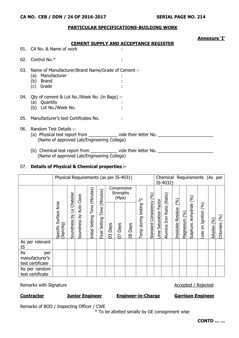
CA NO. CEB / DDN / 24 OF 2016-2017 SERIAL PAGE NO. 214
PARTICULAR SPECIFICATIONS-BUILDING WORK
CONTD … …
Annexure „I‟ CEMENT SUPPLY AND ACCEPTANCE REGISTER
01. CA No. & Name of work : 02. Control No.* : 03. Name of Manufacturer/Brand Name/Grade of Cement :- (a) Manufacturer : (b) Brand : (c) Grade : 04. Qty of cement & Lot No./Week No. (in Bags) :- (a) Quantity : (b) Lot No./Week No. : 05. Manufacturer‟s test Certificates No. : 06. Random Test Details :-
(a) Physical test report from ____________ vide their letter No. _______________________ (Name of approved Lab/Engineering College)
(b) Chemical test report from ___________ vide their letter No. _______________________
(Name of approved Lab/Engineering College) 07. Details of Physical & Chemical properties :-
Physical Requirements (as per IS-4031) Chemical Requirements (As per IS-4032)
Speci
fic
Surf
ace
Are
a
(Sqm
/Kg)
Soundness
by L
e C
hate
liar
Soundness
by A
uto
Cla
ve
Initia
l Sett
ing T
ime (
Min
ute
s)
Fin
al Sett
ing T
ime (
Min
ute
s) Compressive
Strengths
(Mpa)
Tem
p d
uring t
est
ing 0
C
Sta
ndard
Consi
stency
(%
)
Lim
e S
atu
ration F
act
or
(Ratio)
Alu
min
a I
ron R
atio (
Ratio)
Inso
luble
Resi
due (%
)
Magnesi
um
(%
)
Sulp
huric
Anhydride (
%)
Loss
on I
gnitio
n (
%)
Alk
aile
s (%
)
Chlo
rides
(%)
03 D
ays
07 D
ays
28 D
ays
As per relevant IS
As per manufacturer‟s test certificate
As per random test certificate
Remarks with Signature
Accepted / Rejected
Contractor Junior Engineer Engineer-in-Charge Garrison Engineer Remarks of BOO / Inspecting Officer / CWE * To be allotted serially by GE consignment wise
CA NO. CEB / DDN / 24 OF 2016-2017 SERIAL PAGE NO. 215
PARTICULAR SPECIFICATIONS-BUILDING WORK
CONTD … …
3.2. Fine Aggregate. Fine aggregate for concrete work shall conform to material specifications and gradings within the limits of Grading Zones II to III all as specified in clause 4.4 of MES Schedule 2009 Part-I. 3.3. Coarse Aggregate. Refer Clause 4.4 of MES Schedule Part I. Coarse aggregate for all plain cement concrete shall be graded crushed stone at contractor‟s options. For all RCC work the coarse aggregate shall be graded crushed stone. 3.3.1. Grading of Coarse Aggregate. Graded Aggregate of nominal sizes given herein under shall be used, unless specified otherwise hereinafter : -
(a) Plain or reinforced cement concrete except in foundation of Brick or stone Walls/Pillars, Floors and Sub base to Floors.
(i) For structural elements of depth/thickness more than 50 mm - 20 mm. (ii) For structural elements of depth/thickness less than 50 mm - 12.5 mm.
(b) Plain Cement concrete in Foundation of Brick/stone Walls, Pillars, Floors and
Sub Base to Floors. (i) Under 30 mm thickness : 12.5 mm (ii) 30 to 80 mm thickness : 20 mm (iii) Exceeding 80 mm thickness : 40 mm 3.4. Water. Water shall conform to the requirement stipulated in IS 456 and as per clause 4.9 of MES Schedule. 3.5. Mix of Concrete. Mix of cement concrete in various situations shall be as under : -
Srl No. Situation
Mix of Concrete
Type of concrete
(a) Foundation concrete for all buildings, under brick and lean concrete under plinth/beam and steps, in gaps between plinth/Column under footing, sunken portion filling, foundation for ramps/steps.
: PCC (1:5:10) type E-2 (By volume)
(b) Foundation concrete under column footing
: PCC (1:4:8) type D-2 (By volume)
(c) PCC in plinth protection, drain and channel, PCC cills and PCC block for hold fasts, back of pressed steel frames and plugging for scaffolding holes.
: PCC (1:3:6) type C-1 (By volume)
(d) All RCC work except water retaining structure : Grade M 25 (Design mix as per IS 456-2000)
(e) PCC in bed plate, benching, coping, DPC and pre-cast articles and plain cement concrete not mentioned above.
: PCC (1:2:4) type B-1 (by volume)
(f) All RCC work for water retaining structure Grade M-30 (Design) mix as per IS 456-2000
CA NO. CEB / DDN / 24 OF 2016-2017 SERIAL PAGE NO. 216
PARTICULAR SPECIFICATIONS-BUILDING WORK
CONTD … …
3.6 Important Requirement of Reinforced Cement concrete/plain cement concrete. 3.6.1. (i) All the materials, workmanship, inspection and testing for the cement concrete of Grade
M-25 /M-30 (As applicable) design mix concrete shall be as per the requirements given in IS 456(2000). It is an express condition of the contract that the design mix M-25/M-30 (As applicable) shall be executed with fully computerized mini weigh batching plant / plants of adequate capacity / capacities but not less than 10 cum per 08 hours of capacity / each with weight proportion based on mix design. Volumetric conversion shall not be acceptable. The weigh batching plant/ plants shall be maintained in clean and serviceable conditions and their accuracy shall be checked by the GE periodically.
(ii) For mixing of all cement concrete (PCC and RCC), contractor shall install one or more fully computerized automatic mini weigh batching plant of suitable capacity at site. The capacity of mini weigh batching plant provided at site shall be adequate enough to execute the work as per the approved project management schedule (as per Clause 13 of Special Condition) for completion of activity and the complete project within stipulated time of completion or otherwise the contractor shall provide single mini weigh batching plant of higher capacity or more number of mini weigh batching plants of adequate capacities as required at site, as asked by GE. No claim what so ever arising out on this account is admissible. The decision of GE in this regard shall be final and binding. The plant/plants shall have the digital system of adding specified quantity of water into concrete mix as per the design mix requirement.
(iii) The contractor shall provide all facilities and equipments for casting, curing and conveyance of test cubes of cement concrete of Grade M-25/M30 (As applicable ) (design mix) and other cubes to site / MES laboratory or other Laboratory approved by the GE. The lump sump amount/rate quoted by the contractor for the respective item shall deem to include this aspect; nothing extra shall be admissible to the contractor on this account. Testing of test cubes shall be carried out in MES laboratory in the presence of contractor or his authorised representative. In case the contractor or his authorised representative does not remain present during the time of testing of the cubes, the testing shall invariably be done by officer- in-charge of the laboratory. The testing of concrete cubes if undertaken in the site lab maintained by the contractor and as approved by the GE, the contractor shall ensure testing of cubes as described at clause 24 of special conditions here in before. The test reports shall be signed by the Engineer-in-Charge and the contractor and the same shall be maintained on record. (iv) The contractor shall prepare a trial mix and get the same tested from SEMT WING CME, Govt Engineering Colleges/ IIT/ Polytechnics, Govt/National Test Houses, Testing laboratories/ Pvt Engineering Colleges as approved by Chief Engineer Bareilly Zone Bareilly at his own cost and bring the requisite report from them and shall produce to the GE for his reference and record. The work with design mix concrete will progress only on approval of mix design by GE.
3.6.2 All concrete for RCC work shall be consolidated / compacted by mechanical vibrators of approved type. Pre-cast/cast-in-situ, plain cement concrete may however, be rammed and consolidated by tamping and rodding as specified in MES Schedule. 3.6.3 All RCC member ie including plinth beam shall be cast using form work on all sides and bottom.

CA NO. CEB / DDN / 24 OF 2016-2017 SERIAL PAGE NO. 217
PARTICULAR SPECIFICATIONS-BUILDING WORK
CONTD … …
3.6.4 READY MIX CONCRETE 3.6.4.1 Provision of ready mix concrete of required grade is permitted at the option of the contractor. No price adjustment shall be made for providing ready mix concrete in lieu of concrete mixed with fully computerized automatic mini weigh batching plant. The contractor shall not be entitled for any extra payment on account of provision of ready mix concrete. 3.6.4.2 IMPORTANT REQUIREMENT OF READY MIX CONCRETE. 3.6.4.3 For ready mix concrete ref. clause 4.11.2.1 and 2.11.2.2.1 on serial page no 60 and 61 of SSR Part-1(2009). The relevant details of Design Mix Concrete as specified here in before shall be applicable along with the following details for Ready Mix Concrete. Specification for materials/water etc as given here in before earlier shall hold good for RMC. 3.6.4.4 The ready mix concrete shall be of grade M-25 & M-30 and shall confirm to the requirements of IS-4926-2003 – Specification for ready mixed concrete (Second Revision). The ready mix concrete shall be procured from any plant as approved by GE. The contractor shall intimate the name of ready mix plant before placing order of ready mix concrete to GE for his approval. 3.6.4.5 The cement to be used for RMC shall be as obtained from Design Mix carried out and approved by GE subject to not less than the minimum requirement as laid down in IS-456 : 2000. 3.6.4.6 Initial mix design from RMC manufacturer shall be submitted by the contractor in quadruplicate with complete date adopted for mix design along with test results of all materials and concrete. The initial mix design should take into account the aspects such as loss of workability and strength during transportation till placement of concrete. 3.6.4.7 RMC manufactured and supplied shall be conformity with the trial mix design approved by the GE. Any change shall be made only with approval of GE after necessary revisions to the mix design. 3.6.4.8 Use of chemical admixtures is permitted in accordance with the provision of IS-456 and explained in IS-4926 : 2003. 3.6.4.9 The contractor shall ensure that the all facilities are made available by the manufacturer of RMC at the plant for the department officials to inspect the materials incorporated, tests carried out for all materials, concrete etc. Copies of all the tests carried out for materials used/concrete shall be made available to the department. 3.6.4.10 The concrete shall be transported in concrete transit agitators conforming to IS-5892. 3.6.4.11 Site mixed design concrete (as specified in 3.6.1 (ii) here in before ) may be used, as approved by GE for small concreting used in non structural/in minor structural elements such as lintel bands, plinth bands, shelves, chajjas etc. 3.6.4.12 No water/admixture shall be allowed after initial mixing of concrete at the plant. 3.6.4.13 In addition to the tests carried out by the RMC manufacturer at the plant site, sampling and testing of concrete shall be carried out at the site after delivery as per IS-456:2000 by the department along with the representatives of the contractor. However, cost of testing shall be borne by the contractor. The concrete, which does not meet the requirement of acceptance criteria as per IS-456: 2000 shall be rejected and the contractor shall make good the same at his risk and cost.

CA NO. CEB / DDN / 24 OF 2016-2017 SERIAL PAGE NO. 218
PARTICULAR SPECIFICATIONS-BUILDING WORK
CONTD … …
3.6.4.14 The contractor shall ensure that operational matters such as notice to be given prior to delivery, delivery rate, sampling for testing, additional services such as pumping and action to be taken in case of non-completion etc, are mutually agreed upon between the contractor and the supplier of RMC. A written intimation in this regard shall be given by the contractor to GE. 3.6.4.15 (a) The contractor shall give specification and all relevant information about design
mix in consultation with GE to RMC supplier at the time of enquiry for supply as per IS-4926: 2003.
(b) Producer / supplier of RMC shall give „Delivery ticket information‟ with each load supplied as per details given in IS-4926: 2003. “Delivery ticket information‟ as received from supplier will be submitted by the contractor to Engineer-in-Charge on receipt of material at site.
3.6.4.16 Transportation and placing of concrete: The contractor should plan site arrangements to enable full load of concrete to be discharged within 30 min of arrival at site. The general requirements is that concrete prepared adding suitable admixtures shall be discharged from the transit truck mixers within 2 hrs of the time of loading or time as decided as per the technical requirements as approved by the GE. Any concrete not transported and placed within the approved time frame shall be rejected by the GE and contractor shall remove it from site. 3.6.4.17 Concrete prepared with suitable admixture shall be placed with the use for pumping or otherwise as given below as early as possible after its delivery. Proper planning shall be done where concrete is to be pumped. Concrete transportation and pacing schedule shall be approved by GE. Engineer-in-Charge must check & satisfy themselves for suitability of form work and supporting system for additional load/pressure due to pumped concrete as resorted to. 3.6.4.18 The contractor may choose either of the following options as suitable as agreed to and approved by the GE for transporting and placing of concrete with suitable admixtures prepared from the fully computerized mini batching plant of required capacity as per clause 3.6.1 here in before.
(i) The fully computerized mini weigh batching plant set up conveniently very close to the building and with the help of tower crane/ crane/ lifting arrangement, the concrete is placed at the place of work of concreting as per drawing and specifications as applicable.
(ii) The fully computerized mini weigh batching plant / plants are set up at near by vicinity at location/(s) as suitable with the approval of GE and prepared concrete with suitable admixtures is transported through transit truck mixers (numbers as required as per the quantum of work at the site) to the site of work and at the site concrete is pumped through pneumatic means (pneumatically pumped concrete ) to the place of work of concreting and concrete is placed as per drawings and specifications as applicable.
(iii) The fully computerized mini weigh batching plant / plants are set up close to the site/sites as manageable with in the resources of the contractor but approved by the GE and prepared concrete with suitable admixtures are transported pneumatically through the suitably designed pipes from the batching plant direct to the place of work of concreting and concrete is placed in situ as per drawing and specifications applicable.
(iv) As above but applicable for RMC manufacturer. 3.6.4.19 Strength, workability and other issues/specification shall be as per details given in IS-4926: 2003.

CA NO. CEB / DDN / 24 OF 2016-2017 SERIAL PAGE NO. 219
PARTICULAR SPECIFICATIONS-BUILDING WORK
CONTD … …
3.6.4.20 The contractor shall enter in to an agreement with the approved RMC manufacturer in case this option if resorted to, for the compliance of above aspects. The overall liability for the RMC supplied to the department shall rest with contractor only. 3.6.5 Curing and protection of cement concrete surfaces: - All cement concrete surfaces shall be cured and protected as specified in clause 4.11.13 and 4.11.14 of SSR Part I. 3.6.6 Sampling and testing of concrete: -
(a) Refer clause 4.11.17 of MES Schedule Part I.
(b) Test will be carried out on 15 cms cubes as per IS 456.
(c) The contractor shall provide all necessary materials (including moulds etc) and labour for mixing and casting of cubes and carrying the test cubes including its transportation to Govt labs and any other assistance that may be required for the samples tested in the lab and cost/charges of testing shall be borne by the contractor.
(d) For relatively very small quantities and unimportant work even though testing is waived off by GE, the contractor shall be responsible for to achieve the desired strength of concrete. (e) The concrete which is not up to the desired strength shall be rejected and the same shall be made good by the contractor without any extra cost to the Govt. (f) The test results shall be entered in register and shall be signed both by the Engineer-in-Charge and by the contractor.
3.7. FORM WORK. 3.7.1. Form work shall comply with requirements of clause 4.11.6, 4.11.6.1 to 4.6.11.5 and 7.15 of MES Schedule Part I and IS 14687. 3.7.2. Form work shall be of properly designed steel form work (both verticals props and surfaces). However, deformed steel sheet shall not be permitted for use as form work. In case of any deviation involving form work to surfaces exposed to view, the pricing shall be done at the rates of timber form work for rough finish. 3.7.3. Props used in form work shall be of telescopic steel tubular type with MS shoe plate/base plate. In no case, wooden ballies will be used for props. Shuttering shall be of properly designed steel form work suitable for the RCC work. Bent steel plates or similarly unfit plates shall not be used as shuttering material. At all junctions of shuttering/form work building craft paper shall be used. 3.7.4 Where steel shuttering is not feasible in locations such as soffits and sides of lintels, chajjas, foundation and other locations as decided by GE, the plywood board of adequate strength may be used". 3.8. Exposed surface of concrete Refer clause 4.11.16 of SSR Part I. 3.8.1. Exposed surfaces of concrete including ceiling after striking of form work shall be plastered 5 mm thick with cement and sand mortar 1:3 and finished fair and even.
CA NO. CEB / DDN / 24 OF 2016-2017 SERIAL PAGE NO. 220
PARTICULAR SPECIFICATIONS-BUILDING WORK
CONTD … …
3.8.2. Exposed surfaces of lintels, beams, columns etc. which are continuous with plastered surfaces of wall shall be plastered, in the manner specified for the walls. 3.9. Precast Concrete Articles. Cement concrete lintels with or without integrally cast chajjas upto 1.5 m clear span, shelves, bed blocks/plates, covers slabs, fencing posts, fins and jallies and the like may either be precast or cast in situ. at the contractor‟s option, unless otherwise shown on drawings. If pre-cast, these shall be set in cement mortar (1:4). In case of deviation involving these items, pricing shall be done on the basis of cast-in-situ work. In case of continuous lintels even spanning less than 1.5 m shall be considered as if it is exceeding 1.5 m for the purpose of deviation orders. 3.10. RCC Chajjas with fins/RCC chajja. 3.10.1. RCC chajjas with fins/RCC chajja shall be provided as per details shown on drawings. Thickness of the finished fins after application of rendering in cement mortar (1:3) on both sides shall be 50 mm, unless otherwise shown on drawings. 3.10.2. RCC Chajjas (whether cast integral with the lintel or precast embedded in the wall) shall be provided with a coved fillet of radius 50 mm in PCC (1:2:4) type B-O, preferably cast when concrete is green. 3.11. Drip course/throating/weathering : -
(a) The following works shall be executed by the contractor without any extra cost to department whether shown on drg or not : -
(i) The projection of chajjas, roofs, cills, coping and the like shall be provided with proper drip and/or throating and weathering. (ii) All flat surfaces exposed to weather shall be weathered with a imperceptible slope for smooth run of rain water.
3.12. Kota Stone Cills: Irrespective of whatever shown on drawings, all cills shall be mirror polished kota stone in one piece 18 to 20 mm thick with bull nosed outer edge.These shall be extended in walls at both sides by 75 mm. However, the projection/drip shown in drawing shall be provided only in external walls cills. 18 to 20 mm thick polished Kota stone in one piece shall be laid over PCC cill over neat cement slurry. 3.13. RCC Jali : RCC Jali (with mix 1:1.5:3 using aggregate of size 6 mm and below) shall be precast with wire/MS bars reinforcement as per drawings, and jointed in cement mortar (1:3). Thickness where not shown on drawings shall be 50 mm. Faces of RCC Jali shall have fair and even surface. In the event of deviation RCC Jali shall be priced as precast using aggregate of size 12.5 mm subject to contractor‟s percentage. 3.14. RCC Shelves. 3.14.1. The finished thickness of RCC shelves and platforms where shown on RCC in drawings, shall be as shown on drawings. In case the thickness of shelves has not been indicated on drawings; it shall be as under : -
(a) Shelves of wardrobes / cupboards/ almirahs / cabinets in living accommodation, cooking and preparatory platforms in kitchen and shelves in kitchen, store rooms and other locations in living accommodation etc. - 40 mm.
(b) Irrespective of whatever shown in drawing, kitchen platform top shall be provided with polished telephone black granite 18 to 20 mm thick with bull nosed outer edge.
CA NO. CEB / DDN / 24 OF 2016-2017 SERIAL PAGE NO. 221
PARTICULAR SPECIFICATIONS-BUILDING WORK
CONTD … …
3.14.2. The edges of RCC shelves shall be bull nosed to a radius of 5 mm. 3.15. Bearings of RCC Structural Members. 3.15.1. Bearing to all roof/floor slabs on masonry walls shall comprise of 20 mm thick bearing plaster in cement mortar (1:4) finished even and smooth with one coat white wash applied and two layers of laminated water proofing building paper type-I conforming to IS-1388 Type 1 weighing not less than 100 gms/sqm each layer, laid over it. However, in case floor/roof slab resting on RCC beams/bands, this provision shall not apply. 3.15.2. All RCC beams/bressumers resting on masonry work shall be provided with PCC bed blocks cast in PCC (1:2:4) B-I. Bed blocks shall be twice the width of beams in length covering the entire thickness of wall and of depths 150 mm, unless otherwise shown on drawings. 3.15.3. The bearing of lintels shall comprise of a full brick with vertical joints in brick work staggered. 3.16. No treatment shall be provided under bearing of RCC bands. 3.17. PLINTH PROTECTION:- 3.17.1 Irrespective of what is shown on drawings, plinth protection in all situations shall be provided with 75 mm thick PCC (1;3:6) type C-1 over 75 mm thick consolidated bed of hard core of broken stone aggregate over well consolidated sub grade of earth. Plinth protection shall be laid to a slope of 1 in 12 in a manner that top face shall conform to the finished level of PCC adjacent to the edging. PCC shall be laid in alternate bays (not exc. 2.5 meters length and finished fair on top without using extra cement. 6 mm wide joints shall be provided throughout the thickness of plinth protection in concrete bays at corners and turning points and also in between walling and plinth protection. All joints in bays, as well as between walling and the concrete in plinth protection shall be filled in with mastic filling comprising 1 part of heated bitumen 85/25 grade and 3 parts of sand (all by weight). 3.18. Concrete Padding. Where the required height of walls, openings, is not obtained with adequate size of bricks the same shall be obtained by providing PCC 1:2:4 type B-O padding. Cut bricks shall not be allowed and the cost of complete padding shall be deemed to be included in lump-sum cost quoted by the contractor. 4 BRICK WORK: - 4.1 MATERIALS: - 4.1.1 FLY ASH BRICKS: Irrespective of whatever mentioned in the tender documents or shown on drawings, fly ash brick shall be used for all the buildings of BOQ (Schdule „A‟ Part – I). Fly ash bricks shall be of class A and designation 7.5. The specification approved manufactures or cab be produced at work site with prior approval of accepting officer. The old size bricks shall be used. Fly ash bricks shall be conforming to IS 12894-2002 with technical specifications as under :- 4.1.1.1 Compressive Strength. The minimum average wet compressive strength of any individual brick shall not fall below the minimum average wet compressive strength specified for the corresponding class of bricks by more than 20 percent as mentioned in table 1 in IS 12894 when tested as described in IS 3495 (Part I).

CA NO. CEB / DDN / 24 OF 2016-2017 SERIAL PAGE NO. 222
PARTICULAR SPECIFICATIONS-BUILDING WORK
CONTD … …
4.1.1.2 Drying Shrinkage. The average drying shrinkage of the bricks when tested by the method described in IS-4139 , being the average of three units, shall not exceed 0.15 percent. 4.1.1.3 Efflorescence Test. The bricks when tested in accordance with the procedure laid down in IS 3495 (Part 3) shall have the rating of efflorescence not more than „moderate‟ upto class 12.5 and slight for higher classes. 4.1.1.4 Water absorption. The bricks when tested in accordance with the procedure laid down in IS 3495 (Part 2) after immersion in cold water for 24 hour, shall have average water absorption not more than 20 percent by mass upto class 12.5 and 15 percent by mass for higher classes. 4.1.1.5 Cement. Refer Annexure I to Appendix „B‟ to particular specification (List of manufactures). 4.1.1.6 BLANK 4.1.2 SAND FOR MASONRY MORTAR:- Refer Para 5.4 of SSR Part I. It shall be natural conforming to IS-2116. Sea sand shall not be used in any case. 4.1.3 BRICKS WORK / FLY ASH BRICKS: - Unless otherwise specified here-in-after and/or shown on drawings, brick work in various situation shall be built in cement mortar as under :-
(i) Brick work in half brick thick and under , brick work in : Cement Mortar (1:4) independent pillars and reinforced brick work including
steps, side wall of cup boards/wardrobe upto 1 brick thick wall, dwarf walls of ramps and cavity walls etc.
(ii) Brick work in all other situations including foundation. : Cement Mortar (1:6)
4.1.4 POLY-ETHYLENE FILM: - Refer Para 5.15 of SSR Part I. Unless specified otherwise in Schedule “A”, these shall be conforming to IS 2508 of 150 micron thick. 4.1.5 BITUMINOUS BONDING MATERIALS: - Refer Para 5.16 of SSR Part-I. Blown bitumen shall be conforming to IS-712. 4.1.6 BITUMEN PRIMER: - Refer Para 5.17 of SSR Part I. It shall be conforming to IS-3384. 4.2 WORKMANSHIP: - 1.2.1 Refer Para 5.19 to 5.56 of SSR part I. 4.2.1 PROPORTIONING: - Refer Para 5.19.1 of SSR Part I. 4.2.2 PREPARATION OF CEMENT MORTAR: -Refer Para 5.19.2 of SSR Part I. Unless otherwise specified hereinafter and/or shown on drawings, brick work in various situation shall be built in cement mortar as specified in Annexure XIII. 4.2.3 HALF BRICK THICK WALL: - These shall be reinforced with two numbers 8 mm diameter deformed bars horizontally at every fourth course starting from floor level and anchored in walls/ columns at junctions. The anchorage length provided shall be not less than 100 mm. A RCC lintel band (horizontal and vertical as specified in STD-147 shall be provided. 4.2.4 In the event of deviations, brickwork as specified above, shall be priced at the applicable rates in MES schedule (Part II) for M&L with fly ash bricks, subject to contractor'‟ percentage, as applicable irrespective of strength of bricks specified.

CA NO. CEB / DDN / 24 OF 2016-2017 SERIAL PAGE NO. 223
PARTICULAR SPECIFICATIONS-BUILDING WORK
CONTD … …
4.2.4.1 Width of concrete lintels, beams, cills, columns and the like coming in contact/connection with brick walls/pillars shall be kept to the actual width of brick work of that place unless offsets have been specifically shown; in which case, the width as shown on drawings shall be maintained. RCC bands wherever shown shall be provided as per details given in drawings. Mortar bed joints shall be such that four courses of brick work and three joints taken consecutively shall measure 3 cm to 4 cm in addition to the combined height of bricks themselves. The provision regarding above, made in Para 5.26 of MES Schedule shall be deemed to be modified accordingly and no price adjustment shall be done on this account. 4.2.5 DOWEL BARS: -All brick masonry panel walls other than half brick wall shall be bonded with the adjoining RCC columns with MS flat iron ties of size 40 x 3 mm and 55 cm long at every fourth course starting from floor level. 4.2.6 TESTING OF BRICKS: - The contractor shall make all arrangements for testing of bricks as per IS and shall bear all costs including transportation of bricks to Govt approved Lab and get it tested in the presence of his representative and the EIC. The results shall be recorded by the EIC and signed by both the parties. Cement mortar shall be of mixes not leaner than 1:6. Mixing shall be done in mechanical mixer. 4.2.7 LAYING OF BRICKS: - Refer Para 5.23 of SSR Part I. Top courses of all plinths, Parapets, steps and top of walls below roof/ floor slab shall be laid with brick on edge. 4.2.7.1 BEARING OF FLOORS, ROOFS ETC.: - Refer Para 5.34.14. Of SSR Part I. Tops of walls bearing, the edges of RCC floors, roof slabs, beams or lintels shall be finished with 15 mm thick rendering of cement and sand mortar 1:4 mix. 4.2.8 HONEY COMB BRICK WALLS: - Refer Para 5.38 of SSR Part I. The mix of mortar for honeycomb brick walls shall not leaner than 1:4. 4.2.9 DAMP PROOF COURSE. 4.2.9.1 The damp proof course wherever shown on drawings or not shall be provided to all the buildings and shall consist of 40 mm thick layer of PCC 1:2:4 using graded aggregate of size 12.5 mm and below mixed with liquid water proofing compound @ 200 ml per 50 Kg (bag) of cement or as per manufacturer instructions including all necessary form work then one coat of polymerised bitumen @ 1.2 Kg / sqm shall be applied. Over this 150 micron polythene sheet shall be laid on bitumen surfaces and firmly but carefully pressed down with the help of gunny cloth so as to prevent any damage to the film. The overlap shall not be less than 150 mm and sealed with hot bitumen. 4.2.9.2 Liquid Water proofing compound for damp proof course, shall conform to relevant IS, It shall be mixed with cement concrete in the proportion and manner as given in manufacturer‟s instructions subject to minimum @ 200 ml per 50 Kg (01 bag) cement. However, deviations if any, shall be priced at the rate of 2% by weight of cement with dry WPC. 4.2.9.3 Damp proof course shall also be provided under door/openings below floor by providing a vertical Drop along the sides of the door.
CA NO. CEB / DDN / 24 OF 2016-2017 SERIAL PAGE NO. 224
PARTICULAR SPECIFICATIONS-BUILDING WORK
CONTD … …
4.2.9.4 Wherever, plinth beams / plinth bands are shown in drawing, the same shall be provided
50 mm below from the finished floor level irrespective of whatever is shown on drawings. Irrespective of the location of Plinth Beam shown in structural drawings, the plinth beams shall be provided 50 mm below finished floor level. All external PBs shall be provided with RCC fins as shown in the drgs. 4.2.9.5 Irrespective of the location of Plinth Beam shown in structural drawings, the plinth beams shall be provided 50 mm below finished floor level. 4.2.9.6 Dwarf wall if shown anywhere in the drawing below plinth beams of all external walls shall not be provided. Dwarf walls / toe walls shall be provided to the verandahs / ramps / brick steps and similar places having foundation type ‘A’. The cost of the same shall be deemed to be included in the quoted lumpsum. 4.2.10 LINTEL BEAM/BAND Irrespective of whatsoever shown in drawings, the lintel band / beam shall be provided for all buildings. 4.2.11 Width of concrete lintels, beams,cills, columns and the like coming in contact/connection with brick walls/pillars shall be kept to the actual width of brick work of that place unless offsets have been specifically shown in which case, the width as shown on drawings shall be maintained. 4.2.12 Mortar bed joints shall be such that four courses of brick work and three joints taken consecutively shall measure 3 cm to 4 cm in addition to the combind height of bricks themselves. The provision regarding above, made in para 5.26 of MES schedule shall be deemed to be modified accordingly and no price adjustment shall be done on this account. 5. WOOD WORK AND JOINERY. 5.1. Timber. 5.1.1. Timber for all joinery and wood work shall conform to specifications given in clause 7.3 of the MES schedule and shall be within the permissible limits of defects defined in Clauses 7.4 and 7.5 of the MES. 5.1.2. Timber shall be well seasoned whether air or kiln dried, at the discretion of the contractor but without any price adjustment. The moisture content of timber shall not exceed the limits laid down vide clause 7.7 of the MES Schedule. 5.2. PRESERVATION OF TIMBER. 5.2.1. Preservative anti termite treatment shall be carried out to all woodwork and joinery fabricated by the contractor at site. Factory made ply boards and factory made wooden shutters are deemed to be provided with anti termite treatment. 5.2.2. Chemical used for anti termite treatment to wood work and joinery shall be copper NAPTHANATE, ASCU or any other chemical specified in IS 401, applied in any one of the manners specified in ibid IS. 5.3. The species of timber for joinery/furniture items fabricated at site and prefabricated wood products shall be as specified here-under:

CA NO. CEB / DDN / 24 OF 2016-2017 SERIAL PAGE NO. 225
PARTICULAR SPECIFICATIONS-BUILDING WORK
CONTD … …
(a) Fully panelled or partly panelled/ glazed/wire gauzed shutters.
: Factory made shutters. Styles/rails shall be of Ist class hard wood shisham and inserts panels as specified in clause 5.4.1 hereinafter in the manner as indicated on drawings and specified.
(ii) Door frames : Pressed steel door frames as specified.
(iii)
Edging/beading for particle medium density fibre board exposed to view in shutters, shelves and tops of built-in furniture, cup-boards.
: Shisham wood 6 mm thick with French polish.
(iv) Gutties, plugs, cleats/stoppers, beading and fillets for shutters and frames and rough ground for mirrors.
: Ist class hardwood (shisham)
(v) Frames and shutters of built in cup boards.
: Ist class hardwood (shisham)
(vi) Furniture items : Ist class hardwood (shisham)
(vii) All other woodwork and joinery not otherwise specified.
: Ist class hardwood (shisham)
5.4. PANELLED DOOR SHUTTERS. 5.4.1. Panelled door shutters shall be factory made conforming to IS-1003 (Part I). Styles and rails shall be kiln seasoned and chemically treated (under vacuum pressure). Panel inserted shall be of 12 mm thick veneered particle board BWR conforming to IS-3097 exterior grade (grade 1) solid core, general purpose commercial veneered on both sides. The thickness of shutter shall be 35 mm irrespective of whatever is shown on drawings. Before placing the bulk order, the contractor shall produce samples of shutters for approval of GE. GE shall get the sample tested in the Govt approved test laboratory. This sample shall be approved only, if the test results are satisfactory. All charges of transportation and tests etc shall be borne by the contractor. 5.4.2. The sizes of styles and rails etc shall be as shown in drawings. The wood for styles and rails of factory made panel shutters/gauzed shutters shall be of Ist class hard wood shisham. Pricing of any deviation shall be made on the rates given for second class hardwood in SSR Part II. 5.4.3. GLAZED/GAUZED (PARTLY OR FULLY), PARTLY PANELLED AND PARTLY GLAZED/GAUZED SHUTTERS 35 MM THICK:- These shall be factory made and provided in locations shown in drawing and shall be as specified in clause 8.17of SSR Part I except that the sizes of style/rails/mullions/sash bars etc shall be as shown in drawings. In case of deviation the rates given in MES schedule shall however, be applicable to the joinery for second-class hard wood as specified. Two sash bars of 25 x 12 mm of Ist class HW shall be provided in fly proof shutter to protect damage. 5.4.4 FLUSH DOOR SHUTTERS:- Flush shutters 35 mm thick wherever indicated to be provided shall be BWR grade ply wood with commercial verneered facing on both sides conforming to IS-2202 (Part I) and as specified in clause 8.21 of MES Schedule Part I (2009). 5.4.5 PVC DOOR SHUTTERS AND FRAME: - PVC door shutters 30 mm thick and frame of approved
make as given in Appendix „B‟ with aluminum fittings shall be provided to Toilet WC, &Bath
CA NO. CEB / DDN / 24 OF 2016-2017 SERIAL PAGE NO. 226
PARTICULAR SPECIFICATIONS-BUILDING WORK
CONTD … …
5.5 BLANK 5.6. PARTICLE/MDF BOARDS/PRELAMINATED PARTICLE BOARDS. 5.6.1. Particle boards shall be flat pressed three layers or multi layers or graded veneered particle board bonded with BWP grade synthetic resin adhesive and shall conform to exterior grade of IS-3097. Medium density fiber (MDF) boards where indicated on drawings shall be of flat pressed single layer of exterior grade conforming to IS 13806. Veneered particle/MDF Board used on exposed surfaces of built-in furniture shall be of decorative type provided with laminated decorative surfaces and shall conform to IS 12823. Prelaminated particle board shall be BWP type, exterior grade, phenol formaldehyde bonded, flat pressed, 3 layered, pre-laminated melamine faced, grade I quality having desired decorative shade on one face and balancing white lamination on other face or both faces with desired decorative shade as shown on drawings and shall be ISI marked with IS-3087 (1985) or IS-12823 (1990) having bond strength not less than 12 Kg/Cm. Sq. 5.6.2. Shutters, shelves and partitions of built-in furniture, where indicated on drawings of particle/MDF boards, shall be of decorative type boards laminated on both side all as specified here-in-before. 5.6.3. Edges of shutters/partitions/shelves/tops pelmet boxes and the like where indicated on drawing to be of particle/MDF boards, shall be provided with 6 mm thick edging of wood specified hereinbefore. 5.7. Ply Wood. All ply woods where indicated on drawings shall be BWR grade conforming to IS-303. Decorative plywood where indicated in drawing shall conform to IS-1328. The thickness of plywood wherever not indicated in drgs shall be 6 mm. 5.8. Decorative laminates. Decorative laminates where indicated on drawings shall be 1 mm thick plastic laminated sheet type I as specified in clause 12.7 of MES Schedule. The laminates shall be fixed to base with approved adhesive as per manufacturer‟s instructions. 5.9 Workmanship. 5.9.1. Joinery shall be wrought all over. Timber surface exposed to view shall be wrought and for surface not exposed to view shall be clean sawn. The workmanship and fixing of joinery shall be as per clauses 8.11 to 8.24 of MES Schedule. 5.9.2 The dimensions of the various components of joinery (other than particle board shutters) shown on drawings, wherever at variance, shall supersede the standard dimensions mentioned in the MES Schedule. However, for pricing deviations involving any joinery work the rates in the MES Schedule for the corresponding joinery item shall be applicable without any price adjustment for variation in dimensions given in clause 8.23 of MES Schedule. 5.9.3. Unless otherwise specified, all work both carpenter‟s and joiner‟s shall hold full dimensions shown on drawings except that an allowance of 1.5 mm shall be allowed for each wrought face. Wooden beads and fillets shall however, hold the full dimensions as shown on drawings. The contractor shall also maintain the overall sizes of the doors and windows etc., as shown on drawings. 5.9.4. Timber member‟s upto 3.00 metre length shall be in one piece. 5.9.5. Plugging to walls, shall be done with wooden plugs as per clause 7.29 of the MES schedule and specified herein before.

CA NO. CEB / DDN / 24 OF 2016-2017 SERIAL PAGE NO. 227
PARTICULAR SPECIFICATIONS-BUILDING WORK
CONTD … …
5.9.6. Irrespective of whatever is shown on drawings 1 mm thick aluminium sheet upto top of middle rail on inner face and up to a height 200 mm on outer face shall be provided and also at bottom edge and side edge of all door shutters except of toilets, bath and WCs fixed with cadmium plated mild steel screws @ 10 cm c/c as directed by Engineer-in-Charge. 5.9.7. Where frames of cupboard/wardrobes/almirahs etc are shown flush with the wall plaster, a wooden bead/fillet of 40 mm width and thickness tapered from 12 mm to 6 mm shall be provided alround the frame at junction of frame and wall plaster. The bead shall be fixed with screws, 20 cms apart on wooden door frame or wooden gutties as applicable in case of steel door frames. 6. BUILDER‟S HARD WARE 6.1 General 6.1.1. Items and quantities: - Hardware fittings shall be provided according to the scales indicated on the schedule of iron mongery on the relevant drawing and in conformity with any note that may be appearing on a particular drawing. 6.1.2. Sizes :- In case the size of particular fitting is not given in the drawing, it shall be of size as directed by the GE. 6.1.3. All articles of of builders‟ hardware shall bear ISI marking. In case any item/fitting with ISI mark is not manufactured then it shall conform to the relevant IS specifications and the specifications given in the MES schedule for the relevant item. 6.1.4. Screws used for fixing items of builders hardware shall be as specified in Clause 9.2.6 of MES Schedule. 6.1.5. Articles of builders hardware, where specified to be of aluminium anodized these shall be conforming to relevant IS. 6.2. Articles. 6.2.1. Hinges. 6.2.1.1. Butt Hinges. Butt hinges shall be of cold rolled mild steel of medium weight all as specified in Clause 9.7.2 of MES Schedule Part-Iand ISI marked, fixed with screws. 6.2.1.2. Continuous (piano) Hinges: - Continuous (piano) hinges shall as per IS 3818-1986 type-II. These shall be of aluminium alloy as indicated. In the case of aluminium hinges, the hinge pin shall be of aluminium and in the case of steel hinges, the hinge pin shall be of mild steel. Mild steel hinges shall be bright polished chromium plated. Aluminium hinges shall be anodized. 6.2.2. Handles and knobs. 6.2.2.1. Door Handles. All doors and shutters of built-in cupboards/wardrobes/wooden almirahs etc. shall be provided with aluminium anodized handles, these shall be as specified in MES Schedule Part-I. Where rim/mortise locks or knobs are shown on drgs, handles shall not be provided. 6.2.2.2. Knobs. Shutters and drawers of small sized built-in cabinets/meter and switch boxes and built-in furniture like sided boards/writing table/dressing table etc. as shown on drawings shall be provided with Aluminum anodised knobs of 40 mm dia.

CA NO. CEB / DDN / 24 OF 2016-2017 SERIAL PAGE NO. 228
PARTICULAR SPECIFICATIONS-BUILDING WORK
CONTD … …
6.2.3. Locks and Bolts. 6.2.3.1. Mortice lock. Mortice lock shall be of steel (4 levers) with latch size 65 mm all as specified in clause 9.9.2 of MES Schedule. 6.2.3.2. Barrel Tower Bolts. Tower bolts shall be of aluminiun anodized as specified clause in MES schedule part -I. The shoot of bolts shall be 10 mm dia. 6.2.3.3 Hasps and staples. Shutters of all ward robes/cupboards/lofts unless provided with cupboard locks, shall be provided with hasps and staples safety type made of aluminium anodized as specified in MES Schedule. 6.2.3.4. Sliding Door Bolts. Sliding bolts where shown on drawing shall be aluminium anodized steel with dia of bolt / shoot not less than 16 mm. Clips & bolts shall be all as specified in section 9.5 of MES SSR Part I (2009). In case of deviation, the rates mentioned in MES Schedule sliding bolts, plate type, shall be applicable for sliding bolts, clip and bolt type without any price adjustment. Irrespective of any note given on the main drawings regarding provision of sliding door bolts, it shall be provided to doors as per the scale given in schedule of fittings detailed on door details drawings. One additional sliding door bolt shall be provided on main entrance door internally. 6.2.3.5. Locking Bolts. Locking bolts where shown on drgs shall be of aluminium anodized as specified in MES Schedule. 6.2.3.6. Ball Catch Spring. Shutters of all built-in furniture such as side boards, writing table, dressing table/toilet cup5boards/hot case and meat cases etc. shall be provided with ball catches made of brass and polished bright all as specified in clause 9.14 of MES Schedule. 6.2.3.7. Cupboards locks. Cupboard locks and drawer locks where shown in drawings shall be of brass all as specified in clause 9.9.4 of MES Schedule and 50 mm long four lever unless otherwise specified. 6.2.4. Door Springs. 6.2.4.1. Door springs. All wire-gauged shutters shall be provided with helical door springs made of aluminium anodized all as specified in MES Schedule. Where door springs Rat Rail Type have been shown in drawings, the same shall be amended to read as patent helical door Springs (single action). 6.2.4.2. Double Action Spring Hinges. All swing door shutters shall be provided with double acting spring hinges of aluminium anodized all as specified in MES Schedule and shall be of minimum size 125 mm. 6.2.5. Miscellaneous. 6.2.5.1. Pegs. Pegs where shown on drgs shall be of aluminum anodized, cast integral with base plate. 6.2.5.2. Towel Rails. Towel rails shall be MS conduit nickel chromium plated of „D‟ shape with flanged ends for fixing. It shall be of minimum dia 19 mm and 90 cm long, in case length not mentioned in drawing. The wall thickness of pipe shall be 1.25 mm.
CA NO. CEB / DDN / 24 OF 2016-2017 SERIAL PAGE NO. 229
PARTICULAR SPECIFICATIONS-BUILDING WORK
CONTD … …
6.2.5.3. Wire Cloth. Wire cloth for wire gauzed shutters shall be of stainless steel having average width of aperture 1.20 mm and nominal dia of wire 0.35 mm and provided all as specified in clause 9.29 of MES Schedule. 6.2.5.4 CURTAIN ROD Wherever CR (Curtain Rod) has been shown in drawings, the same shall be amended to read as drapery rod. Specifications for drapery rod shall be given as below. 6.2.5.5 DRAPERY ROD Drapery fancy type curtain rod shall be 32 mm dia weight not less than 250 Gram per RM of aluminium pipe with powder coating with wooden finish including brackets, rings etc. with brass knobs including all fixing arrangement all as shown on drawing and as directed. The cost of drapery rod shall not be less than Rs. 90.00 per RM. 6.2.5.6 PELMET BOXES Pelmet boxes where shown on drawings shall be of 12 mm thick pre-laminated particle boards exterior grade with Shisham wood edging. 19 mm dia mild steel stove enameled black japanned curtain rod with thickness of conduit 1.00 mm, standard socket, fixed with wooden rawl plug @ 450 mm C/C as shown on drawing. 6.2.5.7 TIE HANGER Standard tie hanger „D‟ shaped 300 mm long of aluminum anodized Tubular of dia 15 mm shall be provided where shown on drawings. 7. STEEL AND IRON WORK 7.1 TYPE OF STEEL All steel to be incorporated in the work shall be procured & supplied by the Contractor under his own arrangements and at his own cost. Steel for various types of work shall be of following quality / grade: - (A) REINFORCEMENT STEEL High strength deformed steel bars produced by Thermo Mechanical Treatment Process (TMT steel bars of grade Fe-500 D) meeting all other requirements of IS-1786. (B) STRUCTURAL STEEL
(i) Standard Quality - Conforming to IS-2062. (ii) Ordinary Quality - Conforming to IS-1977.
(C) GALVANISED STEEL SHEETS (Plain and corrugated) - Conforming to IS-277. (D) FABRIC REINFORCEMENT FOR CONCRETE - Conforming to IS-1566.
7.2 SOURCE OF PROCUREMENT OF STEEL
(A) REINFORCEMENT STEEL
TMT steel bars shall be procured directly from the main producers of TMT bars. List of approved Primary Steel Manufacturers for TMT are as given below :-
CA NO. CEB / DDN / 24 OF 2016-2017 SERIAL PAGE NO. 230
PARTICULAR SPECIFICATIONS-BUILDING WORK
CONTD … …
1 Rashtriya Ispat Nigam Ltd (RINL)
Brand : “RINL”
For all types & dia of TMT bars
2 Tata Iron & Steel Company (TISCO or Tata Steel)
Brand : “TATA”
For all types & dia of TMT bars
3 Steel Authority of India Limited(SAIL) Brand : “SAIL”
For all types & dia of TMT bars
4 M/s Jai Balaji Industries Ltd
Brand : “JAI BALAJI”
TMT bars of Gde Fe 500 &
Fe 500D 5 M/s Shyam steel Industries Ltd Brand
: “SHYAM TMT” TMT bars of Gde Fe 500,
Fe 500D and CRS 6 M/s SPS Steel rolling Mills Ltd Brand :
“ELEGANT TMT” TMT bars of Gde Fe 500, Fe 500D and Fe 550
7 M/s Steel Exchange India Ltd Brand :
“SIMHADRI TMT” HSCRM TMT bars of Gde Fe 500 &
Fe 500D 8 M/s Jindal steels and Power Ltd
Brand : “JINDAL” TMT bars of Gde Fe 500 / Fe 500D, Fe 550 / Fe 550D
9 M/s SRMB Srijan Ltd Brand : “SRMB”
TMT bars of Gde Fe 500 / Fe 500D, Fe 550 / Fe 550D (Size 8-32mm)
10 M/s Concast Steel & Power Ltd Brand : “CONCAST MAXX”
TMT bars of Gde Fe 500 (Size 8-32mm)
11 M/s Adhunik Metaliks Ltd Brand : “ADHUNIK MET+”
TMT bars of Gde Fe 500/Fe 500D (Size 8-32mm)
12 M/s Shri Bajrang Power and Ispat Ltd Brand : “GOEL TMT”
TMT bars of Gde Fe 500/Fe 500D (Size 8-32mm)
13 M/s JSW steel Ltd Brand : “JSW TMT PLUS”
TMT bars of Gde Fe 500, Fe 500D and CRS (8-40mm)
14 M/s Electrosteel Steels ltd Brand : “ELECTROSTEEL”
TMT bars of Gde Fe 500D (8-36mm)
15 M/s Jindal steels and Power Ltd Brand : “JINDAL”
Structural steel (Angle, Beam, Column, Channel, Plate)
16 M/s Shyam Metalics & Energy Ltd
Brand : “SEL”
TMT bars of Gde Fe 500
(8-32mm) 17 M/s Kamachi Sponge & Power
Corporation Ltd.
Brand : “KAMACHI”
TMT bars of Gde Fe 500, Fe 500D, Fe 550, Fe 550D, HRCM (8-40mm)
18 M/s BDG Metal & Power Ltd, Kolkata Brand : “BDG6”
TMT bars of Gde Fe 500, Fe 500D and Fe 550D (size 8-32mm)
(B) STRUCTURAL STEEL Structural steel shall also be procured directly from the main producers of structural steel viz. SAIL / RINL / TISCO / IISCO. In case of non availability with main producers, the structural steel can be procured from approved secondary producers with a reduction of 5% (Five Percent) of the accepted rate of structural steel. In case the desired section of structural steel is not rolled / manufactured by the main producers, there shall be no price adjustment in use of structural steel procured from approved secondary producers.
LIST OF APPROVED SECONDARY PRODUCERS FOR STRUCTURAL STEEL
(i) M/s Kashi Vishwanth Steel Ltd., Narain Nagar, Bazpur Road, Kashipur - 244 713, Distt : U.S. Nagar (Uttaranchal) (Ph: 05947-262109, 262138, Fax: 05947-262103) (E-mail [email protected], [email protected]) Visit us at : www.kvsl.com

CA NO. CEB / DDN / 24 OF 2016-2017 SERIAL PAGE NO. 231
PARTICULAR SPECIFICATIONS-BUILDING WORK
CONTD … …
(ii) M/s Shyam Steel Industries Ltd., White Towers, 115 College Street, 1st floor, Kolkata – 12, Tele : 033-22373333, 22373311
(iii) M/S K L Steel Pvt Ltd., Post Box No. 61, Lal Kuan, Bulandshahar Road, Ghaziabad (UP),Tele : 0120-2867911, 2867915 Fax : 0120-2867917
(iv) M/S Shri Badrinarain Alloys & Steels Ltd., 95, Stephen House, 4 B B D Bag, Kolkata 700001 Tele : 033 2220 5381 / 2248 1601, FAX : 033 2248 8664
(v) M/S Pushpak Steel Industries Pvt Ltd., Gate No. 119, Alandi Markai Road, Dhanore, Tah Khed, Pune, Tele-Fax 020-26444700 / 070
(vi) M/s Amba Shakti Ispat Ltd., Plot No. 06, Phase-II Industrial Area, Kala Amb, Distt – Sirmour (HP), Tele : 01734-309983, 309986
(vii) M/s SRMB Srijan Pvt. Ltd., 46, BB Ganguli Street Kolkata – 700012, Phone – 033 -2236999
(viii) REGD OFFICE M/s Shree Parashnath Re-Rolling Mills Ltd. 4C, Maharshi Devendre Road 3rd floor, Kolkata – 700 007 Phone : 033-2274 0045/4475, Fax : 033-2274 0039 ADMN OFFICE M/s Shree Parashnath Re-Rolling Mills Ltd. 3511 Part Dr B C Roy Avenue, Durgapur – 713 201 Phone : 0343-255 0537/0538, Fax : 0343-255 4457
(ix) M/S Tata Steel Industries, Tata Steel – Tube Division Jeevan Tara Building, 1st floor, 5, Sansad Marg, New Delhi – 110001 Tele : 99111 2334, 264601734, 309983, 309986
(x) M/S K L Concast Pvt Ltd, Z-18, Naraina, New Delhi
(xi) M/S Karam Steel Corp., Nasrali, Road, PO Box No. 56, Mandi Gobind Garh – 147301
(C) GALVANISED STEEL SHEETS AND FABRIC REINFORCEMENT FOR CONCRETE These shall be procured directly from primary producers as approved by E-in-C‟s Branch and shall be ISI marked.
(D) Steel sections for railings, gates, fencing, guard bars, grills, steel chowkhat, holdfasts etc., which do not constitute structural members, can be procured from main producers / secondary producers / BIS marked manufacturers or their authorised dealers at the option of Contractor without any minus price adjustment. Tests will not be insisted upon for such steel sections. (E) CORROSION RESISTANT STEEL (CRS) Irrespective of whatever is shown on drawings, Corrosion Resistant Steel (CRS) (Fe-500 / Fe-500 D Grade) procured directly from the main producers of steel shall only be used for water retaining structures. Properties of steel shall be of the same standard as in use and as specified hereunder or as specified in relevant IS codes.

CA NO. CEB / DDN / 24 OF 2016-2017 SERIAL PAGE NO. 232
PARTICULAR SPECIFICATIONS-BUILDING WORK
CONTD … …
NOTES (i) All finished steel shall be well and clearly rolled to the dimensions, sections and weights specified. The finished materials shall be reasonably free from cracks, surface flaws, laminations, rough, jagged and imperfect edges and any other harmful defects and shall be finished in a proper manner. Tolerance on size and weight of reinforcement bars shall not be more than that specified in clause No. 10.17.4 and 10.17.5 of SSR Part-I and as specified in IS-1786 and other relevant IS Codes. (ii) TMT bars shall have embossing / engraved marking of trade name of producer at regular intervals. (iii) Reinforcement Steel, Structural steel and Galvanized Steel Sheets and Fabric reinforcement for concrete may be permitted from authorized dealers of main producers in case the total requirement of steel is less than 5 tones. (iv) Steel sections for railings, gates, fencing, guard bars, grills, steel chowkhat, holdfasts etc., which do not constitute structural members, can be procured from main producers or their authorized dealers at the option of Contractor without any minus price adjustment. Tests will not be insisted upon for such steel sections. 7.3.1 TESTING OF STEEL The manufacturer is to carry out inspections and testing of steel in accordance with the relevant BIS provisions. The Contractor shall submit the manufacturer‟s test certificate in original along with the test sheet giving the results of each mechanical test as applicable and the chemical composition of the steel or authenticated copy thereof duly signed by the manufacturer with each consignment. The Engineer-in-Charge shall record these details in “STEEL ACCEPTANCE REGISTER” as given in Annexure „II‟ hereinafter, after due verification.
Independent testing of reinforcement and structural steel to be carried out by the GE, shall be
optional at the discretion of GE, in case of procurement of steel from main producers and testing charges shall be borne in accordance with condition 10 of IAFW-2249 i.e. testing charges shall be borne by the department if the test results are found in order, otherwise these shall be borne by the contractor. Independent testing of structural steel to be carried by the GE shall be mandatory, in case of procurement of structural steel made from the secondary producers and testing charges shall be borne by the contractor irrespective of the outcome of test results. In both the cases the contractor at his own cost shall provide all facilities required for the testing and cost of material consumed in tests, which shall be borne by the contractor. Independent testing of reinforcement and structural steel shall also be carried out by the GE / CWE for random samples of steel drawn from various lots from National Test House, SEMT Wing CME, Regional Research Labs, NABL approved labs, Govt. Engineering college, Zonal labs etc. as per the recommended minimum frequency shown in table at Annexure „III‟. Sample from each lot shall be tested for quality and elongation. The elongation shall not be less than 18%. Cost of samples, transportation and testing shall be borne by the contractor. The records of such checks shall be maintained in steel test register.

CA NO. CEB / DDN / 24 OF 2016-2017 SERIAL PAGE NO. 233
PARTICULAR SPECIFICATIONS-BUILDING WORK
CONTD … …
ANNEXURE „III‟
FREQUENCY FOR NORMAL MASS, TENSILE, BEND AND RE-BEND TESTS OF STEEL
S. No. NOMINAL SIZE QUANTITY
REINFORCEMENT STEEL
1. Bar size less than 10 mm 1 Sample (3 specimens) for each test for every 25 Tonnes or part thereof.
2. Bar size 10 mm To 16 mm 1 Sample (3 specimens) for each test for every 35 tonnes or part thereof.
3. Bar size over 16 mm 1 Sample (3 specimens) for each test for every 45 tonnes or part thereof.
STRUCTURAL STEEL
4. Tensile Test 1 Test for every 25 tonnes of steel or part thereof.
5. Bend Test 1 Test for every 10 tonnes of steel or part thereof
NOTES (i) For various tests, acceptance criteria, tolerance etc, refer to Annexure „II‟ and relevant BIS Codes.
(ii) In case of procurement of structural steel from secondary producers, testing to be carried out by GE as per above frequency is mandatory. In such case, no payment shall be released to the Contractor for any consignment or part thereof and steel shall not be incorporated in the work unless satisfactory test results are obtained and the consignment is passed by GE. Schedule of procurement shall be prepared keeping in view the time lost in activities related to testing. Any items of steel, not meeting the requirements, shall be rejected and the particular consignment removed from the site by the Contractor at his own cost. The Contractor will have no claim on this account. (iii) Three samples 3.00 m long of each section of each consignment shall be retained at the project site till completion of the work. These samples shall be suitably marked and properly preserved. (iv) In addition to above tests, the TMT steel received at site will be tested by GE / CWE in person before incorporation in the works by simple field tests and records shall be maintained. Simple field test may involve sand papering the section of the TMT bar and dipping the same in chemical solution to give a clearly defined annular ring of tempered steel. (v) Where, CWE has not tested the steel himself as mentioned in preceding para, CWE will carry out the random checks. The record of such random checks shall be maintained in Steel Test Register. (vi) The Contractor at his own cost shall arrange the facilities for such tests as mentioned in above two Paras and cost of sampling, transportation and testing shall be borne by the Contractor.

CA NO. CEB / DDN / 24 OF 2016-2017 SERIAL PAGE NO. 234
PARTICULAR SPECIFICATIONS-BUILDING WORK
CONTD … …
ANNEXURE „II‟ STEEL SUPPLY AND ACCEPTANCE REGISTER
1. CA No. and Name of Work : __________________________________________ 2. Contract No. : __________________________________________
3. Name of Manufacturer‟s TC No. : __________________________________________
4. Manufacturer : __________________________________________
5. RANDOM TEST DETAILS
(a) Physical test report from _______________ vide their letter No. ____________________ (Name of NABL approved Lab / Govt. Engg. College)
(b) Chemical test report from _________________ vide their letter No. _________________
(Name of NABL approved Lab / Govt. Engg. College) 6. TYPES OF STEEL, DIA & QUANTITY
(a) Type : TMT / CRS (b) Dia : mm (c) Actual Weight : MT (d) Conversion Weight : MT
CHEMICAL TEST MECHANICAL TEST
Carb
on (
%)
Sulp
hur
(%)
Phosp
horo
us
(%)
Sulp
hur
+ P
hosp
horo
us
(%)
Manganese
(%
)
Sili
con (
%)
Corr
osi
on r
esi
stant
ele
ment
Weig
ht
per
metr
e
Yie
ld S
tress
(N
/ S
qm
m)
Tensi
le s
trength
(N
/ S
qm
m)
Perc
enta
ge E
longation
(Min
imum
18%
)
Bend T
est
Rebend T
est
Rem
ark
s As per IS 1786
As per
manufacturer‟s test certificate
As per
independent test
Remarks with Signature Accepted / Rejected
CONTRACTOR JUNIOR ENGINEER ENGINEER-IN-CHARGE GARRISON ENGINEER
REMARKS OF BOO / INSPECTING OFFICER / CWE.

CA NO. CEB / DDN / 24 OF 2016-2017 SERIAL PAGE NO. 235
PARTICULAR SPECIFICATIONS-BUILDING WORK
CONTD … …
7.3.2 DOCUMENTATION:- (a) The Contractor shall submit original machine numbered purchase vouchers from the manufacturer for the total quantity of steel supplied under each consignment to be incorporated in the work. All consignment received at the work site shall be inspected by the GE alongwith relevant documents before acceptance. The original vouchers and test certificates shall be defaced by the Engineer-in-Charge duly indicating the CA No. and particulars of work for which used and shall be kept on record in the office of GE duly authenticated and with cross reference to the control number recorded in Steel Acceptance Register. Two separate files may be maintained in GE office duly serially numbered for maintaining original vouchers and manufacturer‟s test certificates in original alongwith test sheets in original or an authenticated copy thereof. (b) The Steel Acceptance Register will be signed by JE, Engineer-in-Charge, GE and Contractor and shall be maintained by GE. (c) A Steel Test Register containing results of independent and additional testing done by GE, field testing done by GE /CWE, random check done by CWE etc shall be maintained by GE. (d) The Accepting Officer may also order a Board of Officers for random check of steel and verification of connected documents. Hence a register containing records of surprise checks and checks done by Board of Officers shall also be maintained by GE. (e) The entire quantity of steel items shall also be suitably recorded in the Measurement Book for record purposes as “Not to be abstracted” before incorporation in the work and shall be signed by Engineer-in-Charge and the Contractor duly checked by GE. (f) Certified true copies of vouchers and test certificates including test sheets shall also be maintained by Engineer-in-Charge after defacing, with cross reference to the control No. recorded in the Steel Acceptance Register.
7.3.3 (a) STORAGE:
(i) Steel of different grades and sizes shall be stacked separately. For each class of steel separate areas shall be earmarked. Steel shall be marked with distinct painting marks for easy identification and it shall be always stacked at least 15 cm above the GL. (ii) Steel shall be stored in a manner so as to prevent distortion and corrosion. Any section that has deteriorated and corroded or if considered defective for any other reason, the same shall be removed from site by Contractor at his own cost. (iii) Steel sections which are not likely to be used before onset of monsoon shall be given cement slurry wash so as to ensure scale and rust free steel. Also steel sections which are procured during monsoon and are not likely to be used within a week from the date of procurement shall be given cement slurry wash immediately.
(b) SAFETY OF STEEL
It shall be the responsibility of Contractor to make sure that all possible arrangements are made for safe custody of the steel. In case of any loss of steel, the Contractor only will be responsible and the loss shall be made good by him without any delay and no claim whatsoever would be entertained on this account.

CA NO. CEB / DDN / 24 OF 2016-2017 SERIAL PAGE NO. 236
PARTICULAR SPECIFICATIONS-BUILDING WORK
CONTD … …
7.3.4 SCHEDULING AND SUPPLYING Schedule of supply of steel will be finalised by GE in consultation with Contractor and the same shall be incorporated in CPM chart so that supply of steel is monitored in a way to avoid any delay in completion of work. GE shall ensure that Contractor places the demand(s)/requisition(s) of steel with adequate time lead. The schedule of supply of steel shall be vetted by CWE from time to time.
7.3.5. PROCEDURE FOR MAKING PAYMENTS FOR STEEL INCLUDING MEASUREMENTS,
CONVERSION WEIGHT ETC. (a) The requirement of steel shall be worked out section wise and shall be recorded in a
separate Register jointly maintained by Contractor and Engineer-in-Charge. Day to day record shall also be signed by the Contractor as well as Engineer-in-Charge. The register should contain different sheets for each steel section indicating reference to drawing number, location, number of bars, sketch of each length of bar with dimensions, length of waste and off cuts and the quantity thereof by multiplying the length of bars with the conversion factors given in MES schedule Part-II. For sections not listed in MES schedule, the I.S. conversion table shall be followed. The contractor shall not have any claim in case the actual weight of steel items works out to be more than the weight obtained by standard conversion factor. For making adjustment, arising out of reinforcement bars, the length of each bar for the purpose of calculation of laps shall be taken as 10 meters.
(b) On completion of work, the Register will be in the custody of the Engineer-in-Charge
and Contractor may keep a copy for his record, if he so desires. (c) Payment for the steel brought by the Contractor shall be released by GE only after
following actions are taken by GE and Engineer-in-Charge:- (i) Physical verification of steel to confirm the actual quantity of steel as well as to verify the aspects brought out in clause 7.3 above. (ii) Receipt of original machine numbered purchase vouchers of manufacturer(s) from Contractor. (iii) Receipt of manufacturer‟s test certificates (in original) alongwith test sheet giving result of each mechanical test and chemical composition of steel or authenticated copy thereof duly signed by manufacturer. (iv) Receipt of satisfactory test results for independent testing on random samples of steel in terms of clause 7.3.1(b) above. (v) Satisfactory test result in case of field testing done by GE/CWE in case of TMT steel manufactured by secondary producers.
7.3.6 ACCEPTANCE/REJECTION OF STEEL: The Contractor shall keep a separate stack of steel
brought at site for inspection, away from the accepted stack of steel. In case, the consignment does not meet any of the requirements of the relevant IS codes, the steel shall be rejected by the GE, and it shall be removed from the site within 24 hours at the cost of the Contractor.

CA NO. CEB / DDN / 24 OF 2016-2017 SERIAL PAGE NO. 237
PARTICULAR SPECIFICATIONS-BUILDING WORK
CONTD … …
7.4. WELDING. (a) Refer clause 10.15 of MES Schedule Part I and shall be carried out by metal arc process all as per IS-816 and IS-823. (b) Unless, otherwise specified here-in-after or shown on drgs welding shall be 6 mm thick continuous fillet weld and shall cover the joint.
7.5. GUARD BARS / GRILLS. Irrespective of what is shown in drawing, 12 mm square Guard bars shall be provided to all windows/ventilators as per design shown on drawings. 7.6. HOLD FASTS/LUGS. Flat iron hold fast/lugs shall be provided by welding as and where shown on drawings except those, to be provided to wooden chowkats, which shall be fixed with bolts/nuts as per details shown on drawings. Holes in wooden chowkats shall be plugged with hard wood plugs. Hold fasts/lugs shall be embedded in PCC (1:2:4) bed blocks of size 230x230x75mm in one brick thick or equivalent walls and 115mm x 230mm x 75mm in half brick thick or equivalent walls. 7.7. FAN HOOKS WITH BOXES. Wherever fan hooks/fan points have been shown, cast iron MS boxes with fan hooks as per details shown on drawings, shall be provided. Exposed faces shall be given two coats of white paint over a coat of red oxide primer. 7.8. EXPANDED METAL. Where expanded metal is shown and its size is not given on the drawings, it shall be 20 mm short way by 50 mm long way mesh, wire of nominal size 2.5 mm x 1.2 mm, weighing not less than 2.183 Kg per square metre. 7.9. FABRIC REINFORCEMENT. Hard drawn steel wire fabric, where shown as reinforcement, shall conform to IS 1566. Wire fabric for general use such as fencing, window grills, etc. shall conform to IS-4948. 7.10. STEEL WINDOWS/VENTILATORS AND DOORS. 7.10.1. General :-. Steel windows/ventilators and doors, where shown on drawings, of rolled steel sections shall conform to IS-1038. Rolled steel sections used for fabrication shall conform to IS 7452. These shall be factory made and shall be of an approved make listed in Appendix „B‟. 7.10.2. The frame shall be pressed steel CRCA sheet of profile as shown in drawings. The thickness of sheet shall be 1.25 mm. The frame of windows & ventilators shall conform to IS : 4351 (1976). The rolled steel section used for fabrication shall conform to IS-7452. The shutters for windows/ ventilators shall conform to IS-1038 (1983). 7.10.3. Steel frames and fixed/ openable shutters shall be fabricated of sections specified above, corners welded to form a solid fused welded joint. The process of welding adopted may be flash-butt welding or any other suitable method which gives a continuous and solid joint all along the place of meeting the members. Welds shall be properly ground with no protrusions of welding material at the joint. 7.10.4. 100 mm size mild steel barrel tower bolts shall be welded to shutter of steel windows, one at top and one at bottoms of shape and pattern as approved, M.S. handles of 75 mm size, Z shape shall be welded to steel window shutter corner on each opening. Shoot of barrel tower bolt shall be 10mm. 7.10.5. M.S. hook and eye of suitable size as approved shall be provided.

CA NO. CEB / DDN / 24 OF 2016-2017 SERIAL PAGE NO. 238
PARTICULAR SPECIFICATIONS-BUILDING WORK
CONTD … …
7.10.6. All windows/ventilators shall be provided with friction hinges for gauzed shutters. 7.10..7. Machine screws as specified in IS 1038 shall only be used for fixing.
7.10.8. Fixing lugs to fixed frames shall be as per provision of IS-1038-1983 except that the top and bottom lugs shall not be provided. The bedding of steel frames shall be done in CM 1:4. 7.10.9. The sub dividing/sash bars of windows and vents shall be tennoned to frame and riveted as specified in IS-1038. 7.10.10. Wire gauze shall be fixed with metal beads or MS flat bars fillets of size 12 mm x 3 mm with steel screws @ 200 mm c/c. 7.10.11. No mastic filling is required for fixing of steel windows vents. Lugs of steel windows/vents shall be embedded in PCC blocks of size 230mm x 230mm x 150 mm. Lugs shall be provided in vertical members of steel windows and vents. 7.10.12. One of the windows of each quarter shall be provided with a 15 mm dia hole in the steel frame for easy access of cable (antenna wire). The location of hole shall be as shown on drgs/or as decided by EIC. 7.10.13 For the purpose of pricing deviation, rates given in MES schedule for section of windows/ ventilators shall be applicable. 7.11. PRESSED STEEL FRAMES FOR DOORS/WINDOWS. 7.11.1. Pressed steel frames for doors/windows where shown on drawings shall be fabricated from 1.25 mm thick mild steel plain sheet. Frames shall be provided as per details shown or drawings and as specified in Clause 10.27 of MES Schedule. Pressed steel frames shall be filled with PCC (1:3:6) C-0 Type Door frames shall be factory made and shall be obtained from approved manufacturers listed in Appendix `B‟. Internal surface of pressed steel door frame shall be treated with 2 cotes of black bituminous paint. . 7.11.2 Door frames shall also be of pressed steel wherever angle iron 40mm x 40mm x 6mm door frame is shown on drawing. The profile and dimension of pressed steel door frame shall be as shown on drgs. The tolerance over the profile size shall be +/- 2 mm. 7.11.3 The whole frame shall be rigidly fixed together with mechanical means. 7.11.4. One number MS flat iron 20 x 4 mm thresh hold shall be provided for single rebated and two numbers for frames with double rebated at the bottom of frames by welding to the frame and these tie bar shall be embedded and left in floor. 7.11.5. The frames shall conform to specification given in IS-4351 with regard to fittings, hinges and shock absorbers except that hinges shall be of mild steel butt hinges, ISI mark. Cleat hinges may be welded on top of frames. 7.11.6. MS conduit 19 mm dia of 16 gauge closed at one end shall be welded to inner face of frame for receiving shoot of bolt. MS sockets for housing shoots of tower bolt shall also be provided as directed.
CA NO. CEB / DDN / 24 OF 2016-2017 SERIAL PAGE NO. 239
PARTICULAR SPECIFICATIONS-BUILDING WORK
CONTD … …
7.11.7 ALUMINIUM DOOR/WINDOW: Aluminium door/window shall be size and shape as shown in the drawing. All remaining specifications shall be followed as specified under 10.37 of SSR Part I (2009 Print) including its sub para. Glass sheet shall be fixed as per manufacturers instructions complete all as specified and directed, with aluminium glazing strips with EPDM rubber gasket. Thickness of glass sheet shall be 5.5 mm irrespective of whatever shown on drawings. Builder‟s hardware articles/fittings shall be aluminum anodized as approved by GE.
7.12. STRUCTURAL STEEL WORK. 7.12.1. Structural steel work in steel gates/doors shall be made of MS Channel, Rolled steel beams, Angle, Flat and Plates etc. riveted/welded joints, all as per drawings. PGI/PBI sheets covering to steel doors as shown on drawings, shall be of 0.80 mm thick sheet, unless otherwise shown on drawings. The grade of steel shall be Fe-410-0 or Fe-310-0 and no test certificate is to be produced for steel required for steel gates/door. 7.13. RAILING/ PARAPET FOR BALCONY AND STAIR HALL/ STAIR CASE. 7.13.1. Wherever shown railing consisting of flat iron and/or square bars duly welded shall be provided as per details shown on drawings and as specified hereinafter. Mortice hole left in concrete for fixing blusters of railings shall be grouted in cement mortar (1:2) round finished to match the adjoining surface of concrete. 7.13.2. PVC hand rail where shown on drawing shall be Vinyl rail cover manufactured by M/S Fixo Pan Industries or M/S Cali Plast. Wooden hand rails where shown on drawings shall be of shisham wood all as per drawings Wooden hand rail shall be French polished.
8. ROOFING. 8.1. RCC Roof. RCC roof slabs shall be cast/ laid as per slope shown on drawing. However, RCC roof slabs where shown as level/ flat in structural drawings shall be cast/ laid to slope of 1:30 whatever shown in drawing and the height shown on drawing in such case shall be considered as minimum height irrespective of whatever is shown on drawings. The top surfaces of RCC roof slab shall be finished even and fair without using extra cement while the concrete is still green and before testing of RCC roof slab for water tightness. 8.1.1. RCC roof slab shall be prepared as described in paras 11.31.2 and 11.31.2.1 of MES schedule before carrying out any treatment. 8.2. WATER PROOFING TREATMENT TO RCC ROOFS. 8.2.1 Apply 10 mm thick plaster in CM 1:4 mixed with WPC as per manufacturer instructions over RCC slab when concrete is green. 8.2.1.1. After RCC slab is cured and fully set, ponding shall be done over RCC slab by filling water, which shall be kept there for one week. In case a slightest indication of seepage/leakage is noticed, the same shall be rectified by injection grouting. Injection grouting shall be done as under :-
(i) Use Polymer modified waterproof grout such as Contricrete-M/s MC Bauchemie. (ii) Grouting operation shall be undertaken only after removal of formwork.

CA NO. CEB / DDN / 24 OF 2016-2017 SERIAL PAGE NO. 240
PARTICULAR SPECIFICATIONS-BUILDING WORK
CONTD … …
(iii) Drill 12 mm dia holes upto 40 mm depth and provide PVC nozzles/entry ports over grid at 1 m C/C or less depending upon the situation (as directed by Engineer-in-Charge)
(iv) Before injecting grout, compressed air shall be blown to remove all dirt and dust.
(v) Grouting at pressure 5 Kg/Sq cm shall be done till refusal/rejection or appearance of grout from adjacent nozzle.
(vi) After grouting nozzles shall be sealed off with cement mortar 1:3 and
(vii) Roof surface shall be rechecked for water tightness.
This stage shall be passed by the GE. Further water proofing treatment as specified here-in-after shall be carried out only when above stage is passed by GE and no seepage/ leakage observed.
8.2.2 Over finished clean and dry RCC roof slab as above, a priming coat of primer @ 0.30 kg per sqm using bitumen primer followed by a coat of bitumen 85/25 @ 1.2 kg/sq m shall be applied.
8.2.3. NON ASSESSABLE ROOFS:-
8.2.3.1 Water proofing treatment shall be provided with APP modified Polymeric water proofing membrane (weighing not less than 3.6 Kg/Sqm) on prepared surface as per manufacturer instruction and under strict supervision of manufacturer technical representative. For the purpose of pricing deviation and to calculate the amount of security deposit against WPT. Rate of polymeric water proofing membrane shall be considered as Rs 170/- per sqm of roof surface area subject to deviation percentage for Sch 'A' Part I.
8.2.3.2. The technical specifications for APP membrane are as under :-
8.2.3.3. Technical Specifications :-
(i) Thickness of non woven polyster core (center core – 160 gsm). (ii) Heat resistance 100 deg C for 1 hour - should not drip & slide. (iii) Cold resistance at (-) 5 deg C - should not be crack
(iv) Tensile strength
Lengthwise - 650N/5cm Cross wise - 450N/5 cm
(v) Elongation
Length wise - > 40%
Cross wise - > 35% (vi) Softening point > 120º C (vii) Tear resistance longitudinal tranverse - Lengthwise - 300N Cross wise - 250N (vii) Water Absorption - less than 0.15% (Note : Testing method as per American Standard Testing Method (ASTM)

CA NO. CEB / DDN / 24 OF 2016-2017 SERIAL PAGE NO. 241
PARTICULAR SPECIFICATIONS-BUILDING WORK
CONTD … …
8.2.3.4. Application of Treatment
(i) The surface of roof, parapet and gutters, drain mouths etc over which waterproofing treatment is to be applied shall be cleaned of all foreign matter such as fungus, moss, dust etc by wire brushing and dusting. For cast iron drain outlets a grove shall be cut around to tuck in the treatment. Concrete angle fillets shall be provided at junctions between roofs and vertical faces of wall (parapet and other walls) around obstacles such as pipes chimneystacks, etc and other similar situation to ease up about corners. (ii) Primer conforming to IS: 3384-1965 @ 0.30 Kg/sqm to be applied on prepared surface, till the surface is properly impregnated. Note: This item is not applicable when flame technology is used for bounding the APP modified membrane. (iii) Apply a coat of bitumen 85/25 grade @ 1.20 Kg/Sqm over primer. (iv) Over the coat of bitumen as above APP modified polymeric membrane (weight not less than 3.6 Kg/Sqm) unrolled and bonded completely to the substrate with side over lap of 75 mm or end over lap of 100 mm. The overlaps are then sealed/ fused by flame or bitumen as per manufacture instruction. A coat of hot blown bitumen grade 85/25 @ 1.20 Kg/Sqm shall be applied on top of APP modified polymeric membrane and finally it will be finished with a coat of aluminium paint @ 0.20 Kg/Sqm as per manufacturer instructions. The laying procedure are as under :- Note: This item is not applicable when flame technology is used for bounding the APP modified membrane.
(a) The membrane shall normally be laid in length at right angles to direction of the run-off gradient, Commencing at the lowest level and working up to the crest. The membrane shall be first cut to required lengths, brushed clean of dusting material and laid out flat on the roof. Each length of membrane prepared for laying shall be laid in position and rolled up for a distance of half of its length. The hot binding material shall be laid on to the roof across the full width of the rolled membrane as the later is steadily rolled out and pressed. The excess binding squeezed out at the ends shall be removed as laying proceeds. (b) When the first half of the membrane has been bonded to the roof, the other half shall be rolled up and then unrolled on to the hot binding material in the same way as per Para (a) above. (c) The minimum overlaps of 100 mm shall be allowed at the ends and sides of strips polymeric membrane. All overlaps shall be firmly bonded by heating and fusing the layer of asphalt and melting the protective plastic film, but taking care not to over heat this, as too much heat can harm the central polyethylene core, which is essential for water proofing function.
8.2.3.5. OVERLAP FUSING METHODOLOGY
(i) Keep the overlap open with the help of trowel and the direct the flame uniformly inside and towards both membranes. Working the flame in opposite direction to the advance of the applicator.

CA NO. CEB / DDN / 24 OF 2016-2017 SERIAL PAGE NO. 242
PARTICULAR SPECIFICATIONS-BUILDING WORK
CONTD … …
(ii) When the asphalt starts flow, the applicator should press both membranes with his foot, on the opposite side to the hand holding the torch until a thin string of fluid asphalt appears, indicating correct fusing and bonding. During this phase, the trowel should be worked with a back and forth, lengthwise motion, to homogenize the bonded area. (iii) Apply a layer of blown grade bitumen (conforming to IS : 702) 85/25@ 1.2 Kg/Sqm (iv) Blinding material, such as sand in dry condition @ 0.5 to 1.0 Kg/Sqm shall be dusted over the bitumen. (v) Precast machine pressed cement concrete tiles of size 250 x 250 x 20 - 22 mm or 200 x 200 x 20 - 22 mm conforming to IS : 1237-1980 shall be laid over 12 mm thick cement mortar screed in 1:4 & jointed Flush pointed with CM in 1:4 mixed with integral water proofing compound. NOTE: Tiling shall be done only in case of accessible Roof /terrace.
(vi) The rain water pipe outlets (here after referred as drains) can be horizontal or vertical depending on whether they are situated in the floor or in the parapet walls. In either case, the treatment is the same, although the difficulty of application may vary. The correct execution of a drain should include the following steps. The method polymeric membrane does not adhere to PVC roof therefore the same requires review, either by changing the type of WP treatment or by changing the roof to CI/AC pipes:-
(a) Cut a strip of polymeric membrane 25 cm in width and length equal to the perimeter of the drain, adding 10 cm for the overlapping. Flame bonds the part of the strip to be inserted into the drain. i.e. approx 15 cm. (b) Cut the protruding end of the drain strip vertically upwards, with the aid of a heated trowel, into as may slits as are necessary to then be able to press it downwards and flame bond it to the surrounding roof deck. Then, with the help of the trowel and torch, go over the exterior of the drain to obtain an even spread of the asphalt and fill in all the pores. (c) Cut a square piece of polymer membrane about 15 cm larger than the diameter of the drain. Flame bonds this square over the drain opening, as centered as possible. (d) Then, using the heated trowel cut the part that covers the opening of the drain in to the shape of a star with 8 peaks. Fold the peaks outwards and heat them one by one with the torch and then insert them into the drain. Pressing them down with your fingers to ensure perfect adherence. (e) The last step is to go over the inside of the drain, leveling of the surface. The drains shall be at least 15 mm lower than the substrate, so that the extra thicknesses caused by the various layers of the polymeric membrane do not cause unnecessary pounding of water.
CA NO. CEB / DDN / 24 OF 2016-2017 SERIAL PAGE NO. 243
PARTICULAR SPECIFICATIONS-BUILDING WORK
CONTD … …
8.2.3.6. WATER PROOFING TREATMENT TO PARAPETS:- In vertical finished with polymeric membrane shall be cut in suitable length and width and should
be adhered to the parapets and taking up and over the top of the parapet wall. The lower portion of membrane shall be taken over wall/RCC slab joint and taken upto a length 150 mm horizontally and bonded effectively with polymeric membrane as explained above. The membrane shall be protected with 15mm thick cement mortar 1:4 plaster and PCC coping at top of the parapet. 15mm thick plaster can't be applied directly to membrane and provision of chicken mesh is essential. Further it has been observed that hairline plaster cracks develop at every 5-7m even after providing mesh. Frequency of test - At least one test consists of three-sample specimen a random from each lot. 8.2.4. ACCESSIBLE ROOFS/TERRACE: - Roof treatment shall be carried out all as per Clause No. 8.2.3.1 to 8.2.3.6 above. Over this roof treatment PCC tiles of size (200 x 200) mm and (20-22 mm) thick machine made laid on cement sand mortar (1:4) screed 12 mm thick. The joint of the tiles shall be grouted and flush pointed with cement sand mortar (1:3) mixed with integral water proofing compound.
Polymeric water proofing treatment shall be of any of the following makes :-
(i) Multiplas manufactured by M/s Texsa India LTD.
(ii) Hyperplas standard manufactured by M/s I W L India ltd
(iii) Superior polyplus manufactured by M/s STP Ltd.
(iv) M/S Hydro Tech Ltd 17, Shiv Bagh, Ameer Pet Hyderabad - 16
8.2.5 SECURITY DEPOSIT TOWARDS WATER PROOFING TREATMENT TO ROOF
(a) Should the GE at any time during construction or reconstruction or prior to the expiration of a period of ten years after the certified date of completion of buildings or group of buildings finds that the building shows leakage, dampness or any sign of defective water proofing treatment, the contractor shall on demand in writing from the GE specifying the building complained of, not withstanding the fact that the same may have been inadvertently passed, certified and paid for, forthwith undertake to carryout such treatment as may be necessary to render the said buildings waterproof at his own expense for a period of ten years from the certified date of completion of said buildings and in the event of his failing to do so, within a period to be specified by the GE, in his demand as aforesaid, the GE may undertake such treatment at the risk and expense in all respects of the contractor but the liability of the contractor under this condition shall not extend beyond the period of 10 years from the certified date of completion unless the GE had previously given notice to the contractor.
(b) The amount calculated as per table given below shall be retained from the contractor's final bill amount as security deposit towards effectiveness of the water proofing treatment and the same shall be released after satisfactory completion of guarantee period as state above. The contractor may alternatively submit fixed deposit receipt for the said sum from Scheduled Bank in lieu of the sum to be retained out of the final bill :-
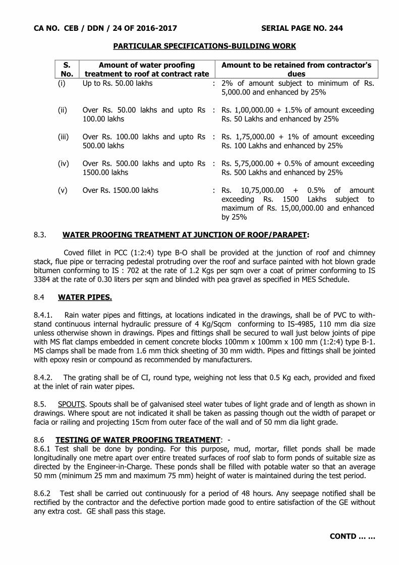
CA NO. CEB / DDN / 24 OF 2016-2017 SERIAL PAGE NO. 244
PARTICULAR SPECIFICATIONS-BUILDING WORK
CONTD … …
S. No.
Amount of water proofing treatment to roof at contract rate
Amount to be retained from contractor's dues
(i) Up to Rs. 50.00 lakhs : 2% of amount subject to minimum of Rs. 5,000.00 and enhanced by 25%
(ii) Over Rs. 50.00 lakhs and upto Rs
100.00 lakhs : Rs. 1,00,000.00 + 1.5% of amount exceeding
Rs. 50 Lakhs and enhanced by 25% (iii) Over Rs. 100.00 lakhs and upto Rs
500.00 lakhs : Rs. 1,75,000.00 + 1% of amount exceeding
Rs. 100 Lakhs and enhanced by 25% (iv) Over Rs. 500.00 lakhs and upto Rs
1500.00 lakhs : Rs. 5,75,000.00 + 0.5% of amount exceeding
Rs. 500 Lakhs and enhanced by 25% (v) Over Rs. 1500.00 lakhs : Rs. 10,75,000.00 + 0.5% of amount
exceeding Rs. 1500 Lakhs subject to maximum of Rs. 15,00,000.00 and enhanced by 25%
8.3. WATER PROOFING TREATMENT AT JUNCTION OF ROOF/PARAPET: Coved fillet in PCC (1:2:4) type B-O shall be provided at the junction of roof and chimney stack, flue pipe or terracing pedestal protruding over the roof and surface painted with hot blown grade bitumen conforming to IS : 702 at the rate of 1.2 Kgs per sqm over a coat of primer conforming to IS 3384 at the rate of 0.30 liters per sqm and blinded with pea gravel as specified in MES Schedule. 8.4 WATER PIPES. 8.4.1. Rain water pipes and fittings, at locations indicated in the drawings, shall be of PVC to with-stand continuous internal hydraulic pressure of 4 Kg/Sqcm conforming to IS-4985, 110 mm dia size unless otherwise shown in drawings. Pipes and fittings shall be secured to wall just below joints of pipe with MS flat clamps embedded in cement concrete blocks 100mm x 100mm x 100 mm (1:2:4) type B-1. MS clamps shall be made from 1.6 mm thick sheeting of 30 mm width. Pipes and fittings shall be jointed with epoxy resin or compound as recommended by manufacturers. 8.4.2. The grating shall be of CI, round type, weighing not less that 0.5 Kg each, provided and fixed at the inlet of rain water pipes. 8.5. SPOUTS. Spouts shall be of galvanised steel water tubes of light grade and of length as shown in drawings. Where spout are not indicated it shall be taken as passing though out the width of parapet or facia or railing and projecting 15cm from outer face of the wall and of 50 mm dia light grade. 8.6 TESTING OF WATER PROOFING TREATMENT: - 8.6.1 Test shall be done by ponding. For this purpose, mud, mortar, fillet ponds shall be made longitudinally one metre apart over entire treated surfaces of roof slab to form ponds of suitable size as directed by the Engineer-in-Charge. These ponds shall be filled with potable water so that an average 50 mm (minimum 25 mm and maximum 75 mm) height of water is maintained during the test period. 8.6.2 Test shall be carried out continuously for a period of 48 hours. Any seepage notified shall be rectified by the contractor and the defective portion made good to entire satisfaction of the GE without any extra cost. GE shall pass this stage.

CA NO. CEB / DDN / 24 OF 2016-2017 SERIAL PAGE NO. 245
PARTICULAR SPECIFICATIONS-BUILDING WORK
CONTD … …
8.6.3 All mud fillet ponds shall be removed and surface made clean and tidy after completion of satisfactory testing. 8.6.4 Satisfactory completion of test shall not absolve the contractor from his responsibilities of rectification of defects which may arise during defect liability period. 8.7 GALVALUME METAL TILES PROFILE SHEET: - Colour coated metal tiles profile sheet shall be provide all as described in Schedule „A‟. The sheet shall be pre-painted and installed with self drilling metal coated screws class 3 of appropriate size with lock all as per manufacturer‟s instructions. 8.7.1 Contractor shall produce manufacturer test certificate for the chemical and mechanical prosperities of steel for approval of the Engineer-in-Charge prior to installation. The sheet shall have brand marking of the manufacturer on the back of the sheet at every 1.00 m centre to centre for conforming genuinely of the material. 8.7.2 CHARACTERISTICS OF COLOUR COATED METAL TILE PROFILED SHEET (a) Total coated thickness : 0.50 mm
(b) Sheet thickness : 0.45 mm (c) Yield strength of sheet : 300 mpa (minimum) (d) Zinc aluminium alloy coating : 150 Gram per sqm (e) Colour coating
Top surface (i) Super polyster colour bond XRW : 20 micron (ii) Primer coating : 5 micron Bottom surfaces (i) Super polyster colour bond XRW : 5 micron (ii) Primer Coating : 5 micron
8.7.2.1 Sheet material: The steel base material of sheet shall be minimum 0.45 mm thick, made out of cold rolled steel and shall be coated with anti-corrosive layer of hot dip metallic zinc aluminium alloy coating of zinc 45% and aluminium 55% as zincalume 150 gm/sqm on both sides. 8.7.3 Erection and fixing: The product will be fastened using class 3 screws as per AS3566 galvanized hexagonal headed, self drilling fasteners of approved make (Buildex or equivalent) and quality including Neoprene washer on each crest (or as per design) of the sheet connecting with the purlin. 8.7.3.1 The standard practice as specified by the manufacturer and as approved by Garrison Engineer shall be followed. All sheets and accessories must be erected without any damage, dent, scratches, etc. 8.7.3.2 Flashing, capping and trims shall be formed out of same colour coated substrate and thickness as that of the roofing sheet fixed with fixtures compatible with the system.

CA NO. CEB / DDN / 24 OF 2016-2017 SERIAL PAGE NO. 246
PARTICULAR SPECIFICATIONS-BUILDING WORK
CONTD … …
8.7.3.3 The contractor shall ensure that panel erector is familiarized with the erection procedure and all the supporting members are straight, level, plump and true. Panels shall be erected as directed by Engieer-in-Charge. 8.7.3.4 The payment will be done on the actual finished/covered surface area of th sheet No. separate payment will be made for the lap of sheet and accessories, bolts, nuts, washers, adjustable bolts and supports for gutters and other fixtures. These are deemed to be included in the quoted rates. 8.7.4 Profile and colour: The design, pattern and colour of the tile profile colour coated sheet shall be approved by GE. The pitch size 195mm to 200mm c/c. Depth of crest 28 to 30mm trapezoidal profile and tile pitch in sloped direction shall be 200 to 220mm. 8.7.5 The guarantee period for colour coated zincalume tile profiled metal sheet on roof and ridges contemplated in the contract shall be FIFTEEN YEARS after completion of work. The contractor shall furnish written guarantee for period of 15years from the manufactuer.It shall be the responsibility of the contractor to replace the defective sheet if any found during guarantee period. The contractor shall furnish FDR of 2.5% of the work done of metal sheets in favour of GE Dehradun for the above period, which shall be released on satisfactory completion of the guarantee period. 8.7.6 Steel Testing 8.7.6.1 The manufacture of steel material should submit the manufacturer‟s test certificate for the base metal including the chemical and mechanical properties for each heat/coil clearly mentioning the following test results. Standard shall be followed according to AS 1397. (a) Chemical Composition of base steel (b) Tensile strength(minimum/maximum) (c) Yield Strength(minimum/maximum) (d) Elongation (e) hardness 8.7.6.2 The substrate or corrosion protection coating is Zinc-aluminium alloy coating as per AS 1397 :1993 (for exterior roofing and should be clearly mentioned in the test certificate with the coating mass i.e. AZ150. 8.7.6.3 The manufacture should submit related document for expected product service performance of pre-painted metal sheet as per AS/NZS 2778:1997 8.7.6.4 BINDING WIRE:- Binding wire shall be conforming to IS-280. The dia of wire shall be not less than .9mm (Annealed). 8.8 WATER PROOFING ON RCC CANOPIES/PROJECTED CUPBOARDS ETC.
Provide water proofing treatment to top of RCC canopy etc with 15 mm thick cement plaster in cement mortar (1:3) mixed with water proofing compound in the proportion as recommended by the manufacturer subject to minimum 2 % by weight of cement laid on slope over RCC canopies and chajjas etc when the concrete is still green. The top of surface of plaster shall be finished even and smooth without using extra cement.

CA NO. CEB / DDN / 24 OF 2016-2017 SERIAL PAGE NO. 247
PARTICULAR SPECIFICATIONS-BUILDING WORK
CONTD … …
9. FLOORING. 9.1. General. 9.1.1. Provisions contained in clause 13.25, 13.32, 13.38 & 13.39 of MES Schedule are to be adopted for laying floors and pavements. 9.1.2. Floors shall be laid to levels or to falls as shown on drawings and as directed by the Engineer-in-Charge. Floor finish shall be extended over dwarf walls, doors and other openings. For types of flooring, refer schedule of finishes/drawing including notes thereon. 9.1.3. Sinking of floors in kitchens, toilets, baths and WCs etc where shown on drawings shall not be achieved by reducing RCC slab thickness. 9.1.4. Connected ramps shall have the same type of floors as adjoining floors of building and shall have in addition chequered finish. 9.1.5. Treads and landings of stairs, steps on entrance, risers and skirting shall have matching finish i.e. terrazzo or PCC as indicated on drawings. 9.1.5.1 Wherever kota stone flooring has been shown on tread of steps shall be bull nosed. 9.1.6. Cast-in-Situ terrazzo finish unless indicated otherwise on schedule of finishes drawings shall be with 100% grey cement. Where cast-in-situ terrazzo with white cement has been indicated, it shall be with 100% white cement mixed with pigment of light shade if so directed by GE without any extra cost. Pozzolana or slag cement shall not be used for floor topping. 9.1.7. Marble aggregate (chips) for cast-in-situ terrazo flooring shall be 7 to 9 mm (grade I) and for dado/skirting it shall be 2 to 4 mm (grade-I). The colour of marble chips shall be as approved by GE. 9.1.8. Surfaces of floors, skirting/dado when finished in terrazzo Kota stone shall be polished without use of bees wax as specified in relevant clause of MES Schedule. 9.1.9. The dividing line between the floors of different types wherever they so meet between adjoining rooms, shall be determined on the basis of the finish visible when the doors are closed and the applicable finish shall accordingly be provided. 9.1.10. Floor finish over RCC slabs shall be laid all as specified in MES Schedule. Floor topping of Cast-in-situ P.C.C shall be finished even and smooth using extra cement. 9.1.11. Sub floor may not be laid in panels. Under-layer and topping layers of cast-in-situ PCC and terrazzo floors shall be laid in square or rectangular panels as directed by Engineer-in-Charge, Length of panel not exc. 2.0. metre, length to width ratio not exc. 1.5 times in rectangular panels. However, area of each panel shall not exceed 2.00 sqm as specified. 9.1.12. Dividing strips shall be of glass sheet 2 mm less wide than thickness of floors (including topping in case of terrazzo floors) and 4.00 mm nominal thickness. Top of dividing strips shall be finished smooth with top surface of floor. In baths/WC terrazzo finish in flooring and skirting, no dividing strip shall be provided. 9.1.13 Skirting shall be provided of same finish as for floor
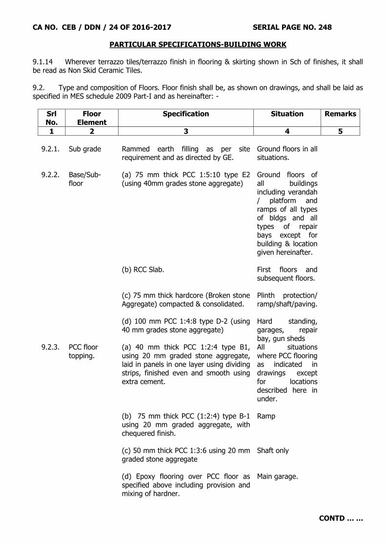
CA NO. CEB / DDN / 24 OF 2016-2017 SERIAL PAGE NO. 248
PARTICULAR SPECIFICATIONS-BUILDING WORK
CONTD … …
9.1.14 Wherever terrazzo tiles/terrazzo finish in flooring & skirting shown in Sch of finishes, it shall be read as Non Skid Ceramic Tiles. 9.2. Type and composition of Floors. Floor finish shall be, as shown on drawings, and shall be laid as specified in MES schedule 2009 Part-I and as hereinafter: -
Srl No.
Floor Element
Specification Situation Remarks
1 2 3 4 5
9.2.1. Sub grade Rammed earth filling as per site
requirement and as directed by GE. Ground floors in all situations.
9.2.2. Base/Sub-floor
(a) 75 mm thick PCC 1:5:10 type E2 (using 40mm grades stone aggregate)
Ground floors of all buildings including verandah / platform and ramps of all types of bldgs and all types of repair bays except for building & location given hereinafter.
(b) RCC Slab. First floors and subsequent floors.
(c) 75 mm thick hardcore (Broken stone Aggregate) compacted & consolidated.
Plinth protection/ ramp/shaft/paving.
(d) 100 mm PCC 1:4:8 type D-2 (using 40 mm grades stone aggregate)
Hard standing, garages, repair bay, gun sheds
9.2.3. PCC floor topping.
(a) 40 mm thick PCC 1:2:4 type B1, using 20 mm graded stone aggregate, laid in panels in one layer using dividing strips, finished even and smooth using extra cement.
All situations where PCC flooring as indicated in drawings except for locations described here in under.
(b) 75 mm thick PCC (1:2:4) type B-1 using 20 mm graded aggregate, with chequered finish.
Ramp
(c) 50 mm thick PCC 1:3:6 using 20 mm graded stone aggregate
Shaft only
(d) Epoxy flooring over PCC floor as specified above including provision and mixing of hardner.
Main garage.

CA NO. CEB / DDN / 24 OF 2016-2017 SERIAL PAGE NO. 249
PARTICULAR SPECIFICATIONS-BUILDING WORK
CONTD … …
Srl No.
Floor Element
Specification Situation Remarks
1 2 3 4 5
9.2.4. Cast-in-situ
terrazzo flooring with white cement and pigment
10 mm thick cast-in-situ terrazzo with white cement mixed with light cream pigment with border of coloured pigment as approved by GE over under layer of 30 mm thick PCC (1:2:4) type B0 (using 12.5 mm graded aggregate) laid in panels using dividing strips.
As indicated in schedule of finish.
9.2.4A Cast-in-situ terrazzo flooring with grey cement and no pigment
10 mm thick cast-in-situ terrazzo with grey cement as approved by GE over layer of 30 mm thick PCC (1:2:4) type B0 (using 12.5 mm graded aggregate) laid in panels using dividing strips.
As indicated in schedule of finish.
9.2.5 Ceramic tiles floor
Ceramic tiles shall be coloured and of size 400x400x 6 to 7 mm thick tiles joint less shall be laid on 20 mm thick screed in CM 1:4 over sub base over rammed earth in ground floor.
Where indicated in schedule of finishes.
9.2.6 Chequerred cement concrete tile flooring confirming to IS-13801-1993 as approved by GE
Chequerred cement concrete tile of size 250x250x22 mm thick shall be laid over 20 mm thick screed in CM 1:4 over sub base / sub floor, set, jointed and pointed with neat cement slurry with pigment to match the colour of tile.
As indicated in Schedule of Finishes.
9.2.7 Non skid ceramic tile with mat finish
Non skid ceramic tile with mat finish shall be laid over 20mm thick base of Screed in CM 1:4 over sub base. The size of non skid tile shall be 400 x 400 x 6 to 7 mm with light colour grey/ ivory and jointless and jointed the neat cement slurry and pointed in white or coloured cement to match colour of tile. The design of tiles shall be as approved by GE.
As indicated in Schedule of Finishes.
9.2.8 Vitrified Tile Flooring
Coloured vitrified tiles (mirror finish) of size 600x600 and 8 to 10 mm thick of make as listed in Appx „B‟ of tender documents of shade and pattern as directed by GE over 20 mm thick screed in CM 1:4 over sub base/ RCC slab.
As indicated in Schedule of Finishes.
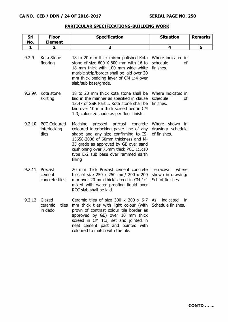
CA NO. CEB / DDN / 24 OF 2016-2017 SERIAL PAGE NO. 250
PARTICULAR SPECIFICATIONS-BUILDING WORK
CONTD … …
Srl No.
Floor Element
Specification Situation Remarks
1 2 3 4 5
9.2.9 Kota Stone
flooring 18 to 20 mm thick mirror polished Kota stone of size 600 X 600 mm with 16 to 18 mm thick with 100 mm wide white marble strip/border shall be laid over 20 mm thick bedding layer of CM 1:4 over slab/sub base/grade.
Where indicated in schedule of finishes.
9.2.9A Kota stone skirting
18 to 20 mm thick kota stone shall be laid in the manner as specified in clause 13.47 of SSR Part I. Kota stone shall be laid over 10 mm thick screed bed in CM 1:3, colour & shade as per floor finish.
Where indicated in schedule of finishes.
9.2.10 PCC Coloured interlocking tiles
Machine pressed precast concrete coloured interlocking paver line of any shape and any size confirming to IS-15658-2006 of 60mm thickness and M-35 grade as approved by GE over sand cushioning over 75mm thick PCC 1:5:10 type E-2 sub base over rammed earth filling
Where shown in drawing/ schedule of finishes.
9.2.11 Precast cement concrete tiles
20 mm thick Precast cement concrete tiles of size 250 x 250 mm/ 200 x 200 mm over 20 mm thick screed in CM 1:4 mixed with water proofing liquid over RCC slab shall be laid.
Terraces/ where shown in drawing/ Sch of finishes
9.2.12
Glazed ceramic tiles in dado
Ceramic tiles of size 300 x 200 x 6-7 mm thick tiles with light colour (with provn of contrast colour tile border as approved by GE) over 10 mm thick screed in CM 1:3, set and jointed in neat cement past and pointed with coloured to match with the tile.
As indicated in Schedule finishes.

CA NO. CEB / DDN / 24 OF 2016-2017 SERIAL PAGE NO. 251
PARTICULAR SPECIFICATIONS-BUILDING WORK
CONTD … …
Srl No.
Floor Element
Specification Situation Remarks
1 2 3 4 5
9.2.13 Acid
Resistance Tiles Skirting
15 mm thick acid resistant, vitreous ceramic and glazed tiles conforming to IS-1457 of size as approved by GE shall be laid over 15 mm thick screed in CM 1:4 in skirting. Laying shall be as specified here in before. Setting, jointing & pointing of tiles shall be in chemicals resistance mortor, raising type all as specified.
As indicated in Schedule of finishes
9.2.14 Acid Resistance Tiles flooring
25 mm thick acid resistant, vitreous ceramic and glazed tiles conforming to IS-1457 of size as approved by GE shall be laid over 20 mm thick screed in CM 1:4 in flooring. Laying shall be as specified here in before. Setting, jointing & pointing of tiles shall be in chemicals resistance mortor, raising type all as specified.
As indicated in Schedule of finishes
NOTE: -
(i) Wherever PCC/terrazzo floor is required to be provided on RCC member, the top surfaces of RCC members shall be smeared with cement slurry @ 3 kg/sqm before providing flooring. The cost of the same shall deem to be included in the lump sum cost quoted by contractor.
(ii) Contractor may use bigger size of floor tiles without any extra cost to Govt.
(iii) Flooring/skirting and finishes of lobby wherever not shown in Sch of finishes shall be
same as in adjacent /connecting rooms. 9.3. WATER PROOFING TREATMENT TO SUNKEN FLOOR SLABS OF BATH / WCs / TOILET ETC. 9.3.1 The RCC slabs of sunken portion shall be laid flat having slope of 1:20 at top by increasing thickness of slab at ends and decreasing at centre. The thickness of slab shown in drawing shall be deemed at centre of slab. Further lateral slope in central portion shall also be provided. At the lowest portion a PVC relief pipe (spout) of 40 mm of dia shall be provided as explained here in after. The concrete in sunken portion floor slabs shall be mixed with liquid WPC @ 200 ml per 50 kg (bag) of cement or as per manufacturer's instructions. However, deviation if any shall be priced at the rate of 2% by weight of cement with dry WPC. 9.3.2 The existing surfaces both at horizontal & vertical shall be cleaned by removing all the loose mortar, laitance, dirt dust etc by chisel hammer/wire brush/jute brush and air blower machine. Two coats of elastomeric compound viz. beck bond WPC - 30 (Make - Beck India Ltd) / Master coat IRC (Make - Conchem India) over one coat on neat primer i.e. Super Latex (Make- Dr. Fixit) / Master bond (Make - Conchem) shall be applied on the cleaned surfaces.

CA NO. CEB / DDN / 24 OF 2016-2017 SERIAL PAGE NO. 252
PARTICULAR SPECIFICATIONS-BUILDING WORK
CONTD … …
9.3.3 Application of polysulphite sealant (Make- Dr, Fixit/STP/Chowskey) around any outlet pipe of 75mm bore (Approx 25mm wide and 10 to 12mm deep) in toilet/kitchen/washing areas and the like shall be given to make water tight. 9.3.4. Application of polysulphite sealant (Make - Dr Fixit/STP/Chowskey) around any outlet pipe of 100 mm bore (Approx 25mm wide and 10 to 12 mm deep) in toilet/kitchen/washing areas and the like shall be given to make water tight. 9.3.5. 15mm thick plaster in cement mortar 1:3 using liquid water proofing compound @ 200 ml per 50 kg (bag) of cement or as per manufacturer's instructions shall be applied at both horizontal & vertical surface. However, deviation if any, shall be priced at the rate of 2% by weight of cement with dry WPC. 9.3.6. The sunken portion shall be filled with lean concrete 1:5:10 using brick aggregate as approved by GE including fixing of sanitary items requiring embedding in cement concrete. 9.3.7 The sunken floor shall then be tested for leakage/seepage by ponding it with water for minimum 72 hours. There shall not be any seepage/dampness in the slab as seen underneath and sides. 10. PLASTERING AND POINTING 10.1. General. 10.1.1. Plaster and/or skirting/dado shall be returned in jambs, soffits of lintels and window cills etc. 10.1.2. Where plaster on concrete surfaces is shown to match the adjacent wall surfaces, the mix of plaster shall be as for the brick surfaces. 10.1.3. All plastered surfaces shall be trowelled to a smooth and even surfaces without using extra cement. 10.1.4. All external finishes (plaster/Pointing etc) shall be carried out upto 15 cm below ground level. 10.1.5. Thickness of cement plaster mentioned hereinafter shall be finished thickness exclusive of dubbing. Dubbing may however be done in one operation with plaster.
10.1.6. All corners, angle, junctions, and edges shall be truly vertical or horizontal as the case may be and shall be carefully finished. Corners around jambs of openings and junction of walls shall be rounded to minimum radius of 5 mm. 10.1.7. 150 mm wide chicken wire mesh 0.71 mm dia of wire and 25 mm x 25 mm mesh size at the junction of RCC & brick masonry or grip other dissimilar material (internally & externally) before plastering shall be provided. 10.1.8. Particular attention of the contractor is invited to take notice of local practices and local availability of materials like bricks, stones, sand, form work etc for any extra quantity of mortar required, extra dubbing required, touching up for achieving smooth and even surfaces. This shall be deemed to have been included in the lumpsum or the item rate quoted for plasterwork, as applicable. 10.2. Materials. 10.2.1. Cement. Refer cement here-in-before. 10.2.2. Sand. Refer clause, 14.5 of MES Schedule.

CA NO. CEB / DDN / 24 OF 2016-2017 SERIAL PAGE NO. 253
PARTICULAR SPECIFICATIONS-BUILDING WORK
CONTD … …
10.3. Cement Plastering to surfaces. 10.3.1. Internal surfaces of masonry work indicated in schedule of finishes of buildings including inside surfaces of CBs, ward robes and lofts etc under Schedule „A‟ Part I shall be plastered with 12 mm thick in cement mortar (1:6). Risers of steps if indicated on drawings shall be plastered with 10 mm thick cement mortar (1:4). 10.3.2. All external masonry surfaces, except where otherwise specified shall be plastered 15 mm thick in cement mortar in two layers consisting first layer 10 mm thick in cement and sand mortar 1:6 and top layer 5 mm thick in cement mortar 1:4 mixed with approved water proofing compound as per manufacturer‟s instructions subject to a minimum of 3% by weight of cement in top layer (5 mm thick) only. In case of deviation, the quantity of water proofing compound shall be taken as 3 % by weight of cement. 10.3.3 All external masonry surfaces, except otherwise shown on Schedule of Finishes, shall be provided with washed stone grit plaster two layers, under layer 12mm cement plaster in CM 1:4 finished rough by combing with jute brushes for proper bound followed by the under layer applying cement slurry @2 kg/sqm top layer 15mm thick with mixture 1 part of cement and 1.5 part of crushed stone marble chips of approved quality of shade and size as approved by GE with 12mm wide and 15mm deep grooves including scrubbing with brushes and washing the top layer with water to expose stone chipping complete. Grooves shall be painted with weather proof paint. Spacing of grooves shall be all as directed by GE. 10.4. POINTING. 10.4.1. Pointing to brick masonry wall where shown shall be keyed pointing in cement mortar (1:3) unless any other type of pointing is specified or indicated on drawings. 10.5. SKIRTING AND DADO. 10.5.1. KOTA SONE SKIRTING. Wherever kota stone floor is indicated kota stone skirting shall be provided all as shown on drawings to matching with the adjoining floor over 10 mm thick screed bed of cement mortar (1:3). Height of Kota stone skirting where not shown on drawings shall be 10 cm for skirting. The glazed tiles in dado of 1150 mm or as indicated in Drg in lobby near mirror and two metres or door height in toilet/bath (whichever is more) Junction of floor and dado/skirting shall be rounded to a minimum radius of 5 mm and top edge of skirting/dado to be finished slightly tapered so as to avoid accumulation of dust over it. 10.5.2. CEMENT DADO. Cement skirting/dado shall be provided adjoining PCC floors in locations indicated in drawings. It shall be 15 mm thick on brick wall consisting of 5 mm thick setting coat in cement mortar 1:2 over 10 mm thick on screed bed in cement mortar 1:4. Height of cement dado/skirting where not shown on drawings shall be as specified for kota stone skirting/dado. It shall be in line with plastering and separated with a groove. Junction of floor and dado/skirting shall be rounded to minimum radius of 5 mm and top edge skirting/dado to be finished slightly tapered so as to avoid accumulation of dust over it. 10.6. GLAZED CERAMIC TILES DADO. 10.6.1 Colour glazed tiles where shown on drawings shall be laid in the manner as specified in relevant clause of MES Schedule. Glazed tiles in dado shall be the coloured to match with floor tiles and of size 300 mm x 200 mm or near size x 6 mm thick irrespective of whatever is shown on drawings. These shall be laid over screed of 10 mm thick in cement mortar (1:3) and set and jointed in neat cement slurry and

CA NO. CEB / DDN / 24 OF 2016-2017 SERIAL PAGE NO. 254
PARTICULAR SPECIFICATIONS-BUILDING WORK
CONTD … …
pointed in white cement and colour pigment to match the tiles. Height of dado shall be as specified and shown on drawing. Glazed tiles shall conform to IS-13712.Dado in kitchen shall be provided upto 2100 mm height. 10.7. Plaster Band. Band in extra cement plaster shall be 10 mm thick in cm 1:4 over existing plaster as indicted/shown on drawings. 11. WHITE/COLOUR WASHING AND CEMENT BASE PAINT
11.1. All synthetic enamel paint, emulsion paint shall be of Ist quality manufactured by the standard firms of make as per Appendix „B‟.
11.1.1. The contractor shall inform the GE, within four weeks of the acceptance of the tender, the brand names of the manufacturers of paint proposed to be used in the works and submit sample thereof well in time and obtain prior written approval of the GE before their use in the work.
11.1.2. The contractor shall, when so required by the GE, produce certificate from the manufacturer or their authorised dealer/representative to establish that the brands of paints purchased by the contractor from them satisfy the requirements of the relevant Indian Standard. 11.1.3. Paints for priming coat, under coat and finishing coat shall be of same manufacturer.
11.1.4. Tint of paint, if not mentioned in drawings/schedule of finishes will be approved by the GE. 11.2. Workmanship.
11.2.1. All wood work required to be painted shall be smoothened, sized and knotted and then applied with priming coat. Stopping and filling (filler coat) shall be done after priming coat and surface rubbed down to a level of smooth surface and thereafter under coat and finishing coat applied, all as specified in clause 17.6 of MES Schedule. Steel and iron work shall be painted in the manner as specified in clause 17.8 of MES Schedule.
11.2.2. The surfaces indicated in the Schedule of finishes to be given aluminum paint shall be given two coats of aluminum paint conforming to IS-2339, over a coat of appropriate primer.
11.2.3. No treatment shall be given to reinforcement.
11.2.4. Other steel surfaces (except GI pipes) and wood work exposed to view but not covered in Schedule of finishes or their finishing is not specifically indicated in any other drawings or specified elsewhere, shall be given two coats of synthetic enamel paint over a coat of primer of tint as directed by the GE.
11.2.5. Bottom of door shutters shall be given one coat of primer only.
11.2.6. Irrespective of what is indicated on drawings and specified elsewhere, finishing coat and under coat shall be with synthetic enamel paint.
11.3. Tarring. The backs of wooden chowkats in contact with brick brick/plaster etc. and also wooden/steel surfaces embedded in walls of tar and sanded.
11.4. Cement Slurry. Portions of MS bolts, lugs, anchor bolts etc embedded in concrete shall be treated with neat cement slurry.

CA NO. CEB / DDN / 24 OF 2016-2017 SERIAL PAGE NO. 255
PARTICULAR SPECIFICATIONS-BUILDING WORK
CONTD … …
11.5 French Polish. The wood work in railing and built-in furniture‟s, where indicated to be polished shall be French polished all as specified in clause 17.7.4 of MES Schedule.
11.6 WHITE WASHING:-Refer Para 15.12 of SSR Part I. The quantities of lime, water, gum Sodium chloride and blue etc. shall be as specified in Para 15.12 of SSR Part I. Unless specified otherwise elsewhere/ shown in drgs new plastered surfaces / unplastered surfaces shall be treated with three coats of White wash. White wash shall strictly be carried out as per Para 15.12.5 of SSR Part I. 11.7 COLOUR WASHING:-Refer Para 15.12 of SSR Part I. The quantities of lime, water, gum, Sodium chloride, blue and mineral colour etc. shall be as specified in Para 15.12 of SSR Part I. Mineral colour shall be added to extent required to achieve required shade/tint. Unless specified otherwise elsewhere/ shown in drg new plastered /un-plastered surfaces shall be treated with two coats of colour wash over one coat of White wash. 11.8 DISTEMPERING WITH DRY DISTEMPER:-Refer Para 15.13 of SSR Part I. unless specified otherwise elsewhere/ shown on drawings all newly plastered /un-plastered internal surfaces shall be treated with one coat of primer followed by two coats of dry distemper. 11.9 DISTEMPERING WITH OIL BOUND DISTEMPER / EMULSION:-Refer Para 15.14 of SSR Part I. Unless otherwise specified elsewhere/ shown on drawings all new plastered /un-plastered surfaces shall be treated with one coat of primer followed by two coats of oil emulsion and old surfaces shall be treated with one or more coats of oil emulsion as indicated. Newly Plastered surfaces distempered, before a period for 06 Months, shall be treated with a coat of alkaline resistant priming paint. 11.10 CEMENT PAINTING:-Refer Para 15.15 of SSR Part I. To prevent algae growth and moss growth and efflorescence, silicon base water repellant compound shall invariably be added as directed by EIC. Unless otherwise specified elsewhere /shown on drawings newly external plastered/un-plastered surfaces shall be applied with two coats of cement base paint over one coat of cement base primer. 11.11 Weather Coat : Two coats of weather sealed paint shall be applied over a coat of primer all as shown on Schedule of finishes and as specified in IS 12027-1987. It shall be of make Asian Paints (Apex) / Berger (Weather Coat). 11.12 Irrespective of what is shown in Schedule of Finishes, Internal Plastered Surfaces of walls / ceiling shall be provided with one coat of wall care and white cement putty (Birla white / JK Wall Care) to have uniform smooth finish. Contractor‟s quoted rates for Sch „A‟ Part-I shall be deemed to include the cost of the same. 12. GLAZING: -
12.1 GENERAL: - Unless specifically mentioned otherwise in drawings/ elsewhere in particular specifications, glazing to windows/vents/doors etc., where shown on the relevant drawing shall be with 3.00 mm thick nominal sheet glass up to 0.5 sqm and 4.0 mm thick exc. 0.5 Sqm for each pane.
12.2 MATERIALS: - 12.2.1 SHEET GLASS:-Refer Para 16.2 of SSR Part I. Sheet glass shall be conforming to IS-2835. 12.2.2 FROSTED GLASS:- Frosted glass shall be as specified in Para 16.15 of SSR Part I. 12.2.3 PUTTY: - Refer Para 16.5 of SSR Part I. It shall be conforming to IS-419.
CA NO. CEB / DDN / 24 OF 2016-2017 SERIAL PAGE NO. 256
PARTICULAR SPECIFICATIONS-BUILDING WORK
CONTD … …
12.3 WORKMANSHIP:- 12.3.1 GLAZING WITH PUTTY:- Refer Para 16.6 to 16.10 and 16.13 of SSR Part I. 12.3.2 GLAZING WITH BEADS:- :- Refer Para 16.6 to 16.8 and 16.13 of SSR Part I. Beads shall be fixed with screws. 12.3.3 GLAZING IN STEEL SURROUNDS:- Refer Para 16.6 to 16.8, 16.9,16.10 and 16.13 of SSR Part I. Beads shall be fixed with screws. 13. PAINTING:- Type of Finishes shall be, as shown on drawings, and shall be as specified in MES schedule 2009 Part-I and as hereinafter: 13.1 GENERAL: - 13.1.1 All synthetic enamel paint, emulsion paint shall be of 1st quality. 13.1.2 The contractor shall inform the GE Dehradun, within four weeks of the acceptance of the tender, the tender, the brand names of the manufacturers of paint proposed to be used in the works and submit sample thereof well in time and obtain prior written approval of the GE Dehradun, before their use in the work. 13.1.3 The contractor shall, when so required by the GE Dehradun, produce certificate from the manufacturer or their authorized dealer/representative to establish that the brands of paints purchased by the contractor from them satisfy the requirements of the relevant Indian Standard. 13.1.4 Paints for priming coat, under coat and finishing coat shall be of same manufacturer. 13.1.5 Tint of paint, if not mentioned in drawings/schedule of finishes will be as approved by the GE Dehradun. 13.2 MATERIALS:- 13.2.1.Refer Para 17.2 of SSR Part I. 13.2.2 SYNTHETIC ENAMEL PAINT:- It shall be conforming to IS-2932 and shall be one of the make specified hereinafter. 13.2.3 RED OXIDE ZINC CHROME PRIMER:- It shall be conforming to IS-2074. It shall be one of the makes/ brands specified hereinafter. It shall be of the same make as that of finishing / under coat. 13.2.4 COAL TAR BLACK: - It shall be of grade “A” conforming to relevant IS specifications and shall be one of the make specified hereinafter. 13.2.5 CREOSOTE OIL: - It shall be of type- I conforming to IS-218 and shall be one of the make/ brands specified hereinafter. 13.2.6 PINK PRIMER:- It shall be conforming to IS 3536 and shall be one of the make specified hereinafter. It shall be of the same make as of finishing coat/ under coat. 13.2.7 ALUMINIUM PAINT :-It shall be conforming to IS-2339 of Make as approved by GE Dehradun in writing.

CA NO. CEB / DDN / 24 OF 2016-2017 SERIAL PAGE NO. 257
PARTICULAR SPECIFICATIONS-BUILDING WORK
CONTD … …
13.2.8 FRENCH POLISH: - It shall be of make as specified. 13.3 WORKMANSHIP:- 13.3.1 GENERALLY: - Painting Generally:- Refer Para 17.3 to 17.5 of SSR Part I. 13.3.1.1 All wood work required to be painted shall be smoothened, sized and knotted and then applied with priming coat. Stopping and filling (filler coat) shall be done after priming coat and surface rubbed down to a level of smooth surface and thereafter under coat and finishing coat applied, all as specified in clause 17.6 of MES Schedule. 13.3.1.2 No treatment shall be given to reinforcement. 13.3.1.3 Steel surfaces (except GI pipes) and wood work exposed to view but not covered in Schedule of finishes or their finishing is not specifically indicated in any other drawings or specified elsewhere, shall be given two coats of synthetic enamel paint over a coat of primer of tint as directed by the GE Dehradun. 13.3.1.4 Bottom of door shutters shall be given one coat of primer only. 13.3.1.5 TARRING. The backs of wooden chowkats in contact with brick brick/plaster etc. and also wooden/steel surfaces embedded in walls of tar and sanded. Cement Slurry. Portions of MS bolts, lugs, anchor bolts etc embedded in concrete shall be treated with neat cement slurry. 13.3.2 FRENCH POLISH. The wood works in railing and built-in furniture‟s, where indicated to be polished shall be French polished all as specified in clause 17.7.4 of MES Schedule. Minimum two coats of French polishing over a filler coat shall be applied. 13.3.3 PAINTING TO WOOD WORK:- Refer Para 17.6 of SSR Part I. 13.3.4 PAINTING STEEL AND IRON WORK:-Refer Para 17.8 of SSR Part I. Mordant solution made with composition of 64 parts of water and copper chloride, copper nitrate, aluminium chloride and HCL acid, each one part all by weight, shall be applied to GI surfaces @ 5 litres /100 sqm before application of red oxide etc. where GI surfaces ordered to be painted. All steel surfaces unless specified otherwise elsewhere be applied with two coats of synthetic enameled paint over one coat of primer 13.3.5 PAINTING OF AC BUILDING BOARDS/ PLASTER/CONCRETE/ BRICK AND STONE SURFACES:-Refer Para 17.9 of SSR Part I. New surfaces shall be applied with a priming coat of alkaline resistance priming paint conforming to IS 109, of the same make as that of paint. Over a coat of primer, two coats of paint shall be applied unless otherwise indicated. 13.3.6 CREOSOTING:- Refer Para 17.11 of SSR Part I. Unless specified otherwise in Schedule “A”, creosoting shall be done in two coats using creosote oil @ 1.00 litre per 10 sqm. 14. SANITARY, TOILET FITTINGS/APPLIANCES AND PLUMBING WORK.
14.1 GENERAL. 14.1.1 All sanitary appliances /fittings shall be of vitreous china (white/Ivory) first quality and shall be ISI marked and shall conform to IS-2556 for General requirements and the specific requirements as mentioned in relevant clause of MES Schedule.

CA NO. CEB / DDN / 24 OF 2016-2017 SERIAL PAGE NO. 258
PARTICULAR SPECIFICATIONS-BUILDING WORK
CONTD … …
14.1.2 Flush pipe and socket of fittings rim of WC shall be jointed with white and red lead cement (white and red lead in equal proportion by weight) and linseed oil added to form paste. 14.1.3 „P‟ or „S‟ trap shall be of cast iron and jointed to Indian type WC pan with epoxy compound as directed by Engineer-in-Charge. These shall be of long neck pattern. 14.1.4 The sizes, given hereinafter are approximate sizes. The size of sanitary fittings to be provided shall be the nearest size as per manufacturers catalogue as approved by GE Dehradun . No price adjustment shall be made on this account.
14.1.5 Make – (a) EWC - TULIP EWC CAT No – 20053 alongwith cistern CAT No 21036 of Hindware or equivalent of Jaquar & Co. Pvt Ltd or Hindustan Sanitary Ware (1st quality) or Parryware (Super fine) or Cera (1st quality) or Johnson Pedder. (b) WHB - TOPAZ CAT No – 91028 of make Hindware or equivalent of Jaquar & Co. Pvt Ltd or Hindustan Sanitary Ware (1st quality) or Parryware (Super fine) or Cera (1st quality) or Johnson Pedder. 14.2 MATERIALS:- 14.2.1 BALL VALVES:- Refer Para 18.19 of SSR Part I. These shall be of HDPE, high-pressure type and shall conform to IS-1703, horizontal plunger type. The float shall be of polyethylene, high-pressure ball valves. The minimum weight shall be as specified in Para 18.19 of SSR Part I. The cost of ball valve shall be deemed included in lump sum cost, unless separate item is given in Schedule „A‟ for „Internal water Supply”. 14.2.2 WASTE FITTINGS: - Refer Para 18.20 of SSR Part I. Waste fittings for wash hand basins (vitreous chine/ trough type) and sinks shall be 32 mm dia. and 40 mm dia. respectively. Waste fittings shall also be of PTMT of make as specified. 14.2.3 WASTE PLUGS: - Refer Para 18.21 of SSR Part I. 14.2.4 CI SOIL, WASTE AND VENTILATING PIPES: - Refer Para 18.23 of SSR Part I. These shall be of CI, spun cast, ISI marked, any type, and spigot and socketed. CI fittings shall be conforming to IS-3989, medium weight. However 50 mm nominal bore CI spigot and socketed pipe and fittings may be sand cast having ISI certification mark as approved . 14.2.5 CI COWLS:- Refer Para 18.24 of SSR Part I. Unless otherwise indicated cowl shall be suitable for 50 mm nominal bore pipes. 14.2.6 NAHANI TRAPS:- Refer Para 18.25 of SSR Part I. These shall be consisting of gratings. 14.2.7 SGSW PIPES AND FITTINGS:- Refer Para 18.28 of SSR Part I. These shall be of grade „A‟. These shall be an approved product of BIS and shall have ISI certification mark. The rates given in SSR shall be deemed amended for the same. 14.2.8 CONCRETE PIPES:- Refer Para 18.29 of SSR Part I. Unless otherwise indicated these shall be of NP3 , non pressure type, ISI marked.
CA NO. CEB / DDN / 24 OF 2016-2017 SERIAL PAGE NO. 259
PARTICULAR SPECIFICATIONS-BUILDING WORK
CONTD … …
14.2.8.1 SANITARY FITTINGS AND APPLIANCES:-Refer Para 18.32 of SSR Part I. These shall be of first quality. 14.2.8.2 Wash basins:- Refer Para 18.32.5 of SSR Part I. Unless otherwise specified specifically elsewhere these shall be of vitreous china white, size 630x 450 mm. Waste fittings of PTMT ,32 mm dia. shall be provided. 14.2.8.3 Stainless steel Sinks with Draing Board : - These shall be of stainless steel of size overall size 915mmx460mm with bowl size 410mmx 330 mmx160mm and made out of 1.00 mm thick sheet and fixed as directed by EIC. These shall be of make as specified herein after. Waste fittings of PTMT ,32 mm dia. shall be provided 14.2.8.4 Stainless steel Sinks : - These shall be of stainless steel of size overall size 495 mmx420mm with bowl size 410mmx330mmx160mm and made out of 1.00 mm thick stainless steel sheet and fixed as directed by EIC. These shall be of make as specified herein 14.2.8.5 Urinals: - These shall be of half stall type irrespective of what is shown on drawings or else where. Refer Para 18.32.7.2 of SSR Part I. 14.2.8.6 Poly-propylene moulded Flushing cistern: - Refer Para 18.34 of SSR Part I. Flushing cistern shall be low level type. These shall be of moulded polypropylene virgin. The capacity of cistern shall be 10 litres. Flush pipe shall be of PVC , 40 mm nominal dia. 14.2.8.7 Plastic water closet seat and cover: - Refer Para 18.36 of SSR Part I. These shall have recessed bottom. Seats and covers shall be of any of the materials as directed by EIC. 14.2.8.8 HDPE Water tanks:- These shall be ISI marked (IS-12701). These shall be of three-layer type. Unless specifically mentioned otherwise elsewhere/ shown on drawings, tanks shall be of 500 litres capacity. 14.2.8.9 Mirror:- Unless specifically specified otherwise elsewhere/ shown in drawings ,the mirror shall be of square size 600x450x6mm thick with beveled edges. Back shall be fitted with plywood, 12 mm thick BWP type, 5 ply and provided with aluminum “C” channel having wall thickness not less than 1 mm all-round to suit the thickness of glass (mirror) including plywood. The rates given in SSR shall be deemed for the same. 14.2.8.10 Gully traps:- These shall be of salt glazed stone ware, square mouthed 150mm ,‟P‟ trap type complying with the requirements of IS 651 duly fitted with Cast iron perforated grating of 150 mm x 150 mm bituminous coated. 14.2.8.11 Salt Glazed Stone Ware pipes:- Unless specified otherwise/ shown in drawings, SGSW pipe shall be of 100 mm nominal bore. These shall be ISI marked. 14.3 Water closet Pedestal Pattern : Irrespective of what is shown on drawings EWC shall consists of :- (a) Water closet wash down pattern of height 40 cm of vitreous china (white) bearing ISI marked with 'S' trap in ground floor and „P‟ trap in intermediate floors all as per IS-2556Part-II. (b) Plastic seat and cover with flat underside solid moulding, closed front pattern, with cover shall be as per IS 2548 (Part I). Seat and cover shall be of colour matching with WC with chromium plated hinge and nuts of make as given in Appx „B‟.

CA NO. CEB / DDN / 24 OF 2016-2017 SERIAL PAGE NO. 260
PARTICULAR SPECIFICATIONS-BUILDING WORK
CONTD … …
(c) 10 litres discharge capacity low level PVC flushing cistern with siphon fittings, ISI marked as per IS-7231 moulded from virgin poly propylene fixed with rawl plug and screws as per manufacturer‟s instruction directed. (d) 32 mm dia PTMT of approved quality waste flush pipe bend to required shape including PTMT coupling. (e) The closet shall be screwed with brass screws to shisham wood plugs embedded in floor. (f) CP jet with PVC connection. Note : Where flushing cistern cannot be fixed in wall due to window/lintel as per sanitary plan, the same shall be fixed in the side wall with additional bend, the cost of which shall be deemed to include in the lumpsum cost of the building given in Schedule „A‟ Part-I. 14.3(a) Water Closet Squat Pan (Orissa Pattern) and Flushing Cistern: Wherever in drawings Long pan pattern WC is shown on drawings, these shall be Orissa pattern with integral foot rests shall be provided in toilets/WC of all buildings and shall have ISI Certification mark. WC shall be of size 580 x 440 mm white, provided with cast iron „P‟ or „S‟ trap, including following fittings: -
14.3.1 10 liter capacity low level PVC flushing cistern ISI marked with symphonic fitting, supported on a pair of 25 x 25 x 3 mm thick angle iron brackets, flushing pipe shall be of PVC, 32 mm dia. 14.3.2 The pan shall be set in PCC 1:5:10 using stone aggregate at least 15 cm around and finished just below the rim to receive the specified thickness of floor finish. 14.3.3 Where flushing cistern cannot be fixed in wall due to window/lintel as per sanitary plan, the same shall be fixed in the side wall with additional bend, the cost of which shall be deemed to be included in the lump sum cost of buildings given in Schedule „A‟ Part I. 14.4 Vitreous China Wash hand Basin with Mirror Wash hand basin vitreous china wherever shown in drawings shall consist of: - 14.4.1 Wash hand basin shall be of size 55 x 40 cm vitreous glazed ware, flat back with waste union and perforated grating (both fittings of brass chromium plated). 14.4.2 Pair of cast iron brackets. 14.4.3 32 mm dia PTMT waste pipe of approved quality fitted with brass chromium plated waste coupling outlet complete. Length of waste pipe shall be as indicated on drawing. 14.4.4 One 15 mm dia (bore) brass chromium plated pillar cocks/taps (where only cold water provision exists, only one pillar cocks shall be provided). The pillar tap shall not be measured and paid separately.
CA NO. CEB / DDN / 24 OF 2016-2017 SERIAL PAGE NO. 261
PARTICULAR SPECIFICATIONS-BUILDING WORK
CONTD … …
14.4.5 Mirror shall be of square size 600x450x6mm thick with beveled edges. Back shall be fitted with plywood, 12 mm thick BWP type, 5 ply and provided with aluminum “C” channel having wall thickness not less than 1 mm all-round to suit the thickness of glass (mirror) including plywood. The rates given in SSR shall be deemed for the same. 14.5 Wash Hand Basin Trough Type With Mirror: WHB through type with mirror shall be provided/ constructed in locations shown in drgs with the following specification read in conjunction with the specification given here in before and shown on drgs. The WHB through type shall be consisting the following: - 14.5.1 Looking Mirror: - Mirror shall be 5 to 5.5 mm thick of approved make/ polished sheet glass with square corners and beveled edges and of size (over all) shown on drgs. Mirror shall be in one piece. Mirror shall have 6 mm thick back ply, commercial facing both side as specified. The edges of mirror and plywood shall be sealed with aluminum-anodized Channel of size 20 x 15 x 1.5 mm around.Mirror shall be fixed on wall with rawl plugs. Full size mirror whereever shown shall be length of equal to counter and height 1.0 mtr above the counter. 14.5.2 COUNTER TYPE WASH HAND BASIN:- It shall be of shape and size as shown in drg and shall be fixed with 16-18 mm thick dark Udaipur green marble slab provided/jointed over 20 mm screed in CM 1:6 and RCC slab 1:2:4 type B-0 mix. Reinforcement shall be provided as per drawing. Formwork for WHB shall be rough finished surfaces. Brick wall shall be rendered/finished as shown in schedule of finishes or any other drawing. Angle iron brackets shall be embedded in PCC blocks of 100 x 100 x 230 mm.Udaipur green marble stone 16-18 mm thick shall be provided on all external edges of RCC slab and the external edges of stone shall be half rounded alround. 14.5.3 Waste water pipe shall be PTMT, 32 mm nominal dia. fixed with all fittings. 14.5.4 Other details and specifications shall be followed wherever specified in these documents. 14.6 OVAL TYPE WASH HAND BASIN:- 14.6.1 These shall be provided in locations as shown in drgs. 14.6.2 Oval type wash hand basin of standard size shall be provided wherever wash hand basin shown on drawing and these shall be embedded in 18-20 mm thick granite slab over 18-20 mm thick screed in CM 1:6 over RCC platform. The lump sum amount quoted by contractor against respective items of Schedule „A” Part-I shall be deemed to be included for these Provisions. 14.6.3 Half stall urinals :- 14.6.3.1 Refer Clause 18.32.7 18.34 and 18.88 of SSR Part I. 14.6.3.2 Half stall type urinals wherever shown in drawings shall consist of: - (a). Vitreous china white Urinals of size 580x380x350mm. (b) PVC Automatic flushing cistern conforming to IS-2326. (c) HDPE ISI marked waste pipes shall be provided and these shall of 32 mm nominal bore. (d) The capacity of flushing cistern and the size of flush pipe for urinals shall be as Specified and directed by GE and Engineer-in –charge.
CA NO. CEB / DDN / 24 OF 2016-2017 SERIAL PAGE NO. 262
PARTICULAR SPECIFICATIONS-BUILDING WORK
CONTD … …
14.7 SOAP NITCHE :-Soap niche shall be provided of size as shown on drawing and at place indicated by the Engineer-in-Charge and all sides of niche shall be finished as per the surrounding dado finish unless indicated otherwise on drawings. 14.7 (a). TOILET PAPER HOLDER :- Toilet paper holder shall be 150 mm x 150 mm recessed roll type and fixed all as directed, at the side of pedestal pattern WC.
14.8 NITCHE WITH WASH HAND BASIN:- Where glass or vitreous China shelf not indicated with wash hand basin, a niche of size 450 x 200 x 100 mm shall be provided. All sides of the niche shall be lined with white glazed tiles. 14.9 WATER STORAGE TANKS – Irrespective of whatever is shown in drawings, Water storage tanks shall be of HDPE vertical type. Water tank shall be rotational moulded polyethylene water storage tank. Water tank shall have triple-layered wall construction. The tank shall be installed in position truly level. The tank shall be placed on slab as shown on drawing Nos STD-157(Retraced) upto 2500 litres capacity. The installation of same shall be done as specified in particular specification and as per clause 18.60 of MES Schedule. The overflow and washout pipe shall be provided as shown in drawings. The cost of these pipes shall be deemed to be included in lump sum cost quoted by contractor against respective items of Schedule „A‟ Part I. Each water tank shall be provided with PTMT ball valve as specified hereinabove suitable for inlet pipe. Over flow pipe and washout pipe shall be provided for each tank separately. The dia of these pipes shall be as shown in drawings failing which these shall be of 25 mm and 20 mm nominal bore and brought up to nearest rain water pipe. However where RWP are provided these shall be extended upto 15cm above the Plinth protection. 14.10 PLUMBING WORK 14.10.1 GENERAL. 14.10.1.1 Plumbing work shall be carried out as specified in clauses 18.13 to 18.23 of MES Schedule (Part-I).
14.10.1.2. SOIL / WASTE / VENT PIPE / FITTINGS / ACCESSORIES. These shall be centrifugally cast spun pipe conforming to IS 3989 (1984) without ears except 50 mm dia vent pipe which shall be cast iron sand cast pipe. All the pipes and fittings shall have ISI certification mark. Fittings/accessories such as bends, junctions, branch pieces shall be provided with access door. NOTE :- In case particular size of pipe shown in drawing is not available/is not manufactured by manufacturers mentioned in tender documents, then pipe of next higher size available along with respective fitting shall be used and shall be provided by the contractor without any extra cost to the department. 14.10.1.2.1 JOINTING. All CI pipes and fittings passing through walls or embedded in floor/walls shall be jointed with epoxy compound joints as directed by Engineer-in-Charge and pipes and fittings which are not embedded in walls/ floors i.e. are on outer surfaces of walls shall be jointed in cement and sand mortar. However vent pipes shall be jointed in CM all as specified in MES Schedule. Waste/ soil pipes under floor/concealed portions shall be in single piece (except where single piece cannot be provided due to long lengths).
CA NO. CEB / DDN / 24 OF 2016-2017 SERIAL PAGE NO. 263
PARTICULAR SPECIFICATIONS-BUILDING WORK
CONTD … …
14.10.1.3 FIXING OF PIPES TO WALLS. CI pipes and fittings shall be fixed to wall all as specified in Clause 18.67 of MES Schedule (Part-I) with mild steel clamps. The horizontal distance between surface of pipe and walls shall be not less than 50 mm. 14.10.1.4 The CI vent pipe 50 mm nominal bore shall be extended 150 mm above the top level of water storage tanks above roof level as shown in TD drawing No TD/254 sheet 1/1. 14.10.1.5 FIXING OF NAHANI/FLOOR TRAPS:- Nahani/Floor traps shall be provided in situations as shown on drawings. These shall conform to IS 3989. Floor traps/Nahni traps shall be provided with cast iron grating. Where Nahani floor traps of 15.00 cms depth cannot be accommodated in sunken floor, a 300 mm x 300 mm portion of the RCC slab shall be sunken to the extent it accommodates the Nahani Trap without any additional cost. 14.10.1.5.1 Sunken Nahani trap shall be provided with an additional grating of stainless steel. The grating shall be of Stainless steel, round type, made out of 14 gauge stainless steel sheet of grade 304mm
NOTE : Where Nahani floor traps of 15.00 cms depth cannot be accommodated in sunken floor, a 300 mm x 300 mm portion of the RCC slab shall be sunken to the extent it accommodates the Nahani Trap without any additional cost.
14.10.1.6 SHORTER LENGTHS: - Except for WC connections, the contractor may use pipe pieces without sockets in shorter lengths (less than one pipe length) if approved by the GE Dehradun and connect these to pipes fitting with double sockets/collars, including additional joints as specified above without extra cost to the Government. 14.10.1.7. FIXING OF GULLY TRAPS: - (a) Gully traps shall be of salt glazed stone ware complying with the requirements of IS 651. (b) Gully traps shall be provided to all outlets of waste water pipe at locations shown in drawings. Gully traps shall be square mouthed, 150 mm size, type „P‟ set in PCC (1:3:6) type C-2, block measuring 45 cms square, thickness of bed concrete shall be 10 cm. Jointing to drain pipe shall be done in cement mortar (1:1). (c) Cast iron perforated grating shall be 150 mm x 150 mm bituminous coated and fixed as directed by the Engineer-in-Charge. (d) PCC (1:2:4) type B-1 Kerb and RCC cover slabs shall be provided all as directed by the Engineer-in-Charge. 14.10.1.8. FIXING OF SALT GLAZED STONE WARE PIPES :- SGSW pipes shall be an approved product of BIS and having ISI certification mark and shall be laid and jointed all as specified in MES schedule. The excavation in trenches in any type of soil shall be done as per the width given in SSR Part II and depth as required at site. The trenches shall be back filled after testing of pipes with excavated earth in layers not exceeding 25 cm and surplus spoil disposed to a distance not exceeding 100 metres. All soil, waste and vent pipes shall be tested as specified in clauses 18.79.1 and 18.79.5 of MES schedule. Record of testing shall be maintained for separately for each building.
CA NO. CEB / DDN / 24 OF 2016-2017 SERIAL PAGE NO. 264
PARTICULAR SPECIFICATIONS-BUILDING WORK
CONTD … …
14.10.1.9 PLUMBING STACK FOR WASTE PIPES, SOIL & VENT PIPES ETC. Irrespective of whatever is shown in drawings or else where specified the disposal system/plumbing stacks shall be provided in the following manner: - 14.10.1.10 SOIL PIPES AND VENT PIPES: 14.10.1.10.1 Ground floor and subsequent floor water closets: - Soil pipe shall be of Cast iron 100 mm nominal bore. It shall be connected to WC outlet and brought up to first manhole by providing branch pieces having access door, Heel rest bend and 100 mm dia pipe. Vent pipe 50 mm dia nominal bore shall be connected to branch pieces through CI reducers of required size and the pipe (vent pipe) shall be extended up to 150 mm above the top level of water storage tanks. CI vent pipes shall be provided with CI cowl. The system for ground floor and subsequent floors WC shall be provided as shown in drawing No TD/254 sheet 1/1 and single stack of soil pipes for ground and subsequent floors shall be provided. 14.10.1.10.2 Other details shall be provided as shown on Drg No. TD/254 sheet 1/1. 14.10.1.11 WASTE PIPES:- (a) Ground Floor and subsequent floors (Bath/kitchen/lobby/ toilet/water trough etc.) : - Waste pipe shall be of Cast Iron 75 mm nominal bore. It shall be connected to SNT/NT. The out let of SNT/NT shall be connected to CI bend/ CI Branch (with access door), CI pipe and bend brought up to gully trap and further extended up to first man hole all as shown in drawings. (b) Irrespective of whether shown in drawings or not, One gully trap at GF for each waste pipe stack shall be provided. (c) Wherever in drawings CI pipes 80 mm bore is shown shall be amended to read as CI pipe 75 mm nominal bore. CI soil pipe and waste pipe shall be of 100 mm nominal bore and 75 mm nominal bore shall be connected to first manhole which will be up to 3 metre from the outer edge of external wall. The cost of these pipes up to first manhole shall be deemed included in the lump-sum cost quoted against schedule “A” Part I. 14.10.1.12 LAYING OF SGWG PIPES /RCC HUME PIPES Refer Para 18.68 to 18.76 and 18.79 of SSR part I. Unless specified otherwise, PCC for bedding , hunching and surrounding or encasing shall be of mix type D2. Unless specified otherwise hunching shall be provided. Testing shall be done by smoke test, for pipe above GL and by water test if pipe is below GL. 14.10.1.13 TESTING. All soil waste and vent pipes shall be tested as specified in clauses 18.79.1 and 18.79.5 of MES Schedule. Record of testing shall be maintained for separately for each building. 15. NOSING TO STEP OF STAIR CASE: - Irrespective of whether shown in drawings or not shown, nosing to stair case of MS flat Iron 35x6 mm shall be fixed with holdfasts of size 25x3mm. 150 mm long split ended and embedded in PCC of treads (except wherever Kota stone/granite / marble shown in steps).
16. NUMBERING OF BUILDINGS:- Format for numbering of bldgs as shown in drawing No TD/313, sheet 1/1 shall be provided on both gable sides in CM 1:4, 10 mm thick. It shall be finished with white synthetic enamel paint, two coats. Bldgs Nos to be given with letters in black paint. Quarter Nos shall also be provided for each quarter with synthetic enameled paint at the location as directed by Engineer-in-Charge.
CA NO. CEB / DDN / 24 OF 2016-2017 SERIAL PAGE NO. 265
PARTICULAR SPECIFICATIONS-BUILDING WORK
CONTD … …
17. RUBBER STOPPERS:- All the doors which are flush with wall, their shutters shall be provided with rubber stopper/PVC stopper at least 1 No per shutter to keep the shutter 40 mm away from wall. The dia of stoppers shall be not less than 40 mm. 18. CRUMPLE JOINT: Refer Drg No. STD-158 R Sheet 1/3 to 3/3 irrespective what ever mentioned elsewhere in these tender documents. 18.1 CRUMPLE JOINT AT ROOF: - It shall be provided at shown in drg. RCC of size 250x100 mm as shown in drg at one beam and RCC of size 100x100 mm on other beam shall be casted monolithically with Roof beam duly reinforced by extending reinforcement of RCC slab. Half brick wall shown in drg shall be constructed in Cm 1:4. Gap between the RCC and Half brick wall shall be 25mm. RCC slab shown at top shall be M-25 design mix duly reinforced with 8 mm bars 200 mm C/C both ways. Aluminum sheet shall be not less than 1.5 mm thick and shall be fixed with anchor bolts. Gap between the roof beams shall be filled with 25 mm thick preformed bituminous filler. Mastic filling shall be prepared as directed. 18.2 CRUMPLE JOINT AT ROOF( Inverted Beams) : - It shall be provided at shown in drg. RCC of size as shown in drg at one beam projected downward upto 150 mm above roof level shall be casted monolithically with Roof beam duly reinforced by extending reinforcement of RCC slab and RCC of size 100x100 mm on other beam. Half brick wall shown in drg shall be constructed in Cm 1:4. Gap between the RCC beam and Half brick wall shall be 25mm RCC slab shown at top shall be M-25 design mix duly reinforced with 8 mm bars 200 mm C/C both ways. Aluminum sheet shall be not less than 1.5 mm thick and shall be fixed with anchor bolts. Gap between the roof beams shall be filled with 25 mm thick preformed bituminous filler. Mastic filling shall be prepared as directed. 18.3 CRUMPLE SECTION AT INTERMEDIATE FLOORS: - It shall be provided at shown in drg. Aluminum sheet shall be not less than 1.5 mm thick and shall be fixed with anchor bolts. Gap between the beams shall be filled with 25 mm thick preformed bituminous filler. Mastic filling shall be prepared as directed. Top portion at crumple section shall be finished with tiles of adjoining finish duly giving gap of 5 mm for mastic filling. 18.4 CRUMPLE SECTION AT BEAM TO WALL OR BEAM TO BEAM WHEN ONE SIDE RAISED: - It shall be provided at shown in drg. RCC of size 100x100 mm on one beam inner edges casted monolithically with Roof beam duly reinforced by extending reinforcement of RCC slab & half brick on outer edge and one brick thick wall on other beam as shown in drawing shall be provided in CM 1:4. RCC slab shown at top shall be M-25 design mix duly reinforced with 8 mm bars 200 mm C/C both ways. Aluminum sheet shall be not less than 1.5 mm thick and shall be fixed with anchor bolts. Gap between the roof beams shall be filled with 25 mm thick preformed bituminous filler. Mastic filling shall be prepared as directed.
CA NO. CEB / DDN / 24 OF 2016-2017 SERIAL PAGE NO. 266
PARTICULAR SPECIFICATIONS-BUILDING WORK
CONTD … …
18.5 CRUMPLE JOINTS FACES OF WALLS/ COLUMNS:- (a) EXTERNAL WALLS / COLUMNS FACES:-Crumple joints shall be provided wherever shown on drawings. Crumple joints on external face directly exposed to weather shall be filled with pre-moulded bituminous joint filler board to full depth of walls/ columns joint sealed with 25 mm thick bituminous filler board of approved make and all exposed face of crumple joints shall be covered with aluminium sheet powder coated of approved colour fixed with screws on both sides at interval of 20 cms. 18.6 CRUMPLE SECTION AT GROUND FLOORS: -Crumple joints at GF shall be provided as shown drg No. TD-244 Sheet 1/1 . Aluminum sheet 200 mm wide, 1.5 mm thick shall be fixed in mid of sub floor and half top thickness of sub base shall be filled mastic filling as directed. (a) INTERNAL WALL/ COLUMNS FACES:-Crumple joints shall be provided wherever shown on drawings. Crumple joints on internal wall face shall be covered with aluminium sheet powder coated of approved colour fixed with screws on both sides at interval of 20 cms. 19 BRICK STEPS: - Refer drg No. TD-313 for details. Brick steps shall be constructed in locations as shown in drawings ( where shown in main plan) . PCC under brick steps shall be in PCC 1:5:10 type E2 and brickwork shall be in CM 1:4. Unless otherwise shown in drawings/ specified elsewhere top of brick steps shall be provided with PCC 1:2:4 type B1, 40 mm thick chequered finish 20 mm projected. Sides & front of brick steps shall be rendered & finished as specified for external plaster. 20 RCC SCREEN WALLS: - Refer drg No. TD-313 for details. These shall be provided in locations as shown in drawings. RCC screen walls shall be of Mix 1:2:4 type B1. The screen walls shall be overall 50 mm thick. Unless shown otherwise in drawings, top surfaces of RCC screen walls shall be provided with 5 mm thick terrazzo finish using 100% white cement with or with out pigment to match with the adjoining surfaces. Screen wall shall be reinforced with 8 mm TMT bars @ 150 mm c/c in both directions. PCC platform as shown shall be in PCC 1:2:4 type B1. Top surfaces shall be finished matching with adjoining surfaces of floor. 21. CILLS: - Refer drg No. TD-313 for details. Irrespective whatever shown on drawings or mentioned elsewhere in these tender documents ,Cills shall be of kota stone . 22 KOTA STONE CILLS :- Cills shall be of kota stone & shall be of 18-20 mm thick . Kota stone cills bedded over 15 mm thick screeding in CM 1:3 and jointed in grey cement mixed with pigment to match the color of stone. Unless specified otherwise / shown in drawings these shall be extended in walls by 75 mm on each side. Kota stone cills in external walls shall be extended 60 mm beyond external face of walls duly provided with throating . External edges of cills shall be rounded as directed by EIC. Kota stone cills shall be in single piece upto requirement of 2400mm 23 RAMPS :- Refer drg No. TD-313 for details of ramps. Ramp shall be provided in locations and of size as shown in (where shown in main plan) drawings. Depth of brick dwarf wall foundation shall be 500 mm. Ramps shall be constructed with the following specifications:-

CA NO. CEB / DDN / 24 OF 2016-2017 SERIAL PAGE NO. 267
PARTICULAR SPECIFICATIONS-BUILDING WORK
CONTD … …
(a) Excavation and earth work As specified here before including spreading leveling soil under floor, r.f.& r and removal of surplus soil if any to a distance of not exceeding 50 M
(b) PCC foundation 1:5:10 type E-2
(c) Antitermite treatment As specified for the adjacent buildings
(d) Brick Work Cement & sand mortar 1:6
(e) Base, Sub base and Floors As specified hereinbefore
(g) Rendering 15 mm thick in two coats plaster work. 10 mm thick under coat in CM 1:6 followed by 5 mm thick 1:4 using WPC @ 2% by weight of cement, top finished even and smooth all as specified.
(h) Finishing to rendered surfaces Two coats of cement base paint over a coat of cement base primer.
24.. Brick Parapets:- Brick parapets wherever shown in drawings shall be constructed in Cement mortar as specified. However, irrespective of whatever is shown in drawings, top of parapets shall be provided with 18-20 mm thick Kota stone, having length not less than 2000mm (except where lesser length is required). Kota stone shall be bedded over 15 mm thick cement and sand mortar 1:3. Kota stone shall be projected 50 mm on outer side and 15 mm on inner side (width) duly provided with throating and the edges shall be rounded as directed by EIC. Top of slab and edges shall be polished to give granite finish.
25. NITCH FOR INTERNAL ELECTRIFICATION:- Refer Drawing No. TD-051:-Unless specified/ shown in drawings otherwise, it shall be of type „A‟ and type „B‟. The size shown in drawings are tentative minimum sizes and therefore, its size shall be decided in consultation with EIC in the light of accessories required to be installed in niche based on details shown in electrical plan. Welding wherever required shall be continuous fillet weld. Steel required for fabrication of niche shall be of grade Fe-410-O or Fe-310-O. All exposed steel surfaces shall be treated with two coats of black bituminous paint. Steel surfaces in contact with masonry/ concrete shall be tarred. Brass Knob shall be of dia. 25 mm. Medium weight butt hinges shall be 75 mm long. Brick work less than half brick thick shall be in CM 1:3. 26. Built in Furniture Items: Referred to in reference to drawings and/or elsewhere shall deemed to be included in lump-sum cost inserted by contractors. These shall be provided with the following specifications : -
26.1 BOARD NOTICE :- These shall be size 900x600mm and fixed in locations as shown in drgs/ or
as directed by EIC. Board notice shall be constructed with the following specifications read in conjunction with specifications given here in before:-
(a) Particle board These shall be 25 mm thick teak wood, decorative face
veneered both face of exterior grade.
(b) Edging These shall be first class hard wood Shisham, 25x4mm finished size, wrought and fixed with
nails.
(c) Aluminium flat These shall be size 61x3.25 mm.
(d) Soft board and green As approved by GE. Baize cloth
(e) Al „E‟ type channel It shall be of wall thickness not less than 1.00 mm.
CA NO. CEB / DDN / 24 OF 2016-2017 SERIAL PAGE NO. 268
PARTICULAR SPECIFICATIONS-BUILDING WORK
CONTD … …
(f) Sliding door shutters These shall be of sheet glass 4.00mm nominal
thickness of size 550x550mm, duly fitted with stainless steel roller two nos per panel.
(g) Painting All exposed wood/wood based surfaces shall be treated
with two coats of synthetic enameled paint over one coat of pink primer(Except veneered decorative)
(h) French polishing Veneered decorative face of particle board and edging shall
be French polished after applying filler coat.
26.2 Looking Glass: 26.2.1 Looking Glass shall be 5 to 5.5mm thick of approved make polished sheet glass with square corners and beveled edges and of size (Over all) shown on drawings. Unless shown otherwise the size of looking mirror shall be 600x450mm.
26.2.2 Looking glass shall have 9 mm thick back ply commercial facing both side as specified. The edges of looking mirror and plywood shall sealed with wooden finish plastic frame make & size as approved by GE.
26.2.3 Looking glass shall be fixed to rough ground made out of IInd class hard wood (Sal) wrought on all faces. The rough ground shall be fixed with screws to wooden plugs as shown on drawings. in case,
the size of looking glass not mentioned on drawings it shall be 600x450mm. Rough ground shall be tarred before fixing. 26.3 Book shelf and writing shelf: Book shelves and writing shelves shall be fixed/ provided in locations as shown in drawings. These shall be of size and shape as given in drg no TD-067 sheet 1/1. These shall be the following specifications irrespective of whatever mentioned elsewhere in these docs. 26.3.1 Book shelves and writing shelves:- These shall be fixed/ provided in locations as shown on drawings, fabricated as per drg no TD-067. These shall be fabricated out of 19 mm thick prelaminated particle boards decorative ( melamine faced) both sides. One face finished with teak finish & other balancing white or as directed by EIC. The edges of particle boards shall be sealed with first class HW Shisham of size 19 mm x 6mm, wrought on all faces and fixed with wooden screws. Book shelf shall be fixed by means of wooden plugs(03 Nos). Mild steel angle iron for fixing writing shelf shall be 60 mm long with fish tailed. Prelaminated particle board shall be fixed to angle iron with screws. PCC blocks shall be 1:2:4 type B1 mixed. All mild steel work embedded in PCC shall be tarred before embedding & exposed surfaces shall be painted with two coats of synthetic enamelled paint over one coat of red oxide primer. wooden edging shall be French polished to give glossy finish. Irrespective of whatever is specified, these shall form part of contract agreement. 27. Display cup board Display cup board shall be made of size and shape and shall be provided to the locations as shown on drg No TD/047 Sheet 1/1.
(a) Display cup board shall be made of 19 mm thick block board with teak face (out side) box fixed to walls with cadmium screws and Rawl plug. (b) „T‟ Iron of 25 x 25 x 3 mm - 3 Nos Support shall be provided at the bottom of display cup board and embedded in walls with PCC block 230 x 230 x 230 mm.

CA NO. CEB / DDN / 24 OF 2016-2017 SERIAL PAGE NO. 269
PARTICULAR SPECIFICATIONS-BUILDING WORK
CONTD … …
(c) 12 mm x 12 mm wooden bearer shall be provided of Ist class hard wood shisham as shown on drgs. (d) 5.5 mm thick sheet glass of approved make shall be provided as a shutter to display cup board fixed on aluminium channel with sliding device (6 Nos) and double grooves of standard size. (e) F.I. grill shutter of shape and size as shown on drg shall also be provided to Glass shutters. (f) Shelf of the cup board display board shall also be made of 19 mm thick block board. All wood/steel work shall be given two coats of synthetic enamel paint over a coat of primer. Chromium plated knob shall be provided to each glass shutter of size as shown on drg.
28. Black Board Fiber glass (1200 x 900mm) – Drawing No AED/MH/Misc-09, sheet MI-
09) (i) 6mm thick plywood, grade BWP, type BB, confirming to IS-303-1975 shall be fixed on wall with rawl plugs and screws as shown on drawing and as directed. Over plywood 12mm thick fiber glass black board shall be fixed. (ii) Aluminium channel shall be fixed around the board all as shown on drawings. (iii) Rest all as specified and shown on drawing.
29. Peg Set of three / six (Drawing No. FD-253
(i) Base of peg set shall be of Ist class hard wood shisham of size as shown on drawings. (ii) Aluminium hook / rod shall be bent to shape and riveted to aluminium flat at one end with rawl plugs and screws as shown on drawings. (iii) Set of peg shall be finished with aluminium anodized matt finish.
30. Mirror with self (FD-52), sheet No. 1/1
(i) Mirror shall be of provided all as shown on drawings and as per standard trade practice. Mirror of size shall be as shown drawings.
(ii) Mirror shall be of make – Saint Gobain / Modi (iii) Timber shall be of teak wood. (iv) Shelf shall be of 18/19 mm thick 31. Show case : The slow case shall be built as per drawing No. FD-1028. The show shall be of size as shown on drawing and with the materials and workmanship as specified or directed by GE.
CA NO. CEB / DDN / 24 OF 2016-2017 SERIAL PAGE NO. 270
PARTICULAR SPECIFICATIONS-BUILDING WORK
CONTD … …
32. Dressing Mirror (FD-378) :- Shape and size of dressing mirror shall be all as shown on drawings. 33. Cup Board (CB-1 & CB-2):- It shall be of size as shown in drgs of depth 600mm and shall be in location as shown in drg with the following specifications read in conjunction with specifications given here before and as shown in drawings:-
1. PCC Platform PCC 1:2:4 Type B1, top finished even and smooth without using extra cement.
2. RCC Shelves Structural design of slab shall be as shown for relevant width of RCC shelves. Top of RCC shelves shall be finished even and smooth with out using extra cement.
3. Wooden Frame It shall be of 1st class H W, wrought on all faces and fixed with Mild steel Hold fasts made out of 100 mm long FI 25x3 mm ( 4 nos) .
4. Shutters These shall be as shown on drawings.
5. Hasp and Staple These shall be of Aluminium anodized , 100 mm long .
6. Handles These shall be of Aluminium anodized, 150 mm long , die cast.
7. Finishing to wooden surfaces
All exposed surfaces of wood and wood base materials shall be treated with two coats of synthetic enamel piant over one coat of primer.
8. Tarring All steel surfaces and wooden surfaces in contact with masonry/ concrete shall be tarred before fixing in position.
9. Finishing exposed surfaces of concrete/
plastered surfaces
These shall be matching to the adjoining surfaces.
10. Ball spring catch To be fixed with both shutters.
35. Service Counter - Service Counter shall be provided in locations to the extent as shown in drawings. These shall be constructed as per details shown in drawings with the following specifications read in conjunction with specifications given here before and as shown in drawings:-
1. Wooden frame
It shall be of 1st Class HW Shisham , wrought on all faces and fixed with Mild steel Hold fasts made out of 100 mm long FI 25x3 mm ( 4 nos) and 04 nos of Mild steel expansion fasteners.
2. Shutters These shall be 35 mm thick made out of 1st Class HW shisham having panels of 12 mm thick commercial veneered both side, particle Boards. Stiles and rails shall be 80 mm wide.
3. Hinges Butt Hinges shall be medium grade, 100 mm long . Total nos of hinges shall be 14 Nos. ( 2 Nos each to intermediate shutters and 3 Nos each to end shutters.
4. Aldrop Bolts
These shall be of Mild steel, stove enameled black 150 mm long. Each shutter shall be fitted with 2 Nos bolts.

CA NO. CEB / DDN / 24 OF 2016-2017 SERIAL PAGE NO. 271
PARTICULAR SPECIFICATIONS-BUILDING WORK
CONTD … …
5. Counter Slab
Counter slab shall be of RCC as specified for shelves. Structural design of slab shall be as shown for relevant width of RCC shelves. Top and edges of RCC Counter slab shall be provided with 18-20 mm thick Marble stone slab over 10 mm thick screed bed in CM 1:4. As far as possible Marble stone slab shall be in one piece in each direction. Hole when shown in drg shall be provided.
6. RCC Slab RCC slab below Counter shall be of RCC as specified for shelves. Structural design of slab shall be as shown for relevant width of RCC shelves. Top and edges of RCC slab shall be provided with 18-20 mm thick Kota stone slab over 10 mm thick screed bed in CM 1:4. As far as possible stone slab shall be in one piece in each direction. Hole when shown in drg shall be provided. Joints of Kota stone shall be finished to match the colour of tiles. Mitred joints shall be made at corners
7. Finishing to walls
All the vertical surfaces below counter and up to 600 mm above counter shall be finished with Ceramic glazed tiles over 10 mm thick screeding in CM 1:4. Joints of tiles shall be finished to match the colour of tiles. Mitred joints shall be made at corners.
8. PCC Platform
It shall be 100 mm high in PCC 1:2:4 type B1, top finished even and smooth without using extra cement.
9. Finishing to wooden surfaces
All exposed surfaces of wood and wood base materials shall be treated with two coats of synthetic enamel paint over one coat of primer.
10. Tarring All steel surfaces and wooden surfaces in contact with masonry/ concrete shall be tarred before fixing in position.
11. Finishing exposed
surfaces of concrete/ plastered surfaces
These shall be matching to the adjoining surfaces.

CA NO. CEB / DDN / 24 OF 2016-2017 SERIAL PAGE NO. 272
PARTICULAR SPECIFICATIONS-BUILDING WORK
CONTD … …
36 Cup Board (CB):- It shall be of size as shown in drgs of depth 600mm and shall be in location as shown in drg with the following specifications read in conjunction with specifications given here before and as shown in drawings:-
1. PCC Platform
PCC 1:2:4 Type B1, top finished even and smooth without using extra cement.
2. RCC Shelves Structural design of slab shall be as shown for relevant width of RCC shelves. Top of RCC shelves shall be finished even and smooth with out using extra cement.
3. Wooden Frame
It shall be of 1st class H W, wrought on all faces and fixed with Mild steel Hold fasts made out of 100 mm long FI 25x3 mm ( 4 nos) .
4. Wire guaze shutters
These shall be 35 mm thick made out of 1st Class HW shisham . Stiles and rails shall be 80 mm wide.
5. Wire Gauuze
Wire gauze shall be of mild steel galvanized as specified here before and shall be fixed with wooden fillet/ beads of 10x10mm. Beads shall be mitred at corners.
6. Hasp and Staple
These shall be of Aluminium anodized , 100 mm long .
7. Handles These shall be of Aluminium anodized, 150 mm long , die cast.
8. Finishing to wooden surfaces
All exposed surfaces of wood and wood base materials shall be treated with two coats of synthetic enamel piant over one coat of primer.
9. Tarring All steel surfaces and wooden surfaces in contact with masonry/ concrete shall be tarred before fixing in position.
10. Finishing exposed
surfaces of concrete/ plastered surfaces
These shall be matching to the adjoining surfaces.
11. Ball spring catch
To be fixed with both shutters.
37. RCC 2 Tier Shelves :- It shall be of size s shown in drgs . Unless shown otherwise in main drg top and bottom shelf shall be 600mm and 450 mm wide. These shall be he following specifications read in conjunction with specifications given here before and as shown in drawings:-
1. RCC Shelves Structural design of slab shall be as shown for relevant width of RCC shelves. Top of RCC shelves shall be finished even and smooth with out using extra cement.
2. PCC Platform PCC 1:2:4 Type B1, top finished even and smooth without using extra cement.
3. Finishing exposed surfaces of concrete/ plastered surfaces
These shall be matching to the adjoining surfaces.

CA NO. CEB / DDN / 24 OF 2016-2017 SERIAL PAGE NO. 273
PARTICULAR SPECIFICATIONS-BUILDING WORK
CONTD … …
38. Steel Lockers: - 38.1 Mild steel lockers shall be manufactured all as shown in drgs. Dimension/sizes as indicated on drawing are finished sizes and no tolerance in respect thereof shall be permissible. 38.2 All materials/fittings shall be new and shall be of quality as approved by the GE. 38.3 Steel sheet shall be cold rolled plain black mild steel sheet. these shall be flat and free from twist and other defects and shall not indicate any sign of crack/twist/distortion etc while bending. Thickness of shown on drawings shall be nominal thickness. 38.4 Steel iron pipe and sockets: - Steel conduit pipe shall be rigid pipe. Dia mentioned in drg shall be amended to read as 20 mm external dia. Thickness of pipe shall be 1.60 mm. Pipe shall be fixed two No sockets. Sockets shall be welded to sheets. Conduit pipes shall be Chromium plated. 38.5 Hinges: - 100 mm long pin type hinges made out of 3mm thick plain black steel plate made to the shape as shown in drg shall be provided. 38.6 Welding: - Welding shall be done by metal arc process in accordance with IS-816. GE may permit gas welding without any price adjustment. 38.7 Riveting: - Rivets shall be made out of mild steel rivet bar conforming to IS 1148 and shall have flat head and reasonably free from harmful surface defects. Members to be riveted shall be properly and rigidly held together while riveting. The head of rivets shall be central to sunk and shall grip the assembled members firmly. Size, Nos and spacing of rivets shall be as directed by the GE. However distance in between two rivets shall not be more than 100 mm. 38.8 Fabrication of Lockers: - Lockers shall be fabricated and manufactured as specified and shown on drawings. Sockets for conduit pipe, umbrella hanger, angle iron for sliding drawer for shoes, vertical joints of stiffener of shutter, shelves and locker shall be jointed by riveting. Though not shown in drg, bottom of legs shall be inward by 20 mm as per trade practice to have wider base of the lockers. Individual steel members/sections required for fabrication of lockers shall be in one piece and more than one piece to make the required size shall not be permitted. Joints as shown in drg shall only be permitted. 38.9 Painting:- All exposed surfaces of mild steel shall be applied with two coats of synthetic enameled paint over one coat of red oxide primer after the preparation of surfaces all as specified. Painting shall be done with sprayers. 38.10 Fixing of lockers:- These shall be fixed in locations as shown in drgs. The lockers shall be fixed in manners as shown in drgs in case fixing arrangements are not shown in drgs the lockers shall be fixed in manners as directed by GE. 38.11 Godrej Pattern Locks with Handle:- Irrespective of whatever is shown on drawing one No Godrej pattern lock (with duplicate keys) with handle shall be provided in each Built –in-locker. Size of handle shall be 125mm. 39. MISCELLANEOUS 39.1 General : Specifications for miscellaneous item are given for guidance. Drawings of respective items must be studied to avoid any likely ambiguity. All fittings and fixtures shown on drawings unless omitted specifically shall be provided as per details given in the drgs and their cost is deemed to be included in the lump sum cost of buildings in Sch „A‟ Part I.

CA NO. CEB / DDN / 24 OF 2016-2017 SERIAL PAGE NO. 274
PARTICULAR SPECIFICATIONS-BUILDING WORK
CONTD … …
39.2. Nosing to step of stair case : These shall be angle iron 40x40x6mm and fixed with hold fast of size 20x3mm, 300 mm long with split end and embedded in PCC of treads complete all as directed and shown in drg.
39.3 Corner Reinforcement/Supporting bars/Chairs etc These shall be provided all as shown in TD drawings. In case these provision have been modified in main drawings specifically, then the provn of main drawings shall be followed.
39.4 MS Rungs Unless specified/shown on drgs otherwise these shall be provided as per drg No TD-067. PCC bed block shall be PCC 1:2:4 type B-1. Embedded portion of rungs shall be tarred and exposed surfaces painted as specified for steel surfaces.
39.5 Electrical Boxes. These shall be factory made duly painted all as specified and shown in drawings. These shall be fixed in locations as directed by EIC.
39.6 Rubber Stoppers. All the doors which are flush with wall, their shutters shall be provided with rubber stopper/PVC stopper at least 1 No per shutter to keep the shutter 40 mm away from wall. The dia of stoppers shall not be less than 40 mm.
39.7 Duplicate key box Duplicate key box shall be provided all as shown in drg No TD/047 Sh 1/1. 19 mm thick shisham wood box of size and shape as shown on drg shall be fixed on wall with wooden plugs. Standard steel hooks shall be as approved by Engineer-in-Charge. 3 mm thick ordinary plain glass shall be provided. Wooden surfaces shall be painted two coats of synthetic enamel paint over a coat of pink primer as directed. 39.8 GI Wire with Hooks. Two rows of GI wire of 4 mm dia shall be provided in balcony/platform of each quarter & shall be fixed with MS hooks. These hooks shall be painted with two coats of synthetic paint over one coat of primer. 40. Masonry platform: Hard standing shall be constructed with the following specifications read in conjunction with the specifications given herein below and shown in drawing :- (a) Excavation and earth work In any type of soil including disposal of surplus soil to a distance n.exc 50m
away, spread, leveled all as directed.
(b) PCC foundation PCC 1:5:10 type E2 (c) Brick work Cement mortar 1:4
(d) PCC floor 50 mm thick PCC 1:2:4 type B2 using 40 mm and below stone aggregate over 75 mm thick PCC 1:5:10 type E2 over filled and well rammed earth. Top surface shall be finished even & fair
(e) Type of foundation Type „B‟ (f) Thickness of wall 230 mm thick (g) Plaster and finishes As specified here-in-before and as directed by Engineer-in-Charge.
CA NO. CEB / DDN / 24 OF 2016-2017 SERIAL PAGE NO. 275
PARTICULAR SPECIFICATIONS-BUILDING WORK
CONTD … …
41. Flower box:- The internal surfaces of flower box (planter) shall be finished with 5 mm thick cement mortar 1:3 over 10 mm thick cement plaster of mix 1:4 with 2% WPC by weight of cement to the full height. 42. Display window It should be provided as shown in drawings. 43. Wall paneling It should be provided as shown in drawings. 44. False Ceiling :- False ceiling shall be provided as per the manufacturer's instructions and as shown on drawings. 44.1. 12 mm thick gypsum board shall be provided all as per clause of MES Schedule 2009 Part-I and shall be fixed in ceiling as specified in clause of MES Schedule 2009 Part-I and as per manufacturer's details. 45. HARD STANDING:/APRON& ASSEMBLY;-- Hard standing/Apron and Assembly shall be constructed with the following specifications read in conjunction with the specifications given herein below and shown in drawing :-
(a) Excavation and earth work
: In hard / dense soil including disposal of surplus soil to a distance n.exc 50m away, spread, leveled all as directed.
(b) PCC foundation : PCC 1:4:8 type D2
(c) Brick work : Cement mortar 1:4 with fly ash bricks.
(d) PCC floor : 100 mm thick PCC (1:2:4) type B-1 over 150 mm thick PCC 1:4:8 type D-2 sub base over 100 mm thick hard core of broken stone aggregate. Top surface shall be finished even and fair without using extra cement.
46. WPC: Irrespective of whatever is specified elsewhere in these documents water proofing compound shall be liquid WPC and shall be provided @ 200 ml per 50 Kg (one bag) of cement or as per manufacturer's instructions. The compound shall be mixed with gauging water to be used for preparing concrete / mortar and then added to concrete / mortar mix. It shall not be mixed direct to dry mix of concrete / mortar. 47. ROLLING SHUTTERS: - Steel rolling shutters shall conform to the requirement of IS: 6248. Rolling shutters shall be gear operated type shutters (Mechanical type) fitted with ball bearings. These shall be operated by a bevel gear box and crank handle. Thickness of steel strip for curtain shall be 1.25mm. One pair of safety locks shall be fitted on the either cuts of the bottom lock plate. Rolling shutters shall be provided two coats of synthetic enamel paint over a coat of red oxide primer both side all as specified in SSR Part I. All remaining specification shall be followed as specified in clause 10.23 of SSR Part I (2009 print). 48. ALUMINIUM SHEET LINING TO WOODEN DOORS SHUTTERS:-Irrespective of whatever is shown on drawings 1 mm thick aluminium sheet up to top of middle rail on inner face and up to a height 200 mm on outer face shall be provided and also at bottom edge and side edge of all door shutters of toilets, baths and WCs fixed with cadmium plated mild steel screws @ 10 cm c/c as directed by Engineer-in-Charge. Aluminum sheet lining will not be provided where toilet and bath doors are having PVC shutters.
CA NO. CEB / DDN / 24 OF 2016-2017 SERIAL PAGE NO. 276
PARTICULAR SPECIFICATIONS-BUILDING WORK
CONTD … …
49. PCC HARDSTANDING:- Refer drg No. TD-104 sheet ½ & 2/2. PCC HARD STANDING FOR NON TRACKED VEHICLE/ FLAG GROUND /CARS :-PCC Hard standing for non tracked vehicle / car /Flag Ground shall be constructed of size as mentioned in Schedule „A‟/ directed by Engineer-in-Charge at location shown in drawings/ directed by EIC, with the following specifications read in conjunction with the specifications of materials given as under:-
(a) Excavation and earth work : In any type of soil including disposal of surplus soil to a distance n.exc 50 m away, spread, leveled all as directed.
(b) PCC foundation : PCC 1:5:10 type E-2 (c) Brick work : Cement mortar 1:4
(d) PCC floor : 75 mm thick PCC 1:2:4 type B-1 using 20 mm graded stone aggregate over 75 mm thick PCC 1:5:10 type E2 over hard core. Top surface shall be finished even and fair without using extra cement. Top / finishing layer of floor shall be laid in panels of size as directed and joints of floor shall be filled with sealing compound Grade „A‟.
50. Form Work 50.1 Refer clause 3.7, 3.7.1 and 3.7.2 of particular specifications.
50.2 Finish to Concrete Exposed Surfaces: The contractor shall use proper form work so that the concrete in contact with forms on removal of form work presents a fair and even surface, and shall not be plastered. The surface shall be presentable without any further treatment. Any irregularities and protruding form work marks shall be removed and minor honey combing made good with 5mm thick cement and sand mortar 1:3 all as specified in clause 4.11.16 on SSR Part-I
50.3 Cement Base Paint All exposed surfaces of RCC Overhead Reservoir, staging, stair case/landing etc shall given two coats of cement base over a coat of primer after preparation of surfaces.
50.4 Painting All steel surfaces shall be painted with two coats of synthetic enamel paint over a coat of red oxide primer.
50.5 PCC Paving/Floor/Plinth Protection 75mm thick in PCC 1:2:4 type B-1 over 15cm thick hard core (broken stone aggregate of size 40-63 mm) over rammed earth. Paving/Floor shall be laid to slopes as directed.
50.6 Plastering Water proofing plaster of internal surfaces of dome except the underside of top dome shall consist of 15mm thick cement plaster in cement mortar 1:4 with using WPC @ 5% by weight of cement.
CA NO. CEB / DDN / 24 OF 2016-2017 SERIAL PAGE NO. 277
PARTICULAR SPECIFICATIONS-BUILDING WORK
CONTD … …
50.7 Construction Joints Construction joints shall be provided as shown on drawings. The vertical wall of tank shall be cast in stages. The first PVC water bar shall be provided at 300mm above the top of ring beam and others at 1200mm center to center spacing. The total number PVC water bar is four. Construction joints shall be provided with PVC ribbed type water bar of approved quality and as shown on drawing. The joints shall be prepared as per IS-3370 and shall be fully leak proofed. The size of PVC shall be as shown on drawings.
50.8 Sky Light Opening Sky Light Opening shall be provided as shown on drawings.
50.9 Railing and Ladder These shall be provided as shown on drawings. Ladder shall be of angle iron 75x75x6mm and shall be provided from the manhole of opening (600mmx600mm) with 22mm dia MS rungs @ 300mm center to center spacing.
50.10. Cast Iron Pipes and Fittings Refer clause of MES Schedule Part I. CI pipe shall be centrifugally cast iron pressure flanged ends pipes including CI screwed and drilled flanges of class „B‟ conforming to IS-1536. Cast iron fittings shall be suitable for pressure pipes and conforming to IS-1538. CI pipes and fittings shall be provided as specified and shown on drawings.
50.10.1 CI sluice valves shall be double flanged class PN – 1.6 conforming to IS-780 and bear ISI mark and shall be fitted with gun metal spindle fitted with iron wheel. Sluice valve shall be fixed as per clause 35.57 of MES Schedule Part –I.
50.10.2 All external surfaces of cast iron pipe, fittings and valves shall be painted with two coats of synthetic enamel paint over a coat of primer.
50.11 Water Level Indicator:- Water Level Indicator shall be provided as shown on drawings.
50.12. Leakage Test for Reservoir 50.12.1 RCC overhead tank reservoir shall be water tight to satisfy the requirements of IS-3370. The tank shall be subjected to full load capacity and tested against leakage after making all the connections by filling the tank with water. The test shall be carried out as directed by Engineer-in-Charge.
50.12.2 Any leakage/seepage detected shall be made good by the contractor of his own cost to the entire satisfaction of the Garrison Engineer.
50.12.3 The work shall be deemed to be complete when the tank is tested and found satisfactory. The period for completion of work given in the contract documents includes the time taken for testing the tank. Water for the testing shall be supplied by MES free of cost. 50.12.4 All necessary arrangements for pumping of water for filling the tank shall be made by MES till satisfactory test achieved. 50.12.5 The initial filling of over head tank shall be carried out gradually in stages all as directed by the Engineer-in-Charge.
50.13. Obstruction Light Twin aviation light shall be provided on the top of overhead tank and shall be as per GEC Cat No HZ-752 with two 100 W Gls lamps, obstruction light shall be fixed all as directed by Engineer-in-Charge.
CA NO. CEB / DDN / 24 OF 2016-2017 SERIAL PAGE NO. 278
PARTICULAR SPECIFICATIONS-BUILDING WORK
CONTD … …
51. PHOTOGRAPHS FOR BOTH BUILDING WORK AND SOLAR POWER PLANT 51.1 The contractor shall provide minimum 35 (thirty five) photographs (coloured in duplicate with negatives of the important stages of the work in progress as directed by GE/Engineer in Charge. The contractor shall arrange the equipment or any other attachment for taking the photograph. 51.2 The photographs shall be postcard size and shall be sharp, neat and clean and of standard as approved by GE. Cost of these photographs shall be borne by the contractor. 51.3 In case, photography is prohibited in that area, these photographs shall not be taken and no price adjustment shall be made on this account. The contractor shall not allowed to carry the camera or the equipment connected with the photographs in the area/buildings without permission of the Engineer-in-Charge. (Signature of Contractor) Astt Dir/Dy Dir (Contracts) Dated…………………………. For Accepting Officer

CA NO. CEB / DDN / 24 OF 2016-2017 SERIAL PAGE NO. 279 PARTICULAR SPECIFICATIONS (CONTD……)
(INTERNAL WATER SUPPLY)
1. SCOPE OF WORK The extent of work under this Contract is as indicated in relevant part/section of Schedule ‘A’, particular specifications and drawings. All reference to clauses in succeeding paragraphs pertains to MES schedule (Part-I.). 2. GENERAL REQUIREMENT. 2.1. The requirement pertaining to materials, conformity with National Building Code, workmanship, testing, record of installations shall be all as specified in MES Schedule. Laying and jointing of GI pipe shall be in accordance with clause 18.51 of MES Schedule. 2.2. All pipe work shall be laid or fixed to be completely airtight and watertight as specified. 2.3. Testing of pipe shall be carried out as specified in clause 18.50.4 of MES Schedule. Record of testing shall be maintained separately for each building. 3. Water tubing. All water tubing shall be galvanised medium grade ISI marked conforming to IS 1239 and fittings shall also be ISI marked and comply with the requirement of relevant IS. The pipes for supply of water shall run on the walls except where otherwise specified/shown on drawings. Where GI pipe crosses the wall, GI sleeve piece of suitable dia/length shall be provided to accommodate the pipe and cost of same shall deemed to be included in the lump sum cost of building. The Contractor shall use proper bends, elbows, tees etc at turning/corners. Contractor shall provide screwed plugs to all open ends of pipe on completion of days work. 4. BIB TAPS / PILLAR TAPS / STOP VALVES / SHOWER ROSE These shall be as described in Schedule “A” & shall be of any of the makes specified in Appendix “B” hereinafter. taps shall also be ISI marked. 5. PVC/COPPER CONNECTIONS Cold water supply connection shall be of PVC pipe, 40 cm long suitable for 15 mm nominal bore GI pipe complete with brass chromium plated union and rubber washer. The weight of brass coupling nuts shall not be less than 40 grams. The weight of PVC pipe shall not be less than 47 grams. Copper connections chrome plated and of standard make shall be provided with for all hot water supply connections. 6. RECORD DRAWINGS Three copies of line plan of completed work, indicating line of pipes, size, positions of fittings etc shall be submitted by the contractor on tracing cloth to the Engineer-in-Charge on completion of work on tracing cloth. 7. In internal water supply work, GI bends will be provided in lieu of elbow, if not possible due to site conditions, prior permission shall be obtained in writing from Engineer-in-charge. …………………………………… (Signature of Contractor) Astt Dir/Dy Dir (Contracts) Dated…………………………. For Accepting Officer

CA NO. CEB / DDN/ 24 OF 2016-2017 SERIAL PAGE NO. 280
PARTICULAR SPECIFICATIONS (CONTD……) (INTERNAL ELECTRIFICATION)
CONTD ……
1. SCOPE OF WORK The extent of work under this contract is as indicated in relevant part of Schedule ‘A’, Particular specifications and drawings. All references to clauses in succeeding paragraphs pertain to MES Schedule. The layout of conductors/cable, route shall be as directed by the Engineer-in-Charge. 2. GENERAL 2.1. Refer relevant clauses for earthwork, concrete, brick work, plastering etc shall be followed except for specific provisions given in Schedule ‘A’ or specified here-in-after. 2.2. The IS mentioned in the MES Schedule and in the other documents shall deemed to be changed/modified as per latest amendments issued to IS upto date of receipt of tender. 2.3. The installation shall strictly comply with the provision contained in the latest edition of the Indian Electricity Rules and code of practice and IS-732 for electrical wiring and fittings buildings as applicable to these works except where such regulation and rules are modified by these specifications. 2.4. All electrical works shall be executed properly by skilled licensed electricians under the supervision of suitable qualified electrical supervisors. The contractor on demand by Engineer-in-Charge shall produce such evidence of qualifications of his workmen, supervisor(s) either at the time of commencement of the work or any time thereafter during contract period. 2.5. The position of electrical fittings and fixtures shown on the drawings may be changed by the Engineer-in-Charge at the time of execution, if found necessary. Such changes do not entail any price adjustment. 2.6. The 5 amps socket on independent boxes shall be mounted at 100 cms height from FFL. 2.7. The run of wires shall be marked on the walls and soffits of roof/floor slabs for wiring. Approval of the Engineer-in-Charge shall be obtained in writing before fixing plugs, cables and fittings etc. 2.8. Loop-in-system of wiring shall invariably be used throughout the installation. 2.9. All electrical fittings and wiring shall be clear off doors, windows and other openings. 2.10. Wiring shall be done strictly in conformity with IE rules and IS specifications. Layout shall be strictly in conformity with modern Engineering practice. 2.11. No twisting/jointing in earth wire is allowed. All continuous earth wires shall be connected to main earth/Switch boxes/DBs/MCCB, Socket. Outlets, fittings etc by use of suitable size lugs/sockets and application of crimping tools only. 2.12. The phase identification should clearly be provided at the main incoming switch.
2.13. The name of functions of each distribution board like ‘Power’ ‘Light’ or Sub main/DB as applicable shall be clearly and neatly painted on the distribution boards. 2.14. The height of the MCB, distribution boards, enclosures, various light fittings, and fans shall be as per TI and as decided by the Engineer-in-Charge. However the height of the distribution boards shall not be less than one metre.
CA NO. CEB / DDN/ 24 OF 2016-2017 SERIAL PAGE NO. 281
PARTICULAR SPECIFICATIONS (CONTD……) (INTERNAL ELECTRIFICATION)
CONTD ……
2.15. The contractor shall submit wiring diagram to the Engineer-in-Charge for his approval within two months from the date of placing work order to commence the work. Approval of the Engineer-in-Charge shall be obtained to proposed run of wires and exact positions of fittings before resorting to the fixing of conduits, cable and fittings etc. 2.16. General conditions and specification as given in para 19.2 of MES Schedule shall be complied. 2.17. The main supply in all buildings shall be 230 volts, AC single phase or 400 volts, 3 phase or as indicated in Schedule ‘A’. 2.18 MATERIALS AND SAMPLE BOARDS
All materials shall be ISI marked. In case ISI marked product are not available these shall conform to relevant IS specifications or to BS specifications where ISI is not existing. In absence of any IS specifications these shall be as approved by GE. 2.18.1 Approval of GE referred to in clause 19.2 of MES Schedule Part I shall be in writing.
2.18.2. Sample of all materials, fittings and fixture to be supplied by the contractor shall be submitted to GE for his approval. The contractor shall not commence his work until the samples are approved in writing by the GE. The contractor shall ensure that all the materials incorporated in the work are identical in all respect. Samples approved and samples destroyed in testing shall be returned to the contractor after completion of contract. No payment shall be made for samples destroyed in testing. 2.18.3. Of the makes specified (if any) materials shall be arranged of the best available make as approved by the GE. Out of different makes as specified in CA, the makes approved by the GE shall only incorporated in the work. 2.18.4. All manufactured articles required for incorporation shall be brought to site in the manufacturer’s original packings with the seal intact. Incorporation shall be done when approved by Engineer-in-Charge. 2.19. SCREWS AND NAILS ETC. All screws and nails used in the work shall be of brass. Screws which are visible such as for switch box covers etc shall be brass chromium plated. 2.20. System of Wiring shall be as described in Schedule ‘A’. 2.20.1. Surface/concealed conduit of ISI marked. Wiring PVC insulated and single ore cable with stranded aluminum conductor cable shall be ISI marked.
2.20.2. No bare or twist joint shall be made at intermediate points in through run of cables unless the length of final sub circuits or sub main is more than the length of standard coil. If any joint becomes unavoidable, such joint shall be made through proper junction boxes as approved by Engineer-in-Charge. 2.20.3. Wiring shall be done without any junction or connection boxes on line. 2.20.4. Cable shall bear ISI mark on reel IS-694 for PVC insulation and IS-398 for aluminum conductors and shall be suitable for voltage of supply. Cable shall be fixed as specified in para 19.124 and 19.125 of MES Schedule Part I.
CA NO. CEB / DDN/ 24 OF 2016-2017 SERIAL PAGE NO. 282
PARTICULAR SPECIFICATIONS (CONTD……) (INTERNAL ELECTRIFICATION)
CONTD ……
3. CONDUITS AND CONDUIT FITTINGS All conduits and conduit fittings and accessories shall be rigid PVC conduit and shall be ISI marked. 3.1. Brass machine screws shall be used in all conduit wiring. 3.2. Fixing Screws in conduit boxes and inspection covers shall be of brass. 3.3. All electrical fittings/accessories shall be mounted inside the conduit boxes, boards or directly on the surface available when these are conduit entry metallic type as directed by the engineer-in-Charge. 3.4. Colour of insulation of cable shall be one throughout for all phases (line) conductors and other neutral conductor, where insulated earth continuity conductor is specified, the colour of insulation shall be different from that of phase and neutral conductors and preferably green. 4. WIRING 4.1 FLAME PROOF FITTINGS & WIRING These shall be ISI marked and confirming to ISI 2148 and of make GEC/Crompton/Balige/Shyaam. 4.2 CONDUIT WIRING Conduit wiring shall be carried out all as specified in Para 19.124 to 19.132 of MES Schedule (Part I) and IS-732. 5. TERMINATION OF WIRING POINTS Wiring points for light/fans points and light/ power plugs (socket outlets) for mounting switches, sockets, regulators and other fittings etc shall terminate in a recessed cast iron or sheet metal boxes fixed flush to the walls and covered with 3 mm thick plastic laminated sheet non inflammable. 6. Each circuit shall have its separate neural conductor originated from neutral busbar. 6.1. It shall be ensured that in case of single phase circuits the phase conductor is taken to the single pole switches with single switches ‘OFF’ position. There should be no live conductor at the outlet controlled by the switch. 6.2. Power circuit and lighting circuit which have three pin piano type socket outlets shall have separate earth wire for each circuit brought upto the earth terminals on the control boards from where the circuit originates. 6.3. All circuit arrangements shall be got approved from the Engineer-in-Charge before fixing the control and fittings. 6.4. All the connection of wire/cable shall be lugs/bottle neck only. 7. TERMINALS BOXES Cost of recessed terminal boxes for housing switches, socket outlets, power plugs and regulators etc shall deemed to be included in the unit rates of respective point wiring and no extra payment shall be admissible on this account. Works pertaining to all niches, their frames/shutters boxes etc for mountings of MCB, DBs shall also deemed to be included in the lump sum cost of the bldg and the percentage/rate quoted by the contractor and nothing extra shall be paid on this account.

CA NO. CEB / DDN/ 24 OF 2016-2017 SERIAL PAGE NO. 283
PARTICULAR SPECIFICATIONS (CONTD……) (INTERNAL ELECTRIFICATION)
CONTD ……
7.1. Niches required for housing of DB’s, meters etc. shall be provided with sheet metal frame and shutter factory made using 1.8 mm thick MS sheet. It should have mortise lock, steel almirah type hinges, sheet 10 mm dia MS rod locking device. All steel work shall be painted with two coats of synthetic enameled paint over one coat of red-oxide primer, 4 Nos MS flat iron strips of 25 x 5 mm size shall be provide inside the niches for fixing of DB’s etc. The size will be decided by Engineer-in-Charge. 8. ELECTRICAL FITTINGS / FIXTURES Lamp holder shall be of brass with porcelain insulator standard size complied with IS 1258 provided with brass back plate with brass screws and shall be ISI marked. These shall be suitable for fittings of pendant, bracket or batten type fittings as indicated. 8.1. The terminal points for switches, socket outlets etc for all wiring shall terminate in recessed cast iron boxes fitted flush with wall surface and covered with 3 mm thick Hylam sheet fixed with brass screws. The cost of the above arrangement is deemed to be included in rates for respective items of point wiring. 8.2. To reduce the risk of corrosion of aluminum conductors as a result of galvanizing action with brass/copper in wet conditions, the stripped end of aluminum conductors, before inserting into fittings, shall be smeared with anticorrosive grease as recommended by the manufacturer. 9. MCB DISTRIBUTION BOARDS, MCBS AND RCCBS 9.1. Distribution boards shall consist of miniature circuit breakers steel enclosure and isolators of ratings as described in Schedule ‘A’. Miniature circuit breakers shall be suitable for 250/240 volts AC supply ISI marked and shall be one of the reputed make given in Appendix “B”. 9.2 Miniature circuit breakers shall be housed in factory made sheet steel enclosures and shall be made of minimum 1.2 mm thick MS sheet totally enclosed type, having hinged gasket, doors and locking arrangements, for protections. The sheet metal enclosures shall be vermin proof and painted with two coats of synthetic stove enameled scratch resistant paint over a coat of primer. These shall be of the same make as that of MCBs/RCCBs. 9.3. The MS door of the box shall be kept flush with the wall and fixed at a height of not less than 1.00 metre (bottom of box) from finished floor level. 9.4. Sunken type boxes shall be of sheet steel and shall conform to IS-5133 Part I. The boxes shall be factory made duly painted with two coats of black bituminous paint both internally and externally before fixing of the bolts. Cast iron boxes have welded, drilled and screwed earth dolly separately for fixing the earth wire/leads. 10. LIGHT FITTINGS 10.1. Light fittings shall be all as described in Schedule ‘A’. Light fittings shall be of any of the makes specified in Appx `B’. All the luminous (lighting fixtures) as specified in Schedule ‘A’ shall be purchased directly from the manufacturers or the authorised dealers and brought to site duly packed and sealed in their original packing cases. The relevant purchase documents and factory gate passes for each lot shall be produced to GE/ Engineer-in-Charge for their perusal and according of necessary approval.

CA NO. CEB / DDN/ 24 OF 2016-2017 SERIAL PAGE NO. 284
PARTICULAR SPECIFICATIONS (CONTD……) (INTERNAL ELECTRIFICATION)
CONTD ……
10.2. The cost of all accessories required for hanging/fixing light fittings including provn of welding of hooks wherever necessary and connecting with flexible cable as applicable shall deemed to be included in the lump sum/rates quoted for the fittings. 10.3. The wiring used inside the channel of tube light fittings shall be colour coat and neatly tacked to the channel and shall not be less than 3/0.029 of copper conductor cable. Choke, if not otherwise specified, shall be copper wound. 10.4. Schematic layout of lighting circuits have been shown on drawings. Points of ceiling fans and socket points shall be connected to available ways in the MCB distribution boards meant for lighting. 10.5. 14 SWG GI wire shall run along with the conduit as continuous earth wire and connected to all ceiling fans, sockets points and regulators. The cost of same shall deemed to be included in the unit rates for point wiring. 10.6. All MCBs/DBs enclosures shall be connected with 2.03 mm dia GI earth wire. Three phase boards and enclosures shall be connected with two distinct earth connections. 10.7. Sub busbar chambers shall be connected with two distinct earth lugs and nut/bolts. 11. FITTINGS 11.1. All utility electric fittings shall be strictly as per constructional materials and dimensions mentioned in the different sketches of MES Schedule. These shall be of make as given in Appendix `B’. If makes are not given in Appendix `B’, these shall be as approved by GE. The fittings shall be connected with 14 SWG GI earth wire with suitable size lugs. 11.2. The light fittings shall be provided with four number brass machine screws 4 mm dia, 15 mm long to hold the glass shade. Minor items like washers, screws etc, which are not given in specifications will be provided by the contractor without any price adjustment. 11.3. Refer para 19.115 of MES Schedule Part I. The blocks shall be of first class hardwood. The cost of attachment of fittings shall deemed to be included in the rates of point wiring. 11.4. These fittings alongwith wooden blocks shall be fixed on walls/ceiling with ‘GRIP’ brand or equivalent nylon plugs with suitable brass screws. Heavy duty brass lamp holders will be incorporated with fittings. These shall be of reputed brand. 11.5. Unless otherwise specified while fixing on walls, the fittings shall be at a height of 215 cms above the floor level. As a principle the position of the light fittings shall be below fan height of proper illumination. 11.6. Light fittings shall be provided with three core (connection of light fittings) copper flexible cable of size 23/0.193 mm (23/0076) about 15 cm long. Extra flexible cable shall be provided with all fittings for making connections with connectors/ceiling roses. The cost of extra length of flexible cable shall deemed to be included in the unit rate of the fittings. 11.7. All fittings are to be stove enameled or anodized and specific Acrylic sheet 3 mm thick 040 grade used with fittings shall conform to IS-7569. 11.8. Brass holders will be ISI marked as approved by the GE.
CA NO. CEB / DDN/ 24 OF 2016-2017 SERIAL PAGE NO. 285
PARTICULAR SPECIFICATIONS (CONTD……) (INTERNAL ELECTRIFICATION)
CONTD ……
11.9. Minor items of fittings like screws etc shall be of standard quality gauge and easy for operation. 11.10. Wherever specifications have not been given, the materials components shall comply with the relevant IS specifications. In its absence such specifications/Code of practice or good engineering practice shall be followed. 11.11. The surface finish on the outside surfaces of all fittings with black stove enameled CRCA sheet shall be ‘MATT DULL’. 11.12. Wherever thickness of sheet is not indicated, 1.2 mm thick sheet shall be used. 12. SWITCHES SOCKET OUTLETS BUZZER/BELL PUSH Switches, socket outlets, Buzzer shall be flush/piano type white ivory finish and shall be of any of the makes specified in Appx `B’. Switches shall be of ISI marked if no makes here. Multipurpose socket outlets 5 Amps 5 pin sockets shall conform to relevant IS. 13. FIRE RESISTANCE LOW SMOKE (FRLS) CABLE PVC Cable for point wiring and submain wiring shall be Fire Resistant Low Smoke (FRIS) confirming to relevant I.S. 14. EARTHING 14.1. Unless otherwise specified in Schedule ‘A’ or elsewhere provide earthing all as per electrical plate No. 5 on Srl page 19.49 of MES schedule Part I including PCC chamber, GI light grade pipe protection funnel, RCC cover 1:2:4 type B-1 reinforced with MS round bars 6 mm dia 150 mm c/c both ways and earth work and excavation. GI pipe protection to earth wire shall be provided upto main board. Excavation shall be in any type of soil and surplus soil shall be removed away to a distance of 50 metre and site left clean and tidy. PCC for chamber shall be 1:2:4 type B-1. The unit rate shall include for the above provisions. 14.2. The cable lugs at the end of earth wire shall be connected with 03 Nos 6 mm dia galvanised iron rivets spaced not more than 20 mm centre to centre. Excavation and earth pit shall be passed by Engineer-in-Charge. The contractor shall then execute installation of earth plate in the presence of authorised MES representative. Charcoal dust and return filling shall be done in layers not exceeding 150 mm thick each layer properly watered and rammed. Surplus spoil shall be removed away and site left clean and tidy.
15. TESTING
Refer Para 19.14.6 of MES Schedule Part I. The work will be completed only after such testing and the record of such testing will be certified as satisfactory by Engineer-in-Charge and shall be signed by the Engineer-in-Charge and contractor jointly. The contractor at his own cost shall provide all instruments, material and labour required for testing.

CA NO. CEB / DDN/ 24 OF 2016-2017 SERIAL PAGE NO. 286
PARTICULAR SPECIFICATIONS (CONTD……) (INTERNAL ELECTRIFICATION)
CONTD ……
16. RECORD DRAWINGS On completion of work, the contractor shall supply the following record drawings on tracing
cloth: - (a) Plan showing position of lights, switches, sockets, fans and circuits as per symbols adopted in contract drawings. (b) All the outlets marked with circuit number to which belong. (c) Typical section indicating mounting heights etc adopted. (d) Any other connected details required by GE / Engineer-in-Charge shall be incorporated in these drawings.
…………………………………… (Signature of Contractor) Astt Dir/Dy Dir (Contracts) Dated…………………………. For Accepting Officer

CA NO. CEB / DDN / 24 OF 2016-2017 SERIAL PAGE NO. 287
PARTICULAR SPECIFICATIONS (CONTD……) (SITE CLEARANCE AND PROTECTIVE WORK)
Contd/-…
1. GENERAL Specifications for earth work, brick work, PCC block masonry, random rubble masonry, concrete, Steel and iron work, plaster etc. given here-in-before shall be applicable. 2. SITE CLEARANCE Site Clearance shall be done in accordance as given in respective part of Schedule ‘A’. …………………………………… (Signature of Contractor) Astt Dir/Dy Dir (Contracts) Dated…………………………. For Accepting Officer
CA NO. CEB / DDN/ 24 OF 2016-2017 SERIAL PAGE NO. 288
PARTICULAR SPECIFICATIONS (CONTD……) (ROAD, PATH AND HARDSTANDING)
CONTD … …
1. Excavation and earth work 1.1. Excavation and earth work shall be carried out all as per description of item in Sch `A’. 1.2. Before commencement of excavation or earth filling, the representative of the GE and the contractor will be required to take the levels jointly, of the existing ground surfaces at intervals as decided by the GE (the decision of the GE being final and binding in this respect) and plot the same on longitudinal and cross sections to be prepared by the Engineer-in-Charge. These cross sections shall also show the proposed formation levels after consolidation and shall be signed by the GE and contractor in token of their acceptance. 1.3. For the purpose of filling/cutting, the entire area where filling/cutting activity is to be done shall be divided into grids of suitable sizes and quantities shall be computed by using Simpson’s rule for areas and primordial formula for computing volumes. 1.4. The earth for filling shall be of PI value less than 20. 2. Rolling Formation Surfaces. 2.1. The formation surfaces. 2.2. Where rolling is not feasible, prior permission of the GE shall be obtained in writing for hand ramming. The laying of the base course will commence only after the earth formation is approved by the GE. . Materials: - 3.1 Stones and boulders for soling (sub base) :- Unless otherwise specified in Schedule ‘A’ soling stones shall be sand stone / lime stone / laterite. It shall be broken to size 100 to 150mm.it shall be of approved quality. 3.2 Aggregates for Water Bound Macadam :- Refer Para 20.A.3 of SSR Part – I. It shall be crushed or broken at Contractor’s option. Stone shall be of approved quality. Los Angeles, abrasion value and flakiness Index shall be with in limits given in Para 20.A.3.1 of SSR Part I. Unless specified otherwise in Schedule ‘A’ Coarse aggregate shall be of grading 1 or grading 2 for 100mm and 75mm compacted thickness water bound macadam respectively. 3.3 Screening :- Refer Para 20.A.3.2 of SSR PartI. Screening to fill voids in the coarse aggregate of the same materials as the coarse aggregate. Screening of type “A” AND “b” shall be used in conjunction with coarse aggregate of grading 1 & 2 or 3 respectively. 4. Drainage of Earth Formation. At all times, the formation surfaces shall be kept drained by the contractor. The contractor shall provide such temporary open drain as may be necessary to prevent accumulation of water from any cause whatsoever without any extra cost to the Government. 5. Earthen Berms. Earthen berms as described in respective items of Schedule ‘A’ shall be watered and well consolidated with 8 to 10 ton power roller and finished to profile in line with finished surface of the road/path. 6. Soling. soling where indicated on drawings shall consists of 20 cm thick (spread thickness) broken stones laid and leveled in one layer, watered and rolled to required surface and camber all as per relevant clauses of MES SSR Part I.
CA NO. CEB / DDN/ 24 OF 2016-2017 SERIAL PAGE NO. 289
PARTICULAR SPECIFICATIONS (CONTD……) (ROAD, PATH AND HARDSTANDING)
CONTD … …
7. Water Bound Macadam. 7.1. Stone aggregate, screenings and blinding materials for water bound macadam shall be as specified in clause 20-A.3 to 20.A.3.3 MES Schedule Part I on page No.499 - 502 and conform to the samples kept in GE’s office approved by the GE before incorporation in the work. Screenings to be of grade ‘A’ as specified in clause 20-A.3.2 of MES SSR Part I - 2009. 7.2. Water bound macadam shall consist of 150 mm thickness in two layer of 75mm thick each (compact thickness of broken stone aggregate consolidated thickness) as mentioned in Sch “A”. Spreading rolling applying screening and watering shall be as specified in clause 20-A.21.1 to 20-A.21.13 of MES SSR Part I. The rolling shall be done with 8 to 10 tone power roller after the application of screenings and wet rolling as described in MES SSR Part I. 8. BINDER – The Binder shall be VG -10 grade paving bitumen. The bitumen shall be purchased by the contractor directly from the manufacturer viz., Indian Oil Corporation / Hindustan Petroleum Corporation Ltd. And delivered to the site in manufacturer steel containers or bulk bitumen for semi dense asphaltic concrete, bitumen macadam and premix carpet. However, bitumen for tack and seal coat shall be brought by the contractor at site in manufacturers steel sealed containers. However, when the bitumen required for hot mix plant shall be procured by the contractor from manufacturer in the bulk, the contractor shall submit the original purchase voucher, excise gate pass and manufacturer test certificate of bitumen for verification of Engineer-in-charge and signed by the contractor should be kept on record. The quantity brought at site shall be recorded in measurement book. However bitumen containers shall be returned to the contractor after completion of work. 8.1 Bitumen shall be brought by the contractor with manufacturers seals intact and seal shall be opened in the presence of GE. 8.2 No Trade Tax form “viz” Form 31 or Form III-D:, shall be issued to the contractor for procurement of bitumen 8.3 Binder shall be any of the following make / manufacturer:- Indian Oil / Bharat Petroleum / Hindustan Petroleum / IBP. 9. Preparation of WBM surface and application of prime coat. 9.1. Priming coat shall be applied before laying bituminous carpet all as specified in clause 20A.23 of MES SSR Part I and as under : - 9.2 The binder used for priming coat shall be bitumen VG-10 grade applied at the rate of 10 Kg/10 Sqm or as specified in Schedule ‘A’. The binder shall be applied uniformly with help of pressure sprayer. 10. Semi dense Asphaltic concrete:- 10.1 Coarse Aggregate / Fine Aggregate 10.1.1 Coarse aggregate shall be crushed material retained on IS 2.36 mm sieve and shall be crushed stone, crushed shingles and shall consist of angular fragments of clean durable and tough rock, free from disintegrated pieces and organic or other deleterious matter and adherent coating.

CA NO. CEB / DDN/ 24 OF 2016-2017 SERIAL PAGE NO. 290
PARTICULAR SPECIFICATIONS (CONTD……) (ROAD, PATH AND HARDSTANDING)
CONTD … …
10.1.1.1 Fine aggregate shall be the fraction passing 2.36 mm sieve and retained on 75 micron sieve, consisting of crushed run screenings, stone dust or a mixture of both. If shall be clear, hard durable, dry and free from adherent coatings, sort and flaky pieces and organic or other deleterious substances. 10.2 PHYSICAL REQUIREMENTS: The coarse aggregate shall satisfy the physical requirement as specified in clause No. 20.B.2.3.1.2 of SSR Part-I. 10.3 The combined grading of coarse aggregate shall conform to the parameters as laid down in clause 20.B.2.3.3 of SSR Part-I. The filler for asphaltic concrete shall be hydrated lime and as specified in clause 20.B.2.5 of SSR Part-I. 10.4 Design mix criteria for bituminous macadam and Semi-dense asphaltic concrete pavement 10.5. Design mix criteria : The mix for bituminous macadam and semi dense asphaltic concrete shall be designed based on marshal method. The designed requirements shall be as under :- Sl No Description Specified Value Method of
test Bitumi-nous Macadam
Semi-Dense Asphaltic concrete
(a) Marshall stability (75 blows) at 600C minimum
545 1050 ASTMD: 1559-1979
(b) Marshall flow at 600C, mm 2.0 – 4.0 2.0 – 4.0 -do- (c) Marshall quotation, Kg/mm - 250-500 Stability +
Flow (d) % void in mix (to prevent bleeding) 10-15 3.0 - 5.0 - (e) Requirement of retained stability
after 24 hours in water at 60C % minimum
- 90 ASTMD: 1075-1979
(f) Type of binder Grade 35-90 As per mix design - (g) Binder content percent by weight of
total mix 3.5 – 4.5 4.5 – 5.5 -
10.6 Preparation of under laying course and application of tack coat : The under laying course shall be prepared shaped and conditioned to a uniform grade and section as specified, any depression or pot hole shall be properly made up and thoroughly compacted. The surface shall be scrapped clean and free from dust and foreign materials before applying tack coat. Binder shall be heated upto appropriate temperature and shall be applied uniformly over the proposed surfaces by mechanical or by pressure sprayer. 10.7 Job mix formula : The mix formula based on Marshall method shall be designed in any of the following Govt institutions :-
(a) IIT, Roorkee (b) National Test House, Delhi (c) G B Pant University of Agriculture and Tech, Pantnagar (d) Central Road Research Institute

CA NO. CEB / DDN/ 24 OF 2016-2017 SERIAL PAGE NO. 291
PARTICULAR SPECIFICATIONS (CONTD……) (ROAD, PATH AND HARDSTANDING)
CONTD … …
10.7.1 The blending of various type and size of aggregate shall be done on the basis of requirement as indicated vide clause No. 20.B.2.5.4 of SSR Part-I. 10.7.2.1 For job mix formula proposed to be used in the work the following detail shall be recorded :-
(a) Source and location of all materials. (b) Proportions of all materials expressed as follows where each is applicable :-
(i) Binder : As percentage of weight of total mix. (ii) Coarse aggregate : As percentage by weight of fine aggregate and total aggregates. (iii) Test results of physical characteristics of the aggregate in form of parameters specified in clause 20.B.2.5.2 of SSR Part-I. (iv) A single definite percentage passing each sieve for the mix aggregate. (v) The results of tests for job mix formula in form of parameters specified in clause 10.5 above. Note : The minimum percentage of binder content in SDAC shall be 5.5% of the total mix. If the final mix design contains less percentage / quantity of binder content (i.e., less than 5.5% of the total mix) then necessary price adjustment shall be made through minus deviation order and if the percentage of binder content in the mix design is more than 5.5% of the total mix then there shall be NO price adjustment and the quoted rate is deemed to include the same.
10.8 The contractor shall submit their job mix formula to the GE within 30 days of the acceptance of contract, giving the details as mentioned in proceeding clauses. The cost on account of transportation and testing shall be borne by the contractor. Wherever there is a change in batch/lot No. of paving bitumen, the job mix formula shall be redesigned. The job mix formula / mix design shall be got approved and vetted by the CE office before incorporation of the work. 10.9 Preparation of mix : The mixing of aggregate and binder and filler shall be done in hot mix plant of adequate capacity having arrangement for grading and batching by weight, the binder heating and control unit for metering out the correct quantity of heating binder, and filler supply unit shall also be part of plant. The correct quality of material of each size of aggregate as per job mix formula shall be fed with specified quality and quantity of binder and filler resulting in homogenous and balance mix. The GE will also detail his representative to be present at hot mix plant to ensure that proper quality of bitumen being mixed at the hot mix plant. The temperature of binder at the time of mixing shall be in the range of 150 degree centigrade to 163 degree centigrade and that of the aggregates in the range of the 155 degree centigrade to 177 degree centigrade provided that the difference in temperature between the binder and aggregates at no time exceeds 14 degree centigrade mixing shall be thorough to ensure that a homogeneous uniformly and the discharge temperature of mix shall be between 130 degree centigrade and 170 degree centigrade. The mix shall be immediately transported from the mixer to the point of use in suitable vehicles or wheel barrows. The vehicles employed for transport shall be clean and the mix being transported be covered in transit if so directed by the Engineer-in-Charge.

CA NO. CEB / DDN/ 24 OF 2016-2017 SERIAL PAGE NO. 292
PARTICULAR SPECIFICATIONS (CONTD……) (ROAD, PATH AND HARDSTANDING)
CONTD … …
10.10 Spreading of the mix : The mix shall be transported from the Hot Mix Plant to the site by mechanical transport and shall be spreaded by means of self propelling mechanical paver with suitable screeds capable of spreading, tamping and finishing the mix true to grade, line and cross-section without causing segregation dragging, irregularities or other surface defects and at a speed consistent with character of the machine. The temperature at the time of laying shall be the designed temperature. The mix shall be spread so that required thickness is achieved after rolling. However, in restricted locations and in narrow width where available plant can not operate the GE may permit manual laying of the mix. 10.11 Rolling and compaction : 10.11.1 Rolling and compaction shall be done with 8 to 12 ton power roller all as specified in clause 20.B.4.7 of SSR Part-I. The compaction shall be done to the entire satisfaction of GE. 10.11.2 Rolling operations shall be conducted when the mix is neither, to hot, nor to cold, so that shoving or hair cracks may be eliminated. Rolling shall be continued till the density achieved is at least 98% of that, of the laboratory Marshall Specimen and all roller marks are eliminated. 10.11.3 Rolling operations shall be completed in all respects before the temperature of the mix falls below 100 degree Celsius. 10.12 Construction joints : These shall be as specified in clause 20.B.7.10.3 of SSR Part-I. 10.13 Controls : Controls and permissible variation of various ingredients shall be as specified in clause 20.B.4.9.3 and 20.B.4.10 of SSR Part-I. 10.14 DUMMYJOINTS 10.14.1 The dummy joints shall be as specified to clause 20.B.7.10.2 of MES Schedule Part-I (2009) on Srl page No 564. 10.15 Filler for asphaltic dense concrete: The filler shall be lime stone dust passing through 600 micron sieve, at least 90% passing through 150 micron and not less than 85% passing through 75 micron sieve. 10.16.Temperature: The temperature of binder at the time of mixing shall be in the range of 150 degree centigrade to 177 degree centigrade and that of the aggregates in the range of 155 degree centigrade to 163 degree centigrade, provided that the temperature of mix at no time exceeds 160 degree centigrade. Mixing shall be thorough to ensure that a homogeneous mix is obtained, in which all particles of the aggregates are coated uniformly. The mix shall remain covered during transportation as directed by the Engineer-in-Charge. The temperature of mix at the time of laying shall not be less than 120 degree centigrade. 10.17 Record of temperature: The contractor shall maintain a register in which temperature of mix at the time of laying will be recorded for each truck-load of material. The register shall be signed both by Engineer-in-Charge and contractor / his authorised representative daily in token of verification of its correctness and will be checked by the GE.

CA NO. CEB / DDN/ 24 OF 2016-2017 SERIAL PAGE NO. 293
PARTICULAR SPECIFICATIONS (CONTD……) (ROAD, PATH AND HARDSTANDING)
CONTD … …
11. HUME PIPE CULVERT :- The Hume pipe culvert shall be constructed of length, depth, with diameter as specified in Schedule "A" and as shown in drawings with the following specifications :-
(a) Excavation and earth work : In any type of soil including removal of surplus soil to a distance not exceeding 50 mtr away and as specified. (b) PCC foundation/bed of pipe : 1:4:8 type D-2 using 40 mm graded aggregate. (c) Brick work : All brick work shall be built in CM 1:4 using fly ash bricks. (d) PCC coping : 1:2:4 type B-1, using 20 mm graded stone aggregate. (e) Form work : As specified in SSR Part-I clause 4.11.16.2 (a). (f) Rendering : All the surfaces including parapets shall be rendered 15 mm thick with cement mortar 1:4 and the rendered surfaces shall be finished with three coats of white wash. (g) RCC Hume pipe culvert and collars : These shall be of class NP-3 unless specified otherwise in Sch "A". The pipe and collars shall be conforming to relevant IS. Laying and jointing of pipe shall be all as specified in MES schedule. (h) Bedding Layers : As shown in drawing (j) Wall finishes : 3 coats of white wash shall be provided.
12. RCC SLAB CULVERTS : The RCC slab culverts as mentioned under Sch 'A' Part XIII, Item No. 1 shall be constructed all as shown on drg No. (TD/027, Sheet 1/4 to 4/4) with the following specifications". (i) Excavation and earth work : As shown in drawing in soft/loose soil. (ii) Foundation bed : PCC 1:4:8 type D-2 (using 40 mm graded stone aggregate.) (iii) Brick work : Brick work shall be in CM 1:6 with old size sub class ‘B’ Bricks. (iv) PCC bed block/copping/ : PCC 1:2:4 type B-1 (using 20 mm graded stone benching aggregate) (v) Foundation channel drain : PCC 1:3:6 type C-1 (using 20 mm graded stone aggregate) finished even in smooth using extra cement. (vi) RCC : M-25 design mix. (vii) Wall finishes : 3 coats of white wash shall be provided over and including 12 mm thick plaster in CM 1:4
(viii) Hard core : Hard core of broken stone, 75 mm thick gauge 63 to 40 mm.
(ix) All other work : As shown on drawing.

CA NO. CEB / DDN/ 24 OF 2016-2017 SERIAL PAGE NO. 294
PARTICULAR SPECIFICATIONS (CONTD……) (ROAD, PATH AND HARDSTANDING)
CONTD … …
13. Paths. The paths shall be provided as specified in relevant items of Schedule ‘A’ and as shown on drawings. 14. Opening to Traffic : Refer clause No. 20.B.5.8 of SSR Part I (2009). …………………………………… (Signature of Contractor) Astt Dir/Dy Dir (Contracts) Dated…………………………. For Accepting Officer

CA NO. CEB / DDN / 24 OF 2016-2017 SERIAL PAGE NO. 295
PARTICULAR SPECIFICATIONS (CONTD……) (SEWAGE DISPOSAL)
CONTD ……
1. GENERAL Specifications for earthwork, Brick work, concrete, steel and iron work, plaster etc given herein before shall be applicable. 2. EXCAVATION AND EARTHWORK Irrespective of the width of trenches for the pipes excavated, the width for the purpose of payment shall be the authorised width as defined in clause 3.2 of MES Schedule (Part-I). Other requirements specified hereinbefore and in the MES schedule as applicable shall be complied with. 3. SEWAGE PIPE SGSW AND FITTINGS
(a) SGSW (Salt glazed stone Ware) pipes including fittings and accessories shall be Grade `A’ ISI marked IS : 651 – 1992) and shall conform to the specifications laid down in clause 18.28 of the MES Schedule. (b) Laying and jointing of SGSW pipes shall be done all as specified in clause 18.69 and 18.70 of MES Schedule Part I. (c) PCC in concrete bedding and hunching shall be of the type and mix given in relevant Part of Schedule ‘A’. (d) In Schedule bedding and hunching has been catered for. However reference shall be made to IS 4127 (Clause 4.1, 4.2 and 4.3) and if the site conditions regarding sub soil water level and other related factors so require, adjustment for providing bedding only or completely encasing the pipe shall be made through a deviation order. (e) Filling of spoil in trenches and ramming shall be carried out in layers not exceeding 25 cm thick and surfaces left slightly proud of the adjacent ground. Surplus spoil shall be disposed off to a distance exceeding 50 metres and not exceeding 250 metres if not specifically mentioned in schedule ‘A’.
4. TESTING Drains and sewers shall be tested as per clause 18.79 and 18.79.2 to 18.79.5 of MES Schedule and its record shall be maintained. 5. MANHOLE (REFER DRAWING NO. TD-270) Manholes shall be built as per the relevant items given in the respective Part of Schedule ‘A’ and as shown on drawings or specified herein after.

CA NO. CEB / DDN / 24 OF 2016-2017 SERIAL PAGE NO. 296
PARTICULAR SPECIFICATIONS (CONTD……) (SEWAGE DISPOSAL)
CONTD ……
6. SEPTIC TANKS BRICK CONSTRUCTION (REFER DRAWING NO. TD-217 AND TD-217A) Septic tanks shall be built to the following specifications and as shown on drawings: -
(i) Excavation / Earthwork.
: As shown on drawing and in any type of soil. The surplus spoil be disposed off to a distance exc 50 metres and not exceeding 100 metres.
(ii) Foundation bed and floor
: PCC (1:2:4) type B2 over rammed earth. floor shall be finished with 20 mm thick water proof cement plaster in cement mortar (1:3) (The cement mixed with an approved water proofing compound as per manufacturer’s instructions) subject to a minimum of 2% by weight of cement to an even and smooth surface using extra cement.
(iii) Brick Work : Brick work in cement mortar 1:4, using Fly ash bricks.
(iv) Finishes. : 12 mm thick water proofing cement plaster internally in cm (1:3) finished even and smooth using extra cement mixed with approved water proofing compound according to the manufacturer’s instruction subject to a minimum of 2% by weight of cement. External surface shall be flush pointed as the work proceeds.
(v) All RCC : M-25 design mix.
(vi) PCC : As shown in drawing.
(vii) Steps. : 20 mm dia mild steel steps 30 cms apart vertically staggered in situations shown on drgs and painted with 2 coats of bitumen paint.
(viii) Soil waste and Vent pipe.
: Cast iron soil/ vent pipe sand cast conforming to IS. Cast iron vent pipe 100 mm dia with cowl.
(ix) Sluice Valve : Cast iron sluice valve PN-1 conforming to IS 780 shall be provided as shown on drawing.
(x) All other details. : As shown on drawings.
NOTE: - Cost of sluice valve, Tee and pipes upto 1.80 m beyond external face of tank wall shall be deemed to be included in the unit rate of tank.
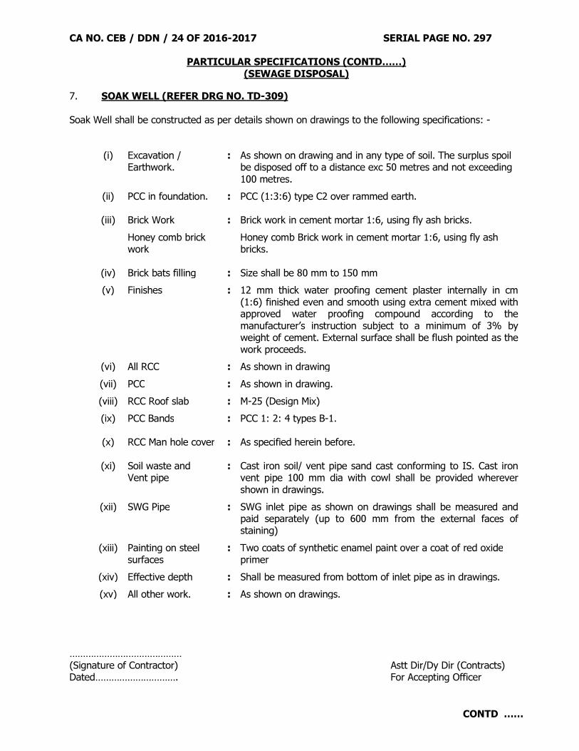
CA NO. CEB / DDN / 24 OF 2016-2017 SERIAL PAGE NO. 297
PARTICULAR SPECIFICATIONS (CONTD……) (SEWAGE DISPOSAL)
CONTD ……
7. SOAK WELL (REFER DRG NO. TD-309) Soak Well shall be constructed as per details shown on drawings to the following specifications: -
(i) Excavation / Earthwork.
: As shown on drawing and in any type of soil. The surplus spoil be disposed off to a distance exc 50 metres and not exceeding 100 metres.
(ii) PCC in foundation.
: PCC (1:3:6) type C2 over rammed earth. (iii) Brick Work : Brick work in cement mortar 1:6, using fly ash bricks.
Honey comb brick work
Honey comb Brick work in cement mortar 1:6, using fly ash bricks.
(iv) Brick bats filling : Size shall be 80 mm to 150 mm
(v) Finishes
: 12 mm thick water proofing cement plaster internally in cm (1:6) finished even and smooth using extra cement mixed with approved water proofing compound according to the manufacturer’s instruction subject to a minimum of 3% by weight of cement. External surface shall be flush pointed as the work proceeds.
(vi) All RCC : As shown in drawing
(vii) PCC : As shown in drawing.
(viii) RCC Roof slab : M-25 (Design Mix)
(ix) PCC Bands : PCC 1: 2: 4 types B-1.
(x) RCC Man hole cover
: As specified herein before. (xi) Soil waste and
Vent pipe : Cast iron soil/ vent pipe sand cast conforming to IS. Cast iron
vent pipe 100 mm dia with cowl shall be provided wherever shown in drawings.
(xii) SWG Pipe : SWG inlet pipe as shown on drawings shall be measured and paid separately (up to 600 mm from the external faces of staining)
(xiii) Painting on steel surfaces
: Two coats of synthetic enamel paint over a coat of red oxide primer
(xiv) Effective depth : Shall be measured from bottom of inlet pipe as in drawings.
(xv) All other work. : As shown on drawings.
…………………………………… (Signature of Contractor) Astt Dir/Dy Dir (Contracts) Dated…………………………. For Accepting Officer
CA NO. CEB / DDN / 24 OF 2016-2017 SERIAL PAGE NO. 298
PARTICULAR SPECIFICATIONS (CONTD……) (AREA DRAINAGE)
1. GENERAL
(i) Specification for earth work, concrete works, brick work, steel and iron work, plaster etc given hereinbefore for building work herein before shall be applicable for area drainage also.
(ii) PCC drain / brick storm water drains as specified in Schedule shall be constructed as per the locations shown on drawings are directed by Engineer-in-Charge. The drains shall be constructed with the specifications laid down in respective item of schedule ‘A’.
2. DRAINS Drains shall be provided to the gradient as directed by the Engineer in charge as per details shown in drawings and specified in relevant of Schedule ‘A’. …………………………………… (Signature of Contractor) Astt Dir/Dy Dir (Contracts) Dated…………………………. For Accepting Officer

CA NO. CEB / DDN / 24 OF 2016-2017 SERIAL PAGE NO. PARTICULAR SPECIFICATIONS (CONTD……)
(COMPOUND WALL AND GATE)
CONTD ……
299
1. GENERAL Specification for earth work, concrete works, Brick masonry work, steel and iron work, plaster etc given hereinbefore for building work herein before shall be applicable for fencing/ compound wall and gate. 2. FENCING POSTS 2.1 These shall be fabricated and fixed in locations as shown in and as decided by the Engineer-in-Charge. The post shall be fabricated and fixed consisting of the following specifications read in conjunction with the specifications given here in before and shown in drawings: -
(a) Excavation and Earthwork : Any type of soil.
(b) Foundation : PCC 1:4:8 type D-2 using 40 mm graded stone aggregate.
(c) Precast RCC Posts : RCC 1:2:4 Type B-1.
(d) Angle Iron Post : Angle iron for fabricating post shall be 65 x 65x 6 mm, Fe-410-O grade, with splitted ends. The post shall be embedded in block by 550 mm. Mild steel nibs made out of 4mm dia. wire shall be fixed to the angle iron post by drilling holes in angle iron of required size and nibs inserted into it and bent at 90 degree splitting the nib ends. The dia. of hole shall not be more than 10mm where the angle iron post is to be fixed at corners, it shall be supported by angle iron stay of size 65 x 65 x 6mm. Stay shall be fixed with 12mm dia. bolts, 50mm long with one nut and washer.
(d) Painting: - All exposed steel surface shall be applied with two coats of synthetic enamel paint over one coat of red oxide primer and portion embedded in PCC shall be tarred before fixing in position.
3. STEEL GATE These shall be fixed in locations as shown in drawings and as decided by the Engineer-in-Charge. These shall be fixed consisting of the following specifications read in conjunction with the specifications given here in before and shown in drawings: -
(a) Excavation and Earthwork
: In any type of soil l including removal of surplus soil to a distance n. exceeding 50 m away and as specified.
(b) PCC Foundation : 1:4:8 type D-2 using 40 mm graded stone aggregate.
(c) Brick masonry work : All Brick masonry work shall be built in CM 1:6.
(d) PCC bed / copings : PCC 1:2:4 type B-1, using 20 mm stone aggregate.
(e) Rendering : 15 mm thick rendering with cement mortar 1:6

CA NO. CEB / DDN / 24 OF 2016-2017 SERIAL PAGE NO. PARTICULAR SPECIFICATIONS (CONTD……)
(COMPOUND WALL AND GATE)
CONTD ……
300
(f) RCC Column & column
base : RCC M-25 (Design Mix)
(g) Column base : 1:4:8 type D-2, 75mm thick.
(h) Form work to column : As specified for rough finished surface.
(i) MS reinforcement : As shown on drawing & described in Sch
‘A’.
(j) Cast iron wheel : FG-150 graded cast iron.
(k) MS framed work : As described in Sch ‘A’.
(l) Finishing : (1) All plastered / rendered / concrete surfaces shall be applied with two coats of cement based paint. (2) All exposed surfaces of steel shall be coated with two coats of synthetic enamel paint over one coat of red oxide primer. (3) All mild steel articles embedded in PCC / brick work / in contact with masonry shall be treated with tar before fixing.
(m) Mild Steel Gate : All members of steel gate shall be of Fe-500 TMT grade. Irrespective of whatever is shown on drawings, vertical bars shall be of 16 mm dia. The welding wherever shown / required shall be 6 mm thick fillet weld. Mild steel hooks shown in drawing shall be provided to match with the number of fencing wires and cost of these hooks shall be included in lump sum cost of gate inserted by department.
NOTES: - (i) In case the height of gate is specified more in Schedule ‘A’ in such case the height of guard bars portion shall only to be increased. (ii) The height of gate pillars shall also be increased proportionally.
CA NO. CEB / DDN / 24 OF 2016-2017 SERIAL PAGE NO. PARTICULAR SPECIFICATIONS (CONTD……)
(COMPOUND WALL AND GATE)
CONTD ……
301
4. COMPOUND WALL WITH SWAN NECK FENCING 4.1 These shall be fabricated and fixed in locations as shown in drawings and as decided by the GE. Compound wall shall be of following specifications read in conjunction with the specifications given here in before and shown in drawings.
(a) Excavation and Earthwork : Any type of soil.
(b) Foundation : PCC 1:5:10 type E-2 using 40 mm graded stone aggregate.
(c) Brick work : In cement mortar 1:4
(d) PCC bed / copings : PCC 1:2:4 type B-1, using 20 mm stone aggregate
(e) Rendering : 15 mm thick rendering with cement mortar 1:6.
(f) Finishing : All plastered surface shall be applied with two coats of cement based paint. Over a coat of primer.
5. GALVANISED STEEL BARBED WIRE FENCING Barbed wire fencing shall be provided all as shown on drawings.
…………………………………… (Signature of Contractor) Astt Dir/Dy Dir (Contracts) Dated…………………………. For Accepting Officer

CA NO. CEB / DDN / 24 OF 2016-2017 SERIAL PAGE NO. 302
PARTICULAR SPECIFICATIONS (CONTD……) (EXTERNAL WATER SUPPLY)
CONTD ……
1. SCOPE OF WORK The extent of work under this contract is as indicated in relevant part of Schedule ‘A’, particular specification and drawings. All reference to clauses in succeeding paragraph pertains to MES Schedule. 2. GENERAL REQUIREMENT 2.1. The requirement pertaining to materials, conformity with National Building Code, workmanship, testing, record of installations shall be all as specified in MES Schedule (Clause 18.409 and 18.41). Laying and jointing of CI/GI pipe shall be in accordance with clause 18.50 to 18.51 of MES Schedule. 2.2. All pipe work shall be laid or fixed to be completely airtight or watertight as specified. 2.3. Testing of pipe shall be carried out as specified in clause 18.48.7 and 18.50.4 of MES Schedule. 3. CAST IRON PIPE AND FITTINGS Pipes and fittings shall bear ISI mark. Class of pipe shall be as specified in schedule ‘A’. These shall comply the requirement laid down in clause 18.2.1 to 18.2.4 of MES Schedule. 4. GALVANISED TUBES AND FITTINGS Pipes and fittings shall bear ISI mark. Grade of pipes shall be as specified. These shall comply the requirement laid down in clause 18.4.1 to 18.4.2 of MES Schedule. 5. CAULKING LEAD AND SPUN YARN Shall be in accordance with clause 18.9 and 18.10 of MES Schedule. 6. RUBBER GASKET OF JOINTING Shall be in accordance with clause 18.11 of MES Schedule and shall conform to IS 5382. 7. SLUICE VALVE Shall conform to IS 14846 to 2000 and shall bear ISI mark, fixing of sluice valve shall be done in accordance with clause 18.57 of MES Schedule.

CA NO. CEB / DDN / 24 OF 2016-2017 SERIAL PAGE NO. 303
PARTICULAR SPECIFICATIONS (CONTD……) (EXTERNAL WATER SUPPLY)
CONTD ……
8. VALVE PITS Valve pits shall be constructed with the following specification read in conjunction with the specifications given here-in-before and as shown in drawings: -
(a) Excavations and earth work
: Hard/dense soil, soft/disintegrated rocks
(b) Foundation : PCC 1:2:4 type B-2, using 40 mm graded shingle.
(c) Bed/Floor/copings : PCC 1:2:4 type B-1, using 20 mm graded shingle.
(d) Masonry work : PCC block 1:3:6 type C-1 masonry in CM 1:6
(e) Rendering : Internal surfaces of valve pit and 15 cm below GL on external surface shall be rendered 10 mm thick in CM 1:4 mixed with water proofing compound. External surfaces of valve pits below 15 cm shall be pointed flush as the work proceeds.
(f) Steel iron work : As shown in drawing.
(g) Painting : All surface of steel and iron work in contact with brick work /concrete shall be treated with tar before fixing the same in position. All other steel and iron work shall be painted two coats of synthetic enamel paint over a coat of primer.
9. Making connection of GI Distribution with CI/GI Main shall be as specified in MES Schedule, Clause 18.59. 10. Cutting of GI Pipeline, Fixing water meter and stop valve shall be as specified in clause 18.63 to 18.66 of MES Schedule. 11. Centrifugal pump provided for disposal of rain water shall be of specification as described in Schedule ‘A’. 12. TUBE WELL BORING 12.1 SCOPE OF WORK : The works shall be executed all as mentioned in schedule `A’, specified
hereinafter, building specifications and as directed at site. The quoted rates of the contractor shall be deemed to include the complete cost of materials and labours, T & P, testing apparatuses & allied works etc required to complete the works & all processes to the entire satisfaction of the GE.
12.2 Boring shall be done as per IS – 2800 (Part I & II) – 1979.

CA NO. CEB / DDN / 24 OF 2016-2017 SERIAL PAGE NO. 304
PARTICULAR SPECIFICATIONS (CONTD……) (EXTERNAL WATER SUPPLY)
CONTD ……
12.3 It is mandatory on part of the contractor to carry out the resistivity test / survey for the location
of drilling site. The contractor will inform the date of resistively survey to Engineer-in-Charge and the resistivity shall be got done in the presence of Engineer-in-Charge. The contractor will not be allowed to commence the drilling unless the resistivity test & survey report is submitted by the contractor to Engineer-in-Charge for his reference and approval of site/locations of drilling bore(s) approved by the GE & Engineer-in-Charge. The contractor’s quoted rates in Schedule `A’ items are deemed to include the cost of resistively survey and field test of each bore hole(s).
12.4 The entire assembly shall be installed & fixed in true vertical positions. The verticality of the
wells(s) shall be tested up to a depth of 5. 00 meters above the bottom of bore well with latest Engineering practices with plumb bob, steel circulars gauge etc. Tolerance to confirm to the provisions as per latest IS. Further verticality of bore well (s) shall be as per recommendation of pump’s manufacturer. The tests shall be carried out in the presence of Engineer-in-Charge and signed by both the contractor and Engineer-in-Charge. The contractor shall submit the relevant test certificate in respect of verticality of each bore to Engineer-in-Charge and cost on this account shall be borne by the contractor. The Tube well bore(s) not conforming to this condition/specification shall be rejected and no payment shall be made to the contractor for rejected/unspecified bore well(s).
12.5 If trial bore found suitable and approved by the GE, the deep bore well shall be made on the
approved location of trial bore & trial bore may be developed to the required deep bore well. If trial bore is found dry or unsuccessful the matter shall be brought to the notice of the GE. The drilling machine from location of trial bore either successful or unsuccessful or deep bore well(s) shall not be removed from the site until depth of the bore well is verified by the GE & approval or rejection of the trial bore made specifically by GE.
12.6 The abandoned/rejected/dry bore holes shall be filled with soil obtained from the drilling of bore
hole(s) & compacted thoroughly all as directed by the GE & Engineer in charge. All the relevant information’s like depth of the bore hole, strata position of availability of water etc and with CA details shall be indicated by the contractor at the site of every unsuccessful/dry bore holes on a suitable brick pillar built in CM (1: 6) plastered all around in 15 mm thick CM (1: 4) in the manner as approved by the Engineer in charge the information shall be clearly given & engraved while the plaster is green & nothing extra shall be paid to the contractor on this account.
12.7 Approach-ability of drilling rig to site of work will be the responsibility of contractor. Department
will not make any extra payment on this account. 12.8 All risk and compensations consequent to accidents on any account whatsoever will be
responsibility of the contractor alone. All losses on account of jamming and breaking of drilling tools will be responsibility of the contractor. Payment of the bore abandoned on this accounts will not be made except as specified in clause No 7.10 herein after.
12.9 Water, if required for drilling, shall be made available by the contractor’s own arrangement at his
own cost. Contractor shall make necessary arrangement at his own cost for lifting, carrying or conveying water to the site of work as required.
CA NO. CEB / DDN / 24 OF 2016-2017 SERIAL PAGE NO. 305
PARTICULAR SPECIFICATIONS (CONTD……) (EXTERNAL WATER SUPPLY)
CONTD ……
12.10 DRY BORES : Payment for dry bores will be made only if resistively survey has been carried out
showing availability of water at the site and if the bore has been drilled to depth of 60 meters or above as per direction of Garrison Engineer and even then water is not available.
12.11 It will be responsibility of the contractor to take appropriate precaution during drilling upto
completion of work to protect bore(s) from all damage & avoiding all the mis- happenings at site. 12.12 Suitable 02 Nos Housing clamps for each column pipe hall be provided (projected on either side
of the pipe) & shall be tightened with 02 Nos 16 mm dia nuts bolts & spring washers on each side of a clamp. The clamp shall be painted with two coats of synthetic enamel paint over a coat of red oxide primer all as directed. Contractor’s quoted rates in Sch `A’ shall be deemed to included this provision for the connected items.
12.13 PCC Platform of size 900mm X 900mm X 600mm around each bore well in PCC (1:3:6) type C-2
(using 40 mm graded sand stone aggregate) shall be provided all as directed by the engineer in charge without any extra cost to department
12.14 The contractor shall not remove the boring machine from the site of bore(s) until the
measurement of the bore is recorded. The spoil of trial bore and boring shall be disposed off by spreading the same over the ground outside Air Force Area all as directed by Engineer-in-Charge.
12.15 No payment will be made to the contractor for drilling/boring in case any loss or damage occurs to the bore(s) due to carving/scouring during drilling or lowering, casing pipes/strainer pipes or/and slotted pipes assembly or packing of pea gravel etc.
12.16 All risks of accident, jamming and breakage of drilling equipment etc will be contractor’s own liability. No extra payment will be made on this account in any cases.
12.17 The contractor shall have no claim whatsoever for any precious materials (as decided by GE) if
any recovered from the bores during process of boring or development and it will be the property of Govt and contractor shall remove the same to the Govt stores.
12.18 All works shall be carried out to the entire satisfaction of Engineer-in-Charge and GE. 12.19 DRILLING OF BORES AND COLLECTION OF SAMPLES 12.19.1 The drilling shall be carried out by approved method so that samples of materials/soil/rock
obtained from bore holes will be obtained in crushed form and not as core as obtained in clay. Drilling should be carried out through suitable rotary mechanical rig of appropriate capacity.
12.19.2 During the drilling operations sample of the sediments shall be collected at every 3 mtrs or at the change of litho logy whichever is earlier. The time taken for every 3 mtrs of drilling shall also be recorded.
12.19.3 The unit rate quoted by the tenderer shall be deemed to include collection and supplying the samples in suitable polythene Jars duly leveled as stated above to the entire satisfaction of GE and as directed by him.

CA NO. CEB / DDN / 24 OF 2016-2017 SERIAL PAGE NO. 306
PARTICULAR SPECIFICATIONS (CONTD……) (EXTERNAL WATER SUPPLY)
CONTD ……
12.20 DEPTH OF BORING 12.20.1 The depth of boring of the tube well at the site is anticipated to be 190 metres below ground
level. The depth may, however, be ordered in writing to be varied by the GE upto a maximum of 30 metres (plus or minus). If suitable water bearing strata is not available in the aforesaid bore or the boring can not be continued further on account of the type of strata met with, the contractor shall bore at other site (s) until suitable water strata is met with. All the cost on account of getting the sufficient water bearing strata is deemed to be included in the rates quoted by the contractor in respective Sch ‘A’ item.
12.21 CASING/SLOTTED PIPE ETC 12.21.1 Casing and slotted pipes shall be ERW MS pipes conforming to IS 4270-1992 as given in
respective items of Sch ‘A’ and all as approved by the GE.
12.21.2 The pipes of sizes in approved depths shall be lowered in the bore hole centrally and vertically so that the gravel packing in the annular space is of uniform thickness all around. The contractor will ensure that all the housing casing/slotted pipes are fixed in perfectly vertical position.
12.21.3 200mm dia casing pipes may be cut down to suitable lengths and threaded to facilitate in lowering the casing and connecting to strainer and casing pipes. The casing pipes shall be thoroughly and securely screwed in the plain socket before lowering in the bore.
12.21.4 The bail plug specified shall be provided if required at the bottom of the bore well casing and fixed securely. MS screwed bell caps shall be provided at the top of the casing pipe 750mm above the ground level.
12.21.5 The MS casing pipes, plug and strainer pipe etc shall be given outside two coats of
approved bituminous anticorrosive paint before lowering in bores. The surface of the pipes shall be thoroughly cleaned with wire brush and made free from rust before painting. The Engineer-in-charge shall approve the surface before paint is applied. The contractors quoted rates of Sch ’A’ are deemed to include this provision.
12.21.6 The casing pipe/slotted pipe shall be screwed at joints with suitable sockets as per Sch ‘A’
welded at each joint to sockets & pipe from the each end of socket all as directed by Engineer-in-Charge.
12.22 DEVELOPING OF WELLS
12.22.1 The contractor will develop the well by suitable air compressor to ensure that the well is
fully developed. The discharge during development shall be measured at an interval of one hour and record there of shall be kept by the contractor. The exact time of development shall be noted and paid under respective items of Schedule `A’. Additional gravel be added as the development proceeds. The development process may be continued in excess of 24 hours and if so ordered by the GE taking into consideration the following: - (a) The discharge ceases to improve at a fixed depression or alternative depression ceases to improve at constant discharge or the well ceases to absorbs more gravel.

CA NO. CEB / DDN / 24 OF 2016-2017 SERIAL PAGE NO. 307
PARTICULAR SPECIFICATIONS (CONTD……) (EXTERNAL WATER SUPPLY)
CONTD ……
(b) The water is free from sand and any suspended matter. The water shall be considered sand free if the sand contents or suspended matter are not more than five parts in million parts of water by volume within ten minutes of the start of pumping. ( c) The discharge will be measured with a suitable 900 `V’ notch. An approved channel for the flow of water shall be provided over the ground with suitable baffles to eliminate the turbulence completely before the water is allowed to flow over the `V’ notch. The rear levels and working levels of water shall be recorded before commencement and during progress of well development.
12.23 PEA GRAVEL PACKING AND MEASUREMENT 12.23.1 The pea gravel used will be of sizes, all as mentioned in schedule `A’. The gravel will be
screened thoroughly and washed with water and shall be cleaned, free from any dust/dirt/kankar or other foreign matter and then poured into the space between the casing pipe and well of the bores. The gravels will be added allowing it to fill in the cavities around the causing pipe and well of the bores. The gravels will be added allowing it to fill in the cavities around the casing/ strainer pipe, while pumping out the water during development, pea gravel will be further added to make up the loss due to development until further gravel adding is not possible.
12.23.2 The pea gravel of specified sizes shall be brought to the site and neatly stacked. Before using the screened gravel for packing purpose, it shall be measured in boxes on level ground at the work site and recorded in MB duly signed by both Engineer-in-Charge and the contractor. The payment shall be made for the quantities calculated on the basis of dia of the bore holes i.e. 250 mm & external dia of casing pipe i.e.200mm+ pipe wall thickness or actual quantities used at site which ever is less, irrespective of the actual more quantities of pea gravel used for filling the wells. The pea gravel shall be brought at site in appropriate quantities and filled thoroughly & completely upto the top of bore holes.
12.23.3 The GI pipe of 50mm bore should be fixed in ground level upto the height of 30cm above ground level for packing the pea gravel for taking up the shrinkage of level of pea gavel during compaction.
12.24 The contractor shall be deemed to have himself fully acquainted with the scope of the proposed
works, nature of soil and all matter affecting the execution of work. No claim whatsoever shall be entertained on account of knowledge on part of contractor in this respect.
12.25 All work shall be carried out in accordance with the latest Engineering practice to the entire
satisfaction of the GE. 12.26 STRATA’s SAMPLES AND RECORD 12.26.1 The contractor shall supply to the Engineer-in-Charge on completion of the tube wells a
complete strata chart of the tube wells in a standard form on tracing cloth all as directed by the GE showing the following details without any extra cost to Govt for the same as the contractor’s quoted rates are deemed to include this provision : (a) Strata change encountered with description and depth with particular reference to size
and grain of sand and the water bearing strata. (b) Spring level below ground level (aquifer’s with water bearing stratas) opposite which
strainer and slotted pipes have been located. (c) Strata against which blind/plain pipe have been located. (d) Position of joints in slotted/blind pipes/housing pipes.

CA NO. CEB / DDN / 24 OF 2016-2017 SERIAL PAGE NO. 308
PARTICULAR SPECIFICATIONS (CONTD……) (EXTERNAL WATER SUPPLY)
CONTD ……
(e) Diameter of the bores and reduced bores sizes with depth (if any). (f) Diameter and length of each section of bore well casing and strainer pipes. (g) The quality of gravel initially poured in the well and quality of gravel added during
development depression. (h) Yield test and duration of development operation and working level, prevalence of sand
etc. 12.26.2 After completion of the bore well drilling, the bore should be checked by electro logging
system by CGWB or other authority to check the discharge of the strata as well position of the strainer. The electro logging chart/graph should be handed over by the contractor to the Engineer-in-Charge and contractor’s quoted rates are deemed to include this provision.
12.27 TENTATIVE LAYOUT FOR LOWERING OF CASING STRAINERS PIPES/ASSEMBLY IN BORE WELL 12.27.1 Before lowering length of pipe in the tube well, the contractor shall submit a tentative
layout plan on a paper with his recommendation for location of MS plate and strainers, bail plug and the casing pipes, which in his opinion would give the desired yield and obtain approval of the Engineer-in-Charge/GE in writing which shall be the basis of the final drawings on tracing cloth as specified above which shall be signed by both contractor and the Engineer-in-Charge.
12.28 TESTING 12.28.1 On satisfactory completion of development, Yield-test of the completed well shall be
taken. For this purpose, the contractor shall undertake pumping, starting from 25% of anticipated. Yield gradually increasing the rate of pumping every half an hour and recording depressions and corresponding time taken in recoupment. The rate of pumping in this manner will be increased to a stage when the depression will not fall further and corresponding out put will be taken as yield of the well.
12.28.2 The contractor shall provide the specified yield from the tube well for continuous 08 hours pumping against a depression of not more than approx 5 meters beyond the test level. The yield will be measured by means of over a `V’ notch or venturimeter apparatus as approved by GE.
12.28.3 Sample of water shall be taken from the tube well (after development) in presence of the
contractor and shall be sealed in a clean container duly signed by the contractor and Engineer-in-Charge. The sample of water so obtained shall be sent to any of the Govt. recognized laboratory for testing the quality of water and to confirm that the water drawn from the tube well in potable water and fit for human consumption.
12.28.4 The cost of above test shall be included by contractor in relevant items of Schedule `A’. 13. SLUICE VALVE/NON RETURN VALVE 13.1 Sluice valves shall be all as mentioned in Schedule `A` and conforming to IS-780, class PN-1
flanged ends and drilled. Make : Kirloskar or of superior quality as approved by GE. 13.2 Sluice valves shall be provided as specified in clause 18.57 of SSR-Part I (1991). 13.3 Non return valve shall be ISI marked and all as specified in Schedule `A'.

CA NO. CEB / DDN / 24 OF 2016-2017 SERIAL PAGE NO. 309
PARTICULAR SPECIFICATIONS (CONTD……) (EXTERNAL WATER SUPPLY)
CONTD ……
14. CAST IRON PIPES AND FITTINGS 14.2 Cast iron fittings shall be conforming to IS-1538 (Part I to XXIII) – 1976. The fittings shall
withstand the hydrostatic test pressure of 25 Kg/cm2 without showing any leakage, sweating or defects of any kind.
14.3 Relevant clauses of section 18 of MES schedule Part-I (1991) shall also be referred strictly for cast iron pipes and fittings. For laying, fixing, jointing and testing of pipes clause 18.41 to 18.48 refers.
14.4 Caulking lead for joints shall be conforming to IS-782-1978 as specified in clause 18.9 of SSR-
Part-I. The spun yarn used in joints shall be of hemp and of good quality. It shall be free of oil, tar or greasy substances and shall be of sterilized quality.
14.5 Rubber gasket for joints shall comply with the requirement of IS-5382-1985. It shall be free
from extractable substances which impart-taste, smell or toxicity to water. 15. CUTTING OF CAST IRON PIPES IN POSITION 15.1 Cutting of existing pipes for inserting valves/fittings etc. shall be done in neat and workman like
manner without damage to the pipe, so as to accommodate the fittings properly and to leave a smooth end at right angle to the axis of pipe. The rates quoted by the contractor includes the cost of necessary excavation and earth work, all T&P and arrangements required at site, dewatering of pipe line, cutting & removing the pipe length retrieved from cutting to MES store and marking good the damaged pipe lines/disturbed surfaces to match with the existing one all as directed by Engineer-in-Charge.
16. SUBMERSIBLE PUMP SETs 16.1 Submersible pump sets shall be suitable to meet the requirement of Schedule `A'. The model of
the pump shall be as recommended by the manufacturer for the Schedule `A' requirement. The contractor shall submit all the relevant documents i.e. literature/catalogue of pump he want to use in the work alongwith manufacturer recommendations and flow chart/performance curve of recommended pump & motor. The model of the pump and motor shall be got approved by the contractor from the GE before placing ordered on the manufacturer / supplier.
16.2 Testing of the pump set shall be done by the contractor to the entire satisfaction of the
Engineer-in-Charge and all the T&P / resources for testing the pump set shall be arranged by the contractor without any extra cost to Government.
…………………………………… (Signature of Contractor) Astt Dir/Dy Dir (Contracts) Dated…………………………. For Accepting Officer

CA NO. CEB / DDN / 24 OF 2016-2017 SERIAL PAGE NO. 310
PARTICULAR SPECIFICATIONS (CONTD……) (EXTERNAL ELECTRIFICATION)
CONTD ……
1. SCOPE OF WORK The extent of work under this contract is as indicated in relevant part / section of Schedule ‘A’, particular specification and drawings. All reference to clauses in succeeding paragraphs pertains to MES Schedule Part-I. The layout of conductors / cable, route shall be as directed by the Engineer-in-Charge. 2. GENERAL REQUIREMENT 2.1. The requirement pertaining to materials, conformity with Indian electricity Act and rules, workmanship, testing, records of installations, safety procedures and practices and fire safety, shall be all as specified in MES Schedule clause 19.2. 2.2. The contractor is deemed to have included in rates, cost of making holes/chases where required through roads/masonry or concrete work for taking in cables/conduits and conductors, etc and making good the same to match with existing work. 3. Conductors. Shall conform to relevant IS specification and as given in MES Schedule. Laying of Conductor should be as per clause 19.56 to 19.66 of MES Schedule. 4. BEARER WIRE Shall conform to clause 19.11 of MES Schedule. 5. ISOLATORS, EXPULSION TYPE FUSES AND LINE CONNECTORS Shall conform to relevant IS and as mentioned in Clauses 19.15 to 19.18 of MES Schedule. 6. MCB (MINIATURE CIRCUIT BREAKER) These shall be of utilisation category M-9 with 9 KA breaking capacity as per IS-8620 with amendment suitable for use on 240/415 volts AC 50 HZ supply termination of aluminum cables and fixing arrangement on DIN channel and housed in dust proof stove enameled steel sheet enclosure of 1.6 mm thickness with facility to operate MCB without opening enclosure with IS mark or make as per Appendix ‘B’. 7. PANEL BOARD 7.1 The bus bars for phases and neutral shall be identified with colour code, supported property with adequate clearance. 7.2 Incoming and out going cable will be identified with arrow marks and the name of circuit on each out let will be written in front and rear of panel board. Connection between bus bars and individual switch unit of more than 63 Amps will be made with solid conductor. Bus bar and connection from bus bar to incoming should be inaccessible when the door of switch are opened for renewal of fuses etc.
7.3 All screws, bolts and uts which secure current carrying parts to the panel will be of brass, copper or similar rust proof materials. The base plate of cable chamber will be of large size to accommodate all cable glands intended for outgoing cables. 7.4 The fixing of ammeter, voltmeter, indicating lamps will be in such a way so that these should not come above the face of bus bar chamber.

CA NO. CEB / DDN / 24 OF 2016-2017 SERIAL PAGE NO. 311
PARTICULAR SPECIFICATIONS (CONTD……) (EXTERNAL ELECTRIFICATION)
CONTD ……
7.5 There will be no any unused opening/holes in the panel board, if it, then these will be sealed by non inflammable material. 7.6 The drawing of electrical panel be got approved by Engineer-in-Charge/GE before incorporation in the work. 7.7 Outdoor LT panel (feeder pillar) should also confirm to following :-
(a) The following provisions of IS : 5039 of 1983 should be complied with in fabrication of enclosure for out door LT panel :-
(i) It shall be made from a suitable material to with stand rough usage and weather. If fabricated out of MS sheet, the thickness of the sheet shall be at least 3.15 mm. (ii) The top of the feeder pillar shall be fitted with a sloping canopy design of which shall be such that rainwater shall not accumulate on top. (iii) They will have a set of double-hinged doors at the front. Similar doors shall be provided at the back, if required and specified. The doors shall be fitted to provide the interior the maximum protection from atmospheric conditions. The hinges shall be of such construction that the doors can be swung open by not less than 1500. In addition the hinged design shall permit doors being removed completely if necessary. The base horizontal member shall be completely removable to facilitate cable jointing. (iv) The doors shall be provided with suitable locking arrangements. (v) The outdoor LT Panel shall be suitably protected against corrosion. (vi) The type of enclosure of out LT Panel shall be able to provide degree of protection IP 43, in accordance with IS : 13947 (Part-I).
(b) All other points as mentioned for cubicle type panels should be completed with for outdoor panels also. (c) A bayonet lamp holder complying with IS-1258-1279 with a tumbler switch complying with IS-3884-1966, a three pin plug and socket complying with IS-1293-1978 with necessary fuse and wiring shall be provided inside the pillar on the front bottom portion of the shell near the neutral bus bar.
8. CABLES (LT, HT & XLPE CABLES) Refer Para 19.19 of SSR Part-I. These shall be an approved product of BIS having ISI certification mark. 9. CABLE JOINTS Refer Para 19.22 & 19.85 of SSR Part-I. These shall be an approved product of BIS having ISI certification mark.

CA NO. CEB / DDN / 24 OF 2016-2017 SERIAL PAGE NO. 312
PARTICULAR SPECIFICATIONS (CONTD……) (EXTERNAL ELECTRIFICATION)
CONTD ……
10. TESTING All the external electrification shall be tested as per IS provisions to the entire satisfaction of Engineer-in-Charge and test result shall be submitted duly signed by the contractor/Engineer-in-Charge. Layout and schematic diagram showing sizes, length, and capacity of conductor, cable and equipment shall be prepared on tracing cloth and submitted by contractor. No extra payment shall be paid on account of above provision to contractor. 11. STEEL TUBULAR POLES These shall conform to relevant IS specification and mentioned in Clause 19.3.1 to 19.3.6 of MES Schedule Part I. These shall be erected as specified in schedule ‘A’, particular specification and as shown on drawing. 12. POLE FITTING AND CROSS ARMS Insulator and Insulator fittings shall conform to relevant IS specification and as given in MES Schedule. Steel cross arms shall be of angle or channel section as given in drawing and shall be provided as per clause 19.53.1 to 19.53.3 of MES Schedule Part I. 13. STAY WIRE AND STAY WIRE ASSEMBLIES These shall conform to relevant IS specification and as giver in clause 19.7 to 19.8 of MES Schedule Part I. These shall be executed as given in clause 19.55 of MES Schedule Part I. 14. STREET LIGHT FITTINGS 14.1 Refer para 19.42 of MES SSR 2009 (Part-I). These shall be an approved product of BIS having ISI certification mark. 14.2. Mounting bracket for street light fittings shall be fabricated from 32 mm bore galvanised steel tubing light grade. Overall length of the bracket shall be 1.2 M. Bracket shall be bent to shape as shown on typical drawing or as directed by Engineer-in-Charge. 14.3. Bracket for street light shall be fixed to poles with clamps of Flat iron 50x6mm, nuts and washers, clamps shall be painted with two coats of synthetic enamel paint over a coat of primer. 15. EARTHING Unless otherwise specified in Sch ”A” or elsewhere, Earthing shall be provided all as per Electrical Plate No. 3 of SSR Part I given on page No. 19-49, including necessary earthwork and excavation, PCC 1:2:4 type B1 chamber, galvanized mild steel light grade, 15 mm dia. protection pipe with 4 mm dia. galvanized mild steel earth wire, PGI sheet 1.25 mm thick funnel for water, GI wire mesh, GI pipe 20 mm dia. for water (light grade) , salt coal dust, angle iron frame made out of mild steel angle 30x30x5 mm thick, duly painted with two coats of synthetic enameled paint over one coat of primer red oxide , RCC 1:2:4 Type B-1 pit cover 50 mm thick duly reinforced with MS 6 mm dia. bars @ 150 mm c/c both ways or as described in relevant item of Sch ‘A’, surplus soil shall be disposed at a distance not exceeding 50 m away. The unit rate for earthing shall include thee above provisions. Earth shall give required test results to the satisfaction of Engineer-in-Charge

CA NO. CEB / DDN / 24 OF 2016-2017 SERIAL PAGE NO. 313
PARTICULAR SPECIFICATIONS (CONTD……) (EXTERNAL ELECTRIFICATION)
CONTD ……
16. DANGER NOTICE PLATES Refer Para 19.18 of SSR Part-I. These shall be an approved product of BIS having ISI certification mark. Danger Notice Plate shall be IS-2551-1982. 17. LIGHTENING ARRESTOR Refer Para 19. 13.2 of SSR Part-I. These shall be an approved product of BIS having ISI certification mark. Lightening Arrestor shall be ISI-3070 (Part-3) 1993 or latest edition. 18. GANG OPERATED AIR BREAK SWITCHES Refer Para 19.69 of SSR Part-I. These shall be an approved product of BIS having ISI certification mark. 19. ANTI-CLIMBING DEVICE Refer Para 19.72.1 of SSR Part-I. These shall be an approved product of BIS having ISI certification mark. Isolator shall be ISI-278-1969. 20. STAY ASSEMBLY Refer Para 19.8 of SSR Part-I. These shall be an approved product of BIS having ISI certification mark. Isolator shall be ISI-9921-1985. 21. POWER CABLES 21.1 The tenderer shall submit complete test certificates giving full particulars/specifications of cable, constructional details and maximum continuous current carrying capacities in ground, air and induct alongwith standard design conditions. It shall be guaranteed by the tenderer that the cable offered by them shall be of specified sizes/makes and shall carry normal load as well as short circuit current in the event of any fault at ground conditions of Bareilly 211.2 All cables shall be as mentioned in Schedule `A' and shall be laid/fixed and tested in accordance as specified in clause 19.73 to 19.86, 19.91 and 19.93 of SSR 2009 (Part-I). 21.3 Wherever cables will be crossing or running parallel to existing telephone cables, suitable measures will be taken and distance will be observed as per latest IS on the subject. 22. MILD STEEL GALVANISED TUBING 22.1 These shall be provided as mentioned in Schedule `A' and as directed by the Engineer-in-Charge. Mild galvanized tube / pipe shall comply with IS-1239. 23. PAINTING 23.1 All steel part of HT/LT switch gears and other accessories shall have undergone a rigorous rust proofing process before painting. They shall be treated with high corrosion resistant primer and finally painted with synthetic enamel paint of grey tint.
CA NO. CEB / DDN / 24 OF 2016-2017 SERIAL PAGE NO. 314
PARTICULAR SPECIFICATIONS (CONTD……) (EXTERNAL ELECTRIFICATION)
CONTD ……
24. TESTING AND COMMISSIONING OF EQUIPMENTS AND INSTALLATIONS 24.1 The testing and commissioning of all electric equipments at site shall be carried out according to clause 19.97.1 to 19.97.9 of MES Schedule (2009) Part-I and the procedure laid down below. 24.2 All equipments shall be tested, installed and commissioned in accordance with the latest relevant standards and codes of practices published by Indian Standards Institution wherever available and stipulations made in relevant general specifications. In case Indian Standards are not available, these shall be carried out in accordance with latest standards and code of practice published by other recognized National Standards Institutions or latest publications of International Electro Technical Commission (IEC). 24.3 The testing of all electrical equipments as well as the system as a whole shall be carried out to ensure that the equipments and its components are in satisfactory condition and will successfully perform its functional operation. The inspection of the equipment shall be carried out to ensure that all materials, workmanship and installation construction standard well as accepted, codes of practice and stipulations made in the relevant general specification. 24.4 All test shall be carried out by the contractor using his own instruments, testing equipments as well as qualified testing personnel. 24.5 The results of all tests shall conform to the specifications, requirements as well as any specific performance date guaranteed during finalization of the contract. 24.6 At site all equipments shall be energized only after certification by the personnel performing the test that the equipment is ready for energizing. 25. PREPARATION OF PLANT FOR COMMISSIONING After completion of the installation at site, for the preparation of plant for commissioning, the tenderers shall carry out checking and testing of all equipments and installation in accordance with agreed standards code of practice of Indian Standards Institutions and specifications/instructions furnished by the particular equipment supplier as will as purchaser. 26. TAKING OVER OF EQUIPMENTS INSTALLATIONS If the tests of equipments/installations as described herein before do not show satisfactory results, the contractor shall at his own expense rectify / replace the defective installation or any part thereof as directed by the GE within one month. The decision of the GE shall be final and binding in this regard. The installations shall be retested after rectification/replacement of the defective parts. The installation / equipments shall be finally taken over after the contractor gives a satisfactory result certified by the GE. 27. LITERATURE ETC. Tenderer shall submit technical literature/ catalogue of transformer and any other equipment as desired by the GE.
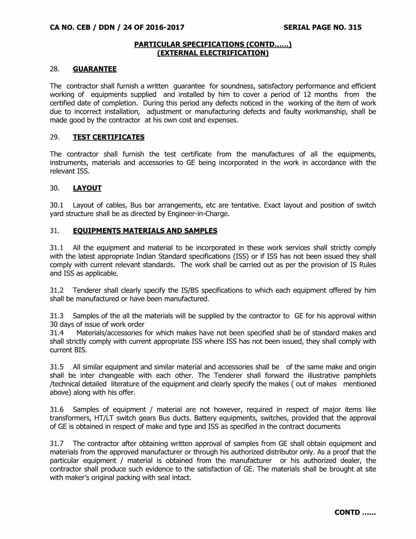
CA NO. CEB / DDN / 24 OF 2016-2017 SERIAL PAGE NO. 315
PARTICULAR SPECIFICATIONS (CONTD……) (EXTERNAL ELECTRIFICATION)
CONTD ……
28. GUARANTEE The contractor shall furnish a written guarantee for soundness, satisfactory performance and efficient working of equipments supplied and installed by him to cover a period of 12 months from the certified date of completion. During this period any defects noticed in the working of the item of work due to incorrect installation, adjustment or manufacturing defects and faulty workmanship, shall be made good by the contractor at his own cost and expenses. 29. TEST CERTIFICATES The contractor shall furnish the test certificate from the manufactures of all the equipments, instruments, materials and accessories to GE being incorporated in the work in accordance with the relevant ISS. 30. LAYOUT 30.1 Layout of cables, Bus bar arrangements, etc are tentative. Exact layout and position of switch yard structure shall be as directed by Engineer-in-Charge. 31. EQUIPMENTS MATERIALS AND SAMPLES 31.1 All the equipment and material to be incorporated in these work services shall strictly comply with the latest appropriate Indian Standard specifications (ISS) or if ISS has not been issued they shall comply with current relevant standards. The work shall be carried out as per the provision of IS Rules and ISS as applicable. 31.2 Tenderer shall clearly specify the IS/BS specifications to which each equipment offered by him shall be manufactured or have been manufactured. 31.3 Samples of the all the materials will be supplied by the contractor to GE for his approval within 30 days of issue of work order 31.4 Materials/accessories for which makes have not been specified shall be of standard makes and shall strictly comply with current appropriate ISS where ISS has not been issued, they shall comply with current BIS. 31.5 All similar equipment and similar material and accessories shall be of the same make and origin shall be inter changeable with each other. The Tenderer shall forward the illustrative pamphlets /technical detailed literature of the equipment and clearly specify the makes ( out of makes mentioned above) along with his offer. 31.6 Samples of equipment / material are not however, required in respect of major items like transformers, HT/LT switch gears Bus ducts. Battery equipments, switches, provided that the approval of GE is obtained in respect of make and type and ISS as specified in the contract documents 31.7 The contractor after obtaining written approval of samples from GE shall obtain equipment and materials from the approved manufacturer or through his authorized distributor only. As a proof that the particular equipment / material is obtained from the manufacturer or his authorized dealer, the contractor shall produce such evidence to the satisfaction of GE. The materials shall be brought at site with maker’s original packing with seal intact.

CA NO. CEB / DDN / 24 OF 2016-2017 SERIAL PAGE NO. 316
PARTICULAR SPECIFICATIONS (CONTD……) (EXTERNAL ELECTRIFICATION)
CONTD ……
31.8. The contractor shall proceed with the work only, after approval of samples in writing by the GE and approved samples shall be labeled as such and signed by both contractor and GE and kept in custody of the GE till the final completion of the work. The major equipment material such as Transformers, HT switch gears MCCB, Isolators, Batteries. Lightning arrestors, HT/LT cables, aluminium conductors etc shall be got approved from the GE in writing before erecting. The equipment / material shall be designed to withstand prevailing climatic condition at Bareilly, without effecting to life and operation of equipments. 32. STANDARD OF QUALITY AND WORKMANSHIP 32.1 The supply and installation of all electrical equipment and accessories shall strictly comply with provisions contained in the latest edition of Indian Standard code of practice/specifications as applicable to above mentioned works, except where such regulation and rules are modified by these specification. 32.2 Refer condition 25 of General conditions of contracts IAFW-2249 All electrical work shall be carried out by properly skilled and electrical supervisors / engineers. The contractor shall, on demand by the Engineer-in-Charge, produce such evidence of qualifications of his workmen / supervisors / engineers, either at commencement of work or at any time thereafter during the currency of the contract again required by Engineer-in-charge. The entire work shall be of high class with the best workmanship and to the entire satisfaction of GE / Engineer-in-Charge. 32.3 The H.T switch gears, transformer, cables, DC battery-cum charging equipment accessories, etc incorporated there in shall be capable of giving satisfactory operation under the climatic conditions at Bareilly. 32.4 The equipment called for in this contract/required for are an important Defense Installation where continuity of services is very essential. The design and manufacture of the equipment and the materials / accessories used therefore, shall be of highest standard to ensure continuous and trouble free services. 33. DANGER BOARDS/SIGNS 33.1 Danger boards shall be fabricated out of 1.6 thick MS sheet, vitreous enameled white of size given in Sch A . The letters, figures, conventional skull and bones will be in signal ‘RED’ colour on the front side. The rear side of plate shall also be enameled. Except the modifications mentioned above the Danger boards shall comply with the requirements of IS-2551-1963 or latest edition. 33.2 HT switchgears and transformers and steel structures for 33 KV/11 KV installed in the outdoor type sub station will be provided with MS sheet danger boards. These will be fixed on the equipment with four numbers GI bolts, nuts and washers. 33.3 HT switchgears, battery charging panel, 33 KV control etc installed inside the building will be provided with panel PERMACLL Make danger signs manufactured by M/S Johnson and Johnson. 33.4 Rates for both as mentioned in clause 40.2 and 40.3 shall be the same ,accordingly the contractor shall quote the rates for relevant item in Sch A. Only one number danger board / sign will be provided on each switch board, eqpt, pole, transformer etc as directed.

CA NO. CEB / DDN / 24 OF 2016-2017 SERIAL PAGE NO. 317
PARTICULAR SPECIFICATIONS (CONTD……) (EXTERNAL ELECTRIFICATION)
CONTD ……
34. HT / LT CABLES AND CABLE WORK 34.1 33 KV 3 Core cables XLPE insulated with aluminum conductors and shall conform to IS: 692-1973 or latest version thereof. These cables shall be suitable for earthed system. The aluminum conductors used for cables shall conform to IS: 1753-1967 or current edition. Note: Wherever 11KV is mentioned in the tender documents, it shall be read as 33 KV. 34.2 The cables HT shall carry normal load as well as short circuit current in the event of any fault. 34.3 The work of underground cables shall be carried out as specified in IS : 1255 -1967 or latest edition and as described in section 19(Electrical works section) sub class 19.74 to 19.82 and 19.83 to 19.87 of MES standard Schedule of Rates all zones. The cable under road crossings railway tracks etc (existing or proposed) shall be enclosed in GI pipes. The sizes of the pipes shall be decided by the Engineer-in-charge as described in Sch ‘A’ size of the pipe shall be such that the suitable space alround the cable is available. The pipe shall be provided throughout the width or roads/Railway/tracks/drains and extended for 1200mm either side of the road/railway track level. The joints of GI pipe shall be as specified in standard schedule of rates 2009 (Part I specifications). The two ends of pipes shall be sealed with wooden bush and sealing compound. Nothing extra shall be paid on this account and tenderers are advised to visit the site before the quoting their rates. 34.4 Where the cable are to be laid in the trenches, a 80 mm thick cushion of clean dry sand shall e provided below the bottom of cable. The cable shall be covered by a further layer of clean in SSR 2009 Sch ‘A’. The bricks PCC cover for covering the cables shall be as specified herein before. The bricks/PCC cover shall be laid flat (width of protection being equal to length of brick). After the layer of brick cover is laid the remaining trenches will be filled with excavated earth all as specified in Schedule ‘A’. 34.5 The cable shall be snaked to provide a 4 meters length of cable for future joints at all straights joints(both side of the joint ie. 4 meters on each side) of cable laid in trenches and 2 meters lengths at terminal cable boxes. The above additional length of cable specified for snaking shall also be measured and paid for under the respective items of cable in Schedule ‘A’ laying brick cover and sand cushion at places where cables are snaked, shall be done as directed by the GE. No price adjustment shall be made for variation in quantity or connected (allied) items like sand cushion sand cover and brick layer, excavation and earthwork, etc. 34.6 Where the cables run vertically they shall be firmly fixed with flat iron clamps as directed by the Engineer-in-charge at one metre centre to centre alongwith the support. 34.7 Cable path indicators shall be provided at distance of every 100 metres and at cable joints and turning of all cables excepteror street light cables and 2 core cables. Cables path indicators shall be of CI plate, indicating cable size voltage and sub station/building number to which it is feeding carved on it, welded to 40mm x 40mm x 6mm angle irons bent to shape as shown on drawings. The height of the cable path indicators above ground level shall be as shown on drawings. The cable path indicators shall be erected at the time of refilling the trenches and the path shall be painted as under :-
(i) For HT 11 KV Cables- ‘BROWN’.
NOTE: - The cost of cable indicators shall be deemed to be included in the rates quoted in Schedule ‘A’ for cables.

CA NO. CEB / DDN / 24 OF 2016-2017 SERIAL PAGE NO. 318
PARTICULAR SPECIFICATIONS (CONTD……) (EXTERNAL ELECTRIFICATION)
CONTD ……
34.8 All jointing materials for thermo fit (heat shrinkable) type jointing of cables (11 KV grade cables) as specified in clauses of particular specification for straight through joints shall be deemed to be included in the rates quoted for these cables in the schedule ‘A’ by the contractor. 34.9 Layout of HT cables shown in the drawings is for guidance only. The contractor shall, however, verify the cable lengths actually required at site before procurement of the same. 35. CABLE TERMINATION AND JOINT KITS Refer Para 19.22 and 19.86 of SSR Part I. These shall of indoor/ out door type as indicated in Schedule ‘A’. 36. SPECIAL EARTHING FOR SUB STATION EQUIPMENTS 36.1 Earthing shall generally conform to the requirements of IS : 3043-1987 (Code of practice for earthings) or latest edition and IE rules. 36.2 The contractor shall obtain approval of Engineer-in-Charge for layout of earthing before commencement and shall be executed in the presence of his representative. Excavation shall be passed by Engineer-in-Charge before filling. 36.3 The dimensions of plate earth electrode shall be 600mm x 600mm x 6.3 mm and shall be placed vertically. The plate electrode shall be surrounded with charcoal dust and common salt mixture to a packed thickness of 300mm around plate ie. Below, above and outward on all sides. The earthing shall be executed as shown in electrical plate No 5 of MES standard schedule of Rates 2009 (Part I specifications) except modifications mentioned in these particular specifications and Sch ‘A’. 36.4 The charcoal dust and common salt mixture and return filling shall be done in layers not exceeding 15cm and shall be properly watered and rammed. Surplus spoil shall be disposed of and site left cleared on completion. 36.5 The link shall be provided in the circuit of each pit, at a suitable point to be approved by the Engineer-in-Charge for carrying out resistance measuring test. The earth resistance of the whole system shall be as near as possible to zero but shall not in any case exceed one Ohm. 36.6 As for as possible joints in the copper earthing strips shall be avoided. But wherever it is absolutely necessary prior permission of engineer-in-charge in writing be taken. While jointing copper strips shall be properly cleaned. Straight joint shall overlap 50mm. All joints shall be riveted (using 6mm dia copper rivets in two rows with 2 Nos. rivets in each row) and then soldered welded on all the four sides and to full length of joint. 36.7 Concrete chamber including coping shall be PCC 1:2:4 mix using 20mm graded stone aggregated. All internal surface of concrete chamber shall be given 12mm thick plaster in cm (1:4) finished fair without using extra cement. Funnel in the chamber shall be with wire gauge (of 22 gauge, 9 meshes per linear inch). The frame for earth pits shall be of MS with RCC cover, the other details are shown in the drawings and described in the Schedule ‘A’. 36.8 Common salt and charcoal dust as available in the market shall be used for earthing.

CA NO. CEB / DDN / 24 OF 2016-2017 SERIAL PAGE NO. 319
PARTICULAR SPECIFICATIONS (CONTD……) (EXTERNAL ELECTRIFICATION)
CONTD ……
37. PRODUCTION OF TEST CERTIFICATE Manufacturer’s test certificate in respect of cables and transformers, poles, HT / LT cables, Gang operated air break switches, and other equipments are to be submitted to the EIC by the contractor before submission of Running payment / Final bill. 38. PLATFORM FOR TRANSFORMER Refer drawing listed in list of drawings/specified in Schedule “A”. Unless specified otherwise elsewhere Platform for Transformer shall be constructed in location as decided by Engineer-in-Charge and as per details shown in drawings to the following specifications read in conjunction with specifications given herein before:-
S. No.
Nomenclature Specifications (a) Excavation and earth work In any type of soil and disposal of surplus soil to a
distance of 500 M and spread and leveled (b) PCC in foundations 1:3:6 type C-2 (c) Brick walls / Dwarf walls Brick work in cement and sand mortar 1:4 (d) All RCC works RCC, M-25 (Design mix) (e) Brick bats filling These shall be of gauge not exc. 63 mm. (f) PCC in any location not
specified elsewhere PCC 1:2:4 Type B-1
(g) Rendering On all exposed faces 15 mm thick plastering in CM 1:6 upto 150 mm below ground level.
(h) Wicket gate As shown on Drg No. CEBZ/TD/002 sheet 1/1 amended upto date.
(j) Barbed wire fencing Barbed wire fencing shall be 1400 mm high all as shown in drg No. TD/090 sheet 1/3 to 3/3 and all as directed by GE.
(k) All other works As per drawings (l) Bearing Plaster 15 mm thick 1:4 top finished even and smooth and
proving building paper (m) Reinforcement Reinforcement steel shall be high strength deformed
bars Fe-500 grade. (n) Ramp All as shown on drg and specified here-in-before.
…………………………………… (Signature of Contractor) Astt Dir/Dy Dir (Contracts) Dated…………………………. For Accepting Officer

CA NO. CEB / DDN / 24 OF 2016-2017 SERIAL PAGE NO. 320
PARTICULAR SPECIFICATIONS (CONTD……)
APPENDIX ‘A’
LISTS OF ISI / BIS / CERTIFIED (MARKED) PRODUCTS TO BE INCORPORATED IN WORKS
S. NO.
MATERIAL IS NO.
1. CONCRETE (a) Integral water proofing compounds IS:2645 (b) Cement Ordinary Portland IS:8112
2. JOINERY (a) Wooden flush door shutters, solid core type IS:2202 Part 1
3. BUILDERS HARDWARE (a) Steel Butt Hinges IS:1341 (b) Non ferrous butt Hinges IS:205-1978 (c) Ferrous Tower/ Barrel Bolts IS:204 Part I (d) Non- Ferrous Tower/ Barrel Bolts IS:204 Part II (e) Door Handles ( Non Ferrous) IS:208 (f) Parliament Hinges , Ferrous IS:362 (g) Hydraulically operated Door closers IS:3564 (h) Continuous piano hinges IS:3818 (j) Non Ferrous metal sliding door bolts IS:2681 (k) Tee and strap Hinges IS:206 (l) Mild steel sliding door bolts IS:281 (m) Hasp and staples IS:363
4. ROOF COVERING (a) Bitumen felts of water proofing and damp proofing (
Hessian felt) IS:1322
(b) Glass fibre base felts type 2 grade II IS:7193
5. CEILING AND LINING (a) Plywood for General purposes IS:303 (b) Untenured particle Board IS:3087 (c) Fibre Hardboard IS:1658 (d) Medium density fibre board IS:12406 (e) Veneered Particle Board IS:3097
6. FLOORING (a) White Portland cement IS:8042 (b) Cement concrete flooring tiles IS:1237
CONTD ……
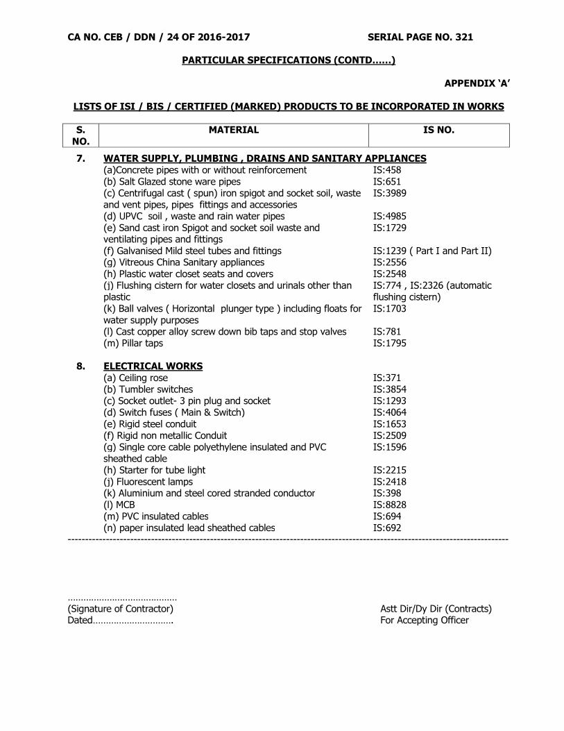
CA NO. CEB / DDN / 24 OF 2016-2017 SERIAL PAGE NO. 321
PARTICULAR SPECIFICATIONS (CONTD……)
APPENDIX ‘A’
LISTS OF ISI / BIS / CERTIFIED (MARKED) PRODUCTS TO BE INCORPORATED IN WORKS
S. NO.
MATERIAL IS NO.
7. WATER SUPPLY, PLUMBING , DRAINS AND SANITARY APPLIANCES (a)Concrete pipes with or without reinforcement IS:458 (b) Salt Glazed stone ware pipes IS:651 (c) Centrifugal cast ( spun) iron spigot and socket soil, waste
and vent pipes, pipes fittings and accessories IS:3989
(d) UPVC soil , waste and rain water pipes IS:4985 (e) Sand cast iron Spigot and socket soil waste and
ventilating pipes and fittings IS:1729
(f) Galvanised Mild steel tubes and fittings IS:1239 ( Part I and Part II) (g) Vitreous China Sanitary appliances IS:2556 (h) Plastic water closet seats and covers IS:2548 (j) Flushing cistern for water closets and urinals other than
plastic IS:774 , IS:2326 (automatic flushing cistern)
(k) Ball valves ( Horizontal plunger type ) including floats for water supply purposes
IS:1703 (l) Cast copper alloy screw down bib taps and stop valves IS:781 (m) Pillar taps IS:1795
8. ELECTRICAL WORKS
(a) Ceiling rose IS:371 (b) Tumbler switches IS:3854 (c) Socket outlet- 3 pin plug and socket IS:1293 (d) Switch fuses ( Main & Switch) IS:4064 (e) Rigid steel conduit IS:1653 (f) Rigid non metallic Conduit IS:2509 (g) Single core cable polyethylene insulated and PVC
sheathed cable IS:1596
(h) Starter for tube light IS:2215 (j) Fluorescent lamps IS:2418 (k) Aluminium and steel cored stranded conductor IS:398 (l) MCB IS:8828 (m) PVC insulated cables IS:694 (n) paper insulated lead sheathed cables IS:692 ------------------------------------------------------------------------------------------------------------------------------- …………………………………… (Signature of Contractor) Astt Dir/Dy Dir (Contracts) Dated…………………………. For Accepting Officer
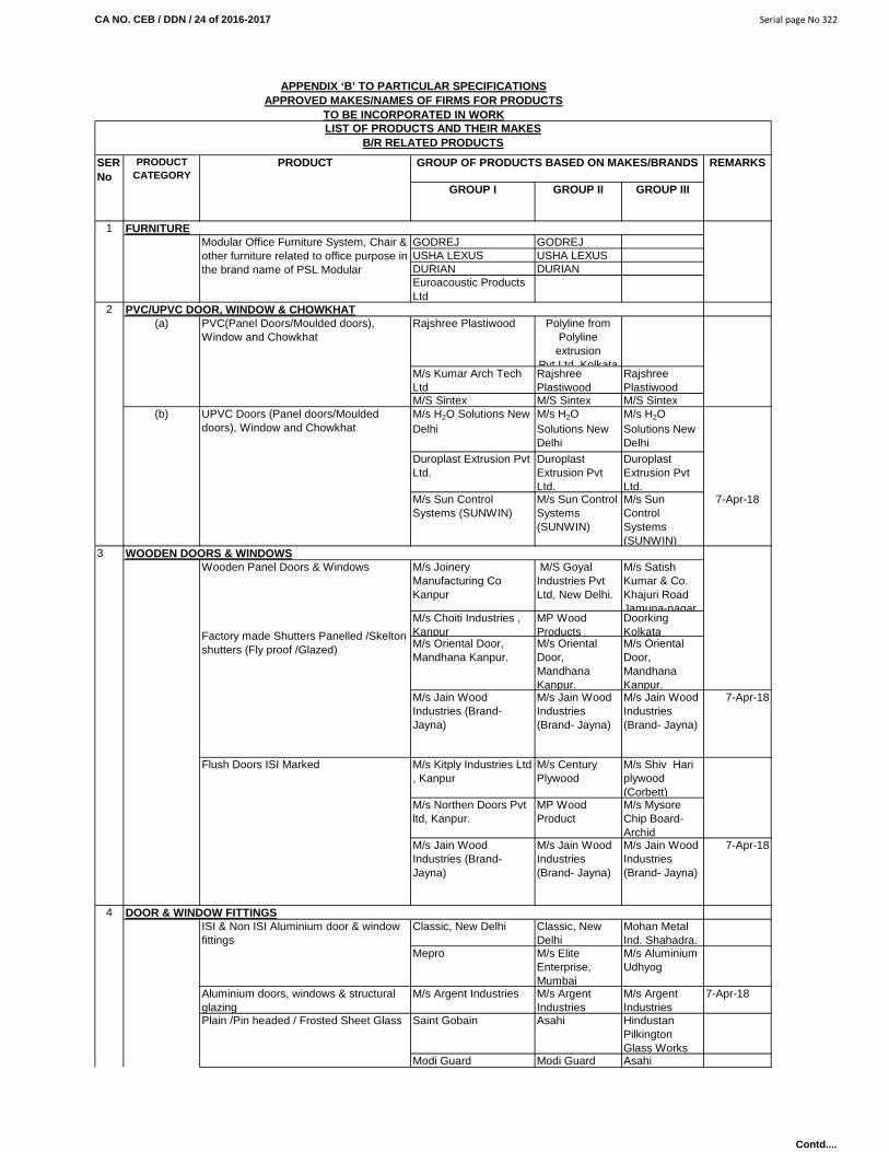
CA NO. CEB / DDN / 24 of 2016-2017 Serial page No 322
GROUP I GROUP II GROUP III
GODREJ GODREJUSHA LEXUS USHA LEXUSDURIAN DURIANEuroacoustic Products Ltd
Rajshree Plastiwood Polyline from Polyline
extrusion Pvt.Ltd Kolkata
M/s Kumar Arch Tech Ltd
Rajshree Plastiwood
Rajshree Plastiwood
M/S Sintex M/S Sintex M/S SintexM/s H2O Solutions New Delhi
M/s H2O Solutions New Delhi
M/s H2O Solutions New Delhi
Duroplast Extrusion Pvt Ltd.
Duroplast Extrusion Pvt Ltd.
Duroplast Extrusion Pvt Ltd.
M/s Sun Control Systems (SUNWIN)
M/s Sun Control Systems (SUNWIN)
M/s Sun Control Systems (SUNWIN)
7-Apr-18
M/s Joinery Manufacturing Co Kanpur
M/S Goyal Industries Pvt Ltd, New Delhi.
M/s Satish Kumar & Co. Khajuri Road Jamuna-nagar.
M/s Choiti Industries , Kanpur
MP Wood Products
Doorking Kolkata
M/s Oriental Door, Mandhana Kanpur.
M/s Oriental Door, Mandhana Kanpur.
M/s Oriental Door, Mandhana Kanpur.
M/s Jain Wood Industries (Brand- Jayna)
M/s Jain Wood Industries (Brand- Jayna)
M/s Jain Wood Industries (Brand- Jayna)
7-Apr-18
M/s Kitply Industries Ltd , Kanpur
M/s Century Plywood
M/s Shiv Hari plywood (Corbett)
M/s Northen Doors Pvt ltd, Kanpur.
MP Wood Product
M/s Mysore Chip Board- Archid
M/s Jain Wood Industries (Brand- Jayna)
M/s Jain Wood Industries (Brand- Jayna)
M/s Jain Wood Industries (Brand- Jayna)
7-Apr-18
Classic, New Delhi Classic, New Delhi
Mohan Metal Ind. Shahadra.
Mepro M/s Elite Enterprise, Mumbai
M/s Aluminium Udhyog
Aluminium doors, windows & structural glazing
M/s Argent Industries M/s Argent Industries
M/s Argent Industries
7-Apr-18
Saint Gobain Asahi Hindustan Pilkington Glass Works
Modi Guard Modi Guard Asahi
ISI & Non ISI Aluminium door & window fittings
FURNITUREModular Office Furniture System, Chair & other furniture related to office purpose in the brand name of PSL Modular
4
Wooden Panel Doors & Windows
Factory made Shutters Panelled /Skelton shutters (Fly proof /Glazed)
Flush Doors ISI Marked
3
UPVC Doors (Panel doors/Moulded doors), Window and Chowkhat
(b)
APPENDIX ‘B’ TO PARTICULAR SPECIFICATIONSAPPROVED MAKES/NAMES OF FIRMS FOR PRODUCTS
TO BE INCORPORATED IN WORKLIST OF PRODUCTS AND THEIR MAKES
B/R RELATED PRODUCTS
REMARKS
Plain /Pin headed / Frosted Sheet Glass
PVC/UPVC DOOR, WINDOW & CHOWKHAT
WOODEN DOORS & WINDOWS
DOOR & WINDOW FITTINGS
SER No
PRODUCT CATEGORY
PRODUCT GROUP OF PRODUCTS BASED ON MAKES/BRANDS
1
2(a) PVC(Panel Doors/Moulded doors),
Window and Chowkhat
Contd....

CA NO. CEB / DDN / 24 of 2016-2017 Serial page No 323
GROUP I GROUP II GROUP III
REMARKSSER No
PRODUCT CATEGORY
PRODUCT GROUP OF PRODUCTS BASED ON MAKES/BRANDS
Gold Mohar Shalimar Hardware
Rajdoot
J&N Berger
Indian Gypsum Everest Industries
Everest Industries
Kumar Arch Tech Pvt Ltd
Indian Gypsum Indian Gypsum
ARMSTRONG ARMSTRONG Indian Gypsum
Ramco Industries Ramco Industries
False Ceiling/ Partitions / Wall paneling / Pre fab uPVC cabins / Site office
M/s Sun Control Systems (SUNWIN)
M/s Sun Control Systems (SUNWIN)
M/s Sun Control Systems (SUNWIN)
7-Apr-18
M/s Agra Timber & Steel Products, Agra.
M/s Gupta and Jain Enterprises
M/s Ishwar Industries, 175/A, Bombay Bazar, Meerut Cantt.
M/s Anoop Industries Pvt Ltd, Hanuman Chowk, Meerut Cantt.
M/s AGEW Steel Manufactures (Pvt) Ahmedabad
M/s Aswini & Sons, E-15, Patel Nagar -II, Ghaziabad
M/s GS Udyog, G-11, Site III. Panki, UPSIDC Industrial Area, Kanpur.
M/s Multiwyn Industries Corpn Calcutta.
Poonam Enterprises, E-10, Industrial Estate, Talkatora , Lucknow.
Bajaj Steel Industries Ltd
M/s Chandni Industries Ghaziabad
M/s Chandni Industries Ghaziabad
Bajaj Steel Industries Ltd
Chhabra Steel Udhyog Ltd Meerut
M/s Gupta and Jain Enterprises
M/s Gupta Iron Udyog M/s Gupta Iron Udyog
M/s Gupta Iron Udyog
7-Apr-18
M/s Argent Industries M/s Argent Industries
M/s Argent Industries
7-Apr-18
PVC Kitchen Cup Boards/ ward robes Kumar Arch Tech Pvt Ltd
EVEREST SWASTIK CHARMINAR CHARMINAR CHARMINAR VISKAM/S Ispat Indistries Ltd M/s Cril Colour
Roof India Ltd.M/s Lloyd
Tata Blue Scope Steel Ltd
Tata Blue Scope Steel Ltd
M/s Matco Roof Pvt Ltd
Prestart infrastructure Projects Ltd
Everest Industries Ltd
Tata Blue scope steel Ltd
Wooden wall Panel ARMSTRONG ARMSTRONG -
Jaquar & Company Pvt Ltd
Plumber Prayag Polymer Pvt Ltd
Marc Gem Gem
CP Bath Fittings
Color Coated Sheet galvalume
7
6 CUPBOARDS, CABINETS, DOOR & WARDROBE
5
Putty for glazing
GALVANIZED SHEETS, PANELLING, PARTITIONS, HUTS & BA THROOMSCGI/PGI sheet
PVC False ceiling
Gypboard/'E' board False Ceiling
M/s Sen Harvic Vora Building, 1st Floor, 50 Nakhoda Street Bombay
M/s Anoop Industries Pvt Ltd, Hanuman Chowk, Meerut Cantt.
FALSE CEILING
Steel windows, ventillator (as per IS 1038 of 1983) and pressed steel door/ window frames, steel lockers & cup board frame/ shutters
8 SANITARY WARES
Contd....

CA NO. CEB / DDN / 24 of 2016-2017 Serial page No 324
GROUP I GROUP II GROUP III
REMARKSSER No
PRODUCT CATEGORY
PRODUCT GROUP OF PRODUCTS BASED ON MAKES/BRANDS
Zolotov. Seiko SeikoBlue Star -SILVER SHINE
Plastocraft Sanitary India Pvt LtdAluminium Udhyog
M/s Status Sanitech Pvt Ltd (Brand-PLAYER)
M/s Status Sanitech Pvt Ltd (Brand-PLAYER)
M/s Status Sanitech Pvt Ltd (Brand-PLAYER)
7-Apr-18
M/s Mohan Metal Industries (Brand - CORONET)
M/s Mohan Metal Industries (Brand - CORONET)
M/s Mohan Metal Industries (Brand -
7-Apr-18
Zolotov. M/s Prakash & Co Mayapuri, Delhi
M/s Prakash & Co Mayapuri, Delhi
Zolotov. L&KPTMT Bathroom and Hardware fittings M/s R.S. Industries
(Brand-POLYTUF)M/s R.S. Industries (Brand-POLYTUF)
M/s R.S. Industries (Brand-POLYTUF)
7-Apr-18
Jaquar & Company Pvt Ltd
Neycer Kermag (standard)
Somany
Hind ware Hind wareHindustan Sanitary Ware (Hindware) (1st quality),
Hindustan Sanitary Ware (Hindware) (1st quality),
Hindustan Sanitary Ware (Hindware) (1st quality),
Parryware (Super fine) Parryware (Super fine)
Cera
Cera (1st quality) Cera (1st quality)
Johnson Pedder Johnson Pedder
Nirali Amco AmcoBlue Star -SILVER SHINE
Cobra Anupam
Blue Star -SILVER SHINE
Designer bath Suites Jaquar & Company Pvt LtdPrayag Polymer Pvt Ltd Blue Star -
SILVER SHINE Anupam Industries
Jain Brothers Sanitation Pvt Ltd
Nirali Nirali
Float valves/Ballcocks, Cockroach Traps, Glass shelfs
Prayag Polymer Pvt Ltd Prayag Polymer Pvt Ltd
Prayag Polymer Pvt Ltd
Prayag Polymer Pvt Ltd Blue Star -SILVER SHINE
-
Jain Brothers Sanitation Pvt Ltd
Nirali -
Parryware Commander - Champion
Commander - Champion
Hind ware Parryware Hindustan CERA Hind ware
Blue Star -SILVER SHINE
Parryware Parryware Commander - Champion
Hind ware Hindware Hindustan
Stainless Steel Kitchen Sink
Seat cover for EWC
PVC Flushing Cistern (IS- 774-1984)
Blue Star -SILVER SHINE
SS Plate Rack
Wash Basins/WCs
SS Wash Basins/WCs
Bib Taps & Stop Cocks (Brass)
Contd....
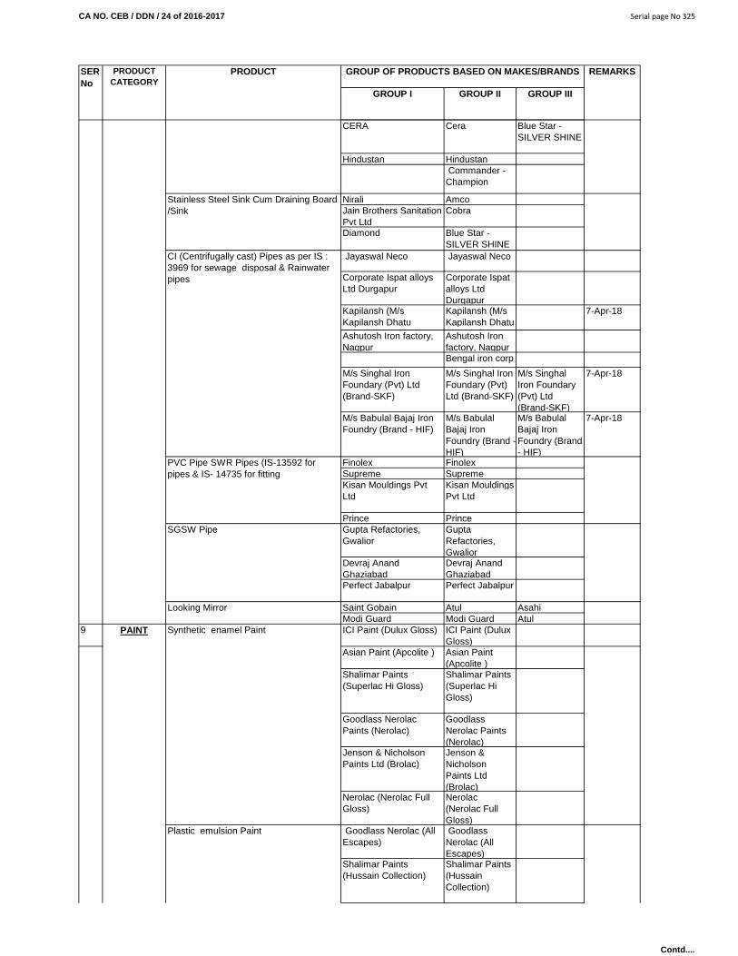
CA NO. CEB / DDN / 24 of 2016-2017 Serial page No 325
GROUP I GROUP II GROUP III
REMARKSSER No
PRODUCT CATEGORY
PRODUCT GROUP OF PRODUCTS BASED ON MAKES/BRANDS
CERA Cera Blue Star -SILVER SHINE
Hindustan Hindustan Commander - Champion
Nirali AmcoJain Brothers Sanitation Pvt Ltd
Cobra
Diamond Blue Star -SILVER SHINE
Jayaswal Neco Jayaswal Neco
Corporate Ispat alloys Ltd Durgapur
Corporate Ispat alloys Ltd Durgapur
Kapilansh (M/s Kapilansh Dhatu
Kapilansh (M/s Kapilansh Dhatu
7-Apr-18
Ashutosh Iron factory, Nagpur
Ashutosh Iron factory, NagpurBengal iron corp
M/s Singhal Iron Foundary (Pvt) Ltd (Brand-SKF)
M/s Singhal Iron Foundary (Pvt) Ltd (Brand-SKF)
M/s Singhal Iron Foundary (Pvt) Ltd (Brand-SKF)
7-Apr-18
M/s Babulal Bajaj Iron Foundry (Brand - HIF)
M/s Babulal Bajaj Iron Foundry (Brand - HIF)
M/s Babulal Bajaj Iron Foundry (Brand - HIF)
7-Apr-18
Finolex FinolexSupreme SupremeKisan Mouldings Pvt Ltd
Kisan Mouldings Pvt Ltd
Prince PrinceGupta Refactories, Gwalior
Gupta Refactories, Gwalior
Devraj Anand Ghaziabad
Devraj Anand Ghaziabad
Perfect Jabalpur Perfect Jabalpur
Saint Gobain Atul AsahiModi Guard Modi Guard Atul
9 ICI Paint (Dulux Gloss) ICI Paint (Dulux Gloss)
Asian Paint (Apcolite ) Asian Paint (Apcolite )
Shalimar Paints (Superlac Hi Gloss)
Shalimar Paints (Superlac Hi Gloss)
Goodlass Nerolac Paints (Nerolac)
Goodlass Nerolac Paints (Nerolac)
Jenson & Nicholson Paints Ltd (Brolac)
Jenson & Nicholson Paints Ltd (Brolac)
Nerolac (Nerolac Full Gloss)
Nerolac (Nerolac Full Gloss)
Goodlass Nerolac (All Escapes)
Goodlass Nerolac (All Escapes)
Shalimar Paints (Hussain Collection)
Shalimar Paints (Hussain Collection)
PAINT
CI (Centrifugally cast) Pipes as per IS : 3969 for sewage disposal & Rainwater pipes
Synthetic enamel Paint
PVC Pipe SWR Pipes (IS-13592 for pipes & IS- 14735 for fitting
SGSW Pipe
Plastic emulsion Paint
Stainless Steel Sink Cum Draining Board /Sink
Looking Mirror
Contd....

CA NO. CEB / DDN / 24 of 2016-2017 Serial page No 326
GROUP I GROUP II GROUP III
REMARKSSER No
PRODUCT CATEGORY
PRODUCT GROUP OF PRODUCTS BASED ON MAKES/BRANDS
Jenson & Nicholson (Special Effect)
Jenson & Nicholson (Special Effect)
Asian Paints (Royale) Berger Paints (Luxol Silk Splender)
Asian Paints (Royale) Berger Paints (Luxol Silk Splender)
Good lass Nerolac paints
Good lass Nerolac paints
Shalimar Paints Shalimar Paints
Jenson & Nicholson Jenson & Nicholson
Asian Paints Asian Paints Berger Berger
JK White JK White Birla White Birla WhiteSuper Snowcem Super Snowcem Cemkote
Duracem Duracem DuracemCemplus by TATA pigments
Cemplus by TATA pigments
Cemplus by TATA pigments
Gutucem by Asian Pigments
Gutucem by Asian Pigments
Accrocem Accrocem Berger Paints -Weather Coat smooth
Berger Paints -Weather Coat smooth
Asian Paints - APEX. Asian Paints - APEX.
Shalimar Paint XTRA Shalimar Paint XTRA
Nerolac Paint - AXCEL Nerolac Paint - AXCEL
Aluminum composite Panels M/S Alstone International, Noida (UP)
M/S Alstone International, Noida (UP)
Novapan Century plywood
Shivam Tar products, Mathura
Kitply Bhutan Board Bhutan BoardGreen ply Nepal Board Nepal BoardNovapan Century
plywoodBhutan Board
Kitply Bhutan Board Nepal BoardGreen ply Nepal Board Shivam Tar
products, Mathura
Formica/ Sunmica Decolam from Century
Century Green LamGreen Lam Sunmica
11NITCO, Mumbai Star Tiles &
Industries, Rama Devi , Kanpur
M/s Mehatab Tiles 8, Rani Shopping Centre, Bhanwar, Indore.
Redsun Tiles & Pavers, Panchkula.
Mayur Tiles & Interlocking paves, Lucknow.
Cement Based Paints
Plywood for general purposes (ISI 303 Marked )
Plain Particle Board/Particle Board Ceiling Tiles Prelaminated Particle Board
Laminated Sheets
Mosaic/PCC Plain/ Chequered tiles/ Inter Locking paver blocks.
TILES
10
External Weather proof paint
PLY BOARD/MDF & HDF BOARDS
Acrylic washable distemper/Oil emulson distemper
White cement & Wall Care Putty
Contd....
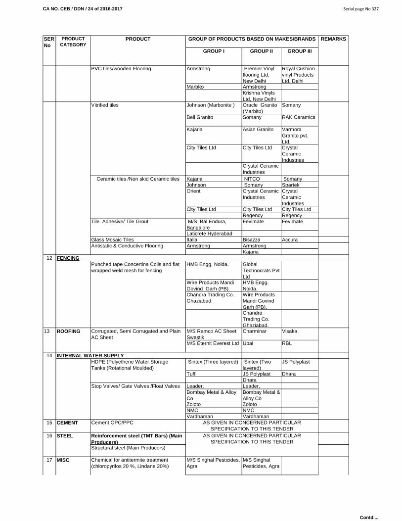
CA NO. CEB / DDN / 24 of 2016-2017 Serial page No 327
GROUP I GROUP II GROUP III
REMARKSSER No
PRODUCT CATEGORY
PRODUCT GROUP OF PRODUCTS BASED ON MAKES/BRANDS
Armstrong Premier Vinyl flooring Ltd, New Delhi
Royal Cushion vinyl Products Ltd, Delhi
Marblex ArmstrongKrishna Vinyls Ltd, New Delhi
Johnson (Marbonite ) Oracle Granito (Marbito)
Somany
Bell Granito Somany RAK Ceramics
Kajaria Asian Granito Varmora Granito pvt. Ltd.
City Tiles Ltd City Tiles Ltd Crystal Ceramic Industries
Crystal Ceramic Industries
Kajaria NITCO SomanyJohnson Somany SpartekOrient Crystal Ceramic
IndustriesCrystal Ceramic Industries
City Tiles Ltd City Tiles Ltd City Tiles LtdRegency Regency
M/S Bal Endura, Bangalore
Fevimate Fevimate
Laticrete HyderabadGlass Mosaic Tiles Italia Bisazza Accura
Armstrong ArmstrongKajaria
HMB Engg. Noida. Global Technocrats Pvt Ltd
Wire Products Mandi Govind Garh (PB).
HMB Engg. Noida.
Chandra Trading Co. Ghaziabad.
Wire Products Mandi Govind Garh (PB).Chandra Trading Co. Ghaziabad.
M/S Ramco AC Sheet Swastik
Charminar Visaka
M/S Eternit Everest Ltd Upal RBL
Sintex (Three layered) Sintex (Two layered)
JS Polyplast
Tuff JS Polyplast DharaDhara
Leader, Leader, Bombay Metal & Alloy Co
Bombay Metal & Alloy Co
Zoloto ZolotoNMC NMCVardhaman Vardhaman
Reinforcement steel (TMT Bars) (Main Producers)
M/S Singhal Pesticides, Agra
M/S Singhal Pesticides, Agra
17 MISC Chemical for antitermite treatment (chloropyrifos 20 %, Lindane 20%)
15 CEMENT Cement OPC/PPC
16 STEEL
Structural steel (Main Producers)
AS GIVEN IN CONCERNED PARTICULAR SPECIFICATION TO THIS TENDER
AS GIVEN IN CONCERNED PARTICULAR SPECIFICATION TO THIS TENDER
ROOFING Corrugated, Semi Corrugated and Plain AC Sheet
14 INTERNAL WATER SUPPLYHDPE (Polyethene Water Storage Tanks (Rotational Moulded)
Stop Valves/ Gate Valves /Float Valves
PVC tiles/wooden Flooring
FENCING12
13
Antistatic & Conductive Flooring
Ceramic tiles /Non skid Ceramic tiles
Vitrified tiles
Tile Adhesive/ Tile Grout
Punched tape Concertina Coils and flat wrapped weld mesh for fencing
Contd....
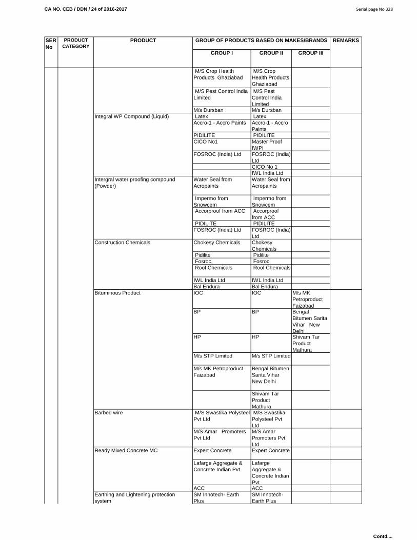
CA NO. CEB / DDN / 24 of 2016-2017 Serial page No 328
GROUP I GROUP II GROUP III
REMARKSSER No
PRODUCT CATEGORY
PRODUCT GROUP OF PRODUCTS BASED ON MAKES/BRANDS
M/S Crop Health Products Ghaziabad
M/S Crop Health Products Ghaziabad
M/S Pest Control India Limited
M/S Pest Control India Limited
M/s Dursban M/s Dursban Latex LatexAccro-1 - Accro Paints Accro-1 - Accro
PaintsPIDILITE PIDILITECICO No1 Master Proof
IWPIFOSROC (India) Ltd FOSROC (India)
LtdCICO No 1IWL India Ltd
Water Seal from Acropaints
Water Seal from Acropaints
Impermo from Snowcem
Impermo from Snowcem
Accorproof from ACC Accorproof from ACC
PIDILITE PIDILITEFOSROC (India) Ltd FOSROC (India)
LtdChokesy Chemicals Chokesy
Chemicals Pidilite Pidilite Fosroc, Fosroc, Roof Chemicals Roof Chemicals
IWL India Ltd IWL India LtdBal Endura Bal Endura IOC IOC M/s MK
Petroproduct Faizabad
BP BP Bengal Bitumen Sarita Vihar New Delhi
HP HP Shivam Tar Product Mathura
M/s STP Limited M/s STP Limited
M/s MK Petroproduct Faizabad
Bengal Bitumen Sarita Vihar New Delhi
Shivam Tar Product Mathura
M/S Swastika Polysteel Pvt Ltd
M/S Swastika Polysteel Pvt Ltd
M/S Amar Promoters Pvt Ltd
M/S Amar Promoters Pvt Ltd
Expert Concrete Expert Concrete
Lafarge Aggregate & Concrete Indian Pvt
Lafarge Aggregate & Concrete Indian Pvt
ACC ACC SM Innotech- Earth Plus
SM Innotech- Earth Plus
Integral WP Compound (Liquid)
Intergral water proofing compound (Powder)
Construction Chemicals
Bituminous Product
Barbed wire
Ready Mixed Concrete MC
Earthing and Lightening protection system
Contd....

CA NO. CEB / DDN / 24 of 2016-2017 Serial page No 329
GROUP I GROUP II GROUP III
REMARKSSER No
PRODUCT CATEGORY
PRODUCT GROUP OF PRODUCTS BASED ON MAKES/BRANDS
Dhruva Tech Pvt Ltd Protec
Dhruva Tech Pvt Ltd ProtecKanak Earth Energies
18Ecocell Branc Rigid Foam PVC sheets of thickness varying from 0.40 mm to 0.50 mmPrelaminated sheet of thickness varying from 0.40mm to 0.50mmPrefabricated PVC hut and Bathrooms
PVC Sheets
Sec color Galvanised color/ powder coated steel windows doors partitions and structural GlazingsCalcium Silicate Partitions
Kirby Bldg Systems Kirby Bldg Systems
Kirby Bldg Systems
23-Dec-15
Lloyd Insulations (India) Ltd
Lloyd Insulations (India) Ltd
Lloyd Insulations (India) Ltd
8-May-17
Octamac Engineering Ltd
Octamac Engineering Ltd
Octamac Engineering Ltd
3-Apr-16
Everest Industries Ltd Everest Industries Ltd
Everest Industries Ltd
16-Aug-18
Apex BuildSys Ltd Apex BuildSys Ltd
Apex BuildSys Ltd
2-Apr-16
Tiger Steel Engineering (I) Pvt Ltd
Tiger Steel Engineering (I) Pvt Ltd
Tiger Steel Engineering (I) Pvt Ltd
23-Dec-15
Modern Prefab Systems Pvt Limited
Modern Prefab Systems Pvt Limited
Modern Prefab Systems Pvt Limited
10-Feb-17
RCC Eco-Build System Ltd
RCC Eco-Build System Ltd
RCC Eco-Build System Ltd
23-Dec-15
Saxena Marine Tech (P) Ltd
Saxena Marine Tech (P) Ltd
Saxena Marine Tech (P) Ltd
26-Nov-14
M/s Richa Industries Ltd
M/s Richa Industries Ltd
M/s Richa Industries Ltd
27/09/2018
M/s Pennar Engineered Building systems Ltd, Hyd
M/s Pennar Engineered Building systems Ltd, Hyd
M/s Pennar Engineered Building systems Ltd, Hyd
28/09/2016
M/s Jindal Build Sys Ltd M/s Jindal Build Sys Ltd
M/s Jindal Build Sys Ltd
29/10/2018
Butzback GmbH, Germany made TORRITE and TENALITE Brand Electromechanical / Auto mode Sliding Aircraft Hanger Door
M/s Jugapro M/s Jugapro M/s Jugapro 3-Nov-17
Cipy Brand EPU (Epoxy Polyurethane Industrial Flooring
Cipy Polyurethane Pvt Ltd
Cipy Polyurethane Pvt Ltd
Cipy Polyurethane Pvt Ltd
30-Jan-17
Flooring Range (Epoxi/Polyurethane Pidilite Industries Ltd Pidilite Industries Ltd
Pidilite Industries Ltd
13-Dec-14
PEB & HANGER DOORS
2 FLOORING, FLOOR PRODUCTS & CONSTRUCTION CHEMICALS
PVC, Galvanised sheet, Panelling, Partitions, huts and BathroomsKumar Arch Tech Pvt Ltd
Jain Irrigation Systems Ltd
NCL Altek & sec color Ltd
Ramco Industries Ltd1 PEB & HANGER DOORS
Contd....

CA NO. CEB / DDN / 24 of 2016-2017 Serial page No 330
GROUP I GROUP II GROUP III
REMARKSSER No
PRODUCT CATEGORY
PRODUCT GROUP OF PRODUCTS BASED ON MAKES/BRANDS
Chryso - Floor Hardner CHRYSO Proof Acrylic, chryso Emalite RTU, CHRYSO Thermoshield Flooring - Sika Chapdur, Sika Chapdur C, Sikafloor 19 N Purcem, Sikafloor 20N PurCem, Sikafloor 21N PurCem, Sikafloor 22N PurCem, Sikafloor 29 N PurCe, Sikafloor 31 N Pur
The Structural Water Proofing Co Pvt Ltd
The Structural Water Proofing Co Pvt Ltd
The Structural Water Proofing Co Pvt Ltd
13-Oct-15
Flooring - Sika Chapdur, Sika Chapdur C, Sikafloor 19 N Purcem, Sikafloor 20N PurCem, Sikafloor 21N PurCem, Sikafloor 22N PurCem, Sikafloor 29 N PurCe, Sikafloor 31 N PurCem, Sikafloor 81, EpoCem, Sikafloor 82 Epo Cem, Sikafloor 83 EpoCem, Sikafloor 89, Sikafloor 91, Sikafloor 91, SLS, Sikafloor 105, Sikafloor 161, Sikafloor 220W Conductive, Sikafloor 261 ASN, Sikafloor 264, Sikafloor 381, Sikafloor 381 ASN, Sikafloor 619, Sikafloor 2530W, Sikafloor 7530, Sikafloor Gurehard 24, Sikafloor - Level 25, Sikafloor Proseal 22, Sikagard 63, Sikagard 63/1, Sikagard 67, Sikagard CCPU, Sika Ceram, Sika Tilofix & Sika Wall Decor,
Sika India Pvt Ltd Sika India Pvt Ltd
Sika India Pvt Ltd
17-Jun-17
Epoxy resin based and Polyurethane based Floor coatings(Floorgard SLP, Florgard SL, Florgard ESD, Florthane WB, Florthane UV, Florscreed, Florscreed SL, Florgiene MD, Florgiene ESD SL, Polydeck BC, Polydeck UV & Polyscreed.PrimersWalgard prime, Florprime WB, Florprime EP, Florprime ESD & Florprime DPMWall CoatingWalgard WBA, Walgard WB, Clearseal, Clearseal XT, Carboshield
M/s Apurva India Limited, Mumbai
M/s Apurva India Limited, Mumbai
M/s Apurva India Limited, Mumbai
16-Mar-20
3
Pidilite Industries Ltd Pidilite Industries Ltd
Pidilite Industries Ltd
13-Dec-14
Structural Water Proofing Co Pvt Ltd
Structural Water Proofing Co Pvt Ltd
Structural Water Proofing Co Pvt Ltd
13-Oct-15
Apar Infotech Pvt Ltd Apar Infotech Pvt Ltd
Apar Infotech Pvt Ltd
2-May-16
M/s Supreme Bituchem India Pvt. Ltd
M/s Supreme Bituchem India Pvt. Ltd
M/s Supreme Bituchem India Pvt. Ltd
1-Feb-18
Water Proofing Coating (Eposeal, Sealcrete & Elastocrete
M/s Apurva India Limited, Mumbai
M/s Apurva India Limited, Mumbai
M/s Apurva India Limited, Mumbai
16-Mar-20
HYDROSTOPWater proofing membrane, in all its permutation and combinatiuon, as also Tiki primer_- WB & OB & Tiki Flash ( Bitumen based Alum paint )
Tiki Tar Danosa India Pvt Ltd.
Tiki Tar Danosa India Pvt Ltd.
Tiki Tar Danosa India Pvt Ltd.
7-Nov-19
4
WATERPROOFING / COATING
Water Proofing/ Coating/ Seal/ Patches/ Shields/ Grouts/ Liquid applied Membranes
MEMBRANE & LIQUID MEMBRANE
Contd....
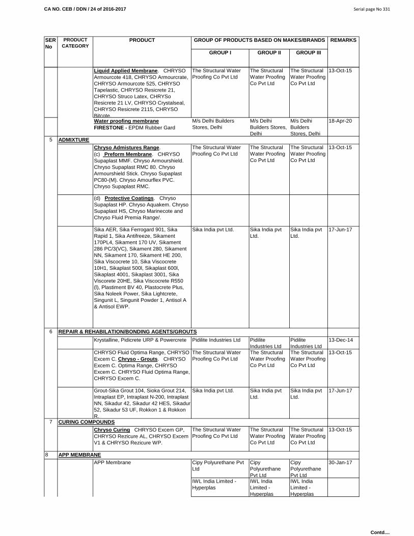
CA NO. CEB / DDN / 24 of 2016-2017 Serial page No 331
GROUP I GROUP II GROUP III
REMARKSSER No
PRODUCT CATEGORY
PRODUCT GROUP OF PRODUCTS BASED ON MAKES/BRANDS
Liquid Applied Membrane . CHRYSO Armourcote 418, CHRYSO Armourcrate, CHRYSO Armourcote 525, CHRYSO Tapelastic, CHRYSO Resicrete 21, CHRYSO Struco Latex, CHRYSo Resicrete 21 LV, CHRYSO Crystalseal, CHRYSO Resicrete 2115, CHRYSO Bitcote.
The Structural Water Proofing Co Pvt Ltd
The Structural Water Proofing Co Pvt Ltd
The Structural Water Proofing Co Pvt Ltd
13-Oct-15
Water proofing membraneFIRESTONE - EPDM Rubber Gard
M/s Delhi Builders Stores, Delhi
M/s Delhi Builders Stores, Delhi
M/s Delhi Builders Stores, Delhi
18-Apr-20
Chryso Admistures Range . (c) Preform Membrane . CHRYSO Supaplast MMF. Chryso Armourshield. Chryso Supaplast RMC 80. Chryso Armourshield Stick. Chryso Supaplast PC80-(M). Chryso Amourflex PVC. Chryso Supaplast RMC.
The Structural Water Proofing Co Pvt Ltd
The Structural Water Proofing Co Pvt Ltd
The Structural Water Proofing Co Pvt Ltd
13-Oct-15
(d) Protective Coatings . Chryso Supaplast HP. Chryso Aquakem. Chryso Supaplast HS, Chryso Marinecote and Chryso Fluid Premia Range/.
Sika AER, Sika Ferrogard 901, Sika Rapid 1, Sika Antifreeze, Sikament 170PL4, Sikament 170 UV, Sikament 286 PC/3(VC), Sikament 280, Sikament NN, Sikament 170, Sikament HE 200, Sika Viscocrete 10, Sika Viscocrete 10H1, Sikaplast 500l, Sikaplast 600l, Sikaplast 4001, Sikaplast 3001, Sika Viscorete 20HE, Sika Viscocrete R550 (l), Plastiment BV 40, Plastocrete Plus, Sika Noleek Power, Sika Lightcrete, Singunit L, Singunit Powder 1, Antisol A & Antisol EWP.
Sika India pvt Ltd. Sika India pvt Ltd.
Sika India pvt Ltd.
17-Jun-17
Krystalline, Pidicrete URP & Powercrete Pidilite Industries Ltd Pidilite Industries Ltd
Pidilite Industries Ltd
13-Dec-14
CHRYSO Fluid Optima Range, CHRYSO Excem C. Chryso - Grouts . CHRYSO Excem C. Optima Range, CHRYSO Excem C. CHRYSO Fluid Optima Range, CHRYSO Excem C.
The Structural Water Proofing Co Pvt Ltd
The Structural Water Proofing Co Pvt Ltd
The Structural Water Proofing Co Pvt Ltd
13-Oct-15
Grout-Sika Grout 104, Sioka Grout 214, Intraplast EP, Intraplast N-200, Intraplast NN, Sikadur 42, Sikadur 42 HES, Sikadur 52, Sikadur 53 UF, Rokkon 1 & Rokkon R.
Sika India pvt Ltd. Sika India pvt Ltd.
Sika India pvt Ltd.
17-Jun-17
Chryso Curing CHRYSO Excem GP, CHRYSO Rezicure AL, CHRYSO Excem V1 & CHRYSO Rezicure WP.
The Structural Water Proofing Co Pvt Ltd
The Structural Water Proofing Co Pvt Ltd
The Structural Water Proofing Co Pvt Ltd
13-Oct-15
8
Cipy Polyurethane Pvt Ltd
Cipy Polyurethane Pvt Ltd
Cipy Polyurethane Pvt Ltd
30-Jan-17
IWL India Limited - Hyperplas
IWL India Limited - Hyperplas
IWL India Limited - Hyperplas
6 REPAIR & REHABILATION/BONDING AGENTS/GROUTS
7 CURING COMPOUNDS
APP MEMBRANEAPP Membrane
5 ADMIXTURE
Contd....
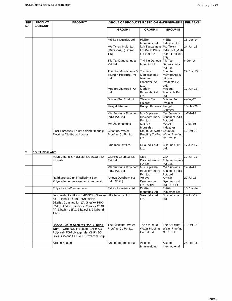
CA NO. CEB / DDN / 24 of 2016-2017 Serial page No 332
GROUP I GROUP II GROUP III
REMARKSSER No
PRODUCT CATEGORY
PRODUCT GROUP OF PRODUCTS BASED ON MAKES/BRANDS
Pidilite Industries Ltd Pidilite Industries Ltd
Pidilite Industries Ltd
13-Dec-14
M/s Texsa India Ldt (Multi Plas), (Texself 1.5)
M/s Texsa India Ldt (Multi Plas), (Texself 1.5)
M/s Texsa India Ldt (Multi Plas), (Texself 1.5)
24-Jun-16
Tiki Tar Danosa India Pvt Ltd.
Tiki Tar Danosa India Pvt Ltd.
Tiki Tar Danosa India Pvt Ltd.
8-Jun-16
Torchtar Membranes & bitumen Products Pvt Ltd.
Torchtar Membranes & bitumen Products Pvt Ltd.
Torchtar Membranes & bitumen Products Pvt Ltd.
22-Dec-19
Modern Bitumode Pvt Ltd.
Modern Bitumode Pvt Ltd.
Modern Bitumode Pvt Ltd.
13-Jun-15
Shivam Tar Product Shivam Tar Product
Shivam Tar Product
4-May-20
Bengal Bitumen Bengal Bitumen Bengal Bitumen
15-Mar-20
M/s Supreme Bituchem India Pvt. Ltd
M/s Supreme Bituchem India Pvt. Ltd
M/s Supreme Bituchem India Pvt. Ltd
1-Feb-18
M/s AR Industries M/s AR Industries
M/s AR Industries
17-04-19
Structural Water Proofing Co Pvt Ltd
Structural Water Proofing Co Pvt Ltd
Structural Water Proofing Co Pvt Ltd
13-Oct-16
Sika India pvt Ltd. Sika India pvt Ltd.
Sika India pvt Ltd.
17-Jun-17
9
Cipy Polyuretheanes Pvt Ltd.
Cipy Polyuretheanes Pvt Ltd.
Cipy Polyuretheanes Pvt Ltd.
30-Jan-17
M/s Supreme Bituchem India Pvt. Ltd
M/s Supreme Bituchem India Pvt. Ltd
M/s Supreme Bituchem India Pvt. Ltd
1-Feb-18
Rallithane 862 and Ralliprime 190 Polyurethane base sealant compound
Ameya Dyechem pvt Ltd. (ADPL)
Ameya Dyechem pvt Ltd. (ADPL)
Ameya Dyechem pvt Ltd. (ADPL)
22-Jul-16
Polysulphide/Polyurethane Pidilite Industries Ltd Pidilite Industries Ltd
Pidilite Industries Ltd
13-Dec-14
Joint sealant - Sikasil 728NS/SL, Sikaflex 68TF, Igas IH, Sika Polysulphide, Sikaflex Construction (J), Sikaflex PRO-3WF, Sikadur Combiflex, Sikaflex 2c SL (h), Sikaflex 11FC, Sikacryl & Sikabond T2/T8.
Sika India pvt Ltd. Sika India pvt Ltd.
Sika India pvt Ltd.
17-Jun-17
Chryso - Joint Sealants (for Building work) CHRYSO Freecure, CHRYSO Polycaulk PS-Polysulphide. CHRYSO Stick SBA and CHRYSO Swellseal Strip
The Structural Water Proofing Co Pvt Ltd
The Structural Water Proofing Co Pvt Ltd
The Structural Water Proofing Co Pvt Ltd
13-Oct-15
Sillicon Sealant Alstone Internatrional Alstone Internatrional
Alstone Internatrional
24-Feb-15
JOINT SEALANT
Floor Hardener/ Thermo shield flooring/ Flooring/ Tile fix/ wall decor
Polyurethane & Polysulphide sealant for all joints
Contd....

CA NO. CEB / DDN / 24 of 2016-2017 Serial page No 333
GROUP I GROUP II GROUP III
REMARKSSER No
PRODUCT CATEGORY
PRODUCT GROUP OF PRODUCTS BASED ON MAKES/BRANDS
Refurbishment . Sika Wrap Glass Fibre, Sika Wrap Carbon Fibre, Sika Anchorfix 2/3 +, Sikadur 31, Sikadur 32, Sikadur 32LP, Sikadur 41, Sikladur 43, Sika Ferro Gard 903, Friazinc R, Sikagard 703W, Sikagard 550W Elastic, Sika Rep Microcrete 1/2, Sikadur 31 PBA, Sika Rep Microcrete 3 UW, Sika Rep Microcrete 4, Sika Carbo Dur, Sikadur 12 Pronto, Sika Top 77, Sika Top 122, Sika Top 122HS, Sika Top Armatec 108, Sika Top Armatec 108PC & Sika Top Armatec 110 Epo Ce.
Sika India pvt Ltd. Sika India pvt Ltd.
Sika India pvt Ltd.
17-Jun-17
10
Shiva Asphaltic Products Pvt Ltd.
Shiva Asphaltic Products Pvt Ltd.
Shiva Asphaltic Products Pvt Ltd.
19-Sep-16
Ooms Polymer Modified Bitumen pvt Ltd.
Ooms Polymer Modified Bitumen pvt Ltd.
Ooms Polymer Modified Bitumen pvt Ltd.
14-Jan-17
Hindustan Colas Ltd. Hindustan Colas Ltd.
Hindustan Colas Ltd.
19-Jan-17
M/s Maruti Bitumen Pvt Ltd
M/s Maruti Bitumen Pvt Ltd
M/s Maruti Bitumen Pvt Ltd
29/09/2017
M/s G R Infraprojects Ltd
M/s G R Infraprojects Ltd
M/s G R Infraprojects Ltd
17/01/2018
11
Giridhar Techfab Pvt Ltd.
Giridhar Techfab Pvt Ltd.
Giridhar Techfab Pvt Ltd.
16-May-15
Techfeb (India) Industries Ltd.
Techfeb (India) Industries Ltd.
Techfeb (India) Industries Ltd.
2-Sep-16
Ooms Avenhorn HoldingIndia Pvt Ltd.
Ooms Avenhorn HoldingIndia Pvt Ltd.
Ooms Avenhorn HoldingIndia Pvt Ltd.
8-Jun-17
Maccaferri Environmental Solutions Pvt Ltd.
Maccaferri Environmental Solutions Pvt Ltd.
Maccaferri Environmental Solutions Pvt Ltd.
7-Nov-16
12Shiva Asphaltic Products Pvt Ltd.
Shiva Asphaltic Products Pvt Ltd.
Shiva Asphaltic Products Pvt Ltd.
19-Sep-16
M/s Maruti Bitumen Pvt Ltd
M/s Maruti Bitumen Pvt Ltd
M/s Maruti Bitumen Pvt Ltd
29/09/2017
M/s G R Infraprojects Ltd
M/s G R Infraprojects Ltd
M/s G R Infraprojects Ltd
17/01/2018
13Soil Stabiliser RBI Grade 81 Alchemist Technology
LtdAlchemist Technology Ltd
Alchemist Technology Ltd
28-Apr-17
POLYMER MODIFIED BITUMEN (PMB)
GLASS GRID
Glass Geo Grid/Polyster Geo Grid/ Glass reinforced Mesh/ Glass Fibre Grid
PMB 40 and 70 conforming to IRCSP 53/2002 or latest, IS 15462 : 2004 and base bitumen sourced only from any one of the PSUs of India/ Bitumen Emulsion Confirming to IS - 8887 : 2004 and ASTM D 2397
Bitumen Emulsion (Rapid, Medium & Slow Setting - 1&2)
BITUMEN EMULSION
SOIL STABILISER (RBI Grade 81)
Contd....
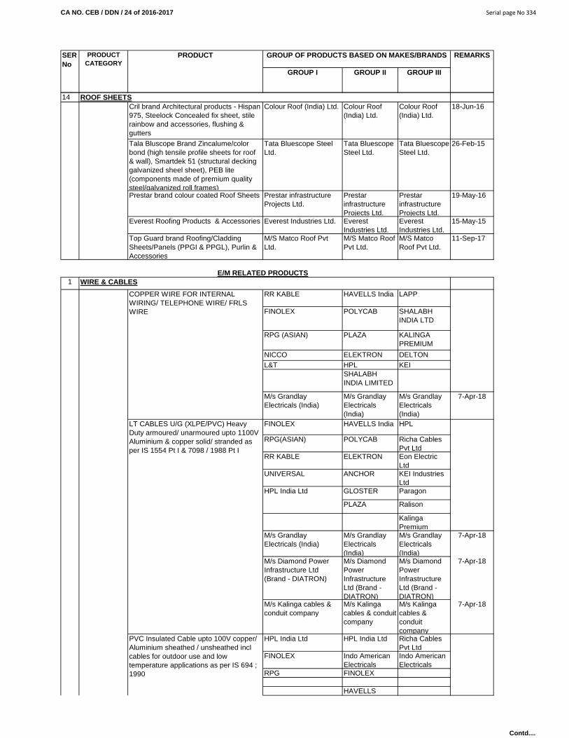
CA NO. CEB / DDN / 24 of 2016-2017 Serial page No 334
GROUP I GROUP II GROUP III
REMARKSSER No
PRODUCT CATEGORY
PRODUCT GROUP OF PRODUCTS BASED ON MAKES/BRANDS
14Cril brand Architectural products - Hispan 975, Steelock Concealed fix sheet, stile rainbow and accessories, flushing & gutters
Colour Roof (India) Ltd. Colour Roof (India) Ltd.
Colour Roof (India) Ltd.
18-Jun-16
Tala Bluscope Brand Zincalume/color bond (high tensile profile sheets for roof & wall), Smartdek 51 (structural decking galvanized sheel sheet), PEB lite (components made of premium quality steel/galvanized roll frames)
Tata Bluescope Steel Ltd.
Tata Bluescope Steel Ltd.
Tata Bluescope Steel Ltd.
26-Feb-15
Prestar brand colour coated Roof Sheets Prestar infrastructure Projects Ltd.
Prestar infrastructure Projects Ltd.
Prestar infrastructure Projects Ltd.
19-May-16
Everest Roofing Products & Accessories Everest Industries Ltd. Everest Industries Ltd.
Everest Industries Ltd.
15-May-15
Top Guard brand Roofing/Cladding Sheets/Panels (PPGI & PPGL), Purlin & Accessories
M/S Matco Roof Pvt Ltd.
M/S Matco Roof Pvt Ltd.
M/S Matco Roof Pvt Ltd.
11-Sep-17
1
RR KABLE HAVELLS India LAPP
FINOLEX POLYCAB SHALABH INDIA LTD
RPG (ASIAN) PLAZA KALINGA PREMIUM
NICCO ELEKTRON DELTONL&T HPL KEI
SHALABH INDIA LIMITED
M/s Grandlay Electricals (India)
M/s Grandlay Electricals (India)
M/s Grandlay Electricals (India)
7-Apr-18
FINOLEX HAVELLS India HPL
RPG(ASIAN) POLYCAB Richa Cables Pvt Ltd
RR KABLE ELEKTRON Eon Electric Ltd
UNIVERSAL ANCHOR KEI Industries Ltd
GLOSTER Paragon
PLAZA Ralison
Kalinga Premium
M/s Grandlay Electricals (India)
M/s Grandlay Electricals (India)
M/s Grandlay Electricals (India)
7-Apr-18
M/s Diamond Power Infrastructure Ltd (Brand - DIATRON)
M/s Diamond Power Infrastructure Ltd (Brand - DIATRON)
M/s Diamond Power Infrastructure Ltd (Brand - DIATRON)
7-Apr-18
M/s Kalinga cables & conduit company
M/s Kalinga cables & conduit company
M/s Kalinga cables & conduit company
7-Apr-18
HPL India Ltd HPL India Ltd Richa Cables Pvt Ltd
FINOLEX Indo American Electricals
Indo American Electricals
RPG FINOLEX
HAVELLS
E/M RELATED PRODUCTSWIRE & CABLES
HPL India Ltd
COPPER WIRE FOR INTERNAL WIRING/ TELEPHONE WIRE/ FRLS WIRE
LT CABLES U/G (XLPE/PVC) Heavy Duty armoured/ unarmoured upto 1100V Aluminium & copper solid/ stranded as per IS 1554 Pt I & 7098 / 1988 Pt I
PVC Insulated Cable upto 100V copper/ Aluminium sheathed / unsheathed incl cables for outdoor use and low temperature applications as per IS 694 ; 1990
ROOF SHEETS
Contd....

CA NO. CEB / DDN / 24 of 2016-2017 Serial page No 335
GROUP I GROUP II GROUP III
REMARKSSER No
PRODUCT CATEGORY
PRODUCT GROUP OF PRODUCTS BASED ON MAKES/BRANDS
M/s Grandlay Electricals (India)
M/s Grandlay Electricals (India)
M/s Grandlay Electricals (India)
7-Apr-18
M/s Kalinga cables & conduit company
M/s Kalinga cables & conduit company
M/s Kalinga cables & conduit company
7-Apr-18
UNIVERSAL HAVELLS KEIRPG (ASIAN) POLYCAB ICL
TORRENT GLOSTER PRIME KABLES
CCI LTD PLAZA ParamountFINOLEX KEI Ravin Cables
Crystal Cable Industries LtdRavin Cables Ltd
M/s Grandlay Electricals (India)
M/s Grandlay Electricals
M/s Grandlay Electricals
7-Apr-18
M/s Diamond Power Infrastructure Ltd
M/s Diamond Power Infra Ltd
M/s Diamond Power InfraLtd
7-Apr-18
FINOLEX PLAZA PLAZA
POLYCAB HAVELLS HAVELLSRR KABEL KALINGA KALINGA
M/s Diamond Power Infrastructure Ltd
M/s Diamond Power Infra Ltd
M/s Diamond Power InfraLtd
7-Apr-18
M/s Kalinga cables & conduit company
M/s Kalinga cables & conduit company
M/s Kalinga cables & conduit
7-Apr-18
Transmission & Distribution conductors upto 11 KV
M/s Diamond Power Infrastructure Ltd
M/s Diamond Power Infra Ltd
M/s Diamond Power InfraLtd
7-Apr-18
2
JINDAL KEJRIWAL KEJRIWALTATA JAISWAL
NECOJAISWAL NECO
KESORAM BENGAL IRON CORP.
BENGAL IRON CORP.
ELECTROSTEEL ELECTRO-STEEL
JINDAL JINDAL SWASTICELECTROSTEEL ELECTRO-
STEELJAI BALAJEE
LANCO LANCO Rashmi Metallic Ltd
M/s Electro Steel Casting Ltd
M/s Electro Steel Casting Ltd
M/s Electro Steel Casting Ltd
7-Apr-18
TATA BST
JINDAL TIRUPATI
SAIL
UPADHYAY KEJRIWAL BIR
LEADER KARTAR
KIRLOSKAR
ELECTROSTEEL TATAFINOLEX RELIANCE VECTUS
SUPREME INDUSTRIES
TIRUPATI NEELKAMAL
DURTON Kisan Mouldings Pvt Ltd
Kisan Mouldings Pvt Ltd
KAVERI Prince
MS PIPE / ERW PIPES
CI FITTINGS
BENGAL IRON CORPORATIO
N
HDPE PIPES/UPVC PIPES and fittings
SUBMERSIBLE COPPER FLAT CABLE
PIPES (CI, GI & DI PIPES)
CI PIPE
DI PIPE
HT XLPE CABLE upto 66 KV as per relevant IS
Aerial Bunch Cable (ABC) upto 11 KV
Contd....

CA NO. CEB / DDN / 24 of 2016-2017 Serial page No 336
GROUP I GROUP II GROUP III
REMARKSSER No
PRODUCT CATEGORY
PRODUCT GROUP OF PRODUCTS BASED ON MAKES/BRANDS
Rishi
JINDAL PRAKASH ADVANCEDTATA OSWAL NIDHIZENITH SWASTIK
FINOLEX
Supreme Industries
Supreme Industries Kisan Mouldings Pvt Ltd
Jain Irrigation System Ltd
- Kisan Mouldings Pvt Ltd
Kisan Mouldings Pvt Ltd
- Supreme Industries
Supreme Industries
3
JINDAL KALINGA VIKASHFINOLEX AKG PRECISIONMK INDIA BEC STEEL KRAFT
ASIAN BHARAT STEEL TUBENEW INDIA CONDUITS PVT LTD FARIDABAD
FINOLEX ICL ICL
Finolex
INDO AMERICAN ELECTRICALS
FINOLEX Supreme SUPREMEMODI PLAZA PLAZAJINDAL Prestoplast Prestoplast ASIAN AKG AKG
AVON PLAST AVON PLASTHARSH HARSH
4 LIGHTS
PHILIPS BAJAJ DECON
WIPRO CROMPTON KESELLGEHAVELLSC&S
PHILIPS BAJAJ DECON
WIPRO CROMPTON KESELLGE Surya Roshni
LtdHAVELLS Adhunik Switch
Gears Pvt Ltd
C&SPHILIPS SURYA
ROSHNI LTD SURYA ROSHNI LTD
WIPRO ADHUNIK ADHUNIKHAVELLS HALONIX HALONIXCROMPTONGEBAJAJC&SPHILIPS SURYA
ROSHNI LTD SURYA ROSHNI LTD
T-5 LAMP/CFL LAMP FITTINGS/HPSV/HPMV/High Mast LampsT-5 Fittings/ TUBE LIGHTS/ CFL FITTINGS & ENERGY EFFICIENT TUBES & LAMPS
SURYA ROSHNI LTD
STREET LIGHT FITTINGS
HPSV/HPMV FITTINGS & LAMPS
HIGH MAST Lights
CONDUITS
RIGID STEEL CONDUITS/ MS CONDUITS
FLEXIBLE (PVC) CONDUIT/SPIRAL CONDUIT
ESS ESS KAY ENGINEERING
Finolex
CASING & CAPING
GI PIPES
PVC Pipes and Fittings FINOLEX Kisan Mouldings Pvt Ltd
PPR Pipes and Fittings
Contd....
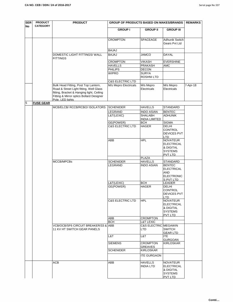
CA NO. CEB / DDN / 24 of 2016-2017 Serial page No 337
GROUP I GROUP II GROUP III
REMARKSSER No
PRODUCT CATEGORY
PRODUCT GROUP OF PRODUCTS BASED ON MAKES/BRANDS
CROMPTON SPACEAGE Adhunik Switch Gears Pvt Ltd
BAJAJ
BAJAJ JAMCO DAYAL
CROMPTON VIKASH EVERSHINEHAVELLS PRAKASH AMCPHILIPS DECONWIPRO SURYA
ROSHNI LTD
C&S ELECTRIC LTDBulk Head Fitting, Post Top Lantern, Road & Street Light fitting, Well Glass fitting, Bracket & Hanging light, Ceiling Fitting & Mirror optics Bollard Designer Pole, LED lights
M/s Mepro Electricals M/s Mepro Electricals
M/s Mepro Electricals
7-Apr-18
5
SCHENIDER HAVELLS STANDARD
LEGRAND INDO ASIAN BENTECL&T(LEXIC) SHALABH
INDIA LIMITEDADHUNIK
GE(POWER) BCH SIGMAC&S ELECTRIC LTD HAGER DELHI
CONTROL DEVICES PVT LTD
ABB HPL NOVATEUR ELECTRICAL & DIGITAL SYSTEMS PVT LTD
PLAZASCHENIDER HAVELLS STANDARDLEGRAND INDO ASIAN BENTEC
ELECTRICAL AND ELECTRONICS PVT LTD
L&T(LEXIC) BCH LEADERGE(POWER) HAGER DELHI
CONTROL DEVICES PVT LTD
C&S ELECTRIC LTD HPL NOVATEUR ELECTRICAL & DIGITAL SYSTEMS PVT LTD
ABB CROMPTONBCH L&T LEXICABB C&S ELECTRIC
LTDMEGAWIN SWITCH GEAR LTD
L&T L&T ITE GURGOAN
SIEMENS CROMPTON GREAVES
KIRLOSKAR
SCHENIDER KIRLOSKAR
ITE GURGAON
ABB HAVELLS INDIA LTD
NOVATEUR ELECTRICAL & DIGITAL SYSTEMS PVT LTD
ACB
FUSE GEARMCB/ELCB/ RCCB/RCBO/ ISOLATORS
MCCB/MPCBs
VCB/OCB/SF6 CIRCUIT BREAKER/33 & 11 KV HT SWITCH GEAR PANELS
DOMESTIC LIGHT FITTINGS/ WALL FITTINGS
Contd....

CA NO. CEB / DDN / 24 of 2016-2017 Serial page No 338
GROUP I GROUP II GROUP III
REMARKSSER No
PRODUCT CATEGORY
PRODUCT GROUP OF PRODUCTS BASED ON MAKES/BRANDS
L&T C&S ELECTRIC LTD
BENTEC ELECTRICAL AND ELECTRONICS PVT LTD
SEIMENS HPLSCHENIDER CROMPTON
GREAVES
GE POWER ITE GURGAON
PACTIL HARYANA ELECT INDUSTRIES
JAIPURIA RASHTRIYAMEIBHELSCHENIDER HAGAR ADHUNIK
ABB BCH ADHUNIK
L&T LEXIC HPL SIGMA
GE POWER VINTEC STANDARDLEGRAND PLAZA
INDO ASIAN SHALABH INDIA LTD
C&SHAVELLS INDIA
SCHENIDER CROMPTON GREAVES
MEGAWIN SWITCH GEAR LTD
ABB ITE GURGAON ITE GURGOAN
SEIMENS KIRLOSKAR KIRLOSKARL&T MEGAWIN
SWITCH GEAR LTD
SIEMENS ITE GURGAON
SCHENIDER KIRLOSKAR
ABB ITE GURGOAN
L&T KIRLOSKARHAVELLS INDIAL&T INDOASIAN STANDARD
C&S HAVELLS SHALABH PVT LTD
SCHNEIDER HPL NOVATEUR ELECTRICAL & DIGITAL SYSTEMS PVT LTD
ABB CROMPTON
SIEMENS SHALABH PVT LTD
6
ANCHOR SSK CLIPSALLEGRAND CONA NORTH WEST
CRABTREE (HAVELLS)
KAY KAY
MK (HONEY WELL) LEADER NOVATEUR ELECTRICAL & DIGITAL SYSTEMS PVT LTD
SWITCHES PLUG & SOCKETSMODULAR SWITCH/SOCKETS
GOD/DO SWITCH(AIR BREAK)
DISTRIBUTION BOARDS
NOVATEUR ELECTRICAL & DIGITAL SYSTEMS PVT LTD
HT RING MAIN UNITS SF6/VCB 11KV
HT LOAD BREAK SWITCH MEGAWIN SWITCH GEAR LTD
CROMPTON GREAVES
CHANGEOVER SWITCH/ STARTER/ HRC FUSES
Contd....

CA NO. CEB / DDN / 24 of 2016-2017 Serial page No 339
GROUP I GROUP II GROUP III
REMARKSSER No
PRODUCT CATEGORY
PRODUCT GROUP OF PRODUCTS BASED ON MAKES/BRANDS
INDO ASIAN(GLINT)
HAVELLS INDIA
ANCHOR KINJAL CONA
LEGRAND PLAZA PLAZA
HAVELLS INDIA SSK SSK
HPL CONA EON ELECTRIC LTD
C & S RR KABEL RR KABEL7
USHA PLAZA PENTA
CROMPTON LEADER MOSAIC
BAJAJ KHAITAN
HAVELLS ALMONARDANCHORANCHOR ESS ESS KAY ESS ESS KAYCRAB TREE PLAZA PLAZAANCHOR CONA CONA
LEGRAND PLAZA PLAZA
HAVELLS INDIA ANCHOR
WIPRO LEGRANDBAJAJ
8
LEGRAND HPLHAGER INDO ASIANABB BCHSCHENIDER HAVELLSL&T NOVATEUR
ELECTRIC & DIGITAL SYSTEMS PVT LTD
GEC&S ELECTRIC LTD
9
SIEMENS ITE GURGAON M/S MEGA ENERGY SOLUTIONS PUNE
SCHENIDER KIRLOSKAR ITE GURGOAN
ABB CROMPTON GREAVES
L&TABB MAHENDRA
ENGG LTDSCHNEIDER International
Transformer Ltd
CROMPTON GREAVES
INDOTECH
RAJASTHAN TRANSFORMERSITE GURGAONGE POWERINDOTECHABB KIRLOSKAR KIRLOSKAR
CROMPTON GREAVES
RAJASTHAN TRANSFORMERS
RAJASTHAN TRANSFOR-MERS
SIEMENS INDOTECH INDOTECHSCHENIDER
TIME SWITCHESTIME SWITCHES
SUB STATION TRANSFORMER, POWER TRANSFORMERS
COMPACT SUBSTATION/ UNITISED SUB STN
TRANSFORMERS UPTO 500KVA
TRANSFORMERS ABOVE 500KVA
ELECTRIC SWITCH/SOCKETS/ PUSH BELL
FAN REGULATORS, LAMP HOLDERS, CEILING ROSE, ELECTRIC CALL BELLSFAN REGULATORS(ELECTRONIC)
LAMP HOLDERS/CEILING ROSE
ELECTRIC CALL BELLS
Contd....

CA NO. CEB / DDN / 24 of 2016-2017 Serial page No 340
GROUP I GROUP II GROUP III
REMARKSSER No
PRODUCT CATEGORY
PRODUCT GROUP OF PRODUCTS BASED ON MAKES/BRANDS
ITE GURGAON
GE POWER
ABB KIRLOSKAR KIRLOSKARCROMPTON GREAVES
RAJASTHAN TRANSFORMERS
RAJASTHAN TRANSFOR-MERS
SIEMENS INDOTECH INDOTECHSCHENIDERITE GURGAON
GE POWERVOLTAM LTD
Transformers (Power & Distribution) Star Rated upto 50MVA, 66 KVA
M/s Diamond Power Infrastructure Ltd
M/s Diamond Power Infra Ltd
M/s Diamond Power Infra Ltd
7-Apr-18
10
V-GUARD BLUE BIRD BLUE BIRD
AE M/S SAI ELECTRICALS
M/S SAI ELECTRICALS
APLAB ITE GURGAON ITE GURGAON
SINETRAC PREMIERMICROTECH SARZENITH VOLINAITE GURGAONAPLAB VOLINA
(VINITEK ELECTRONIC)
BLUE BIRD
SINETRAC M/S SAI ELECTRICALS
M/S SAI ELECTRICAL
BRENTFORD ITE GURGAON ITE GURGAON
AE POWERWARE
KIRLOSKAR ElectrotecknicBRENTFORD KIRLOSKARANDREW YULE BRENTFORDAEKAPPA CROMPTON
GREAVESCROMPTON GREAVES
AE C&S C&SSIEMENS PRAYAG PRAYAGPACTILPRAGATIABBSCHENIDERABB CROMPTON
GREAVESMINIMEX
SCHNEIDER HAVELLS M/S SAI ELECTRICALS
L&T C&S UNISTARSIEMENS BCH APCOSL&T HPL ALTOS
LEGRAND KAYCEE GEPC
SIEMENS BGH
C&S
ABB
AE HAVELLS
L&T CROMPTON GREAVES
PUSH BUTTON/ SELECTOR SWITCH/INDICATING LAMP
MEASURING INSTRUMENTS/ RELAYS/ AMMETERS/ VOLTMETERS/ POWER FACTOR METERS & FREQUENCY METER
FAN REGULATORS, LAMP HOLDERS, CEILING ROSE, ELECTRIC CALL BELLS
VOLTAGE STABLIZER UPTO 5 KVA
SERVO VOLTAGE STABLIZERS, CTs & PTs, Sub stn Eqpt
HT VOLTAGE STABLIZER
CURRENT & POTENTIAL TRANSFORMERS (LT)
CAPACITOR BANKS HT & LT
TRANSFORMER 33 KV STEP DOWN/ TRANSFORMER 33/0.433 KV STEP DOWN
Contd....

CA NO. CEB / DDN / 24 of 2016-2017 Serial page No 341
GROUP I GROUP II GROUP III
REMARKSSER No
PRODUCT CATEGORY
PRODUCT GROUP OF PRODUCTS BASED ON MAKES/BRANDS
SCHNEIDER JYOTI
ABB BHARAT BIJLEE
L&T ANCHOR
HAVELLS DATAPRO
HPL BHARAT BIJLEE
INDO ASIAN BENTEC ELECTRICAL & ELECTRONICS PVT LTD
SECURE
LEGRANDL&T UNILAC ASIANSCHNEIDER TRICOLITE POWER CARE
JABALPUR
ABB ADLECSIEMENS ITE GURGAON
LEGRAND HPLHAVELLS SHALABH
INDIA LTDC&S UNIVERSAL
SWITCHGEAR CONTROL
L&T
11
BAJAJ BAJAJ VENUSUSHA LEXUS USHA LEXUS CROMPTONRACOLD RACOLD EON
ELECTRIC LTD
HAVELLS HAVELLS ORISONJAGUAR & CO PVT LTD
EON ELECTRIC LTD
12
USHA USHA POLAR
CROMPTON CROMPTON MIEBAJAJ BAJAJALMONARD ALMONARDHAVELLS HAVELLSKHAITAN KHAITANORIENT ORIENTKHAITAN KHAITAN POLAR
HAVELLS HAVELLS ORIENT
CROMPTON CROMPTON
USHA USHABAJAJ BAJAJ
ORIENT
POLAR
BAJAJ BAJAJ CROMPTONALMONARD ALMONARD BHARAT
BIJLEEHAVELLS HAVELLSKHAITAN KHAITANUSHA USHA
AIR CIRCULATOR /TURBO VENTILATOR /WALL MOUNTED FAN
WATER HEATERSGEYSERS KITCHEN/ BATHROOMS
FANSCEILING, EXHAUST,CABIN FANS
EXHAUST FANS PVC BODY
ENERGY METERS (KWH) TAMPER PROOF DIGITAL/ ANALOG METERS
DELHI CONTROL DEVICES PVT
SWITCH FUSE/ MAIN SWITCH/ FEEDER PILLAR BOX AND LT DISTR PANELS/ POWER FACTOR COMPENSATOR, HARMONIC FILTER/ AUTOMATIC POWER FACTOR CONTROLLER (APFC)
Contd....
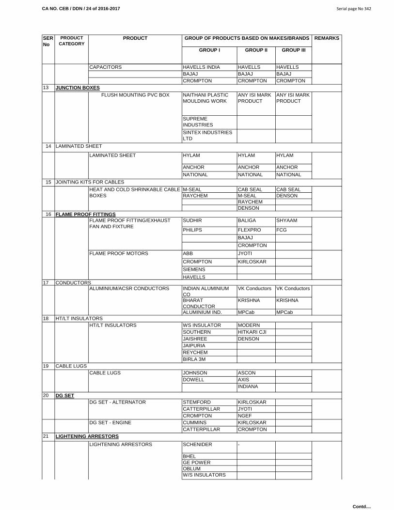
CA NO. CEB / DDN / 24 of 2016-2017 Serial page No 342
GROUP I GROUP II GROUP III
REMARKSSER No
PRODUCT CATEGORY
PRODUCT GROUP OF PRODUCTS BASED ON MAKES/BRANDS
CAPACITORS HAVELLS INDIA HAVELLS INDIA
HAVELLS INDIABAJAJ BAJAJ BAJAJ
CROMPTON CROMPTON CROMPTON13
NAITHANI PLASTIC MOULDING WORK
ANY ISI MARK PRODUCT
ANY ISI MARK PRODUCT
SUPREME INDUSTRIES
SINTEX INDUSTRIES LTD
14
HYLAM HYLAM HYLAM
ANCHOR ANCHOR ANCHOR
NATIONAL NATIONAL NATIONAL
15
M-SEAL CAB SEAL CAB SEALRAYCHEM M-SEAL DENSON
RAYCHEMDENSON
16SUDHIR BALIGA SHYAAM
PHILIPS FLEXPRO FCG
BAJAJ
CROMPTON
ABB JYOTI
CROMPTON KIRLOSKAR
SIEMENS
HAVELLS17
INDIAN ALUMINIUM CO
VK Conductors VK Conductors
BHARAT CONDUCTOR
KRISHNA KRISHNA
ALUMINIUM IND. MPCab MPCab18
WS INSULATOR MODERN INSULATORSOUTHERN
INSULATORSHITKARI CJI
JAISHREE DENSONJAIPURIAREYCHEMBIRLA 3M
19JOHNSON ASCONDOWELL AXIS
INDIANA
20STEMFORD KIRLOSKARCATTERPILLAR JYOTICROMPTON GREAVES
NGEFCUMMINS KIRLOSKARCATTERPILLAR CROMPTON
GREAVES21
SCHENIDER -
BHELGE POWEROBLUMW/S INSULATORS
LIGHTENING ARRESTORS
LIGHTENING ARRESTORS
DG SETDG SET - ALTERNATOR
DG SET - ENGINE
HT/LT INSULATORSHT/LT INSULATORS
CABLE LUGSCABLE LUGS
FLAME PROOF FITTINGSFLAME PROOF FITTING/EXHAUST FAN AND FIXTURE
FLAME PROOF MOTORS
CONDUCTORSALUMINIUM/ACSR CONDUCTORS
LAMINATED SHEET
LAMINATED SHEET
JOINTING KITS FOR CABLES
HEAT AND COLD SHRINKABLE CABLE BOXES
JUNCTION BOXESFLUSH MOUNTING PVC BOX
Contd....
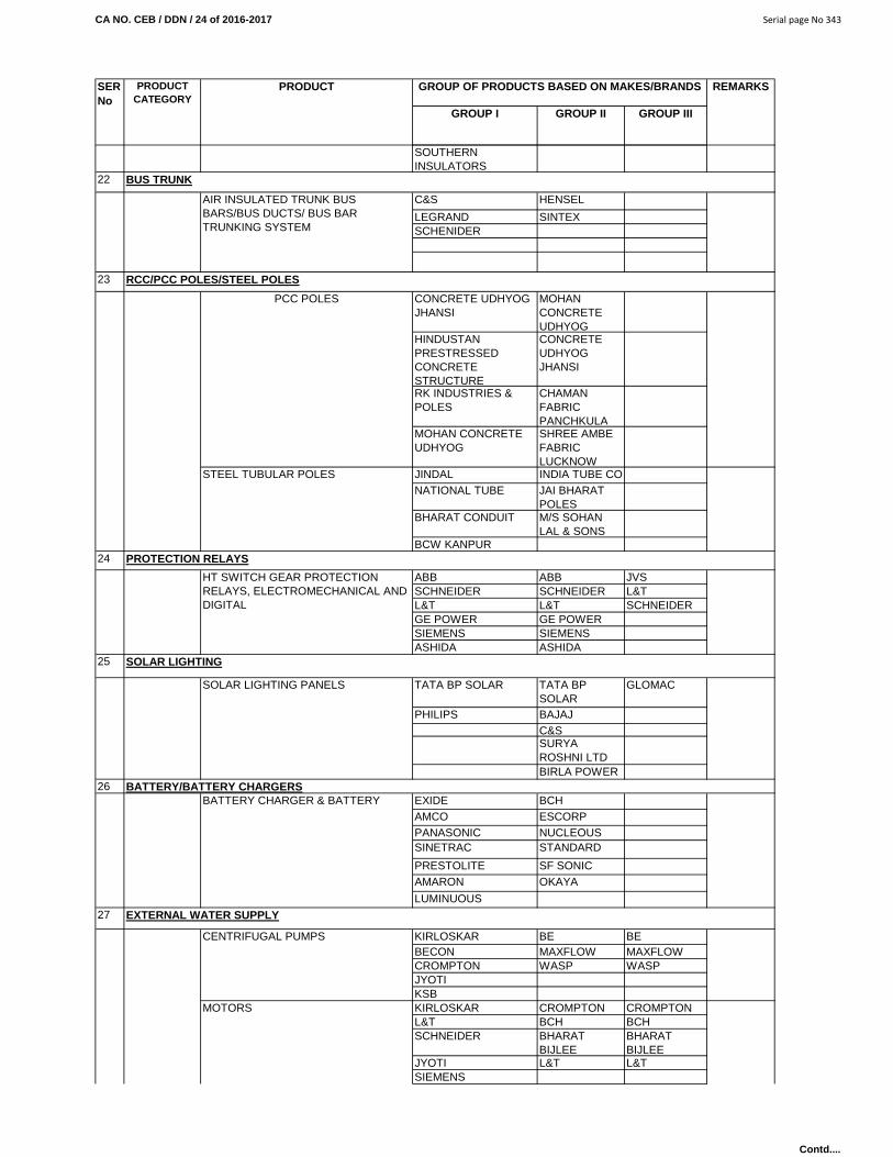
CA NO. CEB / DDN / 24 of 2016-2017 Serial page No 343
GROUP I GROUP II GROUP III
REMARKSSER No
PRODUCT CATEGORY
PRODUCT GROUP OF PRODUCTS BASED ON MAKES/BRANDS
SOUTHERN INSULATORS
22
C&S HENSEL
LEGRAND SINTEXSCHENIDER
23
CONCRETE UDHYOG JHANSI
MOHAN CONCRETE UDHYOG
HINDUSTAN PRESTRESSED CONCRETE STRUCTURE
CONCRETE UDHYOG JHANSI
RK INDUSTRIES & POLES
CHAMAN FABRIC PANCHKULA
MOHAN CONCRETE UDHYOG
SHREE AMBE FABRIC LUCKNOW
JINDAL INDIA TUBE CONATIONAL TUBE JAI BHARAT
POLESBHARAT CONDUIT M/S SOHAN
LAL & SONSBCW KANPUR
24
ABB ABB JVSSCHNEIDER SCHNEIDER L&TL&T L&T SCHNEIDERGE POWER GE POWERSIEMENS SIEMENSASHIDA ASHIDA
25
TATA BP SOLAR TATA BP SOLAR
GLOMAC
PHILIPS BAJAJC&SSURYA ROSHNI LTD BIRLA POWER
26EXIDE BCHAMCO ESCORPPANASONIC NUCLEOUSSINETRAC STANDARD
PRESTOLITE SF SONICAMARON OKAYA
LUMINUOUS27
KIRLOSKAR BE BEBECON MAXFLOW MAXFLOWCROMPTON WASP WASPJYOTIKSBKIRLOSKAR CROMPTON CROMPTON L&T BCH BCHSCHNEIDER BHARAT
BIJLEEBHARAT BIJLEE
JYOTI L&T L&TSIEMENS
EXTERNAL WATER SUPPLY
CENTRIFUGAL PUMPS
MOTORS
SOLAR LIGHTING
SOLAR LIGHTING PANELS
BATTERY/BATTERY CHARGERSBATTERY CHARGER & BATTERY
RCC/PCC POLES/STEEL POLES
PCC POLES
STEEL TUBULAR POLES
PROTECTION RELAYS
HT SWITCH GEAR PROTECTION RELAYS, ELECTROMECHANICAL AND DIGITAL
BUS TRUNK
AIR INSULATED TRUNK BUS BARS/BUS DUCTS/ BUS BAR TRUNKING SYSTEM
Contd....

CA NO. CEB / DDN / 24 of 2016-2017 Serial page No 344
GROUP I GROUP II GROUP III
REMARKSSER No
PRODUCT CATEGORY
PRODUCT GROUP OF PRODUCTS BASED ON MAKES/BRANDS
NGFABBKSB
KIRLOSKAR WORTHING-TON
JYOTI CROMPTONJOHNSONKSBKIRLOSKAR CALAMA
JYOTI SHAKTI
KSB V-GUARDTULLU GRANDFOS
CRIZOLOTO VENUS KARTARLEADER KEJRIWAL BIRAUDCO KARTARKIRLOSKAR BIRIVCUPADHYAYL&T
L&T L&T BENTEC
ABB BENTEC SINETRAC
C&S SINETRAC STANDARD
HAVELLS STANDARD HPL
BCH HPL
INDO ASIAN MINILEC
CROMPTON SECO
SCHNEIDER GIC
SINETRAC PUMPUTER PUMPUTERAKASH AKASH AKASHPHOTOTRON SURYA SURYASURYA PHOTOTRON PHOTOTRONSECODASHMESH DASHMESHKIRLOSKAR KIRLOSKAR
28
KIRLOSKAR KIRLOSKARBLUE STAR BLUE STARVOLTAS VOLTASCARRIER CARRIERCARRIER CARRIERYORK DENUMBUSHTRANEKIRLOSKAR CROMPTON CROMPTON
L&T BCH BCHSCHNEIDER Bharat Bijlee Bharat Bijlee
JYOTI L&T L&TSIEMENSNGFABBKSB
L&T L&T BENTECABB BENTEC SINETRAC
C&S SINETRAC STANDARD
AIR CONDITIONING
COMPRESSOR RECIPROCATING
COMPRESSOR SCREW TYPE
ELECTRIC MOTOR
MOTOR STARTER
TURBINE PUMP/VERTICAL TURBINE PUMP
SUBMERSIBLE PUMP /HORIZONTAL PUMP
GM GATE VALVES /STOP VALVES/CI SLUICE VALVES/REFLUX VALVES/FOOT VALVES/AIR RELEASE/FOOT VALVE
MOTOR STARTER/SINGLE PHASE PREVENTOR/PHASE SEQUENCE CORRECTOR(AUTO)/ FASD STARTER/DOL STARTER/AUTO MOTOR CONTROL TIMER PANELELECTRONIC DIGITAL MOTOR PROTECTION RELAYS
WATER LEVEL INDICATOR DIGITAL
WATER METERS
Contd....
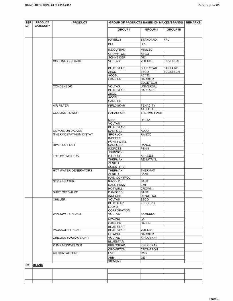
CA NO. CEB / DDN / 24 of 2016-2017 Serial page No 345
GROUP I GROUP II GROUP III
REMARKSSER No
PRODUCT CATEGORY
PRODUCT GROUP OF PRODUCTS BASED ON MAKES/BRANDS
HAVELLS STANDARD HPL
BCH HPL
INDO ASIAN MINILECCROMPTON SECOSCHNEIDER GICVOLTAS VOLTAS UNIVERSAL
BLUE STAR BLUE STAR PARKAIREZECO ZECO EDGETECHACCEL ACCELCARRIER CARRIER
EDGETECHVOLTAS UNIVERSALBLUE STAR PARKAIREZECOACCELCARRIER
KIRLOSKAR TENACITYATHLETE
PAHARPUR THERMO PACK
MIHIR DELTAVOLTASBLUE STARDANFOSS ALCOSPORLON RANCOINDFOSSHONEYWELLDANFOSS RANCOINDFOSS PENNJOHNSONH-GURU AIRCOOLTHERMAX RENUTROLZENITHSCIENTIFICTHERMAX THERMAXZENITH SANTRAID CONTROLRACOLD SANTDASS PASS EMIHOTWELL CROWNDANFODD SANTINDFOSS RENUTROLVOLTAS ZECOBLUESTAR FEDDERSLLOYD CORPORATIONVOLTAS SAMSUNG
HITACHI LGCARRIER DAIKINBLUE STARBLUE STAR VOLTASHITACHI CARRIERVOLTAS KIRLOSKARBLUESTARKIRLOSKAR KIRLOSKARCROMPTON CROMPTONL&T C&S
ABB GESIEMENS
29 BLANK
HOT WATER GENERATORS
STRIP HEATER
SHUT OFF VALVE
CHILLER
WINDOW TYPE ACs
PACKAGE TYPE AC
CHILLING PACKAGE UNIT
PUMP MONO-BLOCK
AC CONTACTORS
COOLING COIL/AHU
CONDENSOR
AIR FILTER
COOLING TOWER
EXPANSION VALVES/THERMOSTAT/HUMIDISTAT
HP/LP CUT OUT
THERMO METERS
Contd....

CA NO. CEB / DDN / 24 of 2016-2017 Serial page No 346
GROUP I GROUP II GROUP III
REMARKSSER No
PRODUCT CATEGORY
PRODUCT GROUP OF PRODUCTS BASED ON MAKES/BRANDS
30
JAIPURIA JYOTI
JYOTI INSUILATICA
31
SIEMENS SIEMENSHONEYWELL HONEYWELLKIRLOSKAR CRI
KSB GRUNDFOSS32
TATA JINDALSAIL TATA
SAILROCKWELL HOISTO Cranes Pvt Ltd
POINEER CRANES
HERCULES HOISTO TURBO FERGUSAN (INDIA) PVT LTD
ALMONARD ALMONARDCROMPTON CROMPTONPHEONIX PRAGATI
ELECTROCOMVOLTAS SM Innotech-
Earth PlusDhruva Tech PVT LTD -PROTECH
VOLTAS VOLTASBLUE STAR BLUE STARUSHA SRIRAM USHA SRIRAM
PHILLIPS BAJAJWIPRO WIPRO
GECSIEMENS MICROTECH APLABV GUARD SU-KAM MICROTECH
DAMPER CARRIER ATECARRIER ATE
MHPMARPO
GPRS/GSM BASED SCADA WIRELESS SECO SURYA ELECTRONIC CONTROLS JODHPUR
PHILLIPS BAJAJ
CROMPTON GREAVES
PHILLIPS
BLUE STAR BLUE STAR
INGEROLL RAND INGEROLL RAND
OTIS MITSUBISHIKONE INDIA KONE INDIAJOHNSON JOHNSONSIEMENS MITSUBISHI
ABB TOSHIBA
DIFFUSERS/ GRILLER
FIRE FIGHTING SYSTEMS
UNDER WATER LIGHTS
STATIC FREQUENCY CONVERTORS
INVERTERS-BLANK
AIR COMPRESSORS
ELECTRIC LIFTS
FIRE DETECTORS
FIRE PUMP/ JOCKEY PUMP
MISCELLANEOUS ITEMS
GI SHEETCLASS 8
EOT CRANE
AIR CURTAINS
ADVANCE LIGHTING PROTECTION UNIT
WATER COOLERS
AVIATION OBSTRUCTION LIGHTS
UPS
SHOCK PROOF INSULATION
ELECTRICAL INSULATION RUBBER MATs
Contd....

CA NO. CEB / DDN / 24 of 2016-2017 Serial page No 347
GROUP I GROUP II GROUP III
REMARKSSER No
PRODUCT CATEGORY
PRODUCT GROUP OF PRODUCTS BASED ON MAKES/BRANDS
APOLLO SAFEWAY
DG CONSURAKSHANAVEEN
ISOLATION TRANSFORMER VOLINA VOLINANON GAS BASED CHLORINATION SYTEM/DOSING SYSTEM WITH DOSING PUMP
DECLIBAC POTER & WATT CORP BRIOZING UNLIMITED
DECLIBAC POTER & WATT CORP BRIOZING UNLIMITED
DECLIBAC DECLIBAC
POTER & WATT CORP
POTER & WATT CORP
BRIOZING UNLIMITED BRIOZING UNLIMITED
CAPITAL CONTROL CAPITAL CONTROL
JESCO JESCOPATTERSON PATTERSON
SEWER MANHOLE CI COVER BENGAL IRON CORP.
33MEGA ENERGY SAVER FOR WINDOW, SPLIT AND PACKAGE AC, MEGA ENERGIX-P/G ENERGY SAVER FOR PUMPS AND FAN MOTORS. MEGA SLC ENERGY SAVING STREET LIGHT CONTROL SYSTEM AND MEGA ENERGY SAVER SYSTEM FOR CENTRAL AIR CONDITIONING
M/S MEGA ENERGY SOLUTIONS PUNE
NATURE SWITCH FOR AUTOMATION OF STREET LIGHTING CIRCUITS
KAKATIYA ENERGY SYSTEMS PVT LTD
1 LED LIGHTS
Havells 11-Sep-16M/s Insta Power Ltd 1-Sep-17Phillips Phillips Phillips
Electron* * Experi-mental basis
M/S Surya Roshni Ltd. M/S Surya Roshni Ltd.
28-Aug-17
M/s Kalinga cables & conduit company
M/s Kalinga cables & conduit company
M/s Kalinga cables & conduit company
7-Apr-18
M/s DIFIFLIC Enerpax Global Pvt Ltd
M/s DIFIFLIC Enerpax Global Pvt Ltd
M/s DIFIFLIC Enerpax Global Pvt Ltd
7-Apr-18
*M/s Mega Energy Solutions
* Experi-mental basis
M/s Kalinga cables & conduit company
M/s Kalinga cables & conduit company
M/s Kalinga cables & conduit company
7-Apr-18
M/s DIFIFLIC Enerpax Global Pvt Ltd
M/s DIFIFLIC Enerpax Global Pvt Ltd
M/s DIFIFLIC Enerpax Global Pvt Ltd
7-Apr-18
M/s VIN Semi-conductors PvtLtd
M/s VIN Semi-conductors PvtLtd
M/s VIN Semi-conductors PvtLtd
7-Apr-18
M/s DIFIFLIC Enerpax Global Pvt Ltd
M/s DIFIFLIC Enerpax Global Pvt Ltd
M/s DIFIFLIC Enerpax Global Pvt Ltd
7-Apr-18
ENERGY SAVER
Havells Havells
MANUAL CALL POINT
CHEMICAL FOR CHLORINATION
CHLORONOME PLANT
LED Energy efficient lighting systems and Luminaries for domestic/ commercial/ industrial/street lighting
Mega LED Lighting for indoor and outdoor Use.Mega Solar LED Lighting
LED decorative indoor lighting and LED outdoor lighting
Contd....

CA NO. CEB / DDN / 24 of 2016-2017 Serial page No 348
GROUP I GROUP II GROUP III
REMARKSSER No
PRODUCT CATEGORY
PRODUCT GROUP OF PRODUCTS BASED ON MAKES/BRANDS
2Thermax Limited Thermax
Limited21-Mar-20
Ion Exchange (India) Ltd
Ion Exchange (India) Ltd
19/12/2017
Fontus Water Ltd
8-May-17
Hydrotech Paryavaran (India) Pvt Ltd
30-Jan-15
Nitasha Constructions
5-Dec-14
Sophisticated Industrial Materials Analytic Lab Pvt Ltd (SIMA)
15-May-16
M/s Optimus Enviropro Pvt Ltd
M/s Optimus Enviropro Pvt Ltd
M/s Optimus Enviropro Pvt Ltd
3-Jul-18
Thermax Limited. Thermax Limited.
Thermax Limited.
21-Mar-20
Nitasha Constructions Nitasha Constructions
Nitasha Constructions
5-Dec-14
Sophisticated Industrial Materials Analytic Lab Pvt Ltd (SIMA)
Sophisticated Industrial Materials Analytic Lab Pvt Ltd (SIMA)
Sophisticated Industrial Materials Analytic Lab Pvt Ltd (SIMA)
17-Feb-16
Fontus Water Ltd.
Fontus Water Ltd.
8-May-17
Thermax Limited. Thermax Limited.
Thermax Limited.
21-Mar-20
Nitasha Constructions Nitasha Constructions
Nitasha Constructions
5-Dec-14
Sophisticated Industrial Materials Analytic Lab Pvt Ltd (SIMA)
Sophisticated Industrial Materials Analytic Lab Pvt Ltd (SIMA)
Sophisticated Industrial Materials Analytic Lab Pvt Ltd (SIMA)
17-Feb-16
Hydrotech Paryavaran (india) Pvt Ltd.
30-Jan-15
M/s Optimus Enviropro Pvt Ltd
M/s Optimus Enviropro Pvt Ltd
M/s Optimus Enviropro Pvt Ltd
3-Jul-18
Nitasha Constructions Nitasha Constructions
Nitasha Constructions
5-Dec-14
Sophisticated Industrial Materials Analytic Lab Pvt Ltd (SIMA)
Sophisticated Industrial Materials Analytic Lab Pvt Ltd (SIMA)
Sophisticated Industrial Materials Analytic Lab Pvt Ltd (SIMA)
17-Feb-16
Hydrotech Paryavaran (india) Pvt Ltd.
Hydrotech Paryavaran (india) Pvt Ltd.
Hydrotech Paryavaran (india) Pvt Ltd.
30-Jan-15
Package type treatment plant for water & waste water
Sophisticated Industrial Materials Analytic Lab Pvt Ltd (SIMA)
Sophisticated Industrial Materials Analytic Lab Pvt Ltd (SIMA)
Sophisticated Industrial Materials Analytic Lab Pvt Ltd (SIMA)
17-Feb-16
FBBR, FAB, FMR, SAFF
ASP Technology
SEWAGE TREATMENT PLANT S
MBR
MBBR
SBR
Contd....

CA NO. CEB / DDN / 24 of 2016-2017 Serial page No 349
GROUP I GROUP II GROUP III
REMARKSSER No
PRODUCT CATEGORY
PRODUCT GROUP OF PRODUCTS BASED ON MAKES/BRANDS
PSTP-Package Sewage treatment plant, PWTS- AM Advance Septic Tank and PWTS- STBF Sewage Treatment Plant
M/S Sintex Industries Limited (Plastic Division)
M/S Sintex Industries Limited (Plastic Division)
M/S Sintex Industries Limited (Plastic Division)
Till 19 Nov 17
Testing Lab for water & waste water, chemical, building material and other products as per NABL approval
Sophisticated Industrial Materials Analytic Lab Pvt Ltd (SIMA)
Sophisticated Industrial Materials Analytic Lab Pvt Ltd (SIMA)
Sophisticated Industrial Materials Analytic Lab Pvt Ltd (SIMA)
18-Feb-16
3
Mark Baxer brand water disinfectant granules/tablets - Sodium Dichloro isocyanurate (Na DCC)
25-Aug-16
Aquafit brand Calcium Hypo Chlorite 65% to 70% Chlorine content in granular and tablet form
29/10/2017
(a) Poly Aluminium Chloride - Liquid, Brand Name : "VIKRAM PAC-AC 100S", Grade : High Basicity.
22/04/2017
(b) Poly Aluminium Chloride - Liquid, Brand Name : "VIKRAM PAC-AryaPAC", Grade : High Basicity.
22/04/2017
(c) Poly Aluminium Chloride - Liquid, Brand Name : "VIKRAM PAC-AC 100S", Grade : Medium Basicity.
22/04/2017
M/s Sree Rayalaseema Hi - Strength Hypo Ltd.
M/s Grasim Industries Ltd (Chemical Division)
M/s Grasim Industries Ltd (Chemical Division)
M/s Grasim Industries Ltd (Chemical Division)
WATER TREATMENT
BM Aqua Tech Pvt Ltd.
Contd....

CA NO. CEB / DDN / 24 of 2016-2017 Serial page No 350
GROUP I GROUP II GROUP III
REMARKSSER No
PRODUCT CATEGORY
PRODUCT GROUP OF PRODUCTS BASED ON MAKES/BRANDS
Dosatron Brand Non Electricity Based Water Powdered Dosing Pump for disinfection of drinking water manufactured by M/s Dosatron International, France
22/12/2017
Water treatment equipments(a) Gaseous Chlorinator(b) Chemical Dosing System(c) Emergency Safety Kit.(d) Silver Ionisation plant / Dual Ionisation plant.(e) Bleaching Dozer.(f) Water filtration plant(g) Chloroscope kit.
29/11/2017
Water treatment equipments(a) Electrochlorinator Model-PBP5(b) Electrochlorinator Model-PBP25(c) Electrochlorinator Model-PBP50.(d) Electrochlorinator Model-PBP100(e) Electrochlorinator Model-PBP200(f) Electrochlorinator Model-PBP400(g) Electrochlorinator Model-PCP25.
26/01/2018
(h) Electrochlorinator Model-PCP50(j) Electrochlorinator Model-PCP100(k) Electrochlorinator Model-PCP200(l) Electrochlorinator Model-PCP500(m)Electrochlorinator Model-PCP1000(n) Sunchlor 5 (o) Sunchlor 25(p) Sunchlor 50 (q) Sunchlor 100
26/01/2019
8-May-1721-Mar-2017-Feb-16
(i) Reverse Osmosis Plant from 1000 LPH to 100 cum/hr.(ii) Ultra filtration sys from 8000 LPH to 200 Cum/hr.(iii) Iron Removal filter from 1000LPH to 75000 LPH.(iv) Water softener from 1000LPH to 75000 LPH.(v) Water Filters (MGF / DMF / ACF). (vi) Packaged water treatment plant with static mixer & flocculation plant (SMFT) for mixing of coagulants / flocculants and for flocculation procured Lamella clarifier for settling of flocs/ suspended particles & self-cleaning filters for removal of suspended impurities up to 100 microns.
3-Jul-18
M/s Bharti Waters Pvt Ltd
RO Plants, Filters & Softners Fontus Water Ltd.Thermax Limited.Sophisticated Industrial Materials Analytic Lab Pvt Ltd (SIMA)
M/s Pristine Water
M/s Optimus Enviropro Pvt Ltd
M/s Satyha Sai Aqua Pura Services
M/s Pristine Water
Contd....

CA NO. CEB / DDN / 24 of 2016-2017 Serial page No 351
GROUP I GROUP II GROUP III
REMARKSSER No
PRODUCT CATEGORY
PRODUCT GROUP OF PRODUCTS BASED ON MAKES/BRANDS
4PLC wireless gateways, wireless communication and misc, itemsPLC/IRTU Model (10000, 300, 6000, 9000), ISLC 3000, Wireless Gateway Unit, Aqua Scanet, Power Scanet, Lighting gale FEP (Front End Processor), IPMU 4000 Energy Meter, ICOM 6000 wireless communication modem
7-Sep-17
(Signature of Contractor) Astt Dir/Dy Dir (Contracts)Dated…………………………. For Accepting Officer
M/s CIMCON Software (India) Pvt Ltd.MISC
NOTES :- Group of every building shall be mentioned in schedule 'A' notes/BOQ. Make of product as mentioned groupwisein aforesaid list shall be incorporated in the work. If make of any product is not available in concern group but the same
of the superiority shall be from Group-III to Group-I. Further if no make is available in most superior group and the same isis available in other superior groups, the same shall be incorporated in the work without any extra cost to the Govt. Order
required to incorporate in the work from the makes of other groups, in such cases make of product to be approved by the Accepting Officer before incorporation in the work.
Contd....

CA NO. CEB / DDN / 24 OF 2016-2017 SERIAL PAGE NO. 352
PARTICULAR SPECIFICATIONS (CONTD……)
APPENDIX ‘C’ SOURCES OF MATERIALS
S. NO. NAME OF MATERIALS SOURCE OF MATERIALS FOR WORKS AT
STATION
1. Bricks and brick tiles Muzzafar Nagar, Roorkee, Najibabad, Meerut , Shamli
2. Coarse aggregate for all works Crushed aggregate of Rishikesh, Hardawar, Rispana, Tones, Song, Rajpur, Raipur (Dehradun).
3. Fine aggregate for all works
Crushed aggregate of Rishikesh, Hardawar, Rispana, Tones, Song, Rajpur, Raipur (Dehradun).
4. Sand for plastering, pointing, brick masonry, stone masonry, sand for cushioning, filling and covering for LT cables
Rishikesh, Hardawar, Rispana, Tones, Song, Rajpur, Raipur (Dehradun), Yamuna.
5. Broken / crushed stones for Hardcore / Sub base / Soling / WBM / Stone screening / chippings, for premixed carpeting / semi dense asphaltic concrete, bituminous macadam
Crushed aggregate of Rishikesh, Hardawar, Rispana, Tones, Song, Rajpur, Raipur (Dehradun).
------------------------------------------------------------------------------------------------------------------------------- NOTES: - 1. Sources indicated are for guidance only. The tenderer shall ascertain the actual position / exact location of source before submitting his tender and no additional payment shall be made on account of misunderstanding or its distance from site of works. 2. The tenderer shall amongst other things also ascertain all information such as royalties, taxes, duties and other charges etc. on the materials and no additional payment shall be made on account of the foregoing. 3. However, if due to any ban imposed by the Sate Government/any other authority on obtaining the materials from the sources specified hereinabove and /or specified materials is not available at the source mentioned above, these materials conforming to specifications as given in particular specifications will be obtained by the contractor from any other place / source without any extra cost to the Government. …………………………………… (Signature of Contractor) Astt Dir/Dy Dir (Contracts) Dated…………………………. For Accepting Officer
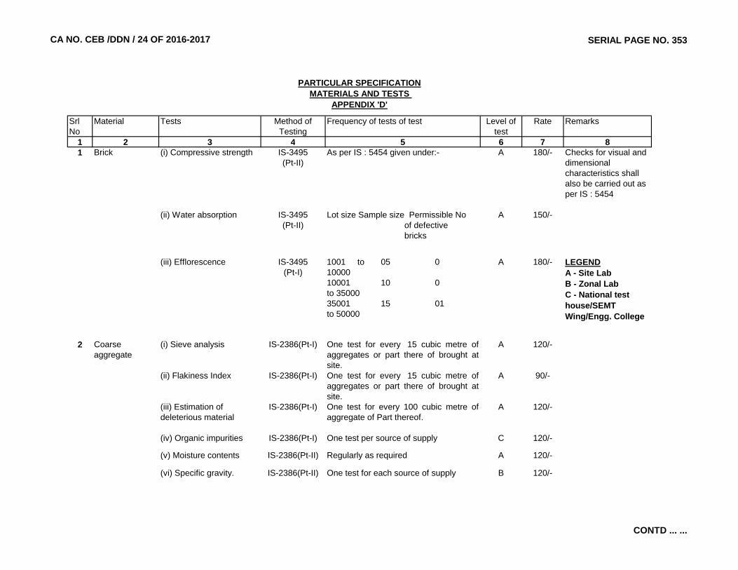
CA NO. CEB /DDN / 24 OF 2016-2017 SERIAL PAGE NO. 353
Srl No
Material Tests Method of Testing
Frequency of tests of test Level of test
Rate Remarks
1 2 3 4 5 6 7 81 Brick (i) Compressive strength IS-3495
(Pt-II)As per IS : 5454 given under:- A 180/- Checks for visual and
dimensional characteristics shall also be carried out as per IS : 5454
(ii) Water absorption IS-3495(Pt-II)
Lot size Sample size Permissible No of defective bricks
A 150/-
(iii) Efflorescence IS-3495(Pt-I)
1001 to 05 01000010001 10 0to 3500035001 15 01to 50000
A 180/- LEGENDA - Site LabB - Zonal LabC - National test house/SEMT Wing/Engg. College
2 Coarse aggregate
(i) Sieve analysis IS-2386(Pt-I) One test for every 15 cubic metre ofaggregates or part there of brought atsite.
A 120/-
(ii) Flakiness Index IS-2386(Pt-I) One test for every 15 cubic metre ofaggregates or part there of brought atsite.
A 90/-
(iii) Estimation of deleterious material
IS-2386(Pt-I) One test for every 100 cubic metre ofaggregate of Part thereof.
A 120/-
(iv) Organic impurities IS-2386(Pt-I) One test per source of supply C 120/-
(v) Moisture contents IS-2386(Pt-II) Regularly as required A 120/-
(vi) Specific gravity. IS-2386(Pt-II) One test for each source of supply B 120/-
PARTICULAR SPECIFICATIONMATERIALS AND TESTS
APPENDIX 'D'
CONTD ... ...

CA NO. CEB /DDN / 24 OF 2016-2017 SERIAL PAGE NO. 354
1 2 3 4 5 6 7 83 Fine aggregate (i) Sieve analysis IS-2386(Pt-I) One test for every 15 cubic metre of FA
or part when brought to siteA 180/-
(ii) Test for clay, silt and impurities
IS-2386(Pt-I) One test for every 15 cubic metre of FA or part when brought to site
A 90/-
(iii) Specific gravity IS-2386(Pt-II) One for each source of supply B 180/-
(iv) Moisture content IS-2386(Pt-II) Regularly as required subject to 2 tests/day when being used.
A 180/-
(v) Test for organic impurities
IS-2386(Pt-II) One test for each source of supply C 180/-
4 Structural concrete (M-15 grade and above)
(i) Slump test or compacting factor test or vee-bee time
IS : 1199 The minimum frequency of sampling of concrete of each grade shall be as under:-
A 180/- Random sampling shall be carried to cover all mix units.
Qty of concrete No of samplesin the work (CUM)
(ii) Compressive strength IS : 516 1 - 5 16 - 15 216 - 30 331 - 50 4 51 and above 4 + 1 for each addl 50 Cum or part thereof
A 120/- As per IS-456, Clause No. 14 for frequency of sampling
5 (a) PCC block walling (Hollow block)
(i) Compressive strength IS : 2156 -1984 (Appx 'B')
8 blocks out of 14 A 60/- Samples - 14 blocks from consignment of every 5000 blocks or part thereof.
PARTICULAR SPECIFICATIONMATERIALS AND TESTS
APPENDIX 'D'
CONTD ... ...

CA NO. CEB /DDN / 24 OF 2016-2017 SERIAL PAGE NO. 355
1 2 3 4 5 6 7 8
PARTICULAR SPECIFICATIONMATERIALS AND TESTS
APPENDIX 'D'
(ii) Water absorption IS : 2156 -1984 (Appx 'E')
3 blocks out of 14 B 120/-
(iii) Density IS : 2156 -1984 (Appx 'A')
3 blocks out of 14 B 90/-
(b) PCC solid block for walling
(i) Compressive strength IS : 2185 12 block out of 18 A 60/- Samples - 18 blocks from consignment of every 1000 blocks or part thereof.
(ii) Water absorption IS : 2185 3 blocks out of 18 B 120/- These blocks to be checked for dimenstion and weight.
(iii) Density IS : 2185 3 block out of 18 B 120/-
6 Cement flooring tiles/terrazzo tiles
(i) Water absorption IS-1237 (Appx 'D')
6 tiles out of 18. B 180/- Samples of 18 tiles from each source of supply selected at random
(ii) Wet transverse strength
IS-1237 (Appx 'E')
6 tiles out of 18. B 144/-
(iii) Resistance to wear IS-1237 (Appx 'F')
6 tiles out of 18. C 540/-
Srl No 5 (Contd…)
CONTD ... ...

CA NO. CEB /DDN / 24 OF 2016-2017 SERIAL PAGE NO. 356
1 2 3 4 5 6 7 8
PARTICULAR SPECIFICATIONMATERIALS AND TESTS
APPENDIX 'D'
7 Burnt clay roofing tiles (hand made)IS-2690 (Pt-II)LENGTH150 mm to 250 mmWIDTH100 mm to 200mmTHICKNESS35mm to 50mm
(i) Water absorption
(ii) Compressive strength
IS-3495(Part-II)
IS-3495(Part-I)
6 tiles out of 12
6 tiles out of 12
B
A
216/-
180/-
SAMPLES : 12 tiles from each source of supply selecetd at random.
8 Mangalore pattern roofing tiles
(i) Water absorption IS : 654 (Appx 'A')
6 tiles out of 32 B 180/-
(ii) Breaking load IS : 654 (Appx 'C')
6 tiles out of 32 B 120/-
9 Timber (i) Specific gravity and weight
IS : 1708 Minimum 3 samples from a lot of 4 cum or 250 pieces of seasoned timber
B 120/-
(ii) Moisture content IS : 1708 - do - A 120/-
10 Water for constn. Purposes
(i) Test for acidity
(ii) Test of alkalinity
(iii) Test for solid content
IS-456 & 3015
IS-456 & 3015
IS-456 & 3015
Once at the stage of approval of source of water
-do-
-do-
B
B
C
240/-
240/-
300/-
Also refer clause No. 4.3 of IS-456 and its subsequent clauses regarding suitabilitly of water.
SAMPLES : 32 tiles from each consignment of 3000 tiles or part thereof. These tiles shall be checked for dimensions.
CONTD ... ...

CA NO. CEB /DDN / 24 OF 2016-2017 SERIAL PAGE NO. 357
1 2 3 4 5 6 7 8
PARTICULAR SPECIFICATIONMATERIALS AND TESTS
APPENDIX 'D'
11 Welding of steel work
Visual inspection test IS-822clause 7.1
100% visual inspection Work site 360/- Specialised test, their method and frequency to be decided on consideration of their importance by Accepting Officer.
12 Timber paneled glazed door window shutters (including factory made shutters)
(a) Dimensions sizes workmanship and finish
IS : 1003 (Pt-I) Frequency of sampling from each lot shall be as under:-LOT SIZE SAMPLE SIZE26 to 50 551 to 100 8101 to 150 13151 to 300 20301 to 500 32501 to 1000 501001 to above 80
A 180/-
(b) STRENGTH TESTS
(i) Slamming IS : 1303 From the each lot 5% of the factorymade shutters shall be manufacturertested for strength tests.
(ii) Impact Identation IS : 1303 ~do~
(iii) Shock resistance IS : 1303-1990 ~do~
(iv) Edge loading IS : 1303-1990 ~do~
13 Ply Wood (IS : 303)
(a) Moisture content IS : 1734(Part I)
Six test pieces cut from each of theboards selected as per table shall besubjected to tests
C 240/- Sampling shall as perIS : 7835 Table
CONTD ... ...
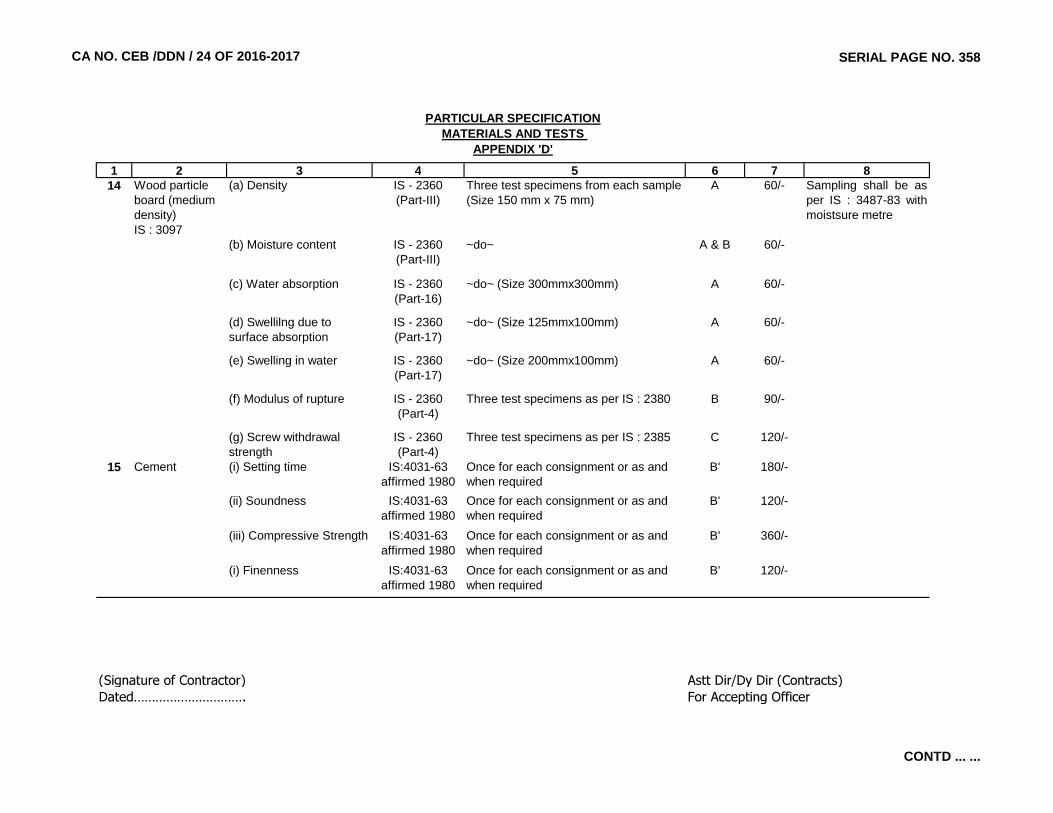
CA NO. CEB /DDN / 24 OF 2016-2017 SERIAL PAGE NO. 358
1 2 3 4 5 6 7 8
PARTICULAR SPECIFICATIONMATERIALS AND TESTS
APPENDIX 'D'
14 Wood particle board (medium density) IS : 3097
(a) Density IS - 2360 (Part-III)
Three test specimens from each sample(Size 150 mm x 75 mm)
A 60/- Sampling shall be asper IS : 3487-83 withmoistsure metre
(b) Moisture content IS - 2360 (Part-III)
~do~ A & B 60/-
(c) Water absorption IS - 2360 (Part-16)
~do~ (Size 300mmx300mm) A 60/-
(d) Swellilng due to surface absorption
IS - 2360 (Part-17)
~do~ (Size 125mmx100mm) A 60/-
(e) Swelling in water IS - 2360 (Part-17)
~do~ (Size 200mmx100mm) A 60/-
(f) Modulus of rupture IS - 2360 (Part-4)
Three test specimens as per IS : 2380 B 90/-
(g) Screw withdrawal strength
IS - 2360 (Part-4)
Three test specimens as per IS : 2385 C 120/-
15 Cement (i) Setting time IS:4031-63 affirmed 1980
Once for each consignment or as and when required
B' 180/-
(ii) Soundness IS:4031-63 affirmed 1980
Once for each consignment or as and when required
B' 120/-
(iii) Compressive Strength IS:4031-63 affirmed 1980
Once for each consignment or as and when required
B' 360/-
(i) Finenness IS:4031-63 affirmed 1980
Once for each consignment or as and when required
B' 120/-
(Signature of Contractor) Astt Dir/Dy Dir (Contracts)Dated…………………………. For Accepting Officer
CONTD ... ...

CA NO. CEB / DDN / 24 OF 2016-2017 SERIAL PAGE NO. 359
PARTICULAR SPECIFICATIONS (CONTD……)
APPENDIX ‘A’ LIST OF EQUIPMENT FOR FIELD TEST LABORATORY
FOR BUILDING WORKS 1. WEIGHING BALANCE (a) 7 Kg to 10 Kg capacity, semi-self indicating type (Accuracy-10 gram) (b) 500 gm capacity, semi-self indicating type (Accuracy-1 gram) (c) Pan balance – 5 Kg capacity (Accuracy-10 gram) 2. OVENS
Electricity operated, thermostatically controlled upto 220 0C (Sensitivity-1 0C) 3. SIEVES AS PER IS-460-1962
(a) IS SIEVES 450 mm internal dia of sizes 100 mm, 80 mm, 63 mm, 50 mm, 40 mm, 25 mm, 20 mm, 12.5 mm, 10 mm, 6.3 mm, 4.75 mm complete with lid and pan.
(b) IS SIEVES 200 mm internal dia (brass frame) consisting of 2.36 mm, 1.18 mm, 500 microns, 425 microns, 300 microns, 212 microns, 150 microns, 90 microns, 75 microns with lid and pan.
4. Sieve shaker capable of 200 mm and 300 mm dia, sieves, manually operated with timing switch
assembly. 5. EQUIPMENT FOR SLUMP TEST
Slump cone, steel plate, tamping rod, steel scale and scoop. 6. Dial gauges 25 mm travel 0.01 mm / division, least count – 02 Nos. 7. 100 Tonne compression testing machine, electric cum manually operated. 8. Graduated measuring cylinder 200 ml capacity-03 Nos. 9. ENAMEL TRAYS (FOR EFFLORESCENCE TEST FOR BLOCKS) (a) 300 mm x 250 mm x 40 mm – 02 Nos.
(b) Circular plates of 250 mm dia –04 Nos. FOR ROAD WORKS 1. WEIGHING BALANCES (a) 7 Kg to 10 Kg, capacity semi self indicating type (Accuracy-10 gram)
(b) 500 gm capacity, semi self indicating type (Accuracy-1 gram) (c) Chemical balance, 100 gm capacity (Accuracy-0.1 gram) (d) Pan balance - 5 Kg capacity (Accuracy-10 gram) (e) Platform scale - 300 Kg capacity
------------------------------------------------------------------------------------------------------------------------------- …………………………………… (Signature of Contractor) Astt Dir/Dy Dir (Contracts) Dated…………………………. For Accepting Officer

CA NO. CEB / DDN / 24 OF 2016-2017 LIST OF DRAWINGS
SERIAL PAGE NO. 360
S. No.
Description of Drawings Drg No. Sheet No.
Date of drawing
Date of Revision
1 2 3 4 5 6
1 List of drawings BZ /DDN / LD / 219 1/1 01.06.2017 22.08.20172 Site Plan showing external B/R & E/M Services. BZ / DDN / LP / 182 1/1 01.06.2017 22.08.2017
3 Plan, Elevation, Section, E/M plan and Roof plan BZ / DDN / 848 1/1 01.06.2017 22.08.2017
4 Structural Plan col & footings, plinth level, Roof level and schedules
BZ / DDN / STR / 848 1/1 01.06.2017 -
5 Floor Plan, Elevations and Details BZ / DDN / 846 1/3 01.06.2017
6 Sections and Toilet detail BZ / DDN / 846 2/3 01.06.2017
7 E/M Plan and Roof Plan BZ / DDN / 846 3/3 01.06.2017 22.08.2017
8 Structural Plan col & footings, plinth level, Roof level, schedules and details
BZ / DDN / STR / 846 1/2 01.06.2017 26.07.2017
9 Misc Details BZ / DDN / STR / 846 2/2 01.06.2017 -
10 Schedule of Finishes BZ / MRT / 847 1/1 01.06.2017 22.08.2017
11 General, Structural, Masonry and Construction Notes.
STD / 147 (Retraced) 1/3 22.07.1998 23.10.2000
12 General, Structural, Masonry and Construction Notes.
STD / 147 (Retraced) 2/3 22.07.1998 23.10.2000
13 General, Structural, Masonry and Construction Notes.
STD / 147 (Retraced) 3/3 22.07.1998 23.10.2000
14 Typical Detail of Seismic Strengthning Measures. STD / 148 (Retraced) 1/5 25.01.2002 25.11.2002
15 Typical Detail of Seismic Strengthning Measures. STD / 148 (Retraced) 2/5 25.01.2002 25.11.2002
16 Typical Detail of Seismic Strengthning Measures. STD / 148 (Retraced) 3/5 25.01.2002 25.11.2002
17 Typical Detail of Seismic Strengthning Measures. STD / 148 (Retraced) 4/5 25.01.2002 25.11.2002
18 Typical Detail of Seismic Strengthning Measures. STD / 148 (Retraced) 5/5 25.01.2002 25.11.2002
19 Details of Foundations and Brick Parapet Walls. STD / 149 (Retraced) 1/2 17.08.1998 05.01.1999
20 Details of Foundations and Brick Parapet Walls. STD / 149 (Retraced) 2/2 17.08.1998 05.01.199921 Typical Details of RCC Lintels and Beams. STD / 150 (Retraced) 1/2 21.01.1980 02.08.1986
SCHEDULE OF FINISHES
NAME OF WORK :- PROVISION OF 2 MW SOLAR ENERGY PROJECT AT DEHRADUN
STD DRAWINGS
GUARD ROOM
SUB STATION BUILDING (MAIN CONTROL ROOM)
CONTD ... ...

CA NO. CEB / DDN / 24 OF 2016-2017 LIST OF DRAWINGS
SERIAL PAGE NO. 361
S. No.
Description of Drawings Drg No. Sheet No.
Date of drawing
Date of Revision
1 2 3 4 5 6
22 Typical Details of RCC Lintels and Beams. STD / 150 (Retraced) 2/2 21.01.1980 12.01.199923 Typical Details of RCC Chajjas, Chajja with Facia
& Fin, Shelves and Roof Projections.STD / 151 (Retraced) 1/4 17.08.1998 14.09.1999
24 Typical Details of RCC Chajjas, Chajja with Facia & Fin, Shelves and Roof Projections.
STD / 151 (Retraced) 2/4 17.08.1998 14.09.1999
25 Typical Details of RCC Chajjas, Chajja with Facia & Fin, Shelves and Roof Projections.
STD / 151 (Retraced) 3/4 17.08.1998 14.09.1999
26 Typical Details of RCC Chajjas, Chajja with Facia & Fin, Shelves and Roof Projections.
STD / 151 (Retraced) 4/4 17.08.1998 14.09.1999
27 Typical Details of RCC Slabs. STD / 152 (Retraced) 1/5 17.08.1998 23.10.200028 Typical Details of RCC Slabs. STD / 152 (Retraced) 2/5 17.08.1998 23.10.200029 Typical Details of RCC Slabs. STD / 152 (Retraced) 3/5 17.08.1998 23.10.200030 Typical Details of RCC Slabs. STD / 152 (Retraced) 4/5 17.08.1998 23.10.200031 Typical Details of RCC Slabs. STD / 152 (Retraced) 5/5 17.08.1998 23.10.200032 Reinforcement Detailing Requirement for RCC
Frame Structures.STD / 154 (Retraced) 1/7 16.01.1999 12.11.2003
33 Reinforcement Detailing Requirement for RCC Frame Structures.
STD / 154 (Retraced) 2/7 16.01.1999 12.11.2003
34 Reinforcement Detailing Requirement for RCC Frame Structures.
STD / 154 (Retraced) 3/7 16.01.1999 12.11.2003
35 Reinforcement Detailing Requirement for RCC Frame Structures.
STD / 154 (Retraced) 4/7 16.01.1999 12.11.2003
36 Reinforcement Detailing Requirement for RCC Frame Structures.
STD / 154 (Retraced) 5/7 16.01.1999 12.11.2003
37 Reinforcement Detailing Requirement for RCC Frame Structures.
STD / 154 (Retraced) 6/7 16.01.1999 12.11.2003
38 Reinforcement Detailing Requirement for RCC Frame Structures.
STD / 154 (Retraced) 7/7 16.01.1999 12.11.2003
39 Retaining Walls. STD / 155 (Retraced) 1/1 23.08.2002 -40 HDPE Overhead Tanks. STD / 157 (Retraced) 1/1 28.02.2003 -41 Typical Detail of Crumple Section. STD / 158 R 1/3 16.12.2014 -42 Typical Detail of Crumple Section. STD / 158 R 2/3 16.12.2014 -43 Typical Detail of Crumple Section. STD / 158 R 3/3 16.12.2014 -44 Typical Detail of Seismic Strengthning Measures. STD / 169 1/5
45 Typical Detail of Seismic Strengthning Measures. STD / 169 2/5
46 Typical Detail of Seismic Strengthning Measures. STD / 169 3/5
47 Typical Detail of Seismic Strengthning Measures. STD / 169 4/5
CONTD ... ...

CA NO. CEB / DDN / 24 OF 2016-2017 LIST OF DRAWINGS
SERIAL PAGE NO. 362
S. No.
Description of Drawings Drg No. Sheet No.
Date of drawing
Date of Revision
1 2 3 4 5 6
48 Typical Detail of Seismic Strengthning Measures. STD / 169 5/5
49 Structural Notes and references BZ / MRT / 266 1/6 -50 Structural Notes and references BZ / MRT / 266 2/6 -51 Structural Notes and references BZ / MRT / 266 3/6 -52 Structural Notes and references BZ / MRT / 266 4/6 -53 Structural Notes and references BZ / MRT / 266 5/6 -54 Structural Notes and references BZ / MRT / 266 6/6 -55 Notes, Precautions and instruction BZ / DDN / STR / 558 1/5 22.01.2011 -56 Foundation plinth beam BZ / DDN / STR / 558 2/5 22.01.2011 -57 Columns, lintels, sunshades, shelves and
counters etc.BZ / DDN / STR / 558 3/5 22.01.2011 -
58 Beams, floors / roof slab with facia, parapet etc. BZ / DDN / STR / 558 4/5 22.01.2011 -
59 Slopped roof and roof slab connections, solarstand etc.
BZ / DDN / STR / 558 5/5 22.01.2011 -
60 Amendments BZ / DDN / STR / 559 R 1R/4R 25.04.2011 24.04.201161 Amendments BZ / DDN / STR / 559 R 2R/4R 25.04.2011 24.04.201162 Amendments BZ / DDN / STR / 559 R 3R/4R 25.04.2011 24.04.201163 Amendments BZ / DDN / STR / 559 R 4R/4R 25.04.2011 24.04.201164 Steel door for garage and repair way STD / 131.2.3 1/1 09.08.1985 -
65 Details of Bar Counter. BZ / DDN / 174 4/766 Rain Water Harvesting. CEBZ / TD / 128 1/167 Details of Sanitary Fittings. TD / 254 (NZ) 1/268 Details of Sanitary Fittings. TD / 254 (NZ) 2/269 Details of Fire Point. SK / 569 1/170 MD ACCN 1986 Detail of RWP (Surface /
Concealed) CI Grating, Splash Stone etc. TD / 013 1/3 20.05.1987 -
71 MD ACCN 1986 Detail of RWP (Surface /Concealed) CI Grating, Splash Stone etc.
TD / 013 2/3 20.05.1987 -
72 MD ACCN 1986 Detail of RWP (Surface /Concealed) CI Grating, Splash Stone etc.
TD / 013 3/3 20.05.1987 -
73 Built in Cup Board (Large and Medium) TD / 022 1/6 09.08.1988 22.10.200174 Built in Cup Board (Large and Medium) TD / 022 2/6 09.08.1988 22.10.200175 Built in Cup Board (Large and Medium) TD / 022 3/6 09.08.1988 22.10.200176 Built in Cup Board (Large and Medium) TD / 022 4/6 09.08.1988 22.10.200177 Built in Cup Board (Large and Medium) TD / 022 5/6 09.08.1988 22.10.200178 Built in Cup Board (Large and Medium) TD / 022 6/6 09.08.1988 22.10.2001
TD DRAWINGS (B&R)
CONTD ... ...
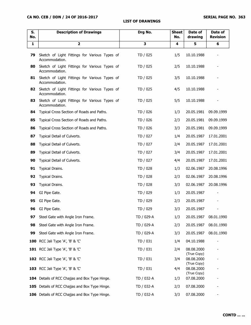
CA NO. CEB / DDN / 24 OF 2016-2017 LIST OF DRAWINGS
SERIAL PAGE NO. 363
S. No.
Description of Drawings Drg No. Sheet No.
Date of drawing
Date of Revision
1 2 3 4 5 6
79 Sketch of Light Fittings for Various Types ofAccommodation.
TD / 025 1/5 10.10.1988 -
80 Sketch of Light Fittings for Various Types ofAccommodation.
TD / 025 2/5 10.10.1988 -
81 Sketch of Light Fittings for Various Types ofAccommodation.
TD / 025 3/5 10.10.1988 -
82 Sketch of Light Fittings for Various Types ofAccommodation.
TD / 025 4/5 10.10.1988 -
83 Sketch of Light Fittings for Various Types ofAccommodation.
TD / 025 5/5 10.10.1988 -
84 Typical Cross Section of Roads and Paths. TD / 026 1/3 20.05.1981 09.09.199985 Typical Cross Section of Roads and Paths. TD / 026 2/3 20.05.1981 09.09.199986 Typical Cross Section of Roads and Paths. TD / 026 3/3 20.05.1981 09.09.199987 Typical Detail of Culverts. TD / 027 1/4 20.05.1987 17.01.200188 Typical Detail of Culverts. TD / 027 2/4 20.05.1987 17.01.200189 Typical Detail of Culverts. TD / 027 3/4 20.05.1987 17.01.200190 Typical Detail of Culverts. TD / 027 4/4 20.05.1987 17.01.200191 Typical Drains. TD / 028 1/3 02.06.1987 20.08.199692 Typical Drains. TD / 028 2/3 02.06.1987 20.08.199693 Typical Drains. TD / 028 3/3 02.06.1987 20.08.199694 GI Pipe Gate. TD / 029 1/3 20.05.1987 -95 GI Pipe Gate. TD / 029 2/3 20.05.1987 -96 GI Pipe Gate. TD / 029 3/3 20.05.1987 -97 Steel Gate with Angle Iron Frame. TD / 029-A 1/3 20.05.1987 08.01.199098 Steel Gate with Angle Iron Frame. TD / 029-A 2/3 20.05.1987 08.01.199099 Steel Gate with Angle Iron Frame. TD / 029-A 3/3 20.05.1987 08.01.1990100 RCC Jali Type ‘A’, 'B' & 'C' TD / 031 1/4 04.10.1988 -101 RCC Jali Type ‘A’, 'B' & 'C' TD / 031 2/4 08.08.2000
(True Copy)-
102 RCC Jali Type ‘A’, 'B' & 'C' TD / 031 3/4 08.08.2000(True Copy)
-
103 RCC Jali Type ‘A’, 'B' & 'C' TD / 031 4/4 08.08.2000(True Copy)
-
104 Details of RCC Chajjas and Box Type Hinge. TD / 032-A 1/3 07.08.2000 -105 Details of RCC Chajjas and Box Type Hinge. TD / 032-A 2/3 07.08.2000 -106 Details of RCC Chajjas and Box Type Hinge. TD / 032-A 3/3 07.08.2000 -
CONTD ... ...

CA NO. CEB / DDN / 24 OF 2016-2017 LIST OF DRAWINGS
SERIAL PAGE NO. 364
S. No.
Description of Drawings Drg No. Sheet No.
Date of drawing
Date of Revision
1 2 3 4 5 6
107 Details of Steel Window for OTM ACCN. TD / 032 1/10 29.10.1988 09.08.2000108 Details of Steel Window for OTM ACCN. TD / 032 2/10 29.10.1988 09.08.2000109 Details of Steel Window for OTM ACCN. TD / 032 3/10 29.10.1988 09.08.2000110 Details of Steel Window for OTM ACCN. TD / 032 4/10 29.10.1988 09.08.2000111 Details of Steel Window for OTM ACCN. TD / 032 5/10 29.10.1988 09.08.2000112 Details of Steel Window for OTM ACCN. TD / 032 6/10 29.10.1988 09.08.2000113 Details of Steel Window for OTM ACCN. TD / 032 7/10 29.10.1988 03.07.2001114 Details of Steel Window for OTM ACCN. TD / 032 8/10 29.10.1988 03.07.2001115 Details of Steel Window for OTM ACCN. TD / 032 9/10 29.10.1988 03.07.2001116 Details of Steel Window for OTM ACCN. TD / 032 10/10 29.10.1988 03.07.2001117 Fixing Details of Nahani and Gully Traps. TD / 034 1/4 21.07.1989 26.08.1991118 Fixing Details of Nahani and Gully Traps. TD / 034 2/4 21.07.1989 26.08.1991119 Fixing Details of Nahani and Gully Traps. TD / 034 3/4 21.07.1989 26.08.1991120 Fixing Details of Nahani and Gully Traps. TD / 034 4/4 21.07.1989 26.08.1991121 Detail of Bracket for Air Cooler. TD / 036-A 1/1 19.02.2000 -122 Detail of Air Cooler Stand. TD / 036 1/2 25.11.1989 26.12.1989123 Detail of Air Cooler Stand. TD / 036 2/2 25.11.1989 26.12.1989124 Typical Cross Section of RCC Circular Static
Water Tank.TD / 037 1/2 25.05.1990 26.09.1990
125 Typical Cross Section of RCC Circular StaticWater Tank.
TD / 037 2/2 25.05.1990 26.09.1990
126 Precaution for Leakage, Seepage and DampnessWater Proofing Treatment.
TD / 041 1/7 04.01.1993 -
127 Precaution for Leakage, Seepage and DampnessWater Proofing Treatment.
TD / 041 2/7 04.01.1993 -
128 Precaution for Leakage, Seepage and DampnessWater Proofing Treatment.
TD / 041 3/7 04.01.1993 -
129 Precaution for Leakage, Seepage and DampnessWater Proofing Treatment.
TD / 041 4/7 04.01.1993 -
130 Precaution for Leakage, Seepage and DampnessWater Proofing Treatment.
TD / 041 5/7 04.01.1993 -
131 Precaution for Leakage, Seepage and DampnessWater Proofing Treatment.
TD / 041 6/7 04.01.1993 -
132 Precaution for Leakage, Seepage and DampnessWater Proofing Treatment.
TD / 041 7/7 04.01.1993 -
CONTD ... ...
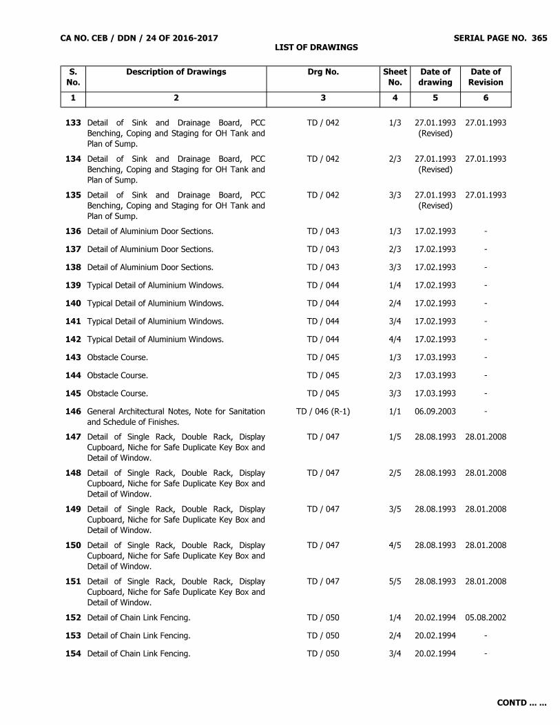
CA NO. CEB / DDN / 24 OF 2016-2017 LIST OF DRAWINGS
SERIAL PAGE NO. 365
S. No.
Description of Drawings Drg No. Sheet No.
Date of drawing
Date of Revision
1 2 3 4 5 6
133 Detail of Sink and Drainage Board, PCCBenching, Coping and Staging for OH Tank andPlan of Sump.
TD / 042 1/3 27.01.1993(Revised)
27.01.1993
134 Detail of Sink and Drainage Board, PCCBenching, Coping and Staging for OH Tank andPlan of Sump.
TD / 042 2/3 27.01.1993(Revised)
27.01.1993
135 Detail of Sink and Drainage Board, PCCBenching, Coping and Staging for OH Tank andPlan of Sump.
TD / 042 3/3 27.01.1993(Revised)
27.01.1993
136 Detail of Aluminium Door Sections. TD / 043 1/3 17.02.1993 -137 Detail of Aluminium Door Sections. TD / 043 2/3 17.02.1993 -138 Detail of Aluminium Door Sections. TD / 043 3/3 17.02.1993 -139 Typical Detail of Aluminium Windows. TD / 044 1/4 17.02.1993 -140 Typical Detail of Aluminium Windows. TD / 044 2/4 17.02.1993 -141 Typical Detail of Aluminium Windows. TD / 044 3/4 17.02.1993 -142 Typical Detail of Aluminium Windows. TD / 044 4/4 17.02.1993 -143 Obstacle Course. TD / 045 1/3 17.03.1993 -144 Obstacle Course. TD / 045 2/3 17.03.1993 -145 Obstacle Course. TD / 045 3/3 17.03.1993 -146 General Architectural Notes, Note for Sanitation
and Schedule of Finishes.TD / 046 (R-1) 1/1 06.09.2003 -
147 Detail of Single Rack, Double Rack, DisplayCupboard, Niche for Safe Duplicate Key Box andDetail of Window.
TD / 047 1/5 28.08.1993 28.01.2008
148 Detail of Single Rack, Double Rack, DisplayCupboard, Niche for Safe Duplicate Key Box andDetail of Window.
TD / 047 2/5 28.08.1993 28.01.2008
149 Detail of Single Rack, Double Rack, DisplayCupboard, Niche for Safe Duplicate Key Box andDetail of Window.
TD / 047 3/5 28.08.1993 28.01.2008
150 Detail of Single Rack, Double Rack, DisplayCupboard, Niche for Safe Duplicate Key Box andDetail of Window.
TD / 047 4/5 28.08.1993 28.01.2008
151 Detail of Single Rack, Double Rack, DisplayCupboard, Niche for Safe Duplicate Key Box andDetail of Window.
TD / 047 5/5 28.08.1993 28.01.2008
152 Detail of Chain Link Fencing. TD / 050 1/4 20.02.1994 05.08.2002153 Detail of Chain Link Fencing. TD / 050 2/4 20.02.1994 -154 Detail of Chain Link Fencing. TD / 050 3/4 20.02.1994 -
CONTD ... ...
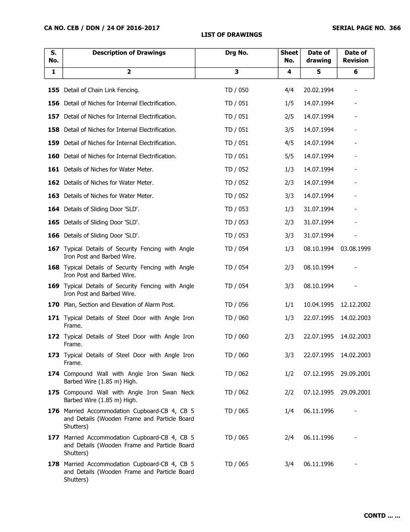
CA NO. CEB / DDN / 24 OF 2016-2017 LIST OF DRAWINGS
SERIAL PAGE NO. 366
S. No.
Description of Drawings Drg No. Sheet No.
Date of drawing
Date of Revision
1 2 3 4 5 6
155 Detail of Chain Link Fencing. TD / 050 4/4 20.02.1994 -156 Detail of Niches for Internal Electrification. TD / 051 1/5 14.07.1994 -157 Detail of Niches for Internal Electrification. TD / 051 2/5 14.07.1994 -158 Detail of Niches for Internal Electrification. TD / 051 3/5 14.07.1994 -159 Detail of Niches for Internal Electrification. TD / 051 4/5 14.07.1994 -160 Detail of Niches for Internal Electrification. TD / 051 5/5 14.07.1994 -161 Details of Niches for Water Meter. TD / 052 1/3 14.07.1994 -162 Details of Niches for Water Meter. TD / 052 2/3 14.07.1994 -163 Details of Niches for Water Meter. TD / 052 3/3 14.07.1994 -164 Details of Sliding Door 'SLD'. TD / 053 1/3 31.07.1994 -165 Details of Sliding Door 'SLD'. TD / 053 2/3 31.07.1994 -166 Details of Sliding Door 'SLD'. TD / 053 3/3 31.07.1994 -167 Typical Details of Security Fencing with Angle
Iron Post and Barbed Wire.TD / 054 1/3 08.10.1994 03.08.1999
168 Typical Details of Security Fencing with AngleIron Post and Barbed Wire.
TD / 054 2/3 08.10.1994 -
169 Typical Details of Security Fencing with AngleIron Post and Barbed Wire.
TD / 054 3/3 08.10.1994 -
170 Plan, Section and Elevation of Alarm Post. TD / 056 1/1 10.04.1995 12.12.2002171 Typical Details of Steel Door with Angle Iron
Frame.TD / 060 1/3 22.07.1995 14.02.2003
172 Typical Details of Steel Door with Angle IronFrame.
TD / 060 2/3 22.07.1995 14.02.2003
173 Typical Details of Steel Door with Angle IronFrame.
TD / 060 3/3 22.07.1995 14.02.2003
174 Compound Wall with Angle Iron Swan NeckBarbed Wire (1.85 m) High.
TD / 062 1/2 07.12.1995 29.09.2001
175 Compound Wall with Angle Iron Swan NeckBarbed Wire (1.85 m) High.
TD / 062 2/2 07.12.1995 29.09.2001
176 Married Accommodation Cupboard-CB 4, CB 5and Details (Wooden Frame and Particle BoardShutters)
TD / 065 1/4 06.11.1996 -
177 Married Accommodation Cupboard-CB 4, CB 5and Details (Wooden Frame and Particle BoardShutters)
TD / 065 2/4 06.11.1996 -
178 Married Accommodation Cupboard-CB 4, CB 5and Details (Wooden Frame and Particle BoardShutters)
TD / 065 3/4 06.11.1996 -
CONTD ... ...
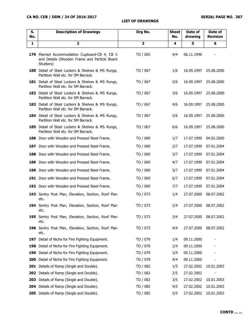
CA NO. CEB / DDN / 24 OF 2016-2017 LIST OF DRAWINGS
SERIAL PAGE NO. 367
S. No.
Description of Drawings Drg No. Sheet No.
Date of drawing
Date of Revision
1 2 3 4 5 6
179 Married Accommodation Cupboard-CB 4, CB 5and Details (Wooden Frame and Particle BoardShutters)
TD / 065 4/4 06.11.1996 -
180 Detail of Steel Lockers & Shelves & MS Rungs,Partition Wall etc. for SM Barrack.
TD / 067 1/6 16.09.1997 25.08.2000
181 Detail of Steel Lockers & Shelves & MS Rungs,Partition Wall etc. for SM Barrack.
TD / 067 2/6 16.09.1997 25.08.2000
182 Detail of Steel Lockers & Shelves & MS Rungs,Partition Wall etc. for SM Barrack.
TD / 067 3/6 16.09.1997 25.08.2000
183 Detail of Steel Lockers & Shelves & MS Rungs,Partition Wall etc. for SM Barrack.
TD / 067 4/6 16.09.1997 25.08.2000
184 Detail of Steel Lockers & Shelves & MS Rungs,Partition Wall etc. for SM Barrack.
TD / 067 5/6 16.09.1997 25.08.2000
185 Detail of Steel Lockers & Shelves & MS Rungs,Partition Wall etc. for SM Barrack.
TD / 067 6/6 16.09.1997 25.08.2000
186 Door with Wooden and Pressed Steel Frame. TD / 069 1/7 17.07.1999 04.02.2000187 Door with Wooden and Pressed Steel Frame. TD / 069 2/7 17.07.1999 07.01.2004188 Door with Wooden and Pressed Steel Frame. TD / 069 3/7 17.07.1999 07.01.2004189 Door with Wooden and Pressed Steel Frame. TD / 069 4/7 17.07.1999 07.01.2004190 Door with Wooden and Pressed Steel Frame. TD / 069 5/7 17.07.1999 07.01.2004191 Door with Wooden and Pressed Steel Frame. TD / 069 6/7 17.07.1999 07.01.2004192 Door with Wooden and Pressed Steel Frame. TD / 069 7/7 17.07.1999 07.01.2004193 Sentry Post Plan, Elevation, Section, Roof Plan
etc.TD / 073 1/4 27.07.2000 08.07.2002
194 Sentry Post Plan, Elevation, Section, Roof Planetc.
TD / 073 2/4 27.07.2000 08.07.2002
195 Sentry Post Plan, Elevation, Section, Roof Planetc.
TD / 073 3/4 27.07.2000 08.07.2002
196 Sentry Post Plan, Elevation, Section, Roof Planetc.
TD / 073 4/4 27.07.2000 08.07.2002
197 Detail of Niche for Fire Fighting Equipment. TD / 079 1/4 09.11.2000 -198 Detail of Niche for Fire Fighting Equipment. TD / 079 2/4 09.11.2000 -199 Detail of Niche for Fire Fighting Equipment. TD / 079 3/4 09.11.2000 -200 Detail of Niche for Fire Fighting Equipment. TD / 079 4/4 09.11.2000 -201 Details of Ramp (Single and Double). TD / 082 1/5 27.02.2002 10.01.2003202 Details of Ramp (Single and Double). TD / 082 2/5 27.02.2002 -203 Details of Ramp (Single and Double). TD / 082 3/5 27.02.2002 10.01.2003204 Details of Ramp (Single and Double). TD / 082 4/5 27.02.2002 10.01.2003205 Details of Ramp (Single and Double). TD / 082 5/5 27.02.2002 10.01.2003
CONTD ... ...

CA NO. CEB / DDN / 24 OF 2016-2017 LIST OF DRAWINGS
SERIAL PAGE NO. 368
S. No.
Description of Drawings Drg No. Sheet No.
Date of drawing
Date of Revision
1 2 3 4 5 6
206 Sliding Door. TD / 084 1/3 Sep 2001 20.12.2004(True Copy)
207 Sliding Door. TD / 084 2/3 Sep 2001 20.12.2004(True Copy)
208 Sliding Door. TD / 084 3/3 Sep 2001 20.12.2004(True Copy)
209 Coal and Coke Yard Plan, Elevation, Section,Foundation Detail.
TD / 086 1/2 01.11.2001 -
210 Coal and Coke Yard Plan, Elevation, Section,Foundation Detail.
TD / 086 2/2 01.11.2001 -
211 Typical Detail of Steel Window and Ventilators. TD / 088 1/17 07.01.2002 27.08.2003
212 Typical Detail of Steel Window and Ventilators. TD / 088 2/17 07.01.2002 -
213 Typical Detail of Steel Window and Ventilators. TD / 088 3/17 07.01.2002 -
214 Typical Detail of Steel Window and Ventilators. TD / 088 4/17 07.01.2002 -
215 Typical Detail of Steel Window and Ventilators. TD / 088 5/17 07.01.2002 -
216 Typical Detail of Steel Window and Ventilators. TD / 088 6/17 07.01.2002 -
217 Typical Detail of Steel Window and Ventilators. TD / 088 7/17 07.01.2002 -
218 Typical Detail of Steel Window and Ventilators. TD / 088 8/17 07.01.2002 -
219 Typical Detail of Steel Window and Ventilators. TD / 088 9/17 07.01.2002 -
220 Typical Detail of Steel Window and Ventilators. TD / 088 10/17 07.01.2002 -
221 Typical Detail of Steel Window and Ventilators. TD / 088 11/17 07.01.2002 -
222 Typical Detail of Steel Window and Ventilators. TD / 088 12/17 07.01.2002 -
223 Typical Detail of Steel Window and Ventilators. TD / 088 13/17 07.01.2002 -
224 Typical Detail of Steel Window and Ventilators. TD / 088 14/17 07.01.2002 -
225 Typical Detail of Steel Window and Ventilators. TD / 088 15/17 07.01.2002 -
226 Typical Detail of Steel Window and Ventilators. TD / 088 16/17 07.01.2002 -
227 Typical Detail of Steel Window and Ventilators. TD / 088 17/17 07.01.2002 30.07.2003
228 Typical Detail of Trough Type Wash Hand Basin. TD / 089 1/3 12.02.2002 07.01.2004
229 Typical Detail of Trough Type Wash Hand Basin. TD / 089 2/3 12.02.2002 07.01.2004
230 Typical Detail of Trough Type Wash Hand Basin. TD / 089 3/3 12.02.2002 07.01.2004
CONTD ... ...
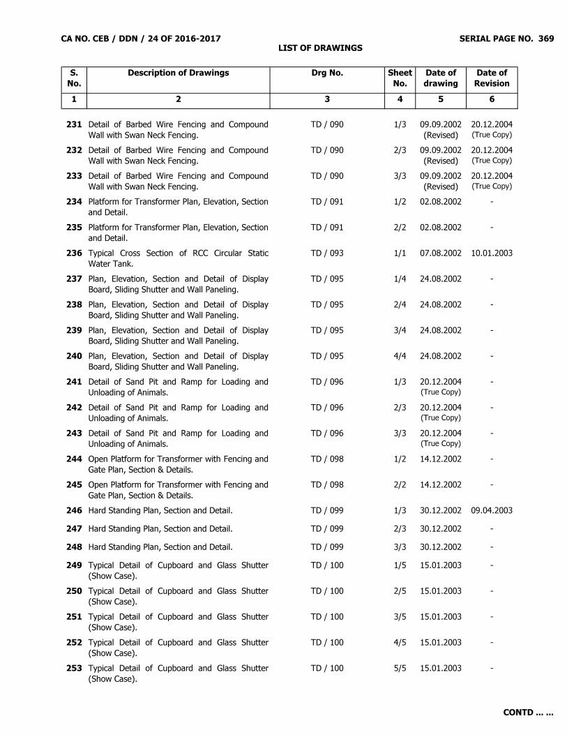
CA NO. CEB / DDN / 24 OF 2016-2017 LIST OF DRAWINGS
SERIAL PAGE NO. 369
S. No.
Description of Drawings Drg No. Sheet No.
Date of drawing
Date of Revision
1 2 3 4 5 6
231 Detail of Barbed Wire Fencing and CompoundWall with Swan Neck Fencing.
TD / 090 1/3 09.09.2002(Revised)
20.12.2004(True Copy)
232 Detail of Barbed Wire Fencing and CompoundWall with Swan Neck Fencing.
TD / 090 2/3 09.09.2002(Revised)
20.12.2004(True Copy)
233 Detail of Barbed Wire Fencing and CompoundWall with Swan Neck Fencing.
TD / 090 3/3 09.09.2002(Revised)
20.12.2004(True Copy)
234 Platform for Transformer Plan, Elevation, Sectionand Detail.
TD / 091 1/2 02.08.2002 -
235 Platform for Transformer Plan, Elevation, Sectionand Detail.
TD / 091 2/2 02.08.2002 -
236 Typical Cross Section of RCC Circular StaticWater Tank.
TD / 093 1/1 07.08.2002 10.01.2003
237 Plan, Elevation, Section and Detail of DisplayBoard, Sliding Shutter and Wall Paneling.
TD / 095 1/4 24.08.2002 -
238 Plan, Elevation, Section and Detail of DisplayBoard, Sliding Shutter and Wall Paneling.
TD / 095 2/4 24.08.2002 -
239 Plan, Elevation, Section and Detail of DisplayBoard, Sliding Shutter and Wall Paneling.
TD / 095 3/4 24.08.2002 -
240 Plan, Elevation, Section and Detail of DisplayBoard, Sliding Shutter and Wall Paneling.
TD / 095 4/4 24.08.2002 -
241 Detail of Sand Pit and Ramp for Loading andUnloading of Animals.
TD / 096 1/3 20.12.2004(True Copy)
-
242 Detail of Sand Pit and Ramp for Loading andUnloading of Animals.
TD / 096 2/3 20.12.2004(True Copy)
-
243 Detail of Sand Pit and Ramp for Loading andUnloading of Animals.
TD / 096 3/3 20.12.2004(True Copy)
-
244 Open Platform for Transformer with Fencing andGate Plan, Section & Details.
TD / 098 1/2 14.12.2002 -
245 Open Platform for Transformer with Fencing andGate Plan, Section & Details.
TD / 098 2/2 14.12.2002 -
246 Hard Standing Plan, Section and Detail. TD / 099 1/3 30.12.2002 09.04.2003247 Hard Standing Plan, Section and Detail. TD / 099 2/3 30.12.2002 -248 Hard Standing Plan, Section and Detail. TD / 099 3/3 30.12.2002 -249 Typical Detail of Cupboard and Glass Shutter
(Show Case).TD / 100 1/5 15.01.2003 -
250 Typical Detail of Cupboard and Glass Shutter(Show Case).
TD / 100 2/5 15.01.2003 -
251 Typical Detail of Cupboard and Glass Shutter(Show Case).
TD / 100 3/5 15.01.2003 -
252 Typical Detail of Cupboard and Glass Shutter(Show Case).
TD / 100 4/5 15.01.2003 -
253 Typical Detail of Cupboard and Glass Shutter(Show Case).
TD / 100 5/5 15.01.2003 -
CONTD ... ...

CA NO. CEB / DDN / 24 OF 2016-2017 LIST OF DRAWINGS
SERIAL PAGE NO. 370
S. No.
Description of Drawings Drg No. Sheet No.
Date of drawing
Date of Revision
1 2 3 4 5 6
254 Detail of Sump for Water Disposal. TD / 101 1/2 and 2/2
31.01.2003 -
255 Typical Detail of Cook House. TD / 102 1/11 13.02.2003 - 256 Typical Detail of Cook House. TD / 102 2/11 13.02.2003 - 257 Typical Detail of Cook House. TD / 102 3/11 13.02.2003 - 258 Typical Detail of Cook House. TD / 102 4/11 13.02.2003 - 259 Typical Detail of Cook House. TD / 102 5/11 13.02.2003 - 260 Typical Detail of Cook House. TD / 102 6/11 13.02.2003 - 261 Typical Detail of Cook House. TD / 102 7/11 13.02.2003 - 262 Typical Detail of Cook House. TD / 102 8/11 13.02.2003 - 263 Typical Detail of Cook House. TD / 102 9/11 13.02.2003 - 264 Typical Detail of Cook House. TD / 102 10/11 13.02.2003 - 265 Typical Detail of Cook House. TD / 102 11/11 13.02.2003 - 266 Volley Ball Ground, Basket Ball Ground, Parade
Ground, Sentry Post, Dhobi Ghat, Washing Platform and Misc. Details.
TD / 103 1/7 10.02.2003 -
267 Volley Ball Ground, Basket Ball Ground, Parade Ground, Sentry Post, Dhobi Ghat, Washing Platform and Misc. Details.
TD / 103 2/7 10.02.2003 -
268 Volley Ball Ground, Basket Ball Ground, Parade Ground, Sentry Post, Dhobi Ghat, Washing Platform and Misc. Details.
TD / 103 3/7 10.02.2003 -
269 Volley Ball Ground, Basket Ball Ground, Parade Ground, Sentry Post, Dhobi Ghat, Washing Platform and Misc. Details.
TD / 103 4/7 10.02.2003 -
270 Volley Ball Ground, Basket Ball Ground, Parade Ground, Sentry Post, Dhobi Ghat, Washing Platform and Misc. Details.
TD / 103 5/7 10.02.2003 -
271 Volley Ball Ground, Basket Ball Ground, Parade Ground, Sentry Post, Dhobi Ghat, Washing Platform and Misc. Details.
TD / 103 6/7 10.02.2003 -
272 Volley Ball Ground, Basket Ball Ground, Parade Ground, Sentry Post, Dhobi Ghat, Washing Platform and Misc. Details.
TD / 103 7/7 10.02.2003 -
273 Hard Standing Plan, Section and Detail. TD / 104 1/2 20.02.2003 -274 Hard Standing Plan, Section and Detail. TD / 104 2/2 20.02.2003 -275 30 Yards / 27 Metres Range Plan, Longitudinal
Section and Cross Section.TD / 106 1/2 04.04.2003 -
CONTD ... ...

CA NO. CEB / DDN / 24 OF 2016-2017 LIST OF DRAWINGS
SERIAL PAGE NO. 371
S. No.
Description of Drawings Drg No. Sheet No.
Date of drawing
Date of Revision
1 2 3 4 5 6
276 30 Yards / 27 Metres Range Plan, LongitudinalSection and Cross Section.
TD / 106 2/2 04.04.2003 -
277 PCC Hardstanding. TD / 107 1/2 14.05.2003 -278 PCC Hardstanding. TD / 107 2/2 14.05.2003 -279 Layout of Furniture / Electrical Appliances in SM
Barrack and Detail of Partition Wall.TD / 110 1/4 27.08.2003 20.10.2003
280 Layout of Furniture / Electrical Appliances in SMBarrack and Detail of Partition Wall.
TD / 110 2/4 27.08.2003 20.10.2003
281 Layout of Furniture / Electrical Appliances in SMBarrack and Detail of Partition Wall.
TD / 110 3/4 27.08.2003 20.10.2003
282 Layout of Furniture / Electrical Appliances in SMBarrack and Detail of Partition Wall.
TD / 110 4/4 27.08.2003 20.10.2003
283 Typical Detail of Security Fencing with RCC Postsand Barbed Wire.
TD / 111 1/3 27.11.1972 12.03.1997
284 Typical Detail of Security Fencing with RCC Postsand Barbed Wire.
TD / 111 2/3 27.11.1972 12.03.1997
285 Typical Detail of Security Fencing with RCC Postsand Barbed Wire.
TD / 111 3/3 27.11.1972 12.03.1997
286 Detail of Railing in Stair Case / Verandah /Balcony / Platform and Wicket Gate.
TD / 112 1/3 30.01.2004 -
287 Detail of Railing in Stair Case / Verandah /Balcony / Platform and Wicket Gate.
TD / 112 2/3 30.01.2004 -
288 Detail of Railing in Stair Case / Verandah /Balcony / Platform and Wicket Gate.
TD / 112 3/3 30.01.2004 -
289 Detail of Steel Gate 3000 / 6000 / 5000 / 3600 /4600 / 3660 / 5150 Wide.
TD / 120 1/4 25.10.1972 04.09.2001
290 Detail of Steel Gate 3000 / 6000 / 5000 / 3600 /4600 / 3660 / 5150 Wide.
TD / 120 2/4 25.10.1972 04.09.2001
291 Detail of Steel Gate 3000 / 6000 / 5000 / 3600 /4600 / 3660 / 5150 Wide.
TD / 120 3/4 25.10.1972 04.09.2001
292 Detail of Steel Gate 3000 / 6000 / 5000 / 3600 /4600 / 3660 / 5150 Wide.
TD / 120 4/4 25.10.1972 04.09.2001
293 Counter Type Wash Basin. TD / 0120 1/1 31.08.2004 -294 Flooring Pattern. TD / 0121 1/1 13.09.2004 -295 Sign Post. TD / 124 1/1296 PVC internal soild door (Plan, elevation, section
and details). TD / 131 / 09 1/1 12.06.2009 -
297 Typical details of false ceiling. TD / 154 1/1 -298 Typical Detail and Schedule of Septic Tank (Brick
Construction).TD / 217 (A) 1/1 09.04.1969 -
299 Typical Detail and Schedule of Septic Tank (BrickConstruction).
TD / 217 1/7 25.11.1968 18.12.1992
CONTD ... ...

CA NO. CEB / DDN / 24 OF 2016-2017 LIST OF DRAWINGS
SERIAL PAGE NO. 372
S. No.
Description of Drawings Drg No. Sheet No.
Date of drawing
Date of Revision
1 2 3 4 5 6
300 Typical Detail and Schedule of Septic Tank (BrickConstruction).
TD / 217 2/7 25.11.1968 -
301 Typical Detail and Schedule of Septic Tank (BrickConstruction).
TD / 217 3/7 25.11.1968 -
302 Typical Detail and Schedule of Septic Tank (BrickConstruction).
TD / 217 4/7 25.11.1968 16.11.1971
303 Typical Detail and Schedule of Septic Tank (BrickConstruction).
TD / 217 5/7 25.11.1968 01.01.1990
304 Typical Detail and Schedule of Septic Tank (BrickConstruction).
TD / 217 6/7 25.11.1968 11.11.1993
305 Typical Detail and Schedule of Septic Tank (BrickConstruction).
TD / 217 7/7 25.11.1968 01.01.1990
306 Details of Incinerator. TD / 224 1/4 09.04.1969 21.12.1979307 Details of Incinerator. TD / 224 2/4 09.04.1969 21.12.1979308 Details of Incinerator. TD / 224 3/4 09.04.1969 21.12.1979309 Details of Incinerator. TD / 224 4/4 09.04.1969 21.12.1979310 Typical Details of Filter Bed (Brick Construction). TD / 235 1/5 11.04.1969 23.01.1990
311 Typical Details of Filter Bed (Brick Construction). TD / 235 2/5 11.04.1969 23.01.1990
312 Typical Details of Filter Bed (Brick Construction). TD / 235 3/5 11.04.1969 23.01.1990
313 Typical Details of Filter Bed (Brick Construction). TD / 235 4/5 11.04.1969 23.01.1990
314 Typical Details of Filter Bed (Brick Construction). TD / 235 5/5 11.04.1969 23.01.1990
315 Fixing Detail of Expansion Fastener. TD / 238 1/2 03.04.1978 -316 Fixing Detail of Expansion Fastener. TD / 238 2/2 03.04.1978 -317 Details of Wicket Gate and Steel Doors. TD / 241 1/4 30.03.1978 06.07.2002318 Details of Wicket Gate and Steel Doors. TD / 241 2/4 30.03.1978 -319 Details of Wicket Gate and Steel Doors. TD / 241 3/4 30.03.1978 -320 Details of Wicket Gate and Steel Doors. TD / 241 4/4 30.03.1978 -321 Flag Post. TD / 245 1/1322 Detail of Pernala PCC Drain, Detail of Fixing Wire
in Drying Shed, Detail of Skirting Dado Stepsand Plinth Protection.
TD / 250 1/3 20.01.1979 05.09.1979
323 Detail of Pernala PCC Drain, Detail of Fixing Wirein Drying Shed, Detail of Skirting Dado Stepsand Plinth Protection.
TD / 250 2/3 20.01.1979 05.09.1979
CONTD ... ...

CA NO. CEB / DDN / 24 OF 2016-2017 LIST OF DRAWINGS
SERIAL PAGE NO. 373
S. No.
Description of Drawings Drg No. Sheet No.
Date of drawing
Date of Revision
1 2 3 4 5 6
324 Detail of Pernala PCC Drain, Detail of Fixing Wirein Drying Shed, Detail of Skirting Dado Stepsand Plinth Protection.
TD / 250 3/3 20.01.1979 05.09.1979
325 Typical Detail of Pedestal and Squat WaterCloset, Urinal, Wash Hand Basin.
TD / 254 1/2 30.08.1963 -
326 Typical Detail of Pedestal and Squat WaterCloset, Urinal, Wash Hand Basin.
TD / 254 2/2 30.08.1963 -
327 Typical Detail of Manhole. TD / 270 1/4 12.12.1979 08.02.1988328 Typical Detail of Manhole. TD / 270 2/4 12.12.1979 08.02.1988329 Typical Detail of Manhole. TD / 270 3/4 12.12.1979 08.02.1988330 Typical Detail of Manhole. TD / 270 4/4 12.12.1979 08.02.1988331 Types of Concrete Bedding for Sewers. TD / 282 1/1 21.12.1989 01.10.1994332 Details of Mirror with Niche over WHB, Urinals,
Fixing of Mosquito Net Wire, Pelmet Box, Ramp,Towel Rail, Skirting Dado, Brick PlinthProtection, Fuel Board Pegs, Pegs fixed to Door.
TD / 283 1/7 01.04.1982 09.08.1982
333 Details of Mirror with Niche over WHB, Urinals,Fixing of Mosquito Net Wire, Pelmet Box, Ramp,Towel Rail, Skirting Dado, Brick PlinthProtection, Fuel Board Pegs, Pegs fixed to Door.
TD / 283 2/7 01.04.1982 09.08.1982
334 Details of Mirror with Niche over WHB, Urinals,Fixing of Mosquito Net Wire, Pelmet Box, Ramp,Towel Rail, Skirting Dado, Brick PlinthProtection, Fuel Board Pegs, Pegs fixed to Door.
TD / 283 3/7 01.04.1982 09.08.1982
335 Details of Mirror with Niche over WHB, Urinals,Fixing of Mosquito Net Wire, Pelmet Box, Ramp,Towel Rail, Skirting Dado, Brick PlinthProtection, Fuel Board Pegs, Pegs fixed to Door.
TD / 283 4/7 01.04.1982 09.08.1982
336 Details of Mirror with Niche over WHB, Urinals,Fixing of Mosquito Net Wire, Pelmet Box, Ramp,Towel Rail, Skirting Dado, Brick PlinthProtection, Fuel Board Pegs, Pegs fixed to Door.
TD / 283 5/7 01.04.1982 09.08.1982
337 Details of Mirror with Niche over WHB, Urinals,Fixing of Mosquito Net Wire, Pelmet Box, Ramp,Towel Rail, Skirting Dado, Brick PlinthProtection, Fuel Board Pegs, Pegs fixed to Door.
TD / 283 6/7 01.04.1982 09.08.1982
CONTD ... ...

CA NO. CEB / DDN / 24 OF 2016-2017 LIST OF DRAWINGS
SERIAL PAGE NO. 374
S. No.
Description of Drawings Drg No. Sheet No.
Date of drawing
Date of Revision
1 2 3 4 5 6
338 Details of Mirror with Niche over WHB, Urinals,Fixing of Mosquito Net Wire, Pelmet Box, Ramp,Towel Rail, Skirting Dado, Brick PlinthProtection, Fuel Board Pegs, Pegs fixed to Door.
TD / 283 7/7 01.04.1982 09.08.1982
339 Detail of Aluminium Door ALD-1. TD / 303 1/2 22.03.1985 28.09.1999340 Detail of Aluminium Door ALD-1. TD / 303 2/2 22.03.1985 28.09.1999341 Garbage Bins. TD / 306 1/4 08.01.1986 -342 Garbage Bins. TD / 306 2/4 08.01.1986 -343 Garbage Bins. TD / 306 3/4 08.01.1986 -344 Garbage Bins. TD / 306 4/4 08.01.1986 -345 Admin and Domestic ACCN at Nainital, Detail of
Hardstanding. TD / 307 1/1 16.01.1986 15.12.2000
346 Typical Details of Soak Well. TD / 309 1/4 17.02.1986 -347 Typical Details of Soak Well. TD / 309 2/4 17.02.1986 -348 Typical Details of Soak Well. TD / 309 3/4 17.02.1986 -349 Typical Details of Soak Well. TD / 309 4/4 17.02.1986 -350 Plan and Detail of Watch Tower. TD / 310 1/3 14.07.1988
(Revised)20.12.2004(True Copy)
351 Plan and Detail of Watch Tower. TD / 310 2/3 14.07.1988(Revised)
20.12.2004(True Copy)
352 Plan and Detail of Watch Tower. TD / 310 3/3 14.07.1988(Revised)
20.12.2004(True Copy)
353 Detail of Fan Hook, Ramp, Screen Wall forUrinal, WHB with Mirror, Trough Type WHB withMirror, Pelmet Box, Curtain Bracket, FormetSoap Niche Steps, Plinth Protection, RCC Chajja,PCC Cill, HMV Dado Skirting.
TD / 313 1/7 28.07.1986 03.06.1999
354 Detail of Fan Hook, Ramp, Screen Wall forUrinal, WHB with Mirror, Trough Type WHB withMirror, Pelmet Box, Curtain Bracket, FormetSoap Niche Steps, Plinth Protection, RCC Chajja,PCC Cill, HMV Dado Skirting.
TD / 313 2/7 28.07.1986 -
355 Detail of Fan Hook, Ramp, Screen Wall forUrinal, WHB with Mirror, Trough Type WHB withMirror, Pelmet Box, Curtain Bracket, FormetSoap Niche Steps, Plinth Protection, RCC Chajja,PCC Cill, HMV Dado Skirting.
TD / 313 3/7 28.07.1986 -
356 Detail of Fan Hook, Ramp, Screen Wall forUrinal, WHB with Mirror, Trough Type WHB withMirror, Pelmet Box, Curtain Bracket, FormetSoap Niche Steps, Plinth Protection, RCC Chajja,PCC Cill, HMV Dado Skirting.
TD / 313 4/7 28.07.1986 -
CONTD ... ...

CA NO. CEB / DDN / 24 OF 2016-2017 LIST OF DRAWINGS
SERIAL PAGE NO. 375
S. No.
Description of Drawings Drg No. Sheet No.
Date of drawing
Date of Revision
1 2 3 4 5 6
357 Detail of Fan Hook, Ramp, Screen Wall forUrinal, WHB with Mirror, Trough Type WHB withMirror, Pelmet Box, Curtain Bracket, FormetSoap Niche Steps, Plinth Protection, RCC Chajja,PCC Cill, HMV Dado Skirting.
TD / 313 5/7 28.07.1986 -
358 Detail of Fan Hook, Ramp, Screen Wall forUrinal, WHB with Mirror, Trough Type WHB withMirror, Pelmet Box, Curtain Bracket, FormetSoap Niche Steps, Plinth Protection, RCC Chajja,PCC Cill, HMV Dado Skirting.
TD / 313 6/7 28.07.1986 -
359 Detail of Fan Hook, Ramp, Screen Wall forUrinal, WHB with Mirror, Trough Type WHB withMirror, Pelmet Box, Curtain Bracket, FormetSoap Niche Steps, Plinth Protection, RCC Chajja,PCC Cill, HMV Dado Skirting.
TD / 313 7/7 28.07.1986 -
360 Detail of Dhobi Ghat (Plan and Section). STD / 147 (E-in-C) 1/2 20.12.2004(True Copy)
-
361 Detail of Dhobi Ghat (Plan and Section). STD / 147 (E-in-C) 2/2 30.12.2002(Revised)
20.12.2004(True Copy)
362 Washing Platform (Brick / Stone) Plan. STD / 148 (E-in-C) 1/3 16.08.1985 -363 Washing Platform (Brick / Stone) Plan. STD / 148 (E-in-C) 2/3 16.08.1985 -364 Washing Platform (Brick / Stone) Plan. STD / 148 (E-in-C) 3/3 20.12.2004
(True Copy)-
365 Inspection Pit. STD / 149 (E-in-C) 1/1 16.08.1985 -366 Detail of Fixing TV Antenna Bracket Master. SK-302 1/1 10.12.2004
(True Copy)-
367 AC Window. SK-580 1/2 19.01.2004 -368 AC Window. SK-580 2/2 19.01.2004 -369 Plan, Elevation, Section and Detail of Steel
Locker for Ors. SKD-562 1/3 15.06.1998 25.08.2000
370 Plan, Elevation, Section and Detail of SteelLocker for Ors.
SKD-562 2/3 15.06.1998 25.08.2000
371 Plan, Elevation, Section and Detail of SteelLocker for Ors.
SKD-562 3/3 15.06.1998 25.08.2000
372 Notice Board. FD-1042 1/2 29.09.1993 29.09.1993373 Notice Board. FD-1042 2/2 29.09.1993 29.09.1993374 Plan, Section, Elevation and Detail of Removable
Platform Squared and Chalk Board / Pin upBoard.
BZ / PITH / 27 1/5 30.04.1994 -
375 Plan, Section, Elevation and Detail of RemovablePlatform Squared and Chalk Board / Pin upBoard.
BZ / PITH / 27 2/5 30.04.1994 -
CONTD ... ...
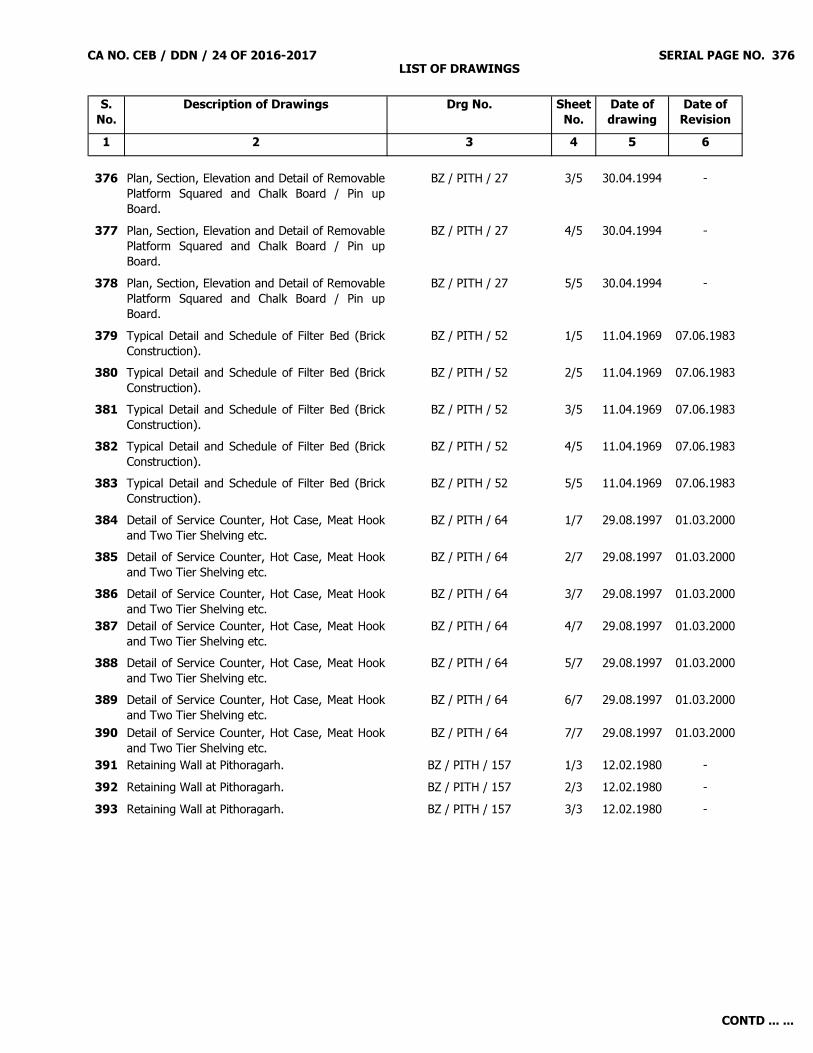
CA NO. CEB / DDN / 24 OF 2016-2017 LIST OF DRAWINGS
SERIAL PAGE NO. 376
S. No.
Description of Drawings Drg No. Sheet No.
Date of drawing
Date of Revision
1 2 3 4 5 6
376 Plan, Section, Elevation and Detail of RemovablePlatform Squared and Chalk Board / Pin upBoard.
BZ / PITH / 27 3/5 30.04.1994 -
377 Plan, Section, Elevation and Detail of RemovablePlatform Squared and Chalk Board / Pin upBoard.
BZ / PITH / 27 4/5 30.04.1994 -
378 Plan, Section, Elevation and Detail of RemovablePlatform Squared and Chalk Board / Pin upBoard.
BZ / PITH / 27 5/5 30.04.1994 -
379 Typical Detail and Schedule of Filter Bed (BrickConstruction).
BZ / PITH / 52 1/5 11.04.1969 07.06.1983
380 Typical Detail and Schedule of Filter Bed (BrickConstruction).
BZ / PITH / 52 2/5 11.04.1969 07.06.1983
381 Typical Detail and Schedule of Filter Bed (BrickConstruction).
BZ / PITH / 52 3/5 11.04.1969 07.06.1983
382 Typical Detail and Schedule of Filter Bed (BrickConstruction).
BZ / PITH / 52 4/5 11.04.1969 07.06.1983
383 Typical Detail and Schedule of Filter Bed (BrickConstruction).
BZ / PITH / 52 5/5 11.04.1969 07.06.1983
384 Detail of Service Counter, Hot Case, Meat Hookand Two Tier Shelving etc.
BZ / PITH / 64 1/7 29.08.1997 01.03.2000
385 Detail of Service Counter, Hot Case, Meat Hookand Two Tier Shelving etc.
BZ / PITH / 64 2/7 29.08.1997 01.03.2000
386 Detail of Service Counter, Hot Case, Meat Hookand Two Tier Shelving etc.
BZ / PITH / 64 3/7 29.08.1997 01.03.2000
387 Detail of Service Counter, Hot Case, Meat Hookand Two Tier Shelving etc.
BZ / PITH / 64 4/7 29.08.1997 01.03.2000
388 Detail of Service Counter, Hot Case, Meat Hookand Two Tier Shelving etc.
BZ / PITH / 64 5/7 29.08.1997 01.03.2000
389 Detail of Service Counter, Hot Case, Meat Hookand Two Tier Shelving etc.
BZ / PITH / 64 6/7 29.08.1997 01.03.2000
390 Detail of Service Counter, Hot Case, Meat Hookand Two Tier Shelving etc.
BZ / PITH / 64 7/7 29.08.1997 01.03.2000
391 Retaining Wall at Pithoragarh. BZ / PITH / 157 1/3 12.02.1980 -392 Retaining Wall at Pithoragarh. BZ / PITH / 157 2/3 12.02.1980 -393 Retaining Wall at Pithoragarh. BZ / PITH / 157 3/3 12.02.1980 -
CONTD ... ...

CA NO. CEB / DDN / 24 OF 2016-2017 LIST OF DRAWINGS
SERIAL PAGE NO. 377
S. No.
Description of Drawings Drg No. Sheet No.
Date of drawing
Date of Revision
1 2 3 4 5 6
394 Fixing Arrangement of Street Light and Pole. TD / EM / 1 1/1 27.11.1973 05.08.1991395 Detail of Danger Board. TD / EM / 2 1/1 27.11.1973 09.09.1994396 Cable Laying Details in Trenches with Path
Indicator.TD / EM / 4 1/1 27.11.1973 14.02.2003
397 Detail of Cable Duct. TD / EM / 6 1/4 09.07.1974 12.07.1999398 Detail of Cable Duct. TD / EM / 6 2/4 09.07.1974 12.07.1999399 Detail of Cable Duct. TD / EM / 6 3/4 09.07.1974 12.07.1999400 Detail of Cable Duct. TD / EM / 6 4/4 09.07.1974 12.07.1999401 Detail of Errection of Electric Pole with / without
Strut Stay assembly for Poles etc.TD / EM / 8 1/3 25.07.1975 03.05.1986
402 Detail of Errection of Electric Pole with / withoutStrut Stay assembly for Poles etc.
TD / EM / 8 2/3 25.07.1975 03.05.1986
403 Detail of Errection of Electric Pole with / withoutStrut Stay assembly for Poles etc.
TD / EM / 8 3/3 25.07.1975 03.05.1986
404 Typical Detail of Fixing 2 Pole / 4 Pole Structureand Transformer, Earthing for Transformer, SubStation and Pole etc.
TD / EM / 9 (R) 1/4 06.07.1988 09.09.1994
405 Typical Detail of Fixing 2 Pole / 4 Pole Structureand Transformer, Earthing for Transformer, SubStation and Pole etc.
TD / EM / 9 (R) 2/4 06.07.1988 09.09.1994
406 Typical Detail of Fixing 2 Pole / 4 Pole Structureand Transformer, Earthing for Transformer, SubStation and Pole etc.
TD / EM / 9 (R) 3/4 06.07.1988 09.09.1994
407 Typical Detail of Fixing 2 Pole / 4 Pole Structureand Transformer, Earthing for Transformer, SubStation and Pole etc.
TD / EM / 9 (R) 4/4 06.07.1988 09.09.1994
408 Detail of Lightening Conductor and Earthing. TD / EM / 11 1/2 17.03.1979 -409 Detail of Lightening Conductor and Earthing. TD / EM / 11 2/2 17.03.1979 -410 Detail of Pit for Valves, Stop Cocks, Brick
Masonary, Stone Masonary.TD / EM / 12 1/2 14.07.1994 24.08.1995
411 Detail of Pit for Valves, Stop Cocks, BrickMasonary, Stone Masonary.
TD / EM / 12 2/2 14.07.1994 24.08.1995
412 Notes and Legend for Electric Fitting. TD / EM / 21 (R) 1/1 01.01.2003 25.08.2003413 Transformer Platform. TD / 156 1/1 26.12.2013 -
TD DRAWINGS (E&M)
CONTD ... ...

CA NO. CEB / DDN / 24 OF 2016-2017 LIST OF DRAWINGS
SERIAL PAGE NO. 378
S. No.
Description of Drawings Drg No. Sheet No.
Date of drawing
Date of Revision
1 2 3 4 5 6
NOTES :
____________________(Signature of Contractor)
Astt Dir/Dy Dir (Contracts)for Accepting Officer
(i) The Typical Drawings listed above are available in two bound folders titled 'TD Drawings' & 'STD Drawings'prepared by the department. These folders have already been issued on payment and are deemed to be in thepossession of tenderers. Therefore such drawings are not enclosed but the same shall form part of tenderdocuments. (ii) Tenderers are supposed to refer the two drawing folders mentioned above with reference to subject work forTypical Drawings. If desired, these folders can be obtained on payment from HQ CEBZ Bareilly or else referred to inthe office of HQ CEBZ, CWE Dehradun and GE Dehradun.(iii) The furniture Drawings listed above are available in FD folders titled 'FD Drawings' held with the department.These folders are deemed to be in the possession of tenderers. Therefore, these drawings are not enclosed but thesame shall form part of tender documents. In case, the above drawings are not available with the tenderer(s), thesame can be seen in the office of CEBZ Bareilly, CWE Dehradun and GE Dehradun during working hours.
(iv) The list of TD/STD/FD drawings are mentioned above are tentative. Please note that if any drg of ibid folders, which is not shown in the list above but the same is essential for execution of the work, will be deemed to be included in the contract.
CONTD ... ...