C2 024 530 Military Curricula for Vocational & Technical ...
617
ED 193 999 TITLE INSTITUTION sPONS ACiENCY PUB DATE NOTE EDRS PRICE DESCRIPTORS IDENTIFIERS DOCUMENT RESUME C2 024 530 Military Curricula for Vocational & Technical Education. Continuous Photoprocessing Specialist, 16-4. Air Force Training Command, Lowry AFB, Colo.: Ohio State Univ., Columbus. National Center for Research in Vocational Education. Bureau of Occupational nni Adult Education (DHEW/OE), Wa.shington, D.C. 3ct 77 630p.: Not available in ra r copy due to small, light, and broken type. Ms03 Plus Postage. P7 Not Available from ENS. Behavioral Oblectives; Chemistry.; Course Descriptions: Curriculum Guises: Equipment Utilization: High Schools: Learning Activities: Lesson Plans: Light: Mathematics; Optics; *Ohotographic Equipment: *Photography: Postsecondary Education: *Production Technignes; Semiskilled occupations: Study Guides: *vocational Education: Workbooks Aerial Photography: Military Curriculum Project ABSTRACT These lesson plans and student study guides and workbooks for a secondarv-postsecondiry-level course in continuois photoprDzessing arc one of a number of military-developed curriculum packages selected for adaptation to vocationnl instruction and curriculum development in n civilian setting. Purpose stated fo: the cnurse is to expose students to fundamental concepts of the photographic process, chemistry, optics, exposure, light, and processing of color and black-and-white film: train them to use equipment and operatibns involved in photographic processing laboratories: and provide fundamental training in sensitometric and densitometric process control techniques and photographic reproduction.,,The plan of instruction, which suggests number of hours of class time devoted to each course objective, is based on the following outline allowing for six units of instruction (blocks) : Photographic Fundamentals (5 lessons), Continuous Processing Fundamentals (5 lessons), Aerial Film I,rocessing (2 lessons), Aerial Film Duplication (2 lessons), erial Select Printing (4 lessons), and Continuous ,Color Processing ( essonsl. The lesson plans contain co4rse outlines, objectives, lid information on support materials and,' guidance. Contents of the sturdy guides and workbooks include objectivesvinformative material, study questions, and exercises. Media materials are suggested, but not provided. (YLB) *********************************************************************** * Reproductions supplied by EDFS are the best that can be made * * from the original document. * ***********************************************************************
-
Upload
khangminh22 -
Category
Documents
-
view
1 -
download
0
Transcript of C2 024 530 Military Curricula for Vocational & Technical ...

ED 193 999
TITLE
INSTITUTION
sPONS ACiENCY
PUB DATENOTE
EDRS PRICEDESCRIPTORS
IDENTIFIERS
DOCUMENT RESUME
C2 024 530
Military Curricula for Vocational & TechnicalEducation. Continuous Photoprocessing Specialist,16-4.Air Force Training Command, Lowry AFB, Colo.: OhioState Univ., Columbus. National Center for Researchin Vocational Education.Bureau of Occupational nni Adult Education (DHEW/OE),Wa.shington, D.C.3ct 77630p.: Not available in ra r copy due to small,light, and broken type.
Ms03 Plus Postage. P7 Not Available from ENS.Behavioral Oblectives; Chemistry.; CourseDescriptions: Curriculum Guises: EquipmentUtilization: High Schools: Learning Activities:Lesson Plans: Light: Mathematics; Optics;*Ohotographic Equipment: *Photography: PostsecondaryEducation: *Production Technignes; Semiskilledoccupations: Study Guides: *vocational Education:WorkbooksAerial Photography: Military Curriculum Project
ABSTRACTThese lesson plans and student study guides and
workbooks for a secondarv-postsecondiry-level course in continuoisphotoprDzessing arc one of a number of military-developed curriculumpackages selected for adaptation to vocationnl instruction andcurriculum development in n civilian setting. Purpose stated fo: thecnurse is to expose students to fundamental concepts of thephotographic process, chemistry, optics, exposure, light, andprocessing of color and black-and-white film: train them to useequipment and operatibns involved in photographic processinglaboratories: and provide fundamental training in sensitometric anddensitometric process control techniques and photographicreproduction.,,The plan of instruction, which suggests number of hoursof class time devoted to each course objective, is based on thefollowing outline allowing for six units of instruction (blocks) :Photographic Fundamentals (5 lessons), Continuous ProcessingFundamentals (5 lessons), Aerial Film I,rocessing (2 lessons), AerialFilm Duplication (2 lessons), erial Select Printing (4 lessons), andContinuous ,Color Processing ( essonsl. The lesson plans containco4rse outlines, objectives, lid information on support materials and,'guidance. Contents of the sturdy guides and workbooks includeobjectivesvinformative material, study questions, and exercises.Media materials are suggested, but not provided. (YLB)
************************************************************************ Reproductions supplied by EDFS are the best that can be made *
* from the original document. *
***********************************************************************

Military Curriculafor Vocational &Technical Education
CONTTNI'Ot'S PlICTIOPROCESSSPIT I ALT ST
THE NATIONAL CENTER
FOR RESEARCH IN VOCATIONAL EDUCATIONTHE. OHIO STATE UNVL 1611

a
..
4
This military technical training course has been selectad and adapted by
The Center for Vocational Education for "Trial Implementation of a Nadel System
to Provide Militaif CurricmammElstarials Or Uss in Vocational and Technical
Educition," a project sponaored Ity the Bureau of Occupational and Adult Education,
ospattment of Health, Education, and Welfare.
A

f c
.,Mj
mILITARr CURRICUUMMERIALS
The militarydeveloped currioalminaterials in this course .
package were selected by the National Center for Researdh in
Vocaticnal Education Military Curriculum Project for dissent-
ination to the six regional CurricultmaMcrdination Centers and .
other instructima materials agengies. The purpose ofdissendnating these courses was to make curriculunaiterialscbveloped by the military mcme accessible to vocaeducators in the civilian setting.
The oourse materials wan acquired, evaluated by project
staff and practitioners in the field, and prwarad for
dissemination. Materials which were specific to the unitary
There deleted, copyriiptelmaterials were either omitted orappro-
val Bar their use was obtained. These course packages containcurriculum resource materials which can be adapte3 to support
vocational instruction ard curriculum development.
.

CONTINUOUS PROCESSING SPECIA1AST
G 3A3R23330 001
Classroomaatuse 16-4
Dave loped by:
United States Air Force
Dive iniiminn andReview Dine*
October 1977
Contents:
Blocks:
I' Photographic Funda-mentals
.I Continuous 'ProcessingFundamellvil.$
:1 Aerial Film Processin
.V Aerial Film I/uplica-tion
V Aerial Select Printin
FI Continuous Color
,
E AI A
to t
X Materials are redommended but nofprovided.
,..ommomilmoAmm:
Photography
Target Audianuas
10 - Adult
printparts: 612
Microfiche: 11
amimbhinity:
Vocational CurriculumCoordination Centers*

G 3AHR23330 001
courseDescription;
This course includes4fundamental concepts of the photographic process, chemdstry, optics,exposure, light, and processinfrof color, and blackandiwhite film; equipment and opera-tions involved in photographic prodessing laboratories; fundamental training in aensito-metrid and densitometric process control techniques; and photographic reproduction.
The,instructional design for this course is G4/Lock Step. The course is based on thefollowing units of instruction:"
Block I Photographic FundamentalsBasic Theory of Light and Optics (3 hours)Exposure Theory and Film Characteristics (14 hours)The Developmental ProCess (12 heurg)The Printidg Process (10 houfrs)
Block II Continuous Photoptocessing Fundamentals'Introducticin to Aerial Photography (2 hours)Continuous Photoprocessing Fundamentals (6 hours)Mathematics Used in,Photography (14 hours)Chemical Mixing and_Certification (14 hours)Sensitometry and,Densitometry (18 hours)
Block III Aerial Film ProcessingContinuous Processor Operation (48 hours)Titling and Cleaning Aerial Film (20 hours)
Block IV Aerial Film DuplicationNondodging Continuous Printing (32 hours)Automatic Dodging Continuous Printing (20 hours)
Block V Aerial Select PrintingManual Contact Printing (16 hours)Copying Techniques (16 hours)Projection Printing (16 hours)Step-Mode Printing (30 hours)
Block VI Continuous Color ProcessingColor Theory (16 hours)Color Chemistry (8 !lol:rs)
Processor OperlticL (43 hdurs)
This course contains Aattrials for both student and teacher use. Instructor materials, include a lan of instruction for each block and lesson plans for each lesson. Studentmaterials consist of study guides and workbooks. Media materials are suggested but notprovided.
4

t.
4.
COMM= PHDT0PROCES83110 SPECIALIST
Pile
Table ot. contents
Course Description
Plan of InstructionBlock I - Photagrephio Fundamentals
52
Basic Smog of -Light & Optics 60
Demurs Theo" Charooterist los 75
Tho Development Process 101
TM Printing Proems 119Block II - Continuqua Processing Fundanentals
IntroductiO to Aerial Photos/x*0W 144
Continuoui Photopromming Facilities 156
Mathematics Used in Ihotolgraphy 174
Cilenical Mixing and Certiftoation 189
&manometry and DensitamotrE 211
Block III - Aerial Film Processing .
Continuous Processor Operator 243
Titling and Moonily' Aorial Film 320Block IV - Maria; Film Duplication
Nondodgins Continuous Printing 377
Automatic Dodging Continuous Printing 416
Block V - Aortal Select PrintingManual Contact Printing 434
Copying Tedsnigues 446
Projection Printinj 469
Step Mode Printin1 485
Mock VI - Chontinuous Color Processing
polar. Theory 507
Color ChemisUE 547
Promisor Oteration 565

aufterammosagramtrarummerwr
A
rIAN OF INSTRUCTioN
(Technical Training )
rut 4 lAAR.:1110.rtiree.aw
CONT I NUOUS FHOTOPROC ESS INC SPiE IALIST
**IbleiNdr
LOWRY TECHNICAL TRALNING CENT=
I th tuber 197/-Ellective 17 October 1977 with class 771017
A"' FOPlii 'It* 76. opeknt,ItTio, of FOAM% its M y 's NON 11 AND US. MAY "
4
sTameani cavaassetT
4.1

1DEPARTMENT OPINE Ara FORCE PLAN OF INS1RUCTIONGSASR21130 0014
3406 Tech 1406 (MC) OW Ode TM '
Lodry Air Pores Base, COlornda 00230 1 October 077
FOREWORD
1. PURPOSE: This publication is the plan of bsetruction (POI) sinwebepains shown oipige A are bound into a single document. The POI pen-.iertheL; the qualitative requirtintsts fnr Course NOmbrr 14041121110 nol.
Continuous Phoroprocessing 4pecta1ist. ta tVONJ Cd erlIvClusn 44.!4.11vand teaching steps presentL4 by units of instruction and ohowu ticorrelation with the training standard, and eupport materinlu aralance. "en separated into unito of inatroctien At becomes Parc I ofthe lesson plan. This POI wad developed under U. provisiods of AICR50-5, Instructional System Development, and AT= 52-7.Phamo ot In-struction and Lesson Plans.
2. COURSE DESIGN/DESCRIPTION. The instructional design for this
course is Group/Lock Step. Ihe course trains airmen to performduties prescribed in AFR 39-1 for Cont4nuous Photoproceeaing Special-ist, AFC 23330. Training includes fundamental concepts of the photo-graphic process, chemistry, optics, exposure, light, and precessimg of
color and black-and-white filmq equipsemd and operations involved inphotographic processing laboratorbes; fundamental training Ls sensito-metric and densitemetric process control techniques; and photonraphit
reproduction; and operator ,knowledges asaociated with photographic
laboratories. In addition, Waited training is provided ondripareducation, mission application ssminar, troop intimation program,commander's calls/briefinna, etc.
3. TRAINIM EQUIPMENT. The number hown in parentheses after equip-,
ment listed as Training Equipeent'under SUPPORT MATERIALS AED GUID-
ANCE is the planned number of etudents assigned to each equipment unit.
4. REFERENCES. This plan of instruction is based on Spocialty ?reiningStandard 231X0. July 1977 and Course Chart C3ABR23330 00i, 3 August 1977.
FOR THE COMMANDER
-
MIN D. BOWIE, Colonel, [MAYCommander, 3430th Tech Tng Gp
Supersedes Plan of Instruction G3A2R23330 000/G3AZR23150 090,
1 November 1976OFR: 3430 TCHTGDISTRIBUTION: Listed on Page A.

IIMODIFICATIONS
t 1..&.5.,ci rt. 1 of this publication has (have) been deleted in
adapting this material for use in Vocational and Technical Education. Deleted
material involves extensive use of military forms, procedures, systems, etc.
and was nol considered appropriate for use in vocational and technical educa-
Lion.
1 1)

1-WiTiirfAueTIAPLA/ N .91. INSTRUCTIONALESSON PLAN PAM I
1 Photographic FuMauntalm
7Career Progression, Security, and Safety
the five primary duties of a continuous photoprocessiggtwee IA int iutd define career laddin. progression procedures. STS: la, .
mill ?tea,. w
) Air Foree classification system
(2) Spec ial t y demc ription
(1) Spey LAI ty Training Standard (STS)
(4) Upgrade t raining
(5) On-the-Job training
(6) (arer development c.lurse
(7) Skill level progression
U CU
a Symcidis
h. Given in f orma t ion pertain ins to security Alassification andessential elements of fm4endly inidattion, identify tems,. definitionsor 'classifications as they relate to COHSE.- STS: 2a0.), 24(2).Pleas: W
(1) Three types of information: classified, unclassified anuthldusified but of possible intelligence value.
. (2) Seturity classification guide.
(i) Proper UMV of MAJCON/SOA esatia3 elements of friendlyinformatioo
. Given intormatlon rvlating to communication mto0s, security**Spike and nonce. finical procedures designed to prevent security viola-tions, identify terms, definitions, risks and corrective actions as theyciliate to COMM. STS: ha Ness: W
(I) Communication nodes vhich wilt itorovide the security, re-liability and speed rrquired.
,
1GNA TWEE AND DATE
1 S St
PLAN OF tAATONTCTION
-NAMGM0112 3330 001
_
* roma a33 NtVOu t Oft IS O LT lo;'A-- .45 41. OCT II
gin-
TI E
6(4/2)
.1.11.1../.1.14(011. .1...14 *Ala
rk.koave KO.
A ber 1971if. f.V. 0.1 07-47+
3
AU livq/%101

MOW COMM?
(Vetoes.
41111=101111=,.....-0 -
(2) Security risks that exist when using unsanored communicatioa
(3) Security risks that e'zist in attempting Le dleguise classifiedor unclassified information of intelligence value.
(4) Procedures designed to prevent bc!;...1,,y visaatious and
practices dangerous to security.
d. Given an example of an operational security vicastIon in your creurfield, identify the cause of the viol&%ion. STS: 2b.c2j, 3m22,1/b(5) 010 Haas: W
(1) Purposes and objectives of OPSSC.
(2) Relationship to other security programa.
(3) OPSRC vulnerabilities of this spftialtv.
e. List two safety precautions you should obourve for each of the
following potential hazards: electrical, mechanical, chemical, and comp-
pressed gases. STS: 3a, 3b 3c(l) 3c(2)4 3d Mean: W, PC
(1) Warning signs
(2) Illumination
(3) Chemical hazards
(4) Compressed gases
(5) Electrical hazards
(6) Mechanical hazards
(/) Fire prevention
AM Fells MAsepLaces LTC POMO MM. MAP TS. AND MA, *VS IL MGM 1111144 911U1140.

PLAN OP INITRUCTION/LEININ PLAN PART I (CapeNeeeliae asse)
COWIN CONTINT
SUPPORT NIITERIALS AN) GUIDANCE
Student Instructional MaterialsSW G3A3R23330 0014-2. Career Progression. Security, and SafetyATC SO E3ABR/0BR00001 Communications Security
Aut_to Visual AidsFibs TF 6650, COMSEC and /ouFibs 1FP. 1872, Alone, Unarmed, and Unafraid
Training MethodsDiscusalon and Demonstration (3 hrs)Performa0-.ta (I hr)CTT Assignment (2 hrs)
Instructional GuidanceRelate continuous photoprocessing to the Photographic Career Field andaerial reconnaissance. Stress the importance of Safety and Security.Give CTT assignment.
Pt ANCOR INSTRUCTION NO.G3ABR23330 001
ATCPOMO .APR 71
RIPLACU ATeti1(D.
DAYS1 October 1977
/-`
ORMI MA, NAN 71, AND 1,70K, AUS n MCP WiLl. IPS

INIIIIIIIIIIIIIIIIIIIIIIIIIIM... Pi 1 P. ART 1
Continuous Photoproceasing Specialist
si.ocK Numetn,
I
KO= -T4
Photo raphic Fundamentals1 TUN
3. Publications
d. Using apprOnridteresearLh exercine 16t:3te
STS: 4a, 4c. Meas:
technical order files, publications, and a
required technical urder information.
W. PC
manuals
technical orders...,
technical orders .
technical orders
and procedures technical orders
technical orders
technical orders
order numbering system1 N
nal'iiiis
-..
numbering syttem
,
.
il
3
.1!11.
..(1) Technical
(2) Preliminary
(3) Automatic
(4) Time compliance
(5) Methods
(6) Abbrelriated
(7) Index type
(8) Technical
(9) Air Voice...regulations
(10) Air Force
(II) Pamphlets
(12) Publications
_
IRMO., APPEOVAL OF LE -NF MI FEAT 11)
$ DNATUD AND DATEEIGNATIONE AND DAT
,
Pi, Are 0 tt, ',RUC Tifkita Num Re t4 ..;
G 3310 4001 '. 1 October 1077.....
AO g NO.
7
eve room Idli envious go el ON is ouvoi.(Te.G.P.OV 1975.671-5S514
ATC 76.27001

FLAN OF INITIWCTION/LOINN FLAN FAIT I (Ceatissuseam Sola4
MOO COMMIT
SUMMIT MiTICRIALS A !1DMC R
'Student Instructional MaterialsEMI G3A1M23330 001-1-39 P4blications=IC 52-49 Alr Force Tecbmical Ckder SystemMUT 52-49 Air Force Techrical Order System
Audio Visual AidsTF 1-51059 The Air Force Technical Order System
Traininit MethodsDiscussion and Demonstration (2 hrs)Performance (1 br)
Instruc tional GuidanceTechnical publications will bs limited to TO, and mill be covered by
discussion and demonstration. Check, CTT assignment.
15
IRIAN 0/ NOSTIONCTION 00.C3A923330 001
ATC
N
0011' 11 October 1977
IMPLACCI A C FOAM ISM NAN 71. ANusas.
obee WI NOCK 00 DS

...,,. P MTN T . PLAN PART-.
Continuods Photrocass , S. cialist
Photo re hic Fundamentals
t. 1 . ' TIME
4. Basic Theory of Light and Optics
a. Identifi the five characteristics of light and their relationship with optics. STS: 13c, 17b, 17c Mean: 14 PC
(1) characLeriaau ui light
(2) Behavior of light
(3) Design of a lens ,.
(4) Lens characteristics
(5) Lens types
(6) Lens aberrations
,
3
SUP UN SON APPIOVAI. Or LESSON PL. AM (PART II)SIGMA TURD AND DAYS 0, DIGNATURI AND DAT-
.
-
IPII.AN OF oNSTRuCTION NUMBER DATE .
G3ABA23330 001 s-.
PAGE 140.
.
. fl,
ATC "" 133OCT VIIPAEviOuS 011SoLiTi
1 6ATT 76.27001

/0 PLAN OP NOTOOCTIOPULIMON PLAN PANT I fCsatioestiss Ows.
COMMIS CONTENT
SUPPCOT NATBRIALS AND GUIDANCE!
Student Instructional MaterialsSW G3A1N23330 001-174, Basic Theory of Liest and Opticti
Audio Visual AidsFilm MN 2449r Introduction to OpticsFilm TVL 23-3, itindementals of Optics aud Photography
Training Methodsriscussion and Demonstration (2 hr.)Performanoe (1 hr)
Instructional GuidanceApply optical principles to photographic use. Explain the relationshipbetween emulsion sensitivity and various types of light.

MAME C.
117-6CW-AotlariA SITME-TaT1--
Photo ra hie Fundamentals
Continuous Photobrocessi Scial1.t
MAE
5. Exposure Theory
a. Nmme the fivefunction of each part.
(1) Body
(.!) nit
(3) Viewing
(4) Focusing
(5) Shutter
ofine ihe major/14 (I ), lk, 151, Og
(1) Film structure
(2) Riaek-atd-white
(3) Specialized
(4) Aerial
(5) Storage
. vrovided J 35MMdirected by your
(1) Exposure
(2) t.xposure
(3) ciimera
and
film
instructor.
operation
Film Characteristics
principal parte of a camera and define theSTS: 13b Meas: W
system
system
characterAstics of photographic film. STS:
Meas (W)
emulsion characteristics
emulsiuna
classificationa
and handling of sensitized materials
camera and film, photograph several JcenesSTS: 13b, I3c New W, PC
theory
and film
14
(12/2)(3)
(3)
(6)
WPERVISOR APP.MVAL OF LESSON PLAN (PART H)
I Aro ur et%7 Hi TfON
63A5R21330
SIGAATUREANDDATg SONATU RAH DATE..*
p,UIIi 1.1
001
ee
OAT
1 October 1977
PAGE O.
11
ATC "Rs 13301 Ts, off %, into, P
0 11 *- . 1,. (I.not. Is 00'44 e TV A I 7C-: 10'11
1 75.6 71 -,86 /42

COURSe CONTeNT.IMMEMIMMINNIP.
SUPPORT IINIIRIALS AND GUIDANCE
ambient Instructional MaterialsSil G3iB123330 001-1-5, lbsposure Theory and File Characteristic
Audio Visual/kidsFilm MN 5383, Fundamentals of Pbotograpy-i't C 4.4" rit
Vainer, Iris Disphragm
Trainina Equiptent35mm Camera (1)
Training MethodsDiscussion and Demonstration (6 hrs)Performance (6 hrs)Cn. Assignment (2 hrs)
Instructional. GuidanceProvide a basic introduction to the functions of the canera and film. Nave
each student expose one roll of 20 exposure film during ad an base photographic
mission. Give CTT assignment.
Pekr.onmacas Ayc roans MA. MAP 11. o MA, APOVOID.
3. IlleNCIO WM& IPS

IT'OnrSir-Mentarraie
e.)& ki71-148f
PLAN OF MSTRUCTION/LtSION PLAN PART I
irrtrirrirPhotogra hie Fundamentals
O T
Continuous Photo) overman s wia114
Tun
h. The Development Process
A. Identity Ow chemital properties of black-and-white processing
Lia(dA)), I !)..( , 5C. J. J4: (2 ) W, PC
(1) Developer
(2) stop bath
(i) Fixing baths
(4 ) Wash
b. Procehs prevloualy exposed film using manual processing
Processod negdtives must be free of physical defects and
hav acceptable demiley and contrast. STS: 3a, 3b, 5a(21)(s),
5a(21)(b), 9a, 9b, 9c, 9d, 9f, 9g, 9h, 91., 9j(1), 9j(2), 9j(3) Mess:
W. PC
(1) Preparing for processing
(2) Processing 35mm film
(3) Time-tempersrure processing
(4) Archival quality
12
(6)
(6)
sue (11111051 AIFFOOVAL OF Lesson PLAN (F MIT O)
IGNA Wit AND DATE
t Aft, A i INS 1 RUC TION NuMef
C3A11123130 OOLlow
ATC 133
MAU AND DA,
..ape
OA E AGE NO.
1 October 1977 13
WOW. Ti CM Ii DISSuL A; 1)1: - i b. 471 -50,0Arc lbVuor

I. VOW*
PLAN OP INSTRUCTIOMMION PIP.M PANT I :CoutkoraNas Iwo)
SUPPORT MATERIALS AND GUIDANCE
Student Instructional MaterialsSW G3141123330 001-1-6, Basic Photo Chemistry
Audio Visual AidsFilm MN 6673, What Happens During Processing
Trainiqg EjuipmentTimer,Continuous (1)Thensometer (2)Laboratory Facilities (8)Film Dryer (8)Processiit Tank and reels (1)
Training MethodsDiscussion and Demonstration (6)Performance (6)
Instructional GuidanceProvide a basic introduction to photographic processing principles and etre..
chemical safety. Check CTT assignment.
PLAN Dr NAIPAUCTIONCIABR23.130 001
ATC AIZIP **4 133A
21
irePs.*Cgs syc Pones WM NAN 111, AND MA. NW IL WV. Nut etwag,.

IFiriZ 'tit 47114.1.14
PLAN OF INSTRUCTION/LESSON PLAN PART I'cumin TITI.t.
Cc/M.161'mm; ithotoprecessina Spwialiattiara-1'MT
Phew re hie Fundiusvntaina TIME
The Printing Process
a. Identity the miljor charneteristics of photographic paper. STS:
81. 1St', Pig Meat W
t
(2)
t lit L.L.
Nuulsion characteti:Aies
13) titurngi . and hand I lug
h. loAng vus-viousty exposed negatvicp.,!se and pro. Vh$N pt ojcv t ion prints.
and vrocerniing 1e1ect4. STS: lb,
MO, Me, 81, 8g, 8h, 9a, 9h, 9c, 9d, 91Mean: W, PC
ives and a,projection printer,Prints must be free of exposureSa(21)(a), 5a(21)(b), 8a(2), 8c,
, 9g, 9h, 91, 93(1), 93(2), 93(3),
(1) Ptivction printing principles
(2) Types ot printers
(3) The EN-523 projection printer
(4) EN-52B uperating procedures
(S) Negative evaluation
(h) Pro)ection printing steps
(1) Print proceshing
00 Print tinishing
altVISOR ArilklYAL, OfLESN PCA-INIFART'-
SIGMA WU AND PAT, SiGNATURE AMP
OPt PPU, Ottbi v Miii ii
CIABR23$ffl) 01/1
ATC fo,":IN 133 vtoil . 0, 114in 1. 'AN% 'Lt. TI
An
10
(4)
'6)
oVs-r-
1 October 1977
IP AG.E NO
0 to 147'.. 42Ah

FLAN OP NOTINETIONANION PLAN Pant I massigass. eon.
[ PLAN Of NOOTINACTION NO.
G3011823330 001
=MI =MOM
SUPPORT NAM PALS AND GUIDANCE
Student Instructional MaterialsSW G3AIR23330 001-1-7, The Printing Process
Audio Visual AidsSlide Ups, FS-52A Projection Printing
rraining Nuipment,Projection Printer (1)Timer. Interval-(1)Timer. Continuous (1)Thermometer (2)Laboratory Facilities (8)Print Wisher (8)Print Dryer (8)
Training MethodsDiscussion and Demonstration (4 hrs)
Performance (6 hrs)
Instructional GuidanceDiscuss and demonstrate proper projection printing techniques. Mmphasise
chemical and eLectrical safety.
8. Belated Training (identified la course chart)
9 Measurement and Critique
a. Measurement Test
b. Test Critique
A
MC AZ.' 4,119 ISM
12
2
PrDPACDS &VC POO. SISTIL ce. fl, AND MA. ADO 74 woe WILL De

/ 1. -Continuous PhotoRrocessing §pecialistlc& Vraiiitii 0114 TITLy
caw itiailUte rho CAI trove:04w Fonitameindt1dMgt
1
I. MiuroduLtIoo to Aerial Photography
. List and explain the foul phases ut the totellAgence cycle,STs: I40 Meas; W
(1) Requirments
t-!)
(i) Lir oduc L ion
(4) Lits8emlnaltion
b. Detine Lundamental techniques and terms used in opticalfcc oana ane e . STS: lb, 140 Mess: W
(I) Cartographic photography
(2) kcconna 1 seats e phot ography
(3) deconn.1 I sms nc c mission*
(4 ) Aeries easier as
(S) Camera posi t ions
List tile capabilities and limitations of nonoptical Imagerysystems. STS: lb, 14a Meas: W
(1) Side looking airborne radar (SLAR)
(2) infrared (IR)
(3) La-ter
SUPERVISOR APPROVAL OF L (SION PL (PART III
2
SIGNATURE AND DATE SIONATURt AND DATE
.410.
PI ti 040, I eg s T,p 0 epof tft ff
t;liAliktiliJU Utit
ATC "3" 133or' T.
P Act MO.
POE VtO0 Ri n Lift
1 QeLober 1977tI.N. AI. 7 -67 -6ATc 76i /OM

UMW 15111111ALS AND =MAME
Studemt Instructional MaterialsSW C3111123330 001-11-19 Introduction tiAerial Photography
;
Audio Visual AidsFilm SFP 1327, Tactical Air Reconnaissance35mm Slides and Script, The Intelligence Cycle
4*Trainins MethodsDiscugglon and Demonstration (2 hro)
Instructional GuidanceMotivate students and establish th place of the 23330 is Aerial PhotoReconnaissance.
Alt "Ile USA nerticas AMC MINN NM MO 71, p 11.4114 MO IL 11110011 WILL OSWNW

ri.toi UP INTR TION/LISION PLAN PANT I
Taiz6i Naliin -TvL1 Lflij
2. COTiLintions Photoprocessing Factlit icb 6(4/2)a. Describe the operating principles of a precision processing
laboratory. STS: 14a, 5a(21)(a), Ss(21)(b) Ness: W
( 1 ) EnV it'intilken Lai I et. I ot
( ) M4it hinvry
( 1) r fauna I hygiene
(4) hrup Wye.. disc ipline
(5) Visitors
(6) :iecur it y
( ) Ma int t. and inspect ion
(8) tiatety
(9) Adjacent areas
b. Describe the mission and organization of the PhotographicProcessing and interpretation Facility (Ppm, WS-43015. STS: 14sMess: W
(1) Mission
(2)- organization
. List the bast. responsibilities of the Production Control unit,tho imagery Interptetation unit (11), and the Imagery Processing unit(11' ) within Un- Wti--4 Wit cumplot. STS: 14.6 luau; W
( I) Pc otiue t lun oiitruL
(2) Imagrry pro.v:,sing
(1) imagrry intvrpretation
steps* Tulle As
TMITIMTOTT. TMITTPT Aft!. ft rm..
...WPERVISOR APPIKIVAL. Elf LESSON PLAN (PART $0OAT SIGNATolit AND DATE
.
Af, Of 114$ T 411( T .44,6601t64
GSABIMYK) Qul
ATC ""s" 133 #fIP ViflJ ". ,,t Ott%.1 t I t0( T 711
DATE
1 October 1977o it.. I ..R6 42
A I
r)i-1
PAGE NO.
19
a

alOPIIIM ellnIP HUM re011011Pmme PApownelliONIMININIMIIIMINOIli11111111=1110111mmomploo
CORMS COMTISM
C219 d. List the functions of the individual shelters contained inthe WS-430B. STS: 14a Nees: W
ES-61B.(1) Expandable Final Edit and inspection Labs, ES40B and
(2) Continuous Processing Lab, ES-59A
(3) Expandable Film Titling and Cleaning Lab, E5-63A
(4) Expandable Interpretation Lab, ES-64A
(5) Series I Printing Lab, ES-573
(6) Series II Printing Lab, ES-58B
(7) Series III Printing Lab, ES-73A
(8) Chemical Mixing and Distribution Lab, ES-65A
(9) Sensitized Materials Storage Shelter, FS4A
(10) Expandable Maintenance Shelter, VS-7A
e. Explain the steps necessary for maintaining a mobility capability.STS: 14a, 14b 14c, 14 14e Maass W
(1) Deployment preplanning
(2) Mobility responsibilities
(3) Facility preparation and setup
(4) Mobility exercises
1. State tile purpose of the Dual
(I) Mission requirements
(2) Operational flexibility
(3) Training
Basing Program. STS: I4a Meas:
g. Explain the major causes of corrosion within the WS-430B complex.STS: 14a Meas:
(1) Climatic conditions
(2) Corrosive chemicals
ATC 133A RIPLocirs AT C room Mk man ts. man Int*. Kw lg. "MC" gniPL Si

COVINA CONTINT-..../Melp
h. List the general responsibilities of all,pursonnel assigned to aWS-430h complex in Hupporting an effective corrosion control program.STS: lb Mess; W
(1) Identification
(2) Correction
(1) Prevention,
L. Oescrtho-tbe reapomiibillticb of ttec OLC ans.: thc LogizitAc-in a WS-430h facility. STS: W
(1) 0!C responsibilities
(2) Logistic officer responsibilities
- SUPPORT MAMMALS AND GUIDAME
Student Instructional Materialti5W G3ABR23330 001,-11-2, Continuoua Photoprocessing Facilities
Audio Vitsual Aidsnom Slides, WS-430B Urientation35mm Slides, Mobilizing the WS-4.1011
35sum Slides, WS-430B Cofrosion Control
Trail-14ga Methods
Discussion and Demonstration (4 hrs)CTT Assignment (2 hrs)
lu t ruct tlinia Gil Walk 4'
F411 .4,41.44 that studnts hav a b.ist ind erstanding of the processing facilitiesrtLit they will probably encountvr in this careef field. Baphasis should be
ed on strategic and tactical processing functions. Give CTT assignment.
PLAN OP li1tAIXT6Olo NOUU
LTC vellitilitgAitACvSII).
ATC POMO NM, ISAX We MA. Au. Ilt. IIINICN sew. gig

"Mei
I. Cant inuous fotofairrYnr r *aNI
3. liathesiatics Udell In PhotographY
. Given photographic related math problems and log tables,solve 80% of the problem correctly. STS: 16a 16be 16c Meas:W, PC
(1 ) Balk dr 1 t hnie t ic
k ) ilumbcrs
( 3) Logarithms
(4) Metric system
(5) Temperature conversions
14(12/2)
soPEnVISOR ArraottAt. OF L E SON PLAN MART N)
4.40111. ..1.1111.=, 0,1.1%11=.10MP
I to 44*. Itt. 1-1(-11Ni sMIlt
GJA1K233.10 001
ATC "4" 133'ot I re PAIVICItib t. DI In OM 11 ONS6,,1 IT%
Of/
Da I t AQE
1 Ortober 1977 2314,75-611-sa6/42
Air 7...770ni

PLAN OP INSTRUCINNALBIRON PLAN PART S (Csanasseles Phsat)
COMM COMM..=11.11=MIMINPm
SUPPORT HAMM.% AM) GUIDAICE
Student Instructinnal MaterialsSW G3A3R23330 001-II-3, Mathematics Used in Photography
Training Plethals_Discussion and Demonstration (6 bra)Performance (6 hrs)CTT Assignment (2 bra)
Instructional GuidanceDetermine in-depth subject matter coverazm by analysing results onmsthematical problems. Giire CTT assignment.
311
PL AN OP IANITRUCTION MO.
G3
DAT 4 Past no.
OROS11111VAL *CDS Mc(ISM
W. NAN Irt AND TWA, AUG U. !MC* WU. OD

1MWFWWWWW-----1
,41
Cuntimuous Phot rocossi ecia1ist
Continuous Photovrocessil rundsmontshecaw 4-1
4. ChemiLal Mixing and Certification
o.1111011111...
A. Given the necessary bulk chemicals, selected formulas,
chemical mix facilities, measuring and miring equipment, prepare black
and-white processing anlutions. Solutions must meet locally prescribed
standards of quality. STS: 3b. 5a(2l)(a), 5a(21)(b) 15b(2), 15b(3),
Ob(5), 15e Meas: W, PC
b. Givendetermine theStudents,valuemusebe within15c(2)
(b)
Chemical grades
Mixing chemicals
Safety in mixing
Storage
Glassware (types)
Cleahlog eassware
Glastware measurements
Beam balances
pH meter, hydrometer set, and photographic solutions,
pH and specific gravity of the photographic solutions.
for pH must be within jt0.10 and specific gravity value
± 0.015 of the class standard. STS: 6b(2)(b), 15c(1),
W, PC
Purpose of specific gravity analysis
Use of the hydrometer
Temperature cOmpensatiote
Reading the hydrometer
-Purpose of pH measurement
taectrudes
14
(12/2)
(8)
(6)
4
SUP ERVISOR- APPROVAL OP LESION PLAN (PART th
SIGNAIUII IbND DAtt
PLANWINSVMUCTIONNUMOLM
ATC "" 133Or T fS
1.111011.1.111MOW
pReviaug teMit ON 1$ 00%01. g faU.S. G.P.O. 1975-671-586 42ATC 7647001

PLAN OP INITINICTIOWilliON PLAN PANT I rissOuselies OW*
COMO CiMeTIINToramn.....m.41M01110. ..0.11* me.. ... glabf
(7) Buffers
(8) Operation of pH meters
(9) pH measurement precautions
SUPPORT MATERIALS AND GUIDANCE
Student Instructional MaterialsSW C3A11123330 00141-4, Chemical Nixing and Certificatien
Audio Visual AidsSlide Tape, Nixing Photographic Solutions
Slide Ups, pH Meter *t
Trainink 119uipment
Chemical Laboratory Facilities (8)
Assorted Laboratory Glassware (8)
Triple Beam Balance (Scales) (2)
pH Meter (2)Hydrometer (2) 4
Thermometer (2)
Training MethodsDiscussion and Demonstration (6 hrs)
Performance (6 hrs)CTT Assignment (2 hrs)
Instructional GuidanceStudents are introduced to chemical laboratory apparatus and procedures.
Stress chemical safety throughout the lesson. Give CTT assignment.
32
PLAN OF ONITRUCTION NO.
WIWI° 001 1541101P111ACIFS ATC MOW WA. NM IL AND rsm. AVS ts. UMW DILL es

NAME OF INETRucrom 10441000 s bg
Contkmatt_lbes2processi
C n n cussin ndomentals-.11411!
S. Sansitometry and Denaitometry
A. Using unexposed original film, sansitomater, previously mixed
processing solutions, and manual processing facilities, expose and
process eensitometrir strips. Procaaiid sensitometric stripe must be
of acceptable density and be free of chemical and physical dedects.
AS; 1 LI , tic , 17e , I1i W, PC
(1) Sensitometry
(2) Classification of sensitometero
(3) Light. sources
(4) Exposure modulators
(5) Kodak Model iOl eensitometer
(6) 1E & C. Mark VI sensitometer
(7) Sensitomerrie processing methods
(8) Safety precautions
b. Using a densitometcr and previously processed senaltometric
strtps, measure and record each density step to within + 0.02 of the
actual density. STS: llb Meas: W, PC
(1) Transmission, opacity and density
(2) Densitometry
(3) Classification of densitometers
(4) Common nensitometera
(5) Operating procedures
(6)
suP union APPOOVAL OF ESON PLAN (r ART n )
SIG44$ TUN( AND DATEsiosamtme AND DATE
-rt.... Of INS T Rut ION fdifko.:111
4
ATC '° 133OCT 71
a f PAGE IVO.
Pat WOW) ni Tip'. IS Off t T1011.c G. O. 75.fi
76.27001-566 4

PLAN Of INITNUCTIONIL1111100 PLAN PANT 1 goattamMe. $hes.
MIMI! CONTINT
bar
are MOM,. 10 a 11.11011aIbliiir4 a...
c. Using deneitemetric readings from it previously processed aanettonetric*trip, plot a sensitometrie curve and determine somas. Gamma moat WI eon- (4)puted to within 4. 0.10 of the class standord. STS: lld Maas: 14 PC
(1) Parts of a characteristic curve
(2) Plotting the curve
(3) Determining gamma
SUPPORT MATtlIALS AND GUIDANCE
Wide* Instructivol Moterialc.SW G3.41E23330 00t-I-5, Sensitomstry and Densitometry
Training EquipmectSensitometer (2)Densitometer (2)Manual Processing Facilities (6)Neutral Density Filters (8)Graphing Implements (6)
Training MethodsDiscussion and Demonstration (6 hrs)Performance (10 hrs)CIT.,..Assigniint (2 hrs)
Instructional GuidanceEmphasize intensity scale sensitomsters, safety and cleanliness. Cover theNdensitometer as a basic tool of sensitometry. Stress atl five parts of thecurve and how each can be used to control .the process. Check cTr assignment.
6. Related Training (Dientified in course chart)
7. Measurement and Critique
a. Measurement Test
b. Test Critique
PLAN OP INSTRUCTION NO.
G 3ABRUtigt opAT'C APR75 133A
3 4
2
I OAT,1
SUIPLACRS ATC POO* MA, MAR 71I. ANDLIMO.
IWO TS. MINN SILL ft

OF INSTR TION/LESSON PLAN PART
111
,1. Coot inuous Processot Operation
a. Identify the basic operating principles of continuous pro-
cessors. STS: 5a(20), 6a, 6b, 6c, 6d, 6e, 6f Nima:
(I) Film ,Irives and transport systems
(2) Machinv-threading yLL
(3) DLeveloping and fixing syritems
(4) Kecirculation systms
(5) Squeegees
(6) Drying systems
(7) Safety
(8) Siiver-recovvry methods
(9) Silver-recovery equipment.
(10) ku ltron
(11) H.T.A. 3(24
(12) Eictschrome RT Processor Model 1811
b. hienEity and locate the major components, systems, and controlsul Versamst 11C41W Processor. STS: 3a, 3b, 34, 6a(1) (a); 6a(1)(b),,ha(1)(2), ba(1)(d), ba(1)(e), 6a(1)(f), 6a(3), 6a(5), 64(6), 64(9)Mead: W, PC
(1) Cuneral description(2) Standard equlpment(3) Accessory and optional equipment.(4) operating principlvn(5) Functional. description(b) uperatlng controls
48
(36/12)
(3)
(3)
Wel MAIO* iPP11011aL. OF LEND* Ft. AN WAITssCiAA Tung Asp DATE SIONATURD AND DATE
...1110P4144 Of MISTIRIot TOON wimpf
CIAIIR23330 001
ATC f°11" 133I T 71I
---..""
1 October 1977 29n.; AI. 19M-L.11-586/4ZA T, *1 7."'off vlOw. TI Ijid S 0N..ii I TE

PLAN OP INITINCINNAMION PLAN PAW S (Cgoiersige OW.
c. Provided a Versamnt proceaker, setup and aystens clean tha pro- (6)
cessor while observing all safety prucautions. STS: 3m, 3b, Id, 56(21)(a),
6d(2), 6f(1), 61(2), 61(3)(b) Moss: Wr, PC
(1) Initial setup
(2) Systems cleaning
d. Using specified packagedsolutions. Mixed solutions must3a. 3b, 6a(2), 15a(2),, 15(b).(1),
Meas: W,PC
chericals, mix and certify the chemical (6)
moo! IneW certification atandarda. STS:
15o(/), Db(4). 154(5), !al)),
(1) Mixing chemistry
(2) Certifying chemistry
(3) Filling processor tanka
e. Using a Versamat processor and operating checklits, startup and (6)
shutdown processor LAW the checklists. STS: 3m, 3b, 30, 58(21)(s),
3a(21)(b), 6a(1)(a), 6a(1)(b), 6e(1)(c), 6s(1)(0), 68(1)(s), 6s(1)(f), 61(3),
6a(5), 6a(6), 6a(9), 6d(2), 6f(1), 6E(2) 6f(3)(b) Nemo: V, PC
(1) Preoperational check
(2) Daily startup
(3) Daily shutiown
(4) Preventive maintenance
f. Provided a Vereamat processor, certify the proceseor mechamIcally (6)
chemically and sensitometrically. The processor will be certified to meet
local certification standards. STS: 3a, 3d, 6b(1)(b), 61,(2)(b) 6b(3)
6e(2), Ila, Ilb, Ilc, lid Mean: W. PC
(1) Mechanical certification
(2) Chemical certification
(3) Trouble sh3oting
(4) Sensitometric certification
(5) Process control
g. Explain dbe need for a quality assurance program within con-
tinuous photoproceasing laboratories. STS: 6b(2)(b) W
(1) Laboratory quality assurance
(2) Central calibration program
POWS OF UOOTNUCTIOW NO.
GlAIR2lara RePtaces avc MM. OM yip. MIA, IVO n. WC* IR% 01SC 0.ATC "1"4 MA
(1)
36

PLAN Of ImTuUCItawIs KAM PANT I (Cosessousses lbws)
COORS" CCMITIENT
(3) Sensor system ovaluation prosram
h. Using a preinspection table and a Versamat processor, preinspect (5)and process exposed aerial film, processed film must be free of processingdefects. STS: 3a. 3d, bc(2), 6c(4), 6c(5), 6c(7), 6c(9), 6e(10)(4,
6r (10)(b), 10a(1), 10a(2) Ness: V, PC
(I) Preinspection and makeup
GO Processing
(j) Processing defects
SUPPORT MATERIALS AND GUIDANCE
Studeet Instrui. t tonal Mater ial sSW G34%111123330 001-111-1, Continuous Processor Operation
Audio ViNuili A dsFile MN 10302A, Th V11-38 Mot ProcessorFilm MN 10302C, The F.M-38 Processor Quality ControlSilver Recovery CartriAlge Trainer
Training EquipmentPreinspection Table (4)Versamat Nixiel lICKW Processor (4)Processing Support Equipment (8)Cleaning Supplies and Equipment (8)
TrAning_ MethodsDiscussion and Demonstration (6 hrs)
Performance (30 hrs)CTT Assignmentft (12 hrs)
it riii i I ona I c;i, Wan,_
Fraptiatittt . checklist proctOktr eh 4dI y. C 1iJ iv/dual. I r. .trLic clan ,611,g at t iii, r ti I Lt. ation , upg tat. ing , trUIAJletitistiot IIi, drul k...I..u:sure that ntudents save their processed film for use in the next SW. CileckCTT dowilinienta.
Ptak./ Of 11111,11OC111001 mO
IAHR21130 001
ATC :41.84 133A
DATE1 October 1977 31
PAOS NO.
It(PL.ACt$ Ayr roams MO, Ewa s). Aso TO& AU, 73, WHICH WWI-%ASO.

imam or lam fouc row jMime yint
nr7m7T-------Continuous Photerncessits SpeciolabC
srsi
Aer la! Ftliu jici.eing
. Titling ona Cleaning Aerial Film
a. Using an editing table,frisking' to a roll of processedrecorded. ST'S: la, 10c, 10e,
(1) l'OaLlmiliec Lion
(2) Pr iwur y Ltreakdown
poetinspeet and attach head and tallaerial film. All defects must beLIAM. lOh(2), 101 Naas: V fC
b. tieing a Dud) head film titler, title processed aerial film.Typv must be torrectly positioned and transfer OD the film must be
legible without flow or embossing. STS: 3e, TA), ?e(2i, 3d,124(1)(a), 12.i(1)(b). Via(l)(c), 12a(1)(4), 12a 2), 12a(3121: 12d Meas:
Ti ink.: print. iples
Genera I Jest r ipt lon
Detailed description
Preoper tion procedures
uperat inn
Shutdown
Preveot Wig ma intenance
. Using a Delaware portable film titler, title processed aerialil as. Type must be turrt t t 1 y potatiored and transfer to the film must
be legible without flow or embossing. STS: 3a, 3d, 12a 1 a),apja(..), 1.31112(d), 12a(2), 12a(3), 12a 12c, 124 Keas:
W,
(I) Genoral description
(2) Detailed deem' ription
(3) Preopera Lion prncedures
Air r11A-iiiIl OF L MON PLAN (PAIO OHSIGN& TWIE MAD DATE
0, ;lest 01.1,;(1.1)iiNualiaik
G 2 33OATC ot 1 Ili
..rmeap-
(6)
(3)
1140Arlieg aolD mare
DA PAGE AG.
1
PR@ we t Do 'ION 06 OlIkPI L fir4

PLAN OP INIITOLICTIO144111141N PLAN PIM I (CeeNeessies Sege
d.
must be3a, Id,AL., 12d
cense CONVENTamow ..mao - . 41.
(4) Operation
(5) Shutdown
(6) Preventive maintenance
Using a film cleaner, cleao oc4free of objectionable dirt, ,,5a(21)(a) 5.1(21)(b), 12b(Ck,i.0 ...E.g.Meas: W, PC
(1) Taconic tacky roll cleaner
(2) Tacky roller film cleaner
e4Red 41MT1411 film. Cleaned fils (4).tt4 ouher forAgn matter. 5TO:
1.140411), 1:11(1)(e), 1TI,Cni le
SUPPORT MATERIALS AND CUIDANCE
Student Instructional MaterialsSW G3AAR23330 001-111-2, Titling and Cleaning Aerial Film
Training EquipmentEditing Table (8)Dual Head Film Titter (8)Delaware Film Titler (8)Tacky Roller Film Cleaner (8)Taconic Tacky Roll Cleaner (8)Allen Wrenches (2)
Trainiqg MethodsDiscussion and Demonstration (4 brat)
Performanve (17 hrs)CTT Assignments (4 hrs)
Instructional GuidanceCheck film tu *sure that.tLtling Lb complete and legible. Stress the
importance of proper film cleaning techniques. Ensure that students save
their titled film for use in the next block. Observe compressed gee safety
precautions. Check CTT assignments.
3. Related Training (itientified in course chart)
4. Measurement and Critique
a. Measurement Test
b. Test Critique 39
MC :447. 1133A toSVD.Ayr t Milan BM NMI TIlle
IvOvtobi
NO 1154. AUG /X %MVPS 1511.1. 1115
2
2

Continuous Photo mess/
I. Nondodging Continuous Printing
A. Using un EN-86A Niagara Continuous Printet and Versamat maimProtessnr, duplicate a roll of previously processed film. Pinimaisdproduct must be free of chemical and physical defacts and have ac-ceptable density and contrast. STS: 3s, 3b, 318, 4(20(a), Sa(21)(0,6L(4), 6c(5), 7a(2), 7b(1), 7b(2), 7b(3), 7b(4), 7c(2), 7d(2), 70(2),I1(2), 7g(1) Me4s: W. PC
(1) Description ot printer
(2) Preoperational procedures for the Niagara Printer
(3) Printer operation
(4) Preventive maintenance
(5) Printer certificationNs
(6) Printer correlation
(7) Msteriuls for photographic duplicaLion
(8) Tone reproduction
(g) Trigradient tone control system
_SUP IOW II APPROVeL OF I. ISOM PLAN (PART On
Time
32(24/8)
ATC 0,17, 133 PRE ViOt1 Øifl0s Is Oetut_ t I a it.s G. 6ATC 76.:1001

PLANOP Wil TIOWLISION ft.eit PM? I Kailliewis
came COMM01111MINI.
SUPPORT MATMIALs AND GUIDANCE
Student Instructional MatarialsSW G3A11123330 ool-rv-I. Mondadging Continuous Printing
Training EquiementER086A Continuous Contact Printer (8)
Versamat Model 1101 Processor (8)
Training MethodsDiscussion and Demonstration (12 hrs)
.Performance (12 hrs)CTT Assignments (8 hrs)
Instructional GuidanceThe dupe positive produced In this unit of instruction will be used for
printing a dupe negative in the next study gulde/workbook. Stress electrical
and mechanical safety. Check CTT assignments.
4 1
NM IV Milyg /33A
OAIrt I PAOIE NO
1 Octobec 1977 36
NV% ACE% AC room MA, NAO. ft NM AV. II. IMO, WILL elliSt u.
60,

S/LOt Pt 1111
lv
P AM INSYR T ON LESSON PLAN PART
Vittrv NIMIRRCyntinyousPhotuproeessinst
Aerial Film Du licai onsa ME
2. Automatic Dodging Continuous" Printing
a. Using an SP 10/70 Continuous Contact Printer. and Vereamat 11CHit roll of previously processed film. Finished
choulcal and physit-Al lefects and have acry.,1.14t, 3h, 'ia(21 )(a), 5a(21)(b),
7d(2), 7e(2), 7f(2), 76(1)
ft,,cessor, duplicate.trOdoLt. Mast. he freeable density andOr (4), 7a(2),Meas: W, PC
titcontrast.
71)(1), 76(2), 76(), 7c(2),
(1) General description
(2) Detailed description
(3) Control panel description
(4) Accessories
(5) Initial setup and certification
(6) Opera t ional print ing
SIGNATUN
201 (16/4)
SUP E VI SO R APPIOVAL.OP L ESSON PL AN (P ART ifi*MD DATE j StreMATUDII AND DA E
U TION NUMBER
CiAaR23330
ATC `'N" 13371b
omf t ¶, UN 11 01,3.4 t IL P. 1476-1-st 71..SA6`1,.:"011

PLAN OP INITIIKINNULIIIION PLAN PAW I (CasNisoNas lose
couiss amnia
SUPPORT MATFRIALS AND GIIIIIANCE
Student Ins true tiona l Mater la IsSW G3ABR23330 00l -IV-2. Automatic Dodging Continuous Printing
Training EquipmentSP 10/70 Continuous Contact Printer (8)
Versamat 'Model 1101 Processor (8)
Trainins MethodsDiscussion and Demonstration (6 hrs)
Performance (10 hrs)slIFT Assignments (4 hrs)
Instructional GuidanceEnsure that students save their dupe negatives for use in ths nett
block. Stress electrical and smchanical.safety. Check CTT asolinmente.
3. Related Training (iden ified in (ourse chart) 2
4. Measurement and Critique
a. Measurement Test
b. Test Critique
PtAsi OF MISTOUCTIOO NO.
G3ABR23330 001
ATC Losa"7. 133A
WW1 PAOII MO,
1 October 1977 8
NIMACI111 LYC PONOS 1 TA, NAN IL AND /Mk MOO 111. IMPIIC MIL
USE 0.

.1 PLAN OF MitItUCT 014/1.11ISON PLAN PANT
.M7E-11111--
yrallCOnt Wilma Phuto )rueusa
AerNT
1. Manual Contact Printing
'swim
wsw.aelfalla
TLm
a. Using manual contact printers, laboratory facilities, aerialnegativem, and printing materials, produce black-and-white prints whichare tree of exposure and processing defects. STS: 3a, 3b, ld,
;d(21)(41), 5a(i1)(b), 8h, tie, d, tie, 8f , 8g, 8h, 9.3 , 9b , 9c , , 'tf,9h, 9i, 21(1), 9.1(2), 91(3), 17c Meas: W, PC
(1) Principles of contact printing
(2) Manual contact printers
(3) Printing materials
(4) EN-22A, Manual Contact Printer
(5) Contact printing controls
(6) Safety
I.
16(12/4)
SUPERVISOR APPROVAL, 0
siGNA Tuna AND DATE
L MON PLAPI (PART 1)italiATUDE
..111,1eimmipinIMM=141011..10.
AND
PLAN Or OAS tRut. NualOIR
CIA8R23330 001
ATC '"" 133or tit PNVIOuf øfl1Oq if ObSi 0.g YE.
1 Occpegs 1977 39II. s. G.P.O. 1975-671.586742AT.- 712-27001

37PIAN'Or NaliumUCIIIONAIIIMOON *IAN PAW triassiamilam &me
COURSE COMMovwfIMINN=RMIMOron.
SUPPORT MATERIALS Ate GUIDANCE
Student Ipstructtenal MaterialsSV MAER23330 001-V-1, Manual. Contact Printing
Audio Visual AidsFilm MN 5387, Fundamentals of Photography Printing the Positive
Training EquipmultEN-22 Contact Printer (1)Timer, Interval (1)Timer, Continuous (1)Thermometer (2)Laboratory Facilities (8)Print Washer (4)Print Dryer (8)
Training:Methods.Discussion and Demonstration (2 hrs)Performance (10 hrs)CIT Assignments (4 hrs)
Instructional GuidanceStress electrical safety. Use previously produced aerial duplicate
negatives. Give individual assistance on dodging techniques. Bmphasise
contrast and density controls. Check CTT assignments.
PLAN Or INSTRUCTION NO.
G3ABR23330 001
ATCorisatias
133A
CATE1 OCtOISCr 1977
P hag No.40
REPLACES ATIC FORMS MA, NMI 22. AND 7704. MAO 72, 'MN IPILLUSED.

111113111 OW% s S. t SAMS r ram s I
2. Copying Techniques
a. Given mosaics, copy equipment, processing and printing
facilities, produce a scaled reproduction of the mosaic. The size of
tAic reproduction must be within + 5 percent of the desired size.
STS: 3a, lb, 5a(21)(a); ia(21)(h), 13a, 13b, 13c, 17c tieis: W, PC
(1) Mosaic production
(2) Fundamentals of copying
(3) Lighting for copying
(4) Filters
(5) Film selection
(6) Copy camers'operation
(7) Laboratory safety
suPfevesosormovaLorLiisoirtimanno,SHWA TUINI ASO DAVI
AND DAT
16
(12/4)
I 0*i I OAS I IC/I I 10141 Nu hi llt
G JABR2 3330 001 1 October 1977
ATC '"" 133OC T TOpot ofuw, It CAT IS
f. .0. 197 6 86'42AK 76.27001

FLAN OF WSTOUCTIOMAISKIN PLAN PART I gesenewithe
COMO CON T MT
SUPTCOT NATIMIALS AID =MANCE
Student Instructional MaterialsSW C3ABR23330 001.4-2, Copying Technique.
Training EqpipmentCopy Camera (2)Copy Equipment (8)Copy Room Facilities (8)
Laboratory Facilities (8)
Timer, Continuous (1)Print Washer (4)-Print Dryer (8)
Training MethodsDiscussion and Demonstration (3 hrs)
Performance (9 hrs)
CTT Assignments (4 hrs)
Instructional GuidanceMake this SW slanted toward field operations. Check CTT assignmenti.
PLAN or teirrttuCTIOW
G IUD 04ATC FeN;as 133A
DATI AU NO.I October 1977
WU% ocrs *TC POMO 121%. 711, AND ma. AUO 7*. grattN MLR InWinn.
1

P AN P DIST* PLAN PART 1
Int11177111"-----
wow. Pte/LarOt* Pie II S 40t.foltat
3. Projection Printing
a. Using manual projection printers, laboratory facilities,aerial negatives and printing materials, produce black-and.wwhite
prints which are free of exposure and processimg defects.
hTh: 3o, 3b, Id, 5.1(21)(a), S4(21)(b), 8n(2), 8c, 8d, 8e, 8f,
17b. Seas: W, PC
(1) Principles of projection printing
(2) Types of projection printers
(3) Projection printer models
(4) EN-5211 projection printer
(5) Prujection printing procedures
(6) Projection printing controls
16(12/4)
suetievijon APropvg. or Loom PLAN (PART 11)SIGMA FUNS AND DATE L ICAIATUDE AND DATE
611 'A Y1 j V 011/4 U01,4111, 111
Cl/a/QM() 001
ATC " 133pitt,ttt t Ito It ON iS t)i I. IL AI 7... 'qv!
DA 1'4 IP AGE No
CI
##, s, G. P.O. 1975-n71.,SA 42

PLAN OP INSTRUCTION/LISION PLAN PANT 0 (Caotineseten
COVISe alone*,
SUPPORT MADRIALS AND CU IDAPICE
Student TAintructional MaterialsSW C3AER23330 001-11-3, Projectiah Printing
t
Projection Printer (1)Laboratory Facilities (8)Timer, Interval (1)Timer, Continuous (1)Thermometer (2)Print Whaher (4)!tint Dryer (8)
Trainin$ MethodsDiscussion and'Demonstration (3 hrs)
Performance (9 bre)CTT Assignments (4 hrs)
Instructional GuidanceStress chemical and electrical safety. Use previously produced duplicate
negatives. It uly be necessary to remove selected frames from the roll of
fits. If frames are removed, the students will splice the film back together
properly. Check CTT assignments.
PL AN 00 iiISTIUKTION NO.
G)A61171'30 00Ve am,
AMC ArroOM g
saloniltPL ACES AUSE LI
C r
DATE Plot ons1 October 1977 44'
MI MA. MAN 711, AMP MA. AUG IL 1MMCN WILL PP

Plugs Ur MSS
.14.0-t'si twirler?* ak Aro( rir.-r
!ANL'
4. Step-etode Printing
4. Using a Mark URSA printer, Vetsamat 1104 processor,tive0, and printing materials, produce prints in the contactleer ion modes of operation. Prints oust be free of physical1..141 defects and must have .ueeptable density and contrast.STS: slit ki , 5a C.' Ma), 4/421)(b), 7a (2),7c (3), ld
(1) Description
le(2),, y(2), 711Q), 111f Mena;
(2) Exposure and dodging systems
(3) Controls and indicators
(4) Operation of the Mark IIR5A
(5) Safety precautions
7hi2)
nese-and-pro-and chow.
we Maws APPOOVAL OP LIMON Pt. AM (PART II)
IIDIAA TUNE AND PATO
30
(;2/0)
0.1
PL. AM 0 MIS T TiOis sottONCIR
GlAIR21330 OO
ATC "" 133/II
OAT&
PMtV*OIJS Ifl4fløSOMW,LLT(
1 October 19gt c .11. 19 4 1. di 4Z
Irf r ni.riOns

FLAN OF INSTRUCTIONMEISON PLAN PART I (CeallassMem abase)
COWIN CONTt NT
=MORT NAM IALS AIM GUMMI
Student Instructional MaterialsSW C3A1111123330 001-9-4, Step-IMode PrIntlng
1.124.41.1115AMEJLMark IIR5A (8)
Versanat 11CM Processor (4)Exposure Index Calibration Sheet (4)
RELIABAJWI2tEDiscussion and Demonstration (6 hrs)performance (16 hrs)CTT Assignments (8 hrs)
Instructional GuidanceStress electrical safety. Use duplicate negatives from previous block.Check= assignments.
5. Measurement and Critique
a. Measurement Test
b. Test Critique
MAN OF NOITNUCTION No.
G3ADR23330 001
ATC Pe n 1=A
2
OAt t1 October 1977
Nun, Acrt Aim roams MA. NAN 71. AND MN. AVGult 0-
1. INNINCN Mkt, ft

*SIAM tor 11111 OIVC. TOO
-lac% NSTI
Cellar
1. Color Theory 16(12/4)
a, Provided exerc teem pertaining to the function of Atte light (3)in fuming colors, identify collage formed by additive and subtractivemeans. STS: 17a(1), 174(2) Ness: W
(I) Etc'. trixaagnet tc npect rum
(2) Viutble spectrum
(3) Trichroetatie systems
(4) Additive color process
(5) Subtractive color process
(6) Additive and subtrictive printer systems
b . Using provided diagrams, write the rouses of dyes formed invarious color film emulsions when exposed to given colors. STS: 13c,151, as, 17a(1), 17n(2) Moak, we PC
(1) Dye couplers
(7:, Standard reversal process
(3) Color negative proemial
(4) Storage
(5) illumination
APPROVAL OP L ESION PLAN (PART )
(3)
SIONA1UM11 AND DATE
ATC Ire" 133Or T 74ar woo f VI OM 16 OWL t
Aot AO.
1 October 1977 47
A TC 76 -17001I. 586 4. . .

counmicopmpor
c. Describe the major characteristics of motion picture sensitised (6,
materials. STS: 13c Mess: W9 PC
(1) Requirements of motion picture film
(2) Motion picture film configurations
(3) Spooling
(4) Reversal films
SUPPOiT MATPRIALS AIV GUIDAICE
Student Instruct:inal MaterialsSW G3A8R23330 O4i.-VI-1, Color Theory
Audio Visual AidsColor Charts on Characteristics of LightColor Star
Training MethodsDiscussion and Demonstration (6 hrs)Periormance (6 hrs)CTT Assignments (4 hrs)
Instructional GuidanceStudents are authorized a six hour field trip to expose film for lateruse in this block. Check CTT assignments.
PumisovoaTAUCTmmow.G3AAR23330 00
)3
"2" NEALACFS ATC FOAM, MA. MAN tiATC ISLA*Po 71 &Ago.
No A, Alio IL *HMS WILL OS

lanT177-417117-11 . SLOCKTiTLI
V .euntinuous Color Process/.
Continuous Pho ..rocessi Seeiali s
2. Color Chemistry 6(6/2)
a. List the major processingssteps khat are required for prow.ceasing different types of color film. STS: 15s(I) Hess; W
(1) NegJ Live /post Live procesti
(2) Reversal process
b. List the componentb of the ME-4 process in order and exylainthe purpose of ach component. STS: 3b1 l5s(1) Mass; W
(1) 'Prehardner.
(2) Neutralizer
(3) First developer
(4) First stop
(5) First wash
(6) Color developer
(7) Second stop
(8) Second wash
(9) Bleach
(l.0)
(11) Final vv.in
(12) Stabil
(11) Dry
SUPERVISOR APPROVAL OF LESSOR iPLAN MART MSION* TURA AMC DAT! SOMATIOU AND DATE
I. AN 0 V Wilk TOWC Y110041 NUMMIR
tf3Ailit 2 i3JO 001
ATC 1334)4' T 71 ten, ve0u% kit. 914*:.4 f
-IP AGE NO.
;
I. October 1977 4I" . 1475.67S -.440/42ES'S its...':001

4/7PLAN OF INSTRUCTION/LESSON PLAN PART I (Coitioustien )
COUNSli CONTENT
p.
c. Using packaged ME-4 color chemicals, chemical mixing facilities
and equipment, mix ME-4 color chemicals following the manufacturer's
instructions. STS: 3a, 3b, Id, 58(21)0), 5a(21)(b), 15a(11,
151)(3), 15h(A), 151)(5) Meas: W, PC
(1) Handling color chemicals
(2) ME-4 chemical handling precautions
(3) Mixing solutions
(4) Certification of mixed solutions
SUPPORT MATERIALS AND GUIDANCE
Student Instructional MaterialsSW G3ABR23330 001-V1-2, Color Chemistry
Audio Visual AidsSlide Tape ME-4 Color Chemistry
Trainin& EquizmentHydromixer (8)
Training MethodsDiscussion and Demonstration (3 hrs)Performance (3 hrs)crr Assignment (2 hrs)
Instructional GuidanceInsure thorough understarxiing of the sequence of each processing step.Emphasize safe handling precautions and cleanliness. Check crr asstgnment.
pt. AN OF tNITNUCYSON No
G3A8R23330 0
ATC ,Ft1:7, 133A
DATE
OC tober 1977N.I*cIS ATC 'WINS $ 7A. NAN 7$, AND 770A, A10 7$01711C14 RILL REUSE

PLAN Of NSTRUCTION/LESSON PLAN PART ICOUW5111 TITLW
nuous Photo r ass
3.
on in au 1
Processor Operation 43(2701
d , Identify the functions of motion picture processors. STS a)$.1 id, 64(2), tic (1), tt4 (4) MCds: W, PC
(1) Black-and-white processors
(2) Difference between black-and-white and color processors
(3) ME-4 processing design considerations
b. identify and locate the majatEomponents, systems, andcontrola of the Colormastet Mark II pratessor. STS: 3a, 3b, 3d,6a(1)(a), 6a(1)(b), 6a(1)(c), 6a(1)(d), 6a(1)(e), 6a(1)(f) Mesa:W. PC
(I) General descr iption
(2) Detailed description
c. Using a Colormaster Mark Il processor and an operating check-list, start up, certify and shut down the processor INN the checklist.STS: la. 3b, 3d1 6a(l)(e), 6e(1)(b), 6s(l)(c), 6a(1)(d), 61(1)(a),6a (1) (f ) , 6a (3) , (4), 6a (5) , 6a (6), i6iVal, 6a , 61),(1) (a), 6b0) (a),
hbAil, W(1), 61 (1), 61(2), 5a (21) (a). 5a (21) (b) . 6f (3) (a) Mess: W.PC
(I ) P reope ra iond 1 procedures
(2) Startup
(3) Operation
(4 ) Ler tif ication procedures
( ) Shut down
(b) Preventive smintanancs
(4)
(12)
UPRUOR AP ROYAL. OF LESION PLAN (PART (1)SIGMA Tullf AND ()ATI SIGNATURE! AND ()ATI
. _Ala (II iiP4S 1' Hut I ION l iM III (I
ciABR23330 00
ATC 133 PHIEVICto ECM TS ON IS Okt5il.11 Tg
DA ft PAGE NO.
. t,.P.q. 975.67t.S7(.-27001
51/42

ii9
PLAN OP INSTRUCTIONMISSON 'PLAN PART I (Cmagaaenee Shea)
COURSE CONTENT
d. Make up previously exposed motion picture film and process on (9)the Colormaster processor. Film must be free of processing defects. STS:
3b, 24, 68(1)(a), 6a(1)(111), 6a(1)(0, 6a(1)(4, 6e(1)(0, fra 1 f 6c(1),
§sia, 6c(0), 6c(9), 6c(lO)(a), 6c(1C1)(b) 6e(l) 10t, 10e, 10h 10h(1)
10i Mena: W, PC
(1) Film makeup
(2) Load station change over
(3) Takeup station change over
(4) Systems monitoring
(5) Processor malfunctions
(6) Postinspec t ion
SUPPCRT MATER TALS AND GU/DANCE
Student Instructional MaterialsSW G3AER23330 (MI-VI-3, Processor Operation
Training EquipmentColormaster Mark II Processor (8)
Staple Gun and Staples (8)
Makeup Table (8)
Splicer (8)
Training_ MethodsDiscussion and Demonstration (6 hrs)Performance (21 hts)CTT Assignments (6 hrs)
Instruct ional Guidance
Stress importance of constant monitoring i or any malfunct lolls during equipment
operation. Also insure that thorough equipment shutdown rind cleanup procedures
are followed. Insure students observe safety practices at all times during pro-
cessor operation. Check C17 assignments.
'4. Related Training (imiicated in course chart)
5. Measurement and Critique
a. Measurement Test
b. Test Critique
6.. Course Critique And Graduat InnPLAN OF INSTRUCTION Mo.
C3A8R23330 001
ATC 133A
4
2
1
OATS PROS NO
1 CPI tuber 1977 52
NFPI. ACES AVC roam MA, NAN TS, ARO 779A. AUG TS, WINCH! WILL t(Mt

50STUDY GUIDES AND WORKBOOKS
/141111*
63A1W23330 001-I
Technical Training
Continuous Photoprgcessing Specialist
PHOTOGRAPHIC FUNDAMENTALS
October 1977
*.71,N06.6:40r-tA
.tt
3400th TECHNICAL TRAINING WING3430th Technical Training GroupLowry Air Force Base, Colorado
Designed For ATC Course Use
DO NOT USE ON THE JOB

24 oda , 5edi on 1 and?Ltr-1.1 el 5e.ct .to n
MODIFiaTIONS
of this publication has (have) been deleted in
4
adapting this material for use in Vocational and Technical Education. Deleted
material involves extensive use of military forms, procedures, systems, etc.
and was not considered appropriate for use in vocational and technical educa-
5 9

SAFETY
Accidents happen without cause. Accident records show that of allaccidents, 88 percent are caused by unsafe acts of people, 10 percent byunsafe conditions which people allow to exist, and only 2 percent bynatural disasters. The identification, isolation, and dontrol of thesecauses form the backbone behind accident prevention programs.
Some phases of photographic work have a potential for producingaccidents. Some of the work is performed in total darkness or underajextremely low levels of illumination. Some of rhe photographic pro-cesses require the use of chemicals that, if used improperly, can causeserious injuries. However, if you are aware of the potential danger andexercise the safety precautions covered in this text, the chances ofyour being involved in an accident are extremely limited.
You should begin to develop good safety habfts now. Accidentsresult in pain and suffering, needless waste of manpower and materials,and could result in failure to carry out the assigned mission of theunit. For this reason, safety is stressed throughout the course. Pro-tect yourself from possible accidents by paying close attention to theprescribed safety policies and procedures.
SW MABR23330 001-1-2'
is

The following information is provided tO,Itelp you deal with some ofthe more common safety problems you may encouriter.
\
Warning Signs
Observing posted warning signs and complying with directed pro-cedures help establish safe working habits. Signs such as INFLAMMABLE,HIGH VoLTAGE, TOXIC CHEMICALS, and POISON are there to identify poten-tal hazurds and to help you avoid accidents. Observe the signs andcomply with recommended procedures for hsndline these items. If indoubt as to what action to take, check with your instructor. Don'tbecome an accident statistic through ignorance.
Illumination
Photo darkrooms.require the use of little or no illumination. Thisprovides an excellent environment for accidents. Organization is thekey to accident prevention here. If you work in the dark, you must knowby memory, where everything is located. Everything has its place inthe darkroom and should be properly stored when not in use. Check yourdarkroom before turning out the lights. This tittle tip can save you .many bumps and bruises. Small quantities of.luminous paint et' tape atehelpful in identifying hazards or orienting yourdelf in the.dark.
Chemical Hazards
Almost any chemical, if misused, constitutes a hazard of soee sort.Generally, photo chemicals present no more of s hazard than some of thecommon cleaning prodects found around the home. HoWever, to avoid anychance of an accident, you should follow the following procedures inhandling the storage of chemicals.
111.*
1. Strict adherence to the manufacturer's recommendations formixing and use of the chemistry is mandatory. Because of the researchinvolved, the manufacturer is the most informed source concerning thenecessary safety precautions.
2. Make sure that your laboratory has adequate ventilation.Vents should be installed to insure that vapors are quickly removed fromthe work area. Some of the photographic chemistry contains Formalin,the liquid formula for formaldehyde. This chemical is a nose and throatirritant. If the worker is exposed to its vapors for prolonged periodsof time, he will develop severe headaches. Proper ventilation eliminatesthis problem.
3. Never sniff a container or opened bottle to determine its con-tents. Sniffing concentrated ammonia could damage your lungs. If it isnecessary to identify a substance by smell, cautiouely sniff the lidinstead.
SW G3ABR23330 001-1-2
16 61

4. When necessary, proper protective equipment and clothingshould be worn. Working with caustic chemicals or acids requires.thatyou use a rubber apron, rubber gloves, and goggles. If you are mixingchemicals in a powder ford, a respirator is advised to prevent inhalingthe dust. Again, adequate ventilation is required. When dileting acidswith water, remember this rule, ALWAYS ADD ACID. Adding water toconcentrated acid can cause it to boil and splatter. This could resultin severe burns and possible damage to the eyes. Always add acid towater. When diluting sodium hydroxide in water, always use cold water.Sodium hydroxide raises the temperature of the water. If ward water isused, it will boil and splatter. In case you didn't remember, sodiumhydroxide is commonly called lye and can produce very severe burns.
Other chemicals used to compound photographic solutions can causeskin irritation. This is not a common occurrence, but it does happen.Gene! .11y, the person involved has a record of problems pertaining toakin sensitivity. One of the best ways to -void problems like this isto wash the exposed area as noon ae possible after exposure. If you arehand processing prints, periodically rinse your hands in the stop bathor fixer to neutralize the effects of prolonged contact with the de-veloper. Proper application of soap and water also helps to lessen thechances for irritation.
S. Make certain that solutions are stored in properly labeledcontainers. When these containers are not in use they should be storedin 8 safe place,. Avoid storing acids and other hazardous chemicals onhigh shelves. This precludes the possibility of their being knocked offand causing au accident. Corrosive chemicals, such as color bleach,should be stored in hard rubber tanks or glass bottles. Amber coloredbottles or tanks with floating lids may be used where appropriate.
Compressed Gases
The most frequently used form of compressed gas is nitrogen. It isused to provide agitation during film and print processing. Nitrogen isan odorless, colorless, tasteless, and chemically inert gas which isneither corrosive, explosive, nor flammable.
After what has just been said, you might wonder how this compressedgam could produce a situation that could be hazardous to you. Actually,
can be dangerous in two ways. First, since it is in a compressedform, there is quite a volume present Lathe container. If it were usedin a confined area and there were a lack of adequate ventilation, thegas could easily asphyxiate the worker., Because it is odorless, color-less,,and tasteless, it would be almost impossible to identify thehazardous eituation until too late. Good ventilation and carefulinspection to insure that hoses and fittings are in good condition andproperly connnected will eliminate this potential hazard.
SW G3ABR23330 001-1-2
17

I
Secondly, because the gas is in a rompreesed form, the containeritself is a source of danger. The contoiner must he handled carefullyto avoid damage. If the top were cracked or hroken the escaping gaswould turn the cylinder into a deadly piolectile. Although these typesof accidents occur infrequently, the possibility exists, so remember tohandle the gas cylinders with care.
el,.rrical Hazards
A great many items of equipment used in the photographic processesare electrically powered. You should coke special safety precautions torednce the possibility of electrical shuck, burns, and equipment damagewhen using this equipment. Check power cerds for worn or !rayed 1nsula7-Lion, loose connections and broken parts to minimize accidents. Seethat electrical equipment is properly grounded, and all power cords havepolarized, three-prong plugs attached. You can reduce your chances ofbeing shocked by removing items of lewelry such as iings, watches, andbracelets while operating machines.
Overloading electrical circuits is extremely dangerous and is notpermitted at any time. All systems installed in Air Force installationsmust be equipped with fuses, circuit breakers. or other approved meansto prevent accidental overloading. Only fuse ,. ef the proper capacityshonld_be used and tinfoil, solder, or other waterials should never beu0dIn place of a fuse.
Machine Operation
With any type of equipment there is always an inherent safetyproblem to be coped with. Trimmers have sharp edges that can cut; pro-cessing machines hove gears that can pinch. The list of potentialdangers is limitless. An alert individual, following the establishedsafety practices, can avoid becoming a-victim of theme hazards. Remem-ber, most safety rules are established as a result of scalreone's unfor-tunate experience. Don't. you provide a reason'for nudking a new rule.
The iollowing'procedures will help I. inhere safe operation ofequipment.
1. Make ertain that no loose clothing, such as neckties, un-bUrtomed lab coats, wrist watches, or rings cue become ent4ngled in themachine's drive mechanism.
2. Print trimmers and scissors are used to cut film and paper.rivey can gals() slicb fingers. When not in use, these items should be
,.roperly stored and the trimmer blade lert in ihe down position.
3. Avoid the possibility of accidental burns. Display a "HOT"warning sign after using a dry mounting press, tackleie iron, or filmsplicer.
c;3ABR23330 001-1-2
18

I.
4. Pertotm prescilhed eperator wainienance only. Don't be "Do
it yourseli" statietic. limey automated processors or printers have cqm-. plex mechanical or electriv4I.compenente and require the servieea Of aMitinfenahCe tIic4ait.
Fire Prevention
To produce a fire, thtee things must be present: fuel, heat, andoxygen. If any ohe of the .three is missing, a fire'cannot start, or, ifany one of them is removed, the lire will go out. Good housekeeping isessential.to effective firv provvntion. Agcumulatien of'rubbish,waste, and residue are all sources Of fuel. Concentration of flammableor explosive gases and vapta's can be destructive. Fires are:con:mayatarted hy.people dumping lgareites and ashtrays into waste paperleceptacies. Avoid this placticc.
Since fires.mai occur unexpectedly, you muet be ready to fight themquickly and effectively. This 014.411161 that you should know the tel4hone
number of the hatie fire departmeut (Ill on Lowry). Prompt reporting ofWee can limit-the damage. You should know the location of fire ex-tinguishera, the type of extinguisher roquiree.to fight the fire, andthe proper method for using the extinguisher.
Fires are grouped into four general viassea, each of which can beextingmished by a particular action, agent, or extinguisher. Hecauseall fire extinguishing agents cannot be used on all types of fires, thisclassification makes it possible to determine the agent best suited forfighting,a particular type of fire.
CLASS A. Fires in this classification can be extinguished effec-tively and safely by water, or solutions containing water. Firesoccurring in wood, paper, and rags, are typical Class A fires.
CLASS B. Fires caused by flammable liquids, such as gasoline andother fuels, solvents, greases, or similar substances are termed Classft tires. Agents like CO2, which dilute or eliminate air by blianketingthe fire, are e.ttective on this type of fire.
CLASS C. tiectricar tires comes under Class C. Extinguishingagents, such s C01, which are nonconductors of electricity ind workprincipally ou smothering the fire can be used. Extinguishers con-taining cerbon tetrachloride must not be used on electrical fires.
CLANS D. Fires that occur in combustible metals, such as Magnesium,potarinium, powdered aluminum, zinc, sodium, titanium, zirconium, andlithium are Class D fires. Dry powder extinguishers should be used onall CLASH D fires.
SW C3A8R23330 001-1-2
19

Exercise 3
PROCEDURES
Answer the following questions and record your answers on a separatesheet of paper. DO NOT WRITE IN TUIS STUY WORKBOOK.
1. What is the chief cause of accidents?
2. List two safety precautions you should observe for each of thefollowing potential hazards:
a. Electrical.
b. Mechanical.
SW G3AB14.23330 001-1-2
E3

C. Chemical.
d. Compressed gases.
3. List the four classes of fires and give nu example of each.
SW C3ABR23330 001-1-2
22

ocki t5e.di 104
MODIFICATIONS
of this publication has (have) been deleted in
59
adapting this material for use in Vocational and Technical Education. Deleted
material involves extensive use of military forms, procedures, systems, etc.
and was not considered appropriate for use in vocational and technical educa-
tion.

oSciences Branch SW G3ABR23330 001-1-4
Lowry Air Force Kase, Colorado October 1977
BASIC THEORY OF LIQHT AND OPTICS
OBJECTIVE
Identify the five charActeristicl of light and state their rela-
- tionship with optics.
INTRODUCTION
While che photoprocessor need not make an extensive.study of thephysics of light, he should nevertheless', be acquainted with certainaspecti of its behavior that are of importance because of their relationto his work.
INFORMATION
THEORY OF LIGHT
Light is usually described as s form oUradiant energy. It is aform of wave energy that radiates from its source in all directions.Othar forms of radiant 'energy include radio waves, infrared, ultra-violet, x-rays and gamma radiations. A simple example of wave motioncan be demonstrated by dropping a pebble into a pool of water. As thepebble hits the water it causes waves that spread in every expanding
es. The light waves from the sun travel in much the same manner.
aaracteristics of Light
WAVE LENGTH AND FREQUENCY. Different forms of radiant -energy aredistinguished from each other in two ways. They differ in (1) wave-length and (2) frequency. Wavelength is the distarce from the crest ofone wave to4the crest of the next. Frequency is the number of wavesthat pass a given point in bne second. The product of wavelength andfrequency is called velocity or the speed of light. Figure 4-1 illus-trates the parts of a wavelength.
CREST OF WAVEON E Wsvslsngth
Figure 4-1. Parts of a Wwvelength

Light travels at approximately 186.000 mtles per second. The speedof light is constant for any given medium, but it varies as it enters amedium of a different density. For example, the speed of light inordinary glass is only about two thirds of itn speed in air. Sincefrequency remains constant, the change in speed is due to a change inwavelength.
ELECTROMAGNETIC SPECTRUK. The various forms of radiant energy forma continuous series of wavelengths, each differing from the adjacentwavelength by an extremely small amount. This grouping of wavelengthsis known as the electromagnetic spectrum. Figure 4-2 illustrates theelectromagnetic spectrum.
VISIBLEIti1-11
LUSIVI1( (,AMMA III 114AVII il. l l
.....
IIII
I
1-IN1 HA11(1 f)
1Ili (41/IAN
I 1
1441)1(71 rIN,Cf (J(., (141(ALI 1M-11. L. AT IONS
VISIBLE_ LICHT 4.-,PLCTRUIVI
vim! T BLIP (,/41 IN V11.1 (NY (114AN(.7 1111.1
400IM=1.
460 5 0 580 600 630 /90NAN1)M111115
Figure 4-2. The Electromagnetic Spectrum
Visible light occupies just a small part of the total spectrum andconsists of wlvelengths from about 400 to 700 nanometers. The 700.nanometer dimension is extremely small. A micron is one-thou,andth of amillimeter; thus a nanometer is one-millionth of a millimeti.
If you view the entire range of visible spectrum (from 400-700mm),you get the senaation of seeing white light. Hodever, if you see only
small portion of the visible spectrum, or a particular wavelength, youget the sensation of seeing one color. For example, light with awavelength of 450 nanometers appears blue, 500nm appears green, and650nm appears red.
If you see various combinations of wavelengths, you get the sensa-tion of seeing different colors. The red, blue, and green colocsmentioned above are called primary colorN. All other colors are combi-nations of varying amounts of equal primary colors. For example, equalamounts of red and green gives yellow. If there is more red than greenthe color becomes orange.
SW G3ABR23330 001-1-4
2
ko
1
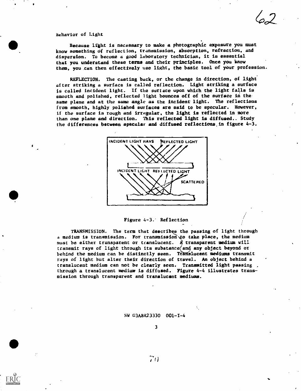
6azBehavior of Light
Because light is necessary to make a photographic exposure you mustknow something cif reflection, tr.insmission, absorption, refraction, anddispersion. To become a good laboratory technician, it is essentialthat you understand these terms and their principles. Once you knowthem, you can then effectively use light, the basic tool of your profession.
REFLECTION. The casting back, or the change in direction, of light'after striking a surface is called reflection. Light striking a surface
ts called incident light. If the surface upon which the light falls issmooth and polished, reflected light bounces off of the surface in thesame plane and at the same angle as the incident light. The reflectionsfrom smooth, highly polished surfaces are said to be specular. However,if the surface is rough and irregular, the light is reflected in morethan one plane and direction. This reflected light is diffused.. Studythe differences between specular and diffused reflections.in figure 4-3.
INCIDENT LIGHT RAYS EFLECTED LIGHT
1
!NCI DEN T L KART RE F L ECTED LIGHT
SCATTE RED
Figure 4-3. Reflection
TRANSMISSION. The term that describes the passing of light throughLi medium is transmission. For tranmmission o take place, the mediummust be either transparent or translucent. transparent medium willtransmit rays of light through its substance an4 any object beyond orbehind the medium can be distinctly seen. Tt lucent mediums transmitrays of light but alter their direction of travel. An object behind atranslucent medium can not be clearly seen. Transmitted light passing .
through a translucent medium is diffused. Figure 4-4 illustrates trans-mission through transparent and translucent mediums.
SW G3ABR23330 001-1-4
3

L IGHT RAYS
TRANSL HUNTMI MUNI
I HOSTED
GLASS
L HMI RAYS
TRANSPARENTMEDIUM
EMI 1111111111111111
Figure 4-4. Transmission Through Transparentand Translucent Mediums
CLEARGLASS
ABSORPTION. When light is neither transmitted nor reflected by amedium, it is absorbed. Black objects, such as a black cloth, blackink, black paint, appear black because they reflect very little of thelight that falls on them. On the other hand white objects such as whitepaper and snow appear white because they reflect most of the incidentlight.
Objects appear as a specific color because of their powers ofabsorption and ceflection. When light falls upon a medium, some absorp-tion and some reflection always takes place. No known medium completelyabsorbs or reflects all of the incident light. Figure 4-5 illustratesthis phenomenon.
, I I 4 I U AV S 14F I I I, I, A
Ali,114F111) 14A y5 II. ANCMI T .1 II R At
figure 4-5. Transmission, Reflection and Absorptionof Light Rays
REFRACTION. The bending of a light ray is called refraction. Aslight passes from a medium of one density to a medium of another density,its speed is altered. If the ray strikes the new medium at a 90.
SW G3ABR23330 001-1-4
4
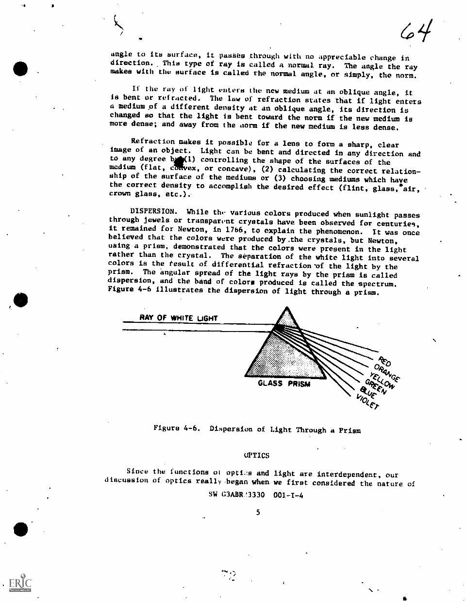
angle to its surface, it pasaes through with no appreciable change indirection. This type of ray is called a normal ray. The angle the raymakes with the aurface is called the normal angle, or simply, the norm.
If the ray of light enters the new medium at an oblique angle, itis bent or refracted. The law of refraction states that if light entersa mediumpf a different density at an oblique angle, its direction ischanged so that the light is bent toward the norm if the new medium ismore dense; and away from the aorm if the new medium is less dense.
Refraction makes it possible for a lens to form a sharp, clearimage of an object. Light can be bent and directed in any direction andto any degree 410) controlling the shape of the surfaces of themedium (flat, etRiVex, or concave), (2) calculating the correct relation-ship of the surface of the mediums or (3) choosing mediums which hayethe correct density to accomplish the desired effect (flint, glass, air,crown glass, etc.).
DISPERSION. While the various colors produced when sunlight passesthrough jewels or transparent crystals have been observed for centurieg,it remained for Newton, in 1766, to explain the phenomenon. It was oncebelieved that the colors were produced by.the crystals, but Newton,using a prism, demonstrated that the colors were present in the lightrather than the crystal. The separation of the white light into severalcolors is the result of differential refraction 'of the light by theprism. The angular spread of the light rays by the prism is calleddispersion, and the band of colors; produced is called the spectrum.Figure 4-6 illustrates the dispersion of light through a prism.
RAY OF MMITE LAW
GLASS PR SM
Figure 4-6. Dimpersion of Light Through a Priam
OPTICS
Since the functions ol opti,14 and light are interdependent, ourdiscussion of optics really.began when we first considered the nature of
SW G3ABR.1330 001-1-4

(0 5'light. However, since the word optics usually implies the use of somesystem of reflecting and refraction devices to control the behavior oflight, we will discuss it in terms of those systems.
Design of a Lens
To understand the design and function of a lens, we must return ourColehts to the prism. As you recall the prism has the ability to bendor reiract light rays. If two prisms are placed one on top of theother, bases touching, the light rays passing through the prisms willconverge at a point on the other side. Conversely, when prisms arearranged in an opposite manner, points touching, the light will diverge.
A lens is a solid piece of glass (or other transparent material)that is a refinement of two prisms. There are two basic types oflenses: positive and negative. A lens that causes light rays to con-verge is a positive lens; one that causes light rays to diverge is an2gative lens. The determining factor is the thickness of the lens inthe center as related to the thickness at its edges. A positive (con-vex) lens is thicker in the center and thinner at the edges. A negative(concave) lens is thinner at the center and thicker in the edges. Lensshapes are not limited to these two basic shapes mentioned. Figure 4.1.7
illustrates some of the most common lens shapes. Very often, two ormore types of lenses are cemented together to form a complex lens system.
PLANO.CONVEX
DOUBLE MENISCUSCONVEX
PLANO. DOUBLE MENISCUSCONCAVE CONCAVE
Figure 4-7. Common Lens Shapes
SW C3A13R23330
6

Lens Characteristics
There are many items that must be included when we consider thecharacteristics of a lens. To perform well as a photographic workman,you must be able to recognize the effect of these lens characteristicson the photographic product. You must also learn Itow some of the lenscharacteristics may limit your photographic operation capability as wellas improve your.work.
FOCAL LENGTH. The term "focal length" is defined as the distancebetween the optical center of the lens;and the image produced by thelens, when the lens is focused on infinIty. To understand this defini-tion, it is essential to understand the terms "optical center" and"infinity."
The optical center of a lens is a point usually (although notalways) within a lens, at which the rays of light from two differentsources entering the lens are assumed to cross. The "infinity" is notso easy to define. When light is reflected from a point of an objectthrough a lens% the closet the point is to the lens, the greatee is theangle of the spread of the light rays from the object to the lens. Asthe point gets tarther away from the lens, the angle of spread becomesless and less until a distance is reached at which the rays from asingle point striking top and bottom of the lens, for all practicalpurposes, can be considered parallel. This distance is "infinity."
Photographic lenses are measured according to their focal length,and the focal length is usually imprinted somewhere on the lens mounting.This focal length information is.measured in millimeters for shortlenses and in both millimeters and inches for long lenses.
Two factors directly related to focal length are (1) image size and(2) subject coverage. These two factors vary inversely; i.e., imagesize would increase and subject coverage would decrease as the focallength is increased. Conversely, when the focal length is decreased,the image size is decreased and the subject coverage is increased.Figure 4-8 illustrates this.
LENS SPEED. One major characteristic of a lens is its speed. The
term "lens speed" refers to the largest possible aperature of a lens--the maximum amount of light that a lens allows to pass to the focalplane and form the image. The lens speed is indicated by a numerical
.value termed an "f/number." It is dependent upon twe factors and theirrelationship. These factors are (1) the maximum aperture of the lensand (2) the focal length of the lens. The relationship between focallength (FL) and diameter CD) in determining lens speed is expressed as
FLlens speed 01
maximum D
SW G3ABH23330 001-1-4

6, 7
40.
TOTAL COVER/4i
TOTAL COVERAOE
2 X 2 X
FOCAL
IVTAL COVERAGE
so'
Figure 4-8. Image Size Related,to Focal Length
Observe figure 4-9. You can easily see from this figure that iffocal length remains constant, a lens having a larger opering.allowsmore light to reach the focal plane than does a lens having-is smalleropening. The lens with the larger opening is capable of producing abrighter image than the lens with the smaller opening and is, therefore,
)
termed a "fast" lens. Conversely, the lens thi the smaller opening istermed "slower."
LARGELENS ADMITSMUCH LIGHT
LIGHTSOURCE
WALLLENS ADMITS -oTTLf LIGHT
POINT ONFOCAL
41 PLANEAPPE ARSBlisGHT
POINT ONFOCALPL ANE
APPEARSDNA
Figure 4-9. Effect of Lena Aperture on Image Brightness
SW WA31t23330 001-1-4 7 5

a
63RESOLVING POWER. The term "resolving power" refers to the ability
of a photographic lens or material to form an image of, or record, finedetail. The normal method of measuring this,quality is to photograph asuitable test pattern at a greatly reduced BCAlle and then examine thedeveloped image under adequate magnification to determine the smallestdetail that is resolved. Resolving power should usually be consideredwith respect to a lens-film combination. The resolving power of a lensby itself, or a film by itself, indicates little, as the final photo-graphic product is necessarily a result of the lens-film combination.
PHOTOGRAPHIC DEFINITION. The term "photographic definition" refersto the quality aspect of a photograph that is associated with the clarityof detail. Since photographic definition is an impression made on themind of an observer when he views a photograph, the concept of definitionbecomes subjective and depends on the viewer. In common terms, defi-nition is a composite effect of at least four subjective factors:resolving power, sharpness, graininess, and tone reproduction.
Lens TypcP
NORYAL LENS. The normal focal length lens for a camera is approxi-mately equal to the diagonal dimension of the film being used to recordthe image. This lens coverage is an angle that is very near the anglecovered '13, the human eye; i.e. 450 . For standard film sizes, the fol-lowing focal lengths are considered approximatley "normal."
FILM SIZE NORMAL FOCAL LENGTH
35mm 50mm120 (producing 2 1/4 x 2 1/4) 80mm120 (producing 2 1/4 x 2 3/4) 100=4 x 5 -150mm8 x 10 300mm
NOTE: The same approximate focal lengths are considered "normal"for enlarging lenses when printing the different film sizes.
WIDE.ANGLE LEN, The wide angle lens has a shorter-than-normal
II\focal length. That is, e focal length is less than the diagonaldimension of the film bein used.
In terms of focal length for 35mm cameras, wide angle lenses startat 35m and typically_go to 28mm and then to 21mm or shorter. Theselenses give an angle of view from 70° to 180° for a "fisheye" lens. Awide ahgle lens offers greaten subject cnverage with a smaller image
- LONG FOCAL LENGTH LENS. "Lung focal length" refers to any lensthat,-has a focal length greater than the diagonal dimension of ihebeing used..
SW G3ADIL/3330' 001-1-4
9

49The advantages of a long focal length lens are that it has a
narrower angle of coverage (350 or narrower), and produces a largerimage size than does a normal lens under the same lens-to-subject dis-tance. This makes the lens ideal for portraits and photographs of far-away subjects.
Lens Aberrations
The inability of a lens to project an image that is a faithfulreproduction of the original is called an aberration. It has been foundthat by combining lenses of different'shapes and refractive indices,aberrations can be reduced to tolerable limits. Such is the case in thewell-corrected lens used in cameras today.
CHROMATIC ABERRATION. The term ."chromatic aberration" describesthe inability of a lens to bring all the colars of the visible spectrumto the same plane of focus. In figure 4-10 you can see how a lens thatis not corrected for chromatic aberration focuses the various colors ofthe spectrum at different planes even though they originate from thesame source. The aberration forms color fringes around the imagepoints, which represent points of the subject if the subject reflectscomplex light.
LIGHTRAI'S
LENS BLUEVIOL ET GREEN ORANGE
BLUE YELl OW RED
Figure 4-10. Chromatic Aberration
The term "apochromat" is applied to a lens which is corrected forthree colors. Generally apochromatic 1ens are used by photoengraversand copy personnel working with color separation and similar work.
ASTIGMATISM. The aberration in a lens that is characterized by itstnability to bring togetlier at a common plane of focus bo.th horizontaland vertical lines is known as astigmatism. This.aberratien is especiallynoticeable at.the outer edges of the image. Figure 4-11 is a giiphicrepresentation of the probLem. When the verticil lines are brought intofocus, the horizontal' linei are out of focus. Conversely; when hori--zontal lines are brought,into focus, the vertical lines out offocus.
SW G3ABR23330 001-1-4 P.; 7
10
fp'

SUBJECT
sarimmiiausserzunman5111111111811111111111111111111111101BEIREIRS
fallIN
SUBJECT
VEtITICAL LINES IN FOCUS
1111,
IMAGE
HORILONTAL LINES IN FOCUS
Figure 4-11. Astigmatism
IMAGE
When a lens has been corrected for astigmatism,,it te given theterm "anastigmat." Anastigmatic.lenses are used in copy work.
COMA. The aberration caused by the iLability of a lens to bring anoblique ray to a common point with equal magnification and brightness istermed,"coma." Light rays in passing through a single lens at anoblique angle come to focus in the same plane, but fall at differentpoints, rather than being superimposed. The image formed by thewhich strikes nearest the tenter of the lets produces the smallest,brightest point. The rays stiiking the lens toward the edges produce'images which are increasingly larger and dimmer. The total effect is animage of a point that is smallest at its brightest end and grows largertoward its dimmest end. Because the image of the point tends to re-semble that of a comet, the aberration was named coma. You can bestunderstand the appearance of this aberration by studying figure 4-12.
SW OAB123330 001-1-4
11

7/
Figure 4-12. Com,
SPHERICAL ABERRATION. Spherical aberration occurs when light raysthat enter the outer portions of a lens fail to reach the same foCa1point as those entering the center of the lcns. You can understand thisproblem better if you study figure 4-13. This problem can be partiallyovercome by stopping 4own the aperturc, but ideally the lens should beconstructed to contain the elements necessaly to preiNnt its occurring.
Figure 4-13. Spherical Aberration
SW CiABR11330 001-1-4
12

Aga
72FLARE. There are two general types of flare: mechanical and
optical. Mechanical flare is the t2rm glven to the flare caused byreflections that occur because of reflective surfates on the inner sideof the lens barrel, the camera, or anywhere else near the lens. Normallymechanical flare is not an inherent characteristic of the lens, but itis a result of a damaged or burnished surface. Such flare can beeliminated by coating the damaged surface with a nonreflective coating.
Optical flare is the trm given to flare that results from internalreflections from the glass-to-air surfaces of the lens itself. Opticalflare is not really classified as an aberration, and it is present, tosome extent, in any lens that has more than one element. A technique,known as cOating, minimizes this problem. The various elements of theleni are coated with a mstelial that helps reduce internal reflections.In addition to reducing the internal reflections, coating a lens also"increases the lens transmisaion. Because the front-surface of the lensis also coated, une must be very careful in cleaning the lens, since toovigorous rubbing can remove the coating.
QUESTIONS
DO'NOT WRITE IN THIS STUDY CUIDE/WONKBOOK. USE A SEPARATE SHEET OFPAPER.
1. What is light?
2. how fast does light travel?
3. Define w.avelength.
4. Define frequency.
. What Pi 'te product of wavelength and frequency?
6. compare the speed of light in glass with the speed in air.
7. What is the electromagnetic spectrum?
8. The visible radiation ranges from approximately what frequencyto what frequency?
9, Why are lenses coated?
10. Define reflection.
11. Objects appear as specific color because of their powers ofand
12. Define refraction.
SW C3ABR23330 001-1-4
13

7313. The separation of white light into several colors is the
result of
14. Describe a positive lens.
15. Define focal length.
16. What two factors are directly related to focal length?
17. How is lens speed determined?
18. How is a normal lens for a camera determined?
19. The term describes the inability of a lens to bringall the colors of the visible spectrum to the same plane of focus.
4
20. Describe astigmatism.
21. Describe coma.
22. List the iwo types of flare.
23. What causes mechanical flare?
24. What effect does coating the lens hove on the lens?
SW C3ABR23330 001-1-4
14
S
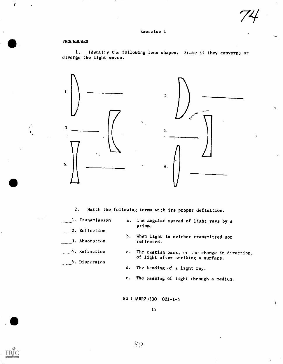
Exercise 1
PROCEDURES
1. identiiy the following lens shapes. State if they converge ordiverge the light waves.
3
2.
4,
6.
.......
2. Match the following terms with its proper definition.
1. Transmission
2. Reflection
3. Absorption
4. Refraction
5. Dispersion
a. The angular spread of light rays by aprism.
b. When light is neither transmitted norreflected.
c. The casting back, or the change in direction,of light after striking a surface.
d. The bending of a light ray.
e. The passing of light through a medium.
SW C1ABR21330 001-1-4
15

Sciences Branch SW C3ABR23330
Lowry Air Force Base, Colorado October 1977
EXPOSURE THEORY AND FILM CHARACTERISTICS
OBJECTIVES
Explain the principle parts of a camera.
Define the major charatteriatics of photographic film.
Provide a 35mm camera dad film, photograph several scenes asdirected by your instructor.
INTRODUCTION
The term "photography" is derived from two Greek words meaninglight (phos) and wTiting (graphein). Light is the essential element inphotegraphy for it possesses two properties that combine to create a
permanent image. The first is that light, when passed through a lensand focused on some field, such as paper or glass, can produce an image.
The second is the ability ot lighL to physically alter some materials.The first property was discussed in the previous study guide. The
second property of light and how it is used to produce an exposure onsensitized materials is the subject of this study guide. The discussion
also concerns the basic camera; the tool used with light to make photo-
graphic exposures.
INFORMATION
ThiS CAMERA
No one knows when man first onstructed a device that :ottld project
images of light. An old legend tells of a certain Arab wl,) .iwoke onemorning to find a vision on the wall of his tent. Atter hs firstAstonishment had passed, he realized that his "vision" was actually aninverted image of a groLhp of people outside. A tiny hole in opposite
wall of the tent had acted as a crude lens. This phenomena was later
called "camera obscura."
This principle was exploited fliring the Renaissance as a meals toachieve correct perspective in painting. It was not until later in the18th century that this principle Wats Used to record images on glass.
Despite striking differences in physical appearance, all camerasare fundamentally the SAMe. The camera c.onsists of a light tight boxwith a hole at one end and light sensitive material at the other. The
hole or aperture admits light into the box. The light sensitive filmreceives the light and recocds an image in response to it,

Every camela, however inexpensive or costly, is equipped with fivebasic features: the body, the lens, the viewing system, the focusingsystem, and the shutter. Differences between one model and the nextdepend upon the relative simplicity or sophistication of these features.
Body
The body of the camera is a light-tight box. Its major function isto ke- light from striking the sensitized material when the shutter isclosed. The body also houses the lens, the mechanical and electricaloperating devices of the camera.
Lens
The lens gathers the light rays reflected from the scene beingphotographed and projects them onto the film surface. A camera, what-ever the quality of its other features, is only as good as its picturetaking lens. No other aspect can be considered so important as thelens. A good lens is capable of producing sharpness and accuracy in theimage projected upor the film. The lens consists of several layers ofdifferent kinds of optical glass. All are ground to extremely finetolerances and combined to adjust smoothly for exact focus. Lenses werediscussed in study guide 4. It may be beneficial to review that sectionof the study guide.
Viewing Systen
The v. ing system normally consists of a lens that permits viewingthe scene the camera will record on film. Early box cameras did nothave a special viewing system. Instead, the instrument was held atwaist level and pointed. This method was quite inadequate. A view-finder was then devised and fitted to later cameras. A viewfinderpermits one to look tltrough the camera and see the approximate area itwill record. This arrangement is perfectly adequate for the ordinarysnapshot, and the viewfinder is still used on some inexpensive cameras.However, the viewfinder has one major drawback--parallax.
Parallax is a defect inherent in the viewfinder that prevents itfrom revealing with accuracy the area actually recorded by the camera.This discrepancy occurs because the viewfinder and the lens do nor sightfrom the same pc,sition. Usually, the viewfinder is located slightlyhigher than the lens and off to one side. See figure 5-1.
SW G3ABR23330 001-1-5
2

EYE PIECOPTICAL VIEWFINDER
RANGE F INDER
Figure 5-1. Camera Using an Optical Viewing andiFocusing System
Parallax can be eliminated with the use of a single lens reflexcamera that has through-the-lens viewing. This camera uses a system ofmirrors and prisms which enables the photographer to see exactly whatthe lens will record; See figure 5-2.
Sw OARR23330 001-1-5

78
ANGLE OF FIELO
Figure 5-2. Principles of Typical Single Lens Reflex Cameras
Focusing System
The focusing system works mechanically to move the lens closer toor farthev away from the film. This makes the image sharp er blurred asit strikes the film surface. Not all cameras have a built in mechanismfor making this adjustment. Early box cameras and some contemporaryModels are designed to produce a relatively sharp image as long am thesubject is at least six feet away.
To achieve really sharp photographs, it is essential to have somedependable means for relating the distance between camera and subject tothe distance between lens and film. Two principle focusing devices havebeen developed for accomplishing this end: the rangefinder and theground-glass viewing screen.
RANGEFINDER. The rangefiader is an optical-mechanical focusing4device that produces in the viewfinder a double image of the subject to!,e photographed.' When the two images coinc4de exactly, the camera is infocus.
GROUND-GLASS VIEWING SCREEN. An older device for focusing thecamera is the ground-glass viewing screen. In tbis system, light re-fleC'Od from the subject passes through the camera len, and protect";onto a piece of ground glass. This produces an image that can be viewed.Thus, you see what the lens "sees." You can bring the.image into focun
SW G3ABR23330 001-1-5
4
c )

by watching it on the etched glass screen as the lens focusing mechan-
ism is manipulated.
Shutter
The shutter and the aperture of the lens controls the amount oflight that reaches the film. By adjusting these fsechanisnis, the ex-
posure of the film is varied according to the requirements of thesubjects.
Many kinds of shutters have been developed, but.today most camerasemploy either the leaf shutter or the focal plane shutter.
4EAF SHUTTER. The leaf shutter is also called a between-the-lensshutter, because it is located between the lens elements. This deviceconsists of a series of tiny metal blades which, when closed, overlap toprevent light from entering the cameri See figure 5-3. The openingand closing of the blades are controlled by a gear and a spring mechan-ism. For the shutter to open, the spring must be cocked and subse-quently tripped by the shutter release button. Some cameras cock thespring automatically. Others require that it be done manually.
FOCAL PLANE SHUTTERS. The focal plane shutter operates near thefocal plane of the camera--directly in front of the film. This type ofshutter consists of an opaque curtain with a slit. A spring mechanism
pulls the slit past the film. In doing so, it exposes the film to
light. 13 combining a wide slit with a low spring tension, a longexposure is produced. A narrow slit and a high spring tension produces
a short exposure. A wide range of shutter speeds are therefore avail-,able. See figure 5-4.
PHOTOGRAPHIC FILMS
When the shutter operates, lt allows light to strike the film. The
film records the scene as the light strikes it. All conventionalphotographiC'films are made up severaI-layert. Each layer is made of
A given material to serve 4 specific function. The following paragraphsdescribe the functions of each layer. See figure 5-5.
Film Structure
.OVEHCOATING. The overcoating is a gelatin layer which protef:ts theemulsion beneath it during normal handling. Without this protectiveovercoating, the mere act placing films on top of one another wouldbe sufficient Co cause minor scratches and abrasions which show up after
processing.
EMULSION COATING. The emulsion is the light-sefisitive layer con-sisting of millions of microscopic silver halide particles suspended
SW 'CAA3R23330 001-I-5
5

OPEN
4
CLOSED
,-.111111
Figure 5-3. Simplified Leaf ShArer Mechanism
-SW G3ABA23330 001-1-5
6

2 1
A
2
2
E Xl'USUHE A IHIGHSPE EL)
2
1
.....11=11111111
1
Figure 5-4, y%,...e.t1 Plane Shutter PrincipleSitr, c; ,ABR2 3 s'i0 001-1-5
7
eiBEFORE
EXPOSURE
EXPOSURE ATSLOW SHUTTERSPEED 111/60SECOND ORLONGER/
EXPOSURETERMINATED

OVERCOATING
EMULSION
SUI3STRATU M COATING
BASE
SUBSTRATUM COATING
ANTIHALATION BACKING
Figure 5-5. Cross-Section of Film Structure
gelatin. The emulsion characteristics are determined by ths kind andcombination of silver halides, the size o, the silver halides, and howevenly distributed they are in the gelatin. Also the addition of dyesand Dther chemicals along with the quality of the gelatin itself effectemulsion characteristics.
SUBSTRATUM COATING. The gelatin Ontaininsths light-sensitiveparticles does not adhere to the base without a bonding material. Acoating spread over the base provides the bond between the base and theemulsion. The bondirg coat is a very exact formula consisting of acellulose acetate solvent, gelatin and gelatin solvent.
FILM,BASE. At one time the only support used for negative emul-sions was glass. These glass plates were heavy, bulky and easilybroken. Eventually, rese.Arch proved cellulose nitrate was suitable asa base material for the emulsion. It was light weight, chemicallyineM ,transparent when free from impurities and flexible. However, itwas extremely flammable. It would burn with almost explosive forCe.Pr.esent film deSign now gives fire-resistant plastic bise materials withgreat resistance to shrinking and tearing. Some of the more common film*bases used today are lade of cellulose acetate or cellulose tri-acetate.
ANTIHALAT1ON RACKING. The antihalation la,tking is usu4ly a layerof dyed gelatin on the back side of the film. This backing serves twopurposes.. One of these is countering the curling tendencies of the filmdue to the contracting of,the emulsion layer when it sets and dries.The other purpose is to absorb as much light as possible which goesthrough the film daring the expoeure. This light would otherwise bereflected back into th_emulsion layer causing a halo.around brillianthighlights. Such unwanted effects are called halation.
.
G3A3R23330 001-1-59

lilack-iand-Uhite Emulsion Characteristics
The 'photographic emulsion (or light-sensitive layer) is a regult aT
many yeare expeqmentation and research. There are very few light-
sensitive adbstaft6 which will respond proportionately to light inten-
sities in the same manner and effectiveness as the silver halide crys-
tals. Although you are unable to detect'this response to light until
after development of the film or psper, the change caused,by the action
of light on the silver halide crystals, which forms the latent image,
will remain relatively.stable for a givenetime before the imite is
ot
processed and made visible. (It is 13 ,to process the film as socin as
possible after exposure.) With many t light-sensitive substances,the reaction or change caused by light disappears as soon as the light
le removed.
The-Action.of light on silver halide trystals also is progres-
sive. ThIS meals that with pro onged exposure to light, you can see adarkening of the emulsion layer (without proceseing) due to the physical.
release of metallic silver within the silver halide crystals.
SILVER HALIDES. There are three silver halides which are used,either separately or in combination, for most of the sensitized photo-
graphic materials on the market today. They are silver iodide, silver
chloride, and silver,bromide.
1. Silver iodide is seldom used by itself, due to its extremely
slow response co light. However when it is added to silver bromide insmall quantities (from three to five percent), it increases the "speed"
or response 01 the silver bromide to light. This combination of silverbromide and silver iodide therefore, is used in many film emulSions.
2. Silver chloride is used by itself for making contact paper
emulsions. \,'
3. Silver bromide is the fastest of the silver halides, Itnd its
response io light, is increased even more by the addition of a small
quantity of silver iodide. Therefore, thie,4lver eombi-
natign ih used for fast4film emulsions. Silver bromide by itself is
useein some of the slower film emulsions.
..T4ese three si1.ver4halides, silver iodide, silver chloride and
silvei "bromide are controlling fuccors in the formation of other eMP
Sion characterisiics. The six remaining emulsion characteristics are:color sensitivity, controst, light sensitivity, grain, resolving power,
and accutance.
7 COLOR SENSITIft. Visible light which appears white, is a mixture
ot the primary cot rs red, blue and green. When photographic emulsions
were first made, th silver halides used were sensitive only blue
SW G3A13R2.3330 001-I-5
9

limht and somewhat to invisible ultraviolet radiation. These films iereaffected only by th$ blue portion of light. Thus, the blues in a scenewere reproduced too light and the other color, ware raproduced too dark.
*af The blue sensitive emulsions were also slow. Refer to figure 5-6for the reason. This shows how the color senaltivity of typicalfilmscompares to the human eye. .Blue senbitive film is sensitive to aboutone third of the total visible spectrum, which accounts for its slowspeed. In other words, to make a good exposure on this film. a lot of
414 wora sk Onttel MI 0 ,suma 4E0
Figure 5-6. Color Sensitivity of Film
SW C3ABR23330 001-1-5
10

light or lo4 exposure ia needed. However, this type of emulsion is
useful. It is still manufactured becuuse it yielda the high contrastresults needed.for copying black and white line drawings, charts, book
pages, etc.
Eventually, dyes were added to blue sensitive emulsions to sensi-tize the silver halides to green light as well as blue light. Thig film
was named orthochromatic, (true color) because it was believed that theultimate in color sensitivity was reached. The term was incorrect,however, since the emulsion was not sensitive to red and would not re-produce red in the correct shade of gray. attho films, as they areoften called, are made in several speeds and variations. They areexcellent for many uses, provided that their incorrect rendition of redis consid....ed when the scene is photographed. Since they are not sensi-tive to red, red light does not (for practical purposes) make a latentimage on the film. Therefore, after processing, red objects are rela-tively transparent on the negative. This means they are quite dark onthe print.
As an example, ortho film is good for/a portrait of 4 man; but notfor-photographing a woman wearing makeup. If used for the woman, thelight reflecting from her red lipstick would not expose the film and herlips would look too dark (almost black) on the print.
Years after the design of orthochromatic film, additional dyes weireadded to emulsions to make silver halides sensitive to red light also.The term "panchromatic" (meaning all-color) was given to this new film.Panchromatic films record most colors in their relative tones or shadesof gray. Even though panchromatic film is sensitive to.all colors, iti,does not reproduce them in the same tonal values seen by the eye. Of
the three primary colors, green appears brightest to the eye- 'Yet,green photographs darkest on the majority of panchromatic films. This
effect.can be modified to some extent through the use of photographicfilters. Filters change the sensitivity of the film by allowing onlycerteAn portions of the visible spectrum to strike the film.
eir;
CONTRAST. Some phucographic densiti are black in areas, some arewhite (or transparent) and in between, th e are many shades of gray.Closely associated with density is the aracteristic known as contrast.Contrast is the dtfference between the igh and low densities.
A light t.ubject area reflects a great amount of light, causirig aheavy density in the negative, called a highlight. A dark subject areareflects lane light, resulting in a thin density in thE negative,called a shadow.
The subject brightness between these light and dark areas alsoregisters as corresponding densities, cali4d middle tones. Normal con-trast is represented by a full range of denCties, including highiights,
SW OABR23330

486middle tones and shadows. High contrast does not have a full range of
densities and consists only of highlights and shadows with little or no
intermedlate graduations. Low contrast has very little difference in
densities.
Emulsions are manufactured with varying degrees of itiherent eon-
t-ist. High contrast (process) film is used to record a short range of
On"' .-ch as black and white line drawings. Medium and low contrast
illms ale used to record a longer range of tones such as might be found
in a portrait. Therefore, the selection of the film should be governed
by the subject contrast and the desired rendition.
Usually, the emulsions which have the slowest speed (react slower
to light) have the highest inherent.contrast. Fast films respond to
light much more rapidly than the slower films. This tends to flatten
out or lower the contrast of these films.
Many other factors influence the contrast of the final result.
Development has an effect. So do the lighting conditions of the original
scene and the 'contrast ratio of objects in the original scene. Normally
contrasty film is not used for a portrait or similar subject when the
intermediate tones must be retained. Conversely, do not use a low con-
trast film for a reproduction of a black and white line drawing where
the intermediate tones are undesirable.
LIGHT SENSITIVITY. The sire of the silver halide crystal in a film
emulsion determines other major characteristics of that particular film.
Among them is its light sensitivity or "speed." The larger the crystals
are, the greater the sensitivity anJ vice versa, sae figure 5-7. This
means that a film with high sensitivity (a fast film) requires leen
light to produce an image than one with low sensitivity (a slow film).
The various speeds available to the photographer are indicated by ASA
numbers established by the American National Standards Institute.
The major classifications of film speed, by average ASA ratings
are:
Slow films, about ASA 32, which require a highlight level.
Med films, about ASA 125, which are used in average or normalIttult
light s ations.
Fatk4ilms, about ASA 400, which are needed when the light level is
low or when a fast shutter speed is required to stop action.
Extra fast films, some well above ASA 800, are used only when the
other types of films are too slow, under the dimmest light levels or
when the highest shutter speeds are necessary.
SW G3ABR23330 001 -I -5
1 2

87I lag SA &Ai114 UU IMI3$ *
c141.114 "MNit Mt 11.0111411011.
et moo 40120Ru-wasmeta mums,14P&A PEPS/Lt. fAIIPOIACAP
1All x.aPultrt
Figure 5-7. Size of Silver Halides
GRAIN. In addition to speed, the size of the light sensitive
crystals in a film emulsion determines the nature of its grain, see
figure 5-7. Grain is the texture quality of tones in a print that is
produced when microscopic particles of silver clump together during
processing. A fast film, though highly sensitive tig light, is grainier
and less sharp tHan a slow, fine grain film. When choosing the best
film for a particular situation, consider not only whether it will give
satisfactory exposure under the conditions, but also the kind of image
it will create. Since it is impossible to attain both maximum speed and
the finest visual quality simultaneoualy, photographers often compromise
by using a medium speed film.
'In addition to the inherent grain size, processing also has a great
effect on the grain size. By using special processing techniques,
excessive clumping of silver crystals can be prevented during develop-
ment. When the grain becomes apparent in the image, it is said to be
grainy.
RESOLVING POWER. The resolving power of a film is its abi:ity to
distinguish between closely spaced lines. A technique for determining
the extent of this ability is to photograph a chart that corisists of
areas of parallel lines. The distance between the lines ranges by
degrees from rather far apart to very close. At some point on the
negative, -the lines can no longer 11 distinguished as lines, but are
seen as a tone of gray. This indicates the limit of resolving power for
4 particular film.: The resolving power is expressed in lines per
millimeter and, in general, the alewest films have the highest resolving
power. r
SW C3A5R23330 001-1-5
13
9;5

geACUTANCE. Acaince describes a film's sharpness. It is accurately
gauged by placing a knife edge on the film, then exposing and processing
it. The silhouette of the knife edge on the negative is examined by a
microscope. Because light scatters when it strikes the silver halides
in the emulsion, there is always same gradation of white to black at the
boundary between bright and dark areas. The narrower this gradation is,
higher the acutance of the film.
:Sp
Infrared film is sensitive to the infrared region of the
electromagnetic spectrum (700 to 900nm wavelengths) which is Invisible.
Even though infrared is invisible to the human eye, this film can "see"
it; therefore, an exposure can be made...
Infrared film has many uses in scientific, investigative and aero-
space photography. One outstanding use for this film is in aerial
reconnaiesance photography. It gives sharp definition and good tone
differentiation of distant objects under adverse climatic conditions.
It penetrates haze since infrared ie scattered considerably less than
visible light. Additionally, the filivis usefukin document.photo-
graphy, microphotography and in many other scientific fiélds.%
ULTRAVIOLET FILM. All films are sensitive sg,ultraviolet radis'ir'i
tions. With normal and infrared films, the ultraviolet radiations are
eliminated by filters. With ultraviolet film, the ultraviolet ralia-
tions must be allowed to'reach the film in order to produce an etpelinlre..7
In most cases, photorraphy using ultraviolet is confined to scientific !
work and many of the emulsions are designed for a specific purpose
The most widely known application of ultraviolet hotography is in\\. .
114the area of detection. Altered documents can be ide lied, paintings
can be verified, etc. This technique is also used in investigative
photography, 'since inexeible ink and finger prints are readily detected.
Aerial Film Classification
There are several methods df classifying films. You have, or
probably will hear such classifications as Type V Class L film or Class
A film, Class film, etc. These designations come from Federal Speti-
fication L-F-330, dated December 17, 1956, amended April 20, 1962. Most
still photography film is designated this way. However, Federal Standard
170a, dated March 31, 1967, specified a new designatnrisystem for
Federal agencies in its application to the purchase vf such films% ,
Military Specification MIL-F-32F, dated 22 March 1965, amended 2 March
1967, uses the same designator system as Federal Standard 170a. MIL-F-
32F is mandatory for use by all departments and, agencies Of the Depart-
ment of Defense. This specification covers the detail requirements for
black-and-white photographic film for use in, and duplication of, aerial
photography.
SW G3ABR23330 00i-I-594 3
14
e

e9In the designator system, outlined by these two documents, all
filma sold to the Federal Government through GSA (General ServicesAdministration) are classified according to: (1) product, (2) type ofmaterial, (3) base material, (4) base thickness, (5) spectral sensi-tivity, (6) gamma range, and (7) relattve sensittvity. The designatoris written in the format of XX-XX-XXX. An explanation of each digitfollows:
1. The first digit riders to the product relative to its use.All aerial film has the nutob6r _ine as its first digit.
2. The second digit reft :o the type of material. Host aerialfilm will be either I negative, 4 duplicating. 5 is never used asaerial film, and 2 is seldon mow,
3. The third digit refers to base type of material.
4. The fourth digit refers to true thickness of the material.
5. The fifth digit refers to the spectral sensitivity; that is,whether it is blue sensitive, orthochromatic, panchromatic, infrared,etc.
6. The sixth digit refers to the gem= range obtained when thisfilm is processed in acco4dance with applicable specifications.
7. The last digit is actually a lower case,letter which refers tothe relative sensitivity obtained when using the appropriate method andprocessing standard from the specification. This relattve sensitivitydoes not bear a relationship to the manufacturer's published exposureindex number or any other established film speed methods.
Figure 5-8 gives a complete listing of each designator and allpossible values for each.
One purpose of using the designator system is to enable manufac-turers to produce a film meeting a certain specification. Therefore, if\Kodak, DuPont, and GAF all produced a film having the same designatornumber, a laboratory could use them interchangeably. In fact, mostprocurement of films in now based on designator numbers exclusively.
Some of the more common films you will use in this career field andtheir designators are:
SW G3ABR23330 001-1-5
15

8F-4iLet
ProductD
Typen
FILM CLASSIFICATION SYSTEM
Designator 11 25 24a
1 Aerial film
2 Motionpicture film
3 Roll andfilm pack
i Sheet film
5 Photomechanical
6 Nlii-rofdm
Designator
1 Negative
2 Positivefilm
3 Reversal
i Duplicating
5 Soundrecording
St_pporttypeD
Totalthickness
D '
Spectralsensitivity
GammaD
1 Cellulose.ester regular
2 Cr-Hui/lee.e.ter lowshrink
1
1.9
2 2.1)
1 Emended ultra.violet
2 Blue sensitive
1 0.100.50
2 ii.511.00
3 Sy ntheticresin
3 3.") 3 Orthochromatic 1 1.011 .
4
Pok sty rene 5 2 High green 4 1.51
ty pe 6.3 3,00
5 stripping 5 6 6 Panchromatic 3.C1
base Li 7.00
6 8,3 Panchminatir 5,01
10.0 extended red Above
7 10 1 7 Infrared 0 r'ther12.0
0 Other
Relativesensiti; it)
I) '
abc-de
0.8
1'5
6
122.12.24.2
12
50
8.58.61718
- - 35
:"'_
t 1
h 1 on72140141200280
f 281570
1*-- 571k-- nig)
1100I 1101
1-1600 230072301
m-1200 4500
1

9/Desipator Number
I4-33-23d14-33-23d14-33-23c14-24-24d14-35-23d14-33-24a14-14-24d14-32-23d
11-13-64111-33-64i11-33-64k11-33-63111-32-64gII-32-64i11-32-64d11-24-74oII-14-64i.11-12-64i
Kodak.Aerographic Duplicating FilmKodak Aerographic Duplicating FilmDuPont Cronar Aerial Duping FilmKodak Aerographic Duplicating FilmKodak Aerographic Duplicating FilmKodak Fine Crain Aerial Duping FilmKodak Aerial Recon Duping FilmKodak Aerographic Duplicating Film
Kodak Plus-x Aerographic FilmKodak Plux-x Aerographic FilmKodak Tri-x Aerographic FilmKodak Double-x Aerographic FilmKodak Panatomic-x Aerial FilmKodak Plus-x Aerial FilmKodak High Definition Aerial FilmKodak Infrared Aerographic FilmKodak Plus-x Aerocon FilmKodak Plus-x Aerocon Film (thin base)
Manufacturer's Name and Number
24202427228R5427,
442724308427SO-122
2401240224032405340034013404542484018402
Storage and Handling of Senaitized Materials
Photosenmitized materials deteriorate rapidly when exposed to veryhigh temperatures (even for short periods of time) or when exposed toextremely high relative humidities or to radioactivity. As a result
there may be a loss of light sensitivity a change (usually a loss) incontrast,41 loss of emulsion speed, an increase in fog level, or varying
degrees Wall four conditions may be present. The two prim factors
which affect deterioration are hest and humidity.
The effects of moisture can be controlled by the use of vapor-resistant packaging, desiccants, or humidity controlled environments.The effects of heat can be minimized by proper control of temperature
during storage. AFM 67-9, Storage Manual, lists the procedures forstoring photographic film, paper, and chemicals. The following iafor-
mation has been extracted from AFM 67-9, paragraph 5-12.
o The required relative humidity for sensitized materials rangesfrom 30 percent to 60 percent with 50 percent considered ideal. A con-
stant relative humidity level shall be maintained.
o Photosensitive materials shall be stored at temperatures of50"F (10"C) or lower. Constant temperature shall be maintained.
o Photosensitive materials will be protected from harmful gasses.High concentrations of formaldehyde, hydrogen sulfide (sewer gas),ammonia, mercury vapor, etc., can damage photographic emulsions.
SW G3ABR23330 001-1-5
17

o Adequate thickness of lead or other shielding material will beused to protect sensitized materials from X-rays', radioadtive andatomic fission radiation if present.
o raotosensitive materials shall be issued according to theexpiration date shown on the package. Earliest expiration date materialis used first. tf the material has been properly stored, upon reachingthe oxpiration date, the expiration date can be automatically extendedar-c- o the following table:
Material Type
Black-&-White FilmsGraded PaperVariable Contrast PaperColor FilmInfrared FilmCamouflage Detection
FilmPolarbid Materials
Stateeide
12 months12 months12 months6 months6 months
6 monthsNo extension
Overseas
6 months6 months6 months0 months0 months
0 monthspermitted
When .the new expiration date is reached, the material should not beused until it is tested. The material should meet standards establishedby TO 10J-1-4, Storage, Issue, and Shipment of Film, Paper and Chemicals.If the material does not meet the required standards, action must betaken to dispose of it. Should the material meet the standards, theexpiration date can be extended up to 12 months.
If a lab has adequate testing facilities it will be responsible fortesting supplies stored at the base. If the testing capability is notpresent, the responsibility shifts to the command. Because of the costinvolved in testing, evaluation is usually restricted to emulsionbatches, on a sampling basis.
TO 103-1-4 lists the various types of tests that can be used todetermine the usability of outdated materials. Refer to this TO ifrequired to evaluate expired materials.
PHOTOGRAPHIC EXPOSURE
One can have the best camera, the finest lens, the greatest filmand total control of the lighting, but without proper exposure one-stillwill not'have a good photograph. One must be able to control the amountof light reaching the film and the amount of time it exposes the film.Without this control, results would be haphazard at best, if not totallyuseless.
1_ 0 1
SW G3ABR23330 001-1-5
18

93Exposure Theory
Accurate exposure is essential if negatives are to record faith-
fully the wide range of tones in a scene. About fifty basic and dis-
tinct tones of gray can be rendered in a photograph, but the range of
tones in nature far exceeds this. For every photograph, then, e choice
must be made between tones to be neglected and tones to be emphasized.
How Well the choice is represented in the final print depends largely
upon how the negative has been exposed.
The term "exposure" means the amount of light which le permitted to
act upon a photographic emulsion. A light of high intensicy may ha
permitted to act for a short time, or one of lesser intensity for a
greater time. Both exposures produce the same photographic effect on
the film. The exposure formula which applies to most practical work is:
Exposure'. Intensity x Time (E I x T)
Intensity in this case refers to the brightness of the image on the
film. This intensity depends on the lens aperture in conjunction with
the light reflected from the subject. Time is the interval during which
the shutter remains open to permit light to reach the film.
For example, three different exposures of one scene were made. The
first exposure is a product of a shutter speed of 1/125 second and a
lens aperture of f/11. The second is 1/60 second at 1/16 and the third
is 1/250 at f/8. All three were developed exactly alike. All the
negativeLwill have the same equivalent amount of exposure. In this
demonstration, the exposure (E) has remained constant While both inten-
sity (I) and time (T) have varied. When the intensity was reduced, tle
tims was increased to keep the exposure constant.
Thus, the Laps aperture works with the shutter to control the
exposure. The exposure formula could be rewritten as:
Exposare e Lens Aperture times Shutter Speed
Here the lens aperture relates to the intensity and the shutter
speed to the time needed to produce the exposure.
It was stated that the three example exposures were equivalent;
This formula can be used for these or any given exposures. As the
shutter speed changes so must the f/stop. However, this must be done
accordiag to the formula.
Each f/stiip.thanges the intensity of the light by a factor of two
from the f/stops on either side of it. Changing the f/stop from f18 to
f15.6 will double the intensity of the light striking the film. Chang-
ing the f/stop from f/11 to f116 will cut the intensity in half. The
SW 6141E23330 001-1-5
19

same relationship is true with shutter speeds. Each shutter speedchanies the length of exposure by a factor of two from the npeeds on
either side of it. Changing the shutter speed from 1/60 of a second to
1/30 will double the time the light strikes the film. Oohing from1/125 to 1/250 will half the time.
Because of this, f/stops or shutter speeds can be changed in orderto rntch the scene being photographed--to stop bction, blurt. action,irn -r decrease depth of field.
Exposure and Film
To record an image, insert a piece of photographic material intothe back of the camera. The image is recorded during tha time theshutter is open. No matter how-the light-sensitive material is alteredunder the influence of the light falling on it, assune that there is onecorrect exposure giving the best results. Underexposure means that only
the brightest parts of the subject are recorded, if.at all. The amount
of light reflected from the darker parts of the subject is too weak toeffect the senstive material. Overexposure means that the brighterparts of the subject will appear the same--the light sensitive emulsion
being incapable of'separating or grading the bright tones of the subject.
A negative is said to be correctly exposed when it gives a satis-factory rendition of detail in both the deepest shadows and brightest
highlights. Fortunately, in many cases there Is more than one singleexrIsure which will produce such a result. Tlwre is a wide range of
possible exposures within ehich satisfactory tone separation is possible.
The minimum satisfactory exposure is one in which good tone separation
is just attained in the deepest shadow areae. The maximum satisfactory
exposure is one in which detail is just retained in the brightest high-
light. Any additional exposure causes this highlight detail to becomeflattened.out or "bloc up."
The range between th minimum and maximum satisfactory exposures is
called latitude. This latitude may be either narrow or wide, dependingupon the subject natter', lighting conditions, type of film and degree of
development of the negative. Generally speaking, black-and-white.films
have a wider latitude than color films.
An exposure meter is used to help determine the exposure required
in a given situation. The reading that the light meter gives is trans-
-lated in terms of lens aperture and shuttei speed in correlation with
the speed of the film used.
Camera Operation
After the film and camera hove been selected and is basic knowledge
of exposure learned, then you must learn to oprrate the particular
SW G3ABR23330 001-1-5
20
if)3
4 4
314'

camera to be used. Many different cameras exist and ,many operateslightly different (although the basic deeign is similar). In order to
get the best photographic results, learn to use the particular cameraproperly. Never cry to guess how to use an expensive camera. Follow
the instruction booklet, study guide or TO carefully.
The following is a discussion of the Topton Super D, a 35s singlelens re:laz camera. Refer to figure 5-9, 5-10, and 5-11 while studyingthis information.
GENERAL CHARACTERISTICS OF THE TOPCON SUPER D. Focusing and fram-
ing with the Topton is done through the lens. The image is reflectedfrom a 45 mirror, located behind the lens, into a pentaprism whichshows an unreversed image at eye level.
The image seen is 97 percent of the final negative. It is identi-cal to the image that will, appear-on the film, so there is no parallax.What in shown on the focusing screen is what the camera records.
The focusing zereen has a full area ground glass field plus asplit-image rangefinder spot surroundeSby a fine focus ring. The
pante -prism and focusing screen are removable. To avoid the possibility
of dirt and fingerprints in the viewing system, they should NEVER beremoved unless absolutely necessary.
FILM WINDING PENTA?RISMLEVER FINDER
C etTOPCCDN
-
SHUTTER RELEASEBU TTON
CABLE RELEASESOCKET
SELF -TIMERRELEASEBUTTON
SE LF.TIMERLEVER
, r "se'
""411111.1MIER''`
AM&
Figure 5-9. Camera Controls and Indicators, Front View
SW G3ARR23330 001-1-5
101
21
REWINDKNOB
FLASH UNITBAYONETMOUNT
DEPTH OFFIELD PREVIEWLEVER
LENS LOCI.RELEASE LE vER

DEPT OF FIELDSCALE
APERTURE RINGADJUSTMENT CONTROL
APERTURE -SCALE
REWINDCRANK
FLASHSOCK E
INDEXM RK . INFRARED INDEX
FOCUSINGSCALE-
FOCUSINGRING
SHUTTER SPEEDSCALE
FILM PLANEINDICATOR -
EXPOSUREcouNTERmove
EXPOSURECOUNTER
FILMSPEEDINDICATOR
FILM SPEEDADJUSTING RING
Finure 5-10. Camera Controls and Indicators, Top View
TRIPODSOCK
MOTOR DRIVESHAFT COVER
.0111111L...i
MIPIN"
LINE LOCKRELEASE LEVER
/SACK COVERLOCK RELEASE
RATT1ERY8. COMPARTMENT
COVER
EXPOSURE METERCONTROL SWITCH
Figure 5-11. Camera Controls and Indicators, Bottoi View
04=23330 002.-I-5
10522

9While viewing, the lens is at maximum aperture and automatically
closes to the predetermined aperture immedietely prior to exposure.
OPERATING CONTROLS. The standard Topcon lens is the f/1.8 Auto-
Topcon. The f/stop rens* is from f/1.8 to f/22. Apertures are con-
trolled by a ring on the lens barrel closest to the camera body. The
aperture index mark is s dot in the center of the depth-of-field scale.
The "R" beside the index dot is for focusing with infrared film.
The shutter speed dial is located on the right of the camerabeside the penta -prism. Shutter speeds are selected by revolving the
dial in either direction. The dial will nfm revolve beyond the ASA
window. Speeds ars 1 sec. to 1/1000 sec. pins "B."
Focusing adjustments are made by revolving the rubber distancefocusing ring on the forward part of the lens barrel. Distances can be
read off the indicator mark which also doubles as the aperture mark.The camera focuses from 18 inches to infinity.
The shutter release is located on the front right of-the camera.The sequence which occurs after release of the shutter is: the mirror
swings up, the diaphragm closes to the present aperture, the shutter
releases, the mirror returns and ths diaphragm reopens.
Film advance is accomplished as follows: after making an exposure,
use the right thumb to push the Lilm-advanee lever as far as it will go.
It is possible to make several short strokes, but it must always advance
until it comes to a full stop. The advance lever advances the film one
frame, advances the exposure counter, cocks the shutter, changes the
mirror-raisine mechanic= and releases the shutter lock.
The Topcon has a depth-of-field preview lever. It is located on
the left side of the lens mount. Depressing the lever closes the
aperture to the preselected f/stop to permit visual check of the depth
of field on the ground glass.
AUTOMATIC OPERATION. The Topcon's built-in CdS exposure meter isinternally coupled to both shutter speed and to the lens diaphragm.
Since this ts behind the lens it automatically compensates for filter
factors, bellows extenaion, etc. Operating power for the meter is;
provided by a round mercury 1.3 volt battery installed in the basebf
the camera. Battery life is about one year.
Before using the meter, set the camera to the ASA of the film_that
will be used. This is accomplished by lifting and revolving the milledring that is around the shutter speed dial. Revolve the ring until the
desired speed is seen in the window. Speeds range from 10 to 800.
After selecting the proper ASA, push the switch on the bottom of the
camera to "on." This switch is located just to the left of the battery
SW G3ABR23330 001-1-5
23
lOG

compartment. With the subject carefully framed in the viewfinder,
adjust EITHER the shutter speed dial or the aperture ring, or both,
until the T indicator seen just below the focusing screen is aligned
correctly with the apex of the V-index mark. The extended legs of the
V-index indicate4/2 stop over or under exposure. An indicator is also
visible on top of the camera beside the rewind knob and is used to check
meter operatLon without having to look into the viewfinder. Turn the
metnr ,,,ff when not in use to avoid battery drain.
LOADING PROCEDURE. To load film into the Topcon, first open the
camera back. This is done by push-tutning the back cover lock that is
located an the bottom of the camera. Pull the back open all the way.
Now pull up the rewind knob as far as it will go and insert the film
cartridge into the empty chamber. The leading end of the film points
towards the take-up spool. Push the rewind knob down. Now inairt.the
film leader as deep as possible into the slit an the take-up spool. Be
sure a perforation on the film engages the screw head protruding et the
lower end of the slit. If the slit is nin visible, revolve the take-upspool by graspidg it by its serrated flange. Revolve the serrated*flange slowly until the,perforationa at both top and bottom fully
engage the film sprockets. Now push the back cover closed until itcatches, then turn the rewind knob clockwise to tension the film. Next,
trip the shutter and advance the film twice, until the "0" appears
beside the dot in the exposure ebanter window. The exposure counter
indicates the number of exposures already made, not the number remaining.
UNLOADING PROCEDURE. After shooting the final exposure on a roll,
depress the rewind button on the bottom of the camera. Unfold the
rewind crank from its storage position and revolve it clockwise. Rewind
the exposed film into its cartridge. Now all that remains is to open
the back cover', pull out.the rewind knob and lift out the cartridge.
QUESTIONS
DO NOT laIre'IN THIS SW. USE A MARATE SHEET OF PAPER.
410-
1. What is meant by the term parallax?
2. What are the Cm main types of focusing systems?
3. tipt the 5 layers in black-and-white film.
4. What is the purpose of the overcasting?
5. What is the purpose of the substratum?
6. What is the purpose of the antihalation becking?
7. How are films sold to the federal government designated?
SW G3ABR23330 001-1-5
24

qgS. 'Whet is the ideal relative humidity level for storing photoT
graphic materials?
9. Exposure is a product of times
10. Define latitude.
11. The Topcon camera focuses from to
12. How is it possible to.preview the depth of field with the
Topcon?
exercise 1
PROCEDURE
Answer the following questions and record your answers on a aeparate
sheet of paper. DO NOT WRITE IN THIS SW.
1. Whdt are the 5 principle parte of a camera?
2. List the basic function of each of the 5 principle parts of a
camera.
Exercise 2
PROCEDURE
Answer the following questions and record your answers on a separate
sheet of paper. DO NOT WRITE IN THIS SW.
1. List the 3 silver halides used in most of the sensitized
photographic materials.
2. Which silver halide is the most-sensitive to light?
3. What two silver halides ars used in combination to produce
fast film emulsions?
4. What accounts for the slow speed of the blue sensitive films?
5. What is the name given to film that is
green light only?
6. Which of the three colorsrad, green,darkest on pasichromatic films?
celled
sensitive to blue and
or blue--photograph the
7. The difference between high densities and low densities is
SW G3AER23330 001-4-5
1 9
25
/8. When would you use a fits that has a.high contrast?
9. Which films have the highest isiherent contrast?
10. What.is meant by the term "film speed"?
11. What is meant by the term "grain"?
What is the term used to describe the ability of a fibs todistinguish betwlen closely spaced lines?
13. The term used to describe a film'. sharpness is called
Exercise 3
EQUIPMENT
Topcon camera outfitFilm
PROCEDURE
Basis of Issue
1/student1 roll/student
1. Observe the instructor's classroom demonstration of theTopcon Super D camera.
2. Follow the instructor's directions as you expose the film.
3. Photograph several scenes around tha school.
SW G3A8R23330 001-1-5
26
10 9
r

/0Scisadss Branch SW G3ABR23330 001-1-6Lowry Air Force Base, Colorado October 1977
THE DEVELOPMENT PROCESS
OBJECTIVES
Identify the chemical propertie black-and-white processingsolutions.
Process previously exposed film using manual processing facilities.Processed negatives must be free of physical defects and have acceptabledensity and contrast.
INTRODUCTION
In one sense, the moment the camera shutter clicVs, the photograph'has been made. Yet nothing shows on the film: the image is there butit is invisible--a latent image. To make this latent image visible andpermanent, the film is processed in chemical solutions. The followingdiscussion describes the various chemical solutionc used to developfilm.
INFORMATION
PROCESSING SOLUTIONS
Developer
The first of these processing solutions in the development processis the developer. The developer creates density in those areas of thefilm that were exposed to light. Actually, this is a process of reduc-ing the exposed silver halides (the latent image) to black metallicsilver. There are many chemicals used in a single developing solutionand each one has a definite function. Common developers generallycontain the following components:
1. Solvent (water)
2. Developing agent (reducer)
3. AcCelerator
4. Preservative
. Retainer
6. Special additive ingredients

/ 0,2SOLVENT. Tap water is used as the solvent for mixing t..e chemical
components to a developing solution. Without water, the dry chemicalscould neither soften the emulsion nor reach the exposed halides.
REDUCING DEVELOPING AGENT. The most important chemical in a de-veloping solution is the reducitg agent, which actually reduces orchanges the exposed halides to black metallic silver, making the imagevisible. There are several chemicals which may be used as reducingagents; bu:: only two, hydroqpinone and metal are found in most standarddeveloping solutions.
Hydroquinone is a slow-working, high-contrast reducing agent. It
becomes inactive at temperatures lower than 50°F (10°C), and has atendency to produce fog at temperatures over 80°F (26.7C). Hydroquinonehas good keeping qualities, is nonstaining, and produces a cold, blue-black tone.
Metol and hydroquinone are generally uaed in combination. Theresultant (MQ), metol-hydroquinone, developer has the desired character-istics of both reducing agents and is \superior in many ways to a solu-tion containing either agent by itself.
ACCELERATORS. The solution must be in an alkaline state so thatthe developing agent will be active. Most agents are either neutral orslightly acid, making it necessary to add an alkali to the developingsolution. The alkali, called an accelerator, energizes the developingagent and also causes the emulsion to soften and sw,s1, thus allowingthe developing agent to penetrate more rapidly.
Accelerators fall into three general classifica mild, eod-
erate, and strong: Sodium borate (borax) is a mild alkali and is usedin low-contrast, fine-grain developers for negatives only. Sodiummetaborate (Kodiak) is slightly stronger than borax, but is similar in
action. Sodium carbonate is a doderately strong alkali and is theaccelerator used in most developers, both film and paper. Sodiumhydroxide, a very caustic alkali, is extremely active and is used inhigh-contrast film developers only.
The activity of a developer can be changed to a considerable extentby varying the amount of alkali included. Because the accelerator is edetermining factor in the activity of a developing solution, it has amarked influence upon the degree of graininess produced in a negative.Graininess is caused by the clumping together of the silver halidesduring development. The more active the developer, the greater theclumping action; t4e milder or less alkaline the developer, the finer
the grain.
PRESERVATIVES, A solution containing water, a developing agent andan alkali can develop an emulsion. However, such a solution wouldoxidize very quickly, resulting in rapid deterioration. It would also
SW G3ABR23330 001-1-6
2lii

/ (03fog and stain the emulsion. In order to prevent excessive oxidation, achemical used as a preservative is added. The preservative retards theoxidation of the developing agent, making the solution more stable and
preventing stains. The chemical most commonly used as a preservative is
sodium eulfite.
RESTRAINERS. A developing solution containing only a reducer,accelerator, and preservative has a tendency to reduce the unexposedsilver halides. Such unrestricted developing action results quickly inchemical fog. To prevent this action, a restrainer, which makes thedeveloper more selective by restraining developing action in the unex-posed areas of the emulsion, is added. The restrainer also permitslonger development and, consequently, greater contrast can be obtained.An excessive amount of restrainer greatly retards development and,unless developing time is increased, may produce greenish-brown tones inprints.
The chemical most commonly used as a restrainer is'potassiumbromide. Other chemicals which can be used are potassium iodide andsodium chloride (table salt), although they are not entirely satisfactory.
SPECIAL ADDITIVE INGREDIEJ6S. 'Common developer solutions containa solvent (water), a reducing agent, a preservative, an alkali, and arestrainer, although the last two are not absolutely required. However,in continuous photoprocessing you will very seldom uee one of the commondevelopers. You iill probably use one of the newer proprietary developersolutions which contain other compounds in addition to the ones listedabove.
Within the past twenty years a variety of organic compounds hasbeen shown to possess important antifoggant ptoperties. Not only dothey inhibit fogging to the same degree as bromides, but they do notcause a* great a loss in film speeds in doing so. At the elevatedtemperatures in use today, antifoggants must be used since bromide isnot very effective at these higher temperatures. Same examples ofantifoggants in use are Kodak A1'#1, AF#2, AF#6, AF#7, benzotriazole, and6-nitrobenzimidazole.
When there is a high concentration of compounds dissolved in adeveloper solution, there is a tendency for sludging and precipitation.Sequestering agents, which act as protective colloids, keep the developerby-products in solution preventing sludgief and precipitation. Examplesof sequestering agents are sodium metaphosphate, sodium tetraphosphate,calgon, quadrafos, and EDTA.
Wetting agents facilitate the absorption of developing solutioninto ths emulsion. Examples are ethyl alcohol, butyl alcohol, benzylalcohol, ethylene discloride, and tri-ethanolamine.
SW G3ABR23330 001-1-6

oxiStop Baths
A stop bath is needed for the.three following reasons:
1. To interrupt development instantly by neutralizing the alkali
of the developer that is trapped in the emulaion, or more slowly by
diluting the developer.
2. To prolong the life of the fixing bath.
3. To prevent the fixing bath from staining the photographic
emulsion.
There are three general types of stop baths: water, acid, and
hardening. Each has a specific purpose and should be used accordingly.
1. Water, as a stop bath, helps to retard development and washes
excessive developer from the emulsion thereby minimizing contamination
of the-fix.
2. An acid bath stops all development by neutralizing the action
of the developer. This definitely prolong* the life of the fixing bath
and aids in preventing stains.
3. A hardening stop bath (usually chrome alum) ill used when the
emulsion is processed in high temperatures or tropical climates. If you
cannot keep the developer temperature below 86°F (30.0°C) a hardening
stop bath should be used.
Fixing Baths
When a negative or print is removed from the developer and rinsed,
there are silver halides in the emulsion which have not been developed.
These halides are made soluble (can be dissolved) in..' solution called
a fixing bath. The chemicals and agents most commonly used in a fixing
bath are:
1. olventrixineiSilverlialideSIt - The silver halide sol-
vent is the agent which changes the undeveloped silver halides to A
water-soluble salt. The salts are then removed, thereby making the
image permanent. The chemical most commonly used as a halide solvent is
sodium thiosulfate (hypo).
2. Acid or Neutralizer -After development, the softened eMulsion
retains considerable amount of developer. If this developer ii allowed
to remain, it will continue its reducing action. -Even though an emul-
sion is thoroughly rinsed in water before it is placed in the fixing
bath, enough of the developer remains to continue developing action.
The result would be stains, making the negative unfit to print. To
SW GIAB123310 001-I -6
4 113
atop development and prevent staining, acetic acid is added to the fix.
This neutralizes the alkalinity of the developer and stops its action.
3. Preservative - When acid is added to the fixing bath, thesodium thiosulfate decomposes into free sulphur and sulphurous acid.. To
offset decomposition, a preservative, sodium sulfite, is added. Sodium
stilfite acts as a preservative by combining with free sulphur and
forming new sodium thiosulfate. It also prevents discoloration of the
solution which could cause stains.
4. Hardener - During development, the emulsion becomes soft and
swollen. If processing is continued without hardening the gelatin,frilling, scratching, and other undesirable effects may occur. The most
common hardening agent used is potassium alum, and is added to the
fixing bath to allow the film or paper to fix and harden at thssametime.
TYPES OF FIXING BATHS. Some common fixing baths are listed below.
1. Plain fixins bath - A plain fixing bath contains nothiug morethan sodium thiosulfate (hypo) and water. It is very seldom used exceptfor special purposes, such as fixing prints that are to be toned.
2. Acid fixing bath - A solution of sodium thiosulfate'combinedwith the proper proportions of acetic acid and sodium sulfate is an acidfixing bath. This type of bath is unsatisfactory for negatives becauseit has no hardening qualities. It is primarily intended for prints.
3. Acid hardening fixing bath - An acid bath contains a hardeningagent, mitking the solution suitable for both negatives and prints.
Wash
The purpose of washing negatives and prints is to remove thesoluble salts left in the emulsion after fixing. An unwashed, orimproperly washed emulsion may stain, change color, and fade. There-fore, the washing of the photographic emulsion is just AS important asany other part of the development process.
How long should you wash your materials? An ides may be gained ifyou realize that the hypo yemaining in the sensitized materials is con-tinually halved in equal periods of time. Tkat is, if the averagenegative gives up half of its hypo in 15 seconds of time in directcontact with running water, after 30 seconds, only one fourth of hypowill remain, and so on. The czact washing time depends on many things
including:
1. The efficiency of the washing method.
SW G3ABR23330 001-1-6
5

/062. The chemical composition of the fixing bath.
3. How long the emulsion remained in the fixing bath.
4. The temperature of the wash water.
5. The degree of hypo removal required.
WASHING IN TRAYS. There are three methods of washing negatives and
prints in trays. The simplest is to place the material in a tray full
of water and change the water at least once every five minutes. A
second method is to have a continuous stream of water running into the
tray for a minimum of 20 minutes. The third and most efficient method
of washing in trays uses a device attached to the tray which siphons the
water from the bottom of the tray While fresh water is being run in at
the top. In any method, care must be taken to separate the negatives or
printee to insure that sufficient fresh water reaches all areas of each
emulsion.
WASHING IN TANKS. A very satisfactory method of washing negatives
is the tat* method. Metal or plastic frames hold the negatives and
suspend them in the tank. Water is then allowvd to run into the tarik
and the negatives are washed for the required time.
MECHANICAL WASHERS. A convenient method of wishing a large number
of small and medium size prints is by the use of a mechanical washer.
These washers spray fresh water onto the prints and at the same time
siphon off the contaminated water. .Th4 type of wisher sometimes has a
large tray or basket which is revolved either by the force of the water
spray or by a separate motor. The ro tion, together with the spray of
fresh water, gives constant agitation and the water is changed every few
minutes.
DEVELOPING TECHNIQUES
Preparing for Processing
The processing of photographic emulsions is done beet in a properly
equipped laboratory. At this time we will not go into complete detail
on the laboratory layout, but we will familiarize you with a few of the
essentials. These factors are important, whether the darkroom is large
or small, if quality wirk is to be prottaced.
1.,AE SET UP. It ie tmpossible4to turn out good photographic workAn
a dirty laboratory. At all times the laboratory suit be maintained in.
a.spotless clean condition. Shelves, bottles, walls, floor, and inks
should be cleaned thorOUghly and checked frequently. Chemicals that
might get into the air front dried.spillage or other careless techniques
can be detrimental to your health and will lower tt,e quality of the
photographic product.
, SW G3A3i23330 001-1-6
6 115
4.

/a7Always check the lab for cleanliness before begliming work. Take
a few minutes and wipe off the surface of the area where film is handled.
Then,after you've finished processing for the day, clep all the equip-
ment used, clean and dry the sink, and mop the floor. Always leave the
lab clean= than you found it.
Imagine the laboratory as being divided into two sections --a wet
section and a dry section. Make it a habit to take nothing that is wet
into the dry section, and also never take anithing that must be kept dry
into the wet section. This prevents the dry negatives from becoming
spotted with water or fixer. It also prevents water from getting onto
the printer or easel. Sloppy darkroom techniques always result in poor
quality work. Be neat. Wear an apron to prevent chemistry from getting
on your clothes and keep-a dry towel handy. Always rinse and dry your
hands thoroughly before going from the wet section to the dry section.
When it becomes necessary to go into the dry section from the wet
section, rinse and dry your hands.
Every laboratory should have a standard rule of "a place for every-
thing and everything in its place." This is important for finding items
in total darkness andlor moving about safely.
ILLUMINATION. Safelights are designed to produce illumination
which will not affect light sensitive materials. The proper safelight
is necessary for the materials being handled. Different emulsions are
sensitive to different colors of light. Orthochromatic emulsions are
not sensitive to red light, therefore a red safelight filter would not
expose the film. Panchromatic film is sensitive to all colors of light
and must be developed in total darkness. However, some panchromatic
emulsions may be.viewed under a dark green saflight for short periods
of time after processing is partially complete.
The safelight illumination must be the proper color plus it must be
the proper intensity and the proper distance from the film. Check the
film data sheet for safelight illuminetion used with the film being
processed.
EQUIPMENT. The basic equipment needed to process a roll of 35mm
film is a developing tank with lid, developing reel, interval timer,
scissors, film cassette opener, thermometer, graduates and chemistry.
Arranse the equipment in an orderly manner. The graduates and chemistry
ars placed on a wet side of the darkroom while all other equipment is
placed on the dry side. While arranging the equiptent, always keep iu
mind that the lights will be turned off, leaving total darkness. Place
the items so they can easily be located.
,
PREPARING THE CHEMISTRY. After the equipment has been arranged on
the dry side of the.darkroom, begin orgahizing the wet side of the dark-
room. The first step is chemistry preparation.
SW 03A3R23330 001-T-6

Photographic processing solutions are prepared as either stock`'N
solutions or working solutions. Stock solutions are prepared in a con-
centrated form. Stock solutions require dilution prior to use. Workingsolutions havit the correct concintration for use. %%en properly di-luted, the stock solution becomes a working solution. The libel on eachcontainer of photographic solutions should contain the following infor-mation: the type of solution and its strength.
The developer that will be used to process the film in this section .
is a stock D-76 solution. This solution will need to be diluted to a.ratio of 1:1. This means, mix one part developer to ene part of water.For the developing tanks that will be used, a total working solution ofeight ounceses needed. TO achieve thie volume, dilute four ounces of.developer with four ounces of water.
The stop bath also comes in a stock solution. Again a total-ofeight ounces is needed. The dilution ratio for the stop bath is 1:32.
When diluting a stock solution, measure theliquids carefully. Be
careful with the solutions as some are hazardous to health.
CAUTION
The stop bath contains acetic acid. Fill the graduatewith water first then add the acid to it. Remember: Alwaysadd acid (AAA)!
Prepare the proper dilutions of chemistry before loading the filmreel. Measure the temperature of the solutions. The ideal temperaturefor processing film manually, is betvien 68* and 72*F. (20* and 22.2*C)AA has been stated before, temperature greatly affects development.Correct temperature is extremely important.
PREPARATING THE FILM FOR PROCESSING. After the solutions are mixedand at the proper temperature, prepare the film for processing. At thispoint recheck the arrangement of the equipment since the next steps willbe done in total darkness.
With all ltshts off, open the roll of film. TO remove film from astandard 35Mm cassette, find the spool end protruding from one and Of
the cassette. Pick up the cassette by this end. Pry off the other andwith the cassette opener or a soft drink bottle opener, see figure6-1,A. Slide the spool out.
With the scissors, cut off the protruding end of the film to squareit off, site figure 6-18. Do not try to tear the film: Besides injuring
the emulsion, the friction of tearing could cause a flash of eteticelectricity, creating enough light to streak the film. Put ths scissors
where they can be found and where the blades or points cannot scratch
the film.
SW GIA3123330 . 001-1-6
1
I.
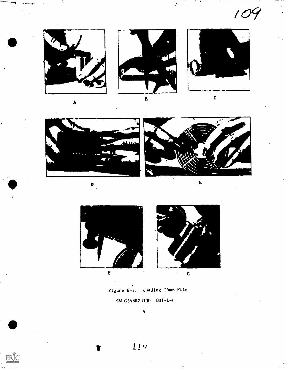
p.
-a
A
MAJOR&
-7
(39
E
Figure 6-1. Loading 3Soun Film
SW C3ABR23330
9
1. k.s1
NA_
p.

//0Hold the film spool in either hand so tha.: the film unwinds off the
top. Unwind *flout three inches and bow it slightly between thumb end
forefinger, see figure 6-1C. The reel must be oriented properly in the
other hand or the film will not slip into the grooves. Each reel is
made of wire in a spiral starting at the core of the reel and running to
the outside. The space between the wire spirals forma the groove that
holds the film edges. Hold the reel so that the sides are.vertical and
tfeel for the blunt ends of the spirals. Rotate the reel until the ends
-lave at the top. If the ends then face the film, the orientation is
correct. Insert the squared-off and into the core of the reel, see
figure 6-ID. Rotate the reel away from the film to start the film into
the innermost groove.
To finish threading the reel, place it edgewise on the flat sur-
face, see figure 6-1E. Hold the film spool as before, with thumb and
forefinger bowing the film slightly. Unwind three or four inches of
film and push the film so that the reel rolls forward. As it rolls, it
will draw the film easily into the grooves. .When all the film is wound
on the reel, cut the spool free with the scissors, see figure 6-1F.
Check that Cie film has been wound into an open spiral. Unless the reel
is correctly loaded, sections of film nay touch, stopping development at
those points.
After properly winding the film on the reel, place it into the
developing tank and cover with the lid, see figure 6-1G. After the lid
is on the tank, turn on the light and process the film. Do not remove
the lid,until the process is completed. Practice the film loading
procedure a few times with dummy film while the lights are on. Refer to
figure 6-1 for an illustration of the steps.
Processing 35mm Roll Film
PRESOAKING. Before starting development, run tap water in the
vented top of the tea. Prevetting the film causes the mmulsion'to
soften and swell. This allows the developer to be absorbed more quickly.
It also reduces the shock to the emulsion of being thrown into a strong
alkaline bath. Agitate the tank continuously for 30 seconds. Pour out
the water.
DEVELOPER. In addition to exposure there are four factors in
development that control the density of the negative. These four
factors are:
o Development time.
o Temperature of the developer solution.
o Degree of agitation.
o Activity of the developer uied.
SW G3A8R23330 001 -I A 1 9
10

/1/Time of bevelopment. When the exposed material is placed in the
4111tveloper, the solution,ponstrates the emulsion and basins to rediee the
wooed silver halides to,mmtallic silver. The longer the developmenttime, the more silver in reduced, and the denser the image becomese
If development is carried too far, the density may become too high.
Then the developer may begin to act on the unexposedvilver halide%
crystals. This causes "chemical fog," Which tends to veil the shadow
detsil.
Temperatuye of Developer Solution. The rate of development te
affected by.the temperature of the developer solution. As the tempera -
Lure rises, the rate of development incresses. Thus, when the developer
temperature is low, the reaction is slow. The development time recom-
mended for the normal temperature would then give underdevelopment.
When the temperature is high, the reaction is fast and the same time
would give overdevelopment. Within certain limits, these changes can be
coupsnaatbd for by increasing or decreasing development time.
Agitation of the Developer. If exposed photographic materials are
placed in a developer solution and allowed to develop without any move-
ment, the action soon slows down. This is because the developing power
of-the solution in and around the emulsion becomes exhausted. If the
material is agitated, fresh solutions are continually brought to the
emulsion surface and the rate of development remains constant. ,There-
fore, agitation has au important effect on the degree of developeent
obtained.
MOTTLE. An even more important effect of agitation is prevention
of uneven development or mottle. Without agitation, the exhausted
solution, loaded with developer by-products. Ibay flow across the emul-
sion from the dense areas producing uneven streaks. Agitation keeps the
solution uniform throughout and prevents uneven developeent.
Activity of'the Developer Solution. The rats of development is
also affected by the chemical activity of the developing solutipn. This
depends upon the composition, nature and concentration of the developing
agent and the alkalinity of the solution. The stronger the developing
agent, the faster the developing solution reacts with the exposed silver
crystals. Likewise, the stronger the alkali in the solution, the faster
the development rate. The dilution of the developer in water will also
affect its activity.
EMAUSTION.. In addition, the exhaustion of the developee affects
the activity of the salutiou. As the developer is used, its developing
power decreases. Even when the developer S. not used, its activity may
decroese because of aerial oxidation of the developing agent.
SW G3ABR23330 001-1-6
4ER

There is a right developer for each emulsion. The film data sheet
in the film carton will list the preferred developer.
As soon as the presoak water has drained from the tank, pour the
developer into the vented top of the tank. Agitate the tau* five to ten
seconds every minute of development time. Develop the film for the
r-coinmended time for its temperature. Pour out the deeeloper.
AGITATION. During development, to achieve desired results, use
proper agitation. For consistent results, keep the rate and method of
agitation constant. One method of agitating is by turning the tank back
And forth through 4 45" arc, as if turning a key in a lock.- Another
method is by firmly gripping the tank and lids and completely inverting
the tank. Remember that agitation la an essential part of the develop-
ing process. 46
STOP RATH. '--e the developer has drained from the tank, pour the
stop bath into t. id top. Agitate continuously for 30 to 60
seconds. Pour out cne stop bath.
FIXER. After draining the stop bath, pour ths fixer into the
vented top of the tank. It is necessary to agitate the film in the
fixing bath because gases are released and gas bells may fors on thm
film surface. If theoe gas bells form, they will cause dark spots on
the film. Agitate the film continuously for 60 seconds. Let the tank
sit for another minute. Remove the top of the tank and check the back
of the film. The milky appearance on the back of the film should have
kAsappeared. If the back of the film still hes a milky appearance,
leave the film in the fixer another couple of minutes. Pour the fixer
back into its bottle at the end of the fixing time.
NOTE: NEVER DISCARD THE FIXER!
WASH. After the fix is complete, wash the film under a stream of
running tap. water for 10 to 30 minutes. Leave the flIm on the reel
while it wattles. The washing of photographic emulsions in just as
important as any other part of the developeent process.
WETTING AGENT. After the film has lashed eufficiently, pour out
the water...and pour a wetting agent into the tank. Let the film sit in
the wetting agent for 30 aeconds.
The term "wetting agent" is used to describe a class of agents'
which reduce the surface tension or increasm the *matins properties of
water. Wetting agents act primarily as water spot inhibitors. rhey
speed up the drying time by 'Fatiguing the vater so that it runs off the
negative without beading. Wetting agents are ueed highly dilutik
(approximately,1:600 or one ounce to five gallons of water).
SW G3ABR23330 001-1-6
12 L

DRYING. When the film has remained tm the wetting agent for 30
seconds maim the reel iron the tank and Wefully remove the film
from the reel. Remember that the emulsion is still wet and soft and
easily "cratched. Attach a clip to one end and hang it in a dust free
place where the room temperature will remain constant during the drying
period. Pull the film taut and remov excess water from the surface by
gently drawing a damp viscous sponge or damp cotton ball down both sides
of the film. This pulls away tiny particles of grit and at-, isolated
vater drops which did not drain away.
It is best to let the negatives air dry at room temperature. If
the drying rate is increased by using extremely hot air, the outer film
surface may dry and harden before the moisture contained within the
gelatin can diffuse out. This might cause surface ruptures. The use of
moderate heat is tolerable If short processing time I. important. If
the emulsion is dried too completely, it becomes dry and brittle and
will easily crack. The ideal situation is one in which the film dries
uniformly until it is in equilibrium with the surrounding air.
LAB CLEAN UP. Before any session in the darkroom is terminated,the equipment and lab must be cleaned. Thoroughly wash and dry the
developing tank and reel. Any chemicals left on these items can con-
taminate the chemicals used to process the next roll of film. Wash the
graduates kand thermometer and dry them. Rinse and dry the sink and mop
the floor. A little time spent cleaning now will prevent large clean
ups later and will assure the production of quality work.
SUMMARY OF DEVELOPMENT PROCESS. The following is a step-by-step
breakdown of the development process. Study the steps and keep them
handy for use in the lab.
ROOM LIGHT
1. Clean area and arrange equipment so it can be found in total
darkness.
2. Mix chemistry according to instructions. (Reimember AAA.)
3. Use thermometer to meisure temperature of solutions. Consult
time/temperature chart for correct time.
TOTAL DARKNESS
4. Wind film onto film reel, taking care to keep fingers off the
emulsion.
5. ?lace reel into tank and secure the 14d. Do not remove the
lid until film in in the fixer.
SW G3ABR23330 001-1-6
13

114ROOK LICHT
6. Presoak film in tap voter for 30 seconds withragitation. Pour
out water.
7. Pour.developes into vented top and start tifier. Develop for
recommended time with agitation. Pour out developer.'
8. Pour stop bath into vented top. Agitate for 10 to 60 seconds
and pour out.
9. Pour fAxer into vented top and agitate continuously for 60
seconds. Check film after another minute in the fixer.
10. Wash the film under running water 10 to 30 minutes. Pour out
water.
11. Pour wetting agent into tank and let sit for 30 seconds. Pour
out.
12. Hang film for drying.
13. Wash and dry tank and reel. Clean other equipment in the lab
and mop the floor.
Time -Tmaperatu7e Processing-
For correct development, both time and temperature must be accurately
controlled--such techniques are known as time-temperature processing.
Within limits, time can be adjusted for a given time. Normally, ttsper-
aturels maintained as a constant at 68"F (20'C), and time of devil;op-
meat is varied to produce the'desired results. There are several
reasons for this standardisation. First consider the temperature at
68"F (20"C). The gelatin in the emulsion swells sufficiently to provide
adequate penetratipn of the solution without oversoftening the emulsion
to the point where it becomes dangerously soft (Which it dOes at higher
temperatures). Temperatures lower than 65'Y (20%), tend to slow
development excessively and may even cause chemicals to crystalliae out
of the solution. -Only when time is of uteost importance are tempera-
tures above 68.11 (20°C) used. In most instances whenevery high temper-
atures are used, special chemical treatment is given the film, or the
film is handled by machine where it is less subject to handling.damage.
The time element is seldom.of sufficient importance, except under
emergency conditions, to become significant. Since a several-degree
rise in temperature will shorten the developing tile only a relatively
short amount, there is little to be gained and much to be lost by
changing the teMiterature from the standard 65'Y (20"C).
SW G3A51123330 001-14
141 3

TIVF (MAM)
tio
70°F121.1°C)
811F IMAM)
135°FI18.3°C)
60°F(15.8C)214
TIME-TEMPERATURE DEVELOPMENT
FILM (NAME OF FILM)
1
a---........,
q
3 4 5 6 7 8 10 12
TIME OF DEVELOPMENT (MINUTES)
INYERMITTENT AGITATIONEXAMPLE: GOOD RESULTS WILL BE ACHIEVEDWITH "DK60A" AT 3% MINUTES AT 70°F. APMIC-50" AT 50 MINUTES AT 68F
Figure 6-2. Time-Temperatuee Table
There is a definite correlation between time and temperature as
shown on the sample time-temperature graphs ia fighre 6-2. When it is
impossible to maintain solution temperature at the desired level, time
can be shortenea or lengthened to compensate. As the temperature rises,
developing time must be decreased to provide equivalent development. As
the temperature drOpe,,developing time must be increased to provide
equivalent development.
RETICULATION. At this time, it is important to recognize a problem
related to solution temperature. The temperature of alI solutions
(developer, rinse, fixing bath, and wash) should be as near to each
other as possible. If there is considerable difference in the tempera-
ture between the solutions, the emulsion is subjected to excessive
expansion and contraction which may cause it to wrinkle and/or crack.
This effect is known as reticulation and gives the negative surface a
loather-like appearance. Normally, it renders the negative useless for
printing, since reticulation is not correctable.
SW OABR23330 001-I-6
15

Archival Quality
Archival quality in photography means the "keeping property of the. final photographic product"--not for days or wseka but for many, manyyears. This means that, if a photographic material has been processedto archival quality, the material will not deteriorate with the passingof years.
Every step in the photographic process must be given careful con-sideration to produce materials of srchival quality.. Normally, thecomposition of the developer will have no effect on archival quality.
However, fixing in a fresh fixing bath'is a must in the "keepingquality" of your final product.- When washing this final product, ussproperly conditioned water in an adequate flow across the surface of theemulsion. There will always be same residual hypo left in the emulsionno matter haw long it is washed. When this residual hypo ham beenreduced to.0.005 milligram per square inch or less, it is generallyconsidered that it will do no damage to the emulsion.
QUESTIONS
DO NOT WRITE IN THIS SW. USE A SEPARATE SHEET OF PAPER.
1. What is meant by the term latent image?
2. What four factors in development control the density of thsnegative?
3. What are the primary reasons for using a stop bath?
4. What effect does the fixer have on the silver halides in theemulsion?
5. What will happen to the emulsion if the fixer is not removed?
6. What is the difference between a stock solution and a workingsolution?
7. What is the ideal temperature for processing negatives sanually7
8. How often should the film be agitated while it is in thedeveloper?
9. Why is it necessary tJ agitate ths film while it is in the
fixer?
10. How long should negatives be washed?
SW G3,0E23330 001-1-6
I 2 516

11. What is the purpose of using a wetting agent?
12. What ie the relationship between time and temperature in the
development process?
13. What causes reticulation?
14. What in meant by the term archival quality?
IS. What factors affect archival quality?
16. List the six main components of a developer.
17. What two reducing agents are found in most standard developing
solutions?
18. What is the function of the accelerator?
19. The chemical most commonly used as a preservattve is
20. List the three general types of stop baths.
21. List the chemicals most commonly used in a fixing bath.
22. List the three common fixing baths.
Exercise 1
PROCEDURES
Using a separate sheet of paper, match the followthg terms. DO NOT
WRITE IN THIS SW.
a. solvent
b. developing agent
c. accelerator
d. preservative
e. restrainer
f. meta
g. stop bath
h. plain fixing baths
i. acid fixing baths
j. silver halide solvent
k. hydroquinone
SW 03ABR23330 001-1-6
17

/I1. A soft, quick working, law constrast reducing agent.
2. Energizes the developing agent.
3. Changes the unexposed silver halides to a water soluble salt.
4. Water.
.. 5. Makes the developer more selective.
6. Prevents excessive oxidation.
7. Neutralizes the developer.
8. A slow working, high contrast reducing agent.
9. Changes the exposed silver 'halides to black metallic silver.
10. Contains nothing more than sodium thiosulfate.
11. Containsodttum thiosulfate and acetic acid.
Exercise 2
MNM
EQUIPMKNT Basis of Issue
35mm developing tank 1/student
35mm reel 1/student
interval Timer 1/2 students
Scissors 1/student
Film Cassette Opener 1/stueinnt
Thermometer 1/2 students
Graduates 3/student
Laboratory Fee il it ies 1/claas
Film Dryer 1/class
PROCEDURES
1. Set up processing lab as described in SW.
2. Dilute chelistry to the proper.dilution as given by instructor.
3. Process film following the procedures described in SW.
4. Clean lab. -
SW G3ANR23330 0014-6
ls 127

Sciences Branch!awry Air Force Base, Colorado October 1977
/ 9SW G3ABR23330 001-1-7
THE PRINTING PROCESS
OLIECTIVES
Idaatify the major characteristics of photographic paper.
thing previously exposed negatives and a projection printer, exposemul protein projection prints. Prints must be free of exposure and
processing defects.
INIRODUCTION
Vnu have learned two fundamental steps in the photographic process.lialiever, taking the photograph and developing the film are.only two ofthenecessary steps. .To complete the process, it is necessary to printthis nmgetive and produce a positive imago having approximately the sametherms as the original. This positive image is usually made on sensi -tismd paper and is called a photographic print.-
The quality of the image on a print can be varied by the choice ofprinting material, exposure and processing. Many of the deficiencieswhith may exist in the negative can be corrected in the print. ftecauseof this, it-is important to have a working knowledge of all the materials,upuipment and procedures necessary to produce the desired results.
INTORP1ATION
PRINT MATERIAL
The following information describes conventional'printing papersmod in printing black-and-white negatives. See figure 7-1 for amoss-section of paper structure.
Pagmr Structure
THE PAPER RASE. The payer used as a base supporting the emulsionmust have specific propertime. It must be of the highest quality andpuslty, free from any foreign or metallic particles which might reactwith the emulsion or the solutions. Chemicals used im the manufacturingof the paper stock must be neutralized, or they will affect the perman-ency and quality of the photographic image. The paper must be strongmud reallient,to withstand prolonged immeraion and handling in thevarious solutions. It must be as white as possible (bleached), opaquestud evenly flexible. Usually, the paper base is made from a very puremslfits pulp stock and comes in three weights--light, single, and doubleweight.

/c2FILM STRUCTURE
OVERCOATINGPAPER STRUCTURE
EMULSION
BARYTA ANDGELATIN COATING
SUPF t RATUMCOATING
SUBSTRATUMCOATING
ANTIMALATIONBACKING
a
Figure 7-1. Crosse-Section of FilmiPaper Structure
THE BARYTA AND GELATIN COATING. If the emulsion were coated onto
the paper base without the baryta (barium sulfate) and gelatin coating,
the emulsion would soak into the paper fibers. The resultant image
would be extremely weak unlese a large quantity of emulsion were used.
Not only does the haryta and gelatin coating act as a "filler," it also
aids the reflecting ability of the paper.
The ArmedsForces use anOther paper treated with a solution of
cellulose acetate which makes the paver water resistant sod requires if
substratum coating, the same as for film bases. This paper is used for
rush printing assignments calling for rapid processing in conventional
chemistry.
THE EMULSION COATING. The emulsion coating is a light sensitive
layer. It consists of millions and millions of tiny microscopic silver
halide particles imbedded or suspended in gelatin. The characteristics
of the emulsion are determined by the kind and combination of silver
halides, the size of the silver halides, how evenly distributed they are
in the gelatin, and the addition of dyes and other chemicals in the
emulsion along with the quality of the gelatin itaslf.
SW G3ABH23330 001-1-7
2
1

/e,2/THE OVERCOATING. The overcoating consists of a thin layer of
gelatin which acts as a protector to the emulsion underneeth, during
normal handling and tumid ths matotrial. Without this groutetivs over-casting, the mere act of placing one sheet of paper on top of another
would be sufficient to cause minor scratches and abrasion marks. These
would show up after processing. However, this overcasting will notprotect the emulsion under rough or abusive handling.
PAPER SURFACES. The surface of a paper is a combination of texture
and finish. The texture may be smooth, fine grained or rough. in
addition, there are many artificiel textures such as silk, canvas,
suede, etc.
Glossy, semiglossy, seminatte and matte are the most used finishes.However, these may be described by other names such as, half-imatte,
lustre, memilkmtre, velvet, etc.
Watling papers, and to a lesser extent, contact papers, are glade
with a variety of surfaces. This variety offers the technician andphotographer the opportunity, through selection, to improve the photo-
graph. He can choose the paper most suitable to match the mood orcharacter of the subject.
The foregoing information covers the physical makeup of the paper.
This will give you a better understanding of how this material is con-structed. Next you will delve into the characteristics of various paperemulsions to discover how they react to light.
Emulsion Characteristics
SILVER HALIDES. There are three silver halides which are used,either separately or in cenkination for most of the sensitized photo-graphic materials on the market today. These are silver iodide, silver
chloride and silver bromide.
o Silver chloride is used by itself for making contact paperemulsions. It is also added to silver bromide to make the popular"chlorobromide" projection papers. Since silver chlorLde is slower inits response to light than silver bromide, the greater the percentage ofsilver chloride tn silver bromide in the emulsion, the slaver theemulsion will be. The so-called warm-toned slow projection paper. have
a greater percentage of silver chloride than silver bromide.
o Silver bromide is the fastest ef the silver halides, and itsresponse to light Ls increased even more by the eddition of a small
quentitx of silver iodide. Silver bromide is slowed dawn by the additionof silver chloride, which makes it suitable for projection paper soul -
aims. Usually, when there is a greater percentage of silver bromidethan of silver chloride, it is called brOlide paper.
SW G3A3R23330 001-I-7
130
.

ENULSION TYPES. There are four types of emulsions used in coatingpaper that include the above silver halides separately or in combina-tion; silver chloride for contact paper, slow chlorobramide for warmtone contact paper, silver bromide for projection paper and fast chloro-bromide for warm tone projection paper.
o Silver Chloride Paper (Graded Contrast). These peers have:only giver chloride in the emulsion. The senstivity of these papers iscompavatIvely slow, making them suitable for contact printing. This lowsensitivity under artificial light permits handling wlth bright yellowsafelight (Wratten 00) or safelights intended for other conventionalpaRers. Development takes about 45 to 90 seconds in AFD 025, (D-72)diluted 1:2, at 70'P (21.4°C). This produces blue-black tones.
o Slow Chlorobramide Paper (Graded Contrast). Emulaions of thistype contain, primarily, silver chloride, combined with small portionsof silver bromide.
Sensitivity of this paper is about 10 times faster than chloridepapers. This makes it ideal for faster contact printing and sometimesfor enlarging. The increased sensitivity makes it necessary to use ayellow-green safelight (Wratten OA) or safelights designed for use withequally fast or faster papers.
o Silver Bromide Paper (Graded Contrast). These papers are fre-quently referred to as bromide papers. The emulsion contains onlysilver bromideMhough frequently a trace of silver iodide will beadded.
Bromide papers, being the most sensitive of the printing materials,are 100 to 1000 times more sensitive than chloride or contact papers.These papers are used mainly for enlarging due to the lower intensity ofthe printing light and the distance between the light source and thepaper. The sensitivity of bromide paper is such that even a very weaklight will fog it; therefore, they should be handled under a yellow-green safelight (Wratten (OA) using a bulb of no more than 15 watts ata distance of about 4,1/2 feet. Development in AFD 025 (D-72) for twominutes produces very deep and pure blacks.
o Fast Chlorobramide Papers (Graded Contrast). Fast chloro-bromide papers have an emulsion consisting of silver bromide and smalleramounts of silver chloride. Occasionally, small portions of silveriodide is also used. These papers are not quite as fast as plainbromide emulsions. Even though they are used mainly for projectionprinting, they require as much as four times the exposure as bromidepapers.
CONTRAST. Density can be referred to as the smaitnt of metallicsilver deposited in any area of an emulsion. The difference between thedensities of the various areas of the emulsion is.called contrast.
WW G3A3R23330 001.4-7
4 131_

1,23A bright area of subject reflects the greatest *mount of light and,
therefore, called the highlight. Conversely, any area reflecting little
or no tight can be called the shadow arse. The subject brightness
between these highlights and shadows are known as the middle tones. The
difference in brightness, from highlights through the middle tones to
the shadows, is referred to as the subject contrast. Normal image con-
trast is represented by a full rause of densities, including -highlights,
middle tones, and shadows. Sigh Imp contrast does not have a full
range of densities and consists only of highlights and shadows with
little or no gradation between. Low image contrast has very little
difference in densities.
Graded Contrast Papers: Nest papers are made in several contrast
grades. This range of contrast is essential for the photographer who
wants to produce the best possible print from' any type of negetive--from
soft to hard. Graded contrast emulsions are primarily sensitive to blue
light.
Each manufacturer of photographic printing paper has classified the
range of contrasts according to his own standards. Therefore, the paper
of a particular grade number and deecription may not agree with that of
another carrying the same description. However, papers currently avail-
able conform in a broad sense to the following scale.
No. 0 -- Extra SoftNo. 1 -- SoftNo. 2 -- NOrnal or MediumNo. 3 -- Hard or ContrastyNo. 4 -- Extra Hard or Extra ContrastyNo. 5 -- Ultra Hard or Ultra Contrast
Grades 0 and 5 are not available through normal military supply
channels.
A normal or medium grade paper is accepted as the one giving the
best print from an average negative.
Using A soft paper, with an average negative, will yield a print
without much tone gradation. The entire picture would be Shades of
gray, with no real blacks and no light hishlights. Low contrast papers
are used with high contrast negatives to produce prints with normal or
near normal contrast. Printing an average negative, on hard paper, will
be over-contresty. All the light tones would be wbite, while the
darker areas will be solid black. Rish contrast papers are Limed with
low contrast negatives to produce prints with normal or near normal
contrast.
Variable Conirast Papers. Variable contrast papers offer several
advantases over graded contrast paper.. Probably the firet is that of
economy, since fewer boxes of paper would bs required. Secondly, AS
Wi 03A1123330 001-1-7
1 '3

ife:2 11/'many as 10 grades of contrast are available, through the use of filters*compared to four or five with graded contrast. TO permit this,function,variable contrast emulsions must be sensitive to both blue and green
light. Another advantage is in the amount of storage space needed.with variAble contrast it is considerably lees than with graded contrastpaper.
The structure, surfaces, and finiahes of variable contrast papersCorpAre favorable with those of graded contrast papers, with thisexception--the emulsion or sensitized coating.
Most variable contrast papers are coated with a single layer ofemulsion in which the larger, faster halides are sensitised to greenlight to produce the low contrast component. The remaining halidesrespond only to blue-violet light. It is obvious that green light willpmoduce minimum contrast while maximum contrast will be derived from theblue-violet. Intermediate degrees of contrast are obtained by combiningvarying amounts'of blue and green. The lower the amount of green, thehigher the contrast, the lower the amount of blue, the lower the contrast.
All variable contrast papers are sensitive to blue and green lightin varying degrees. It is easy to se* that high contrast filters are_htmish in color, but you may be puzzled by the fact that low contrastfilters are yellow. Why? A filter has rwo-functions to perform; itmust transmit the color of light desired and it mun absorb those colorsnot desired. The low contrast filter mot transmit green and absorbblue-violet. A green filter that would absorb the blue-violet wouldhave to be very dense. Therefore, your exposures would be rather long.Since yellow is very efficient in absorbing blue, a medium yellow filterwill do a very good Job. Yellow is a coebination of red and green. Thepaper, being insensitive to red, will only be affected by the greenportion. By using yellow instead of green for low contrast filters,long exposures can be avoided.
Most variable contrast papers will produce a normal contrast, equalto a #2 graded paper, when exposed without a filter.
Variable contrast printing filters are available Lo rwo sets, onemade by DuPont and the other made by Eastmain Kodak Compeny. DuPontfilters are made of an optical grade plastic and4111 withstand con-tinuous heat up to 140.F.(60.C), without warping. These filters arnumbered from 01 (low Contrast) through 010 (high contrast), #5 isconsidered to be equivalent to contrast 2 graded paper. Kodak "Poly,-
contrast" filters are made of optical grade plastic too and have thssame qualities of DuPont filters, except for the number of filters per
set. Kodak filters are numbered to correspond with a similar grededcontrast paper, thus 1, 1 1/2, 2, 2 1/2, 3, 3 1/2, and 4.
SW G3A31423330 001-1-7
6 13:3
Ire

425.Variable contrast papers, unlike graded contrast papers, cannot be
handled under Wrattan 00 or OA safelights without foggins. However,both types of paper may he handled under DuPont's S55-X or Kodak'sWrattan OC safelight filters. These filters are brownish yellow incolor and afford excellent light for judging print quality. See figure7-2 for proper safelisht/papar combinations.
SAFELICBT FILTERS PAPERSCRADED CONTRAST
CONTACT PROJECTION
VARIABLE CONTRAST
CONTACT PROJECTION
Wratten 00
Wratten OA
Wratten OC
DuPont 055-X
X
X
X X X
X
Figure 7-2. Safelight - Paper Combination Chart
Storage and Handling
Manufacturera package their produce either for 4omestic use or forexport. Materials intended for export or for use wherever high relativehumidity is prevalent are packaged in moisture-proof containers whichare vapor tight and water tight. Packaging for export is so labeled onthe individual units as well as en the shipping cartons. Materialsintended for noraal domestic use may be packaged in moisture-resistant,but not in water tight and vapor tight containers. You should assumethat say unlabeled package is intended for domestic use, and handle itacco rdingly. Do not keep sensitised papers under refrigeration once thesealed packages have been broken, unless the refrigerator can be held at50 to 60 percent relative humidity.
Store individual packages of film and paper on end so that theweight of the contents is on the edges of the film and paper. Youshould also store material with the earliest expiration date to thefront of the stack. This enables you to use the material with theearliest expiration date first. However, when it is known that thepaper that is due to be used next has boon stored or shipped underunfavorable conditions, and a highly critical mission is to be printed,use the fresh material.
Paper removed from cold storage areas must be adjusted to roomtemperature before the packages are opened. This will prevent moisturecondensation on the paper. Bring the paper to room teaperature over aperiod of at least eight hours prior to use. tenser times are requiredfir wara-up if the packages are stacked.
SW OA3R23330 001-I-7
7

/2ef,FUNDAMENTALS OF PRINTING
Photographic printing is the process of permitting light to passthrough a negative to expose sensitized material (photographic paper).The exposure can be made either by placing the negative in contact withthe sensitized _material (contact printing) or by projecting the mostly*image onto the material (projection printing).
Projectionyrinting Principles
The process'of projectionyrinting, also known es enlargementprinting, enables the photographer to produce prints scaled larger thanthe negatives.. In contact printing there is one-to-one relationshipbetween the size of the print and ths size of the negative. That is,the print is the same size as the negative. Today's precision instru-ments--cameras and enlargers--are capable of transforming small negativeimages into large prints of good quality.
PRINTERS. An enlarger is capable of producing only enlargedprints, while a projection printer can produce enlargements one-to-oneprints or even reductions. The proper nomenclature for the printer usedin this course is projection printer.
PRINCIPAL PARTS OF A PRINTER. The printer head contains a lightsource, negative holder and lenses and is connected to a rigid verticalcolumn. The head can be adjusted higher or lower on this column toincrease or decrease image size. The light source can be an incan-descent bulb or a tubular fluorescent lamp. Most often it is au in-candescent bulb.
The light from the Loop falls upun a condenser system, which dis-tributes light evenly over the negative thus giving unifore illunina-tion. The condenser is arranged as a pair of convex lenses or as a flatpiece of frosted (diffusing) glass. The negetIve carrier, locatedbetween the condenser system and thessin lens-14day, holds the negativeflat and level.
A bellows is located under tha negative holder. It permits marerefined distance adjustments from the main lees to the printing paper.The bellows serves to focus the image clearly von the printing paper.(It Jo focused by turning a knob.) Like a camera lens, the enlarger'lens bends light rays to project an,image to the focal plane, which inprojection printing is the printing paper. The lens also contains adiaphragm, which regulates the amount of light posit* throu h the lone,.
AI the base of the vertical column,. a platform supports.the struc-ture of the enlarger and the easel. The easel hold* the paper flat,level end in proper position to record the image projected-from theenlarger lens.
FW MAER23330 001-I-7
8'135

EASEL221.261
LAMP
NEGATIVE
LAMPMOUSING
DIFFUSINGGLASS
LENS FOCUSINGADAISTMENT
EASEL
Figure 7-3. Condenser and Diffusion Printers
Types of irinters
221.20
Printers exist in many different brands with a variety of control
mechanisms. They can be classified according to two basic optical
systems; one is the diffusion enlarger, the other is the condenser
enlarger. See figure 7-3.
DIFFUSION ENLARGER. In a diffusion optical system a sheet offrosted glass scatters the light rays from the laip over the entire
negative. Because the light rays scatter in all directions, some light
rays never reach fhe negative. Other rays overlap and-the result is an
overall loss of light before it enters the main lens. Therefore, prihts
made by a diffusion enlafter tend to have softened details and a rather
diffused appearance. Because of the loss of a cortaiA amount, of image
quality, the diffusion system is not recommended for se ial Vork. In
aerial work image sharpness is the utmost concern.
SW G3ABR23330 001-1-7
f?!
9

CONDENSER ENLARGER. A superior system for directing light from itssource through the negative and into the enlarging lens is the condohsersystem. It is based upon two saucer-shaped lenses whose convex sidesare interfaced. This arrangement gathers light and spreads the beamsuniformly and"directs them through the negative. This system loseslittle light and directs more light to the printing paper. The straightline of the projection-miniiizes the overlapping of light rays.
The condenser enlarger reproduces the maximum amount of detail inthe print. For this reason, negative defects, such as suiface scratchesoften become apparent on the print. With the condenser enlargerAtheprojected image is contrastie,7 than with a diffusion type printer.
The EN-52B Projection Printer
The EN-52B, a condenser-type projection printer, is used in thiscourse. The main feal...ures are:
1. Lens and Mount Assemlblies - f/3.5, 50mm; f/4.5, 105mm andf/4.5, 150mm focal lengths; all mounts are equipped with an f/numberilluminator.
2. Heat Absorbing Glass - 5-inch (12.7cm) diameter.
3. Condenser Lens Assembly - two, 7-inch (17.78cm) diameter planeconvex lens.
4. Spool type Photographic Negative Carriers - six, consisting of30mm single frame glassless, 70mm glassless, 70mm (120 aperture)glpsless, 2 1/4 x 3 1/4 inch, (5.72 x 8.25cm), glass and a 4 x 5-inchIA .16 x 12.70cm) glass.
The operating controls and principal parts of the EN-52B arelisted in figure 7-4.
The projection printer may be rotated on its base to permit thenegative to be projected onto the floor or at an intermediate level inorder that enlargements of a size greater than 11 x 14 (27.94 x 35.56cm)inches may be made. Hold the carriage and girder securely, loosen thethree cap screws, and secure the three rotary clamping pads. Rotate thegirder 180° on the base and secure it in this position with the capscrews.
CAUTION
Before rotating the girder and carriage for projectionto the floor, you must secure the base board to the table with"C" clamps to prevent the projectiofi printer from overturning.
SW G3ABR23330 001-1-7
10
13/

41.
Figura 7-4. Photographic Projection Printer, EN-52B
SW G3A3R23330 001 -1 -7
11

/The Photographic Projection Printer, EN-52B is very ehmilar to the
Type B -15B Photographic Projection Printer. In fact, most of the parts'
and accessories are interchangeable. The major differences are:
o Condenser spacer retainers must be in the center of the film
stage opening to avoid possible cutoff of the projected image.
o Heat absorbing glass is inserted into top of variable con-denser lamp house after removing lamp house and condenser assembly and
disconnecting the cable from the elapsed time indicator.
at, The plug from the lamp house cable moat be connected to the recept-
acle of the elapsed time indicator and the cable of the elapsed time
indicator must be connected to the power source. This assures time-in -
use record when feed through switch is ON.
The accessory carrying case and the elapsed time indicator are
exclusive items with the EN-52B.
EN-52B Operating'Procedures
Operate the projection printer as follows:
1. Cteck the condenser lens to see that it is properly positioned
in the lamp house assembly. Set the cam follower wheel on the cam so
that it is matched with the proper lens.
NOTE: Matching cam and lens are identified by the matching part
number inscribed on the lens' and cam identification plate.
2. After an initial manual adjustment, the lens is kept in
proper focus for all magn4fications by an auto-focusing device. This
device consists of a special cam cut to match the characteristics of the
leas and a CM follower. The cam follower changes the lens to object
(negative) distance as the printer housing I. moved up or down, changing
the lens to image distance. When lenses are changed, the cam follower
must be changed to the matching cam.
3. Select the appropriate size negative carrier for the negative
being printed, raise the lamp house assembly; install the negative
carrier on the film stage.
a. Insert negative with erulsion (dull) side down on the
bottom plate of the carrier.
b. For aerial roll film, insert the film in the left bracket
assembly of the spool-type carrier, thread and attech it to the ampty
spool in the right bracket assembly, rotate the cradk handle of Owright bracket assembly to bring the desired negative into position.
SW G3A3R23330 001 -I -7
12 139

/3/c., Lower the lamp house assembly.
d.- Set the variable contrast filter turret assembly so that
the blank opening is below the lens. Set.the lens aportiumwdde-open by
,turiiing the diaphragm COntrol counterclockwise, and snap tha feed-
through switch to ON.
e. Place a sheet of white paper in the'projection printing
easel, loosen ihe brake knob, and raise the carriage assembly to its
highest position by turning the handwheel knob. Vocue by making adjust-
ments with the focusing knob until a sharp image is obtained. Adjust-
the projection printing easel by using the margin control knobs to set
each of the masking blade arms. The margin width markings on the mask-
ing blade arms must line up to the dimension of the photographic paper
being used.f
NOTE: After a sharp image his been obtained, subsequent raising
and lowering of the carriage assembly to vary the size of the desired
enlargements do not affect the ,sharpniis of the image.
f. Lower the carriage asseibly by torning,the handwheel knob
until the desired enlargement size is projected 'on the white paper in
the projection printing easel. Tighten the carriage break knob. 4
CAUTION
.To avoid damage to e carrier geaTs, always loosen the
brake knob before tu t e handeheellkibb.
g. Set the diaphragm ring to the'desited f/stop,
h. Position the easel to assure that the desired image is
composed within the aria indicated by the iaskingiblades.
i. turn the time switch from focus to time and replace tha
white paper in the projection easel with a sheet of sensitized paper.
The sensitized side must be up with the top and left edgirs tight against g_
the margin guides. Lower the hinged frame and make certain that the
position 9f the easel is not disturbed.
NOTE: If variable contrast paper is to be exposed, set the turret
assembly to positioe the required filter beloit the lens.
j. Set the desired time on the timerOsnap the toggle switch
to the start position and Coke the exposure. The exposure tins must be
determined by the f/stop setting, the type of paper being used, the
denmity of the negatives, and the degree of maenificetion desired.
SW G3ABR23330 001-I-7
13
1

/42k. After the desired time has elapsed Os timer will auto-
matically terminate the exposure. Raise the hiaged frame of the easelto remove the exposed print for processing.
Negative Evaluation
Unfortunately, there is no simple answer to the question of what isa vod negative. Yet we know that you nead good negatives before youcan make good prints. We know that you should aim toward products;negatives of consistent quality. En this section, we discuss ammo ofthe more important factors, other than development, which determineswhether or not your exposures will develop into quality negatives.We'll start by discussing the finished product--the finished negative.
How should you look at your negatives to determine if they arequality negatives in terms of density and contrast? Don't try to judgea negative by holaing it up to a window or an ordinary room light source.This procedure fill give you a false impression of negative quality.View'your negatives by reflected light, light which is reflected fro,white paper. Another way to view your negatives properly is to placethem on a well-diffused light box designed for that purpose. A verypractical method of judging negative quality is to place your negativesdirectly over a newspaper or magazine page or to view the negative bythe light reflected from the magazine or newapaper page.
A quality negative has a wide range of tones--a real variety of .
grays with areas that will make rich blacks and brilliant whites on thefinal print if they are supposed to be there. The variety of tonesshould be imitable to the nature of the original subject. Ths filmshould have been exposed enough to record all thOmportant shadowdetails. On the other hand, the.highlight areas must not be too dense.You should be able to read magazine or nevspeper type through thedeneest'parts of the negative if,viiwed as discussed above. By prac-tical definition, a quality-ffiliative is one which, when enlarged duringthe priniing process, easily prints with the morsel grade of enlargingpaper. This negative has a wide range of nicely separated tones ail theway from the shadows to the highlights.
An underexposed negative can never produce prints to match the
, quality of those from the normal negative. An un4erikposed negative hasonly h small range of tones, and the highlight arils are too trana-parent. ,The shadow areas are almost clear end contain no detail.
A negative wits very denim from heavy overexposure. Asain, youhave a negative displaying only a small number of separate tonie. There
is Very little difference between any two adjacent tone values. Itw.
larged prints from these negatives are very low in quality and requirevery long printing exposures.
11SW OANR23330 00144
14

Projection Printing Steps
Follow this procedure when making projection prints.
1. Clean the working area thoroughly. Be sure that your labora-tory and equipment are free of dust, dirt, and other foreign materiels.Because minor dust particles on the negative or on the glass plates ofthe negative carrier become extremely noticeable when enlarged, clean-liness is especially important.
2. Prepare the solutions.
3. Select, very carefully, the negative to be printed. There isa rule which states: "If it isn't in the negative, you can't expect toproduce it in the print." Moreover, if it is in the negative, it willalso show up in the print., To make a good print, especially an enlarge-ment, you must start with a good negative. A good negative is one freefrom surface scratches, moderate in density and contrast, and adequatein detail.
4. Position the negatie in a clean negative carrier with theemulsion side of the negative cing the lens. Ildsert the negativecarrier in its proper position ato the piojection printer.
S. Turn on the projection lamp (nd. while viewing the image,adjust the masking devices to eliminate extraneous light Oich may come.from around the outer edges of the negative. Position the masking armson the easel to produce the correct sise of opening for the print beingmade. Adjust the paper positioning devices of the easel to make thecorrect size borders to the print.
6. Place a piece of white paper (the same size 61(nd weight as theprinting paper) in the easel. Turn the printing light on and open thediaphragm to its saximum aperture.
7. Adjust the position of the printer head to give the correctimage size. (If the projection printer is not equipped with an auto-matic focusing device, it will tie necessary to focus. This may,changethe taiga size sufficiently so that the printer head must be reposition-ed. Repositioning the head may necessitate refocusing. Continue thisprocedure until the image is correct in size and is in critically sharpfocus.)
S. Adjust the position of the essel to produce theposition in the photograph.
9. Judge the contrast of the image and the densitytive. (If you have not developed the ability to do this,the contrast is evert*e end give an average exposure.)
desired com-
of the nega-assume that

/34/10. Stop the diaphragm down to the desired opening. The exact
amount that the lens diaphragm should be closed is difficult to deter-mine without experience. Tty to control the illumination so that theiposure requires from five to ton seconds. For the beginner, ail.suggested that the printer lens be etopped down to three stops from themaximum aperture. Thin should produce a long enough exposure with inaverage negative to allow for accurate timing.
11. If graded paper is being used, select a grade which you con-sider tO be of the proper contrast. If var,lable -contrast paper is beingused, position the correct filter in front of the lens. (In lieu ofexperience, assume that the negative has normal contrast.)
12. Under safelight conditions, cut the sheet of projection-print-ing paper into teat strips about two inches (5 cm) wide.
CAUTION
When you finish using a paper trimmer, always leave theblade in the lowered position.
13. Remove the white paper from the easel and place a test stripin the easel with the emulsion facing the lens. Be sure to includehighlight, middle tone, and shadow areas in the test. Make a series ofexposures on individual test strips on one test strip.
14. Process the test strip or stripe. Be cure to use a 68'F(20"C) solution temperature and from 1 to k minutes developing tine.
15. Judge the teat strip for contrast and exposure. If the testdoes not fall within the desired range of tone and contrast, makeadditional test until both the correct contrast snd the correct exposurehave been determined. Use the same processing time for all tests.
16. Using the exposure and contrast determined by the test strip,make the desired number of print, on full-sixed paper. Be sure toposition the paper in the easel so that borders and composition arscorrect. Process the prints for the same time you used for your tests.
Print Processing
Processing prints is very similar to processing film. Many of thesteps are the same and the same principles of time/temperature/agitationapply to development. Of critical importance are the principle, ofcleanliness and the wet and dry divisions of the lab.
The developer used will have a different formula, but its functionis the same as for film developing. The developer will aleo have a
SW G3ABR23330 001-1-7
316

different dilution. The dilution will be 1:2, or one part of developerstock solution to twe parts of water. Developer formula D-72 will be
used.
On* gmdor difference in the processing of prints compared to pro-cessing film will be the use of safelights and the use of trays insteadof tanks. Prints will be exposed and processed wader safelight
DIVELOPING. As soon as the printing paper hes been exposed,immerse it quickly, gently and completely in the developer solution. Tokeep fresh solution washing over the print throughout development, rockthe tray. The agitation must be easy enough not to splash any chemi-cals. Development should be timed carefully. One could follow theprocess visually and make a judgement of the print as it emerges.However, in the dim illonination of a safelleht, an image looks darkerand appears fully developed before it is. A good indication of correctdevelopment is the evidence of Ilear detail in deep shadows and brighthighlights:
. If left in the developer for less than one minute, print typi-cally looks underexposed and mottled with a limited tonal range. De-veloping beyond two minutes could cause staining of the print. The .
print that appears too light after two minutes in the developer shouldbe discarded and a new print mode with a longer exposure.
STOPPING.. When development is completed, the print must be trans-ferred to the stop bath. (Before placing the print in the/stop bath,hold it above the developer tray and allow the excess developer to drainback into its tray.) Submerge the print into the stop bath solution.
The stop bath neutralises the developer, halting its chemicalaction. Usually the developed print is placed in the stop bath withalight agitation for 10 to 15 seconds. Next, the print is lifted aidexcess solution is allowed to drain into the stop bath tray. The printis than transferred to the fixer.
FIXING. Lmmersion time in the fixer can last from three to tenminutes, depending on the type of paper and fixer used. It is a goodidea to agitate the print from time to timembile it is in the fixer.This keeps fresh fix in contact with the print surface thus assuringproper fixation. A print exposed to white light before adequate fixingis likely to have veiled highlights and poor tonal qualities. If
exposed to white light before fixing, it will immediately turn black.Prolonged immereion in the fixer can also destroy a print by causing theimage to disappear.
After fixation, one may examine the print by placing it in an,empty, clean tray and taking it out of the darkroom into a fully illum-ineted area.
SW G3ABR23330 001-1-7
17
1ii

/36Print Finishing
The process of preparing prints for delivery to the requester is
called "print finishing." Flashing begins at the point where darkroomhandling of the material is ne longer required. Once the prints have
completed their necessary fixation, the finishing procedures are started.
Thege procedures are not limited to only the washing and drying steps.
Rat' .r, they often require correction of certain faults in their quality,
mounting ind toning. In some cases, you may need to completely elimi-nate the fixer from the prints to achieve archival quality. We can
begin a discussion of the print finishing process with a study of the
two basic steps, smehing end drying.
WASHING. Unless all residual chemicals are removed from photo-
graphic emulsions they will eventually fade and yellow. Normal washing
procedures are suificient to remove enough of these chemicals to pre-
serve the imLge for many years. Therefore, thorough washing will be
satisfactory for the majority of photographs.
There are several factors which deteraine how rapidly the materials
can be washed. One of these factors involves the structure of the base
material. Light weight printing paper has far leas capacity for re-
taining chemicals than does single weight material4 Double weisht paper
retains chemicals loi.ger than single weight materiel. do. When properly
processed, water resistant papers contain very little chemistry in their
base.
Another factor in determining washing rates is the frequency of
water ihange. A good rate of flow will remove fixer chemicals in a
relattvely few minutes. This of course depend. on tho number of prints
being washed. But even the good water flow will not do satisfactory
washing job if the print. are not agitated pfoperly. Water temperatures
are not as critical to washing as the chemical solution temperatures are
to processing. However, you should use water as close to normal room
temperature as poesible. Very low water temperatures will reduce the
effectiveness of the washing process. High temperatures increase the
possibility of damage to ths emulsion during agitation and handling
before dryipg.
Normal print washing procedures are satisfactory for the majority
of purposes providing fresh fixer has been used. Although complete
fixing is possible with moderately aged chemicals, the time must be
extended for that step. Washing becomes less effective when fixing
times have been longer than normal or when aged chemistry is.used.
Either trays or mechanical washers can be toed for washing prints. The
adequacy of their performance can be Checked with other chemical solutions.
Mechanical Washers. A convenient method of washing large umbers
of small and medium size prints is by the use of a mechanical washer.
Average washing time for single-weight prints is 90-60 tee, double-
sW p.A81111330 00I-1-7
18
1.1.5
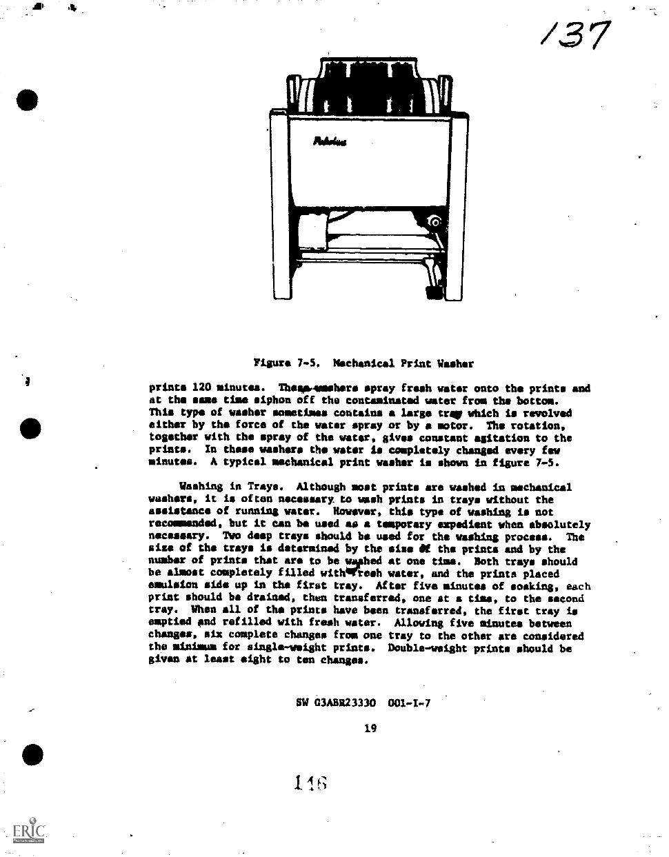
/3 7
Figure 7-5. Mechanical Print Washer
prints 120 minutes. Thew-welshers spray fresh water onto the prints andat the ease time siphon off the contaminated water from the bottom.This type of washer sometimes contains a large trerwbich is revolvedeither by the force of the water spray or by a motor. The rotation,together with the spray of the water, gives constant agitation to theprints. In these washers the water is completely changed every fewminutes. A typical mechanical print washer is shown in figure 7-5.
Washing in Trays. Although most prints are washed in mechanicalwashers, it is often necessary, to wash prints in trays without theassistance of running water. However, this type of washing is notrecommended, but it can be used as a temporary eepedient when absolutelynecessary. Two deep trays should be used for the washing process. Thesize of the trays is determined by the else At the prints and by thenumber of prints that are to be wmphed at one time. Both trays shouldbe almost completely filled witheriesh water, and the prints placedemulsion side up in the first tray. After five minutes of soaking, eachprint should be drained, thsn trensferred, one at a time, to the secondtray. When all of the prints have been transferred, the first tray isemptied end refilled with fresh water. Allowing five minutes betweenchanges, six complete changes from one tray to the other ors consideredthe minimum for single-weight prints. Double-weight prints should begiven at least eight to ten changes.
SW 03A5R23330 001-1-7
19

f3e-A second way of tray washieg is to utilise running water and sub-
merge the hose in the mush tray. This system is adequate for washing a
few prints, but it is not recommended as an ideal procedure. There is
a tendency for the contaminated water to sink to the bottom of the tray
and remain there. When this method of washing is used, the flow of
fresh water must be sufficient to thoroughly circulate the water in the
tray. Prints should be agitated frequently.
A third method of washing involves the use of trays and a specially
designed tray siphon.
DRYING PHOTOGRAPHIC PRINTS. When washing hae bsen completed, dry
the prints between blotters especially designed for photogrephic work,
on drying racks, on ferrotype plates, and on belt driers. The drying
method depends on the purpose of the prints and the availability of the
various types of drying equipment.
Drying Prints Between Blotters. Occasionally, it is considered
advantageous to dry prints between photographic blotters. These blot-
ters are made so that they will not leave lint on the print. The method
used is to drain the prints well, place them between two blotters, and
remove all of the surface water. After this treatment, they are plaeee
between two dry blotters. They are then weighted or placed in a press
that is capable of holding them flat until they are dry. When seteral
prints are to be dried in this manner, it is advantageous to use car-
regated cardboard between each combination of two blotters and a print.
Air can then circulate through the stack, and drying will be speeded up.
This method of drying is relatively slow, but does produce a nice flat
print.
Drying Prints on Racks. The procedure for drying prints on rack.
has the big advantages that no change in print tons occurs and both
stretching and shrieking are minimized. For these reasons, the rack-
drying procedure is normally used when prints are being prepared for a
controlled, photographic mosaic.
Drying Prints on Belt Dryer. The majority of prints (other than
those made for mapping purposes) are dried on the motor-driven belt-trm
dryer. A belt dryer consists of a drum aver which 'a wide endless cloth
belt or apron travels. The drum is motor driven and is usually heated
by electricity. The rate that prints dry is regulated by the tempera .
ture of the drum and the speed st which the drum rotates.. The drum
temperature is controlled by a thermostat, while the drum rotating speed
is regulated with a yariable speed motor and a speed reduction syntmm.
The prints are held in contact with the drum by means of the endless
belt and ars dried during one revolution of the drmm.
Olace the prints on the apron, allowing 1/2-inch (1.27cm) between
prints and not less than 1/2-inch (1.27cm) from 'he edge of the apron.
Glossy prints are positioned face up on the tab or apron portion of
SW G301123330 001-I-7
201 .4 7

Figure 7-6. Print Dryer
of ths .1,:Allt; matte prints are positioned with the emulsiou toward the
apron.
Solt dryers have a capacity for drying 100 single-veight 8 X 10-
inch (20.32 X 25.40cm) prints per hour. If double-weight prints arebeing dried, the rate is 50 8 X 10-inch (20.32 X 25.40cn) prints per
hour. Prints up to 24 indigo (60.96cm) in width may be dried on thismachine. A typical belt dryer is shown in figure 7-6.
To stop the dryer, first turn off the heaters. The apron should be
allowed to move for 15 minutes to allow the drum to cool.. When the drum
hes cooled, place the motor in the OFF position.
QUISTIONS
DO NOT WRITE IN MIS SW. USE A SEPARATE SKEET OF PAPER.
1. What I. the baryta and gelatin coating?
2. What is the purpose of the overcasting?
SW 03AS123330 001-1-7
21

3. The surface of a paper in a coibination of
long?
4. List the three silver halides used in asking paper emulsions.
5. Graded contrast papers ara primarilrsansitive to light.
6. Variable contrast papers are sensitive to light.
7. How long should papers bs allowed to WM iiibefore use?
8. List the two typos of projection printers.
9. Define "quality negatives."
10. How long sh-Ild the print remain in the developer?
11. What is the function of ths stop bath?e
12. What will happen to the print if it JAI left in the fixer too
13. What is the result if prints are not washed sufficiently?
14. List three methods of drying prints.
15. Describe the operation of a belt print dryer.
Exercise 1
PROCEDURES
Match the following items, etc.
a. silver chloride d. graded papers
b. silver bromide a. variable contrast papers
C. contrast
1. Sensitive to b a and green light.
2. Difference between densities.
3. Used by itself for making contact paper emulsions.
4. Sensitive to blue light.
5. Fastest of the silver halides.
SW G3A8R23330 001-4-7
1 1 922

Ps
41/a. slow chloride papers
b. slow chlorobwomide papers
c. silver bromide pipers
d. fast chlorobromids papers
1 Sensitivity is 10 times fisterthen chloride papers.
2. Used mainly fo* (Merging.
3. Requires as much ss.4 times the exposure as bromide papers%
4. Produces blue-black tones.
Exercise 2
EQUIPMSKT Basis of Issue
Negatives From Previous SW 1/student
Projection Printing Laboratory facilities 1/class
Projtstion Printers and Timers 1/student
Projection Printing Paper As needed
Print Washer 1/class
Print Dryer 1/class
SAFETY PRICAUTIONS \.
1. Wake sure electrical equipment is provided with ground attachments.
2. Keep electrical equipment away from wet sinks.
3. Do not handle electrical equipment (printers, timer, etc.)
with wet hands.
4. Use extreme caution when using the paper trimmer. Never place
your finger. in the cutting area. After mans the trimmer, always leave
the cutting blade in the lowered position and locked.
PROCEDUIKS
1. Obtain the necessary chemicals for proceising paper from chao
mix. Maks your tFay set up using 8 x /0-inch (20.32 x'25.40as) trays
and AID No. 25 (D-72) solution 1:2 (16 ounces of developer to 32 ounces
of wator) (473m1 of developer to 946m1 at water).
SW G341123330 001-I-7
21

gc,22. Check aut the projection printer as follows:
a. Inspect the printer for cleanliness and ease of operation.
b. Clean the lens. If necessary, dust it with a camel's.hair
brush.
c. If the printer has interchangeable condensers, insurethat the set matching the lens' focal length is clean and properly
installed.
d. gbeck the cam follower wheel to maks sure that it is on .
the proper track to match the focal length of thn lens.
3. Adjust the printing easel to give 6 x 10-inch (20.32 x 25.
40cm) Trints with a quarter inch border (7 1/2 x 9 1/2-ineh inside
dimensions) (19.05 x 24.13cm inside dimensions).
4. Select the negative to be enlarged.
5. Place the negative in the carrier and insert into the printer.
6. Check to make sure that the cam follower is on the cam cor-responding to the lens you are using, and that the condenser assembiy is
positioned properly.
7. 'Raise the lamp housing to the top of its travel. Open the
lona diaphragm wide open.
8. Turn on the projection printer lamp and focus on the easel.
Arrange the desired composition at this time also.
9. Close the lens diaphragm down two clicks and turn off the
lamp.
10. Refer back to Projection Printing steps in the SW and follow
steps 12 through 16 using a normal, dense and a thin negative respectively.
SV G3A83330 001 -I -1
24
arc enigrvalop our. Ire III
glA

e
STUDY GUIDE AND WO
G3ABR23330 001II
Technical Training
c,a11.1uout, Photoproccsaing Specialist
CONTINUOW. PROCFSSING FUNDAMENTALS
ocEoliat 19/1
Str
i/ipani TECHNICAL TRAINING WING1410rh Tvvhnical Training Group
iwry Alr Force Base, Colorado
A 11 IOWA 210 (.1 AN 70 1
Dvaigned For ATC Course. Use
Do NOT USE ON THE JOB
nm' ITV! ATC FV1 II14, MAY U. US, NOV 011 AND Sat MAT T1, STANDARD COVIRINRET
5:)

Sciences Branch SW G3AIR23330 001-I1-1
Lowry Air Force Base, Colorado October 1977
INTRODUCTION TO AERIAL PHOTOGRAPHY
OBJECTIVES
List and explain the Our phases of the intelligence cycle.
Identify fundamental techniques and terms used in optical
reconnaissance.
List the capabilities and limitations of non-optical buggery
systems.
INTRODUCTION
Since primitive man first realized the advantage of an elevated,
unobstructed view of his enemy, the'concept of reconnaissance hes been
part of physical combat. With the advent of theballoon, wy.n no longer
was dependent upon terrain to provide a vantage point. Furthermore,
with the introduction of photography, he woe no longer dependent upon
his memory to relay his observations to his eomrades on the ground.
Thus, in the past century and a half, a new dimension ham been added to
reconnaissance. With man's conquest 01 the air and, more recently, of
space, the scope of reconnaissance has leaped forward. An aircraft can
reconnoiter hundreds ot miles within A few hours. Space vehicles can do
the same over thousands of miles within minutes.
Significantly, wAill this vast increase in coverage there is also an
increase in the minuteness ot deta LI which can be obtained. Through thy
use of one or more Men!iors, it is posaible _to detect virtually any MOW-
ment of an enemy UIT a p(ltential enemy, provided the sensor can be brought
within range. Aa enemy, fully awar(' of this potential, mnst exercise
elaborate precautions to hide or camouflage his moves from observation.
The expanding array of ,wasors available makes this increasingly diffi-
cult." No longer IS it posaible to hide behind the hill, under cover of
darkness, or poor weather. These defenses have been penetrated by air-
borne day and night optical sensors, Infrared, radar. and electronic
reconnaissance.
This vastly increased ability to gather reconnaissance information
means an increased amount of information about any enemy or potential
enemy. Add to this reconnaissance information, all the other informa-
tion gathered by national intepigence agencies and information elbow. ,
an enemy lq oven greater. This is an age of Instantaneous attack caps-
hiIitv. A nation cannot depend on tell-tmle signs of Impending attack
persedes W 3/014/310). October 1 971

mach an In/waive military mozation. The deployment of weapons of
masts 4entruetion digUdird du end to international isolationisr The
United Ntates int(' 1 Inviwe community must be Constantly awnre,of the
c.spahil files 'of' al i poteuffni opittittli41rt4 WM 1Mattgrela POSAPV 12101001%
must never be surprised by 411 dnfriendly nation.
INFORMATION
FHE INTELLIGENCE CYCLE
Intelligence I! the beht pose Ude knowledge, of a known degree of
tiodhinlor:oN, Ine1,1 .ylibtilLion. It in the best knowledge possible
ln light ol d I i (wallah!, information. Intelligence deals with external
Information. That In, tntormation about an enemy or potential enemy.
1111.4.1,16d iliformdtfou id termell operational Information.
These fire !snit 11111'11 /gem phatirtt !Vaned 4111 the need of a user of
git . I I I Kiln 1., 11111' ittuttiVre is e
Hviiti t I sthivtil!tit- Int, 111g,ho.e.
rhu recognItioil'And th validation of a need
.
Aho pru..nrement ol Information for
Int pnt pwso!,.
i't. jolt! 1!10 tranaforNwirlon of collected lntormat ion into
Iutriligefirv.
Thv timely dial ibution of intelligence in
ill iu t I I i need Ing Sio figure 1-1.
INTELOUNCE PROCESS
USFR
DISSEMINATION REOUIRENIENTS
The InivIligence Cyri
!,/ i. 'AMU I i 10 0,11-4 1- 1

Requirements
There are many reasons why intelligence information may ba required.
However, the two most important reasons that concern.a continuous photo-
processing unit are immediate battlefield needs and long range
strategic planning. .
IMMEDIATE BATTLEFIELD NEEDS. Military forces under combat situa-
tions need up-to-the-minute information about the enemy. Enemy troop
movementp, concentrations and capabilities are some examples of the
information needed.- The information must be accurate but it must also
be gathered quickly.
LONG RANGE STRATEGIC PLANNING. .1.11 order for military and civilian
policymakers to make p1an4 for the future, information must be obtained
about any potential enemy. Some examples of this Information might
include military hardware, troop movement and locations, production
capability, and transportation.
Collection
After a need has been established, the information must be collected.
Many sources and methods are used to colle.ct the information.
SOURCES. Among the many mOurces available to the intelligence col-
lector are aerial reconnaissance, electronic imagery; and communication
monitoring., (The use of aerial reconnaissance and electronic imagery
are directly a part of this career field.) .Also, the collector can use
foreign news reports, civilian reports to foreign governments, and
individuals.
METHODS OF OPERATION. There are three methods of operation: overt,
covert, and clandestinr, Overt ,,perations are ,onducted openly. Overt
operations are often d=ow di!.cret"ply, however, lo avoid unwanted inter-
ference. Covert ouetAtfons ale t,,nducted to keep the collector or user
secret,. They also dre used to krep thr information gathered secret.
Clandestine operationg are intended tt 1.(eep ihe existance of the opera-
tion ifselt secrct.
- Production
Once the information in gathered it olust he put in a usable form.
In the case of aerial reconnais4ance, (he images must be processed and
interpreted. Other types of information must also be interpreted and
conclusions drawn from the knowledge. In this manner, the policynakers
can make the beet decision's.
SW G3ABR23330 001-II-1

Dissemination
Once Ainformation is collected and put imto a logical form, it
must be givensto the agencies that can best use it. Usually the infor-
mation is returned to the controlling authority for formal dissemina-
Urn. The controlling authority then distributes the intelligence to
th agencies that requested the information.
AERIAL PHOTOCRAPHIC SYSTEM
Aerial photographic syetems are generally placed in two categories:
reconnaissance and mapping. Mapping and cartographic photography place
more demands upon the syHtem in the areas of accuracy in eptical linearity,
altitudes and flight Attitude. Critical measurements are made from
,cartographic photograplui of terrain features over large areas. For
this reason; prescribed conditions must be strictly adhered to.
Cartographic Photography
Thim type photography in performed whenever it is uecessary to
obtain aerial photowraphs'to he used in compiling maps, charts, 'photo
mosaiCs, and similr ratfographic materials. Suth a photographic mis-
sioh gitfers from the other reconnaissance missions previously described.
The mapping mission usually consists of several parallel flight.lines
with prescribed overlap ,between photographs, flown at a specified alti-
tude above the terrain. It is evidont that optimum photographic coverage
cannot be procured under combat conditions because the aircraft must
tly at maximum altitudes and speeds, using evasive action whenever
necessary. The photographic squadron, therefore, has the problems of
(1) selecting the most suitable camora installation for any given situa-
tion, and (2) developing photographic reconnaissance techniques that
will insure procuring the best possible photographic coverage of the
terrain.
,Reconnaissance Photography
Reconnaissance photography Cain he largely categorized into strate-
gic and tactical areas, each having a different set of rules. Tactical
reconnaissance im ummilly done under more time-demanding conditions and
is accomplished to provide intormation for combat organizations in the
field. This photography is usually accomplished from faster fighter
type aircraft, often over hostile terrain, and loses its value quickly.
Since the need is immediate, it is osually accomplished on a day-to-day
or even hour-to-hour basis. Strategic reconnaiasance, on the other. band,
is used for more long-range planning. of a surveillance nature, it
may or may not be accomplished over hostile terrain and can be accom-
plished from kigher altitudes with s higher degree of accuracy. Where
cartographic 'photography may deal with terrain features primarily,
strategic reconnaiseance deals with terrain in addition to minute man-
made features-weapons installations, under water obstacles, industrial
SW C3ABR23330 0011F-1I-.1
4

features, transportation capabilities, and other information valuable in
determining the capability of a potential iray to sustain combat.
Reconnaissance Missions
Reconnaissance missions have one primary purpose. This is to pro-
vide information to intelligence aod planning agencies. The information
requirements determine the type and time of the mission. The broad
categories of aerial photo reeonnaissanc. missions and their defini-
tions are closely related to the information requirements.
The reconnaissanei cycle.is a comprehensive and constant program of
initial, periodic, and thorough survey ol the enemy and his targets.Initial pioneer seAreh reconnaissatice in made of an ores to determin
its military value'and potential. gpecille objective reconnsisSSOCO
obtains pre-strike information to nbtain the most current information
about the target and surronnding territories. The bomb impacts are
recorded photographically on /he spot by strike photos. AB soon as the
smoke has cleared eqfticiently lo permit acceptable phOtography, a post-
strike mission iS flown by the reconnaissance aircraft to give a positive
evaluation of the attack. Sometimes, these post-strike photographs
serve as pre-strike information for the next strike force action. If
not, the reconnaissance crew makes periodic surveillance missions to
check on enemy buildup, concentration, and movements. Still another
phase of the reconnlissance cycle is cartographic photography to obtain
photographs to be wwci ln preparin mapt4 tor ground operations and navi-
gational and target charts.
Aerial Camers
In principle, the Aerial camern ii essentially similar to its
ground-photo couwerpari. IN. three ha*Ic components are the lens, the
shutter, lnd the tilm .wport mechtiniNm. Aerial cameras ate classified
as motion picture, o frame, mid pe, ial plirpotte.such Og the scrip
camera. It IN thu !eingle frame iistiern which fs used the'most, and it is
in the area et adaptathIn that the ierial 4Aimera btwomcf; unique. A1though
some elimera,4 ,kre hf I c and usvd as a f.;:ewie unit mnqt are considered
to collSiE4L of three basic units. The lens cvnt normally conta ins both
the lens ami shutter, Nerving essentially the same purpose as the
bellows in a ground camera. The aerial vamera, however, seldom has any
provision for focusing Aince.it: is normally assumed that the lens to
subject. distance In aerial work will he greater than the hyperfocil dis-
tance of the lens at maximum aperture. The back, or case drive, is th
chassis which supports the other components and contains film drive
motors, shutter tripping mechani.ms, and electrical connections. the
Tagazine contains the illm and platen. Depending upon the design, it
may also contain hearers and mechanisms for image motion compensation.
Some cameras con!-;ist oi an integrated magazine nnd case drive, while
others have the lens cone integrated with the tase drive.
SW C1ABR2Illo

a
Some of the more commonly used cameras for aerial work are the 9 x
9-inch (229 x 229) KC71A and KC-1B which wore designed for mapping;
the 9 x 9-inch (229 x 229) K-17C, designed for mapping; the 9 x 9-inch
(229 x 229mm) K-17, designed for reconnaissance; the Kle-55, KA-56, KA-90
and KA-91 panoramic cameras; and the KS-72C-1 and KS-87A cameras which
produce 4.5 x 4.5-inch (114 x 114mm) negatives. The Ki.18A strip camera
is still used, though not very often, and the K-38 and KA-1 9 se 18-ineh
(229 x 457mm) cameras are used to some extent.
The 9 x 9-inch (229 x 229mm) format is used in high-altitude search
reconnaissance and in precision mapping. This format is used in same
tactical applications along with the 9 x 18-inch (229 x 457mm) format.
smaller cameras, capable of extrema resolution, are used in some high-
altitude strategi( applicationu, ao0 exposure and process specifications
must be highly controlled if optimum results are to bt obtained.
Camera Positions
Although a limited amount of aerial photography is occomplishe&
with hand-held cameras, the practice is considered impractical for most
purposes. Most aerial cameras are somewhat heavy and cumbersome to
begin with. When this factor is combined with even minor G-forces,
a considerable strain is placed upon the photographer. For stability
required in most applications, aerial cameras are placed in fixed mounts
in the aircraft, and systems have been devised for this type of mission.
Also systems are designed today which include the aircraft itself, with
the camera system being designated a subsystem. For tactical reconnais-
sance, particularly, these are usually modifications of conventional
fighter type aircraft. They normally carry no armament, and the basic
fuselage may be extended or enlarged to accomodate the camera subsystem.
Depending upon the number of cameras and the positions, focal lengths,
etc., the system offers a great number of combinations, or configurations,
for various mission requirements. See figure 1-2.
There are three main types of installations: the vertical, the
oblique, and the fan.
VEnTICAL PHOTOGRAPHY. A vertical photograph is an aerial photo-
graph taken with the camera axis perpendicular to the earth's surface.
Ground features appear in perspective and with minimum distortion of
their horizontal dimensions.
Vertical photographs have relatively small errors in scale, in
relief features, and in optical-distortion.Measurements may be accom-
plished easily and with moderate accuracy. Scale is fairly constent
throughout the photo. Verticals provide excellent aids to crew* accost-
pitching high altitude missions.
SW G3ABR23330 001-II-1

LOW ALT
FORWARD STATION
CAMERA .STATION
INDEXNO
NIGH ALT.$ TATION
K58/ OH M. I; F oHyvAHO nat Int if NiEF4t ICAI
7 PCS87 (11 M; H 1 ft Fl ofil 101/LS (3IPANI) 1 (0 PAN0HAnAir r f. Sib
3 K5447 014 PO", 1,' *4 4, 1 Sptit SPI IT \it 141'1( At S 011 A A I Oil h * is i pANIIIIANn(
4 ANAAt, 1E4 INI liAIII I) MAPIMP , 11f 1 Oltpf El
5 AN'Al'ti 102 ..;ii ot t (tOKING HAIIAtf f4f ( (114(.4+4
6 APO t 02 fiAnAll AN I NNA
Figure 1-'. KF-4C :;ensor PoNitions
A disadvontsge of vertical piwtugrapny is chat it presents an image
which is seeu from an uniAmtliar p6int of view and ahows a limited field
of view.
OBLIQUE-PHOTOGRAPHY.Oblique photoKraphy is an aerial photograph
taken with the camera axis directed intentionally between the horizontal
and vertical. Therefore, the airciat does not have to fly directly over
the area to be photographed. A high oblique hows the horizon; low
oblique does not. A high oblique photo shows much more area than a
vertical photo with the same focal length and from the same altitude.
However, the images grow smaller toward the horizon. Objects in the
background tend to lose their proper perspective proportionate to the
SW C3ABR21330 001-TI-1
1 59

obliquity of the camera angle, to the extent that the correct horizontal
plene of individual object csnnot be determined.
In oblique photos, the terrain appears as a conventional image
rather than the map-like presentation of the vertical. Since oblique
photos are more pictorial and more readily read, they provide excellent
briefing aids for crews accomplishing low-level missions.
One disadvantage of oblique photography is that scale diminishes
from toreground to horizon. Calculations are also difficult and must be
a;.comp1ished by the use of trigonometry. Observation is limited to
line of sight. In addition, 'oblique photography is not very effective
at :light.
FAN PHOTOGRAPHY. Viivre are three fypVb Of fan installations used:
the nplir-vertical, the tri-metrogon and the multi-camera.
The split-vertical Ifistallation, shown in figure 1-3, consists of
two oblique cameras operating simultaneously. They are mounted in ouch
a manner ati to provide small amount of sidelap.
Tri-metr(!gon photogiaphy is used in qearch reconnaissance. It
requires three cartographic cameras with b-inch (152mm) wide angle lenses.
One vertical and IWO oblique cameras are mounted as shown in figure 1-4.
The center camera is veltieal, and the oblique cameras are opposing
each other at 30* depression angles. This gives horizon to horizon
coverage.
Figure 1-3. SpIit-Vertival Figure 1r4. Tri-Metrogon
Aircraft Camer.4 Inmtallation Aircraft Camera lnstallatiOn
SW G3AhR213i0 U01-41-1
16()

4.
Figure 1-5. Multi-Camera InAalltd With Split-VerticalInstalled in Foreyround
/5".,2
The multi-camera installation eansisfs of three or more camerae
mounted so as to provide a small ami.int ot Interlock between each adjacent
photograph for the purpose ot provicinfilic,mtinuotia extended lateral
coverage. Installations with an odd nomlat pi cameras include 4 vertical
in the center. Thome with an even wiltibvt tan out from the split-vertical.
A typical mUltl-camera installation la !anon In figure 175.
Nt;11-tPTILAL IV/WHO SYSTEMS
Besides the cameta thitu at other sensors installed in
_the reconnal sgance aircratt. Thew, ,alpplefficat the optical senoors and
provide information that .teriol card iap. cmrinnt projofv. The three main
non-optical sensor!; aic ,Ade-lookinv. alchofuo ratiar (:LAR), infrared
sensors, and laserf,.
Side-Looking (tfrborne
Side-looking airborne racial (s1.0) plodocca radnr imagery whose
range and ground resolution f 'ir mipetior lo earlicr airborne radars.
Its high rewlutiun capabiliti(s milk/. It a '1'4E4,11 all weather, day or
night mapping and rcrounalosance tcfm "high resolution" is
used in compnrivn to common homh .iod not to phutography.)
This type of radar is tetmed "!.ide-looking" because it transmits the
radar beam at right angles to the allcralr. Thum, the rider antennas
"!look" to the sides of the aircraft (set' fig. 1-0.
A radar beam is sent from the aircraft to the groued and bounces
back according to the groun4 featurvm. rhiti returned signal to converted
into light by.the !titans -of 4 (44th0dv ittv tube (CRT) which is similar to a
TV picture tube. A photographic data l(fra Is passed over the CRT and
exposed. At the completion al the tllgW. the dotes film is processed.
SW G3AfiR2i I it) NI; I I-1
It
161

6-3/
Then the data film is placed in an optical correlator. This machine acts
am a.printer and unscrambler of the information recorded on the data
film. This optical correlator %tees ths date film to expose'a.fina1 WWI .
map film which is then processed and used normally.
Infrared
A combination of the optical and radar sensors studied so far does
not folfill all the requirements for an ideal reconnaissance ystem.- An
Additional aensor system is available which makes use of.natural infrared
radiution. This system helps to cover some of the missing requirements.
All (Alecto radiat infrared energy. There are many sources for
this energy with the sun being the prime %me. The infrared sensor can
record this radiation. As an object radiates infrared, the airborne
sensor picks up the radiation and focuses it into an electronic unit.
This unit convertn the infrared into an electronic signal which is pro-
jected onto panchromatic film through a CRT. The film is then proceised
normally at the completion of the mission.
It takes a ektlled interpreter, however, to use the images recorded
by the sensor. The interpreter must understand the nature of infrared
energy and the physical laws which govern its behavior. Also, the image
is greatly Affected by natural, mechanical, and environmental factors.
Lasers
Latierh are electro-optiedl recording eensors, not light recording
cameras. Visible laser light is beamed to the ground and reflected beck
to the aircraft. The reflected optical energy is converted into elec-
tronic impulses: These electronic impulses can then be amplified,
recorded As a video signal or handled with other electronic techniques
and devicea.
The laser has rathet poor weather penetrativeness and works poorly
at high altitudes.
QUESTIONS
Do NOT WRITE IN TillS SW, USE A SEPARATE SHEET OF PAPER.
list and explain the fotir phases of the intelligence cycle.
2. What are HOMV sources of intelligence information?
j. What 14 the difference between tactical and strategic aerial
reconnaissance?
4. What in a disAdvantage of vertical photography?
sW C3A11223330 001-II-1
10,

k
5. What is the difference between high and low oblique photography?
6. Why is SLAR called side-looking"?
7. What are disadvantages to the trio of lasers?
8. List the eapabilitivs and Iisti:ttions of non-optical imagery systems.
EXERCISES
Exertifile
PROCEDURES
On a separate sheet of paper, rolteh the intelligence cycle in column
A with its definition in coltimn h,
COLUMN A COLUMN
gequirements 1. The transformation of collected irtformation
into Intelligente.
Collection2. The tecognition't id the validation of a need
Production for fetellimenee.
Dissemination rhe timely olatribution of,intelligence in
quIrdhic In.m te wenries needing it.
vhe Hymtesw lc plocurement of information for
int V.) I 1}1,6,111" r
I
1. A.swvr tho 11,1111%4111K qUe611(00,1 .1 separate Rhect rq paper.
a. What
h. What is a tri-metrog(rn itpqn11.4tion?
c. What is the primary polpotie I econnatRsaue?
2. M4tctl the aerial camera h. ciOulla A to its desurivtion or
purpose in column h. Use a separat Hhc.t or paper.
SW GlAwitto ttot-tt-t

K-17
K-17C
t
16-72C-1
KA-9I
COLUMN
1. Panoramic camera.
2. Produces 4.5 x 4.5 inch (114 x 114mm) negatives.
3. Produces 9 x 9 Inch (229 x 2290m) reconnaissnce
negatives.
4. Produces 9 x 9 inch (229 x 2290m) mapping
negatives.
5. A ritrip camets.
1. Match the reuonnsiesance mission in column A with its descrip-
tion or purpose in column B. 'Each answer may he used once, more than
once or not et all.
COLUMN A COLUMN B .
Pre-strike rconnaiaenu* 1. Used in preparition of, maps.
Strike re'ct1nnais:4ui&1 Gives positive evaluation of the
'attack.
Pout 4 vike toconnaissaneeA. Made to determine an area's military
Pionepr searkh value.
reconnaissance4. Used to determine the most current
Informiltion about the target. ,
Made.do the hombs.hit the target.
ExerLise i
PROCEDURES
Match th o. terma in lumn A with the phrase In column P that
describex IE.
COLUMN A coLUMN 8
SLAB 1. Is greatly at ectod by natural, mechanical and
vnvironmental factors.
Infrared Sensor2. Ass poor weather capabilities.
Laser). utilizes a corrrlator alter the film is processed.
SW clABR2)130 1,01-11-1

/5(0Sciences BranchLowry Air Force Base, Colorado
OBJECTIVES
SW OAB1123330 001-11-2October 2977
CONTINUMS PHOWITOCESSING FACILITIES
Describe the opoi.o.,nr, 10;1411)1es of a precision processing
laboratory.
Identify the mis!Atw ,yt! oirioilzatiun of the Photographic Pro-
cessing and InterpreLlil.to Lt. iNyv (PPIF), WS-430B:
List the bash_ iti.a of the Production Control Unit, the
Imagery Interpretation linft t ..ad the Imagery Processing Unit (IP)
within the WS-430B compl,,
430B.
List the functiol., 111.. (m!ividual shelters contained in the WS-
Identify the stcv, ci ,Iv lor maintaining a mobility capability.
State the purpo,u. ;I, itt flasirw Program.
Identify the I%
List the generalWS-430B complex in !0';:.
,.. or onion within the WS-430B complex.
0,14 01 11.1 personnel assigned to a, corrosion control program.
Define the ,1 the OW and the Logistics Officer in
WS-430B iacility,
INTRODUCTION
Once the reconuAh , .iation is recorded, it must be pro-...
cessed in order to 1,, "- olcen the images lose value as time
goes by, uLh as 1-11 .111 e situation. AL other events, there
is more time for liFt 'ic cs cii to, requirements for exactness and
quality are extremoy i!!,1 are laboratories designed to handle
any type of situatiun ;'1,Y ;q1rhi required to gain the most valuable
information from thy 1, .,11nut.t/tny, mission.
Most Air For p1 ?,1(.1phic pri-essing takes place in a reconnais-
sance unit. There 4T1 0.1c11 ..uppotr other photographic aspects of
the Air Force mission, bui Moml co,tint10118 photoprocessing personnel are
assigned to a reconuat9h.inck aometime during their career.
In any photogruphl. tertain prescribed requirements
must he met. Cleanlim.,.. l.! IL ly are two aspects which must always

S.
he considered. Aa work becomes more critical, and equipment more so-
phisticated, these two Uspecta become of primary impartance. Also with
the possibility of conflict, 4'world-wide capability.ls. necessary.
- At present Ow two,main types oi reconnaissance labs are the Pre-
cision Processing Lab (PPL) and the mobile Photographic Processing and
Interpretation Facility (P?IF).
I6FOR%ATION
VRV.;:ISION PROCESSING LABORATORY
reconwilmNance materials may account for a large volume
;)Intelligence infrirmat Ion wLhii relatively few square millimeters
of image area. Any degrAdat Loh of the image area may mean the loss of
vItal information. Even a tiny speck of di.o;t or lint could hide valuable
elligenre infolmttion. In recognition of this, the trend in strategic
laboratories has for many ye.or:; been toward a clean lab.
Environmental Desiv
The largest siuKle Licio; In achieving and maintaining,an accept-
able cleanliness level i he physiaal design of the work area. Since a
great amount of strategi, reconnaissance Is high altitude, small format
photogc,p::,, it is usually done In , specifically designed, fixed
facility. Theae are controlled Areas designed to create a puitable
enviroment for highly sophisricatrd and precise photographiC equipment.
Allt CONDITIONING. Air conditioning will be of standard commerical
design witlythought given to dust particulate removal of one (1) micron.
Where feasible, thought should be given to installing equipment capable
of supplying enough air flow whereby high efficiency particulate air
(HEPA) type filters could be installed if required. All air handling
equipment will he run 24 hours a day.
PhESSIIRF OIFF1-14k141 IAL. A preoliure Aifferential will he maintained
at all times sufficient co Prevent infiltration of contaminated air.
(4Air.lock will he'requited.) Air handling unit will be designed to
provide 5 - 10 air chanTs an hour.
-AIR F11,TRAII0N. s)tage one will comiiNt of, a rough filter (washable
or d1t,41asable type); 'm - 60percent (NSB). Second stage or final filter
will be rated.atA0 ki perceilt eqicieut at 1.0 micron and larger
(disposable type).
TEMPERATURE TOLERANCE. Temperature in.normal shop areas wilt not
exceed 80°F (26°C) yr drop below 70°F (21°C). If calibration type work
19 to he accomplished within controlled areas, limits.will be 72°F
(22°C) plus or minus 5°F (2.5QC). Temperature recorders shall be pro-
vided with a cherc read-ont.
SW G3ABR23i30 001-11-2
2 .

Vo
'HUMIDITY TOLERANCE. Humidity will be 40 percent plug or minus 10
percent unless otherwise noted. Humidity recorders shall be provided
with chart read out. Photo labs will be 50 percent plus or minus 10
percent.
PARTICULATE COUNT.TOLERANCE. Operational tolerance will be no nore
than 300,000 particles per cubic foot of air 0.5 microns or larger, no
more than 72,000 particles per cubic foot of aft 1.0 micron and larger,
no more than 2,200 particles per cubic foot of 10.0.0 microns and
larger.
.MONITORING. Contamination levvls my be monitored by automatic
light scattering equipment or by the manual method.
FLOOR. The floor will be,finiahed with grease res'istant material.
Care must he taken to insure that pPrmanrnt bond between floor covering
and subfloor is made. All corners .;hoold be coved (rounded).
WALLS AND CEILING. Walls and ceiling will be painted or covered
with material that can withstand constant cleaning. As with the floors,
all corners should be rounded.
UTILITIES AND FIXTURES. Utilities and fixtures will be installed
with the thought of cleaning in mind. Utilities will be recessed where
possible and fixtures to he slim liue and easily clehned.
LI.MTING. Lighting will be lt.signed,to 100 foot candles (30 4.8
meter candles) at bench level. Where additional lightihg is required,
supplementA lighting will be pruvidvd..'hench mounted.
Machinery
Machinery and equipment, used in the clean lab should be kept td the
minimum. Ir mhouid he installed NO that vlbrntion is held to the mini-
.
mum. Also, it 010111d hP loCatVC: NO that it is easily avyessible for
cleaning. Processing machines shoUld be filled, replenished, and
drained by system of pipes innt!tiled rn feed dirPctly in and.out of
the machine. These pipes should not pass through the room. Wherever
,possible, a:i valves and switches should be located outside the area.
Both white light and satelight illumination should enter the room
through a translucent ceiling. These lighting fixtures should be
serviced from catwalks above the ceiling.
Personal Hygiene
Personnel with skin or upper respiratory diseases, will not be
allowed to work ii the clean room. Some examples of physiological
problems that are detrimeut4i to clean room operations lire:
SW G3ABR23330 01-11-2
.7

I. Allergies to aynthetic fatale.
2. All/ergtes to type selvente being seed in vario s clean rooms.
3. Profuse nasal discharge.
4. Skin conditions which result in 4boVe-normal skinshedding,
dandtuff, or skinflaking.
.High amounts ol Acid found in the moisture of hands.
6. Severe nervous conditions, itching, scratching, or claustrophobia.
All personnel will receive periodic Indoctrination on the importance
uf p.-rsonal hygiene in clean roottioperatinns.
All clean room personnel will pracri..e clean hahits and observe
'emulations to maintain d healthy environment.Personnel with colds,
temporary coughing and sneezing; and severe sunburn will be assigned to
lobe outside the clean room until they are sufficiently recovered.
.Personnel will Lake all neceamary prcautions ugainst receiving severe
euarb of sulhhurn. This hrecaurion is ne essary to prevent peeling skin
from contaminating the .c'ea. The high degree ot cleanliness required
necessitates that the personne1 develop the following habits:
1. Bathe daily.
1. !;hampoo hatr often and take action agaima heavy dandruff.
1. Wear clean under 4nd outer garments to insure eaximum cleanliness.
4. Avoid scratching or rubbing emloged areas col the body.
. Wear gloveh it hands are fievetely chapped.
6. Kale personnel are Lo shave daily.
1. Permonsel having sidebottim or heindri will welr a cover of some
type. This can Ioe either a face liank or hood with eye opening.
8. All lorge or busy mustaches must he covered or removed.
9. Keep hail coniined under a cap, hood, or snood. The tuft of
hair on the hack 07,a person's neck thnt cannot be covered by a head
piece (when properly worn) is acceptable.However, hair that lit 'not
cOvesed on the flont oi the head at (he toreline is not acceptable. If
difficulty is encountered, a combination of cap, hood, or snood may.be
used.
SW GUAR2i330 001-11-2
41.C'n5

Employee Discipline
The precision processing lab must be restricted to authorized indi-
viduels. Protective clothing must be used at all times and by atil indi-
viduals entering the room. This clothing is not to be worn outside the
clean room or in the contaminated section of the change room. Smoking
and eating in the lab is forbidden. Paper material will not be allowed
within the lab until anainalysis has been made to determine its particu-
late count.
Employees' attitudes are of prime importance. .4.11ammust lie pre-
pared to meet the challenges of the lab's work before being allowed to
work in it. They are to consider everything but their *mediate work
area as being contaminated. Also, they should be able to recognize the
eommon'types of contaminatiun (lint, paper chips, etc.). They will be
advised to report any such contamination to their supervisor. They will
also consider any work or tools dropped on the floor an being contami-
nate2. Any work ( nr tools) which tliey consider to be contaminated will
be reported to their supervisora. Lab personnel movement-is to be
restricted as much as possible to prevent the aettled particulate matter
on the floor from being stirred up.
Visitors
Visitors to the precision prov..ssin).. lab must observe all the rules
which the employees must obaerve. This includes top manngement aa well
as supervisors.
Security
Because of the 11.1tre of photoKritphtc Intelligence dota, precision
labs are usually highly sonsirive areaq. All materifiln ,auat be handled
in aecordance with AFR The plant, as well nn fill 'materials are
given maximum protection. All personnel connected with the operation
are required to have security clearance9.
Maintenance and Inspection
Routine inspections usually made in photo Labs become more critical
in high acutity labs. They must be ins7ected frequently to insure the
proper performance of the equipment. Furthermore, they must be made by
personnel who are authorized access to tho room. Algo, servicing and
alignment of equipment must be performed to precluded contamination.
Detailed inspection check lists should he used and complete records of
inspection and maintenance should be kept. Inspection reports should be
certified by the inspector and given to the supervisor for review.
Critical film should not be processed until the area and equipment are
certified as completely operatioeal. Otherwise, vital inforaation mdght
be lost. If new installations are made, or components of the equipment
repaired, a sufficient number of trial runs must be made to guarantee
SW GlARR2333D . 1-2
-159
a

_proper operation. All equipment Used to produce the final product suet
,cmirtglitxk, WA*. Age444. Tf, nnlatisfactory conditions
exist, they should be dficoviral *Of
Safety
Although every photogrepher knows the hazards of working in total
darkness, it is well to.reamphasize them here. When vork is extremely
critical, or when many hours of continuous work is required, it is .
naturaUfor the worker t6 be under greater pressure than is normally
experienced. Working with machinery in darkness does increase the
possibility of accidents. Danger, utiles include mars, drives, and,
clutches of machinery, aS well is electrical:and electronic' circuitry.
Other danger areas exist in chemical mix and chemical analysis labora-
toricp. However, work in these areas is carried oat under barna room
illissitRkvion;
Adjacent Areas
The clean room in a high acuity lab is usually adjoining other work
. areas in which the environmental control is leas stringent. More
temperatuxe and humidity latitude la allowed, and larger dust particles
are tolerated. Outside the control area, perhaps only ordinary air
conditioning will be necessarY.
THE WS-430h
Because of the ever-changing world tatuation and the vast commit-
ments of trio United States, a totally mobile processing facility is
needed. The WS-4308 fulfills this need.
Mission
The WS-43011, Photographic Frocessing aneInterpretation Facility
(ITIF), provides tdctical reconnaissance units with a self-contained
-capability to process, print and interpret tactical reconnaissance
imagery. The WS-430B rimplex consists of 25 air-traniportable units
called shelters. The complex can be deployed worldwide in part or in
whole. The operation of the facility is outlined in AFR 55-19, Organ-
ization, Operation und management of the WS-430B.
Organization
The basic function of the WS-43011 is to process and exploit tacti-
cal reconnaissance imagery. All functions are directed toward the
timely accomplishment of that end.
Figures 2-1, 2,2, and 2-3 show tfie organizational structure 'of the
WS4301 requiretfor imagery exploitation.
SW G3AIIR23330 001 -II -2 '

ppMe
WS43011 OIC
iea,c2
MOBILITYUNIT
1.0PERATIONSSECTION
CONTINUEDON FIGURE 2-2
CONTINUEDON FIGURE 2-3
Figure 2-1.4 Organizational Structure of the WS-430B
bIC. The officer ii charge of the WS-430B complex has a knovledge
of processing and interpeetation. He is directly responsible to the
squadron commander for the operation and contra] of the complex.
gib
101BILITY, ADMINISTRATION AND TRAINING UNITS. The mobility section
insures compliance with mobility manuals and operations plans. This
section directs mobil1zat1o6 of the complex when it it, to be deployed.
The administration unit does all typing and controls classified docu-
ments. It Also maintains required manuals, regulations and operational
instructions. The training unit monitors all training progrAms in the
complex. The personnel in this unit work with the squadron training NCO
and section supervisors to comply with required training specified in
AFR 55-19.
OPERATIONS SECTION. The operations section consists of a produc-
tion control unit, the imagery processing unit snd 6e imagery inter-
pretation unit. The production control unit coordinates the work
between the processing and interpretation units. Mote detail will be
given'to this section in another part of this SW.
Lqmslus SECTION. The logistics section is basically in charge of
the maintenance of the equipment in the complex. These personnaLmain-
tain the photographic system-sr, refrigeration, power, electrical systems,
and plumbing in the complex.
_SW 030423 ID 00I -II-2
7171/

1-'
IMAGERYPROCEWING UNIT
OUAL IT YCONTROLSUBUNIT
SUPERVISORSH I FT 7
NmwommimalmtrumulPmwm
__
4
IMAGER YINTERORETATIOSI
TEAM

4.
LOGISTICS CONTR, UNIT I
LOGISTICSSECTION
MAINTENANCE UNIT
PRECIPONPHOTO SYSTEMS
I POWERPsoDur VON
[ Pi 1.1MBER
Jr
IIIIIIIRIOSNATION I
ELECTRICIAN
Figure 2-3. Organizational Structure of the Loglatica
Section of u WS-430B
DETAILED FUNCTTONS OF'THE OPERATIONS SECTION
Production Control Unit
The production control unit has four main functiona. These are
production of the daily production/sortie log, record equipment status,
logistics coordination, And corrosion control. The doily production/
sortie log C4F Form 2598) is a permanent record of the mission an ths
film moves thrOugh processing and printing. The-pvoduction control Unit
maintains a record of each roll of film, the time it entered ths lab,
where iris in production, and .its due out time.
SW C3A8R23330 001 -II -2
9

/65"
e_
174.,
The production control unit keeps§ a record of each piece of equip-
Ment and ita funetionel stem,. When maintenance is needed for any
pieeut eciatiient,-the'prOdUttibti ttfttrot Writt'eettidinatesiwith-the.
logistics section for the maintenance. It also works with logistics to
insure adequate supplies. The unit monitors corrosion control (along
with the maintenance unit) and schedules maintenance on corroded units
according to mission requirements.
Imagery Prociasing Unit
The imagery processing unit ham the responsibility of film pr-
ocessing, printing, titling, and guality control. The personnel.assigned
to thiti section process the mission fil. and clean it. They also make
reproductions of the film and control quality to the limitations of the
WS-410B complex.
Imagery Interpretation Unit
Peraohnet ih the imagery interpretation unit examine images on
aerial photography and airborne sensors. They identify objects and
detince their significance. The timely and accurate reporting of intel-
ligence information taken from the imagery is the primary mission of
this unit.
DESCRIPTION OF SDELTERS
Each shelter in the WS-43011 cowplex is designed to perform a
speCific function and to contain certain pieces of equiement. In ad-
ditive, each unit is de!iignated by a number. Each unit has an assigned
location as well. (See fig. 2-4.)
Expandable Final Edit iid Inspection Lahs, ES-b0B and ES-61B
The ES-60 and E,:-.61 shelters provide the work space and equipment
required tor finai editing and inspection of film which has been pro-
ceoseJ and printed in the facility's other laboratories. The ES-60B
and ES-6; laboratorlei, diao serve as the central access to the remainder
of the facilfty and Ifs central control points for power distribution to
specific areas of Ow facility. .In addition, they provide storage
space, administrative 'netts, and personnel rest areas. The ES-60B
laboratory also functions ad a command post for the facility.
Continuous Processing Lab, ES-59A
The ES-59A mheiter provides the primary roll-film and paper pro-
ceasing capability of the facility nd can he used separately to fulfill
a'similar need at a remote site if required. 'In all, a total of sixES-59A laboratories are used in a complete facility (three in each
half-fecility). Processing in done in a Versamat Model llagi Film
Processor.
SW G1ABR23310 001-II-2

11-73
P1010L MOM, Or,
Pin twGstill% _
Sok Ile4001,040 I
vtSst VAIN (151511,10411)fillaftrompo
new 0LASOWEVIlv
t cow YHA/CMillorwG
Soft refMOCIONO FC
IS- 57
PPPOTOLAMONAIrinrif
PlkreiriGvimMtn
IrApoilID
rwOTO LAIONAtOrrowl IIIPINIATIOS
ArOusMO
rAstacpiray I rvircalii
IS-43
r4370 LAIOMat011,Ft' r rttisr4C CliArraraG
Sriti 111 mesofp
PoemLasourvan,copinftuousPeaCtifiama
Pottlewein4110
"--
Nmperammirgemm....r
IS-0 114
MOMMUM t0rAlliftMSTOMiGEIsittlit
?NorcouwimitomootanstataCeVIM 111
magic) MAINTINANCI SHOP10411111 4tIi
iminiammoomed1orr imiimuftwomm
1541
MIX*101110100211,
COM*410411FICCISSING
0131001D
0111010LAIPOPATORClognemiasziNG-
trinovne.teammom=

Expandable Film Titling and Cleaning Lab, ES-63A
The ES-63A slielter provilles-the vquiPment-and controlled esvirow,
ment necesaary for film titling Operations and for production control of
photographic film processed in the facility. In addition, the ES-61A
laboratory includes film cleaning equipment and permits interim storage
of in-process film.
KxpilvdAhle interpretation Lah, ES-414A
The 11:-64A shelter provides the needed capabilities for Support of
normal tactical interpretation functions. Specifically, the laboratory
is uHrd in initial screening, detailod inferpretstion, indexing, and
plotting ot tactical reLonnaissonce information. It also provides a
capgAbillvy NI- Storage 01 maps and other related data as required. ,A
security file (safe) 14 included in thes storage provisions. In normal
situations, an ES-64A laboratory to installed in and used with each half
of 4 facility. The laboiatory is also capable of operation as a unit,
independent or the facility. In such remote applications, only its con-
nection to an electrical power source is required for normal operation
of the laboratory.
Series 1 Printing, ES-')ih
Tho 1:.;-:%/1) Hhelter has capabilities for both continuous and step-
and-repeat printing. Film to be printed here is normally processed in
one of the FS-59A sheltvrti. Continuous contact printing is dons on. the
EN.-6A(2) printer and manual contact printing is done on the EN-22
printer. Step-and-repeat printing is done on a Mark IIR5 printer.
Series 11 Printing, ES-',81)
The F.-581) shelter has the capabilities of producing projection ,,/
printa. It is divided into a darkroom and a finishing room. Frintifig
is accomplished on an LN-WA projection printer. A sink, print washer
4114 print dryer oTe also provided.
5eries 111 Printing, El-;-/iA
A Niagara Contl000s Lontact Printer provides the highspeed con-
tinuous printing capabilities of the ES-/IA shelter. The Niagara is the
major piece of egoipmeni in this lab, hut it also has work space and
film atorage facilities. Although designed for use with the entire WS-
43011 complex, this unit can he used separately at a remote site when
electrical i)ower is provided.
%impel Mixing and Otstribution Lab, ES-65A
The 1S-65A shelter provides a capabliity for mixing, temporary
storage, and distribution of the developer and fixer solutions required
tJ C1ABR23310 001-II-2
1 71S12
-
4

-
/6ein the facility for normal film processing. lbe laboratory Also includes
provisions for mix,ing and storage of chemical olutions required by the
radar film correlator-procesaor(s) sometimeainstalled in one or more of
the facility's ES-59A laboratories: CorrvIator-processor chemicals
would, however, have to be handcarried to the ES-59A labotatories,
whereas the chemical solutions for normal film processing can be dis-
tributed by the facility chemical supply nystem. No ES-65A laboratories
are normally installed in a complete facility: one in each half-
facility, Each ES-05A laboratory normallv services the three ES-59A
laboratories in its half of the facIlity.
Major elements of the ES-65A lisboratory include four Pako Hydro-
'mixers; two'mixing valves (one for each two hydromixers); two plestict,
five-gallon mixing and !;torage tankfl for the correlator-proressor
chemicals; and a portabfe mixer for utillty purposes.
Sensitized Materials Storage Shelter, FS-6A
The FS-6A provides refrigerated storage space for the photographic
materials. Up to 4000 pounde (118 kg) of material can be stored in this
shelter. Materials can he transporled in this shelter if precondition-
ing is given to them but only for certain specified times. This shelter
can be used by itself when electrical power is supplied.
Expandable Maintenance Shelter, FS-IA
The FS-/A photographic maintenance shop contsing the tools
associated equipment required for mainteuflure of the various IsIr !ortes
Aa6 relatLJ facility-level intercoourct cquipment. The shop als(, n,ludes
-itorage prov I i,r or eceseary ciwInteuance equipment, records,
spare part!i. Tn Adition, the sho:, tuclildes an air compressov and tank
which servesaH the compresved ait Hource for facility's "wet shelter"
laboratories. It .ilso .:erveu as au electLical power control and, disrri-
bution centel tut the ;aboratory and for the FS-6A storage
shelters in that half-f,icility u which the shop is a part. Although
normally u.;cd A"; Hirt. of 1 W:.)-41O tat (one shop in each half-
facilityt, Ti". Ff,, ;A 111,11,71tetulip:v .4110c, k). also be lisd aq an inclepeFident
unit, if der.red. ih ,i0ch do tIppliitiil!k,h,(!e::netion of 6!.lectriosi
power to rrit hut Irequired for ',ormal operation.
MOB! LTY;
The WS-430B complex must be maintained in a high state of readi-
ness. The complex must be ready to deploy anywhere in the world at any
time. Because of this requirement, per4onnel must be ready to dis-
assemble, help deploy and reassemble th,- complex wherever needed.
SW r,3AITR7illo 001-1172
1).?

Deploymeet Preplanning
In or'.r to deOlny any time plans must be made in advance of
any situation. Recall rosters must be up-to-date so personnel can be
notified to report to the complex at once. As the shelters are being'
disassembled, these personnel must also he out-processed. In addition,
the transportation squadron must supply the needed equipment. As each
shelter is made reitcly and'the transportation is made available, check-
!teta mow be kept to Insure proper handling of the shelters.
The other preplt.nning step le for a person knowledgeable of WS- .
43(Ws to survey the new site for the Complex.
Responsibilities
The WS-430H OIC hae overall responsibility for mobility. He
attends all deployment hriefingn and gathers AS much information as
possible uucerntng the deployment. ile NCOIC is responsible for-super-
Vining all portions of i mobility exercise or actual deplorcent. He
reviews 61i procedures and checklists for accuracy, completenesi, and
complik.ace with directives. He coordinates all deployment activities
and rrsolves problems.
The mobility NCO is responsible for developing'mobility procedures
and checklIsts for any operational requirement. He assigns personnel to
mobility crews, FICtti up personnel processing schedules and maintains a
status.roster for personnel immunizations. Each packing and mobilizing
team chief is responsible for seeing that each shelter is packed, in-
specied and marshalled un time. He insures that crews have the proper
tools ahd pment for mobilizing the shelters.
The maintenance NC0 monitors Ole mobilization of the electrical
genetat()rs and supervises maintenance personnel in disconnecting power
and intercom cables and water., drain, and air lines. The area marshall-
ing coordinator controls the WS-430H area checkpoint. As equipment
pnases this area, it I!; checked oft on copies of the load lists.
The final inspector insures that shelters have been properly
placed. Ile signs appropriate forms certifying this action. The WS-
430B Nc011, or a designated alternate is the final inspector.
Facility Preparation aud Stepup
Upon arrival at the deployment site some preparation and planning
is necessary before setup begins. Some considerations are the source of-
water, drain point, power sourees, surface conditions,'and the number of
shelters deployed. After the plans are made, the shelters are moved to
the site. The shelters ea placed on the site in the proper sequence
and order. Finally, the shelters are connected to the power, intercom,
water, drain, and Air lines.
SW OA8R23330 001-11-2
14
n

-Mobility Exercises
In order for all persorulel to be ready for instant deployment, each
ws-43qp complex will exercise n deployment at'least once each year.
This means that did complex is mobilized and reassembled at least once'
each year.. In additio% the personnel must process actuai mission or
previously exposed film during any such exercise.
THE DUAL BASING PROGRAM
The coniept of dual basing means that a squadron which is physically
assigned to one location supports anothet Command in a different looation
other than their home base. This means that a stateside unit will be
ready to move to an overseas base to support the mission of that base,
The purpose of this prcigrm,is Lo support US commitments to European
allies. No sPecial training is required tor photographic personnel
except that they must remn/n proficient fit mobilizing ehelters.
CORROSION CONTROL
BecauSe of the large amount of meta] used to construct the WS-430B
complex, corrosion is a constant problem. The two main causes of corro-
sion are climatic conditions and th, use or corr6m1ve chemicals.
Climatic Conditions
The metal in the WS-4-'015 comp1cx 14 It1gh1y affected by weather.
Not only does rain And humidity affect onrm1de portions of the facility,
but personnel tracking in watt.' contribute to corromlon Inside the
unitr..' When the complvx In . humId climate, corrosion
becomes an even bigger prohlem t;;Ain W;IUN It is located, in a dry climate.
Corrosive Chemical,;
The main source or cotrosion thP chemical laden atmosphere
inside the ;wt. pkoko4Rin,., lucil tttri And ...nter mplamh from cleaning
attempts. Tilt' c1omtri111-; used in photography-are highly corrosive.
Special core ;mint he thiclrn to insute that All chemicAl leaks-and spills
are properly cleaned up.
Identification
No corrosion coptrol program c411 work without 'the full cooperation
of all personnel. Everyone must vustantly be aware of the formation of
corrosion. The people moet likelY to notice corrosion build-up will be
those individuals who work Aaily gin a particular shelter. Those per-
sonnel in the wet process,ing shelteTs must continually watch for any
siins of corrosion since it is more likely to occur there.
SW clARIGIliO 0101-EI,Z
15
AS.

COrrec,t 4
muPt hv mndv Tacitly to AI, (-)irod-d aren before the
problem accelerates. ii sltowed Lo r4Imaill, 'Ale corrosion can cause
major dsmnge Co th o. shelter ihon bindoridg iho miesknn of the complex.
.Report any signs of corrosion imimmt.ntut% to a supc4Ariaor. Do not.wilt
for periodic mainteunnre or An insrtt.tirr. 1t mAy be ton late then'
!Fx:OVelq !OH
, t r rv, :r Ii;ri in H. ,"..1H v;ion arlording to AFR
S') 19. Tit t ii 'it 4, tlii 4IC.I t.orroHive vapors,
To do Ivonlildttili, fan im i ) .1v, .a)T.11-41 tsoks,nnd the
'tr udidirlontng (1,.1 a ;,)f lott.40,111/ outside
hat t t,1, I I .) ,.: ;mu, oil- Mir f ;trod that
reirrndo. P1 tit:, I .',, i ha! tolls t NI hut clo not splash Water On
0(1411pr:eta. KePp I h.! iihrIrti
Oil: 01 t
ill p, .'t .,I [w( Of the
1114IS Import Alit 414Pl j,,!.,vitics officer.
OIC H.'!,.11ow,(O111.14 h
I I !I,. ,I), , 14-feu mentioned. He1,01, 0: i I ,, . , ;
I,
dii..,A. i (:.)))ai 111,1 . ( II,. . lipt-,, ,r ps:r..!Jon of rhe WS -43015
C OM) I t .i hit- 31 tidl II f, Hal! I,/ Irit. I t: ' owl I ,I II.. ,,, in ilmbIllty., His duties
1 r.4111,11 vim141 Ion I 1101, ti: .1) i I mw t i 't hO,Weell ,:poift;,..ionfi .ind logistics.
05 well .1, Lilo otb.d unlit, L, rhu aw1)14. .L1 ft,01, AVOV to the mission
of rho sooddion.
IA)gih: Ico 11,1 I i i-
Itt ri I 4,1 t I 4 wa1'agf!9 this area
!IttL Ilti I, -f .h 1 ,;. -u r19ponsible tO
the. W . ik. ;1 I iv,. iJ I ion int enance and
logi!,fh 4uppoct fdwIlity 'Ho LH arolisued maidtenance and
logistics cootiol thifill Hien.
1 Hr. 1::`;
.1110 w!,-.4 0 B eop I pi i y ,; ov processing"
re(onnaisstince but .1.14 nor 4i,f41,0(..1 t, mollon picture
film. The,F.S.-N5 complex is devign d tv givo (hi Air Force the Same
nohile capability bitch... IIIJAIon pi cure iaporst(tv.
The L:;-161$ tonkLatm ripnl AwIrcr:# These 5heltera can
ha air liftve ot moved $10 Og p.ound.t.lanopoitstcon. The facility is
:14 4.1Ad10-1(r ni-li
1 CI
,
'71
used for tactical strike photography support. The facility's mission is .
to.produce motion pictures of strike photography ail soon'as poosible
after the aircraft has landed.- This film (commonly called gun-camera
(ilm) is used to brief the combat crews. Color and black-and-4We
motion pictures can be processed and printed in thid facility.
QUESTIONS
DO NOT WRITE IN THIS SW, USE A SEPARATE SHEET OF PAPER.
1. What is the lergest single factor in achieving and maintaining
an acceptable level of cleanliness in a photographic laboratory?
2. How many shelters are id a complete WS-4303 complex?
3. Whtch unit in the WS-430B complex directs mobilization of the
complex when it is deployed?
4. Which shelter can perform continuous and step-and-repeat
printing?
5. What are the duties of the NCOIC of the WS-430B complex during
a mobility exercise?
6. What speciil training is required for Tthotographic personnel
concerning the dual basing program?
7. What is the main source of corrosion in the WS-43087
What can be the results ot not teporting corrosion immediately?
9. Whitt are the two main steps In prevention of corrocton in the
WS-430B?
10. Who has the prime responsibil'ity for mobilization in the WS--
43013?II. Dubcribc the opi:raLing prth, of a prec,ision procesqing laboratory.
EXERCTSES
Exer, ise 1.
PROCEDURES
1. List nn pa0r six examples of physiological problems that' are -
detrimental to clean room operations.
'Write the misbi011 of the WS-4JOB on paper.
3. List the basic responsibilities of the Production Control
Unit.SW OASR23310 001.4t 2
14,

4. List the basic responsibilities of tbe Imagery Interpretation
U4It.
S. List the basic responsibility of the Imagery Processing Unit.
6. Match the WS-4302 shelter in column A with the phrase in
column I that describes the unit, its function or squipment it contains.
Column A
ES-59A
ES=7'3A
ES-57D
ES-6A
Column D
1. Can produce projection prints.
2. Contains an EN-22A printer%
3. Provides primary roll-film and.paperprocessing,
4. Provides refrigerated storagespace.
S. Contains the Niagara printer.
List the ateps for maintaining a mobility capability.
Wrile the purpose of At- dual basing program.
Write two major causes of corrosion in the WS-430B complex.
10. List the three general responsibilities of all personnel
ambioed to a WS-4303 complex ,in supporxing an .effective corrosion con-
trol program.
11. Write the main responsibilities of the OIC and the Logistics
officer in a WS-430B.
SW C3ABR23330 001 -TI-2
18
194
-,

4 FPi V= VW= ==1
Sciences BranchLowry Air Force Base, Colorado.
OBJECTIVE
SW C3ASR23330 001October 1977
MATHEMATICS USED IN MHOTOGRAMY
Given photographic related math problems and log [abler, solve 80
percent of the problems correctly'.
,INTRODUCTION
At first thought, it max seem unnecessary or even useless to study
math in a photography field. However, upon closer examination, one will
see that many common _every day functions in photoirophy, are based on
mathematical principles.
Measuring chemical characteristics, determining development time,
and measuring negatiye densities are sin based on mathematical.functions.
INVORMATION
MA rliDiATICS REVIEW
This section is intended Ahl.d basic review of,mathematics with an
emphasis on those functions used most uftl.n in photography. Depending
on your background, this may be a simple review, but be aware that most
mistakes are made by carelessness during these basic operations.
Accuracy 1.0 most important. A wrong"answer has no value.. In fact,
d wrong answer can he worse than no answer at all, if it.causes you to
damage valuable m.issiop film. l.earn the mathematical processes so that
accuracy and speed become standards for you.
i3asic Arithmetic
There Are four fundamental operations in arithmetic: addition, -
subtraction, multiplication, and division. All other arithmetical
,
operations are either derived from one of these four or a combination o
two or more of them: 'fon may know all of these operations, but in a
precision iahoratory even the Pimple things should be reexamined with a
view towar,4 improvemem.
. ADDITION. Addition is the operation of finding the sum of two or
more numbers. When adding several numbers, place the numbers In a ver-
tical Column so that the decimal points are all In the same vertical
line. Be sure to do this accqretely. If no decimal point to indicated,
the PoiotLio imoumod to follow the last disit to the risht. Se
-1 v5-
cv=6.11
'

especially careful that the operation of carry4ng is accomplished.Phibirs fo do t1ia, 'otheethan incorrect addition, Is ptebtbly air lost
common error.
When adding, be careful that all numbers are in like units. Almost
all naibers which arise in practital arithmetic are concerned with
definite amounts such as a 100 feet, 25 miles, 10 milliliters and so on.
These are.called units. In addition, sll the units must be the sac*.
SUBTRACTION._ This is the operation of finding the differencet,ctweer two numbers. A4 in addition, it is necessary to subtract like
units. Once again, it is important that decimal points be properly
aligned. Be especially careful during any "borrowing" process.
Subtraction is a simple process and because of this simplicity,errors can be made through carelessness. In a precision photography
lab, these etrors could prove disastrous. With this in mind, itrwould
pay to reexamine your own methods with a view toward improving them, if
necessary.
kULT1PLICATION. This Is probably the Most common process used in
arithmetic. It is a short method of adding a number to-itself as many
times indicated. The numbers which are Lo be multiplied are called
the-multiplicand and the multiplier.' The answer is called the product.
in the c-:.0,-ession 7 times 3 equals 21 7 is the multiplicand, 3 the
muJtiplter, and 21 the product.
Be sure to locate the decimal point at the proper position. When
thero isre decimal points in themultiplicand, multiplier or both, they
are ignored until the final product is obtained. Tt. place the decimal
point in the final product, count off the number of digits to the right
of the decimal point in both the multiplicand and the multiplier, Nest,
count trom right to left in the product for an equal number of digits
and insert the decimal point.
add1ti0:1 alid subtraction, multiplication of different enits
can be performed. Howtver, not just any or all units can he multiplied.
There must be a relationship between them such as watt-seconds, feat per
minute, man-hours, etc.
DIVISION. This op, attan is the reverse of multiplication. It is'
the process of finding how many times one number is contained in ailother.
The number co be divided is called the oividend and che number by which
it is to be divided is the divisor. The answer is the-quotient. In theaspreseion M divided by 4 equals 2, 8 is the dividend, 4 the divisor and
2 the quottenc.
ncorrect placement of the decimal point is WO important in division
as in any other process. If decimals are present in eith'ir the divisor
or the dividend, tt will bscomenecessary to place the dec}iwal in its
SW C3ABR23330
1 S' 62

proper place in the quosient. TO do so, move the decimal in the divisor
to the extreme right of ,the last figure in the divisor. Then move the
decimal point in the dividend to the right of its present location the
same number of,places. (It may be necessary to add zeros to the right
of the dividend in order to place the decimal correctly.) The decimal
in the quotient will now be in a direct line with the new position of
the decimal in the dividend.
Another time that decimals are encountered in diviiiion 14 in deal-
ing with remaidders.. It is very umommon in division to nave the
Aivisor go into the dividend exactly even. When this happens, a remain-
der is indicated. Most often the remainder is indicated as a decimal.
To do this, zeros are added to the right of the dividend and division is
continued three to four more places. This many places is usually suf-
ficient for most photogrhphic problems.
Signed Numbers
The sign before a number merely indicates whether the number is
positive (greater than zero) or negative (less than zero). One must not
confuse the sign before a number with the functional signs of addition
(+) and subtraction (-) even though they look 4dentical. Solving the
problem 4 minus 3 will give a much different answer than will the
problem 4 minus -3. The first will be 1 while the second will be 7.
LIKE SIGNS. When,adding numbers with like signs, that is, all PT-e
positive or all are negative, the sum will have the same sign Ari jte
numbers that are added together.
To suhtruct aumbel.; with like signs:first change the sign of the
1,.ottom number. 1I It h; pocitive change it to negative and if 5t is
negative ch.nw,c It to.positive. Seuond, find the difference between the
numbers and third, give the answer the sign of the larger of the two
numbors.
The rule in mfatiplication la very mImple. When numbers oe like
signs are n. it Ipi d togetho:-, the rrodliq !,4 alwayu powitive, simi-
larly, whc: iihci ot div:dd, :hi, quotient iu always
positive.
UNLIKF. SIGNS. Addition with unlike signs (one number is positive
and the other is negative) La similar to qubtraction of like signs.
Find tne difference between the two numhets and then give the answer the
'sign of a larger of the two numbers.
To subtract numbers of unlike signs, change the sign of the bottom
number. Then .add the numbers following the rule given fur addition of
.like signs.
SW G1100123110 001-11-1
k

/ 7 7'Once etiietwirtultipLigiikaan apd diviaion rwiee are eaay. If, numbers
of unlike sigma are multiplied or divided, the answer will alwaye-be
negative.
Here-are same examples:
Like Signs Unlike Signs
addition; 4 -4 -4 4
3 -3 -3 -3
7 -7 1
Subtraction: 4 4 -4 4
3 3
-1
Multiplication: 4 x 3 12 -4 x is -12
-3 12 4 x - 12
Division: 12 * 4 -12 * 4
-12 * -4 = 3 12 s -4 -3
Logarithmti
Of AlA the mathematical prOcesses, the use of logarithms is the one
most ofte3 used in phOtography. Ext;ctly how they are used will be
taught later in this block; but first working knawledge of kogarithms
must be learned.
A logarithm is simply the number of times that a number must be
multiplied by 10 to equal i given number. Stated another way, a loga-
rithm is the exponent, or power, to which a nutber must be raised in
ordor to equal a given number. To understand this better, examine the
tellwing
1 L'
SW pA3R23330 001-11-3
4
7
1

Given. Number
109000
1,000
100
10
1
o.r
0.01 .
0.001
. (Loom
Power. of Ten
'104
logarithm
4.000
10 3.000
102 2.000
10
10o
10-1
10-2
1 . 000
0.000
All of the above are exact powers of ten. However, logarithms can
he used to equal any number. In this case the digitx to the right of
the decimal point will not be zero as they are in the chart. Instead,
they will be a ,set of digits found on a logarithm chart.
For those numbers that are not exact powers of ten, the logarithm
consists of two parts. The part to the left of the decimal is called
the characterisfic and the part to the right of the decimal in the
mantissa. For example, the log ,of 595 is 2.7745. The characteristic is
2 and the mantissa is .7745. The characteristic I. found by inspection
and the mantissa is found from a log table.
CHARACTERISTIC. The characteristic tells which power of tan is
used. It is determined by the placement of the decimal,in the given
number. The characteristic can be found by*followine the following
rules.
When the given number is a whole number or a whole nuraier and a
decimal fraction, the characteristic will be positive and will be one
LESS than the number ni figures to the LEFT or the decimal ipoint in the
.given number.
Whole-number 687 Characteristic 2
Whole number and fraction 687.42 Characteriatic 2
(NOTE: If a given number is between 1 and 10, the characteristic
will be zero.)
SW G1ABR23330 001-11-3
SI(.3
u".

/fr7q..When the given number is a decimal fraction, the characteristic
Wip be negative and will be one MORE than the number of zeros between
the decimal point and the first significet figure in the Oven number.
Decimal fraction.4820 Characteristic I.
Decimal fraction.00395 Characteristic 3
MANTISSA. The mantissa denotes the dig/to in the number. The
trintisaa is found in a logarithm table. qumbers which have the saint
disitS in the aame ord..1 hut only differ in the position of the decimbl
have the same mantissa. The mantissa for 595 is .7745 and the mantissa
of S9,5 it, alao .774. The logarithms will differ only in their charac-
teristics.
Rogarnleso of the qign ot
always positive.
characteristir, the mantissa is
1%1 find the logaiithm .d a number, first determine the character-
Istics by using the above rules. Next, tind the mantissa from the
table. (Ignore the decimal place tempotarily.) In the logarithm table,
(see [lg. 3,1) the lett-hand column contains the tirst two digits of the
numbers whose mantissas ore given in the table, and the top raw contains
the third digit. Thus, ro find the mantissa of 595, find 59 in the
lett-hand column and 5 at the top. In the column under 5, and opposite
59, in 174s, the ,mantissa. (This is similar to using a mileage chart on
a road aap. Therefore, following the rules'for finding the charac-
teristic and the log table for the mantissa, the log of 595 would be
2.7745.
This means that 102.7/45 equals 595. Another way'of expressing
thin ts log 595 2.7745,
ANTILOGS. To find Ole number that corresponds to the logarithm,
you perform a reverse operation. Ohio is called finding the antiloga-
yithm or antilog.
LooKing in the body oi the common logarithm tables you note that
the four-digit figures (the mantissas) increase from the left to right,
line by line, down the page, and from page to page. -70 find the antilog
1.7582, the mantissa, or .7582, is located and found to be line 57 under
,colnmn "N." to the lett, and under column 3. Therefore, the digits in
the number are 511. Since the chisracteristic of the log is 1, there
must he tWO digits preceding the decimal point in the number. There-
fore, the number is 57.3. To determine the location of 'lie decimal
point, reverse Che rule for finding a characteristic. That is, the
number must be a whole number, having one more digit to the left of the
decima point mitah the value of the chsracteriatic.
After the anttlog has been found, the decimal must be placed in the
proper place. To accomplish this, observe the following rules.
SW G3ABR23330 001-11-3
6
13

C)c)
*ma
' 4!VOA..
Common Logarithmso I 2
10 0000 0313 0066II 0414 0453 OM12 0792 081111 01464
13 1139 193 120614 1461 102 1573
15 1761 1780 1418;6 24-ro. ,20,41
17 23114 2330 es:0)lea 1343 2577 2f ,01
14 27qh 2610 2.93.1
232h27
397941 'Al
1431;44::
,44,:4
30 477!31 49!4
'1",3!
3 4 7
0128 WO 0242 0233 02940331 0569 0607 0645 OW0899 0934 0969 1004 1038239 1271 1303 1333 1367
1333 1584 1614 1644 1673
1947 1875 4903 4931 1959
2172 2144 2175 2201 22272380 2405 243) 2453 24802625 7648 2872 269s 771825,6 2878 2902 29'23 2945
:Ai:,
4:4J 1:6-4
1444 4444 3443.14.34.4
1421D365:, .3674
.J.K.O;
3997 40,4 40344156 41s.3 4404330 4541, 4.0W:
4447 4 f; 4 h
143g 4f,4
4746 oi6) 4! 4
OZ6
I 9
0334 03740719 07531072 11061399 14301703 1732
1987 20442253 72792304 23297742 27652967 2989
i, i 3i41 314I nm3.104 31 4445 334,-, 33W 3404
3.402 S52 3541 1560 un 3.59$
36W 37,1 rn ve 3766 37%4
3874 3aw 3909 3927 3944 3962
4044 4o6: 44)1R2 4099 4116 41334'1 6 442 4-49 4265 4281 429843ih 4409 4415. 44*3 4456
4 . "4 4 4.54 4609
4W 4,,9,6 4713 C26 4742 47J7
021 4344J 4.- 447; 4466 4700
4964 4'44:7 4997 '01t 1024 5038
33 51%) ',198 2.. ;Z37 5:63 2.:76 '226'4
34 ::21I 5340 :4:14 5466 Sai 5403 54,6 4428
35 5-441 ',453 446; ',476 54g0 554r.. 5:)27 5539 3651
31 5563 50N33 s547 55.5.4 5670
37 r-54A;I: 5084 571 3728 574i, 573; 5763 5775 5196
38 ;37114 3 o29 3143:2 5443 S6.-,S 5 A* :477 3984 3899
39 ,59Il 5922 5934 j944 3644 5966 S977 5900) 3999 6010
40 46021 61111 604: 6653 6064 1*4:5 ',CA$ 6096 6107 8117
41 6124 6158 610 6140 670 6i40 6;91 6201 6212 MI42 6737 6243 624 6,3"..1 6274 62214 6294 6304 6314 (1123
43 45 W45 43%5 A365 4375 63l4 ', 6453 6405 ma ou44 Wo 44.-04 (3144 0474 84,43 6-4W WM 04 OW
43 6337 6343 6531 ti.:51 6371 6310 ono 6399 009 WM639 ich/7 984 6641 9665 6473 004 603 092 9712
47 AM 6730 1170 9749 6736 67117 11176 6793 6694 MIhc: 6331 6&33 %b3*, 6848 6957 5866 6173 ON 6993
49 6903 6611 6920 65071 6933 611411 6953 6964 6072 611111
313 ravo 0911 7MG, 7816 11124 7033 70W 7059 71397
TNSI 7076 6294 1663 7104 7110 nig 7133 7143 lin33 7160 7701 7177 7'43 7193 72C4 7210 7214 7229 7133
m nu nN nra nc 7775 7284 nw nm nn 711$$4 7324 7 301 Um 73 0 7356 7964 71 7390 1391 1 HS
6467f
69
0 I 2 3 4.$ 4 7 9 9
7404 7412 7419 7427 7435 7443 7451 7459 7486 7474
7482 7490 7497 7505 7313 7320 7528 7536 7143 7331
7539 7366 7374 7382 7389 7597 7604 7612 7619 7627
7634 7642 7849 7537 7664 7672 7679 7696 7694 7781
7709 7746 7723 7731 7738 7745 7752 nao nor 7774
7717 7749 7796 NM 7510 7419 7125 032 7839 7646
7853 7950 71458 71175 7/482 7669 7696 7903 7910 7917
7924 7931 7936 7945 7932 7959 7966 7973 7960 7447
7993 low 8007 1014 60,.; 9028 9035 8001 804* 803.1
8062 3059 9073 900.2 8069 80616 8102 *109 81;6 8122
4129 4:36 8142 849 8136 8162 8169 8174 6162 61446
4198 /2()2 9209 441.5 5772 5228 8733 824! 8244 8254
I:251 8267 8274 8290 87247 6293 6799 6306 5312 8319
<75 9331 6336 6344 8331 6357 8363 5370 1379 14443,441 4393 9401 %11w7 8414 8420 8426 8432 8439 5444
770 9344513!
772 64463373
74 1692
7765 87860515,4345S
74 6921:9 9975
5437 84$2 4.470 8476 9462 8440i 5494 4300 MI019 4325 6531 8337 6543 344 9 14533 6361 1567
8.5.* 11591 1597 8603 4609 9615 90714.39 I 37 8663 460 8674 SEM 86W494 A704 870 9716-4722 h727 8733 6739 574
9736 4762 4768 8774 9779 KM 8791 11797 9802
4811 8420 962.; 863 1 xs37 Iwo 5948 1634
471 4.47r. 44.i..1 6887 4893 8699 4904 1910 9914
8977 4932 4938 8943 4948 5934 amp 8963 897 I
093 6997 4993 8998 9004 9009 9013 9030 9323
90 4=1.1 9036 ow 9047 9033 9339 903 9W9 g74 9079
111 9064 9990 9096 9401 9106 91i2 9117 9122 11)29 9133
92 9129 9143 9149 9154 9139 9464 9179 9173 9110 910 .33 9/91 910 970t 9206 9212 9347 U13 9227 9212 iapy84 9142 4i411248 92.3 930 92W 9299 074 9271 1120 0010
904 099 Ws 9309 9313 9320 U25 9339 93339343 9370 9355 9360 930 070 9373 00 11333 9310
9393 940 WO 9410 9413 9420 9429 9430 940 96499443 9430 94v; 94450 9463 9469 9474 9479 94114 9469
9494 9499 4:04 9309 11613 9318 903 93211 033 MO
NM 9395 9600 9603 9609 9614 9619 1934 1190
9612 1019 094 9E99 9703 9728 9711 9717 9722OM 9147 W93 4567 1661 11171
We 9647 WO 1037 U92 9196 W71 1100
9711 1736 9741 93411 9730 9754 1109 97113 WW1
IW3 WW Ns 1641 .1946 912 1112.90110 9735 091 9796 1101 isms we
um 9102 f577 4890994 1917 WM 9936 9630 91134 IWO WO WO MkWU 9191 MA OW 9974 1171 11181 MI
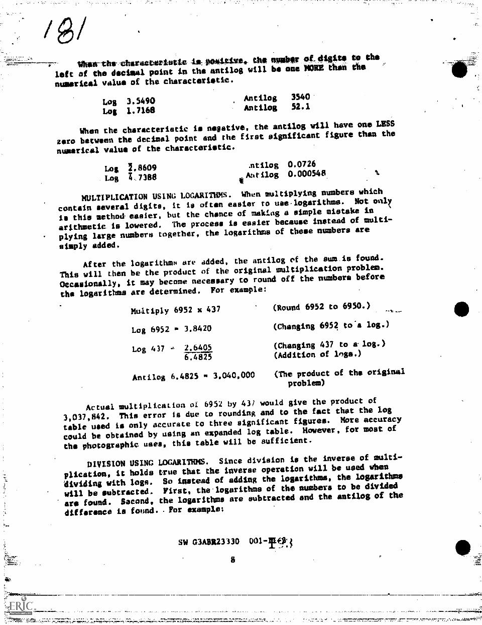
Vhen-vhs-vhavaiswistic ii. ,PokUivit... th ;MOST Pg-,01114$ to taoleft of the decimal point in the antilog will be one NONE thah the
numerical value of the characteristic.
Log 3.5490Log 1.7168
Antilog 3540
Antilog 52.1
When the characteristic is nsative, the antilog will have one LESS
zero between the decimal point and the first significant figure than the
numerical value of the characteristic.
Log 2.8609 ntilog 0.0726
Log Z. 7388 ilog 0.000548
MULTIPLICATION USING LOGARITHMS. When multiplying numbers which
contain several digits, it is often easier to use.logarithms. Not pally
is this method-easier, but the chance of making a simple mistake in
arithmetic is lowered. The process is easier because instead of multi-
plying large numbers together, the logarithms of these numbers are
simply added.
After the logarithms are added, the analog of the sum is found.
This will then be the product of the original multiplication problem.
Oecasionally, it may become necessary to round off the numbers before
the logarithms are determined. For example:
Multiply 6952 x 437 (Round 6952 to 6950.)
Log 6952 3.8420 (Changing 6952 to-a log.)
Log 437 2.6405 (Changing 437 to a-log.)
6.4825 (Addition of Inge.)
Antilog 6.4825 P. 3,040,000 (The product of the original
problem)
Actual multiplication (31. 6952 by 431 would give the product of
3,037,842. This error is due to rounding and to the fact that the log
table used is only accurate to three significant figures. More accuracy
could be obtained by using an expanded log table. However, for most of
the photographic uses, this table will be sufficient.
DIVISION USING LOGARITHMS. Since division is the inverse of multi-
plication, it holds true that the inverse operation will be used when
dividing with logs. So instead of adding the logarithms, the logarithms
will be eubtracted. First, the logarithms of the numbers to be divided
are found. Second, the logarithms are subtracted and the antilog of the
difference is found. For example;
SW G3A3R23330 001-1!?.3
8
`

Divide 249 e 0.9628 (Round 0.9628. to 0.963.)
Log 294 1. 2.3926 (Changing 249 to a log.)
Log 0.9628 1.9836 (Changing 0.9628 to a log.) .
2.4090 (Subtraction of logs.)
Antilog 2.4090 m 256 (The quotient of the original
problem.)
Once again this is an approximate answer. However, it ie accurate
enough for most photographic applications.
The Metric System
Throughout your career as a Continuous Photoproceeeing Specialist,
you will be concerned with using mathematical formulas. Often times
these formulas are used with different physical measurements. Chemical
formulas, replenishment rutes, development times and quality cantrol
analyses are few examples. In dealing with these situations, you will
sometimes need to use a system of weights and measures.
In the United States there are two systems, the US Custostary and
the metric systems. The US Customary is probably the most familiar,
however the metric system is used to a great extent in the photoscieftes.
The metric system was invented for its simplicity and has been
adopted in most countries. The simplicity of the metric system result.
from facts; it is a decimal and therefore fits our decimal notation.
Also, its units for lengths, area, volume and weight are all dependent
on one unit, the meter. In the US Custamnry system of weights and
measures, there are about 150 different terms and 50 different numbers.
Some of the more common measures are committed to memory--5280 feet to
a mile, 36 inches to a yard and 16 ounces to the poundhowever, there
are too many to learn them all. Also, seldom de these units have any
relation to each other.
UNITS. In the metric system there are only three units and all of
these are related to each other through the meter. These units are the
meter for linear measure, the liter for vnlumetric measure and the gram
for weight. To denote the different amounts of these units. a prefix is
attached to each one. These prefixes are:
1. Mega--which denotes 1,000,000
2. Kilo--which denotes 1,000
3. Hecto--which denotes 100
4. Deka--which denotes 10
SW OAER23330 001-11-3

5. Deciwhieh denoted 0.1.
6, Centi--which enotes 0.01
7. Milli--which denotes 0.001
8. Microwhich denotea 0.000001
9. Nano-.-which denotes 0.00000001
Ability to hetldle the metric system depends on a ready understand-
ing of the terms used. FOr instance, the word kilometer should mean, at
once 1000 meters and the word milliliter should, at once mean, one-
thousandth of a liter. After the terms ale learned, converting from one
unit to another is simple. This is the greatest advantage to this
system. This simplicity la due to the decimal relationship among the
units. To change to a Isrger imit, divide by 10; 100, 1000, etc., by
moving the decimal point the correct number of spaces to the left. To
change 3768 centimeters to meters, move the decimal point two places to,
the left which gives 37.68 meters. To reduce to a smaller unit, move
the decimal to the right the correct !lumber of spaces. Thus, 0.5 liter
will equal 500 milliliters.
Since both the metric- system and the US Customary system are in use
in this country, it may be necessary at times to convert from one system
to the other. In order to do so, a conversion factor is used. The con-
version factors for some of the Lire Lommon units are given in figure
3-2.
Temperature Conversions
Most people dre familiar with the thermometer, the instrument used
to meAsure temperdlure. Temperaturv is measure of the INTENSITY of
,heet, not the quantity of heat in a substance. There are three 41.f-
ferent temperature scales and 411 three nre used in the photographic
sciences at different times. These scales 4re the Fahrenheit, Celsius
and Xelvin scales.
The most familiar scale in the United States is the Fahrenheit
scale, which was first crudely defined by taking the temperature of the
human body as being 100°. The lowest temperature obtainable with a
mixture of ice and ltat MOO set as 00. The Celsius scale (also called
the centigrade scale) Was invented through more precise scientific
methods. On this scale, water freezes at 0 and boils at 100°.
If we compare the two scales, we note that there are 1000 between
the freezing point and the boiling point of water on the Celsius scale.
This corresponds to 180° on the Fahrenheit scale (freezing point 32',
boiling point 212'). Therefore, the CelMius degree equals 915 of a
Fahrenheit degree.
SW C3ABIt23330 001-11-3
10
195

,
CUSTOMARY TO METRIC
TO CONVERT FROM TO=lonolow.
INCHES
FEET
YARDS
MILES (STATUTE)
OUNCES (FLUID)
QUARTS (FLUID)
GALLONS
GRAINS
OUNCES (DRY)
POUNDS
CENTIMETERS
METERS
METERS
KILOMETERS
LITERS
LITERS
LITERS
GRAMS
GRAMS
KILOGRAMS
MULTIPLY OY
2.154
0.3040
0.9144
16093
0.02958
0.9463
3.7853
0.0646
26.3495
0.4536
TO CONVERT FROM
METR IC TO CUSTOMARY
TO MuLT1PLY BY
CENTIMETERS INCHES
METERS INCHES
KILOMETERS MILES
MILLILITERS OU NC ES1*-tiV9
LITE RS QUARTS (FLUID)
GRAMS GRAINS
KILOGRAMS POUNDS
0.3931
39.37
0.621
0.336
I 0567
15.432
2 2046
Figure 3-2, Conversion Tables
SW G )ABR23330 001-11-310-A
1-9A=Lx

To change from Fahrenheit to Celsius use this equation;
°C 319 - 12)
To change from Celsius to Fahrenheit uee thie equation:
(915) (sC) 412
- The Kelvin scale is used in photography to meamure the color tem.
perature of light. Therefore, conversion to or fraiche Kelvin scale is
seldom necessary.
QUESTIONS
DO NOT WRITE IN TUIS SW, USE A SEPARATE SKEET OF PAPER.
1. How is the decimal point located in the product of a simple
multiplication problem?
2. What is the rule for subtracting numbers of unlike signs?
3. What are the two parts of a logarithm?
4. Whet:. part of a logarithm is always positive?
S. Exolain the procedure for locating the decimal point Oen
going from a logarithm to the antilog.
6. Explain how to use logarithms in multiplication.
7. What is the basic unit of measure in the metric system?
8. How does one convert from meters to kilometers?
9. What is temperature?
10. How is the Kelvin used in photography?
Exeicise 1
PROCEDURES
Solve the problem; using a separate sheet of paper.
1. Perform the following additions.
a. 467
894
b. -1640 e. 320 d. -12
292 -92 -783
SW O3A3R23330 001 -II -3
11

2. Perform the following subtractions.
41111.
a. 991 b. 62 c. -516
minus 428 minus -121 minus 29
d. -11,243
minus *-696
3. Perform the following multiplications.
4.
a. 6.5 x 19,8 b.
c. -6.85 x -10.1 d.
173.1 x -0.048
-231 *.0.0086
Perform the following divillions.
a. -4.292 0.418 b. 7.552 -0.128
b. 0.9245 . 0.43 d. -22.8 9.6
p.
Determine logarithms of the following numbers using log tables.
a. 7 b. 9 c, 16 d. 3785
e. 56 f. 12 g. 92 h. 1725
i. 1/2 j. 25% k. .20Z 1. .0033%
m. 1,5SR n. 1
ti , Deermine analogs of the following numbers.
7).0043 d. 2.9494
3.444 h. 1.9996
2.M543 1. 3.2201
a. 2.8470 b. 0.7235 e .
e. T.4900 f. 0.0009 g.
1. 2.8808 1. 1.0000 k.
m. 1.5666 n. 2.5098
7 Solve the Tbflowing multiplication problems using logarithms.
a. The first thing to-do ih At/lying these problems is to
change each quantity to logarithmic form. In some cases, rounding off
must be used to obtain the correct logarithm.
\
b. The multiplication procedures when 'wing logarithms are
to add the logarithms of the individual quantities.
SW G3A99.23330 001 -T1 -3
12
19s

c. This sum of the two logarithms is used to find the answer
of the problem by determining its antilog. 'Again, if the mantissa
cannot be found in,the tables, find the entilog by mans a nentlime that
im,listod, which has a numerical valu cloeet to the one you aro
looking for.
(1) 496 (2) 2111 (3) 0.0764 (4) 3.001
768 533 99 0.006
(5) 7563 (6) 9268 (7) 396 (8) 2008
6355 8420 65 0.94
(9) 7254 (10) 0.004 (11) 756 (12) 8355
6450 0.4657 756 94
(13) 9001 (14) 7158
7564 2959
8. Solve the following division problems using logarithms.
a. After changing all quantities in each problem to loga-
ithmic form, the logarithm of the diviaor must be subtracted from the
logarithm of the dividend.
h. Again, in these problems, some quantites must be rounded
off before the logarithm can be obtained.
c. After subtraction, the autilog of the difference is the
final answer.
(1) 3847 (2) 156 (3) 0.7563 (4) 8674000
46 0.01 876 6453
(5) 0:001 (6) 6579 (/) 8675 (8) 75620
0,001 85 648 80
(9) 56.47 (10) 0.005735 (11) 56.04 (12) 5.009
8.46 0.5683 5.006 1.001
(13) 6730000 (14) 0.000000005768
756 0.00000675
SW G3ABR23330 001-11-3
13
199

9. Convert temperatures from one scale to the other by computing
the equivalent temperatures in the following problems.
Celsius
a.
b. 25
c. 86
Fahrenheit
-40
d. 50
e.
f. 4
g. 50
h. -20
10. Convert the measureeents from one system to the other by com-
puting the equivalent.measure in the following problems.
Metric Customary
a. kilometers 3.5 miles
b. 250 milliliters ounces
c. 178 kilograms , po4.nds
d. liters 15 gallons
e. meters 16.5 yard.
f. kilograms 12 pounds.
44,
SW C3AgR23330 001-11-3
14.

Sciences BranchLowry Air Force Basa4 Colorado
OBJECTIVES
SW G3ABR23330 0014I-4October 1977
CHEMICAL MIXING AND CERTIFICATION
Given the necessary bulk chemicals, selected formulas, chemical mix
facilities, measuring and mixing equipment, prepare black and white pro-
cessing solutions. Solutions must meet locally prescrOped standards of
quality.
Given pH meter, hydrometer sat and photographic solutions, deter-
mine pH and specific gravity of the photographic solutions. Value for
pH must be within t0.015 of the class standard.
INTRODUCTION
The saying goes that d Chain IN Only as strong as Its weakest link.
'roducing aerial photo-intelligence ean he compared to a chain. Each
step in the process is d link--from preplanning the flight, to flying
the mission, to processing and on to interpretation and usage. Each
phase is important and If a hreak occurs in any of these "links," then
the entire mission might result in failure.
F.,;ch person associated with any part of the mission must insure
that the links do not break. One A the links in processing is mixing
of chemicals and their certification. Should a mistake be made in this
sep, the valuable mission film could be degraded severely or even
totally lost. So the importance of this study section is very high.
The chemicals and tnrmulas that are used in today's Air Force have
been the result of yeais of tesearch and usage. They have been designed
to give,the best results with the highest quality possible. Used in
conjunction with the highly sophisticated camera systems, and high
quality films, these formulas will give the utmost in photo-intelligence
information.
However, there is a catch! These formulas must be mixed properly,
kept within standards nnd timed cortectly. In order to avoid costly and
embarrassing errors, brief study in chemical mixing and the certifica-
tion of photographic solutions is in order. The better this area is
known, the less likely d "break" will occur in the "chain."
2 9

INFORMATION
CHEMISTRY FOR BLACK-A0D-WHITE PROCESSING SOLUTIONS,
Chemical Grades
Afton selecting chemicale for any photographic purpose, twO factors
must be considered. One of these is the purity of the chemical used.
Chemicals with too many impurities will not give desirable results. The
other consideration is cost. Although some chemicals are nearly per-
fectly pure, the results they give may not be much different from a leSe
pure and less expensive chemical. Chemicals are available in many
concentrations and many grades of purity. Some of these chemical grades,
are as follows:
TECHNICAL. The least pure of the chemical grades, technicai chimi-
cals are used primarily in manufacturing processes, for washing and
cleaning compounds, soil conditioners, insecticides and other Omiler
uses.
PHOTO GRADE. These chemicals are designed especially for photo-
graphic uses. Although these chemicals contains some impurities, these
impurities have peen tested end ars determined to cause little If any
effect on the photographic materiets.
ITED STATES PHARMACOPOEIA CUSP). These chemicals meat very hish
sta ards set by the United States Pharmacopoeia.They are used in the
preparation of medicines.
ANALYTICAL REAGENT (AR). These chemical are used primarily for
chemical analysis.They are the most pure and haJa been analysed by the
manufacturer to show kuown impurities.
While USP and AR grade chemicals can be used in photopraphic solu-
tions,.theyusually are not used because of their high cost. Technical
grade chemicals are the least expensive, but their impurities make their
results undependgble. Therefore, considering the quality desired eihd
the cost involved, the mie of the photo grade chemicals would be the
best choice.
Mixing Chemicals
After the developer formula has,been chosen,the next step le to
mix the developer from bulk chemicals. Mixing instructions are usually
given with the photographic formulas. Alwaye read these insitructions
and follow them carefully. The metric system is used for measurements.
It is very important that chemicals be mixed in the proper =der
and that each one is thoroughly dissolved before the next is added. If
the next chemical is added too soon, before the preceding one is dissolved.
SW C3A3R23330 001-11-4
2

/an adverse reaction could occur. This reection might lower the solu-
tion's developing capabilities. It is also important that the chemicals
be sifted into the water slowly; otherwise, they may cake sad then they
would be difficult to dissolve. Unless some other temperature is mom-mended, water hould be 100 - 120°F. (38 - 50°C).
The solution should be stirred gently so that introduction of air
into the solution Is avoided. Violunt stirring should be.avoided.
Also, when esing a magnetic or other type of automatic mixer, a spinniug
vortex in the solution must not be allowed. These practices will cause
the solution to oxidize more rapidly.
.tfleLy in Mixing
WARNING
Cddritic dlkallea and ntrong acids generate considerable
hedt and can react violently when added to water. When mixing
very strong otitis or alkalies, always use the exhaust hood
.nd appropriste asFety clothing. Wear a plastic or rubber
apron, rubber gloves and a face mask or goggles. If the
chemical giveh off toxic fumes, use a gam mask as well.
Kemember the rule: ALWAYS ADD ACID. It holds true with
alkaliesALWAYS ADD ALKALIES. Never add water to an acid
or alkali; add the atid or alkali it the water.
HL aware of the ha7ards of the other chemicals, too. Many photo-
graphic chemicals are toxic if awallowed. Many can cause skin burns or
, damage to the eyes. Know whve the safety shower and eye wash is
located. Avoid contact with the chemicals. If accidents do occur, take
immediate steps. Get medical help, if necessary.
Storage
once the solutiona are ready, they must be stored in proper con-
tainers. ln the chemistry laboratory, chemicals are usually stored in
glash containers. If the solutions are affected by light, they should
he tatore(!.in amber bottles away frop the light. In general photographic
laboratories, however, solutions are also stored in-stainless steel or
polyethylene containers. Polyethylene Ls the most common material
because of its lower cost and inertness to most phoeographiglichemicals.
The most. imvrtant thing to remembr about storing photographic
solutions is to exclude air. Air isuseu the solution to oxidise rapidly.
Therefore, solutions should be kept in full, tightly stoppered bottles.
If partially used bottles are to be kept for.any length of time, their
contents should be transferred to smaller bottles so that excess air may
be excluded. In larger containers Used for mixing and storing large .,
amounts of processing solutions, a floating-lid is often provided. This
SW C3A6R23330 001-11-4
3

/lid fits snugly into the tank and floats on top of the solution, thereby
keeping air from the solutions.
Glassware (Types)
Besides storing chemicals, glass containsrs ars also used for
mixing and,transporting chemicals. Glass is durable and is inert to
photographic chemicals. However, be careful when using glassware as it
is brittle and easily broken. Excess breakage is costly and broken
glass is dangerous. Basically, there are two kinds of glassware used in
the laboratory. These are volumetric and mixing.
VOLUMETRIC GLASSWARE. The manufacturer of volumetric glassware
calibrates the glassware to measure a specified volume. This calibra-
tion is certified to conform to tolerances st.t by the National Bureau of
Standards. This glassware gives very accurate measurement. of, volume
when used properly.
Volumetric glassware is calibrated at 68'F. (WC). Extreme devia-
tions from this temperature will affect the capacity of the glassware
and the volume of the solution being measured. To attain very high
accuracy, the solution must be at 2T2°C. At no time should volume-
tric glassware be heated or rinsed wi h hot water. Heating can cause a
permanent change in the glassware end will result in inaccurate measurements.
GLASSWARE FOR MIXING. Glassware for mixing is not calibrated for
a specific measurement. It is designed eo withstand temperature changes
and for heating solutions. The volumetric changes caused by heatinA
these pieces is not important since they are not ueed for measuring any
way.
In the laboratory there is a variety of glassware. Each piece is
designed for d specific purpose. A/though one piece may be substituted
for another at times, it is b2st to use each piece for the job it was
designed. The glAssware that will he used in this unit is lieted below.
(See fig. 4-11.
Beaker--A beaker is dn ungraduated fitility cup with a wide mouth.
It is used tor mixing !4o1utions and for io 'ding the solution during.the
pH reading nt the solution.
Funnel--A funnel ig used to pour liquids in containers with spell
openings. There are many.different types.
Hydrometer--a hydrometer is a highly calibrated instrument titled to
determine specific gravity. It has A graduated stem and is weighted
with lead et the bottom.
Graduated Cyllnder--This is a cylinder graduated for accurate
volumetri_c Illeileurement R
SW MAHR23330
291

BIAKER.PTREI, BEAKER.PYREX,lir FORM
lIttNt CtitmiC AL
TALL FORM '
f LIN/iffilKtiNER rPf,
OiS(
Cjeantng Glassware
fuNfvflHUCHNER TY Pf
wit T PE R ORA? tPt A 1 [
f4YDROMETER
Figure 4-1. Laboratory Glassware
92
CYLINDER,GRADUATED
Before dny piece of glassware can be used, it must be cleansed of'.
Irsidue. Contamination from previous work mist be totally removed.
utherwise, it will affect the results 4 the new solution being mixed.
Threv types ot cleaning soluttons,are recommended to keep glassware,
clean.
oFfEHrENT. Mid 1 i very eftective, inexpensive material for most
cleaning problems. However, it must be a nontoxic ansj noncorrosive
type.
SUCFURIC-DICHROMATL. This Is i mixture of_40Sei:m or potassium
dichtomate in coneentreited sulfuiic Acid. -This mixture is very effec-
tive against grease, but it is dangerous because of its strong acid,
oxidizing and dehydrating properties.
ACIDo-ALCOHOL. This cleaner is pade by mixing one volume of 3N
hydrochloric acid with one.yolume isopropylvor methyl alcohol. This
cleanser is very effective in removing dye stains.k
NOTE: Detergent will be used exclusively in this course!
SW MA13R23330 001.-11-4
1.

When preparing glameware for use, rinse it a total of fout times
after cleaning. Rinse twice with tap water and twice with distilledwater or deionised water. If, after rinsing, drops adhere to the wallsof the glassware, it is not sufficiently clean. There should be a solid
film of water remaining for at least one minute.
When preparing glassware for stomp DD NOT rinse with distilledwater. This is to conserve the distilled water. After cleaning, glass-ware should be stored in such a potation that it will drain.
Glassware Measurements
Solution quantities are determined from the meniscus of the solu-
tion. The meniscus is the curved upper portion of a column of liquid.As a result of capillary action, the meniscus is concave when the liquidwets the walls of a container. (See fig. 4-2A.) If the liquid does not
wet the glass, the meniscus le inverted. (See fig. 2B.)
A
Figure 4-2. Mentscus Normal and Inverted
Measurements of clear liquids in most containers are taken fram the
1 neest point cn the meniscus. FxceptionH to this ate the measurement of
opailtre liqutds, the mebmurement of specific gravity and when the meniscus
is inverted_ In these cases the measurement is taken from the top of
rhe meniacwi.
Beam Balances
After the glassware is arranged for use and liquids have beenmeasured into them, the dry chemicall must be weighed carefully before
they are added to the liquid. The instrument used for weighing these
chemicals is the beam hdlance. Photosraphic formulas are quite exact,
SW G3A3R23330 001-11-4
6 2 f)P3

therefore, accuracy is verY important, Do not take short cuts when
weighing these chemicals.
The following procedures are specifically for the ORAUS triple beamhalance but they also apply in general to all beam balances. There are
two models of the OHAUS in common use. They are the Model 311 (with amaximum capacity of 311 grams) and the Model 2610 krith a maximum
capacity of 2610 gramb).
ZEROING THE BALANCE
1. Slide all poises to zero.
2. Make sure the balance is level.
3. Place a sheet of protecc1,.,e paper on the weighing pan.
4. Rotate the knurled compensator knob until the pointer lines uplotth zero,
WEIGHING DNICNOWN SPECIMENS
With the balance beam arrested in locked position, place thespecimen on the weighing pan.
2. Unlock the arrest and allow thu beam to swing.
Move the heaviest poise to the right to the first notch whichLauaea the pointer ro drop, then move it back one notch causing thepointer to rise.
4. Repeat Ois procedure with the next lighter poise.
5. Repeat this procedure with each succeeding lighter poise.
b. With the lightest poise, slide it to a position which bringsLIi t! pointer to zero.
i. The weight of the specimen is the sum of the values of allpoise positions; read directly from the graduated beams.
WEIGHING PREDETERMINED AMOUNTS
1. Zero balance with weighing pan in place. Large amounts ofchemical can be weighed in a beaker if the beaker has been "tared out"
as follows:
d . Remove weighing pan And replace with the beaker.
SW G3A5R23310 001-11-4
1

b. Zero the beam by adding tare weights (counterweights) to
the beam to bring to approximately zero.
c. With the knurled balance compensator knob, bring the beaM
to final zero.
2. Set all poises to total the amount desired.
3. Add the built chemical slowly until the Loam just starts to
rise, then stop.
4. From this point on, add very small amounts of the chemical and
check the position of the pointer after each addition.
5. If too much chemical is added and the pointer comes to rest
above zero, remove a small amount of chemical and slowly add pert of
this back until the pointer comes to zero.
The beam balance is a simple in rument to use but it must never be
abused. Handle it carefullY and keep dust off of it. When preparing
the beam balance for storage, remove the tension from the weighing pan
by raising the resting shoe and setting the pan on it. Return all
poises to zero and remove the beams from the fulcrum. If the balance
has proper care, it will always give easy and accurate measurements.
SOLUTION CERTIFICATION
Just because the formula was followed correctly and measurements
made correctl; it cannot be assumed that the chemical solution,' win
perform correctly. Precautions must be taken to assure that the chemical
solutions do the work they are desigred to do. Testa must be run, also,
co assure that the solutions will process the film suitably. There are
three basic tests for certifying photographic solutione--specific
gravity, pH and a sensitometric test. (Tlie sensitometric test will be
discussed in a later SW.) All tests nre important and must be made
before the solutionq can be certified for use.
SPECIFIC CRAVITY
Purpose of thp specifi( Crv1.ty Analysis
The first check made on all solutions is the specific gravity test.
It is a quick check to determine if the mix ls complete. SpeLific
gravity is the ratio of the mass of a given volume of a substance to an
equal volume of distilled water at 60°F (15.6°C). Distilled water iv
assigned the specific gravity of 1.00. The specific gravity of esch
element is known, so from these facts, the specific gravity of any
combination of elements in any ratio can be determined. The specific
gravities for all processing solutions have been determined through
years of use and testing and remains constant. The solution being
SW C3ABR23330 001-11-4
29S

tested will have the same specific gravity provided it has been mixed in
the proper proportions.
Specific gravity will! howeVer, vary from one batch of solution toanother because of various factors Involved (quality of chemicals, in-
accurate scales used in measuring chemicals, etc.). Because of these
factors, upper and lower control limits must be set. If specific
gravity is made to determine the cause. If the specftic gravity goes
beyond the upper control limit, it might indicate that more than the
formula amount of an ingredient has been used, a foreign ingredient has
been used, or the solution has not been diluted properly. A specific
gravity which is below the lower limit might indicate that an ingredient
hes been left out of the solution, or that too much water has been
added.Pr
Ude of :he Hydrome:et
To aid in the determination of specific gravity, the hydrometer is
U3Va. rhe hydrometer la a highly calibrated instrument with a stem and
a lesd weight at the bottom. When (lead, it gives a direct reading of a
solution's specific gravity.
Be csreitil while tv,ing the hydrometer 40 it breaks easily. While
handling the hydrometer carefully, gently lower it into the proper
graduated cylinder. hu :tore that the cylinder is wide enough so that
the hydrometer does not become stuck. Be careful, too, when placing thehydrometer into the solution, that it does not drop quickly to the
bottom and break. If the hydrometer seems too heavy for a particular
solution, use a lighter hydrometer. This simply means that the wronghydrometer was used, mince each one is calibrated to measure only a
certain range of specific gravities.
As the correct hydrometer is lowered into the solution, give it a
gentle spin. This will prevent the hydrometer from clinging to the
sides of the cylinder. The hydrometer should bob only slightly and spin
only for a few seconds. After it has come to rest, the reading may be
made.
' ReadinK Ae Hydrometer
With the cylinder on a level suppolt, the hydrometer will float
vertically in the liquid. The reading ton he taken from the emerging
portion of tAe Otem. The hydrometer is ialibrated along the stem. This
scale is calibrated to read the ratio of the.submerged volume of the
hydrometer in the liquid to the submerged volume when it is floating fn
water.
Make the reading at rhe top of the meniscus (fig. 4-3) on a level
even with the meniscus. The hydrometer will give a reading of 1.00 in
distilled water. For liquids heavier than water, the hydrometer has ascale reading downward from 1.00 to 2.00 or more. For liquids lighter
SW G30123310 001-II-4
9
q

opfottoMETER STEM
L INE OF VISION
MENISCUS
INDER WALL
SOLUTION
Figure 4-3. Section of Hydrometer Stem
,than water, the hydrometer is adjusted to a scale reading from 1.00 to,
0.7.
Temperature Compensation
The hydrometer is also calibrated at 60°F (13.6°C) in distilled
water. A temperature change will have a direct effect on the specific
gravity reading. In the case of water, 0.001 must be added to the read-
ing for every 5°F (2.5°C) increase in temperature. For every 5°F
(2.5°C) decrease in temperature, 0.001 must.be subtracted from the
reading.
Since most photographic sclutions contain several solids dissolved
in water, their density fH not. the. Mame as the density of distilled
water. Because the phbtographic solution is denser than water, the sol-
ution will expand more for each degree of temperature change. The
temperature correction for most photographic aolutions whose specific
gravity falls between 1.100 and 1.200 is 0.003 for each 10°F (5°C)
temperature change. Laboratory.research indicates this fact. There-
fore, after taking the reading it ts necessary to find the temperature
of the solution and apply this correction factor.
SOLUTION pH'
Purpose of pH Measurements
Specific gravity is the first and quickest test given to a photo-
graphic solution. However, even if the solution has the right pecific
gravity, it must not be assumed that it will perform as desired. The
alkalinity or acidity of a solution will also affect its ability to
process photographic materials. The amount of alkalinity or acidity tu
determined by measuring OH. This amount will vary from solution to
solution. Figure 4-4 ehows the pH values of some common substances frmv,
the most acidic to the most alkalink.SW C3ABR23330
21010

SOLUTION
GASTRIC Fi.UID
VINEGAR MS ACETIC ACID1 3.1
ORANGE JUICE 3.8
MILK
-PURE" WATER 7.0
BORAX (9 016) 93
AMMONIA (10%) 112
'VW
Figure 4-4. pH Values of Common Substances
The pH of a solution can be described as a measure of its alka-
linity or acidity. Such a figure is necessary when making various
photographic formulas, for predicting its effectiveness, etc. Certain
indic.itors, such as litmus paper, can establish the fact that a solqtion
is acidic, alkaline or neutral. However, they do not indicate how mmch.
A pH meter will tell how acidic or alkaline a solution is.
Tbe pH value has a scale of zero to 14 with 7 being the neutral
point of pure water at 77°P (25°C). Numbers less than 7 indicate a
degree of acidity and numbers greater than 7 indicate a degrer of alka-
linity. Liquid solutions are Acid or alkaline according to 4.ac.r ratio
of hydrontum (H10+) to hydroxyl (OH-) ions. Acidic solutions 1-live more
hydrontam ions than hydroxyl ions while alkaline solutions have more
hydroxyl them hydronium ions.
Hydronium ion concentration is used to express both acidity and
alkalinity. This is because an electrode that will sense hydronium ion
concentration is much more stable than one which will-sense hydroxyl ion
concentration.Since numerical values for the hydronium ion concentra-
tion often are extremely small fractions (for example, 1/10,000,000) the
pH unit is used instead. ihe prt unit is defined as the negative of the
logarithm of the hydronium !.on concentration.
SW G3ABR23130 001;41-4
11
2.11
V

pH METERS
Basically, a pH meter is a device which measures an electrochemical
potential. To perform this function the pH meter is composed of many
subsystems including the electrodes which generate a minute electrical
potential. It also includes an amplifier to amplify the minute poten-
tial from the electrodes and a scale to indicate the pH of the solution.
Electrodes
The electrodes develop an electrical potential when immersed into a
solution. In most cases two electrodes nre used: a glass electrode to
generate an electrical potential of the test solution and a reference
electrode to generate a constant potential against which the glass
electrode is measured. (Refer to fig. 4-1).)
ocsas (L Imola trim ot ode t Tow,
1.11M.010coretsma
- wool &OMtime
CMkt
CAP
S IKESfoITTROLL
liktivr
TWITSOLOMON
WI %LOCTERNINATTIEN
)1A iiri
V.EN OE ITIPTITT
11451 MO
C AP
MUT MNFt140111Mkt
PRAM,NOLA
- COWIN
INT IMO&etflogr
mar vu
Kati' gooriqINTERNAL11.111NT
ALICTROLT ItIOW ION/ /
reuIR AMC !IOW
- inncntial ht.twren intvrhoolvii.ment .1nd fotandard s.olutinn
piri tIiI 1.41 beIwi'efl 1..ondel rtl
.1nd IVITIVrItir(Act.gI.isi 5411910)1.1Ii4
put ent 1,11 I n 11.11C r MI1 r fat I
pH- ',unsItivi. gIll. bulb and1,,t ir'Iutaun. IhIS Is thy unlyputvntial in ely.ctr,,th, sycterntn.it VI rit ill or dmice withluirigi In hydrugull - 14,11 4 un
n 1 r iii i pii, (tr tcst %jolt't I uti
17.0c1111,41 sd hqfild pul(Awn 61.
11A: f'11 I I ond le%1 golu
- )tynt aid di vi.lirpo.d in(crnaleIrrnent iii r h.c I rolvli. mthit
Fikure 4-5, Electrode System
§1,1 G3MR23330
12

GLASS ELECTRODE. The basic purpose of the glass electrode'is to
measurelthe hydrenium ion concentration of the sample. The electrical
potentia developed at the glass electrode is proportional to the p11 of
the solution. The measurement of the electrical potential, developed at .
the glass electrode, is accomplished with the pH meter.
In some types ofkelectrochemiCal potential measurement, such as
oxidation reduction, a metallic electrode is substituted for the glass-
electrOde. Then the readout is in millivolts instead of pH units.
_NEVER USE METAL ELECTRODES TO DETERMINe pH OF DEVELOPERS!
REFERENCE ELECTRODE. The purpose of the reference electrode is to
provide a constant reference voltage. This permits measurement of the
potential at the glass electrode. The reference electrode is filled
with a saturated solution of potassium chloride (KC1). The constant
voltage is supplied by this KC1 A small, but constant, flow of KC1
solution is maintained through a liquid function in the tip of the
referent" electrode. The KC1 solution forms a conductive salt bridge in
the sample solution between the two electrodes.
Buffers
When making a pH measurement, the electrodes are first immersed in
a buffet solution. A buffer is a solution whose exact pH is known. The
meter is calibrated so that the reading shown is the exact pH of the
buffer. Following this calibration, unknown pH values will be in a
direct readout when the electrodes are immersed in the test solution.
Normally there are three buffers in the lab--pH 4, pH 7 and pH 10.
For accuracy, always select the buffer that would correspond closesi to
the pH of the solution toeing tested. For example: When testing developers,
use buffer 10 and with Clxing baths, use 4. When the test solution is
unknown, use buffer 7 or use litmus paper for a quick test of acidity or
alkalinity. The use of litmus paper is normally, preferred.
Operation ot pH Meters
Atter the buffet. selected, taking the pH measurement is a simple
operation. Howe'ver, he careful. the pH meter is an expensive, precise
Instrument. Follow the direction carefully and observe all safety
precautions.
In this cuuthe, there are thrve different models of pH meters.
These are the Beckman Expandomatic, the Expandomatic Model SS-2 and the
Model 3500. Each meter will give accurate pH readings and operating
principles are basically the same.
The first ten steps in operation of the pH meters are the same for
each different model and will generally hold true for any other meter.
The other steps merely allow for the different designs of the meters.
SW G3ABR23130 001-11-4
1 3

GENERAL OPERATING PROCEDURES. Follow these eteps when taking a pH
measurement.
1. Depress Standby Pus% Sutton. (Press the STANDBY pushbutton to
the in position on_the Model 3500.)
2. Select three 25: na beakers.
3. Wash and rinse glassware properly.
4. Label each beaker as either test solution, bUffer; or trash
water.
5. Select the proper buffer which corresponds with the oplution
being tested. (Alkall/Acii)
6. Using proper solutions, fill beakers marked buffer and test.
(Approximately 1 1/2 to 2 inches (3.8 to 5.1 cm) of solution.)
7. Slide rubber sleeve from the orifice of the reference electrode.
8. Insure that the KC1 Is at proper level in,tbe reference elec-
trode. (If not, notify your instructor.)
9. Using the trAsh watei beaker, rinse electrodes and thermometer
with distilled water and blot off excess water with lint free absorbent
tissue.
10. Gently\lo,er the electrodes into the buffer.
From this point, follow the directions given for the particular pH
meter being used. (Refer to fig. (.,-5, 4-6, 4-7, and 4-8.)
BECKMAN EXPANDOMAT1C. When using th14 meter, follow the first ten
steps given above then continue with these steps:
11. Depress STD (Standard) button.
12. Droress pH button.
13. Adjust the STANDARDIZE knob until the needle matches the pH of
Ole buffer.
14. Depress STANDBY butto9.
15. Lift the electrodes, replace the buffer with the trash con-
tainer, rinse and blot the electrodeo dry.
16. Gently lower the electrodes into the test solution.
SW G3ASR23330 001-11-4
14 211

4
_a
Figure 4-6. Beekman Expandematte pH Neter
ft.
Figure 4-7. Beekman Expemilematie ps-2 pm Neter
SW GA8R23310 001-11-4

17. Depress ST, button end,record pH reading.
18.; Depreso STANDBY button, lift, rinse ehe dasetrodei over the
trash contsiner.
'19: Immerse the electrodes in a beaker of distilled water.
BECHMAN MODEL BS-2. When using this meter, follow the first tensteps given for the general operating procedures thei continue lath
these steps:
rl. Set function control to AUTO TC for automatic temperature
compensation.
12; Depress the,STD (Standard) buttoni
13. Unlock standerilize knob and adjust the needle to the pH of the
buffer. Relock the standardize knob.
14. Depress STDBY (Standby) button.
15. Lift the electrodes, replace the buffer with the trash watrcontainer, rinse, and hrot the electrodes dry.
16. Gently lower the electrodes into the test solution.
17. Depress the- STD button and record the pH reading.
18. Depress STDBY button, lift and rinse the electrodes over the
trash container.
19. Immerse the electrodes in 4 beaker of distilled water.
BECKMAN MODEL 1500. This is a digital readout pH meter. When
using it, follow the first ten steps given tor the general operating
procedures then continue with these steps:
11. Depress pH pushbutton to the in position (engaged). Do not
sdiust surf.: control.
12. Prefis STANDBY pushbulton to disengage (out position).
13, Adjust STANDARDIZED control to obtain buffer pH on digital
displai, and then lock control.
14. Depress STANDBY pushbutton to the in position (engaged).
15. Lift'the electrodes, replare the buffer with the trash con-
tainer, rinse, and blot the electrodes dry.
SW C3ABR23330 061-11-4
9

atAari
lata,
Figure 4-8. Beckman Model 3500 Digital pH Meter
16. Gently lower the electrodes into the test solution and allow
them to reach thermal equilibrium.
17. Pftss SlAMDBY pushbutton to di.engage (out position) and rem&
pH value on digital display.
1M. Depress STANDBY pushbutton to the in (engaged) position, lift,
and rinse the lectrodvs over the trash water container.
19. immerse lite e1nctrt)dea In A beaker ot distilled water.
pK Measurement Preraurions
Follow the given directions atep-hy-!itep. 'II they are follOwed
precisely, exact and clear readings will be obtained. Inaccurate
readingaJwill i1 ohtaihed if they are not. Resides the inaccurate
readings, the meter may be damaged. To acquire good readings and avoid
Meter &Image, observe the following precautions:
I. Electrodes a:v very fragilevoever let the tips touch the
bottom of the beaker;
SW GIABR23330 001-11-4
1 7
Alt

-4
4.472. NEVER MOVE T3E =moss nom mamma nem mu maam Is IN STANDBY!!
3. Keep the electrodes clean. Rinse them with distilled or
deionited water and blot them with chemically inert absorbent tissue
before immersing them in the buffer er test solution.
4. Care should be taken not totransfer body electrical zharge to
I the glass electrode when blotting electrodes. Blnt only, DO NOT WIPS.
Reading drift will occur if the charge is transferred. If glass elec..
trodes obtain a charge, wait for it to discharge before proceeding.
5. The filling hole on the reference electrode should always be
covered when not in use.
6. Always check the level of the KC1 in the reference electrode;
if not full, notify the instructor.
7. Always leave the tips of the electrodes immersed in distilled
or deionized water when not in use.
8. Do not stir the buffer ur test solution with 4e electrodes in
the beaker.
9. The pH of any given formula lona vary somewhat from one con-
tainer to another. Therefore, each lab will have to make a series of
readings from each solution batch.
10. When using the Expandomatic or the SS-2, always observe the
needle so that it covers its own reflection in the seals mirror. Other-
wise parallax will cause an inaccurate rending.
Because pH measurement involves liquids plus electrical equipment,
insure that the mefer is grounded at all times. This will prevent any
accidental damage to the meter or the operator during operation.
The pH meters used in this course are equipped with automatic
temperature control. This means that the meter automatically edjusts
for the temperature of the solution. Also, most pH,meters in the Air
Force are so equipped. However, one may have need to use a pH meter
without thiH equipment. When this occurs, it will be necessary to take
the gtemperature of the solution and adjust the Temperature Compensator
Control Manually to the temperature of the solutions. This step must be
added since the pH of n solution will change with temperature variations.
A label from a buffer powder package is shown in figure 4-9 to indicate
how temperature effects,pH of a solution.
sy G3ABR23330 001-11-4

110110IMPORMMM.,
pH - TEMPERATURE TABLE
Ettg Eta POWDER IN THIS .PACKAGE, WHENDISSOLVED 1.1 500 ML OF DISTILLED WATER, WILL
GIVE A BUFFER SOLUTION04CURATE TO LOW PIOOf- THE FOLLOWING
°C pH
0 9.46
5 9 39
10 ,9 33
15 9 21
10 9 22
QC pH aC pH
25 9 19 80 866
30 1314 70 8.92
35 9 10 80 8.89
40 9.07 90 8 85
50 9 01 9b 8 83
vAt 11ES RASED ON COmI'Ll 'ft- THERMAL
EMU IBRIUM OF EL ECTRODES AND BUFFER./IMINIMONOPMIN.M.MIROW
4111111.1,
Figure 4-9. Changes in pH Duc to Temperature Changes
QUESTIONS
DO NOI WRITE IN THIS SW, USE A SEPARATE SHEIET OF PAPER.
1. What are the precautiois whrn mixing acitia?
Volnietric glassware is calibraied at what temperature?
1. What is the procedure for washing glassware?
4. What will be the results of mixing photographic developers
violently?
5. What might happen if al chemical for a solution is added before
thu preceding chemical ha.-r dissolved?
b. What ia the minimum number of times glassware should be rinsed
after being washed With,a cleaning solution before storage?
7. Measurements oi k-lear solutione in containers are gere-,..ily
taken dt the 01 the meniscus.
M. What are the three basic testa given for certification of
photographic solutions?
9. What is speciiii gravity:
CIARR23310 001-II-4
19
21 rr
Os-

-r -
10. Whet is.theAlietiffm,gravity o( distilled weter at WI(15.6%), at 70°F 121:4°C) and at 115°F (46.i°C)?
11. What is a hydrometer?
12. HIOromeeers are calibrated at what temperatures?
-13. What correction factor must be applied to hydrometer readings
for temperature changes when testing photographic solutions?
10.
14. How is a hydrometur read?
15.."What is a pH meter?
16. What La the definition of the pH unit?
17. What Is pH?
18. What is the neutral pH?
19. What are solutions with low pH called?
20. What are solutions with high pH 'values called?
21. What is the purpose ut the reference electrode? What in the
purpose of the glass electrode?
22. What is KC1? How is it used?
23. What are buffer t.olutionn?
24. Before the electrodes aro lifted from a solution, the elpc-
trodes must be In
25. IN) tempvrature cliangos aftrct the pH of a given aolution?
EXERCISES
Exercise 1
EQUIPMENT
Chemical Mixing Facilities
Assorted Laboratory Glassware
Magnetic Mixing Apparatus cr
Stirring RodsTriple Seam Balances
Basil) of issue
1/classAs needed
1/student1/student
SW C1A8R23330 Ml-11-4.
20

v
PROCEDURESg'S
2. 0 9
1. Observe the general safety precautions for the particularchemicals being used.
2. Remember the triple A (AAA) rule when using acids--ALWAYS ADDACID. Add the acid or alkali to-the water or other solutions. If water
or other solutions are added to acid or alkali, splattering oftenresults, endangering the eyes, skin or clothing.
3. Select proper equipment needed to mix 1.05 quarts (one liter)
of AFD #1.
4. Obtain chemicals from the instructor.
5. Following the formula givenproper order. Take plenty of time.
6. The instructor will discussmission.
below, mix the chemicals in their
mixing techniques during the
FORMULA - AFD #1(D-19)
Water (52 C or 125 F)
Metol
110 Sodium Sulfite, desiccated
Hydroquinone
Sodium Carbonate, monohydrated
Potassium Bronidb
Cold Water to make
Exercise 2
EQUIPMENT :
Hydrometer SetGraduated CylinderProcessing SolutionGlassware Washing IscilitiesThermometer
500 ml
2.0 grans
90.0 grams
8.0 grams
52.5 grams
5.0 grans
1.0 liter
Basis of Issue
2/classI/studentI/studentAs deeded2/class
SW G3ABR23330 001-11-4
21
of

a2/PPOCEDIMIS
1. Pour a sample of the developer mixed in exercise 1 tato a
proptr graduated cylinder.
2. Use a hydrometer and take the specific gravity.
3. Take the temperature of the solution.
4. Mathematically adjust the reading according to the procedure
stated in the SW.
Exercise 3
EQUIPMENT
pM MeterProcessing SolutionAssorted BeakersGlassware Washing FacilitiespH BufferDistilled (Deionized) WaterChemically Inert Tissue
PROCEDURES
Basis Of Issue
1/student1/studentAs neededAs neededA. neededAs neededAs needed
1. Use the same solution mixed in exercise 1.
2. Using procedures prescribed in the SW, determine the pH of the
solution.
3. Observe all personnel and equipment safety precautions.
4. Store the remaining developer in a brown stoppered bottle, as
per the instructor's directions for use in the next SW. Libeling
instructions: YOUR MAMECOURSE NUMBERDATE MIXEDINSTRUCTOR'S NAME
SW G3ABR23330 001-11-4
2*2
222

ciences BranchLowry Air Force Base, Colorado
:--
OBJECTIVES
SW G3ABR23330 001:LI -5
October 1977
SENSITOMETRY AND DENSITOMETBY
Using unexposed original film, sensitometer, previously mixed
solutions, and manual processing facilities, expose and process sensi-
tometric strips. Processed sensitometric strips must be of acceptable
density and be free of chemical and physical defects.
Using a densitometer and previously processed sensitometric strips,
measure and record each density step to within +0.02 of the actual
density.
Using densitometric readings from a previously processed sensito-
metric strip, plot a sensitometric curve and determifte gamma. Gamma
must he computed to within +0.10 of the class standard.
INTRODUCTION
In the early years of aerial photo reconnaissance, processing was a
hit-and.-eiss game. However', in more recent years, research has produced
means.of controlling and predicting the results of photographic process-
ing. Results that were good "sometimes" would not provide high quality
intelligence information that was good enough.
One method of achieving good quality control is the use of sensi-
tomstry. Through sensitometry, a very previse control can be kept on
the sensitized materials, photographic solutions, and the method of
processing.
INFORMATION
SENSIMMETRIC FUNDAMENTALS
When 4 photographic emulsion is expoosd to light, certain changes
occur which-eventually produce a series of densities. If this'exposure
takes place in a camera, a great many densities are created whose values
are the opposite, or the negative, of the luminances in the scene.
These negative densities, in turn, modulate light passing through them
to produce positive densities in a print. Each density le some approxi-
mate product of the intensity of the light the emulsion was subjected to
and the length of time it was exposed. Such a variety of exposures are
produced in a cemera that to make comparisins between exposures and
densities would be extremely difficult. Therefore, an instrument capable
of producing's series of known exposures over the range likely to be
encountered in practice must be used. The instrument which does this is
a senaitometer.
-44
?3

The .firstrequirement Of a eeaaitoaeter la that Lt. coufwelvt0
practice. If the response of an emulsion to exposure is to be "Watered,
the duration, intensity and quality of the exposure must be controlled.
Also, the results must be predictable and reproducible.
Sensitometry and densitometry are terms that are closely tied
together.Sometimes thqy are even used interchangeably.
Howevato this
is incorrect, since densitometry is merely a part of sensitometry.
Sensitometry is the science of determining the photographic charac-
teristics and responses of radiation sensitive materials. Densitometry
is just the process of obtaining data for a sensitometric calculation.
Sensitometry
As the name Implies, sensitometry le concerned with the measureMent
of sensitivity.This does not mean just sensitivity to light, but to
all forms of radiation that are used in photography.These include
light, X-rays,ultraviolet and infrared
radiation and so forth. There-
fore, the measurement of the effect of radiation on ensitive material
is perhaps a better working definition of sensitometry.
In practice, sensitometry consists of giving sensitised materials
a controlled exposure of radiation.After the exposure, the sensito-
metric strip is processed and the densities of the exposure are evaluated.
In order for the evaluation to be valid, the exposure, materiels
and processing must match those in actual use. It would be uselss to
test a material that is not used or to test it in a manner differant
from its intended use.
The senoitometric strip, sometimes called a control strip Or test
strip, is a convenient method of producing 8 uniform, measurable set of
densities for test purposes. These densities should progress by some
predeterminedmultiple of exposure and should have sufficient range to
be representativeof any densities likely to be encountered in the
photographic negative.
Sensitometry can be used to test the effectiveness of a batch of
photographic chemicals. It can be used to evaluate a certain method of
processing or the reliability of a processing machine It cen also be
used to determine the characteristicsof a particul type of film.
Therefore,sensitometry can be a very important tool for the photopro-
ceasing specialist.
Classification of Sensitometers
The instrument used to produce the controlled exposure on the
sensitizedmaterial is a sensitometer. Photographic
sensitometer ste
5W C3ABR2333(1 001-1I-5
z
2?1
sr,
r

ea/designed to meke controlled exposures which produce densities suitable
for sensitometric testing. Sensitometric-densitometric testing requires
a method of comparing the amount of expoeure given to an emulsion to the
etiOunt of denvity whteh vesulte fro* that exposure.
Sensitometers are grouped into two classes. If the intensity of
the light is changed while the tims is held constant, the sensitometer
is an intensity-scale instrument.= If the time varies while the inten-
sity is kept constant, the instrument is a time-scale sensitometer.
T1ME-SCALE SENSITOMETERS. There are several designs for time-scale
sensitometers. Choa way to build sUch act tnstrument would have the
material exposed in different steps. This would be similar to exposing
a test. strip during prolection printing. ln other words, one sectionwould recetve an exposure, then another section would receive a larger
exposure until the entire strip had been exposed.
Another design, more commonly-used, uses a rotating wheel with
apertures of different lengths cut into the wheel. (See fig. 5-1.) Tbe
apertures are precisely cut in order to give an accurate exposure time.
In both of these de-signs, the intensity of the.exposing lamp remains
constant.
LIGHT SOURCk
EX POSURE DISK
Figure 5-l. Time-Scale Sensitometer
SW MABR23330 001-11-5
3

Until recent years, ttme-scale sensitometers were used for mostprecision work because it was easier to obtain a series of accurateexposures by varying the time than by varying the illumination. Theuaual method of obtaining a time-scale exposure is by means of a ro-tating disk,with apertures of varying length. When the disk is rotatedin front of the sensitive material, the time of exposure varies directlyWith the length of the aperture. The exposure varies by the power of
two.
INTENSITY-SCALE SENSITOMETERS. Sensitometers in which ths scale ofexposures is produced by varying the illumination on different parts of
the emulsion are preferred because, in actual practice, photographicmaterials are usually exposed to differences in illumination. Forexample, exposing negative materials in the camera subjects the emulsionto varying intensities rather than to different times. Many types of
sensitometers proaucing illumination scales have been designed, butthose using light absorbing filters, commonly known as step wedges, ore
the most widely used.
Light Sources
Photographic exposure is defined as the product of illumination and
time (E I x T). The unit of exposure is the meter-candle second
(MCS). This is the exposure produced by a atandard candle in onesecond, at a distance of one meter from the material. It follows then,that the two important parts of a sensitimeter are the light, source and
the device for producing a series of graded exposure steps.
Light souree lamps for a sensitometer must be carefully chosen, andtheir characteristics must be precisely known. The intensity of the
light must be known. it must be sufficient,to make the time of exposurecorrespond closely with actual photograOhic practice and it must remainconstant over long periods of time. In addition, the color temperature
of the light must be known. These illumination requirements are ful-filled most completely at the/present time by special incandescent
tungsten lamps. Both the int/enmity and the ,:clor quality of lamps of
this kind depend on the current flowing through the filament. It is
necessary to maintaie proper voltage at all rtmes. Another factor in
precision aennitometry in the change in hot!, ;ntenaity and color with
the age of the lamp. A reolneement lamp should he burned for short
time before using it for testing purposes. An old lamp should be dis-
carded before any appreviable change occure.
Incandescent lamps of the type.most suitable for use as a standardlight source operate at a color temperature of about 2300* K, while the
color temperature of sunlight at the earth's surface has been fixed at
5400' K. Therefore, ie-is necessary to use a filter to alter the colortemperature of the lamp so that it is equal cn the eoloi temperature"of
sunlight. Gelatin filters, such as the "Wratten" 78, 76A, anor79 aresufficiently accurate for practical exposures and are generally used.
SW 03AB1(23330 001-11-5
4 2?(.3

Another light source suitable lor use am a standard light source is
a sewn flash (similar to 0 strobe light). Advantages of this typs of
ight.source age lefig We color quality close to daylight, and little
loss of calor quality oveethe tUe ot the Isar.
Exposure Modulators
For a sensitonetsr to produce a graded series of exposures, the
values of the exposure intervals must be accurately known. These inter-
vals are generally arranged in steps increasing in order from law to
high exposure. A part of the strip is left unexposed in order that the
log density of the paterial may be determined.
TIME-SCALE MODULATORS. First, consider the time differential used
in sensitometers and see why the time intervals are figured the way they
are. Consider making a test strip and that the exposure times are un-
known. Assume a trail range of exposure times from 5 to 80 seconds.
What intermediate steps should bs used?
One answer might be to use steps, 5, 10, 15, 20, 25 seconds and so
an. This might appear to be a reasonable system of exposure, but it
fails to meet the requirements for an equal set of exposure changes.
This can be seen by comparing the steps in the low and high ranges. The
change from 5 to 10 seconds is a 100 percent increase in exposure, and
the change from 10 to 1!, aeconds a 50 percent increase. The change
from 75 to 80 seconds would only be an increase of about 6-1/2 percent.
Therefore, as the exposure time becomes greater, the effective increase
becomes less.
In designing the exposure modulator, then, a set of equal changes
is required. If a change from 5 to 10 is appropriate, to use, the next
step should be 20, then 40 and no on. Such a series of numbers would be
equally spaced in a geometric progression. There is a common multiplier
(2) which is used to generate each number from the preceding one. The
complete series would he 5, 10, 20, 40, and 80. Notice though, that
here you have exhausted the range tram 5 to 80 in only 5 steps. The
principle that applies here is "to produce a series of equal exposure
changes, do so by repeated multiplication by some factor." (The factor
need not be 2, although this is commonly used.)
Now convert the twries developed above to logarithms and notice
that the logs have a common difference, which is 0.30. (This is the log
of the common factor 2.)
5 10 20 40 80
0.70 1.00 1.30 1.60 1.90
The principle used here lo: "A series of equally spaced exposures
(squally spaced in Out they differ'by a common multiplier) when expressed
SW C3A3R23130 001-11-5
5

in logarithms, have a common difference." The exposure sheet oe the
sensitomater is designed to give these squally spaced exposures during
one revolution of the wheel.
The device or method used as an exposure modulator must also most
certain requirements. First, it should be able to produc an exposure
range that conforms closely to that found in actual experience. Next, .
It should be accurate. Also, it must be consistent. Finally, It should
have no significant effect on the color quality of the light.
INTENSITY-SCALE MODULATORS. In the time-scale ensitometers, the
exposure is changed (or modlated) by apertures of varying length. The
modulator used in a intensity-scale instrument is commonly celled a
step wedge or'tablet and hos steps of varying densities. These densi-
ties are precisely known. This modulator changes the-inteesity of the
light striking the film being tested. By using this modulator even
exposure changes can be obtained.
Absorbing step wedges, are usually made by coating glass with a
layer of gelatin containing carbon or same black pigment. For rough
sensitometric work by the practical photographer, it is often adequate
to use a step wedge consisting of a photographic negative made by
exposing a film in steps and developing it in a developer which gives
deposit as free as possible of color other than gray.
An intensity-scalesensitometer using a step wedge is simple to
construct and to use. It merely involves placing the wedge,in contact
with the test strip and exposing both to the light from a standard lamp
through an accurately timed shutter. The intensity may be further
modulated by placing neutral density filters between the light source
and the step wedge,. See figure 5-2.
LE AST E X rOSU EFILM
r 1 -1. 1 f-,
f
I STFPNif-DGfOf NSE irJ;) 1
I
MOST EXPOSURE
-1LIGN f NO
Figure 5-2, Intensity-Scale Sensitometer
5W 63ABR233)0 001-II-5
2 ?

,
4
There are two Nensitometers in common use in the Air Force. These
are thc Kodak Process Control Sensitometer Model 101 and the E G 6 C
Senittameter. Both of theaeinstruments are intsnoity-seale
-1006fitokators.
Kodak Model 101 Sensitometer
FUNCTIONAL DESCRIPTION. This Instrument provides repeatable ex-
posures for either black-and-white or color photogrsOhit materials for
process control purposed in laboratories. The sensitometer is versatile
enough to handle all commonly proce:oied puotographic materials with
sufftcient 4Ccurdilf tO pr4 wide the degree of control required,r
A fixed exposure time (It 1/5 mewnd Is produced by 4 shutter disk
connected directly to si mynchronous motor. Illumination of constant
intensity and color quality le provided bV A calibrated projection lamp
mounted in a polgrlzed )-prooKed plug,. The electrical control circuit
for the lamp contiiseW or d voltage stabilizer to supply constant volt-
age, a variable transformer to produce the correct lamp current, and an
ammeter to set and read the reqdlred lamp current. Combinations of
calibrated neutral deniiity and color-balancing filters are used in the
exposing beam to convert the illumination intensity and color quality to
mise requixemence of the material being exposed.
During exposure, film or paper is held by a pressure pad against a
st,ep wedge. ThJ KodagThensitometri, Step Tablet No. 1, supplied with
the sensitometer, provides 11 exposures with a 0.30-density increment
between steps: Total exposed area to 7/ti by 4 7/16 inches (22mm x
113mm).. Other step wedges tor specIalizt-d emulsions are also provided.
This sentiometer mUlt he used In a darkroom, but, for efficient
operation, it is advisable for you to practice operating it in the
light. (See fig,
The calibration 111e ot the lamp im 100 to 150 hours. To conserve
this, turn off the insttument yhen it is not in use and do not operate
the lamp ac a current value greater than_rspecified on the calibration
tag. As 4 further caution, alWays turn the instrument on and off with
the labtp control knob, not by insedIng .ind pulling the power cord in
the outlet. This will protect the lamp .mnd ammeter from sudden current
surges.
The sides ot the gote are notched t4, allow positioning. Strips of
film or paper 35mm or 3 1/2 inches wide can be handled by resting
their lo'wer edges on the lowest stov on Ihe gate. The strips must be ar
least 6 1/2 inches (165mm) long to allow proper handling on the gate,
but they can be puch longer it desired.
SW G3ABR23330 001-1I-s

ove
A -- GATE
B - DARK SLIDE-GATE RELEASE LEVER
o - LAMPCONTROL KNOBE - EXPOSURE BUTTONF MODULATOR WITH STEP WEDGE'
Figure 5-3. Kodak Process Control Sensitometet, Model 101
The removable neutral density filter assembly cdntsins two glass
filters and allows adjustment of the light intensity to suit three
genecal Xypes of material. These include black-end-white negative
films, color films, and most print materials. The lighter of these two
filters has a density of approximately 0.04 and the-darker one has a
density of approxivate1y 2.10. The filter assembly is removable for
conditions where no filter is required.
SW G3AB1121330- 001-11-5
230_

.The color filter holder
balaines- the color quality
color taatotisiti.
OPERATING PROCEDUNil.
carefully:
,accepts 3-inch (76mm) square filters needed
of the illumination for the warious types
To operate the Kodak 101, follow these steps
1. Make certain that power cord is unplugged - lamp control knob
"011P.
2. Insert proper neutral density and color compensating filters.
3. Close dark slide door.
4. Plug power cord into 100V grounded outlet.
S. Check proper placement of exposure modulator.
6. Turn lamp control knob "ON" and adjust to bring anmeter.to
value given on lamp calibration.tag.
7. After 2 minutes readjust lamp control knob if reading on
ammeter is not correct.
S. Turn out room lights.
9. Open platen gate.
110 10. Place strip across pressure pad, holding the ends in appro-
priate notches - chyle platen gate.
0-
r-
11. Press, and immediately release, exposure button. CAUTION--
Holding the button too long will result in multiOle exposures.
12. Open the gate and remove the exposed strip.
13. Turn "OFF" by turning the lamp control knob counterclockwise
mail the switch clicks.
14. Unplug the pawpr cord.
15. Open dark slide doot and remove the filters - close the dark
slide.
E C 6 C Mork Vl Svositometvr
FUNCTIONAL DESCRIPTION. The Mark VI is a precision photographic
research tool which WWII a xenon flash source. Designed tO be used as
the exposure light source for film characteristics investigations, pro-
gees control operations, and reciprocity effect itudies, the Nark VI can
SW C3ABR23310 001-11-5
,)
.71
,.

be used with all types of photographic emulsions. Since the light
. output approximates ,the color quality of daylight, no color compensation
is required for testing black-and-white or daylight-type color sag-
alone.- The Mark VI has sufficient light output to test the slowest add
fastest emulsione and flash durations which approximate the exposures
encountered in snapshot, electronic flash, and high speed motionficture
photography.
The Mark .yi Sensitometer hes four operating cdntrols OPT
toggle, and 10 , 10 , and 10 SECOND EXPOSURE TIME 'selector switches)
located on the top of ihe instrument. -Closing the cover platen triggers
the exposure lamp. A socket is provided 4on the right of the base so
that the user may also trigger the unit remotely.
The sensitometer operates on standard 115-V1 60-cycle, AC power., A
built in voltage regulator circuit prevents change in light output wAth
line-voltage fluctuations from 95V to 1307. The time constants of the
three Aifferent RC circuits provide three precise durltion flashes at
three different energy levels. The highest outputL3approximately 5000'
meter-clndle secgnds (MCS) is obtained from the.10 second circuit..
The 10 and 10 second circuits deliver approximately 1000 and 130
MCS, respectively.
The three expoeure time selector switches corresFond to different
shutter speeds in normal_Rhotography. The switchil0 4quale 1/100
second exposure time; 10 equals 1/1000 second and 10 equals 1/10000
second. These exposure times are provided to allow an exposures equiva-.
lent to the exposure used during actual usp.
The complete systemconsists of the sensltometer, a gray-scale box,
tlashtube shield, two variable-area filters, and an uncalibrated Kodak
No. 2 Photographic 21-Step Tablet (step wedge). See figure 5-4. Cali-
brated photographicstep tablets cat ! be obtainui, or the scale provided
can he easily calibrated. Tbe gray-qcale hox, which is inserted into
the body cavity,under the plmten of !he instrument, provides the ex-
posure platform upon which the r111 nridergoing test is exposed. The
variable arca filters ( i-line iind i9 line), which are inserted between
.the fjashtuhe shield ,)nd the gray scaly 11,x, allow the user to balance
the light outotlt of thv rAirek' 4eporaLe c :9 within + 10 percent.
The 3-line if:ter d/id !he 19-line filter, which can he considered equiv-
alent to ND 1.70 and NI) 1.0 ilitermLrespectively, are used to normalize
_the light output of the 10-) and 10 second circuits Lo that of the
10-4 second circuit. Normalization of the light output of .he three
.circuits (an be useful in studying film characteristics and exposure
reciprocity effects. The step tablq in 4upplied as an exposure modi-
,lator. Neutral denoity filters, such as the'Mratten 96 series, can also
be used to reduce the light output of the individual circUits to suit
the needs of the specific film being tested. Neutral density filters
are not recommended for color work however.
SW G3ABR2)330 001-11-5
9'1010

A
A - mARK VI SENSITOPAET ERB - GRAY-SCALE BOX
111
Figure 5-4. Complete Mark VI System
C FLASHIUBE SHIELDVAR1ABLE-AREA FILTERS
The E C 6 G Mark VI Sensitomater is an instrument with which stand-
ardization CAR be accomplished. With it, complex photographic variables
can be analyzed separately and scientifically. The precise duration and
constant repeatability of the light output of the Mark VI makes it
possible to consider all aspects of the photographic process from the
point of view of exact, controlled exposure. Film characteristics and
the effects of processing conditions can he determined easily and pre-
cisely with this sensitometer.
The foregoing informAtion on the Mark VI sensitometer includes data
only for one type (or version) of the Mark VI. There are two versions
SW WASi23330 001-11-5
l 1

of this sensitometer in existence .4nd'e1ie output varies slightly betimes
them. To compute the exposure properly, the output of tne sousitemster
must be known.
These two versions are commonly referred to as the "gray model" and
the 'Srhite model." The differences in output are as follows:
"Gray Model" "White Model"
_z10 circuit Att
1300 mcs .1000 Nes
10 circuit 7000 mcs 5000 mcs
10-4
circuit 130 mcs 110 mcs
OPERATING PROCEDURES. To operate the Mark VI, follow these steps:
1. Plug power cord into,110 volt, 60 cycle AC outlet.
2. Switch power on.
3. Press desired exposure time selector switch.
4. Add neutral density filters or variable area filters if
necessary.
NOTE: To add filters, remove the gray scale box completely from
the instrument. Drop filters or area weighted attenuators into the-
cavity over the light source and replace the gray scale box. Mike sure
the curved edge is at the rear. Otherwise, the box will not seat properly
and will be ,mpossible to make an exposure.
/5. Check the operation of the instrume-t by pressing the micro-
swiEch located behind !he gray scale box while lf!aking into the cavity
through the step wedge. . if the flash is.not seen, check the electrical
,-onnection And he sure the flaqh (krIstion hatton is depressed completely.
.Turn room lights
7. P ,ition film strIp on gray scftik: ',ox so that it completely
covers the ,!ep wedge. tx) N Iu he ttim cn cover the mictoswitch.
S. Close lid of the sensitometer until the "click" of the micro-
switch is heard. When this is heard, exposure is complete.
9. Allow at least 5 seconds between exposures to insure recharg-
ing of circuit capacitors.
10. Repeat steps 5 through 1. until all strips have been exposed.
SW G3ABR23330 001-11-5
12 2 3 1

OM,
11. When all exposures have been made, switch the instrument off
and unplug the power cord.
Senoitomotric Processing Methods
The density of a developed image depends on the characteristics of
the emulsion, its exposure and the degree of development. With any
emulsion, the degree of develOmeht depends on the temperature of the
developer, development time the degree of agitation, and the activity
of the developer. In order to make a usable sensitometric test, all of
these variables must be the same from one test to the next test. Use
the same developer/film combinatiork at the same temperature, for the
same time wftli,...the same amount of agAtation. Everything must be exact.
There are 3 ;thods for processing sensitometric strips: The ASA
tray method, the "nk method, and the machine method.
\,.
411 ASA TRAY METHOD. For procesaing most test strips, the ASA tray
method of agitati n be satisfactory. In this method, prdVide three
trays of suitable si r d4eloper, rinse or stop bath and fixer. Pse
solutions at 68 , Keep the proper amount of developer in a
graduate until tiMe for processing. Place the proper amounts of rinse
end ffxer in theitr4ys. Then, with the lights out, proceed as follows:
.-
-1. Tape the test strip Co th ttom of the dry developer tray.,t'
2. Start the-timer and pour the beaker of developer into the tray
containing the test strip. . f
J. Agitate continuouslytin the following manner:
d. Raise the left,aide ot the tray 1Zf2o 3/4 of an inch (or
about 2 centjmeters).
h. Lower smoothly,'and immediately rlise and lower the near
side in a similar manner.
Next, raise and lowei- the rlght side.
d. Then, again raise and lower the near sirre.
4. Rinse the film (with agitatiOn) for about 5 seconds.
5. Transfer the film to the fixing bath and agitate (as described
for development) for shout JO seconds. Repeat' che agitation several
times during fixation.
6. Thoroughly wash the film, treat with a wetting agent anOtang
to dry.
SW G3ABR23310 001-11-5
3

p
While developers and development are of primary importance, kmep in
mind that all of the other steps in the processing of film are eleo
important. If ssandards are to be msintsined and results uniform, there
must be uniformity in stop bath or rinseft, fixer, end wash. !very step
in the entire process, from exposure to drying the processed film, must
be carried out as carefully and systematically as possible.
TANK PROCESSING. The ASA method of processing is satisfactory for
some purposes: However, it is possible to protean sensitometric control
strips in tanks. The type of tank may vary to suit different needs, but
the same processing controls must be met. The only thing that differs
is the method of agitation. Conventional tank agitation methods are
usually satisfactory. When extremely critical reiults are desired,
however, a commercial tank processing unit is used.
^
In some commercial processors,agitation is made by 4 controlled
burst of compressed nitrogen. This allows for more consistent and
repeatable results. Other commercial processors are designed to process
nothing sansitametric strips. These sensitometricprocessors pro-
vide exti4mely accurate results.
MACHI rROCESSING. Quite often a'sensitomatric strip will be pro-
cessed in a production film processor. Thisuaerires two purposes. It is
used to certify the processingsolutions in the machine.before valuable
mission film is run; and it certifies the reliabil*ty of the machine
itself. Although this method Zioes oot have the extremely high degree of
control that a sensitomptric processorwould have, it proves to be a
valuable and Practical means of proceaspg control strips.
Safety Precautiom;
Remember the basic rules of darkroom safety when processing control
strips. Beware of lhe chemicals used, particularly of acids. Working
in total darkness presents additional liizards. Place equipment properly
before turning unr the lights. This will prevent needless gropinvand .
stumbling about in tGtal ual.kness.
DFNSITOMETRIC MEASURFMENTS
Aftel';trIp is exposed and properly processed, the
densities must be meAsured accurately.(;uessing ham no place in the
precision photographic lab. The method used to measure theRe densities
is called densitometry and is based on the Concepts of transmission,
opacity and density.
Transmission, Opacity and Density
When light strike,4 a negative, part of it if reflected, part of it
issabsorbed, and the remAinder passef; thrmigh. Mese.three.conditions
bear a definite relationship to each other, For the present, consider
SW G3ABR23)0
23fi
;db.

only-ihe transmitted light and the things that affect it. Basically,
transmission is the t.atio of the amount of light transmitted by any ona
61
afea4ei a negative to the amount of-light falling upon that Mao
f
tr ttod tiohtThus, 4rsassiission t liiht
For example, if two units of light strike a Ortion of a negative and
only 004 passes through, the ratio would be
T 1/2 or 0.50 or 50 percent
The condition which reduces the amount of incident light to the
amount of tranmmitted light is a degree of opaqueness or opacity of that
area of the negative. This is the inverse of the ratio of transmission
or:
Opecityincident l4sht
m transmitted light
For instance, using the values from the preceding example,
20 m -i- or 2
Thus, it is apparent that the opacity is the reciprocal of the trans-
mission and vice versa, since by dividing either value into 10 the other
is obtained. For example
1 1
0.502
Since the values of transmission and opacity are reciprocal, it can
be seen that as the per,cent of transmission diminishes, the numerical
expression of opacity increases until, whereextremely small tr ans it-
tances are concerned, the opacity becomes uncomfortably large. (r ens-
mittance is given hire as a measure of transmission.) This could a
disadvantage.Therefore the common logarithm (to 2 places) of the
opacity is used and, for purposes of differentiation, is called density.
Thus, Density logio Opacity
To illustrate, using the values from the previous examples
D logio 2 0.30
where 0;30 is the logarithmic value of 2 as obtained from a table of
common logarithms.
SW G3A1R23330 001 -II .5
t15
6

In Summary, transmittance is a poeticise* 41MiliablailitIV
Hence, it is always less then 100 percent of 1, and normally will be
'shown either as a decimal fraction, or as percestege. 1° cite is the
reciprocal of the transmittance end will alweys'be a equal to, Of
'Muter than I. Density is the common logarithm of the agesjav
The photographic image produced by exposura and development melbe
considered in either of oleo ways: (1) as the.Sese of silver per unit
area, or (2) as the ability of the deposit of silver to absorb light.
The first is useful whewi considering image formation as a result of
chemical action. The second is important since the photographic func-
tion involves the absorption.and transmission of light. Both methods
can be used to evaluate the effect of exposure and development, but the
first method, although it appears to be the more logical, is more dif-
ficult to measure. It is more useful to evaluate SD Lmage by measuring
its absorption and transmission of light.
Of the three terms used in this lesson, transmission, opacity and
density, the most important is density. However, no one of these terms
can be disassociated from the other. two. If the value of any one of
these is known, the values of the others can be computed.
Densitometry
Densitomapplication of
characteristicsdensitometry i
y provides the information needed for the practical
ensitometry in the determination of the photographic
of radiation-sensitive materials. In other words,
the portion of sensitometry when measurements are taken.
Densito try is the measurement of density. This density can be an
film or p or any other seniitized material. Density is measured
with some form of photometer which compares the light transmitted by a
substance with the light incident upon it. This instrument is a demi-
tometer.
Classification of Densitometers
A densitometer measures, in terms of density, the light stoppAng
ability of areas of films or prints. There are several types of densi-
tometers in use and more are being designed for future use. Although
most densitometric readings will be done by the quality control section,
a thorough knowledge of densitometers is helpful to the photoprocessing
specialist so that the mission of the unit can be accomplished smoothly
and quickly.
VISUAL COMPARISON WSITOMETERS. Visual comparison dIpsitometers
have a field of view consisting of two concentric areas of light as
shown in figure 5-5.
SW G3ABR23330 001-11-5
2?,S

OUTER CIRCLE DENSE
INNER CIRCLE WNW
EQUAL Dassillge
Figure 5-5. Visual Comparison Densitometer - Field of View
These two fields are comparkd visually as to brightness end an
adjustment is made until the intensities appear equal. The adjustment
knob or level is calibrated and marked in density units, and density
readings are taken directly from it.
Because of their simple design, visual comparison densitometers are
rather inexpensive. However, they do have some distinct disadvantages.
One of these is the posObility of making erroneous measurements because
of the fallability of the eye and errors in judgement. Also, if the
instrument is used over a long period of time, eye fatigue usually
ramuXts. Nevertheless, in spite of the disadvantages, visual couparison
type densiommeters serve a valuable purpose, especially when photo-
electric densitometers are not available.
PHOTOELECTRIC DENSITOMETERS. Photoelectric densitometers are eb
named'because they employ a phctoelectric cell or similar detector, to
Aptermine the intensity of light. Tine-most extensively used photoelec-
tric densitometers are the direct-reading type. TO use a densitometer
of this type, the materiel to be measured is placed in the light bees
between the source and the photocell and the density value is read
directly from a meter. Photoelectric densitometers havell,the main ad-
vantage of eliminating errors due to poor judgment or eye fatigue, since
the measurements taken are not based upon visual impressions. Some dis-
advantages are possible instabilities due to fluctuations in light
source intensity and to the aging characteristics of photoelectric cells
and meters.
Common Densitometers
MACBETH QUANTALOC DENSITOMETER, MODEL TD-I00. The TD-100 is a
transmission densitometer designed to measure densities of black and
white materiels only. It can be used in the microfilm, graphic arts, X-
ray, and photographic areas where precise measurement of the diffuse
transmission density of seterials.is needed to establish consistent
product quality. It permits the operator to make rapid, accurate and
reproducible measurements with a minimum of training. The mirrored
meter scale and *trail* spaced graduations minimise parallax errors. See
figure 3-6.SW G3A6R23330 001 -II -5
17
ft*.

5
+OMB;
TO
'11 11tryuiiiki NIP fror otto
fit Par,' lief' ,trol (C) Prot.* *mut
( 1) smut 1 ovum (41 Cs Libre Win see1ro1
1111 ringer Ii Ca 11W* Um ramie.brew
Figure 1,-6. Model 1D-100 Denaitometer
6
Because the long warmup and atablltzatlon period required, it is
advisable to leave this machine "Ok1" at All times. The power supply is
self-regulating, therelole, ft J. not ofivet0 by normal line voltage
variations. However, tine v(qttigr variations do affect the stability of
the energy radiated by the opticAl avFitem'a light source. Thergore, a
.voltage stabilizer mu.4. be (stied Thlft !nattliment may be used in room
light or in a darkroom. Sini i. thr; mpter cnLv iH not illuminated, some
form of illumination la required when rea(Lng the 'scale under darkroom
conditions.
MACBETH QUANTAUX: DENSITOMETER, MODEL TU.107. The TD-l02 is
transmission densitometc.r capablo nt mew-luring densities of both black-
and...white and color material-0. Thia la the malor practical difference
between it and the TD-100. .11. ham adiustmenta for fine calibration for
pillage color work but is operated basically the same as the TD-l00.
The preceding paragraph concerning the wnrmup period, voltage require-
ments and illumination .1 the TD-100 alai. apply to the TD-102. See
figure 5-7.
SW G3AHRW1110 001-11-5
1M
2 4

(1) Linear ester A (5j Calabration eanteol
cl, [rr a4j001, cuatrol i(I) CAltbrs1,1444 Warm. %seer
(J) Snout lower 11) t,mr trim eentrole
(4) niter root (g) Pres.. ram
Figure 5-7. Model TD-102 Densitometer
A similar instrument is the Model 11)-203 which is almost identical
to the T11-102. The majos difference is in the color filters installed
in each instrument. The TD-203 has different color filters than .the TD-
102. These filters 4re used when measuring densities of color materials.
Operating Procedures
The operating procedures for the TD-100 and the TD-102 are very
sialir when measuring black and white dynsities. Before using the
TD-102, be sure that the yellow trim knob on the front of Or machine is
in the bottom position. The controls for the densitometers and their
functions are described below. The instruments should be operated in
the sequence presented:
ZERO ADJUST--/Thi:i uontrol preforms .1 dual purpose. It is a
combined power ON-OFF switch and ZERO ADJUST control.
1. Rotating this switch clockwise supplies AC power to the
instrument after it ham been plugged'intu a suitable power line whose
voltage Is stabilized with a voltage regulator.
SW G3ABR23330 001-11-5

0,2,3o2. The zero adjust control must be rotated further clockwise to
set the meter for zero scale reeding. Do this with the snout MoWer in
the depressed position. Note that the meeer continues tp read below
. zero until the snout lever is fully depressed with no sample OtOr the
aperture. This is normal and insures against an erroneous zero adjust
setting.
CAL/BRATtON - The calibration control is used to adjust'the meter
pointer to read a specific up-scale density reeding for which the -
instrument was calibrated at the factory. Set this control as follows:
I. Place the internal calibration refer,lce in the measuring beam
by moving the CALIBRATION REFERENCE control bacAward until you feel it
"click in." This control is located on the bottom right-hend side of
the photomultipliet housing.
2. Depress the snout lever.
3. Adjust the calibration control until the meter reads the
density indicated on the tag adjacent to this control.
4. Remove the internal calibration reference from the uessuring
beam by moving the calibration reference control forward until you feel
it "click out." -
5. Recheck your zero adjust control and calibration control
settings by repeating steps previously described.
DENSITY MEASUREMENTS. When "Ong this instrument to make deneity
measurements follow these operating instructions:
1. Plug the voltage regulator Into a wall receptacle.
2. Plug the densitometer Into the voltage regulator.
3. Turn the zero adjtmt control clockwise to turn power on. (The%
circular stage diffuser is illuminated.)
imr#
4. Allow at least ia minutes for warmup. (As stated before, it
is best to leave this machine "ON" alway4.)
5. With no sample over the aperture, depress the snout lever and
move the zero adjust control until the meter reads zero.
b. Push the calibration reference control backward. Depress the
snout-lever. Set the calibrationcontrol for a meter reading corres.-
ponding to the density indicated for this control.
7. Flick the calibration reference control towards yourself out
of the optical path.
SW C3AHR23330 001-11-5
202 1

Cla?/1
8. Recheck the meter readings obtained in 5 and 6 above and,reset
the coetrols, if necessary.
9. The instrument is now ready for uss. Proceed to make measure-
liehts of the densities of the *simples.
'WADING TNISATRIP,. After the densitometer is adjusted, insert de
control strip over the circular-stage diffuser.and position the llth
step (on a 21-step strip) over the one millimeter circular aperture.
(The Ilth step will be lurked with a small notch to one side.) Depress
the snout lever, read and record the measurement. Measure, read, and
record the density for each step in the same manner. Be sure that the
needle on the meter scale covers its reflection in order to avoid
parallax errors.
CONSTRUCTION AND ANALYSIS OF SENSITONETRIC CURVES
Once seneitometric data is obtained through the use of the densi-
tometer, the data must he analyzed. The method used for analyzing this
data ie to'plot a sensiiometric curve. This curve will represent in
graphic form the sensitometric capabilities of the particular film/de-
veloper/developmenc used in the test.
The principles of.pliitting graphs are the same regardless of the
type of graph plotted. One begins with a set of data. Thelile data are
obtained bY making measurements on a process or experiment to determine
the relationship betweeu two quantities.. An example is exposure and the
densities Produced.
Normally one quantity is changed to find what change this will
produce in the secend quantity. The first quantity le called the "inde-
pendent" variable and the second is the "dependent" variable. In sensi-
tometry, exposure is Ahe independent variable and the density produced
is the dependent variable. The independent variable is alweis plotted
along the horizontal Axis while the dependent variable is plotted along
the vertical axis. The value assigned each block or line on the graph
should be such that the values are easy to plot and read, and such that
most of the paper is used. On sensitometric curves always use 0.40
units (either density or exposure) to the inch. In this course 20 X 20
to the inch graph paper will be used so each small square will equal
0.02 density units or log E units.
Parts of a Characteristir Curve
Figure 5-14 illustrates a graph of d hypothetical curve with all of
the essential parts identified. The graph itself provides two axes 80
that density vs relative log E plots con be located. The horizontal
axis, or abscissa, is the log E axis. The vertical axis, or ordinate,
is the density axis. The graph should be long enough to permit an
SW C3ABk2333O 001-11-5
2 13
21

1.1
1.5
13
T
.9
.6
.3
0
_._
.liimm M1
NIe mE/404r-
sTIANNY LsalI 1 I
#
I.I
I
1
1
i All I
1
1
1
I
, - 1 _ *
I
I
4 A/
GRADIENTco
si.orE
Im
, THREIHOLO
/0
46.mob, ...iirb
BAiE PLUS:FOG....b bat b.m. lb ClIlliSITY
OM Sea Ulgal 01110
*
wow MOM
30 .50 so ri 1.5 1.5 LI 11.4 SY 3
INIRTIA POINT RflATIVE LOG E AXIS
Figure 5-8. Characteristic Curve
exposure range equal to, or greater than, t e range of xposures pro-duced by the sensitoneter and should be deep nough to accomodate a
complete range of densities. The lownr portion, or toe of the curve is
the region of increasing gradient where increases in density are greeter
than proportional to their corresponding exposure increases. The.
straight-line portion is the region of constant gradient where densityincresses.ace proportional to their corresponding exposure intreases.
The upper portion, or shoulder, is the region of decreasing gradientwhere density increases are less than proportional to their correspond-
ing increases in exposure. Finally, if the exposure continues toincrease, the density values will decrease even more, and we have the
region of reversal. In practice, most exposures will fall on the toe
and straight-line gradients. Seldom will there be an exposure thatproduces densities up on the shoulder and probably never in the revered'
, region. It takes extremely long exposures to produce the reversal
effect.
TOE. The toe is flat At its extreme end, representing the base-
plMs-fog density of the emulsion. The length of this flat portion of
thf toe is Affe4:ted by the amount of overall exposure the film has
re4eived. If the exposure is low, the flat portion of the toe will be
SW OARR23330 001-11-5
22
214

4
1
tOG t
100 I "...-.41111.
a LOG I 4b.
1.00 *P.
Figure 5-9. A-111. The Effect of Exposure Chapges
on a Characteristic Curve
C-D. The Effect of Development Changes on aCharacteristic curve
longtr and the straight-line portion will be moved to the right, figure
-OA. On the other hand, increasing the exposure will shortea the flat
portion of the too and move the straight-line portion to the left figure
5-9S.
Where the toe is flat, the silver halides hove not been exposed.
long enough to render them developable under the developing conditions
used. A more ena-,gotic developer or increased developing time wili
shorten the fla part of the toe. However, it will also steepen-thetraight-line gradient and will not appreciably, change the Sztreme end
of the toe, see figure 5-9C. Shortening development in an attempt to
compensate for overexpoeure may produce a toe but will also produce a
flatter curve, see figure 90.
SW C3ASR23330 001-II -5
23
4

INERTIA POINT. -When the !ftraisht-iline portion of the curve is
extended to intersect the base-plus-fog-density,and aline draWe .
vertically to the relative log E altie GR Shown in figure.5-8, the point
of intersbction is called the %nevi/. point.." The tnertia point can be
used to establish an emulalon speed.
TMIZSMOLD. The threshold ia the point on the toe of thm curve
where the density first comes perceptible. This varies. No two ob-
servers see exactly alike afid will disagree upon the location of a
threshold density. This is why some procedures for.calculating film
speed set a specific densityfibove base fog aR a basis for Measurenent.
STRAIGHT-LINE GRADIENT. On the straight-line gradient, equal
changes in log E produce eqiial (or almost equal) clianges in density.
Any deviations f.yom a straight line occuring in normally exposed and
developed sensitometric strips will'avierage out, and we can ignore them
in most of our calcukations. This is the most important Part of the
curve. The degree of processing is determined from thin part of the
curve.
SHOULDER. Normally, the shoulder nf a'characteristic curve is
somewhat convex. The dPnsity changes represented in it ate less than
corresponding log E changes. Density iq still increasing but not as -
rapidly as it is In the straight line ol toe. It continues to increase
until maximum density (D max) is 1,!ached. If the exposlre continues to,
increase beyond this point, the reversal.effect Is produced. Mbst
camera exposures avoid the shouldei. In this area, detail is lost
because the density differences are not great enough to allow the viewer
to distinguish between them, and the result is blocked up highlIghts.
Plotting the Curve
There are three means uf labeling and plottihg the graph. These
are density versus relative log F, density versus absolute log E and
density Versus, density. Becduse of its rase of use, most graphs are
plotted using the density versus relative log E method.
DENSITY VMOS RELATIVE 1.(x. F. Follow tteu- EtLeps in plotting a
r density VarNuRrivlativi, log F ("rviis;
1. the vertical axis as densiq and mark each half inch as
0.20, 0.40, 0.60, etc. Start with .7er as the hasp line and increase
upward.
2. Tim horizontal axis will be labeled according to the method of
plotting used. Start by plotting relative log E (density vs relative
log E) go the horizontal axis will be labeled relative log E.
a. Start one and a half inches from the left side of he
.graph paper and label the horizontal base line In increments of Of 20
units per half inch starting with zero.
.4
""."-%..,.#A
qi CiA1411211in 001-71-5
..-.

i
54
.
I
45.,IL
As
111111111
HMI Illilliiiiii::"1:21:66-004--*-416-4--
41 1111111111111111111111111111112:14:"
/1111/1C1111 11111111111111M1111"
111111111111111i11111/12:1914111 3
1111111Vi11 I 11111111111111i111114,'
IL Iifflh1hllllIIllllhIkp:
11 4 5
14404064so%
*slim4 6,664es
40
:
1111111111 40041 SOO 06*000
DIM itiiiiilliillitihman9umMU !" MI:4RM
aiiiis
uutwtsnuififflAllalUNIII
: .1
' * ;
. 6 ;
*

4. Subtract the denaity of all neutral density filters mad at
uators that were inserted in the light path from the sbove log Of
exposure. This is the unmodulated log of exposure.
5. Subtract the density of the densest end of the step wedge from
the above value. This is the log E value of the zeroirelative log E
point. Mark this value on the graph at the zero relative log E point,
see figure 5-10.
DENSITY VERSUS DENSITY. The major difference between the density
versus relative log E and the density versus density curves is in label-
ing the graph. A bit of arithmetic is also required, on the density
versus density curve. Label the vertical axis "Density of the Dups."
Label the horizontal axis "Density f the Original." Mark the density
steps on the vertical axis the same as (or.the density versus relative
log E graph.
Mark off the horizontal axis in increments of 0.20 units starting
with 3.00, one and one-half inches from the Lift side of the graph.
Count down to 0.0. Starting at 0.0 and movini to the left, place the
density of each step of the modulator at the point corresponding to its
density. As an example: If the first step on the modulator is labeled
0.05, place d small mark at the 0.05 point to the left of the 0.10 mark.
Continue marking each step of the modulator at its corresponding point.
The density measurements from the sensitometric strip wilt now be
plotted above each of these points.
DENSITY VERSUS ABSOLUTE LOG E. In d density versus absolute log E
curve, the vertical axis in labeled )ust as it is in a density versus
relative log E curve. To label the horizontal axis, begin at the
extreme right edge of the graph with 0.0. Using increments of 0.20,
label each half inch up Lo 4.00, moving from right to left. (Al) of the
numbers may not fit on the graph. This is normal.) Then subtract the
smallest density of th modulator from 4.09 and mark the difference,at
its corresponding point. (4.00 is limed mince it in considered maximum
density.) Sabtract each step of the modulator from 400 and plot each
difference at Its proper point. label the horizontal axis as\
absolute log E.
NiMost relate ud nmhers,.when plotted, give smoo h, regialar lines.
This Is a grotement of faith, borne out of exhaustive tests in a multi-
tude of scientific Ileitis. "Smooth, regultir lines" means straight
lines, ascnding or descending curves becoming gradually steeper or less
steep. Sharp breaks and abrupt changes in direction. are -an indicktion
of probable error and should be checked.
If a smooth curve is no't eVident when .the points are plotted; (1)
the data are actgally unrelated, (2) tliere are serious errors in the
data, (3) one or more points is incorrectly plotted. Always double
SW G3ABR23330 001-11-5
26
4
21c4

,227check to insure that the latter is not the case. If the first condition
is present, there is no sense in drawing the line, and in the second
condition, draw the best possible curve or obtain more and/or better
date.
Durins the connection of the dots, if some of the points do not fit
a smooth curve, try to average out the points, so that some of them fall
on each side of the line. NEVER draw a line so that all of the points
along one portion of the curve fall to one side of the line and at
another place they all fall on the other side. If they do, the line is
drawn improperly.
When drawing sensitometric curves, draw the straight line portion
first. Place the straight edge along the series of points and shift it
so the maximum number of points will fall along the straight edge. Make
sure that all of the points along the toe, or left hand portion of the
curve fall to the left of the straight edge and those along the shoulder
or right hand portion fall to the right. Once the straight edge is
Aligned properly, draw a thin line through all points falling .41ong the
straight edge. Next, take an irregular curve and fit it to the points
along the toe of the curve. Try various sections of the curve until the
best fit is found; then draw through those points which fit. Move,the
curve to fit some more points and draw through them. A smooth blend of
the lines is the desired result. Repeat for the shoulder portion of the
curve.-
Determining Gamius 41.
Gasnis'( ) i a useful measure of the degree of development and as
such is a valuable tool. Gamma is determined after the curve is drawn
and the curve is labeled with its gamma.
GRAPHIC METHOD OF DETERMINING GAMMA. When drawing the straight
line portion of the curve, extend the line down to the horizontal axis.
Prom.this point count to the right 50 squares (1.00 log units) and
extend this point upward until it intersects the straight line. Read
the density of this point from the density axis. This.is the gamma
value.
GAMMA METER METHOD. Another way to determine ganna is to use a
gamma meter. This is 4 piece of film with vertical scales on it. To
use the gamma meter, extend the straight line portion until it inter-
eecta the horizontal axis. Place the reference point of the gamma meter
at thin intersection and place the horizontal line of the meter over the
horizontal axis. Gamma can be read directly where the straight line now
intlrsects ons of the vertical scales. See figure 5-11.
'SW C3ARR23330 001-11-5
27
Api

sf,?3e6 OD 40
SA 1.0
7.0
4
ILO
io .0
A
-26 1.2
6624
-22
Figure 5-11. A Gamma Meter
SIGNIFICANCE.OF GAMMA. An increase in gamma indicates an increase
in development, all other parameters being unchanged. An increase in
time, temperature,agitation, or developer activity, results in increased
gamma, and a decrease in any nt these factors results in decreased
gamma. A moderately energetic developer can produce high game if the
time, temperature,or both are stepped up. Moreover, the reverse is
true. A high energydeveloper can be made to produce low gamma if the
other factors are held back.
.It is teportabt to remember that gamma relates only to develop-
mentnot to exposure. A photographic negative developed to a pre-
determined gamma will possess that gamma regardless of the exposure.
The densities In the negAtive which correspond to straight-line densities
SW G3A8R21330 001-11-5
2'o')

in the D log E curve, will have the same density differences. Of
course, sensitometriccurves made at different exposures would occupy
correopomdingly different positions on a graph.
The time of development is only one of the processing factors
,affecting gamma. Other factors are the type of developer used, dilution
of developer, processing temperature, and the method of agitation. If
th gamma is measured and found to be high, an appreciable amount of
developeent was obtained, even though the developing time may have been
short.
' Gamma is one of the most !important tools used in processing con-
trol. Negatives developed to the same gaima, for example, show com-
parable tone reproduction. If it is desired to determine that processing
ts constant,sensitometric strips are run along with the material being
processed and the gamma plotted. If the gamna remains the ghme, pro-
cessing is constant. Whenever practicable, the test strips should be
printed on the material itself; on the edge of cut film or at the end of'
a roll of film,
QUESTIONS
DO NOT WRITE IN THIS SW, USE A SEPARATE SHEET OF PAPER.
1. What is a gobd working definition of sensitometry?
2. Name the two classes of sensitometers.
3. Describe the ASA tray method of processing.
4. What is the relationship between transmission and opacity?
Between density and opacity?
5. What are some disadvantages in the visual comparison
4ensitometer?.
6. 'What are some disadvantages to photoelectric dehsitometers?
7. What values are normally plotted on the vertical axis (or-
dinate) of the characteristic curve?
8. List the parts of a characteristic curve.
9. How is absolut.e log E determined?
10. What Are the two methods of determining gamma?
bll. Name the parts of A characteristic curye.
SW CiABR23330 001-11-5
29

eXii/612:\X the exposure is low, what will happen te the flat tos
portion a the straight-lime portion of the characteristic =NW
EXERCISES
Exercise 1
EMPMENT
SensitometerProcessing FacilitiesNeutral Density FiltersPhotographic Film'
PROCEDURE
Basis of Issue
1/class1/class1 set/classAs needed
1. Prepare the sensitometer and expose three sensitosetric stripson thi film. Your instructor will provide the necessary exposure data.
2. Develop the strips in the developer mixed earlier in the blockat varying time increments. (i.e., 3,. 6, 9 minutes.), Fol1ow theprocessing methods outlined in the SW describing the ASA tray method.
3. Fix, wash and dry all stripe.
4. Repeat the above steps using a dilution of 1:1 with the
developer. Label all strips.
5. Fix, wash, dry and label all strips. Clean the processingarea and return any equipment to its proper storage place.
Exercise 2
EQUIPMENT'
DensitometerPaper and Pencil
PROCEDURE
Basis of Issue
1/2 studentsAs needed
1; Follow the procedures outlined in the SW text, standardise the
densitometer..
2. Rend the densities from each step on the test strips and
record the readings. Read the density of each step at two or moredifferent places cold average the results
SW C3ABR23330 001-1t-5

Exercise 3
WymanGraphing ImplementsGraph Paper
PROCEDURE
Basis of fame
As noddedAa needed
1. Prepare the graph paper for a density versus relative log E
curve following the procedures explained in the SW.
2. Plot the densities produced for each of the 21 steps on one
strip and draw the curve.
3. Plot the densities of the two other strips processed in the
same developer dilution on the same graph.
4. Plot the densities of the three strips developed in the other
developer dilution on another sheet of graph paper.
5. Determine gamma for each curve. C"\6. In the top left of each graph, enter all pertinent informs-'
tion. This includes:
a. Film type.
b. Process used (i,e., ASA tray method).
c. Develoier type.
d. Developer temperature.
e. Process times (or speeds if machine processed).
f. Number of racks in developer (if machine processed).
g. Sensitoieter used.
h. Exposure time.
i. Log E before modulation.
1. Any ND filter used.
k. Date of test.
1. Your name.
7. The instructor will check the graphs for neatness, accuracy,
an4 completeness.
SW G3A5R23330 001-11-5
31

-
STUDY GUIDES AND ItfitiCBOOU
G3ASR23330
Technical Training
Contimthus Photoprocessing Specialist
AERIAL FII24 PROCESSING
October'1977
Tafradpr
3400T0 TECHNICAL TRAINING WIIC3430th Technical Training GroupLowry Air Force Base, Colorado
Designed For NIC Courie UseDO NOT USE ON THE. JOB
2 5

. to'
e=e2 4/3Sciences branch SW G3ABR23330 001-111-1
Lowry AFE6 Colorado October 1977
CONTINUOUS PiocEssoa OPERATION
OBJEeTIVES
Lientify the basic operating principles of continuous processors.
Lientify and locate the major components, systems and controls ofa Versamat 11C4W processor.
Provided a Vereamat processor, setup and systems, clean the processorwhile observing ill safety precautions.
Using specified packaged chemicals, mix and certify the chemical
solutions. Mixed solutions must meet local certification standards.
Using a Versamat processor and operating checklists startup and
shutdown the processor IAW the checklists.
Provided a Versamat processor, certify the processor mechanically,
chemically, and sensitometrically. The processor will be certified to
meet local certification standards.
Explain the need for a quality assurance program within continuousphotoprocessing labonatories.
Using a preinspection table and a Versamat processor, preinspect
and process exposed aerial film. Processed film must be free of pro-
cessing defects.
INTRODUCTION
A continuous pholoprocessing laboratory is charged with the re-aponsibility of handling valuable property each time a roll of original
film enters the laboratory. The cost of a roll of aerial film is only
minor compared to the value placed upon it after the mission has been
flawn and the exposures recorded.
One duty of a Continuous Photoprocessing Specialist will be toprocess, or support the processing of aerial reconnaissance film.
In many cases, the film may have a direct bearing on the security of
the United States. For this reason, only personnel of high responsibilityshou..d be selected to operate continuous film processors.
Supersedes SW 3AER23330-III, October 1973

The basic steps of development, fixation, washing, and drying aresimilar to those used in processing sheet film. However, inlrocess-.ing continuous lengths of film where each exposure must receive identi-cal treatment, some entirely different problems are introduced. Everyproblem must be corrected, and each operation must be performed withutmost care to provide the desired final product.
INFC&MATION
BASIC OPERATIM PRINCIPLES OF CONTINUOUS PROCESSORS
The history of using machines to process reconnaissamce film datesto 1952. At that time, the Air Force first used contimuous processingmachines in Korea undercombat conditions. -This machine, known as theA-9 processing machine, could handle film 9.5 inche (24.1 cm) in width .
in lengths ilp to 1000 feet (304.8 m). Prior to 195 , all continuous
indprocessing machines were designed for narrow films uch as 16mm a
35mm. Before the A-9 Machine came into existence, t was necessaryfor the processing technician to use a rather simple hand processor.This hand processor did not allaw for repeatability.
Since the advent of the A-9 until about 1962, very little progresswas made in the design of new processors. However, since 1962 rapidadvances in continuous processors have been made. 'Equipment iS nowquite complicated, and the technician-must be completely familiar withall systems of the particular machine he is using before he can becomea.qualified operator.
The basic function 1 a proceasing machine is to transport the filmthrough the various solions and to permit an appropriate u.estmenttime for the film in each solution. The machine must fulfill these func-tions in a reproducible manner.
There are many continuous procesaing machines currently in use inthe Air Force. During this course, it would he impractical to try toteach the operation of each machine. However, it will be helpful tnlearn the design of dnese machines. These operating procedures can beadapted to any processor.
Film Drives and Transport Systems
One of the most important areas of machine design is the filmdrive system. The film must be driven through the solution tanks ata constant speed. The operator must be able to adjust this film drivespeed as the situation warrants. Also, the speed must be r producible.
SW G3A13R23330 001-1II-1
2.5.)

:eet
That is, if the oOrator changes from 10 feet per minuze (1 mpm) to20 fps (6.1 mpm) and then beck to 10 fpm (3 mpm), the second 10 fpm(3 mpn) setting must produce the same speed as the first 10 fpm (3 mpm).
4
In the field of continuous processing, the ideal transport wouldbe a system which moves the film through the machine without touchingIt (the thought being that if the film were not touched it wouLd not bedamaged), and recently a means of liquid bearing transport has been de-vised which purports to do just that. The ideal drive would be one thatwould move the film through the process at /Crate both uniform and exact.That is, one that could be set with accuracy and one which would neitherexert strain nor permit slack in the film. Most drives consist of amotor, some type of variable transmission, 'arid a drive chain which pro-duces rotation of the transport rollers tisrough a system of clutches.
The type of transport selected is largely dependent upon the sizeof the film to be processed and the quality of the product required.Marrow film widths are generally transported by gangs of rollers whilethe Larger widths pass over single rollers. Most transport rollersoperate by friction although it is possible to employ sprocket driveswhen perforated Man are to be processed. Some rollers are flangedwhile others depend upon alignment for accurate tracking. Some rollersare narrow while others are wide. Some are of small circumference whileothers are large. Each of these variables has its particular effect onthe system.
Flanged rollers tend to glide the film in the desired directionprovided other factors do not interfere. If misalignment occurs becauseof worn rollers, shafts, or bearings, the film may climb the flanges.This could cause the film to have crimped or fluted edges, or longitudi-nal creases, or even to run off the roller and become broken. The widerollers depeml upon their width to permit the film to find its own pathwithout the danger of running otf. This permits some lateral movementwith the possibility of sidewide strain being introduCed fnto the film.If considerable misalignment exists, one edge of the film may rise up offthe roller, thus increasing the danger of the emulsion becoming damaged.
Rollers having small diameters are oconom.fral of apace; however,they exert more behding strain than do rollers whose diameters arelarger. Owing to size and cost requirements, the former are extensivelyused. Also, there are machines which have rollers of more ,than one size.The technician should know the diameter of the rollers and their locationin his machine so that he can quickly locate troubles involiring them.For instance, a repetively occurring abrasion mark might be caused bysome foreign material imbedded in a roller, and the space between themarks would indicate the diameter of the offendieg roller. Knowingthe loqgtion of rollers of that diameter would limit the search.
SW G3ABR23330 001-III-1
3
5-5

442One type of processing machine citerssmat Model 112410 uses a
unique method of transporting film by means of closely spaced rollers.
Mo threading of the processor is needed. slack-land-white film is in-
serted into the darkrOom end of the processor. The roller transportaccepts the film, manipulates it through the various solutions in azigzag motion, carries it through the dryer, and deposits it, pro-cessed and dried, at the takeup station.
The roller transport provides agitation by removing the re-action byproducts from the emulsion as fresh solution is being applied.Racks containing the rollers are arranged in a vertical path with ap-propriate crossover rollers to carry the film from one roller rack_ to
another (figure 1-1).
MUL MU SQUIRM
MAN DIM MOTOR
ow. RNTRANCI CROSSOVER
MYER PIRIGURI PLENUM
DOM n CROUOVER
DARKROOMWu' PANEL
RACK
TIMNAROUND so
or Le ee.4
11.4 trr- f
44:9 4 4 r 4 4 r F
t.
Ftim PROCESSING SECTION
Ant
IIPIENTSMIR PUMP
;
PRA, Orfill SOCTION
AIR COWER TRANSPORT RCMP R
F igure 1-1,, Processor Sec t ions
,./SW G3AAR23330 001-III-I
4
..444%

OP .244/Machine Threading Systems
LUNEN Typg. Host processing mach are threaded with a lewderwhick may be a thick opaque acetates t opaque acetate, or clear ocopaque mylar material, and in some instances, clear fibs. The filmto be processed is then spliced to this leader. The threading patternused most often with wide film (over 70mm wide) is the "over-under.system." Normally when this pattern is used, the emulsion side of thefilm touches only the bottom rollers which are always wet with theprocessing solutions. (Refer to figure 1-2). However, one processornow being timed is.operated with the film emulsion,down which meansthe emulsion side touches the top rollers and the base side touchesthe bottom rollers.
U 0' 0' 9 p 1
0
Figure 1 -2,0ver -Under Threading
Another threading system is the "loop" type. In this system, the
film is threaded in a loop around the rollers and only the film base
touches the roller. See figure 1-3.
LEADERLESS MACHINES. These machtnes do not require threading witha leader, but transport the film through the machine by another !pens.This transport method is a double row of roller4 that are closely spicedto each other, end to the opposing row. The film iS transported betweenthe rows of rollers, by friction, through the machine.
SW C3ABR23330 001-Ill-1
5

02.4/e
Figure 1-3. Loop Type Threading
Developing and Fixing Systems
Continuous processing machines employ three major types of
developing and fixing systems.
IMMERSION. The immersion system of processing is perhaps the
oldest and oust wiliely used of the three processing systems. In this
system, the film, carried on rollers, travels through various tanks
containing solutions. Figure 1-4 shows how a typical tank in an
immersion-type processor might appear. The film receives agitation
solely by passing through the solution.
SPRAY SYSTEM., The spray processor consists of empty tanks
through which the film passes. As film moves through'the tanks,
solution is sprayed against the emulsion. Spray heads are often
mounted on both sides of the film so .thst spray pressures are
tilm will not be pushed to one side. See figure
1-5.
SW C3ABR23330 001-111-i
6c;

ROLLERS
UTION
Figure 1-4.
Schematic of a Typical Immersion
Processing Tank
SOLUTION DRAIN
Figure 1-5. Schematic of a Typical Spray Processing Tank
SW G3ABR23330 001-III-1
7

There are two main spray processing configurations. One spraysfresh solution which is used once and then drained away. The otheremploys a sump in which the solutions accumulate to be pumped throughthe spray system onto the film and back to the'sump. Both systemsare in common use. Each has its advantages and disadvantages. Whena developer solution is exposed to air, it oxidizes rapidly. Duringspray.processing, the oxidization process is speeded up, since theexposure of developer.to air is acceLerated. This is why some systemsuse the developer-only once, after which it is drained. In systemswhere the solution ts used again, the msehine is equipped with a re-plenishment system to offset the effects of oxidation. La eithersystem, it helps to use a developer formula with a high preservativecontent. There are some complex systems in which the air within themachine developing tank is evacuated and replaced with nitrogen gas.Nitrcgen gas does not support oxidation, and developer used in a
nitrogen environment may be recovered and used again and again.
SPRAY IMMERSION. The third (fi 1-6), is a combination of bothsystems. In this system the spray bars are placed in the full devFlopertanks.
ROLLERS
Figure 1-6.
Schematic of a Typical Spray Immersion Processing lank
SW (:iAhk2 I I 30 (03 -

...1
There are advantages and disadvantages to each Major chemical
system. The spray concept gives excellent rdpid processing. However,
adjustment of tb, spray fan to minlimise streaking is critical. In the
spray processes,- the cabinet Oars may be weed making all cabinet
dress accessible far cleaning. Since solutions do not remain in the
cabinets, there is no drastic build-up of chemical byproducts in the-
machine. Deposits which are formed can be removed by wiping with a
*sponge. In an immersion type system, phe operator cannot reach the
bottom of the tanks and must rely upon chemical cleaning agents to
remove chemical deposits. When the spray machine is.used, every
milliliter of Solution can be filtered before it is repumped into
\the pachine. Developer, however, is oxidissxl rapidly and requires
a large amount of replenishment. The rapid exhaustion of the devel-
oper, and consequent high rate of replenishment, makes the spray
-process expensive to operate.
Other &) iderationa are the.
.
man-hours required to six this re-
planieher, and he storage space,the replenisher occupies. Most pro-
'censors in the Air Force are immersion machines that incorporate the
spray .principle. In tOese machines, solution iaremoved from the chem-
ical tanka, and pumped back into thd same tank through spray tubes thatN
are.under the maximum.solution level. This type system maintains better
'agitation than the standard immersion machine; and the developer oxida-
tion rate is relatively low since the developer is not sprayed into air.
Recirculation Systems
Recixculation systems in both immersi.nn and spray processors
usually perform the followit functions: (See figure 1-7).
1. Provide agitation of the solutions for even development. and
'fixation-
2. Filter solutions.
3. control temperature of solutions.
4. Provide a logical-place to introduce replenishers into the
machine.
FILTRATION. Solutions are generally' filtered before.they are
reintroduced.into the machine. Continuous filtration of_this type, at
least during machine operation, is generally regarded.as preferable to.-
batch filtration. This filtration is usually accomplishetshrough the
use of screen or cartridge filters. The particle size passed by the
filter is of prime importance. Most Air Force processors use filters
that filter out all particles larger than 10 microns. Wash water must
~be filtered to the.same degree as the chemical solutions. Instruments
used on the solution Mug system should include pressure gauges on the
inlet and outlet of the filter to indicate the pressure drop across the //
filter system. The pressure drop will signal when the filters are be-
coming clogged and beed-cleaning or replacing.
SW G3AM123331) 001-I1I-1
9

57,2.semwrasy
11111111.11111R
IF* 1114SUMP"
eseumessol../wILAN 111 NM FOS 001111.0,111 MO FMarm wry MPUMNTI nay wowSIVIIILIM! MOWN MT IS mom two
MININIVIMT sannesemer
atalirLIARY ts-14-4are
-.0:OMANI MIT
LOIN Mr,MATO
PuNP ,F11,1111.1
111CMCVIAMNI111111181111
Figure 1-7. Typical Recirculation System
Manx
THRFERATURE CONTROL. One of the most critical elements of thephotographic process is solution temperature control. Temperaturemust be controlled for consistent and reproducible results. The de-veloper is the most critical solution and should be held withid+ 1/4to 1/2°F 00.1 to 0.25°C). Other solution temperatures are less crit-ical, but should be controlled to within 2°F (1.1°C) of the developer
(temperature.
Most recfrculation systems contain a heat exchanger. The heatexchanger usually incorporates refrigeration coils and electricalheating elements. The developer:and fixer solutions are pumped throughthese heat exchangers - each 'through a different exchanger - adjustedto the Koper temperatures, and reintroduced into the processing ma-chine. A temperature sensing probe, located within the processing '
machine tank, monitors solution temperatures and transmits this in-formation to the solution thermoStats. If Solution temperature istoo high, the refrigeration compressor is activated, driving, the re-frigerant through the coils within the heat exchapger and thus coolingthe.solution. the solution in the tank is.too cold, the heaterslocated in the heat exchanger are activated; thus heating the solution.
SW C3ABR23330
10 2 PI

The operator merely sets the solution thermostats at the desired
temperature and the processing solution temperature is automatically
cantrolled.
REPLENISHMENT. Replenisher la severally introduced .to existing
solutions in the recirculation system. During this introduction, it
is Aimed with the partially exhausted solutions and, therefore, does
not enter the machine in its raw, undiluted state. If rem replenisher
were added directly into the solution tanks, uneven development and/or
fixation would occur before dhe regenisher thoroughly mixed with the
solutions already present. The rate of replenishment is controlled byvalues and is incorporated within the system 03 allow the operator to
monitor and adjust the replenisher floe.
Squeegees
As the film is transported from tank to tank, solutions arecarried over which will cause contamination or dilution. A squeegee
is used to remove most of the fluid from,the film surfaces to minimize
carry over. It is also very important to remove excess water from tfib
film before it enters the driing cabinet. There are two gemeral types
of squeegees. The first type removes fluid by actual contact with the
film. Rubber blades or rollers are employed for this purpose. This
type of squeegee has the disadvantage of scratching the film if any
foreign matter is trapped by fhe squeegee. Thessecond typd-of squeegee
uses compressed gas or air to blov off excess liquid. The method is
considered to be one of the most satisfactory thethods available.
prying Systems
The drying of film is q complex. operation. So that moisture may
be removed from the thickn(sd of an emulsion, it must first migrate
to the surKace and then evaporate in the air. The rate at which this
takes place depends upon the thickness of the emulsion, the amount of,
hardening is received, the density of the developed image, the tempera-ture, the relative humidity, and the movement of the ambient air reaching
-.the film.
The air is heated to expand it, to lower its relative humidity,
and to accelerate the evaporation of moisture. These factors are
directly proportional to the temperature. The temperature must be
.held within-certain limits. If it is too low, evaporation is slowedup; and if it is too high, the emulsion may be damaged. The exact
limits are governed by.the kind of material being dried, how it was
processed, and the type of dryer being used.
SW G3ABR23330 001-III-1 "-
11

The main reason why the air should be kept moving is that tha air
at the surface of the wet emulsion soon becomes saturated and will not
take up additional moisture. The saturated air must be replaced by un-
saturated air if drying is to continue. Of course, even still sir isin constant motion, ind an emulsion will dry eventually, but the dryingwill most likely be uneven. When warm, dry air moves slowly across afilm, the film tends to dry more rapidly at the edges than in the center.Thus, any condiderable change in the drying conditions that persists for
a comparatively long period of time will leave visible lines at the wet-
dry borders at the time of change. This condition is apt to occur in
some type of parallel-flow dryers.
PARALLEL-FLOW. These dryers utilize a series of reverse-bendducts to conduct warm dry air across the film as it moves through
the drying cabinet. Figure 1-8, shows sChematically a iypical ar-
rangement.
Ift order to prevent the drying marks mentioned above, parallel -
flow dryers should be operated at rather high velocities. The tem-
perature should not be excessive, and the relative humidity of the
air should not be too low. The exact conditions must be adjusted
to the climate in which the dryer is being used. Different settings
would be required for coastal areas than, for example, the Arizona
desert.
Figure 1-8. Parallel Flow Drying Cabinet
SW G3AER23330 001-II1-1
t;12

p.
.263'INPLICHMENT. One of the most common methods is called im-
pingement drying. this method, jets of air are applied at rightangles to the emulsion and base surfaces of the film simultaneously.The scheMettr figure 1-94 shows the relation of the.film to theair plenums in the drying compartment of a continuous processor.The air-is heated to dry-bulb temperatures ranging between 100°Fand 150°F (37.8°C to 65°C) and is directed against the film atvelocities of from 5000 to 6000 ft/min (1524 upm to 1830 we).An efficient air squeegee must be used since surface liquid re-maining on the film:Will result in onuniform drying. As withsay other type ut dryer, the condition of temperature and velocitymust be adjusted to the local climate. Otherwise, the film willdry more,raptdly al the edgem telth the usual undesirable effects.
Some tyvvs oi lilw tmutt to become excessively brittle whendried rapidly by this ottethod. Thisi Is due to reduced relativehumidity ruthvt than over4;rylug.
Figure 1-9. Impingement Drying Cabinet
SW G3Alik2.1130
13

Safety
Thera are three basic areas of safety: Chemical, Electrical,and Mechanical. When dealing with any photographic solution, aesumethat it will be harmful. Also always remember AAA. ALWAYS ADD ACIDto water. When working with any equipment that requires electricitythere is always a chance of electrical shock. Before operating anyequipment, make sure that is is grounded. The third type of safetyis mechanical. When using Machines, make sure to keep all loosefitting clothing away from gears and chains. SAFETY IS A NEVERENDING JOB. Remember, it is better to be Rafe than sorry.
Silver Recovery Methods
Photography, more than any other major profession, depends onsilver-bearing materials. Films and papers contain varying con-centrations of EL.Lyer, which in its purest form, is valued at morethan $1.75 Per tt4 ounce. However, the diminishing reserve of US_produced silver and the greater dependency on foreign silver pro- /duction makes this/metal even more precious. Perhaps the poorestexample of conse7vation has been the silver which has flowed downthe drain with photographic fixers. Include the silver in.discardedalms and papers, special batteries, electronics, missile parts, andother silver-bearing scrap, and the tosses are magnified.
To reduce further waste of silver, the Department of DefenseOD(D) is tasked with establishing and monitoring a silver recla-mation program for government agencies. Die Direttive 4160.22,
AFR 400-14, and TO 10-1-25 are designed to aosure benefits fromsilver recovery in government operations. Whereas, AFR 400-14details various levels of management in silver recovery, TO 10-1-25is directed toward laboratory operatiotis. Thus, it im the Technical
Order which will be used at this level of the progtam.
There are three primary methods for silver re( ()very from used
fiKer solutions.
1. ELECTROLYSIS. Silver is removed by passing i controlledelectrical current through electrodes placed in the solution. Silver
is deposited on the cathode in the form of near pure silver plate.The cathodes are removed periodically and the sil.fer is stripped off.To maintain the highest efficiency and recovery ,:ates, silver contentof the solution and anperage of the electrical current are constantlymonitored electronically. This method is the only one that permits
reuse of fixer after the silver is removml.
SW G3AER23330 001-III-1
f3 s14

2. METALLIC REPLACEMENT. Insertion of a base metal, such assteel wool, into the flutes solution causes an interchange of the basemetal fee the silver, in the solution, resulting in silver-beeringaludge. This sludge is removed after maximum exchange is accomplishedand refined to reclaim the saver. The fixing solution must be dis-carded after silver is recovered by this method.
3. CHEMICAL PRECIPITATION. Recovery of silver is possible byadding certain chemicals to the solution. Silver is precipitated inuhe form of a sludge which is dried and refined to reclaim the silver.fixing solution must be discarded after using this method. This methodis not recommended for kir Force use due to facility and manpower re-quirements and the noxious fumes and odors generated.
There are currently two methods for recovery_of silver from pro-cessed and unprocessed film/paper remnanta.
1. ENCINERATION. The silver in photographic film and paper canbe recovered by completely burning the material in an incinerator whichcontrols both the burning process and the fly ash. Residual ash is
, processed to reclaim the silver content. Special incinerator equip-Meet is necessary to accomplish this method.
2. EMULSION STRIPPING. The emulsion layer containing the silvercan be removed from the film base, using chemical or mechanical means.The resulting sludge is than refined to recover the silver. Thismethod of saver recovery from film is still in the development stage.
Methods, procedures, and equipment are not yet available to meetproduction processing requirements.
Silver Recovery Equipment
METALLIC REPLACEML1T CARTRIDGE SYSTEM. Low-volume photographic/reconnainsance processing facilities, which generate less than 30gallons (114 1.) of exhausted hypo-solution per eight-hour day, willuSe the metallic replacement Cartridge Recovery System. This wouldnqrmally include such activities as medical/dental X-ray laboratories,phatographac hobby shops, and possibly some base photographic labora-tories. All mobile facilities will use the cartridge recovery systemunless authorised by the Item Manager to use electrolytic equipment.(Figure 1-10)
NOTE: Operating units which generate less than 200 gallons (760 1.)of exhausted fixer solution annually will not be issued cartridges.
SW 03ABR23330 001-III-1
15

a 8When economically practical, exhausted fixer solution will be trans-
ferred to a central collection point for processing.
The cartridge is a serially-numbered, plastic or plastic-coated
drum which is filled with a spun metallic filler. The main top or
lid is tightly crimped in place and is not intended for removal at
base level. The cartridge is available in two types. The Type IP
cartridge contains a coarse metallic filler and is intended for
general use. The Type II/IIP cartridge is packed with a finemetallic filler and is specifically debigned for use with color
film and color-print fixers. These cariridges have a maximumcapacity of 4.75 gallons per hour or.300 cc per minute and will
process approximately 200 gallons (760 1.) of fixer before.the
cartridge is exhausted. The cartridge should be replaced when
tests of the effluent indicate the cartridge CS exhausted. The
removed cartridge contains silver sludge and will be processed
for shipment to the central collection point.
p1141P alf.,....,.
Ir g
U .
IR
to
.41 :
e : . . tto
:1 0
eag.41 0 .ggir.. .
°wee
wie.e wip
IMO
\gams)ftral01.11° 11141411,
BYPASS
LINE FROM
PROCESSOR
CONNECTION
TO DRAtN
SPACE FOR FLOW
OF SOLUTION
IRON FILLER
PLASTIC SCREEN
VOID TO HOLD
SILVER SLUDGE.
Figure 1-10. Meta,lic Replacement Cartridge
SW G3ABR23330 0140.11. -1
4;lb
selMe,
OMPs.

XLECIROLYTMC RECOVERY SYSTEM. Mediun'and high-volume processingfacilities, which generate mare than 30 gallons (114 1.) of exhaustedfine* *elution per etBat-beer day, (except mobile laboratory facilities)will use electrolytic recovery units. (Figure 1-11). This would in-clude activities such as Reconnaissance Technical Squadrons, Radio-graphic, and Base Photographic Laboratories. Electrolytic recoveryunits can recover approximately 2.5 tray ounces (70.8 g.) of silverper hour using a "batch" process. It will process approximately100 gallons (378.5 1.) every twenty-four hours. Facilities whichgenerate hypo in excess of 100 gallons (378.5 1.) per twenty-hourday will require installation of multiple units.
Figure 1-11. Electrolytic Recovery Unit
SW G3AIR23330 001 -I1I -1
17

This recovery unit includes an electronic sensing device which
adjusts the plating current to the silver concentration in the fixing
bath by reducing the current as the silver is removed. It shuts off
the plating current when the recoverable silver has been extracted and
turns on automatically when silver is present.
This,type of equipment will be used with medium through high pro-
duction operations because it is clean, reliable, efficient, and re-
quires minimum manpower for operation and maintenance.
The silver recovery system for a high-production reconnaissance
processing facility would consist of multiple electrolytic recovery
units installed in a cascade arrangement.Gravity flow would be used
from the processing equipment to a centrally located holding tank and
also between the cascaded recovery units. Pimping from the holding
tank to the first silver recovery unit would be required and the sys-
tem would be sized, based on the daily generation of exhausted fixer.
The determination of silver recovery equipment requirements for specific
installations is based on the amount of film processed, and the quantity
and type fixer (ammonium or sodium thiosulfate) used U3 process the
film.
Silver will be harvested or stripped from the cathode plates as
prescribed by the applicable equipment maintenance manual. The strip-
ping operation will be witnessed by a designated representative of the
commander. The silver will be accurately weighed, the weight annotated
on the turn-in document, and certified by the witness. The silver will
be placed in a metal container, secured, and turned in for shipment to
the central collectiu, point.
TYPES OF CONTINUOUS PROCESSORS
There are many different types of continuous processors that
may be encountered in the field. This discussion will be limited
to four common processors:
1. Fultron
2. liTA-3CM
3. Ektachrome AT Model 1811
4. Versamat 11CM
The first three will be covered briefly and the last in detail.
Fultron
The "Fultron" processor(Figure 1-12), is manufactured by the
SW C3ASH23330 001-I1I-1
18 (4.)

4ct
0
0.4P.4
Figure 1-12. Fu4ron Threading Diagram
2""'

Eastman Kodak Company. The "Fultron" is designed to process con-
tinuous lengths of original negative and aerial duplicating films
with a speed range of 5 to 60 feet per minute (l.5-18.3mpm). It
uses a combination spray and immersion syetem for processing. The
four principal operating sections are deocrihed as follows:
4
LOAD SECTION. This section includes the following:
Feed Stand. The feed stand, located at the feed end of the pro-
cessor, supports the rolls of film during processing. A heat seal
splicer is mounted.on top of the stand so that rolls of film can be
spliced intc continuous lengths. Also, within the stand is the eon-
trol panel for all aspects of operation.
Elevator Assembly. The elevator assembly consists of an upper
fixed carriage with four rollers and a lower moveable carriage with
three rollers. The elevator assembly is a storage device that allows
time for splicing without stopping the processing operation.
WET SECTION. This section if:ludes the following:
Developer System. The developer system consists a a developer
spray cabinet, temperature control apparatus, a recirculation pump,
and a filter (located on the pump stand). stainless steel devel-
oper spray cabinet encloses Ywo hanks of nozzles to spray developer
onto the emulsion. It also has a lank of nozzles positioned to spray
developer onto the base to remove any antihalation coating.
Pump Stand. The pump stand (not shown) is comprised, pvincipally,
of a pressure control panel, a chemical control panel, deli% lcper
temperature control apparatus, filters, and pumps.
Cutoff-Spray Cabinet. The cutoff spray cabinet is attached to
the exit_of the developer cabinet. Termination of development is
acc=plished in this cabinet by a cutoff spray rinfie of fix-laden
wash water drawn from the sump of the first wash spray. This cutoff
spray rinse flushes carry-over develor to the drain, thereby re-
ducing contamination of the fix.
Tank Sections. The tank sections consists of an imersion
fix section, a first wash spray section, a wash bath section wetting
agent tray, and a tank drain section.
Final Wash Spray Cabinet. This small cabinet is :punted on
top of the last compartment of the tank assembly. In this cabinet,
a final rinse is sprayed onto both sides of the film.
SW C3ABR23330 001- -1
204") f4v -Aav

'atm,
c,2605
Wetting Agent Tray. This shallow tank is attached to the takeupend of the tank assembly. It holds a wetting agent to disperse dropletsof water evenly on the film surface which helps prevent water marks dur-ing drying. Film is submerueas it passes through,the pan under theWet roller.
DRY SECTION. This section contains the following:
Squeegee Assembly. This squeegee assembly comprises an idlerroller, a main drive roller, and a pressure roller. The film feediaround the idler roller and the main drive roller. The squeegee actionoccurs as film passes between the main drive and pressure roller.
Subtractor Assembly. Any surface moisture remaining on eithersurface of the film after it passes through the squeegee is removed bythe subtracto: assembly. This assembly consists of a series of stagger-ed rollers and warm air ducts which remove anylketnctable traces ofwetting agent solution.
Dryer. Two cabinets constitute-the dryer sectIon of the pro-cessor. The front cabinet houses three idler rollers and 33 slottedair tubes in the first half, and the takeup elevator in the,secondhalf. The rear cabinet contains a dryer blower, heating elements,filters, and two plenums to direct the air flow to the slotted airtubes in the front cabinet. An auxiliary control panel is locatedon the tekeup end, at the top of the rear dryer cabinet.
Dryer Elevator Assembly. The dryer elevator assembly inside thedryer cabinet has a similar function to the elevator at the feed end ofthe processor. The takeup elevator collects the film strand to elimiwire any need for stopping the processing operation while changingN is on the takeup assembly.
TAKEUF SHCTION. This section includes:
Antibackup Rollers. The antibackup rollers, located on top ofthe dryer cabinet, prevent loss of tension within the dryer cabinetwhen the takeup drive is stopped for changing'spools, or when a breakoccurs between these antibackup rolleis and the takeup spool.
Viewer and Cutter Assembly. The viewer and cutter assembly, atthe takeup end of the processor, is designed for viewing the processedfilm and cutting the film for spool change over.
Takeup Assembly. Two spindles, driven by a single torque notor,comprise the takeup assembly. Only one spindle at a time actually windsfilm. The other spindle holds an empty spool so that film can be cut
SW G3A3R23330 001-III-1
21

4
SP, ICES
LOAD ACCUmULATOR
SURTRACTOR ROLLERASSEMAY
TEMPERATURE NVOICATOR
FILm LOCK
mAGAZINE
powersection
DAYLIGHT HOODS FtSST WASH
0 0 040 a
011111+144401411rOirlfellreITIFVfeltoir440M111111111111111111111110111WINI111110 111111111111111111110111111 II 111 111 II III
111111MisseassiNissuisouseli anamosansuma easawawasausulsor
,,
111. 1101111111111111111 11111110111111111
1
1
1:1
DEvELOPER
SECOND
1111111111 1111111 111111 IIIIUlinaleallillanftesaeaumiameilmeitsumeassmarammismsion
011111111111 1/11111 Ii iIMMEIMMONIMMII MIMES
S S
MU* CART;OPTIONAL EOutPmENT) RENNET STOP MTH WAY WASH
CASCADE wASH SPWAY WASH
Figure 1-13. HTA-301 Threading Diagram
041Es
TAsEuP ACCumULATOR

and transferred directly to the empty spool when the other spool ib full.
Up to IMO feet (305 s) of standard base film can be wound en a takeup
spool placed on either spindle.
urA-3Cy
The um-334 continuous film processor (Figure 1-13) is a daylight-
operated machine designed, to .process 70 am to 9.5 inch (24.1 em) film,
either standard base or thin base. Processing speeds are fry:" 5 to 60
feet per minute (1.5 to 13.3 mpm).
The processor is constructed chiefly of stainless steel. All parts
of the machine likely to be exposed to corrosive solutions or.vapots are
fabricated from Type 316 corrosion-resistant stginless steel, synthetic
rubber; or inert materials.
The Nauston-Fearless HTA-3C1 processor consists of four principal
operating sections described as follows:
-, POWER SECTION. The power,section, located at the loading end of
the processor, contains the film-loaZing magazine, the film splicer,
tht main drive unit, and the principal:operating controls. The opera-
ting controls are located on the front of the upper power-compartment
section. All panels enclosing the power section are temoVable to per-
mit access to the power distribution and control components. lte
film-loading magazine guides awl the film splicer are mounted on top
of the paver eection.
LOAD ACCUMULATOR. :The load accumulator, situated between the
power section and the orewet tank, provides, a film reserve so that
film can be spliced without stopping the machine. The accumulator
has three top.rolkers and two elevator rollers over b4ich the film
,is looped. When the end of the film reaches the film splicer, the
film is locked automatically, and_the magnetic elevator break releases
the elevator. The elevator rises no the film is pulled into the wet
section. The accumulator holds sufficient film footage to permit
making splices while processing at 30 feet per minute (9.1 ape).
After a splice has been completed, the film lock is released and the
elevator descends to its normal operating.position. If a splice is
not complete lethin the allotted time, the processor drive shuts off.
The proceseor can be started again after the sOlice has been com-
pleted.
WET SECTION. The wet section consists of the following tanks:
Prewst tank, developei taak, stop-bath fank, fixer tank, and three
S4,03AER23330 001 -III -1
2 3

.*
.2(06wash tanks. The deve1oping And fixing olutions can be continuouslyrecirculated, filtered, and tempered. oThe developing solution isturbulsted by means of pumps and submerged manifolds. Plowmeters,to meter the replenishment of:the developer, stop bath, and.fixingsolution are provided. Wash tanks use both spray and full-immersionwash techniques and provide these options: (1) the first wash may befull spray, spray-and half-immersion, or full immersion. (2)'thesecond and third washes are a combination7spray and 'cascade arrange-ment. Wash water temperature is controlled by a manually adjustablemixing valve which admits hot and cold water in the'correct pro-portions to maintain the desired temperature.
Solution carryover into the developer, stop bath, fixer, and washtanks is limited by roller squeegees located at the exits of the'pre-wet, developer, stop bath, fixer, and first and second wash tanks.Carryover from the third wash tank is llpIeed by a wringer-type rollersqueegee located at the tank'exit.
DRYER. The dryeran accumulator, a film1000 feet (304.8 m) ofbase film can be wound
section consists of an upright dryer cabinet,viewer, and a dual film-talwup section. Up tostandard base, or 1800 feet'(549 0 of thinon a takeup spool placed on Other siindle.
Ektachrome RT Processor Model 1811
The Model 1811 Proces r La"Ektachrome" aerial roll filmwide in EA-5 chemistry. The prsystem, and all film requires aport. Access time is approximattion.
The processing unit is deThe first module, containing tat approximately 1166F (43.3°C
(51.7°C).
designed to process and dryall sizes up to, 9 1/2 inches (24.1 m)essor operates on the roller-transporthreading leader tab for positive trans-y 9 minutes at 7 fpm (2.7 mpm) opera-
gned in two modulee of 9 tanks each.first developer solution, is operatedd the second at approximately 125°F
I.
A compact control console separate from the prucessor, includesall elements for replenishment, recirculation, temperature control, andfiltration of solutions. A panel, situated above the plumbing f.ixtures,contains all the control swit hes, speed meter, _therpometeri, flowmetersand 15 gpm (56.8 lpm) theimostatic water mixing valve (figure 1-14).
Nine 55-gallon (189.3 1.) chemical.storage units, made of durablepolyethylene tanks (complete with fittings, hose, dust covers, andfloating lids) are provided with the processor. Replenishment tubingis also provided.
SW G3A3R23330 001-III-1
24 2

CONTROL PANEL
ROLL FEW LNG MOIXRES
-.!
* * of1111.1.1.1. .
ROLL
4,, TAKEUP
REPLEPOMMENTSYSTLN UNIT
Cadrisav lofts' Kodak Ca.
Figure 1-14. "Ektachrome" RT Processor, Model 1811
VERSAMAT FIU4 PROCESSOR, MODEL 11CMW
Almost every laboratory has the job of processing film of various
sizes and formats. For example, rodtine work orders over a week's dura-
tion may include requests to.process cut film, film packs, and roll film.
The roll film requests may include sizes ranging from 16 mm to 9.5 inches
(24.1 cm) in width. In addition to the 4-by 5-inch .(100 x 125 mm) film
pack processing request'', cut !ilia in 4- by 5-inch (100 % 125 mm) or 8-by
10-inch (200 x 250 mm) formeLs hr slim processed. Ordinarily, separate
processing equipment would be used to develop such a wide range of film
sizes and formats. However, the Model 11CMW Versamat processor can handle
all of the film aizes bud formats usually found on routine work orders, on
a selective basis. This processor uoit can handle, at the seine time, cut
or sheet film in any size ranging from 4 by 5 inches to 11 by 14 inches
(280 x 356 mm).
General.Description
The Versarat processor is usually installed in a wall that sepe-
raLes the laboratory darkroom and its white-,lighted finishing room.
SW 031ER23130 001-III-1
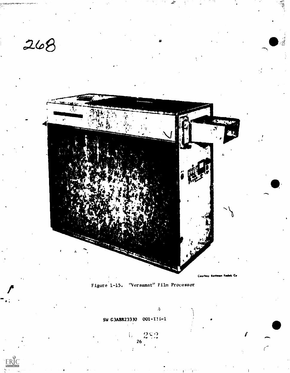
.1,7"--°*-1.,-*-,
.26
a I.2 4*
4.74Y 10. -
#Pi.
a. 4 ,vi
er_.ri
14 it6
,
611
s,
Figure 1-15. "Versamat" Film Processor
SW G3ABR23330 001-111-1.
26
af.
""
Covrtimy finfoosee Rob& Cy

3
. The feed and of the Vereamat, which is shawn in figure 1-15, is in thedarkroom while dile tekeup end is in the lighted roam.
The basic processor measures 58 inches (1.5 m) in length, 25inches (0.6 0 in width and 54 inchee (1.40 in height. Maximsweight of the unit, without processing solutions, is 1200 pounds(540 kg). Although no more than 11 square feet (1 m2) of floorspace is"Eded for installation of the basic procesaor unit,additional gpace may be needed to accommodate floor-mounted, 25-gallon (95 1.) storage tanks for feplenisher solutions. To operateand service the Versamat processor, a space requirement of two feet(0.6 m) is necessary on the dontrol side and at both ends of the,unit.
The electrical power needed by the Versamat processor is suppliedby a 4-wire, 3-phase, 60-Hz, 110/208-volt source. Total electricalload required to operate the processor unit should not emceed 12kilowatts. Unlike most equipment, the Versamat processor has no mainpower switch on its control panel. Instead, the electrimal powersupply is provided by a wall-Imounted, off-on switch. When thisswitch is in its ON position, all components of the processor areenergized up to their individual control stations.
Standard Equipment
The following equipment comes as part of the Versamat processor:
1. Two 30-gallon (114 1.) replenisher tanks for developer andtiKer, complete with compression fittings, hose adapters, mimingpaddle, floating lid, and dust covers.
2. Fifty feet (15.2 m) of tubing with clamps to connect re-pleniaher tanks to processor.
3. Two strainers, one for fixer and one for developer.
4. Thermostatically controlled water mixing valve with checkvalve, strainers for hot and cold water, and a temperature gauge.
5. A flow control orifice.
6. Two Weir blocks to direct fixer flow for aerial-type orcommercia1-type chemistry.
7. Ons splash guard.
SW G3ABR23330, 001-III-1
27

c:2 7Accessory and Optional Equipment
The Versamat's accessory and optional equipment includes:
1. Roll film and takeup adapter.
2. Developer bypass to bypass the first developer tank.
3. Skip rack crossover for bypassing any tank after the first.
4. Adapter assembly for MillA-Holiewerth 6rindow attachment.
5. Silver recovery device.
Operating- Principles
Once the exposed film is placed in the feed end of the Vrereamat
processor, its film transport system, which is self-threading, auto-
matically takes aver handling the film. Exposed film is conveyed
through the various processing solutions with the atd of special
racks, located in each of the seven stainless steel tanks. Each
rack has a number of rollers, arranged so that a strand of roll
film moves between the rollers. In addition to its transport duty,
this system furnishes an effective agitation action so that reaction
byproducts can be removed readfly as fresh developer solution is eir-
culated around the film.
When sheet film or roll film is attached to a lender bullet, it
guides the film through the roller racks. Because the roller racks
are located within the tanks, the film is compietely,immersed in the
various processing solutions. The film is cleared by a cascade spray
wash before it enters the drying compartment. AR the film enters this
compartment, it passes through a squeegee assembly where excess water
is removed and is transported downward and then upward between air
tubes, which directs hot aix on both surfaces of the film.
Air within the drying compartment naturally becomes laden with
moisture as the film is drying. in ordiq :0 mnintain the desired
opeiating speed, the moisture-laden air,must be eliminated-. This
is done by tillausting the air way from the drying compartment so
that dry. heated air may enter *and replace the moisture-laden air.
Thus, the drying action is not allowed to slow down and the transport
speed of the processor is maintained. The processed and dried film
then passes into a receiving bin (for sheet film) or to a takeup
adapter (for roll film).
SW G3ABR23130 001-Ill-I9
2R

Functional Deacription
Major parte of the Versamat are identified in Figure 1-16 and
the following paragraphs describe the various processor systems.
A
1_
A\
'
JEN.
ott
1.
2.
J.
4.
is
Figure 1-16.
Nmmber 1 Developer TankNumber 2 Developer TankNumber 1 Fixer TankNumber 2 FiAer Tank
1 .?
Versamat Major Parts
11. Dryer Thermostat Pilot Lamp12. Damper Control Knobs13. Dryer Temperature Gauge14. Overflow
5. Number 3 Fixer Tank 15. -FiNer Islet (ft type Chemistry)
6. DEV Thermostat Pilot Laiitp 16. Fixer Inlet (8 type Chemistry)
7. Developer Thermostat 17. Number 1 wash tank and rack
8. Weir Block IS. Nwmber 2 wash tank and rack
9. Dryer Fiood Light Switch 19. Squeegee Assembly
10. Dryer Thermostat 20. Dryer llood Light
SW G3ASK23330 001-1n-1
29

RECIRCULATION SYSTEM. The developer recirculation system (figure1-0) continuously pumps the developer from developing tanks througha filter, hest exchanger, thermostatically controlled electric heater,and beck to the developing tanks. An ON-OFF rocker switch operatesthe pump end energizes the thermal control system.
TKILMOSTAT
MATTI
KAT IXCKANO/I1 11
PUMP OIVILOPIl TANIS
=1. IWO ROM LINO
TO OMAN K PUPIt1 TANK IIICINUATIC*1 INUT
KIPLINIStil RUMPSAMOS YAM I STIAINIA
OWN VALVIS(TO WAIN WWI
KICNICU/ATION MUT
UPLINISNII !NUT
Figure 1-17. Developer Recirculation Flow
NATE: Fixer solution is not recirculated.
- The water circulation pystem operates from line pressure to pro-vide water to the cascade spray wash tanks through the Jacket side of
pie developer heat exchanger. Water temper.iolre is regulated by anexternally mounted, thermostatically controlled mixing valve. The
temperature should be adjusted 5° F (2.8'0 less Olen the desired
developer temperature.
REPLENISHMENT SYSTEM. The fixer and developer replenishmentsystems pump fixer and developer to the processing tanks from the re-
plenishment tanks. Both replenishment pumps are operated automatically
by a swlf^h in the film.detector assembly. The pumps start when filmis detected passing through tbe rollers and stop when.no film io passing
through. Both replenishment systems are energized by an AUTOMATIC-OFF-
MANUAL rocker switch. The manual. setting allows operation with thin
base films that may not actuate the switch.
2SW
c'G3A11123330 001-111-1

F1XHR REPLENISHMENT FLOW. The fixer, unlike thm developer, isnot recirculated, but it must be replenished. Figure I-L8 shows howthis replenishment system works. Fixer replenisher ugarts with thereplenishment tank then flows through a strainer, the fixer replenisherpump, the selector valve, a check valve, the flowmeter, and into thefixer tank (tank #3 on ,the Versamat). The selector valve is used toremove any air in the replenishment system. Both the fixer and devel-oper hove their own check valve.
CNICK VMVE
COUNTER FLOW CINCULATION IN TANKS
TO CRAIN 5i).AP
SILICT101 VAIVi
1tKINISKRTM4K
OPLINiwt I NW ST MINERaltgarAVES
ROM
FociR REPO NiSogg 1,011COMMIACIAL-TYPE FILM CHIAMSTRY
Figure 1-18. Fixer Replenishment Flow
DRAINAGE. The draimige system, which continuously gravitrudrainsthv wash tanks and the overflow from the process tanks, is also useddurir4; cleaning to completely drain the protehm tanks.
MAIN DRIVE. The main drive system, consisting of a single, vari-'-ableqspeed motor, sprockets, chains, and gears which drive the entireroller transport system, is actuated by an ON-OFF rocker switch. Thedesired speed (0-25 feet per minute) (0-7:6 mpm) is set with a speedcontrol potentiometer. The set speed is automatically kept constantby a drive control an electrical loads vary.
SW G3ABR23330 001-III-I
31

AIR CIRCULATION. The air circulation system is designed to cir-culate heatAd alipthrough the dryer section df the processor. A blower,
'located beneath the processing tanks, continuously recirculate§ airthrough the dryer and heater,sections. Makeup air is added throughthe grille opening in the drTer end panel and an equivalent amountis discharged through the dryer exhaust, thereby maintaining properrelative humidity in the dryer. Approximately 250 cfm is replaced
in this manner. The blower motor and dryer heaters are controlledby an ON-OFF rocker switch located on the front panel.
WARNING: Do ntt operate dryers for more than a brief periodof time with side panels removed.
ROLLER TRANSPORT SYSTEM. This system consists of:
1. A film detector assembly.
2. Seven racks.
3. . Eight crossovers.
4. A squeegee assembly - all in the processing section.
The film detector assembly (Figure 1719) consists of the following:
two rollers and three micro switches. The film passes in between these
000 rollers and a buzzer sounds imlicating a double thickness of film
(film spliced onto a bullet). This buzzer is activated by the two
outside micro switches. The center miLro switch operates the re-plenishment pumps when the replenishment switch is in the automatic
position. Three seconds after the trailing end of the film has passed
the detector rollers, a bell sounds. This bell indicates that the end
of the film is is the processor. This also indicates that another roll
of film can now be processed.
Each rollei rack consists of a serics of chain-driven rollersmounted in a staggered path. As the rollers rotate, the fiLm isconveyed from roller to roller thr,mghout the system. When the film
reaches the bottom of each rack, it is turned 180 degrees to complete
its course through the rack by a turn-arcumf assembly mounted at the
bottom of each rack. When the film reaches the top of a rack, itenters a crossover assembly similar in design to the turn-around
assembly, which conveys it to the next rack. There are eight cross-
over assemblies: one for the entrance to the first rack, one between
each of the seven racks, and one at the exit of the last rack. To
minimize surface deposits, certain rack transport rollers are covered
with polyethylene.
SW G3ABR2331Q. 001-111-1

3
v "..;",f4r. ,
a
V if4
1W7
1. Thickness Detection Switches Z. REPLEN Pump SvatchI. Detection Rollers
Figure 1-19. Detet Lion Switches, Top View
MD TRAY. 'rift' pUr Nay of the feed tray is to guide the film intothe pro.'essor ,sud to keep the I Um from drifting from side to side duringpfocvstiing.
path.
DRYER TRANSPORT SYSTEM. This sy,tem consists of:
1. Entrance dud exit crobsovers.
2. Two verticul rows of belt-driven rollers mounted in a staggered
A turn.sround.
4. Air tubes mounted between tlw transport. rollers.
The air tubes direct air onto both surfaces of the film. An
aaditional air tube is located above the dryer entrance crossover toremove excess moisture prior to drying. Guide pins, mounted on the
SW G3ABR23330 001-111-1
33

IP,ip fie Id.'. till' e :".11. rtv
l''t *.r.r141
flt
, R,,11 i I m t'eed In. 1lat Ltn
air tub,-;, d ir,', t ne Urn t rkir, ;Inc t ri711cr it) the hvIct .
lint- tubes with ire to .1 vent 1 igrunent ofid pins.
NOTE: Me down-path fi1m transiwrt roller, ro idontified .by
a smooth surface at the on,! it while the up-
path transport ro If ors arc idt-ta ft led by a groovel
surface at the end ot tilt. pulley.
ROLL FEFD ADAPTERS. When the Vorsamat is tn used to proceati
SW G3MIRZ3330 001-11.1-1
2 I34
,,
e.

1. Dryer Exit Roller2. Windup Reels3. Collars4. On-Off Switch
Figure 1-21. Roll Film Takeup Adapter Installation
SW G3AdR23330 001-111-1
3

rob
aerial roll film, a roll feed adapter must be installed. The roll
feed adapter consists of two metal rods that support the roller sod
clutch arms (Figure 1-20). The roll of film is placed between an
idler arm and 'a clutch arm and fed into the processor. A,tension
adjusting thumbscrew is used to keep proper.tension on the film as
it is being processed'.
In place of the roll feal adapter, a Mil1er-Ho1zwarth Magazine
Adapter is often used. (Figure 1-22). This adapter allows for
white light operation at the feed end of the processor. You may
find either the roll feed adapter or the magazine adapter'used in
the field as well as here in the school. The magazine and the roll
feed adapters both allow for various widths of film to be processed.
ROLL TAXEUP ADAPTER. The roll film takeup adapter is installed
in place of the receiving bin. A dryer exit roller and takeup reels
then provile contimous takeup of roll films. The outer rims of each
reel rest on a motor driven drive shaft by moveable collars. The drive
shaft turns the reel, and the idler shaft permits it to slip, ensuring
that the reel will takeup all slack, but will slip as necessary to
avoid overstressing and tearing of the film. The motor is plugged into
the accessory outlet at the dryer end ot the proceesor (Figure'l -21).
Operating Controls
FEED END CONTROLS. Following is a list of the feed end contrifts
and the function of each. (See Figure 1-22).
CONTROL NOMENCLATURE FUNCTION
1. DRYER FAN SWITCH Controls dryer fan and heater circuits.
2. MAIN DRIVE SWITCH Controlm main drive motor.
3. REPLEN PUMP :)WI'ItH M a1 -Providem continuous operation ol re-
plenintwr pumpa.Trovidet-: antomstIc operation of re-
pump!: 1,N, the thi,kncw4
it' .1
DEV RECIRC PUN? ;'411V,11
5. ,l'!1.23 IND1CMOR LIGHT SW
Cviltro! lovolcr TocircAlating pompaod 111-dter cir, ult.
CoatroH :1;omination he t4,7iVd
ind I t or aoLi I (pbornuters.
SW .3A3R2i130 001-111-1
it)

6. SPEED INDICATOR
7. SPEED CONTROL KNOB
S. FLOWMETER TUBES
9. FLOWMETER CONTROL VALVES
10. DEV TEMPERATURE GAUGE
U. ROLENISMENT PUMPS
INDICATCR LAMPS
Provides visual indication of pro-cessor speed in feet/minute.
Allowstadfustment of the speed of'the film transport system.
Indicate the flow rate of the devel-oper and fixer replenishment to theprocessor.
Controls the flow rate of the fixerand developer replenisher.
Visual tadication of the developertemperature in degrees F.
Indicates that the replenishmentpumps are on when glowing.
DRYER END CONTROLS. The following is a list of the dryer endcontrols and the function of each. (See Figure 1-23).
1. DRYER FLOM LIGHT SWITCH Controls dryer section flood light.
2. DRYER THERMOSTAT Allows selection of air temperaturesin dryer section up to 155°F (68.300.
3. DRYER SECTION MOT LAI* Provides visual indiguition thatdryer heaters are in operation.
4. DAMPER CONTROL !OOHS Controls amount of air in dryer.
5. DRYER TLMPERATURE GAUGE Provides visual indication ofair temperature in dryer. section.
6. DRYER FLOOD LAMP Lights up dryer.
SW G3ABR23330 001-1I1-1

2 80
II woz
PO,
7
1 .
1 2 3 4 5
DRYER FAN Switch
6
S1'EL1) INDICATOR
2. MAIN DRIVE Switch 7. SPEED CONTROL KNOB
3. kEPLEN PUMP Sw itch FLOWMETEX TUBES
4. DEV RECIRC PUMI' Surikc:h FLOWMETUi CONTROL VALVES
5. SPELT) PiDICAIWZ LIOIT Swit, h It I . 1/EVE1,0PER Temperature GaugeI REPLENISHFR PUMPS INDICA11111
LAMP
Figure 1-22. Feed End Centrols
INITIAL PROCESSOR PREPARATION
Before the Versamat can be operated, 1111[1;11 setup must be performed. There are two steps for thia setup: Water supply and powersupply.
2 1? ISW C3ABR23130 001-III-I
38

02 6/Initial :t=ettsp
WATER SUPPLY. E4ch Versamat has Its own water supply and mixing
valve. The water must be turned an and adjusted to 5.F (2.8°C) leas
than the developer temperature. TUrn an the water and adjust the
tonperature. Before the power can be applied, the last wash tank-
muut be at least halt lull.
CAUTION: TURN ON WATER BEFORE POWER.
*a
POWER SUPPLY. Each Versamat has its own circuit breaker. TUrn
Mt' ALL switches on the feed end dryer section of the rrocessor. TREN
turn on this main circuit breaker.
L 4_
a
11110PNINOMmmo
IMP
6
I. Dryyr Flood Light Switch 4. Damper Control Knobs
2. Dryer Thermostat 5. Dryer Temperature Gauge
3. Dryer Thermostat Pilot Lamp 6. Dryer Flood Light
Figure 1-23. Dryer Section Controls
SW G3ABR2J330 001-11I-1
39

'Systeme Cleaning
The physical quality of processed film will be acceptable only ifcare is exerca.sed to keep equipment and processing solutions clean anduncontaminated. Frequency of use and the environment in which theequipment is used will affect the type and amount of cleaning required.
PROCEDURES. Follow these steps to clean the develeper tanks.
J. Drain all developer from thy processing tanks by openingthe drain valves on the developer tanks.
. Remove all crossovers.
3. Position the splash guard on the partition between thP devel-oper and fixer tanku (tanks 2 and 3) to protect the fixer. Removeracks 1 and 2 from the developer tankH.
4. Remove the developer filter cartridge and replace the coveron the filter holder.
WARNING: System Cleaner contains Sulfamic Acid, causes burns.Do not get in the eyes, on skin, or clothine. In cageof contact, flush skin or eyes with plenty of Water forat least 15 minutes. For eyes, get medical attehtion.
5, Fill the twu developer tanks with approximately 10 gallons(37.9 1.) of premixed Kodak developer systems cleaner.
To make a stock solution Of systomm tlenner, dissolve thecontents ot its container in three gallons (11.4 1.) of water at100°F (38°C). Prepare a wIrk1144 4olvtion by diluting one part oistock solution with three parts of 90°F (32°C) water. This willgive 12 gallons (4').5 1.) of working solution.
6. Run the recirculation pumps for at lesst 15 minutes.
7. For normal cleaninr, place the (lovol-,:er rak4s in n sinkanA rinse with warm water. The temperatuti -.f4 not exceed 120°F(49°C). WJER IMMA6E 1EL KACKS,IN sYsTwis CLEANER!
8. Discoloration of the rollers is not hartitto!,.but built-
up deposits should be removed. In Lase oi extreme encrustation,a plactic abrasive material. may hf? wled. Never uqe fireel wooi on
SW G3/%1E23330 001-111-1

.2eany procaseor parts. Abrasive cleaeers should not be used on
polyethylene-catered rollers. A rough towel or cloth should be used.
9. If stubborn chemical deposits remain, rotate the rack drive
gear in a clockwise direction and apply systems cleaner to all rollers
and side plates. Use a soft brush or rough cloth. CAUTION: Wear
goggle:a or other eye protection and a plastic apron when using a brush.
10. Fluoh the racks with warm water and wipe them with a dampsponge to remove all the cleaner.
II. Repeat steps 7, 8, and 9 as necessary for thorough rack
cluaning. Rack cleaning can usually be done during the time the
cleaner is circulating through the developer tanks.
12. Alter 15 minutel., Hrop the recirculation pump and open
the drain valves. Dryly and flush the tanks.
13. Replace the developer racke and fill the tanks with water.Turn on the recirallation pump and the msin drive.' (The water must
he on in thy machine when the main drive is on). Allow them to run
for about five minutes. Repeat flushing and dumping until the water
shown no discoloration.
14. Clean all crossovers using the same method described in
steps 7, 8, and 9.
iL). If the processor is to be returned to service right away,the Vorsamat must be filled with chemistry. The developer tanks
and racks must be seasoned before film can be run. This prevents
"dichroic fog" from forming on the film. Dichroic fog is a two
color sheen reeembling grease or oil on the film. Dichroic fog
can be removed by rinsing the negative(s) in a neutral solution
of Potassium Permanganate (1/2 gram per liter) until the fog has
disappeared. Then immerse in a 5% solution of Sodium Ilisulfite
until the brown permanganate stain is removed. The above procedure
may not be feasible with continuous lengths of aerial film, but
could be used when select prints are required. Season the tanks
bY filling them with half water and half developer and recirculate
tor five minutes. After this, drain the tanka and remove racks.Refill the tanks with fresh, certified developer following theprocedures listed in this SW tor Filling Processor Tanks.
PREPARING PHOTOGRAPHIC SOLUTIONS
Mixing Chemistry
Photographic solutions 11110t be prepared in a systematic manner
SW G3AB1L23330 -II1 -1
41

a
dictated by the chemical formula or package instructions. Usuallythe order in which the ingredients are added to the solution servesto protect the integrity of other ingredients amd of the solutionitself. A developer, for'instance, whose constituents are addedin an order other than that prescribed could become discolored andpractically inert due to aerial oxidation or an undesirable reaction.The temperature of the solution and the stirring method are of equalimportance and are generally specified with the mixing order. Eachconstituent must be thoroughly dissolved before the next is added.Usually the instructions will specify 1nix until clear" hut thereare exceptions.
Mixing.and storage equipment must be nonporous and inert tophotographic solutions. Glass, hard rubber, polyethylene, enameledsteel and polyvinyl chloride (PVC) which all meet these requirementsare used in smaller labs or where cost IS important. Most largeprocessing facilities, however, use AISI (American Iron and SteelInstitute) Type 31b stainless steel fur ail solutions except "colorbleach" solution which requires the use of "Hastaloy C" stainlesssteel. (Type 302 stainless steel is not acceptable for use in aprocessing lab).
Mix tanks should be equipped with a mechanical stirring deviceto obtain efficient mining without causing excessive oxidation ofthe solution during the mixing operation. Some labs mount thestirrer so that the bnpeller shaft in at an angle with the vert,ical.With baffles along the cuter edge of the tank, there is no beatinof the air into the mix or vortexing of the liquid which wi!1 cauaroxidation.
If it is ix...vim:try to use the same mlx tank to mix more thnnone solution, it Is desirable to mix.them Lii the order they nre usedin the process. For example, deVAloper, Niter L stop, fixer, etc . Inthis manner, i tiaces ,1 the .11..TI:cal remain lo the mixieg Leek afterit has been cleaned, their ettvct; on the t,,1;owiug Nclution is minimirW,The mix tank and stirrinv, al.ptot, should lir riused thoroughly nitereach solution use. Ail equipmunt must he thoroughly leaned after afixer solution is mtxe6, particularly br!orc mixin another developer,;olution Atter (Icaninv., mixing I d Thu rinsed threetime.; with :op watev.
Mix tanks must be calibrated so that thv vointne tft itcruratelYknown. The most ,:omMvn laethod emplyed hy Iabs 1!4 to.osi a measuringdevice, t.aich as a graduated cylinder, will, o rarwitv of between 4 and10 Tvrcent of the capacity of the mix Lank. The container la filledto the graduated Iirle with water and emptied into the mix Wilt. This
SW G3A1H2 U 40 001-11 I-t
42

precedure is repeeted until the desired volume is achieved. The solution
Level in thou matk04, either an the side of the tank er tin a special
calibration indicator. Thie is generally satisfactory for most solutionsniece the solution will be diluted to the same level every time,.tbere-fore, achieving a good degree of precision.
Certifying Chemistry
Cqrtificntion tests are conducted after the solution has been
brought to final volume at romv temprature. The solution is then
remixed and samples taken. To iliminate as much variability aspesulhIc, the s.unpl will he withdrawn in the same manner, from the
blunt' 44ct In the rank and at the same point with each batch.
There are three husfc tests used in certification of processingwalla lonti.
Physical Properties, consisting of specific gravity test.
o Chemical Properties, consisting of pH
0 ProceNsine Properties, (Sensitometric) consisting of atent that evaluates the solution's atfect on a piece of photographic
Maturial.
The specitic gravity test is the first test and serves as a quickcheck to determine whether the solution appears to be complete as toift density. The pH teat can tell what the overall activity of the
solution is. Othertests can he performed if these are inconclusive.
1U'levver, ii a aolutien is oi substandard quality, it will normally bedetected by the combination oi the specific gravity, pH, and precessingproperties test. Therefore, performieg a complete chemical analysison solutions that have been certified by the above tests will net
little useful information. If the normal certification tests are
itwonclusive, or if the solution is believed to be of substandardquality, it may be deeirable to perform 'additional tests. The addi-tional Lento may provide sufficient information to pinpoint the de-ficiency, and thus, enable the solution to be brought into standardby corrective additiona rather than t be dumped. Personnel ln
Quality Assurance ahould maintain their ability and state-of-readinessby periodically practicing ail of the.analysis procIpres on solutionsknown to be certified.
DKVELUPER CE2TIFICAT1ON. A specific gravity test is accomplishedby d measurement that is indicative of the total amount of dissolvedsolids containsd in the developer, by definition, specific gravityis the ratio between the weight of a given volume of a substance andthe weight of an equal volumam of pure water at 60°F (15.6°C).
SW G3A1W23330 001-Ill-1
4 3

co2R6The use of the hydrometer to measure specific gravity has already
been 'taught. In Block 11 it was stipulated that a correction fattor
of 0.001 units wild he added for each 5°F (2.8°C) temperature change
above the standard. This correction applies to pure water only. The
coefficient uf expansion of a solutin heavier than water is greater
than the coefficient of water. The solution expands more on heating,
resulting in a greater change in silt,' if iv gray ity per unit of tempera-
ture change. Laboratory researt 11 I nd 1,(!tes t hat t he therm I eorree t ionfactor t or most photographic developer ::t op bat hs and f I xer m is veryc lose to 0.003 per 10°F (5.6°C).
Temporary standards for the sp., if ;c gravity tests, the mean and
,-ontrol limits (eg. 1.103 + 0.(J01), can ho based upon the f irst 15
hatches of c er t if ied so lu t ion . These tit aodard s are t 11(.11 ref filedperiodically vs additional data I 11 t ed.
When the upper control 1 imit I N exl ceded, the hhl h. at ion is Ohl t
more than the specified amount of an ingred ient was added, a wrimg
ingredient was added, or the SU I Lit Was not di 1 nted to the properamount . Conversel y, when t he measurement falls below the i ower limA t .
t. he Ind ic at to Is t hat one of the iwred lents may have been 1 ef t out ,a wrong ingredient was used, or the sol ution wan d ilu ted to too great
Watime.
The purpose of the pH test It, to dot. rmine whether the developerhat, t he proper al ka It ufty to pr4 yduc- t ho pr4Ter rate of development .'Flit pH value of deve loping so lu t Is en crone ly cr I t Ica 1 44 Ince I
Is d irectly related to the abi I i ty 1 the developer agent to -educet he silver halide to meta I I ie s 1 . Th4.1711 va!oes of I resit! y mixed4: eve 1 op ing So 1.11 t to TIN w I I I }IV floral I y iai in ap,r..ement withallot her. If t_ho v.11.4.11 ion ot 1 ut ion -amp le proves to he 011 t tit
tontroi on two ci'tii' u I ex t I t Is i ;tri'llp, nd it at ion that a,A.1 Jo r error has been Slatit lii rue.r4ur lug n*. Nor... the constor In the mix ing 4.r d i lit ion 10 tte soh,:
The proceasiiv, propr t i i a cleVel %Ter Is a nensi tomeir ictest performed to tteti'Liiii H a lit' v oeeel.,pet 'In int ion w11
e t hp i'1 cc', phot ograi :11. et t . ..;; -.ft; u rettVt. lopilw, t ,Inet t ';.t ip io i s,alip . e,. 4,pes ht.
evdluated , 0171; ir !he T f'Sil ago 1w.! s ;iltdord del ermi.wthe saint ton in i he t or! at ion requ Ii el';ottit '4 klil y ropv:a
a ble pru.:es,4ing r.oHla ; s viindat or v. Mt e'valsti .f 1ot Ut I rt'.io'l I vdetect f ault s that may or may not 1.0 Ind lk tAl lv lio the: tc,:t };.
The processing U; performed in one t hree di! t eront ways. The
most, common is the ASA tray method whkh haS been covers,d in the lastblock. Probabl y the method used lwi:t I requent I y is to use an tua
Le7o-4,iy it I, .4 4.4ri,,!, ,t he 1 f t.!: :11 X. : !',t I ;:t .cer
SW (:1AH1(21 IR) 001-1 (1-1

hove a special processor called a "Dip Test" or "Sensitometric" pro-
vessor whii:h they uHe Lor thia purpose.
CERTVICATION UV 'rut* OATHS, Large quintitiee of unexposed,
undeveloped silver,halides remain in the emulsion upon termination
of development. In order'to obtain a permanent image, they must be
removed. A fixing agent chemically reacts with the silver halide,
which is not soluble in water, and converts it to a water soluble
complex.
The specific gravity test is used primarily to detect gross
mixing errorh, improper dilution, and inadequate mixing. , It is
quite sensitive to de16tions or incorrect,amounts of sodium or
ammonium thinsuifate since they constitute a major portion of the
solution.
The Al of fixint,, holuti.!nr. is iildaive of the concentrations of
acetic acid, borh acid and other buffering agents. If the pH of a
siker is too low, colloidal sulfur will be formed which causes stains
on the emulsion. It the ph i too high, aasludge of aluminum phosphate
will ha formed, decreasing Chc hardening properties of the solution.
The processing properties test of fixing baths is simply a check
ot the time required to fix a sample of raw stock material properly.
This Lost is based up,1) ttle clenriug time which is"defined as the
time requird for the film to he fixed to a point where there is no
viaihle sign of silver halide remaining. Actually, 5-10% of the
, cr halide remains invisible at this point. The general rule
tred in most labs is that the total fixing time be twice that of
the cLearing time.
Filling Proc whir Tanks
To prepare the tanks for filling with chemistry, the following
steps must he taken.
I. Close th drain Valves (five in all) located at the bottom
ot ie fixer and developer processing tanks.
lnfttall the Number I rack io the Number I developer tank.
Fill the Number 1 and 2 developer tanks with developer to the fill (-
line visible in the Number 2 tank, using a suitable container. Carefully
lower the Number 2 rack in the Number 2 developer tank. Install a new
developer filter in the filter holder.
3. Place the spitish guard betwe-n the Number 2 developer tank
SW G3ABR23330 001-III-1
45
z

and the amber 1 fixer tank to help prevent contamination of the da-veloper solution when filling the fixer tanks.
4. Install the Number 3 rack in the Number 1 fixer tank. Fill the
fixer tanks with fixer solution to the fill lin-c visible in the Number2 and 3 fixer tanks using a suitable container. Carefully lower theNumber 4. and 5 racks in their respective tanks.
5. Install the Number b and Number 7 racks in their respectivetanks. Be sure all racks are firmly seated. Remove the splash guard.
6. Install the entrance, intermediate, and exit crossoversworking from the feed end. Hake certain that the positioning studsare properly located in the tops of the racks and that the gears areengaged. Install the squeegee assembly and fasten in place with the,4pring clip provided.
The preceding procedures for filling the processor tanks areappropriate after syseem cleaning or when the chemistry has been
dumped.
PRMESSOR OPERATION
Preoperational Check
A preoperational check must he conduct ed before machine startup
accomp 1 ished Failuru to uuke proper startup checks could real,'
in damage to the processor or g ivy a 1 A I SC ind ict in in the cs,.7 h ine
rel jab ill ty . Preoperat 'Antal 4 hocks wl I I vary t t om rachine to
another. KT., are some ot thu 111:1 ir polln ti be uonsider 1.4!
ti,t- any maclane.
1. Make cer L.% in :Ibit fp I PPit-tt k;rimnded proper; y,
c: .- 'hit d rTIA,v 1 lig
p.irts as gelas, diive belts,
C tleC ; u un j.n pro, s!.
t .
tC .
tailk.; and rcplen-
4. CNock c lean. lnuss o all roners an ! rulucogoes thnt normally
operate in :he dry state - clean if dirty.
5. Check machine racks and/or elevators for :lenalmness - clean
if irty.
SW C3AMR23339 001-III-1
46

c2e39a. Chock tp_iiitire that all rollers and other moving parts are
fruit running. *4-,
Daily Startup
1. RemoVe crossover racks and check for cleanliness. If necessary,
clean with warm water (not over 120*F or 49°C).
2. Check racks, gears, chains, and the general cleanliness of
the machine. Clean as required.
3. Check ,wilutlon levels in replenishment tanks. Fill if needed.
4. Ittplace csossovr racks - seat properly. (Entrance crossover
must he dry before film is nrocessed).
. Make sure !Alver c Jr t r idge Is in place.
6. Make sure all switches are in the OFF position. Turn the
speed control full. counterclockwise.
7. Turn on water, adjust to 5°F (2.8°C) lesu than the desireddeveloper temperature (tieveloper temperature - 85°F or 29.4°C).
S. Turn ON main
9. Torn main drive switch ON (CAUTION - Make sure speed controlis lull counterclockwise before turning on main drive). Adjust speed
- to live fpc (1.5 mpm). Check all moving parts for proper operation.
10. Tian dryer ON, adjust thermostat to required temperature.
11. Turn ON developer recir..ulation switch.
12. Turn replenisher pump switch LO AUTO. (Set flow rate with the
switch in the MANUAL position first).
13. Cheek solution temperature with a process thermometer. When
correct temperature is reached, rertifv the chemicals.
In addition Lo the above d.$11y startup procedures, the filmdetector/replenishment system and the feal-tray alignment should
be checked.
DETECT0R/REPLEN1SHMENT SYSTIM CH6CKS. Proceed as fol;ows
to check the thickness detection switches and ihe replenisher pump
switch and, il necessary, have maintenance technicians adjust these
SW 03AHR23330 001-I1I-1
47

9se)switches:
1. Place the REPLEN PUMP switch in the ON AUTO position.
2. Insert a single piece of normal thickness f ilm (approximately
0.008 inch or 0.2 mm) approximately 2 inches (5.1 (m) wide between the
detector rollers.
3. The replenisher pumps should start when the film is inserted
and the "feed" bell should ring approximately I seconds after the trail-
ing edge or end of film has passed the detector rollers. If the pumps
and bell are nut working properly, adjust the replenisher pump switch
oy inserting the film strip at one end of the detection rollers and
turning the square ad lust ing nut. slowly until the pumps just operate.
Move the f ilm to the ot her end and read ins t if necessary.
NOTE: The switch adjustmentli,; maintained by spring tension.
Turn the nut clockwise to rai.a. the switch.
4. Check the thickness detection-switch adjustment by inserting
a double thickness of film between the detection rel lyre, tirst at one
end, and then the other. The detect ion huzzer should sound at both
f ilm positions. If the bnzzer is ni.t wot king properly, mi lust the
detection switches by insert 1 ne t he don b ilm thickness at one end
tlw detee t ion rol lers and turninr, t he .hluat e-ad just 1 ng nut unt 1 1
the buzzer just operates. then t ight on t he ad juqt ine nut 1/6 of a
turn . Move the t I 1m te the tailor end am! ad just thy ot her switch J.,
necessary.
NOTE: Our i .fid iustztent of t! hl che:;;,letif t ion switches.
t lie rep I en I sher -pump sw I 4hou I hr I 1114 orr posit ionto avoid linnecess it t nd stIlpuf nr of t Ile pumps.
EF2-1RAY ALIC:NNEKI. Check t h i t Ay a I I gitmera With an:t 0) int; t 200 N .I.-)01;u9 01 t h... 1 lm on t in f eed
tray and slide It ti,rward until ft ionta, t a cit .tlon rollers.
Check that the i I im squ.irel y con: a. the re If not , loosenI ht. thu..0, rou.; N I I I t tray w.111 1 I im 1w 1.1 f
11..1 ho (Iv .;,t, lie, .irc he ; cad !tiv. t N.. t I Ii with t ht.detect ton r ! 1 r s Intl t ighten i t hk111111 ti rewti
Daily Shutdown
I. Decrease machine speed to 5 fpm (l 5 mpm).
2. Turn dryer thermostat OFF, remove tep :mai side covers of processur.
3. Replenisher pump switch OFF.
SW G3AHR21.330 001- I
3111
"mg\

c.
9/4. Developer riacirculation switch OFF.
5. Remove smd clean All crossovers. .(Weter not over 120°F or WC).
6. Wipe down machine thoroughly with a damp sponge.
7. Replace crossovers.
S. Dryer fan switch OFF.*
9. Main drive switch OFF.**
10. Water OFF.**
11. Rain power switch OFF.
12. Check machine for cleanliness. Replace all sides and covers.
Dryer temperature should be 100°F (37.8°C) or less.
** Do liot turn water off with main drive on. Damage to pump of water
conaervation kit will result.
Prevnttve Maintenalu.e
The Technical Manual tor operation and service of the VersamatProcessor, Model 11C-M, is TO 11E5-2-12-1. This publication
covers the daily, weekly, and monthly maintenance routines, alongwith periodic cleaning and lubrication.
The following items are listed as areas of CAUTION and WARNINGduring various machine funetions:
1. The Kodak Developer System; Cleaner contains sulfamic acid.Avoid contact while using this chemical.
2. A 10 percent solution of sulfuric acid is used to removechemical deposits from the ficwmeter and check valve. Mix in auopen, uni:nngested area, and avoid contact.
3. Take extreme care not to get any oil or grease on thecrossovers, racks, in the solution tanks,'Or on dryer-transportrollers and air tubes.
4. Chain tension is important and may be adjusted by looseningthe chain idler stud and relocating the assembly.
SICC3Alik23330 001-III-1

DAILY MAINTENANCE. Essentially, the bulk of the mointenan6eresponsibilities centers about keeping the Versamat processor clean.For some parts of the processor, cleanliness is a daily task. Each
time the processor is shut down,.remove all crossover assemblies inthe processing section and wash them with warm water. When deposits
are seen, use a soft brush to remove them. Wipe down all rack rollers,above the level of each solution, with a clean damp sponge. Finally,
wipe clean the feed rollers In the entrance roller assembly.
In add it ion to the leaning chores Just described , check the
ol loWing it ems da
o Flowmeter set t lags.
o Temperature of tho dovelopur solution.
o Wash water temperature.
o Replenishment level in the storage tank.
o Leader material for excesslve wear or tears.
WEEKLY MAINTENANCE. M ter one week's product ton runs are cum-plettxl, shut down the Versamat processor and remove the roller racksand crossover assembl les for Wash ing and wIpiAg down. lie sure t it
- remove al I chem Ica I il epos{ t I rem the s i(tus of each rack, aroundt he gears, and t rooi the chain I ight oner.4. Turn each roller by h:chlto see U t hey rotate y. ketnov., itiV NI ack hy adjust lag Owcha in t ighteners. At tor checking ea, h ra, I( for twi sts or bends,replace t hem air! , hock t he goars t o mak, (0 proper seat ing.
Examine al i hem i, a I sell' t low; iii t pro, f.isor for c lar ity.Determine if any toreigh part ic los are present To see whe chert ha set ht .iro he i,u ri"C tu ru 41; t hi, pumps and w.itebi
I ace el ;, T t Ion tur hu I onc e h Ind 1i at es t hat ( he
pumps are ,,perat mv, proper I . Nex t t the a ir tubes to thedryer compar t Valli I. 4.1 ''Ce WJitn a 11V )00; !II?, has curred. Cal 1
the ma i t I Oil it .11.1r k7t `: t !'4 pi ugged. At thist imo , it wou to exart Inc t he :41 ,vcr ing the air intake
for the dr- ver corupar k men t le see whot her chi. reon is c I ear o: anyobstruct tons.
Both the daily check and the weekly cleaning are importanttasks which are rontinOy assigned to the operator of the,Versamat
processor. The operator also maintains a log sheet of minor diffi-
culties that he may have experience-4 either during the shutdowns
or during production runs. Purpose or this log in to acquaint
SW G3AER23.330 091-III-1
3 4;

c293ausintensace peraunnel with thene difficulties which wo:ild then aidin the repair or adjustment of the processor.
MONTHLY MAINTENANCE. Monthly maintenance is perfurmed concurrently.with the weekly maintenance. Moirthly maintenance will also includecleaning the processor tanks (if neceseary) and cleaning the replenisherInd recirculation systeM. Any scheduled maintenance should be performedat this time also.
PROCESSOR CERTIFICATION
Processing facilities are entrusted with the critical responsibilityLI processing films in a manner that will minimize the possible loss ord istor t ion of the luformathmal content. B" au se the facility often hasonly one chance to procetis the material, it is essential that all possibleprecautions be taken to ensure that the material is competently handled.The premission certif ication of processors is performei prior to pro-cessing any original or duplicate film to detect conditions which willtend to degrade the informational content of the processed imagery.Machine certification consists of three major areas: mechanical,chemkal, and sensitometric certifications.
Meehani, 41 Cert It [cat ion
There is no room for error in any operation conducted by acent lanc.au photoprocessing laboratory. Much of the laboratoryequipment used is highly sophisticated and complex, specific pro-cedures must be followed, careful ly, and personnel must be proficient.If you were the pilot of an aircraf t, you would follow a preflightcheckliet to make sure that all instruments read normal values andthat all controls are operable. During flight, you would continuouslymonitor your instruments to minimize the possibility that somethingcould go wrong. During and after landing, you would follow anotherchef. kl tot to land and shut down t he ai rcraf t. Such tec hoiques aic slsoappropriate to photographic equipment and procedureu. Mechanicallycertifying a processor requires that you process a scratch test andverify all functions before mission f Im is processed. ,
SCRATCH TEST PRODUCTION. During machine startup, you are inreality, certifying that all 'processor systems are operating properly.Ii unusual noises, or inoperative pumps, motors, etc., are found, theyare repaired or replaced beiore processing begins. But just becauseall processor systems operate properly does not guarantee that the pro-duct will be f ree of physical defects produced by Ow processor.
Basically, mechanical certification consists of processing aquantity of flash film. Flash film is raw stock that has been exposed
SW G3ABR23330 00l-VII-1
51

to simulate the overall density of mission film (usually, a density of
1.00 to 1.20). ,If any def9ct that could have been produced by-the
machine is evident upoh examination of the flash film, the machine
is shut down until the cause of the defects can be found and corrected.
ELNMINATION OF nig PROCESSED FLASH FILM. it is checked for
developing and drying streaks, developing mottle, scratehes, abrasions,
pinholes, etc-. The presence of any such defect indicates that-the pro-
cessor is not operating as it should. As an example, drying streaks
could result from two common sources. These are improper squeegeeing
or blocked airflow in the drying compartment.
SCRATCH TEST ANALYSIS. The defect most often found during
mechanical ,Certification is scratches. The cause of scratches la
also the most difficult to fiml. After processing, the scratch test
-could contain scratches from a number of sources% Some of these are
the printer used to expose the film, cinching the film, the processing
magazine, and the processor itself, only to name a few.
The method most often used to determine if the scratches are pro-
duced by the processor is quite simple. This method consists of cutting
a short length of the flash film from the center of the strip, turning
it, and resplicing it into the strip before processing. The degree of
turn may be either 90° or 180°. There is one disadvantage to both turns,
however. On the 90° turns, the length of film chat is spliced hack into
the strip must be the exact width of the flash film. During analysis of
the 180° turn, sow scratches not produced by the processor may math
perfectly and falsely 1 e t1it they were produced by t hP processor.
In most cases, however,' scratches on both turns that are continuous
might ha VC been produced by t lit' processor. Al `; may be ignored
during processor cert if ication.
Another certii ication function that rmist_ he performed prior to
processing mission film deal:: cut irely wit ii tne coal it y of the pro-
cessing so lu I ions While t anal y: :; ot t!:e , hem Ic al E'er t if icat len
data is the responsibility ot assurante personnel, you. as
the operator .!re responsible for pt.,yidiag the necessary input data.
cdtemie l Ler t i it at ion.
Both the developer and fixer must be certified prior to VrPtessing
mission film. Such checks as pH and spy( Mr gravity may be made ea(h
day during startup. Some laboratories also pt.lrform the:a. Hweks at
regular intervals during the day or after-1 given quantity of tilm
has bom processed.
SW CIA114.131 IC) - 4-

7:
RICOUINS
Wok*, or tacked insoaks& %
;295TO* 1.4 TrattfieshoOaRB the infettomoriFthoftrecatow
urn falls to bo transportedn processing section.
POMO CAM
film not femStg square. Chemicalor other doposits on rack ration.
Mei& the thickness switcheson retist incorroctly set.
Rack chain too loose.Devoloper solution temporaturotoo high.
Solutions improperly mixed.
Foamy do/volt:war solution.
Film does not transportin dryor comportment
Tacky film surfaces caused by ex-costively high temperaturus of proc-essing solutions or wash water.
improperly mixed or dilutedprocessing solutions.
Low rodrculation rote. Obstructions in solution pump, hootexchanger, or tubing of recirculationsystom.
teas. in recirculatk.n pump, tubing,or cannoctions.
Dryor air tubes not seated. Guidepins for air bees are ntisolignedot item
ManAdjust feed tray. Remaxewith cleardng solution.
Adjust detector roil assembly.
%Med:Correct by%
1. Reset shormostat.2. Tighten thermoital mountkig
110*WL3. Free thermostat plunger.4. Monitor thermometer.3. Check solution ond water
temperature with long mom-mod thermometer.
6. Allow frosholutions timeto cool.
7. Turn on water supply. Checkif yule.* are open.
Correct by;1. Draining and refilling with
properly mixed soludonc2. Checking for leaks in heat
exchanger.
Check%
1. Pump intake for obstructionsot looks.
2. Solution lovols in tanks Waremat-bins startup.
3. Tubing of recirculation systemfor kinks or obstructions.
4. Bearings of redrorlation pumpimpeller for wear.
Soo corrective remedies for theystat adiustments above.
Check for leak in heat exchanger.Drain and refill with fresh properlymixod solutions.
Remove foreign particles or cleanwith system cleaner.
Contact moinsonence shop.
Snap into locking position.Straighmn bent pins mai wow,loop pins in place with *posy.111,
SW t.; JAB/4.231:W
3 I)
53

Table 1-1. Troubleshooting the "Monomer Pam Pretesser (Confine/ND
Dirty slits on air tubes. Dryer cam-postmen! temperature too high.
Light leaking through cover an pro-cessing section.
Developer contaminated by fixer.
'Woubleshooting
Replenishment rate slightly high.
Developer temperature too high.
Developer replenisher incorrectlyformulated.
Developer temperature too low.Developer exhausted.
Diluted or improperly mixed do.veloper solution.
Old or exhausted replenishmentsolution.
MOW
Clean tubes with warm waftr.Adiust temperature setting.
Seat cover tightly.
Drain, rinse tanks and roff4 withdeveloper.
Check rate.
Check and adiust themantat seeing.
Drain an i refill storage tonk withsolution mixed according to dim-!ions an package.
Check aod adios thermostat esithig.Check replenishment rote andiermix fresh solution.
Check far leak in heat exchanger.Drain and refill with developer mutedaccording la package direttlam
Drain and refill with fresh solutior,mixed atcortang to packagedirpion5
To salvage t he I I. tm when trouble ot:c;:nt4 ti I e the Versamot is
overatriit, do not turn off the power. Lead I r I IOW these pro-
cedures:
1, Pull a crossover assembly jcp;t ahoad of the malfunction.
2. Remove the film(itsxf at this point to prevent further pileup.
Dv- films are collected a placed in,a tray of water which prevents
their sticking to each other.
3. Clear the processor.
SW G34%131(23330 001-111-1
54

-I. Reintroduce the film into the processor at the point gf
Any malfunction in the Veraamat processing system may cause a
failure of film OD be transported not only at the aource.of trouble
but at any location beyond. This is true 'particularly when the mal-
function is caused by chemical action is, for example, high temperature
of processing solutions. When this situation:is presentt'the film fails
to be transported in the fixer tick assembly since the softened.emulsion,
becomes tacky. Or, Improperly mixed replenisher or fixer solutions may
cause 0 film transport failure in the drying compartment. Table /-1
lists some of the common troubles that can Occur while operating the
Vermamat procesaor.. Because some of the malfunctions can be attributed
to mechanical rather than chemical causes, study the manufacturer's
instructions. When mechanical trouble sources are i4ent1fire as.,causing
a particular malfunction, notify maintenance personnel imdediately..
Seusitometric Certification
Sentsitometrk strips arv also processed at the time of certification,and .ic regular intervals during the day. Data from these checks aremaintained on control charts for each processor. If the first senaito-metric strip fails within the control limits, but is near one of thecontrol limits, do Ilot assume that the machine is cht.m.tkally certified.A sttiond, and even .1 third ritriv should be processed, depending on crit-Ixality ot mission t t un. Mmi t laboratories process flash film duringmachine certification with sensltometric strips splirt.%1, within thefLthl t tint at regular interVals. Each laboratory_has its oWn chemicalcercif ication standards. However, if the required. footage of- flashfilm has been processed, and the sensitometric strips are within con-
trol standards, and if chemicals meet pH and speCific gravity standards,the machine can be said to be chemically certified.
At times, the operator may not be able to bring his machine intochethical control. When this happens, the only alternative is to drainthe chemicals, refill the machine with fresh chemicals, and restart the4 hemical certification. If replenisher solutions have been stored forHiMW time, they should be recertified befnre the machine is consideredhemically certified.
Process Control
Once the processor is Lertif ied, process ciintrol k;aliProcess control is knowing the capabilities of the maihirw. Inother words, being able to state what the machine can do. Theprimary control available to the technician is GAMMA.
The gamma value of a photographic mater4al is not fixed. It
SW 63,AHR23330 001-II1 -1
55

can often be varied within wide limits by the cheice of developer and themethods of development.
Gamma has been defined aa the slope of the ntrnight line portionof the characteristic curve. This is the only part of the curve wheresigniftcant changes in density are obtained by changes ip development.For this reaSon, gamma is uneiul as a measure of the degree of devel-opment. Gamma varies directly with development; the greater the de-velopment, the higher the gamma up to gamma infinity.
The time ot development is only one of the processing factors af-fecting gamma. Other factors are the type of developer used, dilution;If developer, processing temperature, and the method of agitation. If
the gamma is measured and found to be high, an appreciable amount ofdevelopment was obtained, oven though the developing time may havebeen short.
Gmnma is one of the most important tools aged in processing con-trol. Negatives developed to the same gamma, for example, show com-parable tone reproduction. If it is desired to determine that pro-cessing is constant, sensitometric strips are run along with ellenmaterial being processed and the gmmma.plocted. If the gamma re-mains the same, preeessing is constant. Whenever practicable, thetest strips should be printed on the material itself; on the edgeof cut. tilm or at the end of a roll of film:
To summarize, the behavior of any film-developer combination,time-gamma or machine speed-gamma curves can be plotted. Thin
discussion will be geared to machine speed-gamma eurves. These
machine speed-gamma oharts nre plotted on deloiltv vursum density
curves.
DENSITY VERSUS DENSITY CURVES. While not a true D log F curve.an understanding ot rhe similar density - density plot is desirable
at tills point. Fiynre 1-24 shows how it test qtrip printed throuFh
standi-id Eastman Stql Tablet No. 2 would be plotted. This.tabletconsists of 21 f:tvp.., rangiu in detr,:trfrom approximalely 0.05 to
approximately Ihe .lifferen. ')etwolvi; step isaboti I O. I . A ;It ,. edure "for pi .; I II U! %PP f a
test nide in 'his manner fs as tollowr!,
SW G3AAR23330

3 0
1 6
06
6
04
2
Man11111111
1111110111111113 20
3 03 1ra
2 00 1 60
2113
1.05
30 2 03 1 09%
1 33 143 093 I 065
.10 0 00 0 30 020
Figure 1-24. Density ot Original, Plotting Density vs Density
1. The densities of the original step tablets are read
and recorded.
2. The densities obutin0 in the test strip arc read
and recorded in a column beside the densities of the
original (Figure 1-25).
A Araph sheet having
markii oft in periods frfhalt filch, starting with
corner and moving to the
(horizontal oxis) and upw
(verticil axis).
20 squares to the inch is0.20 density units to the
zero in the lower rAght.-hand
left along the abscissaard along the ordinate
L. The densities of the original Htep tablet are
then plotted across the base line with step i lo-
cated near the right nd and step 21 located near
the left end of. the lins.
WAILYA 23330 001-111-1
1
57
0.5
7
-

3 44
.0N
Dimly Tat Competed to De;etity elOffvfnel Sip raw
Stip Dealt? ofaf4higi
Deratr elTaff
Figure 1-25
5. The density of ea(h step of the test 1. A thenp lot t vd t,v p ac ing a dot t he v,r31/') cl;/;,,.mite itvalue Lin the vertical axls ani! alinve its axis. Thisi. c on t Haled %int ii al I 21 i-:teps ar, plotted.
'rho dots are t hen o 11 ted wit h a bent f it curveusing :.traighLedw. and rrench mid the r COUWin. b Th Outra,:terint;, :urve In rt.lative 1) log E values.
11.ACHINE-S171:1-1) GAMMA CHAU. Use the sarru hanic procedures forthe machii: -speed gamma (MSG) chart &ii thlthe used for plotting densityvs. density. The proeAlures- for construct ing MF,4; , harts are a:; follows:
1. Print 10.sensitemetrie strips on n sensitometer.
2. Rocord the'density values of the exposure modulator on the
sensitemeter. These readings will be used at a later time.
3. Using one developer rack on a Versamat, process one sonsite-metric strip at five fpn: (1.5 mpm), one at 10 film (',1 mpm) and so on
4,through 25 fpm (7.6 mpm).
SW. G3ABR23330 _001-i1l-I ,
311

/4. Using both developer racks,.repeat step #3.
NOTE: Be *ir e. to stark the'stripa for oaa rack or two sadtheir machine speeds.
5. All IO strips must be read o,t and all readings recorded.
6. Plot the five strips (family of curves) that were processedIn one rack on one sheet of graph paper.. Plot the five strips pro-cessed in two racks on another sheet of graph paper.
7. in.the upper left hand corner of each graph, construct,a small speed gamma chart. Gamma is plotted on the ordinate andmachine speed is plotted ow.the abscissa.
ealt
'From these machine gamma chat.ts, the proper mathinespeed for a mrticular gamma can be found.
After the density vs. density curves are constructed, in-formation provided by the curve is transferred to various controlcharts. .This information often-includes gamma, D-Imin (the minimumuaeful density on the curve), D-avg (an average, middle tone density,usually step 11), and D-max (maximum useful density).
Control charts of pH and vecific gravity are also kept for..theLhemicals. Control of developer pH is of particular importance sincean increase in pH results in aa increase in activity and a decreasein pu results ia a decrease in activity.
Control charts provide the operator witii a graphic record tocompare what is huppeping now with what hap happened before. Theycontain aim points and control limits so the operator can.actuailysee how his machine is running compared to how it should run. Controlcharts also enable the operator to predict possible problems and cor-rect them before they can occur. In this respect a control chart canbe considered to be an "action" chart.
QUALITY ASSURANCE PROGRAMS
Imagery-recording systems continue to provide one.of the majorsources of information to satisfy intelligence requirements. Themaximum information must be obtained from the hmagery produced.This means that each component of the'reconnaissance cycle must
be controlled.
The levels of quality obtainable from reconnaissance missionsvary with the sensor system, the operating conditions, recording
SW C3ABR23330

4
media, processing, and printing characteristics and other related
factors. The capabilities of the supporting facilities also vary
according OD their assigned' mission. Therefore, variations must
be identitited.in order to establish quality contyols and to insure
that the maximum imagery information is obta4eed.
Laboratory Quality Assurance
Thmre fs no single quality assurance specification covering
ALL reconnaissance programs. Instead, "quality goals" are set
for each type of reconnaissance system in accordance with AFR-96-1,
Evaluation and Quality Assurance for U.S. Air Force Reconnaissance
Imaging Systems. Once this "quality goal" is set, very specific
steps are taken to reach this "goal." Any quality assurance pro-
gram must maintain this high "quality goal" in order to retain as
much intelligence information as posnihle. Otherwise, vast amounts
of _information will be lost due to poor handling, bad chemistry. poor
processing techniques, and other means.
If all variables are under control, the reliability of the
laboratory production is assured. This is very important. In
this way, no matter where or when a mission is flown, the results
can be predicted beforehani. Regardless of the lab's mission or
the duties of its personnel, quality control applies to all personnel
in that laboratory.
LABORATORY QUALITY ASSURANCE FUNCTIONS. The laboratory qualit:
assurance program can he separaco! into font- specific steps. They
Lientifying variables.
2. Using instruments. WIlother I.JcSu devices dre simple or
complex, their repeatability and accuraky must be known. They will
be calibrated periodically.
3. Lollecting and present I ci., lAta. i.i II y Assurance data will
he t.ollected and recorded accurately and uniformly. The data will he
recorded on specific Air For:c toms.
4. An.,I.:7.ing And intergrating data. Analvsiq ot data be.Ons
by examiningcontrol charts for abnormal results. All variables are
examined b-f,ore any changes are made. If a proces- correction is made,
more data must,he collected to analyze the results of this correction.
If the corrective action fails to restore control, the operation is
suspended until a complete analysis is made mid further corrections made.
SW G3A11R23330 001-111-1
ht):3 1

.11
If these steps are to work, all continuous photoprocessing
laboratories must maintain minim= standards for.equipment certifica-
tion amd calibration. Certification, standardisation, and quality
assurance will be performed at, or exceeding, the frequency stated
in AFR 96-1.
Central Calibration Program
Thin program was established to insure that all sensitometers
and densitometers (and any future designated devices) in the Air Force
meet certain specifications.
The responsibilities for this program start at USAF Central
Calibration Facility (USAF/CCF) and follow the chain of command
downward to each Laboratory.
Senaor System Evaluation Program
Sensor system evaluation program is the Air Force effort to
determine the performance of specific imagery systems. The sensor
system includea such variables as aircraft, camera, film, processing
and environmental conditions. The sensor system evaluation program
provides a measure of the quality of the reconnaissance information.
The degree of evaluation can range from limited visral inspection
Lo indepth documentation requiring sophisticated instruments. The
sensor system evaluation program allows one to identify problems and
causes and provides for corrective action. The key element in this
program is the Nominal Performance Standard (NPS). This standard
provides a common base line f.r Air Force organizations, It tells
the minimum standard for any het of conditions.
FMK PROCESSIKU
Once the qufility of the procesaor, chemicals, and processing
methods have been assured, the film may be processed. However, VW
other steps are necessary. Before .1 roll of film is processed, it
must be preinspected fur torn or crimped edges wIlich might cause a
processor malfunction. Also, the film must be made-up for processing.
Both of these steps are normally accomplished at the same time.
Preinspection and Makeup
Since the film is exposed and unprocessed, visual inspection
by ordinary means cannot be made. It is possible, however, to use:.
an infrafed light source and an image convertor to view the film.
SW G3ABR23330 001-I1I-1
bl.

This method is satisfactory provided the film is not sensitive to
IR. If equipment of this type is not available or if the film is
sensitive to IR, preinspection must be made by touch in total darkness.
PREINSPECTION STEPS.
1. Set up the preinspection table to handle one width of
material.
2. Procure adequate amounts oi exposed step wedges, heat
splicing tape and Itylar" tape.
3. Inspect the f!.lm for edge tears, holes, creases, and
splices. Perform these operations by touch while wearing gloves.
Record all noted defects.
4. Repair torn edges with liylar" tape.
5. Cut out any torn area deemed to be hazardous to machine
operation and make a heat spliec.
. Save the cut out portion to be developed later.
7. Carefully check and repair, or cut out, all splices
as required. Factory splices are usually safe, hut must be checked.
8. Exercise extreme caution at oll _times, particularly
while transporting material across tit'. pretnapection table. Traur.port
the material across the table at a slow, ,:teady speed to mihimizu static
electricity discharge, pressure, and abrasion mark,
MAKEUP. Before film can he prove:;sord it mtv;t lie 111.1d-up. Film
makeup may vary from lab to lab. {lore in he sthool. vour tilm maiwup
will he as fo:low:
1. To a !)t.111.t., attach a Itc:Ad sensit(nm,tri, Rtrip.
2, To the head sensitometr strip. Attlih tho (b-iginal Negative
(0.N.).
3. To the O.N., attach a tali :wilsitomctrit strip.
Both preinspeLion and ilm makeup mast be ,4, r I !:!1, hf.' fore
processing.
SW 1flA 30 001-111-1
6.;
3

3067Processing
During film processing, the operator must remain alert at all
times. Film, whose length is less than 5.inehes (12.7 cm) should
not bejed into the processor. The replenishment flow meters must
be constantly monitored to assure proper flow rate. The flow meters
should be read at eye level to avoid parallax distortion and the
bottom qf the boll is used as the reference point. If air bubbles
appear in the flow meter tubes, this is an indication of hmproper
replenishment rates. Machine speed indicators must be monitored
since line voltage tluctuations may change the drive speed, nec-
essitating a machine speed adjustment. Film drying must be monitored
at all ttnies and the dryer thermostat adjusted to control drying.
Solution temperatures must lso be checked periodically to assure
proper processing temperature.
The machine operators must be prepared to correct any machine
malfunction that occurs. Often this must be done in total darkness.
These, and many other operations, must be done while the film is
being processed. By now, you can see that Ihere are too many
.3peratioSil for one technician. Two or more people should be as-
signed to each processing machine. Where only two people are
available, one should operate the feed end, while the other
operates the takeup end of the machine. Responsibilities for
each function should he well defined so that all functions are
monitored.
Processing Defects
The processed fllm should be monitored for physical or image
defects. These are then reported to the operator's supervisor.
The following list gives some of thuse defects and their descrip-
tions.
Abrasion
Banding
Brittlenessdr Buckled
Film
A scuff. A series or group of very light scratches;raused by rubbing of two reasonable smooth surfaces
together under pressure.
A series of varyinA densities of different widths
across the width of the film. The edges of the
hands may be either shar:: or soft. Usually caused
by improper spray presfoure, clogged spray nozzles,improper spray angle, or nonuniformity in printerilluminance.
Brittleness or wavy buckle are both caused bydrying at exceptionally high temperature or in
SW C3ABR23330. 001-III-1
63
3 19

Bromide Drag Uneven densities ueen extendimg from dense areason film "flow."- Appears in longitudinal directionon film.
Chemical Discoloration Of portions of the bnagery caused byStain contamination of developer, fixer, or improper washing.
Cinch Similar to abrasions in appearance; caused by excessiveMarks tension of takeup or sudden stops or starts during re-
winding of film.
Creased A single or multiple elongated bending of the film.Film Usually along the edges caused by improper takeup
or tracking in the machine.
Crimped A small cresent shaped distortion in the base of theFilm film caused by wrinkling of the film from improper
handling.
Deckled A rippling of the edge of the film caused by poorEdges tracking in a machine or improper torque and/or
alignment during takeup.
Developer Developer spraying back in droplets onto the un-Sprayback developed portion of film before reaching the first
spray nozzle, tausing high density spots.
Dimples
DoubleExposure
HmbeddedDirt
Finger-Prints
Hypw Spray-back
Indentations which are the result ot winding film,over a piece of embedded partirle or any otherprotrusion. Those may he :r:Insforred throughseveral layers tO lilm.
Two separate exposures having been recorded on thes ime piece of film. Usually causes a double image.
Any particle which has become embedded into the filmbase OT VMOIsion.
Marks showing the lines, L.1 Lhe fingertips; frequentlyLaused by handling the dry negative with dirty, moist.or 0-easy fingers. Tr the fingermark.; are dark, c47n-Lamination with developer is indlt.at(d. II marks alelight, hypo on the fingers is the pr,,hablc cause.
Hypo spraying back onto film that is Neing developed,causing thin density spots.
SW G3A1W23330 001-ill-1
64

ImproperTakeup
Light Fog
MOttle
NewtonRings
Oil gpots
ovvrdevelop-
ment/Under-development
PressureStreaks
Pin Holes
Reticula-tion orfrosty-wrinkledappearanceof emulsion
St-
When film is improperly aligned on takeup spool
causing indentations, stretched, creased, or torn
'film.
A density of varying size or shape which may, or may
not remain within the frame limits; caused by film
being exposed to an uncontrolled light source at a
time up to the time of fixation.
An appearance of unevenness in density in irregular
form caused by improper development. Normally
caused by improper spray pressure, clogged spray
nozzles, or improper spray angle. Not to be'con-
fused with Newton Rings.
Irregular 51ap.,11 varied densities throughout the
film. This is an effect of interference between
light rays reilected from adjacent surfaces during
printing. NOTE: NOE cause for reject.
Chain of small gray areas; irregular light gray areas;
mottled areas; black spots, with or without white cen-
ters; strippled streamline effects. Caused by oil
adhering to the surface of the film prior to process-
ing or during processing.
Heavy or light D-max/min returns. Processing limits
not within standards.
A sheen on the emulsion side of the film normally run-
ning in parallel lines lertgardise along the fibn.
intermittent; caused by excessive tension before the
film is dry or during drying.
A small clear hole in the emulsion caused by trapped
alkali solution.placed in a strong acid solution,
causing a gaseous discharge through the emulsion; or
fine particles printed in from the preceding generation.
Sudden temperature change from solution to solution
or,to wash of different temperature. Driving in too
much heat.
SW GUMMY) 001-lII-1
65
3 ?

sScratch An indentation of varied length, width, and depth
either on the base or emulsion side of the film;caused by a sharp protrusion being scraped acrossthe surface. Emulsion abrasions on the originalnegative often appear as emulsion scratches on adupe positive.
Scum A thin layer of impurities found on the emulsion orbase of the film.
Static Forked, branching, tree-like marks on the film,Marks oPeier than the imagery; usually caused by static
elec tricity discharges, created by rapid windingof Jw f il.m in an exceptionally dry (low humidity)are 4..
Stopped in Extreme overdevelopment, spotting, and streaking inProcessor large areas of processed film.
Uncleared Film with a milky appearance from lack of fixation.Film
Uneven Unevenness of density across the width of the film.
Density Usually caused by improper spray pressure, cloggedspray nozzles, Improper spray angle, or nonuniform-
ity in printer illuminative.
WaterSpots
REVIEW QUESTIONS.
Intermittent spots of varying size and density; causedby irregular ilrying or improper squeegeeing prior todry ing. A 12X magn if ler should ht used to insurv thattlk. materlaI Is free of %Cater spots during processor4 ert it ic at ion and produc t ion runs.
DO NOT WRITE IN THIS SW - US! A SEPARATE FILtE OF PAM.
I. At wha t int I s rep I enisher generally introduced to existing
solutions in f i Im processor?
, ratat et t ect does overdrying have on f
3. Why is a spray-processing machine expensive to operate?
4, Explain the over-under threading systmn; the loop-type threadingsystem.
SW G3A$R23330 001-III-I
66

41111r.e
.3075. How is even-film Pension achieved in moist processors?
6. Describe how self-threading machines transport the film.
7. Why are squeegees employed on continuous processing machines?
8. List the functions thet the recirculation system performs.
9. List some of the factors which affect replenishment rate.
10. Are silver recovery programs optional, desired, or required in aphotosraphic operation?
11. What is the basis.for your answer to the previous question?
12. Why are silver recovery programs included as part of laboratoryoperations?
13. List three primary methods of silver recovery from fixer solutions.
14. Which combination of a silver recovery system and fixer solutionpermits reuse of the solution?
15. Which silver recovery system is used by Air Force photo labs toproduce refineable sludge?
16. How is silver normally recovered from processed film and paper?
17. Which type of recovery system is'intended for use by faciliitieswill% less than 30 gallons (114. 1.) of fixer per etght4our day?
18. What recovery system is basic in medium and high-volume processinglaboratories?
19. What types of facilitres use cartridge as their standard silverrecovery systems?
20. What do air bubbles in the flowmeter tubes indicate?
21. What type of threading is used on the Versamat 11CM?
22. What is the maximum speed that the Versamat can be run at?
23. What film can be run on the Versamat?
24. How many tanks comprise the Wet section of the Versamat?
SW G3AUR23330 001-111-1
67
IN

e
8/25. At what temperature should the water be adjusted to on the Versamat?
26. What causes a buzzer to sound.when the operator is feeding film intothe Versamat?
27. Where is replenisher introduced into the Versamati
28. What is the developer temperature on the Versamat?
29. What is the developer temperature tolerance range on the Versamat?
30. How does the temperature control system operate on the Versamat
processor?
31. What is the dryer temperature range on the Versamat?
32. What must the dryer temperature be before the Versamat can be shut
down?
33. Why must the cover on the Versamat be left slightly ajar after
shutdown?
34. What could be the cause, if the film fails to transport throughthe dryer section of the Versamat processor?
35. What solution(s) are filtered on the Versamat?
36. What is a developei bypass?
37. What is a skip-rack crossover?
38. When cleaning the crossovers and racks on the Versamat. what isthe maximum temperature that thv wator can ht.?
3(4. What so 1 i t ion i s u sod t. an ht pro. or+;;or Links"!
40. Why shoti Id prot 4:c I Ivo equ I Iin.Ilt ht worn when sy:n ow c leant:1,g a
processor?
41. How is tie Versamai processor drained 1'1 IEH solutions;
42. What is used to season the tanks in the Versamat?
43. What :41ght happen if the tanks in the Versama! were not seasoned
after cleaning?
44. If it is necessary to mix mure'than one solution in the saN4ixtank, hoW'should they be mixed? fr.
Alt
SW G3ABR23330 001-111-1
3 T.
68

"a-7'4,
,31/45. Name the three basic tests used in certification of processing*olutioaa.
46. What is the thermal corre:tion factor for most photographic solutions?
47. List the major points on a processor preoperational check.
48. What are the two types of machine certification?
49. What is flash film and what is it used for?
50. Why is film given a preinspection before processing?
51. Describe the preinspection procedures.
52. How may a small tear in i H be repatrtd during preinspection? Alarge tear?
54. How are detects on the edge of film detected during preinspection?
54. Describe some ot the operator's functions which must. be accomplishedduring film processing.
55. Why must the processor be certified before proccssinr sensitometricst.rips tor pr ocess control!
56. How is process control achieved?
57. What is-the purpose of procc,ss control?
58. Huw are sensitomtric strips plotted for proce$s control?
59. Li/St the habic steps in determining the proper machine speed forprocessing to a specific gamma.
60. Descrave four common processing defects found on processed aerial4
film.
PRACT IC AL am(' sEs
PROODURES
LIERCISE 1
Ai separate sheet of paper, match the principles of
SW G3A8R23330
69

continuous processors in column "A" with the correct reeponoes
in column "B." The items in column "A" may have more than one
response.
A
1. Film Drives a. Rubber
Threading b. Mechanical
3. Developing and Fixing c. Impingement
4. Recirculation J. Electrical
5. Squeegees e. Agitation
6. Drying 1. Chemical
7. Safety g. Loop
Skiver Recovery Methods h. Air
Silver Recovery Equipment i. Over and Under
J. Parallel Flow
k. Rollers
1. Ligoid Bearings
m. Electrolysis
n. Spray
0. irtridge
p. Filter Solutions
ltun mitximum
Met .1 11, Replacement
t ro 1 y t li Recovery Un It
t. Immersion
SW G3ABR23330 ,
, )
70

EKERCISE II
PROCEDURES
3/3'
1. On a separate sheet of paper, Identify the items listed
as numbers 1 through 20 in Figure 1-26.
Figure 1-26. Parts of a Versamat
SW OARR23330 001-III-1
71

,10
On a separa.te sheet'of-paper, identify the items listed -
as numbers 1 through 11 in.Figure 1-27.
WO.. fan I le. 411.INV ins. 41.111411.
4 II
411 Mi
MO
1I I 7
4S.
MIPP,Formq,
4 0.4
Figure 1-27. Versamat Con-trolo
SW G3ABR23330 001-111-1 ell-
774
7
- 4
011111,..

3/5DLERCISE III
EgVIEMEMT AND SUPPLIES
Basis of Issue
Versmaat Processor 2/claise
Systems Cleaner 2/class
Cleaning Supplies and Equipment As needed
PROCEDURES
1. Using procedires outlined in this SW, systems clean
the processor. Observe all safety precautions.
DcmcIsi IV
EQUIPMENT AND SUPPLIES Basis of Issue
Mixing Facilities 114 students
Pqapackaged Developer Mix 1/4 students
Pirpackaged Fixer Mix 1/4 students
pH Meter 2/class
Hydrometers (set) I/class
PROCEDURES
1. The instructor will assign the specific prepackaged
solutions to be mixed.
2. Make sure the mixer is clean. If it is mat, clean it
before proceeding.
3. Mix the developer, following the manufacturer
instructions.
SW C3ABR23330 001-III-1
7 3

3/6
v .t
4. Withdraw a sample of 'the developer for certification.
5. Determine the pH and specific gravity readings of thedeveloper. Check with your instructor to see if these reeding@meet certification standards.
6. Construct a control chart for pH and specific gravityvalues of the developer andifilot these readings on the chart.Retain this chart for future use. (A chart might already beavailable in the machine area).
7. Transfer the developer to the proper storage and processortanks.
8. Clean and rinse the mixer thoroughly.
9. Mix the prepackaged fixer using the same procedures as insteps 2 through 8.
EXERCISE V
EQUIPMENT AND SUPPLIES
Versamat Processor
Cleaning Supplies and Equipment
PROCLDURES
Basle of Issue
2/class
Am needed
1. Using proCedures (yutlined in this SW, ,nsa11 racks,,.:rossovers, anj 4Awmistry in the Versam.it processor.
LiNc I SI',
EQU I P!. NT. AND SU P FL I ES
Vers mat Fr i C:;SO r
Cleaning Supplies and Equipment
. Preexppsed Control Skrips
-Flash Film
SW G3AHR2333U OUI-III-1
76
B:IsIs of Issue
:Jclass
A9 needed
As needed
As needed
3

Thermometer
pH Hater
Hydrometers (set)
Densitometer
Graphing Materiai
PROCEDURES
2/class
2/c lass
2/class
As needed
3/ 7
1. Following the daily startup checklist in this SW, perform
, daily startup on the Versamat processor.
2. Perform mechanical; chemical, and sensitometric certification
tor tlw Versamat processor.
3. Atter the Versamat is ter-titled, establish process control by
making a machine speed gamma chart(s).
4. Perform any and all preventive maintenance required to insure
1,roper Versamat operation.
5. When necessary, shut down the Versamat following the shutdown
Lhecklist in this SW.
6. ObServe ali safety precautions.
EXERCISE VII
NU1PMENT AND SUPPLIES Basis of Issue
Preinspection Table 1/4 students
Lint-free gloves 1 pr/student
bupty Reels As needed
Exposed, unprocessed film 1 roll/ciass
PROCaUKES
I. Clean preinspection area and equipment.
. Insure sufficient amount of splicing tape.
SW G3ABR23330 001-I1I-1
75

3. TUrn on safe lights (if applicable), turn off room lights.
4. Position film on rewinder, fasten end of film to the takeup reel.
5. Start rewinder. Place gloved fingers lightly against the edgesof the film as it moves from the supply to the takeup reel.
6. When damaged film is detected, stop rewinder and repair filmas outlined in the text. Instructor assistance may he necessary.
7. After the film has been rpaired, save it for processing.
EXERCISE VIII
FAXIIMENT AND SUPPLIES Basis of Issue
Versamat Processor 1/class
Processing Support Equipment As needed
Preinspected Film 1 roll/class
PROCEDURES
1. Start up the Versamat according to the checklist - developertemperature 85° (29.4°C)
2. Certify the :not:hint. accord inv, to past exerc isem.
Process flit. pre inspoct d t I n I rom Exert. 1st. VIII. The instruc torwill 0.ye the ne..'eary pruccsslny, intormation. (heck procegsed film
!or Oefek'ts.
When f inished thc .urk .1 and ogn linen t rui.d return in/Pry-th I ng to it s proper. 1 i 2."
FAI-.1-ti: (SY IX
PROCEDURES
1. Answer the following questions on a separate sheet of paper.
Do NOT write in this SW.
SW G3ABR23330 001-III-1
76
.3"'"

a. Why is there a need for a quality assurance pragram
in a photoprocessing laboratory?
b. If all variables are under control, the
of the production of the laboratory is assured.
c. List the four steps in thequality aasurance program.
d. Xhy was the Central Calibration Program started?
e. What it, the purpose of the Sensor System Evaluation
Program?
SW G3ADR23330 001-1ll-1

ag.
Sciences Branch
3,2,0SW G3ABR21330 001-111-2
Lowry AFB, Colorado October 1977
TITLING AND CLEANING AERIAL FIII4
OBJECTIVES
Using an editing table, postinspect and attach head and tailfriskets to a roll of processed aerial film. All defects must berecorded.
Using a Dual Head film titler, title processed aerial film..Type must be correctly positioned and transfer to the film mustbe legible without flow oz embossing.
Usiqg a rielaumte portle film titler, title processed aerialfilm. Type must be correctly positioned and transfer to the filmmust be le ible without flow or embossing.
Using a film cleaner, clean processed aerial film. Cleanedfilm must be free of objectionable dirt, dust, and other foreignmatter.
INTRODUCTION
la the field of high-altitude reconnaissance photography, originalnegatives are priceless. They give a permanent record of a vast amountof detailed information within the view of the camera lens-informationthat is acquired only through careful planning and a great expense.(Furthermorethe information the negatives contain may be such that itc_in never a in be obtained. In the previous SW, film processing was$iacussed with an emphasis on processing oriAlnal negatives. As ar.toult of this work, ttiere are now on hand Original, one-of-a-kindfilms.
For various reasons, the roll of negatives.can be studied and'restudied. Whenever the negative roll is studied, it must be viewed,and viewing requires handling and a risk of potential damage. Addi-tionally, it is usual to disseminate information among various AirForce organizations. With only one roll of negatives; this is im-possible.. Therefore, the negative roll must be reproduced. Thus,
this SW concerns the inspection, breakdown, titling and cleaning ofthe original negatives. These operations normally precede reproduction.
7
7-4

We!
INFORMATION
INSPECTION AND BREAKDOWN
Postinapection
Naturally, the first step after processing is inspecting themgterial for physical defects. During this inspection, you aretequired to note and record all physical defects. Use the physical
ia&pection report procedures when recording defects.
The defects found should be checked with the results of the
preinspecticm. For example, edge deckling caused by the processor
would not have appeared during preinspection. In general, defects
are listed during each step of the entire Lab handling sequence, sothat they can be traced to their source and eliminated. At this
point the film is ready for another viewing., often referred to asthe primary breakdown.
PHYSICAL INSPECTION REPMT PROCEDURES
PURPOSE: To define specific procedures for the evaluation of mission
material.
SCOPE: Applies to all peesonnel assigned to the Physical Inspection .
Section.
RESPONSIBILITY: All personnel assigned to the Physical Inspection
Section must comply with these pi..2colures.
PROCEDURES7
I. To assure th at. missaln material is properly evaluated, accomplish
the report in the following iormat:
. Miss ion name and number .
h. Pate of inspection.
c. In-:oecior(s).
d. General image characteristics (define ciluseS when poseible).
(.1) Density (in terms of processing and/or (xposure).
SW C3AHR23330 001-111-24 ''')

(2) Evenness (in terms of processing or exposure).
(3) Contrast
(a) Extremely bigg:7 a. 1.60 or above.
(b) 1.20 to 1.60.
(c) Average- V a 0.80 to 1.20.
(d) Flat-Y 0.40 to 0.80.
(e) Extremely flat- a 0.40 and below.
(4) General subject analysis.
(a) Cloid coverage (percmt, approximately).
(b) Any other factor such .is haze, terrain, etc.
(5) Processing deficiencies.
(a) Under or overdevelopment.
(b) Streaking and/or unevennesa.
(c) Any other factor.
e. Physical defects (define cause if possible).
(1) Pinholes.
(2) Tears.
(3) Scratches.
(4) Deckling.
(5) blistering.
(6) Emulsion pulls or stripping.
(7) Abrasions.
(8) Dirt imbedded or loose.
(9) Creasing.
(10 Other.
SW G3ABR23330
3

I..
3,23NOTE: When reporting physical defects, be specific; i.e.,
IInumerous pinholes scattered thioughout all rolls." "Tears in
frames 1092, 1246." 'Veep emulsion scratches in frames 510
through 640. "Dirt inbedded in frames 0010,0600."
f. The Section Supervisor.accomplishes the overall sub-
jective evaluation oi the mission.
2. A sample mission evaluation follows and can be used as a guide.
SAMPLE
MISSION EVALUATION
i. Mission Name:
2. DIte of Inspection:
3. Inspector(s):
4. General Image Characteristics:
a. Overall mission was extremely dense due to overexposure.
Image contr. t was flat primarily because of overcast weather.
b. Cloud coverage extended over.approximately 80 percent
of the imagery. \J
C. Processing was normal with no evidenre of malor processing
problems.
0
..=111,
d. Physical Defects Noted: Pinholes were scattered (1ightly) r
throughout all rolls. Light umulsion scratches throughout Vollss.
r
7L, 81., 9L. Scattred heavy emulsion scratches, probably causedr
...
bu c.fmera thioaghout roll 91.. Deckled edges attributable to pro- le
cessing were noted on,frames 600 througa 610. Imbedded dirt wnai 0
4found in trames 0025, 0162, 1180, probably due to mishandling during
or igin..11 inspect lo;d.
e. Cverall Subjective Evaluation of Mission: the overall
quality of this mission was slightly poorer than previous missions
over the Iasi two months and can be attributed to original over-
exposure. Minor processing'problems were noted bnt overall pro-
cessing-was above average. Informational imagery was tlat hut
yielded good informational returns. Titling of originals continues
to give us trouble since originator is using white titling instead
of black.
SW GJABK23330 001-114-2

Primary Breakdown
Primary breakdown of original negative serves oss major purpose..That is, a long roll can be broken dbwn into sMaller rolls, each rollconsisting of a single pass or other logical division. Each roll in-cludes a leader and a trailer which furnishes identification informa-tion deemed necessary by the lab. Leader and trailer segments arespliced on in the usual manner. The mission log sheet should beannotated to tientify the breakdown. Following this breakdown, itis necessary to add complete identification information to be printedover to the master positive.
VIEWING FILM. During this task, view the film over a light tableequipped with a spliver. Since original negative nocessin,,, rollsare to be cut, it is advisable that two operators be present. "TWo
heads are better than one.-
An editing table consolidates (int.9 a compact work center) theaccessories essential to roll lilm uditing. Diffused fluorescentlight is provided for the viewing ol tilm. Adjustable masks re-sfrict the illuminated area to a width more suitable for the size'film being viewed. These masks also block flare light at the edgeswhere it cuuld interfere with vision.
A splicing assembly mounted over the viewer includes a knife to,square the ends ot the selected film sections. A clamp holds thefilm ends in place aethiy are spliced with tape under heat and.i.ressure.
407
Rewinds may be set to accept film spools in various widths.Many tables include a dual rewind assembly which is desirablein Home operations. This motor-driven unit includes under-the-table spindles that hold leader and trailer material. These
accessory films are fed through a slot in th table top to thesplicer in approximate register with the film to which theyare spliced.
A motor-driven transport system moves thv liim in eitherdirection at tue tengion and speed selected. Tension is ad-justable to high or low. Any speed, froA creep to maximum,can be obtained. A manual reAland version of this same table
is also available, but it dirs not include leader and trailer
storage. With the manual unit, tension is controlled byhand-snubbing the feed roll.
UNWANTED FOOTAGE. One oi the subtasks of primary filmbreakdown is removing the unwanted material footage from themission film.. The term "unwanted footage" is used to identify
SW G3A11R23330 001-111-2
t

-
5
material that is not an actual part of the mission. To understand
just what thie means, trace the film from camera uploading, through
mission recording, to camera downloading at the conclusion of the
mission.
When the unexposed film is loaded into the camera magazine,'
several feet of it are used to attach to the takeup reel and to
imsure that the film it; advancing and taking up properly. The
magazine is then taken to the reionnaissance aircraft where it
is positioned onto the camera. Pre, the camera power supply
is activated and several camera cycles are allowed to check out
the camera operation. The film footage expended here is called
ground clearance.
Once the aircraft becomes airltorne, the pilot usually exposes
several more feet of film hefore reaching the target area. This
action serves two purposes. First, to doubleeheek the operational
capability of the camera and, second, to advance film footage that
might have been accidentally fogged during camera uploading. This
section of film is called air clearance. The pilot then proceeds
to the target and records it. If two or more targets are to be
photographed on the same flight, or if more than one pass must
be made on any one target (such as prestrike and bomb damage
assessment), the pilot might choose to expose a few more fee)
of film to separate one target or mission from the others.
When all targets have been re,orded. the pilol returns to Ow
base. Upcn landing and parking the Aircraft, the camera is again
operiited to insure that all va I 11.411 misqion footage is on the
takeop reel. This is to pr,v,-It 1..e:Ong of the film
during dowulua;ilug proced.ii
Sinctf iiuv ext i.1 rs,3 !. In [Ire our se of aMi,Is tort, minv t 1.. 4-t 1.11 ...1y,ht conta ined on a
i 11CF..4: .'. t . 14, ret a tu this unwanted
w,..(416 fxt,!,,: :1710 «4 gubsequent.
-xpend more up t itc. at inp mat I , .1nci count it iiti, and consume
4do it t-n.t! 1 , ;
ul SC'. : (,:f
elear.I-o ond tto. 4:
are rtained. Ln other c.ases, th . orifzi,4separated according to targets. ibis
method to urie. Instead, the method is ple
operating unit and mission.
..xercine ..are
*I to be removed.
tNe. first air
p otAnd iearance1 negative roll might beanot 4111 tato whirl;
esLablished for each
SW (;)A;iR211I) 00J-IT11219

,Z26Aerial reconnaissance film is not t1 e.. only photography from which
unwanted footage MIK by removed. This dim) occurs in motion picturework. HOwevart the removal at material from at!tion picture footageIs not as critical as it is in acrialireconnaissance.wiwk. One frameof aerial reconnaissance ON can contain 100 percent of the desiredinformation - information that might be impossible to replace. Veryfew, if any, motion picture heCnCri halve ever been lost because oflosing one frame from the beginning or end of the sequence.
FR1SKETS. Friskvis are attached to roil f I 1m for two primaryeasoner. F irst, for both der ial ref. ,tnnaissance: and mot ion picture
water Ls's, when propel ly annotated, t he iriskets prov ide pert i nentident . if ia it ion info' mat t Lit i al. i I . Furthermore,t or BUIL /Mt p Ic t ure t I is 1 is, osi t y source tot L hi i ii l.a t Loh Int ormat ton, wha I sm i I g i ma I at yr Li I Is to heprinted ott a contiouoos tu-ito Iona! niter in 1 ot her thanmitas ion I outage.- is required t o t tire ad I ;lc pr tot tr .
In all eases, I i t 11kL ti a t a I iwd l h t he head and tail01 each roll. F.veil i hoar,h ni n-mat L,,i i t 11.1t 1111,lt .1t411 onboth the head and t all I riski-i the s:11c, there are minor%Par Lit. ions in t he pi ace:mesa os tat ot,i.a I lost prevent ing the Irinterchange. The- information which i!; annotated on the motionpicture leader and t rai ler vat iot., idiot ably, and again theyre not int erc ha ng n .
WI:.1. attaching iriskets or i gina 1 negat Ives, themust he wound bo that the t irst cxposure made is on
the outside of the roll, emul:doll (low. This roll should thenposi timed on the let [-hand :iide tot a er /rewinder or a
viewing tit' that hati a motor rewind. The head frisket is thenplaced so tnat the Imprinted iw ormat Lon can he easily read. Boththe f ilm and f risket end S are tut squarely and Joined, usually with"Mylar" type tape. (In some e:.es, and usually in all situationsC onc erning motion picture meter I , I he I Lim .conent or heat splicingmethod ki are used). The f ilm is then wound to the right side and thetail risket attaelmi in a simi ar manner.. When the friskets areproperly at trolled, t imprinte,i int 4,1-ma t ion should be near themission footage with a substantial quantity of clear leader materialon the. extreme erldi, o I Lhe eolith I twit rol
Once the friskets are at cached to the mission f ilm, they musthe annotated with the appropriate iniormat ion.
FRISKET ANNOTATION. The tuitiiniuii entries nide on the head andtall friskets of aerial reconnaissance film are estahlishad inDef ense Intelligence Agency (NA) Manual 55-5, Aerial Photography
SW G3ABR21310 001-111-2
340

V
Airborne Sensor Loewy (Forwarding,. Titling. and Plotting). AP
prescribed by this manual, thelollowing information must be In-
cluded:
o Camera position (depression angle).
Taking unit.
O Sortie/mission number.
o Mate (followed by double hyphen 1).
o Focal length and enlargement coefficient.
O Project name and/or num4er.
o veurity classification and dowmgrading group number.
o Release Ln8trutiims, if applicable.
If space on the friskts permits, the following information is
also included:
O Service.
Time group and zone letter.
0 Al t Linde.
o Kind of photography or tmigery.
ra'h I i r,
r !II )1,
p
tyi'e Id I 11t I 11 at 4111.
ALIOA;
Since aerial reconnaiftmance tilm mi.-it he tdentif$rd, nperisl
egeipment is needed to title tne roils ,I film. fLtAing is the
process ol printing information, Much 4S frame numbeirs, date, and
tother information related to the mission film. onto 'the fi .
SW C3ABH21140
311

Usually this is Accomplished by heating a type holder and pressing
it onto the tiTm through pigment 41apregnate4 tape. 'No common
titlers are tilt Dual-Head Film Titler, Model 1-A, and the Delaware
Portable Film Titler,,Piedel /I.
Titling information is usaually placed on the film base (glossy
eurface of the film). Howaer, film exposed by cameras using mirrors
or prisms are usually titled. on the emulsion. All titling will be
uniformay located to minimize obstruction of hnage detail. Title
data will be in upper case letters ar numerals.
Moat aerial eduerat4 are equipped with data recording chambers,
designed to expoNe pertinent data outside the image area. Examples
ot this data are as follows:.1"
Lens aerial mumbei nd calibeated focal length.
2. Time of ilight.
3. Flight altitude,
4. Nposure Lowlier rejJing.
Aircr .f t num!, r.
. Date.
7. Mission name or numbr.
8. Type of film.
In addition to the data provided by\the data chamber, the minimism
titling requirements lettered next to each exposure are as tollows:
1. Negative numbei Er. Date (followed by a doublehyphen [ ))
2. Camera position7. Time group and zone letter
3. Taking unit (GMT)
4. Service S. Focal length
5. Sortie/mission number 9. Altitude
10. Security Classification and
_SW G3A.8823330 001-111-2
9
Downgrading Instructions

Negatives are titled by mechanical or manual methods. Titling is
not to exceed two lines.
A smaple titling strip:
1211F2I/325 RTS/USAF/109125 Jan 67 me 1630Z/36 in/12,000 ft/
Unclassified
Explanation of items used in titling strip:
1. Negative number. Numerical identifivation is applied to each
'frame in a Amquence of exposures.
2. Camera position. This entry identifies the camera position in
a single or multiple camera installation (camera fan). In the example
above, the letter "F" is followed by 2 digits. The first, digit to indi-
cate the number of cameras in the fan and the second digk to indicate
the camera position, i.e.,
Split Fan - F21 F223 Camera Fan - F31 F32 F33
3. Taking Unit. Entry identifies the unit which flew the
photography.
4. Service. Entry identifies the OM service of the taking unit.
5 . Sor tie/Mission 1lUmber. . Numeric al d es ignat ion to ident if y the
sortie or mission.
6. Date. Day, month, rind year the photography wa!; I I ourn.
7. Time p,twap !-;tiou 1.enwich ilean Time (Z).iimc .4;11'
S. F01..
..uutcrs, r !:y!.;
A t i
symbols to -.how typt: of photography.
Ivngt h inches, ent
"-o, 4 .rq.
a. 1K. - Itf ra ed altbornr. -tnt--.or
- Reconnaissance, continuous strip
SW G3AHR23330 '001-111-2
10
!Pt,.

c. color
d . RD - Reconn4issance, day
e. RN Reconnaissance, nip
1. RP - ReconnaiSaance, panoraiflic
g. SLAR - Side looking airborne radar
"
Geographfr Coordinates. The geographic coordinates of thefirst and laSt eapobuie will be entered in the leader (head frisket)and tr.ai-ler (tail frlaket) of a continuous roll or negatives. Degreesof longitude,will be :itatL.d in 3 digits, using zero (0) before longi-tude entries .1..ess(i...h:sn 100 degrees.
12. Descriptive Tdent.ities approxitLate place or tile subjectof the photograph.
I 3. l'ro I t Na or imber.. Jae lud ed in the assignment genera t ingthe flight(s).
14. Camera Type and Serial Number. Alpha/numeric designation andserial number assigned to the type'of camera used to expose the film.
15. Security Classification. 'me security classificatiog assignedthe photographic coverage by the responsible security authority. DOD
...,. lfltLuction C-5210.52, "Security Clastlif ication of Airborne SensorItuagv'y (U), " 25 October 1966, prevides instructions and guidance."Downgrading and Dec Lissa .ca__ 1Oo of Classified Defense Information,"will be an integral part ot the security classification and is coveredin DOD Directive 5200.10. Thepie are categorized.as group numbers, i.e.,GP-1, GP-3, etc.
Other information pertaining CD' titling can be found in DefenseIntel lignce Agency Manual- 0)1AM) 55-5; Ajrial Photography and ALrbOrneElectronic Sensor imagery '(Forwarding, Titling, and Plotting).
DUAL-HEAD 1:1111 T1TUX MCOEL 1-A
The Dual-Head Film it ler, Model I -A (1: igure 2-1 ) imprints codedtitle information in the clear border of processed aerial reconnaissancet ilm. It can accomodate f in widths from 7m to 9.5 inches (22.1 cm).The tlitle consiste of a 6-diglt number which can advance consecutively -or ppeat from frame to iratue, and one or two lines of fixed alphanumerictype. Two title heads are available.
1
SW G3A.131t2 s330 001-III-2
.1 1
11

331
LoMPRESSF DAIR IIA.Lvf'S
IIUAL TITLINntiF rs %PI PM L. E
MAIM TIMER IPSOTAPP OPIVF SMITCHF
swiTC04, (IMF tjTION111.%MITCH
'AL AT I.coN Taols
6etwral DI..sct- ipt on
pct. r,surt u AntiANt RP(. TOMIS
The. PnA H ii F m Tit It:! rami' alung the edge of
,inn., ist;.in4 ncr ; i !; ')) t o 1)}; pigment I runt aCoil It'd 1:t& 1h K Id. i :,; r-1:f hv pr hea tvd bar
of type as the film is supported by hard rubher pad or platen. The
coated side of the tape is t orck,d aglinst I w t flm in the conf iguration
of the letters and numbers of the t vpt, kir 1hv p 4,gment Is tranoferred
to the surface of the film in the form of opaque alphanumeric characters.
The pigment has adhesive ciaracterfstics that enable it t,o stick to
the photographic film surface. Transfer iq pigment strips the tape.
f4W G iABR i0 001 - 1 1 -:
2

Therefore, the tape feed is indexed tu advanee 1/4" (6.4 mm) aftereach print cycle to make available a soiid strip of pigment for thenext impression.
WO title heads are provided. Etther'one can-be used, or both
can be operated lii conjunetion. Each Wend contains a serial number
ing head and room ior 4-3/16" (113.8 mm) of type which can contain
alphanumeric information set from connercially available type-fonts
in a variety of faces and sizes. the numbering heads can be adjusted
Of repeat or to advance serially. In the serial mode, frame numbers
can be sequential ly pr inted automat. icall y.. with the rest of the title.
The film transport is driven by two torque motors, controlled in .
either directi,,n. F I ln travel is stopped m,Imentarily by hand for the
print cycle, wthl,..h is activated by a foot switch. Holding Oh: switchdowh will produce pile print tycle every 4 seconds for volume pro-duction. Controlled c(imprutizsco air re6et.5 the counters and drivesthe printing heath,.
Standard or thin base tilm can be titled on either the base'or
the emulsion tiide.
liet ailed Descript ion
The Dual-Head Fiim Titicr, a pneumatic-electrical (i)Kirc-e,ss'Wall,
designed to apply coded-title intormation, which repea6i frame aftert rame, and sequent ial f rame iuiiiiL;er in t be c lear, , unexposed area of
..cessed film. Film sizes !loll, 70mm to 9.5 inch (24.1 cm) can betit led . The sequent ia I or index ing counter will print up to andineluding a 6-digit number or any eombination of numbers and spacestotaling six. This b-digit colobination may be sequential or re-
petitive.
For the repeated, coded-t itle ihtormation, characters in 6, 8, 10,or 12 point lead type can he ..et up with the total number of characters
restricted only by the six-im h (15.2cri) printing block space. The
lead type is set in a holder held ih place on the printing head by
two retaining screws in the top plate. Type can be changed easilyio this holder when the holder is rmoved from the printing head.
Ouring the titling oper,.rion, the code letters or words are re-petitive on each trame while the counters are consecutive or repeti-
tive as desired.
Although the machine is equipprd with tw) titling heads, it ispossible to use ouiy one head by turning off the controls to the headthat is not being uscxl.
SW G3AHR23330 001-111-2
ii

"Cello" tape (black, white or brown) is used ag the trangfer 'medium
and is fed between the filM and the lead type and counter (figure 2-2).
. .
I. S.:pply Spindk,tling Tape
3. Tare Reel Shaft4, Tape Idles- linllet
VI PA 411 r(4.81.1.e; Cowrir4P
FigurePigmented Tape Setup
SW G3ABI(21330 1101-1t1-2
) 4 3 1"
RAISEDPOSITION
MAI) flff- (JR PRINTIIf.
g rape Advance Roller' 4;41%44 Atifteml,ly

The lead tyPe aud counter must be heated and proper'presaure applied
40 transfer the material to the edge of the film properly. To heat the
Cyuntera to the proper operating temperature, two 50-matt heating ele-
mita are inatalled in each, counter nest. The temperature of these
hea ing elements Is controlleit indtvitsaily bk the "%rim" control
knobs labeled No, I COUNTER NEATER and No. 2 COUNTER NEATER. The No.
I COUNTER HEATER is the temperature control knob for the counter in
Printing Head 1 (left-hand head) and the No. 2 COUNTER BEAM is the
temperature 'control knob for the counter in Printing Head 2 (right-
hand head).
To heat the lead typ.1 to the proper operating temperature, a 240-
watt heating element is installed in each of the two blocks. The
temperature of thetw heating elements is controlled by the "Variac"
control kno bs labeled No. I TYPE HEATER and No.-2 TYPE HEATER. The
No. 1 TYPE HEATER is the temperature control knob for the type in
Printing Head I (left-hand head) and the No. 2 TYPE HEATER is the
temperature control knob for the type in Printing Head 2 (right-
hand head). During.operation, adjustmemt to these "Variac" controls
depends upon characterist1t7s of the material to be titled. If the !
temperature of these heating elements is too high, the transfer medium
will flow, and it the temperature is too low, improper or illegible
transier will result.
To obtain the proper printing pressure, adjustments can be made to
iiinge the readings on the gauges labeled No. I COUNTER PAD, No. I. TYPE
PAD, M). 2 coUNTER PAD, and Nn. TYPE PAD. Readings'on these gauges
,hanged by manipulation ot the two control knobs to the right of
eakh gauge. The extreme right control knob should be fully open for
each gauge and then the proper pressure achieved by turning the con-
trol knob nearest the gauge counterciockwise to decrease the gauge
reading ur clockwise to 1ncrea:w it., Proper pressure is achieved
when the film is not embossed and the title is clear and legible.
Each counter stamp pad and each lead type stamp pad its own pressure
gauge so that the pressure for each kounter or lead type stamp pad
,an be adjusted individually.
The pressure.gauge labeled COUNTIX AIR and the control knobs to the
right of this gauge 'arc used to control the pneumatic system for in-
dexing the counters.
Too high a pressure on the COUNTER PAD and TYPE PAD gauges will
cause embossing of ihe Ulm and too low a pressure will result izi
light ur possibly illegible titles and reference numbers. Too low
a pressure on the COUNTER AIR gauge will result in improper indexing
uf the counters.
SW GJAHR23330 001-111-2
15

/PHYSICAL CHARACTERISTICS. The pneumatic and mechanical assemblies
that make up the_Dnal-Head Film Titler aMf mounted on a rigid metal
frame. The Upper portion of the unit conaists of the printing table,the film handling mechanism, the titling hi/ads, and the rubber covered
stamp pads. The lower portion of the machine consists of the pneumaticand electrical components required for machine operation.
AIR REQUIREMENTS. A constant air supply of 40 psi should be avail-
able for operation of the pneumatic portion of the machine. The air
supply is then reduced by the pressure regulating valves in ,the machine
to the proper operating pressure. It is recommended that this air be
clean and dry! A compressor capable of delivering .1 cubic feet of free
dir 40-50 psi is suitable as the source of compressed air.
ELECTRICAL REQULREMENTS. The machine is designed to operate on
110-volt, 60-cycle, single phase ac. Power consumption'is 1,000 watts.
A three-wire grounded receptacle must be provided.
CONTROLS. Ail machine controls tor operation 'of the Ihial-Head
Film Titler are lbcated on the front of the machine within easy reach
.of the operator. The "Variac" control knobs for regulating temperature
of the lead type and the_counter as well as the prt.msure control:valves
tor regulating and turning off the incoming air supply for the pneumatic
stamp pads and counters are located in the lower portion of the machine.
The Dual-Head Film Titler, designed to he used in normal room
light, can be installed in any clean work area equipped with proper
electrical outlets and with connections to a suitable air supply.
A work space of three feet m) should.Oe ;Illowed at the front of
the machine and a spacf. from one to thrcv Iccf (.1 .9 m) should he
allowed at each end of the unit.
Preoperation ProcedumeH
Before operat 1.14; Le Dua I -lit r 1 1:1 t t rvri rtu t1II I ol lowingsteps:
1. SETUP OF PRINTINU HEAD (1,11-1-11,M41) ION)). With the printint head
in the raisml position, -,et Ole ,ouhtti in ii t '1g. Head 1 to the proper
digit. or digits for th.., fir! t !It- Im 1,, e mmhered . To !--;ot
count..k, ri,tAt%. ;,, 'Int 11 t
proper digit is reached.
To set up the proper title in the type hlork of iTintinr, Head I,
remove the type holder from the printing he:td by I useniqg the two
retaining thumbscrews. Loosen the soy:let (4(0 !4ervw At the rnd of
SW C.VOCR ; It) )Uh 111
(.3 i
AP

.edeli row in the tYpe block dnd Insert the lead type to a bottomedposition. (Noteliel side of the type fac_es the front of the typeblock). Secure the type by Lightening the socket setscrew. This
must be flush or,*below the surface of the type block. Proofread
by placing the iype block in front of a mirror, then replace-the
block and secure with the two retaining thumbscrews.
Turn the MAIN. switch ON and set the No. I COUNTER -HEATER and
the No. I TYPE MATO( "Variac" control knobs at their maximum
meetings for 10 minutes. Then return them to a predeterminedbeiLing (see NOTE) allowing heating elements to heat the counter
_ and the lend type to the proper temperature. Then reset the"Vdriac" control knobs lower on the .d bil unt il tests made witha piece of scrap t i Lw shuw sat isf ac tory resul ts.
WM: l'ruper Sett Ings for pressure and heatare best determined by adjusting the appropri-ate control:, whit,. printing "on st. -ap pieces off ilm. Ii possiblc, the scrap pieces should beof the saw nuterial as that. to be titled. Thesetest:, should tk_: run unl y f ter all preparatorysteps noted. in t Lw operat ing portion of thissee t ion are comp! eted .
Adjust. Ow in..oming air pressure with the machine pressurecifutrol reu I st i s that the gauge labeled No. I. C011NTElt PAD
reads 10 psi and thy gauge 1ebeled No. 1 TYPE PAD reads 15 psi.)en tbe valve labeled COUNT1N SEgliENClit; AIR No. 1, and close
valve labeled COUNTD{ SEQUENCING AIR No. 2.
Place the "Cello" t:ipe on tlw pr inc. ing head suppl y spindleso thu the tape coating is next to the film when the printinghead is lowered to the titling position. Thredd this tape overthe guide roller, in front of the upper phenolic roller and therubber-covered drive roller, behind the lower phenolic rollerand into the exit slot so that some tape extemis into the exitchute.
2. SETUP OF PRINTING HEAD 2 (RIGHT-HAND HEAD). Setup the
counter and type block for this printing head as described
above. Adjust imOming air pressure with the machine pressure
control regulators so that t he gauge labeled No. 2 COUNTER PAD
reads 10 psi sad Use gauge lebeled No. 2 TYPE PAD reads 15 psi.
Open the valve labeled COUNTER SEQUENCING AIR No. 2. Set the
No. 2 COUNTER HEATER and the No. 2 TYPE HEATER "Variac" control
knobs at their maximum bettings for 10 minutes. Then return to
SW G3AHR23.130 001-111-2
17
);)

111.-.10
the previously determined settings to ollov the heating elementsto heat the counter and lead type to thc proper temperature.
If it is not in the raised poAtion. raise Printing Head 2(right-hand head), place the Tello" tope on the printing headsupply spindle, and thread in the mannel described in step I.
3. SET UP OF PRINTING HEADS 1 AND 2. Set up the counter and typeblock for both,printing headg as described in step 1. Regulateinicdming air pressure with the ma(hine pressure control regulatorsqo that tile gauges labeled No. 1 COUNTER PAD and No. 2 COUNTER PAD
read 10 psi and the gauges labeled No. 1 TYPE PAD and No. 2 TYPEPAD read 15 psi. Set the four "%rariac" controls labeled No. 1
COUNTER AEATER, No. 1 TYPE HEATER, No. 2 TYPE HEATER, and No. 2
COUNTEA HEATER at 40. If not already In t he ra I ged pos it ion,raise both printing heads, pl ac e the "Cul 1 o" tape on the print inghead spindles, and t hread in t he m I nnt.tr descr I bed in Step
4. THREADING FHB FOR TITLING. i he ma, hine I des igned so thateither spindle can be used as a supply pind le.
If the lef t-hand spindle is to be used as the supply, 'place thematerial to be tit led on this spindle so that t he f I im comes off thetop of the roll. Then thread it wider the left gti ide rol ler, acrossthe printing table, under the r ight-gn ide rol ler , and onto the toilot the takeup spool on the r ight -hand se i il 1 e.
Both lef t and rightA-guide rol lersi aye pivoted t or convenienceduring thread ing. When the hook , lamps on the front of these ro 1 1 orsare re leasol the rol lers an be ra ised .md t ho f 1111 threaded . A orthreading is complete, lower t he rol ler; and c I amq . e hem in pl are to keepthe film at Ow proper height above t he !4t amp pads.
When t it ling other than ithrun I I lel, ly nree, la 1 /Orrin guide rol lershown between the two pr int ing he ids i s romovol 0,0 tilts, I °oment he two screws in the Mmint I i 1) k md it ho unt ire ii tilt oifthe pr int ing t able.
When t it 1 ing dupe f ilm, a spec la; ay ler must lie used toprevent curl. C lamp this rol ler to the udv,e of the cut off forPr i;iting ad 2 (right -hand head ) ;, t hat t h 11.r i!; posi t toned.'between the two print mg heads. The bark edge cif ii ny ion rol 1 ormust be even with the edge of the f i 1 m. Thread t he dupe f ilm underthis roller as it. passes from Print ing 1 to lir Int tog !load .
SW G34BR23.3" 001-111-2
1,4

4
d 4
WARNING
Both the counter and the type block are hotand contact With either 0o61d caUfie a burn.Se careful to keep any part of the hands or
arms from coming in contact with the type
blocks or counters.
When threadthg is complete, lower Printing Head I. or Printing
Head 2, or both, to the printing position and lock in place with
the clamps provided on each side of the printing head. Tiirn the
knurled knobs for these clamps clockwise or counterclockwise to
lock the head in place.
Turn the No. I TAPE DRFVF switch for Printing Head 1 or the
No. 2 TAPE DRIVE switch for Printing Head 2, or both, to the ON
position and adjust the speed control knob on the right front of
the machine (above the Directional,Switch) to read between 70 and
80. This setting should provide sufficient forward torque for
windup. Adjust the speed control knob on the left front of the
machine to read between 40 and 50. This setting will providesufficient reverse torque to keep proper tension on the film
during the printing operation.
it the supply roll is on the riy,ht-hand spindle and the
takeup roll is un the left-hand spindle, adjust the speed con-1101 knob on the left front ot the ipachine to read between 70
and SO. Adjust the speed control knob on the right front of the
machine to read between 40 and 50.
r). PRINTING HEAD ADJUSTKENT. Both printing heads can be ad-
justed front and back to accommodate any variations in the un-
exposed areas of the film to he titled. Printing Head 2 (right-
hand head) can also b, loved loft or rigl,t to provide for perfect
placement of the title on the film.
b. TAPE ADVANCE. To prevent a flowing imprint of characters fromheat softened "Cello" tape, when starting a titling operation, move
the TAPE ADVANCE switch to the ON position until unmarked tape is
under the counter and lead tape.
7. LIGHT. The machine is equipped with illuminated viewing areaa
to the front of the printing heads to allow the operator to determine
whether the titling operation is being performed satisfactorily.
SW G3ABk23330 001I1I-2
19

3394Turn the light switch to the ON position to turn on the lights in
the viewing area.
Operation
After accomplishing the preoperational steps in the previous
section, the following steps are ready to be performed.
I. SWITCH POSITIONS . Ai ter the mach ine has been Set up for
operation, using Print ing Head 1, Pr int lug Head 2 or both, turn
the t imer switch to the ON position.
If the film to be titled is on the left-hand spindle and is fed
from the top of the spool, turn the film direction-toggle switch
below the suppfy spindle (left-ha(nd spindle) to L to apply reverse
torque to the supply roll. This keeps tension on the film during
the titling operation. Turn the tilm direction-toggle switch be-
low the takeup spindle (right-hand spindle) to R to apply forwatd
torque for windup of the t it led t I 1m.
If the film to he titled s on the r Ugh t -hand sp ind le and fed
of f the top of the rpoo 1 , turn the f 1 1m d free t ion-t oggle switch
below the t akeup sp I nd 1 ( t -hand sp ind I e ) to 1. t o apply forward
torque tor windup of the t it led I 1m.
In some t it 1 ing ope rat ions, i t is Ile,- essary to unwind the f 1m
om the bot tom ot the supp 1 v ro 1 1 and w I nd he t it led f 1m ont 0
t hot tom of the t keup ro I
When unwind ing f rom tho hot t of t h. v ei the lef t -handspind Iv, turn t he t I I iii d irect ion- ogy, 1 e t oh limier the supply
nd 1 i t o .ipp I v revel ,,r que t t rill 1 . Thi stcnI:iqn on tit, tilr; !he : :hip! oporation. Turn
t ii f d !roc t -t ogy. , I fih!tT .ikoup ipiiiiI t cl 1, t
d; TIN' 1 i; w.1 rd tor Tie ,,r no 1 if I 4..!
: . . t , !it rrt.ssure wit hgloved hand to the large iiii1, in i he so;,,, sp Ind Ii . The triuneto be t it I od 411011141 Iry ,,!e, ei; d I re i . ir the' p: int ing head)t- 1,t as a I led tor 1,1; the t i t 1 Ito.. 1(111irstme,nt s. TheseItCtI r s 1 11 k "..;1;l't tlf II
shallP he L hit mu t bOd '11 , 1 ily; t 0 ! nv. he.141', iildmanner in which the it 1 inr, is p ic I ho 1. In).
Af ter stopp ing t he f 1m mov evwut.. dl :s rel ease the
SW (-3Aiii3 2 IV) 001-T11-2
20

toot switch to operate t he I/44..1441w t i4 " Thu Lug On I t which .11 1 ius dirLI) ii CO tile lower y i indet Lin each print lug hvail
NUM .This Litafig unit id prom= at the factory
and the set of thv CdMh bhould not b changedexiept for the cam on the extreme left which con-.
trots the tape advance. See step 3.
Application of .itr to th ft. cylinders raises the ruhber-euveredhtamp padh to press Against the countvr and lead tape.
t ot11.1 hcld at,,ainst t he count er and lead t ypetor the t arav I Lilt set in I h imiog mechanism a nd t hen lowered to threst potiltthn. Alt.,r the htamp pads are lowered, t he "CO In" t ape isail vaileied /L1 inch (t,.Attlio au t ,tmat 14. a I Ly And the count er j indexed tithe next Aiglt.
A L iLl Log i y,: L., ; d s too ottlp I u I C. 1 I ithirat or fails 14.1 release tile vet I It II .1:-; oaon near:. t he
I L.wei cylinder:, advAu, t tic int t Wi 1)1.:
I . ADA) STMI-'14 1 oF ADVANt.f. LAM i t lie 1 ape does not .iiiv.inceHui t ic tent I y t prey nn t ouper impost 1 ton ot charac ter:. on t he "Ce l otdp..e move 't 114' U :LC dill I kA' it i.il .1 I I. lic cX11-.1:112 IC; t ot t lit
uMeadmat lc" Timing Iui t iv I art her part. Select a positionLii permit advanciny, only surticleut tape lc prevent gmporimposition,
bein aretui to prevent tape wastc. To gain access to the 14eadmatic"
T wing tint t turn t ne knoh t)t u Afar ice" ..ontrol knobs counter-luc 14%41 134.' opt% Lite hinged door,
Hnit. doWn
When Nhut I ing I he lila. Iii Ile down, move t he pr int lug !wads to the.sed posit luti t keep i ram lorm in)! a 1,1- a t spot in t he ruhber-eovered
tape itrivi rot ter .
lurn OFF bia h the Main w it h nd t he i r ip
Ii t tuia. hint' I:, La be 1.11c even :dior t per ind of ime, itis good pract to turn the Tinier swi tch OFF .
Prevent Ns, Ma int enance
Ail go.hi !Wk.' t p lii g pro edu re., 111.1 I are no rma 1 ! or ha togr a phi c
I pine nt apply to ! he Ii.i i -head I i !;, i I ler . In hid it ion, the f al I owingspec la 1 ma int vtlisik' c v it tb .-11104114.1 ti - Cd
SW i 10 001 -111-2
3'3
O

1. DAILY. Brush all flakings from the "cello" tape off of the printing
table, the counters, and the lead type. Vacuum all surfaces around the
printing areas to remove flakings. Exercise extreme. cart, to be sure that
the flakings do not become wedged in the roller bearingm.
Wipe of f a 1 1. rollers on the print I ng heads to prevent a buildup ofI- ings on the rol lers. The rol lers should be wiped of I with solventper iod ic a l 1 y.
PERIODIC. The counter should bt luhr at ed eve! V : months. If a t-mospher lc cond it ions in t. he area wlwro the Dual-Dead. F lm Till er Is in-stalled are conducive to rust , t he c oun s shot, ld he I ubr ictited more
requently t han at 2 month int erva Is. it IN reeinumendod t ha t thecitunters he removed from the pr Int inr heads and ret's rued t thetrac tor I or lubricat I on. if it is th.emed nee ossarv t uhr loat e the
,.unt t. the s it C, I o.. t t I It I it I ,11 will he ut nt fittedthe, manufacturer upon reque!.
The cyl inders for the. st imp pad!: qhoul d he hihr Ica tod every 3 or 4months. To l ubr icate these cyl iuder', put .1 few dr of 0(1 in the .main air line so that all yl i.t.4iorti and v I w 1 1 1 ti i :VC 3 Srhi iianwunt 4)1 1 uhr ic t ion; or put a oup 4. ol dr op of oil in t he separate
ir lint for each k v! ind or . "14 good p,rade of I lett ttii h ine 011 shouldbe used in ei 1 het app tit. ivn.
put I ow dro .,t a 0,.,..41 gr.ede of I ledit mac hint.'. Ti Liii "litki. int:" r 't4,1 .
r I '
r
;
I 1r
N4.. .:.
; ot"1. 11!
A
;7 t
It'

tAt,
r.
NOTE: Aftcfr 10 milvuteh ruturu kuubh to their recommendedsettings (COUNTER HEATERS to 30 and TYPE HEATERS to 48) to
allow .hrating elements to heat the counter and type to the
insper temperature.
11. Adjust Nu. I COUNTER PAD to 10 psi
12. Adjust No. 1 TYPE PAD to 15 psi
13. Adjust NO. 2 COUNTER PAD to 10 phia. .Adjust Nu. 2 TYPE PAD to 15 phi
AdjUSE COUNTER AIR to 10 phi
NOTE: IL tivt ,gild it 's,S111-l ca Ii he rciad justed;slit & priett tit ii t.% 0ri t 11;4 .
J(J. Open CtilINTER SI.QC LS,: :NG A IR v.1 !.o. and N. 2I/. TIMER switch ou
IS. LIGHT hwitch LH.
19. TAPE DR IVE lid N. oN
20. Set COUNT ou 0
11. Run PLATEN TES! 01 N-. FYIT, No. I (ATNTER, No. 2-eterlin* , and
No. 2 TYPESul, COUNT to 0.-.1rea nuLl!wi
Ji Set. VOLTAGL 1,)1 t i 1 i/ 11(1.lONAL :3.11(:1124. Thread ttlm
el. Holding ham! ieit .nid right DIRECTIONAL SWITCH
Shutdour
1. Raise LiLIiflt h.ad2. MAIN POWTR switch oFFi. Air supply OFF4. Heaters OFF 4
Air valves OFF0. Clobe Comm MiXANC1N6 AIR7. All switches OFFh. (lean work are.,
'DELAWARE PURTAOLE FI114 iITLER, MGM_ Ii
tr1 Debi' rtpt.
The Delaware Portable Filo' Model 11 (figure 27:0-, is a
I'neuni.i Cie -e I ect r Ica I 'ivy it e, igiwd t Apply tstimi-t. inf orma t ion
on the ewulsiou ,q thInv HiJu .11 proved AtT141 photographir films.
in.ormation Call be .ippilvd .41ko.., l'ifri.itT or within the inter-
tramm oracings of fig. film. All standard film widths betwen 70mm and
U1lt233 30 001-111-2
3:-
9 1/2 inches (24.1 cm) can be titlod, counter will print &p to and
including a 4-digit number. -rids 6-digit combination may be-sequrntial,'
repetitive,,or skip-numbered.
For repeated, coded-title tot ormat ion, a choice from WO Sizes ofcharacters can be .,; tabl ished with the total number of characters limitedon I y by the 1 7/8 inch ;4 ieti vim ) capac ity of the t ype holder. One or tworows of type ,c an he ern pl ov ed in the t ype holder. Dix fog the titlingoperation, the code let ter:. or we; d setilp in t h t ype holder will berepeated on L.Ai It .
Detailed Descript ion
The film essent ial ly consists ot a t it ler meelunism, two spool_dr ive assoubi iet;, an a i r t ype preheat er , and a footswit ch.The bottom ot the carry i ;1,, f V t.11, ;4isk. t t. I t icr
TITLFX MECHANIA241. The t it ler mechanism consistu of a Nuppor t. towhich is attached a pivot rilT. the piv,.t ring supports a rotating ringwhich holds two pneum.it ic ty I inder one to operate a counter. A t it lingtape feed and takeup mei fhU11i11i, .1 t ype holder , .1.1t ed componentsare mounted on the tit I ing he,id
Pivot Ring. The pivot ring qupper t thc rot at frig ring and al I t'Wiit ,ind components mounted thereon to he p ! vot (.11 t rom the vertical posi-t ion, whet.. t it I Inc, is performi, t t Ih h r 1 ,774IT1 1. a 1 rilf4 t Ion r at, 1 1`
t he ounter or pert. orm oth r N' 1L t'.4 . Tight ciii Ile, a knurled t 31I-
;...r.cw I ocks t he r t h.. Hy, po,; It Ion.
:o t VI IV i
I t 1:er .1 irt., tLnj;,.. !
"'+, I
.1
1 1 4 lIt I ."4 IV
.114i ; 714 '.; mt. i : 1
110 ld tvvo t Fitt' .114'1`. I :It; 4'41 r r
Count er
t t 4 .1 I (Ilrt'L'4 41'4
14 t ' ; id ITII t. loll ,
4 ;4:1t,r Icpci it I uv, p.19 II 1,t11.
,:tik a I,- t
t 141 14! 0'1 11intt h. '
. ,4t e' 44' t
44 '
1 ;rig
t 1 Or i t (3'./s hV ,In. ;1 1 VI t'
4.,4 VVV iIV .1 tIIBtWetcL .44. ,
COlit!t ii: t.' 1!! :t :!! 1{ t u,.:14" v ftyur ot
01( , A( 1
tew,t.3

4
3
4
411
1 SPOIA DRIVE ASSEMBL Y 4 ADJoSTABEE SPOOL SUPPORT ASSEMBLY 7 RUBBER PAD2 ROLLE R ASSEMBLY 5 MAIN PLATE 8 ROLLER LATCH3 T' T MEChANISM ASsEMBLY b. CARRYING CASE BASE 9 RULER
tsafe S. Port Able I. i 1 ri tier
h art w-,vd /or, Hi.t t 'r i ivt! unused wheels can be4,110;vod t ,) pt v it t 1i ir t I.,. ill
1 ttki : lit', . . 'I! it i 1:j t;.. i :LEI er is .onia 11 , oub 1 t.
y 1 i ! , ,t11 ; 1, ; t fit' r tilICC. or 1.10.rictz.
i.s. t, I it iii oper,f 1.',; pr ;Iv iLic 1,i r .4cip-hurnber trig of successiVt,f",11!leri . The ,iti 11.1cf .'.111 .1 i b. to ti; low ILptt.tt bous num
11 11 i tig Lipe eed 4ud I h p Myt I I The t it 1 ing tape ( eed and,ii<tt; p mt -, i1 t spool:; idler ro ers
111 id )hst 1,- ;J,0..,1 ana r.ir. iut %.-;;t-1 liii lug tape f eeds, dull side.;1 1 t II ;,,,, 1 1 iL ; ,, .'; , -; !miler the two ieller rollers,
arid IS tviiqind Oil ti t .4k4.' 41' e 114" t ill lug head moves upward,hie rot chc t whk,-1 ;,11 t h ku ti1 :111,11 4211g,l,t's tlw dustable pawl
'111d ""S" t . ,[4414- nit. t. ion of a turn. Thus, a f resh
SW G5A;,.;.!J33u 001-I11-2

area of titling tape from one-eighth to one inch (3.2 mm to 25.4 mm) pertitling cycle.
Type Holder. Two sizes of type holders are furnished with the filmtitler; one size for b-point type and one ter 10-point type. 46 8-pointholder is available on order. rne selected type holder. loaded With oneor two lines ot Cype, is positioned in an aperture in the titling head.An insulated handle on the type holder facilitates handling when hot.
SPOOL DRIVE ASSEMBLIES. Two,spool drive assemblies (rewind units)accommodate film rolls in standard widths from 7Umm to 9 1/2 inch (24.1 cm)on standard aerial film,Spools up to 7-5/8 inch (19,-5 cm) diameter. Eachunit consists of a drive assembly and an adjustable spool support assemblythat face each A1cer and traverse on a mounting plate. The position ofone rewind ufcit can be matched to the position of the second by aligniagthem with the same mark( on two mounted millers. Thus, both rewind unitsan be adjusted ior correct tilm widtti and alignment.
AIR COMPRESSOR. A pistOn-type air compressor supplies air throughtwo main lines at different pressures to operate the titling cylinder andindexing cylinder. One line delivers air, at tuil pressure to a/pressureregulator on the main plate and thence to the titling-cylinder. A filterin this line removes moisture from the air. The secor..: line has a factory-adjusted pressure regulator and a tee fitting. Two air lines, runningfrom the tee fitting, supply Air Ill -perliv tiw indexing cylinder.
FOUTSWITLIi.
titlicw operation.I SU' I t 11;lt,e'd by t he ,perator, Ina ia t
TYPE PRMIEATEit. TAc tpv-ho1 d..1 - . watt hyt plate. is
;: co, 11., ! ,,: !,-. t '. toi t1015:,'. ' '1r 4 : 1;, N .i I c :.-:t ;11 led in, the t I t I i ngIl it is Ile,
!;}"I' T I I
'tt
SWit A : ', , :ADVANCE, Te,:
SW G3ABK.:,i'!1) 001-1H-2
r h' :4 ! '1 t i':3, 4'

A
1.
34/2. TYPE SEMI'. Seioot the desired type-holder and type font, loosen
th t ype-holder r W iUI insert t he desired charae tern to a bottomed
position. (The notched bide of type f aces the front. of type holder)
When only one line of type is required, insert a spacer iR place of.
the second line of type.. Tighten the type-holder screws to apply light
pressure against the Lype, prootread (hold before a mirror aryl read the
reflected image). Check to Insure the type is all the same height, and
tighten the screws firmly. Insert the Lypc--holder in the titling head
poking sure that it is pushed in ag,iinst the stop.
T1REA1) 1NI '11'1; I,. Install pigmentd-t it 1 ing tape, ,f irstrivet tin (ht. rA,f1 to the tape feed and rakeup mechanism.
Tiwil Push in'th. sPrihti adcd rotate it one-half turn, and remove
it inn! Eta! ga Li u ,upp17.. spool (wrARNpg; t-ht, Linerhas bcen I Fl opet . lit I Li .1114; .eild it L., ;.Ot --itAJUF (1 21 ) -and wr4,oL, bar . tilt used tapeere and Place a nu.... : on L supp 1 , t he guide'
flange and the '.ip. R tw takcup speoi t tom itsbracket t hy pul I int; ;1.- 7 1 r: thu. front of the tirler
reMQVc t Le used !iq k 'F. yttp Sp.4.,1 in it s bracketsasc ert u tnt ng t ha t I 1.4. t Ai.. .,;a' s!Ltp Over toe takeup spoolskit ( . Feed he Lit I iiw, t ay. !!:( !,o;.;11,/ :Tool , lt.i1 1 surf ace down,Wider LW') 14.1 1 11' Id le( V., .104.1 :ie. kit t : t he takeup spool witht spv I 1 i.p . Pivot he !'..i.trd d>wu t ight eu t ie thumbscrew.(NO11 At t er Uri 1 . . t h4. i.i')t to prevent danuge due
CoN1ROL C,,t0 th, PO4.111i switch ON. The
IscalcIs areyetwrgily(1 aL H thc air .ompressor has justn int:rating, wait tw, mioof. , tor lir to lOced from lines belore
turning POWER swfcch ON. 14;ith leidhal air pressure in the lines,
a ir compressor will not 111411 controI knob at 3.
Th is may have 111.-rase,i ii dcli eretid by out, or two points toa Lit C lie besi .i1,111 14 at ion br var ious f i 1m thicknesses
tit' ma ter this. Next , loosen t In I husn.acrew and raise the plastic).uar,t , This wi I I foe II t tate i ompl i.diin v, the next st eps.
Cif teen mi flute it t yr 1_111 u I power switch, check thatttiention,et thkkLI:ki i . ! 21 'L ) . s moy h.ive t o in-
, ri,1,,,,,1 one t o (. `, to 5. 5°C) roeht ail; up IP.iuli, t It I r e!,111 To i o r,;O,4 t ullp.crata re, cantI tie t ad :Jo.. tine in 7.4. 14W 14 ,, .1( d ir. t ly behi nd tile handleto t tic type ho Ider) ...lint yr. I.:el:WI:St'. AI low t ime f or thermometer
it, a t t he t t'n.t' i 0 tot e decrease t empe rat art', L Liu
I. I hernw;it J t rev: , Jo i Ttl ro t he CUMPii I.:.`OR swi tc hON ad ad ).i. I ,. 4. 4_I. t ..id M pt: read int?,may be var ied [her 4. t rola psi to btain opt imum titlingresult
SW CjAR:'iii0 001-111-2
3t;10

34/ 7Next, 1oo'sen the pawl adjustment thumbsFrew and position the pawl
to advanee,Xhe titling tape to the requieed amount. Single-1ine titling&quires a 3116 inch (4.8 mm) wide prigting+orea and douhle-line titlingrequires a 1/4 inch (6.4 mm) wide printing orea. (With Pawl in,itsbottom position, the tape will advance one inch (25.4 mm) per title;in the uppermost position, 1/8 inch (3.2 mm). Tighten the pawl adjust-
ment thumbscrew securely and carefully rotate the titling tape takeup
spool a few turns by !land. This action removes the section-of tapewith the heat-softened pigment tton under the titling head. 'Lowerthe guard and secure in place.
Operation-
1. LOADING FILM FOR TITLING. nue film titler.is designed so thateither spool drive assembly can he used as a supply spindle. The
determination of which unit will hold the spool of film to he titled
depends upon: (a) The side of the film to be titled (emulsion orbase) must be up as it passes under the titling.head. (1) When titlingon the edge of the film, the film edge to he titled must be at the
rear of the rewind unit, su that the film edge pas!:es under the titling
head. (Sue figure '2-4).
LHSWITCHIS OFF
OR MI CCW°
. A
C Pk-01Pett
totaurPoi
11F1 ,Pro,
RIGIHT (TAM -UPI
2i "
it &hirable Hi bevy met err* co, rthe swei, ip:101 0, recap.gm.itw, , ow. the the/noon& 'twitchy kr OW 401C1.!. fltet:Nti 4 phei,aned
CW oi (CW :father rho, 719 ciev.p..4 ,Slrytfgt
SW Gitlf 001-111-/3"I
INWITCHATCiCKProu
1(W)
ChFh10 AT (Oh'
fooil
C 1'
f or h '.;rt ,!

NOTE; It is revommended C hat. a test run, using
sampler t tIm of the same t Iiickness and -type as
thst tu be titivd, be made before starting aproduction ran in order to 4eterm1ne propertemperature,-time, ,and Air preSsUte Settings.
Raise the IWO r;b11ers and thread the film to be titled. Lower the
rollers and make sure both spool-drive assemblies are located so that theinformaqutp to be titled will he centered in the 'available space on the
tilm. (RWTE--Altsure th.t1 the ;pool-support knobs are in their detfitposition preventiw easy axial movement). Position the LH and RH switches
so that the filru ttom supply to takeup (figure 2-4). Turn the REWINDMOTORS switch ON au.1 ualtist the SP1TD CONTROL knob SO that film moves
from suppiy tO t.titxtap .tt A dt-;it:11,io :1Lit the f!!:: runs
without contacting the C i JiIg: 0 it 1tt spool. ibru RFW1Ni) LiORSswitch OFF.
--...
-. ',ATLINC ON .1)G1' OF FILM. Chi., h ,' 1!It. !tiling head is positioned
1so that the tit'ing yil ! he putollt-1 :. ,. 'to fIlm travel. The two scribed
1 i nes on t he rot :it i lig r itT ma:, i a I igtt wi t il t ht. t. wo ..1 ine:; scribed On the
14'c bt tri 2. Itt htnyot' I .. i r ad ;t1f,tliWill 1 1 -yi j 1 cd th,u ;,.osen ulto thumb-
screw and rotate t ac t :1 ii!tc hk .i,1 :::t : 1 t I:, two .it'i then 1 lne Oil
ft4..,Iting ring matcli (_!:,. line:, ..ortheo c!: tit.. uoci( of the support arm.
Tighten the thumbr,;crew. Turn the REWIND MOTORS switch ON and adjust
the SVIAD CONTROL :. LI..t. tki : ilm trivets from the supply'io the
takeup at the desired opetating speed. (NOTEThe SPEET) CONTROL,
calibrated 0 1 o WO, vont ro Is t he %rot t ar,e app 1 i ed to the spool-drive
as, u,: y torque ut(rtors.) The vAtue t t, which the SPEED CONTROL is set
it, ttic direct pk.rcentage ot lihe Veit ige 010) applied to the riglIt
to rquk. Motor . For t he pert' cut age appl ied to the left torque mottle'
tiLia value IS subtracted Irom 110. For example: If the SPEED CONTROL
is sef to 10, then 10 percent of line voltage (11 volts) i'i-i applied to
the right torque motor and 90 percent ,(110 minus 10) of the line voltage(99 volts) is upplled to the left torque motor.
When t hi t rame t o h. titled trAyel.. !ti the appropriate placeunder the titling head, halt rotation tq the supply spindle by handpressure on the spool-:4upporl KIWI, 411A proSS douni on the fohtswitvli
!0 Initiate C lit I U I cy (1)neu initiated, the .-yele will com-
p] ega rd t is of t lie I ot sw I tIi pos It ion) . Re] ease the footswitch
ahd spool-support knob. Repeat these steps to title each successiveframe. When the supply reel becornes olapLy, turn t he REWIND MOTORSswitch OFF.
3. INT}IFKAM Tt IT 11\t, . inter! rani.. I tilt ng t he same t T ling on
the cx.ige exccpt i hc rit Jt iu r 1 tl; turned approximately 90 degreet;
to align the head With the end (d the tilp tram.. Title Informationis applied to the film in the same manner as outlined for edge titling.
SW .G3ABR423330. 001-111-2
29

4P?Shutdown
,Upon completion of titling operatie!is for the day, shutdown the
film titler by first assuring thst the REWIND MOTORS switch Is OFF.
Next, turn the COMPRESSOR and POWTN switches OFF. Store the footswitrh
in a safe location. clean the work :iren And ret I ru any equipment to itsproper 1 oca t ion.
IST DELAWAI-IF 'WW1, I I
Startup
I. Assure adequate tapo supply2. Attach footswitch3. Plug in power cord I.) I Lhf i t
MAIN POWI ';w1ttm FF
5. Set counter of printing head6. Set INDEXING switch to desired setting
7. Set type blockS. POWER switch ON--aftct chc, 1 or temperature
(2500F)(121°C)9. Set timer
10. COMPRESSOR swit le ON
11. Adjust pressur tctil,lor 117-;1
1-1; it tit.t.'4itT !1, fild r'1,"+'4,1r 1/t'
rea6 f wh I 4.e t n F
4. 1
T.%; .
As;-,t,L1t
:4:1
. t.. .ti
SW t. .k.
, .1! old '1111,1.0

AERIAL ROLL FILM CLEANING
Cleaning is onw of the most important and most often repeated tasks
ever done. It ia a large part. of the operational Coat of anY industry.
1 11 the phi,Lagraphie' liold, c ioaning takes a large part of the techni-.
clans' Limo. With chi.. tremendoo,; ptcrease in the use of photographic
intelligence in recent years, the problem of cleaning film has heeome
staggering.
i lin can het 41! t v t 14'411:0i uornia fti nd 1 ing, 'kid wit bout proveriLt. dirty I: dt w H orod, rttts with poor resolut ion
nd lous iii iL ;111 Ortuige on Chi. negat Ivo is so1111_1 t tE t it , .o: .vt, t I i Isy A par tic le of dust.
im c irdiiinet t Lit co:,t 17. Machiheqbeen deve 1 oped .4 :1 ti rr:c :int! I. (-11.aning.
'lack.onic Tisk. ky RI i
liii 'flicou it i.i ;, I desned toILLIIUVO 1tR1,t j 1F I ro;11 t ! L. isc sides of ;,rocessed b lack-And -whit ro I I ii lit C i I i i ditt coI lec t ion on the
I e, I. int
;1c onnod at t I I i ;
1111:114's (2.4.1 ) 01;
111K Ily tit ,r1 l Iv( , h rge. The cleaner willInd"! I i d bet w. u 70mm and 9,5
hi. co (2b.1 cm) in diameter.
The i. tilinv, dont. by ;11,h 1 I ht. 1,1m surfaces with tackyfcr 4., I 4, wit j,11 i1.41 I I, I i" j ht stat ic charge in
he' fi liii IS orascd iiv p.issin,:, (11c t In; kl \fel' a static el ec tr ic y-el imiaator bar. 1 tiLt, d rs immod late ly af ter the f ilm haghassed the last ro 1 ler .tnd jh:it prior to its winding up.
Bin h 41:1 I l i t ' ? 1 , 4 i l 1 ci i. dup! t it i uy 1 . tor f i 1 nts , eitar thinhlandard o le.hitd iii t ti . Note that this unit
cannot iisvgi to I van lor I i 1 ms. It is intended for black-and-whi Lt : VI i4t I Old 'r iy,111411 111441t. IVO 15 c 1eancy,1 just, before
printing. Thcreattcr, tt tAmmlion ti. to clean the original
tour r it I n Th, dtTliciting ma,;ter is
ivatwd : timed 1., t ,).,.41 i o. g' i iV.P0 t ion and, by BMW Users,0 F pr !k' ft11
At- tut- t. Cali /I 4It't i S11041 L: be I horoughly cleanedoitti intit 1 lvd in any whit e-I i in .irt-.1 where a 115-vac, 60 Hz, 1150-
t , 10-anip e ut lei, I r. Av.* .1111 t A work ing are.f of at1 ast three I eel in) is net o,i4es t rout of the cabinet. The
Lye hiu:.1 lT tim; ih ti. rt.. 5 porct.nt. If RHis not wihin this rfinge, t 11 tacky roll ers col. id pull the Emulsion
/SW tAAlilt23330 001-111-2
31

off the oupport.
The Taconic Tacky Roll Clet.aner shown in Figure 2-5 has its major
components described, below.
CABINET. This stainless steel, floor-standing unit is 41 inches
(104cm) wide, 30 inches (76cm) deep, and 10 inches (178cm) high. The
cabinet houses the tacky roll cleaning assembly, a 300 CFM blower, a
filter installatlen, a pressure Kane am' the main-control panel.
The cabinet hau four removehle panel::: one in front, two in the
back, and the fourth in the right side. The panel fn front is re-
moved to gain access to the blower and the filter installation. The
lower removable panel at the back oi the ,ahinet also gives access to
the f liter installa t ion. The uppt.t panel at t he hac k prov ides access
to the back of the tac ky rtrl I . I emi i nr, a micaill The small panel on
the right side of the cabinet iq removed to met at the rear of the
pressure gauge.and to make electrical VOnnectlOnN hl the Control bun.
TACKY ROLL CLEANING ASsi14131.Y. The basi components of this
ssembly are the ha seplat e, t he mot or I zed 41;11p I v and t akehp spindle
assemblies, two tacky roller and t he st a t ic ci imf na tor bar . These
t:omponents shown in Figure 2. 6 Arc descr I bed he low.
Buseplate. The C leaher ki.4epl at i made of 1/7 inch (1. icm)
aluml -um ly st odc and it; mowst es: 'sL ic I I to a 54 ippor t frame in t he .
upper part 01 t,he e.dtinet
Mounteu to the t rout id t 4..; arc t he .;uppi y wl takeup
sp I nI les , ad a 1 supp,r t p t e. ro I ertzt and st at ic
l mit t.t powt1 ; v !cc at 4 1, I fru nator hir
.1.1t I. , 1 I ft;
lotie (
; I ....died Iri
,w i he tackyT
f 'rt.::: I u.1.1-; tr.!1:t
Tip '
i
flue !..1 '
T CJO;1 . 1
:O.' ....pot.,
..., , tic r iy,itt
51.dt. .0 : ',:,..,eJ.Ar.,, Ar.,:l i,,. ,c1,.: A, .1. : ;/. I :i.st . nt C
eac!! othor . lilc,.,_ ,...t,t'vet 3/.. .:.x., -. ,..- . ... : I . with i.
altic.,-... ;-.il 4. ht. ', : d ;.!' :,; '. .:, , . , : .. 1- T. I ,-...n
by :i or gig, moLor mohut,.....d ,.01 -: !...iiI-1.: ...o.t I.. ti .. - --,ecamd to ( he
bottom of t he powered Ite..iti . !-,...:4_-. 1 1. tr. ,.. !,t 1.. 1 r ,,ri the usoto1
to the head v ia u t iming he I t sit I., ..0-,,p; t orque r. .t or aprl fen a
"hold-hack" tcusiort to the I (kr .i:, ; : !:70vc. I rm: ,..hc .upply sp t ad l e
32;3 .

a
I
"Itr"
r
lbI. ,4011t.L. '5%11110
A0101Fit
a
25c2-
Flews 2-5. Over-All View of Taconic Tacky Roll Cleaner
SW G3A1003330 001-111-2
33

to takeup spindle during the clealling operatien.
The torque motor is controllyd by a variable autotransformerwhich IN positioned behind thy control panel housed in the right
front of the cabinet. This autotransformer ha.; a dial markelNOW-HACK TFNS ION on ht cunt ro I panel . (See HOW MCK TENSIONlater).
Thu powered And id ter h..6d,: c ted b' a Negiator Kpr fugwhi.-11 acts to pull the two heads t-g-t her And than hold f ilm fipot1 I i
in position be twoon the two heads. 1 amp on one of the twoY 1 indr ic a I ra I 1.: call !:e ! oc k hold t ho idler head from the
powered head at. a s 1 ight I y lesn a 1 ntance t han the widt It of the
int 9p00 I This imik. I t 4. 'tivon tlit t or t he opera t tr to rep:114 lo s of id cif( 1, a 1
Roth the supp I y spine] le and t ho r ki p spirld le an he ad lusted1 t era 1 ly to permit I I Im al ignment ht.( weol t 'qv Ind 1 es and thetacky rt,I lcrs. Itistment tsr I ot od Iry rot at tug t he mill I hand -whet. 1 cent ored Iii t Ito right !iopport tor I y I indr heal rat IN.
s oprat ion tarns a 1 cad:;t rvw wh ich engage I.; a Mit anchored Int he base of t powered !wad . St nue the head t; are connected byt hA Neg t or spr ing, t hey rurvi- tor.s.t hut .;orlur. t h juntment
or!.: t ito powered head ofoa, 11 :4!) i nil 1 e --sold)! v int1 two Me ( al ru 3 ern I antened
h.O.t platy las i 1 it at t 110 t Wilt S.
t Ls;
-$1.e1 I .rty
I pr..d4; ;
I
;
e
i- -siit, ;, mottirtr.del 1, 1.0r; it I. ident Icssi
t ; , o uju.itlI : rev ti
I nu i 01 reot1 A ;
; e 1 *:11 It, plat IIt T q, I. h.;
lira 'It! OAt .- A 7 Ntir 6, .1. 'F'
'W. at t ; .e. I. i r .1, I I,. 'I.:. 0.. ; hi 1; ,,!Y r.p Oaf 1.-to ' ralt : 1!1-:!, . ! rf-.1
LI I Vt r It p.ixt;:rt. ph 1.2; I:;, rs rs part lo les from t ht.
surface of t.he t he,. guise 4 tg: 1st et I Ii"; "f g I Ycer
c,;4 ; ; ;.. !P., ! --
;

a
2
3
-M4.4
5
igure 2-6. Tacky Ro l 1 Cleaning Agsembly
I. Takeo p Spindit. Ah themb y
2. Place tor Tacky Rol le r Dur ing Time Chey Are Changed
4. Stat. I Elec tricky Eliminator Bair
4. Taelty goiters (Ulu) Ilged for Cleaning
S. Supply Spindle Assembly
SW G3A6103)30 001- 11-2
35

the Taconic Tacky Roll Film Cleaner must be operated in an area where
relative humidity is controlled to 50 4. 5 percent. ;
One roller is supported by two shafts whose housings are secured
in the metal support plates mounted to the haseplate. The outer rolleris held by two shafts whose housings are mounted in an arm assemblywhich is attached to the metal-support plates. The left shafts forthe two tacky rollere are spring-loaded enabling either roller to bereplaced easily when the roller lot,s its tacky quality and no longersufficiently cleans the film.
The arm assembly which supports one of the tacky rollers is movableto facilitate machine threadup; i.e., the arm can be raised and secured
in the "threading" position. With the arm aasembly locked in the thread-ing position, as shown in Figure 2-1, film Is simply run from supply
spindle to takeup spindle. After the machine is threaded, the armassembly is lowered and secured in one of the four "cleaning" posi-
tions shown in Figure 2-8, Film wrap and cleaning action Increase aatit... arm assembly iS moved inward toward tho vertical basepl ate of t he
tacky roll cleaning assembl v.
Four locking studs are positioned in the top and bottom front
torners of the two metal plates. Ilto twv studs in the bottom front
corners are Wied to secure the arm assembly in one of the four "cleaning"
p-sltioos. Both studs loek and tin 10.4t in the Name manner. To secure
.i;-;emb lv, t hey are pushed I Iv rain ii e"i t ed i t he re spec ti yelocking ho les in ...shit. arm. To t ee t IP' arm 444emhl y they are pit
out .
ii thut et t Ii .. studs le I spr ) In the top f ront.,t 04. It:0 met i,1( t c arm assembly In the "thread ing"
" t ri;ht plate is ustd to: 7 vai released
v .!!:,..3nb I v. he otherw, . !,4 I t. Ott Why :1.
.r.!; atul on I .- ect;, '41',.:4 's "' 31-111 Itt
Jlie 141.
,"! ra; hi t Iu
; s v... , a ; s' 4a. rp..rates a stag. 1;e I c.. t r ie it ; .1fl( r ,vs tem. ioe o it ; . # :e ab) 'mina r
.,c . I na t. or bar Is he 1,by t h tuo mot al nlatcs uhic h Nt1rport 4-v ro. Tors. The high voltage
SW (3ABK23:130 00)-1;1-2

power supply tor this LulL is mounted to the hick of the cleanerbaseplate. The static control system is energized when the POWERon4 ANTISTATIC switches are panted ON,
_
The-static eliminator-control system uses moderately highvoltages but draws relatively low current. As installed, and ifproperly maintained no shock hazard exists to the operator framany exposed portion (bar, cable, etc.) of the system.
CONTROL PANEl.. 11te control panel shown in Figure 2-9 isloclited on the.right :font of the cabinet in full view and easyrcach oi opefaiof. rite panel has the following controls:
Powt CIolt Yhi:; ia thecrLa..r., c14.-.J1 olont ro I ; ; lie 4 .4! . I. :1111:;; oN 1,, enorgi
101 ..ilid :tW! hos.. ..,71 1.10 ow, doc: ;11 ; ;; el ei.treurtipinitsi t a (Iplowvr, two I. ittl,rep-went I ilv,ht yr; thin °cab inet -opera-
Lion inlet ior , torque motors, vie .-.11;inet
Mot or Powv t he POWER . ireo t broaker, thisswiich tuwit b ON euergi/e the toriple motors tor the takeup andsupply-spindle assemblies. This switch has a. guard that helps pre-vent ac.Idental operation.
coatrol. This calibrated dial (0 to 100) iscoupled with a varlable antottamnormer that controls voltage to the
y torque motor. Depending on roll width and diameter, this dial.
r.et to establish a satisfactory "holdback" tension on the filmduring the cleaning operation.
Running Tension Control. This calibrated dial (0 to 100settings) is coupled writh the variable autotransformer that controlsvoltage to the takeup c.irque motor. Since operating speed dependson certain variablea (width. diameter oi film rolls, tackiness ofthe two rollers. etc.), there is no single-dial setting. The dialshould be set $o that film travelu from thr supply spindle to thetakeup spind1e at a moderate, even rate.
The kUNNING TENSIoN oontrol limit relay and micro-to prevent film snap tear during machine startup. The
limit relay must he t....neigtzed to activate both th takeup andsupply torque-motor circuits. This relay is controlled by amicroswitch whieh is me.'hanically connected to the RUNNING-TENSIONdial. lt the dial Is at any r.etting othvr than zero when the MOTOR-PoWER swit,.h is turned ON, the microswitch will not Inergize the
SW WARR-23330 001-111-2
37

cm:
relay. Mos, the operator must firHt turn ON the MOTOR-POWER switchand then rotate the dial from zero ro tt,e desired setting to energize_the relay and activate both torque motors.
Ant I t4tat ic Swit ch. Iii add ft ion to t he POW1.3t-c ircu it breaker,thiLT, togo t ;;Witc h must ;h. CN to energize the static el Pr tr irity-con-tr 01 .s.r!'t.eir.
1:11"'ort': t LIi. 'alit' t a it breaker, this swi t li
111114( be ON to energize hi owc..r i t ha, hot t .11 t the I .
BLOWFR AND AIR I' WIER . A b ower rate.1 at 300 CFM and a Iterinstil I at ion are housed in t bot t t he ahinet to furnish at low ot tilt et..,d iii !u -al:1W t ..hamber I ollows: Air
drawn through ii ter 1.1:-t a t ion .nid i ravels up the 4 ;OH [Wt.
)cic.k SVC t..t02 TilVit nie-:: ci it moves ak.-ros t he t or-it ed plate tt he top ot the cabinet nd ex ists t hrttn0 a-n ad instable !tall le 141.4. tiledto t. Ito t rout of t pert ar at...d pl e. This forms an a Cr Shower acrosshe opening in t h. ront ot the tie t tat pr el.ra.ut .! I r t I I iU ent er Inv
the C lean; y ham (Per . just.Cal e bai i 1 e ha S heell ;(/t. I OT opt (momtr:il 1 Ls but i k..ib be read just tAi t 4' rewi late t la a It shower
Me is a ttachen tlik: plat( tlaree row, wht! Ii .-an be loosenednix ; battle set t i 1'- .1 t lag- .1 I.
di Awn t he pi.rt ni a ..,t it ;Ir1.;ai I t
c-ri I ig thy air slit vort or; / lean! fr.
-1 ' I kr.: t l;*. a'J iN pet ,..1 p la t te ;Itol I ae I / A Li, -* '' hi a t e t C.
I a ;1 I 1.Itr V14' "' ' I 6 kttl
s' 1 '
, i64 `It IV. alt -.41G ;
" 111.;:,:,*F
St, - A. 4.4
-"Ark. .
t_ r L-!!!
;.. ; t.i Ia ;
Ii
.aai I zli I: .
.4 ov-. t '.tr, itt lagr 4.; t a-i- he ; t'tI.. (iii l: a"./ ;.
' k 4'I`17',`
.04

-
" _ - - - - - _
.-
IOW"
Regular Loekiny, Stud
. ing-Lo..king Stud, Asseml, I y Locked in Thread I ng Posit ion
-.111
. Locking Studo Whiek lire Aral in Cleaning Position
rigure Y-8. Acm As.,citibly in Cleanitnr, Pos it f on
sw C IAHICI I ; 10 001- I 1-:./
t9
- -

1
Figur 2-9. Contr. Parri
SW 0A1114,23'3,30 .001-111-2
) ,60
ft*
11.

260.50 indivates ihai the filter is approximately 69 percent loaded
with dirt, and should be changed.
HACtilNE RUNNIK; SPEEDS. Since running speed 1s dependent on many
q variables (e.g., diaieter and Width of film roll, thickness of filmbase, HOLDBACK and RUNNING TENSION settings, tackiness of rollers,
etc.),-gemeral maximum and minimum running speeds cannot be stated.It Is suggested that a sample roll of film be used to establish
running speeds for the size and type of film to be cleaned.
Ner at intr-Pro k ii
41.
1. 13e riure .1: d turn al 1 Chrtne switches on the conci 01 panelt o the mOFF poi t lot: k,h,ck the Rt!NN1Nt.; TES!ION and 1101.DHArK TENSION ,c.;ntro I d WI h ut h ,haik:10 bit- a I t lie zer,:, pus i Lion. Plug [Iv. vower .._c ord into a L15-vac , ..II -, V. I t. . 10-amp, proper ly grounded otbriet .
NeTF
A t. I a I run : a f t he :iitTIC1:1 i. i t rth-ommemied.
he 1 i o be t leaned I 1 led On olle edge, a f 1 lmsamOiv with titlinp mhouid he tried. it may be necessary to cover
ort empond o ti t at' ky rollers wi t h masking tape tolifvvent reMOVal of 01 part 01 the [flit'.
CALITicN
ta n. that t acky rollers are dry', buttacky, bef ore cleaning film. Damp rollerscould strip the inulsion off the film.
3. Turn ou the POWilt circuit breaker a nd ANT I STAT IC switch toeuergize the l'itatic-vlectricity control system. To check system
operation, p lace f ingers lightly ag,ainst the needle points on thestatic-eliminator ksr. . A very slight tickling 1/4sensation will bet el t at the monut trt c on Lai t if the instrument . is operating pro-
Continued cont...ct will produce no additional feeling.
!WU
tt properly mainLtined,I thEe I n0 shock hazard to he operator
trom any exposed portion of the instrument.
SW G3A111.23330 001-111-2
41

4. After energizing the static electricity-control system, turn
the BLOWER sw ch ON to establish a constant flow of.filtered airthrough the claning amber of the cabinet.
5. to loadidler head awaythe spool so imatch the otherUse the same prspindle.
a spool of film in the supply spindle, push therom the powered head with otte hand and positionslot mates with the powered head's spindle. Thennd of the spool with the shaft on the idler head.edure to position an empty spool in the takeup
a. eliminary alignment oi the takeup and supply spindlesis rewired before film threadup. The'handcrank at the right sideof each spindle assembly is rotated clockwise to move the spindleassembly left to right and counterclockwise for right to Mtlateral movement. Jur 9.5 inch (24.1cm) film, use these handcranksto position the pointers at ii 3/4 inches (29.8em;,on the-metal rulers.
- b. After preliminary alignment of the two spindle assemblies,raise the tacky roll arm assembly and use the spring7loaded luckingstud to secure it in the threading position (see figure 2-9). Slowlypull leading 'end of the film and thread it'between the tim, tack* rolls,over the static-eliminator bar, and wrap it (abomit 2 or 3 revolutions)around an empty spool in the takeup spindle. See figure 2-10, Thread-ltw Diagram.
c. lUrn ON the MOTOR POWER switch and set the HOLD-BACKTENSION,kuob at about.3U on its dial. Then immediately return theRUNNING TENSION knob to zero encrOze L to:'4rit. motors) ond
increase the knob t 1". on its r!on
ugh ren,i-n '1W web ty prev-irt tho tflm Crimt unwindinr,r. .T.,.7.,;. 44 of h. f Inii ne:
1, 1 i!!..1' .t.rp 40 tf.' thr,:ndup
VO.t!".
,
.144 p '.;
,,.rintt.s: :
ju.-t t
r .i V 10 4 ,..ur cleaning
! oru ! N)N " qupr! 'power
-f k*
, net k Its; -IT ,IL vrt 'tor, 3,
fw- I =f4.:Ir y !11
;1`!--
,-; Ow Lout I ,-.;dt thc.
'takeup The 1:.et or', it t tn,! -!117111 y
spindles fa.A.Litate precise alignment of -Liu. CIA/ unit,.
SW G3ABR2111 ot;;-TIT-;
0.1.
A.
tee
'CR

OW .i464t2NOTI)
--Nr-ow-44145monwAtio__fichouitt_incluttam_ngittetriat
the CHM in relation to the tacky rollers.
7. With the POWER circuit break.= and the MOTOR POWER switch ON,
first set the RUNNING TENSION eowol and then the HOLD-BACK TENSION
according to ong of the tables below.
be sure to set thetANING TENSION first,, If the libtD-BACK
TENSION is adjusted first, the film threaded-through.the machine
could be draum back to the supply spindle and the machine would
have to be rethreaded. klso, be sure to turn ON the POWER andMOTOR PoWL1( switches before getting the RUNNING TENSION dial.
If thiS dial is adjusted first and then the switches are.turned
)N, the supply and takeup torque motors will not energize.
The tables holow convain recomwended settings for the widest,
the medium, and the h4frowest width fiim and for three roll diametersSeLtings fur widths not listed and for other roll diameters can be
evalosted from this data.
TABLE 2-1.
Ihiti,1 ';ol.ii111:311 for Thir. !ins/ Films
MoLd-BACK 1:14.2oh aumatiG T.4NSI0N.
2000' 1000', 500' 450' 2000' 10o01 500' 250'V11.1, iii-e
PIO m 305 m is2 m 76 m 610 m 105 m 152 m 76 m
70 mm 30 25 .!t.) 15 50 : 45 40 35
5" (12,7 cm) 40 35 30 25 75 70 60 45
9.5" (d4.1 04: 53 45 40 30 100' 90 TO 55
TABLE 2-2.,
iattiA:01 for 3t4bahrd Base Filas
) Film 312.1PM, Or
7Q mM
4.2.05
H..1.1)-10,04i .1..iI )1,', hUNNIN) T..;113IL,N.
104-41 540d1 25O' *pow 54)01 254;1
305 M 152 m 76 m 305 m_I
153 m 76 tn
I 30
2 cm
401 am) 50
25
a
20
70 _2.440 1 00 4 90 TO
* These tabulated readings are initial settings which may have to bechanged .as aim is being trausferred from supply to takeup.
'SW G3A4R23330
43

^
..r2r71r-s7,-27
7'PiN 0i /
OPEN d II
Position)(Threading Mum*
WOW
II
THREADING DIAGRAMShilf vs'
Figure 2-10.
151403ABR4330 001-111-2
44

8. After film has been cleaned, simiily turn off mrmoR POWER switchand roadie the, fiha roll from the tekoup spindle. Do notAiop fibs dors.lisqt-eleassing. as ,exsiacinattOir
ataitwtion Win be done on a rewind table.
TROUBLE SHOOTING
ThOUBLE PROBABLE CAUSE REMEDY
Film fails to moveTrom supply totaktrup spindle.
rTacky rollers noticking up dirtparti..Ies.
Main power cord not plugged in
eoWEE hreakerMOTOR POWER switch oFF.
RONNINt. TENSIoN dtal
nut Het h,gh enough.
4
RUNNINC TENSION control wasset before turning thePOWER and MOTOR POWER switchesON
Plug cord in a115 vac, 610 HI,10 Amp,recep'acle.
he sure both4witches are ON..
Sk dial tic) tflat
filM moves fromsupply to take-up at a moderateeven rate.Refer toiTables
in Section 2.5,Adjusting Ten-sion Controls.
Turn dial iackto zero andthen reset.
Rollers dirty or glaved.
___
Excessive, starlc 1. ANTI-STATIC switch orF.
electricity build-up
in cleaned and r- Static eliminator bar dirty
[
wound film.
Wash rollers withdamp cloth orreplace with newrollers if washingfails to restoretackineEs.
Turn switch ON.
Clean bar withsoft brush orcleth.
4
SW 03ABR23330
45

TROUBLE PROBABLE CAUSE REMEDY
tN-OFF toggle switch on Re sure switch is inpower supply acci-dentililv 01V position. The power
turned to OFF position. suppl V 1T1 It mOunteri
ti the bJso 4 themechanism plate. The
f:ii J it the hiltot the t at, net mtm t heremoved to vet at theplvr nn t
High vol t ige rowel supplyf at led.
Notify mNinset
I i tif t1:1114'.'
Emulsion beingpulled off film.
Ma int onanck.
t .t. ;.v L.,' : I bc
Wipe hot I rol lergthorough ly wi th 'sohI Int-I rv c loth. A I 4n,
he sure machine is
I vd I n a rvit
where RH I.; YI 4- ad.
;co 1 7 I ,4t 410 vc
.1, . f, 11;!).11.1t ,Irr:tt .f v Imrt t.i ;l';110,1.
,..;.; t. f
1,4f :!' ij P. 10
; . .! 4 r !"
l'111 t.:/;
' i44 V ( Pi
W- .44 V "t ' I Ilr
! : " PP.. +1
-+."1 r It :*" t . ri 14-i 4 '
i. rer,(01'..: either !..t.:.ky r;. ler ! r on i! S Imp ly
push the roi ler to Ow Lei 1, to t-onilitt44 114' ;1:1- fitg- I 1: Ith.41
in it. s housing and to f rev the end of t lw rohler f rom the right -f-ippor t =rto t . oltrc t is is t-nd .41 Itt' r 4`1141 I ri 411;
t ht" ing-Ioaded !;i1.1f t !;1_7nply rver.;! I he Above pretredItro t
'inst. I or
5W-clAttfr,-,11-ve nit- I I-I
a.%
I.

f
_
3(0CAUTION
U0 nut lay tacky rulterb "low for long because
. f*twt-miata-leiiiatUigfftvjit,eii-tisr'-rialer--ftt44dtAW.
should always b stored in their shipping ease butmay he placed on ihe rolivr holders in the cabinetLater' t for short periods when immediate a ail-
'
ability I. desired.
LIIRMATION. The bear tags in ae supp L y and t akeup sp d andLOI qui., motors do nut i OLIO Ire 1 tibricat ion.
STATIC COhfRui. SYSTEM CARL. To Ioata Ln opt imum and long f outt ht ail( el ect rh It y cola ro syst em, its components (static* im inat orbar and power supp I y mu:,t be g iven propet care.
1!Ic0, St at ic-H m nat or C I m-s is essent ill to good per-tormane cumu la t ion 01 dip.t and d rt )r near the bar needle pointswi I reduce pert ormance ot t I ..tat imi at or bar. Thus, at least0{14: 64 week use a c !eau, sol t ii t 11 i 1)1 t o reClove aitv at, culTa.4 I a tedust f rum the bar. liii st at i.-c I imina tor bar must be kept dry. If thebar al.... ta I ly should bec .i Imp i mie bc dried t horoughly bef ore
ng operated . The bat- an be dr i I'd at ova I d t emperatures, butuot .fyer (hs.bac). Ow har saait I dental 1 y wi th water,ret uni, it eo the Ilia ao I t t' oi r
power phi h., ',owe, illi I t and bar-leeder 1 a bl
norm, I riotoi Ire very I lit I e ,g-rv 1 however, t bar-feeder cablesLa: ol.! inspect d occasional ly br 11 bra,; hni or other dama)...e.
0:114l racks p Jig iii L lu .th I t1 will lat I 4,11 will ,tase no harm) .Ally cables wit h break:. tot ext4.11.1 I 4I I hrough t he outer ins ulat ionand hit o or through the i ut er or meta I bra id sheath should be returnedt t he t act ory t or repa
V)ert ica 1 baseplate requires li t t lc at t -nt ion other than to see that theThe st all,. 4- 4n1 t ro I power an I t m000t od to tho tyck of the cleaner's
high- vo l tag, socket s arc kep t c Ivan mid dry, and cl osed it h a blankplug when not in use. z
ky Rol Ir Fi lin CI caner
DESCRIPTIoN. 1Iu hi. ky k1d ler Im C leaner (I igure Z-11 ) is apmiract f im e leani dot/ 1, de!,i,,,n, t romove dust and I int from
/Omm through 9. 't iii It (Jlf m ) In add i t ion t c lean ing I het Elm, t tie mat bine a I o I easOV eti a A, I It rges ret a rd I ng turf hercol lect len 01 dust atid di rt
The cleaner ac:ccptS /malt t though nc1-24.1 cm) f ilm in lengthsii 100ti feet ( .iW) in) The sp$ to I Oland rc I ?4, Willett are loaded f rom each
,to.lR2 I it) ot/I -11
Iii
3 )

.)
MISM.
,LM t L.t ANIbRT ACK Y Rol itr"
444;It'
..
-14
sly"'
WOO
s T A TR. f LifTfT4 A T""1111` te
Rot.t.eveRF LeA9F hNCIR
TDAR
IL*A IQ A tcdfs LIN f
KAdIffI
ru 7aard9rOm T
MITC4
Figure 2-11. TaL ky- Rol I F Elm Cleaner
\ 11_001Ril AtSr KHOO
_f CLM BMA( KP TLf.t 1'1144. 01JUK
end , wIll accommod,ite e i t her st:indard Mil liar," Spec If isa t fon oriHist Fe.srle.is "!3" . .1tv. t 1( t 0 I eau t tic film;one Comae t hoe th .8t1.1 I 'It ot he-t I r!)1 t th, 0Th:11410n Hide.Beth rollers re en. ht:-.d in .1 "r14.1iiriiS" ti kirep dust from
tamivat ing I be 7-, I le: :tt r ,1.-efia; t
+Nor I t1 0.1) ! it. ' t 11 P.; ; 1;;;! ; ;I. 1? may be removed '.ur dt.,yre..: r tir,- I ,s.t.1...1 --via; 01 wh I L'is re lease9
b-th end!; t i
;'f -t ronspoi- t speed Is va I-.:11)1e to i r - I. I t 1.1! ( Ion...4. A Ner19 i rig a rut
t t -io! I Int .1 !;,,'. wi t t L + 2 !,ercent of Het:weed. To I.tevenf :4 tat it. bui :dui) oi) r. t takeup spoo, 4 .t .; a t 1c 4, im-
!mator ls mounted a t the f I 1m exit of t roi ur I -;.!4sire lilts highvoltage potential static eliminator is capacitance coppled to the volt-
age source to prevent a shock hazard to operating periwnnel. A "Pl..xi-
glaa" liousing is provided to cover the unit.
SPECIFICATIONS. The specification.; for the Tark7 Roller Film
Cleaner are as follows:
sw G3ABR23310 001-111-2
-
--41r

1. lelLK OAPACITY: 70mm, 5 inch (12.7 cm) or 9.5 inch (24.1 cm)
tilm in rolls to 1000 feet (305 m) in length.
TRANSPOKT SPEED: 135 feet per minute (41.1 mpm) + 15 percent.
3. ELDCTRICAL KEIWIRHMENTS: 115 volt, 60 cycle, ac, single phase,
500 watts.
4. APPROXIMATI. DIMENSIONS AND WEIGHT: Length, 36 inches (19.4 cm);width, 20 inches (51 em); height, 15 inches (38.1 cm) and weight, 120pounds (54.4 kg).
PREPARATION FOk OPERATION. Before operating the Tacky Roller FilmClaner, perform the tollowing steps:
Setup. Place the Tackv Roller unit on a reasonable level tableand pais the electrical cord into a .1-pole, grounded, 115-volt, acsingle phase, 60-cycle outlet. The circuit to which the unit iscouhected aluusid be ....viable tit !sandhog J 500-watt load.
Threading. By loosening the knob at the base of the bracket, and
rilAding the bracket in or out as required, adjust the film spool bracketsto accept the film size being cleaned. Tighten the knob firmly when thecorrect spacing has been attained.
NOTE: When using the Houston Fearless "8" typefilm spool, it is neeessary to slide thy entirespool bracket out for insertion or removal.
die roll in Itlm to he cleaned on the left loading bracketby putting the Wtob sof the movable bracke.. -qui insetting the spool
0,,to the pins. Then open the "Plexiglas" door on the front of themachine located on the control panel. Using the left hand, pull thefilm from the supply spool., pass it under the first tacky roller inthe "Plexiglas" cabinet, over the second tacky roller, and onto the
takeup spool (figure 7).
CAUTION
Be sure that the film is correctly lined up fromspool to spool. The "tooth" of the tacky rollerprevents the 14h1fting of the film during operationwhich would normally correct improper tracking.
Place the sensing-arm roller, located at the rear of the machinean the cakeup end, against the film. The sensing arm controls themotor speed to insure constant driving speed.
SW G3A11823330 001-111-2:
3
49

go
.
Alaggpup=
OPERATION. To operate the Tacky 14,114r film Cleaner, accomplishthe following steps:
1. Turn the transport specd knob counterclockwise to zero andengage the transport gw1 tch.
2. Turn the 4itatic-elimi ltor switch to the ON position by pressingthe tipper portion of the switch. This switch is interlocked with thefilm-transport switch,and allows the static eliminator to commence oper-ating when the transport system is energized. The cleaning unit can beoperated without the static eliminator, but this im not recomMended dueto the intense stat ic charge Aenera tut' by Ow two tacky rollers.
3. Energize the transport -.vstem by pressing the upper portion ofthe f t 1m t ransp or t s i t eli .
4. Turn the transport speed .ont rol knob c loc kwise to obtain Owdesired operating speed. Max *mum c 1 eaning uhts med wi t h t he s loweroperat ing speeds.
5. As a safety precaution, turn the transport mpeed control knobto zero before deenergtzing tlw transport drive.
(t. The c leaning unit should be covv red when not in usi to reduceout s Lie C4Int.lini1ult
I %AM. Ow prevent ivt- rii.uiu1 enanyi Mit HAWd in t his sect I.
; t per- t orrred 11% f.ht. . ;11. I LW 1,verha iii must be doneby mai at errant 4. !-,II1h1 I
10'1 AI -;,(.1I I ;:e.,-; thls ',it it IiiiVi* Ivei11 t at' t or y I ubr :ited
!t1014 !..:1.'; I I ;1 t'
-!11 , I
,,i rChr .1 c or :11114 1 ox lour t el ver aor I t grea:4e I norma I I y
g :4iL! t 14614041i. , .1i l !ill. 11 tf t; INN.
4.1 I !! it OnSt:1( 1,
"1 f :!! y ;ft v.tt. .1 ; I, r
Use s:xt. rem" ,:are when )Fandling the ta.:ky vol let tg.tie spat eria I is ex (7 err I v t and emu bc east) y
SU U31=2,333:I OUI-10-.:
50
f
;.
4
damaged . Hand I& t 1w rot !yrs, on I y by title OSE crto 4void damage by t Luger prints. Store the
ir&i. ft elit- -um --e crridttliitrshould the rol lers ever be stored horizontally, orin contact with any surface.
TO viinve 1.11t, re l le CH, open the "Plexiglas" door, grasp a rollerf irmly by the 'end, pull the roller retaining knob, and lift out therol lei. Clean the rollers by washing them in lukewarm water. If
uSe 1 Li. t i 1 le.t water. Do nor use a soap-base cleaner.buy the roliers with a stream ot eompressed air. NEVER use clothor strait lar LssattrLsls t.ir dry tug rollers.
Keltio,L, 1 1 g t l4 TN' igi CA) iiwt . To emovk t t 1 i rstdisconnect the scat te-el iminator cable :tr. the st it ic bar, t removeall t he round hd41 h. rod:s wht, h f asten t he "Pl ex L o 1.14e us-131
hous .
Next , remove t "i1ex ig i;is" !loos tot; by slowly iii ring it 1 root t hema In t rattle . The l,sr.o .it the i 1 e.1:1 1 14; b inet should remaid attachedto the housInt.
Tr eking. Ira( k my an by orrected by I ow-wn ing t he four bearing1,!..eic retainer screws at the cud of cai h tacky ro 1 ler, and making ad-
tep I me ut 110.i 1 1 i ,t. I 4,iirc lit
Ad justment . A manual clutch lom aced under the metal housing ony-spoo tde In the maeh I rw. The o lut Is adjusted at the
t I ory and should regal i re 1 it t or no Ad instment . However, whenhee'essary c {Each 4sdjus tnwnt Us ail-sirup] I shed by turning the knur ledknob clockwise to increase t en:. ion and count erclockWise to reducetension.
rusea. A 1-amp and 2-amp "tilo-hlou tuAc are I ocat ed under the f 1 nor.the clean en nipa r t men t . io replace t fuses, remove the tacky
rol tyro, rentiwe the round head s reun ho Id i lay tilt, compartment f loor, andthen 1 it t. out t he t I oor
KIN 1 1.44 quEsi low.;
DO NUT With IN THIS SW USL A sk.PAKAll. SHELt oF
I What i. the par po:ie r iin.iry i i 1 an bri-akdown''
Why i s leader am) Ira i ler ma t er sp I iced on ea, ;I roll alt. orprim.ary ha me .ikelown?
SW C3AHR2.1130
51

".1
rOin
3. How does an appropriate editing table enhance film editing?
4. Following is a list of sequenct-s that night be found on a. roll
of aerial original negatives hmiicate which sequences might
be considered unwanted footage.
a. Completely fogged film..
. A seqUence of closeup J1glit flue exposures.
c. A sequence of cloud cover.
sequence, containing a railhead.
e. A cquencc.'of dense foliage.. "
. Several frames of a missile site.
g. A sequence of closeup flight line exposurs.
Why are ground and air clearing frams deleted from the roll
during roil film breakdown?
6. Should all air clearance footage be removed from the aerial
;11m roll regardless of the type f mission?
Should all ground clearance !outage he removed from the aeri
film roll regardless of the type of mission?
S. 0:ovrating directives require that 3 centlnuous, unspliced
roll of ON containing three targets he forwarded to higher
headquarters. Ketween tarv.et!: two and three. there are
approximatel,, 1(Jr) frames or Air cloArark v. rorthermore,
proce:.o;or !^.;:11.:t1-t ion re:in! t in a h (7.( cm)
tear in this aft.cleara:Ice area. How shonid ihro situation
hatid Id ?
. ' l.l c_!1J t o ;11 t .wft 1 f.;Wier r ihs t, mot ion
10. Ignia t mvr hod is tiscqj to a t t at it iriskets to Aerial r rconna qsancv
.Ma tct i?
11. What arC the purposes for attaching friskct or leader materials
to roll film?
12. What size film ran be titled on the Dual Head Titler?
SW G3ABR21- 30 001-111-2

13. *plain the "printing" system um the Dual Head Titler.
14. How are the counter and type heads heated.on the buiaHead Titler?
15. What can happen if the type heads are too hot?
16. .How fast can film be titled on the Delaware titler?
17. Explain what would cause embossing of the film duringtitling.
IS. How much pressure is required to operate the Dual Headand Delaware tillers?
i9. Why must the printer heads on the Dual Head Titler bein the raised position for shutdown?.
20. How long does it take for LIU' printer heads and thelead type to reach printing temperature?
21. On who t s ide of the film is the t tiling placed, usingconventional aerial photography?
22. Can the trihkeis be hand titled?
:)3. What is the maximum number of lines that can be titledOn aerial film?
24. What is the purpose of the Taconic Tacky Roll Cleaner anththe Tacky Roller Cleaner?
25. What. size film can be cleaned on the Tacky Roller filmc leaner and t he Taconic Tacky Roll Cleaner?
26. Eriplain the method used to clean the tacky rollers.
27. Why is it undesirable to lay a tacky roller down forlong periods of time?
PRACTICAL EXI*CliES
PROCEDURES
CISE I
SW C3ABR23330 001-111-2
51

3 731. An RF-4C assigned to the 69th TRS took off at 0630Z on
25 October 1977. The aircraft was equipped with K-38cameras in a split fan configuration (F-21). 24 inch(610 mm) focal length, serial number 762. It was thefifth mission flown at 15,000 feet (4,572 m).. It wasa clear day over the target. The target was locatedat 19° 05' south and 155° 10' west of Hawaii. ft wasan unclassified project mith the cede name "Pineapple."
2. List it asfilm. Use
3. List it asfriskets.
it would appear titled on aerial reconnaissancea separate sheet of paper.
it would appear annotated on head and tlilUse a separate sheet of paper.
EXERCISE II
EqUIPMENT AND SUPPLIES
Frisket MaterialSplicing TapeEditing TableAerial Roll Film
Basis of Issue
As neededAs needed2/classAs needed
PROCEDURES
1. Annotate friskets with the proper tatormatton about themission trom Exercise I.
2. Remove unwanted foutav,e from film.
3. AttJvil hydd frisky,
4. Postins:vct film fur defects.
trisket.
6. V 1 out the itoTertion report .
SW G3ABR2333U 001-111-2
f -f
S.
ct. ...a Versenjai - Tke, wee I 4 "

EXERCISE III
EQUIPPIDIT AND SUPPLIES
Dual Head TitterAerial Roll FilmLead Type
?HMI:1=ES
Basis of Issue
1/classAs neededAs needed
1. Set. up t er tor operation in accordance with proceduresout 1 ined in SW.
ab. Set up type in accordance with the instructor's directions.
Title the I 11w. Use scrap i ihi for practice..
EXFRCISE IV
EQUIMENT AND SUPPLIES
I'.'loware Por tab le Tit lerArrial FilniLead Type
Basis of Issue
1/ classAs neededAs neebded
PROCEDURES
1. Set up titler for operation LAW procolures outlined inthis SW.
2. Set up type LAW thw instruct or' s direc Lions.
3. Title the tihu.
FIDIC1SE V
FA(JIPMENT AM) SUPPLILS
Taconic Tacky Roll CleanerAerial Roll Film
SW GVIABit23330
3Sts,Y
550
ot Issue
1/class1/.student

PROCEDURES
I. Prepare the film cleaner for operation as outlined in
this SW. Accomplish mechanical inspection (certification).
Thread the f 1 lm leaner and e lean film using this SW as
a reference. Practice on NV rnp film before attempting
the objective.
3. Shut down the film cleaner and perform cleanup using thisSW fur pruper procedure.
EXERCISE VI
EQUIPMENT AM) SUPPLIES
Tacky RolIer Film CleanerAerial Roll Film
PROCEDURES
Basis of Issue
11e1.055I/student
1. Prepare the film cleaner i ur operat fon 89 out 1 ined in th is
SW. Accompl ish mec hank al InFiPet
Thread the film cleaner and clean film using this SW as a
reference. Practice on wrap film before attempting the
ob jec t ve
3. Shut down the film cleaner and perform cleanup using this
'SW tor proper procedurem.
SW G3ABR2133411 001-111-2
Shr.,
Afft pp. f ff.**.

0
STUDY GUIDES AND
C3111=3330 001-1V
Technical Training
invous Fhotoprocessing Specialist
AERIAL FILM DUPLICATION
October 1977
*
xle
VOOTH TECHNICAL TRAINING WIM3430th Technical Training GroupLowry Air Force Base, Colorado
Designed For ATC Course Use
DO NOT LiSt. ON THE JOB

r...41111
iencea BranchWury AY, Colorudv
OBJECTIVE
%. 37 7SW G3ASI23330 001-11/-1
October 1977
NON.101X;ING CONTINUOUS PRINTIM
a
Using an EN-86A Niagara Continuous Printer and Versamat UCHi'rucossor, duplicate a roll of previously processed film. Finishedproduct_ must lie I rt-e- t chemIca1 and physical defects and have ac-ceptable denuitv and :ontrast.
;WIWI OCT1ON
Cont tItc. pr [nary tasks of a continuouspuotoprocerin 1.1% rxicl: .. St W you are making a positive trans-parency from 1;le Ilef,o(Ive, 01 a duplicate negative from the
ive, it it; Imperatho that any loss of information be held to an
.disolute miutmuni. 'the Image must not be degraded. Printing is an ex-pcience. Thus. utmost .control must be maintained, so that little
tyr no lose of uitel tgen,-k± occurs.
INFORMATION
THE NIAGARA Pk ATIR
Niagara Printer, EN-86A, is a high resolution, low distortionpi-Inter :estgned to produce dupl icate film, at an operating speed of100 feet per minute mpm) of continuous rolls in lengths up toIOW feet (304.8 m). Figure 1-1 shows an overall view of the printer..Used under darkroom conditions, this printer can reproduce any width
J i 1 m 70m to (24.1 cm). It is indexed fok 7m, 5-inch02.1 cm), 6.6.- inch (16.O cm), d-liu:h (20.3 cm) and 9.5winch (24.1 cm)ihu wound on stand.ird MAY roll film aerial spools.
The Niagara is cIesigned to print up to three widths of 70nal film.), 1 d ngl e ! cm) rawstock.
Description of Printer
LOWER CABINET. A !ower cabinet supports an upper cabinet and asuechanism plate- Alie ;.abinet is mounted on four locking casters for
easy mobility. A control panel (figure 1-2) containing all operatingcontro16, is mounwd on the front of the lower cabinet. The cabinet
contains two drawers and a single door storage space with one adjust-able shelf. Printing masks and a spindle adjusting scale are stored
S-u-Wr-tied;s- .SW obeL 1973
391
. .
----,=7.-fflwerpnwpew ;*=w4'vw...--se,,, e e-

-4.
54 '
- .4
4"5-#. ' .,
; 1-;
_,,r,.;)!..."-- _ e., - - .' .,,.
A
abfe'e.
a.41,
if
* ""'i
1-1; ANAL_Not
i I.'II- .
11,1111111M1---
2 it;4+,2-
rt
iktitg 4 -,4ly 4
S..
/kr..-
-3"`

19 11
Fie.urt. 1-2. c
3. ;',A
4 . LAMP ilLADI Lig1t5. LAMi r
. 1AM1' ADJUS"1. Knob7. LAMP FAILURE Ugh:
L:NLOCK Ihit t.,)119. LAMP VOLTAGE Se1ector Swi Le:itu. NR;:v:IVE :-;VP t.
2 14 9 is
n. RAWF;TUCK SI: ?PLY ;:oriv,,., Motor cora r.)1 Knot,
12 .; 3.
NFGA MU. -4A}Z-r TorRAWSIOCi: --
MotorMtltor CrAntrol r1,1.
14. START Butt. 0111. SP,P Ti ,
16. SLF"..- Sith17. VO11) P.ut tor,Is. LAM!' voiri 1,i p,ht19. Vol.!) CANCLL Butt. ,.}n

4.
7,7=11111111111111111111.M.
41,
lir4441',004B...449.4144"84,11".4,44,141.10.4
0 0
tto,
44 ,0 3
Alt
r-1,
sa.".
i 1
a
4414
014 Pa"*" -
7114MittirAt-
a0.
0r
Srt; ft.
N Ale
4
1
.21-
r.447 7. 4_4,0,1,,,.-1r,
' 10.1.1 4 g,;11
AI.

4411"'4
14
azt 441i."*".
.16
i II I 4 1.7.44 tJA NI i's I II( vr
; ; . pI y itraeke t.
4.1.11.1p 41. ide Koller
Li , If In. lakeup Bracket
11. Svevi.,1 Filter Positioning LevvrRi!1,1[1:1;
.1:1 I 'PI - I 2 . 1-11111) IititiiiIg!:1 t 1 t. :1,4t;ity Adjusting 1(no
vioire tioller Positioning LevLrVriociug and Main Drive Drum
;yegntio nuA iivrl,v,41 16. itubber -Coated Pressure Roller
Unit 17. Viewer
SW 1`10 001. IV
39
'W-7.1.44'117ME

re.
0
on the oppe4 dirswer. Three eI!...7trIclt 0;1.,
collector bag for the dust and stntIe remr_nr.el aTc 04-0.41!1,1e
through a panel In the rear center of the cablitql. The upper ehANui!,4nd its component parts which are rIctered 7.".!p.-;rc 1-3 ;-c
t 110 1 ight and mpt or covt ro 1 ..-11.iss I : 17..a ko./7 "for the various motors etai %-uust.mit tJ r rect. 47 it. '170_7 truf.f
pr int irig I amps . Th- 1. owe r to!:,7eglilat.)! g.;
'-'
1IPPER ;:A11114FT. uppor cl tissit s I y t vtr-I r*;
I ewer cablite:-. r.s.1 sty.:lr 1 Fs ..ite . 1%
OWE r f 0 T.' the dust qu,.1 it t t ; Ut i i-
p I've I picks, i LIV.r .'ft.
I it ;11 ..,1f.t
'ts.; 1h"
Ciibi 'tier Jot.h doOr!.4 are prov :,I4'ts tah .1 4'
1" Ow
gt"
;
01)1S. :1`1, ,
1 1.
I A. 11 :,3;1 i'Side 1w nege.t
41;! f

4E4
-
t . . : t.J . It :1114ke or a blower which removes dirt and.r, i. 4,I4er 4ep4,A1t t4 p4Irtiviet in a stor.age bag in
If t
1141 4 .11 C't
f 11ra drive and transportt i4 LIZty)..ile lit
drivom by individual torquetie t iv LI r4: located iit t he top crernera
re I kk.tated tho tomt. 1r,
t 0.14147 lesfit I W idth.
.:; wit ..i 'I; I -t wz s
ei
:.
r t t .t t:e ht.!t'.. . : L hcc.
t ; cc.-11 !.ti 1:0 it s
V,` 131 e I itI ; 1, 1;-;
t: .11; t het1 I h4. nt i i.t I Ito,. it
, i t.tii dr:tm 1.n
i r. t I iit.t.t.l led in1,:!. I t. 11 I lit cl bi)1'1....1. Oil
ht. .
tit ;1 Lti
'
I:1i cr-1 (16( (To ,1 Lt sI.1k1 ing
. iiI. ;. signal t t(.1:. ont: f. ii
..! t L. net 4..0y in-.veett b tonna t- on oi
t ! :11d
,o "".$01:%! ;114.,: r,tit;.$ 'Alen ilt.lgat. I ve
I. .-t'it ."4 eit he.r; :; , . . : f !;:clvenent
..!. I 2 t-4; t _lye is Lo 1.4x4.4)t-t *At' t'! edsied , t he negat ive unthreaded
ng at4 thvii placed on the sievingt Lion lIt !Ate alewing operation, the negatiVe
c. 1 ; A .; I
_lorICSAME.tnW'V '..tY.374.311L4 " - -,.."9150.", Nat*.

_ .
must be rethreaded around the Utter t-ic-1
the printing operation can be resumed.
140operational Proce0t,reR for 0. Nt4.11:1
To preplre t he rtr-, er operqt. jt -it
is turned Lo Ow 014 7sJ.t 1 ij (07- is
rlilItIt V PI whtch ft 1 1 e IHS t irir Hp;it it TIC!. t t; I. (.9 f I. I - CU' I
t 1.1(11: lt; t 1 ,' ;'."
By t..»,:ct-;s ft-.g tty.0Pd'abl" 1(d'7," te!4t t i ,J
pr-e!-ised, :
L.; :3L thc II.; ;1 ..!. . ,yera t Jolt h:is been 114,r form«..i VP d d
'All, VI 1...:
via ,,, c .1(1 r f
pp; (..r,"itt t
?-`
Pt.
I
. , - 1 ('
-
this oper at a scale i u'v 11;
.1-1.7" 'z::; - 4. j.! : .
A.11
3 c).1 .

nr a.
A00.441,
'r
3
(.0 i;i1..11.1f
_ark
11 1, ,L nitet
te,ur 1-1). (lit. k1i It SpoLii Issor F hinge with scale
tio
-

The outboard supports for a II. supply and tsheur ;:to !.:;)T ft:-
loaded toward the wee hanism pin! p ond will acccArodst e oi'y qpc,a7frau 70mm to 9.5 inch (241 cat) . Travel of each outboard suppurtlimited by a hold tog c I amp on OW 013 f t . When p! t i.g ,p.a7) t I.
ties of one-width f lm, set at d t ighten the (.7.1 mnr roxpi it
away from t he rubber stop on I. mechanism plate (C- tor n p i
in the sPindle-suppor r brat-hpt Ti protrvdpig net c:I.-must he posi tioned anay I -1111 iie ;101 (to av.)!1 z ta ta.
). When the spout, is reniova.d , i he gap lystize,.4 1 ,
piudte wt.! 1 4.st on41.,,a th54 h -41,7 r
APJUsT ToR E coNmoCs Af ter ad 44s.t lagbrat-kers, a. cult t ro I 1 4.)ks tnts; t)e !let . ; ..v!It ()per t f ft!" ti1F7 U14;01 '7` :41'.6"11, -tr 1 Tid 01; !!-
milt !,) I a tiT 7 hf,t!f, 1 y " 'uot or8 must be pre(' isety ad ju 914 Imp! :-a!
ause d va- T.,?so.lut I.011 in t ha. dui' I ;.
s I. ppagv . It a.;4 4) a ;..44!st- ;IC 111,1 *.' I
1 1 Cyr I t. ; eITI a r "1
t- oc 5:441- I tvf: rl !It-) 9
";;;T::: RAW" K N -1` IV
1 ;
TF)61 e , r:c1 : t 1,
41(7
,..---Ja",:
a
"C;

*ii-4;--
.01AT FV1.. '`!!! liAtelSirCVL Referring to the Thiesdingi; 1 a spooi of risweitoilk ou the lower supply
Lo-f the bottom of the spool with the emulsiona. 1 ef guide rol ler, throtigh the dust
u;t41.1,- unit, under the second guide roller, over the:mita the right guide roller and onto the bottom of
: 7 : V.I. , t f sion in ,
.1 P'
c.tICAAff.41.
1_ J/
,
N v))///AV. Ilk
11141.14
.IsJG P3,50 WI;
NA'' SfOCAa
t"q
1111.r.
illi)/.11 MIR
j-w NiJK,tra
/ NiGAT-TVI AXIEUP
LAW sTrx pdui&
; !;,-; .r1.1. .:ti y Sp .1 111 n tIi, 1. ( : .; . :e ti AH h ; f -,n Jowii. pre 5E; t
$J LL. bulde roller, over the static eltminator unit,.. L 44. . ,c flex ii &'1 icr, und.er the pressure roller,
L:A t4-4.151 (&41PVI-LUifOhed oil the rawsterdWunder the nextrid and onto the top ut the takeup topool so that it is wound
uln ;c:,
3ALitt 3:i0
AirlIftea.t... ,71...! ?S'At GMS-VeZNIf Wg..T.X.../Faralaft<r...n . '12113.M7 - -

The pressure roller control lcvcr should he horizontal 1.,rthreading and vertical for oper:It fon. An inter loek prevent lJi
printer from operating it the volarel 1..ver ig not Inth,! vertic/0
posirlon.
When the printor Is properly threaded, the ernuistoo rf the.
negatAye nnd the emolsion of ti. rowstfil, 're fn 0.1 th.'printing diaim. The negat 'Va. o`Pt? !;t11 ;11L4 otC !rt
r threadod emnIsli!ti
INSERT MASKS. The priutei f9 equipped iftt a sc't of ip14 1
which are st,,recl in Ow top r hh di rtwer itt thr'Mere is, ti trwsP. each 1,4 I cI t M:4 1 lot i.ri; I h f pc pl
. !.; .1 mtt 1L, f 1,911
Liu s: Y. 5, f,+, ( :old ti ¶ T.;-! 'three strands 9.5--inel: (24 ) ..ttot 444 t,1,7 f h
itisl s: /0- I 0- '.11t, 1,11 /0 0:1
`,-7.(14.4 t 'Or 111." ' I ;,:;!.- t , L IV +.-
I Ftt. I 31111) tRitIS I r.K. The etity, f ( I ;I:0-. ;L,
irtiff /Cly 1tid shovt>d lc t. v 1.11 p' ii7 he perm-H.0,11f magne %II! I) li. it in
i!AF ril'! it A' I ;
y i ;04.;Itee. L.. 1
i?1,1-;[ (Ai i
1 .4(; i.'
.;
;
:n
; 4.11.
et I.,
Kodak Aerial Vupl ic ting ltlw 74/.0.in L., 4- f":01 s r LI P
imprt.,v4.A
j141111 ILYI
1
V .'t ib t e1
'
SW .1.:1M'.R2.3' N: I.
1tt!t,

a
1.0wery.
1.
mimic AA47 TNTINSITY Lamii tiêiJty for öptimisi11.; 'ak7:-ory !.kt IfA the meter is calibrated to zero at
L1.0 is imed, a gradual deposit of mercuryt,.!7,1,1c A ...he glat,ft. This Interferes with the.passage
at light ai.4 eutb down the available illumination. Two control knobs,kc the left of, and the other underneath the panel, can increase
the lamp aqd bring illumination uy to the requfred standard., . f! LO c!:!,-1-11!Al tho plus and mintlimits
1.ottd tiil give acceptsble exposure.
! u LAIIP TNTENITY meter atHo Litt hid icates ap-10t1.7; a10 MOrod wtth the two
. it lu enntiola the left pointer;poinLe:.
iu 1-yuph,,ohe and IL:.
i t etri ty drif L3 utIZ
7 YOH' 4.1 :itti the ti'AILIIRE 11htSc :a 7 01 a.t oy the lamp
munt. Lc pressed beforoJ 4..11(.1;i1.13% Va intla6 in-
, vir ;01,,, no at the end of the. 8-blaci. Indicating pointertin
o, if unt, adjust to 0 with the LAMP ADJUST
4111. %flit of toleritnee any time after the;dole light will come on. In this
t41.:1(A hat ton dud ad fuht the LAMP INTENSITY0 vi(1. ihe IMP AOJUST kiwi,. When tolerance cannot
. 4,V1 tt;! LAMP ADJUST klaoh back to 0 and increase the--1(- L.-A tht- !AHP Vi/LTAGE kaoh under the panel to
t1L.01!)11 of aLbit!M to HI(.H). When.-anc.nt he olitaialed with thetie adjustments, replace
lit Ai: Nt3g,l."J velnteV Coubistni et
sthitil4, Cat: printer, (2) stopping(i) Mice-strand printing, and (4) printer shutdown.
N; PRiNTLI. To laart the printer, first make
C3A k I 3 iiC 001-1V-1
-reek ... ,"

sure the rubber covered pressurv nIller 19 in cuiltact with Ole
printing drum. Then, depress the START button. The printerwill not start moving the negative and rawstock materialsImmediately, since there Is a f ive-set-ond delay before print innoperation. This f ive-second delay Is to allow the torqueto takeup the al ack. Af ter this f ive-Hecond 'del ay, the dnrkshutter o;,4.ns, the MO In drive motiL:- starts, and the pt lot logoperatlon begins.
Good tracking must exist at all timer; dertop:Atte negat ive and rawatck miter I:tIH should t properi y ifthe spring-loaded col/ars are properly positt3ned on their re-spect tve spindles. ildwever, a tracking problem may develop hvc..aua. of l.mpropet ly made f I im spl Tlrrofore, the splic.e..made 1.11 Ow 'Length of f 4.1m 1.0 kept to a minimum. Whwa,sill ices are necessary, they mtt4It be 1..01 l a I f.gnp4i. triprvw.rtracking may also ',CCM' 5f the torque motitrs nr"o the ot icc t sett big.
STO PP THE PR INFERS . While pr tnting, may be neresaar yT.4) Stop operation momentet 11 v. lo do t-his, doleve.s t he Teti sror
OLI When the step but I.0:, t d pr 4.sse.d the, orque motor ft (10
,.'ePueritiz,-... InattAfateoly. A. with thy st.tvt.ing, Opera:11On,%0 , I hi ; t t-441 detvoh:lpi!-,g
ist!. ; f
I r I
t-t
ie.
t )117 Pr :
c Set the variable ornsiLy ;.tit-c;-proviccs
SW
4 1. ;
."' _ _ N,s-,44. -4. ac ...---444.44-44
4,.._447MIVEL4.1CrSt : XT. £1 disr,..LIWZ=Ar.,4,524. wo.N.

F
Air A,1u,T Itt4iative supply and takeup apind1es.113 the-
the procodure described in the previous
O Adjust the rhwstock supply and takeup spindles to thep6,43 it
/ t ar..1 9.5- inr-!-!..!.s14 ti p le-scrtii.cA It. I u. t.V tous se.t fon.
:
fr r. "
6
; .0. :4 1.1,8 itto rue Lions
LICW. L op Pr iiLifig.
rut Li-te ()4 . 1%10 rewo.t.i...ck at theItlt
:'- :,. ;i v , It 9. la,' is (24.1cm): s 1.0-it 1011..
< ' , t , 1111t' SI7 1114,!,1 L.' if loos, place--- H.-11 (.24.1 ,./u) rawstock ia the
t , r;:',)!, The txposeti t r ip is now in the inboard
4b v 9. )-- Inch 24.1cm) ,ipool in the rawstockL C.
,.. ii ( 4 t k t hr.)tish the p: inter,: L I s nOUr f he on I. boat -1 port ion is unexposed.
; . at a I t4c4.1,d the next leagth of 70mm negative.
i! k i'i STL)1° !JUL L 4111 Lt1 Lilt.- in inter.
-t t, ) 11,144 exposed!.:kt."11) 1.0 hit. iap1y bracket.
tau arty) hflUffl4 f or the one
suppl y and takeup spindles to thet. i4Jaltion ut.ing-th procedure described in the previous
kieC L
:;W (4iAlit(2.33:)0 001-1.V-1
15
_ . . . .
4-Avist221::: .VINSC `Iila-x5.^.00.'-j-1. - .
T,.
14.;

o Load and tbr end tilt- next length ot /Umm new' L .
o Print
All three strands are not printed, arti the 9.5-twIl (A. tum)
film may be procersed, slit. aud
PRINTER SHUTDOWN. Af ter al 1 t he ;.1- int tngshutdown lf the N Ln;ar pt I ii t er mn t ho f o
!Inc, r4 4'4.914111 01 041
One of Lhe most Impror !alit I ea Lere,.. trf t he Ningarst is ttuncOnlpilcated oper Ilit; 14 a I.:14 tie
procedures. The 11 rmt shutdrwu cow. idrta f ton f q to t op
oporatiou of the pr inter raiwpor T I L S 4 l l i "ay I I
triy olue of t hr t. way.z Thr,f14, ) 4..*Ify erl I ti ;;Tilf'
hzti. (..!) ii Is;ig e 1%; . 11'r r. 7 r-
drum, and (1) t urn ing the ma in powor suit 4 h of f. ONLY
s recommended . Ot herwl se, t ho torgur mt.t 1r 4 trot enc. 14,
I or Lhe recc, tJ. o :! ibreen st upped , :-;hotrlowo on:, I t; imp I v 4.1 t .1111 17 be MA ; I.:
Ii v... , f '1,1 T 'Jr :" : !
turrwd of f aird I ;14.xti 4,0 C!;, 1 V ,, 1oo, I
oil- Lod il el;i1,,;- bet or . 10,4. ;1'1; -
an ght m [nut s. s! po! t .rd r red bef ore:it fly: : kt. 14
; 1 14,
44., 4,
I
e i. 4::c
f r_ I t he rm. ortr 11-0
:4 r4 S
;I t.4 I,
Aff'
I.

0 a
'::V;1111F
,
te 1" e 311 t-116 Mies ofi- the-roweecon-dfiiit-msd-tatatie- removalhLfidtip which ean trap dirt particles and cause
: ;4, j3.
fluntidy Remo%e the covers on the rawetock-Aust-and-etatic unit
.0-1 tem.:ye OVI:i accumulation of dust from the covers or inside mechanism.
: he w:sp C /Ind duor all parts as required. Check the, 11,.0,.tisarv' (See below).
, - 10 J 510.1 thv air manifold fitters.; t. -, H. .1 .1 L Or ilt)th t titers. Check.
oper,,r; f or rep)ace
.;: 4, a Of
The power packsL4., -. cal.! tiCt ccgo.fre no
It t ;.= on Tile'71 %AA fru any uninitral
; . rr 41c I .11' 1 y L! f4,!1Nt It long.11., ' leaLl it s..1,1 neutral. tzei
t y pastling .3 1) lie.jV' . t Fite 14 rat VI.
! .';_, 1;1/v1-41110U SL, the b.:(,w,f-rj i.tt, Lij. At:CW.4.11 ioil of dust
,, ..! t.;111ir..,t Lug itkinctor .atl be remcved.: art.f;ri I,ot to bead or
;1.411; 7 I pi! I it. .: n are ,iyal 1 exenu4ed Pieces of wire.)
t; I bc t eleutrIcal In
1!, !:t:. removed and emptied periocif-; 114.` ,,21.1414' r 4:i t hat for t he chassis.
. 1 0LN:311% I. ILTIA . Remove the access platet
'.. tin' : J14e, 14, 'WV i ilt!,* Tarn the filter dial knob!.f 1;:t 1 lilci- with the left.; ; :, .5I$4, I......,1 1.4o4 iobt .. - lean, lintiree
4 or: . t o ' .4. k, 1.).C4)1. ejts
t mi:7L t-er al thrill-led as follow>:
! ,L liaJd I t ny he f liter - Scratches4t46e ttrti. In t photographic outpi4t.
tau the dial knob counterelockwitie until it stops.
three c ! amp I ag se-refria on the 4 ial plate.
23310 OW - IV- 1
17

o Turn the dial plait ontll the indPit peiut nboje the km,hon the front of the lamp hoce711nt And the rttnrh Nork hovoi:11 1.10 onthe dial are lined up.
o Tighten the throe screws InObthc. cl!thrmt ji nn in compigt
Th[ I H t he VIt t ,11t of till' !Al tes'irms-I ( :tip per f tirmcAoperator . Al I ot her Inn ti f tie I id InR I vicqp roil! ricf ie 1! r
f". ;honl,I I ..j.tsie !.y I h il:t '1st 0.1^.111 '.. `.
rzinter certification
The pc [aim y fabc t ion cit :my pi I n't er i ; 1-0 t WOO or o tIminu 1.1 1st F -ii, t,1:1( 0.. ill It.,:7er:,
int oriflay:',1 richt cif of I:evrwatertar Insure that the 1 I I be, i It! n '1111M:up.the eertt it.)6 OTIS Is CS Of .1 9 t t 4 inn! 4 ,-1
.111i1 0101! P:t .s
inSulro. pt Intg.r ;w1 piv t 1 t'v :legrnAing Hie p:oditct.Thk- pr t.T St mi alai t ;./.6 ( N, t ,UC I : i ghe0
!ly the imo,Lii oc.t ore't y
a 1
;1/111. ;Air: I ;
r".
P . .1- v .
;
I t'
4.10; 2
.
(+i ,
Yot .4, 1 i. Mi. 9
r" t-1441r4
51:
)r
tl
)4 iv e f. s_ ic.1 !:;:sc'r 1'.
onl y as a generii 1
.1

4r
a
S.
s
liff epOLLITI3r.
GRAPH fC ART b FT 114/7 SCRI I 4
Figure 1-8. A Typical Pri,Iter r-rrif I
4
- 4
0.4 AR,.
,=trr, ,,..-Vt711. . wp-
la.a.
na INLI0u4-. evt 0,0_.
411.

If this Standardization Ma.;ter has been lost or destroyed throughcontinual use, a substitute can be made quite easlh,. T11 nabf7titate
test is as foltows:
o Thread the pr int er -lts the uormai msn.ner ncept ih:11" I (-err lerma ter is uses:I p l.a cit. of C. vtga 'The al- r I ..r nip te.r a 1 ft,tico
he f ree of any phy.: h. a I ti4Tradat tofu': shot, Id he i f tniisplrrntpw4s ibl le..r bitso 1c.idor lc) t ei Ia I r p, e4sud I whh it:1d
:1 I I .,t 01111 1 S t,ii ;a n11 frufw,ry r,.mily I. 17 V I rrl . t III 1" ;
bleach (hyp,chlilri Lc olut Is t reglynit 1 y usvid fit! tl
o Af ter pr I nter has r.:1.- tied i.t.f3 0?,t." T. rlinfii1Or t IIIFIT!"Step wed eit clo flrst ) tiorwven the -aw f-41.0vP rind c'Arr 1f 'T
fua jug.t ohe.-td o f r 4.* I ," . I pi..1 .,(4 ea(ihk st op we(i)-,.. , I. i. rt ; ',(!1twice in Ow Salm: rimmer as t Ito l'r lot or St Ani!;,rd ?Tat '.011
1 11p, (*.X :"0-111i i 112 12111.ni:O17:cI v 14111., 1 y ;It
Pr iut t.' at lo4
t 1,W produr7t I yn :-../41 or. o TUVE' t. Coo r qu:;: I " y
-.--174 t4,--:;,-: "1 -;lutY .:.. ;II .- 7i .,-.;
7:itabj 1 i eqI ,(i1:Vir "1' j 4.
:
.1 ;- ,:f.:t
a "
t ; a ;At-
procedures' are aa foliows;
4.
.. I17r 4--
SW G i0
4 1,
L
6'
;

110
.39 7
ti Srandsrd-Prinver, print a 'Step wads& an a:r4211- of
h
it! :.t ,4;e I. 1011 at raystack, using
tjto:tc,11 5ta:fnlis, with,ench of the printers to be correlated.
).1ent-s epel: expow!re on the ro11 at the time of exposure.
:..! 4*, '. f proceEse-0y;:111 tu 1.25).
Ind 1.1 40' . .IkLL*:ribcie_H.: tih. licnt !Iv e:1,..11
I.! . 141%11.( ?:. I . 1,1:: I I. I it: t,-..pos3re of
1.1.1t1, to the tmt- ' L&.. tai4.i1jiI Pr inc.er , uSe a
! o yid ? fa 4.-!; ti figure141 te re 0
.)4:1"! t ,?&pr!, nj the
1 LA_ . It i 1 TittsL ilgo.
I: `J t..
t E 2-LOG Ei
LOG Ria*UIRED
. ;11' IN nicL le indicate:hi a changv of 4- 10 per-
,-;, ';%Jwttictt a re cq..proy. ima Lel y equal, to a I og E change
0. ,1 and - 10. Turf, the IMO ADJUST knob until the LAMP INTIM-
sllY wok:4. poiliter tudicates the required setting for the desired shift
hi 1,00
SW C3AbIC3330 nOl-iV-1
21
8. Repeat steps 2 through 5 and cheek to determine how close theprinters now correlate. They aingt correlate to within a + 0.05 densityunits.
9. When the printer has heen oorre1ated to within this tolerance.adjust thc recessed puten tiotnet t...r St: Cew, which is 1.04.11 Led just to Ow4.1 t ot t he VOW hut tOil, wit t 1,0 LAMT TNTFASITY meter 1-,_satfr zet
AERIAL F Pt, 1C4T TON
There is a cot, t I.nuiug need 'in the Air Force for dupi -lent ions cifat: I. i al t( iiuiak $iltC I I rn. ii' stme Inbs, dup I [cat. ion I.F; the 1113 lorpar of I he trork--1,),I, ,,vvra i i t it/e go- dup Flr't
11";11, f 11:41 .1 mix s ill( t" I ;0111':I III} t 1,h T e-t A I ned.
Zt is not ec,±akInficli tri make I. e:,t. exvosuresf I m t;ot. h I For, -tnhdpt,!nt of mazer !a 1 a3d iaanhoeuq, a ine:.!)oc1oqt ro be f (hind wi 1ch w Ii I prodtR e accoptab le result fl ITV)
et f ic Lent v a result, a tr ty iaittit C Inc Ctini r01iu soond r.iici.t (3mtL and s t t ica 1 met hods, was deve 1 oped . Thls:34 r'llr 1 111c s how to cou st rut- tyx:Id len t ont ro 1. vsf
fi"t ur:,1 I i ly .11;r.r. ;r
"4 .rd're e ¶ i,
i ; '. i . t 1 i :;I . .t i i"fr, r-i lil 4 C -,-- . i, r I ,,,,1 IL
' . '. .i 1 'i t . 're tlt .11. r't ; ,:,* ' $14'. ,rin.. ..- ii 1 ,
, /14. ,.: I
7. : C 1 k .,i . 4' V ''.1
5, I,''
t7. k .1 - I s t:t
A f rctt t e1 n pr
SW OAER23330 001IVi
4 -1
e
t rk I iv
e
.1

W.1-41111 -014MUE-RKPRODUCT10014hTSRUI.S.:---- -IireAWeniebale
In two primary nediums -- numbered or graded contrasts and variable
contrasts -- each medium having certain advantages. Numbered contrasts
are useful when the original negatives being produced era all of one
contrast. However, since the originals are not exposed under cow-
trolled conditions, results are varied. Using a variable contrastmaterial makes it necesaary to stock only one paper. Comparing the
hensit~tric curUc of transpArcncy materials with that of opaque
materials, it As found that the former varies with each material
,And gutoma itlinity is rather hard LO, obtain, while opaque niatealsreach gamma infinity rather quickly with less evident change in
gamma.
l'Avet lb alao iv.iltLc 1.4 lotl form and is used when prints are
needed of an entire roll of tim,.
TRAWAREMY MATERIALS. These covet a wide variety of photo-
Ar.phic materials which are co.tted on transparent or semitransparent
bdbas. The moat common of these are eoated on conventional film bases,
but t.thers may be coated on gI or other photographically inert
material: Chatactetistics of base4 as well as the physical character-
ibLicn f LhC emul:rion, vaty a4..ording to usage and manufacturing
specifi.:ations. The most_ widely used transparency bases employ
conven,' acetate, triacetate or pvlyester materials. Hmulaion
type, may be generally divithW into two classes, normal and high
detinilion. In the former clas are materials such as Easbsan Kodak
Typc 2421, 8427, and DuPont 228R. Their definition is adequate for
all hut highly specialized applications, and their characteristics
lend themselveo to the majority of conventional reproduction re-
quic.ements. The second class of materials is that of very high
,fttinirion material. At thib time only one product is currently
L -that Eaf;tmal: Kodak rype 8430 (formerly 80 278).
hcAfever. there are svverdl apeLial-order. emulsions which may be
sap,.1, .1 eveA greateT detinition. These materials are suitable
to_ infl7cd ,ittplication,uf or iginal negatives possessing very
ht,th and are :Juited to many precise reproduction functions.
The tone controls that are discussed in this SW are related to
normal defluitioa transparent h-aterials.
Tone Reproduction
The photographic image ran be seen because of the differenttones that are present within the various areas. The photographicimage is a copy of the original sub/ect, due to the close relation-ship between the-tones of the image and the Imminence of the original.
SW G3A13R23330 001.-11/-1
23 7-72

'49 '4".=L4- ,=
_
4/0o
-L.
This close relationship' is referred to as "tone,reproduction."
A photoprocessing specialist knows that a nuMber of steps are
needed before a photographic reproduction is finiehed. Someone
else exposes,the negative of the original scene, but the photo-
processor will be called upon to process the film. Once the- film
is processed, either contact or projection prints must be eede from
the negative. In each of these steps, it must be ensured that the
maximum amount of intelligenee information is retained.
TOo requirements that must be met, if this intelligence in-
formation is to be retained, when duplicating are:
1. The straight line portion of the characteristic cervo'of the printing material must be used. For most duplicating
films, the straight line lies between densities of 0.40 to 1\sp.
Thus, in the duplicate, the minimum density should be 0.ose to
0.40 and the maximum density should be no more than .1.80.
2. The density difference between the highli ht
should fall between 0.80 and 1.20, ideally near 1.00.
The first requirement will be met if the exposUre
the printer is correct. The 6,, und will be met if the
is correct.
and shadow
level of
proces4lng
In order to. achieve these goalq. eame form of tone control
must be used to guide the printing and procesqing operations.
The duplicating of aerial reconnain,:ante film requires that
exacting standards and control h iitd to ensure that the leave
is vf the highest possible quality.
Trigradient Tone Control Sy-item
The trigradient tone cont!-fel 4y!41em is considerPd tl be
most flexible procedure for de!crrCf,'-.. nod procem!:ing
requirements. As the name lmples. thud ell;thivs ele photo-
procef.4,cr to sOoet one of three ,.!a.,!(irGl...7.ed pzacedgorm, each pro-
ducinc a differc7.! contt;t-,t. The of -proceng ig dependent
upon whether the density range lr-,onsed,
maintained,.or decreased. The r r 04: i nt. , .=3 t -(71 vyst ejiah
one to chang, the density range in eaoh generation of reproduction.
In this way the final product provides the deNfted tonal va.fieg.
The heart of the tone reproduction method is the set of tone
control curves. Each set (high, mediom,'and low contram0 conatets
of a series of characteristic curves -which fflustrste the tones that
are produced in the dupliCate Llage when a step wedge :s,printrd
SW C3A5117.3310 001-ri/-1
4 1 1.324

1
r t;. :
1-- :.:4. ...;..-: ,_:..... - 4 ...;..t
.........ao-- (. -.... :
I:, 'I. : .
t;
- . -
4
-4- ....°./4,--LZ. - _.--- A....-.
; . ' i 4
. ! 1..--t ..- -._ _ -r-. 7.-t.-- -I
I.- ;.
._.: :. ,..
; _. .__i
;
,
t1- . - ....... . _
;
I -4
.. :
1 . ,
. .. .
f""7"-"*--1-------
'47:7'.;;*- -:. .
.1
t---:V- -4 ---
t1. 0
t- '1:
,r..4.... r.1.)..40 _ii ........
mmairt- ---rAiri.,PigrAncr.,4oP.AorAo?!MC run .--,;:. Ai
I nr.4inglir:g:PF -fir", or-, :MAHN'ratite: vliz. - fitr , . g3,-...11-.....ar,-;14::.0tior---.100,-- .01,-,.... , - ;:_:...p.i_t
-, ---___ --- !!:-.::1::::1-11.1 itla V I ;',.. ' ' ' !.'.. , $ ". ....i.e"'..,..r.i.$ I
,:..
...................................4.......,,,,....."Ca. A Sim Ztat :...ne aiii IEFII - itll0
_
6 24 22 20 I. 8 1. 6 L.4 1.2 LO , . 4
. 4
Ii-ENSITY OF ORIGINAL Figure 1-10. .Systems Gradient 1.20
. 2
. 0

tt.
under various conditions. Figure 1-10 illustrates s set of tonecontrol curves that has been printed, using a Niagara printer.Fach curve is labeled with the amount of neutral density thatwas used in that particular operation. All other major variables,such as printer lamp luminance, printer transport speed, emulsion
characteristics, and processing conditions were standardized.
PREPARATION OF TONE CONTROL .CURVES. The preparation of a set
of tone contro 1 curves must he accent& shed with the utmost. care.
Since each set of tone control. curves is valid for only one standard-
ized process, a separate set mut he prepared for each type vfduplicating film, each printer, and each processor used.
Normally, these nets of tone control curves (representing low,
medium, and high contrast), aro pr ep_ired fcr mr_lor 1n4-pro-
cessor combination.
The first task in prepar lug tone control curves is to spier t
the equipment and materials to be need and to Pst abi I oh appl up,procet;sing standards.
The equipment used will he Ow Niagarii printer and the Versamatfilm processor. The duplication material used will either be lkidak
Aor iri?, II ;II .'4"./Ti ,1 nit Poot As4 L.41 Dnpl irnt ing l 77.91k.
M icr 0, c.,.!Apo-ents 4,1 t*0 PrOVYP9 have been selectvd,optprmille the proresr.
k' 44 4' ' r:.f' 7' Ifs. t °
".":!.. I:171"4 71 hi , 5 ,4 MIR t ITCa f4 h Phed
t CO ' 411. I i.j VfS *IiC TI4 "01 t
t o m. In r tt
101.
414.'1, in
The valutes for each grad.i(-,,:. i-w, !)10)
from unit to unit.. The destreil on t ra4-3 4:55 wz-!, eo t
ccfntrol curves are selected on the basis of Cie crudity of tvi. imager
the n-r-911%, ,11-; -17-11 55';
r.10.gc. t I 1....igryt r y ! . ^ 1.e ' . !i',
tar
rw 4-,.1AFT nfli-W-1

ilvt,..TAt, would- bLnruc aLr4$ii,eJta 0,90, 1.00. _and
I ( C.1114 IL /a:it gie- -e-lidtr1131I-Stiected-iitinitt
1,; )vA:f .1111.6 14.67 b 4,1 t.:1*SILy I. 14144e, such as 0.70, 100, and
Ail 0E the sensitumetric strips-used in the preparation of the
tune Coot ot ut vies Ana Ehe nppiopr!ate gradients, must be exposed
s: fi pc int t . Genet al iy tipe_A lug, there is a gamma
,
.' -1,. a
:;i_ itth ,;1- )n a ...cnsitometermtI hy the clac of s continuous printer.
spt., I I 1 1 it `,F ot t he tt.A.1 I ight
. v iz . : Ls* 'Va.' big' 1,
tz 1 I ..1 her,ie I in" Sell:.-1itlitutll et IS wore,. r t t.n I 141..; st SOO tometer
!I I f'M :4 I. 4-3 t 't i',111fIlIA The ga U1iA 1 od tit t t h..
t.*t 1- I 1.,1 (IP S/1:.t pr er I ti knol.m 11
I el hI , t .5 I t; 11,4 1 (LI:, V.:. : it 11(' Combined ',tintpt-
da,r cal Act eimined by OK. use (if.. tt j J ; , i Iti t I J.S Milk! latiI1T Atlid (b.1 ICI I al . make t hi hart., use theNI sensitometer and then t,,ttow the same procedures
;ig i :, ed -14.(simIA . Then ust" t 4.. hart
I ,It , 1 h a I;4. ..ik" CAI I : the desired gradient( (40, 1.00, 1.20).
ts 11p; ia to ;IC 41.! Vitt Chit I, tie t the. 01(.4 t le Juhired gradient s
.1: 'u ir. lit. t print. ihe tone4 '1 :ft .
It? d t -1 clean leader, which, ILl it . t L t lv p4/siti,,o. A
; k it .1:e tt1 ii 1t i hrcjdnd in thei I ut tr tr,Insp,..rt system is engaged and
as the t..t.or wetig (Inser t oz1 den:41: end first)
un.ter tile or ffiT Inv .-ip$.1-1 tire. The transportr , tI and h I /t. Of I he exPtistit e is
"Alitelf raubiock. This process is repeated untilLi; :! the r:t.. t-xpotoures tar given Act. of tone control
k rve h4tfe het-al made on one roll of rawstock.
wit4,4 :wing the Niitgara printer to produce the tone control
rurv..;s, simply rotate the neutral density dial to vary che ex-
posures. tegin with-neutral density dial set to 0.00 (no filter
SW GiA1tliZ3330 00.1-111-1
t 2/ irr,.

at all) and progress Ln increments ol 0.10 until a neutral density
of 1.00 has been reached. Then insert a bias filter with a value
of 1.00 above the printing mask. Rotate the dial bark to 0.10neutral density and make a second get of exposures. Thig will
give a total of 11 exposures ranging from 0.00 to 2.00 neutraldensity. Then process the roll of exposures.
PROCESSING TONE CONTROL CURVES FILM SAMPLES. The processing
of the sensitometric images from which the tone control curves aremade is tndeed critical. Sloppy processing tecistiques cocild ruin
the work accomplished on the printer and destroy the tone centrol
pfogram. Make sure the machine has been certified both chemically
and mechanically. Do not begin procssing until the temperature.transport rate, replenishment, etc., are set aecurately. (The
transport rate is determined by tIm machine speed:grodieut chart-)
PLOTTING TONE CONTROL CURVES. The curves for the trigradientsimilarly to the characteristicThe only difference Is that the
as density'versos density. Take
fignre 1-11. Along the horirontallino the DrNSITY oF ORiGINAL.horl7ontal axis are obtained frow
Al,lag the verti. II
DrN:;ITY Of nUPE.
tone control system are plottedcurves used to determine gamma.tone control curves are plotrina moment and study the graph In
axis, going from right to ;et:.density values marked along the1!,e step wedg,! t!li.
:it the right ,ide of t,L0 grap,densities will be tho.ie plo4medwith "1*-,.
lv t steT WV:104'4." IS1
t I i Hv-temo (11, .
! "! 4.
pe4v10p4-
1
1,0IX2133()
111

tratit coiATROL CHART4SY51EMS GRDIEistr. /00NIAGARA 'PRINTERn1142420 t
tROCESSOR- VERSAMAT. 4. MP 851F
DEV 4,41
;
2. b
?. 6
Z. 4
AltdAd
Irrefirreinprrr siogrorrier-110410-010-0 .44
P
,11-11; ;.y
3. Z. 81. 4
DENSITY Oit ORIGINAL
4.)
,J:.ft
Figure 1-11. Systems Gradient 1.004 .
I
. 6
. 4
. 0

In addition to this informatioo, each curve must be identifiedby the neutral density filter used to produce that particular curve.Also, the aim poiat;should be Located. This aim point depends uponthe standards of the laboratory. For moat dupl kitting opercit ions,a good aim point is 0.20 to 0.30 above the base-plus fog density ofthe duplication material. Thts will usually place the Rim pointbetween 0.25 and 0.40.
When the graphs have 11.-en plottvd for each Systeme gradientthey cn be used to determine the exposure and proresa needed tpduplicate a roll of aerial negatives.
USING TONE CONTROL CURVES TO COMPUTE PRINTINC AMO PRUCESINGREQUIREMENTS . The compu I nt lvti of ow pr I nt.i.ing. and ,ro. 4'' I .1p."quirements involves Ow petformank e three ta4ks:
o Densi tometric eve lu.I t It,n ef t he or tsz Inn 1 nogative r, dot ormtthe useful U-min aixl D --Ma X v.i hieq.
o Selec t ion of the proper set of tone c..;.1tro bps,'upon the d?nsf Ly range ho or I I yin 1-,Tu!: yr v.
Computation of t.t.e pr ttgingprorImto Set of t otrol rvoIt osPft,
v:Ilues of- !he origiaaJ and tho jestroj riin !of, of 0-0
Y.I.rt.N1: ,..TAF."Pi.'. F.V,V.,11",..! 1' '^' :
1,- or 1. ,.! 4.1v, : i 1...,..... .,,. t- 1."4-` ' f!.!7
i:1- .04.... .-1.., i 4; 119. ,.,
:{17
rH1
.te.
I
41.1: :( f
* 'II
c ::_eg v Inc iki lid I . .1! 7 i-
rtinuaye, (..)1t tanks, etc. - -Tmnst be avoided, as' 14hould 14 I tif Z(' !! (.1,15 r 21(n
potentiP;,
12ft_!: D-Intr Vrt-/
SW -3ARFO. 13 1..)
30

4/ 7
ifilascry: areau of dense forrestry, asphalt runways, topographical1mi +Allan arenis Whir ti are-located in clOad-ahadOWEld,ataa-iisti...-4,Heavily shadowed areas which contain no detail or potential in-
blioula not. t',e used. .
It is recommended that the usful. an4 D-Isix values bened from eight Lk-, ttn friates, selec ted at random. An ex-
..30c.r ci ,t1i# Cl4 1 t'Wt1 L hnn right frame9. Soweone1.h; ! 411.1y tit-S.11 t` to take more than ten
att.: 1%-u:i r. value fctnal Within eaci,lAs 1 , ; V.4 4.1.1 i t. hy
yr jA I. r-,) I ;14;:tA st tri t.Lx 1.6 it L-1,1 ab the 1,-1:1axt . .01 4.'. " heiVI._ L4.1 be toc id
An et t.;.4:t t-4.; 441 ivc. ' dud I16eft:1 !-)--talt, valuesdiffiryney.
it i.. t once .; dr:: a CA...,0).4 Tc r,Impute the7 , 77i' i'r . t i ! t !!O ;) eittlx . For
;.-., t -0 and the uset u.l. D -Mar*,*.r, 1 I .11,0 t W Id ( .55.
..rL :1,,' A I i LA.J I . AIL r, the drub itv ratitic ot .!c t ot a roil of f I lin, the
0 ..... d en L 1:2 I I nu. t 11(.: deterwined. TItrril y ' r 1:1 is 1.00. This is the
cousily rangy st i 1V4 14)1 .
V.' r. I itt t rj:, t J. I ?:41.., ;14.10 t one colltI oh sys!ell'ih I 1 (4P t i. . isc Iii br a I terod so that
t T. nt t t h es ired dei,1 ty;.... Ai ad lent 'will lowerdui, I lc., t Th med ium cor,,Tast chart or 1. 0001 1 hr
1. . ; -it t hr Ica -D. The high con-. 1 : A; :la tcm I Lim( ruaev tht delta-D
r Ar:rr i-i !A :,11,,t,n 1iow t hi C %hit le rent roils of f ilm could
r Att, ( 4; impr.iste t ranay \ot t he: third generation.[!, !f. i%) ,11-11-! hi8LiUcIIUfll or 1.c.:w contrast-as
At A ,11 y 1 'Ai 14'*ited
SW G3ABR 3330 001-IV:1
31
a

n111
. .L
ORIGINAL NEGATrVE
1.00
D-min 0.36
0.64
ROLL B
DUPE POSITIVE .
HIGH CONTRAST
.50N.D.+.80N.D.
dit ORIGINAL NEGATIVE
D-max 1.40
trqn 0.40
1.00
4
DUPE 1IRCATIVE
HIGH CONTRAST
.30N.D.+.80N.D.
20 1.39
0.40 ------- O. 42
0.00
DUPE POSITn"
MEDIUM =IRAS:
;
.401.40 1
---) 40
1.00
0.97
DUPE NEGATIVE_
MFD1OM CONTRAST
1.70 N.1.
DUPE POSITIVE
"11. NFVAT'VY I A1.4 4:111.4Ti)
A ilguL
To increase the densityOrstems gradient was ust-d.
fell within Lhe e.i-!yy;
(FtiOlt :
I.O0
DUPE NEGATIV)-:
LOW CONTR15.,
0.40 N.
. virt o-
t ;t14.1,v L* :10 1;
L

;
tr;
4.
4
Z. 8
;
4
EV.. MX4,41
ItOtier
3. 0 2.8DENSITY OF ORIGINAL
4 2. 2 2.0 1. Fe t .T 1 .: 1. 0 h . 4 .
Figure 1-12. Systems Gradient .80

.
In Roll C the density range was too high so the low contrast chart orthe 0.80 ayhtems gradient was used. (Figure 1-12). In each case,each generation was evaluated and the necessary changes were made sothat the final product conformed to the desired density range.
COKPUTATION OF TRE PRINTING'INSTRUCTIONS. Computation of theprinting instructions is merely determining the neutral density valueto be used during the printing operation. Once the proper syvemsgradient (low, medium, or high) has been selected, the neutral densityvalue can be determined in the following manner:,
-
o Locate the useful D-max of the roll of film to be duplicatedon the horizontal axis of the tone control chart.
o Locate the D-min aim point (the desired D-min of the duplicate),usually 0.40 on the vertical axis.
o Locate the intersection of_these two lialues by tracing a %fort-iceline from the previously located P-max point and a hoOzontal line tromthe D-min aim point.
o The.intersection.of these two lines will fall on or near oneof the tone control curves. If the point of intersection fails oncurve, the neutral density Value which was used to produce this curvewill then Iv qsed to print the dupit-,..Htc. If Oe point of intersectionlies betwcien two curves. interiwlate to (ind the proper neu,r0' k,erolityvalue. For example, if thc pollif of intcrsc(:tfon lies oni:--th:r6 cji. OP
Is tatu:P 1*..1%.4--') !,1W 0. 5(1 *1.(; 1011': Y ':Arvos. 11' rP 1wyuld !,v it
" 1:117 ". "1. ." ; I tt; r
, .7; N 1,4 r r
;-.' J. T. . .
00 Ntrr --
t1 ; " .?;.;: "Z
j . MOO: ;Mi./Ain 1.14.) i&tet.i.y una stabilit.ye
4. When the Niagara is stopped and you bear an d .rm, what 14,indicated?
34
.4?9
When la the special filter _mum' on the Niagara?
h. What is the warm up period for the Niagara?
. How do you check the threading before the Niagara is,varmed up?
H. What is the ranKe of the variable density filters on the Niagara?
1:)1)' Li tiOC. A five-sel und delay after the start button is pushed1,LiutInv
ahould 61111i!". t:r )--.tittCA
i. LA- tat.:- 1.1 40,J 11 we are to retain the maximumamount of inteil4ence information when duplicating?
What szepr4 mu:,t !)e taken (he pccturra42.ion of tone control charts?
1 4. W!1.11. :; !" c 4;
;:a . I. L :IL' hree
A' 042 k /IA L
6k11111.411 411W systems gradient7
t omputatiol: ot tli1 ptinLing
15. r the diftvi ence bet weei: ti I D-Imin and actual D-min.
tht: pc ; 4; ILL (i ?
If'. how j, you deterwl;;..- w f oet .A tone control charts to use?
PRAC114Al. r SF
EXERCISE' I
LliCta.:141RES
S)olve the 1 o1)/itile, pioblemt, using Figures 1-10, 1-11, 1-11A, 1-12,..ou Ow oeedufeslound in tile SW.
1 44t: oi tr,in 1 negative kLA!i a P-max 44 1.70 and a D-min of-.20. ApoLdtive lb reyuiced, from this negative, that has adNeof
i.L0 t.rth a 0-min of_ .40. What density printing filter woulu you use?
2. A duplicatv positive has a D-max of 1.96 and a'IY-min of .40. Ifa dupe negative is needed with the range.0t tha dupe negative beinuthemime as that of the dupe positive, what printing filter would 110 used?
SW G3A13R23330 001-N-1
35
430
8
--04:711911i

z71/
3: An original negative ha.1 a D-max of 2.05 and a D-min of .40.
If a transparency is required having ;IAD of 1.65 and a D-min of .40,ep what printing filter would be used?
4. An original negative contains a D-max of 1.68 and a D-min of.19. A dupe positive is required whoseitU is 1.80 and a D-imin of .40.What printing filter would be used?
5. An original . gative whose P--max is 1.70 and D-win is .24 hasbeen printed with a .80 neutral density filter and pryceased to a systems
gradient ef .80 (see fignre 1-12). what is theil D of the revroduction?
6. A dupe positive contains a D-max of 1.60 and a D-min of .40.
A dupe negative is required wit t-. aLS, of 1.45 Ind a Din of V). What
printing filter bmuld be used?
7. An original negative with all D of 1.501hal a D-max of 2.15. If
a positive is required from this negative and thell D:of the positive is
to be 1.20 and the D-Tnin .40, what pOing filter ,0Ould be tiaed?
8. A dupe positive has a ,1)-Tnax of 2.401Ind A D-inin of .50. A dupenegative is printed using a .20 :teutral densit.sicter, for a D-mir: clf.40. The positive is pruCessed to a 5ystms radtiit of .80. Whai is
D-max of the posit What t lie. P of the punitive"(
9. A positive is made fron an ot iginal negative and tt",- ; of:ffioth are, Tf th. or!;,.1,1.1! rwri-It Ivo Nati a Dma),. of 2.65 andt he, D-13 .. e i;.,e4 it . ; f nting f t et nar; 'toed?
401'; et!: ad it a aystema grad te,nt7
I .1
/6 ; ..)! (7T
VOTI it,t t_t1 t) *1 .
..!qt;1., tl
(X!1
tRol) ut DwwivEoj ut i.:rummy fupii
ikdbEDURES
1. Tutn the Niagara cain pc,et
SW :7,3AN1.231-70c tV-1
36471
IRRAI1
!/C1Nr-7
6616416,

2. Adjust supply And takeup spin4les for correct printingposition. (Consult tha text if fteceessfy).
. Place a mask in the printing aperture.
L4. Adjust the variable neutral density filter to the 0.601.0-0(ton and positiol. the special filter out of the light path.
A.2.,,st the f:,:que, motor "varlacs" to correspond to the
'1 Tftl,!#, 1!:Aed .1:4414(. 10 ot thls SW,
itqlc p:erisure roller .'OntrC:t 1C1/7 is in
thc nor 1.-4')Ta Cat k 11,1:, ;i;
7. Thread a roil of dummy film in the negative position anda col! in the raw stovit position.
8. Depte.'s tLv rr.essure rol!et ..c.nuro% lever .1) that theloiter contscts the .m.
9. Set t.:14.: t4,7...rancy pointers in the UMY INTFNSITY
sactt i 5 (hi eat_
: the green LAMP READY light is ON, adjust tne LAMPAL.,usT "k (isc" tit) that the LAMP INTENSITY Meter reads "O."
,
NoTE
The prinfe: c:ip he operated for mtwheinical check out
only before the 8-minute warmup period has elapsed. To
.iteowpliA this, press the LAMP INTERLOCK VOID buttonand then the START button. When the printer is operatedIii this m.uner, the shutter dnes not open and exposure -
.!..ws not oecta. Tho LAMP VOID light must then be can-by prebsing the VOID CANCEL button. When the 8-
minute timer runs out, the LAMP VOID light turns OFF.
thc START button. There is a 5-second'delay beforetransport st irt :J.
U. lt, fLr any reason, you wish to stop the printer uuring theprinting cycle, press the STOP button.
When Chu dummy film has titn completely "printed," press theSTOP button. Rethread the negative in the SLEW.position and rewind it.
SW C3AHR23130 001-1V-1
37

14. Practice the threading aod printing operations several timeewith the white light ON.
15. TUrn off main power, clean printer and'work area.
EXEMCISE III
EQUIPMENT AND suITLIEs
Niagara PrinterVersamat 11CM processorRoll of DUplication FilmStep WedgeGraphing LmplementsSensitometerDensitometer
PROCEDURESfieb
Basis of_ Issue
1/class1/class2/clana1/classAs needed1/class1/class
1. Prepare both the Niagara and the Veraamat for operation.
2. Certliy the proyessor andyrinter.
3. Construct a macnine speed-gamma chart and a mach, weed-gradient chart.
Usine C14. two chart:4, Pstabll:4h i,rocessing cooditionsma,:111111. 4:poed) neyed..,! :o prIce thc low, medlum,
M'tI of :_011.' ..0111 .1t4
5 . o t op .7f.dt...e104:1Nt 1:11
I. (I OW; ne.. a r IS; Ft.',
. t.. i L7J) hutdowli yq, r t.4
1, I ::1 7 r ; ; I t
SW GlArY7711
38 4 11
g in

-11
4.
a
EQUIPKENT AND SU LIESI,
(141
gara Printererssmat 11CK Processor
Roll of Aerial Negativesoll of Duplicating Film
Densitomater
PROCEDURES
NURC/SE IV
41/
Basle of Issue
1/claosliclass1/class1/class1/claso
1. Read out Ole negatives. Determine the "Dalta-D" and averageD-max.
2. Determine the proper tone control chart to use in order foryour dupe positive to have a Delta7D between 1.00 and 1.20.
3. Refer to tone controls produced in the previotts exercise todeeermine the neutral density required for printing.
4. Set this ueutral density into the printer and thread thenekotive.
5. Print and process your dupe positive.
b. Cleanup and shutdown the Versamat and the Niagara.
7. Clean the darkroom and return to classroom for a critiqueby your instructor.
SW G3ABR23330 '001-IV4
39
4 13

es branch
-..0314°.7.-Ariti-Canitadu
SW 03AISI23330 001-W-2eeraer-1977
AU IMAM DODGING CoNTINJWS PRINTING
4110Ut3JECT1VY
ne,1100, an !O/i0 4o1iinuous Cotliaa. PrintOr and Versamar 11CM&arti,,,tv , roll 0: ptuviousiy processed film. Finished
mst be tree of ,hemica1 and physical defects and nave accept-qr6 Iv.-e,t,y and contrm..
INTRODUCTION
The plevfous ltudy guide di!;eL4ised how the ovin ii 1 Jea4ity Qfa coil ot aerial film could tt e. improved with the use f tone controlsand the Niagar.1 printcr. but, whar about the 1'0;1 ot film that hasvaried densitie3 throughout7 Thc SP 10/70 continuous printer has oneunique feature which the Niac.la printer does not have. It can auto-matically vary tts ,om frame tO frame and within each frameto enhure a Lnliorm exposure throughout the whole roll of film.
INP'ntmA,ION
SP 10/70 CoNTINCOils C0NTK3 PRINTER
The SP 10/70 4:ontinuous vontaet printer; it prints fromd loll or vither positive of negative transparency'onto any roll ofilitabarsc air paptfr-:lase photosensitive material. The printer featuresAka COI i,t L 114' tit;10-tft dtMig II% and exposure app lied to thepriaittaA material a:. it passes through the printing area. This feature.0m,-,eunstes tor nonunitormity in the (ranspareney. It ensures uniform
.:-.111 , I rora iram frame ant! witllin each frame, for a given printm.31 4- 1-1.. 1.
Gvoeral D4-ctiptton
The SP 10/70h/IA-incer (See iigure 2-1), consists of an enameled. aolact upon which i:, moulated a transport system, cassette, and photomultiplier boA. The interior oi the cabinet houses an electronic chassis,,Irvower supp1y clidshis, a main drive motor and control chassis. It also,oncalub a athode ray tube, a Jens and bellows, junction box assembly,and irmit4prireucy hupply and takeop spools. All eahinet components areace. ,Afd, *filen the access covers are removed. Mechanical and eleedbtronic cuntfols, switches, and associated indicator lamps are located

Caw ir to ^llama& rIVITM COM( Illtaavalt
ata31
Casel ull! I ibatt
taL ea Rock Fa ----41114--
v"i MeCol&s.s.:Wan, IPLATIM Mi111104.
Odkt Can*allatialll V
POWYCIMUL 'WI If IP1101I 4$1111111.or
naistrea&AMIN!twin,
rawaa aursq.v04,44444imante
Awlim DLVI 86.)7uNT net 1 H 4411, c,
MOM' r
fT
VI It virosa([Mater &PIO
COorvoRt Vassal.
twin yeas(v *Akar /Moo
TaavealvOliT CmASSISAND caleoraot vamorl.
cipteitch 11011flairlomerftc V PV1
Figure 2-I. SP 10/70s Continuous Contact Printer
SW 311 BR 2 ! .10 06 ;
0( Oatic( SAWS

..ynveulktntly on Lilo LWO control panels on the front of the cabinet. A
-c-ranap_aruncy viewing table Ap sot flush in the top of the cabinet.
Functionaily, ille SP 10/70B/ printer incorporae,o a transport system,printiTmlkight eource, expostire level control circuits, antonatic dodgingcircuits, end regulated power supplies. It is capable of handling ma..
teri4.1 from 70mm to 9.5 inches (24.1cm) wide. The Lens supplied with
the SP i0/70t1 has a rcsolution capability of repro4icing 200 lines per
milpii.etel. A functioq.11 description (if the SF 10 70B printer is given
in the paragrapils I. 1kA I: follow. .
Det.Aled Pcseription
TRANSPOla SYTEM. ide oi the transport system are
suown in 17.igure 2-2. The, transport wellantim has two modes of
operation: KEWIND and PRINTING. .The MRINTING systekoperates
only when the printing stage is in the lowered snd laked position.
Doring , r..he tronspiireue .141 the printing material
are drawn trom thelf respective supply ,poolH, driven right in a
horizontal plane through the printing Htage with their emulsion
sides in intimate conc..t. and then directed to their respective
takeep spools. Toe transparency and printing materials are main-
eined La al., almost flat plane during transport.
iour rubber rollers are located at strategic points where t..14e
t rn v and /pr int I 14.; Pidt L. 1.11 elr fence tiharp ckinges ih 4,1-
.rc..tIon. on these rollers, radial slits are cut at 45-degree angles
iaclrued toward tilt c.enter ot,the roller. As 4 result of differential
trictivn, thes'e slits force the transparency and printing material
to,tr..k along the center:line of the rollers, thereby ensuring
:orrect regfl,tratLon of prints with respct to the printing material.
The drive mechanism is located in the printing area and contains
reiler And a drag roller (Figure 2-2). The drive rolltr is,0 Olf t.akewp side of kilt: main frame (.r.0 tht right of the
..purcurv) and the drag roller Is lue;.(ed on Lhe supply side
ot the main frame (ft, the left of the printing aperture).
The drive roller is driven oy a 1/4 horsepower variable-speed
40,1 redo. Lion pulley system. ihe speed of the motor shaft is
ii 4,1 led liy .djwiLmeak t of its dc input voltage, derived from 3
mAr.etio amplitter in the MAili drive motor control chassis. This
manwsl adjustment, from 5 to 60 FPM (105 to 18.3 MPH), iB made by
ruLating the PRINTING SPEED control, locateN1 on the transport control.
ThP drive roller roiates in aliloOodise direction when viewed
SW G3ASK23310 001-IV-2
3
47r

.471/9
from the front at the printer, and provides forward motion to thetransparency and printing materials. The drag roller coupled to amechanical disc-type friction brake and also rotates in a clockwisedirection, applying drag which maintains tension on the transparency6m4 printing materials.
Two rubber rollers located on the printing stage are positioneddirectly above the drive and.drag rollers when the printing stage islowered and locked. These rollers ey.,rt pressure on the transparencyand printing material during prfnilny, 111.,d0 of operation. This pressureis sufficient to provide emulsion-to-emulsion contact, and cauges theserollers to rotate with the drive ;tne .rag rollers. The braking actionflf the drag rollers places enough teugion on the materials as they tra-verse the small steel rollers at t ist: printiftg, aperture to on,4ure eN-cellent printing resolution dur ing "%postu . c i control I ed expfgs.e.rg
takes place as a frame passes over the printlng aperture, which isnarrow slit positioned at right angles to the direction of transport.
The printing platen ts a tree-turning lucitc roller locater! op theprinting stage and positioned directly above the printing aperture. Pasroller presses against the nonemuision siCo go the printing materiai andassists in.maintaining intimate cortact between the emulsion surfac-es ofthe printing matrial and t ranspareney. S i the hit: Ito roP .7 t rann-parent, light passing t tit outOi t ransparent v and t he pr iii I. a Itrom the :icanuing spot is aoLlitted readily for view by twutubes.
Tho , ,7; .gg! :t; 'Alt !lig apes f.',.:;e.g byng ult.:: :h.' IL+ ! 114 r I t::ct'.ov breaking the v7dulsien-
t ';`T.
p[o.eUZ.,
!.t
!tig 7;:1 t.cr :11,3C: -a 4. . ;
f;I:!!!.: 1.0l. 1).1(
irir, (It- t (- tr it: t v r
7 -,,;4,7 t '!",111
-
J :
b.jt- 1,3 rorate(! *--;fterftl drAwr, frrNm the
supply spool. In attempting to t..qatv c loeivalno, tt maintains let.sion
on the transparency, hetwei-n ,,t1pply pii1 irld drag rollees.
C',Al2.13".10 00l-tV-2
1`41-

PRiNTING TAATERIAL.SUPALw SPOOt
SuULSION
.
A
/4,2o
PRINTING MATERIALTAKE UP SPOOL
1 PRINT,NG STAGE$t4 1 HI` RA$St.7.1;,'
POI:11'10N
0CITEPRINTINGPLATEN
DRIVEROLLER
DRAGROLLER
PRINTINGAPERTURE
_TRANSPARE NETTAKE UP SPOOL
TRANSPARCNCSUPPLY SPOOL TORGuE MOTORS'
Figure 2-2. The SP 10170B and its Transport System
SW G3AB1123330 001-IV-2
5
-41

.44* 4 ..
The transparenasy.takeup torque motor rotates the takeup spool ina counterclockwise directiow9 The torque of this mator is varied bythe action of an autotorquerAesigtor which samplem the changing diameter6f material on tbe transparency supply spool. When the supply spool is
: full, a reduced voltage is fed to the takeup corquarmotor. This voltageis incrAaavd gradually by rotation of the autotótque'resistor arm as the.sulsply empties and the takeup spool Fills. Conversely, the -supply torque
motor recives maximum voltage when the' :itipply spool in full.t_and a dimin-
ishing voltage as.the supply spool empties and the takeup,
DtKing the rewind mode of operation (printIng stage'raised), the auto-.torque resistor function is replaced by that of the TRANSPARENCY REwlqp
SPEED AND DIRECTION control. 16;t3ting this cioncrol counterclockwi4eincreases the torque of.the supply motor and decreaseil the torque'71
the takeup motor thereby i.ewindinv ttke transparency on thi. f;uppiy spool.
Conversely, rotating the contr.o! clockwise !ncreases'the torque oV the
bakeup uotor and decreases the t(2rque of tihv rinpplif motor. This pormits
the/transfer of the transparency to theNtAeup qponl without printing.4,
.During oper a t ion,. each -spool s r et a tned in posit ion by an undr I vonspring-loaded spool-holder spindly which is prov Wed v1th an ex t er na 1
cam-type restralder. Thj.s enab tve spr ing pre!Isure co be removedwhile loading or ttnioadThg mater ials. The SP 10/70B will hold SOOfeet (1.52.4m) of pr tnt material and 400 t eet (12t.%) of tramparen
FRUIT INC; 1,11i,HT SOURCE. A 10- h (25..4kci) d iatni;.t er alum hi V(41
cathode ray tube prwvides the printig light sOurce,in the attip kinter.
-The cathode ray tnrle operatiog In (000nction wit)) the projection lens
i=roduc eN in 114p. f'x wti ' li I '4 I -', iocitt4 a ted by [WI 5 fromtimt ixigins e_g 4.1,$111L,' 011t FL, I pilot t IpI fel" t tibe5 Air chflifti
th Ilik; 6 I ok j.:. ;;.:: . 1711k I I1V, t X-d 1:-ec t or At
r i 4- .: ran r ft;t 1:1;11.,Cr i4 .ght ins--
.
h -; t H.1.;
.4 4.0;11 i it ter 1!- *_11E. - z c.
; out h Ali X-prod-41'1:i! 1: v f no 134)t Ofl
r pe
vrijic sii; 4-1 t t _
c r kin t,f
4 ("..c1,-;t,4; 1.-
,1170:; 1 i 1, 1. /1
.41"1 t rr/k4,
r
approximat,ly 1400 sweizps per secc.,vi.. Thf,: rattit quf f.ixientlyhigh in terms of transport ppeed and ::.p(It Hizr eliminato. any evide.lcc!
of scan lines in the prints-
T1-4

0',
.AU1OUTIC.tXPOSUV LEVEL CONTROL. _The actual_expoftre level dependsnat only uPon the ipea of the priiiting itinddiott Via "al-so 'von, the 'com-bination of average brightness level and Aranaport speed. Control of
the average cathode ray.tube brightness Ai the transport direction-(Y-axis) is accomplished by an exposuk level photomultiplier tube ONT).Thih RAT is equipped with a lens and aperture plate assembly, shown inthe Olock diagram (Figure 2-3), to restrict the field of view in the X-direcii,In to 1 112 inch (J.8em) region at the center.of the printing
; The ph..:,wial tip I ier tube measures spot briohtness during apart ,1 be imnii:g line.. The astod.c current outpueis amplitudemodo-.Lot.',: by virt.itt,ms in transmission density. The ripple component
tom tilts s ignal and a varying, negat ive d-c voltage isjeve::oeed and to.; throuish the d-c coupled cathode I ollower outputstage to the drid ot the cathode ray, tube and.controls the beam currentctintthuously. This contrôl'maintains a constant average brightnesswhich, in. torn, prodtketi a 'uniform exposure over the full length oft.:.i prlLing fluter La 1.
When Ie frawes of the transparency are denise, the anode current isde. reaseo, reducing cathode ray tube bias and increasing spot brightness.:outicrzwiy, when the tramcs of the transparency are less dense, the 'spotbrightntss is iecreased. The degree uf exposure control is adjustablehy li7t operating voltage- for the photomuj.tiplier tube from the
000-vol t supply. An exposure level meter registers the average,mooe arrent and provides a continuous of brightness Control at thepr !ltAgc. Maximum printing. efficiency is lthtained by causing the
ray tube to reach peak brightness while scanning the most dense,
6roup 4,1 transparencies within a given roll. All transparencies which4re demw wi,i1 be correctly exposed because the brightness levelat tell' LID ul.,iau t1ilL le held substantially constant by the action oft txposure ont rot negative feedback loop. This condition is achievedaperationally% by adjustment of the END POINT control.
0006 I !sit, . Light. or ig I na t taw at t he scannin3 spot on thee ol t h at hode ray tube, showh in the block diagram (Figure
2-3), it, pro le,. tett by a convent ional 6 inch (lfi2mm) focal length lens.hroGgh t. h cansparea,:y and printing material. A portion of this
ditito,ed after iL passes through the materials, is intercepted10-dylk.)%it.# Aody,ing photomultiplier tube. This tube views the
ew. Ic ug Lit ion) ot the cathode ray tube scan in the printingLiti.t: and ut.,!t irors the transmissicot density ot the transparency con-
-% inuousiy at all points in the printing stage.
SW C3ABRI33:10
I.
alb

0
Ceti'
N.;
Is
ftPDSURt LE&51,1511M11
LS";DOOM sittSTIVrt
=OENOTJAYL-10. If ft
0 :04E
-, -4t..2\-sv#,Tcol
,..oak.. ex,tcrzuict ix-vat
en'APE XICIOL -0 Pi ATE II
SiV:TSstPC.T.
;:t70.V kW
.' 4
I t ;-tat: C.4 'r
1 . _ J
:t:44 T6,-14)
,FAID a.FAS
4 9-
P
V.% C
. ...1 I
, /
4

ttariations in density of the transparency produce .proportionalvariations in incident light intensity at the photomultiplisy tubeand control the magnitude of currents derived from photocathede
Dense areas in the transparency are represetted by =tallercurrents mad thin areas are represented by larger currants. The actualcurrents obtained are subjected to considerable amplification by actionof the 10 dynodes. The degree of dodging is adjuitable by varying thevoltage applied to'the dynode voltage divider network from the regulatednegative 1000-volt supply. The'dynode currents obtained ace a-c ampli-fied by an a-c coupled, dodging amplifier. The cathode follower output.stage provides a low-impedance drive for the a-c dodging signals.fklback to the cathode ray tube grid and for the d7c,coupled exposurecontrol voltage, Which constitutes the workinebias for the cathoderay tube during printing. The response 0 the feedback loop is fast,compared to the Inanning rate, and enables'the dodging signals toprovide instantaneous, continuous control of cathode ray tube brightness.-The'scanning spot is brightened for denee transparyncy areas and is dimmedfor thin transparency areas.
Control Panel Description
MO9L of the controls on the SP 10/7014 are'located on two controlpanels at the front of the machipe, (see figure 2-4 and 2-5), or at thetop of the photomultivlier box. The controls for the operation of thetransport sistem are grouped at the lett side of the machine on theTRANSPORT1CONTROL PANEL. The controls for expOsure regula:ion aregroupedon the right side of the machine on the ELECTRONIC CONTROLPANEL. The furwtions of each control arp Iv ei below:
PO:41'1Z W I111:1! . Whr. t:h4, power 1,-1u/itch l'i-volts, :lc potential
is :11,.,1 lel 10 c-I "Cit. witch Is of f , powerI Ca il,' r
Tllis switch opetAtes reu Hvfelight viewingf!,! :ranspot:. Tho LIH.e prides the printing area
7u.:! .W ; ;-1- ed .
;;F!,/$: A:uer the printiRgg( 144,;:lof nd1c, this sw.itch is pressed
a!',d WLen the printin4the machine biops pr1:-!ting. printing, tilt
PR,IpITING SPEED CONTROL. This control consisto,of a dial that iscalibrated in arbitrary units from one to ten. Transport speed is in-creased gradually as the dial is -ltated in a clockwise direction.
SW G3ABR:!1:330 001-1V-2
1121117-.7

tfr
cerS 11$
ti
:i1q/01,IS 1.'411%1 1 I; ',t .1.0 ej ;WA!
I
'
'fr P.
ti /01- l..I JI4;'I!I II '
-:,11$ lot I pm',
; 1 1 r .1111 411 101%2.01 *.01 hlfr it 2fr III I 4 11,11 .11 IMO .1 id
( 111.,:l I 11; II° 1) 11111 6(17 I I/4) I I I !- k.tv; %It'd :NOM
_

TRANSPARENCY REWIND SPEED AN, DIRECTION CONTROL. While theTRAISPARENCY REWIND PRESS iiiITCH is depressed, this switch is rotatedto control the speed and direction of the transparency motion.
-17uNbTIpm swITcs (Isith indicator light.) This rsitch operates
when the printing stage is lowered and locked. When the switch isset on al (setup), the CRT is operating at constant brightness tofacilitate centering the projection scan in the printing aperture.(The exposure level meter and the indicator light do not operateat .thisvtin ). When the witch is set on EC (exposure control),exposure is controlled from frame: to frame, but there is no dodging
within a frame. This position is used when duplicating a roll oftransparencies which has already been dodged once.% Redodging wouldproduce an overly flat print. (The exposure level meter is opera-ting at this time but the indicator lamp iS not.)
When the switch is set on BC F. D (exposure control and dodging),f2xposure control from frame-to-frame, and dodging within a frame,.areaccomplished. (The /.ndicator light,glows at this time.)
CAUTION: Unless the function switch is in the SU position, the roomslight should be off when the machine is operating. Failure to turn thelights off will result in damage to the FIRTs.
X CENTER CONTROL. Rotating this contrcl shifts the projected scanof the CRT in the X direction (lengthwise in the aperture) without_ alteringthe length ot the scan.
X AMPLIDE 1:0NTROL. Rotat_Ing contrel changes the CRT scanlength in X diroction.
1:-!-.N Co."1".11 Rrpittrt tht.4 ron.trol 4h1fts the projected scantho CRT wit!twl-,c in the aperture (in the direction of transport mntion)
t.jj t or ' c!W,t h he St-
WARNING
'HIE Y. AMPL111_,DE /4:1" EACEPIATEMAN EIGHT INK:My: ( . CM . Con) CAUSE
4URNS ON THE 1:R7.
U. 'JSURE LEVEL NETEA. Thi motor, cillibrat,-ci in microamperes,
indicates the light intensity at the printing aperture during BC'andEC St D-functions.
END POINT CONTROL. This control adjusts the automatic exposure
a
S6'(;3ARR23330 001-TV-2
410
4
Oa

level circuit su that the CRT rea,hes maxirtum average !mt-
scanning the densest transparenelea oi a goll. Clockwi,,
euases Oa light intensity and the reading level on the .
Meter.
DODGING CONTROL. This control adjust the sensitivity ..'
dodging BHT. If too much dodging io being obtained, lower tsensitivity by turning the contml counterclockwise.
EXPOSlikr: CONTROL. This control adjusts the sensitivity
exposure control rmT. it ncreased density in the optica: ts
apparent (due to ptinting with relatively opaque 1ateri3 17,
this colitroi clo4;kw1se to Incren:4e sensitivity.
"le
AL cesseries
MASKs. The printer is installed nerigal:y with ixeenpositioned for printing 9 It8 iu. (23.8cm) transpareni:ics.
accessorteb Jre 4vai!..hIc to permit workin wi.th
and 70mm materials. These accessorte 'rrfsI st of masks, rot! pr-,vI
core adapters. film spool adapters, and a +2 Portra Jens.
trips of transpaYent, colored acetate are satisfactory for
material. However, neutral density strips may be used if desired or
any witcr material that has an apparent density equal to the svoratl,.
density of the transparency being printed. After tilt! masks Itzve hcen
correctly positioned in the musk holder, pieces of transparent, pres-
sure-sensitive tape may be useAl to secure them in pleice. The mask
nperture is a flat metal har with an elongated slot stn the center and
with undercut grooves along the edges for supporting the mask materin'.
Access to the mask aperture is gained by removing the small c:Iver pl:re
located between the two control panels. The mask aperture is removed
from the holder by sliding the aperture out along the mounting track.
The aperture has an adjustable stop and a detent at the far end which
correctly positions and locks the aperture in place.
ADAPTERS. Adapters are supplied for roll paper cardhoar0 corw;
hat have an instde diameter of 2 1/2 inch (6.25cm) or wood cores
that have a 2 inch (5.lcm) square hole. An adapter shaft fitted at
one end with,a flange containing a square plug accommodates elthor
tvpe of Jre. Two different threwied fldnges for the Other nd .of
the shaft are interchatweable. Tlx. flange with tiso 2 inch (5.1c0
plug accommedates the wood core. The other flange accommedat.es tecardboard core.
.SW C3ADR23330
! I
41

2, eCAUTION
The use.or any epool with a core diameter of lees than 2 inchee
(5.1cm) is not recommended. Ekcessive tension-may result if trans.-
parency and printing materials are drawn onto takeup spools having
smaller diameter cores.
Fiim spool adapters are supplied in sets of 4 for both trenea:*
parency and printing material supply and takeup spools. These adapters
permit centering of 5 1/4-inch (133mm) and 70mm materials in the trans-
port system.
LENS. A +2 Portra lens is supplied for use in conjunction with
the 6-inch (152mm), focal length projection lens when installed in
the upper mouning position. This reduces the projected scan optically
to the correct size for printing on 70 millimeter material.
Initial Setup and Certification
SETUP. The printer ahould be set up in a clean, dry area, with
at least 4 feet (1.2 m) of working space all around the machine. The
area should be remote from any electrical equipment which might have
a strong magnetic field. These fields may have an adverse effect on
the scanning of the transparency by the CRT. To prevent difficulties
in the transport system, the printer should also be leveled by use of
the screws at its base.
The power cord is connected to a 115-volt (4-1(11%), 60-cycle, single
phase outlet fused at 15 amperes. Make sure that the main power switch
at the front of the machine is in the off position before Connecting
the power cord; otherwise the printer circuit may be damaged. Because
it carries extremely high v.Atagts (85Q0 volts, maximum), never operate
the printer without a good electrical ground connection. If a 3-prong
power outlet is available, ose it. If the Outlet is for a 2-prong plug,
a ground wire must be connected '',etween the machine chassis and a grounded
object.
Whcb!, the power cord has been properly tmnected, turn an the machine
and let .t warm ud for at lea;:t TO minor.2. While the machine is warming
up check to make sure that it is equipped with the proper reels, and that
the proper printing mask is in the printing aperture. Check for proper
mask placement by first lowering and ImAing the printing stage handle,
and then looking down into the PMT box at the printing aperture. To Hee
the aperture, open the porthole at the side of the ART box.
To adjust the printing mask, remove the mask holder from the printing
SW G3M3a23330 -1V-Z
-4

epertute. When this is done, cot two pteces of green AVIOA).. Tr1;141'
material. The pieces must.be wide enough so that they r! -*
in the wok holder, and long enough so that they PxtelA! ovt'r
tratopereney--beriiir ifidle checkii thg sp*also check to see that the X Amplitude is adjusted so that th,
spot turns around within the mask area. Adjusting thelt
a maintenance function, and should be done by saintenante per4onn'1
only.
CERTrFICATION. When the printer has been set up with the...prcper
reels amdmasks, turn. aut the room lights and thread the mae-fne wi:h
its printing material (emulsion down). Then select a roll o trans-
pareneies, with greater-than-average density, and thread 4t intm the
machine emulsion side up.
Now lower and lock the printing stage handle. 'bon printir_
speed dial to its "1" position. Rotate the end-point control until
the meter reaches its maximum reading and then b3ck off frer, thi%
reading by 10 percent. Run approxtmate1y 1 foot (0.3 m) of" trann-
parency through the printing area and,change the printing siwed
dial to ire "2" position. After another foot (0.3 0 of tral1F-
parency has been printed, change the dial to its "3" position.
Continue until reaching t1eiel0" position. Raise the printing
stage handle to stop printing.
Process this test and look for the test which is slightly darket
than desired and run the roll of transparencies at this speed. Now
run ahother test to find the correct end point for printing. Rewipd
the toll to its beginning and set the printing speed dial at the tpeocl
determined from the.last test. Start printing again, but this time
instead of changing the speed dial, change the end point. Each time
a foot (0.3m) of the transparency has passed over the aperture, rotate .
the end point dial in a counterclockwise direction. Decrease the en'
point in graduated amounts until reaching 50 percent of the original
reading. Process this test. Find the best transparenciei on the test
and run the roll at this point. The resulting strip of dry prints
consittutes the find calibration of the printer and will yield suffici,.mt
exposure Jets to establish suitable positions for the PRINTIN5 SPEM an,3
ENV MINT control knobs during operational printing.
OPNRATIONAL PRINTING. Rewind the transparency to the beginning
of the roll. Set.the speed and end point dials at the settin,..s de-r:vod
frosi the two tests and print the roll. The exposure level OWLer .;'olted
remain fairly steady. If it drops by a large amount, this indicatc;
that transparencies denser than the ones used to calibrate the machinv
are passing the printing stage. Slow down the print speed dial and
print the dark transparencies. When the meter returns to its original
SW G3ABR23330 001-W-2
13

4/30
reading, return the print speed dial to its original position. Afterthe roll has been printed, it is processed in the some UM= as thetests.
REVIEW QUESTIONS
DO NOT WRITE IN THIS SW USE A SEPARATE SHEtT or PAPER
1. What is the minimum core diameter recommendid for use with the SP10/7011? Why?
2. Can the SP'10/70B be used in a roomlight condition? Why?
3. The Y center control moves the scan of the CRT in Va.NOIreeMe
4. What is/are the caution/cautions that pertain to X amplitude?
5. How do you stop the SP 10/703?
6. What is the speed range of the SP 10/708?
7. How can you adapt the SP 10/703 to accommodate 70mm materials?
8 What is the resolution capability of the SP 10/703?
9. What purpose do the radial slits nerve in the rubber covereddrive rollers?
10. Why is the platen made of clear lui it ?
11. What is tilt: light sourck in the SP 10170117
12. How many photumultiplILI tubc:1 are 4.3ntained in the SP 10/70137
PRACTICA!, YXERCISF
1:XLItc1SE 1
EQUIMENT AND SUPPLIES
SP 10/70BRoll of Dupe PositiveRoll of Duplicating FilmVersamat 11CM Processor
SW G3ABR23330 001-1V-2
4 4916
Basis of Issue
1/class1/ss needed
I/class

43/P1WCIDURSS
ly Use dupe poeitive pro4uesCie previous SW.
2. Follow setup procedures stated in SW TV-2, Initial setup-:,0,'certification.
3. Run tests to select proper printing speed and end-point sw.:.ing.Testing procedures are stated I. SW IV-2, Initial setup urCcertification.
4. Procaaa test.
5. Inspect test material for contrast, density, and physical Jvf-,-,
6. Print a duplicate negative using printing speed and end-poin!.setting selected from your'rest. Use the EC + D position fora few frames and then EC position. A
7. Inspect finished product for contrast, density, and.physical
and chemical defects.
EXERCISE II
EQUIh'iZN1 AND SUPPLIES
SP 10/7011
Roll of dupe negativesRoll of photographic psperVereamat 11CM processor
PROCUDURES
1. Use dupe negative roduced in Exercise I.
IL\ ia2. Follow setup proc ures stated in SW IV-2, Initl setup and
Rests of Issue
liclass1/class2/class
1/class
certification.
3. Run tests tio select proper prineing speed and end-point setting.Testing procedures are stated in SW ry -2, Initial setup and
certification.
4. Process test.
S. Inspect test material for contrast, density, and physical defects.
SW G3AVR23330 001.-1V-2
I 5
1 j

f
4441030:20.
6. Print a positive paper print, using printing speed and end-pointsetting selected from your test. Use the BC4o position for 1/2
the frames and then for the remainder.
7. Inspect finished product for contrast, density, snd physical andchemical defects.
f.
SW G3AMR73330 001-17-2yip

-0111/MIlma lon
4 r r FOAM SI* I, AN 'Mt
Technical Training
Continuous Photoprocessing Specialist
AERIAL SELECT PRINTING
October 1977
*14. 44116111e4
4
3400TH TlEHNICAL TRAINIIG3430th Technical Trainii.4 GroupLowry Air Force Base. Colorado
449.41.14.14M111411141411141411
Designed For ATC Course Use
DO NOT USE ON THE JOB
0111041115 AVG MINN SW NAV INV *SC NOV** AND In NAY 71. STANDAIND covsesoser
44,

Sciences Branch SW G3ABR23330 001-V-1Lawry AFB, Colorado October 1977
WNW. CONTACT IMMO
OBJECTIVE
Using manital contact printers, laboratory facilities, aerialnegatives and printing materials, produce black-and-white printswhich are free of exposure and processing defects.
INTRODUCTION
Using the Niagara printer and the SF 10/70 is an excellent methodof printing copies of very long rolls of film. However, these machineswould prove impractical it only a few copies of one or two negativeswere needed. Also, the time needed to set up these printers (especiallythe SF 10/70) may prove to be too long for some particular mission.Where a small number of prints from a few Particular frames are needed,manual contact printing is the most practical answer.
- As wlth the other machines, local control othe printing processis necessary to compensate for poor negative quality. Many deficiencieswhich may exist in the negative can be corrected in the print. Becauseof this, it is important to have a working knowledge of the materials,equipment, and procedures used in high quality reproduction work.
INFORMATION
PHOTOGRAPHIC PRINTING
rte. formation of a Litent image on light sensitive material duringm4nual contact printing is basically the same as continuous contactprinting. Light is allowed to pass through a negative to expose thesensitized material.
Principles of Contact Printing
Contact printing is the method of printing in which the unexposedprint material is held in direct, close contact with the negative.Figure 1-1 shows a simplified diagram of contact printing.
Suitersedea SW 3ABR23330, October 1973

f ...f.44+4 ff.. - tas:3 11
ACT PRfNTER
WEN BASE t,4
OF_KrLm,
:III"
Figure -l. Contact Printing Schematit
G.
A contact print is produced by placing the negative emulsionside up on a transparent surface above a ligtrpourfe. The rawstockis placed directly on top of the negative with the two emulsions facingeia other. The negative and rawstock are held in tight contact bypressure platen. Light then passes thorugh the transparent surface andnegative exposing the rawstock.
The most light passes tehi.ough the least dense areas of the negative.The least light passes through-the most dense areas. Between theme two-
extremes, varying amounts will pass. Theie different amounts of lightstriking the rawstock form the various tones in the final linage.
Manual Contact Printers
A contact printer is a,lighttight box with an enclosed lightsource. The box contains a ground glass for diffusing light, a clearglass to support the negative, aril a platen to hold the negative andrawstock in tight contact during exposure. Some Air Force contactprinters are quite elaborate and some are quite simple. Some have,
an air-filled platen hag: others use a vacuum to hold the negative
Sw 03ABR23330 00l-V-1
k,
2
ele
ca.
"NW
tit
I-S

S.
:
-and rawstock together. Contact printers come in many 'different aims.Timing can be controlled miptually,-by external timing devices/or by abuilt-in'timer, delionding on deatgn.
CalliCT !Itum uml IMIMMUMIN. certain printing probiams aza strictlyrelata to contact printing. 0014 extiOaure /t1LSWaSedt1411 to iniintalnperfect contact between the ntgative.and the rawmtock. Any separationof Cho nssative end rawstock anyWhere over the image will degrade tbefinal product.
41-1141113
Lack of proper contact could be the result of many contributingfactors. An improperly inflated, air-filled platen could be the cause.Foreign materts1 between tha transparency and the rawstock could alsocanoe such problems.
-
Figure 1-2 shows only part of the problom created brimpropercontact but an tsportant part -,distortion of the image. The resultof thlils resembles a very "fussy" out of focus area on the print..
NEGATivE
POSiTIVE
BASEEMULSION
EMULSION
SW
Figure 1-2. Contactf*Printing Problems Due to Boor Contact N
Damage to either the transparency or the sensitized material couldresult from this problem. In all high quality control printers there issome means provided to create the proper contact. Wheneves the contactis inadequate, the pressure system of the printer should be investigated.Do- not rule out any possibility. Sometimes a clue to the tro6ble is aparticular area of the print so affected. Look for repetition of theproblem on other prints created by tht\same printing equipment.
SW d345R23330 001-V-1

Printige Me6eriais
As mentioned earlier, eontrol over the printing Procesa can* greatly enhance the final productr._0ne method of control is the
Jtype of. _printing papier Used. ther&Aire tisolsolgte of --eontrottliscontrast ddring manual frocessing. ,this is _done through the useof graded contrast or variable contrast papers. Regardless of the ,
type used,.the use is the same. Use a law contrast grade of Omer(or a low contrast filter) with a negative of high contrast. ..Theopposite holds true fo: negatives of low contrast. Negatives withnormal contrast are printed.on a normal &rade of paper or withoutany filter on variable contrast paper.
In addition to knowing about graded papers and variable con-trast papers, the operator must be aware of special papers usedonly for contact printing. These papers come in all the usualgrades of contrast. Contact papers are normally slower thanpapers used for projection printing. However, since most contactprinters produce very bright light.-seis slow speed is seldom adisadvantage. Note, too, that paper used for projection printingcan be used in contact printing if illumination or exposure time:is reduced.
Regardless of the material being used, make sure that theproper safelight is used. Each package of-paper lists the\!manu-tacturer's recommended safelight.
EN-22A, Manual Contact Printer
The EN-22A is one 'of the most commonly used manual contactprinters in the Air Force. Because of its widespread use andcommon operating principles, it has been selected for use in
thi s course.
GENERAL DESCRIPTION. The EN-22A is a self-contained unit(1,..;ed for manual contact printing: It incorporates spot dodgingfeatures. It contains a built-in-variable contrast roll filter:or printing'variable contrast paper. This printer can accommodatenc,atives up to 10 X 10 inches (25.4 x 50.8 cm). Aerial roll film.,iizes are printed with the aid oi negative spool brackets; These
brackets arc complctely adjustable. They will support roll filmwidths up to 9.5 inches (24.1 cm) and any length up to 900 feet(152.4 m) ot standard base,film.
The,printer uses 73 individually louvered and separatelyswitch,,d printing lamps. The louvers control light spread and
SW pA*23330 001-V-1
4

2/3
(
4,4
Figure 1-3. The EN-22A Showing Access to the Printing Lamps
make spot dodging practical. Eight safelights provide safe illumina-tion lwvels for operator convenience and may be turned on for mostprinting applications.
The contrast filters are contained wfthin a continuous roll of
SW G3ABR2333i 001-V-1
5ft
4

9,
acetate. The roll is.divided into segments, each of which passes adifferent coIer light (comparahle to the colors produced by a set ofvariable-contrast filters.) By turning a crank on the outside of thecontact printer, the appropriate acetate filter can be placed betweenthe light AMAMI and_ the panties-surface,
PREOPERATIONAL CHECKS. As with any piece of Air Force equipment,there are.certain preoperational checks that must be made if the printeris to produce high quality results.
Clean the printing area before starting other operations. Elimi-nate all dust, lint, dirt, and other foreign matter from the printingarea. When possible, use a vacuum cleaner as dusting will merely -
cause the material to become airborne, and it settles back onto theworking area. Be sure the printer and the rubber platen are clean.It sometimes becomes necessary to use a lint-free cloth add a smallamount of alcohol for cleaning purposes.
Check the platen for the correcvinflation. If the platen con-tains too much or too little air, correct the situation as outlinedin TOE8 -2 -16 -11. Improper platen inflation, either over or under,can be detrimental to both the printer and the product. In the caseof overinflation, LOU much pressure Is applied to the clemr glass etthe printing stage. This causes the glass to break which puncturesthe negative and the platen. If the platen I. underinflated, therels not enough.pressure to produce proper contact between the negativeand the rawstock. This results in fuzzy corners on the print.
To check the inflation, lower the printer lid until the platenrests on the glass. Then release the printer handle. The platenshould hold the lid so that the handle clamps are approximately 112inch (1.3cm) above the clamping bar.
Connect the timer to the printer and then to_the properreceptacles. Place all che printing-light switches in the ONposition and check the operation of all lights. Check the view-lights and the safelights in the printer for proper operation.Place the master switch in the OFF position and check the operationof the platen-actuJted, pushbutton switch.
Set up Ole trays for processing in the usual arrangement usedtor manual print processing. Fill each tray to a depth of 2.5 centi-meters Ohont n14. in. II) with the proper solution.
OPFAATION OF THE EN-42A. After preparing the laboratory andmiking all nvces'sarv checks, printing may be starxed. Follow each
SW G3A8R23330 001-V-1
6
ea

60
WO
step carefully and completely before going to the next step.
I. Clean the negative to be printed -- remove all foreignMatter.
2. ItSbe the negative emulsion aide up, in such a mmy that theimage will be portrayed with the best composition possible.
J. Judge the contrast of the negative. If you do not have theability to judge contrast, start out by assuming that the negativehas normal contrast.
4. Decide what grade (contrast) of unexposed material must beused (or what filter must be used.)
5. Thrn off all white room lights. Use only correct safelights.
6. Cut a sheet of the selected printing paper into test stripsapproximately two-;nches (5 cm) wide. If narrower strips are sufficient,use them. This fumes sensitized material.
7. Choose the area of the negative to be used for exposing thetest strips. The area for tests should contain a highlight, middletones and a shadtm.
NOTE: Each test strip that ii made should be madeof the same part of the negative. Only inthis way can one test strip be accuratelycompared with_another test strip.
8. Make a series of t exposures using a systematic methodof exposing. For example. latsrt with two seconds and double iteach time. Or, another method is to expose each test with an equalamount of increase. Aa'an xample, two seconds could be added toeach test. Sorb a system would give exposures 2, 4, 6, 8, 10, etc,seconds. The main thing is to be sure to bracket the correct ex-posure; that is to go from underexposure to overexposure.
9. Procss all test strips simultaneously for one minute Med10 seLonds at 06°F (213°C), using normal agitation. Before processing,identify the leans carefully. It must be known which contrast andexpoSiirc prodmed the iloal results. Test strips must be processedwith the same agitAtlon and iime of development JS the final prints.
10. 1nspe.t the tcht htrips. Determine the best exposure forttw gradu of paper tested by observing useful highlight areas. The
SW C3ABIL23330 001-V-I
7

Wi Ifs
highlight areas should be slightly darker than the same paper with no
exposure. The highlight areas should contain detail. Too much ex-
posure is indicated when the highlight areas are much darker than un-
exposed materiel, if the highlights are not correct on our of the
test strips, run a ass Series Of tests on theorem-pew loringinoreor less exposure as indicated.
II. When the best exposure has been selected, determine if the
correct contrast exists. Do this by examining the shadow area of the
test strip that has the correct highlight exposure. If the shadow area
of this test is too light, the paper (or filter) does nut have ufficient
contrast. Either a higher-numbered graded paper or a higher-contrast
filter is needed. If the shedow is too dark, the paper (or filter) has
too much inherent contrast. Either a lower-numbered graded paper or a
lower-contrast filter is needed.
12. After the best exposure and contrast hove been determined, print
the entire negative.
Contact Printing Controls
Mao} aerial missions are flown under less than ideal conditions.
This results in wide variations in density in different arms of a
sicigle negative. That is, the exposure in one area is greater or less
than in other areas of the negative. This in often unavoidable because
of a wide variation In tones or reflectance of the subject. It may be
due to poor lighting or cloud shadows. Since the objective is to pro-
duce accurate, detailed representations of the subject, same of these
negatives may need special treatment.
If the print is exposed long enough to bring up highlight detail,
the shadow detail is lost. If the exposure is short enough to bring
up shadow detail, the highlights are lost. If an exposure betweenthe'se two extremes is used, some detail IS lost in either the high-
liWats, the shadows, or both.
Corrective action is taken by dodging. Dodging means controlling
the exposure tn speLific areas of a single point. This means giving
one area more exposure than another area. The techniques used in
dodgin4 vary with the type of printing being done. However, in con-
tact printing with the EN-22A there are three methods.
DODGINC METWDS. There are three methods which can be used and
At times, inure than One of these methods may be used in the same print.
The most common ant; easiest method of the contact-print dodging
techniques is to turn out individual lights under parts of the nega-
tive that print too dark. This leaves the lights burning under the
SW G3A8R23330 001-V-I
8

I/442areas of the negative that have'the greatest deniity. Therefore,'these areas of Ihe print tend to get more exposure. If turningthe lights off-for the entire exposure time lighten* -thm moss tootook. be" miciasuiliiltibit i.tof only Nt pottial elin4.1:11printing time. If turning the lights off for thc total priatifttime does not hold the light back enough, those Lampe surroundingthe thin areas of the negatiVe may haveHto be turned off in additionto those directly below the:thin area. 4
A second method of dodging when making ccmtact prints is byplacing a translucent medium between the light source and thenegative. Material such asi tissue paper can be torn in theapproxiaate shape and size of the thin area of the negative. Thisdodging device can be positioned on the diffusing glass directlyunder the thin areas of the negative. The increased density inthis portion of the diffuser will reduce the light which is exposingthe paper in that area.
A third method that may be considered for some negatives is toplace an opaque medium between the light source and the thin portionof the negative. The prqcedure is the same as that given im theprevious paragraph for translucent material. When this iethod isused, however, only the light cooing through frost an angle can ceasean exposure through the thin part of the negative.
Whenever it is necessary to do a large amount of dodging, ex-posure compensation may be necessary as the total intensity of theillUmination is being decreased. Thus, it is wise, whenever possible,to establish the dodging time before making the exposure test strips.
Laboratory Safety.
Peen though safelights are normally used during contact printing,safelight levels are far below normal room lighting. Therefore, alwaysexercise caution when working in the laboiatory. The E1l-22A and theattached timer ate grounded differently. Therefore, to avoid electri-cal shock, never touch the printer and the timer at the sone time.Never use wet hands when handling the printer or the timer. Clean allspilled solutions irmeediately in order to avoid slips and falls.
MUM QUESTIONS
DO NuT WRITE IN THIS SW-USE A SEPARATE SHEET OF PAPER.
%I. Why is eleanlinss so important in contact printing?
SW G3ASR23330 001-V-I
9

1 What are the rea?.ous for making tist Agripe7
3. How is a set of test strips made/
4. It a 'print As trio dark; how can tt be corrected?woo
5. What is the function of the platen in a contact printer!
6. How are the negative and rawstock emulsions related intheir positions foc contact printing?
7. What miaht result if the platen is overinflated on theEN-22A?
S. What are the two means of controlling contrast duringmanual printing?
9. Where are the contact filters located on the EN-22A?
10. What must be accomplished if projection print materialis used in a manual contact printer?
PRACTICAL EXERCISES
EXE1CISE I
'EQUIPMENT AND SUPPLIES
EN-22A Contact PrinterPrinter Timer
. Continuous Timeriliermometer
Laboratory FacilitiesPrtnt WasherPrint DryerAerial NegativesVAriable Cnncragt Vaper
PROCWORES
Basis of Issue
I/student1/student3/class1/class
1/clessI/closs1/classAs needed
20 sh/mtudent
I. Mak o.. sure that electiical equipment is furnished with groundingattachments and that all are properly grounded.
SW t3ARR23330
_
r,

gAV4/2. seevelectrical equipment away from Wet sink areas. Do
not handle any electrical equipment (printer, timer, etc.) withwet heeds. Aloe, do not hamile both the printer mid the tinftat thileine
Obtain the necessary proceseing chemicals from cbeamix.\ _Uee AFD #25 (D-72) diluted 1:2.
4. Check the printer platen and glass ftir cleanlinees. Bothmay be cleaned if necessary.
S. Check the printer as follows:
a. Connect the cord to an electrical outlet, turn alllamp switches on and replace any burned out lempe.
b. Check the platen for proper inflation.
CAUTION: If the platen appears to be overinflated, DO NOTclamp the printer handle down. The pressure of anoverinflated platen 'spy break the printer glees,the ground glass and foes of the Lampe. Moreover",the broken glass may puncture the rubber-platen.
v. Check the printing glans to see that it is seatedproperly. If it ix cocked up on one'corner or edge, even normalpressure may break it.
d. Turn un the safelighte aid check for proper filterinstallation.
e. Turn out the, overhead lights and check to 940 that theprinting lights operate properly when the printer lid ie clampeddown. The overhead lights may be turned on again.
I. if roll film is used, adjust the roll film bracketsLo the proper film width.
h. Select .4 negative of 4verdge contrast and density. Brushdust und lint from the negative using a negative brush. Clean thenegative only if necessary and then very carefully. Film emulsionsare easily scratched and marred. If the negative needs cleaning,use aleohol dnd cotton.
1. Recheck the-printer glass for cleanliness. Then positionthe negative approximately in the center of the glass and secure itby the corners with ,amell pieces of taps.
7 CAUTION: Handle negatives by the edges only.
SW GA81123330 001-V-1
II
x-=. ,- - r--
imar.0°.

The following steps must be accomplished under suitable
sidelights. Read through the entire procedure and have the steps
well in mind before turning out the white light,.
CAUTION: To maid fogging uncovered prietbig- paper. OMturning out the white lights in the lab, DO NOT
turn on the printing or white lights ha the printer
unless the platen is lowered.
8. Cut a sheet of variable contrast paper into test strips.
Use a 02 filter or white light to make a series of test exposures.
CAUTION: Use extreme caution when using the paper trimmer.
NEVER place the fingers in the cutting area.
ALWAYS leave the cutting blade km the lowered
-position after using the trimmmr.
9.
constant
After exposing the strips, process them all at once, with
agitation for 90 seconds. Rinse them and place them in
the fixer tray.
10. Inspect the strips'for a suitable exposure. An acceptable
set of strips consists of strips ranging from too light to too dark.
Be aware that prints tend to appear slightly darker under safelights
than under white light.
II. In consultation with the instructor, determine the exposure
time which will produce the best possible print with this filter.
Save this test strip to compare it with the final print. Throw the
remaining strips'away.
12. Select a sheet of variable contrast psper. Using a soft
lead pencil and slight pressure, record the required information
on Lim hack. For example: Name, filter used and exposure time.
H. Expose the print for the correct number of seconds and
process it carefully. Compare the density of the print to the
test strip. With the instructor's aid, determine if an acceptable
density has heen achieved. If not, repeat the process until an
a4,.eptah1e print is produced.
114. Determine if the contrast is aorrect. If not, change
the filtration and repeat the process.
15. Return all unexposed paper to its box. Insure that the
paper boxes 4re tightly closed then turn on the normal room
lights.
16. At the direction of the instructor carry the prints-to
the finishing room for washing.and drying. Clean thi Lab,
SW GiA14R23330 001-V-1
12
e.:0::

e'
iencau Brant hLowry Al% Colorado
COPYIIM 'UMW
OLINCTIY13
Given mosaics, copy equipment,ities, protice scaled reproductionstile reproduction must be within 4.5%
INTRODUCTION
4/4/6SW C3A8R23330 001-V-2
October 1977
processing and printing facil..of the mosaics. The size ofof the desired size.
After paper prints are made on the Niagara or several con-Isecutive negatives are printed on the EM-22A, whet happens tothmn? Often they are used as they are as single prints. Theyare spliced together to form one large photograph. These arecalled mosaics and can be used to show a large area of land inone photograph. They can also be used to make maps and othercharts.
However, these mosaics are very bulky. Also, producing amosaic can be very time consuming, particularly if several copiesof une mission are needed. Therefore, once.a mosaic is made, itcan be copied and many copies can be made quickly and easily. Tbemosaic is often copied to a reduced scale for ease of handling.These prints may be used in the preparation of new maps and flightcharts.
INFORMATION
Once the mishion tilM has been processed and printed, a mossiclb produced. While it is not the purpose of this career field toptoduce the mutisicu, a very brief discussion of their productionwill aid in understanding the importance of copying techniques.
MOSAICS
Moomic Production
'REPARATION OF AN MEX. The first step to be takan wben amossh is to be made Is the presentation of a photo "...ACLU. (Seefigure 2-1.) A photo index is a rough assembly of aerial printsmade from the negatives exposed on a reconnaissance or mappingmiss4on. 416 soon ale the mission has bean flown, the film is pro-cessed and a set of acceptable prints are made. These prints arethan assembld in sequence by the use of staples. This assembly

shows:
1. Whether the desired Mrea has been adequately photographed.
This is called "coverage." If the coverage la Incomplete (044 if
with gape, railed "holidaya," between flight stripe), it Siey hel Mew*
evsnry tu refly the mission.
2. The percentage of overlap and eidelap.
3. Which print, laying near the center of the strip, will be
selected as the master print.
4. Roughly the oVerall size of the mimic to be laid.
This is helpful in determining the size of the mounting board
to be used.
The index is prepared by removing the bfack borders from the
prints. The prints are assembled by matching the detail in the
center portions of the overlapping print areas and fastening then
together with staples. It is important that the central detail
portions be matched; however matching detail in the border areas
is not important as they seldom match anyway. Figure 2-1 illus-
trates haw an index looks.
30 SICMILAP
Figure 2-1. A Photo Index
SW C3A2R23330 001-v-2
2

Printing negatives for mosaic assembly is much the Emma asmaking printu for other purposes. There is a difference ia thsway the prints are processed aad 4rtede howevax, Mats Radeon stagle weight glossy paper--not on water proof paper. Uniform_me and density are vitally important if the mosaic is not to
have an unpleasant patchy or checkerboard appearance. The achieve-ment of this quality takes a little mere care than is normally usedin manual printing and processing.
COPYING MOSAICS TO SCALE. The completed mosaic is of littlevalue unless reproductions of it can be made. Usually the mosaicis Copied on a 24 X 10 inch (61 X 76 cm) negative for use in makingcontact prints and on an 8 X 10 inch (200 X 250 mm) negative forprojection printing.
To compute the percentage imaie of the copy or the resultingsize frum a given percentage, use the percentage calculator suppliedwith the camera. This calculator is very simple to operate. SetOle desired size of the copy opposite the original size and readthe percentage of the original sire directly.
If a percentdge calculator is not available, the dimensionscan still be calculated. To find the desired dimensions fromgiven percentage, multiply each dimension by the percentage. Thus.a 50% reduction of a photograph of 8 units by 10 units would be 4units by 5 units. That is: .50 (8 units) 4 units; and .50 (10units) 0 5 units. ly the same method. a 3001 enlargement of a
---- photograph of 8 units by 10 units would be 24 units by 30 units.A 1002 reproducIion means that the copy is exactly the same elseas the original. A 100% reproduction is also dolled a 1:1 re-
COPY PRINCIPLES
Fundamentals of Copying
Copy work Lan be done with many types of ground cameras.Nowever, copying differs from conventional ground photography intwo respects: (I) the subject to be copied is in one plane, i.e.,it has only two dimensions, length and width and (2) the scale lsipwally much largervery-often 1:1 or larger. Because of thesespecial difterences, specialized cameras have beer produced forcopy work.
CHARACTERISTICS OF A COPY CAMMA. The fact that the subjectis on one place eliminates any depth of field problem. Thls doesnot, however, decrease the importance of critleal focusing. Becausethe subject to be copied is on one plane, copy cameras use a specialtype anastigmatic lens. This loth: is highly corrected for 4 flat
SW G3A8R23330 001-V-2

4419field and has very high resolving power. It is known Ai a processanastigmat or process lens. Also, lenses used for copying coleysubjects should be corrected for chromatic aberration. * loom ofthis tyle la ea- apechrematie lees.
Because of the short distance from the subject to the fileplanet copy cameras usually have ground glass focusing. Viewfinderfocusing seldom has enough parallax correction to compensate for thedistance between the viewfinder aid the film plane. Also, sincespecific sizt is usually desired in the copy negative, the use ofthe ground glass makes the measuring of the image size simpler.Finally, any flare from the lighting is.readily seen on the groundglass and can be eliminated.
Cameras specialized for copying are designea with a longbellows extension. This long bellows allows for the productionof 1:1 copies or even larger. Most of these also have both frontand back focusing. These capabilities give increased control overthe tnage size of the reproduction.
COPYING WITH NONSPECIALIZED CAMERAS. Copying can be done withordinary ground cameras. However, apecial precautions must be taken.The best results will be produced with a camera designed,strictly forcopying.
One of the simpler methods of copying is to use a view or press-type camera mounted on a tripod, with the subject held by a copy boardor easel placed in front of the camera. In such cases, the camerashould be mounted firmly on the ttipod. In an emergency, one caneven tape the subject to a wall. ,The lights normally used with thissetup are photoflood lamps and, refl,Yctors, which are mounted on stands.Diffusers ire provided for the reflectors to obtain even illumination.
When copy* witA a ground camera, make sure that the ground glassis parallel to the subject being copied in order to avoid distortion.It is important to have the lens board parallel to both the groundglass and.the ease:. Place the camera squarely in front of the subjectwith ihe horizontal swing, vertical tilt, and rising-and-falling frontin neutral positions. When using a tripod, be sure that the legs areextended evenly to prevent any tilting.
Lighting for COying
After the camera has been selected, you must consider properlighting. There are two important things to remember about lightingfor copying. The first is to maintain an even illumination over thitentire surface oi the subject. This prevents hot spots (areas of
A.
SW G31031123330 Ml-V-2
4
A

overexposure) from appearing on the copy negative.
-
017.
/7673
Ths second is to place the lights in such a way thst surfacereflections do not blot out detail. For sactoth, glossy surfacie,the lights provide the best illumination when placed at a 45 degreeangle to the subject (See Figure 2-2.) The lighting angle should beincreased to about 75 degrees to the subject for rough surfaced subrjects. The greater angle will prevent the texture fr?is costingshadows across the subject.
LAMY
se. SUJECT45% / % 48°
% .
ee
e
LICHT
A. SMOOTH SWAM
UOIT
*
suexcir-711.
Lies,
L NNW SURFACES -
Figure 2-2. Positioning Lights fur Copying
After positioning the lights to.the desired angle, alwayscheck Ole ground glass for unwanted refleetions.and uneven density.
sw G3ABR23330 OOl-V-2
5
"we

A
Reposition the lights as
r //
essary to achieve even illumination.
Bounce lighting Is smetimes used in copying when the Uskintensity is tee _high. The lipht. may Ire pcpaitleaed ae thetithalight bounces off the ceiling or a wall. However, men ilialimationis difficult to attain and contrast is very low with bounce Helaine.If the right intensity is too high, it is bctter to use a neutraldensity filter over the caiera lens.
Filters
Sometimes the use of a filter can greatly improve the reeultsduring copying. Blueprints, colored line drawings, faded photo-graphs, and photographs with transparent stains may be greatlyimproved if copied through appropriate filters.
A filter will transmit its min color and absorb all others.Bucause of this characteristic, many flaws .in the copy subjectcan be corrected. This characteristic is also important in pre-dicting the results that can be obtained with any particular filter.
STAIN REMOVAL. On occasion, the subject Lo.be cppled willcontain a stain. This is caused by aging, pilled solutions orsome other accident. When thfs occurs, the stain needs to beremoved, if possible. If the image can be seen through thestain, the correct filter will reduce or ,eliminate the stain.If the.stain is opaque, filvation will not remove the stain.
To remove the stain, use a filter with the same color as thestain. With this Cater, only)khe light that is the same color asthe stain will reach the film. The film will record the 'Abjectwhile eliminoting the stain.
TONE ENHANCEMENT. Subjects with poorly saturated colors, suchblueprints, can be Improved with filters. To enhance a color,
do jw:t the opposite of stain removal. Instead of using a filter0! the same color, use a filter of OPPOSrTE color. The fi.ter willahsof4b the color to be enhanced. This causes the film to record
k.olor A5 black, thus giving it more inherent contrast.
ln most Air Force copy laboratories, a Type C-1 filter betused. This filter set contains eight filters. These include
A #6 !ight yellow filter, a #8 (K2), medium yellow [literand Ii (XI). ..0110w-green filter; It also contains a 015-C,deep yellow Filter, a 25-A, medium red filter a 29-F, deep redfilter. 4 Yi-B. deep green filter and a #50 (C-5), deep blue filter.
SW C3ABIC.33J0 00I-V-2

When aulftting.a Mier, try to previeualize the demigod results.Ti, prpdetrrofito f hip resit It m Ow (knot irriat ,vistsally eitouthe sheeubjevt tbrongh a number of different filters. Waft, maks a test axpeaurethrough the filter that hss been, selected.
POLARIZ4G FILTERS. Folarfiting screens do three useful things.They darken a blue sky, penetrate haze, and remove or reduce reflec-tions from noweetallic surfaces. The last item is the one most Im-portant in copy work.
To understand how polarizing screens work, recall a few thingsabout the nature of light. Liglit rays travel in straight lines.They also vibrate in all directions perpendicular to their directionof travel. When a lighd ray hits a nonmetallic surface, the vibrationin only one direction is reflected completely. CALI. vibrations are re-flected from 3 bare metallic surface.) Depending upon the angle atwhich one views the light reilected from an object, vibrationsother planes are reduced or eliminated. This reflected lightvibrating in onlly one dlrection--is called "polarised light." (Seefigure 2-3.)
MUM MOIMISOUMW IN
Figure 2-3. Polarization of Light
Whether or not a polarizing screen will have-any effect onpolarized light &Tends on the position of the screen. If thescreen passes polarized light, efiect will happen. (See Figure2-4.) However, if the screen is rotated 90 degrees, 'polarizedlight ran be eliminated.
SW GJA5R23330
-7

67.---,..;
L=. _
1/673a
POLARIZEDLIGNT RAY
Figure 2-4. How Rotation of a Polarising Screen Affects
Polarized Light
Polarizing screen darken a blue sky since the light rays arepolarized when they refhct off of duet and moisture particles inthe air. This is also haw a polarizing screen can penetrate hese.However, in copy work, the reduction of reflections from the copysubject or the.:copy board an the camera is the most useful property.
A polarizing screen, like a neutral density filter, transmits"all colors of light. Therefore, a polarizing screen can be usedvith color rawstock materials.
FILTER FACTORS. When using a filter, note that a filterf3crur must he applied when computing an exposure. Since filters
.olsorb light. the amount of exposure given with a Wter must begreater than the exposure given without a filter. Exposure ad-
:ustment depeeds on the filter's density, the film's color sensi-tivity, the .olor of illuminition and reflective properties of the
sobjekt. With the short latitude of some copy films, failing toapply a filter faLtor produces poor or unacceptable results.
Every tilter will have a given filter factor for each.filismtd light sooree (ombination. This factor can he obtained fromthe data shi.t pa,ked with the film or from the data packed with
new:11'1r -;et. There are three ways to.apply filter factors.,
SW U3A5R2.1330
8
;,=;

*
One way is to divide the factoro,into the film Opeed (k8A) andset thel exposureKieter foe thia new value; Thus, if thellWapeed-wee AfiA 400 and ditit--mta fastiii. leer, 'ttin esigesure-soter weld beset to PO. (400 divided by 4 is 100.),. Once the,seter isreet# itis used in the normal manner.
.Another way t.,o allow for the,filter factor is tn Osage thef/stop to compensate for the factor. The amount of 1/stop Changecan usually be -found in the film data sheet. This-chart is a goodexample.,
Filter Factor 2 4 8
Increase f/stop by 1 2 3
The third way to compensate for the filter factor is tomultiply the exposure time 4y the factor. For exampler A basicexposure without a filter might be 1/500 second at f116. A filterwith a factor of four is installed. The new exposure would be:
1/500 x 4/1 1/125 second at f116.
The third method is most commonly used in copy work. As thecopy camera is quite rigid, lona exposures can easily be handled.
NOTE: The filter factor value depends on the light sourceand film type, in addition to the absorption of the
Therefore, a test strip is often necessaryto determine exposure accurately.
Polarizing screens have a filter factor of 2.5 'constantly.However, refer to the. manufacturer's film data sheet for completeand accurate information concerning fl4ter specifications for eachtype of emulsion.
To summarize LW.. information about filters, read the followingguidelines:
I. Filters transmit their own color and absorb all.others.
2. Correction filteri help balance the color sensitivity ofthe fil Riving orthochromatic rendition.
J. Deep colored filters increase contrast.
4. Use filters only when the condition of the originalrequires them.
SW G3ABR233J0 001-V-2
9

5. Expose accurately for optimum response. Do not neutralise
the action of the filtcr.
6. Compensate for exposure with filter factors.
T. To lighten a color IN A FINAL PRINT, use a filter of the
SAME COLOR.
8. To darken a color IN A FINAL PRINT, use a filter of the
OPPOSITE COLOR.
9. Use a polarizing screen to reduce reflections from the
copy subject or copy board.
Film Selection
Once the camera and lighting methods have been'selected and
any necessary filters determined, the next step ie to determine
the film and developer to be used.
Copy originals can be classified generally into one of four
classes. These classes are black-and-white line drawings, colored
line drawings, black-and-white continuous tota, and colored con-
tinuous tone. Figure 2-5 shows a table of these classesotwith the
recommended film/developer combinations.
Films designed for copy and reproduction are generally slowerthan conventional films for general usage. This reduced sensitivityprcivides good resolving power, maximum subject definition tand greater
contrast control. However, the exposure latitude is ueually veryshort, increasing the need of exposure accuracy. In fact the proper
exposure of the slower photomechanical films (used for ine drawings),
become most critical. Wen the manufacturer, realizing he various
fIlumination sources, omits any specific ASA data for these films.
Only a suggested exposure is included in the data sheets.
Orthocliromatic film is used frequently because it is not
se6sitive f.0 red sAfelights. Since the film does nut have a
notching code indicating the emulsion side, this ssfelight featureallows for identification of the emulsion side. Process panchromatic
f'lm Is available when panchromatic ewlsions are needed. A line
drawing with several different colors of ink wonld require a process
panchromatic film.
.
Commercial Ortho can be classified its a general purpose filo
SW G3ABR23330 CoOl-V -2
ro
1..4
'

'1
e.
FILMDESCRIPTION
SUBJECTCLASSIFICATION DEVELOPER
RATIO OFDILUTION
TIME El
68°F (i0%)
Process B&W Line D-19 °
Orthochromatic Drawings (AFD #1) None 6 Min
Photomechanical BEM Line Fineline* A-1:3Orthochromatic Drawings "A" 6 "B" 3-1:3 2-4 Min
Process Colored Line D-19Panchromatic Drawings (AFD #1) None 6 Min
Photomechanical Colored Line Fineline* A-1:3
Panchromatic Drawings "A" te "B" 3-1:3 2-4 Min
Commercial Continuous DK-50Ortho 4125 Tone B01 (AF) #2) None 8 Min
Med-Contrast Continuous DK-50
Panchromatic Tone--BW or (AFD 02). Noae 8 Min
Colored
NOTE: Copy films are fixed, washed, and dried inthe same manner as conventional black-and-white films. In all cases it is best toconsult the manufacturer's directions forspecific time and temperature for eachprocessing and finishing step.
*Should be a substitute solution as AFD #1 (D-19)be used, increase exposure 25%.
471;

used frequently in routine copy work. The structure of this film
is-such that exposure controls tha quality and contrast of the
final negative sort so that development. Landscapeso portraits, c
machine illustrations, and mechanieal parts are typical subjects
for copy purposes using Commercial Ortho. One exception would be
red colored images, since Ortho films are not sensitive to red.
CAUTION: Do not use a red filter with this film. A red
filter absorbs blue and green to which the film
is sensitive and no image would be recorded.
Another popular copy film is Medium Contrast Panchromatic.Its characteristics oç contrast, speed,.grain, and resolving powerall fall within the useful raflge. This is a panchromatic, continuoustone film loving the ability to copy continuous tone blackand-wbiteor color subjects. Also, many general purpose films can be used forcopy work.
COPY CAMERAS
There are many cameras specifically designed for copy wori.
These cameras vary in size of negative production, light sourcesand controls, but many features are very similar. Figures 2-6and 2-7 show the two cameras used in this course. Mote the
similarities. Both cameras have ground Ores focusing, front andrear focusing, swing lights, and a long 'gni/0'o extension. Eventhough not shown, both cameras also have a process anaetismat andapochromatic lens.
Copy Camera Operation
The general operating procedures for the average copy ceeraare very similar.
1. Loading the copy board:
a. Check to see that the original material and the copyboard are free of lint, dust, and other foreign matter.
b. Load the original in the center of the copy boa d
ScaJe and iocus:
a. Determine and position.the copy board and bellows f
correct scale ;z1ze) and focus. Fine focusing must be done by viewing
through rhe ground glass.
SW Z:A23330 001.-V-2
12
0.4

ExposureCaseate 1 Crewed Glass
fecosion lackFilm Holder
Row Case t1 Nat Case
5792
Copyboonl
Film lack Lock
Vacevis Pomp Hair
Vecuom Pomp gad Maw
Camera Lave hag Screws Darkroom Wall
F I El& NuAri Copy C.inivr
46111Lamps
Loma Carriers
Comera Bed
Camera Leveling Screws
Lxii Ei 2- / l'r i iic et. I pY Collwr.1
SW I:3A tth23 te. 001-V-1
Is
4

-------
b. Position the lights for even illumination. check for
reflect ens through the ground glass. Reposition the lights as nec-
essary.
3. Exposure!
a. Determine exposure and set the timer and f/stop to thecorrect settings. When possible, the lens should be set at its criticalaperture, (the aperture that renders the sharpest image.) Normally,
the critical aperture is three or four stops from wide open, (i.e.,
an 1/4.5 lens is usually sharpest at f/ll.)
4. Film loading and exposing:
a. Position the film so that the emulsion will face thesubject during exposure. (The NuArc copy camera is set up so thatthe film loading/exposure section is in a darkroom and the copy boardi,, in a lighted workroom.)
b. Start timer and expose. (Most copy cameras are equippedso that when the timer is started, the shutter diaphragm automatically
opens.)
c. After the exposure is completed, remove the film and
proc,..ss.
CAUTION: When operating any copy camera, do not force anycomponent to move. If any part does not movefreely, check the camera carefully to determine
the causei If the cause cannot be determined,inform the supervisor or repair personnel.
VUARC MODEL SST-I418. The NuArc copy camera model SST-1418is designed to be installed outside the darkroom with the exposureconsole end placed against a light lovked opening into the darkroom
wall. This arrangement enables darkroom personnel to load, expose,
-it'd process film under safelight conditions. Included as standard
ciplipmelit are:
1. A counterbalanced 21 x 25 inch (53.3 x 63.5 cm) copy board.
A percentage calibrated diaphragm control.
3. A Wray0 1/4 inch (210 mm) ide angle precision lensproviding 41 reproduction raètge from 202 reduction to
3002 enlargement.
SW C3A5R23330 00l-V-2
14

4. Direct-reading dials for focusing and scaling.
5. A vacuum back to accommodate all film sizes up to
14 x ill inches (35.6 x 45.7 cm).
6. An automatic reset timer.
7. A self-9contained quartz iodine lighting system with four
lamps.
Operation of the NuArc t41S. To position the copy board for
loading purposes, swing it to -toting position on the stop plate.
A locking pin keeps it in this izontal position. The copy board
has a spring latch and pressuze type copy platen with a polished
glase cover. The platen accommodates varyingthicknesses of copy
material, ranging from thin typewriczr paper to pages pasted on
thick boards.
Using the latkh bar, raise the glass from upward past the locking
position and then lower it slightly until it locks. Both hands are now
free for placement of copy material. Always center the material to be
copied in the copy bosrd. The platen has been rectangularly "toned for
thie purpose.
Close the glass frame by lifting it slightly beyond the lock point
and letting it down again, reversing the earlier procedures. Close the
Lstch firmly. Pull out the locking pin and swing the copy board for-
ward to its vertical position.
The quartz-iodine cycle lighting system illuminates the copy board
and gives optimum efficiency and economy. Each reflector is individually
adjustable for controlled copy board coverage. The quartz bulb should
be mounted with the cube protrusion focusing up.
CAUTION: Always use cotton gloves, Kleenex or similar
materials when handling quartz lamps --
NEVER BARE HANDS. This protects the bulbs
against fingeOrints which can be etched into
the lamps when they are hot.
The Wray precision lens on the NuArc camera tons specially
designed to give optimum results with process cameras. The SHUTTER
for this lens is solenoid operated from the exposure console.
On the lens board, directly above and controlling the lens
opening, is the lens diaphragm chart with a manual setting ars.
iW G3A5R23330 001-V-2
15

4/6The diaphragm opening governs the amount of light that peewee throughthe lens to the film at a given time exposure.
The tDp line on the lens board represents the actual f/stopsetting (f/6.8 to f/3.2.) The 22, 16, and 11 lines represent set-tings for varying types of copy material. The 22 line is ueed mostlywhen copying continuous tone subjects. The 11 line is seldom usedunless the subject matter is very hard and the large f/stop is needed.When the percentage of enlargemcnt or reduction is calculated, thesetting arm is aligned on that percentage along the chosen line (i.e.,22, ih, 11.) By doing thir. compensation for bellows extension orreduction is automatically calculated and the lens diaphragm (f/stop)is in the correct position for the copy.
All the controls and features of the Exposure Console are con-venivntly placed and clearly identified. Flip the MASTER SWITCH onthe control panel to the ON position. This turns on the power forall the accessories on the camera.
The tape switch illuminates the percentage tape viewers. The
Ik.it viewer is for the lens board tape, the right viewer for thecopy board tape. The percentage tapes are moved by corresponding,!ranks below the control panel. When both tapes are set at thedesired percentage, the copy material is in focus.
NOTE: Focus should always be checked on the ground glass.
To open the shutter and turn on the copy lights, move theTEMER-FOCUS switch on the left end of the panel from OFF to FOCUSposition. Use the latch knob to open the camera back. Move theground glass into position for viewing.
The VACUUM film back assures a perfectly flat placement ofthe film so that there is no distfttion of the copy hmage. The
va4uem pump is ovyrsized to provide a steady VACUUM draw through
ca,h ot thy pyrtoracions on the film back. The vacuum does not,Auso vibrations that destroy sharpness and detail in the filmedimag. Thu Mot k is zoned into the standard film sizes. Center-
Cie film on thy iilm back, positions the film opposite the centered;,uhjeit material.
To eliminate linger and scratch marks on the emulsion, handleall film by the edges only, or wear cotton gloves whenever possible.Iqace the tilm on the film back with the emulsion aide facing up. This
ian be checked under the proper safelight. When the film is La theproper place on thy vacuum back, turn the vacuum pump on. The pump
SW G3ABR23330 00I-V-2
16

L/6,2_. immediately draws the film tight to the fiLm back which is now ready
to close for exposure.
The expotimle timer is numbered in seconds and hes two hands,
colored green aimed. The timer is set by turning ths black dial
in its center to the desired exposure time. Turning the black dial
moves both the green and red hands from the previous exposure to the
new setting. The red hand moves towards zero when you press the ex-
posure button. The green button remains stationary so that anotherexposure at the same setting can be made immediately.
Press the white button to begin the exposure. At the end of
the selected time interval, the timer clicks' and the red hand onthe timer returns to its position under the green hand. At the
instant that the exposure is completed, the lenm shutter closesand the copy lights go off.
-PRINCETON COPY CAMERA. The Princeton copy camera comes in
a variety of sizes and models. Regardless of size, the operation
procedures are the same. The major difference among the variousmodels is in the dimensions of the cameras.
Unlike the NuArc, the Princeton is not designed for darkroominstallation. Instead, it is freestanding with film insertion
through the use of cut film holders. This arrangement allows for
the full operation (except loading film holders and processing)
to he accomplished in normal room light. One person can easily
operate the Princeton alone.
The Primeton can produce stme-size reproductions, reductions,and enlargements. The exact range depends on the particular model
being used. The film size used also varies with the models, withsome capable of handling film up to 18 x 24 inches (45.7 x 61 cm).
operation of the Princeton Copy Camera. Before attempting
to use the Princeton, load a sufficient number of cut film holders.
The film loading must he accomplished under darkroom conditions.
If the film used ih panchromatic, load it in total darkness. Reed
and understand the loading procedures before attempting to load the
holders. Practice in normal light using a sheet of dummy film.
To load film holders, proceed as follows (See Figure 2-8):
1. Pull out the slide and partially reinsert it in the filmholdt4. Make sure that the bright side of the slide facesaut. Accomplish this before the lights are turned out.
SW G3ABR23330 00I-V-2
4
1 7
g's

Turn out the roimi lights and open the fibs box.
3. Open the hinged bottom of the film holder. bid thehinged bottom open with the left hand and the film in
the right hand, with the forefinger on the notches.
(The film notches should be in the lower right corner
so that the emulsion will be up.)
Figure 2-8. Loading Film Holders
4. Slide the iilm into the grooves, along the sides of the
film holder, until it is fully inserted. Close the hinged
bottom.
Insert the slide completely into the film holder and into
the hinged bottom.
b. Set the locking screw (not shown) to hold the slide in
Position.
7. Turn the film holder over and load the opposite side.
S. Close the film box and turn on the lights.
SW C3ABR23330 00l-V-2
18 4

/6After loading the ills holders. place the subject in the copy
beard and prepare to make the copy.
Remove the camera dust cover and the lens cap. Inspect thelens and camera for dust. Remove lens dust with a camel's hairbrush or lens tissue and lens cleaner. Install the proper slamground glass focusing back and inspect it for dust. Remove thedust with the camel's hair brush.
To load the copy board, release the latch at the rear of it.rip the copy board to the horizontal position. Release eke side-latch fasteners and raise the glass. Insert the copy, close andfasten the copy hoard. Raise the copy board to the verticalposition and fasten it. The glass MUST be clean for good results.
Prepare the lighting system as outlined earlier la the sectionon lighting.
Upon the shutter and set the f/stop to its maximum aperture.Thiu gives the brightest image. for focusing. Use the followtagprocedures to obtain the required size aRd proper focus:
1. Move the carriage locking handles backward to release thecarriages.
Rotate the front band wheel (clockwise or counterclockwise)until the image on the ground.glass is approximately thedesired size.
1. Rotate the rear hind wheel (clockwise or counterclockwise)until the image on the ground glass is coarse focused. Usethe fins focusing knob until the tame is sharply focused.
4. If the image is not the proper size after focusing, repeatsteps 2 and 3.
5. Move the locking handles to secure the carriages.
b. Close the shutter and set the lens to the proper f/stopand shutter speed. (Sec the following section on deter-mining exposure.)
Alter attaining the proper focus, insert a film holder, removethe dark slide, expose the film, and replace the dark slide. Replacethe dark slide with the black side of the slide facing out, indicatingthe tilm is unposed. Turn off the copy lights, go tato the darkroomand process the film.
SW G3ASR23330
19

2/66'Determining Exposure. The exposure in determined through the
use of a light meter. 'Bon on the lights and determine the exposure
tine with an incident light meter. (Reirember that the less Is set
at the critical aperture.) This IS the baste exposure for a 1:1
reproduction. In this size of reproduction, the bellows extensionequals the lens focal length. (This only applies in copying.)
Measure the length of the bellows from the center of the MOOto the focal plane. Take the square of the bellows extension (U)divided by the lens focal length (FL) to obtain the bellows ex-tension factor (BEF.) Multiply the bellows extension factor bythe original light meter expesure for the new exposure. 1%c example:
The incident light reading gives an exposure time of 1/2 second atf/16. The lens focal length is 305 mm and the bellows is measuredat 610 mm. Therefore,
BE2
FLBEF
(BEF) x (A) . new exposure (4) x (0.5) 2 seconds
The new exposure will be two seconds at f/16.
Keep a record of all exposures to be able to make any necessaryminor adjustments to get the maximum quality.
Laboratory Safety
Both the NuArc and the Princeton copy cameras are powered byhigh voltage current. Never handle these cameras with wet hands.Also, vete- on 'tie darkroom floor poses an electrical hazard when
using tiv-. NuAlc.
BesidF!s the elmtrical shock hazard, water and/or spilledprocessing solutions on the darkroom floor can cause the operatorto fall. This is particularly important since much of the darkroomwork Ls ix, total darkness. Therefore, always clean up spilled solu-
tion.i before proceeding.
When rot using the NuArc's ground glass focusing' screen, keepit secured with Eht chain provided. Otherwise, the screen may falland break against thv tamera.
SW G3ASR23330 001-4/-2
e-:!)20

W
'41
KEY LEW AWESTIOWS!-
DO.WOIT WRiTE iN TglS SW-Iditt A SEPARATE SHEET OF FAME:
I. What is'a photo index?.
2. What is a photographiC holiday?
3. What type of paper is used to print mosaics?
4. At what angle should the lights be positioned when copying
rough surtace materials?
copying5. At what angle should the lights be positioned when
smooth surface materials?
6. What precautions must be taken when replacing limp tubes
on the NuArc copy camera?
7. What is the critical aperture of a lmms?
B. What three effects are accomplished by using a polarising
filter? Which is most important in copy work?
9. Explain one way to allow for a filter factor.
10. Given the following information, determine the proper
exposure: Incident Light reading: 0.2 sec. at f/16;
Focal length: 4001m; Bellows extension: 66.
PRACTICAL EXERCISES
EQUIPMENT AND SUPPLIES
Copy room facilities.Darkroom facilitiesCopy cameraType V Class A filmFilm drying cabinytAerial mosaics
EXERCISE I
SW G3A1M23330 00I-V-2
4
21
t)
Basis of Issue
1/claes
1/2 students50 sheets/clasa1/classAs needed

4/40PROCEDURES
I. Obtain the desired scale of the copy frem the footnotes.
2. Determine the size of the final copy end set the camera
to the correct size and focus.
3. Dt.termine the proper exposure as outlined in this SW.
4. Expose the film following the operating procedures as
outlined in this SW.
5. Process the film in accordance with the film data sheet.
6. Clean up all work areas and return to the classroom for
critique by the instructor.
EXERCISE II
EQUIPMENT AND SUPPLIES
Laboratory facilitiesEN-22A contact printerPrinter timerContinuous timerThermometerPrint washerPrint dryerNegative of a mosaicVariable contrast printing paper
PROCEDURES
Basis of Issue
I/classI/student1/studant2/c la a
2/class
1/class1/class1/student5 sheets/student
1, make sure that electrical equipment furnished with grounding
attachments art properly grounded.
2. Keep electrical equipment away from wet sink areas.
3. Do not handle any electrical equipment (printer, timer, etc.)
4. Obtain the necessary processing chemicals from chem mix. Use
AFD No. 25 (D-72) diluted 1:2.
SW G3ASR23330 001-V-2
224 c'

4/6 eCheck printer platen and glass for cleanliness. Both may becleaned with a damp cloth if necessary, to renew chemicalSpas, etc. Par safety's sake, disconnect the printer fromthe power outlet while doing this. (Use alcohol and cottonto clean the printer glass.) Use lint free cleaning clotheand dry the parts carefully after cleaning.
6. Position the mosaic negative emulgion side up on the printer.Tape it down by at least two corners. Use small pieces oftape and do not allow any part of the tape to extend into
- the picture area.
7. Cut a sheet of the printing paper into test stripe, aidthen make test exposures and process as outlined in theprevious SW.
8. Expose a sheet of printing paper for the correct number ofseconds and process it carefully within the allowable timelimits. Compare the density of the print with that of thetest strips. With the instructor's aid, determine if anacceptable density has been achieved. If not, repeat theprocess until an acceptable print is produced.
Return all unexposed paper to its proper box. Insure thatthe paper boxes are tightly closed, then turn the normalroom.lights on.
10. At the direction of the instructor, carry the prints tothe finishing room for washing and drying.
SW G348R21330 00l-V-2
2 3

4.)
Ir
Sciatica, Branch SW G30123330 0014-3Lowry An Co/orad.,, Combs; 1077
PROJECTION PRINTING
OBJECT WE(1
Using manual projection printers, laboratory facilities, aerialnegatives and printing materials, produce black-and-white printswhich are free of exposure and processing defects.
INTRODUCTION
Earlier in this course, basic projection printing was introduced.This section will review those principles and refine them. In thislesson, aerial negatives will be used. Far mote precision is neededwith aerial bark than with snapshots. One square centimeter can con-tain vaet *mounts of information in reconnaissance work.
-One of the main advantages of projection printing is the abilityto select portions of a negative to print and eliminate unimportantportions. Also, the important area can be enlarged greatly to bringMA the detail.
IbW GMAT IQN
PROJECTION PRINTING FUNDAMENTALS
Principles of Projeccion Printing
Projection printing is the method which uses a lens to projectan image of a negative or positive, onto unexposed material. Lnegative (or positive) ls placed in the printer between the lightsource and the rawstock. Au light posses through the negattve, thelens. projects the image onto the emulsion of the rawstock. Thisproduces the latent Lmage'on the rawstock.
The 1117e of the projected image is controlled by the lensloyal length jnd/or the distance fram the negative to the mistook.SviactIon of the lens focal length depends on the negative size beingprintvd or the degrue oi magnification desired. Normally, the focallvngth should he rqual to the negative's diagonal length. In practice,it lo tsmodlly slightly shorter. In instances where only a mall por-tion of the nogazive is to be printed, the loos focal le4gth can bemuch shorter than the negative diagonal.
With a given negative -to -rewstock distance, the shorter the

V70lena focal length is, the larger the projected image site will be.
With 4 given fccal length, as the nagative-to-rewstock distance
increases, the image silt. increases. Conversely, en image is Rade
maaller by using a leas that has a longer focl length or by de-
creasing the negative.to -rewstock
Types of Projection Printers
The Armed Forces use two basic types of projection printers.
These are the diffusion type and the condenser type. (See Figura
3-1.)
DiFFUSION SYSTEM. The diffusion type projection printer has
a diffusing glass between the light source and the negative. Light
strikes the diffusing glass and.ie scattered in all directtune.
Thus, the negative is illuminated evenly but softly.
An advantage of diffused illumination is that minor negative
defects are not recorded clearly in the print. However, there is
a softening of the image sharpness and a reduction in contrast.
Therefore, diffusion projection printers are not used in aerial
reconnaissance work.
AseL
LAMP
Lg
!miser Tv 'e
Figure 3-1. Diffusion and Condenser Projection Printers,
SW G3ABR23330 001-V-3
2

4/7CONDONSO SYSTONS. In a condenser projection printer, ths.light
is concentrated by Oe condanier Lenass,through the negative. 7.1n
this manner, there is no softening,of the image. Maximum 4itm4 is
retained.
Condensing lenses slao utilise as much of the existing light
as possible. As a result, exposure times are much shorter than
with a diffusion printer. In aerial reconnaissance work, even
seconds count.
Projection Printer Models'
The Air Force inventor: contains many models of projection
printers. A brief description of some of thane models is in order.
BEACON PRECISION ENLARGER: The Beacon Precision Enlarger(Figure 3-2)-is capable of producing enlargements from preeelectedareas of erial roll film. It will enlarge negative sections withdiameters of 3.7 inches te,0.32 inches (94 to &es) to magnificationsfrom 3x to 40x in color and 3x to 15:m in black-and-white. Solaris-
ments'are printed,on rawatock up to 40 inches (102cm) on a side.
Tha area to be enlarged Is specified by coordinates within the
negative frame. It will handle Any standard roll film else from70me to 9.5 inches (24.1cm) in rolls up to 7.6 inches (19em) lo
diameter.
Optics. Six standard and two optional interchangeable lens/condenser sets are furnished to provide continuous 3X-131X magni-fication for black-and-white enlargements with the first five lens
sets being color corrected to permit color emlargemente up to 40E.
The precision optics ere aligned rigidly on a massive frame, hockisolated from the base to enhance image sharpness.
Transport Systems. Film transport and easel drive assemblies
are motorised to speed the location of selected frames in a roll
of film. They also position the edsel for exact focusing and mag-
nification. A horizontal transport system moves the negative tolocate a designated frame and to position the horizontal coordinate
at a requested point within the frame. The vertical coordinate ofthe frame is positioned by a vertical tnsnsport system, which alsomoves the film into and out of the optical path of the enlarger.
Magnification and Focusing: A semiautomatic system forselecting magnification and focusing is also provided. An illumi-
nated display on the easel drive indicates magnification valueat each negative -,to -easel distance for the leas being used. A
SW 03ABR23330 001-V-3
4 1
3

NEGATIVE TRANSPORTSPINDLE
VIE WEI
AM MOUSE , :ONDENSOR,LTER WHEf L ASSY
HAIN CONTROLUNIT
EASEL
EASELAe."."EXHAUST
EASELCARRIAGE
EASEL DRIVE ,EXPOSURE CONTROL
MAIN FRAMEet (RUBBER MOUNTED)
MAIN CHASSIS
Figure 3-2. Beacon Prec is ion En1 arv,er
p;Irid lel d I sp nd icates the required I ens focus sett Inv,. Thelens !)Arrel moves in And out, and drives a counter that displaysthe numerical lens locus setting. When the lens is in focus for
spec ific Ci35C1 pos i I ion, the number on the I ens I t he !-;ame dSt hat isp la yed hes ide t he magnif ic:it ion number .
Exposure. A photometer Is provided to he I p est ahl ish correr tc..posuro tor the pr int !;tock W;Cd. A proho , wliirh has i 1mm d inae torspot iiid in he held at, any Posit ion on t he , r an be ii scd to readD-min dud D-max areas of the projected imarx. IntonAty ot the prfrit-IA% 1 ight 0 ii ho var by ad just ing t he vo I t age app I led to the Limp,and exposur e t Imes ot l -second to III -seconds, in tenths of a seyond,are ava h .
Negative Positioning. Negat lye f I lm it; ho ld st ;it I onary hv
"4.
SW G 3330 001-V-1

A
4/73
clamping between glass plated. A serfnee coating of pecial fluid
is injected on each side to clean the film, to elisinats NiwtOn
rings, and to reduce the effect of scratches and abrasions on the
fibs. (Newton rings are concentric bands of colored light some-
times seen around the areas where two transparent surfaces are
not quite in contact. The rings are the results of interference
and occur when the separation between the surfaces is of the some
order as the wavelength of light.)
Rawstock Positioning. The rawstock (paper or film) is held
snugly against the vertical easel surface by a vacuum. For printing
film which does not have an antihalation backing, a porous dark screen
can be pulled down over the easel to prevent light scatter from the
easel surface. Print stock holders are provided to hold down the
edgee of badly curled film or paper that might not otherwise lie flat
on the easel surface.
DURST X-184M PROJECTION PRINTER. This.printer consists of the
projection printer head mounted on two vertical columns, a lamp
hduse, a base equipped with casters, a movable vacuum table Also
mounted on the vertical columns, a power supply console and ventilator
installation and a vacuum pump. (See Figure 3-3.) A counter balance
is mounted at the top of the vertical columns and is connected to the
printer head to reduce force required to raise and lower it.
The projection printer head conjfiins intercbamgeeble type
opcical condensers, a filter drawer for interchangeable light filters,
a negative carrier, the light source and the projection lens. The
head le reised and lowered by a hand crank amsembly. An electric
motor drive can be substituted for the hand crank.
The light fotace for this printer is an xenon lamp which is
controlled by the power supply console. The power supply console
contains a iientilaCing unit which supplies cool air for the lamp
housing thigfugh a duct. It also houses a precision timer for ex-
posure time control and control of the exposure lamp cooling blowers.
The exposure Imp can be operated at full or half power.
SW G3ABR23330 00l-V-3
5

tel7
LAMP mousr
VACHUM TAF
VENTILATOR
PRCJFCTION HEAD
VACUUMPUMP
BASE POWER SUPPLYCONSOLE
igure 3-i. Pr( cc. t ic,n Printer , Durst X-1811
SW (;ARR2i 33f (MI -V- I
"1" I

$47/
X-18414 Spec if icatIons
Nagative Size limitations
Maximum Enlargements (3604M lens)
Ver...ical projection
Horizontal projection
Projection lens
Vacuum table
EN-520 Projection Printer
35M4 to 8 x 10 inch and 9 x 9 inch(200 x 250mm end 230 x 23)
2.5 x negative length
21 x negative length
84 f/5.6
150M4 f/5.6
240KM f/9
36(14M fig
Allows up to 30 x 40 inch(760 x 1020mm) prints
The E4-528 projection printer is one of the more common
models in the Air Force. Review figure 3-4 to recall the basic
components of the printer.
Besides the features shown in Figure 3-4, the EN-528 is
equipped with three lenses--an f/3.5, 5; an 1/4.5, i05mm;
and an 1/4.5, 150mm. It also has a heat absorbing glass and_two plan(' eonvex lenses in the condenser as well as an addition
variable condensvr Ivns. Negatives aceoheld in place by one of
six carriers of vi4rying sizes.
The prolvttion printer may law rotated on its base to permit
the negative to be projected onto the floor. This permits en-
largements 1arger than 11 x 14 inches (280 x 35(mm). Hold the
carriegu and girder securely, loosen the three cap screws and
secure the three rotary clamping pads. Rotate the girder 180'
SW G3ABR23330 001-V-3
7

4/76
1. Lena Mount Assembly, 150mm2. Lens Mount Assembly, 105mm3. Lens Mount Assembly, 50mm4. Condenser lens assembly, two
plane-convesS. Lamp house Assembly6. Carriage Assembly7. Cam, 150mmB. Cam, 105mm9. Cam, SOmm10. Mrder Asitmbly11. Baseboard Assembly12. Wrench11. Cam follower wheel14. Lifting lever - raise!" lamp house
assemblyIS. Variable contrast filter turret
assembly16. Diaphrasm Control - all mounts
equtpped with an f/nueber illuminator17. Film Stago
18. Variable Condenser Houing19. Elapsed time indicator recordstime
in use20. Focusing Knob - contracts or expands
the bellows for fine focus adjust-,
ment21. Randieheel knob - controls the position
of carriage on girder assembly; there-by controlling the sire of the en-largement
27. Brake Knoll - lorkcarringe in posi-tion on Order assembly
Figurt, 3-4. EN-52B Mantial Projection Printer
SW G3ABR23330 001-V-3
8

1Ie
L7/7 7on the base and secure it in this position with the cep screws.
CAUT/ON: Before rotating the girder and carriage forfloor projection, secure the base board to thetable with 4C" clamps to prevent the printerfrom overturning.
Projection Printing Procedures
Regardless of the printer being used, some basic principlesapply to all of them. Oms of these is cleanliness. Be sure thatthe laborstory and equipment are free of dust, dirt, and otherforeign materials. Because minor dust particles on the negativeor On the glass plates of the negative carrier became extremelynoticeable when enlarged, cleanliness is very important.
Another basic principle is proper chemical preparation.This area hes been thoroughly discussed in earlier parts ofthis couree, so no further discussion is necessary.
Finally, there is a rule which states, "If it isn't in thenegative, it can't be produced in the print." Moreoveri if itis in the negative, it will also show up in the print. To pro-duce good prints, especially enlargements, it is helpful to startwith good negative. However, in aerial photographic situations,leas than ideal negatives will be received at times.
The followine procedures outline the general proceduresused in projection printing. Although they apply specificallyto the IV -5211 used in this cours, they can be applied (withslight modification) to other projection printers.
1. Install the proper lens for the size of negative beingused and the desired print size. Plug the printer intothe timer and the timer into the appropriate electricaloutlet.
Chck the condenser lena to see that it is properlypositioned in the lamp house assembly. Set the camfollower wheel on the cam so that it is matched withthe proper lens.
3. Turn off the room lights and turn on the safelights.
4. After an initial manual adjustment, the lens is keptin focus for all magnifications by an autofocuaingdevice. This device consists of 4 special cam cut
SW G3ABB21330 001-Y-3
9

to match the lens eharacteristics and a cem follower. The
cam follewer changes the lens to negative distance se the
Priam ,hroolos, .to emo4 up or downs thuivehmogios the leeeto image distance. When lenses are changed, ehi ó foliewermust be changed to the matching cam.
5. Select the appropriate size negative carrier far the negativebeing printed. Insert the negative, smalaion down, on the
bottom of the carrier.
6. Raise the lamp house assembly and install the negativecarrier on the film stage.
For roll film, insert the film in the left bracketassembly of the spool-type carrier. Thread and
attach the film to the empty spool in the rightbracket assembly. Rotate the crank of tha rightbracket assembly to bring the desired negativeinto position.
7. Set the lens aperture wide open by turning thediaphragm control counterclockwise. Miro the
timer control to "focus."
8. Place a sheet of white paper in the projection printingeasel. Loosen the brake knob and raise the carriageassembly to its highest position by turning the hood -wheel knob. Focus by making adjustments with thefocusing knob until a sharp image is obtained.
9. Lower the carriage assembly by turning the handebsel
knob until the desired size is projected on the white
paper. Tighten the carriage brake knob finger tightAdjust the easel position to produce the desiredcropping in the photograph.
CAUTION: To avoid damage to the carriage gears, alwaysloosen the brake knob before turning the hand -wheel knob.
10. Stop down the diaphragm to the desired opening. The
exact amount that the lens diaphragm should be closed
is difficult to de;:ermine without experience. Try to
control the illuminwtion so that the exposure requiresfrom 5 to 10 seconds It is suggested that the lensbe stopped doum tuv to three stops from maximumaperture.
11.. Turn the timer switch from "focus" to "time." Cut a
SW G1ABR23330 00:-V-3
1049S

4/7 91sheet of projection paper into test strips about 2-inehiwo(5 centimeters) wide. Lower the bladed:cm tiajnepaper cutter. e
L. If graded paper is being used, select a grade of theproper contrast. If variable contrast paper la used,position the pnoper filter in front of tha lens. (Inlieu of experience, assume Chat the negative has normalcontrast.)
13. Remove the white paper from the easel and place a teat.strip in the easel with the emulsion side facing thelens. Include highlight, middle tone, and shadow areasin the test. Maks a series of exposures on one test strip.
14. Process the test strip or strips. Be sure to use a 68 F(20C) solution temperature. Develop for 90 seconds.
15. Judge the test strip for contrast and expopure. tf thetest does not fall within the desired range of tone andcontrast, make aiditional tests until both are determined.Use the same processing tim a for each test.
16. Using the exposure and contijast determined by the test,make the desirmi num6er of 4rinta on full sized paper.Position the paper in the sel so that the bordersand composition are correct. Process the printsexactly the same as the test strips.
Projection Printing Controls
Not all negatives are perfect, by applying dodging, burning-in and contrast control, the appearance of the final print can beUnproved.
DODGING AND BURNING-IN. Dodging is holding back the lightfrost tipecific areas for part of the exposures. Meanwhile, themajor portion of the print is given normal exposure. Dodgingts witsi to prevent certain areas of the print from becomingtoo
Mirning-in is 4dding additional light to specific areasater the completion of the primary exposure. During burning -in, thy major portion of the print is receiving no more additionalexposure. Burning-in brings-out detail in print areas that tendto rbe too light.
SW G3ABR23330 001.-V-3
11
99

Dodging and burning-in are techniques that are refined by
practicev While learning these techniques, observe certain pre7
cautions. For example, an essential part of these tedbniqussis to keep the dodging or burning-in device in constant motionduring the exposure. This is necessary to blend one area intoanother without a noticeable dodging or burning line. If the
device is held steady'during the entire period of its use, adefinite line will be formed between the two exposures. This
is unsatisfactory.
The devices used for dodging and burning-in need not becomplicated. As shown in Figure 3-5, the operator's hands may
be used for dodging or burning-in. Another taple device fordodging is a piece of opaque material attached to a stiff wire.This is then held between the lens and the rawstock blockingthe light on specified areas of the prints. (See Figure 3-6.)
An 11.1paque sheet with a hole to allow passage of light
makes a very useful burning-in device. (See Figure 3-7.)
Figur': 3-5. Using Lhe Hands for Dodging ur Burning-In
SW G3A31123330 0Ol-V-3
1 2.

. it is sometimes advisable to have a large burning-in devicewith several openings availsble for use 41 needed. With sucha device and a bit of ingenuity, the operator unmake minormodifications in the opening shape with the fingers or anotherheet of paper.,
1319
Figure 3-6. Using a Wire-Supported Dodging Device
/
Figure 3-7. Using au
Opaque Sheet for Burning-in
The closer tii t. dodging device is held to the lens, the largerits image on the paper will be. When the device is held close tothe pdper, the size of the shadow closely approaches that of thedevice itself.. Mso the closer the clCvice is to the lens, the lessdistini.t its imagt will be. The closer the device is to the paper,the more sharply defined. will be its shape and its edges. Normally,it is hest to use any dodging device relstively close to the lens.
SW C3ARR23330 1301-V-3
13
5(1

lt tends to produce btter blending of thr expoeure given each port
of the print, less motion is required, and the device cn be relatively
small in size.
The relative amount of exposure given each area ie en intangible
factor and only experience or test exposures can produce the exact ex-
posure times required.
CONTRAST CONTROL. Contrast is controlled tn projection printing
through the uSe of graded contrast or variable contrast papers.
After making the test strips, judge the strips for contrast. If tlAr
contrast is unsatisfactory, change to another contrast. Use the
same criterion as used in cotitact printing for determining the
correct contrast grade or contrast filter.
REVIEW QUESTIONS
DO NOT WRITE IN THIS SW-USE A SEPARATE SHEET CP PAPER
1. How is the size of the projected image controlled?
2. What are the two basic types of projection printers?
3. Why is the diffusion type projection printer never
used in aerial photographic laboratories?
4. Why are condensing lenses employed in projection
printing equipment?
5. What are Newton rings?
6. What is the li ht source of the Durst X-184N projection
printer?
. Whtt lensvs are supplied with the EN-52B?
8. Explain the procedures in making a test strip for
projection printing.
9. Why is it important to keep the dodging or burning-in
device in constant motion during its use?
10. How is contrast controlled in projection printing?
SW G3ABR23330 00I-V-3
14
1 1"

#47/e3PRACTICAL EXERCISES
EXERCISE I
EQUIPRENT AND SUPPLIES
EN-52B projection printerPrinter timerGlass ndkative carrierContinuoue timer
t ThermometerPrint Washer.Print dryerLaboratory facilitiesProcessed aerial negativesVariable ccmtrast projection paper
PROCEDURES
Basis of Issue
1/student1/student1/student3/class2/classI/class1/class1/c less
A. needed15 sheets/student
1. Obtain the necessary chemicals for processiAg paper from
the chemical mix section.. Set up the processing trays
and use AFD 025, diluted 1:2.
2. Check the projection printer as follows:
a. Inspect the printer for cleanliness and ease of
operation.
b. Clean the lens. If necessary, brush it with a
camel's hair brush.
c. If the printer has interchangeable condensers,ensure that the set matching the lens' focallength is clean and properly installed.
d. Cheik the cam follower wheel to make sure that it
is on the proper track to match the focal length
of the lens.
j. Adjubt. thc princing easel to give 8 x 10 inch (200 x
25(m) prints with 4 border.
SW G3AER23330 001-V-3
15

1°31/4. Place the aerial negative in the carrier and insert
it into the printer.
S. Follow the instructions outlined in this gW fovtest strips and prints. The prints MUST have acceptabledensity and contrast.
6. The first print must show as much of the negative aspossible.
7. After making a satisfactory print of the entire negative,consult the instructor. The instructim will choose anarea of the photograph which is to be enlarged.
8. At the instructor's direction, wash and dry the prints.
9. Clean the laboratory and return to the classroom fora critique.
SW G3ABR23330 001-V-3
16

*LINA* Brogan SIN!G3A1K23330 001.q 4 .
Lowry OA, Colorado October 1917
REP MOE Marta
OBJECTIVE
Using a Mark IL RSA printer, Versamat 11CM processor, negatives,
and printing materials, produce prints in the contact and projeation
modes of operation. Prints must be free of physical end chemical
detects and must have acceptable density and contrast.
INTRODUCTION
Aortal photographic reconnaissance requires superior tone
reproduction which leads to high information content and Intel-
ligence information. These factors may be present on the orlginsl
negative or they may not be. If they are included la the original,
can they be retained through a series of reproductive generations?
If they ere not present, can they be improved? Tone reproduction
is not now an artistic endeavor as it once was. Nor is it a hit
or miss method. It is a field where precise methodology and pur
posetu/ thought can end must be applied.
liffORMATION
MARE II 115A STEP MODE HUNTER
41 recent years, several important developments relating op
Unproved tone reproduction Moe occurred. Psrhspsths most
spectacular development has been the automat edøagiitg printers.
Deicription
Tho Nati( 11 R5A printer produces contact or double-sired
projection prints. It can print from aerial negatives, medical
an4 sgiantific negatives, X-rays, and ordinary negatives ii
specified format sixes. It retains maximum detail in *11 areas
end can 04 operated manually ol; automatically. When operated
automatically, the Mork II RSA can produce up to 119 good prints
before the automatic roll paper transport suet be reset.
gawstock is fed through the printer manually or automatically
by the roll paper transport (RPT). The platen hood assembly holds
the negative and rawstock in close contact, similar op the platen
on the 41142.44 manual contact printer. However, the platen hood

I.
on the Mark II R5A can be operated automatically,by the autimatIc
Olaten lifter (UL).
The RPT has an advancing speed of S-inches (13es) per mood.
It will advance the paper from 8-to 20-inches (20 to 51em) with an
accuracy of +1/8 inch (3.2mm). It can handle rawutock up to 9.5-
inches (24.1cm) wide and up to 590-feet (152 m) long. The Mark
II R5A accepts single weight, double weight, and water proof
paper nr film In sheet or roll form.
CAUTION: Never use film with an opaque backing on the
Mark Il RSA. Damage to the cathode ray tube
wikl result.
The printing light source is a cathode ray tube located near
the bottom of the cabinet. This cabinet also houses a lens box
assembly, two lenses, electronic circuits, and power supplies,
One of the lenses is a 1121ms focal length used for contact
printing and the other is a I38mm focal length used for pro-
jection printing.
A photomultiplier tube (PMT) is located at the rear of the
hood assembly. The PMT controls the exposure and dodging system.
This PMT is expensive to replace. Never lower tha hood assembly
with the main power on and the rocm lights on. Wiese damage to
the mnT will result.
All controls are located-on the front of the Waod assembly,
on the.front of the cabinet or to the right side of the cabinet.
In addition, there is a safelight and a white light inside the
cabinet. All indicator lights and the safelight can be dimmed
during operation.
Exposure and Dodging Systems
The Mark II RSA operates on the principle of incremental
exposure control. Several small areas, or increments, approximately
1/4 inch (6.4mm) wide are exposed at one time. Automatic controls
keep the average density of each area the same ns that of every
other area.
EKOOSURL AND DODGING METHODS. As the hood is closed and
exposure begins, Lhe cathode ray tube (CRT) projects a spot of
light upward through the negative onto .the rawstock. Thie spot
sweeps back and forth across the negatives and moves down the
negative exposing the entire negative area. The rate of the
sueep is determined by the R4T.
SW. G3A8R23330 001.-11-4
2

.
The FMT measures the amount of light passing through thenegative and.rawstock. In the denser negative areas, less light
passes through. The MT measures this and slows the rate of thesweep to give this area more exposure time. The opposite is truwith thin negative areas. A great amount of light passes throughthe rawstoek, therefore, the RtT increases the speed of the sx-
-posure sweep.
4fhe sweep speed change is almost instantaneous. Over large
areas or between areas having mnall density differences, the
dodging effect is very uniform. However, there is some borderenhancsment where the scanning spot moves from a dense area to
a thin one. Since the scanning spot has a finite size, it re-quires a certain time to move across the border between the
adjacent density areas. During that time, the feedback signalfrom the FMT will call for a large quantity of light. The spot,
having partially entered the thin area, will tend to overexposethe thin area until the feedback signal catches up to the spot
position. This effect is shown in Figure 4-1.
Higher than normal density will occur at this border. In
one respect this can be an advantage. This edge enhancementwill cause the edges of an object to be more clearly defined.On the other hand, edge enhancement could possibly interfere
with accurate measurements of objects. Moving the spot from
a thin Area into a dense one wciuld result in the opposite effect.
The dense border would receive leas than a normal exposure, hence
it would be defined by a thin edge.III
EXPOSURE MODES. The printer is equipped with an exposure
mode switch with three positions. TEST, MANUAL, and AUTOMATIC.
Ln the TEST position, the CRT is fully lit to allow raster ad-
justment. The raster adjustment alters the light size to fit
the negative size. The TEST position also allows for adjusteent
of the mask. (See a following section on raster and mask adjust -
_ment.) In MANUAL position, the PKT is off and there is no dodging.
In the AUTOMATIC position, the FMT is on so that dodgidg and ex-
posure are automatic as long as negatives of ate same approximate
density are being printed. If negatives are changed, or if there
is a radical change in density to which the printer cannot adjust,
the exposure index must be reset.
MASKING AND OVERSCAN. .A mask of colored acetate is placed
around the image area of the negative. The purpose of this
masking is twofold: It prevents extraneous light from reaching
the MKT; and it mlnimizes border enhancement caused by the spot
SW OASR23330 00l-V-4
3
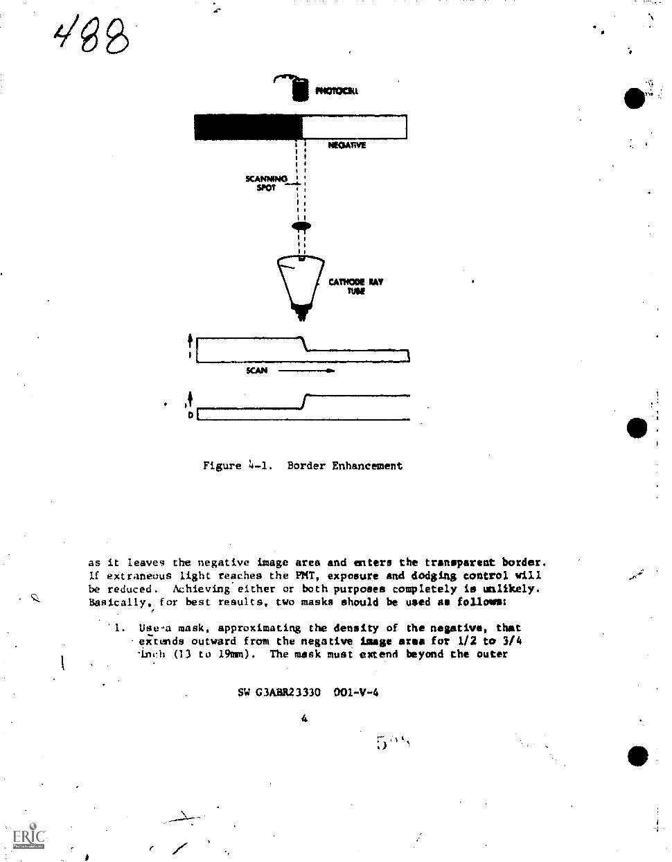
rtrikPHOTOCIU ryt.
I NEGATtvi
KAMM)
V CAM= RAYTM
[
SCAN
. bt
Figure 4-1. Border Enhancement
as it leave9 the negative image area and enters the tranoparent border.If extraneous light reaches the PIKT, exposure and dodging control willbe reduced. Achieving either or both purposes completely is unlikely.Basically, for best results, two masks should be used ae follows:
1. Use-a mask, approximating the density of the negative, thsteihends outward from the negative image area for 1/2 to 3/4'inch (13 to 19mm). The mask must extend beyond the outer
SW G3AMR23330 001-V-4
4
5 "*

edge of the raster overseen.
Use a second mask of high density, essentially opaque,extending to the edge of the printing stage. The openingfor this mask must be large enough so that no part of theraster is covered.
NOTE: Generally, results are goad enough with only the firstmask, so that the second mask is not usually used.
Ln practice, green masking material is used with a normalnegative, red with a dense,negative and blue with a thin negative.However, if these colors are not available, an amber mask will beaccepteble for any negative.
Raster overscan is required in order to prevent a black borderat the right and left edges. Some overseen is also required atthe top and bottom edges because the starting and ending lines ofthe raster are not always complete. Generally, tbe overseen shouldbe leost 1 1/2 spot diameters. This makes the overseen 3/8 to1/2 inches (10 to 13mm).
CAUTION: No part of the raster should bs masked by an opaquearea. If the scanning spot is opaqued out of viewof the my, the spot will slow down, possible burningthe CRT phosphor.
Controls and Indicators
The controls and indicators are illustrated in figures 4-2,4-3, and 4-4. Tables 4-1, 4-2, and 4-3 describe the functions.Table 4-1 describes the power control panel which is on the printer'shood. Figure 4-2 illustrates this panel. Figure 4-3 correspondsto Table 4-2 and illustrates the function control panel. Table 4-3describes and Figure 4-4 illustrates the Roller Paper Transport (RPT),cabinet and Automatic Platen Lifter (4PL) controls and indicators.Study those carefully before attempting to use the Mark II RSA.
SW G3ABR23330 001-V-4
5

Figure 4-2. Power Control Penal!0111.
Table 4-I. Power Control Panel Controls and Indicators
INDEX M3, CONTROL OR
(SEE Figure 4-2) INDICATOR FUNCTION
1 Lmdicator fuse holders Lights to indicate power on andfuses gcod
2 MASTER POWER switch Controls pcmer to entire unit
3 TRANSPORT POWER switch Controls power to RPT and APL
4 LIFTER POWER switch Controls power to APL
5 NEGATIVE CARRIER power Controls power to negative
switch carrier and filter holdersol2noi4s at lens box
SAFE VIEW LIGHTS DEM Reduces safe view lamp inten-
potentiometer sity
7 SAFE-WHITE VtEW LIGHTSselector switvh
Select WHITE or SAFE view lamps
8 Hood Hitndle Letches hood down and startsexposures
9 DEMMER potentiometer Reduce fuse indicator lampintensity
SW OABR23330 001-V-6
(1, 110
t.

11 12 13 14
NON
0a 041NO
0WO
42 ea ea.11110410106
17
fogrE
Figure 4-3. Function Control Panel
491141141
Table 4-2. Function Control Panel Controls and Indicators
co1IOi ..7O1r--s----liajjklumiA:11 INDICATOR wr
10 PNT ester Winternal Measures MT current when call-
vies lemp brstieg agsiest emulsion used
11 WSW switch Allows repeat exposures with-out moving hood
1, MOON* INDIR Provides calibrated eepoeure
switch adjustment from 10 to 1000 snit*
13 NODC switch Provides choice of TEST, MANUAL,or AUTO operate* modes
14 RAMS edge controls Allow individual selection ofraster udge position
IS MOSING loop Lights to indicate that printeris in exposure position of cyan(eanust and automatic modes oaly)
16 EXPOSINC lamp Allows decreased level of indica-tor lamp brighteess in meter Limpend MOBINO leap
17 SENSITIVITY adjust- Adjust gain of photo-mnitislier
dieser.
Met tube
SW C3A1R21330, 001-V-4
7
14

1/Z2
Figure 4-4. RPT and APL Controls and Indicators
, SW G3A8R23330 001-V-4

4Tabl. 4-3. Roll Paper Trensport, Cabinet, Automatic Platen 471144?Ct5 .
Lifter Controls and Indicators
INDEX NO.(SEE Figure 4-4)
1
2
3
4
5
6
7
CONTROL ORINDICATOR
RPT print counter
RPT counter reset
RPT paper advancerevolution counter
APL fuse holder
APL SMULEPWITLTIPLEPRINT switch
APL print counter
APL print counterresat button switch
FUNCTION
Number of RPT advances
Thumb wheel to remit counter
(I
to zero
Provides adjustment of paper ad-vance 8 to 20 + 1/8 in. (20 to51 cm + 3.2)
Holds APL fuse
Disables motor control circuitfor single print operation
Allows number of desiredprints be dialed iim-forautomatic repeat-operation
Start switch for Auto Repeatoperation
Operation of the Mark II R5A
Foliow these directions carefully when operating the Mark II R5A.This ensures the best results and the minimum of problems.
PRO,MH1NARY INSTRUCTIONS. Follma these general preparationswhen using the Mark II R5A regardless of the type of printing tobe done.
J. Ensure that the power cord is connected to 105-130-volt,60-Hertz input power receptacle and to an external powersource. Never operate the printer without an electricalground connection.
2. Cheek diet the RPT power, the APL power and the negativepower are off.
SW G3A8R23330 001-V-4
9

3. Check the airbag inflation by raising and lowering the hoodassembly several times. The airbag holds the printing materialand negative in contact during the contact node. MR the pre-jection amides it prevents wrinkles or al: bubblas between theprinting material and the printing stage. Use a spring balanceto measure the airbag pressure. Attach the spring below. tothe platen handle. Place a sample of negative and ramstockon the printing stage. Close and lock the hood by pull's";
down on the balance. If the hood locks at a weight indica-tion of 8 to 12 pounds (3.6 to 5.4 kg.) airbag pressure issatisfactory.
4. Ensure that the printing stage is clean and free of dust andfingerprints.
CAUTION: Nrver have the hood down with the power on andthe normal room lights on. Damage to the PKTwill result!
5. Raise the hood to the maximum up position. Set the MASTSMPOWER switch to ON and allow a 30-second warmup time.
CONTACT MODE. Follow this step-by-step procedure to operatethe printer in the contact mode. Remember rawstock may be either
in roll or sheet form.
1. Re sure that the proper lens for contact printing issecurely In place. The 112mm lens is used for generalcontact printing. Select a mask of proper density and
size. (See Figure 4-5 for.placement of ths mask.) Turn
off all Lamps except safe lamps and adjust SAFE VIEWLIGHTS potentiometer for the brightness level desired.
2. Set the MODE switch to TEST. Adjust all raster edges
to fall inside the mask cutout.
3. Place a sample of the unexposed rawatock over thecUtout and Afer1apping the mask on all four sides.
4. Close and latch the hood. Read the PIHT sensitivity on
the meter. Set the SENSITIVITY adjustment to bringthc sensiiivity reading to 25 (midscale) on the meter.
5. Raise the hood and remove the rawstock sample.
SW G3A8R23330 001-V-4
10,

ft
01...,
7
4/967"
&ALI( (SI ITEEATIVE
al CUT OuT ANS WI AS NLGATIVI ARIA NI TAPE TO RAISEAND LODEN *LEEAPI TO PRINTING STAGI (T1 PEINTINO STAGE
(41 PelsTiNG MATERIAL
Figure 4-5. Mask Placement
6. Adjust thg RASTER cowols until the rasters extendapproximately 1/2 inc.% (13mm) beyond the cutout intothe mask on all four sides.
Set the MODE switch to AUTO.
NOTE: Step 8 applies only when the exposure index isunknown. If the exposure index is known, proceedto step 9.
8. Make 4 test print using the-exposure index calibrationsheet,
d, Spjevt A negative the same piste as the cutout
SW G3ABR23330 001-V-4
11

04/4)64area with average density and somenegative beneath the mask with theinns, areas of the negative shouldcutout edges.
detail.emulsioncoincide
6
Tape theup. The
with mask
b. Obtain 4, piece of unexposed rawstock approximatelythe size of the negative. Place the calibrator(emulsion side up) behind the material. Fold thenumbered flap of the calibrator over the rawstockso that the numbers overlai, the rawstock emulsion.Place the rawstock (emulsion down) and calibratoron the negative with the numbered flap on the righthand side.
c. Set the EXPOSURE INDEX switch to 10. Lower thehood assembly and lock it in position. Duringexposure the EXPOSING indicator lamp is lit. Whenthe indicator lamp goes out, raise the hood assemblyand remove the exposed rawstock.
d. Process the exposed rawsLock.
e. The numbers on the left side of the test print wreexposure index settings. Use the number beside thearea of best exposure as the proper setting for therawstock tested.
If all areas of the test are too light, repeat thetest with the EXPOSURE minx set to 100. Multiplythe number beside the area of best exposure by 10to obtain the exposure index.
f With the EXPOSURE INDEX switch at the proper setting,place another sheet of rawatock (emulsion down) overthe negative and expose it without the calibrator.Expose two more sheets--one with the EXPOSVRE INDEXswitch one setting higher and one with it set onesetting lower than determined by the calibrator,
g. Process the three exposures and select the bestexposure index. Set the EXPOSURE INDEX accordingly.
NOTE: Normal room lighting may bevsed for step 9.
9. Remove the test negative and place the negative 10 beprinted on the printing stage. If the negative is in
SW C3A3R23330 00I-V-4
12

cut torm, Once it (emulsion up) undor the cutout areaso that all image Areas coinelJe with the cutout Wiwi.Tape it to the printing stage. If the negative is inroll form, place the roll on the spool holdtr at theleft of the printing stage. Insert an empty spool
holder at the right. Feed the negative (emulsion uP)over the rollers, under the mask and thread it into
the empty spool. Position the negative so that thsimage areas coincide with the mask cutout.
10. Turn off ull.buc allowable safelights. Position therawscock (emulsion down) on top of the negative onthe printing stage. If the rawstock is in toll form,thread it According to Figure 4-6.
SUPPLY
NEGATIVESUPPLY
PRINYMATERIAL EMULSION DOWN
L gm.
OPM
.1 !MY. 111P ow.
PRINTING STAGE
r I
NeGATIVEEMULS1ON UP
MOAT! yf !from
Figurc 4-6. Concoct. Mode ThreadiRg Diagram
SW G3A3123330 001-V-4
13

49811. Set the MODE switch tu AUTO and the EXPOSURE INDEX switch
to the desired position.
12. bower,the hood assembly and lock it. Exposure begins
automatically %then the hood is locked.
13. Unlock the platen handle and raise the hood. Remove
the exposed rawstock and process it.
PROJECTION MODE. Operating procedures for the projection
mode are very similar to the contact mode. Once again, follow
these steps carefully and in the order given for the best
results.
1. Set the f/stop of the 138mm lens to f/4.5. Adjust the
PMJ sensitivity as before.
2. Set the MODE switch to TEST. Adjust the raster controluntil the outline of the raster edges barely extends
beyond the outline of the projected negative carrier.
3. Place a mask over the printing stage. The mask should
be large enough to extend beyond the printing stage.Mark the mask to coincide with the outline of the
projected negative carrier.
4, Remove the mask and cut out the indicated area. Tape
the mask to the printing stage.
NOTE: Do not touch the raster controls or the mask for
the remainder of the operation.
NOTE: Step 5 applies only when the exposure index is not
known. Tf the exposure index is known, proceed to
step 6.
5. Dutermine the proper exposure index.
n. Obtain a test negative equal in size to the mask
cutclyt area, with leader eKtending on the right
and left sides.
b. Open the cabinet door, unlatch the lens box and
center the teat negative (emulsion up) in the
negative carrier. Close and latch the lens box.
SW G3A1R23330 001-V-44
14 1 t

r
c. Sot the MAME .CARRIER switch to ON. Adjust the
negative position by the leader until the projected
image is centered in the cutout area on the printing
stage.
d. Set the NEGATIVE CARRIER switch to arr, remove the
teat negative, close the cabinet door and set the
MCOE switch to AUTO.
e. Follow the instructions given in the contact mode
procedures for using the exposure index calibration
sheet.
6. Place the negative to be copied on the negative carrier.
a. if the negative is in cut form, open the cabinet
door and lens box, position the negattve on the
negative carrier (emulsion up) and close the Lens
box and cabinet.
b. If the negative is in strip or roll form, thread
it as shown in Figure 4-7. Peed the negative
(emulsion up) over the stainless steel roller to
the upper right of the supply spool, down the left
side of the cabinet under the black aluminum roller.
Pass the negative through the slot, under the left
sluoinum roller, over the lower negative carrier
and under the right black aluiinum roller. Bring
the-negative up the right side through the slot,
over the stainless steel roller and tato the takeup
negative holder. Awn the takeup spool until theroll of negative is firmly engeged. Close the lens
box.
7. Set the NEATIVE CARRIER to ON and position first
negative. Set NEGATIVE CARRIER switch to OFF and
close the cabinet.
NOTE: Before proceeding, turn off all hut'allowable aafelighta.
8. Place translucent material aver the mask cutout on the
printing stags. Check that the negative in correctlypositioned for proper projection on the printing stage.
Focus the lens if necessary.
SW G3601123330 00l-V-4
15

SUPPLY
PRINT MATERIAL EMULSION DOWN
NEGATIVESUPPLY
- -1
i1
11
i I
L ..- - - _ --- -
SLOTIN
CASINET
/MEI!
0111. ./1.
NEGATWE SPOOLTALCIP
NEGATIVEEMULSION UP
NEGATIVE CARRIER
Figure 4-7. Projection Mode Threading Diagram
9. Set the MODE switch to AUTO and place rawstock (emulaiondown) over the mask cutout on the printing stage. If theraw,4toek is in roll form, thread it according to Figure4-7.
10. Set Ow EXPOSURE INDEX switch to the predetermined setting.
SW C3ABR23330 001-V-4
;I s
16

,5'6/11, Lower the hood assembly and lock it.
12. After the exposure, unlock the platen handle and raisethe hood. Remove the exposed rawstock and process it.
13. Set the NEGATIVE CARRIER switch to ON and the MODEswitch to TEST.
14.-"Transport the roll film to the next frame and positionthe negative. Set the MODE gwitch to AUTO and theNEGATIVE CARRIER switch to OFF.
NOTg: If cut film is use& with roll rawstock, place anopaque mask on the printing stage during positioningof the negative. The mask prevents the rawstoCk frombeing exposed when the lens box is opened.
RPT AND APL OPERATION. Using the Roll Paper Transport (RPT)and the Automatic Platen Lifter (APL) frees the operator fromraising and lowering the hood between exposures and from manuallyfeeding riwstock into the printer.
Before using the RPT and APL, set up the printer for itsintended use (contact or projection printing). Determine theexposure index and adjust the ANT sensitivity. Then threadtho rewetock (emulsion (Jowl) through the roller aseemb3y,across the printing stage and into ths takaup spool.
Check that the LIFTER POWER switch if OFF and that the
A.Pi I. in eingle print mode. Set the RPT paper advance control
to the proper number. (Ninety-six is the approximete setting
for 0 10-inch (25.4cm) long original. This gives a 3/4 inch
(2cm) space between prints.) Check for the proper amount ofpaper advance by marking the rawstock, lowering the hood withoutlocking tha handle and then raising the ed. Measure. the distance
frnn the first position to the %ark. Adjast the paper advance
accordingly.
After any final adjustments, expose the emulsion, raisethe hood end allow the rawatock to advance before making thenext exposure. Repeat as necessary.
If a large number of prince is needed, it is beo to usethe Automatic Platen Lifter (APL.) Prepare the printer asbefore and mat the RPT. Set the APL print counter to one morethan the number of prints required. The final exposure isdouble; thus, the extra count achieves the required number of
SW G3ABR23330 001-V-4
1 7

57002_copies. Set the APL switch tO MULTIPLE PRINT.
Set the LIFTIat POWER switch and the tRANSPORT POW* swisch.to 'ON. Push the 'white' APL print button. Close and latch tehood: Operation is now automatic.
CAUTION: Do not set the print cotmter higher theerepired.When the.-APL operation has begpn, decreasini thedia.led number of- prints causes eacessive wear onthe APL counter.
To turn the APL off, set the API. switch to SIICLE PRINTand turn off the LIFTER POWER. The APL must be turned off atthe bottom of a stroke or the printer will not operate in themanual-or automatic modes. --
SHUTDOYN PROCEDURES. When the operation of the printer is44,completed,.set all power switches to OFF. Set` the MODE Witch
to MANUAL. Raii;e the hood and remove any unexposed rawatockfrom the printer. Leave the hood V the raised position. Cleanthe pr.inter
After each seven 'day period, ,make a -set of dodged andundodged prints from the standar! negative or step wedgesupplied witt the printer. The...pa:tints should be asde undercsrefully controLle4 conditions awkl then compared_ with previousprints. -Any deViationiti should be checked, using the uble-shooting chart in Sec-tion VI of TO 10E8-2-19-ll.
Safety Precautions
The Mark II R5A ls a highly sophisticated piece ofequipment. Treat it as such. Do not operate it Withoutan electrical ground connection. It contains very high"electrical voltage. CarelessnesS can cause damage to themachine anti injury to the operator.
Keep hands ond fingers away from the hood assembly duritigautomatic operation. Be extremely careful when working inside
the cabinet in safelight conditions. Electrical shock could
result. Never operate the machine with wet hands.
SW G3ABR2 33 30 001-V-4
c.
1 8
. SI

REVIEW qUESTIONS
Do NOT WRITE IN THIS SW - USE A SEPARATE SKEET OF PAPER.
1. What is "incremental exposure control"?
2. What widths and lengths of rawstock does the Mark IIMA accept?
3. Which lens is used for projection printing on theMark I1R5A? Which one is used for contact printing?
4. What is the purpose of the TEST, MANUAL and AUTOMATICpositions of the exposure mode switch?
5. How is the raster adjusted for proper length and width?
6. For what two reasons is the image area of the printermasked?
7. Why is raster overscan required?
8. What is the printing light source of the Mark II R5A?
9. What is the advancing speed of the RPT?
10. What is the purpose of the 114T?
PRACTICAL EXERCISES
EXERCISE I
EQUIPMENT AND SUPPLIES
MArk 11 RSAAerial NegativesMasking MaterialPrinting Material Roll PaperVerssmat 11CMExposure Index Calibration Sheer
SW G3ABR23330 001-V-4
19
Basis of Issue
2/classAs neededAs needed30 feet (9m)/student,l/clast
I/class

PRUCEDURES
1. Prepate the printer as outlined in this SW for contact
printing with roll paper.
2. Determine the exposure index using the Exposure Ind=Calibration Sheet as outlined in thja SW.
3. Process the test in the Versamat 11CM.
4. Using the API., RPT, and an aerial negative, maks
three acceptable prints.
S. Compare the results of the finished prints. Inspect
for contrast, density and physical dfects.
6. Upon completion of printing, shutdown the printer
as outlined in this SW.
7. Shutdown the Versamat 11CM according 6 normal
pracedures and clean the lab. Return to the classroom
for a critique of the results.
EXERC ISE II
EQUIPMENT AND SUPPLIES
Mark II R5ARoll of 5" (12.7cm) Aerial Negatives
Roll of printing material
Masking MaterialVersamat 11CMExposure Index CalihrArlon Sheet
PRCCEDURES
Dixie of Issue
1/classA. needed30 fet (9m)/studentAs needed1/class1/class
Prepare the printer as outlined in this SW for projection
printing with roll paper,
2. Determine. the exposure index using the Exposure Index
Calibration Sheet as outlined in this SW.
3. Process the test in the Versamat 1101.
SW C3ABR23330 001-V-4
20 i

4. Using the AFL, RFT and a normal negative, make threeacceptable projection prints.
All/ 5. Compare the results of the finished prints end inspect
s,
for contrast, density and physical defects.
6. Upon completion of printing, shutdown the printer asoutlined in this SW.
7. Shutdown the Versamat 11CM according to normalprocedures and clean the lab. Return to the clkssroom
for a critique of the results.
SW G3ABR23330 001.-V-4
21
SIUDY (algaG3ABR 01-VI
Technical Training
Continuous Fhotoprocessing Specialist
CONTINUOUS COLat PROCESSING
4f,
October 1977
litiallikfr
3400th TEQLNICAL TRAINING WIIC34 Oth Technical Training Group
wry Air Force Eases Colorado
Designed For ATC Course Use
DO KW USE ON THE JOB
5 ?

11
5-67Sciences branch SW t; MM.! WO din I 1Lowry OK, Colorado October Mt
COLOR THEORY
OBJECTIVES
Provided exeralses pertaining to the function of white light in
forming colors, identify colors formed by additive and subtractive
means.
Using pro.idad diagrams, write the names of dyes formed in various
color film emulsions whop exposed to given colors.
Describetha major characteristics of motion picture sensitized
materials.
INTRCOUCTION
During the past few years, there has been an ever increasing
demand for color photography in the armed services. Much of this
is due to the rapid improvements which have been made in color
photographic products during the last decade. For example, aerialctilor emulsions are now capable of yielding one third more toper
graphic information than do production type black-and-white films.
Am color quality and speed are continually being improved, more
widespread usage is indicated for the future.
Since processing color photography used to be difficult and
time consuming, it was limited to just a few labs. Now most lab-
oratories are capable of processing color photography without ex-
cessive t.xpense or extra space requirements. New processes and
equipment have made it much easier for the photographic technician
to grocess color photography with reasonable assurances of obtaining
satibfactory results.
INFORMATION
LIGHT
Most of the principles and procedurcs used in color photography
are adaptations or extensions of those wwd in black-and-white photo-
graphy. In order to understand color photography, it is first nec-
e ssary to understand what is meant by the terms "light" and "color."
Color does not exist in the absence of light. It ia an integral part
of light, and since this is true, a logical beginning point is a
S hort review of prior tudies Lnto the nature of light itself.
Supersedes SW 3ABR23330, Oc'tober 1973
5 9'

08The teem "light" leas ot ten been der 1 nod ns visible radiant energy.
To be more specific, it is necessary to define each of these words ....
visible, radiant, and energy - eeparotely and in more detail. The
term visible is defined as being detectable by the human eye. Radiant
describes the way in which light energy is emitted or given off by its
source. Energy, literally, is the ability to do work. The work done
may vary from raising the temperature of an object, to stimulating
the retina of the eye, or causing a minute change in the photosensitive
emulsion, which upon development, yields an image.
Electromagnetic Spectrum
Light or visible radiation occupies a very small region of the
electromagnetic spectrum, embraced at one end of the extremely short
cosmic rays, and at the other end by radio waves which may extend to
a mile in length. By refereing OD Figure 1-1, the extent of the
electromagnetic spectrum may be noted. The.various types of radiation
wlLc constitute the electromagnetic spectrum are cosmic rays, gamma
rays, X-rays, ultraviolet, visible, infrared, and radio waves.
- ,-
,
- -s-Visible Speetrum.
...---; T
Blue 1 :024114111 ;
400 le4 .600,
Ciez 1 Yellow]
703 St
Figure 1-1. Electromagnetic Spectrum
All forms of radiant energy travel in wave motion and if mean,would resemble the waveform created by dropping a ,pebble into a still
pond. These forms of energy travel at the same tremendous peed,about 186,000 miles per second (297,600 km/eec), but they differ inwavelengths and frequency. A wavelength is the distance from the
.SW G3ABR23330 001+-Tylvl
2

crest of one wave tu lhe crest. ut the next wave, while frequency
is the number of waves passing a given ikiint in one second, noted
in Figure 1-2. The pruduct of the twu is the velocity of travel,
commonly known as the "speed of light."
...111111p
Figure 1-2. Simple form of Wave Motion
sAi
Photography is interested in the ce4ra1. regions of the elec-tromagnetic spectrum, chat is wavelengths from 200 to 1350 milometers.
This area includes the ultraviolet, visible, and infrared regions
which occupied a very small portion as compared to the entAre spec-
trum. Because of these short wavelengths in this area, the standard
unit of measurement is in nanometers previously referred to as mil-
limicrons. For purposes of comparison, a millimicron or nanometeris equal to one-millionth of a millimeter, whereas a millimeter is
approximately the thickness of a dime.
Visible Spectrum
The visible portionwei the spectrum has been explained in Figure
1-1 which includes wavelengths of from approximately 400.to 700 nano-
meters. These are not the exact limits since the human eye is re-
latively insensitive to the extremes of the light spectrum. Lumediacely
below 400 nsnometers are tlw ultraviolet rays and above 700 nanometers
are the infrared rays. Although these two types of radiations are in-visible to the human eye, they do produce a similar effect, as do
light, (m sensitized material and are very much utilised in photo-
gr,aphy.
When light of all wavelengths from 400 to 700 manometers
SW GAM23330 00l-VI-1
3

reavhes the eye in vety 110d4IV equal qudelti lea, the vlotuot sneat Wit
of color loos or whit e I isht Is proihwod . 1.1 t he anottitt s are varied,
or u particular portion or 'Am apecirom viewed, "voior" I. ssn.Color is simply brought about by thv changes in wavelengths of the
energy reaching the eye. If an observer could view separately the
energy of three single wavelengths, say 450, 550, and 650 nanometsre,
he would see "pure color." of blue, green, and red.
At one time, the common belief was that "white" was a separate
and distinct color as was blue, green, and red. It was not until
after Newton demonstrated the composition of whitt light by the
means of a glass prism, that the theory of the color pectrum was
fully accepted. By using a similar prism today, one can identify
the same areas of the spectrum as being, violet, blue, blue-green,
yellow, orange, and red. The separation of white light into dif-
ferent colors (See Figure 1-3) is explained by the fact that the
speed of light is reduced in glass by different amounts for dif-
ferent wavelengths. When a beam of white light enters the flat
glass surface at an angle, the differingwavelengths are bent or
"refracted" by different amounts, the shorter wavelengths being
refracted to a greater degree than the longer wavelengths.
amamilli
G1438 PRISM
Figure 1-3. Dispersion of Light
COLOR
Trichromatic Systems
Maxwell followed Newton and ,
monstrated in 1861, that all colors
SW G3ASR21330 001-VT-I
4
5.)1

57/can be observed by adding together cortain amounts of light of the
three "additive primsry colors." Hence, the Maxwell method (commonly
referred to as the triehromatie theory) is fundamental to all modern
processes of color reproduction.
Color reproduction infers the ability to match the spectral dis-
tribution of an object sufficiently close so that a human observer
(and sometimes an objective measurement system) cannot tell the
difference. If it were necessary to match the duplicate with the
original scene at each wavelength, the task would be extremely
difficult, if not impossible. Fortunately, the task can be simpli-
fied by the use of the swvalled trichromotic systems. These sys-
tems are based upon the selection of three pillory colors Which,
when mixed in various proportions, may be used to match any color
in the visible spectrum.
FREMARY =as. Blue, green, and red have been designated
the primary colors because of their specific characteristics.
Three of the characteristics of these colors which should be
considered ore as follows:
1. All three colors (blue, green, And red) must be present
in approximately equal v-oportions to produce white light.
2. Almost any color can be matched, or produced, by suitable
mixtures of light beams of these three colors.
3. No one of them can he reproduced by any mixture of the
mher two.
FILTERS. in order to understand how the human eye sees colors,
consider the action of Iight filters. A filter is defined as a sub-
stance wbich selectively absorbs or transmits certain portions of
the spectrum. Theoretically, any filter transmits light pf its own
color and partially or completely absorbs all other colors. In
practice the amount of absorption depends upon the characteristic
of the filter itself.
Because a filter selectively absorbs certain light waves, it
naturally appears colored. A green book appears green because it -
reflects green light and absorbs light of the other colors. A
green filter appears green because it absorbs red and blue light
and transmits green light. A filter which absorbs red and green
light appears blue. Lookiog through such a filter, all red and
green objects will appear darker while blue objects will appear
1ighter. A filter which absorbs only blue light appears yellow
because it transmits green end red, and these colors affect the
eye 41 yellow. See figure 1-4.
SW C3ABR23310 00I-VI-1
5

67,2Since the amount of energy bburbed by a filter varies with the
wavelength, the characteristics of a filter may he repreeented by
plotting this absorption (or its reciprocal, transmittance) ss
function of wavelength. Figure 1-s ahows the characteristics of
Wratten K-2 yellow filter plotted thus.
IMAM nIXER
1 %
io%
100 %
"SLUM LIM
Figure 1-4. K-2 Yellow Filter
400 500 600
%mason (nut)
700
.- ONO
Figure 1-5. Typical Filter Absorption Curve (K-2 Filter)
SW G3AAR23330 001-VT-1
6
5 ,

.573Now consider the relationship of paluIrp cutting filters of the
primary colors and one'white light auurcv. Sharp cutting filters
are those which will transmit only their own color, and absorb all
others. If a red sharp cut!ing filter Le placid ever the light
source, blue and green are absorbed, or eliminated from the white
light, with only the red pertian being treemitted ,ar allowed to
pass. If either a blue or greenfilter is placed oVer ths light
source in combination with the red filter, all of the light is
eliminated since either has the capacity of absorbing red. This
is true of any filter combination of the primary colors.. If the
filters used are not sharp cutting, any combinati#n of two primaries
will create a neutral density since a portion of /all three colors is
absorbed. These characteristics of,the primary colors mak* thee-
impractical for use in the finished color print or transparency.
Additive Color Process
All color processes in use by the Air Force at present start
with the application of the additive color process Or principle.
They utilize the primary colors - -blue, green, eed red--for photo-
graphically recording the original scene. An utderstanding of
additive color mixtures will help in understamding the structure
of color materiale and how to uee them.
When equal parts of blue, green, and red light are projected
from separate projectors and partially superimposed on a white
mermen, white is seen is the WIWI of overlap of all three colors,
as shown in Figure 1-6. The area of overlap between the blue and
green light produces cyan (blue-green), the area of overlap oeths
red and blue light produces magenta, and the overlap of the red
and green light produces yellow. Almost any desired color match
can be produced by varying the mount of one of the two colors
used for producing that color. For example, if equal proportions
of red and green ore present, the result is yellow; by increasing
the amount of red, the result is orange. Since matching a wide
range of colors with rad, green, and blue light involves addition
of colored light, the primary colors are often identified further .
as the additive primaries.
In color photography, the three colura produced by mixtures
of the additive primaries in pairs -ire of particular importance.
These colors-cyan, magenta, and yellow - -are known, as the sub-
tractive primaries, or secondary colors. Since each represents
whits light minus one of the additive primaries, the subtractive .
primaries are complements of the Additive primaries. For example,
cyan, and red light-blend together te give whits light. Similarly,
**gents is complementary to green, and yellow is complemostary to
blue.
SW C3AM23330
7

At this point, refer to Figura. I-1. And study the illuxtration
of the color star. Remember which colors are the additive primaries
(blue, green, and red) and notice that the subtractive primary colors
between any two of the additive primiries and mixtures of these two
primary colors. Also, notice the colors tnat are directly opposite
each other in this star; these colors are complementary to each other.
SECONDARY MAGEMA
Figure 1-6. Aiiditive Process
Although the original photographic record on volor material uses
the addit...ve primary colors. these are not suitable for the final color
product in general use. Three filtered light sources, such as those
produced by three projectors, are required for producing colors by the
additive color mixtures. For practical purposes, most color trans-
pareneies or prints must be viewahle when only one white light source
(made possible by the use of the subtriwilve color process which is
just the reverse of the additive k-olor prr)cess) is used.
Subtractive Color Process
La the additive color process where thrPf, projectors were used
SW GWAR/M0 001-V1-1
4

Figure 1-7. Color Star
(one lens Was covered with j red filter, one with a green filter, and,'
one with a blue filter), any desired color could be produced. Theo-
retically, any filter.transmits light of its own color and absorbs
all other colors. The amount of absorption depends upon the density
of the filter. Therefore, all three filters could not be placed over
a single light source. To a certain extent, the filters are mutually
exclusive; that is, none of them transmits light passed by either one
of the other two. Consequently, any two of the filters used in com-
bination in front of a single light source absorb all of the light.
Since a fitter of any of the additive primary colors transmits
only that.one primary color, the subtractive primary colors are used
as filters in the structure of color materials. This makes it possible
to transmit any two of the additive primary colo-es and subtract the
third.
A cyan filter transmits blue and grven light, but absorbs red
light; hence, it subtracts red from white light. Similarly, a
magenta filter (which transmits red and hlue) does nothing more
than subtract green from white light. Finally, a yellow filter
(which transmits red and green) functions by subtracting blue from
white light.
SW G3ABR23330 00l-VI-1

4
14.
Since each of the subtractive pri4rv filters transmits
approximately two-thirds of the spPvtrwm. suOerimpesing any two
of them oyer a single light solitce ploduics other colors. Refer
to X4gure 1-8 for an illustration of the principle of the sub-,
tractive cotor process. Notice that thc combination of any pair
of the subtractive primary celors in equril densities produces onc!,
of the additive primary colors. For-example, a 'yellow filter
transmits red and green and absorbs blue, and thf magenta filter
,cikansmits red and blue and subtracts griwn from the light source.
lihml these two filter.s are used over a single light source, the
one color that is transmitted by both magvnts and yellow is red.
Therefore, yellow plus magenta produves red.
4IAGINTA
,*
',F gure I-S. .,Sublvactiv 4"rocete
wy
3.n the sime manner,, when yellow anti cyan are used in comt,ination;
the one cblor that is transmitted by both filters is green, since
yellow tranam4ts red and green and (fyan Cran.sipits blue and green.
Cvnn plus magenta produces bluw, heA:114:hlue ia-trsnamitted by both.
SW G3ABR233-30 601-Vli'l

filters. (Sae figure 1-9) where all three filters overlap in the
center, all of the light is subtracted, and the result is black.
. By varying the densities of subtractive filters used in com-
bination, any desired change in the color produced can he accomplished.
For example, to change the appearance of red to make it an orange,
the amount of yellow may be increased or the amount of magenta de-
creased. All three colors may be needed in varying densities to pro-
duce some colors other than black, such as shades of gray or brown.
-
These same principles apply to artists' colors (water colors,
paints, etc.) and dyes such as thepe used for dye transfer prints.
.ftwever, much confusion has resulted frnm the common practice of
designating the artists' primaries as blue, red, and yellow. If
REDABSORBED 4101
BLU4 & GRA=TRANSKITTID
GREENABSORBED
BLUETIANBUTTED
Figure 1-9. Effects of Subtractive Filters
a lull range of colors is to be produced ,ompletely as possible,
how-ver, the red will really be d magenta and the blue will really
be a blue-green or cyan. lc is unfortunate that the -quoted names
have so often been uaed, because their use in this sense has un-
doubtedly acted as a bar to a more widespread understanding of
the principles of color mixture.
As previously stated, all color materials - negatives,
///Y
ransparencies, and reflective type prints - in current use by
the Air Force begin with an application 01 the additive process.
' but the subtractive process is utili4ed for the final product;
that is, these materials all incorporate yellow, magenta, and
cyan dye layers, which act as subtractive filters, to reproduce
the original subject colors.
SW OABR23330 DOI-VI-1
11

Add ft Lve and. *him. t 1vit Pr intut Svp own
In a printer system using the 41041 it Ivo process, throe aspirate
exposures are required to obtain the overall sxposure. This is
normally accomplished by either using three separate light sourest;
A (one primary filter over each source) or one .light source and in-
dividually placing each filter between the light source snd the
print material for three separate.exposures times.
MirRod
Filter
NME:No ND Filter
e
I ---ha
Grer new
ND
4/ PI
issignimealiZask
BlueriltarND
lter
Figure 1-10. Additive Process Plus Neutral Density Filters
Figure 1-10 illustrates one of the latest designs in an additive
(or tri-color) printing system, employing the use of ND filters. MO-
cause of the mirror conff.gurationa the ovvrall exposure can be made
simultaneously, making it ideal for vontinuoos ty0e-contact printers.
SW G3ABR23330 00 -V1-1
12
?S

Many motion picture snd aerial color printore manufactured todayemploy this or similar principles.
\ ThsIartiacOeptof tricaloi ittpoting tea -be related toprojection printing as shown in Figure 1-11. The projection printerhas ,one light source and in order to obtain ain overall exposure of4hite light, three separate exposures are required, one througheach primary filter.
F4 8403,
Figure 1-It. Projection Printing
The advantage of the aqdltive system is that it does producea higher quality product, biah in definition and color saturationas compared to the subtractive system. Hummer, the main dis-advantage is the type of filters which are required for thisprinting system. Filters normally employed in trioolor printingere tha Kodak Wratten Series No. 25 (Red), No. 98 (Blue), and No.99 (Grson). These filters are constructed of dye glass which has
SW G3ABK23330 001-VI-1
13

Sc2,,
sharp-cu tting charieterietita And' are,',4)1-y dense* requiring- boy
very long exposure times or very high Antensity source.
Recently, the mubject of additive ciilor reproduction has been
reappraised in light of recent technical developments. The com-
mercial development of dichroii coated mirrors created the beam-
splitting means by which the optical system was able to Incresne
the light energy arriving at the film plane. The dichroic mirrbre
consist of a glass with a number of evapmated metallic conUngs.
They are able to reflect selectively a chosen wavelength band ol
the spectrum while allowing the remaining wavelengths to be traen
emitted. They do this with an efficiency of approximately 95 per-
cent. This compares with the figure of 10 times more retinired
light on a system not using dichroic coated mirrore, therefore
the tricolor printing process has been shortened considerably.
The p 1 oc Motion Picture Printer used in this career field
employs the dichroic mirror principle of exposure.
Printers for many years have utilized the subtractive system.
employing the use of Kodak Color Compensating filters. These
filters are constructed of lightly dyed gelatin on acetate having
higher transmission properties -than the additive primaries previ
ously mentioned. Color Compensating (CC) filters are available
in the following colors; magenta, yellow, cyan, green, blue, and
red.
The subtractive 3ystem (commonly called the white light methed).
employed the same setup as illustrated ie Figure 1-11. This system
has the advantage of requiring only one exposure of shorter duret len
for the print material. The color of the light is controlled hY
placing the desired CC filters of various hues and densities in the
light path of the 'printer. These filter!; subtract their rrspe,tivp
complementary colors from the printer light, thus modifying it to
specific requirements of the negative: or positive being printed-
SENSITIM MATERIALS
Most colcm films, whether reversal or negative, are integral
tripack films. The term "integral" if; Utiod whenever more than mie
emulsion is coated on a single base. An integral tripack complete
of a single base with three light sensitive emulsion layers coated
on one side, each layer responsive to a separate region of thi
spectrum. The three emulsions are not separable and must be pro-
cessed together.
An integral tripack emulsion con4ists of (1) a suitable base.
(2) an antihalatian coating, which may ite coated on either side
SW 63A0R23330 001-VI-1
5

of the base, (3) three individual liAht-:wnsitive layers And (44 thin
layers of gelatin used to meparate the lieht-sonaitive layers ao4
which, in some instances, funetlontil
The cOmplete eripack is about one-thousandth' an inch
.(.251se) thick. In addAtion to silver halides, the emulsion
layer say contain sensitizing agents and substances for the
formation of dye images.
Between the emulsion layers are interlayers of gelatin. In
some instances they may serve as color filters for the sensitized
emulsions, but their main purpose is to minimize the effects of
one layer on the other.
This combination of emulsion layers and gelatin interlayers
plays an important part in image resoluChn. Resolving power is
a function of emulsion thickness and the size of the light sensitive
grains. To produce a color film with normal speed, the grain size
must be fairly large. The increase In grain size results in a loss
of image resolution.
Because of the tripack construction, light striking the emulsion
must penetrate a considerable distance to reach the lower two layers.
In traveling this distance, the light scatters and the image becomes
diffused. This light scatter also results in lowered Luise resolution.
To provide adequate liAht transmission and to retain the
sharpest possible image in the lower emulsion, the top emulsions
are designed to be am transparent as possible. These emulsions
may also contain light-absorbing dyes to help minimize light
scatter.
The magenta image is most rvadily seen because of the eye's
sensitivity to this part of the spectrum. Unfortuaately, this
layer is located In the middle of the trlpack, which is not the
best location for maximum resolution. The top layer is best suited
for resolution, hut it contains a yellow dye image which is least
visible to the eye.
Attempts have been made to design films with the magenta layer
on top, but it has heen virtually impossible to remove the magenta
layer's sensitivity to blue light. The classical order of yellow,
magenta, and cyan from top to bottom will probably exist for many
years to come.
The location of the dye image, in the emelsion, is determined
by the location of the developed silver grains. The dyes are formed
in the areas adjacent to the reduced silver. When the silver is re-
moved, during processing, the dye remelt's as a cloud centered where
SW G3ABR23330
15

the grain wee located. Because the dye imaRis ore partially trans-
parent, rather than opaque, end ere formoll by chemical difftteion,
their density increases gradually Horn Ole edge to the center.
On the other hand, the density of a qiiver image changes abruptly
at the edge of the grain. Therefore, color film appears less
grainy than black-lend-white, but the image has lower edge sharpness
and image definition. The magenta dye image (green-sensitive Layer)
has the greatest appearance of graininess because the peak sensitivity
of the human eye is in that region of thu spectrum.
Since red, green and blue are recordvd in the same manner in
almost all color films, negative and revursal, a cross section of
a typical piece of color film will help in better understanding.
Refer to figure 1-12.
. -.1...
aim sioserms ernams f*VMS
simemve SINI
Figure 1-12. Color Film Emulsions
Starting at the top and working down, first is the blue
sensitive layer of the emulsion. This is where the blue record
is made. Remember the blue sensitive emulsion is sensitive to
blue 1,ght only. Below the blue sensitive emulsion there is a
tsyer of colloidal silver suspendPd in clear gelatin which ab-
sorbs the stray blue light which penetrates the blue sensitive
emulsion this layer is similar tO A yellow filter. The colloidal
silver is bleached and fixed away during the Processing. The green
recording layer is an orthochromatic emulsion and is sensitive to
both blue and green light. Because of the colloidal silver, only
red and green light is allowed to penetrnte to this point. Since
this emulsion layer is not sensitive to red and Pince all the blue
light has been absorbed, the only expomure possible at this point
is that produced bi green li ht. Following the green, another
SW G3ABR23330 001-VI-1
5 7

423record is made in the next layer whieh is a panchromatic emulsion
that records red. This emulsion is manulnctured With 4 very low
sensitivity to green. Therefore, since khe blue cannot penetrate
to this point, only a red record is msde.
In effect than a sheet of neeative or reversal color film ie
mode up of three separate emulsion layers, each one sensitive to
only one of the additive primary colors.
Dye Couplers
The most accepted method of producing dye images within a color
negative or transparency ie by a chemical reaction of substances
known as couplers combining with the oxidized developer. This
reaction is called coupler development and in the secondary function
of the color developer. As the developer reduces the exposed silvexhalides to form metallic silver, the developer itself is oxidized.
The by-products of this reaction combine with the coupler Agentsto produce the dyes. This dye-forming reaction produces dyes in
proportion to the amount of silver developed; in other words, for
each Silver halide that is reduced by the color developer, there
is a molecule of dye formed. Since the dye formedis insoluble,it will remain in the emulsion to yield a photographic image in color.
Originally, the dye coupling agents can be colored or colorless
when first introduced into the emulsion and then they are changed to
another color during the developing process. The type of coupling
agents used will depeed on the particular film.- In reversal films,
the end-product is primarily designed for direct viewing, in which
caee, the coupling agents must be colorless in nature. However,
color negatives are not intended for direct viewing," but are judged
for their printin, characteristics. Thus it is possible by utilizing
colored couplers in the negative material to overcome the effect of
incorrect dys absorptions that are so prominent in color prints.
Coupling agents (colored,or colorless) combine with the oxidized
color developer to produce either a yellow, magenta, or cyan dye,
depending upon emulsion. Nermally, the color of the dye formed is
complementary to the original light sensitivity of the emulsion layer.
For an example, the bottom emulsion layer is sensitive to red light.
After color development, it will yield a cyan dye image.
0Ye couplers may be placed in either the developing solutions
or in the three emulsion leyers, depending on the type of film. Inthe Kodachrome anctilfochrome process, the coupling agents are put
into the processing solutions. Theme coeplers must be readily soluble
in ths developing solutions and they must diffuse freely through thegelatin together to the site of the exposed silver halide. To confine
SW C1AJR23330 00L-VI-I
17

the dye images to their appropriate inyyt, it is necessary to use
three separate color developers, one for each dye. Also, it is
necessary to reexpose selectively each emulsion before development.
This type of process requires both elaborate equipment and extreme
accuracy in its control. Due to its complexity, only a few of the
larger processing laboratories opernte this process.
By mixing the coupling agents into the emulsion, all dye layers
can be formed simultaneously, thus eliminating the need for multiple
reexposures and color developers. Film4 such as Agfacolor, Ansco-
chrome and Ektachrome incorporate the coupler components into the
emulsion layers during manufacturing. By doing so, the three
different colored dye images can be produced utilizing only a
single reexposure step and color developer, thus simplifying the
process so that it can be performed in any darkroom, with standard
darkroom equipment.
When these coupling compounds are incorporated into the
emulsions, they must meet certain major requirements. They must
be nondiffusing (remain in one location), be evenly distributild,
and nol become crystallized. To produce the cyan, magenta, and
yellow dyes, the different couplers must be capable of reacting
with the same color developing agents. The resultant dyes formed
must have definite spectral characteristics, so that all colors
are 4iccurately reproduced in the final peeduct. Also these couplers
must be stable compounds to provide permanency (nonfading) of the
color dyes. These/Compounds must not interfere with the initial
exposure of the film and must not cause any Nrnmful effects during
storage of the film prior to exposure.
Standard Reversal Process
The standard color reversal process is illustrated in Figure
1-) 3. Such films as Kodak Ektachrome a rype 7241 (daylight) and
Ektachrome R Print Type 7389 are processed in this manner% A
latent image of the original scene is formed by the light reflected
from thO subject, exposing the silver halides in one or more of the
appropriate light-sensitive layers. Each emulsion layer is sensitive
to a different part of the spectrum: the top layer to the blue region
only, the second layer to the green region, and the bottom or third
layer to the red region. Also, a colloidal silver (yellow filter)
interlayer is placed below the blue-sensitive emulsion. After the
camera exposure, the film is developed in a modified black-and-White
developer to form a silver negative image. (Sae Figure l-134.) No
dyes are formed in this "negative" since the black-and-wwihite devel-
oper yields no coupling compounds.
SW G3ABR23330. 0,0311I-1
18

Maw MeMOO 111111101111
t
awl MOPS
OA,. IWO
amillas
Ile OM.
41.46111
-a
4
*110
AK 011%101_-----Arai
MOSSION1111 MO
_
-§-
0E4'1345gm NM arrisMI umea sow qualimtre rs ctIN
'
affal OMNI MINI NO Me
IMINI 4111111111M1 Rims
Is INIIIPPN 1111411111111111.
Figure 1-13. Typical Color Reversal Process
SW C3A3R2333b 001-VI-1
19
5.
7;\

,After thie'step, the film UndergOes fogeing to expose all the'
remaining residual silver halides that wvre unaffected by the initial
camera exposure and the first developer. This reexposure may simply
consist of holding the fiLa under a strong light, or by a chemical
fogging agent which has been introduced in SOSO color chemistry,
such as Kodak's E -4, and EA-5 procesaes. This chemical called
Kodak Reversal Agent RA-1 (tertiary-butylmnine borane, also known
as T-BAS), is added to the color developer to produce the *ems
effect as the physical reexposure.
. Once fogged, the reexposed silver halides are reduced to
metallic silver by the color developer aed dyes are simultaneously
formed in those areas, as illustrated in Pigure 1-131. Note that
not all the silver halides have been developed by the first devel-
oper. Note also, that the dyes formed are the complementary color
to the emulsion's original sensitivity. That is, the yellow dye
forms in the blue-sensitive layer, magenta dye in the green-send'
sitive layer, and cyan dye in the red-sensitive Layer. At the end
of color development, the film (if viewed) would be completely
opaque (nontransparent) to tranamitted light since there are now
three silver negative images, three silver positive images, and
three positive dye images within the emulsion layers of the color
film.
Figure 1-13C represents the film after the bleaching and fixing
steps. Both the negative and positive silver images are removed,
along with the metallic yellow filter layer, leaving only the super-
imposed dye images. Perfectly registered, these images form a posi-
tive color transparency which can be viewed by transmitted light or
ty projection on a screen.
When the processed transparency is placed over a source of
white light, the various colors of the original subject are re-
produced by the subtractive process. For example, red if formed
by the overlapping of the magenta and yellow dyes or colorants.
The magenta colorant absorbs the green purtion of the white light,
and the yellow colorant absorbs the blue part of the White light,
thus preventing these colorants from being seen. The only part
of the viewing light not absorbed by either colorant is red, which
is tranaMitted and therefore seen. By utilizing the secondary
primaries, dye or colorants (cyan, magenta and yellow) in the final
product, almost any color can be produced. Black is produced by
the overlapping of the heavy dye formation in all three Layers per-
mitting no light to be transmitted. lesser amounts of these three
colorants (of equal portions) would yield various shades of gray.
White is produced by the unobstructed passage of light through the
three emulsions, since colorless couplers are used in this type of
`film.
SW G3ABR23310 Offl-VI-1
70

9
Since each emulaion loyer of tho tripeick forms a dye image
complementary in color to its sensitivity, each layer can be
thought of aS n primary color absorbEng alter; thus each.emulsion
controls the transsioivof its ow color. Mm reveraal_filmt the
density of absorption of the dye image is related to the amount of
residual silver left in the emulsion'for color development. For
example, an area of ths subject that reflects a bright green would
produce a very dense image in the green-sensitive layer by the first
developertherefore very little magenta dye can be formed. At the ,
same time the other two layers receive little or not exposure and
are not affected by the first,developerf thus leaving almost all of
the residual silver halides in*each of theae layers. 4ter color
Aevelopment, the top emulsion would produee a dense yellow dye and
the bottom or red-sensitive emulsion would yield a dense cyan dye.
Therefore,..with the combination of these two Layers, the area would
appear a deep green in the final transparency.
Lntermediate tones and shades of color are produced by the
varioua amounts of silver halides in the different eMulsions. After
coupling development, the colorants or dyes produced yield only a
partial absorption within the given emulsion layers. For elample,
orange is produced by a dense or heavy deposit of yellow dyeand
only half the maximum amount "of magenta dye with no cyan dye present.
41Various shades of pink are obtained by the varying amounts of magenta
dye only. , t
At this point, it should be explained, that the above ei&taple8
arti based upon theoretically perfect dyes or colorants. Unfortunately,
the best aveilable dyes absorb some of the light that they should be
transmitting freely. Per example, a perfect cyan dye would absorb
only red, and would transmit freely the blue and green lights. How-
ever, all known cyan dyes absorb a significant amount of both blue
and green. Likewise, a perfect magegta dye would absorb only green
light, while transmitting freely the red an4 blue lights. Actually,
magenta dyes transmit red light freely, bur-absorb some of the blue
light. Of the three dyes used in subtractive color photography, only
the yellow most closely approaches the ideal colorant. because of
theme dye imperfections, some color:: such as the blues-slid greens
oill be darker and have less saturation. Some colors wig actually
clangs in hue.
Although, these unwanted dye absorptions tend to degrade the
resulting colors, they havv no serious effecta on the original color
transparency, which is to be used obIy for direct viewigg or pro-
jection purposes. However, the real prolaem is encountered when a
duplicate transparency or color print is reproduced from the original
transparency. The dye deficiencies of the original are then multiplied
by the deficiencies present in the reproduction material. It is possIble
to minimize many of these deficiencies by various selective masking
SW G3ASR23330 Col-VI-1
21
procedures. Many masking procedures are available to the technician
to improve the color quality of the anal product in the reproduction
stage.
Color Negative Process
The physical structure of negative color film is similar to
other multilayer color films. The dye couplers are placed in the
emulsion layers at the time of manufacture. The negative,process
is illustrated in Figure 1-14. The blue sensitive (top) layer
produces yellow dye, magenta is produced in the green sensitive
(middle) layer, and cyan is produced in the red sensitive (bottom)
emulsion layer. The dye layers perform the mame function as in the
case of reversal color films; each layer acts as a subtractive
filter for control of one of the additive primary colors.
Unlike the color reversal materials, color negative films
are developed only once, in a color developer solution. After
exposure to the original scene, the film is processed in the
color developer (Figure 1-14A) where both the negative silver
images and a negative dye image are formed in each layer. Again,
these dyes are formed only where the exposed silver halides are
being reduced to a metallic silver. Therefore, the amount of
complementary dye produced in esrh emulsion Layer is proportional
to the exposure that layer received. Since the desired result is
dye negative images, both the negative silver images end the col-
loidal silver (yellow-filter) in the interlayer must be removed
from the film.\ This is accomplished hy placing the film in a
bleach solution which changes the metallic silver back to a
silver complex molecule. The fix, then, removes the silver
halide complex, leaving the dye images intact in each layer.
The dye images which remain are negative with rcspect to the
tonal graduations of the subject. Also, they are complementary
7,) the colors of the original subject_(Ftgure 1-1143).
SC.orage
Color emulsions are subject to change, caused by aging.
These emulsions are easily damaged if exposed to heat, high
numidiry, or to long periods of uncontrolled storage. Multi-
lAyer films are especlally critical since each layer iS likely
to respond differently to the aging process.
The manufacturer marks each batch of color material with an
expiration date. These
Rowever, if color filmsLhe aging process,, they
dates assume normal storage conditions.
are stored under conditions that retard
may be safely used after this date expires.
SW G3ABR23330
LI

MOM& SIMtailens ammo
me
MOIMINI
=17nip an
Ns.
01121 ong 11:303=1:3
111) II WPM= MS ISICS 110111111111
NO Wei ligall1111M OS
w ma ausieL 1111111111
Figure 1-14. Color Negative Process
Color films that are going to be used in a relatively short
period of time may be safely stored tt 50°F (10°C). For long
term storage.(6 months or more) temperatures of 0*F (-18°C) are
recommended. Faulsion changes are minimized at these temperatures.
Relative humidlty should be between 40 to 60 percent, preferably
nearer 40 percent.
SW G3A8R23330 001-VI-1
23

Illumtuation
The eye automatically adjusts tot ehtirges 14 the eoior quality.
of the illumination source. Color I lim4, unfortanately, do not have
this capability. They are constrtictod to meet lighting sitgations
having specific spectral qualities. Therefore, a Olor emulsionwill most accurately reproduce the colors of the eqhject when ex-posed under illumination for which it is balanced.
Spectral quality refers to the various combinations of !Ave-lengths present in the light source. Daylight consists of approxi-
mately equal amounts of these wavelengths. Daylight color films,
therefore, must receive equal amounts of these radiations in orderto produce a satisfactory color balance:.
Tungsten illumination is comparatively high in red and deficientin blue wavelengths. For this reason, tungsten color films have a
relacively higher blue sensitivity. Due to this increased sensitivity,ii exposed under daylight conditions, tungsten reversal emulsions will
have a predominately bluish cast. On the other hand, daylight colorfilms appear reddish, if exposed under tungsten illumination.
Whenever possible, the source of illumination and the coloremulsion should be malched. However, situations sometimes arisethat make it necessary to use color emulsions and light Sources
that do not match. Under certain conditions, acceptable results `\
can be obtained provided filters are used to alter the spectral
quality of the light source.
CHARACTERISTICS OF MOTION PICTURE FILM
Requirements of Motion Picture Film
Although motion picture film follows the basic structure offilm, there are some eharacteristAcs of motion picture film which
need discussing.
The base of a motion picture film for use in the Laboratorymqst possess several veryimportant is flexibility.being bent or flexed manyand projection.
4
Motion picture film requires a strong, tough base with ex-cellent wearing qualities because it has to be transported, often
at high speect, by mechanical teeth which engage perforations located
along the edges of the film. In addition, the film is subjected to
importantThe filmtimes dur
properties. One of the mostmust be able to withstandtag processing, duplication,
SW G3ABR23330 001-VI-1
24
;).)

wsib
5.:5/stress end strain during proceeding, printing, and projection.
One factor, not as critical now as it has been in the Past.,
la the degrie of inflammsbility of motion picture film. limy
. yeare ago,'motion picture film was made almost entireiy from
cellulose:nitrate. Then it was discovered that in the presence
.0 high heat, cellulose nktrate would sometimes burst into
flames due to the decompoiition of the.nitric and sulfuric
acids. This led to the production of improved.film bases and
the ultimate production of acetate base materials. Now, except
in rare cases, most motion picture bases are made of flame-
resistant materials.
An easy method of identifying nitrate base film is to check
the edge of.the film. Nitrate base film nearly always has the-
words "NITRATE FIlii" printed at frequent intervals along the
edge of the film. The danger in using this method is that-there
is a chance the acetate film has been printed onto nitrate base
film, or vice versa. This can cause a misidentification. So,
when inspecting stored film for any nitrate base film, be sure
,to check carefully.
Another method ot identifying nitrate base film is through
its peculiar odor of nitric LiCid. When a can of stored nitrate
base film is opened,"a strong odor of nitric acid fills the air.
Sincv about 1950, virtually all motion picture films have
been coaTed lin.safety supports (most often with the words "SAFETY
FILM" printed frequently along,the edge). These supports are of
cellulose triacetate, or acetate propionate materials. The latter
is toed_ only for multilayer reversal-type color films. These, of
course, are flame resistant and have excellent dimensional stability.
They,provide a very satiefactory hese upon which to bond the all-
important, light7sensitive film paterial.
Motion Picture Film Configurations
F.igare 1.-15 illustrates fourtonfigurations of motion picture
film'ihat might be,seen in the field. In the figure,,the most
,obvious difference is size; twO are 16mm films and tarlare 35mm
films. Another difference Is that two of the films are fldr
sileqt pictures while the ojther two include a sound track. Look
at ths 16mm sound film a little more clasely and see a third dif-
ference. The 16mm sound film has speocket holes down one side
only. Thiii is to allow space for the sound track. The film
would be too narrow to accommodate the sound track if it had
sprocket holei on both sides. In the case of 35mm film, there is
space for both a sound track and the sprocket holes.
SW C3ABR23330 001-VI-1
25

Sprocket holes are the perforations down the edge of the file.
These holes engage teeth in both the pamera and projector which
move the film along the film travel path. Note that the 35em film
has more sprocket holes than the 16mm. This is because the 35em
film must travel qt a 'aster speed through the projector; therefore,
more sprocket holes are provided to lessen the chances of tearing
the film. The 16mm film will permit exposure of 40 frames per
foot (just over 131 frames per meter) while the 35mm film will
accommodate only 16 frames per foot (or about 52.5 frames per
meter).
Spooling
Motion picture film is supplied on many types of cores and
in several typeg of winding. Films xhat are said to be 4wound
OH" are fastened to, and wound around a solid core (center) and
cannot be removed except by unwinding the film. Often, film is
initially wound on a collapsible spindle which is then removed
and the solid core inserted. However, in the case of "inserted"
winding, the film is not fastened to the core. Be careful when
handling the film and do not allow it to slip loose from the
core inadvertently. If the film does slip loose from the core,
it will be totally uncontrollable.
Two different windings, designated as windingl and winding
B, Are used for motion picture film. The purpose of these windings
is twofold- The first reason is ideatification of the position of
the soundtrack. On 16mm films, the sound track is located on the
edge of the film where there are no perforations. 35mm films,
the.sound track is Tocated on the inside e perforations along
side of the film (see figure 1-15). To identify the film as
A or 13 wind, the film must be wound onto a core, emulsion in, with
zhe head end of the film coming off of the top of the reel, going
from lett Le right. If all of theso conditions are met, and the
soundtrack is toward the operator, the film is said to be in the
A wind position (see figure 1-16). If all of the conditions hold
true and the soundtrack is away from the operator, the film is in
tht- B wind position.
The other use of A and B windings Is to describe the manner
in which the information on the film was recorded. If the in-
formation on the film can be properly.read by viewing it through
the base of the film, the film is in the B wind position. lf it
can be read through the emulsion, it is A wind, This is.important
because not all motion picture filtu; used by the Air. Fórce contain
a soundtrack. When film is processed (camera original), it is in.
the B wind position. When a contact print is made, (emulsion to
emulsion) the position of the information is reversed, and therefore
SW G3ABR23330 OCI-VI-1
26

7
4 5A.3
IS III Ain
Imelpopmmw
WI INN IMMO
caratiolkommEmaileilli~.11.4
rilLieemsemp.minimor--.
--16.
Figure 1-15. Motion Pit ture Vilma
Figure 1-16. A and B Windlings
SW C3ABR23330 001-V1-1
27

the print is A wind. This hada true for all widths of motion
pic,ture film (16, 35, or 70mm).
Reversal Films
In the conventionalnegative/positive system, to obtain els
positive film needed for release to the using activities, one had
to make positive prints from the negatives. Although the quality
of the end production warrants it, this process is time consuming
and involves large quantities of material. To cut down the time
element for special projects, (Where speed is more important than
quality), use a fiLm which can produce a positive (same as original
scene) image during processing and elhninate intermediate duplicating
steps. This type of film is known as reversal film.
There are no basic structural differences between negativr
and reversal films; and while it is possible to reverse any black-
and-white film to obtain a positive image, reversal film has an
emulsion designed especially for th2 reversal process.
Reversal film has other advantages. One of these is that the
developed reversal film hnages are found to be less grainy than
those obtained by developing a negative and printing positives
from it. Remember, the Larger the grain in the film, the more
sensitive it is. Consequently, the larger grains, being those
which are exposed most easily, produve the negative hnage. They
are developed and then removed by a bleach solution during the
reversal developing sequence. The remaining silver halides being
smaller, develop up to a finer grained positive hnage.
If rcversal film provides a positive image without the nee-
e..;ity of goinr through the other phIses of the production pro-
cess, why bother with any othef type of, motion picture film? By
using reversal film, the need for negative fiLm could be eliminated
tIntirely. There are two basic answers to this question. First,
negative film is used when a Large quantity of copies must be
made for release to other agencies. The films that are used in
mass production of reversal prints have inadequacies that restrict
their uses. Thus, the quality of the retease prints wutild slip if
reversal films were used for master production films. The second
reason is that a finished motion picture film is made up of many .
segments of the film spliced together to form the final release
print. To get the final release print, ir is necessary to produce
duplicate copies of the reversal master so that the film can be
cut and splieed during production. This, too, would result in a
loss of quality.
Positive motion picture films are atained by two methods.
They are produced either by'the reversal process, or from a
SW G3ANC3130 00i-VI-1
2fi

negative 011to pouitiviv material.in their use becsuae the originalpositives can he made if needviiin the several systems, they will
AIthourh rilvVrOdi films are limitod
is the ouly positive, additionelSince there are many_SilMilarWesbe discussed together.
Generally, when many printo are needed, the procedure is to
make an intermgdiate positive from the original negative film and
then make duplicate negatives to produce the release prints. By
using duplicate negatives, as many release prints as needed can
be produced without damaging the original.
When intermediate positives and duplicate negatives are made
to produce release prints, what kind of tilm should be used? (TO
simplify matters, this discussion only deals with black-and-white
films). The release positive film is a slow speed, fairly contrasty
photographic material. Its emulsion is generally blue sensitive only
and is applied'to a clear base having high scratch resistance. High
scratch t,sistance is necessary to protect the film from the frequent
'handling that it receives from the using organizations. The release
positive material should also be extremely fine grained and have high
resolving power and image sharpness. When producing release positives,
these factors should govern film choice.
An advantage of using an intermediate positive and duplicate
negatives to produce rele.se films is that it is a very effective
way of producing large quantities of 'high twenty film. Also the
various steps allow the correction of any undesirable densities or
contrast that may be found in the original. The steps also allow
control of the between-scene densities in the finished print 60 that
light scenes intermixed with dark scenes can be avoided. But if only
one or two release prints are needed for immediate use, this process
is too long and costly. What should be done instead?
In this situation, turn to a reversal duplicating film. ThiS
4 slow-speed, orthochromatic (non-red-sensitive) film thaz is
used for making duplicate positive print, for immediate release.
It is also acceptable for producing black-and-white positives
from color reversal originals. By using reversal duplicatingfilm, one or two copies c-ffn be produced tor immediate use and
would still preserve the original copy. &at remember, the quality
will suffer since this does not have the control afforded by -che
previous procedure.
Occasionally one may be called upon to produce positive films,
such as titles or silhouettes, where extreme high contrast is desired.
In this case, use a high-contrast positive film. Sensitive to blue
light only, and quite slow, this film gives the extreme blacks and
SW G3ABR23330 GOI-VI -1
29
whltes that are required.
REVIEW QUEST4ONS.
DO NOT WRITE IN THIS SW - USE A SEPARATE SHEET OF PAPER.
1. What is light?
2. t4hat portions of the electromagnetic spectrum are photo-
graphically significant?
3. What is the approximate electromagnetic range of the visible
spec trum?
4. What type of radiation is directly above the visible pectrum?
5. What are the additive primary colors?
6. How are additive primary color!: used to produce white light?
7. Which primary colors are used during the original photo-
graphic record?
S. What are the subtractive primary colors?
9. How are subtractive primary colors produced?
10. What are complementary colnrs?
11. How are complementary colors lo, ted on the color star?
12. How much of the visible spectrum is absorbed by an additive
primary f 1 ter ?
How much of the visible spectrum will an additive filter
transmit?
Subtractive primary filters trailsmit and absorb how much
of the visible spectrum?
1. What is the effect of supet-iimposing two subtractive
filters over a single light source?
16. What is the effect of additive filters over a single light
source?
If a cyan filter and a yellow f lter are superimposed in
beam of white light, what Wuld be the resultant color
o f the beam?
SW G3ABA23330 001 -V

18. What is the chief advantage of the additive printingsystem?
19. What is the advantage of the subtractive printing system?
20. What is the purpose of the yellow filter layer in colorfilm?
21. At what point in Lhe color process is the yellow filterremoved?
22. Why are the color images not visible at the end of thecolor development step?
23. What color dye is formeil in the middle layer in the colorreversal process?
24. What is the function of the first developer in the colorreversal process?
25. What is the purpose of the second exposure in the colorreversal process?
26. Since there is no red dye In color reversal films howdoes an object appeax red when projected or viewed?
27. How should color films be stored?
28. Describe some of the requirements of a motion picturefilm base?
29. How can nitrate base film be distinguished from safetybase film?
30. What are some of the advantage of using a reversal filminstead of a normal negative film? What are same dis-advantages?
PRACTICAL EXERCISES
EXERCISE I
MOCEDURES
DO NOT MARK OR WRITE IN THIS SW. Use a separate sheet of paper
SW G3ABR23330 001-VI-1
31

5for the illustrations. Completr parts n through * ae directed by
the instructor. Turn in the answers for evaluation when omepleted.
a. List ihe additive primary colors and their corresponding
subtractive primaries as complements.
"OR
Figure 1-17. Color Star
SW G3ABR23330 001 VI 1
5 .)

39Fill in the names uf the colors formed by the three projected
Figure 1-18. Additive Syutem
SW GIA1A21330 001-VI-1
5 5
_3 3

c. VLLL in thy names itt thu citlirs I farmed by uvereapphis thw
three subtractive primaries filters wirer a single 1 ight source.
mimic TABLE
Cyan
a ...I
I II I
_ - _ _ _ -4 fa. ,M. M Me de Me go l /
II /I
II
1.. _ _ - 1Mr Me Me ILIM. MP Me ele MP -1 ..im - m .--- -A
I
Figure 1-19. Subt rac t ive Syst em
SW C3ABR23330 001-VI-1
3 4
,.=" =1,14

aw
d. I In oravi tnIsoctIvity or OW Vpil0114 vOloCal nt
white light.
GUM PRISM
Figure 1-20. Dispersed Light
SW G3A1R23330 001VI-1
56/
35
Is

5242e. To indicate the effects of Muhl's on white light, use the
appropriate symbols R, C, and B to indicate colors transmitted and
an 0 to indicate colors absorbed.
IMMIIMI
..=1M.
..11me.
11111=
aiNOIMIMPINNO.
mmamma..MI.MININIVe
Figure 1-21. Filter Lffer-ts
tW G3A8R23330 001-VI-1
36 5
OROMMIIIIPEW

EX ate ISE 11
PROCI6URES
Use a separate sheet of paper and complete procedures a And b.
a. The following illustrations represent cross-sections of
negative color film. The top illustration represents colors of an
original scene. Mark an (X) in each block of each illustration that
is affected during exposure to the additive and subtractive primaries
and then processed. No errors are permitted.
ORIGINA L SCENE
COLOR DEVELOPER
[
13LEACH'
FINAL DYE IMAGE
Figure 1-22. Negati: Process
SW GMBR23330 001-VI-1
37

b. ,This following illustration orprvNunt eroam-aections of color
2, reversal film. The tou illustration repsescnts colors of an original
scene. Mark an (X) in each block of each illustration that is affected
during exposure to the additive and Aubtractive primaries and then pro-
cessed. No errors are permitted.
ORIGINAL SCENEMAGENTA BLUE CTREEN
FIRST DEVELOPER
SECOND EXPOSURI
COLOR DEVELOPtli
1
FINAL DYE IMAGE
Figure 1-23. Revers.11 Process
SW G3A8R23330 U01.--V1-1
38

KM/ACM III
PROCROURES
Referring to the attached figure, answei all of the following
questions...
Figure 1-24. Motion ctcture Film
nP
Thib figur4- illuscratrs a (ort iLt pint from a "B win original.
a. Which .iide ot the film .s towar.! you?
this print "A wind" I wind?"
c. 11- a soundtrack was includcd on this film, where would it be?
d. Is tLib film l6mm-or Vmm.
SW G3AB103330 OQ1-VI-1
J`)

6
EQUIPMENT AND SUPPLIES'
16mm motion, picture camera
Exposure meter16mm dummy film16him color reversal f 1m
PROCEDURES
arykb
I Mt L.I. IV
Basis of Issue
1/student1/c law;
AS niseded200 ft/Rtudem
1. Practice load ing the dummy f ilm into t hi. mot ion picture
cawora as directed by the instrm.tor.
2. Using the dummy film, practice T liming different scenes.
3. Load the unexposed film into thy camera.
4. Using camera exposure set t ings detertained by ithe instructor,
exPose .several different scenes .
SW C3R1123330 001-VI-1
40 4-";
"a.
,

et hmova firms
149eri AY*, W4441140
COLOR CHEMISTRY
OBJECTIVES
3W 001-Y1
Oaottur 19)?
List the major processing steps that are required for processing
-different types of color film.
List the components of the ME-4 process in order and briefly
explain the purpose of each component.
Alsing packaged ME-4 color chemicals, chemical mixing facilities
and equipment, mix ME-4 color chemicals following the manufacturer's
instructions.
INTRODUCTION
The tinal step in the produitloo ot an image is that of processing, ,
There are,numerous photographic processes, some produce a. negative image,
while others produce a positive image:
Some of the processes that wirl he discussed are Ek-5 used for
processipg of aerial color iilms, E-4 used to hand process color
reversal films, ME-4 used to machine grocess potion picture reversal
films.and finally E-b, one of the newest color reversal film pro-
cesses.
Sinc most of these processes Are similar, this SW will con-
centrate on the ME-4 process.
1 INFORMATION
COLOR PRoC ESS NC
_To better und erstand 1.he steps
a,review of thr black-and-white pro(and-white process a developer Ueda,
halides into black metallic silver..
remaining silver halides into, waferchat remains on the film aLter proce
ative silver image.
Colqr Negative/Positive Processing
needcd to process color films,
esti is required. In the black-
er) , flanges the exposed silverThe fixer (hypo) converts the
soluable silver complexes. All
ssing is a black-and-white neg-
When a color negative is viewed, although colors are present
throughout the entire negative, it is not ,completely opaque. That
is, one din still see'through any portopn of the'negative. This
means that metallic silver no longer remains in the, amulsion after
-

processing. Since only a color dye image remains, a slight modifica-
tion of the process is required. ch.. dev%loppr must be one that will
fokm dye images aS well as a negativi. sllver image. Subsequently, the .
silver must be removed. The fiist.part easy berause'n special color
developer is ut4ed. The second part is mely difficult.
It is already known that the fix rermewes the silver halides and
has no effect on the mecallic snorer. Thurefore, Lf the metallic
silver can be changed back into allvur halides befOre fixing the
film, the silver can be removed altogethyr. This is done by intro-
ducing a bleach step Into the pro,esq. The purpose of the bleach
As to change all oU the metallic silver into silver halides once
again. .This allows the fix to remOVV silVer particles leaving
only a negative dye image. The miler styps of the negative/positive
process aro:
Color Developer
2. Bleach
3. Fix
The m*rall oriinge cast seen OQ 0 Odor negative is purposely
built into the film to correct for unwAnted dye transmission and
absorption qualitius. Pfocess DIN.1-2 or the newer process C-41
are typically used for processing colot negative films.
Reversal Processing
Thy purpose of the reversal pr.q...ss Is to provide a positive
image direet4y tram the exposure (without the use of an intermediate
negative). A color transparyncy (a slid..) is the most common ex-
ample of the reversal process.
Something yxtra mllst be introduced to develop the film to a
positive image rather than negativr, on... This is accomplished
by using a modified black-and-whitedevcloper to develop a negative
image. This loaves only a negative kz lvi r image and unexposed silver
halides. The f iLm is then reéxpost i! c-hwically in a color developer
ano positive silver and positive dyy images are formed. The bleach
and fix steps act exactly the same here as ihey do in the figative/
positive processing. That is, the bleach changes the metallic silver
to silver halides and the fix removus thorn. The primary,steps in n
basic reversal process are:
1. First develiper
2. Lolor developer
SW G3AHR233 fo .00l-V1-2
$44
aa
a-
-::.

1. bleach
Fix
There is no overall orange mask on a color transparencybecause a transparency is designed primarily for direct viewing.Various reversal processes are as follows;
PROCESS E-4. The E-4 process is used for processing stillphotography revetsal films. The chemistry may be used in con-tinuous processors or in menusl daylight processing tanks. This
process consists of thirteen steps and the average processingtemperature'is 85°F (29.4°C). Processing time is 56 minutes.
PROCESS E-6. The most recent deVelopment in still reversalproceasing is the E-6 process. Designed to replace the k-4 pro-cess, this process consists of ten steps and operates at 100°F
(37.8°C). The higher process temperature reduces proeessingtimes by approximately 50 percent. In 'addition to the reducednumber of chemicals used, some ecological changes have been made
also. The bleach has been'improved to arevent corrosion of metaltanks and environmental pollution.
PROCESS EA-'). The EA-5 woces:. is ',Emilia to ihe E-4
process except that it is designed far processing aerial reversal
films in continuous processors. Thellk-') process essentially con-tains the,same chemistry as E-4,'but processing temperatures are115°F (46°C) as opposed to 85°F (29.4°C). This allows for fasterprocessing times but it also poses more (ontrol problems resultingin stricter tolerances.
PROCESS ME-4. Process ME-4 is the .errently recommended
process for IFluickvoine ER, EF, MS, And color print reversal motionpicture films. Babically, this process contains the same chemistrycis the L-4 and 4A-5 processes. Processing temperatures may rangefrolo 95° to a1001: (35° to 41?C). precess is critical dhd oneslightly off-standard condition or the presence of contaiinstimmay adversely alfect quality.
ME-4 CHEMICAL COMPoNENTS
The Mi 4 chemical compunentio, tunctitqls, and processing stepsare explaiued ill the following paragraphb,
Prehardener
The prehardener is the first ME-4 processing step. The two
SW C3ABR23130 001-V1-2
c'
3

667)major components of this solution nro formaldehyde and succinaldehyde.
These two aldehyde groups act to harden the emulsion of the film.
They work in an additive fashion. That is, the two chemicals together
act more effectively than the Wm total of each alone, -These aldehydes
react.by cross-linking with each other to harcien the emulsion, and to
reduce emulsion swelling; making the film more resistant to physical
damage. The prehardener also supplies antifoggants , to prepare the
film for first development.
Prehardening time controls the anrumit of hardening and the
,thickness of the gelatin emulsion. Lncreasing,or decreasing the
treatment.time changes sensitometrie spived (30 seconds 1/6 stop).
Because secondary effects may result from over.or under hardening,
do not use prehardener time adjustments for process control. In-
creased temperature or increased prehardening time causes an in-
creased rate of hardening. Thus, for optimum eesults the tempera-
ture must he kept within + 1°F (t0.',"C) of the recommended processing
temperature. Recirculation must els') he rontrolled to prevent Ioam
from forming on the solution. Air bubbles in the solution can cause
uneven hardening and produce spots oe 1te film.
Neutralizer
The neutralizer forms harmaens complexes with any aldehydes
carried over from the prehardener. In this way they cannot react
with the first developer. There are normally no control problems
with the neutralizer. Its reaction is rapid and goes to completion
wlth no further effects.
Fir st ,De ve I oper
In the first developer, the exposed areas of the film are
developed to give a black-and-white negative silver image in each
layer. In general, the first developer 1 a very stable. easily
controlled solution. When any donstitnents are oft-standards,
there is usually a well defined c,,rn.liktion with sensitometrie
results. Treatment time in the developer controls sensito-
metric speed. As a rule of thumb, one minute is equivalent to
about one camera stop in speed. This is useful for forced pro-
cessing of films. The major components:are similar to those
contained in other black-and-white developers. These components
consist of a solvent, reducer, aceelerator, restrainer, and a
preservative.
The reducer is a combination oi hydroquinone and phenidone
(a metol-like chemical). The other tomponents are the same as
those used in the developer that Ida*: dfscussed in Block I.
sy c;71A1ift233i0 001-V1-Z
rI

5S7
Firs Stop Bath
The stc bolh is 4 buffered acetic avid solution which stops
development and replaces the chrome alum hardener. It simply
stops the action of the first developer. By proper replenishment,
the pH of the bath can be maintained within control.limits. High
pH caused by excessive carryover of first developer, or by in-
adequate replenishment, causes high photographic speed.
First Wash
Each step in the photographic process produces by-products which
must be removed from the emulsion. Water wash baths accomplish this
.4t# post effectively. The wash servcs to relmove by-pro4ucts of the dev-
elopment step and to keep the acidic firist stop from contaminating
the alkaline color developer which folloWs.
Color Developer
In the color developer solution, the remaining silver halides
are sensitized and developed to a positive silver-plus-dye Image.
Reexposure is accomplished through the use of on RA-1 fogging agent.
The dye is complementary in color to the layer sensitivity. For ex-
'ample, the image in the blue-sensitive layer consists of developed
silver plus yellow dye. The image in the green-sensitive layer
consists of developed silver plus magenta dye, and the tmage in the
red-sensitive layer consists ordeveloped silver plus cyan dye.
RA-1 is one of Ole two major components In the color developer.
The other is a color developing agent CD-3.
As In all developmeot systems, the principal chemical control
in the color developer is pH. Control pH carefully, high pH pro-
duces excess yellow dye and the final image will appear yellowish.
Low pH produces insufficient yellow dye and the visual appearance
will be bluish. Maintain the pH of the replenisher higher Chan that
of the tank to make up for the pH lowering effect of the development
reaction and the pH loverihg effect of the carbon dioxide absorbed
froim the air. Store the replenisher under floating covers. To
maintain the correct tank pH, it may be necessary to adjust the
pH of the replenisher slightly to compensate for differences in
machines and storage condiiions.
Second Stop Bath
The second stop bath stops the actln of the color developer
carried over by the film and reduce!, emulsion swelling. This solu-
tion removes oxidized color developvr agent (CD-3) from the film,
and itspH should be held to standard by proper replenishment.
SW t3AJR23330 Ml-1/1-2

51t7,2_
An exhausted (high pH) second stop bath causes pink stain in high-
lights because CD-3, carried into the bleach, further oxidizes to
form a red compound.
. Second Wash
This wash serves to remove by-products (such as any minute
traces of CD-3) from the color development step and prohibits the
carry-over from the second 'stop bath frem decreasing the pH of the
bleach solution which follows. A decrease in pH of the bleach will
cause a stain called Prussian blue. a low flow rate of. water
may permit some CD-3 to enter the bleach, thus causing a magenta
stain to form.
Bleach
During the bleach process, all metallic silver is converted to
silver salts and then removed by the fining bath. The bleach also
converts the silver in the yellow filter layer and the antihalation'
layer to'silver salts. Inadequate bleaching, due to low-bromide or
low-ferricyanide concaltration, appears J8 a cloudy streakiness with
dark red and magenta areas. The bleach is usually trouble-free as
long as proper replenishment is maineairied.
Fixing Bath
As the film enters the fixing b.
and a large amount of silver salt!;.
remove most of the silver salts and ,
water soluble compounds, lvaving thv
fixing will leave traces of 3ilver s,
exposure to light, will photolyze t,
image to darken 39 it ages.
Final Wash
ith, lt contains the dye images
The purpose of the fixer is to
.onvvrt the remaining salts into
dye images intact. Inadequate
Ills in the film whieh,son continued
metallic silver, causing the final
This particular wash serves to remove residual tixer, by-produc 9
of fixation, and any remaining mall amount of water, soluble silver
compounds from the_film. An inadequate tinal wash will give poor
dye stability in the final imagery.
Stabilizer
The stabilizer solution hardens the dmulsion and stabilizes
the dye images. The stabilizer ts an integral part of the process
and ia required for good dye stability. Since it is the Last wet
step in the process, it is important to keep the solution clean
SW GIOR21131) 001411-2
tee.

4
5, -3
WIJ to rep.1 on U adcquat el y. A 1 j1 114 i tUV I o dump and ref Ill
un weekende ut whenever there le evideems. 01 dirt par Litlea an, Or im,
the solution.;
Drying
The final processing step is to dry the film before it rolls
up on the film takeup core. Drying ib performed to remove excess
moisture from the emulsion.
In Table I, the normal temperatures, pH of each solutionand some of the major components are included as a quick refer-
ence to process ME-4.
PREPARATION OF COLOR PROCESS SOLUTIONS
The mixing and preparation of prLwe!;sing solutions is a major
fat t or in det ern ining t he f nal qua lity ot the photographic product.
This is particularly true ih processing color materials since more
solutions are used than in normal black-and-white processing. Minor
errors hurts can cause major discrepancies in the resultant color
images. However, this is ouly one reason that the technician in-
volved in the preparation ot proces:iing solutions must carefully
observe all precautions and procedures relative to his task. The .
oecond reason for extreme care lies in the fact that many of the
chemicals used in color procece17:f present a potential hazard to
the safety of those who handie them. The technician who allows
himself to become careless In this area, then, is not only jeop-
ardizing Ole quality of the final product but his own personal
safety as well.
In consideration of product quality, the techniques used to
mix photo solutions are in many tases just as important as the
chemical Ingredients (stied. Temperature, agitation, aeration,
chemical order, and rate ol addition can all affect the
characteristics of the final mix. OnCe mixing is completed,
measurements such as specific gravity and solution pH can be
made to indicate possibility of improper preparation. In most
cahes, if no Both indication appears in these tests, the mix
can be assumed good.
Ln the area of chemical mixing, there are certain require-
ments common to all processes, particularly in the physical
aspects of the laboratory. First, mixing should be accomplished
in an area convenient to, hut distinctly separate from, the pro-
area. Mixing areal, should be well-lighted and MUST be
well ventilated. Above all, the area MUST BE CLEM. Chemical
SW GJABR23,30 00l-V1-2

a:
TABLE (PI. PROCESSING AND RELATED DATA FOR PROCESS ME--
PROCESSIM STEP
1. Prehardener
2. Neutralizer
pH
4.85
.
5.10
Temperature(°F) (°C)
95 + 1 (35 + .5 )
95 + 5 (35 + 2.8)
Major.Components
HA-1
Formaldehyde
HA-I
.
PURPOSE
Hardens the emulsion to pre -pare for high temperature.
Renders residual aldehydes
inert.;
3. Fust Developer 9.90 98 + 1/2(36.7+.28)
HydroquinonePhenidone
Culverts exposed halides to
metallic silver.
4. First Stop Bath 3.50 95 + 5 (35 + 2.8)
Acetic AcidSodium Hydroxide
Lowers pH to stopdevelopment
5 . Wash 7.0 100 (37.8+1.14 2
..-...---....-
Removes stop to prevent con-tamination of color developer
6. Color Developer 1.65 1 0+1 (43.3+.5)
RA-1 (TBAB) BenzylAlcohol CD-3
IlerimrpfitiTiDeevi:Irs- toe
-. gc,r.ld Step Sath
8. Wash 7.0
93+5 (35+2.S)_
100+2 (37.8+1.1)
Acetic AcidSedium Hydroxide Same as f,irst ,top
Removes stop to prevent con -tamination of bleach.
......,
9. Bleach 7.80 95+5 (35+2.8)
PotassiumFerricyanide
Lonverts metallic silver to
silver halides.
10. Fixer 8.20
7.9
7.0
95+5 (35+2.8)
100+2 (37.8+1.1)
95+5 (3542 8).
Sodium ThiosulfateSodium Sulfite
Formaldehyde
Converts silver halLdes tdwater soluable complexes.%
Dissolves remiltining silver
salts.
Stabilizes dye Lmages.Promotes even drying.
U. *Wash
12. Stabilizer
SIN

euirtamittat istiv sta- 410 -4-1-14404:444w-iiNfOrm, 4tuti tuh,. with s'tYii9 ittitivoltaW*. .
To aid in the prevention of vontaminni ion, rinse dli mix tanks
thoroughly with fresh hot water at Icast three times between mixes.
If contaminated solutions are discovered,'vlean the mix tank, the
replenisher storage tanks, the replenisher lines and filters, the
processor tanks and recirculation systems and filters thoroughly
before mixing fresh chemistry.
Handling Color Chemicals
Figure 2-1 illustrate- .:ome of the caution markings placed on
chemical containers by a 'acturer. Be sure to abide by the
warnings. They are not tn treated lightly. Some color pro-
cessing chemicals may only pr4duce an inflammation of the skin
after prolonged exposure, but Lrhers van be quite dangerous if they
are mishandled.
The best insurance against problems caused by chemicals is a
laboratory and personal program of contact prevention. Many pro-
blems stem from the fact that fairly Large quantities of hazardous
liquids, solvents, and solids will be handled. Even in small quan-
tities, some of these are hazardous. Some general precautions will'
follow. Each lab will-have many additional handling precautions
and procedures. One of the outstanding preventive measures is
cleanliness.
HANDLIKU LIquips AND SOLVENTS. Some of the major precautions
in liquids and solvents handling are listed below. Remember, these
are generalized statements and may not include specific measures es-
tablished for every lab.
1. Keep working areas clean and free from spilled solutions.
2. Wear rubber gloves, protective clothing, and tight-fitting
goggles--especially when handling large quantities of liquids or
any hazardous liquids.
3. Always add arid or alkali to water, never water to acid
or alkali.
than.
4. Flush and dry the outside of acid bottles before opening
S. Take care in opening containers.
6. Do not carry roncentrated acids,
open containers.
Never leave them open.
alkalies, or irritants in
SW CiARR2133U 0Ol-VI-2
9
5'7f, 3

PART
CAUTION: May cause skin irrita-tion Avoid contact with skin Avoidbreathing dust In cis of contau,flush with plenty of water.
NI 171181
PART
Contains Formaldehyde
WARNING! Causes irritation of skin, eyes. nose.and throat. Avoid prolonged- or repeated contactAvoid prolonged breathing of vapor. Use with ade-quate ventilation In case of contact. immediatelyflush skin or eyes with plenty of water for at least15 minutes: for eyes, get medical attentidn
POISON IIANTIDOTE: Give a tablespoon of salt in a glass ofwarm water and repeat until vomit fluid is clear. Givemilk or whites of eggs beaten with water. CALL APHYSICIAN.
PART
Contains sodiurn bisutfatsCAUTION: May cause Om ifritaPon Avoid contact with skin andeyes In ale, cif contact with eyesget medical attention
IP b IVO
PART BCenseins sodium hydraelie
COANOGNI Causes severe Ilsone toeilia and ores Do not gra in elmen Wan. eathIng De not tallismimeo, When handling weer Saftglee or fora strafe
fif POISON IIIANYSOOTE fliternot In am of cowtact, inenklistely AAA 1111n IMPOI OM,of *OW fef avss krah wit plentyof water for 1.1111 15 111111111,11 Midgat modical attenten Warm& Conot use emetics Give stew 1.101tarp armors of tatittedItinill. iffnenOf maw cm* Fellow will ow* orwhites ci ens hasten with MilerCALL A PHYSICIAN
Figure 2-1. Caution Mirkiniva
.4W C3Allit2 31 10 OW -VI -2

53--
*nee large hasardmis liquid containers an ur neer the floor.--O. StorNicumable solvents Ln appreved containers and away from
ignition aource ,Store them at electrical ground potential by employ-
ing a grounding wire. Observe "no smokiAg" regulations.
9. Do not breathe (or contact vapor) from solvents such as
formaldehyde, ethylene chloride; chloroform, and benzyl alcohol.
Provide forced air ventilation as required- -for example, over the
tanks of processing machines or other areas where these vapors
exist.
10. Never pipette small quantities of any hazardous liquids by
mouth. Use a rubber bulb or aspirator pump.
11. _Know the location ot emergeney body and eye showers and how
and when to use them.
HANDLING SOLIDS. The principles of lundling solids safely are
basically the same as those of handling liquids and solvents safely'.
That is, avoid skin contact and inhalation. seep chemicals off the
skin, out of the eyes, out of the lungs, and out of the stomach.
This is largely accomplished by means of personal protective measures,
mechanical handling, proper storage and transport, use of ventilation
hoods, and clothing/area cleanliness.
All bulk weighin, and container-to-coutainer transfer should be
performed under a vented weighing hood so that chemlcal dust is re-
moved before it can fall on clothing or be inhaled. Keep the area
clean, wear gloves and goggles, and change clothing frequently.
Clothing cufis catch chemical dust and are the moat frequent cause
of difficulty.
IN CASE OF CHEMICAL CONTACT. Even it one is not directly in-
volved with mixing up large quantities of color processing chemicals,
there is still u good chance of contact with them. For example, when
phyrically checking film tension by touching the film during pro-
cessing, one may get some color developer, bleach, or stabilizer on
the hands.
In Cd14V Of any chemical coming in contact with the skin, the
most effective treatment is immediately tu flush the area with large
amounts of running water for at least ten minutes. In addition, the
affected area should be thoroughly washed with a neutral soap such as
pH/sage (available from MeWlicsa SurnalY).or Neutrogena. For any skin
or eye burns, medical attention should be obtained as soon as possible.
It is further recommended that persons who work around color chemicals
regularly contact the Public Health Branch of the Flight Surgeon's
SW G3AAR13330 00l-VI-2

Office so that-their medical recorde may hr tiagged "Occupational
Health Hazard." This will insure prempt mrilical treatment in case
of a medical problem arising.
Seldom will normal contact with any of the process components
result in any drastic or immediately disabling injury. in the
majority of instances, no effects will he noted if sensible precautions
are taken. Man'y chemicals, however, have cumulative effects. That is .
it may build up in the system day a(ter day and its effects appear
gradually and unnoticed until it becomes serious. This is particularly
true of many toxic chemicals which are absorbed into the bloodstream
through the skin resulting in the same" effects as if they mere in-
gested or inhaled. By far the most common affliction among photo-
graphic workers is a skin inflammation or sensitivity brought about
by chemicals.
DERMATITIS AND ITS AVOIDANCE. Color developers are especially
active skin sensitizers and will cause dermatitis (skin inflammation)
for practically all those who handle them careleesly. The formalde-
hyde in a stabilizing bath and the potassium ferricyanide in a bleach
bath are also chemicals that cause dermatitis.
It is not known how much chemical contact is required to produce
skin sensitivity. The amount will vary with different people. There-
fore, avoid all contact as much as po4sibie. When cohcact is made with
the above solutions, wash as soon 8R POSRIble. The following statements
show the major factors leading to skin inflammation:
o Frequency and extent of skin contact are the most important
causes.\
o Concentrated forms of the (hmical <or simultaneous contact
with a number of chemicals) mayhEcqvn r,he effects.
o Duration of the contact-will haw. 4 pronounced effect. The
sooner the chemical is removed, thr les!: the chance of developing
dermatitis.
o A past history ,of dermatitis or chrmiral-.allergy should make
one especially cautiot7ii of exposurv.
o Previous inrles to the skill cml accelerate the Appearance
of dermatitis.
Once again, etie best cure fot dermatitis is an affective pre-
vention program. Learn to recognize the symptoms, If they appear.
It is especially in ortant to watch the Wads and wrists. If any
itching, burning, r dness, or swelling occurs around the fingernails
or between the fingers, see a &XVII. 4 sUOM rin possible. Do not con-
tinue working and d0not attempt treatment.
5-414SW GMBR23.430 00t-Ati-2

ME-4 Chemical Handling Precautions
PREHARDENER. The hardener agent HA-1 (Part A in the prehardenerpackage) and succinaldehyde stock solutions are hazardous chemicals.HA-1, which is 'used to Grim succinaldeflydc, is toxic. Succinaldehydesolutions are iiritating to the skin and eyes. They are also allergenic.It is imperative to prevent contact by these chemicals with the akin andeyes and to avoid prolonged breathing of their vapors. In the event ofcontact with skin or,eyes, immediately wash the solution away with large'amounts of water.
When handling HA-1, use either an exluflist hood or some respiratoryprotection, much as an organic vapor mask. Always use protective cloth-ing, rubber gloves, and safety goggles in the chemical mix room. Themix.and processing rooms Ln which the chemicals are handled must alwaysbe well ventilated. To protveL the mix and machine operators from suc-cinaldehyde vapors, remember to keep the prehardener mix tank and thepreheirdener processing tank covered with exhaust hoods at all times.
NEUTRALIZER. The neutr.ilizer solution contains hydroxylaminesulfate, a chemical known to cause skin irritation and sensitivityunder conditions of repeated contact. Contact with the solution andsolid chemicals should be avoided.
FIRST DEVELOPER. The first developer solution contains developingagents hydroquinone and phenidone which may cause skin reactions insame sensitive individuals.
STOP BATH. This solution contains acetic acid. Avoid contactwith skin, eyes, and clothing.
COLOR DEVELOPER. The color developer solutions contain developingagent CD-3 which may catiae skin irritations and chronic sensitivity uponrepeated contact. One part of the mix contains tert-butylamine borane,a reversal agent commonly referred to as Kodak's RA-1 or T-BAB, whichis a very toxic chemical. Ail contact with this chemicalArhotad beavoided. RA-1, solid or in solution, should not be alleited to oneinto contact with the skin, because it is readily absorbed thr ughthe skin. In came of contact, wash the area immediately with largequantities of water. Avoid breathing the dust created during thechemical mixing process. RA-1, either Sol.id or insolutiOn, slowlyreleases hydrogen gas. Therefore, always Store RA-1 in-liolyethylenebottles, never in closed-glass containers. (Polyethylene id porousto hydrogen, and storing this agent in polethylene bottles preventsany pressure buildup.) Always store RA-1 and ifs solutiOns in a cool,dry area away from any possible contaCt with acidic chemicals. Otherconstituents of the solution, notably benzyl alcohol-and ethylenedisminesulfate, can cause eye damage on contact. Irritation of the respiratory
4.
SW G3ABR21330 001-V1-2
13

t
tract will he hcought ou by teeemea . ite to Imen Itom Otte
solution.
BLEACH. The bleach contains potassium ferriounide which may
cause crermatitis. Follow normal safety procedures in handling.
FIXER. The normal care due any solution of the '9-4 process
shoubd be exercised. Do-not permit the !,olutión tccontact the
eyes or skin, and flush well with water !Olould contact occur.
STABILIZER. The.stabilizer contain!: formaldehyde. Maxim=
care must be taken when mixing or handling this solution. Formal-
dehyde fumes will irritate respiratory traet., and the soluticin
may damage eyes or irritate skin if it come in contact with either.
Mixing ME-4 Solutions
The chemical constituents of the ME-4 Process are provided in
packaged units. All 10 solutions provided for the process are used
as mixed. In all but two, the working solutions and replenisher
solutions are identical. The two exceptioes are the first dev-
eloper and color developer solutions which are used wherr.initially
charging the processor from an inactive state. All solutions are
provided in 26.5 gallon (100L) sizes except for the prehardener
which comes in a !-,OL size.
GENMAL MIXING PROCEDURES. The foflowing procedures should be
followed Olen mixing chemistry in gvnerAL
Start with water at the right temperature and in the right
quantity. The manufacturer has carefully determined the amount of
water necessary to dissolve the ingredients; water too cold will not
dissolve all chemicals while water too liot may destroy some charac-
teristics of many of the constituents.
2. Add chemicals in the order specified. Some ingredients are
included to increase solubility ot other more photographically im-
portant chemicals. Added out of sequence, the latter may not dis-
solve cowletely.
3. Allow the recommended time hetwecn additions. This can be
particularly important. ln some rates, chemicals in the solution are
formed by reaction during thy mixing process. Chemicals added later
in the mix stop the reaction after the proper amount of desired pro-
duct has been formed. Allowing insufficient or overabundant time
can cause too little or too much of such An ingredient to be formed.
4. It is just as important not to overmix a solution as it is
not to undermix it. Time the mixing carefully as the manufacturer
SW G3ABR233311 001-VI-2
.

.5a,/
directs.
5. A number of ingredients are_highly subject to aerial oxidation.
Usually this reaction is not too serlous as loag as the chemicals are
in a dry state, but once they have-United in solution, the reaction
can take place easily. During mixing, ivoid opening the recirculation
valve fully as this can cause a vortex resulting in large amounts of
air being trapped in the solutioa. Recirculation systems with faulty
seals should be repaired so that the plumbing does not introduce air
bubbletit into the solution. MIX tanks using motor stirrers should
have the mixing propellers far enough below the surface to avoid
splashing and removed from the center enough to minimize oxidation.
ME-4 MAXIM INSTRUCTIONS. When mixing ME4-4 chemistry, follow
tile manufacturer's mixing instructions packaged in each kit. How-
ever, since mixing instructions are subject to change whenever
changes in formulation or packning occur, do not post specific
instructions in the chemical mix room. Regardless of how familiar
one becomes with the chemicals involved in the ME-4 process, it is
essential always to refer to the mixing instructions supplied with
the kit being used. When mixing the processing solutions, mix the
entire unit. Because of the manner in which the chemicals are blended,
a partial mix cannot be prepared.
Certification of Mixed Solutions
The procedures used in certifying processing solutions are pri-
marily designed to detect mixing errors, omissions, incomplete mixing,
measurement errors, etc. These tests may or may not identify in-
accuracies in some of the less critical chemicals. The best protection
against such defects is to follow thy formula directions conscientiously
and Use equipment that will provide the required degree of precision.
The adoption and routine use of standard operating procedures and
check lists are considered essential to quality assurance.
Certification tests ccnsisting of specific gravity and pH, are
performea after a solution has been brought to final volume at a
specified temperature. The solution is then remixed and samples
tskien for cortification'tests. It is important that certification
procedures be conducted at che same point in time with each batch
in order that reeults will be consistent.
QUESTIONS
DO NOT WRIT4 IN WS SW - USE A SE*HATE SHEET OF PAPER.
1. What major step is included in color reversal processing
that is not in the color negative process?
SW G3ABR23330 00l-VI-2
15
4 4,

'42. What are the basic solution step. of process ME-4, excluding
the washing stepa?
3. What is the primary difference beiween the ME-4 process
and the FA-5 process?
4. %%at filM iS processed in EA-5 chemistry?
5. What are two improvements of the E-6 process over the E -4
process?
6. Which solutions of the ME-4 process can easily cause
a density change?
7. Which four processing solutions have acidic pH's?
8. What principal chemical control Is used in the color
developer?
9. Which exhausted ME-4 solutten causes a pink stain to form
in the film's highlights?
10. What is the principal function of the color developer?
11. Why is it necessary to be very careful in controlling
the pH of the bleach?
12. All contact should be avoided with which chemical in the
color developer?
13. Why should the color developer's reversal agent, KA-I, be
stored in a special type bottle?
14. What is the best insurance against problems caused by
handling chemicals in a laboratclry?
15. HOW can chemical contact be ivoided?
16. What is the most effective treatment for kin contact
with chemicals?
17. What protection can be take!) film toxic vapors when mixing
prehardener?
18. Why is ME-4 stabilizer hazatdous to human health?
19. The ME-4 writing solutions ond rcplenisher solutions ere
all identical except for whfth cw,,?
SW MA81123330 oni-v1-2

20. Why Should mixing instructions far thzzAW4 process newer
be posted in the'ehemtes1 mix area
PRACTICAL !BRUISER
RKERCISE I
PROCEDURES
List on a separate sheet of paper, the major processing steps
that are required to process the following types of film;
1. Color negative
2. Color reversal
EXBRCISE
PEOCIDURRS
1. Listed below are some ME-4 processing components. On a
separate sheet of paper list the components in proper sequence.
111. Bleach e. First mash i. Color developer
b. Final wash f. Prehardener j. Second wash
c. Stabilizer g. Second stop k. First stop
d first developer h. Neutsiateee 1. Fixer
2. The purpoees of various ME-4 components are listed below.
Explain the purpose of each component by matching with the processing
steps in Procedure I. Use a separate sheet of paper.
a. Keeps the first stop from contaminating the color developer.
b. Removes oxidised cclor developer from the film.
c. Reduces emulsion swelling to prevent physical damage.
d Prohibits econd stop from beteg carried over hmto the bleach.
. Is required for good dys t4bility.
OW CU3R23330 001-VI-2
17

562 4/'
f . Producs a bl4wk-and-white nvga Ivo Image.
g. Removes the yellow filter layer.
h. Halts the action of the first developer.
I. Forma harmless complexes with any aldehydes carried overfrom the prehardener.
j. Produces,a positive silver -plus-dye image.
k. Removes residual fixer from the film.
1. Removes silver salts from the film.
DCERCISE III
EQUIPMENT AND SUPPLIES
Prepackaged ME-4 chemistryHydromixerSafety apparelpH meterHydrometer set
PROCEMIRES
I. Ensure mixer cleanliness.
2. Wear safety apparel.
Basis of Issue
As needed2/clessAs needed1/class1/c1ass
3. Following the manufacturer's instructions, mix chem:stryas deemed necessary by the instructor. Observe all safetyprecau t ions .
4. Certify mixed solutions and transfer them to the appropriatestorage tanks.
5. Clean the mixers and the chemical mix room.
SW G3ABR23330- -OVI-VI-2
18

\'\
Sciences Wrench!Awry An. Colarsdo
PROCESSOR OPERATION
OBJECTIVES
NW ai42.I1O 00141-3October 1977
Ldentify the functions of motion picture processOrs.
Identify and locate the msjor components systems, and controls
of the Colormaster Mark II processor./ -
Using a Colonsaster Mark II processor atnd check-
list, startup, certify, and shutdown the prOces r IAW the check-
list./ /
Mske up previously exposed motion pipturs film and process
on the:Colormaster processor. Film must/he free of processing
defects.
INTRODUCTION4
i
When viewing a motion picture on,ittie screen, one sees
46.thousande of separate positive isaavs, ing projected in rapid
succession. Lmagine how it would 1 if it were not processed
to haws equal quality throughout its entire length. The success
of motion picture production dependh on the accurate, consistent
processing of the film shot by the/cAmmnusmn. This is why it is
important to learn as much as possible about the systems and tech-
niques of motion picture processing. The following lesson is de-
signed to present a firs knowleige of motion picture precessieg.
INFORMATION
NOTION pxoutu PROCESSORS
Slack-and-White Processors
/or the most part, the processing machines' that process black -
and0white motion picture films are similar to those used for black -
and-white aerial films. IN, major difference is the manner in which
the film is transportedithrough the machine. La the aerial machines
that have been used thrOughout this course, a bullet was attached to
the Ms, fed into the/processor, and retrieved at the ether end of
the machine. In the Motion picture processors, however, it is not
quite so simple. Theis machines use a loop method of transport.
That Ls, the film travels In loops through the solutions, and these
Co 6

.57loops are always threaded with either film or a lender stock (verythick, nonreactive film material.) To process film, the exposedrawstock is spliced to the end of this ledder and pulled throughthe machine. As the end of the film is about to enter the firsttank, more leader is attached to keep all of the loops on theracks properly threaded.
The number and trrangement of tdnks in the processing machinedepends upon the specific model of processor and the purpose forwhich it is designed. For example, in a machine intended fororiginal negative processing, the tanks are usually arranged toprovide a developing solution, stop bath solutions, fixing bothsolution, washing section, and a drying.chamber. On the otherhand, a machine designed specifically for processing black-and-white rrversal film consists of tanks for development, stop bsth,bleach, clearing hath, second developer, stop both, fixing both,wash, and a drying chamber. in addition to this, many stylesof processing machines are designed so thdt their tanks can berearranged, by changing solutions, to permit the machine to beused for processing both negative and positive material. Samemachines use a series of bypass rollers to carry the film overa tank when the solution in that tank is not part of the specificprocess. This makes it unnecessary to dump one set of solutionsand recharge with another set whenever changing from processingone type of material to another. But regardless of the tankarrangement of'the processor, its function is to transport thefilm through the solutions so that the photographic developingprocess can take place.
In any processing system, one must consider the processingtime, the temperature, and the rate of agitation of the processingsolutions. in addition to these variables, one must control therecirculation of the solutions, replonishment, filtration, carry-over of solutions from one tank to another, and also film drying.
MACHINE SPEED. The time that the solutions are allowed toact on the film is determined by thy speed st which the machinemoves the sensitized material and by.the length of film containedin the developing tank. Ln most machines, the travel speed of thefilm is given by an indicator whirh shows the length of film pass-ing through the machine per minute. Thus, the length per minuteof travel and the specific film length in a given ection of themachine determine the development time, fixation time, washingtime, and drying time. If the speed control knob is set to 10-feet per minute (fpm), a certain point on the material beingprocessed will take 3 minutes to go from where it enters the
SW G3ABR23330 001-V1-3
2
Mae

56 7developing tank to where it leaves the developing tank if thi tank
contains 30 feet of film. Thee there is a correlation between the
rate of travel, the tank capacity, and tho developing time. The
problem can be stated another way. If the tank contains 30 feet
of film, the developing time at 10 fem is 3 minutes.
Developing Time w Lenkth of film in dev. tank
Machine Speed
TEMPERATURE. One of the MOOL critical elements in the control
of the photographic process is temperature: The speed of chemical
reaction increases as the temperature of a solution is raised and
decreases as the temperature is lowered. In machine processing,
the temperature may vary, depending on the machine and the kind of
processing being done. High-speed processing machines operate at,
quite high temperatures. In any event, temperature control is
critical and must be maintained to close tolerances to produce
correctly developed results.
AGITATION. If film is placed in the solution and is allowed
to remain without any movement, only the solution that has soake4
into the emulsion is doing any work. As development progresses,
this solution soon becomes exhausted and cease* to work, and in-
sufficient and uneven development results. If either the film or
the solution is agitated'(moved), fresh solution la brought into
use, and development continues as planned. This movement of the
film or solution is called agitation.
Automatic processing machines must agitate the film and/or
the solution in some way during processing. Le some cases the
simple action of moving the material through the solution provides_.-
the only agitation. But this is somewhat unsatisfactory, since
agitation tends to increase as the velocity of the material through
the solution is increased. For eritical work, the mere motion of
the film through the solution does not provide either sufficient
or proper agitation. More efficient methods have been adopted.
Of the many devices used for providing accurate and controlled
agitation in motion picture processing, the following are most
often used:
o Gaseous burst agitationprovides intermittent bursts
of some photographically inert gas (such as nitrogen) which is re-
leased from the bottom of the tanks and rises up through the pro-
cessing solution.
o Tank turbuletion or solution recirculationprovides
rapid movement of large volumes of solution through the tank.
SW G3ABR2333() 001.411-3
3

4
o Jet or spray headsioften uvud inside of a tank to
direct a stream of developer onto the sulface of the emulsion.
This system does not ordinarily retain a deep well of olution
in the tank; instead, a series of spray heads directs -the.de-
veloping solution onto the film which is moving. throuph the
tank.
In many instances various combinatiens of the preceding
agitation systems are used. For example. one commonly used
processor employs both recirculation and submerged jets.
RECIRCULATION. Motion picture processing machines utilize
large amounts offipletions. One of the purposes of a recir-
culation system-14a to provide filtration of the chemical solu-
tions. This is done by installing filters into the recircelation
line to remove dirt, solidified chemicals ard emulsions bits that
have stripped off of the film.
Recirculation aids in agitation by providing a constant
flow of solution (usually in the developers) through turbula-
tion bars on the bottom of the processing tanks. The motion of
this solution up through the entire tank provides adequate agi-
tation in most cases.
REPLENISNMINT. Motion picture processors employ
replenishment systems similar to aerial processors. Replenisher
formulas and the rate at which replenishers are added to a solu-
tion depend on the type of machine being used; the type and size
of film being processed; the chemical formula of the original
solution; and, to some extent, the temperature.
FILTRATION. 'Any motion picturc proeessor employing re-
plenishment and recirculation systems should also include some
type of solution filtration device. Dirt particles can enter
.the system during film entry, solution recirculation, and re-
plenishment. These particles must be continually and completely
removed. In addition to dirt particles, chemical residue or even
bits of Processed material may enter the system and deposit them-
selves on the surface of the film buing processed unless they are
filtered out.
SOLUTION CARRYOVER. Usually, chemical carryover is minimized
by the use of mechanical squeegees. Air squeegees are generally
used at the end of each wash operation to prevent carryover of
contaminated water to a subsequent wash and to remove surplus
water before the film enters the drying cabinet. On some
machines, air squeegees ma, be used between two P.anks containing
different processing solutions if the air impingement (i.e., the
SW G3ABR233)0 001-V1-3
4
7
s'

5-(09
high-preoriuro air striking the o511 1 .4.0 et the Mot eaueed by
squeegee oporetion will not affect Ose eificteney 4o the solu-
tions thoough oxidation.
In most systems, the air squeeg, L. is simply a narrow slit
through which a Large volume of air passes under pressure. By
forcing air against the surface of the film in this manner, most
of the liquid being carried on the surface is blown back into the
tank froisi which it came. All squeegees must operate properly if
an accurate replenishment rate is to be maintained.
Any time that high-velocity air is being directed against a
piece of fiLm, as it Is with air squeegees, make sure that the
compressed air being supplied to the squeegee does not contain
any dust, moisture, or oil. Therefore, the air supply must be
filtered. A filter that can remove oil is especially_desirable
if the air ommpressor is oif-lubricated. (If there is a choice,
use air compressors that do not require oil for lubrication.)
Air filters provided with the machine should be cleaned or changed
often enough to insure that completely clean, dry air is being
delivered to the air squeegee.
DRYING. After the material is developed, fixed, and washed,
it continues on through the machine into the drying cabinet, where
the moisture is removed. It emerges from the cabinet in a dry con-
dition and is spooled onto a reel.
Both the temperature and the relative humidity of the air
supplied to the drying cabinet must be carefully controlled and
adjusted for the speed at which the machine is operatins. Newer
motion picture processors usually have an impingement-type dryer
using high air velocities directed against the surface of the
film. Air impingement systems require precise control of temperature
and humidity. Under ideal drying conditions, the drying cycle should
yield film having a moisture content in equilibrium with air at about
50 percent relative humidity. The film is in equilibrium when it has
no uendency to give up or to take on moisture from the air.
Differences Between Black-and-White and Color Processors
For the most part, bl4ek-and-white .eld color motion picture
processing machines serve the same purpose. They take previously
exposed film and by pulling it across a series of prethreatied
rollers, deliver a perfectly developed Uinal product. Either
type of machine can be designed to process negative or reversal
type materiels. Tte major difference is the number of tanks,
SW G3ABR23330 00I-VI-3

6.at7O
temperatures and acceptable toleranees, snd the overall extra com-
plexity of the color machines. Due to th corrosive nature of same
color chemistry, special steel alloys are required to contain these
solutions. Because of this chemistry, more expensive, nonreactive
staples are required when splicing the rolls of film together. The
next section will discuss more in depth what specific differences
exist when dealing with color processing machines that use ME-4
Color chemistry.
ME-4 Processing Design Considerations
Process ME-4 is very precise. rhe machines designed for it
must meet very high and rigid standards.
The machine used for'Process ME-4 should have a sufficient
number of tank sections and racki for all of the solution and
washing steps required. Also, tike specified treatment times
for each stage of the process should be posted. The processing
times shown should be for normal operation for optimum quality.
At the sacrifice of some picture quality, forced processing may
be used to increase the effective film speed. This involves
increasing tha time and/or temperature of the first developer
to obtain the speed increase desired. To provide for prolonged
development, extra tanks are needed for the first developer.
The tanks and racks for all solntions except the bleach should
be made of stainless steel. The bleach tanks and racks should by
constructed of Hastelloy (a combination of titanium and Hastelloy)
or of red brass to prevent corrosion and deterioration of the metal.
It is feasible, of course, to use other materials for general con-
struction if suitable linings are made from inert materials. Fiber-
glass, hard rubber, and polyvinyl chloride linings are widely used
for color processing machines.
Black iron is suitable material for piping the first developer
and color developer, and copper may be used-for wash water lines;
'however, use stainless steel AISI Type 316 for the prehardener,
neutralizer, and fixing bath lines. Lines for the bleach solution
should be made of Hastelloy, red hra4s, m- polyvinyl chloride; all
of these resist corrosion from the ierricyanide solution.
An exhaust hood is needed over the prehardener tank to carry
away aldehyde vapors. The hood should have an exhaust fan with
sufficient capacity to remove these vapors effectively. A fan
similar to one used in a home kitchen exhaust unit should be
adequate.
The processing machine requires auxiliary equipment, such as
SW G3ABR2:1330 001-111-3
5 (.Y1

7/heat. exchangers, tempersture euntrui devices, solution filters, flow-
meters, recirculation pumps, valves, etc. To prevent solution carry-
over which might cause excessive chemical dilution or contamination,imitable squeegees are installed at specified locations on the machine.
An oil-free air supply to operate queegees and dryers is almost man-
datory.
In the wash steps follawing the first stop bath, second stopbath, and fixing bath, the countercurrent flow method usuallyproduces the most efficient washing. While a conventional drying
cabinet can be used, an impingement dryer is the best choice where
space is at a premium.
To increase Ole effective emulsion speed, (1) extend the first
developer time, (2) raise the temperature, or (3) use a combination
of both. To increase the effective film speed one camera stop, in-
crease the development time approximately 1 minute or increase the
temperature about 5.5°F (3*C). For a two-stop speed increase, in-
crease the development time by about 2 minutes or alternativelyincrease the time by 1 minute and increase the temperature by
5.5°F (3*C).
To compensate for overexposure. reduie the effective film
speed by shortening the development time or reduce the temperature,
or both. All corrections should be based on the results of pre-liminary sensitometric tests obtained from a development time-
mid-temperature series.
COLORMASTER MANI( II PROCESSOR
The Colormaster Mark It Processor (darkroom loading) is the
processor utilized in this course.
General Description
The Colormsster Mark 11 Procelo.or is a standard processor
designed for rapid continuous processing of 16em revirsal color
film. Normal operating speed is 57.5 feet per minute (17.4mpm).
This processing speed meets the fitm manofacturer's tolerancesfor immersion times in all solutions, but can be adjusted overa wide range from approximately lOfpm to INfpm (3 to 30.5mpm)
to meet special requirementa. Where bmdividual tanks permit
more than the required immersion times, the elevators can be
operated in partially raised position to reduce the immersedfootage (and therefore the processing time) to the requiredvalue.
SW G34.M23330 00141.-3

The temperature control system for the ColormasterProcessor has electrical immersion heatrs under elec%rottic controlto maintain each solution within the required value. The tanks are
built essentially of stainless steel. Metals that come in contactwith the bleach solution are Hastelloy or titanium.
Detailed Description
The processor consists of four major sections--load section,wet section, dryer section and takeup section. Refer to Tables
1 and 2 and Figures 3-1 and 3-2 while reAding the followingdescriptions.
WET SECTiON. The wet section constkits of 12 tanks selectedto meet the requirements and mounted on a common base frame. (See
Figures 3-1 and 3-2.) The first five tanks are located in thedarkroom, due to the reaction of light on the film. The remaining
steps ale conducted under normal room light.
FIUM DRYER. The film dryer is an impingement type, in Whichheated and filtered air is directed against the emulsion sutlaceof the film from perforated plenums. (S4c Figure 3-2.)
Table 1. Colormaster Mark II Configurations
3
4
LOAD SECTION
START and STOFswitch
FEED FLANGES, twn
LOAD ACCUMULA-TOR
5 MICRO SWITCNBRAKE
6 J PREHARDENEREXHAUST HOOD
7 WET SECTIONdarkroom area
SW G3ABR23330
8
Functions
where-film is
loodecrcm prtssor
Hmorgenty START and STOP' switchfor darivvom operator
Location of leader aod/or un-processed film prior to machineen r
A dry tank that supplies film toprocessor during running splice
Activates PIM altAXIS holding fibsduring'runring splice
Removea fismes from the prehardener,uSuk
consists of 5 tanks, Prehardener,neutralizer, first developer, firstst,Ip and first wash

Tablet 2
Figure 3-2References
L
Section Function
.
,
1 WET SECTION,light area
Seven wet tanks, color developer
second stop bath, second wash,
bleach, fix, final yeah, and
tabiliser
2 REPLENISHMENT Regulates the flow of the re-
FLOWRATE METERS plenishment solution to the
. chemdAal malution tasks..
3 DRYER SOX Dries film
4
,
ACCUMULATOR Receives film during takaup
RACK section change wrer. .
5
6
MAKEUP SECTION
FLANGE TAKEUP
Winds processed fibs onto
flanges,
Operates upper cr lower =SUPswitch FLANGE
7 FILM BRAKE Holds fiLa during takoup section
change over
6 FILM TRANSPORT TRANSPORTf Ole film through the
, machine
FILM 12ANSPOPT SYSTEM. The main drive motor is a variable speed
direct current type with solid-state electronic speed control and a
reduction gear. The main chain drive turns the top shafts of the
processor through friction clutches, which can be adjusted to main-
tain pieper tension on the film. Three (or two) file rollers on the
top Waft are toyed to the shaft at the end that draws the filo from
the preceding talk. The other rollers on the top shaft sod all the
rollers ee he lower shaft are idler rollers with ball bearings. The
front film roller an the top shaft of the accumulator task is the
metering roller, which establishes the caned of the fibs movement.
SW G3AIR23330 001 -VI-3
9

,.*
_AS
Figure 3-1. Colormaster Darkroom St.( Lions
imberq,
1111111.
4
Figure 3-2. Colormaster Lightroom Sections
SW G3M1423330 001-V1-3
OC)5
a

TOIL; 3
Figure 3-3References Control/Indicator
c75
Function
3.
2
3
4
5
6
7
8
TEMPERATURE CONTROLunit switches andrecirculstion pumpindicators
HEAT SWITCHES andindicator lightsfor the first devel-oper and color devel-oper
AUXILIARY
DRYER CONTROLSswitches and ther-mostat knob
TEMPERATURE SET/READ OUT DIAL,button and indica-tor STATION INDICA-TOR and solution
TRANSPORT/Start andStop buttons/withindicator light
SPEED INDICATOR andSPEED CONTROL knob
FOOTAGE indicator
These switches are used forturning the TIMPERATURE CON-TROL unit on. (ROTE: The pre -
hardener, first doveloper, andcolor developer switches alsooperate the recirculation pwsps.)
These HEATER SWITCHES automat-ically come on when the tempera-ture control switches are turned
nn. HIGH is used for decreasingthe warmup time when the machinehas been shutdown. LO is for
normal processing after thechemicals have come to tempera-
ture
One witch turns on the air com-pressor. The other switch oper-ates the replenishment pumps.
Blower witch, heater switch,and light switch, plus a ther- 0
mostat knob used to controltemperature to the dry box
Multi-Point Indicator, makesavailable a TEMPERATURE READOUTLimmadiately, also used to set
the solution at the proper
temperature
A START and STOP button to startor stop film transport
INDICATOR shows PPM and SPEEDCONTROL knob is used for in-creasing or decreasing FFM.
FOOTAGE indicator counts footageof film processed
SW OARR23330 001-VI-3
1)

All the other upper shafts are driven at a slightly higher speed
causing the drive clutches to maintain tension on the film by the
friction of the clutch. The lower shafts are mounted on elevatorswhich can be raised with lifter rods for film threading or oper-ated in a partically raised position to reduce immersed film footege.
TEMPERATURE CONTROL. Temperature control is accomplished for
all chemical solutions except the stabilizer by using electrical
immersion heaters. The heaters and coils are mounted in the olution
tanks. An electronic sensing and control system actuates the heater
circuits (mmd the refrigerant valves, if provided) as required to
maintain the solutions within the temperature tolerances of the pro-
cess. The temperature sensing probes are located in the recirculationlines for solutions having pumps, and in the tanks for the remaining
solutions.
Wash water is temperature controlled with a thermostatic mixing
valve that blends hot and cold water in tne required proportions to
produce the preset temperature.
FILTERING AND AGITATION. Recirculation pumps are provided for
the prehardener, the first developer, and color developer. The re-
maining processing solutions are agitated with air bursts. A part
of the solution being recirculated by the pump is passed through a
replaceable cartridge filter to, remove suspended matter. In the
first developer and color developer tanks, the solutions are re-
turned through turbulation bars to ensure a high rate of agitation
near the emulsion surface.
OPERATING CONTROLS AND INDICATORS. All operating controls are
grouped on the takeup section in thermostatically controlled sequence.
Refer ta Table 3 and figure 3-3.
OPERATIM INS1IWCTIONS
This section contains the operating instructions including the
preliminary adjustments and control gettings for the COLORMASTER
MARK II processor.
Preoperational Procedures
After the processor has 'been installed, connected to utilities,
and checked out, the following preliminary procedures should be per-
formed. Repeat after each relocation, major maintenance, or' extended
period of shutdown.
The processor is normally left threaded with film leader. If the
leader has been removed, load a flange with leader and rethread the
processor.
SW G3ABR23330 001-VI-3

11...01M
-1111
Figure 3-3. Colurmaster Control Panel
NOTE: The processor should be threAded with leader atall times when not proceqsing so that film to beprocessed need only be stapled to leader and pro-cessing can begin inuediately. leader should bestapled CU the end of the film in the processorso that the processor is always ready to acceptnew f ilm
FILM LOADING PROCIDUKES. The tollowing procedures applyto the loading of light -Sens i ive Inateriais under darkroomconditions. The procedures tor loading machine leader are thesame, except for the darkroom requirements.
SW GMB1C23330 00l-VI-3
13
.)-

61gIn the darkroom, the film le pl4ced on the left rewind: emulsion ,
down, attached to a core on the right rewlnd, emulsion down, and woundacross left to right. Then the core of I U.n Ls placed on t processor
flange.
THREADING THE PROCESSOR. The machine may be threaded with thetanks either full or empty (water or chemical solution). Only cleanreader without bulky splices that might cause binding or damage tothe rollers should be used. The threading procedures are as follows:
I. Install a roll of machine leader on the load flange.
2. Raise all tank elevators with lifter rods to the top positionand secure with spring clips.
3. Start at load flange and thread leader through micro-brakeswitch.
4. Thread leader over accumulator rack guide roller, overtop shaft roller of accumulator tank, and under first elevatorroller. Hold elevator near top until ail rollers are threaded.
5. Allow elevator to descend while holding Leading end of leader.
6. Proceed threading top shafts and elevators and release lifterrods, allowing elevators to descend 4nd .socumulate a full hank of film.
7. Start and stop drive as required.
8. While threading leader, eivoire leader in placed between all
squeegees.
9. Proceed in same manner until all elevators are threaded.(A number of starts and stops will be necessary until experiencein threading is acquired.)
INSTALLATION OF FILM OR LEADER AND 1/4,PLICING. To install a roll
of film or leader and to splice it to thl leader already in the pro-cessor, follow the steps listed below.
1. Place the roll of film in position on the loading flange.Slip the leading end of film onto film track and under film holddown and bring to the protruding pin. Do the same with the trailingend of the machine leader in the machine.
2. Pull mylar tape across; press tape to film; cut the tape
and pull che tape and film from !iplicer. Seal tape on all edges
and put one staple on splice overlap are:I.
SW G3ABR23330 001-VI-3
14 529

410
3. Load film in the micro-swit.h et film brake, pull the film
to release the brake and let accumulator rack lower slowly until
ray* is at the bottom of tank.
FILLING THE WASH TANKS. If the wash water has been drained,
the procedures for filling the tanks is as follows:
NOTE: All drains and red capped valves should be closed.
1. Open and adjust water source valves so that the temperature-
stabilized water level in the wash tanks remains constant at the
level of the overflow opening in the overflow pipe.
2. When the tanks are filled to overflow level, adjust the
shutoff valve for desired flow rate.
FILLINZ CHEMICAL SDLUTION TANK. If it is necessary to fill
the chemical solution tanks, proceed as follows:
NOTE: All tank drains should be closed (red valves closed.)
The chemical solution tanks may be filled by pouring source
pumping or gravity feeding the mixed or tempered solutions into *
their respective processing and replenisher tanks. The solution
levels in the processing tanks will be kept up to overflow level.
Replenishment chemical:a should be as close to the required process-
ing temperature as possibly.
STABILIZIW CHEMICAL SOLUTION TEMPEMTURES. The processing
solutions should be maintained at the temperatures recommended
by the film manufacturer. Before processing film, the solution
temperature should be checked at the thermometer on the control
panel.
Startup
1. Oefore operating the proce:isor, follow the checklist
and check the tollowing:
a. Processor is threaded ,orrcctly.
h. Solution tanks are filled to proper levels.
2. Turn on TEMPERATURE CONTROL for all solutions and ensure
their operation.
3. Place the SpLUTION HEATERS for first deAllgoper and color
1:ocleveloper on the HIGH position. Wtwn the developers reach their
SW G3A3R23330 001-V1-3
ri I

560operating temperature, place the SotolION REAM awitehes in the 1.0
position.
4. Turn on the wash water and adjust for desired overflow
rate and temperature.
CAUTION: Excessive water pressure will cause wash water
to splash over the tank partition walls. When
the processor in running with leader, adjust
water valves to prevent any splashing.
5. Activate the AIR COMPRESSOR MOTOR and ensure that the air
squeegees are operating.
6. Ensure that drying compartment polishing drums are clean
and then turn on the DRYER switch.
7. Ensure that the dryer blower, heater, and temperature
controls are operating properly. If the dryer does not reach
the proper temperature, adjust the DRYER TEMP control knob.
8. Ensure that the solution replenishment equipment is on and
operating properly.
9. Attach a roll of machine 1oadcr to the processor.
10. In the TAKEUP SECTION, vusnre that th0 machine. leader is
attached to a takeup flange and that the flange is activated.
Operation
1. Depres.; DRIVE S1ART switch.
2. Observe professing speed eu SPEED INDICATOR and adjust to
57.5 fpm (17.4mpm).
3. During subsequent processiqg, monitor the following:
ja Film transport speed.
NOTE: The film transport speed should be changed and
monitored only while th, ma4hine drive is in
operation.
b. Film loop tension (elevator position).
r. Solution temperatures.
SW C3A51123130 001-VI-3

6-thd. Replenishment dila VOCW.uid140ft tiOW 14t0O.
C. Wash and rinse tanks overflew rates.
f. Squeegee air pressure and flow rate..
g. Dryer temperature.
h. Takeup tension.
Certification Procedures
It should be recognized that among the various facilities in
the Air Force that some differences exist as regards to machine
design, machine.speed, agitation rates, recirculation and re-
plenishment systems, extent of carryover from one solution to the
next, wash water rates. water pHs, etc. Tberefote, no single set
of recommendations can be given which will be applicable for all
of these facilities. In each instance, therefore, a Veriod of
testing is required in order to arrtve at the specific condi-
tions necessary to obtain satisfactory results.
The ultimate goal is to produce color products whose quality
level will atisfy the customer. This means that there should-be
no color shift in the finished product. Also there should be an
adeleate contrast and,saturation; there should be detail in both
important highlights and shadows; and the extreme highlights
.should be clean and bright. For these (and other) reasons it is
customary to include a pictorial scene along with the sensitometric
Strip when establishing standards.
Dering the initial testing stage, one must obtain all pertinent
data relative to the mechanical and chemical conditions of the process
so that when the desired photographic qualYy hiss been obtained, the
process can then be specified as completely as possible in theie
terms'. Both sensitometric and picture tests should also be made,
thus enabling one to include the film as well as the chemistry of
the process in the complete specificstion. At later ntages, when
the precess has, been stabilized, it should be possible to hold the
process in the proper control with the use of sensitometric tests
and chemiCal checks Such as pH and qpecific griwitv.
Changes in time,*temperature, agitation, composition of the
processing solutions, etc. do' not affect each layer of the film in
exaetly the 'me manner. It is never safe, therefore, to assume
thation off-standard condition con he compensated for by a change
SW G3ABR23330 00I-VI-3
1 7

in some other condition,, and that some modifications in the process
will yield satisfactory results for all emulsion batches of the
same film. There are also more steps in processing a multilayer
color film than for a black-and-white filo, and each step must be
carried qut to a-greater degree of precision end attention to detail
than what is normally, required in black-and-White processing.
ce the conditions have been established which are known to
produce sa &factory results, there is left very little opportunity
for modification of the process. Adequate control equipment and pro-
cedures are an absolute requisite if consistently high quality results
are to be expected.
The control of the color process requires first a knowledge of
the characteristics of the product and pfocess, and,the specific con-
ditions which are required to obtain the desired results. Also, there
must be a means for continugus evaluation of the process to see that
the status of the process remains unchanged and to insure that the
characteristics in the finished product are being maintained. If
changes do occur, then a means for diagnosing the difficulty and lo-
cating the cause must be available. Finally, the proper corrective
action must be taken to restore the process to its original condition.
A proGess control system-has three essential parts: mechanical,
chemical, and sensitometric.. All three are important, but photo-
graphic control'will receive the greatest emphasis here because it
provides the best index to the quality of the total system.
MECHANMAL CONTROL. Solution times, replenisher flow rates,
solution temperatures, and recirculation rates should-be checked
periodically and proper adjustments should be made, if necesasoi.
The actual readings and any adjustment should be.recorded on the
process,control chart to aid in the interpretation of any process
fluctuations. This control chart will be described in the section
on sensitametric control.
The machine speed must be checked daily to insure that the
film spends the proper time Ln each solution. This check should
be made with a tachometer on one of the drive rollers, or as an
alternative, make a mark on a piece of leader and measure the time
in each solution with a stop watch. . e
Replenisher rates must be regulated to keep the activity of
the various solutions at the correct level. The setcings on the
flowmeters for replenishers shoela he checked every hour as a
minimum. .Because of the carryover irom one solution to another,
SW C3ASR23330 00l-VI-3
18
co 3

.5e3the repleniaher should be turned on At any time there is material
pestling through a given solution. There should be one setting for
leader/and a different (higher) setting for film. The flowmeter
should be turned on when the last material leaves the tank. A
sure way of losing process control is to take the "lazy man's"
Vey out and turn all replenisher flowmeters on at one time and
turn them all off simultaneously.
The setting on the flowmeter should he checked once a month
by measuring the flow by means of a graduated cylinder and a stop
watch. Disconnect the replenisher line at a convenient place be-
tween the flowmeter and themachine. With the replenisher running
and the flowmeter set at the recommended value, collect the solution
in the graduated cylinder. Measure the volume ,of solution collected
in 30 or 60 seconds. Compare this volume with the recommended volume.
If the correct volume does not agree within 52 of this recommended
volume, run a second check. lf agreement is not obtained, clean
the flowmeter and then recheck the rate. If the correct volume
ia not delivered in the specified time, then recalibrate the flow-
meter by measuring the flow at four different settings above the
desired flow. Plot the volumes obtained against the corresponding
meter settings. Connect the points with the best fit smooth curve.
Use'this curve to determine therproper flowmeter setting to give
the desired vplume flow.
Check the solution temperatures at least every half hour.
The thermometers built into the machine are adequate to determine
if any major drift has occurred. In addition, the temperature of
the prehardener, first developer, and color developer should be
checked with a high caliber thermometer before each batch of film
is run.
Check the filtration system for proper operation. Processing
solutions and wash waters usually contain same incoluble material.
If this material is not removed, it will stick to the film, rollers,
etc. Change the prehardener filter every 15 days and the rest of
the filters monthly.
The processor should be mechanically certified prior to pro-
cessing production film. This certification will consist of a
scratch test and functional checks.
CHEMICAL CONTROL. Chemical control for the color process
depends upon proper mixing procedures anil the use of prepackaged
chemicals. The pH and sp. gr. of all the chemicals, except the .
stabilizer, should be checked daily.
SW G3ABK23330 001-VI-3

6 84/liecaulte solutiou volumes in Ow pit% ..msor are mall, elaborate
chemical analysis to evaLuate each ...Outten would be too time von-
suming and costly. It is more practical to replace any solution
suspected of contamination or deterioration. However, if proper
attention is given io mixing and using replenishers, and to
avoiding dirt or chemical contamination, the working solutions
can last almost indefinitely. As a practical matter, the working
solutions are changed whenever a major cleanup of the processor is
performed. Even then, the color developer and blench could be
transferred to a holding tank to be reused after cleaning because
of their high water pollution properties.
SENSITOKETRIC CONTROL. The photographic quality of the processed
film is the final test as to whether or not a photographic system is
operating satisfactorily. Therefore, the best means of quality con-
trol is to process photographic control strips in advance of and with
the original film. A rapid and accurate means of evaluating the pro-
cess photographically is provided by the use of these sensitometric
strips.
In using sensitometry for procvss control, there are certain
assumptions which must be made. It will be well to discuss those
'briefly before proceeding with the details on the evaluating of
the sensitometric strips.
It must first be assumed that all sonsitometric strips have
identical exposure. Since most lab:, UM' the preexposed control
strips provided by Eastman Kodak, this assumption is reasonably
valid.
It is further assumed that the film is uniform throughout the
length of a roll. This is a valid assumption an long as only a
single cut number of one emulsion number of raw stock is used
for making strips. When the supply of the particular rut and
emulsion number of film used for stsips has been depleted and
a new one must be used, it will he uecessary to revise the
photographic standards to allow for possible differences be-
tween the batches.
The assumption that the film 1.; stable with time is somewhat
dangerous. Under ordinary conditious of temperature and humidity,
film is not precisely constant, and as itcqhges many of its charac-
teristics change. In addition, after it hes been exposed, the
latent image changes with time. Fortunately, such changes can
be greatly minGized by storing the film in taped cans at tempera-
tures of O'F. (-18°C), or lower, prior to processing.
SW G3A3R2333n 00i-VI-3

6'86Preexposed control strips are bupplivd in 100-foot (30.50)
_ rolls. 18mm wide, by Eastman Kodak. There is a complete control
strip every 9 1/2 inches (24.1cm), and eaeh-strip Nixon Il-st0p
graymicale and three color patches (cyan, yellow, and magenta.)
Each roll contains approximately 120 control strips. Notches
between strips indicate where to cut them apart. To use, pull
out 18 inches (45.8cm) and cut to insure having a complete
sensitometric strip. Each package of control strips also in-
cludes a reference strip for each of the two process cycles
recommended for each of the films in the data sheet section.
The procedure for using these control strips is given below:
1. Store at 0° F. (-18°C) or below.
2. Before processing, bring strips to room temperature before
opening the can. Allow a minimum of one hour for this purpose.
3. Handle the control strips in complete darkness when the
strips are outside of the light protective container.
4. Remove only a sufficient numler of strips for a day's use
from the roll and place them in a separate container. Return bulk
roll to the freezer.
5. Run a control strip along with the scratch test, and one
along with a run of film. If the run is to exceed an hour, run a
strip at one-hour intervals.
Some processinglaboratories utilize a checklist to insure
that all variables are controlled. Figure 3-4 illustrates a
typical checklist. Mechanical, chemical, and sensitometric
conditions must be ideil before any film is processed on the
machiile. At some large laboratories the checklist must be com-
pleted by both a processor and a member of the quality assurance
(quality control) section. This provides a double check and re-
sults in increased productivity.
CONTROL CHART REFERME READINGS. Since it is assumed that
most organizations will be using the prorinted Kodak Control
Strips, the discussion in this section will be limited to their
use. The reference Control Strip that is included in the roll
of Process Control strips is read at steps 1, 4, 7, and 11 through
the red, green, and blue filters in the densitameter. This op-
eration is repeated at least twice a day for several days. Then,
the average value for each set of densities is obtained. If there
are more thsn one box of control strips of the some code number,
SW GIAM233i0 001-V1-3
690-

4.
%
Mic,iIPT, CITITIF1:1:ru....
1 Pzi =Inn RUN 1 r:.,) -ry i: PRINT
MACK # DATE TEM
MM. We''
1 ',71: -1:"7 !ir;FOR::.; wiNNING t.C. PROC.Milellilliallll1111ina1111111111.,\\\ NIIIIIIIIIII
a TI_W:'T ''. I b " Ril'''"'
try. ,. OF TitlanWIT-3i oN (FALTES) ,
Ilr"IrMIIIIIIIIIIIIIIIIIIIIIIIIIIIIIIIIIIIIIIIIIIIIIIIIk NEMOMEAD UP SKIPS & WSW =EL \
IIIIIIIIIIIIIIIIIIIi \ NMI=IIIIIIIIII MM.11111111111111\
COMM STRIP OK
SCRATC4 1* OK
iyoy,31 OK
S i!,171:Ia pi!
BUFFO OK\ \ \MOM
AVV\V\VIIIIIIIIIIItiii c:: - -,ifon sexyc177K Lirv7 ..mly. RuNTING
mfccuriv er:im (ORIC KM) k \\ \ 11111111111soLorioN .4 .1 TER !:,j, M \\AVW MEM
IEBBIBEEEEIIIIIIIIIIIIIIIMIIIIIIIIIIIIIIIIIIIIIII:Ilyi, L--vi
CONTROL LiTRIP FRI. UENCY MA\AA 111111111111
4C MTIFIFS . IIROC:" IVO MITIFIER
Fisure 3-4. Machine Cectif ication.Checkliat
SW G3AER23330 001-VI-3
77 '1

597removs the reference strip tram (loch box .1o4 read their deomIty value*
as if they had been token from one vofervuge strip onlyv
Theoretically, all correctly processed control stripe should be
identical to the reference strip and should plot on the reference (0)
lines. Recall from an earlier block that there exists certain in-
herent variability in any process which cannot be eliminated. It
should be noted, thoukh, that the nearer the control strips plot
to mach reference line, and the smaller the color balance spread,
the better the quality of the process.
When a control strip plots outside the tolerance limits for
either density or color balance, or when a series of control strips
plot near a tolerance limit even though the control strips are within
the limit, hmmediately investigation should be made to determine the
cause.
1. Examine the control strip for physical defects, such as
fingerprints, Scratches, fog, etc.
2. Compare the factory code number of the Kodak control strip
with that of the reference strip used to determine the reference
readings.
3. Reread the control strip tv elliainate measuring error as
a possible cause of the out-of-control plot.
4. Process, read, and plot another process control strip.
a. If this strip plots within tolerance limits, the
previous control strip may have been handled incorrectly before or
during processing. Also additive conditions may have been the cause
of the out-of-control plot. When this is the case, it is very possi-
ble that the process is drifting toward n out-of-control condition.
Therefore, it is advisable to process additional strips La order to
confirm whether or not the process is approaching an out-of-control
condition.
b. If the out-of-L:oncrol condition is confirmed by the
plot of additional control ltrip(s). quality assurance will determine
correctWe action to be taken.
Shutdown
Procedures are as fol4ows:
1. Splice on sufficient leader to thread the entire processor.
SW G3ABR23330 001-V1-3
23

002. When the leader reaches the takcup section, end the tali
of the leader is about to enter the first tank, stop the machine
drive.
3. For extended shutdown, turn off turbulatlon/recirculation
pumps, temperature controls and main power. For temporary shutdown,
keep temperature controls and pumps operating.
CAUTION: Film splice staples will deteriorate in the fixerand bleach solutions during extended hutdown.
4, Shut off wash water and air compressor.
5. If shutdown is for a long period, drain water from wash
tanks and rinse tanks.
6. Shut off the dryer heat and allow dryer blower to runfour minutes to cool the dryer and the heater elements, and then
shut off.
7. Clean all areas of the processor thoroughly, inside and
out. Clean the processing work area.
8. For weekly shutdown, drain the wash and stabilizer tanks.
Before processing after a lengthy shutdown, cbeck and clean
processor thoroughly, especially film rollers and all other points
which come in contact with film.
CAUTION: To prevent damage to the pumps and solution
heaters, DO NOT OPERATE unless the processortanks contain solution.
Preventive Maintenance
A good preventive maintenance program will not eliminate
all processing problems, but it will keep them to a minimum.
The goal of preventive maintenance is to eliminate problems
before film is processed on the machine.
DAILY MAINTENANCE. Each of the following types of maintenance
is o be performed daily as a minimum.
1. Each rack must be checked both by the operator and at
regularly scheduled intervals (usually monthly) by qualified
maintemanee personnel. Each roller must turn either by turning
SW GlABR23330 001 -VI -3
24 609

the drive abaft or by Apthotom thew wlth thu lihseta. Almos *ny
ehemieel buildup must he removed.
2. The squeegees must be cleanyd and changed when necessary.
3. The sock that acts as a backup roller in the dry box must
be checked and changed regularly.
4. The final phase of preventative maintenance is that of
corrosion control. Since the chemistry that is ueed,in process
ME-4 is strong, even stainless steel is not immune to,corrosion.
To prevent the steel from deteriorating, the entire machine must
be cleaned after each use. The chemistry that has splashed out
of the tanks should not remain on th machine any longer than
necessary. This is especially true of the bleach. The bleach It
will corrode stainless steel but only the bleach tank is con-
structed of hastelloy or titanium, not the surrounding surfaces.
S. Besides wiping the machine with water and mild detergent,
a rust inhibitor can be applied to prevent future splashed chemicals
from immediately contacting the steel surface.
WEEKLY AND MONTHLY MAINTENANCE. For a more detailed listing
of preventative maintenance, to include weekly and monthly cheeks,
see T.O. 10E5 -2 -17-l.
PROCESSING MOTION PICTURE FILM
Film Makeup
Upon receipt of film in the pro,essing section, work orders
and film can labels should contain a:1 information regarding material
size, type, speed rating, and any special handling instructions. You
should check the work orders received against the film containers.
Information contained on the wark orders and film can labels will be
compared for accuracy and consistency.
The film containers will be sorted into groups according to
process required. At this time, you will begin makeup. Carefully
sort through the
;
cans, checking each one for film type; speed rating,
i
processing time or any special process instructions. If there is
any doubt about ny of the information listed, resolve the problem
before any further makeup. Depending on the emulsion of an organi-
zation, you may have to further sort out the material to be processed
according to security classification.
Generally, separate roans are equipped for makeup according to
the file izes handled by a Laboratory. This is a darkroom equipped
SW C3ABR23330 OW-V1-3
2 5
p.

690with the nveeemary tuule Nuch as a t.ible, rewinds, splicer, stc. All
like film material's are placed on utn. reel in this roan by splicing
separate lengths together. It should be noted that wten malting any
type of splice, the edges of both Mos must be in alignment. Other-
wise the film can ride up and over rollers or jump off sprockets, re-
sulting in considerable damage ..or loss of product.
When splicing the fiLe together, overlap the ends of the films
about 1 1/2 inches (3.8cm) and secure them with a splice consilting
of five staples. Figure 3-5 illustrates the 5-staple splice, known
as the 2-1-2 splice. In making the splice, place the trailing end
of the film on the windup spool over the leading end of the film
on the camera spool. As the film comes off of the spool and goes
into the processor, the leading edge of the splice will then be on
top, allowing itIto pass over the outside of the rollers during
processing. This lessens the chances of splice damage or breakage.
SECOND NOLLOF FILM
MOUND LIDor FILM ON TOP
t===3LEADINO ENDOr TISK MAI c=4:=1UNDEmniffr
I nor NOLLOF FILM
EMULSION SIDE UP
Figure 3-5. The 5-Stnple (2-1-2) Film Splice
NOTE: Staples should hold leading edge of splice down firmly
so that it cannot curl hack. Use stainless steel taples
for splicing leader. (Other staples may deteriorate rapidly.)
SW G3A8R23330
2
The limullent ntapier 4NV en !tee !witting operution is the
plivr-type staples.. Thip in shoved like A puir of pliere with the
'stapling end in the norm portion. To make the splice, lunation the
spilt nOtie of the stapfar-Over the ii.16 where the stnple- Li tO -be
placed. Then squeeze the handles ot the stapler firmly together as
far as they will go. After putting the :itaple-in place, check to
make Sure that IL is not bent or broken. Any sharp ends can catch
against a roller and tear the film.
During the makeup,provess, it is desirable to identity each
roll of film placed on a single reel. Such identiiication is usaally
punched at one end of the roll. This can be done With a hand punch
or with a special film perforator, using a locally devised coding
system.
During the makeup prOcChS, the ends of the film that are to be
joined will be squared off hefore splicing. The splice of film snipped
oft should be tastened to the outside of the empty original film can
with tape. This sample is inspected after the lights are turned on
ea,insure that the film type is as specified on the film can label.
To avoid braks and taillitvs during pro..essing, the film must
be inspected tor nick, torn peri,,rations, creases, or other damage.
This inspection ,an be made by running the film between the thumb
and fingers, lightly holding it by the edges, and winding it slowly
enough to detect any damage. The first or 4 feet (0.9 I.2m) are
inspected by holding the extremv end of the film in the right hand
and running the left hand along the film odges. This provides
enough inspected film to start on the takeup core of the rewind.
If a roll oi film is found to contain damaged footage, it is
generally returned to Its original .0nrainer, later repaired, and
processed separately. It Ow damage is slight, the damaged area
may be hacked (not on tile emulsion !..ide) with leader to prevent
processing trouble and further clamors, to the rest of the film.
If the damage is severe, other methods must be devised, depending
on the kind of damage.
Atter makeup iN iomplece, hi I lm Is wrapped in black paper
placed in 4 film can and the can ih then sealed with tape before Ole
lights are turned on. The sampAips ,t fi1m taped to the outside of
the individual cans 3re checked to stsure that they are of the indi-
cated emulsion. At this time, complete the makeup slip, showing all
pertinent information regasding the film contained in the film can.
The film is now ready for processinr. In some cases, it may be nec-
rtiSdry LO transh.r it CO d magazine before processing. On some pro-
cessing machines, it is possible to use the reel as a machine supply .
if the loading end ot the machine in a darkroom status.
SW G3ABR233e) 001411-3

.5"102
Wad Section Change Over
If the processor is prethrended with leader, it is necessaryto splice the rawstock to the leader. Just before the end of therawstock enters the processor, more leader must be attached to thefilm in order that the machine may always be threaded.
These change avers are made in total darkness and most aremade during processor operation. The initial change over maybe made before the main drive is atarted. All other change oversrequire running splicessplices made while the film is beingproceseed. During a running splice, the load accumulator racksupplies film to the processor. When the accumulator becomesonpty, many machines will automaticallY stop.
When the film or leader flange feeding into the processoris nearly anpty, an alarm will sound. When the low-film alarmsounds, stand by to change to the tivxt roll of film or leaderas follows:
1. When all film or leader haN been drawn from the flange(as indicated by the MICRO-BRAKE switch activation) place trailingend of the machine leader onto the film splicer (darkroom condition).
2. Place the leading end of the film mounted on flange ontothe trailing end of the film already in the processor and make thesplice.
3. After the splice is made and checked for accuracy, threadthe film through the micro-switch ot the film brake and release thebrake. Allow the film to feed 1nt41 the machine lowering the ac-cumulator rack.
Takeup Section Change Over
When the takeup tlange is ['III, mak, a change over as follows:
CAUTION: Always cut film at a splice for takeupchange over to avoid cutting n scene.
1. Have an empty takeup flanw ready.
2. When the takeup flange Is nearly full, check the film insidethe dryer for the location of the noct splice.
3. If possible, allow the spllre and about 5 feet (I.%) offilm to pass, put on the film hand bra4. and fhen cut the film
at the splice.
SW G3ABK23330 001-V1-3
/

.5-1ce
4. Shut oft the flanEe takeup Aditth.
5. Attach the film to the empty tliinge, wrapping it around
the core four or five times. Release the film hand brake and
turn on the flange takeup switch. NaTE: If the takeup section
accumulator rack is allowed to ascend rapidly, it may cause a
break in the film.
6. kemove the roll of film and plat . an empty core on the
flange.
Systdes Monitoring
lan order to Weep the color process within control limits
(necessary to obtain repeatable results), a series of checks
are required throughout the process. The replenishment system
needs very close monitoring to maintain Solution levels and solu-
tion strength. When film is entering a solution, the film rate
of replenishment is required. When the leader is entering the
solution, a lower rate (leader rate) its required since the only
compensation necessary is that due to solution carryover.
Recirculation must be monitored because a lack of recirculation
will cause uneven hardening, uneven development, and therefore the
process will begin to move out of control. An excessive amount of
recirculation will cause oxidation and deterioration of the developers,
and air bubbles in the prehArdener will louse uneven hardening. A
third item that requires thy close eye of the operator is the sensi-
tometric properties ot the entire svgtem. This is performed by
running 3 sensitometriv strip atter each hour of film processing.
Processor Malfuni.tions
When first turning on the color processor for a production run,
quickly monitor all machiov fuoctlonq. Depending upon mach ine speed,
there is. short time to do thih, betAre the film enters the first
solution tank. The-saie time im while the loading (accumulator)
tank is being-filled. If anything t wr.iag, the machine can be
shutdown without causing any damage co the film since processing
has not yet started.
Processing machines are reliable devices, and seldom will
there be an operational fAilure with them. Remember, however,
this reliability is dpenclvni upon regular maintenance. Each
machine has its own maintenance record. While_this will be per-
formed by maintenance personnel, it is advisable to inspect the
records before placing s machine into service. Do not process:
SW GJABR23330. 001-VI-3

,C911111 unt t I Ai* eperuer tete m&ttnt ennui v hni been petiereed.
An uutstanding cause of machine failure is olten a power outage.
&en this shouid not pose an insurmuuntable problem. An operational
unit procesing important film will more than likely have a standby
gasoline-powered electrical generator. he familiar with the system
used in the event of such an emergency.
Other than the above, the most common emergencies will be
caused by film Jamming In the processor or by a break in the film.
Film breaks are held to 4 minimum by proper makeup inspection and
the making of good solid splices. itowevvr, breaks can still occur.
Film breaks most often occur dn.. to excessive tension building
up on the film or torn perforatious. When this occurs, stop the
film drive. Locate the broken film area and keep the film loss
to a minimum. Splice the film ends together and allow the film
that is already in the machine to pass all the way through to the
takeup area. Then check the racks to determine the cause of the
failure.
A machine will normally give a warning that a break is about
to occur. On most large machines with stationary bottom racks, es
the film tightens the tops of the racks begin to jump out of the
tanks. The only solution is to stop processink and correct the
problem.
On the smaller machines, such as the Colormaster Mark II,
excessive tension may cause the lower racks to rise. This in
turn causes the elevator rods to rise. To eliminate this condition
temporarily, loosen the clutch on the following rack. If excessive
slack builds up in a tank, tighten the clutch on the following rack.
Film breaks will occur. Only experience will keep fiLm loss
to A minimum. Careful preinspection will eliminate most torn
perforations. This will eliminate most breaks.
Post Inspection
After processing motion picture film, the film must be in-
spected for exposure, processing ami physical defecte. These
include (but are not limited to): scratches, over and under ex-
posure, blurred images, stains, retirulation, and Improper color
balance.
One of the most common methods of pest inspection is to visually
inspect the film on an inspection table with a diffused light source.
SW C3AeR23330 001-VI -3
30 6,1.5

5-9This allows the operator. to srop at ony point and take a closer
look at *any defects. Thid method s reaily the only acceptable
say of inspecting film prior to,printing.
Because the tilm processed for this course will not be printed,
a faster, simpler method of post inspection is employed, simply
project thd film ontda movie screen. Since the film is color
reveLsal, the projected image should closely resemble the original
subject in density and color balance. There should be no streaks
on the image (caused by scratches) and there should not be any
apparent color stains. Before the lilm can be projected, all of
the small rolls of film must be spliced into larger rolls.
SPLICING. before any film Call he spliced, there are certain
preparations which must be made in order to make a satistactory.
weld. From your previous training you may recall that motion
pitture film is madeup of several layers of material, and these
are:
1. A flexible t ilm b
strong support.
Ise which provides a-durable but
2. The emulsion layer, consisting manly of gelatin in which
are suspended the silver halides or dye that forms the photographic
image, a layer called the binder wh1.11 i', microscopic in thickness
but which binds the emulsion and base tigntly together.
The structure ot a section of motioo picture film is illusfrated
in Figure 3-6(A). From chili, we should begin to see why it is nec-
essary for our preparation to include tho removal of the emulsion
and binder layors in order LO make a satisfactory weld. It is
difficult, it not impossible, to cement the base side of one film
to the emulsion side of another film (B). Even though the emulsion
and binder layers are oxtremely thin, tiwv must still be,removed (C),
in order tor the cement to dissolve the Iwo overlapping areas and
ma ke a st r kwig we Id as i 1 lustrat cd I , (1")).
When splhing manual . leaning with c:lean cloth dampened
with alco1o1 or the "cemenl wipe" tochniloe may be nec.essary.
This technique is very effeitive in rmoving the thin protective
coating applied to sine film bases ond loader material. Apply
only enough film cement to the film base 10 cover the overlap
area normal,ly covered by the splice, and wipe off the cement
immediately with a soft, clean cloth nr your gloves. Do not
use abrasives of any kind on the ba,,e ot a film because of the
danger of spreading grit throughout the roll and scratching the
film.
' SW (iABR2333() 001-VI-3
"0,41

Film-is always placed La a splicing machine with the dullor emulsieurside facing up. This orientation will allow you to
scrape off the emulsiolVand binding laypr;4 readily and relich the
film base. If the scraper of the splicing machine is properlyaligned and its depth of cut is correct, then only one pass over
the film is needed. After both ends of the film have been pre-
pared, apply film cement to the overlap area and bring both ends
in contact. If the splicer you use has Means to bring pressure
on the Once, wipe off any excess cement that may be squeezed
out of the weld and wait until a guetl weld is formed. This is
important because if the excess cement is allowed to remain and
the film is rewound, the cement will aillwre to the base of the
\\LSW G3A3R2333 001-VI-3
30 14

A. Layers of the FilmCnsatisfac tory Spl ice or Weld
C. Film Ends Proper ly Prepared for SplicingD . A Proper Spl it 0 or Weld
1:4;ore i-h . rUL lure t Mi ion Picture Film
f lm immed la le 1 y above the :,p1 ice c h hen becomes d is tor tedor "cockled ." F i lms ,tored under po,ft hu,lidity conditions, oldf ims that have pronounceti curl , i those that have been woundonto reels whic h have a very =al I ,ltamet,T hub are very dif.ficultto splice becaus they hav in ex0_,s -rive ,url.' Films such as thesemay be held under pre,sure In th spi icer for thirty sec onds or moreto al low t he splice to develop morc treng th. Af ter making the splice,'it is advisablv to-rub the spl ice arc. w,ith a sof t cloth wrappedaround your finger for added assurarve ol a better weld,\
Once any splice is made', do not ptit .iny unnecessary strain on
SW G lABR-21330 00
3 1

678the film after removing it from the :wilting machine. Do not Vest the
splice by pulling the film or snapping. The film cement should be.
allowed to dry and "set" properly; this usually takes about 20 to 30
seconds in the machine. After this interval, the film can be removed
from the splicer and wound onoo its reel at normal tension. The
strength of the splice increases over a period of hours so that if
the film is to be subjected to tensions, such as those incurred on
film-cleaning machines, projectors, or printing machines, you should
make the necessary splices at least-2 to 4 hours before its use.
After the splice is made, you should examine it for quality. This
takes only a second, since a visual inspection is all that is needed.
Examine the spliced film by looking through its base side. A good
splice will appear transparent, whereas a poor splice will appear
to hrve hazy areas, and bubbles can be seen throughout the overlap
area.
CAUSES OF POOR SPLICES. As we stated earlier, splicing opera-tions are not complicated, and as your proficiency in the use of. a
splicer increases, most--if not all--of the splices you make will
be satisfactory welds. On the other hand, you should know why some
splices.fail to hold so that you can avoid the cause for failure
in future splicing operations.
Incomplete Removal of the Emulsion or Binder Layers. When any
emulsion or binder remains on the base in the overlap area, the film
cement will not stick, and thus a good weld cannot be made. A. bed
as incomplete emulsion and binder removal is, too much or too deep
a cut is' also the cause for poor welds. The splicer that we will
discuss later requires only a single pass over the film to prepare
the overlap area for cementing. Therefore, excessive scraping of
the film base under the binder layer tends to weaken the remaining
base layer and may cause the film to break.
Time Delays. There must not be too great a delay in bringing
the'two prepared Filmsedges in contact with each other after the
film cement has been applied. Film cemeW contains a solvent whichdissolves the film hase layers in order to make a satisfactory splice.
However, tlie solvent also evaporates rapidly when exposed to air, so
that the cement becomes thick and gummy. In this condition, you will
not be able to make asatisfactory weld. Use'only enough 'cement to
thinly but evenly cover the two prepared film edges and immediately-
bring the edges together, preferably under preisure.
Amount of Cement. You must apply just, enough cement to do the
job; too much may cause the film to buckle after a short time. If
allowed to dry, the thickened oplice may cause trouble later when
SW G3ABR23330 001-V1-3
3.'
61_`4

.599the film passes through a projector film gate. It is important thatyou wipe off excess film cement immediately. Too little an applica-tion of film cement may not cover all areas of the prepared filmedges, so that the welding action occurs only in those spots whereenough cement was placed
This splice is detected by the bubbXes when examined through theback side of the film. A splice such as this will not last long and,if not redone, its edges will remain loose so thAt when tension isapplied, it will readily tear. When you have a splice that failedeven though you apparently used the proper amount of cement, thenlook for the cause as either improper preparation of the film baseor using a cement not suited to the film base.
FILM CEMENT HANDLING PRECAUTIONS. Film cement contains asolvent which is highly volatile and can burn with almost anexplosive force. Although the 16mm and 35mm films are made witha safetrbase which has a low burn rate and presents no fire hazard,the solvent in film cement is a fire hazard so that the proper safetyprecautions must be observed. This is why you should never smokewhile performing splicing operations. You should also avoid gettingfilm cement on other motion picture equipment, since the solvent willruin the protective enamel on such items. Fumes from film cementshould be vented away from your eyes to,avoid irritation.
DESIGN 198 SPLICER. There are various kinds of splicers inuse. Some are manually operated, requiring the use of both hands.Others are motorized to move along lengths of film quickly betweensplices and are controlled by foot pedals. These are found invery large organizations. A manual splicer most often used inthe average processing laboratory is a commercial product and isillustrated in figure 3-7. Known as the Design 198 splicer, itis designed specifically for professional and semiprofessionalwork on 16mm and 35mm films. This splicer is compact and easilyportable, and it is capable of handling heavy-duty work withcomparable ease.
The 198 splicer operates on 110/12O-volt alternating current.To one side of figure 3-7, a power cord is permanently attachedto the unit. All electrical components are hidden within itsbase. The unit is designed to allow instant change from splicing16mm films to splicing 35mm films. This conversion is made possibleby the retracting 16mm perforation pins when the splicer is set for35mm operation, as shown in Figure 3-7.
A permanent scraping device, controlled by a slider bar handle,is made of carbide steel. The depth of its scraping action is
SW G3ABR23330 001-VI-3
33
6121)

00
HORIZCNTALHANDLES
UPPER LEF T-HAND BLADE
POWER CORO
SoOER OARHANDLE ."'"'"6.--
LOWER LEFT-NAND BL ADE
4ts.FOR% -P.
PINS
;
VERTICAL V-HANDLE
%
PILOT LIGHT
,UPPER RIGHT-HAND et AOF
SHAF
Aler OWER RIGHT -HAND BLADE
\'16.4wRIPINS
Figure 3-7. Design 198 Splicing Machine
gauged and set at the factory. An aila result of clipped or broken scraperfied repair technician. The reason
must be meailured with a gauge. Also,ment must be determined with the aid
The thermostatic electrical heattemperature for welding the splice lulike the scraper adjustment., f ield Ad
justment, that may be required as
blades should be made 1.iy a quail-or t his is that the depth Id cutthe parallelism of scraper move-
of a micrometer.
ing clement maintains the propera minimum mount of time. tin-Instments of the heater thrmomtat
SW G3/%54(21330 001-VI-3
34 b?...

GO/0Atilly be made by the,opveator 0 th mplicer.
OPERATINO PRINCIPLES. With the-Ihmign 19a splicer, the prepared
ends of film are joined together under pressure and heated. The proper
amount of regulated heat.is applied to dry the splice more rapidly;
In order to make the splice less apparent on the prosection
screen, the overlap area between scenes has been relocated on the
Design 198 splicer. The relocation of the overlap area eliminates
the annoying "combination" frame that appears on the film as a re-
sult of a splice placed midway between frames. Width of the splice
made by the Design 198 machine is 0.07 inch. This width allows
a toll frame of Scene A to be shown before blending into Scene B.
(Note in figure l41.) The slightly increased density of the weld
makes the splice more difficult tto detect when it is projected on
a screen.
o 0_0 0 0010 0 0 0 0 0 0 0
000000i00000000al
Figure 3-8. Chmbination Frame Splice
PREPARATION FOR USE. ro prepar th, splicer for hse, wipe the
upper and lower blades with a cloth lampulied in acetone and then
wipe them dry with a (lean t:loth. Next ,heck the aligning action
of the scraper unit and, it-necessary, lhhricate. A small amount
of oil on the lfram slide pins will koep'the film cement from ad-
hering to them. If these pins do not operate freely, loosen them
with a few drops of acetone before oiling.
SW G3/%8823330 001-VI-3
3')

Connect the splieer.power. cord to a ilfl- to 120-volt alternating
current power source. The temperatere.wiil rise toe workshle point
within 15 or 20 minutes-and to corrert monimum temileratuv within
approximately 30 minutes. If the unit appears op get too hot, thermo-
stat adjustment may be ,necessary.
OPERATING PROCEDURES. Operating precedures for 16m is slightly
different from 35mm film. The 16mm perforation pins will be raised
when splicing 16mm film and retracte4 when splicing 35mm film. Atter
the perforation pins are correctly positioned, proceed 324 follows:
1. Raise bot.s upper blades to theit top position as shown In
Figure 3-7. The right lower blade must he left in its down posi-
tion.
2. Place one end of the broken tilr= (imulsion side up) across
the right lower blade.
3. Register the film perforations over the locating pins In
the left lower blade. .
4. Lower the right upper blade and lock it in play', with the
vertical lever.
5. Raise both blades (with the 411m locked between them) to
the top position.
6. Place the other end of tho broken film (emulsion Ode up)
across the left lower blade.
7. Register the film perforations over the locating pins.
S. Lower the left upper blade 4nd lock it in position.
9. Draw out the scraper unit.
10. Press down to engage the strapel blade with the film and
push the scraper unit back. (See Figure 1-9.) The scraper unit
is under spring tension and must he hvld firmly against the film
in the entire backstroke in order remove the emulsion properly.
Using both hands during the scraping operation to helpful, though
not-absolutely necessory. Correct prpssure for the scrape ran be
determined only through individual HSP. Do not attempt to scrape
the film while dragging the scraper unit outward. Torn film will
result.
11. Apply Ube cement sparingly io the scraped area with the
applicator brush.
SW C3AJR23lio 001-n1-3
`11

0312. Bring down the tWo right I I .si i iirI luck them In place.
lo lowering, divse blades will cut both ends of the film and seal
Ow inpiace with prensuto .
13. Release all locks.
14. Raise the tip blades and remove the spliced film from the
splicer.
Figure -9. Preparing Film End by Scraping
After splicing operations are completed for the day, discon-
nect the cord from the power source .nid allow the splicer to cool
completely. Then, wipe the upper and lower blades as well as the
scraper blade, to ensure cleanlinew- Uhc a cloth that has been
dampened with acetone co remove all trat:cs of emulsion.
REV IEW cu STIONS
DO NIDT WRITE IN THIS SW USE A SEPAItATE AFFT OF PAPER.
What method of tilm transport if. used by motion picture
processing machines?
Name and explain three Methodi id Nolution agitation.
3. Ay is the motion picture proceh%ing machine prethreaded?
SW G3ABR23330 001-VI-3
3/

'
6oh/4. List the steps La threading the Coloreaster Mark 11,procesmor.
5. What difference, if any, thett: between color and black-
and-white processors?
6. Why are metal parts in the bleach tank mode of material
other than stainless steel?
7. During certification, what process clntrols are reqofred?
8. Why is a length of rawstork and a sensitometric control
film being run?
9. Why does pH have to be checked daily?
10. What precaution is taken to av,,h1 solution carry nver
which might cause excessive chemical dilution ot con-
tamination in a processing machine?
11. How can effective film spetmd hi. Increased in prneees ME-4?
12. Why is a replenishment systom needed?
13. Name the chemical solutions that are provided with re-
circulation pumps on the Colormaiiter Mark
14. Explain film loading procedurem.
15. Explaint.ihe Colormaster's illm transport system.
16. How long should the dryer i, aiii,wed to cool before
the blower is turned off?k
17. Describe the film dryer uhipl in the Colormaster Mark CI.
18. What is the beginning step .4 1i1m makeup?
19. How and when are washed taeks didinel?
20. How can film loss he kept dt a minimum during a power
outage?
21. Hoir does an operator kno wben 1 ilm tension too high on
the Colormaster Mark 11?
22. What is corrosion control?
23. Name and explain two method.; of post inspection.
SW G3ABR23310 001-V1-3
rel ;11'

. Iteiw of t AI e ilt 0 .N.01 0 3, het 14..17 ,
Male three aline% oi CONi ti4114. I tips,
26. Whet three things are required to spiice $1;tvi:
1..XLIO.: 0,1 1
PROC LDUR ES
I. Ursi Ilt; .1 SeViss.el e .1.4 1 i A 1,11.4.1 !,rms
with the si titemem t !eat hem 11,I t he ir I ult. A
a machine speed
b. iltrdt tian
igiIiiL Jou
d. dgy1ng
trA".1, Au
e. r ep I 0. I . i,
I . squeey,fe.
enip .
h. eve Ili. .f
(2) . Thy .iLes .1, e di s'l ilsielt d t,v t he' tie Abelts)", pro, !si
(3) . Determine.d by I ho :.pe od .A1 wis I, h I lie m e,
sena it ized iIlati LAI and he I tlig t h 01 I
the developing tank.
A 1,Alil.dion.
, a t he,.; te.ed in
(4) . Prevents t 11.e i t It te, .,1 heInIc .11 km, vofti it ing
on t tJI t he I I ttr i.e / fig vro,
The last. 14.1) .s. .1,, I Iii Plr ei-0.3,,?
(t) ) une Aol the- s I. ,e It I .e A 6, 1 i t. i ti I h.
pilot itgrai.i. A
(8) .
Prov ideN I Is 1 1 . I Li .11
Must 01)4'1 es Is' I ', 11 III It siS 1 e) be ii.itflt.i 1110.t
41, 46, A ill tilt.
rate
2 . Anbirier the 1,11 14IW, iio.; :147 .1 oi paper .
ii , Itow doeti Ow met A. I rn:rApol Ail [Do, 1, A. , I processors
d if fel' frOui he Air! lj i r e-v I .)-,j A Ii, the course?
SW I. 3 :3 jig; III OW V 1- 3

b. What deteraines the nitivtberti aro arrangstaset ot tankt&
in processing machines?
c. What are the major differences between black-And-whiteprocessors and color processors?
d. Why are the bleach tanks and rail's construeted ot Hastelloy?
e. What can be done to increwie thc effective emniNi4m qpvcd7
f. How do you compensate fot verexposure
PRACTICAL EXERCISES
EKERCI:O.: It
PROCEDURES
Using a separate sheet of paper, match the Colorm!iNcer components in column "A" with the functions performed In column
A
a. Micro-switch brake I. Drains the tanks
b. Load accumulator 2. Warns that a change over is needed
c. Auxiliary switch . Wain@ that a film break may occur
d. Red-capped valves 4 Provides time for change flyer
e. Flow rate meters S. HnIds fiLm in place during changeovcr
I. Black-topped rodA . 11,41 Abl ighes r pc frculat inn rntvn
7. Opvrstes air compressor
. Establishes repleniqhment rntepi
EXERCISE II!
EQUIPMENT
Colormaster processorProcessing support equipment
SW C3A3R2113U 00I-011-3
60
) .
Basis of Issue
1/classAs needed

LO7
kaVult Es
1. Perform Colormaater preoperational procedures as outlined in
the text.
2. Startup the Colorma31e1 ak,oralug to progv4u;i-!; iu the teat.
The instructor will provide you with n ecehuary information
. pertaining to solution temperatures, speoi, and the height
of elevator rods.
3. If the processor neds themistry, mix chemistry and fill the
appropriate tanks.
am: 1 SE IV
Ei..;IPMENT AND SUPPL1LS
COlormaster processorProcessing support equipment
TachometerPreexposed ME-4 control strips
pH meterDensitometer
PROCEDURES
01 ISSue
I f LiSs
As needed1/classAs needed1/classI/class
1. Certity the .hemi, al solulions. Your instructor will provide
the standards.
2. Removc sufficient preexpos..d scnsitometric strips from the
freezet to ,ertify thy pro,.essor.
3. Mechanically certify the plocc,,,or in accordance with pro-
.cedures outlined in the tt.
4. Procss scratch test film and r.cnsitomet strips.
5. lf Ehw scratch tcst itIm 4,MAAlus physical defects, locate
and correct the cause (w1,1t your instructor's guidance) and
repeat the scratch test.
6. Readout Ihe aensitometric trip using.a suitable densitumeter
and plot the densities onto a ionrrol chart. If plotted
SW GIABR23330 001 -V1-3
41

3. 0dens iabli ate not wit it la eat 4%.§1 4; hart at .m444140. _vonrinstructor will determins . collet I fi action le. he taken.Make neceisary correction4 .snel process nother Menotti,-metric strip.
7. When the processor is considered certified, you may proceesthe film you exposed in this block.
MERCISE V
EQUIPMENT AND 'SUPPLIES
Colormaster processorProcer.sing support equipment
PROCEDURES
Baste oi issue
/c lassAs rn'.'deil
Using previously exposed I each st ent v./111.'10m m eroll of film in succession onto one Core. (Darkroom coo,-
dition).
2. Place the loaded core onto the f Lange on the load sect ion.(Dar kroom c ond it ion ) .
3. Process the film and monitor tilt, processor in accordancewith procedures outlined in thy text.
4. While this (Um is being processed, load another core-witht he remaining exposed f lm.
5. At the proper time, perforrl (hang:, ove 'and process thesecond roll of film.
6. At the proper time, attaL h rol 1 of leader t(, the 11 lin andrethread rho processor.
vl
EqUIPMENT AND SUPPLIES
Basle of Issue
Colormsster processor l/elass
SW G3ABR23J10 Ool-VI-3
4,,
6 14

0, odd fikti II$)j* i I t Ipt liottittt
C I ball int; Mit t for it$ d
PROCEDURES
A4 u,,a0aAn nomded
1. Shutdown the processor in accordance with the prok:vdures
outlined in the text.
2. When finished, clean tile processor, the labor4t, and
return everything to its proper place.
3. For more detsilexi cleaning and preventive mai tenance
procedures, consult T.O. 10E5-2-17-1.
DatC1SF. V11
EQUIPMENT AND SUPPLIES
Design 198 splikerFilm cement.Head And tail leaderCotton gloves16mm movie projector
PROCEDURES
1/studentAs neededAs needed1 pr/student1/class
1. Each student will 7,1)11, c tw- rolls of pro;essed
16mm film together.
2. Splice head and tall leadet to tnis roll ot tilm.
3. Splicv all of the ilass tiim into two large rolls.
4. Projekt the tilm.
5. List all the physkal .ocessing detect', present
in the film.
SW G3ABR233.; O 001-VI-3
I 3