Building a Bluetooth Speaker: February Paper Teddy Liang Dr ...
23
Building a Bluetooth Speaker: February Paper Teddy Liang Dr. Dann Applied Science Research I. Abstract The purpose of this project is to build a portable Bluetooth speaker system. The primary objectives for this speaker involve creating circuitry for the amplifier and crossover. Integration with Bluetooth and building the speaker enclosure are also important components. The speaker drivers are store-bought. Significant progress was made on the project despite the effects of the coronavirus, with the amplifier and crossover both in good shape and the enclosure and Bluetooth part in progress. The speaker increased sound by about 20 decibels, but it varies for different frequencies.
-
Upload
khangminh22 -
Category
Documents
-
view
0 -
download
0
Transcript of Building a Bluetooth Speaker: February Paper Teddy Liang Dr ...

Building a Bluetooth Speaker: February Paper
Teddy Liang Dr. Dann
Applied Science Research
I. Abstract
The purpose of this project is to build a portable Bluetooth speaker system. The primary objectives for this speaker involve creating circuitry for the amplifier and crossover. Integration with Bluetooth and building the speaker enclosure are also important components. The speaker drivers are store-bought. Significant progress was made on the project despite the effects of the coronavirus, with the amplifier and crossover both in good shape and the enclosure and Bluetooth part in progress. The speaker increased sound by about 20 decibels, but it varies for different frequencies.
II. Motivation and History Inspiration for this project has mainly come from my love of music and exposure to
speakers in daily life. In my house, we have a stereo system and I have always been intrigued by it. Speakers are ubiquitous in our modern technological society. They’re in cars, sports stadiums, phones, and classrooms. As I thought more about the specifics of the Bluetooth speaker I soon realized that this project would be perfect for me to combine my love of engineering and music. This project also aligned with my desire to dive deeper into electrical engineering since I have not had much experience with it. I hoped to develop my skills and understanding in creating electrical circuits and to learn about how exactly a speaker functions. Hopefully, I will be able to use the final product daily and take it with me to college.
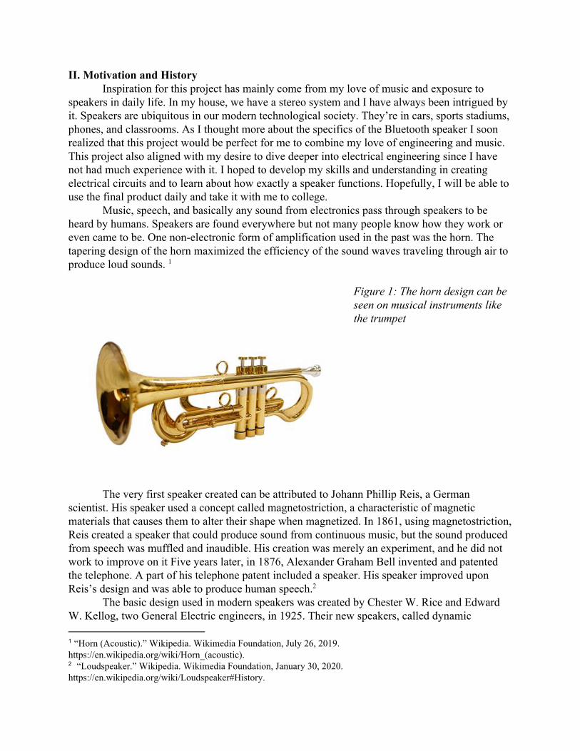
Music, speech, and basically any sound from electronics pass through speakers to be heard by humans. Speakers are found everywhere but not many people know how they work or even came to be. One non-electronic form of amplification used in the past was the horn. The tapering design of the horn maximized the efficiency of the sound waves traveling through air to produce loud sounds. 1
Figure 1: The horn design can be seen on musical instruments like the trumpet
The very first speaker created can be attributed to Johann Phillip Reis, a German scientist. His speaker used a concept called magnetostriction, a characteristic of magnetic materials that causes them to alter their shape when magnetized. In 1861, using magnetostriction, Reis created a speaker that could produce sound from continuous music, but the sound produced from speech was muffled and inaudible. His creation was merely an experiment, and he did not work to improve on it Five years later, in 1876, Alexander Graham Bell invented and patented the telephone. A part of his telephone patent included a speaker. His speaker improved upon Reis’s design and was able to produce human speech. 2
The basic design used in modern speakers was created by Chester W. Rice and Edward W. Kellog, two General Electric engineers, in 1925. Their new speakers, called dynamic
1 “Horn (Acoustic).” Wikipedia. Wikimedia Foundation, July 26, 2019. https://en.wikipedia.org/wiki/Horn_(acoustic). 2 “Loudspeaker.” Wikipedia. Wikimedia Foundation, January 30, 2020. https://en.wikipedia.org/wiki/Loudspeaker#History.

speakers, moved a cone-shaped diaphragm, an electromagnet, and a permanent magnet. For example, looking at figure 2, an electrical signal would be sent through the orange coil to the electromagnet. This would cause the electromagnet to either move towards or away from the permanent magnet. These movements are fast enough that when the electromagnet moves, the cone connected to it will create sound waves. Many improvements have been made on the 3
original dynamic speaker design but the basic concepts remain the same. The Rice and Edward speaker system was soon licensed out to RCA, a radio company. 4
Figure 2: simple diagram of a dynamic speaker 5
An essential part of today’s speakers is the amplifiers. Audio Amplifiers were invented by Lee de Forest and used his previous invention of the triode vacuum tube. This vacuum amplifier was used to make the first AM radios. Most modern amplifiers are based on solid-state transistors like the bipolar junction transistor and the metal-oxide-semiconductor field-effect transistor. Another essential component of a speaker is the crossover, which combines multiple 6
speakers into one cohesive system. It uses filters that allow different speakers to receive different frequencies of sound. It could be used to send low frequencies to a woofer, a speaker engineered to produce good sounding low frequencies. Crossover systems soon came after the invention of
3 “How Loudspeakers Work.” Explain that Stuff, January 9, 2020. https://www.explainthatstuff.com/loudspeakers.html. 4 Mix Staff ⋅ Sep 1, 2007, and Mix Staff. “1925 Chester Rice & Edward Kellogg, General Electric Co. Modern Dynamic Loudspeaker.” Mixonline, September 1, 2007. https://www.mixonline.com/technology/1925-chester-rice-edward-kellogg-general-electric-co-modern-dynamic-loudspeaker-377962. 5 “How Loudspeakers Work.” Explain that Stuff, January 9, 2020. https://www.explainthatstuff.com/loudspeakers.html. 6 “Audio Power Amplifier.” Wikipedia. Wikimedia Foundation, December 23, 2019. https://en.wikipedia.org/wiki/Audio_power_amplifier.

the dynamic speaker. One of the first crossovers was produced by Metro-Goldwyn-Mayer in 1937. It was used by the film industry in movie theatres. 7
Recently, many speakers have been integrated with Bluetooth technology. Research into Bluetooth started in 1989 and took five tech corporations ten years to fully develop. It is a 8
system of standardization that allows electronic devices to communicate with each other wirelessly through a set of frequencies around 2.45GHz. Multiple devices–up to eight–can communicate simultaneously in a system using slightly different frequencies. When a Bluetooth system is established and the devices are capable of sharing information, the system is called a piconet. 9
The core components of modern speakers still remain the same today. But, their complexity and fine-tuning of sound quality go beyond the scope of this project. III. Theory of Operation
Drivers: A speaker driver consists mainly of a voice coil, a permanent magnet structure, a spider, a cone, and a basket. The voice coil is an electromagnet, a coil of wire wrapped around something, usually iron. When electrical current flows through an electromagnet, it acts as a permanent magnet, but when no current flows, it does not interact with magnets. This is because the current flowing through a wire produces a magnetic field.
The electrons that surround atoms have a spin, a form of angular momentum. In most materials, the electrons in the atoms pair up with each other because of their opposite spins, which cancels out the magnetic fields produced by each electron. The spinning of the nucleus of atoms will also create a magnetic field. However, in ferromagnetic materials like iron or nickel, groups of atoms next to each other form domains in which all the atoms are aligned in the same magnetic orientation. Permanent magnets are created by aligning all these domains in the same direction. 10
Unlike permanent magnets, when current is running through the electromagnet the poles of the electromagnet can be flipped by changing the direction of the flow of current. So, the voice coil can either be repelled by or attracted to the permanent magnets. As seen in Figure 3, the voice coil is connected directly to the spider, which is connected to the cone. Rapid movements of the cone will create sound waves that humans can hear. The electromagnet must be repelling and attracting the permanent magnets many times every second to create the sound waves, which means that the current into the voice coil is switching directions rapidly like AC current. 11
7 “Loudspeaker.” Wikipedia. Wikimedia Foundation, January 30, 2020. https://en.wikipedia.org/wiki/Loudspeaker#History. 8 “Bluetooth.” Wikipedia. Wikimedia Foundation, February 10, 2020. https://en.wikipedia.org/wiki/Bluetooth#History. 9 “How Does Bluetooth Work?” Explain that Stuff, January 11, 2020. https://www.explainthatstuff.com/howbluetoothworks.html. 10 “What Is Magnetism? | Magnetic Fields & Magnetic Force.” LiveScience. Purch. Accessed March 19, 2020. https://www.livescience.com/38059-magnetism.html. 11 Harris, Tom. “How Speakers Work.” HowStuffWorks. HowStuffWorks, February 2, 2001. https://electronics.howstuffworks.com/speaker5.htm.

Figure 3: Diagram of a speaker driver 12
Amplifier: An amplifier takes in an electrical signal and boosts it, outputting a larger signal. How much an amplifier boosts the signal is called the gain, which for speaker amplifiers is usually measured in decibels. It can be calculated using the equation ain 0log (P /P )g = 1 10 out in, with being the output power and being the input power. However, merely boostingP out P in 13
the signal is not enough. The amplifier must also be able to amplify all frequencies an equal amount to preserve the initial frequencies. Amplifiers must also maintain the quality of the input signal.
The amplifier used in this project uses an LM386 operational amplifier or op-amp. An op-amp amplifies voltages when used with other electrical components like resistors and capacitors. A basic op-amp has 5 pins: an inverting input, a noninverting input, 2 pins for power, and an output pin. The op-amp has a differential input which means that it takes the difference between two inputs, the inverting and noninverting inputs, as the voltage to be used. This helps with reducing external noise. Ideal op-amps have an infinite input impedance, 14
essentially resistance, so no current will flow through the inputs. Another important characteristic is that the output impedance is 0. In an ideal op-amp, the gain is extremely large, but that is unrealistic and is limited by the power supply voltage. External components help to control the signal and preserve the quality of the signal. To make an op-amp more stable and usable, an Figure 4: op-amp diagram idea called negative feedback is used. A fraction of the output
12 “File:Speaker-Cross-Section.svg.” File:Speaker-cross-section.svg - Wikimedia Commons. Accessed April 26, 2020. https://commons.wikimedia.org/wiki/File:Speaker-cross-section.svg. 13 “Gain (Electronics).” Wikipedia. Wikimedia Foundation, April 27, 2019. https://en.wikipedia.org/wiki/Gain_(electronics). 14 “EEVblog #600 - OpAmps Tutorial - What is an Operational Amplifier?” Youtube.

goes back to the inverting input, which will decrease the voltage difference between the noninverting and inverting pins to almost 0V. This leads to a reduction in noise and a consistent gain of the signal.
Crossover: Typically, commercial speaker systems will use multiple speakers–each designed for certain frequencies–to create better-sounding audio. The crossover splits up the audio into sections of different frequencies. Two types of crossovers exist: passive, and active. Passive crossovers usually consist of capacitors, resistors, and inductors, and they do not need an external power source to operate. All it needs is the audio signal running through it. Active crossovers are more complex devices that allow for easier adjustment of frequency splitting. This project uses a passive crossover because it is cheaper and simpler. 15
A decibel is a standard measure of sound intensity that follows a logarithmic scale. It is calculated using the equation where is the threshold intensity and is(dB) 0log (I/I )I = 1 10 0 I0 I the measured sound intensity. Sound intensity is determined by the power of sound waves per 16
unit area. It is calculated using the equation where is the frequency, is theπ v δ ρcI = 2 2 2 2 v δ amplitude of the sound wave, is the density of the medium the sound wave is travelingρ through, and is the speed of light.c 17
This project uses a 4th order Linkwitz-Riley Crossover. This kind of crossover is standard in commercial speaker systems today. It consists of a high-pass filter section and a low-pass filter section. The high-pass filter lets through frequencies above the cutoff frequency, and the low-pass filter lets through frequencies below the cutoff frequency. For example, in figure 5, the cutoff frequency of a low-pass filter is 250Hz. Right before reaching the cutoff frequency, the loudness of the audio starts to slope downward and is 3 dB quieter at the cutoff than if the filter was not there. Beyond the cutoff frequency, the frequencies will be filtered out more according to the dB per octave value, which in this example is -6. This means that for every doubling of frequency, the decibel value will go down by 6 decibels. 18
Figure 5: low-pass filter frequency graph
15 Harris, Tom. “How Speakers Work.” HowStuffWorks. HowStuffWorks, February 2, 2001. https://electronics.howstuffworks.com/speaker8.htm. 16 “Decibals.” Hyperphysics. Accessed March 20, 2020. http://hyperphysics.phy-astr.gsu.edu/hbase/Sound/db.html#c1. 17 “Sound Intensity.” Wikipedia. Wikimedia Foundation, March 13, 2020. https://en.wikipedia.org/wiki/Sound_intensity. 18 Bohn, Dennis. “Linkwitz-Riley Crossovers: A Primer.” RaneNote 160 (2005).

The Linkwitz-Riley filters use LC filters, which are combinations of inductors and capacitors. Inductors are coils of wire that store energy in magnetic fields when a current runs through them. They have a resistance called inductive reactance that follows the formula
where is the frequency and is the inductance. Inductance is the tendency for aπfLXL = 2 f L 19
conductor to oppose the current running through it. The magnetic field that is created when current travels through a wire changes when the current changes. And, according to Faraday’s Law of induction, this change of the magnetic field will cause a voltage difference across the conductor that goes against the direction of the current. Since inductive reactance is 20
proportional to frequency, a higher frequency will lead to higher reactance, which will lead to less current. Capacitors store energy in an electric field created by two conducting plates when there is a voltage difference across the two plates. Capacitors also have resistance, called capacitive reactance that follows the formula where is the capacitance. Since/(2πfC)XC = 1 C capacitive reactance is inversely proportional to frequency, a higher frequency will lead to a smaller reactance, which will let more current through. Figure 6 is an example of the 4th order 21
Linkwitz-Riley filter. The top section uses capacitors to filter out low frequencies and let high frequencies pass to the tweeter, a speaker designed for high frequencies. The bottom section uses inductors to only let through low frequencies to the woofer.
Figure 6: schematic of a 4th order Linkwitz-Riley filter
The advantage of the Linkwitz-Riley model is that because the gain at the cutoff frequency is -6 dB, the sum of the outputs from the two filters will be 0 dB. This yields a consistent output sound intensity for all frequencies as seen in Figure 7. Other models like the Butterworth model will lead to a louder sound at the cutoff frequency.
19 “Inductive Reactance - The Reactance of an Inductor.” Basic Electronics Tutorials, September 25, 2018. https://www.electronics-tutorials.ws/inductor/ac-inductors.html. 20 “Inductance.” Wikipedia. Wikimedia Foundation, March 16, 2020. https://en.wikipedia.org/wiki/Inductance. 21 “Capacitive Reactance - The Reactance of Capacitors.” Basic Electronics Tutorials, September 2, 2018. https://www.electronics-tutorials.ws/filter/filter_1.html.
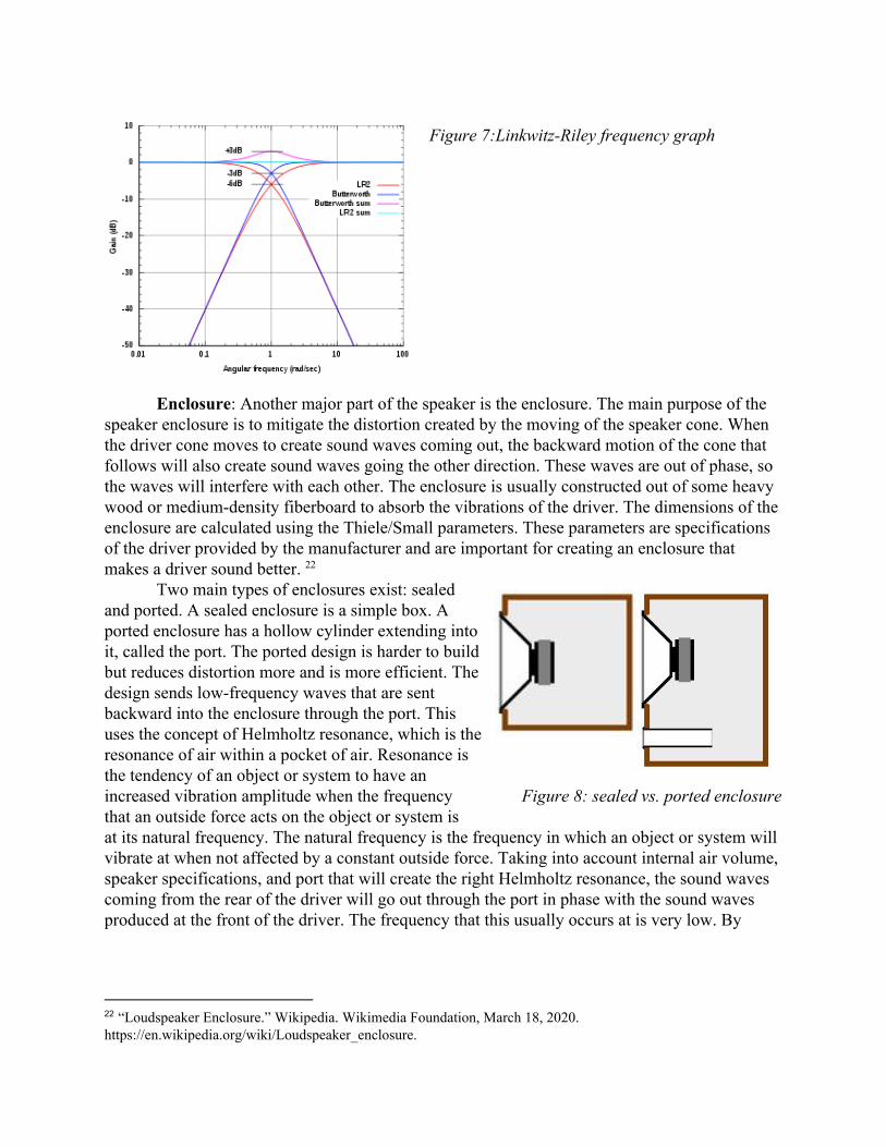
Figure 7:Linkwitz-Riley frequency graph
Enclosure: Another major part of the speaker is the enclosure. The main purpose of the speaker enclosure is to mitigate the distortion created by the moving of the speaker cone. When the driver cone moves to create sound waves coming out, the backward motion of the cone that follows will also create sound waves going the other direction. These waves are out of phase, so the waves will interfere with each other. The enclosure is usually constructed out of some heavy wood or medium-density fiberboard to absorb the vibrations of the driver. The dimensions of the enclosure are calculated using the Thiele/Small parameters. These parameters are specifications of the driver provided by the manufacturer and are important for creating an enclosure that makes a driver sound better. 22
Two main types of enclosures exist: sealed and ported. A sealed enclosure is a simple box. A ported enclosure has a hollow cylinder extending into it, called the port. The ported design is harder to build but reduces distortion more and is more efficient. The design sends low-frequency waves that are sent backward into the enclosure through the port. This uses the concept of Helmholtz resonance, which is the resonance of air within a pocket of air. Resonance is the tendency of an object or system to have an increased vibration amplitude when the frequency Figure 8: sealed vs. ported enclosure that an outside force acts on the object or system is at its natural frequency. The natural frequency is the frequency in which an object or system will vibrate at when not affected by a constant outside force. Taking into account internal air volume, speaker specifications, and port that will create the right Helmholtz resonance, the sound waves coming from the rear of the driver will go out through the port in phase with the sound waves produced at the front of the driver. The frequency that this usually occurs at is very low. By
22 “Loudspeaker Enclosure.” Wikipedia. Wikimedia Foundation, March 18, 2020. https://en.wikipedia.org/wiki/Loudspeaker_enclosure.

using the work done to create the rear-facing sound waves, to cause a louder bass, the system is more efficient than a sealed box. 23
IV. Design A three driver system was chosen for this speaker: two full-range drivers and one subwoofer driver. The full-range speakers will output mid to high range frequencies while the subwoofer will output low-range frequencies. Since the goal of the project is to make a portable speaker, smaller speakers were chosen. The two full-range drivers will be four inches in diameter, and the subwoofer will be 4.5 inches in diameter. Two full-range speakers were chosen to enable sending different sounds to each speaker. The subwoofer was chosen to allow for a nice booming bass. This three-way driver system was also chosen because of its aesthetically pleasing symmetrical design.
The first step in determining the design of the enclosure is whether to use a sealed or ported box. A sealed box design contains no holes, while a ported box design will have a tube-like hole extending into the frame. The ported design was chosen because of its ability to produce more booming sounds. This occurs because, at a certain frequency, the tube will resonate, creating a louder sound, similar to how a bottle will resonate if one blows over the top of it. The frequency that the tube resonates at is determined by the dimensions of the tube and the speaker frame. Another reason the ported box design was chosen was that the Efficiency 24
Bandwidth Product of the speakers were both above 90. Efficiency Bandwidth Product (EBP) = Free Air Resonance (Fs) / Driver Electrical "Q" (Qes) ubwoofer EBP 0Hz/0.5 120s = 6 = ull range EBP 4.4Hz/0.66 27.87f = 8 = 1
For drivers with an EBP below 50, a sealed box is recommended. For drivers with an EBP above 90, a ported box is recommended. Between 50 and 90, either kind of box is suitable. Each speaker will have its hole in the 25
speaker enclosure. Once the ported box design was selected, the equations in figure 3 were used to calculate the internal box volumes and port dimensions. The values of the variables used in the equations are provided by the manufacturer on the datasheets. An online calculator tool was used to aid in these calculations. 26
Figure 9: equations used to find the internal volume and port dimensions
23 “Ported Enclosure Characteristics.” JL Audio Help Center - Search Articles. Accessed March 24, 2020. https://jlaudio.zendesk.com/hc/en-us/articles/204374160-Ported-Enclosure-Characteristics. 24 “Speaker Design Structurally Sound.” Speaker Design RSS. Accessed February 29, 2020. https://sites.psu.edu/speakerdesign/2013/02/07/sealedported-cabinet/. 25“Sealed or Ported Speaker Box Enclosure Calculator.” DIY Audio & Video. Accessed February 6, 2020. https://www.diyaudioandvideo.com/Calculator/SealedVsPortedSpeakerBox/. 26“Speaker Box Enclosure Designer / Calculator.” DIY Audio & Video. Accessed February 5, 2020. https://www.diyaudioandvideo.com/Calculator/SpeakerBoxEnclosure/.

Figures 10 and 11: Finding port size and speaker enclosure volume of the subwoofer and full-range speakers using the online calculator Volume Displacement of the speakers was then calculated. Using these equations:
peaker Driver Displacement .15 Effective Cone Diameter/2) ounting Depth/3S = 3 * ( 2 * M agnet V olume .14 Magnet Diameter/2) agnet HeightM = 3 * ( 2 * M one V olume .14 Effective Cone Diameter/2) Mounting Depth agnet Height max)/3C = 3 * ( 2 * ( − M − X
An online calculator was used to aid this process of finding speaker displacement. 27
27 “Speaker Driver Displacement Calculator Help.” DIY Audio & Video. Accessed February 7, 2020. https://www.diyaudioandvideo.com/Calculator/SpeakerDriverDisplacement/Help/.

Figures 12 and 13: Finding volume displacement of the subwoofer and full-range speakers Finally, the dimensions of the speaker box were found by inputting the values of total internal volume, driver displacement, and port size found previously into an online tool. The box size 28
was found from adjusting the width, height, and depth values until satisfactory. The current planned size of the box will be .in in 0.7in8 × 8 × 2
Figures 14 and 15: Finding the right dimensions for the subwoofer and full-range speakers
28 “Speaker Box Volume Calculator / Designer.” DIY Audio & Video. Accessed February 7, 2020. https://www.diyaudioandvideo.com/Calculator/SpeakerBoxVolume/.

An amplifier circuit will be connected to the speakers to increase the volume of the sound. It will use an LM386 op-amp. Op-amp is short for operational amplifier. It is designed to increase the voltage of the input signal with the help of resistors and capacitors. More complex 29
amplifiers may be used down the line to amplify the sound even more.
Figure 16: schematic of the speaker amplifier The LM386 op-amp contains 8 pins. Pins 1 and 8 are used for gain control, which alters
how loud the input into the amplifier is. In the amplifier schematic of Figure 16, Potentiometer R4 in Figure 10 functions as a variable resistor to adjust the gain of the circuit. Pins 2 and 3 are the pins that receive the input signal to be amplified. Pins 4 and 7 are connected to ground, and pin 6 receives power. Pin 5 outputs the amplified signal that ultimately gets to the speaker. 30
Looking at Figure 16, capacitors C1 and C2 are connected directly to the power from the power supply and are used for decoupling. Typically, power supplies do not produce a steady input voltage, dips and spikes occur frequently. Capacitors take time to fully charge and discharge, so they dampen sharp changes in voltages. If the voltage spikes, the capacitor can absorb the extra energy. If the voltage dips, the capacitor supplies some energy. It essentially smooths out the signal, reducing noise. Capacitor C6 and resistor R2 decouple the audio input. 31
Another component of the speaker is the crossover. The crossover sends different frequencies to the different speakers using high-pass and low-pass filters. The impedance of both drivers, crossover frequency, and crossover type all are taken into consideration for the construction of the crossover. A 4th Order Linkwitz-Riley crossover is planned on being used.
29 Saurabh. “What Is an Operational Amplifier?: Basics For Beginners.” Electronics For You, December 21, 2018. https://www.electronicsforu.com/resources/learn-electronics/operational-amplifier-basics. 30 Agarwal, Tarun, Tarun AgarwalTarun Agarwal, Tarun Agarwal, and Edgefx Technologies Pvt Ltd. “Home.” Buy Electronics Electrical Projects in India, November 29, 2014. https://www.edgefx.in/lm386-audio-amplifier-circuit/. 31Libertec. “Coupling and Decoupling " Capacitor Guide.” RSS. Accessed March 18, 2020. http://www.capacitorguide.com/coupling-and-decoupling/.

The capacitor and inductor values in figure 17 are determined by the driver impedances and crossover frequency. 32
Figure 17: schematic of speaker system crossover
Figure 18: Equations and ratios used to calculate crossover capacitor and inductor values
32 “2-Way Crossover Designer / Calculator Help.” DIY Audio & Video. Accessed February 10, 2020. https://www.diyaudioandvideo.com/Calculator/SpeakerCrossover/Help/.
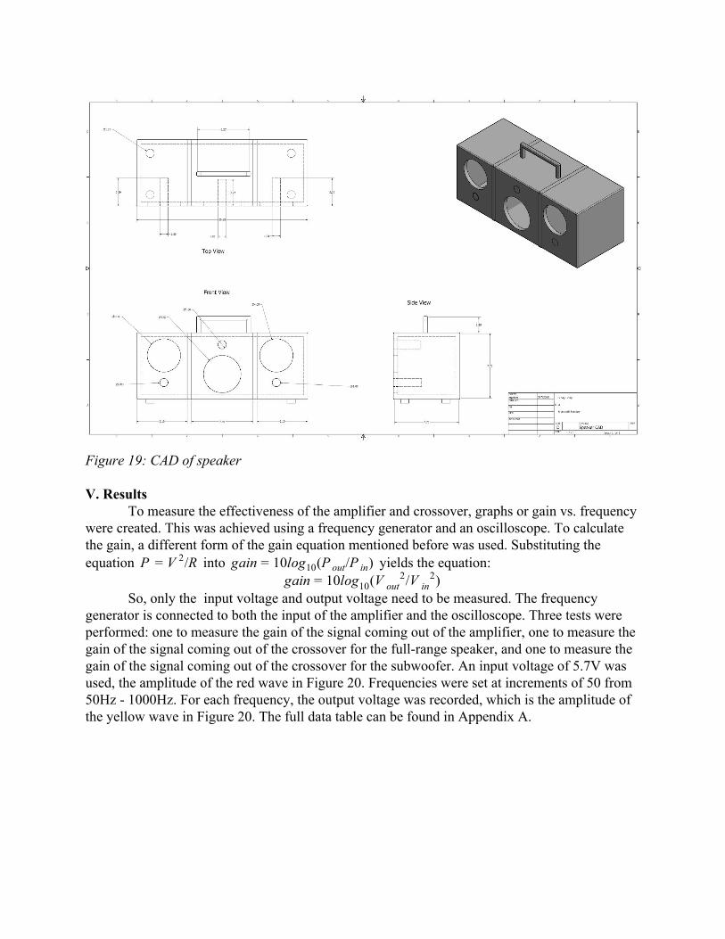
Figure 19: CAD of speaker V. Results
To measure the effectiveness of the amplifier and crossover, graphs or gain vs. frequency were created. This was achieved using a frequency generator and an oscilloscope. To calculate the gain, a different form of the gain equation mentioned before was used. Substituting the equation into yields the equation:/RP = V 2 ain 0log (P /P )g = 1 10 out in
ain 0log (V /V )g = 1 10 out2
in2
So, only the input voltage and output voltage need to be measured. The frequency generator is connected to both the input of the amplifier and the oscilloscope. Three tests were performed: one to measure the gain of the signal coming out of the amplifier, one to measure the gain of the signal coming out of the crossover for the full-range speaker, and one to measure the gain of the signal coming out of the crossover for the subwoofer. An input voltage of 5.7V was used, the amplitude of the red wave in Figure 20. Frequencies were set at increments of 50 from 50Hz - 1000Hz. For each frequency, the output voltage was recorded, which is the amplitude of the yellow wave in Figure 20. The full data table can be found in Appendix A.

Figure 20: An example of what the reading oscilloscope looks like
Figure 21: Gain as a function of frequency using output voltage from the amplification circuit
Looking at figure 21, the gain from the amplifier is consistently around 13dB after the 250Hz mark. This is a substantial amount since a 10dB increase means a sound is ten times more powerful. The consistency of the gain values after 250Hz is another sign that the amplifier is working properly.

Figure 22: Gain as a function of frequency using output voltage from the crossover designated for the full-range driver Figure 23: Gain as a function of frequency using output voltage from the crossover designated for the subwoofer.
For the signal that is sent to the full-range driver, frequencies below 200Hz are filtered out well. Frequencies between 200Hz and the cutoff of 600Hz are boosted but still follow a positive slope up to the cutoff frequency as seen in Figure 22. The peak gain is above 20dB and slowly falls as the frequency gets higher. So in general, the high-pass filtering worked pretty well as it limited the low frequencies and kept the gain of high frequencies fairly consistent.
For the signal that is sent to the subwoofer, in figure 23 frequencies up to 200Hz follow a steep upward trend, which should not be happening. The same pattern can be found at the beginning of figure 21. This leads to a hypothesis that the circuit can not process very low frequencies well. The peak gain is close to 20dB at 200Hz but then falls quickly to the cutoff frequency of 600Hz where the gain is only about 2.5dB. There is a steady decline in gain after the cutoff. This indicates that the low-pass filter does successfully limit the high frequencies, but does not do a good job of keeping the gain of low frequencies consistent. Part of the issue may be the amplifier's ability to process low frequencies as mentioned before.

VI. Conclusion The goal to create a portable Bluetooth speaker was not fully reached, but notable
progress was made. Despite the lack of resources needed and unforeseen circumstances due to the coronavirus, the amplifier is in great shape and the crossover is in a solid condition. Most of the enclosure is cut and the Bluetooth board is not yet fully incorporated into the speaker. Pictures of the current progress of the circuitry and enclosure are in Appendix B. The amplifier increased the sound by 13dB, and the crossover amplified most frequencies to 20dB even though that was not the purpose of the crossover. Ideally, the amplifier would have amplified all frequencies equally including the very low frequencies. It is unclear why the amplifier could not boost the low frequencies as well. Also, the gain vs. frequency graph for the subwoofer would ideally look like figure 5 with a flat line for low frequencies. The graph for the full-range driver looks roughly how it should be.
Overall, the quality of the speaker created through this project does not match commercial speakers. But, it does serve as an example to others who love music or engineering that constructing a speaker for oneself is not an impossible task and is a great experience. Speakers today are ubiquitous. Any device, gadget, or gizmo today can be found with one. Understanding their construction and how they function provides a sense of connection and comprehension. Next Steps
The next step in this project will be to finish the medium density fiberboard frame. The front panel with holes for the speaker cones and the drivers still needs to be cut. Gluing and screwing the pieces would follow. But only some of the panels will be assembled together. The rest will not be permanently set to enable fine tuning of the sound. Another step would be to experiment with polyfill or other enclosure damping materials. These materials are put inside speaker enclosures to further improve the sound quality. Finishing the Bluetooth integration is also a key next step. The project will also need a rechargeable battery connected to an Arduino in order to be portable. Transfering the circuits from breadboards to protoboards with soldering will also be useful.
Once the speaker system is in good shape, a comparison of decibel value between a bare speaker and the speaker system using a sound level meter would be interesting to see.
One path for the project is to make the look and aesthetics better. Sanding down the enclosure for smooth edges, applying a finish to the outside of the enclosure, or even adding LED lights programmed to be in sync with the audio are all possibilities. The overall quality and convenience of the speaker would improve by adding speaker feet and a handle. Integration with an Amazon Alexa or a Google Home API would be an exciting path too. Acknowledgments
I would like to thank Dr. Dann for guiding me through this processing. He answered all my questions and provided me with useful resources. I would not have gotten this far without him. I would also like to thank Joshua Lowe for helping me with my CAD drawings and circuits. A huge thanks also goes out to Mr. Ward and Menlo School for providing me with the many resources available in the incredible Whitaker Lab that allowed me to pursue this project.

VII. Bibliography “Horn (Acoustic).” Wikipedia. Wikimedia Foundation, July 26, 2019.
https://en.wikipedia.org/wiki/Horn_(acoustic). “Loudspeaker.” Wikipedia. Wikimedia Foundation, January 30, 2020.
https://en.wikipedia.org/wiki/Loudspeaker#History. “How Loudspeakers Work.” Explain that Stuff, January 9, 2020.
https://www.explainthatstuff.com/loudspeakers.html. Mix Staff ⋅ Sep 1, 2007, and Mix Staff. “1925 Chester Rice & Edward Kellogg, General Electric
Co. Modern Dynamic Loudspeaker.” Mixonline, September 1, 2007. https://www.mixonline.com/technology/1925-chester-rice-edward-kellogg-general-electric-co-modern-dynamic-loudspeaker-377962.
“Audio Power Amplifier.” Wikipedia. Wikimedia Foundation, December 23, 2019. https://en.wikipedia.org/wiki/Audio_power_amplifier.
“Loudspeaker.” Wikipedia. Wikimedia Foundation, January 30, 2020. https://en.wikipedia.org/wiki/Loudspeaker#History.
“Bluetooth.” Wikipedia. Wikimedia Foundation, February 10, 2020. https://en.wikipedia.org/wiki/Bluetooth#History.
“How Does Bluetooth Work?” Explain that Stuff, January 11, 2020. https://www.explainthatstuff.com/howbluetoothworks.html.
“What Is Magnetism? | Magnetic Fields & Magnetic Force.” LiveScience. Purch. Accessed March 19, 2020. https://www.livescience.com/38059-magnetism.html.
Harris, Tom. “How Speakers Work.” HowStuffWorks. HowStuffWorks, February 2, 2001. https://electronics.howstuffworks.com/speaker5.htm.
“Gain (Electronics).” Wikipedia. Wikimedia Foundation, April 27, 2019. https://en.wikipedia.org/wiki/Gain_(electronics).
“EEVblog #600 - OpAmps Tutorial - What is an Operational Amplifier?” Youtube. Harris, Tom. “How Speakers Work.” HowStuffWorks. HowStuffWorks, February 2, 2001. https://electronics.howstuffworks.com/speaker8.htm.
“Decibals.” Hyperphysics. Accessed March 20, 2020. http://hyperphysics.phy-astr.gsu.edu/hbase/Sound/db.html#c1.
“Sound Intensity.” Wikipedia. Wikimedia Foundation, March 13, 2020. https://en.wikipedia.org/wiki/Sound_intensity.
Bohn, Dennis. “Linkwitz-Riley Crossovers: A Primer.” RaneNote 160 (2005). “Inductive Reactance - The Reactance of an Inductor.” Basic Electronics Tutorials, September
25, 2018. https://www.electronics-tutorials.ws/inductor/ac-inductors.html. “Inductance.” Wikipedia. Wikimedia Foundation, March 16, 2020.
https://en.wikipedia.org/wiki/Inductance. “Capacitive Reactance - The Reactance of Capacitors.” Basic Electronics Tutorials,
September 2, 2018. https://www.electronics-tutorials.ws/filter/filter_1.html “Loudspeaker Enclosure.” Wikipedia. Wikimedia Foundation, March 18, 2020.
https://en.wikipedia.org/wiki/Loudspeaker_enclosure. “Ported Enclosure Characteristics.” JL Audio Help Center - Search Articles. Accessed March

24, 2020. https://jlaudio.zendesk.com/hc/en-us/articles/204374160-Ported-Enclosure-Characteristics.
“Speaker Design Structurally Sound.” Speaker Design RSS. Accessed February 29, 2020. https://sites.psu.edu/speakerdesign/2013/02/07/sealedported-cabinet/.
“Sealed or Ported Speaker Box Enclosure Calculator.” DIY Audio & Video. Accessed February 6, 2020. https://www.diyaudioandvideo.com/Calculator/SealedVsPortedSpeakerBox/.
“Speaker Box Enclosure Designer / Calculator.” DIY Audio & Video. Accessed February 5, 2020. https://www.diyaudioandvideo.com/Calculator/SpeakerBoxEnclosure/.
“Speaker Driver Displacement Calculator Help.” DIY Audio & Video. Accessed February 7, 2020. https://www.diyaudioandvideo.com/Calculator/SpeakerDriverDisplacement/Help/.
“Speaker Box Volume Calculator / Designer.” DIY Audio & Video. Accessed February 7, 2020. https://www.diyaudioandvideo.com/Calculator/SpeakerBoxVolume/.
Saurabh. “What Is an Operational Amplifier?: Basics For Beginners.” Electronics For You, December 21, 2018. https://www.electronicsforu.com/resources/learn-electronics/operational-amplifier-basics.
Agarwal, Tarun, Tarun AgarwalTarun Agarwal, Tarun Agarwal, and Edgefx Technologies Pvt Ltd. “Home.” Buy Electronics Electrical Projects in India, November 29, 2014. https://www.edgefx.in/lm386-audio-amplifier-circuit/.
Libertec. “Coupling and Decoupling " Capacitor Guide.” RSS. Accessed March 18, 2020. http://www.capacitorguide.com/coupling-and-decoupling/.
“2-Way Crossover Designer / Calculator Help.” DIY Audio & Video. Accessed February 10, 2020. https://www.diyaudioandvideo.com/Calculator/SpeakerCrossover/Help/.
“File:Speaker-Cross-Section.svg.” File:Speaker-cross-section.svg - Wikimedia Commons. Accessed April 26, 2020. https://commons.wikimedia.org/wiki/File:Speaker-cross-section.svg.

A. Appendices Appendix A: Output Voltage Measured for Certain Frequencies
Frequency (Hz)
Full-Range Output Voltage (V)
Subwoofer Output Voltage (V)
Speaker Output Voltage (V)
50 0.5 11.2 11.2
100 0.75 20 16.8
150 1.4 33.6 21.2
200 6 52.8 24.2
250 9 38 25.2
300 10 25 24.8
350 12.3 17.6 24.4
400 16.1 12.8 24.8
450 22.4 10.4 24.8
500 33.2 8.8 25.2
550 60 8.4 25.6
600 79.2 7.5 26
650 81.6 7 26.4
700 75.2 6.4 26.8
750 74 5.8 26.4
800 62 5 25.6
850 56 4.7 25.4
900 52 4.4 25.2
950 48 4 25.4
1000 44.8 3.9 25

Appendix B: Pictures Figure XXX: Crossover circuit Figure XXX: Amplification circuit Figure XXX: In progress speaker frame

Appendix C: Parts Used
Part Description What needed for Cost Source
Dayton Audio RS100-4 4" Reference Full-Range Driver 4 Ohm
To Produce Sound $30 Parts-express website
Wavecor SW118WA02 4-1/4" Balanced Drive Paper Cone Subwoofer 8 Ohm
To Produce Sound $65 Parts express website
Resistors, Capacitors, Inductors, Op-Amps, breadboards, wiress
To create amplification and crossover circuits
$0 Whitaker Lab
Batteries To power everything $0 Whitaker Lab
Medium-Density Fiberboard (MDF)
To hold the speakers and make up the frame of the box
$30 Home Depot
Hand Saw To cut MDF $15 Home Depot
Screws To hold the frame together
$0 Whitaker Lab
Handle For picking up the speaker
$5 Parts-express website
Speaker feet For the bottom $10 Parts-express website
Wood glue Extra support to keep MDF in place
$0 Whitaker Lab
Wood Finish To protect MDF and make it look nicer
$0 Whitaker Lab
Polyfill To clean up sound from speakers
$12 Parts-express website
Silicone sealant To seal the speaker box.
$0 Whitaker Lab

Button Speaker On/Off $0 Whitaker Lab
Bluetooth Board To Receive signals via Bluetooth
$26 Parts-express website
Speaker Ports For the Ported Box $20 Parts-express website