Bluetooth Khepera robot control and communication - DIVA
57
Bluetooth Khepera robot control and communication HS–IKI–MD–04–002 Patrick Duchstein Submitted by Patrick Duchstein to the University of Sk¨ovde as a dissertation towards the degree of Master of Science in computer science. September 2004 I certify that all material in this dissertation which is not my own work has been identified and that no material is included for which a degree has already be conferred upon me. Patrick Duchstein
-
Upload
khangminh22 -
Category
Documents
-
view
3 -
download
0
Transcript of Bluetooth Khepera robot control and communication - DIVA
Bluetooth Khepera robot control andcommunication
HS–IKI–MD–04–002
Patrick Duchstein
Submitted by Patrick Duchstein to the University of Skovde as a dissertation
towards the degree of Master of Science in computer science.
September 2004
I certify that all material in this dissertation which is not my own work has been
identified and that no material is included for which a degree has already be
conferred upon me.
Patrick Duchstein
University of SkovdeSchool of Humanities and Informatics
Master’s Dissertation
Bluetooth Khepera robot control andcommunication
Patrick Duchstein
10th November 2004
supervised by Nicklas Bergfeldt

I would like to thank my supervisor Nicklas Bergfeldt for his
supportive work and his very motivating comments. I would also
like to thank Jens Auer for many constructive ideas and
discussions, and my family for giving me mental and financial
support during my stay in Sweden.
Abstract
This thesis aims to provide a solution for wireless control of, and communication withand among Khepera robots, making use of the Bluetooth wireless technology, to allowwireless control of multiple robots in real time. It is based on the foregoing work ofother students who constructed a module for wireless control of Khepera robots overBluetooth, but they were not able to control more than one physical robot at a time.Khepera robots, as well as many wireless solutions to control those, are closely inves-tigated, and an introduction to Bluetooth is given. An implementation of a Bluetoothprotocol stack, which was carried out in the context of this dissertation, and constitutesone of the main parts of this project, is described in detail. The performance of thework discussed throughout this dissertation is evaluated w. r. t. transmission times ofdata over the wireless link, and afterwards compared to other solutions for real-timecontrol of Khepera robots, e. g. a solution to control a Khepera robot over a wirelessradio link. Furthermore, previously simulated experiments with autonomous agents arecarried out on physical robots, to test the quality of the wireless solution. It is shownthat the solution presented here operates much more efficient than any other existingsolution, thus provides a very useful aid for the research community that is experiment-ing with physical robots in general, and real Khepera robots in particular, in order tosimplify research, and allows for a broader spectrum of experiments.
Keywords Khepera, robots, Bluetooth, wireless, radio, multiple robots, control, com-munication
Contents
1 Introduction 11.1 Motivation . . . . . . . . . . . . . . . . . . . . . . . . . . . . . . . . . . . 21.2 Aims and Objectives . . . . . . . . . . . . . . . . . . . . . . . . . . . . . . 2
1.2.1 Aims . . . . . . . . . . . . . . . . . . . . . . . . . . . . . . . . . . . 21.2.2 Objectives . . . . . . . . . . . . . . . . . . . . . . . . . . . . . . . . 3
1.3 Thesis outline . . . . . . . . . . . . . . . . . . . . . . . . . . . . . . . . . . 3
2 Background 42.1 Khepera robots . . . . . . . . . . . . . . . . . . . . . . . . . . . . . . . . . 4
2.1.1 Khepera robot architecture . . . . . . . . . . . . . . . . . . . . . . 42.1.2 Experiments with Khepera robots . . . . . . . . . . . . . . . . . . 6
2.2 Bluetooth on Khepera robots . . . . . . . . . . . . . . . . . . . . . . . . . 72.3 YAKS . . . . . . . . . . . . . . . . . . . . . . . . . . . . . . . . . . . . . . 82.4 Related Work . . . . . . . . . . . . . . . . . . . . . . . . . . . . . . . . . . 8
2.4.1 Wireless robot control . . . . . . . . . . . . . . . . . . . . . . . . . 82.4.2 Khepera wireless interfaces . . . . . . . . . . . . . . . . . . . . . . 92.4.3 Mobile Bluetooth controller . . . . . . . . . . . . . . . . . . . . . . 9
3 Method 113.1 Study and understand the bluetooth specification . . . . . . . . . . . . . . 113.2 Reimplement the Bluetooth communication unit . . . . . . . . . . . . . . 12
3.2.1 Bluetooth Stack . . . . . . . . . . . . . . . . . . . . . . . . . . . . 123.2.2 Minimal or full implementation . . . . . . . . . . . . . . . . . . . . 13
3.3 Performance evaluation . . . . . . . . . . . . . . . . . . . . . . . . . . . . 13
4 Bluetooth 154.1 The Bluetooth layered architecture . . . . . . . . . . . . . . . . . . . . . . 164.2 Radio . . . . . . . . . . . . . . . . . . . . . . . . . . . . . . . . . . . . . . 164.3 Baseband – Link Controller and Link Manager . . . . . . . . . . . . . . . 174.4 HCI . . . . . . . . . . . . . . . . . . . . . . . . . . . . . . . . . . . . . . . 20
4.4.1 HCI command packets . . . . . . . . . . . . . . . . . . . . . . . . . 214.4.2 HCI Event Packets . . . . . . . . . . . . . . . . . . . . . . . . . . . 214.4.3 HCI ACL Data Packets . . . . . . . . . . . . . . . . . . . . . . . . 22
4.5 L2CAP . . . . . . . . . . . . . . . . . . . . . . . . . . . . . . . . . . . . . 234.5.1 State machine . . . . . . . . . . . . . . . . . . . . . . . . . . . . . . 23
v
Contents
4.5.2 Packet format . . . . . . . . . . . . . . . . . . . . . . . . . . . . . . 234.6 RFCOMM . . . . . . . . . . . . . . . . . . . . . . . . . . . . . . . . . . . . 244.7 SDP . . . . . . . . . . . . . . . . . . . . . . . . . . . . . . . . . . . . . . . 26
5 Implementation 285.1 Bootloader . . . . . . . . . . . . . . . . . . . . . . . . . . . . . . . . . . . 285.2 Implementation of the Bluetooth stack . . . . . . . . . . . . . . . . . . . . 29
5.2.1 USART . . . . . . . . . . . . . . . . . . . . . . . . . . . . . . . . . 305.2.2 HCI . . . . . . . . . . . . . . . . . . . . . . . . . . . . . . . . . . . 305.2.3 L2CAP . . . . . . . . . . . . . . . . . . . . . . . . . . . . . . . . . 305.2.4 RFCOMM . . . . . . . . . . . . . . . . . . . . . . . . . . . . . . . 31
5.3 Evaluation and testing . . . . . . . . . . . . . . . . . . . . . . . . . . . . . 325.3.1 Khepera programs . . . . . . . . . . . . . . . . . . . . . . . . . . . 32
6 Results 336.1 Performance . . . . . . . . . . . . . . . . . . . . . . . . . . . . . . . . . . . 33
6.1.1 Serial transmission rate . . . . . . . . . . . . . . . . . . . . . . . . 336.1.2 Comparison of ACL packet types . . . . . . . . . . . . . . . . . . . 346.1.3 Switched roles . . . . . . . . . . . . . . . . . . . . . . . . . . . . . 366.1.4 Polling interval . . . . . . . . . . . . . . . . . . . . . . . . . . . . . 366.1.5 Running two robots at the same time . . . . . . . . . . . . . . . . 37
6.2 Comparison to the Radio Turret . . . . . . . . . . . . . . . . . . . . . . . 376.3 Evaluation of YAKS and the KBU for real robots . . . . . . . . . . . . . . 39
7 Discussion 427.1 Conclusion: Bluetooth for Khepera robots . . . . . . . . . . . . . . . . . . 427.2 Future work . . . . . . . . . . . . . . . . . . . . . . . . . . . . . . . . . . . 437.3 What needs to be done . . . . . . . . . . . . . . . . . . . . . . . . . . . . . 43
A Abbreviations 45
vi
List of Figures
2.1 The Khepera robot . . . . . . . . . . . . . . . . . . . . . . . . . . . . . . . 42.2 Schematic illustration of the Khepera robot . . . . . . . . . . . . . . . . . 52.3 The Khepera robot equipped with a KBU . . . . . . . . . . . . . . . . . . 7
4.1 Bluetooth layers compared to the OSI model . . . . . . . . . . . . . . . . 164.2 Bluetooth connection types . . . . . . . . . . . . . . . . . . . . . . . . . . 174.3 Communication between the lower protocol layers . . . . . . . . . . . . . . 204.4 HCI command packet format . . . . . . . . . . . . . . . . . . . . . . . . . 214.5 HCI event packet format . . . . . . . . . . . . . . . . . . . . . . . . . . . . 224.6 HCI ACL data packet format . . . . . . . . . . . . . . . . . . . . . . . . . 224.7 Packet format for connection-oriented channels . . . . . . . . . . . . . . . 244.8 Packet format for connection-less channels . . . . . . . . . . . . . . . . . . 244.9 Signal packet format . . . . . . . . . . . . . . . . . . . . . . . . . . . . . . 254.10 RFCOMM device types . . . . . . . . . . . . . . . . . . . . . . . . . . . . 254.11 RFCOMM connection- and channel establishment . . . . . . . . . . . . . 264.12 RFCOMM packet structure . . . . . . . . . . . . . . . . . . . . . . . . . . 26
6.1 Baudrate comparison . . . . . . . . . . . . . . . . . . . . . . . . . . . . . . 336.2 Comparison of ACL packet types to the KBU . . . . . . . . . . . . . . . . 346.3 Comparison of ACL packet types to the Khepera . . . . . . . . . . . . . . 356.4 Switched master/slave roles . . . . . . . . . . . . . . . . . . . . . . . . . . 366.5 Packet transmission with two Khepera robots running . . . . . . . . . . . 376.6 Comparison of the KBU to the Radio Turret and a wired serial connection 406.7 ANN of a Braitenberg vehicle . . . . . . . . . . . . . . . . . . . . . . . . . 406.8 Runtime before having to recharge the batteries . . . . . . . . . . . . . . . 41
vii

List of Tables
4.1 ACL packet types . . . . . . . . . . . . . . . . . . . . . . . . . . . . . . . . 184.2 SCO packet types . . . . . . . . . . . . . . . . . . . . . . . . . . . . . . . . 19
5.1 HCI Initialization . . . . . . . . . . . . . . . . . . . . . . . . . . . . . . . . 31
6.1 Bluetooth transmission times . . . . . . . . . . . . . . . . . . . . . . . . . 386.2 Radio turret transmission times . . . . . . . . . . . . . . . . . . . . . . . . 396.3 Direct serial transmission times . . . . . . . . . . . . . . . . . . . . . . . . 39
viii

1 Introduction
Autonomous agents gather an increasing importance in today’s society and research.Among the major topics of interest is communication with and between agents, whichputs an agent into a position to perform even more complicated tasks than it wouldbe able to do on its own. Billard & Dautenhahn (1997), for example, study a teacher-learner situation where a robot communicates information about the inclination it sensesto another robot; Billard, Ijspeert & Martinoli (1999) describe experiments carried outin simulation and on physical robots, where robots learn the locations of objects in anenvironment and communicate those to other robots. The impact of implicit and explicitcommunication between autonomous agents on their performance was investigated byBalch & Arkin (1994), coming to the conclusion that explicit communication offers asignificant benefit to the performance in tasks where little implicit communication isoffered. Easton & Martinoli (2002) study different communication schemes and thecollaboration of robots on a task where two agents have to cooperate on pulling a stickout of the ground, observing that the use of explicit communication offers significantadvantages in terms of performance.
Carrying out research on physical robots very often requires a complicated and expen-sive setup. The requirement of a constant power source and cables to have a permanentconnection to a separate computer which analyzes sensor data and controls the robotmight be a challenging task to fulfill. Whilst several solutions for a constant powersupply exist (see Martinoli, 1999), robots in many cases still have to be wired to a con-trol station, as long as they are not controlled by an on-board computer. Wiring isdifficult, especially in scenarios with multiple robots, since rotary and flexible cable con-nections have to be used in most cases, apart from the fact that cables may influence anagent’s movements. Hence, physical robots need some form of wireless communicationto simplify setting up scenarios in the real world, and to make efficient use of them.
This thesis deals with the problem of wireless communication between mobile andautonomously acting agents. Small mobile robots, called Khepera robots, are equippedwith a communication module which performs wireless communication over Bluetooth.
Several problems arise when trying to fulfill this task:
Performance To control an autonomous agent throughout time, it is indispensable toenable the controlling solution to control the agent in real time. Thus, the latencybetween sending data to the agent and the agent receiving this data has to be aslow as possible.
Bandwidth To be able to control multiple agents at the same time, the bandwidth onthe controlling host has to be broad enough to support this task.
1
1 Introduction
These factors matter especially in the case that global communication is used, i. e.communication to or among multiple agents at the same point in time.
1.1 Motivation
The motivation for this project stems from the lack of an efficient and reliable wirelesscommunication module for Khepera robots. The standard solution that is used by themajority of researchers for wireless communication among these robots, the K-Team Ra-dio Turret, was observed to have a long transmission latency, and to exhibit transmissionerrors (e. g. Kubık, 2003). Furthermore, a lot of research that has been done with theseautonomous agents was based on experiments carried out in simulation only (e. g. Bajaj& Ang Jr., 2000; Gadanho, 2003), most probably due to too complicated or expensivesetups for physical robots. This work tries to help making experiments with real robotseasier for the research community.
Several solutions existed at the time this thesis was written, but none was able tocontrol more than one robot equipped with additional modules in real time. A detailedanalysis of some of the other solutions will be done in section 2.4 on page 8. This thesisis mainly based on the master’s dissertations of two former students at the University ofSkovde, written in 2002 (Eriksson, 2002; Karvosenoja, 2002). Within these dissertations,the construction of a bluetooth module suited for the Khepera robots is discussed, andseveral prototypes were constructed. In Karvosenoja (2002), one of the aims declaredas Possibility to control at least 4 robots at the same time via Bluetooth from the RadioBase Station was not fully met since the whole solution was too slow – hence it wasonly possible to control one robot at the same time. Several attempts were carried outto improve the overall speed of the Khepera Bluetooth Unit (KBU) (Karlsson, 2003;Kostamo, 2003), but all of them failed for completion. Another attempt to improve thespeed is described within this dissertation.
1.2 Aims and Objectives
1.2.1 Aims
The project described in this thesis is basically composed of two aims. The first one is tofind out whether the bluetooth system is able to control more than one Khepera robotat a time. If it is not, try to find causales for this. The second aim consists of providinga basis for Khepera robots to directly communicate with each other over Bluetooth,without the need for a separate controlling base station.
The expected outcome of the project is to have a solution for wireless real time controlof multiple Khepera robots, being controlled exactly the same way as wired robots,without the need for software adaptations, thus making further research using theserobots easier w. r. t. verification of simulated scenarios on physical robots. Furthermore, astep towards direct robot-to-robot communication over Bluetooth will be done, allowingfor fully autonomous, communicating robots.
2

1 Introduction
1.2.2 Objectives
The objectives of this thesis stem from a more detailed analysis of the aims, includingan evaluation of the foregoing work, and some basic ideas on the approach that is to beapplied.
To meet the aims mentioned in section 1.2.1 on the page before, several objectiveshave to be achieved.
• Study and understand the bluetooth specification. Since the specification is a doc-ument comprising of more than 1000 pages with a lot of cross-references, a goodunderstanding of what Bluetooth is and how it works is a basic requirement.
• Partially reimplement and extend the bluetooth communication unit on the robots,make it conform to standards and controllable by a bluetooth dongle. To enablewireless communication over Bluetooth with the Khepera robots without com-plication, and to enable direct robot-to-robot communication at all, the softwarerunning on the KBU has to be reimplemented.
• Evaluate the performance of the implementation. Timing measurements of trans-mission rates have to be performed to verify that the solution works as expected.
• Check how the simulator YAKS performs on real robots by applying simulatedsoccer-playing robots to real robots. Do some empirical tests on how previouslysimulated robots work in reality.
1.3 Thesis outline
The remaining part of this dissertation is structured as follows. In chapter 2, the back-ground of this thesis is presented, along with some samples of previous work. In chapter3, different approaches for achieving the aims are compared. Chapter 4 focuses on adetailed explanation of what Bluetooth is and how it works, and in chapter 5 the resultsare presented. Chapter 6 then sums up the outcome and the main contribution of thisthesis, and contains suggestions for further work.
3

2 Background
2.1 Khepera robots
Stemming from Brooks (1991) claim for situatedness and embodiment of autonomousagents, and the fact that carrying out robot experiments in a simulated environmentoffers many advantages w. r. t. simplicity of setting up experiments and the time neededto carry them out, there is a need for the existence of a robot which is easily adaptableto a simulated scenario. The alternative, to carry out robot experiments in simulationonly and not evaluating them in reality, typically involves plenty of simplifications ofthe real world, for the sake of performance. Furthermore, the postulations mentionedabove are violated in this case. Brooks (1992) points out the danger of trying to solveproblems in simulation which never appear in the real world with a physical robot; healso states that experiments which work very well on simulated robots in many cases failwhen carried out in the real world, due to differences in real world sensing and actuation.
Therefore, and due to the fact that no general, and robust miniature-sized robotarchitecture was available at low cost, the Khepera robot was introduced (Mondada,Franzi & Ienne, 1994). Compared to other physical robot architectures, it is availableat an affordable price, and much more convenient to use. Its general and extendible,but for a potential user still simple architecture makes it suitable for a lot of differentdemands when experimenting with robots. Thus, Khepera robots provide a good basefor doing research with physical robots, giving more research groups the possibility touse real robots for their manifold experiments.
Figure 2.1: The Khepera robot
2.1.1 Khepera robot architecture
The Khepera robot, shown in figure 2.1, has a cylindrical shape, measures 55 mm indiameter, 30 mm in height, and weighs 70 g. It is powered either by a cable connection
4
2 Background
or by four on-board recheargable batteries which allow it a maximum lifetime of 40minutes before having to be recharged.
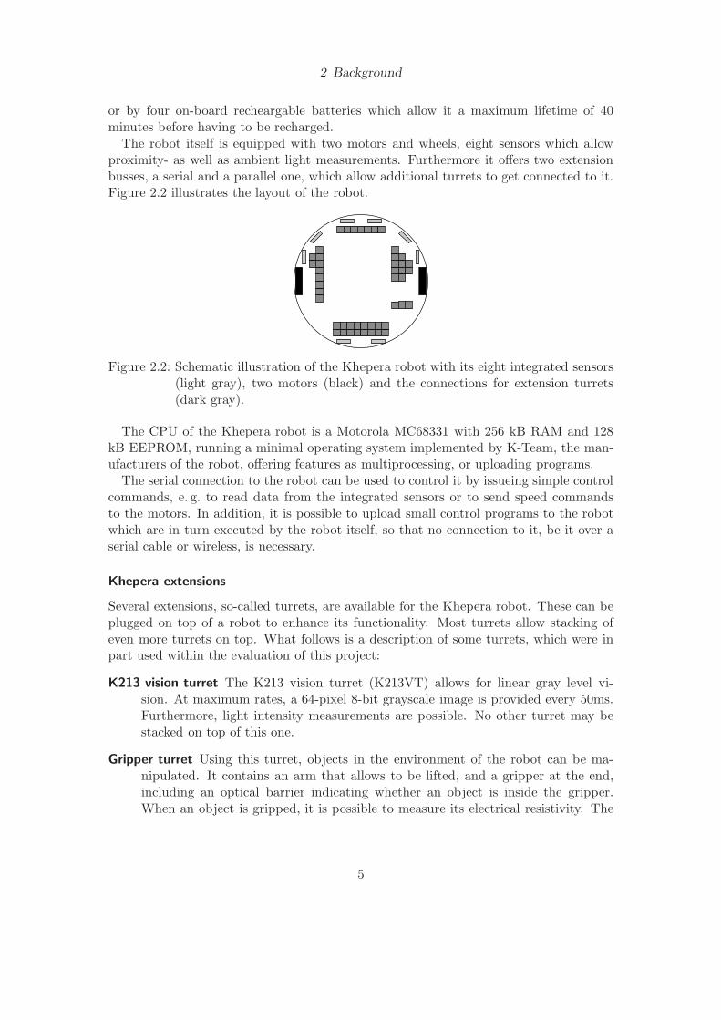
The robot itself is equipped with two motors and wheels, eight sensors which allowproximity- as well as ambient light measurements. Furthermore it offers two extensionbusses, a serial and a parallel one, which allow additional turrets to get connected to it.Figure 2.2 illustrates the layout of the robot.
Figure 2.2: Schematic illustration of the Khepera robot with its eight integrated sensors(light gray), two motors (black) and the connections for extension turrets(dark gray).
The CPU of the Khepera robot is a Motorola MC68331 with 256 kB RAM and 128kB EEPROM, running a minimal operating system implemented by K-Team, the man-ufacturers of the robot, offering features as multiprocessing, or uploading programs.
The serial connection to the robot can be used to control it by issueing simple controlcommands, e. g. to read data from the integrated sensors or to send speed commandsto the motors. In addition, it is possible to upload small control programs to the robotwhich are in turn executed by the robot itself, so that no connection to it, be it over aserial cable or wireless, is necessary.
Khepera extensions
Several extensions, so-called turrets, are available for the Khepera robot. These can beplugged on top of a robot to enhance its functionality. Most turrets allow stacking ofeven more turrets on top. What follows is a description of some turrets, which were inpart used within the evaluation of this project:
K213 vision turret The K213 vision turret (K213VT) allows for linear gray level vi-sion. At maximum rates, a 64-pixel 8-bit grayscale image is provided every 50ms.Furthermore, light intensity measurements are possible. No other turret may bestacked on top of this one.
Gripper turret Using this turret, objects in the environment of the robot can be ma-nipulated. It contains an arm that allows to be lifted, and a gripper at the end,including an optical barrier indicating whether an object is inside the gripper.When an object is gripped, it is possible to measure its electrical resistivity. The
5

2 Background
Gripper Turret offers connections of the Khepera extension bus towards the top ofit, to allow for other turrets to be used at the same time.
Radio turret The Radio Turret provides a Khepera robot with communication options;the robot can be controlled by a Radio Base Station or directly communicate withother Radio Turrets. The maximum transmission rate offered by the turret is9600 baud. Due to the fact that only a very low baudrate is offered, the turretis unusable for real time sensor evaluation and control of Khepera robots. Otherextension units may be stacked on top of the Radio Turret.
K2D video turret If enhanced video acquisition is required, this turret offers a 2D pic-ture of the environment at high quality. A separate cable connection to the turretis necessary to view the pictures. This turret is a top turret, i. e. no other turretsmay be stacked on top of it.
Wireless camera vision turret More possibilities w. r. t. video and sound are providedby this turret, which allows wireless transmission of video and audio data directlyfrom the turret to an external receiver, which in case may be connected to a videograbber and an audio input on a separate computer. In contrast to the K2D VideoTurret, it allows a robot to move autonomously without the need for rotating,wired contacts. This turret is a top turret.
2.1.2 Experiments with Khepera robots
A lot of researchers make heavy use of the robot described here. One example arethe experiments described by Nolfi & Parisi (1995), where a Khepera robot equippedwith a gripper module was trained, using the genetic algorithm technique (Holland,1975) and Artificial Neural Networks (ANNs) (McCulloch & Pitts, 1943), to explore anenvironment avoiding walls, pick up objects with the gripper module, and drop themoutside of the arena. This experiment was carried out in simulation in the first place,and then downloaded and evaluated on a physical Khepera robot.
Floreano & Mondada (1998) carried out a series of experiments to test ANNs interms of its adaptation capabilities to new conditions. In the first set of experiments,a Khepera robot is trained to move around in a maze, avoiding walls, using techniquesof evolutionary robotics (Cliff, Harvey & Husbands, 1993); the underlying ANN is thentested on a bigger robot with similar features, the Koala robot, and re-trained to adaptto the new circumstances, e. g. the different size of the robot, and a differing, but similar,sensor placement. In the second set of experiments, a Khepera robot with a dischargingbattery is placed inside an arena containing a light tower and a recharging area; the taskof the robot consists in moving within the arena – to achieve that it had to rechargeits batteries periodically. The environment was then re-arranged and the robot had toadapt to the new circumstances. These experiments were entirely carried out on physicalrobots.
6

2 Background
2.2 Bluetooth on Khepera robots
This section describes the foregoing work on the KBU. The motivation of the wholeproject was to produce a general Bluetooth turret which can be used on all differentkinds of robots, as long as they are controlled by a RS232, Universal AsynchronousReceiver/Transmitter (UART) or Universal Serial Bus (USB) interface. Therefore twostudents described the design of such a turret within their Master dissertation (Eriksson,2002; Karvosenoja, 2002); furthermore, throughout their projects, the hardware wasconstructed, and several prototypes were built. This turret, the Bluetooth General Board(BTGB), which was also used for the project this dissertation is about, offers an externalRS232-, as well as a USB-connection to directly connect the Bluetooth host controller toa host, e. g. a PC, to use the turret as a type-1 device. Furthermore, a microcontrolleris integrated to allow using the BTGB as a type-2 device (see section 4.6 on page 24 fora description of the different device types).
The KBU, that is, the BTGB connected to a Khepera robot (see figure 2.3), connectsone of the UART controllers of the integrated Microcontroller Unit (MCU) to the serialpins of a Khepera robot. Thus, the KBU is a type-2 device, which receives Kheperacommands transmitted over the Bluetooth wireless link from a computer and transfersthose over the serial connection to the robot. In turn, it receives answers from the Khep-era and transmits them back to the computer. Connections for the Khepera extensionbus are offered towards the top of the turret to allow for other turrets to be stacked ontop of the KBU.
Figure 2.3: The Khepera robot equipped with a KBU
The KBU’s main part consists of an ATMEL ATMega128L MCU, which is able to actas a Bluetooth host. One of its UART controllers is connected to an Ericsson ROK 101007 Bluetooth device, which forms the Bluetooth host controller and is physically placedon top of the MCU. Of the UART-pins offered by both ICs, only the serial input- and
7
2 Background
output-pins are connected to each other, control pins, which are mandatory to enableflow control between the devices, are not connected.
Although the KBU prototypes worked very well w. r. t. connecting to a robot andcontrolling it, the transfer rate between the controlling PC and the Khepera robot wasvery low, i. e. it was impossible to control more than one robot in real time; no clearreason for this was found at first.
Several attempts were carried out to improve the data throughput, based on thesuggestions of the constructors. The Bluetooth-stack was replaced by a self-implemented,very specific and efficient one, directly integrated in Yet Another Khepera Simulator(YAKS) (Carlsson & Ziemke, 2001), carried out by a student in his spare time; thisslightly improved the transmission rate, but did not provide a final solution. In a furtherstep, the RS232 connection to the BTGB was replaced by a USB connection (Karlsson,2003; Kostamo, 2003); this project was not finalized due to problems with the USBdriver, discovered in a late stage of the project. The next step consisted in changing theBluetooth link type, using an Synchronous Connection-Oriented (SCO) link instead ofan Asynchronous Connection-Less (ACL) link to make use of a high synchronous datatransmission rate in both directions; the implementation was never completed.
2.3 YAKS
Yet Another Khepera Simulator (YAKS) is a simulation environment for Khepera robots,developed by members of the school of Humanities and Informatics at the University ofSkovde. Its main advantages lie in efficiency, and the focus on Evolutionary Algorithmsand ANNs. It is easy to adapt to new scenarios, and therefore used by many researchersfor simulation of their own experiments, mainly within the area of evolutionary robotics(Cliff et al., 1993). The simulator runs on several operating systems, and provideseither 2- or 3-dimensional visualization capabilities, as well as a non-visual simulationmode to carry out experiments very fast. Control of physical robots to verify simulatedexperiments is integrated, originally implemented to make use of wired physical robotsand the K-Team Radio Turret.
2.4 Related Work
2.4.1 Wireless robot control
Feng, Borenstein & Wehe (1996) present a Wireless Development System for mobilerobots, consisting of three main components: a joystick interface to allow remote controlover a robot’s components while it is running; a low-cost radio control system, usuallyused in model aircrafts, was used for the wireless transmission of the joystick signals. Awireless computer connection, provided by a radio modem, which operates at a serialtransmission rate of 19200 baud, to allow software updates on the robot and externalcomputerized control. Finally, the system offers a video transmitter on the robot, as
8
2 Background
well as an adequate receiver on the other end. The publication also discusses a wiredalternative for remote robot control.
A robot equipped with an Institute of Electrical and Electronics Engineers (IEEE)802.11b interface (wireless LAN) was developed by Nguyen, Pezeshkian, Raymond,Gupta & Spector (2003), given the task to explore and map an environment. To maintaina connection to an operator’s console, several relay robots were following the lead robotand stopped at certain positions where the quality of the wireless link dropped belowa predefined threshold, i. e. the communication channel was about to get disconnecteddue to far distances.
2.4.2 Khepera wireless interfaces
Besides the Radio Turret for Khepera robots, engineered and manufactured by K-Team,there exists another solution for wireless Khepera control and communication, devel-oped during a student research project at the University of Paderborn, and introducedby Ruping, Loffler, Odenbach & Ruckert (1999), which based on infrared communica-tion using the fieldbus system CAN between the Khepera robots and a master device,mounted on top of an arena. The master device also acts as a repeater, to enable directcommunication between Khepera robots. The system allows transmission rates of up to100kbps. Since the master device’ serial interface only could be connected to a control-ling computer at a transmission rate of 9600bps, it was not suited to control more thanone Khepera robot in real time.
An extension turret for the Khepera robot allowing it to be controlled over Bluetoothwas engineered at the Fachhochschule Regensburg, Germany1. A general Bluetoothcontroller board manufactured by INSYS Microelectronics was modified to plug ontoa Khepera robot’s extension bus. The module does not offer connections for furtherextension turrets to be plugged on top of it, and is thus unusable for more than barecontrol and sensor evaluation of a Khepera robot equipped only with its integratedsensors. The KBU, in contrast, offers the possibility to plug further extension turretson top of it.
Another infrared communication module for the Khepera robot is proposed in (Mar-tinoli, Franzi & Matthey, 1997). It allows selective and explicit communication amongmultiple robots in real time, at a transmission rate of almost 20 kb/s. The main drawbackof the module is a very low range of coverage in practice, around 15cm. Furthermore, itdoes not allow controlling a Khepera robot from an external controlling computer.
2.4.3 Mobile Bluetooth controller
A distributed multi-robot system designed to solve a team-based search and destroytask is presented in (Barnhard, McClain, Wimpey & Potter, 2004; McClain, Wimpey,Barnhard & Potter, 2004). Two robots were given the ‘Honeybee task’, where one robothas to explore an environment to find an object, and then lead the other robot to its
1http://www.insys-tec.de/pdf/i-modul bluetooth.pdf (last visited July 2004). Regrettably, no furtherinformation was published on this module.
9
2 Background
location solely by communicating its location. The robots were equipped with handheldPCs which exhibited Bluetooth functionality. Using the Bluetooth serial port emulationRFCOMM, the first robot transmitted its coordinates within the environment to theother robot. In a second phase of the project, multiple robots were given the task tolocate an object, and the first robot to find it communicates its position to all otherrobots, which should then also move there.
The following work is referenced in this dissertation since the underlying hardware usedcomplies in part with the hardware used throughout this project; the task consisted inevaluating Bluetooth for sensor networks (Leopold, Dydensborg & Bonnet, 2003). Sen-sor networks provide wireless distributed network access to intelligent sensors, controls,and processors that are embedded in equipment, facilities, and the environment. Thepublication discusses how far the Bluetooth wireless technology is suited to meet theneeds of sensor networks, e. g. the ability of inter-communication among sensors for col-laborative processing of signals, or routing issues. For evaluating the technology, anAtmega128L was used as MCU, to connect the Bluetooth device, an Ericsson ROK 101007, to a sensor. A minimal Bluetooth stack had to be implemented on the MCU, on thehigher protocol layers also providing for routing and (re-)connection issues within largernetworks. The performance of the implementation was evaluated w. r. t. maximum datathroughput and energy consumption.
10

3 Method
This chapter deals with different steps to meet the objectives mentioned earlier.The main idea behind this project consists in the replacement of the BTGB on the side
of the controlling computer with a Bluetooth dongle, connected over a USB interface,and to utilize a Bluetooth stack on the computer that comes with the dongle or theoperating system, which in all cases should previously have been verified to run stableand efficient. Hence, to eliminate one bottleneck of the Bluetooth wireless connectionw. r. t. transmission speed.
3.1 Study and understand the bluetooth specification
The Bluetooth specification (Bluetooth SIG, 2001), that is, the standard definition ofwhat Bluetooth is and how it works, is a document comprising of more than 1000 pages;plus further standard descriptions for RFCOMM in ETSI (1997). To accomplish a goodgeneral understanding of it, and all the details necessary to proceed with the otherobjectives, three methods may be applied.
Read the specification only Since the Bluetooth specification provides the definition ofBluetooth, including all details, attentively reading it is one way of understandingwhat Bluetooth is.
Secondary literature A lot of secondary literature has been written about Bluetooth(e. g. Bray & Sturman, 2001; Miller, Bisdikian & Siep, 2001), partly by the peoplewho helped developing the Bluetooth standards documents. These publicationsprovide a deeper insight into Bluetooth functionalities and additional facts thatare not mentioned in the standard.
Consult other people Many researchers and programmers are actively working with theBluetooth wireless technology and thus have a good understanding of it. So deeperinsights may be gained by consulting them.
Throughout this project, the method used for gaining knowledge about Bluetooth wasmainly a combination of intensively studying the Bluetooth specification and consultingother people. The standard document was used as main reference, whilst other peoplewere consulted when questions arose, such as unclear terms in the specification. Sec-ondary literature was not consulted very frequently, due to the fact that it does in mostcases not contain more information that is of use for the implementation; this probablystems from the fact that all secondary literature concerning Bluetooth is based on theprimary literature, i. e. the standard specification documents.
11

3 Method
3.2 Reimplement the Bluetooth communication unit
Two main questions arise when doing a reimplementation of the Bluetooth stack that isto be used on the BTGB.
1. Several Bluetooth stacks were developed by other people for to be used on embed-ded devices, so it has to be deliberated about adapting those to the specific needsfor this project, or do a completely new implementation from scratch.
2. The choice between a minimal implementation and a fully standards compliantBluetooth stack has to be made.
3.2.1 Bluetooth Stack
Since Bluetooth is a fully standardized technology, including the transport layer thatis used for communication between the Bluetooth host and the host controller, it ispossible to port the stack, one of the main software components within a Bluetoothdevice, between differing platforms. One of the main prerequisites for porting is theavailability of the source code. Some of these stacks were closer investigated for portingcapabilities within this project.
BlueZ1 BlueZ, the official Linux Bluetooth protocol stack, been implemented for thekernel of the free operating system linux, thus, also the stack is freely available includingthe source code. The stack is stable, well-structured and efficient, but due to its codesize, its very huge memory requirements, and its close relation to the Linux kernel, it isnot suited to run on the MCU of the BTGB.
BTnode2 BTnode is a project which offers a freely available general Bluetooth con-troller, which uses the hardware identically to the BTGB w. r. t. the MCU and theBluetooth device; the only exception is a larger amount of memory supplied with it.Furthermore, the MCU is connected to the Bluetooth device in a different way, flowcontrol between the devices is enabled, in contrast to the BTGB. A Bluetooth stackincluding the source code is also provided by the project. The two differences mentionedabove form the limiting factors for the use of the stack within the BTGB: the amount ofmemory available is smaller, and no flow control between the modules is available; thus,deep going changes within the source code of the stack of BTnode would be necessaryto make use of it on the BTGB.
Since no Bluetooth stack could be found best suiting the needs for this project, thedecision was taken to implement it from scratch. The reimplementation is based on thesource code provided by the foregoing work on the KBU, which already provided basicfunctionalities.
1http://www.bluez.org (last visited August 2004)2http://www.btnode.ethz.ch/ (last visited August 2004)
12

3 Method
3.2.2 Minimal or full implementation
A minimal implementation of a Bluetooth stack offers the capabilities to do basic commu-nication with other Bluetooth entities also offering a minimal stack, specifically adaptedto fulfill certain needs; it follows the standards specification only as little as minimallyrequired. A full implementation in contrast follows the standards and is able to interactwith other Bluetooth entities without further adaptations.
Implementing a minimal Bluetooth stack can be attained in a very small amount oftime; a very small and, due to it’s problem-specific style, efficient solution is achievable.
Problematic within a minimal implementation for the BTGB is the requirement foran adapted Bluetooth stack on the end of the controlling computer. Hence, no stackprovided with Bluetooth hardware or an operating system could be used; all applicationsthat make use of the BTGB would have to be changed as well. Furthermore, to make useof a USB Bluetooth dongle to communicate with the BTGB instead of another BTGB,and to allow for the serial emulation to take place without the need for application-sideadaptations, a fully standards compliant Bluetooth stack is a requirement for the successof this project, to provide a Bluetooth communication module which is suited for use inother research projects on real robots.
3.3 Performance evaluation
The performance of the KBU can be evaluated in different ways. One way is to measurethe time for round-trips of data packets of different size, originating from a controllingcomputer, being sent to the Khepera, and transmitted back. This way, one gets a globalview on the whole solution’s performance. A drawback is that only long transmissionpaths with transmission channels of different types can be measured; no detailed datafor each transmission channel on its own can be acquired. Though, the acquired data isvery easy to get in touch with real data that is being sent to and received from the robotwhen using it for research purposes. Furthermore, influence of the baudrate applied atall serial connections can be measured.
Another way of evaluating the performance of the KBU consists of measuring thetime packets of different sizes needed for a round-trip from a controlling computer tothe KBU and back. More detailed insight into the performance of the BTGB itself canbe gained this way; the Khepera robot is then completely left out of the evaluation,which is unproblematic since it is not in the hand of the programmer to increase thetransmission speed of the serial channel besides predefined values.
A third way of performance evaluation is to use engineering tools, such as an oscillo-scope, for detailed measuring of packet transmission times on all transmission channels.A very detailed picture of the KBU and all used equipment is acquired by applying thismethod, however, the effort needed to carry it out is very high.
To compare different controlling solutions for the Khepera robot and get a pictureof how fast the KBU is, timing comparisons can be carried out for different connectiontypes, such as the KBU and a direct serial connection to the robot.
13
3 Method
Within this project, a combination of the first two and the fourth method mentionedwill be used for performance evaluation in the first place, since the most meaningfulfactor that matters when carrying out experiments on a physical robot is the transmissionspeed between a controlling computer and a Khepera robot. To adjust parameters thatinfluence the performance, such as the packet type used for wireless communication, itis furthermore necessary to get a deeper insight into the transmission speed betweenthe BTGB and a controlling computer. Furthermore, a comparison of transmissiontimes for different connection types will be carried out. If it turns out that the KBU’soverall transmission times are too slow, more detailed measurements will be done for alltransmission channels.
14
4 Bluetooth
This chapter gives an overview over the Bluetooth wireless technology; however, manydetails have been left out for to simplify and shorten these explanations.
Bluetooth wireless technology is a worldwide specification for a small-form factor,low-cost radio solution that provides links between mobile computers, mobile phones,other portable handheld devices, and connectivity to the Internet. Its main use lies inthe replacement of cables over short distances. Bluetooth was invented in 1994 by L.M.Ericsson. Its name stems from Harald Blatand I, the king of Norway and Denmark inthe middle 900s.
The contents of this section are primarily based on the Bluetooth specification stan-dard (Bluetooth SIG, 2001) and, the standard for emulation of serial ports in GSM TS07.10 (ETSI, 1997).
The Bluetooth wireless technology has several main properties:
Wireless Bluetooth is a wireless technology, i. e. providing the opportunity to commu-nicate without cables.
Open standard The standard itself is open, i. e. available at no cost. It is developed,published and promoted by the Bluetooth SIG.
Certification Certification for devices stating that they are fully compliant to the stan-dard is available, though not required by the Bluetooth Special Interest Group(SIG). This is important for companies selling Bluetooth-enabled products to beable to interact with other Bluetooth entities without complications.
Low cost Bluetooth communication modules are available at a very low cost. The fre-quency spectrum used for communication is free to use without licensing costaround the whole world.
Audio and data Different communication modes exist for transferring audio and dataover the wireless link. This stems from different demands: when transferring audiosignals, a constant data rate is required to suppress delays, whilst an error-free andguaranteed link has to be provided for data communication.
Security Basic cryptographic mechanisms for to send encrypted data over the wirelesslink are provided by the technology.
No transmission errors The Bluetooth wireless link for transmission of data can beconfigured to detect and even correct errors that occur during the wireless datatransmission, thus provide a totally error-free link. The prerequisites for this areestablished in the baseband (see section 4.3 on page 17).
15

4 Bluetooth
Low power The power consumption of a Bluetooth integrated circuit is usually verylow, due to a very low transmitting power.
Robustness As a result of the physical channel definition by hopping through 79 RadioFrequency (RF) channels (see section 4.3 on the next page), the Bluetooth wirelesslink is quite robust concerning interferences with other wireless technologies.
4.1 The Bluetooth layered architecture
The Bluetooth wireless technology is layered according to the scheme shown in figure 4.1.It is difficult to classify the Bluetooth layers into the OSI-model, since it was created tofulfill application specific needs, in contrast to the OSI-model, which is a strictly orderedstack – thus, only a loose comparison is possible.
Radio
Baseband / Link Controller
Link Manager Protocol
HCI
L2CAP
ApplicationsApplication
Presentation
Session
Transport
Network
Data Link
SDP RFCOMM
Physical
OSIReference stack
Bluetooth
Figure 4.1: Bluetooth layers compared to the OSI model
The following sections describe the layers in more detail.
4.2 Radio
According to the Bluetooth SIG (2001), the Bluetooth transceiver is operating in the 2.4GHz Industrial, Scientific, and Medicine (ISM) band. This band is free, i. e. no licensefees have to be paid for using it worldwide.
Three power classes are offered, allowing for different Bluetooth devices with differentareas of coverage: an embedded device that runs on batteries does not have the need
16
4 Bluetooth
for long-range transmissions, but low power consumption, and vice versa for equipmentthat is line-powered.
4.3 Baseband – Link Controller and Link Manager
The Bluetooth link controller operates to carry out the baseband protocols and otherlow-level link routines. The link manager sets up and controls the link.
A connection between two or more Bluetooth devices is always characterized by onemaster device and up to seven active slave devices. Thus, it allows either point-to-point or point-to-multipoint connections; a group of one master device and several slavedevices connected to it is called a piconet. Multiple piconets may be connected to forma scatternet – in this constellation, a device can be the master in one piconet and atthe same time act as a slave in another piconet; or, devices may be slave in multiplepiconets. Figure 4.2 illustrates this. Data can only be transmitted from the master toone or all slaves in the piconet, or from a slave to the master; no direct data transmissionbetween slaves is possible; this implicates for direct robot-to-robot communication thatpackets might have to be routed over the master device, depending on the number ofpiconets the host controller is able to be a member of. Slave devices in a piconet mayenter a parked state while they are not active in the channel; in this state, they can notsend or receive any data, but still remain synchronized to the network.
Piconet 1 Piconet 2
M
M S
S
SS
S
S
S
Figure 4.2: Bluetooth connection types. Two piconets that together form a scatternet.The highlighted nodes form the master devices.
A physical channel in Bluetooth is charaterized by a hopping sequence through the 79RF channels defined in the 2.4 GHz ISM band. The hopping sequence is determined bythe master device of a piconet. The physical channel is subdivided into timeslots: every625 microseconds the RF channel is switched pseudo-randomly. If a data packet containsmore data than can be transferred within one timeslot, the same RF channel as where
17
4 Bluetooth
the packet transmission started is kept for another timeslot. Packet transmissions fromthe master to a slave device starts in even-numbered time slots, whilst transmissions inthe other direction only starts in odd-numbered time slots.
Two different link types are defined for a Bluetooth connection: Asynchronous Con-nection-Less (ACL) and Synchronous Connection-Oriented (SCO) links. They differ inthe assignment of time slots to the slave devices, as well as in the type of data they aresuited for.
ACL link type Within an ACL link, the master transmits data to one or all of the slaveswithin a piconet and assigns timeslots to the slaves for data transmission. Forward ErrorCorrection (FEC), a dedicated mechanisms for error detection and error correction areoffered, though the packet payload decreases when using these mechanisms, for thebenefit of an error-free link. Only one ACL link may exist at a time between a masterand each of its slaves. This link type is commonly used for transmission of pure datapackets. It allows transmission of payload sized 17 to 339 bytes per packet; packettransmission may consume one, three or five timeslots. Table 4.1 gives an overview overthe different ACL packet types.
Payload [bytes] Max. Rate [kb/s]
Type Header Data FEC CRC Symm. Asymm.Forward
Asymm.Reverse
DM1 1 0-17 2/3 yes 108.8 108.8 108.8DH1 1 0-27 no yes 172.8 172.8 172.8DM3 2 0-121 2/3 yes 258.1 387.2 54.4DH3 2 0-183 no yes 390.4 585.6 86.4DM5 2 0-224 2/3 yes 286.7 477.8 36.3DH5 2 0-339 no yes 433.9 723.2 57.6AUX1 1 0-29 no no 185.6 185.6 185.6
Table 4.1: ACL packet types
SCO link type This link type offers a constant data transmission rate by reservingfixed time slots for packet transmission from the master to one of its slaves; time slotsfor transmission in the other direction are assigned by the master to a slave on a per-packet basis. Up to three SCO links may exist between a master and a slave. Thislink type is commonly used for transmission of packets which contain voice data; SCOlinks are created on top of a previously created ACL link. Each packet transmissionlasts exactly one timeslot, packets may contain a payload ranging from 10 to 30 bytes,depending on whether FEC is enabled for the link or not. All possible SCO packet typesare compared in table 4.2 on the next page.
Several mechanisms are offered by the Bluetooth baseband to cope with transmissionerrors appearing on the wireless link. Packet headers are always proteced with a 8-bit
18
4 Bluetooth
Payload [bytes]
Type Header Data FEC CRC Symm. Max.Rate [kb/s]
HV1 na 10 1/3 no 64.0HV2 na 20 2/3 no 64.0HV3 na 30 no no 64.0DV 1 10+(0-9) 2/3 yes 64.0+57.6
Table 4.2: SCO packet types
Header-error-check (HEC), to ensure save transmission of the packet. Error detectionfor the payload is provided by a 16-bit Cyclic Redundancy Check (CRC), being presentin all ACL packet types except AUX1. Furthermore, two different mechanisms exist forerror correction: 1/3 FEC, where the payload is protected by repeating each bit threetimes, and 2/3 FEC, adding Hamming codes to the packets, allowing for correction ofsingle errors and detection of double errors within each 15-bit codeword. If an errorcannot be recovered using these methods, a packet has to be retransmitted. Accordingto Krassi (2001), Bluetooth exhibits a raw Bit Error Rate (BER) of 10−3, that is, onebit in every 1000 bits is corrupted, and a Packet Error Rate (PER) of 9%; this makesclear why effective mechanisms coping with errors are necessary.
Each Bluetooth device is uniquely identified by its 48-bit Bluetooth Device Address(BD ADDR). The upper 24 bit of these addresses are assigned by the IEEE RegistrationAuthority to the company which manufactures the device; the lower 24 bit are assignedby the company itself, uniquely to each device produced. Within a piconet, every activedevice gets assigned a 3-bit Active Member Address (AM ADDR) which gets added tothe header of every data packet from or to the device. In contrast to this, the devicename that is visible to the user may be set by an application programmer using the HostController Interface (HCI), which in turn sets the device name for transmission usingthe Link Manager Protocol (LMP).
Bluetooth offers four different types of security mechanisms at the link layer: a uniqueBD ADDR, which is known to all other devices; a private, 128 bit user key used forauthentication; a private user key, sized 8 to 128 bit, used for encryption; and a randomnumber generator, which might generate pseudo-random numbers in practice. Option-ally, a PIN code might be entered by a user, which is not only used to allow or disallowconnections, but also for key initialization.
The Link Manager (LM) offers control and set-up mechanisms for the link layer. LMPmessages are exchanged between Bluetooth devices to adjust connection parameters,such as PIN codes which might be required by a user for connection establishment,requests to change the master/slave roles within a piconet, or requests to set a deviceinto special connection modes. If information from a higher Bluetooth layer is neededto proceed further, HCI events are triggered. LMP messages are also used to adjustQuality of Service (QoS) settings such as the master device’s poll interval Tpoll, that is,
19
4 Bluetooth
the interval in which a slave device is queried by the master to transmit outstandingdata.
4.4 HCI
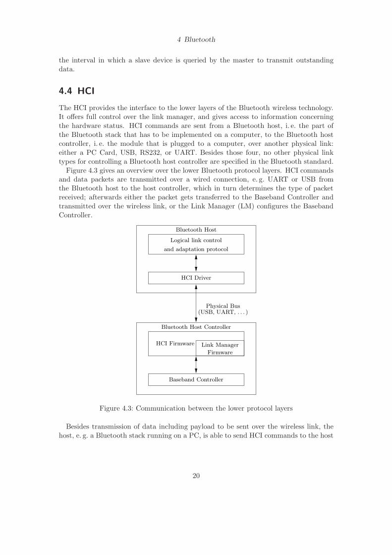
The HCI provides the interface to the lower layers of the Bluetooth wireless technology.It offers full control over the link manager, and gives access to information concerningthe hardware status. HCI commands are sent from a Bluetooth host, i. e. the part ofthe Bluetooth stack that has to be implemented on a computer, to the Bluetooth hostcontroller, i. e. the module that is plugged to a computer, over another physical link:either a PC Card, USB, RS232, or UART. Besides those four, no other physical linktypes for controlling a Bluetooth host controller are specified in the Bluetooth standard.
Figure 4.3 gives an overview over the lower Bluetooth protocol layers. HCI commandsand data packets are transmitted over a wired connection, e. g. UART or USB fromthe Bluetooth host to the host controller, which in turn determines the type of packetreceived; afterwards either the packet gets transferred to the Baseband Controller andtransmitted over the wireless link, or the Link Manager (LM) configures the BasebandController.
HCI Driver
Link Manager
Firmware
HCI Firmware
Baseband Controller
Logical link control
and adaptation protocol
(USB, UART, . . . )Physical Bus
Bluetooth Host Controller
Bluetooth Host
Figure 4.3: Communication between the lower protocol layers
Besides transmission of data including payload to be sent over the wireless link, thehost, e. g. a Bluetooth stack running on a PC, is able to send HCI commands to the host
20
4 Bluetooth
controller, i. e. the Bluetooth module; the host controller may in turn send events to thehost.
4.4.1 HCI command packets
The available HCI commands offered by the host controller can be categorized as follows:
Link control commands These commands allow setting up the Link Manager (LM) andgive full control over connection management to other Bluetooth devices, such asconnection creation and disconnection for ACL as well as SCO connections, inquiry,PIN setup, reading remote device names, and setting of the packet types allowedfor sending out packets (see table 4.1 on page 18 and table 4.2 on page 19).
Link policy commands This group of commands is used to change the policy rules ofthe Link Manager (LM), i. e. the link policy. Previously set up ACL links can bealtered and special modes, such as the park mode, the hold mode where no datamay be sent over the wireless link within a specified amount of time, or the sniffmode that is used to notify a slave device of only having to listen for incomingdata on certain time slots, may be entered. Furthermore, the roles of which deviceforms the master and slave within a piconet can be changed.
Host controller and baseband commands The behavior of the host controller towardsthe host and towards remote devices may be altered using these commands.
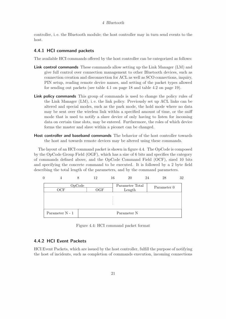
The layout of an HCI command packet is shown in figure 4.4. The OpCode is composedby the OpCode Group Field (OGF), which has a size of 6 bits and specifies the categoryof commands defined above, and the OpCode Command Field (OCF), sized 10 bitsand specifying the concrete command to be executed. It is followed by a 2 byte fielddescribing the total length of the parameters, and by the command parameters.
Parameter N - 1
4 8 12 16 20 24 28 320
Parameter 0OpCodeOCF OGF
Parameter TotalLength
Parameter N
Figure 4.4: HCI command packet format
4.4.2 HCI Event Packets
HCI Event Packets, which are issued by the host controller, fulfill the purpose of notifyingthe host of incidents, such as completion of commands execution, incoming connections
21
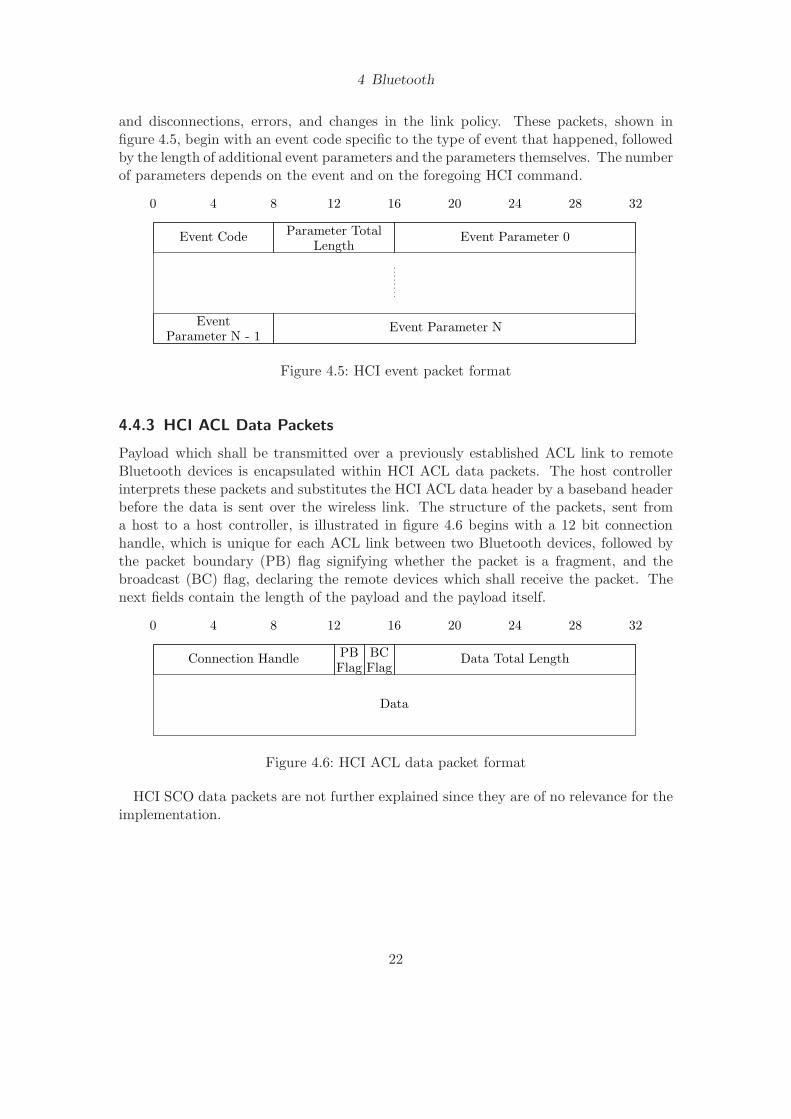
4 Bluetooth
and disconnections, errors, and changes in the link policy. These packets, shown infigure 4.5, begin with an event code specific to the type of event that happened, followedby the length of additional event parameters and the parameters themselves. The numberof parameters depends on the event and on the foregoing HCI command.
4 8 12 16 20 24 28 320
Event Code Parameter TotalLength
Event Parameter 0
Event Parameter NParameter N - 1
Event
Figure 4.5: HCI event packet format
4.4.3 HCI ACL Data Packets
Payload which shall be transmitted over a previously established ACL link to remoteBluetooth devices is encapsulated within HCI ACL data packets. The host controllerinterprets these packets and substitutes the HCI ACL data header by a baseband headerbefore the data is sent over the wireless link. The structure of the packets, sent froma host to a host controller, is illustrated in figure 4.6 begins with a 12 bit connectionhandle, which is unique for each ACL link between two Bluetooth devices, followed bythe packet boundary (PB) flag signifying whether the packet is a fragment, and thebroadcast (BC) flag, declaring the remote devices which shall receive the packet. Thenext fields contain the length of the payload and the payload itself.
4 8 12 16 20 24 28 320
Connection HandleFlagPB
FlagBC Data Total Length
Data
Figure 4.6: HCI ACL data packet format
HCI SCO data packets are not further explained since they are of no relevance for theimplementation.
22
4 Bluetooth
4.5 L2CAP
The Bluetooth logical link control and adaptation protocol (L2CAP) is layered abovethe Baseband, encapsulated in HCI ACL Data Packets, and handles the segmentation ofpackets, as well as QoS setup in order to prioritize data originating on certain links; aboveall, it provides a multiplexed interface to the upper protocol layers, such as RFCOMM(see section 4.6 on the following page) and SDP (see section 4.7 on page 26). L2CAPpackets may only be sent on top of HCI ACL data packets and are not defined for HCISCO data packets, since data integrity has to be ensured.
Multiple L2CAP channels may exist between two Bluetooth devices, due to its multi-plexing capability. Each upper layer protocol that is defined has a standardized Proto-col Service Multiplexor (PSM) value. All L2CAP channels are uniquely identified by aChannel ID (CID), which is dynamically assigned by the host for each open channel.
4.5.1 State machine
L2CAP is constituted as a state machine, interfacing with the lower and the upper layers.Actions are performed from L2CAP to the interfacing layers, whilst events are receivedin the other direction.
The state machine is an integral part of L2CAP, used for channel establishment,parameter negotiation, and disconnection; furthermore, offering a transparent interfaceto the adjacent layers.
The state machine is exemplified on channel establishment for an incoming connectionrequest. Before a channel is associated with the CID, the state machine is in the Closedstate. Though a baseband connection may exist, this is no requirement. As soon as aconnection request comes in from another host, it is forwarded to the upper layer, waitingfor confirmation. If the upper layer accepts the connection, the state is changed to Config,allowing for exchange of L2CAP configuration parameters between the devices. As soonas both devices have exchanged configuration requests and responses, which might haveto be repeated several times to adjust the parameters of the remote end, the state ischanged to Open, and further data processing with the upper layers may proceed. Aslong as the channel is in the state Open, payload may be transmitted to the remoteBluetooth device.
4.5.2 Packet format
L2CAP packets can be categorized as follows:
L2CAP data packets These packets contain payload which is to be transmitted to orhas been received from remote Bluetooth units. Two different kinds of data packetsare defined: connection-oriented packets with only one recipient, and broadcast packetswhich have multiple recipients, i. e. a logical group that was previously set up by a higherlayer protocol; these packets are referred to as connection-less packets. Illustrations ofthose two packet formats are shown in figure 4.7 on the following page and figure 4.8 on
23

4 Bluetooth
the next page. Connection-oriented packets have a 4 byte header containing the packetlength and the CID assigned during the connection setup, whilst connection-less packetshave a header of 6 bytes in length with a fixed CID and additionally containing the PSMvalue signifying the service on the remote end.
8
Length Channel ID
Payload
16 24 32
Figure 4.7: Packet format for connection-oriented channels
8 16 24 32
Channel ID (0x0002)
Payload
Payload (cont.)
PSM
Length
Figure 4.8: Packet format for connection-less channels
L2CAP signal packets Signal packets are used to notify a remote device of new con-nections, as well as to negotiate channel parameters, e. g. the Maximum TransmissionUnit (MTU) or QoS parameters. The format of such packets, shown in figure 4.9 on thefollowing page, contains a length field, a fixed CID, followed by one or more commandscontaining a command code, e. g. for a connection request, an identifier that is increasedon each request and sent back unchanged in responses to help associating a signal re-sponse with a foregoing request. Furthermore, it contains the length of the commandparameters in bytes and the command parameters themselves.
4.6 RFCOMM
RFCOMM provides a multiplexed interface for serial port emulation over the Bluetoothwireless link. It is based on ETSI (1997), the serial emulation used in TS 07.10, withsome adaptations for the Bluetooth system. Only one RFCOMM channel may exist perBluetooth link; multiplexing for up to 64 serial ports is implemented by the RFCOMMprotocol.
Figure 4.10 on the next page visualizes the two different kinds of RFCOMM devicetypes. Type-1 devices are solutions with integrated Bluetooth support, such as comput-
24

4 Bluetooth
8 16 24 32
Channel ID (0x0002)
Payload
Payload (cont.)
PSM
Length
Figure 4.9: Signal packet format
ers and printers; thus, endpoints of a connection. Type-2 devices, in contrast, have awired (serial) connection to the connection endpoint, e. g. to a modem or a mouse. Nodifference between these device types is made within the RFCOMM protocol.
Device with
Bluetooth
(Type-1)
Device with
Bluetooth
(Type-2)
Bluetooth WireDevice without
Bluetooth
with serial port
Figure 4.10: RFCOMM device types
RFCOMM provides the serial link with flow control mechanisms. Besides ModemStatus Command (MSC) packets which may be exchanged between two devices to specifythe control signals known from RS232, such as Ready To Communicate (RTC) and ReadyTo Receive (RTR), a scheme for Credit Based Flow Control (CBFC) is offered. Thisscheme allows a host to specify how many packets it is able to receive before the localbuffers are full. Each packet containing payload decreases a CBFC counter by one,whilst it may contain an extra field specifying how many more packets the remote sideis allowed to send.
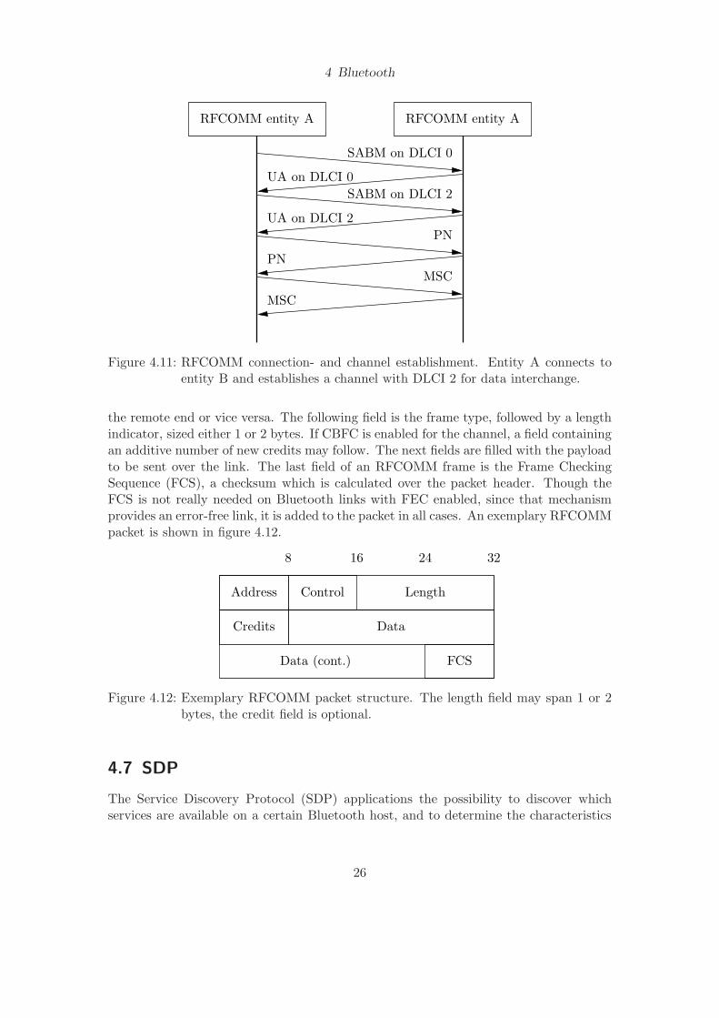
Each RFCOMM channel is uniquely identified by a Data Link Connection Identifier(DLCI), which gets assigned to the channel by the host initiating it. A connectionis initialized by sending a Set Asynchronous Balanced Mode (SABM) frame with thegeneral DLCI 0, replied by an Unnumbered Acknowledgement (UA) frame, also withDLCI 0 (cf. figure 4.11 on the following page). Channel establishment for each channelthat is to be opened then works quite similar: a SABM frame is sent containing a newlyassigned DLCI, answered with an UA frame with the same DLCI. In the next step,Data Link Connection (DLC) Parameter Negotiation (PN) is done in both directions;this includes exchanging the mutual Maximum Frame Size (MFS), and initial credits forCBFC, besides other information. After this, MSC packets are exchanged to set initialvalues containing the RS232 control signals.
RFCOMM packets are structured the following way. Each packet begins with anaddress field containing the DLCI and a flag indicating whether the packet is sent fromthe initiator of the connection, i. e. the host that sent the SABM frame on DLCI 0, to
25
4 Bluetooth
RFCOMM entity A RFCOMM entity A
PN
MSC
MSC
SABM on DLCI 0
SABM on DLCI 2
UA on DLCI 0
UA on DLCI 2
PN
Figure 4.11: RFCOMM connection- and channel establishment. Entity A connects toentity B and establishes a channel with DLCI 2 for data interchange.
the remote end or vice versa. The following field is the frame type, followed by a lengthindicator, sized either 1 or 2 bytes. If CBFC is enabled for the channel, a field containingan additive number of new credits may follow. The next fields are filled with the payloadto be sent over the link. The last field of an RFCOMM frame is the Frame CheckingSequence (FCS), a checksum which is calculated over the packet header. Though theFCS is not really needed on Bluetooth links with FEC enabled, since that mechanismprovides an error-free link, it is added to the packet in all cases. An exemplary RFCOMMpacket is shown in figure 4.12.
Address Control
Credits
FCS
8 16 24 32
Length
Data
Data (cont.)
Figure 4.12: Exemplary RFCOMM packet structure. The length field may span 1 or 2bytes, the credit field is optional.
4.7 SDP
The Service Discovery Protocol (SDP) applications the possibility to discover whichservices are available on a certain Bluetooth host, and to determine the characteristics
26

4 Bluetooth
of those services. Service classes are defined to differentiate between services, such asprinters, or modems, as well as the mechanisms to access them. Service Discovery Pro-tocol (SDP) is based on a request/response model to keep the number of transmissionslow. Services may be arranged hierarchically, to cope with huge numbers of differentservices that may be offered by devices.
27

5 Implementation
This chapter sums up the implementation of the Bluetooth stack, which constituted oneof the integral and most time-consuming parts of this project. All parts of the Bluetoothprotocol stack which were implemented are described within the following chapter, aswell as some additional programs which run on the Khepera robot.
The following part describes some of the main constraints that had to be consideredthroughout the whole implementation.
Memory limitations Since the MCU which is used on the KBU only offers a very limitedamount of memory, no dynamic memory allocation could be used. All variableshad to be defined either in a global or in a local context, i. e. statically below theheap or dynamically on the stack.
Clean programming/debugging Due to the fact that the KBU only offers three LEDsfor direct output, and the debugging interface pins of the MCU are not connected tothe circuit board, debugging the implementation showed to be a challenge. There-fore, special care for code cleanliness had to be taken, manifested in meaningfulcomments and a clean and readable coding style.
Flow control Since flow control between the MCU and the Khepera robot, as well asbetween the MCU and the Bluetooth chip was not available due to missing con-nections, buffers large enough for handling of huge packets had to be declared inthe low amount of memory that is offered by the MCU.
Two Bluetooth stacks were implemented throughout this project: a minimal one con-sisting of a bootloader for easy software updates, further described in section 5.1, and afully standards compliant one, described in more detail in section 5.2 on the next page.
Since the source code was well documented throughout the implementation phase,using the doxygen syntax1, no code fragments are included here. The source files arenamed according to the implemented protocol layer, which makes it easy to find therelevant parts in case of changes and additions.
5.1 Bootloader
During the first programming stages, it came clear that updating the MCUs flash mem-ory always takes a long time, since DIP switches mounted on the KBU have to be setin different ways for programming and for testing. Furthermore, these switches suffered
1http://www.doxygen.org/ (last visited August 2004)
28
5 Implementation
from being physically switched too often, and their replacement would have been nec-essary after a short amount of time. Therefore, the decision was taken to program abootloader, residing in the upmost part of the MCUs flash memory, which is never tobe replaced during normal flash updates.
The main bootloader code consists of a minimal Bluetooth stack, being able to receivecompiled code in Intel’s hex-format, and code to program and verify the update of flashpages. One constraint while programming was a small code size, since the amount offlash memory available for the bootloader was very low. Therefore the implementationis not standard conform in all cases. For the same reason, it was impossible to useinterrupts for receiving and sending packets; the buffers constantly had to get polledinstead. The bootloader operates in the following steps:
1. Check whether the 8th DIP switch on the top side of the KBU is set. If not,continue loading the regular code.
2. Initialize the Bluetooth host controller.
3. Wait for an incoming connection. If a connection is detected, set up L2CAP linkproperly, i. e. negotiate parameters.
4. Wait for incoming data on the L2CAP channel; if the data packet is not prefixedby a magic number, or if an end of file record is detected, quit the bootloader anddo regular boot-up process.
5. Write the data into the corresponding flash ROM page and verify whether it hasbeen written properly. If not, go into an endless loop with blinking LEDs.
6. Send the characters OK over the L2CAP channel, continue with step 4.
If the flash process was successful, the new software gets directly executed.
5.2 Implementation of the Bluetooth stack
The buffers for incoming data from both the Khepera robot and the Bluetooth hostcontroller were declared as ringbuffers to ensure that packets incoming at any time canbe stored. Due to the fact that no flow control could be used from the KBU towardsthe robot and the host controller, they have to be very huge, and thus take up half ofthe MCUs internal memory.
The main function of the implementation consists of calling initialization routinesof the different Bluetooth layers, and an endless loop permanently checking whetherunprocessed packets are residing in the buffers. If no packets are to be handled, theMCU goes into standby mode until an interrupt occurs.
What follows is a summary of the layers of the Bluetooth stack that were implementedwithin this project.
29

5 Implementation
5.2.1 USART
Basic interrupt handling routines, initial setup of the serial Universal Synchronous/Asyn-chronous Receiver/Transmitter (USART) connections, such as baudrate settings, thenumber of data and stop bits, and parity setting are implemented on this layer. Theinterface offered from this layer to the upper layers consists of functions for sendingout a number of bytes which reside in the ringbuffers to either the Khepera robot orthe Bluetooth host controller. If an interrupt occurs, the incoming byte is checked forvalidity if possible, and written into the corresponding ringbuffer. When a full packethas been received from the host controller, and it is classified as an HCI event packet,the HCI layer is directly called from within the interrupt routine to handle that event. Ifa data packet has been received, a counter for the number of unprocessed data packetsin the ringbuffer gets increased.
On incoming packets from the Khepera robot, a fixed number of bytes gets reserved inthe ringbuffer for writing back the Bluetooth headers during further packet processing.If a full data packet has been received, i. e. a carriage return and a line feed have beendetected, a counter for the number of unprocessed packets residing inside the ringbuffergets increased.
5.2.2 HCI
The HCI layer consists of code handling HCI events, as well as HCI ACL data packets.Furthermore, functions for initialization of the host controller are included.
After resetting or powering up the KBU, the folling HCI commands are sent from theBluetooth host to the host controller:
Depending on the packet type detected on the USART layer, i. e. event-, or data-packet, the corresponding function on the HCI layer is called. Event handlers are calledfrom within the interrupt routine, to ensure that events get directly processed, withoutany latency. Due to the fact that transmissions from the host controller can occur atany time, the event handler functions have to be very efficient.
When HCI commands have to be executed, the implementation waits until the trans-mission of a packet to the host controller is completed. Afterwards, interrupts from theKhepera become disabled, and the command is transferred. Normal processing of datacontinues as soon as a certain HCI event has been received, i. e. a Command Completeevent in reaction to the change of the local device name.
Incoming ACL data packets get processed by looking up the internal connection record,identified by the matching connection handle. It becomes then forwarded to the upperlayer, i. e. L2CAP. Outgoing ACL data packets, in contrast, get the ACL header added;afterwards, the USART layer is called to transmit the packet to the host controller.
5.2.3 L2CAP
As mentioned in section 4.5.1 on page 23, the L2CAP connection- and disconnectionprocess, as well as the parameter negotiation, is constitued as a state machine. Foreach CID, the current connection state is saved. Due to memory limitations on the
30

5 Implementation
HCI Command Command Type Purpose
Reset Host controller/Baseband
Reset the Bluetooth Host Controller,Link Manager, and the radio module.
Write AuthenticationEnable
Host controller/Baseband
Disable authentication for incomingconnections.
Set Event Filter Host controller/Baseband
Allow connections from all devices
Write Page Timeout Host controller/Baseband
Set timeout for page responses
Write Scan Enable Host controller/Baseband
Enable inquiry and page scan to show upin device lists
Change Local Name Host controller/Baseband
Change device name to Khepera i, wherei is the ID set with the DIP switches.
Set Event Mask Host controller/Baseband
Filter out unwanted events
Set UART Baudrate Vendor-specific Increase Baudrate beween Host and HostController
Table 5.1: HCI Initialization
MCU, only one L2CAP channel is allowed per connection – if a device tries to establisha second channel, it gets rejected. The transmission between the states occurs wheninteracting with other layers, i. e. the HCI layer and RFCOMM, or when sending andreceiving signals from the remote L2CAP implementation.
Incoming payload gets checked for a valid CID, and then forwarded to the upperprotocol layer. Due to the limited amount of memory available on the MCU, fragmentedpackets cannot be handled correctly; all fragments are solely forwarded to the upper layerin the order they arrive, which in turn forwards them to the Khepera robot. Therefore,payload which originates from different Bluetooth hosts might get mixed up, i. e. it isso far impossible to exchange large amounts of data between Khepera robots over theBluetooth wireless link. Packets with payload sizes which can be transmitted within onepacket are unproblematic though.
5.2.4 RFCOMM
The RFCOMM implementation on the KBU is able to accept resp. establish one channelper remote Bluetooth device. Due to the limited amount of memory available on theMCU, it is impossible to keep packets in the buffer if not enough credits are availableon the remote side, or to split packets up if the MFS is exceeded, the implementationis not fully standards compliant. Packets are sent out as soon as all headers are added,CBFC, control signals, as well as MFS are saved and counted, but ignored.
The RFCOMM standard specification (Bluetooth SIG, 2001; ETSI, 1997) containsseveral unclear terms, which provide for difficulties when interacting with other Blue-
31

5 Implementation
tooth entities2. In such cases, the Bluetooth stack on the KBU was kept conform toBlueZ, the Linux Bluetooth stack.
5.3 Evaluation and testing
5.3.1 Khepera programs
For testing and evaluating the implementation of the Bluetooth stack, several programsthat run on the Khepera robot itself had to be implemented as well.
Due to the fact that the Khepera robots do not allow updating their flash ROMon the fly over a serial link, but rather need to get their ROM removed and externallyprogrammed, the programs described here were loaded into the Random Access Memory(RAM) of the robot and only executed until a reset occurred, e. g. by pulling the powerplug or pushing the reset button.
Ping To measure transmission times for a round-trip of a packet from the controllingcomputer to the Khepera robot and back, a program wich reads the input and echoesit back has to run on the robot. Within this project, two versions of this program wereimplemented: one which reads and writes linewise, and one which echoes character bycharacter. To comply with the Khepera communication protocol, pure line feeds in theinput get substituted by a carriage return followed by a line feed on the output.
ANN To evaluate experiments previously simulated in YAKS, an implementation ofANNs which is able to run on a physical Khepera robot was carried out. Structuraldata of the ANN to use gets compiled in connection with source code which evaluatesthe sensors and sets the motor rotation speeds. The resulting program can be uploadedand executed on a real Khepera robot, i. e. the robot can act completely autonomous,without any cable connections and without an extension turret for wireless control. Adrawback of this method, compared to evaluating an ANN with sensor values withina simulator over the Bluetooth wireless link, is a relatively high effort to carry out anexperiment in the real world.
2Exemplified here by the calculation of the FCS: The standard document states that for SABM, DISC,UA, and Data-Medium Rate (DM) frames, the FCS shall be calculated on the address, control, andlength field. It is left open whether a potential second byte of the length field, which is always presentfor frames larger than 128 bytes, shall be included in the FCS calculation, or not.
32

6 Results
6.1 Performance
In this section, a performance evaluation of the KBU is done. Parameters affecting theperformance, e. g. the packet type used for sending packets, are evaluated. Results arecompared to the Khepera radio turret. Furthermore, the performance of the K213 visionturret gets evaluated using several parameters. Transmission times are compared whenrunning one and two robots at the same time.
6.1.1 Serial transmission rate
0
50
100
150
200
250
300
0 50 100 150 200 250 300
tim
e [m
s]
payload size [bytes]
38400 / 57600 baud38400 / 230400 baud57600 / 230400 baud
Figure 6.1: Baudrate comparison. The first number denotes the baudrate between theKBU and the Khepera, the second one refers to the baudrate between thehost controller and the host. The dots are connected and smoothed to in-crease readability
The UART baudrate between the Bluetooth host controller and the host, as well asthe transmission rate between the KBU and the Khepera robot is clearly a factor thatis important for the achievement of high transmission rates of the whole connectionbetween a controlling computer and a Khepera robot. Figure 6.1 gives an overview on
33

6 Results
how much the baudrate settings are an influencing factor. As one can expect, a higherbaudrate increases the transmission rate significantly.
The huge discrepancies between the curves shown in figure 6.1 on the preceding pageimply that the serial baudrate used has a very high influence on the performance of thewhole solution.
6.1.2 Comparison of ACL packet types
Investigating the different ACL packet types is important for the Bluetooth module in useon the KBU, since it does not support automatic selection of the best matching packettype for each packet to be transmitted. This stems from a limitation of the EricssonBluetooth module that was used on the KBU. Without that limitation, it would bepossible to automatically select the packet type that can be transmitted the fastest wayover the wireless link by enabling only the corresponding packet types and then lettingthe Bluetooth module choose among those packet types.
The underlying data for the following performance comparisons was recorded in analmost noise-free environment. In other environments with a lot of noise, e. g. with otheractive Bluetooth devices, or devices using wireless LAN, which transmits its packets onthe same ISM band, the results might significantly differ.
10
20
30
40
50
60
70
80
90
100
0 50 100 150 200 250 300
tim
e [m
s]
payload size [bytes]
DM1DH1DM3DH3DM5DH5
Figure 6.2: Comparison of ACL packet types for a packet round-trip between the PCand the KBU. The dots are connected and smoothed to increase readability.
In figure 6.2, a comparison between the different ACL packet types (cf. table 4.1 onpage 18) is shown. AUX1 packets are not included in the diagram since an error-freelink is highly desirable. The measurement consisted of a round-trip between the testingPC and the KBU of a packet with increasing payload. Each line in the graph has steps
34
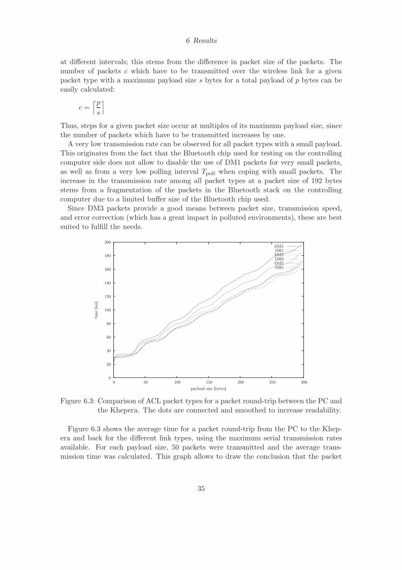
6 Results
at different intervals; this stems from the difference in packet size of the packets. Thenumber of packets c which have to be transmitted over the wireless link for a givenpacket type with a maximum payload size s bytes for a total payload of p bytes can beeasily calculated:
c =⌈p
s
⌉
Thus, steps for a given packet size occur at multiples of its maximum payload size, sincethe number of packets which have to be transmitted increases by one.
A very low transmission rate can be observed for all packet types with a small payload.This originates from the fact that the Bluetooth chip used for testing on the controllingcomputer side does not allow to disable the use of DM1 packets for very small packets,as well as from a very low polling interval Tpoll when coping with small packets. Theincrease in the transmission rate among all packet types at a packet size of 192 bytesstems from a fragmentation of the packets in the Bluetooth stack on the controllingcomputer due to a limited buffer size of the Bluetooth chip used.
Since DM3 packets provide a good means between packet size, transmission speed,and error correction (which has a great impact in polluted environments), these are bestsuited to fulfill the needs.
0
20
40
60
80
100
120
140
160
180
200
0 50 100 150 200 250 300
tim
e [m
s]
payload size [bytes]
DM1DH1DM3DH3DM5DH5
Figure 6.3: Comparison of ACL packet types for a packet round-trip between the PC andthe Khepera. The dots are connected and smoothed to increase readability.
Figure 6.3 shows the average time for a packet round-trip from the PC to the Khep-era and back for the different link types, using the maximum serial transmission ratesavailable. For each payload size, 50 packets were transmitted and the average trans-mission time was calculated. This graph allows to draw the conclusion that the packet
35
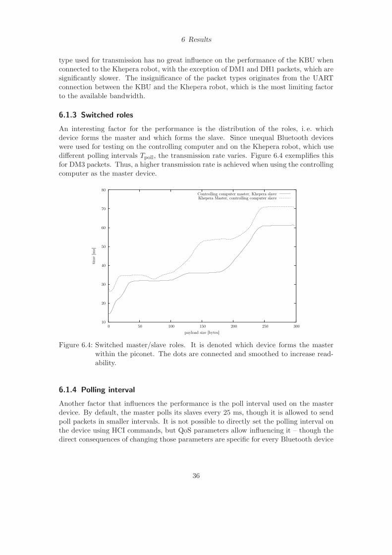
6 Results
type used for transmission has no great influence on the performance of the KBU whenconnected to the Khepera robot, with the exception of DM1 and DH1 packets, which aresignificantly slower. The insignificance of the packet types originates from the UARTconnection between the KBU and the Khepera robot, which is the most limiting factorto the available bandwidth.
6.1.3 Switched roles
An interesting factor for the performance is the distribution of the roles, i. e. whichdevice forms the master and which forms the slave. Since unequal Bluetooth deviceswere used for testing on the controlling computer and on the Khepera robot, which usedifferent polling intervals Tpoll, the transmission rate varies. Figure 6.4 exemplifies thisfor DM3 packets. Thus, a higher transmission rate is achieved when using the controllingcomputer as the master device.
10
20
30
40
50
60
70
80
0 50 100 150 200 250 300
tim
e [m
s]
payload size [bytes]
Controlling computer master, Khepera slaveKhepera Master, controlling computer slave
Figure 6.4: Switched master/slave roles. It is denoted which device forms the masterwithin the piconet. The dots are connected and smoothed to increase read-ability.
6.1.4 Polling interval
Another factor that influences the performance is the poll interval used on the masterdevice. By default, the master polls its slaves every 25 ms, though it is allowed to sendpoll packets in smaller intervals. It is not possible to directly set the polling interval onthe device using HCI commands, but QoS parameters allow influencing it – though thedirect consequences of changing those parameters are specific for every Bluetooth device
36

6 Results
and undocumented. Increasing the polling interval significantly boosts the electric powerconsumption of the device. For no official documentation was published on the exactinfluence of the QoS parameters, no tests could be carried out.
6.1.5 Running two robots at the same time
The performance of the implementation is not particularly much influenced if more thanone robot is run at a time. Figure 6.5 exemplifies the timing of a single robot controlledover the Bluetooth wireless link to two robots at a time. For this test, the ACL packettype DM5 was used with maximum serial transmission rates. The data transmissionwas issued and measured for both robots in parallel, since serializing the packets wouldfalsify the results.
0
20
40
60
80
100
120
140
160
180
0 50 100 150 200 250 300
tim
e [m
s]
payload size [bytes]
DM5 SingleDM5 1/2DM5 2/2
Figure 6.5: Packet transmission time for a round-trip with two Khepera robots runningat the same time, compared to a single robot. The dots are connected andsmoothed to increase readability.
6.2 Comparison to the Radio Turret
This section discusses the comparison of the performance of the KBU to the performanceof the Radio Turret. For to achieve this, several Khepera commands were sent to theKhepera, similar to those used in a real environment:
1. Read proximity sensors
2. Read image from the K213 vision turret
37
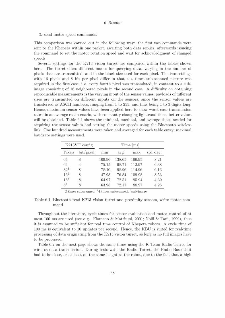
6 Results
3. send motor speed commands.
This comparison was carried out in the following way: the first two commands weresent to the Khepera within one packet, awaiting both data replies, afterwards issueingthe command to set the motor rotation speed and wait for acknowledgment of changedspeeds.
Several settings for the K213 vision turret are compared within the tables shownhere. The turret offers different modes for querying data, varying in the number ofpixels that are transmitted, and in the block size used for each pixel. The two settingswith 16 pixels and 8 bit per pixel differ in that a 4 times sub-scanned picture wasacquired in the first case, i. e. every fourth pixel was transmitted, in contrast to a sub-image consisting of 16 neighbored pixels in the second case. A difficulty on obtainingreproducable measurements is the varying input of the sensor values; payloads of differentsizes are transmitted on different inputs on the sensors, since the sensor values aretransferred as ASCII numbers, ranging from 1 to 255, and thus being 1 to 3 digits long.Hence, maximum sensor values have been applied here to show worst-case transmissionrates; in an average real scenario, with constantly changing light conditions, better valueswill be obtained. Table 6.1 shows the minimal, maximal, and average times needed foracquiring the sensor values and setting the motor speeds using the Bluetooth wirelesslink. One hundred measurements were taken and averaged for each table entry; maximalbaudrate settings were used.
K213VT config Time [ms]
Pixels bit/pixel min avg max std. dev.
64 8 109.96 138.65 166.95 8.2164 4 75.15 98.71 112.97 6.38321 8 78.10 98.96 114.96 6.16162 8 47.98 76.84 109.98 8.53163 8 64.97 72.51 95.94 4.3983 8 63.98 72.17 88.97 4.2512 times subscanned, 24 times subscanned, 3sub-image
Table 6.1: Bluetooth read K213 vision turret and proximity sensors, write motor com-mand.
Throughout the literature, cycle times for sensor evaluation and motor control of atmost 100 ms are used (see e. g. Floreano & Mattiussi, 2001; Nolfi & Tani, 1999), thusit is assumed to be sufficient for real time control of Khepera robots. A cycle time of100 ms is equivalent to 10 updates per second. Hence, the KBU is suited for real-timeprocessing of data originating from the K213 vision turret, as long as no full images haveto be processed.
Table 6.2 on the next page shows the same times using the K-Team Radio Turret forwireless data transmission. During tests with the Radio Turret, the Radio Base Unithad to be close, or at least on the same height as the robot, due to the fact that a high
38

6 Results
rate of transmission errors was observed otherwise; this probably stems from radiationproperties of the antennas used. The data in table 6.2 allows to draw the conclusionthat the Radio Turret is not suited for reading sensor data of the K213 vision turret inreal time.
K213VT config Time [ms]
Pixels bit/pixel min avg max std. dev.
64 8 1223.77 1487.78 2009.66 151.1964 4 887.84 1127.83 1590.01 127.36321 8 873.67 1166.88 1882.92 186.03162 8 712.86 950.53 1435.75 161.76163 8 714.86 964.02 1369.75 146.5583 8 633.87 840.89 1471.73 153.36
Table 6.2: Radio turret read K213 vision turret and proximity sensors, write motor com-mand. 12 times subscanned, 24 times subscanned, 3sub-image
To get an impression on the maximum transmission times that may be achieved,table 6.3 shows the values for a Khepera robot directly connected to the PC, using awired serial connection at a transmission rate of 57600 baud.
K213VT config Time [ms]
Pixels bit/pixel min avg max std. dev.
64 8 75.86 76.83 78.29 0.6564 4 46.50 47.97 59.93 1.66321 8 46.56 47.73 55.96 1.28162 8 29.72 30.08 39.97 1.01163 8 29.96 31.19 43.21 1.3183 8 22.39 23.72 24.28 0.46
Table 6.3: Serial read K213 vision turret and Proximity sensors, write motor command.12 times subscanned, 24 times subscanned, 3sub-image
Figure 6.6 on the following page shows all averaged measurements in a graph, toallow for a direct comparison of the three different connection types. The KBU clearlyoutperforms the Radio Turret.
6.3 Evaluation of YAKS and the KBU for real robots
To empirically demonstrate that it is possible to control more than one robot at a timewith the KBU, a test was carried out with two Khepera robots parallely running in amaze and doing an obstacle-avoidance task using Braitenberg’s vehicles (Braitenberg,
39
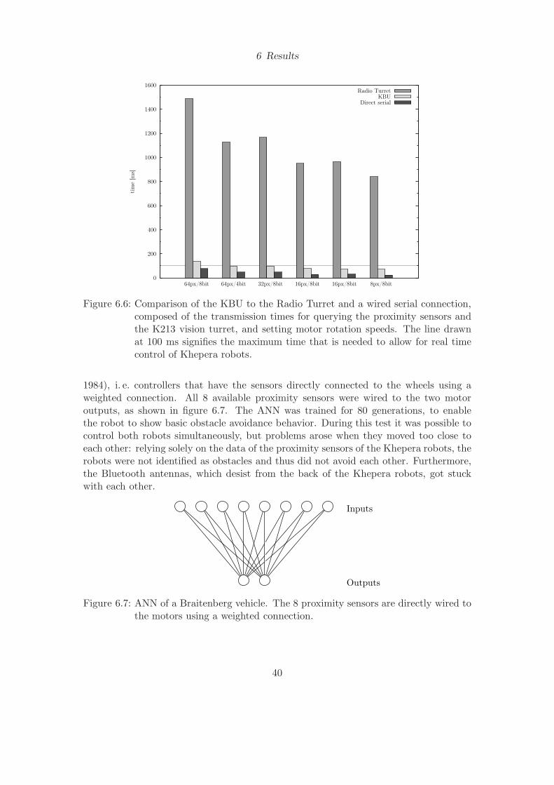
6 Results
0
200
400
600
800
1000
1200
1400
1600
8px/8bit16px/8bit16px/8bit32px/8bit64px/4bit64px/8bit
tim
e [m
s]
Radio TurretKBU
Direct serial
Figure 6.6: Comparison of the KBU to the Radio Turret and a wired serial connection,composed of the transmission times for querying the proximity sensors andthe K213 vision turret, and setting motor rotation speeds. The line drawnat 100 ms signifies the maximum time that is needed to allow for real timecontrol of Khepera robots.
1984), i. e. controllers that have the sensors directly connected to the wheels using aweighted connection. All 8 available proximity sensors were wired to the two motoroutputs, as shown in figure 6.7. The ANN was trained for 80 generations, to enablethe robot to show basic obstacle avoidance behavior. During this test it was possible tocontrol both robots simultaneously, but problems arose when they moved too close toeach other: relying solely on the data of the proximity sensors of the Khepera robots, therobots were not identified as obstacles and thus did not avoid each other. Furthermore,the Bluetooth antennas, which desist from the back of the Khepera robots, got stuckwith each other.
Outputs
Inputs
Figure 6.7: ANN of a Braitenberg vehicle. The 8 proximity sensors are directly wired tothe motors using a weighted connection.
40

6 Results
Another point of investigation was the maximum possible speed setting for the motorsof the robot. Due to the fact that there is a latency between reading the sensor valuesand setting the rotation speeds, mainly stemming from the transmission over serialports, the robot bumps into the other objects when accelerated too fast. Thereforea speed limit was included in YAKS; though the maximum speed possible is 1 m/s,the maximum maintainable speed at which the robot did not bump into obstables wasaround 280 mm/s. This test was carried out empirically on a running robot in the realworld.
Running a robot on battery-power with the KBU stacked on top of it only minimallydecreased its lifetime before having to be recharged. Due to a very moderate powerconsumption of the turret, the robot ran properly in the environment for approximately18 minutes. In comparison, a robot equipped with a Radio Turret ran for approximately20 minutes, however, after 11 minutes, a quickly increasing rate of transmission errorsand loss of data was observed, making the turret unusable. According to the KheperaUser Manual, the robot is able to run 45 minutes autonomously; however, a robot whichwas tested without additional turrets connected did not run for longer than 25 minutes(see figure 6.8 for a graphical comparison). It should be noted here that these factorsare influenced by battery age and conditions, other values might be accomplished withnew batteries.
10
12
14
16
18
20
22
24
26
with Radio Turretwith KBUPlain
tim
e [m
in]
Runtime [min]
Figure 6.8: Runtime before having to recharge the batteries
It was not possible to run simulated robots playing soccer in reality within this project,since the data provided by the K213 vision turret contained more noise than what wassimulated within YAKS, and thus was not usable for evaluation of real robots. Thesimulated turret was never tested to comply with the real turret before.
Due to the limited amount of time available for this project, it was not possible tofully implement or test the direct robot-to-robot communication. However, the basis forthis is provided, which satifies the aim of the whole project, but more coding effort willbe necessary in order to fully enable it.
41
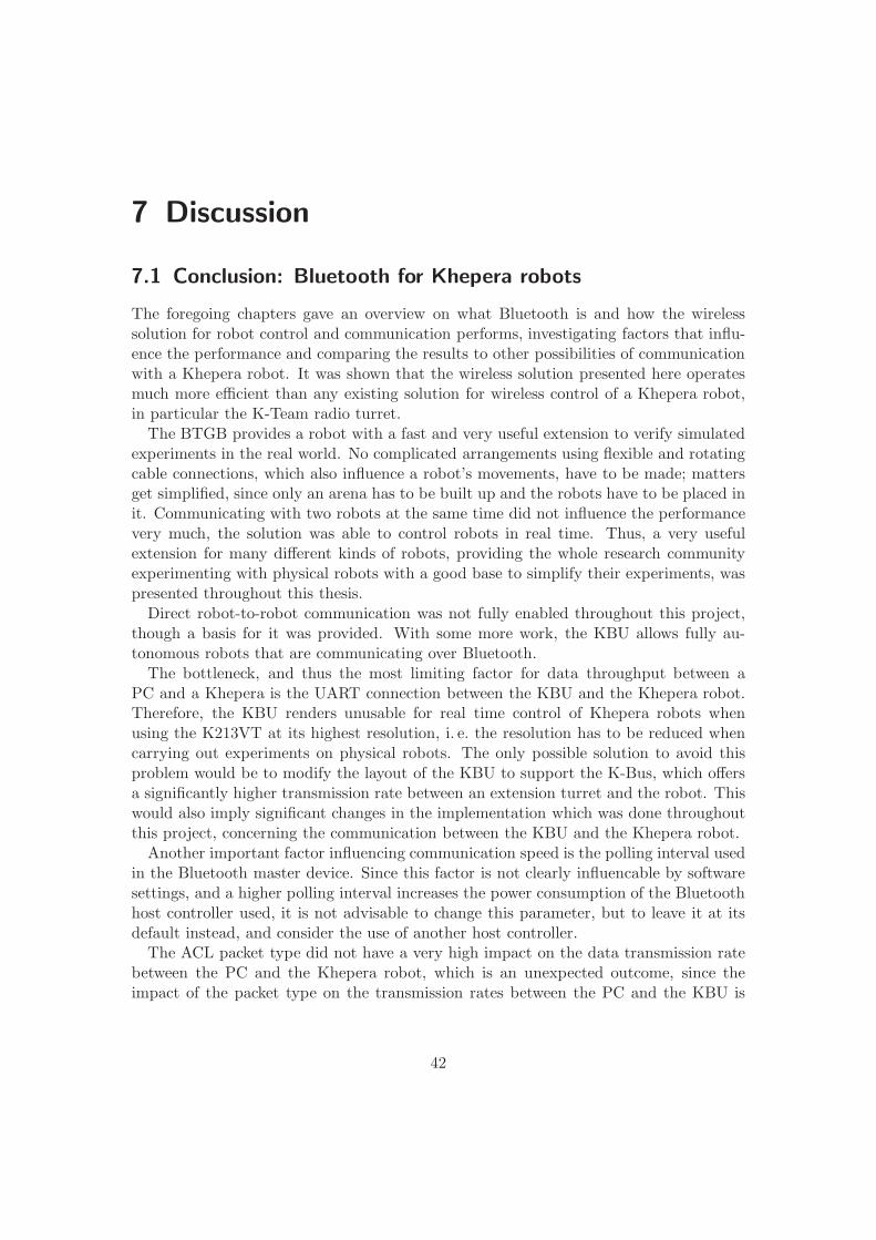
7 Discussion
7.1 Conclusion: Bluetooth for Khepera robots
The foregoing chapters gave an overview on what Bluetooth is and how the wirelesssolution for robot control and communication performs, investigating factors that influ-ence the performance and comparing the results to other possibilities of communicationwith a Khepera robot. It was shown that the wireless solution presented here operatesmuch more efficient than any existing solution for wireless control of a Khepera robot,in particular the K-Team radio turret.
The BTGB provides a robot with a fast and very useful extension to verify simulatedexperiments in the real world. No complicated arrangements using flexible and rotatingcable connections, which also influence a robot’s movements, have to be made; mattersget simplified, since only an arena has to be built up and the robots have to be placed init. Communicating with two robots at the same time did not influence the performancevery much, the solution was able to control robots in real time. Thus, a very usefulextension for many different kinds of robots, providing the whole research communityexperimenting with physical robots with a good base to simplify their experiments, waspresented throughout this thesis.
Direct robot-to-robot communication was not fully enabled throughout this project,though a basis for it was provided. With some more work, the KBU allows fully au-tonomous robots that are communicating over Bluetooth.
The bottleneck, and thus the most limiting factor for data throughput between aPC and a Khepera is the UART connection between the KBU and the Khepera robot.Therefore, the KBU renders unusable for real time control of Khepera robots whenusing the K213VT at its highest resolution, i. e. the resolution has to be reduced whencarrying out experiments on physical robots. The only possible solution to avoid thisproblem would be to modify the layout of the KBU to support the K-Bus, which offersa significantly higher transmission rate between an extension turret and the robot. Thiswould also imply significant changes in the implementation which was done throughoutthis project, concerning the communication between the KBU and the Khepera robot.
Another important factor influencing communication speed is the polling interval usedin the Bluetooth master device. Since this factor is not clearly influencable by softwaresettings, and a higher polling interval increases the power consumption of the Bluetoothhost controller used, it is not advisable to change this parameter, but to leave it at itsdefault instead, and consider the use of another host controller.
The ACL packet type did not have a very high impact on the data transmission ratebetween the PC and the Khepera robot, which is an unexpected outcome, since theimpact of the packet type on the transmission rates between the PC and the KBU is
42
7 Discussion
quite high. This another proof for the fact that the UART connection between the KBUand the Khepera robot is the most limiting factor for data throughput.
A big drawback of running Khepera robots freely without any cable connections is thedependence on the robot’s internal batteries, which only have a limited lifetime beforehaving to be recharged. Thus, only experiments of limited duration can be carried outwith unattached robots, if no solution for a constant, uncabled power supply, such asthe one presented by Martinoli (1999), is used.
7.2 Future work
Several ideas for subsequent projects emerged during this dissertation. A primary objec-tive should be to finalize the communication part for direct robot-robot communication,to offer a wide range of further experiments on real robots.
The preceeding performance evaluation should be carried out on Khepera II robots,which offer a much higher baudrate on the serial port, expecting a much lower packettransmission latency.
Another future project to increase transmission rates would be to use a Bluetooth1.2 enabled chipset instead of Bluetooth 1.1. Bluetooth 1.2 offers adaptive frequencyhopping to reduce the interferences with other links, thus, less packet retransmissionsare required. Furthermore, more advanced error correction is possessed.
Higher transmission rates will also be achieved by replacing the Khepera robots, usedfor the performance evaluation throughout this dissertation, with robots that offer ahigher serial baudrate setting, e. g. Khepera II robots.
To significantly improve the transfer rate between the KBU and the Khepera robotand at the same time get rid of the serial connection at all, the KBU could be enhancedto support the K-Bus, the bus that is used for communication between the MCU onthe robot and its RAM; most of the other extension turrets that were developed for theKhepera robot also make use of this bus. It is an 8-bit wide parallel bus that is wireddirectly to the CPU of the Khepera. Furthermore, the KBU could then be accessed inexactly the same way as other extension turrets, using the protocol proposed by K-Team.
7.3 What needs to be done
To finish the direct robot-to-robot communication, several steps have to be carried out.
KBU command protocol A protocol has to be implemented which allows a programthat runs on the Khepera robot to wirelessly connect to other robots and exchange datapackets between them. This implementation has been started, but not completed yet.
As an alternative to this step, the layout of the KBU could be modified to fully supportthe K-Bus of the Khepera robot. In this case, only the ANN implementation would haveto be reworked to support transmission of data over the K-Bus instead of the UARTport.
43
7 Discussion
Rework ANN implementation The ANN implementation which takes a weight file andan ANN as input from YAKS has to be redone, since the version which was used as abasis for the implementation within this project is based on an old version of YAKS,which does not support all kinds of ANN architectures. To achieve this, the C++ sourcecode for ANNs has to be modified to run on a Khepera robot w. r. t. data input andoutput. The foregoing implementation that was based on an old YAKS version mightsupport this job. Furthermore, new node types are needed for communication betweenANNs. These have to be implemented in YAKS, and afterwards adapted for the Kheperato submit data to the KBU. Routines for initialization of the Bluetooth wireless link areneeded on the Khepera robot, e. g. for connection establishment.
Enhance and test the Bluetooth stack The implementation of the Bluetooth stackthat was implemented throughout this project should be able to connect to other Blue-tooth hosts. Since the implementation of direct robot-to-robot communication was notfully completed, this functionality has never been tested. So additional tests have to becarried out to verify this functionality, consisting of Khepera programs which connectto and communicate with other Khepera robots over the Bluetooth wireless link.
One part that is still missing within the Bluetooth stack is the implementation of theSDP. This is not essential for its functionality w. r. t. connecting to the robot and sendingand receiving data, but should be done in order to have a fully standards-compliantimplementation which fulfills the requirements for Bluetooth certification. Furthermore,some other Bluetooth stacks which run on a PC might rely on the availability of theSDP to identify that RFCOMM is available on the KBU, and connect to it.
44
A Abbreviations
ACL Asynchronous Connection-Less
AM ADDR Active Member Address
ANN Artificial Neural Network
BD ADDR Bluetooth Device Address
BER Bit Error Rate
BTGB Bluetooth General Board
CBFC Credit Based Flow Control
CID Channel ID
CRC Cyclic Redundancy Check
DH Data-High Rate
DLC Data Link Connection
DLCI Data Link Connection Identifier
DM Data-Medium Rate
FCS Frame Checking Sequence
FEC Forward Error Correction
HCI Host Controller Interface
HEC Header-error-check
IEEE Institute of Electrical and Electronics Engineers
ISM Industrial, Scientific, and Medicine
K213VT K213 vision turret
KBU Khepera Bluetooth Unit
L2CAP Bluetooth logical link control and adaptation protocol
LM Link Manager
45
A Abbreviations
LMP Link Manager Protocol
MCU Microcontroller Unit
MFS Maximum Frame Size
MSC Modem Status Command
MSC Modem Status Command
MTU Maximum Transmission Unit
OCF OpCode Command Field
OGF OpCode Group Field
PER Packet Error Rate
PN Parameter Negotiation
PSM Protocol Service Multiplexor
QoS Quality of Service
RAM Random Access Memory
RF Radio Frequency
RTC Ready To Communicate
RTR Ready To Receive
SABM Set Asynchronous Balanced Mode
SCO Synchronous Connection-Oriented
SDP Service Discovery Protocol
SIG Special Interest Group
UART Universal Asynchronous Receiver/Transmitter
USART Universal Synchronous/Asynchronous Receiver/Transmitter
UA Unnumbered Acknowledgement
USB Universal Serial Bus
YAKS Yet Another Khepera Simulator
46
Bibliography
Bajaj, D. & Ang Jr., M. H. (2000), An Incremental Approach in Evolving Robot Behav-ior, in ‘Proceedings of the Sixth International Conference on Control, Automation,Robotics and Vision (ICARCV 2000)’, Singapore.
Balch, T. & Arkin, R. C. (1994), ‘Communication in reactive multiagent robotic sys-tems’, Autonomous Robots 1(1), 27–52.
Barnhard, D. H., McClain, J. T., Wimpey, B. J. & Potter, W. D. (2004), Odin andHodur: Using Bluetooth Communication for Coordinated Robotic Search, in ‘Pro-ceedings of the 2004 International Conference on Artificial Intelligence (IC-AI 04)’.
Billard, A. & Dautenhahn, K. (1997), Grounding communication in situated, socialrobots, in ‘Proceedings of the Towards Intelligent Mobile Robots Conference (TIMR97)’.
Billard, A., Ijspeert, A. & Martinoli, A. (1999), ‘A multi-robot system for adaptiveexploration of a fast changing environment: Probabilistic modelling and experimentalstudy’, Connection Science 11(3/4), 359–379.
Bluetooth SIG (2001), Specification of the Bluetooth System (Core) version 1.1.
Braitenberg, V. (1984), Vehicles: Experiments in Synthetic Psychology, MIT Press, Cam-bridge, MA, USA.
Bray, J. & Sturman, C. (2001), Bluetooth 1.1: Connect Without Cables, Second Edition,Prentice Hall PTR.
Brooks, R. A. (1991), Intelligence without representation, number 47 in ‘Artificial Intel-ligence’, pp. 139–159.
Brooks, R. A. (1992), Artificial life and real robots, in ‘European Conference on ArtificialLife’, pp. 3–10.
Carlsson, J. & Ziemke, T. (2001), YAKS – Yet Another Khepera Simulator, in U. Ruck-ert, J. Sitte & U. Witkowski, eds, ‘Autonomous Minirobots for Research and En-tertainment – Proceedings of the 5th International Heinz Nixdorf Symposium’, HNI-Verlagsschriftenreihe, Paderborn, Germany, pp. 235–241.
Cliff, D., Harvey, I. & Husbands, P. (1993), ‘Explorations in evolutionary robotics’,Adaptive Behavior 2(1), 73–110.
47
Bibliography
Easton, K. & Martinoli, A. (2002), Efficiency and Optimization of Explicit and ImplicitCommunication Schemes in Collaborative Robotics Experiments, in ‘Proceedings ofthe IEEE Conference on Intelligent Robots and Systems IROS-02’, IEEE Press, Lau-sanne, Switzerland, pp. 2795–2800.
Eriksson, A. (2002), Bluetooth for mobile robots (communication units), Master’s thesis,De Montfort University, UK.
ETSI (1997), Digital cellular telecommunications system (Phase 2+); Terminal Equip-ment to Mobile Station (TE-MS) multiplexer protocol (GSM 07.10 version 6.3.0).
Feng, L., Borenstein, J. & Wehe, D. (1996), A Completely Wireless Development Sys-tem for Mobile Robots, in ‘International Symposium on Robotics and Manufactoring(ISRAM ’96)’, World Automatic Congress (WAC ’96), May, 20th - 30th, Montpellier,France, pp. 571–576.
Floreano, D. & Mattiussi, C. (2001), Evolution of spiking neural controllers for au-tonomous vision-based robots, in ‘Proceedings of the International Symposium onEvolutionary Robotics From Intelligent Robotics to Artificial Life’, Springer-Verlag,pp. 38–61.
Floreano, D. & Mondada, F. (1998), ‘Evolutionary neurocontrollers for autonomousmobile robots’, Neural Networks 11(7-8), 1461–1478.
Gadanho, S. C. (2003), ‘Learning Behavior-Selection by Emotions and Cognition in aMulti-Goal Robot Task’, Journal of Machine Learning Research 4, 385–412.
Holland, J. H. (1975), Adaptation in natural and artificial systems, MIT Press.
Karlsson, M. (2003), USB driver development - and Bluetooth base station prototypes,Master’s thesis, De Montfort University, UK.
Karvosenoja, K. (2002), Bluetooth enabled mobile robots, Master’s thesis, De MontfortUniversity, UK.
Kostamo, J. (2003), Usb enabled bluetooth stack, Master’s thesis, De Montfort Univer-sity, UK.
Krassi, B. A. (2001), Reliability of Bluetooth, in ‘Proceedings of the12th conference ”Ex-treme Robotics”’, Central Research Institute for Robotics and Technical Cybernetics,St. Petersburg, Russia, pp. 341–346.
Kubık, A. (2003), Distributed genetic algorithm: Learning by direct exchange of chromo-somes, in W. Banzhaf, T. Christaller, P. Dittrich, J. Kim & J. Ziegler, eds, ‘Advancesin Artificial Life (Proceedings of the 7th European Conference on Artificial Life)’,Springer Verlag, Berlin, Germany, pp. 346–356.
48

Bibliography
Leopold, M., Dydensborg, M. B. & Bonnet, P. (2003), Bluetooth and sensor networks:a reality check, in ‘Proceedings of the first international conference on Embeddednetworked sensor systems’, ACM Press, pp. 103–113.
Martinoli, A. (1999), Swarm Intelligence in Autonomous Collective Robotics: FromTools to the Analysis and Synthesis of Distributed Collective Strategies, PhD thesis,Ecole Polytechnique Federale de Lausanne, Switzerland.
Martinoli, A., Franzi, E. & Matthey, O. (1997), Towards a reliable set-up for bioinspiredcollective experiments with real robots, in A. Casals, ed., ‘Proceedings of the FifthInternational Symposium on Experimental Robotics ISER-97’.
McClain, J. T., Wimpey, B. J., Barnhard, D. H. & Potter, W. D. (2004), Distributedrobotic target acquisition using bluetooth communication, in ‘Proceedings of the 42ndannual Southeast regional conference’, ACM Press, pp. 291–296.
McCulloch, W. S. & Pitts, W. (1943), ‘A logical calculus of the ideas immanent innervous activity’, Bulletin of Mathematical Biophysics 5, 115–133.
Miller, B. A., Bisdikian, C. & Siep, T. (2001), Bluetooth Revealed, Prentice Hall PTR.
Mondada, F., Franzi, E. & Ienne, P. (1994), Mobile robot miniaturisation: A tool forinvestigation in control algorithms, in ‘Experimental Robotics III’, Springer-Verlag,Kyoto, pp. 501–513.
Nguyen, H. G., Pezeshkian, N., Raymond, M., Gupta, A. & Spector, J. (2003), Au-tonomous communication relays for tactical robots, in ‘11th Int. Conf. on AdvancedRobotics (ICAR 2003)’.
Nolfi, S. & Parisi, D. (1995), Evolving non-trivial behaviors on real robots: an au-tonomous robot that picks up objects, in ‘AI*IA’, pp. 243–254.
Nolfi, S. & Tani, J. (1999), ‘Extracting regularities in space and time through a cas-cade of prediction networks: The case of a mobile robot navigating in a structuredenvironment’, Connection Science 11(2), 125–148.
Ruping, S., Loffler, A., Odenbach, C. & Ruckert, U. (1999), Khepera module for wire-less infrared can communication, in A. Loffler, F. Mondada & U. Ruckert, eds, ‘Pro-ceedings of the 1st International Khepera Workshop: Experiments with the Mini-Robot Khepera (IKW99)’, Vol. 64 of HNI-Verlagsschriftenreihe, Paderborn, Germany,pp. 181–187.
49